Fujitsu DP050M33111A1 User Manual 00 Cover 1
Fujitsu Limited 00 Cover 1
UserManual.wiki
>
Fujitsu
>
DP050M33111A1 User Manual
Exhibit E Users manual
Navigation menu
Upload a User Manual
Namespaces
Wiki Guide
HTML
PDF
Info
Views
User Manual
Discussion / Help
Navigation
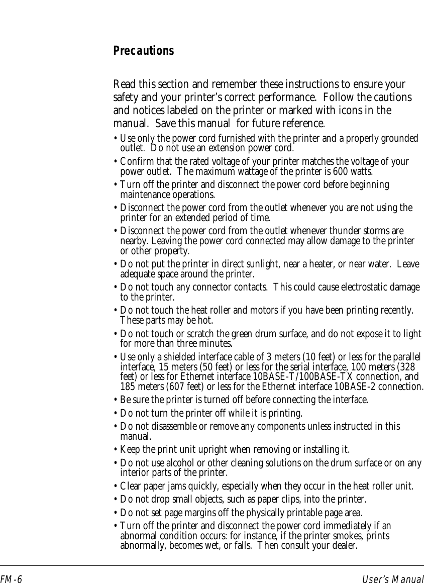
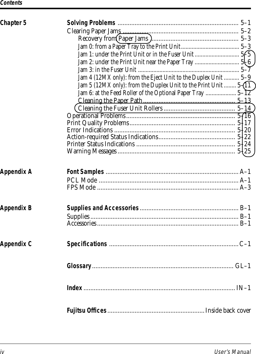
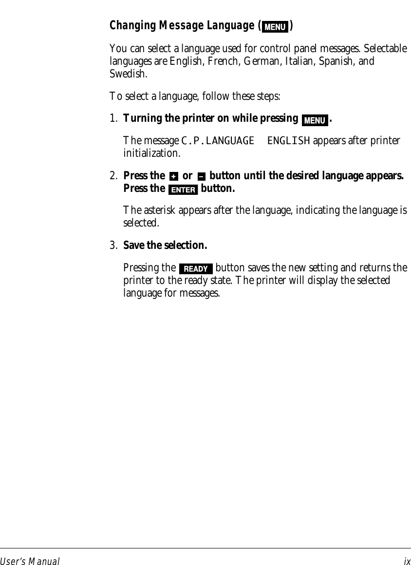

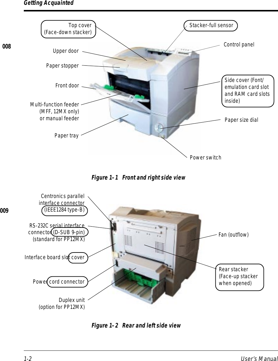
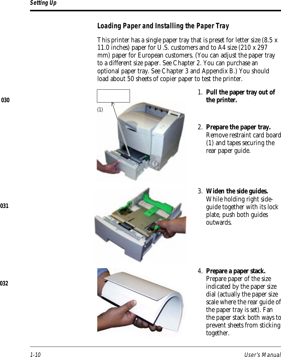
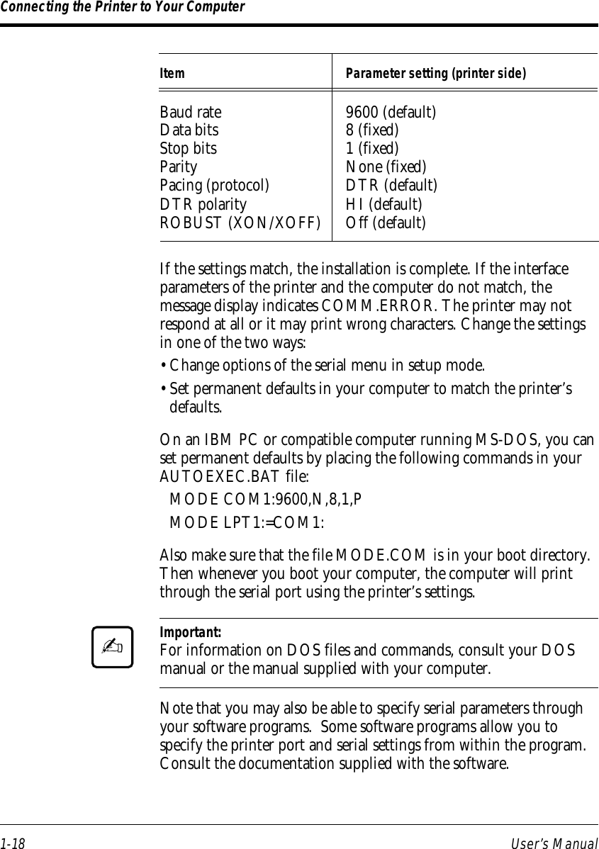
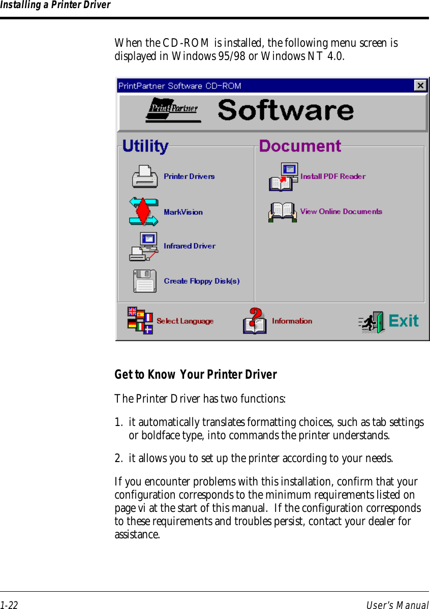
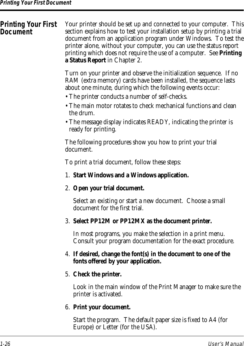

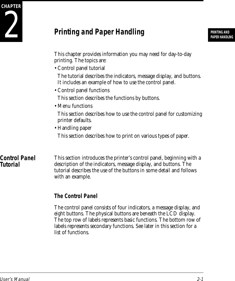
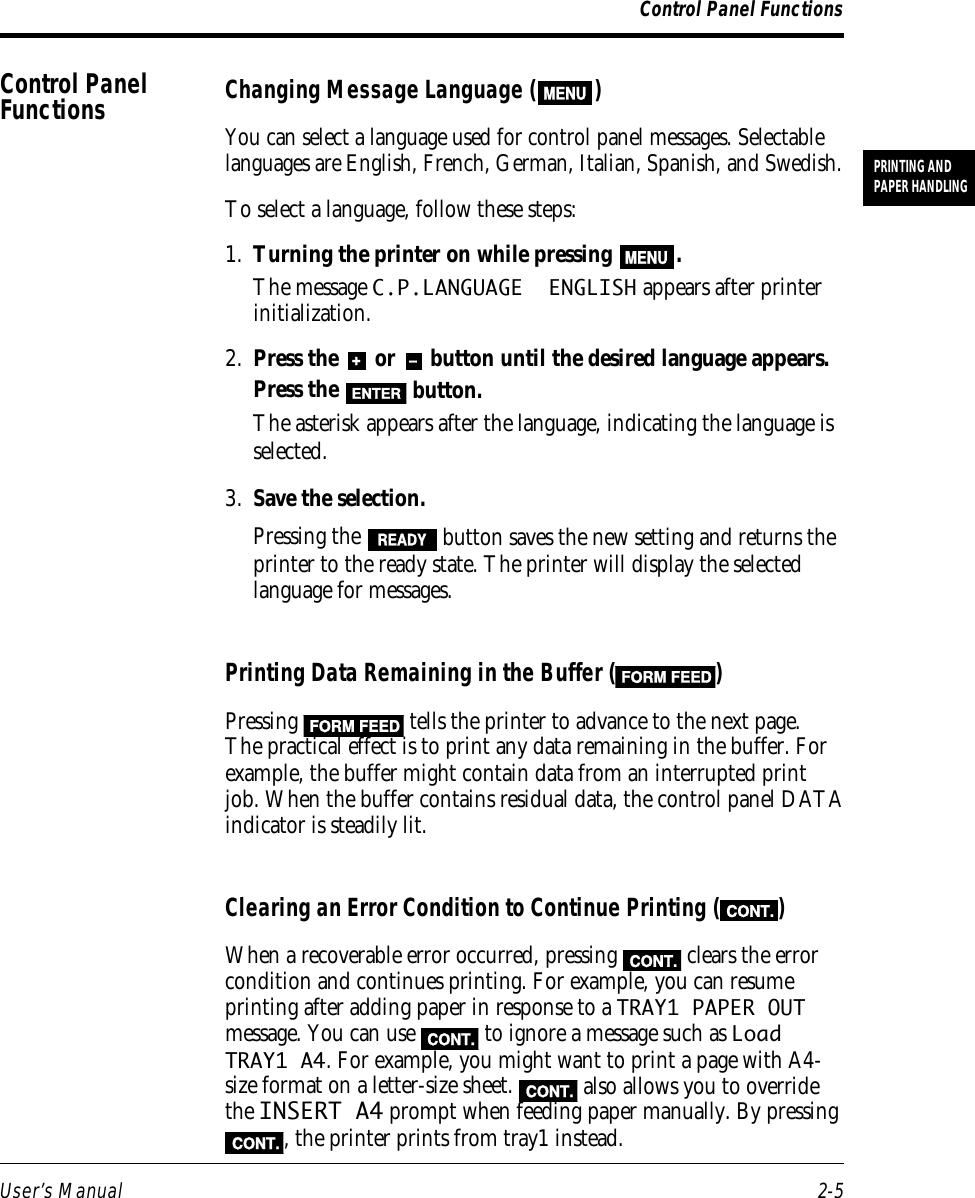
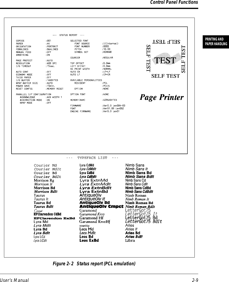
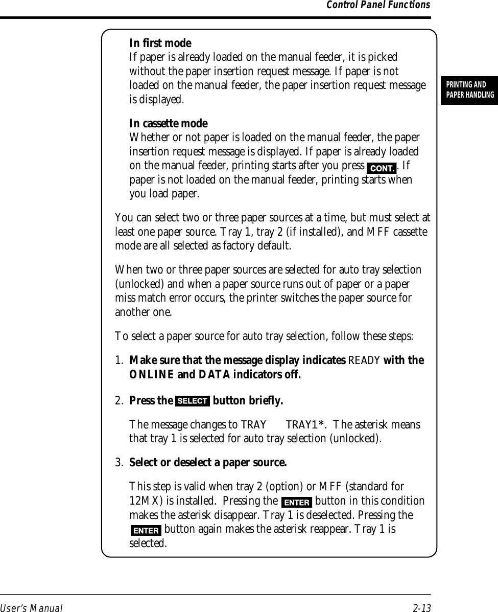
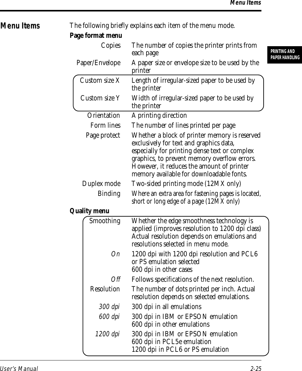
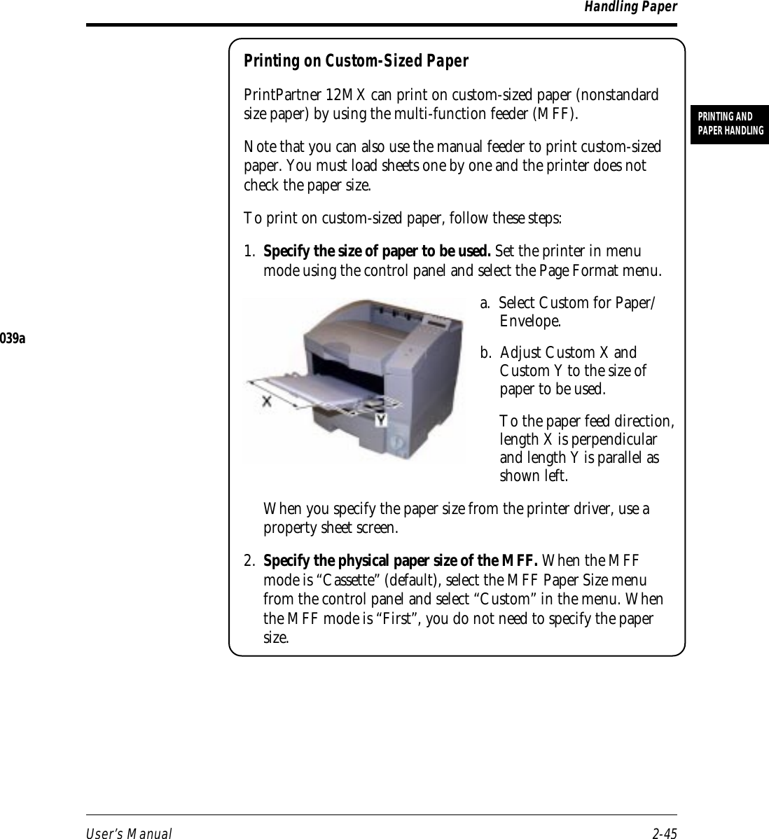
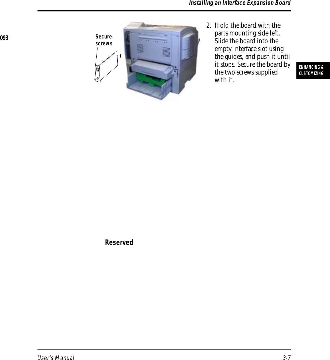
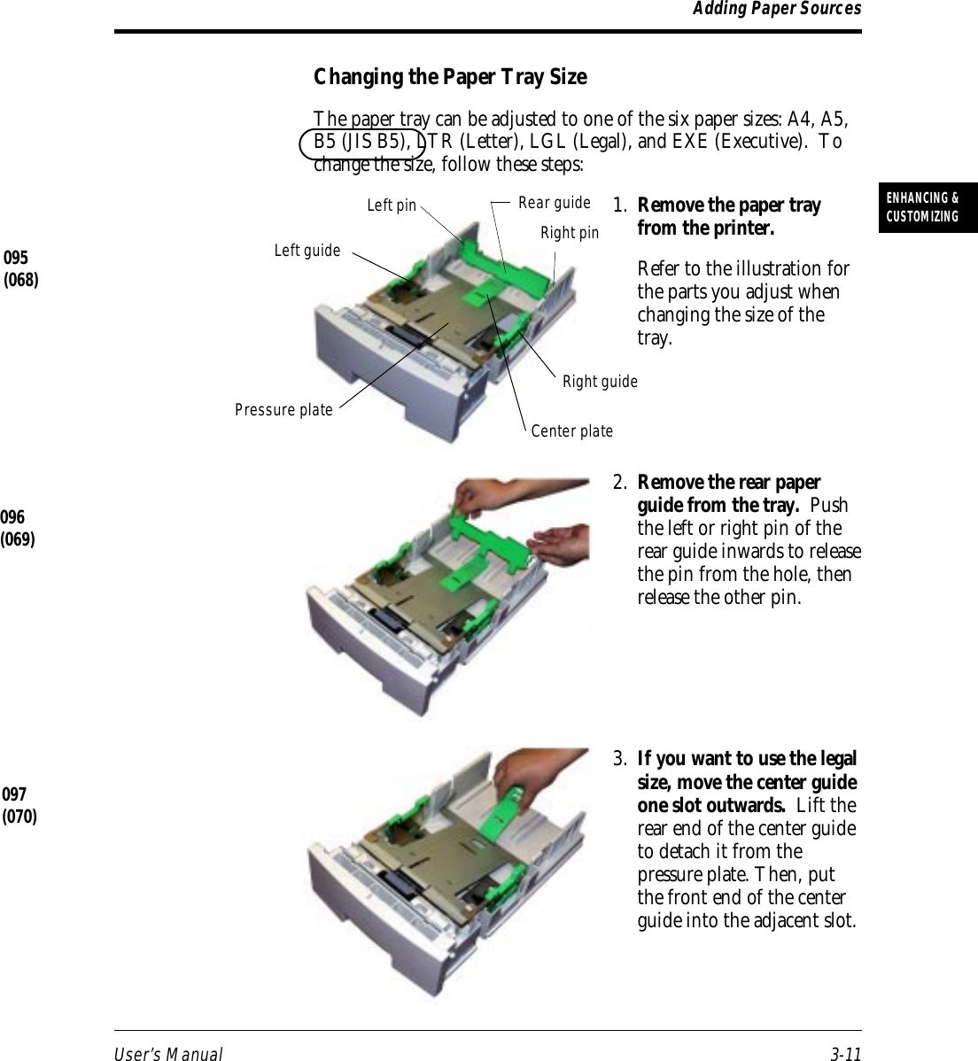
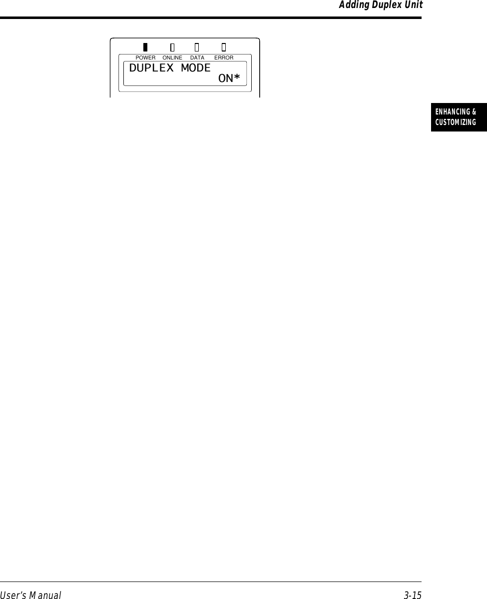

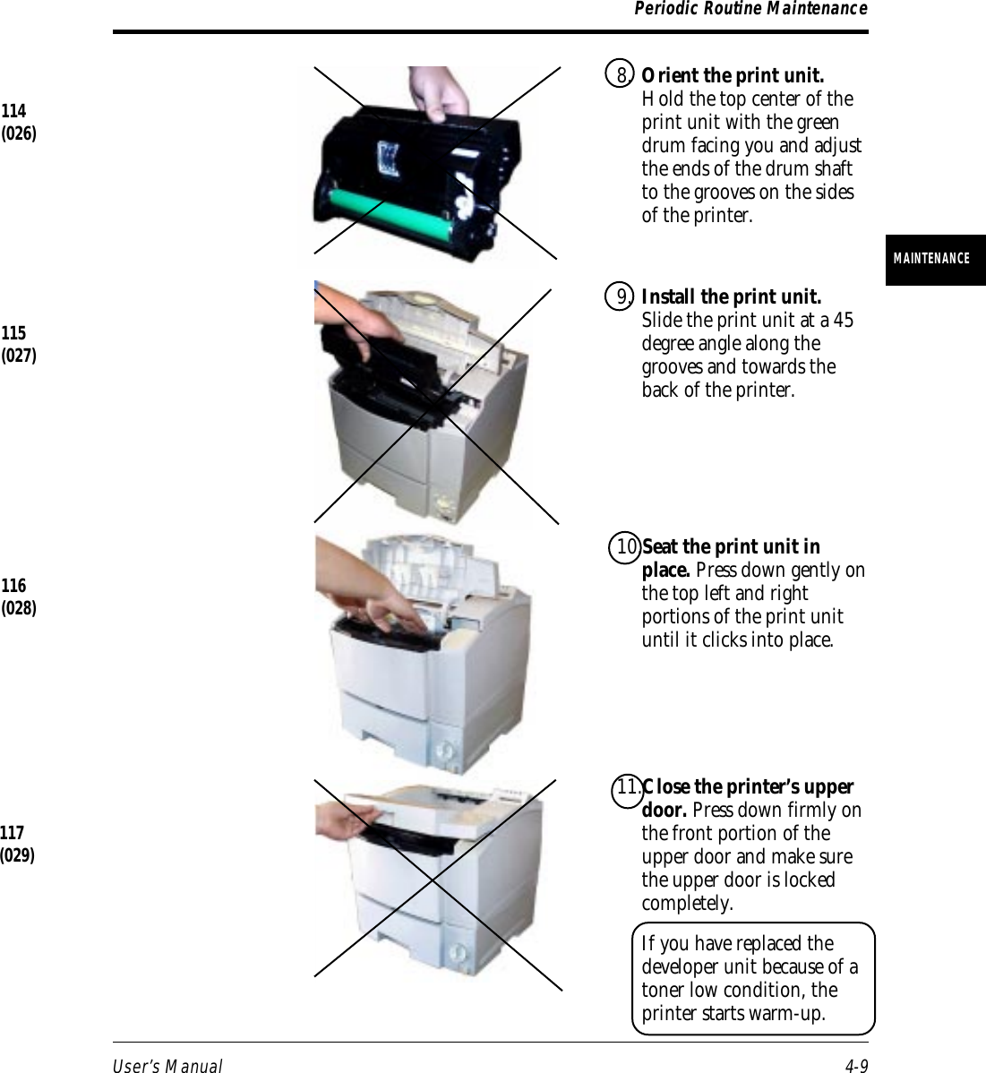

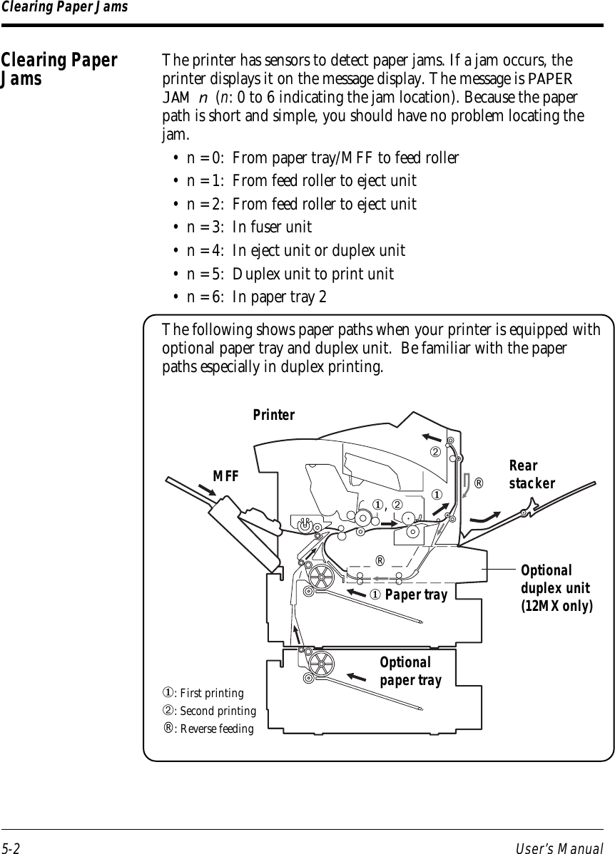
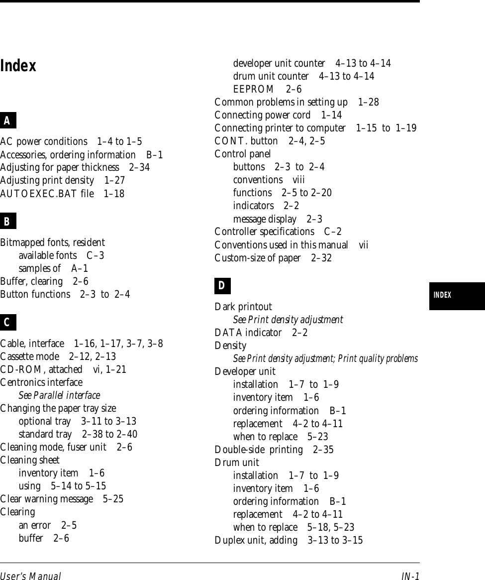
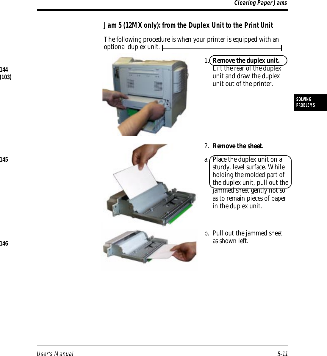
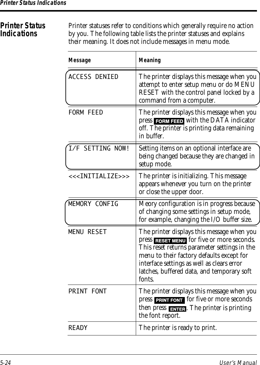
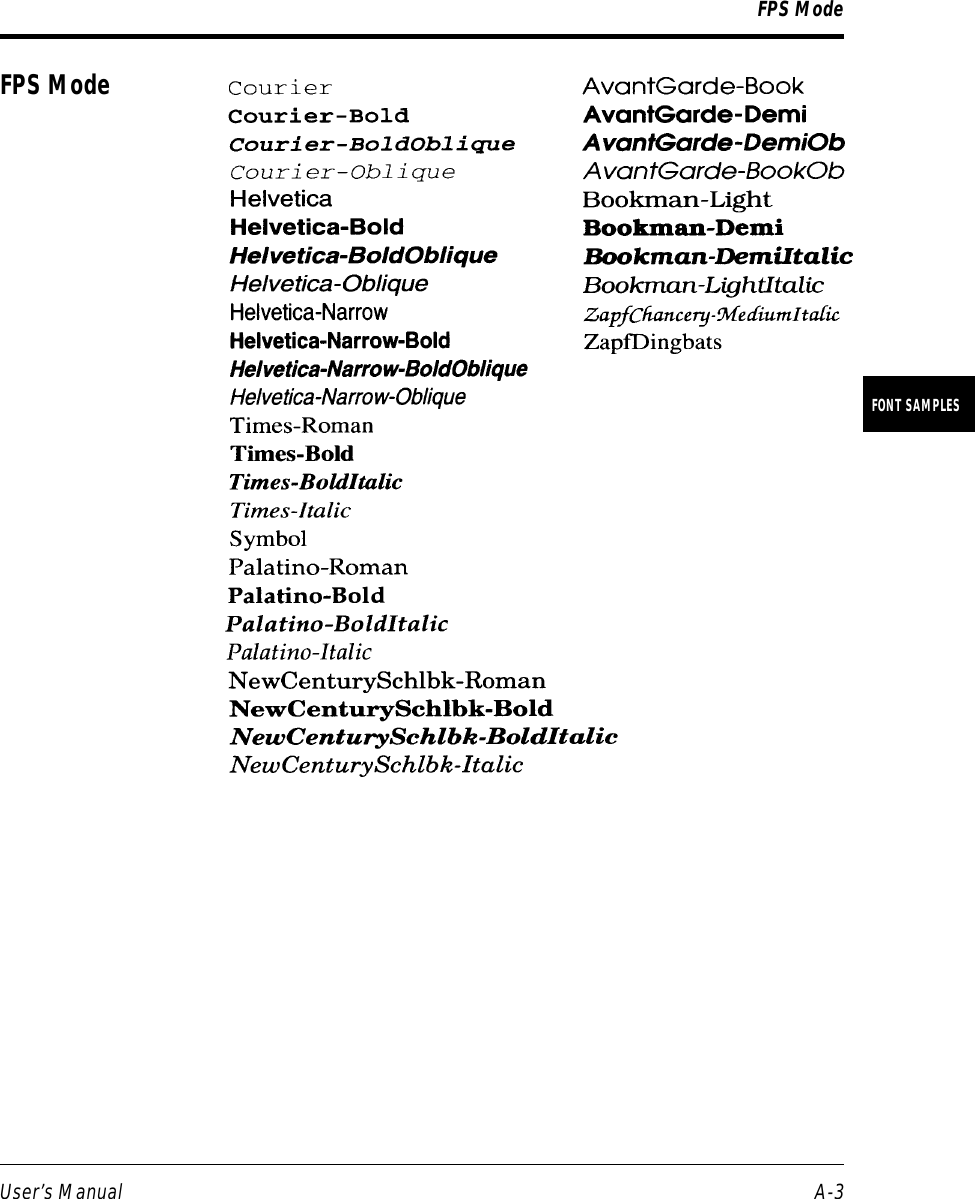
![5-6 User’s ManualCaution:Leaving paper guide ➁ opened causes damage to the print unit whenthe print unit is installed.Jam 2: under the Print Unit near the Paper Tray1. Open the upper door.2. Remove the print unit.For detailed procedures andadvisory notes, see thesection Replacing the PrintUnit in Chapter 4.3. Remove the sheet. Whilelifting the finger-markedportion of the paper guide① to open it, pull thejammed sheet gently not soas to remain pieces of paperin the printer.If you cannot hold thejammed paper, follow thenext steps.4. Pull out the paper tray.132[123]Clearing Paper Jams☞130(023)131(126)](https://usermanual.wiki/Fujitsu/DP050M33111A1/User-Guide-34376-Page-131.png)
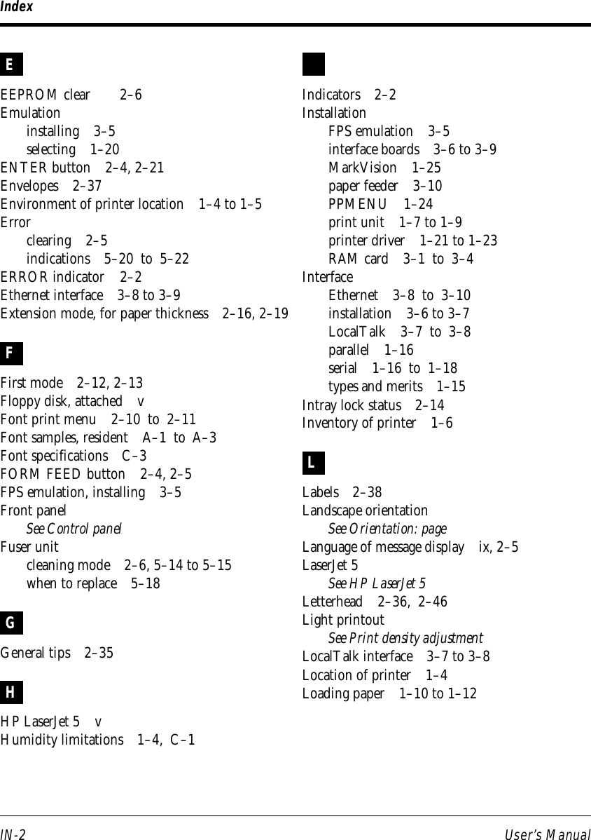
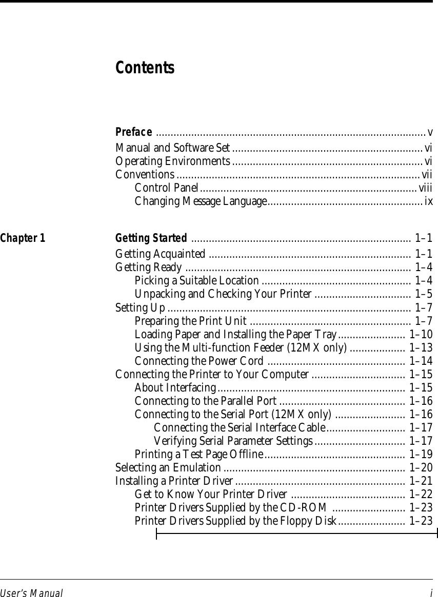
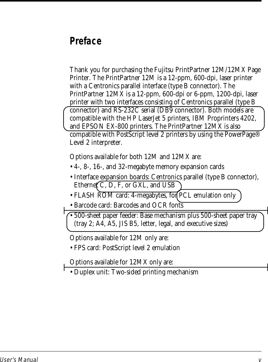
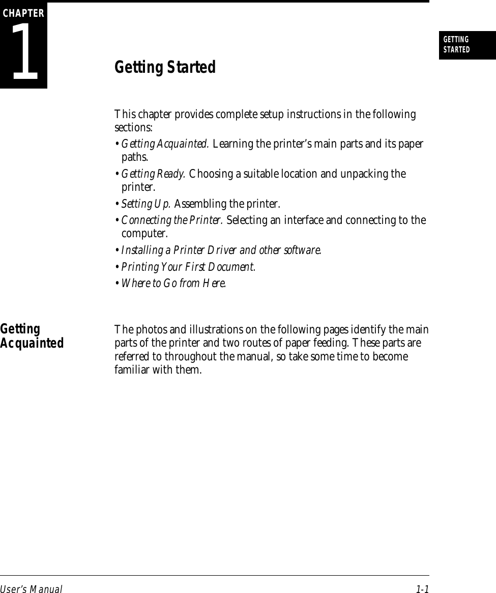
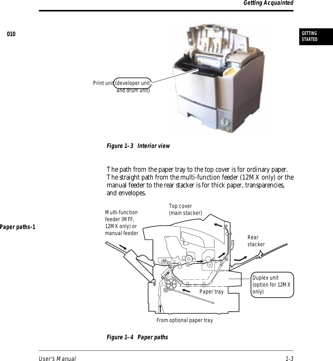
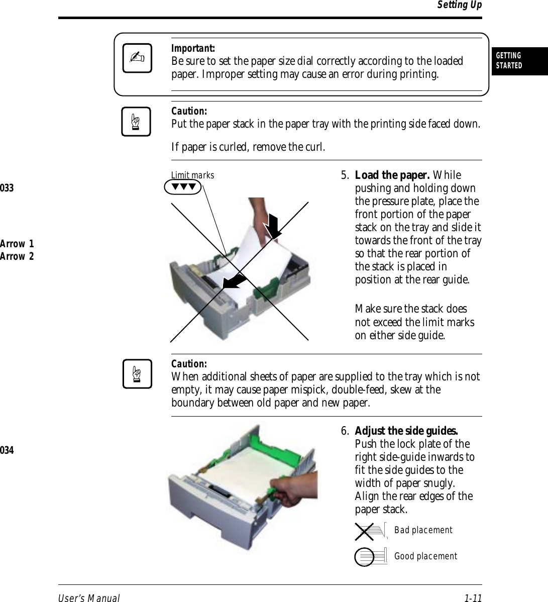
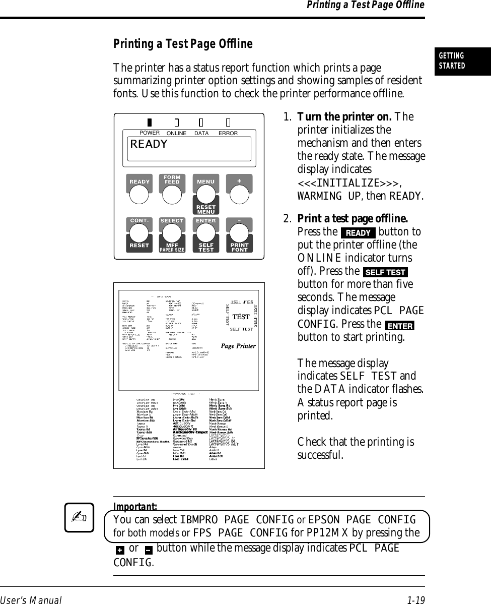
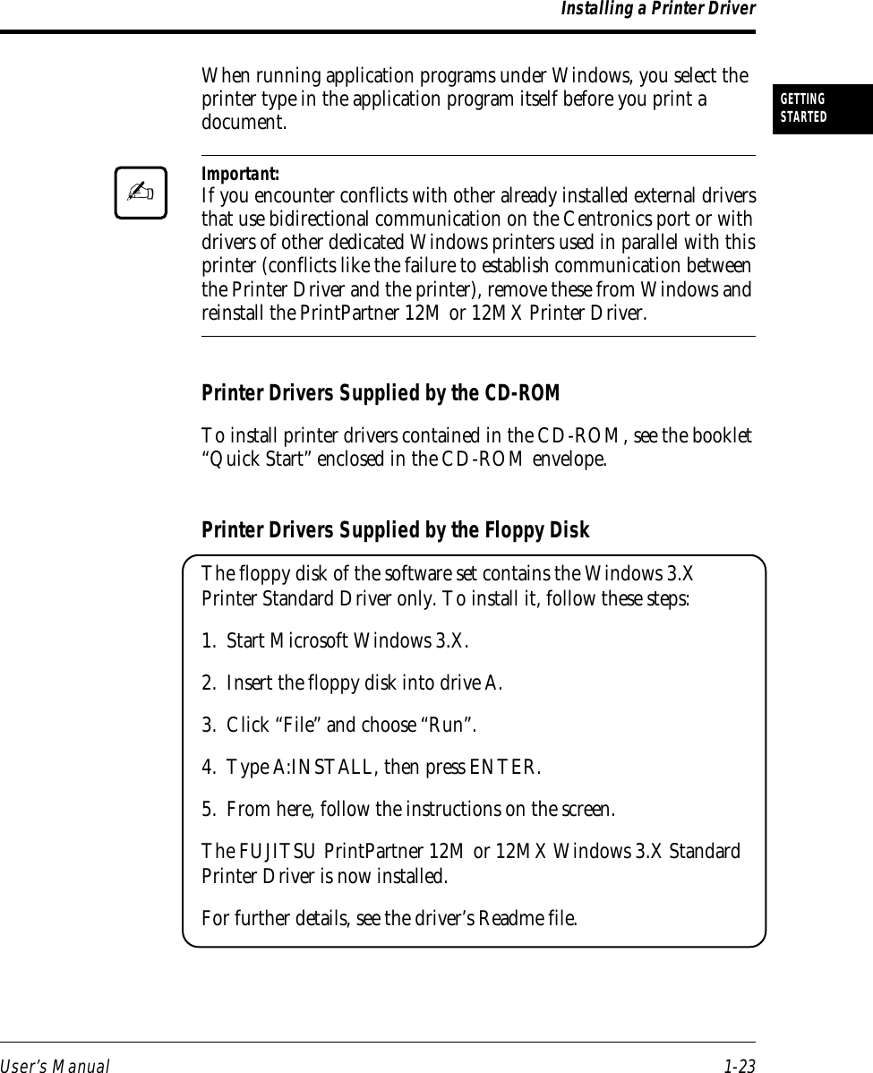
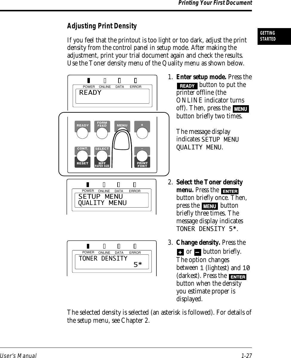
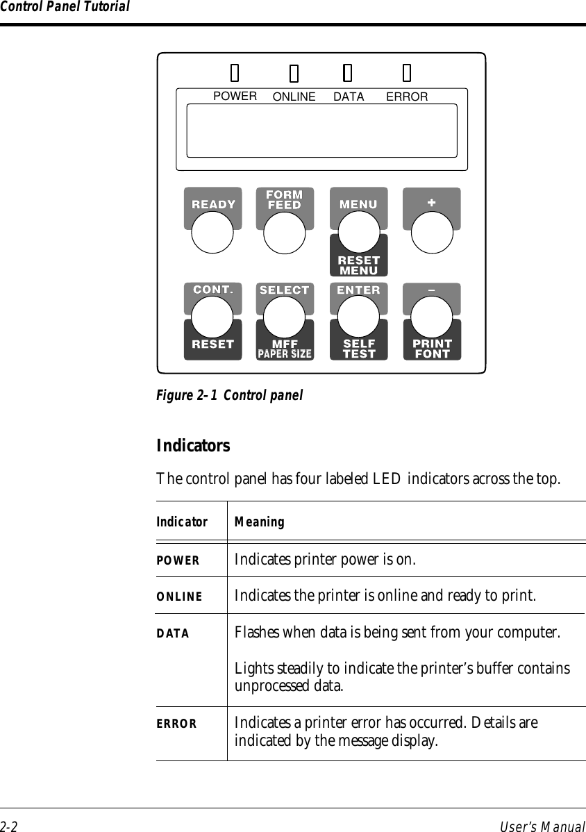
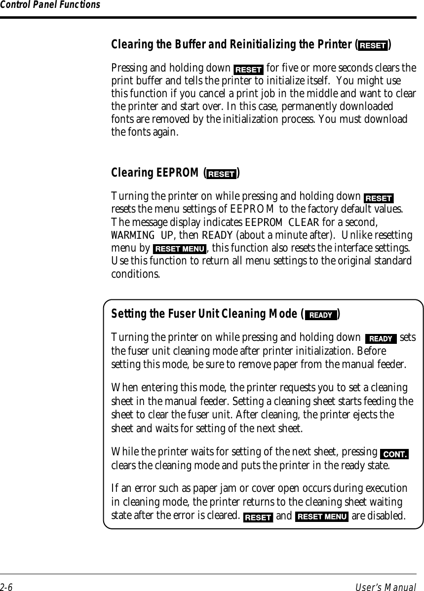
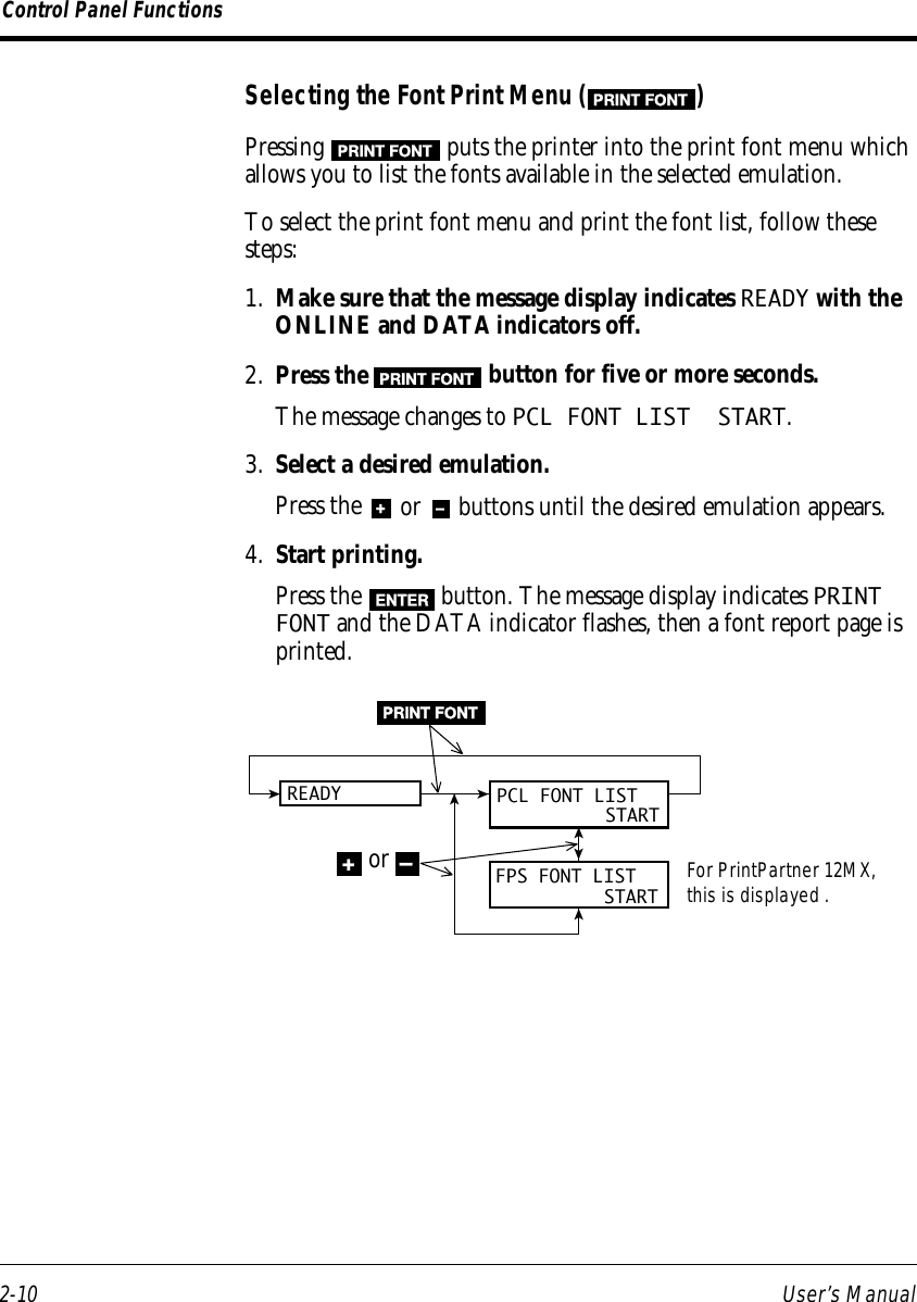
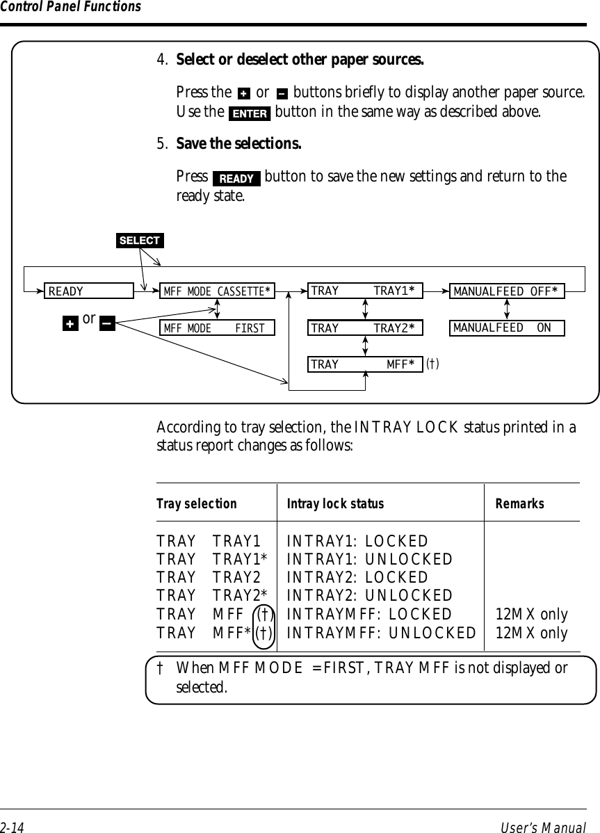
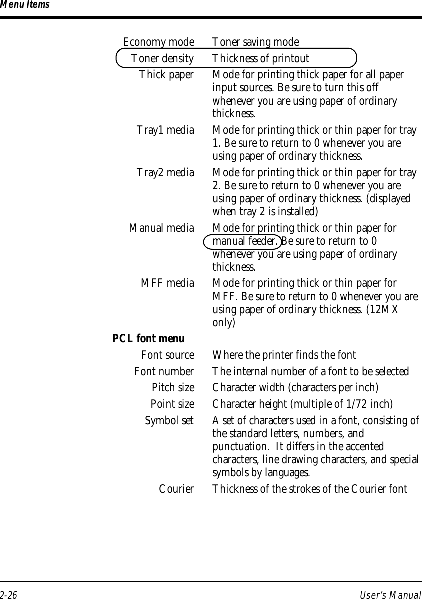
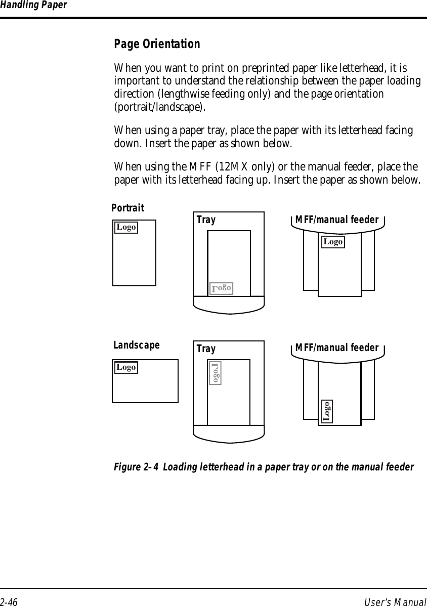
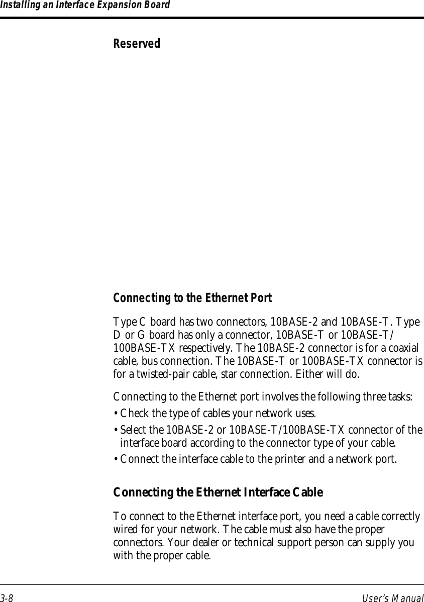
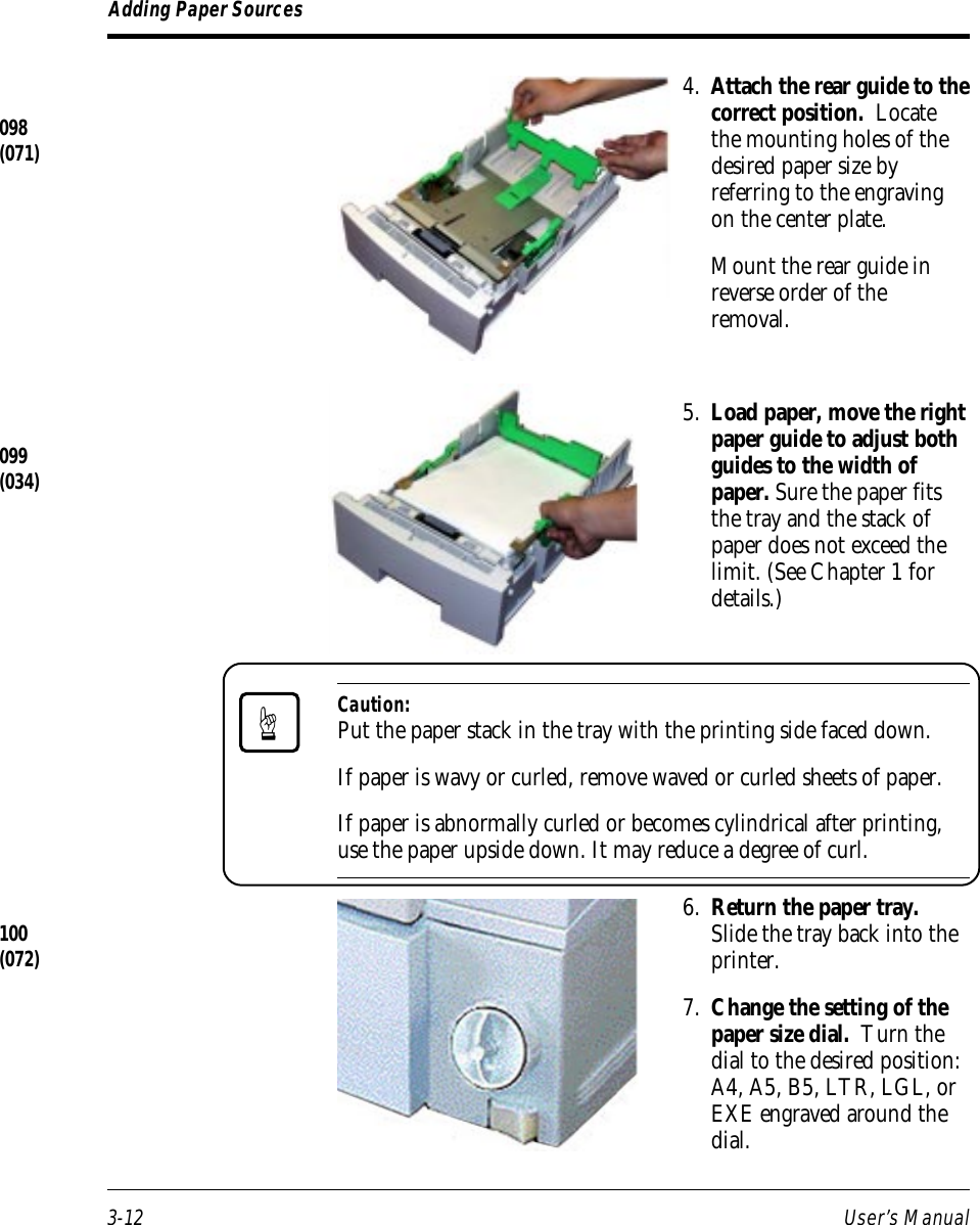
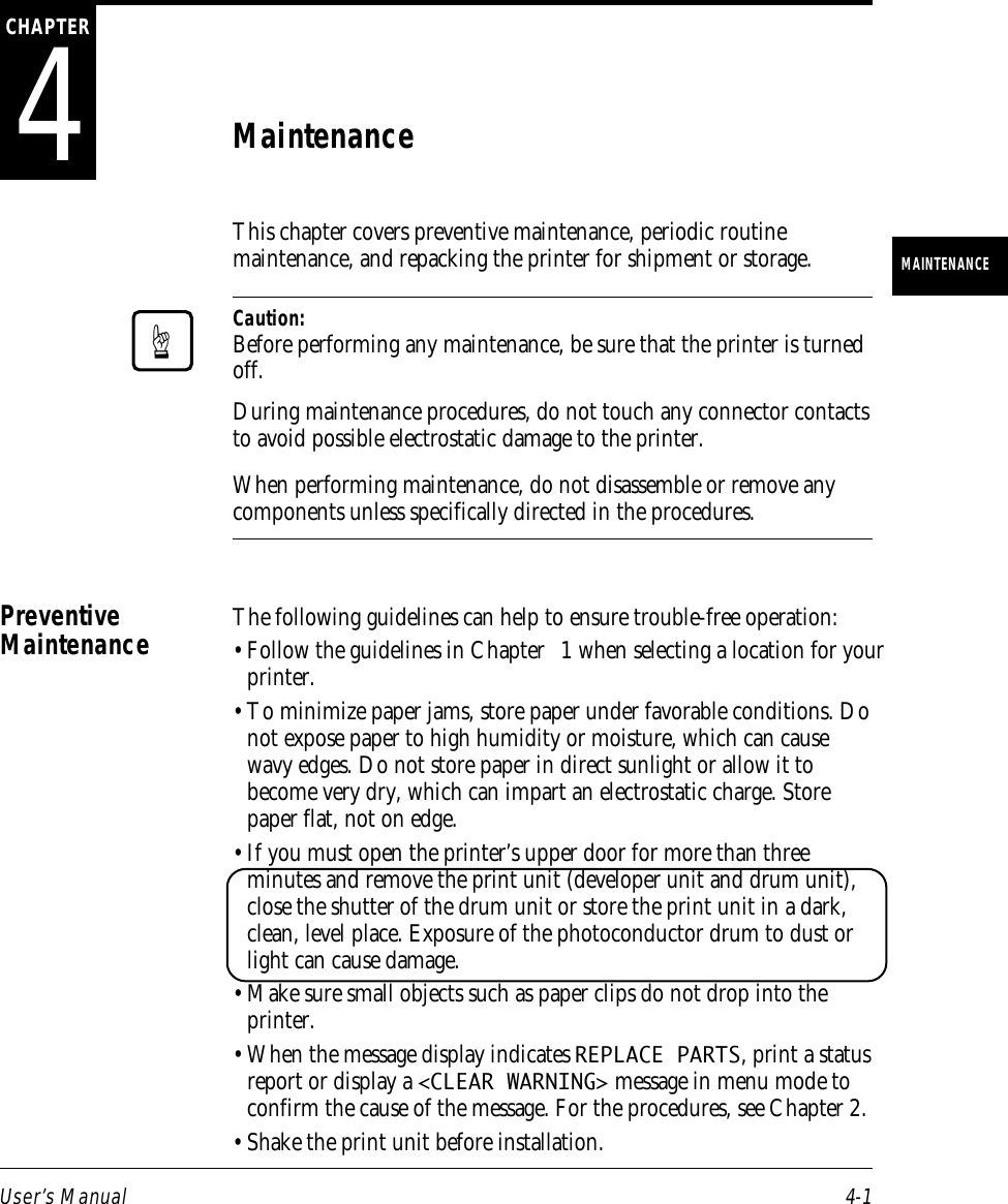
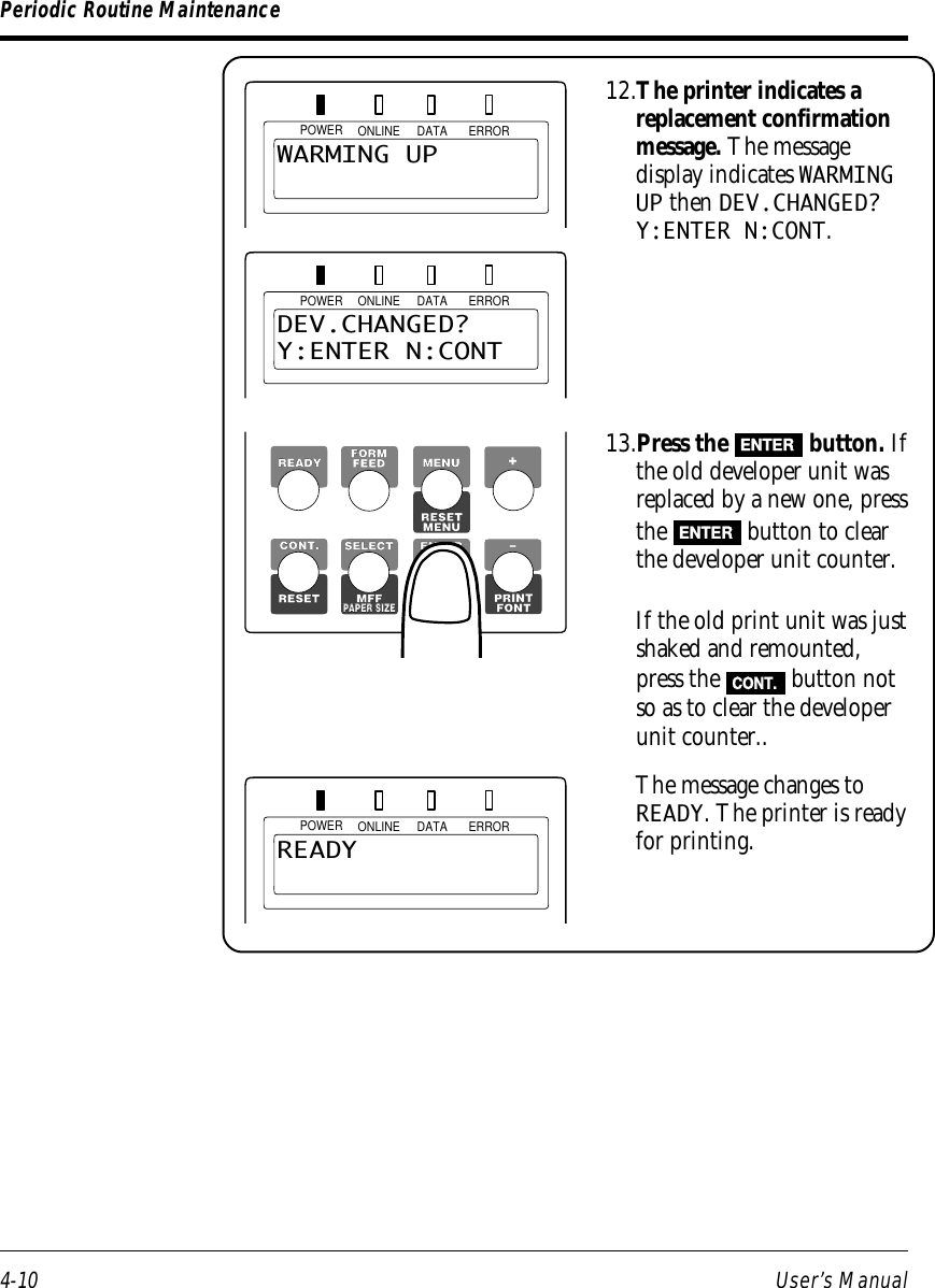
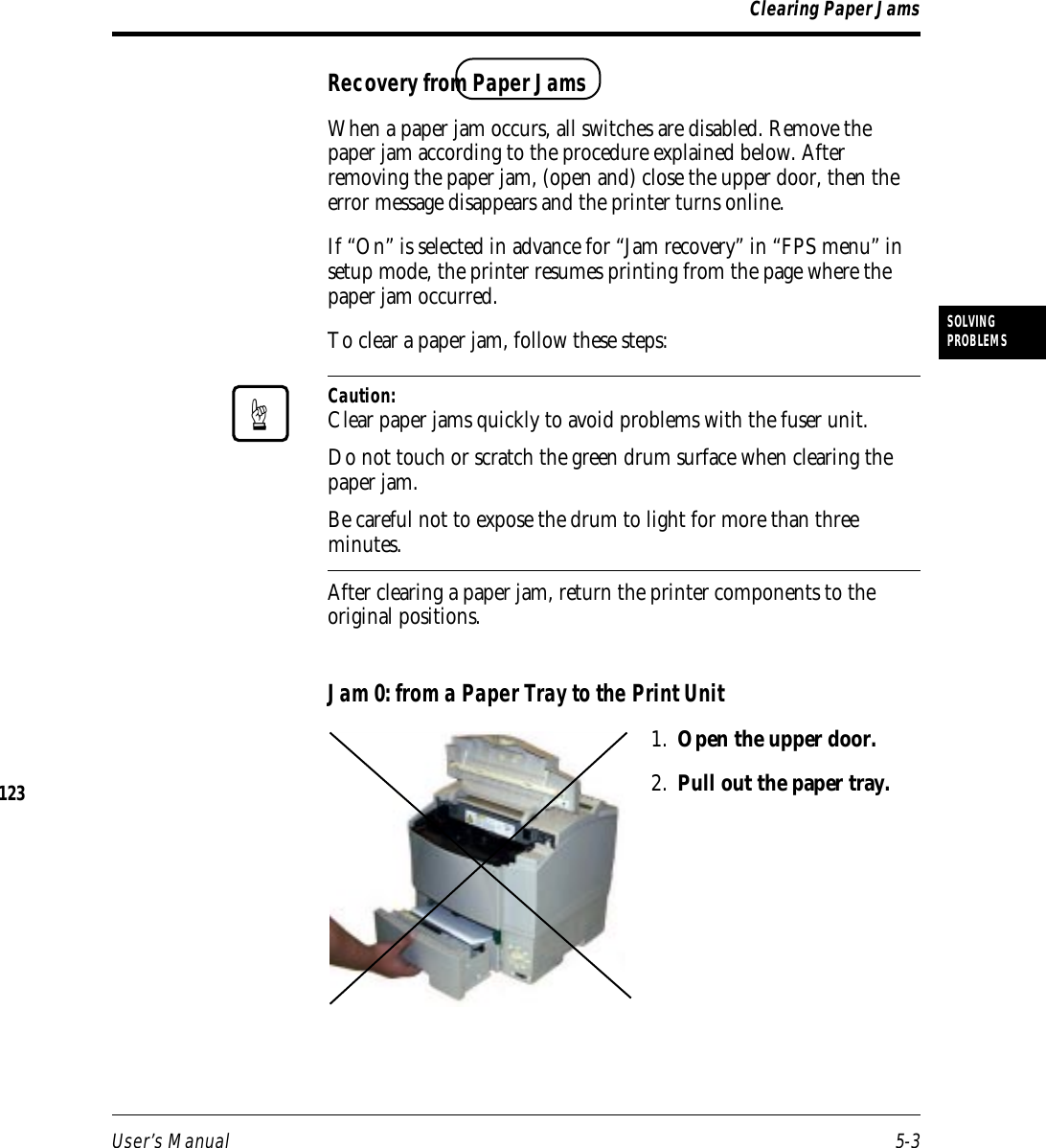
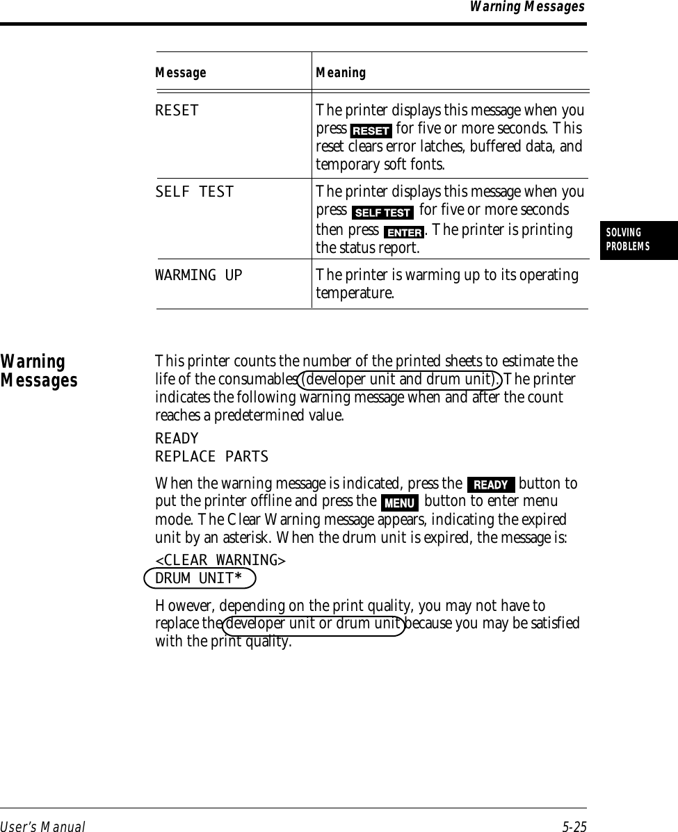
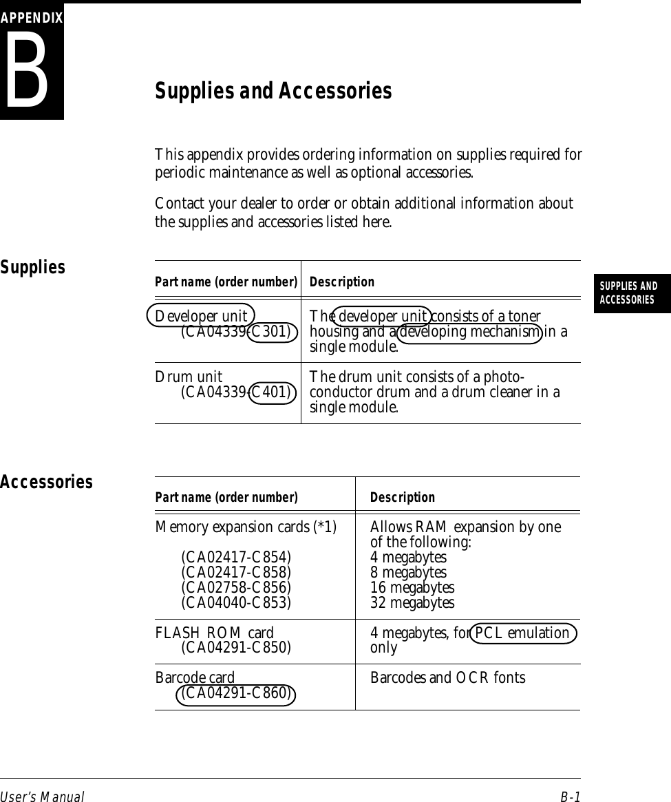
![5-10 User’s Manual3. Lift the rear of the duplexunit and pull out it.4. Remove the sheet. Pull thejammed sheet gently not soas to remain pieces of paperin the duplex unit.5. Return the duplex unit.Insert the duplex unit allthe way along the guidesinside the slot. It isautomatically caught by theprinter.6. Return the paper guideand the rear stacker andclose the upper door. Theprinter is initialized.Clearing Paper Jams142(103)143???[103]](https://usermanual.wiki/Fujitsu/DP050M33111A1/User-Guide-34376-Page-135.png)


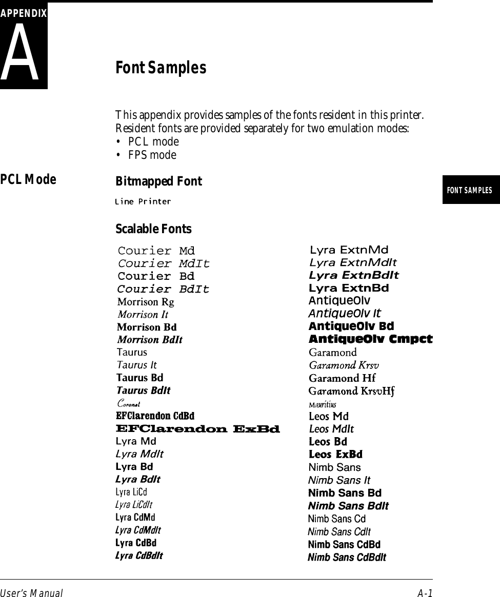

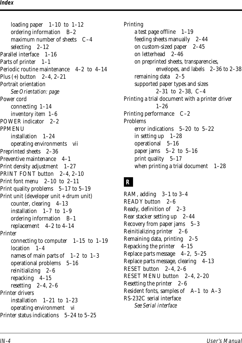
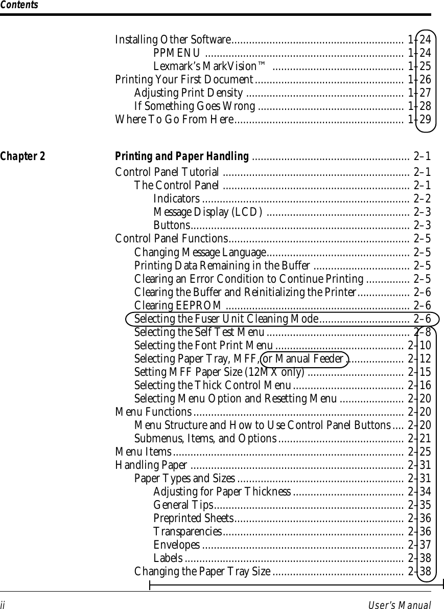
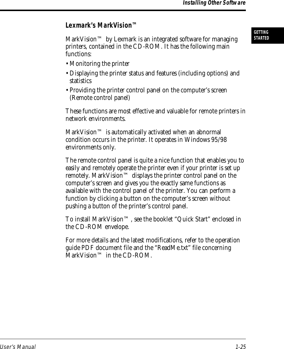
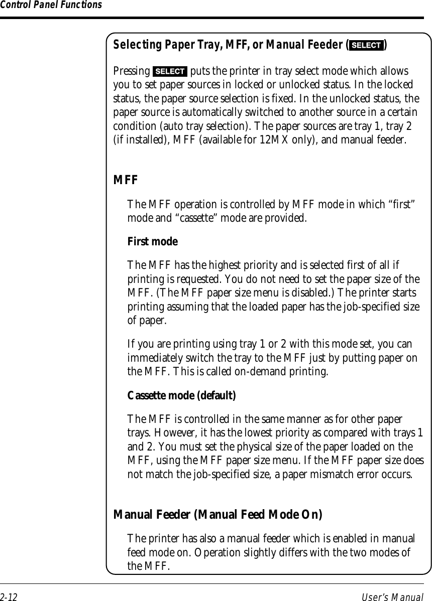
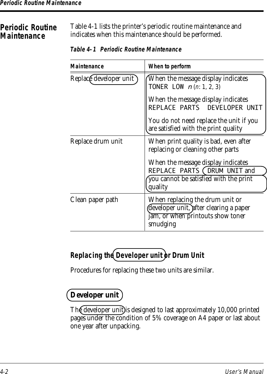
![User’s Manual GL-3GLOSSARYFactory defaultThe settings that are programmed into a printer at the factory. Theprinter uses these settings unless they are replaced by user selectedsettings entered from the control panel or through applicationsoftware.Flow controlSee Serial protocol.FontA complete set of characters and symbols in one size, typeface, andstyle. Size refers to the character height, and is usually measured inpoints (1/72 inch). Typeface refers to the character design, such asCourier, Times, or Helvetica. Style refers to the characterappearance, such as Italic or Bold. Typical examples of fonts are 12-point Courier Bold, and 10-point Times Italic.Fuser unitOne of the internal parts of a page printer. The fuser unit bonds thetoner to the paper. It consists of a heat roller and a pressure rollerthat the paper passes under after toner has been applied.InitializationResets the printer to its power-on defaults. Initialization clears theprint buffer of any data and places the printer online. See also Reset.InterfaceThe means by which information is transferred from one part of asystem to another. For example, the cable between the printer andthe computer is an interface.ISO symbol setISO stands for “International Organization for Stanardization”. AnISO symbol set contains special international characters that replacethe following twelve ASCII characters: #, $, @, [, \, ], ^, 9, {, |. }, and~. ISO symbols sets are available for most European languages,Chinese, and Japanese.Glossary](https://usermanual.wiki/Fujitsu/DP050M33111A1/User-Guide-34376-Page-164.png)