Fujitsu Dx410 S2 Dx440 Users Manual ETERNUS Web GUI User's Guide DX80 S2/DX90 S2, S2/DX440 DX8100 S2/DX8700
2015-01-25
: Fujitsu Fujitsu-Dx410-S2-Dx440-S2-Users-Manual-218439 fujitsu-dx410-s2-dx440-s2-users-manual-218439 fujitsu pdf
Open the PDF directly: View PDF ![]() .
.
Page Count: 1066 [warning: Documents this large are best viewed by clicking the View PDF Link!]
- Cover
- Preface
- Table of Contents
- List of Figures
- Chapter 1 Outline
- Chapter 2 Startup and Shutdown
- Chapter 3 Initial Setup
- Chapter 4 Configuration Settings
- Chapter 5 Volume Management
- 5.1 Volume Status
- 5.1.1 Volume (Basic Information)
- 5.1.2 Performance (Host I/O)
- 5.1.3 Performance (Advanced Copy)
- 5.1.4 LUN Group
- 5.1.5 Reservation
- 5.1.6 Pinned Data
- 5.1.7 Bad Sector
- 5.1.8 Balancing Thin Provisioning Volume
- 5.1.9 Volume Detail (Basic)
- 5.1.10 Volume Detail (Reservation)
- 5.1.11 Volume Detail (Pinned Data)
- 5.1.12 Volume Detail (Balancing TPV)
- 5.1.13 Volume Detail (LUN Concatenation)
- 5.1.14 Volume Detail (WSV Concatenation)
- 5.2 Functions in the Action Area for Volume
- 5.2.1 Create Volume
- 5.2.2 Delete Volume
- 5.2.3 Rename Volume
- 5.2.4 Format Volume
- 5.2.5 Expand Volume
- 5.2.6 Expand Thin Provisioning Volume
- 5.2.7 Start RAID Migration
- 5.2.8 Stop RAID Migration
- 5.2.9 Start Zero Reclamation
- 5.2.10 Stop Zero Reclamation
- 5.2.11 Delete Snap Data Pool Volume
- 5.2.12 Force Delete Snap Data Pool Volume
- 5.2.13 Modify Threshold Thin Provisioning Volume
- 5.2.14 Initialize Snap Data Volume
- 5.2.15 Encrypt Volume
- 5.2.16 Forbid Advanced Copy
- 5.2.17 Permit Advanced Copy
- 5.2.18 Modify Cache Parameters
- 5.2.19 Export Cache Parameters
- 5.2.20 Export Performance Information
- 5.2.21 Release Reservation
- 5.2.22 Start Balancing Thin Provisioning Volume
- 5.2.23 Stop Balancing Thin Provisioning Volume
- 5.1 Volume Status
- Chapter 6 RAID Group Management
- Chapter 7 Thin Provisioning Pool Management
- 7.1 Thin Provisioning Pool Status
- 7.1.1 Thin Provisioning Pool (Basic Information)
- 7.1.2 Threshold (Thin Provisioning Pool)
- 7.1.3 ECO Mode Schedule (Thin Provisioning Pool)
- 7.1.4 License (Thin Provisioning)
- 7.1.5 Flexible Tier Pool (Basic Information)
- 7.1.6 Thin Provisioning Pool Detail (Basic)
- 7.1.7 Flexible Tier Pool Detail (Basic)
- 7.1.8 Flexible Tier Pool Detail (Flexible Tier Sub Pool)
- 7.1.9 Flexible Tier Pool Detail (Volume)
- 7.1.10 Flexible Tier Sub Pool Detail (Basic)
- 7.2 Functions in the Action Area for Thin Provisioning
- 7.2.1 Create Thin Provisioning Pool
- 7.2.2 Delete Thin Provisioning Pool
- 7.2.3 Rename Thin Provisioning Pool
- 7.2.4 Expand Thin Provisioning Pool
- 7.2.5 Format Thin Provisioning Pool (All Area)
- 7.2.6 Format Thin Provisioning Pool (Unformatted Area)
- 7.2.7 Modify Threshold Thin Provisioning Pool
- 7.2.8 Modify Cache Parameters (Thin Provisioning Pool)
- 7.2.9 Assign ECO Mode Schedule (Thin Provisioning Pool)
- 7.2.10 Register Thin Provisioning License
- 7.2.11 Delete Thin Provisioning License
- 7.2.12 Start Balancing Flexible Tier Pool
- 7.2.13 Stop Balancing Flexible Tier Pool
- 7.1 Thin Provisioning Pool Status
- Chapter 8 Advanced Copy Management
- 8.1 Advanced Copy Status
- 8.2 Functions in the Action Area for Advanced Copy
- 8.2.1 Required Settings for the Advanced Copy Function
- 8.2.2 Start SnapOPC+
- 8.2.3 Stop Copy Session
- 8.2.4 Register Advanced Copy License
- 8.2.5 Delete Advanced Copy License
- 8.2.6 Modify EC/OPC Priority
- 8.2.7 Modify Copy Table Size
- 8.2.8 Enable ODX
- 8.2.9 Disable ODX
- 8.2.10 Create ODX Buffer Volume
- 8.2.11 Modify Copy Parameters
- 8.2.12 Set Copy Path
- 8.2.13 Delete All Copy Path
- 8.2.14 Export All Copy Path
- 8.2.15 Export Storage Information
- 8.2.16 Convert Copy Path
- 8.2.17 Measure Round Trip Time
- 8.2.18 Modify REC Multiplicity
- 8.2.19 Modify REC Buffer
- 8.2.20 Assign REC Disk Buffer
- 8.2.21 Create REC Disk Buffer
- 8.2.22 Delete REC Disk Buffer
- 8.2.23 Format REC Disk Buffer
- Chapter 9 Connectivity Management
- 9.1 Connectivity Status
- 9.1.1 Structures for Host Connection
- 9.1.2 Connectivity (Basic Information)
- 9.1.3 Host Group
- 9.1.4 CA Port Group
- 9.1.5 LUN Group
- 9.1.6 Host Response
- 9.1.7 CA Reset Group
- 9.1.8 Host-LU QoS
- 9.1.9 Host Affinity Detail
- 9.1.10 Host Group Detail
- 9.1.11 LUN Group Detail
- 9.1.12 LUN Group : LU QoS Group Detail
- 9.1.13 Host-LU QoS Performance Information
- 9.2 Functions in the Action Area for Connectivity
- 9.2.1 Host Affinity Management
- 9.2.2 Host Group Management
- 9.2.2.1 Add FC/FCoE Host Group
- 9.2.2.2 Add iSCSI Host Group
- 9.2.2.3 Add SAS Host Group
- 9.2.2.4 Delete Host Group
- 9.2.2.5 Modify Host Group
- 9.2.2.6 Modify Host Group (FC/FCoE)
- 9.2.2.7 Modify Host Group (iSCSI)
- 9.2.2.8 Modify Host Group (SAS)
- 9.2.2.9 Add FC/FCoE Host
- 9.2.2.10 Add iSCSI Host
- 9.2.2.11 Add SAS Host
- 9.2.2.12 Delete FC/FCoE Host
- 9.2.2.13 Delete iSCSI Host
- 9.2.2.14 Delete SAS Host
- 9.2.2.15 Modify FC/FCoE Host
- 9.2.2.16 Modify iSCSI Host
- 9.2.2.17 Modify SAS Host
- 9.2.3 CA Port Group Management
- 9.2.3.1 Create FC Port Group
- 9.2.3.2 Create iSCSI Port Group
- 9.2.3.3 Create SAS Port Group
- 9.2.3.4 Create FCoE Port Group
- 9.2.3.5 Delete CA Port Group
- 9.2.3.6 Modify CA Port Group
- 9.2.3.7 Modify FC Port Parameters
- 9.2.3.8 Modify iSCSI Port Parameters
- 9.2.3.9 Modify SAS Port Parameters
- 9.2.3.10 Modify FCoE Port Parameters
- 9.2.3.11 Modify Port Mode
- 9.2.4 LUN Group Management
- 9.2.5 Host Response Management
- 9.2.6 Modify CA Reset Group
- 9.2.7 Host-LU QoS Management
- 9.2.7.1 Enable/Disable Host-LU QoS
- 9.2.7.2 Set Host-LU QoS
- 9.2.7.3 Release Host-LU QoS
- 9.2.7.4 Start Host-LU QoS Performance Monitoring
- 9.2.7.5 Stop Host-LU QoS Performance Monitoring
- 9.2.7.6 Set FC/FCoE Host QoS
- 9.2.7.7 Set iSCSI Host QoS
- 9.2.7.8 Set SAS Host QoS
- 9.2.7.9 Set FC Port QoS
- 9.2.7.10 Set iSCSI Port QoS
- 9.2.7.11 Set SAS Port QoS
- 9.2.7.12 Set FCoE Port QoS
- 9.2.7.13 Add LU QoS Group
- 9.2.7.14 Delete LU QoS Group
- 9.2.7.15 Modify LU QoS Group
- 9.1 Connectivity Status
- Chapter 10 Component Management
- 10.1 Component Status
- 10.1.1 Storage (Basic Information)
- 10.1.2 Controller Enclosure
- 10.1.2.1 Controller Module
- 10.1.2.2 Controller Module (Performance)
- 10.1.2.3 All Channel Adapters
- 10.1.2.4 Channel Adapter Ports (Performance)
- 10.1.2.5 Frontend Router
- 10.1.2.6 Backend Router
- 10.1.2.7 Service Controller
- 10.1.2.8 Power Supply Unit (CE)
- 10.1.2.9 Battery
- 10.1.2.10 FAN Unit
- 10.1.2.11 Operation Panel
- 10.1.3 Drive Enclosure
- 10.1.4 Disks
- 10.1.5 Controller Module Detail
- 10.1.6 Channel Adapter Detail
- 10.1.7 Frontend Router Detail
- 10.1.8 Backend Router Detail
- 10.1.9 BRT Expander Detail
- 10.1.10 Service Controller Detail
- 10.1.11 PSU/CPSU (CE) Detail
- 10.1.12 Battery Backup Unit Detail
- 10.1.13 FAN Unit Detail
- 10.1.14 Drive Enclosure Detail
- 10.1.15 I/O Module Detail
- 10.1.16 Power Supply Unit (DE) Detail
- 10.1.17 Disks Detail
- 10.1.18 QSFP Cable Detail
- 10.1.19 Boot and Utility Device Detail
- 10.1.20 CM Module Management Controller Detail
- 10.1.21 Port Detail
- 10.2 Functions in the Action Area for Component
- 10.2.1 Add Drive Enclosure
- 10.2.2 Turn on Locator Beacon/Turn off Locator Beacon
- 10.2.3 Add Channel Adapter Port
- 10.2.4 Assign Global Hot Spare
- 10.2.5 Release Global Hot Spare
- 10.2.6 Assign Dedicated Hot Spare
- 10.2.7 Release Dedicated Hot Spare
- 10.2.8 Export Performance Information
- 10.2.9 Clear Disk Error Statistics (All Disks)
- 10.2.10 Clear Disk Error Statistics (Selected Disks)
- 10.1 Component Status
- Chapter 11 System Management
- 11.1 System Status
- 11.1.1 System (Basic Information)
- 11.1.2 Network
- 11.1.3 Remote Support (REMCS) for Regions other than EMEA
- 11.1.4 Remote Support (AIS Connect) for Regions other than Japan
- 11.1.5 Key Management
- 11.1.6 Define Role
- 11.1.7 ECO Mode
- 11.1.8 Event/Dump
- 11.1.9 Audit Log
- 11.1.10 Storage Migration
- 11.1.11 Utility
- 11.1.12 System Settings
- 11.1.13 ECO Mode Schedule Detail
- 11.1.14 Path Group Detail Information
- 11.2 Functions in the Action Area for System
- 11.2.1 Change User Password
- 11.2.2 Set SSH Public Key
- 11.2.3 Network Management
- 11.2.3.1 Setup Network Environment
- 11.2.3.2 Setup Firewall
- 11.2.3.3 Setup SNMP Agent Basic Interface
- 11.2.3.4 Setup SNMP Manager
- 11.2.3.5 Setup SNMP Agent MIB Access View
- 11.2.3.6 Setup SNMP Agent User
- 11.2.3.7 Setup SNMP Agent Community
- 11.2.3.8 Setup SNMP Agent Trap
- 11.2.3.9 Download MIB File
- 11.2.3.10 Send SNMP Trap Test
- 11.2.3.11 Display SMTP Log
- 11.2.3.12 Setup E-Mail Notification
- 11.2.3.13 Setup Syslog
- 11.2.3.14 Setup SSH Server Key
- 11.2.3.15 Create Self-signed SSL Certificate
- 11.2.3.16 Create Key/CSR
- 11.2.3.17 Register SSL Certificate
- 11.2.4 Remote Support (REMCS) for Regions other than EMEA
- 11.2.5 Remote Support (AIS Connect) for Regions other than Japan
- 11.2.6 Key Management
- 11.2.6.1 Required Settings for the Key Management Function
- 11.2.6.2 Setup Key Management Machine Name
- 11.2.6.3 Add Key Server
- 11.2.6.4 Delete Key Server
- 11.2.6.5 Modify Key Server
- 11.2.6.6 Create Key Group
- 11.2.6.7 Delete Key Group
- 11.2.6.8 Modify Key Group
- 11.2.6.9 Update SED Authentication Key
- 11.2.6.10 Import SSL/KMIP Certificate
- 11.2.7 Define Role
- 11.2.8 ECO Mode Management
- 11.2.9 Event/Dump Management
- 11.2.10 Audit Log Management
- 11.2.11 Storage Migration Management
- 11.2.12 Utility Management
- 11.2.13 System Management
- 11.1 System Status
- Appendix A User Roles and Policies
- Appendix B Status List
- Appendix C Installing the Security Certificate
- Appendix D Naming Conventions of Volumes and Hosts
- Appendix E Basic Size and MWC Input Condition for RAID Groups
- E.1 Basic Size for each RAID Group
- E.1.1 Basic Size when Using the Default Stripe Depth Value (For Standard, TPV, or SDPV Type Volumes)
- E.1.2 Basic Size when Using the Default Stripe Depth Value (For WSV Type Volumes)
- E.1.3 Basic Size When Stripe Depth is Tuned (For Standard, TPV, or SDPV Type Volumes)
- E.1.4 Basic Size When Stripe Depth is Tuned (For WSV Type Volumes)
- E.2 Input Conditions for MWC
- E.1 Basic Size for each RAID Group
- Appendix F Automatic Controlling CM-CPU Setting
- Appendix G Using RADIUS Authentication
- Appendix H Estimated Advanced Copy Source Capacity
- Appendix I Storage Migration Setting Files
- Appendix J Factory Default List
- Appendix K Error Code
- Colophon

ETERNUS Web GUI User’s Guide
P2X0-1090-10ENZ0
ETERNUS DX80 S2/DX90 S2,
ETERNUS DX410 S2/DX440 S2,
ETERNUS DX8100 S2/DX8700 S2

This page is intentionally left blank.

ETERNUS Web GUI User’s Guide
Copyright 2013 FUJITSU LIMITED P2X0-1090-10ENZ0
3
Preface
This manual provides a variety of basic information about Web GUI for the ETERNUS DX80 S2/DX90 S2, the
ETERNUS DX410 S2/DX440 S2, and the ETERNUS DX8100 S2/DX8700 S2. It should be referred to when setting
up and maintaining the ETERNUS DX80 S2/DX90 S2, the ETERNUS DX410 S2/DX440 S2, and the ETERNUS
DX8100 S2/DX8700 S2 Disk storage systems.
Knowledge of UNIX or Windows® system management is required.
This manual is written for controller firmware version V10L50 or later. Some of the functions herein may not
be supported for firmware version V10L4x or earlier.
Tenth Edition
June 2013
Structure of This Manual
This manual consists of the following 11 chapters and ten appendices.
●Chapter 1 Outline
This chapter describes the ETERNUS DX80 S2/DX90 S2, the ETERNUS DX410 S2/DX440 S2, and the ETERNUS
DX8100 S2/DX8700 S2 Web GUI outlines, features, operation environment, user management function,
and operation screens for Web GUI.
●Chapter 2 Startup and Shutdown
This chapter describes how to start, exit, log in and log out from Web GUI.
●Chapter 3 Initial Setup
This chapter describes the initial settings for the ETERNUS DX80 S2/DX90 S2, the ETERNUS DX410 S2/DX440
S2, and the ETERNUS DX8100 S2/DX8700 S2.
●Chapter 4 Configuration Settings
This chapter describes the configuration settings for using Standard volumes and Thin Provisioning
functions.
●Chapter 5 Volume Management
This chapter describes volume status and management.
●Chapter 6 RAID Group Management
This chapter describes RAID group status and management.
●Chapter 7 Thin Provisioning Pool Management
This chapter describes Thin Provisioning Pool status and management.

Preface
ETERNUS Web GUI User’s Guide
Copyright 2013 FUJITSU LIMITED P2X0-1090-10ENZ0
4
●Chapter 8 Advanced Copy Management
This chapter describes Advanced Copy status and management.
●Chapter 9 Connectivity Management
This chapter describes connectivity settings between the host and the ETERNUS DX80 S2/DX90 S2, the
ETERNUS DX410 S2/DX440 S2, and the ETERNUS DX8100 S2/DX8700 S2.
●Chapter 10 Component Management
This chapter describes component status in the ETERNUS DX80 S2/DX90 S2, the ETERNUS DX410 S2/DX440
S2, and the ETERNUS DX8100 S2/DX8700 S2 and hardware maintenance.
●Chapter 11 System Management
This chapter describes system status and management.
The following items are provided in the appendices.
•User Roles and Policies
•Status List
•Installing the Security Certificate
•Naming Conventions of Volumes and Hosts
•Basic Size and MWC Input Condition for RAID Groups
•Automatic Controlling CM-CPU Setting
•Using RADIUS Authentication
•Estimated Advanced Copy Source Capacity
•Storage Migration Setting Files
•Factory Default List
•Error Code
Latest Information
The information in this manual is subject to change without notice for functionality expansion and
improvement of the ETERNUS DX80 S2/DX90 S2, the ETERNUS DX410 S2/DX440 S2, and the ETERNUS DX8100
S2/DX8700 S2 Disk storage systems. The latest version of this manual and the latest information of the ETER-
NUS DX80 S2/DX90 S2, the ETERNUS DX410 S2/DX440 S2, and the ETERNUS DX8100 S2/DX8700 S2 Disk stor-
age systems are released in the following web-site. Access the following address if needed.
http://www.fujitsu.com/global/services/computing/storage/eternus/documentation/

Preface
ETERNUS Web GUI User’s Guide
Copyright 2013 FUJITSU LIMITED P2X0-1090-10ENZ0
5
Related Documents
Other manuals for the ETERNUS DX80 S2/DX90 S2, the ETERNUS DX410 S2/DX440 S2, and the ETERNUS
DX8100 S2/DX8700 S2 are as follows:
•ETERNUS DX80 S2/DX90 S2 Disk storage system Overview
•ETERNUS DX80 S2/DX90 S2 Disk storage system User's Guide -Site Planning-
•ETERNUS DX80 S2/DX90 S2 Disk storage system User's Guide -Installation-
•ETERNUS DX80 S2/DX90 S2 Disk storage system User's Guide -Operation-
•ETERNUS DX410 S2/DX440 S2 Disk storage system Overview
•ETERNUS DX410 S2/DX440 S2 Disk storage system User's Guide -Site Planning-
•ETERNUS DX410 S2/DX440 S2 Disk storage system User's Guide -Installation & Operation-
•ETERNUS DX8100 S2/DX8700 S2 Disk storage system User’s Guide
•ETERNUS CLI User's Guide ETERNUS DX80 S2/DX90 S2, ETERNUS DX410 S2/
DX440 S2, ETERNUS DX8100 S2/DX8700 S2
•ETERNUS DX Disk storage systems User's Guide -Server Connection- (*1)
•ETERNUS SF KM V2.0.1 Overview
•ETERNUS SF KM V2.0.1 Scenarios
•ETERNUS SF KM V2.0.1 Planning
•ETERNUS SF KM V2.0.1 Installing
•ETERNUS SF KM V2.0.1 Administering
•ETERNUS SF KM V2.0.1 Reference
•ETERNUS SF KM V2.0.1 Glossary
•ETERNUS SF KM V2.0.1 Installation and Configuration Guide
•ETERNUS SF KM V2.0.1 Quick Start Guide
•ETERNUS SF KM V2.0.1 Notes
•ETERNUS SF KM V2.0.1.3 Procedure for Applying Fix Pack
*1: Download the required manuals for your system environment (for server OS, host interface type, etc.) from the
specified web site. Refer to the Documentation CD provided with the ETERNUS DX80 S2/DX90 S2, the ETERNUS DX410
S2/DX440 S2, and the ETERNUS DX8100 S2/DX8700 S2 Disk storage system for URLs of the manual download site.

Preface
ETERNUS Web GUI User’s Guide
Copyright 2013 FUJITSU LIMITED P2X0-1090-10ENZ0
6
Acknowledgments
•Microsoft, Windows, Windows Server, and Internet Explorer are either registered trademarks or trademarks
of Microsoft Corporation in the United States and other countries.
•UNIX is a registered trademark of The Open Group in the United States and other countries.
•Oracle and Java are registered trademarks of Oracle and/or its affiliates.
•IBM, AIX, and Tivoli are trademarks of International Business Machines Corporation, registered in many
jurisdictions worldwide.
•Linux is a registered trademark of Linus Torvalds.
•Red Hat is a registered trademark of Red Hat, Inc.
•HP-UX is a trademark of Hewlett-Packard in the U.S. and other countries.
•VMware, VMware logos, Virtual SMP, and VMotion are either registered trademarks or trademarks of
VMware, Inc. in the U.S. and/or other countries.
•VERITAS Volume Manager is a trademark of Symantec Corp. and its affiliated companies.
•Mozilla, Firefox, and the Mozilla and Firefox logos are trademarks or registered trademarks of the Mozilla
Foundation in the United States and other countries.
•BS2000 is a registered trademark of Fujitsu Technology Solutions
•Other company names, product names, and service names are registered trademarks or trademarks of
their respective owners.

Preface
ETERNUS Web GUI User’s Guide
Copyright 2013 FUJITSU LIMITED P2X0-1090-10ENZ0
7
Naming Conventions
Product names
The following products will be represented throughout this manual by the following abbreviations.
•The following abbreviations are used for Microsoft® Windows Server®.
•Oracle Solaris might be described as Solaris, Solaris Operating System, or Solaris OS.
•Trademark symbols such as ™ and ® are omitted in this document.
Units in this manual
Except as otherwise noted, the following units are used in this manual:
•Drive capacity assume that 1KB = 1000 bytes, 1MB = 1000KB, 1GB = 1000MB, and 1TB = 1000GB
(example: "600GB drive").
•Other capacities (such as for RAID Groups and volumes) assume that 1KB = 1024 bytes, 1MB = 1024KB,
1GB = 1024MB, and 1TB = 1024GB.
Note that the screen shots in this manual were captured during development of the software and the actual
screens may be different.
Microsoft product screen shot(s) reprinted with permission from Microsoft Corporation.
Product name Abbreviation
Microsoft® Windows Server® 2003, Datacenter Edition
Windows Server 2003Microsoft® Windows Server® 2003, Enterprise Edition
Microsoft® Windows Server® 2003, Standard Edition
Microsoft® Windows Server® 2008 Datacenter
Windows Server 2008
Microsoft® Windows Server® 2008 Enterprise
Microsoft® Windows Server® 2008 Standard
Microsoft® Windows Server® 2008 for Itanium-Based Systems
Microsoft® Windows Server® 2008 HPC Edition
Microsoft® Windows Server® 2008 R2 Datacenter
Windows Server 2008 R2
Microsoft® Windows Server® 2008 R2 Enterprise
Microsoft® Windows Server® 2008 R2 Standard
Microsoft® Windows Server® 2008 R2 for Itanium-Based Systems
Microsoft® Windows Server® 2008 R2 HPC Edition
Microsoft® Windows Server® 2012 Datacenter
Windows Server 2012
Microsoft® Windows Server® 2012 Standard
Microsoft® Windows Server® 2012 Essentials
Microsoft® Windows Server® 2012 Foundation

ETERNUS Web GUI User’s Guide
Copyright 2013 FUJITSU LIMITED P2X0-1090-10ENZ0
8
Table of Contents
Chapter 1 Outline 17
1.1 Outline .............................................................................................................................. 17
1.2 Features ............................................................................................................................ 18
1.3 Operating Environment .................................................................................................... 18
1.4 User Management ............................................................................................................ 20
1.5 Screen Operations ............................................................................................................. 21
1.5.1 Overview ........................................................................................................................................................21
1.5.2 Screen Structures ...........................................................................................................................................27
1.5.3 List Screen/Detailed Screen ............................................................................................................................28
1.5.4 Basic Operation .............................................................................................................................................29
Chapter 2 Startup and Shutdown 32
2.1 Startup of GUI ................................................................................................................... 32
2.2 Login ................................................................................................................................ 34
2.3 Logout .............................................................................................................................. 36
2.4 Exit ................................................................................................................................... 37
Chapter 3 Initial Setup 38
3.1 Initial Setup 1 ................................................................................................................... 39
3.2 Initial Setup 2 ................................................................................................................... 49
Chapter 4 Configuration Settings 63
4.1 Configuration Settings for Using Standard Volumes
(When Using Host Affinity Settings) ................................................................................. 63
4.1.1 When Creating Host Groups (when Using the [Add Host Group] Function) ....................................................63
4.1.2 When Host Groups are not Created (when Using the [Add Host] Function) ...................................................66
4.2 Configuration Settings for Using Standard Volumes
(When Using Host Affinity Settings, Previously Referred to as LUN Mapping) ................... 68
4.2.1 When Allocating the CA port Group to the LUN Group .................................................................................... 68
4.2.2 When Allocating the CA port to the LUN Group ..............................................................................................70

Table of Contents
ETERNUS Web GUI User’s Guide
Copyright 2013 FUJITSU LIMITED P2X0-1090-10ENZ0
9
4.3 Configuration Settings for Using Thin Provisioning Functions ........................................... 71
Chapter 5 Volume Management 73
5.1 Volume Status ................................................................................................................... 73
5.1.1 Volume (Basic Information) ...........................................................................................................................74
5.1.2 Performance (Host I/O) .................................................................................................................................. 77
5.1.3 Performance (Advanced Copy) .......................................................................................................................79
5.1.4 LUN Group ..................................................................................................................................................... 80
5.1.5 Reservation ...................................................................................................................................................81
5.1.6 Pinned Data ...................................................................................................................................................83
5.1.7 Bad Sector .....................................................................................................................................................85
5.1.8 Balancing Thin Provisioning Volume ............................................................................................................. 86
5.1.9 Volume Detail (Basic) .................................................................................................................................... 88
5.1.10 Volume Detail (Reservation) .........................................................................................................................90
5.1.11 Volume Detail (Pinned Data) .........................................................................................................................91
5.1.12 Volume Detail (Balancing TPV) ...................................................................................................................... 92
5.1.13 Volume Detail (LUN Concatenation) ..............................................................................................................93
5.1.14 Volume Detail (WSV Concatenation) ..............................................................................................................93
5.2 Functions in the Action Area for Volume ........................................................................... 95
5.2.1 Create Volume ...............................................................................................................................................96
5.2.2 Delete Volume ............................................................................................................................................. 112
5.2.3 Rename Volume ..........................................................................................................................................114
5.2.4 Format Volume ............................................................................................................................................ 116
5.2.5 Expand Volume ...........................................................................................................................................117
5.2.6 Expand Thin Provisioning Volume ...............................................................................................................121
5.2.7 Start RAID Migration ....................................................................................................................................123
5.2.8 Stop RAID Migration ....................................................................................................................................138
5.2.9 Start Zero Reclamation ................................................................................................................................ 139
5.2.10 Stop Zero Reclamation .................................................................................................................................140
5.2.11 Delete Snap Data Pool Volume .................................................................................................................... 141
5.2.12 Force Delete Snap Data Pool Volume ...........................................................................................................142
5.2.13 Modify Threshold Thin Provisioning Volume ................................................................................................ 143
5.2.14 Initialize Snap Data Volume ........................................................................................................................ 144
5.2.15 Encrypt Volume ........................................................................................................................................... 145
5.2.16 Forbid Advanced Copy .................................................................................................................................147
5.2.17 Permit Advanced Copy ................................................................................................................................. 148
5.2.18 Modify Cache Parameters ............................................................................................................................148
5.2.19 Export Cache Parameters .............................................................................................................................153
5.2.20 Export Performance Information .................................................................................................................155
5.2.21 Release Reservation ....................................................................................................................................156
5.2.22 Start Balancing Thin Provisioning Volume ...................................................................................................157
5.2.23 Stop Balancing Thin Provisioning Volume ................................................................................................... 159

Table of Contents
ETERNUS Web GUI User’s Guide
Copyright 2013 FUJITSU LIMITED P2X0-1090-10ENZ0
10
Chapter 6 RAID Group Management 160
6.1 RAID Group Status ...........................................................................................................160
6.1.1 RAID Group (Basic Information) ................................................................................................................... 161
6.1.2 Tuning .........................................................................................................................................................163
6.1.3 ECO Mode Schedule (RAID Group) ................................................................................................................165
6.1.4 SED Key Group .............................................................................................................................................167
6.1.5 RAID Group (Basic) ......................................................................................................................................169
6.1.6 RAID Group (Volume Layout) .......................................................................................................................170
6.1.7 RAID Group Detail (Disk) .............................................................................................................................171
6.2 Functions in the Action Area for RAID Group ................................................................... 173
6.2.1 Create RAID Group .......................................................................................................................................174
6.2.2 Delete RAID Group ....................................................................................................................................... 181
6.2.3 Rename RAID Group ....................................................................................................................................182
6.2.4 Change Controlling CM ................................................................................................................................184
6.2.5 Expand RAID Group ...................................................................................................................................... 186
6.2.6 Modify RAID Group Parameters .................................................................................................................... 189
6.2.7 Assign ECO Mode Schedule (RAID Group) ....................................................................................................192
6.2.8 Set Key Group (RAID Group) ......................................................................................................................... 195
6.2.9 Recovery SED ............................................................................................................................................... 197
Chapter 7 Thin Provisioning Pool Management 199
7.1 Thin Provisioning Pool Status .......................................................................................... 199
7.1.1 Thin Provisioning Pool (Basic Information) ................................................................................................. 200
7.1.2 Threshold (Thin Provisioning Pool) .............................................................................................................. 202
7.1.3 ECO Mode Schedule (Thin Provisioning Pool) ..............................................................................................203
7.1.4 License (Thin Provisioning) .........................................................................................................................206
7.1.5 Flexible Tier Pool (Basic Information) ..........................................................................................................207
7.1.6 Thin Provisioning Pool Detail (Basic) ...........................................................................................................209
7.1.7 Flexible Tier Pool Detail (Basic) ...................................................................................................................212
7.1.8 Flexible Tier Pool Detail (Flexible Tier Sub Pool) .......................................................................................... 214
7.1.9 Flexible Tier Pool Detail (Volume) ...............................................................................................................215
7.1.10 Flexible Tier Sub Pool Detail (Basic) ............................................................................................................217
7.2 Functions in the Action Area for Thin Provisioning .......................................................... 218
7.2.1 Create Thin Provisioning Pool ......................................................................................................................219
7.2.2 Delete Thin Provisioning Pool ......................................................................................................................228
7.2.3 Rename Thin Provisioning Pool ...................................................................................................................229
7.2.4 Expand Thin Provisioning Pool .................................................................................................................... 231
7.2.5 Format Thin Provisioning Pool (All Area) .....................................................................................................237
7.2.6 Format Thin Provisioning Pool (Unformatted Area) ..................................................................................... 238
7.2.7 Modify Threshold Thin Provisioning Pool .....................................................................................................239
7.2.8 Modify Cache Parameters (Thin Provisioning Pool) ..................................................................................... 241
7.2.9 Assign ECO Mode Schedule (Thin Provisioning Pool) ...................................................................................242

Table of Contents
ETERNUS Web GUI User’s Guide
Copyright 2013 FUJITSU LIMITED P2X0-1090-10ENZ0
11
7.2.10 Register Thin Provisioning License ...............................................................................................................245
7.2.11 Delete Thin Provisioning License .................................................................................................................247
7.2.12 Start Balancing Flexible Tier Pool ................................................................................................................ 248
7.2.13 Stop Balancing Flexible Tier Pool .................................................................................................................249
Chapter 8 Advanced Copy Management 251
8.1 Advanced Copy Status ..................................................................................................... 251
8.1.1 Advanced Copy (Basic Information) .............................................................................................................252
8.1.2 Advanced Copy (All Local Sessions) .............................................................................................................254
8.1.3 Advanced Copy (All Remote Sessions) ......................................................................................................... 261
8.1.4 Advanced Copy (ODX) .................................................................................................................................. 265
8.1.5 Advanced Copy (XCOPY) ............................................................................................................................... 266
8.1.6 Setting (Advanced Copy) .............................................................................................................................268
8.1.7 Advanced Copy (Property) ........................................................................................................................... 277
8.1.8 Advanced Copy (Extent information) ...........................................................................................................283
8.1.9 Copy Path Detail .......................................................................................................................................... 284
8.2 Functions in the Action Area for Advanced Copy ............................................................. 287
8.2.1 Required Settings for the Advanced Copy Function ......................................................................................288
8.2.2 Start SnapOPC+ ............................................................................................................................................291
8.2.3 Stop Copy Session ........................................................................................................................................294
8.2.4 Register Advanced Copy License ..................................................................................................................295
8.2.5 Delete Advanced Copy License ..................................................................................................................... 297
8.2.6 Modify EC/OPC Priority .................................................................................................................................298
8.2.7 Modify Copy Table Size ................................................................................................................................ 301
8.2.8 Enable ODX .................................................................................................................................................. 310
8.2.9 Disable ODX ................................................................................................................................................. 311
8.2.10 Create ODX Buffer Volume ...........................................................................................................................311
8.2.11 Modify Copy Parameters .............................................................................................................................. 316
8.2.12 Set Copy Path ............................................................................................................................................... 318
8.2.13 Delete All Copy Path ....................................................................................................................................343
8.2.14 Export All Copy Path ....................................................................................................................................344
8.2.15 Export Storage Information ......................................................................................................................... 345
8.2.16 Convert Copy Path ........................................................................................................................................ 347
8.2.17 Measure Round Trip Time ............................................................................................................................ 349
8.2.18 Modify REC Multiplicity ................................................................................................................................ 351
8.2.19 Modify REC Buffer ........................................................................................................................................ 354
8.2.20 Assign REC Disk Buffer .................................................................................................................................358
8.2.21 Create REC Disk Buffer .................................................................................................................................362
8.2.22 Delete REC Disk Buffer .................................................................................................................................365
8.2.23 Format REC Disk Buffer ................................................................................................................................366

Table of Contents
ETERNUS Web GUI User’s Guide
Copyright 2013 FUJITSU LIMITED P2X0-1090-10ENZ0
12
Chapter 9 Connectivity Management 367
9.1 Connectivity Status .........................................................................................................367
9.1.1 Structures for Host Connection .....................................................................................................................368
9.1.2 Connectivity (Basic Information) ................................................................................................................. 371
9.1.3 Host Group ...................................................................................................................................................374
9.1.4 CA Port Group .............................................................................................................................................. 380
9.1.5 LUN Group ................................................................................................................................................... 387
9.1.6 Host Response .............................................................................................................................................389
9.1.7 CA Reset Group ............................................................................................................................................ 390
9.1.8 Host-LU QoS ................................................................................................................................................ 390
9.1.9 Host Affinity Detail ...................................................................................................................................... 403
9.1.10 Host Group Detail ........................................................................................................................................ 404
9.1.11 LUN Group Detail .........................................................................................................................................405
9.1.12 LUN Group : LU QoS Group Detail ................................................................................................................. 406
9.1.13 Host-LU QoS Performance Information ........................................................................................................407
9.2 Functions in the Action Area for Connectivity .................................................................. 412
9.2.1 Host Affinity Management .......................................................................................................................... 414
9.2.2 Host Group Management ............................................................................................................................440
9.2.3 CA Port Group Management ........................................................................................................................ 516
9.2.4 LUN Group Management .............................................................................................................................574
9.2.5 Host Response Management ....................................................................................................................... 581
9.2.6 Modify CA Reset Group .................................................................................................................................595
9.2.7 Host-LU QoS Management ..........................................................................................................................597
Chapter 10 Component Management 620
10.1 Component Status .......................................................................................................... 620
10.1.1 Storage (Basic Information) ........................................................................................................................622
10.1.2 Controller Enclosure .....................................................................................................................................625
10.1.3 Drive Enclosure ............................................................................................................................................646
10.1.4 Disks ............................................................................................................................................................ 649
10.1.5 Controller Module Detail ..............................................................................................................................652
10.1.6 Channel Adapter Detail ................................................................................................................................ 655
10.1.7 Frontend Router Detail ................................................................................................................................ 658
10.1.8 Backend Router Detail .................................................................................................................................659
10.1.9 BRT Expander Detail ....................................................................................................................................661
10.1.10 Service Controller Detail ............................................................................................................................... 662
10.1.11 PSU/CPSU (CE) Detail ...................................................................................................................................664
10.1.12 Battery Backup Unit Detail .......................................................................................................................... 666
10.1.13 FAN Unit Detail ............................................................................................................................................ 667
10.1.14 Drive Enclosure Detail .................................................................................................................................. 669
10.1.15 I/O Module Detail .........................................................................................................................................672
10.1.16 Power Supply Unit (DE) Detail .....................................................................................................................674
10.1.17 Disks Detail .................................................................................................................................................. 675

Table of Contents
ETERNUS Web GUI User’s Guide
Copyright 2013 FUJITSU LIMITED P2X0-1090-10ENZ0
13
10.1.18 QSFP Cable Detail ........................................................................................................................................ 678
10.1.19 Boot and Utility Device Detail ...................................................................................................................... 679
10.1.20 CM Module Management Controller Detail ..................................................................................................680
10.1.21 Port Detail ...................................................................................................................................................681
10.2 Functions in the Action Area for Component ................................................................... 694
10.2.1 Add Drive Enclosure .....................................................................................................................................695
10.2.2 Turn on Locator Beacon/Turn off Locator Beacon .........................................................................................698
10.2.3 Add Channel Adapter Port ........................................................................................................................... 699
10.2.4 Assign Global Hot Spare .............................................................................................................................. 702
10.2.5 Release Global Hot Spare ............................................................................................................................. 703
10.2.6 Assign Dedicated Hot Spare .........................................................................................................................704
10.2.7 Release Dedicated Hot Spare .......................................................................................................................706
10.2.8 Export Performance Information .................................................................................................................706
10.2.9 Clear Disk Error Statistics (All Disks) ............................................................................................................ 707
10.2.10 Clear Disk Error Statistics (Selected Disks) ................................................................................................... 707
Chapter 11 System Management 709
11.1 System Status ................................................................................................................. 709
11.1.1 System (Basic Information) .........................................................................................................................710
11.1.2 Network .......................................................................................................................................................713
11.1.3 Remote Support (REMCS) for Regions other than EMEA ..............................................................................716
11.1.4 Remote Support (AIS Connect) for Regions other than Japan ...................................................................... 719
11.1.5 Key Management ........................................................................................................................................722
11.1.6 Define Role ..................................................................................................................................................726
11.1.7 ECO Mode ....................................................................................................................................................726
11.1.8 Event/Dump .................................................................................................................................................727
11.1.9 Audit Log .....................................................................................................................................................728
11.1.10 Storage Migration ........................................................................................................................................729
11.1.11 Utility ...........................................................................................................................................................731
11.1.12 System Settings ...........................................................................................................................................731
11.1.13 ECO Mode Schedule Detail ...........................................................................................................................733
11.1.14 Path Group Detail Information ..................................................................................................................... 734
11.2 Functions in the Action Area for System .......................................................................... 739
11.2.1 Change User Password .................................................................................................................................742
11.2.2 Set SSH Public Key ....................................................................................................................................... 743
11.2.3 Network Management .................................................................................................................................745
11.2.4 Remote Support (REMCS) for Regions other than EMEA ..............................................................................799
11.2.5 Remote Support (AIS Connect) for Regions other than Japan ......................................................................821
11.2.6 Key Management ........................................................................................................................................831
11.2.7 Define Role ..................................................................................................................................................853
11.2.8 ECO Mode Management ..............................................................................................................................869
11.2.9 Event/Dump Management ...........................................................................................................................880
11.2.10 Audit Log Management ...............................................................................................................................901
11.2.11 Storage Migration Management .................................................................................................................. 906

Table of Contents
ETERNUS Web GUI User’s Guide
Copyright 2013 FUJITSU LIMITED P2X0-1090-10ENZ0
14
11.2.12 Utility Management .................................................................................................................................... 919
11.2.13 System Management ...................................................................................................................................927
Appendix A User Roles and Policies 948
A.1 Roles................................................................................................................................ 948
A.2 Availability of Functions for each Policy........................................................................... 950
Appendix B Status List 972
B.1 Device General Status ...................................................................................................... 972
B.1.1 Device General Status (Detail)..................................................................................................................... 973
B.2 Volume Status.................................................................................................................. 974
B.3 RAID Group Status............................................................................................................975
B.4 Thin Provisioning Pool Status........................................................................................... 976
B.5 Component Status ........................................................................................................... 977
B.5.1 Drive Status ................................................................................................................................................. 978
B.6 Key Status........................................................................................................................ 979
B.7 Key Server Status ............................................................................................................. 980
Appendix C Installing the Security Certificate 981
C.1 For Internet Explorer........................................................................................................981
C.2 For Firefox........................................................................................................................ 988
Appendix D Naming Conventions of Volumes and Hosts 993
D.1 Naming Convention of Volumes....................................................................................... 993
D.2 Naming Convention of Hosts ........................................................................................... 994
Appendix E Basic Size and MWC Input Condition for RAID Groups 995
E.1 Basic Size for each RAID Group......................................................................................... 995
E.1.1 Basic Size when Using the Default Stripe Depth Value (For Standard, TPV, or SDPV Type Volumes)............. 995
E.1.2 Basic Size when Using the Default Stripe Depth Value (For WSV Type Volumes).......................................... 998
E.1.3 Basic Size When Stripe Depth is Tuned (For Standard, TPV, or SDPV Type Volumes) .................................. 1002
E.1.4 Basic Size When Stripe Depth is Tuned (For WSV Type Volumes) ............................................................... 1003

Table of Contents
ETERNUS Web GUI User’s Guide
Copyright 2013 FUJITSU LIMITED P2X0-1090-10ENZ0
15
E.2 Input Conditions for MWC .............................................................................................. 1007
E.2.1 Allowed Input for the MWC When Using the Default Stripe Depth Value ................................................... 1007
E.2.2 Allowed Input for the MWC when Performance is Tuned............................................................................ 1009
Appendix F Automatic Controlling CM-CPU Setting 1011
Appendix G Using RADIUS Authentication 1013
G.1 Using RADIUS Authentication to Access the ETERNUS DX Disk Storage System .............. 1013
G.2 Notes when Using RADIUS Authentication for GUI ......................................................... 1014
G.3 Setting Up the RADIUS Server ........................................................................................ 1014
Appendix H Estimated Advanced Copy Source Capacity 1017
Appendix I Storage Migration Setting Files 1019
I.1 Template File for Storage Migration Settings................................................................. 1019
I.2 Coding Conventions for the Storage Migration Setting File............................................ 1022
I.3 Setting Example of the Storage Migration Setting File .................................................. 1024
Appendix J Factory Default List 1027
J.1 Advanced Copy............................................................................................................... 1027
J.2 Connectivity................................................................................................................... 1033
J.3 System........................................................................................................................... 1044
Appendix K Error Code 1064

ETERNUS Web GUI User’s Guide
Copyright 2013 FUJITSU LIMITED P2X0-1090-10ENZ0
16
List of Figures
Figure 1.1 Outline of GUI.............................................................................................................................................. 17
Figure 9.1 Basic concept of host connection (when using host groups) ..................................................................... 369
Figure 11.1 Relation between the ETERNUS DX Disk storage system and the key server.............................................. 834
Figure E.1 Basic size when creating volumes ............................................................................................................. 997
ETERNUS Web GUI User’s Guide
Copyright 2013 FUJITSU LIMITED P2X0-1090-10ENZ0
17
Chapter 1
Outline
This chapter describes the outlines, features, operating environment, user management function, and
operation screens for ETERNUS DX Disk storage system Web GUI (hereinafter referred to as "GUI").
GUI is installed in controllers of the ETERNUS DX Disk storage systems (hereinafter also referred to as
"ETERNUS DX Disk storage system" or "the storage system"), and used for performing settings and
maintenance via web browser.
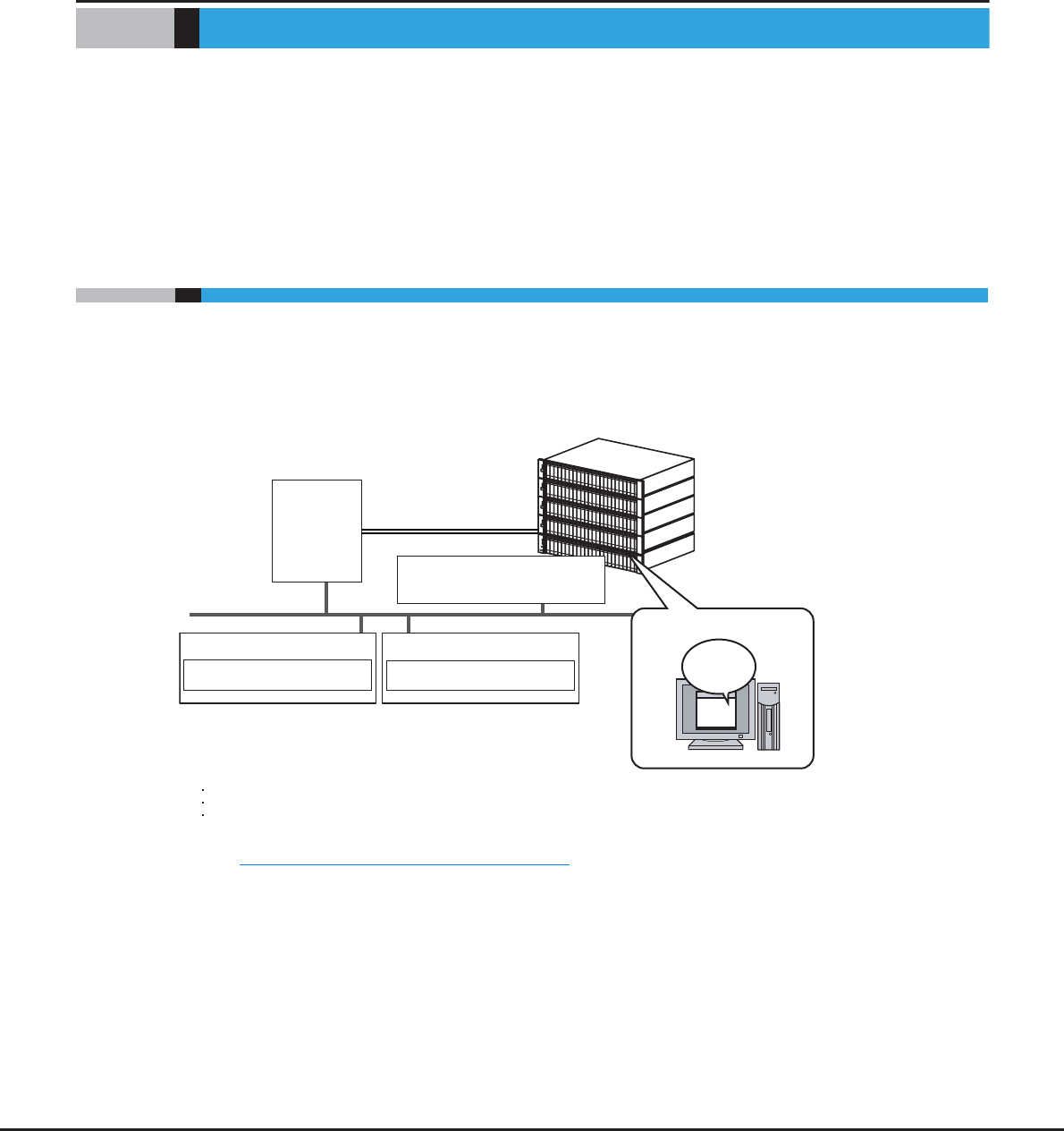
1.1 Outline
Use GUI to set the operating environment and check status for the ETERNUS DX Disk storage system.
GUI can be operated from a web browser by connecting the PC via a LAN connection.
Figure 1.1 Outline of GUI
Refer to "Chapter 2 Startup and Shutdown" (page 32) for details of GUI start up.
LAN
PC
Web Browser
Management Server
Mail Server Program
(*1)
*1: Connect the operation server and the ETERNUS DX Disk storage system
Operating via
GUI
ETERNUS DX80 S2/ DX90 S2
Server
web browser
with one of the following cables:
Operation
Fibre Channel (FC) cable
LAN cable
SAS cable (available only for the ETERNUS DX80S2/DX90 S2)
ETERNUS DX410 S2/DX440 S2
ETERNUS DX8100 S2/DX8700 S2
Chapter 1 Outline
1.2 Features
ETERNUS Web GUI User’s Guide
Copyright 2013 FUJITSU LIMITED P2X0-1090-10ENZ0
18
1.2 Features
The features for GUI are as follows:
●Initial settings by the wizard
The wizard provides instructions for the basic settings that are required to run the ETERNUS DX Disk storage
system.
●Status Display
This function displays the storage system installation image.
●Checking the extent of a failure
If a drive failure occurs, host port, LUN group, volume, RAID group, and installation location can be
referenced to determine the extent of the failure.
●Easy operation
If a hardware failure is detected, the system administrator can receive a mail containing detected failure
information.
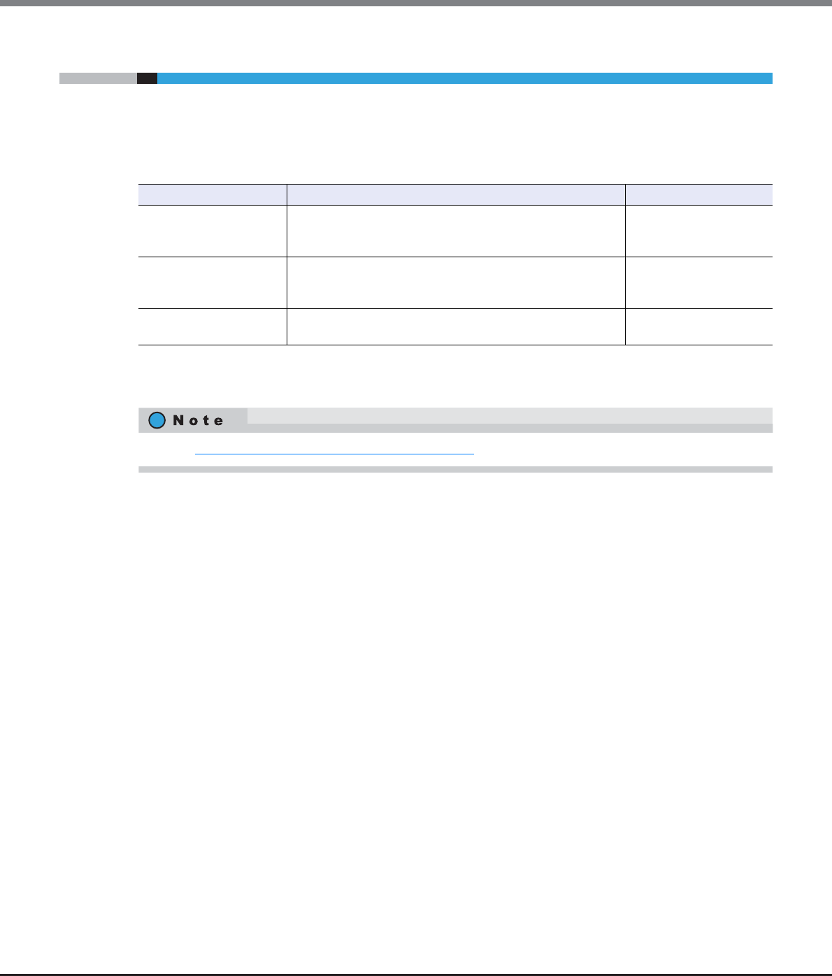
1.3 Operating Environment
The following PC environment is required to use GUI.
Confirmed operating environment Version
Web browser Microsoft Internet Explorer 7.0, 8.0, 9.0, 10.0 (desktop version)
Mozilla Firefox 3.6.x, ESR 10.0.x, ESR 17.0.x
Display resolution •1024 × 768 or more
•24-bit color or more is recommended
–
•Note the following:
-Set "Do not use proxy server" as the proxy setting
-Configure the temporary file (cache) setting of pages so that the pages are updated every time the
browser is started
For example, when using Internet Explorer 7.0, select "Every time I start Internet Explorer".
-Enable the Java Script setting
-When Auto Reading of pages is available, enable the setting

Chapter 1 Outline
1.3 Operating Environment
ETERNUS Web GUI User’s Guide
Copyright 2013 FUJITSU LIMITED P2X0-1090-10ENZ0
19
•Furthermore, when using GUI with Microsoft Internet Explorer 7.0, note the following:
-[Automatic prompting for file downloads] and [Allow websites to open windows without address or
status bars] must be enabled. Click the [Custom Level] button under the Internet Options Security tab
and select the radio buttons for both of these items.
-[Show friendly HTTP error messages] must be disabled. Click the Internet Options Advanced tab and
clear the [Show friendly HTTP error messages] checkbox.
•Furthermore, when using GUI with Microsoft Internet Explorer 8.0, note the following:
-[Automatic prompting for file downloads] and [Allow websites to open windows without address or
status bars] must be enabled. Click the [Custom Level] button under the Internet Options Security tab
and select the radio buttons for both of these items.
-The SmartScreen Filter function must be disabled. If the SmartScreen Filter function is enabled, click
the [Custom Level] button under the Internet Options Security tab and disable [Use SmartScreen
Filter].
-Set the following items for [Display intranet sites in Compatibility View] under the Tools tab.
•If an address for the ETERNUS DX Disk storage system is registered in the [Websites you've added to
Compatibility View.] field, select and then delete the address
•Clear the [Display intranet sites in Compatibility View] checkbox
•Clear the [Display all websites in Compatibility View] checkbox
•Furthermore, when using GUI with Microsoft Internet Explorer 9.0 or Microsoft Internet Explorer 10.0
(desktop version), note the following:
-[Allow websites to open windows without address or status bars] must be enabled. Click the [Custom
Level] button under the Internet Options Security tab and select the [Allow websites to open windows
without address or status bars] radio button.
-The SmartScreen Filter function must be disabled. If the SmartScreen Filter function is enabled, click
the [Custom Level] button under the Internet Options Security tab and disable [Use SmartScreen
Filter].
-Set the following items for [Display intranet sites in Compatibility View] under the Tools tab.
•If an address for the ETERNUS DX Disk storage system is registered in the [Websites you've added to
Compatibility View.] field, select and then delete the address
•Clear the [Display intranet sites in Compatibility View] checkbox
•Clear the [Display all websites in Compatibility View] checkbox
-When using SSL (https), note the following:
•On the Internet Options Advanced tab, scroll to Security, and select [Use SSL3.0] or [Use TLS1.0].
•On the Internet Options Advanced tab, scroll to Security, and clear the [Do not save encrypted pages
to disk] checkbox.
•If the PC and the ETERNUS DX Disk storage system belong to a different network and the transfer rate
setting for each network does not match, the retransmission of packets occur more frequently and the
operation screen for GUI may take more time to display.
By setting the same transfer rate for each network, the retransmission of packets can be reduced. Note
the following points when setting the transfer rate:
-Set the same transfer rate for each network
-When the transfer rate for the ETERNUS DX Disk storage system is not "Auto-negotiation", the same
transfer rate must also be set for the network switches
•Do not use the standard buttons of each browser (for example, the [Back] button, the [Forward] button,
and the [Refresh] button), the [F5] (refresh) key, or the [Back Space] (back) key.
Chapter 1 Outline
1.4 User Management
ETERNUS Web GUI User’s Guide
Copyright 2013 FUJITSU LIMITED P2X0-1090-10ENZ0
20
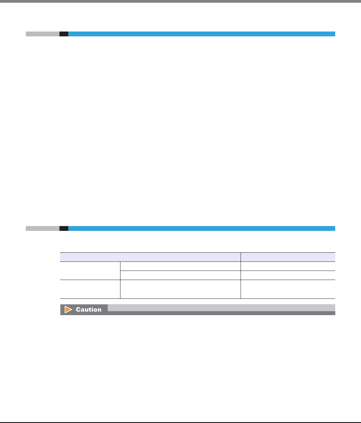
1.4 User Management
Appropriate user management is important to ensure that security is maintained within the system.
The user management function applies roles with multiple policies when user accounts are created to specify
the functions that are allowed for each user.
The following table shows the difference between user roles.
Operation mistakes and maintenance worker hours can be reduced and storage system security can be
improved by placing the authorized functions of system administrators in units of usage and by only giving
the minimum necessary policies to system administrators.
Default role Available functions Default account
Admin "Admin" is a system administrator privilege.
Functions such as status display and configuration
management are available.
root
Maintainer "Maintainer" is a maintenance engineer privilege.
Setting maintenance such as status display, configuration
management, and maintenance functions are available.
f.ce
Monitor "Monitor" is a general user privilege.
Only the status display function is available.
None
Refer to "Appendix A User Roles and Policies" (page 948) for details about user roles and policies.
Chapter 1 Outline
1.5 Screen Operations
ETERNUS Web GUI User’s Guide
Copyright 2013 FUJITSU LIMITED P2X0-1090-10ENZ0
21
1.5 Screen Operations
This section provides a description about GUI screen operations.
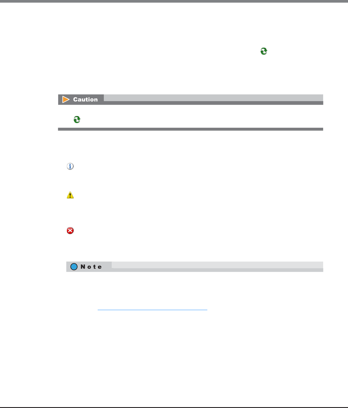
Click the [ ] icon or the [Help] link for a detailed explanation of the functions used during operation. An
explanation (help) screen of the function is displayed.
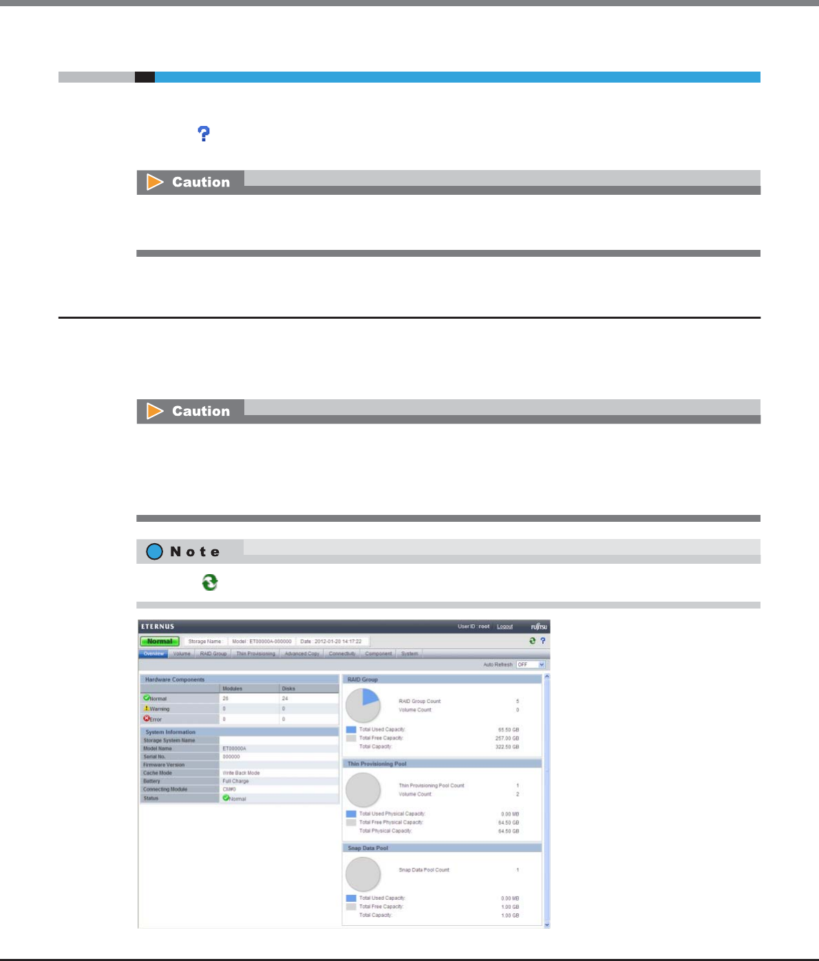
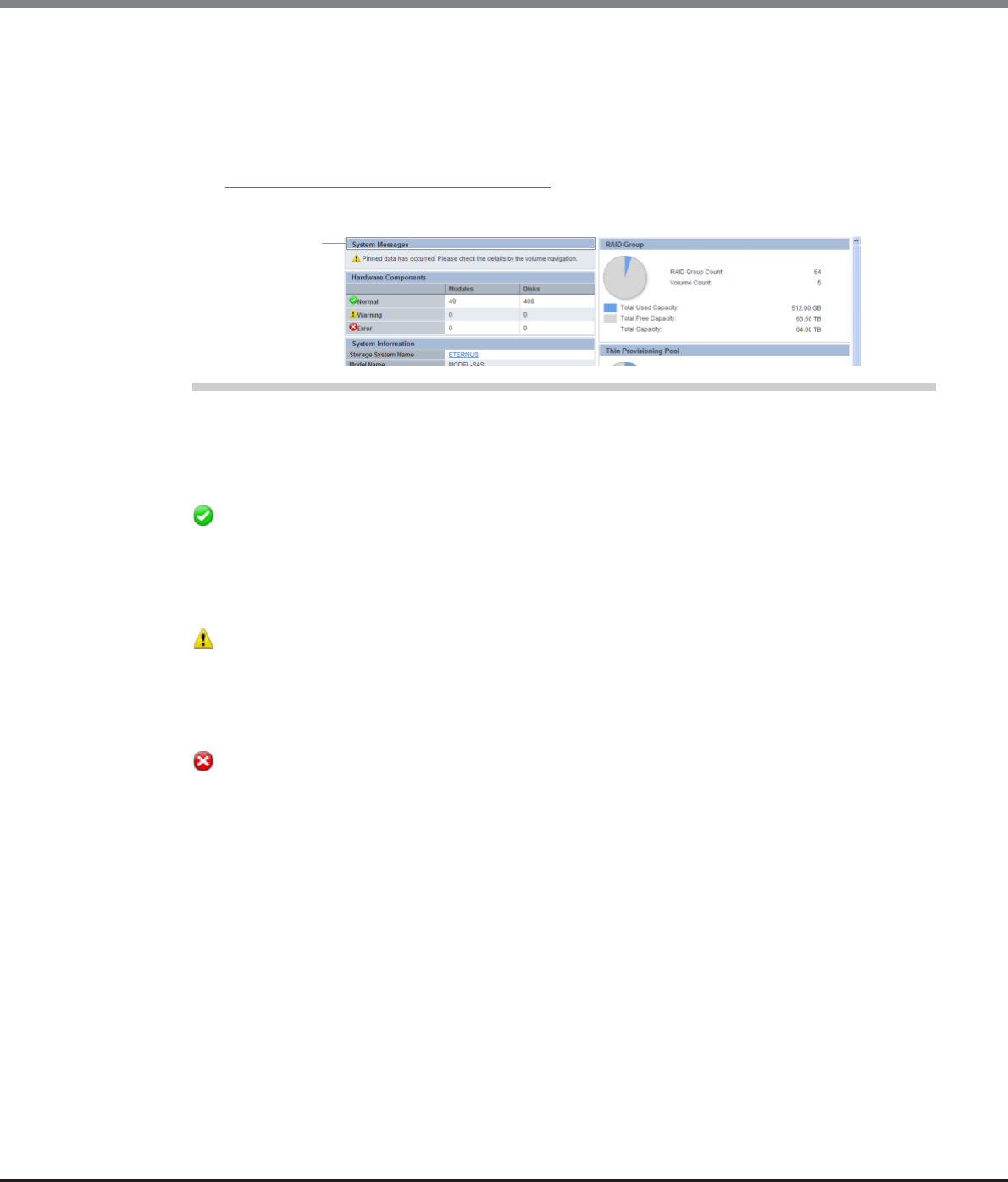
1.5.1 Overview
Overview screen appears immediately after logging in to the GUI. The status of the ETERNUS DX Disk storage
system and the usage of RAID groups, Thin Provisioning Pools (TPP), and Snap Data Pools (SDP) can be
checked in this screen.
•Be sure to log out after all necessary operations are completed.
•If the operation screen is not updated when accessing the GUI, close the web browser, and log in again.
•The [Start Initial Setup] screen is displayed for the first login after installation of the ETERNUS DX Disk
storage system is complete.
•TPP usage is displayed only when the Thin Provisioning license is registered.
•SDP usage is displayed only when the Advanced Copy license is registered.
Click the [ ] icon to update to the latest screen.
Chapter 1 Outline
1.5 Screen Operations
ETERNUS Web GUI User’s Guide
Copyright 2013 FUJITSU LIMITED P2X0-1090-10ENZ0
22
■Auto Refresh
The [Overview] screen is refreshed at the specified update interval.
Select the update interval to refresh the [Overview] screen from "OFF", "60 sec.", "120 sec.", or "180 sec.".
The monitoring time is reset to "0" when the update interval is changed or the [ ] icon is clicked. If the
specified interval is a value other than "OFF", the new update interval is applied after the monitoring time is
reset.
The update interval works while the user is logged in to GUI even when other functions are started from the
[Overview] screen. The update interval returns to the initial state ("OFF") when the Master CM is switched or
when the user logs out of GUI.
■System Message
A system message is displayed.
• Message
When any information from the ETERNUS DX Disk storage system exists, an information message is
displayed.
• Message
When an event causes warning status, a warning message is displayed.
If an LCD message is generated, the LCD message is displayed.
If an Advanced Copy path in warning status exists, a message is displayed.
• Message
When an event causes error status, an error message is displayed.
If an LCD message is generated, the LCD message is displayed.
If an Advanced Copy path in error status exists, a message is displayed.
Auto refresh is available only for the [Overview] screen. Screens other than [Overview] are refreshed when
the [ ] icon is clicked or a screen is redisplayed.
An "LCD message" is a message to notify if a failure or warning status occurs. It is displayed when the
Master CM is used to operate the ETERNUS DX Disk storage system (when logged in to the ETERNUS DX
Disk storage system by specifying the Master IP address (*1) via a web browser). The conditions for
displaying LCD messages depend on the model of the ETERNUS DX Disk storage system.
*1: Refer to "11.2.3.1 Setup Network Environment" (page 745) for details.
•ETERNUS DX80 S2/DX 90 S2, ETERNUS DX410 S2/DX440 S2, or ETERNUS DX8100 S2:
An LCD message is displayed if a component with failed status, a component with warning status, a
storage system with failed status, or a storage system with warning status is detected. Note that spec-
ifying whether to display the LCD message is not available.
Chapter 1 Outline
1.5 Screen Operations
ETERNUS Web GUI User’s Guide
Copyright 2013 FUJITSU LIMITED P2X0-1090-10ENZ0
23
■Hardware Components
The number of components for each status is displayed.
• Normal
-Modules
The number of components in normal status (*1) is displayed.
-Disks
The number of drives in normal status is displayed.
• Warning
-Modules
The number of components in warning status (*1) is displayed.
-Disks
The number of drives in warning status is displayed.
• Error
-Modules
The number of components in error status (*1) is displayed.
-Disks
The number of drives in error status is displayed.
*1: The number of components that can be maintained. The number of components does not include the number of
drives.
■System information
The information of the ETERNUS DX Disk storage system is displayed.
•Storage System Name
The name for the ETERNUS DX Disk storage system is displayed.
When logged in with a user account that can display detailed component information (*1), a link is
displayed on the storage system name.
Click this link to display the [Storage] screen in the [Component] navigation.
•ETERNUS DX8700 S2:
An LCD message is displayed if a component with failed status, a component with warning status, a
storage system with failed status, or a storage system with warning status is detected. The contents of
a message that is to be displayed are the same as the contents of the LCD panel messages on the
Operation panel. It is possible to specify whether to display LCD messages (equivalent to the LCD
panel message on the Operation Panel) by using the [Setup Event Notification] function. Refer to
"11.2.9.1 Setup Event Notification" (page 880) for details. Because it is possible to specify whether to
display the LCD messages by using the [Setup Event Notification] function, the message displayed
might not match the status display for the corresponding component.
System message

Chapter 1 Outline
1.5 Screen Operations
ETERNUS Web GUI User’s Guide
Copyright 2013 FUJITSU LIMITED P2X0-1090-10ENZ0
24
*1: A user account with the "Status Display" policy or the "Maintenance Operation" policy can display detailed
component information. When logged in with a user account that has a "Monitor", "Admin", "StorageAdmin",
"SecurityAdmin", or "Maintainer" default role, a link is displayed on the storage system name.
•Model Name
The model name of the ETERNUS DX Disk storage system is displayed.
•Serial No.
The serial number of the ETERNUS DX Disk storage system is displayed.
•Firmware Version
The current controller firmware version is displayed.
-VxxLyy-zzzz (Vxx: Version, Lyy: Level, zzzz: Release number)
•Cache Mode
The current status and the factor of the cache are displayed. The normal status is "Write Back Mode".
-Write Back Mode
When a Write request is issued from the host, "Write Complete" is displayed after writing to the cache
area is complete.
-Write Through Mode
When a Write request is issued from the host, "Write Complete" is displayed after writing to the cache
area and the drives is complete.
In the Write Through Mode, "Write Through (factors)" is displayed. When there are multiple factors, all
the factors are displayed.
The factors of the Write Through Mode are described below:
•Write Through (Pinned Data)
A large amount of pinned data (*2) is detected in the ETERNUS DX Disk storage system.
*2: "Pinned data" is the data left in the cache memory due to unsuccessful write-back to the volume from the
cache memory.
•Write Through (Battery)
The battery charge level is low.
•Write Through (Maintenance)
The following maintenance operation is currently being used:
-Switch Controller Firmware
-Change Controlling CM
-Add Controller Module
•Write Through (1CM)
The ETERNUS DX Disk storage system is operated with 1CM. (*3)
*3: This mode is displayed when "1CM Write Through" is enabled by using the procedure in "11.2.13.4 Setup
Subsystem Parameters" (page 935) function and the ETERNUS DX Disk storage system is operated with
1CM (only 1CM can be used due to an error such as a CM failure). The "1CM Write Through" setting for the
"Setup Subsystem Parameters" function is displayed and can be changed when logged in using a user
account with the "Maintenance Operation" policy. The normal status is disabled.
•Battery
The battery charge level is displayed.
When the battery charge level is 90% or more, "Full Charge" is displayed. When the battery charge level is
less than 90%, "xx%" is displayed. This item is displayed only when using the ETERNUS DX410 S2/DX440 S2
or the ETERNUS DX8100 S2/DX8700 S2.
•Connecting Module
The Controller Module (CM) to which the GUI is connected is displayed.
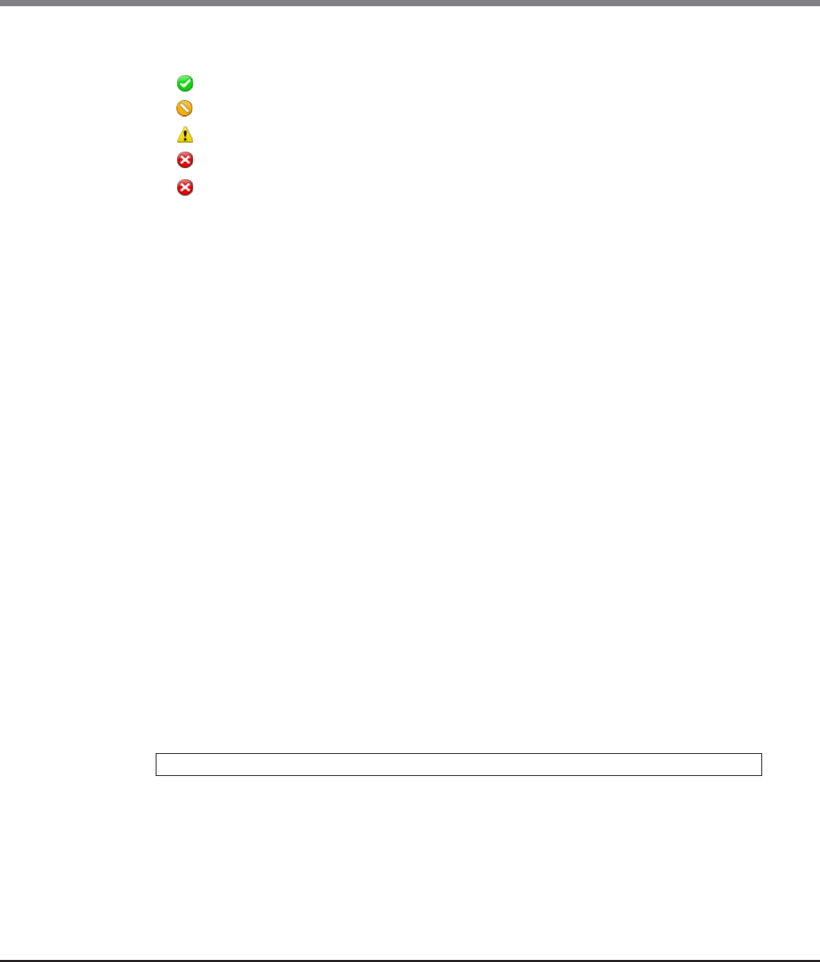
Chapter 1 Outline
1.5 Screen Operations
ETERNUS Web GUI User’s Guide
Copyright 2013 FUJITSU LIMITED P2X0-1090-10ENZ0
25
•Status
The status of the ETERNUS DX Disk storage system is displayed.
- Normal
- Maintenance
- Warning
- Error
- Not Ready (*)
*: This number indicates the cause of the Not Ready status.
■RAID Groups
The usage of RAID groups is displayed.
•Pie chart
The pie chart indicates the total used capacity and the total free capacity in the RAID groups.
Blue: Total used capacity
Gray: Total free capacity
•RAID Group Count
The number of RAID groups registered in the ETERNUS DX Disk storage system is displayed.
The "RAID Group Count" includes the number of RAID groups that configure TPPs and the number of RAID
groups that are registered as REC Disk Buffers.
•Volume Count
The number of volumes registered in the ETERNUS DX Disk storage system is displayed.
The "Volume Count" displays the number of "Standard" type volumes and "Wide Striping Volumes (WSV)".
•Total Used Capacity
The total used capacity of the RAID groups [TB/GB/MB] is displayed. The "Total Used Capacity" is the total
capacity of all of the RAID groups that are used. An example of this capacity is space that is used for vol-
umes in the RAID groups. This value does not include the capacity of RAID groups that configure TPPs and
the capacity of RAID groups that are registered as REC Disk Buffers.
•Total Free Capacity
The total free capacity of the RAID groups [TB/GB/MB] is displayed. The "Total Free Capacity" is a total of
unused capacities in the RAID groups. This value does not include the capacity of RAID groups that
configure TPPs and the capacity of RAID groups that are registered as REC Disk Buffers.
•Total Capacity
The total capacity of the RAID groups [TB/GB/MB] is displayed. The "Total Capacity" is the total capacity of
all the RAID groups in the ETERNUS DX Disk storage system. This value does not include the capacity of
RAID groups that configure TPPs and the capacity of RAID groups that are registered as REC Disk Buffers.
Total Free Capacity = Total Capacity - Total Used Capacity

Chapter 1 Outline
1.5 Screen Operations
ETERNUS Web GUI User’s Guide
Copyright 2013 FUJITSU LIMITED P2X0-1090-10ENZ0
26
■Thin Provisioning Pool
The usage of TPP is displayed.
•Pie chart
The pie chart indicates the total used physical capacity and the total free physical capacity in the TPPs.
Blue: Total used physical capacity
Gray: Total free physical capacity
•Thin Provisioning Pool Count
The number of TPPs registered in the ETERNUS DX Disk storage system is displayed.
•Volume Count
The number of volumes registered in the ETERNUS DX Disk storage system is displayed.
This value displays the number of "TPV" type volumes.
•Total Used Physical Capacity
The total used physical capacity of the TPPs [TB/GB/MB] is displayed. The "Total Used Physical Capacity" is
the total physical capacity of all the TPPs that are used for volumes.
•Total Free Physical Capacity
The total free physical capacity of the TPPs [TB/GB/MB] is displayed. The "Total Free Physical Capacity" is the
total unused physical capacity of all the TPPs.
•Total Physical Capacity
The total physical capacity of the TPPs [TB/GB/MB] is displayed. The "Total Physical Capacity" is the total
physical capacity of all the TPPs in the ETERNUS DX Disk storage system.
■Snap Data Pool
The usage of SDP is displayed.
•Pie chart
The pie chart indicates the total used capacity and the total free capacity in the SDP.
Blue: Total used capacity
Gray: Total free capacity
•Snap Data Pool Count
The number of SDPs that are registered in the ETERNUS DX Disk storage system is displayed.
•Total Used Capacity
The total used capacity of the SDP [TB/GB/MB] is displayed. The "Total Used Capacity" is the total capacity of
all the SDPs that are used for volumes.
•Total Free Capacity
The total free capacity of the SDP [TB/GB/MB] is displayed. The "Total Free Capacity" is the total unused
capacity of all the SDPs.
•Total Capacity
The total capacity of the SDP [TB/GB/MB] is displayed. The "Total Capacity" is the total capacity of all the
SDPs in the ETERNUS DX Disk storage system.
Total Free Physical Capacity = Total Physical Capacity - Total Used Physical Capacity
Total Free Capacity = Total Capacity - Total Used Capacity
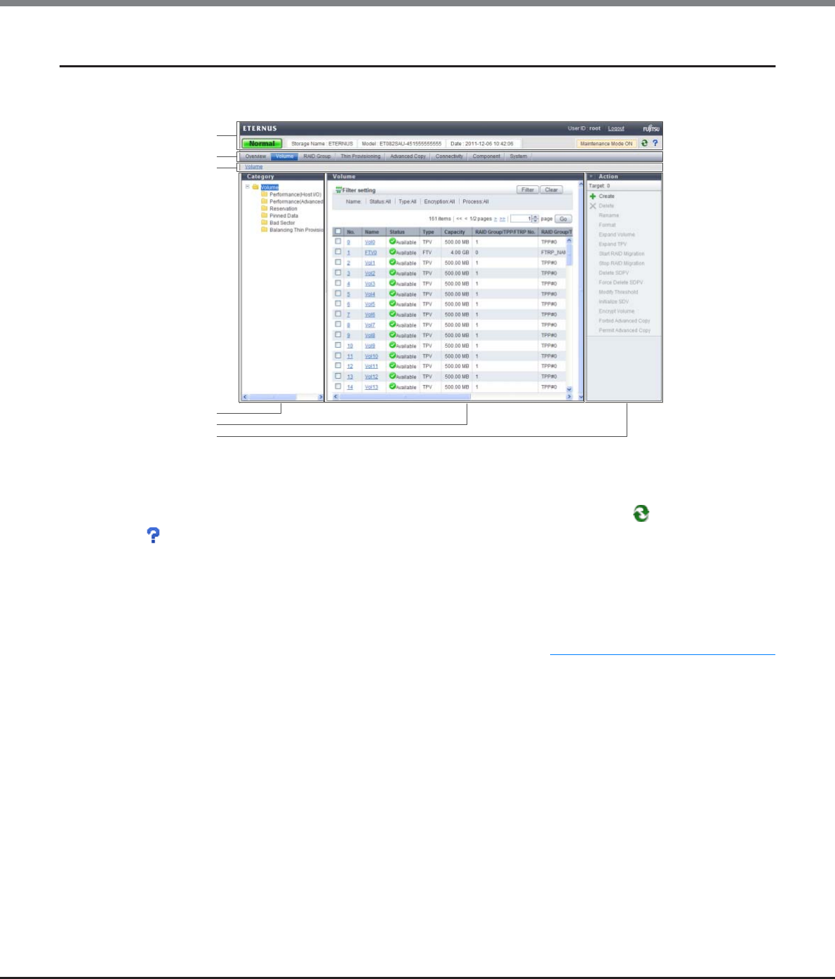
Chapter 1 Outline
1.5 Screen Operations
ETERNUS Web GUI User’s Guide
Copyright 2013 FUJITSU LIMITED P2X0-1090-10ENZ0
27
1.5.2 Screen Structures
This section describes screen layouts for functions other than Overview screen.
■Header
User ID, [Logout] link, general status, storage system name, model name, date, [ ] icon (Refresh), and
[ ] icon (Help) are displayed in the header. When maintenance is being performed for the ETERNUS DX Disk
storage system, the "Maintenance Mode ON" is displayed. If a user with the "Maintenance Operation" policy
logs into GUI, "Maintenance Mode OFF" is displayed when no maintenance operation is being performed.
The header is always displayed.
•General status of the ETERNUS DX Disk storage system
Status of each component in the ETERNUS DX Disk storage system is monitored periodically, and the result
is displayed as a general status icon with character strings. Refer to "B.1 Device General Status" (page 972)
for details about the general status.
■Navigation
Overview, Volume, RAID Group, Thin Provisioning, Advanced Copy, Connectivity, Component, and System tabs
are displayed.
Click the tab for the function that is to be used to display a list screen for that function.
The navigation is always displayed.
■Bread crumb list
Bread crumb indicates the location of the current screen on the GUI.
Click the link to display the list screen of the target item.
Category
Main
Action
Header
Navigation
Bread crumb list
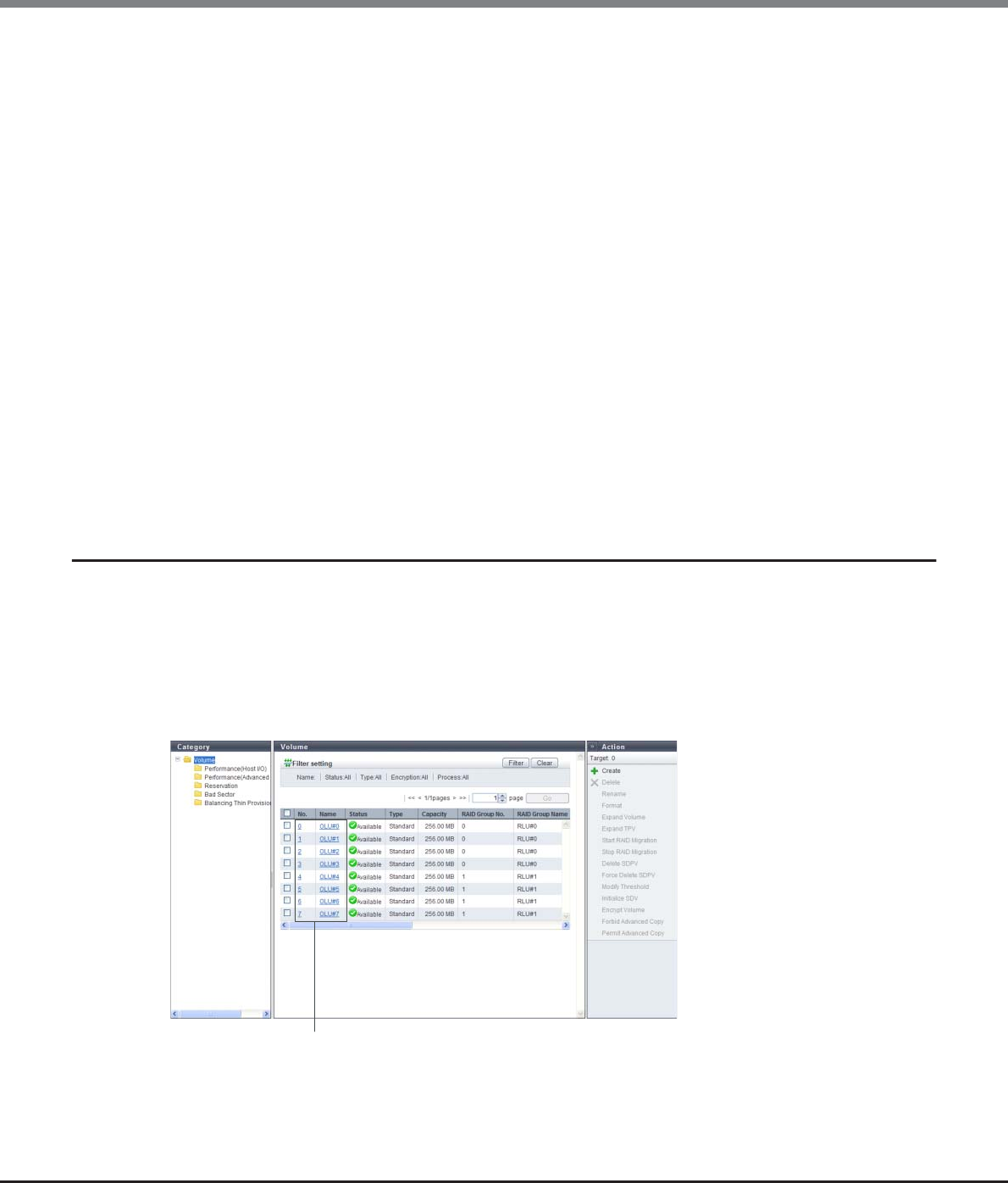
Chapter 1 Outline
1.5 Screen Operations
ETERNUS Web GUI User’s Guide
Copyright 2013 FUJITSU LIMITED P2X0-1090-10ENZ0
28
■Category
The subordinate items are displayed for an item that is clicked in the navigation. The category directory is
used for switching the contents that are displayed in the Main screen. Click the item for the function that is to
be used. The horizontal width of the category area can be changed.
■Main
A list of items is displayed for an item that is clicked on the navigation or in the category.
The filter setting area may also be displayed for some lists.
•Filter setting
Filter setting is a function used to display a list of only the items meeting all the specified conditions. The
conditions that are available depend on the function. No filtering is set by default.
■Action
Only the available functions for the selected items from the navigation or in the category are displayed. Click
the function that is to be used to display the wizard screen.
Click the [>>] button to switch the display of the action area.
The number of operation targets that is selected in the Main area is displayed in the "Target:" field. When no
selections are made, "0" is displayed.
1.5.3 List Screen/Detailed Screen
There are two types of main screens; a list screen and a detailed screen.
The header, bread crumb list, and navigation areas are not included in the screen shots in this section.
■List screen
A list of the items that were clicked on the navigation or in the category is displayed. For items with detailed
information, links to the detailed screens are displayed.
Links to detailed screen
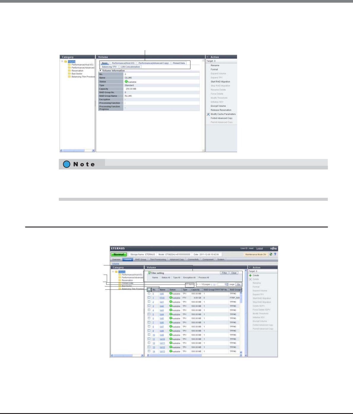
Chapter 1 Outline
1.5 Screen Operations
ETERNUS Web GUI User’s Guide
Copyright 2013 FUJITSU LIMITED P2X0-1090-10ENZ0
29
■Detailed screen
Click the link for each item in the list screen to display a detailed screen. Click the tabs that are displayed to
switch the display.
1.5.4 Basic Operation
Select the desired item and execute the selected operation.
For some items, the same information may be displayed for the list screen and the detailed screen. From
Chapter 5 onward, only the information for items in the detailed screen that is different from the list screen is
described.
Tabs to change detailed screens
Filter setting
Sorting criteria
Select All checkbox
Page specification
Number of target items

Chapter 1 Outline
1.5 Screen Operations
ETERNUS Web GUI User’s Guide
Copyright 2013 FUJITSU LIMITED P2X0-1090-10ENZ0
30
■Selecting an operation
When an item in the navigation or category is clicked, a list items for the selected item is displayed. Select the
checkbox or checkboxes of the listed items for the desired operation. Note that some operations, such as
creating new volumes, do not require the item to be selected.
The following operations are available in the list screen:
•Filter setting
Filter setting is a function used to display a list of only the items that meet all the specified conditions. The
settings that can be specified vary depending on the function that is selected. No filtering is set by default.
•Number of target items
The number of operation target items that are registered in the ETERNUS DX Disk storage system is dis-
played.
•Page specification
Page specification is a function used to display the specified page. This setting is available when lists are
displayed on multiple pages. The total number of pages and the current page number is displayed.
-Click the [<<] button to display the first page.
-Click the [<] button to display the previous page.
-Click the [>] button to display the next page.
-Click the [>>] button to display the last page.
When specifying the page that is to be displayed, input the numeric character in the page specification
spin box and click the [Go] button. A list for the specified page is displayed.
•Sort
Sorting is a function that rearranges the order of the display items in ascending order (A - Z or 0 - 9), in
descending order (Z - A or 9 - 0), or in a specific order. Click the sorting criteria to change the order. The
item that is furthest to the left is displayed in ascending order by default.
•Select All checkbox
The "Select All" checkbox is the first item in the left of the item field. Click this checkbox to select all of the
checkboxes that are listed. This checkbox is left clear by default.
■Executing an operation
Select the desired operation item from the navigation or category, and then select the function that is to be
executed in the Action field.
Only the available functions for the displayed item are displayed in the Action field.
Some functions in the Action field require one target item from the list to be selected, some functions require
multiple target items to be selected, and other functions can be performed without selecting any items.
•[Cancel] button
Deletes the newly added or changed information, and then returns to the previous screen. Or cancels the
current operation, and then returns to the previous screen.
The header, bread crumb list, and navigation areas are not included in the screen shots in the following
chapters and sections.

Chapter 1 Outline
1.5 Screen Operations
ETERNUS Web GUI User’s Guide
Copyright 2013 FUJITSU LIMITED P2X0-1090-10ENZ0
31
■Updating the screen display
When the [ ] icon in the global header is clicked or a category, a navigation, or an action is selected, the
most recently updated screen is obtained. If a tab is clicked, the screen is not updated. Note that only the
[Overview] screen automatically updates periodically according to the specified update interval.

ETERNUS Web GUI User’s Guide
Copyright 2013 FUJITSU LIMITED P2X0-1090-10ENZ0
32
Chapter 2
Startup and Shutdown
This chapter describes how to start, exit, log in, and log out from GUI.
2.1 Startup of GUI
Startup the login screen for GUI.
Connect the PC and the ETERNUS DX Disk storage system using a LAN cable, and display the login screen via
the web browser.
The procedure to start up the login screen for GUI is as follows:
Procedure
1Directly connect the PC and MNT port of the ETERNUS DX Disk storage system via LAN cable.
2Set the IP address and subnet mask for the PC to match the ETERNUS DX Disk storage system
network settings.
3Enter "http://IP address of the storage system/" to the address bar in the web browser
(Default IP address is "192.168.1.1").
→The login screen for GUI is displayed. Refer to "2.2 Login" (page 34) for detailed procedure to login.
•When using SSL (https), the "SSL server certificate" or the "self-signed SSL certificate" must be
registered in the ETERNUS DX Disk storage system in advance.
-When registering "SSL server certificate"
a Send the CSR that is downloaded using the procedure in "11.2.3.16 Create Key/CSR" (page 790)
to the certification authority and obtain the "SSL server certificate".
b Register the obtained "SSL server certificate" by using the procedure in "11.2.3.17 Register SSL
Certificate" (page 795).
-When registering "self-signed SSL certificate"
a Create the "self-signed SSL certificate" using the procedure in "11.2.3.15 Create Self-signed SSL
Certificate" (page 787).
b Register the created "self-signed SSL certificate" in the ETERNUS DX Disk storage system as
described in "Appendix C Installing the Security Certificate" (page 981).
•If Firefox 3.6.x is used for connecting to the ETERNUS DX Disk storage system via "https", a
communication error may occur. This error can be avoided by connecting via "http" or by using
"Internet Explorer".

Chapter 2 Startup and Shutdown
2.1 Startup of GUI
ETERNUS Web GUI User’s Guide
Copyright 2013 FUJITSU LIMITED P2X0-1090-10ENZ0
33
End of procedure
•Refer to "11.2.3.1 Setup Network Environment" (page 745) for procedure to set the IP address of the
MNT port.
•The default number of port that is used for http connection is "80".
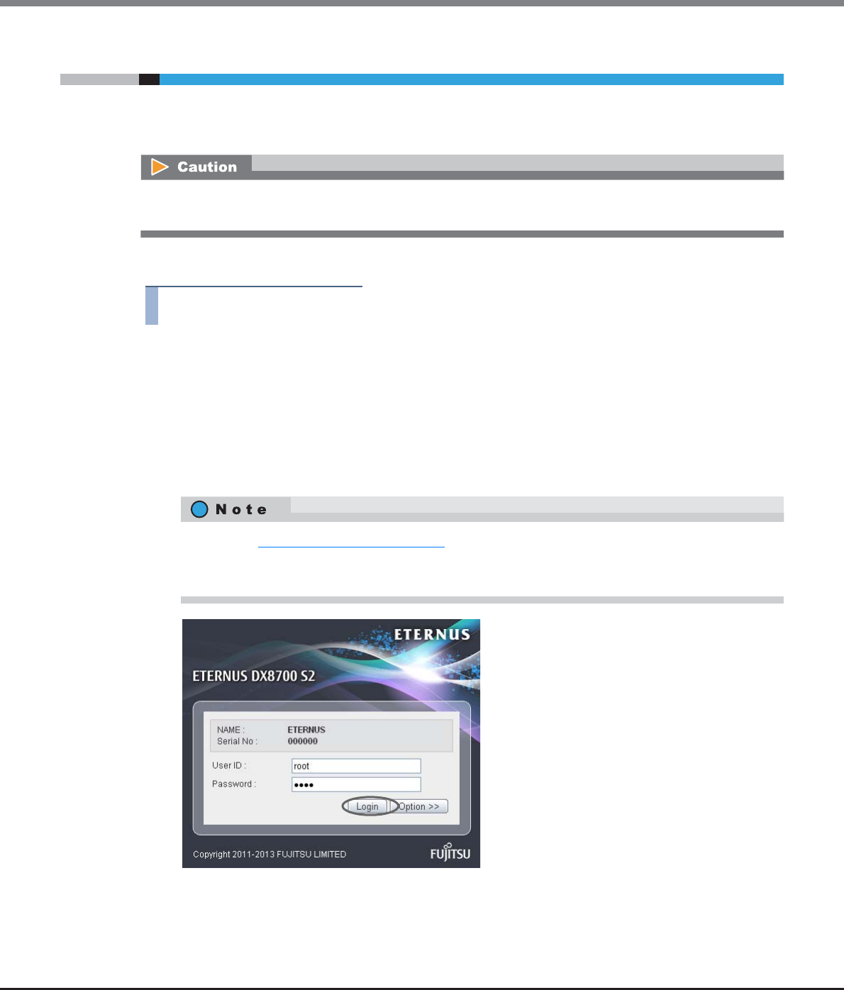
Chapter 2 Startup and Shutdown
2.2 Login
ETERNUS Web GUI User’s Guide
Copyright 2013 FUJITSU LIMITED P2X0-1090-10ENZ0
34
2.2 Login
Log in to GUI to start the operation. The GUI operation screen appears.
The menu that is displayed depends on the role that is applied for the user account.
The procedure for logging in is as follows:
Procedure
1Click the [Option] button in the login screen, and select the language (English or Japanese).
2Enter the User ID and Password, and click the [Login] button.
The User ID and the Password vary depending on which account is being used to log in.
•User ID
root
•Password
root (Default)
→The operation screen appears.
If a login is attempted while 16 users are already logged in to the GUI, an error screen appears. When this
occurs, note the error message and try logging in again after completing the required operation.
•Refer to "11.2.7 Define Role" (page 853) for user accounts.
•If the input error occurs, enter the User ID and Password again to log in to the ETERNUS DX Disk
storage system.

Chapter 2 Startup and Shutdown
2.2 Login
ETERNUS Web GUI User’s Guide
Copyright 2013 FUJITSU LIMITED P2X0-1090-10ENZ0
35
End of procedure
Up to 16 users can be logged in concurrently from the GUI (the number of users that are logged from
CLI is not included). Logging in 17 or more users is not allowed.
Also note that when another user is already logged in and performing one of the following
operations, a warning message appears and some functions cannot be used. Confirm the current GUI
usage state and start operation.
•When applying controller firmware
•When applying disk firmware
•During the RAID group diagnosis
•During the disk diagnosis
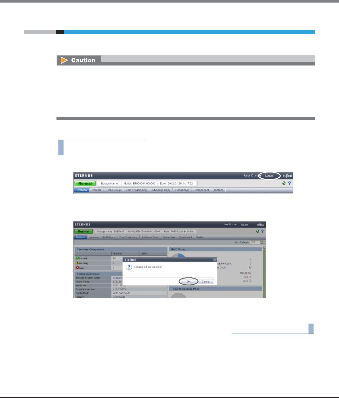
Chapter 2 Startup and Shutdown
2.3 Logout
ETERNUS Web GUI User’s Guide
Copyright 2013 FUJITSU LIMITED P2X0-1090-10ENZ0
36
2.3 Logout
Log out from GUI to finish the operation.
The procedure for logging out is as follows:
Procedure
1Click the [Logout] link on the top right of the screen.
→A confirmation screen appears.
2Click the [OK] button.
→This completes the logging out process.
The login screen appears.
End of procedure
A logout is performed automatically under the following conditions:
•When a different user executes a forcible logout (*1)
•When the ETERNUS DX Disk storage system is turned off
•When no operation is performed for 60 minutes or longer after logging in
*1: When the user name is the same as a user who is already logged in, the user who was previously logged in is
forcibly logged out.

Chapter 2 Startup and Shutdown
2.4 Exit
ETERNUS Web GUI User’s Guide
Copyright 2013 FUJITSU LIMITED P2X0-1090-10ENZ0
37
2.4 Exit
Exit from GUI.
The procedure to exit is as follows:
Procedure
1Click the [Close] button for the web browser.
→Exit from GUI.
The login screen does not appear.
End of procedure
Make sure to perform "2.3 Logout" (page 36) operation before exiting GUI.
If exiting GUI without logging out, the login status is not released.
ETERNUS Web GUI User’s Guide
Copyright 2013 FUJITSU LIMITED P2X0-1090-10ENZ0
38
Chapter 3
Initial Setup
This chapter describes the Initial Setup function for the ETERNUS DX Disk storage system.
This function performs the required initial settings that must be set before operating the ETERNUS DX Disk
storage system on a series of wizard screens.
Initial Setup is divided into "Initial Setup 1" and "Initial Setup 2".
•Initial Setup 1
Performs the minimum settings required before using the ETERNUS DX Disk storage system.
•Initial Setup 2
Makes the reporting settings for when an error occurs in the ETERNUS DX Disk storage system. The settings
can be omitted if the reporting function will not be used.
If the browser is shut down during execution of Initial Setup, other functions will no longer be available. If
this case, forcibly log in using the same user name, and perform Initial Setup 1 again from the beginning.
However, if you have already reached Initial Setup 2, the wizard is executed from the beginning of Initial
Setup 2.
The settings made in the Initial Setup can be changed individually later.

Chapter 3 Initial Setup
3.1 Initial Setup 1
ETERNUS Web GUI User’s Guide
Copyright 2013 FUJITSU LIMITED P2X0-1090-10ENZ0
39
3.1 Initial Setup 1
The flow of wizard operations in Initial Setup 1 is shown below.
(1)Set Storage Name
Register the name, administrator, and installation site of the ETERNUS DX Disk storage system. Refer to
"11.2.13.1 Modify Storage System Name" (page 927) for details.
(2)Set Date and Time
Set the date/time and time zone (storage system location) of the internal clock in the ETERNUS DX Disk
storage system. Refer to "11.2.13.2 Modify Date and Time" (page 929) for details.
(3)Change Password
Change the password for the default account that is currently logged in before starting to use the ETERNUS
DX Disk storage system. Refer to "11.2.1 Change User Password" (page 742) for details.
(4)Register Thin Provisioning License
If using the Thin Provisioning function, register the license here. Refer to "7.2.10 Register Thin Provisioning
License" (page 245) for details.
(5)Register Copy License
If using the Advanced Copy function, register the license here. Refer to "8.2.4 Register Advanced Copy
License" (page 295) for details.
(6)Register SED Authentication Key
Register the Self Encrypting Drive (SED) authentication key to enable the encryption function of the SED.
Refer to "11.2.13.7 Register SED Authentication Key" (page 944) for details
(7)Set Network Environment
Set the environment for the ETERNUS DX Disk storage system to communicate on the network such as IP
address and subnet mask. Refer to "11.2.3.1 Setup Network Environment" (page 745) for details.
Log out when the settings are complete. Log in again, and then proceed to "3.2 Initial Setup 2" (page 49).
If SED has been installed before registering the SED authentication key, reboot the ETERNUS DX Disk storage
system before logging in again.
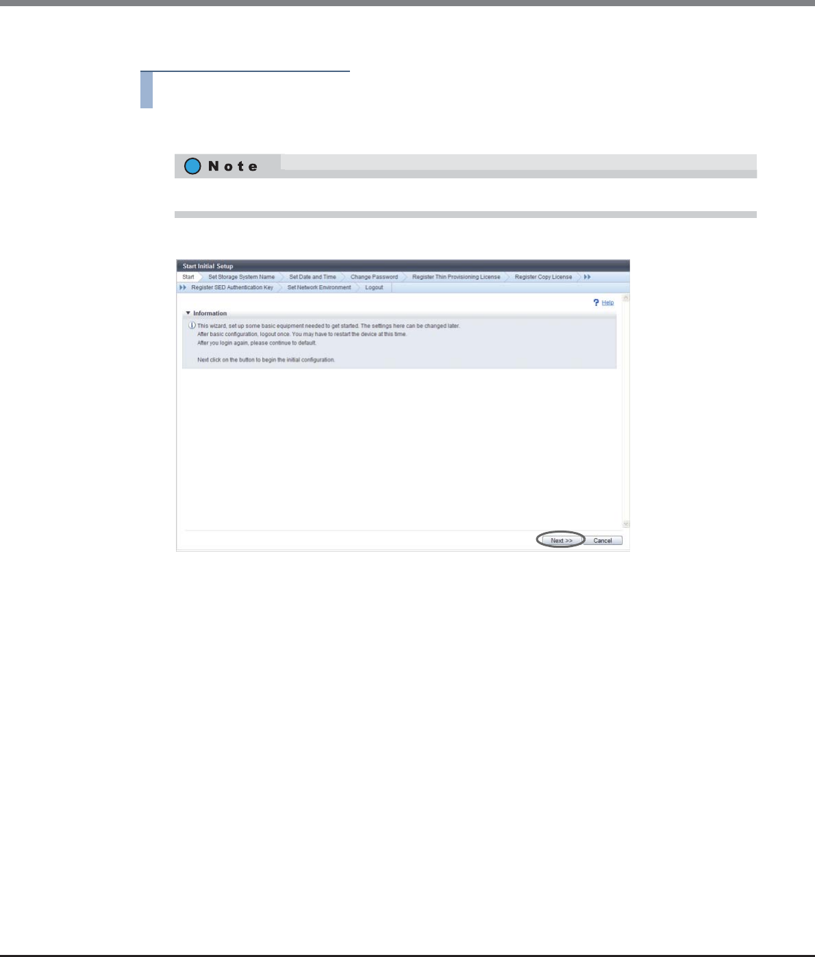
Chapter 3 Initial Setup
3.1 Initial Setup 1
ETERNUS Web GUI User’s Guide
Copyright 2013 FUJITSU LIMITED P2X0-1090-10ENZ0
40
The procedure to perform Initial Setup 1 is as follows:
Procedure
1Click [Start Initial Setup] in [Action].
2Click the [Next >>] button.
→Initial Setup starts.
The [Start Initial Setup] screen is displayed after logging in for the first time.
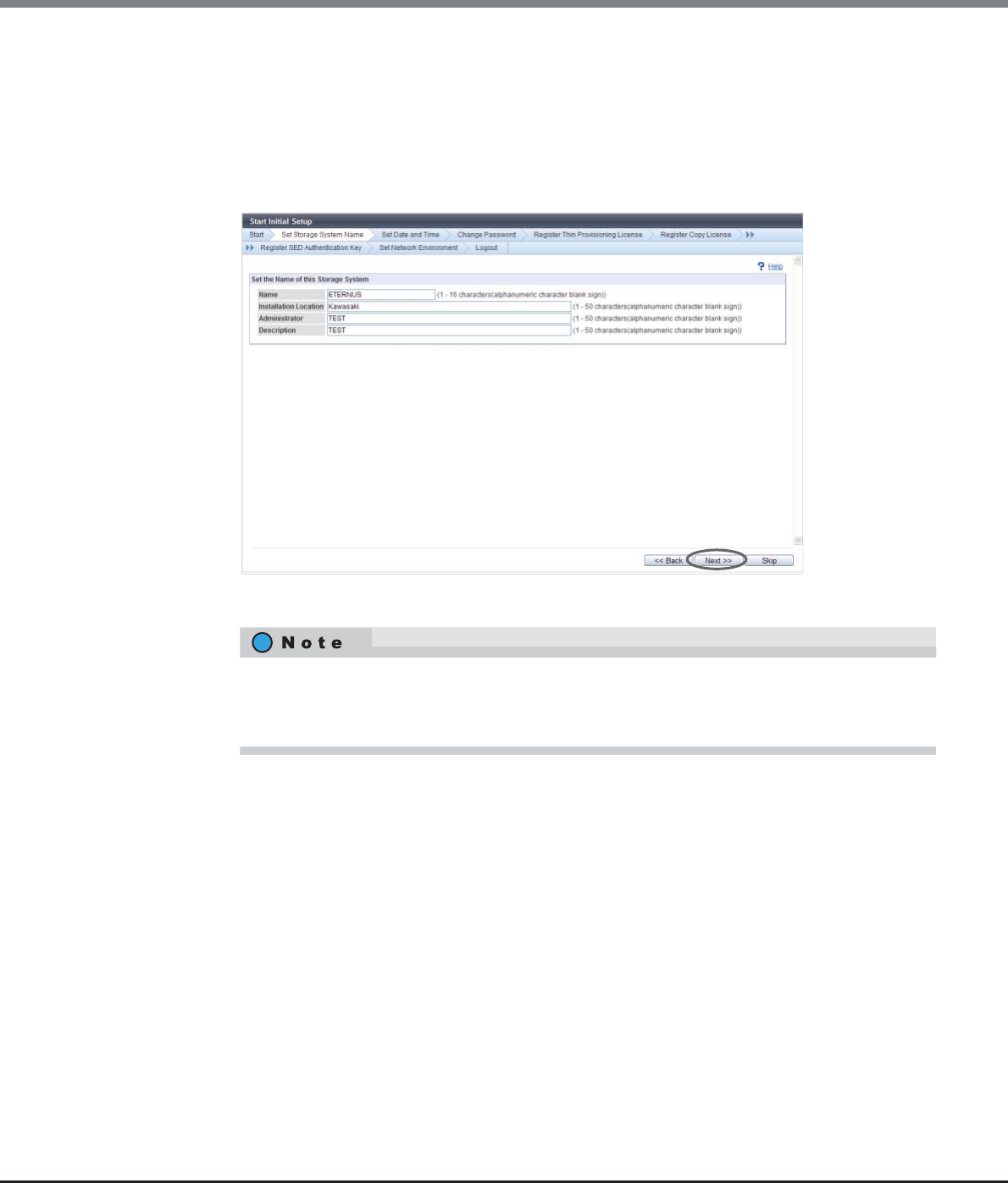
Chapter 3 Initial Setup
3.1 Initial Setup 1
ETERNUS Web GUI User’s Guide
Copyright 2013 FUJITSU LIMITED P2X0-1090-10ENZ0
41
3Proceed to [Set Storage System Name].
3-1 Specify the following items, and click the [Next >>] button.
-Name
-Installation Location
-Administrator
-Description
→A confirmation screen appears.
3-2 Click the [OK] button.
→Setting of the storage system name starts.
3-3 Click the [Done] button.
•If logging in for the first time, be sure to set the name of the ETERNUS DX Disk storage system.
•If not logging in for the first time, click the [Skip] button to proceed to the next screen without
setting.
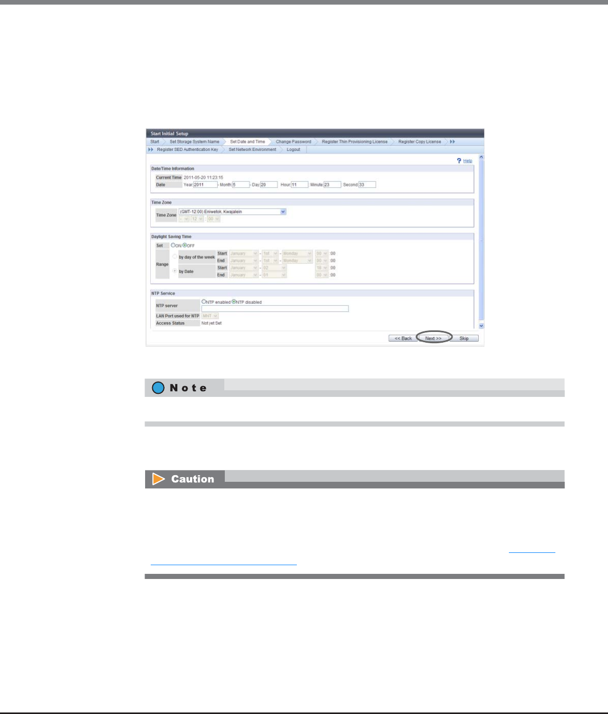
Chapter 3 Initial Setup
3.1 Initial Setup 1
ETERNUS Web GUI User’s Guide
Copyright 2013 FUJITSU LIMITED P2X0-1090-10ENZ0
42
4Proceed to [Set Date and Time].
4-1 Specify the following items, and click the [Next >>] button.
-Date/Time Information
-Time Zone
-Daylight Saving Time
-NTP Service
→A confirmation screen appears.
4-2 Click the [OK] button.
→Setting of the Date/time starts.
4-3 Click the [Done] button.
Click the [Skip] button to proceed to the next screen without setting.
If "NTP enabled" is selected for "NTP server" when there is no NTP server connection or when
communication with the NTP server is unstable, the required time for the date and time setting
may take longer. Wait until the screen is updated. Even if connection to the NTP server fails, the
date and time setting appear as though they have completed. To confirm that the ETERNUS DX
Disk storage system is successfully connected to the NTP server, use the procedure in "11.2.13.2
Modify Date and Time" (page 929) and check "Access Status" in the "NTP Service" field.
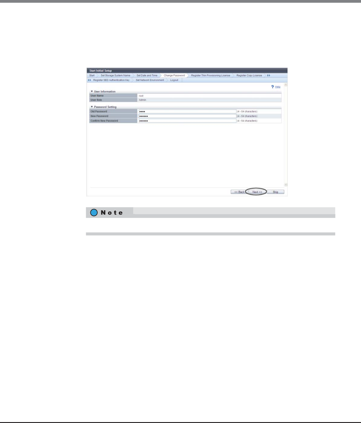
Chapter 3 Initial Setup
3.1 Initial Setup 1
ETERNUS Web GUI User’s Guide
Copyright 2013 FUJITSU LIMITED P2X0-1090-10ENZ0
43
5Proceed to [Change Password].
5-1 Specify the following items, and click the [Next >>] button.
-Old Password
-New Password
-Confirm New Password
→A confirmation screen appears.
5-2 Click the [OK] button.
→Changing of the password starts.
5-3 Click the [Done] button.
Click the [Skip] button to proceed to the next screen without setting.
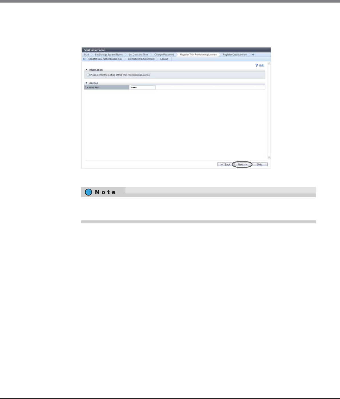
Chapter 3 Initial Setup
3.1 Initial Setup 1
ETERNUS Web GUI User’s Guide
Copyright 2013 FUJITSU LIMITED P2X0-1090-10ENZ0
44
6Proceed to [Register Thin Provisioning License].
6-1 Specify the following items, and click the [Next >>] button.
-License Key (if not already registered)
→A confirmation screen appears.
6-2 Click the [OK] button.
→Thin Provisioning license is registered.
6-3 Click the [Done] button.
•If the Thin Provisioning license key is already registered, proceed to [Register Copy License].
•Click the [Skip] button to proceed to the next screen without setting.
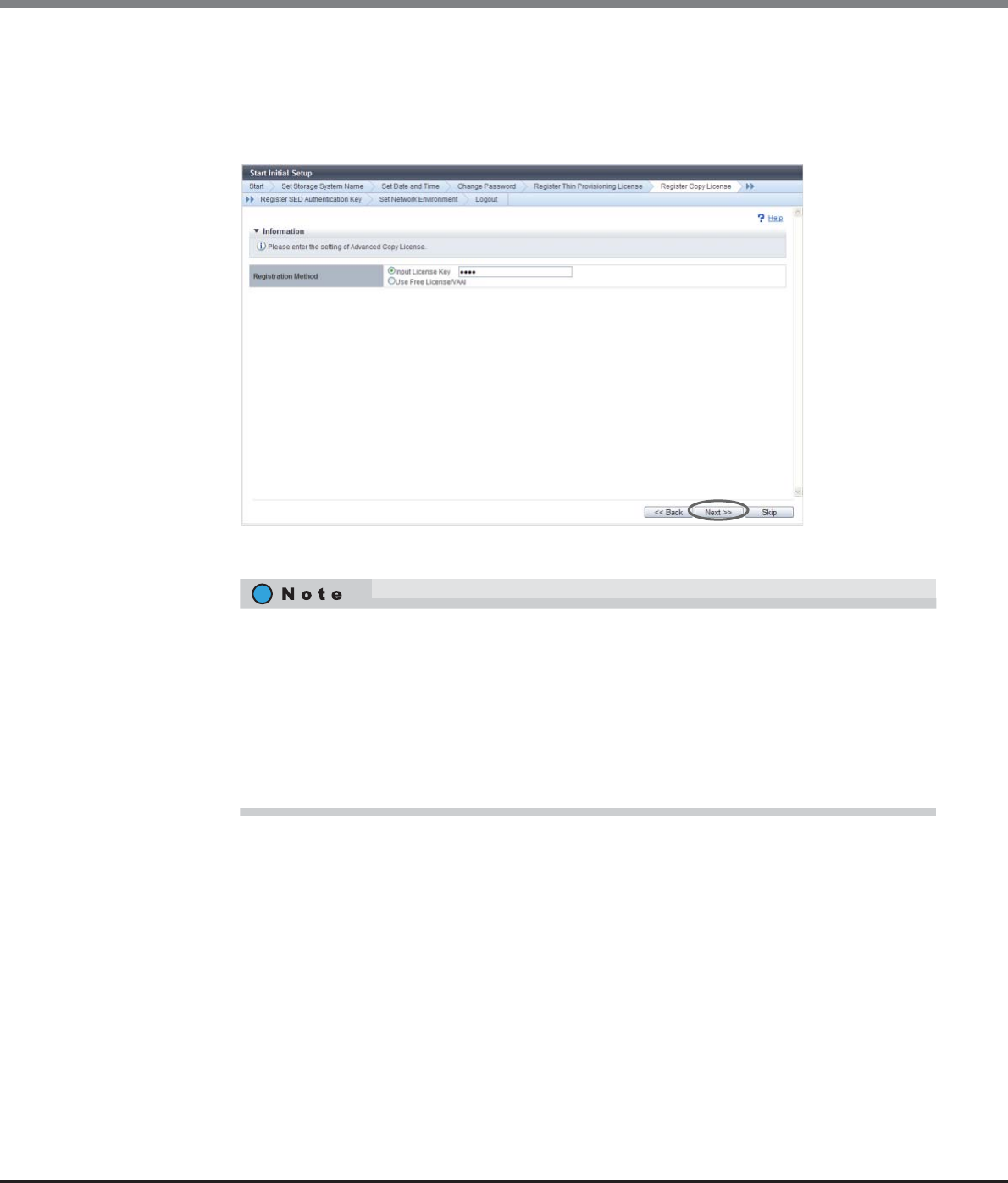
Chapter 3 Initial Setup
3.1 Initial Setup 1
ETERNUS Web GUI User’s Guide
Copyright 2013 FUJITSU LIMITED P2X0-1090-10ENZ0
45
7Proceed to [Register Copy License].
7-1 Specify the following items, and click the [Next >>] button.
-Registration Method
-License Key
→A confirmation screen appears.
7-2 Click the [OK] button.
→The Advanced Copy license registration is executed.
7-3 Click the [Done] button.
•When using ETERNUS SF AdvancedCopy Manager or ETERNUS SF Express, perform the required
settings described in the documents that are supplied with ETERNUS SF AdvancedCopy
Manager or ETERNUS SF Express.
•If a Advanced Copy license (trial license) is already registered, the paid license can be
registered. Input the license key.
•If the Advanced Copy license key (paid license) is already registered, proceed to [Register SED
Authentication Key].
•Click the [Skip] button to proceed to the next screen without setting.
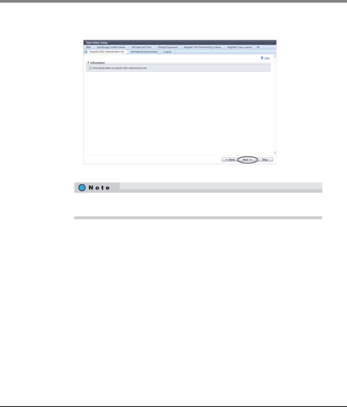
Chapter 3 Initial Setup
3.1 Initial Setup 1
ETERNUS Web GUI User’s Guide
Copyright 2013 FUJITSU LIMITED P2X0-1090-10ENZ0
46
8Proceed to [Register SED Authentication Key].
8-1 Click the [Next >>] button.
→A confirmation screen appears.
8-2 Click the [OK] button.
→SED Authentication Key registration starts.
8-3 Click the [Done] button.
•If the SED Authentication Key is already registered, proceed to [Set Network Environment].
•Click the [Skip] button to proceed to the next screen without setting.
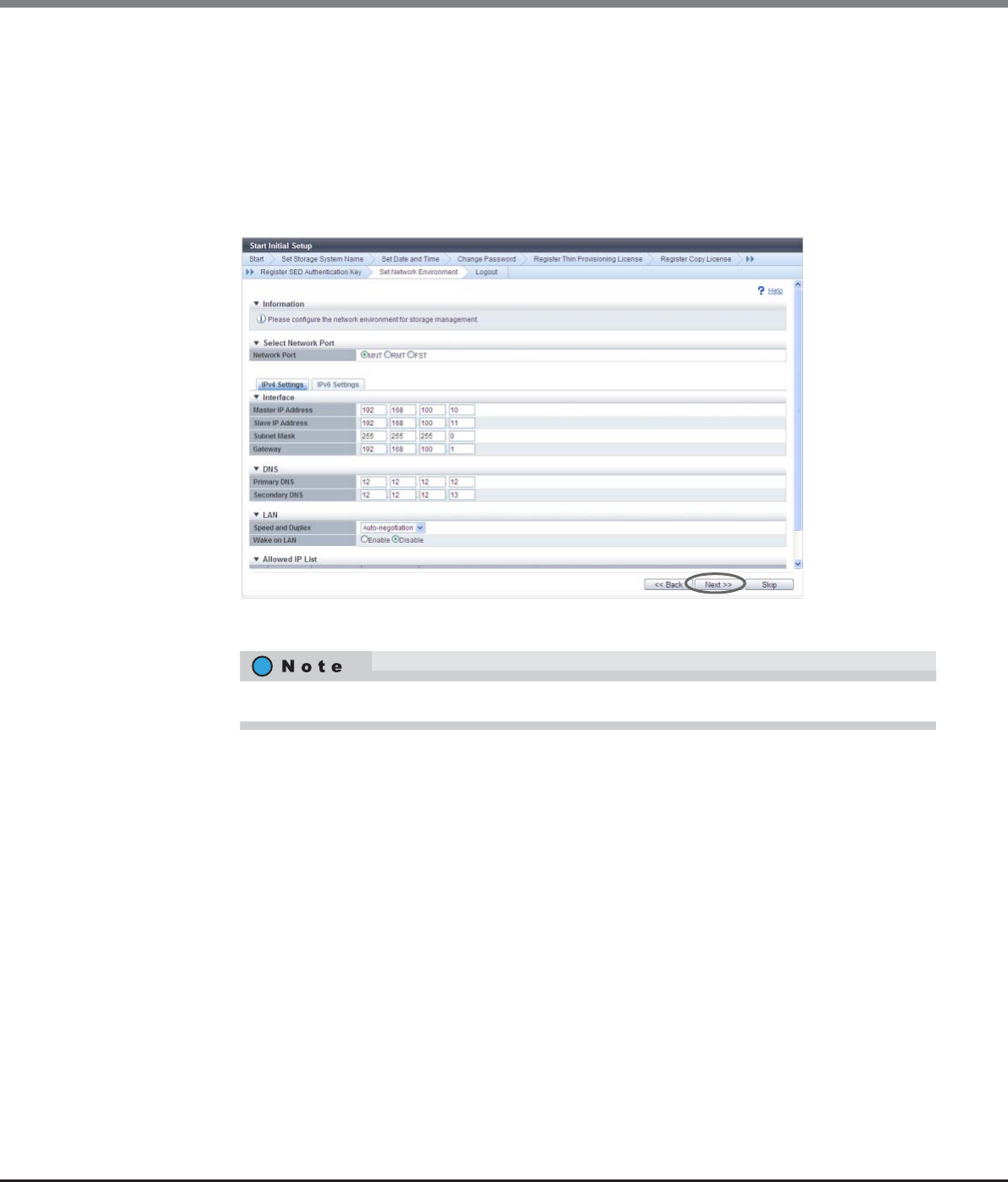
Chapter 3 Initial Setup
3.1 Initial Setup 1
ETERNUS Web GUI User’s Guide
Copyright 2013 FUJITSU LIMITED P2X0-1090-10ENZ0
47
9Proceed to [Set Network Environment].
9-1 Specify the following items, and click the [Next >>] button.
-Select Network Port
-Interface
-DNS
-LAN (only for IPv4)
-Allowed IP List
→A confirmation screen appears.
9-2 Click the [OK] button.
→Setting of the network environment starts.
9-3 Click the [Finish] button.
→A completed screen appears.
Click the [Skip] button to proceed to the next screen without setting.
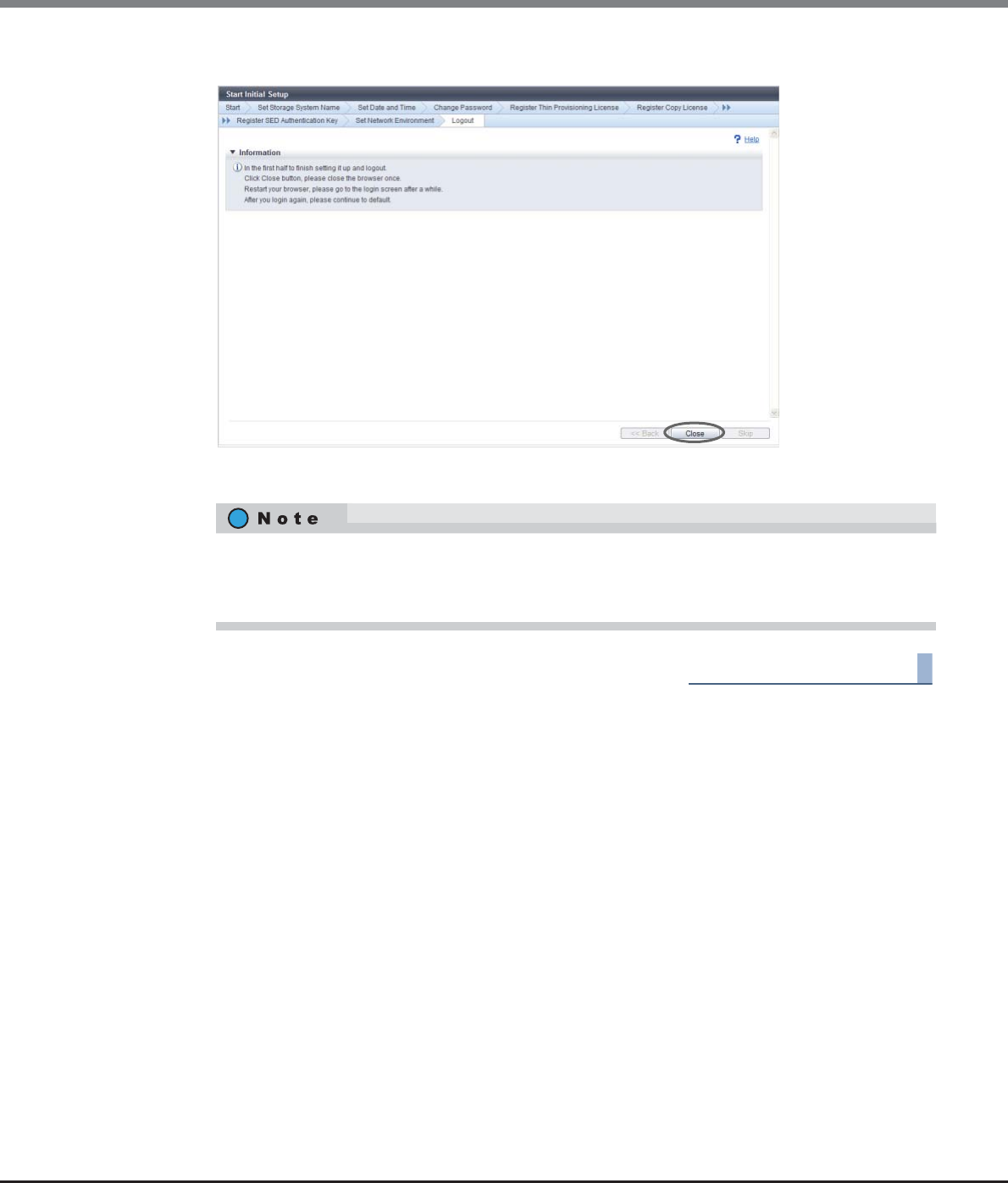
Chapter 3 Initial Setup
3.1 Initial Setup 1
ETERNUS Web GUI User’s Guide
Copyright 2013 FUJITSU LIMITED P2X0-1090-10ENZ0
48
10 Click the [Close] button.
→The browser is closed, and Initial Setup 1 is complete.
End of procedure
•Follow the on-screen instructions to reboot the ETERNUS DX Disk storage system if needed.
•Restart the browser, and wait a few minutes before logging into the GUI again. After logging in
again, continue with the initial setup. Proceed to Initial Setup 2.
Chapter 3 Initial Setup
3.2 Initial Setup 2
ETERNUS Web GUI User’s Guide
Copyright 2013 FUJITSU LIMITED P2X0-1090-10ENZ0
49
3.2 Initial Setup 2
This sets the various reports that are generated when an error occurs in the ETERNUS DX Disk storage system.
If monitoring the ETERNUS DX Disk storage system, use this wizard to build an environment.
The flow of wizard operations in Initial Setup 2 is shown below.
(1)Set SNMP Agent Basic
Set up the SNMP Agent basic interface in the ETERNUS DX Disk storage system. Refer to "11.2.3.3 Setup
SNMP Agent Basic Interface" (page 761) for details.
(2)Set SNMP Manager
Specify the IP address of the SNMP Manager. Refer to "11.2.3.4 Setup SNMP Manager" (page 763) for
details.
(3)Set SNMP Agent MIB Access View
Set the MIB View of the SNMP Agent. Refer to "11.2.3.5 Setup SNMP Agent MIB Access View" (page 766) for
details.
(4)Set SNMP Agent User
Set up the SNMP Agent User.
Set the security levels and the MIB access view for each user. Refer to "11.2.3.6 Setup SNMP Agent User"
(page 768) for details.
(5)Set SNMP Agent Community
Set up the SNMP Agent Community. Refer to "11.2.3.7 Setup SNMP Agent Community" (page 771) for
details.
(6)Set SNMP Agent Trap
Set up the environment to send notification of events that occur in the ETERNUS DX Disk storage system to
the SNMP Manager by an SNMP Trap. Refer to "11.2.3.8 Setup SNMP Agent Trap" (page 774) for details.
(7)Set E-Mail Notification
Set the E-mail notification for events that occur in the ETERNUS DX Disk storage system. Refer to "11.2.3.12
Setup E-Mail Notification" (page 781) for details.
(8)Set Syslog Notification
Set up external servers (Syslog server) for sending logs of events that are detected by the ETERNUS DX Disk
storage system. Refer to "11.2.3.13 Setup Syslog" (page 783) for details.
Some functions do not need to be specified depending on the SNMP version.
This setting is not required when SNMPv1 or SNMPv2c is used for SNMP communication.
This setting is not required when SNMPv3 is used for SNMP communication.
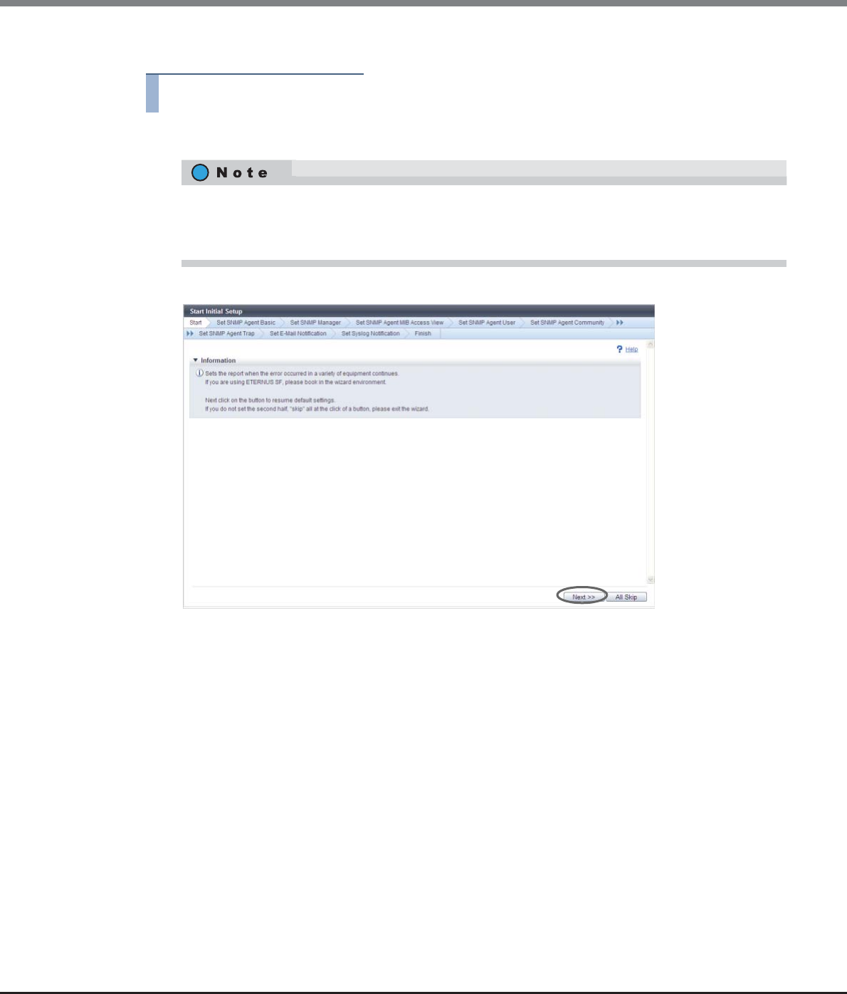
Chapter 3 Initial Setup
3.2 Initial Setup 2
ETERNUS Web GUI User’s Guide
Copyright 2013 FUJITSU LIMITED P2X0-1090-10ENZ0
50
The procedure to perform Initial Setup 2 is as follows:
Procedure
1Click [Start Initial Setup] in [Action].
2Click the [Next >>] button.
→Initial Setup restarts.
•When logging in again after Initial Setup 1 is complete, the [Initial Setup 2] screen appears.
•If all of the settings of Initial Setup 2 are not performed, click the [All Skip] button to exit the Initial
Setup wizard.
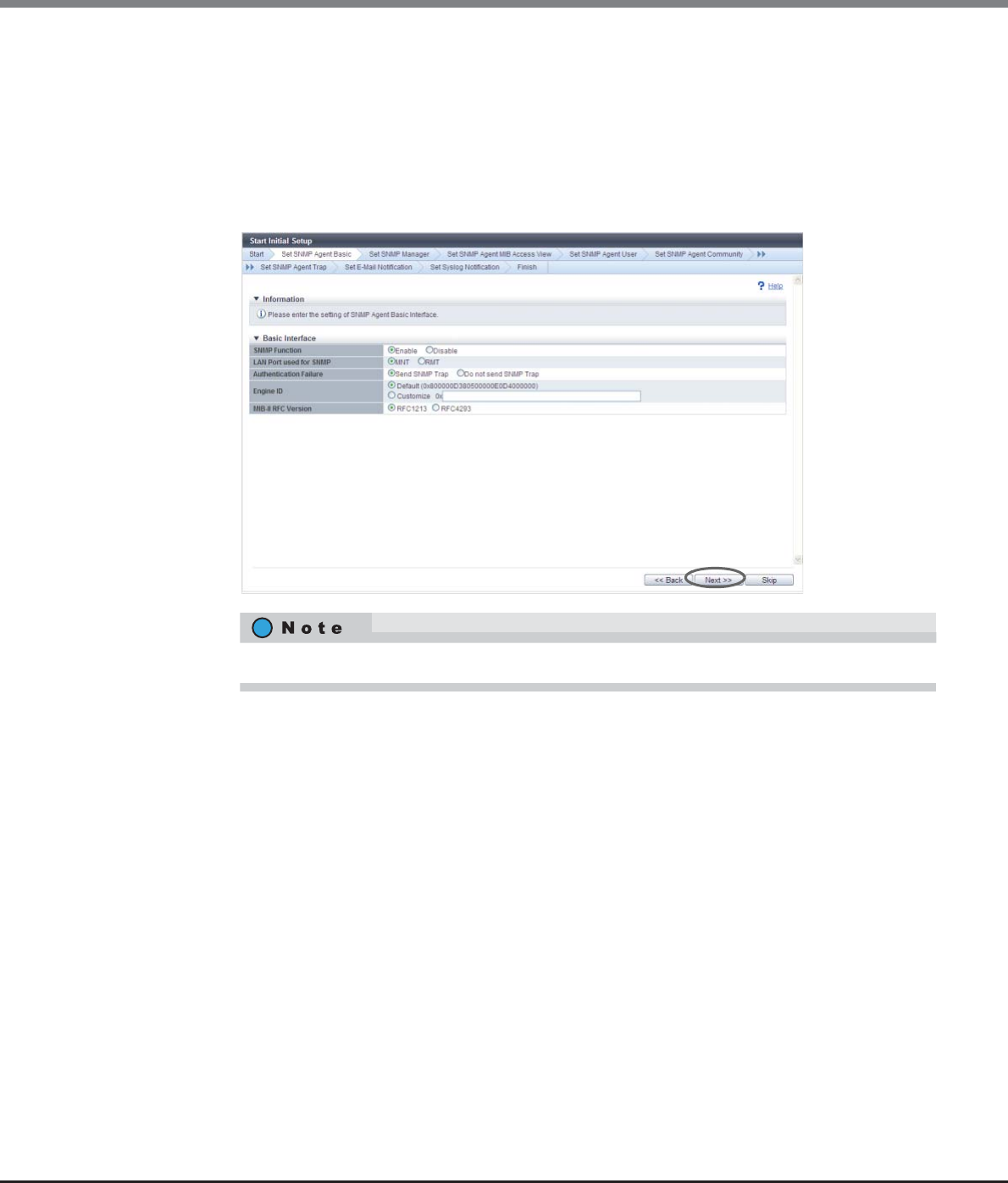
Chapter 3 Initial Setup
3.2 Initial Setup 2
ETERNUS Web GUI User’s Guide
Copyright 2013 FUJITSU LIMITED P2X0-1090-10ENZ0
51
3Proceed to [Set SNMP Agent Basic].
3-1 Specify the following items, and click the [Next >>] button.
-SNMP Function
-LAN Port used for SNMP
-Authentication Failure
-Engine ID
-MIB-II RFC Version
→A confirmation screen appears.
3-2 Click the [OK] button.
→Setting of the SNMP Agent basic starts.
3-3 Click the [Done] button.
Click the [Skip] button to proceed to the next screen without setting.
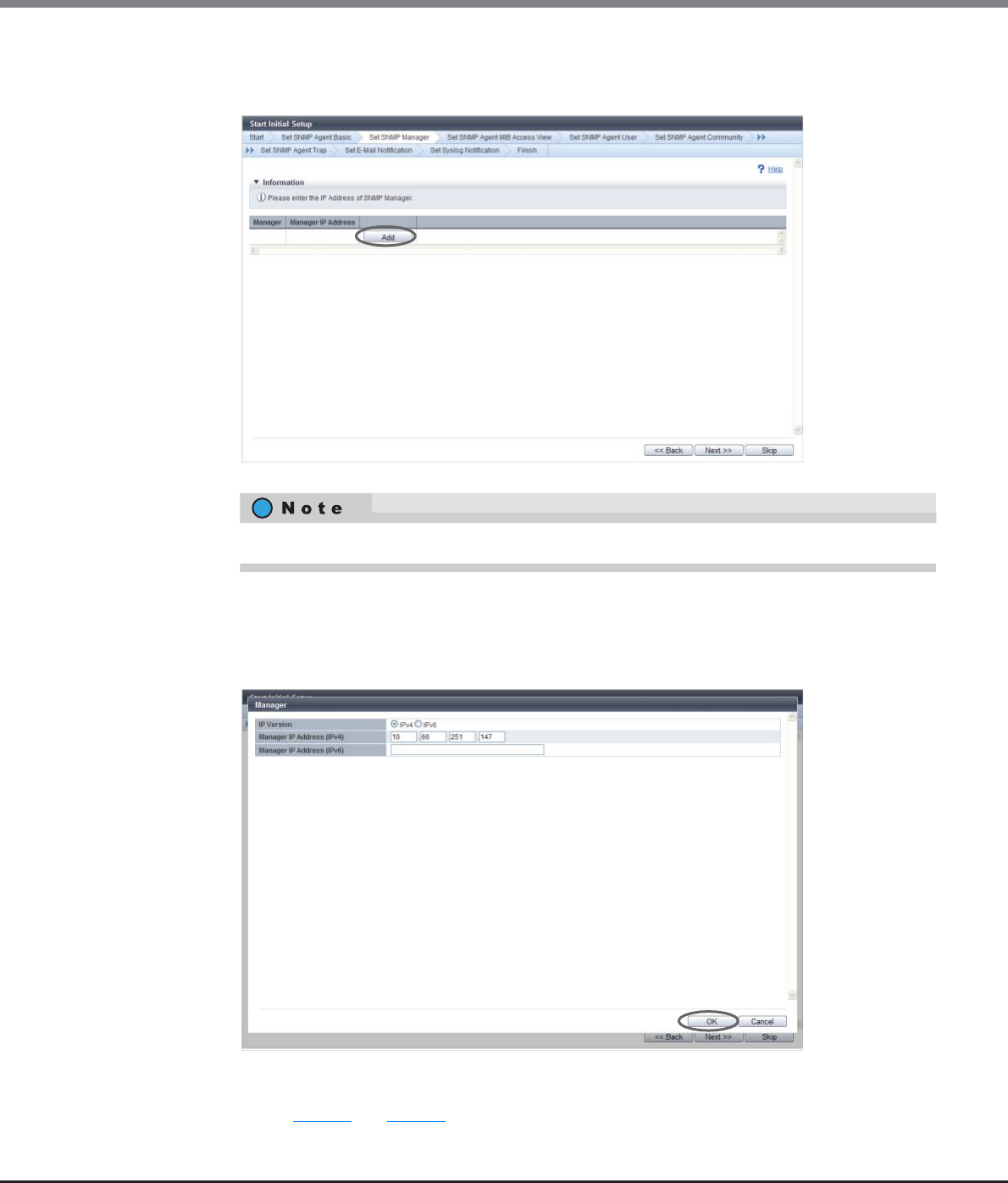
Chapter 3 Initial Setup
3.2 Initial Setup 2
ETERNUS Web GUI User’s Guide
Copyright 2013 FUJITSU LIMITED P2X0-1090-10ENZ0
52
4Proceed to [Set SNMP Manager].
4-1 Click the [Add] button.
4-2 Specify the following items, and click the [OK] button.
-IP Version
-Manager IP Address (IPv4)
-Manager IP Address (IPv6)
→Returns to the original screen.
4-3 Repeat Step 4-1 and Step 4-2 to configure multiple IP addresses.
Click the [Skip] button to proceed to the next screen without setting.
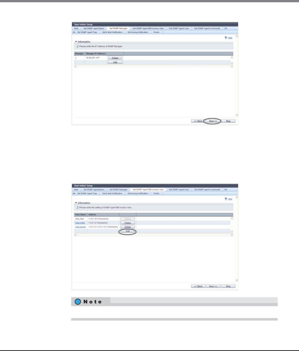
Chapter 3 Initial Setup
3.2 Initial Setup 2
ETERNUS Web GUI User’s Guide
Copyright 2013 FUJITSU LIMITED P2X0-1090-10ENZ0
53
4-4 When the IP addresses are set, click the [Next >>] button.
→A confirmation screen appears.
4-5 Click the [OK] button.
→Setting of the SNMP Manager starts.
4-6 Click the [Done] button.
5Proceed to [Set SNMP Agent MIB Access View].
5-1 Click the [Add] button.
Click the [Skip] button to proceed to the next screen without setting.
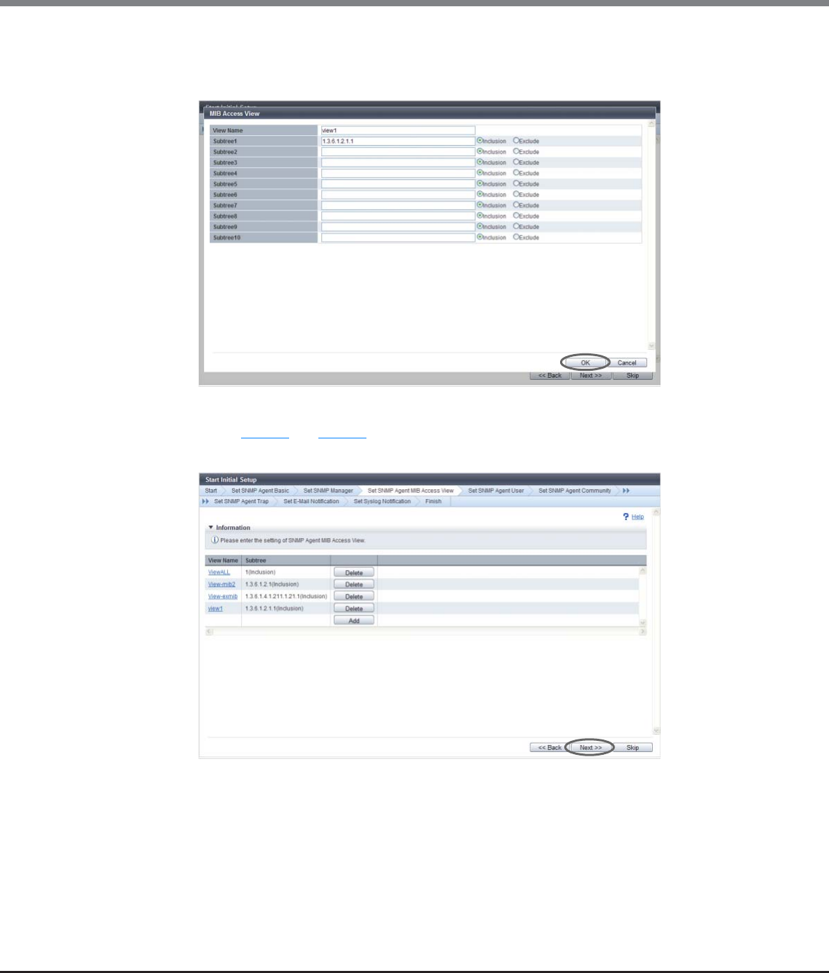
Chapter 3 Initial Setup
3.2 Initial Setup 2
ETERNUS Web GUI User’s Guide
Copyright 2013 FUJITSU LIMITED P2X0-1090-10ENZ0
54
5-2 Specify the following items, and click the [OK] button.
-View Name
-Subtree
→Returns to the original screen.
5-3 Repeat Step 5-1 and Step 5-2 to configure multiple MIB Access Views.
5-4 When the setting of the MIB Access Views is complete, click the [Next >>] button.
→A confirmation screen appears.
5-5 Click the [OK] button.
→Setting of the SNMP Agent MIB Access View starts.
5-6 Click the [Done] button.
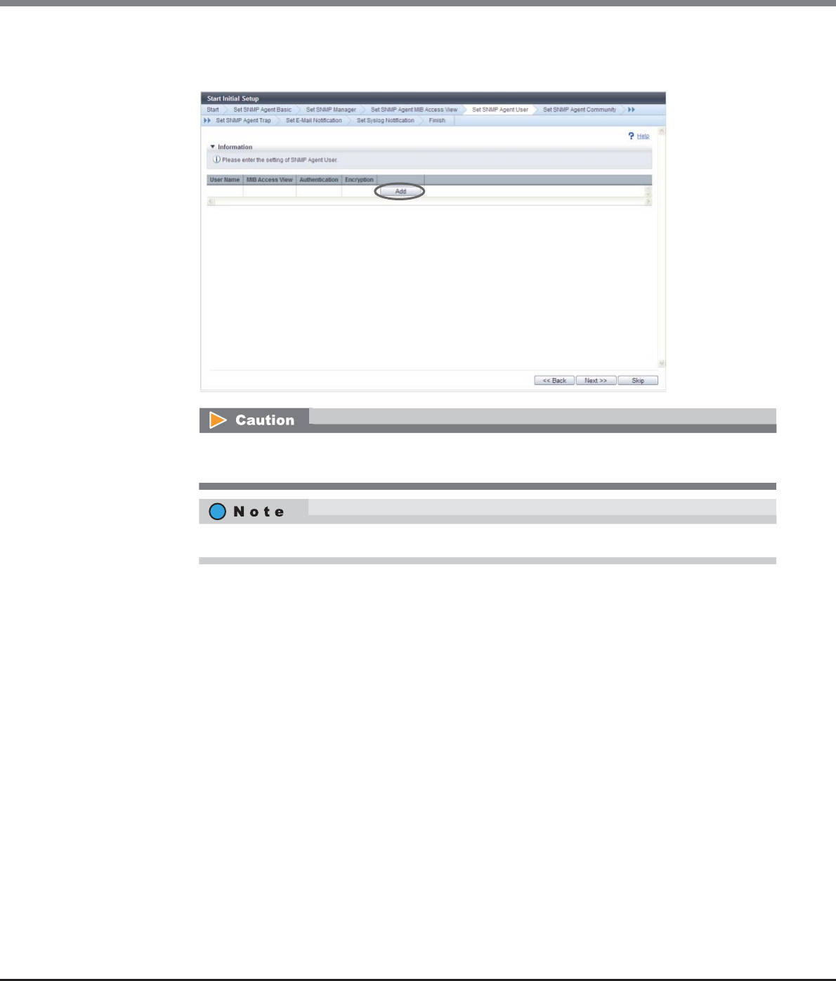
Chapter 3 Initial Setup
3.2 Initial Setup 2
ETERNUS Web GUI User’s Guide
Copyright 2013 FUJITSU LIMITED P2X0-1090-10ENZ0
55
6Proceed to [Set SNMP Agent User].
6-1 Click the [Add] button.
The [Set SNMP Agent User] function must be set when using SNMPv3 in SNMP communication
between the SNMP Agent and SNMP Manager.
Click the [Skip] button to proceed to the next screen without setting.
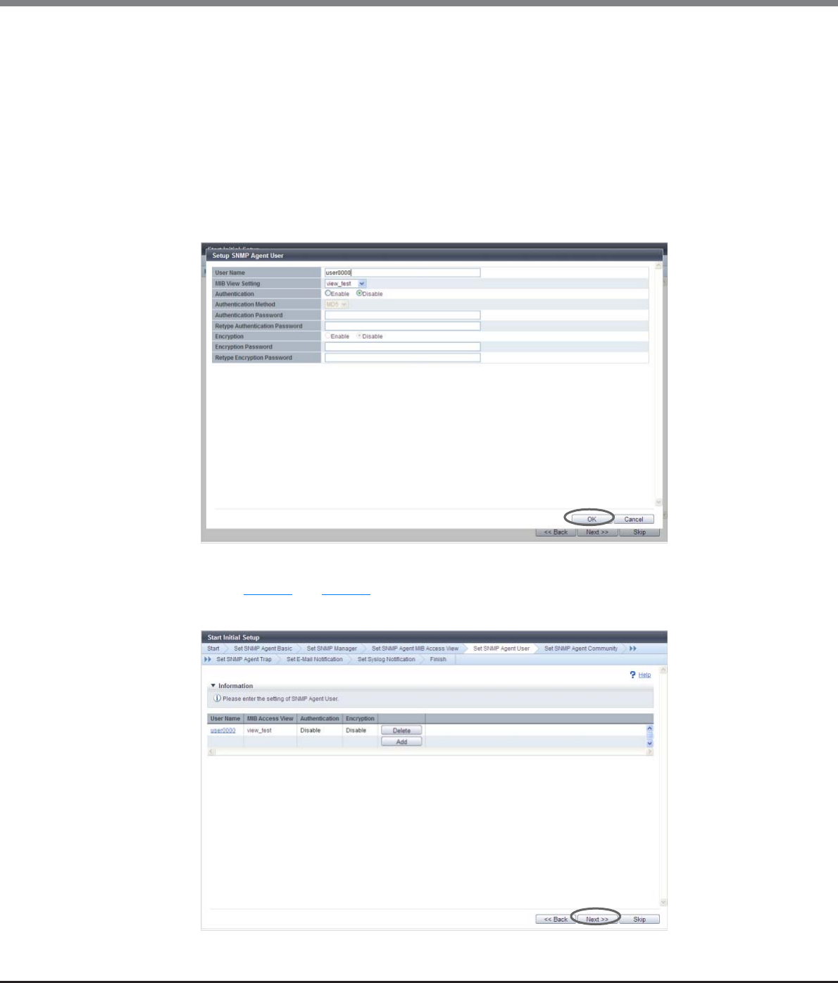
Chapter 3 Initial Setup
3.2 Initial Setup 2
ETERNUS Web GUI User’s Guide
Copyright 2013 FUJITSU LIMITED P2X0-1090-10ENZ0
56
6-2 Specify the following items, and click the [OK] button.
-User Name
-MIB View Setting
-Authentication
-Authentication Method
-Authentication Password
-Retype Authentication Password
-Encryption
-Encryption Password
-Retype Encryption Password
→Returns to the original screen.
6-3 Repeat Step 6-1 and Step 6-2 to configure information for multiple users.
6-4 When the setting of the user information is complete, click the [Next >>] button.
→A confirmation screen appears.
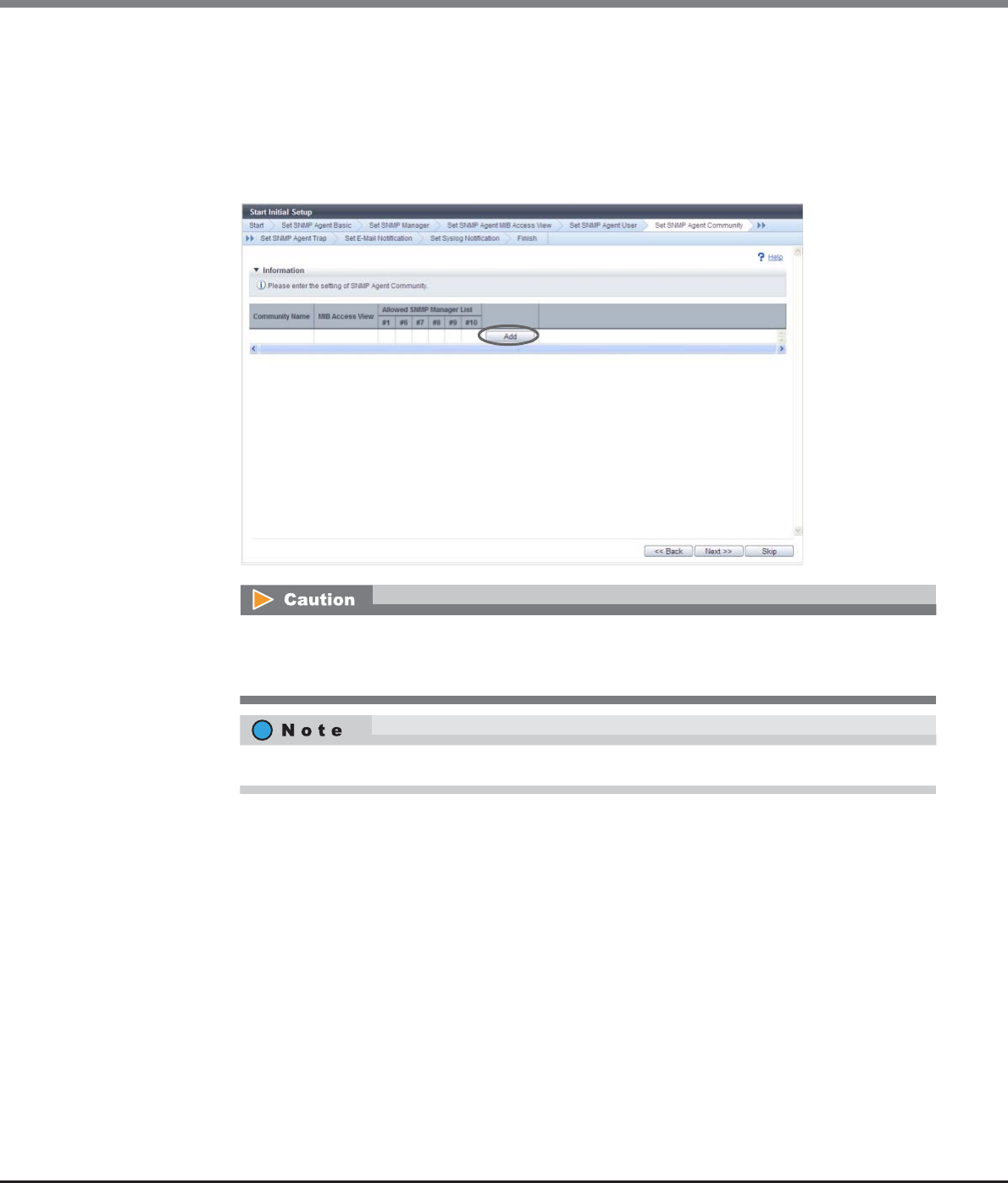
Chapter 3 Initial Setup
3.2 Initial Setup 2
ETERNUS Web GUI User’s Guide
Copyright 2013 FUJITSU LIMITED P2X0-1090-10ENZ0
57
6-5 Click the [OK] button.
→Setting of the SNMP Agent User starts.
6-6 Click the [Done] button.
7Proceed to [Set SNMP Agent Community].
7-1 Click the [Add] button.
The [Set SNMP Agent Community] function must be set when using SNMPv1 or SNMPv2c in SNMP
communication between the SNMP Agent and SNMP Manager. The SNMP Agent Community
setting is not necessary when using SNMPv3 only.
Click the [Skip] button to proceed to the next screen without setting.
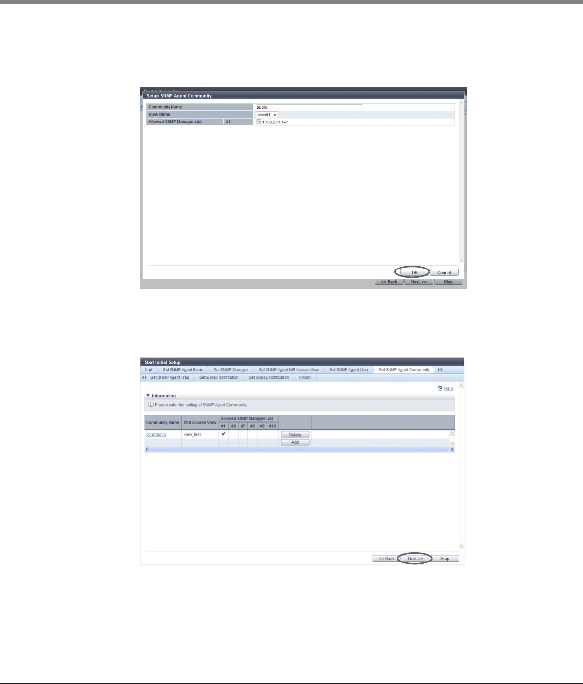
Chapter 3 Initial Setup
3.2 Initial Setup 2
ETERNUS Web GUI User’s Guide
Copyright 2013 FUJITSU LIMITED P2X0-1090-10ENZ0
58
7-2 Specify the following items, and click the [OK] button.
-Community Name
-View Name
-Allowed SNMP Manager List
→Returns to the original screen.
7-3 Repeat Step 7-1 and Step 7-2 to configure multiple communities.
7-4 When the setting of the community is complete, click the [Next >>] button.
→A confirmation screen appears.
7-5 Click the [OK] button.
→Setting of the SNMP Agent Community starts.
7-6 Click the [Done] button.
8Proceed to [Set SNMP Agent Trap].
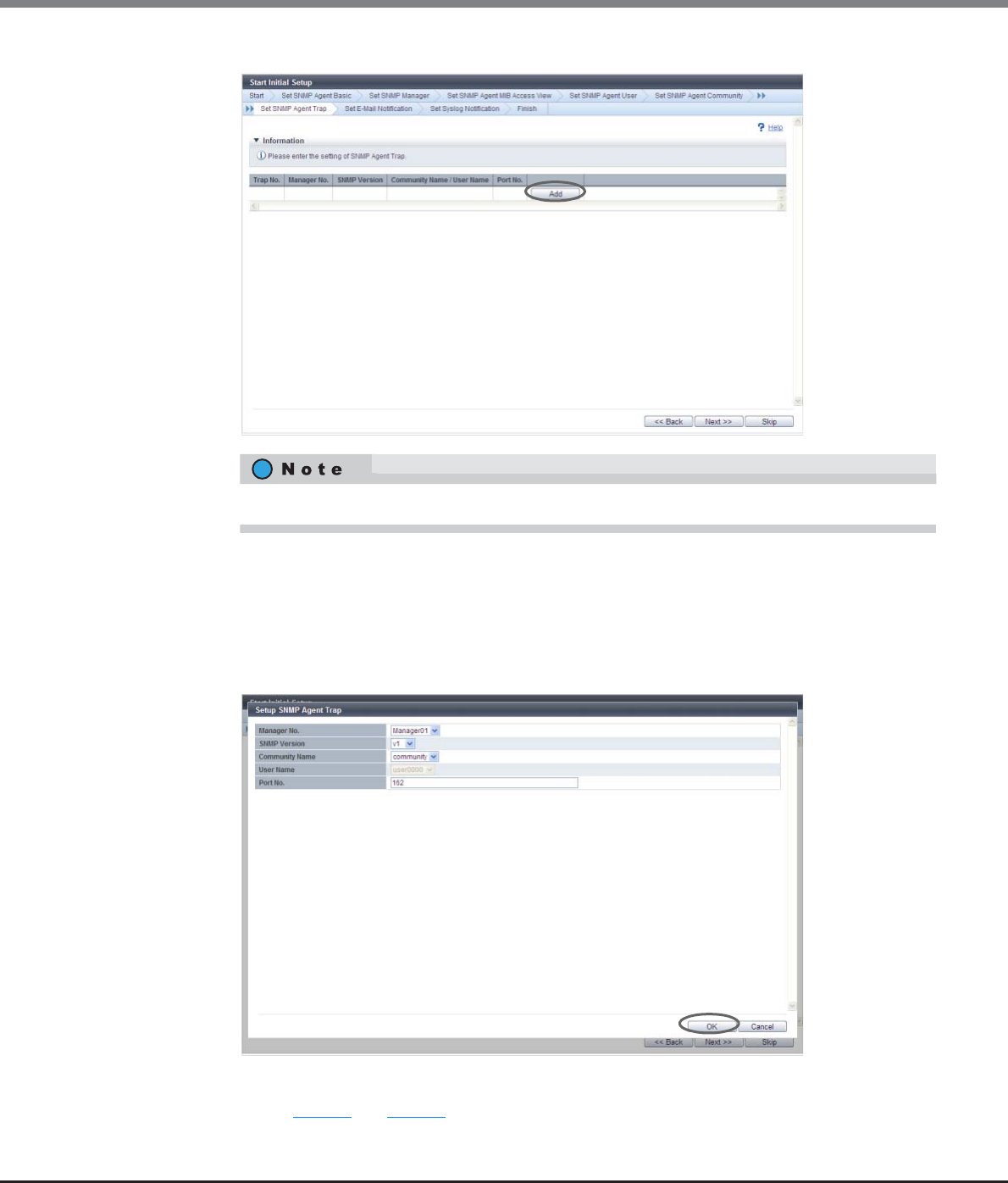
Chapter 3 Initial Setup
3.2 Initial Setup 2
ETERNUS Web GUI User’s Guide
Copyright 2013 FUJITSU LIMITED P2X0-1090-10ENZ0
59
8-1 Click the [Add] button.
8-2 Specify the following items, and click the [OK] button.
-Manager No.
-SNMP Version
-Community Name
-User Name
-Port No.
→Returns to the original screen.
8-3 Repeat Step 8-1 and Step 8-2 to configure information for multiple traps.
Click the [Skip] button to proceed to the next screen without setting.
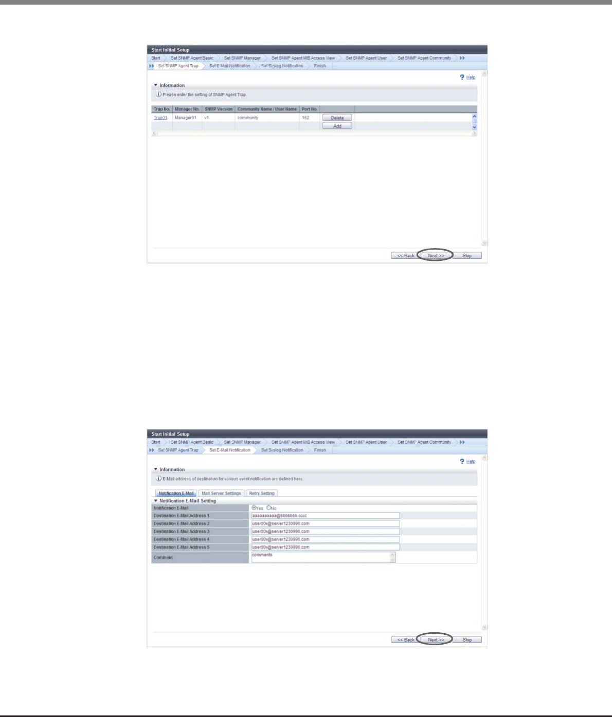
Chapter 3 Initial Setup
3.2 Initial Setup 2
ETERNUS Web GUI User’s Guide
Copyright 2013 FUJITSU LIMITED P2X0-1090-10ENZ0
60
8-4 When the setting of the trap information is complete, click the [Next >>] button.
→A confirmation screen appears.
8-5 Click the [OK] button.
→Setting of the SNMP Agent Trap starts.
8-6 Click the [Done] button.
9Proceed to [Set E-Mail Notification].
9-1 Specify the following items, and click the [Next >>] button.
-Notification E-Mail
-Mail Server Settings
-Retry Setting
→A confirmation screen appears.
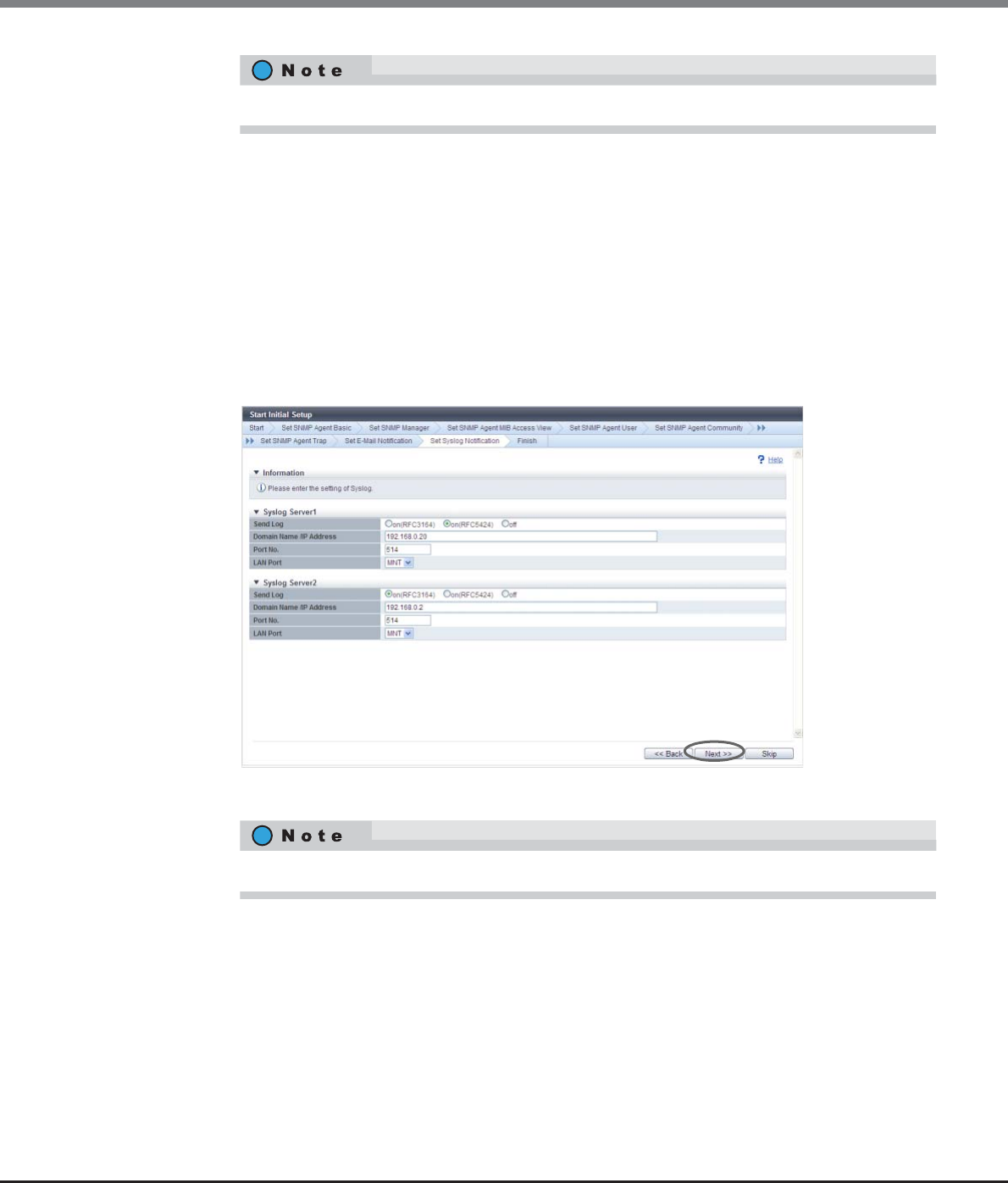
Chapter 3 Initial Setup
3.2 Initial Setup 2
ETERNUS Web GUI User’s Guide
Copyright 2013 FUJITSU LIMITED P2X0-1090-10ENZ0
61
9-2 Click the [OK] button.
→Setting of the E-Mail Notification starts.
9-3 Click the [Done] button.
10 Proceed to [Set Syslog Notification].
10-1 Specify the following items, and click the [Next >>] button.
-Send Log
-Domain Name / IP Address
-Port No.
-LAN Port
→A confirmation screen appears.
10-2 Click the [OK] button.
→Setting of the Syslog starts.
10-3 Click the [Done] button.
→A completed screen appears.
Click the [Skip] button to proceed to the next screen without setting.
Click the [Skip] button to proceed to the next screen without setting.
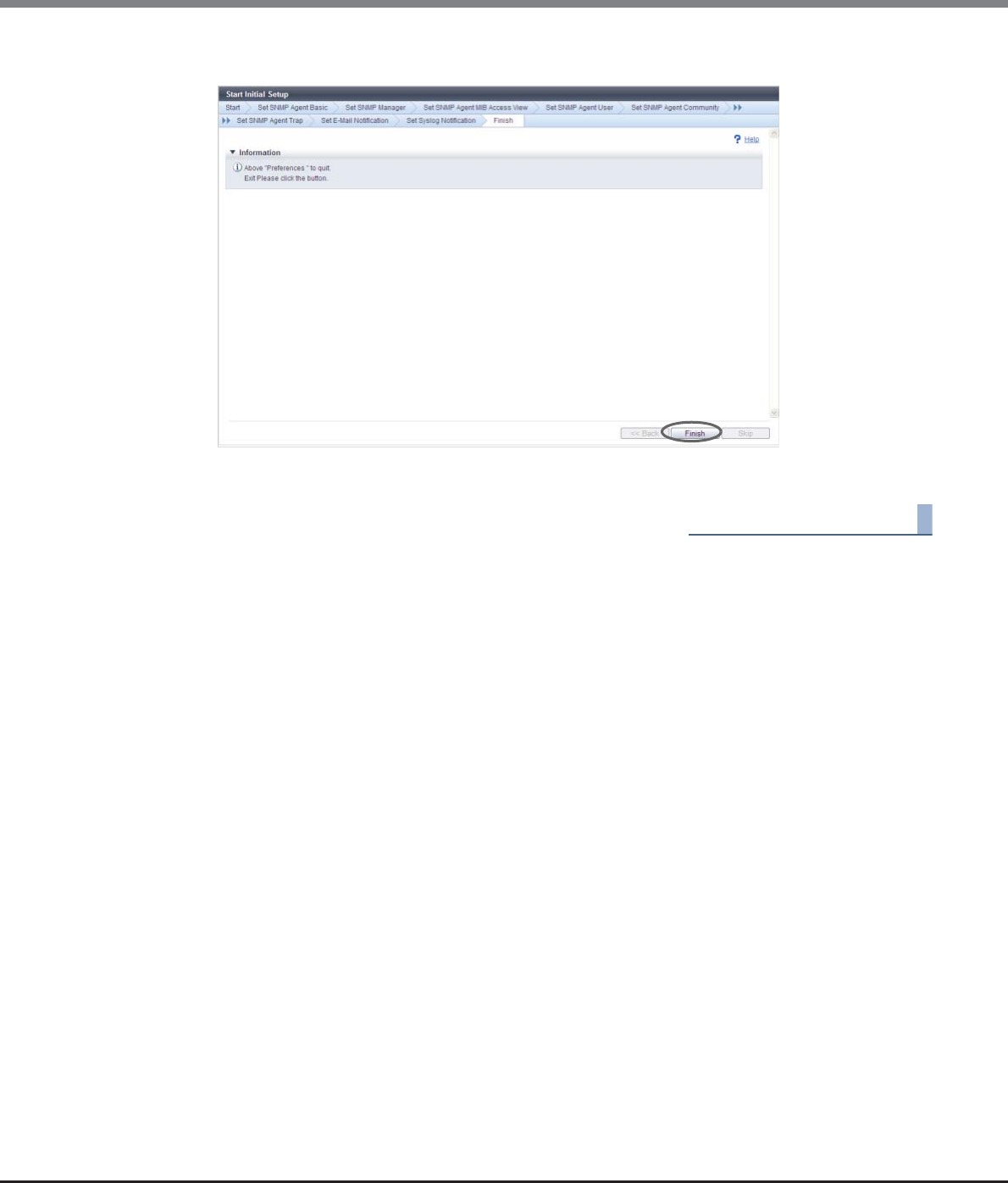
Chapter 3 Initial Setup
3.2 Initial Setup 2
ETERNUS Web GUI User’s Guide
Copyright 2013 FUJITSU LIMITED P2X0-1090-10ENZ0
62
11 Click the [Finish] button.
→Initial Setup 2 is complete, and the [Overview] screen appears.
End of procedure

ETERNUS Web GUI User’s Guide
Copyright 2013 FUJITSU LIMITED P2X0-1090-10ENZ0
63
Chapter 4
Configuration Settings
This chapter describes the following configuration settings:
•Configuration settings for using Standard volumes (when using host affinity settings)
•Configuration settings for using Standard volumes (when using host affinity settings, previously referred to
as LUN mapping)
•Configuration settings for using Thin Provisioning functions
4.1 Configuration Settings for Using Standard Volumes (When
Using Host Affinity Settings)
There are two methods to set the host affinity; one method creates a host group and sets the host affinity (by
using the [Add Host Group] function). The other method sets the host affinity without creating a host group
(by using the [Add Host] function). Use the procedure that does not create a host group only if the previous
procedure for registering hosts in older storage systems (such as the ETERNUS DX410/DX440 or the ETERNUS
DX8100/DX8400/DX8700) is used.
4.1.1 When Creating Host Groups (when Using the [Add Host Group] Function)
The following section describes the series of settings when creating host groups and using Standard volumes.
Not only can new RAID groups be created, adding or changing volumes that are registered in existing RAID
groups can also be performed.
Create RAID Group
Create a RAID group (a group of drives that configures the RAID in the ETERNUS DX Disk
storage system).
Refer to:
-Create RAID Group
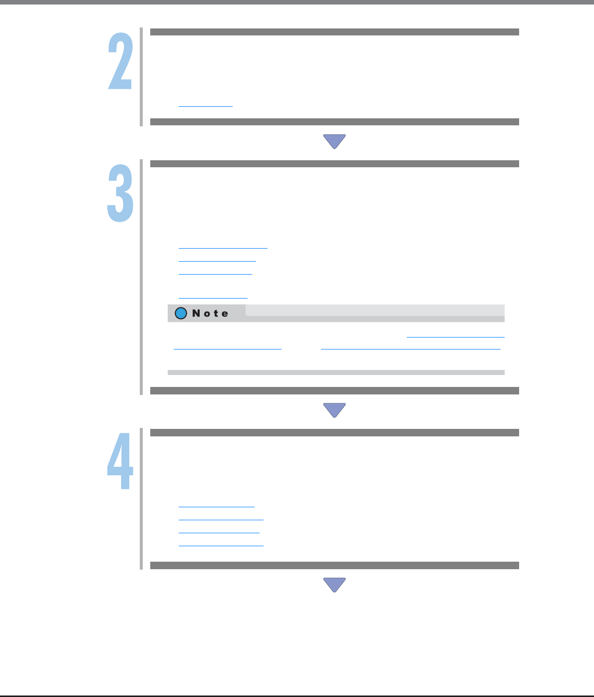
Chapter 4 Configuration Settings
4.1 Configuration Settings for Using Standard Volumes (When Using Host Affinity Settings)
ETERNUS Web GUI User’s Guide
Copyright 2013 FUJITSU LIMITED P2X0-1090-10ENZ0
64
Create Volume
Create a volume (drive area in the RAID group). A volume is a structural unit of RAID that can be
recognized from the server. Select "Standard" for "Type".
Refer to:
-Create Volume
Add Host Group
Add the information of any server that accesses the ETERNUS DX Disk storage system via the
ports. When adding a server, create a host group (a host (HBA) group that accesses the same
LUN group). Assign a host response when creating a host group.
When creating new host groups, refer to:
-Add FC/FCoE Host Group
-Add iSCSI Host Group
-Add SAS Host Group
When adding hosts to existing host groups, refer to:
-Modify Host Group
Create CA Port Group
Create a CA port group (a group of CA ports that are connected to the specified host group) that
is used for the server to access the ETERNUS DX Disk storage system.
Refer to:
-Create FC Port Group
-Create iSCSI Port Group
-Create SAS Port Group
-Create FCoE Port Group
The concept of host connection settings are described in "Chapter 9 Connectivity
Management" (page 367). Refer to "Structures for Host Connection" (page 368)
for details.

Chapter 4 Configuration Settings
4.1 Configuration Settings for Using Standard Volumes (When Using Host Affinity Settings)
ETERNUS Web GUI User’s Guide
Copyright 2013 FUJITSU LIMITED P2X0-1090-10ENZ0
65
Add LUN Group
Create a LUN group (a group of volumes that are recognized from the server, which is
conventionally referred to as an "affinity group").
Correspond the volume number to the Logical Unit Number (LUN) that can be recognized by the
host for each LUN group.
LUN groups are recognized from the server by the host affinity setting that allocates the CA port
groups and the LUN groups to the host group.
Refer to:
-Add LUN Group
Create Host Affinity
To recognize the LUN group from the server, allocate the host groups with the CA port groups
and the LUN groups.
Refer to:
-Create Host Affinity
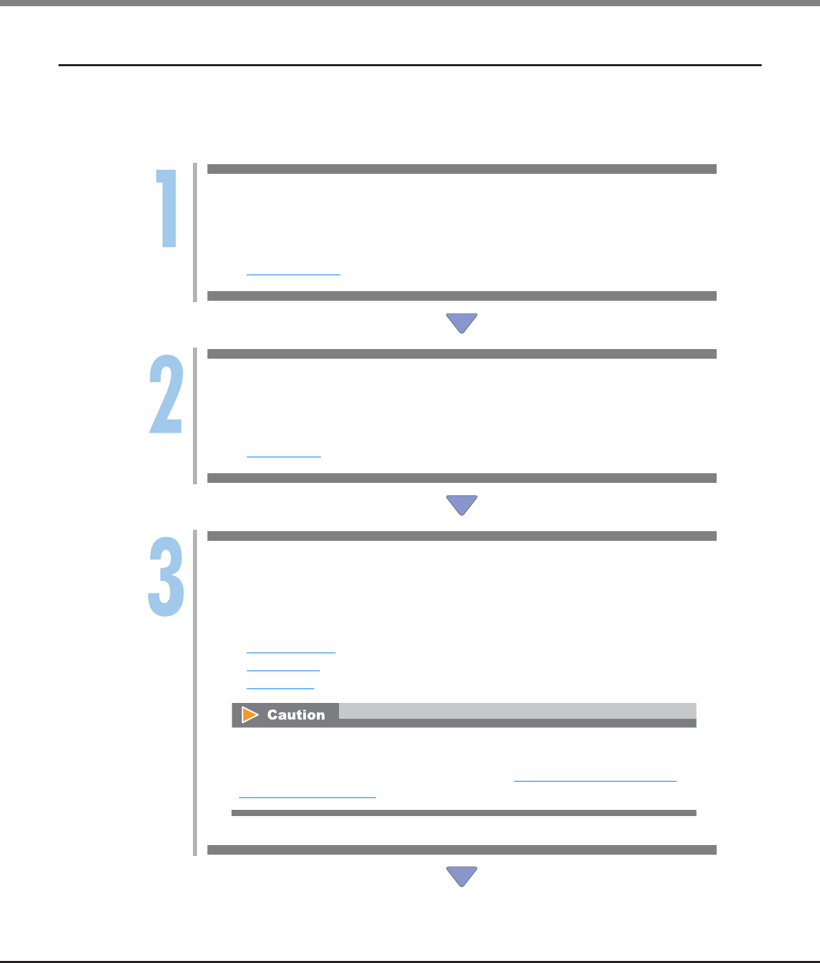
Chapter 4 Configuration Settings
4.1 Configuration Settings for Using Standard Volumes (When Using Host Affinity Settings)
ETERNUS Web GUI User’s Guide
Copyright 2013 FUJITSU LIMITED P2X0-1090-10ENZ0
66
4.1.2 When Host Groups are not Created (when Using the [Add Host] Function)
The following section describes the series of settings when using Standard volumes without creating host
groups.
Not only can new RAID groups be created, adding or changing volumes that are registered in existing RAID
groups can also be performed.
Create RAID Group
Create a RAID group (a group of drives that configures the RAID in the ETERNUS DX Disk
storage system).
Refer to:
-Create RAID Group
Create Volume
Create a volume (drive area in the RAID group). A volume is a structural unit of RAID that can be
recognized from the server. Select "Standard" for "Type".
Refer to:
-Create Volume
Add Host
Add the information of any server that accesses the ETERNUS DX Disk storage system via the
ports. When adding a server, register a new host. Assign a host response when registering a
host.
Refer to:
-Add FC/FCoE Host
-Add iSCSI Host
-Add SAS Host
The "Add Host" functions are only displayed when the "Use "Add Host"" checkbox
is selected for the "Function to Add Host" field in "Web GUI Settings". This item is
not selected (not displayed) by default. Refer to "11.2.13.4 Setup Subsystem
Parameters" (page 935) for details.

Chapter 4 Configuration Settings
4.1 Configuration Settings for Using Standard Volumes (When Using Host Affinity Settings)
ETERNUS Web GUI User’s Guide
Copyright 2013 FUJITSU LIMITED P2X0-1090-10ENZ0
67
Add LUN Group
Create a LUN group (a group of volumes that are recognized from the server, which is
conventionally referred to as an "affinity group").
Correspond the volume number to the Logical Unit Number (LUN) that can be recognized by the
host for each LUN group.
LUN groups are recognized from the server by the host affinity setting that allocates the CA
ports and the LUN groups to the host.
Refer to:
-Add LUN Group
Create Host Affinity
To recognize the LUN group from the server, allocate the host with the CA ports and LUN groups.
Refer to:
-Create Host Affinity

Chapter 4 Configuration Settings
4.2 Configuration Settings for Using Standard Volumes (When Using Host Affinity Settings, Previously Referred to as LUN Mapping)
ETERNUS Web GUI User’s Guide
Copyright 2013 FUJITSU LIMITED P2X0-1090-10ENZ0
68
4.2 Configuration Settings for Using Standard Volumes (When
Using Host Affinity Settings, Previously Referred to as LUN
Mapping)
LUNs can be allocated to either CA port groups or CA ports.
4.2.1 When Allocating the CA port Group to the LUN Group
The following section describes the series of settings when creating CA port groups and using Standard
volumes.
Not only can new RAID groups be created, adding or changing volumes that are registered in existing RAID
groups can also be performed.
Create RAID Group
Create a RAID group (a group of drives that configures the RAID in the ETERNUS DX Disk
storage system).
Refer to:
-Create RAID Group
Create Volume
Create a volume (drive area in the RAID group). A volume is a structural unit of RAID that can be
recognized from the server. Select "Standard" for "Type".
Refer to:
-Create Volume
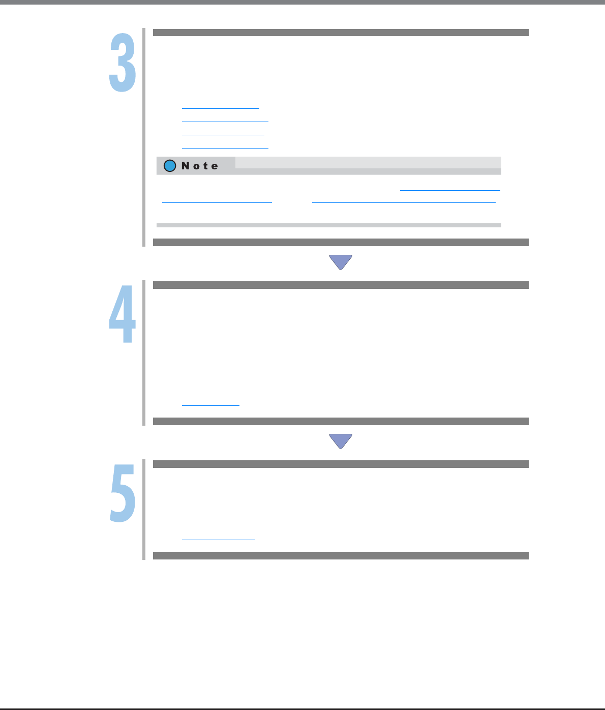
Chapter 4 Configuration Settings
4.2 Configuration Settings for Using Standard Volumes (When Using Host Affinity Settings, Previously Referred to as LUN Mapping)
ETERNUS Web GUI User’s Guide
Copyright 2013 FUJITSU LIMITED P2X0-1090-10ENZ0
69
Create CA Port Group
Create a CA port group (a group of CA ports that are connected to the specified host group) that
is used for the server to access the ETERNUS DX Disk storage system.
Refer to:
-Create FC Port Group
-Create iSCSI Port Group
-Create SAS Port Group
-Create FCoE Port Group
Add LUN Group
Create a LUN group (a group of volumes that are recognized from the server, which is
conventionally referred to as an "affinity group").
Correspond the volume number to the Logical Unit Number (LUN) that can be recognized by the
host for each LUN group.
LUN groups are recognized from the server by the host affinity setting that allocates the CA port
groups to the LUN groups.
Refer to:
-Add LUN Group
Create Host Affinity
To recognize the LUN group from the server, select "All" for the host group and allocate the CA
port group and the LUN group.
Refer to:
-Create Host Affinity
The concept of host connection settings are described in "Chapter 9 Connectivity
Management" (page 367). Refer to "Structures for Host Connection" (page 368)
for details.

Chapter 4 Configuration Settings
4.2 Configuration Settings for Using Standard Volumes (When Using Host Affinity Settings, Previously Referred to as LUN Mapping)
ETERNUS Web GUI User’s Guide
Copyright 2013 FUJITSU LIMITED P2X0-1090-10ENZ0
70
4.2.2 When Allocating the CA port to the LUN Group
The following section describes the series of settings when using Standard volumes without creating CA port
groups.
Not only can new RAID groups be created, adding or changing volumes that are registered in existing RAID
groups can also be performed.
Create RAID Group
Create a RAID group (a group of drives that configures the RAID in the ETERNUS DX Disk
storage system).
Refer to:
-Create RAID Group
Create Volume
Create a volume (drive area in the RAID group). A volume is a structural unit of RAID that can be
recognized from the server. Select "Standard" for "Type".
Refer to:
-Create Volume
Add LUN Group
Create a LUN group (a group of volumes that are recognized from the server, which is
conventionally referred to as an "affinity group").
Correspond the volume number to the Logical Unit Number (LUN) that can be recognized by the
host for each LUN group.
LUN groups are recognized from the server by the host affinity setting that allocates the CA
ports to the LUN groups.
Refer to:
-Add LUN Group
Create Host Affinity
To recognize the LUN group from the server, select "All" for the host and allocate the CA port
and the LUN group.
Refer to:
-Create Host Affinity

Chapter 4 Configuration Settings
4.3 Configuration Settings for Using Thin Provisioning Functions
ETERNUS Web GUI User’s Guide
Copyright 2013 FUJITSU LIMITED P2X0-1090-10ENZ0
71
4.3 Configuration Settings for Using Thin Provisioning Functions
The following section shows the series of settings that need to be performed to use Thin Provisioning
functions.
Not only can new Thin Provisioning Pool be created, adding or changing volumes that are registered in the
existing Thin Provisioning Pools can also be performed.
Register Thin Provisioning License
Register the license to use the Thin Provisioning function.
Refer to:
-Register Thin Provisioning License
Create Thin Provisioning Pool
Create a Thin Provisioning Pool (groups of drives (which are configured in RAID groups) that
configure a Thin Provisioning Pool).
Refer to:
-Create Thin Provisioning Pool
Create Volume
Create a volume (physical drive area in the Thin Provisioning Pool). A volume is a structural unit
of a Thin Provisioning Pool that can be recognized from the server. Select "Thin Provisioning" for
"Type".
Refer to:
-Create Volume
Add Host
Recognize the volume from the server.
Refer to:
Refer to Step 3 onward in one of the following sections:
-"4.1 Configuration Settings for Using Standard Volumes (When Using Host Affinity Settings)"
(page 63)
-"4.2 Configuration Settings for Using Standard Volumes (When Using Host Affinity Settings,
Previously Referred to as LUN Mapping)" (page 68)

Chapter 4 Configuration Settings
4.3 Configuration Settings for Using Thin Provisioning Functions
ETERNUS Web GUI User’s Guide
Copyright 2013 FUJITSU LIMITED P2X0-1090-10ENZ0
72
When using Thin Provisioning functions, monitoring of Thin Provisioning Pool usage is important. Make sure
that the Thin Provisioning Pool usage does not exceed the threshold. Refer to "7.1.1 Thin Provisioning Pool
(Basic Information)" (page 200) for details.
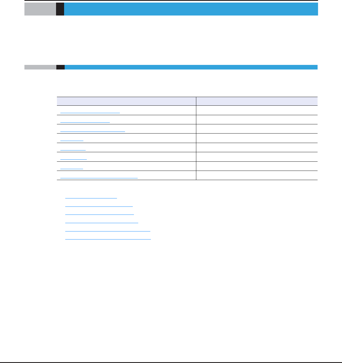
ETERNUS Web GUI User’s Guide
Copyright 2013 FUJITSU LIMITED P2X0-1090-10ENZ0
73
Chapter 5
Volume Management
This chapter describes volume management.
5.1 Volume Status
Volume status displays the status information of volumes.
Volume status screens can be displayed by clicking the following categories:
Detailed information of the volumes can be displayed from the following screens:
•Volume Detail (Basic)
•Volume Detail (Reservation)
•Volume Detail (Pinned Data)
•Volume Detail (Balancing TPV)
•Volume Detail (LUN Concatenation)
•Volume Detail (WSV Concatenation)
Volume status screen Category
Volume (Basic Information) Volume
Performance (Host I/O) Performance (Host I/O)
Performance (Advanced Copy) Performance (Advanced Copy)
LUN Group LUN Group
Reservation Reservation
Pinned Data Pinned Data
Bad Sector Bad Sector
Balancing Thin Provisioning Volume Balancing Thin Provisioning Volume
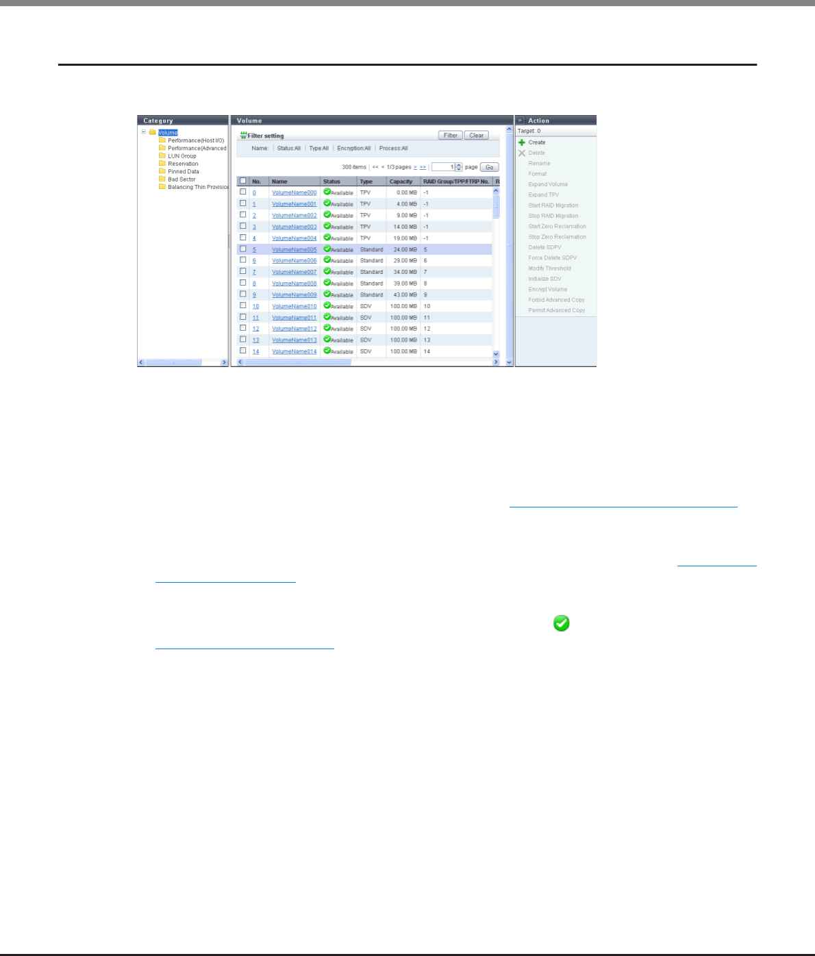
Chapter 5 Volume Management
5.1 Volume Status
ETERNUS Web GUI User’s Guide
Copyright 2013 FUJITSU LIMITED P2X0-1090-10ENZ0
74
5.1.1 Volume (Basic Information)
This function displays the basic information of volumes.
The following items are displayed in the Main area:
•No.
The volume number is displayed.
During volume creation, the volume number can be allocated automatically or specified manually. When
the volume number is allocated automatically, the volume number is allocated from the smallest unused
decimal number in ascending order.
Click this item to display the [Volume Detail] screen. Refer to "5.1.9 Volume Detail (Basic)" (page 88) for
display items.
•Name
The volume name is displayed. Click this item to display the [Volume Detail] screen. Refer to "5.1.9 Volume
Detail (Basic)" (page 88) for display items.
•Status
The volume status is displayed. When the volume status is normal, " Available" is displayed. Refer to
"B.2 Volume Status" (page 974) for detailed information of volume status.
•Type
The volume type is displayed.
-Standard
Standard volume or volume that is used for general operations
-WSV
Wide Striping Volume that is configured by multiple RAID groups that are concatenated with striping to
improve performance
-TPV
Thin Provisioning Volume
-FTV
Flexible Tier Volume
-SDV
Snap Data Volume
-SDPV
Snap Data Pool Volume

Chapter 5 Volume Management
5.1 Volume Status
ETERNUS Web GUI User’s Guide
Copyright 2013 FUJITSU LIMITED P2X0-1090-10ENZ0
75
-Temporary
A migration source volume that failed to delete after RAID migration is complete, a work volume that
failed to delete after TPV balancing is complete, or a work volume that failed to delete after FTRP bal-
ancing is complete.
•Capacity
The volume capacity is displayed.
The capacity is displayed in units of "MB", "GB", or "TB". Even when volumes are created in units of "MB", if
the volume capacity exceeds 1023.99MB, the capacity is displayed in units of "GB". If the volume capacity
exceeds 1023.99GB, the capacity is displayed in units of "TB". The capacity is rounded off to two decimal
places. To check the volume capacity in units of "MB", use CLI.
•RAID Group/TPP/FRTP No.
The following number is displayed:
-If the type is "WSV"
The RAID group number to which the representative volume (*1) belongs is displayed.
*1: A volume for WSV, which is created by concatenating multiple RAID groups with striping, that belongs to the
RAID group that is first in the concatenation order.
-If the type is "TPV"
The Thin Provisioning Pool (TPP) number to which the volume belongs is displayed.
-If the type is "FTV"
The Flexible Tier Pool (FTRP) number to which the volume belongs is displayed.
-If the type is not one of the types listed above
The RAID group number to which the volume belongs is displayed.
•RAID Group/TPP/FTRP Name
The following name is displayed:
-If the type is "WSV"
The RAID group name to which the representative volume belongs is displayed.
-If the type is "TPV"
The Thin Provisioning Pool (TPP) name to which the volume belongs is displayed.
-If the type is "FTV"
The Flexible Tier Pool (FTRP) name to which the volume belongs is displayed.
-If the type is not one of the types listed above
The RAID group name to which the volume belongs is displayed.
•Encryption
The encryption status is displayed.
-CM
A volume that is encrypted by CM
-"-" (hyphen)
A volume that is not encrypted (plain text volume)
-SED
A volume that is encrypted by SED
•UID
The Universal Identifier (UID) is displayed.
The UID is an identifier (storage system name) to specify a volume from the open system server. A UID is
created from the WWN of the ETERNUS DX Disk storage system and a volume number.

Chapter 5 Volume Management
5.1 Volume Status
ETERNUS Web GUI User’s Guide
Copyright 2013 FUJITSU LIMITED P2X0-1090-10ENZ0
76
•Process
A process that is being performed for the volume is displayed.
If multiple processes are being performed, the processes are separated with a ": (colon)" and displayed
using ("xx:yy"). "Encrypting", "Formatting", "Migrating", or "Balancing" is displayed as "xx". "Zero Reclaim-
ing" or "Reserved Zero Reclaim" is displayed as "yy".
If no process is being performed, a "-" (hyphen) is displayed.
-Encrypting
Volume encryption is being performed.
-Formatting
Formatting is being performed.
-Migrating
RAID migration is being performed.
-Balancing
TPV balancing or FTRP balancing is being performed.
-Zero Reclaiming
Zero Reclamation (*1) is being performed for a TPV or an FTV.
-Reserved Zero Reclaim
A TPV or an FTV is reserved for Zero Reclamation (*2).
*1: "Zero Reclamation" is a function that releases the allocated physical area when data in the physical area that
is allocated to a TPV or an FTV is filled with zeros.
*2: When "Start Zero Reclamation after migration" is enabled for RAID migration, the source volume will be
reserved for Zero Reclamation.
•Forbid Advanced Copy
The protection status of the volume or the volume attribute (such as mirroring reservation) is displayed.
-Yes
The volume is protected. The volume cannot be used as a copy destination volume.
-No
The volume is not protected. The volume can be used as a copy destination volume.
-DLM (Dynamic LUN Mirroring)
An attribute that is to be set to a volume being created as the REC copy destination by the Dynamic LUN
Mirroring function regardless of whether the volume is protected. If this attribute is displayed, the
volume might be the one that is left in the storage system due to unsuccessful creation.
-ODX (Offloaded Data Transfer)
An ODX Buffer volume. ODX Buffer volumes cannot be protected.
Filter setting
Filter Description
Name Input the volume name that is to be displayed.
When not using the volume name for filtering, leave this item blank.
Status Select the volume status that is to be displayed.
Type Select the volume type that is to be displayed.
Encryption Select the encryption status of the volume that is to be displayed.
Process Select which current process for the volume is to be displayed.
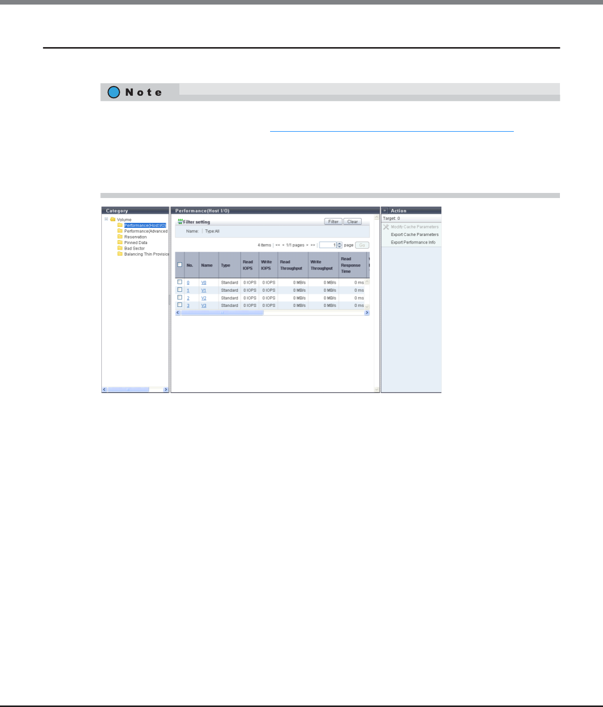
Chapter 5 Volume Management
5.1 Volume Status
ETERNUS Web GUI User’s Guide
Copyright 2013 FUJITSU LIMITED P2X0-1090-10ENZ0
77
5.1.2 Performance (Host I/O)
This function displays the performance information of the volumes for Host I/O.
The following items are displayed in the Main area:
•No.
The volume number is displayed. Click this item to display the [Volume Detail] screen.
•Name
The volume name is displayed. Click this item to display the [Volume Detail] screen.
•Type
The volume type is displayed.
-Standard
-WSV
-TPV
-FTV
-SDV
-SDPV
•Read IOPS
The read count per second is displayed.
•Write IOPS
The write count per second is displayed.
•Read Throughput
The amount of transferred data that is read per second is displayed.
•Performance information is obtained when performance monitoring is operated from GUI, CLI, or any
other monitoring software. Refer to "11.2.12.4 Start/Stop Performance Monitoring" (page 925) for details
on how to start performance monitoring with GUI.
•The interval for acquiring performance information can be specified when starting the monitoring. When
using GUI, the default interval is 30 seconds.
•The average performance values during the specified interval are displayed.

Chapter 5 Volume Management
5.1 Volume Status
ETERNUS Web GUI User’s Guide
Copyright 2013 FUJITSU LIMITED P2X0-1090-10ENZ0
78
•Write Throughput
The amount of transferred data that is written per second is displayed.
•Read Response Time
The average response time (for read) per millisecond is displayed.
•Write Response Time
The average response time (for write) per millisecond is displayed.
•Read Cache Hit Rate
The cache hit rate (for read) is displayed.
•Write Cache Hit Rate
The cache hit rate (for write) is displayed.
•Prefetch Cache Hit Rate
The cache hit rate (for prefetch) is displayed.
•Cache Page Capacity
The cache page capacity is displayed.
When the cache page capacity is "-" (hyphen), there is no limit for the cache capacity.
•PL
The prefetch limit is displayed. If PL is "0", prefetch is not performed.
•FP
The selected usage for the Force Prefetch Mode, which performs forcible prefetching for cache, is displayed.
-ON
Perform prefetch even if the sequential characteristics of the data access is not detected.
-OFF
Perform prefetch only when the sequential characteristics of the data access is detected.
•MWC
The value of the Multi Write back Count is displayed.
•PSDC
The number of times that sequentiality of data access (Read I/O) is detected (value of the Prefetch
Sequential Detect Count) is displayed. If any sequential data is accessed for the number of times specified
for PSDC, such access is determined as sequential access and prefetch is performed.
•SDDC
The number of times that sequentiality of data access (Write I/O) is detected (value of the Sequential Dirty
Detect Count) is displayed. If any sequential data is accessed for the number of times specified for SDDC,
such access is determined as sequential access and prefetch is performed.
•SS
The value of the parameter (Sequential Slope) to determine the sequentiality of data access (Read I/O) is
displayed. If the difference in addresses between the end LBA of the previous I/O and the start LBA of the
current I/O is within (SS setting + 1), it is determined as sequential data.
•SDS
The value of the parameter (Sequential Dirty Slope) to determine the sequentiality of data access (Write I/
O) is displayed. If the difference in addresses between the end LBA of the previous I/O and the start LBA of
the current I/O is within (SDS setting + 1), it is determined as sequential data.
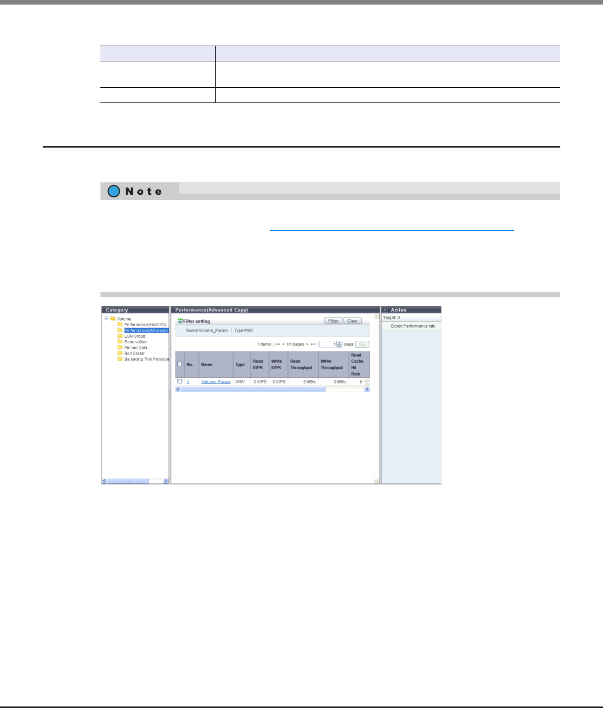
Chapter 5 Volume Management
5.1 Volume Status
ETERNUS Web GUI User’s Guide
Copyright 2013 FUJITSU LIMITED P2X0-1090-10ENZ0
79
Filter setting
5.1.3 Performance (Advanced Copy)
This function displays the performance information of the volumes for Advanced Copy.
The following items are displayed in the Main area:
•No.
The volume number is displayed. Click this item to display the [Volume Detail] screen.
•Name
The volume name is displayed. Click this item to display the [Volume Detail] screen.
•Type
The volume type is displayed.
-Standard
-WSV
-TPV
-FTV
-SDV
-SDPV
Filter Description
Name Input the volume name that is to be displayed.
When not using the volume name for filtering, leave this item blank.
Type Select the volume type that is to be displayed.
•Performance information is obtained when performance monitoring is operated from GUI, CLI, or any
other monitoring software. Refer to "11.2.12.4 Start/Stop Performance Monitoring" (page 925) for details
on how to start performance monitoring with GUI.
•The interval for acquiring performance information can be specified when starting the monitoring. When
using GUI, the default interval is 30 seconds.
•The average performance values during the specified interval are displayed.
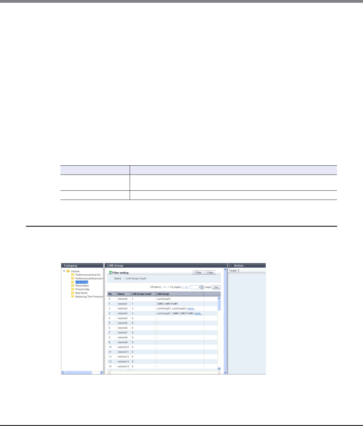
Chapter 5 Volume Management
5.1 Volume Status
ETERNUS Web GUI User’s Guide
Copyright 2013 FUJITSU LIMITED P2X0-1090-10ENZ0
80
•Read IOPS
The read count per second is displayed.
•Write IOPS
The write count per second is displayed.
•Read Throughput
The amount of transferred data that is read per second is displayed.
•Write Throughput
The amount of transferred data that is written per second is displayed.
•Read Cache Hit Rate
The cache hit rate (for read) is displayed.
•Write Cache Hit Rate
The cache hit rate (for write) is displayed.
•Prefetch Cache Hit Rate
The cache hit rate (for prefetch) is displayed.
Filter setting
5.1.4 LUN Group
This function displays the LUN groups of each volume.
A LUN group is a group of Logical Unit Numbers (LUNs), which can be recognized by the host. The allocation
information of LUNs and volumes in the ETERNUS DX Disk storage system are configured to the LUN group.
The following items are displayed in the Main area:
•No.
The volume number is displayed.
Filter Description
Name Input the volume name that is to be displayed.
When not using the volume name for filtering, leave this item blank.
Type Select the volume type that is to be displayed.
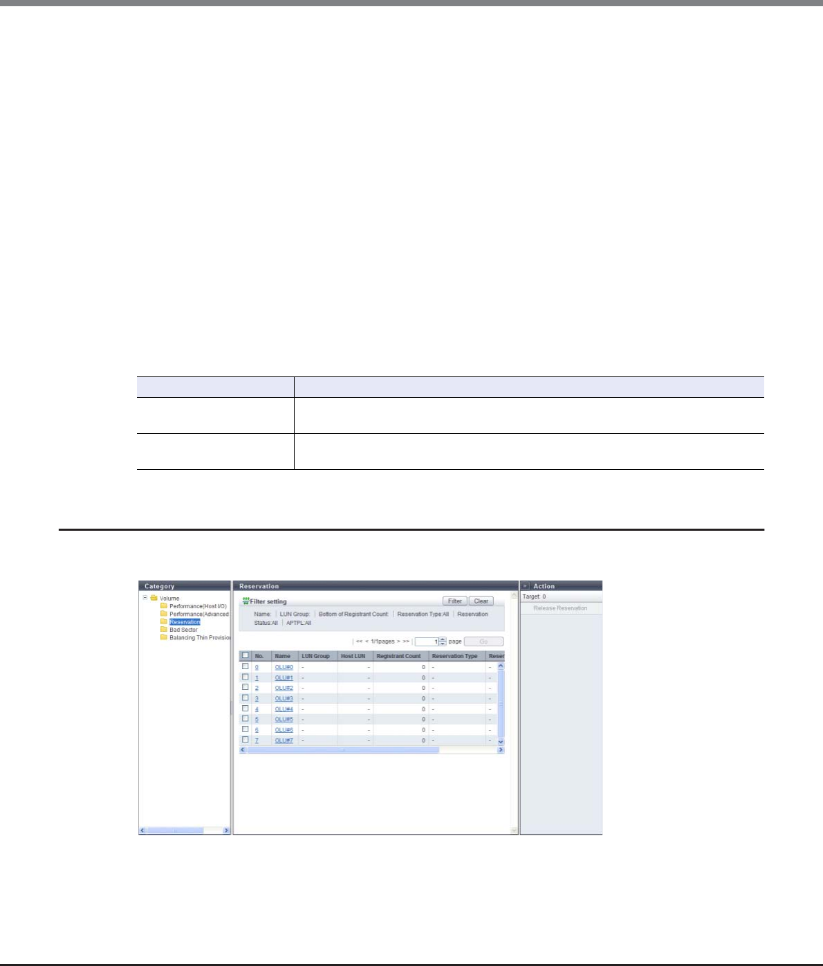
Chapter 5 Volume Management
5.1 Volume Status
ETERNUS Web GUI User’s Guide
Copyright 2013 FUJITSU LIMITED P2X0-1090-10ENZ0
81
•Name
The volume name is displayed.
•LUN Group Count
The total number of LUN groups for the volume and the number of ports to which the volume is allocated is
displayed.
•LUN Group
The LUN group names of the volume are displayed. If the host, ports, and LUNs are allocated without
specifying a host group or CA port group, the location information of the ports is displayed.
If the volume is registered in multiple LUN groups or the volume is allocated to multiple ports, the display
contents vary depending on the number of LUN groups and the number of ports. When there are two
display targets (the LUN group name and the port location information), the items are separated with a ",
(comma)" and displayed. When there are three or more display targets (the LUN group name and the port
location information), the first two items and a [more...] link are displayed.
When the volume does not belong to any LUN groups, or the volume is not allocated to any ports, the field
is blank.
-LUN group name
-CM#x CA#y Port#z (x: CM number, y: CA number, z: Port number)
Filter setting
5.1.5 Reservation
This function displays the reservation status of the volumes that are specified by a host.
Filter Description
Name Input the volume name that is to be displayed.
When not using the volume name for filtering, leave this item blank.
LUN Group Input the LUN group name that is to be displayed.
When not using the LUN group name for filtering, leave this item blank.

Chapter 5 Volume Management
5.1 Volume Status
ETERNUS Web GUI User’s Guide
Copyright 2013 FUJITSU LIMITED P2X0-1090-10ENZ0
82
The following items are displayed in the Main area:
•No.
The volume number is displayed. Click this item to display the [Volume Detail] screen.
Refer to "5.1.10 Volume Detail (Reservation)" (page 90) for display items.
•Name
The volume name is displayed. Click this item to display the [Volume Detail] screen.
Refer to "5.1.10 Volume Detail (Reservation)" (page 90) for display items.
•LUN Group
When the host affinity setting is specified for a host that reserves the volume, the LUN group name is
displayed. If the host, ports, and LUNs are directly allocated (mapped), the location information of the
ports is displayed.
When the volume is not reserved, a "-" (hyphen) is displayed.
-LUN group name
-CM#x CA#y Port#z (x: CM number, y: CA number, z: Port number)
•Host LUN
The logical unit number that is allocated to the relevant volume is displayed.
When the volume is not reserved, a "-" (hyphen) is displayed.
•Registrant Count
The number of reservation keys registered in the volume is displayed.
•Reservation Type
When the volume is in persistent reservation status, one of the following persistent reservation types is
displayed. When the volume is in reservation status other than persistent reservation status, or when the
volume is not reserved, a "-" (hyphen) is displayed.
-WE (Write Exclusive)
-EA (Exclusive Access)
-WE_RO (Write Exclusive-Registrants Only)
-EA_RO (Exclusive Access-Registrants Only)
-WE_AR (Write Exclusive-All Registrants)
-EA_AR (Exclusive Access-All Registrants)
•Reservation Status
The volume reservation status is displayed.
-Yes
In persistent reservation status
-No
In reservation status, but not in persistent reservation status
-"-" (hyphen)
Not in reservation status
•APTPL (*1)
Whether or not persistent reservation information is kept after the ETERNUS DX Disk storage system has
been shutdown/rebooted is displayed. When the volume is in reservation status other than persistent
reservation status, "No" is displayed. When the volume is not reserved, a "-" (hyphen) is displayed.
*1: Activate Persist Through Power Loss
-Yes
The persistent reservation information is kept.
-No
The persistent reservation information is not kept.
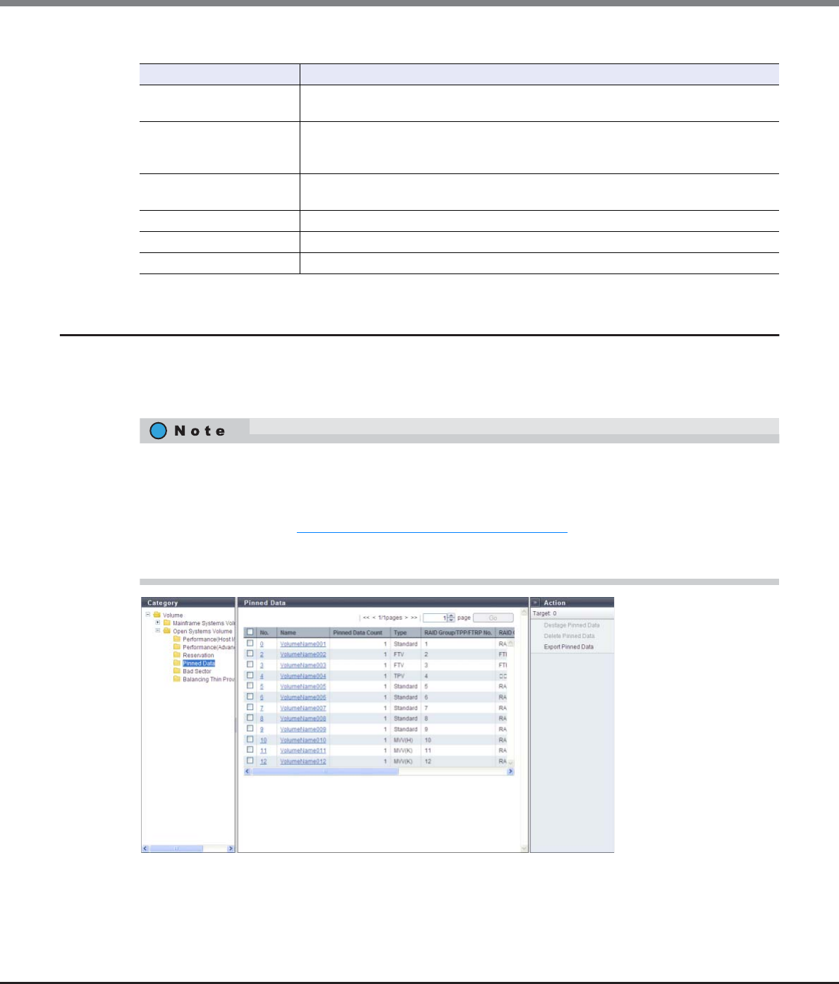
Chapter 5 Volume Management
5.1 Volume Status
ETERNUS Web GUI User’s Guide
Copyright 2013 FUJITSU LIMITED P2X0-1090-10ENZ0
83
Filter setting
5.1.6 Pinned Data
Volumes including pinned data are displayed.
"Pinned data" is the data left in the cache memory due to unsuccessful write-back to the volume from the
cache memory.
Filter Description
Name Input the volume name that is to be displayed.
When not using the volume name for filtering, leave this item blank.
LUN Group
Input the LUN group name or the port location information that is to be displayed.
When not using the LUN group name or port location information for filtering, leave this
item blank.
Bottom of Registrant Count Input the minimum number of reservation keys for the volume that is to be displayed.
When not using the bottom of the registrant count, leave this item blank.
Reservation Type Select the reservation type that is to be displayed.
Reservation Status Select the status of reservations that is to be displayed.
APTPL Select the APTPL that is to be displayed.
When a system message that indicates the detection of pinned data is displayed in the [Overview] screen, or
when a "Pinned data" event is notified by Host Sense or SNMP Trap, use this function to check the detected
pinned data.
Use the [Setup Event Notification] function to specify whether to perform event notification when pinned
data is detected. Refer to "11.2.9.1 Setup Event Notification" (page 880) for details. Note that writing back,
deleting, and saving pinned data can be performed by a maintenance engineer who has the "Maintenance
Operation" policy.

Chapter 5 Volume Management
5.1 Volume Status
ETERNUS Web GUI User’s Guide
Copyright 2013 FUJITSU LIMITED P2X0-1090-10ENZ0
84
The following items are displayed in the Main area:
•No.
The volume number is displayed. Click this item to display the [Volume Detail] screen.
Refer to "5.1.11 Volume Detail (Pinned Data)" (page 91) for display items.
•Name
The volume name is displayed. Click this item to display the [Volume Detail] screen.
Refer to "5.1.11 Volume Detail (Pinned Data)" (page 91) for display items.
•Pinned Data Count
The number of pinned data is displayed.
•Type
The volume type is displayed.
-Standard
-WSV
-TPV
-FTV
-SDV
-SDPV
-Temporary
•RAID Group/TPP/FRTP No.
The following number is displayed:
-If the type is "WSV"
The RAID group number to which the representative volume (*1) belongs is displayed.
*1: A volume for WSV, which is created by concatenating multiple RAID groups with striping, that belongs to the
RAID group that is first in the concatenation order.
-If the type is "TPV"
The Thin Provisioning Pool (TPP) number to which the volume belongs is displayed.
-If the type is "FTV"
The Flexible Tier Pool (FTRP) number to which the volume belongs is displayed.
-If the type is not one of the types listed above
The RAID group number to which the volume belongs is displayed.
•RAID Group/TPP/FTRP Name
The following name is displayed:
-If the type is "WSV"
The RAID group name to which the representative volume belongs is displayed.
-If the type is "TPV"
The Thin Provisioning Pool (TPP) name to which the volume belongs is displayed.
-If the type is "FTV"
The Flexible Tier Pool (FTRP) name to which the volume belongs is displayed.
-If the type is not one of the types listed above
The RAID group name to which the volume belongs is displayed.
•Controlling CM
The controlling CM and the CPU of the volume are displayed.
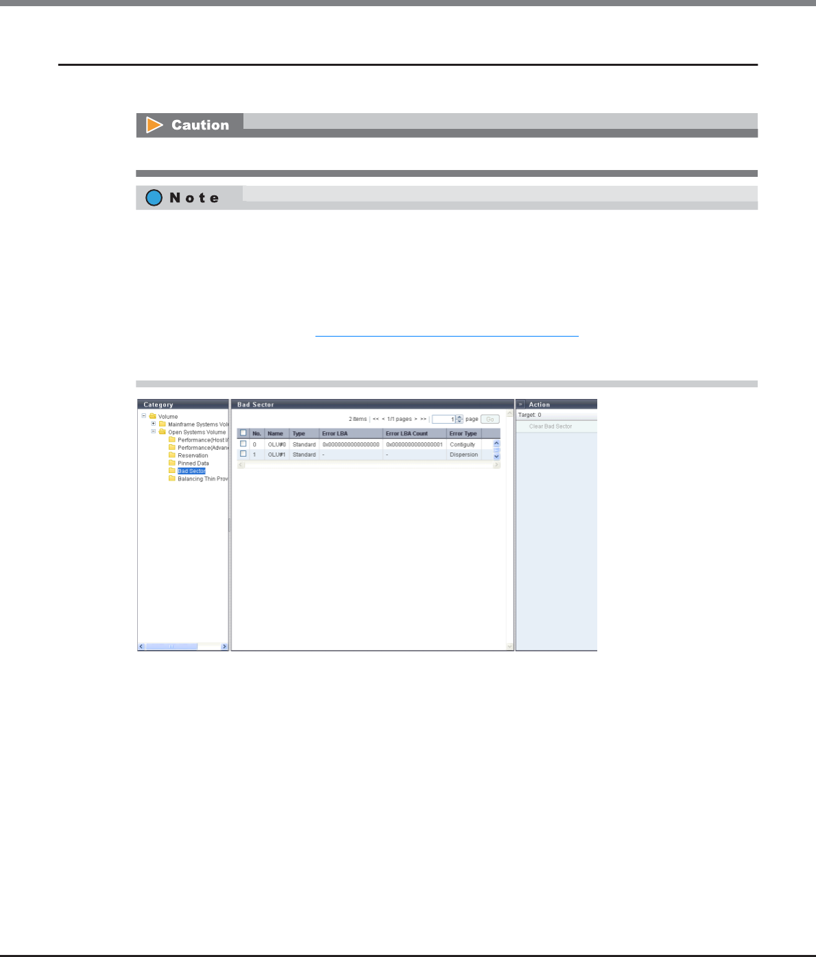
Chapter 5 Volume Management
5.1 Volume Status
ETERNUS Web GUI User’s Guide
Copyright 2013 FUJITSU LIMITED P2X0-1090-10ENZ0
85
5.1.7 Bad Sector
The bad sector information is displayed.
The following items are displayed in the Main area:
•No.
The volume number is displayed.
•Name
The volume name is displayed.
When the volume type is WSV or when the volume is concatenated by LUN concatenation, "Volume name
(n/m)" (n: nth volume in the concatenation order, m: number of concatenated volumes) is displayed.
Drives are not monitored for bad sectors when the drives configure the REC Disk Buffer.
•When data for rebuild, copyback, or redundant copy is not read normally, bad sector information is
recorded.
•When a system message that indicates the detection of bad sector is displayed in the [Overview] screen
or when a "Bad data" event is notified by Host Sense or an SNMP Trap, use this screen to check the
detected bad sector.
Use the [Setup Event Notification] function to specify whether to perform event notification when a bad
sector is detected. Refer to "11.2.9.1 Setup Event Notification" (page 880) for details. Note that the
deletion of bad sector can be performed by a maintenance engineer who has the "Maintenance
Operation" policy.
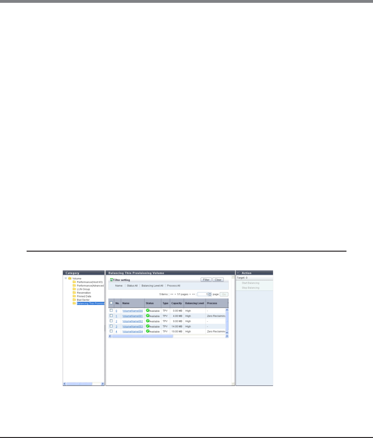
Chapter 5 Volume Management
5.1 Volume Status
ETERNUS Web GUI User’s Guide
Copyright 2013 FUJITSU LIMITED P2X0-1090-10ENZ0
86
•Type
The volume type is displayed.
-Standard
-WSV
-TPV
-FTV
-SDV
-SDPV
-Temporary
•Error LBA
The start position of the bad sector information in the volume is displayed using the Logical Block Address
(LBA).
-When bad sector information is detected in the TPV or the FTV: "-" (hyphen)
-When the "Error Type" is "Dispersion": "-" (hyphen)
•Error LBA Count
The number of LBAs from Error LBA of the bad sector information in the volume is displayed.
-When bad sector information is detected in the TPV or the FTV: "-" (hyphen)
-When the "Error Type" is "Dispersion": "-" (hyphen)
•Error Type
The number of bad sector information in the volume is displayed.
-When one bad sector information exists in the volume: "Contiguity"
-When multiple number of bad sector information exist in the volume: "Dispersion"
-For TPV or FTV, "Dispersion" is displayed regardless of the number of bad sector information.
5.1.8 Balancing Thin Provisioning Volume
This function displays the information of balancing Thin Provisioning Volumes (TPVs).

Chapter 5 Volume Management
5.1 Volume Status
ETERNUS Web GUI User’s Guide
Copyright 2013 FUJITSU LIMITED P2X0-1090-10ENZ0
87
The following items are displayed in the Main area:
•No.
The volume number is displayed. Click this item to display the [Volume Detail] screen.
Refer to "5.1.12 Volume Detail (Balancing TPV)" (page 92) for display items.
•Name
The volume name is displayed. Click this item to display the [Volume Detail] screen.
Refer to "5.1.12 Volume Detail (Balancing TPV)" (page 92) for display items.
•Status
The volume status is displayed. Refer to "B.2 Volume Status" (page 974) for detailed information of volume
status.
•Type
The volume type (fixed to "TPV") is displayed.
•Capacity
The total volume capacity is displayed.
•Balancing Level
The balancing level of the volume is displayed.
-When the volume is balanced: High
-When the volume is almost balanced: Middle
-When the volume is not balancing well: Low
-When the ETERNUS DX Disk storage system is abnormal: "-" (hyphen)
•Process
A process that is being performed for the volume is displayed.
If multiple processes are being performed, the processes are separated with a ": (colon)" and displayed
using ("xx:yy"). "Encrypting", "Formatting", "Migrating", or "Balancing" is displayed as "xx". "Zero Reclaim-
ing" or "Reserved Zero Reclaim" is displayed as "yy".
If no process is being performed, a "-" (hyphen) is displayed.
-Balancing
TPV balancing is being performed
-Formatting
Formatting is being performed
-Migrating
RAID migration is being performed
-Zero Reclaiming
Zero Reclamation (*1) is being performed for a TPV or an FTV.
-Reserved Zero Reclaim
A TPV or an FTV is reserved for Zero Reclamation (*2).
*1: "Zero Reclamation" is a function that releases the allocated physical area when data in the physical area that
is allocated to a TPV or an FTV is filled with zeros.
*2: When "Start Zero Reclamation after migration" is enabled for RAID migration, the source volume will be
reserved for Zero Reclamation.
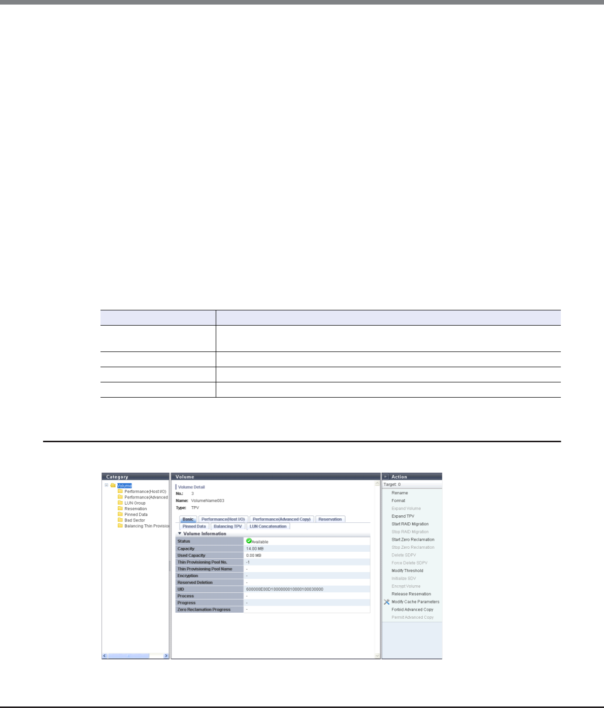
Chapter 5 Volume Management
5.1 Volume Status
ETERNUS Web GUI User’s Guide
Copyright 2013 FUJITSU LIMITED P2X0-1090-10ENZ0
88
•Balancing Process
When "Process" is not "Balancing", a "-" (hyphen) is displayed.
-Status
The status of TPV balancing is displayed.
•Active
Running normally
•Error
Stopped due to an error
-Progress
The progress of TPV balancing is displayed.
-Work Vol. No.
The volume number undergoing TPV balancing is displayed.
-Work Vol. Name
The volume name undergoing TPV balancing is displayed.
-Error Code
The error code of TPV balancing is displayed when an error occurs.
-Elapsed Time
The elapsed time of TPV balancing is displayed.
The displayed time is the elapsed time at the point when this screen is displayed.
Filter setting
5.1.9 Volume Detail (Basic)
The detail information of the volume is displayed.
Filter Description
Name Input the volume name that is to be displayed.
When not using the volume name for filtering, leave this item blank.
Status Select the volume status that is to be displayed.
Balancing Level Select the volume type that is to be displayed.
Process Select which current process for the volume is to be displayed.

Chapter 5 Volume Management
5.1 Volume Status
ETERNUS Web GUI User’s Guide
Copyright 2013 FUJITSU LIMITED P2X0-1090-10ENZ0
89
The following items are displayed in the Main area:
•Status
The volume status is displayed.
When the volume status is normal, " Available" is displayed.
Refer to "B.2 Volume Status" (page 974) for detailed information of RAID group status.
•Capacity
The volume capacity is displayed.
•Used Capacity
The used capacity of volume is displayed.
This item is not displayed when the volume type is other than "TPV" or "FTV".
•RAID Group No.
The RAID group number to which the volume belongs is displayed.
If the type is "WSV", the RAID group number to which the representative volume belongs is displayed.
This item is not displayed when the volume type is "TPV" or "FTV".
•RAID Group Name
The RAID group name to which the volume belongs is displayed.
If the type is "WSV", the RAID group name to which the representative volume belongs is displayed.
This item is not displayed when the volume type is "TPV" or "FTV".
•Thin Provisioning Pool No.
The TPP number to which the volume belongs is displayed.
This item is not displayed when the volume type is other than "TPV".
•Thin Provisioning Pool Name
The TPP name to which the volume belongs is displayed.
This item is not displayed when the volume type is other than "TPV".
•FTRP No.
The FTRP name to which the volume belongs is displayed.
This item is not displayed when the volume type is other than "FTV".
•FTRP Name
The FTRP name to which the volume belongs is displayed.
This item is not displayed when the volume type is other than "FTV".
•Encryption
The encryption status is displayed.
-CM
The volume that is encrypted by CM.
-"-" (hyphen)
The volume that is not encrypted.
-SED
The volume that is encrypted by SED.
•Wide Stripe Size
The Wide Stripe Size is displayed.
"Wide Stripe Size" is the size of the WSV Unit that is allocated to each RAID group in series. A "-" (hyphen) is
displayed when the volume type is other than "WSV".
-Normal
An integral multiple of the basic size for each RAID type (*1). The maximum size is 16MB or smaller.
-Small
An integral multiple of the basic size for each RAID type (*1). The maximum size is 2MB or smaller.
Note that when the basic size for a RAID group is larger than 2MB, the basic size is specified.
*1: The basic size (stripe size) when creating a volume. Refer to "E.1 Basic Size for each RAID Group" (page 995)
for details.

Chapter 5 Volume Management
5.1 Volume Status
ETERNUS Web GUI User’s Guide
Copyright 2013 FUJITSU LIMITED P2X0-1090-10ENZ0
90
•Reserved Deletion
The "Reserved Deletion" status of the SDPV is displayed.
If the SDPV is currently being used, the target SDPV status is changed to "Reserved Deletion". A "-"
(hyphen) is displayed when the volume type is other than "SDPV". Refer to "5.2.11 Delete Snap Data Pool
Volume" (page 141) for details.
-Yes
SDPVs are in "Reserved Deletion" status.
-No
SDPVs are not in "Reserved Deletion" status.
•UID
The UID is displayed.
•Process
A process that is being performed for the volume is displayed.
If no process is being performed, a "-" (hyphen) is displayed.
If multiple processes are being performed, the processes are separated with a ": (colon)" and displayed
using ("xx:yy"). "Encrypting", "Formatting", "Migrating", or "Balancing" is displayed as "xx". "Zero Reclaim-
ing" or "Reserved Zero Reclaim" is displayed as "yy".
-Encrypting
-Formatting
-Migrating
-Balancing
-Zero Reclaiming
-Reserved Zero Reclaim
•Progress
The progress of a process that is being performed for the volume is displayed.
If no process is being performed, a "-" (hyphen) is displayed.
•Zero Reclamation Progress
The progress of a Zero Reclamation (*1) process that is being performed for the volume is displayed.
When Zero Reclamation is not being executed, a "- " (hyphen) is displayed.
When the storage system status is "Not Ready", the field is blank.
*1: "Zero Reclamation" is a function that releases the allocated physical area when data in the physical area that is
allocated to a TPV or an FTV filled with zeros.
5.1.10 Volume Detail (Reservation)
The detailed information of reservation volume is displayed.
The following items are displayed in the Main area:
•Host WWN/iSCSI Name
The WWN or the iSCSI name of the host that can access the volume is displayed.
•CA Port
The location information of the CA port that connects to the host is displayed.
-CM#x CA#y Port#z (x: CM number, y: CA number, z: Port number)
•Reservation Key
The reservation key that is used for persistent reservation of the volume is displayed.
When no reservation keys exist, a "-" (hyphen) is displayed.
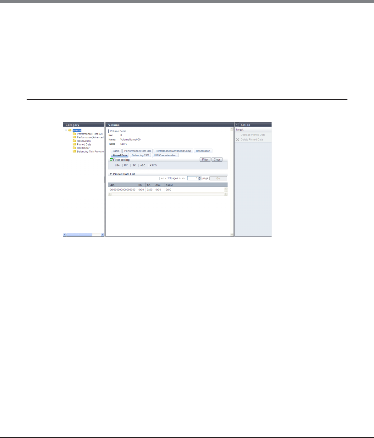
Chapter 5 Volume Management
5.1 Volume Status
ETERNUS Web GUI User’s Guide
Copyright 2013 FUJITSU LIMITED P2X0-1090-10ENZ0
91
•Hold Reservation
Whether the target reservation key is used for persistent reservation is displayed.
When the volume is in reservation status other than persistent reservation status, "No" is displayed.
-Yes
In persistent reservation status
-No
Not in persistent reservation status
5.1.11 Volume Detail (Pinned Data)
The detailed information of pinned data is displayed.
The following items are displayed in the Main area:
•LBA
The location of the pinned data in the volume is displayed using the Logical Block Address (LBA).
•RC
The reason (Reason Code) that created the pinned data is displayed.
•SK
The Sense Key (SK) part is displayed from the sense information that is output when the pinned data is
created.
•ASC
Additional Sense Code (ASC) part is displayed from the sense information that is output when the pinned
data is created.
•ASCQ
Additional Sense Code Qualifier (ASCQ) part is displayed from the sense information that is output when
the pinned data is created.
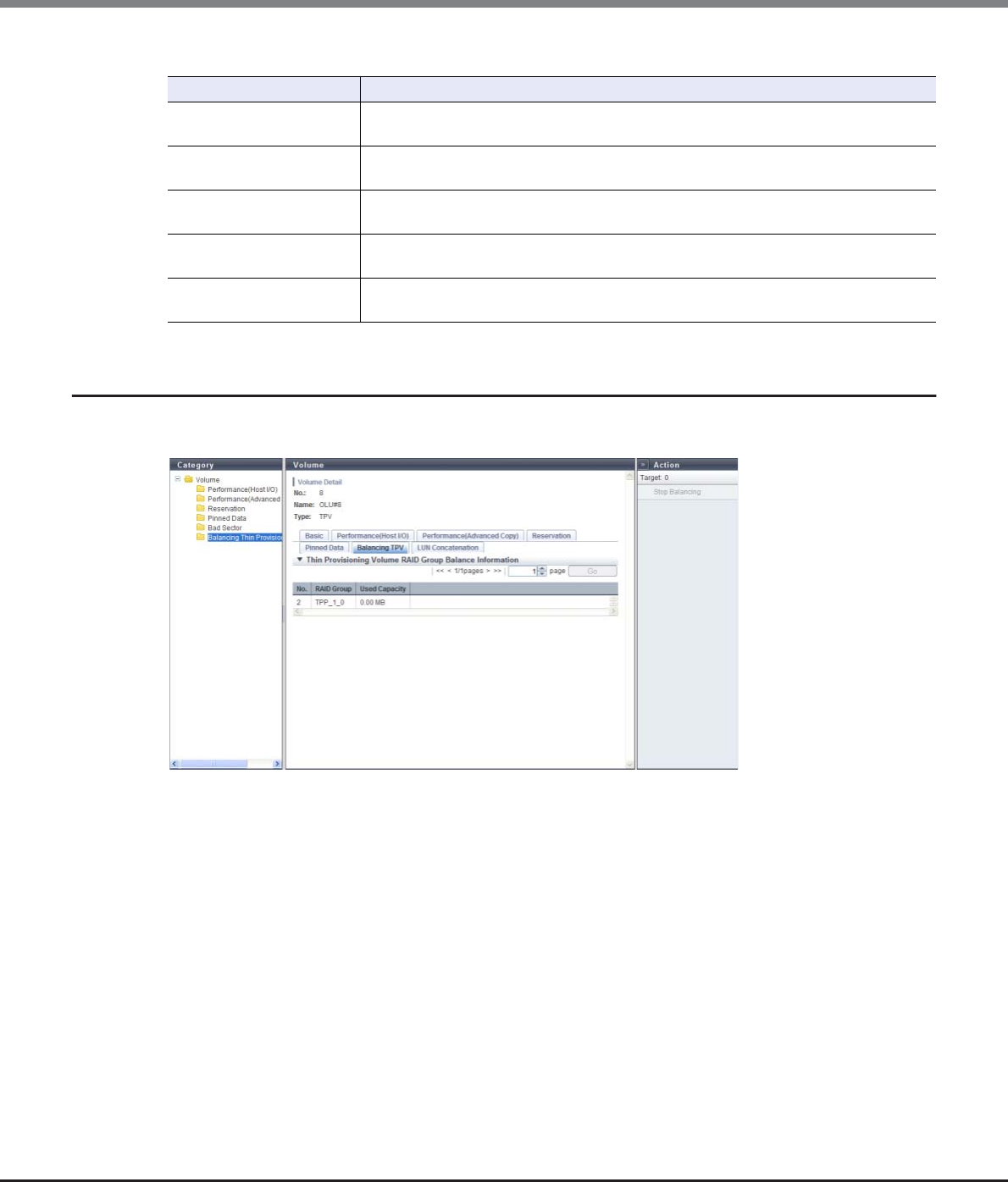
Chapter 5 Volume Management
5.1 Volume Status
ETERNUS Web GUI User’s Guide
Copyright 2013 FUJITSU LIMITED P2X0-1090-10ENZ0
92
Filter setting
5.1.12 Volume Detail (Balancing TPV)
The detailed information of TPV balancing is displayed.
The following items are displayed in the Main area:
•No.
The number of the RAID group that allocates the physical capacity to the target TPV is displayed.
•RAID Group
The name of the RAID group that allocates the physical capacity to the target TPV is displayed.
•Used Capacity
The capacity for each RAID group that allocates the physical capacity to the target TPV is displayed.
This is the capacity that is available when balancing of the target TPV is started.
Note that it is not the capacity after re-allocating the physical capacity in the relevant TPV to the RAID
groups in the TPP.
Filter Description
LBA Input the LBA that is to be displayed.
When not using the LBA for filtering, leave this item blank.
RC Input the RC that is to be displayed.
When not using the RC for filtering, leave this item blank.
SK Input the SK that is to be displayed.
When not using the SK for filtering, leave this item blank.
ASC Input the ASC that is to be displayed.
When not using the ASC for filtering, leave this item blank.
ASCQ Input the ASCQ that is to be displayed.
When not using the ASCQ for filtering, leave this item blank.
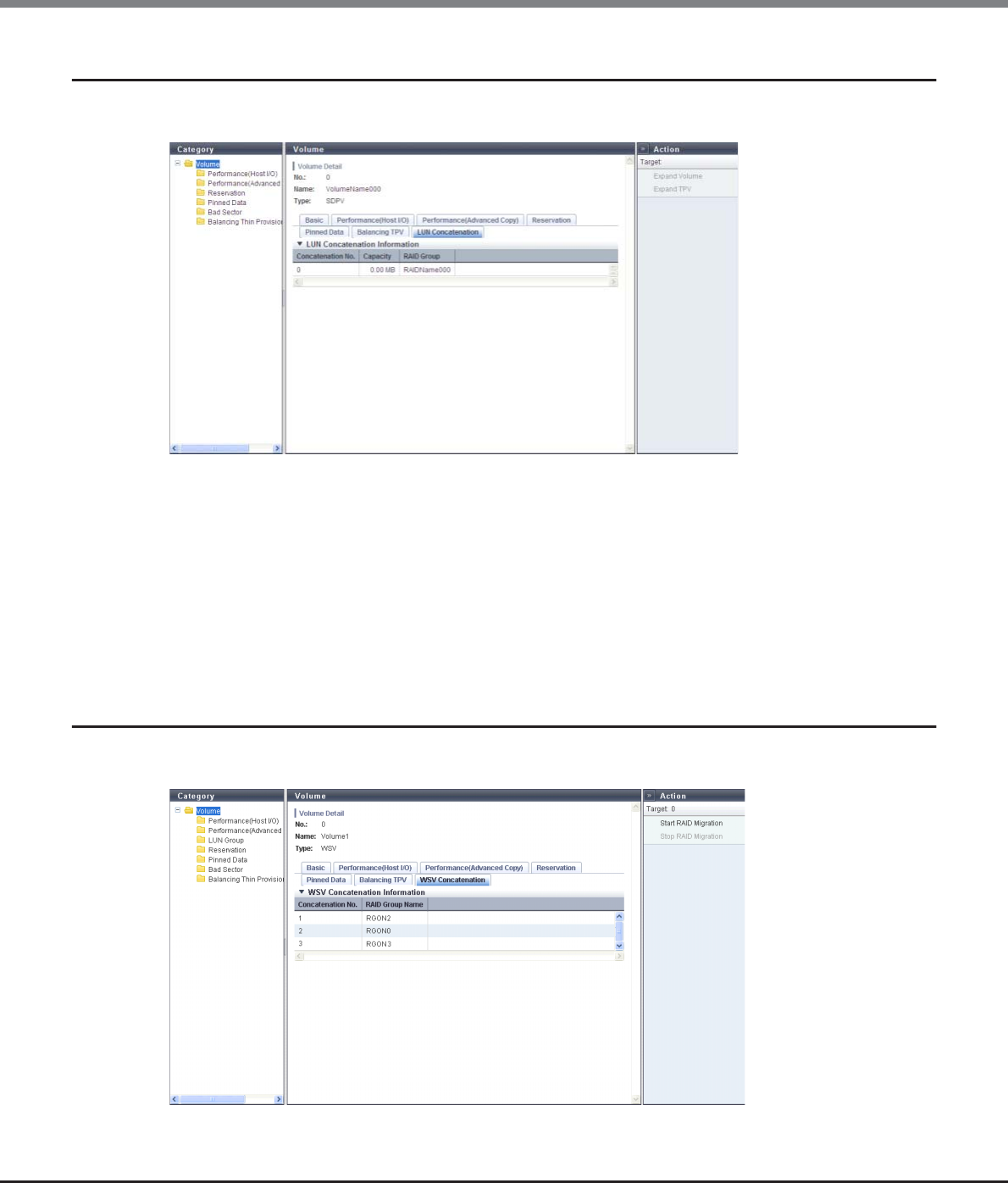
Chapter 5 Volume Management
5.1 Volume Status
ETERNUS Web GUI User’s Guide
Copyright 2013 FUJITSU LIMITED P2X0-1090-10ENZ0
93
5.1.13 Volume Detail (LUN Concatenation)
The detailed information of LUN Concatenation is displayed.
The following items are displayed in the Main area:
•Concatenation No.
The concatenation number of the volume is displayed.
•Capacity
The capacity of the volume that is concatenated to the target volume is displayed.
•RAID Group
The RAID group name in which the volume that is concatenated to the target volume belongs is displayed.
5.1.14 Volume Detail (WSV Concatenation)
The detailed information of WSV Concatenation is displayed.

Chapter 5 Volume Management
5.1 Volume Status
ETERNUS Web GUI User’s Guide
Copyright 2013 FUJITSU LIMITED P2X0-1090-10ENZ0
94
The following items are displayed in the Main area:
•Concatenation No.
The concatenation number of the WSV (the order for allocating WSV Units to RAID groups) is displayed
between 1 and 64.
•RAID Group Name
The RAID group name to which the concatenated WSV Unit belongs is displayed.
Chapter 5 Volume Management
5.2 Functions in the Action Area for Volume
ETERNUS Web GUI User’s Guide
Copyright 2013 FUJITSU LIMITED P2X0-1090-10ENZ0
95
5.2 Functions in the Action Area for Volume
When using functions in the Action area, select the desired function from the Action area that is displayed in
the status display screen.
The functions in the Action area for Volume can be performed from the following display functions:
Functions in the Action area for Volume Display function
Create Volume •Volume (Basic Information)
Delete Volume
Rename Volume
Format Volume
Expand Volume
Expand Thin Provisioning Volume
Start RAID Migration
Stop RAID Migration
Start Zero Reclamation
Stop Zero Reclamation
Delete Snap Data Pool Volume
Force Delete Snap Data Pool Volume
Modify Threshold Thin Provisioning Volume
Initialize Snap Data Volume
Encrypt Volume
Forbid Advanced Copy
Permit Advanced Copy
Modify Cache Parameters •Performance (Host I/O)
Export Cache Parameters
Export Performance Information
Release Reservation •Reservation
Start Balancing Thin Provisioning Volume •Balancing Thin Provisioning Volume
Stop Balancing Thin Provisioning Volume
Chapter 5 Volume Management
5.2 Functions in the Action Area for Volume
ETERNUS Web GUI User’s Guide
Copyright 2013 FUJITSU LIMITED P2X0-1090-10ENZ0
96
5.2.1 Create Volume
This function creates new volumes in the existing RAID group or Thin Provisioning Pool (TPP). Standard
volumes, Wide Striping Volumes (WSV), Thin Provisioning Volumes (TPV), Snap Data Volumes (SDV), and Snap
Data Pool Volumes (SDPV) can be created. Volumes are formatted automatically when they are created.
Standard, WSV, TPV, and SDV can be accessed from the host when host affinity is set after volume creation.
Note that SDPVs can be used after volume creation is complete and formatting is started.
•If a Thin Provisioning license is not registered, TPV cannot be created.
•If an Advanced Copy license is not registered, SDV and SDPV cannot be created. However, when using the
ETERNUS DX80 S2/DX90 S2, a free license is registered by default and SDVs and SDPVs can be created.
•When encryption mode is disabled, volumes encrypted by CM cannot be created. Note that when SEDs
are not installed in the ETERNUS DX Disk storage system, volumes encrypted by SEDs cannot be created.
•The following shows the maximum number of volumes that can be created for each model.
-ETERNUS DX80 S2: 2048
-ETERNUS DX90 S2: 4096
-ETERNUS DX410 S2/DX440 S2: 16384
-ETERNUS DX8100 S2: 16384
-ETERNUS DX8700 S2: 65535
•The following shows the maximum capacity of TPV that can be created for each model.
-ETERNUS DX80 S2/DX90 S2: 128TB
-ETERNUS DX410 S2: 384TB
-ETERNUS DX440 S2: 768TB
-ETERNUS DX8100 S2: 768TB
-ETERNUS DX8700 S2: 1024TB
•The following shows the conditions for creating SDPVs.
-The volume capacity must be 2TB or less
-The volume capacity must be a multiple of SDPE capacity (1GB/2GB/4GB).
•When creating an SDV, the capacity setting is not required. 24 (MB) + "Capacity of source volume (only
SDV)" × 0.1% of the copy source volume capacity is automatically secured in the ETERNUS DX Disk storage
system. "24MB" is the smallest volume capacity. "Capacity of source volume (only SDV)" × 0.1% is the
capacity that is used for the controlling information area in the SDV. When using SnapOPC or SnapOPC+,
make sure to create an SDV and SDPVs. An SDPV is a volume that configures an SDP. The SDP allocates
free space when SDV capacity is insufficient.
•The maximum number of volumes that can be created is reduced in the following conditions:
-When TPPs exist in the ETERNUS DX Disk storage system
-When concatenated volumes exist in the ETERNUS DX Disk storage system
-When REC Disk Buffers exist in the ETERNUS DX Disk storage system
-When volumes undergoing RAID migration exist
-When volumes undergoing balancing TPV exist
-When "Enable" is selected for the Flexible Tier function mode
•The following restrictions apply to WSVs:
-Volume capacity expansion is not available (LUN concatenation cannot be performed)
-RAID group capacity expansion for RAID groups which configure WSVs is not available (LDE cannot be
performed)

Chapter 5 Volume Management
5.2 Functions in the Action Area for Volume
ETERNUS Web GUI User’s Guide
Copyright 2013 FUJITSU LIMITED P2X0-1090-10ENZ0
97
■When creating Standard, TPV, SDV, or SDPV type volumes
There are two methods to create a volume: automatic drive selection and manual drive selection.
When selecting "Automatic"
The procedure to create a volume by selecting drives automatically is as follows:
Procedure
1Click [Create] in [Action].
2Select "Automatic" for "RAID Group/TPP Selection".
3Specify the volume detailed information, and click the [Create] button.
•Name
Specify the volume name. An existing volume name cannot be specified. When creating multiple
volumes at the same time, the new volumes are named automatically. Refer to "Naming
conventions for creating volumes" (page 993) for details.
The following input condition applies:
-Up to 16 alphanumeric characters and symbols (except ", (comma)" and "?")
•If an area with the necessary capacity cannot be acquired from the free space available, use the LUN
Concatenation function to concatenate multiple space into a volume.
•Creating SDPVs in RAID groups with the same RAID type, drive type, number of drives is recommended.
•WSVs are volumes that are created by concatenating multiple RAID groups with striping. Use RAID
migration to add or reduce the number of concatenated RAID groups. The RAID migration function can
also be used to expand WSV capacity. Refer to "5.2.7 Start RAID Migration" (page 123) for details.
•This function cannot be used to create an ODX Buffer volume. Refer to "8.2.10 Create ODX Buffer Volume"
(page 311) for details.
•When manually selecting drives to create a volume (*1), the volume number can be specified. Note that
volumes have to be created one at a time. Multiple volumes cannot be created when specifying the
volume number for a new volume. When "Automatic" is selected to create a volume or when "Manual" is
selected but a volume number is not specified, the volume number is allocated when a volume is created
from the smallest unused decimal number in ascending order.
*1: Select "Manual" to create WSVs or to create TPVs, SDVs, SDPVs, or Standard type volumes by specifying the drives
manually. Refer to "When creating Standard, TPV, SDV, or SDPV type volumes" (page 97) or "When creating WSV
type volumes" (page 105) for details.
•When "Manual" is selected, the specified number of volumes by using the maximum free space that is
available in the RAID group can be created. Inputting the volume capacity is not required. "Standard",
"WSV", and "SDPV" type volumes can be created using the maximum free space.
Chapter 5 Volume Management
5.2 Functions in the Action Area for Volume
ETERNUS Web GUI User’s Guide
Copyright 2013 FUJITSU LIMITED P2X0-1090-10ENZ0
98
•Capacity
Specify the volume capacity and select the unit of capacity.
Up to a 15-digit number including the "." (decimal point) can be input. Note that when "MB" is
selected, the specified value is rounded down to the nearest whole number. When "GB" or "TB" is
selected, the specified value is converted to "MB" and rounded down to the nearest whole number.
The following input conditions apply:
-When creating Standard volumes or TPVs: 24MB - 128TB (numeric characters)
-When creating SDPVs: 1GB - 2TB (numeric characters)
-MB/GB/TB
•Type
Specify the volume type. When the [Create Volume] function is selected from the RAID group list,
"Standard", "Snap Data Volume", or "Snap Data Pool Volume" is displayed.
When the [Create Volume] function is selected from the Thin Provisioning Pool list, only "Thin
Provisioning" is displayed.
-Standard
Normal volumes that are created in the RAID group.
-Thin Provisioning
Volumes that are created in Thin Provisioning Pools.
-Snap Data Volume
Copy destination volumes for SnapOPC or SnapOPC+.
-Snap Data Pool Volume
Volumes that are used as expansion areas for SDV.
•Capacity of source volume (only SDV)
Specify the copy source volume capacity and select the unit of capacity. This item can only be
specified when "Snap Data Volume" is selected for "Type".
The following input conditions apply:
-24MB - 128TB
-MB/GB/TB
Up to 15 numbers can be used. If a decimal point is included in the input value, up to 14 numbers
can be used.
[Example] 0.1234567890123 (14 numbers and a decimal point)
•When creating an SDV, the capacity setting is not required. 24 (MB) + "Capacity of source vol-
ume (only SDV)" × 0.1% of the copy source volume capacity is automatically secured in the
ETERNUS DX Disk storage system. When using SnapOPC or SnapOPC+, make sure to create an
SDV and SDPVs.
•When creating multiple volumes in a RAID group, the maximum number of volumes that can
be created for the user capacity may be reduced. To use the entire user capacity, the volume
size must be an exact multiple of the basic size (stripe size). Refer to "E.1 Basic Size for each
RAID Group" (page 995) for details.

Chapter 5 Volume Management
5.2 Functions in the Action Area for Volume
ETERNUS Web GUI User’s Guide
Copyright 2013 FUJITSU LIMITED P2X0-1090-10ENZ0
99
•Disk Type
Specify the drive type.
-Online
-Nearline
-SSD
-SED
•RAID Type
Select the RAID type. The specified volume type and disk type determine the selectable RAID types
that are displayed as options.
-High Performance (RAID1+0)
-High Capacity (RAID5)
-High Reliability (RAID6)
-Reliability (RAID5+0)
-Mirroring (RAID1)
-Striping (RAID0)
•Key Group
When creating volumes in a RAID group that is registered in the key group (*1), select "Enable".
When creating volumes in a RAID group that is not registered in the key group, select "Disable".
This item is available only when "Disk Type" is "SED". Only the available setting (Enable or Disable)
is displayed as an option. When the "Disk Type" is not "SED", the field is blank.
*1: The key group combines all of the RAID groups that use the same SED authentication key.
•Number of Volumes
Specify the number of volumes to be created in decimal number.
•Encryption by CM
Select whether to encrypt (On) or not encrypt (Off) the new volumes. When the encryption mode is
disabled, "On" cannot be selected. When "Disk Type" is "SED", "On" cannot be selected.
-When the "Disk Type" is "SED":
Volumes are created in the RAID group or the TPP configured by SEDs.
-When the "Disk Type" is not "SED":
•When "On" is selected:
Volumes that are encrypted by CM are created. When creating a TPV, the volume is created in
the TPP that is encrypted by CM.
•When "Off" is selected:
Volumes that are not encrypted are created. When creating a TPV, the volume is created in
the TPP that is not encrypted.
When using the ETERNUS DX8700 S2, up to 1024 volumes can be created at once.
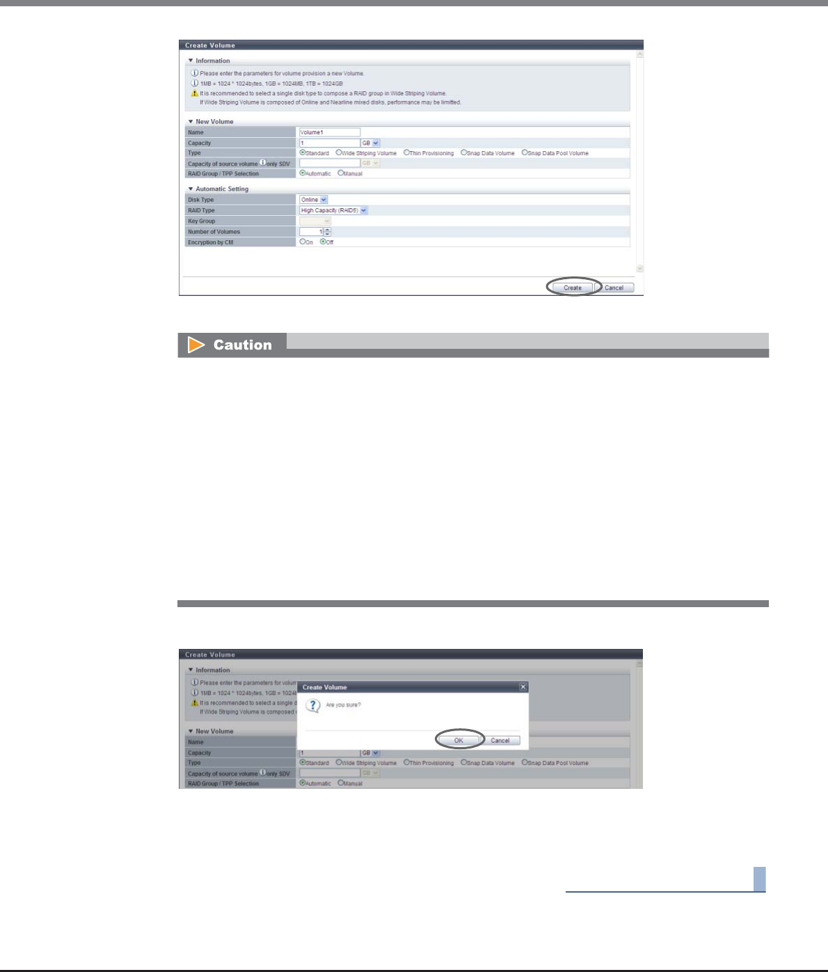
Chapter 5 Volume Management
5.2 Functions in the Action Area for Volume
ETERNUS Web GUI User’s Guide
Copyright 2013 FUJITSU LIMITED P2X0-1090-10ENZ0
100
→A confirmation screen appears.
4Click the [OK] button.
→Volume creation starts.
5Click the [Done] button to return to the [Volume] screen.
End of procedure
An error screen appears in the following conditions:
•When a name is not input for "Name"
•When the "Name" overlaps with an existing volume name
•When the "Name" does not satisfy the input conditions
•When the capacity is not specified for "Capacity"
•When the capacity that is specified for "Capacity" exceeds the maximum capacity that can be
created
•When the SDPV capacity that is specified for "Capacity" is not a multiple of the SDPE capacity (1GB/
2GB/4GB)
•When the number of volumes that is specified for "Number of Volumes" exceeds the maximum
number of volumes that can be created
•When free space in the RAID group or TPP is insufficient
Chapter 5 Volume Management
5.2 Functions in the Action Area for Volume
ETERNUS Web GUI User’s Guide
Copyright 2013 FUJITSU LIMITED P2X0-1090-10ENZ0
101
Manually selecting drives to create volumes
The procedure to create a volume by selecting drives manually is as follows:
Procedure
1Click [Create] in [Action].
2Select "Manual" for "RAID Group/TPP Selection".
3Specify the detailed information of new volumes and select the RAID group or TPP in which
the volumes are to be created. Click the [Create] button.
•Name
Specify the volume name. An existing volume name cannot be specified. When creating multiple
volumes at the same time, the new volumes are named automatically. Refer to "Naming
conventions for creating volumes" (page 993) for details.
The following input condition applies:
-Up to 16 alphanumeric characters and symbols (except ", (comma)" and "?")
•Capacity
Specify the volume capacity and select the unit of capacity.
Up to a 15-digit number including the "." (decimal point) can be input. Note that when "MB" is
selected, the specified value is rounded down to the nearest whole number. When "GB" or "TB" is
selected, the specified value is converted to "MB" and rounded down to the nearest whole number.
The following input conditions apply:
-When creating Standard volumes or TPVs: 24MB - 128TB (numeric characters)
-When creating SDPVs: 1GB - 2TB (numeric characters)
-MB/GB/TB
Up to 15 numbers can be used. If a decimal point is included in the input value, up to 14 numbers
can be used.
[Example] 0.1234567890123 (14 numbers and a decimal point)
•If "Use all Largest Free Space" is selected when creating volumes manually, inputting the
capacity is not required. The specified value and unit are not used.
•When creating an SDV, the capacity setting is not required. 24 (MB) + "Capacity of source vol-
ume (only SDV)" × 0.1% of the copy source volume capacity is automatically secured in the
ETERNUS DX Disk storage system. When using SnapOPC or SnapOPC+, make sure to create an
SDV and SDPVs.
•When creating multiple volumes in a RAID group, the maximum number of volumes that can
be created for the user capacity may be reduced. To use the entire user capacity, the volume
size must be an exact multiple of the basic size (stripe size). Refer to "E.1 Basic Size for each
RAID Group" (page 995) for details.

Chapter 5 Volume Management
5.2 Functions in the Action Area for Volume
ETERNUS Web GUI User’s Guide
Copyright 2013 FUJITSU LIMITED P2X0-1090-10ENZ0
102
•Type
Specify the volume type. When the [Create Volume] function is selected from the RAID group list,
"Standard", "Snap Data Volume", or "Snap Data Pool Volume" is displayed.
When the [Create Volume] function is selected from the Thin Provisioning Pool list, only "Thin
Provisioning" is displayed.
-Standard
Normal volumes that are created in the RAID group.
-Thin Provisioning
Volumes that are created in Thin Provisioning Pools.
-Snap Data Volume
Copy destination volumes for SnapOPC or SnapOPC+.
-Snap Data Pool Volume
Volumes that are used as expansion areas for SDV.
•Capacity of source volume (only SDV)
Specify the copy source volume capacity and select the unit of capacity. This item can only be
specified when "Snap Data Volume" is selected for "Type".
The following input conditions apply:
-24MB - 128TB
-MB/GB/TB
•Use all Largest Free Space
Select the "Enable" checkbox to create the specified number of volumes with the largest available
free space in the RAID group. This checkbox can be selected or cleared only when "Type" is "Stan-
dard" or "SDPV".
If "Enable" is selected, the specified number of volumes in the "Number of Volumes" field are cre-
ated in the free space that is displayed as "Largest Free Space" for each RAID group. If "Type" is "Stan-
dard", capacity is allocated almost evenly for the basic size (stripe size) of the RAID group. If "Type" is
"SDPV", a multiple of the SDPE capacity is allocated almost evenly for the basic size (stripe size) of
the RAID group.
•Volume No.
When specifying the volume number for a new volume, select the "Set Value" checkbox and input
the volume number.
The following input condition applies:
-Numeric characters (decimal)
-The following volume numbers can be used for each model:
•ETERNUS DX80 S2: 0 - 2047
•ETERNUS DX90 S2: 0 - 4095
•ETERNUS DX410 S2/DX440 S2: 0 - 16383
•ETERNUS DX8100 S2: 0 - 16383
•ETERNUS DX8700 S2: 0 - 65534
•When "Enable" is selected, the capacity and the unit that are specified for "New Volume" are
not available.
•The capacity for created volumes is not displayed. Use the [Volume] screen to check the volume
capacity after volume creation is complete.
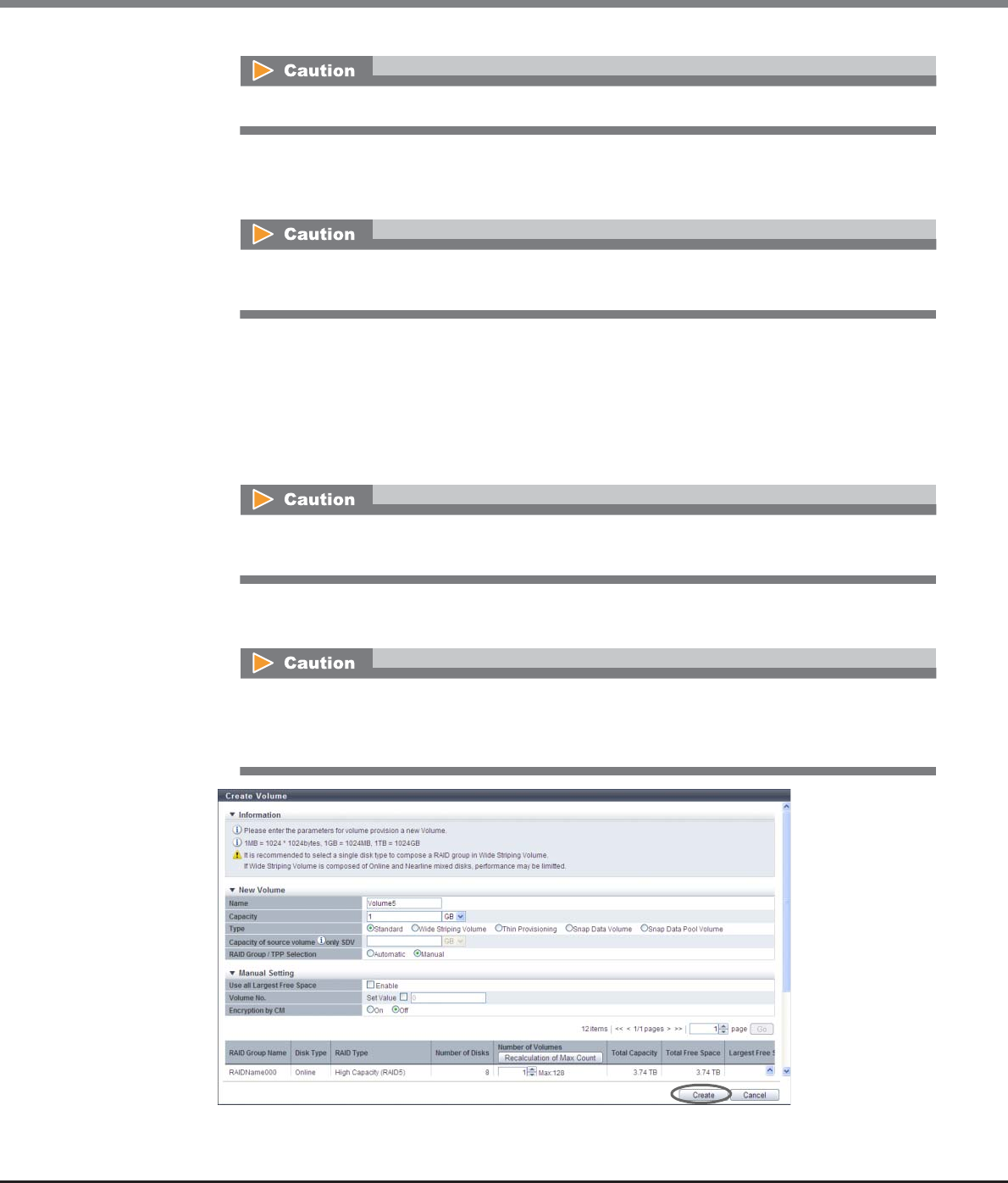
Chapter 5 Volume Management
5.2 Functions in the Action Area for Volume
ETERNUS Web GUI User’s Guide
Copyright 2013 FUJITSU LIMITED P2X0-1090-10ENZ0
103
•Encryption by CM
Select whether to encrypt (On) or not encrypt (Off) the new volumes. When the encryption mode is
disabled, "On" cannot be selected.
•Number of Volumes (When creating volumes other than "TPV")
Specify the number of volumes that is to be created in each RAID group between "1" and "128".
Click the [Recalculation of Max Count] button to display the maximum number of volumes that can
be created in each RAID group with the specified capacity. When the volume capacity is not speci-
fied (including when "Use all Largest Free Space" is selected), the maximum number of volumes
that can be created for each RAID group is displayed. When "Encryption by CM" is "On", volumes can-
not be created in the RAID groups for which "Disk Type" is "SED".
•Number of Volumes (When creating "TPV")
Specify the number of volumes that is to be created in each TPP between "1" and "16384".
→A confirmation screen appears.
An existing volume number cannot be specified.
When creating a volume (when specifying "1" or more for "Number of Volumes") in the RAID group
for which "Disk Type" is "SED", select "Off" for this item.
When volume numbers are manually specified, only one volume can be created at a time. Input
"1" for "Number of Volumes".
•When using the ETERNUS DX8700 S2, up to 1024 volumes can be created at a time.
•When volume numbers are manually specified, only one volume can be created at a time.
Input "1" for "Number of Volumes".
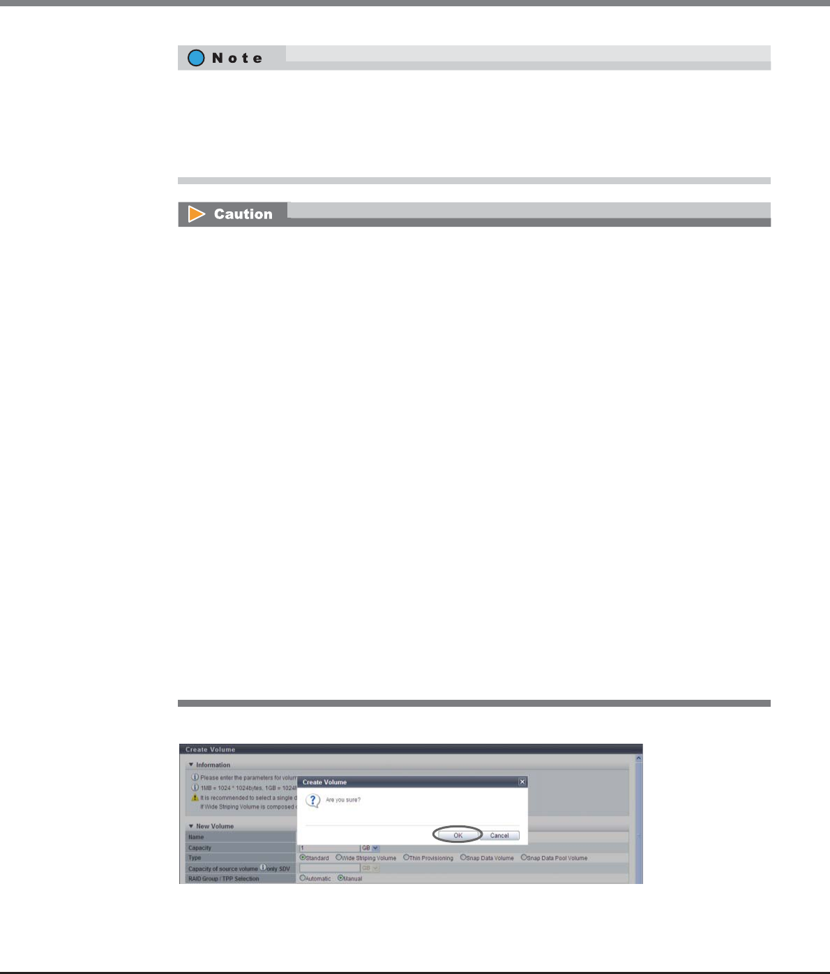
Chapter 5 Volume Management
5.2 Functions in the Action Area for Volume
ETERNUS Web GUI User’s Guide
Copyright 2013 FUJITSU LIMITED P2X0-1090-10ENZ0
104
4Click the [OK] button.
→Volume creation starts.
•When specifying the volume number, select the "Set Value" checkbox and input the volume
number.
•When using the maximum free space in the RAID group to create volumes without specifying the
capacity, select the "Enable" checkbox for "Use all Largest Free Space", and then input the number
of volumes. This setting is available for "Standard" and "SDPV" type volumes.
•When creating a "TPV", the "Encryption by CM" setting cannot be changed.
•An error screen appears in the following conditions:
-When a name is not input for "Name"
-When the "Name" overlaps with an existing volume name
-When the "Name" does not satisfy the input conditions
-When the "Enable" checkbox for "Use all Largest Free Space" is cleared and "Capacity" is not
input
-When the capacity that is specified for "Capacity" exceeds the maximum capacity that can be
created
-When the SDPV capacity that is specified for "Capacity" is not a multiple of the SDPE capacity
(1GB/2GB/4GB)
-When the "Enable" checkbox for "Use all Largest Free Space" is selected and the capacity of a
created volume is 23MB or less
-When the "Enable" checkbox for "Use all Largest Free Space" is selected and the capacity of a
created volume exceeds the maximum capacity
-When the "Set Value" checkbox is selected and "Volume No." is not input
-When the input value of "Volume No." exceeds the settable range
-When the specified "Volume No." is already used
-When "Volume No." is specified and total number of values that are specified to "Number of
Volumes" is not "1"
-When the number of volumes that is specified for "Number of Volumes" exceeds the maximum
number of volumes that can be created
-When free space in the RAID group or TPP is insufficient
-When LDE is being performed in the RAID group

Chapter 5 Volume Management
5.2 Functions in the Action Area for Volume
ETERNUS Web GUI User’s Guide
Copyright 2013 FUJITSU LIMITED P2X0-1090-10ENZ0
105
5Click the [Done] button to return to the [Volume] screen.
End of procedure
■When creating WSV type volumes
WSVs are created by concatenating volumes that are the same size in multiple RAID groups. Input the volume
information for WSVs and the selection information for RAID groups, and specify the RAID groups that are to
be concatenated.
The procedure to create WSV type volumes is as follows:
Procedure
1Click [Create] in [Action].
2Input the detailed information of the volumes that are to be created, specify the selection
information of the RAID group, and then click the [Select RAID Groups] button.
●New Volume
•Name
Specify the volume name. An existing volume name cannot be specified. When creating multiple
volumes at the same time, the new volumes are named automatically. Refer to "Naming
conventions for creating volumes" (page 993) for details.
The following input condition applies:
-Up to 16 alphanumeric characters and symbols (except ", (comma)" and "?")
•The conditions for RAID groups to configure WSVs are as follows:
-The RAID type must be the same
-The number of member drives in the RAID group must be the same
-The Stripe Depth value must be the same
-The disk type (Online/Nearline/SSD/SED) must be the same
(since the access performance of WSVs is reduced, do not select "Online/Nearline").
-The disk speed must be the same
(RAID groups configured with different speed drives can be selected. Note that this reduces the access
performance for WSVs. It is recommended to select the same speed disks. The speed of the drives that
configure a RAID group can be checked in the [RAID Group Detail] screen ([Disk] tab).)
-The key group setting is the same as the existing RAID groups
(When "Disk Type" is "SED", RAID groups with the key group setting enabled or disabled can be
selected. Selecting the same key group setting status is recommended. Not doing so reduces the
access performance for WSVs. The key group setting status can be checked with the "Encryption" field
in the [Select RAID Groups] screen.)
-The sequential unused area must be the same size or bigger than the capacity of the volumes that are
to be concatenated
•The number of concatenated RAID groups is from 2 to 64.
•The WSV capacity is from 24MB to 128TB.
Chapter 5 Volume Management
5.2 Functions in the Action Area for Volume
ETERNUS Web GUI User’s Guide
Copyright 2013 FUJITSU LIMITED P2X0-1090-10ENZ0
106
•Capacity
Specify the volume capacity and select the unit of capacity.
Up to a 15-digit number including the "." (decimal point) can be input. Note that when "MB" is
selected, the specified value is rounded down to the nearest whole number. When "GB" or "TB" is
selected, the specified value is converted to "MB" and rounded down to the nearest whole number.
The following input conditions apply:
-24MB - 128TB (numeric characters)
-MB/GB/TB
•Type
Select "Wide Striping Volume".
-Wide Striping Volume
Volumes that are configured by multiple RAID groups that are concatenated with striping to
improve performance.
•RAID Group/TPP Selection
"Manual" is selected.
●Volume Information
•Use all Largest Free Space
Select the "Enable" checkbox to create the specified number of WSVs with the largest available free
space in the selected RAID group.
WSVs are created by concatenating spaces with the same capacity in multiple RAID groups. If
"Enable" is selected, the specified number of WSVs in the "Number of Volumes" field are created
using the smallest "Largest Free Space" value in the concatenated RAID groups.
Up to 15 numbers can be used. If a decimal point is included in the input value, up to 14 numbers
can be used.
[Example] 0.1234567890123 (14 numbers and a decimal point)
When creating multiple volumes in a RAID group, the maximum number of volumes that can be
created for the user capacity may be reduced. To use the entire user capacity, the volume size must
be an exact multiple of the basic size (stripe size). Refer to "E.1 Basic Size for each RAID Group"
(page 995) for details.
When "Wide Striping Volume" is specified for "Type", "Manual" is selected automatically. Note that
"Automatic" cannot be selected.
•When "Enable" is selected, the capacity and the unit that are specified for "New Volume" are
not available.
•The capacity for created WSVs is not displayed. Use the [Volume] screen to check the volume
capacity after volume creation is complete.

Chapter 5 Volume Management
5.2 Functions in the Action Area for Volume
ETERNUS Web GUI User’s Guide
Copyright 2013 FUJITSU LIMITED P2X0-1090-10ENZ0
107
•Number of Volumes
The number of volumes that are to be created is displayed. Note that "1" is displayed when "Manual"
is selected for "Concatenation Order".
•Volume No.
When specifying the volume number for a new volume, select the "Set Value" checkbox and input
the volume number.
The following input condition applies:
-Numeric characters (decimal)
-The following volume numbers can be used for each model:
•ETERNUS DX80 S2: 0 - 2047
•ETERNUS DX90 S2: 0 - 4095
•ETERNUS DX410 S2/DX440 S2: 0 - 16383
•ETERNUS DX8100 S2: 0 - 16383
•ETERNUS DX8700 S2: 0 - 65534
•Wide Stripe Size
Select the Wide Stripe Size ("Normal" or "Small") for the volumes.
"Wide Stripe Size" is the size of the WSV Unit that is allocated to each RAID group in series. It is not
necessary to change the default setting (Normal) for normal use.
-Normal
An integral multiple of the basic size for each RAID type (*1). The maximum size is 16MB or
smaller.
The actual size varies according to the RAID group type, the number of member disks, and Stripe
Depth.
Select "Normal" to improve random write access performance.
-Small
An integral multiple of the basic size for each RAID type. The maximum size is 2MB or smaller.
The actual size varies according to the RAID group type, the number of member disks, and Stripe
Depth.
Note that because the segment size of the volume is small and many host accesses among
multiple RAID groups occur, the performance may be reduced according to the amount of host I/
O.
*1: The basic size (stripe size) when creating a volume. Refer to "E.1 Basic Size for each RAID Group"
(page 995) for details.
When volume numbers are manually specified, only one volume can be created at a time. Input
"1" for "Number of Volumes".
An existing volume number cannot be specified.
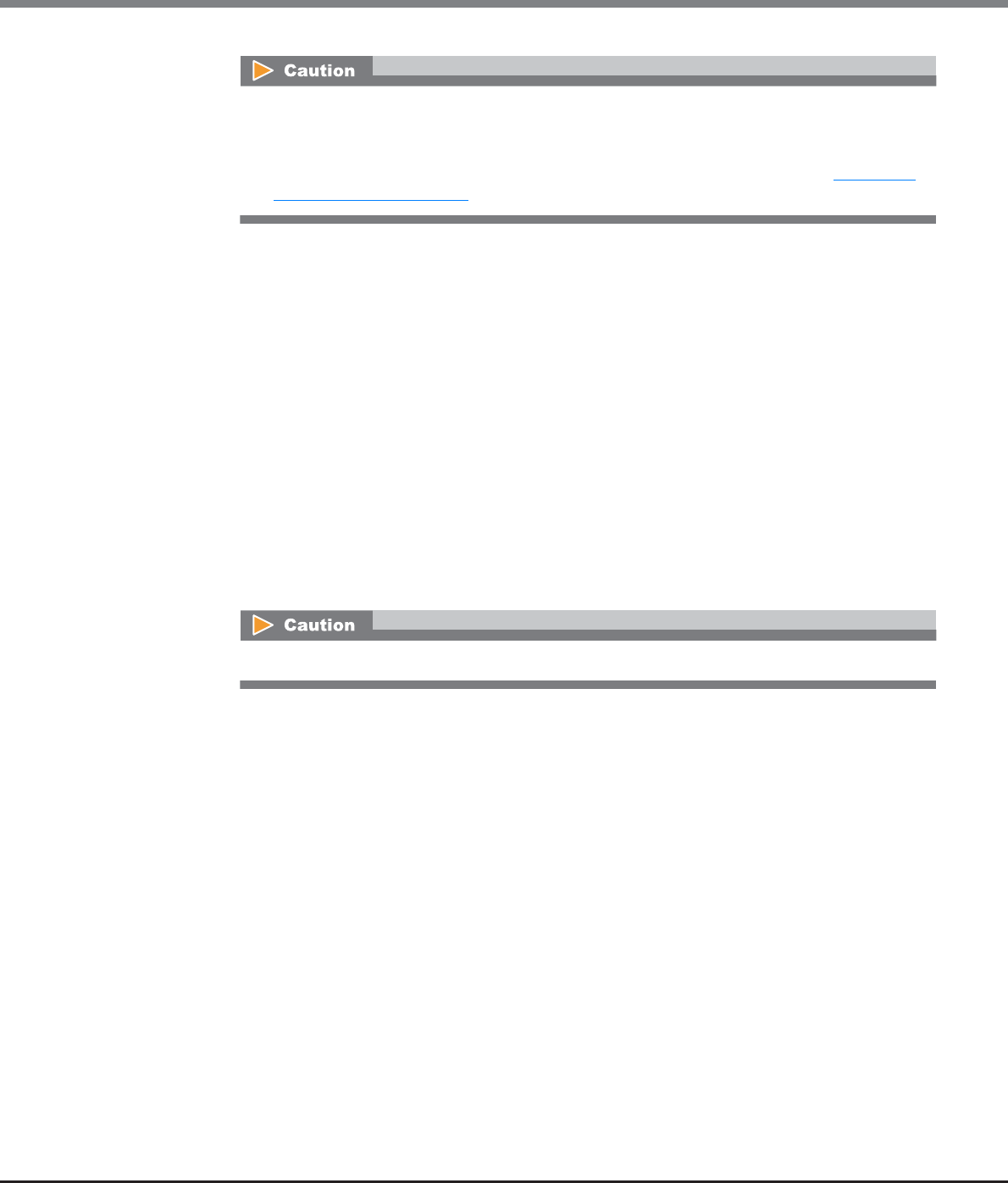
Chapter 5 Volume Management
5.2 Functions in the Action Area for Volume
ETERNUS Web GUI User’s Guide
Copyright 2013 FUJITSU LIMITED P2X0-1090-10ENZ0
108
•Concatenation Order
Select the concatenation order of RAID groups from "Automatic" or "Manual". It is not necessary to
change the default setting (Automatic) for normal use.
-Automatic
Automatically specify the concatenation order of RAID groups.
If multiple WSVs are already registered, the next available RAID group that enables the
controlling CM allocation to be distributed evenly is selected as 1 for the concatenation order. If
multiple RAID groups satisfy this condition, the RAID group with the smallest RAID group
number is selected as 1 in the concatenation order. RAID groups are concatenated starting from
1 (first) in ascending order. The last RAID group is concatenated to the first RAID group.
Volumes that belong to a RAID group for which the concatenation order is 1 (first) are called
"representative volumes".
-Manual
Manually specify the concatenation order of the RAID group.
•Encryption by CM
Select whether to encrypt (On) or not encrypt (Off) the new volumes. When the encryption mode is
disabled, "On" cannot be selected.
●Select RAID Group Information
•Disk Type
Specify the drive type.
The installed drive determine the selectable disk types that are displayed.
If there are no RAID groups in which volumes can be created, the field is blank.
-Online
-Nearline
-SSD
-SED
-Online/Nearline
-Blank
•If the basic size of the RAID group is 2MB or more, the basic size is specified for Wide Stripe Size
even when "Small" is selected.
•This function cannot be used to change the "Wide Stripe Size" setting after WSVs are created. To
change the "Wide Stripe Size" value, use the [RAID Migration] function. Refer to "5.2.7 Start
RAID Migration" (page 123) for details.
When specifying "SED" for "Disk Type", select "Off" for "Encryption by CM".

Chapter 5 Volume Management
5.2 Functions in the Action Area for Volume
ETERNUS Web GUI User’s Guide
Copyright 2013 FUJITSU LIMITED P2X0-1090-10ENZ0
109
•RAID Type
Select the RAID type.
If there are no RAID groups in which volumes can be created, the field is blank.
-High Performance (RAID1+0)
-High Capacity (RAID5)
-High Reliability (RAID6)
-Reliability (RAID5+0)
-Mirroring (RAID1)
-Striping (RAID0)
•Number of Member Disks
Select the number of member disks in the RAID group.
The selectable number of member disks, which is determined by the specified RAID type, is
displayed.
If there are no RAID groups in which volumes can be created, the field is blank.
-High Performance (RAID1+0)
4, 6, 8, 10, 12, 14, 16, 18, 20, 22, 24, 26, 28, 30, 32
-High Capacity (RAID5)
3 - 16
-High Reliability (RAID6)
5 - 16
-Reliability (RAID5+0)
6, 8, 10, 12, 14, 16, 18, 20, 22, 24, 26, 28, 30, 32
-Mirroring (RAID1)
2
-Striping (RAID0)
2 - 16
•Stripe Depth
Select the Stripe Depth of the RAID group.
The selectable Stripe Depth varies depending on the specified RAID type. Refer to "Available Stripe
Depth value" (page 180) for details.
If "Mirroring (RAID1)" is selected as the RAID type, a "-" (hyphen) is displayed.
If there are no RAID groups in which volumes can be created, the field is blank.
-64 KB
-128 KB
-256 KB
-512 KB
-1024 KB
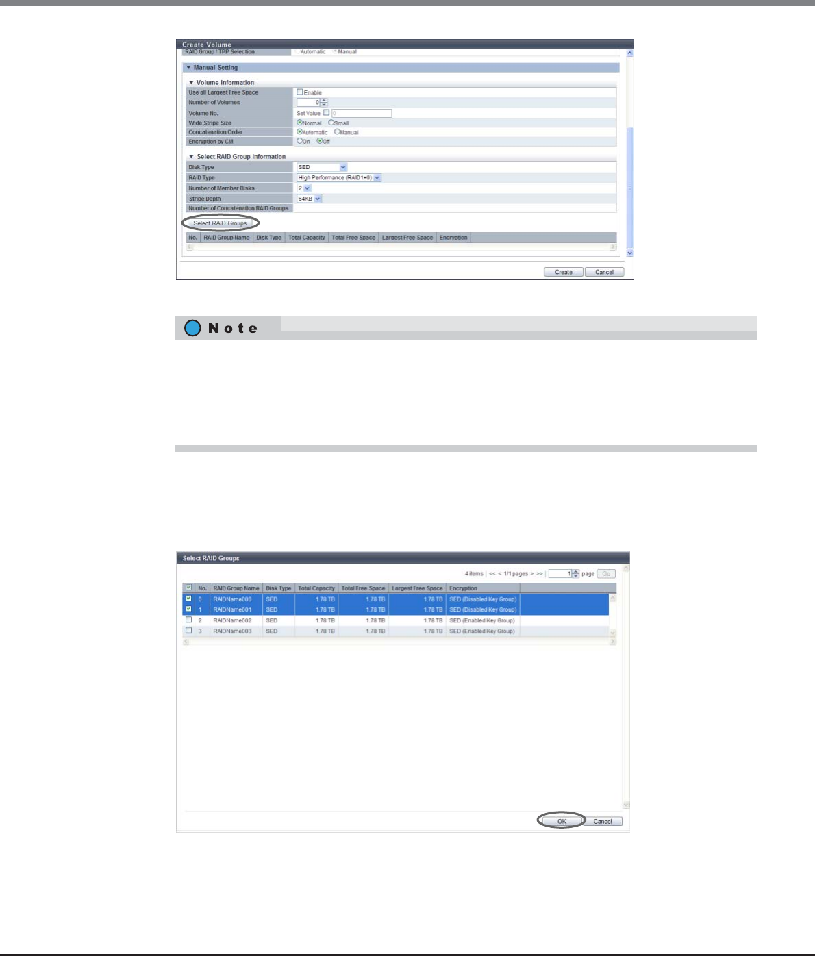
Chapter 5 Volume Management
5.2 Functions in the Action Area for Volume
ETERNUS Web GUI User’s Guide
Copyright 2013 FUJITSU LIMITED P2X0-1090-10ENZ0
110
→The [Select RAID Groups] screen appears.
3Select the RAID group that is to be concatenated (multiple selections can be made) and click
the [OK] button.
•Checkbox to select RAID groups
Select the checkbox for the RAID group to be selected.
→The display returns to the initial screen.
•When specifying the volume number, select the "Set Value" checkbox and input the volume
number.
•When using the maximum free space in the selected RAID group to create WSVs without specifying
the capacity, select the "Enable" checkbox for "Use all Largest Free Space", and then input the
number of WSVs.
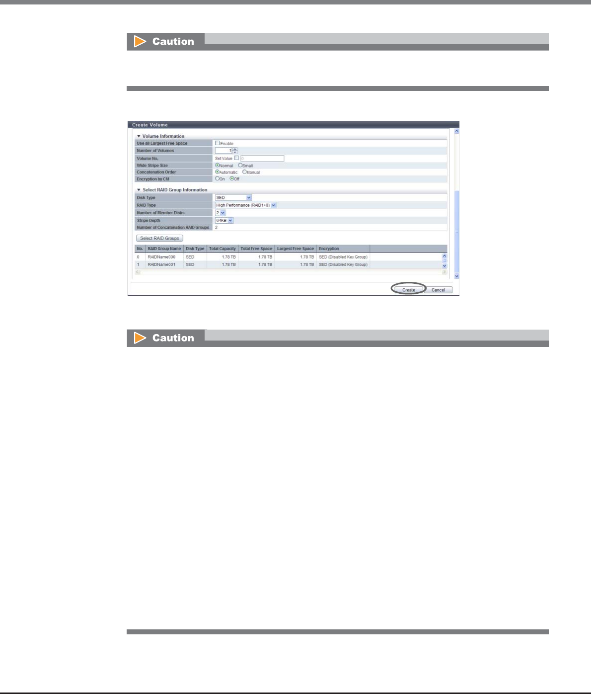
Chapter 5 Volume Management
5.2 Functions in the Action Area for Volume
ETERNUS Web GUI User’s Guide
Copyright 2013 FUJITSU LIMITED P2X0-1090-10ENZ0
111
4After selecting RAID groups is complete, click the [Create] button.
→A confirmation screen appears.
When "Disk Type" is "SED", setting the same "Encryption" settings (the setting status of the key group)
is recommended for all of the RAID groups that configure the WSV.
An error screen appears in the following conditions:
•When the "Name" is not input
•When the name overlaps with an existing volume name for "Name"
•When the "Name" does not satisfy the input conditions
•When the "Enable" checkbox for "Use all Largest Free Space" is cleared and "Capacity" is not input
•When the capacity that is specified for "Capacity" exceeds the maximum capacity that can be
created
•When the "Enable" checkbox for "Use all Largest Free Space" is selected and the capacity of a
created WSV is 23MB or less
•When the "Enable" checkbox for "Use all Largest Free Space" is selected and the capacity of a cre-
ated WSV exceeds the maximum capacity
•When the "Set Value" checkbox is selected and "Volume No." is not input
•When the input value of "Volume No." exceeds the settable range
•When the specified "Volume No." is already used
•When "Volume No." is specified and "Number of Volumes" is not "1"
•When the "Number of Concatenation RAID Groups" field is left blank, "1" is specified, or a value
that is "65" or more is specified
•When the maximum free space in the selected RAID group is smaller than the volume size that is
to be concatenated
•When LDE is being performed in the RAID group
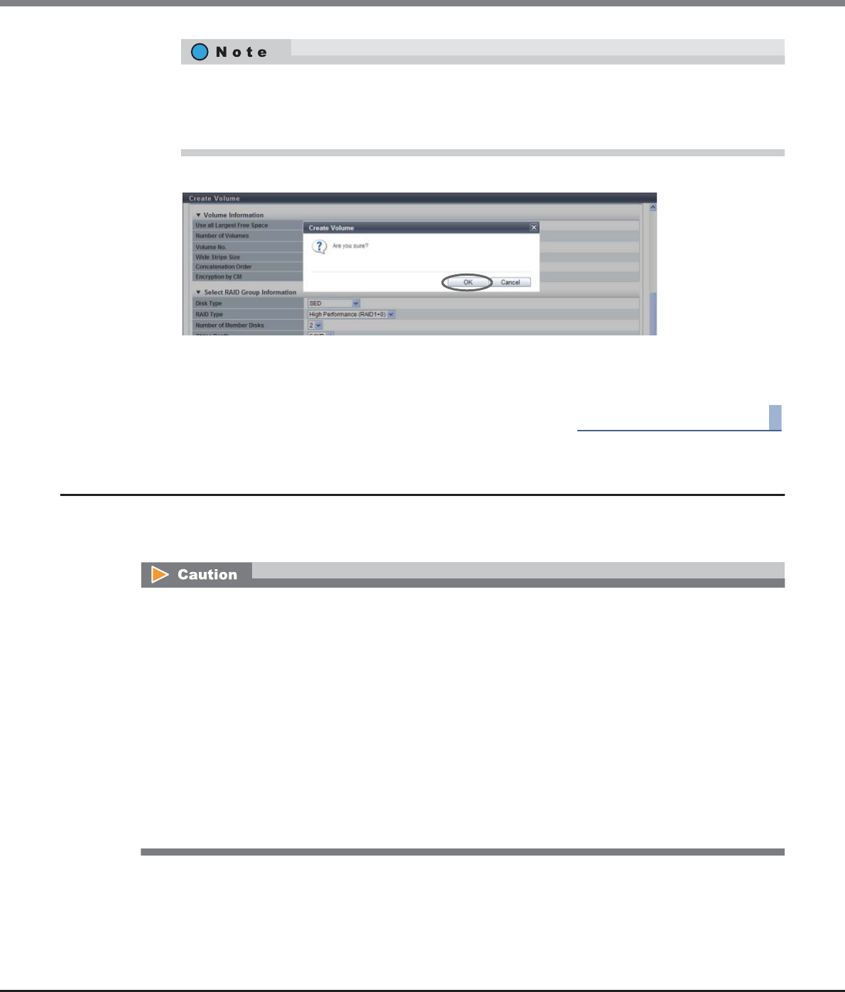
Chapter 5 Volume Management
5.2 Functions in the Action Area for Volume
ETERNUS Web GUI User’s Guide
Copyright 2013 FUJITSU LIMITED P2X0-1090-10ENZ0
112
5Click the [OK] button.
→Volume creation starts.
6Click the [Done] button to return to the [Volume] screen.
End of procedure
5.2.2 Delete Volume
This function deletes volumes.
Standard volumes, WSVs, TPVs, and SDVs can be deleted.
To change the concatenation order of the RAID groups, select "Manual" for "Concatenation Order" in
the Volume Information field. Click the [Concatenation Order] link to display the [Setting
Concatenation Order] screen. The concatenation order of the RAID groups can be changed in the
[Setting Concatenation Order] screen.
•When a volume is deleted, access to data in the target volume is not allowed.
•The following volumes cannot be deleted:
-Volumes that are registered in a LUN group
-Volumes that are mapped with applications other than GUI
-Volumes undergoing RAID migration
-A copy source volume or a copy destination volume of the Advanced Copy that is being executed
-Volumes undergoing TPV balancing (work volumes and target TPVs for balancing)
-Volumes undergoing FTRP balancing (work volumes)
-Volumes with a Storage Migration path
-An ODX Buffer volume for which Advanced Copy (ODX) is being performed
•By repeating creation and deletion of volumes, free space may be dispersed in the RAID group.
•Up to 128 volumes can be deleted at once.
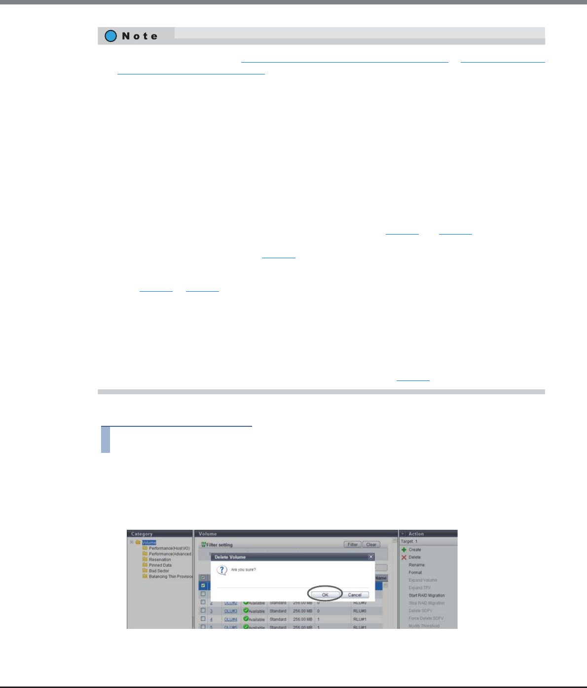
Chapter 5 Volume Management
5.2 Functions in the Action Area for Volume
ETERNUS Web GUI User’s Guide
Copyright 2013 FUJITSU LIMITED P2X0-1090-10ENZ0
113
The procedure to delete a volume is as follows:
Procedure
1Select the volume to be deleted (multiple selections can be made) and click [Delete] in
[Action].
→A confirmation screen appears.
2Click the [OK] button.
→Deletion of a volume starts.
•When deleting SDPVs, refer to "5.2.11 Delete Snap Data Pool Volume" (page 141) or "5.2.12 Force Delete
Snap Data Pool Volume" (page 142).
•This function can be used to delete an ODX Buffer volume.
•When volumes are registered in LUN groups, or a message "The specified volumes have already been
mapped. They cannot be deleted." is displayed, use the following procedure to delete the volumes from
LUN groups.
(1)Check all the LUN groups in which volumes are registered in the [LUN Group] screen under the
[Volume] navigation.
(2)Select a LUN group in which the volume is registered in the [LUN Group] screen under the
[Connectivity] navigation, and then click [Modify LUN Group] in [Action].
(3)Delete "allocation information of host LUN and volume number" in the [Modify LUN Group] screen.
(4)When a volume is registered in multiple LUN groups, repeat Step (2) and Step (3).
(LUN groups in which a volume is registered can be checked with the [LUN Group] field in the
[Modify LUN Group] screen in Step (3).)
(5) If the location information of the port (CM#x CA#y Port#z) is displayed in the [LUN Group] field in
Step (1) or Step (3), the volume is mapped with applications other than GUI. Use the relevant
application to delete the volume from the port mapping information.
(6)Confirm that "LUN Group Count" is "0" in the [LUN Group] field under the [Volume] navigation.
(7)Use this function to delete volumes.
It is not necessary to delete a host affinity when deleting volumes with the host affinity setting from a
LUN group. If all of the volumes in a LUN group are not needed, delete the host affinity, and then click the
[Delete LUN Group] button to delete the LUN group with volumes in Step (2).
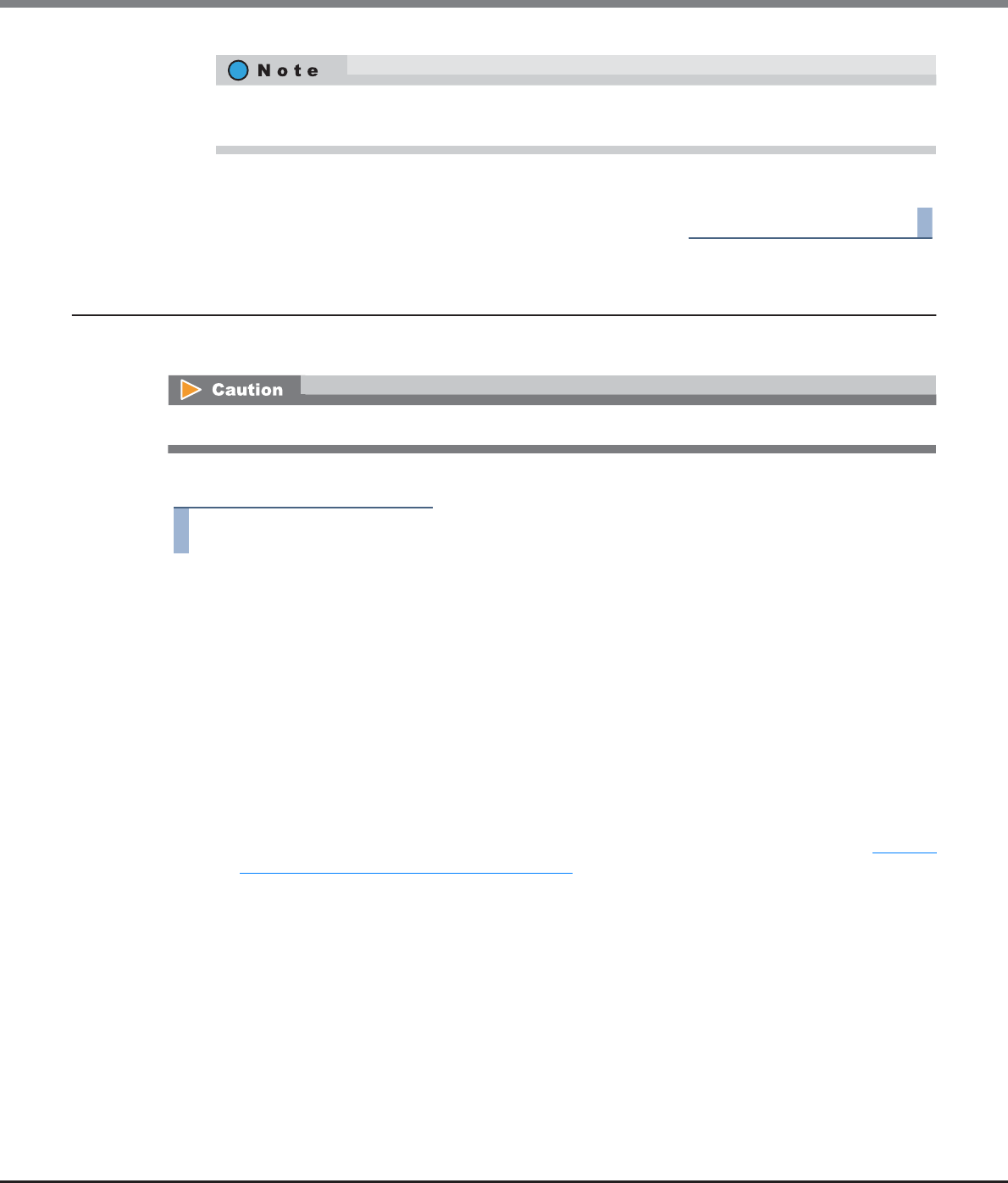
Chapter 5 Volume Management
5.2 Functions in the Action Area for Volume
ETERNUS Web GUI User’s Guide
Copyright 2013 FUJITSU LIMITED P2X0-1090-10ENZ0
114
3Click the [Done] button to return to the [Volume] screen.
End of procedure
5.2.3 Rename Volume
This function changes the volume name.
The procedure to rename a volume is as follows:
Procedure
1Select the volume to be renamed (multiple selections can be made) and click [Rename] in
[Action].
2Input the new volume "Name" and the "Start of Suffix" (only when multiple volumes are
selected), and click the [Rename] button.
•Name
Input a new volume name.
The following input condition applies:
-Up to 16 alphanumeric characters and symbols (except ", (comma)" and "?")
•Start of Suffix
Input the starting number of the suffix that is to be added to the new volume name. When
changing multiple volume names, the suffix number is added to the volume names with
consecutive numbers in ascending order starting with the entered number. Refer to "Naming
conventions for renaming volumes" (page 993) for details. When changing only one volume name,
the "Start of Suffix" field is not displayed.
The following input conditions apply:
-Numeric characters ("0" - "99999")
-Decimal number
-1 - 5 digits
When a TPV is deleted, the physical allocating capacity of the relevant TPV is formatted. The physical
allocating capacity is released after formatting is complete.
When using the ETERNUS DX8700 S2, up to 1024 volumes can be renamed at once.
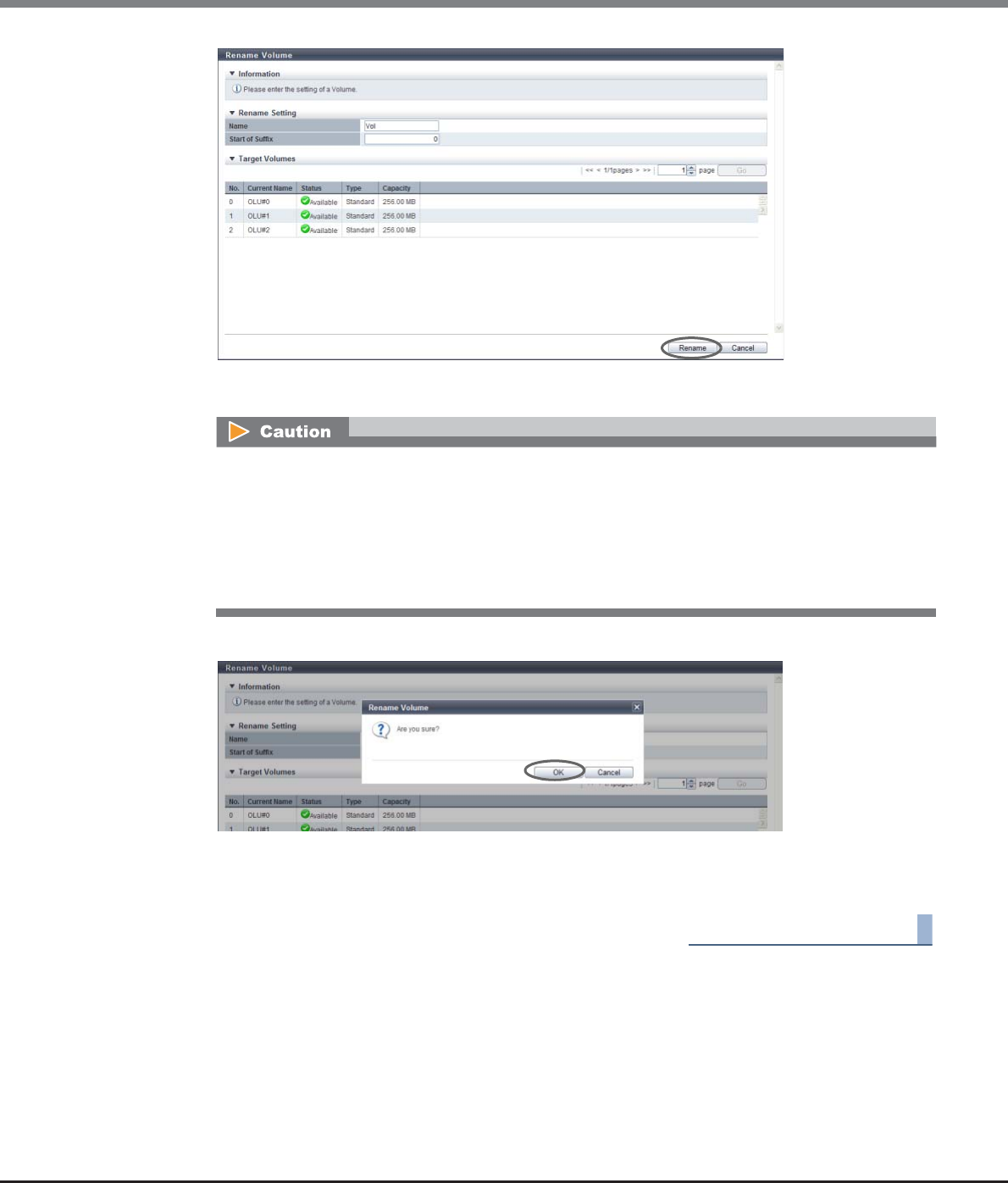
Chapter 5 Volume Management
5.2 Functions in the Action Area for Volume
ETERNUS Web GUI User’s Guide
Copyright 2013 FUJITSU LIMITED P2X0-1090-10ENZ0
115
→A confirmation screen appears.
3Click the [OK] button.
→Renaming of the volume starts.
4Click the [Done] button to return to the [Volume] screen.
End of procedure
An error screen appears in the following conditions:
•When the volume name is not input
•When the "Name" does not satisfy the input conditions
•When the "Name" overlaps with an existing volume name (when selecting a single volume)
•When the "Start of Suffix" is not input (when selecting multiple volumes)
•When the "Start of Suffix" does not satisfy the input conditions (when selecting multiple volumes)
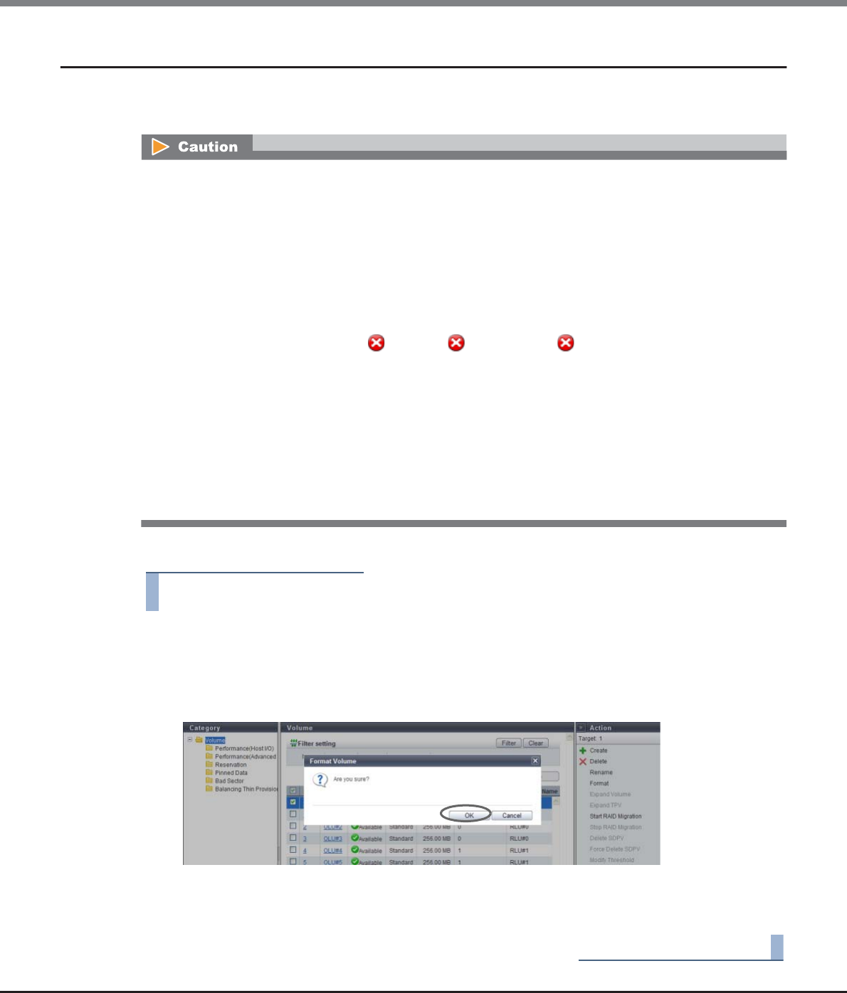
Chapter 5 Volume Management
5.2 Functions in the Action Area for Volume
ETERNUS Web GUI User’s Guide
Copyright 2013 FUJITSU LIMITED P2X0-1090-10ENZ0
116
5.2.4 Format Volume
This function formats the selected volume.
The data stored in the volume will be deleted by formatting.
The procedure to format a volume is as follows:
Procedure
1Select the volume to be formatted (multiple selections can be made) and click [Format] in
[Action].
→A confirmation screen appears.
2Click the [OK] button.
→Formatting of a volume starts.
3Click the [Done] button to return to the [Volume] screen.
End of procedure
•Formatting newly created volumes is not required since these volumes are formatted automatically.
•This function formats "Standard", "WSV", "SDV", "SDPV", "TPV", and "FTV" type volumes.
•When formatting a TPV, the physical allocating area that is used by the target TPV is released.
•This function cannot be used under the following conditions:
-When a RAID group diagnosis is being performed in the ETERNUS DX Disk storage system
-When a disk diagnosis is being performed in the ETERNUS DX Disk storage system
-When pinned data exists in the ETERNUS DX Disk storage system
•The following volumes cannot be formatted:
-Volumes for which "Status" is " Broken", " Data Lost", or " Not Ready"
-Volumes undergoing RAID migration
-A copy source volume or a copy destination volume of an Advanced Copy (local/remote) that is being
performed
-Volumes registered in a RAID group undergoing Logical Device Expansion (LDE)
-An ODX Buffer volume for which Advanced Copy (ODX) is being performed in the ETERNUS DX Disk
storage system
•Do not format the volumes with Storage Migration paths.
•When using the ETERNUS DX8700 S2, up to 1024 volumes can be formatted at a single operation.

Chapter 5 Volume Management
5.2 Functions in the Action Area for Volume
ETERNUS Web GUI User’s Guide
Copyright 2013 FUJITSU LIMITED P2X0-1090-10ENZ0
117
5.2.5 Expand Volume
This function concatenates a new volume to the selected volume by using the LUN Concatenation function to
expand the volume capacity that can be used from the server.
Volume expansion provides the following features:
•Volume capacity can be expanded by using the free space in an existing RAID group.
•Free space that is 1GB or more can be concatenated.
•A volume with a maximum capacity of 128TB can be created. (The maximum capacity of ODX Buffer
volume is 1TB.)
•Concatenation can be performed among multiple RAID groups.
•Any RAID type can be applied for a concatenation source volume and a concatenation destination volume.
Concatenation can be performed regardless of the RAID type for the concatenation source volume and the
concatenation destination volume.
•Data can be accessed from the host in the same way regardless of the concatenation status (before,
during, or after concatenation).
•When the number of volumes in a concatenated volume is 15 or less, volumes can be added to the existing
concatenated volume.
Requirements for concatenating a volume
•The "Type" is "Standard"
•The "Status" is not " Broken", " Data Lost", " Not Ready", or " Readying"
•The volume capacity is 1GB or larger
•When the concatenation source volume is a concatenated volume, the volume must satisfy the following
requirements:
-The number of volumes in the concatenated volume must be 15 or less
-The capacity of the concatenated volume must be less than 128TB
(If the concatenated volume is configured with an ODX Buffer volume, the volume must be less than
1TB)
•RAID migration is not being performed (the target volume is not used as a migration source or a migration
destination)
•There are no Advanced Copy sessions (local or remote) for which the copy range is "Totally" (*1)
•LDE is not being performed for the RAID group to which the target volume belongs
•Encryption is not being performed for the target volume
•A Storage Migration path is not created in the target volume
•The "Cache Page Capacity" must not be limited (*2)
*1: "Totally" is specified for the copy range in the following conditions:
•When performing a LUN to LUN copy session with the ETERNUS SF AdvancedCopyManager Copy Control Module
(CCM)
•When performing a copy session with ETERNUS SF AdvancedCopyManager Adapter for VMware Site Recovery
Manager
•When performing a copy session with ETERNUS VSS Hardware Provider
•When performing a SnapOPC+ session that is specified with GUI or CLI
*2: A "-" (hyphen) is specified for "Cache Page Capacity" by using the procedure in "5.2.18 Modify Cache Parameters"
(page 148). Note that "-" (hyphen) is the default value.
Chapter 5 Volume Management
5.2 Functions in the Action Area for Volume
ETERNUS Web GUI User’s Guide
Copyright 2013 FUJITSU LIMITED P2X0-1090-10ENZ0
118
Requirements to obtain free space from RAID groups
•The "Status" is not " Broken"
•The RAID group must satisfy the following requirements:
-The RAID group must contain Standard type volumes, WSVs, SDVs, or SDPVs
If this is not the case, the RAID group must not contain any volumes
-The RAID group must not belong to a TPP
-The RAID group must not belong to an FTRP
-The RAID group must not be registered as an REC Disk Buffer
•The number of volumes registered in the target RAID group is 127 or less
•The free space for the RAID group is 1GB or larger
•The RAID group must not be blocked
•LDE is not being performed in the target RAID group
•When the disk type of the RAID group to which the concatenation source volume belongs is "SSD", the
concatenation destination RAID group must be configured with "SSD"
•When the disk type of the RAID group to which the concatenation source volume belongs is "SED", the
concatenation destination RAID group must be configured with "SED"
•Backing up the data before performing volume expansion is recommended.
•This function cannot be used under the following conditions:
-When the maximum number of volumes is already registered in the ETERNUS DX Disk storage system
-When switching firmware in hot mode in the ETERNUS DX Disk storage system
-When a RAID group diagnosis or a disk diagnosis is being performed in the ETERNUS DX Disk storage
system
•Expanded volume capacity must be recognized by server.
•The same RAID type and drive speed is recommended for the RAID group to which the concatenation
volume belongs and the RAID group after concatenation.
•The encryption status of volumes after concatenation is the same as the concatenation source volume.
•Concatenated volumes are formatted automatically. Refer to the [Volumes] screen for format progress.
•To expand the TPV capacity, refer to "5.2.6 Expand Thin Provisioning Volume" (page 121).
•Volume expansion (LUN concatenation) can be performed even when the concatenation source volume
is being formatted.
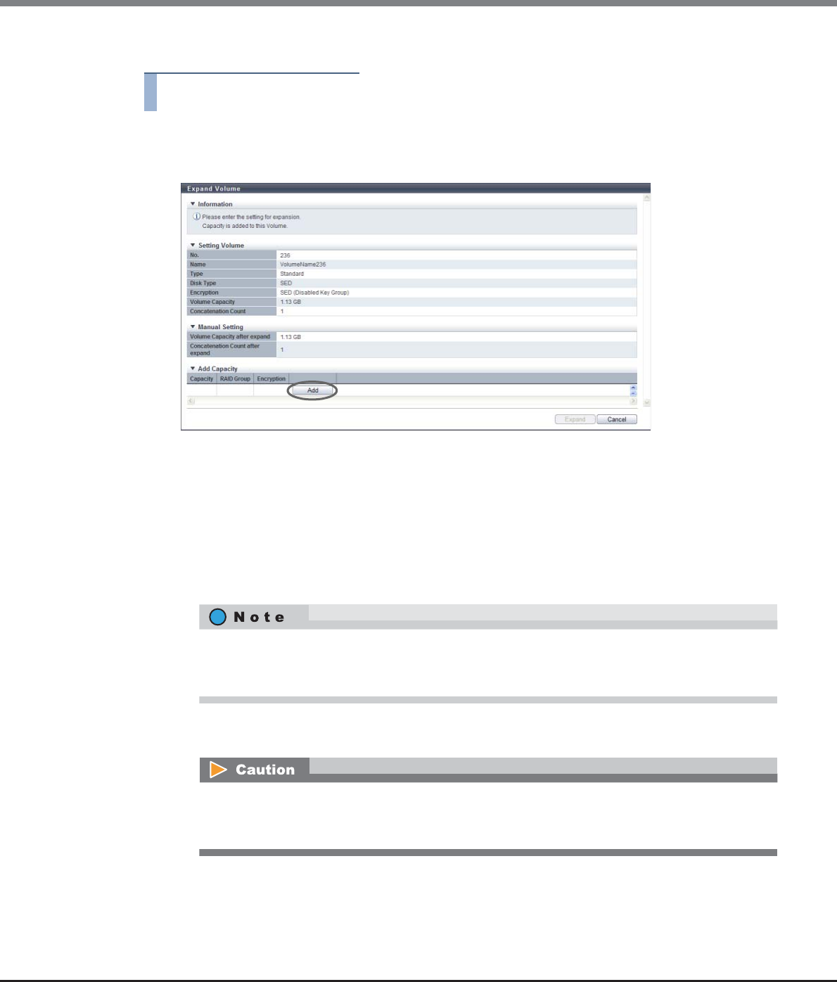
Chapter 5 Volume Management
5.2 Functions in the Action Area for Volume
ETERNUS Web GUI User’s Guide
Copyright 2013 FUJITSU LIMITED P2X0-1090-10ENZ0
119
The procedure to expand volume capacity is as follows:
Procedure
1Select the volume to be expanded and click [Expand Volume] in [Action].
2Click the [Add] button.
→The [Add Capacity] screen is displayed.
3Select the RAID group to obtain the free space from, specify the capacity to be concatenated,
and click the [OK] button.
•Capacity
Input the capacity that is to be concatenated and select the units of capacity (MB/GB/TB).
Up to a 15-digit number including the "." (decimal point) can be input. Note that when "MB" is
selected, the specified value is rounded down to the nearest whole number. When "GB" or "TB" is
selected, the specified value is converted to "MB" and rounded down to the nearest whole number.
•Select RAID Group
Select the radio button of the RAID group to obtain free space from.
Up to 15 numbers can be used. If a decimal point is included in the input value, up to 14 numbers
can be used.
[Example] 0.1234567890123 (14 numbers and a decimal point)
When "Disk Type" is "SED", selecting a RAID group with the same key group setting (Enabled Key
Group/Disabled Key Group) as the RAID group to which the concatenation source volume belongs
is recommended.
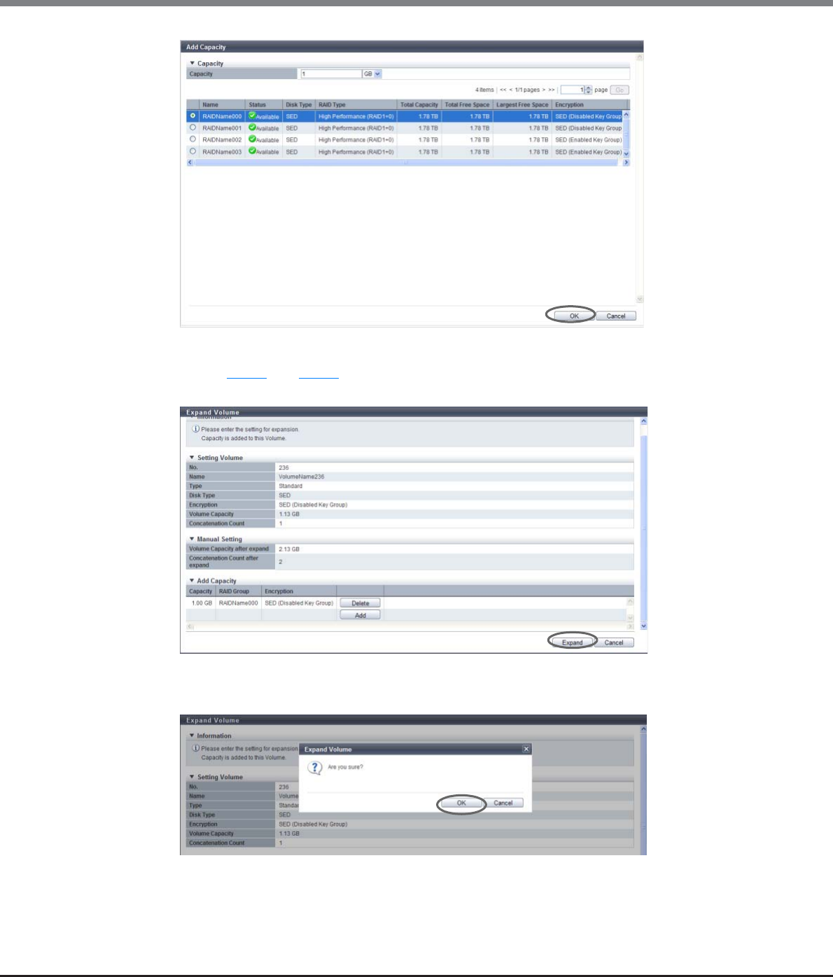
Chapter 5 Volume Management
5.2 Functions in the Action Area for Volume
ETERNUS Web GUI User’s Guide
Copyright 2013 FUJITSU LIMITED P2X0-1090-10ENZ0
120
→Returns to the [Expand Volume] screen.
4Repeat Step 2 and Step 3 to select RAID groups and specify the capacity. After completing
these settings, click the [Expand] button.
→A confirmation screen appears.
5Click the [OK] button.
→Expansion of a volume starts.
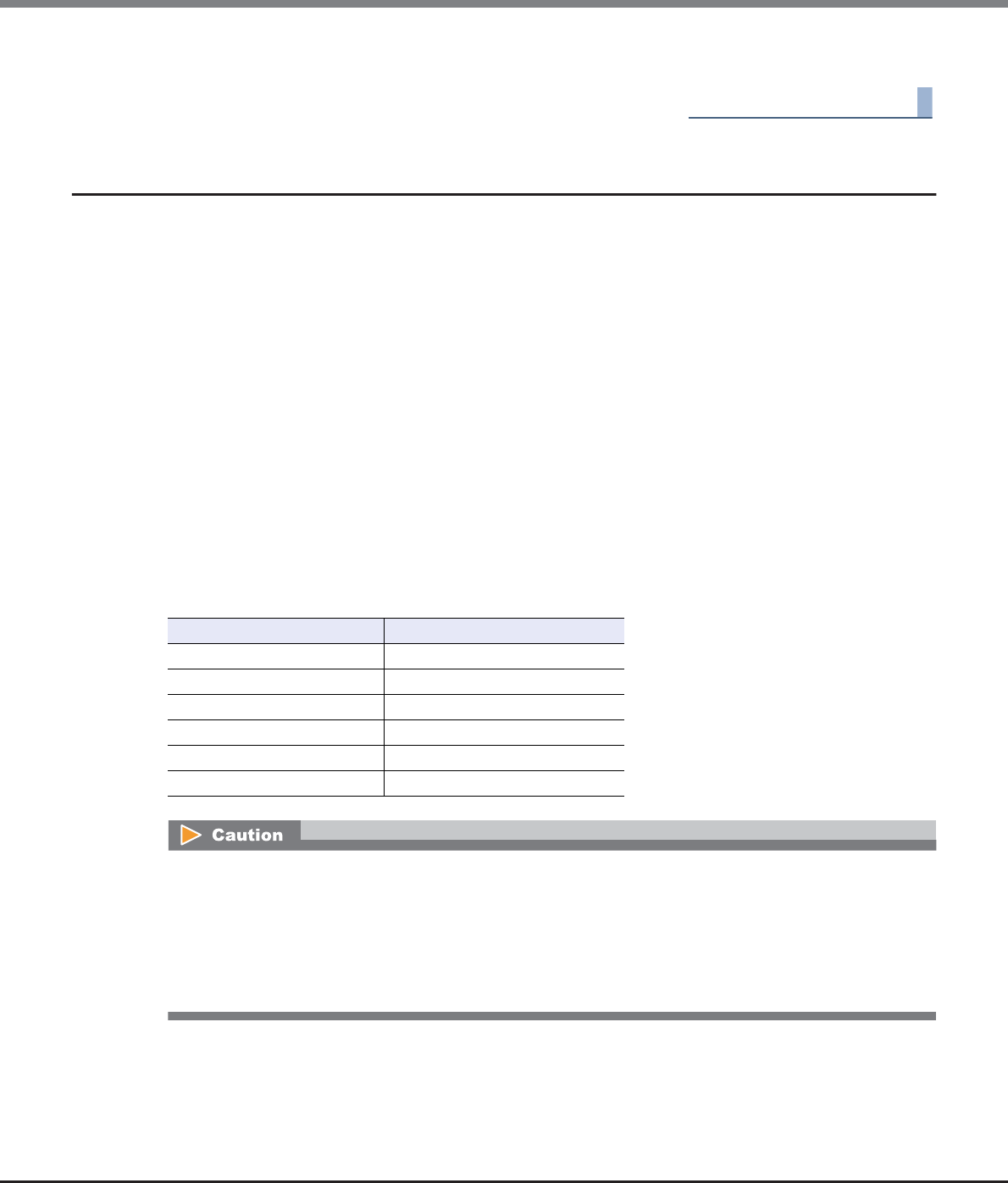
Chapter 5 Volume Management
5.2 Functions in the Action Area for Volume
ETERNUS Web GUI User’s Guide
Copyright 2013 FUJITSU LIMITED P2X0-1090-10ENZ0
121
6Click the [Done] button to return to the [Volume] screen.
End of procedure
5.2.6 Expand Thin Provisioning Volume
This function expands the capacity of Thin Provisioning Volumes.
Requirements for expanding a TPV
•The capacity is not 128TB or more (for ODX Buffer volumes, the capacity must not be 1TB or more)
•There are no Advanced Copy sessions for which the copy range is "Totally" (*1)
*1: "Totally" is specified for the copy range in the following conditions:
•When performing a LUN to LUN copy session with the ETERNUS SF AdvancedCopyManager Copy Control Module
(CCM)
•When performing a copy session with ETERNUS SF AdvancedCopyManager Adapter for VMware Site Recovery
Manager
•When performing a copy session with ETERNUS VSS Hardware Provider
•When performing a SnapOPC+ session that is specified with GUI or CLI
•Balancing is not being performed in the TPV
•RAID migration is not being performed in the TPV
•A Storage Migration path is not created in the TPV
The maximum capacity of Thin Provisioning Pool for each model
Model Maximum TPP Capacity (TB)
ETERNUS DX80 S2 128
ETERNUS DX90 S2 128
ETERNUS DX410 S2 384
ETERNUS DX440 S2 768
ETERNUS DX8100 S2 768
ETERNUS DX8700 S2 1024
•This function cannot be performed when there are no TPVs in the ETERNUS DX Disk storage system.
•The total capacity of TPVs must be smaller than the maximum capacity of TPP.
•The ODX Buffer volume capacity must not exceed 1TB.
•This function cannot be performed when there is no free space for expansion in the ETERNUS DX Disk
storage system.
•Expanded TPV capacity must be recognized by server.
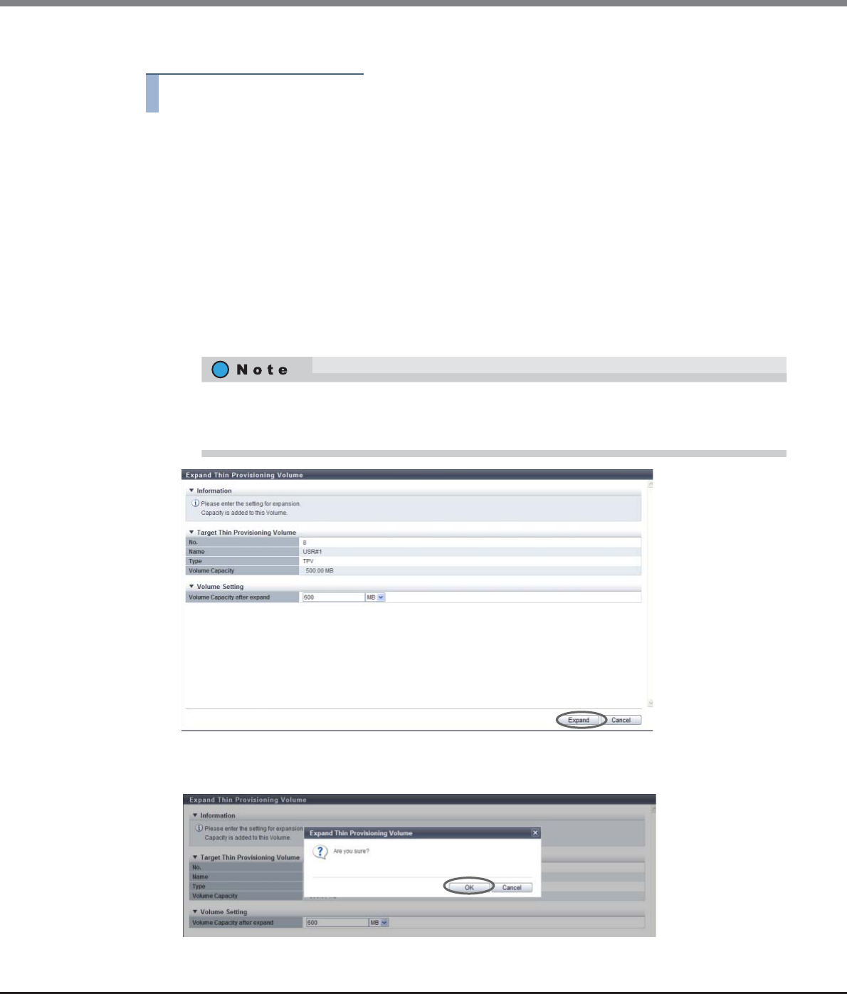
Chapter 5 Volume Management
5.2 Functions in the Action Area for Volume
ETERNUS Web GUI User’s Guide
Copyright 2013 FUJITSU LIMITED P2X0-1090-10ENZ0
122
The procedure to expand Thin Provisioning Volume capacity is as follows:
Procedure
1Select the TPV to be expanded and click [Expand TPV] in [Action].
2Input the TPV capacity after expansion, and click the [Expand] button.
•Volume Capacity after expand
Input the TPV capacity after expansion and select the units of capacity (MB/GB/TB).
Up to a 15-digit number including the "." (decimal point) can be input. Note that when "MB" is
selected, the specified value is rounded down to the nearest whole number. When "GB" or "TB" is
selected, the specified value is converted to "MB" and rounded down to the nearest whole number.
The following input conditions apply:
-25MB - 128TB (for volumes other than ODX)
-1025MB - 1TB (for ODX Buffer volumes)
-Capacity after expansion must be larger than the current capacity
→A confirmation screen appears.
3Click the [OK] button.
→Expansion of a TPV starts.
Up to 15 numbers can be used. If a decimal point is included in the input value, up to 14 numbers
can be used.
[Example] 0.1234567890123 (14 numbers and a decimal point)

Chapter 5 Volume Management
5.2 Functions in the Action Area for Volume
ETERNUS Web GUI User’s Guide
Copyright 2013 FUJITSU LIMITED P2X0-1090-10ENZ0
123
4Click the [Done] button to return to the [Volume] screen.
End of procedure
5.2.7 Start RAID Migration
RAID migration (hereinafter also referred to as migration) moves an existing volume in a RAID group, TPP, or
FTRP to a free space in another RAID group, TPP, or FTRP. After migration is complete, the migration source
volume is automatically deleted. This function can also be used to change the number of concatenations for
Wide Striping Volumes (WSV).
Migration provides the following features:
•Load balancing of host access.
•Volume capacity expansion is available when migrating volumes. (only when the volume type is
"Standard" or "WSV")
•The RAID type of the volume can be changed.
•The number of concatenations for WSVs can be increased or reduced.
•The Wide Stripe Size for WSVs can be changed.
•Because creation and format of new volumes and host interface establishment are automatically
performed, users are allowed to access the data anytime without being affected by the migration.
Migration type
The combinations of volume types that can be migrated are as follows:
Available: Migration is available
N/A: Migration is not available
*1: When migration from "Standard" or "WSV" to "TPV" or "FTV" is performed, 100% of the logical capacity of the "Stan-
dard" or "WSV" is allocated as the physical capacity for the "TPV" or "FTV". When "Start Zero Reclamation after migra-
tion" is enabled, the physical area that is filled with zeros can be released after the migration is complete.
*2: When migration from "TPV" or "FTV" to "Standard" or "WSV" is performed, 100% of the logical capacity of the "TPV" or
"FTV" is allocated as the logical capacity for "Standard" or "WSV".
Migration source
volume
Migration destination volume
Standard
Standard
(LUN
Concatenation)
WSV TPV FTV
Standard Available N/A Available Available (*1) Available (*1)
Standard
(LUN Concatenation)
Available N/A Available Available (*1) Available (*1)
WSV Available N/A Available Available (*1) Available (*1)
TPV Available (*2) N/A Available (*2) Available Available
FTV Available (*2) N/A Available (*2) Available Available
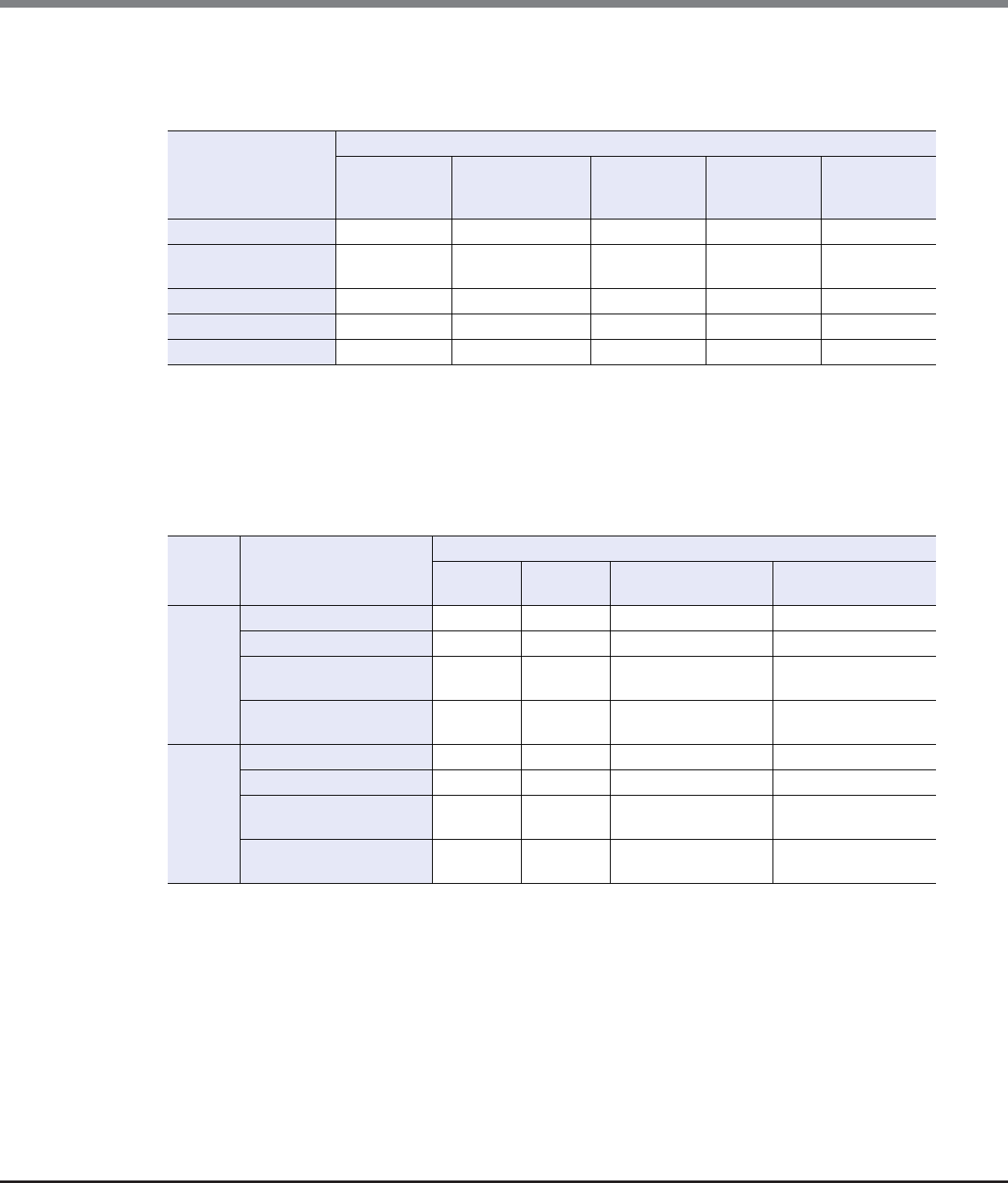
Chapter 5 Volume Management
5.2 Functions in the Action Area for Volume
ETERNUS Web GUI User’s Guide
Copyright 2013 FUJITSU LIMITED P2X0-1090-10ENZ0
124
Combinations of Volume Types for which Capacity Expansion is Available
The combinations of volume types for which capacity expansion can be performed are shown in the following
table.
Available: Capacity expansion is available
N/A: Capacity expansion is not available
–: Migration is not available
Combinations of Encryption Conditions for which Migration is Available
The combinations of encryption conditions for which migration can be performed are shown in the following
table.
Available: Migration is available
N/A: Migration is not available
*1: When the encryption mode is disabled, "by CM" cannot be selected.
*2: SEDs that are managed by the common key (the RAID groups are not registered in the key group).
*3: SEDs for which the SED authentication key is managed by the key server (the RAID groups are registered in the key
group). In this case, only RAID groups can be selected as the migration destination. Note that TPPs and FTRPs cannot
be selected.
*4: If a user without the "Security Setting" policy logs into GUI, migration to reduce the security level cannot be
performed.
Migration source
volume
Migration destination volume
Standard
Standard
(LUN
Concatenation)
WSV TPV FTV
Standard Available – Available N/A N/A
Standard
(LUN Concatenation)
Available – Available N/A N/A
WSV Available – Available N/A N/A
TPV N/A – N/A N/A N/A
FTV N/A – N/A N/A N/A
Security
priority
Encryption setting for the
migration source volume
Encryption setting for the migration destination volume
None by CM (*1) use SED (Disabled Key
Group) (*2)
use SED (Enabled Key
Group) (*3)
Yes None Available Available Available Available
by CM Available Available Available Available
use SED
(Disabled Key Group)
Available Available Available Available
use SED
(Enabled Key Group)
Available Available Available Available
No (*4) None Available Available Available Available
by CM N/A Available Available Available
use SED
(Disabled Key Group)
N/A Available Available Available
use SED
(Enabled Key Group)
N/A N/A N/A Available
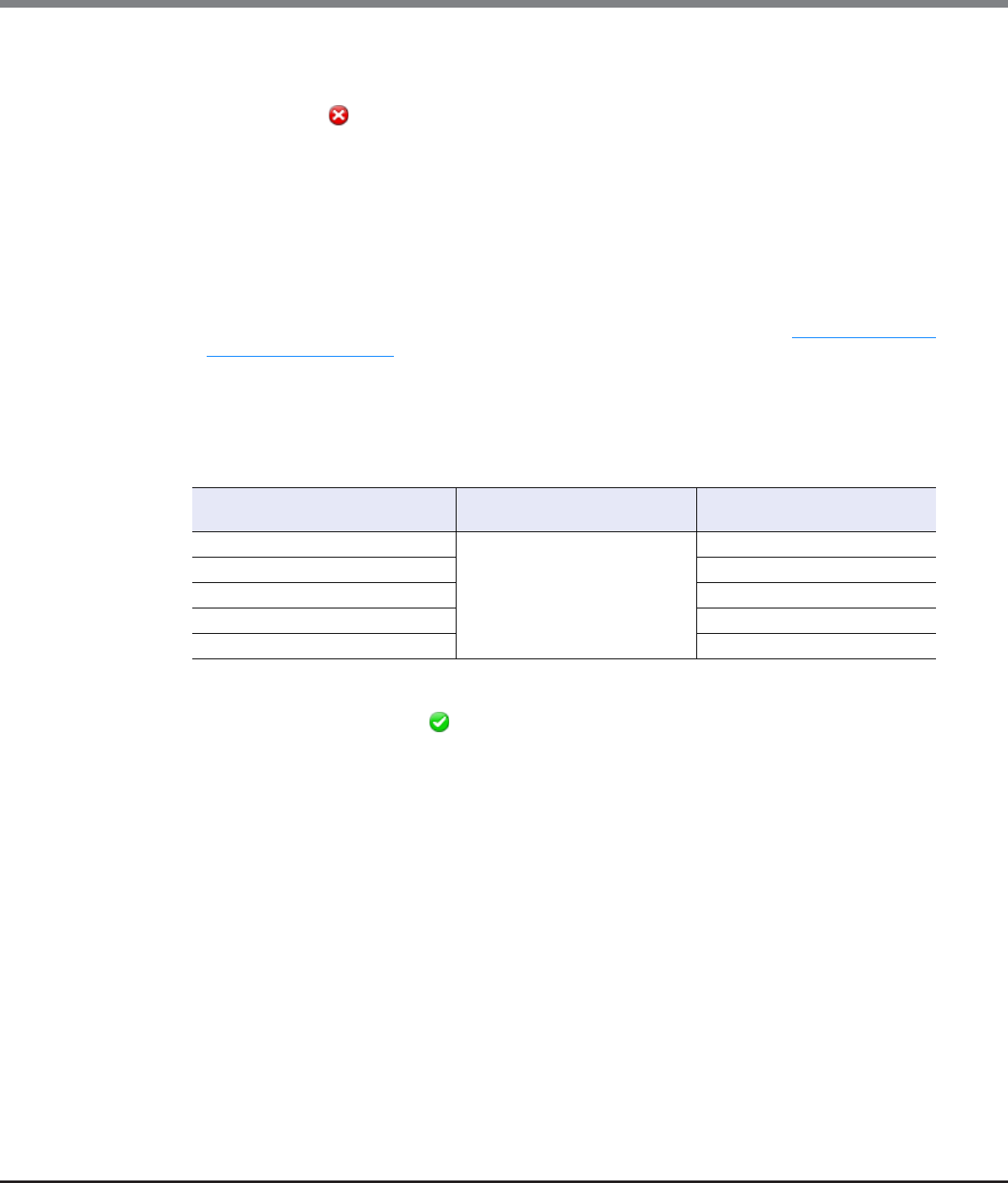
Chapter 5 Volume Management
5.2 Functions in the Action Area for Volume
ETERNUS Web GUI User’s Guide
Copyright 2013 FUJITSU LIMITED P2X0-1090-10ENZ0
125
Requirements for a migration source volume:
•The "Type" is "Standard", "WSV", "TPV", or "FTV"
•The "Status" is not " Broken"
•Formatting is not being performed (only when the volume type is "Standard" or "WSV")
•Migration is not being performed (the target volume is not used as a migration source or a migration
destination)
•TPV balancing is not being performed
•FTRP balancing is not being performed (*1)
•LDE is not being performed for the RAID group to which the target volume belongs
•Encryption is not being performed for the target volume
•A Storage Migration path is not created in the target volume
*1: When the FTRP balancing is performed, the FTV balancing process starts in the FTSP. Refer to "7.2.12 Start Balancing
Flexible Tier Pool" (page 248) for details.
Requirements for a migration destination RAID group:
•The maximum number of volumes are not set in the destination RAID group
Migration creates new volumes. The maximum number of volumes that can be created depends on the
ETERNUS DX Disk storage system model.
•"Standard", "WSV", "Snap Data Volume (SDV)", or "Snap Data Pool Volume (SDPV)" is registered in the RAID
group or the RAID group is not being used
•The "Status" of the RAID group is " Available"
•The free space of the RAID group is more than the capacity of the migration source volume (*1)
•The RAID group does not belong to a TPP
•The RAID group does not belong to an FTRP
•The RAID group is not registered as an REC Disk Buffer
•The RAID group is not blocked
•The free space of the RAID group is more than the capacity of the migration source volume (*1)
•The RAID group is not the same RAID group as the RAID group to which the migration source volume
belongs
•LDE is not being performed in the target RAID group
*1: When the migration source is a TPV or an FTV, the capacity of the migration source volume indicates the logical
capacity of the TPV or the FTV.
Model per RAID group per ETERNUS DX Disk storage
system
ETERNUS DX80 S2
Up to 128
Up to 2048
ETERNUS DX90 S2 Up to 4096
ETERNUS DX410 S2/DX440 S2 Up to 16384
ETERNUS DX8100 S2 Up to 16384
ETERNUS DX8700 S2 Up to 65535

Chapter 5 Volume Management
5.2 Functions in the Action Area for Volume
ETERNUS Web GUI User’s Guide
Copyright 2013 FUJITSU LIMITED P2X0-1090-10ENZ0
126
Requirements for RAID groups that configure a migration destination WSV
•"Standard", "WSV", "SDV", or "SDPV" is registered in the RAID group or the RAID group is not being used
•The "Status" of the RAID group is " Available"
•The maximum number of volumes are not created in the RAID group (*1)
•The RAID group does not belong to a TPP
•The RAID group does not belong to an FTRP
•The RAID group is not registered as an REC Disk Buffer
•The RAID group is not blocked
•LDE is not being performed in the target RAID group
•When using existing RAID groups (RAID groups configure the migration source WSV) to increase the
number of concatenations, the RAID groups that are added must satisfy the following conditions:
-The RAID group is the same RAID type as the existing RAID groups
-The number of member drives in the RAID group is the same as the existing RAID groups
-The Stripe Depth value is the same as the existing RAID groups
-The disk type is the same as the existing RAID groups
-The disk speed is the same as the existing RAID groups (recommended)
-The key group setting is the same as the existing RAID groups (recommended)
•When using existing RAID groups to increase the number of concatenations, all of the RAID groups,
including the existing RAID groups, must have sequential free capacity to migrate volumes (*2)
•When reducing the number of concatenations, all of the RAID groups that configure a WSV must have
sequential free capacity to migrate volumes (*2)
•The number of concatenations for RAID group must be 2 - 64
*1: When the migration destination is a WSV, one volume for each RAID group that configures striping is required (the
same number of volumes as the number of RAID groups in total).
*2: Because the volume (a part of the WSV that is striped by each RAID group) is moved into the free area in the same
RAID group when migration is performed, another sequential free area is required as a migration destination in
addition to the currently used area in the RAID group.
Requirements for a migration destination TPP:
•The "Status" is " Available", " Partially Readying", or " Exposed"
•The capacity of the TPP is more than the capacity of the migration source volume (*1)
•The capacity of the migration source volume is less than the maximum TPP capacity (*2) for each model
•The TPP is not the same as the TPP to which the migration source volume belongs
*1: When the migration source is a TPV or an FTV, the capacity indicates used capacity (the physical capacity that is
allocated from a TPP or an FTRP).
*2: The maximum TPP capacity is the total sum of the TPP capacity and the FTRP capacity in the ETERNUS DX Disk
storage system. Refer to "7.2.1 Create Thin Provisioning Pool" (page 219) for details.
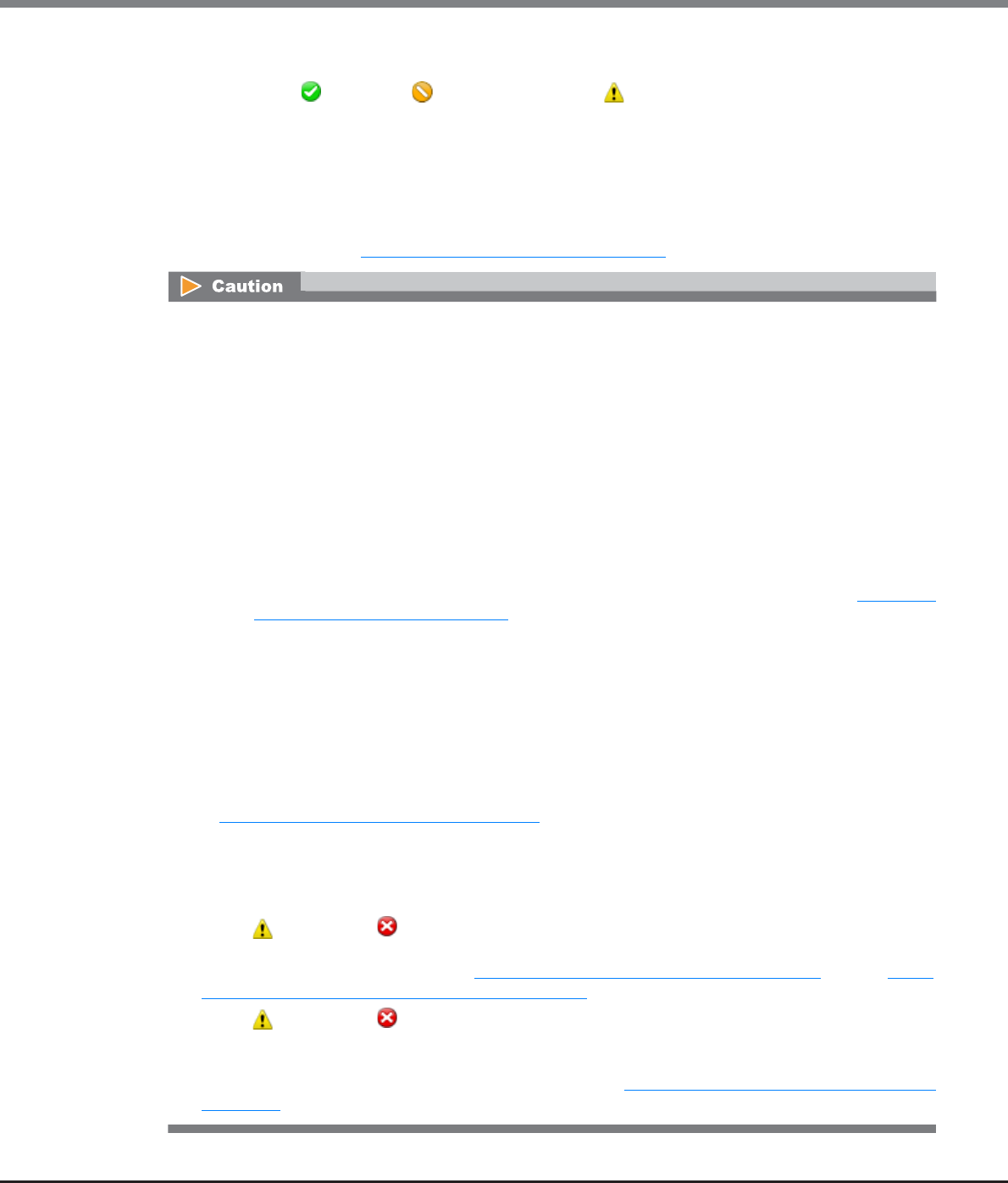
Chapter 5 Volume Management
5.2 Functions in the Action Area for Volume
ETERNUS Web GUI User’s Guide
Copyright 2013 FUJITSU LIMITED P2X0-1090-10ENZ0
127
Requirements for a migration destination FTRP:
•The "Status" is " Available", " Partially Readying", or " Exposed"
•The capacity of the FTRP is more than the capacity of the migration source volume (*1)
•The capacity of the migration source volume is less than the maximum TPP capacity (*2) for each model
•The FTRP is not the same as the FTRP to which the migration source volume belongs
*1: When the migration source is a TPV or an FTV, the capacity indicates used capacity (the physical capacity that is
allocated from a TPP or an FTRP).
*2: The maximum TPP capacity is the total sum of the TPP capacity and the FTRP capacity in the ETERNUS DX Disk
storage system. Refer to "7.2.1 Create Thin Provisioning Pool" (page 219) for details.
•Migration cannot be performed under the following conditions:
-When the maximum number of volumes is already registered in the ETERNUS DX Disk storage system
-When a RAID group diagnosis or a disk diagnosis is being performed in the ETERNUS DX Disk storage
system
-When the RAID group to which the migration source volume belongs is blocked or failed
-When Advanced Copy is being performed by specifying the whole volume in the migration source
volume and the settings for the volume capacity that is to be expanded are performed before and
after migration
-When the total number of migration, TPV balancing, and FTRP balancing (*1) processes that are
running in the ETERNUS DX Disk storage system exceed 32
-When the total capacity of the migration, TPV balancing, and FTRP balancing (*1) processes that are
running in the ETERNUS DX Disk storage system exceeds 128TB
*1: When the FTRP balancing is performed, the FTV balancing process starts in the FTSP. Refer to "7.2.12 Start
Balancing Flexible Tier Pool" (page 248) for details.
•A volume cannot be expanded when the type of migration source volume is "TPV" or the type of migration
destination is "TPP".
•A volume cannot be expanded when the type of migration source volume is "FTV" or the type of migration
destination is "FTRP".
•Even if the volume type is "Standard", the maximum ODX Buffer volume capacity is 1TB.
•A migration source volume and a migration destination volume that are undergoing migration cannot be
deleted.
•When performing migration for volumes for which "Cache Page Capacity" is changed using the procedure
in "5.2.18 Modify Cache Parameters" (page 148), the "Cache Page Capacity" setting is reset to the initial
value (unlimited).
•When the destination volume capacity is expanded by migration, the expanded volume capacity must be
recognized by the server after migration. Refer to the manuals of each OS or file system for information
about server operation.
•When " Attention" or " Warning" is displayed in the "Used Status" field for the migration destination
TPP after migration, the used capacity of the relevant TPP is exceeding the threshold. In this case, expand
TPP capacity by using the procedure in "7.2.4 Expand Thin Provisioning Pool" (page 231). Refer to "7.1.1
Thin Provisioning Pool (Basic Information)" (page 200) for TPP usage.
•When " Attention" or " Warning" is displayed in the "Used Status" field for the migration destination
FTRP after migration, the used capacity of the relevant FTRP is exceeding the threshold. Use ETERNUS SF
Storage Cruiser to expand the capacity of the appropriate FTSP (for which expansion is determined to be
necessary based upon the performance and usage). Refer to "7.1.5 Flexible Tier Pool (Basic Information)"
(page 207) for FTRP usage.
Chapter 5 Volume Management
5.2 Functions in the Action Area for Volume
ETERNUS Web GUI User’s Guide
Copyright 2013 FUJITSU LIMITED P2X0-1090-10ENZ0
128
■When the migration destination volume type is "Standard", "TPV", or "FTV"
The procedure to start a migration is as follows:
Procedure
1Select the volume that to be migrated and click [Start RAID Migration] in [Action].
2Select "RAID Group / Thin Provisioning Pool / Flexible Tier Pool" for "Destination Migration".
Set the volume information after migration, select the destination RAID group, the TPP, or
the FTRP, and then click the [Start] button.
•Volume Capacity
The capacity of the migration source volume is displayed as the initial state.
When expanding the volume capacity after migration, specify the volume capacity and select the
unit of capacity (MB/GB/TB).
Up to a 15-digit number including the "." (decimal point) can be input. Note that when "MB" is
selected, the specified value is rounded down to the nearest whole number. When "GB" or "TB" is
selected, the specified value is converted to "MB" and rounded down to the nearest whole number.
•Progress of migration can be checked on the [Volume Detail] screen (Basic). Refer to "5.1.9 Volume Detail
(Basic)" (page 88) for details.
•If the migration source and migration destination are both "WSV", not only can the migration of a WSV to
other multiple RAID groups be performed, but also the number of concatenations for the existing RAID
group can be changed.
•When Zero Reclamation is reserved after migrating from "Standard" to "TPV" or from "Standard" to "FTV",
the physical area that is filled with zeros is released and the Thin Provisioning function can be used
efficiently. For volumes that are reserved for Zero Reclamation, "Reserved Zero Reclaim" is displayed in
the "Process" field on the [Volume] screen. When Zero Reclamation is performed after the migration is
complete, the progress of Zero Reclamation can be checked with "Zero Reclamation Progress" on the
[Volume Detail] screen (Basic). Refer to "5.1.9 Volume Detail (Basic)" (page 88) for details.
Up to 15 numbers can be used. If a decimal point is included in the input value, up to 14 numbers
can be used.
[Example] 0.1234567890123 (14 numbers and a decimal point)
Volume capacity cannot be expanded in the following conditions:
•When "TPV" or "FTV" is selected as the migration source volume
•When "Thin Provisioning Pool" or "Flexible Tier Pool" is selected as the migration destination
Migration source volume capacity ≤Volume capacity ≤The maximum free capacity in the
migration destination

Chapter 5 Volume Management
5.2 Functions in the Action Area for Volume
ETERNUS Web GUI User’s Guide
Copyright 2013 FUJITSU LIMITED P2X0-1090-10ENZ0
129
•FTSP Priority
Select either "Auto" or the FTSP number that belongs to the migration destination FTRP for the FTSP
number to which priority is given.
When FTRP is not selected from the migration destination list, only "Auto" is displayed as the
available option. If FTRP is specified, "Auto" and the FTSP numbers that belong to the migration
destination FTRP are displayed. If "FTSP number" is selected and the specified FTRP is changed, the
"FTSP Priority" setting returns to the default value ("Auto").
"FTSP Priority" indicates the FTSP number to which priority is given for allocating physical capacity as
the volume migration destination when multiple FTSPs exists in the migration destination FTRP.
When "Auto" is selected, the physical area is allocated to an FTSP for which the disk type is "Online".
If no free space exists in "Online" type disks and migration is not available, the physical area is
allocated to an FTSP for which the disk type is "Nearline". If "Nearline" is also not available for
migration, the physical area is allocated to an FTSP for which the disk type is "SSD". Migration to an
FTRP cannot be performed if "SSD" is not available for migration. "SED" type FTSPs are used as
"Online" type FTSPs.
When "FTSP number" is selected, the physical area is allocated to the selected FTSP. If there is no
free space in the selected FTSP and migration is not available, the migration destination FTSP
number is determined as having the same priority ("Online" → "Nearline" → "SSD") as when "Auto"
is selected.
The disk type for FTSPs can be checked from the [Flexible Tier Pool Detail] screen (Flexible Tier Sub
Pool). Refer to "7.1.8 Flexible Tier Pool Detail (Flexible Tier Sub Pool)" (page 214) for details.
•Encryption
The encryption status of the migration source volume is displayed as the initial state.
Select the encryption status of the volume after migration. There are no limitations for the encryp-
tion status of migration source and destination volumes. Note that when migrating an encrypted
volume to an unencrypted volume, the user must have the "Security Setting" policy.
Refer to "Combinations of Encryption Conditions for which Migration is Available" (page 124) for
details.
-None
-by CM
-use SED (Disabled Key Group)
-use SED (Enabled Key Group)
•Start Zero Reclamation after migration
Select "Enable" or "Disable" for the Zero Reclamation of source volumes after migration is complete.
When Zero Reclamation after migration is enabled, the source volume will be reserved for Zero
Reclamation.
"Zero Reclamation" is a function that releases the allocated physical area when data in the physical
area that is allocated to a TPV or an FTV is filled with zeros.
This item is available only when the migration destination is "Thin Provisioning Pool" or "Flexible
Tier Pool".
•When "use SED (Disabled Key Group)" or "use SED (Enabled Key Group)" is selected for
"Encryption", use an SED for the migration destination.
•When "None" or "by CM" is selected for "Encryption", do not use SEDs for the migration
destination. Use other type of disks.
•When the encryption mode is disabled, "by CM" cannot be selected.
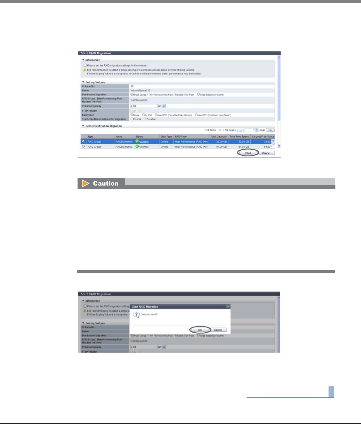
Chapter 5 Volume Management
5.2 Functions in the Action Area for Volume
ETERNUS Web GUI User’s Guide
Copyright 2013 FUJITSU LIMITED P2X0-1090-10ENZ0
130
•Select Destination Migration
Specify the destination RAID group, the TPP, or the FTRP with the radio button. The RAID groups,
TPPs, or FTRPs that can be used for migration are displayed (this is determined by the volume
capacity and the encryption status).
→A confirmation screen appears.
3Click the [OK] button.
→Migration starts.
4Click the [Done] button to return to the [Volume] screen.
End of procedure
•If the migration source is an ODX Buffer volume, select "RAID Group / Thin Provisioning Pool /
Flexible Tier Pool" for "Destination Migration".
•An error screen appears in the following conditions:
-When the "Volume Capacity" is not input
-When "Volume Capacity" does not satisfy the input conditions
-When "Enable" is selected for "Start Zero Reclamation after migration" while Zero Reclamation
is being performed in a migration source volume
-When the migration source is an ODX Buffer volume and "Enable" is selected for "Start Zero
Reclamation after migration"

Chapter 5 Volume Management
5.2 Functions in the Action Area for Volume
ETERNUS Web GUI User’s Guide
Copyright 2013 FUJITSU LIMITED P2X0-1090-10ENZ0
131
■When the migration destination volume is "WSV"
The procedure to start a migration is as follows:
Procedure
1Select the volume that to be migrated and click [Start RAID Migration] in [Action].
When changing the number of concatenations for a WSV, check "Wide Stripe Size" for the WSV, the
specifications of the existing RAID groups (RAID type, Stripe Depth, disk type, disk speed, and number of
member drives), and the name of all the concatenated RAID groups. The following describes how to check
the specifications.
(1)Click the [No.] link or the [Name] link of the migration source WSV in the volume list.
(2)A detailed information screen for the WSV is displayed. Check "Wide Stripe Size" in the [Basic] tab
screen.
(3)Click the [WSV Concatenation] tab to display the concatenation information of the WSV. Check "RAID
Group Name" and "Concatenation Order" that are configured for the WSV.
(4) Filter the RAID group list by the RAID group name that configures a WSV, and then click the [No.]
link or the [Name] link of the RAID group. Any RAID group can be specified because the RAID groups
in the WSV have the same specifications.
(5)A detailed information screen for the RAID group is displayed. Check "RAID Type" and "Wide Stripe
Size" in the [Basic] tab screen.
(6)Click the [Disk] tab to display the information of the drives that are configured for the RAID group.
Check "Disk Type", "Speed", and "Number of Member Disks". For "Number of Member Disks", use the
displayed number of drives.
Chapter 5 Volume Management
5.2 Functions in the Action Area for Volume
ETERNUS Web GUI User’s Guide
Copyright 2013 FUJITSU LIMITED P2X0-1090-10ENZ0
132
2Select "Wide Striping Volume" for "Destination Migration". Input the volume capacity, the
encryption status, the detailed information of volumes, and the selection information for
the RAID groups, and click the [Select RAID Groups] button.
●Setting Volume
•Volume Capacity
The capacity of the migration source volume is displayed as the initial state.
When expanding the volume capacity after migration, enter the volume capacity and select the unit
of capacity (MB/GB/TB).
Up to a 15-digit number including the "." (decimal point) can be input. Note that when "MB" is
selected, the specified value is rounded down to the nearest whole number. When "GB" or "TB" is
selected, the specified value is converted to "MB" and rounded down to the nearest whole number.
•Encryption
The encryption status of the migration source volume is displayed as the initial state.
Select the encryption status of the volume after migration. There are no limitations for the encryp-
tion status of migration source and destination volumes. Note that when migrating an encrypted
volume to an unencrypted volume, the user must have the "Security Setting" policy. Refer to
"Combinations of Encryption Conditions for which Migration is Available" (page 124) for details.
-None
-by CM
-use SED (Disabled Key Group)
-use SED (Enabled Key Group)
Up to 15 numbers can be used. If a decimal point is included in the input value, up to 14 numbers
can be used.
[Example] 0.1234567890123 (14 numbers and a decimal point)
When "TPV" or "FTV" is selected as the migration source volume, volume expansion is not
available.
Migration source volume capacity ≤Volume capacity
•When "use SED (Disabled Key Group)" or "use SED (Enabled Key Group)" is selected for
"Encryption", use an SED for the migration destination.
•When "None" or "by CM" is selected for "Encryption", do not use SEDs for the migration
destination. Use other type of disks.
•When the encryption mode is disabled, "by CM" cannot be selected.

Chapter 5 Volume Management
5.2 Functions in the Action Area for Volume
ETERNUS Web GUI User’s Guide
Copyright 2013 FUJITSU LIMITED P2X0-1090-10ENZ0
133
●Wide Striping Volume Setting
WSVs are created by concatenating volumes that are the same size in multiple RAID groups. Input
the volume information for the migration destination WSV and the selection information for the
RAID groups, and then specify the RAID groups that are to be concatenated.
●Volume Information
Input the volume information of the migration destination WSV.
•Wide Stripe Size
Select the Wide Stripe Size ("Normal" or "Small") for the volumes.
"Wide Stripe Size" is the size of the WSV Unit that is allocated to each RAID group in series. It is not
necessary to change the default setting (Normal) for normal use.
-Normal
An integral multiple of the basic size for each RAID group (*1). The maximum size is 16MB or
smaller.
The actual size varies according to the RAID group type, the number of member disks, and Stripe
Depth.
Select "Normal" to improve random write access performance.
-Small
An integral multiple of the basic size for each RAID group. The maximum size is 2MB or smaller.
The actual size varies according to the RAID group type, the number of member disks, and Stripe
Depth.
Note that because the segment size of the volume is small and many host accesses among
multiple RAID groups occur, the performance may be reduced.
•The conditions for RAID groups to configure WSVs are as follows:
-The RAID type must be the same
-The number of member drives in the RAID group must be the same
-The Stripe Depth value must be the same
-The disk type (Online/Nearline/SSD/SED) must be the same
(since the access performance of WSVs is reduced, do not select "Online/Nearline".)
-The disk speed must be the same
(RAID groups configured with different speed drives can be selected. Note that this reduces
the access performance for WSVs. It is recommended to select the same speed disks. The
speed of the drives that configure a RAID group can be checked in the [RAID Group Detail]
screen ([Disk] tab).)
-The key group setting is the same as the existing RAID groups
(When "Disk Type" is "SED", RAID groups with the key group setting enabled or disabled can
be selected. Selecting the same key group setting status is recommended. Not doing so
reduces the access performance for WSVs. The key group setting status can be checked with
the "Encryption" field in the [Select RAID Groups] screen.)
-The sequential unused area must be the same size or bigger than the capacity of the
volumes that are to be concatenated
•The number of concatenated RAID groups is from 2 to 64.
•The WSV capacity is from 24MB to 128TB.
•When changing the number of concatenations for a WSV, specifying the existing RAID groups is
required. For the details, refer to "Remarks" in "When the migration destination volume is
"WSV"" (page 131).
Chapter 5 Volume Management
5.2 Functions in the Action Area for Volume
ETERNUS Web GUI User’s Guide
Copyright 2013 FUJITSU LIMITED P2X0-1090-10ENZ0
134
*1: The basic size (stripe size) when creating a volume. Refer to "E.1 Basic Size for each RAID Group" (page
995) for details.
•Concatenation Order
Select the concatenation order of RAID groups from "Automatic" or "Manual". It is not necessary to
change the default setting (Automatic) for normal use.
-Automatic
Automatically specify the concatenation order of RAID groups.
If multiple WSVs are already registered, the next available RAID group that enables the
controlling CM allocation to be distributed evenly is selected as [1] for the concatenation order.
If multiple RAID groups satisfy this condition, the RAID group with the smallest RAID group
number is selected as [1] in the concatenation order. RAID groups are concatenated starting
from [1] (first) in ascending order. The last RAID group is concatenated to the first RAID group.
Volumes that belong to the RAID group that is first in the concatenation order are called
"representative volumes".
-Manual
Manually specify the concatenation order of the RAID group.
●Select RAID Group Information
Input information for the RAID group that configures the migration destination WSV.
•If the basic size of the RAID group is 2MB or more, the basic size is specified for Wide Stripe Size
even when "Small" is selected.
•When changing the number of concatenations for a WSV, select the same "Wide Stripe Size" as
the migration source WSV. Refer to "When the migration destination volume is "WSV"" (page
131) for procedure to check "Wide Stripe Size" for the destination source WSV.
"Wide Stripe Size" for an existing WSV can be changed by using the migration function.
When changing the number of concatenations for a WSV, specify the same concatenation order
as the migration source WSV. Refer to "Remarks" in "When the migration destination volume is
"WSV"" (page 131) for the procedure to check the concatenation order of migration source
WSVs. When "Manual" is selected for "Concatenation Order", the concatenation order can be
changed. It is not necessary to change the default setting (Automatic) if the concatenation
order after migration can be changed.
When changing the number of concatenations for a WSV, select the same "Disk Type", "RAID Type",
"Number of Member Disks", and "Stripe Depth" as the migration source WSV. Refer to "Remarks" in
"When the migration destination volume is "WSV"" (page 131) for the procedure to check the
specifications of an existing RAID group.

Chapter 5 Volume Management
5.2 Functions in the Action Area for Volume
ETERNUS Web GUI User’s Guide
Copyright 2013 FUJITSU LIMITED P2X0-1090-10ENZ0
135
•Disk Type
Specify the drive type.
The installed drive determine the selectable disk types that are displayed.
If there are no RAID groups in which volumes can be created, the field is blank.
-Online
-Nearline
-SSD
-SED
-Online/Nearline
•RAID Type
Select the RAID type.
If there are no RAID groups in which volumes can be created, the field is blank.
-High Performance (RAID1+0)
-High Capacity (RAID5)
-High Reliability (RAID6)
-Reliability (RAID5+0)
-Mirroring (RAID1)
-Striping (RAID0)
•Number of Member Disks
Select the number of member disks in the RAID group.
The selectable number of member disks, which is determined by the specified RAID type, is
displayed.
If there are no RAID groups in which volumes can be created, the field is blank.
-High Performance (RAID1+0)
4, 6, 8, 10, 12, 14, 16, 18, 20, 22, 24, 26, 28, 30, 32
-High Capacity (RAID5)
3 - 16
-High Reliability (RAID6)
5 - 16
-Reliability (RAID5+0)
6, 8, 10, 12, 14, 16, 18, 20, 22, 24, 26, 28, 30, 32
-Mirroring (RAID1)
2
-Striping (RAID0)
2 - 16
•Stripe Depth
Select the Stripe Depth of the RAID group.
The selectable Stripe Depth varies depending on the specified RAID type. Refer to "Available Stripe
Depth value" (page 180) for details.
If "Mirroring (RAID1)" is selected as the RAID type, a "-" (hyphen) is displayed.
If there are no RAID groups in which volumes can be created, the field is blank.
-64 KB
-128 KB
-256 KB
-512 KB
-1024 KB
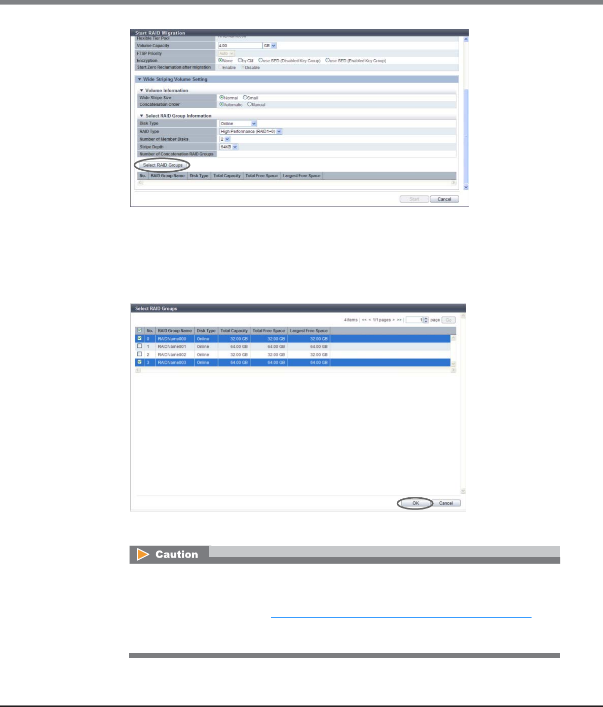
Chapter 5 Volume Management
5.2 Functions in the Action Area for Volume
ETERNUS Web GUI User’s Guide
Copyright 2013 FUJITSU LIMITED P2X0-1090-10ENZ0
136
→The [Select RAID Groups screen] screen appears.
3Select the RAID group that is to be concatenated (multiple selections can be made) and click
the [OK] button.
•Select RAID Groups
Select the checkbox for the RAID group that is to be concatenated.
→The display returns to the initial screen.
•When increasing the number of concatenations for a WSV, select all of the existing RAID groups for
concatenation and the new RAID groups. When reducing the number of concatenations for a WSV,
select the RAID groups that will remain for concatenation from the existing RAID group list. For the
details, refer to "Remarks" in "When the migration destination volume is "WSV"" (page 131).
•When "Disk Type" is "SED", setting the same "Encryption" settings (the setting status of the key
group) is recommended for all of the RAID groups that configure the WSV.
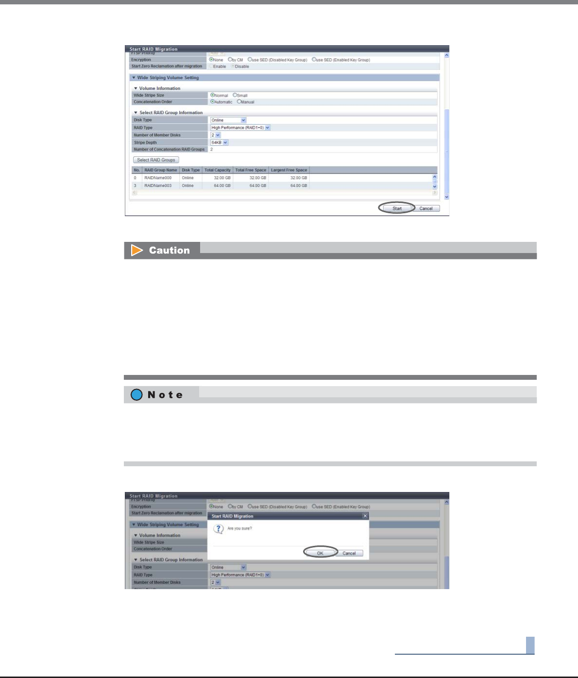
Chapter 5 Volume Management
5.2 Functions in the Action Area for Volume
ETERNUS Web GUI User’s Guide
Copyright 2013 FUJITSU LIMITED P2X0-1090-10ENZ0
137
4After selecting RAID groups is complete, click the [Start] button.
→A confirmation screen appears.
5Click the [OK] button.
→Migration starts.
6Click the [Done] button to return to the [Volume] screen.
End of procedure
In the following cases, an error screen appears:
•When the capacity is not specified for "Volume Capacity"
•When "Volume Capacity" does not satisfy the input conditions
•When the "Number of Concatenation RAID Groups" field is left blank, "1" is specified, or a value
that is "65" or more is specified
•When the maximum free space in the selected RAID group is smaller than the volume size that is
to be concatenated
•When an ODX Buffer volume is selected as a migration source volume
To change the concatenation order of the RAID groups, select "Manual" for "Concatenation Order" in
the Volume Information field. Click the [Concatenation Order] link to display the [Setting
Concatenation Order] screen. The concatenation order of the RAID groups can be changed in the
[Setting Concatenation Order] screen.
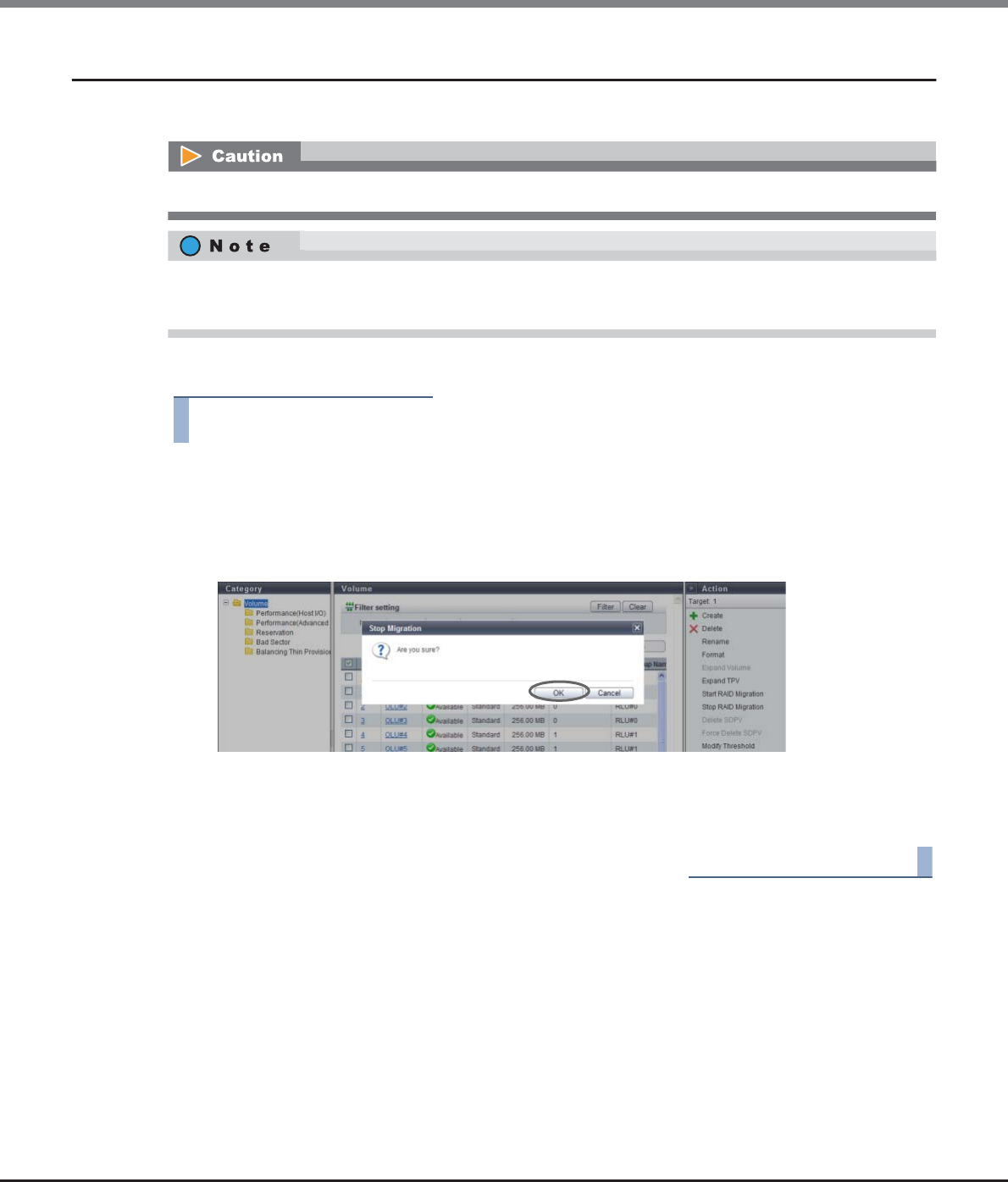
Chapter 5 Volume Management
5.2 Functions in the Action Area for Volume
ETERNUS Web GUI User’s Guide
Copyright 2013 FUJITSU LIMITED P2X0-1090-10ENZ0
138
5.2.8 Stop RAID Migration
This function stops RAID migration.
The procedure to stop migration is as follows:
Procedure
1Select the volume for which migration is to be stopped (multiple selections can be made)
and click [Stop RAID Migration] in [Action].
→A confirmation screen appears.
2Click the [OK] button.
→The stop migration process starts.
3Click the [Done] button to return to the [Volume] screen.
End of procedure
This function cannot be executed when migration is not being performed for the selected volume.
•If migration is canceled, the reservation for Zero Reclamation is released.
•When migration is stopped, data in the migration source volume can be accessed normally.
Chapter 5 Volume Management
5.2 Functions in the Action Area for Volume
ETERNUS Web GUI User’s Guide
Copyright 2013 FUJITSU LIMITED P2X0-1090-10ENZ0
139
5.2.9 Start Zero Reclamation
"Zero Reclamation" is a function that releases the allocated physical area when data in the physical area that
is allocated to a TPV or an FTV is filled with zeros.
This function starts Zero Reclamation.
Volume requirements for starting Zero Reclamation:
•Volumes for which "Type" is "TPV" or "FTV"
•Volumes without " Readying" status, " Not Ready" status, or " Broken" status
•Volumes that are not undergoing Zero Reclaiming or volumes that are not reserved for Zero Reclamation
•Volumes that are not ODX Buffer volumes
•Volumes that are not undergoing RAID migration
•Volumes that are not undergoing TPV balancing
•FTVs that are not undergoing FTRP balancing
The procedure to start Zero Reclamation is as follows:
Procedure
1Select the volume to start Zero Reclamation (multiple selections can be made), and click
[Start Zero Reclamation] in [Action].
→A confirmation screen appears.
This function cannot be performed when the storage system status is "Not Ready".
•The Thin Provisioning function and the Flexible Tier (automatic storage layering) function can be
effectively used by using Zero Reclamation when system configurations or system environment
modifications are performed. Examples of when to use Zero Reclamation are as follows:
-After the initialization of the OS or the file system (such as writing 0 data to all the volumes) is
complete
-After RAID migration from "Standard" to "TPV" is complete
-After RAID migration from "Standard" to "FTV" is complete
•The progress of Zero Reclamation can be checked with "Zero Reclamation Progress" on the [Volume
Detail] screen (Basic). Refer to "5.1.9 Volume Detail (Basic)" (page 88) for details.
•Zero Reclamation can be reserved for the destination volume of the RAID migration. Refer to "5.2.7 Start
RAID Migration" (page 123) for details.
An error screen appears in the following conditions:
•When switching controller firmware is being performed
•When the concurrent firmware upgrade is being performed
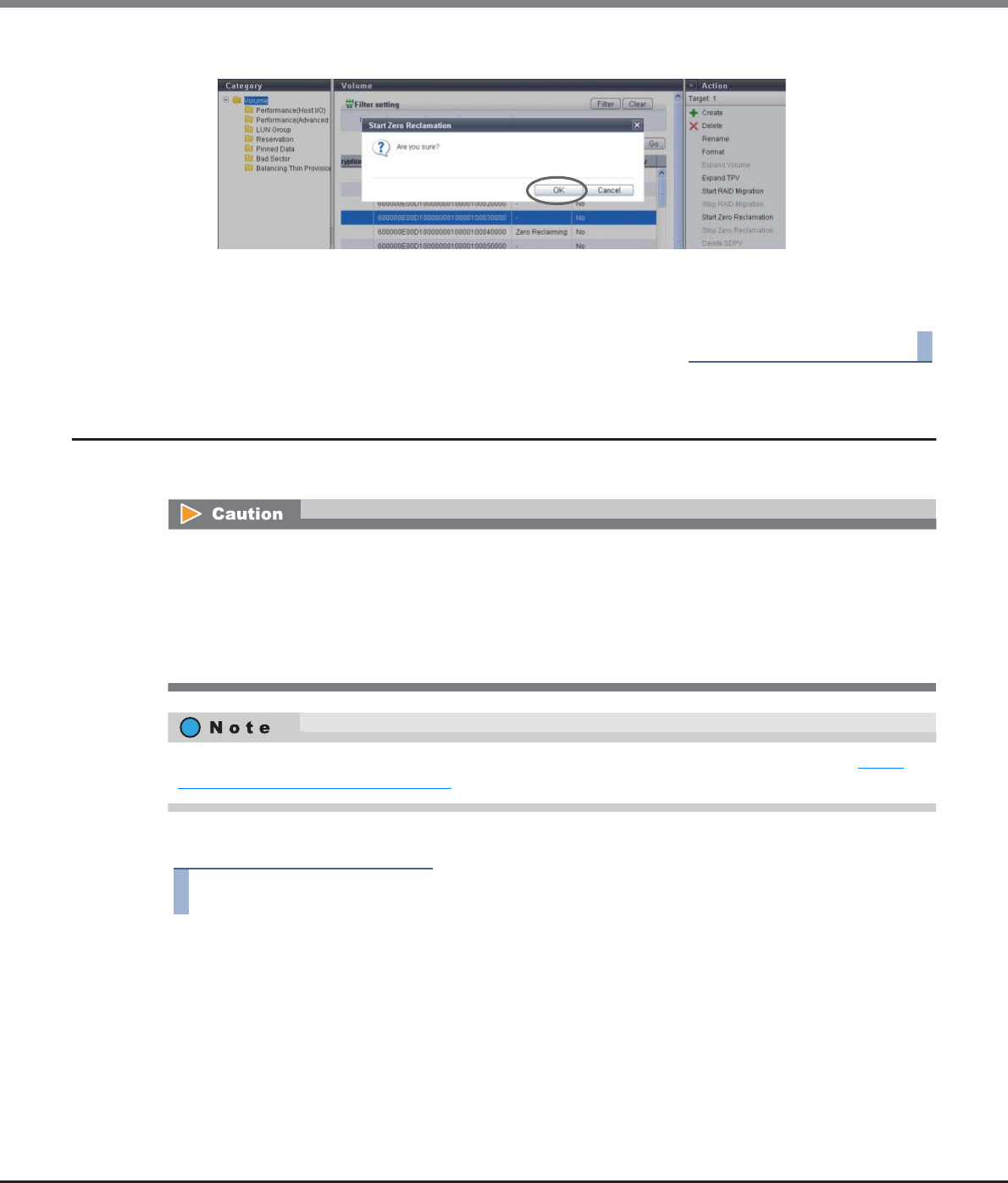
Chapter 5 Volume Management
5.2 Functions in the Action Area for Volume
ETERNUS Web GUI User’s Guide
Copyright 2013 FUJITSU LIMITED P2X0-1090-10ENZ0
140
2Click the [OK] button.
→Zero Reclamation starts.
3Click the [Done] button to return to the [Volume] screen.
End of procedure
5.2.10 Stop Zero Reclamation
This function stops Zero Reclamation.
The procedure to stop Zero Reclamation is as follows:
Procedure
1Select the volume to stop Zero Reclamation (multiple selections can be made), and click
[Stop Zero Reclamation] in [Action].
→A confirmation screen appears.
•Zero Reclamation cannot be suspended and restarted (restarting Zero Reclamation from where it was
stopped). If Zero Reclamation is stopped and then started again, the Zero Reclamation process starts
from the first volume at the top again.
•This function cannot release the volumes that are reserved for Zero Reclamation. The reservation status
of Zero Reclamation is released only when RAID migration is stopped.
•This function cannot be performed when the storage system status is "Not Ready".
The progress of Zero Reclamation can be checked with "Process" on the [Volume] screen. Refer to "5.1.1
Volume (Basic Information)" (page 74) for details.
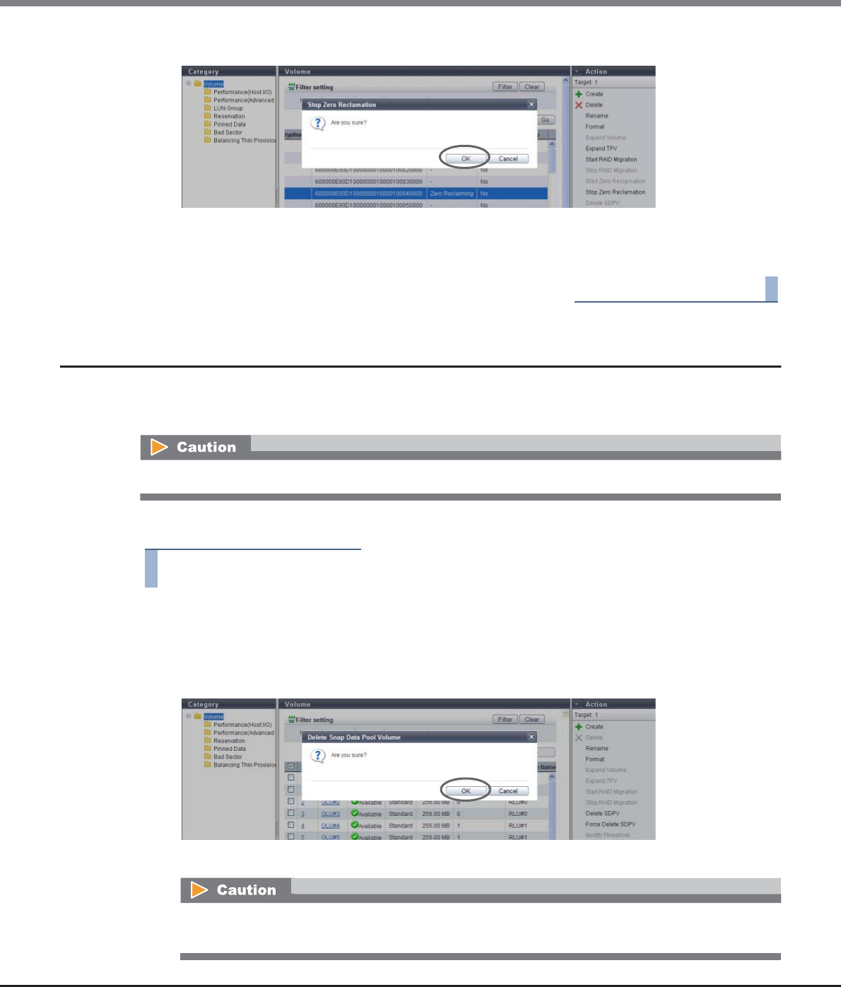
Chapter 5 Volume Management
5.2 Functions in the Action Area for Volume
ETERNUS Web GUI User’s Guide
Copyright 2013 FUJITSU LIMITED P2X0-1090-10ENZ0
141
2Click the [OK] button.
→Zero Reclamation stops.
3Click the [Done] button to return to the [Volume] screen.
End of procedure
5.2.11 Delete Snap Data Pool Volume
An SDPV is a logical volume that is created in the SDP.
This function deletes SDPVs to reduce SDP capacity.
The procedure to delete an SDPV is as follows:
Procedure
1Select the SDPV to be deleted (multiple selections can be made) and click [Delete SDPV] in
[Action].
→A confirmation screen appears.
2Click the [OK] button.
→Deletion of SDPV starts.
If the target SDPV is currently being used, it will be deleted after the SDPV is released.
If the SDPV is currently being used, the target SDPV status is changed to "Reserved Deletion". The
"Reserved Deletion" status can be checked in the [Volume (Basic)] screen.
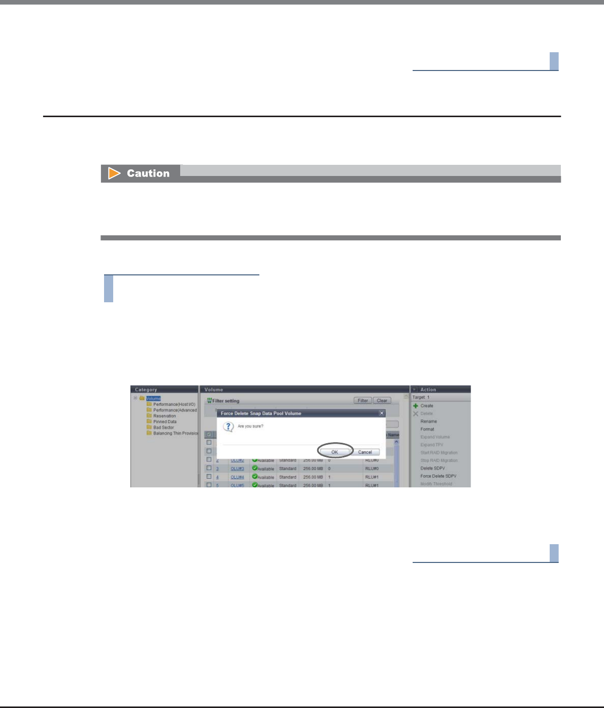
Chapter 5 Volume Management
5.2 Functions in the Action Area for Volume
ETERNUS Web GUI User’s Guide
Copyright 2013 FUJITSU LIMITED P2X0-1090-10ENZ0
142
3Click the [Done] button to return to the [Volume] screen.
End of procedure
5.2.12 Force Delete Snap Data Pool Volume
An SDPV is a logical volume that is created in the SDP.
This function forcibly deletes an SDPV regardless of whether it being used or not to reduce SDP capacity.
The procedure to forcibly delete an SDPV is as follows:
Procedure
1Select the SDPV to be deleted (multiple selections can be made) and click [Force Delete
SDPV] in [Action].
→A confirmation screen appears.
2Click the [OK] button.
→Deletion of SDPV starts.
3Click the [Done] button to return to the [Volume] screen.
End of procedure
•If the target SDPV is being used by a copy session, an error stops the copy session, and then the SDPV is
deleted.
•A SDPV that is in "Reserved Deletion" status can be deleted.
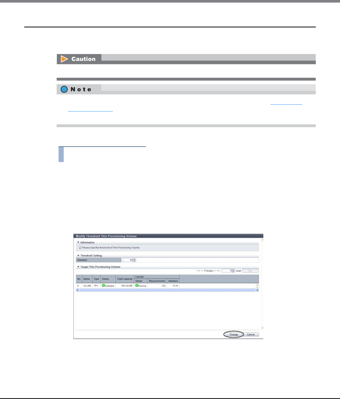
Chapter 5 Volume Management
5.2 Functions in the Action Area for Volume
ETERNUS Web GUI User’s Guide
Copyright 2013 FUJITSU LIMITED P2X0-1090-10ENZ0
143
5.2.13 Modify Threshold Thin Provisioning Volume
This function changes the threshold for monitoring the used capacity of Thin Provisioning Volume. There is an
"Attention" threshold.
The procedure to change the threshold of Thin Provisioning Volume is as follows:
Procedure
1Select the TPV for which the threshold is to be changed (multiple selections can be made)
and click [Modify Threshold] in [Action].
2Specify the new threshold, and click the [Change] button.
•Attention
Select between 1 and 200 [%] for the Attention threshold for monitoring the used capacity of the
Thin Provisioning Volume. The default value is 10 [%].
The Attention threshold is determined by the ratio of "Free space in the TPP to which the TPV
belongs" to "Non-allocated TPV capacity".
→A confirmation screen appears.
This function cannot be performed when there are no TPVs in the ETERNUS DX Disk storage system.
•This function changes the threshold of a TPV that is created by using the procedure in "5.2.1 Create
Volume" (page 96).
•The same threshold can be applied for multiple TPVs in a single operation.
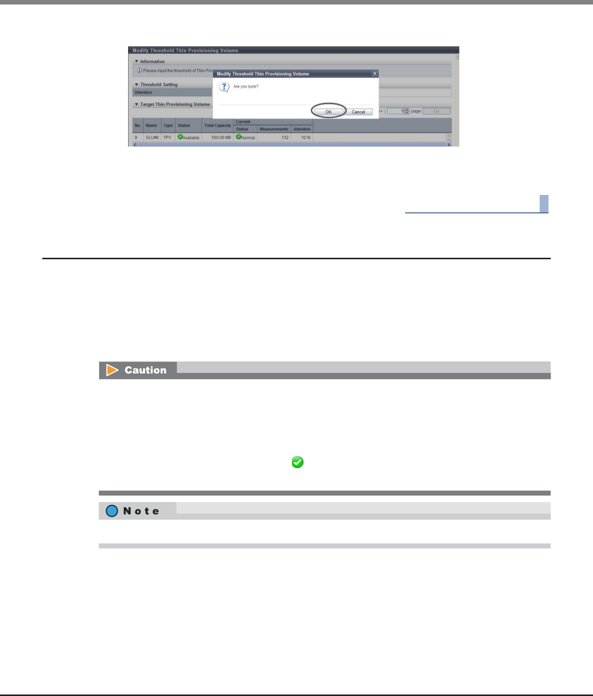
Chapter 5 Volume Management
5.2 Functions in the Action Area for Volume
ETERNUS Web GUI User’s Guide
Copyright 2013 FUJITSU LIMITED P2X0-1090-10ENZ0
144
3Click the [OK] button.
→Thin Provisioning threshold modification starts.
4Click the [Done] button to return to the [Volume] screen.
End of procedure
5.2.14 Initialize Snap Data Volume
This function initializes an SDV.
An SDV is a copy destination volume for SnapOPC and SnapOPC+ that includes a data area and a copy control
information area. SDV initialization is performed when the capacity that can be used for the data area is
insufficient due to a large amount of writing being requested from the host to an SDV for any reason (such as
an operation mistake). SDV initialization is also performed when no more writing is allowed due to a
notification being reported to the host for a writing request that exceeds the SDV capacity.
•After initializing an SDV, any data that is stored in the SDV cannot be accessed. Make sure to backup the
required data.
•This function cannot be used under the following conditions:
-When the target volume is not an SDV
-When LDE is being performed in the RAID group to which the target volume belongs
-When the target volume status is not " Available"
-When Advanced Copy is being performed in the target volume
When an SDV is initialized, the area that is allocated from the SDPV to the SDV is released.
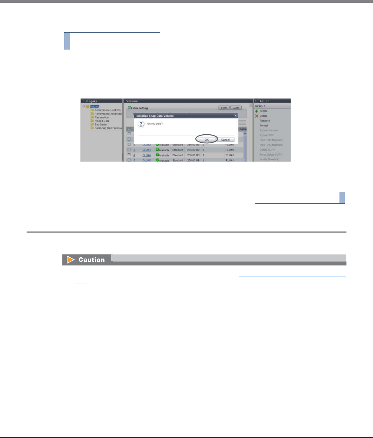
Chapter 5 Volume Management
5.2 Functions in the Action Area for Volume
ETERNUS Web GUI User’s Guide
Copyright 2013 FUJITSU LIMITED P2X0-1090-10ENZ0
145
The procedure to initialize an SDV is as follows:
Procedure
1Select the SDV to be initialized (multiple selections can be made) and click [Initialize SDV]
in [Action].
→A confirmation screen appears.
2Click the [OK] button.
→Initialization of the SDV starts.
3Click the [Done] button to return to the [Volume] screen.
End of procedure
5.2.15 Encrypt Volume
This function encrypts existing volumes.
•When using this function, enable the encryption mode. Refer to "11.2.13.5 Setup Encryption Mode" (page
941) for details.
•This function is used to prevent data leakage due to removal of disks, and cannot prevent data leakage
caused by server access.
•Encrypted volumes cannot be changed to non-encrypted volumes.
•"Standard", "WSV", and "SDV" type volumes can be encrypted.
•Canceling volume encryption is not possible.
•This function cannot be used under the following conditions:
-When a RAID group diagnosis is being performed
-When a disk diagnosis is being performed
-When firmware is being switched in hot mode
-When disk firmware is being applied
-When the status of the ETERNUS DX Disk storage system is other than "Normal"
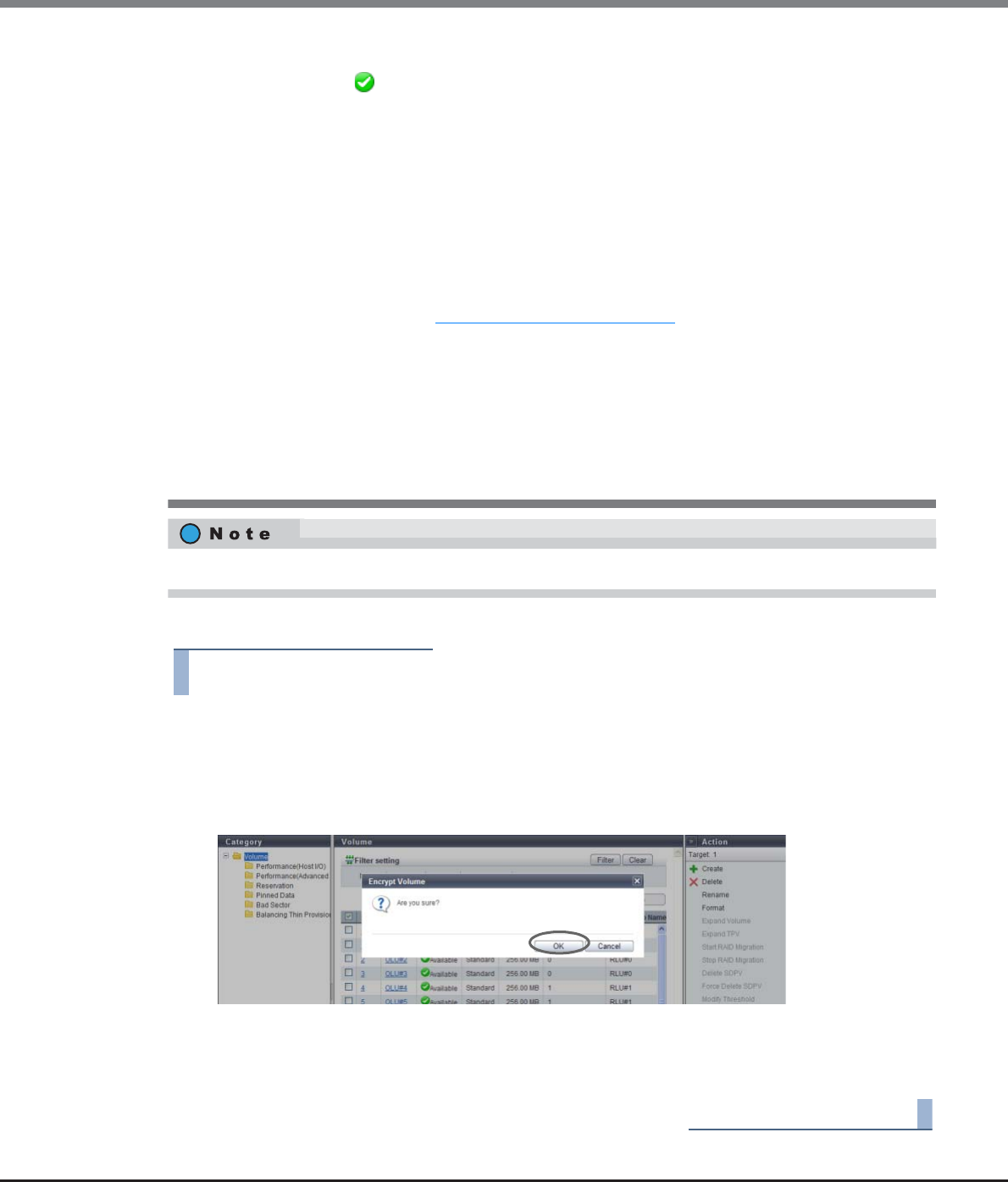
Chapter 5 Volume Management
5.2 Functions in the Action Area for Volume
ETERNUS Web GUI User’s Guide
Copyright 2013 FUJITSU LIMITED P2X0-1090-10ENZ0
146
The procedure to encrypt a volume is as follows:
Procedure
1Select the volume to be encrypted (multiple selections can be made) and click [Encrypt
Volume] in [Action].
→A confirmation screen appears.
2Click the [OK] button.
→Encryption of the volume starts.
3Click the [Done] button to return to the [Volume] screen.
End of procedure
•The following volumes cannot be encrypted:
-Volumes without " Available" status
-Volumes undergoing RAID migration
-Volumes undergoing encryption
-Volumes undergoing formatting or LUN Concatenation
-Volumes registered in a RAID group undergoing LDE
-Volumes in which the drives that configure the RAID group are undergoing rebuild, copyback, or
redundant copy
-Volumes in which the drives that configure the RAID group are "SED"
-Volumes which belong to a RAID group for which the Stripe Depth value is changed (*1)
*1: A RAID group for which the Stripe Depth value is 128KB or more. Note that the Stripe Depth value for RAID1
cannot be changed. Refer to "6.1.5 RAID Group (Basic)" (page 169) for details.
-Volumes with Storage Migration paths
•The following performance may be reduced for encrypted volumes compared with non-encrypted
volumes:
-Access to the encrypted volumes
-Copy transfer of encrypted volumes
•Up to 64 volumes can be encrypted at the same time. Note that if concatenated volumes are selected, the
maximum number of volumes that can be encrypted is less than 64.
TPVs cannot be encrypted with this function. TPVs that are created in an encrypted TPP are encrypted.
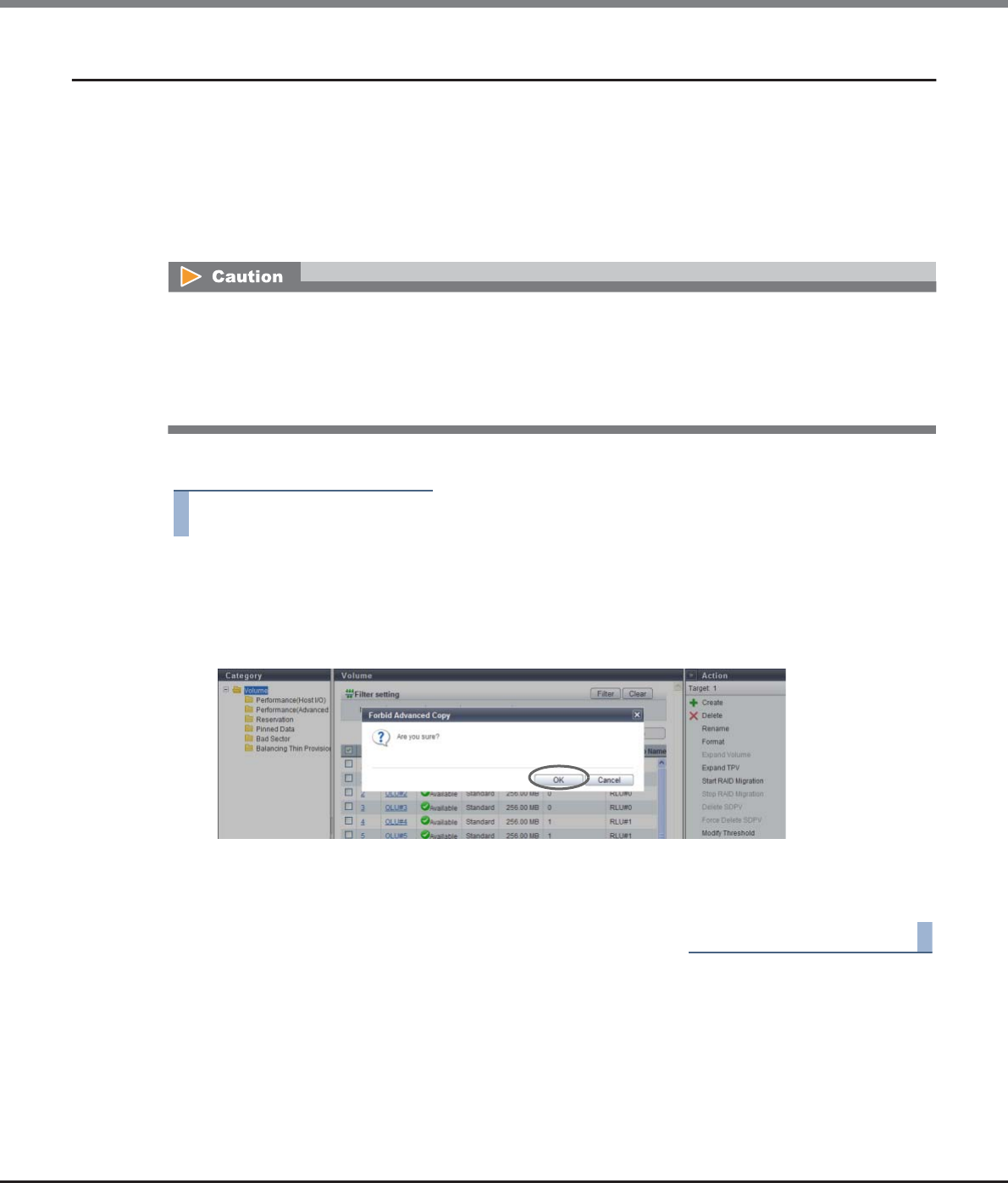
Chapter 5 Volume Management
5.2 Functions in the Action Area for Volume
ETERNUS Web GUI User’s Guide
Copyright 2013 FUJITSU LIMITED P2X0-1090-10ENZ0
147
5.2.16 Forbid Advanced Copy
This function protects a volume so that the volume cannot be registered as the copy destination volume of
Advanced Copy.
The [Forbid Advanced Copy] is a function that protects the data in the selected volumes by forbidding the
volume to be the copy destination of the Advanced Copy sessions or restoration setting. When the Advanced
Copy function is used by multiple software, the same volumes may be used by multiple software, resulting in
unexpected data corruption. This function is available to protect the data in the copy source from being
deleted.
The procedure to protect a volume is as follows:
Procedure
1Select the volume to be protected (multiple selections can be made) and click [Forbid
Advanced Copy] in [Action].
→A confirmation screen appears.
2Click the [OK] button.
→Setting of the copy destination protect starts.
3Click the [Done] button to return to the [Volume] screen.
End of procedure
•If an Advanced Copy license is not registered, volume protection is not enabled. However, when using the
ETERNUS DX80 S2/DX90 S2, a free license is registered by default and volumes can be protected.
•"Standard", "TPV", "WSV", and "FTV" type volumes can be protected. Note that the ODX Buffer volumes can-
not be protected even when the volume type is "Standard", "TPV" or "FTV".
•This function cannot be used for volumes that are already protected.
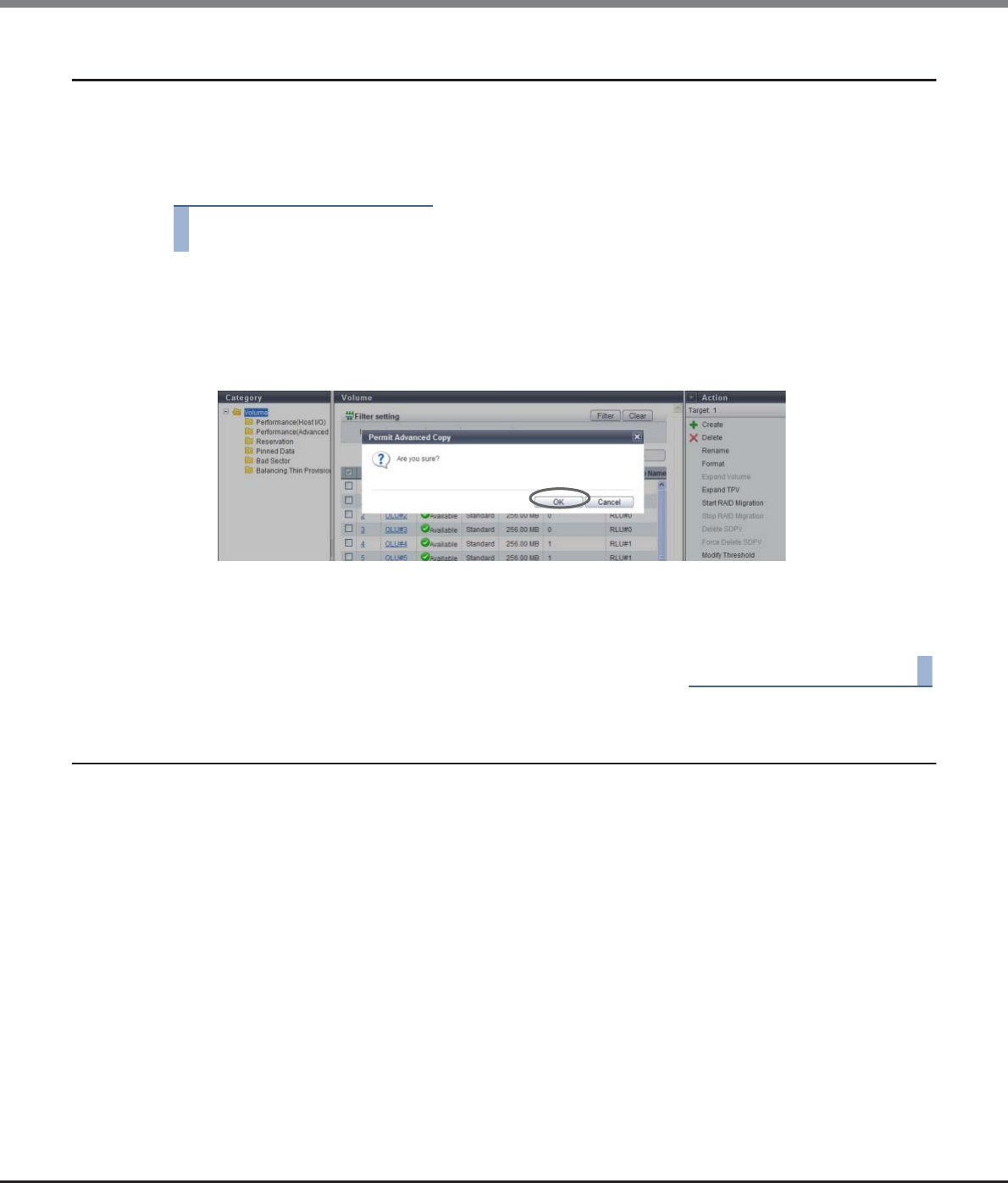
Chapter 5 Volume Management
5.2 Functions in the Action Area for Volume
ETERNUS Web GUI User’s Guide
Copyright 2013 FUJITSU LIMITED P2X0-1090-10ENZ0
148
5.2.17 Permit Advanced Copy
This function releases the protected volumes.
Released volumes can be used as the copy destination volume.
The procedure to release a volume protection is as follows:
Procedure
1Select the protected volume to be released (multiple selections can be made) and click
[Permit Advanced Copy] in [Action].
→A confirmation screen appears.
2Click the [OK] button.
→Releasing copy destination protect starts.
3Click the [Done] button to return to the [Volume] screen.
End of procedure
5.2.18 Modify Cache Parameters
This function changes the cache parameters of each volume.
Performance of the storage system varies depending on the cache hit ratio. The ETERNUS DX Disk storage
system detects sequentiality when a host requests Read/Write. If sequentiality is detected when a Read
request is issued, the cache hit ratio is improved by reading the sequential data into the cache memory in
advance. The characteristics of Read/Write requests from the host depends on the system. Performance of the
storage system may improve by specifying a cache parameter that is suitable for the system that is being
used.
The following parameters can be specified:
•Cache Page Capacity
Specify the cache capacity that is used by volumes.
•Prefetch Limit (PL)
Specify the value to calculate the amount of data that is to be read from the drive in advance (amount of
data to prefetch from the disk) when the cache detects the sequentiality of data access (Read IO).
•Force Prefetch Mode (FP)
Specify whether to perform prefetch even if the sequentiality of data access (Read IO) is not detected.
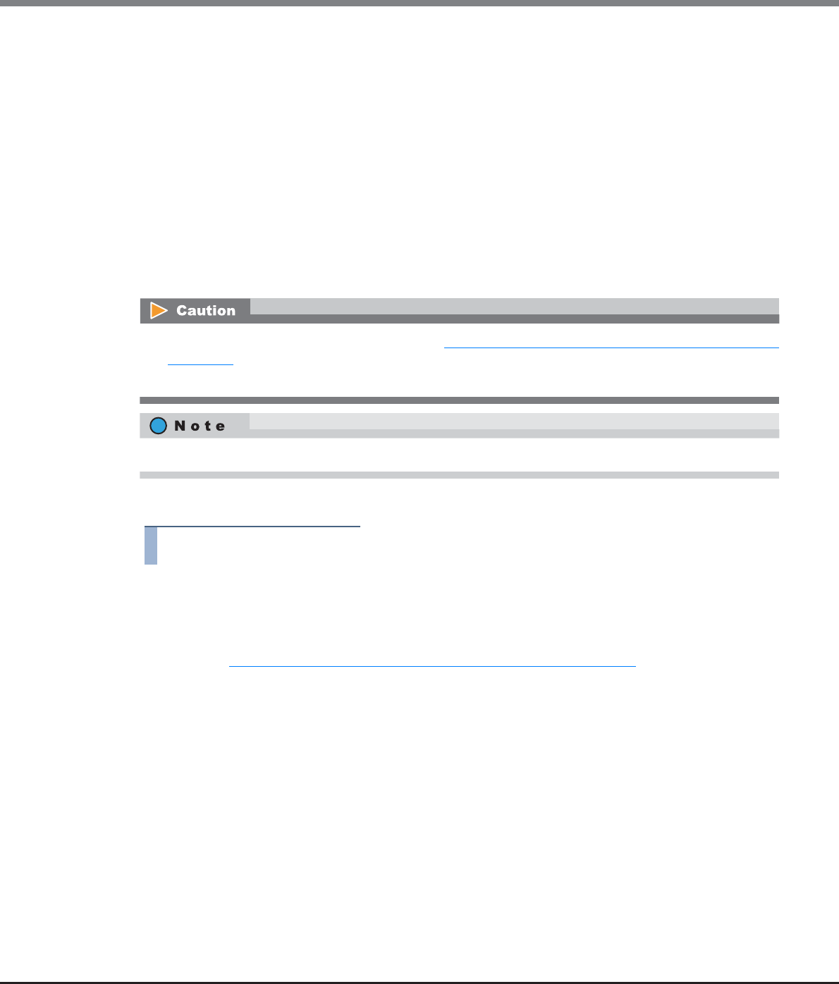
Chapter 5 Volume Management
5.2 Functions in the Action Area for Volume
ETERNUS Web GUI User’s Guide
Copyright 2013 FUJITSU LIMITED P2X0-1090-10ENZ0
149
•Multi Writeback Count (MWC)
Specify the number of processes that can be written back at the same time.
•Prefetch Sequential Detect Count (PSDC)
Specify the number of times for sequential data detection to determine the sequentiality of data access
(Read IO).
•Sequential Dirty Detect Count (SDDC)
Specify the number of times for sequential data detection to determine the sequentiality of data access
(Write I/O).
•Sequential Slope (SS)
A parameter to determine the sequentiality of data access (Read I/O). Specify the number of LBAs by which
the previous I/O and the current I/O are considered as sequential data.
•Sequential Dirty Slope (SDS)
A parameter to determine the sequentiality of data access (Write I/O). Specify the number of LBAs by which
the previous I/O and the current I/O are considered as sequential data.
The procedure to modify cache parameters is as follows:
Procedure
1Select which volume to change the cache parameters for (multiple selections can be made)
and click [Modify Cache Parameters] in [Action].
2Change the cache parameters and click the [Modify] button.
Refer to " Volume types for which Cache Parameters are available" (page 153) for the volume types for
which the parameters can be specified.
•Cache Page Capacity
Specify the cache capacity that is used by volumes.
-"-" (hyphen)
-32.50 MB
-65.00 MB
-130.00 MB
-260.00 MB
-520.00 MB
-1040.00 MB
-2080.00 MB (Not available for the ETERNUS DX80 S2)
•For TPVs, specify the MWC for each TPP. Refer to "7.2.8 Modify Cache Parameters (Thin Provisioning Pool)"
(page 241) for details.
•Cache parameters cannot be changed when pinned data exists in the ETERNUS DX Disk storage system.
The same cache parameter can be applied for multiple volumes in a single operation.

Chapter 5 Volume Management
5.2 Functions in the Action Area for Volume
ETERNUS Web GUI User’s Guide
Copyright 2013 FUJITSU LIMITED P2X0-1090-10ENZ0
150
When "-" (hyphen) is selected, the cache capacity is not limited. It is not necessary to change the
default setting for normal use. If multiple volumes with different settings are selected and [Modify
Cache Parameters] is clicked, a "-" (hyphen) is displayed for the field.
Data in low I/O load volumes may not be stored in the cache memory if volumes with a high I/O load
exist. This reduces the cache hit ratio for the low I/O load volumes. By limiting the cache capacity
that is used by high I/O load volumes, a reduction in performance when low I/O load volumes are
accessed can be prevented. However, the cache hit ratio for high I/O load volumes is lowered and
the access performance for the volumes may reduced.
•Prefetch Limit (PL)
Specify the Prefetch Limit of the volume between "0" and "64". The default value is "8".
If "0" is specified for the "Prefetch Limit (PL)", data prefetch is not performed. It is not necessary to
change the default setting for normal use. If multiple volumes with different settings are selected
and [Modify Cache Parameters] is clicked, the field is blank.
When specifying a larger "Prefetch Limit", the amount of data that is read from a disk for a single
read process is increased. As a result, the number of times that data needs to be read (Staging)
from the disk is reduced. However, the amount of data that is read from the disk for a single read
process increases and requested data may not be read before the next read or write request from
the host is issued. In this case, the waiting time for Staging may increase.
•Force Prefetch Mode (FP)
Select whether to enable ("ON") or disable ("OFF") the Force Prefetch Mode to forcibly read to the
cache. The default setting is "OFF". It is not necessary to change the default setting for normal use. If
multiple volumes with different settings are selected and [Modify Cache Parameters] is clicked,
"OFF" is selected for the field.
This setting is required to improve the sequential read access performance.
When a number of sequential accesses are performed for one volume, the ETERNUS DX Disk storage
system may determine that random accesses have occurred. By selecting "ON" for "Force Prefetch
Mode", prefetching is forcibly performed in such a case.
However, for random read access, unnecessary data is read from the disk and random read access
performance may be reduced.
•Note that this parameter is not used to specify the capacity of dedicated cache for the relevant
volume. This parameter limits the cache capacity that can be used for the relevant volume.
Although a volume with this parameter cannot use a cache memory that exceeds the specified
value, other volumes can use the entire cache, which includes the specified capacity.
•The cache page capacity must be changed when the I/O load of the volume is low.
•When selecting volumes that cannot use this parameter as the target of this function, the
"Cache Page Capacity" setting is not displayed on the screen.
•If write data exceeds the specified cache page capacity for a volume that is stored in the cache
memory, the cache page capacity cannot be changed.
•The cache page capacity cannot be changed for concatenated volumes that are created by the
LUN concatenation function.
•For the ETERNUS DX80 S2, "2080.00 MB" cannot be selected as the cache page capacity.
•The specified cache page capacity includes the mirror area. Note that the maximum cache
capacity used by read I/O is a half the specified value.
•When the cache page capacity is limited, the capacity cannot be expanded for the relevant
volume. Reset the cache page capacity to the default value before expanding the volume
capacity.

Chapter 5 Volume Management
5.2 Functions in the Action Area for Volume
ETERNUS Web GUI User’s Guide
Copyright 2013 FUJITSU LIMITED P2X0-1090-10ENZ0
151
•Multi Writeback Count (MWC)
Specify the Multi Writeback Count between "1" and "16". It is not necessary to change the default
setting for normal use. If multiple volumes with different settings are selected and [Modify Cache
Parameters] is clicked, the field is blank.
The Multi Writeback Count cannot be specified for volumes that are concatenated by the LUN
concatenation function.
When specifying a larger "Multi Writeback Count" value, sequential write access performance is
improved. Note that this is not effective when a number of random write accesses occur. Depending
on the ratio of read access and write access, read access performance may be reduced.
•Prefetch Sequential Detect Count (PSDC)
Specify the Prefetch Sequential Detect Count between "1" and "255". The default value is "3". It is not
necessary to change the default setting for normal use. If multiple volumes with different settings
are selected and [Modify Cache Parameters] is clicked, the field is blank.
If the host splits data into multiple pieces and performs read access in succession, the access may
be determined as sequential access even if it is actually random access. When specifying a larger
"Prefetch Sequential Detect Count", the required number to detect sequential data for determining
sequential data access is increased and a reduction in performance due to incorrect prefetch can be
avoided. Depending on the amount of sequential data, a high PSDC value slows the determination
of sequential data access and performance may be reduced.
•Sequential Dirty Detect Count (SDDC)
Specify the value of the Sequential Dirty Detect Count between "1" and "255". The default value is
"3". It is not necessary to change the default setting for normal use. If multiple volumes with differ-
ent settings are selected and [Modify Cache Parameters] is clicked, the field is blank.
If the host splits data into multiple pieces and performs write access in succession, the access may
be determined as sequential access even if it is actually random access. When specifying larger
"Sequential Dirty Detect Count", the required number to detect sequential data for determining
sequential data access is increased and a reduction in performance due to incorrect prefetch can be
avoided.
Depending on the amount of sequential data, a high SDDC value slows the determination of
sequential data access and performance may be reduced.
•Sequential Slope (SS)
Specify the value of the Sequential Slope between "0" and "4096". If the following equation is true
for sequential data access (Read I/O), the access is determined as sequential access. The default
value is "0". It is not necessary to change the default setting for normal use. If multiple volumes
with different settings are selected and [Modify Cache Parameters] is clicked, the field is blank.
The following can be also determined as sequential access.
-A sequential access that does not have successive Logical Block Addresses (LBAs) and skips
some addresses
-A sequential access that issues multiple host I/Os at the same time and is unable to be received
in the order of LBAs
A high SS value may cause random access to be determined as sequential access, resulting in
reduced performance due to incorrect prefetching.
•Sequential Dirty Slope (SDS)
Specify the value of the Sequential Dirty Slope between "0" and "4096". If the following equation is
true for sequential data access (Write I/O), the access is determined as sequential access. The
default value is "0". It is not necessary to change the default setting for normal use.
If multiple volumes with different settings are selected and [Modify Cache Parameters] is clicked,
the field is blank.
(End LBA of the previous I/O + 1) + SS (Sequential Slope) ⊇ Start LBA of the current I/O
(End LBA of the previous I/O + 1) + SDS (Sequential Dirty Slope) ⊇ Start LBA of the current I/O
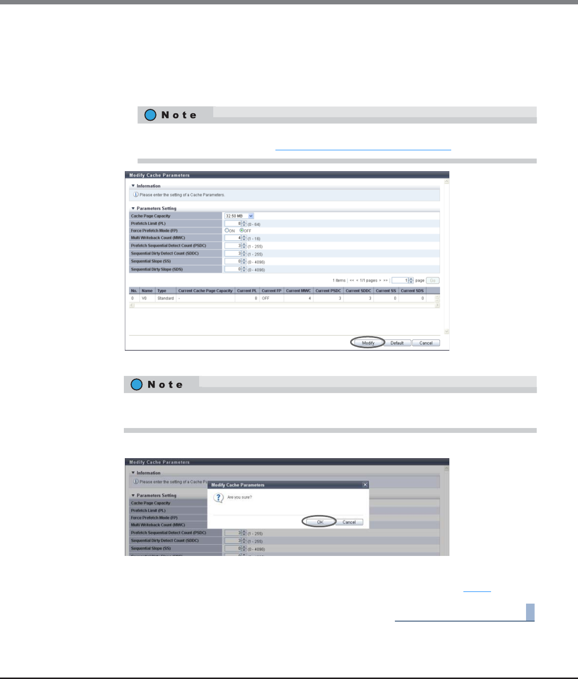
Chapter 5 Volume Management
5.2 Functions in the Action Area for Volume
ETERNUS Web GUI User’s Guide
Copyright 2013 FUJITSU LIMITED P2X0-1090-10ENZ0
152
The following can be also determined as sequential access:
-A sequential access that does not have successive LBAs and skips some addresses
-A sequential access that issues multiple host I/Os at the same time and is unable to be received
in the order of LBAs
A larger SDS may cause random access to be determined as sequential access, resulting in reduced
performance due to incorrect prefetching.
→A confirmation screen appears.
3Click the [OK] button.
→The cache parameter modification starts.
4Click the [Done] button to return to the screen when starting this function in Step 1.
End of procedure
The setting values that are available for Multi Writeback Count vary depending on the RAID type
and drive configuration. Refer to "E.2 Input Conditions for MWC" (page 1007) for details.
If the [Default] button is clicked before the [Modify] button, the default cache parameters are
restored.
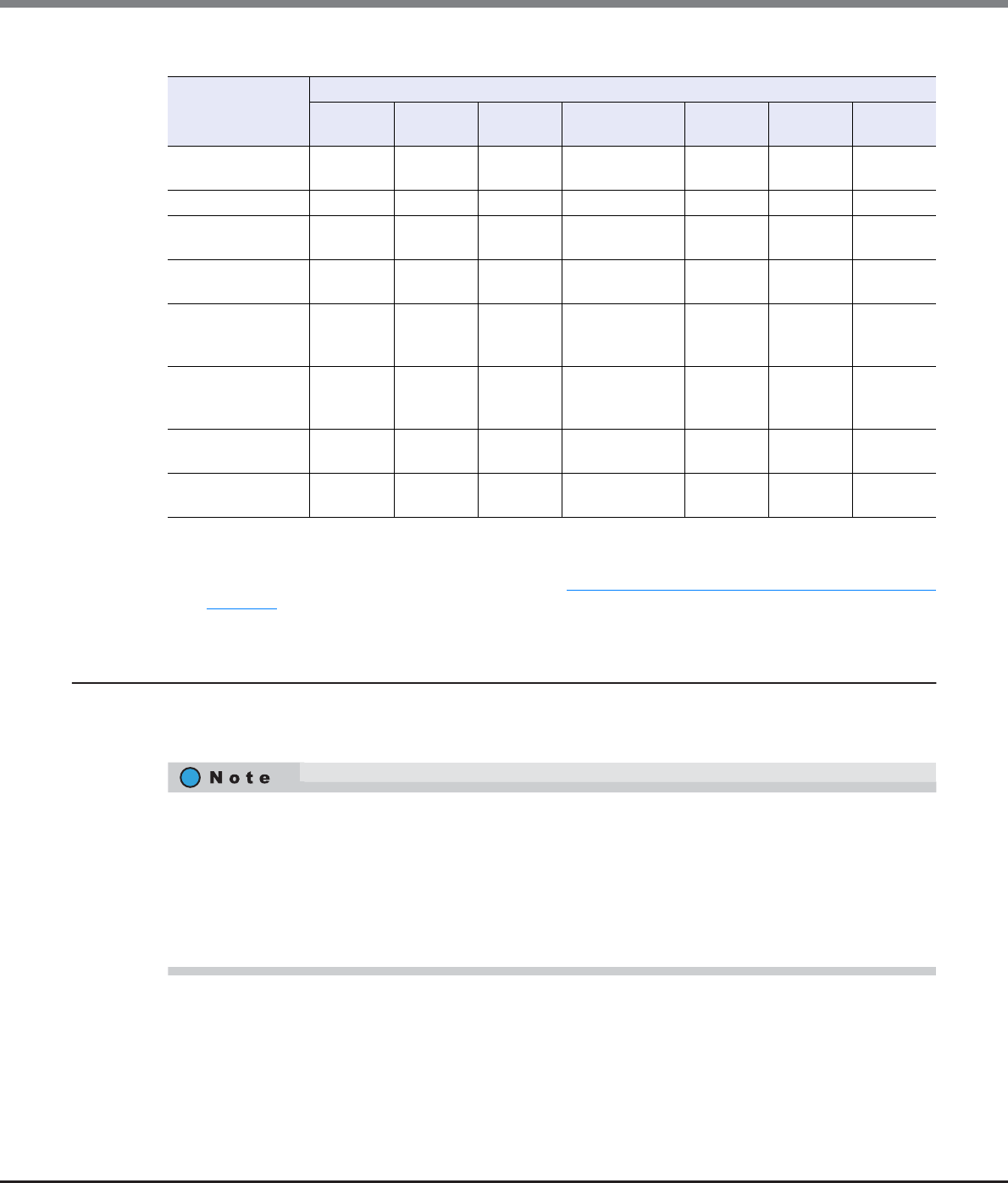
Chapter 5 Volume Management
5.2 Functions in the Action Area for Volume
ETERNUS Web GUI User’s Guide
Copyright 2013 FUJITSU LIMITED P2X0-1090-10ENZ0
153
Volume types for which Cache Parameters are available
Available: The parameter can be specified.
N/A: The parameter cannot be specified.
*1: The cache parameter is specified for each TPP. Refer to "7.2.8 Modify Cache Parameters (Thin Provisioning Pool)"
(page 241) for details.
5.2.19 Export Cache Parameters
This function downloads the setting information of the cache parameters for all the volumes at the same
time.
Item
Volume type
Standard SDV SDPV Standard (LUN
concatenation) TPV FTV WSV
Cache Page
Capacity
Available Available Available N/A N/A N/A N/A
Prefetch Limit (PL) Available Available Available Available Available N/A Available
Force Prefetch
Mode (FP)
Available Available Available Available Available N/A Available
Multi Writeback
Count (MWC)
Available Available Available N/A (*1) N/A Available
Prefetch
Sequential Detect
Count (PSDC)
Available Available Available Available Available N/A Available
Sequential Dirty
Detect Count
(SDDC)
Available Available Available Available Available N/A Available
Sequential Slope
(SS)
Available Available Available Available Available N/A Available
Sequential Dirty
Slope (SDS)
Available Available Available Available Available N/A Available
•"Cache Page Capacity", "Prefetch Limit (PL)", "Force Prefetch Mode (FP)", "Multi Writeback Count (MWC)",
"Prefetch Sequential Detect Count (PSDC)", "Sequential Dirty Detect Count (SDDC)", "Sequential Slope
(SS)", and "Sequential Dirty Slope (SDS)" can be downloaded as cache parameters.
•Cache parameters can be downloaded from "Standard", "WSV", "TPV", "FTV", "SDV", and "SDPV" type
volumes. Note that "Cache Page Capacity" cannot be downloaded from "WSV", "TPV", and "FTV" type
volumes.
•"MWC" for each TPP can be downloaded.
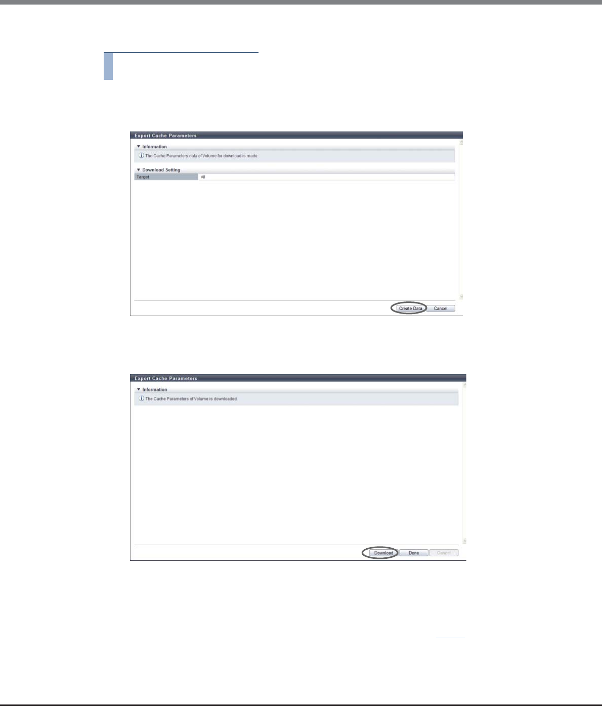
Chapter 5 Volume Management
5.2 Functions in the Action Area for Volume
ETERNUS Web GUI User’s Guide
Copyright 2013 FUJITSU LIMITED P2X0-1090-10ENZ0
154
The procedure to export cache parameters is as follows:
Procedure
1Click [Export Cache Parameters] in [Action].
2Click the [Create Data] button.
→Exporting of the cache parameters is executed.
After the cache parameters are exported, a dialog box to download the file appears.
3Click the [Download] button.
→A dialog box to download the file appears.
4Save the setting information file of the cache parameter.
The default file name is "CacheParam_serial number for the ETERNUS DX Disk storage system_YYYY-
MM-DD_hh-mm-ss.txt".
(YYYY-MM-DD_hh-mm-ss: the date and time when the download screen (Step 3) is displayed.)
→The cache parameter download starts.
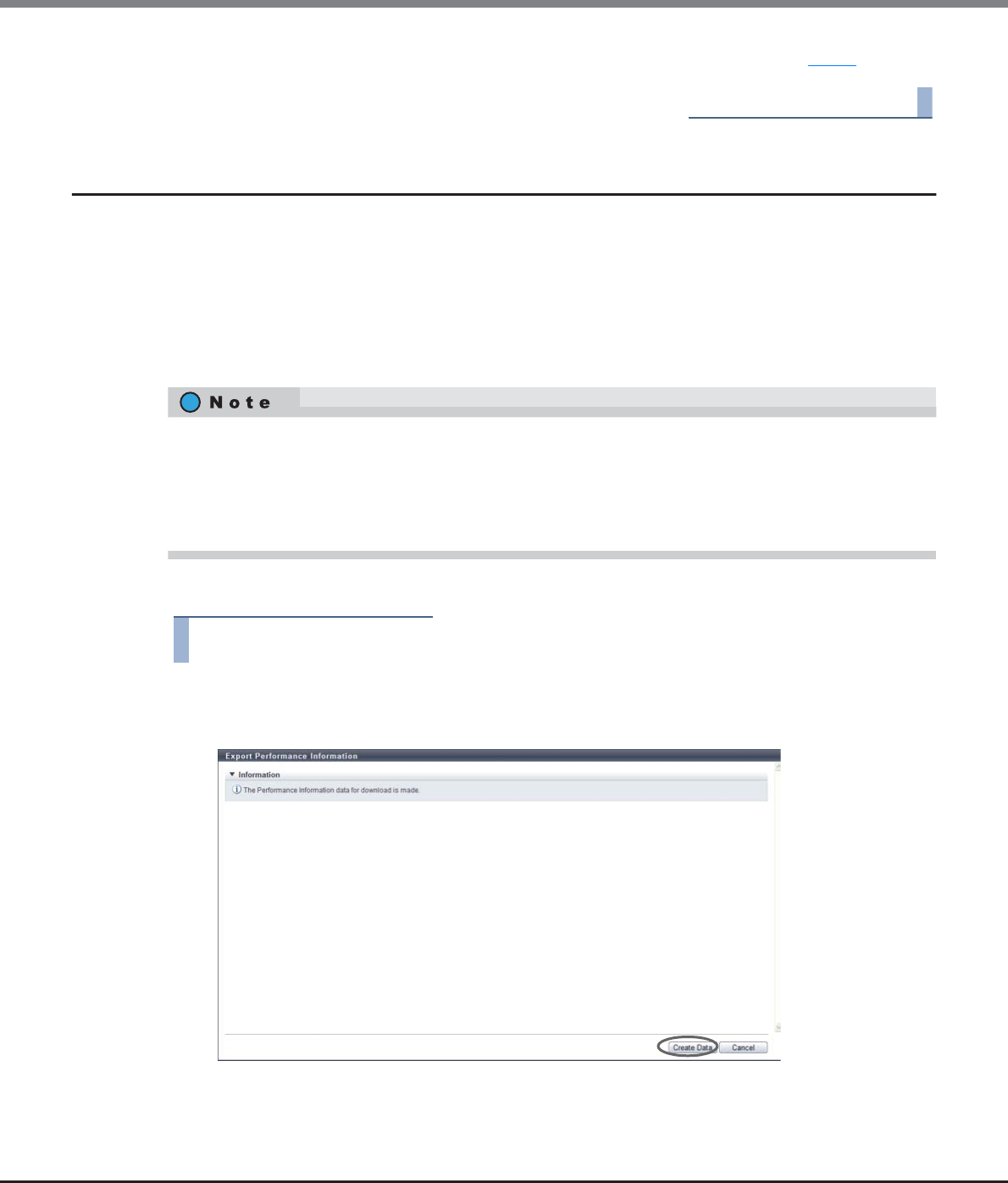
Chapter 5 Volume Management
5.2 Functions in the Action Area for Volume
ETERNUS Web GUI User’s Guide
Copyright 2013 FUJITSU LIMITED P2X0-1090-10ENZ0
155
5Click the [Done] button to return to the screen when starting this function in Step 1.
End of procedure
5.2.20 Export Performance Information
This function exports the following performance information in a single operation and saves it as a text file.
•Performance (Host I/O)
•Performance (Advanced Copy)
•Performance (CA)
•Performance (CM)
•Performance (Drive)
The procedure to download the performance information is as follows:
Procedure
1Click [Export Performance Info] in [Action].
2Click the [Create Data] button.
→The registered performance information in the ETERNUS DX Disk storage system is exported.
After the performance information export is finished, a screen to execute downloading the file is
displayed.
•"Performance (Host I/O)" is the performance information of volumes for Host I/O.
•"Performance (Advanced Copy)" is the performance information of volumes for Advanced Copy.
•The target CA for exporting information of "Performance (CA)" is FC, iSCSI, FCoE, and SAS (for ETERNUS
DX80 S2/DX90 S2). Note that performance information for FC port which port mode is "Initiator" cannot be
obtained.
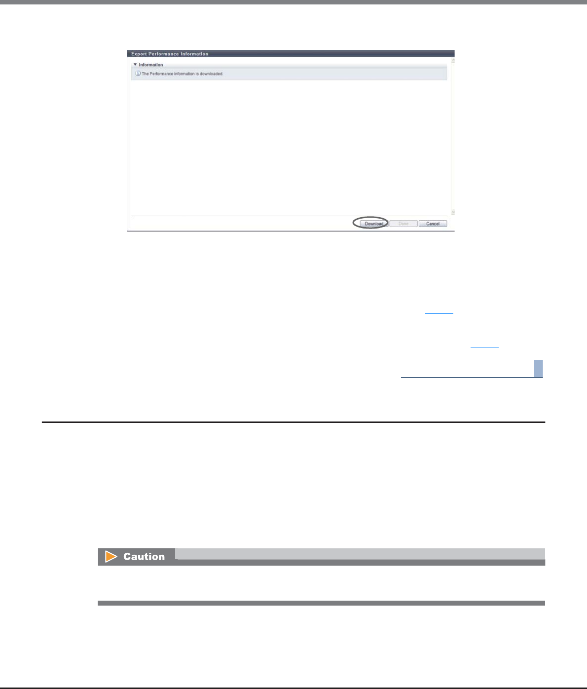
Chapter 5 Volume Management
5.2 Functions in the Action Area for Volume
ETERNUS Web GUI User’s Guide
Copyright 2013 FUJITSU LIMITED P2X0-1090-10ENZ0
156
3Click the [Download] button.
→A dialog box to download the file appears.
4Save the downloaded performance information file.
The default file name is "Perform_serial number for the ETERNUS DX Disk storage system_YYYY-MM-
DD_hh-mm-ss.txt".
(YYYY-MM-DD_hh-mm-ss: the date and time when the download screen (Step 3) is displayed.)
→Downloading the performance information file starts.
5Click the [Done] button to return to the screen when starting this function in Step 1.
End of procedure
5.2.21 Release Reservation
This function releases the reservation status of volumes that are specified by the host.
Reservation and release reservation of a volume is normally performed from the host. This function must be
used only when a reservation of a volume cannot be released due to errors in the host.
This function provides the following features:
•Releasing the volume reservation status
•Releasing the volume persistent reservation status
•Deleting all the reservation keys that are registered in the ETERNUS DX Disk storage system
Be sure to pay attention when releasing reserve status as it may cause data corruption. Check the status of
the target volume before using this function.
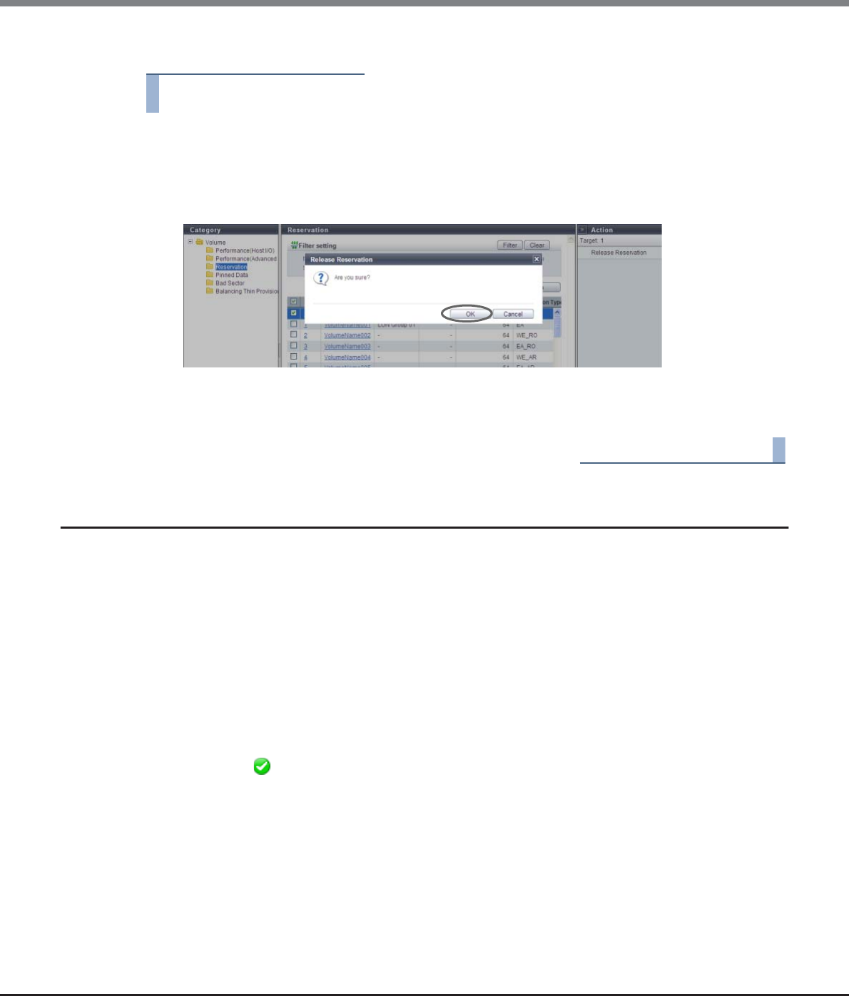
Chapter 5 Volume Management
5.2 Functions in the Action Area for Volume
ETERNUS Web GUI User’s Guide
Copyright 2013 FUJITSU LIMITED P2X0-1090-10ENZ0
157
The procedure to release the reservation status is as follows:
Procedure
1Select the volumes to release the reservation (multiple selections can be made), and click
[Release Reservation] in [Action].
→A confirmation screen appears.
2Click the [OK] button.
→Releasing volume reservation status starts.
3Click the [Done] button to return to the [Volume] screen.
End of procedure
5.2.22 Start Balancing Thin Provisioning Volume
This function relocates the physical allocating area of the TPV to make the physical area of TPV is allocated
equally among the RAID Groups that configure the TPP.
When multiple TPVs in the same TPP are accessed, the physical area is allocated by using the RAID groups of
the TPP one by one in the access order. Therefore the physical area of TPVs may be unequally allocated among
the RAID groups. This phenomenon also occurs when expanding the capacity of a TPP. In this case, the
physical area is allocated unevenly among the newly added and existing RAID groups. This function is to solve
the unequal allocation among RAID groups, and balance the physical allocating area in each RAID group. I/O
load is dispersed among the RAID groups in the TPP and access performance may be improved.
Requirements for a TPV to be balanced:
•The "Type" is "TPV"
•The "Status" is " Available"
•RAID migration is not being performed (the target volume is not used as a migration source or a migration
destination)
•An Advanced Copy is not being performed (the target volume is not being used as a copy source or a copy
destination)
•A Remote Advanced Copy is not being performed (the target volume is not being used as a copy source or
a copy destination)
•An Advanced Copy (ODX) is not being performed
•TPV balancing is not being performed
•Zero Reclamation is not being performed
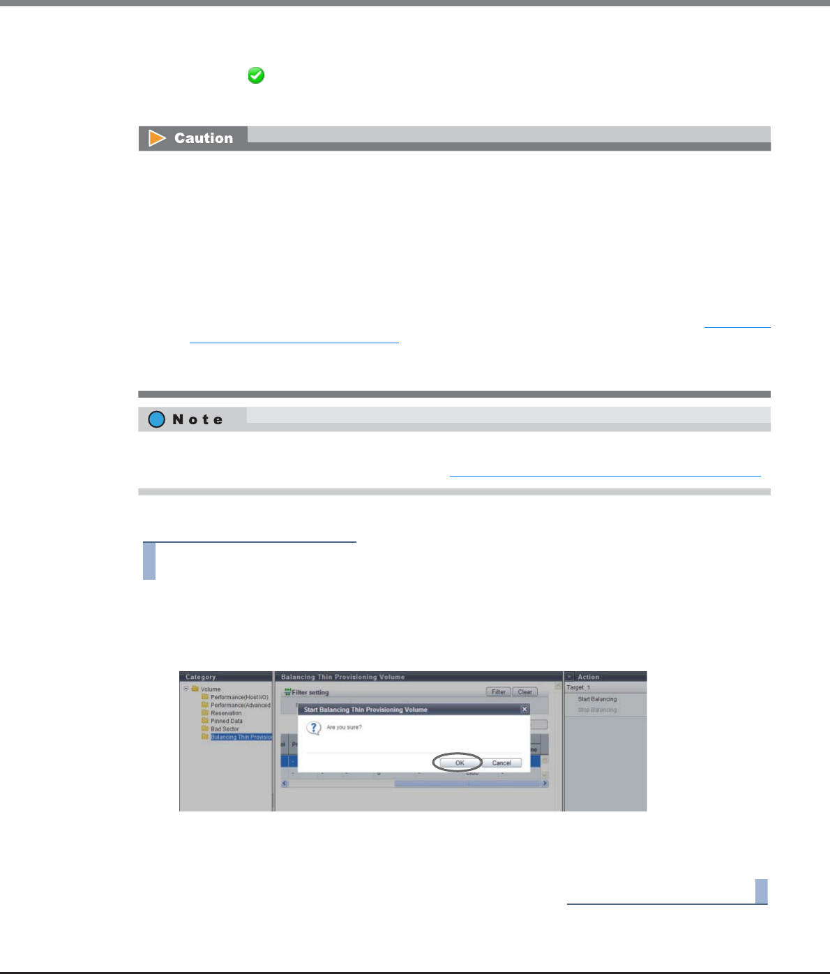
Chapter 5 Volume Management
5.2 Functions in the Action Area for Volume
ETERNUS Web GUI User’s Guide
Copyright 2013 FUJITSU LIMITED P2X0-1090-10ENZ0
158
Requirements for a TPP in which the target TPV is registered:
•The "Status" is " Available"
•The free space in the TPP is larger than the capacity of the TPV that is to be balanced
The procedure to start balancing TPVs is as follows:
Procedure
1Select the TPV to be balanced and click [Start Balancing] in [Action].
→A confirmation screen appears.
2Click the [OK] button.
→TPV balancing starts.
3Click the [Done] button to return to the [Balancing Thin Provisioning Volume] screen.
End of procedure
•If a Thin Provisioning license is not registered, this function cannot be used.
•The TPV balancing cannot be performed in the following conditions:
-When the maximum number of volumes is already registered in the ETERNUS DX Disk storage system
-When the total number of TPV balancing, RAID migration, and FTV balancing (*1) processes that are
performed at the same time is 32
-When the total capacity for the TPV balancing, RAID migration, and FTV balancing (*1) processes that
are performed at the same time is 128TB
-When the TPP capacity that can be registered in the ETERNUS DX Disk storage system is insufficient
*1: When the FTRP balancing is performed, the FTV balancing process starts in the FTSP. Refer to "7.2.12 Start
Balancing Flexible Tier Pool" (page 248) for details.
•This function balances the physical allocating area of the TPV among RAID groups of the TPP to which the
TPV belongs. It is not able to balance TPV by RAID migration of the TPV to other TPPs.
•TPV balancing can be performed during the work I/O.
•To check the balancing progress of a TPV, refer to "5.1.8 Balancing Thin Provisioning Volume" (page 86).
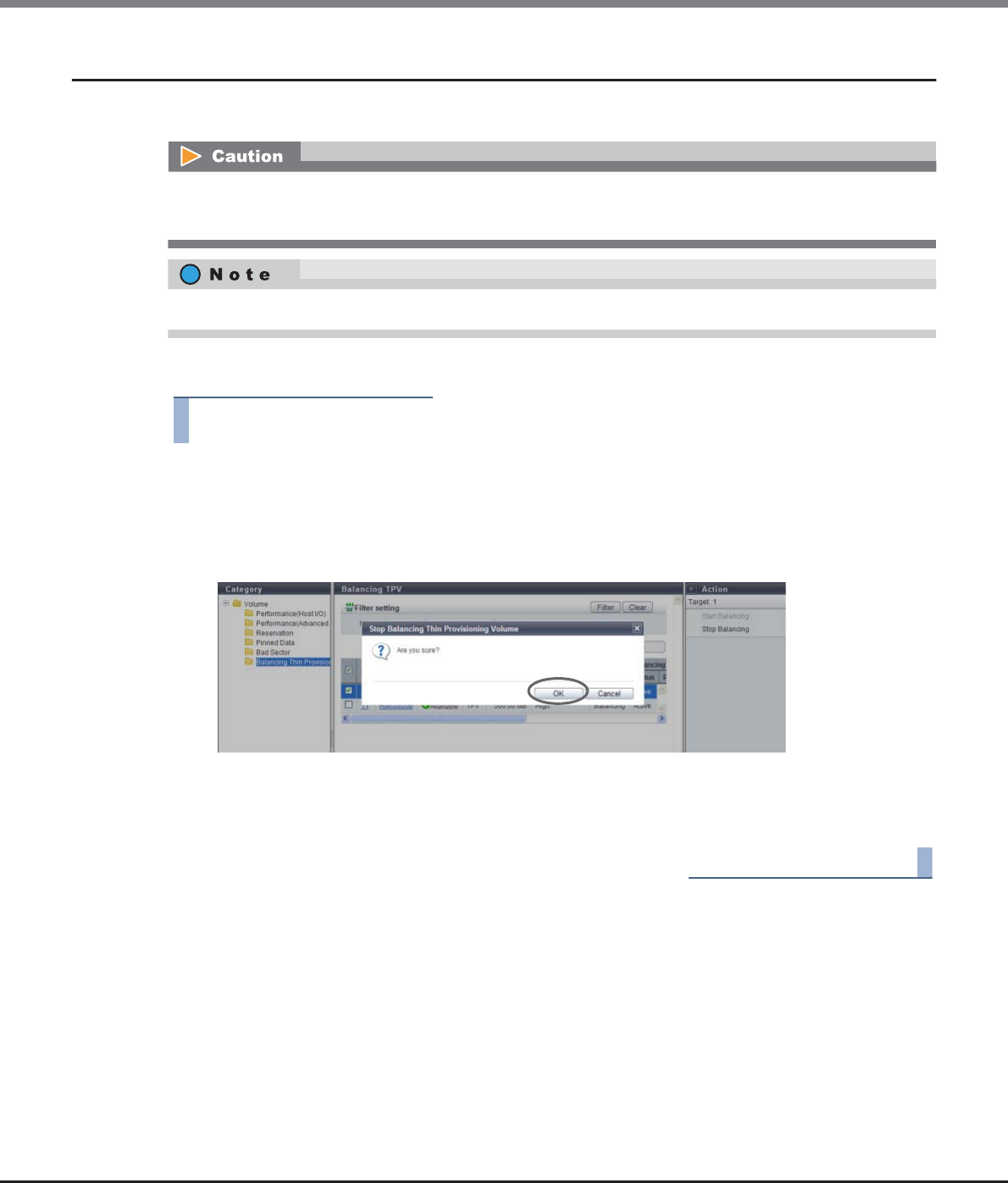
Chapter 5 Volume Management
5.2 Functions in the Action Area for Volume
ETERNUS Web GUI User’s Guide
Copyright 2013 FUJITSU LIMITED P2X0-1090-10ENZ0
159
5.2.23 Stop Balancing Thin Provisioning Volume
This function stops TPV balancing
The procedure to stop balancing of the Thin Provisioning Volume is as follows:
Procedure
1Select the volume for which balancing is to be stopped and click [Stop Balancing] in
[Action].
→A confirmation screen appears.
2Click the [OK] button.
→TPV balancing stops.
3Click the [Done] button to return to the [Balancing Thin Provisioning Volume] screen.
End of procedure
•This function cannot be used when balancing is not being performed for a TPV.
•This function cannot be used when the specified TPV balancing is already complete.
When TPV balancing is stopped, data in volumes that are not balanced yet can be accessed normally.
ETERNUS Web GUI User’s Guide
Copyright 2013 FUJITSU LIMITED P2X0-1090-10ENZ0
160
Chapter 6
RAID Group Management
This chapter describes RAID group management.
6.1 RAID Group Status
RAID group status displays the status information of volumes.
RAID group status screens can be displayed by clicking the following categories:
Detailed information of the RAID groups can be displayed from the following screens:
•RAID Group (Basic)
•RAID Group (Volume Layout)
•RAID Group Detail (Disk)
RAID group status screen Category
RAID Group (Basic Information) RAID Group
Tuning Tuning
ECO Mode Schedule (RAID Group) ECO Mode Schedule
SED Key Group SED Key Group
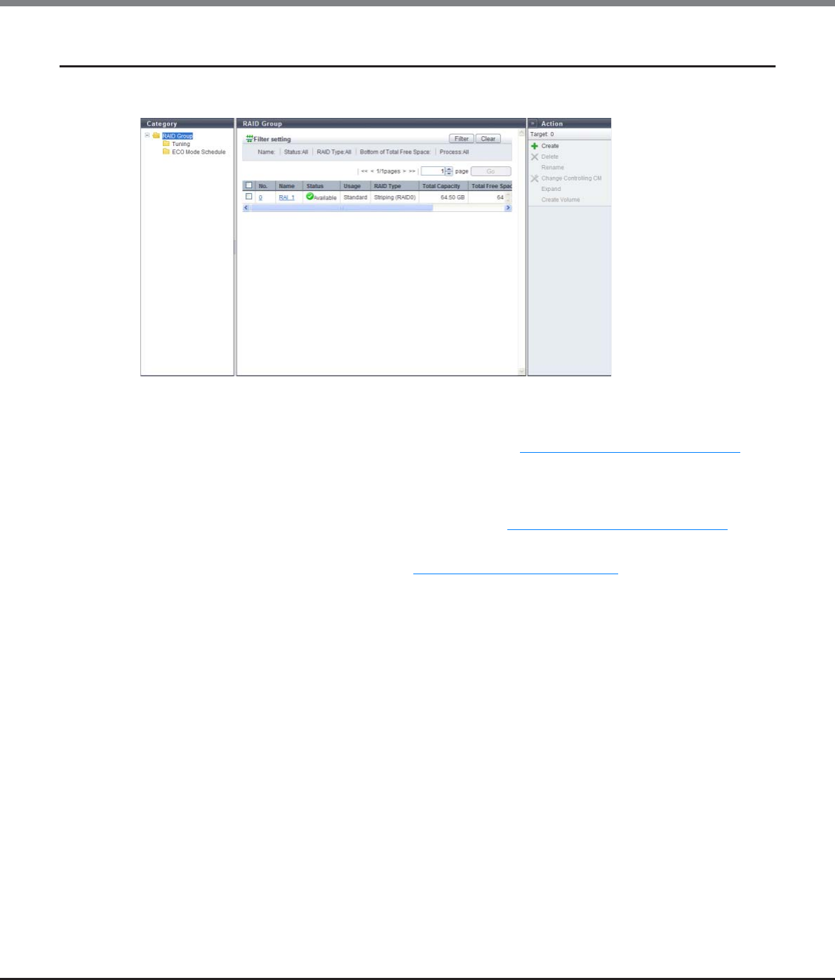
Chapter 6 RAID Group Management
6.1 RAID Group Status
ETERNUS Web GUI User’s Guide
Copyright 2013 FUJITSU LIMITED P2X0-1090-10ENZ0
161
6.1.1 RAID Group (Basic Information)
This function displays the basic information of RAID groups.
The following items are displayed in the Main area:
•No.
The RAID group number is displayed. Click this item to display "6.1.5 RAID Group (Basic)" (page 169).
The RAID group number is allocated when a volume is created from the smallest unused decimal number
in ascending order.
•Name
The RAID group name is displayed. Click this item to display "6.1.5 RAID Group (Basic)" (page 169).
•Status
The RAID group status is displayed. Refer to "B.3 RAID Group Status" (page 975) for detailed information of
RAID group status.
•Usage
The usage of the RAID group is displayed.
-Standard
A RAID group that is used for creating "Standard", "SDV", or "SDPV" type volumes
-Standard / WSV
A RAID group that is used for creating "Standard", "WSV", "SDV", or "SDPV" type volumes
-WSV
A RAID group that is used for creating "WSV" type volumes
-TPP
A RAID group that belongs to a TPP
-FTRP
A RAID group that belongs to a Flexible Tier Pool (FTRP)
-RDB
A RAID group that is registered as an REC Disk Buffer
-Temporary
A RAID group that is temporarily created while LDE is being performed
-"-" (hyphen)
A RAID group that is not used

Chapter 6 RAID Group Management
6.1 RAID Group Status
ETERNUS Web GUI User’s Guide
Copyright 2013 FUJITSU LIMITED P2X0-1090-10ENZ0
162
•RAID Type
The type of RAID group is displayed.
-High Performance (RAID1+0)
-High Capacity (RAID5)
-High Reliability (RAID6)
-Reliability (RAID5+0)
-Mirroring (RAID1)
-Striping (RAID0)
•Total Capacity
The total capacity of the RAID groups is displayed.
The capacity is displayed in units of "GB" or "TB". Even when volumes are created in units of "GB", if the
volume capacity exceeds 1023.99GB, the capacity is displayed in units of "TB". The capacity is rounded off
to two decimal places.
•Total Free Space
The total free space in the RAID group is displayed.
If the total free capacity exceeds 1023.99MB, the capacity is displayed in units of "GB". If the total free
capacity exceeds 1023.99GB, the capacity is displayed in units of "TB". The capacity is rounded off to two
decimal places.
"Free space" means an area in the RAID group where no volume is created, and dispersed areas which
became free by creating and deleting a volume.
•Controlling CM
The controlling CM and CPU of the RAID group are displayed.
-CM#x CPU#y (x: CM number, y: CPU number)
•Process
A process that is being performed for the RAID group is displayed. If no process is being performed, a "-"
(hyphen) is displayed.
-Recovering
Rebuild, copyback, redundant copy, or RAID group recovery is being performed.
-Expanding
Expansion of the RAID group by LDE is being performed.
-Formatting
Formatting of the RAID group is being performed.
Filter setting
Filter Description
Name Input the RAID group name that is to be displayed.
When not using the RAID group name for filtering, leave this item blank.
Status Select the RAID group status that is to be displayed.
RAID Type Select the RAID type that is to be displayed.
Bottom of Total Free Space
Input the minimum capacity of unused free space for the RAID groups that are to be
displayed and select the units of capacity.
When the minimum free space of the RAID group is not used for filtering, specify "0MB".
Process Select which current process for the RAID group is to be displayed.
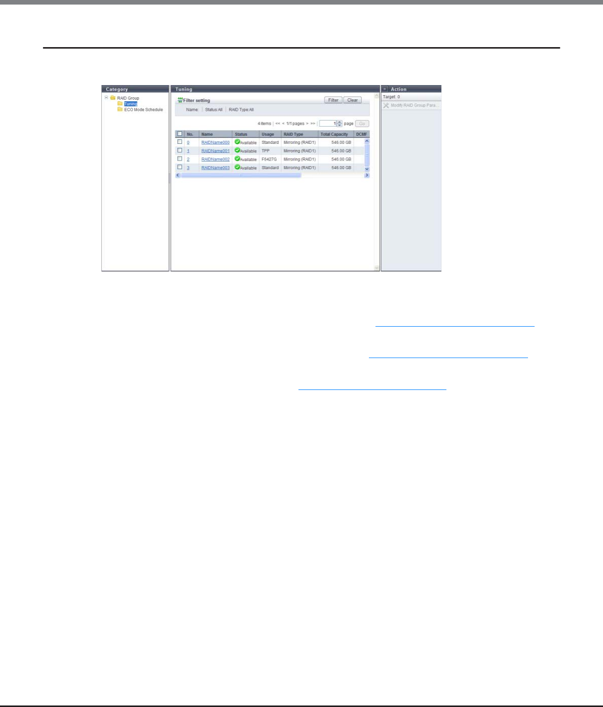
Chapter 6 RAID Group Management
6.1 RAID Group Status
ETERNUS Web GUI User’s Guide
Copyright 2013 FUJITSU LIMITED P2X0-1090-10ENZ0
163
6.1.2 Tuning
The RAID group tuning information is displayed.
The following items are displayed in the Main area:
•No.
The RAID group number is displayed. Click this item to display "6.1.5 RAID Group (Basic)" (page 169).
•Name
The RAID group name is displayed. Click this item to display "6.1.5 RAID Group (Basic)" (page 169).
•Status
The RAID group status is displayed. Refer to "B.3 RAID Group Status" (page 975) for detailed information of
RAID group status.
•Usage
The usage of the RAID group is displayed.
-Standard
A RAID group that is used for creating "Standard", "SDV", or "SDPV" type volumes
-Standard / WSV
A RAID group that is used for creating "Standard", "WSV", "SDV", or "SDPV" type volumes
-WSV
A RAID group that is used for creating "WSV" type volumes
-TPP
A RAID group that belongs to a TPP
-FTRP
A RAID group that belongs to an FTRP
-RDB
A RAID group that is registered as an REC Disk Buffer
-"-" (hyphen)
A RAID group that is not used

Chapter 6 RAID Group Management
6.1 RAID Group Status
ETERNUS Web GUI User’s Guide
Copyright 2013 FUJITSU LIMITED P2X0-1090-10ENZ0
164
•RAID Type
The type of RAID group is displayed.
-High Performance (RAID1+0)
-High Capacity (RAID5)
-High Reliability (RAID6)
-Reliability (RAID5+0)
-Mirroring (RAID1)
-Striping (RAID0)
•Total Capacity
The total capacity of the RAID groups is displayed.
•DCMF
The Drive Command Multiplying Factor (DCMF) is displayed.
If the DCMF is changed, the number of commands issued to the drive is increased in multiples of the DCMF
set value (if DCMF is "2", it is double).
•Rebuild Priority
The rebuild priority of the RAID group is displayed.
When the Rebuild Priority is "Low", give priority to host access.
When the Rebuild Priority is "Middle", give the same priority as the host access to rebuild, copyback, and
redundant copy.
When the Rebuild Priority is "High", give priority to rebuild, copyback, and redundant copy.
•Throttle
The throttle value is displayed.
Throttle is the proportion of the number of commands that are issued to a drive at the same time to the
maximum number of commands that can be issued. When the throttle value is "100%", the maximum
number of commands specified for each drive (the default number of commands) are issued.
When "Disk Tuning Parameter Setting" of the [Modify RAID Group Parameters] function is
disabled, a "-" (hyphen) is displayed.
When logged in with a user account that has a default "Monitor" role, this item is not displayed.
•Ordered Cut
Ordered Cut is displayed between 0 and 65535.
Ordered Cut is the number of commands for optimizing drive access processing (priority control). When
Ordered Cut is "x", the command to perform the priority control is issued for every x commands issued, and
priority control is performed for the command issued before this command.
When Ordered Cut is "0", the interval for priority control (priority control at every "x" commands") cannot be
specified. All of the commands issued to the drive are processed according to their priority settings.
When "Disk Tuning Parameter Setting" of the [Modify RAID Group Parameters] function is disabled, or the
configuration drive of the RAID group is SSD, a "-" (hyphen) is displayed.
When logged in with a user account that has a default "Monitor" role, this item is not displayed.
RAID groups in which LDE is being performed are not displayed in the list.
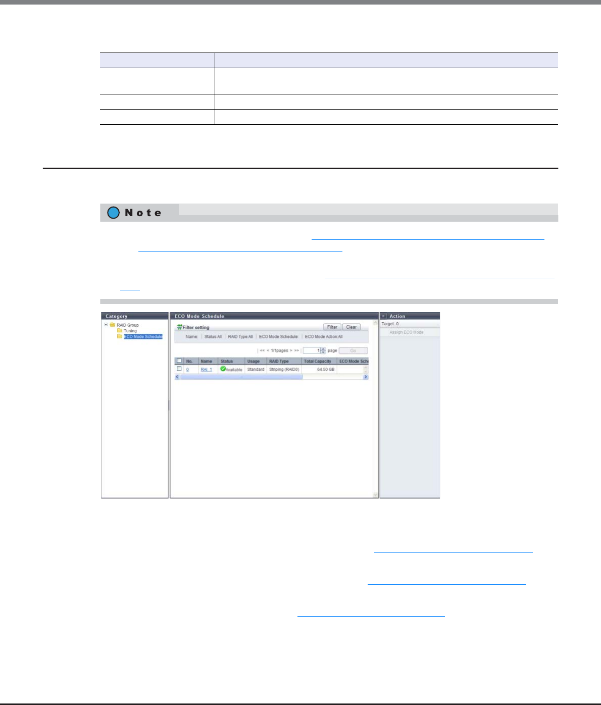
Chapter 6 RAID Group Management
6.1 RAID Group Status
ETERNUS Web GUI User’s Guide
Copyright 2013 FUJITSU LIMITED P2X0-1090-10ENZ0
165
Filter setting
6.1.3 ECO Mode Schedule (RAID Group)
This function displays the setting status of the ECO mode that is applied for the RAID group.
The following items are displayed in the Main area:
•No.
The RAID group number is displayed. Click this item to display "6.1.5 RAID Group (Basic)" (page 169).
•Name
The RAID group name is displayed. Click this item to display "6.1.5 RAID Group (Basic)" (page 169).
•Status
The RAID group status is displayed. Refer to "B.3 RAID Group Status" (page 975) for detailed information of
RAID group status.
Filter Description
Name Input the RAID group name that is to be displayed.
When not using the RAID group name for filtering, leave this item blank.
Status Select the RAID group status that is to be displayed.
RAID Type Select the RAID type that is to be displayed.
•To use the ECO mode, follow the procedure in "11.2.8.1 Modify ECO Mode General Setting" (page 869)
and "11.2.8.2 Create ECO Mode Schedule" (page 871) to perform the general ECO mode setup and create
an ECO mode schedule.
•To assign the ECO mode to a RAID group, refer to "6.2.7 Assign ECO Mode Schedule (RAID Group)" (page
192).

Chapter 6 RAID Group Management
6.1 RAID Group Status
ETERNUS Web GUI User’s Guide
Copyright 2013 FUJITSU LIMITED P2X0-1090-10ENZ0
166
•Usage
The usage of the RAID group is displayed.
-Standard
A RAID group that is used for creating "Standard", "SDV", or "SDPV" type volumes
-Standard / WSV
A RAID group that is used for creating "Standard", "WSV", "SDV", or "SDPV" type volumes
-WSV
A RAID group that is used for creating "WSV" type volumes
•RAID Type
The type of RAID group is displayed.
-High Performance (RAID1+0)
-High Capacity (RAID5)
-High Reliability (RAID6)
-Reliability (RAID5+0)
-Mirroring (RAID1)
-Striping (RAID0)
•Total Capacity
The total capacity of the RAID groups is displayed.
•ECO Mode Schedule
The ECO mode schedule name that is applied for the RAID group is displayed. When the ECO mode
schedule is not applied, the field is blank.
•ECO Mode Action
When the ECO mode is enabled, "ON" is displayed. When the ECO mode is disabled, "OFF" is displayed.
•Motor Status
The disk motor status for the RAID group is displayed.
-Active
The disk motors are activated.
-In the Boot Process
The disk motors are starting up.
-Idle
The disk motors are stopped.
-In the Stop Process
The disk motors are being stopped.
Filter setting
Filter Description
Name Input the RAID group name that is to be displayed.
When not using the RAID group name for filtering, leave this item blank.
Status Select the RAID group status that is to be displayed.
RAID Type Select the RAID type that is to be displayed.
ECO Mode Schedule
Input the ECO mode schedule name that is applied to the RAID group that is to be
displayed.
When not using the ECO mode schedule name for filtering, leave this item blank.
ECO Mode Action Select the operating status of the ECO mode that is applied to the RAID group status that
is to be displayed.
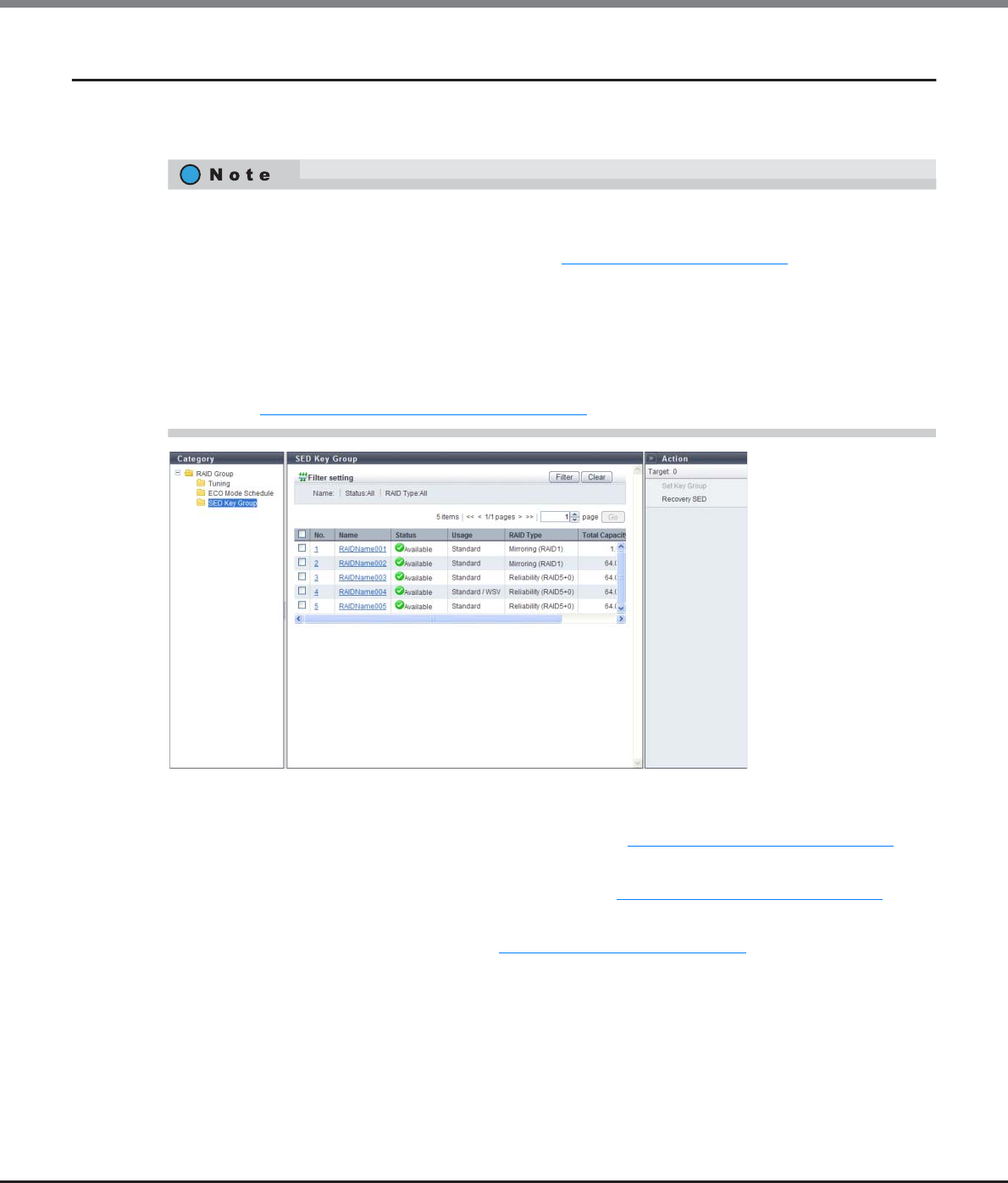
Chapter 6 RAID Group Management
6.1 RAID Group Status
ETERNUS Web GUI User’s Guide
Copyright 2013 FUJITSU LIMITED P2X0-1090-10ENZ0
167
6.1.4 SED Key Group
This function displays the key group settings for the RAID groups that are configured with SEDs.
The key group combines all of the RAID groups that use the same SED authentication key.
The following items are displayed in the Main area:
•No.
The RAID group number is displayed. Click this item to display "6.1.5 RAID Group (Basic)" (page 169).
•Name
The RAID group name is displayed. Click this item to display "6.1.5 RAID Group (Basic)" (page 169).
•Status
The RAID group status is displayed. Refer to "B.3 RAID Group Status" (page 975) for detailed information of
RAID group status.
•One key group can be created in the ETERNUS DX Disk storage system.
•Use the [Key Group] screen to check the SED authentication key information and the SSL/KMIP certificate
information that is used for the key group. Refer to "11.1.5.1 Key Group" (page 723) for details.
•There are two types of SED keys: an SED authentication key that is managed by the key server and a
common key that is stored in the ETERNUS DX Disk storage system. If a RAID group that is configured with
SEDs is registered in the key group, the relevant RAID group is managed by the SED authentication key. If
the RAID group is not registered in the key group, the relevant RAID group is managed by the common
key.
•RAID groups that are configured with SEDs can be added in the key group or deleted from the key group.
Refer to "6.2.8 Set Key Group (RAID Group)" (page 195) for details.

Chapter 6 RAID Group Management
6.1 RAID Group Status
ETERNUS Web GUI User’s Guide
Copyright 2013 FUJITSU LIMITED P2X0-1090-10ENZ0
168
•Usage
The usage of the RAID group is displayed.
-Standard
A RAID group that is used for creating "Standard", "SDV", or "SDPV" type volumes
-Standard / WSV
A RAID group that is used for creating "Standard", "WSV", "SDV", or "SDPV" type volumes
-WSV
A RAID group that is used for creating "WSV" type volumes
-Temporary
A RAID group that is temporarily created while LDE is being performed
-"-" (hyphen)
A RAID group that is not used
•RAID Type
The type of RAID group is displayed.
-High Performance (RAID1+0)
-High Capacity (RAID5)
-High Reliability (RAID6)
-Reliability (RAID5+0)
-Mirroring (RAID1)
-Striping (RAID0)
•Total Capacity
The total capacity of the RAID groups is displayed.
•Key Group
The setting status of the key group for the RAID groups is displayed.
-If the relevant RAID group is registered in the key group: "Enable"
-If one of the following conditions applies to the relevant RAID group: "Disable"
•No common key for SEDs is registered
•The relevant RAID group is not registered in the key group
Filter setting
Filter Description
Name Input the RAID group name that is to be displayed.
When not using the RAID group name for filtering, leave this item blank.
Status Select the RAID group status that is to be displayed.
RAID Type Select the RAID type that is to be displayed.
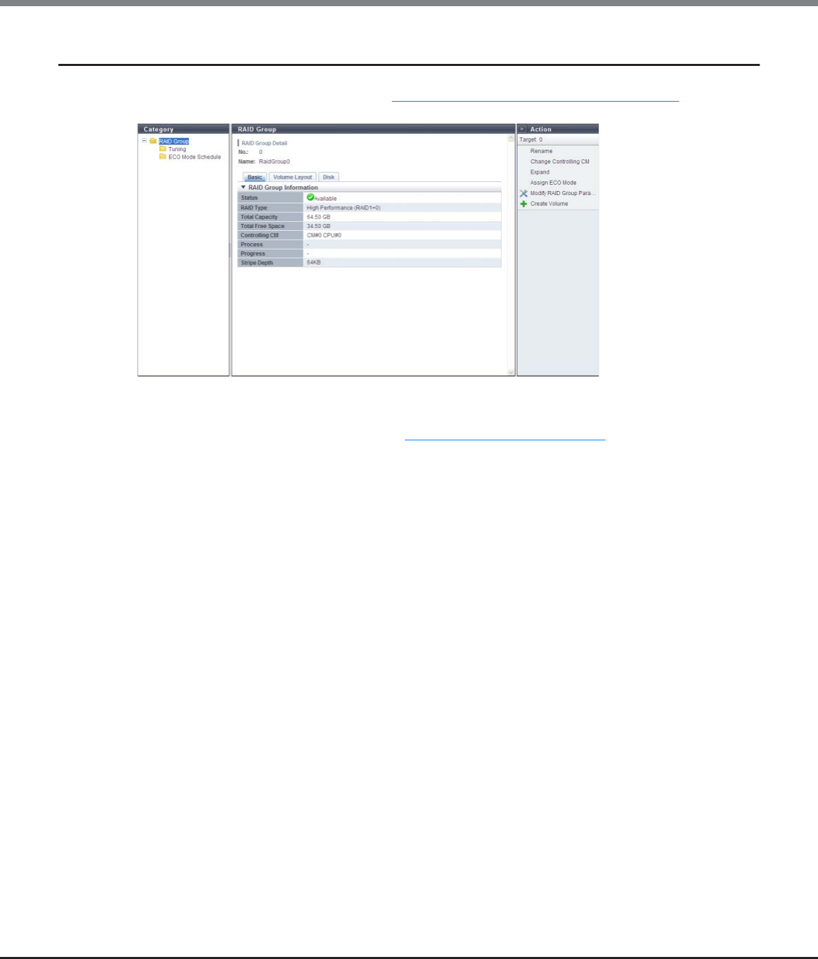
Chapter 6 RAID Group Management
6.1 RAID Group Status
ETERNUS Web GUI User’s Guide
Copyright 2013 FUJITSU LIMITED P2X0-1090-10ENZ0
169
6.1.5 RAID Group (Basic)
Click the [No.] link or the [Name] link in the "6.1.1 RAID Group (Basic Information)" (page 161) to display the
detailed information of the target RAID group.
The following items are displayed in the Main area:
•Status
The RAID group status is displayed. Refer to "B.3 RAID Group Status" (page 975) for detailed information of
RAID group status.
•RAID Type
The type of RAID group is displayed.
-High Performance (RAID1+0)
-High Capacity (RAID5)
-High Reliability (RAID6)
-Reliability (RAID5+0)
-Mirroring (RAID1)
-Striping (RAID0)
•Total Capacity
The total capacity of the RAID groups is displayed.
•Total Free Space
The total free space in the RAID group is displayed.
"Free space" means an area in the RAID group where no volume is created, and dispersed areas which
became free by creating and deleting a volume.
•Controlling CM
The controlling CM and CPU of the RAID group is displayed.
-CM#x CPU#y (x: CM number, y: CPU number)
•Process
A process that is being performed for the RAID group is displayed. If no process is being performed, a "-"
(hyphen) is displayed.
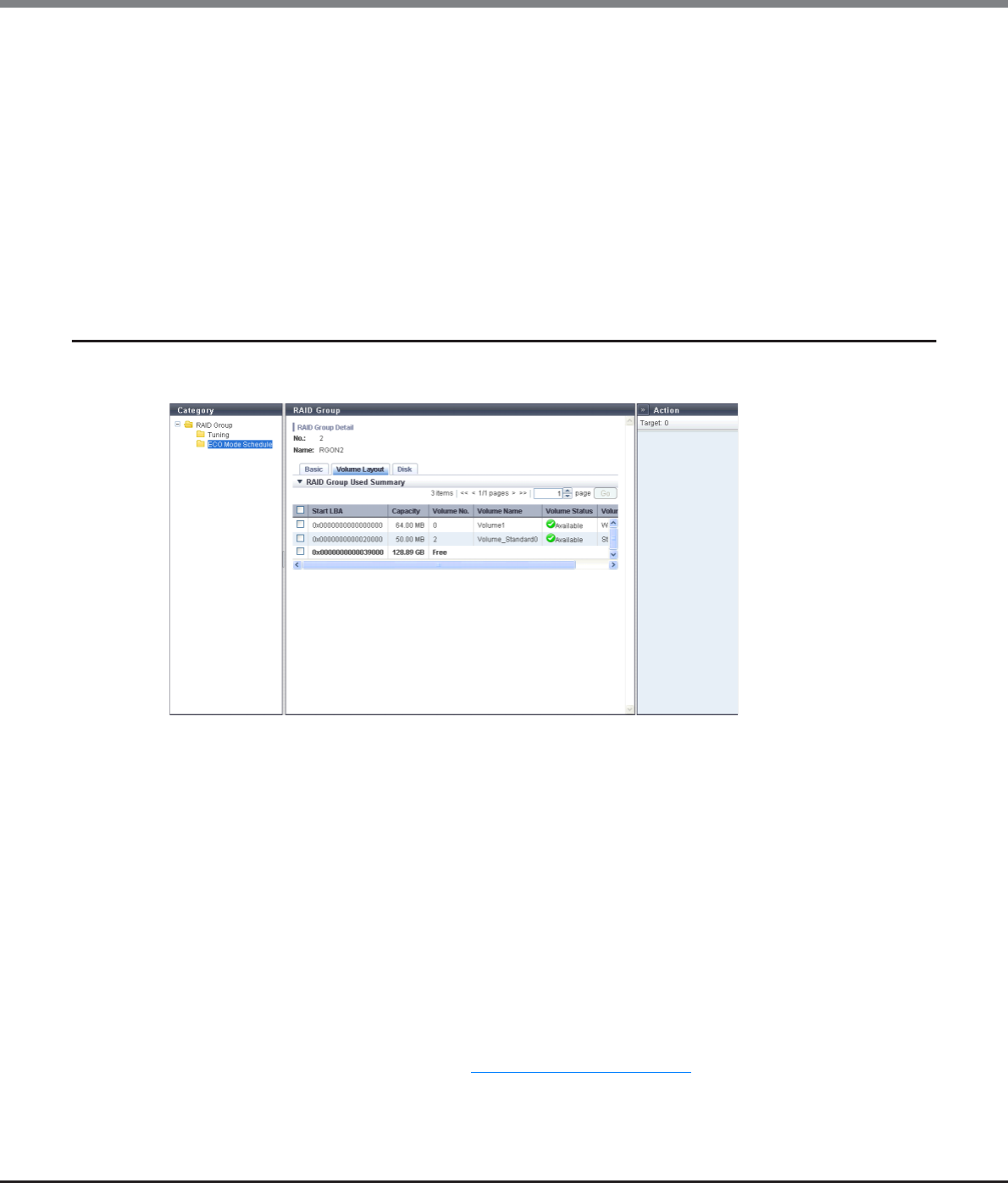
Chapter 6 RAID Group Management
6.1 RAID Group Status
ETERNUS Web GUI User’s Guide
Copyright 2013 FUJITSU LIMITED P2X0-1090-10ENZ0
170
•Stripe Depth
The Stripe Depth (*1) of the RAID group is displayed.
If the RAID type is "Mirroring (RAID1)", a "-" (hyphen) is displayed.
*1: The number of logical blocks that are assigned to a drive for each stripe when configuring a stripe volume in a
RAID group. Normally, it is 64KB.
-64 KB
-128 KB
-256 KB
-512 KB
-1024 KB
6.1.6 RAID Group (Volume Layout)
Detailed information of the volume layout is displayed.
The following items are displayed in the Main area:
•Start LBA
The first Logical Block Address (LBA) of the volume is displayed.
•Capacity
The volume capacity is displayed.
If the volume capacity exceeds 1023.99MB, the capacity is displayed in units of "GB". If the volume capacity
exceeds 1023.99GB, the capacity is displayed in units of "TB". The capacity is rounded off to two decimal
places. To check the volume capacity in units of "MB", use CLI.
•Volume No.
The volume number is displayed. Unused space is displayed as "Free".
•Volume Name
The volume name is displayed.
•Volume Status
The volume status is displayed. Refer to "B.2 Volume Status" (page 974) for detailed information of volume
status.
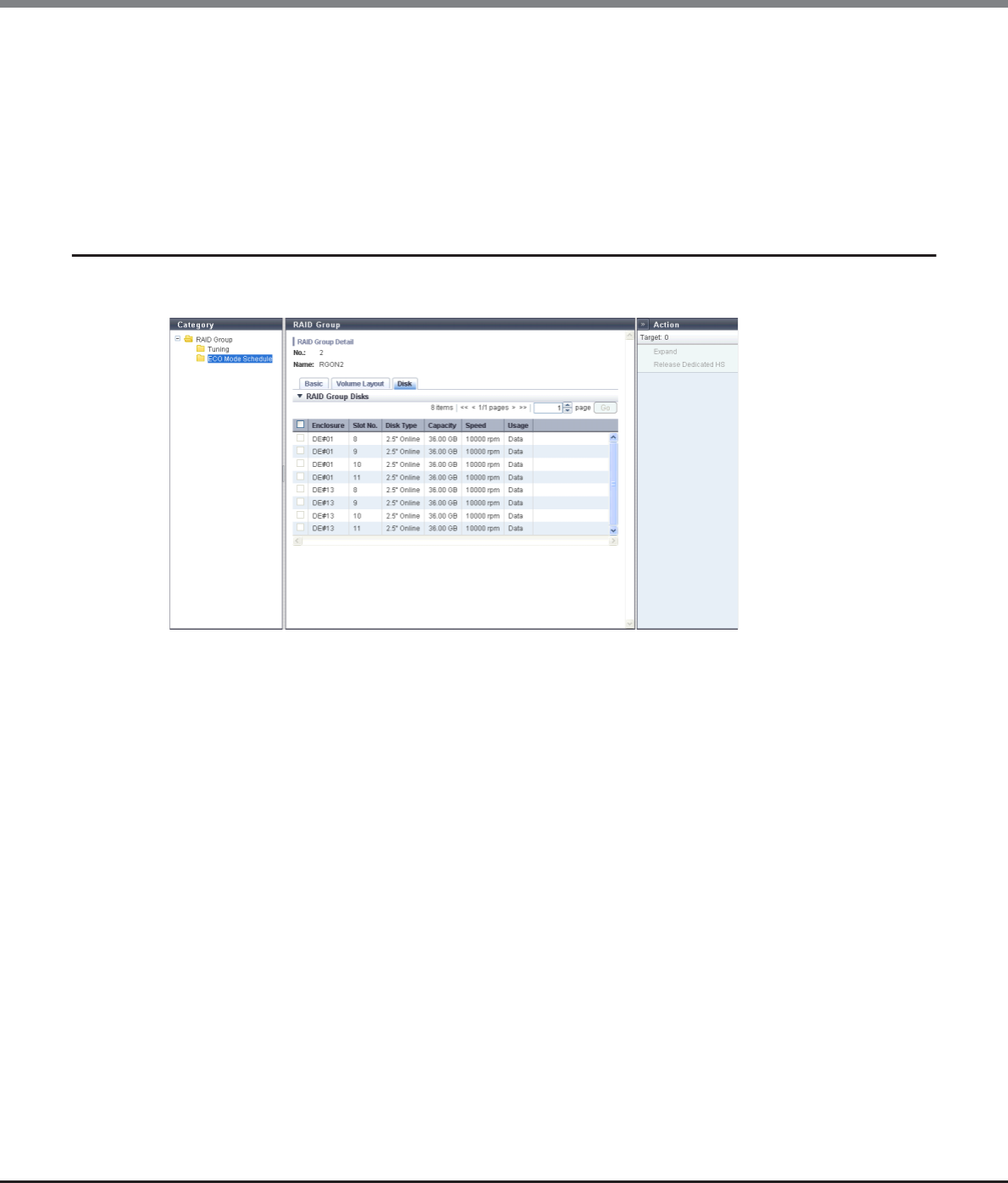
Chapter 6 RAID Group Management
6.1 RAID Group Status
ETERNUS Web GUI User’s Guide
Copyright 2013 FUJITSU LIMITED P2X0-1090-10ENZ0
171
•Volume Type
The volume type is displayed.
-Standard
-WSV
-SDV
-SDPV
6.1.7 RAID Group Detail (Disk)
Detailed information of disks that configure the RAID group is displayed.
The following items are displayed in the Main area:
•Enclosure
The number of the enclosure where the drive is installed is displayed.
•Slot No.
The number of the slot where the drive is installed is displayed.
•Disk Type
The drive type is displayed.
-2.5" Online
2.5-inch SAS disk
-3.5" Online
3.5-inch SAS disk
-2.5" Nearline
2.5-inch Nearline SAS disk
-3.5" Nearline
3.5-inch Nearline SAS disk
-2.5" SSD
2.5-inch SSD
-3.5" SSD
3.5-inch SSD
-2.5" SED
2.5-inch SED

Chapter 6 RAID Group Management
6.1 RAID Group Status
ETERNUS Web GUI User’s Guide
Copyright 2013 FUJITSU LIMITED P2X0-1090-10ENZ0
172
•Capacity
The capacity of the drive is displayed.
•Speed
The drive speed is displayed. For SSDs, a "-" (hyphen) is displayed.
•Usage
The usage of the drive is displayed.
-Data
A drive that is used for user data or an unused drives
-Global Hot Spare
A drive that is registered as a Global Hot Spare
-Dedicated Hot Spare
A drive that is registered as a Dedicated Hot Spare
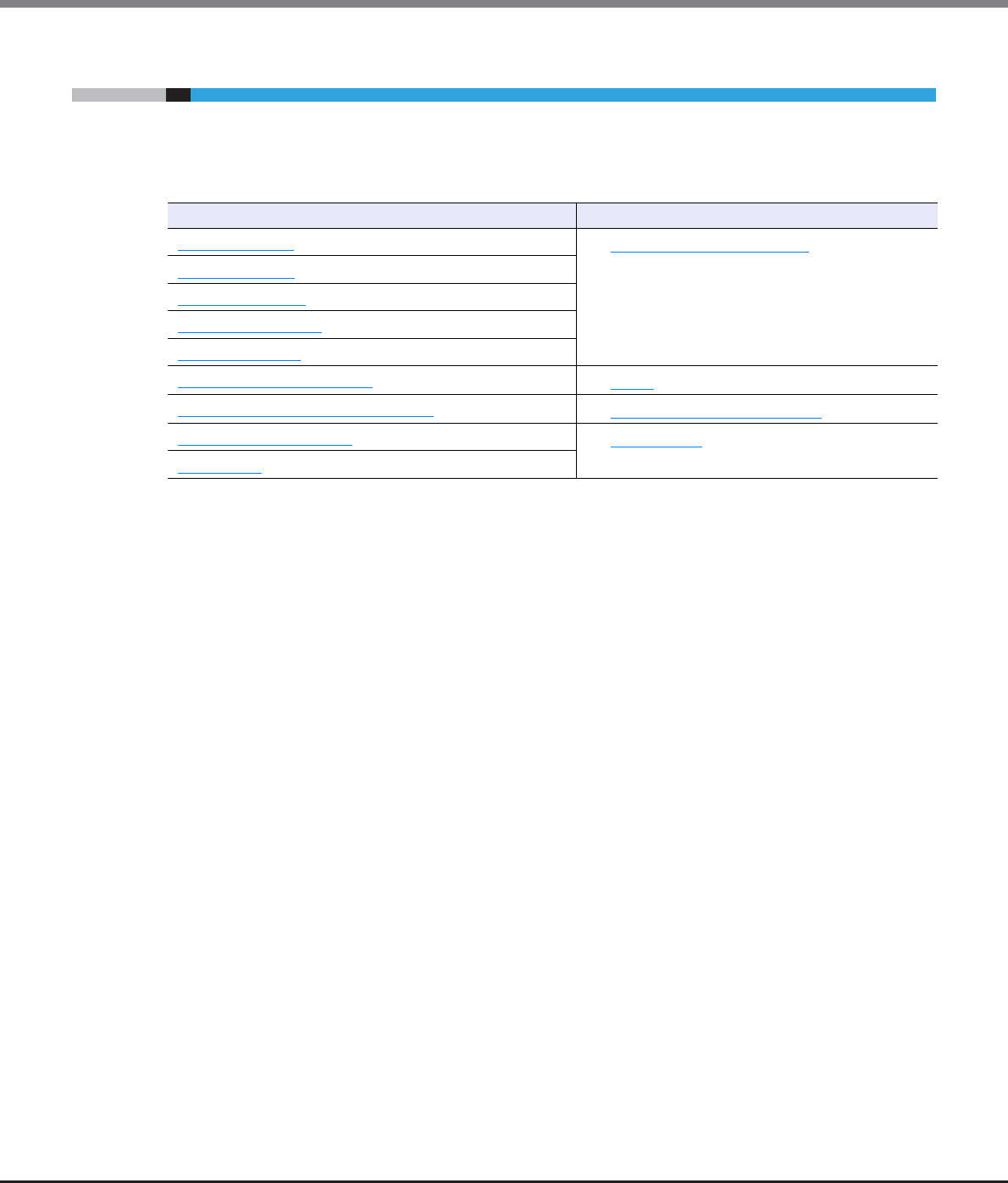
Chapter 6 RAID Group Management
6.2 Functions in the Action Area for RAID Group
ETERNUS Web GUI User’s Guide
Copyright 2013 FUJITSU LIMITED P2X0-1090-10ENZ0
173
6.2 Functions in the Action Area for RAID Group
When using functions in the Action area, select the desired function from the Action area that is displayed in
the status display screen.
The functions in the Action area for RAID group can be performed from the following display functions:
Functions in the Action area for RAID Group Display function
Create RAID Group •RAID Group (Basic Information)
Delete RAID Group
Rename RAID Group
Change Controlling CM
Expand RAID Group
Modify RAID Group Parameters •Tuning
Assign ECO Mode Schedule (RAID Group) •ECO Mode Schedule (RAID Group)
Set Key Group (RAID Group) •SED Key Group
Recovery SED

Chapter 6 RAID Group Management
6.2 Functions in the Action Area for RAID Group
ETERNUS Web GUI User’s Guide
Copyright 2013 FUJITSU LIMITED P2X0-1090-10ENZ0
174
6.2.1 Create RAID Group
This function creates RAID groups.
A RAID group is a group of drives that configure a RAID type.
Features and required number of drives for each RAID type
The following table shows the features and the required number of drives for each RAID type.
Note that "Striping (RAID0)" has no data redundancy.
*1: D: Data drives, M: Mirror drives, P: Parity drives
The maximum number of RAID groups for each model
The maximum number of RAID groups varies depending on each model. The following table shows the
maximum number of RAID groups for each model.
RAID type Feature Required number of drives
High Performance
(RAID1+0)
The high I/O performance of RAID0 (striping) is combined
with the reliability of RAID1 (mirroring). 2D+2M – 16D+16M
High Capacity
(RAID5)
Data divided into units of blocks and allocated across
multiple drives together with parity information created
from the data.
2D+1P – 15D+1P
High Reliability
(RAID6)
The use of double parity allows the full recovery of lost
data even in the event that two of the drives fail. 3D+2P – 14D+2P
Reliability (RAID5+0)
Multiple RAID5 volumes are RAID0 striped. For large
capacity configurations, use of RAID5+0 instead of RAID5
results in enhanced performance, improved reliability,
and shorter rebuilding times.
(2D+1P) × 2 – (15D+1P) × 2
Mirroring (RAID1)
Data is mirrored to two drives.
If one drive fails, the other drive continues operation
(mirroring).
1D+1M
Striping (RAID0)
Data is split in unit of blocks and stored across multiple
drives (striping).
RAID0 has no data redundancy.
2D – 16D
Model The maximum number of RAID
groups
ETERNUS DX80 S2 60
ETERNUS DX90 S2 120
ETERNUS DX410 S2 240
ETERNUS DX440 S2 480
ETERNUS DX8100 S 48
ETERNUS DX8700 S2 1536
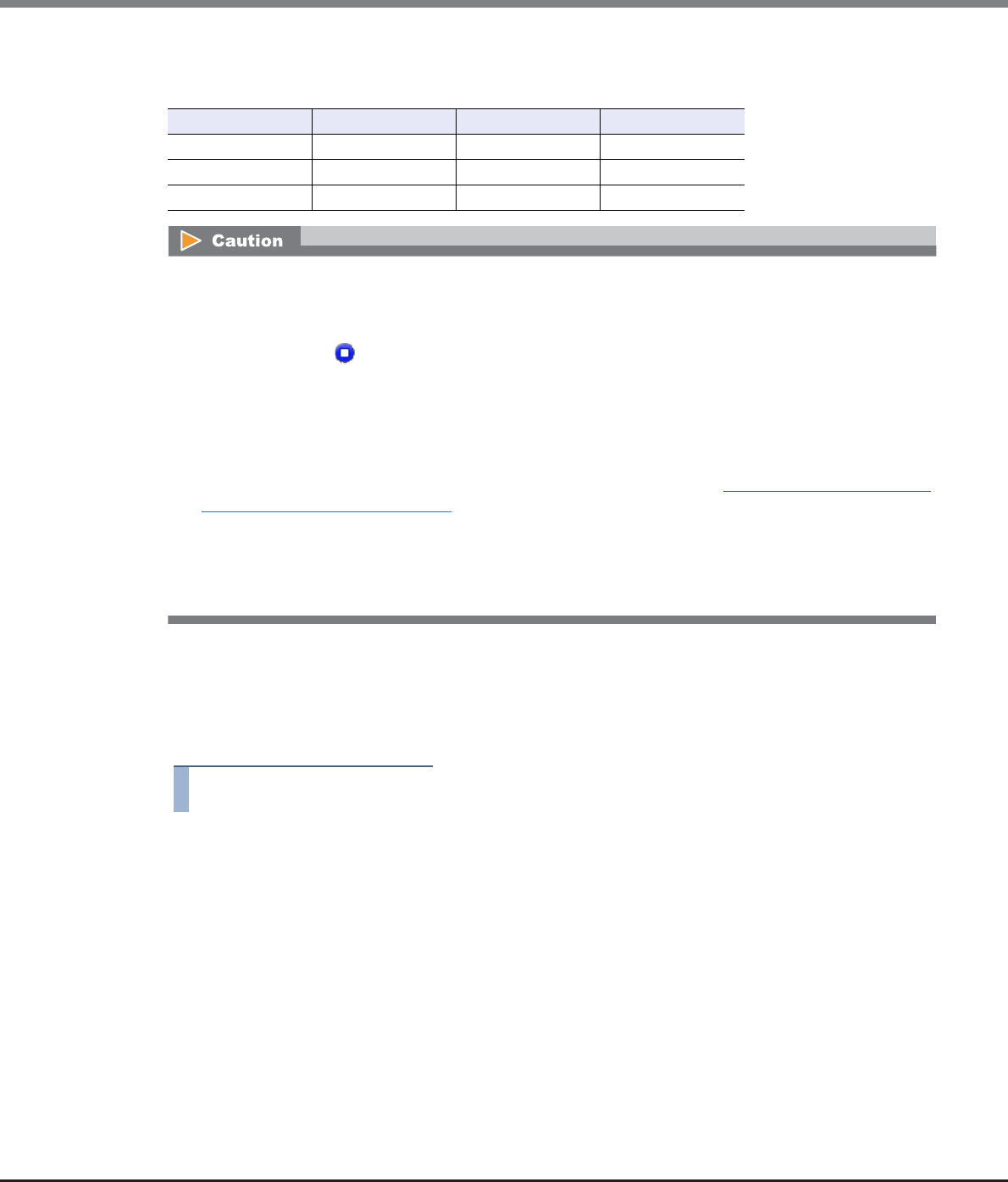
Chapter 6 RAID Group Management
6.2 Functions in the Action Area for RAID Group
ETERNUS Web GUI User’s Guide
Copyright 2013 FUJITSU LIMITED P2X0-1090-10ENZ0
175
Drive combinations that can configure a RAID group
The following table shows the drive combinations that can configure a RAID group.
There are two methods to create a volume: automatic drive selection and manual drive selection.
■Automatically selecting drives to create RAID groups
The procedure to create a RAID group is as follows:
Procedure
1Click [Create] in [Action].
2Select "Automatic" for "Create Mode".
3Specify the RAID group detailed information, and click the [Create] button.
•Name
Input a RAID group name that is to be created.
An existing RAID group name cannot be used.
The following input conditions apply:
-Up to 16 alphanumeric characters and symbols (except ", (comma)" and "?")
-Space
Online Nearline SSD
Online OK OK NG
Nearline OK OK NG
SSD NG NG OK
•RAID groups can be created when the drives satisfy all of the following conditions:
-The drives are not registered in any RAID group, TPP, FTRP, or REC Disk Buffer
-The drives are not registered as hot spares
-The "Status" is " Present"
•All drives that are selected for creating a RAID group must have the same capacity and the same speed. If
drives of different capacities exist in a RAID group, the smallest capacity becomes the standard, and all
other drives are regarded as having the same capacity as the smallest drive. In this case, the remaining
drive space is not used. In addition, if drives of different speeds exist in a RAID group, the access perfor-
mance of the RAID group is reduced by the slower drives.
•Some combinations of drive types cannot configure a RAID group. Refer to "Drive combinations that can
configure a RAID group" (page 175) for details.
•If both Online disks and Nearline disks are used for a RAID group, the drives in the RAID group will have
different speeds and capacity. In this case, some space cannot be used and the performance is reduced.
•"Striping (RAID0)" has no data redundancy. The use of "High Performance (RAID1+0)", "High Capacity
(RAID5)", "High Reliability (RAID6)", "Reliability (RAID5+0)", or "Mirroring (RAID1)" is recommended.
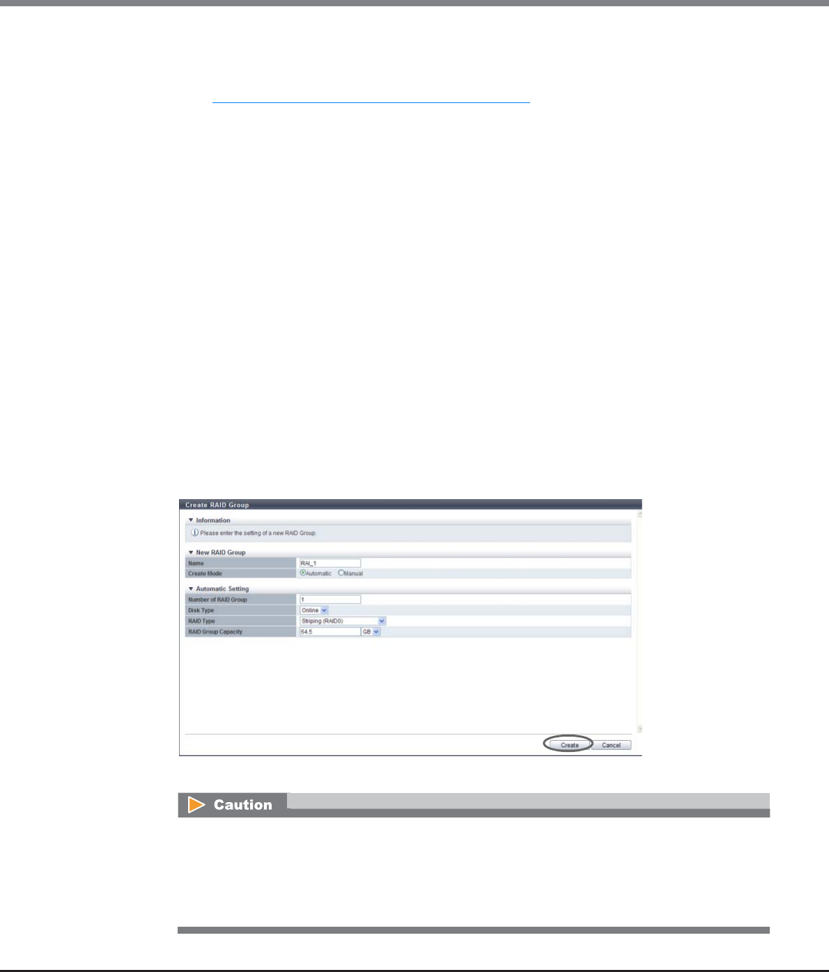
Chapter 6 RAID Group Management
6.2 Functions in the Action Area for RAID Group
ETERNUS Web GUI User’s Guide
Copyright 2013 FUJITSU LIMITED P2X0-1090-10ENZ0
176
•Number of RAID Group
Input the number of RAID groups that is to be created.
When creating multiple RAID groups at a time, the new RAID groups are named automatically. Refer
to "Naming conventions for creating volumes" (page 993) for details.
•Disk Type
Select the type of drive that configures a RAID group from the list box.
-Online
-Nearline
-SSD
-SED
•RAID Type
Select the type of RAID group that is to be created from the list box.
-High Performance (RAID1+0)
-High Capacity (RAID5)
-High Reliability (RAID6)
-Reliability (RAID5+0)
-Mirroring (RAID1)
-Striping (RAID0)
•RAID Group Capacity
Input the RAID group capacity that is to be created and select the units of capacity.
A RAID group is automatically created with a capacity of the entered value or higher.
The following input conditions apply:
-Numeric characters
-TB/GB/MB
→A confirmation screen appears.
An error screen appears in the following conditions:
•When the "Name" overlaps with an existing RAID group name
•When the "Name" does not satisfy the input conditions
•When the RAID group that is specified using the automatic setting cannot be created with the
drives that are installed in the ETERNUS DX Disk storage system
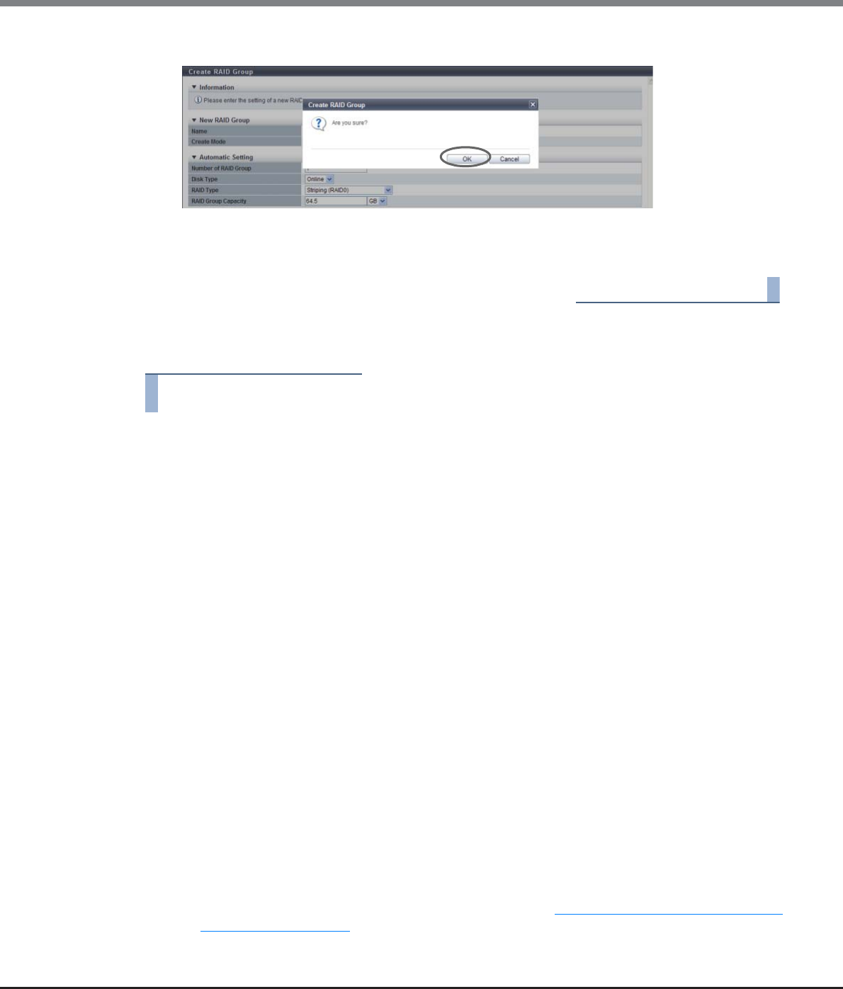
Chapter 6 RAID Group Management
6.2 Functions in the Action Area for RAID Group
ETERNUS Web GUI User’s Guide
Copyright 2013 FUJITSU LIMITED P2X0-1090-10ENZ0
177
4Click the [OK] button.
→RAID group creation starts.
5Click the [Done] button to return to the [RAID Group] screen.
End of procedure
■Manually selecting drives to create RAID groups
Procedure
1Click [Create] in [Action].
2Select "Manual" for "Create Mode".
3Specify the RAID group detailed information, and click the [Create] button.
•Name
Input a RAID group name that is to be created.
An existing RAID group name cannot be used.
The following input conditions apply:
-Up to 16 alphanumeric characters and symbols (except ", (comma)" and "?")
-Space
•RAID Type
Select the type of RAID group that is to be created from the list box.
-High Performance (RAID1+0)
-High Capacity (RAID5)
-High Reliability (RAID6)
-Reliability (RAID5+0)
-Mirroring (RAID1)
-Striping (RAID0)
•Controlling CM
Select the controlling CM and CPU of the RAID group that is to be created.
"Automatic" and the installed "CM#x CPU#y" in normal status are displayed as options.
-Automatic
-CM#x CPU#y (x: CM number, y: CPU number)
Select "Automatic" for normal operations. When "Automatic" is selected, the CM-CPU that is to be
assigned is determined by the RAID group number. Refer to "Appendix F Automatic Controlling CM-
CPU Setting" (page 1011) for details.
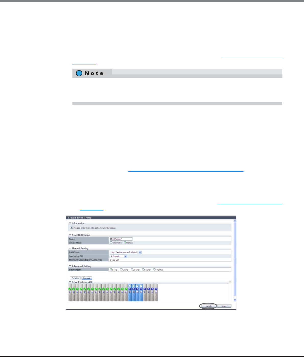
Chapter 6 RAID Group Management
6.2 Functions in the Action Area for RAID Group
ETERNUS Web GUI User’s Guide
Copyright 2013 FUJITSU LIMITED P2X0-1090-10ENZ0
178
•RAID Group Capacity
The capacity of RAID group that is to be created is displayed. The "RAID Group Capacity" is
automatically calculated from the selected RAID type and drives.
•Checkbox to select drives
Select the checkbox for the drive that is to be used.
When using the ETERNUS DX8100 S2/DX8700 S2, the restrictions that apply to the drive layout for
RAID group configuration vary depending on the RAID type. Refer to "Restrictions of drive layout"
(page 179) for details.
●Advanced Settings
Specify the Stripe Depth only when performing the advanced performance tuning for each RAID
group. It is not necessary to change the default setting for normal use.
The higher the Stripe Depth value, the lower the number of drives that access the RAID group. If
"High Performance (RAID1+0)" is used, the number of commands that are issued for the drives is
reduced and access performance for the relevant RAID group is improved. Note that for "High
Capacity (RAID5)", a high Stripe Depth value may reduce the sequential write performance. Also
note that restrictions apply for RAID groups and volumes in the RAID group for which Stripe Depth
value is changed. Refer to "Restrictions for Stripe Depth modification" (page 180) for details.
-Stripe Depth
Select the Stripe Depth of RAID group that is to be created.
When the "RAID Type" is "Mirroring (RAID1)", this setting is not available. When the "RAID Type"
is "Reliability (RAID5+0)" or "High Reliability (RAID6)", the value is fixed to "64KB". Available
Stripe Depth value varies depending on the RAID type. Refer to "Available Stripe Depth value"
(page 180) for details.
→A confirmation screen appears.
Drives can be selected from the list of drives that is displayed for Tabular or from the drive images
that are displayed for Graphic. Click the Tabular tab to display a list of the drives or click the Graphic
tab to display drive images.
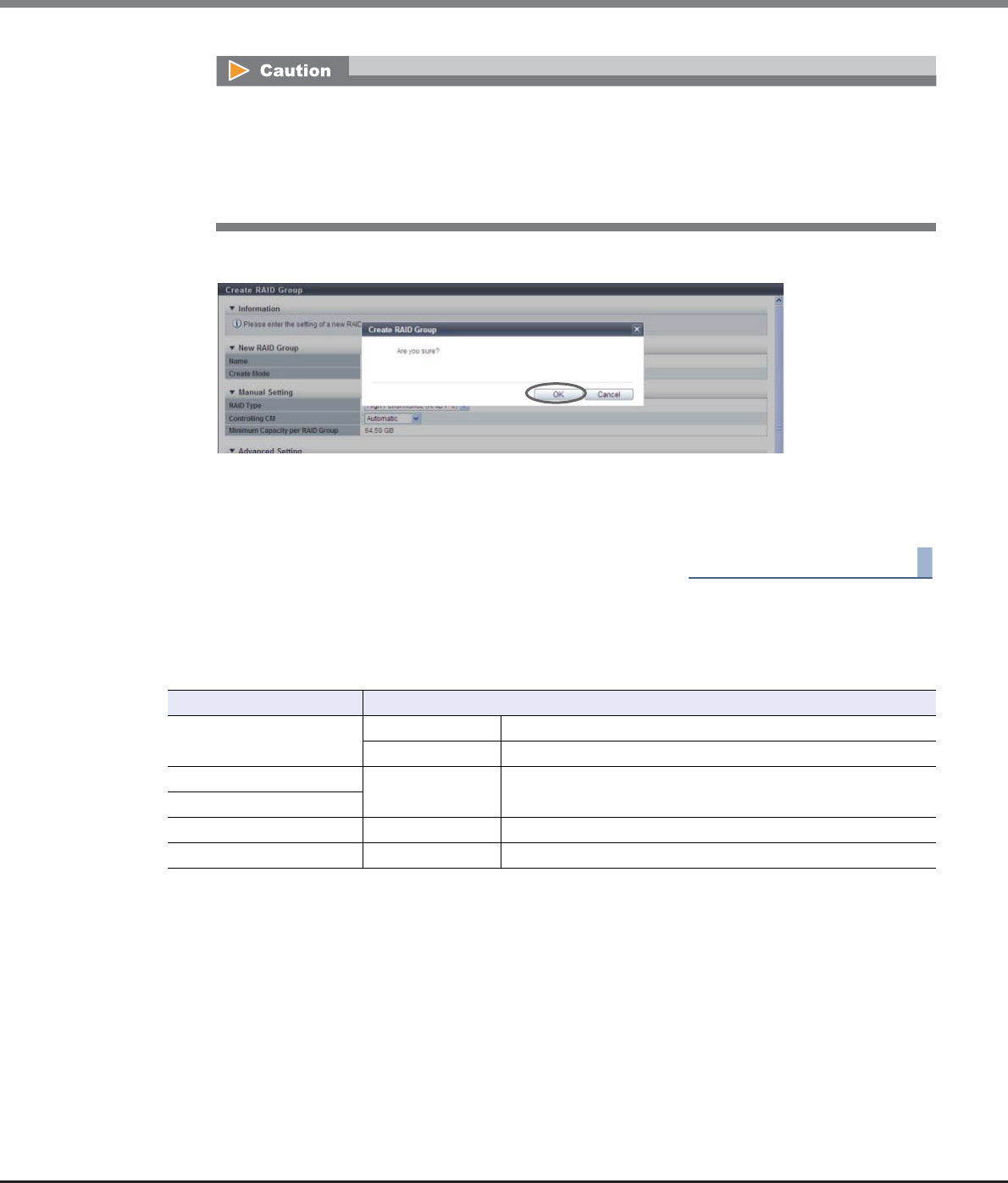
Chapter 6 RAID Group Management
6.2 Functions in the Action Area for RAID Group
ETERNUS Web GUI User’s Guide
Copyright 2013 FUJITSU LIMITED P2X0-1090-10ENZ0
179
4Click the [OK] button.
→RAID group creation starts.
5Click the [Done] button to return to the [RAID Group] screen.
End of procedure
Restrictions of drive layout
When using the ETERNUS DX8100 S2, the following restrictions for each RAID type apply to the drive layout for
RAID group configuration. A RAID group that does not satisfy the required conditions cannot be created.
An error screen appears in the following conditions:
•When the "Name" overlaps with an existing RAID group name
•When the "Name" does not satisfy the input conditions
•When the conditions described in "Restrictions of drive layout" are not satisfied
•When an invalid Stripe Depth for the RAID type is specified
RAID Type Selection Conditions
High Performance
(RAID1+0)
Required Allocate mirroring pair drives to different DEs.
Recommended Distribute striping drives over as many DEs as possible.
High Capacity (RAID5) Recommended Distribute member drives over as many DEs as possible.
High Reliability (RAID6)
Reliability (RAID5+0) Recommended Distribute member drives over as many DEs as possible.
Mirroring (RAID1) Required Allocate mirroring pair drives to different DEs.

Chapter 6 RAID Group Management
6.2 Functions in the Action Area for RAID Group
ETERNUS Web GUI User’s Guide
Copyright 2013 FUJITSU LIMITED P2X0-1090-10ENZ0
180
When using the ETERNUS DX8700 S2, the following restrictions for each RAID type apply to the drive layout for
RAID group configuration. A RAID group that does not satisfy the required conditions cannot be created.
*1: The "SAS cascade" indicates the DEs that are connected to a single BRT port.
Same SAS cascade:
DE#x0, DE#x1, DE#x2, DE#x3 (x: 0 - F)
DE#x8, DE#x9, DE#xA, DE#xB (x: 0 - F)
[Example] SAS cascade for Port#0 of the BRT#0/#1: DE#00, DE#01, DE#02, DE#03
[Example] SAS cascade for Port#4 of the BRT#2/#3: DE#48, DE#49, DE#4A, DE#4B
Available Stripe Depth value
The following table shows the available Stripe Depth value for each RAID type.
*1: D: Data drives, M: Mirror drives, P: Parity drives
Restrictions for Stripe Depth modification
The following restrictions are applied for the RAID groups and volumes in the RAID group of which Stripe
Depth value is changed.
•Stripe depth for the existing RAID group cannot be changed.
•When selecting drives automatically to create a RAID group, the Stripe Depth cannot be changed.
•Capacity expansion (Logical Device Expansion) for the RAID group of which Stripe Depth was changed is
not available.
•Encryption of the RAID group of which Stripe Depth was changed is not available.
RAID Type Selection Conditions
High Performance
(RAID1+0)
Required Allocate mirroring pair drives to different SAS cascades (*1).
No restrictions are applied for BRT.
Recommended Distribute striping drives over as many DEs as possible.
High Capacity (RAID5) Required Allocate member drives to different SAS cascades.
No restrictions are applied for BRT.
High Reliability (RAID6)
Required The maximum number of member drives that can be allocated in
the same SAS cascade is two.
No restrictions are applied for BRT.
Recommended Distribute member drives over as many DEs as possible.
Reliability (RAID5+0)
Required The maximum number of member drives that can be allocated in
the same SAS cascade is two.
No restrictions are applied for BRT.
Recommended Distribute member drives over as many DEs as possible.
Mirroring (RAID1) Required Allocate mirroring pair drives to different SAS cascades (*1).
No restrictions are applied for BRT.
RAID type Drive configuration (*1) Available Stripe Depth value
Mirroring (RAID1) 1D+1M –
High Performance (RAID1+0) Any 64KB, 128KB, 256KB, 512KB, 1024KB
Striping (RAID0)
High Capacity (RAID5)
2D+1P – 4D+1P 64 KB, 128 KB, 256 KB, 512 KB
5D+1P – 8D+1P 64 KB, 128 KB, 256 KB
9D+1P – 15D+1P 64 KB, 128 KB
Reliability (RAID5+0) Any 64 KB
High Reliability (RAID6)
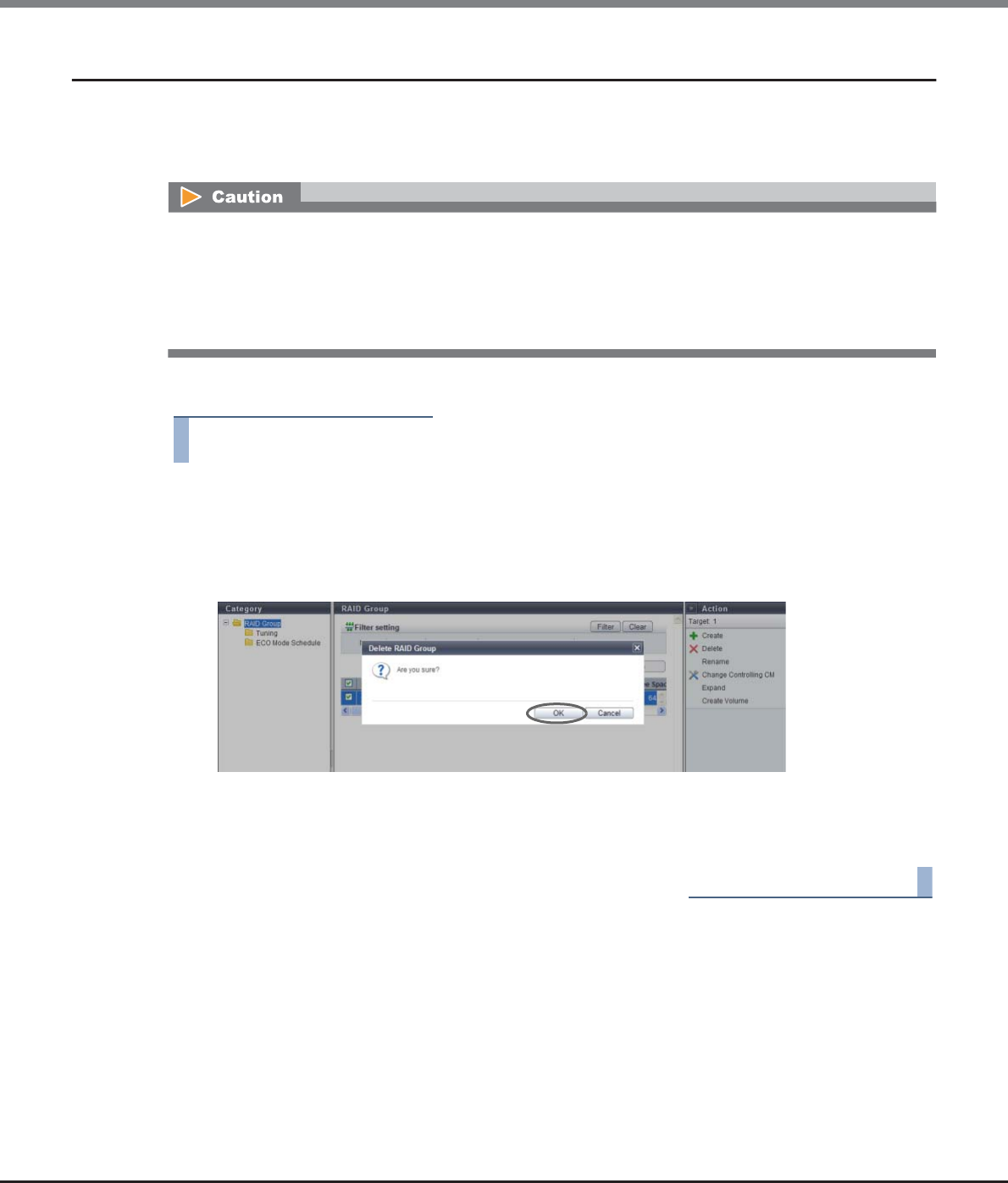
Chapter 6 RAID Group Management
6.2 Functions in the Action Area for RAID Group
ETERNUS Web GUI User’s Guide
Copyright 2013 FUJITSU LIMITED P2X0-1090-10ENZ0
181
6.2.2 Delete RAID Group
This function deletes the registered RAID groups in the ETERNUS DX Disk storage system.
When a RAID group is deleted, the status of the drives that configured the RAID group change to data drives
that are not used by any RAID group.
The procedure to delete a RAID group is as follows:
Procedure
1Select the RAID group that is to be deleted (multiple selections can be made) and click
[Delete] in [Action].
→A confirmation screen appears.
2Click the [OK] button.
→RAID group deletion starts.
3Click the [Done] button to return to the [RAID Group] screen.
End of procedure
•RAID groups that have volumes registered cannot be deleted. When deleting a RAID group, delete the
volumes beforehand.
•The RAID group that is registered in the TPP or the FTRP cannot be deleted.
•RAID groups that are registered as REC Disk Buffer cannot be deleted.
•Up to 128 RAID groups can be deleted at once.
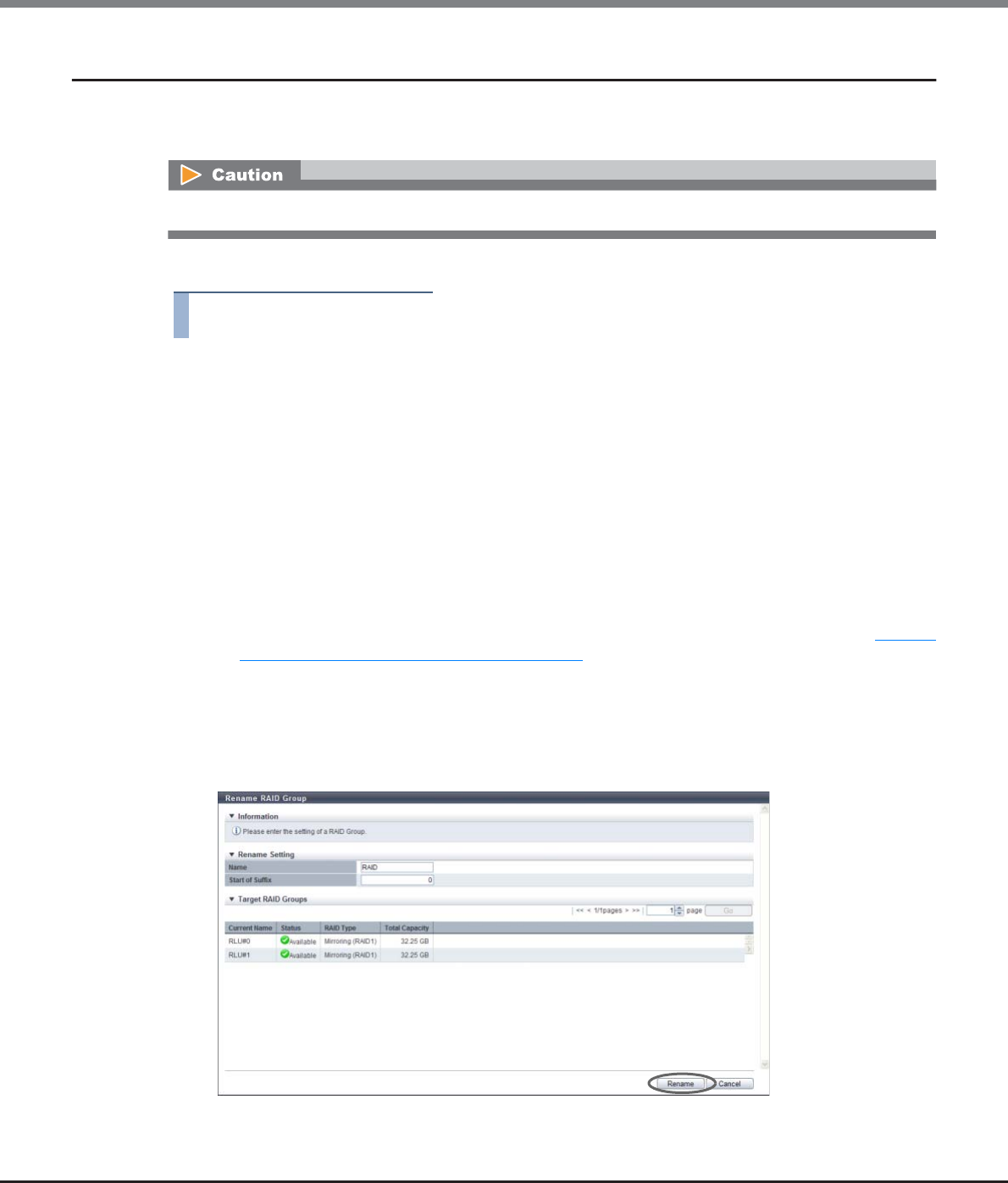
Chapter 6 RAID Group Management
6.2 Functions in the Action Area for RAID Group
ETERNUS Web GUI User’s Guide
Copyright 2013 FUJITSU LIMITED P2X0-1090-10ENZ0
182
6.2.3 Rename RAID Group
This function changes the name of RAID groups that are registered in the ETERNUS DX Disk storage system.
Multiple RAID groups can be renamed with a single operation.
The procedure to rename RAID group is as follows:
Procedure
1Select the RAID group to be renamed (multiple selections can be made) and click [Rename]
in [Action].
2Input the new "Name" and the "Start of Suffix", and click the [Rename] button.
•Name
Specify a new RAID group name.
The following input conditions apply:
-Up to 16 alphanumeric characters and symbols (except ", (comma)" and "?")
-Space
•Start of Suffix
Input the starting number of the suffix that is to be added to the new RAID group name. When
changing multiple RAID group names, the suffix number is added to the RAID group names with
consecutive numbers in ascending order starting with the entered suffix number. Refer to "Naming
conventions for renaming volumes" (page 993) for details. When changing only one RAID Group
name, the "Start of Suffix" field is not displayed.
The following input conditions apply:
-Numeric characters ("0" - "99999")
-Decimal number
-1 - 5 digits
→A confirmation screen appears.
Renaming RAID groups that configure FTRPs is not available.
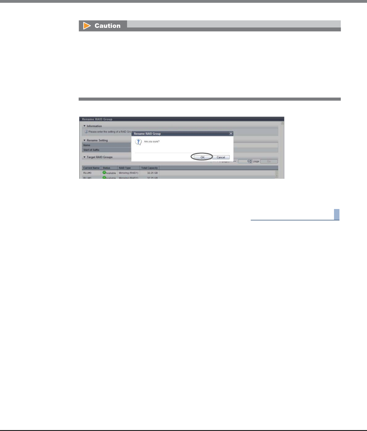
Chapter 6 RAID Group Management
6.2 Functions in the Action Area for RAID Group
ETERNUS Web GUI User’s Guide
Copyright 2013 FUJITSU LIMITED P2X0-1090-10ENZ0
183
3Click the [OK] button.
→Changing RAID group name starts.
4Click the [Done] button to return to the [RAID Group] screen.
End of procedure
An error screen appears in the following conditions:
•When new RAID group name is not input
•When the RAID group name does not satisfy the input conditions
•When inputting the existing RAID group name (when one RAID group is selected)
•When the "Start of Suffix" is not specified (when multiple RAID groups are selected)
•When the value in the "Start of Suffix" does not satisfy the input conditions (when multiple RAID
groups are selected)
Chapter 6 RAID Group Management
6.2 Functions in the Action Area for RAID Group
ETERNUS Web GUI User’s Guide
Copyright 2013 FUJITSU LIMITED P2X0-1090-10ENZ0
184
6.2.4 Change Controlling CM
This function changes the controlling CM that is allocated to the RAID group.
Unequal loading between the CMs can be resolved by changing the controlling CM.
The procedure to change controlling CM of the RAID group is as follows:
Procedure
1Select the RAID group to change the controlling CM (multiple selections can be made) and
click [Change Controlling CM] in [Action].
•While changing the controlling CM, the storage system status is changed from Write Back mode to Write
Through mode, reducing the I/O performance for the ETERNUS DX Disk storage system. Perform this
function when there are not many I/O operations. Changing the controlling CM may take up to 20 or 30
minutes.
•Changing the controlling CM for RAID groups that configure FTRPs is not available.
•This function cannot be used under the following conditions:
-When a CM that is not in " Normal" status exists
-When formatting or LUN Concatenation is being performed in the volumes that are registered in the
target RAID group
-When encryption is being performed in the target RAID group
-When the target RAID group status is not " Available"
-When rebuild, copyback, or redundant copy is being performed in the target RAID group
-When LDE is being performed in the ETERNUS DX Disk storage system
-When RAID migration is being performed in the ETERNUS DX Disk storage system
-When a RAID group diagnosis is being performed in the ETERNUS DX Disk storage system
-When a disk diagnosis is being performed in the ETERNUS DX Disk storage system
-When balancing TPV is being performed in the ETERNUS DX Disk storage system
-When balancing FTRP is being performed in the ETERNUS DX Disk storage system
-When pinned data exists in the ETERNUS DX Disk storage system
This function can also be used for changing the controlling CM of the RAID groups that configure a Thin
Provisioning Pool (TPP).
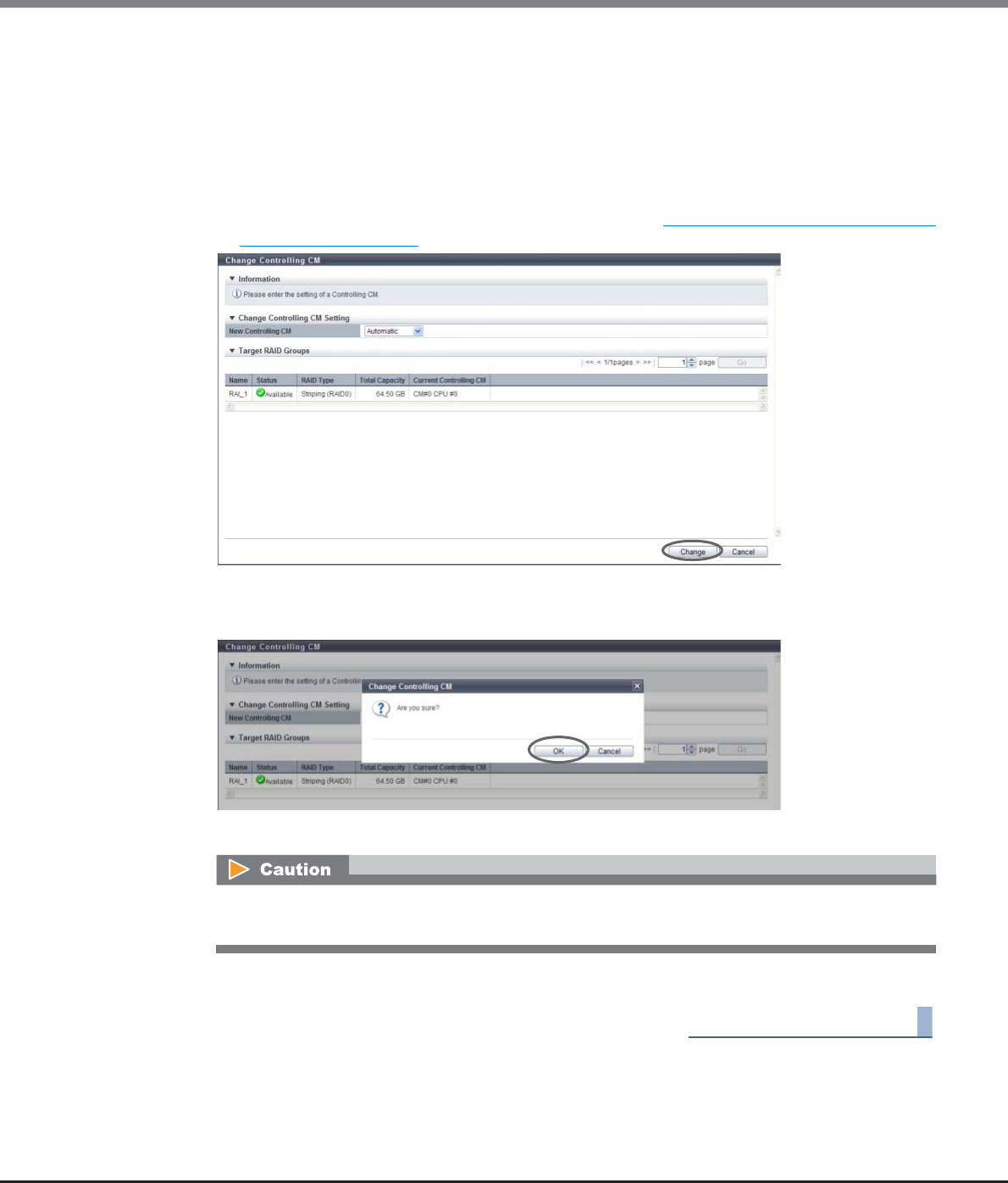
Chapter 6 RAID Group Management
6.2 Functions in the Action Area for RAID Group
ETERNUS Web GUI User’s Guide
Copyright 2013 FUJITSU LIMITED P2X0-1090-10ENZ0
185
2Select the controlling CM after changing, and click the [Change] button.
•New Controlling CM
Specify the new controlling CM and CPU.
"Automatic" and the installed "CM#x CPU#y" in normal status are displayed as options.
-Automatic
-CM#x CPU#y (x: CM number, y: CPU number)
Select "Automatic" for normal operations. When "Automatic" is selected, the CM-CPU that is to be
assigned is determined by the RAID group number. Refer to "Appendix F Automatic Controlling CM-
CPU Setting" (page 1011) for details.
→A confirmation screen appears.
3Click the [OK] button.
→Changing controlling CM starts.
4Click the [Done] button to return to the [RAID Group] screen.
End of procedure
During controlling CM change, the storage system status is changed from Write Back mode to Write
Through mode.
Chapter 6 RAID Group Management
6.2 Functions in the Action Area for RAID Group
ETERNUS Web GUI User’s Guide
Copyright 2013 FUJITSU LIMITED P2X0-1090-10ENZ0
186
6.2.5 Expand RAID Group
This function adds drives to the existing RAID group by using the Logical Device Expansion (LDE) function to
dynamically expand RAID group capacity. This function can also dynamically change the RAID type of an
existing RAID group.
RAID group expansion provides the following features without stopping the ETERNUS DX Disk storage system
operation:
•RAID group expansion add disks to the existing RAID group in units of one drive. This enables capacity
expansion of RAID groups with smaller number of drive expansion.
•RAID groups can be expanded and any existing data in these RAID groups is retained.
Requirements for expanding a RAID group:
•The "Status" is " Available"
•Standard volumes, SDVs, or SDPVs are registered
•Not registered in the TPP
•Not registered in the FTRP
•Not registered as an REC Disk Buffer
•The RAID group is not blocked
•Formatting is not being performed for the volume that is registered in the RAID group
•Encryption is not being performed for the volume that is registered in the RAID group
•Storage Migration paths are not created in the volume that is registered in the RAID group
•The stripe size of the RAID group is not expanded (*1).
*1: A RAID group for which the Stripe Depth value in the [RAID Group (Basic)] screen of the [RAID Group (Basic Infor-
mation)] screen is 128KB or more. Note that the Stripe Depth value for RAID1 cannot be changed. Refer to "6.1.5
RAID Group (Basic)" (page 169) for details.
•Before expanding the RAID group, back up data in all the logical volumes in the target RAID group to a
different location. If not, data cannot be recovered when expansion fails. If expansion fails, data can be
recovered from the backed up data.
•When adding drives, use drives that have the same capacity and speed as the drives that configure the
target RAID group. If drives of different capacities exist in a RAID group, the smallest capacity becomes
the standard for the RAID group after expansion, and all other drives are regarded as having the same
capacity as the smallest drive. In this case, the remaining drive space is not used. In addition, if drives of
different speeds exist in a RAID group, the access performance of the RAID group is reduced by the slower
drives.
•If the drives that configure the target RAID group are SSDs, SSDs must be used when adding drives.
•If the drives that configure the target RAID group are SEDs, SEDs must be used when adding drives.
•RAID group expansion can be performed when the RAID group capacity after expansion is the same or
larger than the current capacity.
•RAID group expansion can only be performed for one RAID group at a time.
•RAID group expansion cannot be suspended.
Chapter 6 RAID Group Management
6.2 Functions in the Action Area for RAID Group
ETERNUS Web GUI User’s Guide
Copyright 2013 FUJITSU LIMITED P2X0-1090-10ENZ0
187
The procedure to expand RAID group capacity is as follows:
Procedure
1Select the RAID group that is to be expanded and click [Expand] in [Action].
2Select the RAID type after expansion and the drives that are to be used after expansion.
Click the [Expand] button.
•RAID Type after expand
Select the RAID type after expansion is performed.
-High Performance (RAID1+0)
-High Capacity (RAID5)
-High Reliability (RAID6)
-Striping (RAID0)
•Checkbox to select drives
Select the checkbox for the drive to be used.
When using the ETERNUS DX8100 S2/DX8700 S2, the restrictions that apply to the drive layout for
RAID group configuration vary depending on the RAID type. Refer to "Restrictions of drive layout"
(page 179) for details.
•The following functions cannot be used for RAID groups in which RAID group expansion is being
performed:
-Format volume
-Create Volume
-Encrypt Volume
-RAID migration for the volume
-Expand Volume
-Preventive maintenance
-Diagnosis for RAID group
-Diagnosis for disks
•The following RAID type changes cannot be performed:
-Changing the RAID type to "Striping (RAID0)" (changing the RAID type from "Striping (RAID0)" to a dif-
ferently configured "Striping (RAID0)" is available)
-Changing the RAID type to "Reliability (RAID5+0)"
-Changing the RAID type from "Reliability (RAID5+0)"
When expanding the drive capacity that configures a RAID group, use the procedure in "5.2.7 Start RAID
Migration" (page 123) instead of this function.
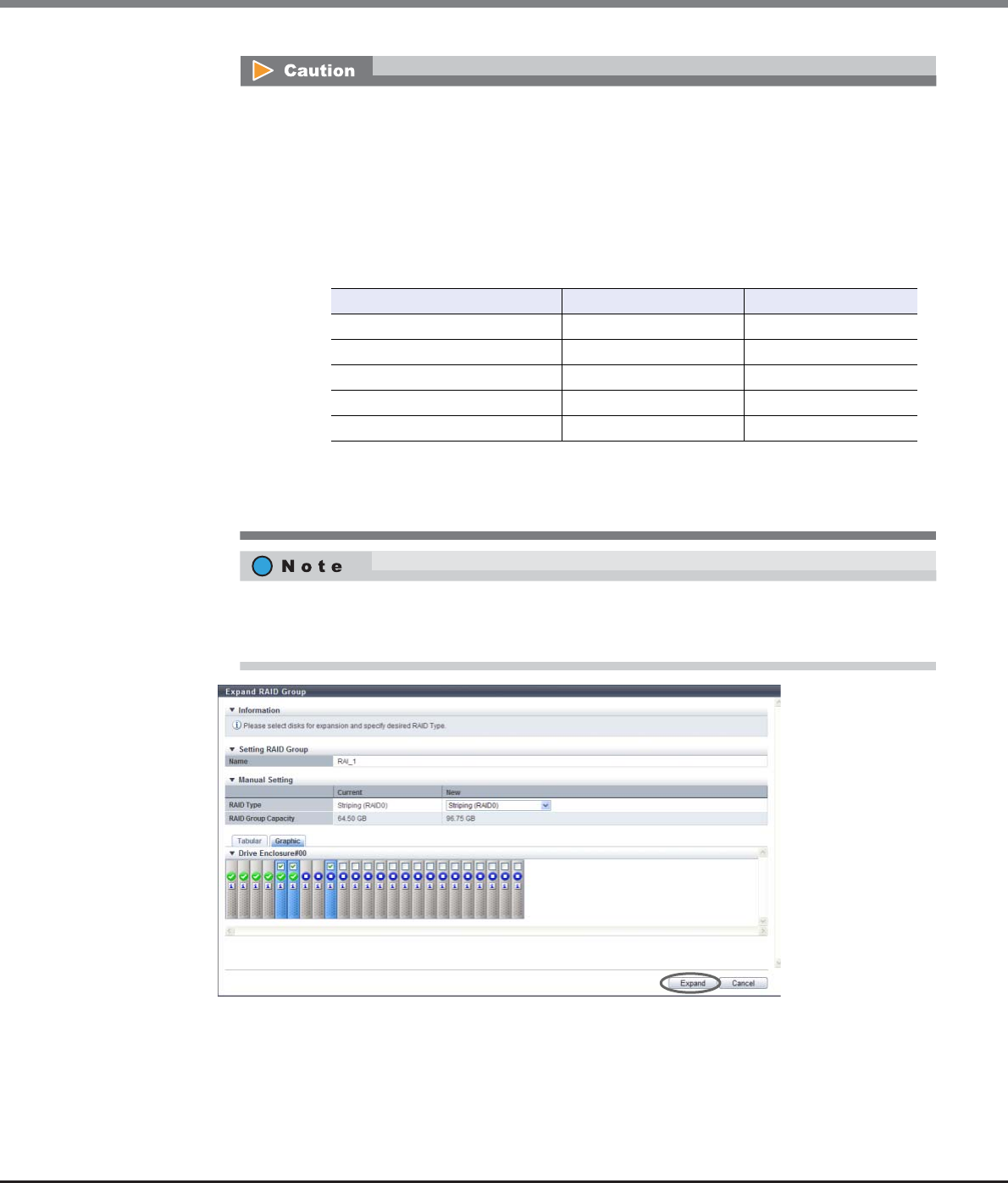
Chapter 6 RAID Group Management
6.2 Functions in the Action Area for RAID Group
ETERNUS Web GUI User’s Guide
Copyright 2013 FUJITSU LIMITED P2X0-1090-10ENZ0
188
→A confirmation screen appears.
Requirements for selecting drives when changing the RAID type:
•When the RAID type before and after LDE is not changed, the drives that are used in the RAID
group before LDE was performed cannot be deleted.
•When the RAID type is changed after LDE:
-The number of RAID group data drives (*1) after LDE cannot be less than the number
before LDE.
*1: "Number of data drives" indicates the number of logical drives in RAID groups that contain user
data. This number is different for each RAID type, as shown below:
-Drives that are no longer used in a RAID group after changing the RAID type can be deleted.
However, not all of the drives can be deleted from a RAID group.
Drives can be selected from the list of drives that is displayed for Tabular or from the drive images
that are displayed for Graphic. Click the Tabular tab to display a list of the drives or click the Graphic
tab to display drive images.
*2: D: Data drives, M: Mirror drives, P: Parity drives
RAID type Drive configuration (*2) Number of data drives
High Performance (RAID1+0) nD+nM n
High Capacity (RAID5) nD+1P n
High Reliability (RAID6) nD+2P n
Mirroring (RAID1) 1D+1M 1
Striping (RAID0) nD n
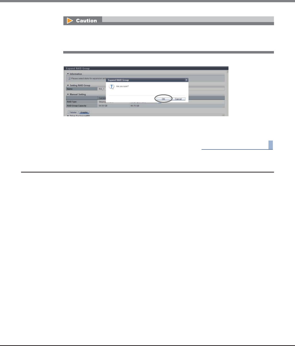
Chapter 6 RAID Group Management
6.2 Functions in the Action Area for RAID Group
ETERNUS Web GUI User’s Guide
Copyright 2013 FUJITSU LIMITED P2X0-1090-10ENZ0
189
3Click the [OK] button.
→RAID group expansion starts.
4Click the [Done] button to return to the [RAID Group] screen.
End of procedure
6.2.6 Modify RAID Group Parameters
This function tunes the following parameters of each RAID group.
•DCMF
DCMF is a coefficient for the command issuance amount of the drive. Specify this parameter to improve the
sequential writing access performance. The bigger the value is, the more commands issue. Specify the
DCMF according to the RAID group operation.
•Rebuild Priority
Specify the level to give priority to rebuild, copyback, and redundant copy instead of host access. Specifying
a larger "Rebuild Priority" value may improve rebuild, copyback, and redundant copy performance.
•Throttle
Throttle is the proportion of the number of commands that are issued to a drive at the same time to the
maximum number of commands that can be issued. By limiting the number of commands that are issued
at the same time to the drive, the load on the specific RAID group (drive) is reduced.
•Ordered Cut
Ordered Cut is the number of commands for optimizing drive access processing (priority control). By
performing the priority control of commands in increments of the specified number, a long queue time for
low-priority commands can be eliminated.
An error screen appears in the following conditions:
•When the drive layout is incorrect
•The number of selected drives exceeds the available maximum number
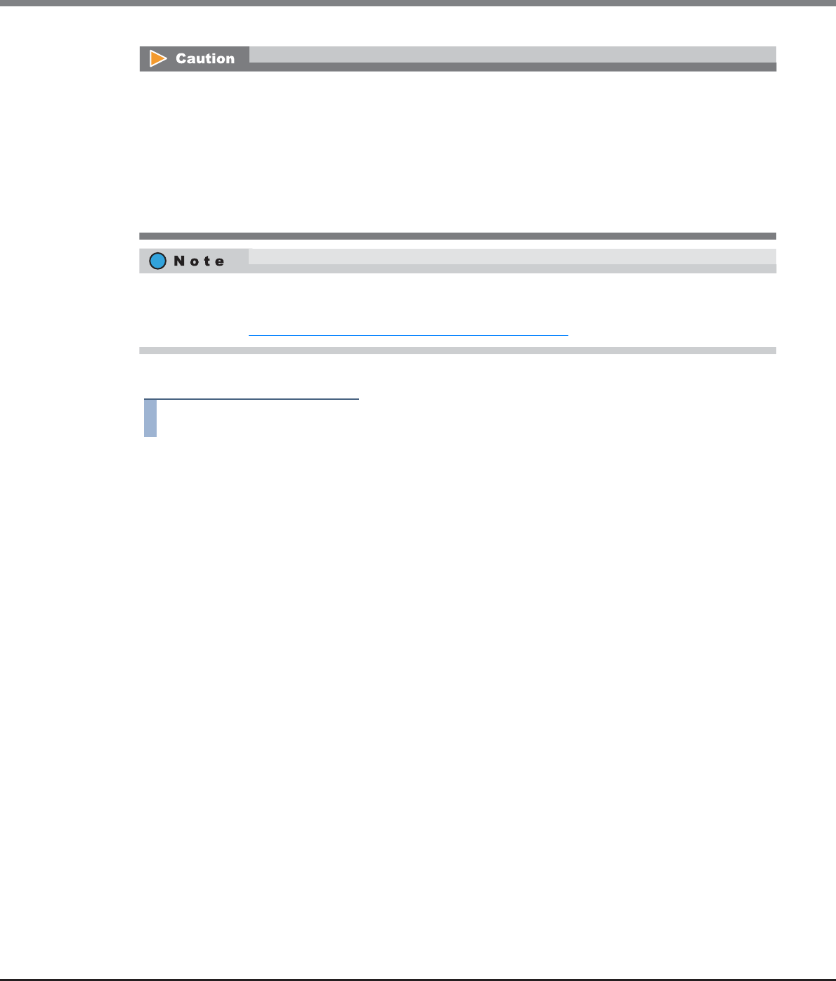
Chapter 6 RAID Group Management
6.2 Functions in the Action Area for RAID Group
ETERNUS Web GUI User’s Guide
Copyright 2013 FUJITSU LIMITED P2X0-1090-10ENZ0
190
The procedure to change the RAID group parameters is as follows:
Procedure
1Select which RAID groups to change the RAID group parameters for (multiple selections can
be made) and click [Modify RAID Group Parameters] in [Action].
2Specify the RAID group parameters, and click the [Modify] button.
•DCMF
Specify the DCMF between 1 - 10. The default value is "1". It is not necessary to change the default
setting for normal use.
The maximum number of commands issued to a drive is changed to a multiple represented by the
specified value. (If "DCMF" is "2", the number of commands is doubled. If "DCMF" is "3", the number
of commands is tripled.) When not changing the DCMF, select "No Change".
The higher the DCMF value is, the more drive throughput is available, improving sequential
performance. Note that high DCMF value may result in a high load on the drive, decreasing
performance.
•Rebuild Priority
Specify the rebuild priority. The default setting is "Low". It is not necessary to change the default set-
ting for normal use.
When not changing the rebuild priority, select "No Change".
When host access is not performed, rebuild, copyback, and redundant copy to RAID groups that is
not registered as REC Disk Buffers are performed with "High" priority regardless of the "Rebuild
Priority" setting.
Rebuild, copyback, and redundant copy performance may be improved by specifying a larger
"Rebuild Priority" value. Note that specifying larger "Rebuild Priority" may cause the degradation of
RAID group performance when performing rebuild, copyback, or redundant copy is performed in the
target RAID group.
•When the "Rebuild Priority" setting is changed, the priority is changed not only for a rebuild, copyback,
and redundant copy that will be performed after the setting is changed, but also for any rebuild,
copyback, and redundant copy operations that are currently being performed.
•When the target RAID group is registered as an REC Disk Buffer, do not select "High" for the "Rebuild
Priority" setting. Even if "High" is selected, rebuilding, copyback, and redundant copy are performed with
"Middle" priority during host access.
•Specify the same RAID group parameters for all of the RAID groups that configure a WSV. If different RAID
group parameters are specified, the host access performance may be reduced.
•When specifying the "Throttle " or "Ordered Cut", enable the "Disk Tuning Parameter Setting" in advance.
•RAID groups that configure a WSV can be checked in the [Volume Detail] screen ([WSV Concatenation]
Tab). Refer to "5.1.14 Volume Detail (WSV Concatenation)" (page 93) for details.

Chapter 6 RAID Group Management
6.2 Functions in the Action Area for RAID Group
ETERNUS Web GUI User’s Guide
Copyright 2013 FUJITSU LIMITED P2X0-1090-10ENZ0
191
-Low
Perform rebuild, copyback, and redundant copy with a normal priority.
-Middle
Give the same priority as the host access to rebuild, copyback, and redundant copy.
-High
Give priority to rebuild, copyback, and redundant copy over host access.
•Disk Tuning Parameter Setting
Specify whether to enable or disable the following disk tuning parameters.
-Throttle
-Ordered Cut
The default value varies depending on the storage system model. When using the ETERNUS DX80
S2/DX90 S2 or the ETERNUS DX410 S2/DX440 S2, the default setting is "Disable". When using the
ETERNUS DX8100 S2/DX8700 S2, the default setting is "Enable". It is not necessary to change the
default setting for normal use.
When selecting multiple RAID groups as the target of this function, the contents of display vary
depending on the setting (Enable/Disable) for each RAID group. If all the settings point to the same
state, that state is displayed. If not, "Disable" is displayed for the ETERNUS DX80 S2/DX90 S2 or the
ETERNUS DX410 S2/DX440 S2, and "Enable" is displayed for the ETERNUS DX8100 S2/DX8700 S2.
•Throttle
When "Disk Tuning Parameter Setting" is enabled, specify the proportion of the number of
commands that is to be issued to a drive at the same time to the maximum number of command
issuance between 100% and 10%. The default throttle value is "100%" (the default number of
command issuance). It is not necessary to change the default value for normal use.
Specifying a low number limits the number of commands that are issued to a drive at the same
time, reducing the load for the specific RAID group (drive). This setting can be used when the
response performance of the specific RAID group (drive) is decreased due to a conflict between host
I/O or batch processes. Note that a low Throttle value decreases the number of commands that are
processed by the drive at the same time to avoid a long queue time.
•Ordered Cut
When "Disk Tuning Parameter Setting" is enabled, specify between 0 and 65535 for the number of
commands to optimize drive access processing (priority control).
The default value varies depending on the model. The default value is "0" for the ETERNUS DX80 S2/
DX90 S2 and the ETERNUS DX410 S2/DX440 S2, and "400" for the ETERNUS DX8100 S2/DX8700 S2.
When Ordered Cut is "x", the order is changed for every x commands based on the priority settings of
the commands. It is not necessary to change the default value for normal use.
When "Ordered Cut" is "0", the number of commands for controlling the priority cannot be specified.
All of the commands issued to the drive are processed according to their priority settings. The
Ordered Cut value cannot be used for SSDs.
Specifying a low value for Ordered Cut reduces the number of commands for priority control.
Commands with a lower priority are processed without delay. Note that by specifying a low value for
Ordered Cut, the priority control of commands is performed in increments for the specified number,
which might cause a delay in processing commands with a higher priority.
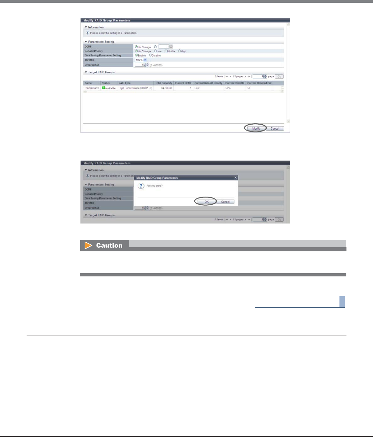
Chapter 6 RAID Group Management
6.2 Functions in the Action Area for RAID Group
ETERNUS Web GUI User’s Guide
Copyright 2013 FUJITSU LIMITED P2X0-1090-10ENZ0
192
→A confirmation screen appears.
3Click the [OK] button.
→The RAID group parameter modification starts.
4Click the [Done] button to return to the [RAID Group] screen.
End of procedure
6.2.7 Assign ECO Mode Schedule (RAID Group)
This function applies the ECO mode schedule to the RAID groups and enables the ECO mode setting.
ECO mode is a function to reduce power consumption by stopping motor of disks that configure the RAID
group while the RAID group is not accessed from the host.
When the ECO mode schedule is applied to a RAID group, the ECO mode setting is enabled. When ECO mode is
running, disk motors are activated during the scheduled event term. During times other than the scheduled
time, disk motors are stopped.
If the RAID group is accessed from the host while the disk motors are stopped, the disk motors are activated
and can be accessed within 1 - 5 minutes.
When enabling the "Disk Tuning Parameter Setting", a confirmation screen with a warning message
appears.
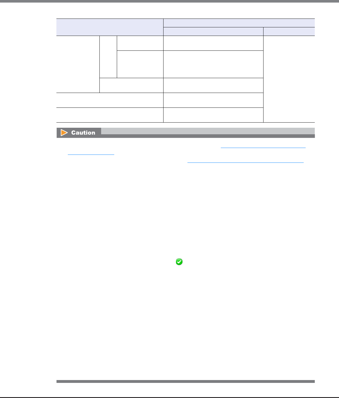
Chapter 6 RAID Group Management
6.2 Functions in the Action Area for RAID Group
ETERNUS Web GUI User’s Guide
Copyright 2013 FUJITSU LIMITED P2X0-1090-10ENZ0
193
ECO Mode Schedule Setting ECO Mode General Setting
Enabled Disabled
Control Status
ON
During scheduled
event term
Disk motor is activated. (ECO mode is
running)
Disk motor runs
regardless of
schedule settings.
(ECO mode is not
running)
Times other than
scheduled event
term
Disk motor is stopped. (ECO mode is
running)
If the RAID group is accessed, disk motors
are activated within 1 - 5 minutes.
OFF The target disk motor is operating
constantly. (ECO mode is not running)
Schedule is not applied Disk motor is operating constantly. (ECO
mode is not running)
Disks not registered in the RAID groups Disk motor is stopped constantly. (ECO
mode is running)
•Before applying ECO mode for RAID groups, use the procedure in "11.2.8.1 Modify ECO Mode General
Setting" (page 869) to enable the ECO mode setting for the ETERNUS DX Disk storage system.
•Set the ECO mode schedule using the procedure in "11.2.8.4 Modify ECO Mode Schedule" (page 876).
•ECO mode is not available for the following RAID groups:
-No volumes are created
-A Storage Migration path is created in the volume
-Configured by SSDs
-Registered as an REC Disk Buffer
•RAID groups to which the Snap Data Pool Volumes (SDPVs) belong cannot be selected as the target for
disk motor management by the ECO mode.
•When using ECO mode, make sure to set the time/date correctly. If the time/date of the ETERNUS DX Disk
storage system is wrong, processes used for stopping and starting the disk motor cannot be performed
per the ECO mode schedule.
•If any of the following conditions occur even when the disk motor is inactive, the disk motor is activated.
The ECO mode schedule is re-enabled when the conditions listed have finished.
-When the target RAID group status is not " Available"
-When performing functions that change the RAID group or the volume configuration
-When performing rebuild or copyback in the target RAID group
-When LDE is being performed in the RAID group
-When formatting is being performed in the volumes registered in the RAID group
-When RAID migration is being performed in the volumes registered in the RAID group
-When Advanced Copy is being performed in the volume registered in the RAID group (copy session
status is not "Suspend" or "Tracking")
-When encryption is being performed in the volumes registered in the RAID group
-During maintenance
-When performing disk diagnosis, RAID group diagnosis, or when exporting G-List
-Module error related to access path to the Controller Modules and drives is detected
•Specify the same ECO mode schedule for all of the RAID groups that configure a WSV. If a different ECO
mode schedule is specified, activation of a stopped drive is required to accept the host access, and the
performance of the response may be reduced.
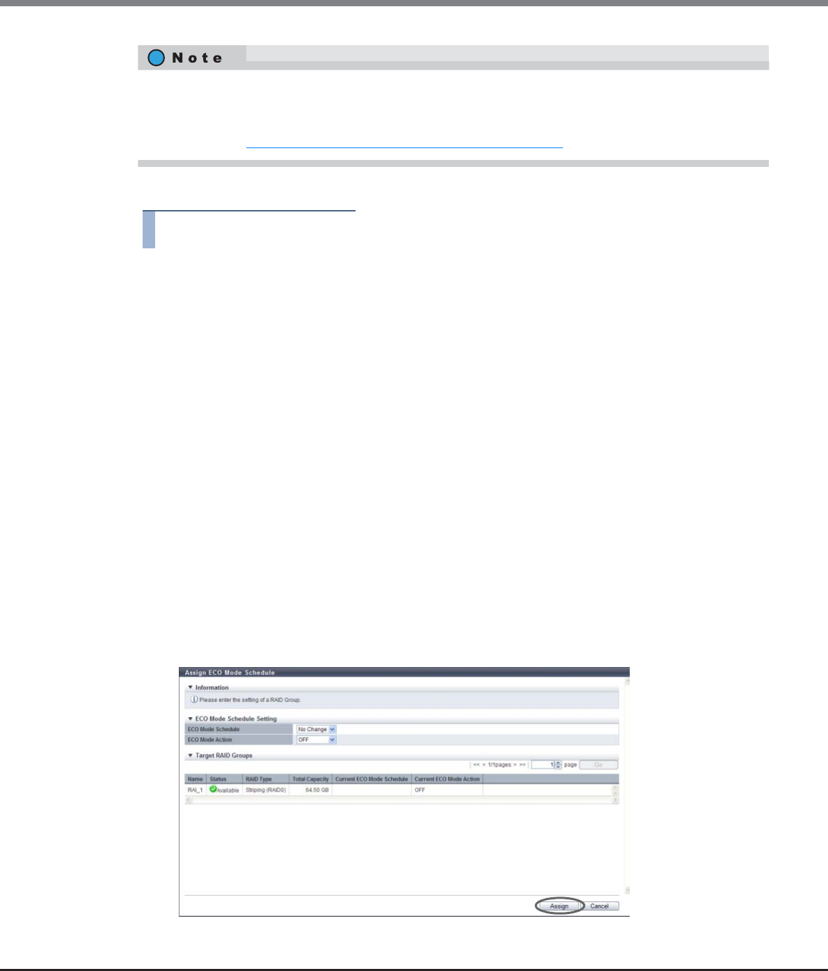
Chapter 6 RAID Group Management
6.2 Functions in the Action Area for RAID Group
ETERNUS Web GUI User’s Guide
Copyright 2013 FUJITSU LIMITED P2X0-1090-10ENZ0
194
The procedure to set ECO mode schedule for the RAID group is as follows:
Procedure
1Select the RAID group to apply the ECO mode schedule (multiple selections can be made) to
and click [Assign ECO Mode] in [Action].
2Select the ECO mode schedule that is to be applied, select whether to enable ("ON") or
disable ("OFF") ECO mode, and then click the [Assign] button.
•ECO Mode Schedule
Select the ECO mode schedule that is to be applied.
-No Change
Do not change the current setting.
-Disable
Disable the ECO mode.
-ECO mode schedule name
Apply the selected ECO mode schedule.
•ECO Mode Action
Select whether to enable ("ON") or disable ("OFF") the ECO mode setting. Select "No Change" to use
the current setting.
-No Change
Do not change the current setting.
-ON
Enable the ECO mode.
-OFF
Disable the ECO mode.
→A confirmation screen appears.
•When selecting multiple RAID groups as the target of the ECO mode, the same ECO mode schedule can be
specified for all the selected RAID groups.
•RAID groups that configure a WSV can be checked in the [Volume Detail] screen ([WSV Concatenation]
Tab). Refer to "5.1.14 Volume Detail (WSV Concatenation)" (page 93) for details.
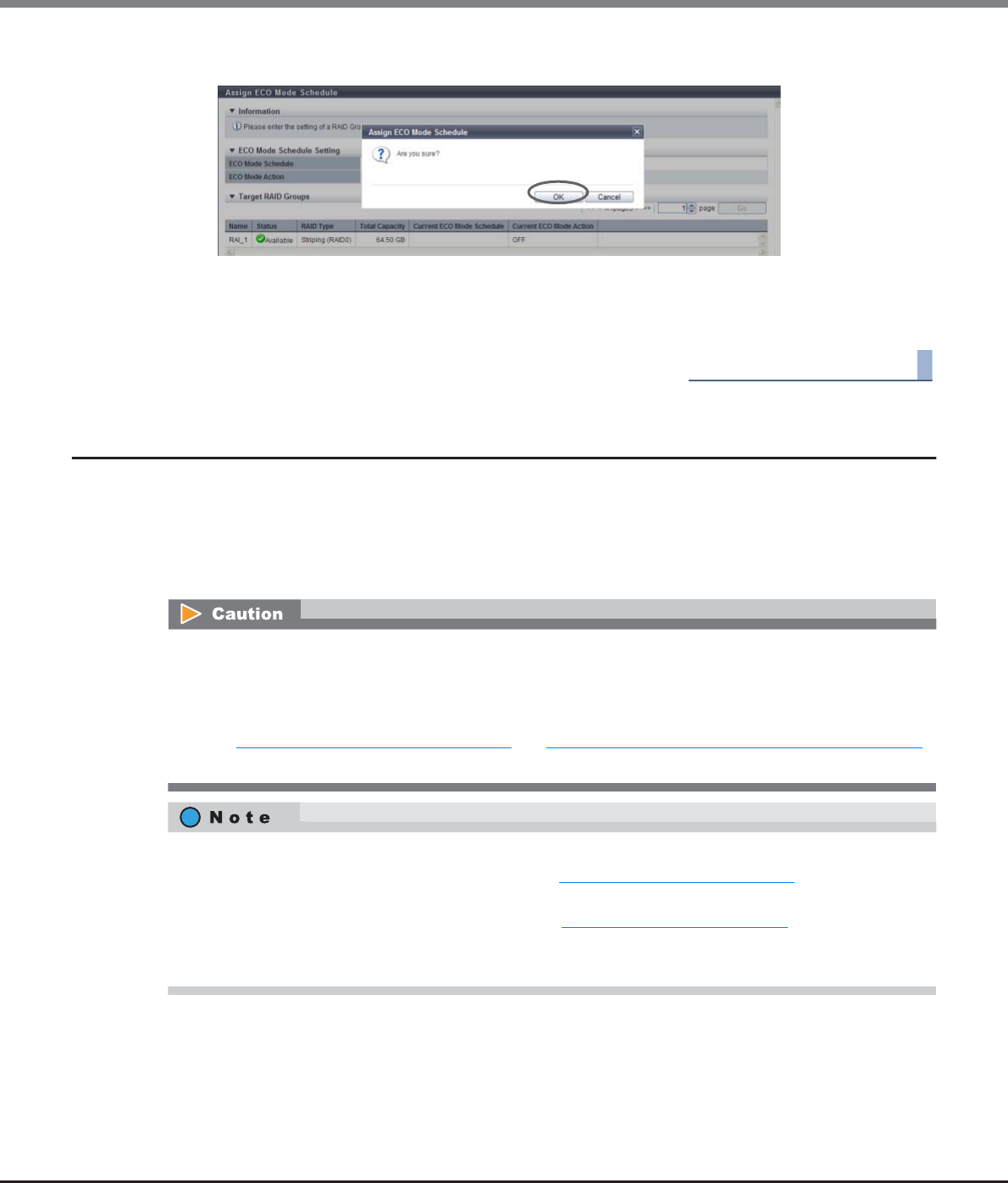
Chapter 6 RAID Group Management
6.2 Functions in the Action Area for RAID Group
ETERNUS Web GUI User’s Guide
Copyright 2013 FUJITSU LIMITED P2X0-1090-10ENZ0
195
3Click the [OK] button.
→Setting of the ECO mode schedule starts.
4Click the [Done] button to return to the [RAID Group] screen.
End of procedure
6.2.8 Set Key Group (RAID Group)
This function registers or deletes any RAID groups that are configured with SEDs in the key group.
The key group combines all of the RAID groups that use the same SED authentication key.
RAID groups in the key group are managed by the SED authentication key that is obtained from the key
server. One key group can be created in the ETERNUS DX Disk storage system.
If a RAID group is not registered in the key group, the RAID group is managed by the common key.
When registering RAID groups in the key group, perform the following settings:
•Create a key group.
•Allocate the master server or the slave server to the key group.
•Set the key for the key group and confirm that the key status is "Normal".
Refer to "11.2.6.6 Create Key Group" (page 841) and "11.2.6.9 Update SED Authentication Key" (page 849)
for details.
•Information on the RAID groups that are configured by SEDs and registration status to the key group can
be checked in the [SED Key Group] screen. Refer to "6.1.4 SED Key Group" (page 167) for details.
•Use the [Key Group] screen to check the SED authentication key information and the SSL/KMIP certificate
information that is used for the key group. Refer to "11.1.5.1 Key Group" (page 723) for details.
•Even when operations are being performed for volumes that configure a key management target RAID
group, this RAID group can be added to or deleted from the key group.
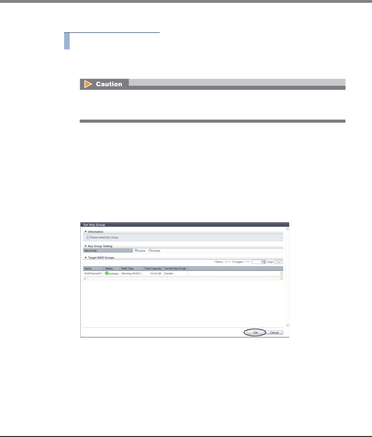
Chapter 6 RAID Group Management
6.2 Functions in the Action Area for RAID Group
ETERNUS Web GUI User’s Guide
Copyright 2013 FUJITSU LIMITED P2X0-1090-10ENZ0
196
The procedure to register or delete the RAID groups in the key group is as follows:
Procedure
1Select which RAID group to add to or delete from the key group (multiple selections can be
made), and click [Set Key Group] in [Action].
2Select the key group setting status, and click the [Set] button.
■When adding RAID groups
•Key Group
To add RAID groups, select "Enable".
If multiple RAID groups are selected, all the selected RAID groups are added in a single process.
■When deleting RAID groups
•Key Group
To delete RAID groups, select "Disable".
If multiple RAID groups are selected, all the selected RAID groups are deleted in a single process.
→A confirmation screen appears.
Settings for the selected RAID groups are applied in a single process. To add or delete multiple RAID
groups, only select the RAID groups that are to be added or deleted (do not select all of the RAID
groups).
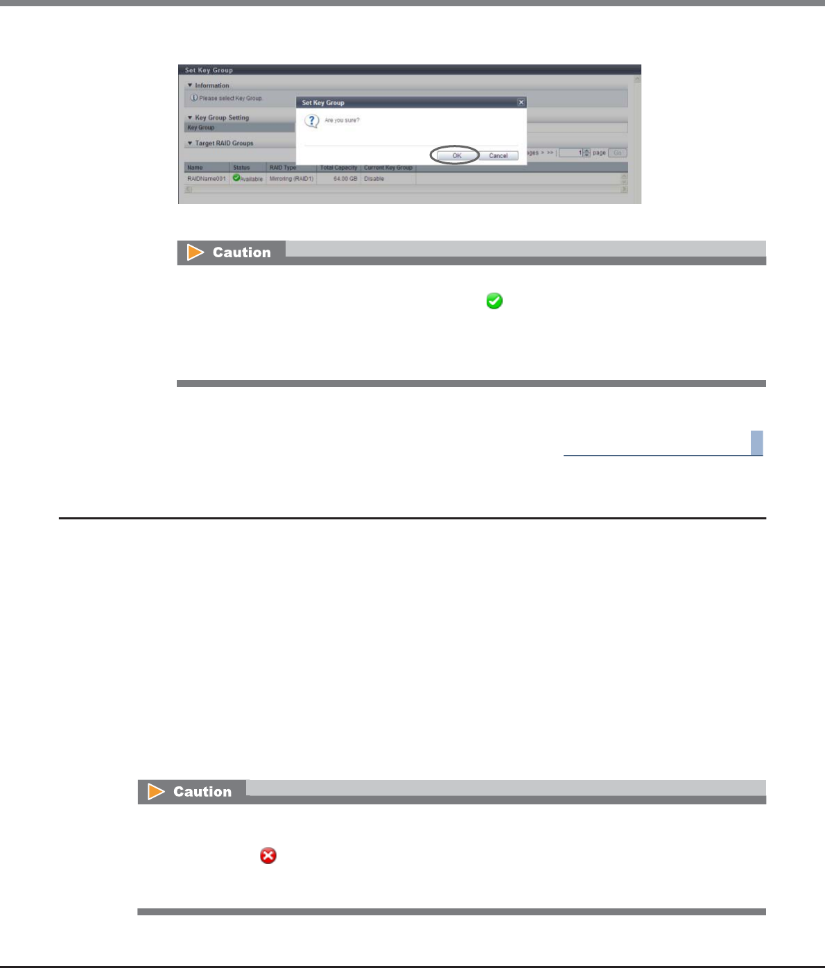
Chapter 6 RAID Group Management
6.2 Functions in the Action Area for RAID Group
ETERNUS Web GUI User’s Guide
Copyright 2013 FUJITSU LIMITED P2X0-1090-10ENZ0
197
3Click the [OK] button.
→Key group setting starts.
4Click the [Done] button to return to the [SED Key Group] screen.
End of procedure
6.2.9 Recovery SED
This function recovers the RAID groups that are in locked status.
"Locked status" indicates that the RAID group is blocked because the SED authentication key could not be
obtained from the key server.
Conditions that can be recovered by using the "Recovery SED" function
•Locked status when enabling or forcibly enabling a disk
•Locked status when forcibly recovering or forcibly enabling a RAID group
•Locked status when recovering from DE failure
•Locked status when applying disk firmware
•Locked status when starting an operation after a disk has been stopped by the ECO mode
•Locked status when communication with the key server failed when starting or rebooting the ETERNUS DX
Disk storage system
An error screen appears in the following conditions:
•If there is a RAID group with a status other than " Available"
•If the status of the key in the key group is not "Normal", "Expiration", or "Modifying"
•If "Enable" is selected but no key group has been created
•If no master or slave server is applied to the key group when "Enable" is selected
This function can only be used to recover locked RAID groups. This function cannot be used for recovering
blocked RAID groups that occur due to errors that are not listed above. Recovery operation of RAID groups for
which the status is " Broken" can be performed by using the [Recover RAID Group] function. Note that the
[Recover RAID Group] function can be performed by a maintenance engineer who has the "Maintenance
Operation" policy.
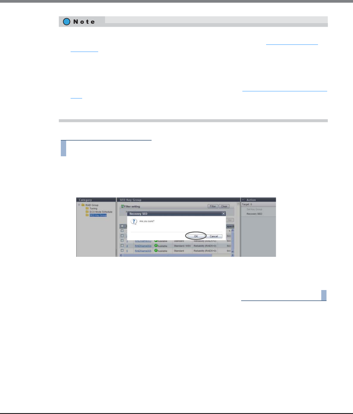
Chapter 6 RAID Group Management
6.2 Functions in the Action Area for RAID Group
ETERNUS Web GUI User’s Guide
Copyright 2013 FUJITSU LIMITED P2X0-1090-10ENZ0
198
The procedure to recover RAID groups that are in the locked status is as follows:
Procedure
1Click [Recovery SED] in [Action].
→A confirmation screen appears.
2Click the [OK] button.
→Recovery of the SED starts.
3Click the [Done] button to return to the [SED Key Group] screen.
End of procedure
•SED recovery from locked status is performed according to the "Recovery Mode" setting of the key group.
The "Recovery Mode" setting can be checked in the [Key Group] screen. Refer to "11.1.5.1 Key Group"
(page 723) for details.
-When "Recovery Mode" is "Auto", the ETERNUS DX Disk storage system monitors the RAID group
periodically. If a locked RAID group is detected, recovery is performed on the RAID group by the
ETERNUS DX Disk storage system automatically.
-When "Recovery Mode" is "Manual", use this function to manually recover the locked RAID group.
•"Recovery Mode" can be specified when creating a key group. Refer to "11.2.6.6 Create Key Group" (page
841) for details.
•This function can be used even if a key group is not created or no locked RAID groups are exist. If there are
no locked RAID groups that can be recovered, this function completes successfully.
ETERNUS Web GUI User’s Guide
Copyright 2013 FUJITSU LIMITED P2X0-1090-10ENZ0
199
Chapter 7
Thin Provisioning Pool Management
This chapter describes Thin Provisioning Pool management.
7.1 Thin Provisioning Pool Status
Thin Provisioning Pool status displays the status information of volumes.
Thin Provisioning Pool status screens can be displayed by clicking the following categories:
Detailed information of the Thin Provisioning Pools can be displayed from the following screen:
•Thin Provisioning Pool Detail (Basic)
•Flexible Tier Pool Detail (Basic)
•Flexible Tier Pool Detail (Flexible Tier Sub Pool)
•Flexible Tier Pool Detail (Volume)
•Flexible Tier Sub Pool Detail (Basic)
Thin Provisioning Pool status screen Category
Thin Provisioning Pool (Basic Information) Thin Provisioning Pools
Threshold (Thin Provisioning Pool) Threshold
ECO Mode Schedule (Thin Provisioning Pool) ECO Mode Schedule
License (Thin Provisioning) License
Flexible Tier Pool (Basic Information) Flexible Tier Pools
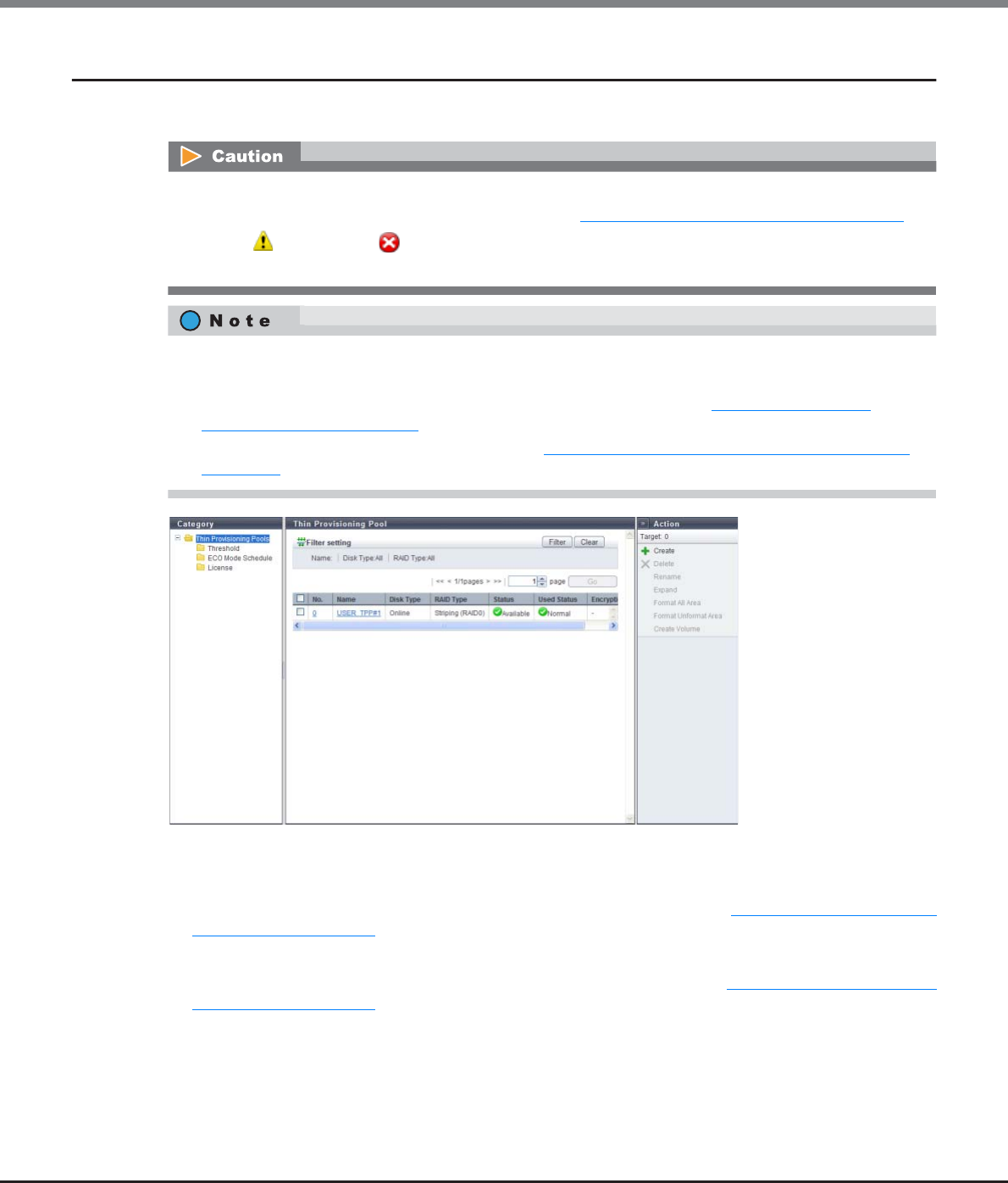
Chapter 7 Thin Provisioning Pool Management
7.1 Thin Provisioning Pool Status
ETERNUS Web GUI User’s Guide
Copyright 2013 FUJITSU LIMITED P2X0-1090-10ENZ0
200
7.1.1 Thin Provisioning Pool (Basic Information)
This function shows the list of TPPs.
The following items are displayed in the Main area:
•No.
The TPP number is displayed. Click this item to display the screen shown in "7.1.6 Thin Provisioning Pool
Detail (Basic)" (page 209).
•Name
The TPP name is displayed. Click this item to display the screen shown in "7.1.6 Thin Provisioning Pool
Detail (Basic)" (page 209).
•Registering the license for the Thin Provisioning feature is required to use the Thin Provisioning function.
To check the registration status of the license, refer to "7.1.4 License (Thin Provisioning)" (page 206).
•When " Attention" or " Warning" is displayed in "Used Status" in the TPP list, the TPP used capacity
exceeds the threshold. Add drives immediately to expand the TPP capacity.
•This function displays the TPP basic information, a list of the RAID groups that configure the TPP, and a list
of the TPVs that are registered in the TPP.
•To check the threshold for monitoring the used capacity of a TPP, refer to "7.1.2 Threshold (Thin
Provisioning Pool)" (page 202).
•To check the ECO mode settings of a TPP, refer to "7.1.3 ECO Mode Schedule (Thin Provisioning Pool)"
(page 203).
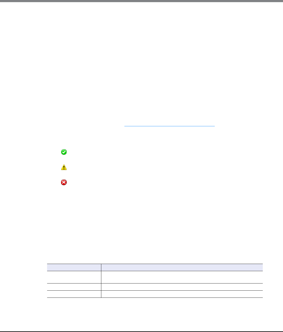
Chapter 7 Thin Provisioning Pool Management
7.1 Thin Provisioning Pool Status
ETERNUS Web GUI User’s Guide
Copyright 2013 FUJITSU LIMITED P2X0-1090-10ENZ0
201
•Disk Type
The type of drive that configures the TPP is displayed.
-Online
SAS disks
-Nearline
Nearline SAS disks
-SSD
-SED
•RAID Type
The type of RAID group that configures the TPP is displayed.
-High Performance (RAID1+0)
-High Capacity (RAID5)
-High Reliability (RAID6)
-Mirroring (RAID1)
-Striping (RAID0)
• Status
The TPP status is displayed. Refer to "B.4 Thin Provisioning Pool Status" (page 976) for detailed information
of TPP status.
•Used Status
The usage of TPP is displayed.
- Normal
TPP usage does not exceed the "Attention" threshold.
- Attention
TPP usage exceeds the "Attention" threshold but does not exceed the "Warning" threshold.
- Warning
TPP usage exceeds the "Warning" threshold.
•Encryption
The TPP encryption status is displayed.
-CM
The TPP that is encrypted by CM.
-"-" (hyphen)
The TPP that is not encrypted.
-SED
The TPP that is encrypted by SED.
Filter setting
Filter Description
Name Input the TPP name that is to be displayed.
When not using the TPP name for filtering, leave this item blank.
Disk Type Select the disk type that is to be displayed.
RAID Type Select the RAID type that is to be displayed.
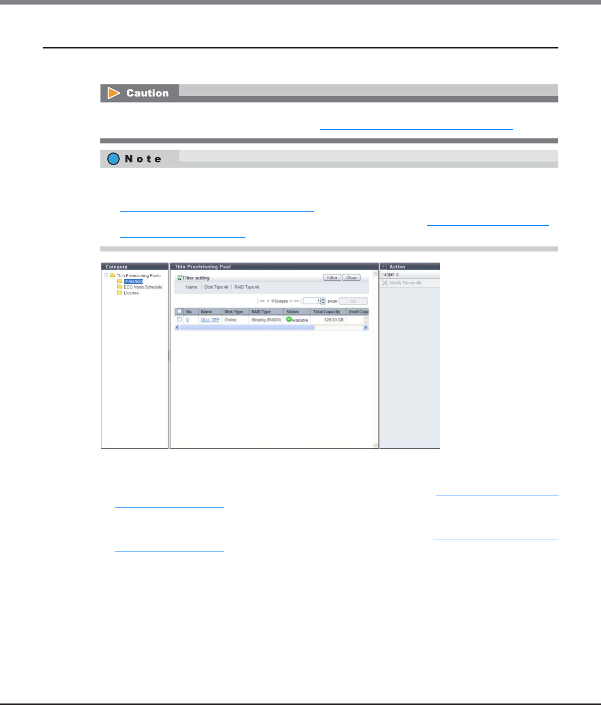
Chapter 7 Thin Provisioning Pool Management
7.1 Thin Provisioning Pool Status
ETERNUS Web GUI User’s Guide
Copyright 2013 FUJITSU LIMITED P2X0-1090-10ENZ0
202
7.1.2 Threshold (Thin Provisioning Pool)
This function shows the threshold for monitoring the used capacity of a Thin Provisioning Pool.
The following items are displayed in the Main area:
•No.
The TPP number is displayed. Click this item to display the screen shown in "7.1.6 Thin Provisioning Pool
Detail (Basic)" (page 209).
•Name
The TPP name is displayed. Click this item to display the screen shown in "7.1.6 Thin Provisioning Pool
Detail (Basic)" (page 209).
•Disk Type
The type of drive that configures the TPP is displayed.
-Online
SAS disks
-Nearline
Nearline SAS disks
-SSD
-SED
Registering the license for the Thin Provisioning feature is required to use Thin Provisioning function. To
check the registration status of the license, refer to "7.1.4 License (Thin Provisioning)" (page 206).
•If the TPP used capacity exceeds the threshold, notification is sent to the destination for REMCS (REMote
Customer Support system) center, SNMP Trap, E-Mail or syslog that was specified using the procedure in
"11.2.9.1 Setup Event Notification" (page 880).
•To change the threshold of a TPP, follow the procedure that is provided in "7.2.7 Modify Threshold Thin
Provisioning Pool" (page 239).
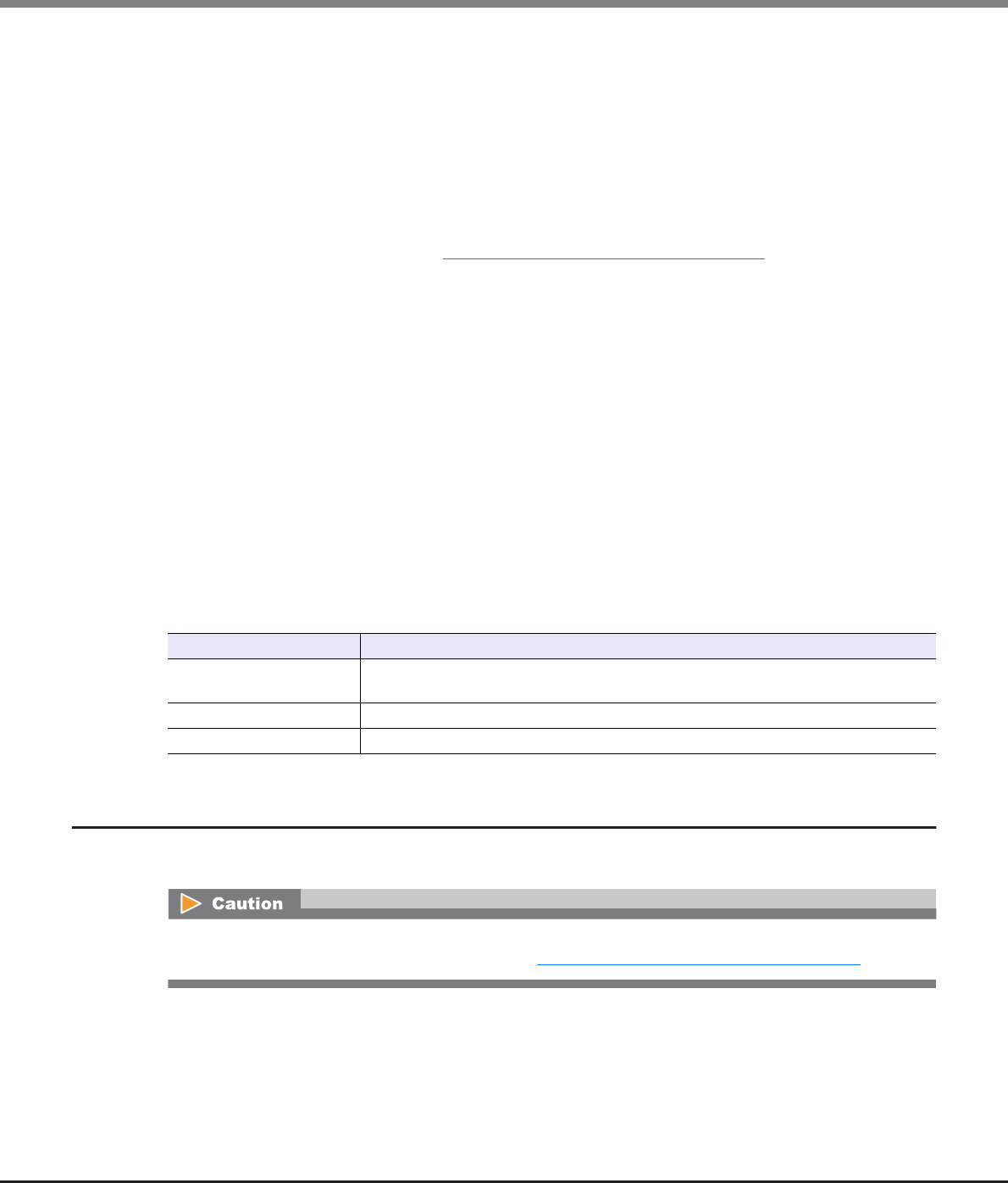
Chapter 7 Thin Provisioning Pool Management
7.1 Thin Provisioning Pool Status
ETERNUS Web GUI User’s Guide
Copyright 2013 FUJITSU LIMITED P2X0-1090-10ENZ0
203
•RAID Type
The type of RAID group that configures the TPP is displayed.
-High Performance (RAID1+0)
-High Capacity (RAID5)
-High Reliability (RAID6)
-Mirroring (RAID1)
-Striping (RAID0)
•Status
The TPP status is displayed. Refer to "B.4 Thin Provisioning Pool Status" (page 976) for detailed information
of TPP status.
•Total Capacity
The total capacity of TPP is displayed.
•Used Capacity
The used capacity of TPP is displayed.
•Warning
The warning threshold (%) for monitoring the TPP used capacity is displayed.
•Attention
The attention threshold (%) for monitoring the TPP used capacity is displayed. When the "Attention"
threshold is omitted, "0%" is displayed.
•MWC
Multi Writeback Count (MWC) of the TPP is displayed.
Filter setting
7.1.3 ECO Mode Schedule (Thin Provisioning Pool)
This function displays the ECO mode setting status of the Thin Provisioning Pool.
Filter Description
Name Input the TPP name that is to be displayed.
When not using the TPP name for filtering, leave this item blank.
Disk Type Select the disk type that is to be displayed.
RAID Type Select the RAID type that is to be displayed.
Registering the license for the Thin Provisioning feature is required to use the Thin Provisioning function. To
check the registration status of the license, refer to "7.1.4 License (Thin Provisioning)" (page 206).
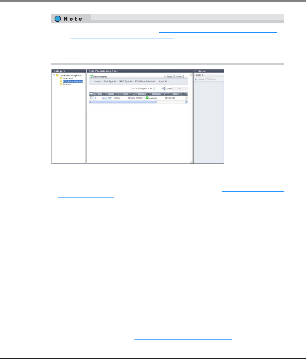
Chapter 7 Thin Provisioning Pool Management
7.1 Thin Provisioning Pool Status
ETERNUS Web GUI User’s Guide
Copyright 2013 FUJITSU LIMITED P2X0-1090-10ENZ0
204
The following items are displayed in the Main area:
•No.
The TPP number is displayed. Click this item to display the screen shown in "7.1.6 Thin Provisioning Pool
Detail (Basic)" (page 209).
•Name
The TPP name is displayed. Click this item to display the screen shown in "7.1.6 Thin Provisioning Pool
Detail (Basic)" (page 209).
•Disk Type
The type of drive that configures the TPP is displayed.
-Online
SAS disks
-Nearline
Nearline SAS disks
-SED
•RAID Type
The type of RAID group that configures the TPP is displayed.
-High Performance (RAID1+0)
-High Capacity (RAID5)
-High Reliability (RAID6)
-Mirroring (RAID1)
-Striping (RAID0)
•Status
The TPP status is displayed. Refer to "B.4 Thin Provisioning Pool Status" (page 976) for detailed information
of TPP status.
•To use the ECO mode, follow the procedure in "11.2.8.1 Modify ECO Mode General Setting" (page 869)
and "11.2.8.2 Create ECO Mode Schedule" (page 871) to perform the general ECO mode setup and create
an ECO mode schedule.
•To assign the ECO mode to a TPP, refer to "7.2.9 Assign ECO Mode Schedule (Thin Provisioning Pool)"
(page 242).

Chapter 7 Thin Provisioning Pool Management
7.1 Thin Provisioning Pool Status
ETERNUS Web GUI User’s Guide
Copyright 2013 FUJITSU LIMITED P2X0-1090-10ENZ0
205
•Total Capacity
The total capacity of TPP is displayed.
•ECO Mode Schedule
The ECO mode schedule that is assigned to the TPP is displayed.
If the ECO mode schedule is not assigned, the field is blank.
•ECO Mode Action
When the ECO mode is enabled in TPP, "ON" is displayed. If the ECO mode is disabled, "OFF" is displayed.
If the ECO mode is not assigned, a "-" (hyphen) is displayed.
•Motor Status
The disk motor status for the TPP is displayed.
-Active
The disk motors are activated.
-In the Boot Process
The disk motors are starting up.
-Idle
The disk motors are stopped.
-In the Stop Process
The disk motors are being stopped.
Filter setting
Filter Description
Name Input the TPP name that is to be displayed.
When not using the TPP name for filtering, leave this item blank.
Disk Type Select the disk type that is to be displayed.
RAID Type Select the RAID type that is to be displayed.
ECO Mode Schedule Select the ECO mode schedule that is to be displayed.
Action Select the action that is to be displayed.
Chapter 7 Thin Provisioning Pool Management
7.1 Thin Provisioning Pool Status
ETERNUS Web GUI User’s Guide
Copyright 2013 FUJITSU LIMITED P2X0-1090-10ENZ0
206
7.1.4 License (Thin Provisioning)
The registration status of the Thin Provisioning license is displayed.
The following items are displayed in the Main area:
•Status
The registration status of the Thin Provisioning license is displayed.
-Registered
-Not Registered
Registering the license for the Thin Provisioning feature is required to use Thin Provisioning function.
Registering or deleting the Thin Provisioning license can be performed depending on the license registration
status. To register the license, refer to "7.2.10 Register Thin Provisioning License" (page 245). To delete the
license, refer to "7.2.11 Delete Thin Provisioning License" (page 247).
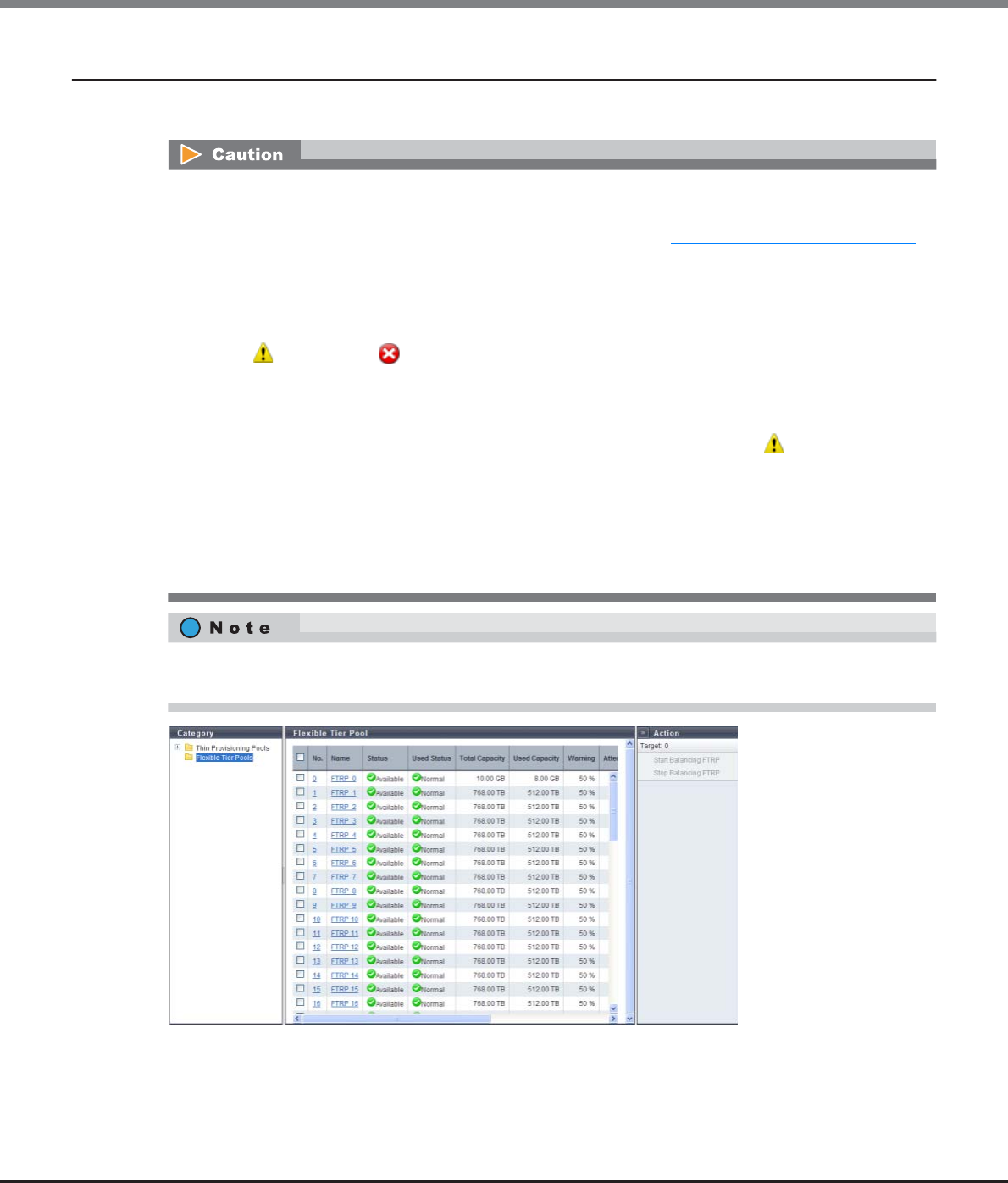
Chapter 7 Thin Provisioning Pool Management
7.1 Thin Provisioning Pool Status
ETERNUS Web GUI User’s Guide
Copyright 2013 FUJITSU LIMITED P2X0-1090-10ENZ0
207
7.1.5 Flexible Tier Pool (Basic Information)
This function shows the list of Flexible Tier Pools (FTRPs).
•To use the Flexible Tier function (auto storage layering), the following operations are required:
-Registering the license for the Thin Provisioning feature is required to use the Thin Provisioning
function. To check the registration status of the license, refer to "7.1.4 License (Thin Provisioning)"
(page 206).
-Register the Optimization option for ETERNUS SF Storage Cruiser.
-Create the Flexible Tier Pools (FTRPs), Flexible Tier Sub Pools (FTSPs), and the Flexible Tier Volumes
(FTVs), using the ETERNUS SF Storage Cruiser.
•When " Attention" or " Warning" is displayed in "Used Status" in the FTRP list, the FTRP used
capacity exceeds the threshold. Immediately add drives and use ETERNUS SF Storage Cruiser to expand
the capacity of the appropriate FTSP (for which expansion is determined to be necessary based upon the
performance and used capacity).
•If the target FTRP does not exist when displaying the details screen, a message, " Target is Not Found."
is displayed.
•The required policy for the [Format Flexible Tier Pool (All Area)] function and the [Format Flexible Tier
Pool (Unformatted Area)] function is changed from "RAID Group Management" to "Maintenance
Operation" with controller firmware V10L40. To format the Flexible Tier Pool with an ETERNUS DX Disk
storage system that has controller firmware version V10L40 or later, ask a maintenance engineer who has
the "Maintenance Operation" policy.
This function displays a basic FTRP information, a list of FTSPs which belong to the FTRP, a list of RAID groups
which configure the FTSP, and a list of FTVs which have been registered to the FTRP.

Chapter 7 Thin Provisioning Pool Management
7.1 Thin Provisioning Pool Status
ETERNUS Web GUI User’s Guide
Copyright 2013 FUJITSU LIMITED P2X0-1090-10ENZ0
208
The following items are displayed in the Main area:
•No.
The FTRP number is displayed. Click this item to display the screen shown in "7.1.7 Flexible Tier Pool Detail
(Basic)" (page 212).
-ETERNUS DX80 S2/DX90 S2: 0 - 29
-ETERNUS DX410 S2: 0 - 59
-ETERNUS DX440 S2: 0 - 63
-ETERNUS DX8100 S2: 0 - 11
-ETERNUS DX8700 S2: 0 - 63
•Name
The FTRP name is displayed. Click this item to display the screen shown in "7.1.7 Flexible Tier Pool Detail
(Basic)" (page 212).
• Status
The FTRP status is displayed. Refer to "B.4 Thin Provisioning Pool Status" (page 976) for detailed
information of FTRP status.
•Used Status
The usage of FTRP is displayed.
- Normal
FTRP usage does not exceed the "Attention" threshold.
- Attention
FTRP usage exceeds the "Attention" threshold but does not exceed the "Warning" threshold.
- Warning
FTRP usage exceeds the "Warning" threshold.
•Total Capacity
The total capacity of FTRP is displayed.
•Used Capacity
The used capacity of FTRP is displayed.
•Warning
The warning threshold (%) for monitoring the FTRP used capacity is displayed.
•Attention
The attention threshold (%) for monitoring the FTRP used capacity is displayed. When the "Attention"
threshold is omitted, "0%" is displayed.
•Encryption
The FTRP encryption status is displayed.
-CM
The FTRP that is encrypted by CM.
-"-" (hyphen)
The FTRP that is not encrypted.
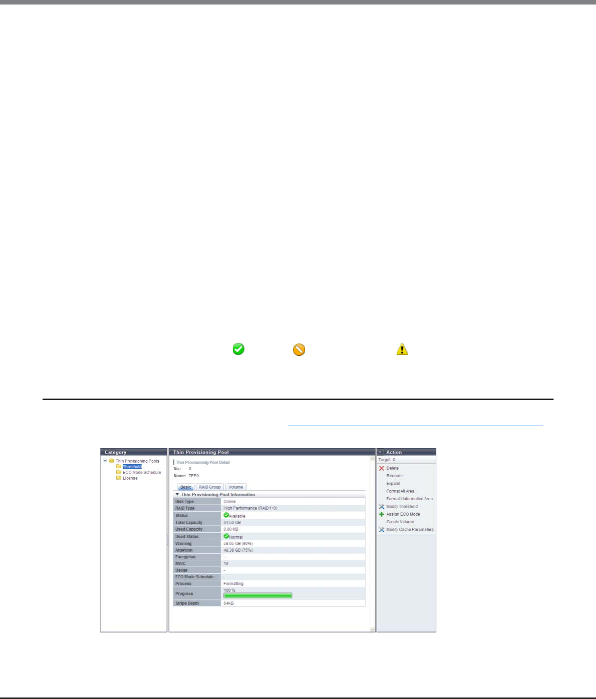
Chapter 7 Thin Provisioning Pool Management
7.1 Thin Provisioning Pool Status
ETERNUS Web GUI User’s Guide
Copyright 2013 FUJITSU LIMITED P2X0-1090-10ENZ0
209
•Balancing Level
The balancing level of the FTRP is displayed.
If multiple FTSPs exists in the FTRP, the lowest balancing level among the FTSPs is displayed. A "-" (hyphen)
is displayed when the physically allocated capacity cannot be checked due to the storage system status or
when the balancing level cannot be obtained due to the FTRP status (*1).
-High
The physically allocated capacity among the RAID groups in the FTSP is equalized.
-Middle
The physically allocated capacity among the RAID groups in the FTSP is slightly unequal.
-Low
The physically allocated capacity among the RAID groups in the FTSP is significantly unequal.
•Balancing Process
A "-" (hyphen) is displayed when FTRP balancing is not being performed, when the physically allocated
capacity cannot be checked due to the storage system status, or when the balancing level cannot be
obtained due to the FTRP status (*1).
-Status
The balancing status of the FTRP is displayed.
•Active
All of the FTVs in the FTRP are either reserved or operating normally.
•Error
An FTV in error status exists in the FTRP.
-Error Code
The error code of FTRP balancing is displayed when an error occurs.
A "-" (hyphen) is displayed if no errors occur.
*1: The status of the FTRP is not " Available", " Partially Readying", or " Exposed"
7.1.6 Thin Provisioning Pool Detail (Basic)
Click the [No.] link or the [Name] link on the "7.1.1 Thin Provisioning Pool (Basic Information)" (page 200) to
display the corresponding Thin Provisioning Pool Details screen.

Chapter 7 Thin Provisioning Pool Management
7.1 Thin Provisioning Pool Status
ETERNUS Web GUI User’s Guide
Copyright 2013 FUJITSU LIMITED P2X0-1090-10ENZ0
210
The following items are displayed in the Main area:
•Disk Type
The type of drive that configures the TPP is displayed.
-Online:
SAS disks
-Nearline
Nearline SAS disks
-SSD
-SED
•RAID Type
The type of RAID group that configures the TPP is displayed.
-High Performance (RAID1+0)
-High Capacity (RAID5)
-High Reliability (RAID6)
-Mirroring (RAID1)
-Striping (RAID0)
•Status
The TPP status is displayed. Refer to "B.4 Thin Provisioning Pool Status" (page 976) for detailed information
of TPP status.
•Total Capacity
The total capacity of TPP is displayed.
•Used Capacity
The used capacity of TPP is displayed.
•Used Status
The usage of TPP is displayed.
- Normal
TPP usage does not exceed the "Attention" threshold.
- Attention
TPP usage exceeds the "Attention" threshold but does not exceed the "Warning" threshold.
- Warning
TPP usage exceeds the "Warning" threshold.
•Warning
The TPP physical capacity "xxx", which is converted based on the TPP warning threshold, and the threshold
(yy%) are displayed.
•Attention
The TPP physical capacity "xxx", which is converted based on the TPP attention threshold, and the
threshold (yy%) are displayed.
When the attention threshold is omitted, a "-" (hyphen) is displayed.

Chapter 7 Thin Provisioning Pool Management
7.1 Thin Provisioning Pool Status
ETERNUS Web GUI User’s Guide
Copyright 2013 FUJITSU LIMITED P2X0-1090-10ENZ0
211
•Encryption
The TPP encryption status is displayed.
-CM
The TPP that is encrypted by CM.
-"-" (hyphen)
The TPP that is not encrypted.
-SED
The TPP that is encrypted by SED.
•MWC
Multi Writeback Count (MWC) of the TPP is displayed.
•Usage
"TPV" is displayed when a TPV is registered in the TPP.
If there are no TPVs in the Thin Provisioning Pool, a "-" (hyphen) is displayed.
•ECO Mode Schedule
The ECO mode schedule that is assigned to the TPP is displayed.
If the ECO mode schedule is not specified, the field is blank.
•Process
A process that is being performed for the TPP is displayed. If no process is being performed, a "-" (hyphen)
is displayed.
•Progress
The progress rate for the TPP is displayed.
If no process is being performed, a "-" (hyphen) is displayed.
•Stripe Depth
The Stripe Depth value (*1) for the RAID groups that configures the TPP is displayed.
If the RAID type is "Mirroring (RAID1)", a "-" (hyphen) is displayed.
*1: The number of logical blocks that are assigned to a drive for each stripe when configuring a stripe volume in a
RAID group. Normally, it is 64KB.
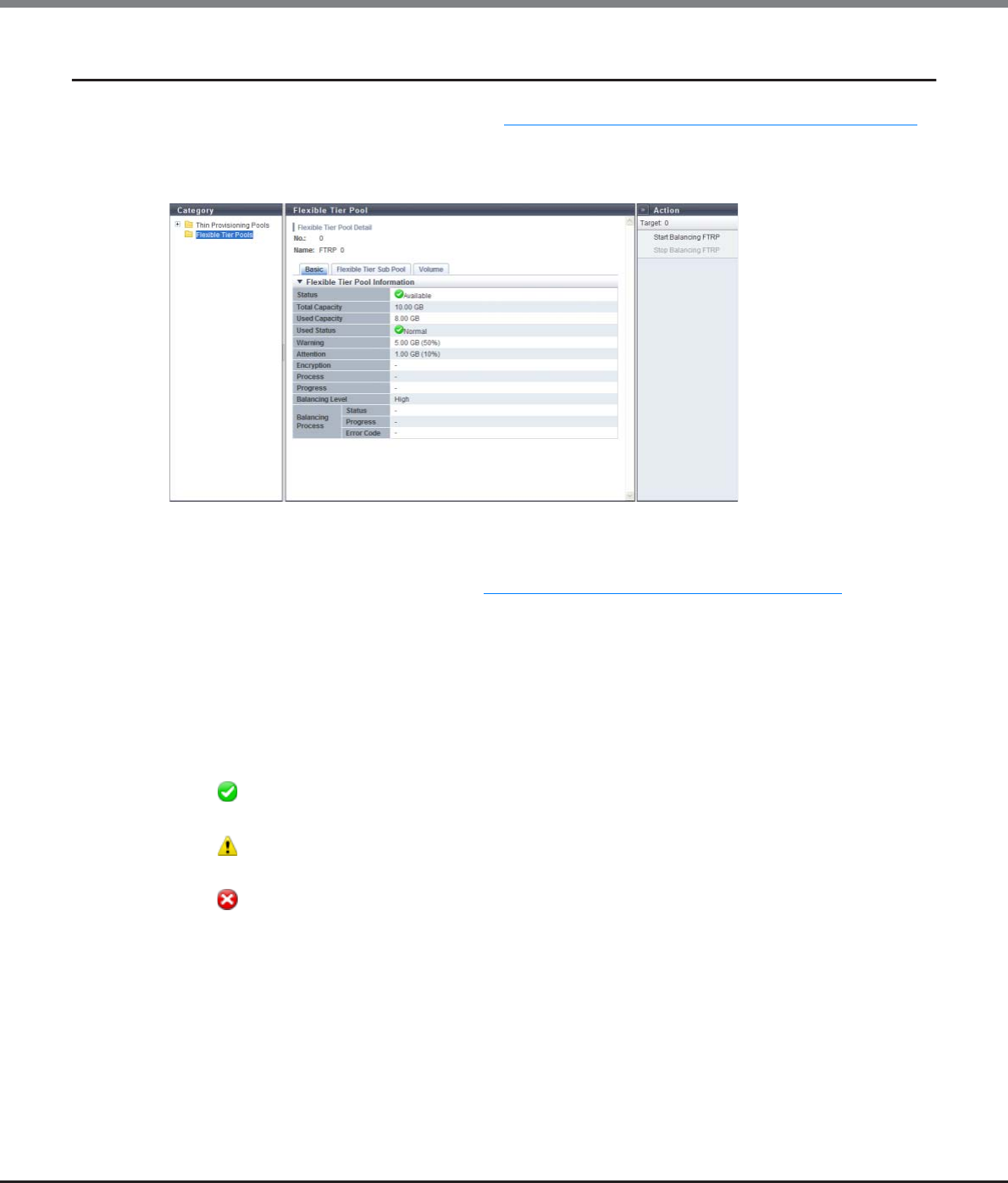
Chapter 7 Thin Provisioning Pool Management
7.1 Thin Provisioning Pool Status
ETERNUS Web GUI User’s Guide
Copyright 2013 FUJITSU LIMITED P2X0-1090-10ENZ0
212
7.1.7 Flexible Tier Pool Detail (Basic)
Click the [No.] link or the [Name] link on the "7.1.5 Flexible Tier Pool (Basic Information)" (page 207) to
display the detailed information of the corresponding FTRP.
Click the [Basic] tab on the [Flexible Tier Pool Detail] to display the basic information of the corresponding
FTRP.
The following items are displayed in the Main area:
•Status
The FTRP status is displayed. Refer to "B.4 Thin Provisioning Pool Status" (page 976) for detailed
information of FTRP status.
•Total Capacity
The total capacity of FTRP is displayed.
•Used Capacity
The used capacity of FTRP is displayed.
•Used Status
The usage of FTRP is displayed.
- Normal
FTRP usage does not exceed the "Attention" threshold.
- Attention
FTRP usage exceeds the "Attention" threshold but does not exceed the "Warning" threshold.
- Warning
FTRP usage exceeds the "Warning" threshold.
•Warning
The FTRP physical capacity "xxx", which is converted based on the FTRP warning threshold, and the
threshold (yy%) are displayed.
•Attention
The FTRP physical capacity "xxx", which is converted based on the FTRP attention threshold, and the
threshold (yy%) are displayed.
When the attention threshold is omitted, a "-" (hyphen) is displayed.

Chapter 7 Thin Provisioning Pool Management
7.1 Thin Provisioning Pool Status
ETERNUS Web GUI User’s Guide
Copyright 2013 FUJITSU LIMITED P2X0-1090-10ENZ0
213
•Encryption
The FTRP encryption status is displayed.
-CM
The FTRP that is encrypted by CM.
-"-" (hyphen)
The FTRP that is not encrypted.
•Process
A process that is being performed for the FTRP is displayed. If no process is being performed, a "-" (hyphen)
is displayed.
•Progress
The progress rate for the FTRP is displayed.
If no process is being performed, a "-" (hyphen) is displayed.
•Balancing Level
The balancing level of the FTRP is displayed.
If multiple FTSPs exists in the FTRP, the lowest balancing level among the FTSPs is displayed. A "-" (hyphen)
is displayed when the physically allocated capacity cannot be checked due to the storage system status or
when the balancing level cannot be obtained due to the FTRP status (*1).
-High
The physically allocated capacity among the RAID groups in the FTSP is equalized.
-Middle
The physically allocated capacity among the RAID groups in the FTSP is slightly unequal.
-Low
The physically allocated capacity among the RAID groups in the FTSP is significantly unequal.
•Balancing Process
A "-" (hyphen) is displayed when FTRP balancing is not being performed, when the physically allocated
capacity cannot be checked due to the storage system status, or when the balancing level cannot be
obtained due to the FTRP status (*1).
-Status
The balancing status of the FTRP is displayed.
•Active
All of the FTVs in the FTRP are either reserved or operating normally
•Error
An FTV in error status exists in the FTRP
-Progress
The lowest progress rate among the FTV balancing sessions that are being performed in the FTRP is
displayed.
-Error Code
The error code of FTRP balancing is displayed when an error occurs.
A "-" (hyphen) is displayed if no errors occur.
*1: The status of the FTRP is not " Available", " Partially Readying", or " Exposed"
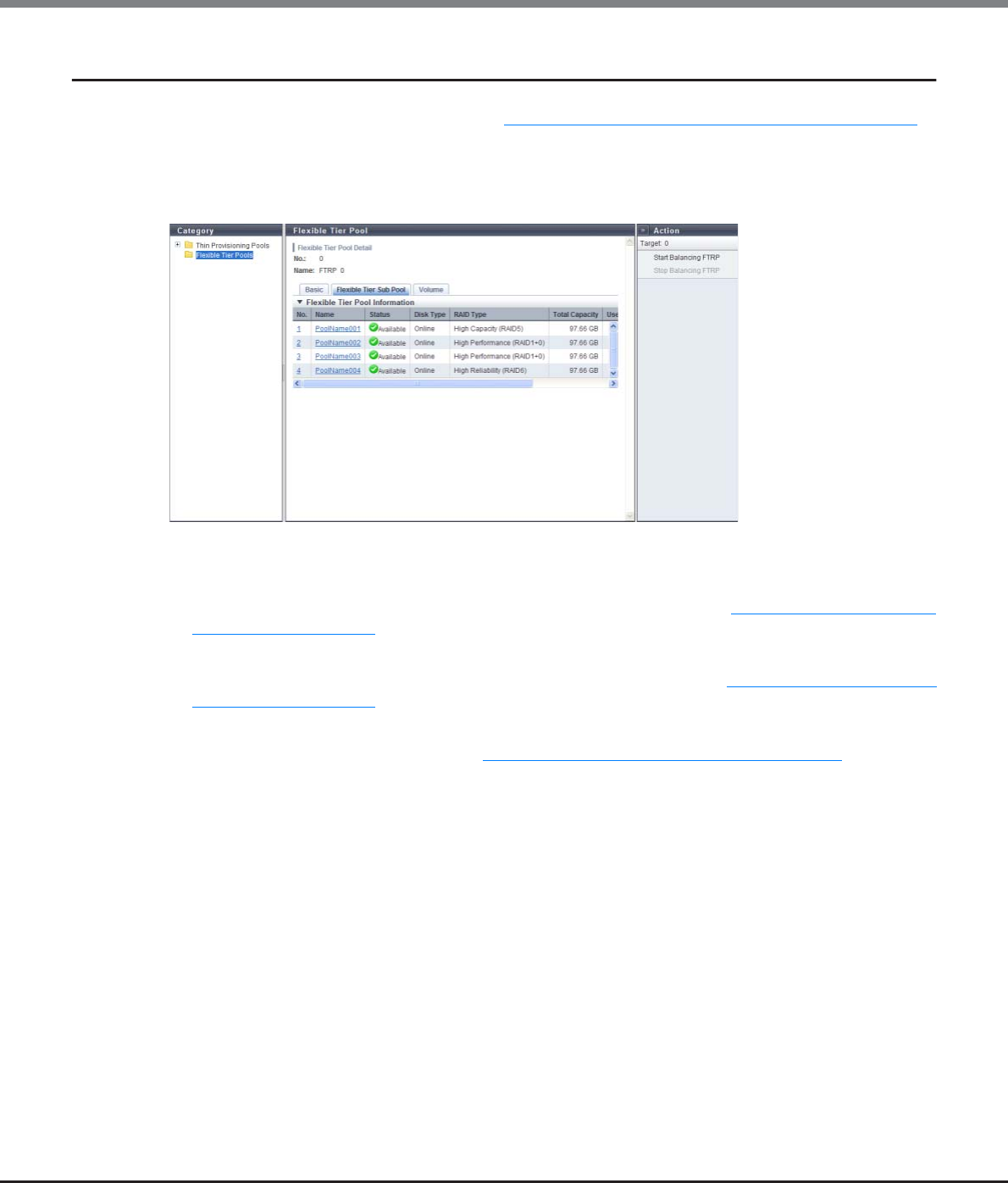
Chapter 7 Thin Provisioning Pool Management
7.1 Thin Provisioning Pool Status
ETERNUS Web GUI User’s Guide
Copyright 2013 FUJITSU LIMITED P2X0-1090-10ENZ0
214
7.1.8 Flexible Tier Pool Detail (Flexible Tier Sub Pool)
Click the [No.] link or the [Name] link on the "7.1.5 Flexible Tier Pool (Basic Information)" (page 207) to
display the corresponding Flexible Tier Pool Details screen.
Click the [Flexible Tier Sub Pool] tab on the [Flexible Tier Pool Detail] to display a list of Flexible Tier Sub Pools
(FTSPs) that are registered in the corresponding FTRP. When no volumes are registered in the FTRP, only the
item name is displayed.
The following items are displayed in the Main area:
•No.
The FTSP number is displayed. Click this item to display the screen shown in "7.1.10 Flexible Tier Sub Pool
Detail (Basic)" (page 217).
•Name
The FTSP name is displayed. Click this item to display the screen shown in "7.1.10 Flexible Tier Sub Pool
Detail (Basic)" (page 217).
•Status
The FTSP status is displayed. Refer to "B.4 Thin Provisioning Pool Status" (page 976) for detailed
information of FTSP status.
•Disk Type
The type of drive that configures the FTSP is displayed.
-Online
SAS disks
-Nearline
Nearline SAS disks
-SSD
-SED
•RAID Type
The type of RAID group that configures the FTSP is displayed.
-High Performance (RAID1+0)
-High Capacity (RAID5)
-High Reliability (RAID6)
-Mirroring (RAID1)
-Striping (RAID0)
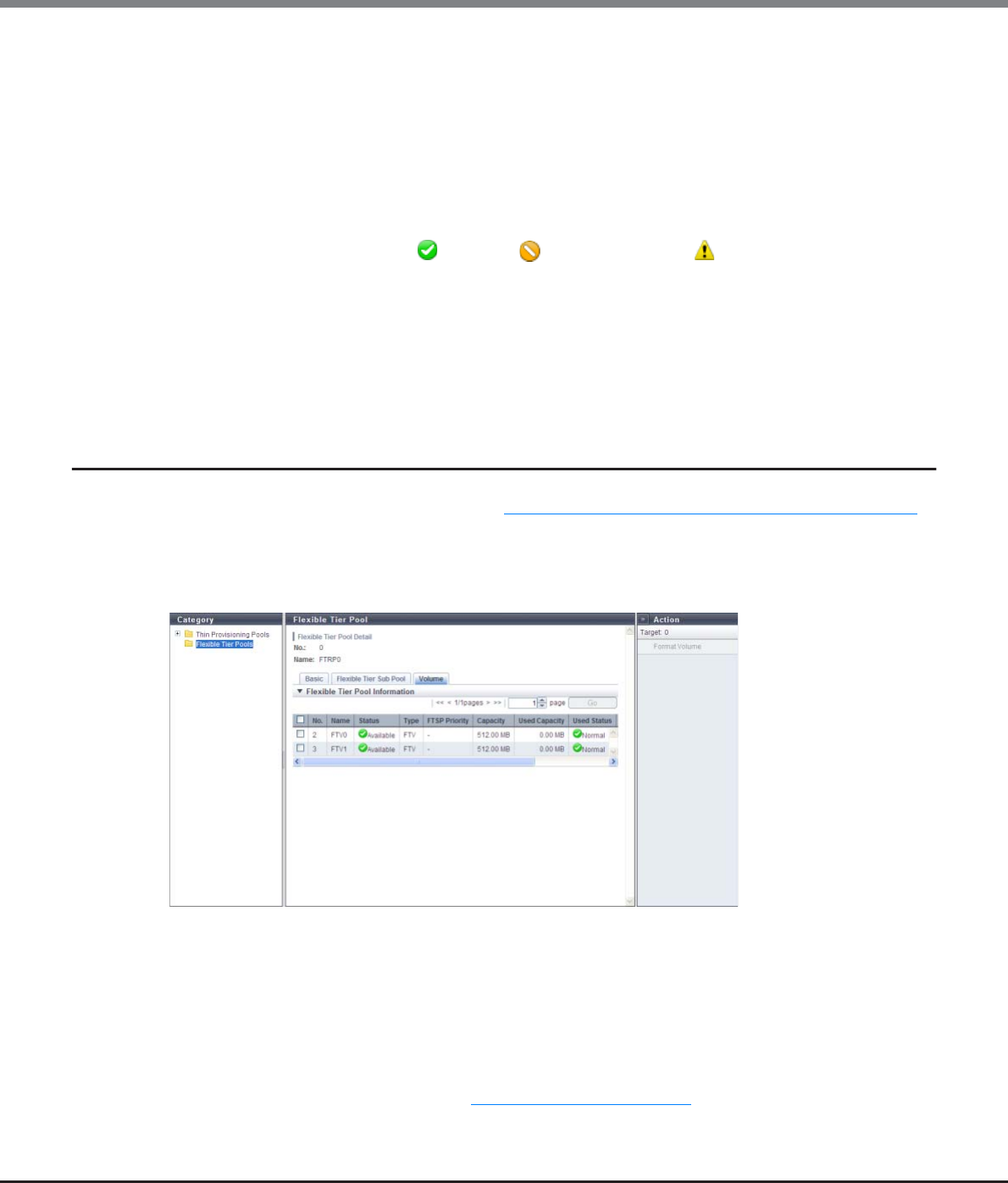
Chapter 7 Thin Provisioning Pool Management
7.1 Thin Provisioning Pool Status
ETERNUS Web GUI User’s Guide
Copyright 2013 FUJITSU LIMITED P2X0-1090-10ENZ0
215
•Total Capacity
The total capacity of FTSP is displayed.
•Used Capacity
The used capacity of FTSP is displayed.
•Balancing Level
The balancing level of the FTSP is displayed.
A "-" (hyphen) is displayed when the physically allocated capacity cannot be checked due to the storage
system status or when the balancing level cannot be obtained due to the FTRP status (*1).
*1: The status of the FTRP is not " Available", " Partially Readying", or " Exposed"
-High
The physically allocated capacity among the RAID groups is equalized.
-Middle
The physically allocated capacity among the RAID groups is slightly unequal.
-Low
The physically allocated capacity among the RAID groups is significantly unequal.
7.1.9 Flexible Tier Pool Detail (Volume)
Click the [No.] link or the [Name] link on the "7.1.5 Flexible Tier Pool (Basic Information)" (page 207) to
display the corresponding Flexible Tier Pool Details screen.
Click the [Volume] tab on the [Flexible Tier Pool Detail] to display a list of volumes that are registered in the
corresponding FTRP. Up to 100 volumes are displayed in a page. When no volumes are registered in the FTRP,
only the item name is displayed.
The following items are displayed in the Main area:
•No.
The volume number is displayed.
•Name
The volume name is displayed.
• Status
The volume status is displayed. Refer to "B.2 Volume Status" (page 974) for detailed information of volume
status.
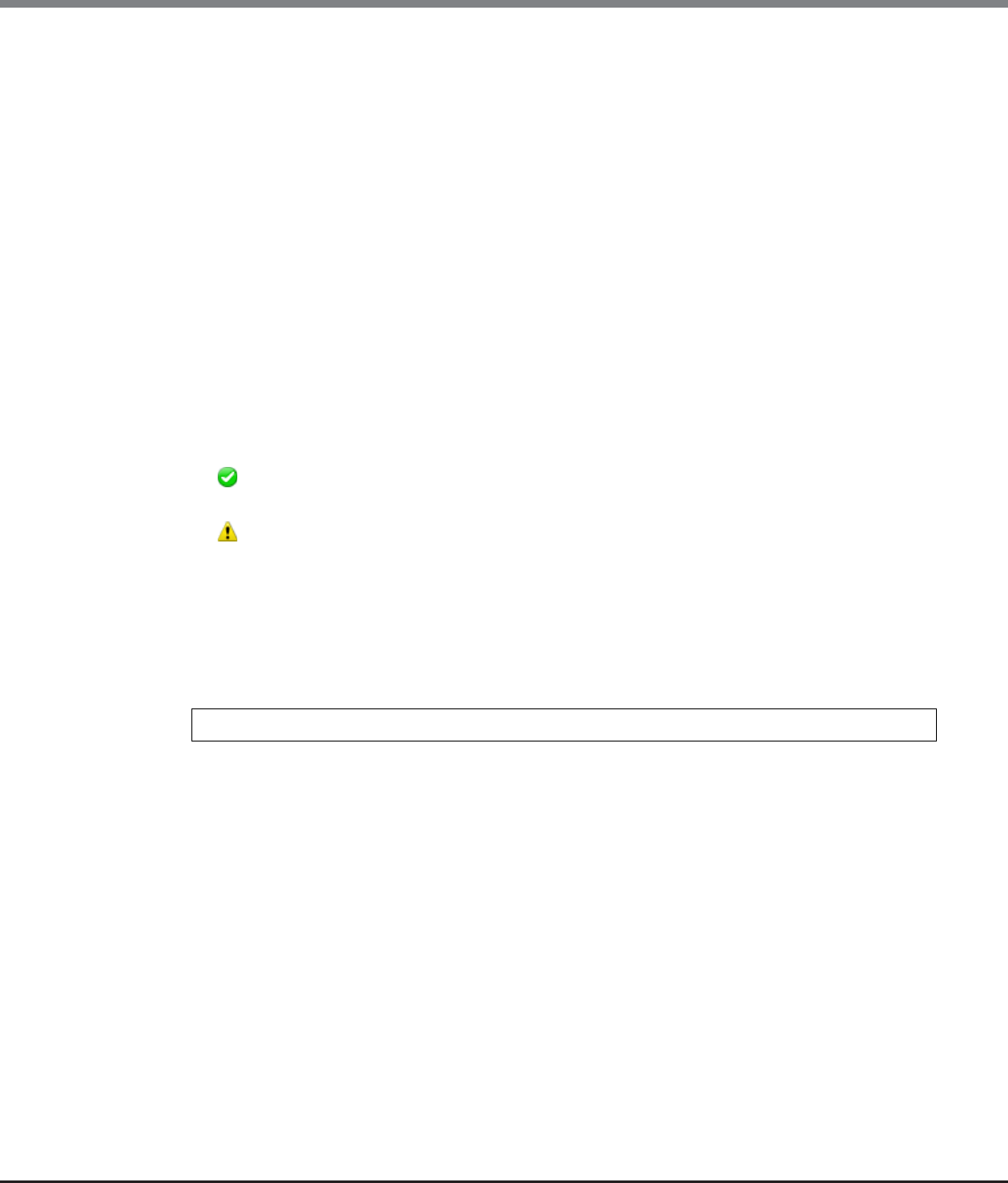
Chapter 7 Thin Provisioning Pool Management
7.1 Thin Provisioning Pool Status
ETERNUS Web GUI User’s Guide
Copyright 2013 FUJITSU LIMITED P2X0-1090-10ENZ0
216
•Type
The volume type is displayed.
This volume list displays only the volumes whose type is "FTV".
•FTSP Priority
The FTSP number, to which a volume is assigned on a priority basis in the FTRP, is displayed. When the
setting is omitted, "-" (hyphen) is displayed.
-ETERNUS DX80 S2/DX90 S2: 0 - 119
-ETERNUS DX410 S2: 0 - 239
-ETERNUS DX440 S2: 0 - 255
-ETERNUS DX8100 S2: 0 - 47
-ETERNUS DX8700 S2: 0 - 255
•Capacity
The total volume capacity is displayed.
•Used Capacity
The used capacity of the volume is displayed.
•Used Status
The usage of the volume is displayed.
- Normal
The volume usage does not exceed the "Attention" threshold.
- Attention
The volume usage exceeds the "Attention" threshold but does not exceed the "Warning" threshold.
Volume usage is determined by the ratio of "Free space in the FTRP to which the volume belongs" and
"Non-allocated volume capacity × Threshold [%]".
•Measurements
The FTRP free space status for each volume is displayed.
The measurement value is calculated by using the following formula: (truncate after the decimal point)
A high measurement value indicates that there is more free space in the volume.
-When the measurement value is larger than 500, ">500" is displayed.
-When the measurement value is smaller than 1, "0" is displayed.
-When the non-allocated volume capacity value is "0", "-" (hyphen) is displayed.
-When the status of the ETERNUS DX Disk storage system is "Not Ready", "?" is displayed.
•Attention
The attention threshold (%) for monitoring the volume used capacity is displayed.
Measurements = FTRP Free Capacity / Non-allocated volume capacity
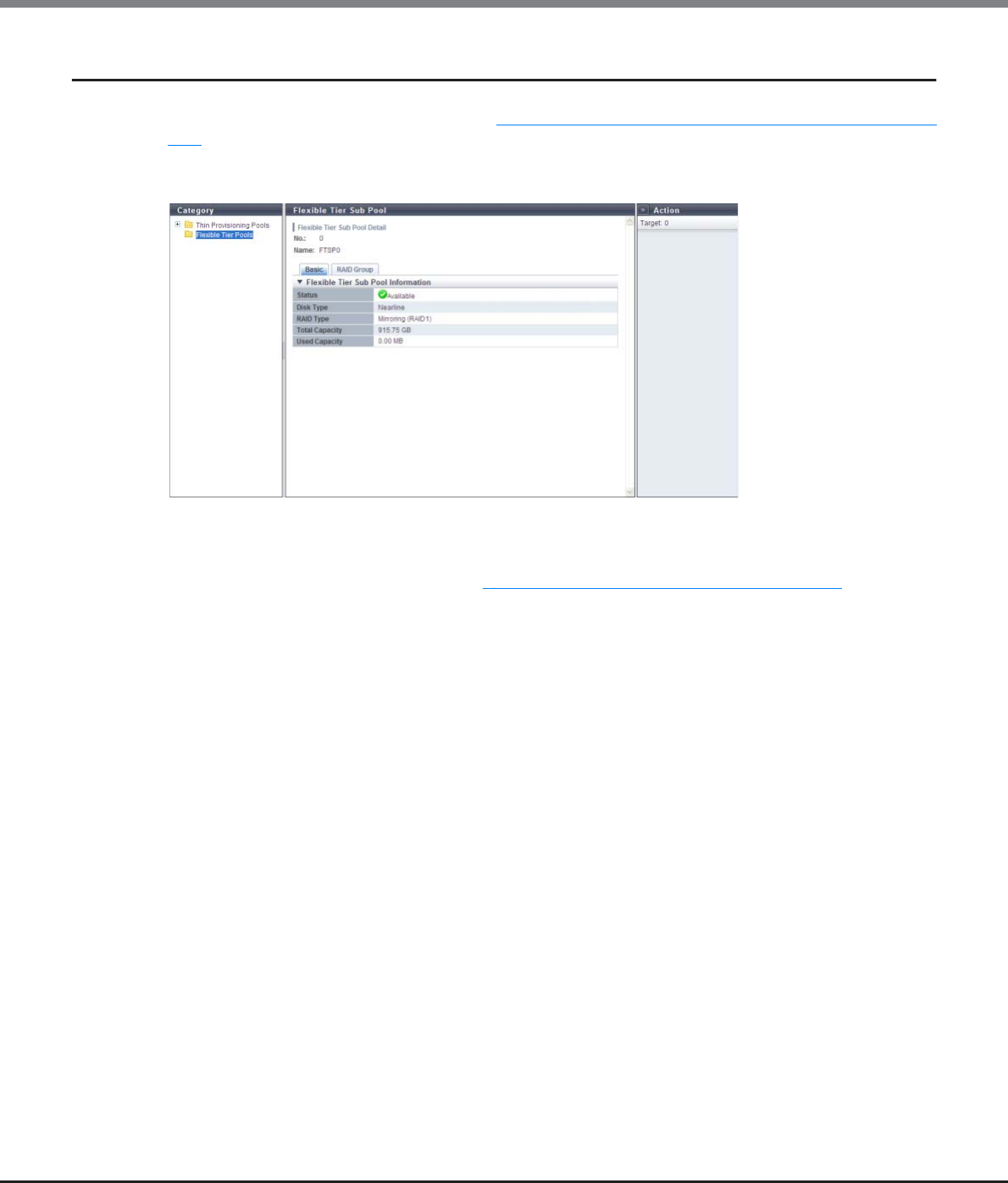
Chapter 7 Thin Provisioning Pool Management
7.1 Thin Provisioning Pool Status
ETERNUS Web GUI User’s Guide
Copyright 2013 FUJITSU LIMITED P2X0-1090-10ENZ0
217
7.1.10 Flexible Tier Sub Pool Detail (Basic)
Click the [No.] link or the [Name] link on the "7.1.8 Flexible Tier Pool Detail (Flexible Tier Sub Pool)" (page
214) to display the corresponding Flexible Tier Sub Pool Detail screen.
Click the [Basic] tab on the [Flexible Tier Sub Pool Detail] to display the basic information of the
corresponding FTSP.
The following items are displayed in the Main area:
•Status
The FTSP status is displayed. Refer to "B.4 Thin Provisioning Pool Status" (page 976) for detailed
information of FTSP status.
•Disk Type
The type of drive that configures the FTSP is displayed.
-Online
SAS disks
-Nearline
Nearline SAS disks
-SSD
-SED
•RAID Type
The type of RAID group that configures the FTSP is displayed.
-High Performance (RAID1+0)
-High Capacity (RAID5)
-High Reliability (RAID6)
-Mirroring (RAID1)
-Striping (RAID0)
•Total Capacity
The total capacity of FTSP is displayed.
•Used Capacity
The used capacity of FTSP is displayed.

Chapter 7 Thin Provisioning Pool Management
7.2 Functions in the Action Area for Thin Provisioning
ETERNUS Web GUI User’s Guide
Copyright 2013 FUJITSU LIMITED P2X0-1090-10ENZ0
218
7.2 Functions in the Action Area for Thin Provisioning
When using functions in the Action area, select the desired function from the Action area that is displayed in
the status display screen.
The functions in the Action area for Thin Provisioning can be performed from the following display functions:
Functions in the Action area for Thin Provisioning Display function
Create Thin Provisioning Pool •Thin Provisioning Pool (Basic Information)
Delete Thin Provisioning Pool
Rename Thin Provisioning Pool
Expand Thin Provisioning Pool
Format Thin Provisioning Pool (All Area)
Format Thin Provisioning Pool (Unformatted Area)
Modify Threshold Thin Provisioning Pool •Threshold (Thin Provisioning Pool)
Modify Cache Parameters (Thin Provisioning Pool)
Assign ECO Mode Schedule (Thin Provisioning Pool) •ECO Mode Schedule (Thin Provisioning Pool)
Register Thin Provisioning License •License (Thin Provisioning)
Delete Thin Provisioning License
Start Balancing Flexible Tier Pool •Flexible Tier Pool (Basic Information)
•Flexible Tier Pool Detail (Basic)
•Flexible Tier Pool Detail (Flexible Tier Sub Pool)
Stop Balancing Flexible Tier Pool
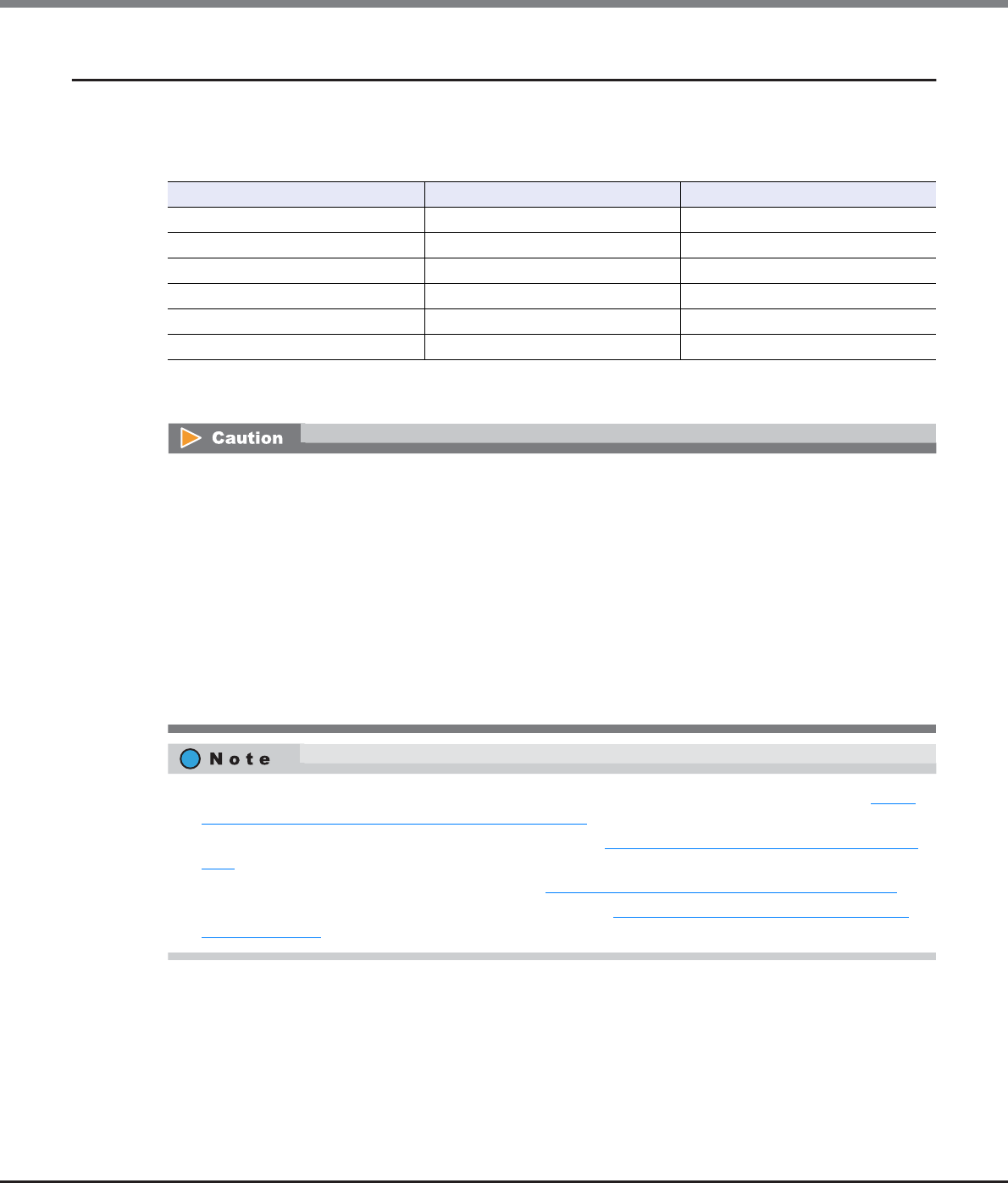
Chapter 7 Thin Provisioning Pool Management
7.2 Functions in the Action Area for Thin Provisioning
ETERNUS Web GUI User’s Guide
Copyright 2013 FUJITSU LIMITED P2X0-1090-10ENZ0
219
7.2.1 Create Thin Provisioning Pool
This function creates a Thin Provisioning Pool.
The maximum number of TPP and maximum TPP capacity for each model
*1: Up to 256 TPPs can be created. When the maximum installation number of drives of a model is 512 or less, the
maximum number of TPPs is half the maximum installation number of drives.
There are two methods to create a TPP: automatic drive selection and manual drive selection.
Model Maximum Number of TPP (*1) Maximum TPP Capacity (TB)
ETERNUS DX80 S2 60 128
ETERNUS DX90 S2 120 128
ETERNUS DX410 S2 240 384
ETERNUS DX440 S2 256 768
ETERNUS DX8100 S2 256 768
ETERNUS DX8700 S2 256 1024
•Registering the license for the Thin Provisioning feature is required to create TPP.
•When encryption mode is disabled, TPP encrypted by CM cannot be created.
•Once a TPP has been created, the encryption status cannot be changed.
•TPPs cannot be created in the following conditions:
-When the maximum number of Thin Provisioning Pools are already registered in the ETERNUS DX Disk
storage system
-When the maximum capacity of Thin Provisioning Pools are already registered in the ETERNUS DX Disk
storage system
-When the resources for creating TPPs (such as the number of RAID groups, the number of volumes,
etc.) are insufficient
(When the maximum number of RAID groups or volumes already exist, TPP cannot be created)
•After a TPP is created, the TPP is formatted automatically. To check the format progress, refer to "7.1.1
Thin Provisioning Pool (Basic Information)" (page 200).
•To expand the TPP capacity after a TPP is created, refer to "7.2.4 Expand Thin Provisioning Pool" (page
231).
•To rename the TPP after a TPP is created, refer to "7.2.3 Rename Thin Provisioning Pool" (page 229).
•To change the TPP threshold after a TPP is created, refer to "7.2.7 Modify Threshold Thin Provisioning
Pool" (page 239).

Chapter 7 Thin Provisioning Pool Management
7.2 Functions in the Action Area for Thin Provisioning
ETERNUS Web GUI User’s Guide
Copyright 2013 FUJITSU LIMITED P2X0-1090-10ENZ0
220
■Automatically selecting drives to create TPPs
To create a new TPP automatically, select Disk Type, RAID Type, and input TPP capacity. The controlling CM of
the RAID groups that configure the TPP is determined automatically.
The procedure to create a TPP by selecting drives automatically is as follows:
Procedure
1Click [Create] in [Action].
2Select "Automatic" for the create mode, specify the other parameters, and click the [Create]
button.
•Name
Input a TPP name. An existing TPP name cannot be specified.
The following input conditions apply:
-Up to 16 alphanumeric characters and symbols (except ", (comma)" and "?")
-Space
•Disk Type
Select the type of drive that configures the TPP from the list box.
-Online
SAS disks
-Nearline
Nearline SAS disks
-SSD
-SED
•RAID Type
Select the type of RAID group that configures the TPP from the list box.
-High Performance (RAID1+0)
RAID1+0(2D+2M, 4D+4M, 8D+8M, 12D+12M) configuration is available
-High Capacity (RAID5)
RAID5(3D+1P, 4D+1P, 7D+1P, 8D+1P, 12D+1P) configuration is available
-High Reliability (RAID6)
RAID6(4D+2P, 6D+2P, 8D+2P) configuration is available
-Mirroring (RAID1)
RAID1(1D+1M) configuration is available
-Striping (RAID0)
RAID0(4D) configuration is available
•"Striping (RAID0)" has no data redundancy. Select "High Performance (RAID1+0)", "High
Capacity (RAID5)", "High Reliability (RAID6)" or "Mirroring (RAID1)" for the RAID Type.
•The number of RAID groups that configure a TPP is automatically determined by the selected
disk type, the RAID type, the specified total capacity of the Thin Provisioning Pool, and the
drives that are installed in the ETERNUS DX Disk storage system.
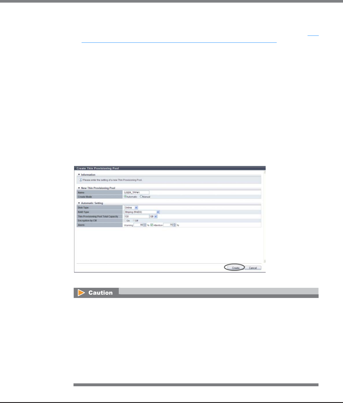
Chapter 7 Thin Provisioning Pool Management
7.2 Functions in the Action Area for Thin Provisioning
ETERNUS Web GUI User’s Guide
Copyright 2013 FUJITSU LIMITED P2X0-1090-10ENZ0
221
•Thin Provisioning Pool Total Capacity
Input a TPP capacity using numeric characters. Select the capacity unit from "TB" or "GB".
A TPP is automatically created with a capacity of the entered value or higher. Refer to "The
maximum number of TPP and maximum TPP capacity for each model" (page 219) for details on the
maximum TPP capacity.
•Encryption by CM
Select the TPP encryption status with the radio button. When the encryption mode is disabled, "On"
cannot be selected.
-On
Encryption by CM
-Off
Unencrypted
•Threshold (%)
Specify the threshold (%) for monitoring the TPP used capacity.
There are two types of threshold: "Warning" and "Attention". Specify the threshold so that "Warning"
is the same or larger than "Attention". The "Attention" threshold can be omitted. When omitting the
"Attention" threshold, clear the checkbox.
The following input conditions apply:
-Warning threshold: "5" - "99"
-Attention threshold: "5" - "80"
→A confirmation screen appears.
•An error screen appears in the following conditions:
-When the "Name" field is not input
-When the "Name" does not satisfy the input conditions
-When the "Name" already exists
-When the "Thin Provisioning Pool Total Capacity" field is not input
-When the total value of TPP capacity to be created and existing TPP capacity exceeds the
maximum TPP capacity for each model
-When a TPP that meets the specified conditions (disk type, RAID type, and capacity that is
equal to or larger than the specified value) cannot be created with the installed drives in the
ETERNUS DX Disk storage system
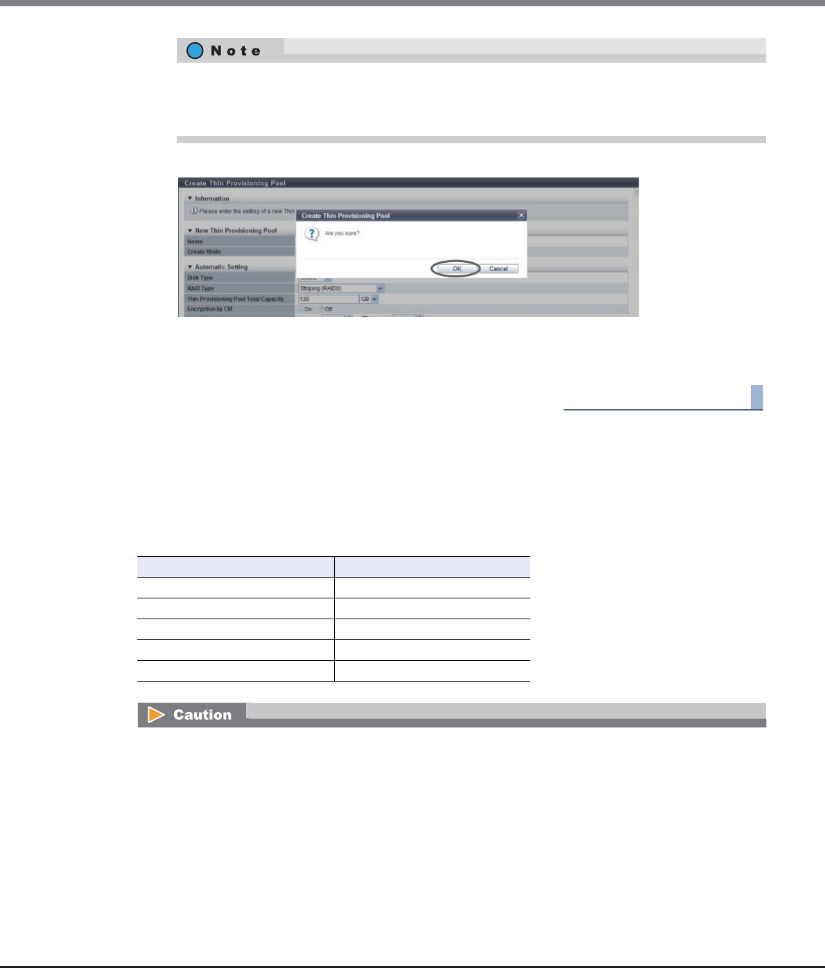
Chapter 7 Thin Provisioning Pool Management
7.2 Functions in the Action Area for Thin Provisioning
ETERNUS Web GUI User’s Guide
Copyright 2013 FUJITSU LIMITED P2X0-1090-10ENZ0
222
3Click the [OK] button.
→Create Thin Provisioning Pool starts.
4Click the [Done] button to return to the [Thin Provisioning Pool] screen.
End of procedure
■Manually selecting drives to create Thin Provisioning Pool
To create a new TPP manually, select Disk Type, RAID Type, and the drive that configures the TPP.
The number of member drives in each RAID group
The number of member drives for each RAID type is listed in the following table.
•Specify the threshold so that "Warning" is the same or larger than "Attention".
•The "Attention" threshold can be omitted. When setting the "Attention" threshold, specify a
threshold while the checkbox is selected.
RAID Type Number of member drives
High Performance (RAID1+0) 4, 8, 16, 24
High Capacity (RAID5) 4, 5, 8, 9, 13
High Reliability (RAID6) 6, 8, 10
Mirroring (RAID1) 2
Striping (RAID0) 4
•The conditions for RAID groups in the TPP are as follows:
-The RAID type (High Performance (RAID1+0)/High Capacity (RAID5)/High Reliability (RAID6)/
Mirroring (RAID1)/Striping (RAID0)) must be the same
-The number of member drives in the RAID group must be the same
-The disk type (Online/Nearline/SSD/SED) must be the same
When "Online" is selected for "Disk Type", three types of RAID group can be registered in the TPP. The
three available types are a RAID group that is configured with "Online" disks, a RAID group that is con-
figured with "Nearline" disks, and a RAID group that is configured with both "Online" disks and Near-
line" disks. In this case, registering RAID groups that are only configured with "Online" disks is
recommended to prevent any reduction of TPP access performance.

Chapter 7 Thin Provisioning Pool Management
7.2 Functions in the Action Area for Thin Provisioning
ETERNUS Web GUI User’s Guide
Copyright 2013 FUJITSU LIMITED P2X0-1090-10ENZ0
223
The procedure to create a TPP by selecting drives manually is as follows:
Procedure
1Click [Create] in [Action].
2Select "Manual" for the create mode, and specify the other parameters.
•Name
Input a TPP name. An existing TPP name cannot be specified.
The following input conditions apply:
-Up to 16 alphanumeric characters and symbols (except ", (comma)" and "?")
-Spaces
•Disk Type
Select the type of drive that configures the TPP from the list box. The drives that are installed in the
ETERNUS DX Disk storage system is displayed. When "Online" is selected for "Disk Type", "Online" or
"Nearline" disks can be selected. In this case, only the use of "Online" disks to configure a TPP is rec-
ommended.
-Online
SAS disks
-Nearline
Nearline SAS disks
-SSD
-SED
•RAID Type
Select the type of RAID group that configures the TPP from the list box. The installed drive deter-
mine the selectable RAID types that are displayed as options.
-High Performance (RAID1+0)
RAID1+0(2D+2M, 4D+4M, 8D+8M, 12D+12M) configuration is available
-High Capacity (RAID5)
RAID5(3D+1P, 4D+1P, 7D+1P, 8D+1P, 12D+1P) configuration is available
-High Reliability (RAID6)
RAID6(4D+2P, 6D+2P, 8D+2P) configuration is available
-Mirroring (RAID1)
RAID1(1D+1M) configuration is available
•The following shows the recommended drive configuration of the RAID group:
-Select drives with the same capacity. If drives of different capacities exist in a RAID group, the smallest
drive becomes the standard, and all other drives are regarded as the same capacity as the smallest
drive. In this case, the remaining drive space will NOT be used.
-Select drives with the same speed. If drives of different speed exist in a RAID group, access
performance of the RAID group may be affected.
-When "High Performance (RAID1+0)" or "Mirroring (RAID1)" is selected for the RAID type, locate the
drives (mirroring pair drives) divided into different lines (for ETERNUS DX410 S2/DX440 S2).
-When "High Capacity (RAID5)" or "High Reliability (RAID6)" is selected for the RAID type, locate the
drives (striping multiple drives) divided into two or more lines (for ETERNUS DX410 S2/DX440 S2).
•When using the ETERNUS DX8100 S2/DX8700 S2, the restrictions that apply to the drive layout for RAID
group configuration. Refer to "Restrictions of drive layout" (page 179) for details.

Chapter 7 Thin Provisioning Pool Management
7.2 Functions in the Action Area for Thin Provisioning
ETERNUS Web GUI User’s Guide
Copyright 2013 FUJITSU LIMITED P2X0-1090-10ENZ0
224
-Striping (RAID0)
RAID0(4D) configuration is available
•Thin Provisioning Pool Total Capacity
Total capacity of the TPP created with the selected RAID type and drives is displayed.
Refer to "The maximum number of TPP and maximum TPP capacity for each model" (page 219) for
details on the maximum TPP capacity.
•Encryption by CM
Select the TPP encryption status with the radio button. When the encryption mode is disabled, "On"
cannot be selected.
-On
Encryption by CM
-Off
Unencrypted
•Alarm
Specify the threshold (%) for monitoring the TPP used capacity.
There are two types of threshold: "Warning" and "Attention". Specify the threshold so that "Warning"
is the same or larger than "Attention". The "Attention" threshold can be omitted. When omitting the
"Attention" threshold, clear the checkbox.
The following input conditions apply:
-Warning threshold: "5" - "99"
-Attention threshold: "5" - "80"
●Advanced Settings
Specify the Stripe Depth only when performing the advanced performance tuning for each RAID
group that configures a TPP. It is not necessary to change the default setting for normal use.
The higher the Stripe Depth value, the lower the number of drives that access the RAID group. If
"High Performance (RAID1+0)" is used, the number of commands that are issued for the drives is
reduced and access performance for the relevant RAID group is improved. Note that for "High Capac-
ity (RAID5)", a high Stripe Depth value may reduce the sequential write performance. Also note that
restrictions apply for RAID groups and volumes in the RAID group for which Stripe Depth value is
changed. Refer to "Restrictions for Stripe Depth modification" (page 228) for details.
-Stripe Depth
Select the Stripe Depth of RAID group that is to be created.
When the "RAID Type" is "Mirroring (RAID1)", this setting is not available. When the "RAID Type"
is "High Reliability (RAID6)", the value is fixed to "64KB". Available Stripe Depth value varies
depending on the RAID type. Refer to "Available Stripe Depth value" (page 228) for details.
•Refer to "The number of member drives in each RAID group" (page 222) for details on the number
of member drives for each RAID type.
•"Striping (RAID0)" has no data redundancy. Select "High Performance (RAID1+0)", "High Capacity
(RAID5)", "High Reliability (RAID6)" or "Mirroring (RAID1)" for the RAID type.
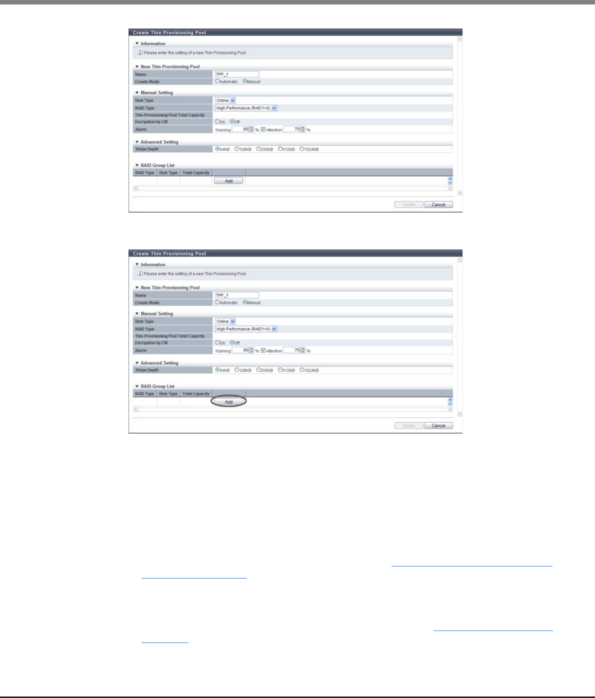
Chapter 7 Thin Provisioning Pool Management
7.2 Functions in the Action Area for Thin Provisioning
ETERNUS Web GUI User’s Guide
Copyright 2013 FUJITSU LIMITED P2X0-1090-10ENZ0
225
3Click the [Add] button, and set the information of the RAID group that configures the TPP.
4Select the controlling CM of the RAID group and all the drives to be registered in the RAID
group, and click the [OK] button.
•Controlling CM
Select the controlling CM and CPU of the RAID group that is to be created.
"Automatic" and the installed "CM#x CPU#y" in normal status are displayed as options.
-Automatic
-CM#x CPU#y (x: CM number, y: CPU number)
Select "Automatic" for normal operations. When "Automatic" is selected, the CM-CPU that is to be
assigned is determined by the RAID group number. Refer to "Appendix F Automatic Controlling CM-
CPU Setting" (page 1011) for details.
•Drive Selection
Select the checkbox for the drive to be selected.
When using the ETERNUS DX8100 S2/DX8700 S2, the restrictions that apply to the drive layout for
RAID group configuration vary depending on the RAID type. Refer to "Restrictions of drive layout"
(page 179) for details.
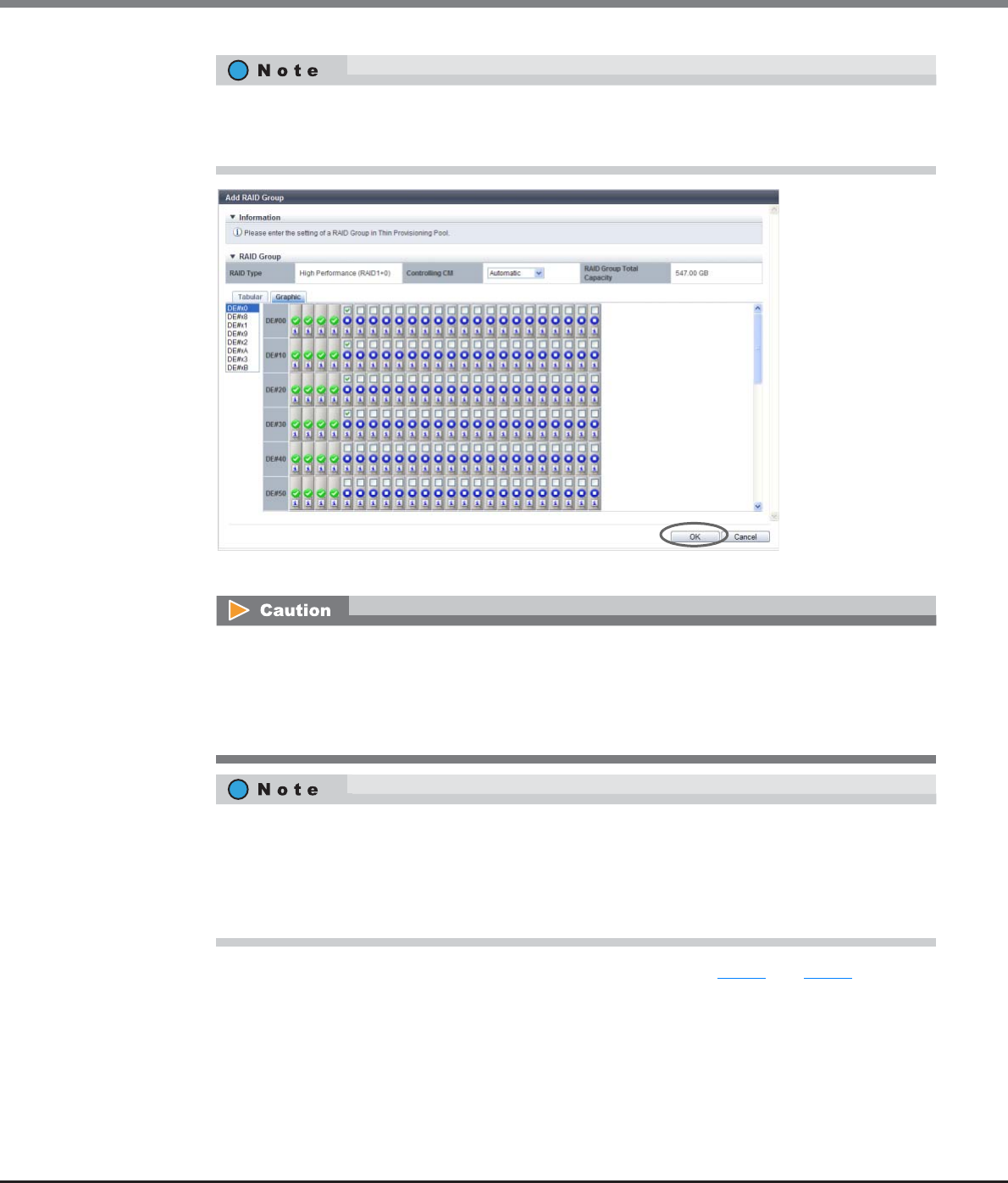
Chapter 7 Thin Provisioning Pool Management
7.2 Functions in the Action Area for Thin Provisioning
ETERNUS Web GUI User’s Guide
Copyright 2013 FUJITSU LIMITED P2X0-1090-10ENZ0
226
→The screen returns to the previous screen. The created RAID group is displayed in the RAID group list.
5When creating multiple RAID groups that configure a TPP, repeat Step 3 and Step 4.
Drives can be selected from the list of drives that is displayed for Tabular or from the drive images that
are displayed for Graphic. Click the Tabular tab to display a list of the drives or click the Graphic tab to
display drive images.
An error screen appears in the following conditions:
•When the number of selected drives and the number of member drives of the specified RAID type
do not match
•When the number of selected drives and the number of member drives of the existing RAID group
do not match
•To check the number of member drives of the RAID group, click the [RAID Type] link for the existing
RAID group. The drives with the checkbox selected in the displayed screen are the member of the
RAID group.
•Click the [RAID Type] link to change the controlling CM and configuration drives of the RAID group.
•Click the [Delete] button to delete a RAID group.
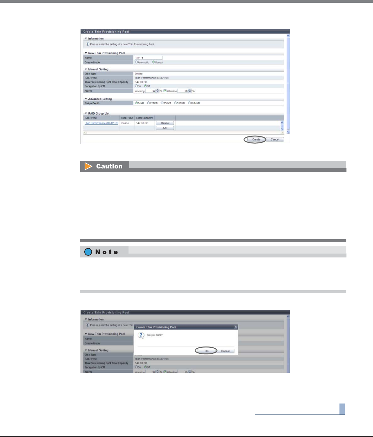
Chapter 7 Thin Provisioning Pool Management
7.2 Functions in the Action Area for Thin Provisioning
ETERNUS Web GUI User’s Guide
Copyright 2013 FUJITSU LIMITED P2X0-1090-10ENZ0
227
6After creating a RAID group that configures the TPP, click the [Create] button.
→A confirmation screen appears.
7Click the [OK] button.
→Create Thin Provisioning Pool starts.
8Click the [Done] button to return to the [Thin Provisioning Pool] screen.
End of procedure
An error screen appears in the following conditions:
•When the "Name" field is not input
•When the "Name" does not satisfy the input conditions
•When the "Name" already exists
•When the total value of TPP capacity to be created and existing TPP capacity exceeds the
maximum TPP capacity for each model
•When the "Stripe Depth" value is a value other than the available value for each RAID type.
•Specify the threshold so that "Warning" is the same or larger than "Attention".
•The "Attention" threshold can be omitted. When setting the "Attention" threshold, specify a
threshold while the checkbox is selected.
Chapter 7 Thin Provisioning Pool Management
7.2 Functions in the Action Area for Thin Provisioning
ETERNUS Web GUI User’s Guide
Copyright 2013 FUJITSU LIMITED P2X0-1090-10ENZ0
228
Available Stripe Depth value
The following table shows the available Stripe Depth value for each RAID type.
Restrictions for Stripe Depth modification
The following restrictions are applied for RAID groups for which the Stripe Depth value is changed.
•Stripe depth for RAID groups that configure the existing TPPs cannot be changed.
•When selecting drives automatically to create a TPP, the Stripe Depth cannot be changed.
7.2.2 Delete Thin Provisioning Pool
This function deletes a Thin Provisioning Pool.
The procedure to delete a Thin Provisioning Pool is as follows:
Procedure
1Select the TPP to be deleted (multiple selections can be made) and click [Delete] in
[Action].
→A confirmation screen appears.
RAID type Drive configuration (*1) Available Stripe Depth value
Mirroring (RAID1) 1D+1M –
High Performance (RAID1+0) Any 64KB, 128KB, 256KB, 512KB, 1024KB
Striping (RAID0)
High Capacity (RAID5)
2D+1P – 4D+1P 64 KB, 128 KB, 256 KB, 512 KB
5D+1P – 8D+1P 64 KB, 128 KB, 256 KB
9D+1P – 15D+1P 64 KB, 128 KB
High Reliability (RAID6) Any 64 KB
•TPPs that have volumes registered cannot be deleted. When deleting a TPP, delete the volumes
beforehand. To delete a volume, refer to "5.2.2 Delete Volume" (page 112).
•This function cannot be used under the following conditions:
-When no TPP is registered
-When all the TPPs have volumes registered
After deleting a TPP, all the RAID groups that configure the TPP are also deleted.
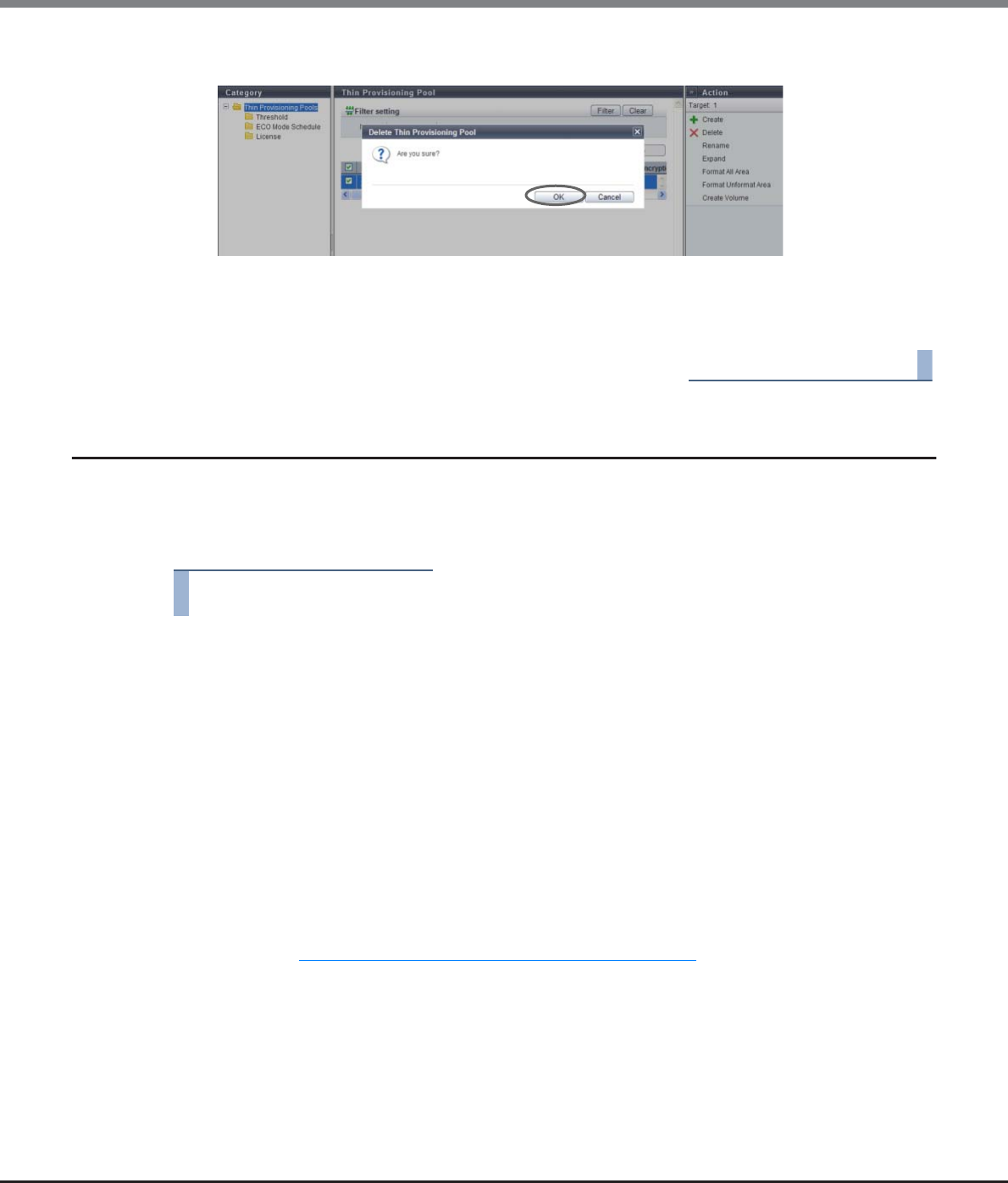
Chapter 7 Thin Provisioning Pool Management
7.2 Functions in the Action Area for Thin Provisioning
ETERNUS Web GUI User’s Guide
Copyright 2013 FUJITSU LIMITED P2X0-1090-10ENZ0
229
2Click the [OK] button.
→Delete Thin Provisioning Pool starts.
3Click the [Done] button to return to the [Thin Provisioning Pool] screen.
End of procedure
7.2.3 Rename Thin Provisioning Pool
This function changes a Thin Provisioning Pool name.
Multiple TPPs can be renamed with a single operation.
The procedure to rename TPP is as follows:
Procedure
1Select the TPP to be renamed (multiple selections can be made) and click [Rename] in
[Action].
2Input the new TPP name and the suffix starting number (only when multiple TPPs are
selected), and click the [Rename] button.
•Name
Input a new TPP name. An existing TPP name cannot be specified.
The following input conditions apply:
-Up to 16 alphanumeric characters and symbols (except ", (comma)" and "?")
-Space
•Start of Suffix
Input the starting number of the suffix that is to be added to the new TPP name.
When changing multiple TPP names, the suffix number is added to the TPP names with consecutive
numbers in ascending order starting with the entered suffix number.
Refer to "Naming conventions for renaming volumes" (page 993) for details.
When changing only one TPP name, the "Start of Suffix" field is not displayed.
The following input conditions apply:
-Numeric characters ("0" - "99999")
-Decimal number
-1 - 5 digits
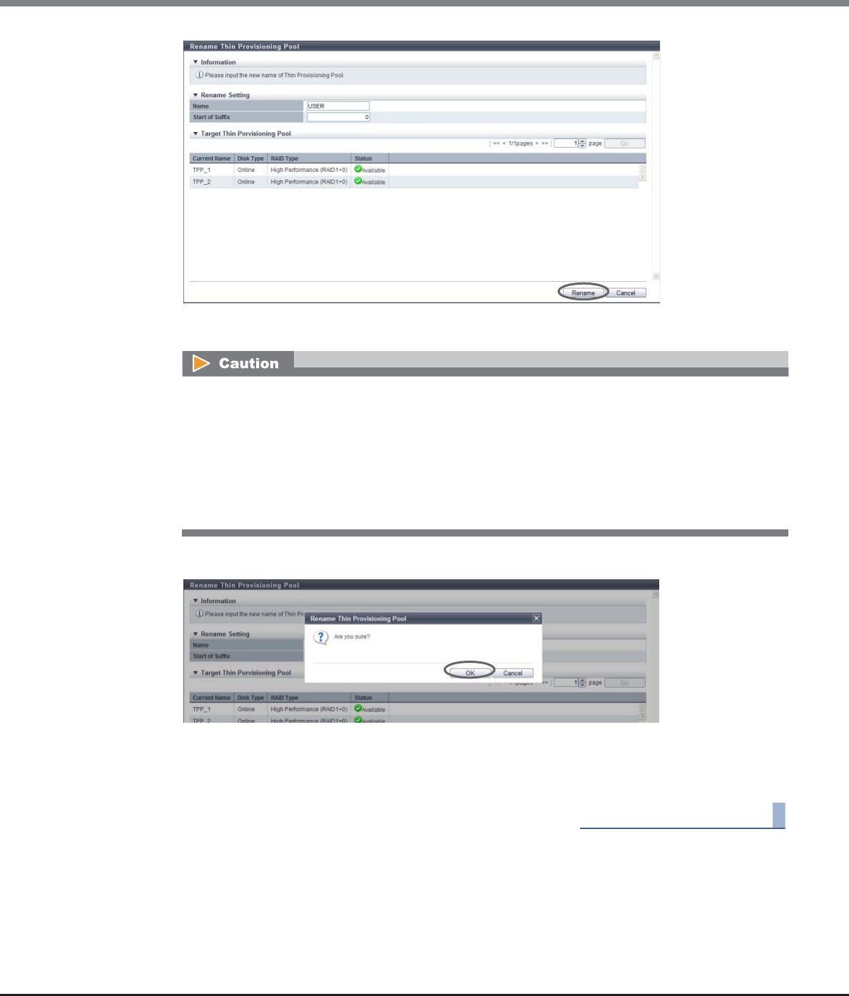
Chapter 7 Thin Provisioning Pool Management
7.2 Functions in the Action Area for Thin Provisioning
ETERNUS Web GUI User’s Guide
Copyright 2013 FUJITSU LIMITED P2X0-1090-10ENZ0
230
→A confirmation screen appears.
3Click the [OK] button.
→Rename Thin Provisioning Pool starts.
4Click the [Done] button to return to the [Thin Provisioning Pool] screen.
End of procedure
An error screen appears in the following conditions:
•When a TPP name is not input
•When an existing TPP name is input
•When the value in the "Name" does not satisfy the input conditions (when one TPP is selected)
•When the "Start of Suffix" is not specified (when multiple TPPs are selected)
•When the value in the "Start of Suffix" does not satisfy the input conditions (when multiple TPPs
are selected)
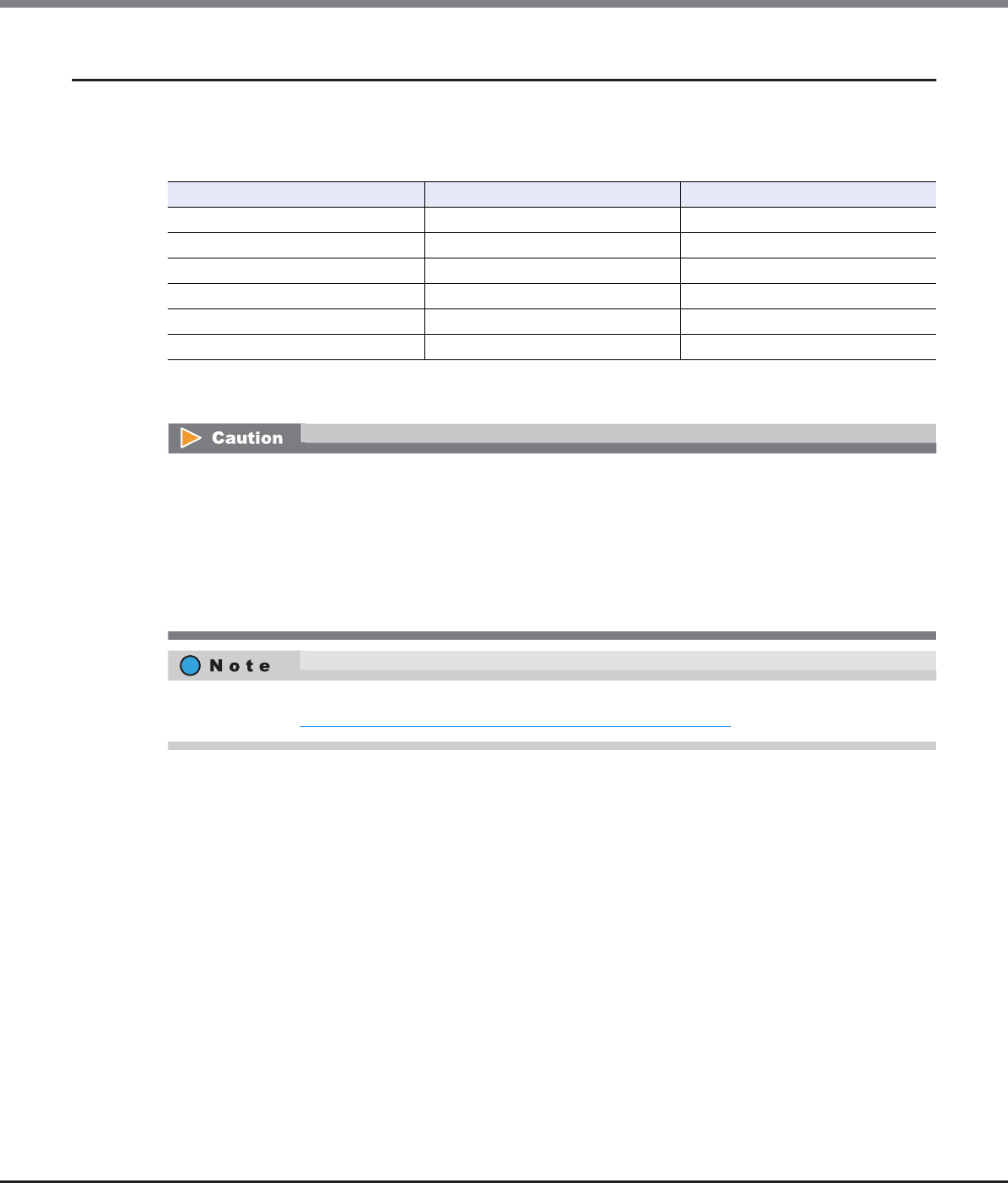
Chapter 7 Thin Provisioning Pool Management
7.2 Functions in the Action Area for Thin Provisioning
ETERNUS Web GUI User’s Guide
Copyright 2013 FUJITSU LIMITED P2X0-1090-10ENZ0
231
7.2.4 Expand Thin Provisioning Pool
This function expands the capacity of Thin Provisioning Pool.
The maximum number of TPP and maximum TPP capacity for each model
*1: Up to 256 TPPs can be created. When the maximum installation number of drives of a model is 512 or less, the
maximum number of TPPs is half the maximum installation number of drives.
There are two methods to expand a TPP: automatic drive selection and manual drive selection.
Model Maximum Number of TPP (*1) Maximum TPP Capacity (TB)
ETERNUS DX80 S2 60 128
ETERNUS DX90 S2 120 128
ETERNUS DX410 S2 240 384
ETERNUS DX440 S2 256 768
ETERNUS DX8100 S2 256 768
ETERNUS DX8700 S2 256 1024
•TPP capacity is expanded in units of RAID groups. The specifications for a RAID group (such as the RAID
type, the disk type, and the number of member drives) that is to be added are the same as the existing
RAID group.
•TPP capacity cannot be expanded in the following conditions:
-When the maximum capacity of TPPs are already registered in the ETERNUS DX Disk storage system
-When resources for creating TPPs (such as the number of RAID groups and volumes) are insufficient
(When the maximum number of RAID groups or volumes already exist, TPP cannot be expanded)
After a TPP capacity is expanded, the expanded area of TPP is formatted automatically. To check the format
progress, refer to "7.1.1 Thin Provisioning Pool (Basic Information)" (page 200).
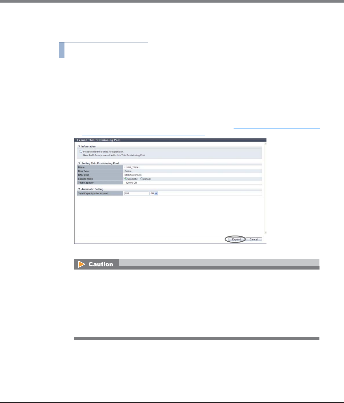
Chapter 7 Thin Provisioning Pool Management
7.2 Functions in the Action Area for Thin Provisioning
ETERNUS Web GUI User’s Guide
Copyright 2013 FUJITSU LIMITED P2X0-1090-10ENZ0
232
■Automatically selecting drives to expand a TPP
The procedure to expand a TPP by selecting drives automatically is as follows:
Procedure
1Select the TPP to be expanded and click [Expand] in [Action].
2Select "Automatic" for the expansion mode, specify the TPP capacity after expanded, and
click the [Expand] button.
•Total Capacity after expand
Input the TPP total capacity in numeric characters after expansion is performed and select the units
of capacity from "TB", "GB", or "MB".
Drives are automatically selected according to the existing RAID group specifications, and the TPP
capacity is expanded to the entered value or higher. Refer to "The maximum number of TPP and
maximum TPP capacity for each model" (page 219) for details on the maximum TPP capacity.
→A confirmation screen appears.
An error screen appears in the following conditions:
•When the capacity is not specified for "Total Capacity after expand"
•When the entered value in the "Total Capacity after expand" is equal to or lower than the existing
capacity
•When the total value of TPP capacity after expanded and existing TPP capacity exceeds the
maximum TPP capacity for each model
•When the TPP cannot be expanded over the specified capacity in the drive installed in the
ETERNUS DX Disk storage system
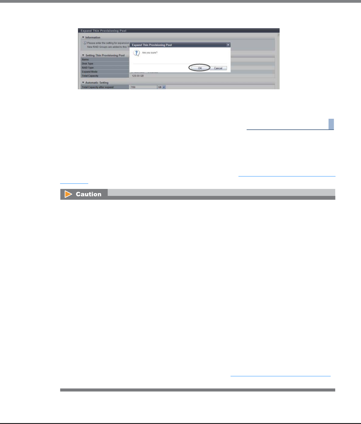
Chapter 7 Thin Provisioning Pool Management
7.2 Functions in the Action Area for Thin Provisioning
ETERNUS Web GUI User’s Guide
Copyright 2013 FUJITSU LIMITED P2X0-1090-10ENZ0
233
3Click the [OK] button.
→Expand Thin Provisioning Pool starts.
4Click the [Done] button to return to the [Thin Provisioning Pool] screen.
End of procedure
■Manually selecting drives to expand a TPP
Select drives manually to expand the TPP.
Check the specifications of the existing RAID groups (number of member drives and disk type) in the TPP in
advance. For the details on how to check the specifications, refer to "Check the RAID group specifications"
(page 234).
•The conditions for RAID groups in the TPP are as follows:
-The RAID type (High Performance (RAID1+0)/High Capacity (RAID5)/High Reliability (RAID6)/
Mirroring (RAID1)/Striping (RAID0)) must be the same
-The number of member drives in the RAID group must be the same
-The disk type (Online/Nearline/SSD/SED) must be the same
(When "Online" is selected for "Disk Type", three types of RAID group may be registered in the TPP. The
three available types are a RAID group that is configured with "Online" disks, a RAID group that is con-
figured with "Nearline" disks, and a RAID group that is configured with both "Online" disks and Near-
line" disks. In this case, registering RAID groups that are only configured with "Online" disks is
recommended to prevent any reduction of TPP access performance.)
•The following shows the recommended drive configuration of the RAID group;
-Select drives with the same capacity. If drives of different capacities exist in a RAID group, the smallest
drive becomes the standard, and all other drives are regarded as the same capacity as the smallest
drive. In this case, the remaining drive space will NOT be used.
-Select drives with the same speed. If drives of different speed exist in a RAID group, access
performance of the RAID group may be affected.
-When "High Performance (RAID1+0)" or "Mirroring (RAID1)" is selected for the RAID type, locate the
drives (mirroring pair drives) divided into different lines (for ETERNUS DX410 S2/DX440 S2).
-When "High Capacity (RAID5)" or "High Reliability (RAID6)" is selected for the RAID type, locate the
drives (striping multiple drives) divided into two or more lines (for ETERNUS DX410 S2/DX440 S2).
•When using the ETERNUS DX8100 S2/DX8700 S2, the restrictions that apply to the drive layout for RAID
group configuration vary depending on the RAID type. Refer to "Restrictions of drive layout" (page 179)
for details.
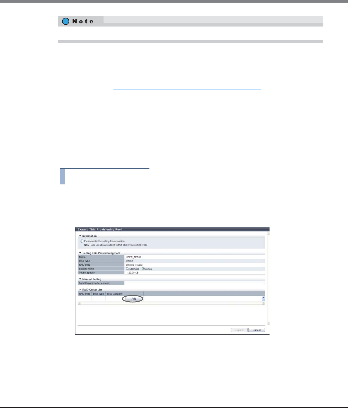
Chapter 7 Thin Provisioning Pool Management
7.2 Functions in the Action Area for Thin Provisioning
ETERNUS Web GUI User’s Guide
Copyright 2013 FUJITSU LIMITED P2X0-1090-10ENZ0
234
Check the RAID group specifications
Check the specifications of the existing RAID groups (number of member drives and disk type) in the TPP in
advance. The following describes how to check the specifications.
(1)From the TPP list in "7.1.1 Thin Provisioning Pool (Basic Information)" (page 200), click the [Name] link for
the TPP that is to be expanded.
(2)The basic information of the TPP is displayed. Click the [RAID Group] tab to switch the display.
(3)The list of RAID groups that configure the TPP is displayed. Click the [Name] link for the RAID group. Any
RAID group can be specified because the RAID groups in the TPP have the same specifications.
(4)Click the [Disk] tab in the [RAID Group Detail] screen. Check the disk type and the number of member
drives that configure the RAID group.
The procedure to expand a TPP by selecting drives manually is as follows:
Procedure
1Select the TPP to be expanded and click [Expand] in [Action].
2Select "Manual" for expansion mode.
3Click the [Add] button and set the information of the RAID group to be added to the TPP.
The same Stripe Depth value as the existing RAID groups is applied for the newly added RAID group.
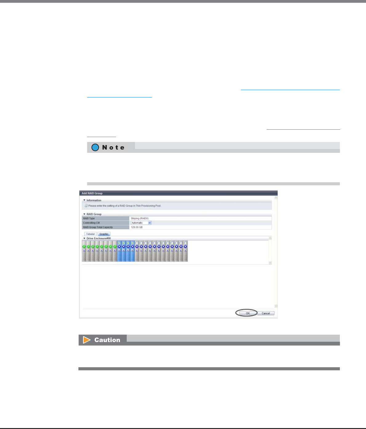
Chapter 7 Thin Provisioning Pool Management
7.2 Functions in the Action Area for Thin Provisioning
ETERNUS Web GUI User’s Guide
Copyright 2013 FUJITSU LIMITED P2X0-1090-10ENZ0
235
4Select the controlling CM of the RAID group and all the drives to be registered in the RAID
group, and click the [OK] button.
•Controlling CM
Select the controlling CM and CPU of the RAID group that is to be created.
"Automatic" and the installed "CM#x CPU#y" in normal status are displayed as options.
-Automatic
-CM#x CPU#y (x: CM number, y: CPU number)
Select "Automatic" for normal operations. When "Automatic" is selected, the CM-CPU that is to be
assigned is determined by the RAID group number. Refer to "Appendix F Automatic Controlling CM-
CPU Setting" (page 1011) for details.
•Drive Selection
Select the checkbox for the drive to be selected.
When using the ETERNUS DX8100 S2/DX8700 S2, the restrictions that apply to the drive layout for
RAID group configuration vary depending on the RAID type. Refer to "Restrictions of drive layout"
(page 179) for details.
→The screen returns to the previous screen. The added RAID group is displayed in the RAID group list.
Drives can be selected from the list of drives that is displayed for Tabular or from the drive images
that are displayed for Graphic. Click the Tabular tab to display a list of the drives or click the Graphic
tab to display drive images.
When the number of selected drives is not an integral multiple of the number of member drives for
the RAID group, the [OK] button cannot be clicked.
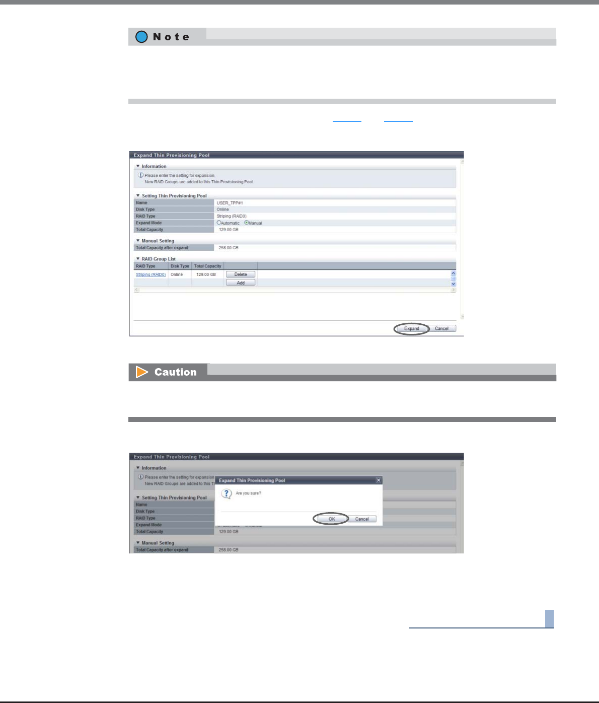
Chapter 7 Thin Provisioning Pool Management
7.2 Functions in the Action Area for Thin Provisioning
ETERNUS Web GUI User’s Guide
Copyright 2013 FUJITSU LIMITED P2X0-1090-10ENZ0
236
5When creating multiple RAID groups, repeat Step 3 and Step 4.
6After creating a RAID group to be added to the TPP, click the [Expand] button.
→A confirmation screen appears.
7Click the [OK] button.
→Expand Thin Provisioning Pool starts.
8Click the [Done] button to return to the [Thin Provisioning Pool] screen.
End of procedure
•Click the [RAID Type] link to change the controlling CM and configuration drives of the newly
added RAID group.
•Click the [Delete] button in the target RAID group area to delete the newly added RAID group.
When the total value of TPP capacity after expanded and existing TPP capacity exceeds the maximum
TPP capacity for each model, an error screen is displayed.
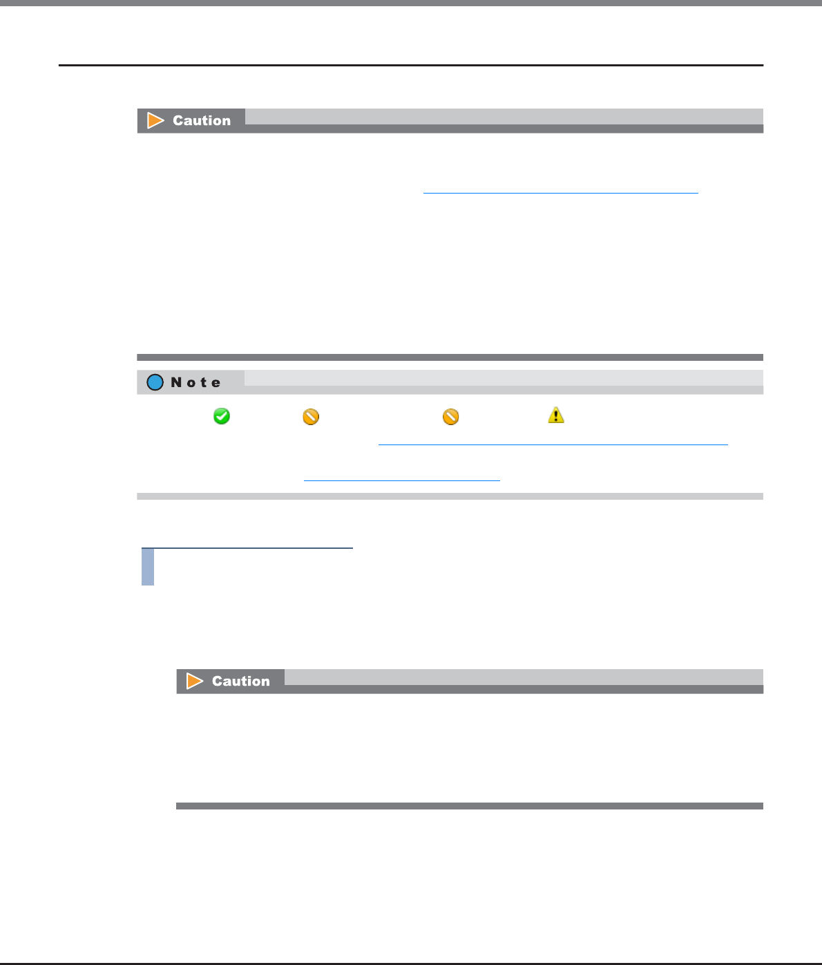
Chapter 7 Thin Provisioning Pool Management
7.2 Functions in the Action Area for Thin Provisioning
ETERNUS Web GUI User’s Guide
Copyright 2013 FUJITSU LIMITED P2X0-1090-10ENZ0
237
7.2.5 Format Thin Provisioning Pool (All Area)
This function formats all of the areas in the Thin Provisioning Pool.
The procedure to format all of the areas in the Thin Provisioning Pool is as follows:
Procedure
1Select the TPP that is to be formatted (multiple selections can be made) and click [Format
All Area] in [Action].
→A confirmation screen appears.
•When formatting all area in the TPPs, data stored in the Thin Provisioning Volumes in TPP will be deleted.
Format TPV to use them again, after deleting data.
•When a TPP is created using the procedure in "7.2.1 Create Thin Provisioning Pool" (page 219), the TPP is
formatted automatically. In this case, it is not necessary to format the TPP by using this function.
•An error will stop the balancing TPV when a TPP, in which the currently balancing TPV belongs, is
formatted. Start TPP formatting after balancing TPV is complete.
•An error will stop the RAID migration when a TPP, in which the currently migrating TPV belongs, is
formatted. Start TPP formatting after RAID migration is complete.
•This function cannot be used under the following conditions:
-When no TPP is registered
-When there is no TPP that can be formatted
•TPPs in " Available", " Partially Readying", " Readying", or " Exposed" status can be formatted.
•To check the format progress, refer to "7.1.1 Thin Provisioning Pool (Basic Information)" (page 200). Click
the TPP name to see the basic information.
•To format a TPV, refer to "5.2.4 Format Volume" (page 116).
•When formatting all area in the TPPs, data stored in the TPVs in TPP will be deleted.
•An error will stop the balancing TPV when a TPP, in which the currently balancing TPV belongs, is
formatted.
•An error will stop the RAID migration when a TPP, in which the currently migrating TPV belongs, is
formatted.
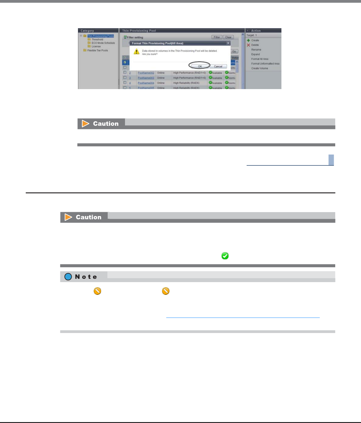
Chapter 7 Thin Provisioning Pool Management
7.2 Functions in the Action Area for Thin Provisioning
ETERNUS Web GUI User’s Guide
Copyright 2013 FUJITSU LIMITED P2X0-1090-10ENZ0
238
2Click the [OK] button.
→Format all area in the Thin Provisioning Pool starts.
3Click the [Done] button to return to the [Thin Provisioning Pool] screen.
End of procedure
7.2.6 Format Thin Provisioning Pool (Unformatted Area)
This function formats unformatted area in the Thin Provisioning Pool.
To use a TPV in the TPP again after formatted with "All Area" selected for the mode, format the TPV.
This function cannot be used under the following conditions:
•When no TPP is registered
•When there is no TPP that can be formatted
•When the status of all the TPPs that are to be formatted is " Available".
•TPPs in " Partially Readying", or " Readying" status can be formatted. Data stored in the TPVs of the
target TPP are not deleted. The "Unformatted area" is a new area that is added to a TPP by the capacity
expansion function.
•To check the format progress, refer to "7.1.1 Thin Provisioning Pool (Basic Information)" (page 200). Click
the TPP name to see the basic information.
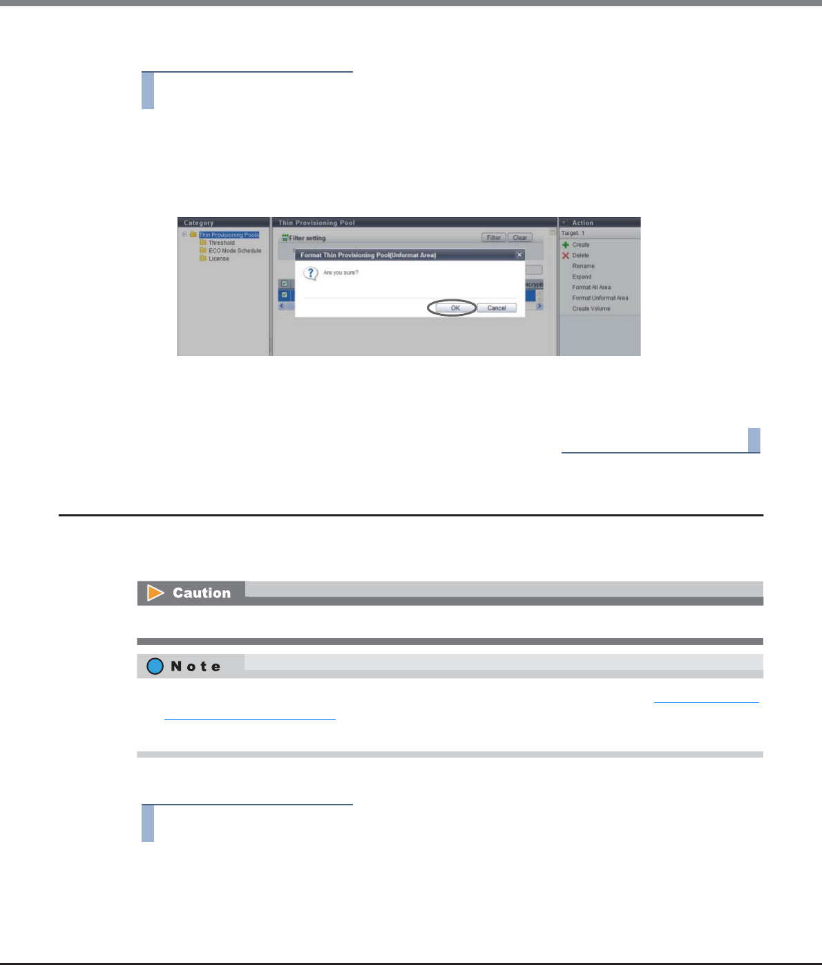
Chapter 7 Thin Provisioning Pool Management
7.2 Functions in the Action Area for Thin Provisioning
ETERNUS Web GUI User’s Guide
Copyright 2013 FUJITSU LIMITED P2X0-1090-10ENZ0
239
The procedure to format an unformat area in the Thin Provisioning Pool is as follows:
Procedure
1Select the TPP to be formatted (multiple selections can be made) and click [Format
Unformatted Area] in [Action].
→A confirmation screen appears.
2Click the [OK] button.
→Format of unformat area in the Thin Provisioning Pool starts.
3Click the [Done] button to return to the [Thin Provisioning Pool] screen.
End of procedure
7.2.7 Modify Threshold Thin Provisioning Pool
This function changes the threshold for monitoring the used capacity of Thin Provisioning Pool. There are two
types of threshold: "Warning" and "Attention".
The procedure to change the threshold of a TPP is as follows:
Procedure
1Select the TPP for which the threshold is to be changed (multiple selections can be made)
and click [Modify Threshold] in [Action].
This function cannot be performed when there are no TPPs in the ETERNUS DX Disk storage system.
•This function changes the threshold of a TPP that is created by using the procedure in "7.2.1 Create Thin
Provisioning Pool" (page 219).
•The same threshold can be applied for multiple TPP in a single operation.
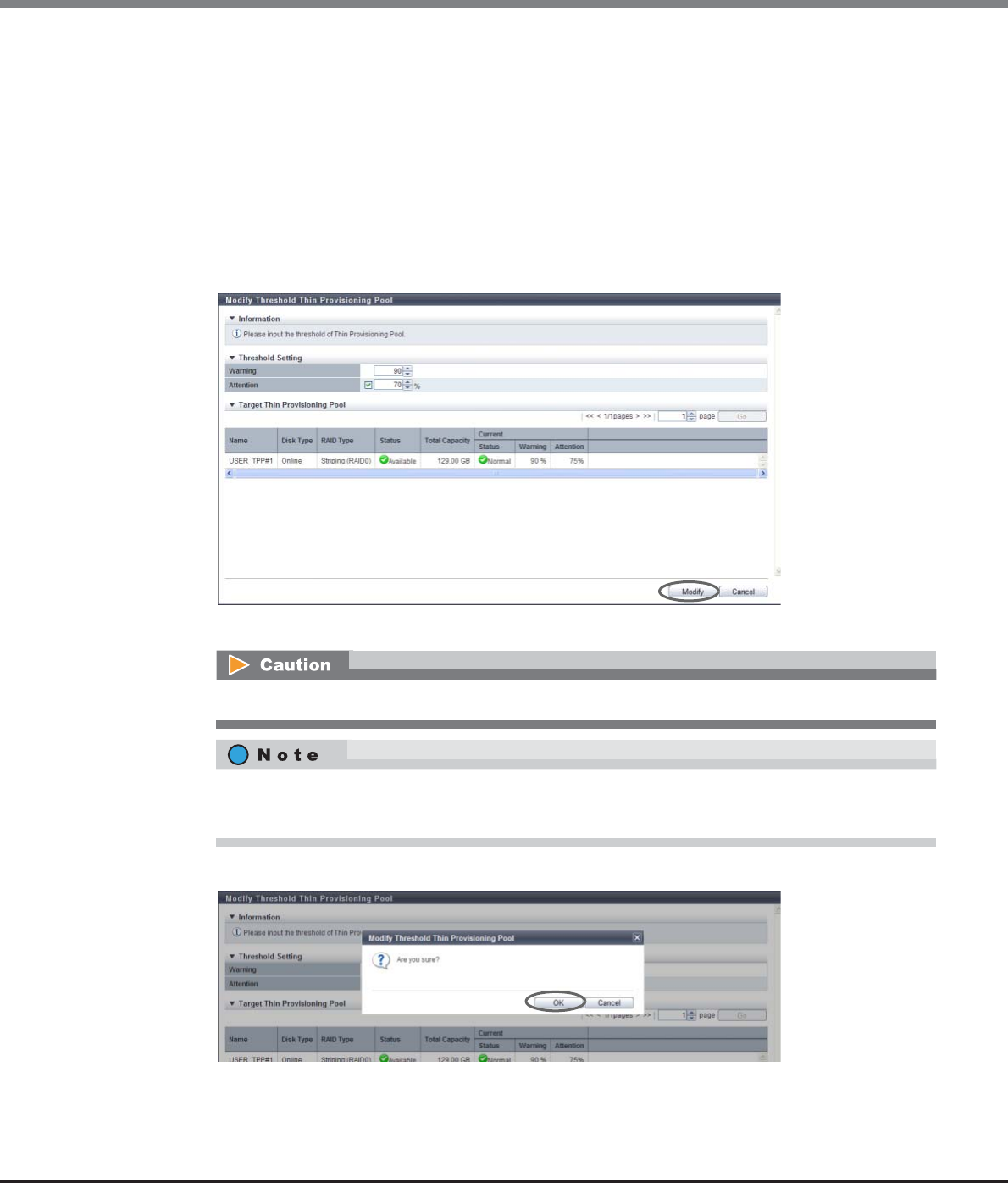
Chapter 7 Thin Provisioning Pool Management
7.2 Functions in the Action Area for Thin Provisioning
ETERNUS Web GUI User’s Guide
Copyright 2013 FUJITSU LIMITED P2X0-1090-10ENZ0
240
2Select a new threshold, and click the [Modify] button.
•Warning
Change the warning threshold (%) for monitoring the TPP used capacity between 5 and 99.
Specify the warning threshold so that the "Warning" threshold is the same or larger than the
"Attention" threshold.
•Attention
Specify the attention threshold (%) for monitoring the TPP used capacity between 5 and 80.
Specify the Attention threshold so that the "Warning" threshold is the same or larger than the
"Attention" threshold.
The "Attention" threshold can be omitted. When setting the "Attention" threshold, select the
checkbox.
→A confirmation screen appears.
3Click the [OK] button.
→Modify Threshold starts.
When "Warning" is smaller than "Attention", an error screen is displayed.
•When changing a "Attention" threshold, select the checkbox and then specify a new threshold.
•When omitting a "Attention" threshold, clear the checkbox.

Chapter 7 Thin Provisioning Pool Management
7.2 Functions in the Action Area for Thin Provisioning
ETERNUS Web GUI User’s Guide
Copyright 2013 FUJITSU LIMITED P2X0-1090-10ENZ0
241
4Click the [Done] button to return to the [Thin Provisioning Pool] screen.
End of procedure
7.2.8 Modify Cache Parameters (Thin Provisioning Pool)
This function changes the cache parameters of each Thin Provisioning Pool.
Device performance varies depending on the cache hit ratio. The cache hit ratio can be improved by detecting
the sequentiality for a Read/Write request from the host and reading continuous data in advance. The
characteristics of Read/Write requests from the host depends on the system. Device performance may improve
by specifying a cache parameter that is suitable for the system that is being used.
The following parameter can be specified:
•Multi Writeback Count (MWC)
Specify the number of processes that can be written back at the same time.
The procedure to modify cache parameters is as follows:
Procedure
1Select which TPP to change the cache parameters for (multiple selections can be made) and
click [Modify Cache Parameters] in [Action].
2Change the cache parameters and click the [Modify] button.
•Multi Writeback Count (MWC)
Specify the Multi Writeback Count.
When specifying a larger "Multi Writeback Count" value, sequential write access performance is
improved. Note that this is not effective when a number of random write accesses occur. Depending
on the ratio of read access and write access, read access performance may be reduced.
If pinned data exists in the ETERNUS DX Disk storage system, MWC cannot be configured.
•The same cache parameter can be applied for multiple TPPs in a single operation.
•Cache parameters other than MWC are specified for each TPV. Refer to "5.2.18 Modify Cache Parameters"
(page 148) for details.
The setting values that are available for Multi Writeback Count vary depending on the RAID type
and drive configuration. Refer to "E.2 Input Conditions for MWC" (page 1007) for details.
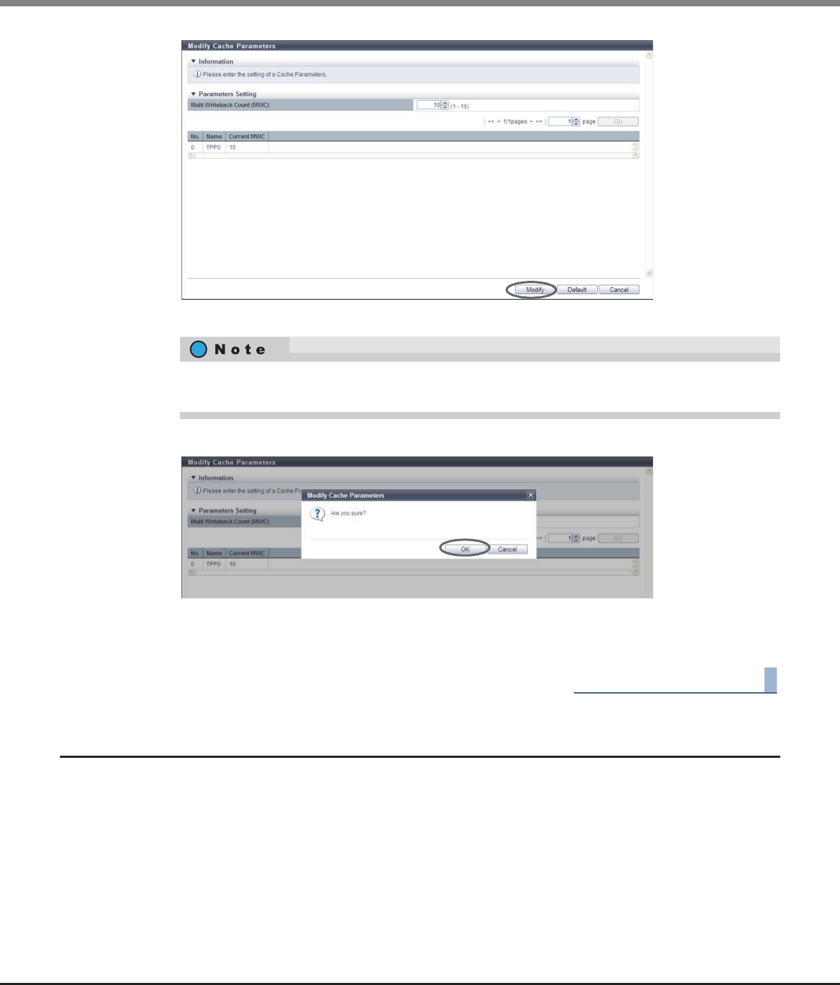
Chapter 7 Thin Provisioning Pool Management
7.2 Functions in the Action Area for Thin Provisioning
ETERNUS Web GUI User’s Guide
Copyright 2013 FUJITSU LIMITED P2X0-1090-10ENZ0
242
→A confirmation screen appears.
3Click the [OK] button.
→The cache parameter modification starts.
4Click the [Done] button to return to the [Threshold] screen.
End of procedure
7.2.9 Assign ECO Mode Schedule (Thin Provisioning Pool)
This function applies the ECO mode schedule to the Thin Provisioning Pools (TPP) and enables the ECO mode
setting.
ECO mode is a function to reduce power consumption by stopping motor of disks that configure the TPP while
the TPP is not accessed from the host.
When the ECO mode schedule is applied to a TPP, the ECO mode setting is enabled. When ECO mode is
running, disk motors are activated during the scheduled event term. During times other than the scheduled
time, disk motors are stopped.
If the TPP is accessed from the host while the disk motors are stopped, the disk motors are activated and can
be accessed within 1 - 5 minutes.
If the [Default] button is clicked before the [Modify] button, the default cache parameters are
restored.
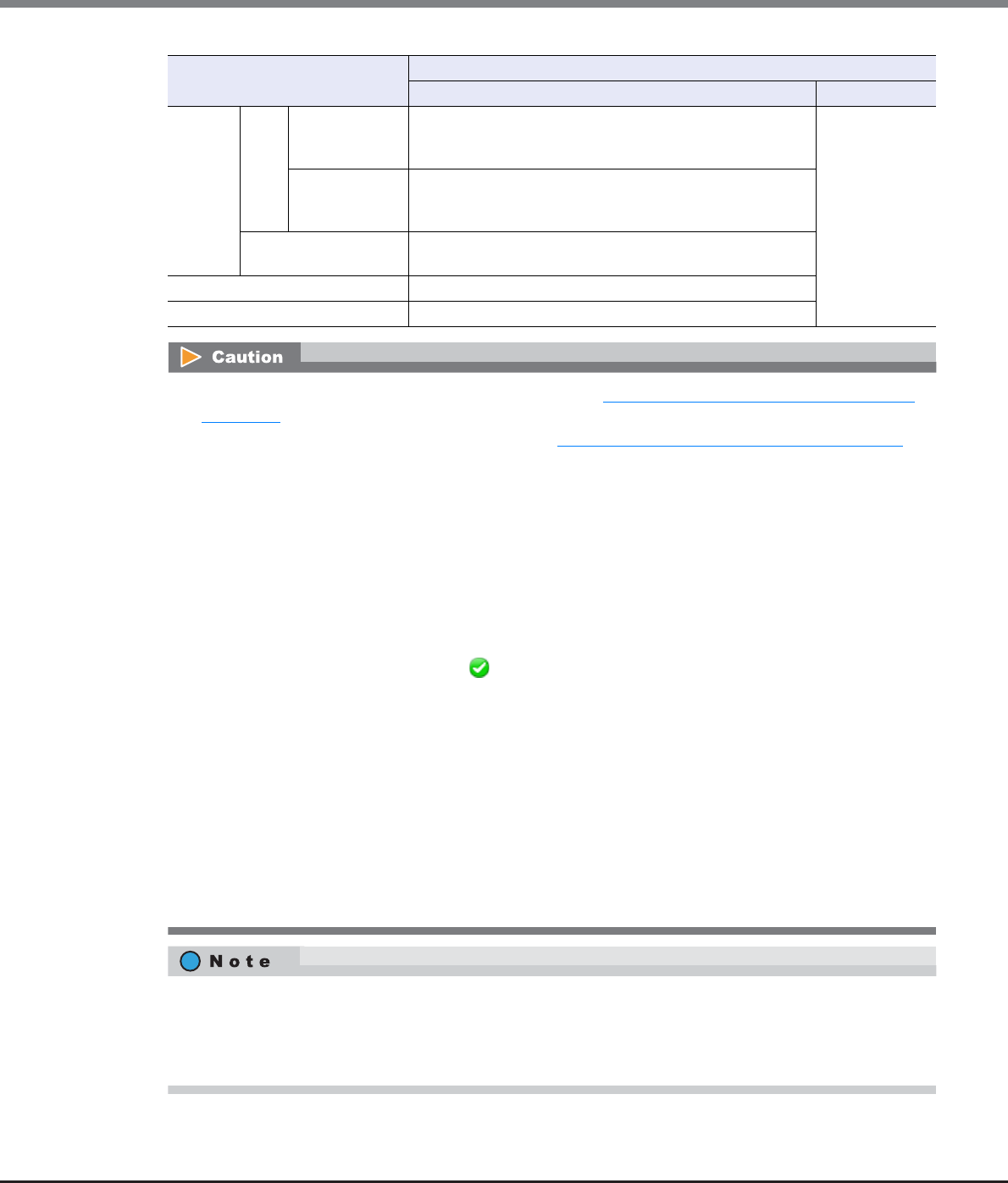
Chapter 7 Thin Provisioning Pool Management
7.2 Functions in the Action Area for Thin Provisioning
ETERNUS Web GUI User’s Guide
Copyright 2013 FUJITSU LIMITED P2X0-1090-10ENZ0
243
ECO Mode Schedule Setting ECO Mode General Setting
Enabled Disabled
Control
Status
ON
During
scheduled
event term
Disk motor is activated. (ECO mode is running) Disk motor runs
regardless of
schedule
settings. (ECO
mode is not
running)
Times other
than scheduled
event term
Disk motor is stopped. (ECO mode is running)
If the RAID group is accessed, disk motors are activated within
1 - 5 minutes.
OFF The target disk motor is operating constantly. (ECO mode is
not running)
Schedule is not applied Disk motor is operating constantly. (ECO mode is not running)
Disks not registered in the TPPs Disk motor is stopped constantly. (ECO mode is running)
•Before applying ECO mode for TPPs, use the procedure in "11.2.8.1 Modify ECO Mode General Setting"
(page 869) to enable the ECO mode setting for the ETERNUS DX Disk storage system.
•Set the ECO mode schedule using the procedure in "11.2.8.4 Modify ECO Mode Schedule" (page 876).
•This function cannot be used under the following conditions:
-No volumes are created
-Configured by SSDs
•When using ECO mode, make sure to set the time/date correctly. If the time/date of the ETERNUS DX Disk
storage system is wrong, processes used for stopping and starting the disk motor cannot be performed
per the ECO mode schedule.
•If any of the following conditions occur during the ECO mode scheduled time, the disk will be started even
when the disk motor is inactive. Note that the ECO mode schedule will be re-enabled when the following
conditions have finished.
-When the target TPP status is not " Available"
-When performing functions that change the TPP or the volume configuration
-When performing rebuild or copyback in the RAID groups that configure the target TPP
-When formatting is being performed in the TPP
-When RAID migration is being performed in the volumes registered in the TPP
-When Advanced Copy is being performed in the volume registered in the TPP (copy session status is
not "Suspend" or "Tracking")
-During maintenance
-When performing disk diagnosis, TPP diagnosis (diagnosing the RAID groups that configure the TPP),
or when exporting G-List
-When a module error related to the access paths of the Controller Modules and drives is detected
•When the ECO mode is set to TPP, the same ECO Mode schedule is set for all the RAID groups configuring
the TPP.
•When selecting multiple TPPs as the target of the ECO mode, the same ECO mode schedule can be
specified for all the selected TPPs.
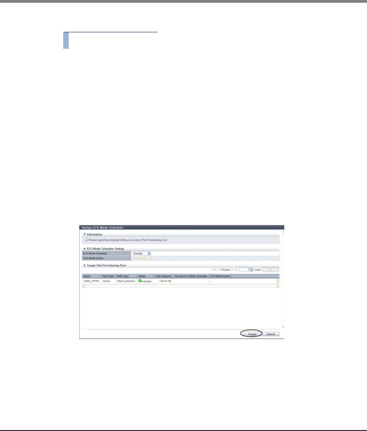
Chapter 7 Thin Provisioning Pool Management
7.2 Functions in the Action Area for Thin Provisioning
ETERNUS Web GUI User’s Guide
Copyright 2013 FUJITSU LIMITED P2X0-1090-10ENZ0
244
The procedure to set the ECO mode for Thin Provisioning Pool is as follows:
Procedure
1Select the TPP for which the ECO mode setting status is to be changed (multiple selections
can be made) and click [Assign ECO Mode] in [Action].
2Select the ECO mode schedule and action to be assigned and click the [Assign] button.
•ECO Mode Schedule
Select the ECO mode schedule that is to be applied.
-No Change
Do not change the current setting.
-Disable
Disable the ECO mode.
-ECO mode schedule name
Apply the selected ECO mode schedule.
•ECO Mode Action
Select whether to enable ("ON") or disable ("OFF") the ECO mode setting. Select "No Change" to use
the current setting.
-No Change
Do not change the current setting.
-ON
Enable the ECO mode.
-OFF
Disable the ECO mode.
→A confirmation screen appears.
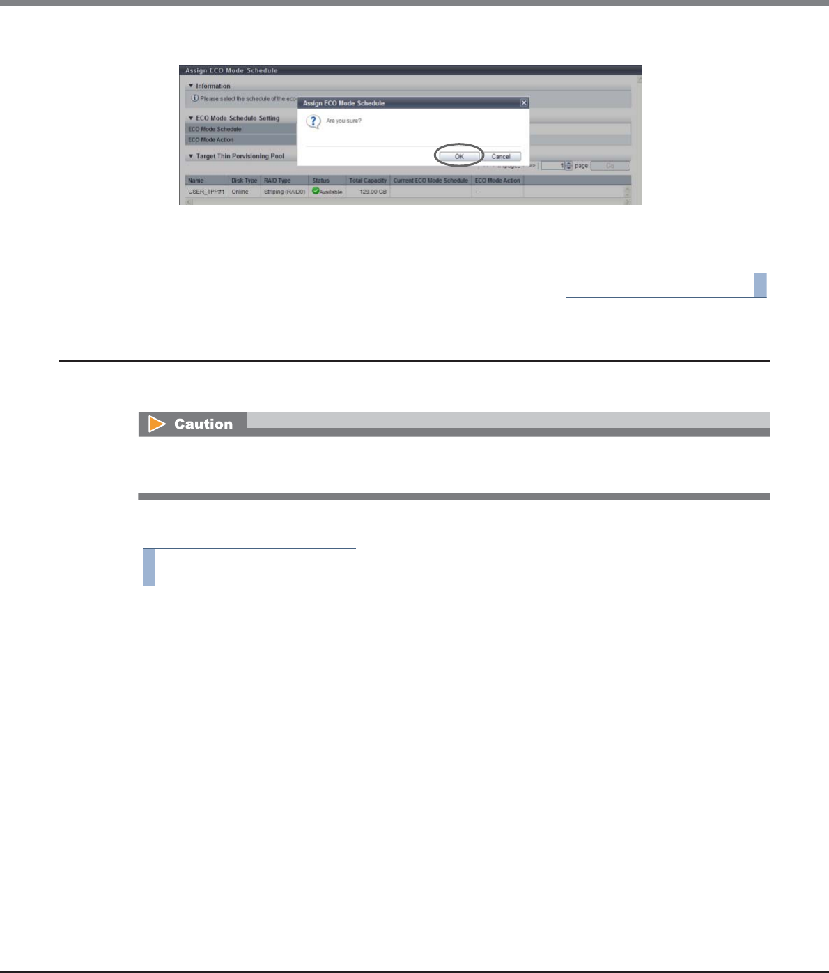
Chapter 7 Thin Provisioning Pool Management
7.2 Functions in the Action Area for Thin Provisioning
ETERNUS Web GUI User’s Guide
Copyright 2013 FUJITSU LIMITED P2X0-1090-10ENZ0
245
3Click the [OK] button.
→Assign ECO Mode starts.
4Click the [Done] button to return to the [Thin Provisioning Pool] screen.
End of procedure
7.2.10 Register Thin Provisioning License
This function registers the Thin Provisioning License.
The procedure to register a Thin Provisioning License is as follows:
Procedure
1Click [Register License] in [Action].
•If a Thin Provisioning license is not registered, the Thin Provisioning function cannot be used.
•If a Thin Provisioning license is already registered, this function cannot be used.
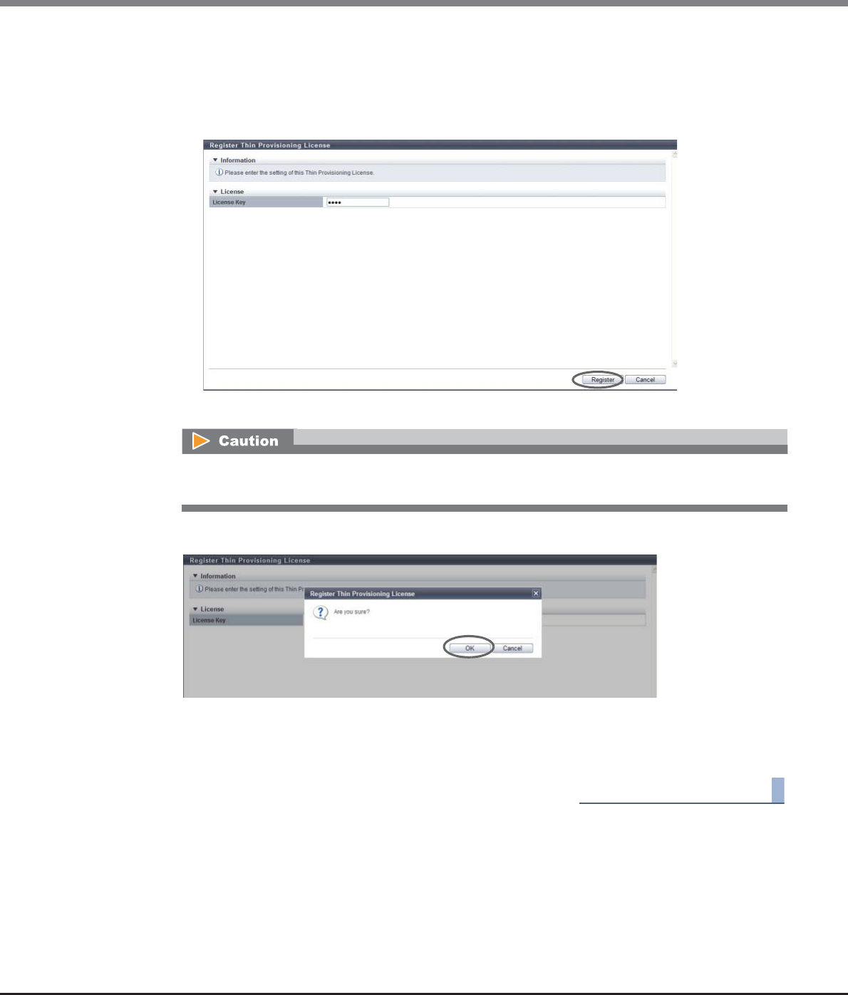
Chapter 7 Thin Provisioning Pool Management
7.2 Functions in the Action Area for Thin Provisioning
ETERNUS Web GUI User’s Guide
Copyright 2013 FUJITSU LIMITED P2X0-1090-10ENZ0
246
2Input the Thin Provisioning license key, and click the [Register] button.
•License Key
Input the Thin Provisioning license key.
The following input condition applies:
-Up to 16 capital letters and numeric characters
→A confirmation screen appears.
3Click the [OK] button.
→Registration of the Thin Provisioning License starts.
4Click the [Done] button to return to the [License] screen.
End of procedure
If the entered Thin Provisioning license key does not satisfy the input conditions, an error screen
appears.
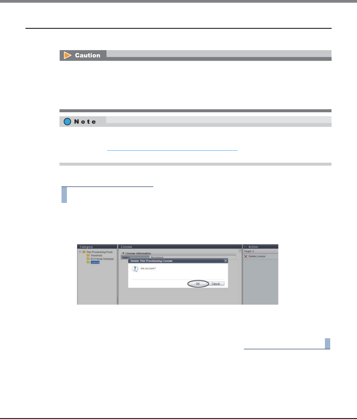
Chapter 7 Thin Provisioning Pool Management
7.2 Functions in the Action Area for Thin Provisioning
ETERNUS Web GUI User’s Guide
Copyright 2013 FUJITSU LIMITED P2X0-1090-10ENZ0
247
7.2.11 Delete Thin Provisioning License
This function deletes a Thin Provisioning license.
The procedure to delete a Thin Provisioning License is as follows:
Procedure
1Click [Delete License] in [Action].
→A confirmation screen appears.
2Click the [OK] button.
→Delete Thin Provisioning License starts.
3Click the [Done] button to return to the [License] screen.
End of procedure
Thin Provisioning license cannot be deleted in the following conditions:
•When no Thin Provisioning license is registered
•When Thin Provisioning Pool is registered
•When "TPV balancing" is selected for "Thin Provisioning Allocation Mode" of the subsystem parameter
•When the Flexible Tier function mode is enabled
A Thin Provisioning license cannot be deleted when "TPV balancing" is selected for "Thin Provisioning
Allocation Mode" of the subsystem parameter. Before deleting the Thin Provisioning license, use the proce-
dure described in "11.2.13.4 Setup Subsystem Parameters" (page 935) to reset the "Thin Provisioning
Allocation Mode" setting to the default "TPP balancing" setting.
Chapter 7 Thin Provisioning Pool Management
7.2 Functions in the Action Area for Thin Provisioning
ETERNUS Web GUI User’s Guide
Copyright 2013 FUJITSU LIMITED P2X0-1090-10ENZ0
248
7.2.12 Start Balancing Flexible Tier Pool
This function starts Flexible Tier Pool (FTRP) balancing sessions.
The FTRP balancing function equalizes unevenly allocated physical area in the Flexible Tier Sub Pools (FTSPs)
that configure an FTRP. By using this function, the physical allocated areas are reallocated equally among the
RAID groups in the FTSPs. The I/O access to the FTV is distributed almost equally to the RAID groups in the
FTSP.
Requirements for an FTRP to be balanced
•The status of the FTRP is " Available", " Partially Readying", or " Exposed"
•Balancing of the selected FTRP is not being performed
•Free space, which can be used for balancing, exists in the FTSPs in the target FTRP
•Even after the FTRP balancing session is performed, the physical allocation between the FTVs and the
FTSPs does not change.
•The FTRP balancing function extracts up to 32 balanceable FTVs (*1) that have a low balancing level from
the selected FTRP and performs balancing sessions in the FTSPs. Note that FTVs are not extracted as
balancing targets in certain conditions. For example, FTVs with a high balancing level, FTVs that are
undergoing RAID migration, or FTVs that are undergoing Zero Reclamation.
*1: Up to 32 sessions, which include FTV balancing sessions, TPV balancing sessions, and RAID migration sessions,
can be performed at the same time. An FTRP balancing session is performed in each FTRP. Note that the number
of FTV balancing sessions that are performed at the same time cannot be specified.
•Balancing of FTVs in the following conditions is not available:
-FTVs which capacity is less than 20GB
-FTVs which used capacity is less than 10GB
The FTV capacity can be checked in the [Flexible Tier Pool Detail (Volume)] screen. Refer to "7.1.9 Flexible
Tier Pool Detail (Volume)" (page 215) for details.
•FTRP balancing cannot be started in the following conditions:
-When the Thin Provisioning license is not registered
-When the Flexible Tier function mode is disabled
-When the maximum number of volumes is already registered in the ETERNUS DX Disk storage system
-When the total number of TPV balancing processes and RAID migrations that are running in the
ETERNUS DX Disk storage system is 32
-When the total capacity for the TPV balancing processes and the RAID migrations that are running in
the ETERNUS DX Disk storage system is 128TB
-When the RAID group diagnosis is being performed in the ETERNUS DX Disk storage system
-When the disk diagnosis is being performed in the ETERNUS DX Disk storage system
-When Zero Reclamation is being performed for all of the balancing target FTVs in the FTRP
•When FTRP balancing is performed, the used FTRP capacity may temporarily exceed the threshold. If the
used capacity exceeds the threshold, " Attention" or " Warning" is displayed in the "Used Status"
field for the FTRP. The usage of the FTRPs is displayed in the [Flexible Tier Pool] screen. Refer to "7.1.5
Flexible Tier Pool (Basic Information)" (page 207) for details.
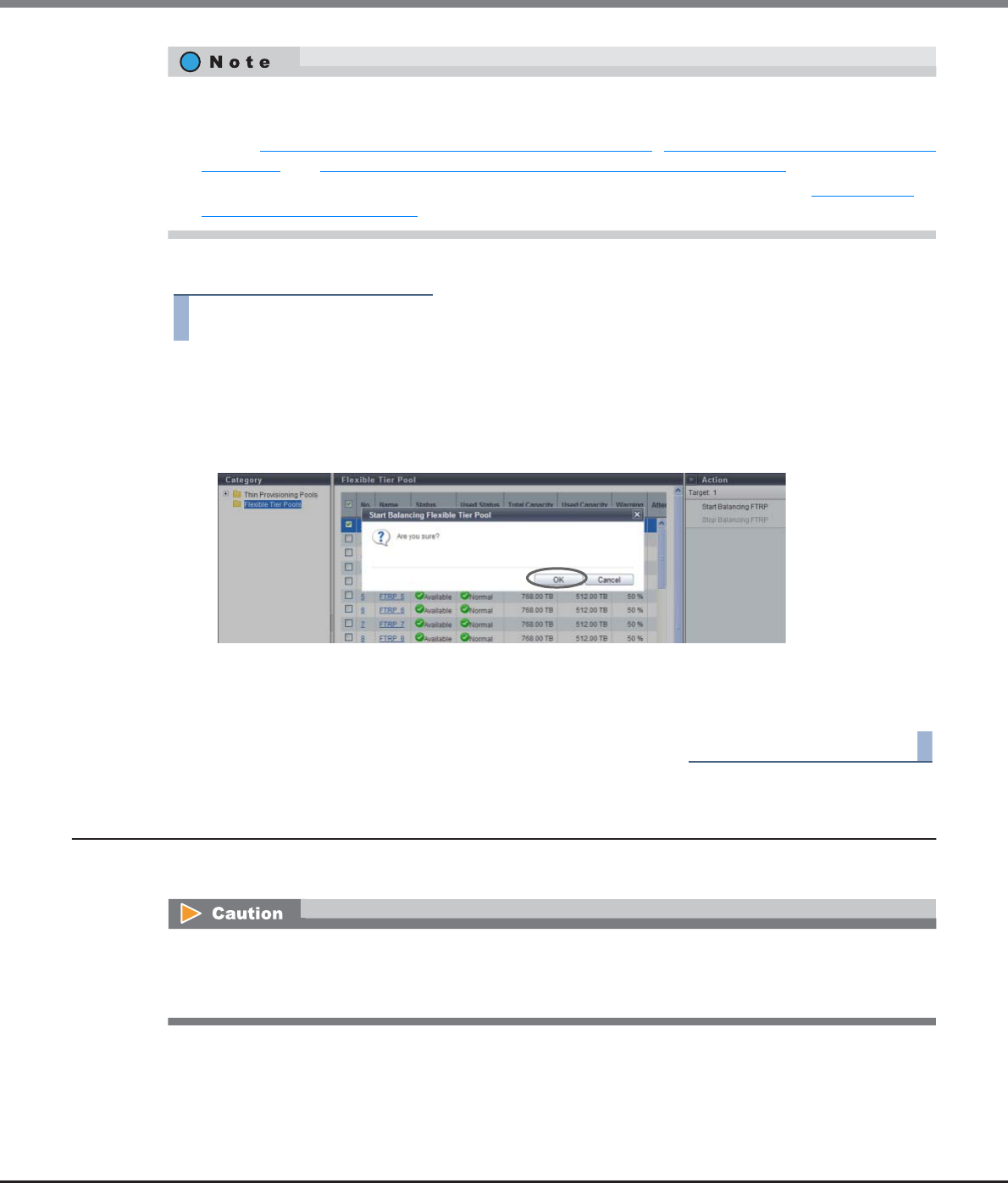
Chapter 7 Thin Provisioning Pool Management
7.2 Functions in the Action Area for Thin Provisioning
ETERNUS Web GUI User’s Guide
Copyright 2013 FUJITSU LIMITED P2X0-1090-10ENZ0
249
The procedure to start balancing FTRP is as follows:
Procedure
1Select the FTRP for which balancing is to be started and click [Start Balancing FTRP] in
[Action].
→A confirmation screen appears.
2Click the [OK] button.
→FTRP balancing starts.
3Click the [Done] button to return to the [Flexible Tier Pool] screen.
End of procedure
7.2.13 Stop Balancing Flexible Tier Pool
This function stops Flexible Tier Pool (FTRP) balancing sessions.
•FTRP balancing can be performed during the work I/O.
•The balancing levels of FTRPs and FTSPs, and the progress of the FTRP balancing sessions can be checked.
Refer to "7.1.5 Flexible Tier Pool (Basic Information)" (page 207), "7.1.7 Flexible Tier Pool Detail (Basic)"
(page 212), and "7.1.8 Flexible Tier Pool Detail (Flexible Tier Sub Pool)" (page 214)for details.
•The progress of a balancing FTV can be checked in the [Volume Detail] screen. Refer to "5.1.1 Volume
(Basic Information)" (page 74) for details.
•This function cannot be used when no FTRPs are undergoing balancing or when no FTRP balancing that
has stopped due to an error exists.
•This function cannot be used when the specified FTRP balancing is already complete.
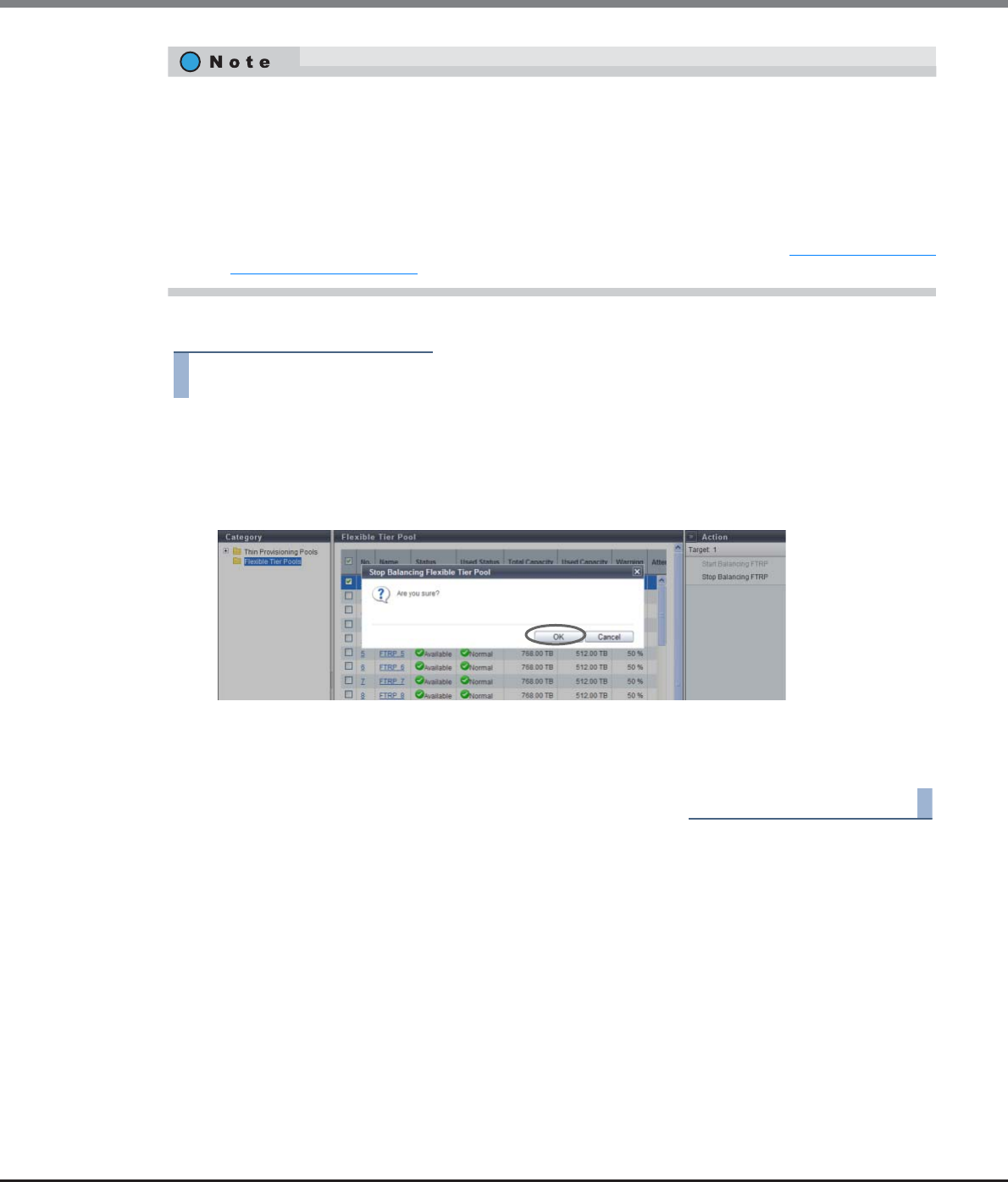
Chapter 7 Thin Provisioning Pool Management
7.2 Functions in the Action Area for Thin Provisioning
ETERNUS Web GUI User’s Guide
Copyright 2013 FUJITSU LIMITED P2X0-1090-10ENZ0
250
The procedure to stop balancing FTRP is as follows:
Procedure
1Select the FTRP for which balancing is to be stopped and click [Stop Balancing FTRP] in
[Action].
→A confirmation screen appears.
2Click the [OK] button.
→FTRP balancing stops.
3Click the [Done] button to return to the [Flexible Tier Pool] screen.
End of procedure
If FTRP balancing has stopped, the following conditions apply.
•All of the balancing sessions that are currently being performed (*1) for the FTVs registered in the target
FTRP are stopped. Even when balancing sessions are being stopped, FTVs that are not being balanced can
be accessed normally.
•Note that completed balancing processes for the FTVs in the target FTRP (*1) cannot be stopped (the
physical allocation after the balancing process cannot be changed). FTVs that are balanced can be
accessed normally.
*1: When an FTRP balancing session is started, FTV balancing starts in the FTSPs. Refer to "7.2.12 Start Balancing
Flexible Tier Pool" (page 248) for details.
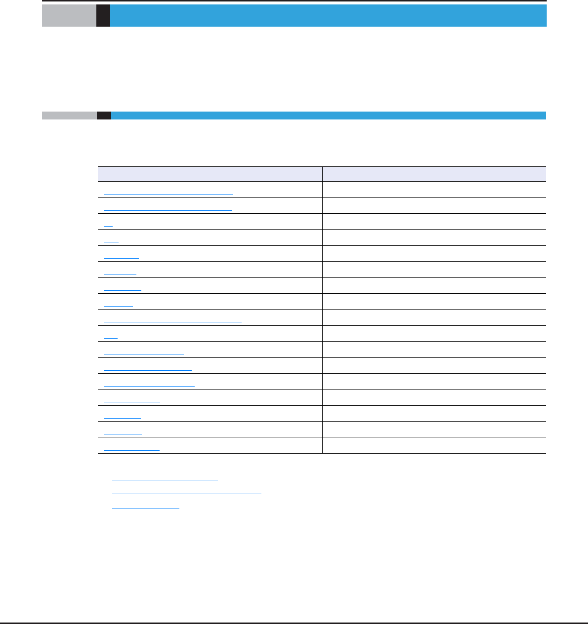
ETERNUS Web GUI User’s Guide
Copyright 2013 FUJITSU LIMITED P2X0-1090-10ENZ0
251
Chapter 8
Advanced Copy Management
This chapter describes Advanced Copy management.
8.1 Advanced Copy Status
Advanced Copy status displays the status information of volumes.
Advanced Copy status screens can be displayed by clicking the following categories:
Detailed information of the Advanced Copy functions can be displayed from the following screens:
•Advanced Copy (Property)
•Advanced Copy (Extent information)
•Copy Path Detail
Advanced Copy status screen Category
Advanced Copy (Basic Information) Advanced Copy
Advanced Copy (All Local Sessions) Local Copy
EC EC
OPC OPC
QuickOPC QuickOPC
SnapOPC SnapOPC
SnapOPC+ SnapOPC+
Monitor Monitor
Advanced Copy (All Remote Sessions) Remote Copy
REC REC
Advanced Copy (ODX) ODX
Advanced Copy (XCOPY) XCopy
Setting (Advanced Copy) Setting
Snap Data Pool Snap Data Pool
Copy Path Copy Path
REC Buffer REC Buffer
REC Disk Buffer REC Disk Buffer
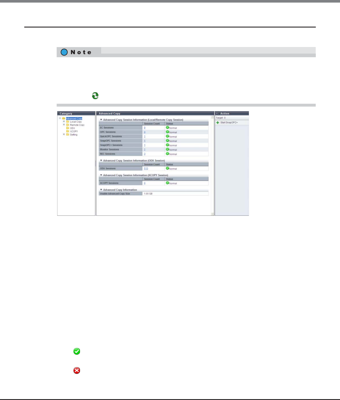
Chapter 8 Advanced Copy Management
8.1 Advanced Copy Status
ETERNUS Web GUI User’s Guide
Copyright 2013 FUJITSU LIMITED P2X0-1090-10ENZ0
252
8.1.1 Advanced Copy (Basic Information)
This function displays the status of all the Advanced Copy sessions.
The following items are displayed in the Main area:
●Advanced Copy Session Information (Local/Remote Copy Sessions)
•Session Count
The number of Advanced Copy sessions that are currently being performed for each type (EC, OPC,
QuickOPC, SnapOPC, SnapOPC+, Monitor, and REC) is displayed.
The "Session Count" is a total of copy sessions in all the statuses including "Reserved". Click the [Session
Count] link to display the list of sessions for each type.
-ETERNUS DX80 S2: 0 - 1024
-ETERNUS DX90 S2: 0 - 2048
-ETERNUS DX410 S2/DX440 S2: 0 - 8192
-ETERNUS DX8100 S2: 0 - 8192
-ETERNUS DX8700 S2: 0 - 32768
•Status
The status for each Advanced Copy session is displayed.
- Normal
All the copy sessions are in normal status.
- Error
At least one copy session is not in normal status.
•To display the Advanced Copy session information (Local/Remote Copy sessions) and the Advanced Copy
information, register the Advanced Copy license.
•Registering an Advanced Copy license is not required to display the Advanced Copy Session Information
(ODX Session) or the Advanced Copy Session Information (XCOPY Session).
•Click the [ ] icon to update to the latest screen.
Chapter 8 Advanced Copy Management
8.1 Advanced Copy Status
ETERNUS Web GUI User’s Guide
Copyright 2013 FUJITSU LIMITED P2X0-1090-10ENZ0
253
●Advanced Copy Session Information (ODX Session)
•Session Count
The number of ODX sessions (0 - 4096) that are currently being performed is displayed.
The "Session Count" is a total of copy sessions in all the statuses including "Reserved". Click the [Session
Count] link to display the list of sessions.
•Status
The status for each Advanced Copy session is displayed.
- Normal
All the copy sessions are in normal status.
- Error
At least one copy session is not in normal status.
●Advanced Copy Session Information (XCOPY Session)
•Session Count
The number of XCopy (Extended Copy) sessions (0 - 4096) (*1) that are currently being performed is
displayed.
The "Session Count" is a total of copy sessions in all the statuses including "Reserved". Click the [Session
Count] link to display the list of sessions.
*1: An XCOPY (Extended Copy) session is created when the Full Copy function of VMware vStorage APIs for Array Inte-
gration (VAAI) is used.
•Status
The status for each Advanced Copy session is displayed.
- Normal
All the copy sessions are in normal status.
- Error
At least one copy session is not in normal status.
●Advanced Copy Information
•Usable Advanced Copy Size
The Advanced Copy capacity that can be added to the session is displayed.
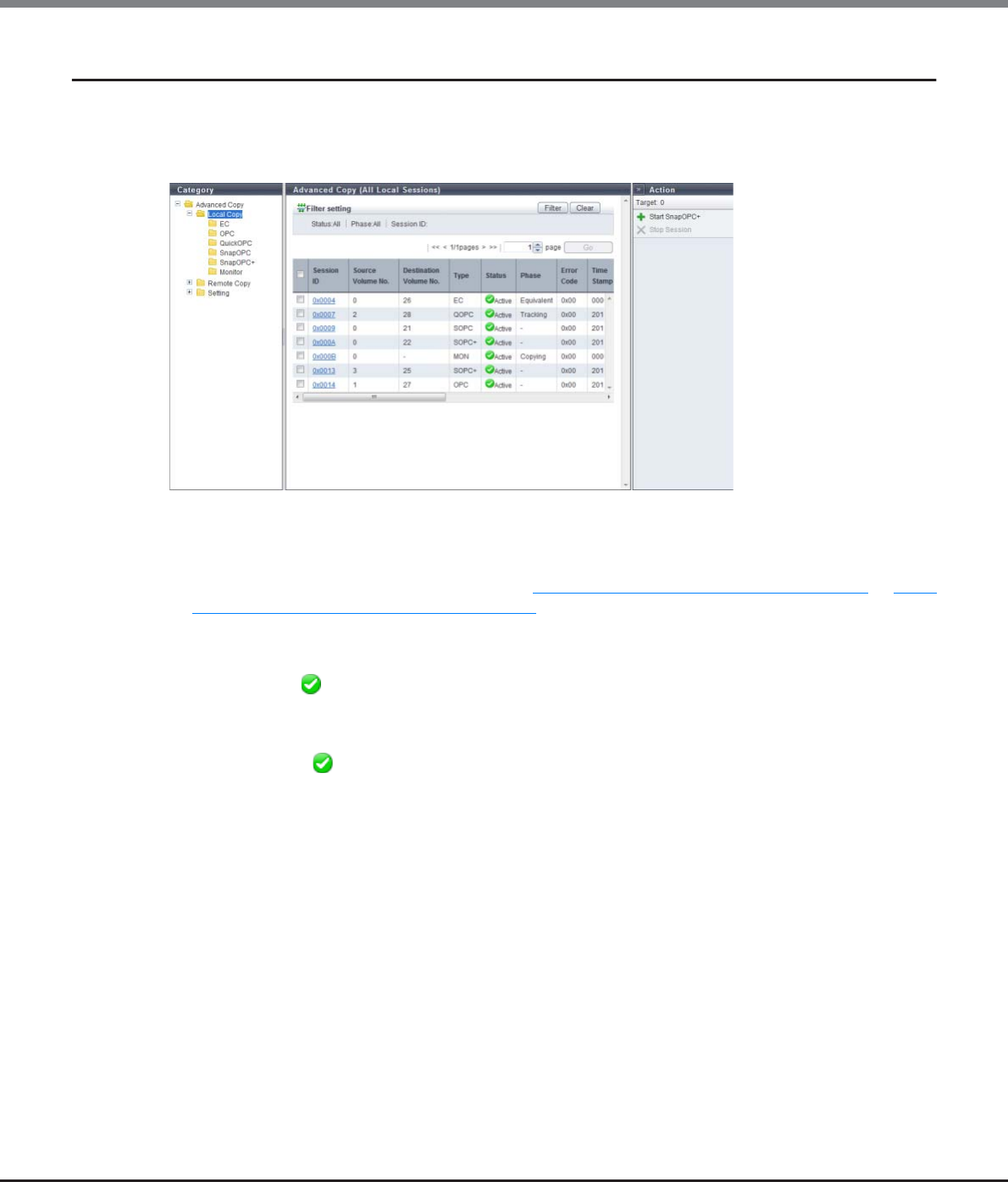
Chapter 8 Advanced Copy Management
8.1 Advanced Copy Status
ETERNUS Web GUI User’s Guide
Copyright 2013 FUJITSU LIMITED P2X0-1090-10ENZ0
254
8.1.2 Advanced Copy (All Local Sessions)
This function displays status for local copy sessions.
The following session types are available: Equivalent Copy (EC), One Point Copy (OPC), QuickOPC, SnapOPC,
SnapOPC+, and Monitor.
The following items are displayed in the Main area:
•Session ID
The session ID is displayed.
Click this item to display the screen shown in "8.1.7 Advanced Copy (Property)" (page 277) or "8.1.8
Advanced Copy (Extent information)" (page 283).
•Source Volume No.
The copy source volume number is displayed.
If the status is " Reserved", a "-" (hyphen) is displayed.
•Destination Volume No.
The copy destination volume number is displayed.
If the "Status" is " Reserved" or the "Type" is "MON", a "-" (hyphen) is displayed.
•Type
The copy session type is displayed using an abbreviation.
-For Equivalent Copy: EC
-For One Point Copy: OPC
-For QuickOPC: QOPC
-For SnapOPC: SOPC
-For SnapOPC+: SOPC+
-For Monitor: MON
Chapter 8 Advanced Copy Management
8.1 Advanced Copy Status
ETERNUS Web GUI User’s Guide
Copyright 2013 FUJITSU LIMITED P2X0-1090-10ENZ0
255
•Status
The copy session status is displayed.
- Active
Operating normally
- Reserve
Session ID reserved
- Suspend
Suspended by an instruction from the host
- Error Suspend
Copy canceled due to an error
- Unknown
A status other than the ones listed above
•Phase
The copy session phase is displayed. If the status is " Reserved", a "-" (hyphen) is displayed.
-Copying
For OPC, EC, SnapOPC, and SnapOPC+: Copying
For QuickOPC: Copying the updated areas after recording of updated areas is stopped
For Monitor: Recording the updated areas
-Equivalent
Maintaining equivalent status of the copy source and copy destination that are duplicated after copy is
complete
-Tracking
Recording only the updated area after copy is complete
-Tracking & Copy
Recording the area updated during copy processing and after copy starts
-Readying
Readying to start multiple copy using the Concurrent OPC.
•Error Code
The error code is displayed when an error occurs. If the status is " Reserved", a "-" (hyphen) is displayed.
Refer to "Appendix K Error Code" (page 1064) for details.
•Time Stamp
The time when backup is complete and the time when an error occurred are displayed. If the status is "
Reserved", a "-" (hyphen) is displayed.
The time stamp is updated in the following conditions:
-OPC, QuickOPC, SnapOPC, and SnapOPC+
The time stamp is updated when copy starts and when an error occurs.
The following information is displayed:
•When "Status" is " Active", the backup time when the copy started is displayed.
•When "Status" is " Error Suspend", the time when the error occurred is displayed.
-QuickOPC
The time stamp is updated when copy starts, restarts, and when an error occurs.
The following information is displayed:
•When "Status" is " Active", the backup time when the copy started is displayed.
•When "Status" is " Error Suspend", the time when the error occurred is displayed.
Chapter 8 Advanced Copy Management
8.1 Advanced Copy Status
ETERNUS Web GUI User’s Guide
Copyright 2013 FUJITSU LIMITED P2X0-1090-10ENZ0
256
-EC
The time stamp is updated at Suspend and when an error occurs.
The following information is displayed:
•When "Status" is " Active" and the copy session is not suspended yet, "0" is displayed for all of the
display items. When suspend is requested and "Status" is " Active", the backup time of the
previous suspend that was requested is displayed.
•When "Status" is " Suspend", the backup time when the copy was suspended is displayed.
•When "Status" is " Error Suspend", the time when an error occurred is displayed.
-Monitor
When "Status" is " Active", "0" is displayed for all of the display items.
•Elapsed Time
The elapsed time after a copy session has started is displayed. If the status is " Reserved", a "-" (hyphen)
is displayed.
•Copied Data Size
The size of copy that has been completed is displayed. If the status is " Reserved", a "-" (hyphen) is
displayed.
•Total Data Size
The total copy size is displayed. If the status is " Reserved", a "-" (hyphen) is displayed.
•Resolution
The copy session resolution is displayed. If the status is " Reserved", a "-" (hyphen) is displayed.
•Requestor
The information of the client that started the copy session is displayed. If the status is " Reserved", a "-"
(hyphen) is displayed.
-SCSI
Copy session requested by the copy management software (via SCSI).
-LAN
Copy session requested by the copy management software (via LAN).
-GUI
Copy session requested by GUI.
-CLI
Copy session requested by CLI.
-SMI-S
Copy session requested by SMI-S.
•License
The registration status of the Advanced Copy license when the copy session is started is displayed.
-Regular
The copy session is started with a paid license or a free license (only for the ETERNUS DX80 S2/DX90
S2).
-Trial
The copy session is started with a trial license. Copy sessions that use a trial license are deleted
automatically after the expiration of the trial license.
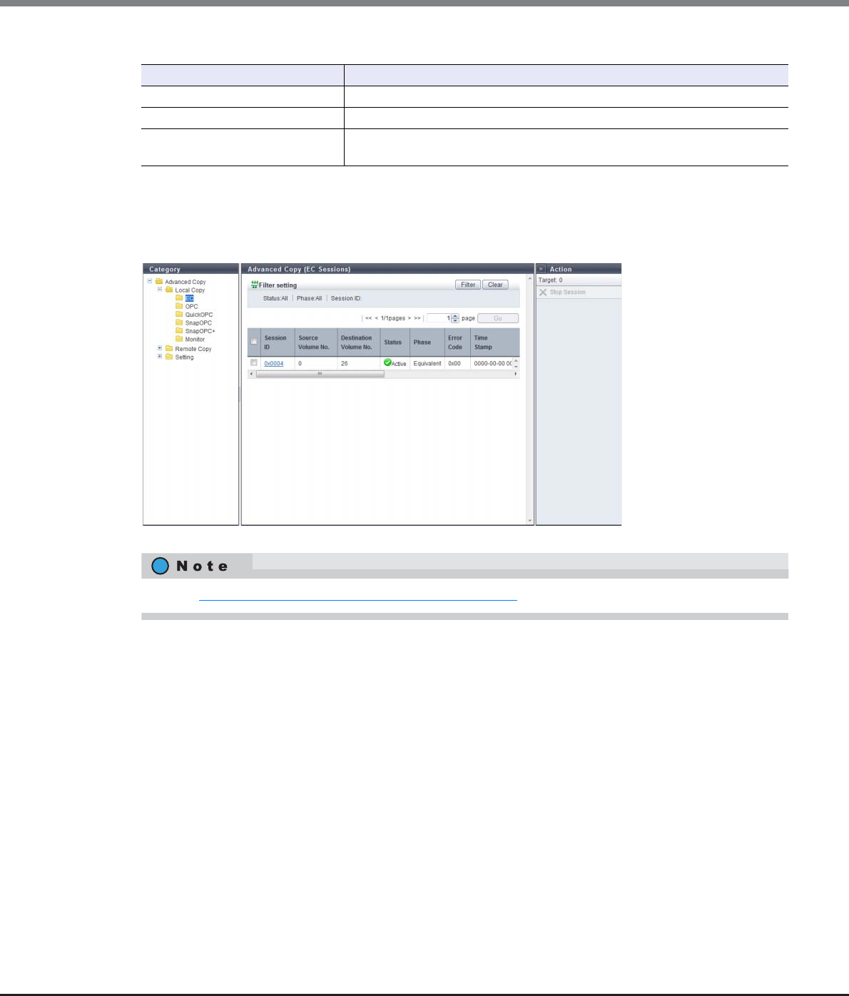
Chapter 8 Advanced Copy Management
8.1 Advanced Copy Status
ETERNUS Web GUI User’s Guide
Copyright 2013 FUJITSU LIMITED P2X0-1090-10ENZ0
257
Filter Setting
8.1.2.1 EC
This function displays detailed information for EC sessions.
Filter Description
Status Select the copy session status that is to be displayed.
Phase Select the copy session phase that is to be displayed.
Session ID Input the session ID of the copy session that is to be displayed.
When not using the session ID for filtering, leave this item blank.
Refer to "8.1.2 Advanced Copy (All Local Sessions)" (page 254) for display items.
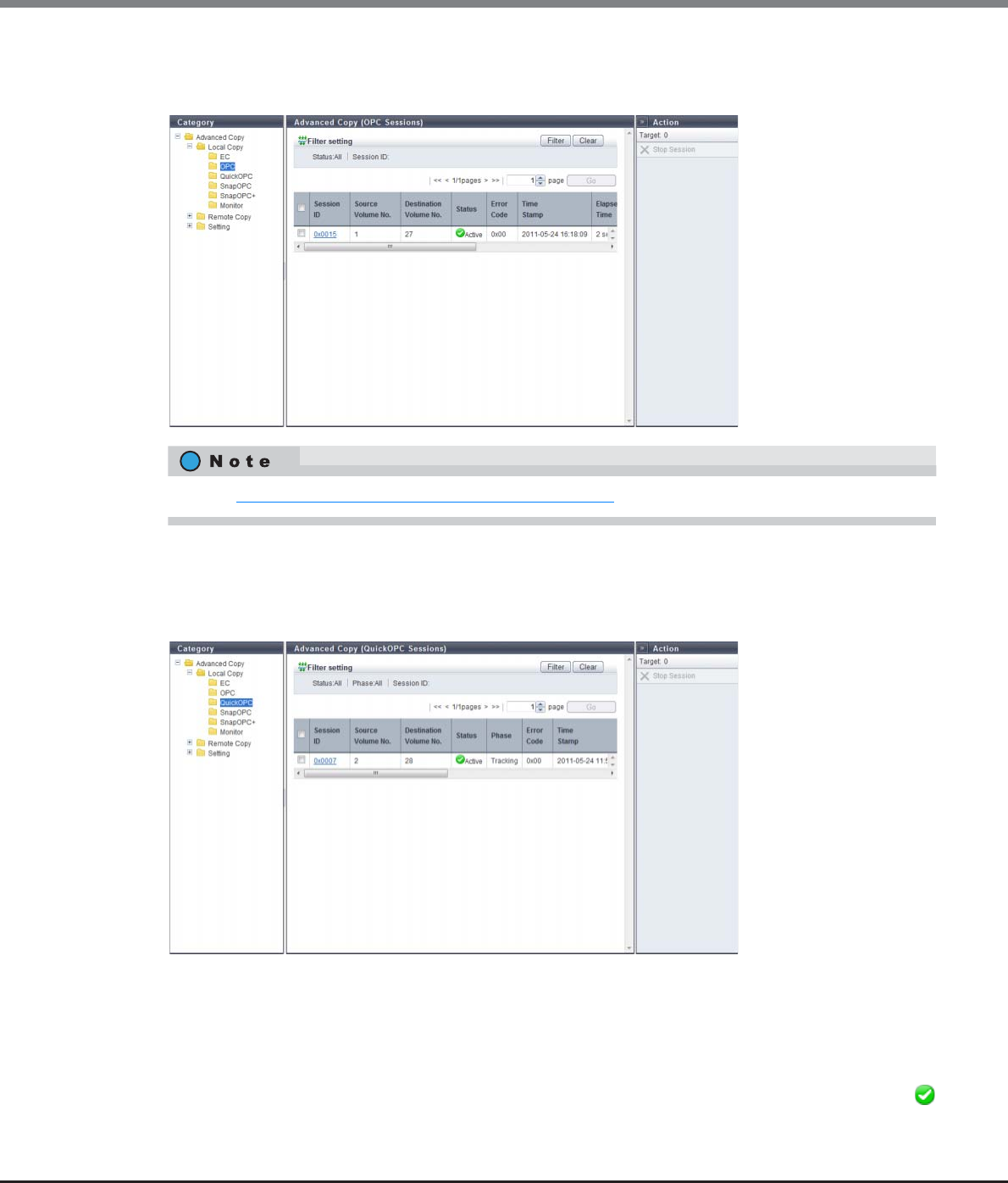
Chapter 8 Advanced Copy Management
8.1 Advanced Copy Status
ETERNUS Web GUI User’s Guide
Copyright 2013 FUJITSU LIMITED P2X0-1090-10ENZ0
258
8.1.2.2 OPC
This function displays detailed information for OPC sessions.
8.1.2.3 QuickOPC
This function displays detailed information for Quick OPC sessions.
The following items are displayed in the Main area:
•Modified Data Size
The differential data size when QuickOPC is executed is displayed.
The modified data size is updated in the "Tracking & Copy" and "Tracking" phases. When recopy starts, the
modified data size is once changed to "0" and then the differential data size from the time when recopy
started is displayed. When tracking stops, the modified data size is changed to "0". If the status is "
Reserved", a "-" (hyphen) is displayed.
Refer to "8.1.2 Advanced Copy (All Local Sessions)" (page 254) for display items.
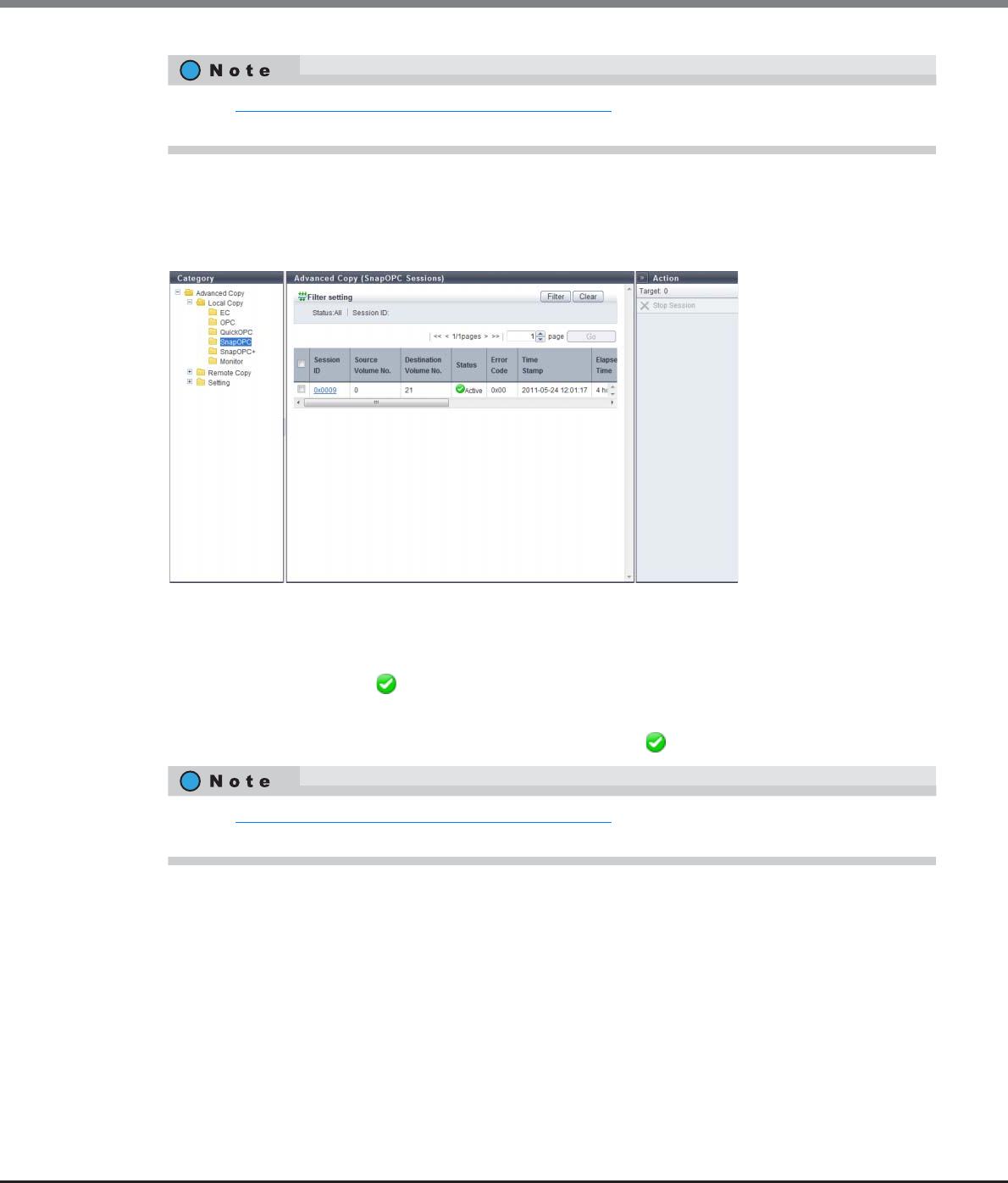
Chapter 8 Advanced Copy Management
8.1 Advanced Copy Status
ETERNUS Web GUI User’s Guide
Copyright 2013 FUJITSU LIMITED P2X0-1090-10ENZ0
259
8.1.2.4 SnapOPC
This function displays detailed information for SnapOPC sessions.
The following items are displayed in the Main area:
•SDP No.
The Snap Data Pool number, which is used when the copy destination SDV capacity is insufficient, is
displayed. If the status is " Reserved", a "-" (hyphen) is displayed.
•SDP Used Capacity
The used capacity of Snap Data Pool is displayed. If the status is " Reserved", a "-" (hyphen) is displayed.
Refer to "8.1.2 Advanced Copy (All Local Sessions)" (page 254) for the display items that are not described in
this section.
Refer to "8.1.2 Advanced Copy (All Local Sessions)" (page 254) for the display items that are not described in
this section.
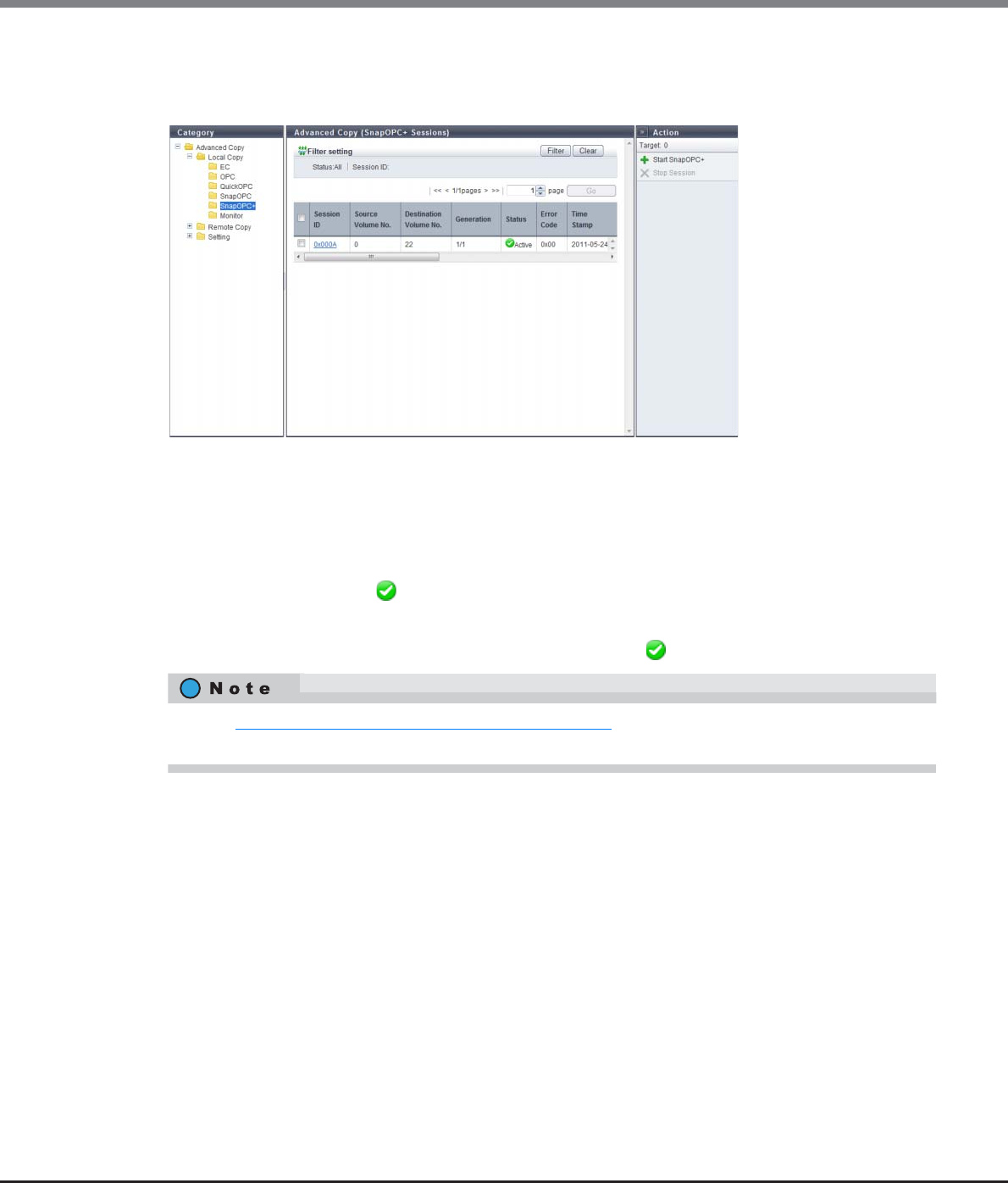
Chapter 8 Advanced Copy Management
8.1 Advanced Copy Status
ETERNUS Web GUI User’s Guide
Copyright 2013 FUJITSU LIMITED P2X0-1090-10ENZ0
260
8.1.2.5 SnapOPC+
This function displays detailed information for SnapOPC+ sessions.
The following items are displayed in the Main area:
•Generation
The generation and total number of generations of the copy session are displayed.
•SDP No.
The Snap Data Pool number, which is used when the copy destination SDV capacity is insufficient, is
displayed. If the status is " Reserved", a "-" (hyphen) is displayed.
•SDP Used Capacity
The used capacity of Snap Data Pool is displayed. If the status is " Reserved", a "-" (hyphen) is displayed.
Refer to "8.1.2 Advanced Copy (All Local Sessions)" (page 254) for the display items that are not described in
this section.
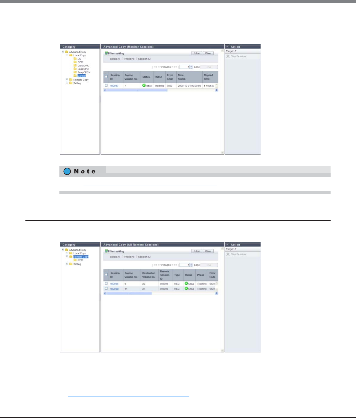
Chapter 8 Advanced Copy Management
8.1 Advanced Copy Status
ETERNUS Web GUI User’s Guide
Copyright 2013 FUJITSU LIMITED P2X0-1090-10ENZ0
261
8.1.2.6 Monitor
This function displays detailed information for Monitor sessions.
8.1.3 Advanced Copy (All Remote Sessions)
This function displays the status for remote copy sessions.
The following items are displayed in the Main area:
•Session ID
The session ID is displayed.
Click this item to display the screen shown in "8.1.7 Advanced Copy (Property)" (page 277) or "8.1.8
Advanced Copy (Extent information)" (page 283).
Refer to "8.1.2 Advanced Copy (All Local Sessions)" (page 254) for display items.
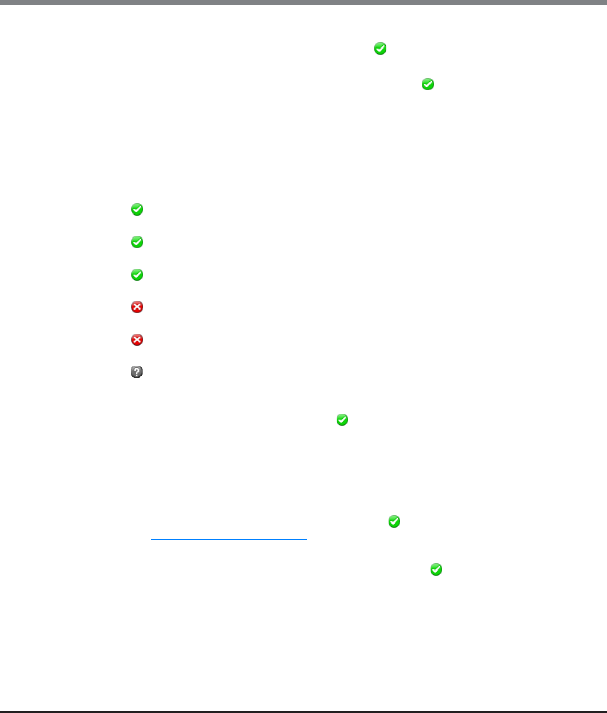
Chapter 8 Advanced Copy Management
8.1 Advanced Copy Status
ETERNUS Web GUI User’s Guide
Copyright 2013 FUJITSU LIMITED P2X0-1090-10ENZ0
262
•Source Volume No.
The copy source volume number is displayed. If the status is " Reserved", a "-" (hyphen) is displayed.
•Destination Volume No.
The copy destination volume number is displayed. If the status is " Reserved", a "-" (hyphen) is
displayed.
•Remote Session ID
The session ID for the remote device is displayed.
•Type
The copy session type is displayed using an abbreviation (REC).
•Status
The copy session status is displayed.
- Active
Operating normally
- Reserve
Session ID reserved
- Suspend
Suspended by an instruction from the host
- Halt
Remote copy disabled due to an error
- Error Suspend
Copy canceled due to an error
- Unknown
A status other than the ones listed above
•Phase
The copy session phase is displayed. If the status is " Reserved", a "-" (hyphen) is displayed.
-Copying
Copying
-Equivalent
Maintaining equivalent status of the copy source and copy destination that are duplicated after copy is
complete
•Error Code
The error code is displayed when an error occurs. If the status is " Reserved", a "-" (hyphen) is displayed.
Refer to "Appendix K Error Code" (page 1064) for details.
•Direction
The copy direction of the applicable session is displayed. If the status is " Reserved", a "-" (hyphen) is
displayed.
-From Local/To Remote
Session from the local device (copy source) to the remote device (copy destination)
-From Remote/To Local
Session from the remote device (copy source) to the local device (copy destination)
Chapter 8 Advanced Copy Management
8.1 Advanced Copy Status
ETERNUS Web GUI User’s Guide
Copyright 2013 FUJITSU LIMITED P2X0-1090-10ENZ0
263
•Time Stamp
The time when backup has been completed, and the time when an error occurred, are displayed.
The time stamp is updated when the process is suspended, when an error occurs, and when the status is
changed.
The following information is displayed for "Time Stamp".
-When "Status" is " Reserved", a "-" (hyphen) is displayed.
-When "Status" is " Active" and the copy session is not suspended yet, "0" is displayed for all of the
display items. When suspend is requested and "Status" is " Active", the backup time of the previous
suspend that was requested is displayed.
-When "Status" is " Suspend", the backup time when the copy was suspended is displayed.
-When "Status" is " Error Suspend", the time when an error occurred is displayed.
-When "Status" is " Halt", the time when an error occurred is displayed.
When the status is changed from " Halt" to " Active" or when the copy session is forcibly
suspended, the time stamp information is cleared and "0" is displayed for all of the display items.
•Elapsed Time
The elapsed time after a copy session starts is displayed. If the status is " Reserved", a "-" (hyphen) is
displayed.
•Copied Data Size
The size of copy that has been completed is displayed. If the status is " Reserved", a "-" (hyphen) is
displayed.
•Total Data Size
The total copy size is displayed. If the status is " Reserved", a "-" (hyphen) is displayed.
•Resolution
The copy session resolution is displayed. If the status is " Reserved", a "-" (hyphen) is displayed.
•Requestor
The information of the client that started the copy session is displayed. If the status is " Reserved", a "-"
(hyphen) is displayed.
-SCSI
Copy session requested by the copy management software (via SCSI).
-LAN
Copy session requested by the copy management software (via LAN).
-SMI-S
Copy session requested by SMI-S.
•License
The registration status of the Advanced Copy license when the copy session is started is displayed.
If the license information for the connection target storage system cannot be obtained due to an REC path
error, "Unknown" is displayed.
-Regular
The copy session is started with a paid license.
-Trial
The copy session is started with a trial license. Copy sessions that use a trial license are deleted
automatically after the expiration of the trial license.
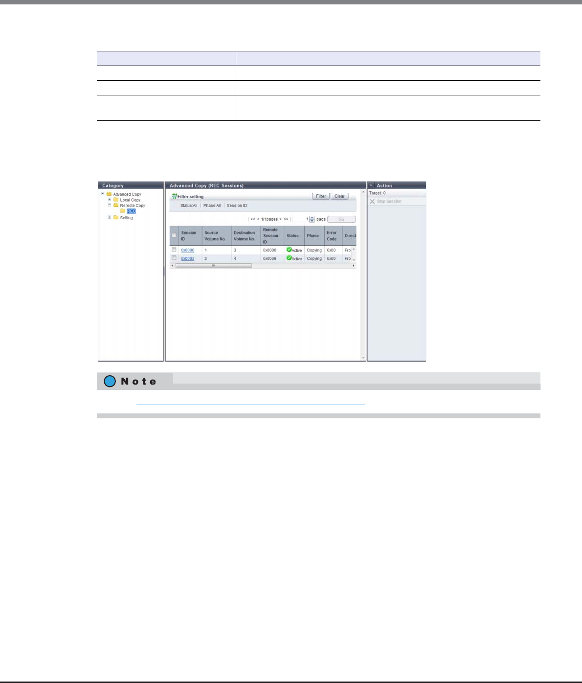
Chapter 8 Advanced Copy Management
8.1 Advanced Copy Status
ETERNUS Web GUI User’s Guide
Copyright 2013 FUJITSU LIMITED P2X0-1090-10ENZ0
264
Filter Setting
8.1.3.1 REC
This function displays detailed information for REC sessions.
Filter Description
Status Select the copy session status that is to be displayed.
Phase Select the copy session phase that is to be displayed.
Session ID Input the session ID of the copy session that is to be displayed.
When not using the session ID for filtering, leave this item blank.
Refer to "8.1.3 Advanced Copy (All Remote Sessions)" (page 261) for display items.
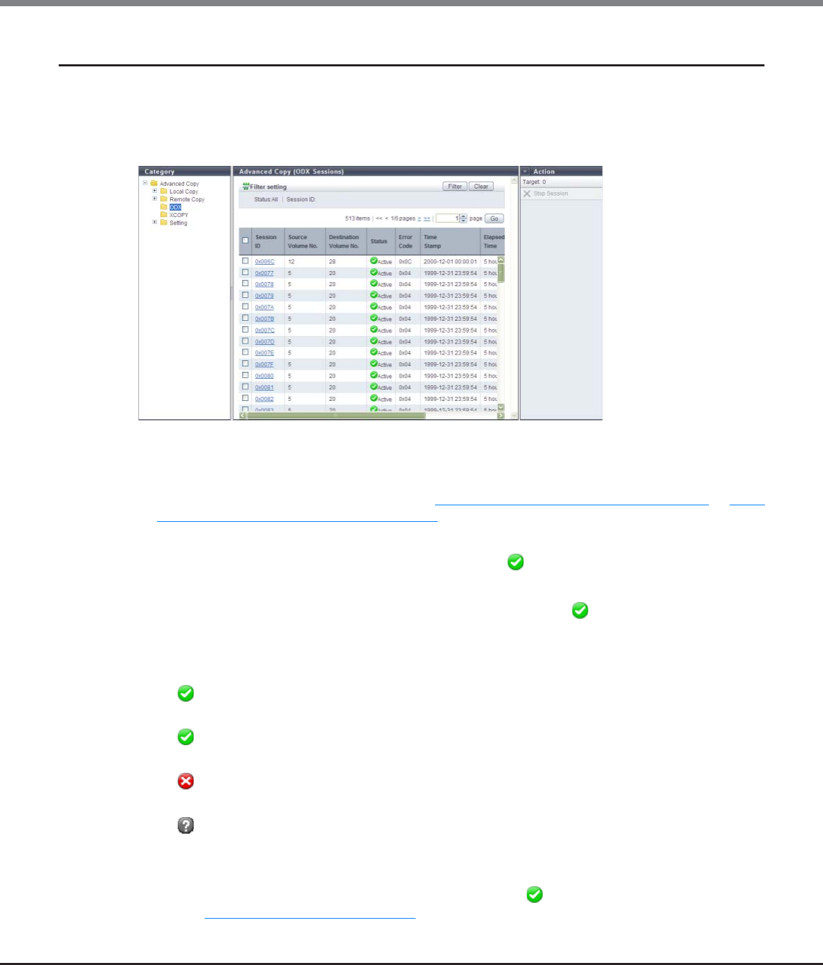
Chapter 8 Advanced Copy Management
8.1 Advanced Copy Status
ETERNUS Web GUI User’s Guide
Copyright 2013 FUJITSU LIMITED P2X0-1090-10ENZ0
265
8.1.4 Advanced Copy (ODX)
This function displays the status for ODX sessions.
ODX sessions are created when the ODX function is used for a server with "Windows Server 2012". The ODX
function offloads the workload for copying or migrating data from the server to the ETERNUS DX Disk storage
system.
The following items are displayed in the Main area:
•Session ID
The session ID is displayed.
Click this item to display the screen shown in "8.1.7 Advanced Copy (Property)" (page 277) or "8.1.8
Advanced Copy (Extent information)" (page 283).
•Source Volume No.
The copy source volume number is displayed. If the status is " Reserved", a "-" (hyphen) is displayed.
•Destination Volume No.
The copy destination volume number is displayed. If the status is " Reserved", a "-" (hyphen) is
displayed.
•Status
The copy session status is displayed.
- Active
Operating normally
- Reserve
Session ID reserved
- Error Suspend
Copy canceled due to an error
- Unknown
A status other than the ones listed above
•Error Code
The error code is displayed when an error occurs. If the status is " Reserved", a "-" (hyphen) is displayed.
Refer to "Appendix K Error Code" (page 1064) for details.
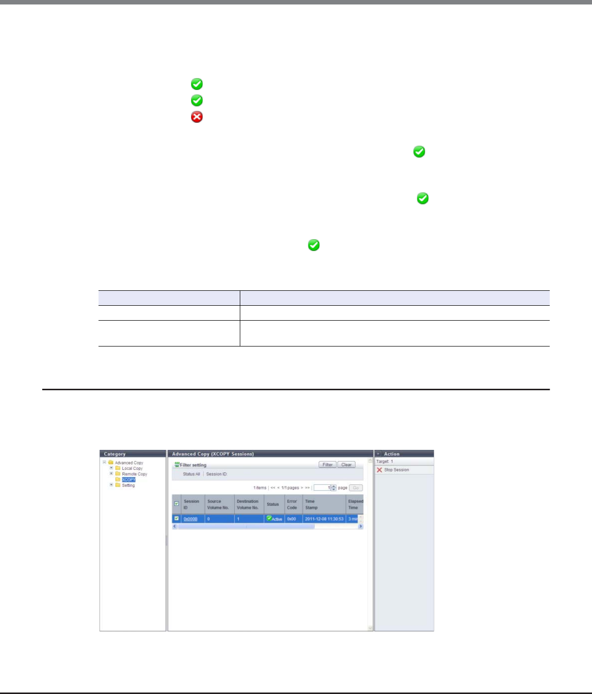
Chapter 8 Advanced Copy Management
8.1 Advanced Copy Status
ETERNUS Web GUI User’s Guide
Copyright 2013 FUJITSU LIMITED P2X0-1090-10ENZ0
266
•Time Stamp
The time when backup is complete and the time when an error occurred are displayed.
The time stamp is updated when starting a copy session or an error occurs.
The following information are displayed for this item:
-If the status is " Reserved", a "-" (hyphen) is displayed.
-If the status is " Active", the previous backup time is displayed.
-If the status is " Error Suspend", the time when an error occurred is displayed.
•Elapsed Time
The elapsed time after a session starts is displayed. If the status is " Reserved", a "-" (hyphen) is
displayed.
•Copied Data Size
The size of copy that has been completed is displayed. If the status is " Reserved", a "-" (hyphen) is
displayed.
•Total Data Size
The total copy size is displayed. If the status is " Reserved", a "-" (hyphen) is displayed.
Filter Setting
8.1.5 Advanced Copy (XCOPY)
This function displays the status for XCOPY sessions.
An XCOPY (Extended Copy) session is created when the Full Copy function of VMware vStorage APIs for Array
Integration (VAAI) is used.
Filter Description
Status Select the copy session status that is to be displayed.
Session ID Input the session ID of the copy session that is to be displayed.
When not using the session ID for filtering, leave this item blank.
Chapter 8 Advanced Copy Management
8.1 Advanced Copy Status
ETERNUS Web GUI User’s Guide
Copyright 2013 FUJITSU LIMITED P2X0-1090-10ENZ0
267
The following items are displayed in the Main area:
•Session ID
The session ID is displayed.
Click this item to display the screen shown in "8.1.7 Advanced Copy (Property)" (page 277) or "8.1.8
Advanced Copy (Extent information)" (page 283).
•Source Volume No.
The copy source volume number is displayed. If the status is " Reserved", a "-" (hyphen) is displayed.
•Destination Volume No.
The copy destination volume number is displayed. If the status is " Reserved", a "-" (hyphen) is
displayed.
•Status
The copy session status is displayed.
- Active
Operating normally
- Reserve
Session ID reserved
- Error Suspend
Copy canceled due to an error
- Unknown
A status other than the ones listed above
•Error Code
The error code is displayed when an error occurs. If the status is " Reserved", a "-" (hyphen) is displayed.
Refer to "Appendix K Error Code" (page 1064) for details.
•Time Stamp
The time when backup has been completed, and the time when an error occurred, are displayed.
The time stamp is updated when starting a copy session or an error occurs.
The following information is displayed:
-If the status is " Reserved", a "-" (hyphen) is displayed.
-If the status is " Active", the previous backup time is displayed.
-If the status is " Error Suspend", the time when the error occurred is displayed.
•Elapsed Time
The elapsed time after a session starts is displayed. If the status is " Reserved", a "-" (hyphen) is
displayed.
•Copied Data Size
The size of copy that has been completed is displayed. If the status is " Reserved", a "-" (hyphen) is
displayed.
•Total Data Size
The total copy size is displayed. If the status is " Reserved", a "-" (hyphen) is displayed.
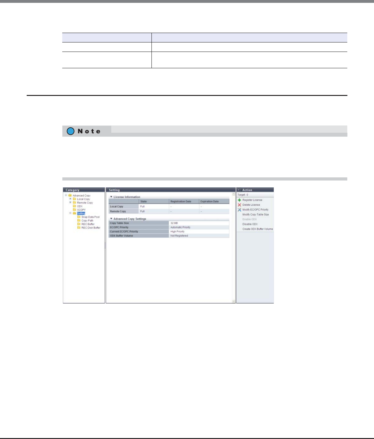
Chapter 8 Advanced Copy Management
8.1 Advanced Copy Status
ETERNUS Web GUI User’s Guide
Copyright 2013 FUJITSU LIMITED P2X0-1090-10ENZ0
268
Filter Setting
8.1.6 Setting (Advanced Copy)
This function displays the current Advanced Copy license registration status and the Advanced Copy setting
status.
The following items are displayed in the Main area:
●License Information
•State
Registration status of the Advanced Copy license is displayed.
-Not Registered
No license is registered.
-Free/VAAI
A free license and a VAAI-use license are registered.
Up to eight local copy sessions can be created. In addition, the Full Copy function of VMware VAAI can
be used. "Free License/VAAI" is displayed only for the ETERNUS DX80 S2/DX90 S2.
Filter Description
Status Select the copy session status that is to be displayed.
Session ID Input the session ID of the copy session that is to be displayed.
When not using the session ID for filtering, leave this item blank.
•When the trial license is registered, the registration date and the expiration date is displayed.
•The registration of an Advanced Copy license or setting of a copy table size is not required when using the
Full Copy function of VMware vStorage APIs for Array Integration (VAAI) with controller firmware version
V10L20 or later.

Chapter 8 Advanced Copy Management
8.1 Advanced Copy Status
ETERNUS Web GUI User’s Guide
Copyright 2013 FUJITSU LIMITED P2X0-1090-10ENZ0
269
-VAAI
VAAI-use license is registered.
The Full Copy function of VMware VAAI can be used. "VAAI" is displayed only for the ETERNUS DX410 S2/
ETERNUS DX440 S2 or the ETERNUS DX8100 S2/DX8700 S2.
-Trial
A trial license is registered. All of the Advanced Copy functions can be used for a limited time.
-Full
A paid license is registered. All of the advanced copy functions can be used.
•Registration Date
The date when the trial license was registered is displayed. A "-" (hyphen) is displayed in the following
conditions:
-Trial license has never been registered.
-A paid license, a free license, or VAAI is registered.
•Expiration Date
The expiration date for the trial license is displayed. A "-" (hyphen) is displayed in the following conditions:
-Trial license has never been registered.
-A paid license, a free license, or VAAI is registered.
●Advanced Copy Settings
•Copy Table Size
A copy table size is displayed.
•EC/OPC Priority
The EC/OPC priority is displayed.
-Automatic Priority
This mode changes the EC/OPC priority automatically in response to the operating load status.
-High Priority
This mode operates by making maximum use of internal resources.
-Middle Priority
This mode operates slightly slower than the High Priority mode.
-Low Priority
This mode reduces the effect on host access.
-Very Low Priority
This mode operates slower than the Low Priority mode.
•Current EC/OPC Priority
The current EC/OPC priority is displayed.
-High Priority
-Middle Priority
-Low Priority
-Very Low Priority
•ODX Buffer Volume
The registration status of the ODX Buffer volume is displayed.
-Registered
-Not Registered
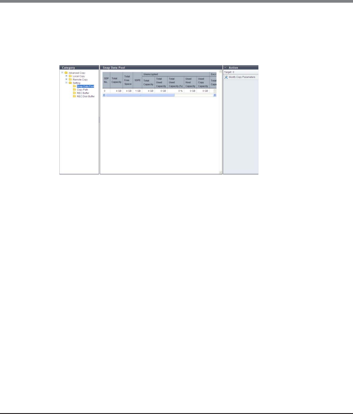
Chapter 8 Advanced Copy Management
8.1 Advanced Copy Status
ETERNUS Web GUI User’s Guide
Copyright 2013 FUJITSU LIMITED P2X0-1090-10ENZ0
270
8.1.6.1 Snap Data Pool
This function displays the SDP status.
SDP is the area used when in case executing SnapOPC and SnapOPC+ increases the amount of copy data and
exceeds the SDV capacity.
SDP becomes available when creating an SDPV. Created SDPV is automatically added to the SDP.
The following items are displayed in the Main area:
•SDP No.
The SDP number (fixed as "0") is displayed.
•Total Capacity
The total capacity of the SDP is displayed.
•Total Free Space
The total free space of the SDP is displayed.
•SDPE
Snap Data Pool Element (SDPE), the allocation unit for SDV, is displayed. Displayed with 1GB, 2GB, or 4GB.
•Unencrypted
-Total Capacity
The total capacity of unencrypted SDP is displayed.
-Total Used Capacity
The total used capacity of unencrypted SDP is displayed.
-Total Used Capacity (%)
The usage rate of unencrypted SDP is displayed.
-Used Host Capacity
The total capacity of the SDPE that is allocated for an unencrypted SDV where a capacity shortage
caused by data writing from the host has occurred is displayed.
-Used Copy Capacity
The total capacity of the SDPE that is allocated for an unencrypted SDV where a capacity shortage
caused by SnapOPC or SnapOPC+ has occurred is displayed.
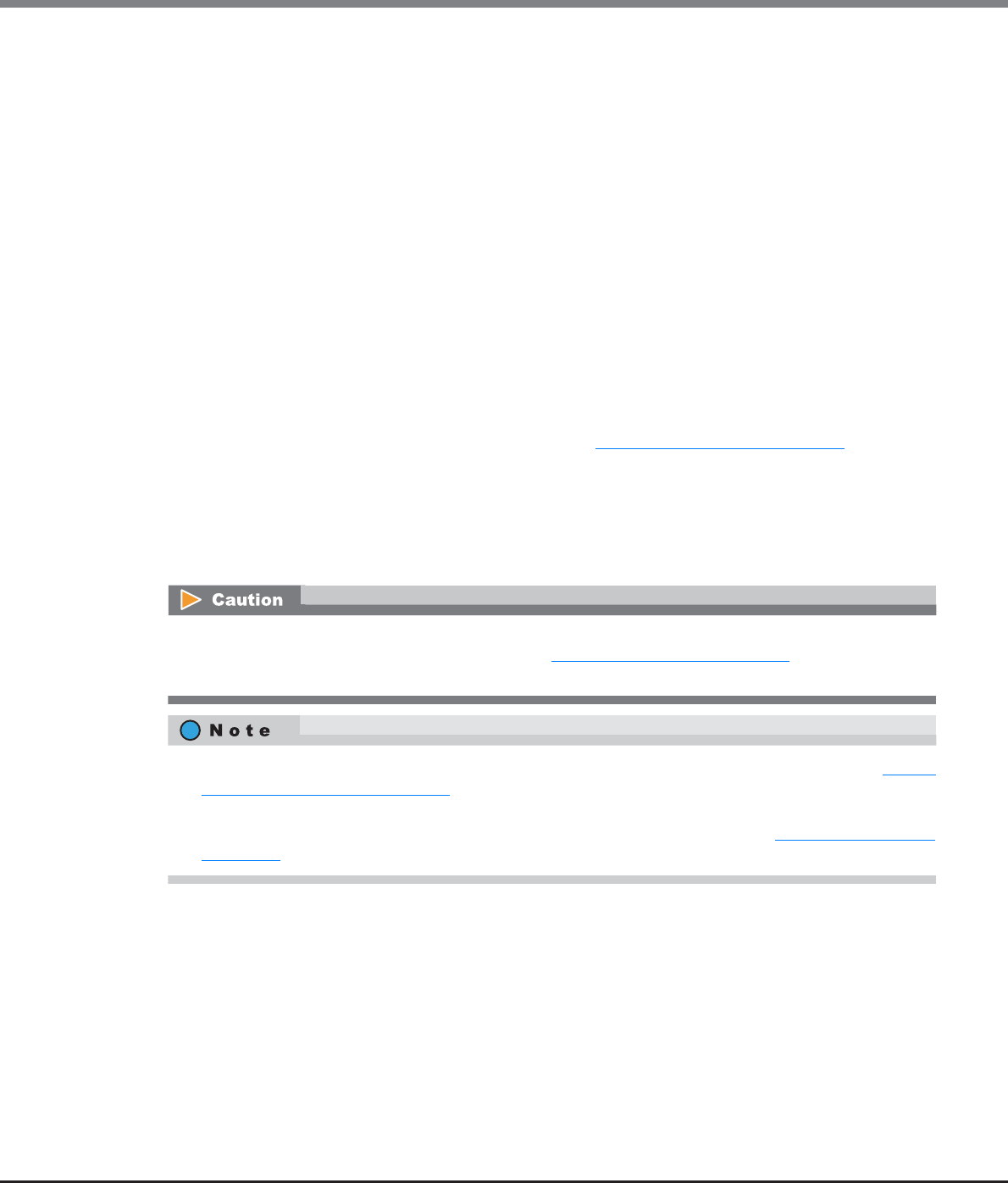
Chapter 8 Advanced Copy Management
8.1 Advanced Copy Status
ETERNUS Web GUI User’s Guide
Copyright 2013 FUJITSU LIMITED P2X0-1090-10ENZ0
271
•Encrypted
-Total Capacity
The total capacity of encrypted SDP is displayed.
-Total Used Capacity
The total used capacity of encrypted SDP is displayed.
-Total Used Capacity (%)
The usage rate of encrypted SDP is displayed.
-Used Host Capacity
The total capacity of the SDPE that is allocated for an encrypted SDV where a capacity shortage caused
by data writing from the host has occurred is displayed.
-Used Copy Capacity
The total capacity of the SDPE that is allocated for an encrypted SDV where a capacity shortage caused
by SnapOPC or SnapOPC+ has occurred is displayed.
8.1.6.2 Copy Path
This function displays the Remote Equivalent Copy (REC) path status between the local and remote devices. It
shows whether the copy path created with the function in "8.2.12 Set Copy Path" (page 318) is operating
properly.
Select the target remote device. (Up to 16 storage systems can be registered.) The following items are
displayed.
•Storage System
•Advanced Copy Path Status
This function is used to check the copy path status by actually sending a command to the copy path between
the storage systems. After following the procedure in "8.2.12 Set Copy Path" (page 318) to set a copy path,
make sure to check the copy path status with the Copy Path function.
•The "Priority Level" and the "Multiplicity" settings can be specified for each remote Box ID. Refer to "8.2.18
Modify REC Multiplicity" (page 351) for details.
•To change the "Link Speed" setting, create a copy path with a new link speed by using the [Set Copy Path]
function, and apply the created copy path to the related storage systems. Refer to "8.2.12 Set Copy Path"
(page 318) for details.
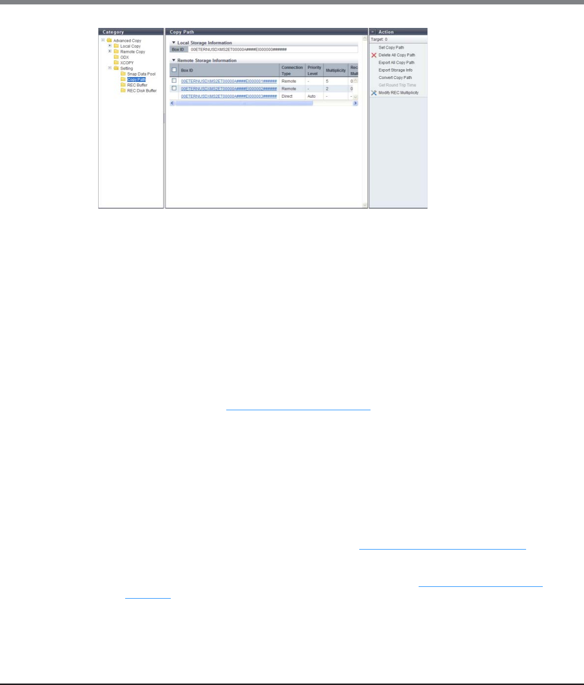
Chapter 8 Advanced Copy Management
8.1 Advanced Copy Status
ETERNUS Web GUI User’s Guide
Copyright 2013 FUJITSU LIMITED P2X0-1090-10ENZ0
272
The following items are displayed in the Main area:
●Local Device Information
•Box ID
The Box ID for the local device is displayed.
"Box ID" is an identifier used to identify individual storage systems. This ID is a unique name in the user
system and consists of 40-digit code.
The initial Box ID is a device ID consisting of device information (such as series name, model name, and
serial number).
●Remote Device Information
•Box ID
This is the Box ID of the remote device that has a path to the local device. Click this item to display the
[Copy Path] screen. Refer to "8.1.9 Copy Path Detail" (page 284) for details.
•Connection Type
The type of connection to the remote device that has a path to the local device is displayed.
-Direct
-Remote
•Priority Level
When the local device and the remote device are connected by direct connection, the priority level is
displayed. When the "Connection Type" is "Remote", a "-" (hyphen) is displayed.
-Automatic
REC is performed using the priority level (Automatic Priority/High Priority/Middle Priority/Low Priority/
Very Low Priority) that is specified using the procedure in "8.2.6 Modify EC/OPC Priority" (page 298).
-1 - 8
REC is performed with the displayed priority level. "1" corresponds to "Very Low Priority", and "8"
corresponds to "High Priority" that is specified using the procedure in "8.2.6 Modify EC/OPC Priority"
(page 298).

Chapter 8 Advanced Copy Management
8.1 Advanced Copy Status
ETERNUS Web GUI User’s Guide
Copyright 2013 FUJITSU LIMITED P2X0-1090-10ENZ0
273
•Multiplicity
When the local device and the remote device are connected by remote connection, the multiplicity is
displayed. If the "Connection Type" is "Direct", a "-" (hyphen) is displayed.
-Automatic
REC is performed with the recommended multiplicity that is calculated using the procedure in "8.2.17
Measure Round Trip Time" (page 349).
-1 - 1024
REC is performed with the multiplicity that is manually specified using the procedure in "8.2.18 Modify
REC Multiplicity" (page 351).
•Recommended Multiplicity
When the local device and the remote device are connected by remote connection, the recommended
multiplicity is displayed. If the "Connection Type" is "Direct", a "-" (hyphen) is displayed.
-0
The factory default setting.
-1 - 1024
The recommended multiplicity that is calculated using the procedure in "8.2.17 Measure Round Trip
Time" (page 349).
-***
The recommended multiplicity is not measured using the procedure in "8.2.17 Measure Round Trip
Time" (page 349).
•Link Speed
When the local device and the remote device are connected by remote connection, the link speed is
displayed between 1 Mbit/s - 65535 Mbit/s. If the "Connection Type" is "Direct", a "-" (hyphen) is displayed.
8.1.6.3 REC Buffer
This function displays the REC Buffer status when performing REC in "REC asynchronous consistency mode".
The "Consistency mode" secures the order of data transfer to the remote device for all of the specified REC
sessions. This mode requires constant securement of the dedicated REC Buffer in the cache memory. Copying
via REC Buffer stores multiple REC session I/Os in the REC Buffer for a certain period of time, and copies in
blocks.
Check if the REC Buffer capacity of the copy source and that of the copy destination are the same size.
If the capacities are not the same, configure the settings, using the procedure in "8.2.19 Modify REC Buffer"
(page 354) function, so that the REC Buffer capacity of the copy source and that of the copy destination
become the same size.
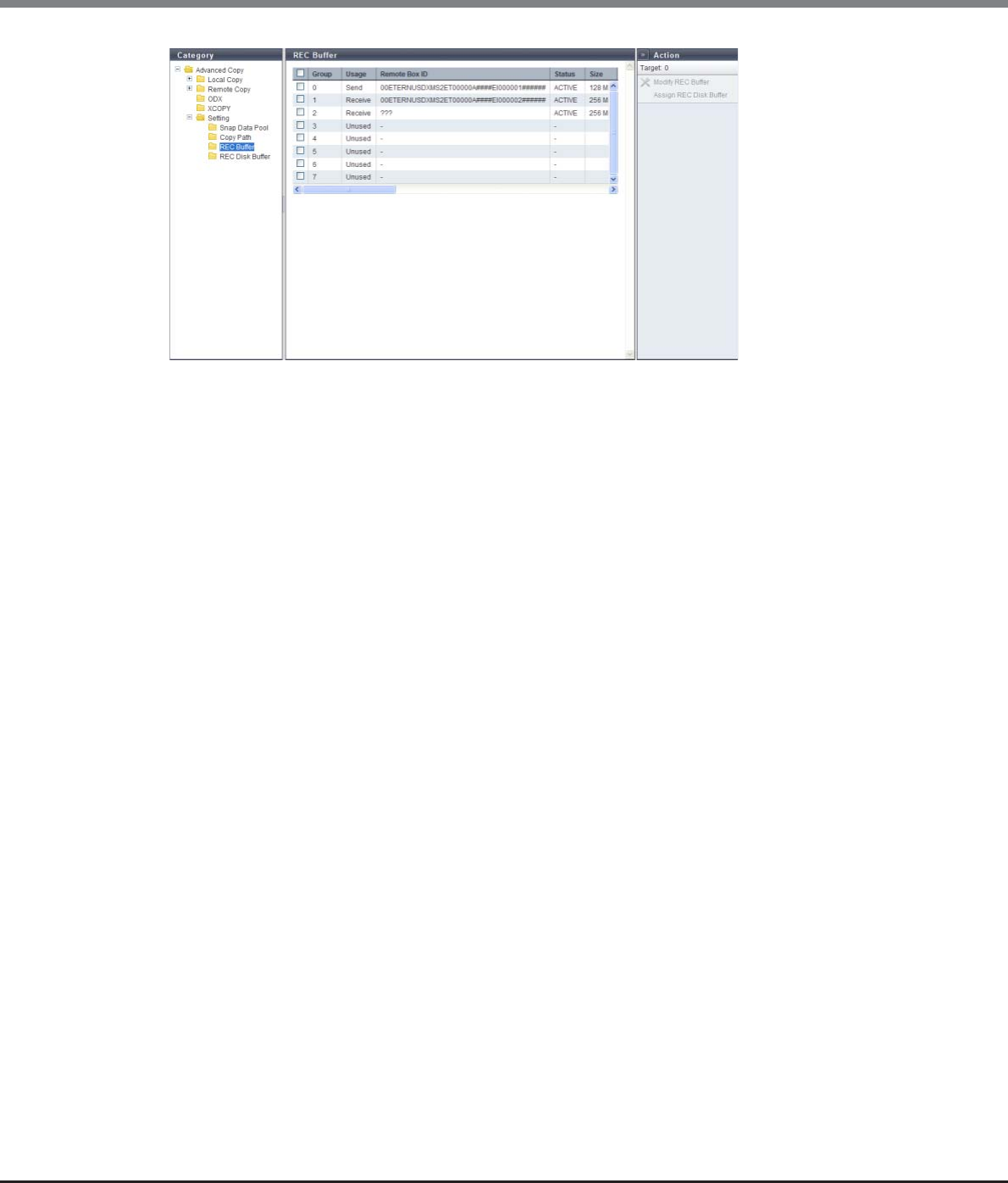
Chapter 8 Advanced Copy Management
8.1 Advanced Copy Status
ETERNUS Web GUI User’s Guide
Copyright 2013 FUJITSU LIMITED P2X0-1090-10ENZ0
274
The following items are displayed in the Main area:
•Group
The management group number of the REC Buffer is displayed.
-ETERNUS DX90 S2: 0 - 3
-ETERNUS DX410 S2/DX440 S2: 0 - 7
-ETERNUS DX8100 S2/DX8700 S2: 0 - 7
•Usage
The REC Buffer usage is displayed.
-Unused
-Send
-Receive
•Remote Box ID
The Box ID for the remote device is displayed.
If the copy path information is deleted, "???" is displayed. When the REC Buffer usage is "Unused", a "-"
(hyphen) is displayed.
•Status
The REC Buffer status is displayed.
-ACTIVE
REC Buffer is available.
-INACTIVE
REC Buffer is not available.
•Size
The REC Buffer size is displayed. When the REC Buffer usage is "Unused", a "-" (hyphen) is displayed.
-ETERNUS DX90 S2: 128MB, 256MB, 512MB
-ETERNUS DX410 S2/DX440 S2: 128MB, 256MB, 512MB, 1024MB, 2048MB
-ETERNUS DX8100 S2/DX8700 S2: 128MB, 256MB, 512MB, 1024MB, 2048MB
•Forwarding Interval
The data transfer interval is displayed. When the REC Buffer usage is "Unused", a "-" (hyphen) is displayed.

Chapter 8 Advanced Copy Management
8.1 Advanced Copy Status
ETERNUS Web GUI User’s Guide
Copyright 2013 FUJITSU LIMITED P2X0-1090-10ENZ0
275
•Monitoring Time
The monitoring time, before transition to the "Halt" status for a copy session when an REC Buffer shortage
occurs, is displayed. When the monitoring time" is "0 min.", the ETERNUS DX Disk storage system is not
being monitored. When the REC Buffer usage is "Unused", a "-" (hyphen) is displayed.
•HALT Wait Timer
The maximum non-responding time is displayed. During the non-response time, the host I/O response is
stopped to give priority to performing REC Buffer transfers in a high-load state. When the REC Buffer usage
is "Unused", a "-" (hyphen) is displayed.
•I/O Priority Mode
Whether the "I/O Priority Mode" is enabled or disabled is displayed. A "-" (hyphen) is displayed when the
usage is "Unused".
"I/O Priority Mode" reduces the effect on host I/O when an initial copy for starting, restarting, or recovering
the copy function is performed.
This item is available when logged in using a user account with the "Advanced Copy Management" policy.
•Immediate HALT Mode
Whether the "Immediate HALT Mode" is enabled or disabled is displayed. A "-" (hyphen) is displayed when
the usage is "Unused".
"Immediate HALT Mode" reduces the effect on host I/O because the REC Buffer is insufficient when "HALT
Wait Timer" is set to "0 sec.".
This item is available when logged in using a user account with the "Advanced Copy Management" policy.
•REC Disk Buffer Status
When the REC Buffer usage is "Send", the status of the REC Disk Buffers that are assigned to the REC Buffer
are displayed. When the REC Buffer usage is "Receive" or "Unused", a "-" (hyphen) is displayed.
-Active
All of the REC Disk Buffers in the REC Buffer are available.
-Rebuilding
Rebuild/copyback is being performed in some of the REC Disk Buffers.
-Formatting
Formatting is being performed in some of the REC Disk Buffers.
-Not Supported
The copy destination storage system for REC does not support the REC Disk Buffers.
-Not Mirrored
Some of the REC Disk Buffers have lost redundancy due to disk failure.
-Error
Some of the REC Disk Buffers cannot be used (due to RAID group failure or RAID group blockage).
If the "REC Disk Buffer Status" is "Formatting", "Not Supported", or "Error", all of the other REC Disk Buffers
that belong to the same REC Buffer cannot be used.
•REC Disk Buffer Total Capacity
When the usage is "Send", the total capacity of the REC Disk Buffer, which is assigned to the REC Buffer, is
displayed. When the REC Buffer usage is "Receive" or "Unused", a "-" (hyphen) is displayed.
•Total Storage Data Size
When the usage is "Send", the used capacity of the REC Disk Buffer, which is assigned to the REC Buffer, is
displayed. When the REC Buffer usage is "Receive" or "Unused", a "-" (hyphen) is displayed.
•Free Disk Buffer Size
When the usage is "Send", the unused capacity of the REC Disk Buffer, which is assigned to the REC Buffer,
is displayed. When the REC Buffer usage is "Receive" or "Unused", a "-" (hyphen) is displayed.
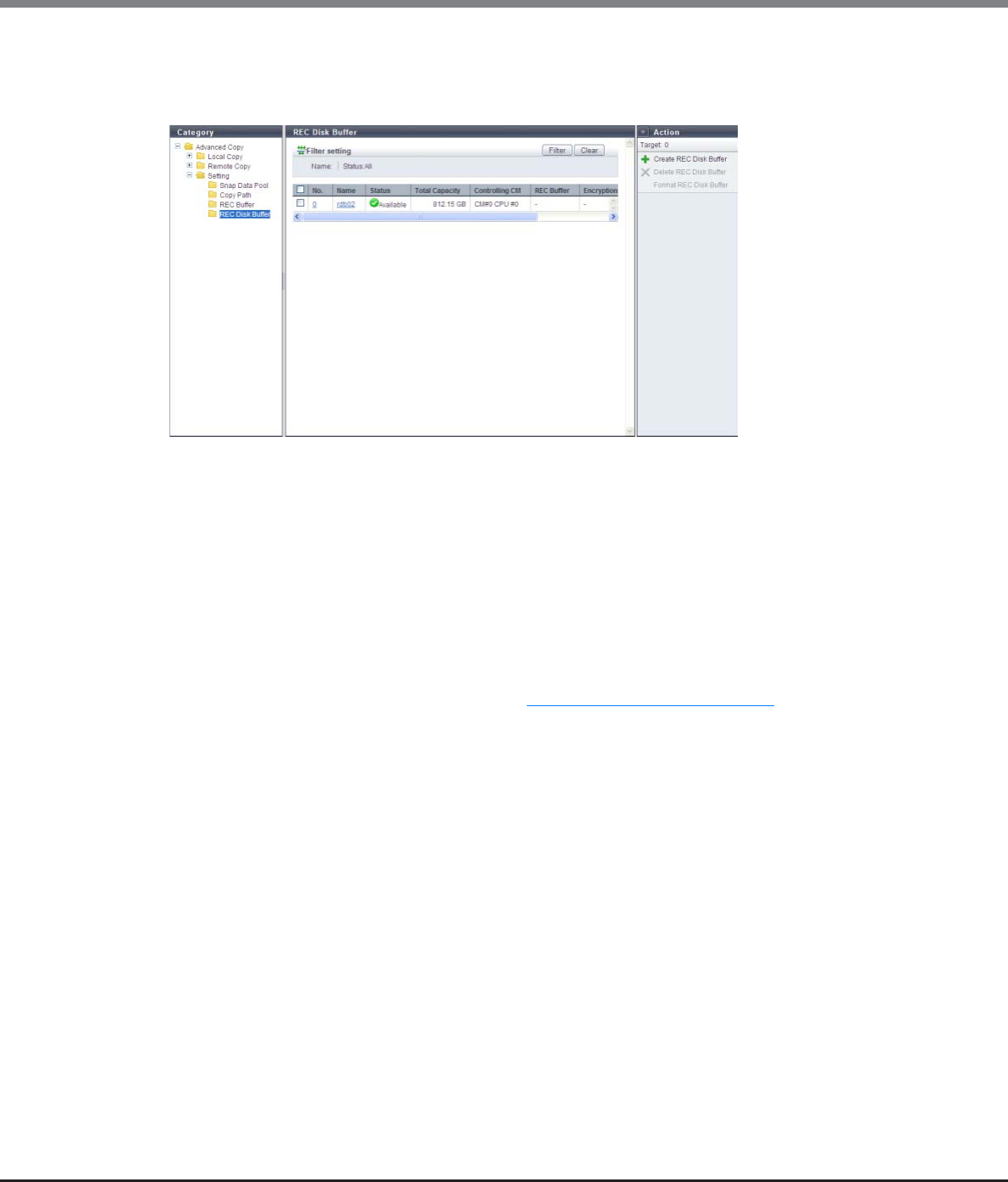
Chapter 8 Advanced Copy Management
8.1 Advanced Copy Status
ETERNUS Web GUI User’s Guide
Copyright 2013 FUJITSU LIMITED P2X0-1090-10ENZ0
276
8.1.6.4 REC Disk Buffer
This function displays the existing REC Disk Buffers in the ETERNUS DX Disk storage system.
The following items are displayed in the Main area:
●REC Disk Buffer List
•No.
The RAID group number of the REC Disk Buffer is displayed. Click this item to display the [REC Disk Buffer
Detail] screen.
•Name
The REC Disk Buffer name is displayed. Click this item to display the [REC Disk Buffer Detail] screen.
•Status
The REC Disk Buffer status is displayed. Refer to "B.3 RAID Group Status" (page 975) for details.
•Total Capacity
The total capacity of the REC Disk Buffer is displayed.
•Controlling CM
The controlling CM and CPU for the REC Disk Buffer are displayed.
-CM#x CPU#y (x: CM number, y: CPU number)
•REC Buffer
The management group number of the REC Buffer, to which the REC Disk Buffer is assigned, is displayed. A
"-" (hyphen) is displayed for an REC Disk Buffer that is not assigned to any REC Buffers.
-ETERNUS DX90 S2: 0 - 3
-ETERNUS DX410 S2/DX440 S2: 0 - 7
-ETERNUS DX8100 S2/DX8700 S2: 0 - 7
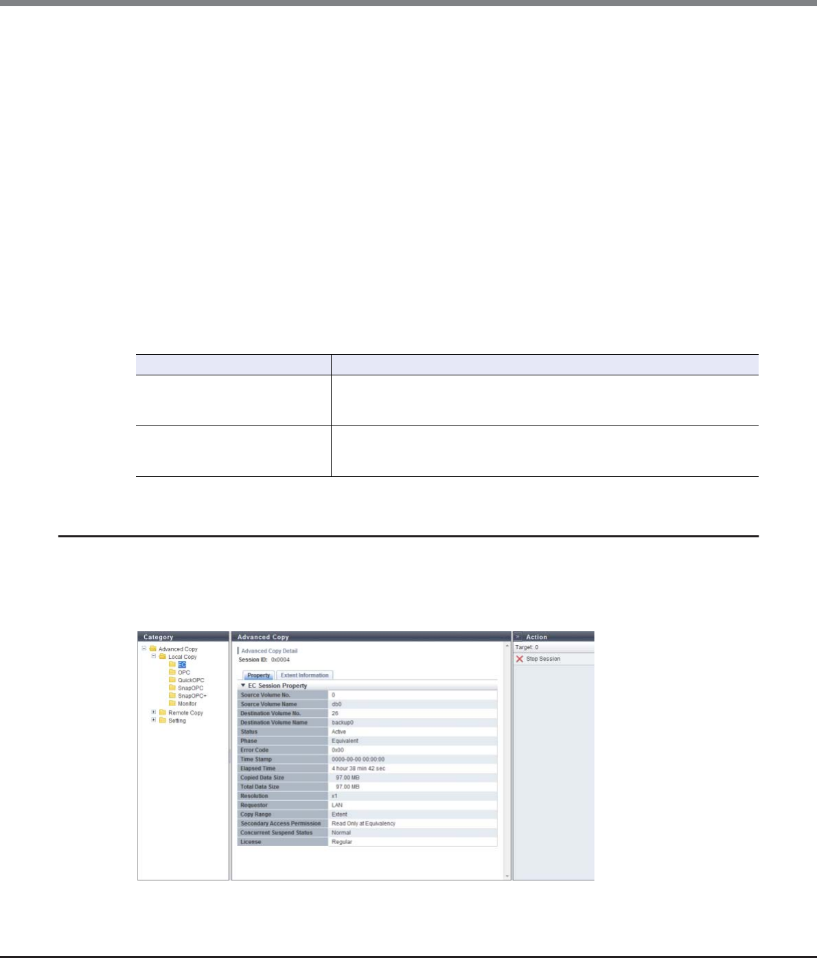
Chapter 8 Advanced Copy Management
8.1 Advanced Copy Status
ETERNUS Web GUI User’s Guide
Copyright 2013 FUJITSU LIMITED P2X0-1090-10ENZ0
277
•Encryption
The encryption status of the REC Disk Buffer is displayed.
-CM
An REC Disk Buffer that is encrypted by CM
-"-" (hyphen)
An REC Disk Buffer that is not encrypted (unencrypted volume)
-SED
An REC Disk Buffer that is encrypted by SED
•Processing Function
A process that is being performed for the REC Disk Buffer is displayed. If no process is being performed, a "-
" (hyphen) is displayed.
-Recovery
Rebuild, copyback, redundant copy, or recovery of the RAID group is being performed.
-Formatting
Formatting is being performed.
Filter Setting
8.1.7 Advanced Copy (Property)
Detailed information (Property) about the Advanced Copy is displayed.
■For Local Copy
Filter Description
Name
Input the REC Disk Buffer name that is to be displayed.
REC Disk Buffers matching or partially matching the input name are displayed.
When not using the REC Disk Buffer name for filtering, leave this item blank.
Status
Select the REC Disk Buffer status that is to be displayed.
When not using the REC Disk Buffer status for filtering, select "All" (all REC Disk
buffers).
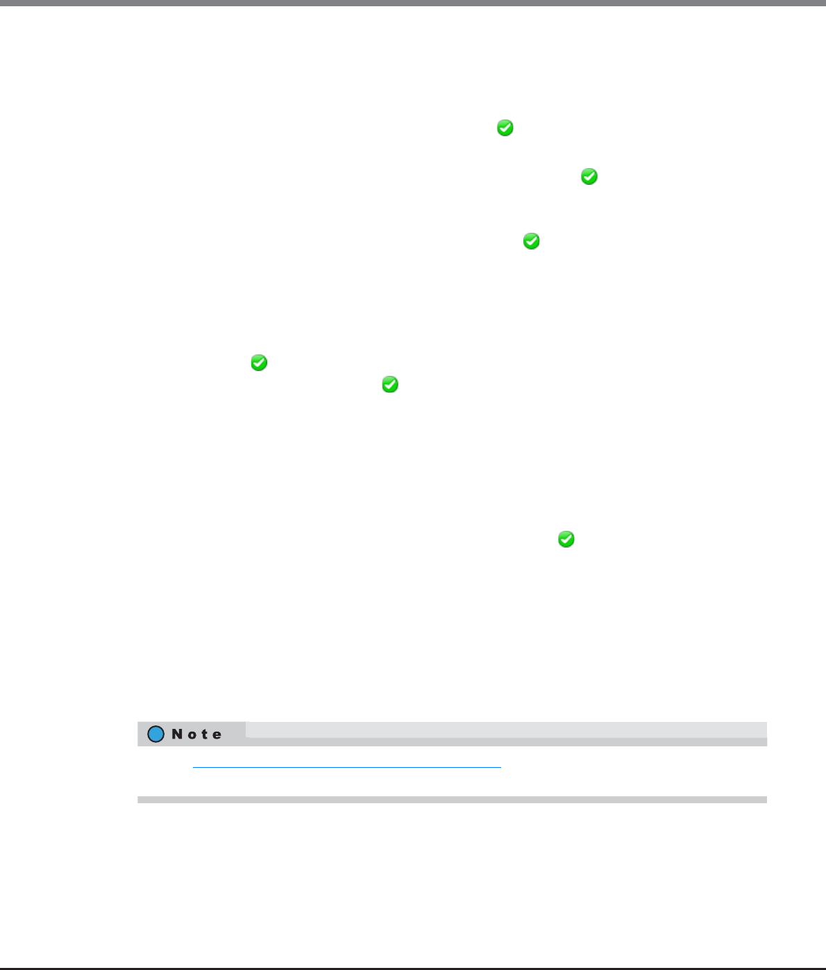
Chapter 8 Advanced Copy Management
8.1 Advanced Copy Status
ETERNUS Web GUI User’s Guide
Copyright 2013 FUJITSU LIMITED P2X0-1090-10ENZ0
278
The following items are displayed in the Main area:
•Session ID
The session ID selected in the [Local Copy] screen is displayed.
•Source Volume Name
The copy source volume name is displayed. If the status is " Reserved", a "-" (hyphen) is displayed.
•Destination Volume Name
The copy destination volume name is displayed. When the "Status" is " Reserved", a "-" (hyphen) is
displayed. When the "Type" is "MON", a "-" (hyphen) is displayed.
•Copy Range
The copy range of the copy session is displayed. If the status is " Reserved", a "-" (hyphen) is displayed.
-Totally
Whole volume
-Extent
Part of volume
•Secondary Access Permission
If the status is " Active", accessibility from the host to the copy destination volume is displayed. This
item is displayed in EC. If the status is " Reserved", a "-" (hyphen) is displayed.
-Read Only at Equivalency
When the "Phase" is "Equivalent", only read access to the copy destination volume is allowed
-No Read/Write
No read/write access to the copy destination volume is allowed
•Concurrent Suspend Status
When an instruction to collectively and tentatively separate multiple pairs of a copy source volume and a
copy destination volume (Concurrent Suspend request) is received in EC session, transition status to
"Suspend" is displayed. This item is displayed in EC. If the status is " Reserved", a "-" (hyphen) is dis-
played. If the Concurrent Suspend Status cannot be obtained, "Unknown" is displayed.
-Normal
Transition to "Suspend" status is complete or Concurrent Suspend cannot be performed
-Exec
Transition to "Suspend" status in progress
-Error
Transition to "Suspend" status failed
-Unknown
A status other than the ones listed above
Refer to "8.1.2 Advanced Copy (All Local Sessions)" (page 254) for the display items that are not described in
this section.
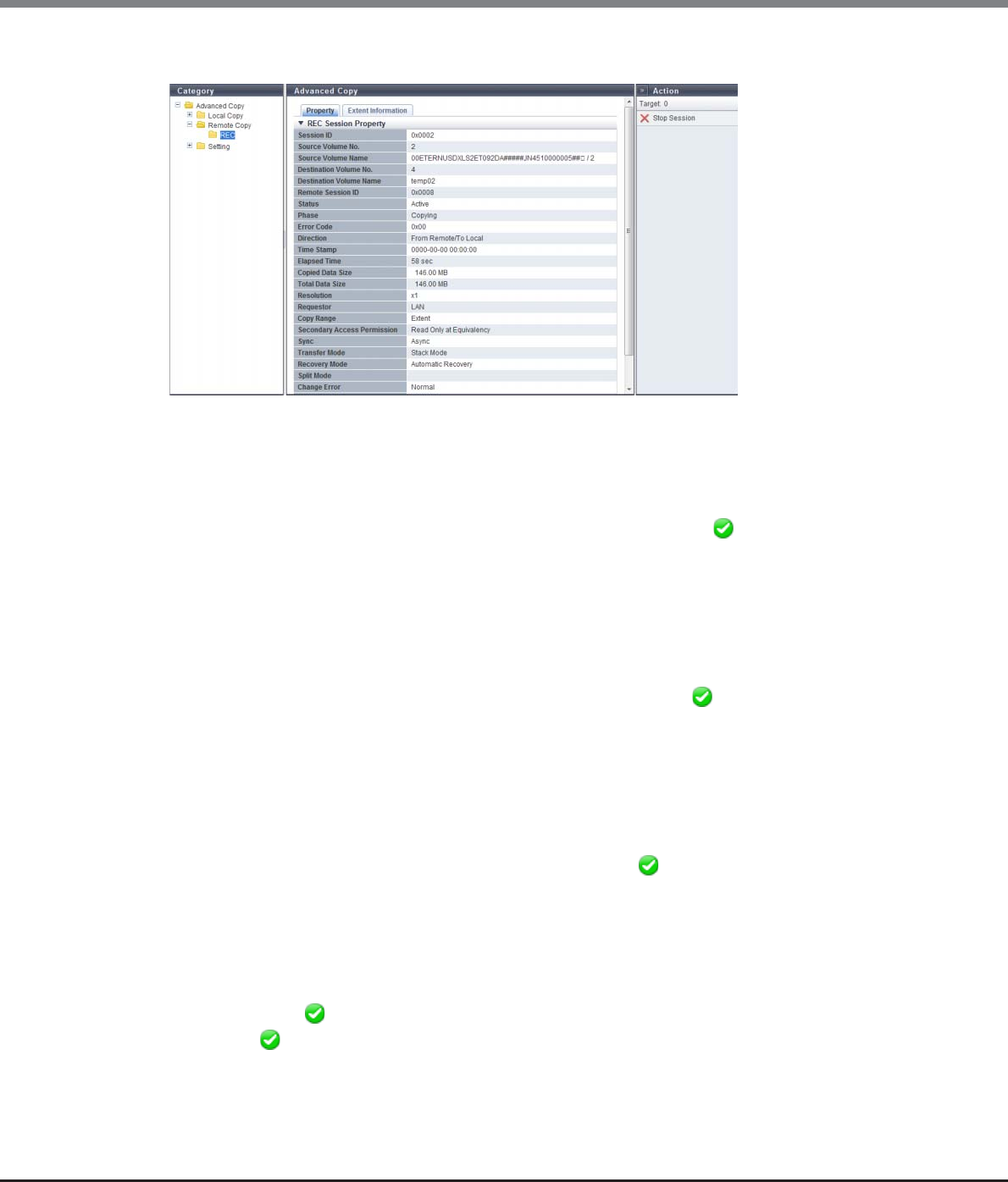
Chapter 8 Advanced Copy Management
8.1 Advanced Copy Status
ETERNUS Web GUI User’s Guide
Copyright 2013 FUJITSU LIMITED P2X0-1090-10ENZ0
279
■For Remote Copy
The following items are displayed in the Main area:
•Session ID
The session ID selected in the [Remote Copy] screen is displayed here.
•Source Volume Name
The following is displayed depending on the "Direction". If the status is " Reserved", a "-" (hyphen) is
displayed.
-When the "Direction" is "From Local/To Remote"
The copy source volume name is displayed.
-When the "Direction" is "From Remote/To Local"
The "Remote Box ID / Copy source volume number" is displayed.
•Destination Volume Name
The following is displayed depending on the "Direction". If the status is " Reserved", a "-" (hyphen) is dis-
played.
-When the "Direction" is "From Local/To Remote"
The "Remote Box ID / Copy destination volume number" is displayed.
-When the "Direction" is "From Remote/To Local"
The copy destination volume name is displayed.
•Copy Range
The copy range of the copy session is displayed. If the status is " Reserved", a "-" (hyphen) is displayed.
-Totally
Whole volume
-Extent
Part of volume
•Secondary Access Permission
If the status is " Active", accessibility from the host to the copy destination volume is displayed. If the
status is " Reserved", a "-" (hyphen) is displayed.
-Read Only at Equivalency
When the "Phase" is "Equivalent", only read access to the copy destination volume is allowed
-No Read/Write
No read/write access to the copy destination volume is allowed

Chapter 8 Advanced Copy Management
8.1 Advanced Copy Status
ETERNUS Web GUI User’s Guide
Copyright 2013 FUJITSU LIMITED P2X0-1090-10ENZ0
280
•Sync
The operation mode of the copy session is displayed. If the status is " Reserved", a "-" (hyphen) is dis-
played.
-Sync (synchronous)
-Async (asynchronous)
•Transfer Mode
The transfer mode of the copy session is displayed. If the "Status" is " Reserved", a "-" (hyphen) is dis-
played. If the "Sync" is "Sync", a "-" (hyphen) is displayed.
-Stack Mode (Asynchronous Stack mode)
-Consistency Mode (Asynchronous Consistency mode)
-Through Mode (Asynchronous Through mode)
•Recovery Mode
The recovery mode of the copy session is displayed. If the status is " Reserved", a "-" (hyphen) is dis-
played.
-Automatic Recovery
In this mode, copy automatically resumes when the copy path is recovered from error status.
-Manual Recovery
In this mode, copy does not automatically resume when the copy path is recovered from error status.
•Split Mode
The split mode of the copy session is displayed. This item is available only for sessions in REC synchronous
mode. If the status is " Reserved", a "-" (hyphen) is displayed. If the "Transfer Mode" is "Stack Mode" or
"Consistency Mode", the field is blank.
-Automatic
In this mode, Write I/O access to the copy source volume is accepted when the copy path is in error
status.
-Manual
In this mode, Write I/O access to the copy source volume is not accepted when the copy path is in error
status. Specific sense data is sent to the host.
•Change Error
The result of changing REC mode ("Transfer Mode", "Recovery Mode", or "Split Mode") and the result of REC
reverse operation is displayed.
When anything other than "Normal" is displayed, the operation mode may be different between the copy
source and the copy destination storage systems, or REC reverse operation may disabled due to restriction
in other functions.
If the status is " Reserved", a "-" (hyphen) is displayed.
-Normal
REC mode change and REC reverse operation are working normally
-Mode Change Error
An error was detected while changing the REC mode change
-Reverse Error
An error was detected while the REC reverse operation was being performed
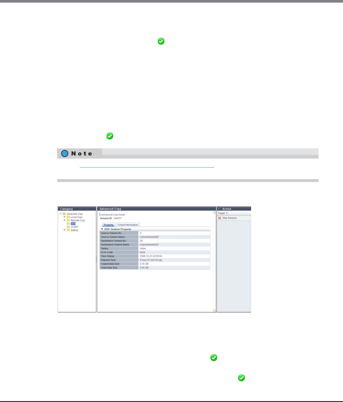
Chapter 8 Advanced Copy Management
8.1 Advanced Copy Status
ETERNUS Web GUI User’s Guide
Copyright 2013 FUJITSU LIMITED P2X0-1090-10ENZ0
281
•Concurrent Suspend Status
When an instruction to collectively and tentatively separate multiple pairs of a copy source volume and a
copy destination volume (Concurrent Suspend request) is received in REC session, transition status to
"Suspend" is displayed. If the status is " Reserved", a "-" (hyphen) is displayed. If the Concurrent Suspend
Status cannot be obtained, "Unknown" is displayed.
-Normal
Transition to " Suspend" status is complete or Concurrent Suspend cannot be performed
-Exec
Transition to " Suspend" status is in progress
-Error
Transition to " Suspend" status failed
-Unknown
A status other than the ones listed above
•Remain Time
The expected time to complete transition to "Suspend" when a Concurrent Suspend request is received.
If the "Status" is " Reserved", or if the "Remain Time" cannot be obtained, a "-" (hyphen) is displayed.
■For ODX
The following items are displayed in the Main area:
•Session ID
The session ID selected in the [ODX] screen is displayed here.
•Source Volume Name
The copy source volume name is displayed. If the "Status" is " Reserved", a "-" (hyphen) is displayed.
•Destination Volume Name
The copy destination volume name is displayed. If the "Status" is " Reserved", a "-" (hyphen) is
displayed.
Refer to "8.1.3 Advanced Copy (All Remote Sessions)" (page 261) for the display items that are not described
in this section.
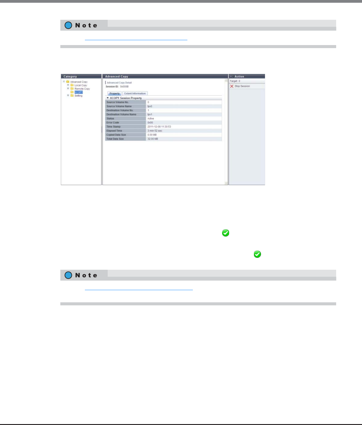
Chapter 8 Advanced Copy Management
8.1 Advanced Copy Status
ETERNUS Web GUI User’s Guide
Copyright 2013 FUJITSU LIMITED P2X0-1090-10ENZ0
282
■For XCOPY
The following items are displayed in the Main area:
•Session ID
The session ID selected in the [XCOPY] screen is displayed here.
•Source Volume Name
The copy source volume name is displayed. If the "Status" is " Reserved", a "-" (hyphen) is displayed.
•Destination Volume Name
The copy destination volume name is displayed. If the "Status" is " Reserved", a "-" (hyphen) is
displayed.
Refer to "8.1.4 Advanced Copy (ODX)" (page 265) for the display items that are not described in this section.
Refer to "8.1.5 Advanced Copy (XCOPY)" (page 266) for the display items that are not described in this
section.
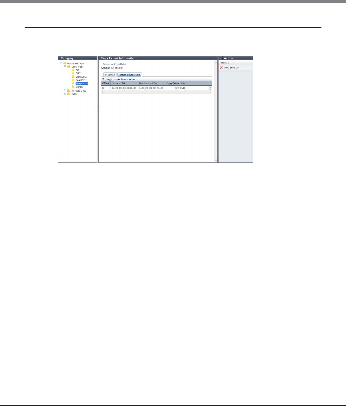
Chapter 8 Advanced Copy Management
8.1 Advanced Copy Status
ETERNUS Web GUI User’s Guide
Copyright 2013 FUJITSU LIMITED P2X0-1090-10ENZ0
283
8.1.8 Advanced Copy (Extent information)
Detailed information (Extent information) about the Advanced Copy is displayed.
This screen is available only when the "Copy Range" is "Extent".
The following items are displayed in the Main area:
•Offset
The array number of extent information is displayed.
•Source LBA
The copy source start Logical Block Address (LBA) of copy with range specification is displayed.
•Destination LBA
The copy destination start LBA of copy with range specification is displayed.
•Copy Extent Size
The data amount for copy with range specification is displayed.
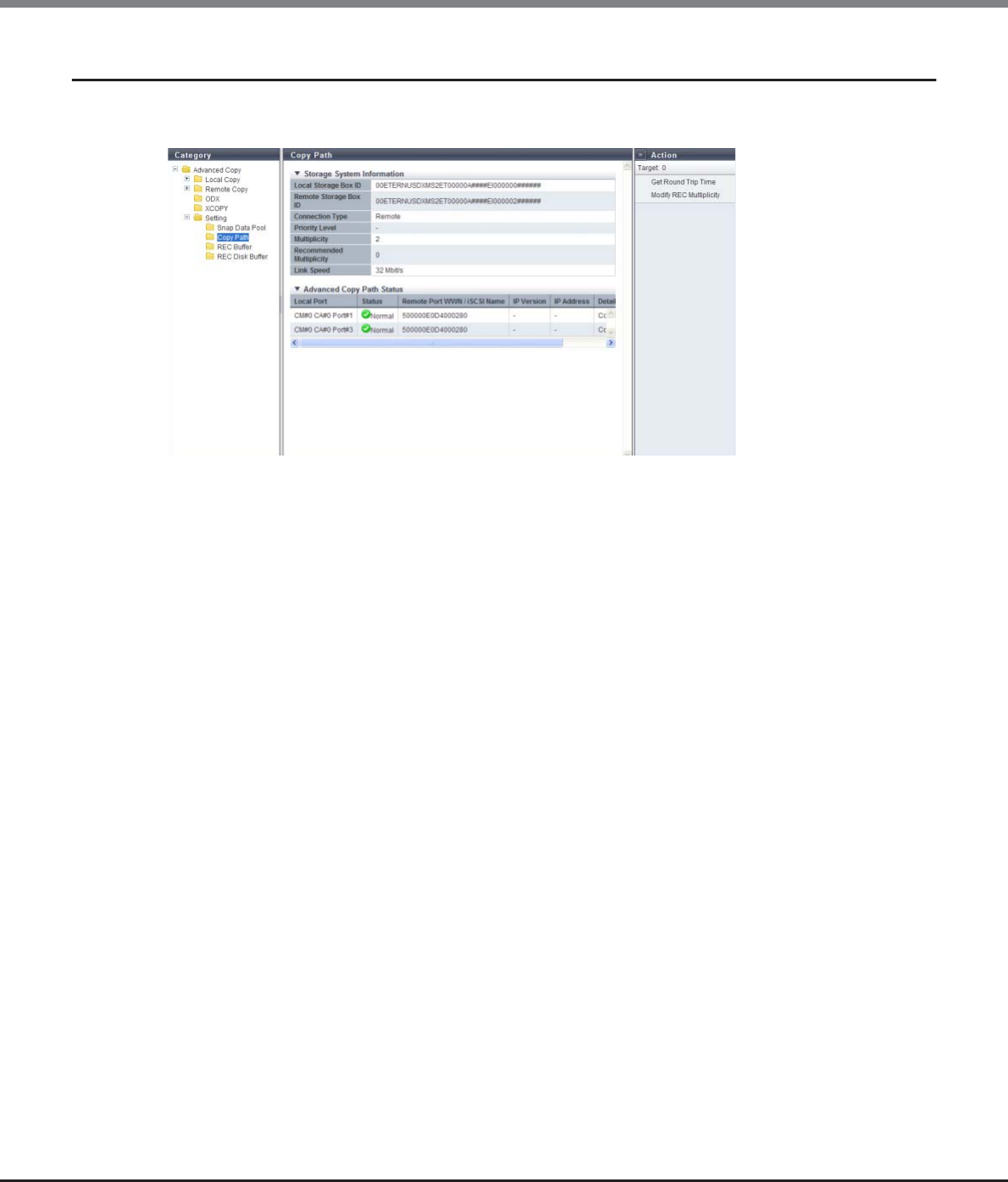
Chapter 8 Advanced Copy Management
8.1 Advanced Copy Status
ETERNUS Web GUI User’s Guide
Copyright 2013 FUJITSU LIMITED P2X0-1090-10ENZ0
284
8.1.9 Copy Path Detail
Detailed information of copy path is displayed.
The following items are displayed in the Main area:
●Storage System Information
•Local Device Box ID
The Box ID of the local device is displayed.
•Remote Device Box ID
The Box ID of the selected remote device is displayed.
•Connection Type
The connection type between the local device and the selected remote device is displayed.
-Direct
-Remote
•Priority Level
When the local device and the selected remote device are connected by direct connection, the priority level
is displayed. If the "Connection Type" is "Remote", a "-" (hyphen) is displayed.
•Multiplicity
When the local device and the selected remote device are connected by remote connection, the multiplicity
is displayed. If the "Connection Type" is "Direct", a "-" (hyphen) is displayed.
•Recommended Multiplicity
When the local device and the selected remote device are connected by remote connection, the
recommended multiplicity is displayed. If the "Connection Type" is "Direct", a "-" (hyphen) is displayed.
•Link Speed
When the local device and the selected remote device are connected by remote connection, the link speed
is displayed. If the "Connection Type" is "Direct", a "-" (hyphen) is displayed.

Chapter 8 Advanced Copy Management
8.1 Advanced Copy Status
ETERNUS Web GUI User’s Guide
Copyright 2013 FUJITSU LIMITED P2X0-1090-10ENZ0
285
●Advanced Copy Path Status
•Local Port
The port information of the local device is displayed.
•Status
The port path status between the local and remote devices is displayed with an icon and a character string.
- Normal
The copy path is in normal status.
- Error
The copy path is in error status
•Remote Port WWN/iSCSI Name
The port WWN or iSCSI name of the remote device is displayed.
•IP Version
When the port type is iSCSI, the IP version for the destination iSCSI port of the copy path is displayed.
A "-" (hyphen) is displayed when the port type is FC.
-IPv4
-IPv6 (Link Local)
-IPv6 (Connect IP)
-"-" (hyphen)
•IP Address
When the port type is iSCSI, the IP address for the destination iSCSI port of the copy path is displayed.
The display format varies according to the IP version.
A "-" (hyphen) is displayed when the port type is FC.
-For IPv4 address
•xxx.xxx.xxx.xxx
xxx: 0 - 255 (decimal)
-For IPv6 address
•xxxx:xxxx:xxxx:xxxx:xxxx:xxxx:xxxx:xxxx
xxxx: 0 - ffff (hexadecimal, "a" - "f" are lowercase letters)
Refer to "IPv6 Address Notation" (page 378) for details.
•Remote Port Mode
The remote port mode is displayed. This item is displayed only when the remote device is ETERNUS6000.
-Initiator
A dedicated port for sending
-Target
A dedicated port for downloading

Chapter 8 Advanced Copy Management
8.1 Advanced Copy Status
ETERNUS Web GUI User’s Guide
Copyright 2013 FUJITSU LIMITED P2X0-1090-10ENZ0
286
•Detail Information
Detailed information about the copy path is displayed.
If an error occurs in the copy path, the error details or location is displayed using the following
abbreviations. If there are multiple error locations, multiple abbreviations are displayed.
-Connectable
The copy path is in normal status.
-Path Unstable
The copy path between the local device and remote device is in unstable status. For example, link-
down repeatedly occurs in a certain period of time or communication fails.
-Bitmap Resolution Mismatched
The resolution settings are different between the local and remote devices.
-Suspected Spot (D)
The copy path settings may be invalid.
-Suspected Spot (N)
The error occurs in the remote device.
-Suspected Spot (T)
The error occurs in the FC-RA port or iSCSI-RA port on the remote device.
-Suspected Spot (C)
The error occurs in the cable.
-Suspected Spot (O)
The error occurs in an adapter that is not for a local or a remote device. This occurs only when the
connection type is FC-AL.
-Suspected Spot (S)
The error occurs in the switch or switch settings.
-Suspected Spot (I)
The error occurs in the FC-RA port or iSCSI-RA port on the local device.
-Suspected Spot (M)
The error occurs in the memory.

Chapter 8 Advanced Copy Management
8.2 Functions in the Action Area for Advanced Copy
ETERNUS Web GUI User’s Guide
Copyright 2013 FUJITSU LIMITED P2X0-1090-10ENZ0
287
8.2 Functions in the Action Area for Advanced Copy
When using functions in the Action area, select the desired function from the Action area that is displayed in
the status display screen.
The functions in the Action area for Advanced Copy can be performed from the following display functions:
Functions in the Action area for Advanced Copy Display function
Start SnapOPC+ •Advanced Copy (Basic Information)
•Advanced Copy (All Local Sessions)
•SnapOPC+ in Local Copy
Stop Copy Session •Advanced Copy (Basic Information)
•Advanced Copy (All Local Sessions)
•EC in Local Copy
•OPC in Local Copy
•QuickOPC in Local Copy
•SnapOPC in Local Copy
•SnapOPC+ in Local Copy
•Monitor in Local Copy
•Advanced Copy (All Remote Sessions)
•REC in Remote Copy
Register Advanced Copy License •Setting (Advanced Copy)
Delete Advanced Copy License
Modify EC/OPC Priority
Modify Copy Table Size
Enable ODX
Disable ODX
Create ODX Buffer Volume
Modify Copy Parameters •Snap Data Pool in Setting (Advanced Copy)
Set Copy Path •Copy Path in Setting (Advanced Copy)
Delete All Copy Path
Export All Copy Path
Export Storage Information
Convert Copy Path
Measure Round Trip Time
Modify REC Multiplicity
Modify REC Buffer •REC Buffer in Setting (Advanced Copy)
Assign REC Disk Buffer
Create REC Disk Buffer •REC Disk Buffer in Setting (Advanced Copy)
Delete REC Disk Buffer
Format REC Disk Buffer
Chapter 8 Advanced Copy Management
8.2 Functions in the Action Area for Advanced Copy
ETERNUS Web GUI User’s Guide
Copyright 2013 FUJITSU LIMITED P2X0-1090-10ENZ0
288
8.2.1 Required Settings for the Advanced Copy Function
This section describes the necessary preparation that must be performed to use the Advanced Copy function
and copy session management. Perform the required settings in the following order.
■Required settings for the Advanced Copy function (Local Copy and Remote Copy)
●Advanced preparation
The following items must be prepared to use the Advanced Copy functions:
(1)License registration
Register a license for using the Advanced Copy function.
If a license is not registered, up to eight copy sessions can be performed (only for ETERNUS DX80 S2/
DX90 S2).
(2)Copy destination volume creation
Create a copy destination physical volume according to the amount of updated data in the copy source
volume. Create an SDV and an SDPV when performing SnapOPC+.
Refer to "5.2.1 Create Volume" (page 96).
(3)Copy table size setting
Set the copy table size depending on the capacity of the copy target volume.
Refer to "8.2.7 Modify Copy Table Size" (page 301) and "How to calculate the copy table size" (page
308) for details.
(4)Copy priority setting
Specify the copy priority in the ETERNUS DX Disk storage system. It is not necessary to change the
default setting (Automatic Priority) for normal use.
Refer to "8.2.6 Modify EC/OPC Priority" (page 298).
When performing SnapOPC+, the following preparations are also required.
When using an Advanced Copy function, refer to "8.2.4 Register Advanced Copy License" (page 295) to
register the copy license.
•The RAID configuration of the copy source and copy destination can be different.
•The copy source and copy destination volume encryption status must match.

Chapter 8 Advanced Copy Management
8.2 Functions in the Action Area for Advanced Copy
ETERNUS Web GUI User’s Guide
Copyright 2013 FUJITSU LIMITED P2X0-1090-10ENZ0
289
Specify the automatic notification parameter when the SDP capacity is insufficient during a SnapOPC+
session.
(1)Copy parameter setting
Set the SDP capacity threshold for each policy level.
Refer to "8.2.11 Modify Copy Parameters" (page 316).
(2)Event notification setting
Select whether to notify when the SDP capacity exceeds the threshold. When notifying, select the
notification method.
Refer to "11.2.9.1 Setup Event Notification" (page 880).
When performing REC, the following preparations are also required.
(1)Port mode setting
Change the port mode from "CA" (for host connection) to "RA" (for REC connection) or "CA/RA".
Refer to "9.2.3.11 Modify Port Mode" (page 571).
(2)Copy path setting
Set the Copy path information between local and remote devices.
Refer to "8.2.12 Set Copy Path" (page 318).
(3)REC Buffer setting
Set the transfer buffer when performing REC in asynchronous consistency mode.
Refer to "8.2.19 Modify REC Buffer" (page 354).
(4)REC Disk Buffer setting
Set the REC Disk Buffer that is used for saving copy data temporarily when the REC Buffer capacity is
insufficient.
Refer to "8.2.21 Create REC Disk Buffer" (page 362).
(5)REC Disk Buffer allocation
Set REC Disk Buffer allocation.
Refer to "8.2.20 Assign REC Disk Buffer" (page 358).
(6)REC multiplicity setting
Set the multiplicity used for performing REC. It is not necessary to change the default setting (Auto-
matic) for normal use.
Refer to "8.2.18 Modify REC Multiplicity" (page 351).
(7)Copy path conversion
Convert the copy path information file format to perform REC with an older ETERNUS Disk storage
system. The copy path information file that is created using the procedure in "8.2.12 Set Copy Path"
(page 318) can be converted.
Refer to "8.2.16 Convert Copy Path" (page 347).
When monitoring copy paths and sessions, the following preparations are also required.
(1)Event notification setting
Set whether to notify REC path errors, REC Buffer halt operations when overloading or failure occurs,
session errors, and recovery from session errors. When notifying, select the notification method.
Refer to "11.2.9.1 Setup Event Notification" (page 880).

Chapter 8 Advanced Copy Management
8.2 Functions in the Action Area for Advanced Copy
ETERNUS Web GUI User’s Guide
Copyright 2013 FUJITSU LIMITED P2X0-1090-10ENZ0
290
●Copy session management
After preparation for Advanced Copy is complete, create a copy session to start copying volumes. Check the
copy session status during the copy operation.
(1)Copy session creation
Note that GUI can only create the SnapOPC+ sessions that are performed in volume units.
To create other copy sessions, use the copy management software. Refer to "8.2.2 Start SnapOPC+"
(page 291).
(2)Copy session check
Check the status of each copy session in the "Advanced Copy Session Information" field.
Refer to "8.1.1 Advanced Copy (Basic Information)" (page 252).
For REC sessions, checking copy path and buffer status are also available.
Refer to "8.1.6.2 Copy Path" (page 271) and "8.1.6.3 REC Buffer" (page 273) for details.
■Required settings for the Advanced Copy function (ODX)
●Advanced preparation
The following items must be prepared to use the ODX functions. The ODX function is supported by "Win-
dows Server 2012".
(1)Enable ODX
Enable the ODX function. The ODX function is disabled by default.
Refer to "8.2.8 Enable ODX" (page 310) for details.
(2)Create an ODX Buffer volume
Create an ODX Buffer volume. No ODX Buffer volumes are registered by default.
Refer to "8.2.10 Create ODX Buffer Volume" (page 311) for details.
(3)Event notification setting
Set whether to notify insufficient ODX Buffer volume capacity, session errors, and recovery from session
errors. When notifying, select the notification method.
Refer to "11.2.9.1 Setup Event Notification" (page 880).
Reboot any servers that are connected to the ETERNUS DX Disk storage system.
●Copy session management
After preparation for ODX copy is complete, create a copy session to start copying volumes. Check the copy
session status during the copy operation.
(1)Copy session check
Check the status of each copy session in the "Advanced Copy Session Information" field.
Refer to "8.1.1 Advanced Copy (Basic Information)" (page 252).
Chapter 8 Advanced Copy Management
8.2 Functions in the Action Area for Advanced Copy
ETERNUS Web GUI User’s Guide
Copyright 2013 FUJITSU LIMITED P2X0-1090-10ENZ0
291
●Stop ODX
The following items must be prepared after all the ODX sessions are complete or stopped:
(1)Delete an ODX Buffer volume
Delete the dedicated volumes for the ODX function.
Refer to "5.2.2 Delete Volume" (page 112) for details.
(2)Disable ODX
Disable the ODX function.
Refer to "8.2.9 Disable ODX" (page 311) for details.
Reboot any servers that are connected to the ETERNUS DX Disk storage system.
8.2.2 Start SnapOPC+
This function is used to select the copy source volume and copy destination volume, and start a new SnapOPC+
copy session.
The procedure to start the SnapOPC+ session is as follows:
Procedure
1Click [Start SnapOPC+] in [Action].
•Only SnapOPC+ copy sessions that are performed in units of volumes can be created using GUI.
To create EC sessions, OPC sessions, QuickOPC sessions, SnapOPC sessions, SnapOPC+ sessions using
range selection, and REC sessions, use copy management software.
•When using SnapOPC+, SDVs are required as copy destination volumes. The "Capacity of source volume"
that is specified when creating SDVs indicates the copy source Standard volume capacity.
When creating an SDV using the [Create Volume] function, the capacity setting is not required. 24 (MB) +
0.1% of the copy source volume capacity is automatically secured in the ETERNUS DX Disk storage system.
"24MB" is the smallest volume capacity. 0.1% of the copy source volume is the capacity that is used for
the controlling information area in the SDV. When using SnapOPC or SnapOPC+, make sure to create an
SDV and SDPVs. An SDPV is a volume that configures an SDP. The SDP allocates free space when SDV
capacity is insufficient.
•An ODX Buffer volume cannot be specified as a copy source.
For controller firmware version V10L30 or later, the number of available generations for SnapOPC+ is 512.
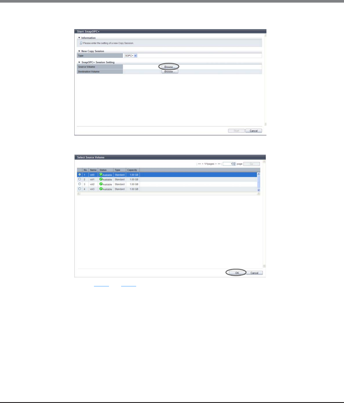
Chapter 8 Advanced Copy Management
8.2 Functions in the Action Area for Advanced Copy
ETERNUS Web GUI User’s Guide
Copyright 2013 FUJITSU LIMITED P2X0-1090-10ENZ0
292
2Click the [Browse...] button.
3Select the radio button for the volume to be used, and click the [OK] button.
Perform Step 2 and Step 3 in the [Select Source Volume] screen and in the [Select Destination Volume]
screen.
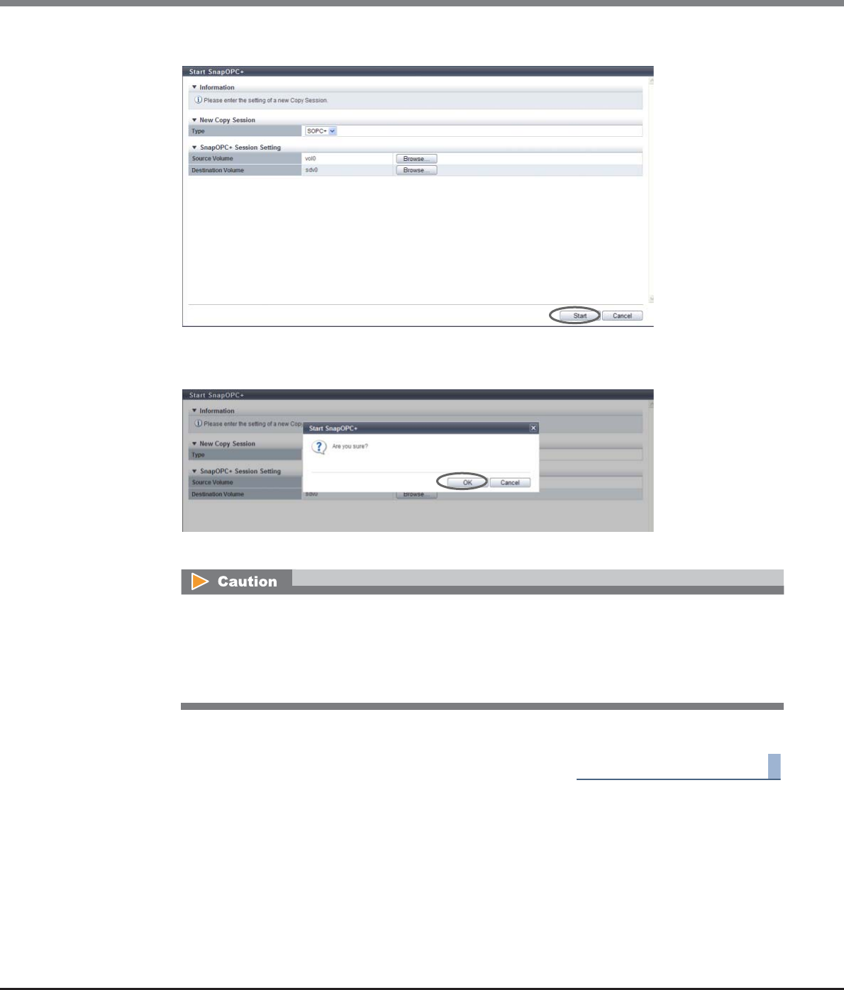
Chapter 8 Advanced Copy Management
8.2 Functions in the Action Area for Advanced Copy
ETERNUS Web GUI User’s Guide
Copyright 2013 FUJITSU LIMITED P2X0-1090-10ENZ0
293
4Check the displayed contents, and click the [Start] button.
→A confirmation screen appears.
5Click the [OK] button.
→SnapOPC+ session starts.
6Click the [Done] button to return to the [Advanced Copy] screen.
End of procedure
An error screen appears in the following conditions:
•When the SnapOPC+ started in the copy source volume exceeds the maximum number of
generations per volume
•When the SnapOPC+ started in the copy source volume exceeds the maximum number of copy
sessions for the entire ETERNUS DX Disk storage system
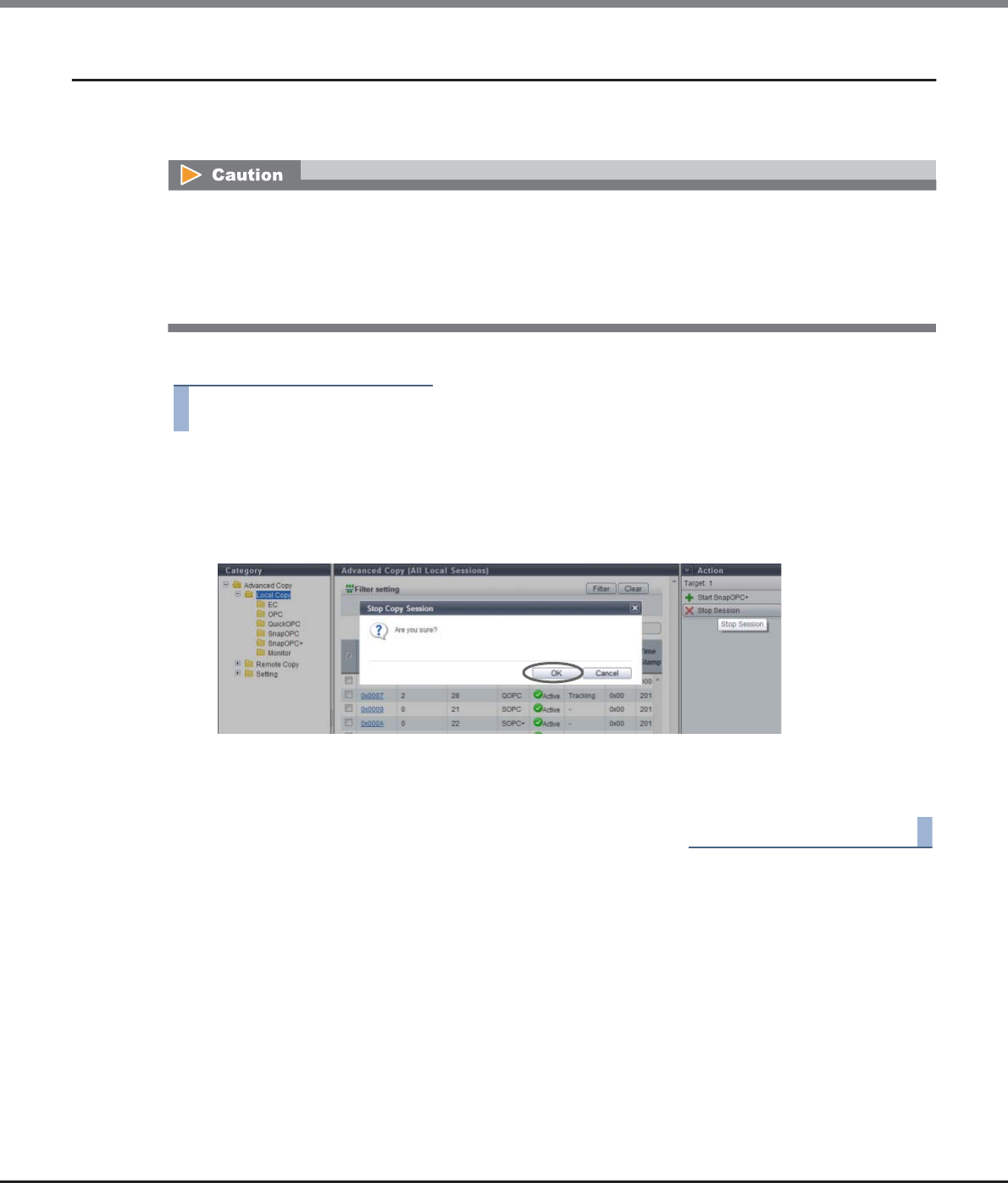
Chapter 8 Advanced Copy Management
8.2 Functions in the Action Area for Advanced Copy
ETERNUS Web GUI User’s Guide
Copyright 2013 FUJITSU LIMITED P2X0-1090-10ENZ0
294
8.2.3 Stop Copy Session
This function stops the selected copy session.
This function is used when a session cannot be stopped due to a host error or other causes.
The procedure to stop a copy session is as follows:
Procedure
1Select the copy session to be stopped (multiple selections can be made) and click [Stop
Session] in [Action].
→A confirmation screen appears.
2Click the [OK] button.
→The selected copy session is stopped.
3Click the [Done] button to return to the [Advanced Copy] screen.
End of procedure
•If one SnapOPC+ session is stopped, all the sessions started earlier than that session are also stopped.
•If one SnapOPC+ session is stopped, all the Restore OPC sessions started earlier than that session become
in error status.
•If a SnapOPC or SnapOPC+ session during a Restore OPC session is stopped, that Restore OPC session
becomes in error status.
Chapter 8 Advanced Copy Management
8.2 Functions in the Action Area for Advanced Copy
ETERNUS Web GUI User’s Guide
Copyright 2013 FUJITSU LIMITED P2X0-1090-10ENZ0
295
8.2.4 Register Advanced Copy License
This function registers the Advanced Copy license for EC, OPC, QuickOPC, SnapOPC, SnapOPC+, and REC.
There are two types of Advanced Copy licenses:
•Paid License
All of the Advanced Copy functions can be used.
•Free License
For the ETERNUS DX80 S2/DX90 S2, up to eight sessions with the local Advanced Copy function can be
used.
When this registration is complete successfully, the customer can use the Advanced Copy functions.
The procedure to register an Advanced Copy license is as follows:
Procedure
1Click [Register License] in [Action].
2Select a registration method, enter an Advanced Copy license key to be registered, and click
the [Register] button.
•Registration Method
To register a paid license, select "Input License Key" and enter the Advanced Copy license key that is
to be registered.
When using the Full Copy function of VMware vStorage APIs for Array Integration (VAAI) with
controller firmware version V10L20 or later, registering an Advanced Copy license is not required.
When using a free license for the ETERNUS DX80 S2/DX90 S2, select "Use Free License/VAAI".
If the Advanced Copy license is already registered, "Use Free License/ VAAI" and "Use VAAI" cannot be
selected.
Refer to "Availability of Copy Functions" (page 297) for the availability of copy functions when
selecting "Use Free License/VAAI" or "Use VAAI".
There are no free licenses for the ETERNUS DX410 S2/DX440 S2 or ETERNUS DX8100 S2/DX8700 S2
•When using ETERNUS SF AdvancedCopy Manager or ETERNUS SF Express, perform the required settings
described in the documents that are supplied with ETERNUS SF AdvancedCopy Manager or ETERNUS SF
Express.
•The registration status of the Advanced Copy license can be checked. Refer to "8.1.6 Setting (Advanced
Copy)" (page 268) for details.
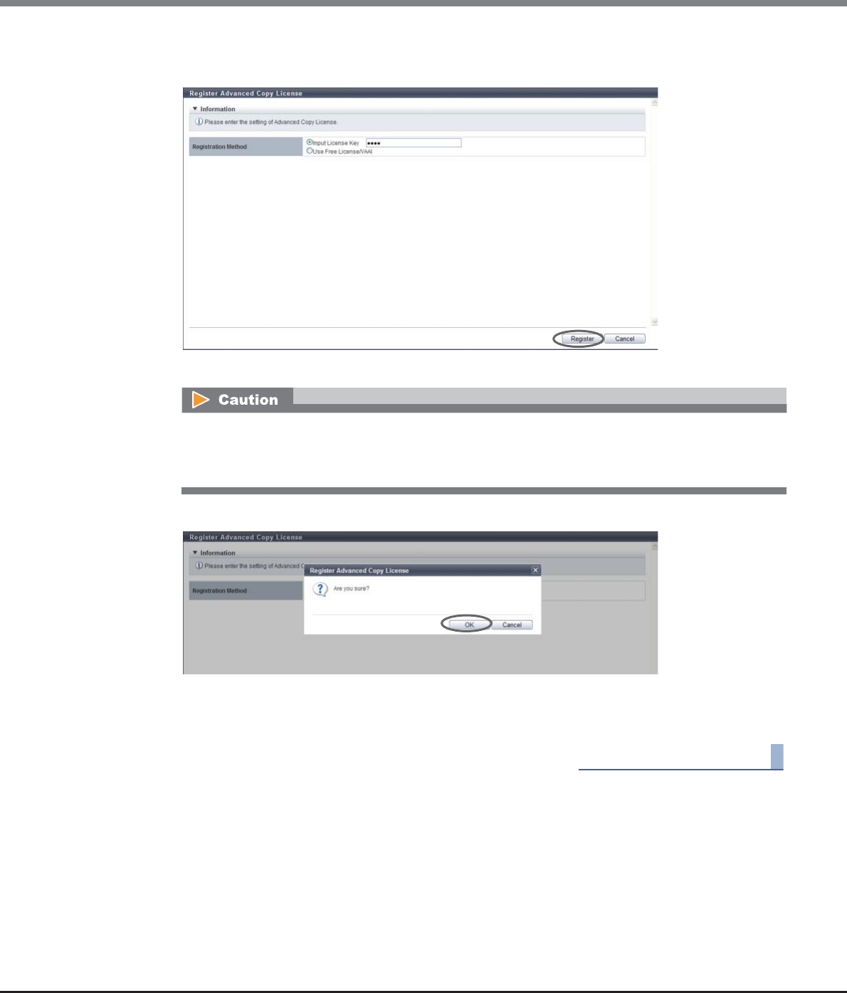
Chapter 8 Advanced Copy Management
8.2 Functions in the Action Area for Advanced Copy
ETERNUS Web GUI User’s Guide
Copyright 2013 FUJITSU LIMITED P2X0-1090-10ENZ0
296
•Input License key
Input the Advanced Copy license key.
→A confirmation screen appears.
3Click the [OK] button.
→The Advanced Copy license registration is executed.
4Click the [Done] button to return to the [Setting] screen.
End of procedure
•Only when registering a paid license, the Advanced Copy license key entry is required.
•When the entered Advanced Copy license key does not satisfy the input conditions, an error screen
appears.
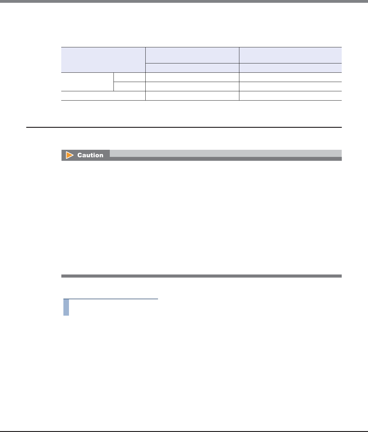
Chapter 8 Advanced Copy Management
8.2 Functions in the Action Area for Advanced Copy
ETERNUS Web GUI User’s Guide
Copyright 2013 FUJITSU LIMITED P2X0-1090-10ENZ0
297
Availability of Copy Functions
The following table shows the availability of copy functions when "Use Free License/ VAAI" or "Use VAAI" is
selected.
8.2.5 Delete Advanced Copy License
This function deletes all of the Advanced Copy licenses registered in the ETERNUS DX Disk storage system.
The procedure to delete an Advanced Copy license is as follows:
Procedure
1Click [Delete License] in [Action].
→A confirmation screen appears.
Copy Type ETERNUS DX80 S2/DX90 S2 ETERNUS DX410 S2/DX440 S2
ETERNUS DX8100 S2/DX8700 S2
Use Free License/VAAI Use VAAI
Advanced Copy Local OK (Up to eight sessions) NG
Remote NG NG
Full Copy by VAAI OK OK
•An Advanced Copy license cannot be deleted in the following conditions:
-When the CM status is other than "Normal"
-When an SDV or an SDPV has been registered
-When a volume that is Advanced Copy protected exists
-When an Advanced Copy session (except for an ODX session or an XCOPY session) exists
-When an Advanced Copy table size has been configured
-When an Advanced Copy path has been configured
-When REC Buffer has been configured
-When REC Disk Buffer has been created
-When a port with the RA mode exists
-When a port with the CA/RA mode exists
•Rebooting the ETERNUS DX Disk storage system is required after deleting an Advanced Copy license.
Chapter 8 Advanced Copy Management
8.2 Functions in the Action Area for Advanced Copy
ETERNUS Web GUI User’s Guide
Copyright 2013 FUJITSU LIMITED P2X0-1090-10ENZ0
298
2Click the [OK] button.
→Deletion of an Advanced Copy license is executed.
3Click the [Done] button to return to the [Setting] screen.
End of procedure
8.2.6 Modify EC/OPC Priority
This function sets the copy speed when using EC and OPC.
The EC/OPC speed is usually set in consideration of the host's I/O load and copy processing load. The set EC/OPC
speed is applied not only for the next sessions, but also for existing sessions.
The procedure to modify the EC/OPC priority is as follows:
Procedure
1Click [Modify EC/OPC Priority] in [Action].
Registering the license for the Advanced Copy feature is required to use EC and OPC.
•EC includes both EC and REC.
Even though the REC priority is specified using the procedure in "8.2.18 Modify REC Multiplicity" (page
351), the EC/OPC priority values specified with this function are applied only when the REC satisfies both
of the following conditions:
-When the connection method is "Direct"
-When the priority level is "Auto"
Refer to "8.2.12 Set Copy Path" (page 318) for connection type settings.
Refer to "8.2.18 Modify REC Multiplicity" (page 351) for priority level settings.
•OPC includes OPC, QuickOPC, SnapOPC, and SnapOPC+.
•When "Auto" is selected for "EC/OPC Priority", the current priority level can be checked. Refer to "8.1.6
Setting (Advanced Copy)" (page 268) for details.
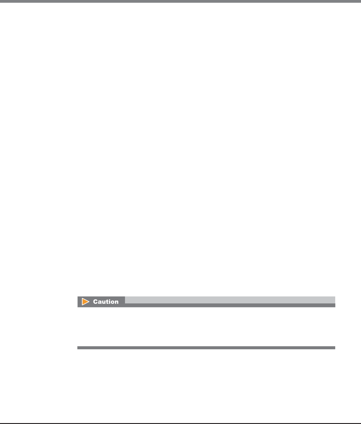
Chapter 8 Advanced Copy Management
8.2 Functions in the Action Area for Advanced Copy
ETERNUS Web GUI User’s Guide
Copyright 2013 FUJITSU LIMITED P2X0-1090-10ENZ0
299
2Select the EC/OPC priority, and click the [Set] button.
•EC/OPC Priority
-Automatic Priority
This mode changes the EC/OPC priority automatically in response to the operating load status.
-High Priority
This mode operates by making maximum use of internal resources.
This mode greatly affects host access performance, thus should not be used during normal
operation. Use when the operation load is low.
-Middle Priority
This mode operates slightly slower than the High Priority mode.
Select this mode when performance is greatly affected by the High Priority mode, but the copy
speed is too slow with the Low Priority mode.
-Low Priority
This mode reduces the effect on host access.
Select this mode when using EC and/or OPC during operation.
-Very Low Priority
This mode operates slower than the Low Priority mode.
Select this mode when performance is affected (such as when the performance of host response
is reduced) by the Automatic Priority or Low Priority mode.
●Advanced Setting
•Copy Schedule Mode
Specify the schedule mode for EC, OPC, and Quick OPC. Use "Session Balancing" for normal
operation.
Setting the schedule mode for SnapOPC and SnapOPC + is not required.
Use the [Modify REC Multiplicity] function to specify the REC schedule mode.
-Session Balancing
Copy sessions are scheduled evenly to each controlling CM-CPU for a copy source RAID group (a
RAID group to which the copy source volume belongs).
-Destination RAID Group Balancing
Only one copy session can be performed for each copy destination RAID group. This method pre-
vents unequal loading on a specific RAID group. This may improve the copy performance when a
copy destination RAID group is configured by Nearline disks or when "High Priority" is set for EC/
OPC.
Copy performance is not improved by selecting "Destination RAID Group Balancing" in the following
conditions:
•When the type of the copy destination volume is not "Standard"
•When the copy destination volume "Standard" and concatenated
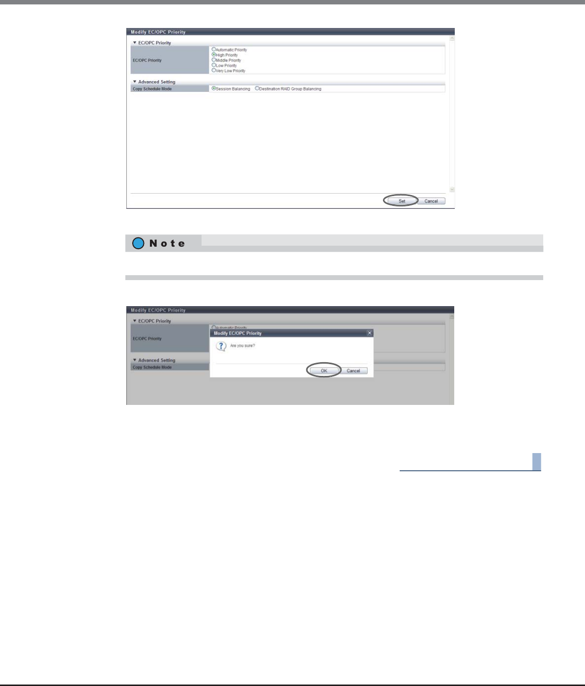
Chapter 8 Advanced Copy Management
8.2 Functions in the Action Area for Advanced Copy
ETERNUS Web GUI User’s Guide
Copyright 2013 FUJITSU LIMITED P2X0-1090-10ENZ0
300
→A confirmation screen appears.
3Click the [OK] button.
→The selected EC/OPC priority is set.
4Click the [Done] button to return to the [Setting] screen.
End of procedure
Click [Advanced Setting] to specify the copy schedule mode.
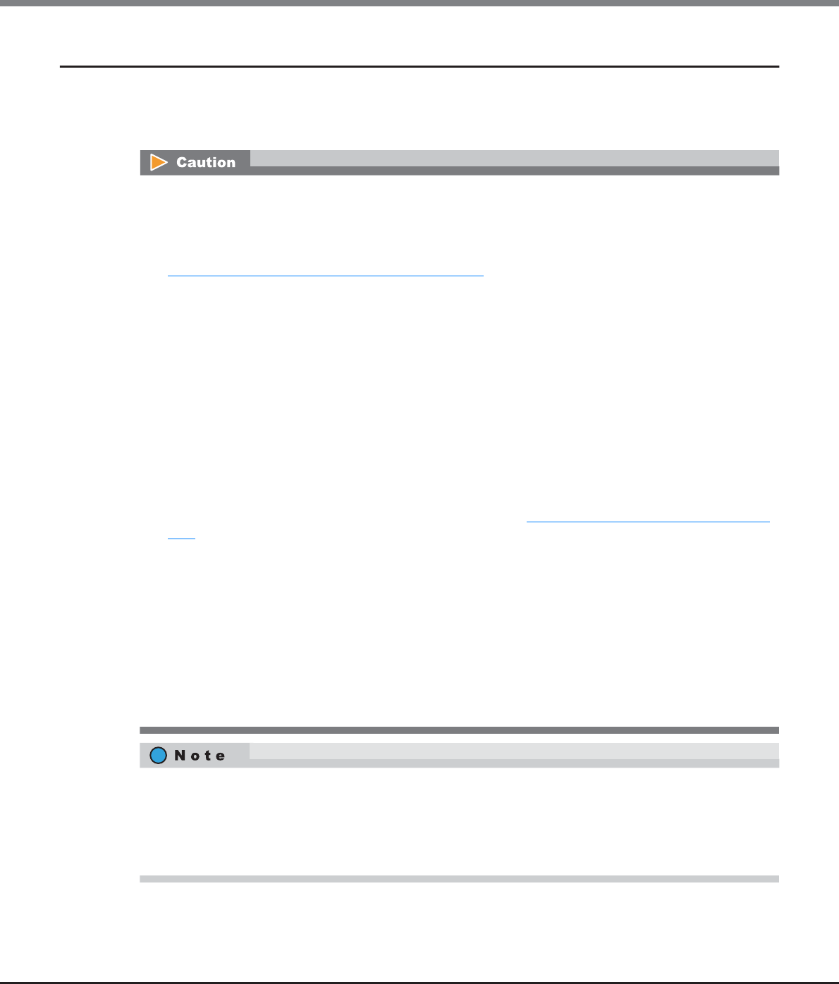
Chapter 8 Advanced Copy Management
8.2 Functions in the Action Area for Advanced Copy
ETERNUS Web GUI User’s Guide
Copyright 2013 FUJITSU LIMITED P2X0-1090-10ENZ0
301
8.2.7 Modify Copy Table Size
This function sets the copy table size, which is used by the firmware for the ETERNUS DX Disk storage system,
on the CM cache memory. When the EC, OPC or REC function is in use, this copy table is used as the area that
manages the progress of the copy.
•Registering the license for the Advanced Copy function is required to set the copy table size.
•When the copy table size is equal to 0MB, copy functions cannot be used. The initial (factory default)
copy table size setting is 0MB. Modify the copy table size before using the copy function.
•Make sure to stop the copy session before reducing the copy table size. To check the copy session, refer to
"8.1.1 Advanced Copy (Basic Information)" (page 252).
•The following shows the maximum copy table size for each model.
-ETERNUS DX80 S2/DX90 S2: 256MB
-ETERNUS DX410 S2: 512MB
-ETERNUS DX440 S2: 4096MB
-ETERNUS DX8100 S2: 1024MB
-ETERNUS DX8700 S2: 12288MB
•Cache memory is not only used for the copy table, but also used for REC Buffers. Note that a copy table
with the maximum capacity for each model cannot always be created. Whether a copy table with the
maximum capacity can be created depends on the memory capacity in the ETERNUS DX Disk storage
system and the cache memory allocation of the REC Buffer.
•If the copy table size is not sufficient, an error occurs in the copy session. Make sure to specify the "Table
Size Threshold" value to monitor the usage of the copy table in advance. The ETERNUS DX Disk storage
system reports the notification using the method specified in "11.2.9.1 Setup Event Notification" (page
880). There are three methods for notification; E-mail, SNMP Trap, and syslog. When reporting, select the
notification method in advance.
•Set the resolution as small as possible. When a large value is specified, the performance may be reduced.
When unsure about whether the copy target area might be increased in future use, specify "× 16" for
"Resolution".
•The same resolution must be used by both the copy source and copy destination storage system for REC. If
the resolution settings for the copy source and copy destination storage systems are different, REC cannot
be performed. Note that the copy table sizes do not need to be the same. If different recommended
resolutions are calculated for the copy source and copy destination storage systems, use whichever
resolution is greater for both storage systems. If the resolution is changed, recalculate the copy table size
setting for the storage system with the new resolution.
•Changes to the resolution setting are applied from the next session. For a copy session that is currently
being performed, data is copied with the resolution that was specified when the session was started. To
change the resolution of a copy session that is currently being performed, cancel the copy session and
start again.
•When the table size or the table size threshold is changed, the new value is applied immediately.

Chapter 8 Advanced Copy Management
8.2 Functions in the Action Area for Advanced Copy
ETERNUS Web GUI User’s Guide
Copyright 2013 FUJITSU LIMITED P2X0-1090-10ENZ0
302
There are two methods to set the copy table size: manually and automatically.
The procedure to set the copy table size is as follows:
■Manually setting the copy table size
Specify the copy table size manually.
Procedure
1Click [Modify Copy Table Size] in [Action].
2Specify "Resolution" and "Table Size" and click the [Set] button.
•Resolution
Select the resolution.
-× 1
-× 2
-× 4
-× 8
-× 16
•Table Size (MB)
Specify the copy table size.
The maximum size that can be specified is an estimated value from the memory capacity in the
ETERNUS DX Disk storage system and the amount of memory allocation for the REC Buffers.
The maximum copy table size for each model is as follows:
-ETERNUS DX80 S2/DX90 S2: 0 - 256 (MB) (integral multiple of 8)
-ETERNUS DX410 S2: 0 - 512 (MB) (integral multiple of 8)
-ETERNUS DX440 S2: 0 - 4096 (MB) (integral multiple of 8)
-ETERNUS DX8100 S2: 0 - 1024 (MB) (integral multiple of 8)
-ETERNUS DX8700 S2: 0 - 12288 (MB) (integral multiple of 8)
•Table Size Threshold (%)
Specify the threshold for monitoring the used capacity of the copy table.
To report when the used capacity exceeds the threshold, enable event notification by using the pro-
cedure in "11.2.9.1 Setup Event Notification" (page 880) and select E-mail, SNMP Trap, or syslog for
the notification method.
•Refer to "How to calculate the copy table size" (page 308) for detailed procedure to calculate
the copy table size.
•Refer to "Appendix H Estimated Advanced Copy Source Capacity" for the maximum copy source
capacity.
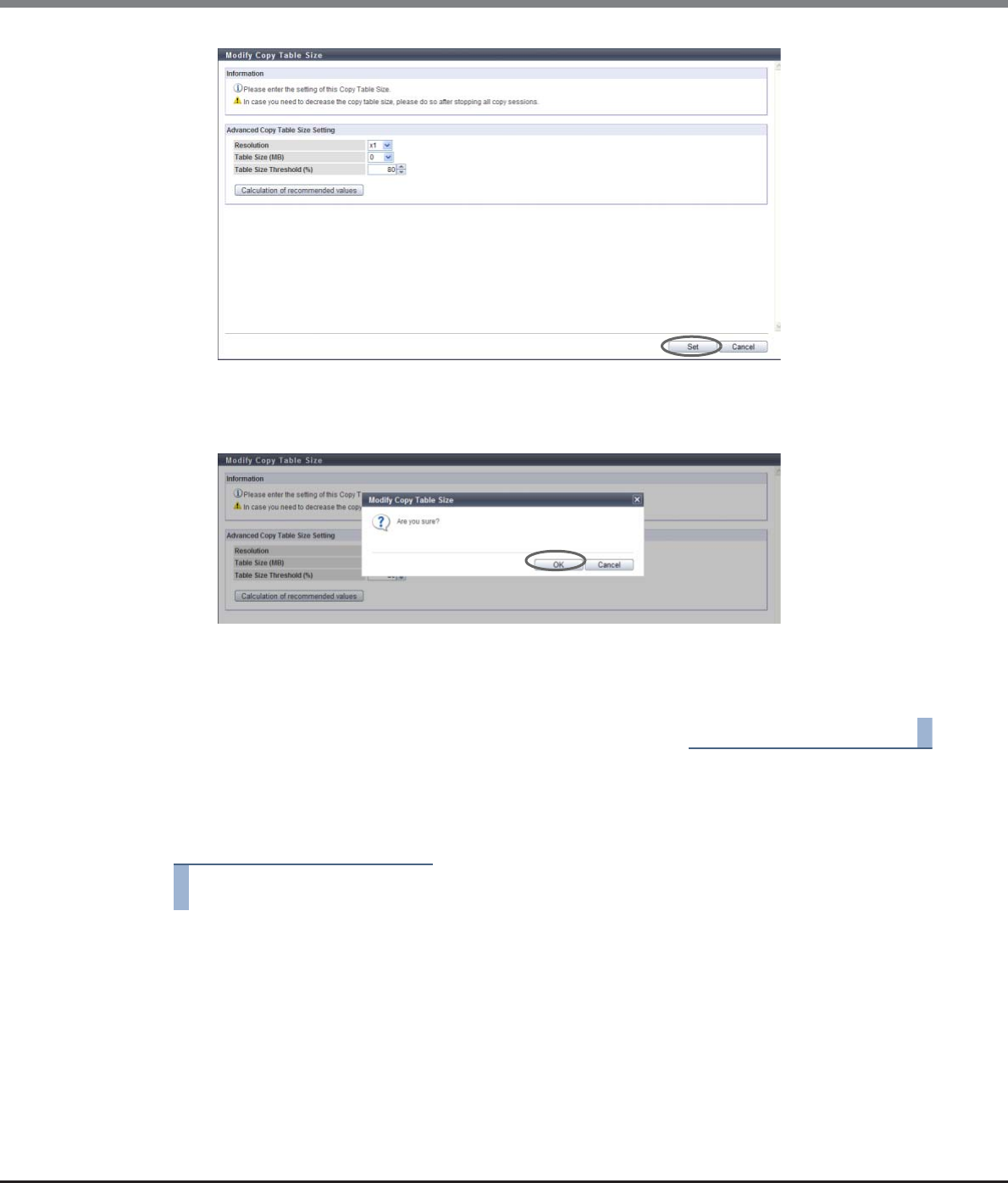
Chapter 8 Advanced Copy Management
8.2 Functions in the Action Area for Advanced Copy
ETERNUS Web GUI User’s Guide
Copyright 2013 FUJITSU LIMITED P2X0-1090-10ENZ0
303
→A confirmation screen appears.
3Click the [OK] button.
→Setting of the copy table size starts.
4Click the [Done] button to return to the [Setting] screen.
End of procedure
■Automatically setting the copy table size
Specify the copy table size automatically.
Procedure
1Click [Modify Copy Table Size] in [Action].
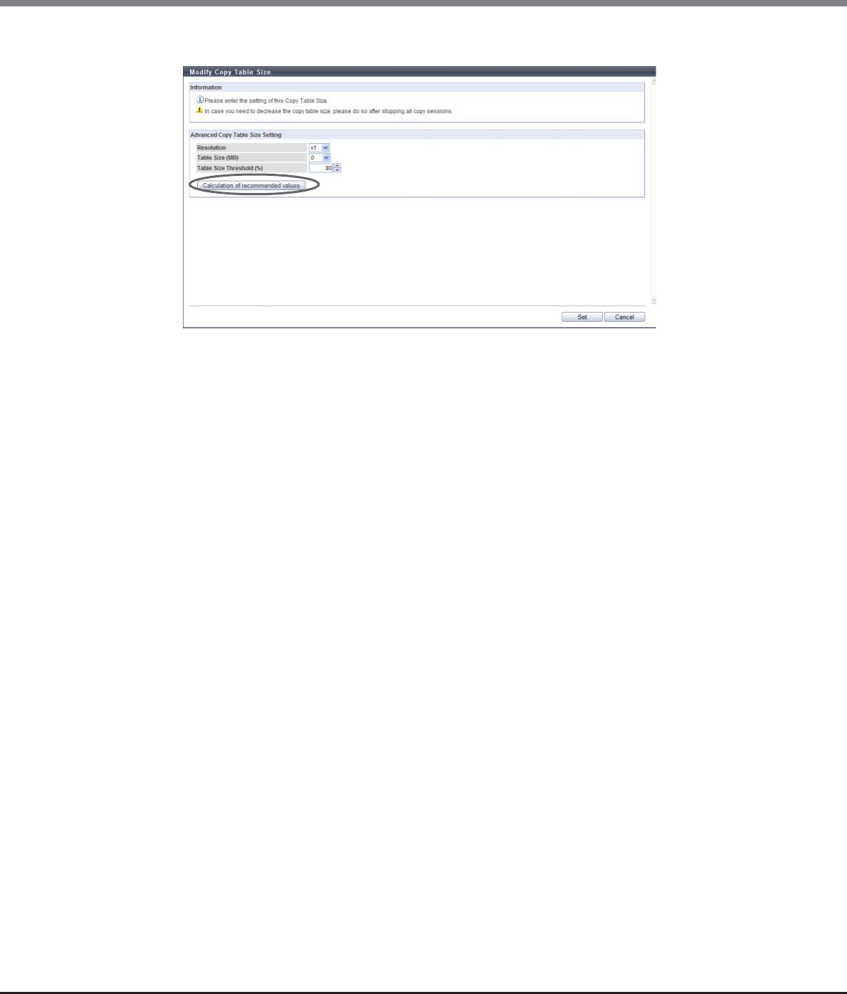
Chapter 8 Advanced Copy Management
8.2 Functions in the Action Area for Advanced Copy
ETERNUS Web GUI User’s Guide
Copyright 2013 FUJITSU LIMITED P2X0-1090-10ENZ0
304
2Click the [Calculation of recommended values] button.
→The [Calculation of recommended values] dialog box appears.
3Input the necessary information and click the [Calculation] button.
•Total Copy Capacity (Restore OPC is not used)
Input the total copy capacity (*1) when Restore OPC is not used (unit: GB). The applicable Advanced
Copy types are as follows:
-EC
-REC
-OPC, QuickOPC, SnapOPC, and SnapOPC+ without using Restore OPC
The following input conditions apply:
-ETERNUS DX80 S2/DX90 S2: 0 - 262144GB (256TB)
-ETERNUS DX410 S2: 0 - 524288GB (512TB)
-ETERNUS DX440 S2: 0 - 4194304GB (4096TB)
-ETERNUS DX8100 S2: 0 - 1048576GB (1024TB)
-ETERNUS DX8700 S2: 0 - 12582912GB (12288TB)
•Total Copy Capacity (Restore OPC is used)
Input the total copy capacity (*1) for using Restore OPC (unit: GB).
The applicable Advanced Copy types are as follows:
-OPC, QuickOPC, SnapOPC, and SnapOPC+ using Restore OPC
The following input conditions apply:
-ETERNUS DX80 S2/DX90 S2: 0 - 262144GB (256TB)
-ETERNUS DX410 S2: 0 - 524288GB (512TB)
-ETERNUS DX440 S2: 0 - 4194304GB (4096TB)
-ETERNUS DX8100 S2: 0 - 1048576GB (1024TB)
-ETERNUS DX8700 S: 0 - 12582912GB (12288TB)
•Sessions (Restore OPC is not used)
Input the total number of sessions (*1) for not using Restore OPC.
The applicable Advanced Copy types are as follows:
-EC
-REC
-OPC, QuickOPC, SnapOPC, and SnapOPC+ without using Restore OPC

Chapter 8 Advanced Copy Management
8.2 Functions in the Action Area for Advanced Copy
ETERNUS Web GUI User’s Guide
Copyright 2013 FUJITSU LIMITED P2X0-1090-10ENZ0
305
The following input conditions apply:
-ETERNUS DX80 S2: 0 - 1024
-ETERNUS DX90 S2: 0 - 2048
-ETERNUS DX410 S2/DX440 S2: 0 - 8192
-ETERNUS DX8100 S2: 0 - 8192
-ETERNUS DX8700 S2: 0 - 32768
•Sessions (Restore OPC is used)
Input the total number of sessions (*1) for using Restore OPC.
The applicable Advanced Copy types are as follows:
-OPC, QuickOPC, SnapOPC, and SnapOPC+ using Restore OPC
The following input conditions apply:
-ETERNUS DX80 S2: 0 - 1024
-ETERNUS DX90 S2: 0 - 2048
-ETERNUS DX410 S2/DX440 S2: 0 - 8192
-ETERNUS DX8100 S2: 0 - 8192
-ETERNUS DX8700 S2: 0 - 32768
*1: For "Total Copy Capacity" and "Sessions", enter the respective total values.
[Example 1]
When executing 10GB OPC (Restore OPC is not used) with 20 sessions and 5GB QuickOPC (Restore OPC is not
used) with 10 sessions
Total Copy Capacity (Restore OPC is not used)
= Copy capacity for OPC (10GB x 20 sessions) +
Copy capacity for QuickOPC (5GB x 10 sessions)
= 200GB + 50GB = 250GB
Sessions (Restore OPC is not used)
= The number of OPC sessions (20 sessions) +
The number of QuickOPC sessions (10 sessions)
= 30 sessions
Example 2:
When executing 10GB OPC (Restore OPC is not used) with 20 sessions and 5GB QuickOPC (Restore OPC is
used) with 10 sessions
Total Copy Capacity (Restore OPC is not used)
= Copy capacity for OPC (10GB x 20 sessions) = 200GB
Sessions (Restore OPC is not used)
= The number of OPC sessions (20 sessions) = 20 sessions
Total Copy Capacity (Restore OPC is used)
= Copy capacity for QuickOPC (5GB x 10 sessions) = 50GB
Sessions (Restore OPC is used)
= The number of QuickOPC sessions (10 sessions) = 10 sessions
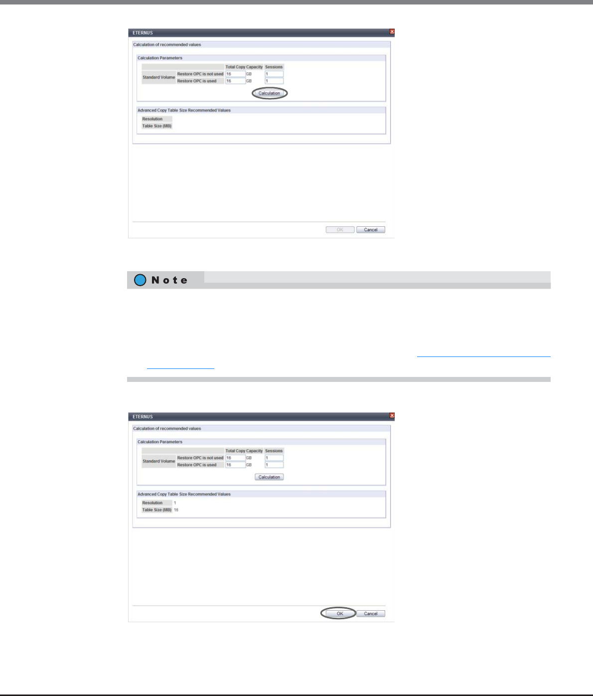
Chapter 8 Advanced Copy Management
8.2 Functions in the Action Area for Advanced Copy
ETERNUS Web GUI User’s Guide
Copyright 2013 FUJITSU LIMITED P2X0-1090-10ENZ0
306
→"Resolution" and "Table Size" are automatically calculated.
4Click the [OK] button.
→The calculated values are reflected to "Resolution" and "Table Size" in the "Advanced Copy Table Size
Setting" field.
•The calculated parameters are "Resolution" and "Table Size". It is assumed that almost 100% of the
copy table size is used.
•When [Calculation of recommended values] is used, the calculation of "Resolution" and "Table
Size" makes allowances for a slight increase of the copy capacity. This is why the calculated values
are higher than values obtained using the procedure described in "How to calculate the copy table
size" (page 308).
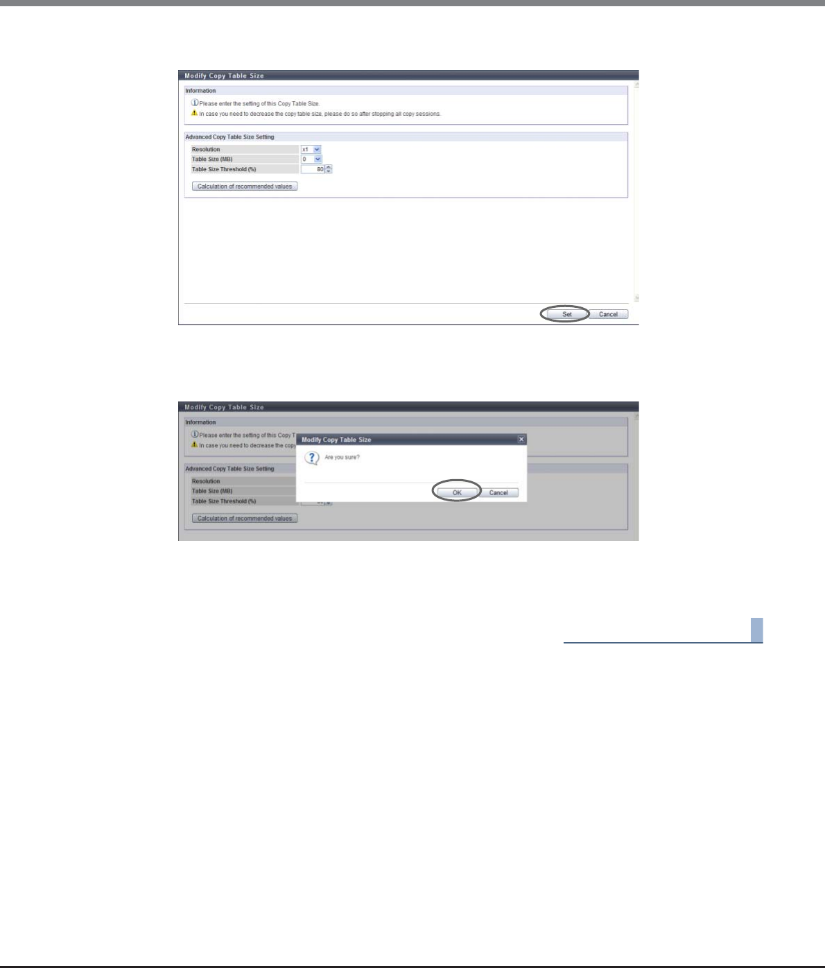
Chapter 8 Advanced Copy Management
8.2 Functions in the Action Area for Advanced Copy
ETERNUS Web GUI User’s Guide
Copyright 2013 FUJITSU LIMITED P2X0-1090-10ENZ0
307
5Click the [Set] button.
→A confirmation screen appears.
6Click the [OK] button.
→Setting of the copy table size starts.
7Click the [Done] button to return to the [Setting] screen.
End of procedure
Chapter 8 Advanced Copy Management
8.2 Functions in the Action Area for Advanced Copy
ETERNUS Web GUI User’s Guide
Copyright 2013 FUJITSU LIMITED P2X0-1090-10ENZ0
308
■How to calculate the copy table size
A dedicated memory area is required for Advanced Copy management and is allocated as a table size. The
table size and resolution settings are determined by the copy capacity and the number of sessions (volumes)
that will be run simultaneously.
S1: Refers to the table size (MB) for EC/REC and for OPC/QuickOPC/SnapOPC/SnapOPC+ without OPC
Restoration.
S2: Refers to the table size (MB) for OPC/QuickOPC/SnapOPC/SnapOPC+ with OPC Restoration.
(Table size (S)) [MB] = (S1) + (S2)
•Round the derived value up to the next multiple of 8 to obtain the correct setting for the copy table size.
•A copy table of the appropriate size (as derived above) is created in each CM.
•If the total table size value (S) exceeds the maximum size allowed, adjust the resolution (M) upward
until the maximum table size is no longer exceeded. The resolution (M) should be as small as possible.
•Maximum allowed table sizes are as follows:
•Allowance should be made for possible increases in the copy capacity.
•If the resolution is changed during an existing copy session, the table sizing formula described in this
section is not applied.
•The same bitmap ratio (M) value must be used by both the copy source and copy destination storage sys-
tems. If the bitmap ratio settings for the copy source and copy destination storage systems are different,
REC cannot be performed. Note that the table sizes (S) do not need to be identical. If different
recommended resolutions are calculated for the copy source and copy destination storage systems, use
whichever resolution is greater for both storage systems. If the resolution (M) is changed, recalculate the
table size (S) setting for the storage system with the new resolution.
The calculated parameters are "Resolution (M)" and "Table Size (S)". It is assumed that almost 100% of the
copy table size is used.
Storage system name Maximum copy table size (per CM)
ETERNUS DX80 S2 256MB
ETERNUS DX90 S2 256MB
ETERNUS DX410 S2 512MB
ETERNUS DX440 S2 4096MB
ETERNUS DX8100 S2 1024MB
ETERNUS DX8700 S2 12288MB
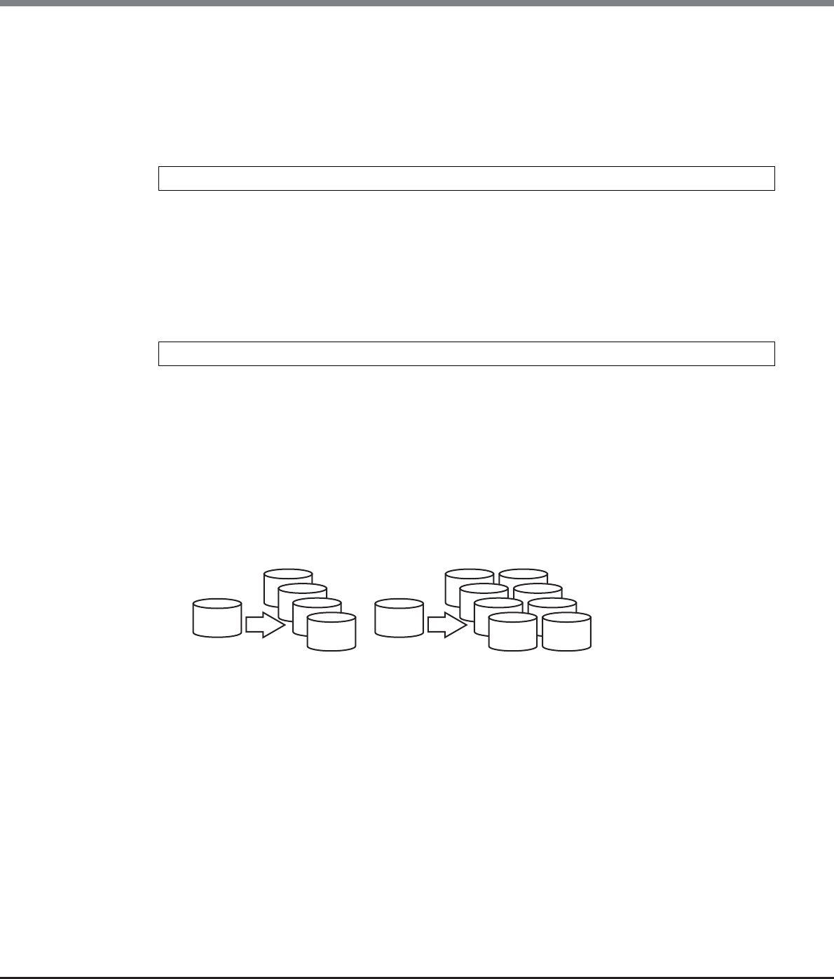
Chapter 8 Advanced Copy Management
8.2 Functions in the Action Area for Advanced Copy
ETERNUS Web GUI User’s Guide
Copyright 2013 FUJITSU LIMITED P2X0-1090-10ENZ0
309
●The table size for EC/REC and for OPC/QuickOPC/SnapOPC/SnapOPC+ without OPC Restoration (S1)
●The table size for OPC/QuickOPC/SnapOPC/SnapOPC+ with OPC Restoration (S2)
*1: For EC, OPC, QuickOPC, SnapOPC, SnapOPC+, and REC copy sources, the copy capacity is the total capacity of all
volumes (slices or partitions) in the ETERNUS DX Disk storage system that are defined as copy sources. For REC
copy destinations, the copy capacity is the total capacity of all the volumes (slices or partitions) in the ETERNUS
DX Disk storage system that are defined as copy destinations.
If the ETERNUS DX Disk storage system is used for both the " EC, OPC, QuickOPC, SnapOPC, SnapOPC+, or REC copy
source" and the " REC copy source", the copy capacity is the total capacity of both.
For multi-copy sessions, the copy capacity is the total capacity of multi-copy source volumes (slices or partitions),
multiplied by the number of multi-copy destinations for each copy source. The copy capacity for generation man-
agement by SnapOPC+ sessions is the total capacity of copy source volumes (slices or partitions) multiplied by
the number of generations in the copy destination volumes for each copy source.
Example for multi-copy sessions:
Copy area in the copy source logical volume A: 200M, Number of multi-copy destinations: 4
Copy area in the copy source logical volume B: 500MB, Number of multi-copy destinations: 8
Add 200 × 4 + 500 × 8 = 4800MB to the copy capacity (C1).
Note that "4" and "8" in this example correspond to the number of generations when calculating the copy table
size for SnapOPC+ sessions.
The number of sessions (N1) for multi-copy and SnapOPC+ is 4 + 8 = 12.
When executing OPC Restoration from a copy destination with multi-copy and SnapOPC+ multi-generation
enabled, select one copy destination and apply the above formula. Other copy destinations are calculated as
being normal multi-copy and SnapOPC+ multi-generation.
M: Resolution (The same value is used in the ETERNUS DX Disk storage system. Set "×1" if possible.)
C1: The total copy capacity (GB) for EC/REC, and OPC/QuickOPC/SnapOPC/SnapOPC+ without OPC
Restoration (*1)
N1: The number of sessions EC/REC, and OPC/QuickOPC/SnapOPC/SnapOPC+ without OPC Restoration.
S1 [MB] = ((2 × C1 / M) + N1) × 8 [KB] / 1024 (Round up decimal point)
M: Resolution (The same value is used in the ETERNUS DX Disk storage system. Set "×1" if possible.)
C2: The total copy capacity (GB) for OPC/QuickOPC/SnapOPC/SnapOPC+ with OPC Restoration in the
volume (*1)
N2: The number of sessions for OPC/QuickOPC/SnapOPC/SnapOPC+ with OPC Restoration
S2 [MB] = ((2 × C2 / M) + N2) × 2 × 8 [KB] / 1024 (Round up decimal point)
B
A
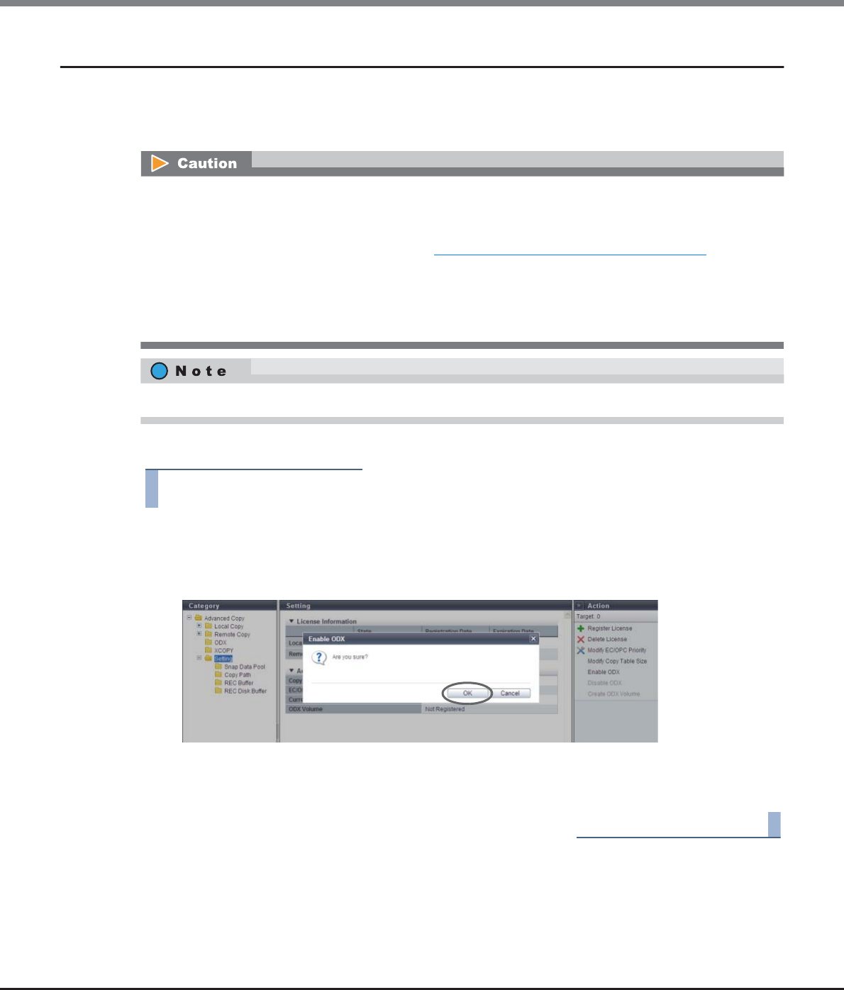
Chapter 8 Advanced Copy Management
8.2 Functions in the Action Area for Advanced Copy
ETERNUS Web GUI User’s Guide
Copyright 2013 FUJITSU LIMITED P2X0-1090-10ENZ0
310
8.2.8 Enable ODX
This function enables the ODX function.
This function supports ODX, which is provided for servers with "Windows Server 2012". ODX is a function that
offloads the load on data copying and migration to the storage system.
The procedure to enable the ODX function is as follows:
Procedure
1Click [Enable ODX] in [Action].
→A confirmation screen appears.
2Click the [OK] button.
→Enabling of ODX starts.
3Click the [Done] button to return to the [Setting] screen.
End of procedure
•To start using the ODX function, the server must recognize that ODX is enabled in the ETERNUS DX Disk
storage system. After enabling ODX with this function, reboot the server.
•ODX requires dedicated volumes (ODX Buffer volumes) to save data before updating. ODX Buffer volumes
can be created after ODX is enabled. Refer to "8.2.10 Create ODX Buffer Volume" (page 311) for details.
•The ETERNUS DX Disk storage system does not support an Advanced Copy when the copy destination is a
volume that is being used by the ODX function.
•The ODX function only supports copying within the same ETERNUS DX Disk storage system. Copying to
other storage systems is not supported.
ODX does not require the registration of an Advanced Copy license and copy table size settings.
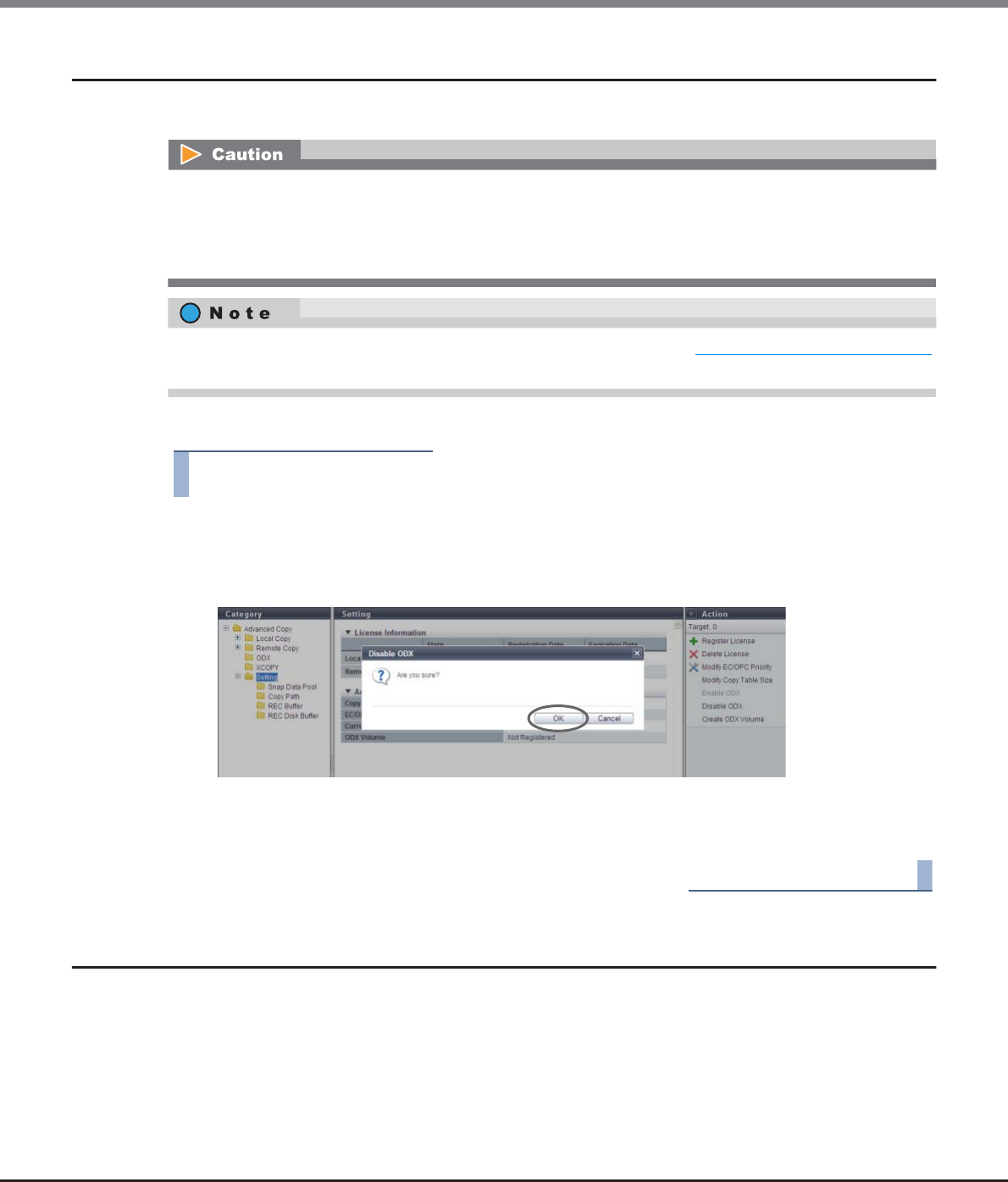
Chapter 8 Advanced Copy Management
8.2 Functions in the Action Area for Advanced Copy
ETERNUS Web GUI User’s Guide
Copyright 2013 FUJITSU LIMITED P2X0-1090-10ENZ0
311
8.2.9 Disable ODX
This function disables the ODX function.
The procedure to disable the ODX function is as follows:
Procedure
1Click [Disable ODX] in [Action].
→A confirmation screen appears.
2Click the [OK] button.
→Disabling of ODX starts.
3Click the [Done] button to return to the [Setting] screen.
End of procedure
8.2.10 Create ODX Buffer Volume
This function creates a dedicated volume for the ODX function.
ODX is a function that offloads the load on data copying and migration to the storage system. ODX copies data
at the time when a copy request is received. If a Write command is issued for the copy source data, this
function backs up the previous data in the area that is to be overwritten. An ODX Buffer volume is used to
store the backup data at this time.
The ODX function is supported by "Windows Server 2012".
•To stop using the ODX function, the server must recognize that ODX is disabled in the ETERNUS DX Disk
storage system. After disabling ODX with this function, reboot the server.
•The ODX function cannot be disabled when ODX Buffer volumes exist in the ETERNUS DX Disk storage
system.
Delete the ODX Buffer volume before disabling the ODX function. Refer to "5.2.2 Delete Volume" (page 112)
for details.
Chapter 8 Advanced Copy Management
8.2 Functions in the Action Area for Advanced Copy
ETERNUS Web GUI User’s Guide
Copyright 2013 FUJITSU LIMITED P2X0-1090-10ENZ0
312
ODX Buffer Volume
•One ODX Buffer volume can be created in the ETERNUS DX Disk storage system.
•The type of the ODX Buffer volume is "Standard", "TPV", or "FTV".
•The capacity of an ODX Buffer volume is 1GB - 1TB.
•An ODX Buffer volume can be created when the ODX function is enabled.
•The ODX Buffer volume must be created with the ODX function.
•If a Thin Provisioning license is not registered, a "TPV" or an "FTV" type ODX Buffer volume cannot be
created.
•When creating an "FTV" type ODX Buffer volume, use CLI. GUI cannot be used to create an "FTV" type ODX
Buffer volume.
•When encryption mode is disabled, an ODX Buffer volume encrypted by CM cannot be created. Note that
when SEDs are not installed in the ETERNUS DX Disk storage system, an ODX Buffer volume encrypted by
SEDs cannot be created.
•If the maximum number of volumes is already registered in the ETERNUS DX Disk storage system, an ODX
Buffer volume cannot be created. Refer to "5.2.1 Create Volume" (page 96) to check the maximum
number of volumes for the ETERNUS DX Disk storage system.
•If the maximum capacity for TPVs or FTVs is already registered in the ETERNUS DX Disk storage system, a
"TPV" type or an "FTV" type ODX Buffer volume cannot be created. Refer to "5.2.1 Create Volume" (page
96) to check the maximum capacity.
•Only one ODX Buffer volume can be created in the ETERNUS DX Disk storage system. Use the [Setting]
screen to check whether an ODX Buffer volume is already created. Refer to "8.1.6 Setting (Advanced
Copy)" (page 268) for details.
•An existing ODX Buffer volume can be checked by using the "Forbid Advanced Copy" field in the [Volume]
screen. Refer to "5.1.1 Volume (Basic Information)" (page 74) for details.
•There are three types of ODX Buffer volumes: "Standard", "TPV", and "FTV". When creating an ODX Buffer
volume in a RAID group, select "Standard" for the volume type. When creating an ODX Buffer volume in a
TPP, select "Thin Provisioning" for the volume type. When creating an ODX Buffer volume in an FTRP, use
CLI. The ODX Buffer volume type is independent of the copy source volume type or the copy destination
volume type.
•Even when the ODX Buffer volume capacity is insufficient, no error occurs in an ODX session that is
already started. Windows Server suspends the use of ODX, and starts a normal copy process that uses
Read and Write processes.
•Monitoring the usage of an ODX Buffer volume is available. If insufficient capacity is detected, the
ETERNUS DX Disk storage system sends a notification. Refer to "11.2.9.1 Setup Event Notification" (page
880) for details. If the ODX Buffer volume capacity is frequently insufficient, the benefit of using the ODX
function is lost. Expand the ODX Buffer volume capacity as required. Refer to "5.2.5 Expand Volume"
(page 117), "5.2.7 Start RAID Migration" (page 123), or "5.2.6 Expand Thin Provisioning Volume" (page
121) for details.
•An ODX Buffer volume can be deleted by using the same procedure as "Standard" and "TPV" type volumes
if the ODX function is not used. Refer to "5.2.2 Delete Volume" (page 112) for details. To delete an "FTV"
type ODX Buffer volume, use CLI.
Chapter 8 Advanced Copy Management
8.2 Functions in the Action Area for Advanced Copy
ETERNUS Web GUI User’s Guide
Copyright 2013 FUJITSU LIMITED P2X0-1090-10ENZ0
313
The procedure to create an ODX Buffer volume is as follows:
Procedure
1Click [Create ODX Buffer Volume] in [Action].
2Specify the detailed information of the ODX Buffer volume and select the RAID group or TPP
in which the ODX Buffer volume is to be created. Click the [Create] button.
•Name
Specify the ODX Buffer volume name. An existing volume name cannot be specified.
The following input condition applies:
-Up to 16 alphanumeric characters and symbols (except ", (comma)" and "?")
•Capacity
Specify the volume capacity between "1GB" - "1TB", and select the unit of capacity (MB/GB/TB).
Up to a 15-digit number including the "." (decimal point) can be input. Note that when "MB" is
selected, the specified value is rounded down to the nearest whole number. When "GB" or "TB" is
selected, the specified value is converted to "MB" and rounded down to the nearest whole number.
•Type
Specify the volume type. If a Thin Provisioning license is not registered, "Standard" is displayed in
this field.
-Standard
A volume that is created in the RAID group.
-Thin Provisioning
A volume that is created in Thin Provisioning Pools.
•The volume capacity that is required for an ODX Buffer volume varies depending on the server system
configuration and the applications that are being used. When using the ODX function for normal file
copying or file migration with Microsoft Windows Server, creating a 10GB ODX Buffer volume is
recommended.
•An ODX Buffer volume can be created by using the maximum free space that is available in a RAID group.
Inputting the volume capacity is not required. "Standard" type volumes can be created using the
maximum free space.
Up to 15 numbers can be used. If a decimal point is included in the input value, up to 14 numbers
can be used.
[Example] 0.1234567890123 (14 numbers and a decimal point)
If "Use all Largest Free Space" is selected, inputting the capacity is not required. The specified value
and unit are not used.
Chapter 8 Advanced Copy Management
8.2 Functions in the Action Area for Advanced Copy
ETERNUS Web GUI User’s Guide
Copyright 2013 FUJITSU LIMITED P2X0-1090-10ENZ0
314
•Use all Largest Free Space
Select the "Enable" checkbox to create an ODX Buffer volume with the largest available free space in
the RAID group. This checkbox can be selected or cleared only when "Type" is "Standard".
If "Enable" is selected, an ODX Buffer volume with a capacity of up to 1TB is created with the
available space displayed in the "Largest Free Space" field for the selected RAID group.
•Encryption by CM
Select whether to encrypt (On) or not encrypt (Off) the new volumes.
-When "On" is selected:
A volume that is encrypted by CM is created.
-When "Off" is selected:
A volume that is not encrypted is created.
●Target RAID Group/Thin Provisioning Pool
•When "Type" is "Standard"
-Radio buttons to select a RAID group
Select the RAID group in which the ODX Buffer volume is created.
•When "Enable" is selected, the capacity and the unit are not available.
•The capacity for created ODX Buffer volume is not displayed. Use the [Volume] screen to check
the volume capacity after volume creation is complete.
•When "Thin Provisioning" is selected for "Type", selecting on or off for "Encryption by CM" is not
available.
•When "Encryption by CM" is "On", a RAID group that is configured with SEDs cannot be selected.
When creating an ODX Buffer volume in a RAID group that is configured by SEDs, select "Off".
•When the encryption mode is disabled, "Encryption by CM" is not displayed.
•When "Encryption by CM" is "On", a RAID group that is configured with SEDs cannot be selected.
•RAID groups in the following conditions are not displayed in the target RAID group list:
-RAID groups that are registered in TPPs
-RAID groups that are registered in FTRPs
-RAID groups that are registered as REC Disk Buffers
-RAID groups in which 128 volumes are already created
-RAID groups for which "Usage" is "Temporary"
-RAID groups with free space that is less than 1GB
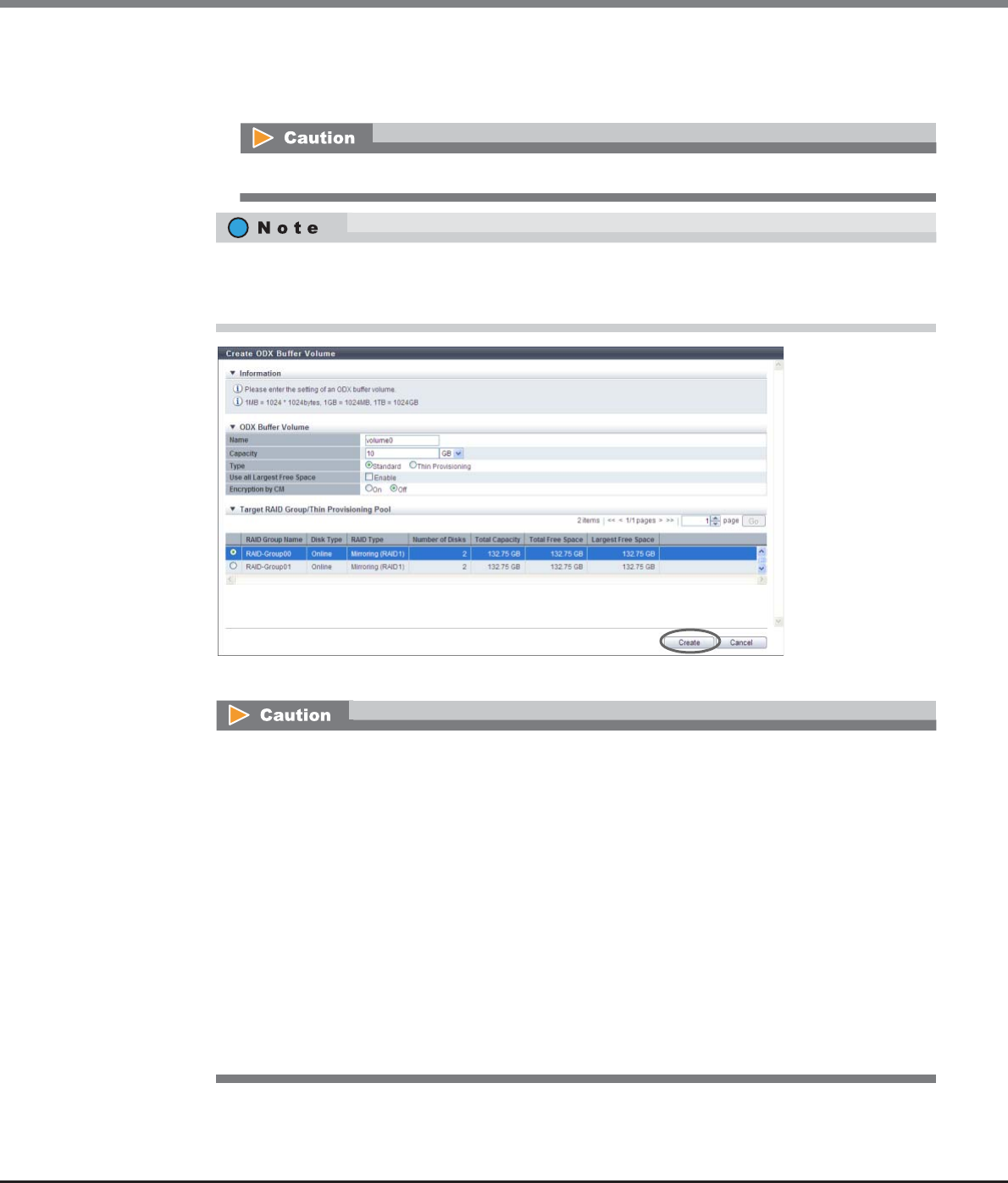
Chapter 8 Advanced Copy Management
8.2 Functions in the Action Area for Advanced Copy
ETERNUS Web GUI User’s Guide
Copyright 2013 FUJITSU LIMITED P2X0-1090-10ENZ0
315
•When "Type" is "Thin Provisioning"
-Radio buttons to select a TPP
Select the TPP in which the ODX Buffer volume is created.
→A confirmation screen appears.
TPPs that are registered in FTRPs are not displayed in the target Thin Provisioning Pool list.
When using the maximum free space in the RAID group to create an ODX Buffer volume without
specifying the capacity, select the "Enable" checkbox for "Use all Largest Free Space". A "Standard" type
volume can be created using the maximum free space.
An error screen appears in the following conditions:
•When the "Name" is not input
•When the name overlaps with an existing volume name for "Name"
•When the "Name" does not satisfy the input conditions
•When the "Enable" checkbox for "Use all Largest Free Space" is cleared and "Capacity" is not input
•When the "Enable" checkbox for "Use all Largest Free Space" is selected and the capacity of a
created ODX Buffer volume is less than 1GB
•When the "Enable" checkbox for "Use all Largest Free Space" is selected and the capacity of a
created ODX Buffer volume exceeds the maximum capacity
•When the capacity that is specified for "Capacity" exceeds the maximum capacity that can be
created
•When the maximum number of volumes that can be created is exceeded
•When free space in the RAID group or TPP is insufficient
•LDE is being performed in the target RAID group
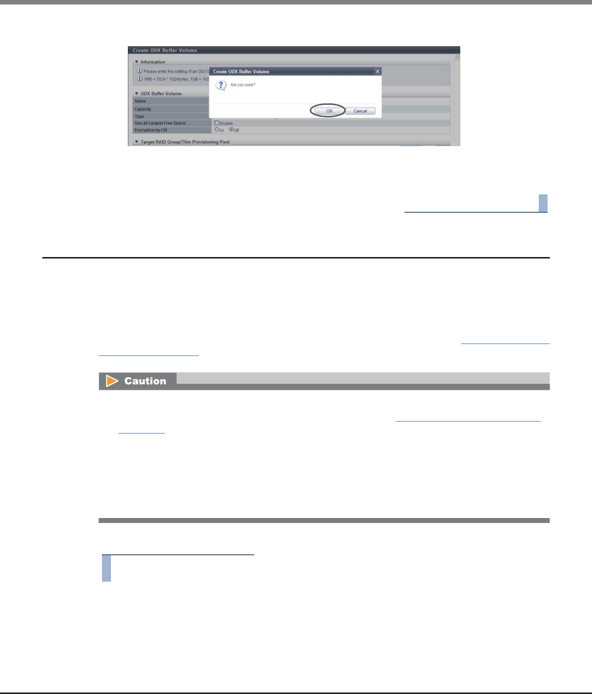
Chapter 8 Advanced Copy Management
8.2 Functions in the Action Area for Advanced Copy
ETERNUS Web GUI User’s Guide
Copyright 2013 FUJITSU LIMITED P2X0-1090-10ENZ0
316
3Click the [OK] button.
→ODX Buffer volume creation starts.
4Click the [Done] button to return to the [Setting] screen.
End of procedure
8.2.11 Modify Copy Parameters
This function sets the parameters to enable automatic reporting when the SDP capacity is insufficient during a
SnapOPC+ session and specifies the unit of the area allocation to the SDV (SDPE). If the copy source data
exceeds the physical capacity of copy destination (and when the free SDP does not exist), an error occurs in
the relevant copy session and other older copy sessions. This function prevents stopping copy session when
the capacity shortage occurs. There are three methods for notification; E-mail, SNMP Trap, and syslog. The
ETERNUS DX Disk storage system reports the notification using the method specified in "11.2.9.1 Setup Event
Notification" (page 880). When reporting, select the notification method in advance.
The procedure to modify copy parameters is as follows:
Procedure
1Click [Modify Copy Parameters] in [Action].
•Registering the license for the Advanced Copy feature is required to use SnapOPC+.
•Make sure to set the notification method by using the procedure in "11.2.9.1 Setup Event Notification"
(page 880) to automatically report when the SDP usage exceeds the threshold.
•Notification of the shortage of SDP capacity is sent only once for each policy level. Even if the threshold is
exceeded again within the 24 hours from the first notification, the ETERNUS DX Disk storage system does
not report that effect. After 24 hours has passed, the ETERNUS DX Disk storage system sends a
notification again.
•If the threshold for multiple policies is satisfied at the same time, the ETERNUS DX Disk storage system
notifies of the highest policy level.
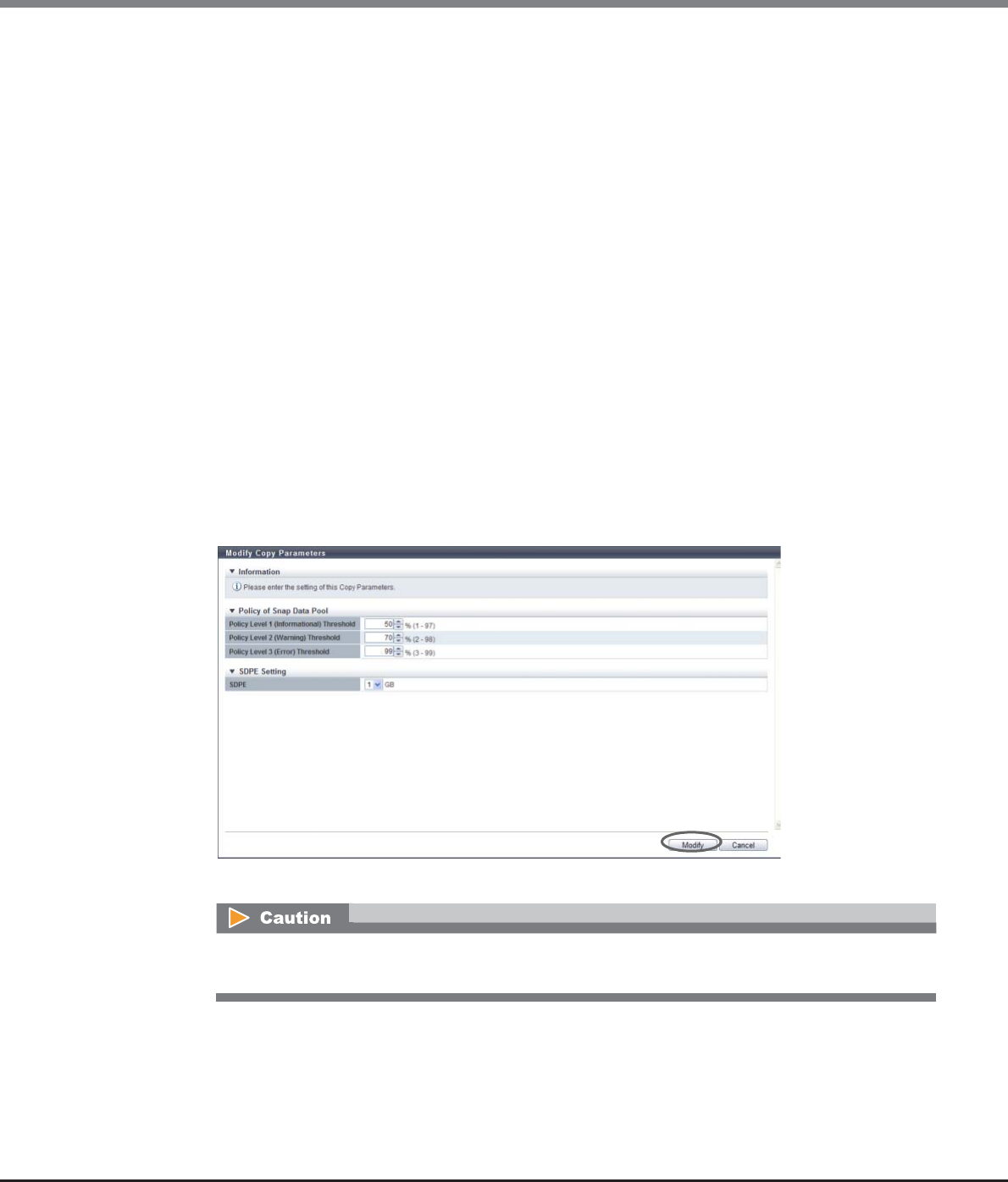
Chapter 8 Advanced Copy Management
8.2 Functions in the Action Area for Advanced Copy
ETERNUS Web GUI User’s Guide
Copyright 2013 FUJITSU LIMITED P2X0-1090-10ENZ0
317
2Specify the threshold for each policy level, and click the [Modify] button.
●Policy of Snap Data Pool
•Policy Level 1 (Informational) Threshold
If the usage of SDP exceeds the specified threshold, the ETERNUS DX Disk storage system notifies
that effect as the Policy Level 1 (Informational).
Specify between 1% and 97% for the threshold.
•Policy Level 2 (Warning) Threshold
If the usage of SDP exceeds the specified threshold, the ETERNUS DX Disk storage system notifies
that effect as the Policy Level 2 (Warning).
Specify between 2% and 98% for the threshold.
•Policy Level 3 (Error) Threshold
If the usage of SDP exceeds the specified threshold, the ETERNUS DX Disk storage system notifies
that effect as the Policy Level 3 (Error). Specify between 3% and 99% for the threshold.
●SDPE Setting
•SDPE
Specify Snap Data Pool Element (SDPE), that is the unit of allocation to the SDV.
-1GB
-2GB
-4GB
→A confirmation screen appears.
If the magnitude relation is not "Threshold for a policy level 1" → "Threshold for policy level 2" →
"Threshold for policy level 3", an error screen appears.
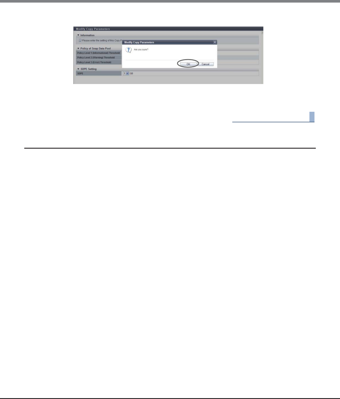
Chapter 8 Advanced Copy Management
8.2 Functions in the Action Area for Advanced Copy
ETERNUS Web GUI User’s Guide
Copyright 2013 FUJITSU LIMITED P2X0-1090-10ENZ0
318
3Click the [OK] button.
→The specified copy parameters are registered.
4Click the [Done] button to return to the [Snap Data Pool] screen.
End of procedure
8.2.12 Set Copy Path
This function sets copy path information between the ETERNUS Disk storage systems required for performing
REC using the wizard screen.
Copy path information indicates the path (copy path and the storage system where the copy path is set) used
for performing REC.
Not only copy path information of the local device but also the information between remote devices can be
created.
The following ETERNUS Disk storage systems support the [Set Copy Path] function.
•ETERNUS DX90 S2
•ETERNUS DX410 S2/DX440 S2
•ETERNUS DX8100 S2/DX8700 S2
•ETERNUS DX90
•ETERNUS DX410/DX440/DX8100/DX8400/DX8700
•ETERNUS4000/ETERNUS8000
•ETERNUS6000
In this section, the storage system that is used to create copy paths is referred to as "local device" and the
storage system that is connected to is referred to as a "remote device".
The following settings are available for the [Set Copy Path] function:
(1)Register Device Information (Register)
(2)Create Copy Path (Create)
(3) Save (Save)
(4) Apply Copy Path (Apply)
(5)Measure Round Trip Time (Measure)

Chapter 8 Advanced Copy Management
8.2 Functions in the Action Area for Advanced Copy
ETERNUS Web GUI User’s Guide
Copyright 2013 FUJITSU LIMITED P2X0-1090-10ENZ0
319
•To create copy path information between different models of ETERNUS Disk storage systems (such as
ETERNUS DX440 S2 and ETERNUS4000), be sure to create the information on the newer model of
ETERNUS Disk storage system (ETERNUS DX440 S2 in the above example). The copy path creating
function on an older model may not have a function to add the device information for newer models or
the created path information file cannot be applied to newer models.
•When creating the copy path information between ETERNUS DX S2 series (*1) with an old controller
firmware version (V10L2x or earlier) and ETERNUS DX S2 series with a new controller firmware version
(V10L3x or later), use the storage system with controller firmware version V10L3x or later (the new
storage system) to create the copy path information. If the copy path information is created with an
ETERNUS DX S2 series with controller firmware version V10L2x or earlier (an old storage system), a device
information file that is created by a new storage system cannot be used for the old storage system. In this
case, the device information of the new storage system must be specified manually.
*1: ETERNUS DX90 S2, ETERNUS DX410 S2/DX440 S2, or ETERNUS DX8100 S2/DX8700 S2
•To use an iSCSI port as the copy path, there are some restrictions for applying the copy path information
files that are created by new storage systems or old storage systems. Refer to "Applying copy path
information files with IPv6" (page 340) for details.
•When the controller firmware version V10L3x or later is used, the IP versions that can be used for an iSCSI
port (except an iSCSI port for older storage system connection) are as follows; IPv4, IPv6 (Link Local), or
IPv6 (Connect IP). A copy path can be created between iSCSI ports that are the same IP version.
•Copy paths cannot be created when the same ETERNUS Disk storage system is set for the local device and
remote device.
•If the Box ID is changed after setting the copy path, REC will no longer run. Create copy paths again with
the new Box ID, and then apply the new copy path information to all the related ETERNUS Disk storage
systems again.
•Different types of interfaces (FC, iSCSI 1Gbit/s, iSCSI 10Gbit/s) cannot exist together on an REC path
(connection between a local device and a remote device).
•Up to 16 remote devices can be connected from one storage system.
•Up to 8 copy paths can be created between a pair of storage systems.
•Up to 32 destination ports (FC-RA) can be connected from one port.
•Up to 16 destination ports (iSCSI-RA) can be connected from one port.
•If a copy path, which is being used in an REC, was modified, it may affect operations, such as the REC
being stopped. Confirm that REC is not in use before modifying the information. To check whether REC is
in use, refer to the copy session list of remote copy.
•Copy path information files cannot be applied to the storage system when the port mode of the port set
in the copy path information does not match the port mode of the adapter installed in the storage system
to be applied to. Modify the copy path information or switch the port mode on the storage system in
advance. Refer to "9.2.3.11 Modify Port Mode" (page 571) for switching port modes.
•Copy path information files cannot be applied to the storage system when the port type (FC or iSCSI) that
is specified in the copy path information does not match the port type of the adapter that is installed in
the storage system. In addition, if the port type is iSCSI, a copy path information file cannot be applied to
the storage system when the IP address and iSCSI name in the copy path information file do not match
the specification of the adapter that is installed in the storage system.
•Before measuring the round trip time, set a physical path properly between the ETERNUS Disk storage
systems. When a copy path has an error, the round trip time cannot be measured correctly.
•It takes a maximum of 160 seconds to measure the round trip time.

Chapter 8 Advanced Copy Management
8.2 Functions in the Action Area for Advanced Copy
ETERNUS Web GUI User’s Guide
Copyright 2013 FUJITSU LIMITED P2X0-1090-10ENZ0
320
The procedure to set an REC copy path is as follows:
Operation Mode Selection
In this screen, select the operation mode.
Procedure
1Click [Set Copy Path] in [Action].
•Only copy path information files created/saved with this function can be loaded with this function.
•The device information files that are exported/saved by the following storage systems can be loaded for
this function:
-ETERNUS DX90 S2
-ETERNUS DX410 S2/DX440 S2
-ETERNUS DX8100 S2/DX8700 S2
-ETERNUS DX90
-ETERNUS DX410/DX440
-ETERNUS DX8100/DX8400/DX8700
-ETERNUS4000
-ETERNUS8000
-ETERNUS6000
•Use the procedure in "8.2.13 Delete All Copy Path" (page 343) to delete the copy path information in the
local device. The copy path information of the local device is initialized.
•The round trip time can be measured only between the local device and a remote device that has a
physical path to the local device. When a copy path is created between remote devices, apply a copy path
information file to the applicable device before measuring the round trip time.
•The round trip time can be measured only when the connection type is "Remote".
•To change the measured round trip time, refer to "8.2.17 Measure Round Trip Time" (page 349).
•To change the link speed, create a copy path with a new link speed by using this function, and apply the
created copy path to the related storage systems.
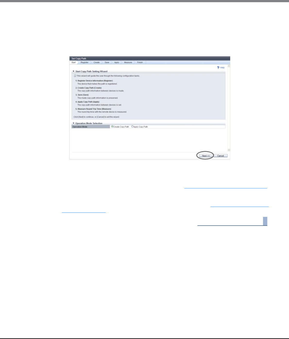
Chapter 8 Advanced Copy Management
8.2 Functions in the Action Area for Advanced Copy
ETERNUS Web GUI User’s Guide
Copyright 2013 FUJITSU LIMITED P2X0-1090-10ENZ0
321
2Select the operation mode, and click the [Next >>] button.
•Operation Mode
-Create Copy Path
Create a copy path and apply to the ETERNUS DX Disk storage system.
-Apply Copy Path
Apply the existing copy path information file to the ETERNUS DX Disk storage system.
The displayed screen is different depending on the selected operation.
■When selecting "Create Copy Path"
The [Base Information Selection] screen appears. Proceed to "Register Device Information" (page 322).
■When selecting "Apply Copy Path"
The [Copy Path Information File Selection] screen appears. Proceed to "Copy Path Information File
Selection" (page 336).
End of procedure
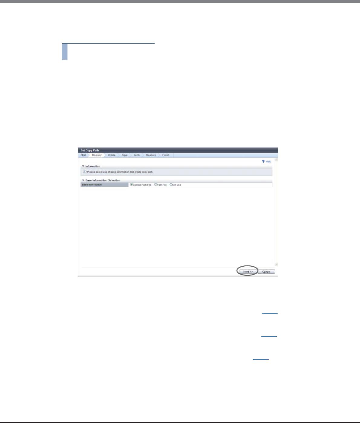
Chapter 8 Advanced Copy Management
8.2 Functions in the Action Area for Advanced Copy
ETERNUS Web GUI User’s Guide
Copyright 2013 FUJITSU LIMITED P2X0-1090-10ENZ0
322
Register Device Information
In this screen, register the device information to which the copy path is created.
Procedure
1Select a device information selection method in the [Base Information Selection] screen,
and click the [Next >>] button.
•Base Information
-Backup Path File
The copy path information file previously applied is used.
-Path File
The copy path information file stored in the ETERNUS DX Disk storage system is used.
-Not use
Copy path is created manually.
The displayed screen is different depending on the selected item.
■When selecting "Backup Path File"
→The [Check Registered Device Information] screen appears. Proceed to Step 3.
■When selecting "Path File"
→The [Copy Path Information File Selection] screen appears. Proceed to Step 2.
■When selecting "Not use"
→The [Device Information File Selection] screen appears. Proceed to Step 7.
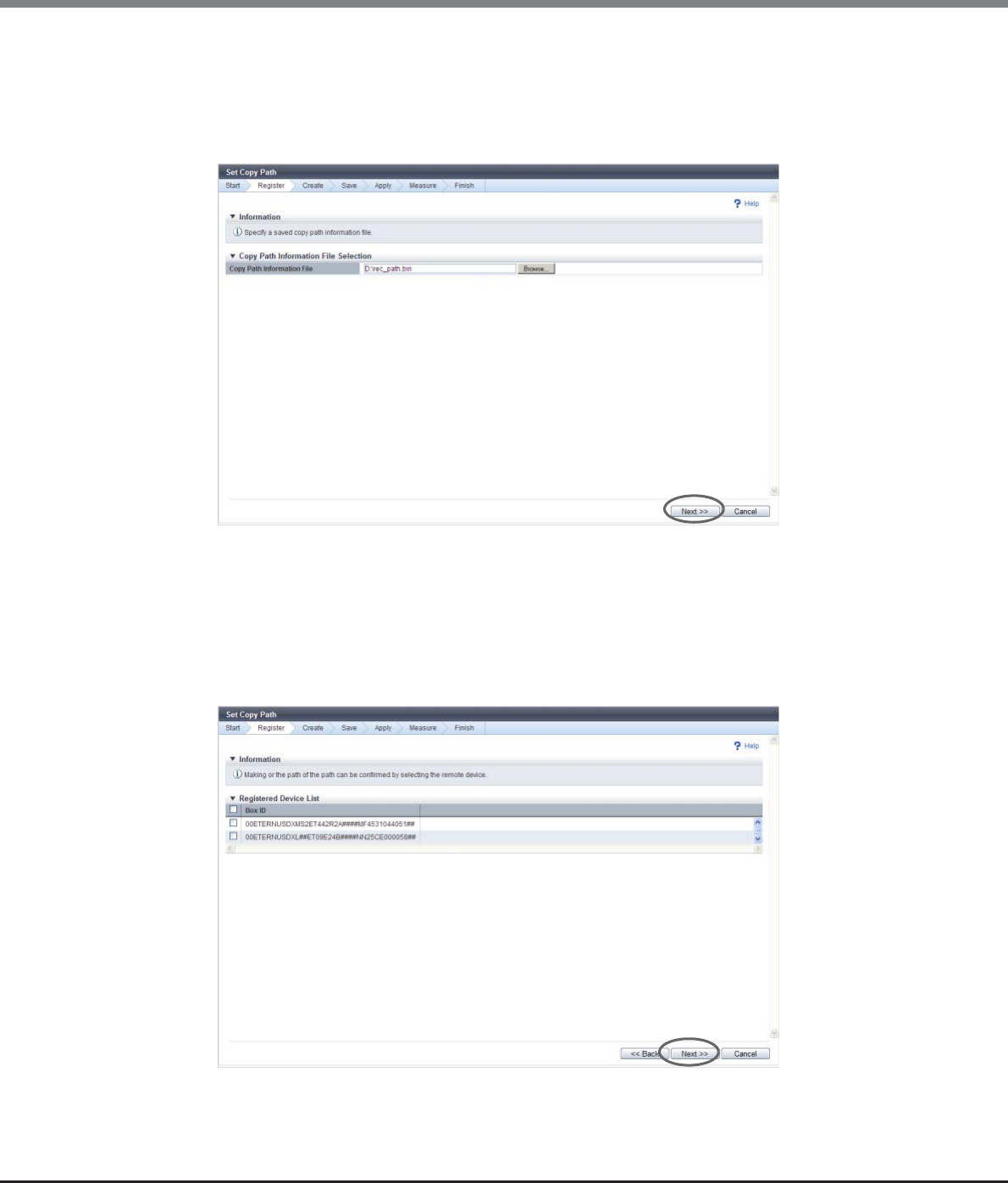
Chapter 8 Advanced Copy Management
8.2 Functions in the Action Area for Advanced Copy
ETERNUS Web GUI User’s Guide
Copyright 2013 FUJITSU LIMITED P2X0-1090-10ENZ0
323
2Input the location where the copy path information file that to be used, and click the [Next
>>] button.
•Copy Path Information File
Input the location where the copy path information file that to be used.
Click the [Browse...] button to specify the location, or input the location directly.
→The [Check Registered Device Information] screen appears.
3Select a device to register the information (multiple selections can be made), and click the
[Next >>] button.
•Checkboxes for selecting a device
A list of the ETERNUS Disk storage system information specified in the copy path information file
previously applied or stored in the ETERNUS DX Disk storage system is displayed.
Select the storage system to create a copy path.
→A confirmation screen appears.
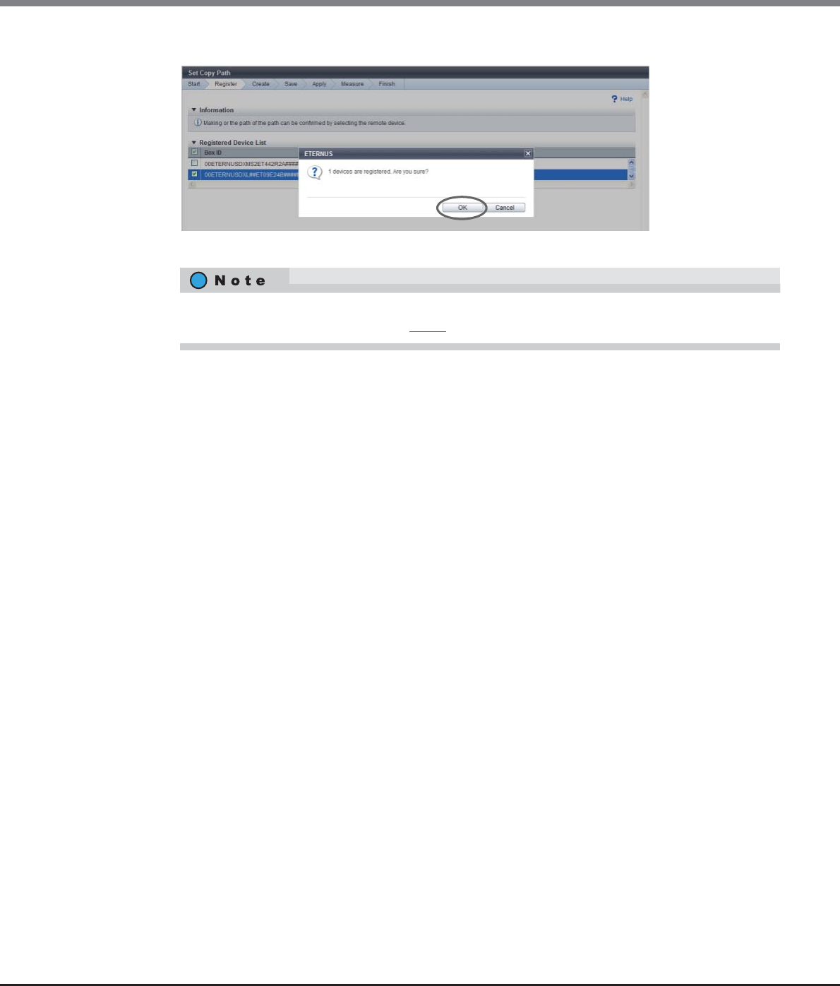
Chapter 8 Advanced Copy Management
8.2 Functions in the Action Area for Advanced Copy
ETERNUS Web GUI User’s Guide
Copyright 2013 FUJITSU LIMITED P2X0-1090-10ENZ0
324
4Click the [OK] button.
→The [Device Configuration Setting] screen appears.
5Set the port to be used for the copy path, and click the [Next >>] button.
•Port Type
Select the port type to set a copy path. The displayed contents vary depending on the device type.
-For ETERNUS DX90 S2
FC 1-Port, FC 2-Port, iSCSI 1-Port, iSCSI 2-Port, iSCSI-RA (*1)
-For ETERNUS DX410 S2/DX440 S2
FC 2-Port, FC 4-Port, iSCSI 2-Port, iSCSI-RA (*1)
-For ETERNUS DX8100 S2/DX8700 S2
FC 2-Port, FC 4-Port, iSCSI 2-Port, iSCSI-RA (*1)
-For ETERNUS DX90
FC 4-Port
-For ETERNUS DX410/DX440/DX8100/DX8400/DX8700 or ETERNUS4000/ETERNUS8000
FC 1-Port, FC 2-Port, FC 4-Port, iSCSI-RA 1-Port, iSCSI-RA 2-Port
-For ETERNUS6000
FC 2-Port, FC 4-Port
*1: iSCSI-RA is a dedicated adapter that is used for REC between the local device and the ETERNUS DX400
series, the ETERNUS DX8000 series, the ETERNUS4000, or the ETERNUS8000.
•Check to use as RA (for an ETERNUS Disk storage system that is not the ETERNUS6000)
Select the port to set a copy path as RA.
The port number is displayed at right side of the checkbox. When "iSCSI-RA", "iSCSI-RA 1-Port", or
"iSCSI-RA 2-Port" is selected in the "Port Type" field, all ports are automatically selected.
- #x (x: Port number (0 - 3))
-When "FC 1-Port" is selected in the "Port Type" field: #0 (#1, #2 and #3 cannot be selected.)
-When "FC 2-Port" is selected in the "Port Type" field: #0, #1 (#2 and #3 cannot be selected.)
-When "FC 4-Port" is selected in the "Port Type" field: #0, #1, #2, #3
-When "iSCSI 1-Port" is selected in the "Port Type" field: #0 (#1 cannot be selected.)
-When "iSCSI 2-Port" is selected in the "Port Type" field: #0, #1
-When "iSCSI-RA" is selected in the "Port Type" field: #0, #1 (All ports are selected.)
-When "iSCSI-RA 1-Port" is selected in the "Port Type" field: #0 (#0 is selected.)
-When "iSCSI-RA 2-Port" is selected in the "Port Type" field: #0, #1 (All ports are selected.)
When no storage system to register the information is selected, the [Device Information File
Selection] screen appears. Proceed to Step 7.
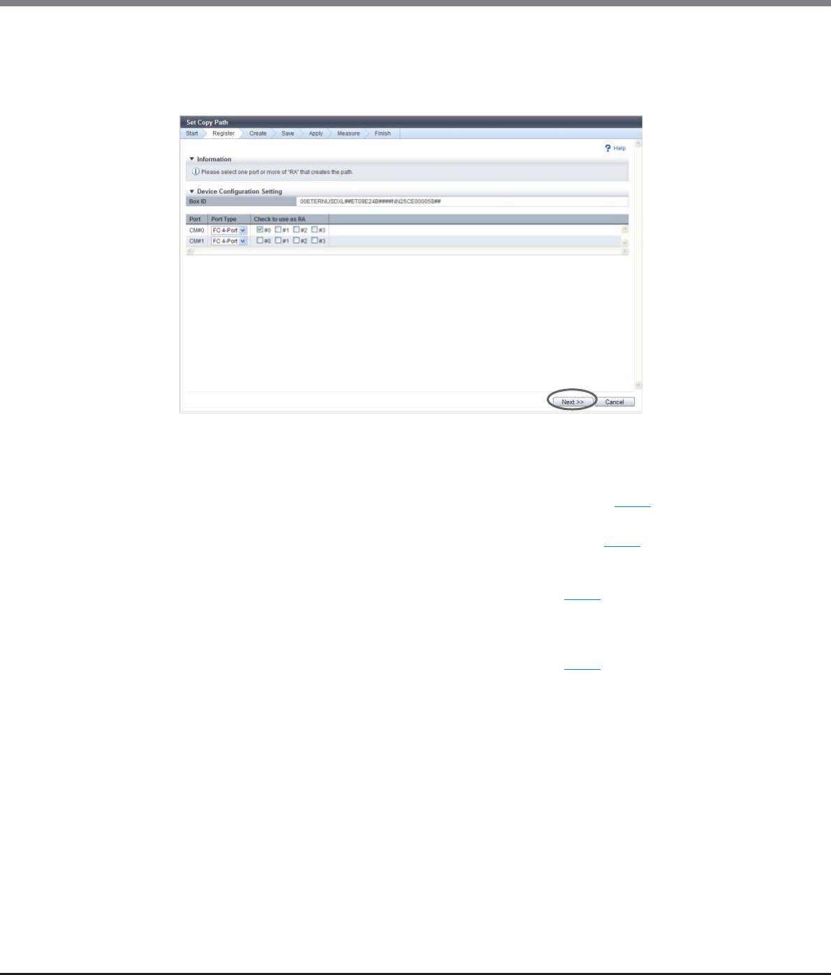
Chapter 8 Advanced Copy Management
8.2 Functions in the Action Area for Advanced Copy
ETERNUS Web GUI User’s Guide
Copyright 2013 FUJITSU LIMITED P2X0-1090-10ENZ0
325
•Initiator / Target Setting
Select the port mode to set a copy path as RA.
-Initiator
-Target
The displayed screen is different depending on the port settings.
■When "FC 1-Port", "FC 2-Port", or "FC 4-Port" is selected in the "Port Type" field
•When a device for which port setting is not completed exists
→The [Device Configuration Setting] screen appears again. Proceed to Step 5.
•When port setting is completed for all the selected devices
→The [Device Information File Selection] screen appears. Proceed to Step 7.
■When "iSCSI-RA", "iSCSI-RA 1-Port", or "iSCSI-RA 2-Port" is selected in the "Port Type" field
→The [iSCSI Port Information Setting] screen appears. Proceed to Step 6.
■When "iSCSI 1-Port" or "iSCSI 2-Port" is selected in the "Port Type" field and one or more ports used as
"RA" exist
→The [iSCSI Port Information Setting] screen appears. Proceed to Step 6.

Chapter 8 Advanced Copy Management
8.2 Functions in the Action Area for Advanced Copy
ETERNUS Web GUI User’s Guide
Copyright 2013 FUJITSU LIMITED P2X0-1090-10ENZ0
326
6Set the iSCSI port in the [iSCSI Port Information Setting] screen, and click the [Next >>]
button.
•IP Version
Select the IP version of the port to set a copy path.
If the copy path is already specified for the port when the copy path information file is being loaded,
the IP version that is set for the port is selected as the default setting. For other ports, "IPv4" is set as
the default setting.
This item is not displayed when "Port Type" is "iSCSI-RA" (for older storage system connection),
"iSCSI-RA 1-Port", or "iSCSI-RA 2-Port".
-IPv4
-IPv6 (Link Local)
-IPv6 (Connect IP)
•IP Address
Input the IP address of the iSCSI port.
This item is required when "Port Type" is "iSCSI-RA" (for older storage system connection), "iSCSI-RA
1-Port", or "iSCSI-RA 2-Port" or when "IP Version" is "IPv4". If not specified, the field is blank.
The following input conditions apply:
-Numeric characters
-First text box: "1" - "255"
-Other text boxes: "0" - "255"
•IPv6 Link Local Address
Input the IPv6 link IP address of the iSCSI port.
This item is required when "IP Version" is "IPv6 (Link Local)".
Refer to "Available IPv6 Address" (page 757) for details. Note that the current setting is displayed by
an abbreviation.
This item is not displayed when "Port Type" is "iSCSI-RA" (for older storage system connection),
"iSCSI-RA 1-Port", or "iSCSI-RA 2-Port". If not specified, the field is blank.
The following input condition applies:
-fe80::xxxx:xxxx:xxxx:xxxx
xxxx: 0 - ffff (FFFF) (hexadecimal, alphanumeric characters)
Refer to "IPv6 Address Notation" (page 378) for details.
•IPv6 Connect IP Address
Input the IPv6 connect IP address of the iSCSI port.
This item is required when "IP Version" is "IPv6 (Connect IP)".
The following IPv6 addresses can be used; "global address", "unique local address", and "6to4
address". Refer to "Available IPv6 Address" (page 757) for details. Note that the current setting is
displayed by an abbreviation.
This item is not displayed when "Port Type" is "iSCSI-RA" (for older storage system connection),
"iSCSI-RA 1-Port", or "iSCSI-RA 2-Port". If not specified, the field is blank.
The following input condition applies:
-xxxx:xxxx:xxxx:xxxx:xxxx:xxxx:xxxx:xxxx
xxxx: 0 - ffff (FFFF) (hexadecimal, alphanumeric characters)
Refer to "IPv6 Address Notation" (page 378) for details.
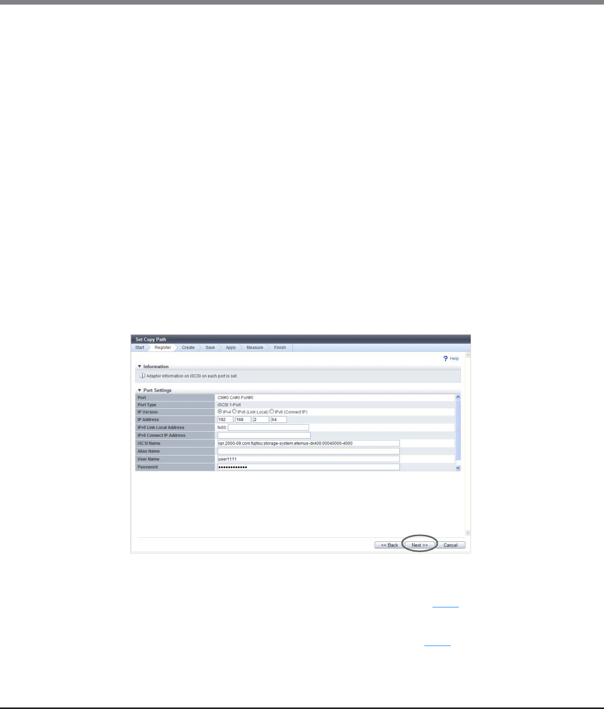
Chapter 8 Advanced Copy Management
8.2 Functions in the Action Area for Advanced Copy
ETERNUS Web GUI User’s Guide
Copyright 2013 FUJITSU LIMITED P2X0-1090-10ENZ0
327
•iSCSI Name
Specify the iSCSI name of the iSCSI port (required). If not specified, the field is blank. Specify a
unique iSCSI name in the same device.
The following input conditions apply:
-Alphabetic characters (lower case) and numeric characters
-Symbols "-" (hyphen), "." (period) and ":" (colon)
-The name starts with "iqn." or "eui."
-4 - 223 characters
•Alias Name
Specify the Alias Name of the iSCSI port (can be omitted). If not specified, the field is blank.
The following input condition applies:
-Up to 31 alphanumeric characters
•User Name
Specify the user name to access the iSCSI port (can be omitted). After specifying the user name,
specify the "Password". If not specified, the field is blank.
The following input condition applies:
-Up to 255 alphanumeric characters and symbols
•Password
Specify the password to access the iSCSI port (can be omitted). This item is required when setting
the "User Name". The entry is displayed with "*" or similar characters. If not specified, the field is
blank.
The following input condition applies:
-12 - 100 alphanumeric characters and symbols
The displayed screen is different depending on the port setting status.
■When a device for which port setting is not completed exists
→The [Device Configuration Setting] screen appears again. Proceed to Step 5.
■When port setting is completed for all the selected devices
→The [Device Information File Selection] screen appears. Proceed to Step 7.
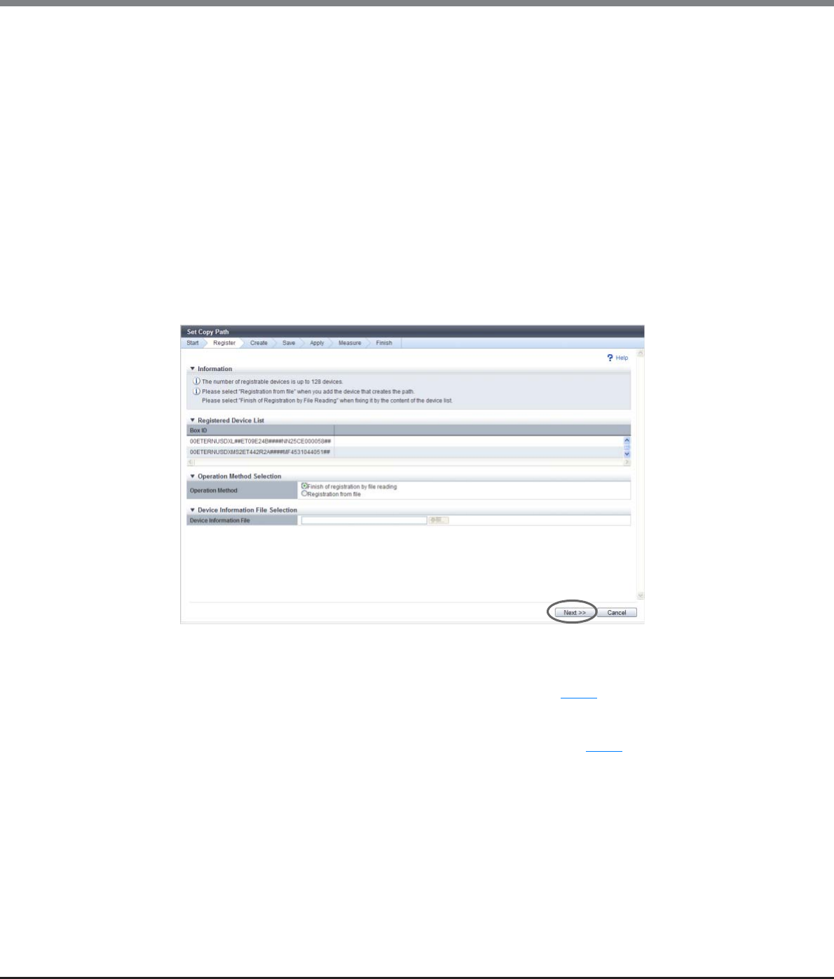
Chapter 8 Advanced Copy Management
8.2 Functions in the Action Area for Advanced Copy
ETERNUS Web GUI User’s Guide
Copyright 2013 FUJITSU LIMITED P2X0-1090-10ENZ0
328
7Specify whether to use the device information file, and click the [Next >>] button.
●Operation Method Selection
•Operation Method
Select whether to continue the device registration.
-Finish of Registration by File Reading
-Registration from File
When selecting "Registration from file", specify a file in the "Device Information File Selection"
field. When 128 devices are already registered, "Registration from file" cannot be selected.
●Device Information File Selection
•Device Information File
Input the location where the device information file is stored.
Click the [Browse...] button and specify the location, or directly input the path.
The displayed screen is different depending on the port setting status.
■When selecting "Registration from File"
→The [Device Configuration Setting] screen appears. Proceed to Step 5.
■When selecting "Finish of Registration by File Reading"
→The [Device Information File Selection] screen appears. Proceed to Step 8.

Chapter 8 Advanced Copy Management
8.2 Functions in the Action Area for Advanced Copy
ETERNUS Web GUI User’s Guide
Copyright 2013 FUJITSU LIMITED P2X0-1090-10ENZ0
329
8Select whether to continue registration of device information, and click the [Next >>]
button.
●Operation Method Selection
•Operation Method
Select whether to continue the device registration.
-Registration by manual operation
When selecting "Registration by manual operation", specify parameters in the "Device
Information Setting" field.
When 128 devices are already registered, "Registration by manual operation" cannot be
selected.
-Finish of Registration by File Reading
●Device Information Setting
•Device Type
Select the device type that is to be registered.
-ETERNUS DX8700 S2
-ETERNUS DX8100 S2
-ETERNUS DX90 S2
-ETERNUS DX410 S2/DX440 S2
-ETERNUS DX90
-ETERNUS DX410/DX440/DX8100/DX8400/DX8700
-ETERNUS4000/ETERNUS8000 MODEL400/600/800/1200/2200
-ETERNUS4000/ETERNUS8000 MODEL300/500/700/900/1100/2100
-ETERNUS6000
•Box ID
Input the Box ID of the storage system that is to be registered.
Box ID that is already registered in the ETERNUS Disk storage system cannot be specified.
The following input conditions apply:
-Alphabetic characters (upper case), numeric characters, spaces, and "#" (hash key characters)
-40 characters (fixed)
In the following conditions, check the Box ID for the relevant storage system from the [System
Settings] screen in the [System] navigation. Refer to "11.2.13.3 Change Box ID" (page 933) for
details.
•ETERNUS DX90 S2 (V10L30 or later)
•ETERNUS DX410 S2/DX440 S2 (V10L30 or later)
•ETERNUS DX8100 S2/DX8700 S2 (V10L30 or later)
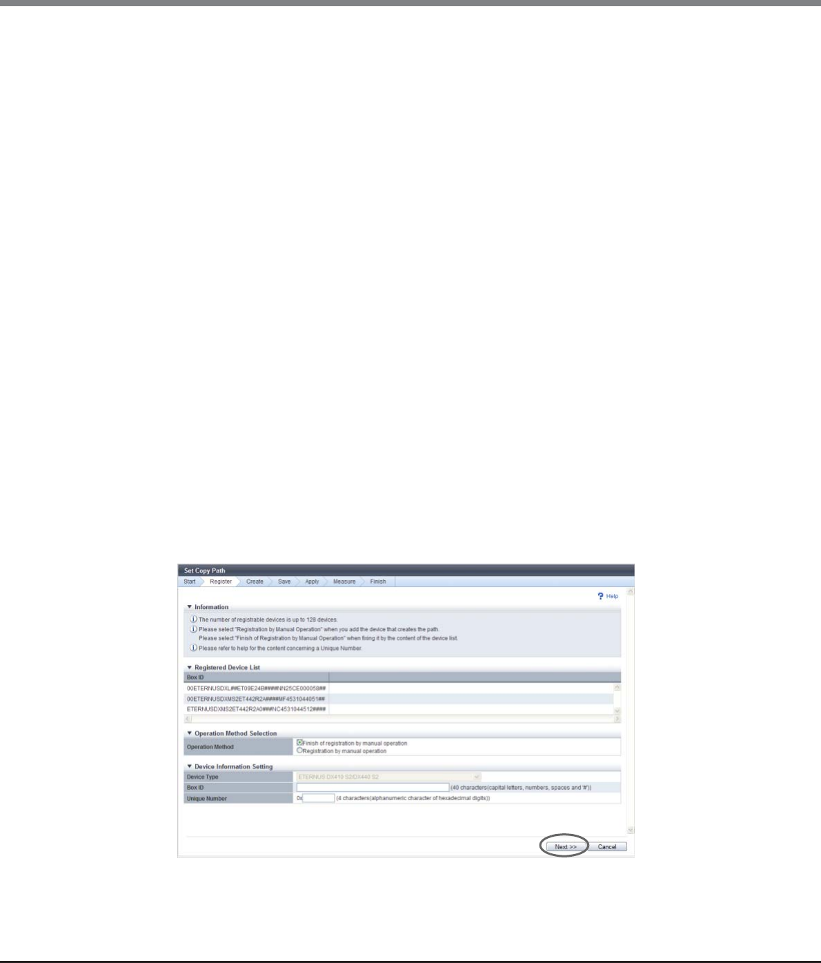
Chapter 8 Advanced Copy Management
8.2 Functions in the Action Area for Advanced Copy
ETERNUS Web GUI User’s Guide
Copyright 2013 FUJITSU LIMITED P2X0-1090-10ENZ0
330
•Unique Number
Input the unique number of the device to be registered.
Input conditions vary depending on the device type.
Unique number that is already registered in another ETERNUS Disk storage system cannot be
specified.
The following input conditions apply:
-For all device types:
4-digit hexadecimal (fixed)
-ETERNUS DX90 S2:
Input the value of the fifth and sixth bytes of the WWN.
[Example] For WWN 500000E0D4445800: [4458]
-ETERNUS DX410 S2/DX440 S2:
Input the value of the fifth and sixth bytes of the WWN.
[Example] For WWN 500000E0D404C500: [04C5]
-ETERNUS DX8100 S2:
Input the value of the fifth and sixth bytes of the WWN.
[Example] For WWN 500000E0D42F1000: [2F10]
-ETERNUS DX8700 S2:
Input the value of the fifth and sixth bytes of the WWN.
[Example] For WWN 500000E0D4314E00: [314E]
-ETERNUS DX90:
Input the value of the fifth and sixth bytes of the WWN.
[Example] For WWN 500000E0D062A100: [62A1]
-ETERNUS DX410/DX440/DX8100/DX8400/DX8700 or
ETERNUS4000/ETERNUS8000:
Input the value of the sixth and seventh bytes of the WWN.
[Example] For WWN 2000000B5D6A1234: [1234]
-ETERNUS6000:
Input the value of the sixth and seventh bytes of the WWN.
[Example] For WWN 2000000E00CB5678: [5678]

Chapter 8 Advanced Copy Management
8.2 Functions in the Action Area for Advanced Copy
ETERNUS Web GUI User’s Guide
Copyright 2013 FUJITSU LIMITED P2X0-1090-10ENZ0
331
The displayed screen is different depending on the port setting status.
■When selecting "Registration by manual operation"
→The [Device Configuration Setting] screen appears again. Proceed to Step 5.
■When selecting "Finish of Registration by File Reading"
→The [Check Registered Device Information] screen appears. Proceed to Step 9.
9Check the device information, and click the [Next >>] button.
→The [Copy Path Creation Device Selection] screen appears. Proceed to "Set Copy Path" (page 332).
End of procedure
•The unique number can be checked by the WWN of the FC port. All of the FC ports in a storage
system have the same unique number. The displayed screens for each storage system model are as
follows:
-For ETERNUS DX90 S2, ETERNUS DX410 S2/DX440 S2, or ETERNUS DX8100 S2/DX8700 S2:
→Port information (FC) of the [Channel Adapter Detail] screen
-For ETERNUS DX90:
→Port status (FC) of the [Storage System Status] screen
-For ETERNUS DX410/DX440, ETERNUS DX8100/DX8400/DX8700, or ETERNUS4000/
ETERNUS8000:
→CA Detailed Information screen (FC) of the [Device Status] screen
-For ETERNUS6000:
→WWN list (FC) of the [Device Status] screen
•If only iSCSI ports are installed in a storage system, the unique number can be checked by the
default iSCSI name. All of the iSCSI ports in a storage system have the same unique number. For
"iSCSI 1-Port" or "iSCSI 2-Port", the last four digits of the iSCSI name indicate the unique number.
[Example]
For the default iSCSI Name iqn.2000-09. com.fujitsu:storage-system.eternus-dx400:00044205:
[4205].
Note that the iSCSI name is a parameter that can be customized. It is not possible to check whether
the iSCSI name is customized or not. In this case, create an REC device information file using the
[Export Storage Information] function and register the device by file reading.
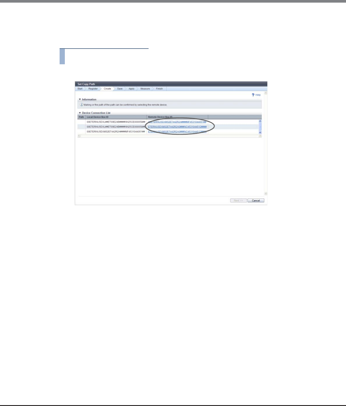
Chapter 8 Advanced Copy Management
8.2 Functions in the Action Area for Advanced Copy
ETERNUS Web GUI User’s Guide
Copyright 2013 FUJITSU LIMITED P2X0-1090-10ENZ0
332
Set Copy Path
In this screen, set a copy path. Specify the Box ID of the target device in which the copy path is created, and
set the line information between devices.
Procedure
1Click the [Remote Device Box ID] link to create a copy path.
→The [Copy Path Setting] dialog box appears.
2Set a copy path in the [Copy Path Setting] dialog box and click the [OK] button.
●Copy Path Setting
•Line Setting
Select a copy path. Up to eight copy paths can be selected.
Checkboxes are displayed only for the combinations meeting all the following conditions
(combinations to which a copy path can be set):
-The same port type (FC, iSCSI, or iSCSI-RA) is used for both the local device and remote device.
-The same IP version (v4, v6L, or v6C) is specified for the iSCSI ports that are used for both the
local and remote devices.
-RA port is used.
-For ETERNUS6000, the local device and the remote device have different port usages (Initiator/
Target).

Chapter 8 Advanced Copy Management
8.2 Functions in the Action Area for Advanced Copy
ETERNUS Web GUI User’s Guide
Copyright 2013 FUJITSU LIMITED P2X0-1090-10ENZ0
333
●Line Setting
•Connection Type
Select the connection type for the remote device.
-Remote
Connecting the local and remote devices via a line.
-Direct
Connecting the local and remote devices without a line.
Even in connection via a switch, select "Direct" when not using a line.
•Link Speed
Specify the link speed (*1) for connection with the remote device. This item can be set when the
"Connection Type" is "Remote".
The following input conditions apply:
-Up to 5-digit decimal number
-1- 65535 (Mbit/s)
*1: For the "Link Speed" field, specify the WAN bandwidth (a total of multiple lines, if used) that can be
actually used for REC. For some cases such as using the bandwidth control device, the WAN bandwidth
that can be used for REC is designated. In this case, specify the designated value. In the ETERNUS Disk
storage systems, the WAN bandwidth control is unavailable. To control WAN bandwidth, using the
bandwidth control device is required.
When using a line device with the compression function, specify the bandwidth (a total of multiple lines,
if used) that can be used after compression. In the ETERNUS Disk storage systems, data compression is
unavailable. To compress data, using a line device with the compression function is required.
Example 1: When the bandwidth control device is not used
Line bandwidth (*2): 200Mbit/s (All available for REC)
The number of lines (*3): 4 (200Mbit/s for all)
Link speed = 200 (Mbit/s) x 4 = 800 (Mbit/s)
Example 2: When the bandwidth control device is used
Line bandwidth with bandwidth limit (*2): 100Mbit/s
(100Mbit/s out of 200Mbit/s line bandwidth is available for REC)
The number of lines (*3): 2 (100Mbit/s for all)
Link speed = 100 (Mbit/s) x 2 = 200 (Mbit/s)
Example 3: When the line device has no compression function
Line bandwidth (*2): 200Mbit/s (All available for REC)
The number of lines (*3): 2 (200Mbit/s for all)
Compression ratio: 0 (%) (No compression)
Link speed = 200 (Mbit/s) x 2 / (1 - 0 (%)) = 400 (Mbit/s)
Example 4: When the line device has the compression function
Line bandwidth (*2): 200Mbit/s (All available for REC)
The number of lines (*3): 2 (200Mbit/s for all)
Compression ratio: 20 (%) (20% for all)
Link speed = 200 (Mbit/s) x 2 / (1 - 20 (%)) = 500 (Mbit/s)
*2: The line bandwidth that the user has signed up to be used for REC
*3: The number of lines that the user has signed up to be used for REC
To change the link speed, create a copy path with a new link speed by using this function, and
apply the created copy path to the related storage systems.
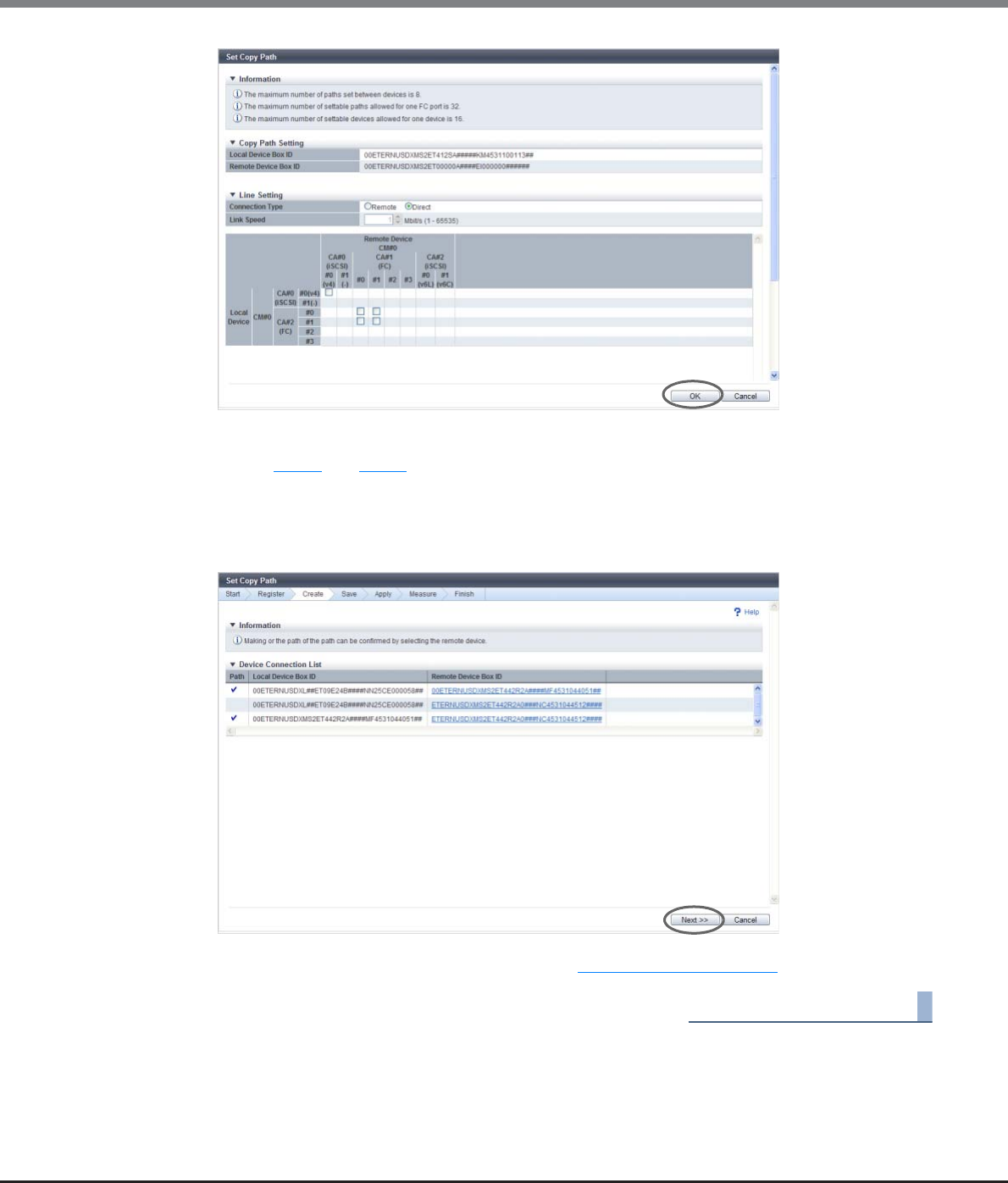
Chapter 8 Advanced Copy Management
8.2 Functions in the Action Area for Advanced Copy
ETERNUS Web GUI User’s Guide
Copyright 2013 FUJITSU LIMITED P2X0-1090-10ENZ0
334
→The [Copy Path Creation Device Selection] screen appears.
3Repeat Step 1 and Step 2 the same number of times as the number of storage systems to set
copy paths.
4When setting a copy path is completed for all the storage systems, click the [Next >>]
button.
→The [Download File] screen appears. Proceed to "Save Copy Path" (page 335).
End of procedure
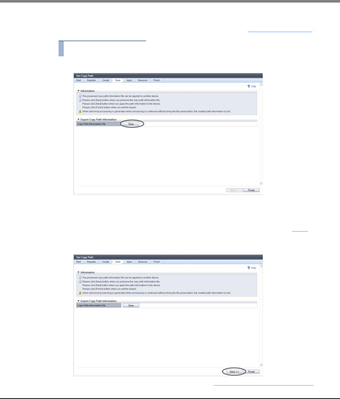
Chapter 8 Advanced Copy Management
8.2 Functions in the Action Area for Advanced Copy
ETERNUS Web GUI User’s Guide
Copyright 2013 FUJITSU LIMITED P2X0-1090-10ENZ0
335
Save Copy Path
In this screen, save the copy path information that is created in the procedure in "Set Copy Path" (page 332).
Procedure
1Click the [Save] button to save the copy path information.
→A dialog box to download the file appears.
2Save the copy path information file.
The default file name is "RecPath_serial number for the ETERNUS DX Disk storage system_YYYY-MM-
DD_hh-mm-ss.bin". (YYYY-MM-DD_hh-mm-ss: the date and time when the save screen (Step 1) is
displayed.)
3Click the [Next >>] button.
→The [Device Connection List] screen appears. Proceed to "Apply Copy Path Information" (page 337).
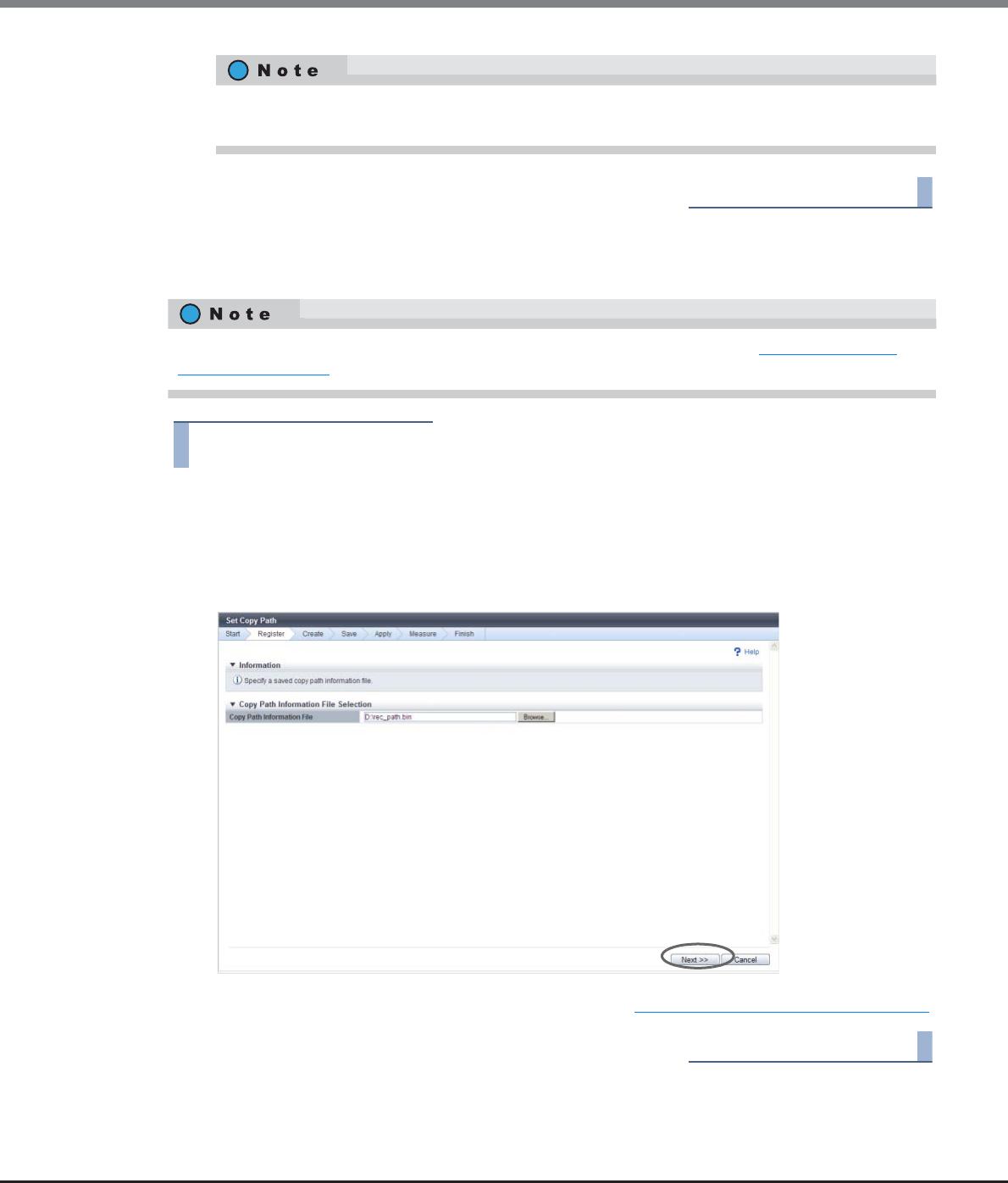
Chapter 8 Advanced Copy Management
8.2 Functions in the Action Area for Advanced Copy
ETERNUS Web GUI User’s Guide
Copyright 2013 FUJITSU LIMITED P2X0-1090-10ENZ0
336
End of procedure
Copy Path Information File Selection
In this screen, select the copy path information file to be used.
Procedure
1Input the location where the copy path information file to be used is stored, and click the
[Next >>] button.
•Copy Path Information File
Input the location where the copy path information file is stored.
Click the [Browse...] button and specify the location, or directly input the path.
→The [Device Connection List] screen appears. Proceed to "Apply Copy Path Information" (page 337).
End of procedure
Clicking the [Done] button displays the [Finish Copy Path Setting Wizard] screen. Click the [OK]
button to finish the [Set Copy Path] function.
Perform this procedure only when "Apply Copy Path" is selected in the procedure in "Operation Method
Selection" (page 329).
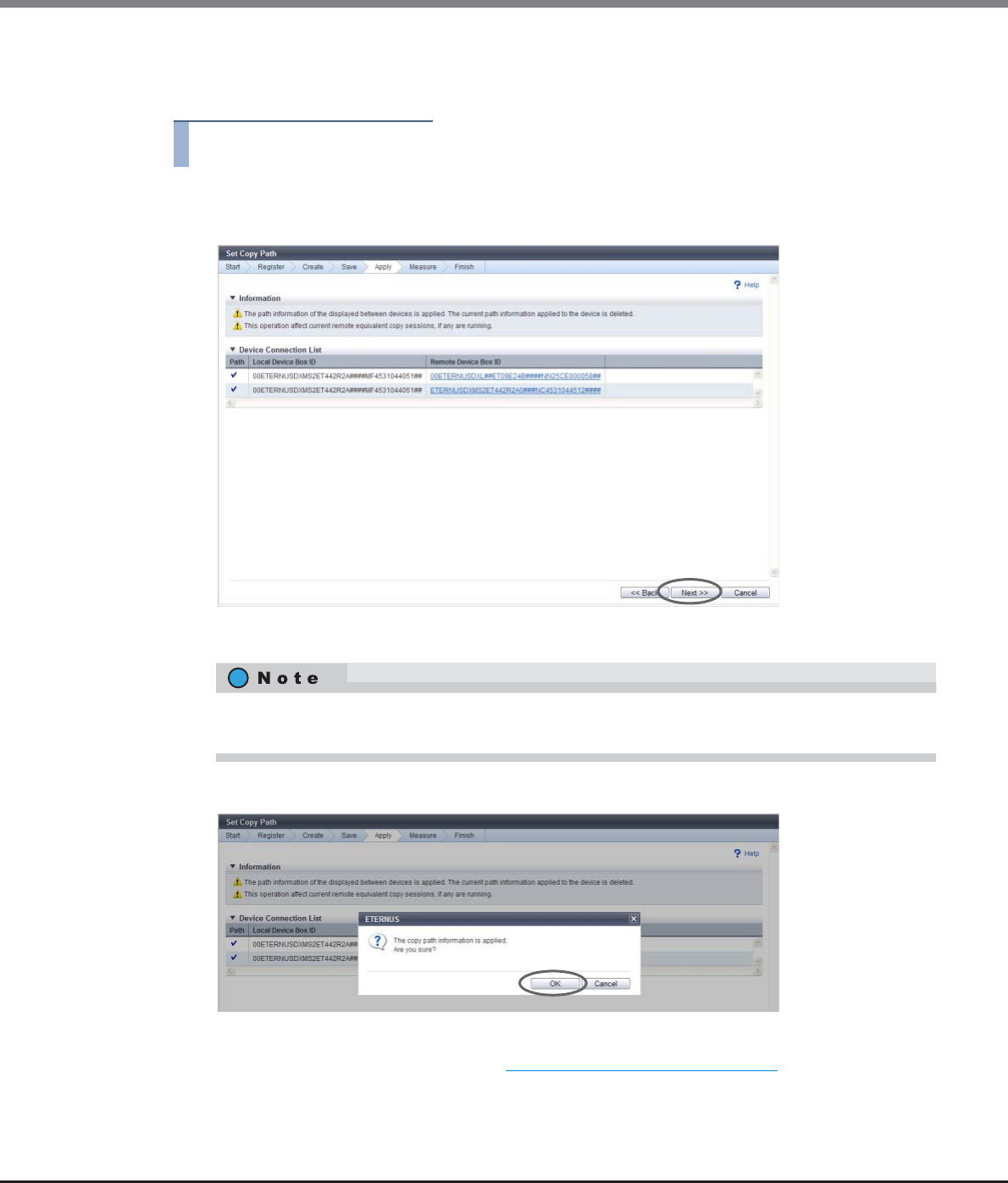
Chapter 8 Advanced Copy Management
8.2 Functions in the Action Area for Advanced Copy
ETERNUS Web GUI User’s Guide
Copyright 2013 FUJITSU LIMITED P2X0-1090-10ENZ0
337
Apply Copy Path Information
In this screen, apply the copy path information.
Procedure
1Confirm that the copy path is set between the devices in the [Device Connection List] screen,
and click the [Next >>] button.
→A confirmation screen appears.
2Click the [OK] button.
→Application of the copy path information starts. After application completes, the [Measure Round
Trip Time] screen appears. Proceed to "Measure Round Trip Time" (page 338).
Click the Box ID of the remote device to display the [Check Copy Path Information Setting] dialog box
where you can check the details of copy path information.
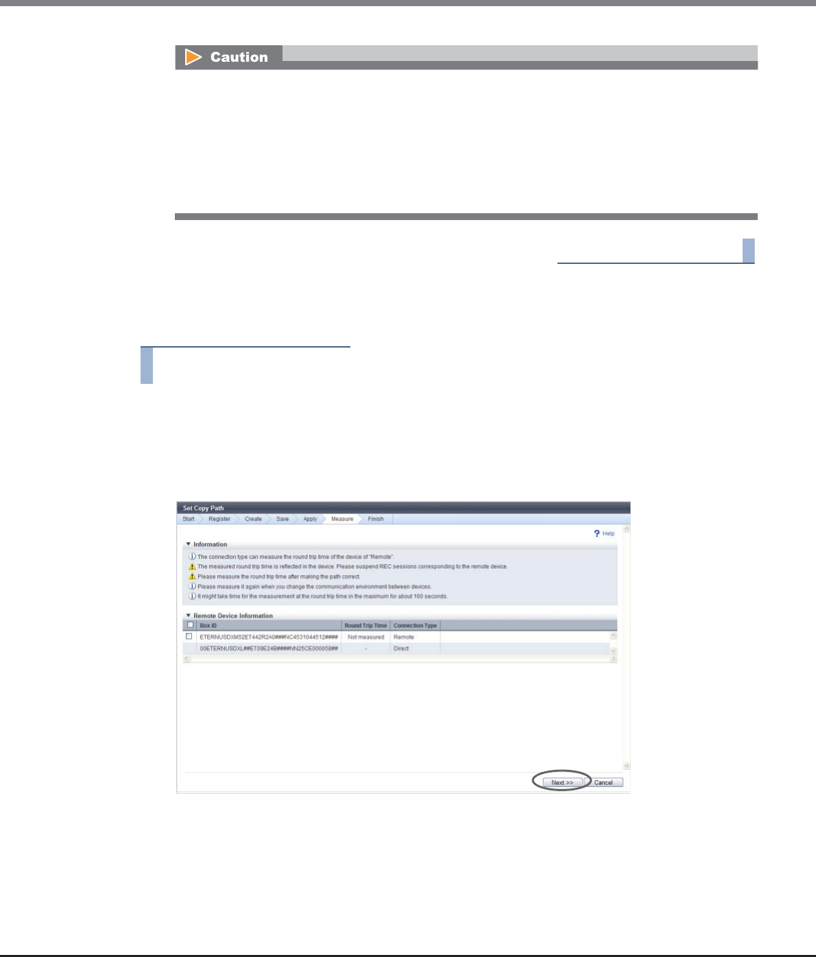
Chapter 8 Advanced Copy Management
8.2 Functions in the Action Area for Advanced Copy
ETERNUS Web GUI User’s Guide
Copyright 2013 FUJITSU LIMITED P2X0-1090-10ENZ0
338
End of procedure
Measure Round Trip Time
In this screen, measure the round trip time between the local and remote devices.
Procedure
1Select a remote device to measure the round trip time in the [Measure Round Trip Time]
screen (multiple selections can be made), and click the [Next >>] button.
•Checkboxes for selecting a remote device
Checkboxes are displayed only for a remote device with a copy path to the local device with a
"remote" type connection. Select the remote device to measure the round trip time.
→A confirmation screen appears.
•If the port mode does not match between the device configuration and the applied copy path
information file configuration ("CA" in the storage system and "RA" in the copy path information
file), an error screen appears.
•The [Finish Copy Path Setting Wizard] screen appears in the following conditions. Click the [Done]
button to return to the [Copy Path] screen.
-No remote device with a copy path to the local device
-The connection type for all the remote devices is "Direct"
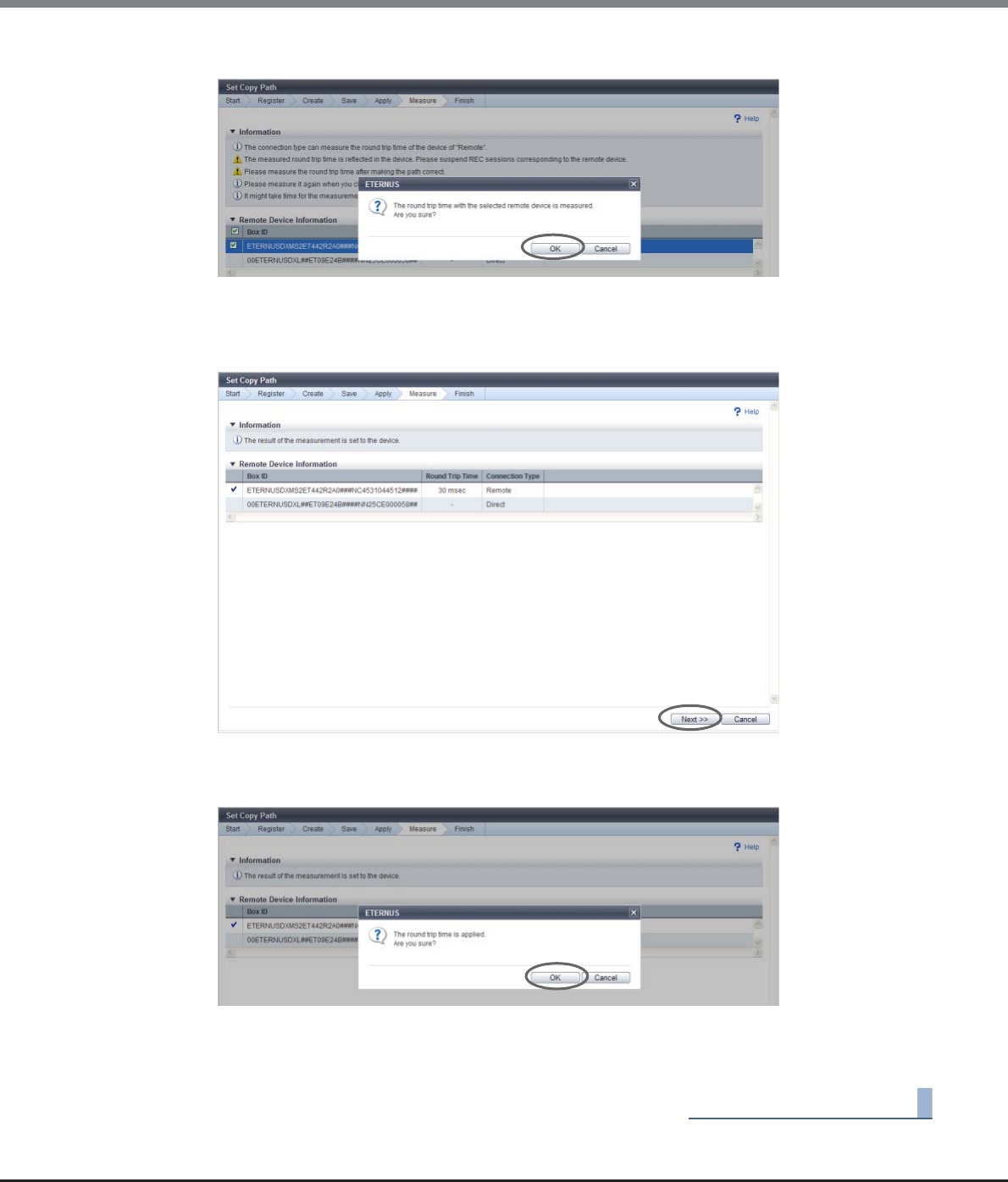
Chapter 8 Advanced Copy Management
8.2 Functions in the Action Area for Advanced Copy
ETERNUS Web GUI User’s Guide
Copyright 2013 FUJITSU LIMITED P2X0-1090-10ENZ0
339
2Click the [OK] button.
→Measurement of the round trip time starts. After measurement completes, the [Measure Round Trip
Time Result] screen appears.
3Check the measured round trip time, and click the [Next >>] button.
→A confirmation screen appears.
4Click the [OK] button.
→Setting the round trip time starts.
5After setting the time, click the [Done] button to return to the [Copy Path] screen.
End of procedure

Chapter 8 Advanced Copy Management
8.2 Functions in the Action Area for Advanced Copy
ETERNUS Web GUI User’s Guide
Copyright 2013 FUJITSU LIMITED P2X0-1090-10ENZ0
340
■Applying copy path information files with IPv6
The following storage systems and copy path information files are used in this example.
The following table shows whether an exported device information file from each storage system can be
loaded when creating a copy path information file.
Available: The device information file can be loaded
N/A: The device information file cannot be loaded (manual input of the device information is required)
Storage system Target model Current controller
firmware version
Exported copy path information file
New storage
systems
ETERNUS DX90 S2
ETERNUS DX410 S2/
DX440 S2
ETERNUS DX8100 S2/
DX8700 S2
V10L3x or later
(IPv6 support)
New file
(IPv4, IPv6 (Link Local), or IPv6 (Connect IP) can
be used for the iSCSI-RA port)
Old storage
systems
ETERNUS DX90 S2
ETERNUS DX410 S2/
DX440 S2
ETERNUS DX8100 S2/
DX8700 S2
V10L2x or earlier
(IPv6 not
supported)
Old file
(only IPv4 can be used for the iSCSI-RA port)
Old storage
systems
(other models)
ETERNUS DX90
ETERNUS DX410/DX440
ETERNUS DX8100/
DX8700
ETERNUS4000/
ETERNUS8000
ETERNUS6000
Any firmware
version
(IPv6 not
supported)
N/A
(When creating copy paths between new storage
systems and old storage systems or between new
storage systems and old storage systems (other
models), make sure to create a copy path
information file using the new ETERNUS Disk
storage system. In this case, creating copy path
information files by using the old storage system
(other models) is not available.)
Copy path information file The storage system from which
the device information file is downloaded
Name The storage system
to which the file is
created
Old storage systems
(other models)
Old storage systems New storage systems
Old file Old storage systems N/A Available N/A
New file
(IPv6 address (*1) is
not included)
New storage systems Available Available Available
New file
(IPv6 address (*1) is
included)
New storage systems Available Available Available

Chapter 8 Advanced Copy Management
8.2 Functions in the Action Area for Advanced Copy
ETERNUS Web GUI User’s Guide
Copyright 2013 FUJITSU LIMITED P2X0-1090-10ENZ0
341
■Applying copy path information files
•Obtain the copy path information file from the storage system to which the copy path is to be created and
apply this file to the old storage systems (other models), the old storage systems, and the new storage
systems
Available: The copy path information file can be applied
*1: IPv6 (Link Local) and/or IPv6 (Connect IP)
*2: Only an IPv4 address is used for the copy path information file
*3: Only an IPv4 path can be used for the copy path information file
*4: Regarded as an IPv4 address is used for the copy path information file
*5: The copy path information file of the target storage system includes IPv6 paths
•Obtain the copy path information file from the storage system to which the copy path information file was
applied
Available: The copy path information file can be obtained correctly
N/A: The copy path information file cannot be obtained correctly
*1: IPv6 (Link Local) and/or IPv6 (Connect IP)
*2: Only an IPv4 address is used for the copy path information file
*3: Regarded as an IPv4 address is used for the copy path information file
*4: The IPv6 path information can be obtained correctly
Copy path information file The storage system to which the file is applied
Name The storage system to
which the file is created
Old storage
systems
(other models)
Old storage
systems
New storage
systems
Old file Old storage systems Available (*2) Available (*2) Available (*4)
New file
(IPv6 address (*1) is
not included)
New storage systems Available (*2) Available (*4) Available (*4)
New file
(IPv6 address (*1) is
included)
New storage systems Available (*3) Available (*3) Available (*5)
Copy path information file The storage system from which the file is obtained
Name The storage system to
which the file is created
Old storage
systems
(other models)
Old storage
systems
New storage
systems
Old file Old storage systems Available (*2) Available (*2) Available (*3)
New file
(IPv6 address (*1) is
not included)
New storage systems Available (*2) Available (*3) Available (*3)
New file
(IPv6 address (*1) is
included)
New storage systems N/A N/A Available (*4)

Chapter 8 Advanced Copy Management
8.2 Functions in the Action Area for Advanced Copy
ETERNUS Web GUI User’s Guide
Copyright 2013 FUJITSU LIMITED P2X0-1090-10ENZ0
342
Setting example 1
[Device information]
Storage system 1 (old storage system)
Storage system 2 (old storage system)
Storage system 3 (new storage system) ← Local device
Storage system 4 (new storage system)
[Copy path information]
Storage system 1 – Storage system 2 (IPv4)
Storage system 1 – Storage system 3 (IPv4)
Storage system 3 – Storage system 4 (IPv6)
When the local device is storage system 3 (or storage system 4), load the device information file from the
copy path between storage system 1 and storage system 4, and then create the copy path information file.
When the copy path information file that was obtained from storage system 3 (or storage system 4) is applied
to the copy path between storage system 1 and storage system 4, the copy path can be used correctly.
Setting example 2
[Device information]
Storage system 1 (old storage system) ← Local device
Storage system 2 (old storage system)
Storage system 3 (new storage system)
Storage system 4 (new storage system)
[Copy path information]
Storage system 1 – Storage system 2 (IPv4)
Storage system 1 – Storage system 3 (IPv4)
Storage system 3 – Storage system 4 (IPv6)
When the local device is storage system 1 (or storage system 2), obtain the copy path information that was
applied when setting example 1.
If the relevant copy path information is applied to the copy path between storage system 1 and storage
system 4, the IPv6 addresses of storage system 3 and storage system 4 are not applied correctly. In this case,
a copy cannot be performed or an unexpected copy path is created.
•When applying the copy path information file to an old storage system (other models), the [Convert Copy
Path] function must be used to convert the format. Refer to "8.2.16 Convert Copy Path" (page 347) for
details.
•Make sure to obtain the copy path information file that includes the IPv6 address of the new storage
system. If copy path information is obtained from an old storage system to which the copy path
information file is already applied, the IPv6 address cannot be obtained correctly. If this copy path
information file is applied to the new storage system, copying may not be available or copy paths may be
set to an unexpected remote device.
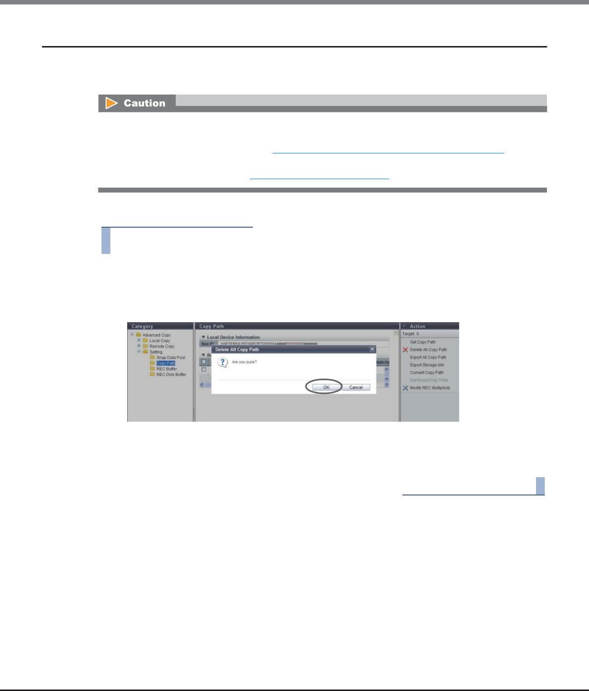
Chapter 8 Advanced Copy Management
8.2 Functions in the Action Area for Advanced Copy
ETERNUS Web GUI User’s Guide
Copyright 2013 FUJITSU LIMITED P2X0-1090-10ENZ0
343
8.2.13 Delete All Copy Path
This function deletes all of the copy path information between local and remote devices registered in the
ETERNUS DX Disk storage system.
The procedure to delete all of the copy paths is as follows:
Procedure
1Click [Delete All Copy Path] in [Action].
→A confirmation screen appears.
2Click the [OK] button.
→Deletion of copy paths starts.
3Click the [Done] button to return to the [Copy Path] screen.
End of procedure
•If a copy path, which is being used in an REC, was deleted, it may affect operations, such as the REC being
stopped. Confirm that REC is not in use before modifying the information.
To check whether REC is in use, refer to "8.1.3 Advanced Copy (All Remote Sessions)" (page 261).
•This function deletes all of the copy paths configured in the ETERNUS DX Disk storage system. To delete
some of the copy paths, refer to "8.2.12 Set Copy Path" (page 318).
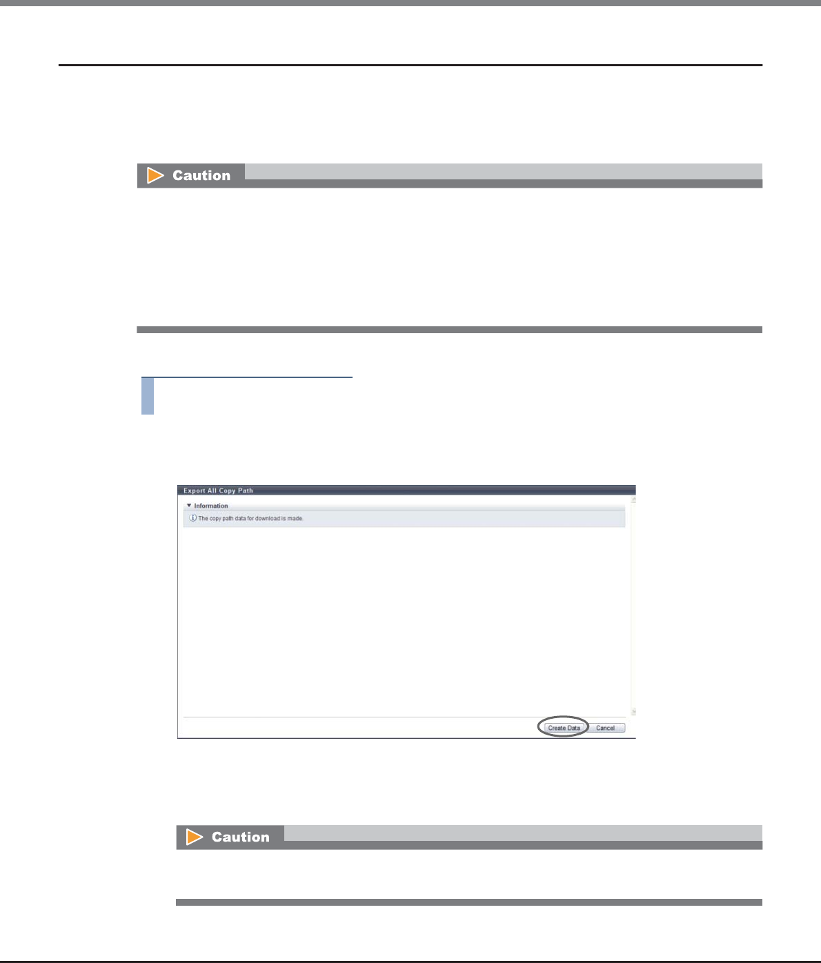
Chapter 8 Advanced Copy Management
8.2 Functions in the Action Area for Advanced Copy
ETERNUS Web GUI User’s Guide
Copyright 2013 FUJITSU LIMITED P2X0-1090-10ENZ0
344
8.2.14 Export All Copy Path
This function exports the copy path information registered in the ETERNUS DX Disk storage system, and saves
the information in a file.
The saved file can be used as path information when creating a copy path, so that manual registration of the
path information will not be required.
The procedure to export the copy path information is as follows:
Procedure
1Click [Export All Copy Path] in [Action].
2Click the [Create Data] button.
→The copy path information, which has been registered in the ETERNUS DX Disk storage system, is
exported.
After the copy path information export has been finished, a screen to execute downloading the file
is displayed.
•A copy path information cannot be exported when it has not been registered in the ETERNUS DX Disk
storage system.
•The format of the copy path information file has been changed in controller firmware version V10L30.
When the copy path information includes an IPv6 address, make sure to export the path information file
from an ETERNUS DX Disk storage system with controller firmware version V10L3x or later. An ETERNUS
DX Disk storage system with controller firmware version V10L2x or earlier cannot export correct IPv6
addresses.
If the copy path information has not been registered in the ETERNUS DX Disk storage system, an error
screen appears.
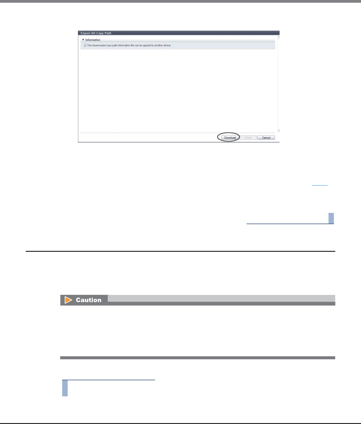
Chapter 8 Advanced Copy Management
8.2 Functions in the Action Area for Advanced Copy
ETERNUS Web GUI User’s Guide
Copyright 2013 FUJITSU LIMITED P2X0-1090-10ENZ0
345
3Click the [Download] button.
→A dialog box to download the file appears.
4Save the copy path information file.
The default file name is "RecPath_serial number for the ETERNUS DX Disk storage system_YYYY-MM-
DD_hh-mm-ss.bin". (YYYY-MM-DD_hh-mm-ss: the date and time when the download screen (Step 3) is
displayed.)
5Click the [Close] button to return to the [Copy Path] screen.
End of procedure
8.2.15 Export Storage Information
This function exports the FCRA/iSCSI-RA installation information in the ETERNUS DX Disk storage system, and
saves the information in a file.
The saved file can be used as device information when creating a copy path, so that manual registration of the
device information will not be required.
The procedure to export the REC device information is as follows:
Procedure
1Click [Export Storage Info] in [Action].
The format of the device information file has been changed in controller firmware version V10L30. A device
information file that is obtained using an ETERNUS DX Disk storage system with controller firmware V10L3x
or later cannot be applied to an ETERNUS DX Disk storage system with V10L2x or earlier controller firmware
when creating a copy path information file. Note that a device information file that is obtained from an
ETERNUS DX Disk storage system with controller firmware V10L2x or earlier can be applied to an ETERNUS DX
Disk storage system with V10L3x controller firmware.
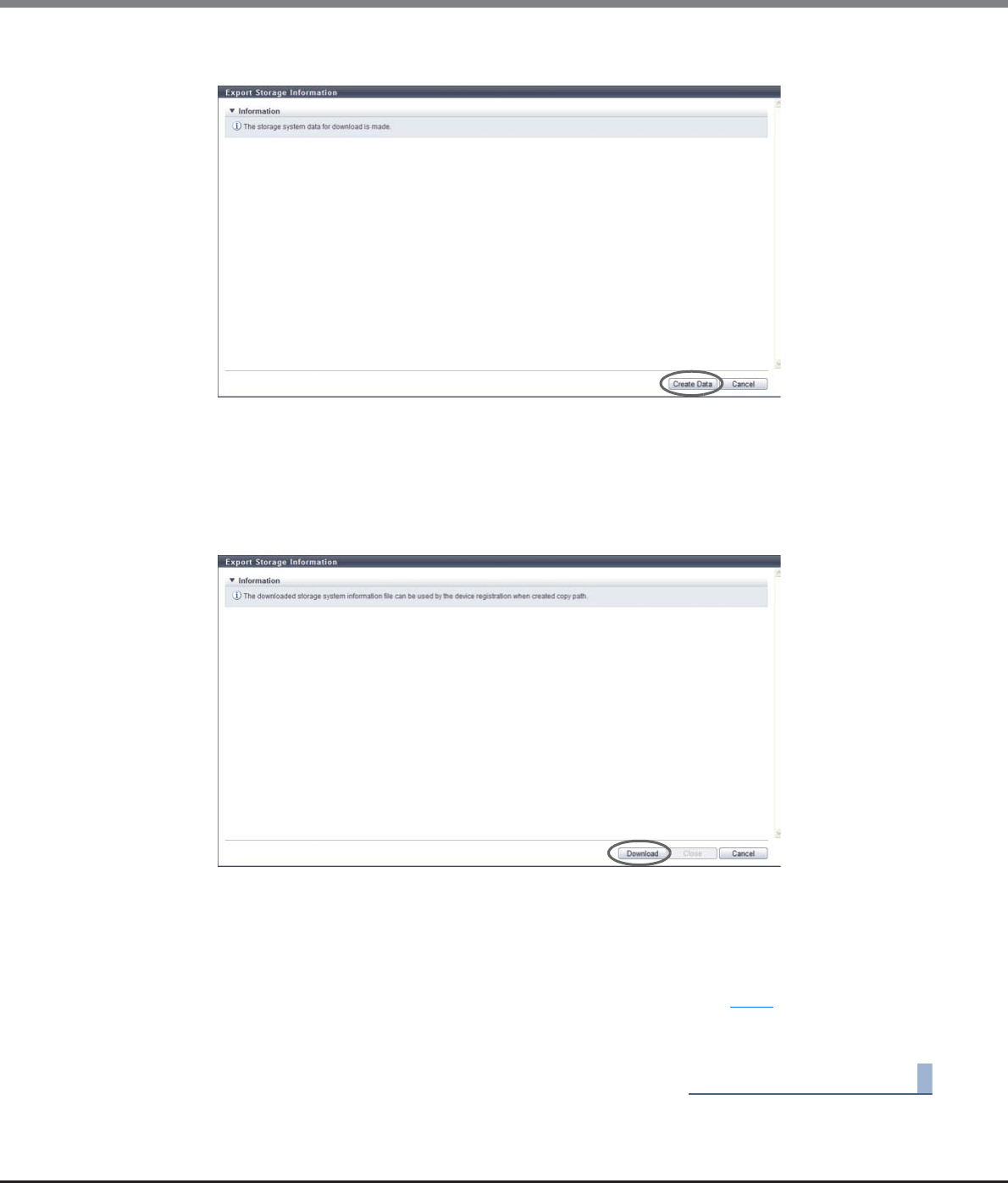
Chapter 8 Advanced Copy Management
8.2 Functions in the Action Area for Advanced Copy
ETERNUS Web GUI User’s Guide
Copyright 2013 FUJITSU LIMITED P2X0-1090-10ENZ0
346
2Click the [Create Data] button.
→The REC device information, which has been registered in the ETERNUS DX Disk storage system, is
exported.
After the REC device information export has been finished, a screen to execute downloading the file
is displayed.
3Click the [Download] button.
→A dialog box to download the file appears.
4Save the REC device information file.
The default file name is "RecRAInfo_serial number for the ETERNUS DX Disk storage system_YYYY-MM-
DD_hh-mm-ss.bin".
(YYYY-MM-DD_hh-mm-ss: the date and time when the download screen (Step 3) is displayed.)
5Click the [Close] button to return to the [Copy Path] screen.
End of procedure
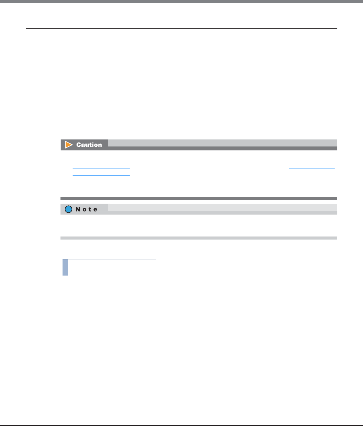
Chapter 8 Advanced Copy Management
8.2 Functions in the Action Area for Advanced Copy
ETERNUS Web GUI User’s Guide
Copyright 2013 FUJITSU LIMITED P2X0-1090-10ENZ0
347
8.2.16 Convert Copy Path
This function outputs the copy path information file for past ETERNUS Disk storage system (hereinafter,
referred to as "previous models").
The copy path information file that is created in ETERNUS DX90 S2, ETERNUS DX410 S2/DX440 S2, or ETERNUS
DX8100 S2/DX8700 S2 is converted to a file format that can be read by previous models and applied for
enabling the execution of Remote Equivalent Copy (REC) with previous models.
The applicable models are shown as follows:
•ETERNUS DX90
•ETERNUS DX410/DX440
•ETERNUS DX8100/DX8400/DX8700
•ETERNUS4000
•ETERNUS8000
•ETERNUS6000
The procedure to convert copy path information file is as follows:
Procedure
1Click [Convert Copy Path] in [Action].
2Select the copy path information file that is to be converted, and click the [Create Data]
button.
•Copy Path Information File
This specifies the copy path information file for which the file format is converted.
Click the [Browse...] button to specify the copy path information file, or directly input the path to
the copy path information file.
•Target Device Box ID
The Box ID of the ETERNUS DX Disk storage system set as file format conversion target in the copy
path information file that was read is displayed as an option.
Select the Box ID of the ETERNUS DX Disk storage system for which the file format is converted.
•Conversion is performed only on the copy path information file created by the procedure in "8.2.12 Set
Copy Path" (page 318) or the copy path information file obtained by the procedure in "8.2.14 Export All
Copy Path" (page 344).
•This function cannot be executed unless there is an ETERNUS DX Disk storage system set as the
conversion target in the copy path information file.
Apply the converted copy path information file to each ETERNUS DX Disk storage system by using the copy
path setting function for each ETERNUS DX Disk storage system that is set as a conversion target.
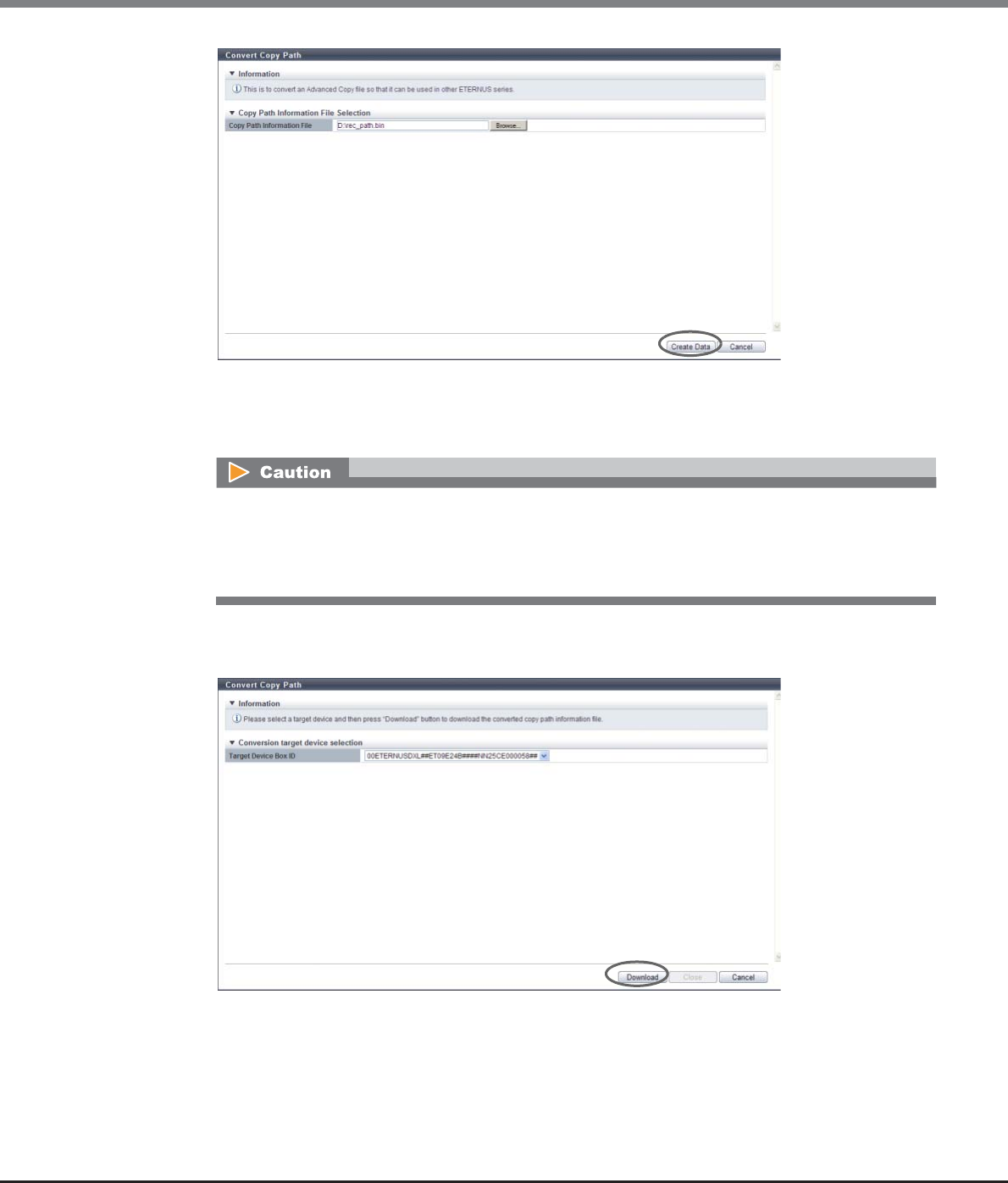
Chapter 8 Advanced Copy Management
8.2 Functions in the Action Area for Advanced Copy
ETERNUS Web GUI User’s Guide
Copyright 2013 FUJITSU LIMITED P2X0-1090-10ENZ0
348
→The copy path information, which has been registered in the ETERNUS DX Disk storage system, is
exported. After the copy path information export has been finished, a screen to execute
downloading of the file is displayed.
3Select the ETERNUS DX Disk storage system that is to be converted, and click the [Download]
button.
→A dialog box to download the file appears.
An error screen appears in the following conditions:
•When the selected file is not a copy path information file
•When the ETERNUS DX Disk storage system that is to be converted does not exist in the copy path
information file
Chapter 8 Advanced Copy Management
8.2 Functions in the Action Area for Advanced Copy
ETERNUS Web GUI User’s Guide
Copyright 2013 FUJITSU LIMITED P2X0-1090-10ENZ0
349
4Save the copy path information file.
The default file name is "RecPathConvt_serial number for the ETERNUS DX Disk storage system_YYYY-
MM-DD_hh-mm-ss.bin".
(YYYY-MM-DD_hh-mm-ss: the date and time when the download screen (Step 3) is displayed.)
5Click the [Close] button to return to the [Copy Path] screen.
End of procedure
8.2.17 Measure Round Trip Time
This function measures the round trip time between the local device and the remote device.
"Round trip time" is the time taken to make a communication between two devices.
Only one remote device can be measured at a time.
The procedure to measure the REC round trip time is as follows:
Procedure
1Select the remote device to measure the REC round trip time, and click [Get Round Trip Time]
in [Action].
•Round trip time can be measured only when the connection type is "Remote". Round trip time cannot be
measured when the connection type is "Direct".
•Set the REC session status to "Suspend" between devices before measuring.
•Make sure that the physical path is correctly configured between devices before measuring. When a copy
path has an error, the round trip time cannot be measured correctly.
•If the path between devices is changed, measure the round trip time again.
•Round trip time measurement requires a maximum of 160 seconds.
A remote device with "Direct" as the connection type cannot be selected.
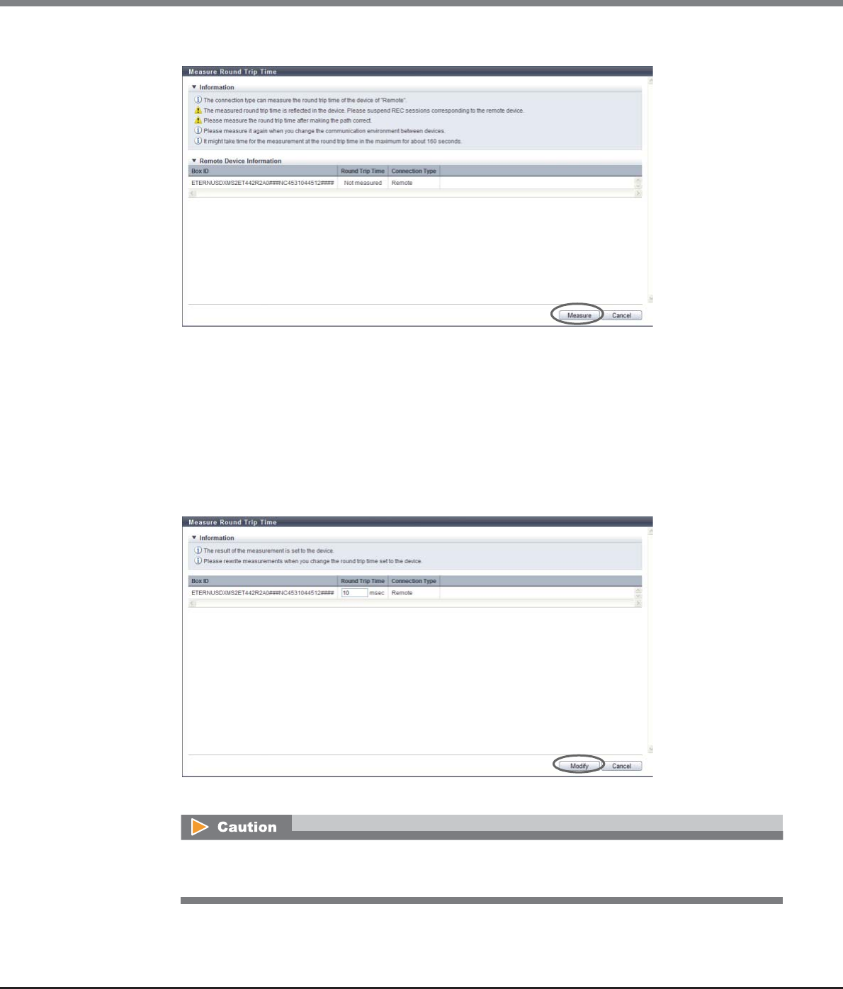
Chapter 8 Advanced Copy Management
8.2 Functions in the Action Area for Advanced Copy
ETERNUS Web GUI User’s Guide
Copyright 2013 FUJITSU LIMITED P2X0-1090-10ENZ0
350
2Click the [Measure] button.
→Measurement of round trip time starts.
3Change the "Round Trip Time (msec)" value if necessary, and click the [Modify] button.
•Round Trip Time (msec)
The round trip time measurement result between the local device and the remote device is
displayed.
If a measurement error has occurred, the field is blank. The value can be changed. The following
describes the recommended round trip time.
-Asynchronous copy: within 100 (msec)
-Synchronous copy: within 50 (msec)
→A confirmation screen appears.
•If the round trip time has not been entered, the [Modify] button cannot be clicked.
•If the entered round trip time does not satisfy the input conditions, an error screen appears.
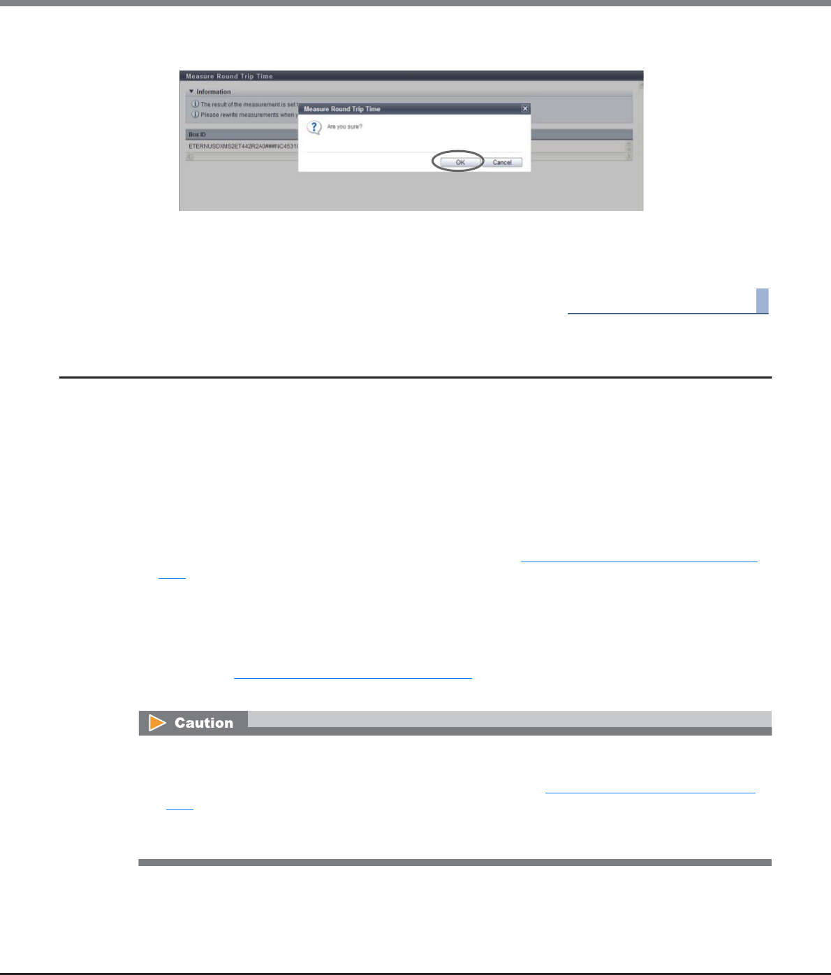
Chapter 8 Advanced Copy Management
8.2 Functions in the Action Area for Advanced Copy
ETERNUS Web GUI User’s Guide
Copyright 2013 FUJITSU LIMITED P2X0-1090-10ENZ0
351
4Click the [OK] button.
→The round trip time measurement result is updated in the ETERNUS DX Disk storage system.
5Click the [Done] button to return to the [Copy Path] screen.
End of procedure
8.2.18 Modify REC Multiplicity
This function specifies multiplicity or priority level when performing Remote Equivalent Copy (REC).
It is not necessary to change the default setting (Auto) for normal use. This function can adjust the copy
performance to give priority to REC over work I/O or to reduce the affect on work I/O.
When the local device and the remote device are connected by remote connection
•If "Auto" is selected for the specification mode, REC is performed with the recommended multiplicity that is
calculated by the obtained round trip time.
If the round trip time is not measured, "***" is displayed in the "Recommended Multiplicity" field.
To display the recommended multiplicity, use the procedure in "8.2.17 Measure Round Trip Time" (page
349).
•If "Manual" is selected for the specification mode, REC will be performed with the specified multiplicity.
When the local device and the remote device are connected by remote connection
•When the priority level is "Automatic", REC is performed using the priority level that is specified using the
procedure in "8.2.6 Modify EC/OPC Priority" (page 298).
•When the priority level is from "1" to "8", REC is performed using the specified priority level.
•If "***" is displayed in the "Recommended Multiplicity" field of the Remote Box ID List, and "Auto" has
been selected for the specification mode, REC will not be performed with the appropriate multiplicity. To
select "Auto", measure the round trip time using the procedure in "8.2.6 Modify EC/OPC Priority" (page
298).
•If the path between local and remote devices has been changed, measure the round trip time and set the
multiplicity again.

Chapter 8 Advanced Copy Management
8.2 Functions in the Action Area for Advanced Copy
ETERNUS Web GUI User’s Guide
Copyright 2013 FUJITSU LIMITED P2X0-1090-10ENZ0
352
The procedure to modify REC multiplicity is as follows:
Procedure
1Click the [Modify REC Multiplicity] in [Action].
2Specify the multiplicity, and click the [Set] button.
●Remote Box ID List
•Priority Level
Select the priority level between "1" and "8". When the "Connection Type" is "Remote", a "-" (hyphen)
is displayed.
-Auto
REC is performed using the priority level (Automatic Priority/High Priority/Middle Priority/Low
Priority/Very Low Priority) that is specified with the [Modify EC/OPC Priority] function.
-1 - 8
Specify from "1" to "8" for the REC priority level. "1" corresponds to "Very Low Priority", and "8"
corresponds to "High Priority" for the [Modify EC/OPC Priority] function.
•Specification Mode
Select the specification mode for multiplicity. If the "Connection Type" is "Direct", a "-" (hyphen) is
displayed.
-Auto
-Manual
•Multiplicity
When the "Specification Mode" is "Manual", specify multiplicity between "1" and "1024". When
"Auto" is selected, or when the "Connection Type" is "Direct", a "-" (hyphen) is displayed.
●Advanced Setting
•Copy Schedule Mode
Specify the REC copy schedule mode for each remote device. Use "Session Balancing" for normal
operation.
-Session Balancing
Copy sessions are scheduled evenly to each controlling CM-CPU for a copy source RAID group (a
RAID group to which the copy source volume belongs).
-Destination RAID Group Balancing
Only one copy session can be performed for each copy destination RAID group. This method pre-
vents unequal loading on a specific RAID group. This may improve the copy performance when
the copy source and the copy destination storage systems are connected by direct connection
and the copy destination RAID group is configured by Nearline disks.
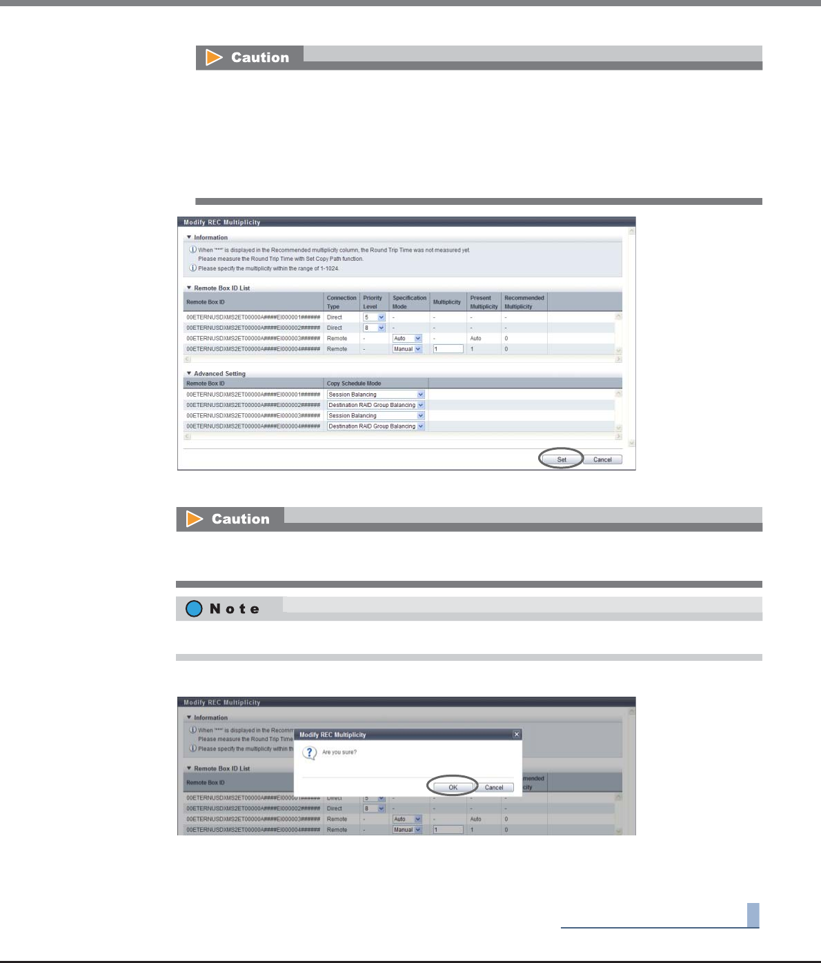
Chapter 8 Advanced Copy Management
8.2 Functions in the Action Area for Advanced Copy
ETERNUS Web GUI User’s Guide
Copyright 2013 FUJITSU LIMITED P2X0-1090-10ENZ0
353
→A confirmation screen appears.
3Click the [OK] button.
→The REC multiplicity settings starts.
4Click the [Done] button to return to the [Copy Path] screen.
End of procedure
•Copy performance is not improved by selecting "Destination RAID Group Balancing" in the
following conditions:
-When the type of the copy destination volume is not "Standard"
-When the copy destination volume "Standard" and concatenated
•Specify the same copy schedule mode for copy source and copy destination storage systems. If
different modes are specified, the copy performance may not improve as expected.
When "Manual" is selected for "Specification Mode" and numeric characters exceed the allowed range
(from 1 to 1024), an error screen appears.
Click [Advanced Setting] to specify the copy schedule mode.
Chapter 8 Advanced Copy Management
8.2 Functions in the Action Area for Advanced Copy
ETERNUS Web GUI User’s Guide
Copyright 2013 FUJITSU LIMITED P2X0-1090-10ENZ0
354
8.2.19 Modify REC Buffer
This function sets parameters of the REC Buffer for copying data via the REC Buffer (in Asynchronous
Consistency mode).
The "Consistency mode" secures the order of data transfer to the remote device for all of the specified REC
sessions. This mode requires constant securement of the dedicated REC Buffer in the cache memory. Copying
via REC Buffer stores multiple REC session I/Os in the REC Buffer for a certain period of time, and copies in
blocks.
The procedure to set the REC Buffer is as follows:
Procedure
1Select the target REC Buffers to be modified (multiple selections can be made), and click the
[Modify REC Buffer] in [Action].
•Perform REC Buffer settings in both the REC copy source and destination storage systems. Make the REC
Buffer size the same for the storage systems of the copy source and the destination. The size will be
adjusted to whichever is smaller.
•Take REC reverse operation into consideration and specify the same values for the REC Buffers
("Forwarding Interval", "Monitoring Time", "HALT Wait Timer", "I/O Priority Mode", and "Immediate HALT
Mode") in the copy source storage system and the copy destination storage system.
•When changing REC Buffers, suspend the sessions using the target REC Buffers.
•When deleting REC Buffers, stop the sessions using the target REC Buffers.
•When performing bidirectional data transfer, settings for "Send" and "Receive" REC Buffers in the ETERNUS
DX Disk storage system are required.
•The following REC Buffer capacity is secured for the cache memory of each controller:
-ETERNUS DX90 S2: 512MB
-ETERNUS DX410 S2: 4096MB
-ETERNUS DX440 S2: 8192MB
-ETERNUS DX8100 S2/DX8700 S2: 8192MB
•The number of REC Buffers, which can be configured, are as follows:
-ETERNUS DX90 S2: Up to 4
-ETERNUS DX410 S2/DX440 S2: Up to 8
-ETERNUS DX8100 S2/DX8700 S2: Up to 8
•This function cannot be used when the remote device and/or copy path is not set.
•If the usage of the REC Buffer, to which the REC Disk Buffer has already been assigned, is changed to
"Receive" or "Unused", the REC Disk Buffer assignment will be cleared (the REC Disk Buffer itself will not
be deleted).
•Cache memory is not only used for REC Buffers, but also used for the copy table. Note that the REC Buffer
with the maximum size for each model cannot be created depending on the memory capacity in the
ETERNUS DX Disk storage system and cache memory allocation for the copy table.

Chapter 8 Advanced Copy Management
8.2 Functions in the Action Area for Advanced Copy
ETERNUS Web GUI User’s Guide
Copyright 2013 FUJITSU LIMITED P2X0-1090-10ENZ0
355
2Change the REC Buffer configurations, and click the [Set] button.
●REC Buffer Setting List
•Usage
Specify the usage of the REC Buffer.
When setting the REC Buffer for sending, select "Send". When setting the REC Buffer for receiving,
select "Receive". When the target REC Buffer is not used, select "Unused".
•Remote Box ID
Select the Box ID for the remote device.
If the copy path information is deleted, "???" is displayed. Select "Unused" for REC Buffer usage or
select a new remote Box ID.
If "Unused" is selected for the usage, a "-" (hyphen) is displayed.
•Size
Select the REC Buffer size.
If "Unused" is selected for the usage, a "-" (hyphen) is displayed.
-ETERNUS DX90 S2: 128MB, 256MB, 512MB
-ETERNUS DX410 S2/DX440 S2: 128MB, 256MB, 512MB, 1024MB, 2048MB
-ETERNUS DX8100 S2/DX8700 S2: 128MB, 256MB, 512MB, 1024MB, 2048MB
•Forwarding Interval
Select the data transfer intervals.
If "Unused" is selected for the usage, a "-" (hyphen) is displayed.
-1 sec., 2 sec., 4 sec., 8 sec., 15 sec., 30 sec., 45 sec., 60 sec., 75 sec., 90 sec., 105 sec., 120 sec.
•Monitoring Time
Specify the monitoring time, before transition to the "Halt" status for a copy session when an REC
Buffer shortage occurs. If the REC Buffer is in a high-load state for the specified monitoring time,
the copy session is automatically changed to "Halt" state. When "0 min." is specified in this field, REC
Buffer shortage monitoring is not performed.
If "Unused" is selected for the usage, a "-" (hyphen) is displayed.
-0 min., 1 min., 2 min., 3 min., 4 min., 5 min., 6 min., 7 min., 8 min., 9 min., 10 min., 11 min., 12
min., 13 min., 14 min., 15 min.
•HALT Wait Timer
Specify the maximum non-response time. During the non-response time, the host I/O response is
stopped to give priority to performing REC Buffer transfers in a high-load state. If the non-response
time exceeds the specified value, response to host I/O is restarted. However, the copy session is
changed to the "Halt" state. When "0 sec." is specified for this field, ETERNUS DX Disk storage system
gives priority to the host I/O, and the copy session is immediately changed to "Halt" state.
If "Unused" is selected for the usage, a "-" (hyphen) is displayed.
-0 sec., 5 sec., 10 sec., 15 sec.
●Advanced Setting
"I/O Priority Mode" and "Immediate HALT Mode" can only be set when setting a copy operation or
host I/O tuning for each REC Buffer. It is not necessary to change the default setting ("Disable") for
normal use.
•I/O Priority Mode
Select either "Enable" or "Disable" for the "I/O Priority Mode" of the REC Buffer.
If "Unused" is selected for the usage, "-" (hyphen) is displayed.
"I/O Priority Mode" reduces the effect on host I/O when an initial copy for starting, restarting, or
recovering the copy function is performed.
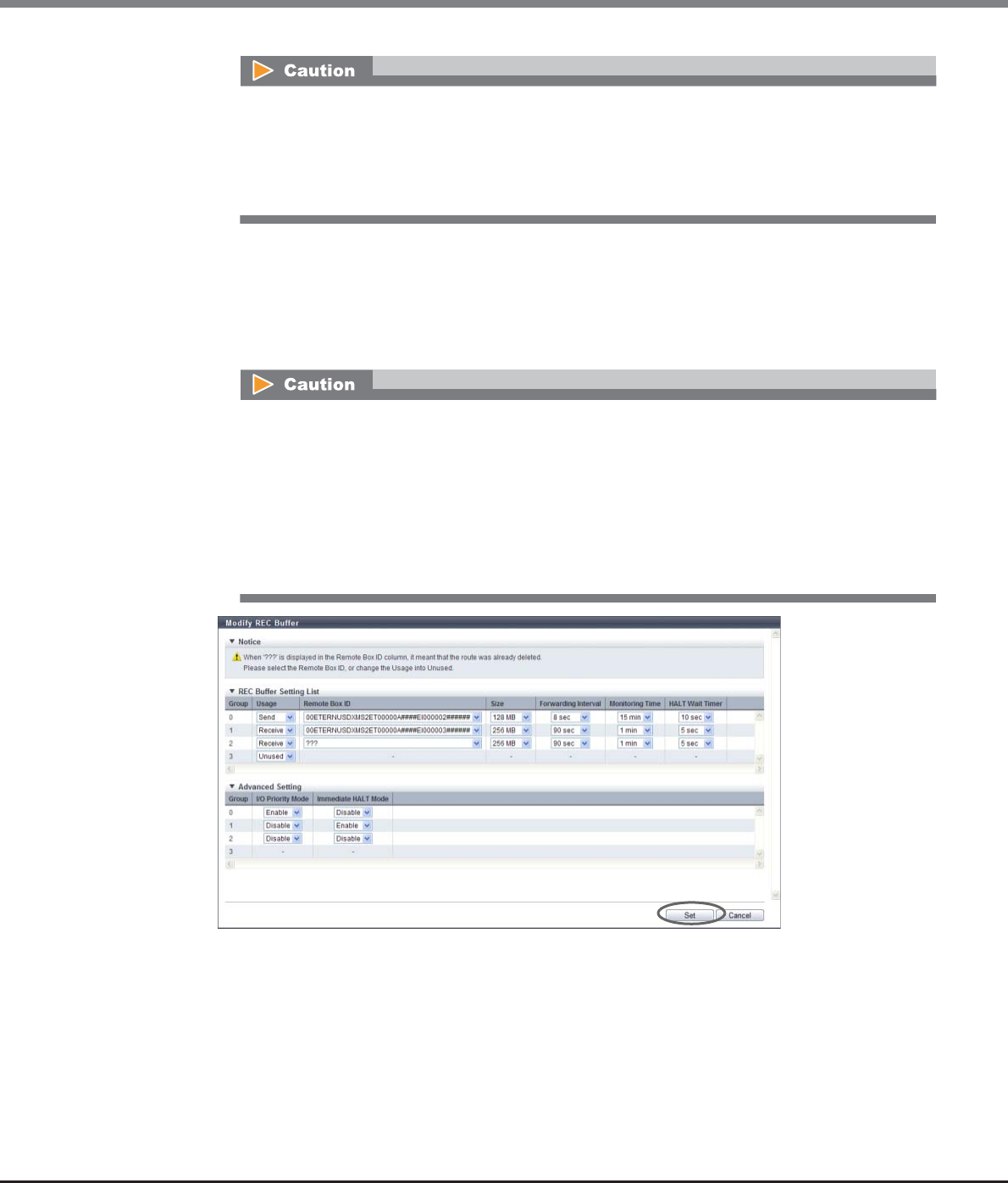
Chapter 8 Advanced Copy Management
8.2 Functions in the Action Area for Advanced Copy
ETERNUS Web GUI User’s Guide
Copyright 2013 FUJITSU LIMITED P2X0-1090-10ENZ0
356
•Immediate HALT Mode
Select either "Enable" or "Disable" for the "Immediate HALT Mode" of the REC Buffer.
If "Unused" is selected for the usage, "-" (hyphen) is displayed.
"Immediate HALT Mode" reduces the effect on host I/O because of the insufficient of REC Buffer
when "HALT Wait Timer" is set to "0 sec.". Enable this item when the response to host I/O is reduced
even if "0 sec." is selected for the "HALT Wait Timer".
→A confirmation screen appears.
•This mode should only be used by users who want to maintain host I/O performance as much
as possible during REC.
•If "Enable" is selected and host I/O with a high load continues, it may take an extended period
of time for the data to reach an equivalent state. Reduce throughput by as much as possible to
avoid exceeding the line bandwidth of REC during initial copying.
•This mode should only be used by users who want to maintain host I/O performance as much
as possible during REC.
•Items that are set for this mode are only applied when "0 sec." is selected for "HALT Wait Timer".
•When "Enable" is selected, the ETERNUS DX Disk storage system changes the sessions using the
target REC Buffers to "Halt" if the capacity of a REC Buffer is insufficient. If this occurs, the initial
copy starts every time when recovering from the "Halt" status and the time required for the
order of data transfers cannot be guaranteed, resulting in this process taking an extended
period of time.
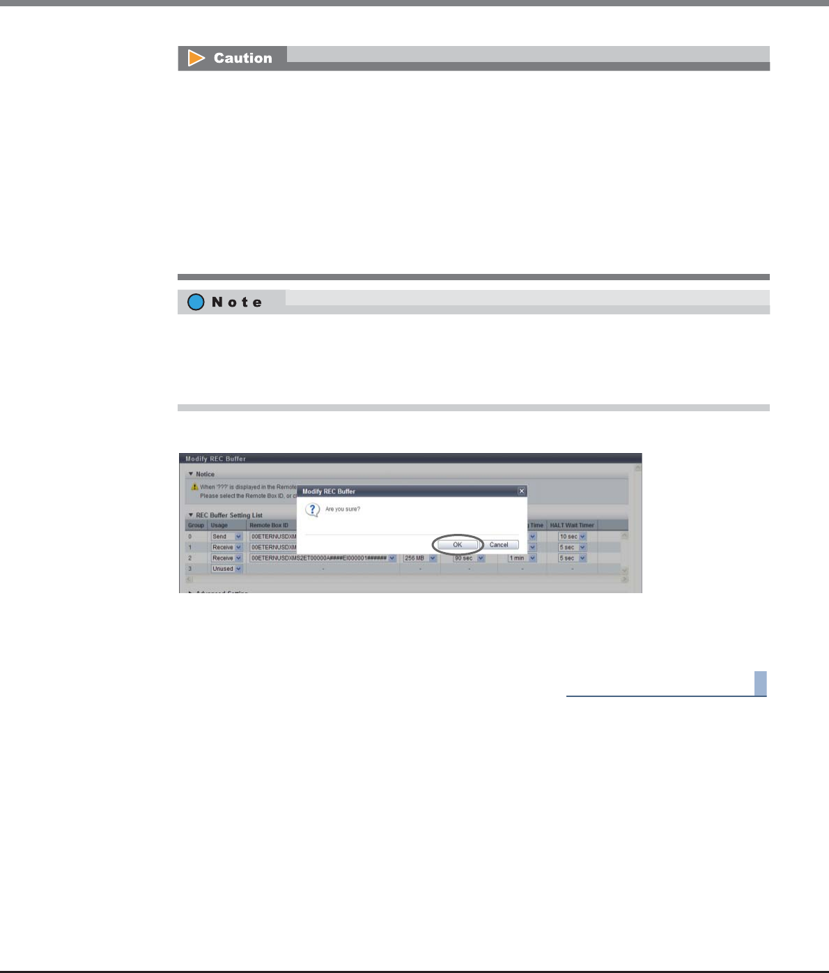
Chapter 8 Advanced Copy Management
8.2 Functions in the Action Area for Advanced Copy
ETERNUS Web GUI User’s Guide
Copyright 2013 FUJITSU LIMITED P2X0-1090-10ENZ0
357
3Click the [OK] button.
→The REC Buffer settings starts.
4Click the [Done] button to return to the [REC Buffer] screen.
End of procedure
An error screen appears in the following conditions:
•The total size of the REC Buffer is larger than 8192MB (512MB for ETERNUS DX90 S2, and 4096MB
for ETERNUS DX410 S2)
•The Box ID for the remote device has been changed
•The same remote Box ID has been selected both for "Send " and for "Receive" as its usage
•When the usage of an REC Buffer is "Send" or "Receive", and its path to the remote Box ID has been
deleted
•An REC Buffer, which has already been deleted ("???" is displayed in the "Remote Box ID" field), still
exists
•When the setting contents of the REC Buffer has not been changed
•To change the remote Box ID, first specify "Unused" for the use of the corresponding group. Then,
click [Modify REC Buffer] again to specify a new remote Box ID and other information in the
corresponding group.
•To change "I/O Priority Mode" or "Immediate HALT Mode", click "Advanced Setting".
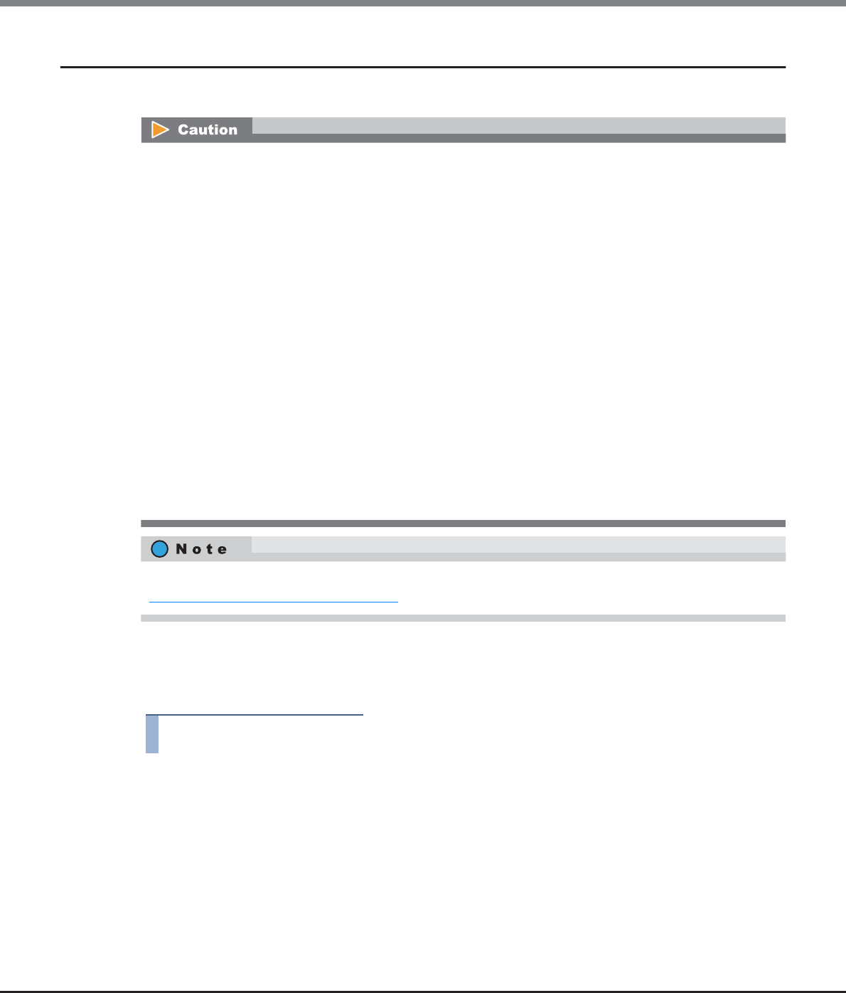
Chapter 8 Advanced Copy Management
8.2 Functions in the Action Area for Advanced Copy
ETERNUS Web GUI User’s Guide
Copyright 2013 FUJITSU LIMITED P2X0-1090-10ENZ0
358
8.2.20 Assign REC Disk Buffer
This function reassigns REC Disk Buffers to an REC Buffer.
■Assigning an additional REC Disk Buffer
The procedure to assign additional REC Disk Buffers to an REC Buffer is as follows:
Procedure
1Select the REC Buffer, to which the REC Disk Buffer is to be assigned, and click [Assign REC
Disk Buffer] in [Action].
•The REC Disk Buffer can be assigned to an REC Buffer only when the REC Buffer's usage is "Send".
•The following number of REC Disk Buffers can be assigned to one REC Buffer:
-ETERNUS DX90 S2/DX410 S2: One or two REC Disk Buffers
-ETERNUS DX440 S2: One, two, or four REC Disk Buffers
-ETERNUS DX8100 S2/DX8700 S2: One, two, or four REC Disk Buffers
•A single REC Disk Buffer cannot be assigned to multiple REC Buffers.
•When assigning multiple REC Disk Buffers to an REC Buffer, each REC Buffer has the following
requirements.
-The assigned REC Disk Buffers have the same drive type
("Online" REC Disk Buffers and "Nearline" REC Disk Buffers can be assigned in the same REC Buffer.
However, only assigning either "Online" REC Disk Buffers or "Nearline" REC Disk Buffers is recommended
since the available capacity and access performance may be reduced when these REC Disk Buffers are
used together.)
-The assigned REC Disk Buffers have the same number of drives (four or eight)
-The assigned REC Disk Buffers have the same encryption status ("CM", "-", or "SED")
•When assigning an additional REC Disk Buffer, use one with the same capacity. When using REC Disk
Buffers of different capacities, the smallest becomes the standard, and all other REC Disk Buffers are
regarded as having the same capacity as the smallest REC Disk Buffer. In this case, the remaining REC
Disk Buffer space will NOT be used.
When assigning REC Disk Buffers to REC Buffers, an REC Disk Buffer must be created in advance. Refer to
"8.2.21 Create REC Disk Buffer" (page 362) for details.
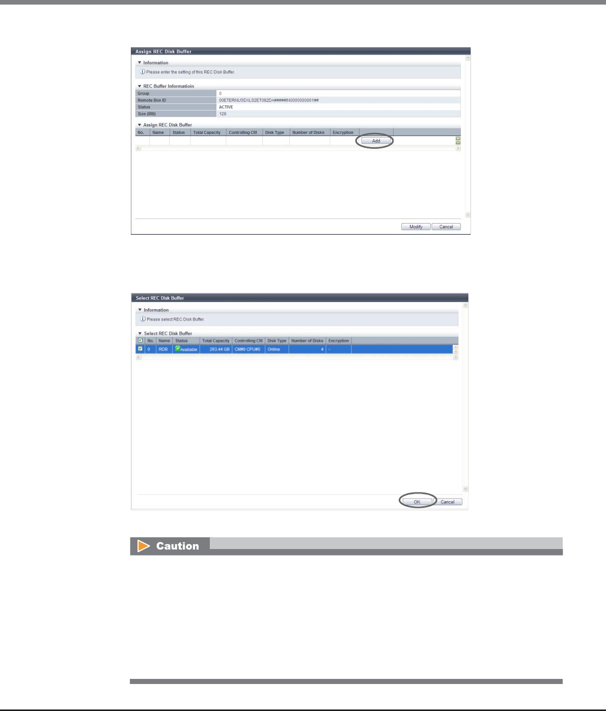
Chapter 8 Advanced Copy Management
8.2 Functions in the Action Area for Advanced Copy
ETERNUS Web GUI User’s Guide
Copyright 2013 FUJITSU LIMITED P2X0-1090-10ENZ0
359
2Click the [Add] button.
→The screen to add REC Disk Buffer assignment appears.
3Select the checkbox for the additional REC Disk Buffer to be assigned, and click the [OK]
button.
→The selected REC Disk Buffer is added.
•When assigning multiple REC Disk Buffers to an REC Buffer, select ones with the same capacity.
•An error screen appears in the following conditions:
-No REC Disk Buffers, which satisfy the assignment requirements, are registered to the ETERNUS
DX Disk storage system
-The number of REC Disk Buffers, which are assigned to an REC Buffer, exceeds the maximum
number which the storage system model supports
-The selected REC Disk Buffer does not satisfy the assignment requirements
-The selected REC Disk Buffer does not exist
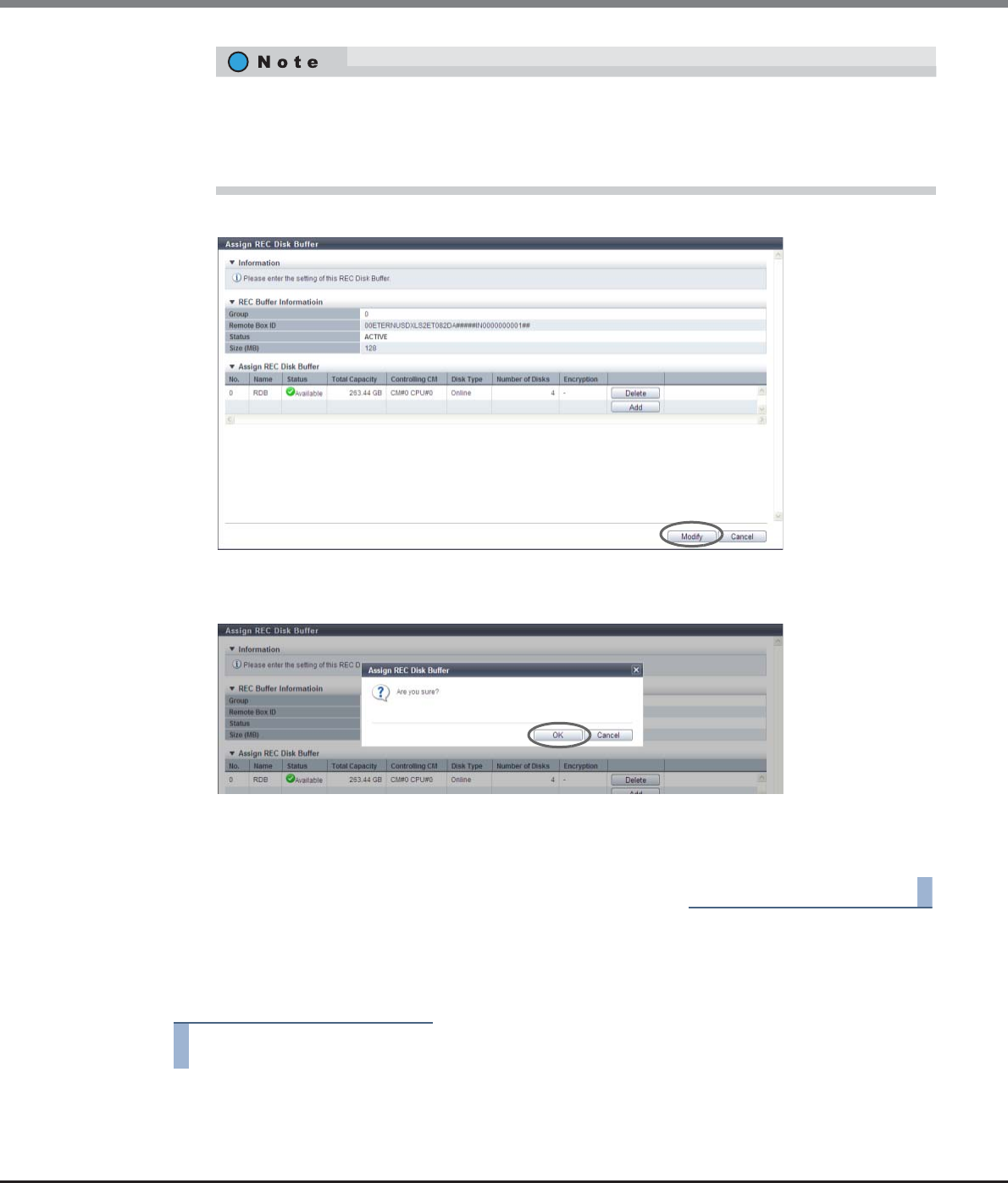
Chapter 8 Advanced Copy Management
8.2 Functions in the Action Area for Advanced Copy
ETERNUS Web GUI User’s Guide
Copyright 2013 FUJITSU LIMITED P2X0-1090-10ENZ0
360
4When the REC Disk Buffer assignment has been completed, click the [Modify] button.
→A confirmation screen appears.
5Click the [OK] button.
→The REC Disk Buffer assignment starts.
6Click the [Done] button to return to the [REC Buffer] screen.
End of procedure
■Deleting an REC Disk Buffer assignment
The procedure to delete the assignment of the REC Disk Buffers from the REC Buffer is as follows:
Procedure
1Select the REC Buffer to delete the assignment of the REC Disk Buffer, and click [Assign REC
Disk Buffer] in [Action].
•To delete the assignment of the REC Disk Buffer, click the [Delete] button for the target REC Disk
Buffer (RAID group).
•When RAID groups in the REC Disk Buffer are configured with both "Online" and "Nearline" drives,
"Online" is displayed.
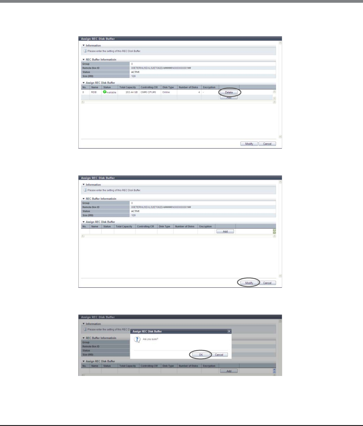
Chapter 8 Advanced Copy Management
8.2 Functions in the Action Area for Advanced Copy
ETERNUS Web GUI User’s Guide
Copyright 2013 FUJITSU LIMITED P2X0-1090-10ENZ0
361
2To delete the assignment of the REC Disk Buffer, click the [Delete] button for the target REC
Disk Buffer (RAID group).
→The selected REC Disk Buffer is deleted from the list.
3Click the [Modify] button.
→A confirmation screen appears.
4Click the [OK] button.
→Deletion of an REC Disk Buffer starts.
Chapter 8 Advanced Copy Management
8.2 Functions in the Action Area for Advanced Copy
ETERNUS Web GUI User’s Guide
Copyright 2013 FUJITSU LIMITED P2X0-1090-10ENZ0
362
5Click the [Done] button to return to the [REC Buffer] screen.
End of procedure
8.2.21 Create REC Disk Buffer
This function creates an REC Disk Buffer.
When using the REC Consistency mode, REC Buffer shortage may occur due to errors (such as a bad line). Note
that the copy session will be halted if the REC Buffer shortage extends for a certain period of time. The REC
Disk Buffer is used for temporarily saving copy data to avoid these situations.
Requirements for Drive Selection
•The requirements for a RAID group that is to be used as an REC Disk Buffer are as follows:
-The number of member drives is four or eight
-Different drive types are not selected at the same time
•The following shows the recommended drive configuration of the RAID group:
-Select drives with the same capacity. If drives of different capacities exist in a RAID group, the smallest
becomes the standard, and all other drives are regarded as the same capacity as the smallest drive. In
this case, the remaining drive space will NOT be used.
-Select drives with the same speed. If drives of different speed exist in a RAID group, access performance
of the RAID group may be affected.
-Dividing the mirroring pair drives into different lines (for ETERNUS DX410 S2/DX440 S2)
•Registering the license for the Advanced Copy feature is required to create an REC Disk Buffer.
•The RAID types, which can be used in REC Disk Buffer, are "High Performance (RAID1+0)" (drive configura-
tion: 2D+2M) and "High Performance (RAID1+0)" (drive configuration: 4D+4M).
•When encryption mode is disabled, an encrypted REC Disk Buffer cannot be created by CM.
•In the following conditions, REC Disk Buffers cannot be created;
-When Online, SSDs, and SEDs are combined in a single REC Disk Buffer
-When Nearline, SSDs, and SEDs are combined in a single REC Disk Buffer
-When resources for creating an REC Disk Buffer (such as the number of RAID groups and volume num-
bers) are insufficient
(When the maximum number of RAID groups or volumes is already registered in the ETERNUS DX Disk
storage system, a new REC Disk Buffer cannot be created.)
•When the REC Disk Buffer creation process is complete, the REC Disk Buffer will be formatted
automatically.
•When assigning multiple REC Disk Buffers to an REC Buffer, each REC Buffer has different conditions.
Refer to "8.2.20 Assign REC Disk Buffer" (page 358) for details.

Chapter 8 Advanced Copy Management
8.2 Functions in the Action Area for Advanced Copy
ETERNUS Web GUI User’s Guide
Copyright 2013 FUJITSU LIMITED P2X0-1090-10ENZ0
363
•The following shows the recommended drive configuration of the ETERNUS DX8100 S2/DX8700 S2:
-A mirroring pair should be distributed over drives that are connected to different SAS cascades (*1).
*1: The "SAS cascade" indicates the DEs that are connected to a single BRT port.
Same SAS cascade:
DE#x0, DE#x1, DE#x2, DE#x3 (x: 0 - F)
DE#x8, DE#x9, DE#xA, DE#xB (x: 0 - F)
[Example] SAS cascade for Port#0 of the BRT#0/#1: DE#00, DE#01, DE#02, DE#03
[Example] SAS cascade for Port#1 of the BRT#0/#1: DE#10, DE#11, DE#12, DE#13
The procedure to create an REC Disk Buffer is as follows:
Procedure
1Click [Create REC Disk Buffer] in [Action].
2Specify the REC Disk Buffer detailed information, and click the [Create] button.
•Name
Input a RAID group name to be created.
The following input conditions apply:
-Up to 16 alphanumeric characters and symbols (except ", (comma)" and "?")
-Space
•Controlling CM
Select the controlling CM and CPU of the RAID group that is to be created.
"Automatic" and the installed "CM#x CPU#y" in normal status are displayed as options.
-Automatic
-CM#x CPU#y (x: CM number, y: CPU number)
Select "Automatic" for normal operations. When "Automatic" is selected, the CM-CPU that is to be
assigned is determined by the RAID group number. Refer to "Appendix F Automatic Controlling CM-
CPU Setting" (page 1011) for details.
•Encryption by CM
Select the RAID group encryption status with the radio button.
-On
Encryption by CM
-Off
Unencrypted
When the encryption mode is disabled, "On" cannot be selected.
•Checkbox to select drives
Select the checkbox for the drive to be used.
•Drives can be selected from the list of drives that is displayed for Tabular or from the drive
images that are displayed for Graphic. Click the Tabular tab to display a list of the drives or click
the Graphic tab to display drive images.
•Refer to "Requirements for Drive Selection" (page 362) to select a drive.
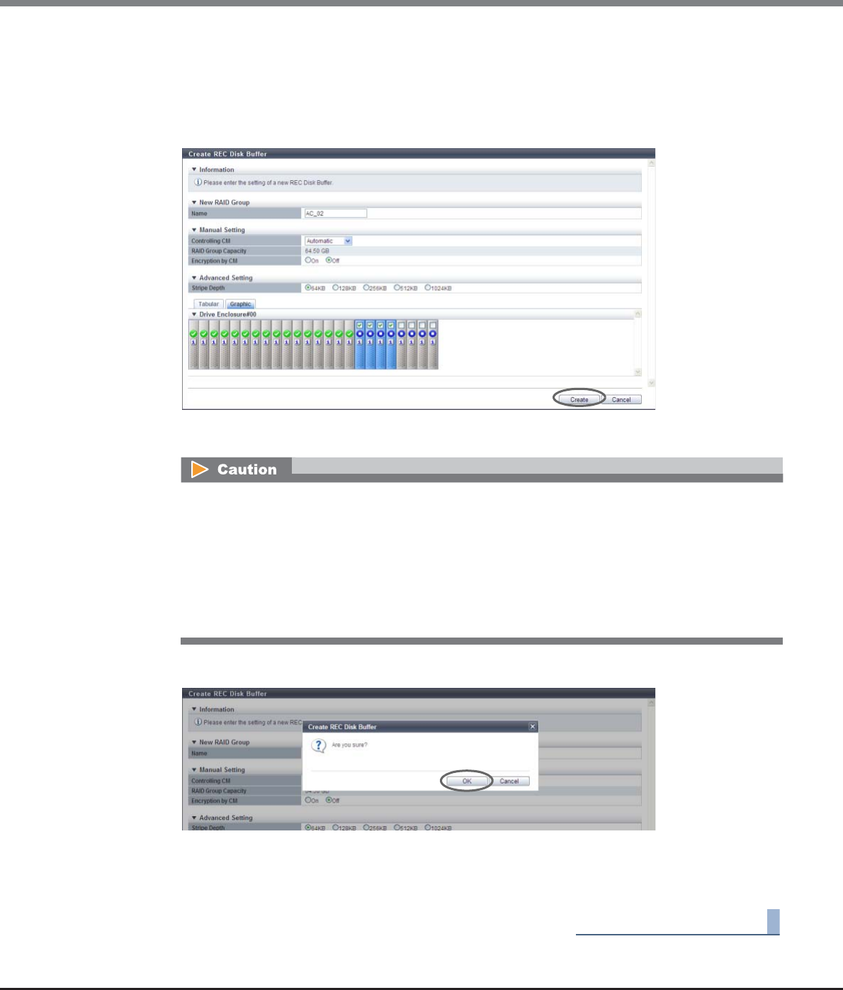
Chapter 8 Advanced Copy Management
8.2 Functions in the Action Area for Advanced Copy
ETERNUS Web GUI User’s Guide
Copyright 2013 FUJITSU LIMITED P2X0-1090-10ENZ0
364
●Advanced Setting
Specify the Stripe Depth only when performing the advanced performance tuning for each RAID
group that configures a TPP. It is not necessary to change the default setting (64KB) for normal use.
-Stripe Depth
Select the Stripe Depth value of the RAID group from 64KB, 128KB, 256KB, 512KB, or 1024KB.
→A confirmation screen appears.
3Click the [OK] button.
→Creation of an REC Disk Buffer starts.
4Click the [Done] button to return to the [REC Disk Buffer] screen.
End of procedure
An error screen appears in the following conditions:
•When four or eight drives are not selected
•When Online, SSDs, and SEDs are combined in a single REC Disk Buffer
•When Nearline, SSDs, and SEDs are combined in a single REC Disk Buffer
•When the same name for the RAID group is specified as that of an existing RAID group
•When the RAID group name specified in the "Name" filed does not satisfy the input conditions
•When the "Name" is not input
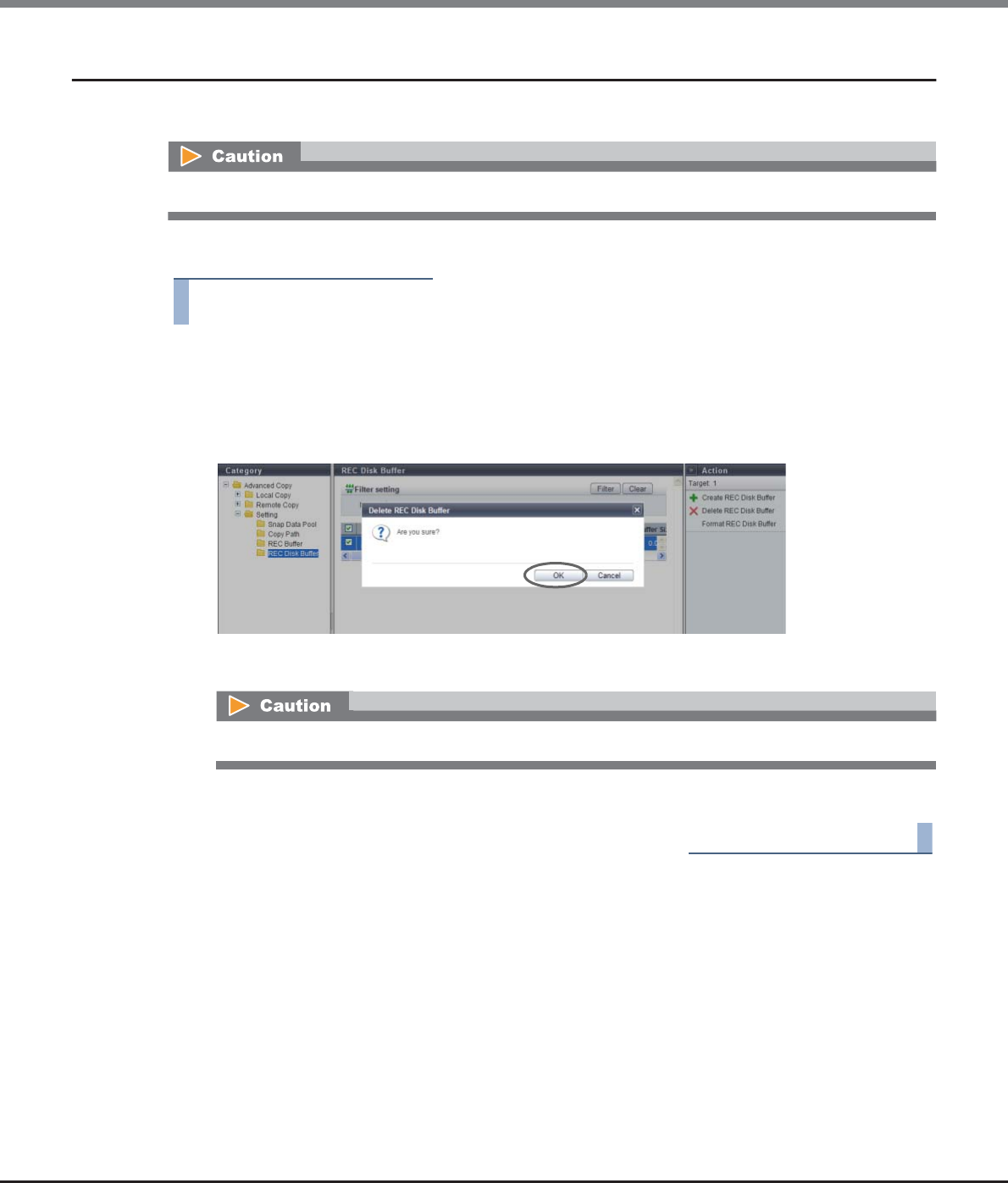
Chapter 8 Advanced Copy Management
8.2 Functions in the Action Area for Advanced Copy
ETERNUS Web GUI User’s Guide
Copyright 2013 FUJITSU LIMITED P2X0-1090-10ENZ0
365
8.2.22 Delete REC Disk Buffer
This function deletes an REC Disk Buffer.
The procedure to delete an REC Disk Buffer is as follows:
Procedure
1Select the REC Disk Buffer that is to be deleted (multiple selections can be made) and click
the [Delete REC Disk Buffer] button in [Action].
→A confirmation screen appears.
2Click the [OK] button.
→Deletion of an REC Disk Buffer starts.
3Click the [Done] button to return to the [REC Disk Buffer] screen.
End of procedure
REC Disk Buffers that have been assigned to the REC Buffer cannot be deleted.
If a selected REC Disk Buffer is assigned to the REC Buffer, an error screen appears.
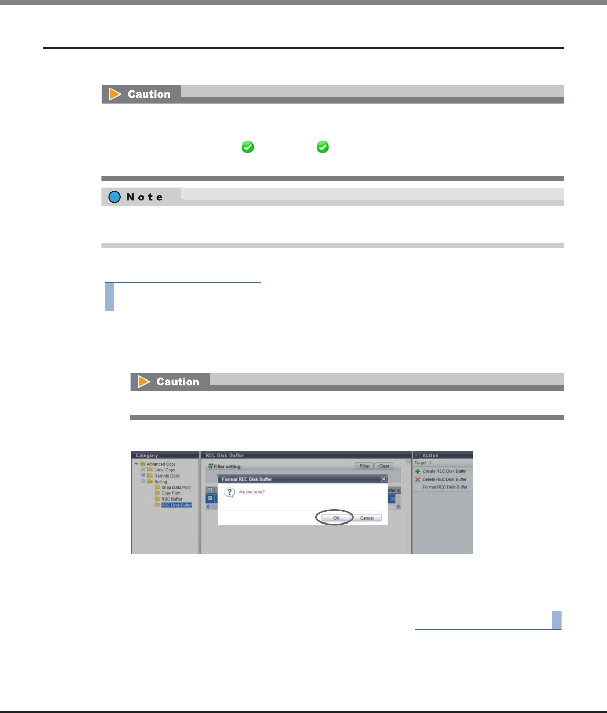
Chapter 8 Advanced Copy Management
8.2 Functions in the Action Area for Advanced Copy
ETERNUS Web GUI User’s Guide
Copyright 2013 FUJITSU LIMITED P2X0-1090-10ENZ0
366
8.2.23 Format REC Disk Buffer
This function formats an REC Disk Buffer.
The procedure to format an REC Disk Buffer is as follows:
Procedure
1Select the REC Disk Buffers to be formatted (multiple selections can be made), and click the
[Format REC Disk Buffer] button in [Action].
→A confirmation screen appears.
2Click the [OK] button.
→Formatting of an REC Disk Buffer starts.
3Click the [Done] button to return to the [REC Disk Buffer] screen.
End of procedure
•If an in-use REC Disk Buffer is formatted, the data stored in the REC Disk Buffer will be deleted.
•The following REC Disk Buffers cannot be formatted:
-The status is other than " Available" or " Readying"
-The REC Disk Buffer is blocked
The newly created REC Disk Buffer will be formatted automatically. In this case, it is not necessary to format
the REC Disk Buffer by using this function.
If an in-use REC Disk Buffer is formatted, the data stored in the REC Disk Buffer will be deleted.
ETERNUS Web GUI User’s Guide
Copyright 2013 FUJITSU LIMITED P2X0-1090-10ENZ0
367
Chapter 9
Connectivity Management
This chapter describes connectivity management.
9.1 Connectivity Status
Connectivity status displays the status information of volumes.
Connectivity status screens can be displayed by clicking the following categories:
Connectivity status screen Category
Connectivity (Basic Information) Connectivity
Host Group Host Group
FC/FCoE Host FC
iSCSI Host iSCSI
SAS Host SAS
CA Port Group Port Group
FC Port FC
iSCSI Port iSCSI
SAS Port SAS
FCoE Port FCoE
LUN Group LUN Group
Host Response Host Response
CA Reset Group CA Reset Group
Host-LU QoS Host-LU QoS
Host QoS (Basic) Host QoS
FC/FCoE Host QoS FC/FCoE
iSCSI Host QoS iSCSI
SAS Host QoS SAS
Port QoS (Basic) Port QoS
FC Port QoS FC
iSCSI Port QoS iSCSI
SAS Port QoS SAS
FCoE Port QoS FCoE
LU QoS Group LU QoS Group

Chapter 9 Connectivity Management
9.1 Connectivity Status
ETERNUS Web GUI User’s Guide
Copyright 2013 FUJITSU LIMITED P2X0-1090-10ENZ0
368
Detailed information of the LUN groups can be displayed from the following screens:
•Host Affinity Detail
•Host Group Detail
•LUN Group Detail
•LUN Group : LU QoS Group Detail
•Host-LU QoS Performance Information
9.1.1 Structures for Host Connection
This section describes structures for host connection.
•Host Group
A host group combines HBAs of the hosts that access the same LUN group into a group (HBAs configure the
multipaths). HBAs in multiple hosts can be configured in a single host group. Once a "host group" is
created, the settings for hosts (HBAs) in the group can be changed at the same time by changing the "host
group" settings. This simplifies the settings that are required to be set for each host (HBA), improving
operability.
•CA Port Group
A CA port group is a group of ports with the same port settings. A CA port group is configured with ports
that access the same LUN group, such as ports that are used for multipath connection to the server or for
connecting to the cluster configuring server. A single CA port group can be connected to multiple host
groups. Once a "CA port group" is created, multiple ports can be selected at the same time for "9.2.1.1
Create Host Affinity" (page 414) and "9.2.1.3 Modify Host Affinity" (page 428). This simplifies the settings
that must be set for each port, improving operability.
•LUN Group
A LUN group is a group of LUNs that is accessed by the same host group and the same CA port group. A LUN
group, which was previously referred to as an "affinity group", is mapping information for LUNs and
volumes.
•Host Affinity
The host affinity settings specify associations between a "host group", a "CA port group" and a "LUN group".
The new host affinity settings enable the "host affinity setting" function and "LUN mapping" function,
which were previously set separately, to be set together. "ON" and "OFF" for the affinity mode is changed by
specifying or not specifying the host group that is to be accessed.
For an ETERNUS DX Disk storage system with firmware version V10L50 or later, a host affinity that associ-
ates "host", "CA port", and "LUN group" can be created without creating a "host group" or a "CA port group".
Use the procedure that does not create a host group (select "Use "Add Host"") only if the previous procedure
for registering hosts in older storage systems (such as the ETERNUS DX410/DX440 or the ETERNUS DX8100/
DX8400/DX8700) is used.
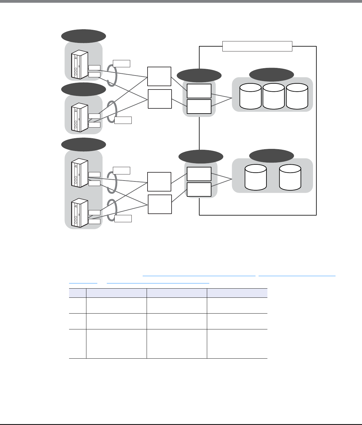
Chapter 9 Connectivity Management
9.1 Connectivity Status
ETERNUS Web GUI User’s Guide
Copyright 2013 FUJITSU LIMITED P2X0-1090-10ENZ0
369
Figure 9.1 Basic concept of host connection (when using host groups)
Setting examples
•Host group settings (Refer to "9.2.2.1 Add FC/FCoE Host Group" (page 440), "9.2.2.2 Add iSCSI Host Group"
(page 448), or "9.2.2.3 Add SAS Host Group" (page 456) for details).
No. Host group Host Host response
1 Host Group A Host A - HBA1
Host A - HBA2
Default
2 Host Group B Host B - HBA1
Host B - HBA2
Default
3 Host Group C Host C - HBA1
Host C - HBA2
Host D - HBA1
Host D - HBA2
Default
LUN Group XX
Vol#1 Vol#2 Vol#3
LUN Group YY
Vol#10 Vol#11
CA Port Group Y
CA Port Group X
HBA1
HBA1
HBA2
HBA1
HBA2
HBA1
HBA2
HBA2
Host Group A
Host Group B
Host Group C
Host A
Host B
Host C
Host D
Multipath
Multipath
Multipath
Multipath
Switch
Switch
Switch
Switch
Port #0
Port #1
Port #2
Port #3
ETERNUS DX Disk storage system
The procedure to define the Host Affinity is as follows:
1. Define host group.
2. Define CA port group.
3. Define LUN group.
4. Allocate the host group, the CA port group, and the LUN group.
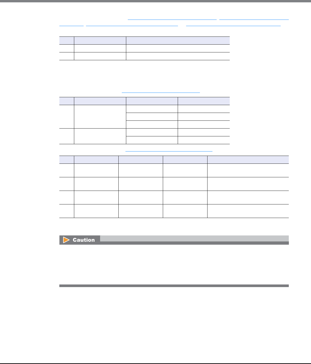
Chapter 9 Connectivity Management
9.1 Connectivity Status
ETERNUS Web GUI User’s Guide
Copyright 2013 FUJITSU LIMITED P2X0-1090-10ENZ0
370
•CA port group settings (Refer to "9.2.3.1 Create FC Port Group" (page 517), "9.2.3.2 Create iSCSI Port Group"
(page 519), "9.2.3.3 Create SAS Port Group" (page 522), or "9.2.3.4 Create FCoE Port Group" (page 525) for
details).
Port#0: CM#0 CA#0 Port#0
Port#1: CM#1 CA#0 Port#0
Port#2: CM#0 CA#0 Port#1
Port#3: CM#1 CA#0 Port#1
•LUN group settings (Refer to "9.2.4.1 Add LUN Group" (page 574) for details).
•Host affinity settings (Refer to "9.2.1.1 Create Host Affinity" (page 414) for details).
*1: Setting example when specifying a host group that accesses LUN group YY via CA port group Y.
*2: Setting example when a host group that accesses LUN group YY via CA port group Y is not specified.
No. CA port group Port
1 CA Port Group X Port#0, Port#1
2 CA Port Group Y Port#2, Port#3
No. LUN group Host LUN LUN
1LUN Group XX 0 Vol#1
1Vol#2
2Vol#3
2 LUN Group YY 0 Vol#10
1 Vol#11
No. Host group CA port group LUN group Description
1 Host Group A
(Default)
CA Port Group X LUN Group XX A host affinity with the affinity mode
set to "ON".
2 Host Group B
(Default)
CA Port Group X LUN Group XX A host affinity with the affinity mode
set to "ON".
3
(*1)
Host Group C
(Default)
CA Port Group Y LUN Group YY A host affinity with the affinity mode
set to "ON".
4
(*2)
All
(Default)
CA Port Group Y LUN Group YY A host affinity with the affinity mode
set to "OFF".
•In setting example No.4, LUN groups other than "LUN group YY" cannot be allocated to the "CA port
group Y".
•In setting example No.4, the "CA port group Y" for which "All" is selected cannot be used for setting
host affinity with the specified host group (setting examples No.3 and No.4 cannot be configured in
the same environment).
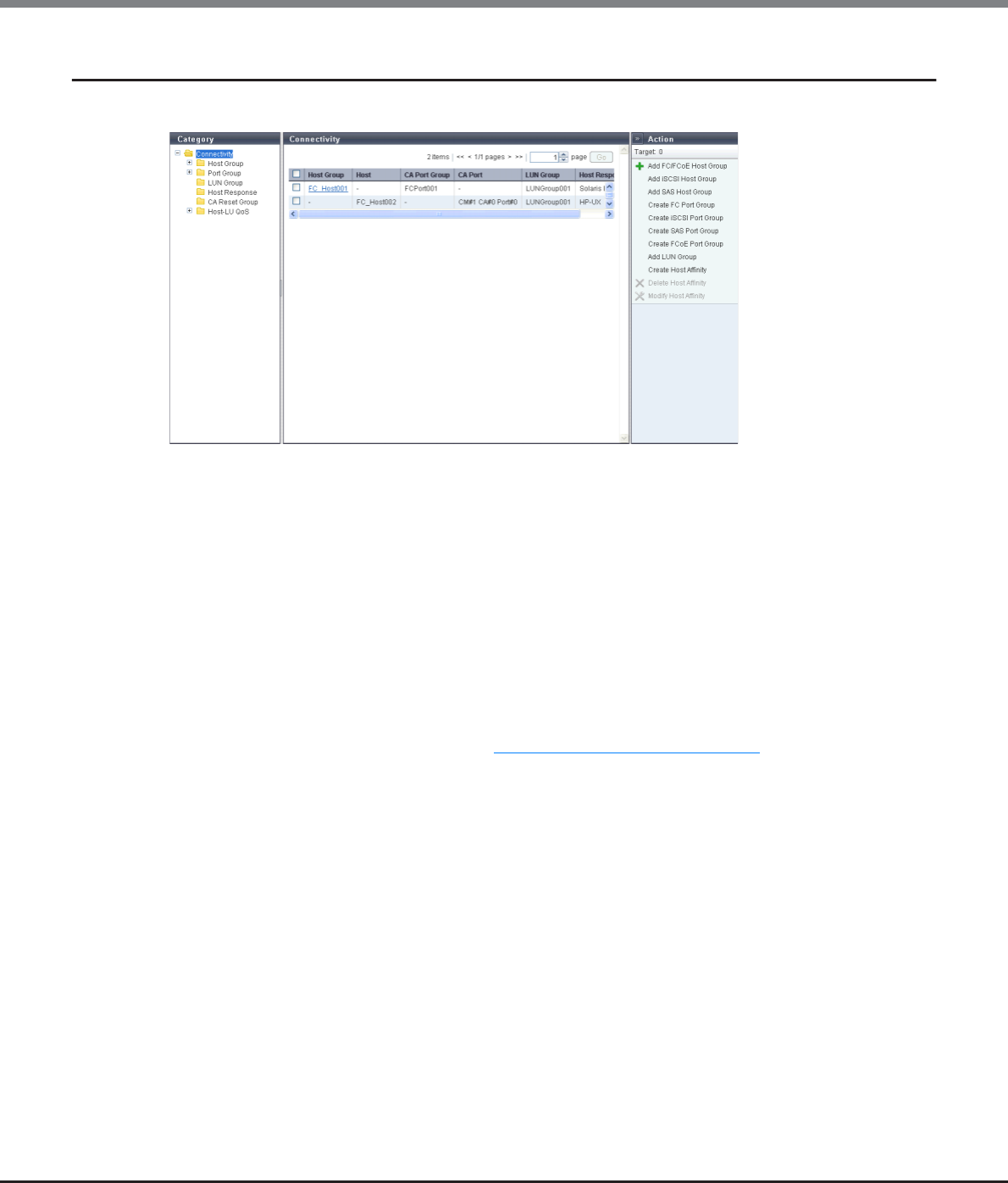
Chapter 9 Connectivity Management
9.1 Connectivity Status
ETERNUS Web GUI User’s Guide
Copyright 2013 FUJITSU LIMITED P2X0-1090-10ENZ0
371
9.1.2 Connectivity (Basic Information)
A list of the host affinity groups is displayed.
When the target connection is "Host Group - CA Port Group", a host affinity is a group that defines an associa-
tion between a "Host Group", a "CA Port Group", and a "LUN Group". When the target connection is "Host - CA
Port", a host affinity is a group that defines an association between a "Host", a "CA Port", and a "LUN Group".
The host affinity function is used when connecting a specific host group (multiple servers) via switches. By
defining the association between a "Host Group", a "Port Group" and a "LUN Group", security is improved since
the volumes that the host recognizes can be limited. In addition, by configuring the groups of hosts (HBAs)
and ports that access the same LUN group, GUI operation can be simplified.
For an ETERNUS DX Disk storage system with firmware version V10L50 or later, a host affinity that associates
"host", "CA port", and "LUN group" can be created without creating a "host group" or a "CA port group".
The following items are displayed in the Main area:
•Host Group or Host
The "Host Group Name" or "Host Name" with the host affinity setting is displayed. By clicking this item, the
[Host Affinity] screen is displayed. Refer to "9.1.9 Host Affinity Detail" (page 403) for display items.
If "All" is displayed for the "Host Group Name" or "Host Name" field, all of the hosts can access the ETERNUS
DX Disk storage system.
Regardless of whether the host belongs to a host group, a "-" (hyphen) is displayed in the "Host Group"
field if the host affinity setting is specified for a host. A "-" (hyphen) is displayed in the "Host" field if the
host affinity setting is specified for a host group.
•CA Port Group
The CA port group names for which the host affinity setting is configured are displayed.
Regardless of whether the CA port belongs to a CA port group, a "-" (hyphen) is displayed if the host affinity
setting is specified for a CA port.
•CA Port
The location information of the CA port with the host affinity setting is displayed.
A "-" (hyphen) is displayed if the host affinity setting is allocated for a CA port group.
-CM#x CA#y Port#z (x: CM number, y: CA number, z: Port number)
Chapter 9 Connectivity Management
9.1 Connectivity Status
ETERNUS Web GUI User’s Guide
Copyright 2013 FUJITSU LIMITED P2X0-1090-10ENZ0
372
•LUN Group
The names of the LUN groups with host affinity settings are displayed.
When LUNs are directly associated to CA ports (when LUN mapping is created) by an application other than
GUI, the field is blank.
•Host Response
One of the following host responses is displayed.
-Host response that is allocated to the host group
-Host response that is allocated to the host
-If all of the hosts are to be connected ("All" is displayed in the "Host" field), the host response that was
selected when setting the host affinity
•Solaris MPxIO
•HP-UX
•AIX EMPD (*1)
•AIX VxVM
•AIX Single Path
•VS850/SVC
•Host responses created in the ETERNUS DX Disk storage system
•Default
*1: EMPD: ETERNUS Multipath Driver
The following modifications are applied for the host response settings with firmware version V10L15 or later.
•"Others" is changed to "Default".
•"Windows EMPD", "Linux EMPD", and "Solaris EMPD" are deleted from the "Host Response" value.
However, these parameters are displayed if they are applied for host groups.
•The setting parameters for "Windows EMPD", "Linux EMPD", and "Solaris EMPD" are the same as "Default".

Chapter 9 Connectivity Management
9.1 Connectivity Status
ETERNUS Web GUI User’s Guide
Copyright 2013 FUJITSU LIMITED P2X0-1090-10ENZ0
373
Display Examples of Host Affinities
Display examples for the host affinity are shown in the following table.
Example
No.
Display contents Description
Host
Group
Host CA Port
Group
CA Port LUN
Group
Host
Response
Example
1
Host_
Group_
xxx
–Port_
Group_
xxx
–LUN_
Group_
xxx
Host_
Response1
The host affinity setting has
been configured in
"Host_Group_xxx",
"Port_Group_xxx" and
"LUN_Group_xxx".
The server recognizes the LUN
group, "LUN_Group_xxx", which
has been specified for each
member host (HBA) in
"Host_Group_xxx".
Example
2
All All Port_
Group_
yyy
–LUN_
Group_
yyy
Host_
Response2
All servers will be covered.
The server recognizes the
specified LUN group,
"LUN_Group_yyy", from every
member port in
"Port_Group_yyy".
Example
3
– Host_z – CM#0
CA#0
Port#0
LUN_
Group_
zzz
Host_
Response3
The host affinity setting of
"Host_z (HBA)" and "LUN
Group_zzz" has been configured
to the device side CA port,
"CM#0 CA#0 Port#0".
Hosts, CA ports, and LUN groups
are allocated without specifying
a host group or CA port group.
Example
4
–All–CM#1
CA#1
Port#1
LUN_
Group_
www
Host_
Response4
The LUN mapping of
"LUN_Group_www" has been
configured to the device side CA
port, "CM#1 CA#1 Port#1".
Hosts, CA ports, and LUN groups
are allocated without specifying
a host group or CA port group.
Example
5
–All–CM#0
CA#1
Port#1
Host_
Response5
The LUN is directly allocated to
CA port "CM#0 CA#1 Port#1" by
an application other than GUI
(LUN mapping is created).
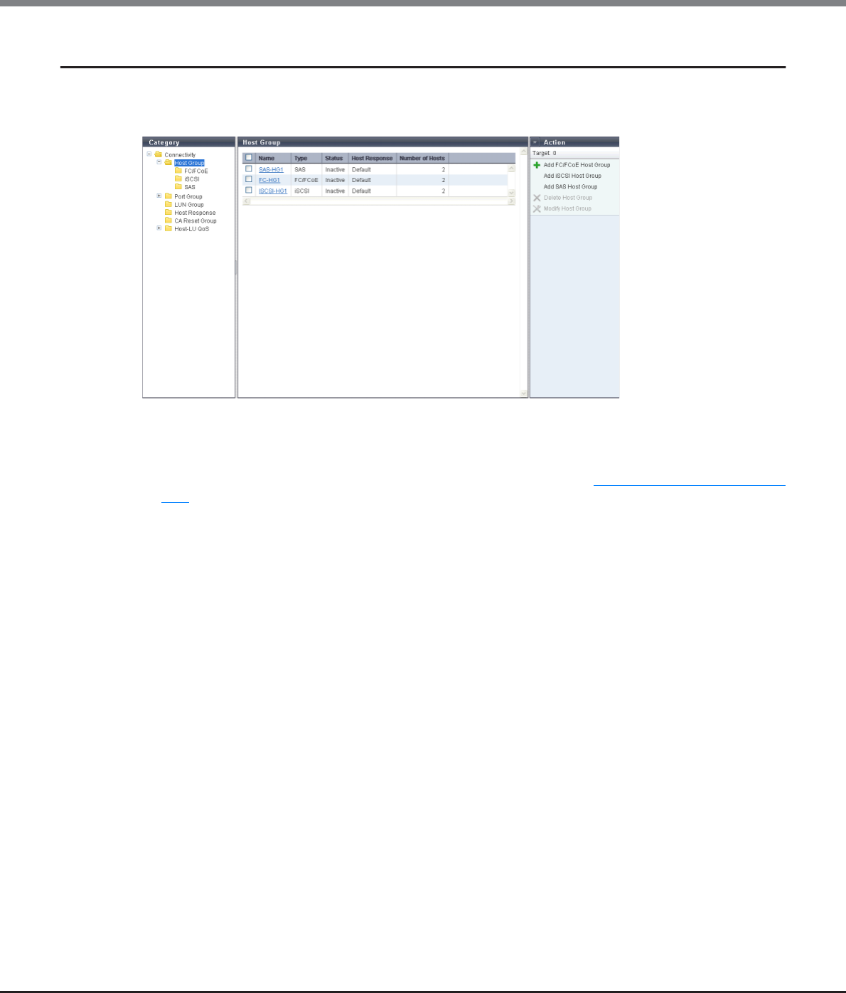
Chapter 9 Connectivity Management
9.1 Connectivity Status
ETERNUS Web GUI User’s Guide
Copyright 2013 FUJITSU LIMITED P2X0-1090-10ENZ0
374
9.1.3 Host Group
The list of the host groups is displayed.
A host group uses the same interface type, and groups the hosts (HBAs), which access the same LUN group.
The following items are displayed in the Main area:
•Name
The host group name is displayed.
By clicking this item, the [Host Group Detail] screen is displayed. Refer to "9.1.10 Host Group Detail" (page
404) for display items.
•Type
The interface type of the host registered in the host group is displayed.
•Status
Whether the host group is used ("Active") or not ("Inactive") for the host affinity settings is displayed.
"Host affinity setting" is to specify association between "Host Group", "CA Port Group", and "LUN Group".
-Active
The host group is used for the host affinity settings. The LUN group can be accessed from the member
host of the host group.
-Inactive
The host group is not used for the host affinity settings.
•Host Response
The host response name, which has been assigned to a host group, is displayed.
•Number of Hosts
The number of hosts, which have been registered in the host group, is displayed.
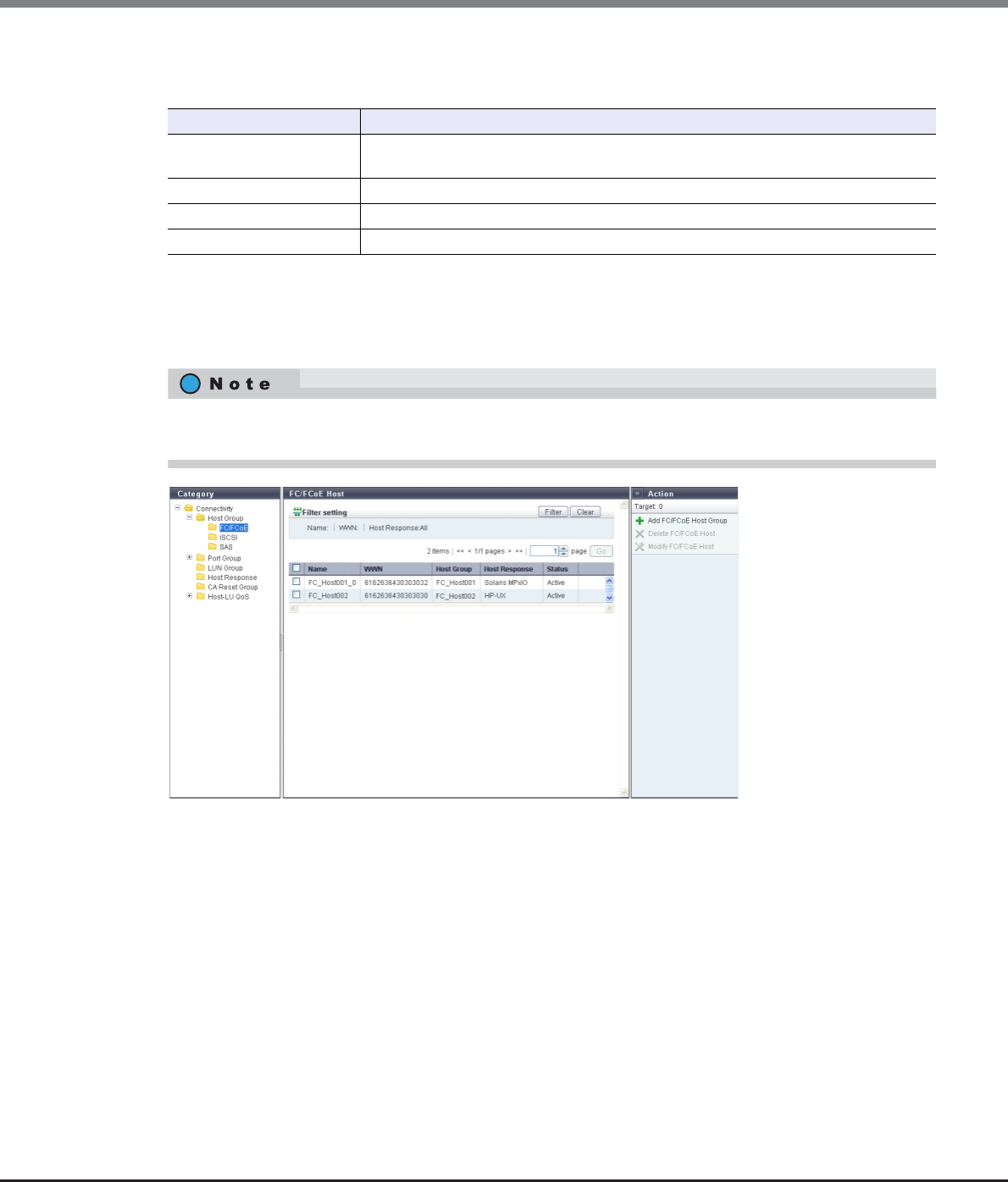
Chapter 9 Connectivity Management
9.1 Connectivity Status
ETERNUS Web GUI User’s Guide
Copyright 2013 FUJITSU LIMITED P2X0-1090-10ENZ0
375
Filter setting
The filter setting field is displayed only for ETERNUS DX8700 S2.
9.1.3.1 FC/FCoE Host
In this screen, registered FC/FCoE hosts in the ETERNUS DX Disk storage system are displayed.
The following items are displayed in the Main area:
•Name
The FC host name is displayed.
•WWN
The FC host WWN is displayed.
•Host Group
The host group name, to which the FC host belongs, is displayed.
When the FC host belongs to two host groups, the host group names are separated with a ", (comma)" and
displayed. If the FC host belongs to three or more host groups, the names of the first two groups and a
[more...] link are displayed.
If the FC host does not belong to a host group, a "-" (hyphen) is displayed.
•Host Response
The host response that is assigned to the FC host or to the host group of the FC host is displayed.
Filter Description
Name Input the host group name that is to be displayed.
When not using the host group name for filtering, leave this item blank.
Type Select the interface type for the host group that is to be displayed.
Status Select the host group status that is to be displayed.
Host Response Select the host response name that is to be displayed.
The interface types "FC" and "FCoE" are both regarded as "FC". Both "FC host" and "FCoE host" are abbreviated
as "FC host" in this section.
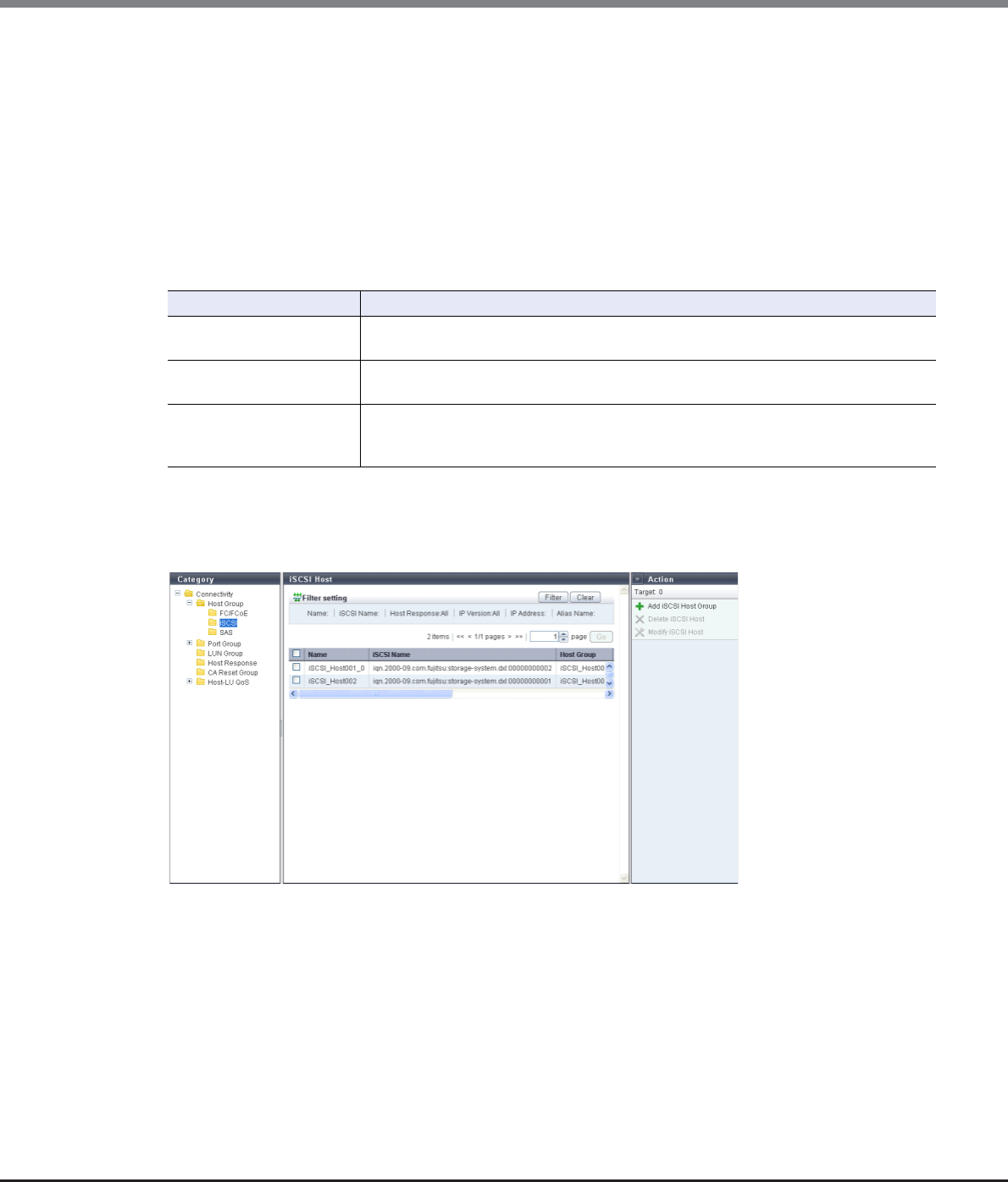
Chapter 9 Connectivity Management
9.1 Connectivity Status
ETERNUS Web GUI User’s Guide
Copyright 2013 FUJITSU LIMITED P2X0-1090-10ENZ0
376
•Status
Whether the host affinity setting is applied to the FC host is displayed.
"Host Affinity Setting" is to specify association between "Host Group", "CA Port Group", and "LUN Group" or
association between "Host", "CA Port", "and "LUN Group". The host affinity setting specifies the path
between each host and port.
-Active
The host affinity setting is applied to the FC host. The LUN group can be accessed from the FC host.
-Inactive
The host affinity setting is not applied to the FC host.
Filter setting
9.1.3.2 iSCSI Host
In this screen, registered iSCSI hosts in the ETERNUS DX Disk storage system are displayed.
The following items are displayed in the Main area:
•Name
The iSCSI host name is displayed.
•iSCSI Name
The iSCSI name of the iSCSI host is displayed.
Filter Description
Name Input the FC host name that is to be displayed.
When not using the FC host name for filtering, leave this item blank.
WWN Input the WWN that is to be displayed.
When not using the WWN for filtering, leave this item blank.
Host Response
Select the host response name that is to be displayed.
The FC hosts, to which the same host response has been assigned, can be used for
filtering.

Chapter 9 Connectivity Management
9.1 Connectivity Status
ETERNUS Web GUI User’s Guide
Copyright 2013 FUJITSU LIMITED P2X0-1090-10ENZ0
377
•Host Group
The host group name, to which the iSCSI host belongs, is displayed.
When the iSCSI host belongs to two host groups, the host group names are separated with a ", (comma)"
and displayed. If the iSCSI host belongs to three or more host groups, the names of the first two groups and
a [more...] link are displayed.
If the iSCSI host does not belong to an host group, a "-" (hyphen) is displayed.
•Host Response
The host response that is assigned to the iSCSI host or to the host group of the iSCSI host is displayed.
•Status
Whether the host affinity setting is applied to the iSCSI host is displayed.
"Host Affinity Setting" is to specify association between "Host Group", "CA Port Group", and "LUN Group" or
association between "Host", "CA Port", "and "LUN Group". The host affinity setting specifies the path
between each host and port.
-Active
The host affinity setting is applied to the iSCSI host. The LUN group can be accessed from the iSCSI host.
-Inactive
The host affinity setting is not applied to the iSCSI host.
•IP Version
The IP version when the IP address was registered for the iSCSI host is displayed.
•IP Address
The IP address of the iSCSI host is displayed.
Note that the IPv6 address is displayed as an abbreviation. Refer to "IPv6 Address Notation" (page 378) for
details.
If the IP address is not specified, the field is blank.
•Alias Name
The iSCSI host Alias Name is displayed.
If the Alias Name is not set, the field is blank.
•CHAP User ID
The iSCSI host user ID is displayed.
If the user ID is not set, the field is blank.
Filter setting
Filter Description
Name Input the iSCSI host name that is to be displayed.
When not using the iSCSI host name for filtering, leave this item blank.
iSCSI Name Input the iSCSI name that is to be displayed.
When not using the iSCSI name for filtering, leave this item blank.
Host Response
Select the host response name that is to be displayed.
The iSCSI hosts, to which the same host response has been assigned, can be used for
filtering.
IP Version Select the IP version that is to be displayed.
The iSCSI hosts with the same IP version are displayed.
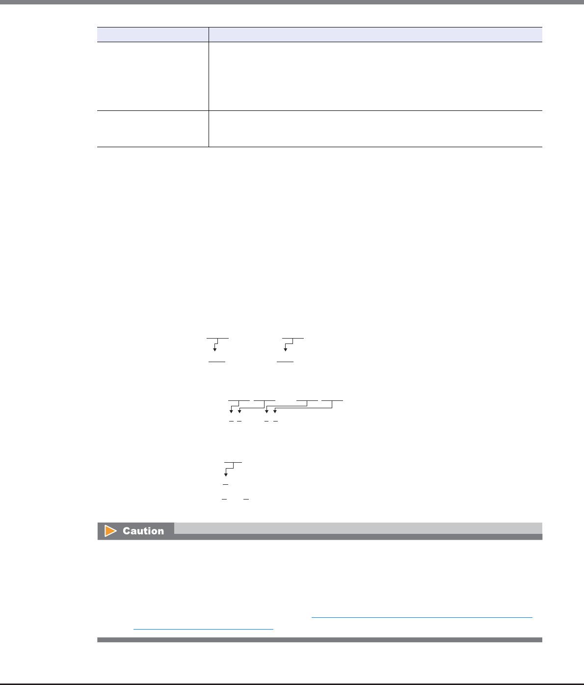
Chapter 9 Connectivity Management
9.1 Connectivity Status
ETERNUS Web GUI User’s Guide
Copyright 2013 FUJITSU LIMITED P2X0-1090-10ENZ0
378
■IPv6 Address Notation
Since the IPv6 address is 128-bit and extremely long, this address is displayed using "xxxx", which describes
16-bit in hexadecimals as being one block that is separated by colons (":").
xxxx:xxxx:xxxx:xxxx:xxxx:xxxx:xxxx:xxxx
•Use 0 - ffff (FFFF) (hexadecimal, alphanumeric characters) for inputting an IPv6 address.
•The current setting is displayed with 0 - ffff (hexadecimal, "a" - "f" are lowercase letters)
•Up to 128-bit
•The first 64-bit (prefix) of the link local address is fixed to "fe80::".
The following three abbreviation methods are available for IPv6 addresses:
(1) Omission of the first "0" of a block that follows consecutive zeros.
(2) Replacement of "0000" blocks with "0".
(3) Replacement of a block with consecutive zeros by "::" is performed only once.
IP Address
Input the IP address that is to be displayed.
ETERNUS DX Disk storage system compares the input IP address and the existing IP
address by starting from the first letter. The iSCSI hosts with the same IP address are
displayed.
An abbreviation for the IPv6 address can be used.
When not using the IP address for filtering, leave this item blank.
Alias Name
Input the Alias Name that is to be displayed.
iSCSI hosts matching or partially matching the input Alias Name are displayed.
When not using the Alias Name for filtering, leave this item blank.
Filter Description
The following IP addresses cannot be specified:
•Link local addresses (the address starts with "fe80::") for which all of the values for the low 64-bit are "0"
•Connect IP addresses (*1) for which the first 3-bit are not "001" or the first 7-bit are not "1111110"
*1: The connect IP address indicates either a "global address", "unique local address", or "6to4 address". Note that
this limitation is not applied when specifying IP addresses for "Common Name". This limitation also does not
apply when specifying "Subject Alt Name" for "11.2.3.15 Create Self-signed SSL Certificate" (page 787) or
"11.2.3.16 Create Key/CSR" (page 790).
[Example] 2001:1000:0120:0000:0000:0123:0000:0000
2001:1000:120:0000:0000:123:0000:0000
[Example] 2001:1000:120:0000:0000:123:0000:0000
2001:1000:120:0:0:123:0:0
[Example] 2001:1000:120:0:0:123:0:0
2001:1000:120::123:0:0 is OK
2001:1000:120::123:: is not allowed
(Replacement of a block with consecutive zeros by "::" is allowed only once.)
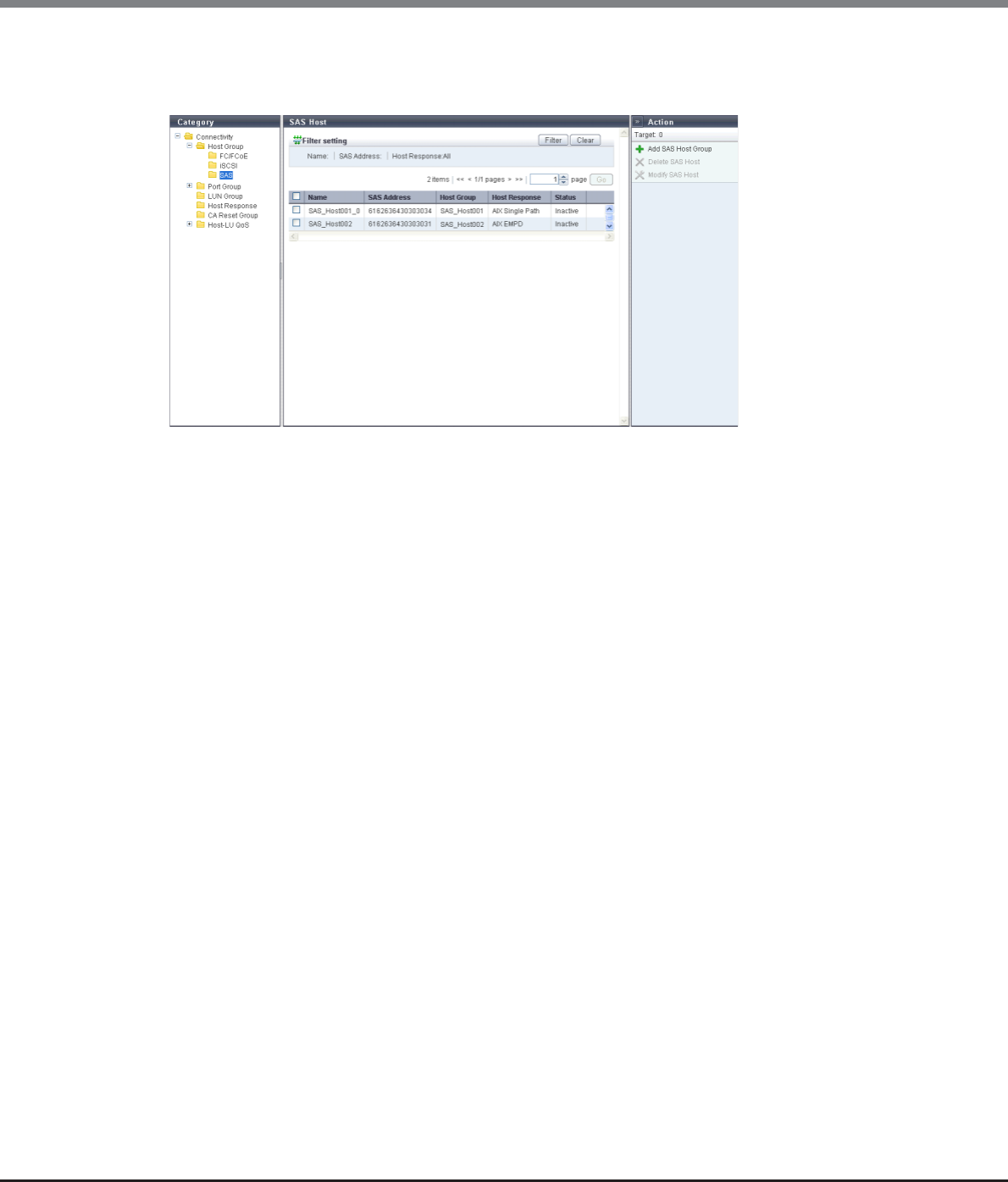
Chapter 9 Connectivity Management
9.1 Connectivity Status
ETERNUS Web GUI User’s Guide
Copyright 2013 FUJITSU LIMITED P2X0-1090-10ENZ0
379
9.1.3.3 SAS Host
In this screen, registered SAS hosts in the ETERNUS DX Disk storage system are displayed.
The following items are displayed in the Main area:
•Name
The SAS host name is displayed.
•SAS Address
The SAS address of the SAS host is displayed.
•Host Group
The host group name, to which the SAS host belongs, is displayed.
When the SAS host belongs to two host groups, the host group names are separated with a ", (comma)"
and displayed. If the SAS host belongs to three or more host groups, the names of the first two groups and
a [more...] link are displayed.
If the SAS host does not belong to a host group, a "-" (hyphen) is displayed.
•Host Response
The host response that is assigned to the SAS host or to the host group of the SAS host is displayed.
•Status
Whether the host affinity setting is applied to the SAS host is displayed.
"Host Affinity Setting" is to specify association between "Host Group", "CA Port Group", and "LUN Group" or
association between "Host", "CA Port", "and "LUN Group". The host affinity setting specifies the path
between each host and port.
-Active
The SAS host is used for the host affinity settings. The LUN group can be accessed from the SAS host.
-Inactive
The SAS host is not used for the host affinity settings.
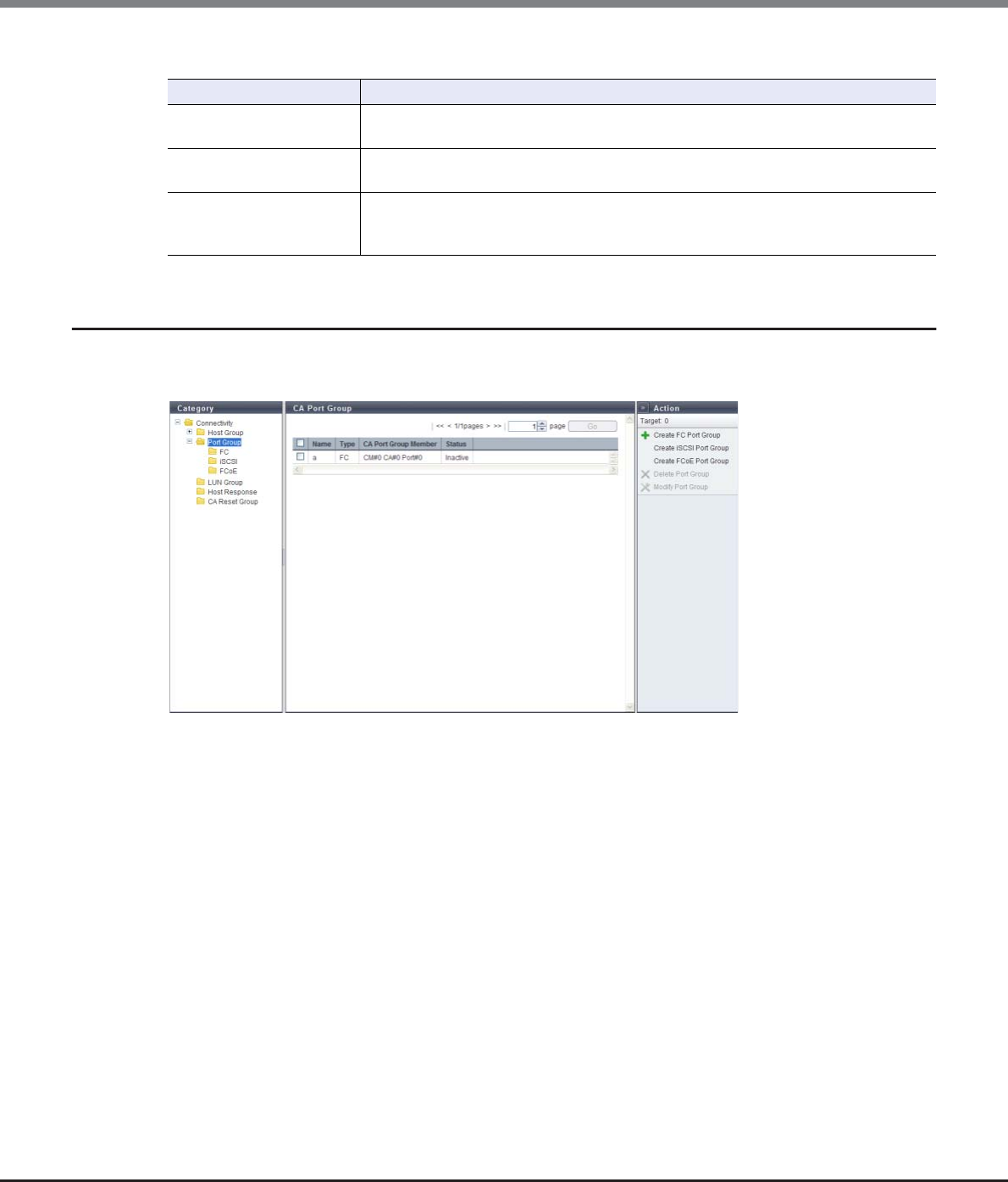
Chapter 9 Connectivity Management
9.1 Connectivity Status
ETERNUS Web GUI User’s Guide
Copyright 2013 FUJITSU LIMITED P2X0-1090-10ENZ0
380
Filter setting
9.1.4 CA Port Group
A list of the CA port groups is displayed.
A CA port group is a group of the same CA type ports that are connected to the specified host group.
The following items are displayed in the Main area:
•Name
The port group name is displayed.
•Type
The type of the CA port group is displayed.
-FC
-iSCSI
-SAS
-FCoE
•CA Port Group Member
The location information of the port, which is a CA port group member, is displayed.
If there are two CA port group members, the ports are displayed, being separated with a ", (comma)". If
there are three or more ports, the location information of the two ports and the [more...] link are
displayed.
-CM#x CA#y Port#z (x: CM number, y: CA number, z: Port number)
Filter Description
Name Input the SAS host name that is to be displayed.
When not using the SAS host name for filtering, leave this item blank.
SAS Address Input the SAS address that is to be displayed.
When not using the SAS address for filtering, leave this item blank.
Host Response
Select the host response name that is to be displayed.
The SAS hosts, to which the same host response has been assigned, can be used for
filtering.
Chapter 9 Connectivity Management
9.1 Connectivity Status
ETERNUS Web GUI User’s Guide
Copyright 2013 FUJITSU LIMITED P2X0-1090-10ENZ0
381
•Status
Whether the CA port group is used ("Active") or not ("Inactive") for the host affinity settings is displayed.
"Host affinity setting" is to specify association between "Host Group", "CA Port Group" and "LUN Group".
-Active
The CA port group is used for the host affinity settings. The LUN group can be accessed from the host
group via the CA port group.
-Inactive
The CA port group is not used for the host affinity settings. The CA port group is not being used.
9.1.4.1 FC Port
Parameters of the FC ports that are registered in the ETERNUS DX Disk storage system are displayed.
The following items are displayed in the Main area:
•Port
The location information of the target port is displayed.
-CM#x CA#y Port#z (x: CM number, y: CA number, z: Port number)
•Type
The CA type of the target port is displayed.
-8G FC
8Gbit/s (maximum) FC. The port mode can be changed (CA, RA, CA/RA, or Initiator).
-16G FC
16Gbit/s (maximum) FC. The port mode can be changed (CA, RA, CA/RA, or Initiator).
•Status
The status of the target port is displayed.
•Port Mode
The mode of the target port is displayed.
-CA
-RA
-CA/RA
-Initiator

Chapter 9 Connectivity Management
9.1 Connectivity Status
ETERNUS Web GUI User’s Guide
Copyright 2013 FUJITSU LIMITED P2X0-1090-10ENZ0
382
•Connection
The connection type of the target port is displayed.
-Fabric
A connection type that enables simultaneous communication among multiple nodes through a Fibre
Channel switch. This connection type can also be used for a direct connection when "Transfer Rate" is
"16 Gbit/s".
-FC-AL
A connection type that connects multiple nodes in a loop.
•Loop ID
If the connection type of the target port is "FC-AL", the Loop ID is displayed.
"Loop ID" is an identification number of a node in a loop.
When the connection type of the target port is "Fabric", a "-" (hyphen) is displayed.
•Transfer Rate
The transfer speed of the target port is displayed.
-Auto-negotiation
-2 Gbit/s
-4 Gbit/s
-8 Gbit/s
-16 Gbit/s
•FC Frame Size
The frame size of the target port is displayed.
"FC Frame Size" specifies the length of the communication information.
-512 bytes
-1024 bytes
-2048 bytes
•Reset Scope
The reset scope of the target port is displayed.
Reset scope is the range where the command reset from the server is performed, when the target port is
connected to multiple servers.
A "-" (hyphen) is displayed when the port mode is "RA".
-I_T_L (I: Initiator, T: Target, L: LUN)
Reset (cancel) the command request from the server that sent the command reset request.
-T_L (T: Target, L: LUN)
Reset (cancels) the command request from all of the servers that are connected to the port.
•Release Reservation if Chip is Reset
Whether the function to release the reservation status of the volume when the target port (chip) is reset is
enabled or disabled is displayed.
A "-" (hyphen) is displayed when the port mode is "RA" or "Initiator".
•REC Line No.
The REC line number of the target port is displayed.
The REC line number is used to switch the communication path when a line fails.
A "-" (hyphen) is displayed when the port mode is "CA" or "Initiator".
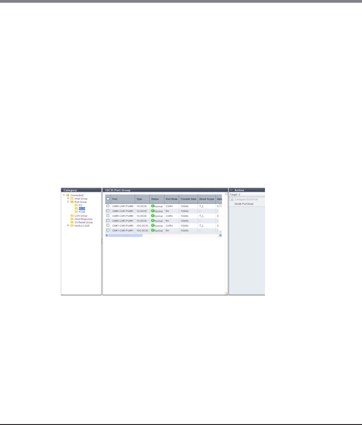
Chapter 9 Connectivity Management
9.1 Connectivity Status
ETERNUS Web GUI User’s Guide
Copyright 2013 FUJITSU LIMITED P2X0-1090-10ENZ0
383
•REC Transfer Mode
Whether the REC synchronous transfer mode, the REC asynchronous stack mode, the REC asynchronous
consistency mode, or the REC asynchronous through mode is enabled or disabled for the target port is
displayed.
A "-" (hyphen) is displayed when the port mode is "CA" or "Initiator".
-Sync
When the REC synchronous transfer mode is enabled, the target port can be used as an REC
synchronous transfer mode path.
-Async Stack
When the REC asynchronous stack mode is enabled, the target port can be used as an REC
asynchronous stack mode path.
-Async Consistency
When the REC asynchronous consistency mode is enabled, the target port can be used as an REC
asynchronous consistency mode path.
-Async Through
When the REC asynchronous through mode is enabled, the target port can be used as an REC
asynchronous through mode path.
9.1.4.2 iSCSI Port
Parameters of the iSCSI ports that are registered in the ETERNUS DX Disk storage system are displayed.
The following items are displayed in the Main area:
•Port
The location information of the target port is displayed.
-CM#x CA#y Port#z (x: CM number, y: CA number, z: Port number)
•Type
The type of the target port is displayed.
-1G iSCSI
1Gbit/s iSCSI. The port mode can be changed (CA, RA, or CA/RA).
-10G iSCSI
10Gbit/s iSCSI. The port mode can be changed (CA, RA, or CA/RA).
-iSCSI-RA (for older storage system connection)
1Gbit/s iSCSI-RA. It is used for REC for the ETERNUS DX400 series, the ETERNUS DX8000 series, the
ETERNUS4000, and the ETERNUS8000.

Chapter 9 Connectivity Management
9.1 Connectivity Status
ETERNUS Web GUI User’s Guide
Copyright 2013 FUJITSU LIMITED P2X0-1090-10ENZ0
384
•Status
The status of the target port is displayed.
•Port Mode
The mode of the target port is displayed.
-CA
-RA
-CA/RA
•Transfer Rate
The transfer speed of the target port is displayed. All transfers are full-duplex.
-Auto-negotiation
-1Gbit/s
-10Gbit/s
-100Mbit/s
•Reset Scope
The reset scope of the target port is displayed.
Reset scope is the range where the command reset from the server is performed, when the target port is
connected to multiple servers. A "-" (hyphen) is displayed when the port mode is "RA".
-I_T_L (I: Initiator, T: Target, L: LUN)
Reset (cancel) the command request from the server that sent the command reset request.
-T_L (T: Target, L: LUN)
Reset (cancels) the command request from all of the servers that are connected to the port.
•Release Reservation if Chip is Reset
Whether the function to release the reservation status of the volume when the target port (chip) is reset is
enabled or disabled is displayed.
A "-" (hyphen) is displayed when the port mode is "RA".
•iSCSI Name
The iSCSI name of the target port is displayed.
•Alias Name
The Alias Name of the target port is displayed.
If the Alias Name is not specified, the field is blank.
•Bandwidth Limit
The bandwidth limit of the target port is displayed.
This item is displayed when the WAN bandwidth that can be used for REC is designated.
A "-" (hyphen) is displayed when the type is "1G iSCSI" or "10G iSCSI".
•MTU
The MTU size of the target port is displayed.
"Maximum Transmission Unit (MTU)" is the maximum amount of data that can be transmitted at the one
time over the communication network.
A "-" (hyphen) is displayed when the port mode is "CA".
•CHAP
When CHAP authentication for the target port is enabled, "ON" is displayed. If the authentication is
disabled, "OFF" is displayed.
When the "Port Mode" is "CA/RA", this item is displayed in "x / y" format.
x: The CHAP authentication status of the CA port ("ON" or "OFF")
y: The CHAP authentication status of the RA port ("ON" or "OFF")
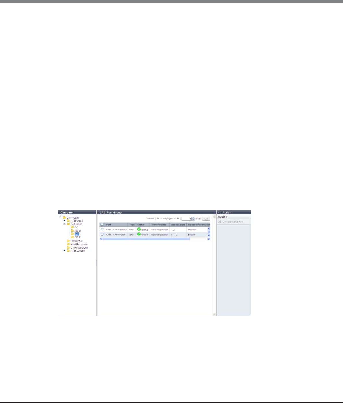
Chapter 9 Connectivity Management
9.1 Connectivity Status
ETERNUS Web GUI User’s Guide
Copyright 2013 FUJITSU LIMITED P2X0-1090-10ENZ0
385
•REC Line No.
The REC line number of the target port is displayed.
The REC line number is used to switch the communication path when a line fails.
A "-" (hyphen) is displayed when the port mode is "CA".
•REC Transfer Mode
Whether the REC synchronous transfer mode, the REC asynchronous stack mode, the REC asynchronous
consistency mode, or the REC asynchronous through mode is enabled or disabled for the target port is
displayed.
A "-" (hyphen) is displayed when the port mode is "CA".
-Sync
When the REC synchronous transfer mode is enabled, the target port can be used as an REC
synchronous transfer mode path.
-Async Stack
When the REC asynchronous stack mode is enabled, the target port can be used as an REC
asynchronous stack mode path.
-Async Consistency
When the REC asynchronous consistency mode is enabled, the target port can be used as an REC
asynchronous consistency mode path.
-Async Through
When the REC asynchronous through mode is enabled, the target port can be used as an REC
asynchronous through mode path.
9.1.4.3 SAS Port
Parameters of the SAS ports that are registered in the ETERNUS DX Disk storage system are displayed.
The following items are displayed in the Main area:
•Port
The location information of the target port is displayed.
-CM#x CA#y Port#z (x: CM number, y: CA number, z: Port number)
•Type
The CA type (fixed at "SAS") of the target port is displayed.
•Status
The status of the target port is displayed.
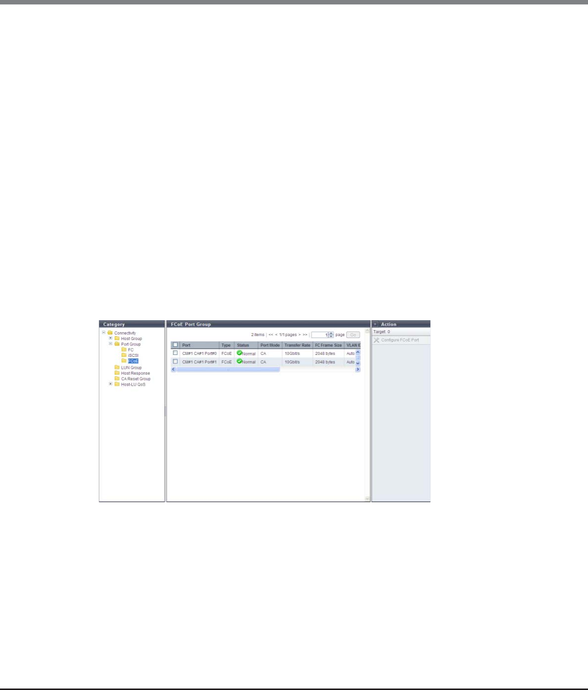
Chapter 9 Connectivity Management
9.1 Connectivity Status
ETERNUS Web GUI User’s Guide
Copyright 2013 FUJITSU LIMITED P2X0-1090-10ENZ0
386
•Transfer Rate
The transfer speed of the target port is displayed.
-Auto-negotiation
-1.5 Gbit/s
-3 Gbit/s
-6 Gbit/s
•Reset Scope
The reset scope of the target port is displayed.
Reset scope is the range where the command reset from the server is performed, when the target port is
connected to multiple servers.
-I_T_L (I: Initiator, T: Target, L: LUN)
Reset (cancel) the command request from the server that sent the command reset request.
-T_L (T: Target, L: LUN)
Reset (cancels) the command request from all of the servers that are connected to the port.
•Release Reservation if Chip is Reset
Whether the function to release the reservation status of the volume when the target port (chip) is reset is
enabled or disabled is displayed.
9.1.4.4 FCoE Port
Parameters of the FCoE ports that are registered in the ETERNUS DX Disk storage system are displayed.
The following items are displayed in the Main area:
•Port
The location information of the target port is displayed.
-CM#x CA#y Port#z (x: CM number, y: CA number, z: Port number)
•Type
The CA type (fixed at "FCoE") of the target port is displayed.
•Status
The status of the target port is displayed.
•Port Mode
The mode (fixed at "CA") of the target port is displayed.
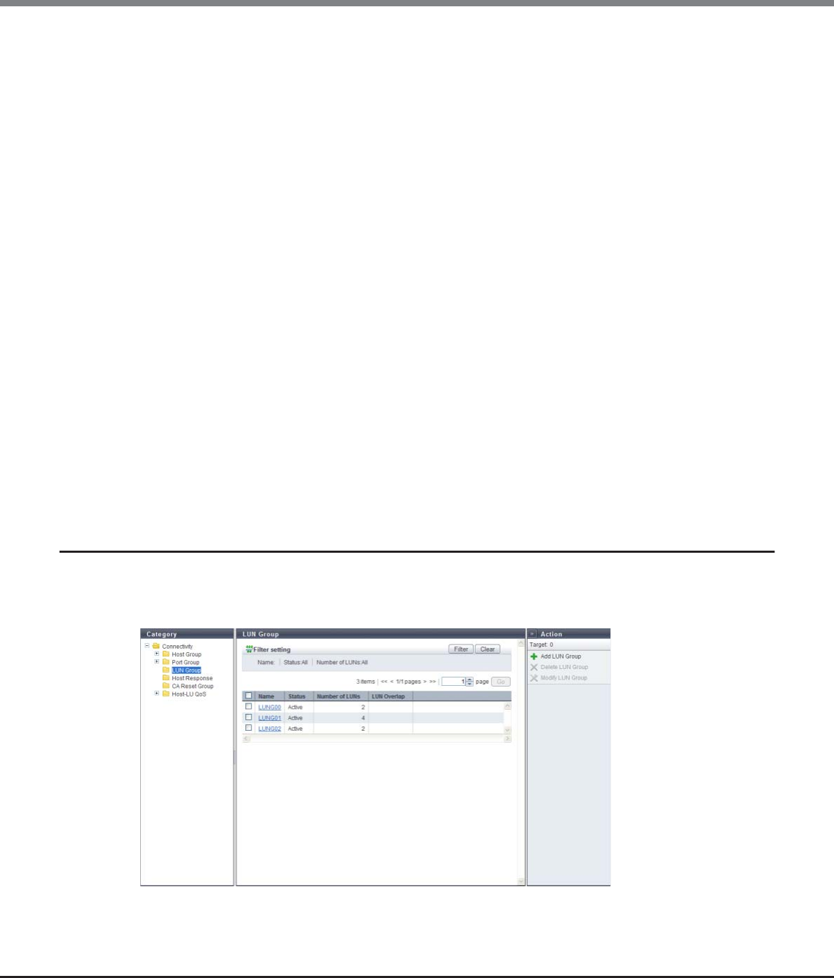
Chapter 9 Connectivity Management
9.1 Connectivity Status
ETERNUS Web GUI User’s Guide
Copyright 2013 FUJITSU LIMITED P2X0-1090-10ENZ0
387
•Transfer Rate
The transfer speed (fixed at "10 Gbit/s") of the target port is displayed.
•FC Frame Size
The frame size of the target port is displayed.
"FC Frame Size" specifies the length of the communication information.
-512 bytes
-1024 bytes
-2048 bytes
•VLAN ID
The VLAN ID of the target port is displayed.
•Fabric Name
The fabric name of the target port is displayed.
•Reset Scope
The reset scope of the target port is displayed.
Reset scope is the range where the command reset from the server is performed, when the target port is
connected to multiple servers.
-I_T_L (I: Initiator, T: Target, L: LUN)
Reset (cancel) the command request from the server that sent the command reset request.
-T_L (T: Target, L: LUN)
Reset (cancels) the command request from all of the servers that are connected to the port.
•Release Reservation if Chip is Reset
Whether the function to release the reservation status of the volume when the target port (chip) is reset is
enabled or disabled is displayed.
9.1.5 LUN Group
A list of the LUN groups is displayed.
A LUN group is a group of LUNs, which can be recognized by the host. The allocation information of LUNs and
volumes in the ETERNUS DX Disk storage system are configured to the LUN group.

Chapter 9 Connectivity Management
9.1 Connectivity Status
ETERNUS Web GUI User’s Guide
Copyright 2013 FUJITSU LIMITED P2X0-1090-10ENZ0
388
The following items are displayed in the Main area:
•Name
The LUN group name is displayed. By clicking this item, the [LUN Group Detail] screen is displayed. Refer to
"9.1.11 LUN Group Detail" (page 405) for display items.
•Status
Whether the LUN group is used ("Active") or not ("Inactive") for the host affinity settings is displayed.
"Host Affinity Setting" is to specify association between "Host Group", "CA Port Group", and "LUN Group" or
association between "Host", "CA Port", "and "LUN Group".
-Active
The LUN group is used for the host affinity settings. The LUN group can be accessed from the host.
-Inactive
The LUN group is not used for the host affinity settings.
•Number of LUNs
The number of LUNs, which have been allocated to volumes in the LUN group, is displayed.
•LUN Overlap
If volumes in the LUN group satisfy one or both of the following conditions, "Yes" is displayed. For any other
conditions, the field is blank.
-The volumes are allocated to different LUN groups.
-The volumes are included in the mapping information, which is directly allocated to the CA port without
specifying the host group or the CA port group.
Filter setting
Filter Description
Name Input the LUN group name that is to be displayed.
When not using the LUN group name for filtering, leave this item blank.
Status Select the LUN group status that is to be displayed.
Number of LUNs Select the number of LUNs that is to be displayed.
Using "512LUN" as the standard, ">512" or "≤512" can be selected.
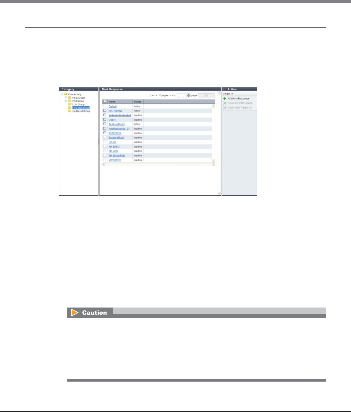
Chapter 9 Connectivity Management
9.1 Connectivity Status
ETERNUS Web GUI User’s Guide
Copyright 2013 FUJITSU LIMITED P2X0-1090-10ENZ0
389
9.1.6 Host Response
The registered host responses are displayed.
The host response configures the appropriate operation mode on which the host makes connection. The usual
host connection uses a recommended pattern or the default setting which have been arranged in advance in
accordance with each OS type.
When customizing the host response in accordance with the OS type or the operating environment, refer to
"9.2.5.1 Add Host Response" (page 581).
The following items are displayed in the Main area:
•Name
All of the host responses, which have been registered in the ETERNUS DX Disk storage system, are
displayed.
-Solaris MPxIO
-HP-UX
-AIX EMPD (*1)
-AIX VxVM
-AIX Single Path
-VS850/SVC
-Host responses created in the ETERNUS DX Disk storage system
-Default
*1: EMPD: ETERNUS Multipath Driver
The following modifications are applied for the host response settings with firmware version V10L15 or
later.
•"Others" is changed to "Default".
•"Windows EMPD", "Linux EMPD", and "Solaris EMPD" are deleted from the "Host Response" value.
However, these parameters are displayed if they are applied for host groups.
•The setting parameters for "Windows EMPD", "Linux EMPD", and "Solaris EMPD" are the same as
"Default".
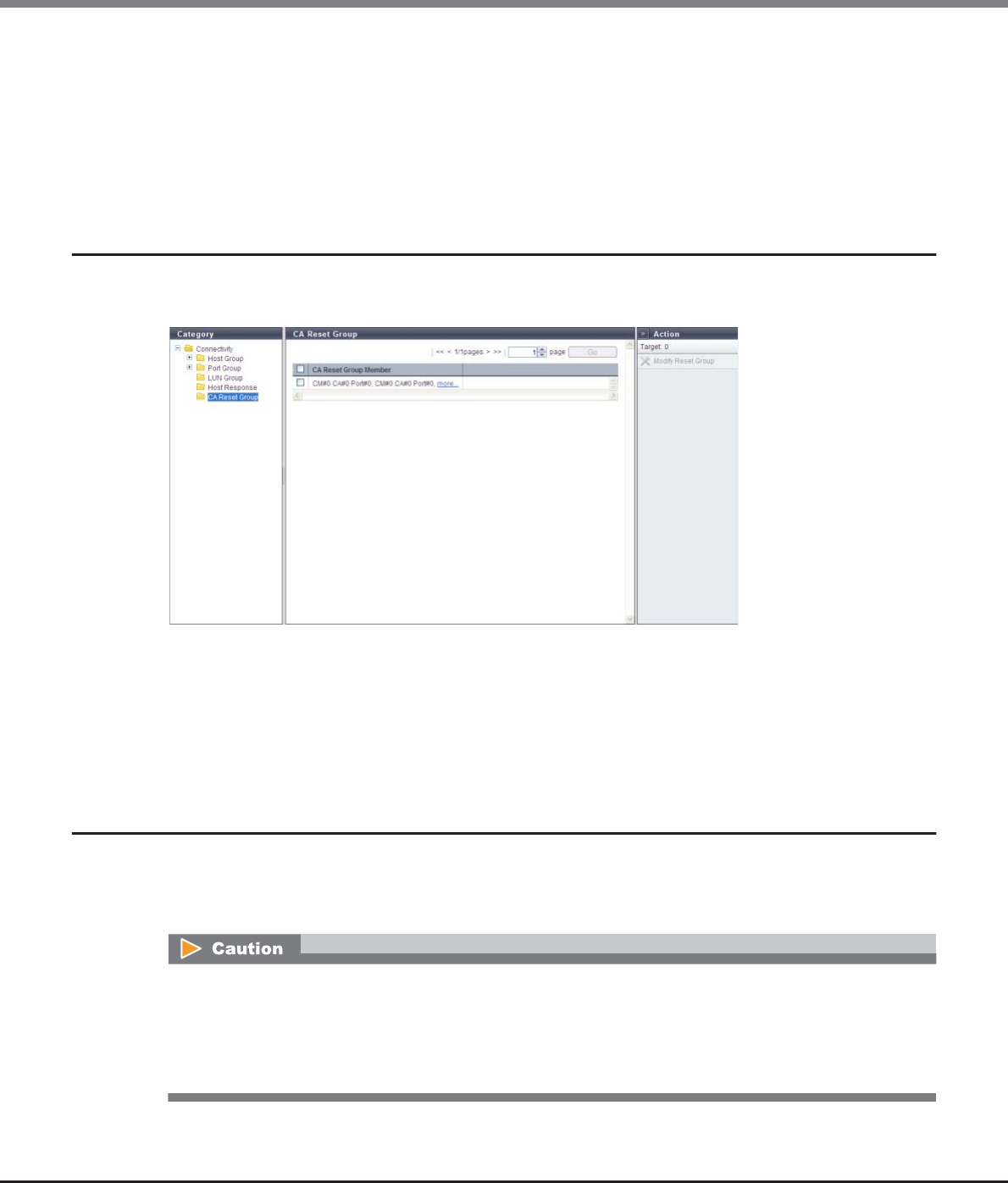
Chapter 9 Connectivity Management
9.1 Connectivity Status
ETERNUS Web GUI User’s Guide
Copyright 2013 FUJITSU LIMITED P2X0-1090-10ENZ0
390
•Status
Whether the host response is used ("Active") or not ("Inactive") for the host affinity settings is displayed.
-Active
The host response is used for the host affinity settings.
-Inactive
The host response is not used for the host affinity settings.
9.1.7 CA Reset Group
A list of the registered CA reset groups is displayed.
A "CA reset group" is a group of ports which are released simultaneously under the instruction of a server.
The following items are displayed in the Main area:
•CA Reset Group Member
The location information of member ports of each CA reset group is displayed.
If there are several ports, the ports are displayed, being separated with a ", (comma)". If there are three or
more ports the [more...] link are displayed.
-CM#x CA#y Port#z (x: CM number, y: CA number, z: Port number)
9.1.8 Host-LU QoS
A list of the registered Host-LU QoS groups is displayed.
The Host-LU QoS list shows the association between "Host", "CA Port", and "LUN Group", bandwidth limit
(performance limits), and performance information.
•When using GUI, schedule settings for QoS parameters and displaying scheduled QoS parameters are not
available. Use CLI to check the scheduled QoS parameters that are specified using CLI. GUI displays only
the bandwidth limit and the performance information that are specified by using GUI.
•Host-LU QoS does not support from LUN#1024 onward. If volumes are mapped from LUN#1024 onward,
only the first 1024 LUNs (LUN#0 - LUN#1023) are displayed.
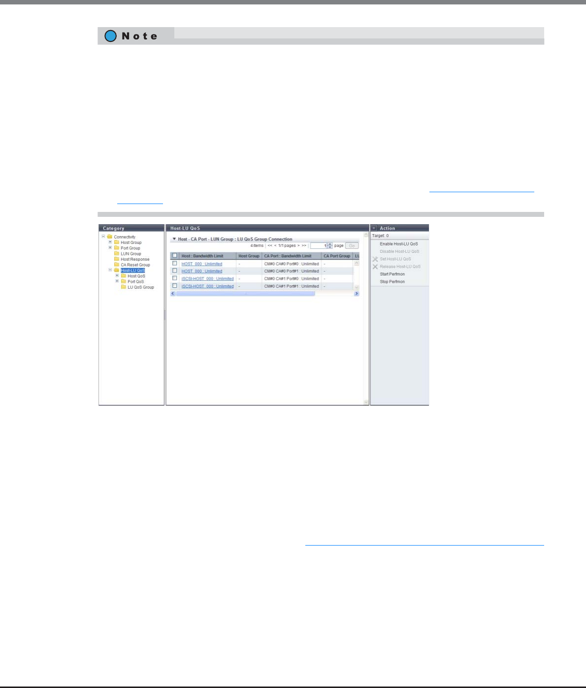
Chapter 9 Connectivity Management
9.1 Connectivity Status
ETERNUS Web GUI User’s Guide
Copyright 2013 FUJITSU LIMITED P2X0-1090-10ENZ0
391
The following items are displayed in the Main area:
•Host : Bandwidth Limit
-Host
The host name for which the host affinity setting is configured is displayed.
If "All" is displayed, all of the hosts can access the ETERNUS DX Disk storage system.
-Bandwidth Limit
The maximum performance is displayed in IOPS (throughput value). If the bandwidth limit has not
been configured (the bandwidth has not been limited), "Unlimited" is displayed.
If "All" has been selected for hosts, a "-" (hyphen) is displayed.
Click the [Host : Bandwidth Limit] link to display the total performance information for the host and the
performance information of each LUN. Refer to "9.1.13 Host-LU QoS Performance Information" (page 407)
for details.
•Host Group
If a host belongs to a host group, the host group name is displayed. If a host does not belongs to the host
group, a "-" (hyphen) is displayed.
If "All" is displayed, all of the hosts can access the ETERNUS DX Disk storage system.
•The operation status of Host-LU QoS can be confirmed with the displayed action name.
-If [Enable Host-LU QoS] is displayed, the Host-LU QoS has been disabled. Host-LU QoS is not running.
-If [Disable Host-LU QoS] is displayed, the Host-LU QoS has been enabled. Host-LU QoS is running.
•Host-LU QoS starts its operation by configuring the bandwidth limit on a "Host", "CA Port", or "LUN Group",
and enabling the Host-LU QoS.
•This function displays the performance information that is obtained during performance monitoring
regardless of whether the Host-LU QoS mode is enabled or disabled. When the performance information
is displayed before performance monitoring is stopped, the performance information that was obtained
up to this point is displayed. This function displays the total performance information for the host and the
performance information for each host LUN.
•The performance information of each CA port can also be displayed. Refer to "9.1.8.5 Port QoS (Basic)"
(page 396) for details.
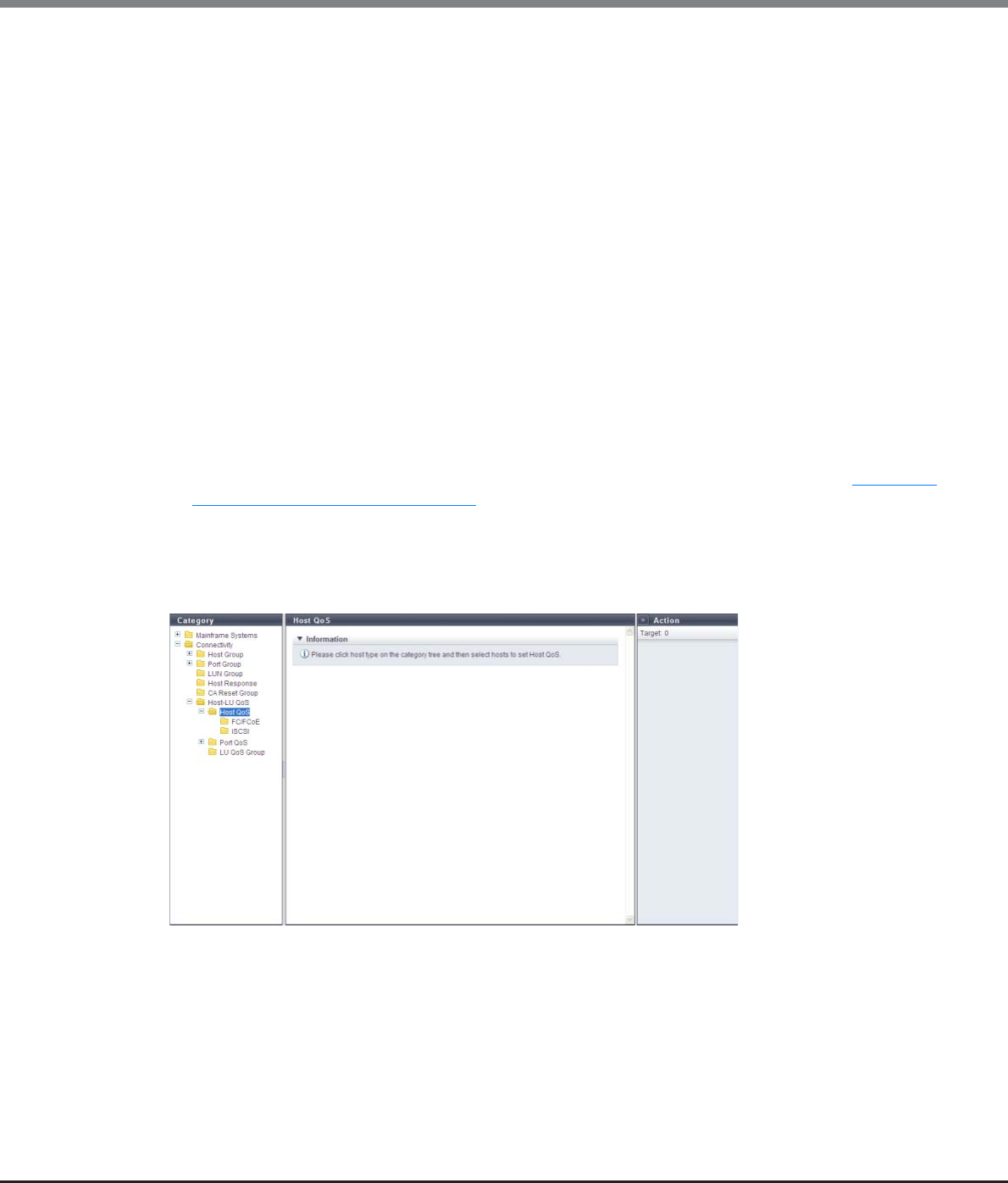
Chapter 9 Connectivity Management
9.1 Connectivity Status
ETERNUS Web GUI User’s Guide
Copyright 2013 FUJITSU LIMITED P2X0-1090-10ENZ0
392
•CA Port : Bandwidth Limit
-CA Port
The location information of the CA port with the host affinity setting is displayed.
-Bandwidth Limit
The maximum performance is displayed in IOPS (throughput value). If the bandwidth limit has not
been configured (the bandwidth has not been limited), "Unlimited" is displayed.
•CA Port Group
If a CA port belongs to a CA port group, the CA port group name is displayed. If a host does not belong to a
CA port group, a "-" (hyphen) is displayed.
•LUN Group : LU QoS Group
-LUN Group
The LUN group name is displayed. If the CLI command ("set mapping") is used for LUN mapping, a "- "
(hyphen) is displayed.
-LU QoS Group
The LU QoS group number is displayed. If a LU QoS group number is not configured, a "- " (hyphen) is
displayed.
•For ETERNUS DX80 S2/DX90 S2/DX410 S2/DX440 S2/DX8100 S2: 0 - 543
•For ETERNUS DX8700 S2: 0 - 2175
Click the [LUN Group : LU QoS Group] link to display a bandwidth limit on each LUN. Refer to "9.1.12 LUN
Group : LU QoS Group Detail" (page 406) for details.
9.1.8.1 Host QoS (Basic)
Follow the message in the Information area to configure a bandwidth limit on each host.
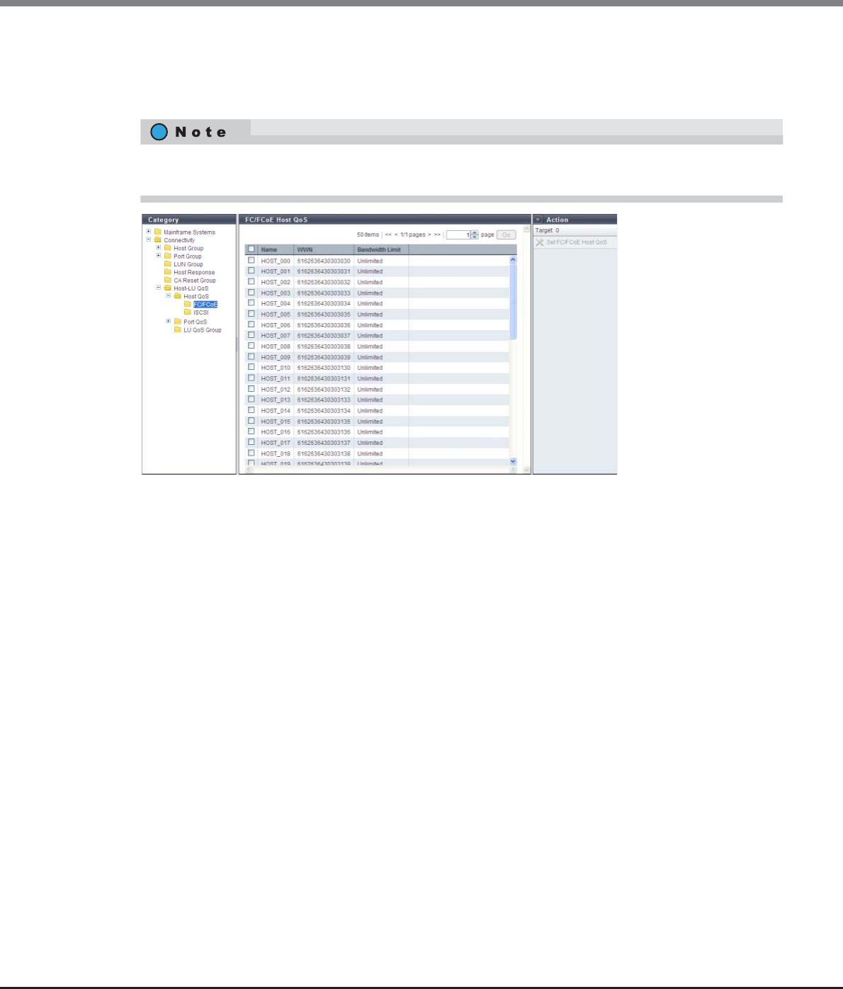
Chapter 9 Connectivity Management
9.1 Connectivity Status
ETERNUS Web GUI User’s Guide
Copyright 2013 FUJITSU LIMITED P2X0-1090-10ENZ0
393
9.1.8.2 FC/FCoE Host QoS
The bandwidth limit of the FC/FCoE hosts that are registered in the ETERNUS DX Disk storage system is
displayed.
The following items are displayed in the Main area:
•Name
The FC/FCoE host name is displayed.
•WWN
The FC/FCoE host WWN is displayed.
•Bandwidth Limit
The maximum performance of the FC/FCoE host is displayed in IOPS (throughput value). If the bandwidth
limit has not been configured (the bandwidth has not been limited), "Unlimited" is displayed.
This function displays all the hosts that are registered in the ETERNUS DX Disk storage system regardless of
whether the hosts belong to host groups or not.
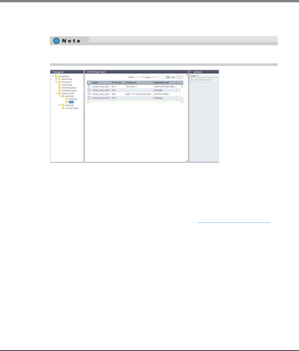
Chapter 9 Connectivity Management
9.1 Connectivity Status
ETERNUS Web GUI User’s Guide
Copyright 2013 FUJITSU LIMITED P2X0-1090-10ENZ0
394
9.1.8.3 iSCSI Host QoS
The bandwidth limit of the iSCSI hosts that are registered in the ETERNUS DX Disk storage system is displayed.
The following items are displayed in the Main area:
•Name
The iSCSI host name is displayed.
•IP Version
The IP version of the iSCSI host is displayed.
•IP Address
The IP address of the iSCSI host is displayed.
Note that the IPv6 address is displayed as an abbreviation. Refer to "IPv6 Address Notation" (page 378) for
details.
If the IP address is not set, the field is blank.
•Bandwidth Limit
The maximum performance of the iSCSI host is displayed in IOPS (throughput value). If the bandwidth
limit has not been configured (the bandwidth has not been limited), "Unlimited" is displayed.
This function displays all the hosts that are registered in the ETERNUS DX Disk storage system regardless of
whether the hosts belong to host groups or not.
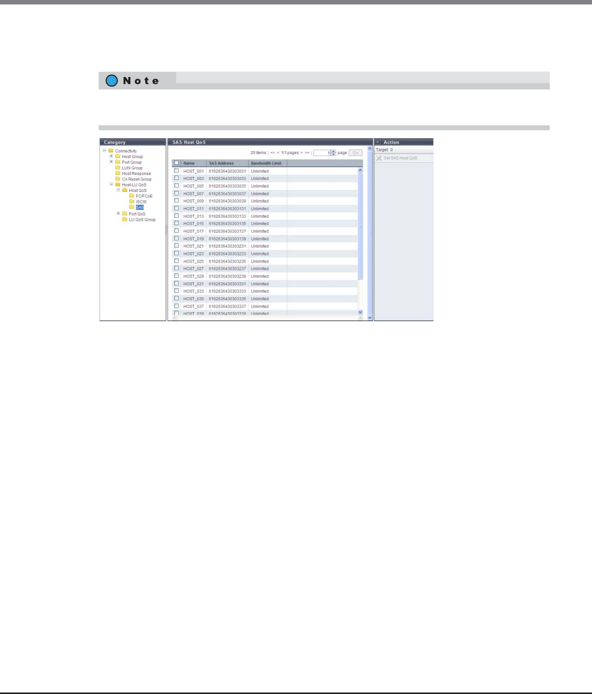
Chapter 9 Connectivity Management
9.1 Connectivity Status
ETERNUS Web GUI User’s Guide
Copyright 2013 FUJITSU LIMITED P2X0-1090-10ENZ0
395
9.1.8.4 SAS Host QoS
The bandwidth limit of the SAS hosts that are registered in the ETERNUS DX Disk storage system is displayed.
The following items are displayed in the Main area:
•Name
The SAS host name is displayed.
•SAS address
The SAS address of the SAS host is displayed.
•Bandwidth Limit
The maximum performance of the SAS host is displayed in IOPS (throughput value). If the bandwidth limit
has not been configured (the bandwidth has not been limited), "Unlimited" is displayed.
This function displays all the hosts that are registered in the ETERNUS DX Disk storage system regardless of
whether the hosts belong to host groups or not.
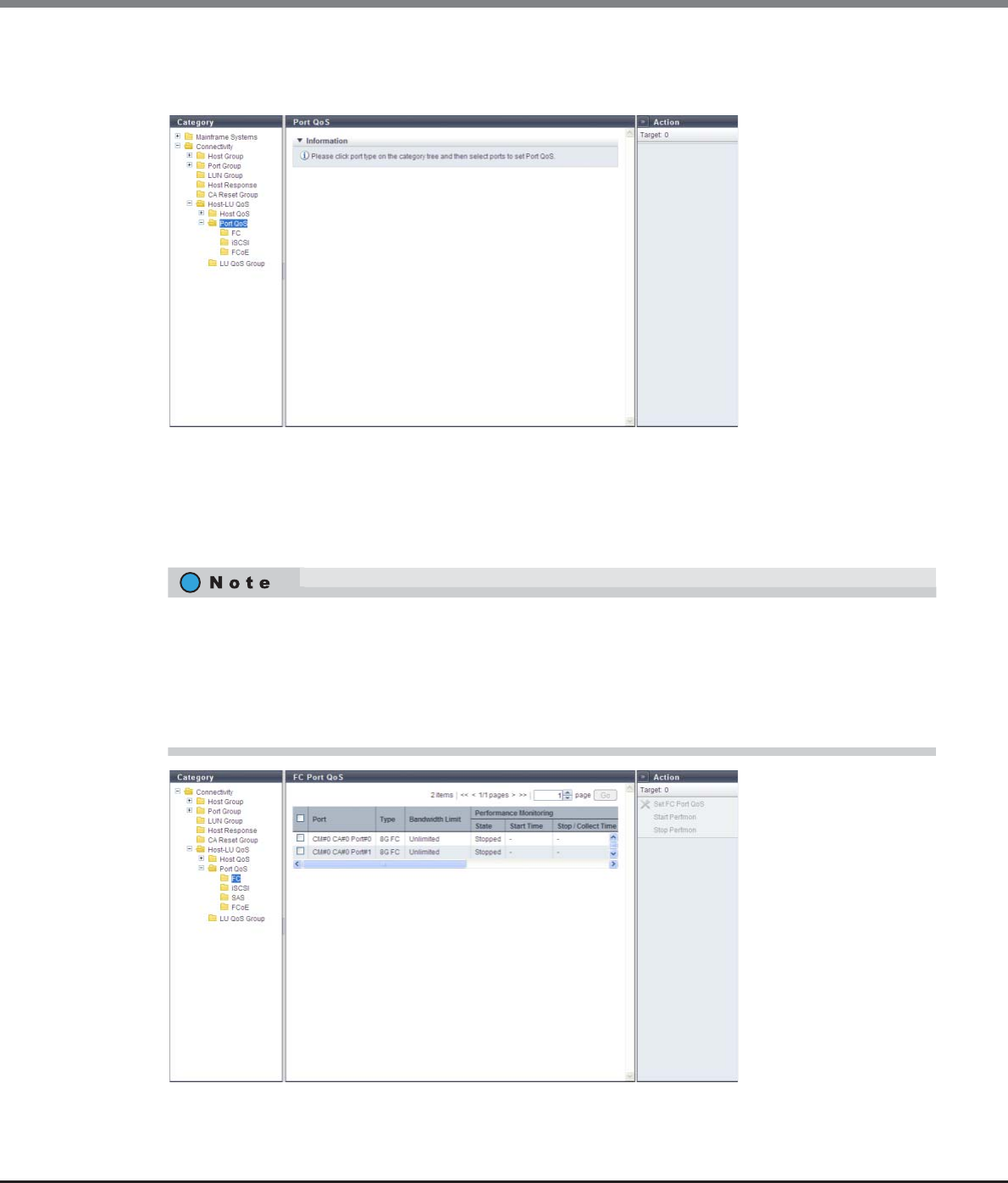
Chapter 9 Connectivity Management
9.1 Connectivity Status
ETERNUS Web GUI User’s Guide
Copyright 2013 FUJITSU LIMITED P2X0-1090-10ENZ0
396
9.1.8.5 Port QoS (Basic)
Follow the message in the Information area to configure a bandwidth limit on each port.
9.1.8.6 FC Port QoS
This function displays the bandwidth limit and the performance information of the FC ports that are registered
in the ETERNUS DX Disk storage system.
•The ports with "CA" or "CA/RA" as the port mode that are registered by the ETERNUS DX Disk storage
system are displayed regardless of whether the ports belong to CA port groups or not.
•This function displays the performance information that is obtained during performance monitoring
regardless of whether the Host-LU QoS mode is enabled or disabled. When the performance information
is displayed before performance monitoring is stopped, the performance information that was obtained
up to this point is displayed. This function displays the performance information of each port.

Chapter 9 Connectivity Management
9.1 Connectivity Status
ETERNUS Web GUI User’s Guide
Copyright 2013 FUJITSU LIMITED P2X0-1090-10ENZ0
397
The following items are displayed in the Main area:
•Port
The location information of the target port is displayed.
•Type
The type of the target port is displayed.
-8G FC
An 8Gbit/s (maximum) FC.
-16G FC
A 16Gbit/s (maximum) FC.
•Bandwidth Limit
The maximum performance of the target port is displayed in IOPS (throughput value). If the bandwidth
limit has not been configured (the bandwidth has not been limited), "Unlimited" is displayed.
•Performance Monitoring
-State
The status of performance monitoring for the host is displayed.
•Active
•Stopped
-Start Time
-Stop / Collect Time
The start time and the end time for performance monitoring are displayed.
•YYYY-MM-DD hh:mm:ss (YYYY: Year (AD), MM: Month (01 - 12), DD: Day (01 - 31), hh: Hour (00 -
23), mm: Minute (00 - 59), ss: Second (00 - 59))
The displayed time varies depending on how the performance monitoring is started or ended.
•Before monitoring is started (*1)
"State" for performance monitoring is "Stopped". "-" (hyphens) are displayed for "Start Time" and
"Stop Collect Time".
•Monitoring is started
"State" for performance monitoring is changed from "Stopped" to "Active". The time when
performance monitoring was started is displayed for "Start Time". The time when the performance
information is obtained is displayed for "Stop / Collect Time".
•Monitoring is started while the monitoring session has already been started
"State" for performance monitoring is "Active". The last time when performance monitoring was
started is displayed for "Start Time". The time when the performance information is obtained is
displayed for "Stop / Collect Time".
•Monitoring is stopped
"State" for performance monitoring is changed from "Active" to "Stopped". The last time when
performance monitoring was started is displayed for "Start Time". The time when performance
monitoring is stopped is displayed for "Stop / Collect Time".
•Monitoring is stopped while the monitoring session has already been stopped
"State" for performance monitoring is "Stopped". The last time when performance monitoring was
started is displayed for "Start Time". The first time when performance monitoring was stopped is
displayed for "Stop / Collect Time".
*1: When performance monitoring is not being performed after the ETERNUS DX Disk storage system is
started. When the start time is "0", "-" is displayed for "Start Time" and "Stop / Collect Time".
When the start time is "0", "-" is displayed for "Start Time" and "Stop / Collect Time".
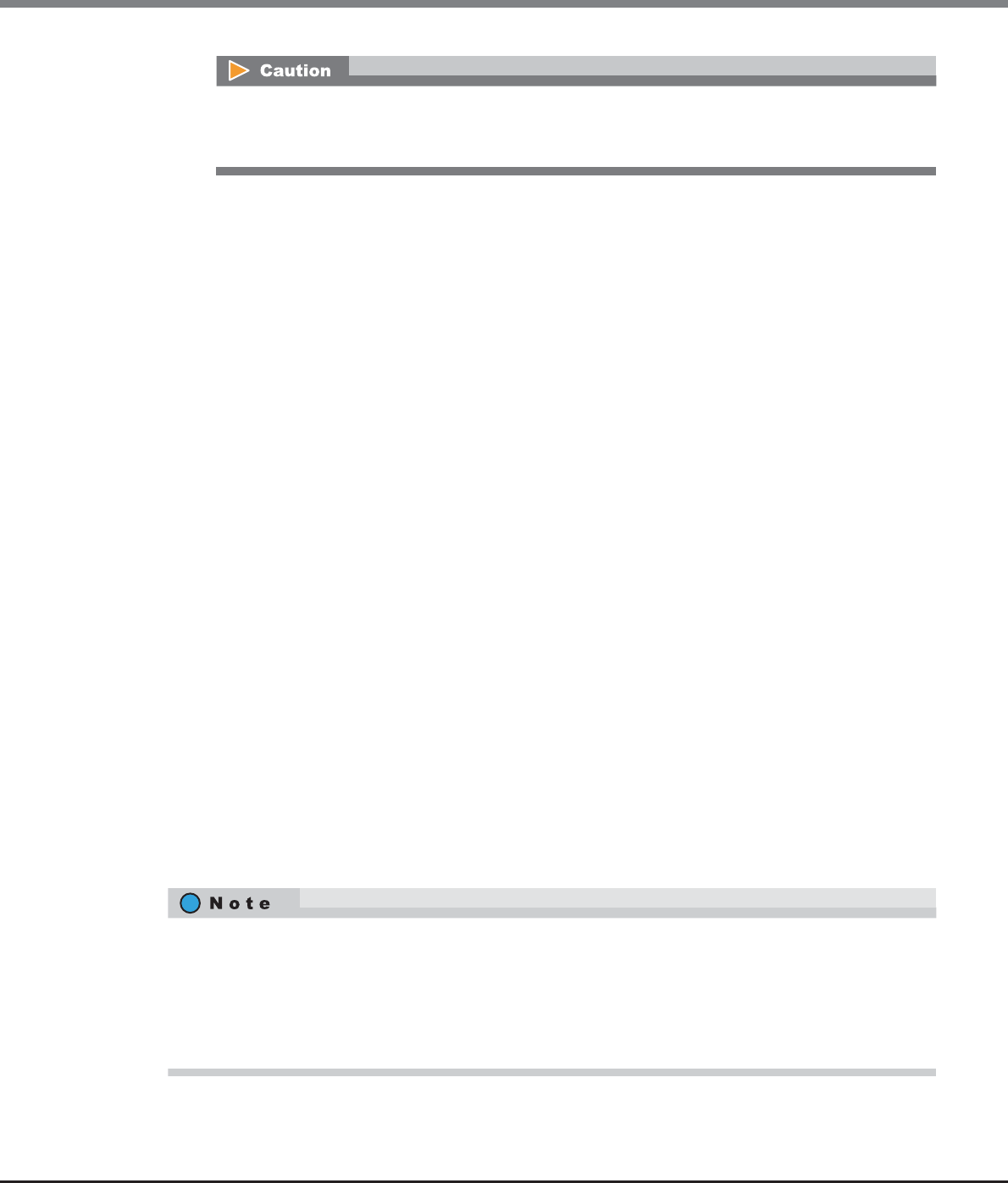
Chapter 9 Connectivity Management
9.1 Connectivity Status
ETERNUS Web GUI User’s Guide
Copyright 2013 FUJITSU LIMITED P2X0-1090-10ENZ0
398
•IOPS
The performance information from when performance monitoring is started until performance monitoring
is ended (or performance information is displayed) is displayed.
-Ave
The average I/O count per second is displayed.
-Min
The minimum I/O count per second is displayed.
-Max
The maximum I/O count per second is displayed.
•Throughput
The transfer data size from when performance monitoring is started until performance monitoring is ended
(or performance information is displayed) is displayed.
-Ave
The average data transfer size per second is displayed.
-Min
The minimum data transfer size per second is displayed.
-Max
The maximum data transfer size per second is displayed.
•Delay Time
-Total
The total delay time for executing a command from when performance monitoring is started until per-
formance monitoring is ended (or performance information is displayed) is displayed. If the total delay
time exceeds the maximum value, "Overflow" is displayed.
-Ave
The average delay time per command from when performance monitoring is started until performance
monitoring is ended (or performance information is displayed) is displayed.
9.1.8.7 iSCSI Port QoS
This function displays the bandwidth limit and the performance information of the iSCSI ports that are
registered in the ETERNUS DX Disk storage system.
If performance monitoring is restarted during an active performance monitoring session, the
performance information that is already obtained is deleted and the collection of performance
information starts again.
•The ports with "CA" or "CA/RA" as the port mode that are registered by the ETERNUS DX Disk storage
system are displayed regardless of whether the ports belong to CA port groups or not.
•This function displays the performance information that is obtained during performance monitoring
regardless of whether the Host-LU QoS mode is enabled or disabled. When the performance information
is displayed before performance monitoring is stopped, the performance information that was obtained
up to this point is displayed. This function displays the performance information of each port.

Chapter 9 Connectivity Management
9.1 Connectivity Status
ETERNUS Web GUI User’s Guide
Copyright 2013 FUJITSU LIMITED P2X0-1090-10ENZ0
399
The following items are displayed in the Main area:
•Port
The location information of the target port is displayed.
•Type
The type of the target port is displayed.
-1G iSCSI
1Gbit/s iSCSI.
-10G iSCSI
10Gbit/s iSCSI.
•Bandwidth Limit
The maximum performance of the target port is displayed in IOPS (throughput value). If the bandwidth
limit has not been configured (the bandwidth has not been limited), "Unlimited" is displayed.
•Performance Monitoring
Refer to "Performance Monitoring" (page 397) for details.
•IOPS
Refer to "Performance Monitoring" (page 397) for details.
•Throughput
Refer to "Performance Monitoring" (page 397) for details.
•Delay Time
Refer to "Performance Monitoring" (page 397) for details.
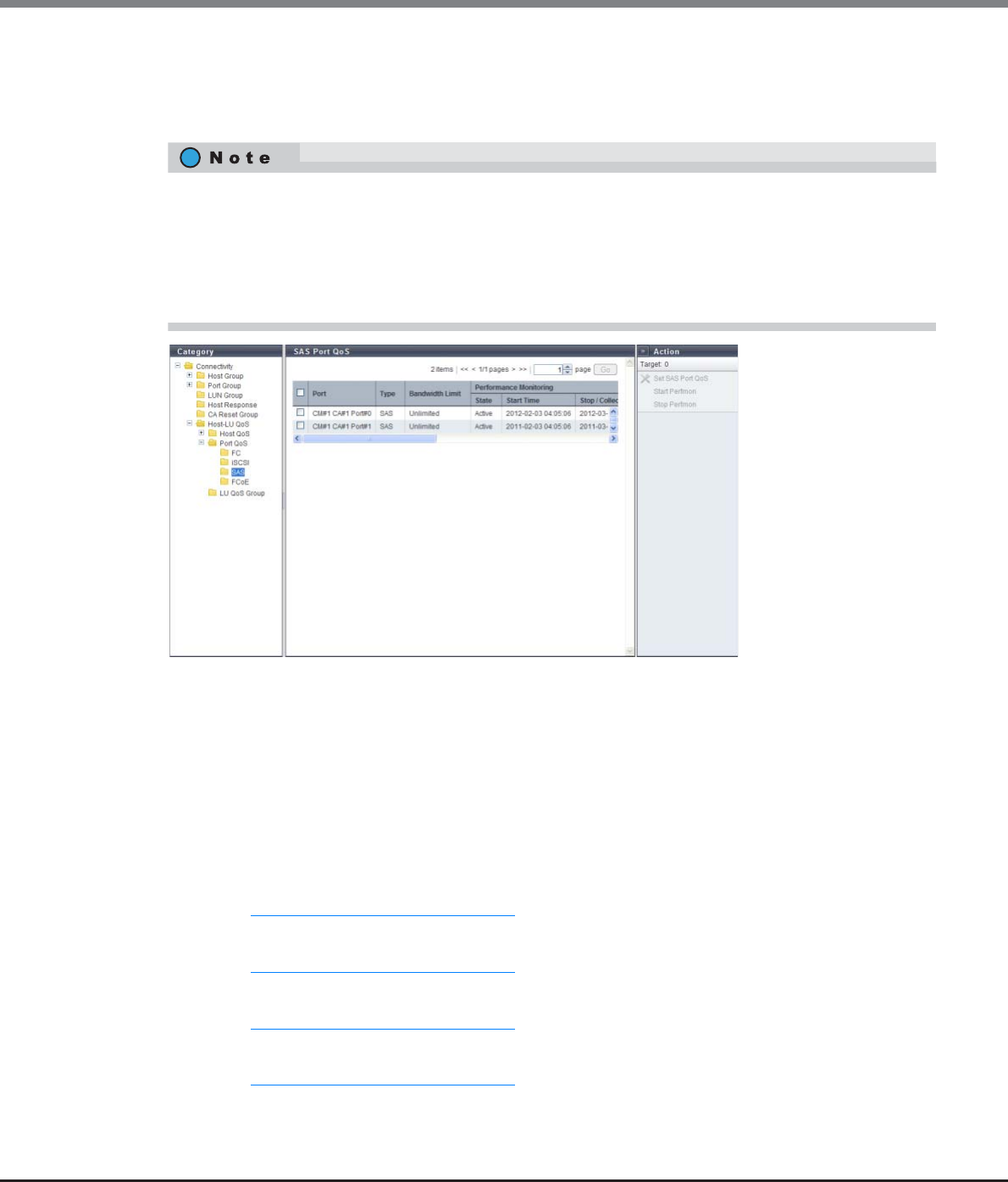
Chapter 9 Connectivity Management
9.1 Connectivity Status
ETERNUS Web GUI User’s Guide
Copyright 2013 FUJITSU LIMITED P2X0-1090-10ENZ0
400
9.1.8.8 SAS Port QoS
This function displays the bandwidth limit and the performance information of the SAS ports that are
registered in the ETERNUS DX Disk storage system.
The following items are displayed in the Main area:
•Port
The location information of the target port is displayed.
•Type
The type of the target port is displayed.
•Bandwidth Limit
The maximum performance of the target port is displayed in IOPS (throughput value). If the bandwidth
limit has not been configured (the bandwidth has not been limited), "Unlimited" is displayed.
•Performance Monitoring
Refer to "Performance Monitoring" (page 397) for details.
•IOPS
Refer to "Performance Monitoring" (page 397) for details.
•Throughput
Refer to "Performance Monitoring" (page 397) for details.
•Delay Time
Refer to "Performance Monitoring" (page 397) for details.
•The ports that are registered by the ETERNUS DX Disk storage system are displayed regardless of whether
the ports belong to CA port groups or not.
•This function displays the performance information that is obtained during performance monitoring
regardless of whether the Host-LU QoS mode is enabled or disabled. When the performance information
is displayed before performance monitoring is stopped, the performance information that was obtained
up to this point is displayed. This function displays the performance information of each port.
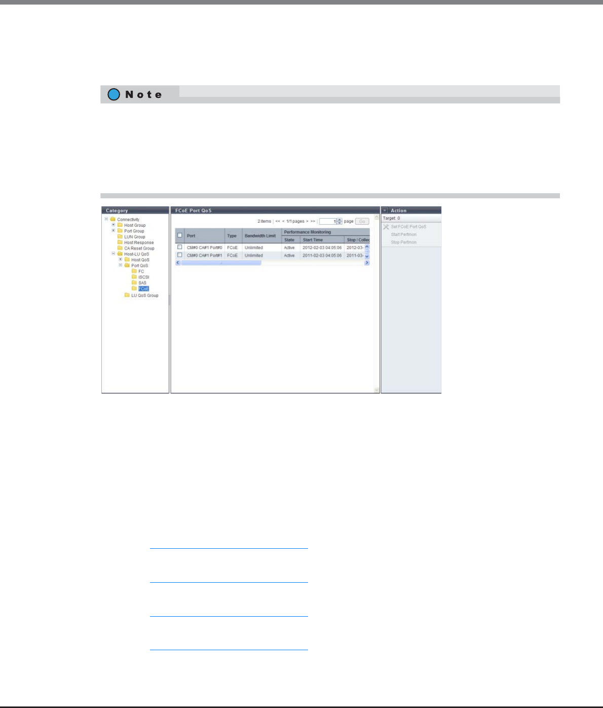
Chapter 9 Connectivity Management
9.1 Connectivity Status
ETERNUS Web GUI User’s Guide
Copyright 2013 FUJITSU LIMITED P2X0-1090-10ENZ0
401
9.1.8.9 FCoE Port QoS
This function displays the bandwidth limit and the performance information of the FCoE ports that are
registered in the ETERNUS DX Disk storage system.
The following items are displayed in the Main area:
•Port
The location information of the target port is displayed.
•Type
The type of the target port is displayed.
•Bandwidth Limit
The maximum performance of the target port is displayed in IOPS (throughput value). If the bandwidth
limit has not been configured (the bandwidth has not been limited), "Unlimited" is displayed.
•Performance Monitoring
Refer to "Performance Monitoring" (page 397) for details.
•IOPS
Refer to "Performance Monitoring" (page 397) for details.
•Throughput
Refer to "Performance Monitoring" (page 397) for details.
•Delay Time
Refer to "Performance Monitoring" (page 397) for details.
•The ports that are registered by the ETERNUS DX Disk storage system are displayed regardless of whether
the ports belong to CA port groups or not.
•This function displays the performance information that is obtained during performance monitoring
regardless of whether the Host-LU QoS mode is enabled or disabled. When the performance information
is displayed before performance monitoring is stopped, the performance information that was obtained
up to this point is displayed. This function displays the performance information of each port.
Chapter 9 Connectivity Management
9.1 Connectivity Status
ETERNUS Web GUI User’s Guide
Copyright 2013 FUJITSU LIMITED P2X0-1090-10ENZ0
402
9.1.8.10 LU QoS Group
A list of the registered LU QoS groups is displayed.
An LU QoS group is a group of the bandwidth limit (the maximum performance) configured for each Host
LUN.
The following items are displayed in the Main area:
•LU QoS Group No.
The LU QoS group number is displayed.
-For ETERNUS DX80 S2/90 S2, ETERNUS DX410 S2/DX440 S2, ETERNUS DX8100 S2: 0 - 543
-For ETERNUS DX8700 S2: 0 - 2175
•Status
Whether a LU QoS group is assigned to a LUN group with the host affinity setting is displayed.
"Host affinity setting" is to specify association between "Host", "CA Port" and "LUN Group".
-Active
The LU QoS group is assigned to a LUN group.
-Inactive
The LU QoS group is not assigned to a LUN group.
By assigning an LU QoS group to a LUN group with the host affinity setting, the bandwidth limit can be
configured for each LUN. Refer to "9.2.7.2 Set Host-LU QoS" (page 599) for details.
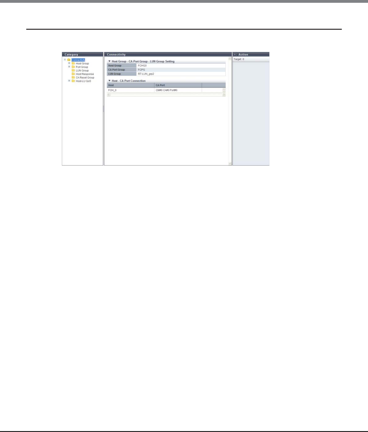
Chapter 9 Connectivity Management
9.1 Connectivity Status
ETERNUS Web GUI User’s Guide
Copyright 2013 FUJITSU LIMITED P2X0-1090-10ENZ0
403
9.1.9 Host Affinity Detail
The details of the host affinity are displayed.
The following items are displayed in the Main area:
●Host Group - CA Port Group - LUN Group Setting
•Host Group
The selected host group name or "All" is displayed.
•CA Port Group
The CA port group that is allocated to the selected host group is displayed.
•LUN Group
The LUN group that is allocated to the selected host group is displayed.
●Host - CA Port Connection
•Host
Member hosts in the selected host group is displayed.
If "All" has been selected for the host group, "All" is also displayed for the host.
•CA Port
The location information of the CA port which has the host affinity setting with the relevant host is
displayed.
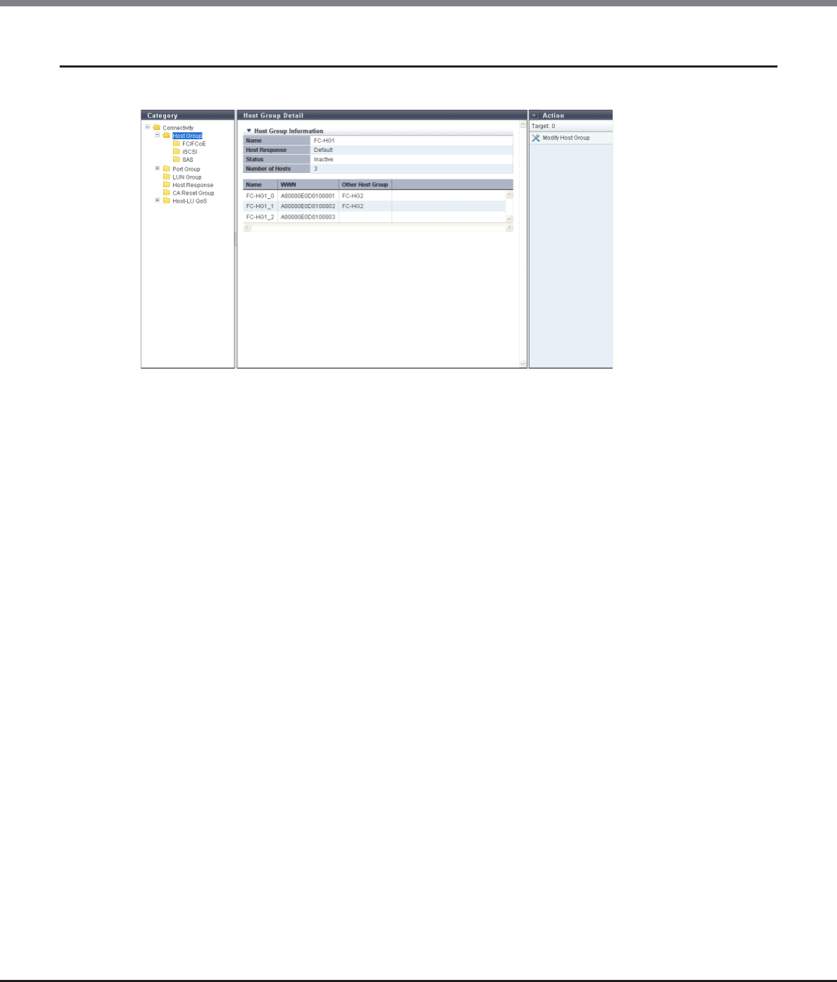
Chapter 9 Connectivity Management
9.1 Connectivity Status
ETERNUS Web GUI User’s Guide
Copyright 2013 FUJITSU LIMITED P2X0-1090-10ENZ0
404
9.1.10 Host Group Detail
The details of the host group are displayed.
The following items are displayed in the Main area:
●Host Group Information
•Name
The host group name is displayed.
•Host Response
The host response name, which has been assigned to a host group, is displayed.
•Status
Whether the host group is "Active" or "Inactive" in the host affinity setting is displayed.
•Number of Hosts
The number of hosts, which have been registered in the host group, is displayed.
●Host List
•Name
The host name is displayed.
•WWN
When the host interface type is "FC/FCoE", the WWN of the host is displayed.
•iSCSI Name
When the host interface type is "iSCSI", the iSCSI name of the host is displayed.
•SAS Address
When the host interface type is "SAS", the SAS address of the host is displayed.
•Other Host Group
The other host group names to which the host belongs are displayed.
When the host belongs to two host groups, the host group names are separated with a ", (comma)" and
displayed. If the host belongs to three or more host groups, the names of the first two groups and a
[more...] link are displayed. If the host belongs to only one host group, the field is blank.
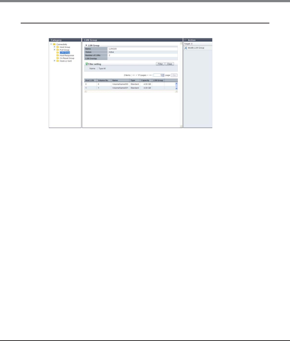
Chapter 9 Connectivity Management
9.1 Connectivity Status
ETERNUS Web GUI User’s Guide
Copyright 2013 FUJITSU LIMITED P2X0-1090-10ENZ0
405
9.1.11 LUN Group Detail
The detailed information of a LUN group is displayed.
The following items are displayed in the Main area:
•Host LUN
The host LUN is displayed.
•Volume No.
The volume number, which is allocated to the LUN, is displayed.
•Name
The volume name is displayed.
•Type
The volume type is displayed.
-Standard
-WSV
-TPV
-FTV
-SDV
•Capacity
The volume capacity is displayed.
When the "Type" is "SDV", the logical capacity, which can be accessed from the host, is displayed.
•LUN Group
If the volume is allocated to different LUN groups, the LUN group name is displayed. If the host, ports, and
LUNs are associated without specifying a host group or CA port group, the location information of the ports
is displayed.
If the volume is registered in multiple LUN groups or the volume is allocated to multiple ports, the display
contents vary depending on the number of LUN groups and the number of ports. When there are two
display targets (the LUN group name and the port location information), the items are separated with a ",
(comma)" and displayed. When there are three or more display targets (the LUN group name and the port
location information), the first two items and a [more...] link are displayed. When a volume is not
allocated to different LUN groups, the field is blank.
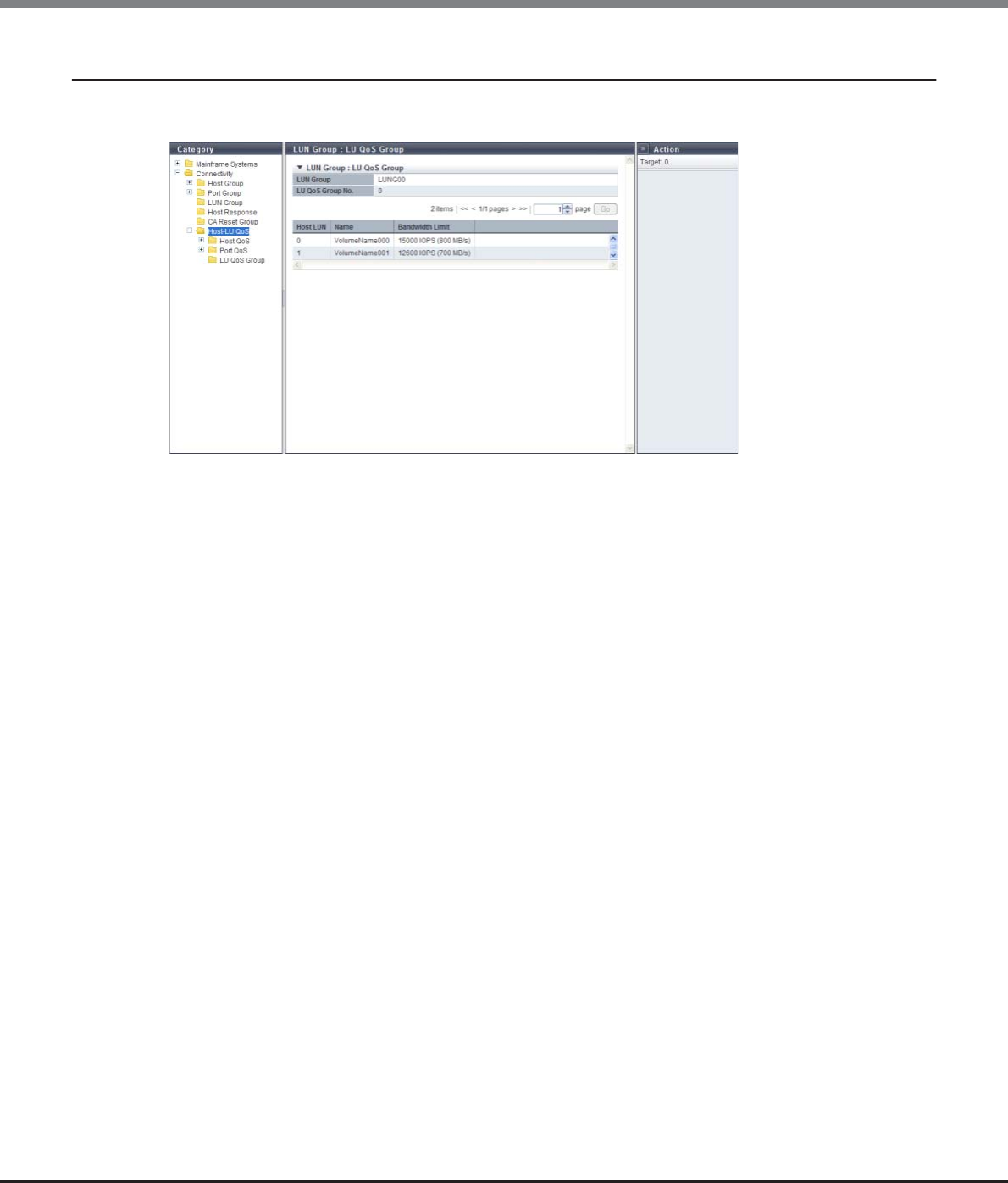
Chapter 9 Connectivity Management
9.1 Connectivity Status
ETERNUS Web GUI User’s Guide
Copyright 2013 FUJITSU LIMITED P2X0-1090-10ENZ0
406
9.1.12 LUN Group : LU QoS Group Detail
The bandwidth limit for each LUN is displayed.
The following items are displayed in the Main area:
•LUN Group
The LUN group name is displayed. If the CLI command ("set mapping") is used for LUN mapping, a "-"
(hyphen) is displayed.
•LU QoS Group No.
The LU QoS group number is displayed. If a LU QoS group number is not configured, a "-" (hyphen) is
displayed.
-For ETERNUS DX80 S2/DX90 S2/DX410 S2/DX440 S2/DX8100 S2: 0 - 543
-For ETERNUS DX8700 S2: 0 - 2175
•Host LUN
The host LUN number is displayed.
•Name
The volume name is displayed.
•Bandwidth Limit
The maximum performance is displayed in IOPS (throughput value). If the bandwidth limit has not been
configured (the bandwidth has not been limited), "Unlimited" is displayed.
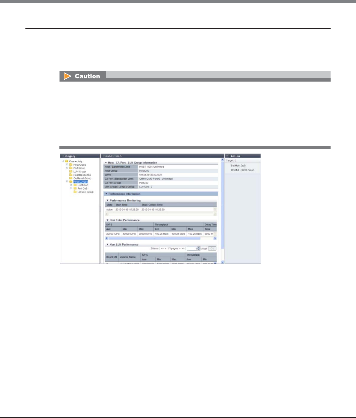
Chapter 9 Connectivity Management
9.1 Connectivity Status
ETERNUS Web GUI User’s Guide
Copyright 2013 FUJITSU LIMITED P2X0-1090-10ENZ0
407
9.1.13 Host-LU QoS Performance Information
When a host affinity setting with a specific host group is already configured, the total performance
information for the host and the performance information of each LUN are displayed.
If a host affinity setting with all of the host groups is configured ("All" is specified as the target host group),
the performance information of each host LUN is displayed.
The following items are displayed in the Main area:
●Host - CA Port - LUN Group Information
•Host : Bandwidth Limit
The host name and the bandwidth limit of the selected host is displayed in "Host : Bandwidth Limit"
format.
If the bandwidth limit has not been configured (the bandwidth has not been limited), "Unlimited" is
displayed as the "Bandwidth Limit". If "All" has been selected for the host, a "-" (hyphen) is displayed as the
"Bandwidth Limit".
•Host Group
The host group name, to which the selected host belongs, is displayed.
If all of the hosts are to be connected, "All" is displayed.
If the host does not belong to a host group, a "-" (hyphen) is displayed.
•WWN
The WWN for the selected host is displayed.
This item is displayed when the host affinity setting is configured and the selected host is "FC" or "FCoE".
The monitoring status of the performance information and obtained performance information are cleared in
the following conditions:
•When the port mode is changed (CA, CA/RA → RA or Initiator)
•When the ETERNUS DX Disk storage system is rebooted
•When an error is detected in the ETERNUS DX Disk storage system
•When the hot maintenance of the CM is performed
•When the concurrent firmware upgrade is being performed in the ETERNUS DX Disk storage system

Chapter 9 Connectivity Management
9.1 Connectivity Status
ETERNUS Web GUI User’s Guide
Copyright 2013 FUJITSU LIMITED P2X0-1090-10ENZ0
408
•iSCSI Name
The iSCSI name for the selected host is displayed.
This item is displayed when the host affinity setting is configured and the selected host is "iSCSI".
•IP Version
The IP version of the iSCSI host is displayed. This item is displayed when the host affinity setting is
configured and the selected host is "iSCSI".
-IPv4
-IPv6
•IP Address
The IP address of the selected iSCSI host is displayed.
Note that the IPv6 address is displayed as an abbreviation. If the IP address is not specified, the field is
blank.
This item is displayed when the host affinity setting is configured and the selected host is "iSCSI".
-For IPv4 address
•xxx.xxx.xxx.xxx
xxx: 0 - 255 for other fields (decimal)
-For IPv6 address
•xxxx:xxxx:xxxx:xxxx:xxxx:xxxx:xxxx:xxxx
xxxx: 0 - ffff (hexadecimal, "a" - "f" are lowercase letters)
Refer to "IPv6 Address Notation" (page 378) for details.
•SAS Address
The SAS address of the selected host is displayed.
This item is displayed when the host affinity setting is configured and the selected host is "SAS".
•CA Port : Bandwidth Limit
The location information and the bandwidth limit of the selected CA port is displayed in "CA Port :
Bandwidth Limit" format.
If the bandwidth limit has not been configured (the bandwidth has not been limited), "Unlimited" is
displayed as the "Bandwidth Limit".
•CA Port Group
If a CA port that is connected to the selected host belongs to a CA port group as a member, the CA port
group name is displayed. If a host does not belong as a member, a "-" (hyphen) is displayed.
•LUN Group : LU QoS Group
The LUN group name and LU QoS group number are displayed in "LUN Group : LU QoS Group" format.
If the CLI command ("set mapping") is used for LUN mapping, a "-" (hyphen) is displayed as "LUN Group".
If a LUN QoS group number has not been configured, a "- " (hyphen) is displayed as "LU QoS Group".
-LU QoS group
ETERNUS DX80 S2/90 S2/410 S2/440/8100 S2 S2: 0 - 543
ETERNUS DX8700 S2: 0 - 2175

Chapter 9 Connectivity Management
9.1 Connectivity Status
ETERNUS Web GUI User’s Guide
Copyright 2013 FUJITSU LIMITED P2X0-1090-10ENZ0
409
●Performance information
•Login IP Address
IP address that is logged in is displayed.
The performance information is displayed for each specified IP address. Note that the IPv6 address is
displayed as an abbreviation. If there is no IP address, a "-" (hyphen) is displayed.
This item is displayed for the iSCSI host when the host affinity setting is configured, the iSCSI name is
specified, and the IP address is not specified.
-For IPv4 address
•xxx.xxx.xxx.xxx
xxx: 0 - 255 for other fields (decimal)
-For IPv6 address
•xxxx:xxxx:xxxx:xxxx:xxxx:xxxx:xxxx:xxxx
xxxx: 0 - ffff (hexadecimal, "a" - "f" are lowercase letters)
Refer to "IPv6 Address Notation" (page 378) for details.
●Performance Monitoring
•State
The status of performance monitoring for the host is displayed.
-Active
-Stopped
•Start Time
•Stop / Collect Time
The start time and the end time for performance monitoring are displayed.
The displayed time varies depending on how the performance monitoring is started or ended.
-Before monitoring is started (*1)
"State" for performance monitoring is "Stopped". "-" (hyphens) are displayed for "Start Time" and "Stop
Collect Time".
-Monitoring is started
"State" for performance monitoring is changed from "Stopped" to "Active". The time when performance
monitoring was started is displayed for "Start Time". The time when the performance information is
obtained is displayed for "Stop / Collect Time".
-Monitoring is started while the monitoring session has already been started
"State" for performance monitoring is "Active". The last time when performance monitoring was started
is displayed for "Start Time". The time when the performance information is obtained is displayed for
"Stop / Collect Time".
-Monitoring is stopped
"State" for performance monitoring is changed from "Active" to "Stopped". The last time when perfor-
mance monitoring was started is displayed for "Start Time". The time when performance monitoring is
stopped is displayed for "Stop / Collect Time".
-Monitoring is stopped while the monitoring session has already been stopped
"State" for performance monitoring is "Stopped". The last time when performance monitoring was
started is displayed for "Start Time". The first time when performance monitoring was stopped is
displayed for "Stop / Collect Time".
*1: When performance monitoring is not being performed after the ETERNUS DX Disk storage system is started.
In the following conditions, "-" (hyphens) are displayed for "Start Time" and "Stop / Collect Time".
•When no iSCSI host with the host affinity setting is connected
•When no IP address for an iSCSI host with the host affinity setting is logged in
•When the start time is "0"

Chapter 9 Connectivity Management
9.1 Connectivity Status
ETERNUS Web GUI User’s Guide
Copyright 2013 FUJITSU LIMITED P2X0-1090-10ENZ0
410
●Host Total Performance
When the host affinity setting is configured by a port and a specific host group, the total performance
information for the specific host that is connected to the port is displayed.
If an IP address is not specified and multiple IP addresses are logged in with the iSCSI host that is
connected to the target port, the performance information of each IP address is displayed.
•IOPS
The performance information from when performance monitoring is started until performance monitoring
is ended (or performance information is displayed) is displayed.
-Ave
The average I/O count per second is displayed.
-Min
The minimum I/O count per second is displayed.
-Max
The maximum I/O count per second is displayed.
•Throughput
The transfer data size from when performance monitoring is started until performance monitoring is ended
(or performance information is displayed) is displayed.
-Ave
The average data transfer size per second is displayed.
-Min
The minimum data transfer size per second is displayed.
-Max
The maximum data transfer size per second is displayed.
•Delay Time
-Total
The total delay time for executing a command from when performance monitoring is started until per-
formance monitoring is ended (or performance information is displayed) is displayed. If the total delay
time exceeds the maximum value, "Overflow" is displayed.
-Ave
The average delay time per command from when performance monitoring is started until performance
monitoring is ended (or performance information is displayed) is displayed.
If performance monitoring is restarted during an active performance monitoring session, the
performance information that is already obtained is deleted and the collection of performance
information starts again.

Chapter 9 Connectivity Management
9.1 Connectivity Status
ETERNUS Web GUI User’s Guide
Copyright 2013 FUJITSU LIMITED P2X0-1090-10ENZ0
411
●Host LUN Performance
The performance information of each LUN is displayed for the specific host (when "All" is specified for the
host, all of the hosts) that is connected to the port.
•Host LUN
The host LUN is displayed.
-0 - 1023
•Volume Name
The volume name is displayed.
•IOPS
The performance information from when performance monitoring is started until performance monitoring
is ended (or performance information is displayed) is displayed.
-Ave
The average I/O count per second is displayed.
-Min
The minimum I/O count per second is displayed.
-Max
The maximum I/O count per second is displayed.
•Throughput
The transfer data size from when performance monitoring is started until performance monitoring is ended
(or performance information is displayed) is displayed.
-Ave
The average data transfer size per second is displayed.
-Min
The minimum data transfer size per second is displayed.
-Max
The maximum data transfer size per second is displayed.
•Delay Time
-Total
The total delay time for executing a command from when performance monitoring is started until per-
formance monitoring is ended (or performance information is displayed) is displayed. If the total delay
time exceeds the maximum value, "Overflow" is displayed.
-Ave
The average delay time per command from when performance monitoring is started until performance
monitoring is ended (or performance information is displayed) is displayed.
Chapter 9 Connectivity Management
9.2 Functions in the Action Area for Connectivity
ETERNUS Web GUI User’s Guide
Copyright 2013 FUJITSU LIMITED P2X0-1090-10ENZ0
412
9.2 Functions in the Action Area for Connectivity
When using functions in the Action area, select the desired function from the Action area that is displayed in
the status display screen.
The functions in the Action area for Connectivity can be performed from the following display functions:
Functions in the Action area for Connectivity Display function
Host Affinity Management –
Create Host Affinity •Connectivity (Basic Information)
•Host Group
Delete Host Affinity •Connectivity (Basic Information)
Modify Host Affinity
Hot Group Management –
Add FC/FCoE Host Group •Connectivity (Basic Information)
•Host Group
•FC/FCoE Host in Host Group
Add iSCSI Host Group •Connectivity (Basic Information)
•Host Group
•iSCSI Host in Host Group
Add SAS Host Group •Connectivity (Basic Information)
•Host Group
•SAS Host in Host Group
Add FC/FCoE Host •Connectivity (Basic Information)
•FC/FCoE Host in Host Group
Add iSCSI Host •Connectivity (Basic Information)
•iSCSI Host in Host Group
Add SAS Host •Connectivity (Basic Information)
•SAS Host in Host Group
Delete Host Group •Host Group
Modify Host Group
Modify Host Group (FC/FCoE)
Modify Host Group (iSCSI)
Modify Host Group (SAS)
Delete FC/FCoE Host •FC/FCoE Host in Host Group
Delete iSCSI Host •iSCSI Host in Host Group
Delete SAS Host •SAS Host in Host Group
Modify FC/FCoE Host •FC/FCoE Host in Host Group
Modify iSCSI Host •iSCSI Host in Host Group
Modify SAS Host •SAS Host in Host Group

Chapter 9 Connectivity Management
9.2 Functions in the Action Area for Connectivity
ETERNUS Web GUI User’s Guide
Copyright 2013 FUJITSU LIMITED P2X0-1090-10ENZ0
413
CA Port Group Management –
Create FC Port Group •CA Port Group
Create iSCSI Port Group
Create SAS Port Group
Create FCoE Port Group
Delete CA Port Group
Modify CA Port Group
Modify FC Port Parameters •FC Port in Port Group
Modify iSCSI Port Parameters •iSCSI Port in Port Group
Modify SAS Port Parameters •SAS Port in Port Group
Modify FCoE Port Parameters •FCoE Port in Port Group
Modify Port Mode •FC Port in Port Group
•iSCSI Port in Port Group
LUN Group Management –
Add LUN Group •LUN Group
Delete LUN Group
Modify LUN Group
Host Response Management –
Add Host Response •Host Response
Delete Host Response
Modify Host Response
Modify CA Reset Group •CA Reset Group
Host-LU QoS Management –
Enable/Disable Host-LU QoS •Host-LU QoS
Set Host-LU QoS
Release Host-LU QoS
Start Host-LU QoS Performance Monitoring
Stop Host-LU QoS Performance Monitoring
Set FC/FCoE Host QoS •FC/FCoE Host QoS in Host QoS
Set iSCSI Host QoS •iSCSI Host QoS in Host QoS
Set SAS Host QoS •SAS Host QoS in Host QoS
Set FC Port QoS •FC Port QoS in Host QoS
Set iSCSI Port QoS •iSCSI Port QoS in Host QoS
Set SAS Port QoS •SAS Port QoS in Host QoS
Set FCoE Port QoS •FCoE Port QoS in Host QoS
Add LU QoS Group •LU QoS Group
Delete LU QoS Group
Modify LU QoS Group
Functions in the Action area for Connectivity Display function
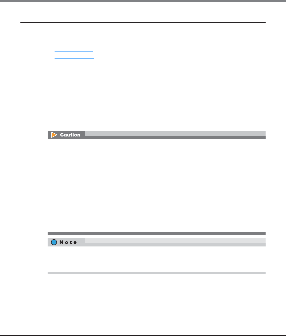
Chapter 9 Connectivity Management
9.2 Functions in the Action Area for Connectivity
ETERNUS Web GUI User’s Guide
Copyright 2013 FUJITSU LIMITED P2X0-1090-10ENZ0
414
9.2.1 Host Affinity Management
Host Affinity management provides the following functions:
•Create Host Affinity
•Delete Host Affinity
•Modify Host Affinity
9.2.1.1 Create Host Affinity
This function creates a new host affinity.
When "Host Group - CA Port Group" is selected for "Target Connection", specify the existing "Host Group", "CA
Port Group", and "LUN Group" settings. When "Host - CA Port" is selected for "Target Connection", select the
existing "Host", "CA Port", "and "LUN Group" settings.
The host accesses a volume via a defined path. Configuring the host affinity can limit the volumes which the
host can recognize.
•The maximum number of connectable hosts (the number of HBAs) per CA port is 256.
•If a host group has been specified in the "Host Group" field of host affinity, all the member ports of the
assigned "CA Port Group" have the affinity mode configured "ON".
•If "All (all hosts)" has been specified in the "Host Group" field of host affinity, all the member ports of the
assigned "CA Port Group" have the affinity mode configured "OFF".
•When one port is registered in several CA port groups, and the affinity setting has been configured on one
of the CA port groups including the corresponding port, the affinity setting is configured on all the CA port
groups, which include the corresponding port, and also on the member ports.
•CA port groups without a host affinity setting can be used for creating a host affinity regardless of
whether the affinity mode is enabled (ON) or disabled (OFF).
•CA ports without a host affinity setting can be used for creating a host affinity regardless of whether the
affinity mode is enabled (ON) or disabled (OFF).
•A host can be a member of several host groups. In addition, a CA port can be a member of several CA port
groups. However, only one LUN group can be allocated to host and port combinations when configuring
host affinity.
•To change the settings of the host affinities, refer to "9.2.1.3 Modify Host Affinity" (page 428).
•Host groups with the host interface "FCoE" can configure host affinity with CA port groups with CA types
"FC" or "FCoE".
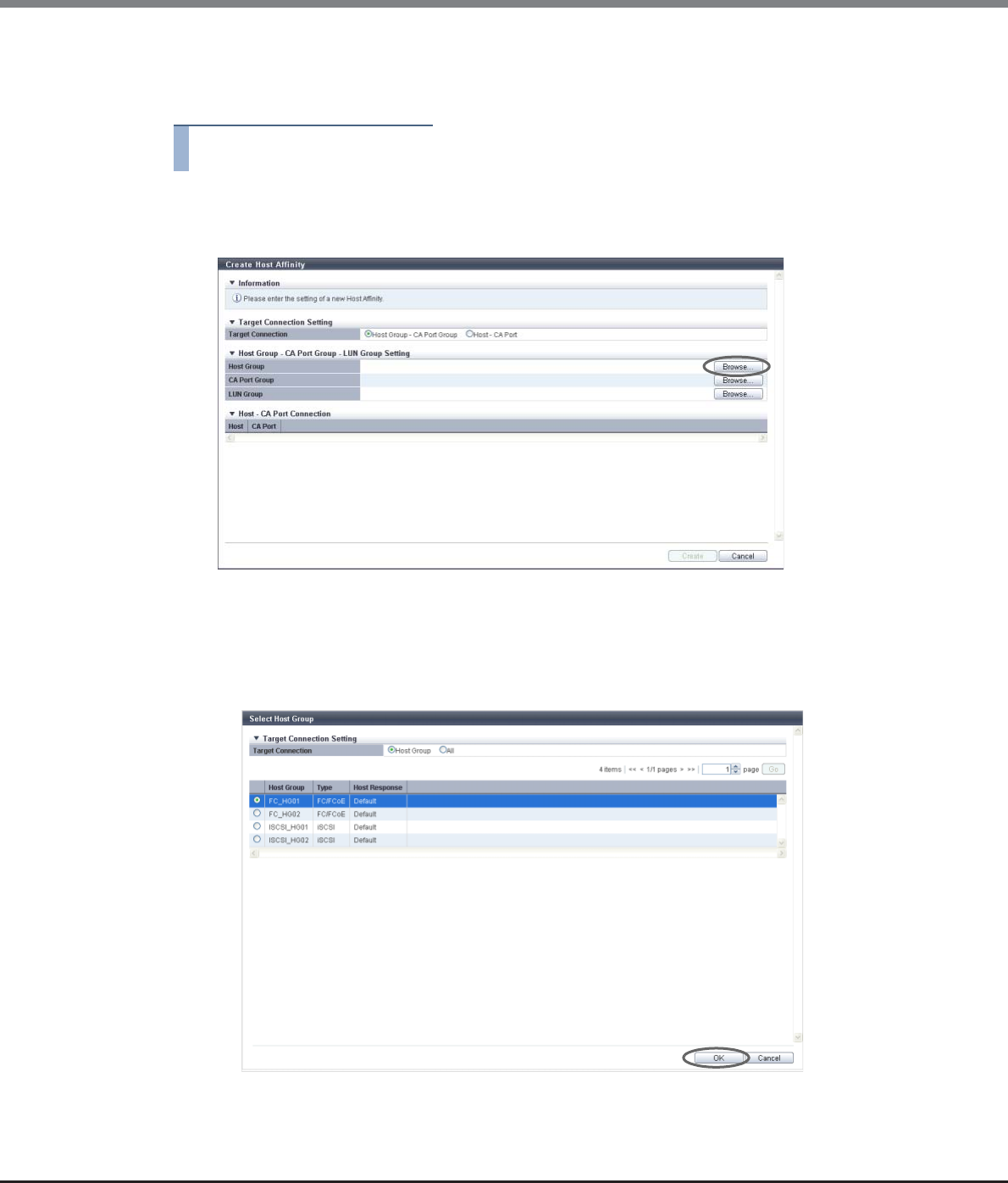
Chapter 9 Connectivity Management
9.2 Functions in the Action Area for Connectivity
ETERNUS Web GUI User’s Guide
Copyright 2013 FUJITSU LIMITED P2X0-1090-10ENZ0
415
■When "Host Group - CA Port Group" is selected for "Target Connection"
The procedure to create a host affinity is as follows:
Procedure
1Click [Create Host Affinity] in [Action].
2Click the [Browse...] button for the host group.
→The [Select Host Group] screen appears.
3Select the connection target.
■When "Host Group" is selected
(1) Select a host group to configure a host affinity, and click the [OK] button.
→The display returns to the initial screen.

Chapter 9 Connectivity Management
9.2 Functions in the Action Area for Connectivity
ETERNUS Web GUI User’s Guide
Copyright 2013 FUJITSU LIMITED P2X0-1090-10ENZ0
416
■When "All" is selected
(1) Select a host response, and click the [OK] button.
→The display returns to the initial screen.
The following modifications are applied for the host response settings with firmware version V10L15
or later.
•"Others" is changed to "Default".
•"Windows EMPD", "Linux EMPD", and "Solaris EMPD" are deleted from the "Host Response" value.
However, these parameters are displayed if they are applied for host groups.
•The setting parameters for "Windows EMPD", "Linux EMPD", and "Solaris EMPD" are the same as
"Default".
To allow all of the hosts to recognize the LUN group, select "All" for "Target Connection" and then select
the host response. "All" is displayed in "All (host response name)" format.
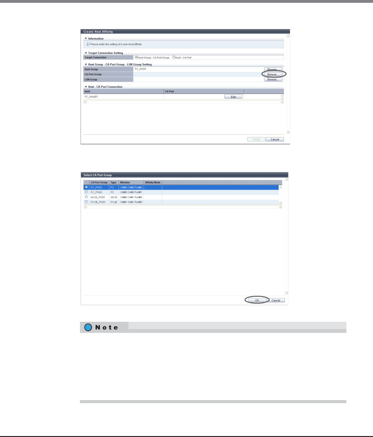
Chapter 9 Connectivity Management
9.2 Functions in the Action Area for Connectivity
ETERNUS Web GUI User’s Guide
Copyright 2013 FUJITSU LIMITED P2X0-1090-10ENZ0
417
4Click the [Browse...] button for the CA port group.
→The [Select CA Port Group] screen appears.
5Select a CA port group to configure a host affinity, and click the [OK] button.
→The display returns to the initial screen.
•If a specific host group has been selected in the "Host Group" field, CA port groups for which the
affinity mode is "OFF" are not displayed.
•If "All" has been selected in the "Host Group" field, CA port groups with any of the following
conditions are not displayed:
-The affinity mode is "ON"
-Member CA ports that used in other CA port groups
-CA port groups that are being used by other host affinities
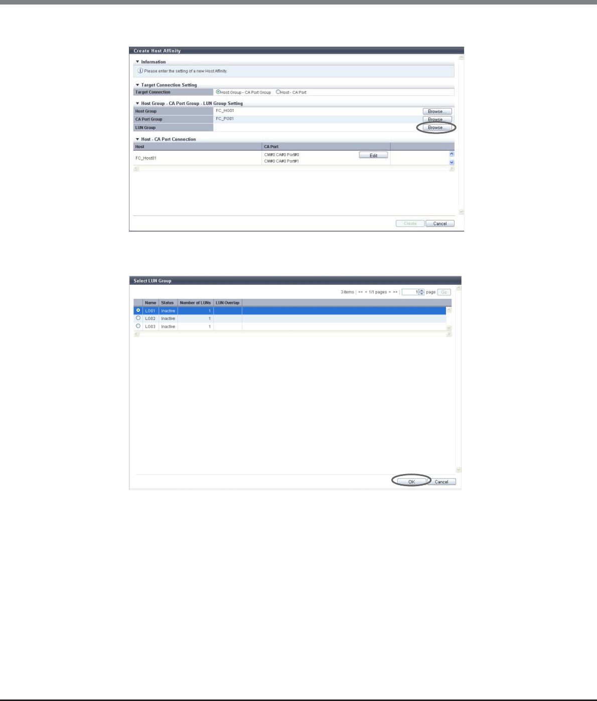
Chapter 9 Connectivity Management
9.2 Functions in the Action Area for Connectivity
ETERNUS Web GUI User’s Guide
Copyright 2013 FUJITSU LIMITED P2X0-1090-10ENZ0
418
6Click the [Browse...] button for the LUN group.
→The [Select LUN Group] screen appears.
7Select a LUN group to configure a host affinity, and click the [OK] button.
→The display returns to the initial screen.
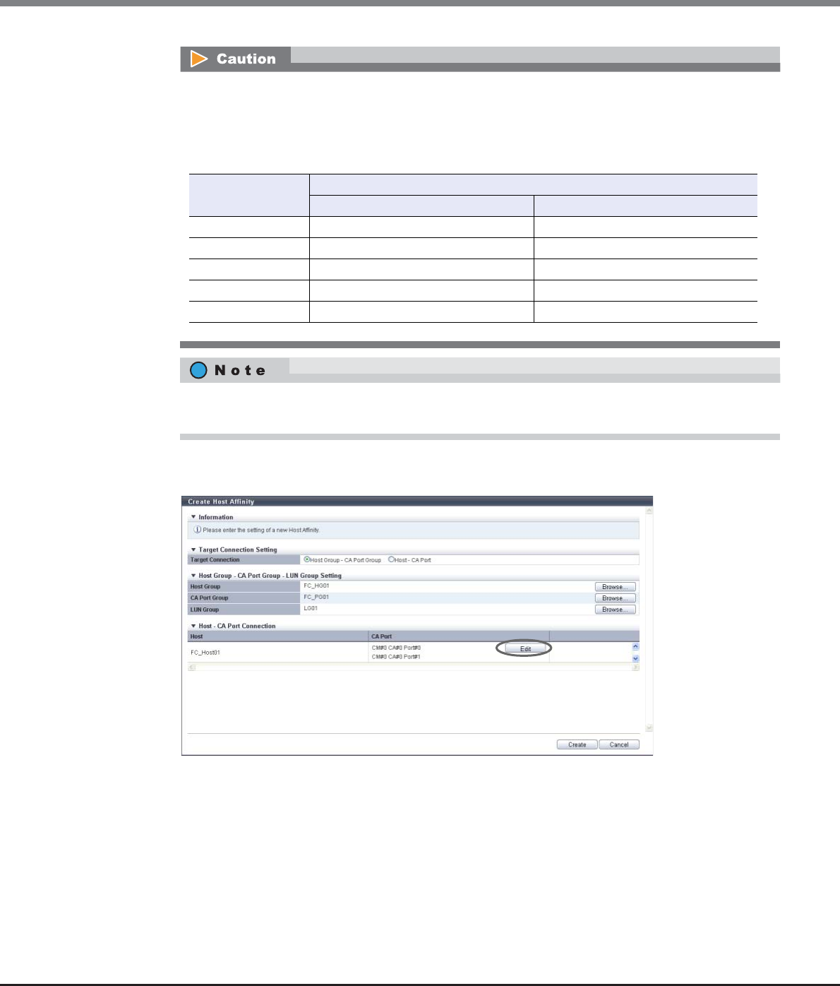
Chapter 9 Connectivity Management
9.2 Functions in the Action Area for Connectivity
ETERNUS Web GUI User’s Guide
Copyright 2013 FUJITSU LIMITED P2X0-1090-10ENZ0
419
8To edit the path between a host and a CA port, click the [Edit] button for the path to be
edited.
→The [Select CA Port] screen appears.
The LUN range that can be recognized from a host depends on the "Host Specific Mode" setting of the
host response that is applied to the selected "Host Group" (specific host group) or "All" (all of the
hosts). A host does not recognize any LUNs that are not included within the following ranges.
The following table shows the LUN range that can be recognized from a host for each "Host Specific
Mode".
When "All" is selected for "Host Group", the LUN groups in which LUNs are specified from LUN#512
onward are not displayed.
Host Specific Mode LUN range that can be recognized from a host
When "Host Group" is selected When "All" is selected
Normal LUN#0 - LUN#255 LUN#0 - LUN#255
AIX Mode LUN#0 - LUN#511 LUN#0 - LUN#511
NR1000V Mode LUN#0 - LUN#511 LUN#0 - LUN#511
HP-UX Mode LUN#0 - LUN#1023 LUN#0 - LUN#511
BS2000 Mode LUN#0 - LUN#4095 LUN#0 - LUN#511
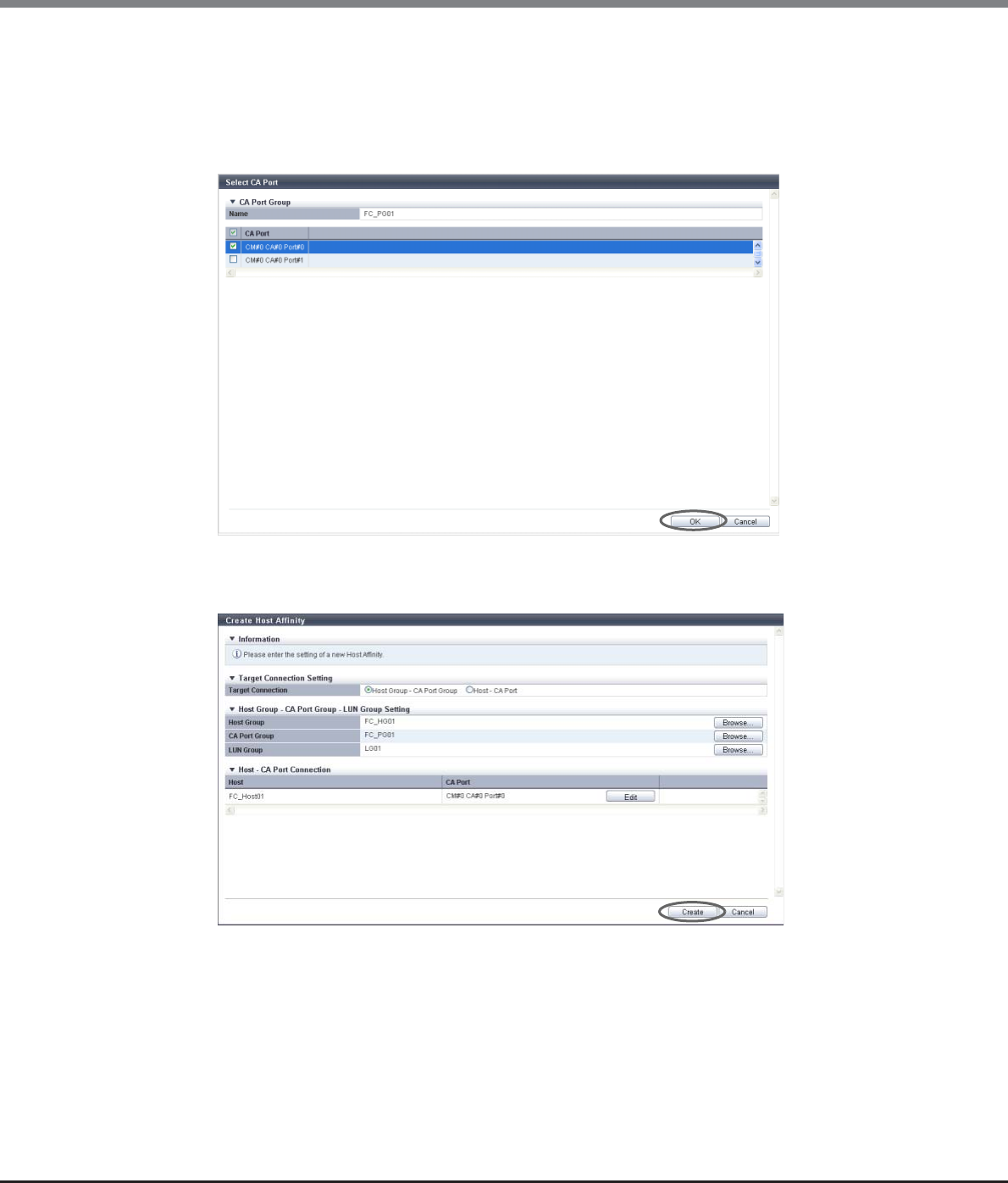
Chapter 9 Connectivity Management
9.2 Functions in the Action Area for Connectivity
ETERNUS Web GUI User’s Guide
Copyright 2013 FUJITSU LIMITED P2X0-1090-10ENZ0
420
9Select whether to enable or disable the path between a host and a CA port, and click the
[OK] button.
•Checkbox to select paths
To enable the path between a host and a CA port, select the checkbox of the CA port.
To disable the path between a host and a CA port, clear the checkbox of the CA port.
10 Confirm the host affinity setting and the path between the host and the CA port, click the
[Create] button.
→A confirmation screen appears.
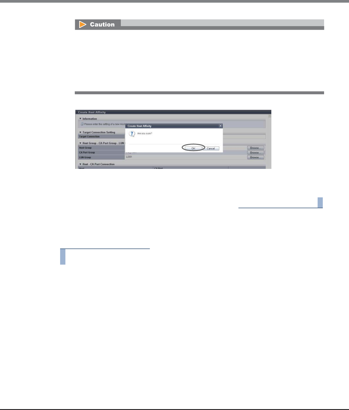
Chapter 9 Connectivity Management
9.2 Functions in the Action Area for Connectivity
ETERNUS Web GUI User’s Guide
Copyright 2013 FUJITSU LIMITED P2X0-1090-10ENZ0
421
11 Click the [OK] button.
→The host affinity creation starts.
12 Click the [Done] button to return to the [Connectivity] screen.
End of procedure
■When "Host - CA Port" is selected for "Target Connection"
The procedure to create a host affinity is as follows:
Procedure
1Click [Create Host Affinity] in [Action].
An error screen appears in the following conditions:
•When the host interface type of the host group and the CA type of the CA port group do not match
Note that the CA types of "FCoE" and "FC" are regarded as the same CA type.
•When the number of host affinities exceeds the maximum number per ETERNUS DX Disk storage
system
•When the number of hosts exceeds the maximum number per CA port
•When a host cannot recognize some LUNs
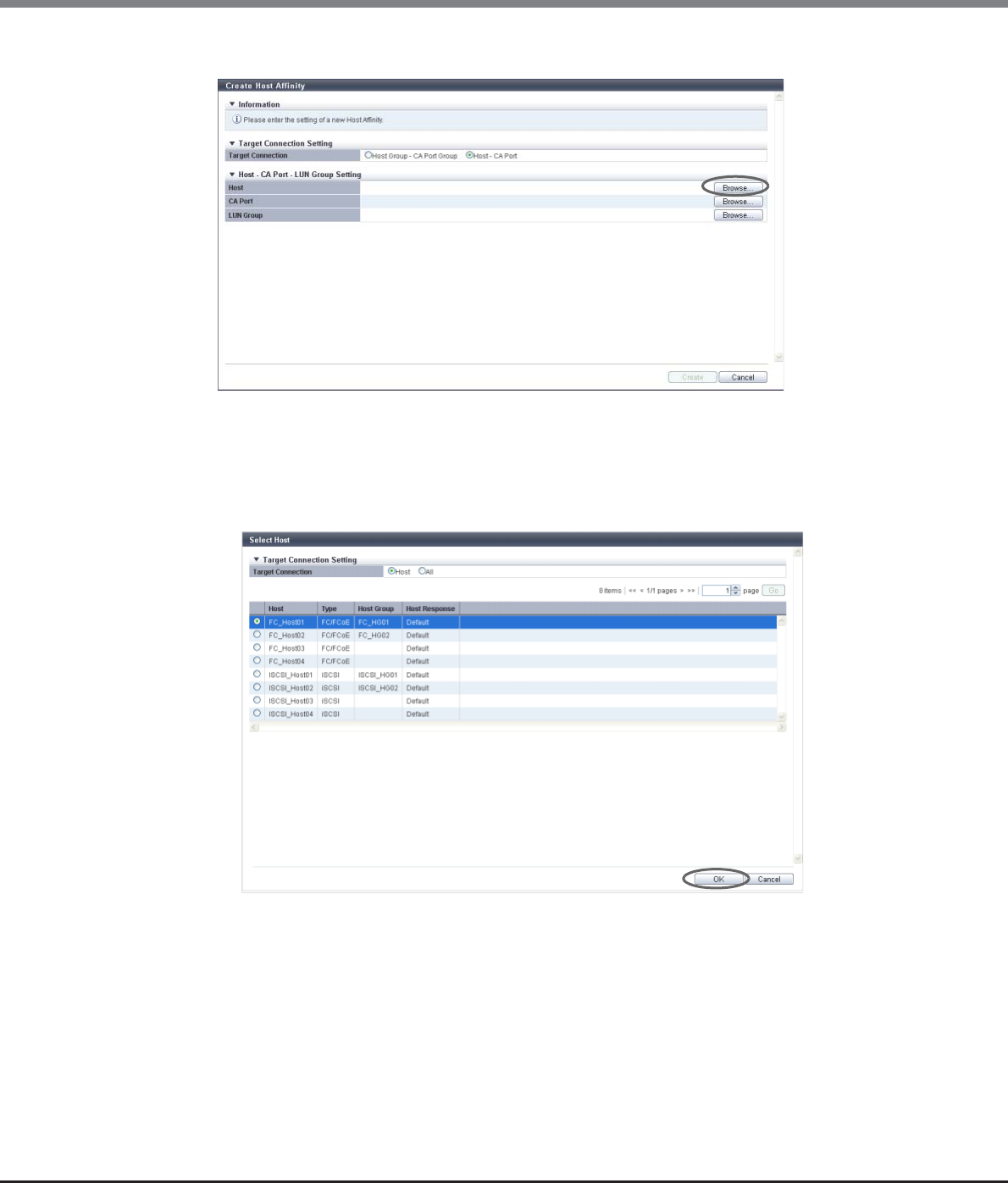
Chapter 9 Connectivity Management
9.2 Functions in the Action Area for Connectivity
ETERNUS Web GUI User’s Guide
Copyright 2013 FUJITSU LIMITED P2X0-1090-10ENZ0
422
2Click the [Browse...] button for the host.
→The [Select Host] screen appears.
3Select the connection target.
■When "Host" is selected
(1) Select a host to configure a host affinity, and click the [OK] button.
→The display returns to the initial screen.
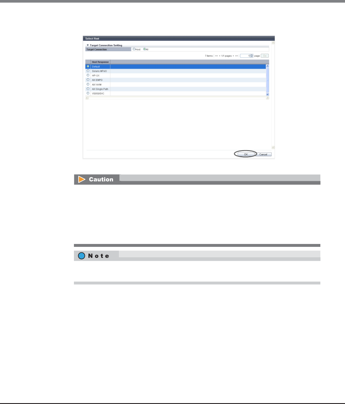
Chapter 9 Connectivity Management
9.2 Functions in the Action Area for Connectivity
ETERNUS Web GUI User’s Guide
Copyright 2013 FUJITSU LIMITED P2X0-1090-10ENZ0
423
■When "All" is selected
(1) Select a host response, and click the [OK] button.
→The display returns to the initial screen.
The following modifications are applied for the host response settings with firmware version V10L15
or later.
•"Others" is changed to "Default".
•"Windows EMPD", "Linux EMPD", and "Solaris EMPD" are deleted from the "Host Response" value.
However, these parameters are displayed if they are applied for host groups.
•The setting parameters for "Windows EMPD", "Linux EMPD", and "Solaris EMPD" are the same as
"Default".
To allow all of the hosts to recognize the LUN group, select "All" for "Target Connection" and then select
the host response. "All" is displayed in "All (host response name)" format.
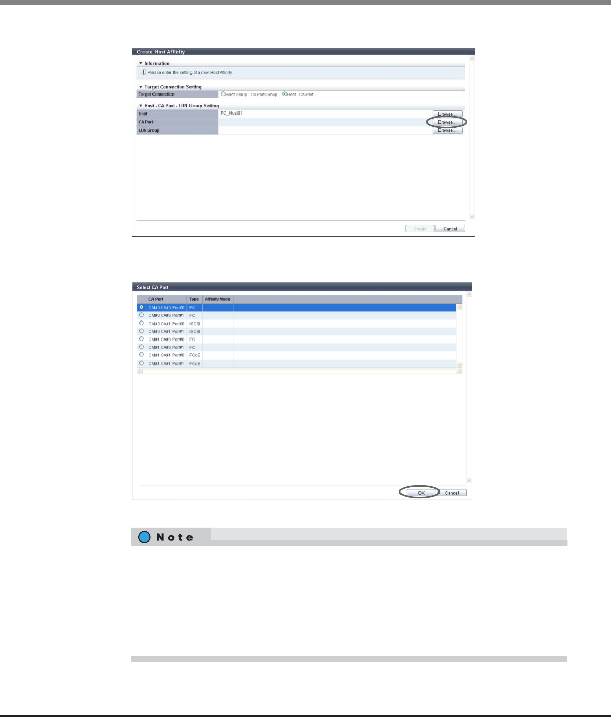
Chapter 9 Connectivity Management
9.2 Functions in the Action Area for Connectivity
ETERNUS Web GUI User’s Guide
Copyright 2013 FUJITSU LIMITED P2X0-1090-10ENZ0
424
4Click the [Browse...] button for the CA port.
→The [Select CA Port] screen appears.
5Select a CA port to configure a host affinity, and click the [OK] button.
→The display returns to the initial screen.
•If a specific host has been selected in the "Host" field, CA ports for which the affinity mode is "OFF"
are not displayed.
•If "All" has been selected in the "Host" field, CA ports with any of the following conditions are not
displayed:
-The affinity mode is "ON"
-The CA ports are used in the CA port group
-The CA port is used by another host affinity
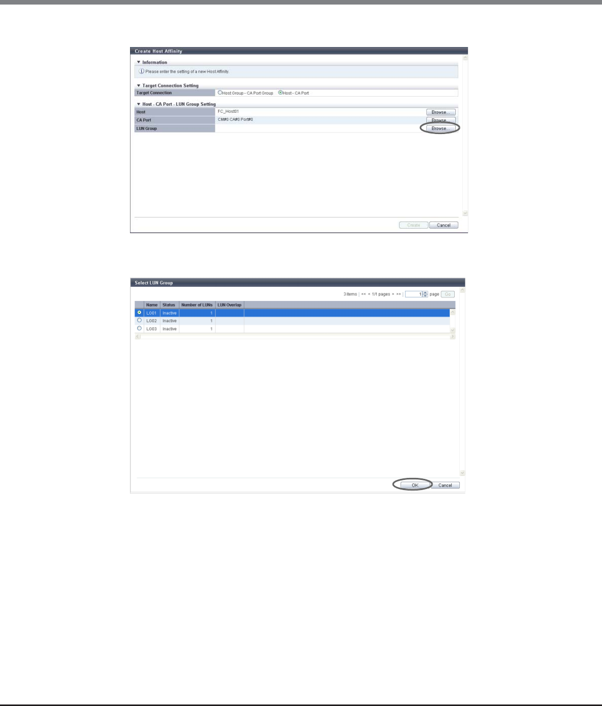
Chapter 9 Connectivity Management
9.2 Functions in the Action Area for Connectivity
ETERNUS Web GUI User’s Guide
Copyright 2013 FUJITSU LIMITED P2X0-1090-10ENZ0
425
6Click the [Browse...] button for the LUN group.
→The [Select LUN Group] screen appears.
7Select a LUN group to configure a host affinity, and click the [OK] button.
→The display returns to the initial screen.
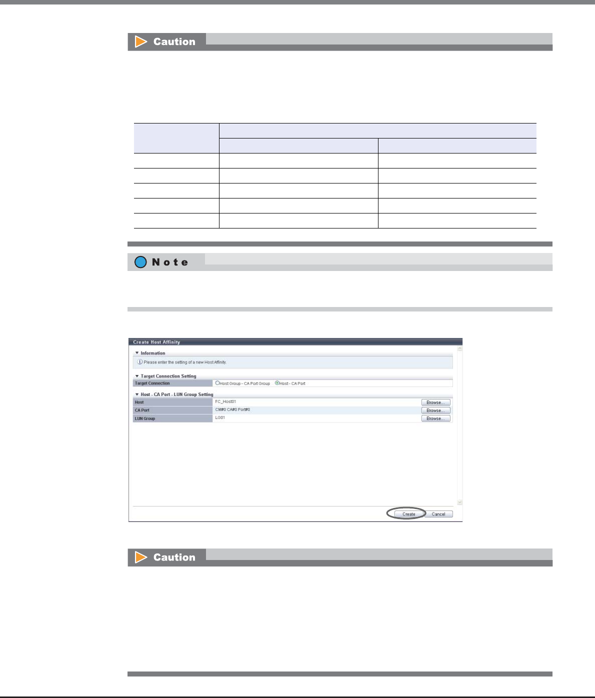
Chapter 9 Connectivity Management
9.2 Functions in the Action Area for Connectivity
ETERNUS Web GUI User’s Guide
Copyright 2013 FUJITSU LIMITED P2X0-1090-10ENZ0
426
8After confirming the host affinity settings, click the [Create] button.
→A confirmation screen appears.
The LUN range that can be recognized from a host depends on the "Host Specific Mode" setting of the
host response that is applied to the selected "Host" (specific host) or "All" (all of the hosts). A host
does not recognize any LUNs that are not included within the following ranges.
The following table shows the LUN range that can be recognized from a host for each "Host Specific
Mode".
When "All" is selected for "Host", the LUN groups in which LUNs are specified from LUN#512 onward
are not displayed.
An error screen appears in the following conditions:
•When the host interface type of the host and the CA type of the CA port do not match
Note that the CA types of "FCoE" and "FC" are regarded as the same CA type.
•When the number of host affinities exceeds the maximum number per ETERNUS DX Disk storage
system
•When the number of hosts exceeds the maximum number per CA port
•When a host cannot recognize some LUNs
Host Specific Mode LUN range that can be recognized from a host
When "Host" is selected When "All" is selected
Normal LUN#0 - LUN#255 LUN#0 - LUN#255
AIX Mode LUN#0 - LUN#511 LUN#0 - LUN#511
NR1000V Mode LUN#0 - LUN#511 LUN#0 - LUN#511
HP-UX Mode LUN#0 - LUN#1023 LUN#0 - LUN#511
BS2000 Mode LUN#0 - LUN#4095 LUN#0 - LUN#511
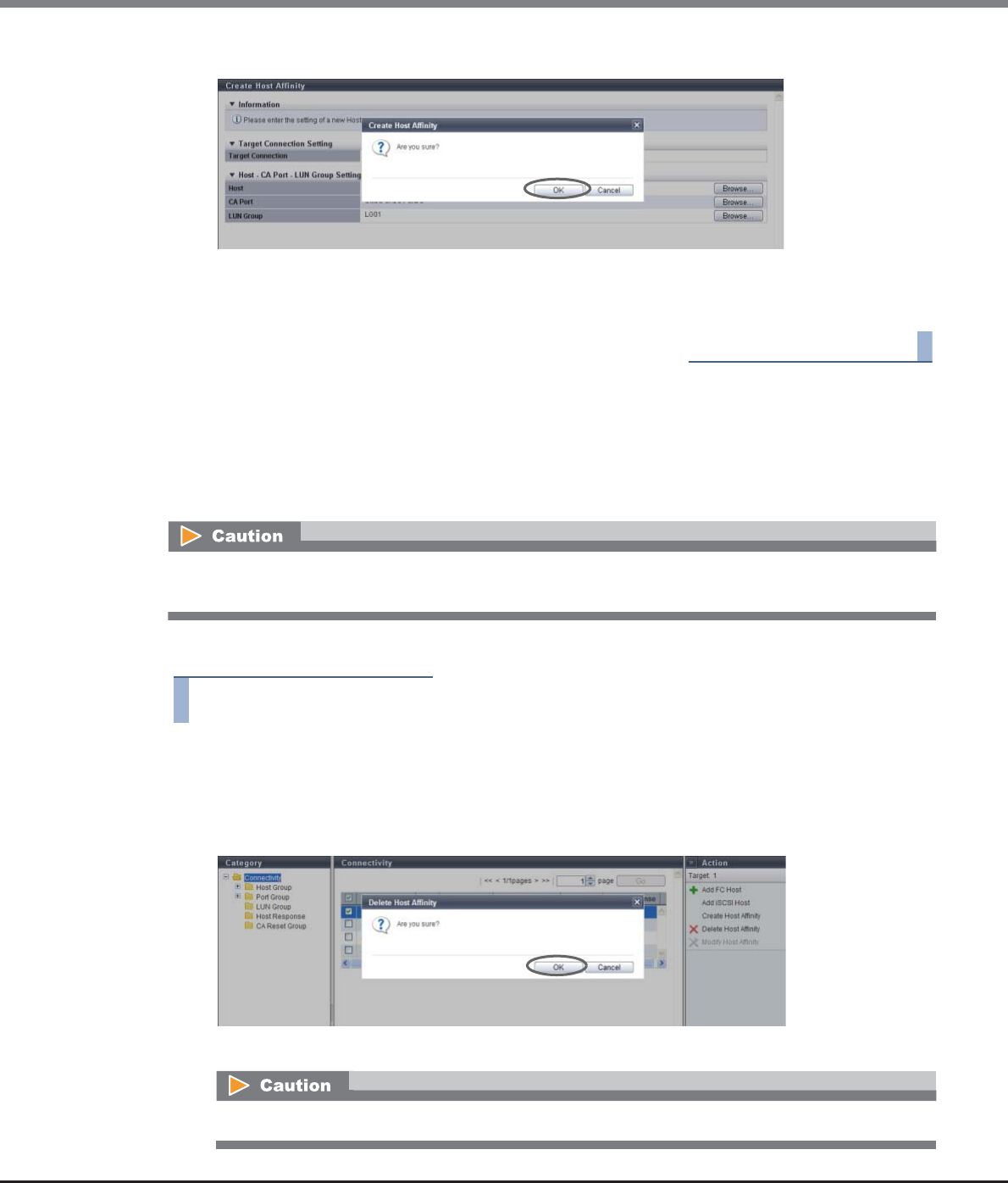
Chapter 9 Connectivity Management
9.2 Functions in the Action Area for Connectivity
ETERNUS Web GUI User’s Guide
Copyright 2013 FUJITSU LIMITED P2X0-1090-10ENZ0
427
9Click the [OK] button.
→The host affinity creation starts.
10 Click the [Done] button to return to the [Connectivity] screen.
End of procedure
9.2.1.2 Delete Host Affinity
This function deletes the registered host affinity in the ETERNUS DX Disk storage system.
When a host affinity is deleted, the paths between "Host Group", "CA Port Group", and "LUN Group" or the
paths between "Host", "CA Port", "and "LUN Group" are also deleted.
The procedure to delete a host affinity is as follows:
Procedure
1Select the host affinity to be deleted (multiple selections can be made) and click [Delete
Host Affinity] in [Action].
→A confirmation screen appears.
2Click the [OK] button.
→The deletion of the host affinity starts.
When deleting a host affinity, make sure to stop the access of the host which has been associated with the
host affinity to be deleted.
If the selected host affinity does not exist, an error screen appears.
Chapter 9 Connectivity Management
9.2 Functions in the Action Area for Connectivity
ETERNUS Web GUI User’s Guide
Copyright 2013 FUJITSU LIMITED P2X0-1090-10ENZ0
428
3Click the [Done] button to return to the [Connectivity] screen.
End of procedure
9.2.1.3 Modify Host Affinity
This function is used to perform the following modifications to the existing host affinity.
•Changing the "CA Port Group" or "CA Port" settings
•Changing the "LUN Group" setting
•Changing the "CA Ports in a CA Port Group" setting (Change the path between the host and the CA port)
•Changing the "Host Response" setting (only when "Host Group" or "Host" is "All")
Not only the path between the existing host and the CA port, but also the path between a host and a CA port,
which has been added after creating a host affinity, can be modified.
•The maximum number of connectable hosts (the number of HBAs) per CA port is 256.
•When modifying an active host affinity, make sure to stop the access of the host which has been
associated with the host affinity to be modified.
•When one port is registered in several CA port groups, and the affinity setting has been configured on one
of the CA port groups including the corresponding port, the affinity setting is configured on all the CA port
groups, which include the corresponding port, and also on the member ports.
•CA port groups without a host affinity setting can be used for creating a host affinity regardless of
whether the affinity mode is enabled (ON) or disabled (OFF).
•CA ports without a host affinity setting can be used for creating a host affinity regardless of whether the
affinity mode is enabled (ON) or disabled (OFF).
•A host can be a member of several host groups. In addition, a CA port can be a member of several CA port
groups. However, only one LUN group can be allocated to host and port combinations when changing
host affinity settings.
•When the procedure in "9.2.2.5 Modify Host Group" (page 463) is used to add a host to a host group, the
paths between the added host and all of the ports that are in the associated CA port group are
configured.
•When the procedure in "9.2.3.6 Modify CA Port Group" (page 528) is used to add a port to a CA port group,
the paths between all of the hosts in the host group and the added port are configured.
•Host groups with the host interface "FCoE" can configure host affinity with CA port groups with CA types
"FC" or "FCoE".
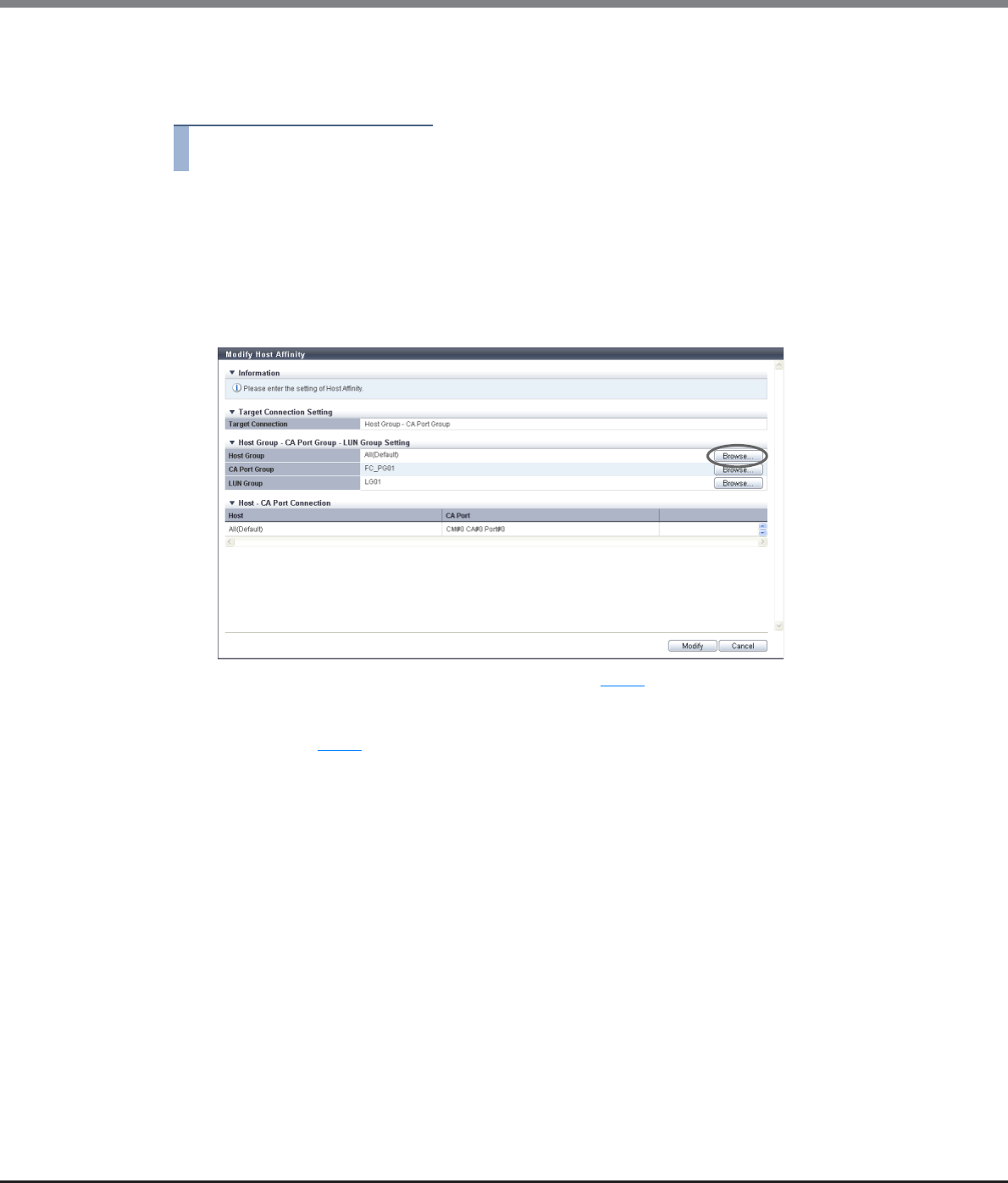
Chapter 9 Connectivity Management
9.2 Functions in the Action Area for Connectivity
ETERNUS Web GUI User’s Guide
Copyright 2013 FUJITSU LIMITED P2X0-1090-10ENZ0
429
■When selecting a host affinity for "Host Group - CA Port Group"
The procedure to modify a host affinity is as follows:
Procedure
1Select the host affinity to be modified, and click [Modify Host Affinity] in [Action].
2Check the display contents of the host group.
The next step that needs to be performed depends on the display contents of the host group.
■When the selected host group is "All (host response name)"
(1) Click the [Browse...] button.
→The [Select Host Group] screen appears. Proceed to Step 3.
■When the host group is not "All (host response name)"
→Proceed to Step 4.
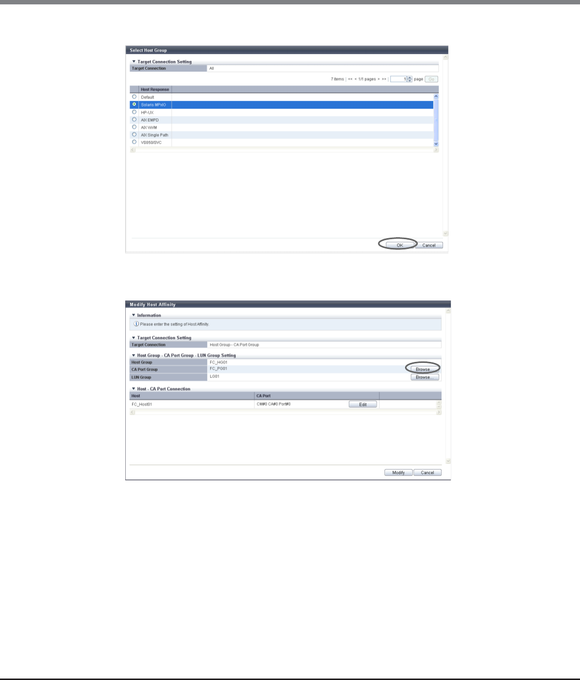
Chapter 9 Connectivity Management
9.2 Functions in the Action Area for Connectivity
ETERNUS Web GUI User’s Guide
Copyright 2013 FUJITSU LIMITED P2X0-1090-10ENZ0
430
3Select the host response that is to be assigned to all of the hosts and click the [OK] button.
→The display returns to the initial screen.
4Click the [Browse...] button for the CA port group.
→The [Select CA Port Group] screen appears.
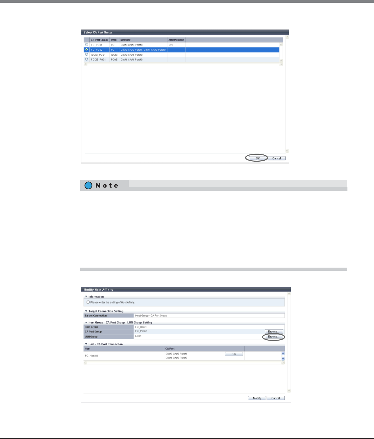
Chapter 9 Connectivity Management
9.2 Functions in the Action Area for Connectivity
ETERNUS Web GUI User’s Guide
Copyright 2013 FUJITSU LIMITED P2X0-1090-10ENZ0
431
5Select a CA port group to configure a host affinity, and click the [OK] button.
→The display returns to the initial screen.
6Click the [Browse...] button for the LUN group.
→The [Select LUN Group] screen appears.
•If a specific host group has been selected in the "Host Group" field, CA port groups with any of the
following conditions are not displayed:
-The affinity mode is "OFF"
-The CA port group is used by another host affinity
•If "All" has been selected in the "Host Group" field, CA port groups with any of the following
conditions are not displayed:
-The CA port group is used by another host affinity
-Member CA ports that used in other CA port groups

Chapter 9 Connectivity Management
9.2 Functions in the Action Area for Connectivity
ETERNUS Web GUI User’s Guide
Copyright 2013 FUJITSU LIMITED P2X0-1090-10ENZ0
432
7Select a LUN group to configure a host affinity, and click the [OK] button.
→The display returns to the initial screen.
•The LUN range that can be recognized from a host is determined by which of the following settings
is used. A host does not recognize any LUNs that are not included within the following ranges.
-The "Host Specific Mode" setting of the host response that is applied to "Host Group" (specific
host group) with the host affinity setting
-The "Host Specific Mode" setting of the host response that is applied to "All" (all of the hosts)
with the host affinity setting
-The "Host Specific Mode" setting of the host response that is newly applied to "All" (all of the
hosts) with the host affinity setting
•The following table shows the LUN range that can be recognized from a host for each "Host Specific
Mode".
When "All" is selected for "Host Group", the LUN groups in which LUNs are specified from LUN#512
onward are not displayed.
Host Specific Mode LUN range that can be recognized from a host
For "Host Group" For "All"
Normal LUN#0 - LUN#255 LUN#0 - LUN#255
AIX Mode LUN#0 - LUN#511 LUN#0 - LUN#511
NR1000V Mode LUN#0 - LUN#511 LUN#0 - LUN#511
HP-UX Mode LUN#0 - LUN#1023 LUN#0 - LUN#511
BS2000 Mode LUN#0 - LUN#4095 LUN#0 - LUN#511
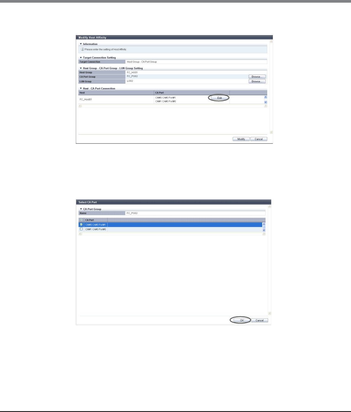
Chapter 9 Connectivity Management
9.2 Functions in the Action Area for Connectivity
ETERNUS Web GUI User’s Guide
Copyright 2013 FUJITSU LIMITED P2X0-1090-10ENZ0
433
8To edit the path between a host and a CA port, click the [Edit] button for the path to be
edited.
→The [Select CA Port] screen appears.
9Select whether to enable or disable the path between a host and a CA port, and click the
[OK] button.
•Checkbox to select paths
To enable the path between a host and a CA port, select the checkbox of the CA port.
To disable the path between a host and a CA port, clear the checkbox of the CA port.
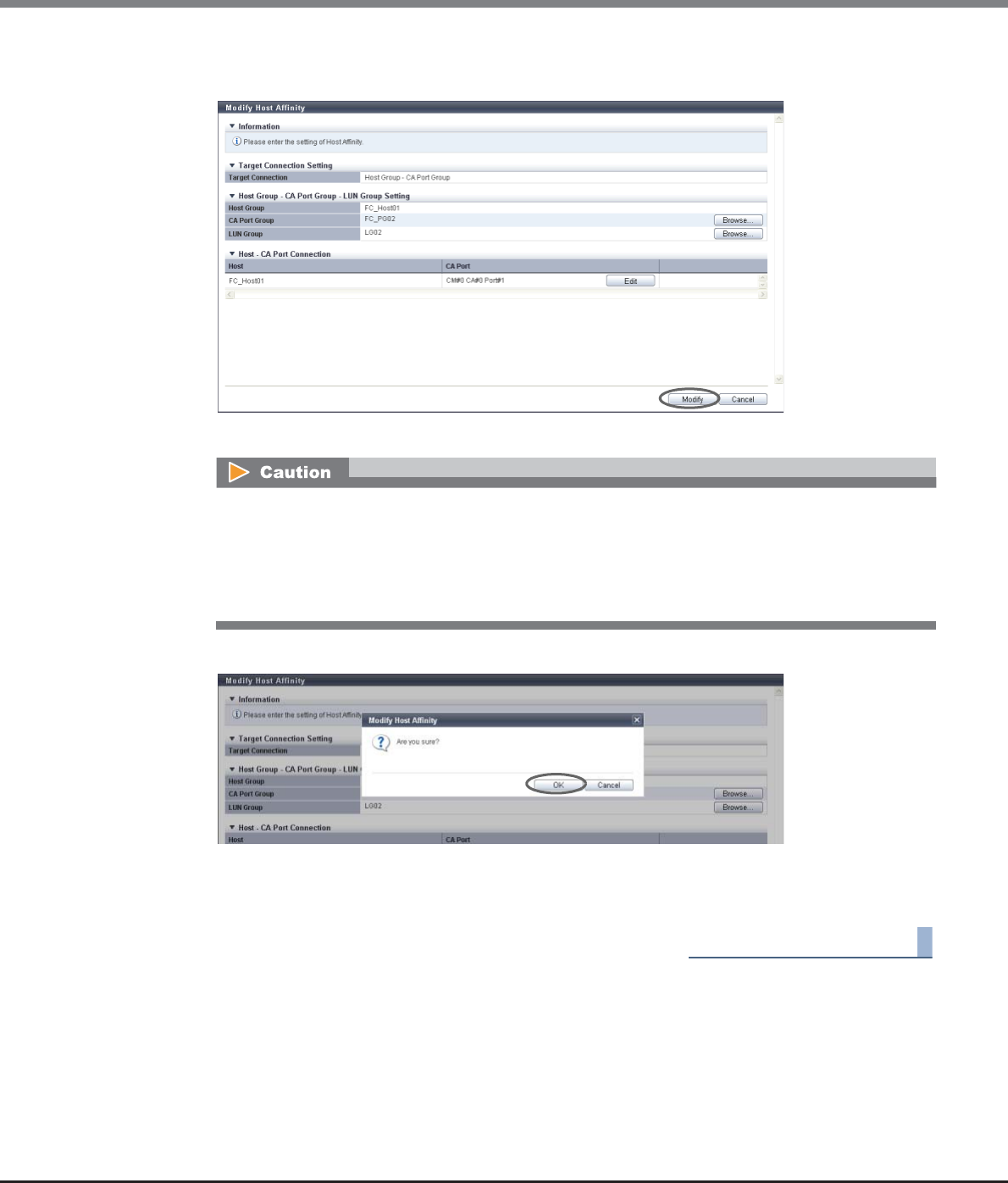
Chapter 9 Connectivity Management
9.2 Functions in the Action Area for Connectivity
ETERNUS Web GUI User’s Guide
Copyright 2013 FUJITSU LIMITED P2X0-1090-10ENZ0
434
10 Confirm the modified host affinity setting and the path between the host and the CA port,
click the [Modify] button.
→A confirmation screen appears.
11 Click the [OK] button.
→The modification of the host affinity starts.
12 Click the [Done] button to return to the [Connectivity] screen.
End of procedure
An error screen appears in the following conditions:
•When the host interface type of the host group and the CA type of the CA port group do not match
Note that the CA types of "FCoE" and "FC" are regarded as the same CA type.
•When the number of hosts exceeds the maximum number per CA port
•When a host cannot recognize some LUNs
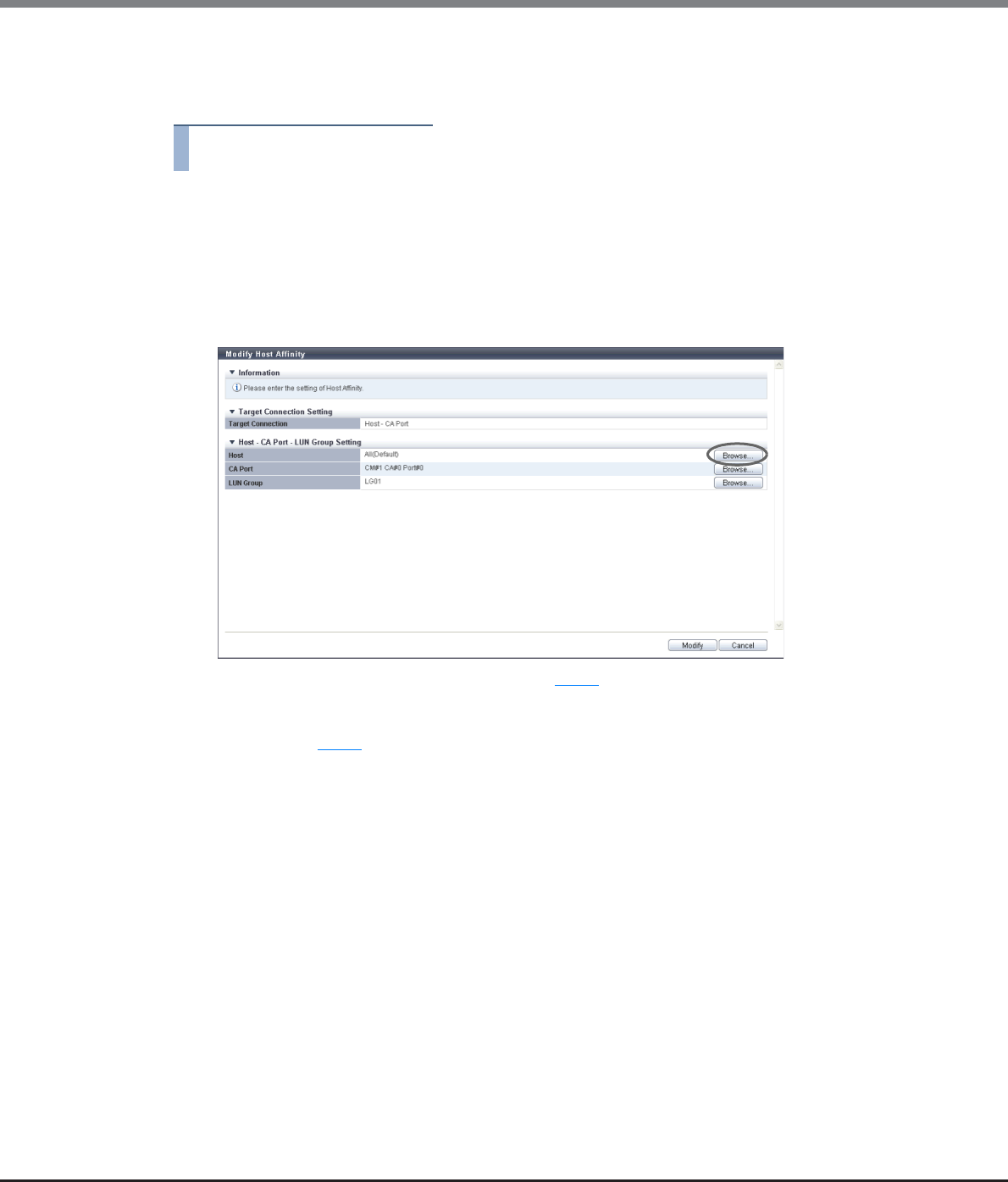
Chapter 9 Connectivity Management
9.2 Functions in the Action Area for Connectivity
ETERNUS Web GUI User’s Guide
Copyright 2013 FUJITSU LIMITED P2X0-1090-10ENZ0
435
■When selecting a host affinity for "Host - CA Port"
The procedure to modify a host affinity is as follows:
Procedure
1Select the host affinity to be modified, and click [Modify Host Affinity] in [Action].
2Check the display contents of the host.
The next step that needs to be performed depends on the display contents of the host.
■When the selected host is "All (host response name)"
(1) Click the [Browse...] button.
→The [Select Host] screen appears. Proceed to Step 3.
■When the host is not "All (host response name)"
→Proceed to Step 4.
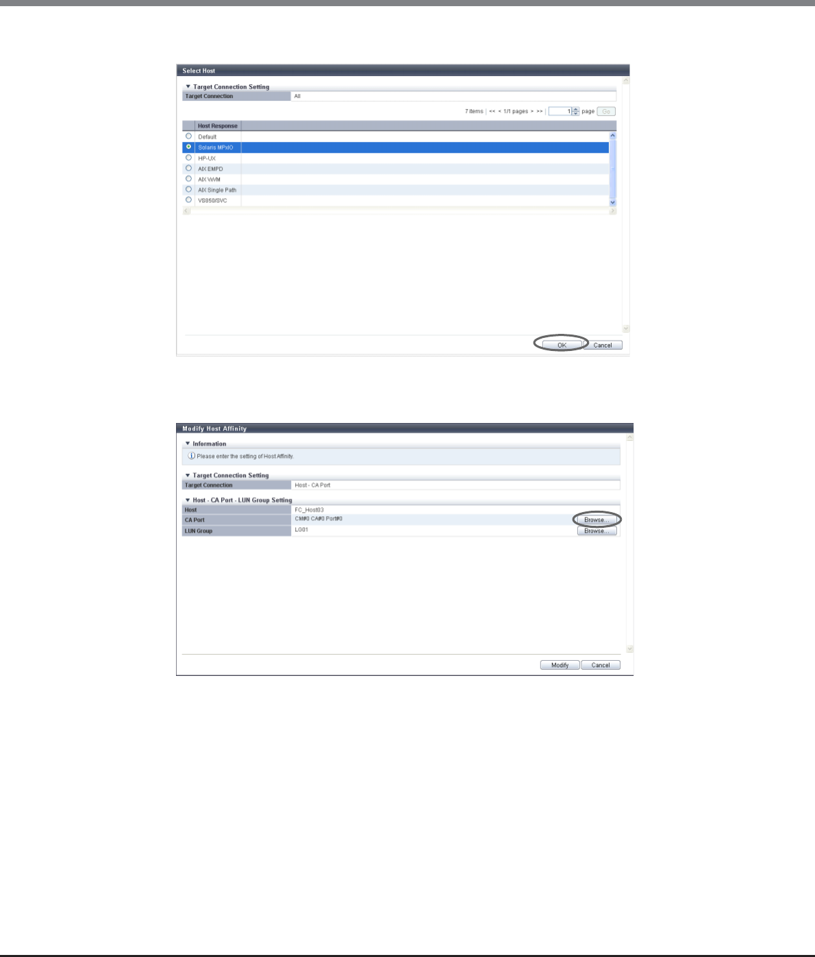
Chapter 9 Connectivity Management
9.2 Functions in the Action Area for Connectivity
ETERNUS Web GUI User’s Guide
Copyright 2013 FUJITSU LIMITED P2X0-1090-10ENZ0
436
3Select the host response that is to be assigned to all of the hosts and click the [OK] button.
→The display returns to the initial screen.
4Click the [Browse...] button for the CA port.
→The [Select CA Port] screen appears.
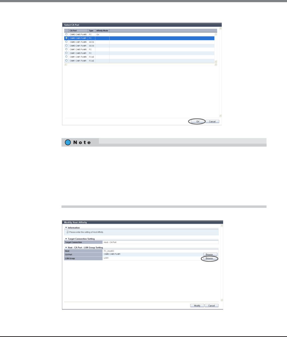
Chapter 9 Connectivity Management
9.2 Functions in the Action Area for Connectivity
ETERNUS Web GUI User’s Guide
Copyright 2013 FUJITSU LIMITED P2X0-1090-10ENZ0
437
5Select a CA port to configure a host affinity, and click the [OK] button.
→The display returns to the initial screen.
6Click the [Browse...] button for the LUN group.
→The [Select LUN Group] screen appears.
•If a specific host has been selected in the "Host" field, CA ports with any of the following conditions
are not displayed:
-The affinity mode is "OFF"
-The CA port is used by another host affinity
•If "All" has been selected in the "Host" field, CA ports with any of the following conditions are not
displayed:
-The CA port is used by another host affinity
-The CA port is used in the CA port group
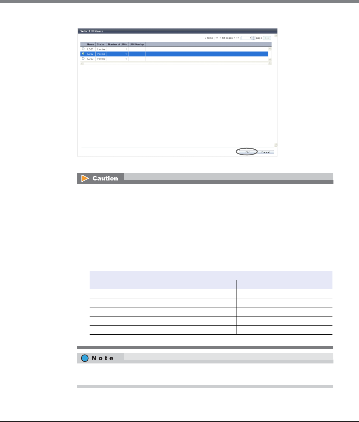
Chapter 9 Connectivity Management
9.2 Functions in the Action Area for Connectivity
ETERNUS Web GUI User’s Guide
Copyright 2013 FUJITSU LIMITED P2X0-1090-10ENZ0
438
7Select a LUN group to configure a host affinity, and click the [OK] button.
→The display returns to the initial screen.
•The LUN range that can be recognized from a host is determined by which of the following settings
is used. A host does not recognize any LUNs that are not included within the following ranges.
-The "Host Specific Mode" setting of the host response that is applied to "Host" (specific host)
with the host affinity setting
-The "Host Specific Mode" setting of the host response that is applied to "All" (all of the hosts)
with the host affinity setting
-The "Host Specific Mode" setting of the host response that is newly applied to "All" (all of the
hosts) with the host affinity setting
•The following table shows the LUN range that can be recognized from a host for each "Host Specific
Mode".
When "All" is selected for "Host", the LUN groups in which LUNs are specified from LUN#512 onward
are not displayed.
Host Specific Mode LUN range that can be recognized from a host
For "Host" For "All"
Normal LUN#0 - LUN#255 LUN#0 - LUN#255
AIX Mode LUN#0 - LUN#511 LUN#0 - LUN#511
NR1000V Mode LUN#0 - LUN#511 LUN#0 - LUN#511
HP-UX Mode LUN#0 - LUN#1023 LUN#0 - LUN#511
BS2000 Mode LUN#0 - LUN#4095 LUN#0 - LUN#511
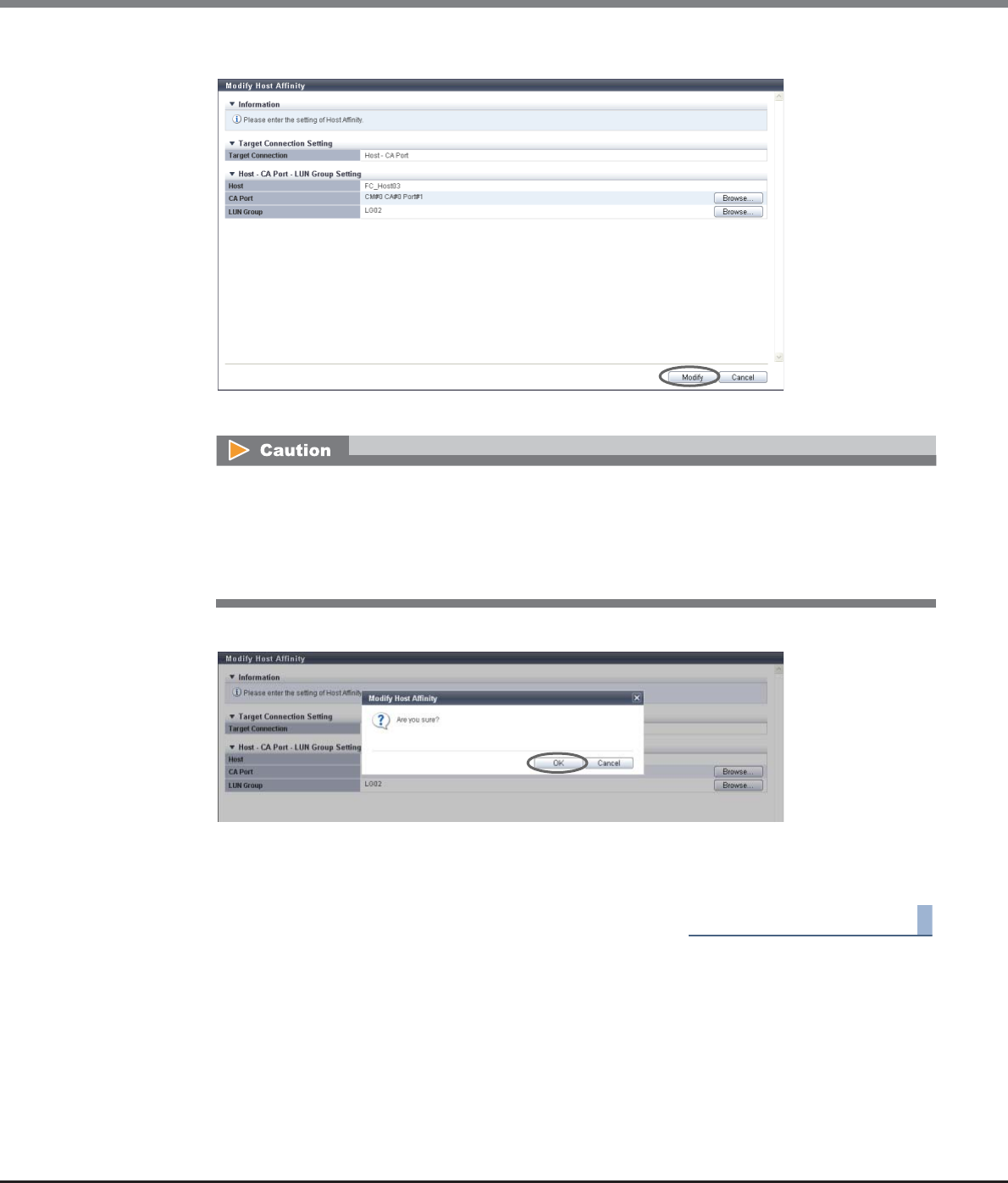
Chapter 9 Connectivity Management
9.2 Functions in the Action Area for Connectivity
ETERNUS Web GUI User’s Guide
Copyright 2013 FUJITSU LIMITED P2X0-1090-10ENZ0
439
8After confirming the host affinity settings, click the [Modify] button.
→A confirmation screen appears.
9Click the [OK] button.
→The modification of the host affinity starts.
10 Click the [Done] button to return to the [Connectivity] screen.
End of procedure
An error screen appears in the following conditions:
•When the host interface type of the host and the CA type of the CA port do not match
Note that the CA types of "FCoE" and "FC" are regarded as the same CA type.
•When the number of hosts exceeds the maximum number per CA port
•When a host cannot recognize some LUNs

Chapter 9 Connectivity Management
9.2 Functions in the Action Area for Connectivity
ETERNUS Web GUI User’s Guide
Copyright 2013 FUJITSU LIMITED P2X0-1090-10ENZ0
440
9.2.2 Host Group Management
Host group management provides the following functions:
•Add FC/FCoE Host Group
•Add iSCSI Host Group
•Add SAS Host Group
•Delete Host Group
•Modify Host Group
•Modify Host Group (FC/FCoE)
•Modify Host Group (iSCSI)
•Modify Host Group (SAS)
•Add FC/FCoE Host
•Add iSCSI Host
•Add SAS Host
•Delete FC/FCoE Host
•Delete iSCSI Host
•Delete SAS Host
•Modify FC/FCoE Host
•Modify iSCSI Host
•Modify SAS Host
9.2.2.1 Add FC/FCoE Host Group
This function creates a new FC host group and registers which hosts are members of this group.
An FC host group uses FC or FCoE as the interface type, and groups the hosts (HBAs), which access the same
LUN group. This function configures Host Affinity settings for each FC host group.
The number of host groups and hosts that can be registered
*1: The total number of host groups irrespective of the interface types.
*2: The total number of hosts irrespective of the interface types.
Model Number of host
groups (*1) per
storage system
Number of hosts
(HBAs) (*2) per
storage system
Number of hosts
(HBAs)
per CA port
Number of hosts
(HBAs)
per host group
ETERNUS DX80 S2 128 1024 256 8
ETERNUS DX90 S2
ETERNUS DX410 S2
ETERNUS DX440 S2
ETERNUS DX8100 S2
ETERNUS DX8700 S2 512 8192 64
Chapter 9 Connectivity Management
9.2 Functions in the Action Area for Connectivity
ETERNUS Web GUI User’s Guide
Copyright 2013 FUJITSU LIMITED P2X0-1090-10ENZ0
441
The procedure to create an FC host group is as follows:
Procedure
1Click [Add FC/FCoE Host Group] in [Action].
•Registration of the host is necessary to create a host group. Create a new host group when registering a
host with GUI by using this function.
•A host can be a member of several host groups. However, only one LUN group can be allocated to host
and port combinations when configuring host affinity.
•To assign an appropriate host response to a created host group, refer to "User's Guide -Server Connection-
" for each OS type. The host response configures the operation mode that is appropriate for the host.
If an appropriate host response is not configured to the host group, the path may not be switched
correctly or the volume may not be recognized correctly.
•The host response that is specified for a host group is applied all the member hosts in the target group.
When a host belongs to multiple host groups, the same host response must be applied for all the groups
to which the target host belongs. When a host that already belongs to an existing host group is added to
a newly created host group, the host response of the new host group is applied to the host. The host
response of the existing host group to which the target host belongs is also changed. Refer to "Example
of changing the host response when adding a host group" (page 447) for details.
•The name of the [Add FC/FCoE Host] function, which creates a new FC host group and registers the mem-
ber hosts, has changed with firmware version V10L50. The [Add FC/FCoE Host] function is now called the
[Add FC/FCoE Host Group] function.
•To change the settings of the host groups, use the procedure in "9.2.2.5 Modify Host Group" (page 463).
•To add a port to an existing host group, use the procedure in "9.2.2.5 Modify Host Group" (page 463).
•To change the host name or WWN, use the procedure in "9.2.2.15 Modify FC/FCoE Host" (page 507).
•An FC host and an FCoE host can be members of the same host group. Both "FC host" and "FCoE host" are
abbreviated as "FC host" in this section.
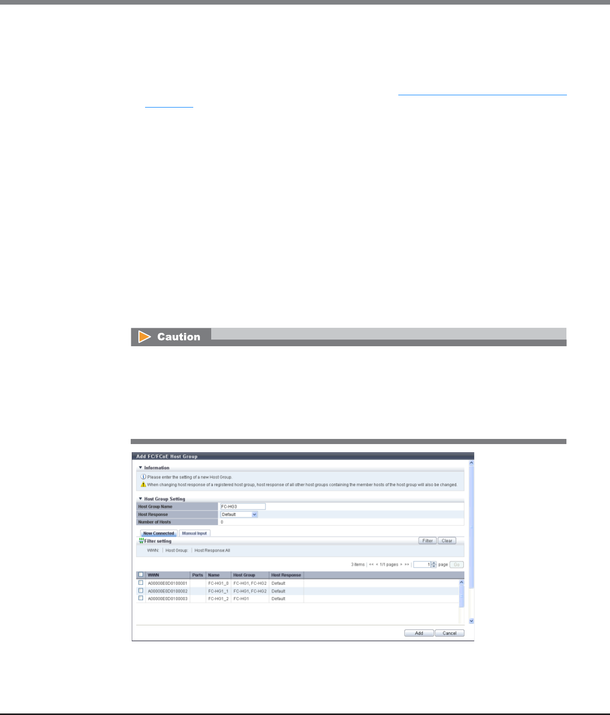
Chapter 9 Connectivity Management
9.2 Functions in the Action Area for Connectivity
ETERNUS Web GUI User’s Guide
Copyright 2013 FUJITSU LIMITED P2X0-1090-10ENZ0
442
2Input a host group name to be created, and select a host response to be assigned to the
host group.
•Host Group Name
Specify the host group name.
An existing host group name cannot be specified. Refer to "Naming conventions for adding hosts"
(page 994) for details.
The following input conditions apply:
-Up to 16 alphanumeric characters and symbols (except ", (comma)" and "?")
-Space
•Host Response
Select a host response to be assigned to a host group.
The host response list created in the ETERNUS DX Disk storage system is displayed.
-Solaris MPxIO
-HP-UX
-AIX EMPD (*1)
-AIX VxVM
-AIX Single Path
-VS850/SVC
-Host responses created in the ETERNUS DX Disk storage system
-Default
*1: EMPD: ETERNUS Multipath Driver
The following modifications are applied for the host response settings with firmware version V10L15
or later.
•"Others" is changed to "Default".
•"Windows EMPD", "Linux EMPD", and "Solaris EMPD" are deleted from the "Host Response" value.
•The setting parameters for "Windows EMPD", "Linux EMPD", and "Solaris EMPD" are the same as
"Default".
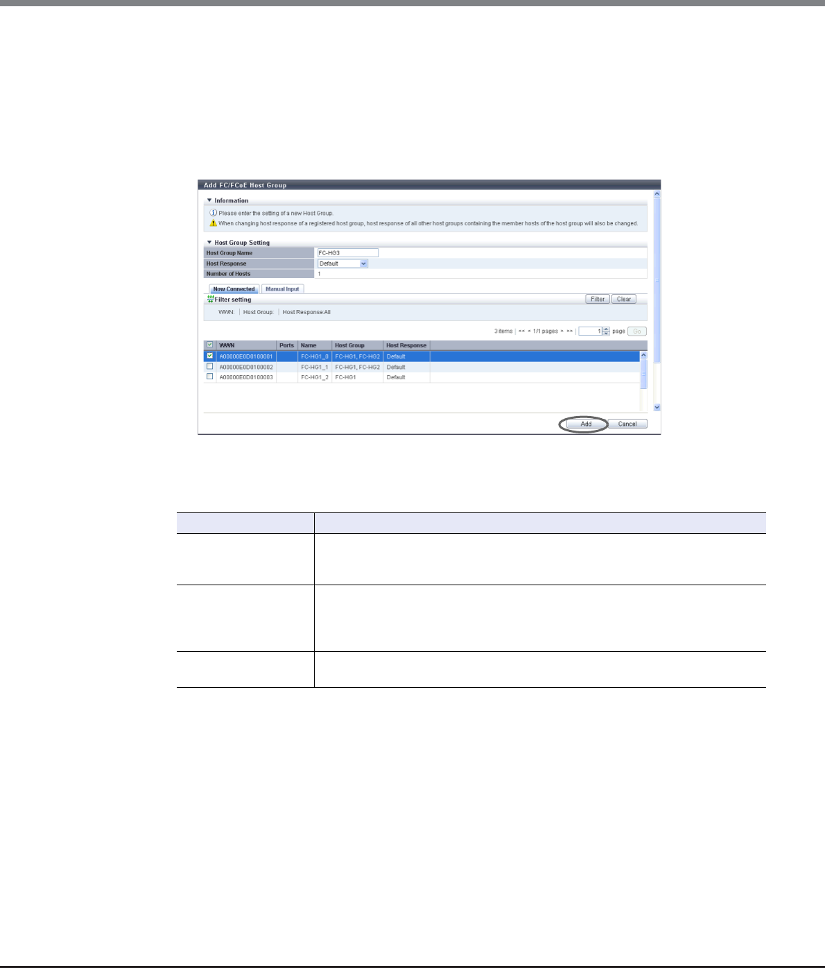
Chapter 9 Connectivity Management
9.2 Functions in the Action Area for Connectivity
ETERNUS Web GUI User’s Guide
Copyright 2013 FUJITSU LIMITED P2X0-1090-10ENZ0
443
3Register a host in a host group in the following procedures.
■When registering a host by selecting from the host list
(1) Click the [Now Connected] tab.
(2) Select a host that is to be registered from the FC host list, and click the [Add] button.
-Checkbox to select a host
Select the FC host checkbox to be registered in a host group.
→A confirmation screen appears.
Filter setting
Filter Description
WWN
Input the WWN that is to be displayed.
FC hosts matching or partially matching the input WWN are displayed.
When not using the WWN for filtering, leave this item blank.
Host Group
Input the host group name that is to be displayed.
FC hosts which belong to any host groups that match or partially match the entered
name are displayed.
When not using the host group name for filtering, leave this item blank.
Host Response Select the host response that is to be displayed.
Any FC hosts that are allocated to the selected host response are displayed.
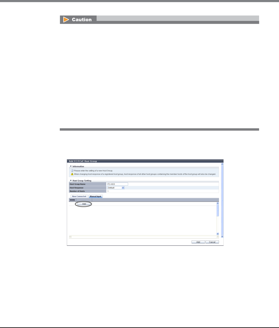
Chapter 9 Connectivity Management
9.2 Functions in the Action Area for Connectivity
ETERNUS Web GUI User’s Guide
Copyright 2013 FUJITSU LIMITED P2X0-1090-10ENZ0
444
■When registering a host by manually specifying the host
(1) Click the [Manual Input] tab.
(2) Click the [Add] button.
→The [Add FC/FCoE Host] screen appears.
•If the WWN is not displayed when clicking the [Rediscover] button, make sure that there is no error
in the connection environment, such as the connection between the host and the switch, and the
CA port settings of the ETERNUS DX Disk storage system. If there is no error in the connection
environment, contact the Support Department, or specify the WWN manually.
•An error screen appears in the following conditions:
-When the "Host Group Name" is not entered
-When the "Host Group Name" does not satisfy the input conditions
-When the "Host Group Name" overlaps with an existing host group name
(Host group names cannot overlap with any other host group names, irrespective of the
interface types.)
-When no hosts are registered in a host group, or when nine or more hosts are registered in a
host group (for ETERNUS DX8700 S2, 65 or more hosts are registered in a host group)
-When the total number of host groups has exceeded the maximum number for the ETERNUS
DX Disk storage system
-When the total number of hosts has exceeded the maximum number for the ETERNUS DX Disk
storage system
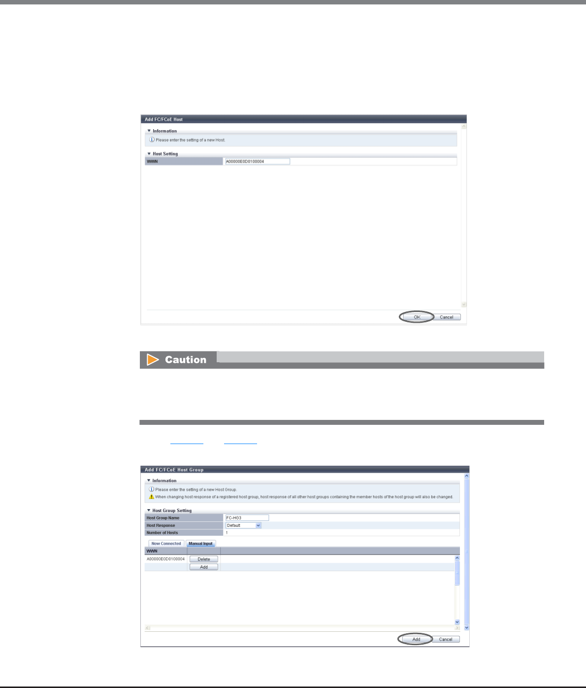
Chapter 9 Connectivity Management
9.2 Functions in the Action Area for Connectivity
ETERNUS Web GUI User’s Guide
Copyright 2013 FUJITSU LIMITED P2X0-1090-10ENZ0
445
(3) Manually specify the WWN of the host that is to be registered, and click the [OK] button.
-WWN
Input the WWN for the FC host.
The following input conditions apply:
•16 hexadecimal numbers
•"F (f)" or "0" used in entire 16 characters are not allowed.
→Returns to the [Manual Input] screen.
(4) Repeat Step (2) and Step (3) to set more WWNs.
(5) After adding the FC host is complete, click the [Add] button.
→A confirmation screen appears.
An error screen appears in the following conditions:
•When the "WWN" is not input
•When the "WWN" does not satisfy the input conditions
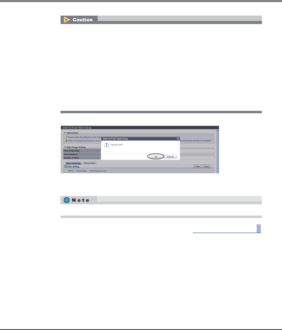
Chapter 9 Connectivity Management
9.2 Functions in the Action Area for Connectivity
ETERNUS Web GUI User’s Guide
Copyright 2013 FUJITSU LIMITED P2X0-1090-10ENZ0
446
4Click the [OK] button.
→Registration of the FC host group starts.
5Click the [Done] button to return to the [Host Group] screen.
End of procedure
An error screen appears in the following conditions:
•When the "Host Group Name" is not input
•When the "Host Group Name" does not satisfy the input conditions
•When the "Host Group Name" overlaps with an existing host group name
(host group names cannot overlap with any other host group names, irrespective of the interface
types)
•When the several FC hosts with the same WWNs have been registered
•When no hosts are registered in a host group, or when nine or more hosts are registered in a host
group (for ETERNUS DX8700 S2, 65 or more hosts are registered in a host group)
•When the total number of host groups has exceeded the maximum number for the ETERNUS DX
Disk storage system
•When the total number of hosts has exceeded the maximum number for the ETERNUS DX Disk
storage system
Click the [Continue] button to continue adding FC hosts.

Chapter 9 Connectivity Management
9.2 Functions in the Action Area for Connectivity
ETERNUS Web GUI User’s Guide
Copyright 2013 FUJITSU LIMITED P2X0-1090-10ENZ0
447
■Example of changing the host response when adding a host group
When a host "Host_G3" (host response: HR_1) is created with "Host-3" and "Host-4" and added to the host
groups listed in the table above, the host response is changed as follows:
The following table shows the host response after new hosts are added.
■Example of changing the host response when adding a host to an existing host group
When a host "Host_3" is added to the existing host group "Host_G3" (host response: HR_1), the host response
is changed as follows:
Host group (Host response) Member host Host response that is allocated to the host
Host_G1 (Default) Host-1 Default
Host-2 Default
Host_G2 (Default) Host-2 Default
Host-3 Default
1. The host response for Host-3 is changed from "Default" to "HR_1" (the host response for Host_G3).
2. Since the host response for Host-3 is changed, the host response for Host_G2 to which Host-3 belongs is also
changed from "Default" to "HR_1".
(The host response for Host_2, which is the member host of Host_G2, is changed from "Default" to "HR_1".)
3. Since the host response for Host-2 is changed, the host response for Host_G1 to which Host-2 belongs is also
changed from "Default" to "HR_1".
(The host response for Host_1, which is the member host of Host_G1, is changed from "Default" to "HR_1".)
Host group (Host response) Member host Host response that is allocated to the host
Host_G1 (HR_1) Host-1 HR_1
Host-2 HR_1
Host_G2 (HR_1) Host-2 HR_1
Host-3 HR_1
Host_G3 (HR_1) Host-3 HR_1
Host-4 HR_1
Host group (Host response) Member host Host response that is allocated to the host
Host_G1 (Default) Host-1 Default
Host-2 Default
Host_G2 (Default) Host-2 Default
Host-3 Default
Host_G3 (HR_1) Host-4 HR_1
1. The host response for Host-3 is changed from "Default" to "HR_1" (the host response for Host_G3).
2. Since the host response for Host-3 is changed, the host response for Host_G2 to which Host-3 belongs is also
changed from "Default" to "HR_1".
(The host response for Host_2, which is the member host of Host_G2, is changed from "Default" to "HR_1".)
3. Since the host response for Host-2 is changed, the host response for Host_G1 to which Host-2 belongs is also
changed from "Default" to "HR_1".
(The host response for Host_1, which is the member host of Host_G1, is changed from "Default" to "HR_1".)
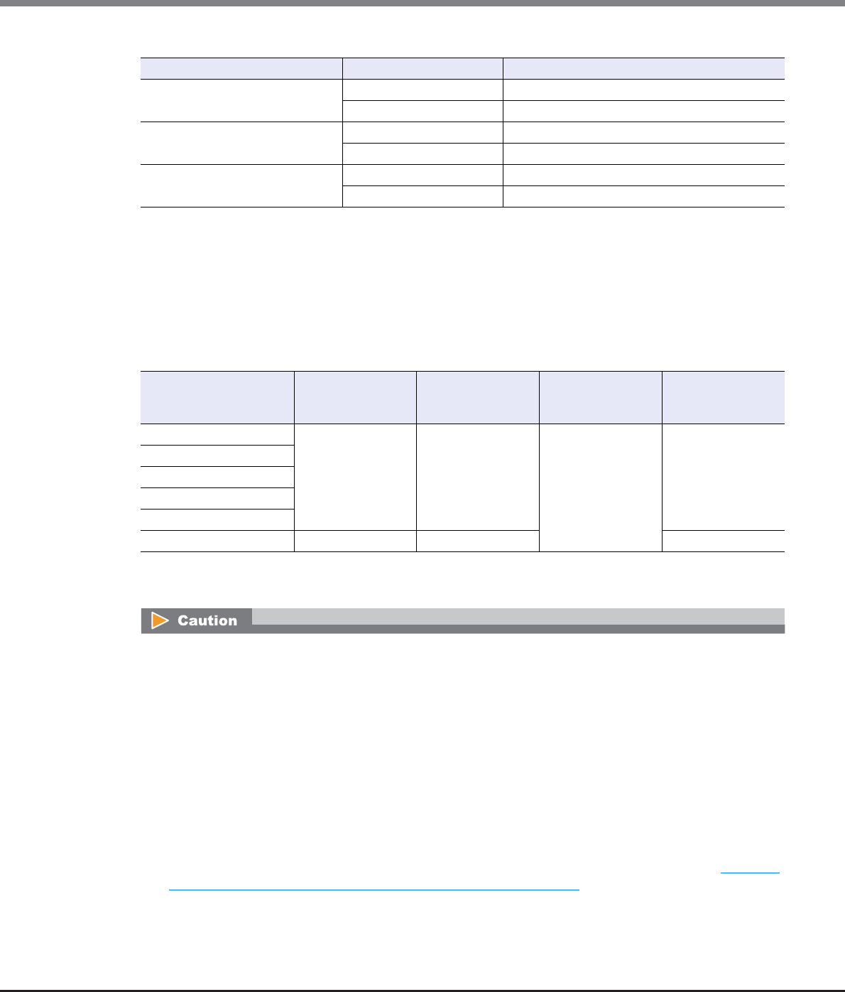
Chapter 9 Connectivity Management
9.2 Functions in the Action Area for Connectivity
ETERNUS Web GUI User’s Guide
Copyright 2013 FUJITSU LIMITED P2X0-1090-10ENZ0
448
The following table shows the host response after new hosts are added.
9.2.2.2 Add iSCSI Host Group
This function creates a new iSCSI host group and registers which hosts are members of this group.
An iSCSI host group uses iSCSI as the interface type, and groups the hosts (HBAs), which access the same LUN
group. This function configures Host Affinity settings for each iSCSI host group.
The number of host groups and hosts that can be registered
*1: The total number of host groups irrespective of the interface types.
*2: The total number of hosts irrespective of the interface types.
Host group (Host response) Member host Host response that is allocated to the host
Host_G1 (HR_1) Host-1 HR_1
Host-2 HR_1
Host_G2 (HR_1) Host-2 HR_1
Host-3 HR_1
Host_G3 (HR_1) Host-3 HR_1
Host-4 HR_1
Model Number of host
groups (*1) per
storage system
Number of hosts
(HBAs) (*2) per
storage system
Number of hosts
(HBAs) per
CA port
Number of hosts
(HBAs) per
host group
ETERNUS DX80 S2 128 1024 256 8
ETERNUS DX90 S2
ETERNUS DX410 S2
ETERNUS DX440 S2
ETERNUS DX8100 S2
ETERNUS DX8700 S2 512 8192 64
•Registration of the host is necessary to create a host group. Create a new host group when registering a
host with GUI by using this function.
•A host can be a member of several host groups. However, only one LUN group can be allocated to host
and port combinations when configuring host affinity.
•To assign an appropriate host response to a created host group, refer to "User's Guide -Server Connection-
" for each OS type. The host response configures the operation mode that is appropriate for the host.
If an appropriate host response is not configured to the host group, the path may not be switched
correctly or the volume may not be recognized correctly.
•The host response that is specified for a host group is applied all the member hosts in the target group.
When a host belongs to multiple host groups, the same host response must be applied for all the groups
to which the target host belongs. When a host that already belongs to an existing host group is added to
a newly created host group, the host response of the new host group is applied to the host. The host
response of the existing host group to which the target host belongs is also changed. Refer to "Example
of changing the host response when adding a host group" (page 447) for details.
Chapter 9 Connectivity Management
9.2 Functions in the Action Area for Connectivity
ETERNUS Web GUI User’s Guide
Copyright 2013 FUJITSU LIMITED P2X0-1090-10ENZ0
449
The procedure to create an iSCSI host group is as follows:
Procedure
1Click [Add iSCSI Host Group] in [Action].
2Input a host group name to be created, and select a host response to be assigned to the
host group.
•Host Group Name
Specify the host group name.
An existing host group name cannot be specified. Refer to "Naming conventions for adding hosts"
(page 994) for details.
The following input conditions apply:
-Up to 16 alphanumeric characters and symbols (except ", (comma)" and "?")
-Space
•Host Response
Select a host response to be assigned to a host group.
The host response list created in the ETERNUS DX Disk storage system is displayed.
-Solaris MPxIO
-HP-UX
-AIX EMPD (*1)
-AIX VxVM
-AIX Single Path
-VS850/SVC
-Host responses created in the ETERNUS DX Disk storage system
-Default
*1: EMPD: ETERNUS Multipath Driver
•Unlike GUI, CLI can register two iSCSI hosts that have the same iSCSI name by setting an IP address for one
of these iSCSI hosts and by not setting an IP address for the other iSCSI host. However, if iSCSI hosts are
registered in the ETERNUS DX Disk storage system in this way, iSCSI hosts cannot be added using GUI.
Avoid this configuration when using GUI and CLI together. If both iSCSI hosts already exist, use CLI to
specify an IP address for the iSCSI host without the IP address.
•The name of the [Add iSCSI Host] function, which creates a new iSCSI host group and registers the mem-
ber hosts has changed with firmware version V10L50. The [Add iSCSI Host] function is now called the
[Add iSCSI Host Group] function.
•To change the settings of the host groups, use the procedure in "9.2.2.5 Modify Host Group" (page 463).
•To add a port to an existing host group, use the procedure in "9.2.2.5 Modify Host Group" (page 463).
•To change the iSCSI host information, use the procedure in "9.2.2.16 Modify iSCSI Host" (page 509).
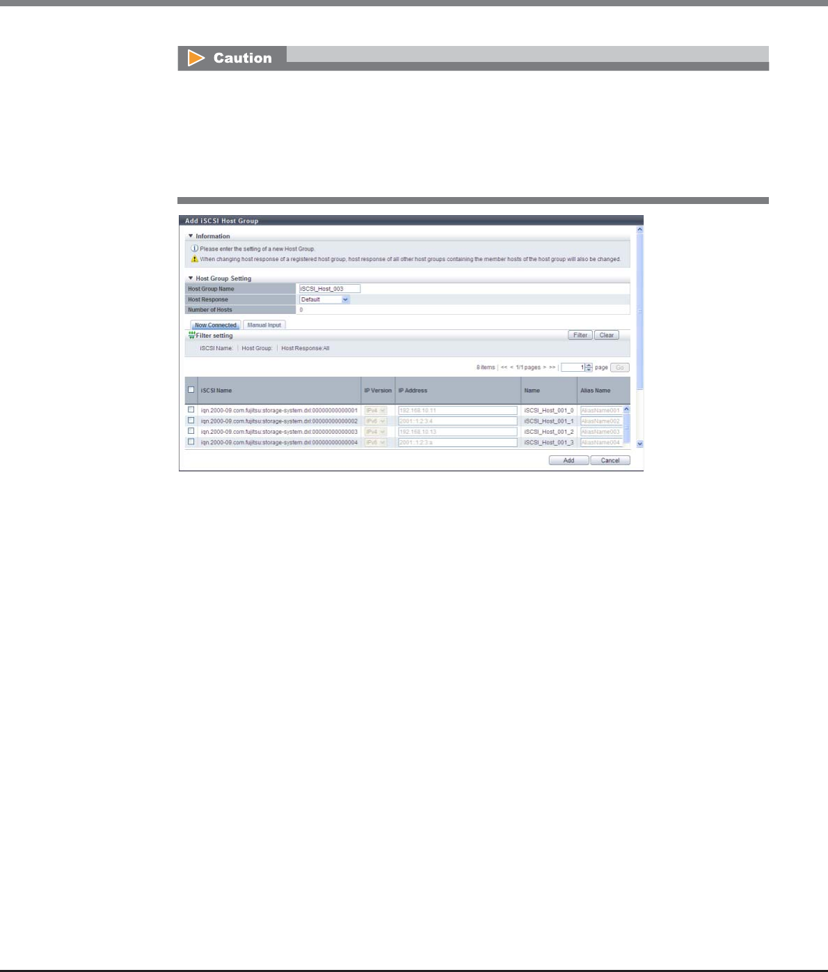
Chapter 9 Connectivity Management
9.2 Functions in the Action Area for Connectivity
ETERNUS Web GUI User’s Guide
Copyright 2013 FUJITSU LIMITED P2X0-1090-10ENZ0
450
3Register a host in a host group in the following procedures, and click the [Add] button.
■When registering a host by selecting from the host list
(1) Click the [Now Connected] tab.
The following hosts are displayed in the [Now Connected] tab:
-Hosts that are connected to an iSCSI-CA or an iSCSI-CA/RA but are not registered in the ETERNUS
DX Disk storage system (*1)
*1: "Host that is not registered in the ETERNUS DX Disk storage system" indicates that a host with the
same iSCSI name, IP version, and Alias Name as the target host is not registered in the storage
system. The host is regarded as unregistered host even if a host with the same iSCSI name, IP version,
Alias Name, and different IP address is already registered. The obtained "iSCSI Name", "IP Version", "IP
Address", and "Alias Name" are displayed.
-Hosts that are connected to an iSCSI-CA or an iSCSI-CA/RA and registered in the ETERNUS DX Disk
storage system
-Hosts that are not connected to an iSCSI-CA or an iSCSI-CA/RA but are registered in the ETERNUS
DX Disk storage system
Click the [Rediscover] button to update the iSCSI host list.
The following modifications are applied for the host response settings with firmware version V10L15
or later.
•"Others" is changed to "Default".
•"Windows EMPD", "Linux EMPD", and "Solaris EMPD" are deleted from the "Host Response" value.
•The setting parameters for "Windows EMPD", "Linux EMPD", and "Solaris EMPD" are the same as
"Default".

Chapter 9 Connectivity Management
9.2 Functions in the Action Area for Connectivity
ETERNUS Web GUI User’s Guide
Copyright 2013 FUJITSU LIMITED P2X0-1090-10ENZ0
451
(2) Select a host to be registered from the iSCSI host list, register the iSCSI host information (the IP
address and the Alias name, etc.) to the selected host, and click the [Add] button.
-Checkbox to select a host
Select the iSCSI host checkbox to be registered in a host group.
-IP Version
Select the IP version of the iSCSI host from "IPv4" or "IPv6".
-IP Address
Specify the IP address of the member host.
There are two methods to specify an IP address; "IPv4" and "IPv6". The IP address must be
specified with the selected IP version (IPv4 or IPv6). The following IPv6 addresses can be used;
"link local address", "global address", "unique local address", and "6to4 address". Refer to
"Available IPv6 Address" (page 757) for details. When the current setting is displayed, the IPv6
address is displayed as an abbreviation.
It is not necessary to specify this item if IP address is not used.
The following input conditions apply:
•For IPv4 address
xxx.xxx.xxx.xxx
xxx: 0 - 255 for other fields (decimal)
•For IPv6 address
xxxx:xxxx:xxxx:xxxx:xxxx:xxxx:xxxx:xxxx
xxxx: 0 - ffff (FFFF) (hexadecimal, alphanumeric characters)
Refer to "IPv6 Address Notation" (page 378) for details.
•If the iSNS server has not been configured in "9.2.3.8 Modify iSCSI Port Parameters" (page
541), the iSCSI host cannot be automatically acquired.
•The following restrictions in the environment that is described below apply for the
automatic acquirement of host information (*1) even when the iSNS server is specified.
*1: "iSCSI Name", "IP Version", "IP Address", and "Alias Name"
-When one of the following OSs is used and there are multiple hosts that have the same
iSCSI name but different IP addresses, only the information of one host can be acquired.
•Windows Server 2003
•Windows Server 2008
•Windows Server 2008 R2
•Oracle Solaris 10
-When the host OS is Oracle Solaris 11, "IP Version" and "IP Address" cannot be acquired.
•The following items can be specified only for the iSCSI hosts that are selected by
checkboxes; "IP Version", "IP Address", "Alias Name", "CHAP User ID", "Change CHAP
Password", "CHAP Password", and "Confirm CHAP Password".
To register an iSCSI host without using an IP address, perform IP version selection as follows:
•Select "IPv4" when the IP address format of the iSCSI host is IPv4 (when using an IPv4 host)
•Select "IPv6" when the IP address format of the iSCSI host is IPv6 (when using an IPv6 host)
•If the IP address format of the iSCSI host cannot be checked (when either an IPv4 host or an
IPv6 host is used), register two hosts. Select "IPv4" for one host, and select "IPv6" for the
other host. Specify the same iSCSI name, CHAP user ID, and CHAP password for each host.
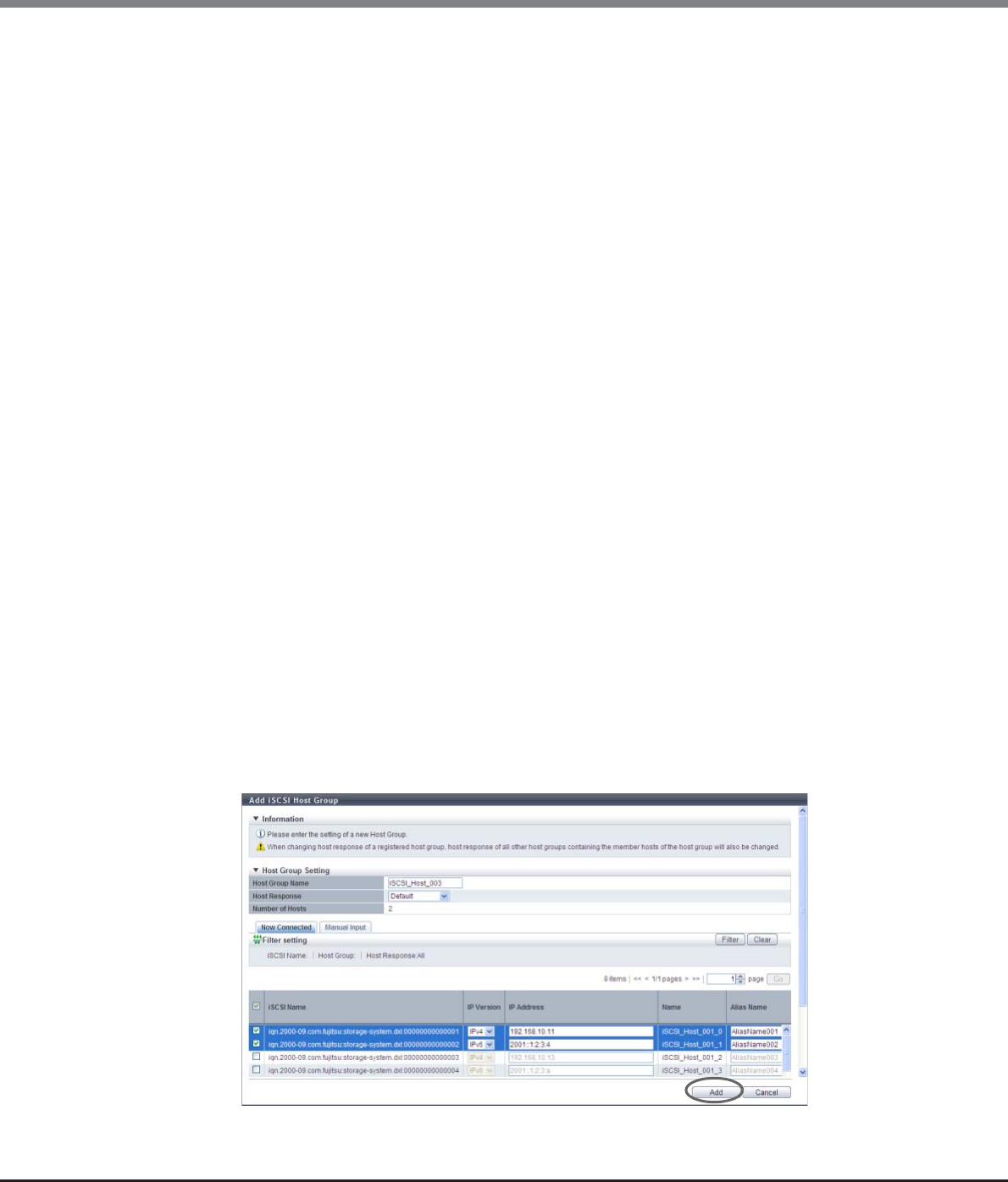
Chapter 9 Connectivity Management
9.2 Functions in the Action Area for Connectivity
ETERNUS Web GUI User’s Guide
Copyright 2013 FUJITSU LIMITED P2X0-1090-10ENZ0
452
-Alias Name
Specify the Alias name of the iSCSI host.
If the iSCSI host has already been registered in the ETERNUS DX Disk storage system, the Alias
name is displayed.
It is not necessary to specify this item if Alias name is not used.
An existing Alias name cannot be specified.
The following input conditions apply:
•Up to 31 alphanumeric characters and symbols (except ", (comma)" and "?")
•Space
-CHAP User ID
Specify the user ID for CHAP Authentication.
If the iSCSI host has already been registered in the ETERNUS DX Disk storage system, the user ID
is displayed.
It is not necessary to specify this item if CHAP Authentication is not used.
Configure the user ID and the password as a pair.
The following input conditions apply:
•Up to 255 alphanumeric characters and symbols (except ", (comma)" and "?")
•Space
-Change CHAP Password
To register the CHAP Authentication password, select the checkbox.
-CHAP Password
Specify the password for CHAP Authentication.
It is not necessary to specify this item if CHAP Authentication is not used.
Configure the user ID and the password as a pair.
The password can be entered only when the "Change CHAP Password" checkbox is selected.
The following input conditions apply:
•12 - 100 alphanumeric characters and symbols (except ", (comma)" and "?")
•Space
-Confirm CHAP Password
Input the CHAP password again for confirmation.
The password can be entered only when the "Change CHAP Password" checkbox is selected.
The following input conditions apply:
•12 - 100 alphanumeric characters and symbols (except ", (comma)" and "?")
•Space
→A confirmation screen appears.
Chapter 9 Connectivity Management
9.2 Functions in the Action Area for Connectivity
ETERNUS Web GUI User’s Guide
Copyright 2013 FUJITSU LIMITED P2X0-1090-10ENZ0
453
Filter setting
Filter Description
iSCSI Name
Input the iSCSI name that is to be displayed.
iSCSI hosts matching or partially matching the input iSCSI name are displayed.
When not using the iSCSI name for filtering, leave this item blank.
Host Group
Input the host group name that is to be displayed.
iSCSI hosts which belong to any host groups that match or partially match the
entered name are displayed.
When not using the host group name for filtering, leave this item blank.
Host Response Select the host response that is to be displayed.
Any iSCSI hosts that are allocated to the selected host response are displayed.
An error screen appears in the following conditions:
•When the "Host Group Name" is not entered
•When the "Host Group Name" does not satisfy the input conditions
•When the "Host Group Name" overlaps with an existing host group name
(Host group names cannot overlap with any other host group names, irrespective of the interface
types.)
•When the "IP Address" does not satisfy the input conditions
•When the "IP Address" is specified and an iSCSI host with the same "iSCSI Name" and "IP Address" is
already registered
•When the "IP Address" is not specified and an iSCSI host with the same "iSCSI Name" and "IP Ver-
sion" is already registered
•When the "Alias Name" does not satisfy the input conditions
•When the "Alias Name" overlaps the existing Alias name
•When the "CHAP User ID" does not satisfy the input conditions
•When the "CHAP Password" does not satisfy the input conditions
•When the "Confirm CHAP Password" does not satisfy the input conditions
•When the "CHAP Password" and the "Confirm CHAP Password" do not match
•When either of the "CHAP User ID" or the "CHAP Password" has been specified
•When no hosts are registered in a host group, or when nine or more hosts are registered in a host
group (for ETERNUS DX8700 S2, 65 or more hosts are registered in a host group)
•When the total number of host groups has exceeded the maximum number for the ETERNUS DX
Disk storage system
•When the total number of hosts has exceeded the maximum number for the ETERNUS DX Disk
storage system
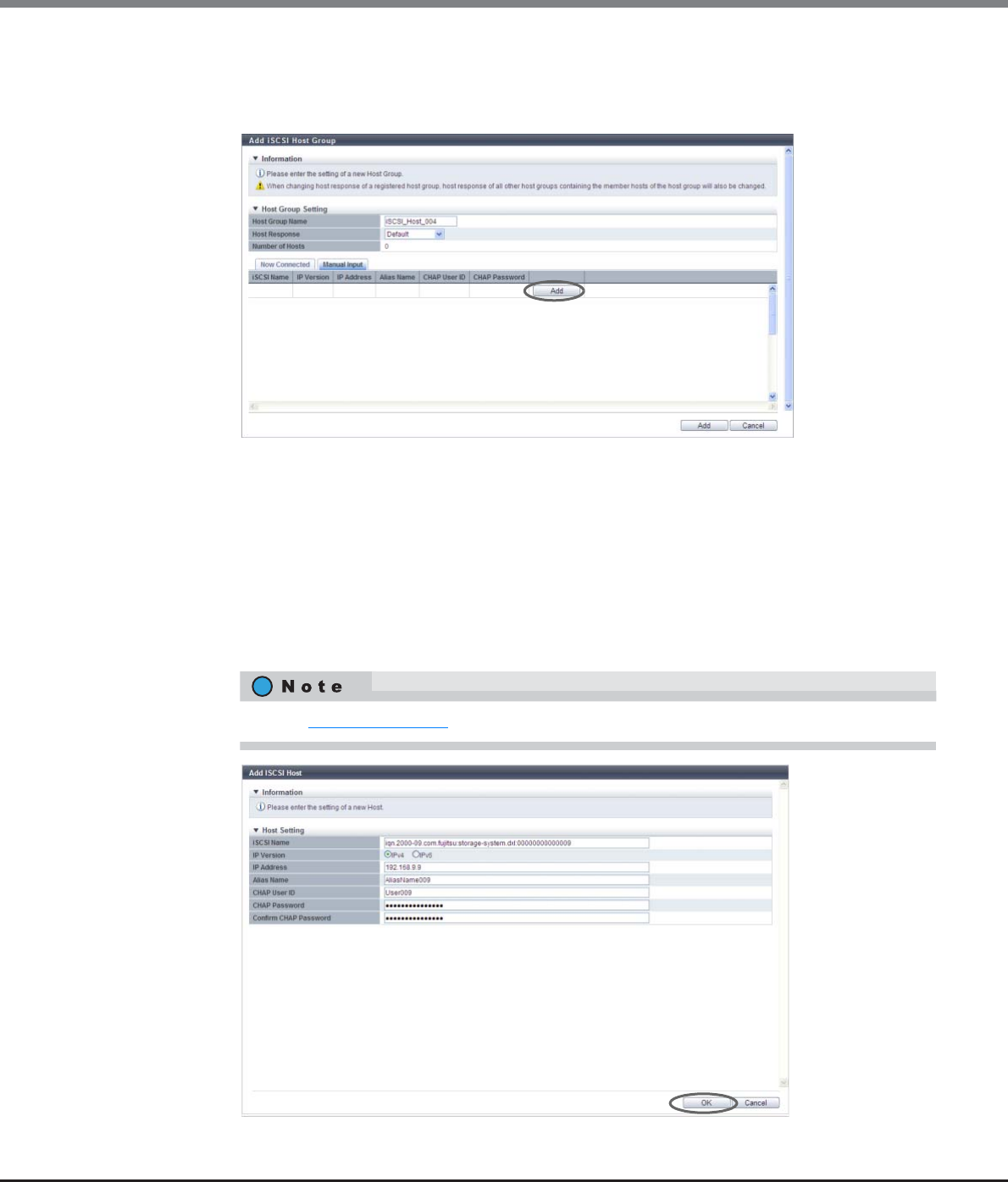
Chapter 9 Connectivity Management
9.2 Functions in the Action Area for Connectivity
ETERNUS Web GUI User’s Guide
Copyright 2013 FUJITSU LIMITED P2X0-1090-10ENZ0
454
■When registering a host by manually specifying the host
(1) Click the [Manual Input] tab.
(2) Click the [Add] button.
→ The [Add iSCSI Host] screen appears.
(3) Specify the iSCSI host information of the host to be registered, and click the [OK] button.
-iSCSI Name
Specify an iSCSI name of the iSCSI host (required).
The following input conditions apply:
•Alphabetic characters (lower case) and numeric characters
•Symbols "-" (hyphen), "." (period) and ":" (colon)
•The name starts with "iqn." or "eui."
•4 - 223 characters
→ Returns to the [Manual Input] screen.
Refer to Step (2) (page 451) for other settings.
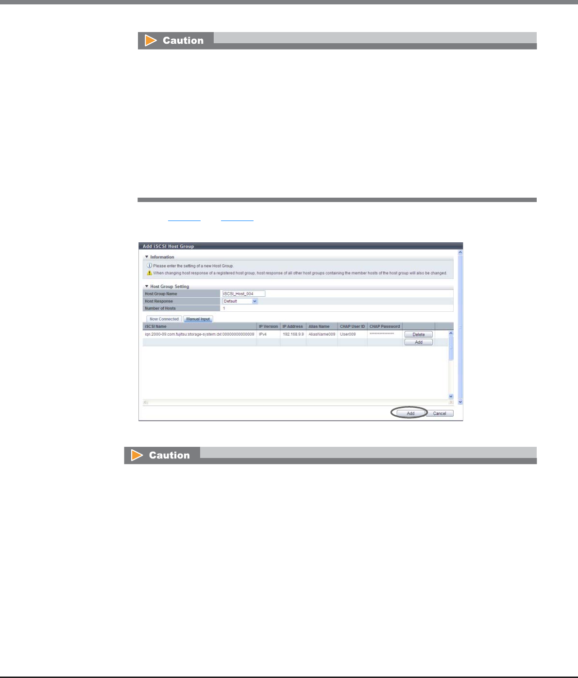
Chapter 9 Connectivity Management
9.2 Functions in the Action Area for Connectivity
ETERNUS Web GUI User’s Guide
Copyright 2013 FUJITSU LIMITED P2X0-1090-10ENZ0
455
(4) Repeat Step (2) and Step (3) to set more iSCSI hosts.
(5) After adding the iSCSI host is complete, click the [Add] button.
→A confirmation screen appears.
An error screen appears in the following conditions:
•When the "iSCSI Name" is not input
•When the "iSCSI Name" does not satisfy the input conditions
•When the "IP Address" does not satisfy the input conditions
•When the "Alias Name" does not satisfy the input conditions
•When the "CHAP User ID" does not satisfy the input conditions
•When the "CHAP Password" does not satisfy the input conditions
•When the "Confirm CHAP Password" does not satisfy the input conditions
•When the "CHAP Password" and the "Confirm CHAP Password" do not match
•When either of the "CHAP User ID" or the "CHAP Password" has been specified
An error screen appears in the following conditions:
•When the "Host Group Name" is not entered
•When the "Host Group Name" does not satisfy the input conditions
•When the "Host Group Name" overlaps with an existing host group name
(Host group names cannot overlap with any other host group names, irrespective of the interface
types.)
•When the "IP Address" is specified and an iSCSI host with the same "iSCSI Name" and "IP Address" is
already registered
•When the "IP Address" is not specified and an iSCSI host with the same "iSCSI Name" and "IP
Version" is already registered
•When the same iSCSI name is specified for multiple iSCSI hosts
•When the "Alias Name" overlaps the existing Alias name
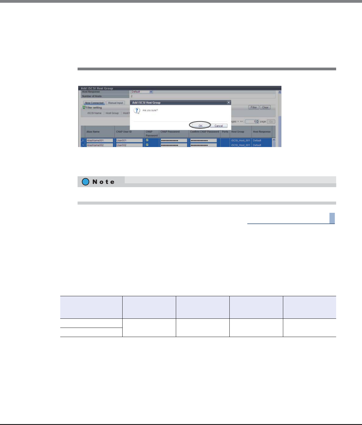
Chapter 9 Connectivity Management
9.2 Functions in the Action Area for Connectivity
ETERNUS Web GUI User’s Guide
Copyright 2013 FUJITSU LIMITED P2X0-1090-10ENZ0
456
4Click the [OK] button.
→Registration of the iSCSI host group starts.
5Click the [Done] button to return to the [Host Group] screen.
End of procedure
9.2.2.3 Add SAS Host Group
This function creates a new SAS host group and registers which hosts are members of this group.
A SAS host group uses SAS as the interface type, and groups the hosts (HBAs), which access the same LUN
group. This function configures Host Affinity settings for each SAS host group.
The number of host groups and hosts that can be registered
*1: The total number of host groups irrespective of the interface types.
*2: The total number of hosts irrespective of the interface types.
•When no hosts are registered in a host group, or when nine or more hosts are registered in a host
group (for ETERNUS DX8700 S2, 65 or more hosts are registered in a host group)
•When the total number of host groups has exceeded the maximum number for the ETERNUS DX
Disk storage system
•When the total number of hosts has exceeded the maximum number for the ETERNUS DX Disk
storage system
Click the [Continue] button to continue adding iSCSI hosts.
Model Number of host
groups (*1) per
storage system
Number of hosts
(HBAs) (*2) per
storage system
Number of hosts
(HBAs)
per CA port
Number of hosts
(HBAs)
per host group
ETERNUS DX80 S2 128 1024 256 8
ETERNUS DX90 S2
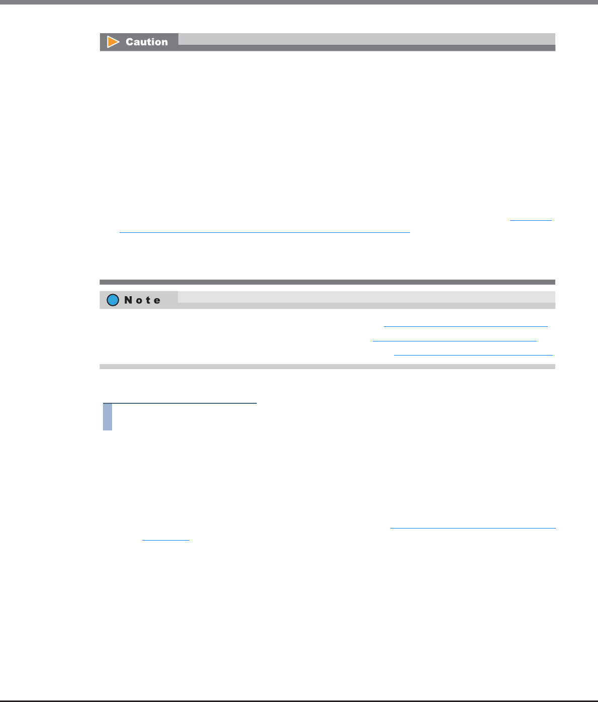
Chapter 9 Connectivity Management
9.2 Functions in the Action Area for Connectivity
ETERNUS Web GUI User’s Guide
Copyright 2013 FUJITSU LIMITED P2X0-1090-10ENZ0
457
The procedure to create a SAS host group is as follows:
Procedure
1Click [Add SAS Host Group] in [Action].
2Input a host group name to be created, and select a host response to be assigned to the
host group.
•Host Group Name
Specify the host group name.
An existing host group name cannot be specified. Refer to "Naming conventions for adding hosts"
(page 994) for details.
The following input conditions apply:
-Up to 16 alphanumeric characters and symbols (except ", (comma)" and "?")
-Space
•Registration of the host is necessary to create a host group. Create a new host group when registering a
host with GUI by using this function.
•A host can be a member of several host groups. However, only one LUN group can be allocated to host
and port combinations when configuring host affinity.
•To assign an appropriate host response to a created host group, refer to "User's Guide -Server Connection-
" for each OS type. The host response configures the operation mode that is appropriate for the host.
If an appropriate host response is not configured to the host group, the path may not be switched
correctly or the volume may not be recognized correctly.
•The host response that is specified for a host group is applied all the member hosts in the target group.
When a host belongs to multiple host groups, the same host response must be applied for all the groups
to which the target host belongs. When a host that already belongs to an existing host group is added to
a newly created host group, the host response of the new host group is applied to the host. The host
response of the existing host group to which the target host belongs is also changed. Refer to "Example
of changing the host response when adding a host group" (page 447) for details.
•The name of the [Add SAS Host] function, which creates a new SAS host group and registers the member
hosts has changed with firmware version V10L50. The [Add SAS Host] function is now called the [Add SAS
Host Group] function.
•To change the settings of the host groups, use the procedure in "9.2.2.5 Modify Host Group" (page 463).
•To add a port to an existing host group, use the procedure in "9.2.2.5 Modify Host Group" (page 463).
•To change the host name or the SAS address, use the procedure in "9.2.2.17 Modify SAS Host" (page 514).
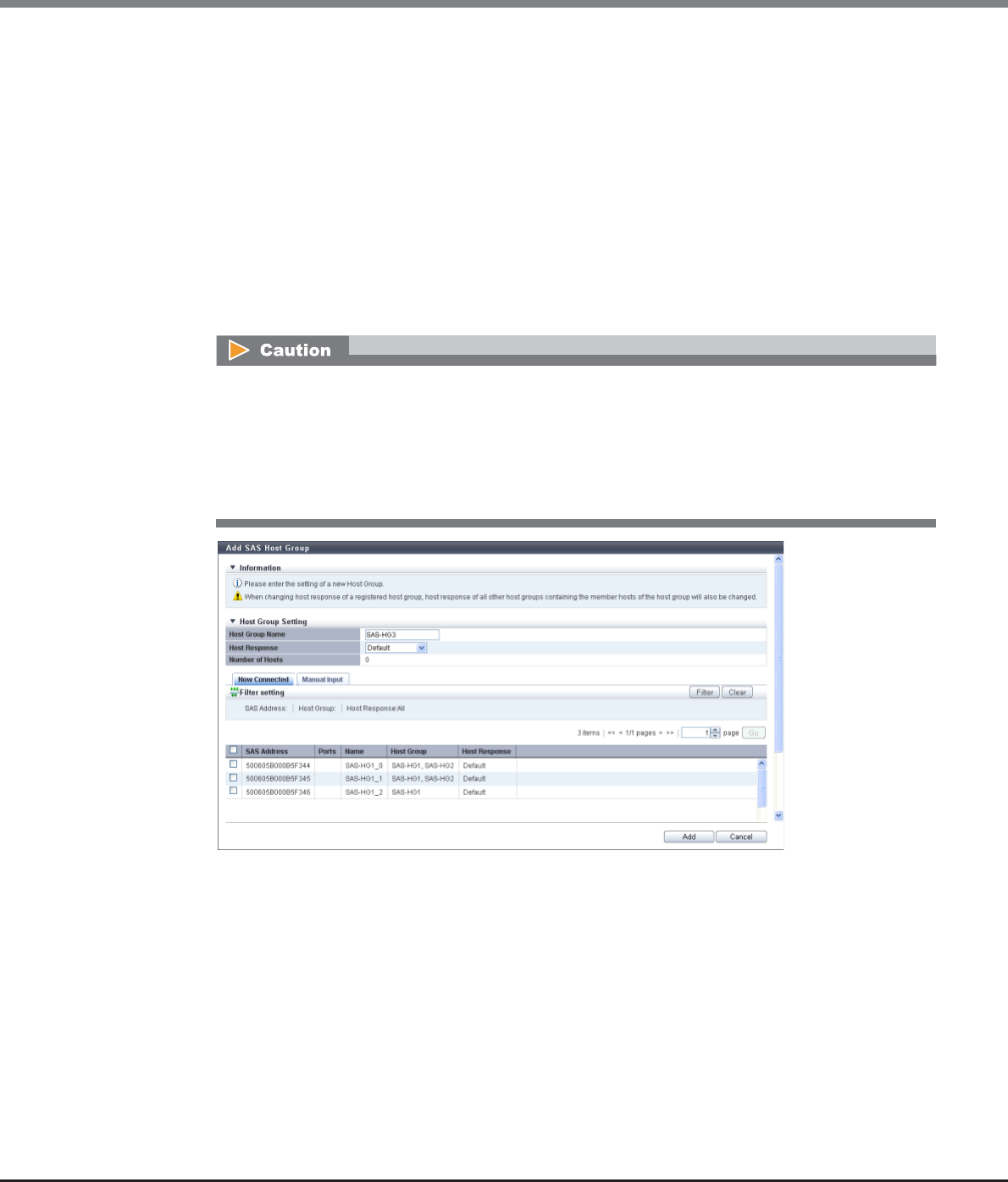
Chapter 9 Connectivity Management
9.2 Functions in the Action Area for Connectivity
ETERNUS Web GUI User’s Guide
Copyright 2013 FUJITSU LIMITED P2X0-1090-10ENZ0
458
•Host Response
Select a host response to be assigned to a host group.
The host response list created in the ETERNUS DX Disk storage system is displayed.
-Solaris MPxIO
-HP-UX
-AIX EMPD (*1)
-AIX VxVM
-AIX Single Path
-VS850/SVC
-Host responses created in the ETERNUS DX Disk storage system
-Default
*1: EMPD: ETERNUS Multipath Driver
3Register a host in a host group in the following procedures.
The following modifications are applied for the host response settings with firmware version V10L15
or later.
•"Others" is changed to "Default".
•"Windows EMPD", "Linux EMPD", and "Solaris EMPD" are deleted from the "Host Response" value.
•The setting parameters for "Windows EMPD", "Linux EMPD", and "Solaris EMPD" are the same as
"Default".
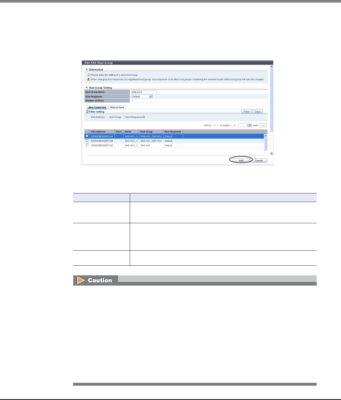
Chapter 9 Connectivity Management
9.2 Functions in the Action Area for Connectivity
ETERNUS Web GUI User’s Guide
Copyright 2013 FUJITSU LIMITED P2X0-1090-10ENZ0
459
■When registering a host by selecting from the host list
(1) Click the [Now Connected] tab.
(2) Select a host to be registered from the SAS host list, and click the [Add] button.
-Checkbox to select a host
Select the SAS host checkbox to be registered in a host group.
→A confirmation screen appears.
Filter setting
Filter Description
SAS Address
Input the SAS address to be displayed.
SAS hosts matching or partially matching the input SAS address are displayed.
When not using the SAS address for filtering, leave this item blank.
Host Group
Input the host group name that is to be displayed.
SAS hosts which belong to any host groups that match or partially match the entered
name are displayed.
When not using the host group name for filtering, leave this item blank.
Host Response Select the host response name that is to be displayed.
Any SAS hosts that are allocated to the selected host response are displayed.
An error screen appears in the following conditions:
•When the "Host Group Name" is not entered
•When the "Host Group Name" does not satisfy the input conditions
•When the "Host Group Name" overlaps with an existing host group name
(Host group names cannot overlap with any other host group names, irrespective of the interface
types.)
•When no hosts are registered in a host group, or when nine or more hosts are registered in a host
group
•When the total number of host groups has exceeded the maximum number for the ETERNUS DX
Disk storage system
•When the total number of hosts has exceeded the maximum number for the ETERNUS DX Disk
storage system
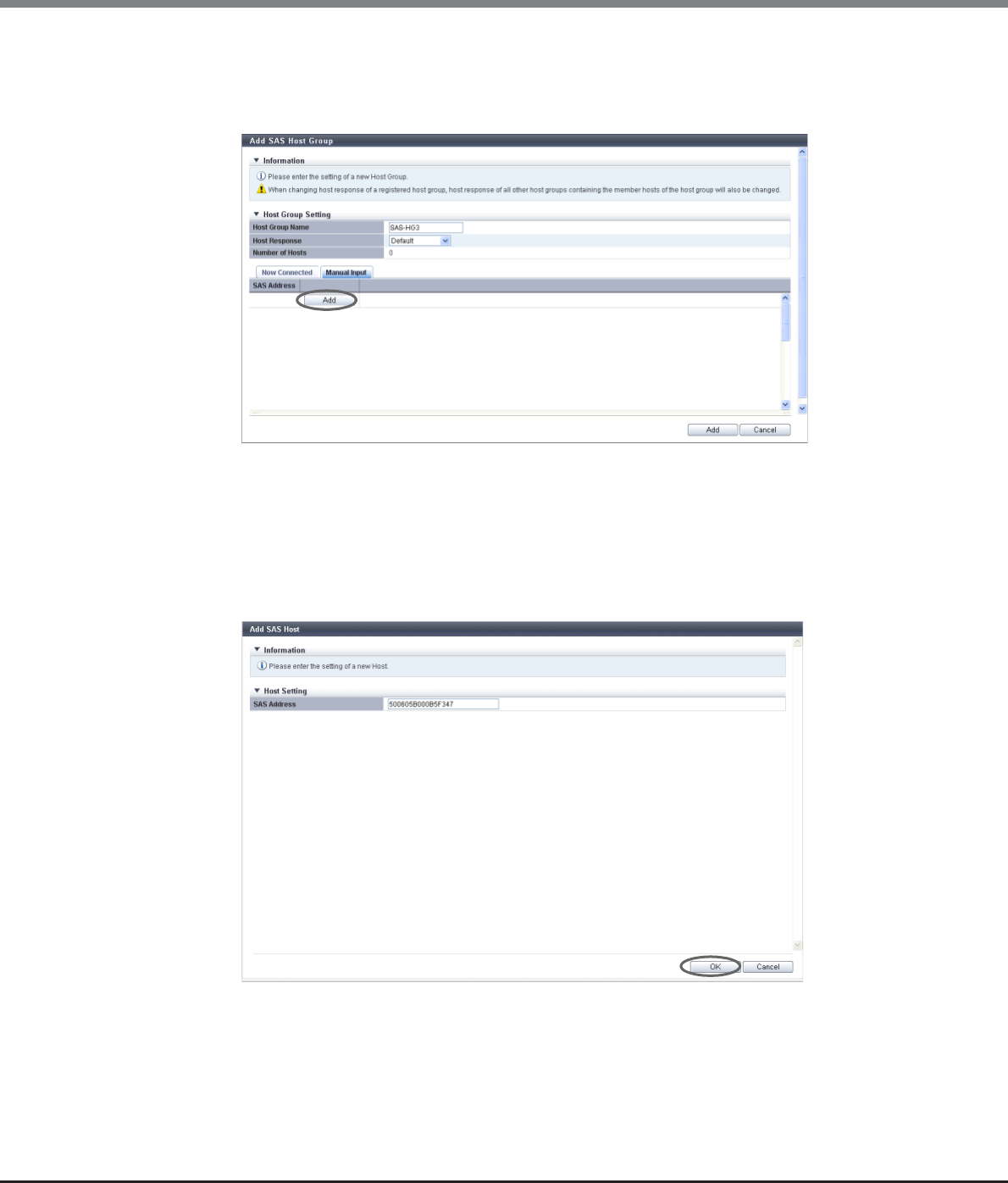
Chapter 9 Connectivity Management
9.2 Functions in the Action Area for Connectivity
ETERNUS Web GUI User’s Guide
Copyright 2013 FUJITSU LIMITED P2X0-1090-10ENZ0
460
■When registering a host by manually specifying the host
(1) Click the [Manual Input] tab.
(2) Click the [Add] button.
→The [Add SAS Host] screen appears.
(3) Manually specify the SAS address of the host to be registered, and click the [OK] button.
-SAS Address
Specify the SAS address of the SAS host.
The following input conditions apply:
•16 hexadecimal numbers
•"F (f)" or "0" used in entire 16 characters are not allowed.
→Returns to the [Manual Input] screen.
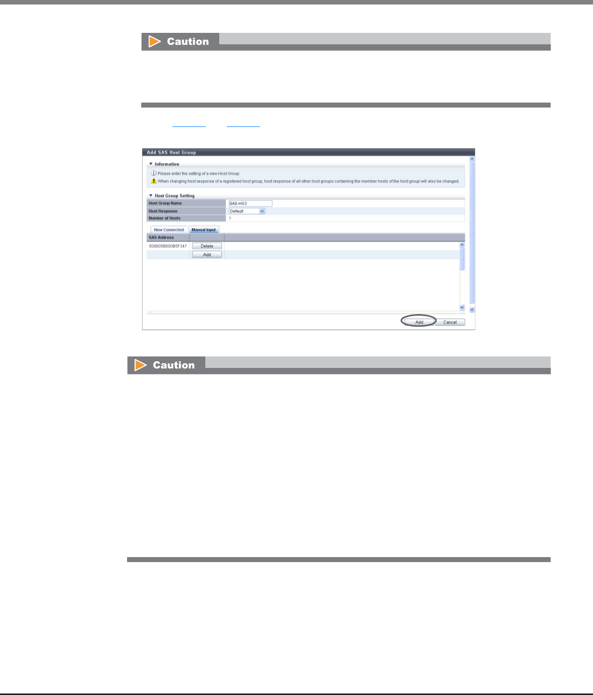
Chapter 9 Connectivity Management
9.2 Functions in the Action Area for Connectivity
ETERNUS Web GUI User’s Guide
Copyright 2013 FUJITSU LIMITED P2X0-1090-10ENZ0
461
(4) Repeat Step (2) and Step (3) to set more SAS addresses.
(5) After adding the SAS host is complete, click the [Add] button.
→A confirmation screen appears.
An error screen appears in the following conditions:
•When the "SAS Address" is not input
•When the "SAS Address" does not satisfy the input conditions
An error screen appears in the following conditions:
•When the "Host Group Name" is not entered
•When the "Host Group Name" does not satisfy the input conditions
•When the "Host Group Name" overlaps with an existing host group name
(Host group names cannot overlap with any other host group names, irrespective of the interface
types.)
•When the several SAS hosts with the same SAS addresses have been registered
•When no hosts are registered in a host group, or when nine or more hosts are registered in a host
group
•When the total number of host groups has exceeded the maximum number for the ETERNUS DX
Disk storage system
•When the total number of hosts has exceeded the maximum number for the ETERNUS DX Disk
storage system
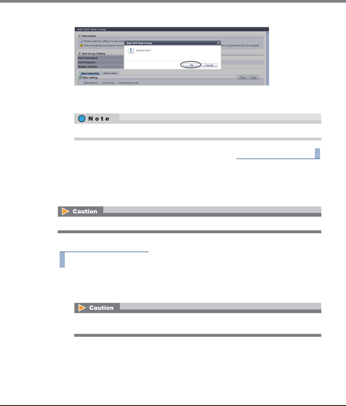
Chapter 9 Connectivity Management
9.2 Functions in the Action Area for Connectivity
ETERNUS Web GUI User’s Guide
Copyright 2013 FUJITSU LIMITED P2X0-1090-10ENZ0
462
4Click the [OK] button.
→Registration of the SAS host group starts.
5Click the [Done] button to return to the [Host Group] screen.
End of procedure
9.2.2.4 Delete Host Group
This function deletes a host group. When a host group is deleted, the hosts, which belong to the host group,
are also deleted.
The procedure to delete a host group is as follows:
Procedure
1Select the host group to be deleted (multiple selections can be made) and click [Delete Host
Group] in [Action].
→A confirmation screen appears.
Click the [Continue] button to continue adding SAS hosts.
The host group, of which host affinity settings have been configured, cannot be deleted.
The host group, of which host affinity settings have been configured (the status of the host group is
"Active"), cannot be deleted.
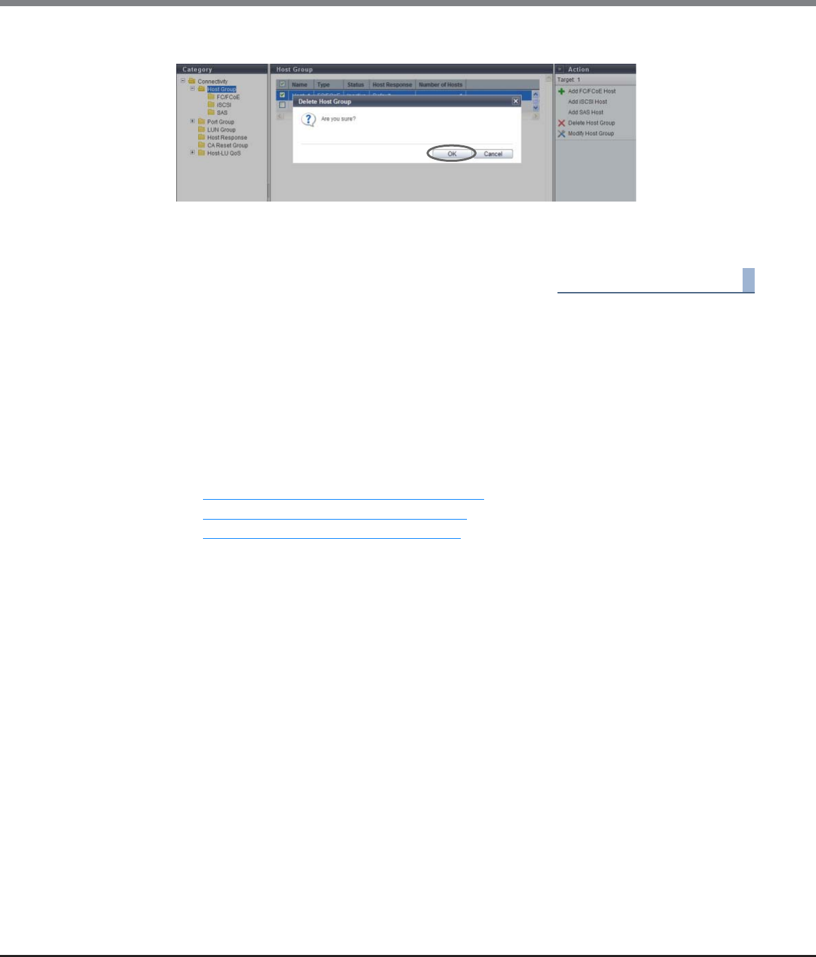
Chapter 9 Connectivity Management
9.2 Functions in the Action Area for Connectivity
ETERNUS Web GUI User’s Guide
Copyright 2013 FUJITSU LIMITED P2X0-1090-10ENZ0
463
2Click the [OK] button.
→Deletion of the host group starts.
3Click the [Done] button to return to the [Host Group] screen.
End of procedure
9.2.2.5 Modify Host Group
This function performs the following modifications to the existing host group.
•Changing the "Host Group Name" settings
•Changing the "Host Response" settings
•Changing the "Host" settings (including addition and deletion of member hosts in a host group)
Operation screens for modifying host groups vary with the interface types.
•Refer to "9.2.2.6 Modify Host Group (FC/FCoE)" (page 463) to edit FC/FCoE host groups.
•Refer to "9.2.2.7 Modify Host Group (iSCSI)" (page 470) to edit iSCSI host groups.
•Refer to "9.2.2.8 Modify Host Group (SAS)" (page 480) to edit SAS host groups.
9.2.2.6 Modify Host Group (FC/FCoE)
This function performs the following modifications to the existing FC/FCoE host group.
•Changing the "Host Group Name" settings
•Changing the "Host Response" settings
•Changing the "Host" settings (including addition and deletion of member hosts in a host group)
Hosts can be added to host groups which the host affinity setting has been already configured, or deleted
from host groups.
If a host is added, the host affinity setting is automatically configured to the host, as a host group member.
If a host is deleted, the host affinity setting is cleared from the corresponding host.
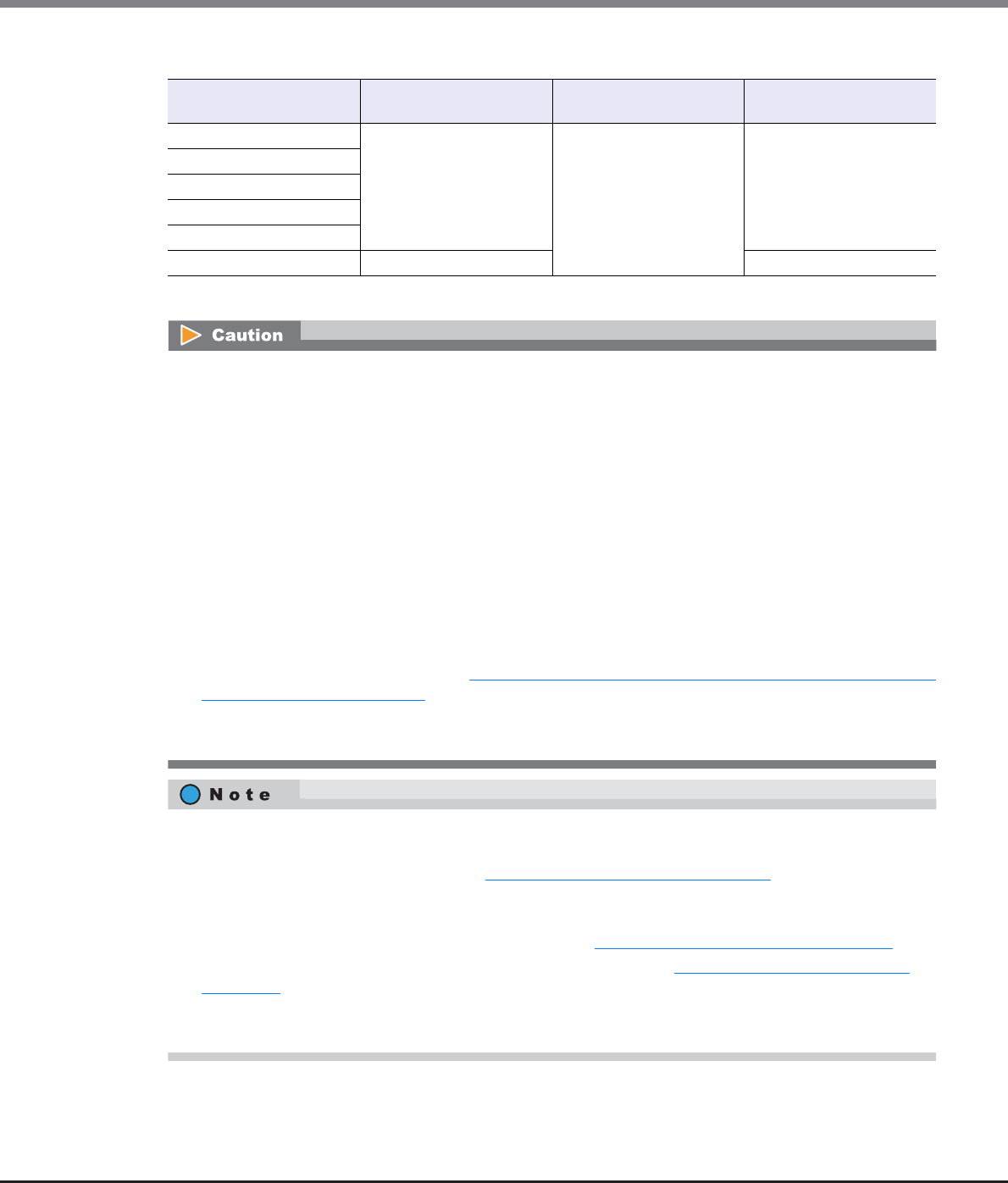
Chapter 9 Connectivity Management
9.2 Functions in the Action Area for Connectivity
ETERNUS Web GUI User’s Guide
Copyright 2013 FUJITSU LIMITED P2X0-1090-10ENZ0
464
The number of hosts that can be registered
*1: The total number of hosts irrespective of the interface types.
Model Number of hosts (HBAs)
(*1) per storage system
Number of hosts (HBAs)
per CA port
Number of hosts (HBAs)
per host group
ETERNUS DX80 S2 1024 256 8
ETERNUS DX90 S2
ETERNUS DX410 S2
ETERNUS DX440 S2
ETERNUS DX8100 S2
ETERNUS DX8700 S2 8192 64
•Registration of the host is necessary to create a host group. It is not possible to delete all hosts from a
host group.
•A host that has been registered with GUI by using this function belongs to one of the host groups.
•A host can be a member of several host groups. However, only one LUN group can be allocated to host
and port combinations when configuring host affinity.
•To assign an appropriate host response to a created host group, refer to "User's Guide -Server Connection-
" for each OS type. The host response configures the operation mode that is appropriate for the host. If an
appropriate host response is not configured to the host group, the path may not be switched correctly or
the volume may not be recognized correctly.
•The host response that is specified for a host group is applied all the member hosts in the target group.
When a host belongs to multiple host groups, the same host response must be applied for all the groups
to which the target host belongs. When a host that already belongs to an existing host group is added to
another host group, the host response of the target host is changed to the host response of the host
group to which the target host is added. The host response of the existing host group to which the target
host belongs is also changed. Refer to "Example of changing the host response when adding a host to an
existing host group" (page 447) for details.
•When changing the host response for the host group, the host responses of the other host groups to
which the target host belongs are also changed.
•When a host was added to a host group, of which the host affinity setting has been configured, paths
between all the ports with the host affinity setting and the added host will be configured. To modify the
path between a host and a port, refer to "9.2.1.3 Modify Host Affinity" (page 428).
•When a host in the host group for which the host affinity settings are already configured is deleted, the
path from the host to the port is also deleted.
•To change the host name or WWN, use the procedure in "9.2.2.15 Modify FC/FCoE Host" (page 507).
•To create a new host group and register hosts, use the procedure in "9.2.2.1 Add FC/FCoE Host Group"
(page 440).
•An FC host and an FCoE host can be members of the same host group. Both "FC host" and "FCoE host" are
abbreviated as "FC host" in this section.

Chapter 9 Connectivity Management
9.2 Functions in the Action Area for Connectivity
ETERNUS Web GUI User’s Guide
Copyright 2013 FUJITSU LIMITED P2X0-1090-10ENZ0
465
The procedure to edit an FC host group is as follows:
Procedure
1Select the FC host group to be changed, and click [Modify Host Group] in [Action].
2Input a new host group name, or re-select a host response to be assigned to the host group.
●Host Group Setting
•Host Group Name
Specify the host group name.
An existing host group name cannot be specified. Refer to "Naming conventions for adding hosts"
(page 994) for details.
The following input conditions apply:
-Up to 16 alphanumeric characters and symbols (except ", (comma)" and "?")
-Space
•Host Response
Select a host response to be assigned to a host group.
The host response list created in the ETERNUS DX Disk storage system is displayed.
-Solaris MPxIO
-HP-UX
-AIX EMPD (*1)
-AIX VxVM
-AIX Single Path
-VS850/SVC
-Host responses created in the ETERNUS DX Disk storage system
-Default
*1: EMPD: ETERNUS Multipath Driver

Chapter 9 Connectivity Management
9.2 Functions in the Action Area for Connectivity
ETERNUS Web GUI User’s Guide
Copyright 2013 FUJITSU LIMITED P2X0-1090-10ENZ0
466
•If the host response is changed for a host group that is configured with the host affinity setting,
the LUNs may not be able to be accessed from the host. Make sure to check the current LUN
settings and select a host response with an appropriate "Host Specific Mode" to change the
host response.
•The following modifications are applied for the host response settings with firmware version
V10L15 or later.
-"Others" is changed to "Default".
-"Windows EMPD", "Linux EMPD", and "Solaris EMPD" are deleted from the "Host Response"
value. However, these parameters are displayed if they are applied for host groups.
-The setting parameters for "Windows EMPD", "Linux EMPD", and "Solaris EMPD" are the
same as "Default". If one of the host responses that is described here is applied to a host
group, change the setting to "Default".
Available: The host can recognize LUNs
N/A: The host cannot recognize some LUNs
LUN settings for LUN groups
with host affinity settings
Host Specific Mode
Normal AIX Mode NR1000V
Mode
HP-UX
Mode
BS2000
Mode
LUN#0 – LUN#255 Available Available Available Available Available
LUN#0 - LUN#511 N/A Available Available Available Available
LUN#0 - LUN#1023 N/A N/A N/A Available Available
LUN#0 - LUN#4095 N/A N/A N/A N/A Available
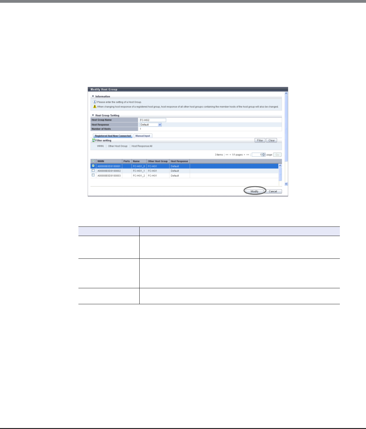
Chapter 9 Connectivity Management
9.2 Functions in the Action Area for Connectivity
ETERNUS Web GUI User’s Guide
Copyright 2013 FUJITSU LIMITED P2X0-1090-10ENZ0
467
3Add or delete a host in a host group in the following procedures.
■When adding or deleting a host by selecting from the host list
(1) Click the [Registered And Now Connected] tab.
(2) Add or delete hosts, and click the [Modify] button.
-Checkbox to select a host
Select the corresponding host checkbox in the FC host list, to add a host.
Clear the corresponding host checkbox in the FC host list, to delete a host.
→A confirmation screen appears.
Filter setting
Filter Description
WWN
Input the WWN that is to be displayed.
FC hosts matching or partially matching the input WWN are displayed.
When not using the WWN for filtering, leave this item blank.
Other Host Group
Input the other host group name that is to be displayed.
FC hosts which belong to any host groups that match or partially match the entered
name are displayed.
When not using the host group name for filtering, leave this item blank.
Host Response Select the host response that is to be displayed.
Any FC hosts that are allocated to the selected host response are displayed.
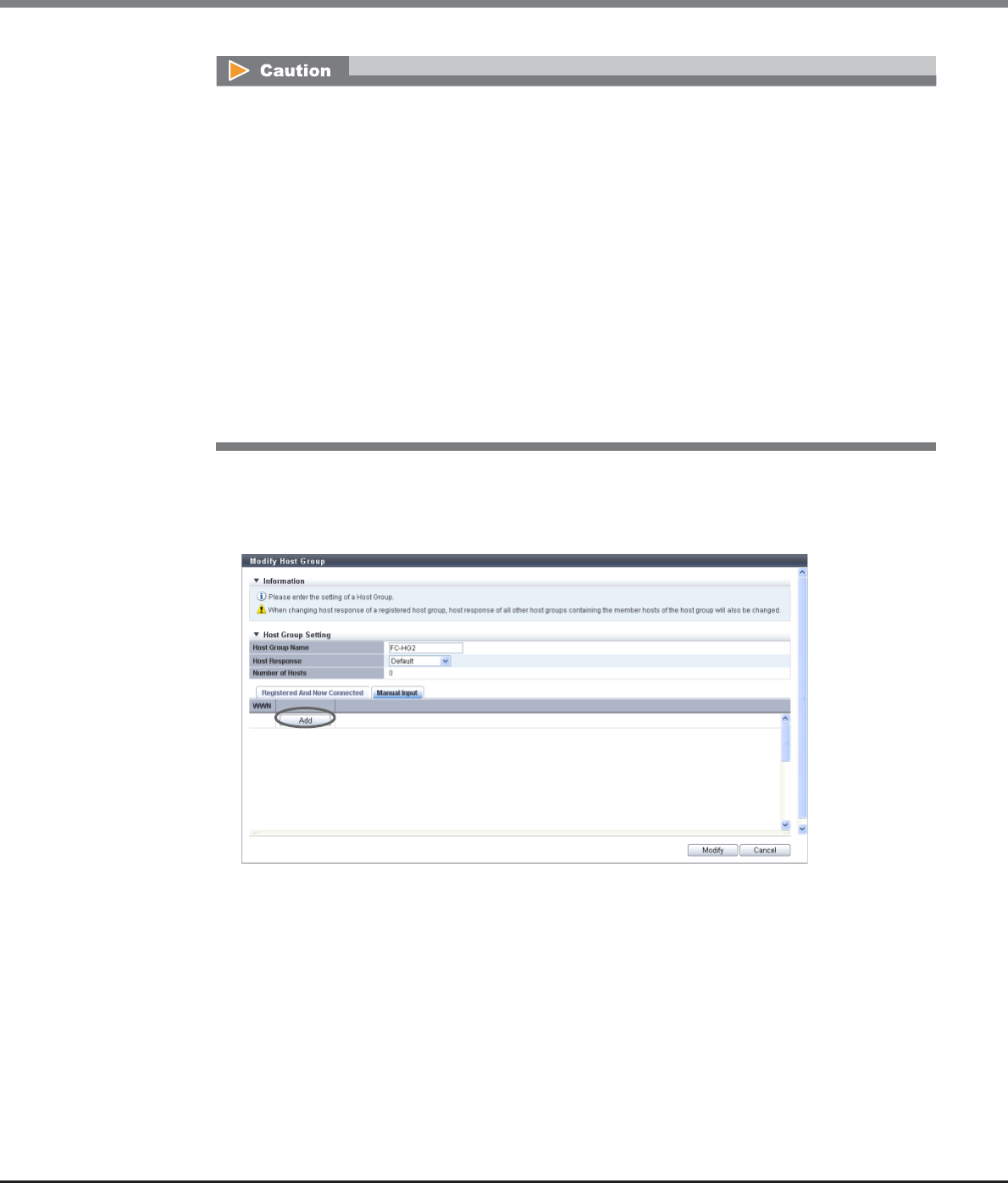
Chapter 9 Connectivity Management
9.2 Functions in the Action Area for Connectivity
ETERNUS Web GUI User’s Guide
Copyright 2013 FUJITSU LIMITED P2X0-1090-10ENZ0
468
■When adding a host by manually specifying the host
(1) Click the [Manual Input] tab.
(2) Click the [Add] button.
→The [Add FC/FCoE Host] screen appears.
•If the WWN is not displayed when clicking the [Rediscover] button, make sure that there is no error
in the connection environment, such as the connection between the host and the switch, and the
CA port settings of the ETERNUS DX Disk storage system. If there is no error in the connection
environment, contact the Support Department, or specify the WWN manually.
•An error screen appears in the following conditions:
-When the "Host Group Name" is not entered
-When the "Host Group Name" does not satisfy the input conditions
-When the "Host Group Name" overlaps with an existing host group name
(Host group names cannot overlap with any other host group names, irrespective of the
interface types.)
-When a host cannot recognize some LUNs
-When no hosts are registered in a host group, or when nine or more hosts are registered in a
host group (for ETERNUS DX8700 S2, 65 or more hosts are registered in a host group)
-When the total number of hosts has exceeded the maximum number for the ETERNUS DX Disk
storage system
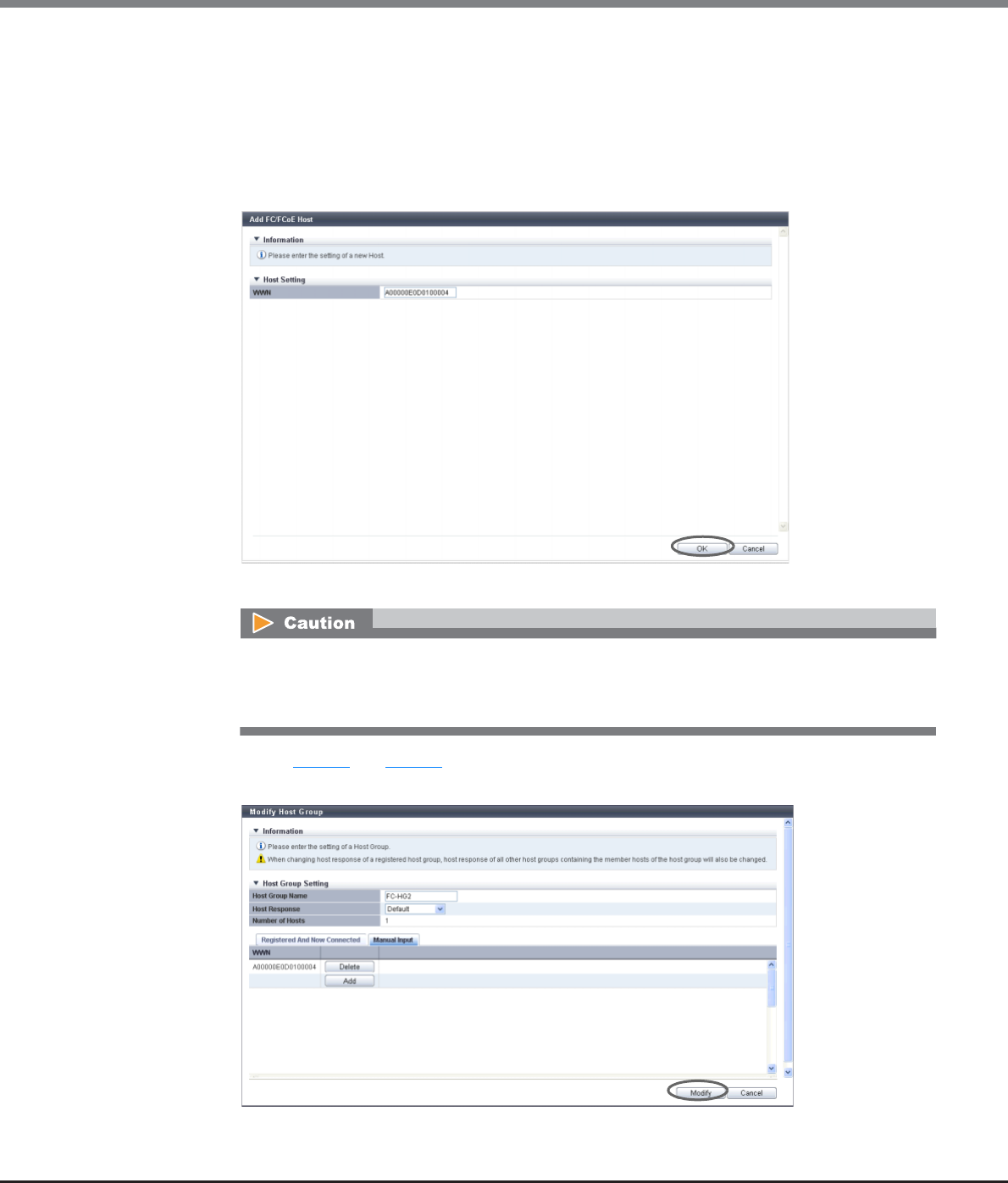
Chapter 9 Connectivity Management
9.2 Functions in the Action Area for Connectivity
ETERNUS Web GUI User’s Guide
Copyright 2013 FUJITSU LIMITED P2X0-1090-10ENZ0
469
(3) Manually specify the WWN of the host to be added, and click the [OK] button.
-WWN
Input the WWN for the FC host.
The following input conditions apply:
•Hexadecimal numbers (0 - 9, A - F, a - f)
•16 characters
•"F (f)" or "0" used in entire 16 characters are not allowed.
→Returns to the [Manual Input] screen.
(4) Repeat Step (2) and Step (3) to set more WWNs.
(5) After adding or deleting FC hosts is complete, click the [Modify] button.
→A confirmation screen appears.
An error screen appears in the following conditions:
•When the "WWN" is not input
•When the "WWN" does not satisfy the input conditions
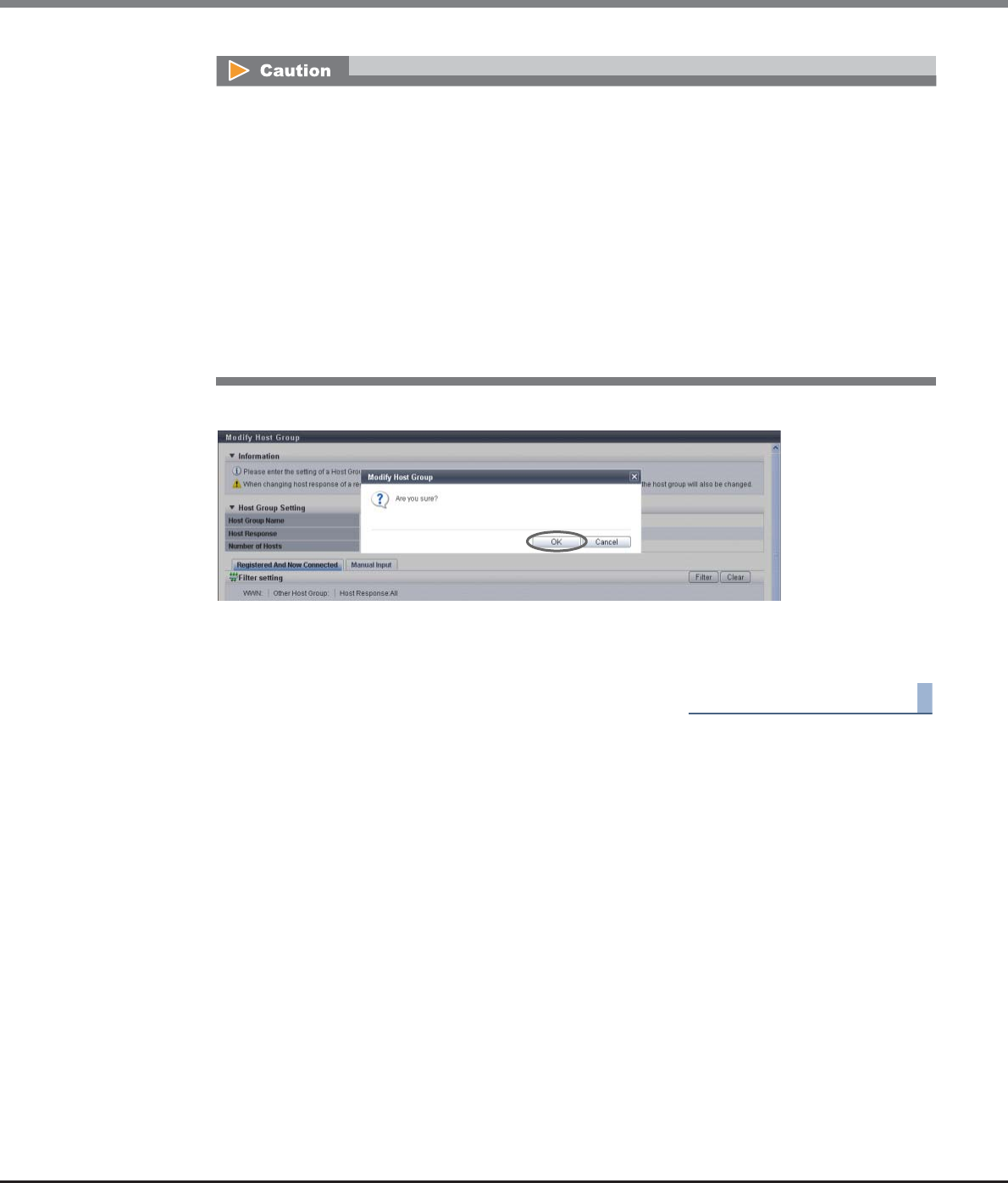
Chapter 9 Connectivity Management
9.2 Functions in the Action Area for Connectivity
ETERNUS Web GUI User’s Guide
Copyright 2013 FUJITSU LIMITED P2X0-1090-10ENZ0
470
4Click the [OK] button.
→Modification of the FC host group starts.
5Click the [Done] button to return to the [Host Group] screen.
End of procedure
9.2.2.7 Modify Host Group (iSCSI)
This function performs the following modifications to the existing iSCSI host group.
•Changing the "Host Group Name" settings
•Changing the "Host Response" settings
•Changing the "Host" settings (including addition and deletion of member hosts in a host group)
Hosts can be added to host groups which the host affinity setting has been already configured, or deleted
from host groups.
If a host is added, the host affinity setting is automatically configured to the host, as a host group member.
If a host is deleted, the host affinity setting is cleared from the corresponding host.
An error screen appears in the following conditions:
•When the "Host Group Name" is not entered
•When the "Host Group Name" does not satisfy the input conditions
•When the "Host Group Name" overlaps with an existing host group name
(Host group names cannot overlap with any other host group names, irrespective of the interface
types.)
•When the several FC hosts with the same WWNs have been registered
•When a host cannot recognize some LUNs
•When no hosts are registered in a host group, or when nine or more hosts are registered in a host
group (for ETERNUS DX8700 S2, 65 or more hosts are registered in a host group)
•When the total number of hosts has exceeded the maximum number for the ETERNUS DX Disk
storage system
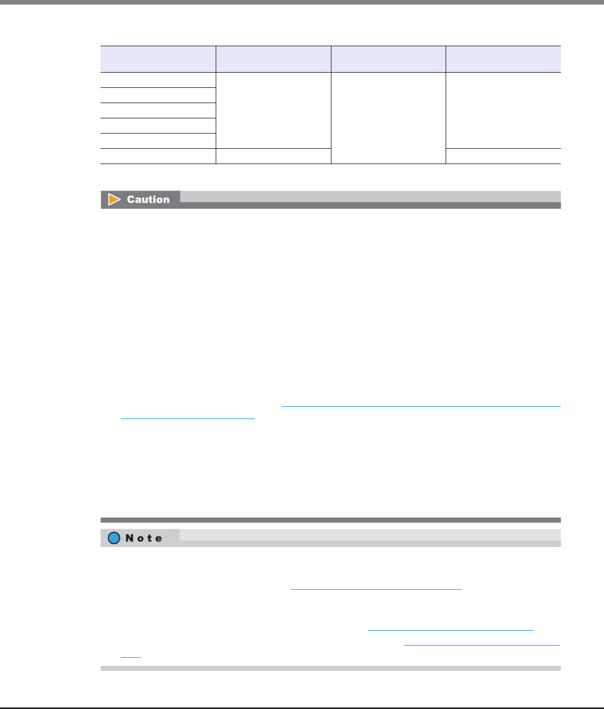
Chapter 9 Connectivity Management
9.2 Functions in the Action Area for Connectivity
ETERNUS Web GUI User’s Guide
Copyright 2013 FUJITSU LIMITED P2X0-1090-10ENZ0
471
The number of hosts that can be registered
*1: The total number of hosts irrespective of the interface types.
Model Number of hosts (HBAs)
(*1) per storage system
Number of hosts (HBAs)
per CA port
Number of hosts (HBAs)
per host group
ETERNUS DX80 S2 1024 256 8
ETERNUS DX90 S2
ETERNUS DX410 S2
ETERNUS DX440 S2
ETERNUS DX8100 S2
ETERNUS DX8700 S2 8192 64
•Registration of the host is necessary to create a host group. It is not possible to delete all hosts from a
host group.
•A host that has been registered with GUI by using this function belongs to one of the host groups.
•A host can be a member of several host groups. However, only one LUN group can be allocated to host
and port combinations when configuring host affinity.
•To assign an appropriate host response to a created host group, refer to "User's Guide -Server Connection-
" for each OS type. The host response configures the operation mode that is appropriate for the host. If an
appropriate host response is not configured to the host group, the path may not be switched correctly or
the volume may not be recognized correctly.
•The host response that is specified for a host group is applied all the member hosts in the target group.
When a host belongs to multiple host groups, the same host response must be applied for all the groups
to which the target host belongs. When a host that already belongs to an existing host group is added to
another host group, the host response of the target host is changed to the host response of the host
group to which the target host is added. The host response of the existing host group to which the target
host belongs is also changed. Refer to "Example of changing the host response when adding a host to an
existing host group" (page 447) for details.
•When changing the host response for the host group, the host responses of the other host groups to
which the target host belongs are also changed.
•Unlike GUI, CLI can register two iSCSI hosts that have the same iSCSI name by setting an IP address for one
of these iSCSI hosts and by not setting an IP address for the other iSCSI host. However, if iSCSI hosts are
registered in the ETERNUS DX Disk storage system in this way, iSCSI host settings cannot be changed
using GUI. Avoid this configuration when using GUI and CLI together. If both iSCSI hosts already exist, use
CLI to specify an IP address for the iSCSI host without the IP address.
•When a host was added to a host group, of which the host affinity setting has been configured, paths
between all the ports with the host affinity setting and the added host will be configured. To modify the
path between a host and a port, refer to "9.2.1.3 Modify Host Affinity" (page 428).
•When a host in the host group for which the host affinity settings are already configured is deleted, the
path from the host to the port is also deleted.
•To change the iSCSI host information, use the procedure in "9.2.2.16 Modify iSCSI Host" (page 509).
•To create a new host group and register hosts, use the procedure in "9.2.2.2 Add iSCSI Host Group" (page
448).

Chapter 9 Connectivity Management
9.2 Functions in the Action Area for Connectivity
ETERNUS Web GUI User’s Guide
Copyright 2013 FUJITSU LIMITED P2X0-1090-10ENZ0
472
The procedure to edit an iSCSI host group is as follows:
Procedure
1Select the iSCSI host group to be changed, and click [Modify Host Group] in [Action].
2Input a new host group name, or re-select a host response to be assigned to the host group.
●Host Group Setting
•Host Group Name
Specify the host group name.
An existing host group name cannot be specified. Refer to "Naming conventions for adding hosts"
(page 994) for details.
The following input conditions apply:
-Up to 16 alphanumeric characters and symbols (except ", (comma)" and "?")
-Space
•Host Response
Select a host response to be assigned to a host group.
The host response list created in the ETERNUS DX Disk storage system is displayed.
-Solaris MPxIO
-HP-UX
-AIX EMPD (*1)
-AIX VxVM
-AIX Single Path
-VS850/SVC
-Host responses created in the ETERNUS DX Disk storage system
-Default
*1: EMPD: ETERNUS Multipath Driver
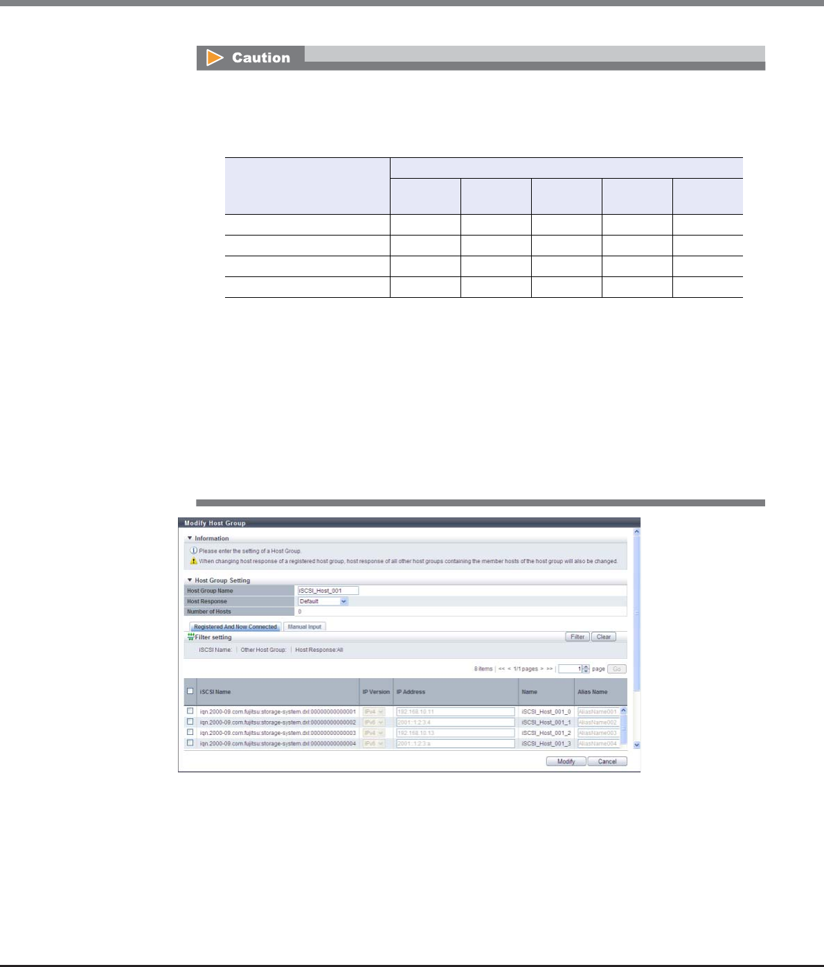
Chapter 9 Connectivity Management
9.2 Functions in the Action Area for Connectivity
ETERNUS Web GUI User’s Guide
Copyright 2013 FUJITSU LIMITED P2X0-1090-10ENZ0
473
•If the host response is changed for a host group that is configured with the host affinity setting,
the LUNs may not be able to be accessed from the host. Make sure to check the current LUN
settings and select a host response with an appropriate "Host Specific Mode" to change the
host response.
•The following modifications are applied for the host response settings with firmware version
V10L15 or later.
-"Others" is changed to "Default".
-"Windows EMPD", "Linux EMPD", and "Solaris EMPD" are deleted from the "Host Response"
value. However, these parameters are displayed if they are applied for host groups.
-The setting parameters for "Windows EMPD", "Linux EMPD", and "Solaris EMPD" are the
same as "Default". If one of the host responses that is described here is applied to a host
group, change the setting to "Default".
Available: The host can recognize LUNs
N/A: The host cannot recognize some LUNs
LUN settings for LUN groups
with host affinity settings
Host Specific Mode
Normal AIX Mode NR1000V
Mode
HP-UX
Mode
BS2000
Mode
LUN#0 – LUN#255 Available Available Available Available Available
LUN#0 - LUN#511 N/A Available Available Available Available
LUN#0 - LUN#1023 N/A N/A N/A Available Available
LUN#0 - LUN#4095 N/A N/A N/A N/A Available

Chapter 9 Connectivity Management
9.2 Functions in the Action Area for Connectivity
ETERNUS Web GUI User’s Guide
Copyright 2013 FUJITSU LIMITED P2X0-1090-10ENZ0
474
3Add or delete a host in a host group in the following procedures.
■When adding or deleting a host by selecting from the host list
(1) Click the [Registered And Now Connected] tab.
The following hosts are displayed in the [Registered And Now Connected] tab:
-Hosts that belong to the selected host group
-Hosts that are connected to an iSCSI-CA or an iSCSI-CA/RA but are not registered in the ETERNUS
DX Disk storage system (*1)
*1: "Host that is not registered in the ETERNUS DX Disk storage system" indicates that a host with the
same iSCSI name, IP version, and Alias Name as the target host is not registered in the storage
system. The host is regarded as unregistered host even if a host with the same iSCSI name, IP version,
Alias Name, and different IP address is already registered. The obtained "iSCSI Name", "IP Version", "IP
Address", and "Alias Name" are displayed.
-Hosts that are registered in the ETERNUS DX Disk storage system but do not belong to the host
group
-Hosts that are registered in the ETERNUS DX Disk storage system and belong to the host group
Click the [Rediscover] button to update the iSCSI host list.
(2) Add or delete iSCSI hosts, register the iSCSI host information (the IP address and the Alias name,
etc.) to the added host, and click the [Modify] button.
-Checkbox to select a host
Select the corresponding host checkbox in the iSCSI host list, to add a host.
Clear the corresponding host checkbox in the iSCSI host list, to delete a host.
•If the iSNS server has not been configured in "9.2.3.8 Modify iSCSI Port Parameters" (page
541), the iSCSI host cannot be automatically acquired.
•The following restrictions in the environment that is described below apply for the automatic
acquirement of host information (*1) even when the iSNS server is specified.
*1: "iSCSI Name", "IP Version", "IP Address", and "Alias Name"
-When one of the following OSs is used and there are multiple hosts that have the same
iSCSI name but different IP addresses, only the information of one host can be acquired.
•Windows Server 2003
•Windows Server 2008
•Windows Server 2008 R2
•Oracle Solaris 10
-When the host OS is Oracle Solaris 11, "IP Version" and "IP Address" cannot be acquired.
•The following items can be specified only for the iSCSI hosts that are selected by checkboxes;
"IP Version", "IP Address", "Alias Name", "CHAP User ID", "Change CHAP Password", "CHAP
Password", and "Confirm CHAP Password".

Chapter 9 Connectivity Management
9.2 Functions in the Action Area for Connectivity
ETERNUS Web GUI User’s Guide
Copyright 2013 FUJITSU LIMITED P2X0-1090-10ENZ0
475
-IP Version
Select the IP version of the iSCSI host from "IPv4" and "IPv6".
-IP Address
Specify the IP address of the iSCSI host.
There are two methods to specify an IP address; "IPv4" and "IPv6". The IP address must be
specified with the selected IP version (IPv4 or IPv6). The following IPv6 addresses can be used;
"link local address", "global address", "unique local address", and "6to4 address". Refer to
"Available IPv6 Address" (page 757) for details. When the current setting is displayed, the IPv6
address is displayed as an abbreviation.
It is not necessary to specify this item if IP address is not used.
The following input conditions apply:
•For IPv4 address
xxx.xxx.xxx.xxx
xxx: 1 - 255 for the top field (decimal)
xxx: 0 - 255 for other fields (decimal)
•For IPv6 address
xxxx:xxxx:xxxx:xxxx:xxxx:xxxx:xxxx:xxxx
xxxx: 0 - ffff (FFFF) (hexadecimal, alphanumeric characters)
Refer to "IPv6 Address Notation" (page 378) for details.
-Alias Name
The Alias name of the member host is displayed.
To add an iSCSI host to a host group, select the checkbox of the iSCSI host to be added, and enter
the Alias name.
If the iSCSI host has already been registered in the ETERNUS DX Disk storage system, the Alias
name is displayed.
It is not necessary to specify this item if Alias name is not used.
An existing Alias name cannot be specified.
The following input conditions apply:
•Up to 31 alphanumeric characters and symbols (except ", (comma)" and "?")
•Space
-CHAP User ID
The user ID of the member host, for which CHAP Authentication will be used, is displayed.
To use CHAP Authentication on the iSCSI host to be added, select the checkbox of the iSCSI host,
and enter the user ID.
If the iSCSI host has already been registered in the ETERNUS DX Disk storage system, the user ID
is displayed.
It is not necessary to specify this item if CHAP Authentication is not used.
Configure the user ID and the password as a pair.
The following input conditions apply:
•Up to 255 alphanumeric characters and symbols (except ", (comma)" and "?")
•Space
To register an iSCSI host without using an IP address, perform IP version selection as follows:
•Select "IPv4" when the IP address format of the iSCSI host is IPv4 (when using an IPv4 host)
•Select "IPv6" when the IP address format of the iSCSI host is IPv6 (when using an IPv6 host)
•If the IP address format of the iSCSI host cannot be checked (when either an IPv4 host or an
IPv6 host is used), register two hosts. Select "IPv4" for one host, and select "IPv6" for the
other host. Specify the same iSCSI name, CHAP user ID, and CHAP password for each host.
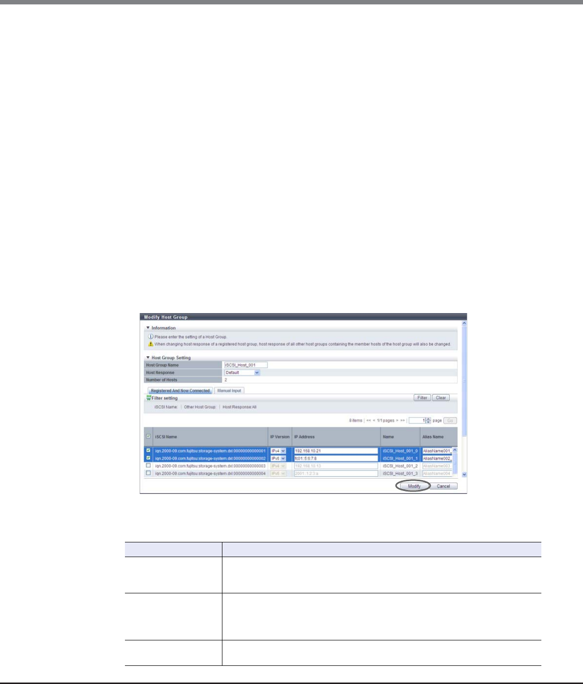
Chapter 9 Connectivity Management
9.2 Functions in the Action Area for Connectivity
ETERNUS Web GUI User’s Guide
Copyright 2013 FUJITSU LIMITED P2X0-1090-10ENZ0
476
-Change CHAP Password
To register or change the CHAP Authentication password, select the checkbox.
-CHAP Password
The password for the member host, on which CHAP Authentication will be used, is displayed
with "*".
To use CHAP Authentication on the iSCSI host to be added, enter the password. It is not
necessary to specify this item if CHAP Authentication is not used.
The password can be entered only when the iSCSI host has been selected, and the "Change CHAP
Password" checkbox has been selected.
Configure the user ID and the password as a pair.
The following input conditions apply:
•12 - 100 alphanumeric characters and symbols (except ", (comma)" and "?")
•Space
-Confirm CHAP Password
The confirmation password for the member host, on which CHAP Authentication will be used, is
displayed with "*".
To use CHAP Authentication on the iSCSI host to be added, re-enter the password for
confirmation. It is not necessary to specify this item if CHAP Authentication is not used.
The password can be entered only when the iSCSI host has been selected, and the "Change CHAP
Password" checkbox has been selected.
The following input conditions apply:
•12 - 100 alphanumeric characters and symbols (except ", (comma)" and "?")
•Space
→A confirmation screen appears.
Filter setting
Filter Description
iSCSI Name
Input the iSCSI name that is to be displayed.
iSCSI hosts matching or partially matching the input iSCSI name are displayed.
When not using the iSCSI name for filtering, leave this item blank.
Other Host Group
Input the other host group name that is to be displayed.
iSCSI hosts which belong to any host groups that match or partially match the
entered name are displayed.
When not using the host group name for filtering, leave this item blank.
Host Response Select the host response name that is to be displayed.
Any iSCSI hosts that are allocated to the selected host response are displayed.
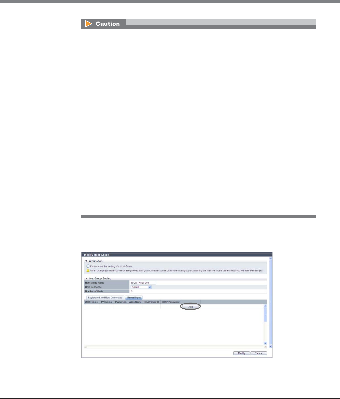
Chapter 9 Connectivity Management
9.2 Functions in the Action Area for Connectivity
ETERNUS Web GUI User’s Guide
Copyright 2013 FUJITSU LIMITED P2X0-1090-10ENZ0
477
■When adding a host by manually specifying the host
(1) Click the [Manual Input] tab.
(2) Click the [Add] button.
→The [Add iSCSI Host] screen appears.
An error screen appears in the following conditions:
•When the "Host Group Name" is not entered
•When the "Host Group Name" does not satisfy the input conditions
•When the "Host Group Name" overlaps with an existing host group name
(Host group names cannot overlap with any other host group names, irrespective of the
interface types.)
•When the "IP Address" does not satisfy the input conditions
•When the "IP Address" is specified and an iSCSI host with the same "iSCSI Name" and "IP
Address" is already registered
•When the "IP Address" is not specified and an iSCSI host with the same "iSCSI Name" and "IP
Version" is already registered
•When the "Alias Name" does not satisfy the input conditions
•When the "Alias Name" overlaps the existing Alias name
•When the "CHAP User ID" does not satisfy the input conditions
•When the "CHAP Password" does not satisfy the input conditions
•When the "Confirm CHAP Password" does not satisfy the input conditions
•When the "CHAP Password" and the "Confirm CHAP Password" do not match
•When either of the "CHAP User ID" or the "CHAP Password" has been specified
•When a host cannot recognize some LUNs
•When no hosts are registered in a host group, or when nine or more hosts are registered in a
host group (for ETERNUS DX8700 S2, 65 or more hosts are registered in a host group)
•When the total number of hosts has exceeded the maximum number for the ETERNUS DX Disk
storage system
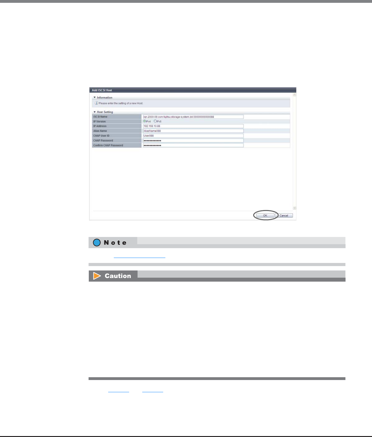
Chapter 9 Connectivity Management
9.2 Functions in the Action Area for Connectivity
ETERNUS Web GUI User’s Guide
Copyright 2013 FUJITSU LIMITED P2X0-1090-10ENZ0
478
(3) Manually specify the iSCSI host information of the host to be added, and click the [OK] button.
-iSCSI Name
Specify an iSCSI name of the iSCSI host (required).
The following input conditions apply:
•Alphabetic characters (lower case) and numeric characters
•Symbols "-" (hyphen), "." (period), and ":" (colon)
•The name starts with "iqn." or "eui."
•4 - 223 characters
→Returns to the [Manual Input] screen.
(4) Repeat Step (2) and Step (3) to set more iSCSI hosts.
Refer to Step (2) (page 474) for other settings.
An error screen appears in the following conditions:
•When the "iSCSI Name" is not entered
•When the "iSCSI Name" does not satisfy the input conditions
•When the "IP Address" does not satisfy the input conditions
•When the "Alias Name" does not satisfy the input conditions
•When the "CHAP User ID" does not satisfy the input conditions
•When the "CHAP Password" does not satisfy the input conditions
•When the "Confirm CHAP Password" does not satisfy the input conditions
•When the "CHAP Password" and the "Confirm CHAP Password" do not match
•When either of the "CHAP User ID" or the "CHAP Password" has been specified
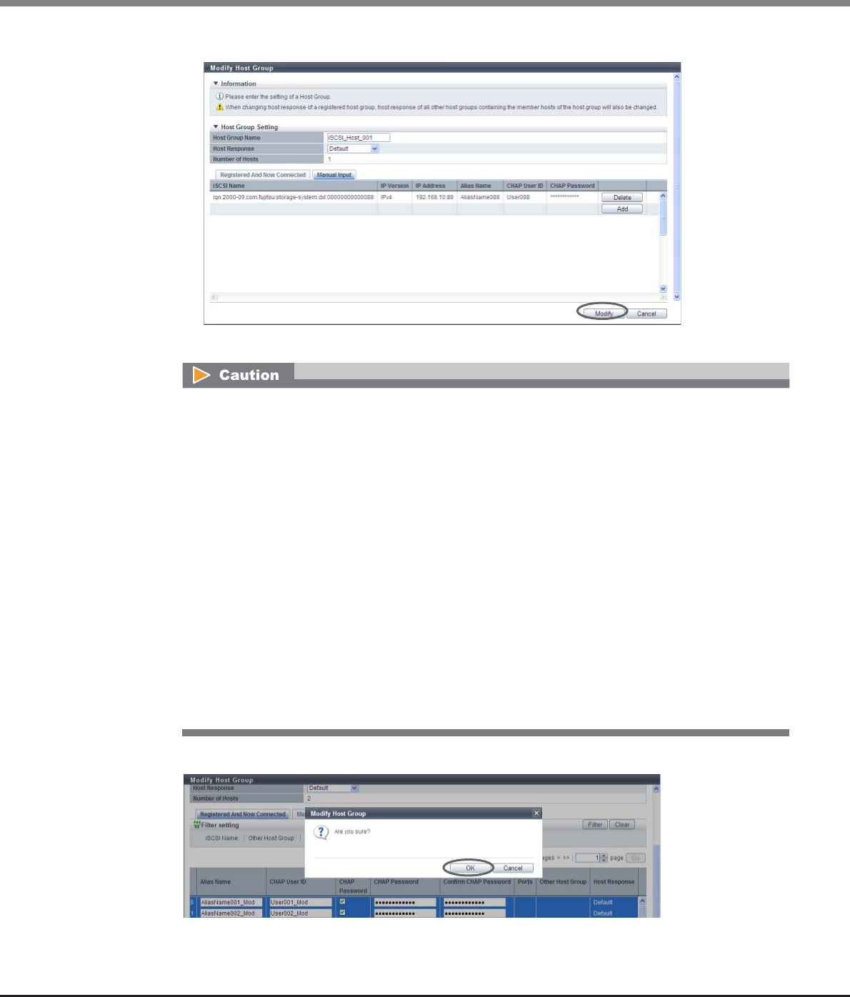
Chapter 9 Connectivity Management
9.2 Functions in the Action Area for Connectivity
ETERNUS Web GUI User’s Guide
Copyright 2013 FUJITSU LIMITED P2X0-1090-10ENZ0
479
(5) After adding or deleting iSCSI hosts is complete, click the [Modify] button.
→A confirmation screen appears.
4Click the [OK] button.
→Modification of the iSCSI host group starts.
An error screen appears in the following conditions:
•When the "Host Group Name" is not entered
•When the "Host Group Name" does not satisfy the input conditions
•When the "Host Group Name" overlaps with an existing host group name
(Host group names cannot overlap with any other host group names, irrespective of the interface
types.)
•When the same iSCSI name is specified for multiple iSCSI hosts
•When the "IP Address" is specified and an iSCSI host with the same "iSCSI Name" and "IP Address" is
already registered
•When the "IP Address" is not specified and an iSCSI host with the same "iSCSI Name" and "IP
Version" is already registered
•When the "Alias Name" overlaps the existing Alias name
•When a host cannot recognize some LUNs
•When no hosts are registered in a host group, or when nine or more hosts are registered in a host
group (for ETERNUS DX8700 S2, 65 or more hosts are registered in a host group)
•When the total number of hosts has exceeded the maximum number for the ETERNUS DX Disk
storage system
Chapter 9 Connectivity Management
9.2 Functions in the Action Area for Connectivity
ETERNUS Web GUI User’s Guide
Copyright 2013 FUJITSU LIMITED P2X0-1090-10ENZ0
480
5Click the [Done] button to return to the [Host Group] screen.
End of procedure
9.2.2.8 Modify Host Group (SAS)
This function performs the following modifications to the existing SAS host group.
•Changing the "Host Group Name" settings
•Changing the "Host Response" settings
•Changing the "Host" settings (including addition and deletion of member hosts in a host group)
Hosts can be added to host groups which the host affinity setting has been already configured, or deleted
from host groups.
If a host is added, the host affinity setting is automatically configured to the host, as a host group member.
If a host is deleted, the host affinity setting is cleared from the corresponding host.
The number of hosts that can be registered
*1: The total number of hosts irrespective of the interface types.
Model Number of hosts (HBAs)
(*1) per storage system
Number of hosts (HBAs)
per CA port
Number of hosts (HBAs)
per host group
ETERNUS DX80 S2 1024 256 8
ETERNUS DX90 S2
•Registration of the host is necessary to create a host group. It is not possible to delete all hosts from a
host group.
•A host that has been registered with GUI by using this function belongs to one of the host groups.
•A host can be a member of several host groups. However, only one LUN group can be allocated to host
and port combinations when configuring host affinity.
•To assign an appropriate host response to a created host group, refer to "User's Guide -Server Connection-
" for each OS type. The host response configures the operation mode that is appropriate for the host. If an
appropriate host response is not configured to the host group, the path may not be switched correctly or
the volume may not be recognized correctly.
•The host response that is specified for a host group is applied all the member hosts in the target group.
When a host belongs to multiple host groups, the same host response must be applied for all the groups
to which the target host belongs. When a host that already belongs to an existing host group is added to
another host group, the host response of the target host is changed to the host response of the host
group to which the target host is added. The host response of the existing host group to which the target
host belongs is also changed. Refer to "Example of changing the host response when adding a host to an
existing host group" (page 447) for details.
•When changing the host response for the host group, the host responses of the other host groups to
which the target host belongs are also changed.

Chapter 9 Connectivity Management
9.2 Functions in the Action Area for Connectivity
ETERNUS Web GUI User’s Guide
Copyright 2013 FUJITSU LIMITED P2X0-1090-10ENZ0
481
The procedure to edit a SAS host group is as follows:
Procedure
1Select the SAS host group to be changed, and click [Modify Host Group] in [Action].
2Input a new host group name, or re-select a host response to be assigned to the host group.
●Host Group Setting
•Host Group Name
Specify the host group name.
An existing host group name cannot be specified. Refer to "Naming conventions for adding hosts"
(page 994) for details.
The following input conditions apply:
-Up to 16 alphanumeric characters and symbols (except ", (comma)" and "?")
-Space
•Host Response
Select a host response to be assigned to a host group.
The host response list created in the ETERNUS DX Disk storage system is displayed.
-Solaris MPxIO
-HP-UX
-AIX EMPD (*1)
-AIX VxVM
-AIX Single Path
-VS850/SVC
-Host responses created in the ETERNUS DX Disk storage system
-Default
*1: EMPD: ETERNUS Multipath Driver
•When a host was added to a host group, of which the host affinity setting has been configured, paths
between all the ports with the host affinity setting and the added host will be configured. To modify the
path between a host and a port, refer to "9.2.1.3 Modify Host Affinity" (page 428).
•When a host in the host group for which the host affinity settings are already configured is deleted, the
path from the host to the port is also deleted.
•To change the host group name or the SAS address, use the procedure in "9.2.2.17 Modify SAS Host"
(page 514).
•To create a new host group and register hosts, use the procedure in "9.2.2.3 Add SAS Host Group" (page
456).
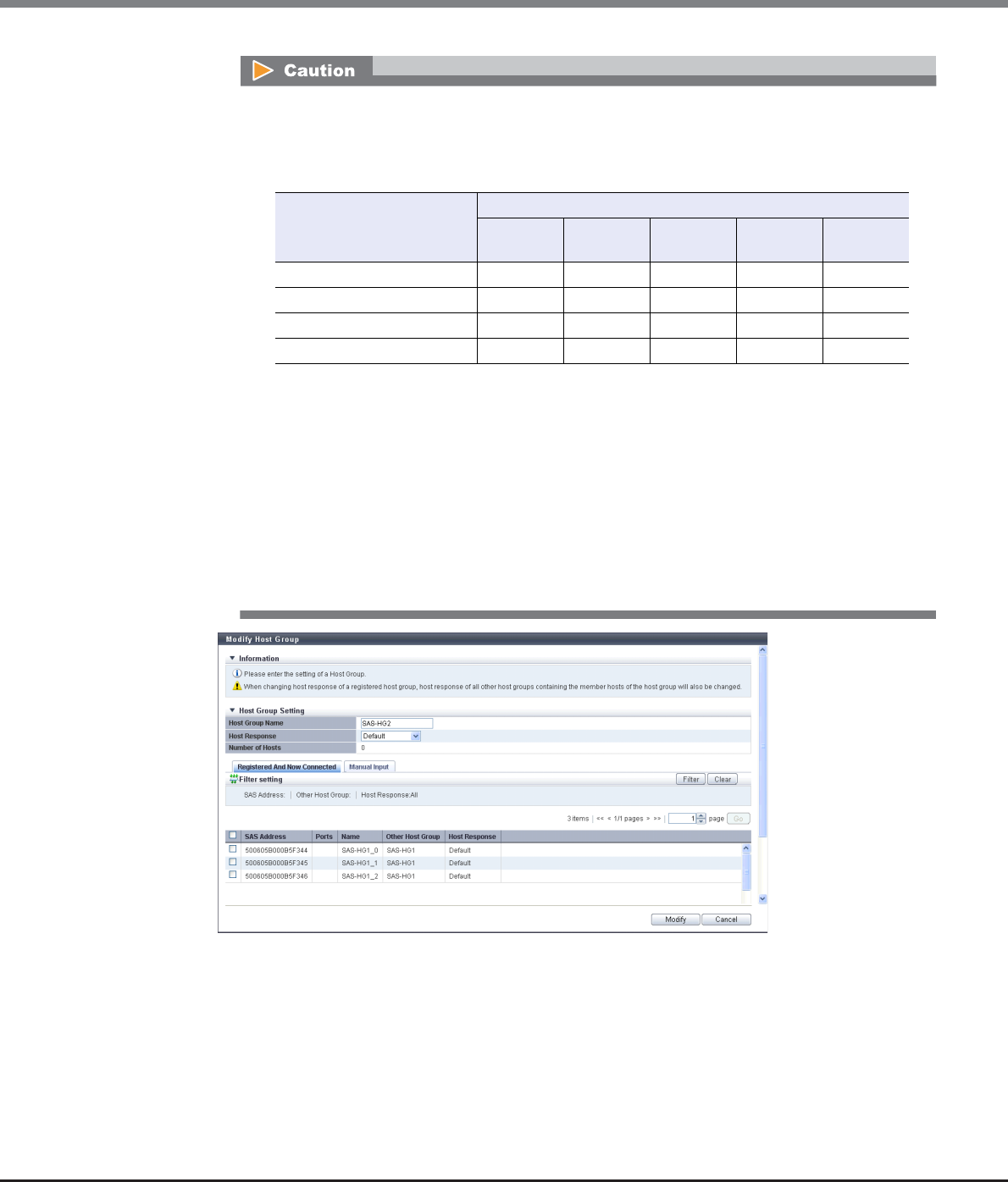
Chapter 9 Connectivity Management
9.2 Functions in the Action Area for Connectivity
ETERNUS Web GUI User’s Guide
Copyright 2013 FUJITSU LIMITED P2X0-1090-10ENZ0
482
•If the host response is changed for a host group that is configured with the host affinity setting,
the LUNs may not be able to be accessed from the host. Make sure to check the current LUN
settings and select a host response with an appropriate "Host Specific Mode" to change the
host response.
•The following modifications are applied for the host response settings with firmware version
V10L15 or later.
-"Others" is changed to "Default".
-"Windows EMPD", "Linux EMPD", and "Solaris EMPD" are deleted from the "Host Response"
value. However, these parameters are displayed if they are applied for host groups.
-The setting parameters for "Windows EMPD", "Linux EMPD", and "Solaris EMPD" are the
same as "Default". If one of the host responses that is described here is applied to a host
group, change the setting to "Default".
Available: The host can recognize LUNs
N/A: The host cannot recognize some LUNs
LUN settings for LUN groups
with host affinity settings
Host Specific Mode
Normal AIX Mode NR1000V
Mode
HP-UX
Mode
BS2000
Mode
LUN#0 – LUN#255 Available Available Available Available Available
LUN#0 - LUN#511 N/A Available Available Available Available
LUN#0 - LUN#1023 N/A N/A N/A Available Available
LUN#0 - LUN#4095 N/A N/A N/A N/A Available
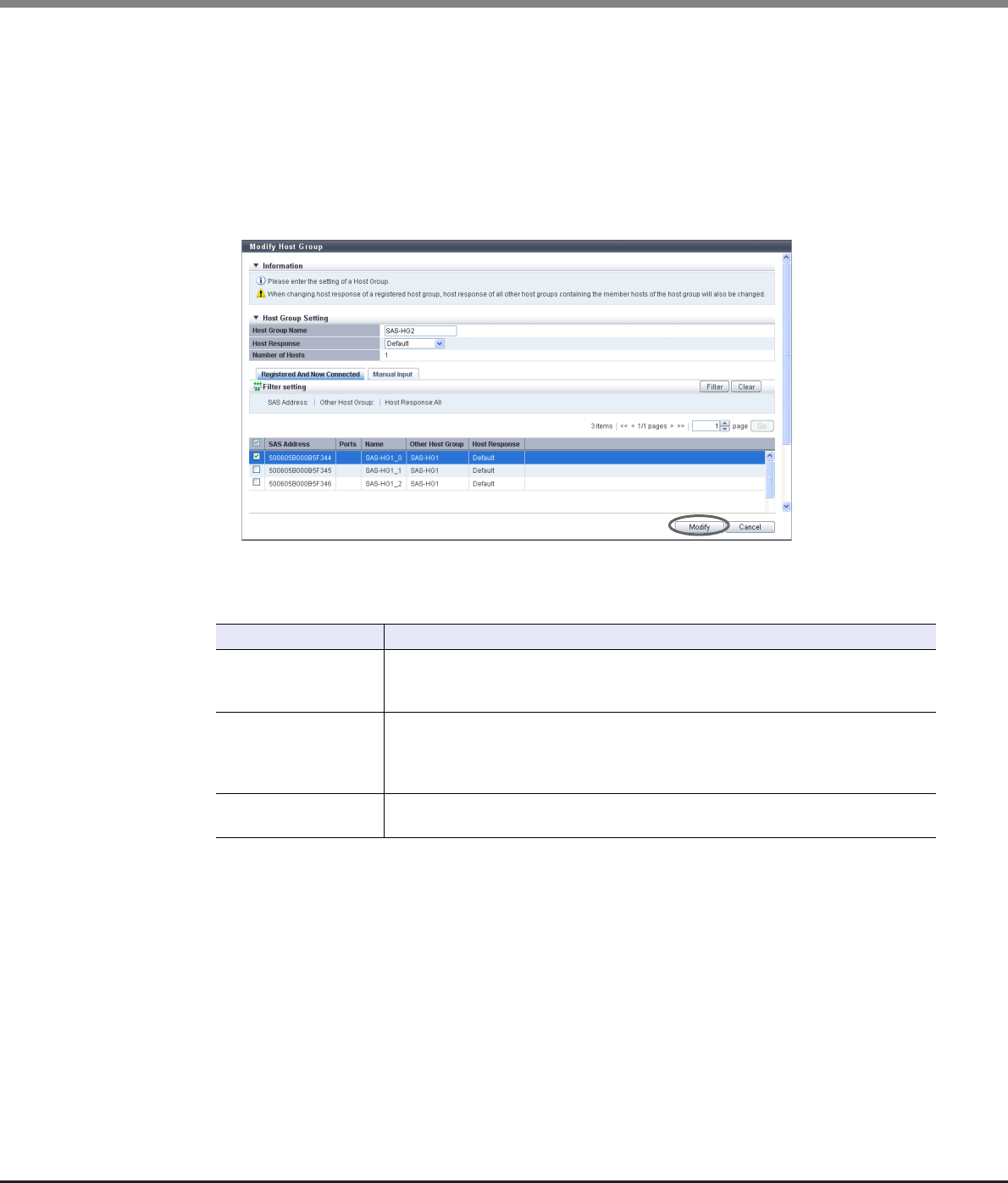
Chapter 9 Connectivity Management
9.2 Functions in the Action Area for Connectivity
ETERNUS Web GUI User’s Guide
Copyright 2013 FUJITSU LIMITED P2X0-1090-10ENZ0
483
3Add or delete a host in a host group in the following procedures.
■When adding or deleting a host by selecting from the host list
(1) Click the [Registered And Now Connected] tab.
(2) Add or delete hosts, and click the [Modify] button.
-Checkbox to select a host
Select the corresponding host checkbox in the SAS host list, to add a host.
Clear the corresponding host checkbox in the SAS host list, to delete a host.
→A confirmation screen appears.
Filter setting
Filter Description
SAS Address
Input the SAS address to be displayed.
SAS hosts matching or partially matching the input SAS address are displayed.
When not using the SAS address for filtering, leave this item blank.
Other Host Group
Input the other host group name that is to be displayed.
SAS hosts which belong to any host groups that match or partially match the entered
name are displayed.
When not using the host group name for filtering, leave this item blank.
Host Response Select the host response name that is to be displayed.
Any SAS hosts that are allocated to the selected host response are displayed.
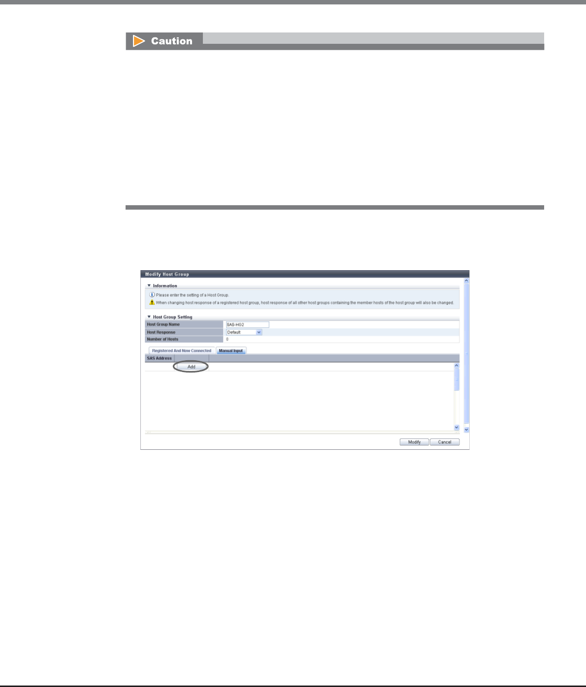
Chapter 9 Connectivity Management
9.2 Functions in the Action Area for Connectivity
ETERNUS Web GUI User’s Guide
Copyright 2013 FUJITSU LIMITED P2X0-1090-10ENZ0
484
■When adding a host by manually specifying the host
(1) Click the [Manual Input] tab.
(2) Click the [Add] button.
→The [Add SAS Host] screen appears.
An error screen appears in the following conditions:
•When the "Host Group Name" is not entered
•When the "Host Group Name" does not satisfy the input conditions
•When the "Host Group Name" overlaps with an existing host group name
(Host group names cannot overlap with any other host group names, irrespective of the interface
types.)
•When a host cannot recognize some LUNs
•When no hosts are registered in a host group, or when nine or more hosts are registered in a host
group
•When the total number of hosts has exceeded the maximum number for the ETERNUS DX Disk
storage system
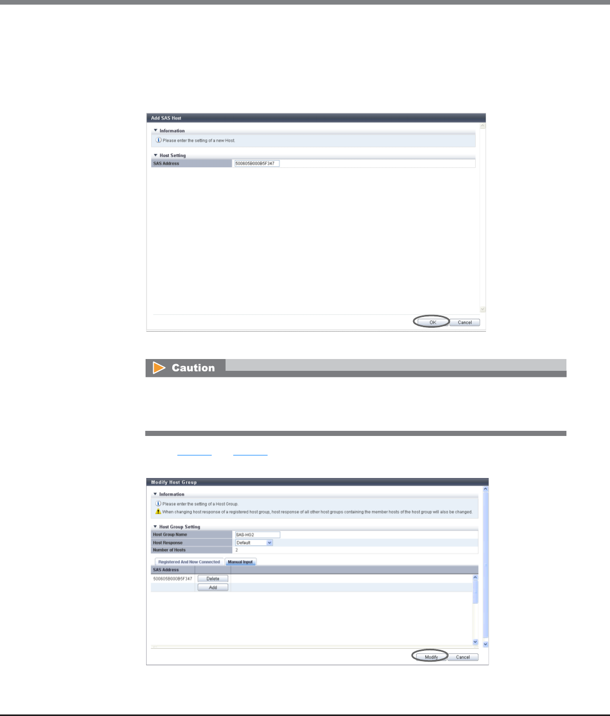
Chapter 9 Connectivity Management
9.2 Functions in the Action Area for Connectivity
ETERNUS Web GUI User’s Guide
Copyright 2013 FUJITSU LIMITED P2X0-1090-10ENZ0
485
(3) Manually specify the SAS address of the host to be added, and click the [OK] button.
-SAS Address
Specify the SAS address of the SAS host.
The following input conditions apply:
•16 hexadecimal numbers
•"F (f)" or "0" used in entire 16 characters are not allowed.
→Returns to the [Manual Input] screen.
(4) Repeat Step (2) and Step (3) to set more SAS addresses.
(5) After adding or deleting SAS hosts is complete, click the [Modify] button.
→A confirmation screen appears.
An error screen appears in the following conditions:
•When the "SAS Address" is not input
•When the "SAS Address" does not satisfy the input conditions

Chapter 9 Connectivity Management
9.2 Functions in the Action Area for Connectivity
ETERNUS Web GUI User’s Guide
Copyright 2013 FUJITSU LIMITED P2X0-1090-10ENZ0
486
4Click the [OK] button.
→Modification of the SAS host group starts.
5Click the [Done] button to return to the [Host Group] screen.
End of procedure
An error screen appears in the following conditions:
•When the "Host Group Name" is not entered
•When the "Host Group Name" does not satisfy the input conditions
•When the "Host Group Name" overlaps with an existing host group name
(Host group names cannot overlap with any other host group names, irrespective of the interface
types.)
•When the several SAS hosts with the same SAS addresses have been registered
•When a host cannot recognize some LUNs
•When no hosts are registered in a host group, or when nine or more hosts are registered in a host
group
•When the total number of hosts has exceeded the maximum number for the ETERNUS DX Disk
storage system
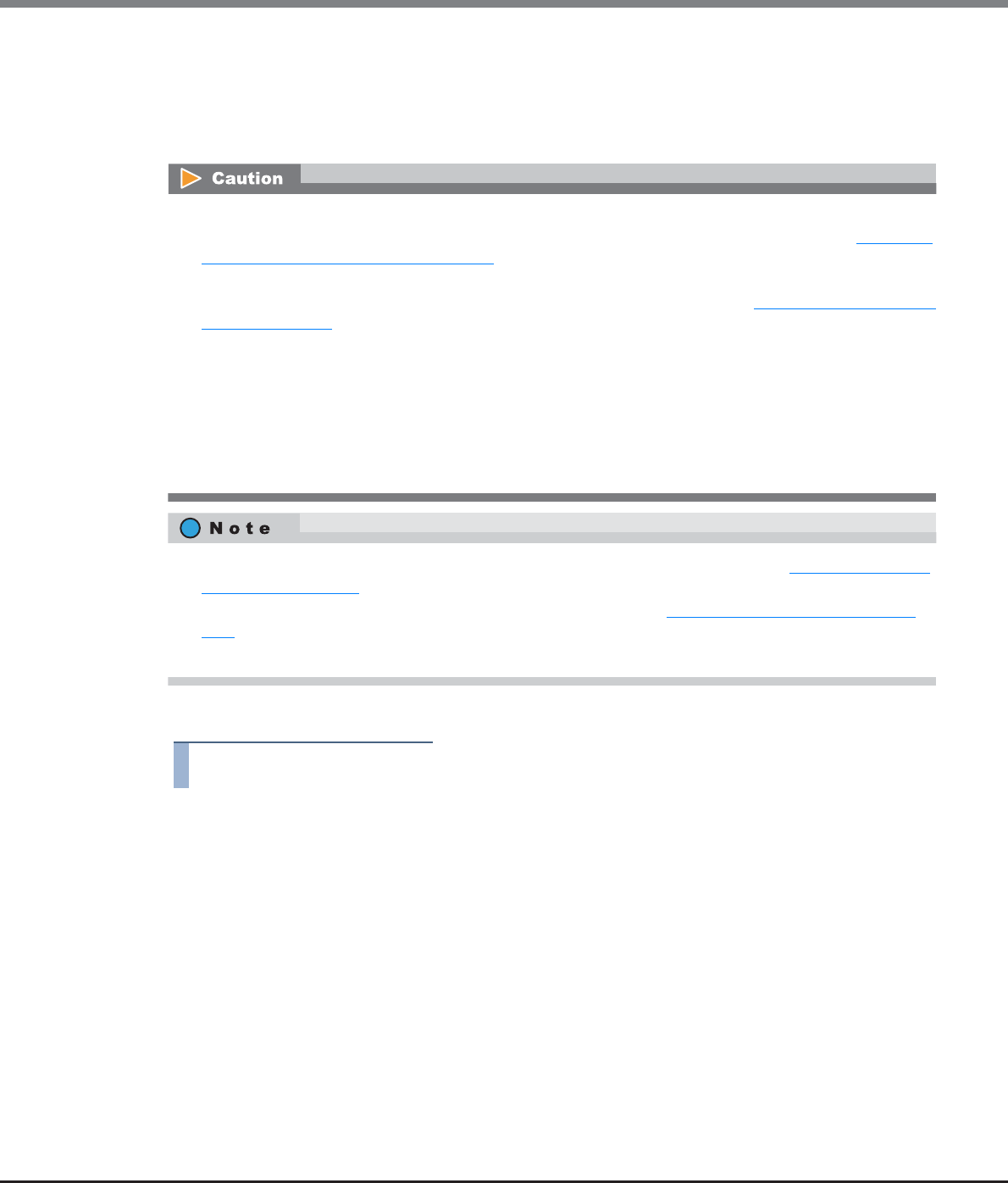
Chapter 9 Connectivity Management
9.2 Functions in the Action Area for Connectivity
ETERNUS Web GUI User’s Guide
Copyright 2013 FUJITSU LIMITED P2X0-1090-10ENZ0
487
9.2.2.9 Add FC/FCoE Host
This function registers a new FC/FCoE host (HBA).
The total number of all the interface type hosts that can be registered in the ETERNUS DX Disk storage system
is 1024 (8192 for the ETERNUS DX8700 S2).
The procedure to register an FC host is as follows:
Procedure
1Click [Add FC/FCoE Host] in [Action].
2Add a host in the ETERNUS DX Disk storage system in the following procedures.
■When registering a host by selecting from the host list
(1) Click the [Now Connected] tab.
•This action item is only displayed when the "Use "Add Host"" checkbox is selected for the "Function to Add
Host" field in "Web GUI Settings". This item is not selected (not displayed) by default. Refer to "11.2.13.4
Setup Subsystem Parameters" (page 935) for details.
•Note that this function does not create a host group. The ETERNUS DX Disk storage system also has a
function that creates new host groups to register hosts as its members. Refer to "9.2.2.1 Add FC/FCoE Host
Group" (page 440) for details.
•Hosts that are registered with this function can belong to multiple host groups. However, only one LUN
group can be allocated to host and port combinations when configuring host affinity.
•Refer to "User's Guide -Server Connection-" for each OS type to assign an appropriate host response to the
host that is to be registered. The host response configures the operation mode which is appropriate to the
host.
If an appropriate host response is not configured, the path may not be switched correctly or the volume
may not be recognized correctly.
•To change the FC host information, use the [Modify FC/FCoE Host] function. Refer to "9.2.2.15 Modify FC/
FCoE Host" (page 507) for details.
•The host affinity setting can be specified for each FC host. Refer to "9.2.1.1 Create Host Affinity" (page
414) for details.
•Both "FC host" and "FCoE host" are abbreviated as "FC host" in this section.
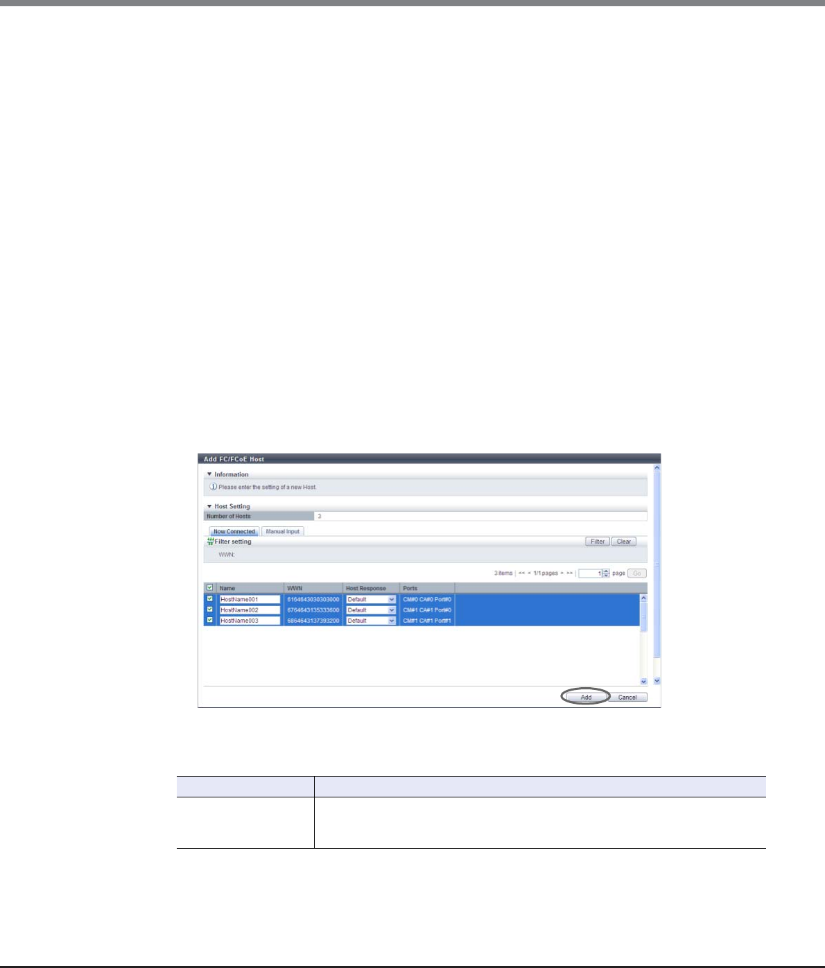
Chapter 9 Connectivity Management
9.2 Functions in the Action Area for Connectivity
ETERNUS Web GUI User’s Guide
Copyright 2013 FUJITSU LIMITED P2X0-1090-10ENZ0
488
(2) Select the host that is to be registered from the FC host list, input the FC host information, and click
the [Add] button.
-Checkbox to select a host
Select the checkbox of the FC host that is to be registered in the ETERNUS DX Disk storage
system. The host name and host response can only be specified for the selected FC host.
-Name
Input the name for the FC host.
The following input conditions apply:
•Up to 16 alphanumeric characters and symbols (except ", (comma)" and "?")
•Space
-Host Response
Select a host response to be assigned to a host.
The host response list created in the ETERNUS DX Disk storage system is displayed.
•Solaris MPxIO
•HP-UX
•AIX EMPD (*1)
•AIX VxVM
•AIX Single Path
•VS850/SVC
•Host responses created in the ETERNUS DX Disk storage system
•Default
*1: EMPD: ETERNUS Multipath Driver
→A confirmation screen appears.
Filter Setting
Filter Description
WWN
Input the WWN that is to be displayed.
FC hosts matching or partially matching the entered WWN are displayed.
When not using the WWN for filtering, leave this item blank.
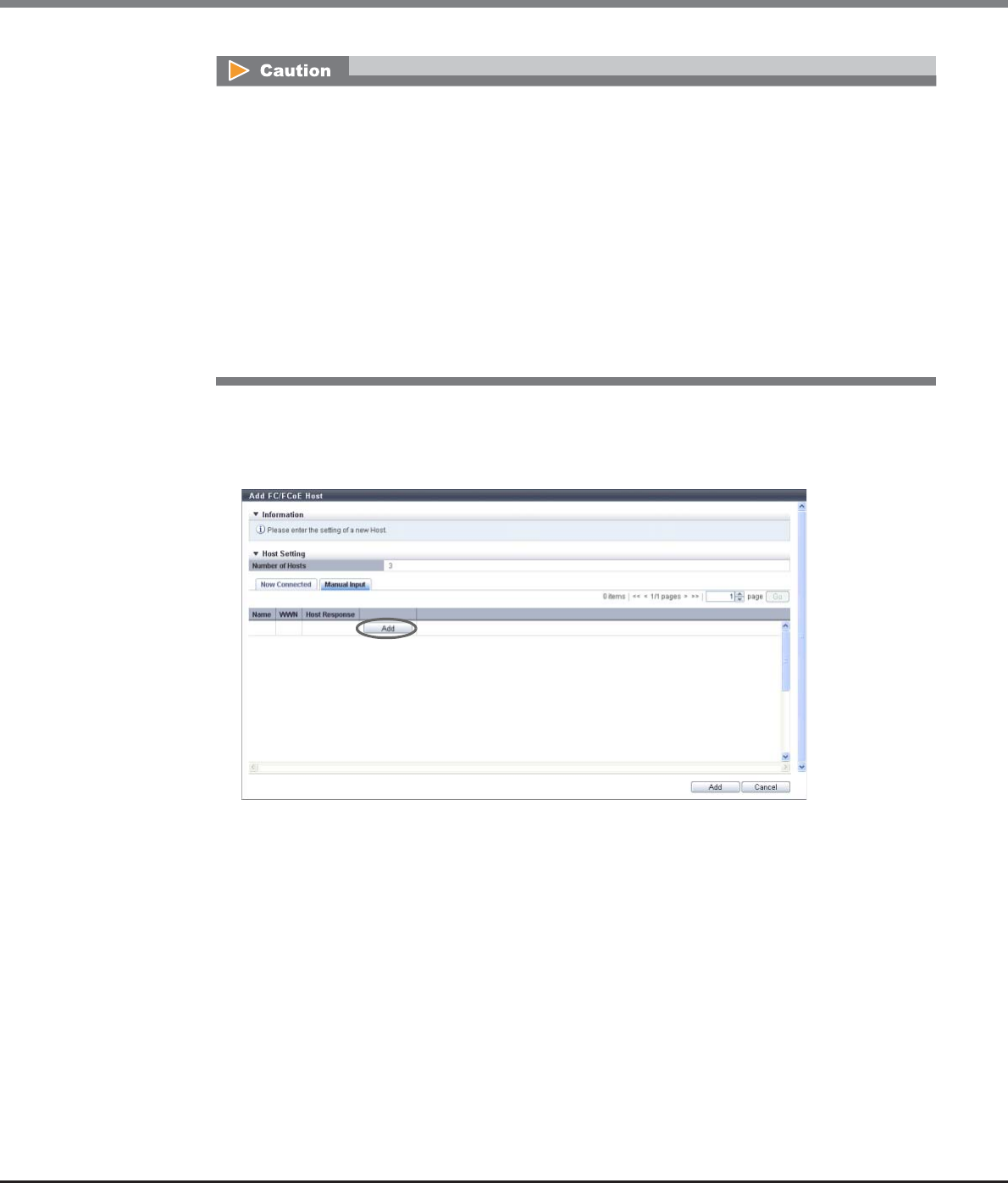
Chapter 9 Connectivity Management
9.2 Functions in the Action Area for Connectivity
ETERNUS Web GUI User’s Guide
Copyright 2013 FUJITSU LIMITED P2X0-1090-10ENZ0
489
■When registering a host by manually specifying the host
(1) Click the [Manual Input] tab.
(2) Click the [Add] button.
→The [Add FC/FCoE Host] screen appears.
(3) Specify the host information of the FC host that is to be registered, and click the [OK] button.
-Name
Specify the FC host name.
The following input conditions apply:
•Up to 16 alphanumeric characters and symbols (except ", (comma)" and "?")
•Spaces
-WWN
Input the WWN for the FC host.
The following input conditions apply:
•Hexadecimal numbers (0 - 9, A - F, a - f)
•16 characters
•"F (f)" or "0" used in entire 16 characters are not allowed.
•If the WWN is not displayed when clicking the [Rediscover] button, make sure that there is no error
in the connection environment, such as the connection between the host and the switch, and the
CA port settings of the ETERNUS DX Disk storage system. If there is no error in the connection
environment, contact the Support Department, or specify the WWN manually.
•An error screen appears in the following conditions:
-When the "Name" is not entered
-When the "Name" does not satisfy the input conditions
-When the "Name" is already used for the registration target host or the same "Name" is already
used in the ETERNUS DX Disk storage system
-When the number of hosts that is to be registered is "0"
-When the number of registered hosts has exceeded the maximum number for the ETERNUS DX
Disk storage system
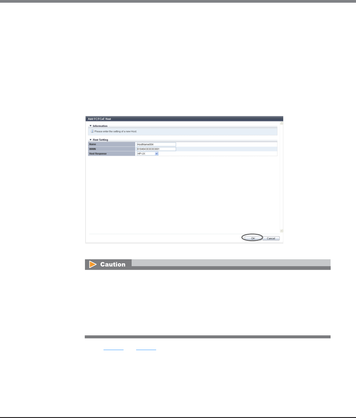
Chapter 9 Connectivity Management
9.2 Functions in the Action Area for Connectivity
ETERNUS Web GUI User’s Guide
Copyright 2013 FUJITSU LIMITED P2X0-1090-10ENZ0
490
-Host Response
Select a host response to be assigned to an FC host.
The host response list created in the ETERNUS DX Disk storage system is displayed.
•Solaris MPxIO
•HP-UX
•AIX EMPD (*1)
•AIX VxVM
•AIX Single Path
•VS850/SVC
•Host responses created in the ETERNUS DX Disk storage system
•Default
*1: EMPD: ETERNUS Multipath Driver
→Returns to the [Manual Input] screen.
(4) Repeat Step (2) and Step (3) when registering several FC hosts.
(5) After registering the FC host is complete, click the [Add] button.
An error screen appears in the following conditions:
•When the "Name" is not entered
•When the "Name" does not satisfy the input conditions
•When the "Name" is already used for the registration target host
•When the "WWN" is not entered
•When the "WWN" does not satisfy the input conditions
•When the "WWN" is already used for the registration target host
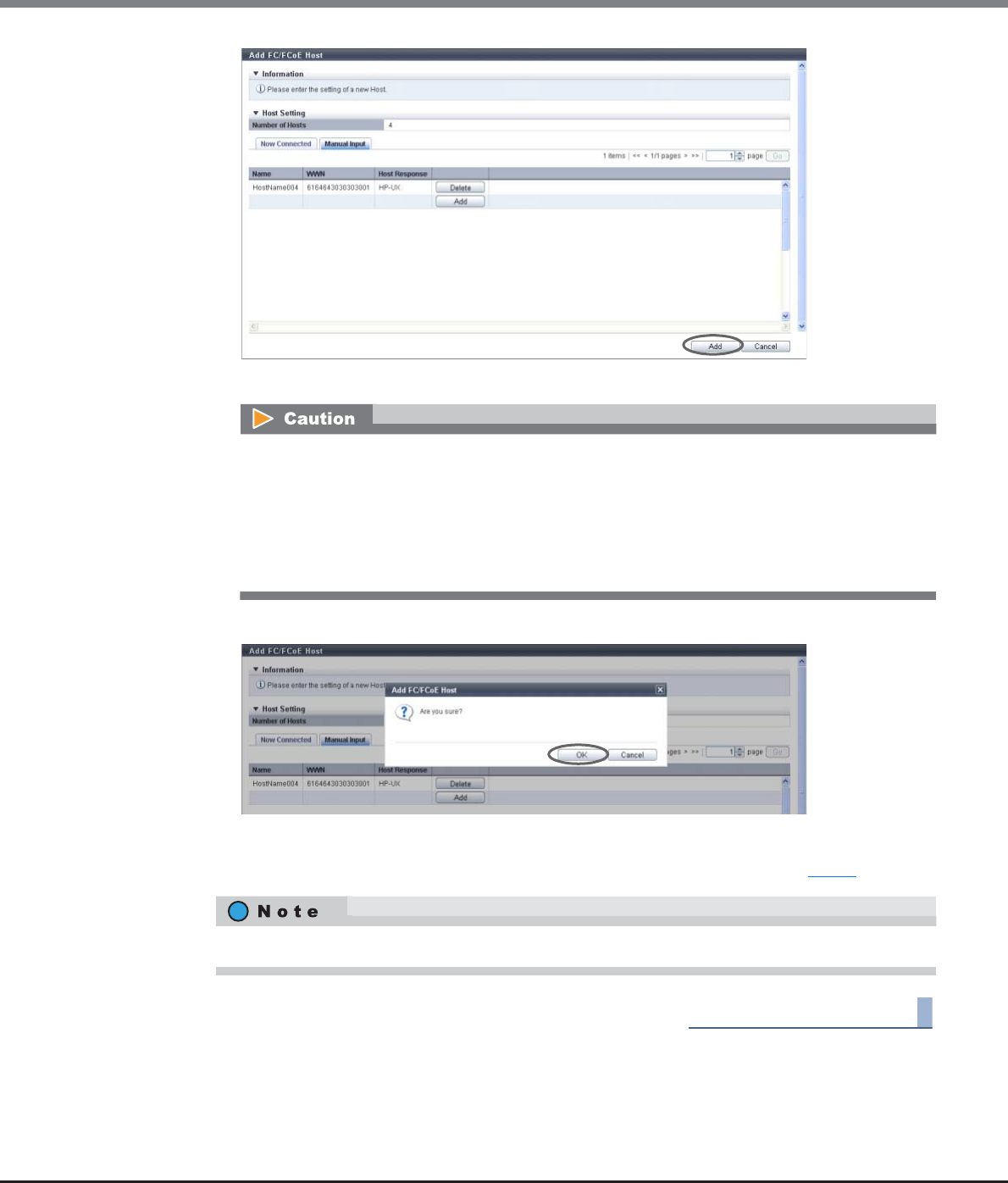
Chapter 9 Connectivity Management
9.2 Functions in the Action Area for Connectivity
ETERNUS Web GUI User’s Guide
Copyright 2013 FUJITSU LIMITED P2X0-1090-10ENZ0
491
→A confirmation screen appears.
3Click the [OK] button.
→Registration of the FC host starts.
4Click the [Done] button to return to the screen when starting this function in Step 1.
End of procedure
An error screen appears in the following conditions:
•When the same "Name" is already used in the ETERNUS DX Disk storage system
•When the same "WWN" is already used in the ETERNUS DX Disk storage system
•When the number of hosts that is to be registered is "0"
•When the number of registered hosts has exceeded the maximum number for the ETERNUS DX
Disk storage system
Click the [Continue] button to continue registering FC hosts.
Chapter 9 Connectivity Management
9.2 Functions in the Action Area for Connectivity
ETERNUS Web GUI User’s Guide
Copyright 2013 FUJITSU LIMITED P2X0-1090-10ENZ0
492
9.2.2.10 Add iSCSI Host
This function registers a new iSCSI host (HBA).
The total number of all the interface type hosts that can be registered in the ETERNUS DX Disk storage system
is 1024 (8192 for the ETERNUS DX8700 S2).
The procedure to register an iSCSI host is as follows:
Procedure
1Click [Add iSCSI Host] in [Action].
•This action item is only displayed when the "Use "Add Host"" checkbox is selected for the "Function to Add
Host" field in "Web GUI Settings". This item is not selected (not displayed) by default. Refer to "11.2.13.4
Setup Subsystem Parameters" (page 935) for details.
•Note that this function does not create a host group. The ETERNUS DX Disk storage system also has a
function that creates new host groups to register hosts as its members. Refer to "9.2.2.2 Add iSCSI Host
Group" (page 448) for details.
•Hosts that are registered with this function can belong to multiple host groups. However, only one LUN
group can be allocated to host and port combinations when configuring host affinity.
•Refer to "User's Guide -Server Connection-" for each OS type to assign an appropriate host response to the
host that is to be registered. The host response configures the operation mode which is appropriate to the
host.
If an appropriate host response is not configured, the path may not be switched correctly or the volume
may not be recognized correctly.
•Unlike GUI, CLI can register two iSCSI hosts that have the same iSCSI name by setting an IP address for one
of these iSCSI hosts and by not setting an IP address for the other iSCSI host. However, if iSCSI hosts are
registered in the ETERNUS DX Disk storage system in this way, iSCSI hosts cannot be added using GUI.
Avoid this configuration when using GUI and CLI together. If both iSCSI hosts already exist, use CLI to
specify an IP address for the iSCSI host without the IP address.
•To change the iSCSI host information, use the [Modify iSCSI Host] function. Refer to "9.2.2.16 Modify iSCSI
Host" (page 509) for details.
•The host affinity setting can be specified for each iSCSI host. Refer to "9.2.1.1 Create Host Affinity" (page
414) for details.

Chapter 9 Connectivity Management
9.2 Functions in the Action Area for Connectivity
ETERNUS Web GUI User’s Guide
Copyright 2013 FUJITSU LIMITED P2X0-1090-10ENZ0
493
2Add a host in the ETERNUS DX Disk storage system in the following procedures.
■When registering a host by selecting from the host list
(1) Click the [Now Connected] tab.
All of the unregistered hosts that are connected to the iSCSI-CAs or the iSCSI-CA/RAs and that can be
recognized by the ETERNUS DX Disk storage system (*1) are displayed. Select the hosts that are to
be registered in the ETERNUS DX Disk storage system and specify the iSCSI host information.
*1: "Host that is not registered in the ETERNUS DX Disk storage system" indicates that a host with the
same iSCSI name, IP version, and Alias Name as the target host is not registered in the storage
system. The host is regarded as unregistered host even if a host with the same iSCSI name, IP version,
Alias Name, and different IP address is already registered. The obtained "iSCSI Name" and "Port" are
displayed.
(2) Select the host that is to be registered from the iSCSI host list, input the iSCSI host information, and
click the [Add] button.
-Checkbox to select a host
Select the checkbox of the iSCSI host that is to be registered in the ETERNUS DX Disk storage
system.
-Name
Input the name for the iSCSI host.
The following input conditions apply:
•Up to 16 alphanumeric characters and symbols (except ", (comma)" and "?")
•Space
•If the iSNS server has not been configured in "9.2.3.8 Modify iSCSI Port Parameters" (page
541), the iSCSI host cannot be automatically acquired.
•The following restrictions in the environment that is described below apply for the
automatic acquirement of host information (*1) even when the iSNS server is specified.
*1: "iSCSI Name", "IP Version", "IP Address", and "Alias Name"
-When one of the following OSs is used and there are multiple hosts that have the same
iSCSI name but different IP addresses, only the information of one host can be acquired.
•Windows Server 2003
•Windows Server 2008
•Windows Server 2008 R2
•Oracle Solaris 10
-When the host OS is Oracle Solaris 11, "IP Version" and "IP Address" cannot be acquired.
•The following items can be specified only for the iSCSI hosts that are selected by
checkboxes; "Name", "Host Response", "IP Version", "IP Address", "Alias Name", "CHAP User
ID", "CHAP Password", and "Confirm CHAP Password".

Chapter 9 Connectivity Management
9.2 Functions in the Action Area for Connectivity
ETERNUS Web GUI User’s Guide
Copyright 2013 FUJITSU LIMITED P2X0-1090-10ENZ0
494
-Host Response
Select a host response to be assigned to an iSCSI host.
The host response list created in the ETERNUS DX Disk storage system is displayed.
•Solaris MPxIO
•HP-UX
•AIX EMPD (*1)
•AIX VxVM
•AIX Single Path
•VS850/SVC
•Host responses created in the ETERNUS DX Disk storage system
•Default
*1: EMPD: ETERNUS Multipath Driver
-IP Version
Select the IP version of the iSCSI host from "IPv4" and "IPv6".
-IP Address
Specify the IP address of the iSCSI host.
There are two methods to specify an IP address; "IPv4" and "IPv6". The IP address must be
specified with the selected IP version (IPv4 or IPv6). The following IPv6 addresses can be used;
"link local address", "global address", "unique local address", and "6to4 address". Refer to
"Available IPv6 Address" (page 757) for details. When the current setting is displayed, the IPv6
address is displayed as an abbreviation.
It is not necessary to specify this item if IP address is not used.
The following input conditions apply:
•For IPv4 address
xxx.xxx.xxx.xxx
xxx: 1 - 255 for the top field (decimal)
xxx: 0 - 255 for other fields (decimal)
•For IPv6 address
xxxx:xxxx:xxxx:xxxx:xxxx:xxxx:xxxx:xxxx
xxxx: 0 - ffff (FFFF) (hexadecimal, alphanumeric characters)
Refer to "IPv6 Address Notation" (page 378) for details.
-Alias Name
Specify the Alias name of the iSCSI host.
It is not necessary to specify this item if Alias name is not used.
An existing Alias name cannot be specified.
The following input conditions apply:
•Up to 31 alphanumeric characters and symbols (except ", (comma)" and "?")
•Space
To register an iSCSI host without using an IP address, perform IP version selection as follows:
•Select "IPv4" when the IP address format of the iSCSI host is IPv4 (when using an IPv4 host)
•Select "IPv6" when the IP address format of the iSCSI host is IPv6 (when using an IPv6 host)
•If the IP address format of the iSCSI host cannot be checked (when either an IPv4 host or an
IPv6 host is used), register two hosts. Select "IPv4" for one host, and select "IPv6" for the
other host. Specify the same iSCSI name, CHAP user ID, and CHAP password for each host.
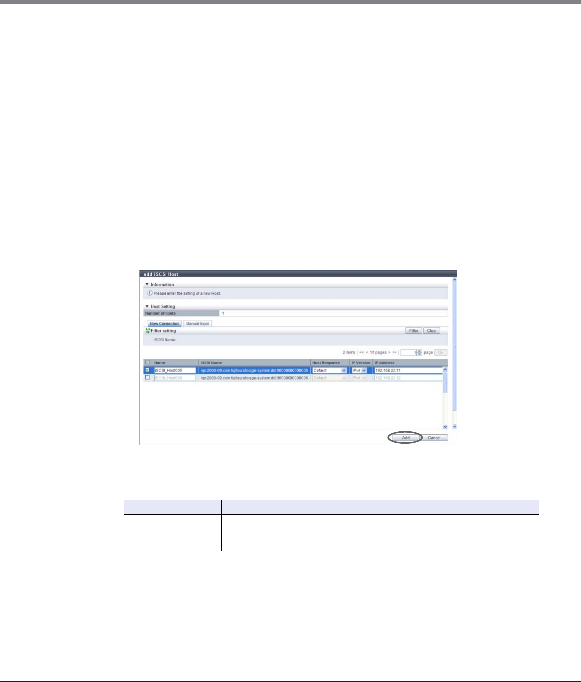
Chapter 9 Connectivity Management
9.2 Functions in the Action Area for Connectivity
ETERNUS Web GUI User’s Guide
Copyright 2013 FUJITSU LIMITED P2X0-1090-10ENZ0
495
-CHAP User ID
Specify the user ID for the CHAP Authentication.
It is not necessary to specify this item if the CHAP Authentication is not used.
Configure a user ID and a password as a pair.
The following input conditions apply:
•Up to 255 alphanumeric characters and symbols (except ", (comma)" and "?")
•Space
-CHAP Password
Specify the password for the CHAP Authentication.
It is not necessary to specify this item if the CHAP Authentication is not used.
Configure a user ID and a password as a pair.
The following input conditions apply:
•12 - 100 alphanumeric characters and symbols (except ", (comma)" and "?")
•Space
-Confirm CHAP Password
Input the CHAP password again for confirmation.
The following input conditions apply:
•12 - 100 alphanumeric characters and symbols (except ", (comma)" and "?")
•Space
→A confirmation screen appears.
Filter Setting
Filter Description
iSCSI Name
Input the iSCSI name that is to be displayed.
iSCSI hosts matching or partially matching the entered iSCSI name are displayed.
When not using the iSCSI name for filtering, leave this item blank.
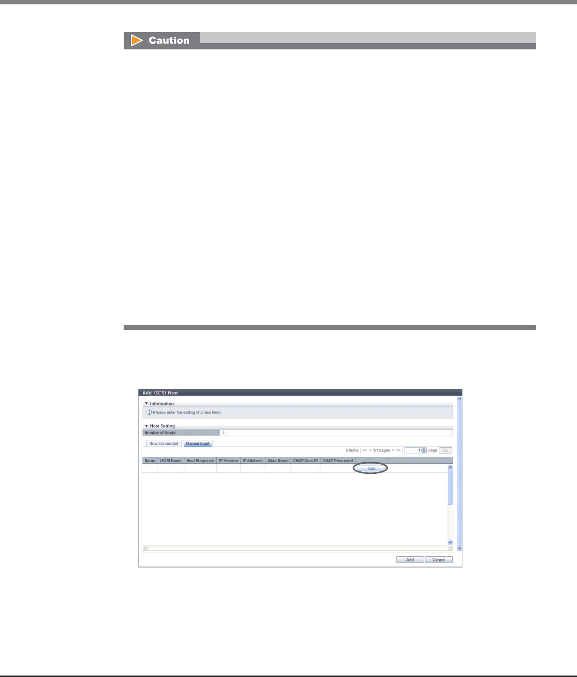
Chapter 9 Connectivity Management
9.2 Functions in the Action Area for Connectivity
ETERNUS Web GUI User’s Guide
Copyright 2013 FUJITSU LIMITED P2X0-1090-10ENZ0
496
■When registering a host by manually specifying the host
(1) Click the [Manual Input] tab.
(2) Click the [Add] button.
→The [Add iSCSI Host] screen appears.
An error screen appears in the following conditions:
•When the "Name" is not entered
•When the "Name" does not satisfy the input conditions
•When the "Name" is already used for the registration target host or the same "Name" is already
used in the ETERNUS DX Disk storage system
•When the "IP Address" does not satisfy the input conditions
•When the "IP Address" is specified and an iSCSI host with the same "iSCSI Name" and "IP Address" is
already registered
•When the "IP Address" is not specified and an iSCSI host with the same "iSCSI Name" and "IP
Version" is already registered
•When the "Alias Name" does not satisfy the input conditions
•When the "Alias Name" is already used for the registration target host or the same "Alias Name" is
already used in the ETERNUS DX Disk storage system
•When the "CHAP User ID" does not satisfy the input conditions
•When the "CHAP Password" does not satisfy the input conditions
•When the "CHAP Password" and the "Confirm CHAP Password" do not match
•When either of the "CHAP User ID" or the "CHAP Password" has been specified
•When the number of hosts that is to be registered is "0"
•When the number of registered hosts has exceeded the maximum number for the ETERNUS DX
Disk storage system
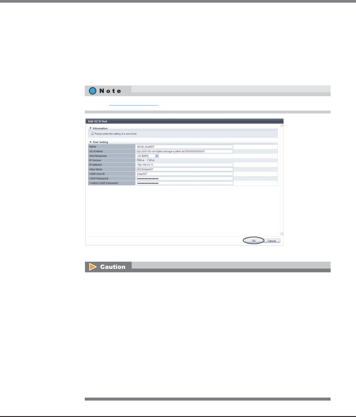
Chapter 9 Connectivity Management
9.2 Functions in the Action Area for Connectivity
ETERNUS Web GUI User’s Guide
Copyright 2013 FUJITSU LIMITED P2X0-1090-10ENZ0
497
(3) Specify the host information of the iSCSI host that is to be registered, and click the [OK] button.
-iSCSI Name
Specify an iSCSI name of the iSCSI host (required).
The following input conditions apply:
•Alphabetic characters (lower case) and numeric characters
•Symbols "-" (hyphen), "." (period), and ":" (colon)
•The name starts with "iqn." or "eui."
•4 - 223 characters
→Returns to the [Manual Input] screen.
Refer to Step (2) (page 493) for other settings.
An error screen appears in the following conditions:
•When the "Name" is not entered
•When the "Name" does not satisfy the input conditions
•When the "Name" is already used for the registration target host
•When the "iSCSI Name" is not entered
•When the "iSCSI Name" does not satisfy the input conditions
•When the "iSCSI Name" is already used for the registration target host
•When the "IP Address" does not satisfy the input conditions
•When the "Alias Name" does not satisfy the input conditions
•When the "Alias Name" is already used for the registration target host
•When the "CHAP User ID" does not satisfy the input conditions
•When the "CHAP Password" does not satisfy the input conditions
•When the "CHAP Password" and the "Confirm CHAP Password" do not match
•When either of the "CHAP User ID" or the "CHAP Password" has been specified
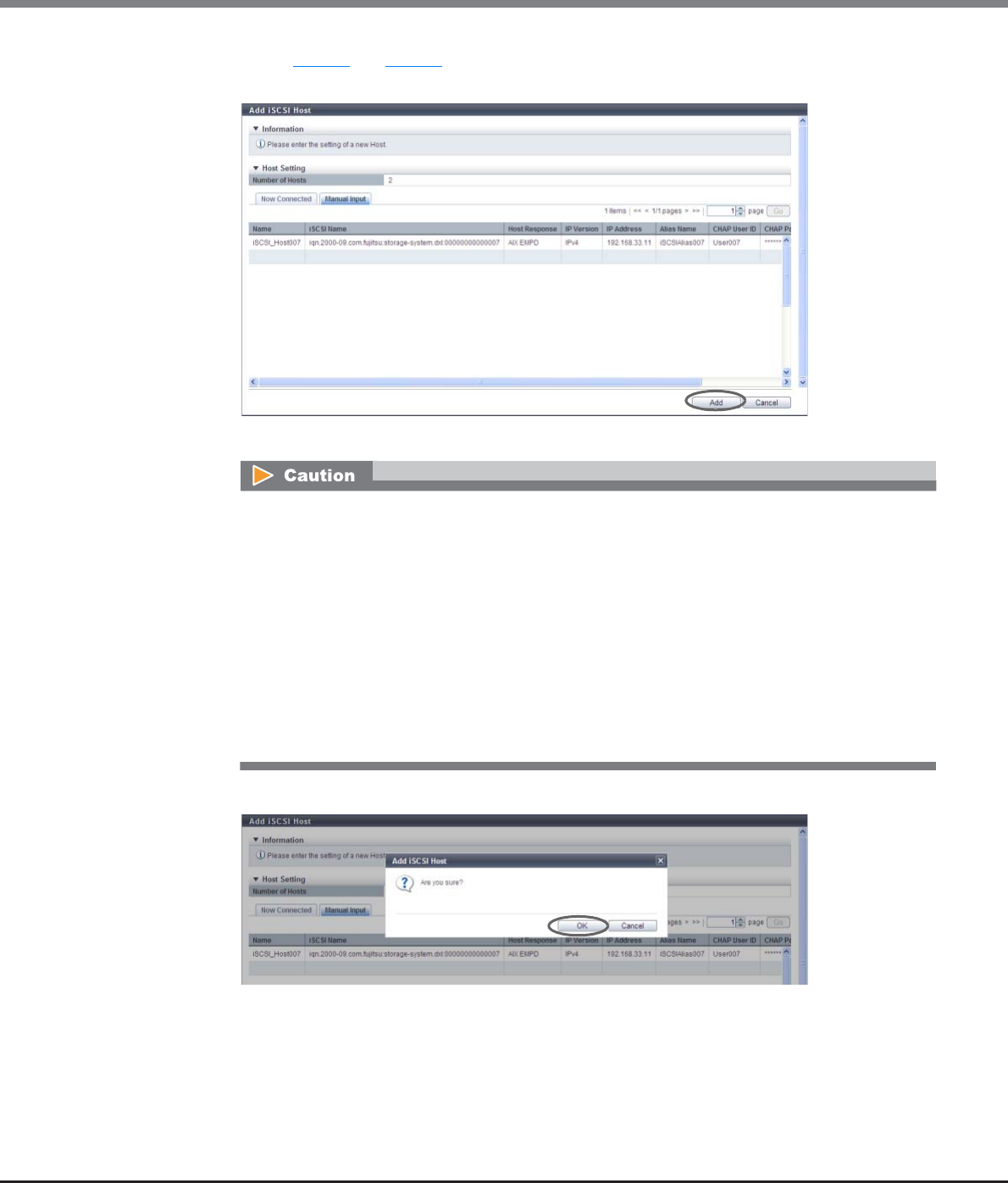
Chapter 9 Connectivity Management
9.2 Functions in the Action Area for Connectivity
ETERNUS Web GUI User’s Guide
Copyright 2013 FUJITSU LIMITED P2X0-1090-10ENZ0
498
(4) Repeat Step (2) and Step (3) when registering several iSCSI hosts.
(5) After registering the iSCSI host is complete, click the [Add] button.
→A confirmation screen appears.
3Click the [OK] button.
→Registration of the iSCSI host starts.
An error screen appears in the following conditions:
•When the same "Name" is already used in the ETERNUS DX Disk storage system
•When the same "iSCSI Name" is already used in the ETERNUS DX Disk storage system
•When the "IP Address" is specified and an iSCSI host with the same "iSCSI Name" and "IP
Address" is already registered
•When the "IP Address" is not specified and an iSCSI host with the same "iSCSI Name" and "IP
Version" is already registered
•When the same "Alias Name" is already used in the ETERNUS DX Disk storage system
•When the number of hosts that is to be registered is "0"
•When the number of registered hosts has exceeded the maximum number for the ETERNUS DX
Disk storage system
Chapter 9 Connectivity Management
9.2 Functions in the Action Area for Connectivity
ETERNUS Web GUI User’s Guide
Copyright 2013 FUJITSU LIMITED P2X0-1090-10ENZ0
499
4Click the [Done] button to return to the screen when starting this function in Step 1.
End of procedure
9.2.2.11 Add SAS Host
This function registers a new SAS host (HBA).
The total number of all the interface type hosts that can be registered in the ETERNUS DX Disk storage system
is 1024.
The procedure to register a SAS host is as follows:
Procedure
1Click [Add SAS Host] in [Action].
Click the [Continue] button to continue registering iSCSI hosts.
•This action item is only displayed when the "Use "Add Host"" checkbox is selected for the "Function to Add
Host" field in "Web GUI Settings". This item is not selected (not displayed) by default. Refer to "11.2.13.4
Setup Subsystem Parameters" (page 935) for details.
•Note that this function does not create a host group. The ETERNUS DX Disk storage system also has a
function that creates new host groups to register hosts as its members. Refer to "9.2.2.3 Add SAS Host
Group" (page 456) for details.
•Hosts that are registered with this function can belong to multiple host groups. However, only one LUN
group can be allocated to host and port combinations when configuring host affinity.
•Refer to "User's Guide -Server Connection-" for each OS type to assign an appropriate host response to the
host that is to be registered. The host response configures the operation mode which is appropriate to the
host.
If an appropriate host response is not configured, the path may not be switched correctly or the volume
may not be recognized correctly.
•To change the SAS host information, use the [Modify SAS Host] function. Refer to "9.2.2.17 Modify SAS
Host" (page 514) for details.
•The host affinity setting can be specified for each SAS host. Refer to "9.2.1.1 Create Host Affinity" (page
414) for details.
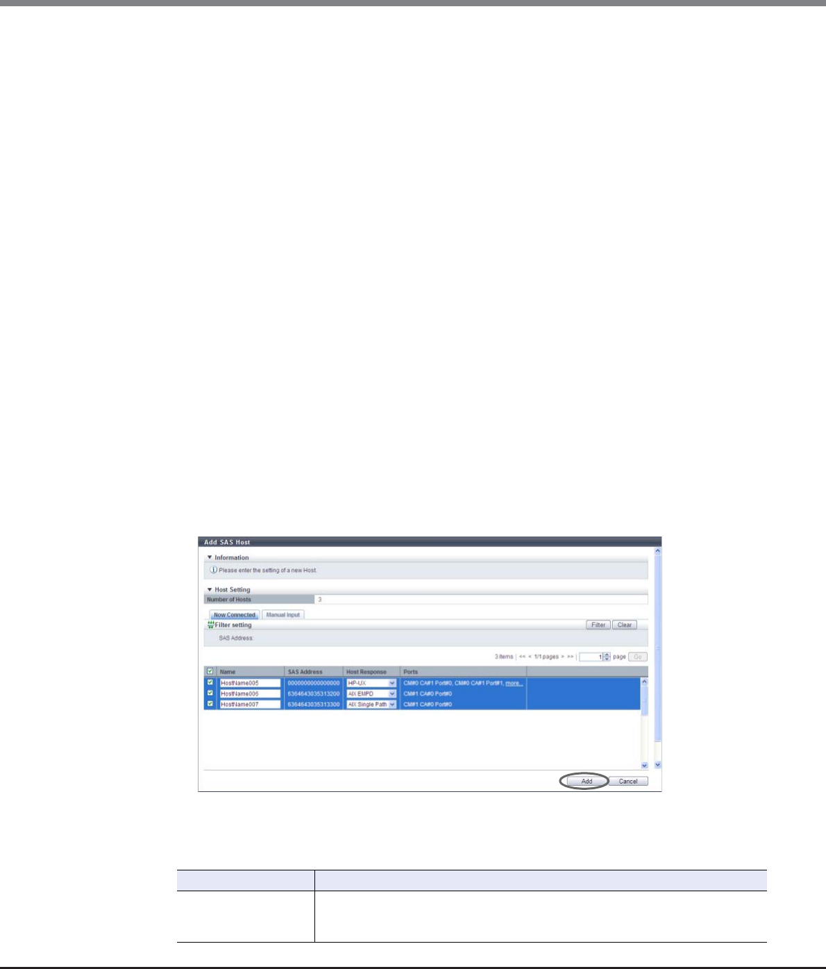
Chapter 9 Connectivity Management
9.2 Functions in the Action Area for Connectivity
ETERNUS Web GUI User’s Guide
Copyright 2013 FUJITSU LIMITED P2X0-1090-10ENZ0
500
2Add a host in the ETERNUS DX Disk storage system in the following procedures.
■When registering a host by selecting from the host list
(1) Click the [Now Connected] tab.
(2) Select the host that is to be registered from the SAS host list, input the SAS host information, and
click the [Add] button.
-Checkbox to select a host
Select the checkbox of the SAS host that is to be registered in the ETERNUS DX Disk storage
system. The host name and host response can only be specified for the selected SAS host.
-Name
Input the name for the SAS host.
The following input conditions apply:
•Up to 16 alphanumeric characters and symbols (except ", (comma)" and "?")
•Space
-Host Response
Select a host response to be assigned to a host.
The host response list created in the ETERNUS DX Disk storage system is displayed.
•Solaris MPxIO
•HP-UX
•AIX EMPD (*1)
•AIX VxVM
•AIX Single Path
•VS850/SVC
•Host responses created in the ETERNUS DX Disk storage system
•Default
*1: EMPD: ETERNUS Multipath Driver
→A confirmation screen appears.
Filter Setting
Filter Description
SAS Address
Input the SAS address that is to be displayed.
SAS hosts matching or partially matching the entered SAS address are displayed.
When not using the SAS address for filtering, leave this item blank.
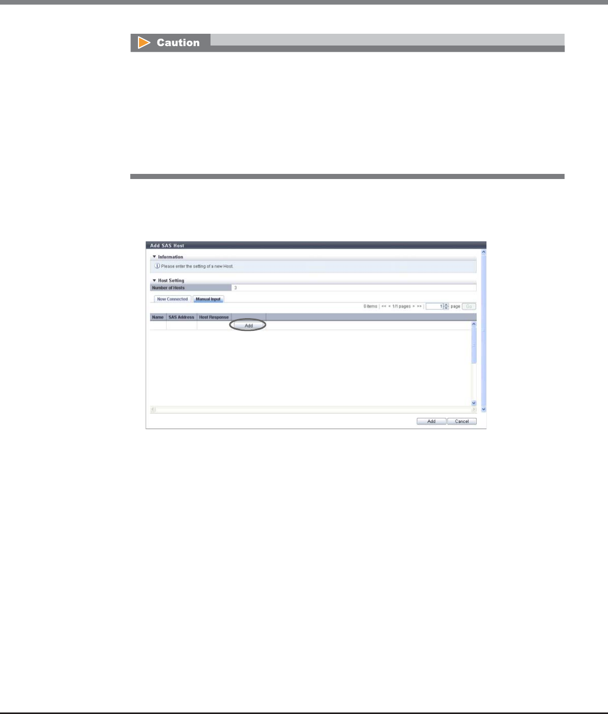
Chapter 9 Connectivity Management
9.2 Functions in the Action Area for Connectivity
ETERNUS Web GUI User’s Guide
Copyright 2013 FUJITSU LIMITED P2X0-1090-10ENZ0
501
■When registering a host by manually specifying the host
(1) Click the [Manual Input] tab.
(2) Click the [Add] button.
→The [Add SAS Host] screen appears.
(3) Specify the host information of the SAS host that is to be registered, and click the [OK] button.
-Name
Specify the SAS host name.
The following input conditions apply:
•Up to 16 alphanumeric characters and symbols (except ", (comma)" and "?")
•Spaces
-SAS Address
Specify the SAS address of the SAS host.
The following input conditions apply:
•16 hexadecimal numbers
•"F (f)" or "0" used in entire 16 characters are not allowed.
An error screen appears in the following conditions:
•When the "Name" is not entered
•When the "Name" does not satisfy the input conditions
•When the "Name" is already used for the registration target host or the same "Name" is already
used in the ETERNUS DX Disk storage system
•When the number of hosts that is to be registered is "0"
•When the number of registered hosts has exceeded the maximum number for the ETERNUS DX
Disk storage system
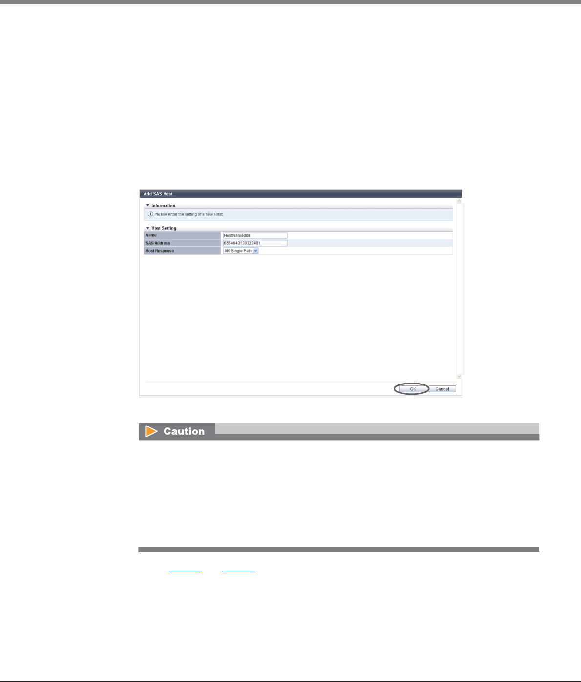
Chapter 9 Connectivity Management
9.2 Functions in the Action Area for Connectivity
ETERNUS Web GUI User’s Guide
Copyright 2013 FUJITSU LIMITED P2X0-1090-10ENZ0
502
-Host Response
Select a host response to be assigned to a SAS host.
The host response list created in the ETERNUS DX Disk storage system is displayed.
•Solaris MPxIO
•HP-UX
•AIX EMPD (*1)
•AIX VxVM
•AIX Single Path
•VS850/SVC
•Host responses created in the ETERNUS DX Disk storage system
•Default
*1: EMPD: ETERNUS Multipath Driver
→Returns to the [Manual Input] screen.
(4) Repeat Step (2) and Step (3) when registering several SAS hosts.
An error screen appears in the following conditions:
•When the "Name" is not entered
•When the "Name" does not satisfy the input conditions
•When the "Name" is already used for the registration target host
•When the "SAS Address" is not entered
•When the "SAS Address" does not satisfy the input conditions
•When the "SAS Address" is already used for the registration target host
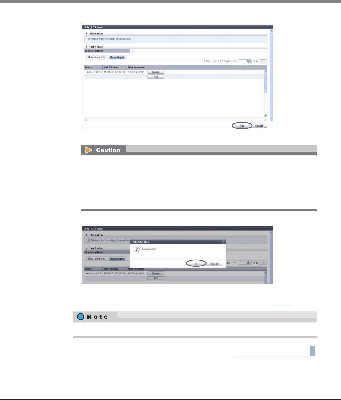
Chapter 9 Connectivity Management
9.2 Functions in the Action Area for Connectivity
ETERNUS Web GUI User’s Guide
Copyright 2013 FUJITSU LIMITED P2X0-1090-10ENZ0
503
(5) After registering the SAS host is complete, click the [Add] button.
→A confirmation screen appears.
3Click the [OK] button.
→Registration of the SAS host starts.
4Click the [Done] button to return to the screen when starting this function in Step 1.
End of procedure
An error screen appears in the following conditions:
•When the same "Name" is already used in the ETERNUS DX Disk storage system
•When the same "SAS Address" is already used in the ETERNUS DX Disk storage system
•When the number of hosts that is to be registered is "0"
•When the number of registered hosts has exceeded the maximum number for the ETERNUS DX
Disk storage system
Click the [Continue] button to continue registering SAS hosts.
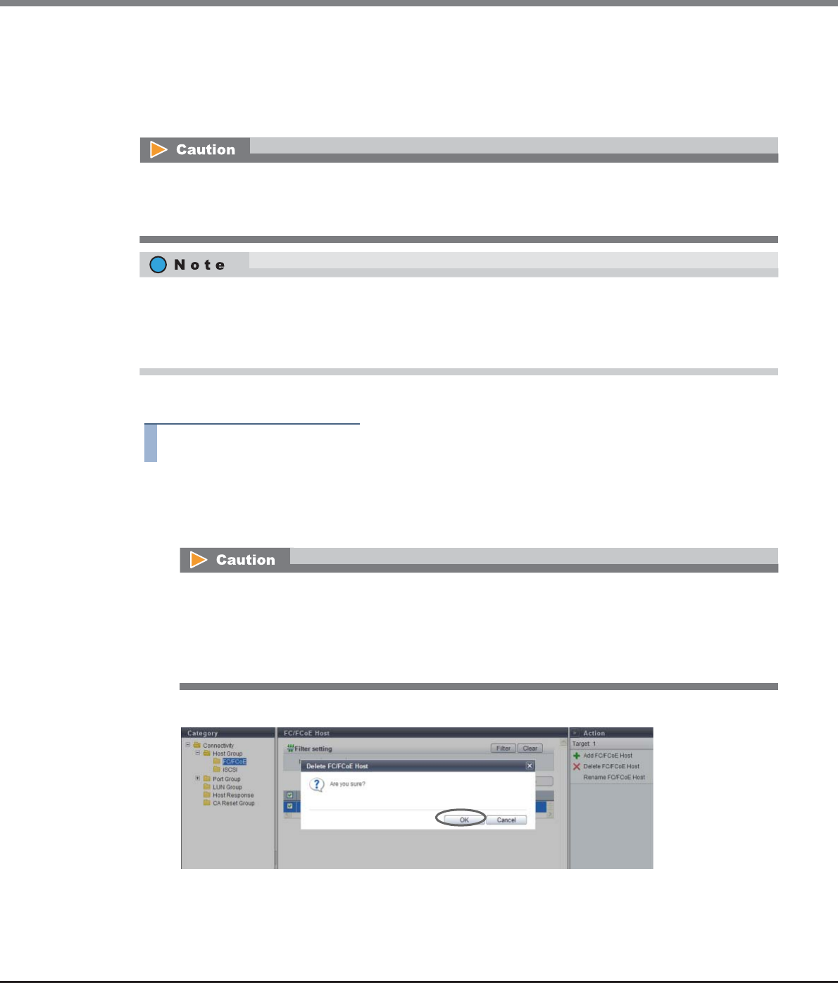
Chapter 9 Connectivity Management
9.2 Functions in the Action Area for Connectivity
ETERNUS Web GUI User’s Guide
Copyright 2013 FUJITSU LIMITED P2X0-1090-10ENZ0
504
9.2.2.12 Delete FC/FCoE Host
This function deletes an FC/FCoE host.
When an FC/FCoE host belongs to a host group, the FC/FCoE host can be deleted, irrespective of its host affinity
settings.
The procedure to delete an FC host is as follows:
Procedure
1Select the FC host to be deleted (multiple selections can be made) and click [Delete FC/FCoE
Host] in [Action].
→A confirmation screen appears.
2Click the [OK] button.
→Deletion of the FC host starts.
•Not all of the hosts can be deleted from a host group.
•When an FC host does not belong to a host group, the FC host, of which host affinity settings have been
configured, cannot de deleted.
•When a host in the host group for which the host affinity settings are already configured is deleted, the
path from the host to the port is also deleted.
•The "FCoE" host interface is regarded as "FC". Both "FC host" and "FCoE host" are abbreviated as "FC host" in
this section.
An error screen appears in the following conditions:
•When the selected FC host is the last host in a host group
•When the selected FC host does not belong to any host group and the host affinity setting has
been configured for the target FC host
•When the selected FC host does not exist
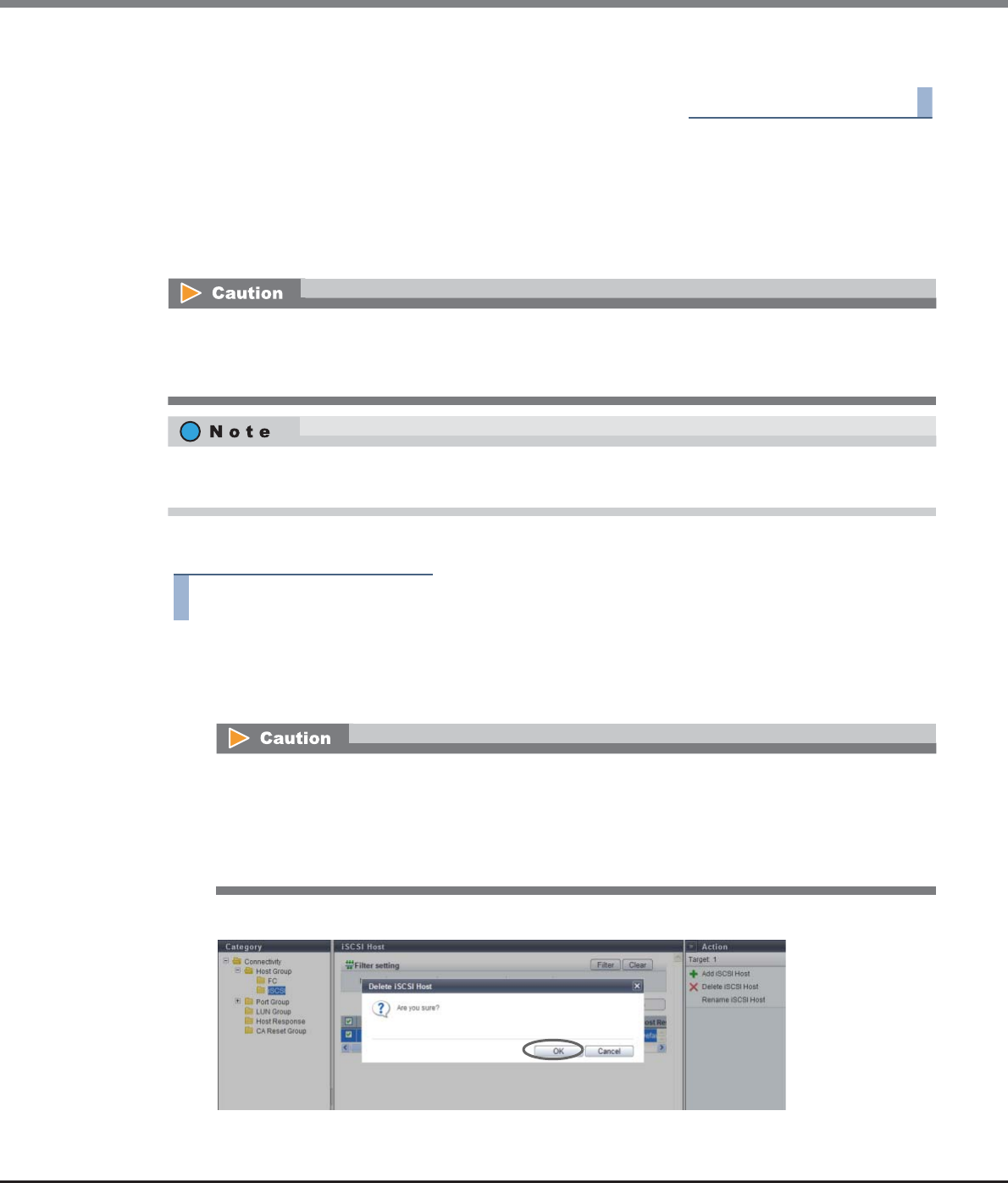
Chapter 9 Connectivity Management
9.2 Functions in the Action Area for Connectivity
ETERNUS Web GUI User’s Guide
Copyright 2013 FUJITSU LIMITED P2X0-1090-10ENZ0
505
3Click the [Done] button to return to the [FC/FCoE Host] screen.
End of procedure
9.2.2.13 Delete iSCSI Host
This function deletes an iSCSI host.
When an iSCSI host belongs to a host group, the iSCSI host can be deleted, irrespective of its host affinity
settings.
The procedure to delete an iSCSI host is as follows:
Procedure
1Select the iSCSI host to be deleted (multiple selections can be made) and click [Delete iSCSI
Host] in [Action].
→A confirmation screen appears.
2Click the [OK] button.
→Deletion of the iSCSI host starts.
•Not all of the hosts can be deleted from a host group.
•When an iSCSI host does not belong to a host group, the iSCSI host, of which host affinity settings have
been configured, cannot de deleted.
When a host in the host group for which the host affinity settings are already configured is deleted, the path
from the host to the port is also deleted.
An error screen appears in the following conditions:
•When the selected iSCSI host is the last host in a host group
•When the selected iSCSI host does not belong to any host group and the host affinity setting has
been configured for the target iSCSI host
•When the selected iSCSI host does not exist
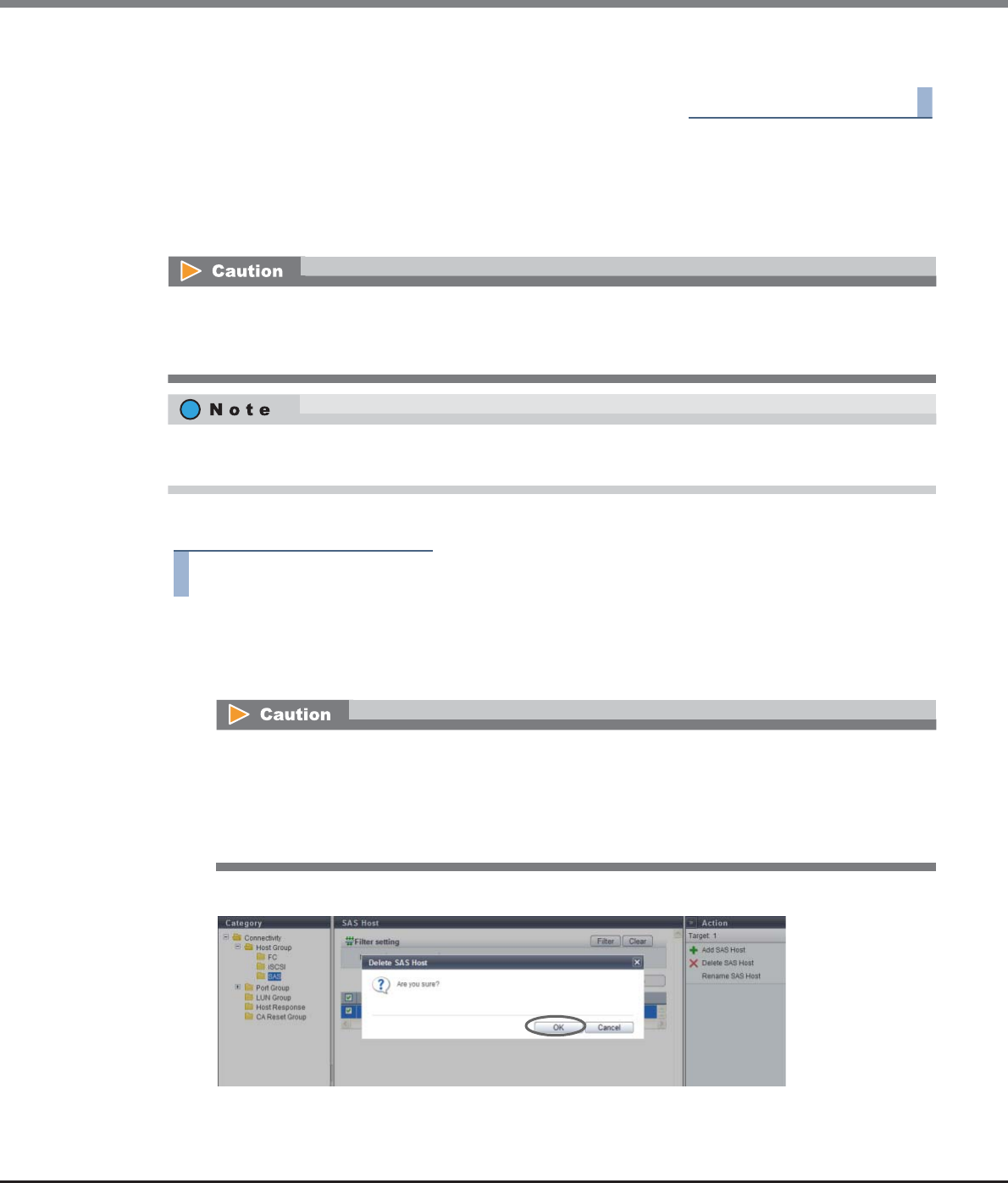
Chapter 9 Connectivity Management
9.2 Functions in the Action Area for Connectivity
ETERNUS Web GUI User’s Guide
Copyright 2013 FUJITSU LIMITED P2X0-1090-10ENZ0
506
3Click the [Done] button to return to the [iSCSI Host] screen.
End of procedure
9.2.2.14 Delete SAS Host
This function deletes a SAS host.
When a SAS host belongs to a host group, the SAS host can be deleted, irrespective of its host affinity settings.
The procedure to delete a SAS host is as follows:
Procedure
1Select the SAS host to be deleted (multiple selections can be made) and click [Delete SAS
Host] in [Action].
→A confirmation screen appears.
2Click the [OK] button.
→Deletion of the SAS host starts.
•Not all of the hosts can be deleted from a host group.
•When a SAS host does not belong to a host group, the SAS host, of which host affinity settings have been
configured, cannot de deleted.
When a host in the host group for which the host affinity settings are already configured is deleted, the path
from the host to the port is also deleted.
An error screen appears in the following conditions:
•When the selected SAS host is the last host in a host group
•When the selected SAS host does not belong to any host group and the host affinity setting has
been configured for the target SAS host
•When the selected SAS host does not exist
Chapter 9 Connectivity Management
9.2 Functions in the Action Area for Connectivity
ETERNUS Web GUI User’s Guide
Copyright 2013 FUJITSU LIMITED P2X0-1090-10ENZ0
507
3Click the [Done] button to return to the [SAS Host] screen.
End of procedure
9.2.2.15 Modify FC/FCoE Host
This function changes the FC/FCoE host information.
The procedure to change the FC host information is as follows:
Procedure
1Select the FC host to change the host information for, and click [Modify FC/FCoE Host] in
[Action].
2Input new host information and click the [Modify] button.
•Name
Input a new FC host name.
An existing host name cannot be specified.
The following input conditions apply:
-Up to 16 alphanumeric characters and symbols (except ", (comma)" and "?")
-Space
•WWN
Input a new WWN.
An existing WWN cannot be used.
The following input conditions apply:
-Hexadecimal numbers (0 - 9, A - F, a - f)
-16 characters
-"F (f)" or "0" used in entire 16 characters are not allowed.
•When no FC/FCoE hosts are registered, the [Modify FC/FCoE Host] function cannot be used.
•When changing the WWN of an FC/FCoE host that is currently being used, make sure to stop access to that
FC/FCoE host.
•The [Rename FC/FCoE Host] function that is provided with controller firmware version V10L24 or earlier is
integrated in this function. Note that this function cannot change multiple FC/FCoE host names. Change
one FC/FCoE host name at a time.
•This function can change the following FC/FCoE host information; "Name" and "WWN". When the FC host is
not registered in a host group, the "Host Response" setting can also be changed.
•When the FC host is registered in a host group, use the [Modify Host Group] function to change the host
response. Refer to "9.2.2.6 Modify Host Group (FC/FCoE)" (page 463) for details.
•Both "FC host" and "FCoE host" are abbreviated as "FC host" in this section.
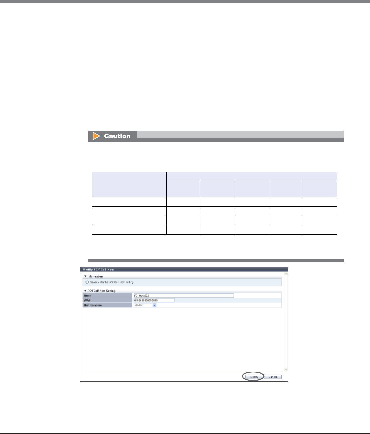
Chapter 9 Connectivity Management
9.2 Functions in the Action Area for Connectivity
ETERNUS Web GUI User’s Guide
Copyright 2013 FUJITSU LIMITED P2X0-1090-10ENZ0
508
•Host Response
Select a new host response that is to be assigned to the FC host.
The host response list created in the ETERNUS DX Disk storage system is displayed.
This item is available only when an FC host is not registered in the host group.
-Solaris MPxIO
-HP-UX
-AIX EMPD (*1)
-AIX VxVM
-AIX Single Path
-VS850/SVC
-Host responses created in the ETERNUS DX Disk storage system
-Default
*1: EMPD: ETERNUS Multipath Driver
→A confirmation screen appears.
If the host response is changed for an FC host that is configured with the host affinity setting, the
LUNs may not be able to be accessed from the FC host. Make sure to check the current LUN settings
and select a host response with an appropriate "Host Specific Mode" to change the host response.
Available: The host can recognize LUNs
N/A: The host cannot recognize some LUNs
LUN settings for LUN groups
with host affinity settings
Host Specific Mode
Normal AIX Mode NR1000V
Mode
HP-UX
Mode
BS2000
Mode
LUN#0 – LUN#255 Available Available Available Available Available
LUN#0 - LUN#511 N/A Available Available Available Available
LUN#0 - LUN#1023 N/A N/A N/A Available Available
LUN#0 - LUN#4095 N/A N/A N/A N/A Available
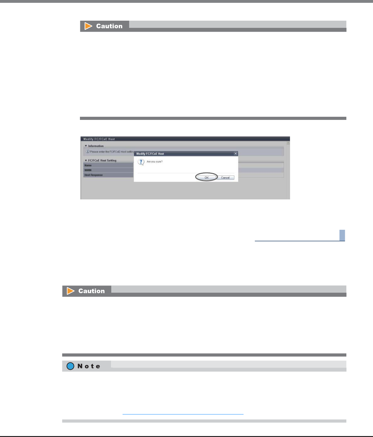
Chapter 9 Connectivity Management
9.2 Functions in the Action Area for Connectivity
ETERNUS Web GUI User’s Guide
Copyright 2013 FUJITSU LIMITED P2X0-1090-10ENZ0
509
3Click the [OK] button.
→Changing of the FC host information starts.
4Click the [Done] button to return to the [FC/FCoE Host] screen.
End of procedure
9.2.2.16 Modify iSCSI Host
This function changes the iSCSI host information.
An error screen appears in the following conditions:
•When the "Name" is not input
•When the "Name" does not satisfy the input conditions
•When the "Name" already exists
•When the "WWN" is not input
•When the "WWN" does not satisfy the input conditions
•When the same "WWN" is already registered
•When there are some LUNs that cannot be recognized from the FC host because the "Host
Response" setting has been changed (only for FC hosts that are not registered in a host group)
•When no iSCSI hosts are registered, the [Modify iSCSI Host] function cannot be used.
•When changing the information of an iSCSI host that is currently being used, make sure to stop access to
that iSCSI host.
•The [Rename iSCSI Host] function that is provided with controller firmware version V10L24 or earlier is
integrated in this function. Note that this function cannot change multiple iSCSI host names. Change one
iSCSI host name at a time.
•This function can change the following iSCSI host information; "Name", "iSCSI Name", "IP Version", "IP
Address", "Alias Name", "CHAP User ID", and "CHAP Password". When the iSCSI host is not registered in a
host group, the "Host Response" setting can also be changed.
•When the iSCSI host is registered in a host group, use the [Modify Host Group] function to change the host
response. Refer to "9.2.2.7 Modify Host Group (iSCSI)" (page 470) for details.

Chapter 9 Connectivity Management
9.2 Functions in the Action Area for Connectivity
ETERNUS Web GUI User’s Guide
Copyright 2013 FUJITSU LIMITED P2X0-1090-10ENZ0
510
The procedure to change the iSCSI information is as follows:
Procedure
1Select the iSCSI host to changed the host information for, and click [Modify iSCSI Host] in
[Action].
2Input new iSCSI host information and click the [Modify] button.
•Name
Input a new iSCSI host name.
An existing host name cannot be specified.
The following input conditions apply:
-Up to 16 alphanumeric characters and symbols (except ", (comma)" and "?")
-Space
•iSCSI Name
Input an iSCSI name of the iSCSI host.
The following input conditions apply:
-Alphabetic characters (lower case) and numeric characters
-Symbols "-" (hyphen), "." (period), and ":" (colon)
-The name starts with "iqn." or "eui."
-4 - 223 characters
•Host Response
Select a new host response that is to be assigned to the iSCSI host.
The host response list created in the ETERNUS DX Disk storage system is displayed.
This item is available only when an iSCSI host is not registered in the host group.
-Solaris MPxIO
-HP-UX
-AIX EMPD (*1)
-AIX VxVM
-AIX Single Path
-VS850/SVC
-Host responses created in the ETERNUS DX Disk storage system
-Default
*1: EMPD: ETERNUS Multipath Driver

Chapter 9 Connectivity Management
9.2 Functions in the Action Area for Connectivity
ETERNUS Web GUI User’s Guide
Copyright 2013 FUJITSU LIMITED P2X0-1090-10ENZ0
511
•IP Version
Select the IP version of the iSCSI host from "IPv4" and "IPv6".
•IP Address
Specify the IP address of the iSCSI host.
There are two methods to specify an IP address; "IPv4" and "IPv6". The IP address must be specified
with the selected IP version (IPv4 or IPv6). The following IPv6 addresses can be used; "link local
address", "global address", "unique local address", and "6to4 address". Refer to "Available IPv6
Address" (page 757) for details. When the current setting is displayed, the IPv6 address is displayed
as an abbreviation.
It is not necessary to specify this item if IP address is not used.
The following input conditions apply:
-For IPv4 address
xxx.xxx.xxx.xxx
xxx: 1 - 255 for the top field (decimal)
xxx: 0 - 255 for other fields (decimal)
-For IPv6 address
xxxx:xxxx:xxxx:xxxx:xxxx:xxxx:xxxx:xxxx
xxxx: 0 - ffff (FFFF) (hexadecimal, alphanumeric characters)
Refer to "IPv6 Address Notation" (page 378) for details.
•Alias Name
Specify the Alias name of the iSCSI host. It is not necessary to specify this item if Alias name is not
used. An existing Alias name cannot be specified.
The following input conditions apply:
-Up to 31 alphanumeric characters and symbols (except ", (comma)" and "?")
-Space
•CHAP User ID
Specify the user ID for CHAP Authentication. It is not necessary to specify this item if CHAP
Authentication is not used.
Configure the user ID and the password as a pair.
The following input conditions apply:
-Up to 255 alphanumeric characters and symbols (except ", (comma)" and "?")
-Space
If the host response is changed for an iSCSI host that is configured with the host affinity setting,
the LUNs may not be able to be accessed from the iSCSI host. Make sure to check the current LUN
settings and select a host response with an appropriate "Host Specific Mode" to change the host
response.
Available: The host can recognize LUNs
N/A: The host cannot recognize some LUNs
LUN settings for LUN groups
with host affinity settings
Host Specific Mode
Normal AIX Mode NR1000V
Mode
HP-UX
Mode
BS2000
Mode
LUN#0 – LUN#255 Available Available Available Available Available
LUN#0 - LUN#511 N/A Available Available Available Available
LUN#0 - LUN#1023 N/A N/A N/A Available Available
LUN#0 - LUN#4095 N/A N/A N/A N/A Available
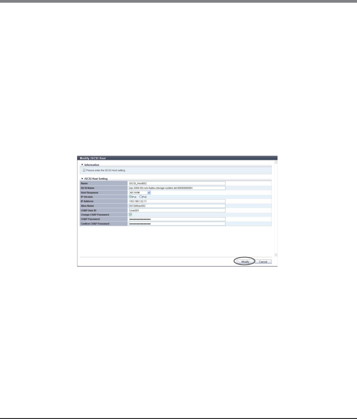
Chapter 9 Connectivity Management
9.2 Functions in the Action Area for Connectivity
ETERNUS Web GUI User’s Guide
Copyright 2013 FUJITSU LIMITED P2X0-1090-10ENZ0
512
•Change CHAP Password
To change the CHAP Authentication password, select the checkbox.
Only when the "CHAP User ID" is registered, the field is available.
•CHAP Password
Specify the password for CHAP Authentication. It is not necessary to specify this item if CHAP
Authentication is not used.
Configure the user ID and the password as a pair.
The password can be entered only when the "Change CHAP Password" checkbox has been selected.
The following input conditions apply:
-12 - 100 alphanumeric characters and symbols (except ", (comma)" and "?")
-Space
•Confirm CHAP Password
Input the CHAP password again for confirmation.
The confirmation password can be entered only when the "Change CHAP Password" checkbox has
been selected.
The following input conditions apply:
-12 - 100 alphanumeric characters and symbols (except ", (comma)" and "?")
-Space
→A confirmation screen appears.
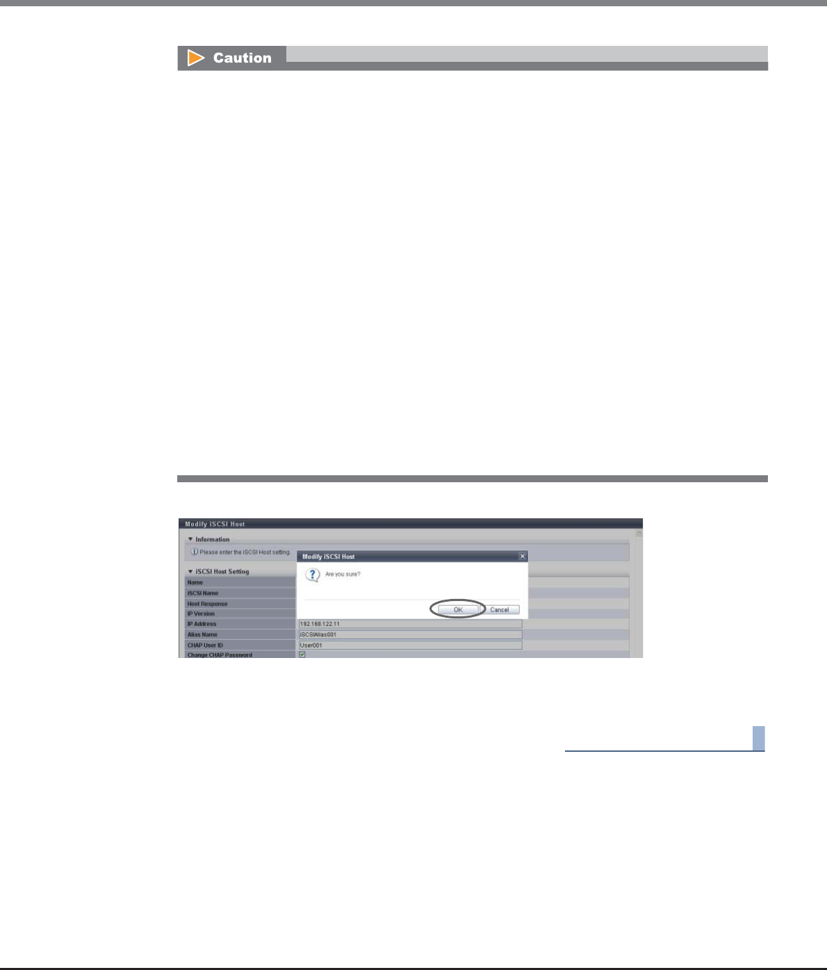
Chapter 9 Connectivity Management
9.2 Functions in the Action Area for Connectivity
ETERNUS Web GUI User’s Guide
Copyright 2013 FUJITSU LIMITED P2X0-1090-10ENZ0
513
3Click the [OK] button.
→Changing of the iSCSI host information starts.
4Click the [Done] button to return to the [iSCSI Host] screen.
End of procedure
•An error screen appears in the following conditions:
-When the "Name" is not input
-When the "Name" does not satisfy the input conditions
-When the "Name" already exists
-When the "iSCSI Name" is not input
-When the "iSCSI Name" does not satisfy the input conditions
-When the "IP Address" does not satisfy the input conditions
-When several iSCSI hosts with the same "IP Address" and "iSCSI Name" have been configured
-When several iSCSI hosts have been specified with the same "iSCSI Name" when the IP
addresses have not been entered
-When the "Alias Name" does not satisfy the input conditions
-When the "Alias Name" overlaps the existing Alias name
-When the "CHAP User ID" does not satisfy the input conditions
-When the "CHAP Password" does not satisfy the input conditions
-When the "Confirm CHAP Password" does not satisfy the input conditions
-When either of the "CHAP User ID" or the "CHAP Password" has been specified
-When the "CHAP Password" and the "Confirm CHAP Password" do not match
-When there are some LUNs that cannot be recognized from the iSCSI host because the "Host
Response" setting has been changed (only for iSCSI hosts that are not registered in a host
group)
Chapter 9 Connectivity Management
9.2 Functions in the Action Area for Connectivity
ETERNUS Web GUI User’s Guide
Copyright 2013 FUJITSU LIMITED P2X0-1090-10ENZ0
514
9.2.2.17 Modify SAS Host
This function changes the SAS host information.
The procedure to change the SAS host information is as follows:
Procedure
1Select the SAS host to changed the host information for, and click [Modify SAS Host] in
[Action].
2Input new host information and click the [Modify] button.
•Name
Input a new SAS host name. An existing host name cannot be specified.
The following input conditions apply:
-Up to 16 alphanumeric characters and symbols (except ", (comma)" and "?")
-Space
•SAS Address
Input a new SAS address. The same SAS address as another host cannot be used.
The following input conditions apply:
-16 hexadecimal numbers
-"F (f)" or "0" used in entire 16 characters are not allowed.
•When no SAS hosts are registered, the [Modify SAS Host] function cannot be used.
•When changing the SAS address of a SAS host that is currently being used, make sure to stop access to
that SAS host.
•The [Rename SAS Host] function that is provided with controller firmware version V10L24 or earlier is
integrated in this function. Note that this function cannot change multiple SAS host names. Change one
SAS host name at a time.
•This function can change the following SAS host information; "Name" and "SAS Address". When the SAS
host is not registered in a host group, the "Host Response" setting can also be changed.
•When the SAS host is registered in a host group, use the [Modify Host Group] function to change the host
response. Refer to "9.2.2.8 Modify Host Group (SAS)" (page 480) for details.
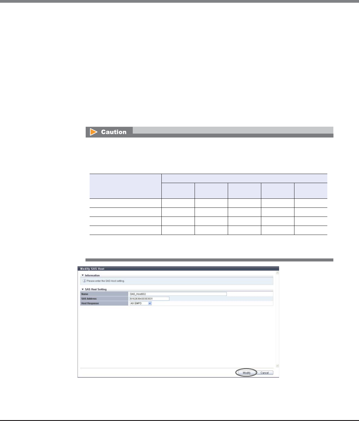
Chapter 9 Connectivity Management
9.2 Functions in the Action Area for Connectivity
ETERNUS Web GUI User’s Guide
Copyright 2013 FUJITSU LIMITED P2X0-1090-10ENZ0
515
•Host Response
Select a new host response that is to be assigned to the SAS host.
The host response list created in the ETERNUS DX Disk storage system is displayed.
This item is available only when a SAS host is not registered in the host group.
-Solaris MPxIO
-HP-UX
-AIX EMPD (*1)
-AIX VxVM
-AIX Single Path
-VS850/SVC
-Host responses created in the ETERNUS DX Disk storage system
-Default
*1: EMPD: ETERNUS Multipath Driver
→A confirmation screen appears.
If the host response is changed for a SAS host that is configured with the host affinity setting, the
LUNs may not be able to be accessed from the SAS host. Make sure to check the current LUN
settings and select a host response with an appropriate "Host Specific Mode" to change the host
response.
Available: The host can recognize LUNs
N/A: The host cannot recognize some LUNs
LUN settings for LUN groups
with host affinity settings
Host Specific Mode
Normal AIX Mode NR1000V
Mode
HP-UX
Mode
BS2000
Mode
LUN#0 – LUN#255 Available Available Available Available Available
LUN#0 - LUN#511 N/A Available Available Available Available
LUN#0 - LUN#1023 N/A N/A N/A Available Available
LUN#0 - LUN#4095 N/A N/A N/A N/A Available
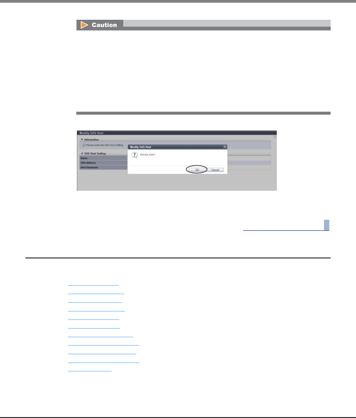
Chapter 9 Connectivity Management
9.2 Functions in the Action Area for Connectivity
ETERNUS Web GUI User’s Guide
Copyright 2013 FUJITSU LIMITED P2X0-1090-10ENZ0
516
3Click the [OK] button.
→Changing of the SAS host information starts.
4Click the [Done] button to return to the [SAS Host] screen.
End of procedure
9.2.3 CA Port Group Management
CA Port Group management provides the following functions:
•Create FC Port Group
•Create iSCSI Port Group
•Create SAS Port Group
•Create FCoE Port Group
•Delete CA Port Group
•Modify CA Port Group
•Modify FC Port Parameters
•Modify iSCSI Port Parameters
•Modify SAS Port Parameters
•Modify FCoE Port Parameters
•Modify Port Mode
An error screen appears in the following conditions:
•When the "Name" is not input
•When the "Name" does not satisfy the input conditions
•When the "Name" already exists
•When the "SAS Address" is not input
•When the "SAS Address" does not satisfy the input conditions
•When the same "SAS Address" is already registered
•When there are some LUNs that cannot be recognized from the SAS host because the "Host
Response" setting has been changed (only for SAS hosts that are not registered in a host group)

Chapter 9 Connectivity Management
9.2 Functions in the Action Area for Connectivity
ETERNUS Web GUI User’s Guide
Copyright 2013 FUJITSU LIMITED P2X0-1090-10ENZ0
517
9.2.3.1 Create FC Port Group
This function creates a new FC port group, and registers the port to be a member.
An FC port group is a group of FC-CA type ports that are connected to the specified host group. This function
configures the host affinity setting for each FC port group.
•The maximum number of port groups per storage system is 128, irrespective of the CA types.
•The maximum number of ports per port group is 8.
•A port can be a member of several port groups.
The procedure to create an FC port group is as follows:
Procedure
1Click [Create FC Port Group] in [Action].
•Registration of the port is necessary to create a port group. A port group cannot be created if the port to
be a member has not been registered from GUI.
•Only ports with "CA" or "CA/RA" as the port mode can be added to a port group. Ports with "RA" as the port
mode cannot be added to a port group.
•A port with the affinity mode enabled ("ON") and a port with the affinity mode disabled ("OFF") cannot
exist together in a port group.
-The affinity mode ("ON" or "OFF") of a port group is decided when the host affinity setting has been
configured on the corresponding port group. All of the member ports in a port group have the same
affinity mode.
-The affinity mode ("ON" or "OFF") of a port group is not changed until the host affinity setting has
been released from the corresponding port group.
-When one port is registered in several port groups, and the host affinity setting has been configured
on one of the port groups including the corresponding port, the same affinity setting is configured on
all the port groups, which include the corresponding port, and also on the member ports.
-Ports without the host affinity setting can be members of a port group, regardless of whether the
affinity mode for the group is enabled ("ON") or disabled ("OFF").
•To change the settings of a port groups, refer to "9.2.3.6 Modify CA Port Group" (page 528).
•To add a port to an existing port group, refer to "9.2.3.6 Modify CA Port Group" (page 528).
•To change the port mode from "RA" to "CA", refer to "9.2.3.11 Modify Port Mode" (page 571).
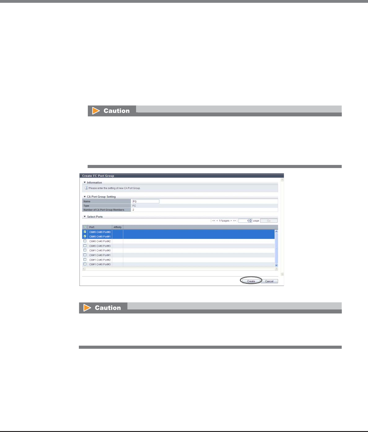
Chapter 9 Connectivity Management
9.2 Functions in the Action Area for Connectivity
ETERNUS Web GUI User’s Guide
Copyright 2013 FUJITSU LIMITED P2X0-1090-10ENZ0
518
2Specify the name of the port group to be created, select all the ports to be registered in the
port group, and click the [Create] button.
•Name
Specify the port group name.
An existing port group name cannot be specified.
The following input conditions apply:
-Up to 16 alphanumeric characters and symbols (except ", (comma)" and "?")
-Space
•Checkbox to select ports
Select the checkbox of the FC port to be registered in an FC port group.
→A confirmation screen appears.
•When a port that has the affinity mode enabled ("ON") is selected, ports that have the affinity
mode disabled ("OFF") cannot be selected.
•When a port that has the affinity mode disabled ("OFF") is selected, ports that have the affinity
mode enabled ("ON") cannot be selected.
•Up to eight ports can be selected.
An error screen appears in the following conditions:
•When the port group name does not satisfy the input conditions
•When the port group name has not been entered
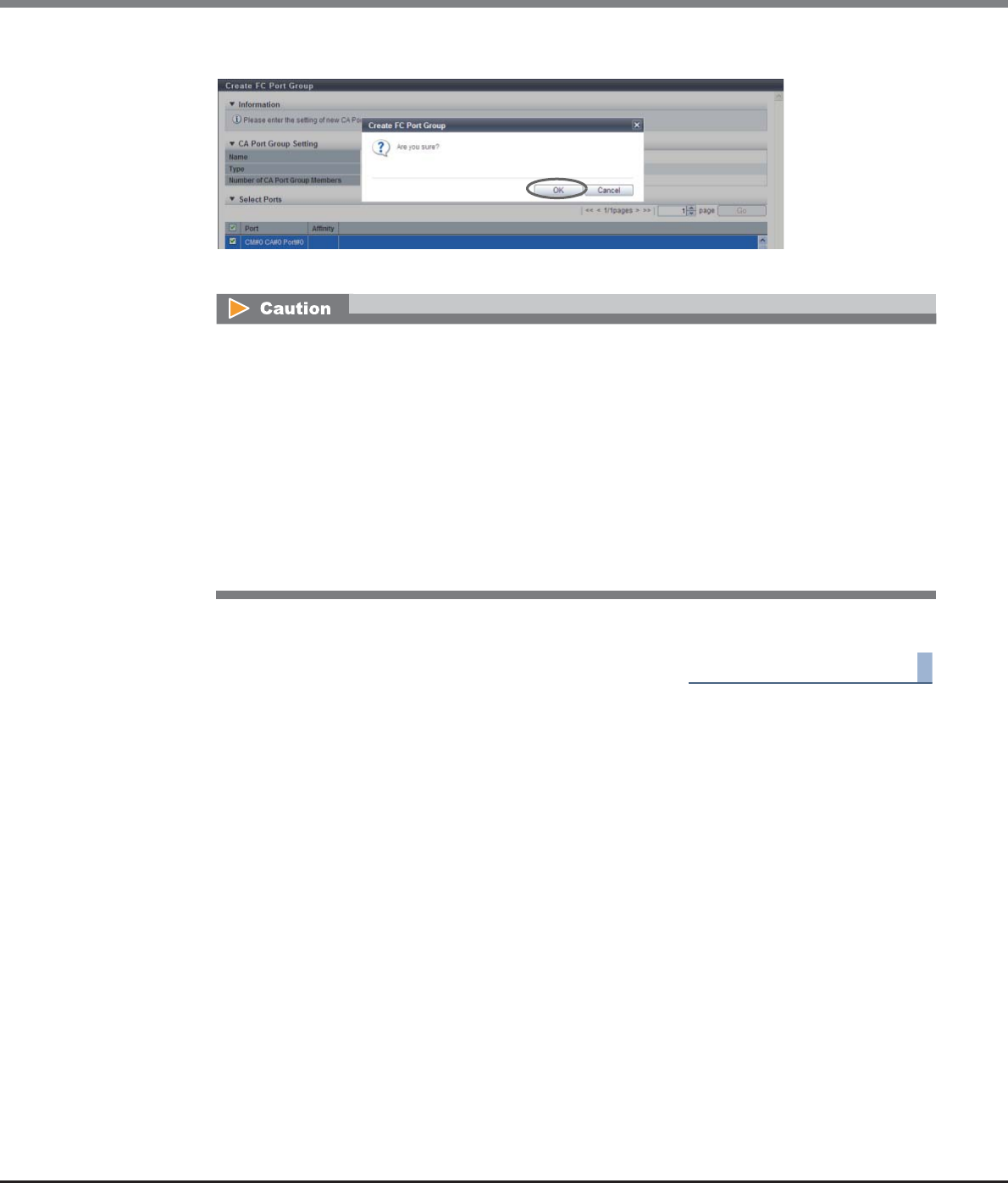
Chapter 9 Connectivity Management
9.2 Functions in the Action Area for Connectivity
ETERNUS Web GUI User’s Guide
Copyright 2013 FUJITSU LIMITED P2X0-1090-10ENZ0
519
3Click the [OK] button.
→Registration of the FC port group starts.
4Click the [Done] button to return to the [CA Port Group] screen.
End of procedure
9.2.3.2 Create iSCSI Port Group
This function creates a new iSCSI port group, and registers the port to be a member.
An iSCSI port group is a group of iSCSI-CA type ports that are connected to the specified host group. This
function configures the host affinity setting for each iSCSI port group.
•The maximum number of port groups per storage system is 128, irrespective of the CA types.
•The maximum number of ports per port group is 8.
•A port can be a member of several port groups.
An error screen appears in the following conditions:
•When the port group name overlaps with an existing port group name (port group names cannot
overlap with any other port group names, irrespective of the CA types)
•When the total number of ports has exceeded the maximum number for the ETERNUS DX Disk
storage system
•When no ports are registered in a port group, or when nine or more ports are registered in a port
group
•When the specified port does not exist in the ETERNUS DX Disk storage system
•When the port mode of the selected port is other than "FC"
•When there are ports of which affinity mode is enabled ("ON") and disabled ("OFF") existing
together
Chapter 9 Connectivity Management
9.2 Functions in the Action Area for Connectivity
ETERNUS Web GUI User’s Guide
Copyright 2013 FUJITSU LIMITED P2X0-1090-10ENZ0
520
The procedure to create an iSCSI port group is as follows:
Procedure
1Click [Create iSCSI Port Group] in [Action].
•Registration of the port is necessary to create a port group. A port group cannot be created if the port to
be a member has not been registered from GUI.
•Only ports with "CA" or "CA/RA" as the port mode can be added to a port group. Ports with "RA" as the port
mode cannot be added to a port group.
•A port with the affinity mode enabled ("ON") and a port with the affinity mode disabled ("OFF") cannot
exist together in a port group.
-The affinity mode ("ON" or "OFF") of a port group is decided when the host affinity setting has been
configured on the corresponding port group. All of the member ports in a port group have the same
affinity mode.
-The affinity mode ("ON" or "OFF") of a port group is not changed until the host affinity setting has
been released from the corresponding port group.
-When one port is registered in several port groups, and the host affinity setting has been configured
on one of the port groups including the corresponding port, the same affinity setting is configured on
all the port groups, which include the corresponding port, and also on the member ports.
-Ports without the host affinity setting can be members of a port group, regardless of whether the
affinity mode for the group is enabled ("ON") or disabled ("OFF").
•To change the settings of a port groups, refer to "9.2.3.6 Modify CA Port Group" (page 528).
•To add a port to an existing port group, refer to "9.2.3.6 Modify CA Port Group" (page 528).
•To change the port mode from "RA" to "CA", refer to "9.2.3.11 Modify Port Mode" (page 571).
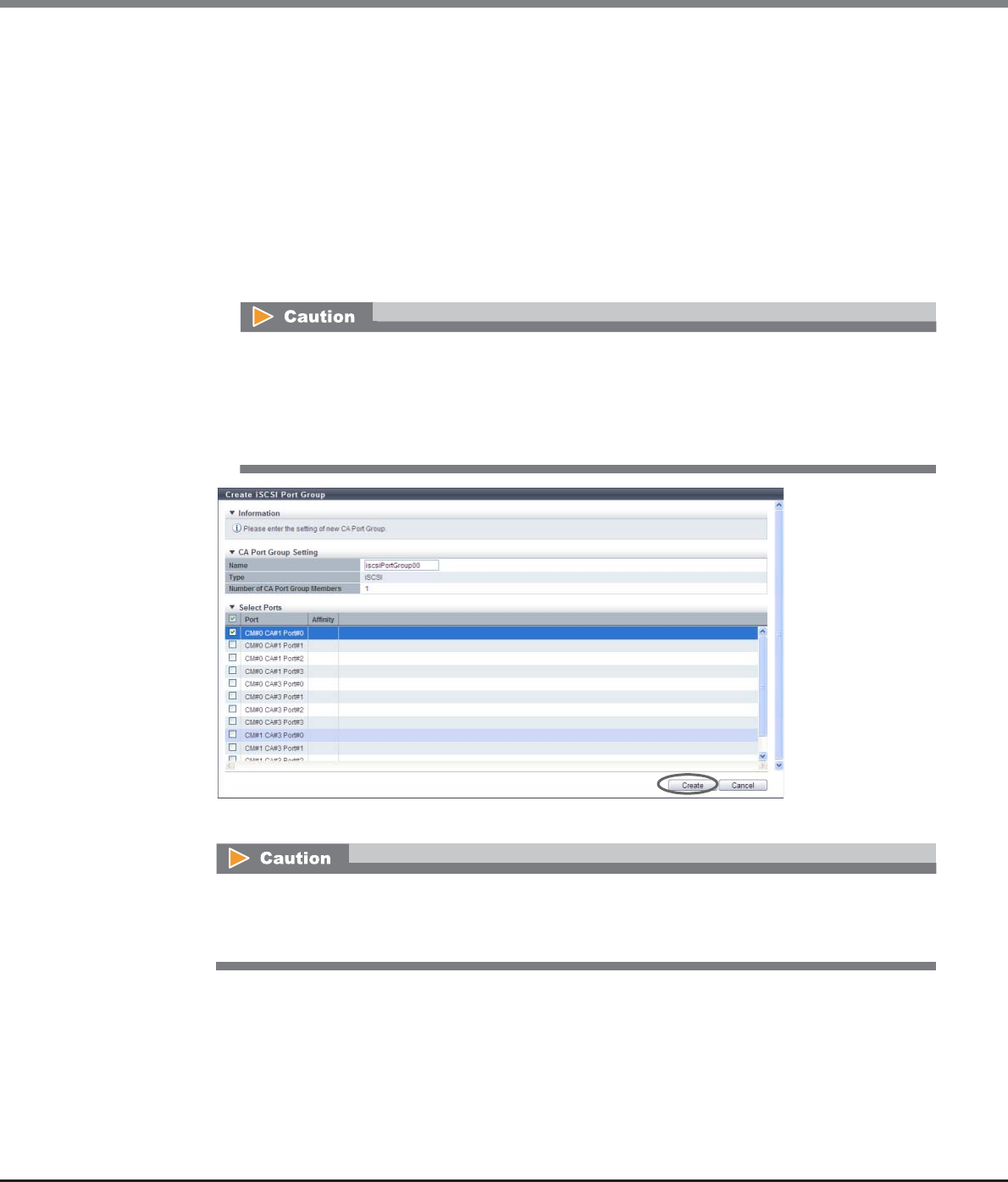
Chapter 9 Connectivity Management
9.2 Functions in the Action Area for Connectivity
ETERNUS Web GUI User’s Guide
Copyright 2013 FUJITSU LIMITED P2X0-1090-10ENZ0
521
2Specify the name of the port group to be created, select all the ports to be registered in the
port group, and click the [Create] button.
•Name
Specify the port group name.
An existing port group name cannot be specified.
The following input conditions apply:
-Up to 16 alphanumeric characters and symbols (except ", (comma)" and "?")
-Space
•Checkbox to select ports
Select the checkbox of the iSCSI port to be registered in an iSCSI port group.
→A confirmation screen appears.
•When a port that has the affinity mode enabled ("ON") is selected, ports that have the affinity
mode disabled ("OFF") cannot be selected.
•When a port that has the affinity mode disabled ("OFF") is selected, ports that have the affinity
mode enabled ("ON") cannot be selected.
•Up to eight ports can be selected.
An error screen appears in the following conditions:
•When the port group name does not satisfy the input conditions
•When the port group name has not been entered
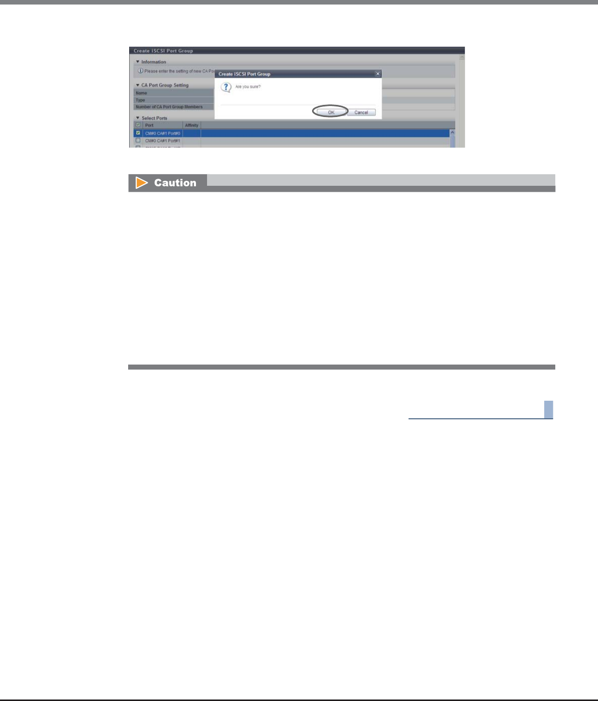
Chapter 9 Connectivity Management
9.2 Functions in the Action Area for Connectivity
ETERNUS Web GUI User’s Guide
Copyright 2013 FUJITSU LIMITED P2X0-1090-10ENZ0
522
3Click the [OK] button.
→Registration of the iSCSI port group starts.
4Click the [Done] button to return to the [CA Port Group] screen.
End of procedure
9.2.3.3 Create SAS Port Group
This function creates a new SAS port group, and registers the port to be a member.
A SAS port group is a group of SAS-CA type ports that are connected to the specified host group. This function
configures the host affinity setting for each SAS port group.
•The maximum number of port groups per storage system is 128, irrespective of the CA types.
•The maximum number of ports per port group is 8.
•A port can be a member of several port groups.
An error screen appears in the following conditions:
•When the port group name overlaps with an existing port group name (port group names cannot
overlap with any other port group names, irrespective of the CA types)
•When the total number of ports has exceeded the maximum number for the ETERNUS DX Disk
storage system
•When no ports are registered in a port group, or when nine or more ports are registered in a port
group
•When the specified port does not exist in the ETERNUS DX Disk storage system
•When the port mode of the selected port is other than "iSCSI"
•When the port mode of the selected port is other than "CA"
•When there are ports of which affinity mode is enabled ("ON") and disabled ("OFF") existing
together
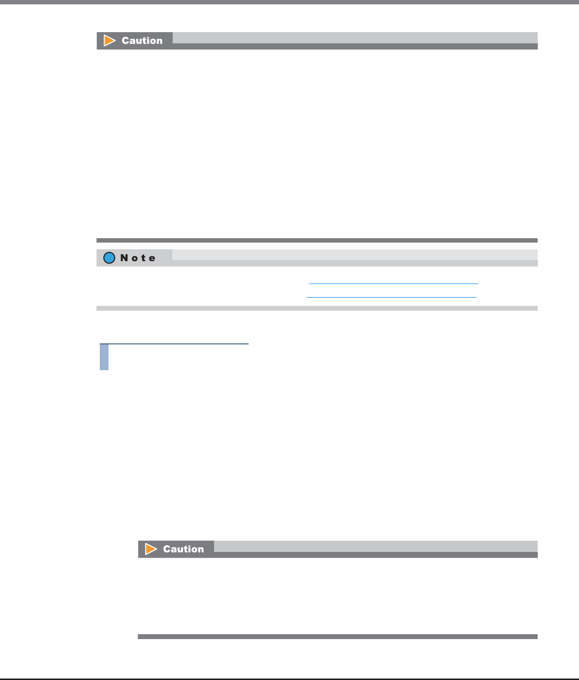
Chapter 9 Connectivity Management
9.2 Functions in the Action Area for Connectivity
ETERNUS Web GUI User’s Guide
Copyright 2013 FUJITSU LIMITED P2X0-1090-10ENZ0
523
The procedure to create a SAS port group is as follows:
Procedure
1Click [Create SAS Port Group] in [Action].
2Specify the name of the port group to be created, select all the ports to be registered in the
port group, and click the [Create] button.
•Name
Specify the port group name.
An existing port group name cannot be specified.
The following input conditions apply:
-Up to 16 alphanumeric characters and symbols (except ", (comma)" and "?")
-Space
•Checkbox to select ports
Select the checkbox of the SAS port to be registered in a SAS port group.
•Registration of the port is necessary to create a port group. A port group cannot be created if the port to
be a member has not been registered from GUI.
•A port with the affinity mode enabled ("ON") and a port with the affinity mode disabled ("OFF") cannot
exist together in a port group.
-The affinity mode ("ON" or "OFF") of a port group is decided when the host affinity setting has been
configured on the corresponding port group. All of the member ports in a port group have the same
affinity mode.
-The affinity mode ("ON" or "OFF") of a port group is not changed until the host affinity setting has
been released from the corresponding port group.
-When one port is registered in several port groups, and the host affinity setting has been configured
on one of the port groups including the corresponding port, the same affinity setting is configured on
all the port groups, which include the corresponding port, and also on the member ports.
-Ports without the host affinity setting can be members of a port group, regardless of whether the
affinity mode for the group is enabled ("ON") or disabled ("OFF").
•To change the settings of a port groups, refer to "9.2.3.6 Modify CA Port Group" (page 528).
•To add a port to an existing port group, refer to "9.2.3.6 Modify CA Port Group" (page 528).
•When a port that has the affinity mode enabled ("ON") is selected, ports that have the affinity
mode disabled ("OFF") cannot be selected.
•When a port that has the affinity mode disabled ("OFF") is selected, ports that have the affinity
mode enabled ("ON") cannot be selected.
•Up to eight ports can be selected.
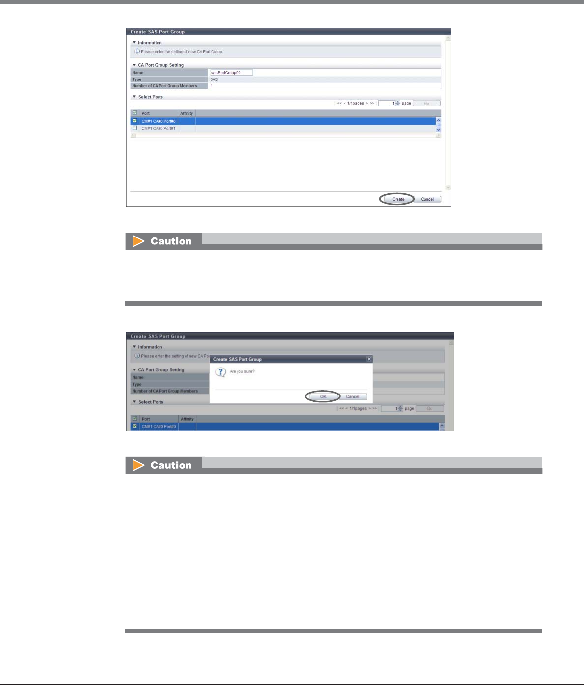
Chapter 9 Connectivity Management
9.2 Functions in the Action Area for Connectivity
ETERNUS Web GUI User’s Guide
Copyright 2013 FUJITSU LIMITED P2X0-1090-10ENZ0
524
→A confirmation screen appears.
3Click the [OK] button.
→Registration of the SAS port group starts.
An error screen appears in the following conditions:
•When the port group name does not satisfy the input conditions
•When the port group name has not been entered
An error screen appears in the following conditions:
•When the port group name overlaps with an existing port group name (port group names cannot
overlap with any other port group names, irrespective of the CA types)
•When the total number of ports has exceeded the maximum number for the ETERNUS DX Disk
storage system
•When no ports are registered in a port group, or when nine or more ports are registered in a port
group
•When the specified port does not exist in the ETERNUS DX Disk storage system
•When the port mode of the selected port is other than "SAS"
•When there are ports of which affinity mode is enabled ("ON") and disabled ("OFF") existing
together
Chapter 9 Connectivity Management
9.2 Functions in the Action Area for Connectivity
ETERNUS Web GUI User’s Guide
Copyright 2013 FUJITSU LIMITED P2X0-1090-10ENZ0
525
4Click the [Done] button to return to the [CA Port Group] screen.
End of procedure
9.2.3.4 Create FCoE Port Group
This function creates a new FCoE port group, and registers the port to be a member.
An FCoE port group is a group of FCoE-CA type ports that are connected to the specified host group. This
function configures the host affinity setting for each FCoE port group.
•The maximum number of port groups per storage system is 128, irrespective of the CA types.
•The maximum number of ports per port group is 8.
•A port can be a member of several port groups.
The procedure to create an FCoE port group is as follows:
Procedure
1Click [Create FCoE Port Group] in [Action].
•Registration of the port is necessary to create a port group. A port group cannot be created if the port to
be a member has not been registered from GUI.
•A port with the affinity mode enabled ("ON") and a port with the affinity mode disabled ("OFF") cannot
exist together in a port group.
-The affinity mode ("ON" or "OFF") of a port group is decided when the host affinity setting has been
configured on the corresponding port group. All of the member ports in a port group have the same
affinity mode.
-The affinity mode ("ON" or "OFF") of a port group is not changed until the host affinity setting has
been released from the corresponding port group.
-When one port is registered in several port groups, and the host affinity setting has been configured
on one of the port groups including the corresponding port, the same affinity setting is configured on
all the port groups, which include the corresponding port, and also on the member ports.
-Ports without the host affinity setting can be members of a port group, regardless of whether the
affinity mode for the group is enabled ("ON") or disabled ("OFF").
•To change the settings of a port groups, refer to "9.2.3.6 Modify CA Port Group" (page 528).
•To add a port to an existing port group, refer to "9.2.3.6 Modify CA Port Group" (page 528).
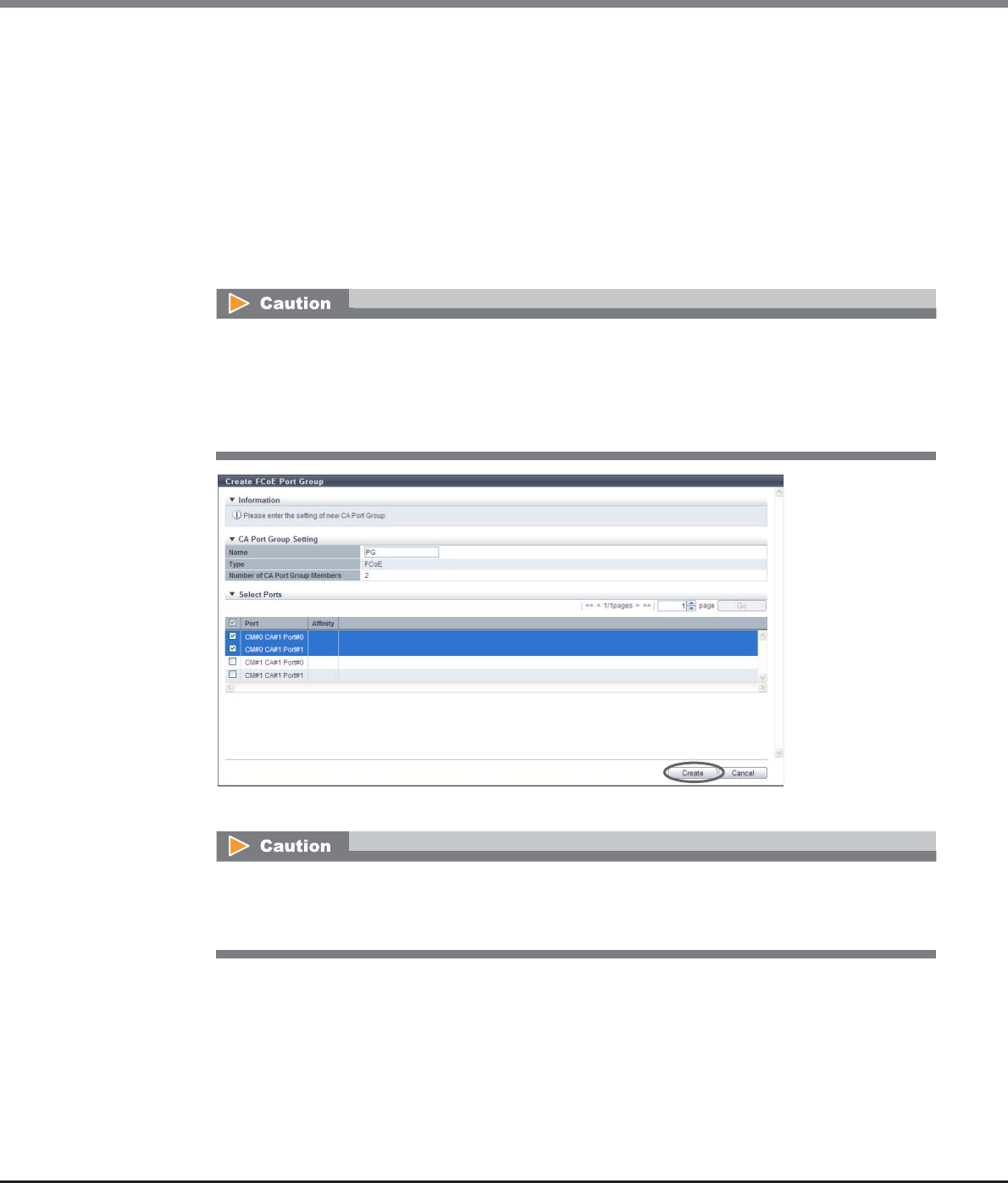
Chapter 9 Connectivity Management
9.2 Functions in the Action Area for Connectivity
ETERNUS Web GUI User’s Guide
Copyright 2013 FUJITSU LIMITED P2X0-1090-10ENZ0
526
2Specify the name of the port group to be created, select all the ports to be registered in the
port group, and click the [Create] button.
•Name
Specify the port group name.
An existing port group name cannot be specified.
The following input conditions apply:
-Up to 16 alphanumeric characters and symbols (except ", (comma)" and "?")
-Space
•Checkbox to select ports
Select the checkbox of the FCoE port to be registered in an FCoE port group.
→A confirmation screen appears.
•When a port that has the affinity mode enabled ("ON") is selected, ports that have the affinity
mode disabled ("OFF") cannot be selected.
•When a port that has the affinity mode disabled ("OFF") is selected, ports that have the affinity
mode enabled ("ON") cannot be selected.
•Up to eight ports can be selected.
An error screen appears in the following conditions:
•When the port group name does not satisfy the input conditions
•When the port group name has not been entered
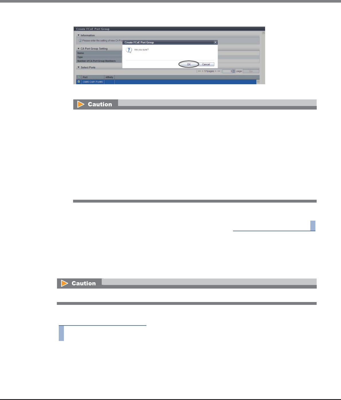
Chapter 9 Connectivity Management
9.2 Functions in the Action Area for Connectivity
ETERNUS Web GUI User’s Guide
Copyright 2013 FUJITSU LIMITED P2X0-1090-10ENZ0
527
3Click the [OK] button.
→Registration of the FCoE port group starts.
4Click the [Done] button to return to the [CA Port Group] screen.
End of procedure
9.2.3.5 Delete CA Port Group
This function deletes a CA port group. When a CA port group is deleted, the ports, which belong to the CA port
group, are also deleted.
The procedure to delete a CA port group is as follows:
Procedure
1Select the CA port group to be deleted (multiple selections can be made) and click [Delete
Port Group] in [Action].
→A confirmation screen appears.
An error screen appears in the following conditions:
•When the port group name overlaps with an existing port group name (port group names cannot
overlap with any other port group names, irrespective of the CA types)
•When the total number of ports has exceeded the maximum number for the ETERNUS DX Disk
storage system
•When no ports are registered in a port group, or when nine or more ports are registered in a port
group
•When the specified port does not exist in the ETERNUS DX Disk storage system
•When the port mode of the selected port is other than "FCoE"
•When there are ports of which affinity mode is enabled ("ON") and disabled ("OFF") existing
together
CA port groups that are being used for the host affinity settings cannot be deleted.
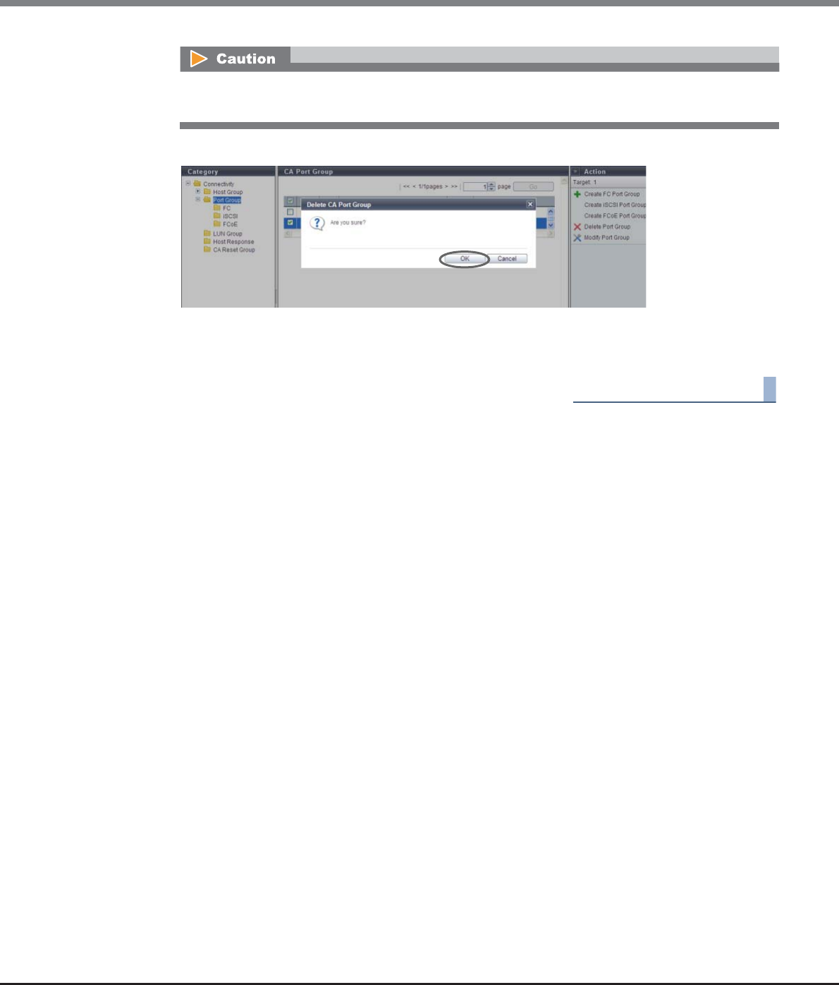
Chapter 9 Connectivity Management
9.2 Functions in the Action Area for Connectivity
ETERNUS Web GUI User’s Guide
Copyright 2013 FUJITSU LIMITED P2X0-1090-10ENZ0
528
2Click the [OK] button.
→Deletion of the CA port group starts.
3Click the [Done] button to return to the [CA Port Group] screen.
End of procedure
9.2.3.6 Modify CA Port Group
This function performs the following modifications for existing CA port groups:
•CA Port Group Name
•Port (Add and delete member ports in a CA port group)
Ports can be added to CA port groups for which the host affinity setting is already configured and ports can
also be deleted from CA port groups.
If a port has been added, the host affinity setting is automatically configured to the corresponding port as a
CA port group member.
If a port has been deleted, the host affinity setting is cleared from the corresponding port.
•The maximum number of CA port groups per storage system is 128, irrespective of the CA types.
•The maximum number of ports per CA port group is 8.
•A port can be a member of several CA port groups.
The CA port group, of which host affinity settings have been configured (the status of the port group is
"Active"), cannot be deleted.
Chapter 9 Connectivity Management
9.2 Functions in the Action Area for Connectivity
ETERNUS Web GUI User’s Guide
Copyright 2013 FUJITSU LIMITED P2X0-1090-10ENZ0
529
The procedure to modify a CA port group is as follows:
Procedure
1Select the CA port group to be changed, and click [Modify Port Group] in [Action].
•Registration of the port is necessary to create a CA port group. Not all of the ports can be deleted from a
CA port group.
•Only ports with "CA" or "CA/RA" as the port mode can be added to a CA port group. The ports, of which port
mode is "RA", cannot be added to the CA port group.
•A port with the affinity mode enabled ("ON") and a port with the affinity mode disabled ("OFF") cannot
exist together in a CA port group.
-The affinity mode ("ON" or "OFF") of a CA port group is decided when the host affinity setting has been
configured on the corresponding CA port group. All of the member ports in a CA port group have the
same affinity mode.
-The affinity mode ("ON" or "OFF") of a CA port group is not changed until the host affinity setting has
been released from the corresponding CA port group.
-When one port is registered in several CA port groups, and the host affinity setting has been
configured on one of the CA port groups including the corresponding port, the same affinity setting is
configured on all the CA port groups, which include the corresponding port, and also on the member
ports.
-Ports without the host affinity setting can be members of a CA port group, regardless of whether the
affinity mode for the host group is enabled ("ON") or disabled ("OFF").
•When a port was added to a CA port group, of which the host affinity setting has been configured, paths
between all the hosts with the host affinity setting and the added port will be configured. To modify the
path between a host and a port, refer to "9.2.1.3 Modify Host Affinity" (page 428).
•When a port in the CA port group for which the host affinity settings are already configured is deleted, the
path from the host to the port is also deleted.
•When creating a new CA port group and registering a port in the CA port group, refer to "9.2.3.1 Create FC
Port Group" (page 517), "9.2.3.2 Create iSCSI Port Group" (page 519), "9.2.3.3 Create SAS Port Group"
(page 522), or "9.2.3.4 Create FCoE Port Group" (page 525) depending on the CA port type.
•To change the CA port mode to "CA" or "CA/RA", refer to "9.2.3.11 Modify Port Mode" (page 571).
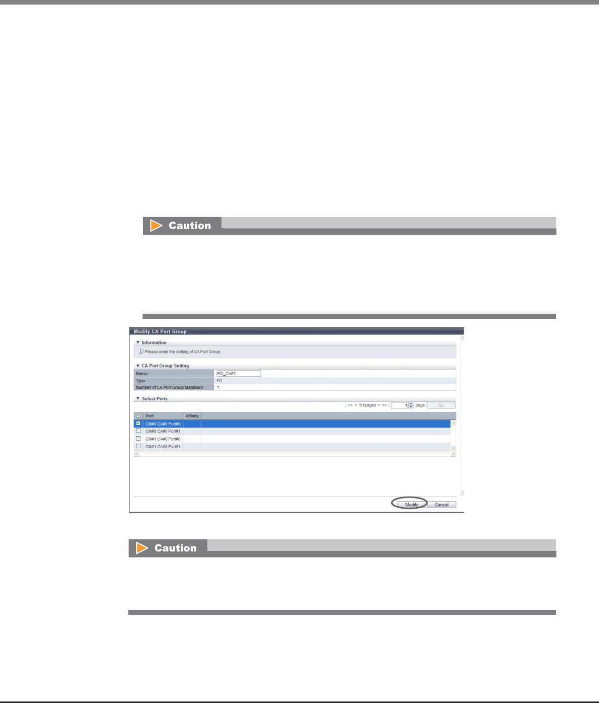
Chapter 9 Connectivity Management
9.2 Functions in the Action Area for Connectivity
ETERNUS Web GUI User’s Guide
Copyright 2013 FUJITSU LIMITED P2X0-1090-10ENZ0
530
2Specify the new name of the CA port group, add a port to the CA port group (select the
checkbox), or delete a port from the CA port group (clear the checkbox), and click the
[Modify] button.
•Name
Specify the CA port group name.
An existing CA port group name cannot be specified.
The following input conditions apply:
-Up to 16 alphanumeric characters and symbols (except ", (comma)" and "?")
-Space
•Checkbox to select ports
The checkbox of the port, which has been registered in the CA port group, is selected.
Select the port checkbox to be added to a CA port group. Clear the port checkbox to be deleted from
a CA port group.
→A confirmation screen appears.
•If the CA port group's affinity mode is "ON" (the affinity mode of all the selected ports is "ON"),
the port, of which affinity mode is "OFF", cannot be selected.
•If the CA port group's affinity mode is "OFF" (the affinity mode of all the selected ports is "OFF"),
the port, of which affinity mode is "ON", cannot be selected.
•Up to eight ports can be selected.
An error screen appears in the following conditions:
•When the CA port group name does not satisfy the input conditions
•When the CA port group name has not been entered
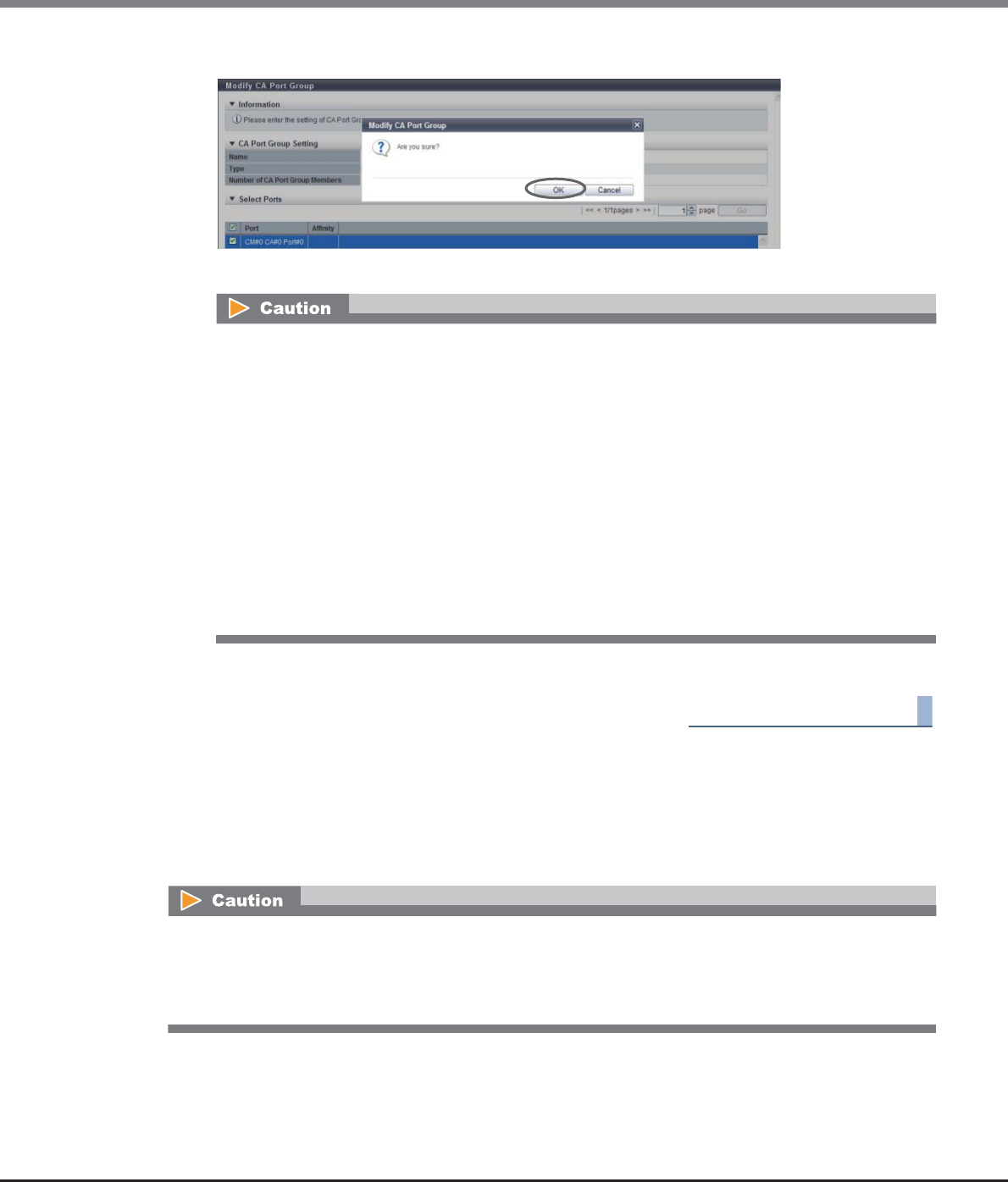
Chapter 9 Connectivity Management
9.2 Functions in the Action Area for Connectivity
ETERNUS Web GUI User’s Guide
Copyright 2013 FUJITSU LIMITED P2X0-1090-10ENZ0
531
3Click the [OK] button.
→Modification of the CA port group starts.
4Click the [Done] button to return to the [CA Port Group] screen.
End of procedure
9.2.3.7 Modify FC Port Parameters
This function sets the FC port connection information between the ETERNUS DX Disk storage system and a
host, between local and remote devices for REC, or between source and destination storage systems for
Storage Migration.
An error screen appears in the following conditions:
•When the CA port group name overlaps with an existing CA port group name (port group names
cannot overlap with any other CA port group names, irrespective of the CA types)
•When no ports are registered in a CA port group, or when nine or more ports are registered in a CA
port group
•When the specified port does not exist in the ETERNUS DX Disk storage system
•When the CA type of the selected port differs from the CA type of the existing ports in the CA port
group
•When the port mode of the selected port is other than "CA"
•When there are ports of which affinity mode is enabled ("ON") and disabled ("OFF") existing
together
•When the affinity mode ("ON" or "OFF") of the selected port differs from the affinity mode of the
existing ports in the CA port group
•When changing port parameters during operation, stop access from the server that is connected to the
target port. Host access does not need to be stopped to change the port parameters of newly added CA
ports.
•The port parameters of an FC-Initiator port that has Storage Migration paths cannot be changed.
Chapter 9 Connectivity Management
9.2 Functions in the Action Area for Connectivity
ETERNUS Web GUI User’s Guide
Copyright 2013 FUJITSU LIMITED P2X0-1090-10ENZ0
532
The procedure to set FC port parameters is as follows:
Procedure
1Select which FC port to set the parameters for (multiple selections can be made) and click
[Configure FC Port] in [Action].
2Set the parameters for all of the selected ports and click the [Set] button.
The settings of port parameters vary depending on the port mode ("When the port mode is "CA" or "CA/
RA"" (page 532), "When the port mode is "RA"" (page 536), or "When the port mode is "Initiator"" (page
539)).
■When the port mode is "CA" or "CA/RA"
•Port
Select the target port or select the copy source port.
The selectable port locations are displayed as options:
-CM#x CA#y Port#z (x: CM number, y: CA number, z: Port number)
•Connection
Select the connection topology for the target port from the "Fabric" or "FC-AL".
When "FC-AL" is selected, it is necessary to assign a Loop ID to the port.
-Fabric
A connection type that enables simultaneous communication among multiple nodes through a
Fibre Channel switch. This connection type can also be used for a direct connection when "Trans-
fer Rate" is "16 Gbit/s".
-FC-AL
A connection type that connects multiple nodes in a loop.
This connection type is used for a direct connection when "Transfer Rate" is 8Gbit/s or less.
•There are four types of port modes for FC ports; CA, RA, CA/RA, and Initiator. CA is used for connecting to a
server, RA is used for REC, CA/RA is used for connecting to a server and for REC, and Initiator is used for
Storage Migration. To change the port mode, refer to "9.2.3.11 Modify Port Mode" (page 571). The default
value is "CA".
•For more details on the parameter settings of FC-CA, refer to "User’s Guide -Server Connection-" for each
OS type.
•When changing the port parameters for FC-Initiator port, delete the path group specified in the target
port. Refer to "11.2.11.3 Delete Storage Migration Path" (page 914) for details.
Multiple selections can be made from FC ports that have the same "Type" and "Port Mode". To set the
same parameters for multiple ports, set the parameters of the copy source port and click the [Copy]
button. Select the copy destination port and click the [Copy] button. The parameters can be copied.
Note that the "Loop ID" that is specified for "Set Loop ID (Manual)" is not copied.
To set different parameters to multiple ports, select each target port and set the parameters.
Chapter 9 Connectivity Management
9.2 Functions in the Action Area for Connectivity
ETERNUS Web GUI User’s Guide
Copyright 2013 FUJITSU LIMITED P2X0-1090-10ENZ0
533
•Set Loop ID
When "Connection" is "FC-AL", select "Manual" or "Auto" as the specification method for the Loop ID.
"Loop ID" is an identification number of a node in a loop.
•Loop ID
-Manual
When the "Set Loop ID" is "Manual", enter the Loop ID.
The Loop ID must have a value that is different from the values of all the ports.
The following input condition applies:
•0x0 - 0x7D
-Auto
When the "Set Loop ID" is "Auto", select "Ascending" or "Descending".
•Transfer Rate
Select the transfer speed for the target port. The available transfer rate varies according to the
selected port type and connection topology.
-Auto-negotiation
-1 Gbit/s (Not supported)
-2 Gbit/s (Not supported when "Type" is "16G FC")
-4 Gbit/s
-8 Gbit/s
-16 Gbit/s (Not supported when "Type" is "8G FC" or when "Type" is "16G FC" and "Connection" is
"FC-AL")
•Frame Size
Select the frame size of the target port.
"Frame Size" specifies the length of the communication information.
-512 bytes
-1024 bytes
-2048 bytes
•Reset Scope
Specify the reset scope of the target port.
Reset scope is the range where the command reset from the server is performed, when the target
port is connected to multiple servers.
-I_T_L (I: Initiator, T: Target, L: LUN)
Reset (cancel) the command request from the server that sent the command reset request.
-T_L (T: Target, L: LUN)
Reset (cancels) the command request from all of the servers that are connected to the port.
Select "Fabric" for a direct connection when "Transfer Rate" is "16 Gbit/s".
•Select "Auto-negotiation", "2 Gbit/s", "4 Gbit/s", "8 Gbit/s", or "16 Gbit/s" for "Transfer Rate". Note
that "1 Gbit/s" is not supported.
•"Auto-negotiation" is selected for "Transfer Rate" when "Type" is "16G FC", "Transfer Rate" is "16
Gbit/s", and "Connection" is changed from "Fabric" to "FC-AL".
Chapter 9 Connectivity Management
9.2 Functions in the Action Area for Connectivity
ETERNUS Web GUI User’s Guide
Copyright 2013 FUJITSU LIMITED P2X0-1090-10ENZ0
534
•Release Reservation if Chip is Reset
Select whether to "Enable" or "Disable" the function to release the reserved status of the volume
when the target port (chip) is reset.
•REC Line No.
Select the REC line number of the target port.
The REC line number is used to switch the communication path when a line fails. The REC line
number is used to recognize failed lines. Set different REC line numbers for each physical
communication path. When lines are in normal status, an REC can be performed regardless of the
REC line number (specifying the same REC line numbers is allowed) in the same way as
conventional REC operations. Note that no priority applies to REC line numbers.
•REC Transfer Mode
Select which REC transfer mode is enabled or disabled for the target port.
When "Enable" is selected, an REC is performed in the selected transfer mode for the target port.
When "Disable" is selected, an REC is not performed in the selected transfer mode for the target
port.
To set the REC transfer mode for the specific port, enable the appropriate mode. For example,
specify different ports for Consistency and Stack to perform data transfers without any interference.
The current setting is retained even when an REC path is changed. When "Enable" is selected for all
of the REC transfer modes (default setting), a conventional REC is performed.
-Sync (REC in synchronous transfer mode)
-Async Stack (REC in asynchronous stack mode)
-Async Consistency (REC in asynchronous consistency mode)
-Async Through (REC in asynchronous through mode)
•This item is displayed only when "Port Mode" is "CA/RA".
•When a line fails, the communication path is switched according to the REC line number of the
copy source storage system. For normal operation, set the same REC line number for the copy
source and the copy destination storage systems to recover data.
•If the port mode has been changed from "CA/RA" to "CA" or "Initiator", the REC line number
returns to the default setting ("0"). When the port mode has changed from "CA/RA" to "RA", the
current REC line number setting is retained. Refer to "9.2.3.11 Modify Port Mode" (page 571)
for details.
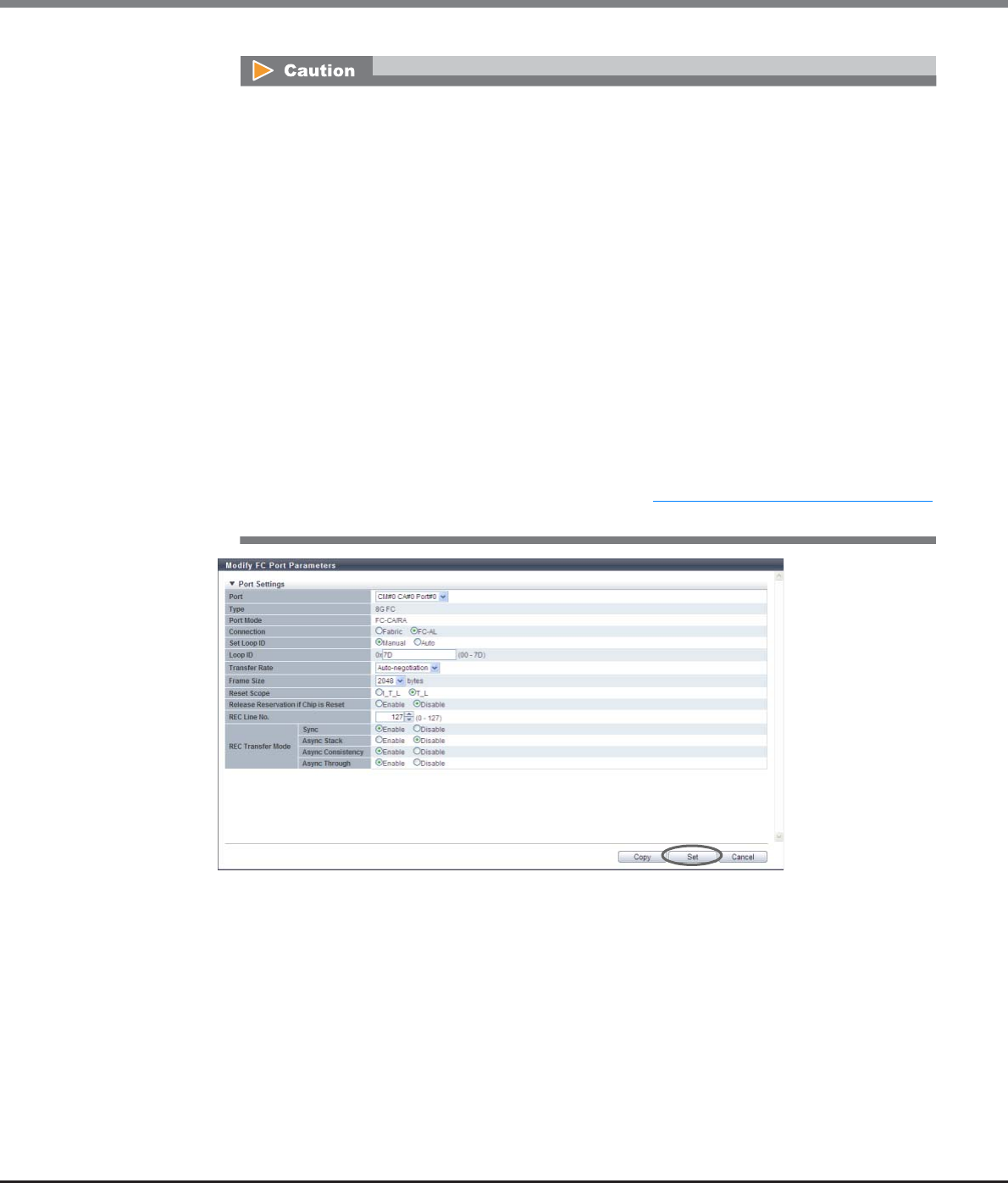
Chapter 9 Connectivity Management
9.2 Functions in the Action Area for Connectivity
ETERNUS Web GUI User’s Guide
Copyright 2013 FUJITSU LIMITED P2X0-1090-10ENZ0
535
•This item is displayed only when "Port Mode" is "CA/RA".
•The REC transfer mode can be changed without suspending a copy session even when an REC is
being performed in the target port. The changed settings are applied immediately to the
ETERNUS DX Disk storage system.
•If specific REC transfer modes for all the RA ports and the CA/RA ports are disabled, a copy
session with a disabled REC transfer mode fails because the REC paths for all the RA ports and
the CA/RA ports are regarded as being blocked. When the REC transfer mode for a copy session
that is being performed is disabled, this copy session is halted.
•When "Async Consistency" is disabled for all the RA ports and the CA/RA ports, the REC buffer
status changes to "INACTIVE".
•For normal operations, set the same REC transfer mode for the copy source and the copy
destination storage systems to recover data. When the REC transfer mode is specified for a copy
source storage system, the specified REC transfer mode is performed even if the controller
firmware version of the copy destination storage system is V10L49 or earlier or when the copy
destination storage system is an old storage system (ETERNUS DX90, ETERNUS DX410/DX440,
ETERNUS DX8100/DX8400/DX8700, ETERNUS4000, or ETERNUS8000).
•If the port mode has changed from "CA/RA" to "CA" or "Initiator", the REC transfer mode returns
to the default setting ("Enable"). When the port mode has changed from "CA/RA" to "RA", the
current REC transfer mode setting is retained. Refer to "9.2.3.11 Modify Port Mode" (page 571)
for details.

Chapter 9 Connectivity Management
9.2 Functions in the Action Area for Connectivity
ETERNUS Web GUI User’s Guide
Copyright 2013 FUJITSU LIMITED P2X0-1090-10ENZ0
536
■When the port mode is "RA"
•Port
Select the target port or select the copy source port.
The selectable port locations are displayed as options:
-CM#x CA#y Port#z (x: CM number, y: CA number, z: Port number)
•Connection
Select the connection topology for the target port from the "Fabric" or "FC-AL".
When "FC-AL" is selected, it is necessary to assign a Loop ID to the port.
-Fabric
A connection type that enables simultaneous communication among multiple nodes through a
Fibre Channel switch. This connection type can also be used for a direct connection when
"Transfer Rate" is "16 Gbit/s".
-FC-AL
A connection type that connects multiple nodes in a loop.
This connection type is used for a direct connection when "Transfer Rate" is 8Gbit/s or less.
•Set Loop ID
When "Connection" is "FC-AL", select "Manual" or "Auto" as the specification method for the Loop ID.
"Loop ID" is an identification number of a node in a loop.
•Loop ID
-Manual
When the "Set Loop ID" is "Manual", enter the Loop ID.
The Loop ID must have a value that is different from the values of all the ports.
The following input condition applies:
•0x0 - 0x7D
-Auto
When the "Set Loop ID" is "Auto", select "Ascending" or "Descending".
•Transfer Rate
Select the transfer speed for the target port. The available transfer rate varies according to the
selected port type and connection topology.
-Auto-negotiation
-1 Gbit/s (Not supported)
-2 Gbit/s (Not supported when "Type" is "16G FC")
-4 Gbit/s
-8 Gbit/s
-16 Gbit/s (Not supported when "Type" is "8G FC" or when "Type" is "16G FC" and "Connection" is
"FC-AL")
Select "Fabric" for a direct connection when "Transfer Rate" is "16 Gbit/s".
•Select "Auto-negotiation", "2 Gbit/s", "4 Gbit/s", "8 Gbit/s", or "16 Gbit/s" for "Transfer Rate". Note
that "1 Gbit/s" is not supported.
•"Auto-negotiation" is selected for "Transfer Rate" when "Type" is "16G FC", "Transfer Rate" is "16
Gbit/s", and "Connection" is changed from "Fabric" to "FC-AL".

Chapter 9 Connectivity Management
9.2 Functions in the Action Area for Connectivity
ETERNUS Web GUI User’s Guide
Copyright 2013 FUJITSU LIMITED P2X0-1090-10ENZ0
537
•Frame Size
Select the frame size of the target port.
"Frame Size" specifies the length of the communication information.
-512 bytes
-1024 bytes
-2048 bytes
•REC Line No.
Select the REC line number of the target port.
The REC line number is used to switch the communication path when a line fails. The REC line
number is used to recognize failed lines. Set different REC line numbers for each physical
communication path. When lines are in normal status, an REC can be performed regardless of the
REC line number (specifying the same REC line numbers is allowed) in the same way as
conventional REC operations. Note that no priority applies to REC line numbers.
•REC Transfer Mode
Select which REC transfer mode is enabled or disabled for the target port.
When "Enable" is selected, an REC is performed in the selected transfer mode for the target port.
When "Disable" is selected, an REC is not performed in the selected transfer mode for the target
port.
To set the REC transfer mode for the specific port, enable the appropriate mode. For example,
specify different ports for Consistency and Stack to perform data transfers without any interference.
The current setting is retained even when an REC path is changed. When "Enable" is selected for all
of the REC transfer modes (default setting), a conventional REC is performed.
-Sync (REC in synchronous transfer mode)
-Async Stack (REC in asynchronous stack mode)
-Async Consistency (REC in asynchronous consistency mode)
-Async Through (REC in asynchronous through mode)
•When a line fails, the communication path is switched according to the REC line number of the
copy source storage system. For normal operation, set the same REC line number for the copy
source and the copy destination storage systems to recover data.
•If the port mode has been changed from "RA" to "CA" or "Initiator", the REC line number returns
to the default setting ("0"). When the port mode has changed from "RA" to "CA/RA", the current
REC line number setting is retained. Refer to "9.2.3.11 Modify Port Mode" (page 571) for
details.
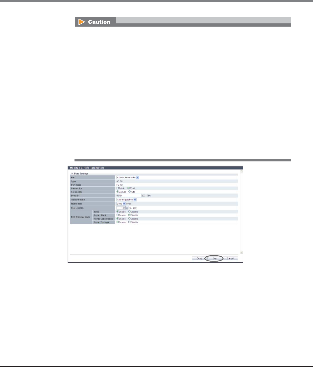
Chapter 9 Connectivity Management
9.2 Functions in the Action Area for Connectivity
ETERNUS Web GUI User’s Guide
Copyright 2013 FUJITSU LIMITED P2X0-1090-10ENZ0
538
•The REC transfer mode can be changed without suspending a copy session even when an REC is
being performed in the target port. The changed settings are applied immediately to the
ETERNUS DX Disk storage system.
•If specific REC transfer modes for all the RA ports and the CA/RA ports are disabled, a copy
session with a disabled REC transfer mode fails because the REC paths for all the RA ports and
the CA/RA ports are regarded as being blocked. When the REC transfer mode for a copy session
that is being performed is disabled, this copy session is halted.
•When "Async Consistency" is disabled for all the RA ports and the CA/RA ports, the REC buffer
status changes to "INACTIVE".
•For normal operations, set the same REC transfer mode for the copy source and the copy
destination storage systems to recover data. When the REC transfer mode is specified for a copy
source storage system, the specified REC transfer mode is performed even if the controller
firmware version of the copy destination storage system is V10L49 or earlier or when the copy
destination storage system is an old storage system (ETERNUS DX90, ETERNUS DX410/DX440,
ETERNUS DX8100/DX8400/DX8700, ETERNUS4000, or ETERNUS8000).
•If the port mode has changed from "RA" to "CA" or "Initiator", the REC transfer mode returns to
the default setting("Enable"). When the port mode has changed from "RA" to "CA/RA", the
current REC transfer mode setting is retained. Refer to "9.2.3.11 Modify Port Mode" (page 571)
for details.
Chapter 9 Connectivity Management
9.2 Functions in the Action Area for Connectivity
ETERNUS Web GUI User’s Guide
Copyright 2013 FUJITSU LIMITED P2X0-1090-10ENZ0
539
■When the port mode is "Initiator"
•Port
Select the target port or select the copy source port.
The selectable port locations are displayed as options:
-CM#x CA#y Port#z (x: CM number, y: CA number, z: Port number)
•Connection
Select the connection topology for the target port from the "Fabric" or "FC-AL".
When "FC-AL" is selected, it is necessary to assign a Loop ID to the port.
-Fabric
A connection type that enables simultaneous communication among multiple nodes through a
Fibre Channel switch. This connection type can also be used for a direct connection when
"Transfer Rate" is "16 Gbit/s".
-FC-AL
A connection type that connects multiple nodes in a loop.
This connection type is used for a direct connection when "Transfer Rate" is 8Gbit/s or less.
•Set Loop ID
When "Connection" is "FC-AL", select "Manual" or "Auto" as the specification method for the Loop ID.
"Loop ID" is an identification number of a node in a loop.
•Loop ID
-Manual
When "Set Loop ID" is "Manual", enter the Loop ID.
The Loop ID must have a value that is different from the values of all the ports.
The following input condition applies:
•0x0 - 0x7D
-Auto
When the "Set Loop ID" is "Auto", select "Ascending" or "Descending".
•Transfer Rate
Select the transfer speed for the target port. The available transfer rate varies according to the
selected port type and connection topology.
-Auto-negotiation
-1 Gbit/s (Not supported)
-2 Gbit/s (Not supported when "Type" is "16G FC")
-4 Gbit/s
-8 Gbit/s
-16 Gbit/s (Not supported when "Type" is "8G FC" or when "Type" is "16G FC" and "Connection" is
"FC-AL")
Select "Fabric" for a direct connection when "Transfer Rate" is "16 Gbit/s".
•Select "Auto-negotiation", "2 Gbit/s", "4 Gbit/s", "8 Gbit/s", or "16 Gbit/s" for "Transfer Rate". Note
that "1 Gbit/s" is not supported.
•"Auto-negotiation" is selected for "Transfer Rate" when "Type" is "16G FC", "Transfer Rate" is "16
Gbit/s", and "Connection" is changed from "Fabric" to "FC-AL".
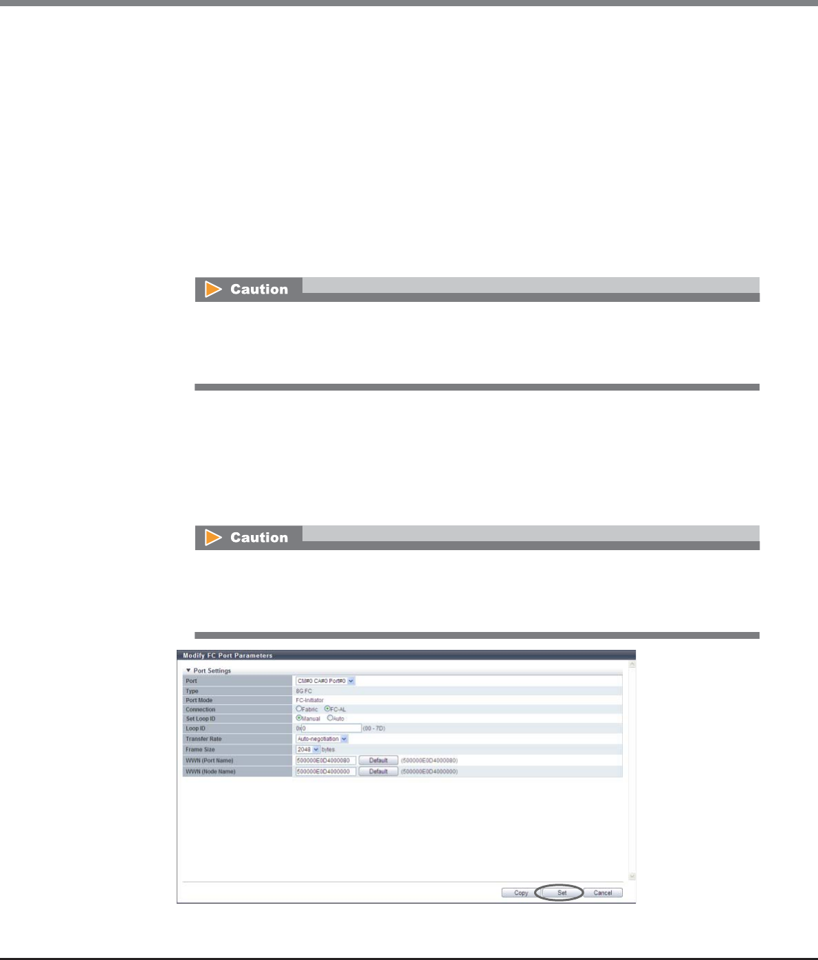
Chapter 9 Connectivity Management
9.2 Functions in the Action Area for Connectivity
ETERNUS Web GUI User’s Guide
Copyright 2013 FUJITSU LIMITED P2X0-1090-10ENZ0
540
•Frame Size
Select the frame size of the target port.
"Frame Size" specifies the length of the communication information.
-512 bytes
-1024 bytes
-2048 bytes
•WWN (Port Name)
When Storage Migration is performed, the ETERNUS DX Disk storage system (destination storage
system) is regarded as a server connecting to the migration source storage system. Specify the
World Wide Port Name (WWPN) for the server that was connected to the FC-CA port of the migration
source storage system.
The default "WWN (Port Name)" is displayed with parentheses on the right side of the [Default]
button. Click the [Default] button to set the default value.
•WWN (Node Name)
When Storage Migration is performed, the ETERNUS DX Disk storage system (destination storage
system) is regarded as a server connecting to the migration source storage system. Specify the
World Wide Node Name (WWNN) for the server that was connected to the FC-CA port of the
migration source storage system.
The default "WWN (Node Name)" is displayed with parentheses on the right side of the [Default]
button. Click the [Default] button to set the default value.
→A confirmation screen appears.
Specifying the WWPN of the server is only required when the host affinity setting is configured
between the server and a migration source FC-CA port.
If LUN mapping is configured for a migration source FC-CA port, the default value does not need to
be changed.
Specifying the WWNN of the server is only required when the host affinity setting is configured
between the server and a migration source FC-CA port.
If LUN mapping is configured for a migration source FC-CA port, the default value does not need to
be changed.
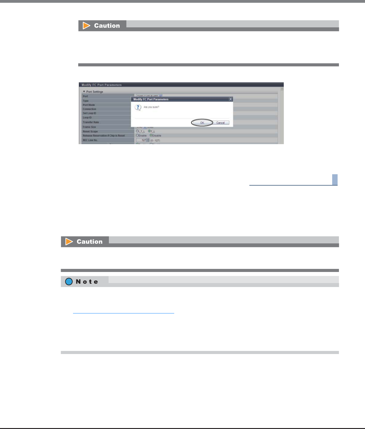
Chapter 9 Connectivity Management
9.2 Functions in the Action Area for Connectivity
ETERNUS Web GUI User’s Guide
Copyright 2013 FUJITSU LIMITED P2X0-1090-10ENZ0
541
3Click the [OK] button.
→Modification of the FC port parameters starts.
4Click the [Done] button to return to the [FC Port Group] screen.
End of procedure
9.2.3.8 Modify iSCSI Port Parameters
This function sets the connection information for the iSCSI ports that connect the ETERNUS DX Disk storage
system and the host or local and remote ETERNUS DX Disk storage systems.
•If the Loop ID is changed while a PRIMEPOWER server is operating, reboot the server immediately.
If the parameters do not satisfy the input conditions, an error screen appears.
•If some parameters do not satisfy the input conditions, an error screen appears.
When changing port parameters during operation, stop access from the server that is allocated to the target
port. Host access does not need to be stopped to change the port parameters of newly added CA ports.
•There are three port modes for an iSCSI port; CA, RA, and CA/RA. CA is used for connecting to a server, RA
is used for REC, and CA/RA is used for connecting to a server and for REC. To switch the port mode, refer to
"9.2.3.11 Modify Port Mode" (page 571). The default value is "CA".
•iSCSI-RA is a dedicated adapter that is used for REC between the local device and the ETERNUS DX400
series, the ETERNUS DX8000 series, the ETERNUS4000, or the ETERNUS8000.
•For more details on iSCSI-CA parameter settings, refer to "User’s Guide -Server Connection-" for each OS
type.
Chapter 9 Connectivity Management
9.2 Functions in the Action Area for Connectivity
ETERNUS Web GUI User’s Guide
Copyright 2013 FUJITSU LIMITED P2X0-1090-10ENZ0
542
The procedure to set iSCSI port parameters is as follows:
Procedure
1Select which iSCSI port to set the parameters for (multiple selections can be made) and click
[Configure iSCSI Port] in [Action].
2Set the parameters for all of the selected ports and click the [Set] button.
The settings of port parameters vary depending on the port type and the port mode ("When the port
mode is "CA"" (page 542), "When the port mode is "RA"" (page 548), "When the port mode is "CA/RA""
(page 554), or "When the port mode is "iSCSI-RA (for older storage system connection)"" (page 562)).
■When the port mode is "CA"
When the type is "1G iSCSI" or "10G iSCSI" and the port mode is "CA", specify the following items:
●Select Port
•Port
Select the target port.
The selectable port locations are displayed as options:
-CM#x CA#y Port#z (x: CM number, y: CA number, z: Port number)
●TCP/IP Settings
•IP Version
Select the IP version for the target port.
-IPv4
Specify the IPv4 address. When "IPv4" is selected, input "IP Address" (required), "Subnet Mask"
(required), and "Gateway".
-IPv6
Specify the IPv6 address. When "IPv6" is selected, input "IPv6 Link Local Address" (required),
"IPv6 Connect IP Address", and "IPv6 Gateway".
-IPv4 / IPv6
Specify both the IPv4 address and the IPv6 address. The input items for IPv4 and IPv6 can be
specified.
•IP Address
Input the IPv4 address of the target port (required when "IPv4" is selected).
Click the [Test Connection (ping)] button to display the "[Send Ping Command] Screen" (page 565).
Specify the IP address to check the connection status of the connection destination storage system
and the number of transmissions. Click the [Send] button. When the "ping" command is sent, the
settings of the IP address and the connection path for the destination storage system can be
checked.
The same port mode can be selected for multiple "1G iSCSI" or "10G iSCSI" type iSCSI ports. Multiple
selections can also be made for the "iSCSI-RA (for older storage system connection)" type iSCSI ports.
When multiple ports are selected, select the target port and set the parameters for each port.

Chapter 9 Connectivity Management
9.2 Functions in the Action Area for Connectivity
ETERNUS Web GUI User’s Guide
Copyright 2013 FUJITSU LIMITED P2X0-1090-10ENZ0
543
The following input conditions apply:
-Up to 3 numeric characters
-First text box: "1" - "255"
-Other text boxes: "0" - "255"
•Subnet Mask
Input the subnet mask of the target port (required when "IPv4" is selected).
The following input conditions apply:
-Up to 3 numeric characters
-All text boxes: "0" - "255"
•Gateway
Input the gateway IPv4 address of the target port.
The following input conditions apply:
-Up to 3 numeric characters
-All text boxes: "0" - "255"
•IPv6 Link Local Address
Input the IPv6 link local address of the target port (required when "IPv6" is selected).
Refer to "Available IPv6 Address" (page 757) for details. Note that the current setting is displayed by
an abbreviation.
Click the [Test Connection (ping)] button to display the "[Send Ping Command] Screen" (page 565).
Specify the IP address to check the connection status of the connection destination storage system
and the number of transmissions. Click the [Send] button. When the "ping" command is sent, the
settings of the IP address and the connection path for the destination storage system can be
checked.
Click the [Default] button to set the default IPv6 link local address.
The following input condition applies:
-fe80::xxxx:xxxx:xxxx:xxxx
xxxx: 0 - ffff (FFFF) (hexadecimal, alphanumeric characters)
Refer to "IPv6 Address Notation" (page 378) for details.
•IPv6 Connect IP Address
Input the IPv6 connect IP address of the target port.
The following IPv6 addresses can be used; "global address", "unique local address", and "6to4
address". Refer to "Available IPv6 Address" (page 757) for details. Note that the current setting is
displayed by an abbreviation.
"IPv6 Connect IP Address" corresponds to "IP Address" for IPv4.
"IPv6 Connect IP Address" can be directly input or created automatically.
Click the [Discovery] button to display the [Select IPv6 Prefix] screen. Up to five "IPv6 Prefix" can be
obtained. Select "IPv6 Prefix" to create an IPv6 connect IP address automatically from the selected
IPv6 prefix and the input IPv6 link local address (interface ID). Click the [OK] button to specify the
created IPv6 address in the entry field.
Click the [Test Connection (ping)] button to display the "[Send Ping Command] Screen" (page 565).
Specify the IP address to check the connection status of the connection destination storage system
and the number of transmissions. Click the [Send] button. When the "ping" command is sent, the
settings of the IP address and the connection path for the destination storage system can be
checked.
The following input condition applies:
-xxxx:xxxx:xxxx:xxxx:xxxx:xxxx:xxxx:xxxx
xxxx: 0 - ffff (FFFF) (hexadecimal, alphanumeric characters)
Refer to "IPv6 Address Notation" (page 378) for details.

Chapter 9 Connectivity Management
9.2 Functions in the Action Area for Connectivity
ETERNUS Web GUI User’s Guide
Copyright 2013 FUJITSU LIMITED P2X0-1090-10ENZ0
544
•IPv6 Gateway
Input the gateway IPv6 address of the target port.
The following IPv6 addresses can be used; "link local address", "global address", "unique local
address", and "6to4 address". Refer to "Available IPv6 Address" (page 757) for details. Note that the
current setting is displayed by an abbreviation.
"IPv6 Gateway" can be directly input or created automatically.
Click the [Discovery] button to display the [Select IPv6 Gateway] screen. Up to three "IPv6 Gateway"
can be obtained. Select "IPv6 Gateway" and click the [OK] button. The selected IPv6 address is
specified in the entry field.
The following input condition applies:
-xxxx:xxxx:xxxx:xxxx:xxxx:xxxx:xxxx:xxxx
xxxx: 0 - ffff (FFFF) (hexadecimal, alphanumeric characters)
Refer to "IPv6 Address Notation" (page 378) for details.
•TCP Port No.
Input the TCP port number of the target port between 0 and 28671.
Click the [Default] button to set the default TCP port number.
•TCP Window Scale
Select the TCP Window scale of the target port between 0 and 14.
"TCP Window Scale" is a parameter that is used to specify the TCP window size. When the I/O load is
high, the expected performance may not be achieved even if "0" or "1" is specified for TCP Window
Scale. Even if "8" or higher is specified, the ETERNUS DX Disk storage system performs as though "7"
is specified for TCP Window Scale.
Specify the "TCP Window Scale" in powers of two (when the value is n-th to the power of two, "n"
indicates the "TCP Window Scale"). The relationship between the setting value and the TCP Window
size is as follows:
•Congestion Control Option
Specify whether to enable or disable the use of "The New Reno Modification to TCP's Fast Recovery
Algorithm" for controlling congestion in the target port. Select "Enable" when using the congestion
control option. When not using the congestion control option, select "Disable". It is not necessary to
change the default setting (Enable) for normal use.
TCP Window Scale TCP Window size
0 32 KB
1 64 KB
2 128 KB
3 256 KB
4 512 KB
5 1024 KB
6 2048 KB
7 4096 KB
8 8192 KB
9 16384 KB
10 32768 KB
11 65536 KB
12 131072 KB
13 262144 KB
14 524288 KB

Chapter 9 Connectivity Management
9.2 Functions in the Action Area for Connectivity
ETERNUS Web GUI User’s Guide
Copyright 2013 FUJITSU LIMITED P2X0-1090-10ENZ0
545
•iSNS Server
Select whether to enable the use of an iSNS server with IPv4 or IPv6, or disable the use of an iSNS
server for the target port.
When "IPv4" or "IPv6" is selected, input the IP address of the iSNS server.
Internet Storage Name Service (iSNS) is almost equivalent to Domain Name System (DNS) for the
Internet. iSNS server is used to convert the iSCSI name to the IP address on the iSCSI network.
•iSNS Server (IPv4 Address)
When "iSNS Server" is "IPv4", input the IPv4 address for the iSNS server.
The following input conditions apply:
-xxx.xxx.xxx.xxx
xxx: 1 - 255 for the top field (decimal)
xxx: 0 - 255 for other fields (decimal)
•iSNS Server (IPv6 Address)
When "iSNS Server" is "IPv6", input the IPv6 address for the iSNS server.
The following IPv6 addresses can be used; "link local address", "global address", "unique local
address", and "6to4 address". Refer to "Available IPv6 Address" (page 757) for details. Note that the
current setting is displayed by an abbreviation.
The following input condition applies:
-xxxx:xxxx:xxxx:xxxx:xxxx:xxxx:xxxx:xxxx
xxxx: 0 - ffff (FFFF) (hexadecimal, alphanumeric characters)
Refer to "IPv6 Address Notation" (page 378) for details.
•iSNS Server Port No.
When "iSNS Server" for the target port is "IPv4" or "IPv6", specify between 0 and 65535 for the port
number of the iSNS server.
Click the [Default] button to set the default iSNS server port number.
●iSCSI Settings
•iSCSI Name
Input the iSCSI name of the target port.
Click the [Default] button to set the default iSCSI name.
The following input conditions apply:
-Alphabetic characters (lower case) and numeric characters
-Symbols "-" (hyphen), "." (period) and ":" (colon)
-The name starts with "iqn." or "eui."
-4 - 223 characters
When "Disable" is selected, the path may be unstable or blocked due to factors such as the path
bandwidth or the switch buffer size. However, if a long transmission delay occurs, performance
may be improved. Perform sufficient verification of the network environment before specifying
"Disable" for the congestion control option.
•When "IP Version" is "IPv4" or "IPv4 / IPv6", "IPv4" and "Disable" can be selected.
•When "IP Version" is "IPv6" or "IPv4 / IPv6", "IPv6" and "Disable" can be selected.
Chapter 9 Connectivity Management
9.2 Functions in the Action Area for Connectivity
ETERNUS Web GUI User’s Guide
Copyright 2013 FUJITSU LIMITED P2X0-1090-10ENZ0
546
•Alias Name
Input the Alias Name of the target port.
While the iSCSI name is a formal nomenclature that specifies the target iSCSI port, an Alias Name is
used as nickname.
An Alias Name that is the same as another port cannot be specified.
The following input condition applies:
-Up to 31 alphanumeric characters
●General Settings
•Jumbo Frame
Select whether to "Enable" or "Disable" the Jumbo Frame.
Select "Enable" when using the Jumbo Frame to transfer data via the target port. When not using
the Jumbo Frame, select "Disable".
Enabling Jumbo Frame increases the amount of data to be transferred per Frame, making data
transfer more efficient.
Confirm that the connected device (*1) supports the Jumbo Frame before enabling the Jumbo
Frame.
*1: When the ETERNUS DX Disk storage system and server are connected directly, this indicates that the
connected device is a server side LAN card (NIC). When the ETERNUS DX Disk storage system and server
are connected via a switch, this indicates that the connected device is a switch.
•VLAN ID
Select whether to "Enable" or "Disable" the VLAN ID for the target port.
When "Enable" is selected, specify the VLAN ID between 0 and 4095.
•Reset Scope
Specify the reset scope of the target port.
Reset scope is the range where the command reset from the server is performed, when the target
port is connected to multiple servers.
-I_T_L (I: Initiator, T: Target, L: LUN)
Reset (cancel) the command request from the server that sent the command reset request.
-T_L (T: Target, L: LUN)
Reset (cancels) the command request from all of the servers that are connected to the port.
•Release Reservation if Chip is Reset
Select whether to "Enable" or "Disable" the function to release the reserved status of the volume
when the target port (chip) is reset.
The same iSCSI name cannot be set to multiple iSCSI ports except the iSCSI name of the ETERNUS
DX Disk storage system.
When specifying the VLAN ID, confirm the VLAN setting values of the LAN switch and the VLAN
tagging configuration of the server LAN card.

Chapter 9 Connectivity Management
9.2 Functions in the Action Area for Connectivity
ETERNUS Web GUI User’s Guide
Copyright 2013 FUJITSU LIMITED P2X0-1090-10ENZ0
547
•CmdSN Count
Change the number of commands that can be accepted from the host to the target port at the same
time. It is not necessary to change the default setting (Unlimited) for normal use.
-Unlimited
-180
-100
-80
-40
-20
●Security
•CHAP
Select "ON" to enable unidirectional CHAP authentication or bidirectional CHAP authentication for
the target CA port. Select "OFF" to disable unidirectional CHAP authentication and bidirectional
CHAP authentication.
For CHAP authentication, an encrypted password based on a random key that the ETERNUS DX Disk
storage system receives from the host is sent, and connection possibility is judged on the server
side.
•CHAP User Name
When using bidirectional CHAP authentication, enter the user name to access the target port. This
setting is not required when using unidirectional CHAP authentication. Make sure to set the user
name and password in pairs.
The following input conditions applied:
-Up to 255 alphanumeric characters and symbols
-Space
•New Password
When using bidirectional CHAP authentication, enter the password to access the target port. This
setting is not required when using unidirectional CHAP authentication. Make sure to set the user
name and password in pairs.
The following input conditions apply:
-12 - 100 alphanumeric characters and symbols
-Space
•Confirm new Password
Specify the same password as that entered in the "New Password" field.
The following input conditions apply:
-12 - 100 alphanumeric characters and symbols
-Space
•Header Digest
Select "OFF" to not add the Header Digest of the target port. Select "CRC32C" to add the Header
Digest. Header Digest is a check code to be added to the header part of the iSCSI port detailed
information.
Specify "CRC32C" when the host requests to add the check code. "CRC32C" is the algorithm that is
used to create a check code.
•Data Digest
Select "OFF" to not add the Data Digest of the target port. Select "CRC32C" to add the Data Digest.
Data Digest is a check code to be added to the data area of the iSCSI port detailed information.
Specify "CRC32C" when the host requests to add the check code. "CRC32C" is the algorithm that is
used to create a check code.
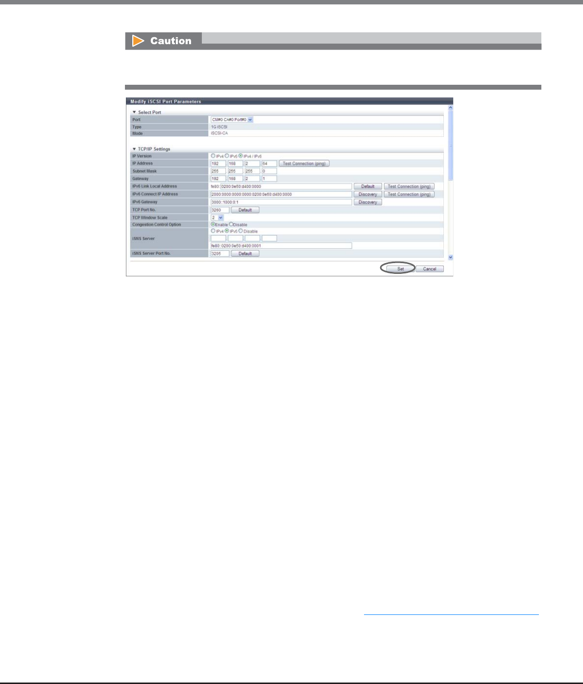
Chapter 9 Connectivity Management
9.2 Functions in the Action Area for Connectivity
ETERNUS Web GUI User’s Guide
Copyright 2013 FUJITSU LIMITED P2X0-1090-10ENZ0
548
■When the port mode is "RA"
When the type is "1G iSCSI" or "10G iSCSI" and the port mode is "RA", specify the following items:
●Select Port
•Port
Select the target port.
The selectable ports are displayed as options:
-CM#x CA#y Port#z (x: CM number, y: CA number, z: Port number)
●TCP/IP Settings
•IP Version
Select the IP version for the target port.
-IPv4
Specify the IPv4 address. When "IPv4" is selected, input "IP Address" (required), "Subnet Mask"
(required), and "Gateway".
-IPv6
Specify the IPv6 address. When "IPv6" is selected, input "IPv6 Link Local Address" (required),
"IPv6 Connect IP Address", and "IPv6 Gateway".
-IPv4 / IPv6
Specify both the IPv4 address and the IPv6 address. The input items for IPv4 and IPv6 can be
specified.
•IP Address
Input the IPv4 address of the target port (required when "IPv4" is selected).
Click the [Test Connection (ping)] button to display the "[Send Ping Command] Screen" (page 565).
Specify the IP address to check the connection status of the connection destination storage system
and the number of transmissions. Click the [Send] button. When the "ping" command is sent, the
settings of the IP address and the connection path for the destination storage system can be
checked.
Data transmission might fail when "Header Digest" or "Data Digest" is enabled. In this case, select
"OFF" for "Header Digest" and "Data Digest".

Chapter 9 Connectivity Management
9.2 Functions in the Action Area for Connectivity
ETERNUS Web GUI User’s Guide
Copyright 2013 FUJITSU LIMITED P2X0-1090-10ENZ0
549
The following input conditions apply:
-Up to 3 numeric characters
-First text box: "1" - "255"
-Other text boxes: "0" - "255"
•Subnet Mask
Input the subnet mask of the target port (required when "IPv4" is selected).
The following input conditions apply:
-Up to 3 numeric characters
-All text boxes: "0" - "255"
•Gateway
Input the gateway IPv4 address of the target port.
-Up to 3 numeric characters
-All text boxes: "0" - "255"
•IPv6 Link Local Address
Input the IPv6 link local address of the target port (required when "IPv6" is selected).
Refer to "Available IPv6 Address" (page 757) for details. Note that the current setting is displayed by
an abbreviation.
Click the [Test Connection (ping)] button to display the "[Send Ping Command] Screen" (page 565).
Specify the IP address to check the connection status of the connection destination storage system
and the number of transmissions. Click the [Send] button. When the "ping" command is sent, the
settings of the IP address and the connection path for the destination storage system can be
checked.
Click the [Default] button to set the default IPv6 link local address.
The following input condition applies:
-fe80::xxxx:xxxx:xxxx:xxxx
xxxx: 0 - ffff (FFFF) (hexadecimal, alphanumeric characters)
Refer to "IPv6 Address Notation" (page 378) for details.
•IPv6 Connect IP Address
Input the IPv6 connect IP address of the target port.
The following IPv6 addresses can be used; "global address", "unique local address", and "6to4
address". Refer to "Available IPv6 Address" (page 757) for details. Note that the current setting is
displayed by an abbreviation.
"IPv6 Connect IP Address" corresponds to "IP Address" for IPv4.
"IPv6 Connect IP Address" can be directly input or created automatically.
Click the [Discovery] button to display the [Select IPv6 Prefix] screen. Up to five "IPv6 Prefix" can be
obtained. Select "IPv6 Prefix" to create an IPv6 connect IP address automatically from the selected
IPv6 prefix and the input IPv6 link local address (interface ID). Click the [OK] button to specify the
created IPv6 address in the entry field.
Click the [Test Connection (ping)] button to display the "[Send Ping Command] Screen" (page 565).
Specify the IP address to check the connection status of the connection destination storage system
and the number of transmissions. Click the [Send] button. When the "ping" command is sent, the
settings of the IP address and the connection path for the destination storage system can be
checked.
The following input condition applies:
-xxxx:xxxx:xxxx:xxxx:xxxx:xxxx:xxxx:xxxx
xxxx: 0 - ffff (FFFF) (hexadecimal, alphanumeric characters)
Refer to "IPv6 Address Notation" (page 378) for details.
Chapter 9 Connectivity Management
9.2 Functions in the Action Area for Connectivity
ETERNUS Web GUI User’s Guide
Copyright 2013 FUJITSU LIMITED P2X0-1090-10ENZ0
550
•IPv6 Gateway
Input the gateway IPv6 address of the target port.
The following IPv6 addresses can be used; "link local address", "global address", "unique local
address", and "6to4 address". Refer to "Available IPv6 Address" (page 757) for details. Note that the
current setting is displayed by an abbreviation.
"IPv6 Gateway" can be directly input or created automatically.
Click the [Discovery] button to display the [Select IPv6 Gateway] screen. Up to three "IPv6 Gateway"
can be obtained. Select "IPv6 Gateway" and click the [OK] button. The selected IPv6 address is
specified in the entry field.
The following input condition applies:
-xxxx:xxxx:xxxx:xxxx:xxxx:xxxx:xxxx:xxxx
xxxx: 0 - ffff (FFFF) (hexadecimal, alphanumeric characters)
Refer to "IPv6 Address Notation" (page 378) for details.
•TCP Port No.
Input the TCP port number of the target port between 0 and 28671.
Click the [Default] button to set the default TCP port number.
•TCP Window Scale
Select the TCP Window scale of the target port between 0 and 14.
"TCP Window Scale" is a parameter that is used to specify the TCP window size. When the I/O load is
high, the expected performance may not be achieved even if "0" or "1" is specified for TCP Window
Scale. Even if "8" or higher is specified, the ETERNUS DX Disk storage system performs as though "7"
is specified for TCP Window Scale.
Specify the "TCP Window Scale" in powers of two (when the value is n-th to the power of two, "n"
indicates the "TCP Window Scale"). The relationship between the setting value and the TCP Window
size is as follows:
Do not change the TCP port number from 3260 (default value). REC can only be performed when
"TCP Port No." is "3260".
TCP Window Scale TCP Window size
0 32 KB
1 64 KB
2 128 KB
3 256 KB
4 512 KB
5 1024 KB
6 2048 KB
7 4096 KB
8 8192 KB
9 16384 KB
10 32768 KB
11 65536 KB
12 131072 KB
13 262144 KB
14 524288 KB
Chapter 9 Connectivity Management
9.2 Functions in the Action Area for Connectivity
ETERNUS Web GUI User’s Guide
Copyright 2013 FUJITSU LIMITED P2X0-1090-10ENZ0
551
•Congestion Control Option
Specify whether to enable or disable the use of "The New Reno Modification to TCP's Fast Recovery
Algorithm" for controlling congestion in the target port. Select "Enable" when using the congestion
control option. When not using the congestion control option, select "Disable". It is not necessary to
change the default setting (Enable) for normal use.
●iSCSI Settings
•iSCSI Name
Input the iSCSI name of the target port.
Click the [Default] button to set the default iSCSI name.
The following input conditions apply:
-Alphabetic characters (lower case) and numeric characters
-Symbols "-" (hyphen), "." (period) and ":" (colon)
-The name starts with "iqn." or "eui."
-4 - 223 characters
•Alias Name
Input the Alias Name of the target port.
While the iSCSI name is a formal nomenclature that specifies the target iSCSI port, an Alias Name is
used as nickname.
An Alias Name that is the same as another port cannot be specified.
The following input condition applies:
-Up to 31 alphanumeric characters
●General Settings
•VLAN ID
Select whether to "Enable" or "Disable" the VLAN ID for the target port.
When "Enable" is selected, specify the VLAN ID between 0 and 4095.
•MTU
Specify the MTU size of the target port.
"Maximum Transmission Unit (MTU)" is the maximum amount of data that can be transmitted at
the one time over the communication network.
The following input conditions apply:
-When "IP Version" is "IPv4": 576 - 9000 bytes
-When "IP Version" is "IPv6" or "IPv4 / IPv6": 1280 - 9000 bytes
When "Disable" is selected, the path may be unstable or blocked due to factors such as the path
bandwidth or the switch buffer size. However, if a long transmission delay occurs, performance
may be improved. Perform sufficient verification of the network environment before specifying
"Disable" for the congestion control option.
The same iSCSI name cannot be set to multiple iSCSI ports except the iSCSI name of the ETERNUS
DX Disk storage system.

Chapter 9 Connectivity Management
9.2 Functions in the Action Area for Connectivity
ETERNUS Web GUI User’s Guide
Copyright 2013 FUJITSU LIMITED P2X0-1090-10ENZ0
552
●Security
•CHAP
Select "ON "to enable CHAP authentication for the target port. Select "OFF" to disable CHAP
authentication.
For CHAP authentication, an encrypted password based on a random key that the ETERNUS DX Disk
storage system receives from the host is sent, and connection possibility is judged on the server
side.
•CHAP User Name
When "ON" is selected for "CHAP", enter the user name to access the target port. Make sure to set the
user name and password in pairs.
The following input conditions apply:
-Up to 63 alphanumeric characters and symbols
-Space
•New Password
When "ON" is selected for "CHAP", enter the password to access the target port. Make sure to set the
user name and password in pairs.
The following input conditions apply:
-12 - 32 alphanumeric characters and symbols
-Space
•Confirm new Password
Specify the same password as that entered in the "New Password" field.
The following input conditions apply:
-12 - 32 alphanumeric characters and symbols
-Space
●REC Settings
•REC Line No.
Select the REC line number of the target port.
The REC line number is used to switch the communication path when a line fails. The REC line
number is used to recognize failed lines. Set different REC line numbers for each physical
communication path. When lines are in normal status, an REC can be performed regardless of the
REC line number (specifying the same REC line numbers is allowed) in the same way as
conventional REC operations. Note that no priority applies to REC line numbers.
•REC Transfer Mode
Select which REC transfer mode is enabled or disabled for the target port.
When "Enable" is selected, an REC is performed in the selected transfer mode for the target port.
When "Disable" is selected, an REC is not performed in the selected transfer mode for the target
port.
•When a line fails, the communication path is switched according to the REC line number of the
copy source storage system. For normal operation, set the same REC line number for the copy
source and the copy destination storage systems to recover data.
•If the port mode has been changed from "RA" to "CA", the REC line number returns to the
default setting ("0"). When the port mode has changed from "RA" to "CA/RA", the current REC
line number setting is retained. Refer to "9.2.3.11 Modify Port Mode" (page 571) for details.
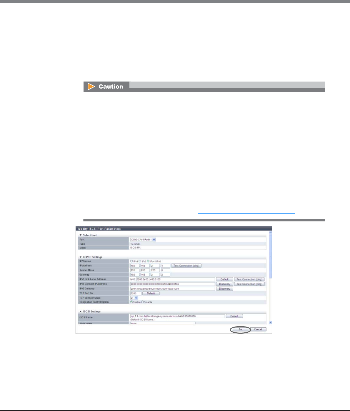
Chapter 9 Connectivity Management
9.2 Functions in the Action Area for Connectivity
ETERNUS Web GUI User’s Guide
Copyright 2013 FUJITSU LIMITED P2X0-1090-10ENZ0
553
To set the REC transfer mode for the specific port, enable the appropriate mode. For example,
specify different ports for Consistency and Stack to perform data transfers without any interference.
The current setting is retained even when an REC path is changed. When "Enable" is selected for all
of the REC transfer modes (default setting), a conventional REC is performed.
-Sync (REC in synchronous transfer mode)
-Async Stack (REC in asynchronous stack mode)
-Async Consistency (REC in asynchronous consistency mode)
-Async Through (REC in asynchronous through mode)
•The REC transfer mode can be changed without suspending a copy session even when an REC is
being performed in the target port. The changed settings are applied immediately to the
ETERNUS DX Disk storage system.
•If specific REC transfer modes for all the RA ports and the CA/RA ports are disabled, a copy
session with a disabled REC transfer mode fails because the REC paths for all the RA ports and
the CA/RA ports are regarded as being blocked. When the REC transfer mode for a copy session
that is being performed is disabled, this copy session is halted.
•When "Async Consistency" is disabled for all the RA ports and the CA/RA ports, the REC buffer
status changes to "INACTIVE".
•For normal operations, set the same REC transfer mode for the copy source and the copy
destination storage systems to recover data. When the REC transfer mode is specified for a copy
source storage system, the specified REC transfer mode is performed even if the controller
firmware version of the copy destination storage system is V10L49 or earlier.
•If the port mode has changed from "RA" to "CA", the REC transfer mode returns to the default
setting ("Enable"). When the port mode has changed from "RA" to "CA/RA", the current REC
transfer mode setting is retained. Refer to "9.2.3.11 Modify Port Mode" (page 571) for details.

Chapter 9 Connectivity Management
9.2 Functions in the Action Area for Connectivity
ETERNUS Web GUI User’s Guide
Copyright 2013 FUJITSU LIMITED P2X0-1090-10ENZ0
554
■When the port mode is "CA/RA"
When the type is "1G iSCSI" or "10G iSCSI" and the port mode is "CA/RA", specify the following items:
●Select Port
•Port
Select the target port.
The selectable port locations are displayed as options:
-CM#x CA#y Port#z (x: CM number, y: CA number, z: Port number)
●TCP/IP Settings
•IP Version
Select the IP version for the target port.
-IPv4
Specify the IPv4 address. When "IPv4" is selected, input "IP Address" (required), "Subnet Mask"
(required), and "Gateway".
-IPv6
Specify the IPv6 address. When "IPv6" is selected, input "IPv6 Link Local Address" (required),
"IPv6 Connect IP Address", and "IPv6 Gateway".
-IPv4 / IPv6
Specify both the IPv4 address and the IPv6 address. The input items for IPv4 and IPv6 can be
specified.
•IP Address
Input the IPv4 address of the target port (required when "IPv4" is selected).
Click the [Test Connection (ping)] button to display the "[Send Ping Command] Screen" (page 565).
Specify the IP address to check the connection status of the connection destination storage system
and the number of transmissions. Click the [Send] button. When the "ping" command is sent, the
settings of the IP address and the connection path for the destination storage system can be
checked.
The following input conditions apply:
-Up to 3 numeric characters
-First text box: "1" - "255"
-Other text boxes: "0" - "255"
•Subnet Mask
Input the subnet mask of the target port (required when "IPv4" is selected).
The following input conditions apply:
-Up to 3 numeric characters
-All text boxes: "0" - "255"
•Gateway
Input the gateway IPv4 address of the target port.
-Up to 3 numeric characters
-All text boxes: "0" - "255"

Chapter 9 Connectivity Management
9.2 Functions in the Action Area for Connectivity
ETERNUS Web GUI User’s Guide
Copyright 2013 FUJITSU LIMITED P2X0-1090-10ENZ0
555
•IPv6 Link Local Address
Input the IPv6 link local address of the target port (required when "IPv6" is selected).
Refer to "Available IPv6 Address" (page 757) for details. Note that the current setting is displayed by
an abbreviation.
Click the [Test Connection (ping)] button to display the "[Send Ping Command] Screen" (page 565).
Specify the IP address to check the connection status of the connection destination storage system
and the number of transmissions. Click the [Send] button. When the "ping" command is sent, the
settings of the IP address and the connection path for the destination storage system can be
checked.
Click the [Default] button to set the default IPv6 link local address.
The following input condition applies:
-fe80::xxxx:xxxx:xxxx:xxxx
xxxx: 0 - ffff (FFFF) (hexadecimal, alphanumeric characters)
Refer to "IPv6 Address Notation" (page 378) for details.
•IPv6 Connect IP Address
Input the IPv6 connect IP address of the target port.
The following IPv6 addresses can be used; "global address", "unique local address", and "6to4
address". Refer to "Available IPv6 Address" (page 757) for details. Note that the current setting is
displayed by an abbreviation.
"IPv6 Connect IP Address" corresponds to "IP Address" for IPv4.
"IPv6 Connect IP Address" can be directly input or created automatically.
Click the [Discovery] button to display the [Select IPv6 Prefix] screen. Up to five "IPv6 Prefix" can be
obtained. Select "IPv6 Prefix" to create an IPv6 connect IP address automatically from the selected
IPv6 prefix and the input IPv6 link local address (interface ID). Click the [OK] button to specify the
created IPv6 address in the entry field.
Click the [Test Connection (ping)] button to display the "[Send Ping Command] Screen" (page 565).
Specify the IP address to check the connection status of the connection destination storage system
and the number of transmissions. Click the [Send] button. When the "ping" command is sent, the
settings of the IP address and the connection path for the destination storage system can be
checked.
The following input condition applies:
-xxxx:xxxx:xxxx:xxxx:xxxx:xxxx:xxxx:xxxx
xxxx: 0 - ffff (FFFF) (hexadecimal, alphanumeric characters)
Refer to "IPv6 Address Notation" (page 378) for details.
•IPv6 Gateway
Input the gateway IPv6 address of the target port.
The following IPv6 addresses can be used; "link local address", "global address", "unique local
address", and "6to4 address". Refer to "Available IPv6 Address" (page 757) for details. Note that the
current setting is displayed by an abbreviation.
"IPv6 Gateway" can be directly input or created automatically.
Click the [Discovery] button to display the [Select IPv6 Gateway] screen. Up to three "IPv6 Gateway"
can be obtained. Select "IPv6 Gateway" and click the [OK] button. The selected IPv6 address is
specified in the entry field.
The following input condition applies:
-xxxx:xxxx:xxxx:xxxx:xxxx:xxxx:xxxx:xxxx
xxxx: 0 - ffff (FFFF) (hexadecimal, alphanumeric characters)
Refer to "IPv6 Address Notation" (page 378) for details.
•TCP Port No.
Input the TCP port number of the target port between 0 and 28671.
Click the [Default] button to set the default TCP port number.
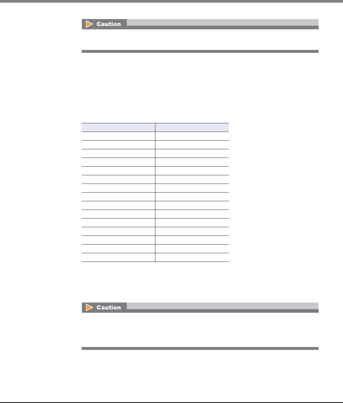
Chapter 9 Connectivity Management
9.2 Functions in the Action Area for Connectivity
ETERNUS Web GUI User’s Guide
Copyright 2013 FUJITSU LIMITED P2X0-1090-10ENZ0
556
•TCP Window Scale
Select the TCP Window scale of the target port between 0 and 14.
"TCP Window Scale" is a parameter that is used to specify the TCP window size. When the I/O load is
high, the expected performance may not be achieved even if "0" or "1" is specified for TCP Window
Scale. Even if "8" or higher is specified, the ETERNUS DX Disk storage system performs as though "7"
is specified for TCP Window Scale.
Specify the "TCP Window Scale" in powers of two (when the value is n-th to the power of two, "n"
indicates the "TCP Window Scale"). The relationship between the setting value and the TCP Window
size is as follows:
•Congestion Control Option
Specify whether to enable or disable the use of "The New Reno Modification to TCP's Fast Recovery
Algorithm" for controlling congestion in the target port. Select "Enable" when using the congestion
control option. When not using the congestion control option, select "Disable". It is not necessary to
change the default setting (Enable) for normal use.
Do not change the TCP port number from 3260 (default value). REC can only be performed when
"TCP Port No." is "3260".
TCP Window Scale TCP Window size
0 32 KB
1 64 KB
2 128 KB
3 256 KB
4 512 KB
5 1024 KB
6 2048 KB
7 4096 KB
8 8192 KB
9 16384 KB
10 32768 KB
11 65536 KB
12 131072 KB
13 262144 KB
14 524288 KB
When "Disable" is selected, the path may be unstable or blocked due to factors such as the path
bandwidth or the switch buffer size. However, if a long transmission delay occurs, performance
may be improved. Perform sufficient verification of the network environment before specifying
"Disable" for the congestion control option.

Chapter 9 Connectivity Management
9.2 Functions in the Action Area for Connectivity
ETERNUS Web GUI User’s Guide
Copyright 2013 FUJITSU LIMITED P2X0-1090-10ENZ0
557
•iSNS Server
Select whether to enable the use of an iSNS server with IPv4 or IPv6, or disable the use of an iSNS
server for the target port.
When "IPv4" or "IPv6" is selected, input the IP address of the iSNS server.
Internet Storage Name Service (iSNS) is almost equivalent to Domain Name System (DNS) for the
Internet. iSNS server is used to convert the iSCSI name to the IP address on the iSCSI network.
•iSNS Server (IPv4 Address)
When "iSNS Server" is "IPv4", input the IPv4 address for the iSNS server.
The following input condition applies:
-xxx.xxx.xxx.xxx
xxx: 1 - 255 for the top field (decimal)
xxx: 0 - 255 for other fields (decimal)
•iSNS Server (IPv6 Address)
When "iSNS Server" is "IPv6", input the IPv6 address for the iSNS server.
The following input condition applies:
-xxxx:xxxx:xxxx:xxxx:xxxx:xxxx:xxxx:xxxx
xxxx: 0 - ffff (FFFF) (hexadecimal, alphanumeric characters)
Refer to "IPv6 Address Notation" (page 378) for details.
•iSNS Server Port No.
When "iSNS Server" for the target port is "IPv4" or "IPv6", specify between 0 and 65535 for the port
number of the iSNS server.
Click the [Default] button to set the default iSNS server port number.
●iSCSI Settings
•iSCSI Name
Input the iSCSI name of the target port.
Click the [Default] button to set the default iSCSI name.
The following input conditions apply:
-Alphabetic characters (lower case) and numeric characters
-Symbols "-" (hyphen), "." (period) and ":" (colon)
-The name starts with "iqn." or "eui."
-4 - 223 characters
•When "IP Version" is "IPv4" or "IPv4 / IPv6", "IPv4" and "Disable" can be selected.
•When "IP Version" is "IPv6" or "IPv4 / IPv6", "IPv6" and "Disable" can be selected.
The same iSCSI name cannot be set to multiple iSCSI ports except the iSCSI name of the ETERNUS
DX Disk storage system.
Chapter 9 Connectivity Management
9.2 Functions in the Action Area for Connectivity
ETERNUS Web GUI User’s Guide
Copyright 2013 FUJITSU LIMITED P2X0-1090-10ENZ0
558
•Alias Name
Input the Alias Name of the target port.
While the iSCSI name is a formal nomenclature that specifies the target iSCSI port, an Alias Name is
used as nickname.
An Alias Name that is the same as another port cannot be specified.
The following input condition applies:
-Up to 31 alphanumeric characters
●General Settings
•VLAN ID
Select whether to "Enable" or "Disable" the VLAN ID for the target port.
When "Enable" is selected, specify the VLAN ID between 0 and 4095.
•Reset Scope
Specify the reset scope of the target port.
Reset scope is the range where the command reset from the server is performed, when the target
port is connected to multiple servers.
-I_T_L (I: Initiator, T: Target, L: LUN)
Reset (cancel) the command request from the server that sent the command reset request.
-T_L (T: Target, L: LUN)
Reset (cancels) the command request from all of the servers that are connected to the port.
•Release Reservation if Chip is Reset
Select whether to "Enable" or "Disable" the function to release the reserved status of the volume
when the target port (chip) is reset.
•CmdSN Count
Change the number of commands that can be accepted from the host to the target port at the same
time. It is not necessary to change the default setting (Unlimited) for normal use.
-Unlimited
-180
-100
-80
-40
-20
•MTU
Specify the MTU size of the target port.
"Maximum Transmission Unit (MTU)" is the maximum amount of data that can be transmitted at
the one time over the communication network.
The following input conditions apply:
-When "IP Version" is "IPv4": 576 - 9000 bytes
-When "IP Version" is "IPv6" or "IPv4 / IPv6": 1280 - 9000 bytes
When specifying the VLAN ID, confirm the VLAN setting values of the LAN switch and the VLAN
tagging configuration of the server LAN card.

Chapter 9 Connectivity Management
9.2 Functions in the Action Area for Connectivity
ETERNUS Web GUI User’s Guide
Copyright 2013 FUJITSU LIMITED P2X0-1090-10ENZ0
559
●Security
•CHAP (CA)
Select "ON" to enable unidirectional CHAP authentication or bidirectional CHAP authentication for
the target CA port. Select "OFF" to disable unidirectional CHAP authentication and bidirectional
CHAP authentication.
For CHAP authentication, an encrypted password based on a random key that the ETERNUS DX Disk
storage system receives from the host is sent, and connection possibility is judged on the server
side.
•CHAP User Name (CA)
When using bidirectional CHAP authentication, enter the user name to access the target CA port.
This setting is not required when using unidirectional CHAP authentication. Make sure to set the
user name and password in pairs.
The following input conditions applied:
-Up to 255 alphanumeric characters and symbols
-Space
•New Password (CA)
When using bidirectional CHAP authentication, enter the password to access the target CA port. This
setting is not required when using unidirectional CHAP authentication. Make sure to set the user
name and password in pairs.
The following input conditions apply:
-12 - 100 alphanumeric characters and symbols
-Space
•Confirm new Password (CA)
Specify the same password as that entered in the "New Password (CA)" field.
The following input conditions apply:
-12 - 100 alphanumeric characters and symbols
-Space
•CHAP (RA)
Select "ON "to enable CHAP Authentication for the target RA port. Select "OFF" to disable CHAP
Authentication.
For CHAP authentication, an encrypted password based on a random key that the ETERNUS DX Disk
storage system receives from the host is sent, and connection possibility is judged on the server
side.
•CHAP User Name (RA)
When "ON" is selected for "CHAP (RA)", enter the user name to access the target RA port. Make sure
to set the user name and password in pairs.
The following input conditions apply:
-Up to 63 alphanumeric characters and symbols
-Space
•New Password (RA)
When "ON" is selected for "CHAP (RA)", enter the password to access the target RA port. Make sure to
set the user name and password in pairs.
The following input conditions apply:
-12 - 32 alphanumeric characters and symbols
-Space
Chapter 9 Connectivity Management
9.2 Functions in the Action Area for Connectivity
ETERNUS Web GUI User’s Guide
Copyright 2013 FUJITSU LIMITED P2X0-1090-10ENZ0
560
•Confirm new Password (RA)
Specify the same password as that entered in the "New Password (RA)" field.
The following input conditions apply:
-12 - 32 alphanumeric characters and symbols
-Space
•Header Digest
Select "OFF" to not add the Header Digest of the target port. Select "CRC32C" to add the Header
Digest. Header Digest is a check code to be added to the header part of the iSCSI port detailed
information.
Specify "CRC32C" when the host requests to add the check code. "CRC32C" is the algorithm that is
used to create a check code.
•Data Digest
Select "OFF" to not add the Data Digest of the target port. Select "CRC32C" to add the Data Digest.
Data Digest is a check code to be added to the data area of the iSCSI port detailed information.
Specify "CRC32C" when the host requests to add the check code. "CRC32C" is the algorithm that is
used to create a check code.
●REC Settings
•REC Line No.
Select the REC line number of the target port.
The REC line number is used to switch the communication path when a line fails. The REC line
number is used to recognize failed lines. Set different REC line numbers for each physical
communication path. When lines are in normal status, an REC can be performed regardless of the
REC line number (specifying the same REC line numbers is allowed) in the same way as
conventional REC operations. Note that no priority applies to REC line numbers.
Data transmission might fail when "Header Digest" or "Data Digest" is enabled. In this case, select
"OFF" for "Header Digest" and "Data Digest".
•When a line fails, the communication path is switched according to the REC line number of the
copy source storage system. For normal operation, set the same REC line number for the copy
source and the copy destination storage systems to recover data.
•If the port mode has been changed from "CA/RA" to "CA", the REC line number returns to the
default setting ("0"). When the port mode has changed from "CA/RA" to "RA", the current REC
line number setting is retained. Refer to "9.2.3.11 Modify Port Mode" (page 571) for details.
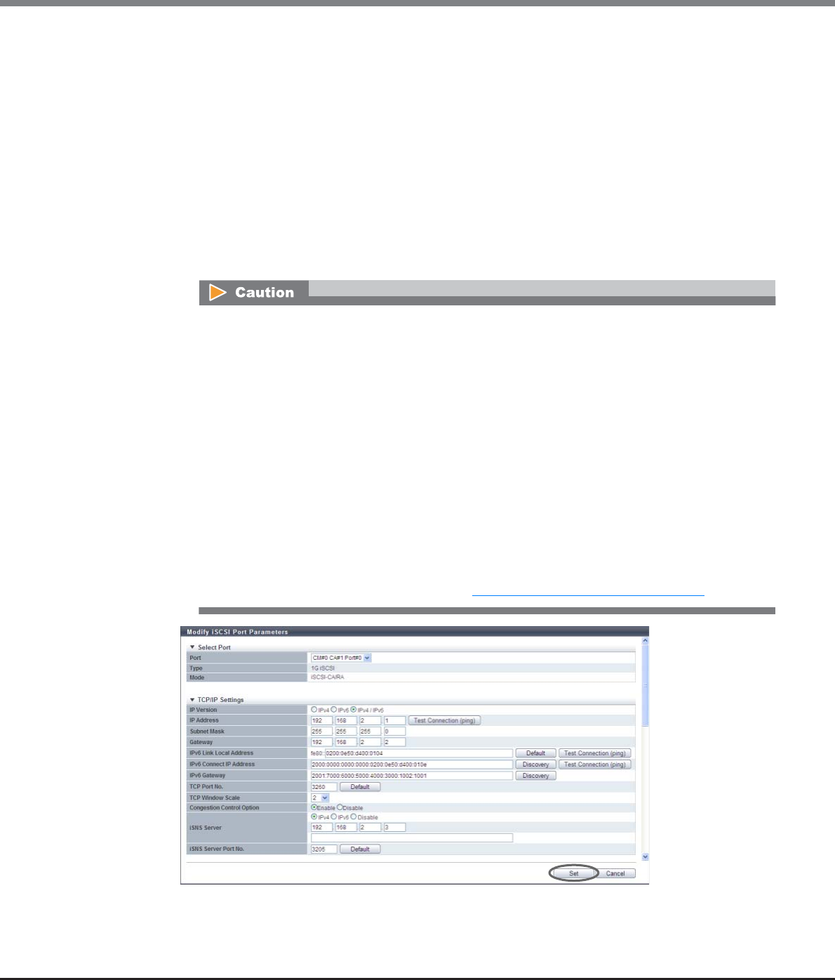
Chapter 9 Connectivity Management
9.2 Functions in the Action Area for Connectivity
ETERNUS Web GUI User’s Guide
Copyright 2013 FUJITSU LIMITED P2X0-1090-10ENZ0
561
•REC Transfer Mode
Select which REC transfer mode is enabled or disabled for the target port.
When "Enable" is selected, an REC is performed in the selected transfer mode for the target port.
When "Disable" is selected, an REC is not performed in the selected transfer mode for the target
port.
To set the REC transfer mode for the specific port, enable the appropriate mode. For example,
specify different ports for Consistency and Stack to perform data transfers without any interference.
The current setting is retained even when an REC path is changed. When "Enable" is selected for all
of the REC transfer modes (default setting), a conventional REC is performed.
-Sync (REC in synchronous transfer mode)
-Async Stack (REC in asynchronous stack mode)
-Async Consistency (REC in asynchronous consistency mode)
-Async Through (REC in asynchronous through mode)
•The REC transfer mode can be changed without suspending a copy session even when an REC is
being performed in the target port. The changed settings are applied immediately to the
ETERNUS DX Disk storage system.
•If specific REC transfer modes for all the RA ports and the CA/RA ports are disabled, a copy
session with a disabled REC transfer mode fails because the REC paths for all the RA ports and
the CA/RA ports are regarded as being blocked. When the REC transfer mode for a copy session
that is being performed is disabled, this copy session is halted.
•When "Async Consistency" is disabled for all the RA ports and the CA/RA ports, the REC buffer
status changes to "INACTIVE".
•For normal operations, set the same REC transfer mode for the copy source and the copy
destination storage systems to recover data. When the REC transfer mode is specified for a copy
source storage system, the specified REC transfer mode is performed even if the controller
firmware version of the copy destination storage system is V10L49 or earlier.
•If the port mode has changed from "CA/RA" to "CA", the REC transfer mode returns to the default
setting ("Enable"). When the port mode has changed from "CA/RA" to "RA", the current REC
transfer mode setting is retained. Refer to "9.2.3.11 Modify Port Mode" (page 571) for details.

Chapter 9 Connectivity Management
9.2 Functions in the Action Area for Connectivity
ETERNUS Web GUI User’s Guide
Copyright 2013 FUJITSU LIMITED P2X0-1090-10ENZ0
562
■When the port mode is "iSCSI-RA (for older storage system connection)"
When the type is "iSCSI-RA (for older storage system connection)", specify the following items:
●Port Settings
•Port
Select the target port.
The selectable port locations are displayed as options:
-CM#x CA#y Port#z (x: CM number, y: CA number, z: Port number)
●TCP/IP Settings
•IP Address
Input the IP address of the target port (required).
Click the [Test Connection (ping)] button to display the "[Send Ping Command] Screen" (page 565).
Specify the IP address to check the connection status of the connection destination storage system
and the number of transmissions. Click the [Send] button. When the "ping" command is sent, the
settings of the IP address and the connection path for the destination storage system can be
checked.
The following input conditions apply:
-Up to 3 numeric characters
-First text box: "1" - "255"
-Other text boxes: "0" - "255"
•Subnet Mask
Input the subnet mask of the target port (required).
The following input conditions apply:
-Up to 3 numeric characters
-All text boxes: "0" - "255"
•Gateway
Input the gateway IP address of the target port.
-Up to 3 numeric characters
-All text boxes: "0" - "255"
●iSCSI Settings
•Alias Name
Input the Alias Name of the target port.
While the iSCSI name is a formal nomenclature that specifies the target iSCSI port, an Alias Name is
used as nickname.
An Alias Name that is the same as another port cannot be specified.
The following input condition applies:
-Up to 31 alphanumeric characters
Older storage systems do not support IPv6. Make sure to specify IPv4 addresses.

Chapter 9 Connectivity Management
9.2 Functions in the Action Area for Connectivity
ETERNUS Web GUI User’s Guide
Copyright 2013 FUJITSU LIMITED P2X0-1090-10ENZ0
563
●General Settings
•Transfer Rate
Select the transfer speed of the target port from the following:
-Auto-negotiation
"100Mbit/s (Full Duplex)" or "1Gbit/s (Full Duplex)" is automatically selected for the transfer rate.
-100Mbit/s
100Mbit/s (Full Duplex)
-1Gbit/s
1Gbit/s (Full Duplex)
•MTU
Specify the MTU size of the target port.
"Maximum Transmission Unit (MTU)" is the maximum amount of data that can be transmitted at
the one time over the communication network.
-1000bytes
-1050bytes
-1100bytes
-1150bytes
-1200bytes
-1250bytes
-1300bytes
-1350bytes
-1400bytes
-1438bytes
•Limit Band Width
Input the bandwidth limit of the target port between 10 and 400Mbit/s.
"Bandwidth limit" is used to limit the amount of data that is transferred via an iSCSI-RA port.
●Security
•CHAP
Select "ON "to enable CHAP Authentication for the target port. Select "OFF" to disable CHAP
Authentication.
For CHAP authentication, an encrypted password based on a random key that the ETERNUS DX Disk
storage system receives from the host is sent, and connection possibility is judged on the server
side.
•CHAP User Name
When "ON" is selected for "CHAP", enter the user name to access the target port. Make sure to set the
user name and password in pairs.
The following input conditions apply:
-Up to 63 alphanumeric characters and symbols
-Space
•New Password
When "ON" is selected for "CHAP", enter the password to access the target port. Make sure to set the
user name and password in pairs.
The following input conditions apply:
-12 - 32 alphanumeric characters and symbols
-Space
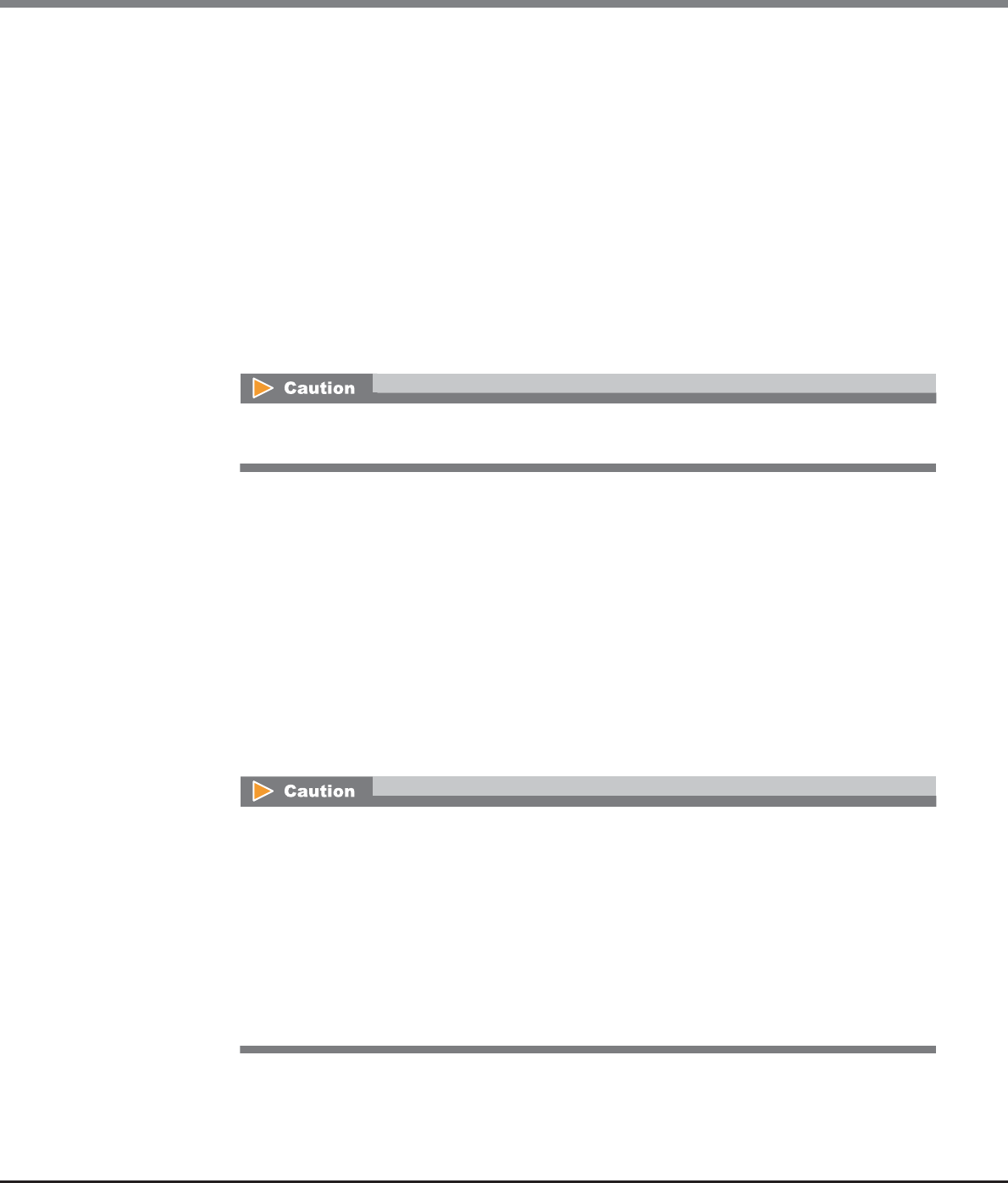
Chapter 9 Connectivity Management
9.2 Functions in the Action Area for Connectivity
ETERNUS Web GUI User’s Guide
Copyright 2013 FUJITSU LIMITED P2X0-1090-10ENZ0
564
•Confirm new Password
Specify the same password as that entered in the "New Password" field.
The following input conditions apply:
-12 - 32 alphanumeric characters and symbols
-Space
●REC Settings
•REC Line No.
Select the REC line number of the target port.
The REC line number is used to switch the communication path when a line fails. The REC line
number is used to recognize failed lines. Set different REC line numbers for each physical
communication path. When lines are in normal status, an REC can be performed regardless of the
REC line number (specifying the same REC line numbers is allowed) in the same way as
conventional REC operations. Note that no priority applies to REC line numbers.
•REC Transfer Mode
Select which REC transfer mode is enabled or disabled for the target port.
When "Enable" is selected, an REC is performed in the selected transfer mode for the target port.
When "Disable" is selected, an REC is not performed in the selected transfer mode for the target
port.
To set the REC transfer mode for the specific port, enable the appropriate mode. For example,
specify different ports for Consistency and Stack to perform data transfers without any interference.
The current setting is retained even when an REC path is changed. When "Enable" is selected for all
of the REC transfer modes (default setting), a conventional REC is performed.
-Sync (REC in synchronous transfer mode)
-Async Stack (REC in asynchronous stack mode)
-Async Consistency (REC in asynchronous consistency mode)
-Async Through (REC in asynchronous through mode)
When a line fails, the communication path is switched according to the REC line number of the
copy source storage system.
•The REC transfer mode can be changed without suspending a copy session even when an REC is
being performed in the target port. The changed settings are applied immediately to the
ETERNUS DX Disk storage system.
•If specific REC transfer modes for all the RA ports and the CA/RA ports are disabled, a copy
session with a disabled REC transfer mode fails because the REC paths for all the RA ports and
the CA/RA ports are regarded as being blocked. When the REC transfer mode for a copy session
that is being performed is disabled, this copy session is halted.
•When "Async Consistency" is disabled for all the RA ports and the CA/RA ports, the REC buffer
status changes to "INACTIVE".
•The specified REC transfer mode is performed only when the target port is a copy source.
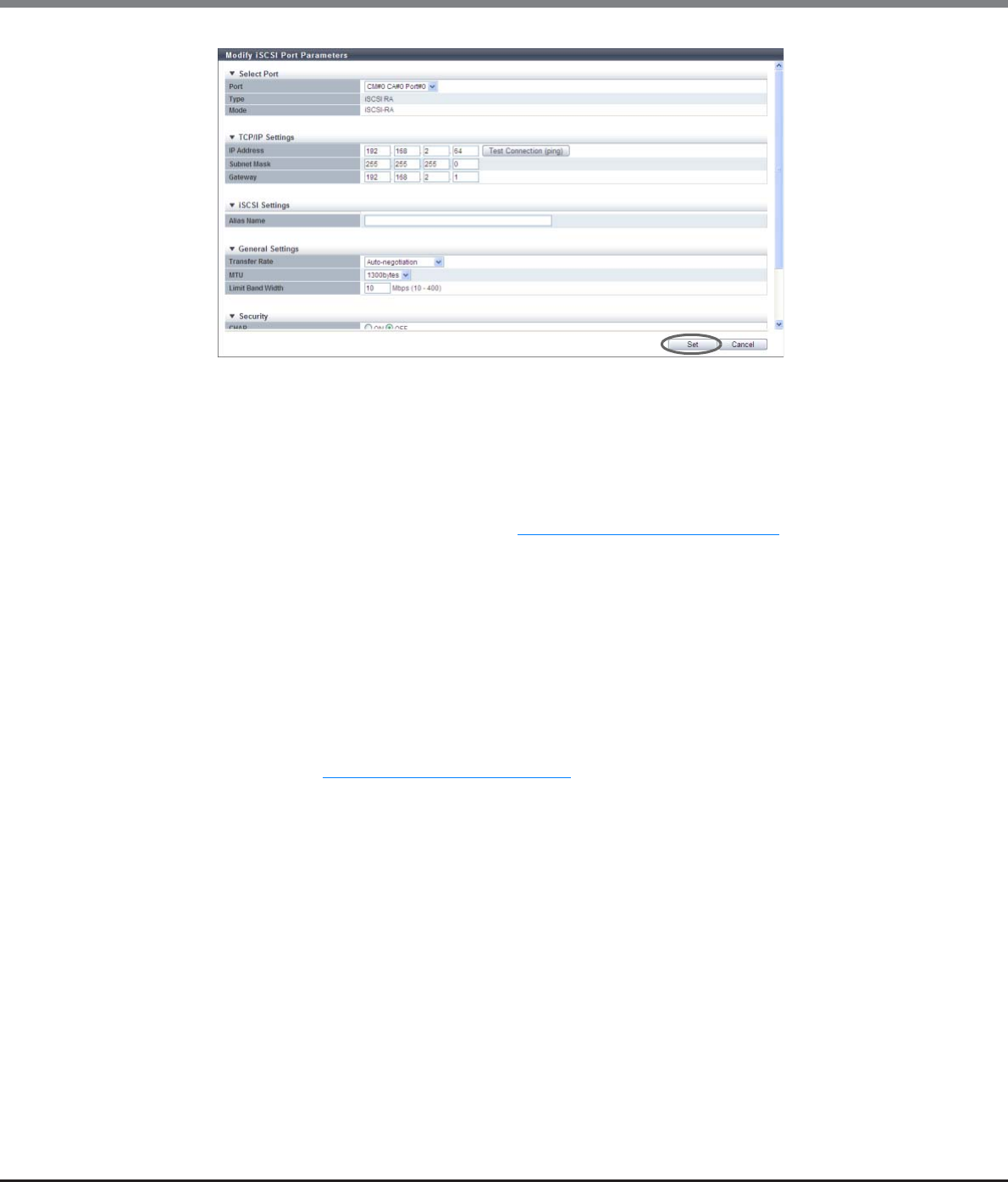
Chapter 9 Connectivity Management
9.2 Functions in the Action Area for Connectivity
ETERNUS Web GUI User’s Guide
Copyright 2013 FUJITSU LIMITED P2X0-1090-10ENZ0
565
■[Send Ping Command] Screen
Checks the connection status between the target port and the destination storage system.
•IP Address
Input the IPv4 or IPv6 address of the storage system that is used to check the connection status of
the target port.
The following IPv6 addresses can be used; "link local address", "global address", "unique local
address", and "6to4 address". Refer to "Available IPv6 Address" (page 757) for details. When the
current setting is displayed, the IPv6 address is displayed as an abbreviation.
The following input conditions apply:
-For IPv4 address
•xxx.xxx.xxx.xxx
xxx: 1 - 255 for the top field (decimal)
xxx: 0 - 255 for other fields (decimal)
•Class must be A, B, or C.
-For IPv6 address
xxxx:xxxx:xxxx:xxxx:xxxx:xxxx:xxxx:xxxx
xxxx: 0 - ffff (FFFF) (hexadecimal, alphanumeric characters)
Refer to "IPv6 Address Notation" (page 378) for details.
•Send Number
Input the transmission count of the ping command between 1 and 10.
•Result
Click the [Send] button to display the results of the ping commands that are sent.
-success
All were sent successfully.
-failed
At least one failure occurred.
Chapter 9 Connectivity Management
9.2 Functions in the Action Area for Connectivity
ETERNUS Web GUI User’s Guide
Copyright 2013 FUJITSU LIMITED P2X0-1090-10ENZ0
566
→A confirmation screen appears.
An error screen appears in the following conditions:
•When "IP Address" and "Subnet Mask" for IPv4 are not specified
•When "IPv6 Link Local Address" for IPv6 is not specified
•When there are parameters that do not satisfy the input conditions
•When "255.255.255.255" is input for the IP address, the subnet mask, or the gateway
•When the IP address and the network address are the same
•When the IP address and the broadcast address are the same
•When the gateway is set and the IP address and the gateway are the same
•When the gateway is set and the IP Address and the gateway are not in the same subnet
•When the [Discovery] button is clicked for "IPv6 Connect IP Address", the IPv6 connect IP address
can be created automatically from the prefix value that is obtained from the router that is
connected to the ETERNUS DX Disk storage system and the input IPv6 link local address.
•When the [Discovery] button is clicked for "IPv6 Gateway", the gateway information can be
obtained from the connected router.
•To check whether the IP address is allocated correctly and the connection status for the destination
storage system, click the [Test Connection (ping)] button for "IP Address", "IPv6 Link Local
Address", or "IPv6 Connect IP Address".
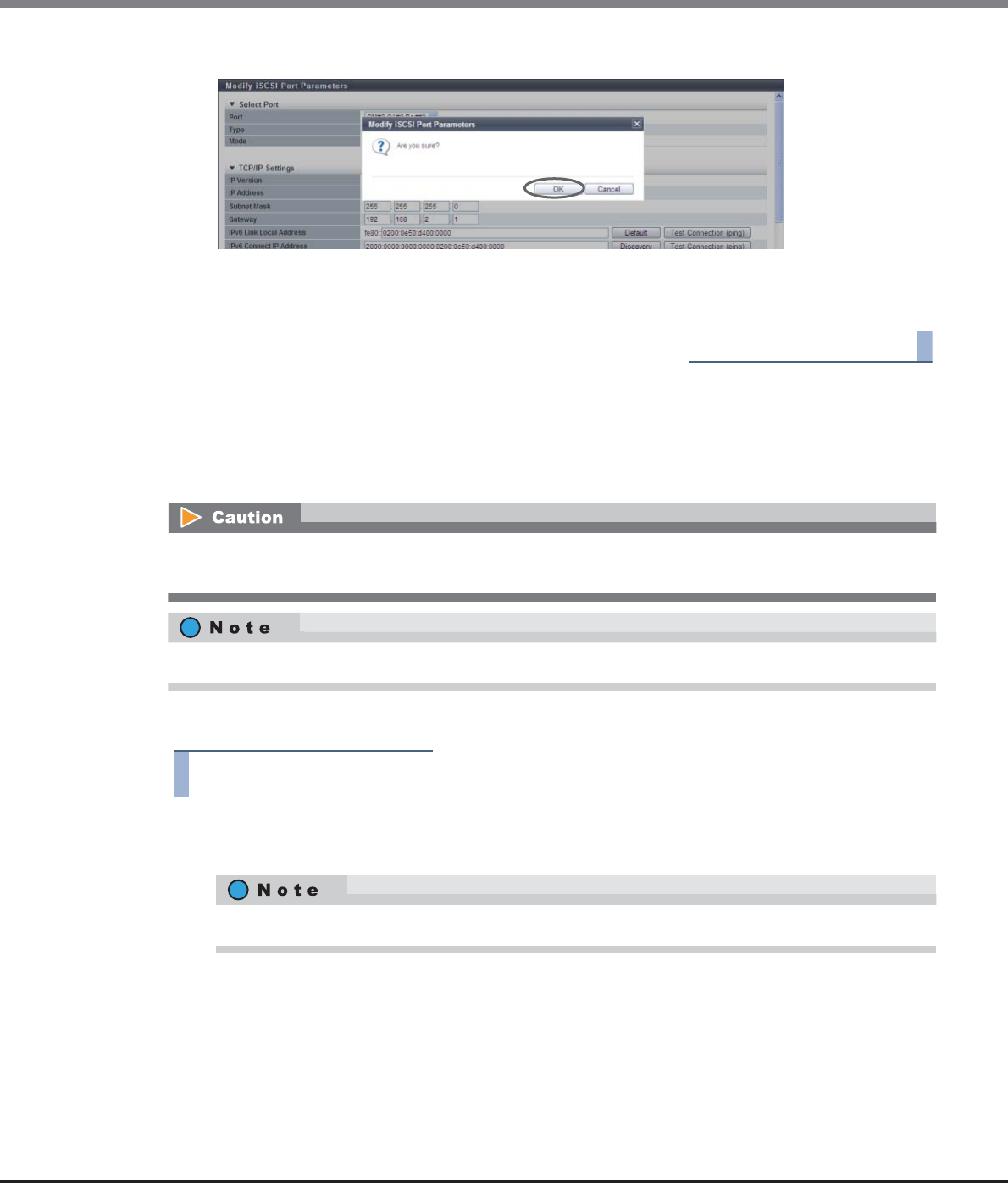
Chapter 9 Connectivity Management
9.2 Functions in the Action Area for Connectivity
ETERNUS Web GUI User’s Guide
Copyright 2013 FUJITSU LIMITED P2X0-1090-10ENZ0
567
3Click the [OK] button.
→Modification of the iSCSI port parameters starts.
4Click the [Done] button to return to the [iSCSI Port Group] screen.
End of procedure
9.2.3.9 Modify SAS Port Parameters
This function sets the connection information for the SAS port that is used to connect the ETERNUS DX Disk
storage system and the host.
The procedure to set SAS port parameters is as follows:
Procedure
1Select the SAS port to set the parameters for (multiple selections can be made) and click
[Configure SAS Port] in [Action].
2Set the parameters for all of the selected ports and click the [Set] button.
•Port
Select the target port.
The selectable port location options are displayed as options:
-CM#x CA#y Port#z (x: CM number, y: CA number, z: Port number)
When changing port parameters during operation, stop access from the server that is allocated to the target
port. Host access does not need to be stopped to change the port parameters of newly added CA ports.
For more details on SAS parameter settings, refer to "User’s Guide -Server Connection-" for each OS type.
When multiple ports are selected, select the target port and set the parameters for each port.
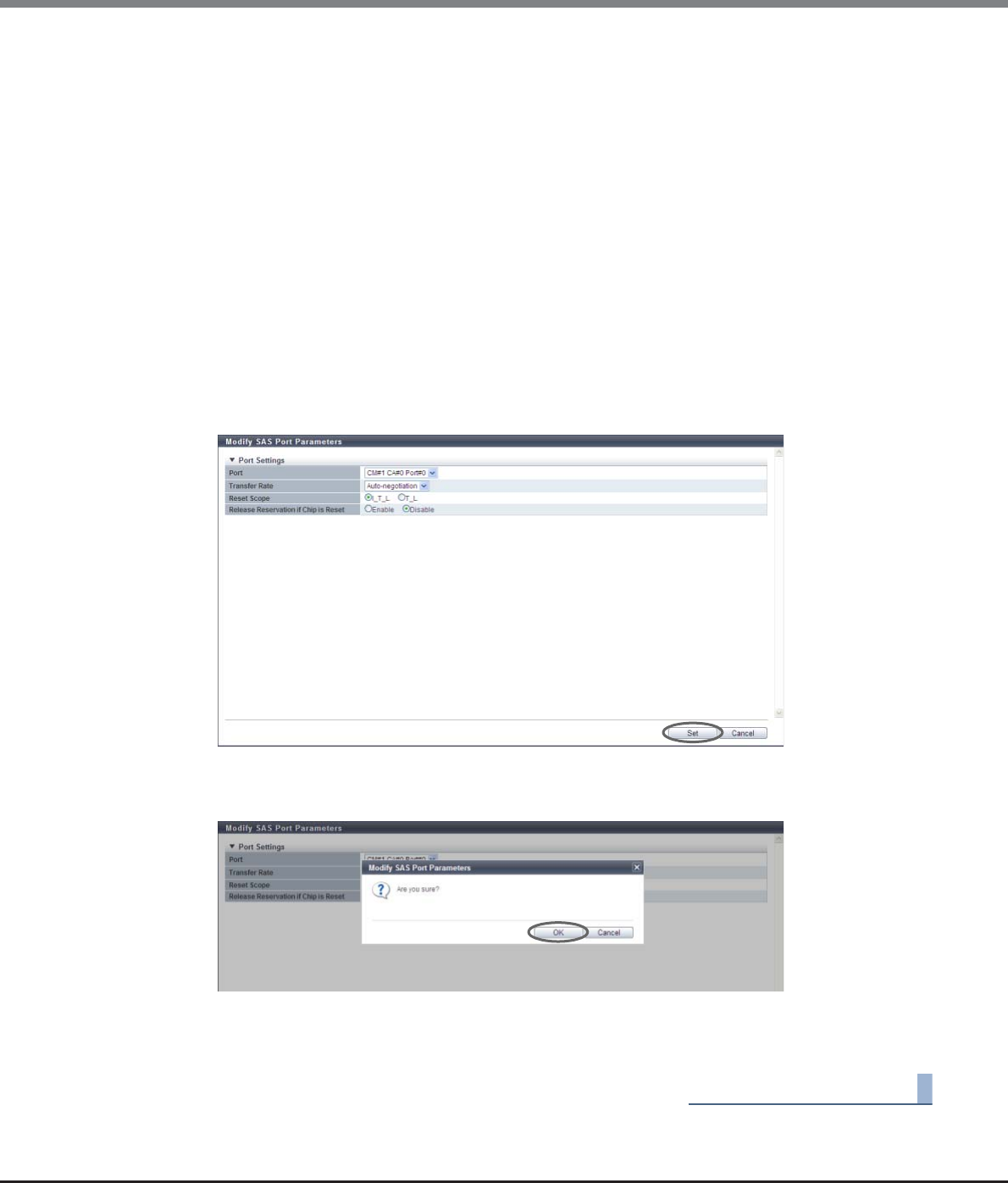
Chapter 9 Connectivity Management
9.2 Functions in the Action Area for Connectivity
ETERNUS Web GUI User’s Guide
Copyright 2013 FUJITSU LIMITED P2X0-1090-10ENZ0
568
•Transfer Rate
Select the transfer speed for the target port.
-Auto-negotiation
-1.5 Gbit/s
-3 Gbit/s
-6 Gbit/s
•Reset Scope
Specify the reset scope of the target port.
Reset scope is the range where the command reset from the server is performed, when the target
port is connected to multiple servers.
-I_T_L (I: Initiator, T: Target, L: LUN)
Reset (cancel) the command request from the server that sent the command reset request.
-T_L (T: Target, L: LUN)
Reset (cancels) the command request from all of the servers that are connected to the port.
•Release Reservation if Chip is Reset
Select whether to "Enable" or "Disable" the function to release the reserved status of the volume
when the target port (chip) is reset.
→A confirmation screen appears.
3Click the [OK] button.
→Modification of the SAS port parameters starts.
4Click the [Done] button to return to the [SAS Port Group] screen.
End of procedure
Chapter 9 Connectivity Management
9.2 Functions in the Action Area for Connectivity
ETERNUS Web GUI User’s Guide
Copyright 2013 FUJITSU LIMITED P2X0-1090-10ENZ0
569
9.2.3.10 Modify FCoE Port Parameters
This function sets the connection information for the FCoE ports that connect the ETERNUS DX Disk storage
system and the host.
The procedure to set FCoE port parameters is as follows:
Procedure
1Select the FCoE port to set the parameters for (multiple selections can be made) and click
[Configure FCoE Port] in [Action].
2Set the parameters for all of the selected ports and click the [Set] button.
•Port
Select the target port or select the copy source port.
The selectable port location options are displayed as options:
-CM#x CA#y Port#z (x: CM number, y: CA number, z: Port number)
•Transfer Rate (Gbit/s)
Set the transfer speed of the target port.
-10Gbit/s
•Set VLAN ID
Specify "Auto" to enable the automatic setting for the VLAN ID of the target port. Specify "Fixed" to
enable the fixed setting.
When "Auto" is specified, VLAN ID is automatically obtained and no need to specify the VLAN ID.
When "Fixed" is specified, specify the VLAN ID.
•VLAN ID
Input the VLAN ID for the target port between 0 and 4095.
Make sure to set the same value for the VLAN ID as the VLAN ID of the FCoE switch that is to be
connected to.
When changing port parameters during operation, stop access from the server that is allocated to the target
port. Host access does not need to be stopped to change the port parameters of newly added CA ports.
For more details on FCoE parameter settings, refer to "User’s Guide -Server Connection-" for each OS type.
Multiple selections can be made for the FCoE ports. To set the same parameters for multiple ports, set
the parameters of the copy source port and click the [Copy] button. Select the copy destination port
and click the [Copy] button. The parameters can be copied.
To set different parameters to multiple ports, select each target port and set the parameters.
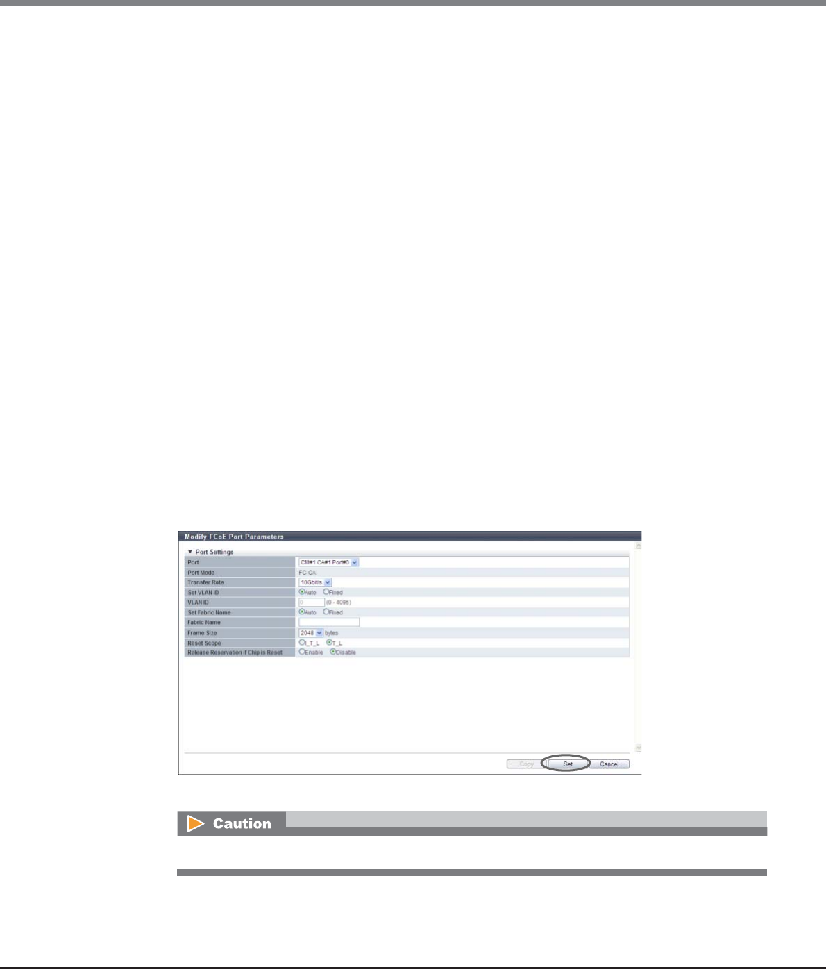
Chapter 9 Connectivity Management
9.2 Functions in the Action Area for Connectivity
ETERNUS Web GUI User’s Guide
Copyright 2013 FUJITSU LIMITED P2X0-1090-10ENZ0
570
•Set Fabric Name
Specify "Auto" to enable the automatic setting for the fabric name of the target port. Specify "Fixed"
to enable the fixed setting.
When "Auto" is specified, the fabric name of the connected FCoE switch is automatically obtained
and does not need to be specified.
When "Fixed" is specified, enter the fabric name.
"Auto" should be set for normal operation. When "Fixed" is specified, connection to any switch other
than the specified FCoE switch cannot be performed.
•Fabric Name
Input the fabric name (WWN of FCoE) of the target port.
•Frame Size
Select the frame size of the target port.
"Frame Size" specifies the length of the communication information.
-512 bytes
-1024 bytes
-2048 bytes
•Reset Scope
Specify the reset scope of the target port.
Reset scope is the range where the command reset from the server is performed, when the target
port is connected to multiple servers.
-I_T_L (I: Initiator, T: Target, L: LUN)
Reset (cancel) the command request from the server that sent the command reset request.
-T_L (T: Target, L: LUN)
Reset (cancels) the command request from all of the servers that are connected to the port.
•Release Reservation if Chip is Reset
Select whether to "Enable" or "Disable" the function to release the reserved status of the volume
when the target port (chip) is reset.
→A confirmation screen appears.
If some parameters do not satisfy the input conditions, an error screen appears.
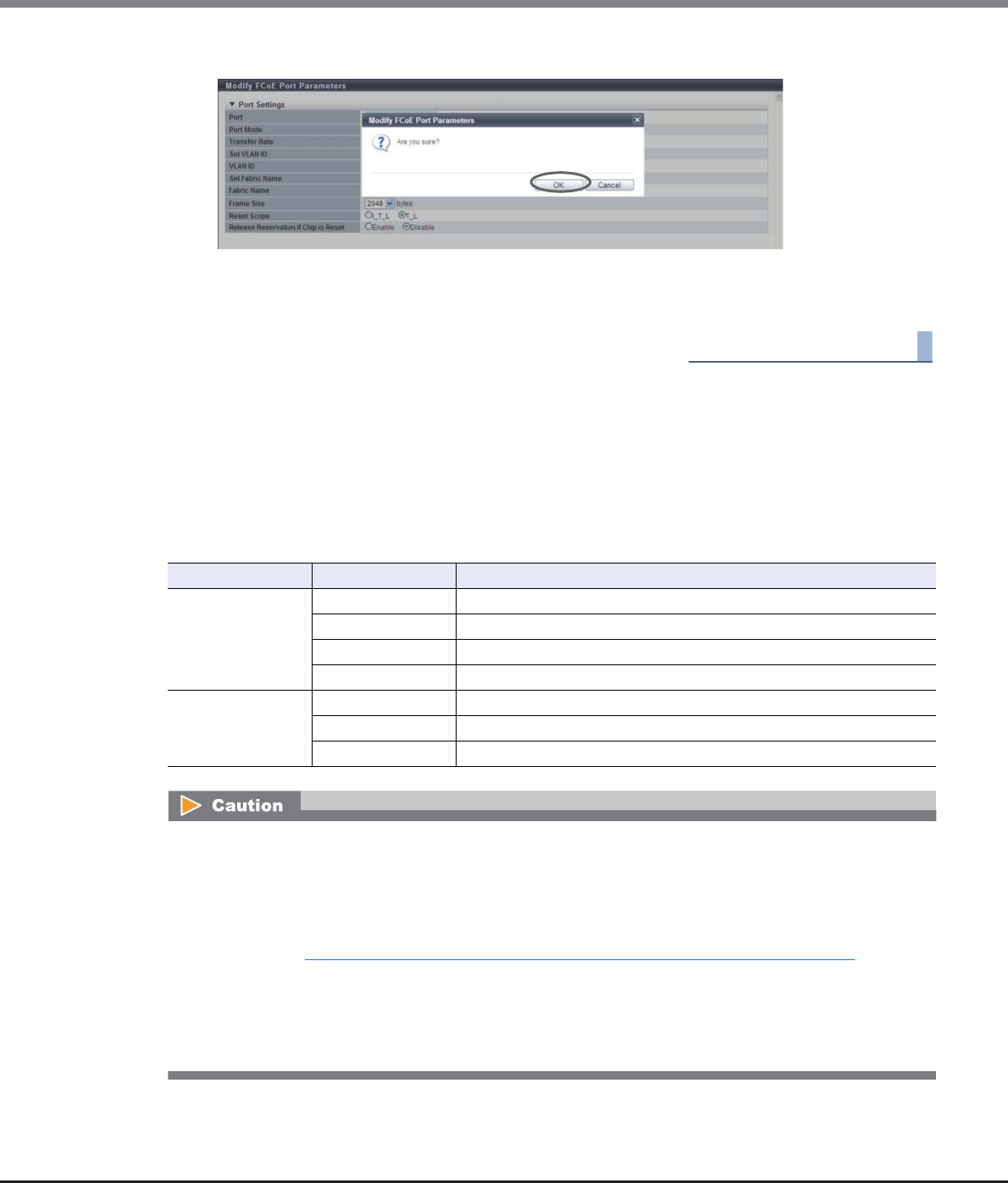
Chapter 9 Connectivity Management
9.2 Functions in the Action Area for Connectivity
ETERNUS Web GUI User’s Guide
Copyright 2013 FUJITSU LIMITED P2X0-1090-10ENZ0
571
3Click the [OK] button.
→Modification of the FCoE port parameters starts.
4Click the [Done] button to return to the [FCoE Port Group] screen.
End of procedure
9.2.3.11 Modify Port Mode
This function changes the port mode of each port among Channel Adapter (CA), Remote Adapter (RA), CA/RA,
and Initiator.
The port modes of the FC port and the iSCSI port can be changed.
Switchable Port Mode
Port Port Mode Usage
FC Port CA CA is used for connecting to the host.
RA RA is used for performing REC.
CA/RA CA/RA is used for connecting the host and for performing REC.
Initiator Initiator is used for performing Storage Migration.
iSCSI Port CA CA is used for connecting to the host.
RA RA is used for performing REC.
CA/RA CA/RA is used for connecting the host and for performing REC.
•When changing the port mode of a running port from "CA" to "RA" or to "Initiator", make sure to stop the
host access connected to the corresponding CA Port.
•When changing the port mode of a running port from "RA" to "CA" or to "Initiator", make sure to check that
there is no session in the corresponding port.
•For details about mapping information and the Advanced Copy path information when changing the port
mode, refer to "Retained and deleted information when changing the port mode" (page 572).
•The port mode of an FC-Initiator port that has Storage Migration paths cannot be changed.
•The port mode of a SAS port cannot be changed.
•The port mode of an FCoE port cannot be changed.
•When the Advanced Copy license is not registered, port mode cannot be changed to "RA" or "CA/RA".
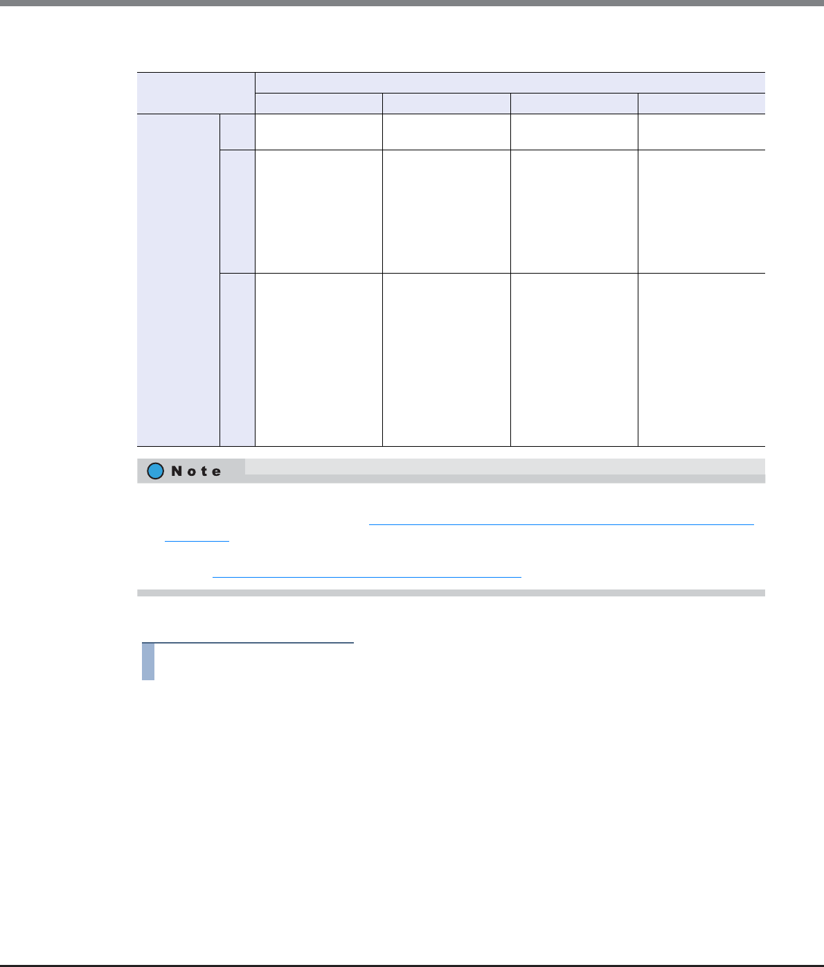
Chapter 9 Connectivity Management
9.2 Functions in the Action Area for Connectivity
ETERNUS Web GUI User’s Guide
Copyright 2013 FUJITSU LIMITED P2X0-1090-10ENZ0
572
Retained and deleted information when changing the port mode
The procedure to change the port mode is as follows:
Procedure
1Click [Modify Port Mode] in [Action].
Port mode after modification
CA RA CA/RA Initiator
Port mode
before
modification
CA – Mapping information
is deleted
Mapping information
is retained
Mapping information
is deleted
RA
Advanced Copy path
information is
deleted
–•Advanced Copy
path information
is retained
•REC Line No. is
retained
•REC Transfer
Mode is retained
Advanced Copy path
information is
deleted
CA/
RA
•Mapping
information is
retained
•Advanced Copy
path information
is deleted
•Mapping
information is
deleted
•Advanced Copy
path information
is retained
•REC Line No. is
retained
•REC Transfer
Mode is retained
–•Mapping
information is
deleted
•Advanced Copy
path information
is deleted
•If the port mode has been changed, the port parameter returns to the default setting. For REC line num-
ber and REC transfer mode, refer to "Retained and deleted information when changing the port mode"
(page 572).
•When changing the port mode for FC-Initiator port, delete the path group specified in the target port.
Refer to "11.2.11.3 Delete Storage Migration Path" (page 914) for details.
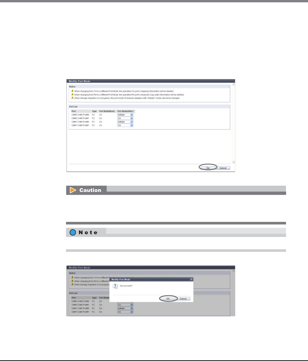
Chapter 9 Connectivity Management
9.2 Functions in the Action Area for Connectivity
ETERNUS Web GUI User’s Guide
Copyright 2013 FUJITSU LIMITED P2X0-1090-10ENZ0
573
2Select the port mode to be changed over to, and click the [Set] button.
•Port Mode (After)
Select from "CA", "RA", "CA/RA", or "Initiator" for the changed port mode.
"Initiator" is displayed only for FC ports.
The current port mode is displayed by default.
-CA
-RA
-CA/RA
-Initiator
→A confirmation screen appears.
3Click the [OK] button.
→Port mode changeover starts.
•If the specified FC-Initiator port is configured in Storage Migration path, an error screen appears.
•When using the ETERNUS DX80 S2, "RA" and "CA/RA" is not displayed in the "Port Mode (After)"
field.
"iSCSI-RA" type ports are not displayed in the port list.
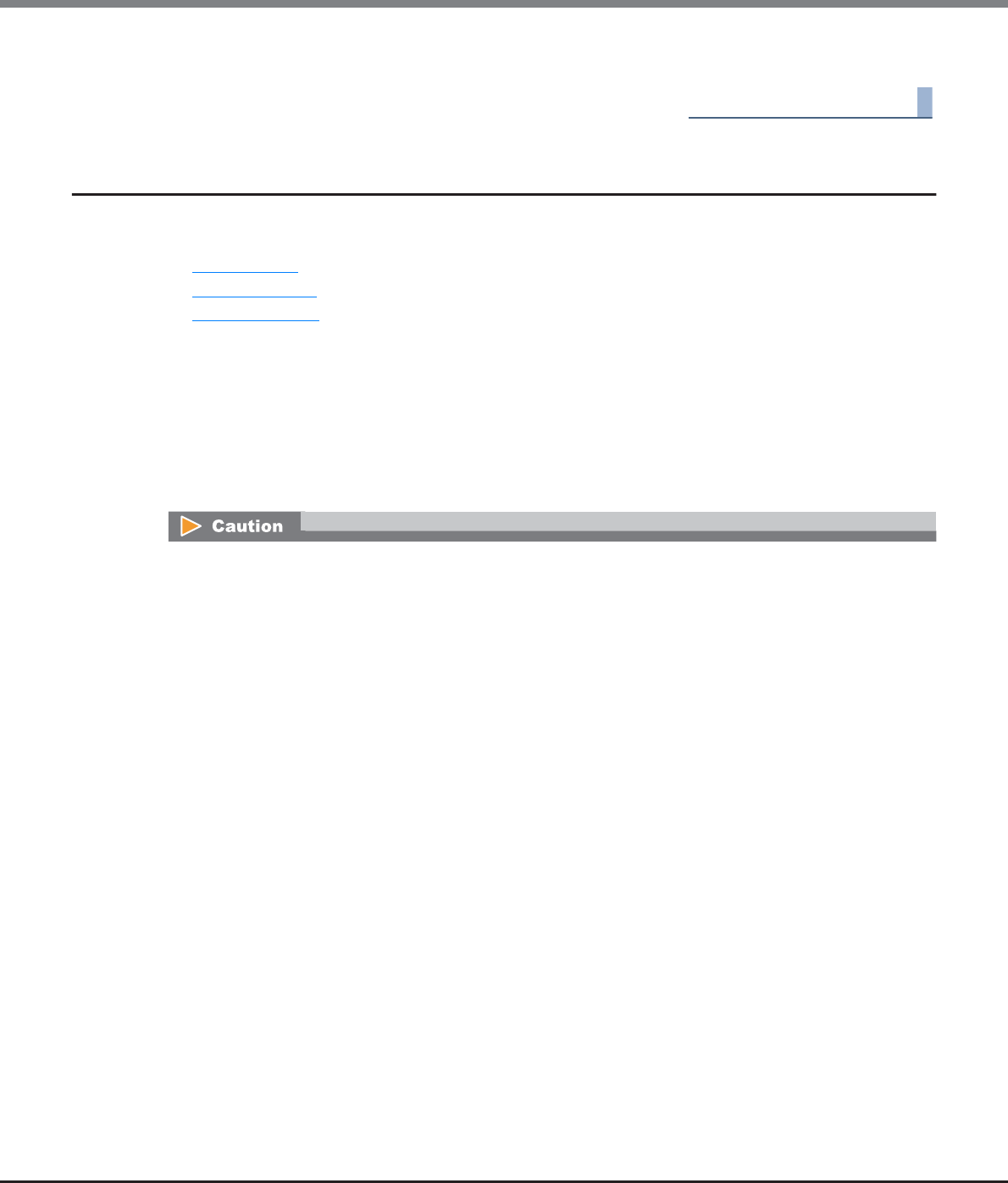
Chapter 9 Connectivity Management
9.2 Functions in the Action Area for Connectivity
ETERNUS Web GUI User’s Guide
Copyright 2013 FUJITSU LIMITED P2X0-1090-10ENZ0
574
4Click the [Done] button to return to the [CA Port Group] screen.
End of procedure
9.2.4 LUN Group Management
LUN group management provides the following functions:
•Add LUN Group
•Delete LUN Group
•Modify LUN Group
9.2.4.1 Add LUN Group
This function creates a new LUN group, and allocates a volume number in the ETERNUS DX Disk storage
system to the LUN, which can be recognized by the host.
Up to 1024 LUN groups (2048 for the ETERNUS DX8700 S2) can be created in the ETERNUS DX Disk storage
system.
•Only the volumes with "Standard", "WSV", "TPV", "FTV", or "SDV" volume types can be registered in the LUN
group. "SDPV" volumes cannot be registered in the LUN group.
•A LUN group cannot be created when no volumes have been registered in the ETERNUS DX Disk storage
system.
•Up to 4096 LUNs can be created. Note that the LUNs that can be accessed from the host vary depending
on the "Host Specific Mode" setting of the host response when the host affinity setting is used to allocate
a specific host group.
-Normal (Default)
256 LUNs (LUN#0 - LUN#255) can be accessed
(LUN#256 - LUN#4095 cannot be accessed)
-AIX Mode
512 LUNs (LUN#0 - LUN#511) can be accessed
(LUN#512 - LUN#4095 cannot be accessed)
-NR1000V Mode
512 LUNs (LUN#0 - LUN#511) can be accessed
(LUN#512 - LUN#4095 cannot be accessed)
-HP-UX Mode
1024 LUNs (LUN#0 - LUN#1023) can be accessed
(LUN#1024 - LUN#4095 cannot be accessed)
-BS2000 Mode
4096 LUNs (LUN#0 - LUN#4095) can be accessed
When the host affinity setting is used to allocate all of the hosts (specify "All"), 256 LUNs (LUN#0 -
LUN#255) can be accessed.
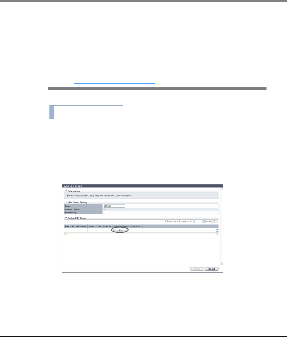
Chapter 9 Connectivity Management
9.2 Functions in the Action Area for Connectivity
ETERNUS Web GUI User’s Guide
Copyright 2013 FUJITSU LIMITED P2X0-1090-10ENZ0
575
The procedure to create a LUN group is as follows:
Procedure
1Click [Add LUN Group] in [Action].
2Specify the LUN group name, and click the [Add] button.
•Name
Specify the LUN group name.
An existing LUN group name cannot be specified.
The following input conditions apply:
-Up to 16 alphanumeric characters and symbols (except ", (comma)" and "?")
-Space
•Note that if a LUN group to which volumes are mapped from LUN#512 onward exists, the maximum
number of LUN groups cannot be created.
This is because when volumes are mapped for LUN#512 onward, an additional LUN group is created as an
internal resource for every 512 LUNs. For example, when volumes are mapped from LUN#0 to LUN#520,
two LUN groups are created (one for LUNs #0 to #511 and one for LUNs #512 to #520).
•Volumes with the mirroring reservation attribute (*1) cannot be registered in a LUN group. Volumes in
this status are not displayed in the "Select Volume" field.
•An ODX Buffer volumes cannot be registered in the LUN group.
*1: The mirroring reservation attribute is applied to the volumes that are being created as an REC copy path by the
Dynamic LUN Mirroring function. Volumes that are not successfully created may have this attribute. Volumes that
have the mirroring reservation attribute can be checked in the "Forbid Advanced Copy" field on the [Volume] screen.
Refer to "5.1.1 Volume (Basic Information)" (page 74) for details.
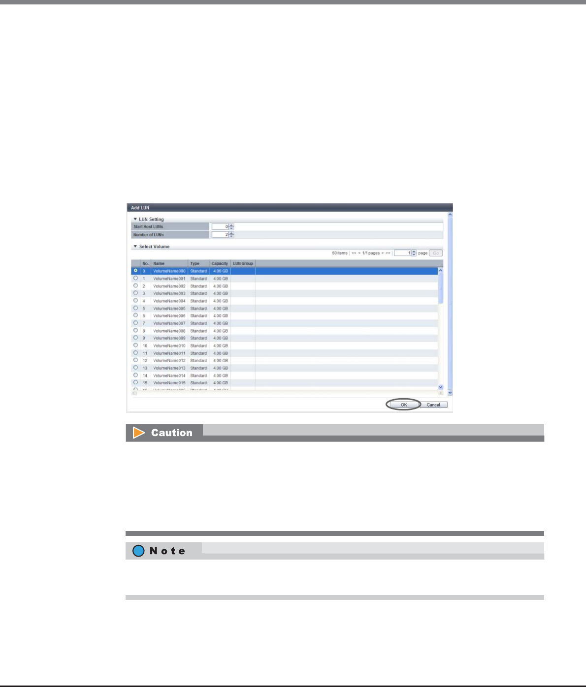
Chapter 9 Connectivity Management
9.2 Functions in the Action Area for Connectivity
ETERNUS Web GUI User’s Guide
Copyright 2013 FUJITSU LIMITED P2X0-1090-10ENZ0
576
3Specify the LUNs and the number of LUNs, to allocate volumes to, select the volume
numbers to be allocated to the corresponding LUNs, and click the [OK] button.
•Start Host LUNs
Specify the LUN from which allocation is to be started. The smallest LUN among the available LUNs
is used as the default value.
The following input condition applies:
-"0" - "4095" (decimal)
•Number of LUNs
The number of LUNs, to which the volumes are allocated, is displayed.
The following input condition applies:
-"1" - "4096" (decimal)
•Select Volume
Use the radio button to select which volume number the allocation is to be started from.
An error screen appears in the following conditions:
•The LUN volume, which is specified in "Start Host LUNs", has already been allocated to a different
LUN
•The LUN volumes, which have been specified in "Number of LUNs", cannot be allocated to the
necessary number of LUNs
•The selected volume already exists in the corresponding LUN group
To delete the LUN and the volume allocation information from a LUN group, click the [Delete] button
for the allocation information to be deleted.
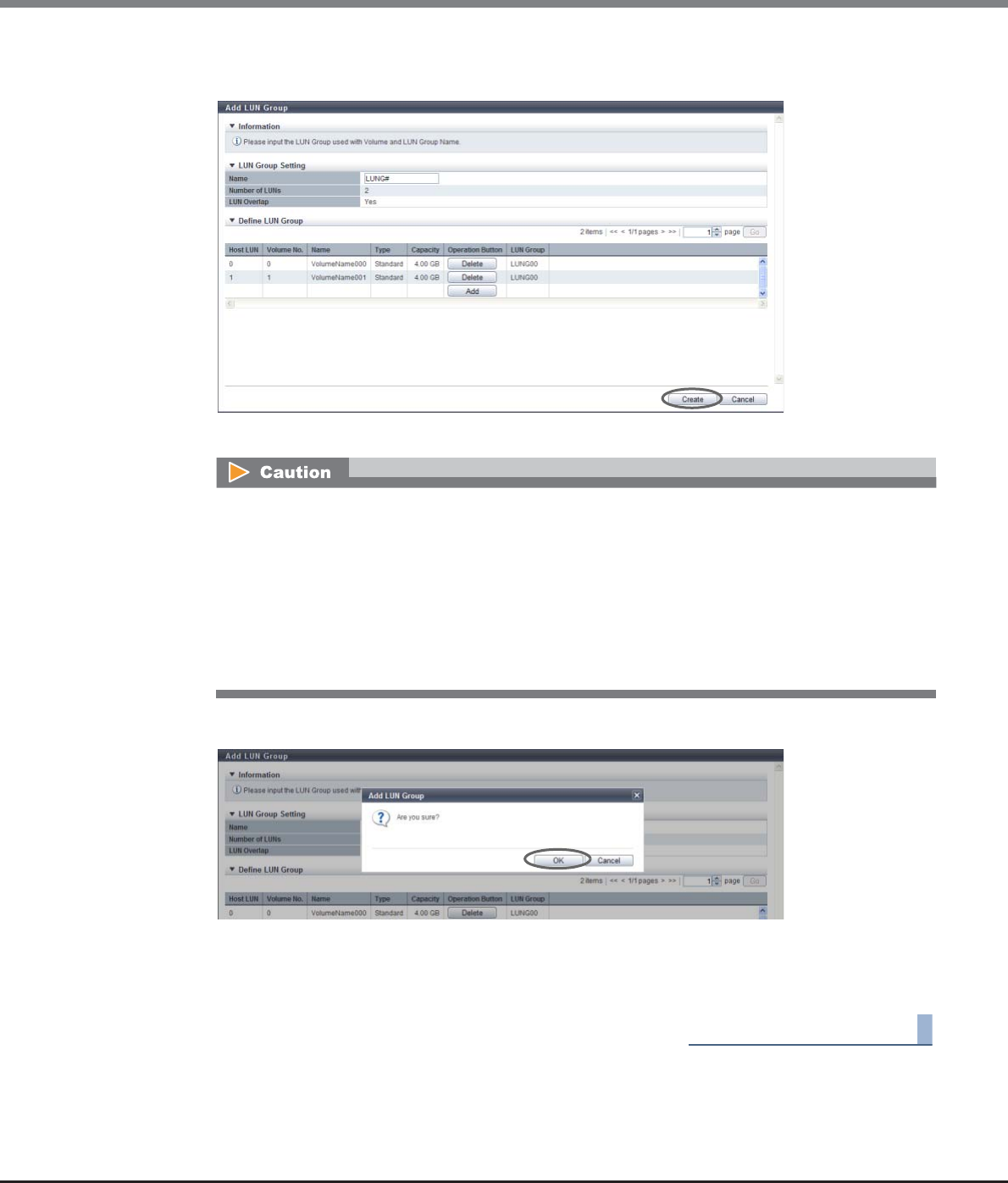
Chapter 9 Connectivity Management
9.2 Functions in the Action Area for Connectivity
ETERNUS Web GUI User’s Guide
Copyright 2013 FUJITSU LIMITED P2X0-1090-10ENZ0
577
4Check the LUN and the volume allocation information to be registered in the LUN group,
click the [Create] button.
→A confirmation screen appears.
5Click the [OK] button.
→Adding LUN group starts.
6Click the [Done] button to return to the [LUN Group] screen.
End of procedure
An error screen appears in the following conditions:
•When the LUN group name, which you entered in the "Name" field, has the same name as an
existing LUN group
•When the LUN group name, which you entered in the "Name" field, does not satisfy the input
conditions
•When the "Name" field is not input
•When the total number of LUN groups has reached the maximum number of storage systems
•When the selected volume does not exist
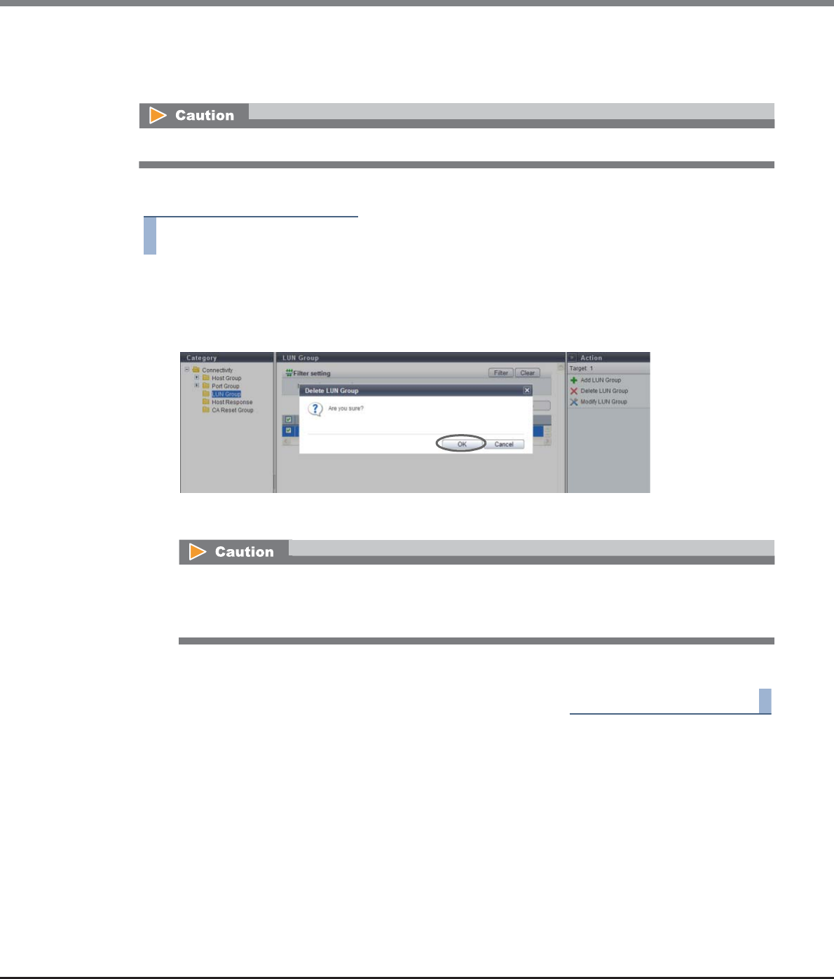
Chapter 9 Connectivity Management
9.2 Functions in the Action Area for Connectivity
ETERNUS Web GUI User’s Guide
Copyright 2013 FUJITSU LIMITED P2X0-1090-10ENZ0
578
9.2.4.2 Delete LUN Group
This function deletes LUN groups.
The procedure to delete a LUN group is as follows:
Procedure
1Select the LUN group that is to be deleted, and click [Delete LUN Group] in [Action].
→A confirmation screen appears.
2Click the [OK] button.
→LUN group deletion starts.
3Click the [Done] button to return to the [LUN Group] screen.
End of procedure
The LUN groups, which are being used in the Host Affinity settings, cannot be deleted.
An error screen appears in the following conditions:
•When the selected LUN group is being used in the Host Affinity settings
•When the selected LUN group does not exist
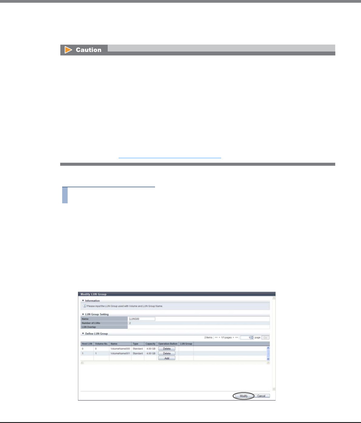
Chapter 9 Connectivity Management
9.2 Functions in the Action Area for Connectivity
ETERNUS Web GUI User’s Guide
Copyright 2013 FUJITSU LIMITED P2X0-1090-10ENZ0
579
9.2.4.3 Modify LUN Group
This function modifies LUN groups.
The procedure to modify a LUN group is as follows:
Procedure
1Select the LUN group that is to be changed, and click [Modify LUN Group] in [Action].
2Change the LUN group name and its volume allocation information, and click the [Modify]
button.
•Name
Modify the LUN group name.
An existing LUN group name cannot be specified.
The following input conditions apply:
-Up to 16 alphanumeric characters and symbols (except ", (comma)" and "?")
-Space
→A confirmation screen appears.
•When changing or deleting the volume allocation in a running LUN group, stop access from the
associated host.
•When adding LUNs or volume allocation to a running LUN group, stopping access from the associated
host is not necessary.
•Only the volumes with "Standard", "WSV", "TPV", "FTV", or "SDV" volume types can be registered in the LUN
group. "SDPV" volumes cannot be registered in the LUN group.
•Volumes with the mirroring reservation attribute (*1) cannot be registered in a LUN group. Volumes in
this status are not displayed in the "Select Volume" field.
•ODX Buffer volumes cannot be registered in the LUN group.
*1: The mirroring reservation attribute is applied to the volumes that are being created as an REC copy path by the
Dynamic LUN Mirroring function. Volumes that are not successfully created may have this attribute. Volumes that
have the mirroring reservation attribute can be checked in the "Forbid Advanced Copy" field on the [Volume]
screen. Refer to "5.1.1 Volume (Basic Information)" (page 74) for details.
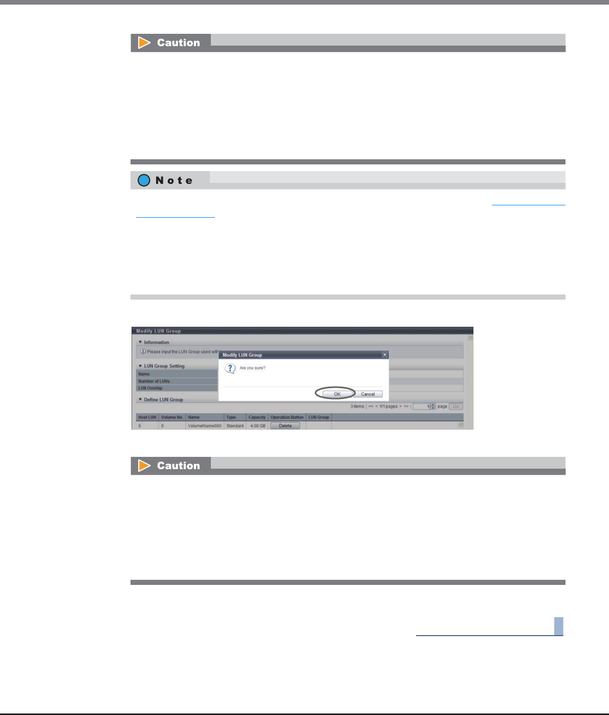
Chapter 9 Connectivity Management
9.2 Functions in the Action Area for Connectivity
ETERNUS Web GUI User’s Guide
Copyright 2013 FUJITSU LIMITED P2X0-1090-10ENZ0
580
3Click the [OK] button.
→LUN group modification starts.
4Click the [Done] button to return to the [LUN Group] screen.
End of procedure
An error screen appears in the following conditions:
•When the LUN group name, which you entered in the "Name" field, has the same name as an
existing LUN group
•When the LUN group name, which you entered in the "Name" field, does not satisfy the input
conditions
•When the "Name" field is not input
•When the selected volume does not exist
The volume allocation information can be edited while performing the procedure in "9.2.4.1 Add LUN
Group" (page 574).
•To add the LUN and the volume allocation, click the [Add] button.
•To delete the LUN and the volume allocation information, click the [Delete] button for the
allocation information to be deleted.
•To change the LUN and the volume allocation information, delete the allocation information to be
changed. Change the allocation volume, and add it to the LUN group again.
Some LUNs cannot be recognized if one of the following conditions applies to "Host Specific Mode" for
which the host response is allocated to a host group with host affinity settings. When adding LUNs to
a LUN group, check "Host Specific Mode" for the host response.
•When "Host Specific Mode" is "Normal (Default)", any LUNs that are added from LUN#256 onward
•When "Host Specific Mode" is "AIX Mode" or "NR1000V Mode", any LUNs that are added from
LUN#512 onward
•When the "Host Specific Mode" is "HP-UX Mode", any LUNs that are added from LUN#1024 onward
Chapter 9 Connectivity Management
9.2 Functions in the Action Area for Connectivity
ETERNUS Web GUI User’s Guide
Copyright 2013 FUJITSU LIMITED P2X0-1090-10ENZ0
581
9.2.5 Host Response Management
Host Response management provides the following functions:
•Add Host Response
•Delete Host Response
•Modify Host Response
9.2.5.1 Add Host Response
This function adds a host response.
The maximum number of host responses per storage system is 256, including the recommended patterns.
For more details on setting the host response parameters, refer to "User's Guide -Server Connection-" for each
OS type.
•If an appropriate host response is not configured to the host affinity, the path may not be switched
correctly or the volume may not be recognized correctly.
•When customizing the host response, make sure to understand the setting parameters and create the
host response with careful attention.
•Assign a host response when adding or changing a host group. Refer to the following functions:
-"9.2.2.1 Add FC/FCoE Host Group" (page 440)
-"9.2.2.2 Add iSCSI Host Group" (page 448)
-"9.2.2.3 Add SAS Host Group" (page 456)
-"9.2.2.5 Modify Host Group" (page 463)
•Assign a host response when adding or changing a host. Refer to the following functions:
-"9.2.2.9 Add FC/FCoE Host" (page 487)
-"9.2.2.10 Add iSCSI Host" (page 492)
-"9.2.2.11 Add SAS Host" (page 499)
-"9.2.2.15 Modify FC/FCoE Host" (page 507)
-"9.2.2.16 Modify iSCSI Host" (page 509)
-"9.2.2.17 Modify SAS Host" (page 514)
•Refer to "9.2.5.3 Modify Host Response" (page 589) to edit host responses.

Chapter 9 Connectivity Management
9.2 Functions in the Action Area for Connectivity
ETERNUS Web GUI User’s Guide
Copyright 2013 FUJITSU LIMITED P2X0-1090-10ENZ0
582
Recommended Patterns of Host Responses
Make sure to use the appropriate recommended pattern in the following connection environment. Select
"Default" in other connection environments.
*1: EMPD: ETERNUS Multipath Driver
Host Response
Name
Connection Environment Settings
Solaris MPxIO This setting is for a host on which
Oracle Solaris has been installed,
and which uses OS standard
Multipath Driver (MPxIO).
Reservation Conflict Response for Test Unit Ready: Conflict
Other parameters are the same as "Default".
HP-UX This setting is for a host on which
HP-UX has been installed.
Host Specific Mode: HP-UX Mode
"Load Balance" setting in the [Setup Subsystem
Parameters] function: Disable
Other parameters are the same as "Default".
AIX EMPD (*1) This setting is for a host on which
AIX has been installed, and which
uses ETERNUS Multipath Driver.
Reservation Conflict Response for Test Unit Ready: Conflict
Host Specific Mode: AIX Mode
Other parameters are the same as "Default".
AIX VxVM This setting is for a host on which
AIX has been installed, and which
uses VERITAS Volume Manager
(VxVM).
Host Specific Mode: AIX Mode
Other parameters are the same as "Default".
AIX Single Path This setting is for a host with a
single path on which AIX has been
installed.
Reservation Conflict Response for Test Unit Ready: Conflict
Host Specific Mode: AIX Mode
Other parameters are the same as "Default".
VS850/SVC This setting is used when
connecting via ETERNUS VS850
Virtualization Storage and SVC.
Byte-0 of Inquiry Response: 0x20 Conversion mode
Inquiry VPD ID Type: Type1
Reservation Conflict Response for Test Unit Ready: Conflict
Change Volume Mapping: Report
Volume Capacity Expansion: Report
Other parameters are the same as "Default".
Default This setting is for host connection
environments that are not listed
above.
Byte-0 of Inquiry Response: No Conversion (Default)
Inquiry VPD ID Type: Type3 (Default)
Inquiry Standard Data Version: Version 5 (Default)
Command Timeout Interval: Default (25sec.)
Load Balance Response: Unit Attention (Default)
Reservation Conflict Response for Test Unit Ready: Normal
(Default)
Change Volume Mapping: No Report (Default)
Volume Capacity Expansion: No Report (Default)
Vendor Unique Sense Code: No Report (Default)
Host Specific Mode: Normal (Default)
Asymmetric / Symmetric Logical Unit Access:
For ETERNUS DX80 S2/DX90 S2, ETERNUS DX410 S2/
DX440 S2, ETERNUS DX8100 S2:
ACTIVE-ACTIVE / PREFERRED_PATH (Default)
For ETERNUS DX8700 S2:
ACTIVE/ACTIVE (Default)
iSCSI Discovery Response Mode: All - Reply All Ports
(Default)
TPGS Mode: Enable (Default)
TPG Referrals: Disable (Default)
iSCSI Reservation Range: CA Port (Default)
Sense Data Conversion: No Conversion (Default)
Chapter 9 Connectivity Management
9.2 Functions in the Action Area for Connectivity
ETERNUS Web GUI User’s Guide
Copyright 2013 FUJITSU LIMITED P2X0-1090-10ENZ0
583
The procedure to add a host response is as follows:
Procedure
1Click [Add Host Response] in [Action].
2Specify the host response name, set each parameter, and click the [Add] button.
●Setting parameters
•Name
Specify the host response name.
An existing host response name cannot be specified.
The following input conditions apply:
-Up to 16 alphanumeric characters and symbols (except ", (comma)" and "?")
-Space
•Byte-0 of Inquiry Response
Set the conversion mode for the Byte-0 value of the Inquiry command.
For a certain period of time after the link between the ETERNUS DX Disk storage system and the host
has been established, the host sends an "Inquiry" command to check the volume status in the
storage system. Specify the Byte-0 of the Inquiry data to respond this "Inquiry" command.
Byte-0 in the Inquiry data indicates the volume status.
-No Conversion (Default)
Responds with the value specified in the ETERNUS DX Disk storage system.
-0x7F Conversion mode
When the Byte-0 is "0x20 (configuration is available, unformatted)", converts the Byte-0 value
to "0x7f (configuration is not available)" and responds.
-0x20 Conversion mode
When the Byte-0 is "0x3f (unknown device that cannot be accessed)", converts the Byte-0 value
to "0x20 (configuration is available, unformatted)" and responds.
The following modifications are applied for the recommended patterns of host response with firmware
version V10L15 or later.
•"Others" is changed to "Default".
•"Windows EMPD", "Linux EMPD", and "Solaris EMPD" are deleted from the "Host Response" value. The
setting parameters for "Windows EMPD", "Linux EMPD", and "Solaris EMPD" are the same as "Default".
•There is a recommended host response pattern which has been prepared for each OS type. Make
sure to select the appropriate recommended pattern. Refer to " Recommended Patterns of Host
Responses" (page 582) for details.
•When customizing the host response, make sure to create a new host response using "Setting
parameters".

Chapter 9 Connectivity Management
9.2 Functions in the Action Area for Connectivity
ETERNUS Web GUI User’s Guide
Copyright 2013 FUJITSU LIMITED P2X0-1090-10ENZ0
584
•Inquiry VPD ID Type
Set the Vital Product Data (VPD) information type to respond to the host.
VPD information includes the device information (Vendor ID, Product ID for each model, volume
number, etc.) for the volume.
Type1 and Type3 indicate the data format.
-Type3 (Default)
-Type1
-Type1 + Type3
•Inquiry Standard Data Version
Specify the Standard Data Version (version number of the SCSI standard) of the "Inquiry" command.
-Version 5 (Default)
-Version 4
-Version 3
•Command Timeout Interval
Select the setting method for the command timeout interval from the following items.
-Default (25sec.)
-Customize
When "Customize" is selected, input a value between 10 and 255 seconds (numeric).
•Load Balance Response
This field sets the response status when an overload-derived timeout is detected. The server retry
reaction is determined by this setting.
While the default response should normally be compatible with all systems, the setting may need
to be changed if problems occur.
-Unit Attention (Default)
-Busy
-Queue Full
•Reservation Conflict Response for Test Unit Ready
Select whether or not to notify the Reservation Conflict to the Test Unit Ready command when
volumes have been reserved from the other host.
-Normal (Default)
-Conflict
•Change Volume Mapping
Select whether or not to report to the host when a volume, which can be accessed from the host, has
been added or deleted.
-No Report (Default)
-Report
•Volume Capacity Expansion
Select whether or not to report to the host when the capacity of a volume has been changed.
-No Report (Default)
-Report
•Vendor Unique Sense Code
Select whether or not to report the asynchronous sense code to the host.
Asynchronous sense code indicates the unique sense code for each vendor that is not coincident
with host I/O.
-No Report (Default)
-Report
Chapter 9 Connectivity Management
9.2 Functions in the Action Area for Connectivity
ETERNUS Web GUI User’s Guide
Copyright 2013 FUJITSU LIMITED P2X0-1090-10ENZ0
585
•Host Specific Mode
Select the operation for a specific host.
-Normal (Default)
Up to 256 LUNs (LUN#0 - LUN#255) can be accessed.
-AIX Mode
Select this to prevent the command initialization and performance degradation. Up to 512 LUNs
(LUN#0 - LUN#511) can be accessed.
-HP-UX Mode
Up to 1024 LUNs (LUN#0 - LUN#1023) can be accessed.
-NR1000V Mode
Up to 512 LUNs (LUN#0 - LUN#511) can be accessed.
-BS2000 Mode
Select this mode when connecting to hosts in which BS2000 is installed as the OS. Up to 4096
LUNs (LUN#0 - LUN#4095) can be accessed.
•Asymmetric / Symmetric Logical Unit Access
Select the access type from the host to a volume.
-ACTIVE-ACTIVE / PREFERRED_PATH
When multiple paths are used for connection between the host and the ETERNUS DX Disk
storage system, there are recommended paths and non-recommended paths. While the volume
can be accessed by using either type of path, if a non-recommended path is used, the responses
to the host may require a longer period of time.
-ACTIVE / ACTIVE
When multiple paths are used for connection between the host and the ETERNUS DX Disk
storage system, any paths can be used equally.
•iSCSI Discovery Reply Mode
Select the reply mode for the iSCSI Discovery request.
-All - Reply All Ports (Default)
Replies to the server with the information for all the iSCSI ports (iSCSI names and IP addresses).
-Port - Reply Target Port Only
Replies to the server with only the information for the specified iSCSI ports (iSCSI names and IP
addresses).
The "Linux/NR1000V Mode" host specific mode is "NR1000V Mode" for firmware version V10L25 or
later. When "Linux" is used as the host OS, select the recommended "Default" pattern as the host
response.
When "ACTIVE / ACTIVE" is set for the ETERNUS DX80 S2/DX90 S2, the ETERNUS DX410 S2/DX440 S2,
or the ETERNUS DX8100 S2, the load balancing function of the multipath software in the server
may perform data transfer between controllers. This may cause a reduction in performance.
When connecting the Citrix XenServer and the iSCSI port, select "Port - Reply Target Port Only".
Chapter 9 Connectivity Management
9.2 Functions in the Action Area for Connectivity
ETERNUS Web GUI User’s Guide
Copyright 2013 FUJITSU LIMITED P2X0-1090-10ENZ0
586
•TPGS Mode
Select whether to enable or disable the Target Port Group Support (TPGS) mode.
-Enable (Default)
-Disable
•TPG Referrals
Select whether to enable or disable the TPG Referrals.
The TPG Referrals function determines the priority path for each block when accessing volumes via
the ETERNUS Multipath Driver in order to prevent cross access. This function can be used for "Stan-
dard", "WSV", "TPV", "FTV", and "Standard (LUN concatenated)" type volumes.
-Enable
-Disable (Default)
•iSCSI Reservation Range
Select the reservation management range for iSCSI connection from the CA ports or the storage sys-
tems.
-CA Port (Default)
The reservation status of volumes is managed for each CA port. This is the conventional iSCSI res-
ervation management range.
-Storage System
The reservation status of volumes is managed for each storage system. Select this item when an
iSCSI connection is configured in a VMware environment. Reservation status remains for vol-
umes when a path is disconnected. This prevents Virtual Machine from hanging up.
The "TPGS Mode" setting is applied only when "Version 5 (Default)" is selected for the "Inquiry
Standard Data Version" setting. When a value other than "Version 5 (Default)" is selected, the host
response setting completes successfully but the "TPGS Mode" setting is not applied for the ETER-
NUS DX Disk storage system.
The TPG Referrals function performs normally when "Enable" is selected and all of the following
conditions apply:
•The ETERNUS Multipath Driver supports the TPG Referrals function
•"Version 5 (Default)" is selected for "Inquiry Standard Data Version"
•"Enable (Default)" is selected for "TPGS Mode"
Confirm that the CA ports that configure the iSCSI connection in the VMware environment are reg-
istered in the same CA reset group. All of the CA ports are registered in the same CA reset group by
default.
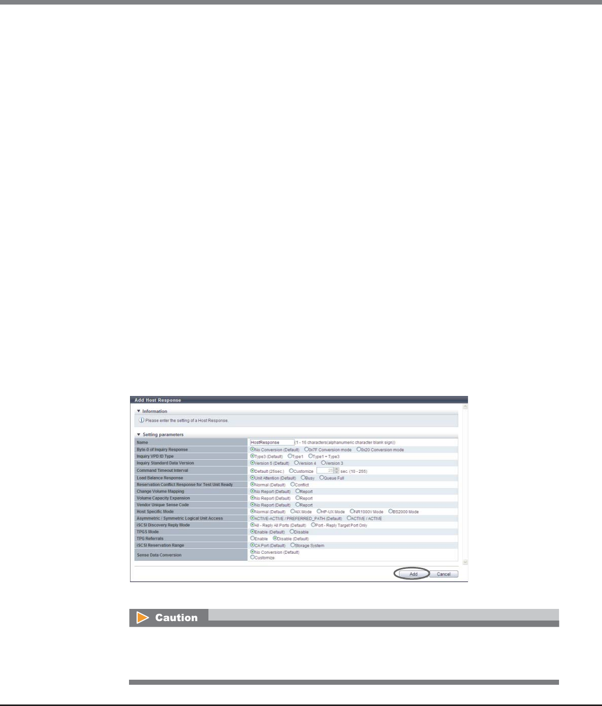
Chapter 9 Connectivity Management
9.2 Functions in the Action Area for Connectivity
ETERNUS Web GUI User’s Guide
Copyright 2013 FUJITSU LIMITED P2X0-1090-10ENZ0
587
•Sense Data Conversion
Select the sense code conversion pattern.
-No Conversion (Default)
-Customize
Customize sense data conversion. Select "Customize" to display the sense data conversion
setting field.
•Sense Data Conversion
-From SK/ASC/ASCQ
-To SK/ASC/ASCQ
Customize sense data conversion.
Click the [Add] button. Input SK/ASC/ASCQ of the conversion target in the "From" field, and SK/
ASC/ASCQ of the conversion destination in the "To" field.
"From SK/ASC/ASCQ" and "To SK/ASC/ASCQ" values are specified in pairs. The sense data that
matches the "From SK/ASC/ASCQ" value is changed to the specified "To SK/ASC/ASCQ" value.
"*" indicates a wild-card, and targets all values.
The maximum number of sense data conversions is eight patterns.
Sense Key (SK): SK indicates sense keys included in the sense information.
Additional Sense Code (ASC): ASC indicates sense codes included in the sense information.
Additional Sense Code Qualifier (ASCQ): ASCQ indicates additional sense code qualifier included
in the sense information.
[Example 1]
The sense information (4/f1/0) is converted to (4/f1/1) before responding to the host.
From SK/ASC/ASCQ: 4/f1/0
To SK/ASC/ASCQ: 4/f1/1
[Example 2]
The sense information (4/f1/0 - ff) is converted to (6/f1/0 - ff) before responding to the host.
"*" indicates all patterns from "0" to "ff". The "*" part is not converted.
From SK/ASC/ASCQ: 4/f1/*
To SK/ASC/ASCQ: 6/f1/*
→A confirmation screen appears.
An error screen appears in the following conditions:
•When the "Name" does not satisfy the input conditions
•When the "Name" has not been entered
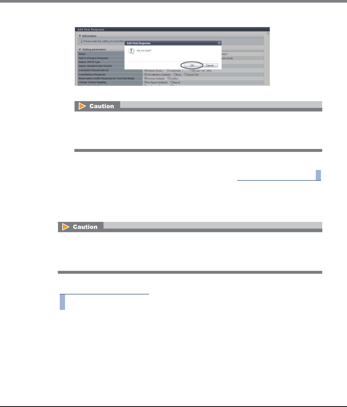
Chapter 9 Connectivity Management
9.2 Functions in the Action Area for Connectivity
ETERNUS Web GUI User’s Guide
Copyright 2013 FUJITSU LIMITED P2X0-1090-10ENZ0
588
3Click the [OK] button.
→Addition of the host response starts.
4Click the [Done] button to return to the [Host Response] screen.
End of procedure
9.2.5.2 Delete Host Response
This function deletes a host response.
The procedure to delete a host response is as follows:
Procedure
1Select the host response to be deleted (multiple selections can be made) and click [Delete
Host Response] in [Action].
→A confirmation screen appears.
An error screen appears in the following conditions:
•When the "Name" matches with an existing host response name
•When the total number of host responses has exceeded the maximum number of host responses
for the ETERNUS DX Disk storage system
•When deleting an active host response, stop the access from the host group which the host response has
been assigned to.
•If an active host response is deleted, the host response setting will return to the initial state.
•The recommended pattern of the host response cannot be changed and deleted.
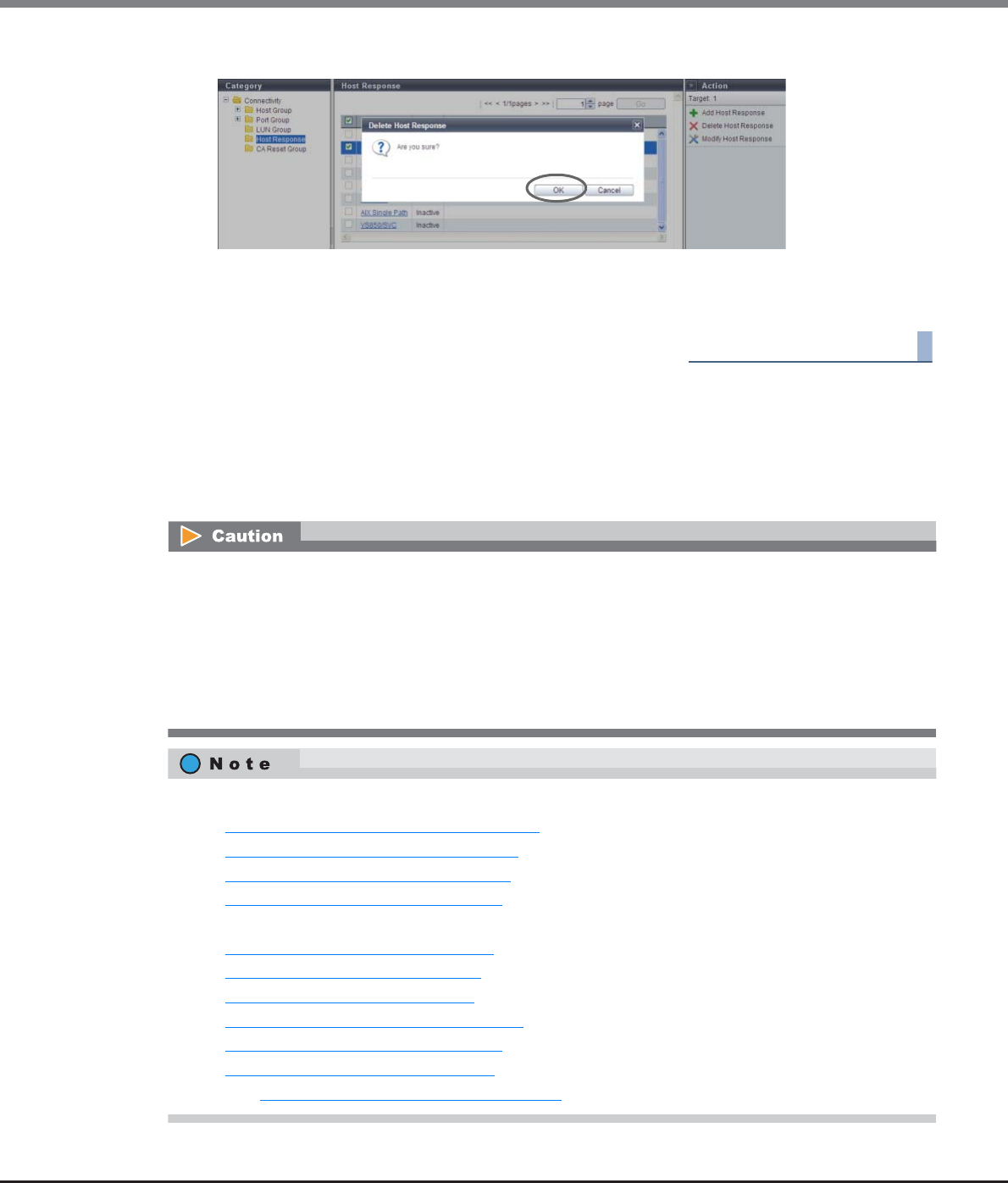
Chapter 9 Connectivity Management
9.2 Functions in the Action Area for Connectivity
ETERNUS Web GUI User’s Guide
Copyright 2013 FUJITSU LIMITED P2X0-1090-10ENZ0
589
2Click the [OK] button.
→Deletion of the host response starts.
3Click the [Done] button to return to the [Host Response] screen.
End of procedure
9.2.5.3 Modify Host Response
This function modifies host response settings.
For more details on setting the host response parameters, refer to "User's Guide -Server Connection-" for each
OS type.
•When editing an active host response, stop the access from the host group to which the host response has
been assigned.
•If an appropriate host response is not configured to the host affinity, the path may not be switched
correctly or the volume may not be recognized correctly.
•When customizing the host response, make sure to understand the setting parameters and create the
host response with careful attention.
•The recommended pattern and the default setting of the host response cannot be modified.
•Assign a host response when adding or changing a host group. Refer to the following functions:
-"9.2.2.1 Add FC/FCoE Host Group" (page 440)
-"9.2.2.2 Add iSCSI Host Group" (page 448)
-"9.2.2.3 Add SAS Host Group" (page 456)
-"9.2.2.5 Modify Host Group" (page 463)
•Assign a host response when adding or changing a host. Refer to the following functions:
-"9.2.2.9 Add FC/FCoE Host" (page 487)
-"9.2.2.10 Add iSCSI Host" (page 492)
-"9.2.2.11 Add SAS Host" (page 499)
-"9.2.2.15 Modify FC/FCoE Host" (page 507)
-"9.2.2.16 Modify iSCSI Host" (page 509)
-"9.2.2.17 Modify SAS Host" (page 514)
•Refer to "9.2.5.3 Modify Host Response" (page 589) to edit host responses.

Chapter 9 Connectivity Management
9.2 Functions in the Action Area for Connectivity
ETERNUS Web GUI User’s Guide
Copyright 2013 FUJITSU LIMITED P2X0-1090-10ENZ0
590
The procedure to edit a host response is as follows:
Procedure
1Select the host response to be modified, and click [Modify Host Response] in [Action].
2Modify the host response name or each item, and click the [Modify] button.
●Setting parameters
•Name
Specify the host response name.
An existing host response name cannot be specified.
The following input conditions apply:
-Up to 16 alphanumeric characters and symbols (except ", (comma)" and "?")
-Space
•Byte-0 of Inquiry Response
Set the conversion mode for the Byte-0 value of the Inquiry command.
For a certain period of time after the link between the ETERNUS DX Disk storage system and the host
has been established, the host sends an "Inquiry" command to check the volume status in the
storage system. Specify the Byte-0 of the Inquiry data to respond this "Inquiry" command.
Byte-0 in the Inquiry data indicates the volume status.
-No Conversion (Default)
Responds with the value specified in the ETERNUS DX Disk storage system.
-0x7F Conversion mode
When the Byte-0 is "0x20 (configuration is available, unformatted)", converts the Byte-0 value
to "0x7f (configuration is not available)" and responds.
-0x20 Conversion mode
When the Byte-0 is "0x3f (unknown device that cannot be accessed)", converts the Byte-0 value
to "0x20 (configuration is available, unformatted)" and responds.
•Inquiry VPD ID Type
Set the Vital Product Data (VPD) information type to respond to the host.
VPD information includes the device information (Vendor ID, Product ID for each model, volume
number, etc.) for the volume.
Type1 and Type3 indicate the data format.
-Type3 (Default)
-Type1
-Type1 + Type3
•Inquiry Standard Data Version
Specify the Standard Data Version (version number of the SCSI standard) of the "Inquiry" command.
-Version 5 (Default)
-Version 4
-Version 3
•Command Timeout Interval
Select the setting method for the command timeout interval from the following items.
-Default (25sec.)
-Customize
When "Customize" is selected, input a value between 10 and 255 seconds (numeric).

Chapter 9 Connectivity Management
9.2 Functions in the Action Area for Connectivity
ETERNUS Web GUI User’s Guide
Copyright 2013 FUJITSU LIMITED P2X0-1090-10ENZ0
591
•Load Balance Response
This field sets the response status when an overload-derived timeout is detected. The server retry
reaction is determined by this setting.
While the default response should normally be compatible with all systems, the setting may need
to be changed if problems occur.
-Unit Attention (Default)
-Busy
-Queue Full
•Reservation Conflict Response for Test Unit Ready
Select whether or not to notify the Reservation Conflict to the Test Unit Ready command when
volumes have been reserved from the other host.
-Normal (Default)
-Conflict
•Change Volume Mapping
Select whether or not to report to the host when a volume, which can be accessed from the host, has
been added or deleted.
-No Report (Default)
-Report
•Volume Capacity Expansion
Select whether or not to report to the host when the capacity of a volume has been changed.
-No Report (Default)
-Report
•Vendor Unique Sense Code
Select whether or not to report the asynchronous sense code to the host.
Asynchronous sense code indicates the unique sense code for each vendor that is not coincident
with host I/O.
-No Report (Default)
-Report
•Host Specific Mode
Select the operation for a specific host.
-Normal (Default)
Up to 256 LUNs (LUN#0 - LUN#255) can be accessed.
-AIX Mode
Select this to prevent the command initialization and performance degradation. Up to 512 LUNs
(LUN#0 - LUN#511) can be accessed.
-HP-UX Mode
Up to 1024 LUNs (LUN#0 - LUN#1023) can be accessed.
-NR1000V Mode
Up to 512 LUNs (LUN#0 - LUN#511) can be accessed.
-BS2000 Mode
Select this mode when connecting to hosts in which BS2000 is installed as the OS. Up to 4096
LUNs (LUN#0 - LUN#4095) can be accessed.
The "Linux/NR1000V Mode" host specific mode is "NR1000V Mode" for firmware version V10L25 or
later. When "Linux" is used as the host OS, select the recommended "Default" pattern as the host
response.
Chapter 9 Connectivity Management
9.2 Functions in the Action Area for Connectivity
ETERNUS Web GUI User’s Guide
Copyright 2013 FUJITSU LIMITED P2X0-1090-10ENZ0
592
•Asymmetric / Symmetric Logical Unit Access
Select the access type from the host to a volume.
-ACTIVE-ACTIVE / PREFERRED_PATH
When multiple paths are used for connection between the host and the ETERNUS DX Disk
storage system, there are recommended paths and non-recommended paths. While the volume
can be accessed by using either type of path, if a non-recommended path is used, the responses
to the host may require a longer period of time.
-ACTIVE / ACTIVE
When multiple paths are used for connection between the host and the ETERNUS DX Disk
storage system, any paths can be used equally.
•iSCSI Discovery Reply Mode
Select the reply mode for the iSCSI Discovery request.
-All - Reply All Ports (Default)
Replies to the server with the information for all the iSCSI ports (iSCSI names and IP addresses).
-Port - Reply Target Port Only
Replies to the server with only the information for the specified iSCSI ports (iSCSI names and IP
addresses).
•TPGS Mode
Select whether to enable or disable the Target Port Group Support (TPGS) mode.
-Enable (Default)
-Disable
When "ACTIVE / ACTIVE" is set for the ETERNUS DX80 S2/DX90 S2, the ETERNUS DX410 S2/DX440 S2,
or the ETERNUS DX8100 S2, the load balancing function of the multipath software in the server
may perform data transfer between controllers. This may cause a reduction in performance.
When connecting the Citrix XenServer and the iSCSI port, select "Port - Reply Target Port Only".
The "TPGS Mode" setting is applied only when "Version 5 (Default)" is selected for the "Inquiry
Standard Data Version" setting. When a value other than "Version 5 (Default)" is selected, the host
response setting completes successfully but the "TPGS Mode" setting is not applied for the ETER-
NUS DX Disk storage system.
Chapter 9 Connectivity Management
9.2 Functions in the Action Area for Connectivity
ETERNUS Web GUI User’s Guide
Copyright 2013 FUJITSU LIMITED P2X0-1090-10ENZ0
593
•TPG Referrals
Select whether to enable or disable the TPG Referrals.
The TPG Referrals function determines the priority path for each block when accessing volumes via
the ETERNUS Multipath Driver in order to prevent cross access. This function can be used for "Stan-
dard", "WSV", "TPV", "FTV", and "Standard (LUN concatenated)" type volumes.
-Enable
-Disable (Default)
•iSCSI Reservation Range
Select the reservation management range for iSCSI connection from the CA ports or the storage sys-
tems.
-CA Port (Default)
The reservation status of volumes is managed for each CA port. This is the conventional iSCSI res-
ervation management range.
-Storage System
The reservation status of volumes is managed for each storage system. Select this item when an
iSCSI connection is configured in a VMware environment. Reservation status remains for vol-
umes when a path is disconnected. This prevents Virtual Machine from hanging up.
•Sense Data Conversion
Select the sense code conversion pattern.
-No Conversion (Default)
-Customize
Customize sense data conversion. Select "Customize" to display the sense data conversion
setting field.
The TPG Referrals function performs normally when "Enable" is selected and all of the following
conditions apply:
•The ETERNUS Multipath Driver supports the TPG Referrals function
•"Version 5 (Default)" is selected for "Inquiry Standard Data Version"
•"Enable (Default)" is selected for "TPGS Mode"
Confirm that the CA ports that configure the iSCSI connection in the VMware environment are reg-
istered in the same CA reset group. All of the CA ports are registered in the same CA reset group by
default.
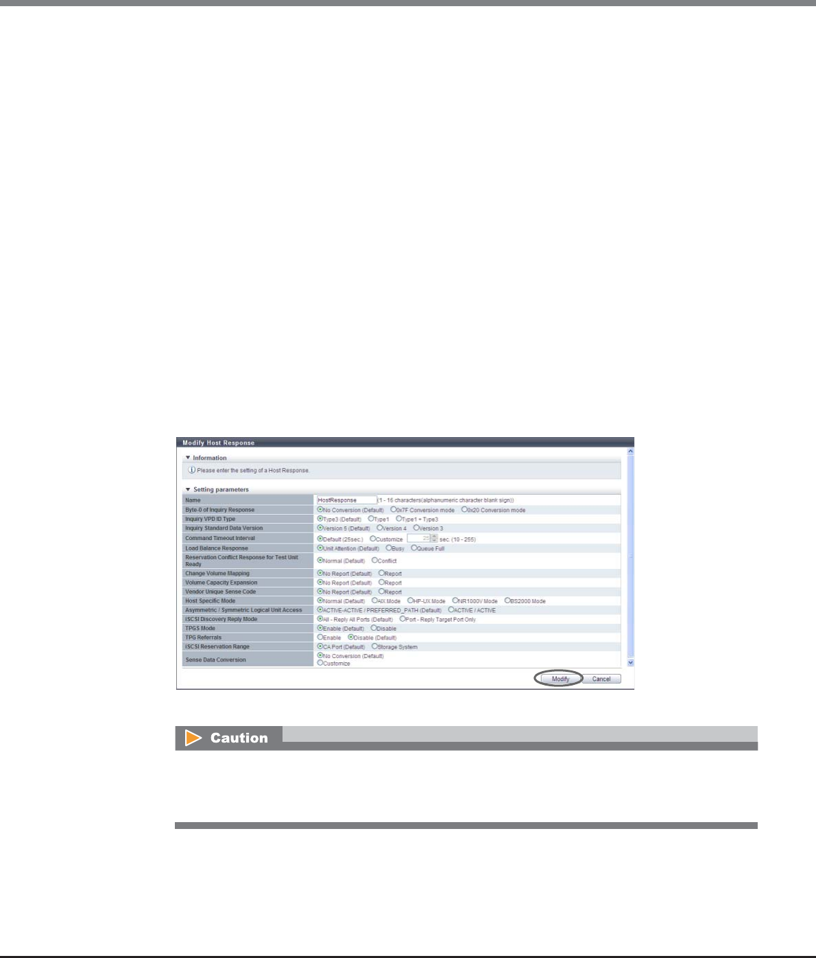
Chapter 9 Connectivity Management
9.2 Functions in the Action Area for Connectivity
ETERNUS Web GUI User’s Guide
Copyright 2013 FUJITSU LIMITED P2X0-1090-10ENZ0
594
•Sense Data Conversion
-From SK/ASC/ASCQ
-To SK/ASC/ASCQ
Customize sense data conversion.
Click the [Add] button. Input SK/ASC/ASCQ of the conversion target in the "From" field, and SK/
ASC/ASCQ of the conversion destination in the "To" field.
"From SK/ASC/ASCQ" and "To SK/ASC/ASCQ" values are specified in pairs. The sense data that
matches the "From SK/ASC/ASCQ" value is changed to the specified "To SK/ASC/ASCQ" value.
"*" indicates a wild-card, and targets all values.
The maximum number of sense data conversions is eight patterns.
Sense Key (SK): SK indicates sense keys included in the sense information.
Additional Sense Code (ASC): ASC indicates sense codes included in the sense information.
Additional Sense Code Qualifier (ASCQ): ASCQ indicates additional sense code qualifier included
in the sense information.
[Example 1]
The sense information (4/f1/0) is converted to (4/f1/1) before responding to the host.
From SK/ASC/ASCQ: 4/f1/0
To SK/ASC/ASCQ: 4/f1/1
[Example 2]
The sense information (4/f1/0 - ff) is converted to (6/f1/0 - ff) before responding to the host.
"*" indicates all patterns from "0" to "ff". The "*" part is not converted.
From SK/ASC/ASCQ: 4/f1/*
To SK/ASC/ASCQ: 6/f1/*
→A confirmation screen appears.
An error screen appears in the following conditions:
•When the "Name" does not satisfy the input conditions
•When the "Name" has not been entered
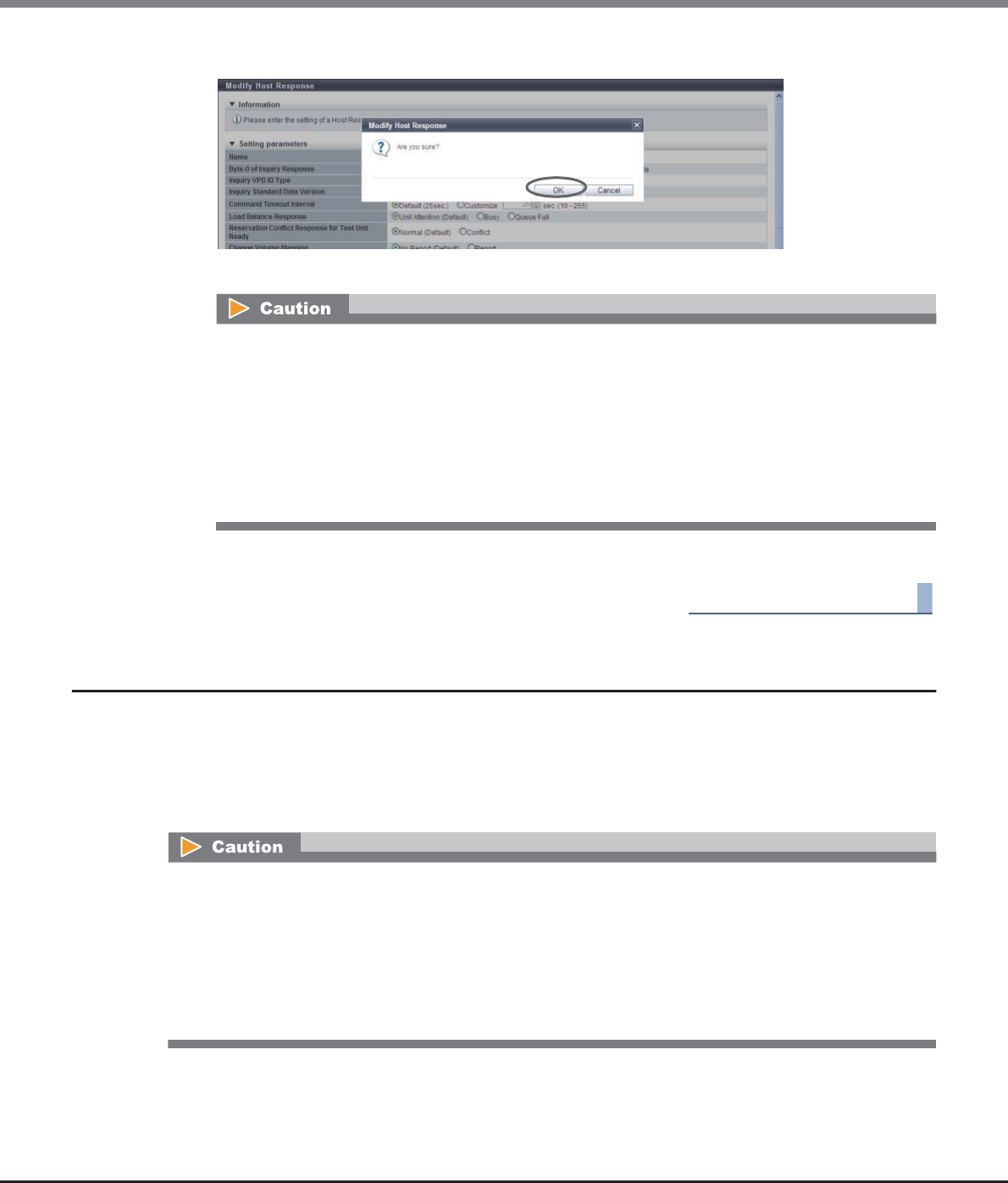
Chapter 9 Connectivity Management
9.2 Functions in the Action Area for Connectivity
ETERNUS Web GUI User’s Guide
Copyright 2013 FUJITSU LIMITED P2X0-1090-10ENZ0
595
3Click the [OK] button.
→Modification of the host response starts.
4Click the [Done] button to return to the [Host Response] screen.
End of procedure
9.2.6 Modify CA Reset Group
This function edits a CA reset group.
All of the ports are configured to be members of one CA reset group on the initial setting. This function can
create a CA reset group with only specific ports or change the member ports of an existing CA reset group
when ports cannot be accessed.
The maximum number of CA reset groups is equal to the number of ports.
An error screen appears in the following conditions:
•When the "Name" matches with an existing host response name
•When performing one of the following modifications in "Host Specific Mode" for which the host
response is allocated to a host group with host affinity settings:
-Select other than "BS2000 Mode" for "Host Specific Mode" when volumes are mapped from
LUN#1024 onward
-Select other than "HP-UX Mode" or "BS2000 Mode" for "Host Specific Mode" when volumes are
mapped from LUN#512 onward
•If a host is unable to access the volumes in a port, this function releases the volumes reserved by the
inaccessible port to the ports in the specified CA reset group, without affecting other ports.
•When a port is shared by multiple servers using the host affinity function, only volumes that can be
released under the instructions from the servers are included in the LUN group, with a host affinity
configured with the target server.
•One port cannot be registered in multiple CA reset groups.
•Only the ports with the "CA" or "CA/RA" port mode can be registered in a CA reset group.
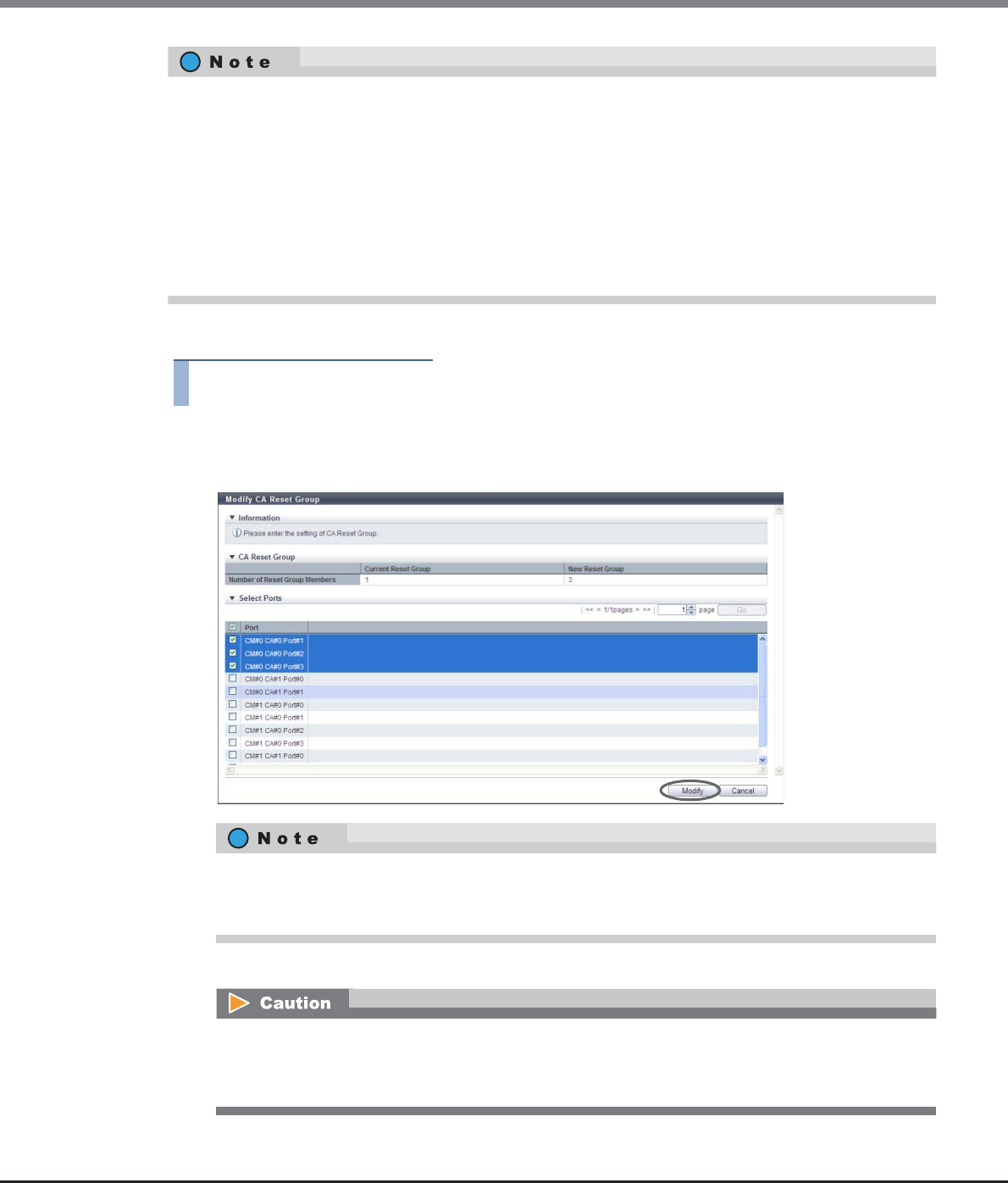
Chapter 9 Connectivity Management
9.2 Functions in the Action Area for Connectivity
ETERNUS Web GUI User’s Guide
Copyright 2013 FUJITSU LIMITED P2X0-1090-10ENZ0
596
The procedure to modify a reset group is as follows:
Procedure
1Select the CA reset group to be modified, and click [Modify Reset Group] in [Action].
2Modify the member ports in a CA reset group, and click the [Modify] button.
→A confirmation screen appears.
•If some ports have been removed from the modification target CA reset group, a different group is created
using those ports. For instance, if ports (Port#2 and Port#3) have been removed from the modification
target CA reset group A (Port#0, Port#1, Port#2 and Port#3), a CA reset group A (Port#0 and Port#1) and a
CA reset group B (Port#2 and Port#3) are created after modification. The minimum number of ports per
CA reset group is one port.
•CA reset groups are required for certain servers to switch clusters correctly.
•Ports with different CA types can be members of the same CA reset group.
•For more details on which servers are required to configure the CA reset group, refer to "User’s Guide -
Server Connection-" for each OS type.
Checkboxes of the member ports of the specified CA reset group are selected. Select the checkbox of
the port to be added in the corresponding CA reset group. Clear the checkbox of the port to be deleted
from the corresponding CA reset group.
•One port cannot be registered in multiple CA reset groups. If a member port of another CA reset
group has been selected, the member port is deleted from the existing CA reset group.
•If the selected "Port" does not exist, an error screen appears.
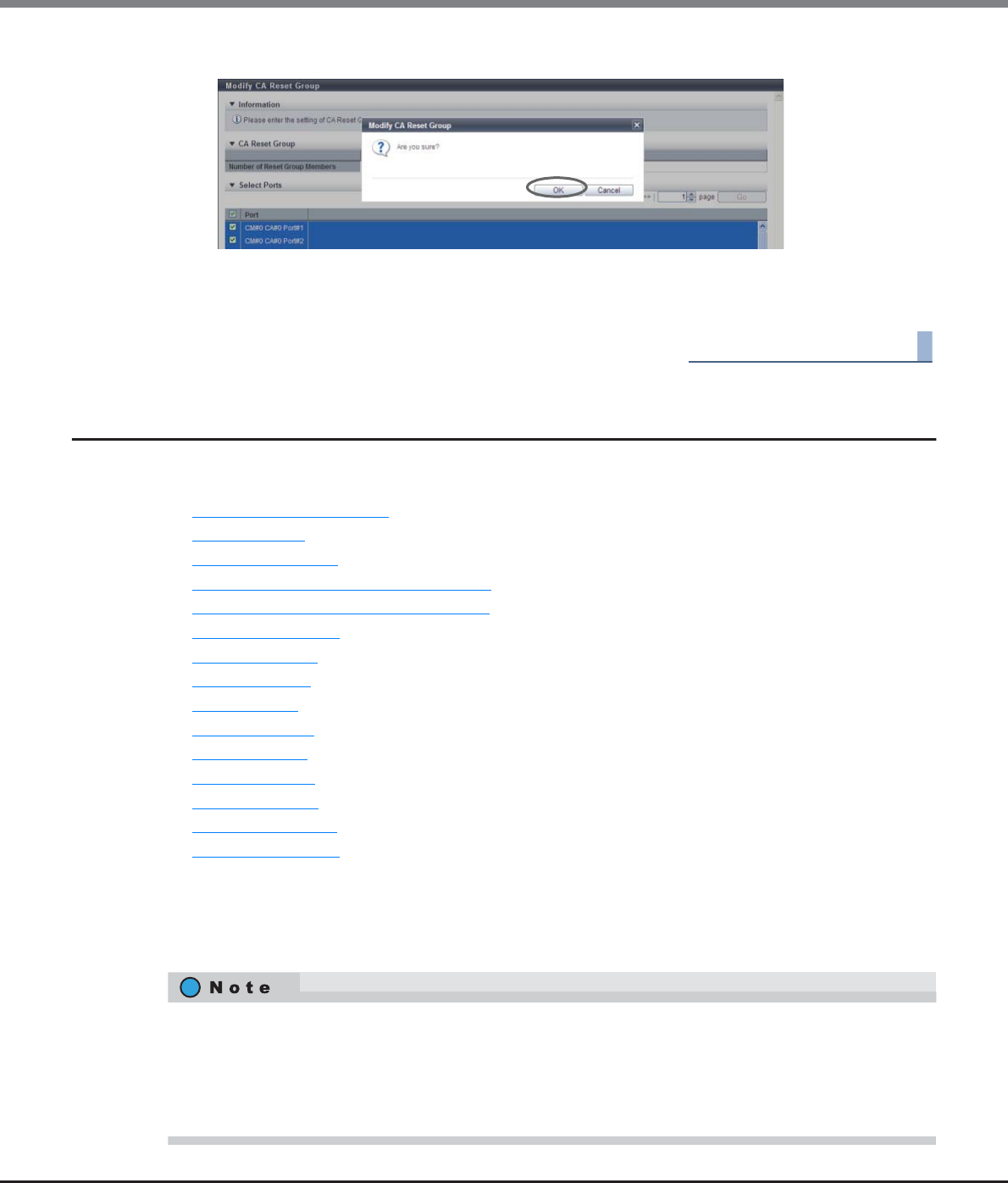
Chapter 9 Connectivity Management
9.2 Functions in the Action Area for Connectivity
ETERNUS Web GUI User’s Guide
Copyright 2013 FUJITSU LIMITED P2X0-1090-10ENZ0
597
3Click the [OK] button.
→Modification of the CA reset group starts.
4Click the [Done] button to return to the [CA Reset Group] screen.
End of procedure
9.2.7 Host-LU QoS Management
Host-LU QoS management provides the following functions:
•Enable/Disable Host-LU QoS
•Set Host-LU QoS
•Release Host-LU QoS
•Start Host-LU QoS Performance Monitoring
•Stop Host-LU QoS Performance Monitoring
•Set FC/FCoE Host QoS
•Set iSCSI Host QoS
•Set SAS Host QoS
•Set FC Port QoS
•Set iSCSI Port QoS
•Set SAS Port QoS
•Set FCoE Port QoS
•Add LU QoS Group
•Delete LU QoS Group
•Modify LU QoS Group
9.2.7.1 Enable/Disable Host-LU QoS
This function enables or disables the Host-LU QoS.
•If the Host-LU QoS is changed from "Enable" to "Disable", the configured bandwidth limit is saved.
•If the Host-LU QoS is changed from "Disable" to "Enable", the Host-LU QoS operates within the saved
bandwidth limit.
•If the bandwidth limit is not specified when the Host-LU QoS is changed to "Enable", "Unlimited" is
applied to all the bandwidth limit settings for hosts, ports, and LUNs (the setting value is not changed).
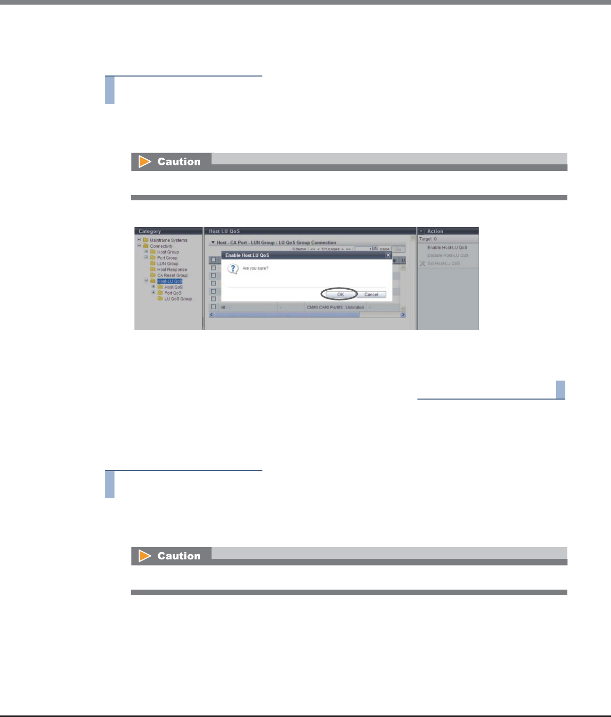
Chapter 9 Connectivity Management
9.2 Functions in the Action Area for Connectivity
ETERNUS Web GUI User’s Guide
Copyright 2013 FUJITSU LIMITED P2X0-1090-10ENZ0
598
■When enabling the Host-LU QoS
The procedure to enable the Host-LU QoS is as follows:
Procedure
1Click [Enable Host-LU QoS] in [Action].
→A confirmation screen appears.
2Click the [OK] button.
→The Host-LU QoS is enabled.
3Click the [Done] button to return to the [Host-LU QoS] screen.
End of procedure
■When disabling the Host-LU QoS
The procedure to disable the Host-LU QoS is as follows:
Procedure
1Click [Disable Host-LU QoS] in [Action].
→A confirmation screen appears.
If the Host-LU QoS has already been enabled, [Enable Host-LU QoS] cannot be clicked.
If the Host-LU QoS has already been disabled, [Disable Host-LU QoS] cannot be clicked.
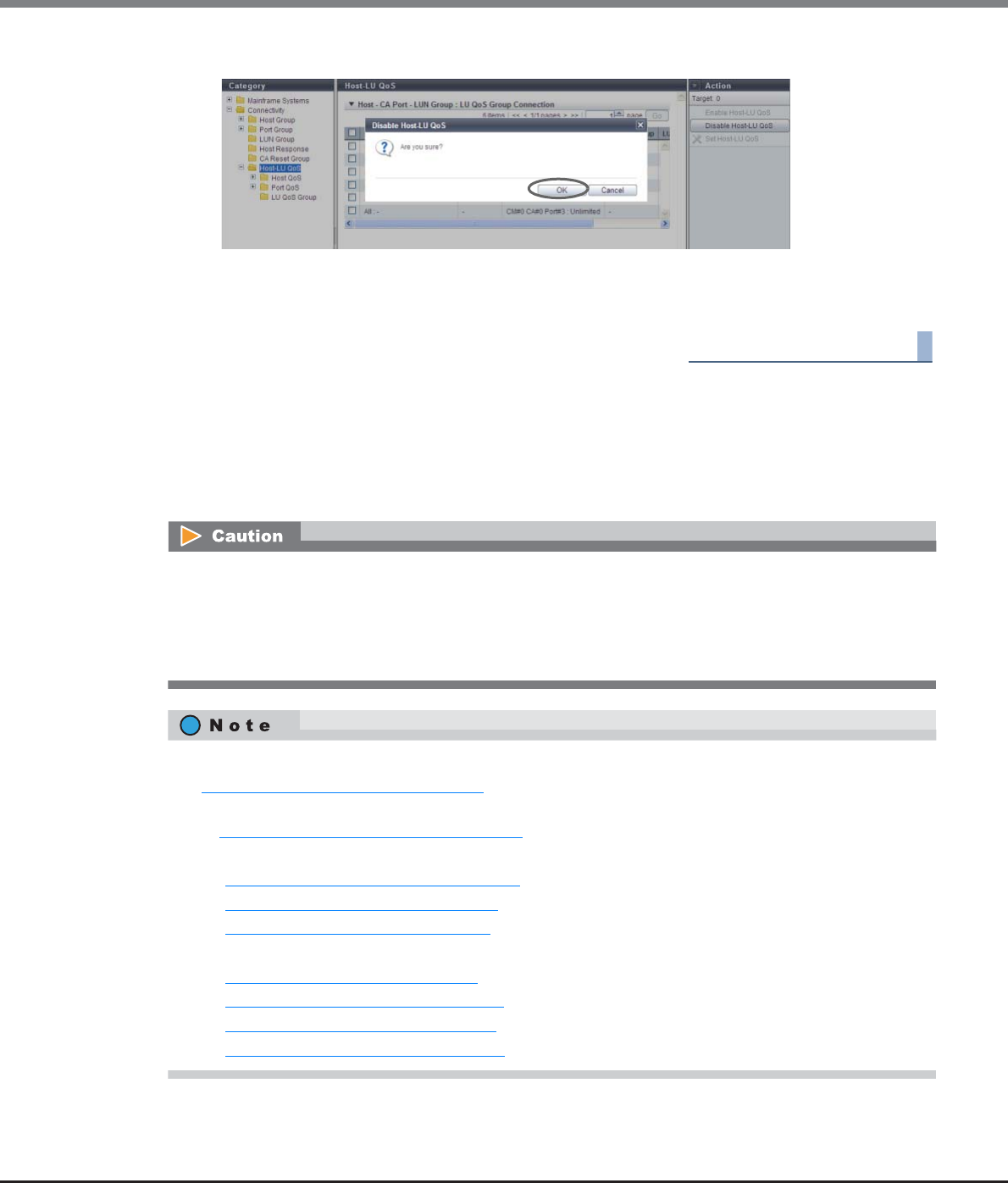
Chapter 9 Connectivity Management
9.2 Functions in the Action Area for Connectivity
ETERNUS Web GUI User’s Guide
Copyright 2013 FUJITSU LIMITED P2X0-1090-10ENZ0
599
2Click the [OK] button.
→The Host-LU QoS is disabled.
3Click the [Done] button to return to the [Host-LU QoS] screen.
End of procedure
9.2.7.2 Set Host-LU QoS
This function assigns a LU QoS group to a "Host - CA Port - LUN Group" on which the host affinity setting has
been configured. A bandwidth limit (the maximum performance limit) is configured to each host LUN in a LU
QoS group.
•This function can be used, irrespective of whether the Host-LU QoS has been enabled or disabled.
However, if the Host-LU QoS has been disabled, the host starts operating within the configured
bandwidth limit after the Host-LU QoS is enabled.
•When assigning a LU QoS group to the "Host - CA Port - LUN Group", check the number of host LUNs and
the current usage for the LUN group, and assign the appropriate LU QoS group.
•Before executing the [Set Host-LU QoS] function, configure a bandwidth limit on each host LUN. Refer to
"9.2.7.13 Add LU QoS Group" (page 616) for details.
•When checking the number of host LUNs and the bandwidth limit of each LUN in the LU QoS group, refer
to "9.2.7.15 Modify LU QoS Group" (page 618).
•Configure a bandwidth limit on each host. Refer to the following sections for details:
-"9.2.7.6 Set FC/FCoE Host QoS" (page 605)
-"9.2.7.7 Set iSCSI Host QoS" (page 607)
-"9.2.7.8 Set SAS Host QoS" (page 608)
•Configure the CA port bandwidth limit on each CA port. Refer to the following sections for details:
-"9.2.7.9 Set FC Port QoS" (page 610)
-"9.2.7.10 Set iSCSI Port QoS" (page 611)
-"9.2.7.11 Set SAS Port QoS" (page 613)
-"9.2.7.12 Set FCoE Port QoS" (page 614)
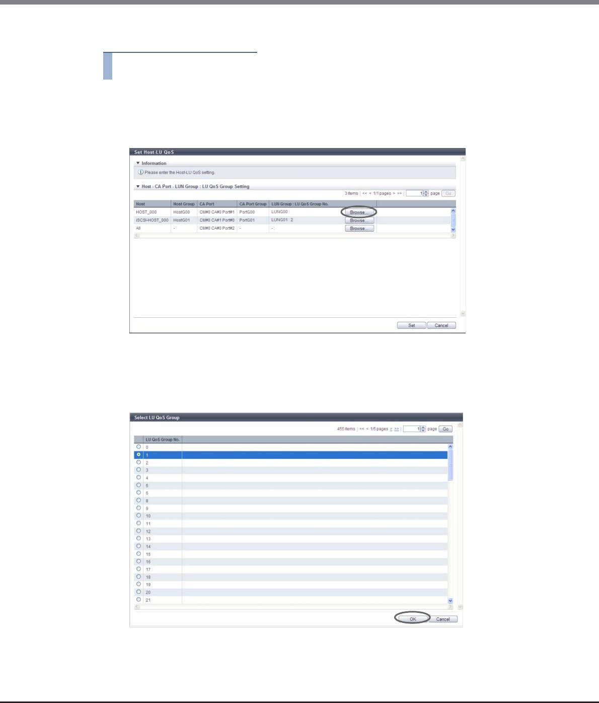
Chapter 9 Connectivity Management
9.2 Functions in the Action Area for Connectivity
ETERNUS Web GUI User’s Guide
Copyright 2013 FUJITSU LIMITED P2X0-1090-10ENZ0
600
The procedure to set the Host-LU QoS is as follows:
Procedure
1Select the "Host - CA Port - LUN Group" to set the Host-LU QoS (multiple selections can be
made) and click [Set Host-LU QoS] in [Action].
2Click the [Browse...] button in the "LUN Group: LUN QoS Group No." field.
→The [Select LU QoS Group] screen is displayed.
3Select a LUN QoS group, and click the [OK] button.
•Select LU QoS Group
Select the radio button for the LU QoS group number to assign to a "Host - CA Port - LUN Group".
→The display returns to the initial screen.
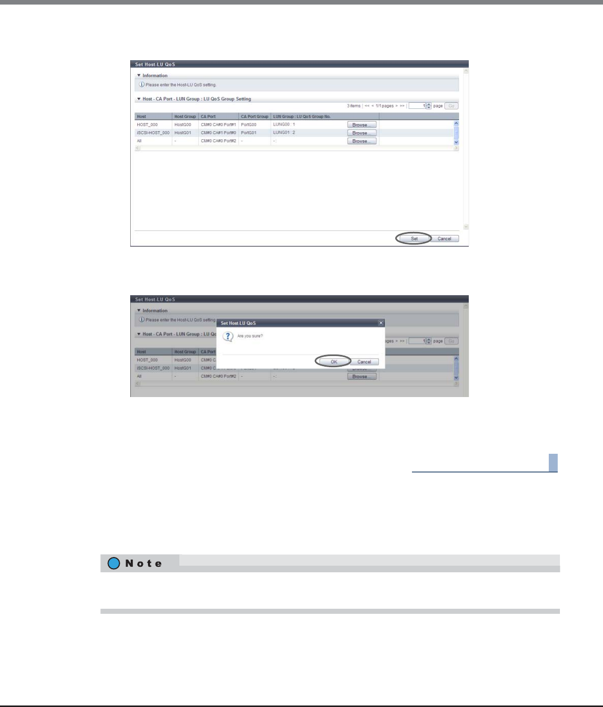
Chapter 9 Connectivity Management
9.2 Functions in the Action Area for Connectivity
ETERNUS Web GUI User’s Guide
Copyright 2013 FUJITSU LIMITED P2X0-1090-10ENZ0
601
4After confirming the association between "Host", "CA Port", and "LUN Group : LU QoS Group
No.", click the [Set] button.
→A confirmation screen appears.
5Click the [OK] button.
→The Host-LU QoS setting starts.
6Click the [Done] button to return to the [Host-LU QoS] screen.
End of procedure
9.2.7.3 Release Host-LU QoS
This function releases the LU QoS groups that are assigned to a "Host - CA Port - LUN Group" with host affinity
settings.
If a "Host - CA Port - LUN Group" for which a LU QoS group is not assigned is selected, the [Release Host-LU
QoS] function cannot be used.
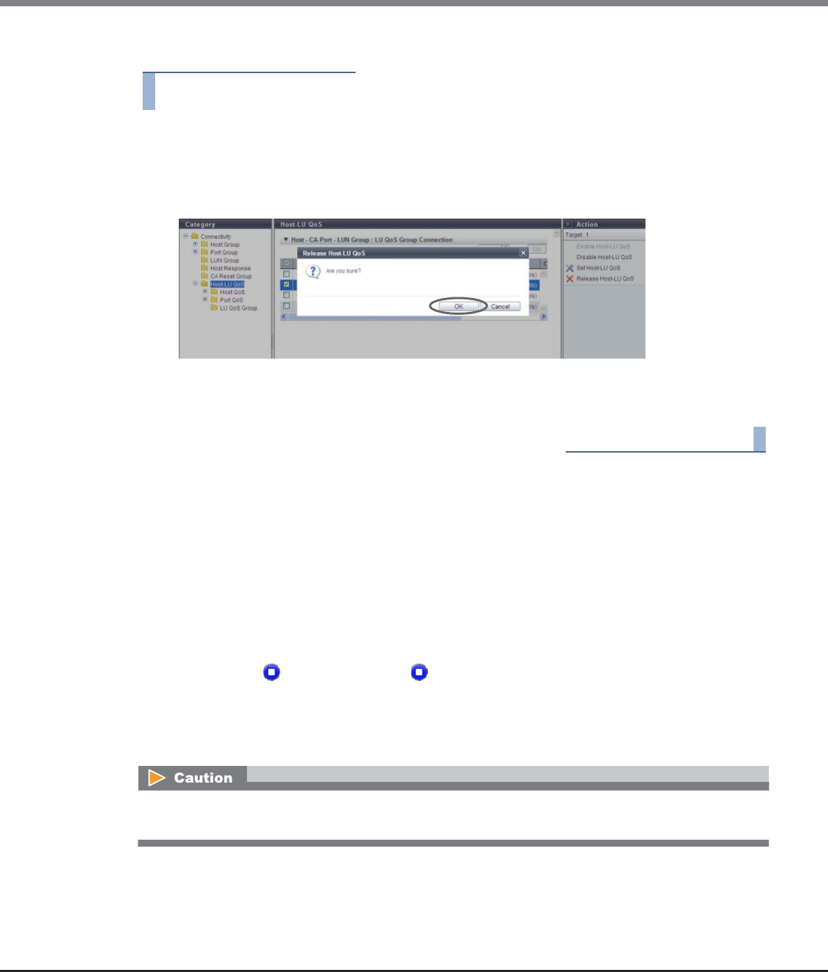
Chapter 9 Connectivity Management
9.2 Functions in the Action Area for Connectivity
ETERNUS Web GUI User’s Guide
Copyright 2013 FUJITSU LIMITED P2X0-1090-10ENZ0
602
The procedure to release Host-LU QoS is as follows:
Procedure
1Select the "Host - CA Port - LUN Group" for which the Host-LU QoS is to be released (multiple
selections can be made) and click [Release Host-LU QoS] in [Action].
→A confirmation screen appears.
2Click the [OK] button.
→Releasing of the Host-LU QoS starts.
3Click the [Done] button to return to the [Host-LU QoS] screen.
End of procedure
9.2.7.4 Start Host-LU QoS Performance Monitoring
This function starts performance monitoring of Host-LU QoS.
Target ports for monitoring performance
•When this function is selected in the [Host-LU QoS] screen, performance monitoring of Host-LU QoS is
started for the following ports:
-All FC, iSCSI, SAS, and FCoE ports that are installed in the ETERNUS DX Disk storage system
-Ports which port mode are "CA" or "CA/RA"
-Ports without " Undefined" status or " Undefined (Error)" status
•When this function is selected in each [Port QoS] screen for FC, iSCSI, SAS, or FCoE, performance monitoring
of Host-LU QoS is started for the following ports:
-Ports that are selected in the [Port QoS] screen for each host interface (multiple selections can be
made)
When this function is started after port selection, ports with different host interfaces cannot be selected at
the same time.

Chapter 9 Connectivity Management
9.2 Functions in the Action Area for Connectivity
ETERNUS Web GUI User’s Guide
Copyright 2013 FUJITSU LIMITED P2X0-1090-10ENZ0
603
The procedure to start the Host-LU QoS performance monitoring is as follows:
■When this function is selected in the [Host-LU QoS] screen
Procedure
1Click [Start Perfmon] in [Action].
→A confirmation screen appears.
2Click the [OK] button.
→Acquisition of Host-LU QoS performance information starts.
3Click the [Done] button to return to the [Host-LU QoS] screen.
End of procedure
■When this function is selected in the [Port QoS] screen for each host interface
Procedure
1Select the port to start the Host-LU QoS performance monitoring for (multiple selections can
be made) and click [Start Perfmon] in [Action].
→A confirmation screen appears.
•This function can start performance monitoring regardless of whether the Host-LU QoS mode is enabled
or disabled.
•Performance monitoring can be started even if other performance information is being obtained. If
performance monitoring is restarted, the performance information that is already obtained is deleted
and the collection of performance starts again. The start time is changed to the last time when
performance monitoring was restarted.
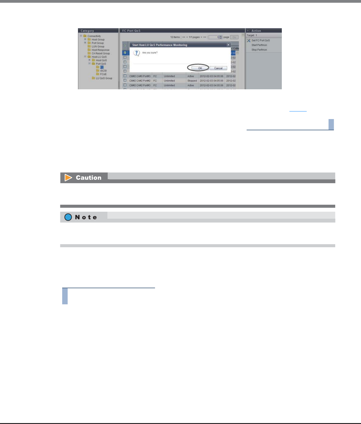
Chapter 9 Connectivity Management
9.2 Functions in the Action Area for Connectivity
ETERNUS Web GUI User’s Guide
Copyright 2013 FUJITSU LIMITED P2X0-1090-10ENZ0
604
2Click the [OK] button.
→Acquisition of Host-LU QoS performance information starts.
3Click the [Done] button to return to the screen when starting this function in Step 1.
End of procedure
9.2.7.5 Stop Host-LU QoS Performance Monitoring
This function starts performance monitoring of Host-LU QoS.
The procedure to stop the Host-LU QoS performance monitoring is as follows:
■When this function is selected in the [Host-LU QoS] screen
Procedure
1Click [Stop Perfmon] in [Action].
→A confirmation screen appears.
When this function is started after port selection, ports with different host interfaces cannot be selected at
the same time.
This function can stop performance monitoring regardless of whether the Host-LU QoS mode is enabled or
disabled.
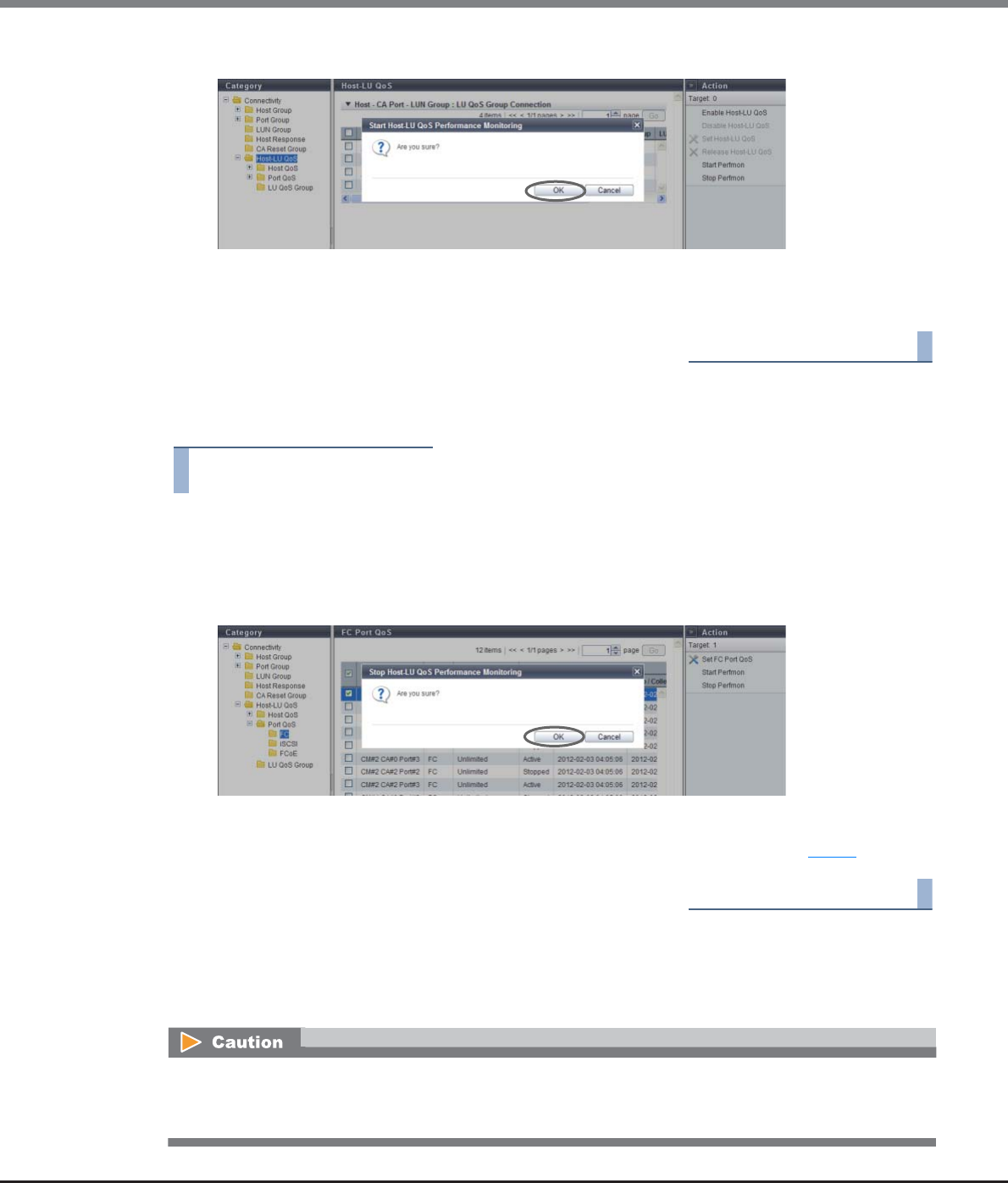
Chapter 9 Connectivity Management
9.2 Functions in the Action Area for Connectivity
ETERNUS Web GUI User’s Guide
Copyright 2013 FUJITSU LIMITED P2X0-1090-10ENZ0
605
2Click the [OK] button.
→Acquisition of Host-LU QoS performance information stops.
3Click the [Done] button to return to the [Host-LU QoS] screen.
End of procedure
■When this function is selected in the [Port QoS] screen for each host interface
Procedure
1Select the port to stop the Host-LU QoS performance monitoring for (multiple selections can
be made) and click [Stop Perfmon] in [Action].
→A confirmation screen appears.
2Click the [OK] button.
→Acquisition of Host-LU QoS performance information stops.
3Click the [Done] button to return to the screen when starting this function in Step 1.
End of procedure
9.2.7.6 Set FC/FCoE Host QoS
This function configures the bandwidth limit (the maximum performance limit) of the FC/FCoE host.
This function can be used, irrespective of whether the Host-LU QoS has been enabled or disabled. However, if
the Host-LU QoS has been disabled, the host starts operating within the configured bandwidth limit after the
Host-LU QoS is enabled.
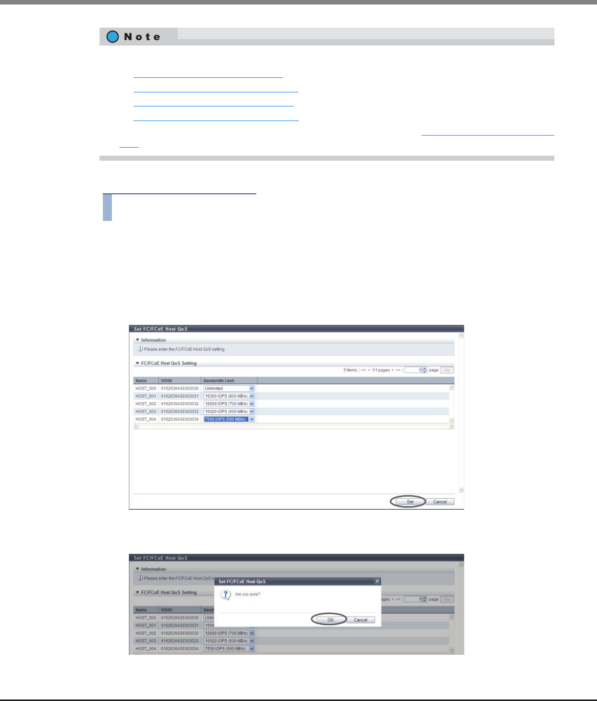
Chapter 9 Connectivity Management
9.2 Functions in the Action Area for Connectivity
ETERNUS Web GUI User’s Guide
Copyright 2013 FUJITSU LIMITED P2X0-1090-10ENZ0
606
The procedure to set the FC/FCoE host QoS is as follows:
Procedure
1Select the FC/FCoE host to set the bandwidth limit (multiple selections can be made), and
click [Set FC/FCoE Host QoS] in [Action].
2Select the FC/FCoE host bandwidth limit, and click the [Set] button.
•Bandwidth Limit
Select the maximum performance in IOPS (throughput value). If the bandwidth limit is not applied,
select "Unlimited".
→A confirmation screen appears.
3Click the [OK] button.
→The FC/FCoE host QoS setting starts.
•Configure the port bandwidth limit on each port. Refer to the following sections for details:
-"9.2.7.9 Set FC Port QoS" (page 610)
-"9.2.7.10 Set iSCSI Port QoS" (page 611)
-"9.2.7.11 Set SAS Port QoS" (page 613)
-"9.2.7.12 Set FCoE Port QoS" (page 614)
•The LUN bandwidth limit can be configured in the LU QoS group. Refer to "9.2.7.2 Set Host-LU QoS" (page
599) for details.
Chapter 9 Connectivity Management
9.2 Functions in the Action Area for Connectivity
ETERNUS Web GUI User’s Guide
Copyright 2013 FUJITSU LIMITED P2X0-1090-10ENZ0
607
4Click the [Done] button to return to the [FC/FCoE Host QoS] screen.
End of procedure
9.2.7.7 Set iSCSI Host QoS
This function configures the bandwidth limit (the maximum performance limit) of the iSCSI host.
The procedure to set the iSCSI host QoS is as follows:
Procedure
1Select the iSCSI host to set the bandwidth limit (multiple selections can be made), and click
[Set iSCSI Host QoS] in [Action].
This function can be used, irrespective of whether the Host-LU QoS has been enabled or disabled. However, if
the Host-LU QoS has been disabled, the host starts operating within the configured bandwidth limit after the
Host-LU QoS is enabled.
•Configure the port bandwidth limit on each port. Refer to the following sections for details:
-"9.2.7.9 Set FC Port QoS" (page 610)
-"9.2.7.10 Set iSCSI Port QoS" (page 611)
-"9.2.7.11 Set SAS Port QoS" (page 613)
-"9.2.7.12 Set FCoE Port QoS" (page 614)
•The LUN bandwidth limit can be configured in the LU QoS group. Refer to "9.2.7.2 Set Host-LU QoS" (page
599) for details.
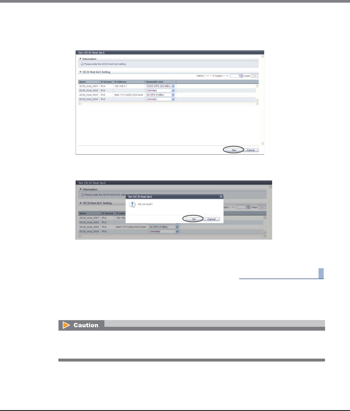
Chapter 9 Connectivity Management
9.2 Functions in the Action Area for Connectivity
ETERNUS Web GUI User’s Guide
Copyright 2013 FUJITSU LIMITED P2X0-1090-10ENZ0
608
2Select the iSCSI host bandwidth limit, and click the [Set] button.
•Bandwidth Limit
Select the maximum performance in IOPS (throughput value). If the bandwidth limit is not applied,
select "Unlimited".
→A confirmation screen appears.
3Click the [OK] button.
→The iSCSI host QoS setting starts.
4Click the [Done] button to return to the [iSCSI Host QoS] screen.
End of procedure
9.2.7.8 Set SAS Host QoS
This function configures the bandwidth limit (the maximum performance limit) of the SAS host.
This function can be used, irrespective of whether the Host-LU QoS has been enabled or disabled. However, if
the Host-LU QoS has been disabled, the host starts operating within the configured bandwidth limit after the
Host-LU QoS is enabled.
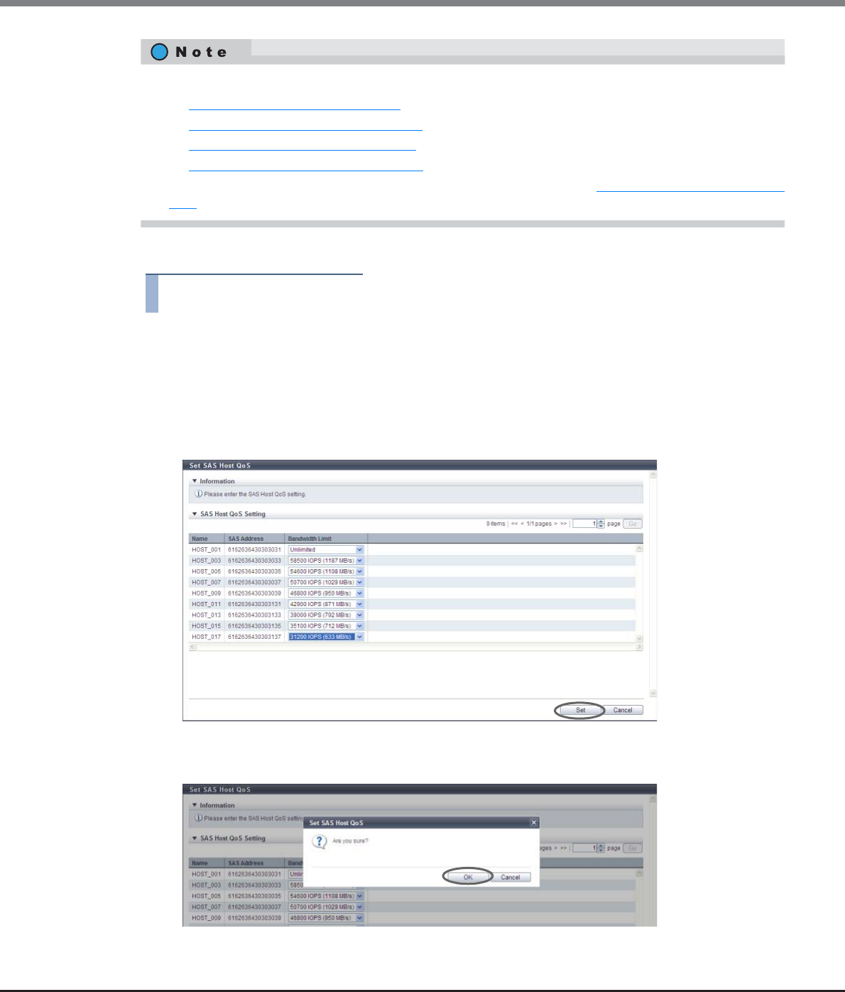
Chapter 9 Connectivity Management
9.2 Functions in the Action Area for Connectivity
ETERNUS Web GUI User’s Guide
Copyright 2013 FUJITSU LIMITED P2X0-1090-10ENZ0
609
The procedure to set the SAS host QoS is as follows:
Procedure
1Select the SAS host to set the bandwidth limit (multiple selections can be made), and click
[Set SAS Host QoS] in [Action].
2Select the SAS host bandwidth limit, and click the [Set] button.
•Bandwidth Limit
Select the maximum performance in IOPS (throughput value). If the bandwidth limit is not applied,
select "Unlimited".
→A confirmation screen appears.
3Click the [OK] button.
→The SAS host QoS setting starts.
•Configure the port bandwidth limit on each port. Refer to the following sections for details:
-"9.2.7.9 Set FC Port QoS" (page 610)
-"9.2.7.10 Set iSCSI Port QoS" (page 611)
-"9.2.7.11 Set SAS Port QoS" (page 613)
-"9.2.7.12 Set FCoE Port QoS" (page 614)
•The LUN bandwidth limit can be configured in the LU QoS group. Refer to "9.2.7.2 Set Host-LU QoS" (page
599) for details.
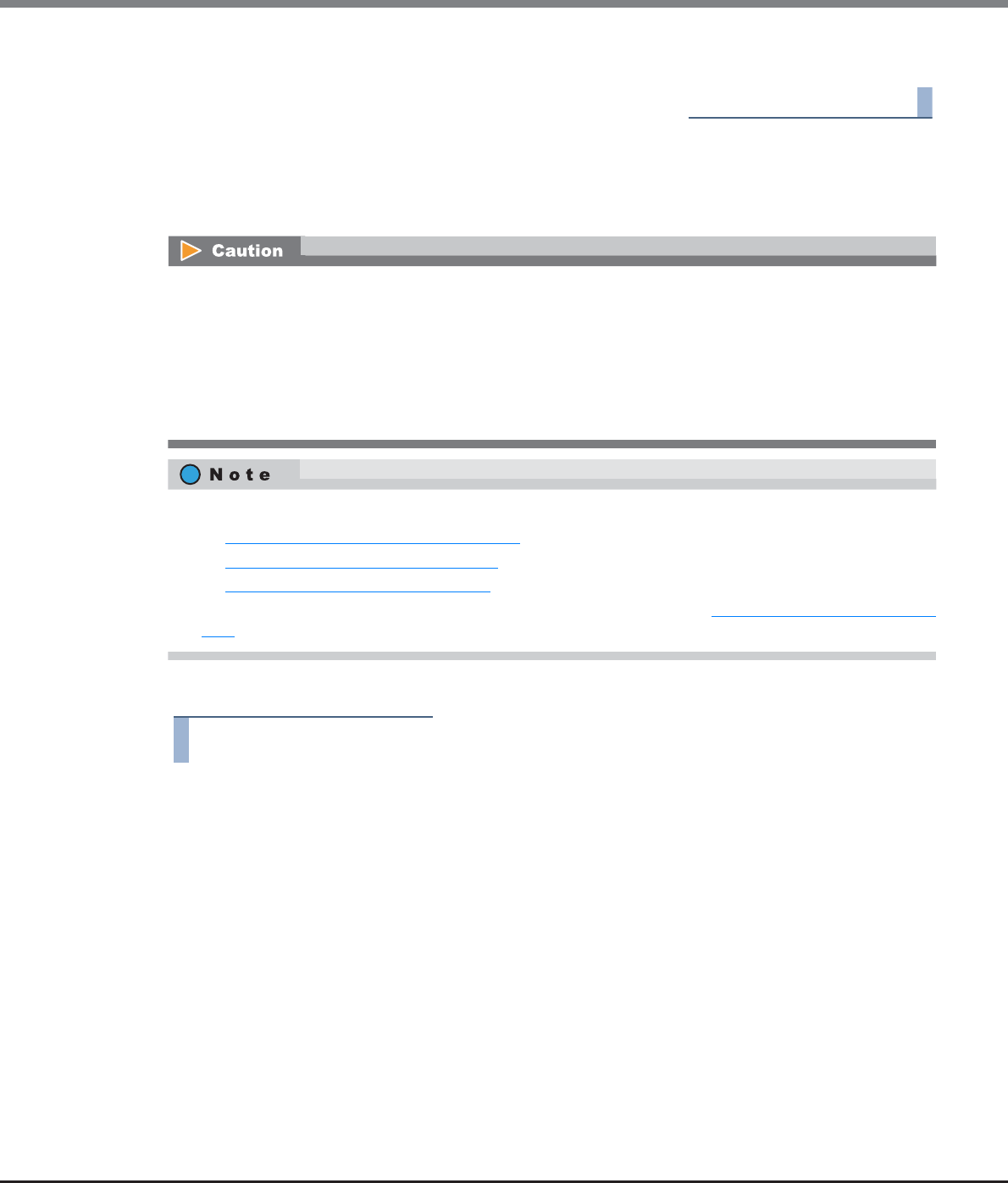
Chapter 9 Connectivity Management
9.2 Functions in the Action Area for Connectivity
ETERNUS Web GUI User’s Guide
Copyright 2013 FUJITSU LIMITED P2X0-1090-10ENZ0
610
4Click the [Done] button to return to the [SAS Host QoS] screen.
End of procedure
9.2.7.9 Set FC Port QoS
This function specifies the bandwidth limit (maximum performance limit) for the FC port.
The procedure to set the FC port QoS is as follows:
Procedure
1Select the FC port to set the bandwidth limit (multiple selections can be made), and click
[Set FC Port QoS] in [Action].
•The bandwidth limit can be configured only for the ports in the port mode of "CA" or "CA/RA". For the ports
in the port mode of "RA" and "Initiator", the bandwidth limit cannot be specified.
•If the port mode has been changed from "CA" or "CA/RA" to "RA" or "Initiator", the bandwidth limit returns
to the default value.
•This function can be used, irrespective of whether the Host-LU QoS is enabled or disabled. However, if the
Host-LU QoS has been disabled, the host starts operating within the configured bandwidth limit after the
Host-LU QoS is enabled.
•Configure the port bandwidth limit on each host. Refer to the following sections for details:
-"9.2.7.6 Set FC/FCoE Host QoS" (page 605)
-"9.2.7.7 Set iSCSI Host QoS" (page 607)
-"9.2.7.8 Set SAS Host QoS" (page 608)
•The LUN bandwidth limit can be configured in the LU QoS group. Refer to "9.2.7.2 Set Host-LU QoS" (page
599) for details.
Chapter 9 Connectivity Management
9.2 Functions in the Action Area for Connectivity
ETERNUS Web GUI User’s Guide
Copyright 2013 FUJITSU LIMITED P2X0-1090-10ENZ0
611
2Select the FC port bandwidth limit, and click the [Set] button.
•Bandwidth Limit
Select the maximum performance in IOPS (throughput value). If the bandwidth limit is not applied,
select "Unlimited".
→A confirmation screen appears.
3Click the [OK] button.
→The FC port QoS setting starts.
4Click the [Done] button to return to the [FC Port QoS] screen.
End of procedure
9.2.7.10 Set iSCSI Port QoS
This function specifies the bandwidth limit (maximum performance limit) for the iSCSI port.
•The bandwidth limit can be configured only for the ports in the port mode of "CA" or "CA/RA". For the ports
in the port mode of "RA", the bandwidth limit cannot be specified.
•If the port mode has been changed from "CA" or "CA/RA" to "RA", the bandwidth limit returns to the
default value.
•This function can be used, irrespective of whether the Host-LU QoS is enabled or disabled. However, if the
Host-LU QoS has been disabled, the host starts operating within the configured bandwidth limit after the
Host-LU QoS is enabled.
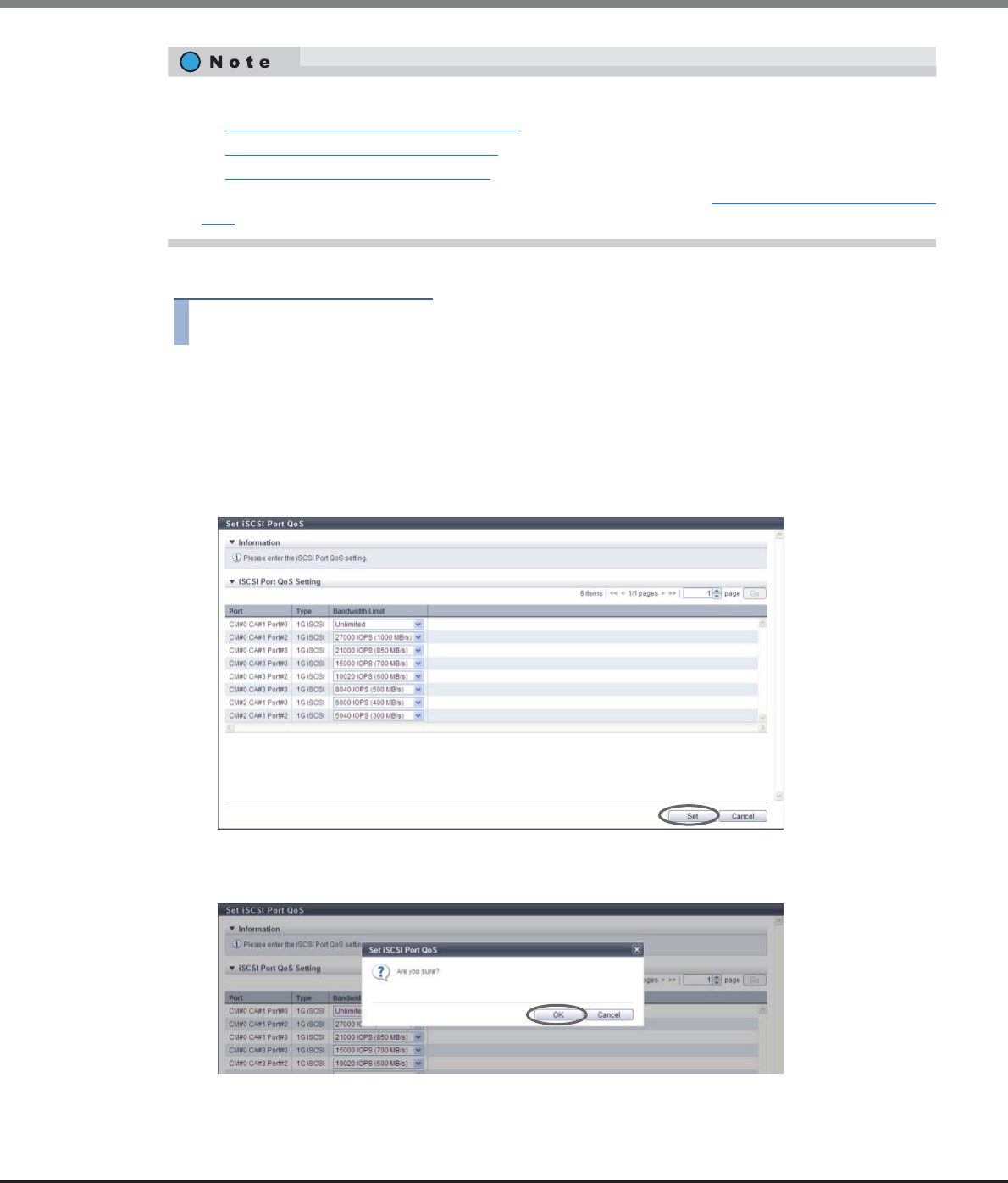
Chapter 9 Connectivity Management
9.2 Functions in the Action Area for Connectivity
ETERNUS Web GUI User’s Guide
Copyright 2013 FUJITSU LIMITED P2X0-1090-10ENZ0
612
The procedure to set the iSCSI port QoS is as follows:
Procedure
1Select the iSCSI port to set the bandwidth limit (multiple selections can be made), and click
[Set iSCSI Port QoS] in [Action].
2Select the iSCSI port bandwidth limit, and click the [Set] button.
•Bandwidth Limit
Select the maximum performance in IOPS (throughput value). If the bandwidth limit is not applied,
select "Unlimited".
→A confirmation screen appears.
3Click the [OK] button.
→The iSCSI port QoS setting starts.
•Configure the port bandwidth limit on each host. Refer to the following sections for details:
-"9.2.7.6 Set FC/FCoE Host QoS" (page 605)
-"9.2.7.7 Set iSCSI Host QoS" (page 607)
-"9.2.7.8 Set SAS Host QoS" (page 608)
•The LUN bandwidth limit can be configured in the LU QoS group. Refer to "9.2.7.2 Set Host-LU QoS" (page
599) for details.
Chapter 9 Connectivity Management
9.2 Functions in the Action Area for Connectivity
ETERNUS Web GUI User’s Guide
Copyright 2013 FUJITSU LIMITED P2X0-1090-10ENZ0
613
4Click the [Done] button to return to the [iSCSI Port QoS] screen.
End of procedure
9.2.7.11 Set SAS Port QoS
This function specifies the bandwidth limit (maximum performance limit) for the SAS port.
The procedure to set the SAS port QoS is as follows:
Procedure
1Select the SAS port to set the bandwidth limit (multiple selections can be made), and click
[Set SAS Port QoS] in [Action].
This function can be used, irrespective of whether the Host-LU QoS is enabled or disabled. However, if the
Host-LU QoS has been disabled, the host starts operating within the configured bandwidth limit after the
Host-LU QoS is enabled.
•Configure the port bandwidth limit on each host. Refer to the following sections for details:
-"9.2.7.6 Set FC/FCoE Host QoS" (page 605)
-"9.2.7.7 Set iSCSI Host QoS" (page 607)
-"9.2.7.8 Set SAS Host QoS" (page 608)
•The LUN bandwidth limit can be configured in the LU QoS group. Refer to "9.2.7.2 Set Host-LU QoS" (page
599) for details.
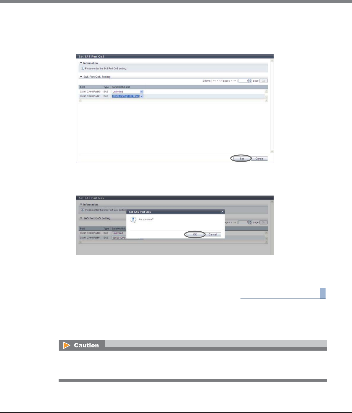
Chapter 9 Connectivity Management
9.2 Functions in the Action Area for Connectivity
ETERNUS Web GUI User’s Guide
Copyright 2013 FUJITSU LIMITED P2X0-1090-10ENZ0
614
2Select the SAS port bandwidth limit, and click the [Set] button.
•Bandwidth Limit
Select the maximum performance in IOPS (throughput value). If the bandwidth limit is not applied,
select "Unlimited".
→A confirmation screen appears.
3Click the [OK] button.
→The SAS port QoS setting starts.
4Click the [Done] button to return to the [SAS Port QoS] screen.
End of procedure
9.2.7.12 Set FCoE Port QoS
This function specifies the bandwidth limit (maximum performance limit) for the FCoE port.
This function can be used, irrespective of whether the Host-LU QoS is enabled or disabled. However, if the
Host-LU QoS has been disabled, the host starts operating within the configured bandwidth limit after the
Host-LU QoS is enabled.
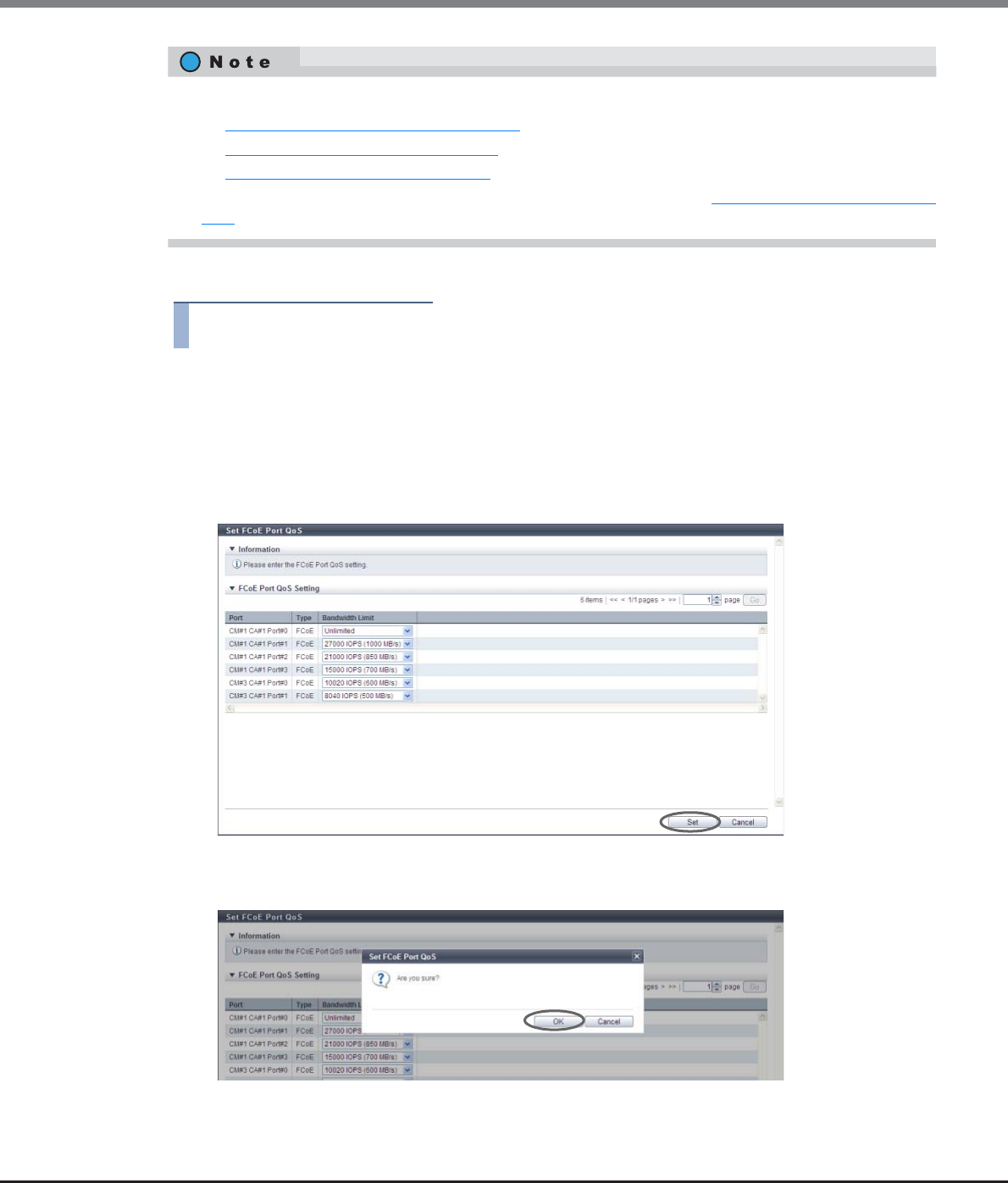
Chapter 9 Connectivity Management
9.2 Functions in the Action Area for Connectivity
ETERNUS Web GUI User’s Guide
Copyright 2013 FUJITSU LIMITED P2X0-1090-10ENZ0
615
The procedure to set the FCoE port QoS is as follows:
Procedure
1Select the FCoE port to set the bandwidth limit (multiple selections can be made), and click
[Set FCoE Port QoS] in [Action].
2Select the FCoE port bandwidth limit, and click the [Set] button.
•Bandwidth Limit
Select the maximum performance in IOPS (throughput value). If the bandwidth limit is not applied,
select "Unlimited".
→A confirmation screen appears.
3Click the [OK] button.
→The FCoE port QoS setting starts.
•Configure the port bandwidth limit on each host. Refer to the following sections for details:
-"9.2.7.6 Set FC/FCoE Host QoS" (page 605)
-"9.2.7.7 Set iSCSI Host QoS" (page 607)
-"9.2.7.8 Set SAS Host QoS" (page 608)
•The LUN bandwidth limit can be configured in the LU QoS group. Refer to "9.2.7.2 Set Host-LU QoS" (page
599) for details.
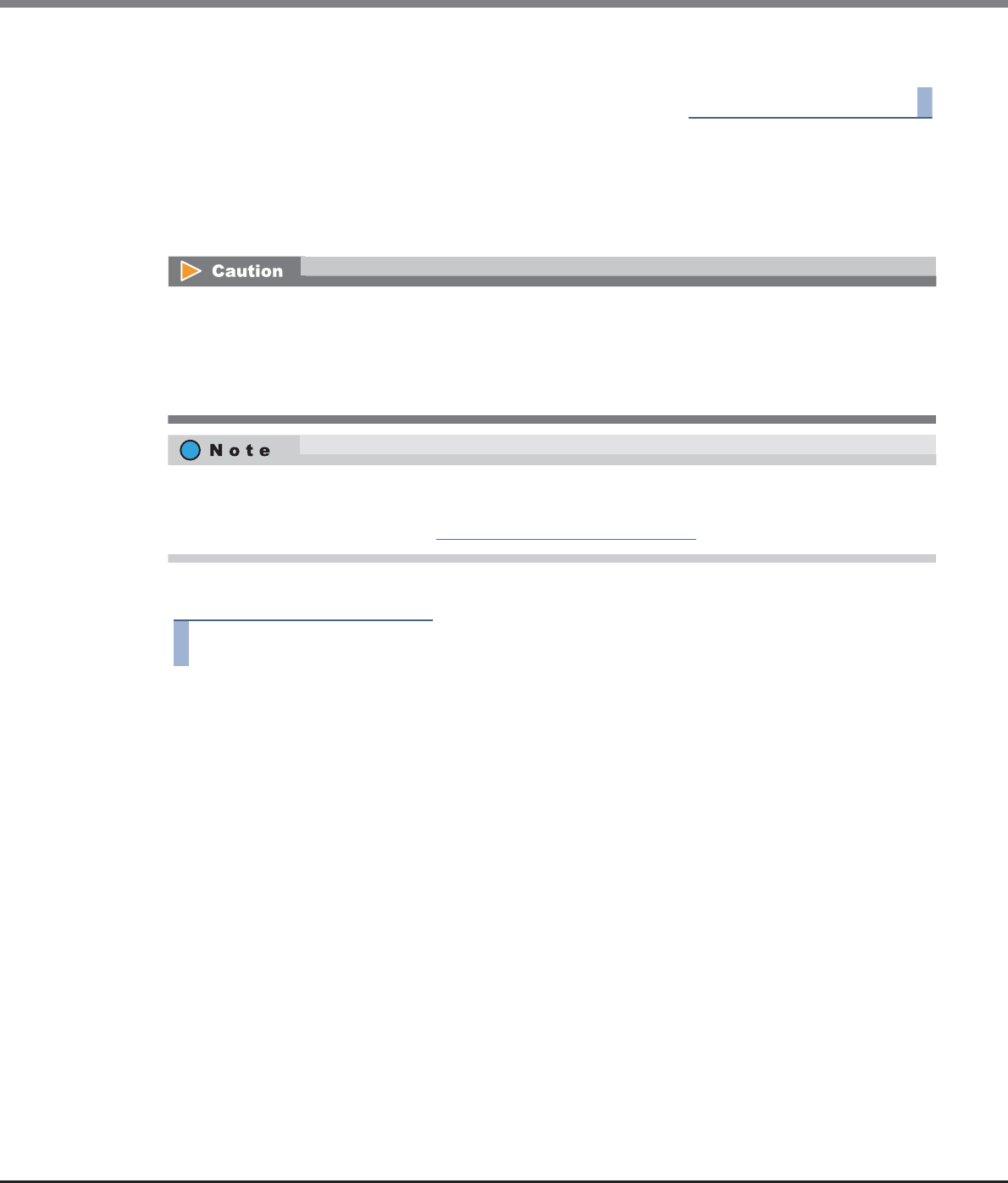
Chapter 9 Connectivity Management
9.2 Functions in the Action Area for Connectivity
ETERNUS Web GUI User’s Guide
Copyright 2013 FUJITSU LIMITED P2X0-1090-10ENZ0
616
4Click the [Done] button to return to the [FCoE Port QoS] screen.
End of procedure
9.2.7.13 Add LU QoS Group
This function adds LU QoS groups with bandwidth limit (the maximum performance limit) settings to each
host LUN.
The procedure to set the bandwidth limit for host LUN is as follows:
Procedure
1Click [Add LU QoS Group] in [Action].
•Use one LU QoS group number per 512 Host LUNs as an internal resource. When there are LU QoS groups
with a bandwidth limit other than "Unlimited" from Host LUN#512 onward, the maximum number of QoS
groups cannot be created.
•Host-LU QoS does not support from LUN#1024 onward. Even if volumes are mapped from LUN#1024
onward, only up to 1024 LUNs (LUN#0 - LUN#1023) can be specified for the bandwidth limit.
•This function can be used, irrespective of whether the Host-LU QoS is enabled or disabled.
•By assigning an LU QoS group to a LUN group with the host affinity settings, the bandwidth limit can be
configured for each LUN. Refer to "9.2.7.2 Set Host-LU QoS" (page 599) for details.
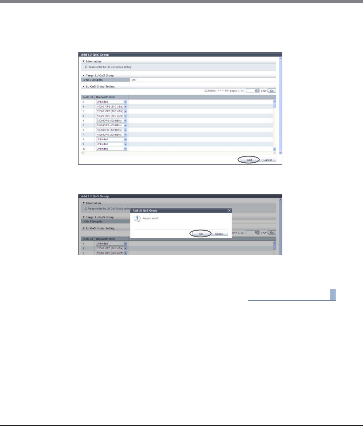
Chapter 9 Connectivity Management
9.2 Functions in the Action Area for Connectivity
ETERNUS Web GUI User’s Guide
Copyright 2013 FUJITSU LIMITED P2X0-1090-10ENZ0
617
2Select a host LUN bandwidth limit, and click the [Add] button.
•Bandwidth Limit
Select the maximum performance in IOPS (throughput value). If the bandwidth limit is not applied,
select "Unlimited".
→A confirmation screen appears.
3Click the [OK] button.
→Addition of LU QoS group starts.
4Click the [Done] button to return to the [LU QoS Group] screen.
End of procedure
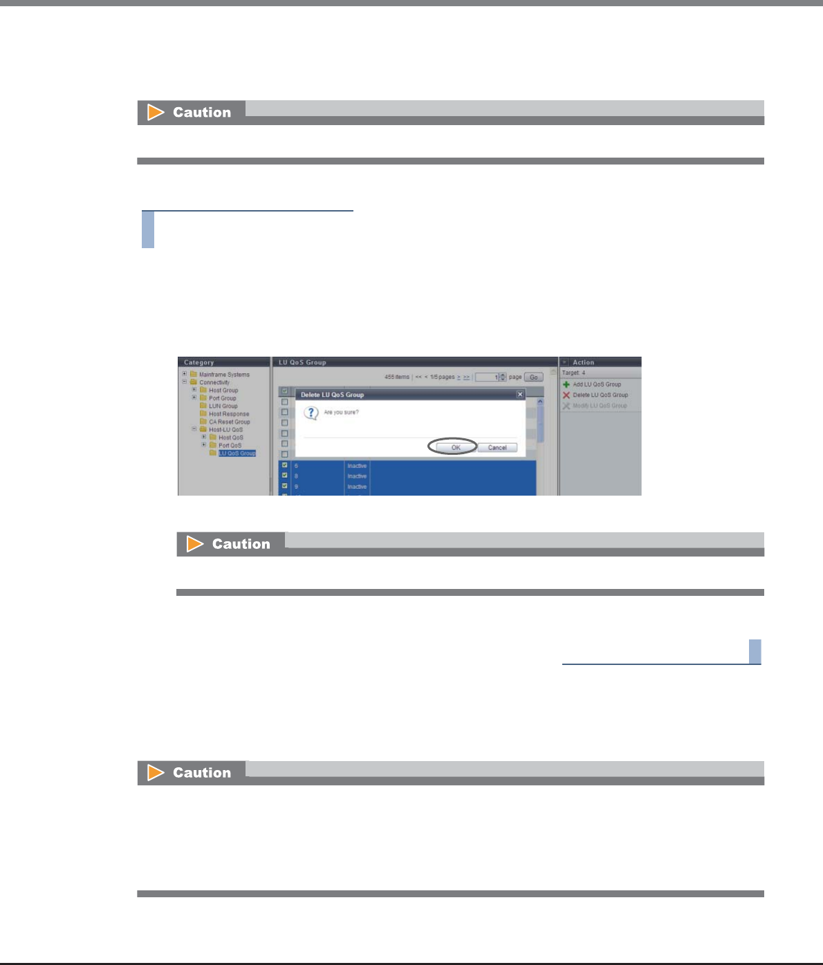
Chapter 9 Connectivity Management
9.2 Functions in the Action Area for Connectivity
ETERNUS Web GUI User’s Guide
Copyright 2013 FUJITSU LIMITED P2X0-1090-10ENZ0
618
9.2.7.14 Delete LU QoS Group
This function deletes LU QoS groups.
The procedure to delete LU QoS groups is as follows:
Procedure
1Select the LU QoS group that is to be deleted (multiple selections can be made) and click
[Delete LU QoS Group] in [Action].
→A confirmation screen appears.
2Click the [OK] button.
→Deletion of LU QoS group starts.
3Click the [Done] button to return to the [LU QoS Group] screen.
End of procedure
9.2.7.15 Modify LU QoS Group
This function changes the bandwidth limit (the maximum performance limit) settings of each host LUN.
An LU QoS group in the "Active" status cannot be deleted.
If the selected LU QoS group does not exist, an error screen appears.
•Use one LU QoS group number per 512 Host LUNs as an internal resource. When there are LU QoS groups
with a bandwidth limit other than "Unlimited" from Host LUN#512 onward, the maximum number of QoS
groups cannot be created.
•Host-LU QoS does not support from LUN#1024 onward. Even if volumes are mapped from LUN#1024
onward, only up to 1024 LUNs (LUN#0 - LUN#1023) can be specified for the bandwidth limit.
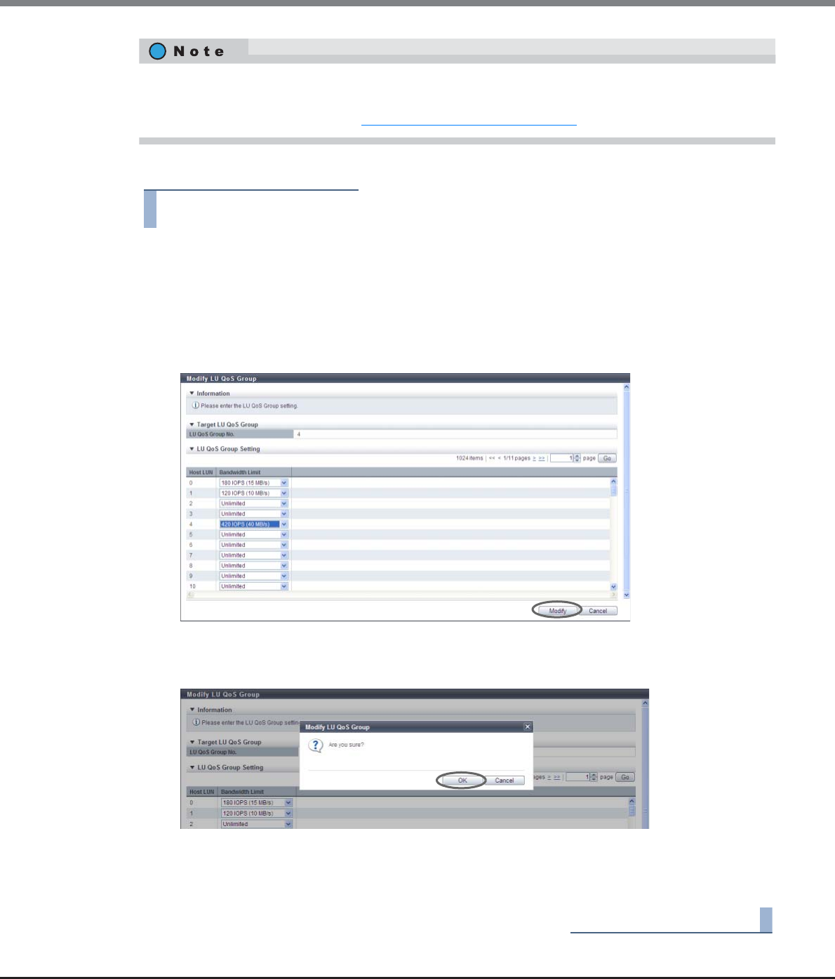
Chapter 9 Connectivity Management
9.2 Functions in the Action Area for Connectivity
ETERNUS Web GUI User’s Guide
Copyright 2013 FUJITSU LIMITED P2X0-1090-10ENZ0
619
The procedure to change the bandwidth limit for host LUN is as follows:
Procedure
1Select the LU QoS group to modify the bandwidth limit, and click [Modify LU QoS Group] in
[Action].
2Select a host LUN bandwidth limit, and click the [Modify] button.
•Bandwidth Limit
Select the maximum performance in IOPS (throughput value). If the bandwidth limit is not applied,
select "Unlimited".
→A confirmation screen appears.
3Click the [OK] button.
→Modification of LU QoS group setting starts.
4Click the [Done] button to return to the [LU QoS Group] screen.
End of procedure
•This function can be used, irrespective of whether the Host-LU QoS is enabled or disabled.
•By assigning an LU QoS group to a LUN group with the host affinity settings, the bandwidth limit can be
configured for each LUN. Refer to "9.2.7.2 Set Host-LU QoS" (page 599) for details.
ETERNUS Web GUI User’s Guide
Copyright 2013 FUJITSU LIMITED P2X0-1090-10ENZ0
620
Chapter 10
Component Management
This chapter describes component management.
10.1 Component Status
Component status displays the status information of volumes.
Component status screens can be displayed by clicking the following categories:
Component status screen Category
Storage (Basic Information) Storage system name
Controller Enclosure Controller Enclosure
Controller Module Controller Module
Controller Module (Performance) Performance
All Channel Adapters Channel Adapters
Channel Adapter Ports (Performance) Performance
Frontend Router Frontend Router
Backend Router Backend Router
Service Controller Service Controller
Power Supply Unit (CE) Power Supply Unit
Battery Battery
FAN Unit FAN Unit
Operation Panel Operation Panel
Drive Enclosure Drive Enclosure
I/O Module I/O Module
Port Error Statistics Error Statistics
Power Supply Unit (DE) Power Supply Unit
Disks Disks
Disks (Performance) Performance
Disk Error Statistics Error Statistics

Chapter 10 Component Management
10.1 Component Status
ETERNUS Web GUI User’s Guide
Copyright 2013 FUJITSU LIMITED P2X0-1090-10ENZ0
621
Detailed information of the components can be displayed from the following screens:
•Controller Module Detail
•Channel Adapter Detail
•Frontend Router Detail
•Backend Router Detail
•BRT Expander Detail
•Service Controller Detail
•PSU/CPSU (CE) Detail
•Battery Backup Unit Detail
•FAN Unit Detail
•Drive Enclosure Detail
•I/O Module Detail
•Power Supply Unit (DE) Detail
•Disks Detail
•QSFP Cable Detail
•Boot and Utility Device Detail
•CM Module Management Controller Detail
•Port Detail
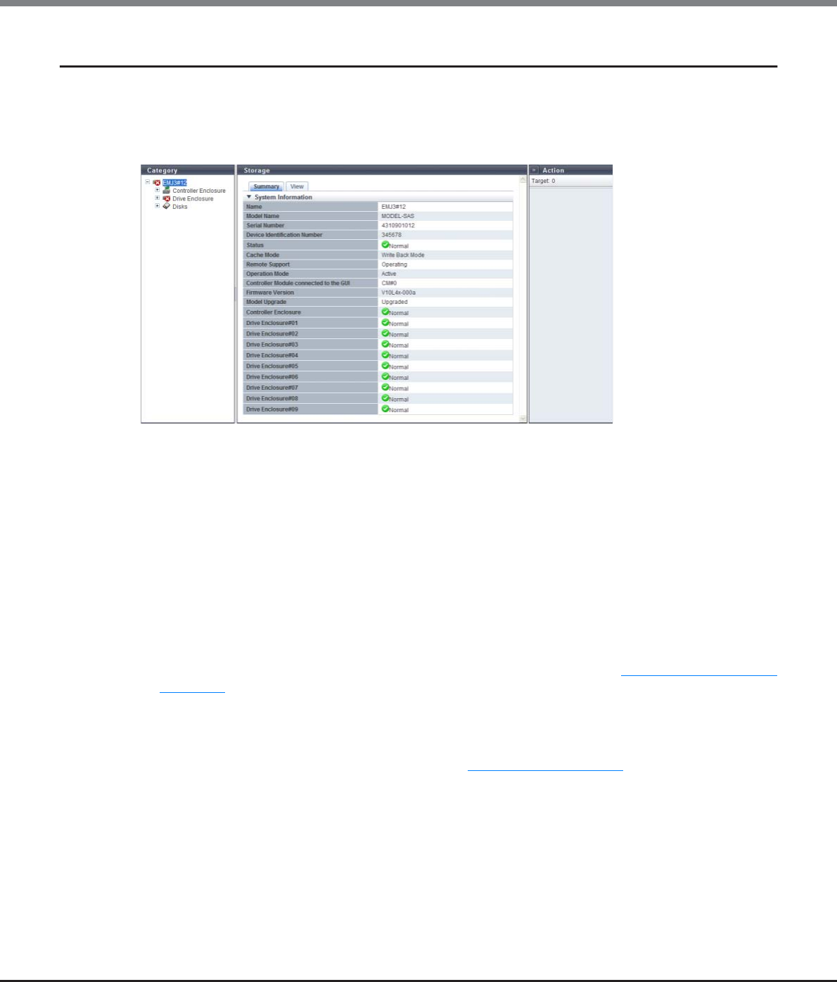
Chapter 10 Component Management
10.1 Component Status
ETERNUS Web GUI User’s Guide
Copyright 2013 FUJITSU LIMITED P2X0-1090-10ENZ0
622
10.1.1 Storage (Basic Information)
The general information for the ETERNUS DX Disk storage system is displayed.
■Summary
The following items are displayed in the Main area:
•Name
The name of the ETERNUS DX Disk storage system is displayed.
•Model Name
The model name of the ETERNUS DX Disk storage system is displayed.
•Serial Number
The serial number of the ETERNUS DX Disk storage system is displayed.
•Device Identification Number
The identification number of the ETERNUS DX Disk storage system is displayed.
•Status
The general status of the ETERNUS DX Disk storage system is displayed. Refer to "B.1 Device General Status"
(page 972) for details.
•Cache Mode
The current status and the factor of the cache are displayed. The normal status is "Write Back Mode". When
Write Through status is displayed, the factors that caused Write Through status are also displayed in
brackets. Refer to the description for "Cache Mode" in "1.5.1 Overview" (page 21) for details about each sta-
tus.
-Write Back
-Write Through (Pinned Data)
-Write Through (Battery)
-Write Through (Maintenance)
-Write Through (1CM)

Chapter 10 Component Management
10.1 Component Status
ETERNUS Web GUI User’s Guide
Copyright 2013 FUJITSU LIMITED P2X0-1090-10ENZ0
623
•Battery
The battery charge level is displayed.
When the battery charge level is 90% or more, "Full Charge" is displayed. When the battery charge level is
less than 90%, "xx%" is displayed. This item is displayed only when using the ETERNUS DX410 S2/DX440 S2
or the ETERNUS DX8100 S2/DX8700 S2.
•Remote Support
The Remote Support (REMCS) status is displayed.
-Operating
The Remote Support is operating.
-Maintenance in Progress
The ETERNUS DX Disk storage system is under maintenance.
-Stopped
The Remote Support is stopped.
-"-" (hyphen)
The Remote Support is not configured.
•Operation Mode
The operation mode is displayed.
-Active
The ETERNUS DX Disk storage system is operating.
-Maintenance
The ETERNUS DX Disk storage system is under maintenance.
•Controller Module connected to the GUI
The CM that is connected to GUI is displayed.
•Firmware Version
The current controller firmware version is displayed.
•Model Upgrade
Whether the model upgrade is possible or not is displayed. When this item is not displayed, the model
upgrade is not possible.
-Not Upgraded
A model upgrade has not been performed yet.
-Upgraded
A model upgrade has been performed.
•Controller Enclosure
The status of the Controller Enclosure (CE) is displayed. Refer to "B.5 Component Status" (page 977) for
details. This item is displayed only when using the ETERNUS DX80 S2/DX90 S2, the ETERNUS DX410 S2/
DX440 S2, or the ETERNUS DX8100 S2.
•Drive Enclosure#xx
The status of the drive enclosure (DE) is displayed. "#xx" indicates the DE number. Refer to "B.5 Component
Status" (page 977) for details. This item is displayed only when using the ETERNUS DX80 S2/DX90 S2, the
ETERNUS DX410 S2/DX440 S2, or the ETERNUS DX8100 S2.
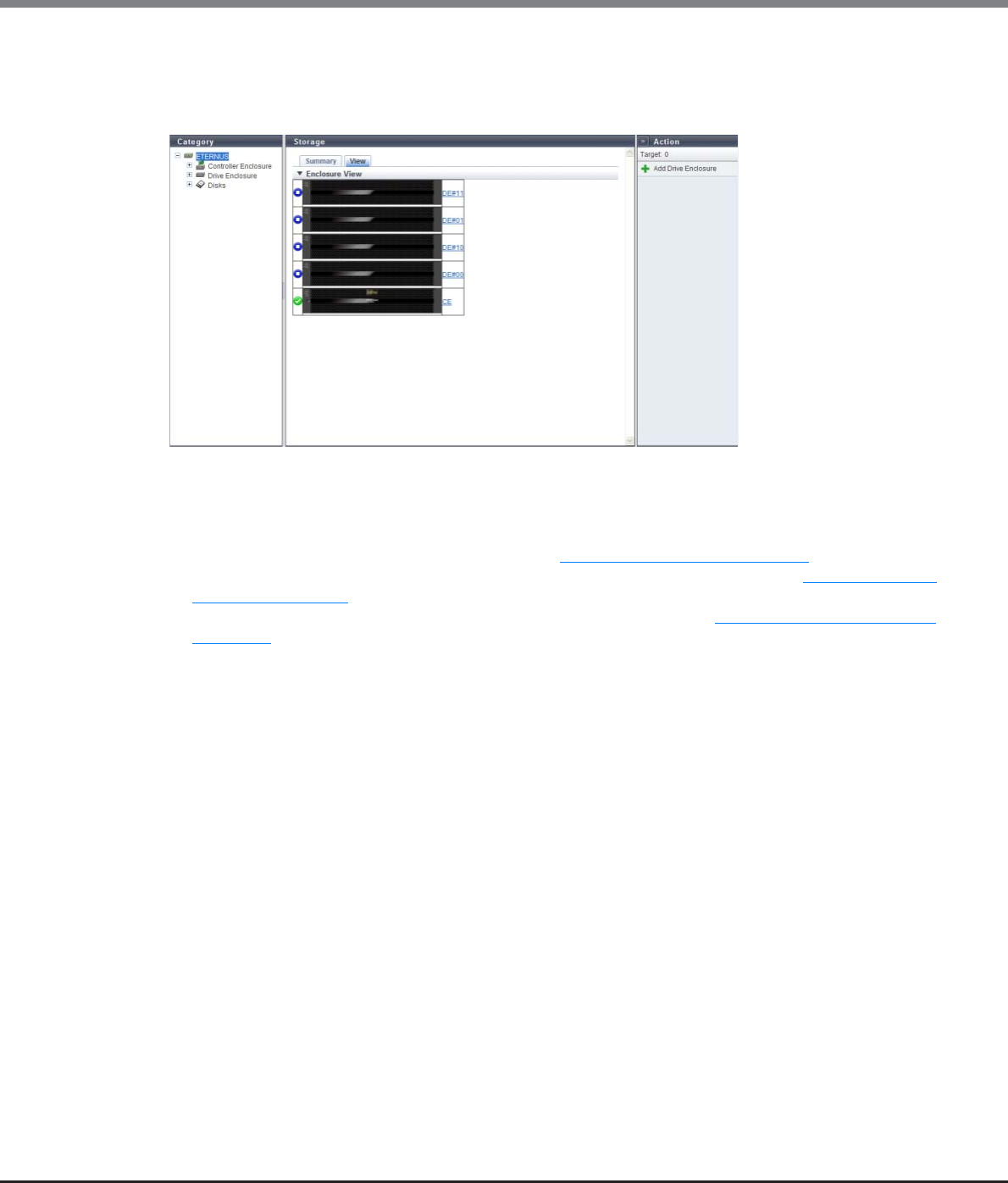
Chapter 10 Component Management
10.1 Component Status
ETERNUS Web GUI User’s Guide
Copyright 2013 FUJITSU LIMITED P2X0-1090-10ENZ0
624
■View
This screen is displayed only when using the ETERNUS DX80 S2/DX90 S2, the ETERNUS DX410 S2/DX440 S2, or
the ETERNUS DX8100 S2.
The following items are displayed in the Main area:
•Device image
The front view of the enclosures that are installed in the ETERNUS DX Disk storage system is displayed. The
enclosure statuses are displayed with icons. Refer to "B.5 Component Status" (page 977) for details.
By clicking the [CE] link, the [Controller Enclosure] screen is displayed. Refer to "10.1.2 Controller
Enclosure" (page 625) for display items.
By clicking the [DE] link, the [Drive Enclosure] screen is displayed. Refer to "10.1.14 Drive Enclosure Detail"
(page 669) for display items.

Chapter 10 Component Management
10.1 Component Status
ETERNUS Web GUI User’s Guide
Copyright 2013 FUJITSU LIMITED P2X0-1090-10ENZ0
625
10.1.2 Controller Enclosure
Information of the CE is displayed.
■Summary
The following items are displayed in the Main area:
•Serial Number
The serial number of the CE is displayed.
•Other Information
Additional information for the CE is displayed.
•Location
The installation location of the thermal sensor is displayed.
-Intake Temp
-Exhaust Temp
•Status
The status of thermal sensor is displayed.
•Error Code
The error code for thermal sensor is displayed.
•Sensor 1
The internal temperature of CM#0 is displayed in Celsius (C) and in Fahrenheit (F).
If the thermal information is not available due to problem such as a sensor failure, a "-" (hyphen) is
displayed. This item is displayed only when using the ETERNUS DX80 S2/DX90 S2, the ETERNUS DX410 S2/
DX440 S2, or the ETERNUS DX8100 S2.
•Sensor 2
The internal temperature of CM#1 is displayed in Celsius (C) and in Fahrenheit (F).
If the thermal information is not available due to problem such as a sensor failure, a "-" (hyphen) is
displayed. This item is displayed only when using the ETERNUS DX80 S2/DX90 S2, the ETERNUS DX410 S2/
DX440 S2, or the ETERNUS DX8100 S2.
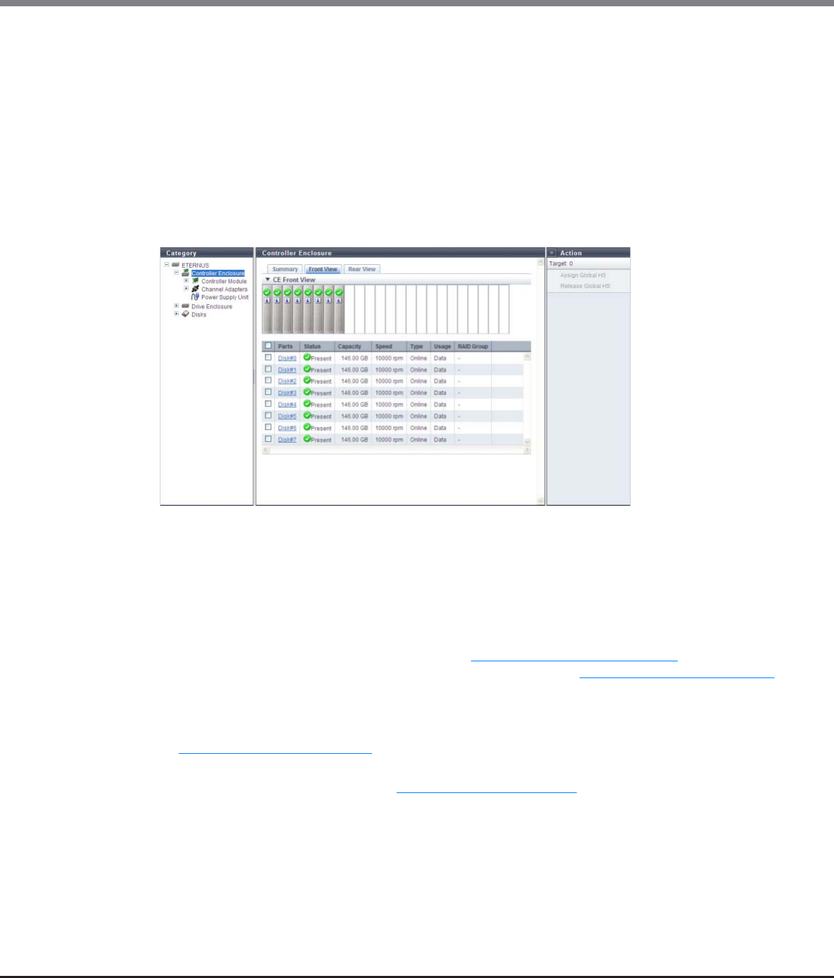
Chapter 10 Component Management
10.1 Component Status
ETERNUS Web GUI User’s Guide
Copyright 2013 FUJITSU LIMITED P2X0-1090-10ENZ0
626
•Sensor
The temperature obtained from the SVC for which thermal monitoring is being performed is displayed in
Celsius (C) and in Fahrenheit (F).
If the thermal information is not available due to problem such as a sensor failure, a "-" (hyphen) is
displayed. This item is displayed only when using the ETERNUS DX8700 S2.
■Front View
The image that is displayed in this screen varies depending on the storage system model.
●For ETERNUS DX80 S2/DX90 S2
The following items are displayed in the Main area:
-Device image
The front view of the CE that is installed in the ETERNUS DX Disk storage system is displayed.
•For 2.5-inch models: 24 (24 drives are lined up horizontally)
•For 3.5-inch models: 12 (3 drives are lined up vertically and 4 drives are lined up horizontally)
•When no drives are installed: Blank
The drive status is displayed with an icon. Refer to "B.5 Component Status" (page 977) for details.
By clicking the drive image, the [Disks] screen is displayed. Refer to "10.1.17 Disks Detail" (page 675)
for display items.
-Parts
The drive number is displayed. By clicking the drive image, the [Disks] screen is displayed. Refer to
"10.1.17 Disks Detail" (page 675) for display items.
-Status
The drive status is displayed. Refer to "B.5.1 Drive Status" (page 978) for details.
-Capacity
The capacity of the drive is displayed.
-Speed
The drive speed is displayed. For SSDs, a "-" (hyphen) is displayed.
•15000 rpm
•10000 rpm
•7200 rpm
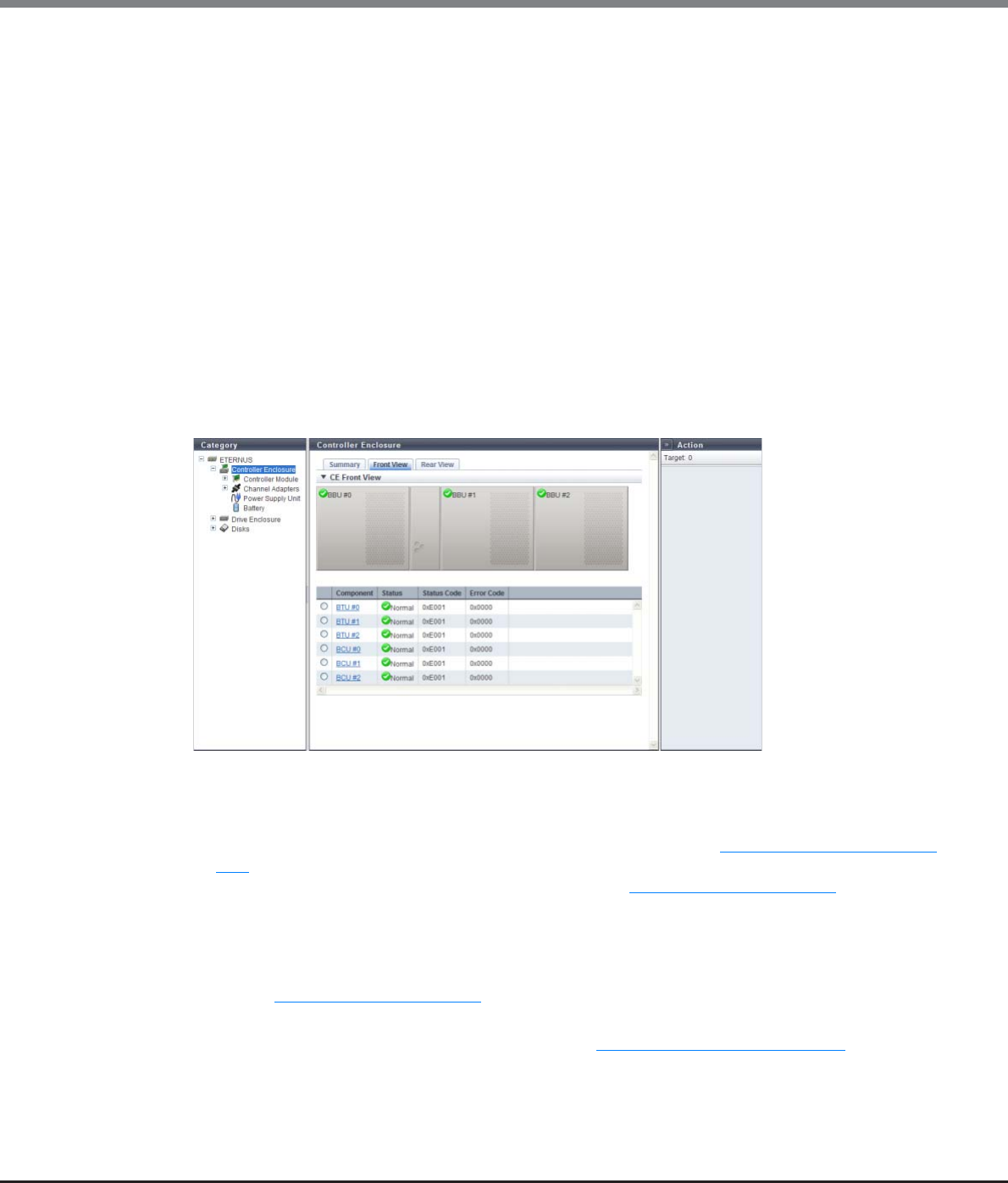
Chapter 10 Component Management
10.1 Component Status
ETERNUS Web GUI User’s Guide
Copyright 2013 FUJITSU LIMITED P2X0-1090-10ENZ0
627
-Type
The drive type is displayed.
•For SAS disks: Online
•For Nearline SAS disks: Nearline
•For SSDs: SSD
•For SEDs: SED
-Usage
The usage of the drive is displayed.
•For a drive that is used for user data or an unused drive: Data
•For a drive that is registered as a Global Hot Spare: Global Hot Spare
•For a drive that is registered as a Dedicated Hot Spare: Dedicated Hot Spare
-RAID Group
If the drive is registered in a RAID group, the RAID group name to which the drive belongs is displayed.
By clicking this item, the [RAID Group Detail] screen is displayed.
●For ETERNUS DX410 S2/DX440 S2 and ETERNUS DX8100 S2
The following items are displayed in the Main area:
-Device image
The front view of the CE that is installed in the ETERNUS DX Disk storage system is displayed.
The Battery Backup Unit (BBU) status is displayed with icons. Refer to "B.5 Component Status" (page
977) for details.
By clicking the BBU, the [BTU] screen is displayed. Refer to "10.1.2.9 Battery" (page 642) for details.
-Component
The Battery Unit (BTU) number or the Battery Charger Unit (BCU) number is displayed.
By clicking the BTU number, the [BTU Detail] screen is displayed.
By clicking the BCU number, the [BCU Detail] screen is displayed.
Refer to "10.1.2.9 Battery" (page 642) for details.
-Status
The BTU status or the BCU status is displayed. Refer to "B.5 Component Status" (page 977) for details.
-Status Code
The status code of BTU or BCU is displayed.
-Error Code
The error code of BTU or BCU is displayed.
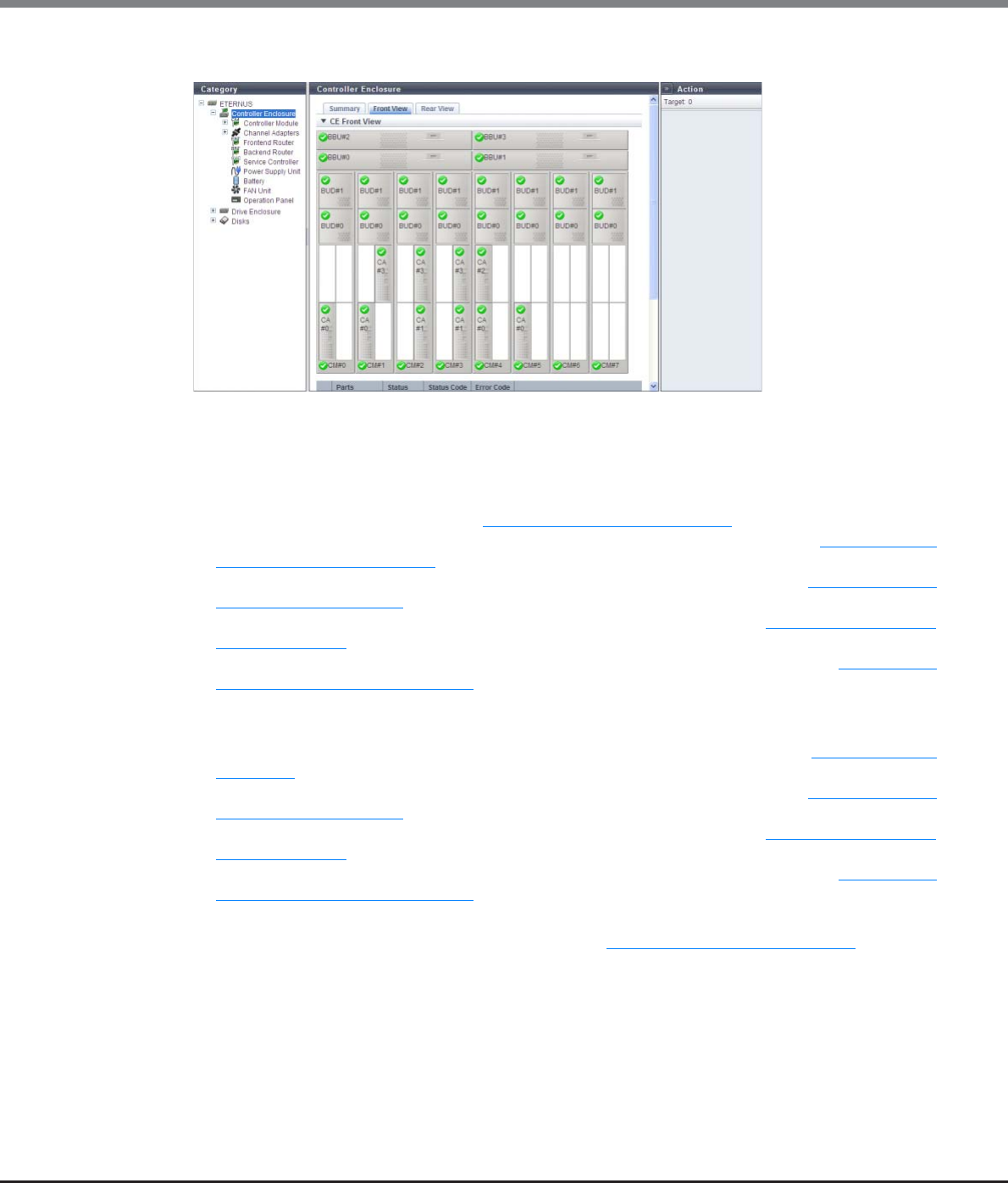
Chapter 10 Component Management
10.1 Component Status
ETERNUS Web GUI User’s Guide
Copyright 2013 FUJITSU LIMITED P2X0-1090-10ENZ0
628
●For ETERNUS DX8700 S2
The following items are displayed in the Main area:
-Device image
The front view of the CE that is installed in the ETERNUS DX Disk storage system is displayed.
The statuses of the BBU, Controller Module (CM), Channel Adapter (CA), and Boot and Utility Device
(BUD) are indicated by icons. Refer to "B.5 Component Status" (page 977) for details.
By clicking the BBU number, the [Battery Backup Unit] screen is displayed. Refer to "10.1.12 Battery
Backup Unit Detail" (page 666) for details.
By clicking the CM number, the [Controller Module] screen is displayed. Refer to "10.1.5 Controller
Module Detail" (page 652) for details.
By clicking the CA number, the [Channel Adapter] screen is displayed. Refer to "10.1.6 Channel Adapter
Detail" (page 655) for details.
By clicking the BUD number, the [Boot and Utility Device] screen is displayed. Refer to "10.1.19 Boot
and Utility Device Detail" (page 679) for details.
-Component
The BBU number, CM number, CA number, or BUD number is displayed.
By clicking the BBU number, the [Battery Backup Unit] screen is displayed. Refer to "10.1.2.9 Battery"
(page 642) for details.
By clicking the CM number, the [Controller Module] screen is displayed. Refer to "10.1.5 Controller
Module Detail" (page 652) for details.
By clicking the CA number, the [Channel Adapter] screen is displayed. Refer to "10.1.6 Channel Adapter
Detail" (page 655) for details.
By clicking the BUD number, the [Boot and Utility Device] screen is displayed. Refer to "10.1.19 Boot
and Utility Device Detail" (page 679) for details.
-Status
The status of BBU, CM, CA, or BUD is displayed. Refer to "B.5 Component Status" (page 977) for details.
-Status Code
The status code of BBU, CM, CA, or BUD is displayed.
-Error Code
The error code of BBU, CM, CA, or BUD is displayed.
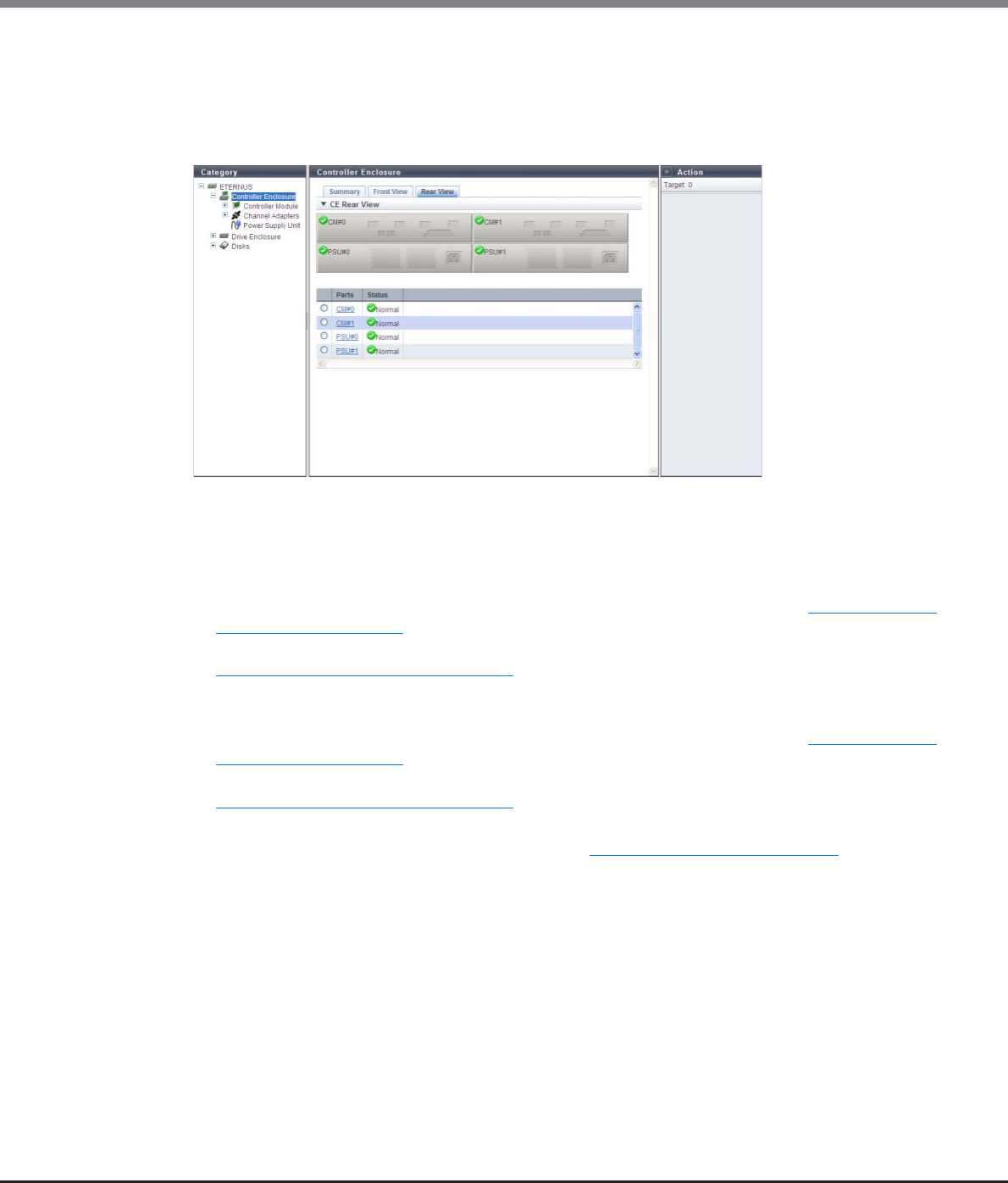
Chapter 10 Component Management
10.1 Component Status
ETERNUS Web GUI User’s Guide
Copyright 2013 FUJITSU LIMITED P2X0-1090-10ENZ0
629
■Rear View
The image that is displayed in this screen varies depending on the storage system model.
●For ETERNUS DX80 S2/DX90 S2
The following items are displayed in the Main area:
-Device image
The rear view of the CE that is installed in the ETERNUS DX Disk storage system is displayed.
The CM status and the Power Supply Unit (PSU) status are displayed with icons.
By clicking the CM number, the [Controller Module] screen is displayed. Refer to "10.1.5 Controller
Module Detail" (page 652) for display items.
By clicking the PSU number, the [Controller Enclosure Power Supply Unit] screen is displayed. Refer to
"10.1.11 PSU/CPSU (CE) Detail" (page 664) for display items.
-Parts
The CM number or the PSU number is displayed.
By clicking the CM number, the [Controller Module] screen is displayed. Refer to "10.1.5 Controller
Module Detail" (page 652) for display items.
By clicking the PSU number, the [Controller Enclosure Power Supply Unit] screen is displayed. Refer to
"10.1.11 PSU/CPSU (CE) Detail" (page 664) for display items.
-Status
The CM status or the PSU status is displayed. Refer to "B.5 Component Status" (page 977) for details.
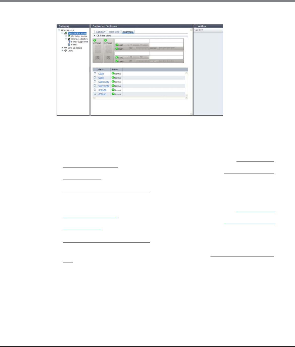
Chapter 10 Component Management
10.1 Component Status
ETERNUS Web GUI User’s Guide
Copyright 2013 FUJITSU LIMITED P2X0-1090-10ENZ0
630
●For ETERNUS DX410 S2/DX440 S2
The following items are displayed in the Main area:
-Device image
The rear view of the CE that is installed in the ETERNUS DX Disk storage system is displayed.
The CM status, the CA status, and the Controller enclosure Power Supply Unit (CPSU) status are
displayed with icons.
By clicking the CM number, the [Controller Module] screen is displayed. Refer to "10.1.5 Controller
Module Detail" (page 652) for display items.
By clicking the CA number, the [Channel Adapter] screen is displayed. Refer to "10.1.6 Channel Adapter
Detail" (page 655) for display items.
By clicking the CPSU number, the [Controller Enclosure Power Supply Unit] screen is displayed. Refer to
"10.1.11 PSU/CPSU (CE) Detail" (page 664) for display items.
-Parts
The CM number, the CA number, or the CPSU number is displayed.
By clicking the CM number, the [Controller Module] screen is displayed. Refer to "10.1.5 Controller
Module Detail" (page 652) for display items.
By clicking the CA number, the [Channel Adapter] screen is displayed. Refer to "10.1.6 Channel Adapter
Detail" (page 655) for display items.
By clicking the CPSU number, the [Controller Enclosure Power Supply Unit] screen is displayed. Refer to
"10.1.11 PSU/CPSU (CE) Detail" (page 664) for display items.
-Status
The CM status, the CA status, or the CPSU status is displayed. Refer to "B.5 Component Status" (page
977) for details.
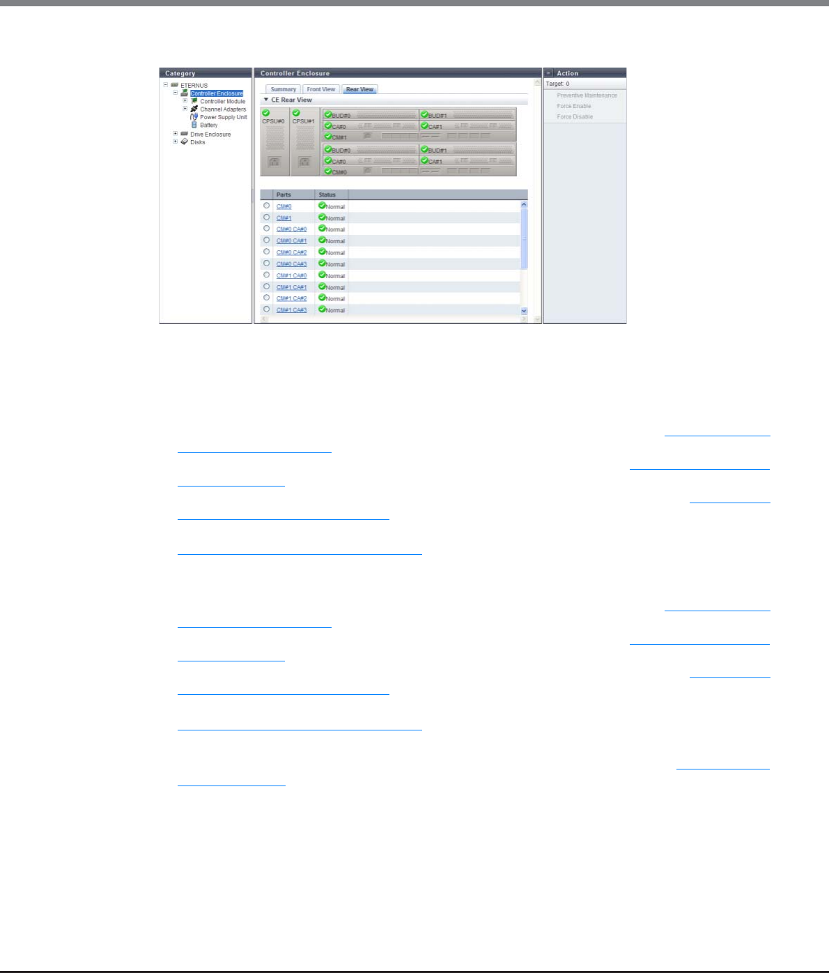
Chapter 10 Component Management
10.1 Component Status
ETERNUS Web GUI User’s Guide
Copyright 2013 FUJITSU LIMITED P2X0-1090-10ENZ0
631
●For ETERNUS DX8100 S2
The following items are displayed in the Main area:
-Device image
The rear view of the CE that is installed in the ETERNUS DX Disk storage system is displayed.
The CM status, the CA status, the BUD status, and the CPSU status are displayed with icons.
By clicking the CM number, the [Controller Module] screen is displayed. Refer to "10.1.5 Controller
Module Detail" (page 652) for display items.
By clicking the CA number, the [Channel Adapter] screen is displayed. Refer to "10.1.6 Channel Adapter
Detail" (page 655) for display items.
By clicking the BUD number, the [Boot and Utility Device] screen is displayed. Refer to "10.1.19 Boot
and Utility Device Detail" (page 679) for details.
By clicking the CPSU number, the [Controller Enclosure Power Supply Unit] screen is displayed. Refer to
"10.1.11 PSU/CPSU (CE) Detail" (page 664) for display items.
-Parts
The CM number, the CA number, the BUD number, or the CPSU number is displayed.
By clicking the CM number, the [Controller Module] screen is displayed. Refer to "10.1.5 Controller
Module Detail" (page 652) for display items.
By clicking the CA number, the [Channel Adapter] screen is displayed. Refer to "10.1.6 Channel Adapter
Detail" (page 655) for display items.
By clicking the BUD number, the [Boot and Utility Device] screen is displayed. Refer to "10.1.19 Boot
and Utility Device Detail" (page 679) for details.
By clicking the CPSU number, the [Controller Enclosure Power Supply Unit] screen is displayed. Refer to
"10.1.11 PSU/CPSU (CE) Detail" (page 664) for display items.
-Status
The CM status, the CA status, the BUD status, or the CPSU status is displayed. Refer to "B.5 Component
Status" (page 977) for details.
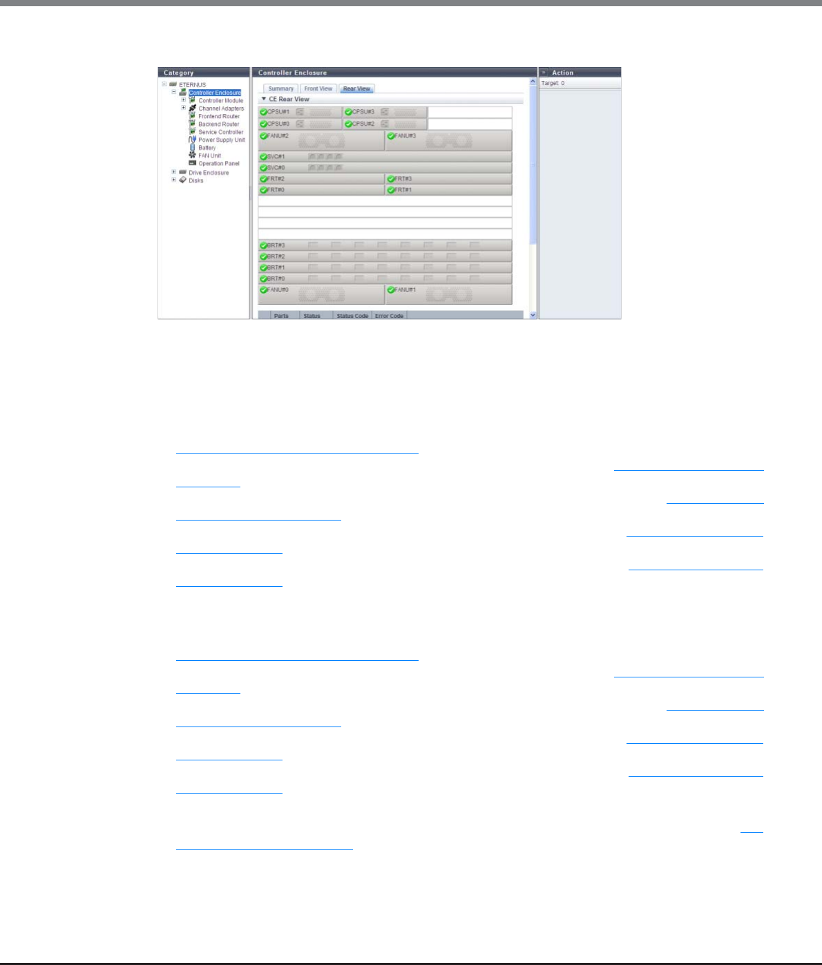
Chapter 10 Component Management
10.1 Component Status
ETERNUS Web GUI User’s Guide
Copyright 2013 FUJITSU LIMITED P2X0-1090-10ENZ0
632
●For ETERNUS DX8700 S2
The following items are displayed in the Main area:
-Device image
The rear view of the CE that is installed in the ETERNUS DX Disk storage system is displayed.
The CPSU status, the FANU status, the SVC status, FRT status, and the BRT status are displayed with
icons.
By clicking the CPSU number, the [Controller Enclosure Power Supply Unit] screen is displayed. Refer to
"10.1.11 PSU/CPSU (CE) Detail" (page 664) for display items.
By clicking the FANU number, the [FAN Unit] screen is displayed. Refer to "10.1.13 FAN Unit Detail"
(page 667) for display items.
By clicking the SVC number, the [Service Controller] screen is displayed. Refer to "10.1.10 Service
Controller Detail" (page 662) for display items.
By clicking the FRT number, the [Frontend Router] screen is displayed. Refer to "10.1.7 Frontend Router
Detail" (page 658) for display items.
By clicking the BRT number, the [Backend Router] screen is displayed. Refer to "10.1.8 Backend Router
Detail" (page 659) for display items.
-Parts
The CPSU number, the FANU number, the SVC number, the FRT number, or the BRT number is displayed.
By clicking the CPSU number, the [Controller Enclosure Power Supply Unit] screen is displayed. Refer to
"10.1.11 PSU/CPSU (CE) Detail" (page 664) for display items.
By clicking the FANU number, the [FAN Unit] screen is displayed. Refer to "10.1.13 FAN Unit Detail"
(page 667) for display items.
By clicking the SVC number, the [Service Controller] screen is displayed. Refer to "10.1.10 Service
Controller Detail" (page 662) for display items.
By clicking the FRT number, the [Frontend Router] screen is displayed. Refer to "10.1.7 Frontend Router
Detail" (page 658) for display items.
By clicking the BRT number, the [Backend Router] screen is displayed. Refer to "10.1.8 Backend Router
Detail" (page 659) for display items.
-Status
The CPSU status, the FANU status, the SVC status, FRT status, or the BRT status is displayed. Refer to "B.5
Component Status" (page 977) for details.
-Status Code
The status code of CPSU, FANU, SVC, FRT, or BRT is displayed.
-Error Code
The error code of CPSU, FANU, SVC, FRT, or BRT is displayed.
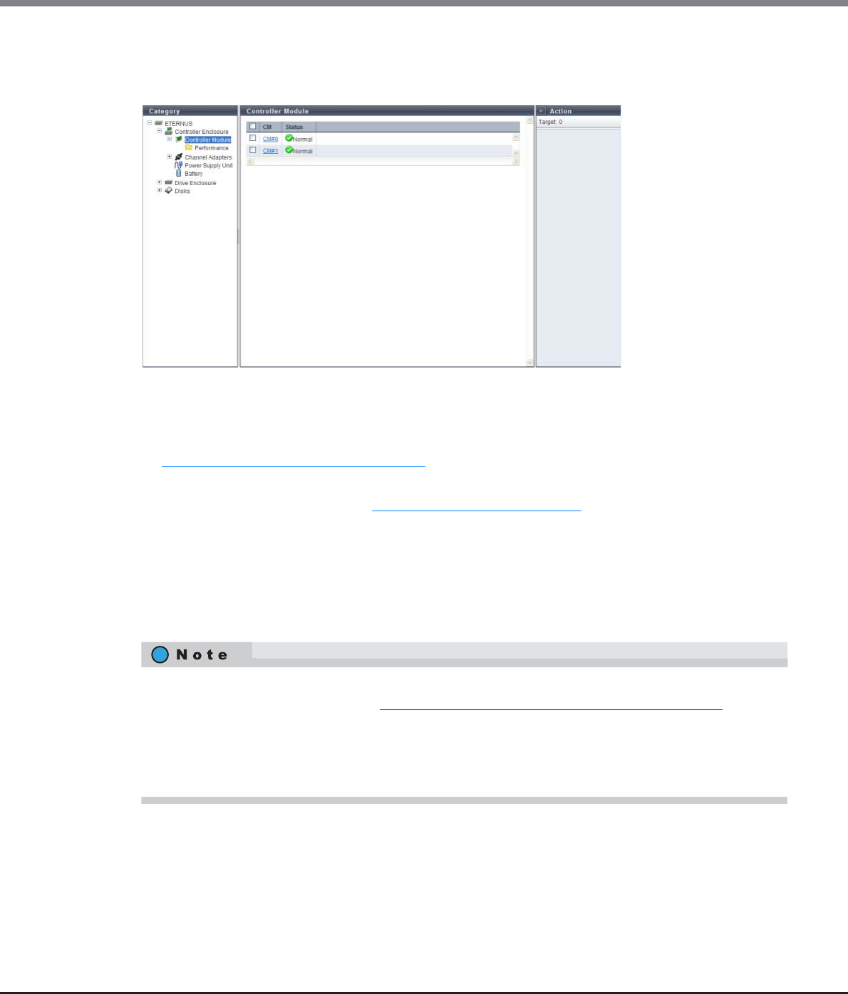
Chapter 10 Component Management
10.1 Component Status
ETERNUS Web GUI User’s Guide
Copyright 2013 FUJITSU LIMITED P2X0-1090-10ENZ0
633
10.1.2.1 Controller Module
The CM information is displayed.
The following items are displayed in the Main area:
•CM
The CM number is displayed. By clicking this item, the [Controller Module] screen is displayed. Refer to
"10.1.5 Controller Module Detail" (page 652) for display items.
•Status
The CM status is displayed. Refer to "B.5 Component Status" (page 977) for details.
10.1.2.2 Controller Module (Performance)
The CM performance information is displayed.
If I/O offloading is enabled for the ETERNUS DX8700 S2, ROE#0 and ROE#1 are displayed for the ROE busy
ratio.
•Performance information is obtained when performance monitoring is operated from GUI, CLI, or any
other monitoring software. Refer to "11.2.12.4 Start/Stop Performance Monitoring" (page 925) for details
on how to start performance monitoring with GUI.
•The interval for acquiring performance information can be specified when starting the monitoring. When
using GUI, the default interval is 30 seconds.
•The average performance values during the specified interval are displayed.
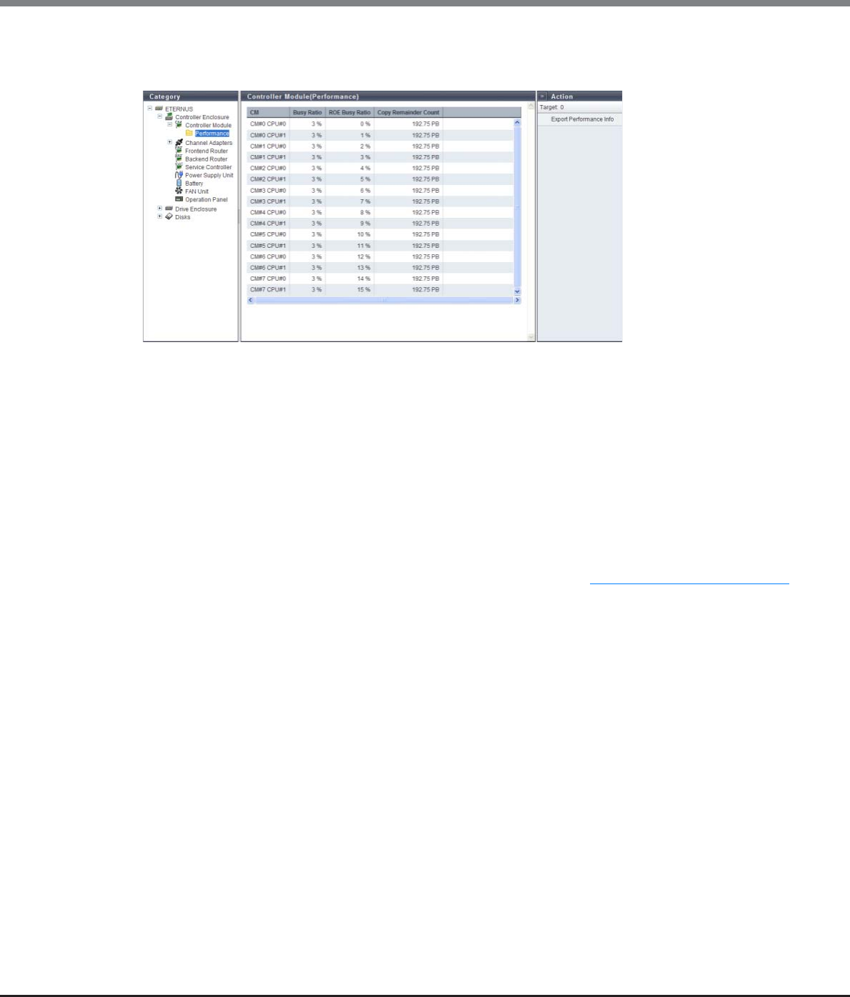
Chapter 10 Component Management
10.1 Component Status
ETERNUS Web GUI User’s Guide
Copyright 2013 FUJITSU LIMITED P2X0-1090-10ENZ0
634
■For ETERNUS DX8700 S2 when the I/O offloading is disabled, ETERNUS DX80 S2/DX90 S2,
ETERNUS DX410 S2/DX440 S2, or ETERNUS DX8100 S2
The following items are displayed in the Main area:
•CM
The CM number and the CPU number are displayed.
•Busy Ratio
The CPU utilization rate is displayed.
For the ETERNUS DX80 S2/DX 90 S2, the ROE busy ratio is included in this value.
•ROE Busy Ratio
The ROE utilization rate of the CPU (*1) is displayed.
*1: RAID Offload Engine (ROE) performs encryption or parity creation processes with RAID5 and RAID6. The "ROE
Busy Ratio" indicates the CPU utilization rate for ROE. For the ETERNUS DX80 S2/DX90 S2, "0%" is displayed. For
the ETERNUS DX8700 S2, this item is displayed only when I/O offloading is disabled. To check the I/O offloading
setting (enable or disable), refer to the [System Settings] screen. Refer to "11.1.12 System Settings" (page 731)
for details.
•Copy Remainder Count
The remaining capacity of the copy session is displayed.
"Copy Remainder Count" is displayed for each controlling CM-CPU in the RAID group to which the copy
source volume belongs.
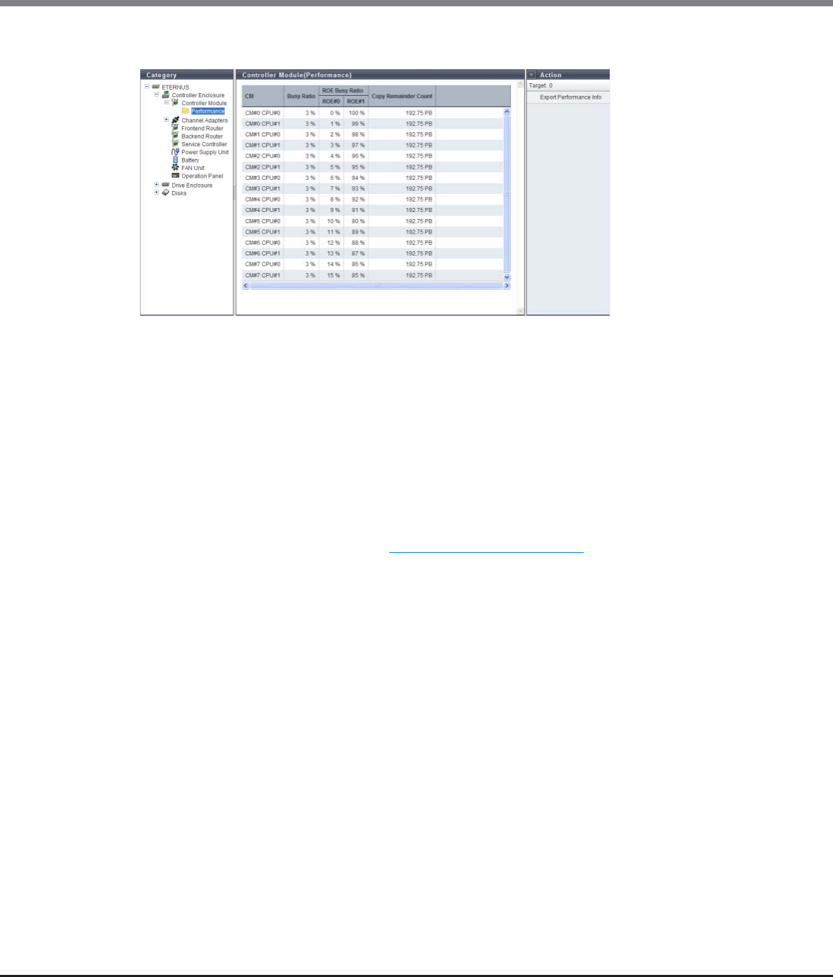
Chapter 10 Component Management
10.1 Component Status
ETERNUS Web GUI User’s Guide
Copyright 2013 FUJITSU LIMITED P2X0-1090-10ENZ0
635
■For ETERNUS DX8700 S2 when the I/O offloading is enabled
The following items are displayed in the Main area:
•CM
The CM number and the CPU number are displayed.
•Busy Ratio
The CPU utilization rate is displayed.
For the ETERNUS DX80 S2/DX 90 S2, the ROE busy ratio is included in this value.
•ROE Busy Ratio
The ROE utilization rate of the CPU (*1) is displayed.
*1: RAID Offload Engine (ROE) performs encryption or parity creation processes with RAID5 and RAID6. The "ROE
Busy Ratio" indicates the CPU utilization rate for ROE. For the ETERNUS DX8700 S2, "ROE#0" and "ROE#1" are
displayed only when I/O offloading is enabled. To check the I/O offloading setting (enable or disable), refer to
the [System Settings] screen. Refer to "11.1.12 System Settings" (page 731) for details.
-ROE#0
Busy Ratio of ROE#0 is displayed.
REC#0 performs encryption processes, parity creation processes for RAID5 or RAID6, as well as some I/O
processes.
This item is displayed only for the ETERNUS DX8700 S2 when I/O offloading is enabled.
-ROE#1
Busy Ratio of ROE#1 is displayed.
REC#1 performs encryption processes, parity creation processes for RAID5 or RAID6, as well as some I/O
processes.
This item is displayed only for the ETERNUS DX8700 S2 when I/O offloading is enabled.
•Copy Remainder Count
The remaining capacity of the copy session is displayed.
"Copy Remainder Count" is displayed for each controlling CM-CPU in the RAID group to which the copy
source volume belongs.
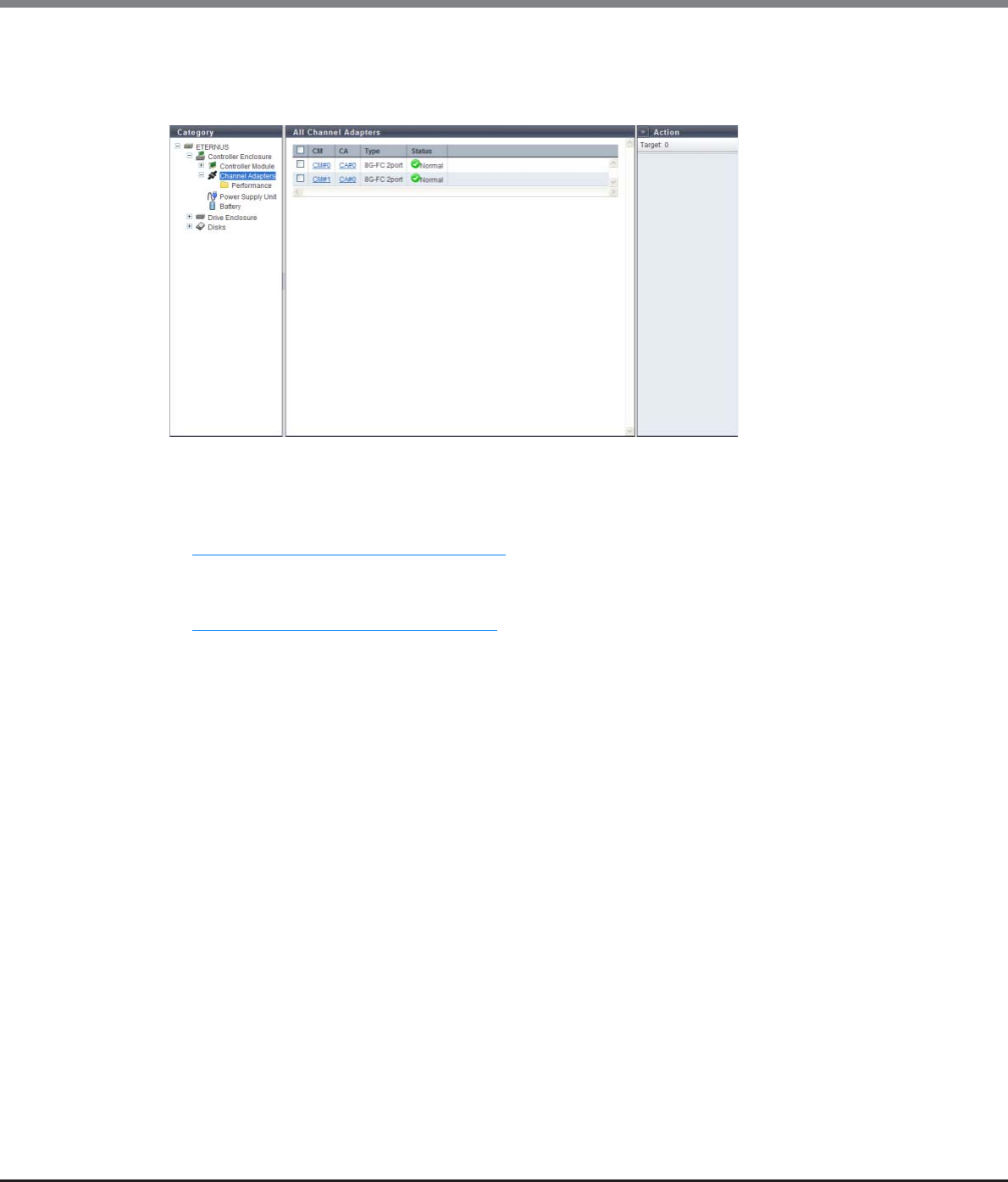
Chapter 10 Component Management
10.1 Component Status
ETERNUS Web GUI User’s Guide
Copyright 2013 FUJITSU LIMITED P2X0-1090-10ENZ0
636
10.1.2.3 All Channel Adapters
The information of all the CAs registered in the ETERNUS DX Disk storage system is displayed.
The following items are displayed in the Main area:
•CM
The CM number is displayed. By clicking this item, the [Controller Module] screen is displayed. Refer to
"10.1.5 Controller Module Detail" (page 652) for display items.
•CA
The CA number is displayed. By clicking this item, the [Channel Adapter] screen is displayed. Refer to
"10.1.6 Channel Adapter Detail" (page 655) for display items.
•Type
The CA type is displayed.
The display items in this filed vary depending on the storage system model.
-For ETERNUS DX80 S2/DX90 S2
•8G-FC 2port
•16G-FC 2port
•10G-iSCSI 2port
•1G-iSCSI 2port
•6G-SAS 2port
•10G-FCoE 2port
-For ETERNUS DX410 S2/DX440 S2
•8G-FC 2port
•8G-FC 4port
•16G-FC 2port
•16G-FC 4port
•10G-iSCSI 2port
•1G-iSCSI 2port
•10G-FCoE 2port
•1G-iSCSI-RA 2port
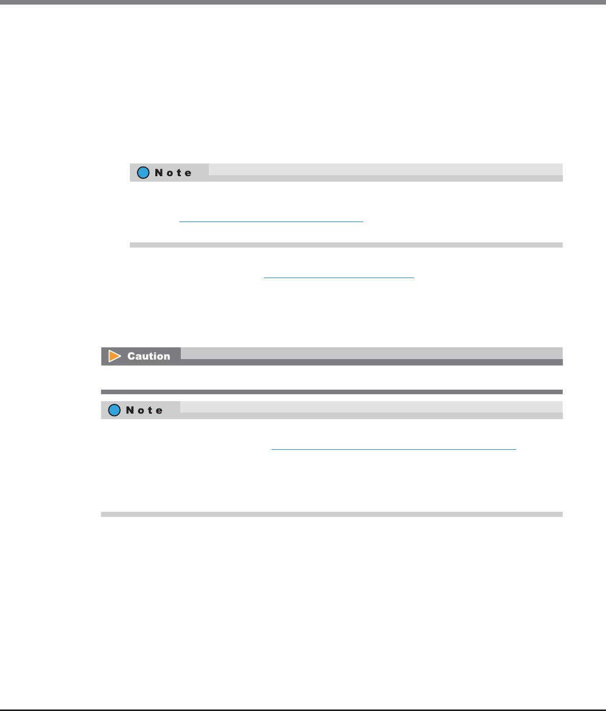
Chapter 10 Component Management
10.1 Component Status
ETERNUS Web GUI User’s Guide
Copyright 2013 FUJITSU LIMITED P2X0-1090-10ENZ0
637
-For ETERNUS DX8100 S2/DX8700 S2
•8G-FC 2port
•8G-FC 4port
•16G-FC 2port
•16G-FC 4port
•10G-iSCSI 2port
•1G-iSCSI 2port
•10G-FCoE 2port
•1G-iSCSI-RA 2port
•Status
The CA status is displayed. Refer to "B.5 Component Status" (page 977) for details.
10.1.2.4 Channel Adapter Ports (Performance)
The CA port performance information is displayed.
The 1-port type CA provided by ETERNUS DX80 S2 is also displayed as a 2-port type. To determine
whether the CA is 1-port type or 2-port-type, refer to the port number displayed in the [Internal Parts]
tab in the "10.1.6 Channel Adapter Detail" (page 655). Note that 1-port type CAs are not available in
some regions.
When the port mode is "Initiator", the CA port performance is not displayed.
•Performance information is obtained when performance monitoring is operated from GUI, CLI, or any
other monitoring software. Refer to "11.2.12.4 Start/Stop Performance Monitoring" (page 925) for details
on how to start performance monitoring with GUI.
•The interval for acquiring performance information can be specified when starting the monitoring. When
using GUI, the default interval is 30 seconds.
•The average performance values during the specified interval are displayed.

Chapter 10 Component Management
10.1 Component Status
ETERNUS Web GUI User’s Guide
Copyright 2013 FUJITSU LIMITED P2X0-1090-10ENZ0
638
The following items are displayed in the Main area:
•CM
The CM number is displayed.
•CA
The CA number is displayed.
•Port
The port number is displayed.
•Port Mode
The port mode is displayed.
-CA
-RA
-CA/RA
•Read IOPS
The number of reads per second is displayed.
•Write IOPS
The number of writes per second is displayed.
•Read Throughput
The amount of data that is read per second is displayed.
•Write Throughput
The amount of data that is written per second is displayed.
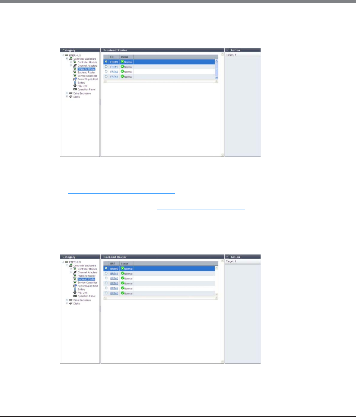
Chapter 10 Component Management
10.1 Component Status
ETERNUS Web GUI User’s Guide
Copyright 2013 FUJITSU LIMITED P2X0-1090-10ENZ0
639
10.1.2.5 Frontend Router
The FRT information is displayed.
This item is displayed only when using the ETERNUS DX8700 S2.
The following items are displayed in the Main area:
•FRT
The FRT number is displayed. By clicking this item, the [Frontend Router] screen is displayed. Refer to
"10.1.7 Frontend Router Detail" (page 658) for display items.
•Status
The FRT status is displayed. Refer to "B.5 Component Status" (page 977) for details.
10.1.2.6 Backend Router
The Backend Router (BRT) information is displayed.
This item is displayed only when using the ETERNUS DX8700 S2.
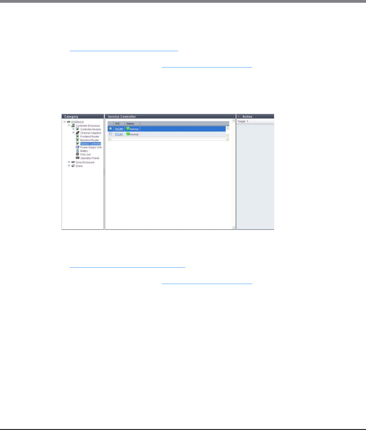
Chapter 10 Component Management
10.1 Component Status
ETERNUS Web GUI User’s Guide
Copyright 2013 FUJITSU LIMITED P2X0-1090-10ENZ0
640
The following items are displayed in the Main area:
•BRT
The BRT number is displayed. By clicking this item, the [Backend Router] screen is displayed. Refer to
"10.1.8 Backend Router Detail" (page 659) for display items.
•Status
The FRT status is displayed. Refer to "B.5 Component Status" (page 977) for details.
10.1.2.7 Service Controller
The Service Controller (SVC) information is displayed.
This item is displayed only when using the ETERNUS DX8700 S2.
The following items are displayed in the Main area:
•SVC
The SVC number is displayed. By clicking this item, the [Service Controller] screen is displayed. Refer to
"10.1.10 Service Controller Detail" (page 662) for display items.
•Status
The SVC status is displayed. Refer to "B.5 Component Status" (page 977) for details.
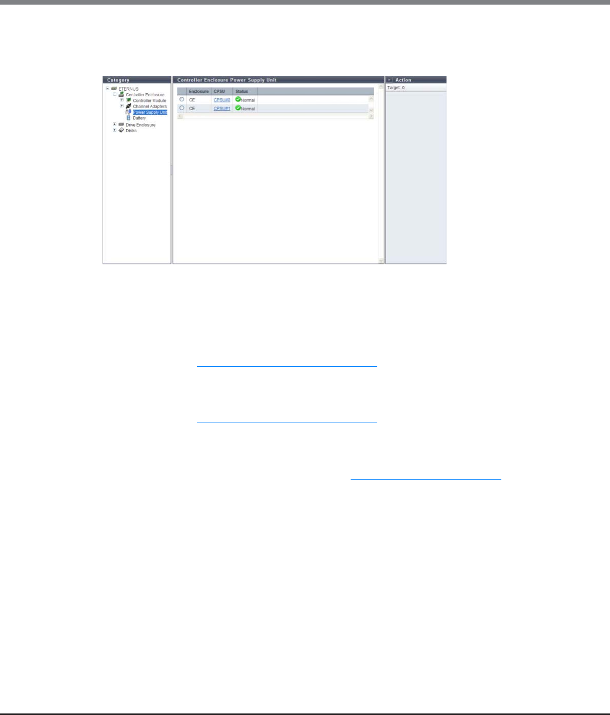
Chapter 10 Component Management
10.1 Component Status
ETERNUS Web GUI User’s Guide
Copyright 2013 FUJITSU LIMITED P2X0-1090-10ENZ0
641
10.1.2.8 Power Supply Unit (CE)
The PSU information for a CE is displayed.
The following items are displayed in the Main area:
•Enclosure
The enclosure where the PSU or the CPUS is installed is displayed.
•PSU
The PSU number is displayed. By clicking this item, the [Controller Enclosure Power Supply Unit] screen is
displayed. Refer to "10.1.11 PSU/CPSU (CE) Detail" (page 664) for display items.
This item is displayed only when using the ETERNUS DX80 S2/DX90 S2.
•CPSU
The CPSU number is displayed. By clicking this item, the [Controller Enclosure Power Supply Unit] screen is
displayed. Refer to "10.1.11 PSU/CPSU (CE) Detail" (page 664) for display items.
This item is displayed only when using the ETERNUS DX410 S2/DX440 S2 or the ETERNUS DX8100 S2/
DX8700 S2.
•Status
The PSU status or the CPSU status is displayed. Refer to "B.5 Component Status" (page 977) for details.
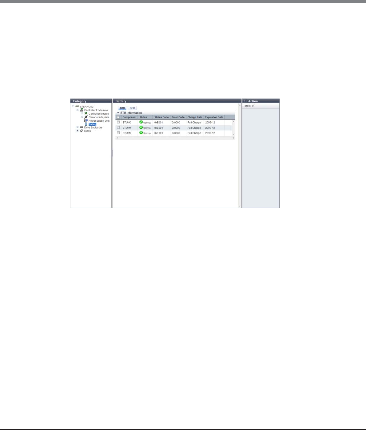
Chapter 10 Component Management
10.1 Component Status
ETERNUS Web GUI User’s Guide
Copyright 2013 FUJITSU LIMITED P2X0-1090-10ENZ0
642
10.1.2.9 Battery
The information of the BTU and the BCU is displayed when the ETERNUS DX410 S2/DX440 S2 or the ETERNUS
DX8100 S2 is used.
The information of the BBU is displayed when the ETERNUS DX8700 S2 is used.
■For the ETERNUS DX410 S2/DX440 S2 or the ETERNUS DX8100 S2
●BTU
The following items are displayed in the Main area:
-Component
The BTU number is displayed.
-Status
The BTU status is displayed. Refer to "B.5 Component Status" (page 977) for details.
-Status Code
The BTU status code is displayed.
-Error Code
The BTU error code is displayed.
-Charge Rate
The BTU charge rate is displayed.
When the battery charge level is 90% or more, "Full Charge" is displayed. When the battery charge level
is less than 90%, "xx%" is displayed.
-Expiration Date
The expiration date for the BTU is displayed.
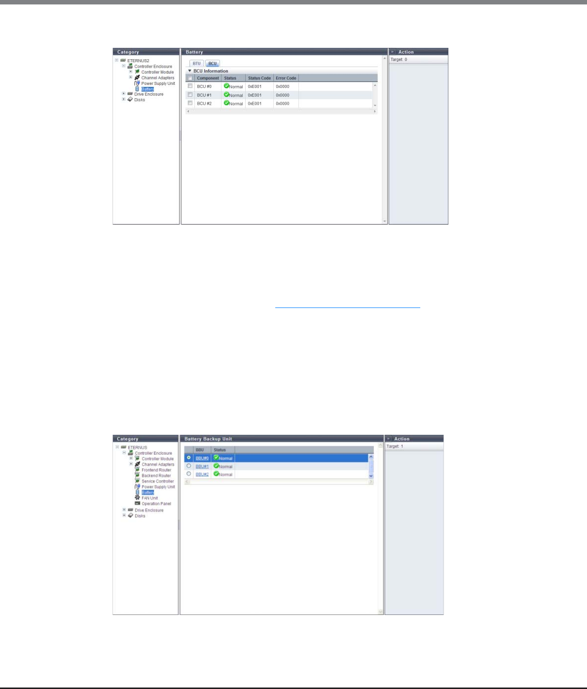
Chapter 10 Component Management
10.1 Component Status
ETERNUS Web GUI User’s Guide
Copyright 2013 FUJITSU LIMITED P2X0-1090-10ENZ0
643
●BCU
The following items are displayed in the Main area:
-Component
The BCU number is displayed.
-Status
The BCU status is displayed. Refer to "B.5 Component Status" (page 977) for details.
-Status Code
The BCU status code is displayed.
-Error Code
The BCU error code is displayed.
■For the ETERNUS DX8700 S2
●BBU
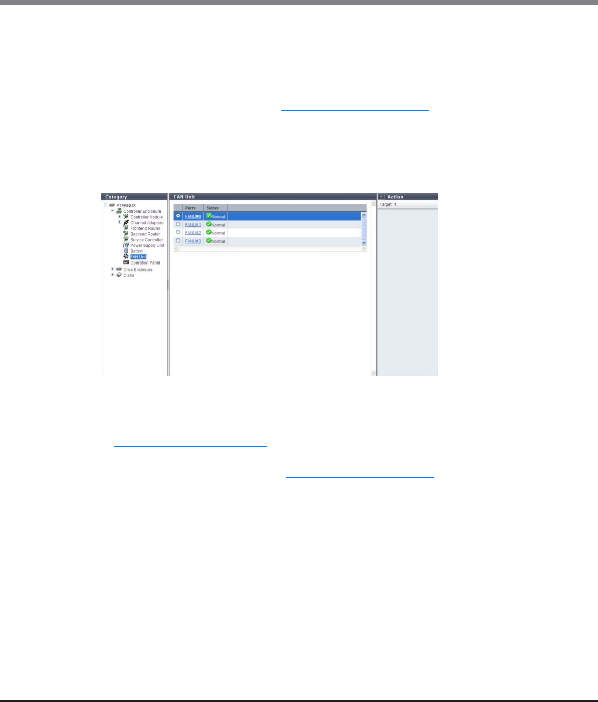
Chapter 10 Component Management
10.1 Component Status
ETERNUS Web GUI User’s Guide
Copyright 2013 FUJITSU LIMITED P2X0-1090-10ENZ0
644
The following items are displayed in the Main area:
-BBU
The BBU number is displayed. By clicking this item, the [Battery Backup Unit] screen is displayed. Refer
to "10.1.12 Battery Backup Unit Detail" (page 666) for display items.
-Status
The BBU status is displayed. Refer to "B.5 Component Status" (page 977) for details.
10.1.2.10 FAN Unit
The FAN Unit information is displayed.
This item is displayed only when using the ETERNUS DX8700 S2.
The following items are displayed in the Main area:
•Parts
The FAN Unit number is displayed. By clicking this item, the [FAN Unit] screen is displayed. Refer to
"10.1.13 FAN Unit Detail" (page 667) for display items.
•Status
The FAN Unit status is displayed. Refer to "B.5 Component Status" (page 977) for details.
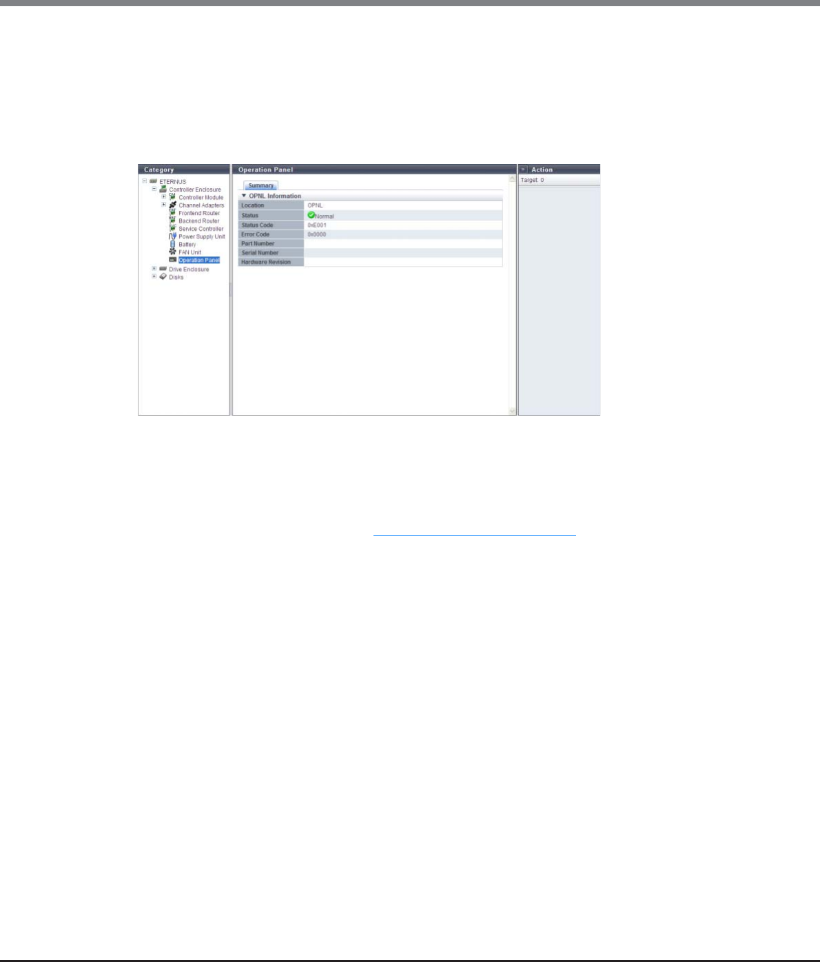
Chapter 10 Component Management
10.1 Component Status
ETERNUS Web GUI User’s Guide
Copyright 2013 FUJITSU LIMITED P2X0-1090-10ENZ0
645
10.1.2.11 Operation Panel
The Operation Panel (OPNL) information is displayed.
This item is displayed only when using the ETERNUS DX8700 S2.
■Summary
The following items are displayed in the Main area:
•Location
The OPNL is displayed.
•Status
The OPNL status is displayed. Refer to "B.5 Component Status" (page 977) for details.
•Status Code
The OPNL status code is displayed.
•Error Code
The OPNL error code is displayed.
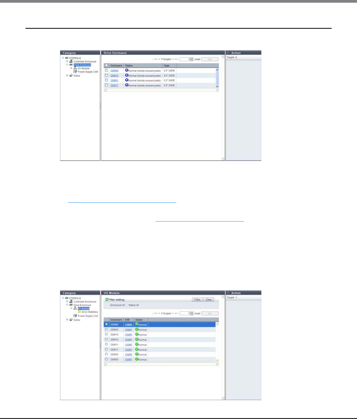
Chapter 10 Component Management
10.1 Component Status
ETERNUS Web GUI User’s Guide
Copyright 2013 FUJITSU LIMITED P2X0-1090-10ENZ0
646
10.1.3 Drive Enclosure
The DE information is displayed.
The following items are displayed in the Main area:
•Enclosure
The DE number is displayed. By clicking this item, the [Drive Enclosure] screen is displayed. Refer to
"10.1.14 Drive Enclosure Detail" (page 669) for display items.
•Status
The DE status is displayed. Refer to "B.5 Component Status" (page 977) for details.
•Type
The drive size and the maximum number of drives that can be installed in the drive enclosure are
displayed.
10.1.3.1 I/O Module
The I/O Module (IOM) information is displayed.
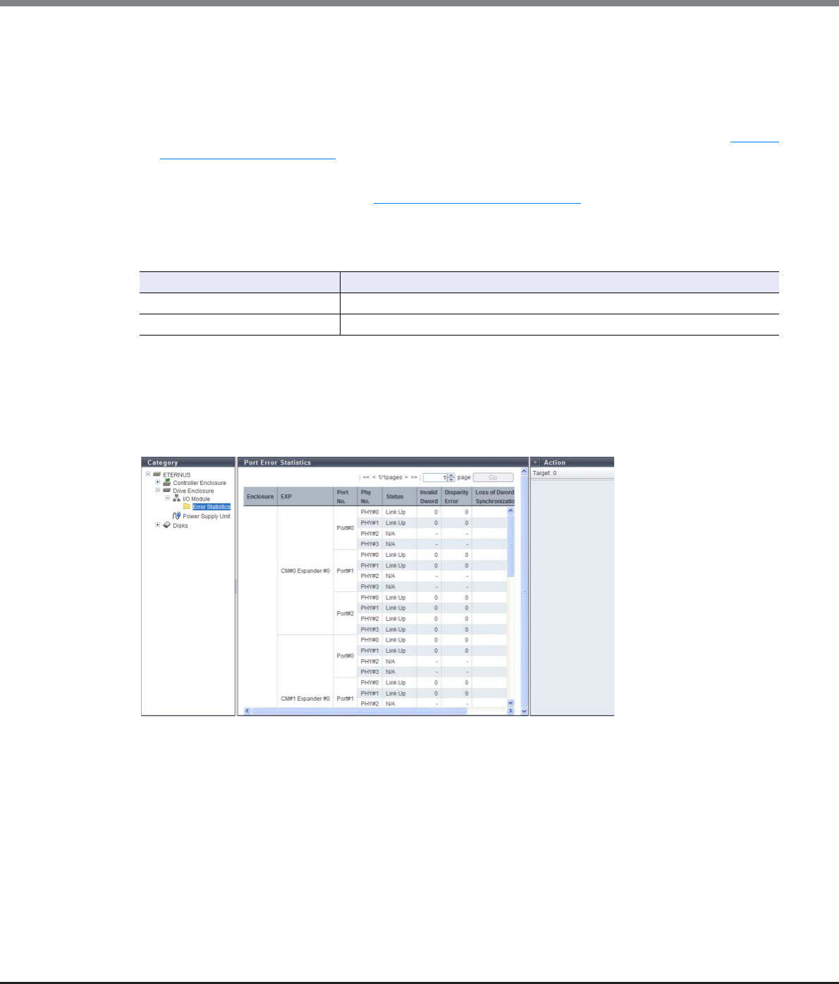
Chapter 10 Component Management
10.1 Component Status
ETERNUS Web GUI User’s Guide
Copyright 2013 FUJITSU LIMITED P2X0-1090-10ENZ0
647
The following items are displayed in the Main area:
•Enclosure
The enclosure where the IOM is installed is displayed.
•IOM
The IOM number is displayed. By clicking this item, the [I/O Module] screen is displayed. Refer to "10.1.15
I/O Module Detail" (page 672) for display items.
•Status
The IOM status is displayed. Refer to "B.5 Component Status" (page 977) for details.
Filter Setting
Filter Setting field is displayed only when using the ETERNUS DX8700 S2.
10.1.3.2 Port Error Statistics
The total number of errors for CM expander and DE IOM ports is displayed.
An increasing number of errors in the information is used to notify early replacement for warning status
components. This can also be used as analysis information when performance is reduced.
The following items are displayed in the Main area:
•Enclosure
The enclosure where the CM expander and DE IOM are installed is displayed.
•EXP
The installation location of the expander is displayed.
•Port No.
The port number is displayed.
•Phy No.
The Phy number of the port is displayed.
Filter Description
Enclosure Select the enclosure that is to be displayed.
Status Select the IOM status that is to be displayed.
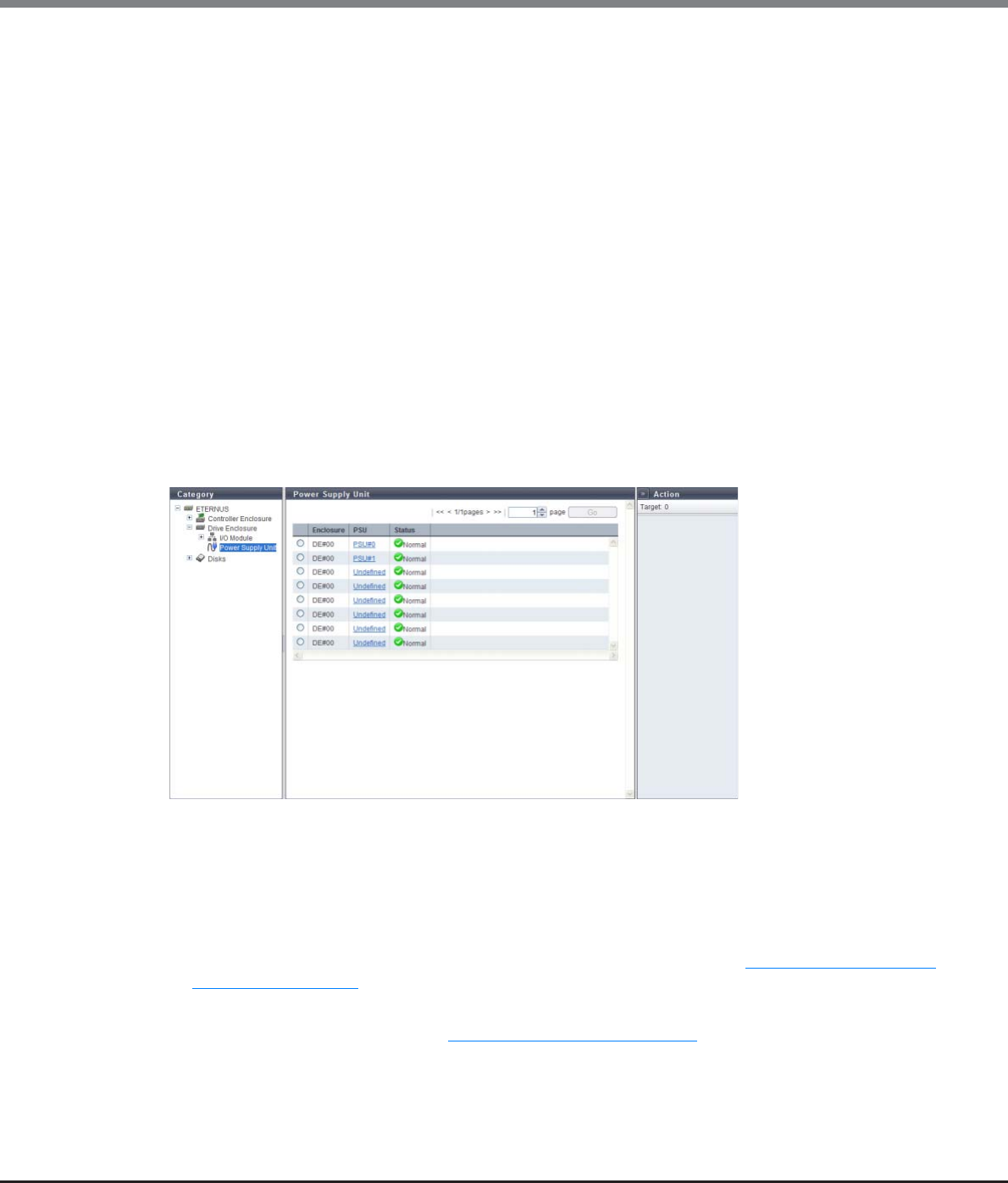
Chapter 10 Component Management
10.1 Component Status
ETERNUS Web GUI User’s Guide
Copyright 2013 FUJITSU LIMITED P2X0-1090-10ENZ0
648
•Status
The Phy status is displayed.
-Link Up
-Link Down
-N/A
•Invalid Dword
The number of Invalid Dword occurrences is displayed.
•Disparity Error
The number of Disparity Error occurrences is displayed.
•Loss of Dword Synchronization
The number of Loss of Dword Synchronization occurrences is displayed.
•Phy Reset Problem
The number of Phy Reset Problem occurrences is displayed.
10.1.3.3 Power Supply Unit (DE)
The PSU information for a DE is displayed.
The following items are displayed in the Main area:
•Enclosure
The enclosure where the PSU is installed is displayed.
•PSU
The PSU number is displayed.
By clicking this item, the [Power Supply Unit (DE)] screen is displayed. Refer to "10.1.16 Power Supply Unit
(DE) Detail" (page 674) for display items.
•Status
The PSU status is displayed. Refer to "B.5 Component Status" (page 977) for details.
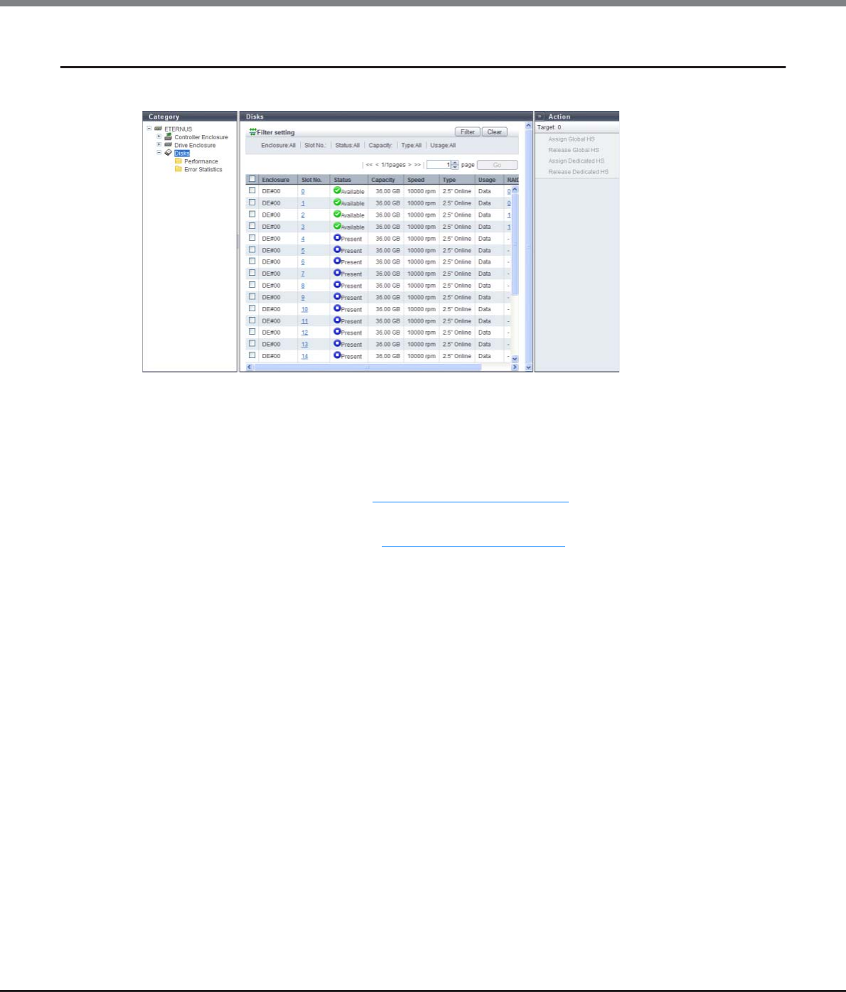
Chapter 10 Component Management
10.1 Component Status
ETERNUS Web GUI User’s Guide
Copyright 2013 FUJITSU LIMITED P2X0-1090-10ENZ0
649
10.1.4 Disks
The drive information is displayed.
The following items are displayed in the Main area:
•Enclosure
The enclosure where the drive is installed is displayed.
•Slot No.
The slot number of the enclosure where the drive is installed is displayed. By clicking the drive image, the
[Disks] screen is displayed. Refer to "10.1.17 Disks Detail" (page 675) for display items.
•Status
The drive status is displayed. Refer to "B.5.1 Drive Status" (page 978) for details.
•Capacity
The capacity of the drive is displayed.
•Speed
The drive speed is displayed. For SSDs, a "-" (hyphen) is displayed.
-15000 rpm
-10000 rpm
-7200 rpm
•Type
The drive type is displayed.
-For 2.5-inch SAS disks: 2.5" Online
-For 3.5-inch SAS disks: 3.5" Online
-For 2.5-inch Nearline SAS disks: 2.5" Nearline
-For 3.5-inch Nearline SAS disks: 3.5" Nearline
-For 2.5-inch SSD: 2.5" SSD
-For 3.5-inch SSD: 3.5" SSD
-For 2.5-inch SED: 2.5" SED
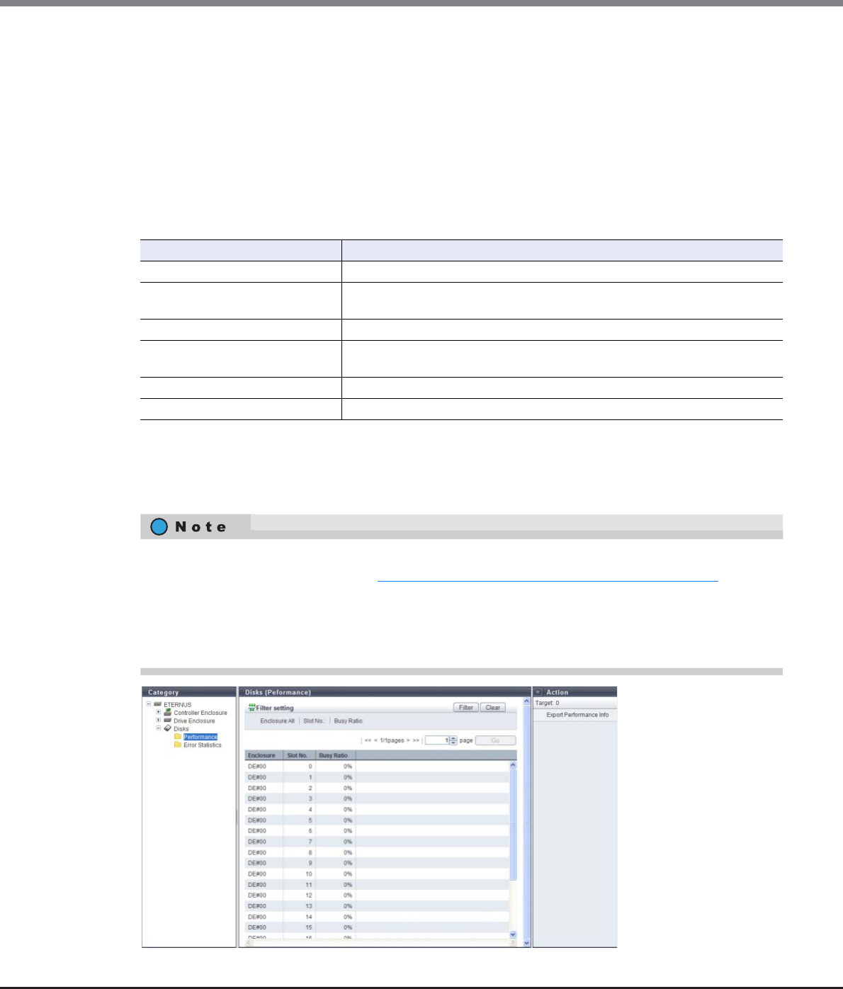
Chapter 10 Component Management
10.1 Component Status
ETERNUS Web GUI User’s Guide
Copyright 2013 FUJITSU LIMITED P2X0-1090-10ENZ0
650
•Usage
The usage of the drive is displayed.
-For a drive that is used for user data or an unused drive: Data
-For a drive that is registered as a Global Hot Spare: Global Hot Spare
-For a drive that is registered as a Dedicated Hot Spare: Dedicated Hot Spare
•RAID Group
If the drive is registered in a RAID group, the RAID group name to which the drive belongs is displayed.
By clicking this item, the [RAID Group Detail] screen is displayed.
Filter Setting
10.1.4.1 Disks (Performance)
The drive performance information is displayed.
Filter Description
Enclosure Select the enclosure in which the target drive is installed.
Slot No. Specify the slot number of the drive that is to be displayed.
When not using the slot number for filtering, leave this item blank.
Status Select the drive status that is to be displayed.
Capacity Specify the capacity of the drive that is to be displayed.
When not using the drive capacity for filtering, specify "0".
Type Select the drive type that is to be displayed.
Usage Select the usage of the drive that is to be displayed.
•Performance information is obtained when performance monitoring is operated from GUI, CLI, or any
other monitoring software. Refer to "11.2.12.4 Start/Stop Performance Monitoring" (page 925) for details
on how to start performance monitoring with GUI.
•The interval for acquiring performance information can be specified when starting the monitoring. When
using GUI, the default interval is 30 seconds.
•The average performance values during the specified interval are displayed.

Chapter 10 Component Management
10.1 Component Status
ETERNUS Web GUI User’s Guide
Copyright 2013 FUJITSU LIMITED P2X0-1090-10ENZ0
651
The following items are displayed in the Main area:
•Enclosure
The enclosure where the drive is installed is displayed.
•Slot No.
The slot number of the enclosure where the drive is installed is displayed.
•Busy Ratio
The busy ratio of the drive is displayed. A "-" (hyphen) is displayed when the status is "Broken" or "Not
Supported".
Filter Setting
10.1.4.2 Disk Error Statistics
The total number of drive errors is displayed.
An increasing number of disk errors can be used as a sign for the early replacement of warning components or
as information to analyze performance when performance is reduced.
Any unnecessary disk error information can be deleted.
The following items are displayed in the Main area:
•Enclosure
The enclosure where the drive is installed is displayed.
•Slot No.
The slot number of the enclosure where the drive is installed is displayed.
•Port No.
The drive port number is displayed.
Filter Description
Enclosure Select the enclosure in which the target drive is installed.
Slot No. Specify the slot number of the drive that is to be displayed.
When not using the slot number for filtering, leave this item blank.
Busy Ratio Specify the busy ratio of the drive that is to be displayed.
When not using the busy ratio for filtering, leave this item blank.
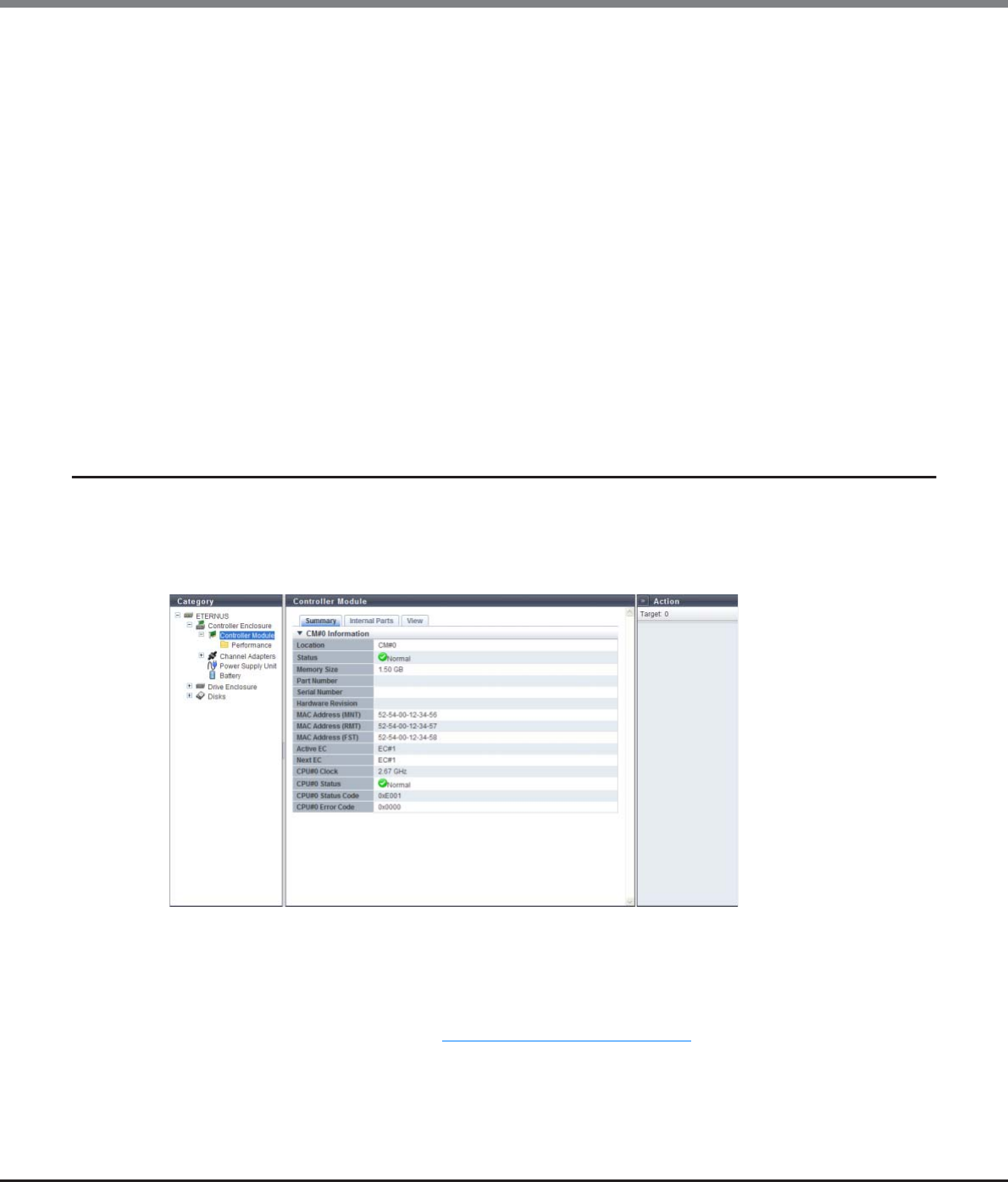
Chapter 10 Component Management
10.1 Component Status
ETERNUS Web GUI User’s Guide
Copyright 2013 FUJITSU LIMITED P2X0-1090-10ENZ0
652
•Media Error
The number of Media Error occurrences is displayed.
•Drive Error
The number of Drive Error occurrences is displayed.
•Drive Recovered Error
The number of Drive Recovered Error occurrences is displayed.
•S.M.A.R.T. Event
The number of S.M.A.R.T. Event occurrences is displayed.
•I/O Timeout
The number of I/O Timeout occurrences is displayed.
•Link Error
The number of Link Error occurrences is displayed.
•Check Code Error
The number of Check Code Error occurrences is displayed.
10.1.5 Controller Module Detail
The detailed CM information is displayed.
■Summary
The following items are displayed in the Main area:
•Location
The CM number is displayed.
•Status
The CM status is displayed. Refer to "B.5 Component Status" (page 977) for details.
•Memory Size
The cache memory capacity of the CM is displayed.
•Part Number
The CM port number is displayed.
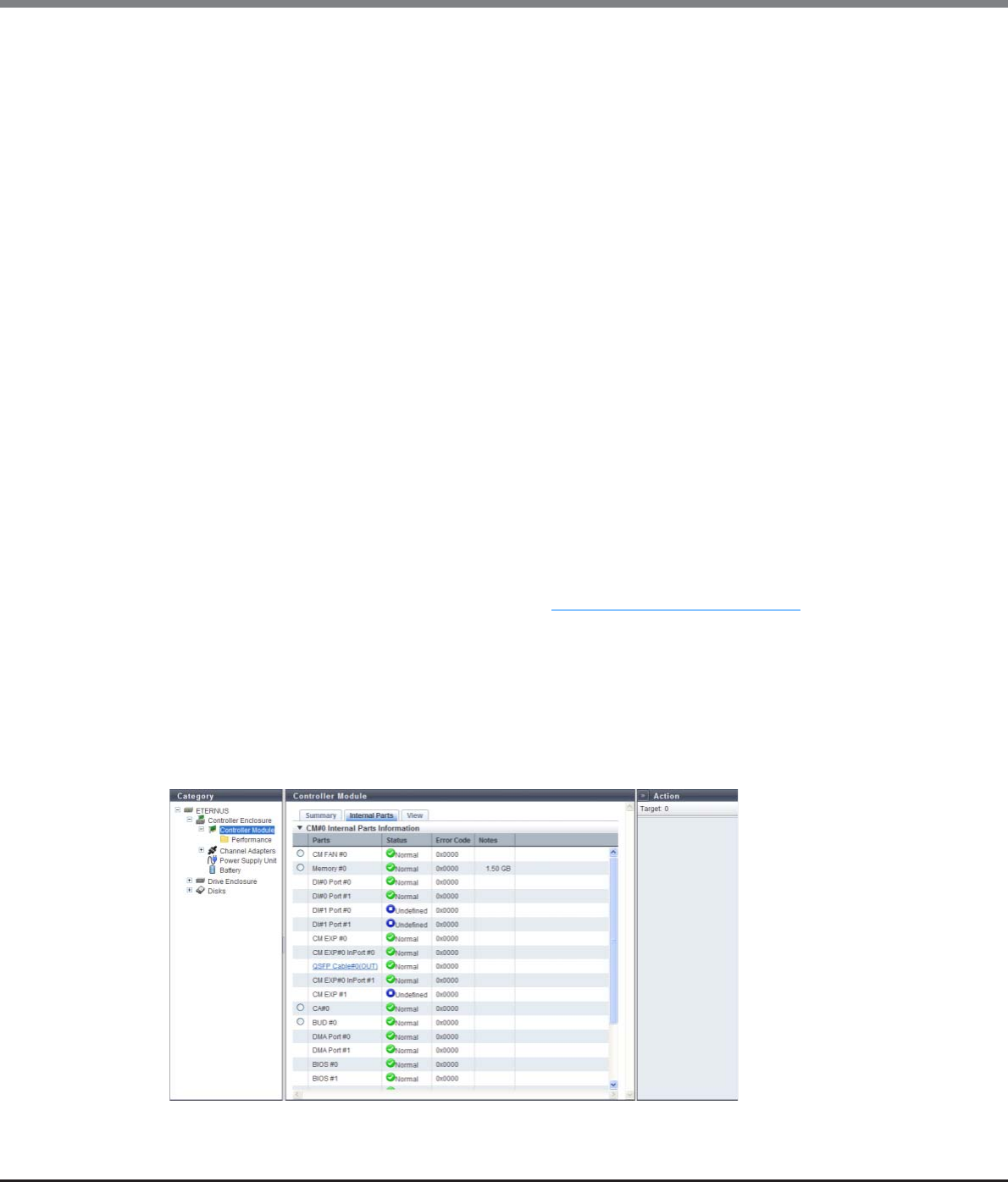
Chapter 10 Component Management
10.1 Component Status
ETERNUS Web GUI User’s Guide
Copyright 2013 FUJITSU LIMITED P2X0-1090-10ENZ0
653
•Serial Number
The serial number of the CM is displayed.
•Hardware Revision
The hardware version of the CM is displayed.
•MAC Address (MNT)
The MAC address of the MNT Port is displayed.
This item is displayed only when using the ETERNUS DX80 S2/DX90 S2, the ETERNUS DX410 S2/DX440 S2,
or the ETERNUS DX8100 S2.
•MAC Address (RMT)
The MAC address of the RMT Port is displayed.
This item is displayed only when using the ETERNUS DX80 S2/DX90 S2, the ETERNUS DX410 S2/DX440 S2,
or the ETERNUS DX8100 S2.
•MAC Address (FST)
The MAC address of the FST Port is displayed.
This item is displayed only when using the ETERNUS DX410 S2/DX440 S2 or the ETERNUS DX8100 S2.
•Active EC
The Edition Control (EC) number of the currently running firmware is displayed.
•Next EC
The EC number of the firmware that is to be run at the next power-on is displayed.
•CPU#n Clock
The clock frequency of CPU#0 or CPU#1 is displayed.
•CPU#n Status
The status of CPU#0 or CPU#1 is displayed. Refer to "B.5 Component Status" (page 977) for details.
•CPU#n Status Code
The status code of CPU#0 or CPU#1 is displayed.
•CPU#n Error Code
The error code of CPU#0 or CPU#1 is displayed.
■Internal Parts
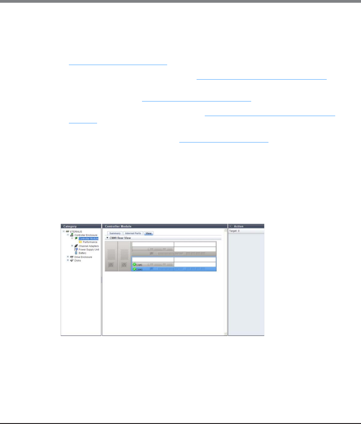
Chapter 10 Component Management
10.1 Component Status
ETERNUS Web GUI User’s Guide
Copyright 2013 FUJITSU LIMITED P2X0-1090-10ENZ0
654
The following items are displayed in the Main area:
•Parts
The component name and the component number are displayed.
A link is displayed for the ETERNUS DX80 S2/DX90 S2, the ETERNUS DX410 S2/DX440 S2, or the ETERNUS
DX8100 S2 when the "Parts" is "QSFP Cable". Click this link to display the [QSFP Cable] screen. Refer to
"10.1.18 QSFP Cable Detail" (page 678) for display items.
A link is displayed for the ETERNUS DX8100 S2/DX8700 S2 when the "Parts" is "BUD". Click this link to dis-
play the [Boot and Utility Device] screen. Refer to "10.1.19 Boot and Utility Device Detail" (page 679) for
display items.
A link is displayed for the ETERNUS DX8700 S2 when the "Parts" is "CA". Click this link to display the [Chan-
nel Adapter] screen. Refer to "10.1.6 Channel Adapter Detail" (page 655) for display items.
A link is displayed for the ETERNUS DX8700 S2 when the "Parts" is "CM MMC". Click this link to display the
[CM Module Management Controller] screen. Refer to "10.1.20 CM Module Management Controller Detail"
(page 680) for display items.
•Status
The component status is displayed. Refer to "B.5 Component Status" (page 977) for details.
•Error Code
The component error code is displayed.
•Notes
Remarks are displayed.
-When "Parts" is "Memory", the memory capacity is displayed.
-When "Parts" is "SCU", the voltage information is displayed (for the ETERNUS DX80 S2/DX90 S2).
■View
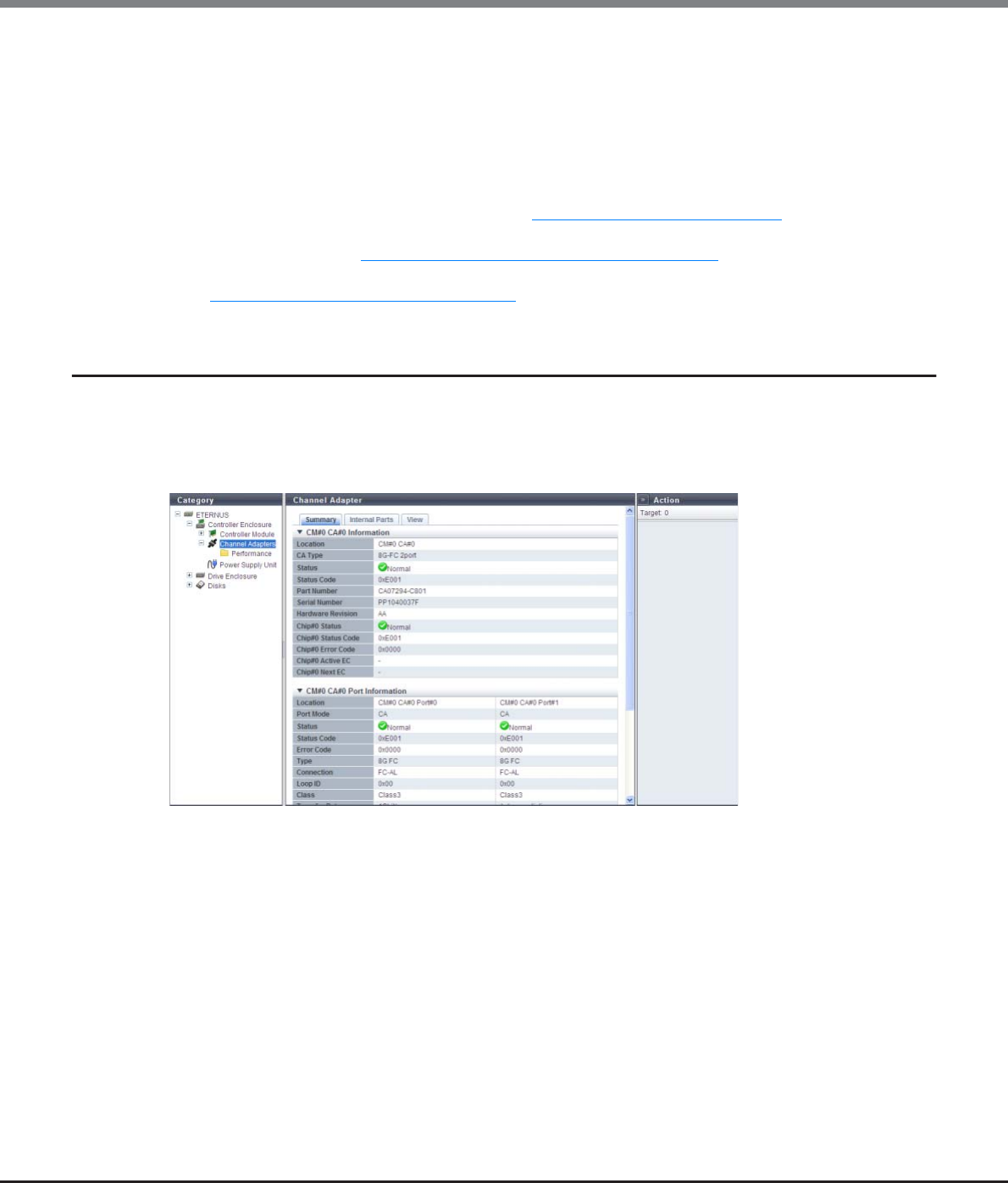
Chapter 10 Component Management
10.1 Component Status
ETERNUS Web GUI User’s Guide
Copyright 2013 FUJITSU LIMITED P2X0-1090-10ENZ0
655
The following items are displayed in the Main area:
•Device image
The rear view or front view of the CE that is installed in the ETERNUS DX Disk storage system is displayed.
For the ETERNUS DX80 S2/DX90 S2, the ETERNUS DX410 S2/DX440 S2, or the ETERNUS DX8100 S2, the rear
view is displayed.
For the ETERNUS DX8700 S2, the front view is displayed.
Components that are not CMs are grayed out.
The CM status is displayed with an icon. Refer to "B.5 Component Status" (page 977) for display items.
When using the ETERNUS DX8100 S2/DX8700 S2, clicking the BUD number displays the [Boot and Utility
Device] screen. Refer to "10.1.19 Boot and Utility Device Detail" (page 679) for display items.
When using the ETERNUS DX8700 S2, clicking the CA number displays the [Channel Adapter] screen. Refer
to "10.1.6 Channel Adapter Detail" (page 655) for display items.
10.1.6 Channel Adapter Detail
The detailed information for the Channel Adapter is displayed.
■Summary
The following items are displayed in the Main area:
•Location
The CA installation location is displayed.
•CA Type
The CA type is displayed.
The display items in this field vary depending on the storage system model.
-For ETERNUS DX80 S2/DX90 S2
•8G-FC 2port
•16G-FC 2port
•10G-iSCSI 2port
•1G-iSCSI 2port
•6G-SAS 2port
•10G-FCoE 2port

Chapter 10 Component Management
10.1 Component Status
ETERNUS Web GUI User’s Guide
Copyright 2013 FUJITSU LIMITED P2X0-1090-10ENZ0
656
-For ETERNUS DX410 S2/DX440 S2
•8G-FC 2port
•8G-FC 4port
•16G-FC 2port
•16G-FC 4port
•10G-iSCSI 2port
•1G-iSCSI 2port
•10G-FCoE 2port
•1G-iSCSI-RA 2port
-For ETERNUS DX8100 S2/DX8700 S2
•8G-FC 2port
•8G-FC 4port
•16G-FC 2port
•16G-FC 4port
•10G-iSCSI 2port
•1G-iSCSI 2port
•10G-FCoE 2port
•1G-iSCSI-RA 2port
•Status
The CA status is displayed. Refer to "B.5 Component Status" (page 977) for details.
•Status Code
The CA status code is displayed.
•Part Number
The CA part number is displayed.
•Serial Number
The serial number of the CA is displayed.
•Hardware Revision
The hardware version of the CA is displayed.
•Chip#n Status
The status of Chip#0 or Chip#1 is displayed. Refer to "B.5 Component Status" (page 977) for details.
•Chip#n Status Code
The status code of Chip#0 or Chip#1 is displayed.
•Chip#n Error Code
The error code of Chip#0 or Chip#1 is displayed.
•Chip#n Active EC
The Edition Control (EC) number of the currently running Chip#0 or Chip#1 is displayed.
•Chip#n Next EC
The EC number of the Chip#0 or the Chip#1 that is to be run at the next power-on is displayed.
The 1-port type CA provided by ETERNUS DX80 S2 is also displayed as a 2-port type. To determine whether
the CA is 1-port type or 2-port-type, refer to the port number displayed in the [Internal Parts] tab. Note
that 1-port type CAs are not available in some regions.
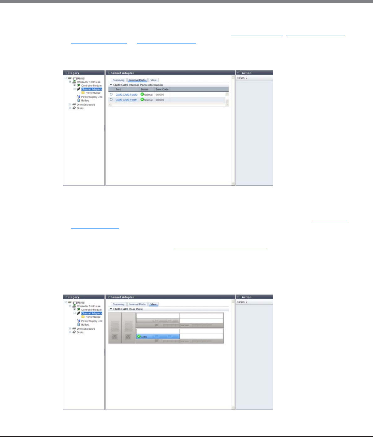
Chapter 10 Component Management
10.1 Component Status
ETERNUS Web GUI User’s Guide
Copyright 2013 FUJITSU LIMITED P2X0-1090-10ENZ0
657
●CM#x CA#y Port Information
The detailed information of all the ports is displayed. Refer to "FC port" (page 681), "iSCSI port" (page 687),
"SAS port" (page 690), or "FCoE port" (page 691) for display contents.
■Internal Parts
The following items are displayed in the Main area:
•Port
The CA port number is displayed. By clicking this item, the [Port] screen is displayed. Refer to "10.1.21 Port
Detail" (page 681) for display items.
•Status
The CA port status is displayed. Refer to "B.5 Component Status" (page 977) for details.
•Error Code
The CA port error code is displayed.
■View
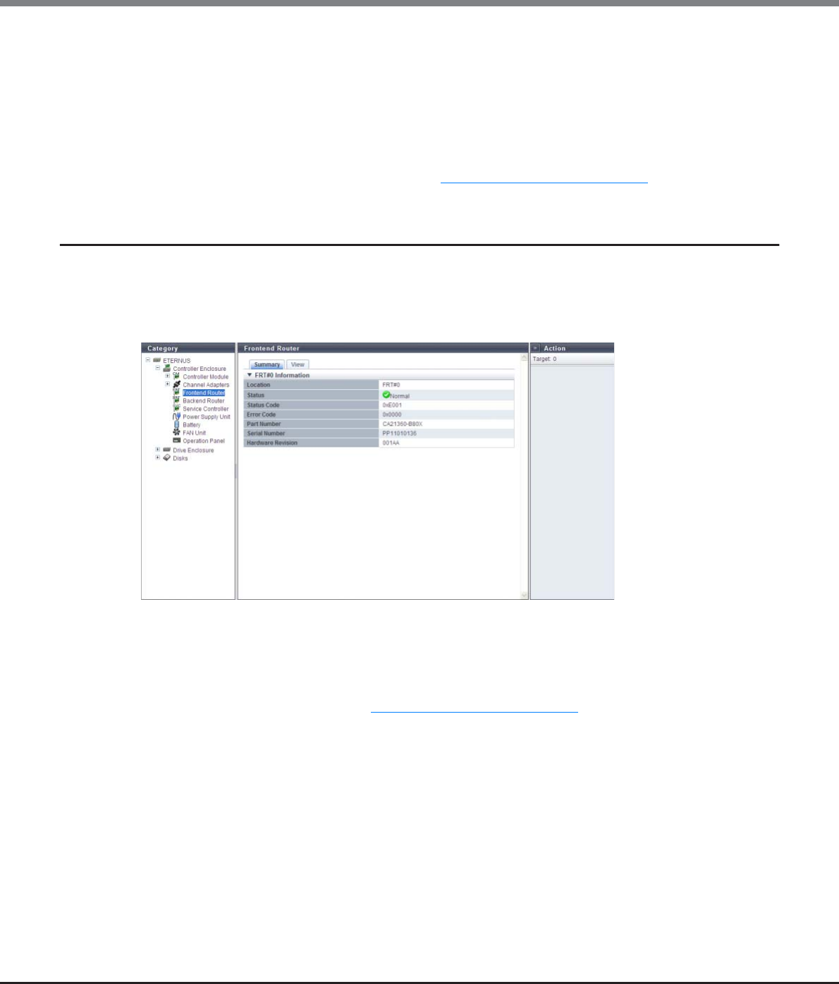
Chapter 10 Component Management
10.1 Component Status
ETERNUS Web GUI User’s Guide
Copyright 2013 FUJITSU LIMITED P2X0-1090-10ENZ0
658
The following items are displayed in the Main area:
•Device image
The rear view or front view of the CE that is installed in the ETERNUS DX Disk storage system is displayed.
For the ETERNUS DX80 S2/DX90 S2, the ETERNUS DX410 S2/DX440 S2, or the ETERNUS DX8100 S2, the rear
view is displayed.
For the ETERNUS DX8700 S2, the front view is displayed.
Components that are not CAs are grayed out.
The CA status is displayed with an icon. Refer to "B.5 Component Status" (page 977) for details.
10.1.7 Frontend Router Detail
The detailed information for the FRT is displayed.
■Summary
The following items are displayed in the Main area:
•Location
The FRT number is displayed.
•Status
The FRT status is displayed. Refer to "B.5 Component Status" (page 977) for details.
•Status Code
The FRT status code is displayed.
•Error Code
The FRT error code is displayed.
•Part Number
The part number of the FRT is displayed.
•Serial Number
The serial number of the FRT is displayed.
•Hardware Revision
The hardware version of the FRT is displayed.
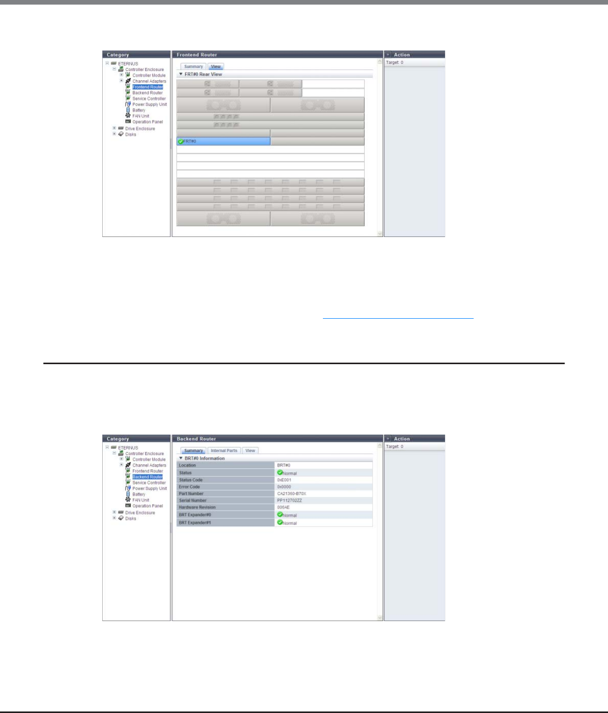
Chapter 10 Component Management
10.1 Component Status
ETERNUS Web GUI User’s Guide
Copyright 2013 FUJITSU LIMITED P2X0-1090-10ENZ0
659
■View
The following items are displayed in the Main area:
•Device image
The rear view of the CE that is installed in the ETERNUS DX Disk storage system is displayed.
Components that are not the target FRT is grayed out.
The FRT status is displayed with an icon. Refer to "B.5 Component Status" (page 977) for details.
10.1.8 Backend Router Detail
The detailed information for the BRT is displayed.
■Summary
The following items are displayed in the Main area:
•Location
The BRT number is displayed.
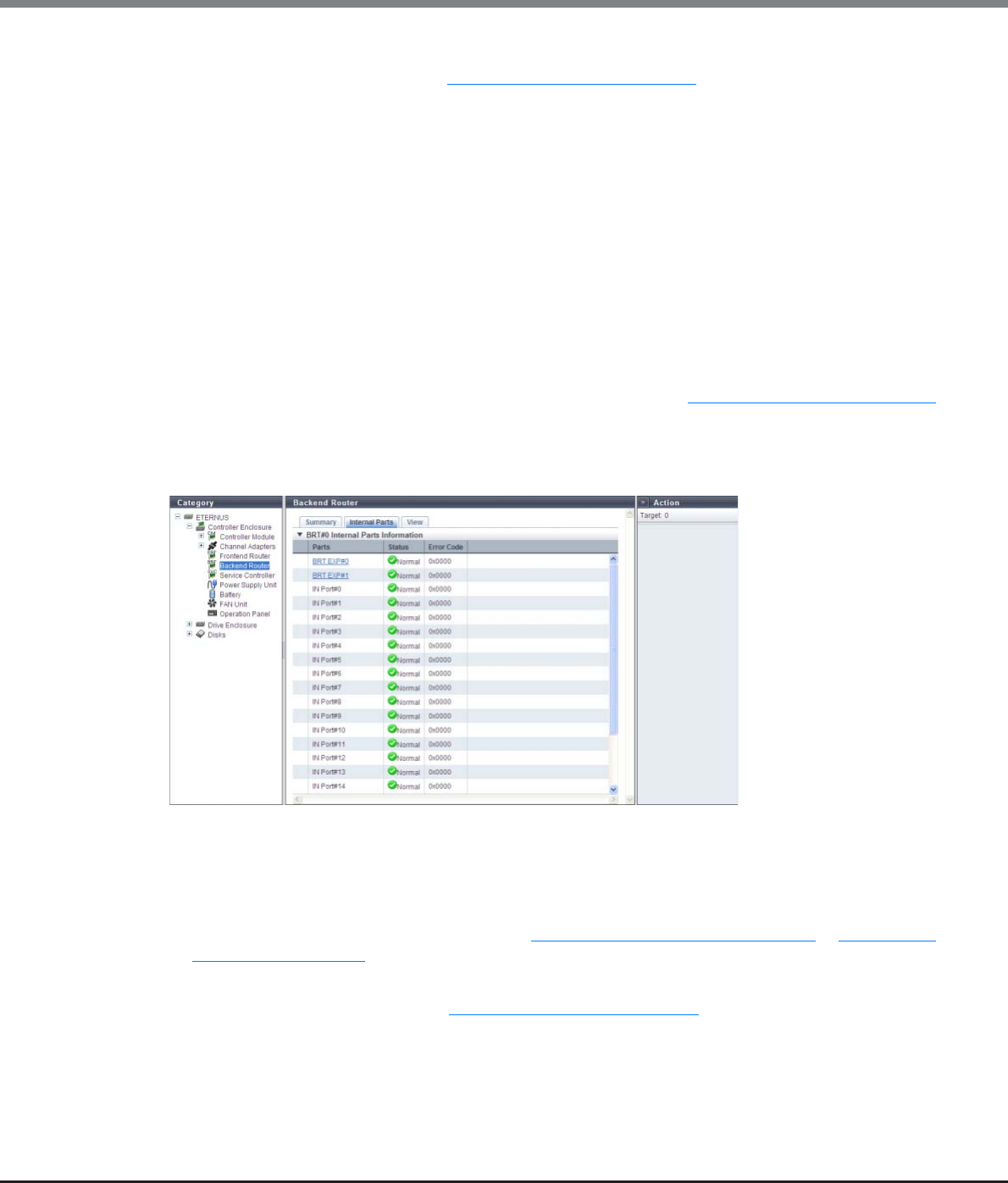
Chapter 10 Component Management
10.1 Component Status
ETERNUS Web GUI User’s Guide
Copyright 2013 FUJITSU LIMITED P2X0-1090-10ENZ0
660
•Status
The BRT status is displayed. Refer to "B.5 Component Status" (page 977) for details.
•Status Code
The BRT status code is displayed.
•Error Code
The BRT error code is displayed.
•Part Number
The part number of the BRT is displayed.
•Serial Number
The serial number of the BRT is displayed.
•Hardware Revision
The hardware version of the BRT is displayed.
•BRT Expander#n
The status of BRT Expander#0 or BRT Expander#1 is displayed. Refer to "B.5 Component Status" (page 977)
for details.
■Internal Parts
The following items are displayed in the Main area:
•Parts
The component name and the component number are displayed.
Links are displayed for [BRT EXP] and [QSFP Cable]. By clicking either of them, the [BRT Expander] screen
or the [QSFP Cable] screen is displayed. Refer to "10.1.9 BRT Expander Detail" (page 661) or "10.1.18 QSFP
Cable Detail" (page 678) for display items.
•Status
The part status is displayed. Refer to "B.5 Component Status" (page 977) for details.
•Error Code
The part error code is displayed.
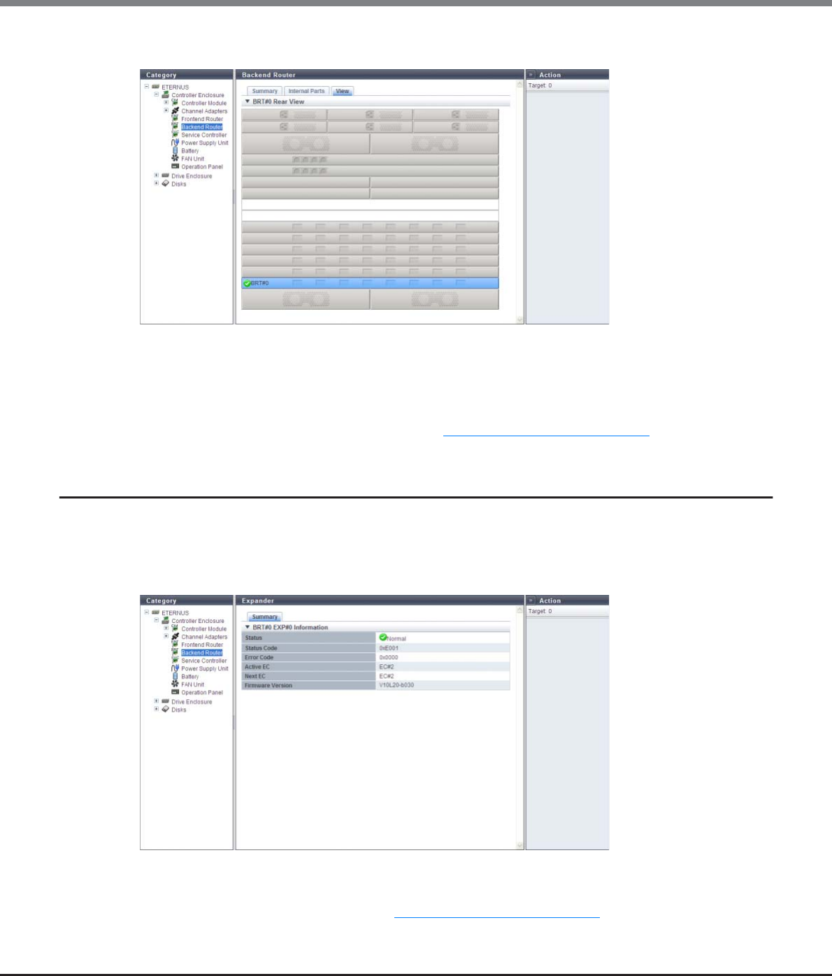
Chapter 10 Component Management
10.1 Component Status
ETERNUS Web GUI User’s Guide
Copyright 2013 FUJITSU LIMITED P2X0-1090-10ENZ0
661
■View
The following items are displayed in the Main area:
•Device image
The rear view of the CE that is installed in the ETERNUS DX Disk storage system is displayed.
Components that are not the target BRT are grayed out.
The BRT status is displayed with an icon. Refer to "B.5 Component Status" (page 977) for details.
10.1.9 BRT Expander Detail
The detailed information of the BRT Expander is displayed.
■Summary
The following items are displayed in the Main area:
•Status
The BRT EXP status is displayed. Refer to "B.5 Component Status" (page 977) for details.
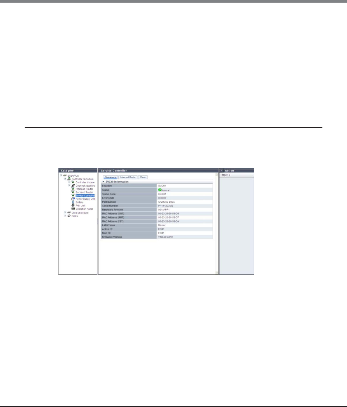
Chapter 10 Component Management
10.1 Component Status
ETERNUS Web GUI User’s Guide
Copyright 2013 FUJITSU LIMITED P2X0-1090-10ENZ0
662
•Status Code
The status code of BRT EXP is displayed.
•Error Code
The error code of BRT EXP is displayed.
•Active EC
The Edition Control (EC) number of the currently running firmware is displayed.
•Next EC
The EC number of the firmware that is to be run at the next power-on is displayed.
•Firmware Version
The current controller firmware version is displayed.
10.1.10 Service Controller Detail
The detailed information of the SVC is displayed.
■Summary
The following items are displayed in the Main area:
•Location
The SVC number is displayed.
•Status
The SVC status is displayed. Refer to "B.5 Component Status" (page 977) for details.
•Status Code
The SVC status code is displayed.
•Error Code
The SVC error code is displayed.
•Part Number
The part number of the SVC is displayed.
•Serial Number
The serial number of the SVC is displayed.
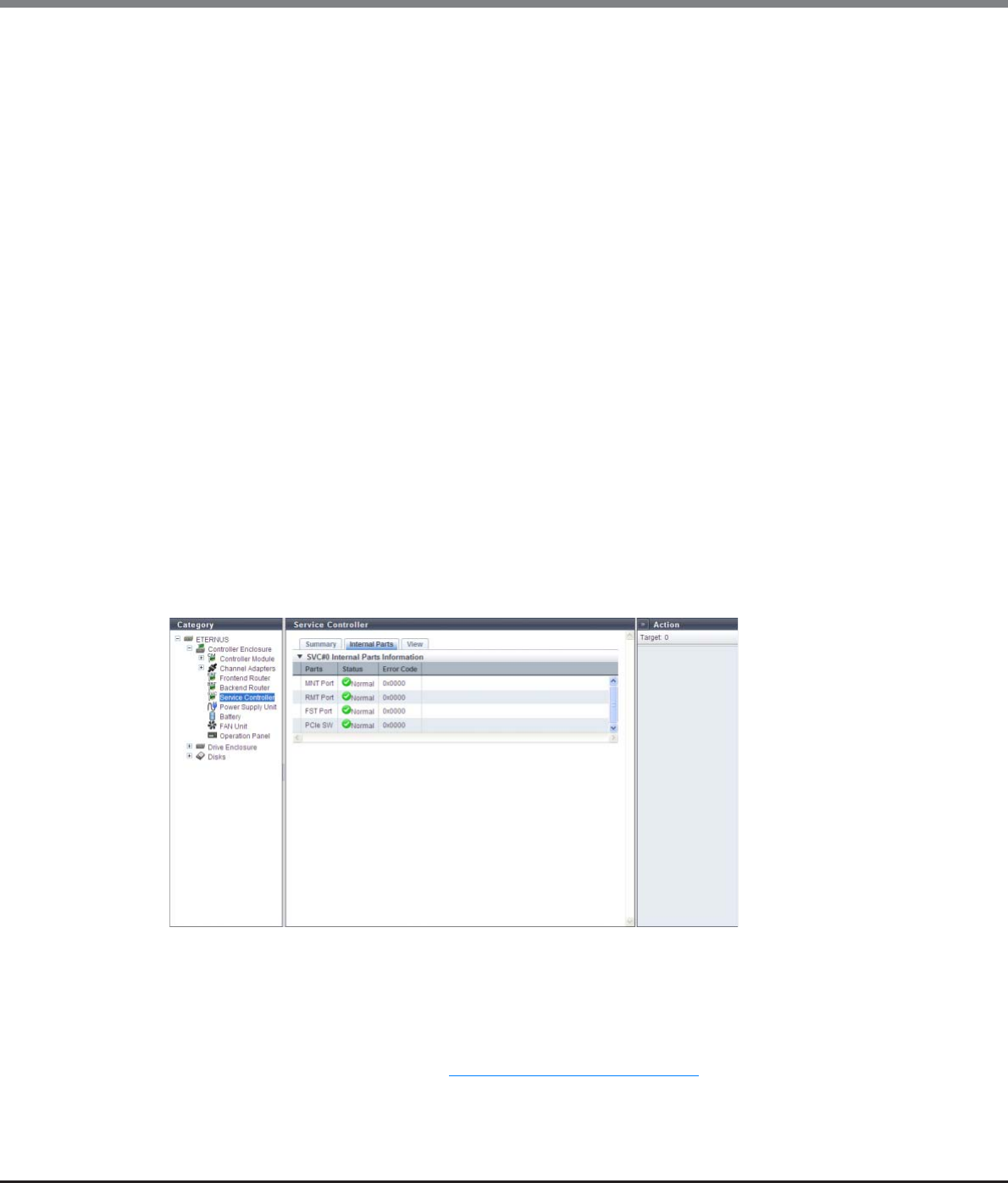
Chapter 10 Component Management
10.1 Component Status
ETERNUS Web GUI User’s Guide
Copyright 2013 FUJITSU LIMITED P2X0-1090-10ENZ0
663
•Hardware Revision
The hardware version of the SVC is displayed.
•MAC Address (MNT)
The MAC address of the MNT Port is displayed.
•MAC Address (RMT)
The MAC address of the RMT Port is displayed.
•MAC Address (FST)
The MAC address of the FST Port is displayed.
•LAN Control
The role of the LAN in the SVC is displayed.
-Master
When the SVC is connected to the Master CM, "Master" is displayed.
-Slave
When the SVC is connected to the Slave CM, "Slave" is displayed.
•Active EC
The Edition Control (EC) number of the currently running firmware is displayed.
•Next EC
The EC number of the firmware that is to be run at the next power-on is displayed.
•Firmware Version
The current controller firmware version is displayed.
■Internal Parts
The following items are displayed in the Main area:
•Parts
The part name is displayed.
•Status
The part status is displayed. Refer to "B.5 Component Status" (page 977) for details.
•Error Code
The part error code is displayed.
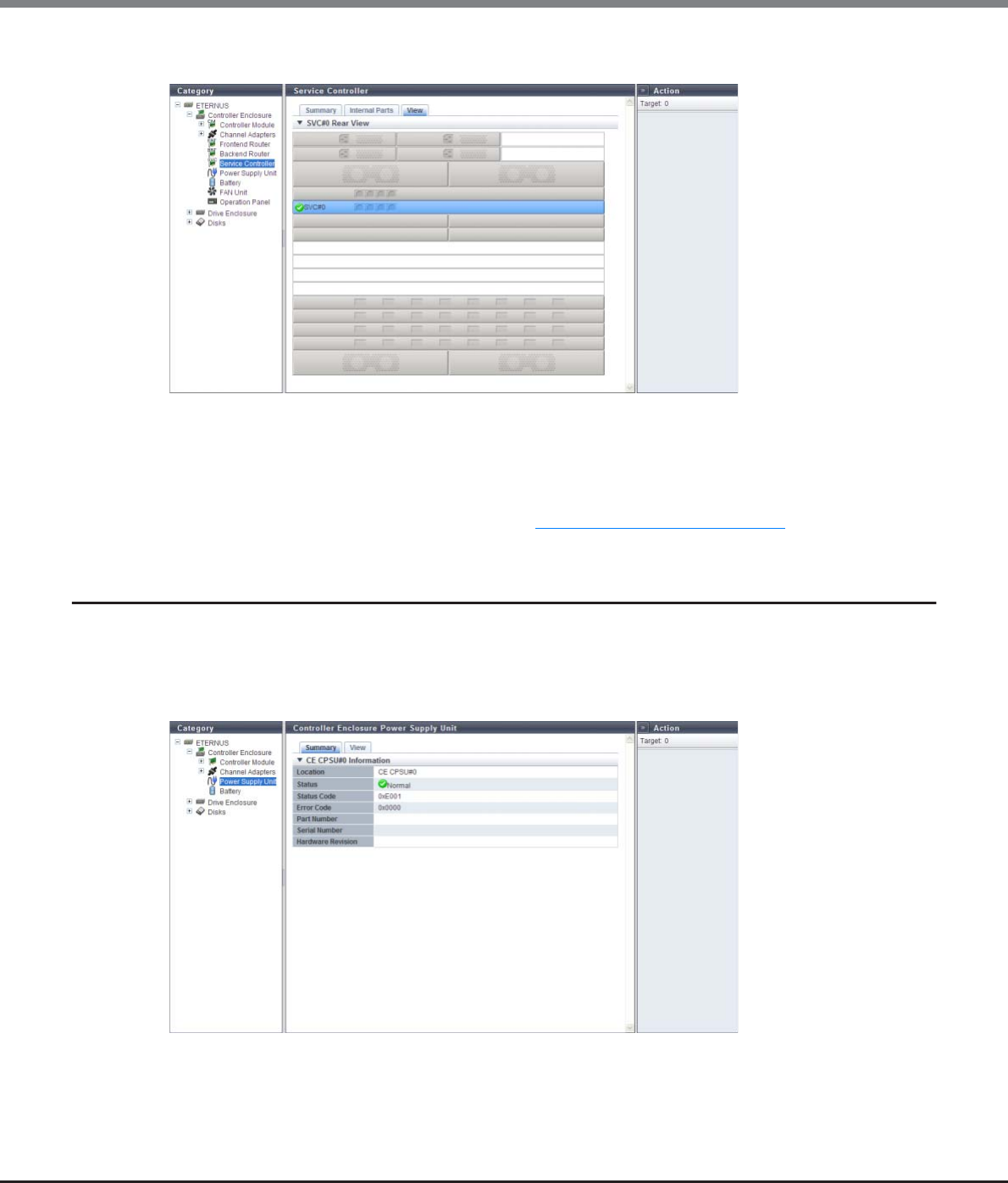
Chapter 10 Component Management
10.1 Component Status
ETERNUS Web GUI User’s Guide
Copyright 2013 FUJITSU LIMITED P2X0-1090-10ENZ0
664
■View
The following items are displayed in the Main area:
•Device image
The rear view of the CE that is installed in the ETERNUS DX Disk storage system is displayed.
Components that are not the target SVC are grayed out.
The SVC status is displayed with an icon. Refer to "B.5 Component Status" (page 977) for details.
10.1.11 PSU/CPSU (CE) Detail
The detailed information for the PSU or the CPSU is displayed.
■Summary
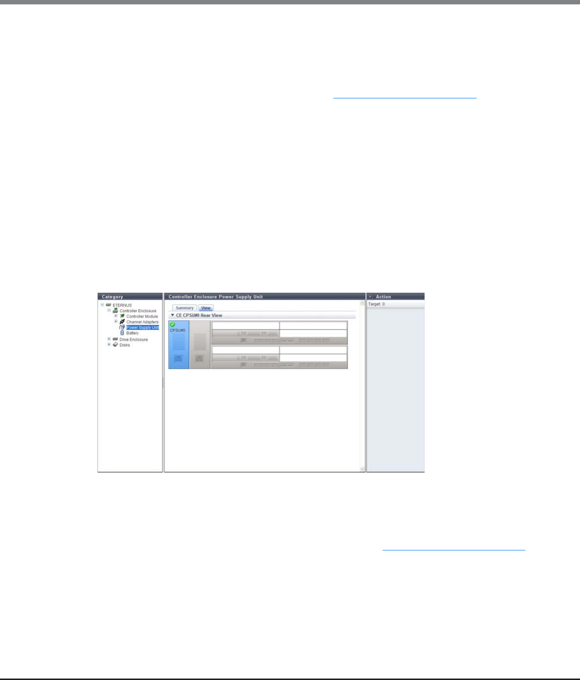
Chapter 10 Component Management
10.1 Component Status
ETERNUS Web GUI User’s Guide
Copyright 2013 FUJITSU LIMITED P2X0-1090-10ENZ0
665
The following items are displayed in the Main area:
•Location
The installation location of PSU or the CPSU is displayed.
•Status
The PSU status or the CPSU status is displayed. Refer to "B.5 Component Status" (page 977) for details.
•Status Code
The status code of PSU or CPSU is displayed.
•Error Code
The error code of PSU or CPSU is displayed.
•Part Number
The part number of PSU or CPSU is displayed.
•Serial Number
The serial number of PSU or CPSU is displayed.
•Hardware Revision
The hardware version of PSU or CPSU is displayed.
■View
The following items are displayed in the Main area:
•Device image
The rear view of the CE that is installed in the ETERNUS DX Disk storage system is displayed.
Components that are not PSUs or CPSUs are grayed out.
The PSU status or the CPSU status is displayed with an icon. Refer to "B.5 Component Status" (page 977) for
details.
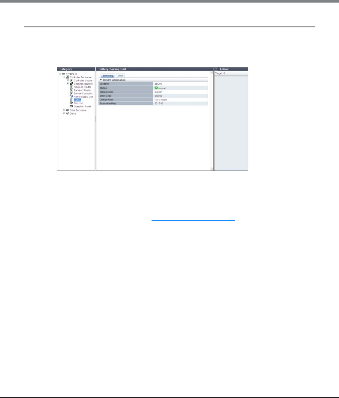
Chapter 10 Component Management
10.1 Component Status
ETERNUS Web GUI User’s Guide
Copyright 2013 FUJITSU LIMITED P2X0-1090-10ENZ0
666
10.1.12 Battery Backup Unit Detail
The detailed information of the Battery Backup unit is displayed.
■Summary
The following items are displayed in the Main area:
•Location
The BBU number is displayed.
•Status
The BBU status is displayed. Refer to "B.5 Component Status" (page 977) for details.
•Status Code
The BBU unit status code is displayed.
•Error Code
The BBU error code is displayed.
•Charge Rate
The BBU charge rate is displayed.
When the battery charge level is 90% or more, "Full Charge" is displayed. When the battery charge level is
less than 90%, "xx%" is displayed.
•Expiration Date
The expiration date for the BBU is displayed.
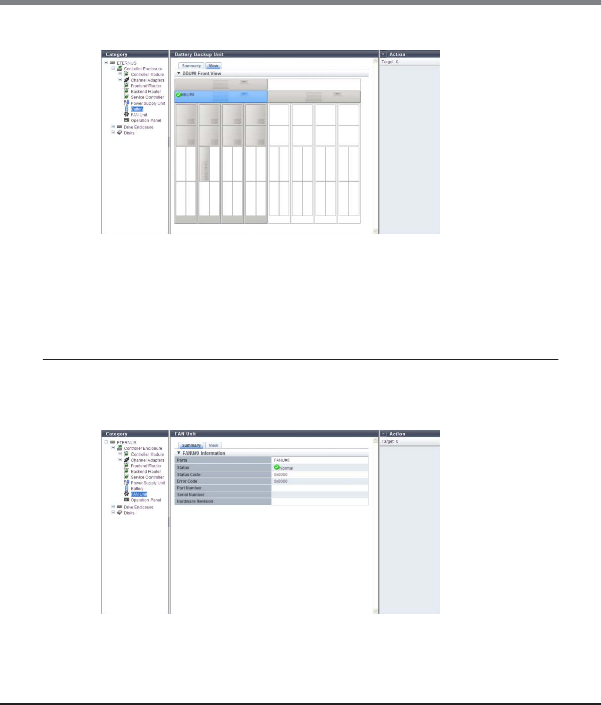
Chapter 10 Component Management
10.1 Component Status
ETERNUS Web GUI User’s Guide
Copyright 2013 FUJITSU LIMITED P2X0-1090-10ENZ0
667
■View
The following items are displayed in the Main area:
•Device image
The front view of the CE that is installed in the ETERNUS DX Disk storage system is displayed.
Components that are not the target BBU are grayed out.
The BBU status is displayed with an icon. Refer to "B.5 Component Status" (page 977) for details.
10.1.13 FAN Unit Detail
The detailed information of the FAN unit is displayed.
■Summary
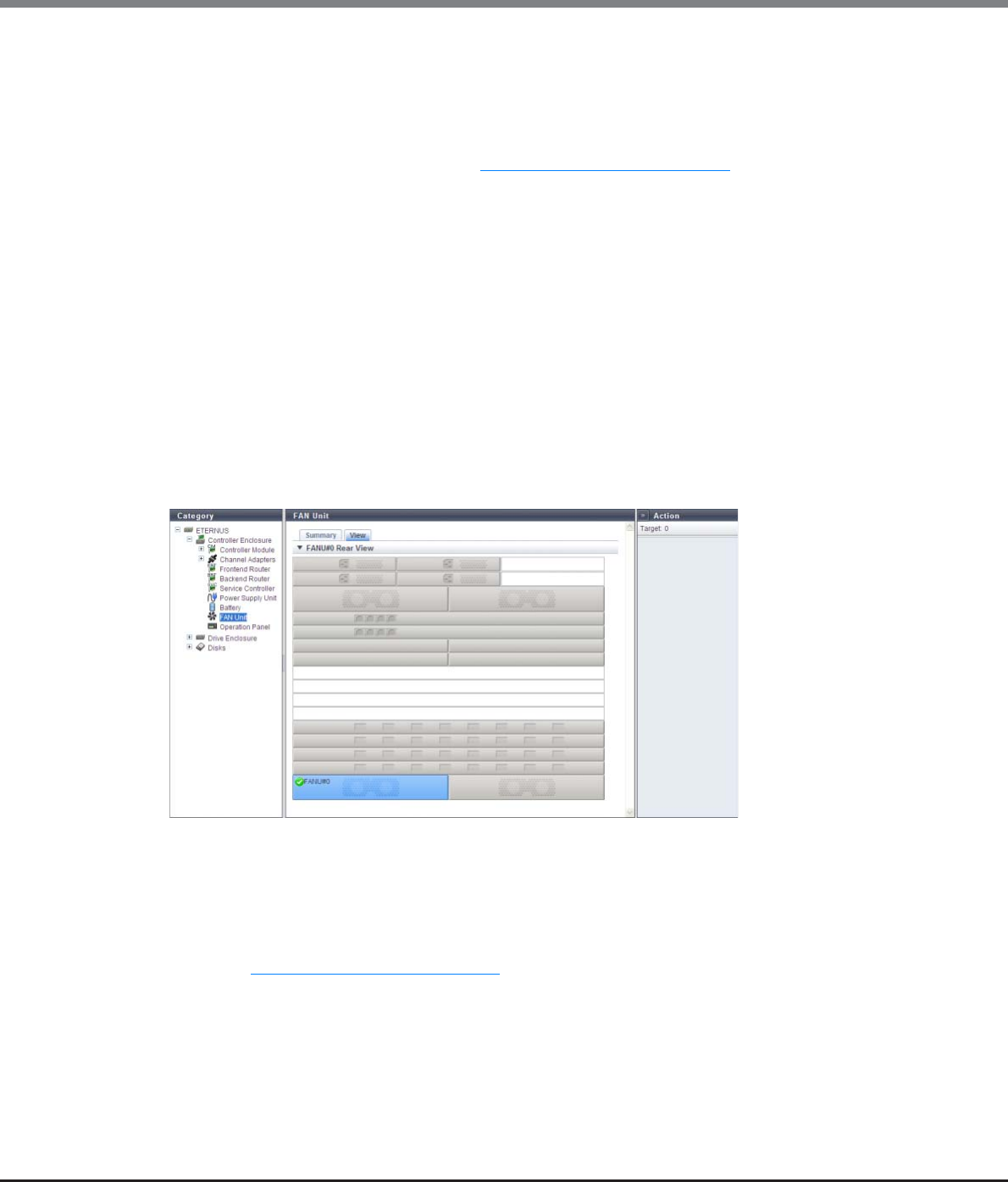
Chapter 10 Component Management
10.1 Component Status
ETERNUS Web GUI User’s Guide
Copyright 2013 FUJITSU LIMITED P2X0-1090-10ENZ0
668
The following items are displayed in the Main area:
•Parts
The FAN unit number is displayed.
•Status
The FAN unit status is displayed. Refer to "B.5 Component Status" (page 977) for details.
•Status Code
The FAN unit status code is displayed.
•Error Code
The FAN unit error code is displayed.
•Part Number
The part number of the FAN unit is displayed.
•Serial Number
The serial number of the FAN unit is displayed.
•Hardware Revision
The hardware version of the FAN unit is displayed.
■View
The following items are displayed in the Main area:
•Device image
The rear view of the CE that is installed in the ETERNUS DX Disk storage system is displayed.
Components that are not the target FAN unit are grayed out.
The FAN unit status is displayed with an icon.
Refer to "B.5 Component Status" (page 977) for details.
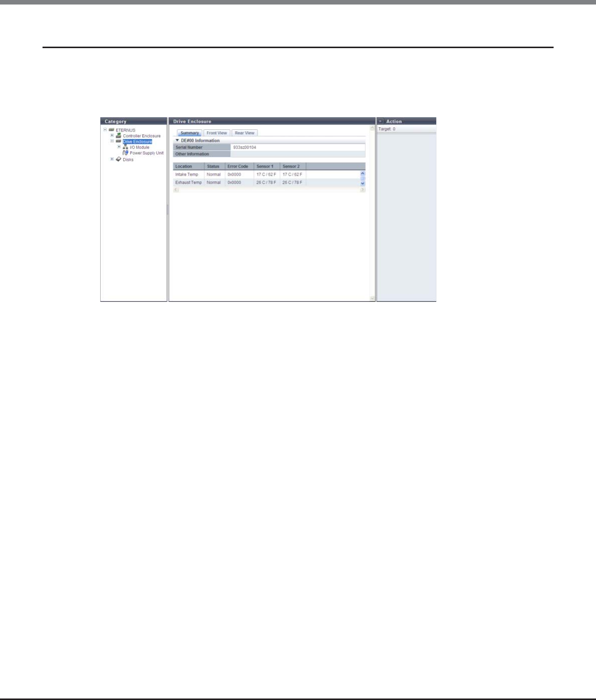
Chapter 10 Component Management
10.1 Component Status
ETERNUS Web GUI User’s Guide
Copyright 2013 FUJITSU LIMITED P2X0-1090-10ENZ0
669
10.1.14 Drive Enclosure Detail
The detailed information of the DE is displayed.
■Summary
The following items are displayed in the Main area:
•Serial Number
The serial number of the DE is displayed.
•Other Information
Additional information for the DE is displayed.
•Location
The installation location of the thermal sensor is displayed.
-Intake Temp
-Exhaust Temp
•Status
The thermal sensor status is displayed.
•Error Code
The error code for thermal sensor is displayed.
•Sensor 1
The internal temperature of the IOM#0 is displayed in Celsius (C) and in Fahrenheit (F).
If the thermal information is not available due to problem such as a sensor failure, a "-" (hyphen) is
displayed.
•Sensor 2
The internal temperature of the IOM#1 is displayed in Celsius (C) and in Fahrenheit (F).
If the thermal information is not available due to problem such as a sensor failure, a "-" (hyphen) is
displayed.
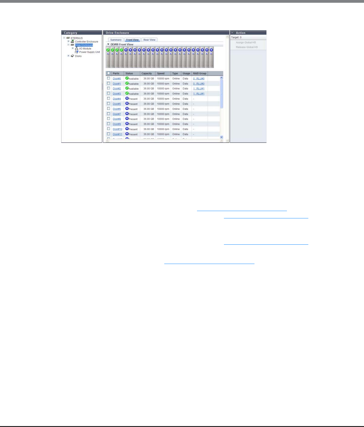
Chapter 10 Component Management
10.1 Component Status
ETERNUS Web GUI User’s Guide
Copyright 2013 FUJITSU LIMITED P2X0-1090-10ENZ0
670
■Front View
The following items are displayed in the Main area:
•Device image
The front view of the DEs that are installed in the ETERNUS DX Disk storage system is displayed.
-For 2.5-inch models: 24 (24 drives are lined up horizontally)
-For 3.5-inch models: 12 (3 drives are lined up vertically and 4 drives are lined up horizontally)
-When no drives are installed: Blank
The drive status is displayed with an icon. Refer to "B.5 Component Status" (page 977) for details.
By clicking this item, the [Disks] screen is displayed. Refer to "10.1.17 Disks Detail" (page 675) for details.
•Parts
The drive number is displayed.
By clicking this item, the [Disks] screen is displayed. Refer to "10.1.17 Disks Detail" (page 675) for details.
•Status
The drive status is displayed. Refer to "B.5 Component Status" (page 977) for details.
•Capacity
The capacity of the drive is displayed.
•Speed
The drive speed is displayed. For SSDs, a "-" (hyphen) is displayed.
-15000 rpm
-10000 rpm
-7200 rpm
•Type
The drive type is displayed.
-For SAS disks: Online
-For Nearline SAS disks: Nearline
-For SSDs: SSD
-For SEDs: SED
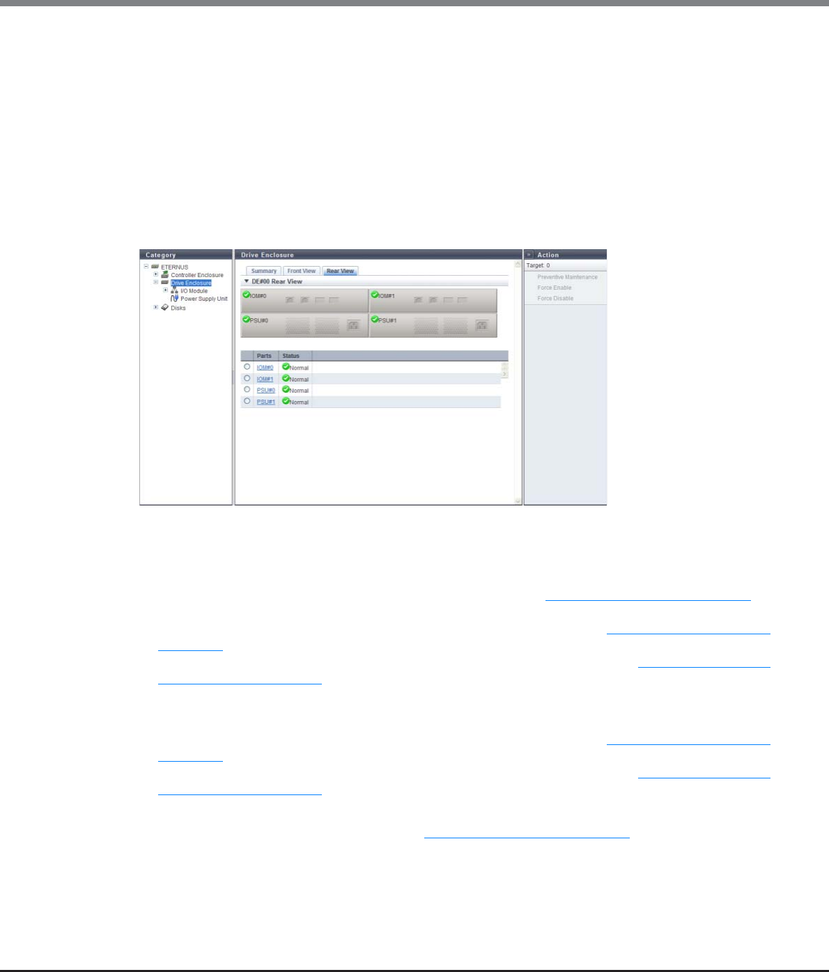
Chapter 10 Component Management
10.1 Component Status
ETERNUS Web GUI User’s Guide
Copyright 2013 FUJITSU LIMITED P2X0-1090-10ENZ0
671
•Usage
The usage of the drive is displayed.
-For a drive that is used for user data or an unused drive: Data
-For a drive that is registered as a Global Hot Spare: Global Hot Spare
-For a drive that is registered as a Dedicated Hot Spare: Dedicated Hot Spare
•RAID Group
If the drive is registered in a RAID group, the RAID group name to which the drive belongs is displayed.
By clicking this item, the [RAID Group Detail] screen is displayed.
■Rear View
The following items are displayed in the Main area:
•Device image
The rear view of the DE that is installed in the ETERNUS DX Disk storage system is displayed.
The IOM status or the PSU status is displayed with an icon. Refer to "B.5 Component Status" (page 977) for
details.
By clicking the IOM number, the [I/O Module] screen is displayed. Refer to "10.1.15 I/O Module Detail"
(page 672) for display items.
By clicking the PSU number, the [Power Supply Unit] screen is displayed. Refer to "10.1.16 Power Supply
Unit (DE) Detail" (page 674) for display items.
•Parts
The IOM number or the PSU number is displayed.
By clicking the IOM number, the [I/O Module] screen is displayed. Refer to "10.1.15 I/O Module Detail"
(page 672) for display items.
By clicking the PSU number, the [Power Supply Unit] screen is displayed. Refer to "10.1.16 Power Supply
Unit (DE) Detail" (page 674) for display items.
•Status
The status of IOM or PSU is displayed. Refer to "B.5 Component Status" (page 977) for details.
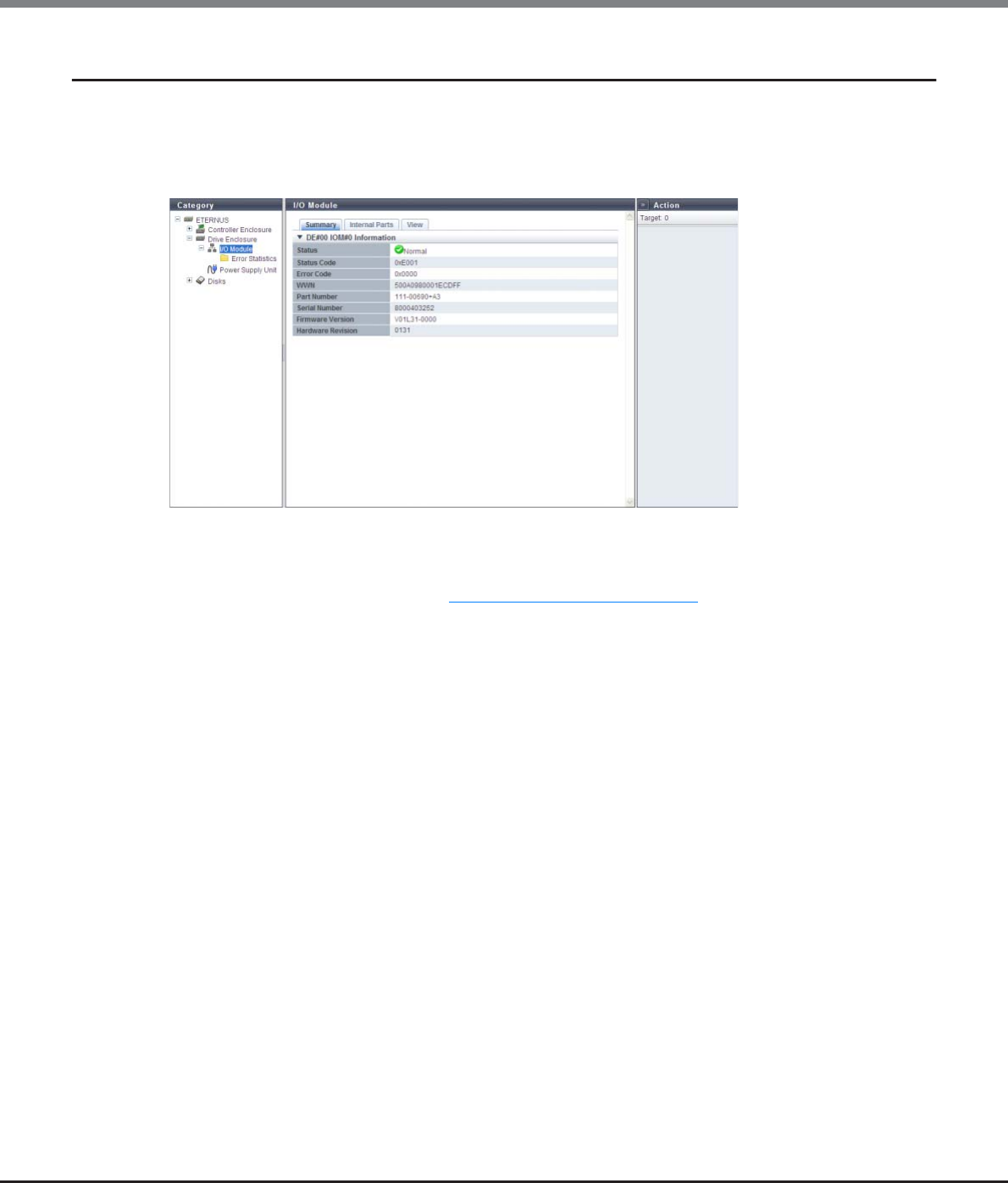
Chapter 10 Component Management
10.1 Component Status
ETERNUS Web GUI User’s Guide
Copyright 2013 FUJITSU LIMITED P2X0-1090-10ENZ0
672
10.1.15 I/O Module Detail
The detailed information of IOM is displayed.
■Summary
The following items are displayed in the Main area:
•Status
The IOM status is displayed. Refer to "B.5 Component Status" (page 977) for details.
•Status Code
The IOM status code is displayed.
•Error Code
The IOM error code is displayed.
•WWN
The IOM WWN is displayed.
•Part Number
The IOM part number is displayed.
•Serial Number
The serial number of the IOM is displayed.
•Firmware Version
The current controller firmware version is displayed.
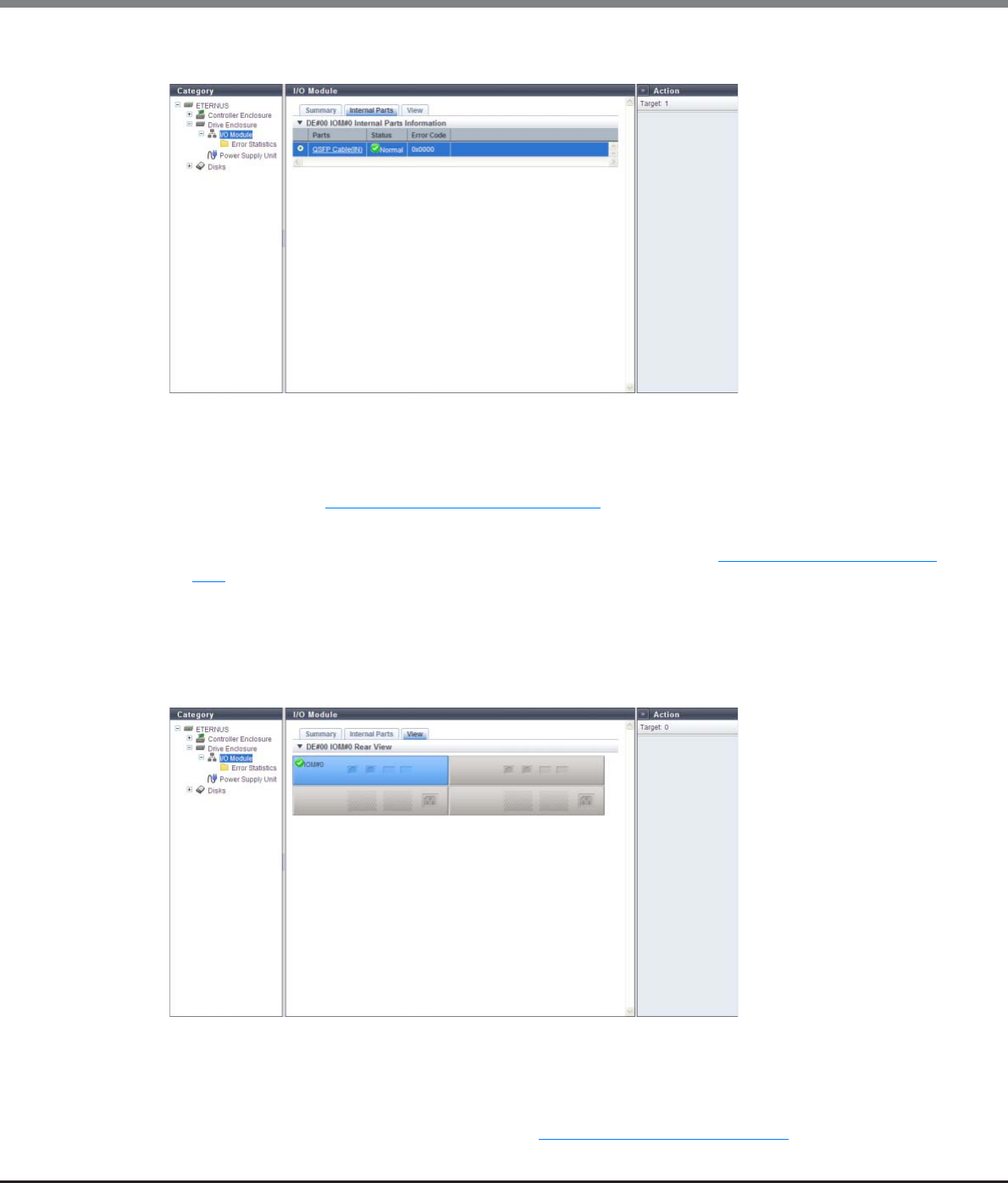
Chapter 10 Component Management
10.1 Component Status
ETERNUS Web GUI User’s Guide
Copyright 2013 FUJITSU LIMITED P2X0-1090-10ENZ0
673
■Internal Parts
The following items are displayed in the Main area:
•Parts
The QSFP Cable (IN) or the QSFP Cable (OUT) is displayed. By clicking this item, the [QSFP Cable] screen is
displayed. Refer to "10.1.18 QSFP Cable Detail" (page 678) for display items.
•Status
The status for QSFP Cable (IN) or QSFP Cable (OUT) is displayed. Refer to "B.5 Component Status" (page
977) for details.
•Error Code
The error code for QSFP Cable (IN) or QSFP Cable (OUT) is displayed.
■View
The following items are displayed in the Main area:
•Device image
The rear view of the DE that is installed in the ETERNUS DX Disk storage system is displayed.
Components that are not IOMs are grayed out.
The IOM status is displayed with an icon. Refer to "B.5 Component Status" (page 977) for details.
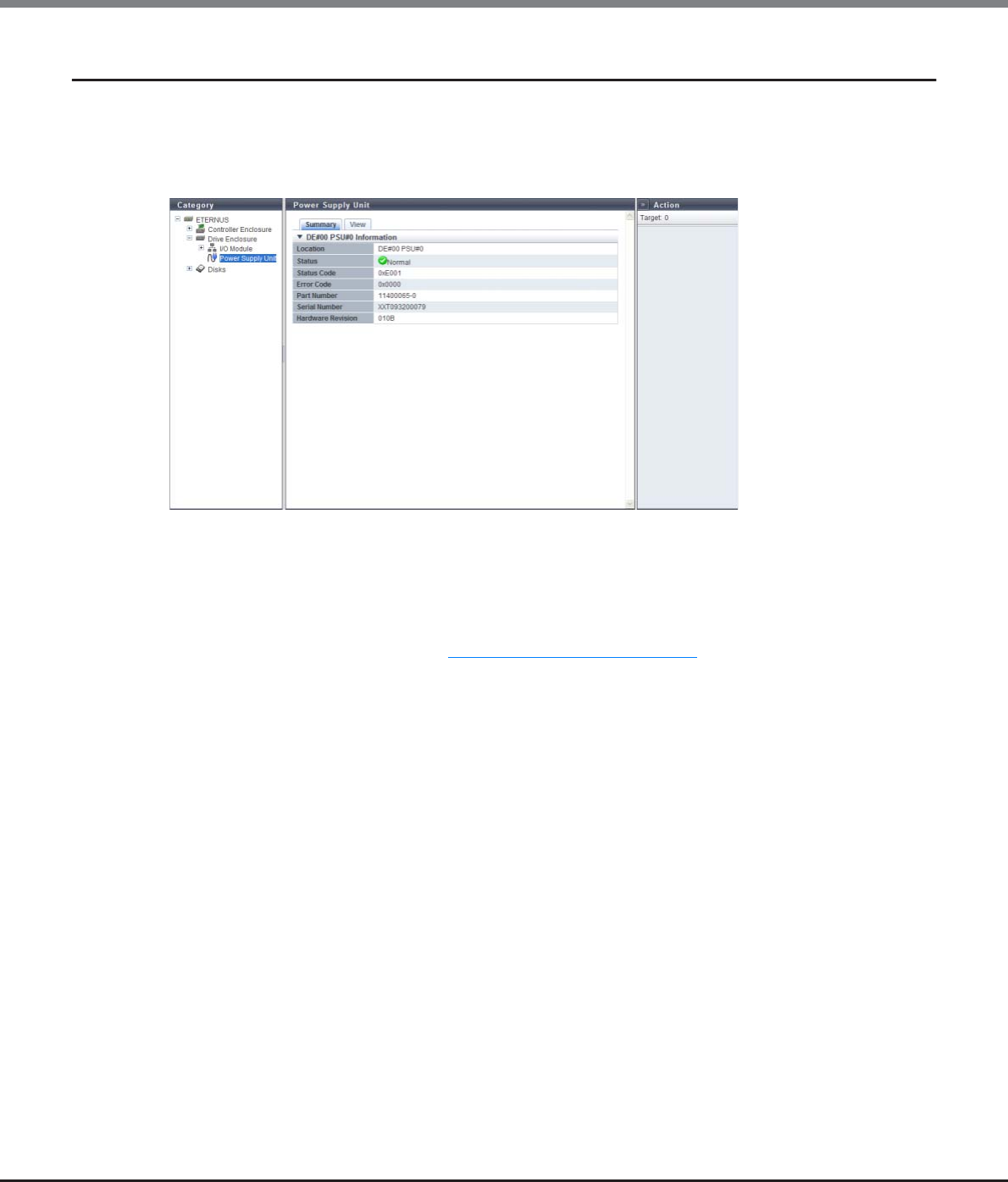
Chapter 10 Component Management
10.1 Component Status
ETERNUS Web GUI User’s Guide
Copyright 2013 FUJITSU LIMITED P2X0-1090-10ENZ0
674
10.1.16 Power Supply Unit (DE) Detail
The detailed information of PSU is displayed.
■Summary
The following items are displayed in the Main area:
•Location
The installation location of PSU is displayed.
•Status
The PSU status is displayed. Refer to "B.5 Component Status" (page 977) for details.
•Status Code
The PSU status code is displayed.
•Error Code
The PSU error code is displayed.
•Part Number
The PSU part number is displayed.
•Serial Number
The PSU serial number is displayed.
•Hardware Revision
The hardware version of the PSU is displayed.
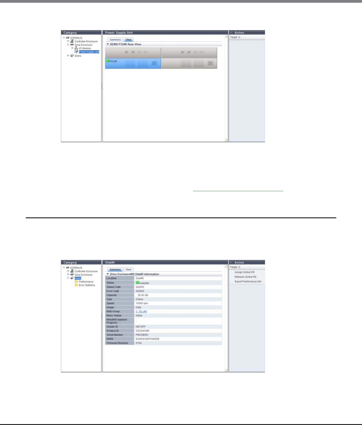
Chapter 10 Component Management
10.1 Component Status
ETERNUS Web GUI User’s Guide
Copyright 2013 FUJITSU LIMITED P2X0-1090-10ENZ0
675
■View
The following items are displayed in the Main area:
•Device image
The rear view of the DE that is installed in the ETERNUS DX Disk storage system is displayed.
Components that are not PSUs are grayed out.
The PSU status is displayed with an icon. Refer to "B.5 Component Status" (page 977) for details.
10.1.17 Disks Detail
The detailed information of the drive is displayed.
■Summary

Chapter 10 Component Management
10.1 Component Status
ETERNUS Web GUI User’s Guide
Copyright 2013 FUJITSU LIMITED P2X0-1090-10ENZ0
676
The following items are displayed in the Main area:
•Location
The detailed information of the drive is displayed.
•Status
The drive status is displayed. Refer to "B.5 Component Status" (page 977) for details.
•Status Code
The drive status code is displayed.
•Error Code
The drive error code is displayed.
•Capacity
The capacity of the drive is displayed.
•Type
The drive type is displayed.
-For SAS disks: Online
-For Nearline SAS disks: Nearline
-For SSDs: SSD
-For SEDs: SED
•Speed
The drive speed is displayed. For SSDs, a "-" (hyphen) is displayed.
-15000 rpm
-10000 rpm
-7200 rpm
•Usage
The usage of the drive is displayed.
-Data
-Global Hot Spare
-Dedicated Hot Spare
•RAID Group
If the drive is registered in the RAID group, the RAID group number and the RAID group name to which the
drive belongs is displayed.
By clicking this item, the [RAID Group Detail] screen is displayed.
•Motor Status
The drive motor status is displayed.
-"Active" status is displayed during operation of the storage system
-"In the Boot Process" status is displayed during operation of the storage system
-"Idle" status is displayed when the storage system is not running
-"In the Stop Process" is displayed when the storage system is in the process of stopping
•Rebuild/Copyback Progress
When rebuild or copyback is being performed, the progress ratio is displayed.
When rebuild or copyback is being performed, the progress ratio is displayed.
•Vendor ID
The drive manufacturer name is displayed.
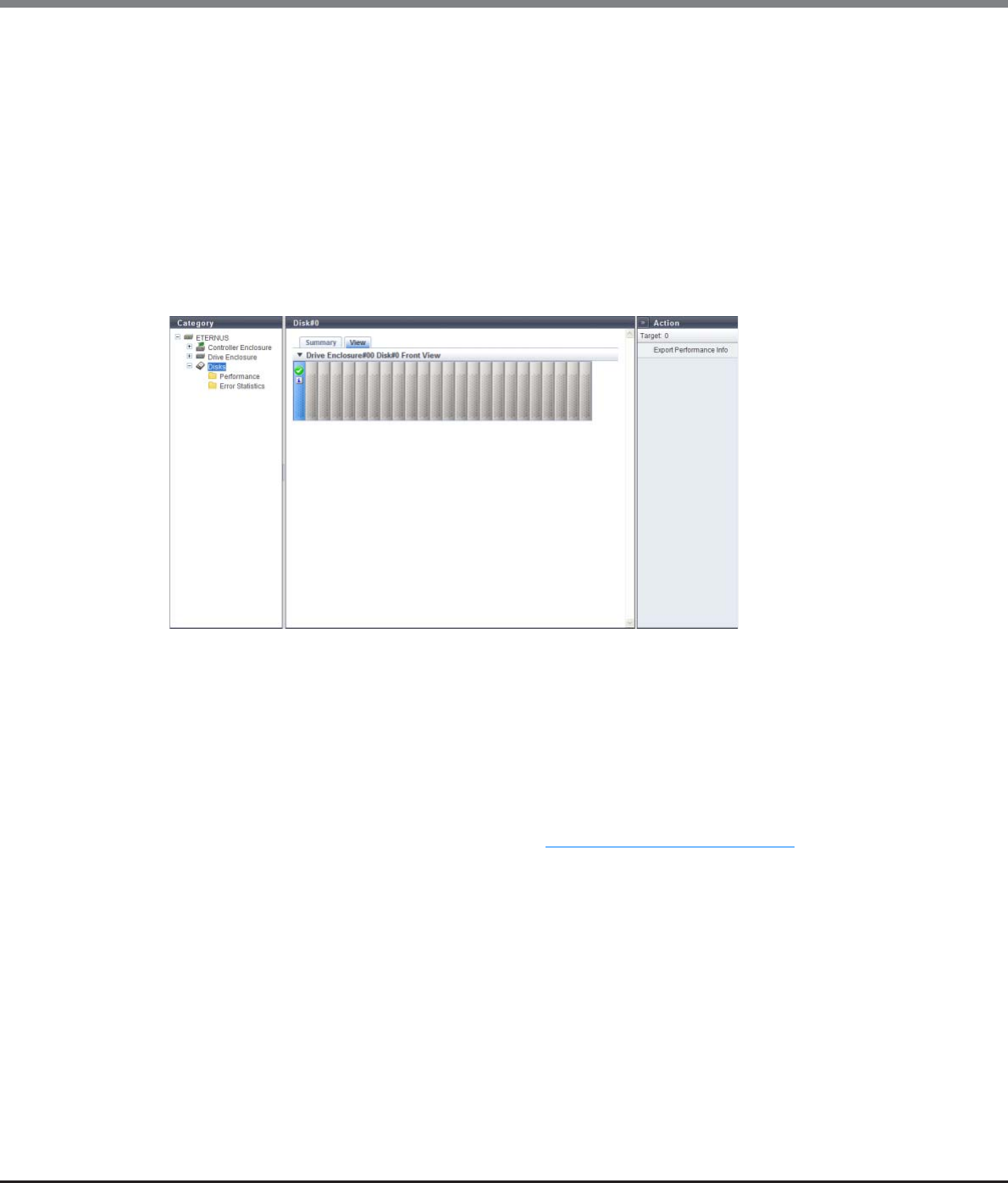
Chapter 10 Component Management
10.1 Component Status
ETERNUS Web GUI User’s Guide
Copyright 2013 FUJITSU LIMITED P2X0-1090-10ENZ0
677
•Product ID
The drive manufacturer name is displayed.
•Serial Number
The serial number of the drive is displayed.
•WWN
The drive WWN is displayed.
•Firmware Version
The drive firmware version is displayed.
■View
The following items are displayed in the Main area:
•Device image
The front view of the DE that are installed in the ETERNUS DX Disk storage system is displayed.
-For 2.5-inch drives: 24 (24 drives are lined up horizontally)
-For 3.5-inch drives: 12 (3 drives are lined up vertically and 4 drives are lined up horizontally)
-When no drives are installed: Blank
Drives that are not selected in the [Drives] screen are grayed out.
The drive status is displayed with an icon. Refer to "B.5 Component Status" (page 977) for details.
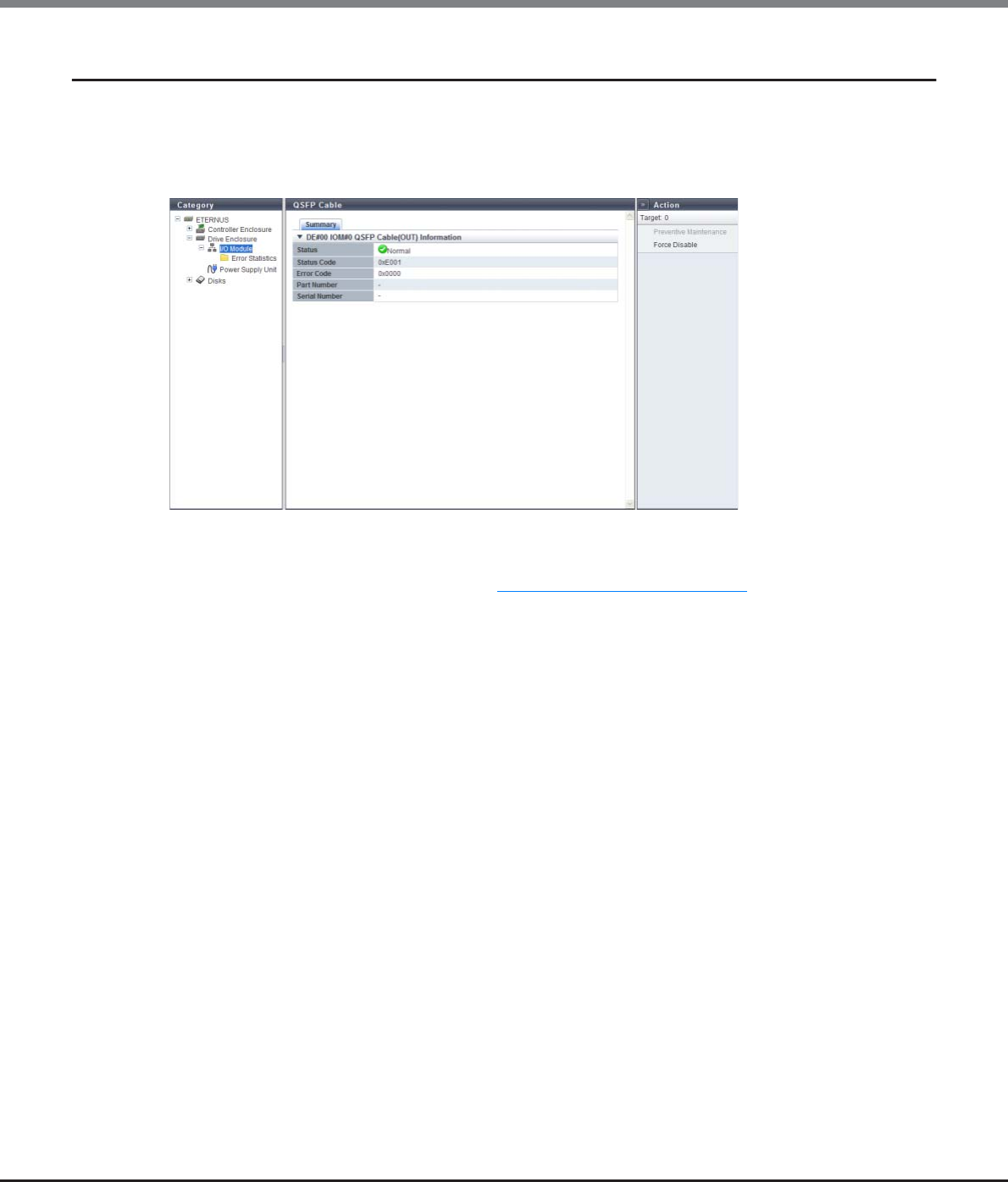
Chapter 10 Component Management
10.1 Component Status
ETERNUS Web GUI User’s Guide
Copyright 2013 FUJITSU LIMITED P2X0-1090-10ENZ0
678
10.1.18 QSFP Cable Detail
The detailed information of the QSFP cable is displayed.
■Summary
The following items are displayed in the Main area:
•Status
The QSFP cable status is displayed. Refer to "B.5 Component Status" (page 977) for details.
•Status Code
The QSFP cable status code is displayed.
•Error Code
The QSFP cable error code is displayed.
•Part Number
The QSFP cable number is displayed.
•Serial Number
The QSFP cable serial number is displayed.
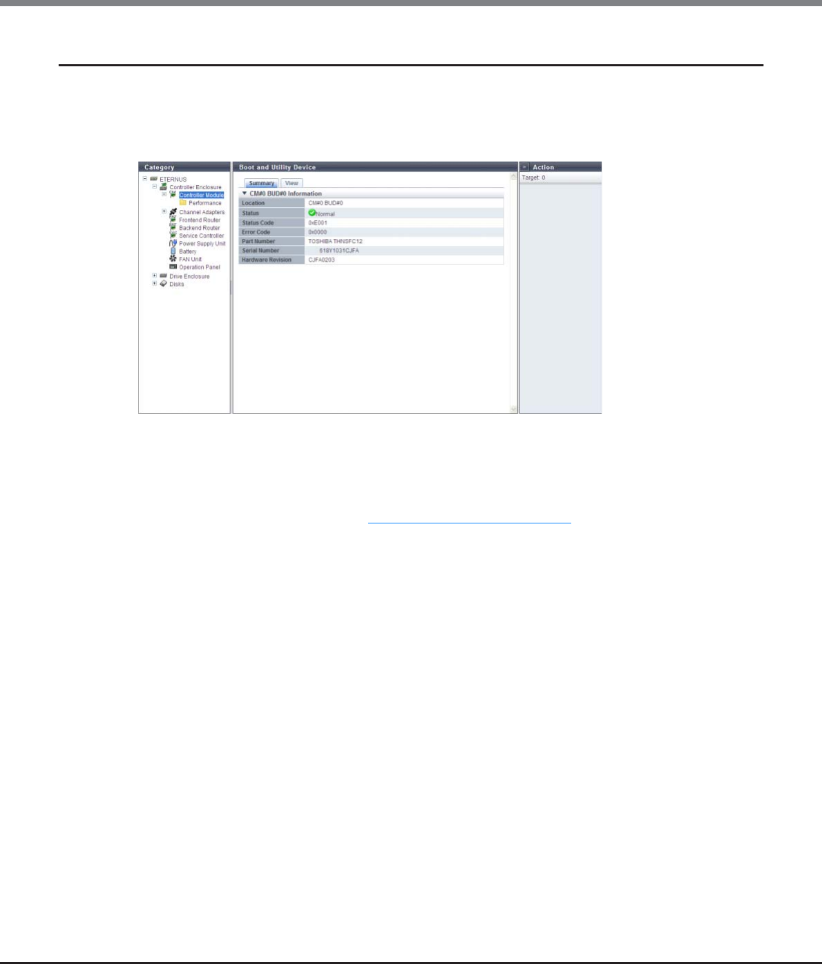
Chapter 10 Component Management
10.1 Component Status
ETERNUS Web GUI User’s Guide
Copyright 2013 FUJITSU LIMITED P2X0-1090-10ENZ0
679
10.1.19 Boot and Utility Device Detail
The detailed information of the Boot and Utility Device (BUD) is displayed.
■Summary
The following items are displayed in the Main area:
•Location
The BUD number is displayed.
•Status
The BUD status is displayed. Refer to "B.5 Component Status" (page 977) for details.
•Status Code
The BUD status code is displayed.
•Error Code
The BUD error code is displayed.
•Part Number
The BUD part number is displayed.
•Serial Number
The BUD serial number is displayed.
•Hardware Revision
The hardware version of the BUD is displayed.
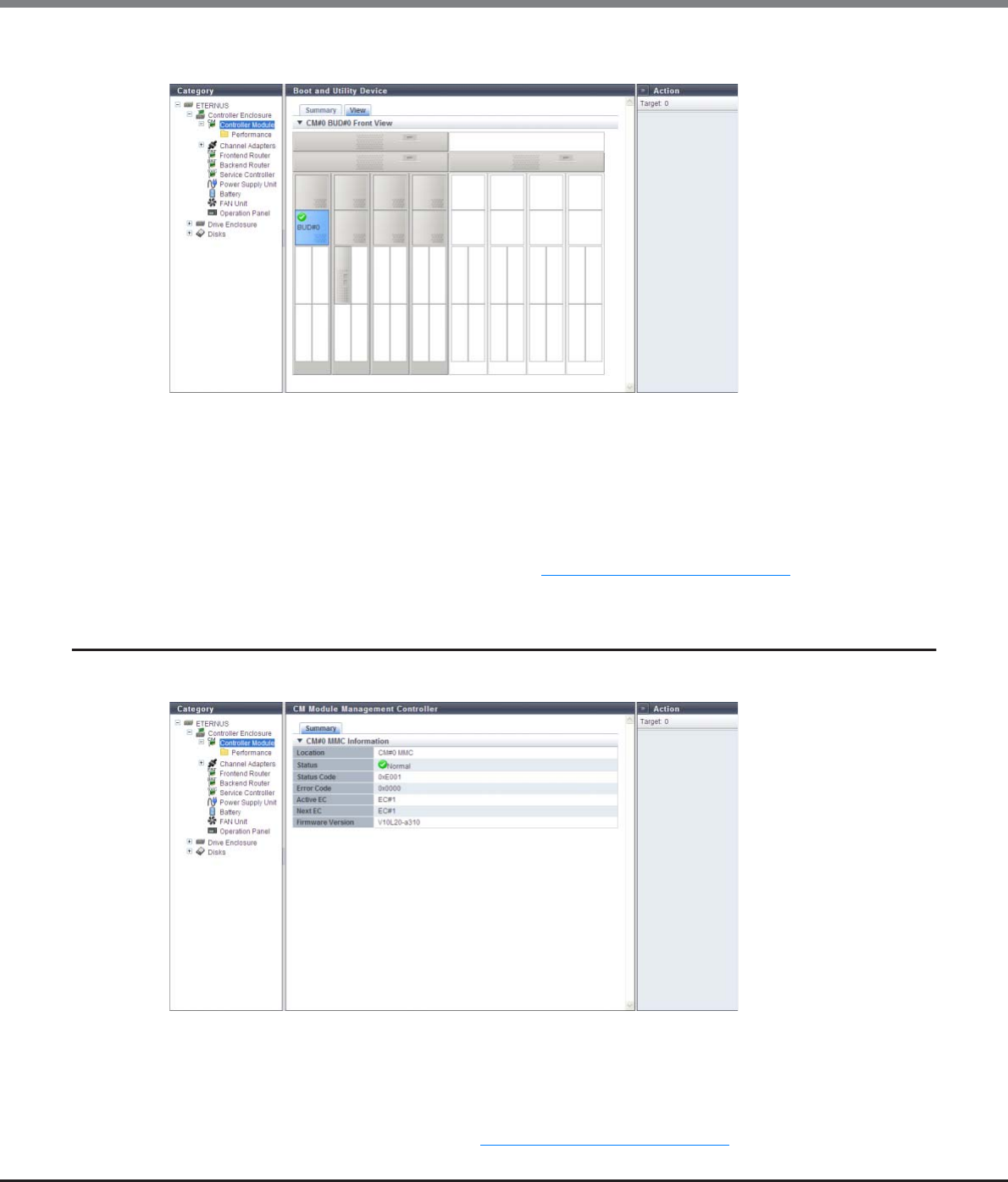
Chapter 10 Component Management
10.1 Component Status
ETERNUS Web GUI User’s Guide
Copyright 2013 FUJITSU LIMITED P2X0-1090-10ENZ0
680
■View
The following items are displayed in the Main area:
•Device image
The rear view or the front view of the CE that is installed in the ETERNUS DX Disk storage system is
displayed.
For the ETERNUS DX8100 S2, the rear view is displayed.
For the ETERNUS DX8700 S2, the front view is displayed.
Components that are not BUDs are grayed out.
The BUD status is displayed with an icon. Refer to "B.5 Component Status" (page 977) for details.
10.1.20 CM Module Management Controller Detail
The detailed information of the CM Module Management Controller (CM MMC) is displayed.
The following items are displayed in the Main area:
•Location
The CM MMC number is displayed.
•Status
The CM MMC status is displayed. Refer to "B.5 Component Status" (page 977) for details.
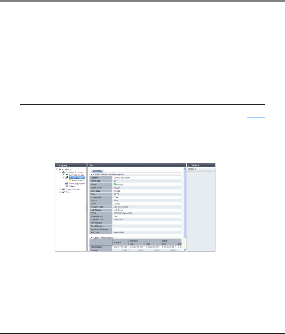
Chapter 10 Component Management
10.1 Component Status
ETERNUS Web GUI User’s Guide
Copyright 2013 FUJITSU LIMITED P2X0-1090-10ENZ0
681
•Status Code
The CM MMC status code is displayed.
•Error Code
The CM MMC error code is displayed.
•Active EC
The Edition Control (EC) number of the currently running firmware is displayed.
•Next EC
The EC number of the firmware that is to be run at the next power-on is displayed.
•Hardware Revision
The hardware version of the CM MMC is displayed.
10.1.21 Port Detail
The detailed information of the port is displayed. Display items vary depending on the port type ("FC port"
(page 681), "iSCSI port" (page 687), "SAS port" (page 690), or "FCoE port" (page 691)).
■Summary
●FC port
The detailed FC port information is displayed.

Chapter 10 Component Management
10.1 Component Status
ETERNUS Web GUI User’s Guide
Copyright 2013 FUJITSU LIMITED P2X0-1090-10ENZ0
682
The following items are displayed in the Main area:
■CM#x CA#y Port#z Information
-Location
The location information of the port is displayed.
•CM#x CA#y Port#z (x: CM number, y: CA number, z: Port number)
-Port Mode
The port mode is displayed.
•CA
•RA
•CA/RA
•Initiator
-Status
The port status is displayed. Refer to "B.5 Component Status" (page 977) for details.
-Status Code
The port status code is displayed.
-Error Code
The port error code is displayed.
-Type
The port type is displayed.
•8G FC
•16G FC
-Connection
The connection type of the port is displayed.
•Fabric
A connection type that enables simultaneous communication among multiple nodes through a
Fibre Channel switch. This connection type can also be used for a direct connection when "Transfer
Rate" is "16 Gbit/s".
•FC-AL
A connection type that connects multiple nodes in a loop.
-Loop ID
If the connection type of the target port is "FC-AL", the Loop ID is displayed.
When the Loop ID is manually specified, the ID that is to be set for the port is displayed in hexadecimal.
When the Loop ID is automatically specified, "Ascending" or "Descending" is displayed.
When the "Connection" is "Fabric", a "-" (hyphen) is displayed.
-Class
The service class of the port (fixed to "Class3") is displayed.
-Transfer Rate
The transfer speed of the port is displayed.
If the status is " Unknown", a "-" (hyphen) is displayed.
•Auto-negotiation
•1 Gbit/s
•2 Gbit/s
•4 Gbit/s
•8 Gbit/s
•16 Gbit/s

Chapter 10 Component Management
10.1 Component Status
ETERNUS Web GUI User’s Guide
Copyright 2013 FUJITSU LIMITED P2X0-1090-10ENZ0
683
-Link Status
The link status of the port is displayed.
If the status is " Unknown", a "-" (hyphen) is displayed.
•Link Down
•1 Gbit/s Link Up
•2Gbit/s Link Up
•4Gbit/s Link Up
•8Gbit/s Link Up
•16Gbit/s Link Up
-WWN
The WWN of the port is displayed.
"WWN" is displayed when the port mode is "CA", "RA", or "CA/RA".
If the port mode is "Initiator", the display status varies according to the screen. A "-" (hyphen) is
displayed for the CM#x CA#y port information in the [Channel Adapter Detail] screen. This item is not
displayed in the [Port Detail] screen.
-WWN (Port Name)
The WWPN of the port is displayed.
"WWN (Port Name)" is displayed when the port mode is "Initiator".
If the port mode is not "Initiator", the display status varies according to the screen. A "-" (hyphen) is
displayed for the CM#x CA#y port information in the [Channel Adapter Detail] screen. This item is not
displayed in the [Port Detail] screen.
-WWN (Node Name)
The WWNN of the port is displayed.
"WWN (Node Name)" is displayed when the port mode is "Initiator".
If the port mode is not "Initiator", the display status varies according to the screen. A "-" (hyphen) is
displayed for the CM#x CA#y port information in the [Channel Adapter Detail] screen. This item is not
displayed in the [Port Detail] screen.
-Affinity Mode
The affinity mode of the port is displayed.
•ON
•OFF
-FC Frame Size
The frame size of the port is displayed.
•512 byte
•1024 byte
•2048 byte
-Part Number
The part number of the port is displayed.
If the part number cannot be acquired, a "-" (hyphen) is displayed.
-Serial Number
The serial number of the port is displayed.
If the serial number cannot be acquired, a "-" (hyphen) is displayed.
-Hardware Revision
The hardware version of the port is displayed.
If the hardware version cannot be acquired, a "-" (hyphen) is displayed.

Chapter 10 Component Management
10.1 Component Status
ETERNUS Web GUI User’s Guide
Copyright 2013 FUJITSU LIMITED P2X0-1090-10ENZ0
684
-SFP Type
The SFP type of the port is displayed. If the SFP is not installed, "Unmount" is displayed.
•Shortwave: 4G ShortWave
•SFP+(SMF): 8G LongWave
•SFP+(MMF): 8G SFP+
•16G SFP+(SMF): 16G LongWave
•16G SFP+(MMF): 16G SFP+
•Unknown: SFP type other than above
-Temperature
The real time temperature of the SFP in the port is displayed in Celsius (C) and in Fahrenheit (F).
When the information cannot be obtained, a "-" (hyphen) is displayed.
•x C / y F (x: -128.00 to 128.00, y: -198.40 to 262.40)
-Voltage
The real time voltage of the SFP in the port is displayed.
When the information cannot be obtained, a "-" (hyphen) is displayed.
•x V (x: 0.00 to 6.55)
-Current
The real time current of the SFP in the port is displayed.
When the information cannot be obtained, a "-" (hyphen) is displayed.
•x mA (x: 0.00 to 131.00)
-TX Power
The real time transmission power of the SFP in the port is displayed.
When the information cannot be obtained, a "-" (hyphen) is displayed.
•x mW (x: 0.00 to 6.55)
-RX Power
The real time received power of the SFP in the port is displayed.
When the information cannot be obtained, a "-" (hyphen) is displayed.
•x mW (x: 0.00 to 6.55)
"Temperature", "Voltage", "Current", "TX Power", and "RX Power" are displayed as the CM#x CA#y port infor-
mation in "10.1.6 Channel Adapter Detail" (page 655). In this screen, "Sensor Information" is displayed.
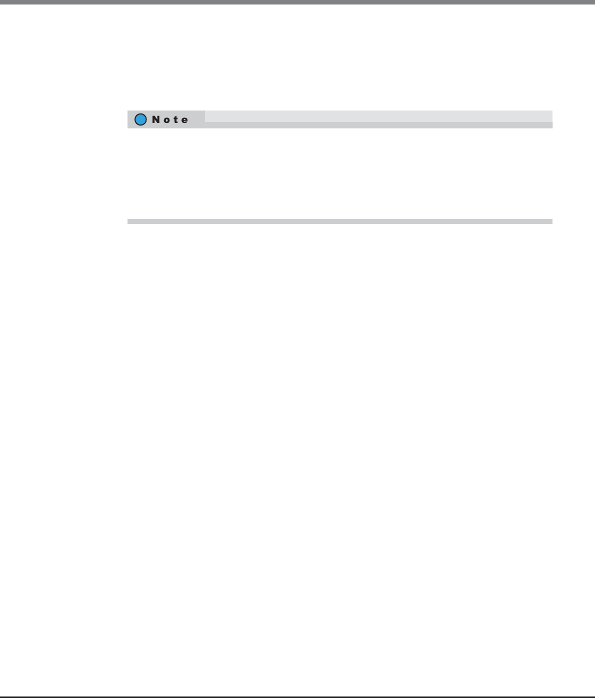
Chapter 10 Component Management
10.1 Component Status
ETERNUS Web GUI User’s Guide
Copyright 2013 FUJITSU LIMITED P2X0-1090-10ENZ0
685
■Sensor Information
The real time and threshold values (Low/High) for the temperature, voltage, current, transmission
power, and received power are displayed in the Sensor Information.
When the information cannot be obtained, a "-" (hyphen) is displayed.
The target components for this information are FC that have SFPs from which information can be
obtained.
-Temperature
•Present
The real time temperature of the SFP in the port is displayed.
-x C / y F (x: -128.00 to 128.00, y: -198.40 to 262.40)
•Warning
-Low or High
The Warning threshold (Low/High) for the temperature of the SFP in the port is displayed.
•x C / y F (x: -128.00 to 128.00, y: -198.40 to 262.40)
•Alarm
-Low or High
The Alarm threshold (Low/High) for the temperature of the SFP in the port is displayed.
•x C / y F (x: -128.00 to 128.00, y: -198.40 to 262.40)
-Voltage
•Present
The real time voltage of the SFP in the port is displayed.
-x V (x: 0.00 to 6.55)
•Warning
-Low or High
The Warning threshold (Low/High) for the voltage of the SFP in the port is displayed.
•x V (x: 0.00 to 6.55)
•Alarm
-Low or High
The Alarm threshold (Low/High) for the voltage of the SFP in the port is displayed.
•x V (x: 0.00 to 6.55)
•An SFP is regarded as being in Warning status when the real time value is lower than the Warning
threshold (Low) and higher than the Alarm threshold (Low).
•An SFP is regarded as being in Warning status when the real time value is higher than the Warning
threshold (High) and lower than the Alarm threshold (High).
•An SFP is regarded as being in Alarm status when the real time value is lower than the Alarm
threshold (Low) or higher than the Alarm threshold (High).

Chapter 10 Component Management
10.1 Component Status
ETERNUS Web GUI User’s Guide
Copyright 2013 FUJITSU LIMITED P2X0-1090-10ENZ0
686
-Current
•Present
The real time current of the SFP in the port is displayed.
-x mA (x: 0.00 to 131.00)
•Warning
-Low or High
The Warning threshold (Low/High) for the current of the SFP in the port is displayed.
•x mA (x: 0.00 to 131.00)
•Alarm
-Low or High
The Alarm threshold (Low/High) for the current of the SFP in the port is displayed.
•x mA (x: 0.00 to 131.00)
-TX Power
•Present
The real time transmission power of the SFP in the port is displayed.
-x mW (x: 0.00 to 6.55)
•Warning
-Low or High
The Warning threshold (Low/High) for the transmission power of the SFP in the port is displayed.
•x mW (x: 0.00 to 6.55)
•Alarm
-Low or High
The Alarm threshold (Low/High) for the transmission power of the SFP in the port is displayed.
•x mW (x: 0.00 to 6.55)
-RX Power
•Present
The real time received power of the SFP in the port is displayed.
-x mW (x: 0.00 to 6.55)
•Warning
-Low or High
The Warning threshold (Low/High) for the received power of the SFP in the port is displayed.
•x mW (x: 0.00 to 6.55)
•Alarm
-Low or High
The Alarm threshold (Low/High) for the received power of the SFP in the port is displayed.
•x mW (x: 0.00 to 6.55)
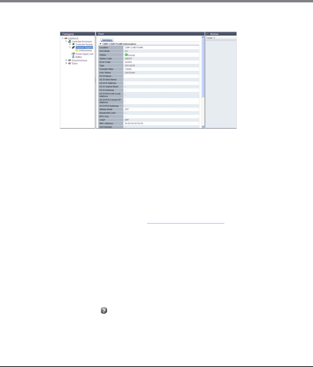
Chapter 10 Component Management
10.1 Component Status
ETERNUS Web GUI User’s Guide
Copyright 2013 FUJITSU LIMITED P2X0-1090-10ENZ0
687
●iSCSI port
The detailed iSCSI port information is displayed.
The following items are displayed in the Main area:
■CM#x CA#y Port#z Information
-Location
The location information of the port is displayed.
•CM#x CA#y Port#z (x: CM number, y: CA number, z: Port number)
-Port Mode
The port mode is displayed.
•CA
•RA
•CA/RA
-Status
The port status is displayed. Refer to "B.5 Component Status" (page 977) for details.
-Status Code
The port status code is displayed.
-Error Code
The port error code is displayed.
-Type
The type of the port is displayed.
•1G iSCSI
•10G iSCSI
•iSCSI-RA
-Transfer Rate
The transfer speed of the port is displayed.
If the status is " Unknown", a "-" (hyphen) is displayed.
•Auto-negotiation
•100Mbit/s
•1Gbit/s
•10Gbit/s

Chapter 10 Component Management
10.1 Component Status
ETERNUS Web GUI User’s Guide
Copyright 2013 FUJITSU LIMITED P2X0-1090-10ENZ0
688
-Link Status
The link status of the port is displayed.
If the status is " Unknown", a "-" (hyphen) is displayed.
•Link Down
•100Mbit/s Link Up
•1Gbit/s Link Up
•10Gbit/s Link Up
-iSCSI Name
The iSCSI name is displayed.
-iSCSI Alias Name
The iSCSI Alias name is displayed.
-iSCSI IP Address
The IPv4 address of the iSCSI is displayed.
If not specified, a "-" (hyphen) is displayed.
-iSCSI Subnet Mask
The subnet mask of the iSCSI is displayed.
If not specified, a "-" (hyphen) is displayed.
-iSCSI Gateway
The IPv4 address of the iSCSI gateway is displayed.
If not specified, a "-" (hyphen) is displayed.
-iSCSI IPv6 Link Local Address
The IPv6 link local address of the iSCSI is displayed.
Note that the IPv6 address is displayed as an abbreviation. If not specified, a "-" (hyphen) is displayed.
•IPv6 address
fe80::xxxx:xxxx:xxxx:xxxx
xxxx: 0 - ffff (hexadecimal, "a" - "f" are lowercase letters)
Refer to "IPv6 Address Notation" (page 378) for details.
-iSCSI IPv6 Connect IP Address
The IPv6 connect IP address of the iSCSI is displayed.
Note that the IPv6 address is displayed as an abbreviation. If not specified, a "-" (hyphen) is displayed.
•IPv6 address
xxxx:xxxx:xxxx:xxxx:xxxx:xxxx:xxxx:xxxx
xxxx: 0 - ffff (hexadecimal, "a" - "f" are lowercase letters)
Refer to "IPv6 Address Notation" (page 378) for details.
-iSCSI IPv6 Gateway
The gateway IPv6 address of the target port is displayed.
Note that the IPv6 address is displayed as an abbreviation. If not specified, a "-" (hyphen) is displayed.
•IPv6 address
xxxx:xxxx:xxxx:xxxx:xxxx:xxxx:xxxx:xxxx
xxxx: 0 - ffff (hexadecimal, "a" - "f" are lowercase letters)
Refer to "IPv6 Address Notation" (page 378) for details.
-Affinity Mode
The affinity mode of the port is displayed.
•ON
•OFF

Chapter 10 Component Management
10.1 Component Status
ETERNUS Web GUI User’s Guide
Copyright 2013 FUJITSU LIMITED P2X0-1090-10ENZ0
689
-Bandwidth Limit
The bandwidth limit of the iSCSI is displayed between 10Mbit/s - 400Mbit/s.
A "-" (hyphen) is displayed in the following conditions:
•When the Bandwidth Limit is "0"
•When the "Type" is "1G iSCSI " or "10G iSCSI"
-MTU Size
The MTU size of the iSCSI is displayed.
•When the "Type" is "1G iSCSI" or "10G iSCSI": 576 - 9000
•When the "Type" is "iSCSI RA": 1000, 1050, 1100, 1150, 1200, 1250, 1300, 1350, 1400, or 1438
When the MTU size is "0" or the port mode is "CA", a "-" (hyphen) is displayed.
-CHAP
The CHAP authentication status is displayed.
•When the "Port Mode" is "CA" or "RA": "ON" or "OFF"
•When the "Port Mode" is "CA/RA": x / y
x: CHAP authentication status for the CA port ("ON" or "OFF")
y: CHAP authentication status for the RA port ("ON" or "OFF")
-MAC Address
The MAC address of the port is displayed.
-Part Number
The part number of the port is displayed.
If the part number cannot be acquired, a "-" (hyphen) is displayed.
-Serial Number
The serial number of the port is displayed.
If the serial number cannot be acquired, a "-" (hyphen) is displayed.
-Hardware Revision
The hardware version of the port is displayed.
If the hardware version cannot be acquired, a "-" (hyphen) is displayed.
-SFP Type
When the "Type" is "10G iSCSI", the SFP type of the port is displayed. If no SFP is installed, "Unmount" is
displayed.
If the "Type" is not "10G iSCSI", the display status varies according to the screen. A "-" (hyphen) is
displayed for the CM#x CA#y port information in the [Channel Adapter Detail] screen. This item is not
displayed in the [Port Detail] screen.
•SFP+
•SFP+ Copper
•Unknown
When the "Type" is "10G iSCSI", the temperature, voltage, current, transmission power, and received power
for the SFP in the port are displayed.
Refer to "FC port" (page 681) for display items.
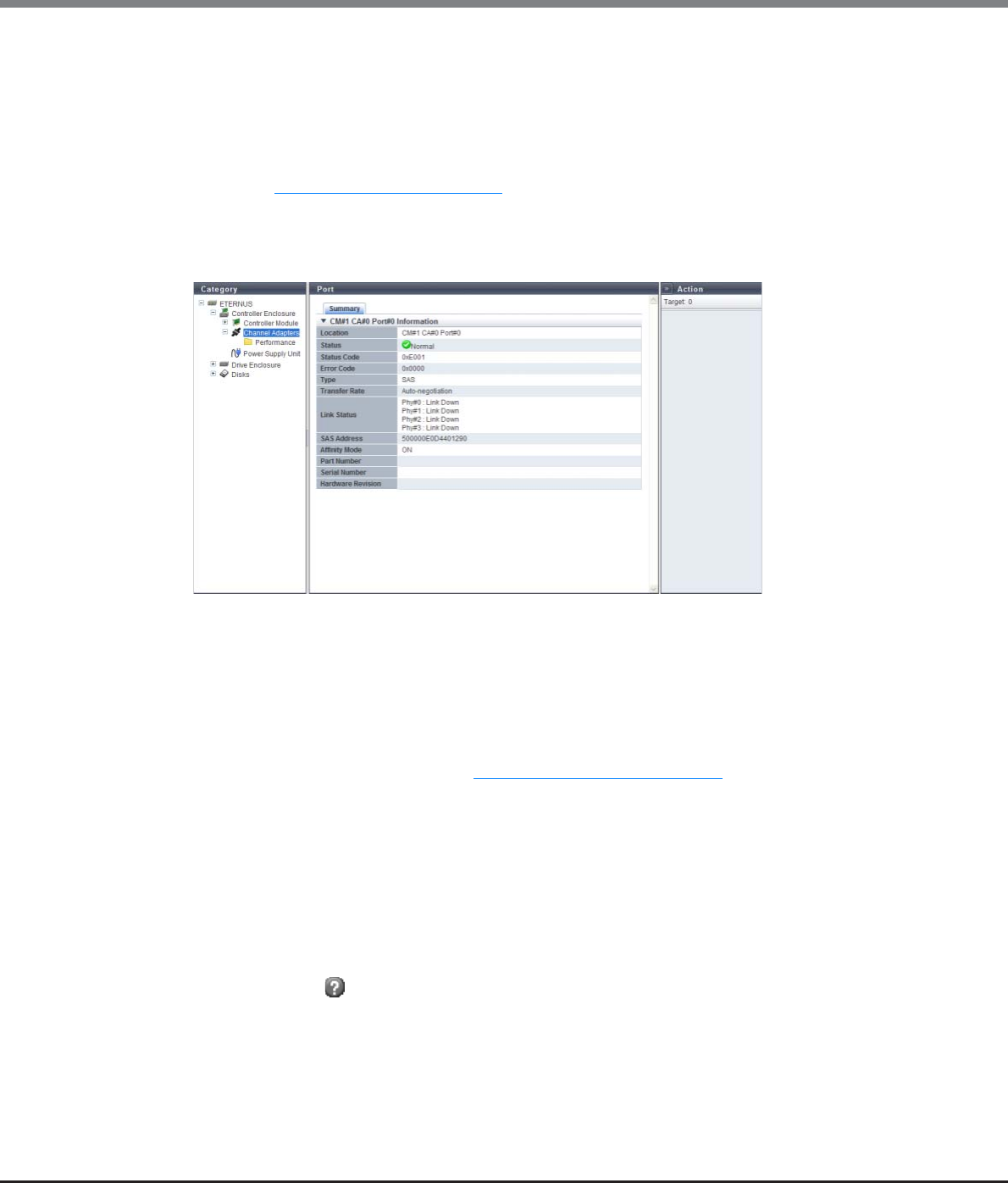
Chapter 10 Component Management
10.1 Component Status
ETERNUS Web GUI User’s Guide
Copyright 2013 FUJITSU LIMITED P2X0-1090-10ENZ0
690
■Sensor Information
The real time and threshold values (Low/High) for the temperature, voltage, current, transmission
power, and received power are displayed in the Sensor Information.
When the information cannot be obtained, a "-" (hyphen) is displayed.
The target components for this information are 10 iSCSI that have SFPs from which information can be
obtained.
Refer to "Sensor Information" (page 685) for display items.
●SAS port
The detailed SAS port information is displayed.
The following items are displayed in the Main area:
■CM#x CA#y Port#z Information
-Location
The location information of the port is displayed.
•CM#x CA#y Port#z (x: CM number, y: CA number, z: Port number)
-Status
The port status is displayed. Refer to "B.5 Component Status" (page 977) for details.
-Status Code
The port status code is displayed.
-Error Code
The port error code is displayed.
-Type
The type of the port (fixed to "SAS") is displayed.
-Transfer Rate
The transfer speed of the port is displayed.
If the status is " Unknown", a "-" (hyphen) is displayed.
•Auto-negotiation
•1.5 Gbit/s
•3 Gbit/s
•6 Gbit/s

Chapter 10 Component Management
10.1 Component Status
ETERNUS Web GUI User’s Guide
Copyright 2013 FUJITSU LIMITED P2X0-1090-10ENZ0
691
-Link Status
The link status for each Phy is displayed.
If the status is " Unknown", a "-" (hyphen) is displayed.
•Phy#0 - 3:x
"x" indicates one of the following statuses:
-Link Down
-1.5Gbit/s Link Up
-3Gbit/s Link Up
-6Gbit/s Link Up
-SAS Address
The SAS address is displayed.
If not specified, a "-" (hyphen) is displayed.
-Affinity Mode
The affinity mode of the port is displayed.
•ON
•OFF
-Part Number
The part number is not displayed.
If the part number cannot be acquired, a "-" (hyphen) is displayed.
-Serial Number
The serial number is not displayed.
If the serial number cannot be acquired, a "-" (hyphen) is displayed.
-Hardware Revision
The hardware version is not displayed.
If the hardware version cannot be acquired, a "-" (hyphen) is displayed.
●FCoE port
The detailed FCoE port information is displayed.

Chapter 10 Component Management
10.1 Component Status
ETERNUS Web GUI User’s Guide
Copyright 2013 FUJITSU LIMITED P2X0-1090-10ENZ0
692
The following items are displayed in the Main area:
■CM#x CA#y Port#z Information
-Location
The location information of the port is displayed.
•CM#x CA#y Port#z (x: CM number, y: CA number, z: Port number)
-Port Mode
The port mode (fixed to "CA") is displayed.
-Status
The port status is displayed. Refer to "B.5 Component Status" (page 977) for details.
-Status Code
The port status code is displayed.
-Error Code
The port error code is displayed.
-Type
The type of the port (fixed to "FCoE") is displayed.
-Connection
The connection type of the port is displayed.
•Fabric
A connection type that enables simultaneous communication among multiple nodes through a
Fibre Channel switch.
•FC-AL
A connection type that connects multiple nodes in a loop.
-Transfer Rate
The transfer speed of the port (fixed to "10 Gbit/s") is displayed.
If the status is " Unknown", a "-" (hyphen) is displayed.
-Link Status
The link status of the port is displayed.
If the status is " Unknown", a "-" (hyphen) is displayed.
•Link Down
•10Gbit/s Link Up
-WWN
The WWN of the port is displayed.
-Affinity Mode
The affinity mode of the port is displayed.
•ON
•OFF
-FC Frame Size
The frame size of the port is displayed.
•512 byte
•1024 byte
•2048 byte
-VLAN ID
The VLAN ID is displayed.
When the VLAN ID is manually specified, the VLAN ID is displayed between 0 - 4095.
When the VLAN ID is automatically specified, "Auto" is displayed.
Chapter 10 Component Management
10.1 Component Status
ETERNUS Web GUI User’s Guide
Copyright 2013 FUJITSU LIMITED P2X0-1090-10ENZ0
693
-Fabric Name
The fabric name (WWN for FCoE) is displayed.
When the fabric name is manually specified, the specified fabric name is displayed.
When the fabric name is automatically specified, "Auto" is displayed.
-MAC Address
The MAC address of the port is displayed.
-Part Number
The part number of the port is displayed.
If the part number cannot be acquired, a "-" (hyphen) is displayed.
-Serial Number
The serial number of the port is displayed.
If the serial number cannot be acquired, a "-" (hyphen) is displayed.
-Hardware Revision
The hardware version of the port is displayed.
If the hardware version cannot be acquired, a "-" (hyphen) is displayed.
-SFP Type
The SFP type of the port is displayed. If the SFP is not installed, "Unmount" is displayed.
•SFP+
•SFP+ Copper
•Unknown
■Sensor Information
The real time and threshold values (Low/High) for the temperature, voltage, current, transmission
power, and received power are displayed in the Sensor Information.
When the information cannot be obtained, a "-" (hyphen) is displayed.
The target components for this information are FCoE that have SFPs from which information can be
obtained.
Refer to "Sensor Information" (page 685) for display items
The temperature, voltage, current, transmission power, and received power for the SFP in the port are dis-
played.
Refer to "FC port" (page 681) for display items.

Chapter 10 Component Management
10.2 Functions in the Action Area for Component
ETERNUS Web GUI User’s Guide
Copyright 2013 FUJITSU LIMITED P2X0-1090-10ENZ0
694
10.2 Functions in the Action Area for Component
When using functions in the Action area, select the desired function from the Action area that is displayed in
the status display screen.
The functions in the Action area for Component can be performed from the following display functions:
Functions in the Action area for Component Display function
Add Drive Enclosure •Drive Enclosure
Turn on Locator Beacon/Turn off Locator Beacon •Controller Enclosure
Add Channel Adapter Port •All Channel Adapters
Assign Global Hot Spare •Disks
Release Global Hot Spare
Assign Dedicated Hot Spare
Release Dedicated Hot Spare
Export Performance Information •Controller Module (Performance)
•Channel Adapter Ports (Performance)
•Disks (Performance)
Clear Disk Error Statistics (All Disks) •Disk Error Statistics
Clear Disk Error Statistics (Selected Disks)
Chapter 10 Component Management
10.2 Functions in the Action Area for Component
ETERNUS Web GUI User’s Guide
Copyright 2013 FUJITSU LIMITED P2X0-1090-10ENZ0
695
10.2.1 Add Drive Enclosure
This function enables DEs to be added without stopping the ETERNUS DX Disk storage system.
Use GUI to install any DEs that are added.
Specify between DE#01 - DE#09 for the drive enclosures that are to be added.
The procedure to expand a DE is as follows:
Procedure
1Click [Add Drive Enclosure] in [Action].
→The start screen appears.
•When logged in using a user account with the "Admin" default role, this function is available only with
the ETERNUS DX80 S2/DX90 S2. To use this function with the ETERNUS DX410 S2/DX440 S2 or the
ETERNUS DX8100 S2/DX8700 S2, a user account with the "Maintainer" default role (or "Maintenance
Operation" policy) is required.
•Only one DE can be added at a time.
•2.5-inch type DEs and 3.5-inch type DEs can be installed in the same ETERNUS DX Disk storage system.
•Be sure to use authorized expansion parts. If parts other than the expansion parts are used, operation is
not guaranteed.
•This function cannot be used under the following conditions:
-When the general status of the ETERNUS DX Disk storage system is other than "Normal"
-When DE#09 is already installed (when the status of DE#09 is " Normal")
•If expansion fails due to an error or problem, the expansion can be restarted from the interrupted point
by starting this function again and recovering the failed expansion parts.
•DEs can be added regardless of whether drives are installed or not.
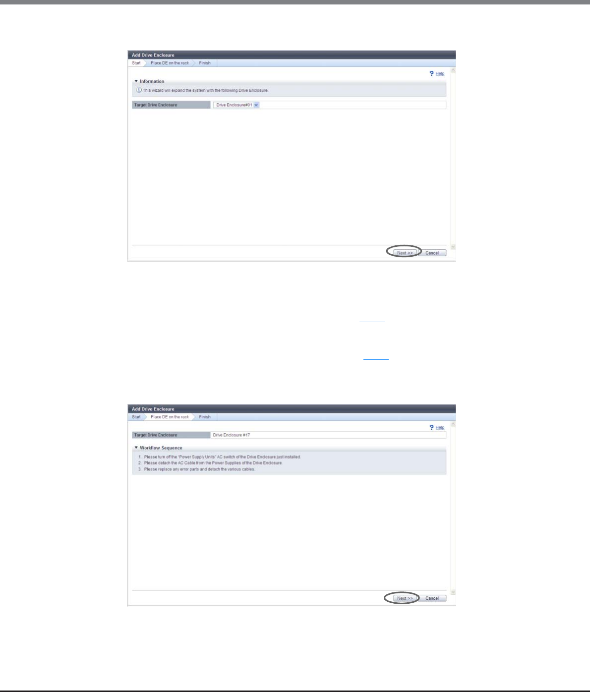
Chapter 10 Component Management
10.2 Functions in the Action Area for Component
ETERNUS Web GUI User’s Guide
Copyright 2013 FUJITSU LIMITED P2X0-1090-10ENZ0
696
2Click the [Next >>] button.
The displayed screen may vary depending on whether the recovery process is required or not.
■When the recovery process is required
→The [Recovery Procedure] screen appears. Proceed to Step 3.
■When the recovery process is not required
→The [Place DE on the rack] screen appears. Proceed to Step 4.
3Perform the recovery operation according to the displayed procedure. When the recovery
operation is complete, click the [Next >>] button.
→ The [Place DE on the rack] screen appears.
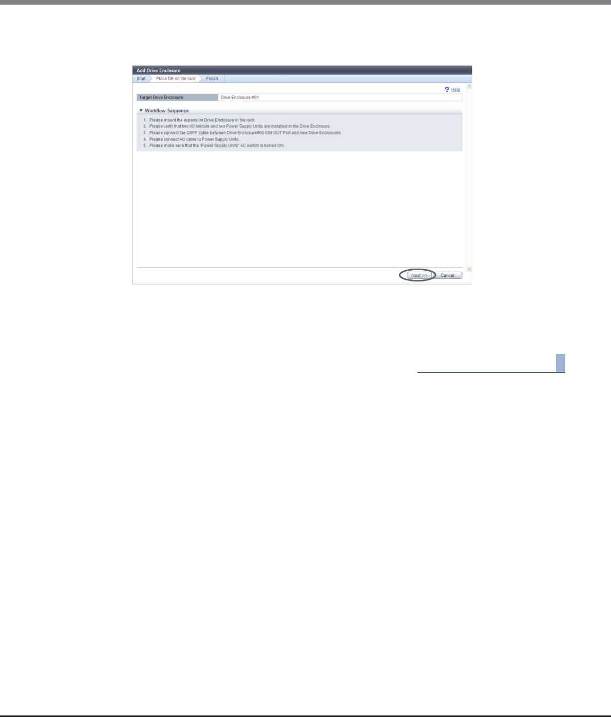
Chapter 10 Component Management
10.2 Functions in the Action Area for Component
ETERNUS Web GUI User’s Guide
Copyright 2013 FUJITSU LIMITED P2X0-1090-10ENZ0
697
4Perform the DE expansion according to the displayed procedure, and click the [Next >>]
button.
→The DE installation starts and the [Status Check] screen appears. After the installation is complete,
the [Finish] screen appears.
5Click the [Done] button to return to the [Drive Enclosure] screen.
End of procedure
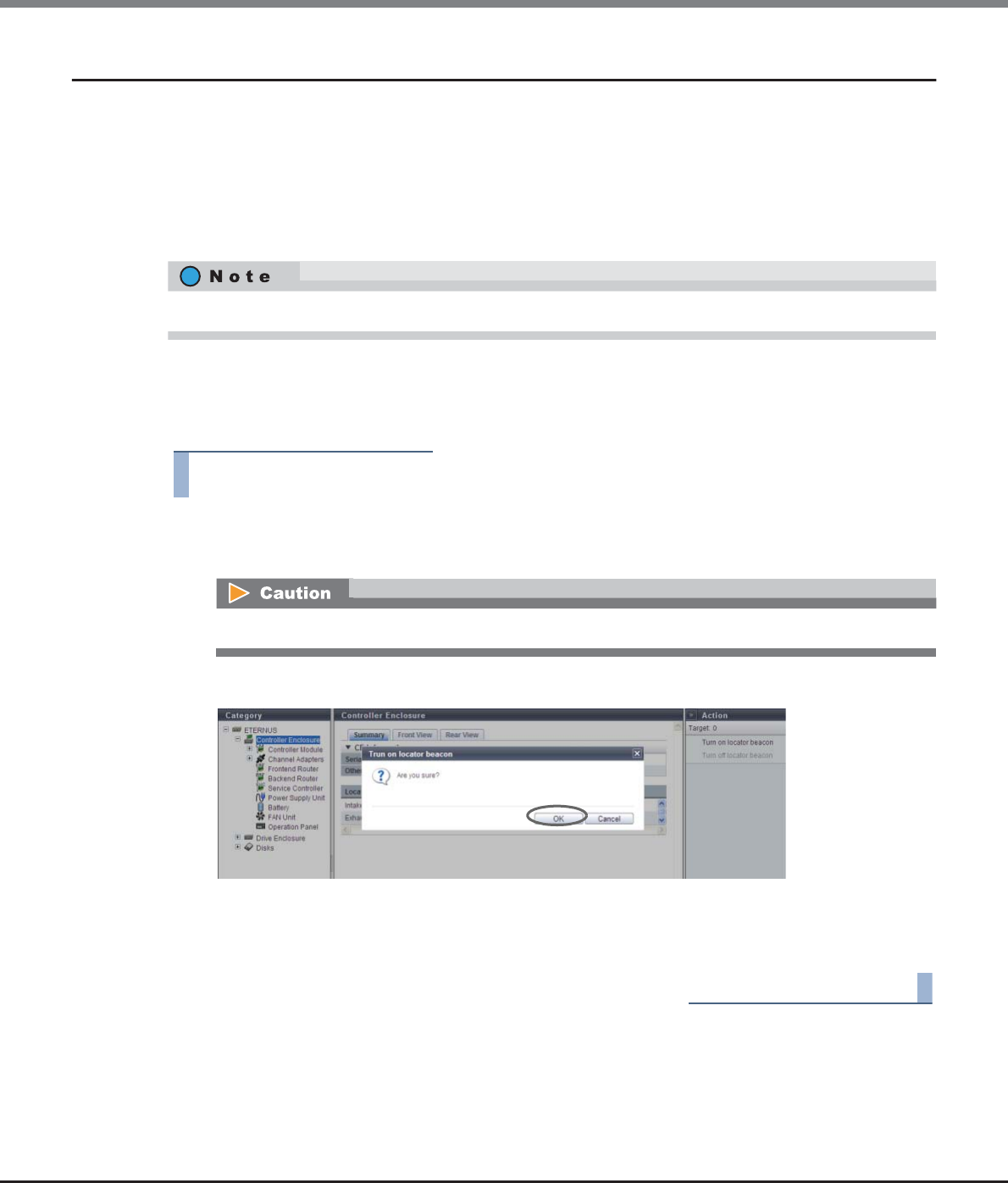
Chapter 10 Component Management
10.2 Functions in the Action Area for Component
ETERNUS Web GUI User’s Guide
Copyright 2013 FUJITSU LIMITED P2X0-1090-10ENZ0
698
10.2.2 Turn on Locator Beacon/Turn off Locator Beacon
This function blinks or turns off the locator beacon of the CE, the CM, or the SVC to identify the component that
requires maintenance.
The "IDENTIFY LED" blinks or is turned off at the following locations:
•The front cover of the CE
•The CM in the rear of the CE (for ETERNUS DX410 S2/DX440 S2 or ETERNUS DX8100 S2)
•The SVC in the rear of the CE (for ETERNUS DX8700 S2)
■Turning on the LED
The procedure to turn on an LED is as follows:
Procedure
1Click [Turn on locator beacon] in [Action].
→A confirmation screen appears.
2Click the [OK] button.
→The locator beacon is turned on.
3Click the [Done] button to return to the [Controller Enclosure] screen.
End of procedure
When using the ETERNUS DX8700 S2, SVC#0 and SVC#1 blink or are turned off together.
If the LED is already turned on, [Turn on locator beacon] cannot be selected.

Chapter 10 Component Management
10.2 Functions in the Action Area for Component
ETERNUS Web GUI User’s Guide
Copyright 2013 FUJITSU LIMITED P2X0-1090-10ENZ0
699
■Turning off the LED
The procedure to turn off an LED is as follows:
Procedure
1Click [Turn off locator beacon] in [Action].
→A confirmation screen appears.
2Click the [OK] button.
→The locator beacon is turned off.
3Click the [Done] button to return to the [Controller Enclosure] screen.
End of procedure
10.2.3 Add Channel Adapter Port
This function enables a CA port to be added without stopping the ETERNUS DX Disk storage system.
If the LED is already turned off, [Turn off locator beacon] cannot be selected.
•This function is available only for the ETERNUS DX80 S2 model that is using one port for each CM.
•CA ports for FC, iSCSI, FCoE, or SAS, host interfaces can be added.
•When the general status of the ETERNUS DX Disk storage system is not normal, a CA port cannot be
added.
The 1-port type CA is also displayed as a 2-port type. To determine whether the CA is 1-port type or 2-port-
type, refer to the port number displayed in the [Internal Parts] tab in the "10.1.6 Channel Adapter Detail"
(page 655). Note that 1-port type CAs are not available in some regions.
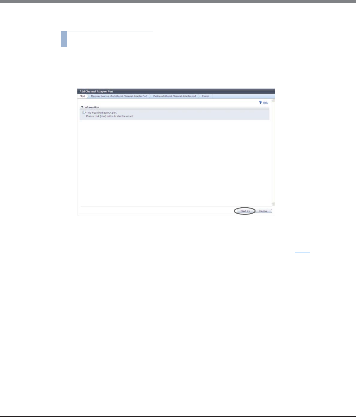
Chapter 10 Component Management
10.2 Functions in the Action Area for Component
ETERNUS Web GUI User’s Guide
Copyright 2013 FUJITSU LIMITED P2X0-1090-10ENZ0
700
The procedure to add a CA port is as follows:
Procedure
1Click [Add Channel Adapter Port] in [Action].
→ The [Start] screen appears.
2Click the [Next >>] button.
The displayed screen may vary depending on whether the installation of license key is required or not.
■When the license key is not registered
→The [Register license of additional Channel Adapter Port] screen appears. Proceed to Step 3.
■When the license key is already registered
→The [Define additional Channel Adapter port] screen appears. Proceed to Step 4.
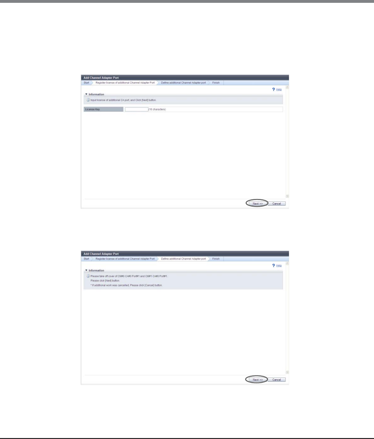
Chapter 10 Component Management
10.2 Functions in the Action Area for Component
ETERNUS Web GUI User’s Guide
Copyright 2013 FUJITSU LIMITED P2X0-1090-10ENZ0
701
3Input the license key, and click the [Next >>] button.
•License Key
Input the license key.
The following input conditions apply:
-16 characters
-Capital letters and numeric characters
→The [Register license of additional Channel Adapter Port] screen appears. The [Define additional
Channel Adapter port] screen appears after the registration of the license key is complete.
4Add the CA port according to the displayed procedure and click the [Next >>] button.
The operations and displayed screen vary depending on the host interface type that is used.
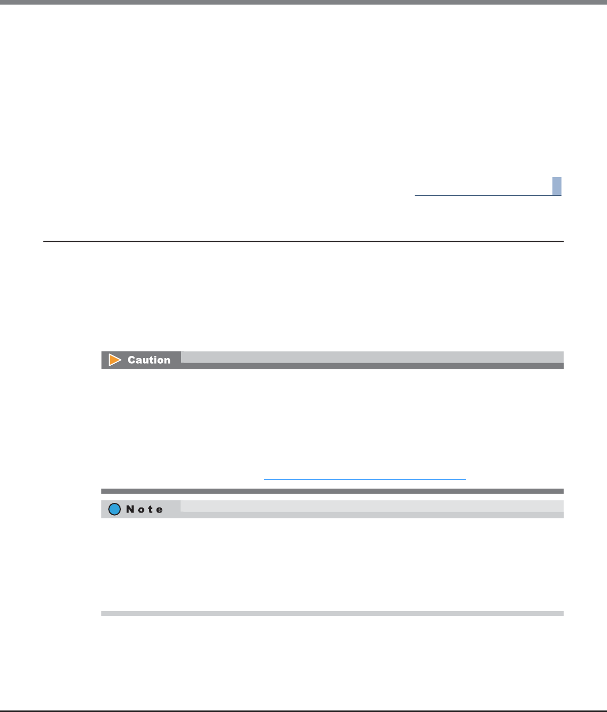
Chapter 10 Component Management
10.2 Functions in the Action Area for Component
ETERNUS Web GUI User’s Guide
Copyright 2013 FUJITSU LIMITED P2X0-1090-10ENZ0
702
■For FC, FCoE, or 10G iSCSI host interfaces
→The installation of SFP starts and the [Check SFP Installation] screen appears. After the installation
of the SFP is complete (when the CA includes an SFP), the installation of the CA port starts and the
[Status Check] screen appears. After the installation of the CA port is complete, the [Finish] screen
appears.
■For 1G iSCSI or SAS host interfaces
→The CA port installation starts and the [Status Check] screen appears. After the installation is
complete, the [Finish] screen appears.
5Click the [Done] button to return to the [All Channel Adapters] screen.
End of procedure
10.2.4 Assign Global Hot Spare
This function registers a drive as a Global Hot Spare.
A Global Hot Spare is a spare drive (hot spare) that is registered in the RAID group instead of the failed drive
when a drive failure is occur. A Global Hot Spare, unlike a Dedicated Hot Spare, can be used by all of the RAID
groups.
If a drive fails, data copy (rebuild) to a Global Hot Spare starts automatically.
When a failed drive is replaced, the data is copied back from the Global Hot Spare that is substituting for the
failed drive, and the Global Hot Spare then returns to a spare drive.
•Drives that are currently used cannot be registered as Global Hot Spares.
•Make sure to register a Global Hot Spare with the same or a larger capacity than the data drives. If the
Global Hot Spare capacity is smaller than the data drive, the drive does not work as the hot spare.
•When a mix of SAS disks, Nearline SAS disks, SSDs, and SEDs are installed together in the ETERNUS DX
Disk storage system, Global Hot Spare of each type is required. Register the Global Hot Spare with the
same capacity as the maximum capacity drive for each type.
•To use hot spares on a priority basis, make sure to register the Dedicated Hot Spare for a RAID group that
contains important data. Refer to "10.2.6 Assign Dedicated Hot Spare" (page 704) for details.
•If the Dedicated Hot Spare is registered for a RAID group to which a failed drive belongs, the Dedicated
Hot Spare is used before the Global Hot Spare. If there is no unused Dedicated Hot Spare and the drive
fails, the Global Hot Spare is used.
•Depending on the hot spare usage status, a drive with a different capacity and type from the failed drive
may be used.
•Hot Spares can be registered any slots of the CEs (only for the ETERNUS DX80 S2/DX90 S2) and the DEs.
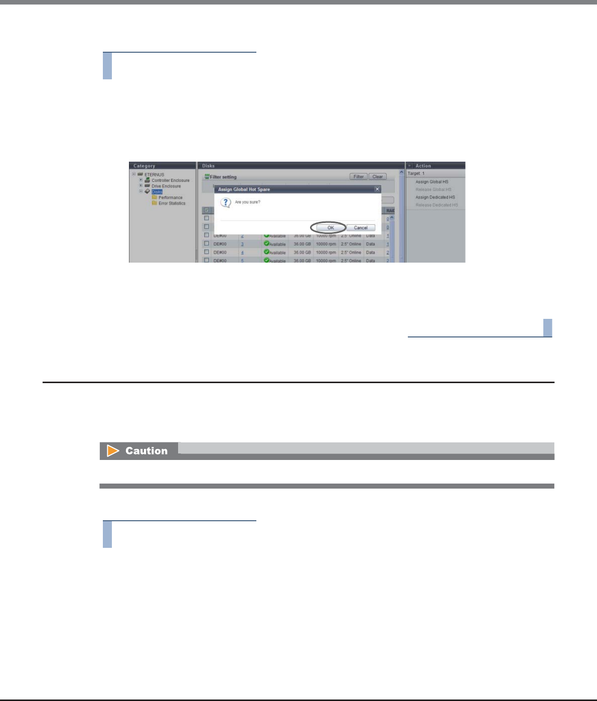
Chapter 10 Component Management
10.2 Functions in the Action Area for Component
ETERNUS Web GUI User’s Guide
Copyright 2013 FUJITSU LIMITED P2X0-1090-10ENZ0
703
The procedure to register a Global Hot Spare is as follows:
Procedure
1Select a drive that is to be used as a Global Hot Spare (multiple selections can be made) and
click [Assign Global HS] in [Action].
→A confirmation screen appears.
2Click the [OK] button.
→Registration of the Global Hot Spare starts.
3Click the [Done] button to return to the [Disks] screen.
End of procedure
10.2.5 Release Global Hot Spare
This function releases a drive from being a Global Hot Spare.
A drive that is released from being a Global Hot Spare can be used as a data drive or Dedicated Hot Spare for a
different RAID group.
The procedure to release a Global Hot Spare is as follows:
Procedure
1Select a drive (multiple selections can be made) that is to be released from being a Global
Hot Spare and click [Release Global HS] in [Action].
→A confirmation screen appears.
This function cannot be used when the drive is already used as a hot spare.
Chapter 10 Component Management
10.2 Functions in the Action Area for Component
ETERNUS Web GUI User’s Guide
Copyright 2013 FUJITSU LIMITED P2X0-1090-10ENZ0
704
2Click the [OK] button.
→Releasing of the Global Hot Spare starts.
3Click the [Done] button to return to the [Disks] screen.
End of procedure
10.2.6 Assign Dedicated Hot Spare
This function registers a drive as a Dedicated Hot Spare for a RAID group.
A Dedicated Hot Spare is a spare drive (hot spare) that is registered in the RAID group instead of the failed
drive when a drive failure is occur. A Dedicated Hot Spare, unlike a Global Hot Spare, is used only for the
specific RAID group.
If a drive fails, data copy (rebuild) to a Dedicated Hot Spare starts automatically.
When a failed drive is replaced, the data is copied back from the Dedicated Hot Spare that is substituting for
the failed drive, and the Dedicated Hot Spare then returns to a spare drive.
•Drives that are currently used cannot be registered as Dedicated Hot Spares.
•Make sure to register a Dedicated Hot Spare with the same or a larger capacity than the data drives. If the
Dedicated Hot Spare capacity is smaller than the data drive, the drive does not work as the hot spare.
•When a mix of SAS disks, Nearline SAS disks, SSDs, and SEDs are installed together in the ETERNUS DX
Disk storage system, Dedicated Hot Spare of each type is required. Register the Dedicated Hot Spare with
the same capacity as the maximum capacity drive for each type.
•Only one RAID group can be registered for each Dedicated Hot Spare. A Dedicated Hot Spare cannot be
registered to multiple RAID groups.
•Dedicated Hot Spares cannot be registered for a RAID group that belongs to a TPP, an FTRP, or an REC Disk
Buffer.
•When the failed drive and the Dedicated Hot Spare are switched, a Dedicated Hot Spare with the same
capacity as the failed drive is used on a priority basis. If there is no Dedicated Hot Spare with the same
capacity, a Dedicated Hot Spare with a larger capacity than the failed drive is used.
•If the Dedicated Hot Spare is registered for a RAID group to which a failed drive belongs, the Dedicated
Hot Spare is used before the Global Hot Spare. If there is no unused Dedicated Hot Spare and the drive
fails, the Global Hot Spare is used.
•Hot Spares can be registered any slots of the CEs (only for the ETERNUS DX80 S2/DX90 S2) and the DEs.
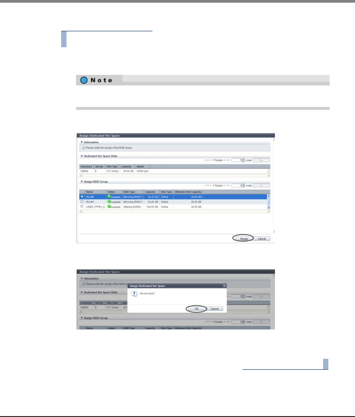
Chapter 10 Component Management
10.2 Functions in the Action Area for Component
ETERNUS Web GUI User’s Guide
Copyright 2013 FUJITSU LIMITED P2X0-1090-10ENZ0
705
The procedure to register a Dedicated Hot Spare is as follows:
Procedure
1Select a drive (multiple selections can be made) that is to be used as a Dedicated Hot Spare
and click [Assign Dedicated HS] in [Action].
2Select which RAID group to use the selected drive as a Dedicated Hot Spare for and click the
[Assign] button.
→A confirmation screen appears.
3Click the [OK] button.
→Registration of the Dedicated Hot Spare starts.
4Click the [Done] button to return to the [Disks] screen.
End of procedure
Select the same type of drives that configure the target RAID group. If multiple types of drives are
selected, the [Assign Dedicated HS] is not available.
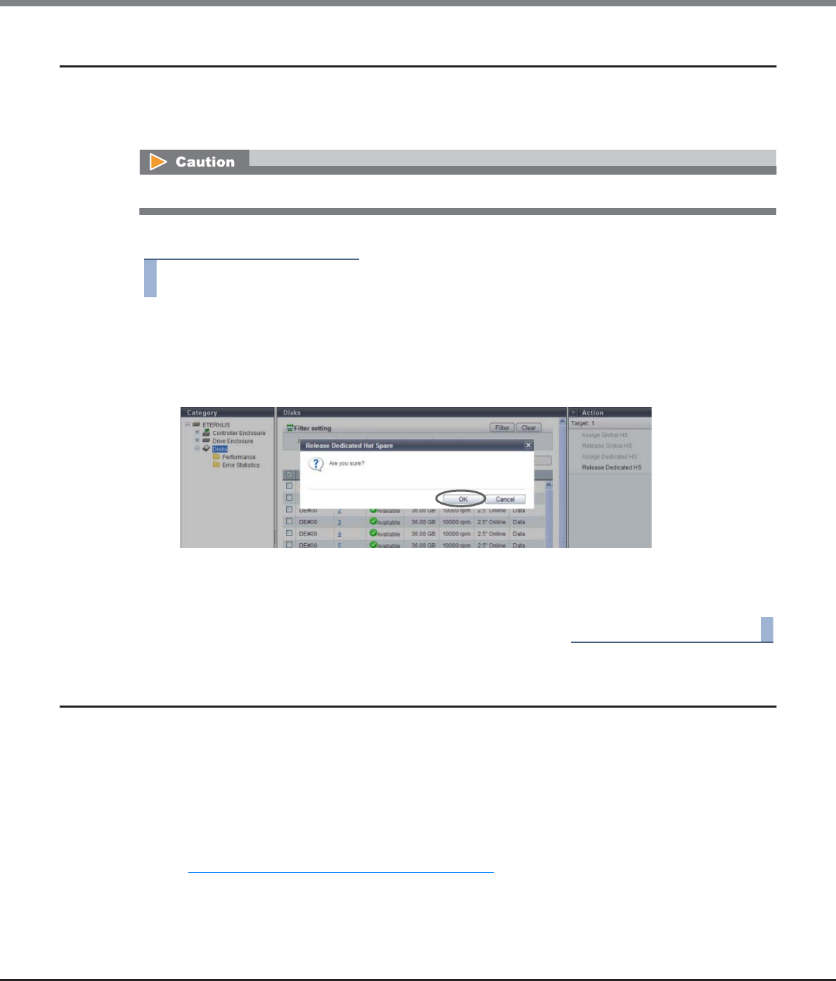
Chapter 10 Component Management
10.2 Functions in the Action Area for Component
ETERNUS Web GUI User’s Guide
Copyright 2013 FUJITSU LIMITED P2X0-1090-10ENZ0
706
10.2.7 Release Dedicated Hot Spare
This function releases a drive from being a Dedicated Hot Spare.
A drive that is released from being a Dedicated Hot Spare can be used as a data drive, Global Hot Spare, or
Dedicated Hot Spare for a different RAID group.
The procedure to release a Dedicated Hot Spare is as follows:
Procedure
1Select a drive (multiple selections can be made) that is to be released from being a
Dedicated Hot Spare and click [Release Dedicated HS] in [Action].
→A confirmation screen appears.
2Click the [OK] button.
→Releasing of the Dedicated Hot Spare starts.
3Click the [Done] button to return to the [Disks] screen.
End of procedure
10.2.8 Export Performance Information
This function exports the following performance information in a single operation and saves it as a text file.
•Performance (Host I/O)
•Performance (Advanced Copy)
•Performance (CA)
•Performance (CM)
•Performance (Drive)
Refer to "5.2.20 Export Performance Information" (page 155) for details.
This function cannot be used when the drive is already used as a hot spare.
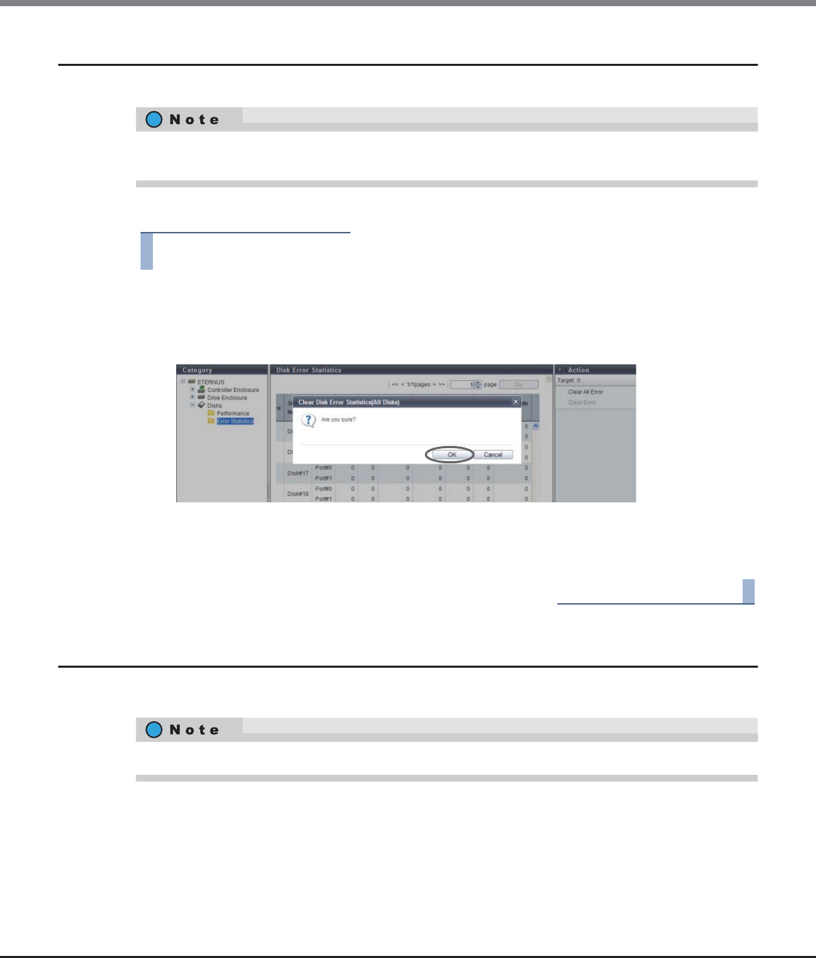
Chapter 10 Component Management
10.2 Functions in the Action Area for Component
ETERNUS Web GUI User’s Guide
Copyright 2013 FUJITSU LIMITED P2X0-1090-10ENZ0
707
10.2.9 Clear Disk Error Statistics (All Disks)
This function deletes the error information from all of the drives.
The procedure to delete error information from all the drives is as follows:
Procedure
1Click [Clear All Error] in [Action].
→A confirmation screen appears.
2Click the [OK] button.
→Deletion of the error information from all the drives starts.
3Click the [Done] button to return to the [Disk Error Statistics] screen.
End of procedure
10.2.10 Clear Disk Error Statistics (Selected Disks)
This function deletes the error information from the selected drive.
This function can be performed without selecting the drive to delete error information or without the error
information that is to be deleted.
This function can only be performed when an error occurs in a drive.
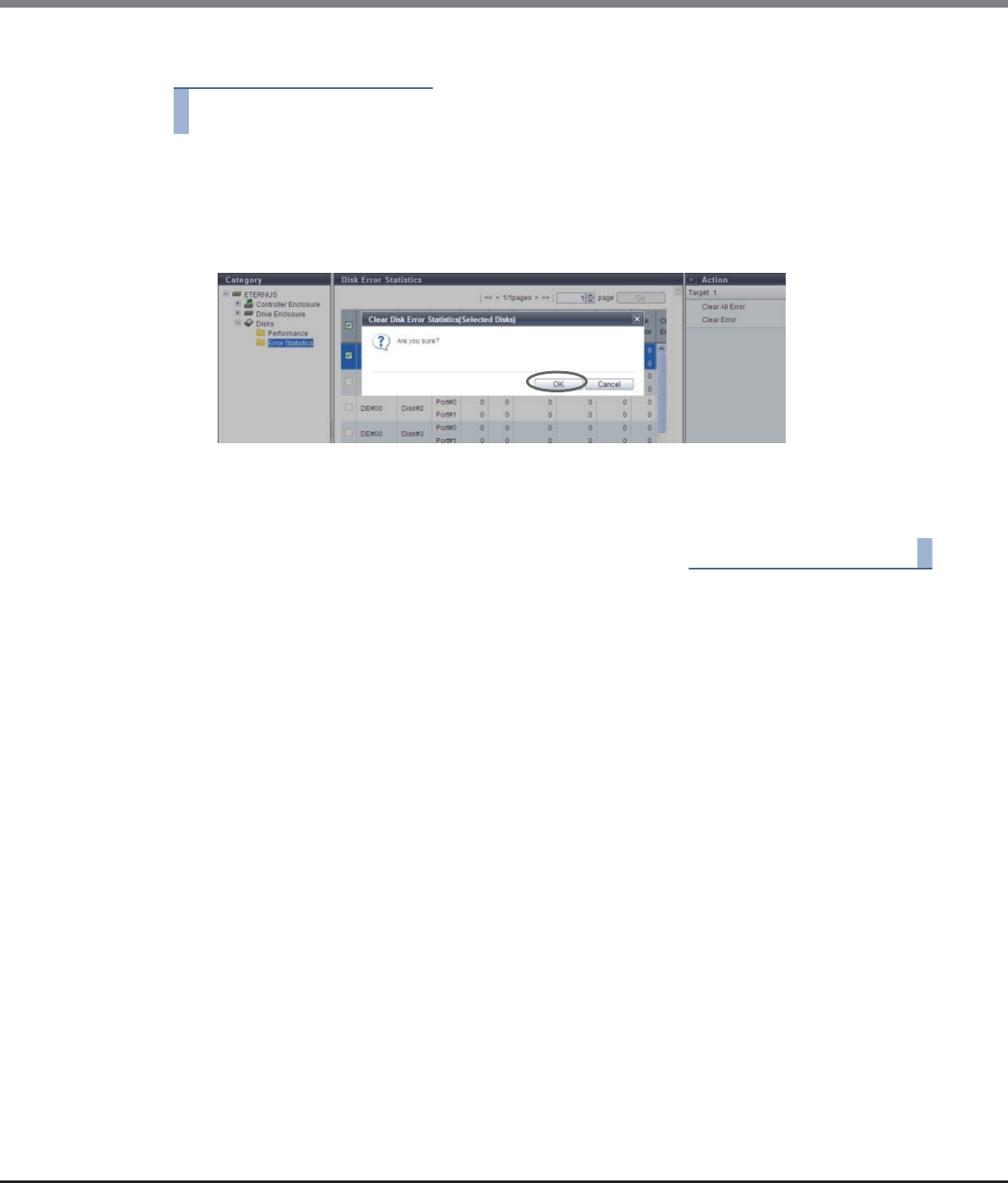
Chapter 10 Component Management
10.2 Functions in the Action Area for Component
ETERNUS Web GUI User’s Guide
Copyright 2013 FUJITSU LIMITED P2X0-1090-10ENZ0
708
The procedure to delete error information from the selected drive is as follows:
Procedure
1Select the drive to delete error information from (multiple selections can be made) and click
[Clear Error] in [Action].
→A confirmation screen appears.
2Click the [OK] button.
→Deletion of the error information from the selected drive starts.
3Click the [Done] button to return to the [Disk Error Statistics] screen.
End of procedure
ETERNUS Web GUI User’s Guide
Copyright 2013 FUJITSU LIMITED P2X0-1090-10ENZ0
709
Chapter 11
System Management
This chapter describes system management.
11.1 System Status
System status displays the status information of volumes.
System status screens can be displayed by clicking the following categories:
Detailed information of the system settings can be displayed from the following screen:
•ECO Mode Schedule Detail
•Path Group Detail Information
System status screen Category
System (Basic Information) Storage system name
Network Network
Remote Support (REMCS) for Regions other than EMEA Remote Support
Remote Support (AIS Connect) for Regions other than
Japan
Root Certificate Root Certificate
Key Management Key Management
Key Group Key Group
Define Role User Settings
ECO Mode ECO Mode
Event/Dump Event/Dump
Audit Log Audit Log
Storage Migration Storage Migration
Utility Utility
System Settings System Settings
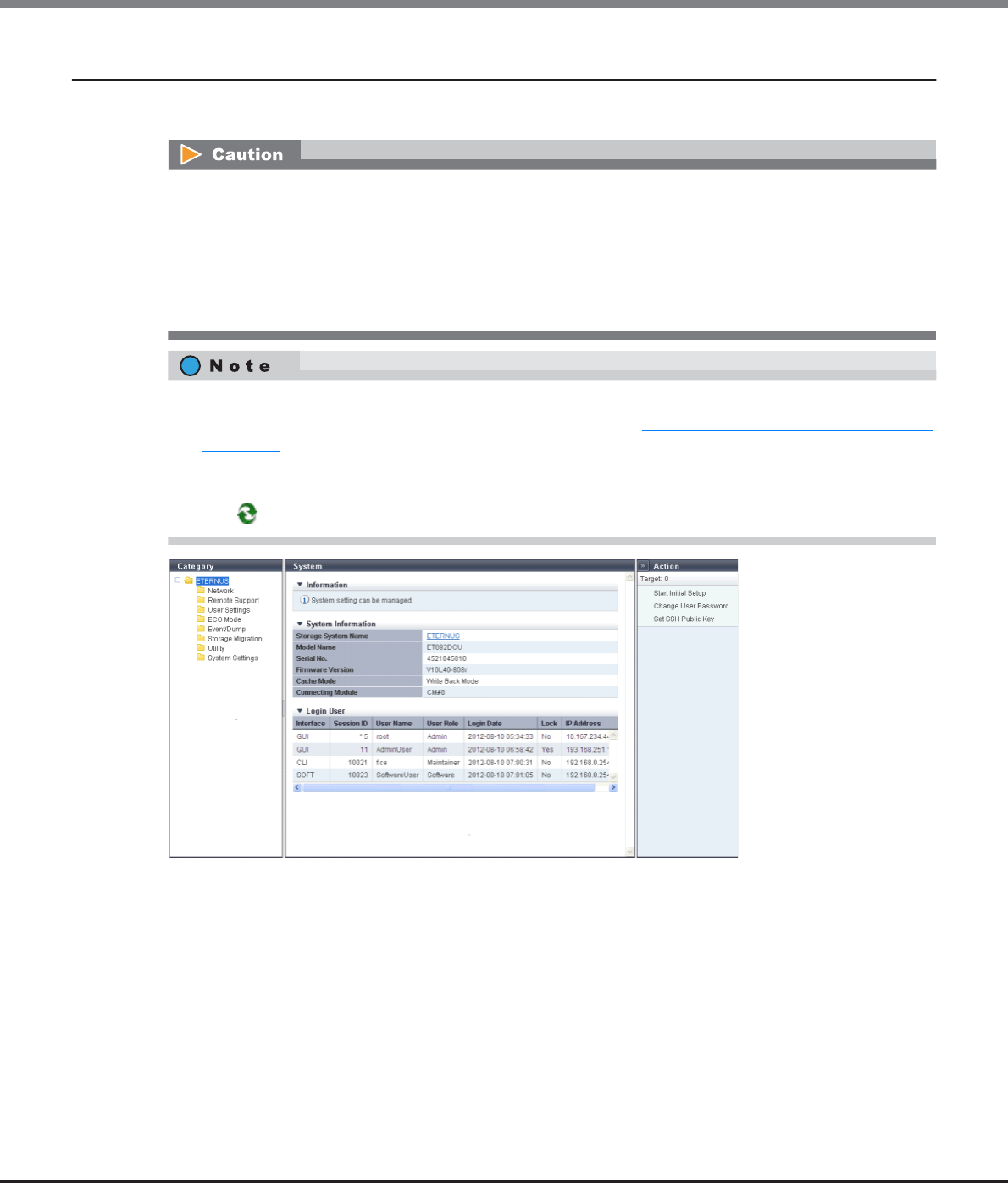
Chapter 11 System Management
11.1 System Status
ETERNUS Web GUI User’s Guide
Copyright 2013 FUJITSU LIMITED P2X0-1090-10ENZ0
710
11.1.1 System (Basic Information)
This function displays the system information and a list of users who are currently logged in.
The following items are displayed in the Main area:
●System Information
•Storage System Name
The name for the ETERNUS DX Disk storage system is displayed.
By clicking this item, the [Storage] screen in the [Component] navigation is displayed.
•Model Name
The model name of the ETERNUS DX Disk storage system is displayed.
•Serial No.
The serial number of the ETERNUS DX Disk storage system is displayed.
•The user list is displayed only when a user account with the "User Management" policy is used to log in.
•A list of following user is displayed:
-Users who are logged in to the Master CM from GUI
-Users who are logged in to the Slave CM from GUI
-Users who are logged in to the Master CM from CLI or other software
Note that users who are logged in to the Slave CM from CLI or other software are not displayed.
•The storage system name is displayed at the top of the [System] navigation category.
The "Storage System Name" is specified using the procedure in "11.2.13.1 Modify Storage System Name"
(page 927).
•Click the "Storage System Name" in the category to display a list of the users who logged in to the
ETERNUS DX Disk storage system in the "Login User" field. Click the "Storage System Name" again or click
the [ ] icon to display the latest screen.

Chapter 11 System Management
11.1 System Status
ETERNUS Web GUI User’s Guide
Copyright 2013 FUJITSU LIMITED P2X0-1090-10ENZ0
711
•Firmware Version
The current controller firmware version is displayed.
-VxxLyy-zzzz (Vxx: Version, Lyy: Level, zzzz: Release number)
•Cache Mode
The current status and the factor of the cache are displayed. The normal status is "Write Back Mode".
-Write Back Mode
When a Write request is issued from the host, "Write Complete" is displayed after writing to the cache
area is complete.
-Write Through Mode
When a Write request is issued from the host, "Write Complete" is displayed after writing to the cache
area and the drives is complete.
In the Write Through Mode, "Write Through (factors)" is displayed. When there are multiple factors, all
the factors are displayed.
The factors of the Write Through Mode are described below:
•Write Through (Pinned Data)
A large amount of pinned data is detected in the ETERNUS DX Disk storage system.
•Write Through (Battery)
The battery charge level is low.
•Write Through (Maintenance)
The following maintenance operation is currently being used:
-Switch Controller Firmware
-Change Controlling CM
-Add Controller Module
•Write Through (1CM)
The ETERNUS DX Disk storage system is operated with 1CM. (*1)
*1: This mode is displayed when "1CM Write Through" is enabled by using the procedure in "11.2.13.4 Setup
Subsystem Parameters" (page 935) function and the ETERNUS DX Disk storage system is operated with
1CM (only 1CM can be used due to an error such as a CM failure). The "1CM Write Through" setting for the
"Setup Subsystem Parameters" function is displayed and can be changed when logged in using a user
account with the "Maintenance Operation" policy. The normal status is disabled.
•Connecting Module
The CM to which the GUI is connected is displayed.
●Login User
•Interface
The interface type for users who are logged in is displayed.
-GUI
Users logged in via GUI or users logged in via GUI from the AIS Connect server (*1)
-CLI
Users logged in via CLI or users logged in via CLI from the AIS Connect server (*1)
-SOFT
Users logged in from software.
"SOFT" is displayed in the following conditions:
•When users log in from software with the default "Software" role via CLI
•When users log in using SMI-S via software
•When users log in from software using Dynamic LUN Mirroring (DLM) via CLI
*1: AIS Connect servers are supplied for regions other than Japan.

Chapter 11 System Management
11.1 System Status
ETERNUS Web GUI User’s Guide
Copyright 2013 FUJITSU LIMITED P2X0-1090-10ENZ0
712
•Session ID
An identification number between 0 - 65535 for users who are logged in is displayed.
A session ID is obtained for each login and released with each logout. Because the session ID is obtained
discretely, the same session ID is not used even if the same user logs in again. GUI uses session IDs
between 1 - 999 and CLI (including SOFT) uses session IDs from 1001 onwards. An "*" (asterisk) is added
on top of the current user's (your) session ID.
-0 - 65535
-For the current user's (your) session: * xxxxx (xxxxx: 0 - 65535)
•User Name
The user name (user ID) for a user who is logged in is displayed. When the interface is "SOFT" (SMI-S or
DLM), the field is blank.
•User Role
The user role for a user who is logged in is displayed.
-Monitor
-Admin
-StorageAdmin
-AccountAdmin
-SecurityAdmin
-Maintainer
-Software
-Custom role
•Login Date
The login date and time are displayed.
-YYYY-MM-DD hh:mm:ss (YYYY: Year (2001 - 2037), MM: Month (01 - 12), DD: Day (01 - 31), hh: Hour
(00 - 23), mm: Minute (00 - 59), ss: Second (00 - 59))
•Lock
If a logged in user is updating data that is managed by the ETERNUS DX Disk storage system, "Yes" is dis-
played. If a user is not updating data, "No" is displayed. When "Yes" is displayed for a user, other users with
"No" displayed cannot update data.
Note that multiple users cannot update data that is managed by the ETERNUS DX Disk storage system at
the same time. The storage system is exclusively used by a user who is updating the data. The exclusion is
released when the updating is complete.
•IP Address
The IP address for a user who is logged in is displayed. When a user logged in from the AIS Connect server,
"AIS Connect Server" is displayed (for regions other than Japan). When the interface is "SOFT" (SMI-S), the
IP address is displayed only when logged in the ETERNUS DX Disk storage system via an external software.
When the interface is "SOFT" (DLM) or when the interface is "SOFT" (SMI-S) and the external software is not
used, the field is blank.
-For IPv4 address
•xxx.xxx.xxx.xxx
xxx: 0 - 255 (decimal)
-For IPv6 address
•xxxx:xxxx:xxxx:xxxx:xxxx:xxxx:xxxx:xxxx
xxxx: 0 - ffff (hexadecimal, "a" - "f" are lowercase letters)
Refer to "IPv6 Address Notation" (page 378) for details.
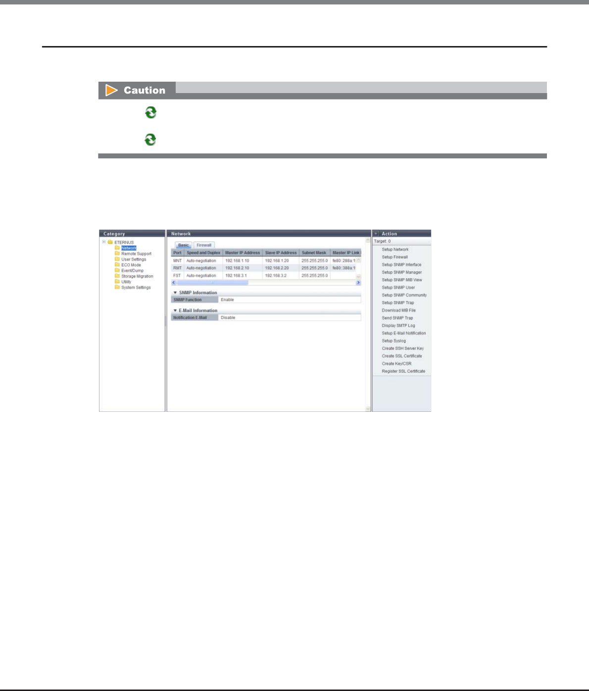
Chapter 11 System Management
11.1 System Status
ETERNUS Web GUI User’s Guide
Copyright 2013 FUJITSU LIMITED P2X0-1090-10ENZ0
713
11.1.2 Network
This function displays the network environment of each port in the ETERNUS DX Disk storage system.
■Basic
The network environment of each port, the SNMP information registered in the ETERNUS DX Disk storage
system, and the E-mail information are displayed.
The following items are displayed in the Main area:
•Port
The port type is displayed.
-For ETERNUS DX80 S2/DX90 S2: MNT or RMT
-ETERNUS DX410 S2/DX440 S2: MNT, RMT, or FST
-For ETERNUS DX8100 S2/DX8700 S2: MNT, RMT, or FST
•Speed and Duplex
The transfer speed and the communication method are displayed.
-Auto-negotiation
-1Gbit/s
-100Mbit/s Half
-100Mbit/s Full
-10Mbit/s Half
-10Mbit/s Full
Click the [ ] icon to display the latest screen. Note that after changing the firewall setting and returning to
this screen, it takes approximately 10 seconds to update the display contents. Wait at least 10 seconds and
click the [ ] icon or click [Network] in the category to display the [Network] screen again.

Chapter 11 System Management
11.1 System Status
ETERNUS Web GUI User’s Guide
Copyright 2013 FUJITSU LIMITED P2X0-1090-10ENZ0
714
•Master IP Address
The IP address of the Master CM, which has been specified to the port, is displayed.
If not specified, the field is blank. This item is used for IPv4.
•Slave IP Address
The IP address of the Slave CM, which has been specified to the port, is displayed.
If there is only one CM, the "Slave CM IP Address" is not displayed.
If not specified, the field is blank. This item is used for IPv4.
•Subnet Mask
The Subnet Mask, which has been specified to the port, is displayed.
If not specified, the field is blank. This item is used for IPv4.
•Master IP Link Local Address
The link local address of the Master CM, which has been specified to the port, is displayed.
If not specified or when "Port" is "FST", the field is blank. This item is used for IPv6.
•Master Connect IP Address
The connect IP address of the Master CM, which has been specified to the port, is displayed.
"Master Connect IP Address" corresponds to "Master IP Address" for IPv4.
If not specified or when "Port" is "FST", the field is blank. This item is used for IPv6.
•Slave IP Link Local Address
The link local address of the Slave CM, which has been specified to the port, is displayed.
This item is not displayed for the 1CM model.
If not specified or when "Port" is "FST", the field is blank. This item is used for IPv6.
•Slave Connect IP Address
The connect IP address of the Slave CM, which has been specified to the port, is displayed.
"Slave Connect IP Address" corresponds to "Slave IP Address" for IPv4.
This item is not displayed for the 1CM model.
If not specified or when "Port" is "FST", the field is blank. This item is used for IPv6.
•Length of Subnet Prefix
The prefix length for the connect IP address is displayed (unit: bit).
"Length of Subnet Prefix" corresponds to "Subnet Mask" for IPv4.
If not specified or when "Port" is "FST", the field is blank. This item is used for IPv6.
●SNMP Information
•SNMP Function
Whether the SNMP function is enabled or disabled is displayed.
●E-Mail Information
•Notification E-Mail
Whether the E-mail notification is enabled or disabled is displayed.
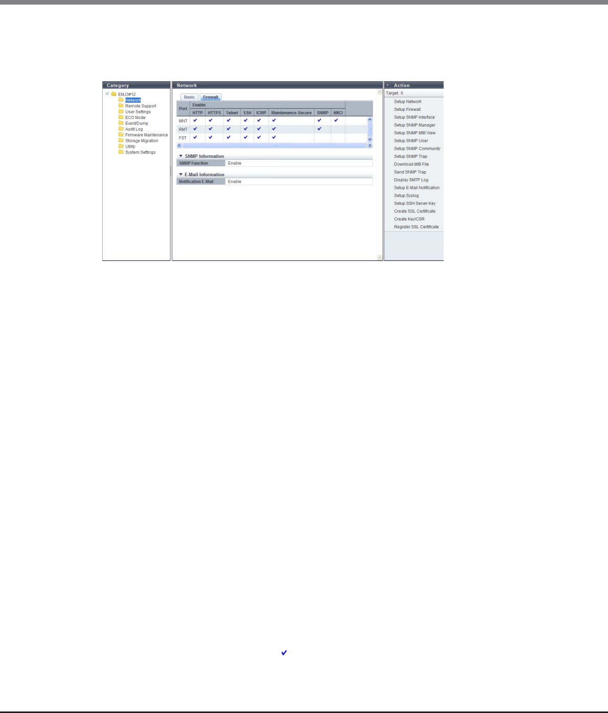
Chapter 11 System Management
11.1 System Status
ETERNUS Web GUI User’s Guide
Copyright 2013 FUJITSU LIMITED P2X0-1090-10ENZ0
715
■Firewall
The Firewall setting status for each service and the SNMP information and the E-Mail information of the ETER-
NUS DX Disk storage system are displayed.
The following items are displayed in the Main area:
•Port
The port type is displayed.
-For ETERNUS DX80 S2/DX90 S2: MNT or RMT
-For ETERNUS DX410 S2/DX440 S2: MNT, RMT, or FST
-For ETERNUS DX8100 S2/DX8700 S2: MNT, RMT, or FST
•HTTP
Whether the HTTP connection is enabled or disabled is displayed. (*1)
•HTTPS
Whether the HTTPS connection is enabled or disabled is displayed. (*1)
•Telnet
Whether the Telnet connection is enabled or disabled is displayed. (*1)
•SSH
Whether the SSH connection is enabled or disabled is displayed. (*1)
•ICMP
Whether the ICMP connection is enabled or disabled is displayed. (*1)
•Maintenance Secure
Whether the Maintenance Secure connection is enabled or disabled is displayed. (*1)
•SNMP
Whether the SNMP connection is enabled or disabled is displayed. (*1)
•RCIL
Whether the RCIL connection is enabled or disabled is displayed. (*1)
Whether RCIL is enabled or disabled is only displayed for the MNT port. This item is always left blank for
RMT and FST ports.
*1: When the SNMP connection is enabled, " " is displayed. If the SNMP connection is disabled, the field is blank.
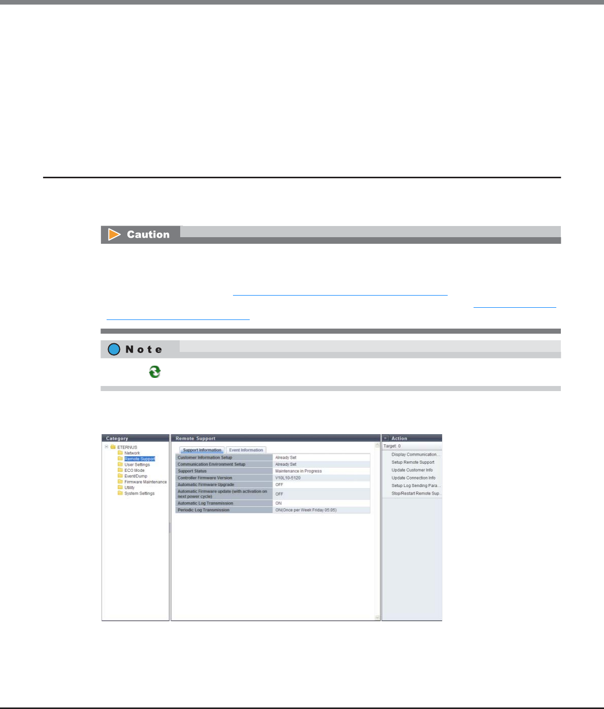
Chapter 11 System Management
11.1 System Status
ETERNUS Web GUI User’s Guide
Copyright 2013 FUJITSU LIMITED P2X0-1090-10ENZ0
716
●SNMP Information
•SNMP Function
Whether the SNMP function is enabled or disabled is displayed.
●E-Mail Information
•Notification E-Mail
Whether the E-mail notification is enabled or disabled is displayed.
11.1.3 Remote Support (REMCS) for Regions other than EMEA
This function displays the Remote Support function settings and the operation status in the ETERNUS DX Disk
storage system.
■Support Information
This caution is applied for regions other than Japan.
REMCS and AIS Connect cannot be used at the same time. AIS Connect function can only be used when
REMCS is not specified or is stopped. When REMCS is used, suspend the REMCS function, and then enable the
AIS Connect function. Refer to "11.2.4.6 Stop/Restart Remote Support" (page 818) for details.
REMCS can be specified or restarted when the AIS Connect function is disabled. Refer to "11.2.5.1 Setup AIS
Connect Environment" (page 821) for details.
Click the [ ] icon to update to the latest screen.

Chapter 11 System Management
11.1 System Status
ETERNUS Web GUI User’s Guide
Copyright 2013 FUJITSU LIMITED P2X0-1090-10ENZ0
717
The following items are displayed in the Main area:
•Customer Information Setup
Whether or not the customer information has been specified at the REMCS center is displayed.
•Communication Environment Setup
Whether or not the communication environment information has been specified at the REMCS center is
displayed.
•Support Status
The Remote Support status is displayed.
-"-" (hyphen)
The Remote Support is not operating.
-Operating
The Remote Support is operating.
-Maintenance in Progress
The ETERNUS DX Disk storage system is under maintenance. When the operation to complete
maintenance is performed, the status returns to "Operating".
-Stopped
The Remote Support has temporarily been stopped. Use the procedure in "11.2.4.6 Stop/Restart Remote
Support" (page 818) to restart the Remote Support and return to the "Operating" state.
If the support status is "Operating" or "Maintenance in Progress", one of the messages below appears in
parentheses based on the Remote Support operating status.
-Controller Firmware Download in Progress
-Termination of Controller Firmware Download in Progress
-Controller Firmware Upgrade in Progress
-Log Collection in Progress
•Controller Firmware Version
The current controller firmware version is displayed.
-VxxLyy-zzzz (Vxx: Version, Lyy: Level, zzzz: Release number)
•Automatic Firmware Upgrade
Whether the automatic firmware upgrade is enabled or disabled is displayed.
-"-" (hyphen)
The Remote Support is not operating.
-ON (download schedule)
The automatic firmware upgrade is enabled. Receive controller firmware according to the download
schedule.
-OFF
The automatic firmware upgrade is disabled.
•Automatic Firmware upgrade (with activation on next power cycle)
Whether or not to execute the controller firmware application, after controller firmware download has
been completed, is displayed.
-"-" (hyphen)
The Remote Support is not operating.
-ON
Execute the controller firmware application after controller firmware download is complete. The
downloaded controller firmware will be changed to the controller firmware which will be enabled at the
next startup.
-OFF
Do not execute the controller firmware application after controller firmware download is complete.
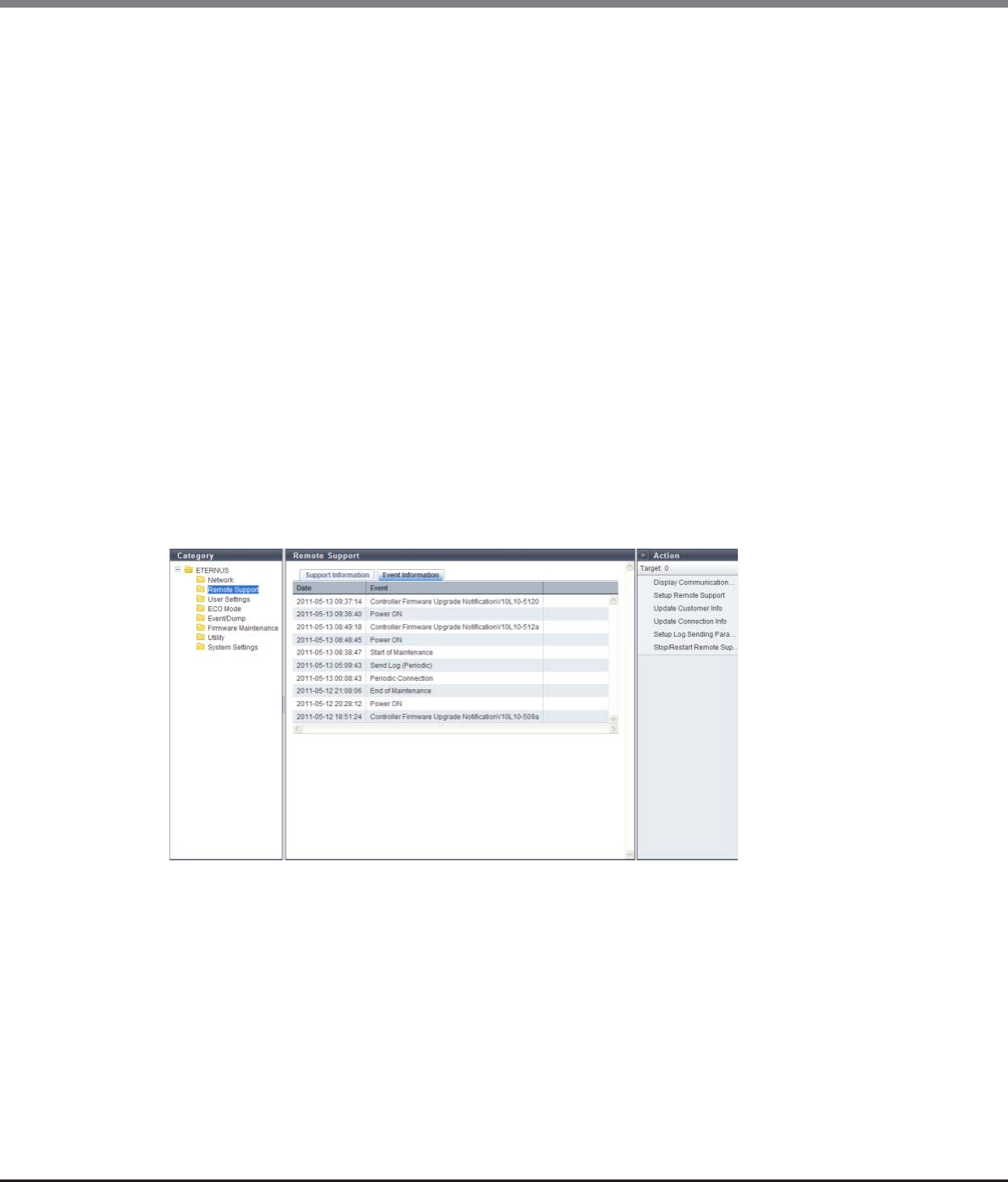
Chapter 11 System Management
11.1 System Status
ETERNUS Web GUI User’s Guide
Copyright 2013 FUJITSU LIMITED P2X0-1090-10ENZ0
718
•Automatic Log Transmission
Whether the automatic log transmission is enabled or disabled is displayed.
-"-" (hyphen)
The Remote Support is not operating.
-ON
The automatic log transmission is enabled. The internal log of the ETERNUS DX Disk storage system is
automatically sent to the REMCS center when an error occurs.
-OFF
The automatic log transmission is disabled.
•Periodic Log Transmission
Whether the periodical log transmission is enabled or disabled is displayed.
-"-" (hyphen)
The Remote Support is not operating.
-ON (transmission schedule)
The periodical log transmission is enabled. The internal log of the ETERNUS DX Disk storage system is
automatically sent to the REMCS center according to the transmission schedule.
-OFF
The periodical log transmission is disabled.
■Event Information
In this screen, ten latest pieces of event information are displayed.
The following items are displayed in the Main area:
•Date
The date and time when the Remote Support events occurred, are displayed.
-YYYY-MM-DD hh:mm:ss (YYYY: Year (AD), MM: Month (01 - 12), DD: Day (01 - 31), hh: Hour (00 - 23),
mm: Minute (00 - 59), ss: Second (00 - 59))
•Event
The Remote Support event is displayed.
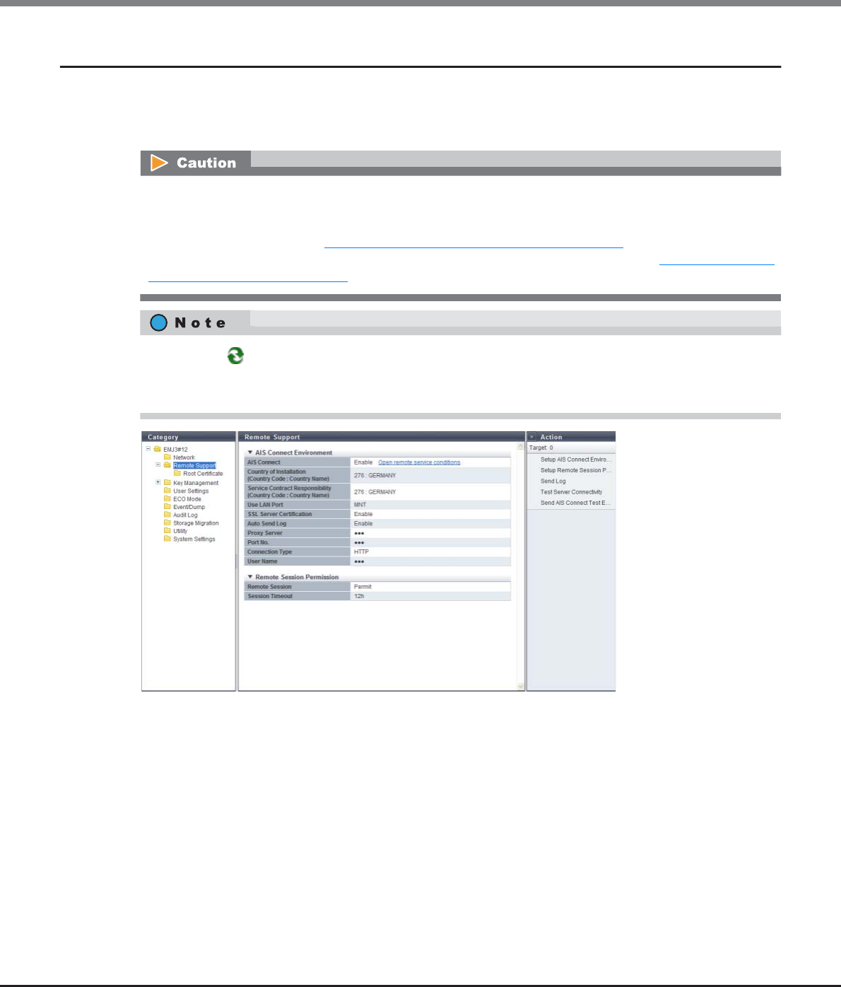
Chapter 11 System Management
11.1 System Status
ETERNUS Web GUI User’s Guide
Copyright 2013 FUJITSU LIMITED P2X0-1090-10ENZ0
719
11.1.4 Remote Support (AIS Connect) for Regions other than Japan
This function displays the setting information for AIS Connect.
The AIS Connect function monitors or controls remotely the ETERNUS DX80 S2/DX90 S2, the ETERNUS DX410
S2/DX440 S2, or the ETERNUS DX8100 S2/DX8700 S2 from a remote server (AIS Connect server).
The following items are displayed in the Main area:
●AIS Connect Environment
•AIS Connect
Whether the AIS Connect function is enabled or disabled is displayed.
When "Country of Installation (Country Code : Country Name)" has been set, the [Open remote service
conditions] link is displayed. Click this item to display the consent form regarding the handling of personal
information.
•Country of Installation (Country Code : Country Name)
The shipment destination (storage system location) is displayed in "Country Code : Country Name" format.
If not specified, "Not Selected" is displayed.
This caution is applied for regions other than EMEA.
REMCS and AIS Connect cannot be used at the same time. AIS Connect function can only be used when
REMCS is not specified or is stopped. When REMCS is used, suspend the REMCS function, and then enable the
AIS Connect function. Refer to "11.2.4.6 Stop/Restart Remote Support" (page 818) for details.
REMCS can be specified or restarted when the AIS Connect function is disabled. Refer to "11.2.5.1 Setup AIS
Connect Environment" (page 821) for details.
•Click the [ ] icon to update to the latest screen.
•Use CLI to set "Service Contract Responsibility (Country Code : Country Name)". Note that the
"Maintenance Operation" policy is required to set this item.

Chapter 11 System Management
11.1 System Status
ETERNUS Web GUI User’s Guide
Copyright 2013 FUJITSU LIMITED P2X0-1090-10ENZ0
720
•Service Contract Responsibility (Country Code : Country Name)
The country in which the support office for the ETERNUS DX Disk storage system is located is displayed in
"Country Code : Country Name" format.
•Use LAN Port
The LAN port that is used for communication with the AIS Connect server is displayed.
-MNT
-RMT
•SSL Server Certification
When SSL server certification is used for communication with the AIS Connect server, "Enable" is displayed.
When the SSL server certification is not used, "Disable" is displayed.
•Auto Send Log
Whether the automatic log transmission is enabled or disabled is displayed.
When "Auto Send Log" is enabled, the ETERNUS DX Disk storage system automatically sends logs to the AIS
Connect server when a fail event (error level or warning level) occurs.
•Proxy Server
The IPv4 address or the Fully Qualified Domain Name (FQDN) of the proxy server is displayed. If the proxy
server is not specified, the field is blank.
-IPv4 address
xxx.xxx.xxx.xxx
xxx: 0 - 255 (decimal)
-FQDN
Up to 63 alphanumeric characters and symbols
•Port No.
The port number for the proxy server is displayed. If the proxy server is not specified, the field is blank.
•Connection Type
The communication method for the proxy server is displayed. If the proxy server is not specified, the field is
blank.
-HTTP
-SOCKS
•User Name
The user name for proxy server authentication is displayed. If the proxy server is not specified, the field is
blank.
●Remote Session Permission
•Remote Session
Whether to permit or forbid a remote session from the AIS Connect server is displayed.
•Session Timeout
The timeout value for a remote session connection is displayed. If the timeout limit is not specified,
"Unlimited" is displayed.
If the time exceeds the specified value without a remote session connection, remote session permission is
disabled and the setting status changes to "Forbid".
This item is not displayed when "Service Contract Responsibility (Country Code : Country Name)" is not
specified from CLI.
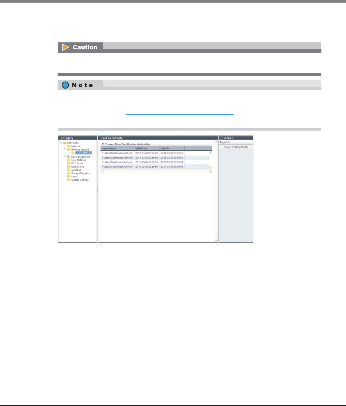
Chapter 11 System Management
11.1 System Status
ETERNUS Web GUI User’s Guide
Copyright 2013 FUJITSU LIMITED P2X0-1090-10ENZ0
721
11.1.4.1 Root Certificate
This function displays the root certificate that is used for SSL communication with the AIS Connect server.
The following items are displayed in the Main area:
●Trusted Root Certification Authorities
•Issuer Name
The issuer name for the root certificate is displayed.
•Valid From
The start date and time of the root certificate validity period is displayed.
-YYYY-MM-DD hh:mm:ss (YYYY: Year (AD), MM: Month (01 - 12), DD: Day (01 - 31), hh: Hour (00 - 23),
mm: Minute (00 - 59), ss: Second (00 - 59))
•Valid To
The end date and time of the root certificate validity period is displayed.
-YYYY-MM-DD hh:mm:ss (YYYY: Year (AD), MM: Month (01 - 12), DD: Day (01 - 31), hh: Hour (00 - 23),
mm: Minute (00 - 59), ss: Second (00 - 59))
If multiple certificates are included in the root certificate file, up to 6 issuer names and their validity periods
are displayed.
•The root certificate that is registered in the ETERNUS DX Disk storage system is displayed by default. When
the root certificate is updated, only the latest certificate is displayed. For details on how to update the
root certificate, refer to "11.2.5.6 Import Root Certificate" (page 830).
•The root certificate is only used for authentication with the AIS Connect server.
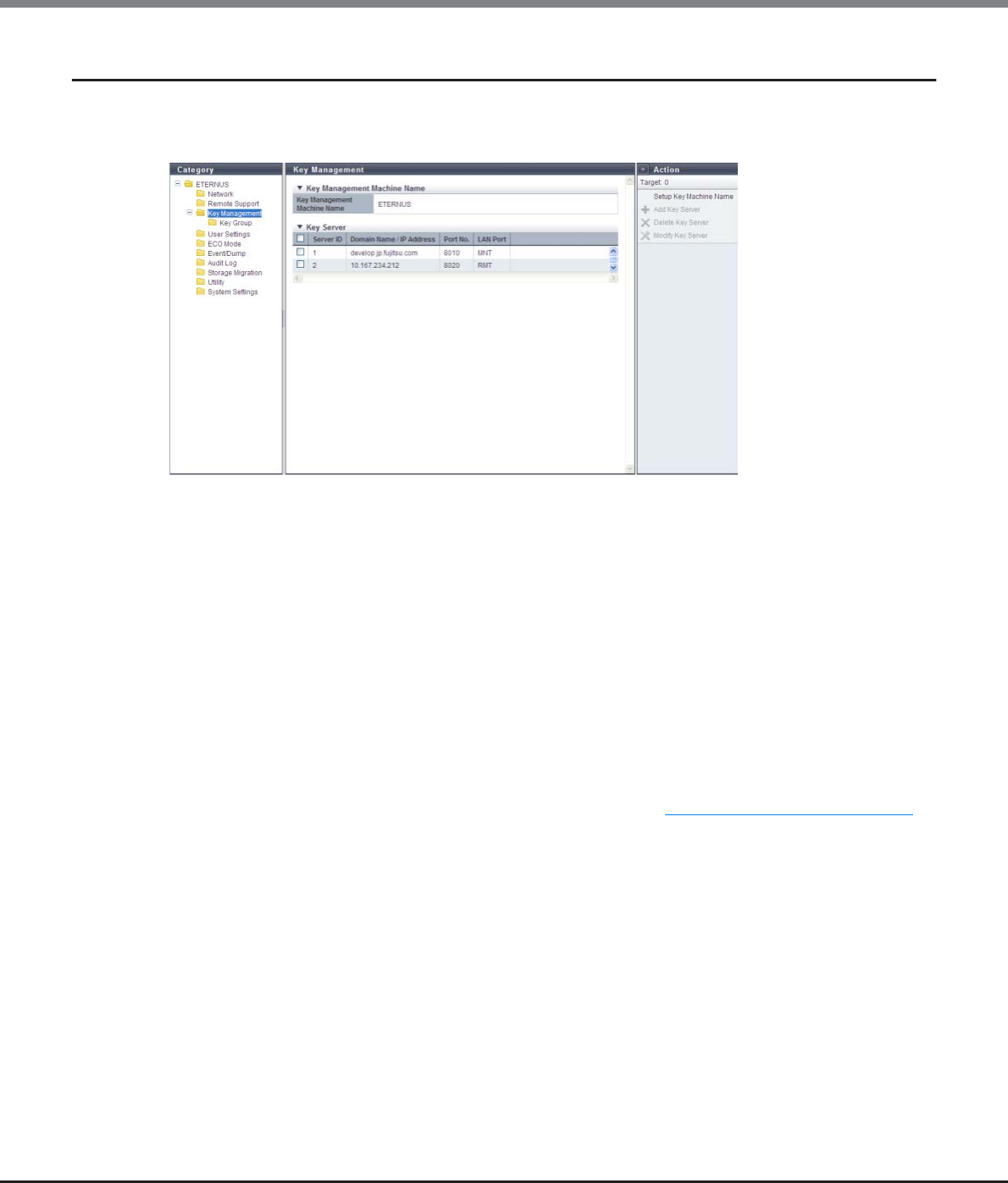
Chapter 11 System Management
11.1 System Status
ETERNUS Web GUI User’s Guide
Copyright 2013 FUJITSU LIMITED P2X0-1090-10ENZ0
722
11.1.5 Key Management
This function displays the setting parameters for the key server.
In this section, the SED authentication key is referred to as "key".
The following items are displayed in the Main area:
●Key Management Machine Name
•Key Management Machine Name
The name of the device that is connected to the key server is displayed. If the key management device
name is not specified, the field is blank.
●Key Server
•Server ID
The key server ID is displayed.
•Domain Name / IP Address
The domain name (Fully Qualified Domain Name: FQDN) or the IP address for the key server is displayed.
Note that the IPv6 address is displayed as an abbreviation. Refer to "IPv6 Address Notation" (page 378) for
details.
•Port No.
The port number that is used to communicate with the key server is displayed.
•LAN Port
The LAN port that is used to communicate with the key server is displayed.
-MNT
-RMT
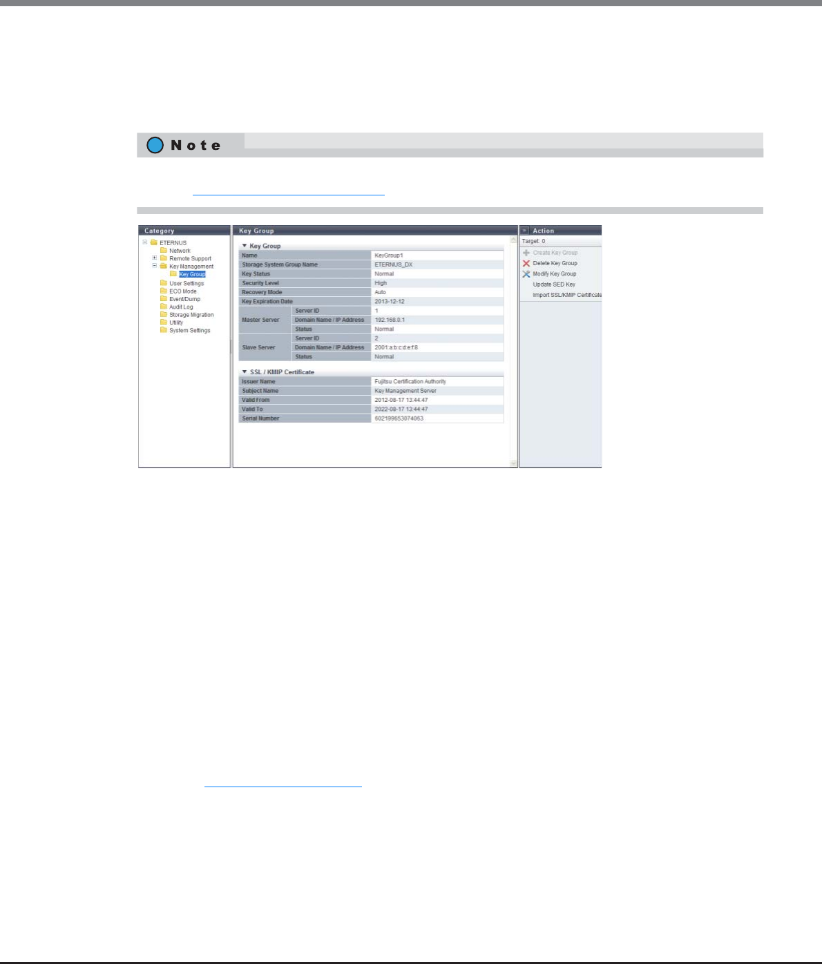
Chapter 11 System Management
11.1 System Status
ETERNUS Web GUI User’s Guide
Copyright 2013 FUJITSU LIMITED P2X0-1090-10ENZ0
723
11.1.5.1 Key Group
This function displays the key information that is used for a key group and the SSL/KMIP certificate informa-
tion.
The key group combines all of the RAID groups that use the same key.
The following items are displayed in the Main area:
●Key Group
•Name
The key group name is displayed. If no key groups are created, the field is blank.
The key group name corresponds to "Serial Number", which is managed in the key server.
•Storage System Group Name
The storage system group name is displayed. If no key groups are created, the field is blank.
The storage system group combines the key management device (Key Management Machine) name that
is managed by the user with the key groups. The storage system group name corresponds to "Device Group
Name", which is managed in the key server. Note that "ETERNUS_DX" is specified as the default device
group name when an ETERNUS DX Disk storage system is shipped with "ETERNUS SF KM" (key management
software).
•Key Status
The key status is displayed. If no key groups are created, the field is blank.
Refer to "B.6 Key Status" (page 979) for details.
•Security Level
The security level for the key group is displayed. If no key groups are created, the field is blank.
"Security Level" indicates the handling level when application of the SED key to the target RAID group fails.
If the key for the relevant RAID group cannot be obtained from the key server due to a communication
error and the SEDs that configure the RAID group are changed to hot spares or changed to new SEDs due to
failure or maintenance, the ETERNUS DX Disk storage system performs operations according to the selected
security level.
The RAID groups that are registered in the key group can be checked by using the [SED Key Group] screen.
Refer to "6.1.4 SED Key Group" (page 167) for details.
Chapter 11 System Management
11.1 System Status
ETERNUS Web GUI User’s Guide
Copyright 2013 FUJITSU LIMITED P2X0-1090-10ENZ0
724
-High
Rebuilding to hot spares for which the key cannot be changed after SED failure is not performed. The
RAID group loses its redundancy (" Exposed" or " Partially Exposed" (for High Reliability
(RAID6))).
When SED maintenance is being performed, replacing a SED with a new SED for which the key cannot
be changed does not complete successfully. If this action is performed, the status of the new SED
changes to " Not Exist".
When communication between the key server and the ETERNUS DX Disk storage system returns to
normal and the key can be obtained, the SED status changes to normal. Rebuilding to the SED for
which the status changed to normal is performed after the key is changed. Note that "Modifying" may
be displayed for the key status for few minutes even though the SED key has already changed. After
changing the key, maintenance of the SEDs is complete.
-Low
Rebuilding or maintenance is performed by using the common key if changing of the key in the key
server fails due to a network error.
Even if the security level is changed from "High" to "Low", the rebuilding process does not start
immediately after the level is changed. Rebuilding processes start after the ETERNUS DX Disk storage
system recognizes that changing of the security level and the key is complete.
•Recovery Mode
The recovery mode for the key group is displayed. If no key groups are created, the field is blank.
The recovery mode is a method to recover locked (*1) RAID groups or SEDs after communication with the
key server is resolved. For RAID groups in locked status, " SED Locked" is displayed. For SEDs in locked
status, " Not Exist" is displayed.
*1: A blocked status that occurs when the key of the RAID groups cannot be obtained.
-Auto
This mode recovers locked RAID groups or SEDs when the communication error with the key server is
resolved.
-Manual
Use the [Recovery SED] function of GUI to recover the locked RAID groups or SEDs when the
communication error with the key server is resolved.
•Key Expiration Date
The key expiration date is displayed. If no key groups are created, the field is blank.
When the key has expired, a new key is obtained from the key server and automatically applied in place of
the expired key.
Note that the display contents for this item changes as follows:
-When the key status is "Modifying", the expiration date before the key was replaced is displayed.
-When the key status is "Unregistered Server Certificate", "No SSL Certificate", "Network Error", "Not
Acquired", or "Key Server Error", a "-" (hyphen) is displayed.
•YYYY-MM-DD (YYYY: Year (AD), MM: Month (01 - 12), DD: Day (01 - 31))
•Master Server
-Server ID
The key server ID for the master server is displayed. If no key group is created or if no master server is
specified, the field is blank.
-Domain Name / IP Address
The domain name (FQDN) or the IP address of the master server is displayed. If no key groups are
created or if no master server is specified, the field is blank.
Note that the IPv6 address is displayed as an abbreviation. Refer to "IPv6 Address Notation" (page 378)
for details.

Chapter 11 System Management
11.1 System Status
ETERNUS Web GUI User’s Guide
Copyright 2013 FUJITSU LIMITED P2X0-1090-10ENZ0
725
-Status
The master server status is displayed. If no key group is created or if no master server is specified, the
field is blank.
Refer to "B.7 Key Server Status" (page 980) for details.
•Slave Server
-Server ID
The key server ID of the slave server is displayed. If no key group is created or if no slave server is
specified, the field is blank.
-Domain Name / IP Address
The domain name (FQDN) or the IP address of the slave server is displayed. If no key group is created or
if no slave server is specified, the field is blank.
Note that the IPv6 address is displayed as an abbreviation. Refer to "IPv6 Address Notation" (page 378)
for details.
-Status
The slave server status is displayed. If no key group is created or if no slave server is specified, the field
is blank.
Refer to "B.7 Key Server Status" (page 980) for details.
●SSL / KMIP Certificate
•Issuer Name
The certificate authority name that issues the SSL / KMIP certificate is displayed. If the certificate is not
imported, the field is blank.
•Subject Name
The name of the destination to which the SSL / KMIP certificate is issued is displayed. If the certificate is not
imported, the field is blank.
•Valid From
The start date and time of the SSL / KMIP certificate validity period is displayed. If the certificate is not
imported, the field is blank.
-YYYY-MM-DD hh:mm:ss (YYYY: Year (AD), MM: Month (01 - 12), DD: Day (01 - 31), hh: Hour (00 - 23),
mm: Minute (00 - 59), ss: Second (00 - 59))
•Valid To
The end date and time of the SSL / KMIP certificate validity period is displayed. If the certificate is not
imported, the field is blank.
-YYYY-MM-DD hh:mm:ss (YYYY: Year (AD), MM: Month (01 - 12), DD: Day (01 - 31), hh: Hour (00 - 23),
mm: Minute (00 - 59), ss: Second (00 - 59))
•Serial Number
The serial number for the SSL / KMIP certificate is displayed. If the certificate is not imported, the field is
blank.
When created, the serial number is combined with the issuer name, which is a unique number in the cer-
tificate authority.
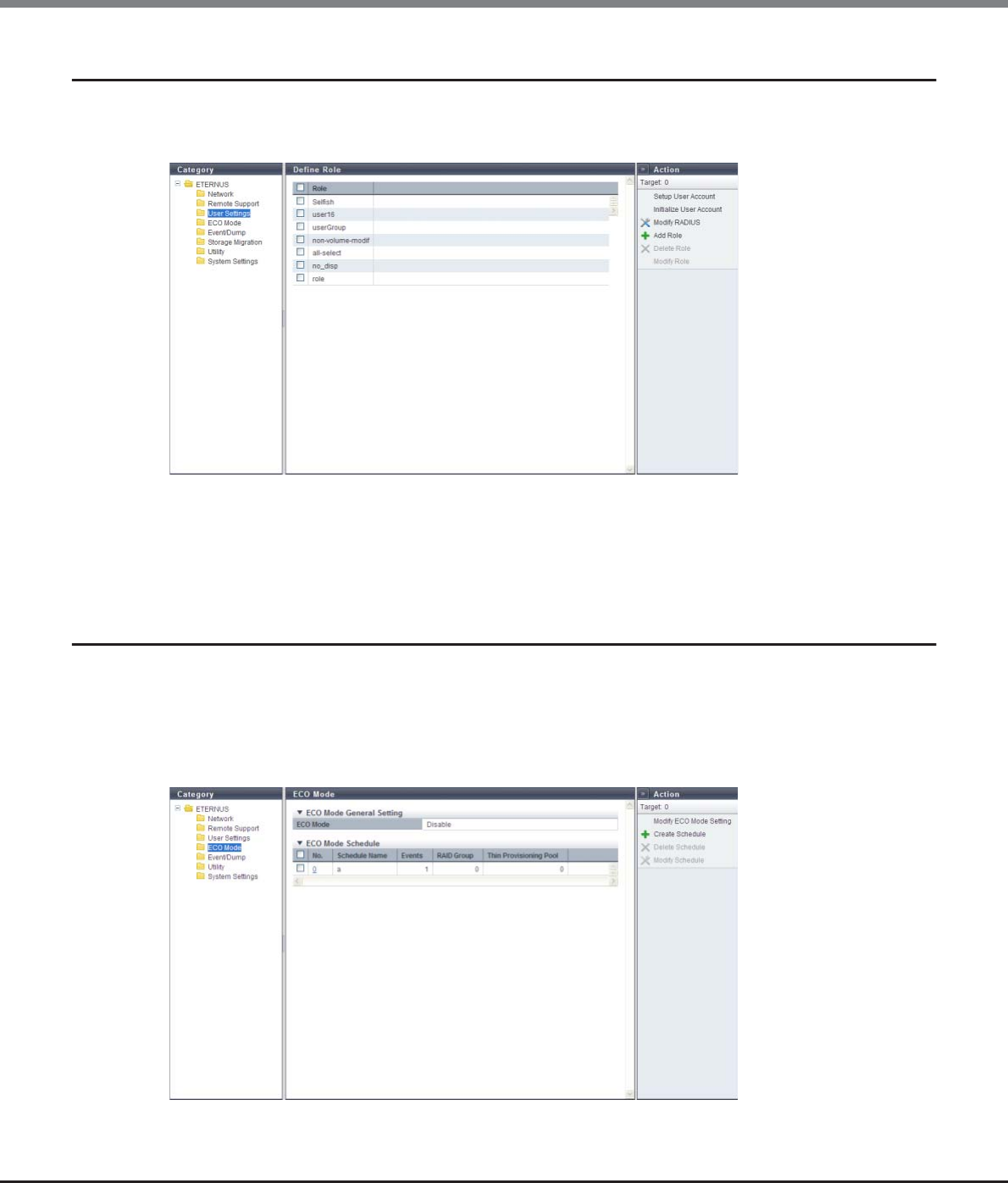
Chapter 11 System Management
11.1 System Status
ETERNUS Web GUI User’s Guide
Copyright 2013 FUJITSU LIMITED P2X0-1090-10ENZ0
726
11.1.6 Define Role
The registered custom roles in the ETERNUS DX Disk storage system are displayed.
A custom role is a role created by the user in combination of policies, in addition to the default roles.
The following items are displayed in the Main area:
•Role
The custom role name is displayed.
11.1.7 ECO Mode
A list of the ECO mode setting status and the ECO mode schedule that is registered in the ETERNUS DX Disk
storage system are displayed.
The ECO mode function schedules the disk operating time in compliance with Massive Arrays of Idle Disks
(MAID). It is designed to save power by stopping the disk motors outside of the scheduled disk operating
time.
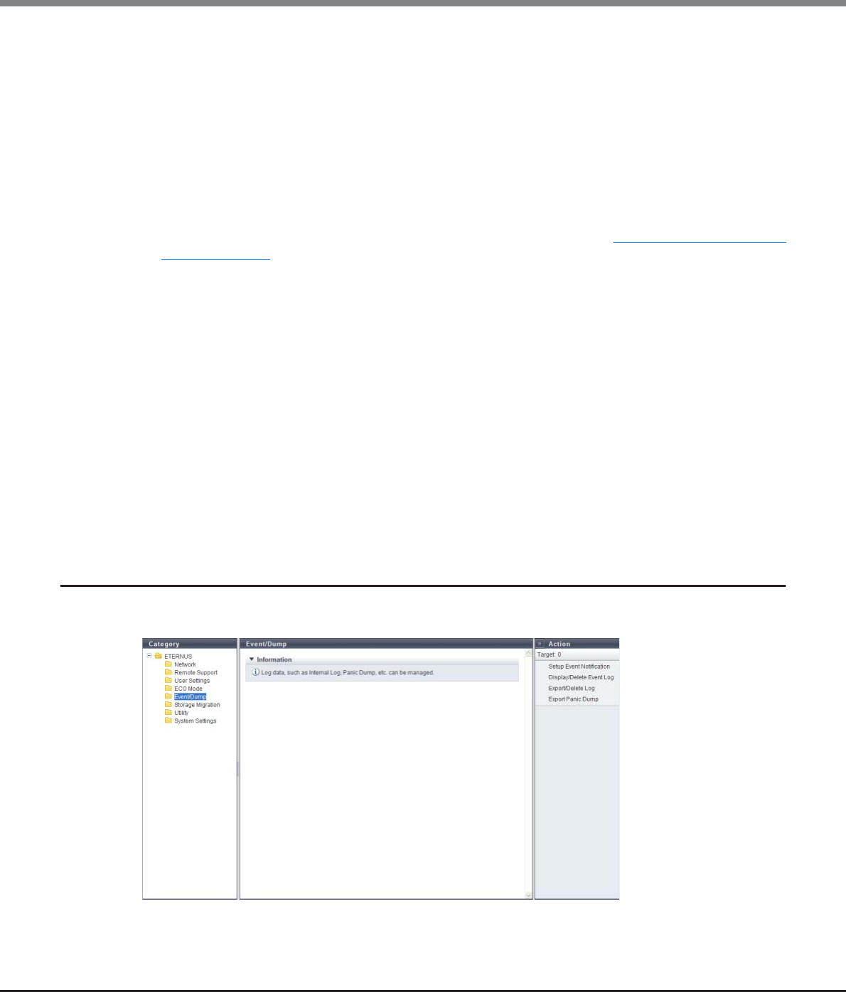
Chapter 11 System Management
11.1 System Status
ETERNUS Web GUI User’s Guide
Copyright 2013 FUJITSU LIMITED P2X0-1090-10ENZ0
727
The following items are displayed in the Main area:
●ECO Mode General Setting
•ECO Mode
The ECO mode setting (enabled or disabled) for all of the ETERNUS DX Disk storage systems is displayed.
●ECO Mode Schedule
•No.
The schedule number is displayed.
By clicking this link, the [ECO Mode Schedule] screen is displayed. Refer to "11.1.13 ECO Mode Schedule
Detail" (page 733) for display items.
If the ECO mode is controlled with the Storage Foundation Software ETERNUS SF, a "-" (hyphen) is
displayed.
•Schedule Name
The schedule name is displayed.
If the ECO mode is controlled with Storage Foundation Software ETERNUS SF, "external" is displayed.
•Events
The number of events that are registered in the schedule is displayed.
If the ECO mode is controlled with the Storage Foundation Software ETERNUS SF, a "-" (hyphen) is
displayed.
•RAID Group
The number of RAID groups for which the schedule is allocated to is displayed.
•Thin Provisioning Pool
The number of Thin Provisioning Pools for which the schedule is allocated to is displayed.
11.1.8 Event/Dump
This function records and displays the event history of the ETERNUS DX Disk storage system as an event log.
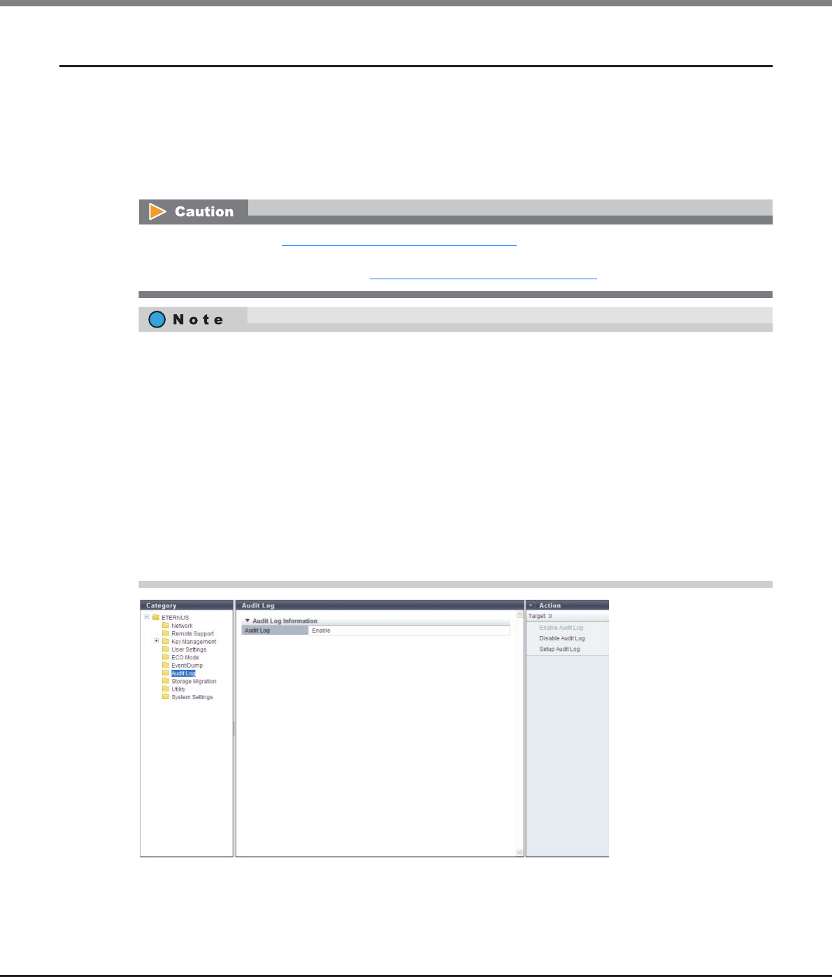
Chapter 11 System Management
11.1 System Status
ETERNUS Web GUI User’s Guide
Copyright 2013 FUJITSU LIMITED P2X0-1090-10ENZ0
728
11.1.9 Audit Log
This function displays the audit log information.
An audit log records not only operations that are performed by a user, but also how the ETERNUS DX Disk
storage system operates for these operations. The audit log function that is provided with the ETERNUS DX80
S2/DX90 S2, the ETERNUS DX410 S2/DX440 S2, and the ETERNUS DX8100 S2/DX8700 S2 transfers the
following information to external servers; when an operation is performed, who performed the operation,
where the operation was performed, the details of the operation, and the results of the operation.
The following items are displayed in the Main area:
•Audit Log
Whether the audit log function is enabled or disabled is displayed.
When the procedure in "11.2.10.1 Enable Audit Log" (page 902) is executed, "Enable" is displayed for "Audit
Log" in the "Audit Log Information" field even if an external server is not specified. Specify the external server
to which the audit log is sent. Refer to "11.2.10.3 Setup Audit Log" (page 903) for details.
Except for the functions that are listed below, the audit log collects all of the information for operations
(including logging in and logging out) that are performed via GUI and CLI (including external software).
•Export Cache Parameters
•Export Performance Information
•Convert Copy Path
•Send SNMP Trap Test
•Create Key/CSR
•Download Template File for Storage Migration Settings
•Backup Configuration
•Get G-List (*1)
•All of the display functions (e.g. displaying the volume list or displaying of the RAID group list)
*1: Operations that can be performed when logged in using a user account with the "Maintenance Operation" policy.
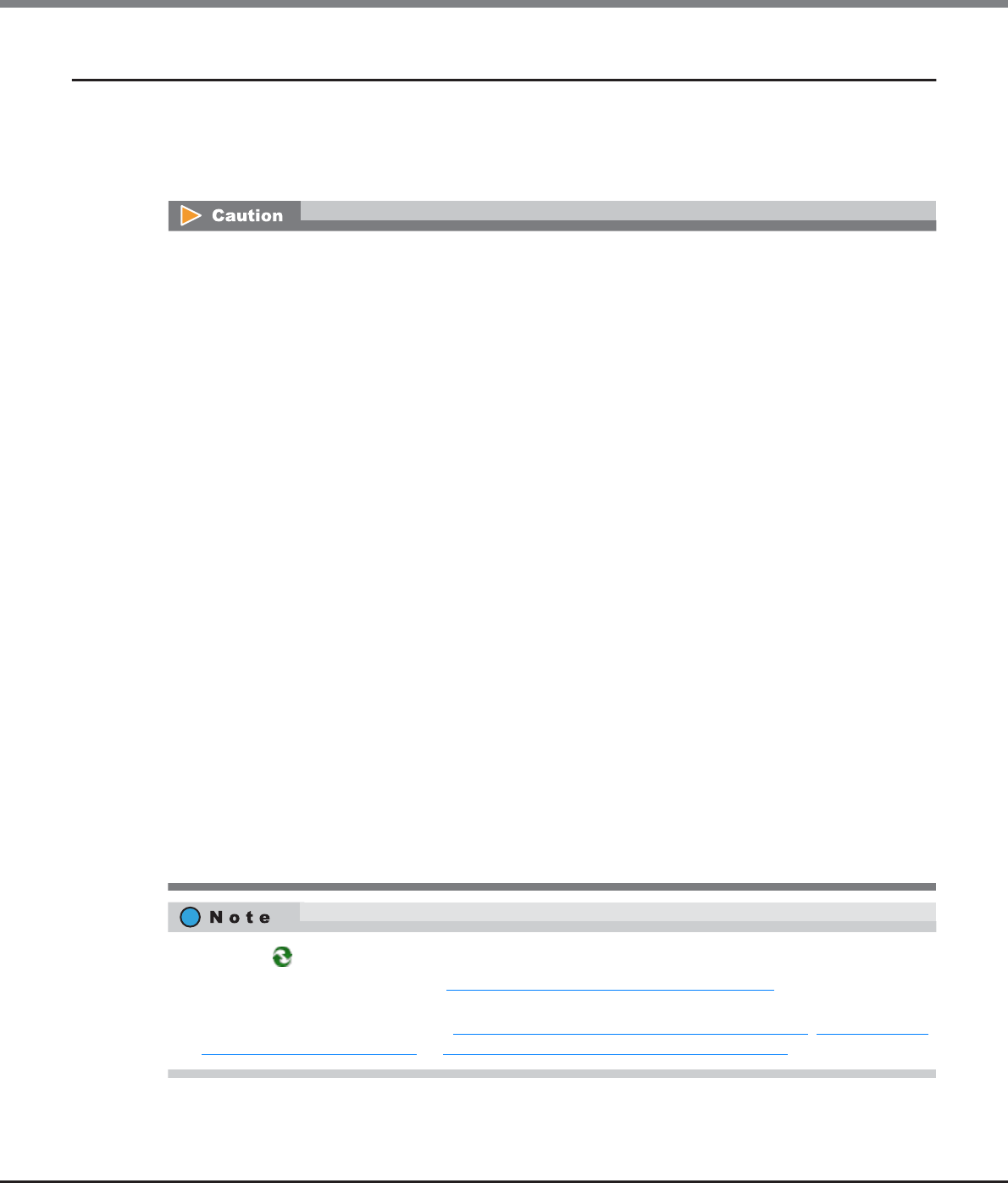
Chapter 11 System Management
11.1 System Status
ETERNUS Web GUI User’s Guide
Copyright 2013 FUJITSU LIMITED P2X0-1090-10ENZ0
729
11.1.10 Storage Migration
This function displays the setting and progress of Storage Migration.
Storage Migration is the function for migrating data by connecting other storage systems (migration source)
and the ETERNUS DX disk storage system (migration destination). Data migration is possible regardless of the
server and the OS, and without using server resources.
•When executing Storage Migration, confirm that there is no access from the host to the source volume
and destination volume.
•Do not perform the following operations when there are Storage Migration paths (hereinafter referred to
as "path group") established.
-Configuration of an Advanced Copy source or Advanced Copy destination to the migration destination
volume
-Configuration of an Advanced Copy source or Advanced Copy destination to the migration source
volume
-Formatting of the destination volume
-RAID diagnosis in the RAID group to which the destination volume belongs
-Disk diagnosis of the disk drives in the RAID group to which the destination volume belongs
-CM hot expansion on the destination storage system
-Memory hot expansion on the destination storage system
•The path groups must be deleted after the data migration is complete. The following operations are not
available before path groups are deleted:
-Concurrent upgrade of firmware at the destination storage system
-ECO mode schedule setting of the RAID group to which the destination volume belongs
-ECO mode schedule setting of the Thin Provisioning Pool (TPP) to which the destination volume
belongs
-Capacity expansion of the RAID group to which the destination volume belongs
-RAID migration of the destination volume
-Encryption of the destination volume
-Capacity expansion of the destination volume
-Deletion of the destination volume
-Port mode modification of the destination FC-Initiator port
-Port parameter setting of the destination FC-Initiator port
-Reduction of the CA to which the destination FC-Initiator port belongs
•Click the [ ] icon to update to the latest screen.
•To start Storage Migration, refer to "11.2.11.1 Start Storage Migration" (page 906).
•A started Storage Migration can be suspended, stopped, and restarted in volume units on the [Path Group
Detail Information] screen. Refer to "11.2.11.6 Suspend Storage Migration" (page 917), "11.2.11.7 Stop
Storage Migration" (page 918), or "11.2.11.5 Restart Storage Migration" (page 916) for details.
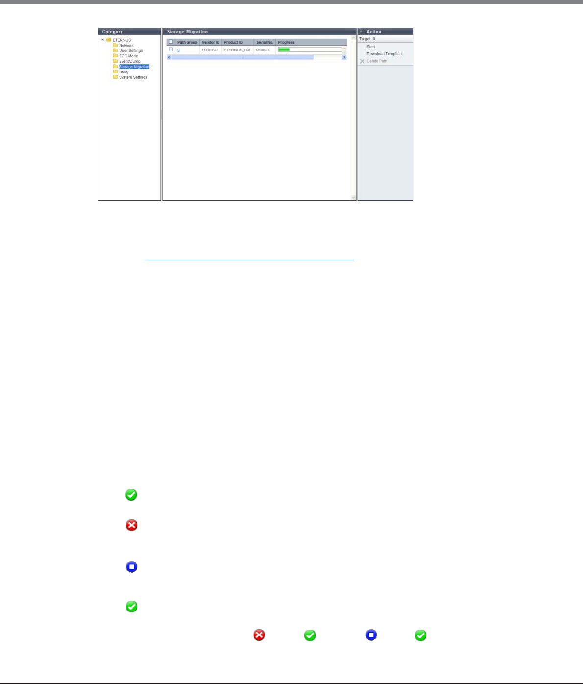
Chapter 11 System Management
11.1 System Status
ETERNUS Web GUI User’s Guide
Copyright 2013 FUJITSU LIMITED P2X0-1090-10ENZ0
730
The following items are displayed in the Main area:
•Path Group
The path group number is displayed. Click this item to display the [Path Group Detail Information] screen.
Refer to "11.1.14 Path Group Detail Information" (page 734) for details.
A path group combines the paths for data migration into a group for each source storage system. The paths
from a single source storage system to the ETERNUS DX disk storage system (destination) constitute a path
group.
•Vendor ID
The manufacturer name of the source storage system to which the path is created is displayed.
An inconvertible code is displayed as "*".
•Product ID
The product name of the source storage system to which the path is created is displayed.
An inconvertible code is displayed as "*".
•Serial Number
The serial number of the source storage system to which the path is established is displayed.
An inconvertible code is displayed as "*".
•Progress
The progress of Storage Migration for the path group is displayed.
•Status
The general status of Storage Migration for the path group is displayed.
- Complete
All Storage Migration operations have completed normally.
- Error
There are one or more LUNs that do not exist in the migration source volume, or there are one or more
volumes for which Storage Migration failed due to error (displayed in red characters).
- Stop
Storage Migration has been stopped for one or more volumes (all other volumes have completed
Storage Migration normally), or Storage Migration of all the volumes has been stopped.
- Normal
Other than above.
The status display priority order is " Error" > " Normal" > " Stop" > " Complete".
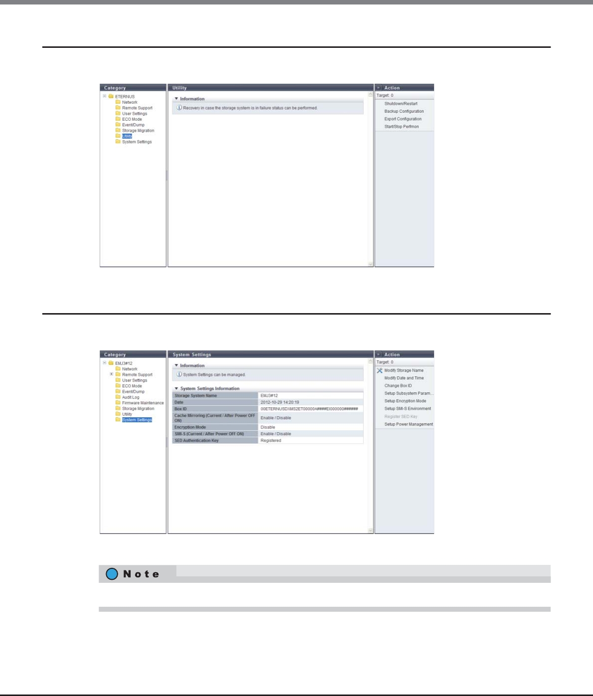
Chapter 11 System Management
11.1 System Status
ETERNUS Web GUI User’s Guide
Copyright 2013 FUJITSU LIMITED P2X0-1090-10ENZ0
731
11.1.11 Utility
Descriptions on the actions that can be started from the [Utility] screen are displayed.
11.1.12 System Settings
This function displays the system setting information.
The following items are displayed in the Main area:
•Storage System Name
The name for the ETERNUS DX Disk storage system is displayed.
For ETERNUS DX8700 S2, "I/O Offloading (Current / After Power OFF ON)" is displayed.
Chapter 11 System Management
11.1 System Status
ETERNUS Web GUI User’s Guide
Copyright 2013 FUJITSU LIMITED P2X0-1090-10ENZ0
732
•Date
The date and time when the event occurs are displayed.
-YYYY-MM-DD hh:mm:ss (YYYY: Year (AD), MM: Month (01 - 12), DD: Day (01 - 31), hh: Hour (00 - 23),
mm: Minute (00 - 59), ss: Second (00 - 59))
•Box ID
The Box ID is displayed.
Box ID is the information to be used for application software to define the remote device. The initial Box ID
is a device ID that is created by combining device information (series name, model, serial number, etc.).
•Cache Mirroring (Current / After Power OFF ON)
The current cache mirroring setting and the cache mirroring setting after rebooting is displayed in "Current
/ After Power OFF ON" format.
-Enable
-Disable
•I/O Offloading (Current / After Power OFF ON)
The current I/O offloading setting and the I/O offloading setting after rebooting is displayed in "Current /
After Power OFF ON" format.
-Enable
-Disable
•Encryption Mode
The encryption mode setting is displayed.
-Fujitsu Original Encryption
-AES
-"-" (hyphen)
•SMI-S (Current / After Power OFF ON)
The current Storage Management Initiative - Specification (SMI-S) setting and the SMI-S setting after
rebooting is displayed in "Current / After Power OFF ON" format.
-Enable
-Disable
•This item is displayed only when all of the following conditions are satisfied:
-When logged in using a user account with the "Storage Management" or the "Maintenance
Operation" policy
-When using the ETERNUS DX80 S2/DX90 S2 or the ETERNUS DX410 S2/DX440 S2
•When different settings are specified for "Current" and "After Power OFF ON", reboot the ETERNUS DX
Disk storage system.
•This item is displayed only for ETERNUS DX8700 S2.
•When different settings are specified for "Current" and "After Power OFF ON", reboot the ETERNUS DX
Disk storage system.
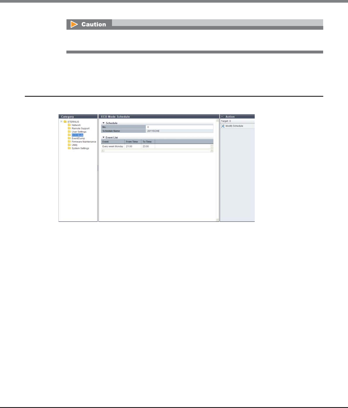
Chapter 11 System Management
11.1 System Status
ETERNUS Web GUI User’s Guide
Copyright 2013 FUJITSU LIMITED P2X0-1090-10ENZ0
733
•SED Authentication Key
Whether the SED authentication key has been "Registered" or "Not Registered" is displayed.
11.1.13 ECO Mode Schedule Detail
In this screen, the detailed information of an ECO mode schedule is displayed.
The following items are displayed in the Main area:
●Schedule
•No.
The schedule number is displayed.
•Schedule Name
The schedule name is displayed.
●Event List
•Event
The detailed event information is displayed.
•From Time
The time at which the event application is started is displayed.
-hh:mm (hh: Hour, mm: Minute)
•To Time
The time at which the event application is stopped is displayed.
-hh:mm (hh: Hour, mm: Minute)
When different settings are specified for "Current" and "After Power OFF ON", reboot the ETERNUS DX Disk
storage system.
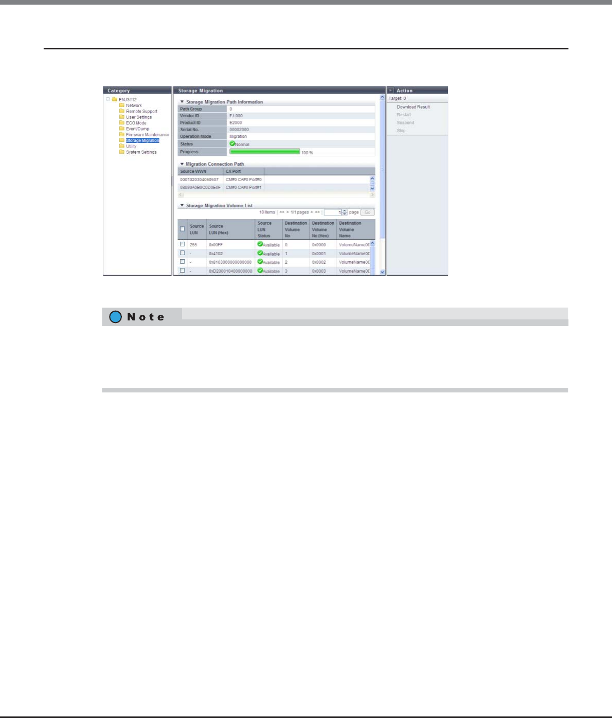
Chapter 11 System Management
11.1 System Status
ETERNUS Web GUI User’s Guide
Copyright 2013 FUJITSU LIMITED P2X0-1090-10ENZ0
734
11.1.14 Path Group Detail Information
In this screen, the detailed information of a path group is displayed.
The following items are displayed in the Main area:
●Storage Migration Path Information
•Path Group
The path group number is displayed.
•Vendor ID
The manufacturer name of the source storage system to which the path is created is displayed.
An inconvertible code is displayed as "*".
•Product ID
The product name of the source storage system to which the path is created is displayed.
An inconvertible code is displayed as "*".
•Serial Number
The serial number of the source storage system to which the path is established is displayed.
An inconvertible code is displayed as "*".
Items displayed in this screen vary depending on whether the previous screen is the [Storage Migration]
screen or the [Start Storage Migration] screen. When the previous screen is the [Storage Migration] screen,
the progress of Storage Migration is checked. When the previous screen is the [Start Storage Migration]
screen, the start status of Storage Migration is checked.
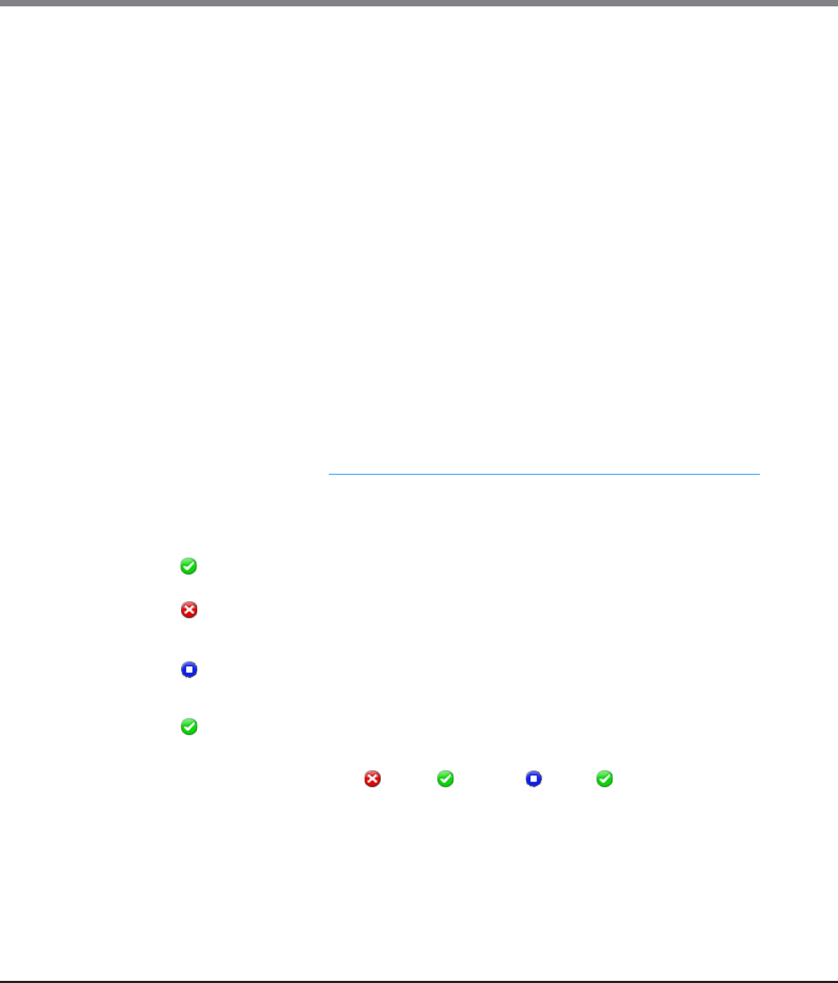
Chapter 11 System Management
11.1 System Status
ETERNUS Web GUI User’s Guide
Copyright 2013 FUJITSU LIMITED P2X0-1090-10ENZ0
735
•Operation Mode
The operation mode for the path group is displayed.
When a Storage Migration setting file is in the old format or when a Storage Migration setting file is in the
new format and the operation mode setting is omitted, "Migration" is displayed.
-Migration
Data migration from the source storage system to the destination storage system is performed.
-Migration + Quick Compare
Data migration from the source storage system to the destination storage system and a data compari-
son of source LUNs and destination volumes are performed. "Quick Compare" compares data in a part of
the volume area. "Migration + Quick Compare" consecutively executes "data migration" and "data com-
parison" for each volume.
-Migration + Full Compare
Data migration from the source storage system to the destination storage system and a data compari-
son of source LUNs and destination volumes are performed. "Full Compare" compares data in entire vol-
ume area. "Migration + Full Compare" consecutively executes "data migration" and "data comparison"
for each volume.
-Quick Compare
A data comparison of source LUNs and destination volumes is performed. "Quick Compare" compares
data in a part of the volume area.
-Full Compare
A data comparison of source LUNs and destination volumes is performed. "Full Compare" compares data
in entire volume area.
*1: There are two types of template files for Storage Migration setting; new format template files and old format
template files. A template file in the new format can be downloaded when the controller firmware version is
V10L30 or later. Refer to "11.2.11.2 Download Template File for Storage Migration Settings" (page 912) for
details.
•Status
The general status of Storage Migration for the path group is displayed.
This item is displayed only when the previous screen is the [Storage Migration] screen.
- Complete
All Storage Migration operations have completed normally.
- Error
There are one or more LUNs that do not exist in the migration source volume, or there are one or more
volumes for which Storage Migration failed due to error (displayed in red characters).
- Stop
Storage Migration has been stopped for one or more volumes (all other volumes have completed
Storage Migration normally), or Storage Migration of all the volumes has been stopped.
- Normal
Other than above.
The status display priority order is " Error" > " Normal" > " Stop" > " Complete".
•Progress
The progress of Storage Migration for the path group is displayed.
This item is displayed only when the previous screen is the [Storage Migration] screen.

Chapter 11 System Management
11.1 System Status
ETERNUS Web GUI User’s Guide
Copyright 2013 FUJITSU LIMITED P2X0-1090-10ENZ0
736
●Migration Connection Path
•Source WWN
The WWN for the source FC-CA port is displayed.
•CA Port
The location information of the destination FC-Initiator is displayed.
-CM#x CA#y Port#z (x: CM number, y: CA number, z: Port number)
●Storage Migration Volume List
•Source LUN
The source LUN is displayed in decimal number.
Source LUNs are displayed with decimal numbers if the source LUNs are specified with decimal numbers
when Storage Migration setting files are created. Source LUNs are also displayed with decimal numbers if
the source LUNs satisfy the conditions for being specified with decimal numbers regardless of whether the
Storage Migration setting file is in the new format or the old format. If the source LUNs do not satisfy the
conditions for being specified with decimal numbers, a "-" (hyphen) is displayed. Refer to "11.2.11.2
Download Template File for Storage Migration Settings" (page 912) for details.
•Source LUN (Hex)
The source LUN is displayed in hexadecimal number.
•Source LUN Status
The status of the source LUN is displayed.
- Available
The source LUN can be used
- Not Available
The source LUN cannot be used
- Not Exist
The source LUN does not exist
•Destination Volume No.
The destination volume number is displayed in decimal number.
•Destination Volume Name
The destination volume name is displayed.
•Destination Volume No. (Hex)
The destination volume number is displayed in hexadecimal number.
•Capacity
The destination volume capacity is displayed.
Chapter 11 System Management
11.1 System Status
ETERNUS Web GUI User’s Guide
Copyright 2013 FUJITSU LIMITED P2X0-1090-10ENZ0
737
•Migration Status
The data migration status is displayed.
-Initial
Initial state
-Waiting
Awaiting migration
-Running
Migrating
-Normal End
Normally completed
-Suspend
In suspension
-Stop
Stopped
-Error (xxx)
(xxx) indicates the error factor.
-"-" (hyphen)
Does not exist in the source LUN (the LUN status is "Not Exist").
•Progress
The data transfer progress is displayed.
•Start Time
•End Time
The start and end times of data migration are displayed.
-YYYY-MM-DD hh:mm:ss (YYYY: Year (AD), MM: Month (01 - 12), DD: Day (01 - 31), hh: Hour (00 - 23),
mm: Minute (00 - 59), ss: Second (00 - 59))
The start and end times are displayed as shown below depending on the migration status.
Migration status Start time End time
Initial The start time is not displayed. Blank
Waiting
Running The migration start time is displayed.
Normal End The migration end time is displayed.
Suspend The time when migration suspends is displayed.
Stop The time when migration stops is displayed.
Error (xxx) The time when migration stops due to error is
displayed.
•When Storage Migration is restarted when its migration status is "Suspend" or "Error", data migration
restarts from the point of suspension. In this case, the start time is not changed.
•When Storage Migration is restarted when its migration status is "Stop", data migration of the LUN is
started over from scratch. The start time is changed to the migration restart time.

Chapter 11 System Management
11.1 System Status
ETERNUS Web GUI User’s Guide
Copyright 2013 FUJITSU LIMITED P2X0-1090-10ENZ0
738
•Error Location
The storage system in which a data migration error occurs is displayed.
If no error is occurred, a "-" (hyphen) is displayed.
This item is displayed only when the previous screen is the [Storage Migration] screen.
-Source
Migration source storage system
-Destination
ETERNUS DX Disk storage system (destination storage system)
•Result
When the source LUN and destination volume are in normal status, the "Result" field is blank.
An error message is displayed when an error is detected in the source LUN or destination volume.
This item is displayed only when the previous screen is the [Start Storage Migration] screen.

Chapter 11 System Management
11.2 Functions in the Action Area for System
ETERNUS Web GUI User’s Guide
Copyright 2013 FUJITSU LIMITED P2X0-1090-10ENZ0
739
11.2 Functions in the Action Area for System
When using functions in the Action area, select the desired function from the Action area that is displayed in
the status display screen.
The functions in the Action area for System can be performed from the following display functions:
Functions in the Action area for System Display function
Initial Setup •System (Basic Information)
Change User Password •System (Basic Information)
Set SSH Public Key •System (Basic Information)
Network Management –
Setup Network Environment •Network
Setup Firewall
Setup SNMP Agent Basic Interface
Setup SNMP Manager
Setup SNMP Agent MIB Access View
Setup SNMP Agent User
Setup SNMP Agent Community
Setup SNMP Agent Trap
Download MIB File
Send SNMP Trap Test
Display SMTP Log
Setup E-Mail Notification
Setup Syslog
Setup SSH Server Key
Create Self-signed SSL Certificate
Create Key/CSR
Register SSL Certificate
Remote Support (REMCS) for Regions other than EMEA –
Display Communication Log •Remote Support (REMCS) for Regions other than
EMEA
Setup Remote Support
Update Customer Information
Update Communication Environment Information
Setup Log Sending Parameters
Stop/Restart Remote Support

Chapter 11 System Management
11.2 Functions in the Action Area for System
ETERNUS Web GUI User’s Guide
Copyright 2013 FUJITSU LIMITED P2X0-1090-10ENZ0
740
Remote Support (AIS Connect) for Regions other than Japan –
Setup AIS Connect Environment •Remote Support (AIS Connect) for Regions other
than Japan
Setup Remote Session Permission
Send Log
Test Server Connectivity
Send AIS Connect Test Event
Import Root Certificate Root Certificate
Key Management –
Setup Key Management Machine Name •Key Management
Add Key Server
Delete Key Server
Modify Key Server
Create Key Group •Key Group
Delete Key Group
Modify Key Group
Update SED Authentication Key
Import SSL/KMIP Certificate
Define Role –
Setup User Account •Define Role
Initialize User Account
Modify RADIUS
Add Role
Delete Role
Modify Role
ECO Mode Management –
Modify ECO Mode General Setting •ECO Mode
Create ECO Mode Schedule
Delete ECO Mode Schedule
Modify ECO Mode Schedule
Event/Dump Management –
Setup Event Notification •Event/Dump
Display Event Log
Export/Delete Log
Export Panic Dump
Audit Log Management –
Enable Audit Log •Audit Log
Disable Audit Log
Setup Audit Log
Functions in the Action area for System Display function

Chapter 11 System Management
11.2 Functions in the Action Area for System
ETERNUS Web GUI User’s Guide
Copyright 2013 FUJITSU LIMITED P2X0-1090-10ENZ0
741
Storage Migration Management –
Start Storage Migration •Storage Migration
Download Template File for Storage Migration Settings
Delete Storage Migration Path
Download Storage Migration Result
Restart Storage Migration
Suspend Storage Migration
Stop Storage Migration
Utility Management –
Shutdown/Restart Storage System •Utility
Backup Configuration
Export Configuration
Start/Stop Performance Monitoring
System Management –
Modify Storage System Name •System Settings
Modify Date and Time
Change Box ID
Setup Subsystem Parameters
Setup Encryption Mode
Setup SMI-S Environment
Setup Power Management
Functions in the Action area for System Display function
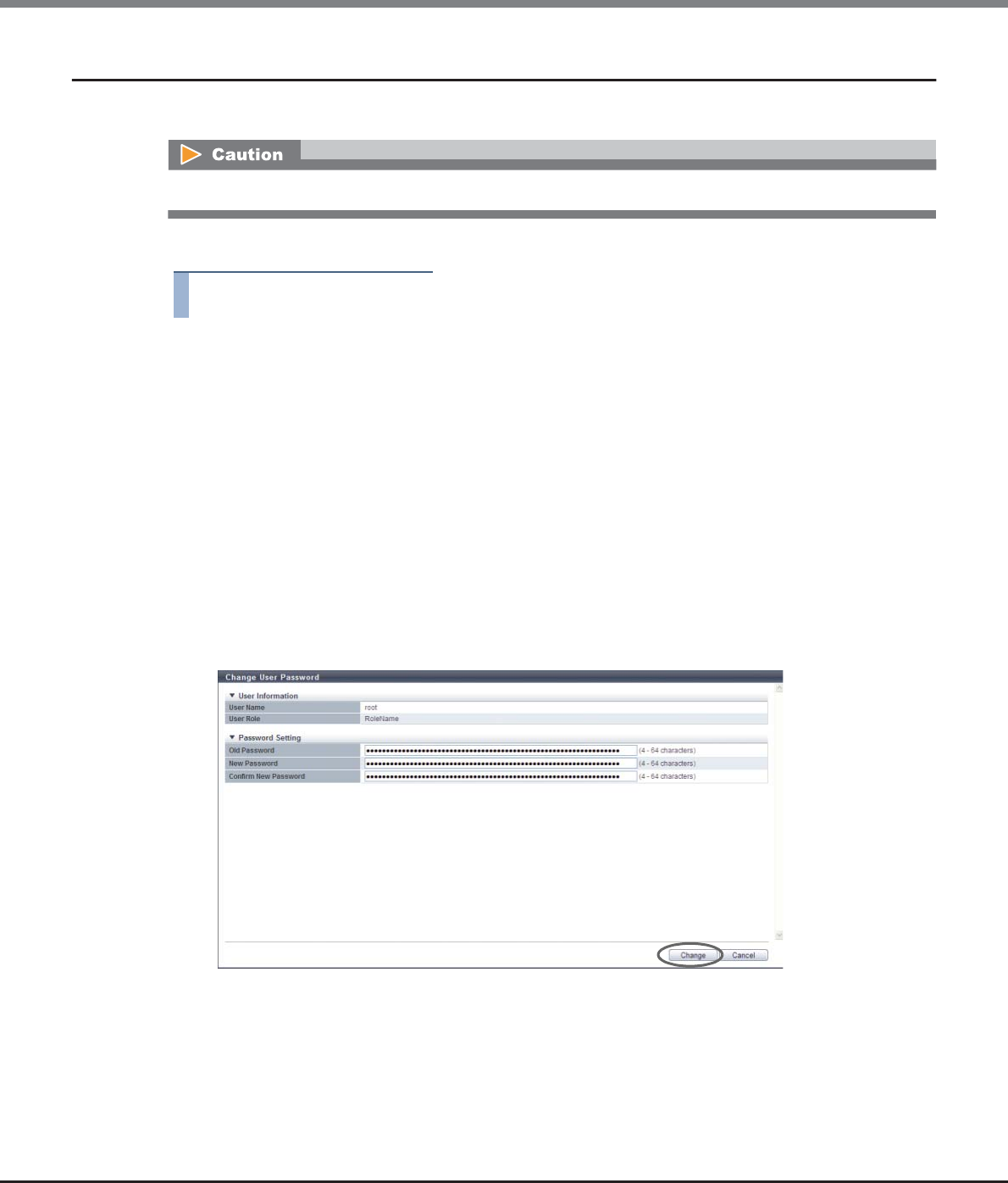
Chapter 11 System Management
11.2 Functions in the Action Area for System
ETERNUS Web GUI User’s Guide
Copyright 2013 FUJITSU LIMITED P2X0-1090-10ENZ0
742
11.2.1 Change User Password
This function changes the current user's (your) password.
The procedure to change the password is as follows:
Procedure
1Click [Change User Password] in [Action].
2Specify the parameters, and click the [Change] button.
•Old Password
Input the current password.
The following input condition applies:
-4 - 64 alphanumeric characters and symbols ('!', '-', '_', '.')
•New Password
Input a new password.
Entered letters are case-sensitive.
The following input condition applies:
-4 - 64 alphanumeric characters and symbols ('!', '-', '_', '.')
•Confirm New Password
Input the same character string as the value entered in the "New Password" field for confirmation.
→A confirmation screen appears.
When RADIUS Authentication is used for login, the password cannot be changed.
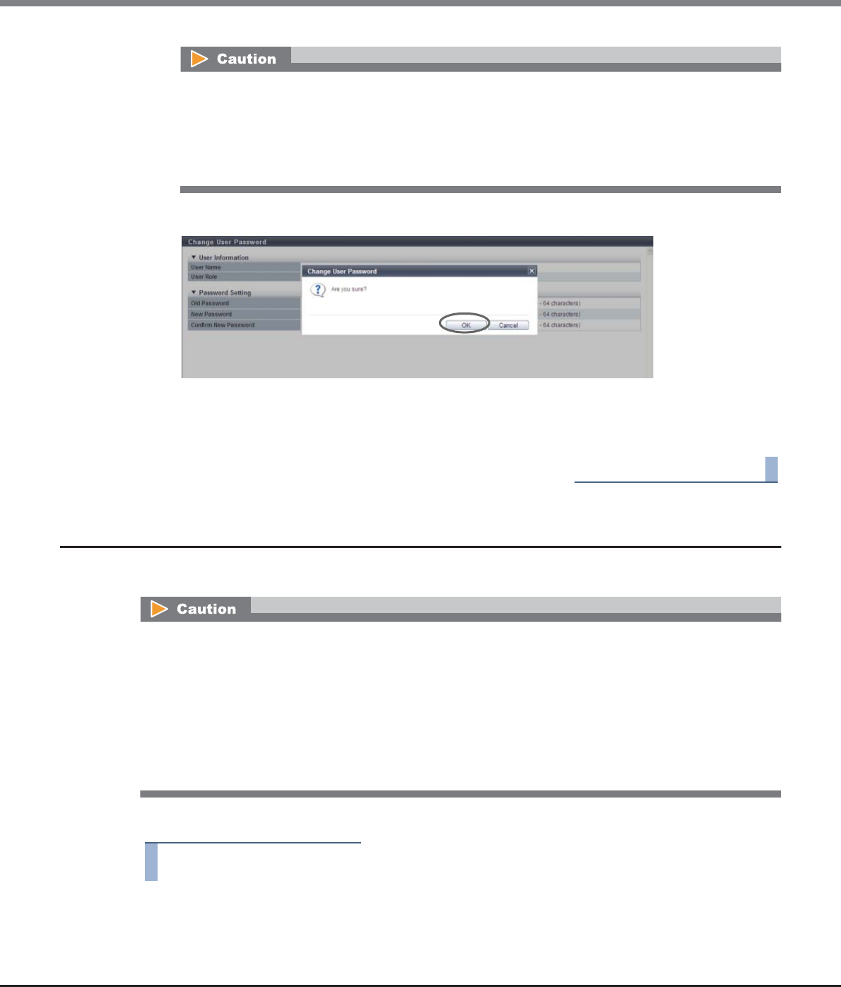
Chapter 11 System Management
11.2 Functions in the Action Area for System
ETERNUS Web GUI User’s Guide
Copyright 2013 FUJITSU LIMITED P2X0-1090-10ENZ0
743
3Click the [OK] button.
→Changing of the user password starts.
4Click the [Done] button to return to the [System] screen.
End of procedure
11.2.2 Set SSH Public Key
This function registers, changes, or deletes the current user's (your) SSH client public key.
The procedure to set the SSH public key is as follows:
Procedure
1Click [Set SSH Public Key] in [Action].
An error screen appears in the following conditions:
•When "Old Password", "New Password", and/or "Confirm New Password" is not input
•When a parameter does not satisfy the input conditions
•When the current password does not match "Old Password"
•When "New Password" does not match "Confirm New Password"
•When using the SSH Client Key authentication, create a pair of the SSH client public key and the SSH
client secret key in advance, using the creation tool. One public key can be registered per user account.
When this function is executed, the public key is registered in the ETERNUS DX Disk storage system.
•The following types (formats) of public keys can be used:
-OpenSSH style RSA for SSH v1
-IETF style DSA for SSH v2
-IETF style RSA for SSH v2
The maximum of encryption strength of the supported public key is 4096-bit.
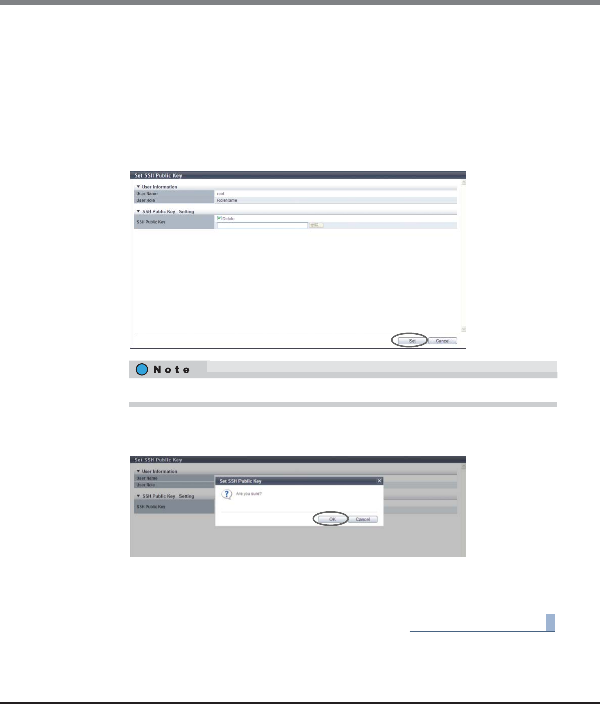
Chapter 11 System Management
11.2 Functions in the Action Area for System
ETERNUS Web GUI User’s Guide
Copyright 2013 FUJITSU LIMITED P2X0-1090-10ENZ0
744
2Specify the SSH Public Key, and click the [Set] button.
•Delete checkbox
To delete the current user's (your) SSH client public key, select the checkbox.
The checkbox is displayed only when the SSH client public key has been registered.
•SSH Public Key
Register or change the SSH client public key used for login authentication from CLI in the ETERNUS
DX Disk storage system.
Click the [Browse...] button and specify the public key to be registered or to be changed.
When using the SSH Client Key authentication, register the SSH public key in the ETERNUS DX Disk
storage system and prepare the SSH secret key, corresponding to the public key in the client PC in
advance.
→A confirmation screen appears.
3Click the [OK] button.
→The registration of the SSH client public key starts.
4Click the [Done] button to return to the [System] screen.
End of procedure
To delete the SSH client public key, select the "Delete" checkbox and click the [Set] button.

Chapter 11 System Management
11.2 Functions in the Action Area for System
ETERNUS Web GUI User’s Guide
Copyright 2013 FUJITSU LIMITED P2X0-1090-10ENZ0
745
11.2.3 Network Management
This section describes the network environment settings.
The following functions are available for the network environment settings:
•Setup Network Environment
•Setup Firewall
•Setup SNMP Agent Basic Interface
•Setup SNMP Manager
•Setup SNMP Agent MIB Access View
•Setup SNMP Agent User
•Setup SNMP Agent Community
•Setup SNMP Agent Trap
•Download MIB File
•Send SNMP Trap Test
•Display SMTP Log
•Setup E-Mail Notification
•Setup Syslog
•Setup SSH Server Key
•Create Self-signed SSL Certificate
•Create Key/CSR
•Register SSL Certificate
11.2.3.1 Setup Network Environment
This function sets up an the environment for the ETERNUS DX Disk storage system to communicate with an
external network.
The IP address, subnet mask (prefix length), gateway, DNS server of the ETERNUS DX Disk storage system, and
network address for the remote operation from outside of the subnet can be configured. Configuration is
required for each MNT, RMT and FST port.
•MNT port
The MNT port is used for general communication between the ETERNUS DX Disk storage system and the
external hosts.
•RMT port
The RMT port is used when the line must be separated from the MNT port.
•FST port
The FST port is used for maintaining the ETERNUS DX Disk storage system.
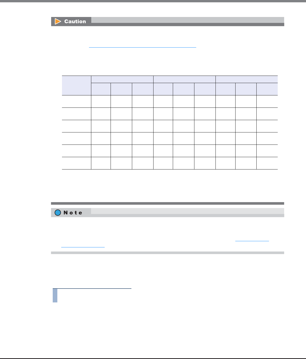
Chapter 11 System Management
11.2 Functions in the Action Area for System
ETERNUS Web GUI User’s Guide
Copyright 2013 FUJITSU LIMITED P2X0-1090-10ENZ0
746
■When using IPv4
The procedure to set network environment using IPv4 address is as follows:
Procedure
1Click [Setup Network] in [Action].
•When SNMP Manager exists in a different subnetwork from where the ETERNUS DX Disk storage system
belongs, specify the IP address or the network address of SNMP Manager in the "Allowed IP List" using the
procedure in "11.2.3.1 Setup Network Environment" (page 745).
•Logging in again may be required after the settings are complete.
•The following table shows the operations that can be performed for each port type according to the
model.
•MNT ports and RMT ports support both "IPv4" and "IPv6". FST ports only support "IPv4".
•Both or either "IPv4 address" and "IPv6 address" can be set for a port.
•To enable or disable each service (such as HTTP and HTTPS), use the procedure in "11.2.3.2 Setup
Firewall" (page 758).
OK: Available N/A: Not available –: Not supported
*1: Either an IPv4 or an IPv6 address must be set for the target port.
*2: If the FST port is not specified, the settings for either the MNT port or the RMT port must be specified even
when the target port setting is deleted.
Model MNT port RMT port FST port
Setting Modifi-
cation
Deletion Setting Modifi-
cation
Deletion Setting Modifi-
cation
Deletion
ETERNUS
DX80 S2
OK OK N/A (*1) OK OK OK N/A – –
ETERNUS
DX90 S2
OK OK N/A (*1) OK OK OK N/A – –
ETERNUS
DX410 S2
OK OK OK (*2) OK OK OK (*2) OK OK N/A
ETERNUS
DX440 S2
OK OK OK (*2) OK OK OK (*2) OK OK N/A
ETERNUS
DX8100 S2
OK OK OK (*2) OK OK OK (*2) OK OK N/A
ETERNUS
DX8700 S2
OK OK OK OK OK OK OK OK N/A

Chapter 11 System Management
11.2 Functions in the Action Area for System
ETERNUS Web GUI User’s Guide
Copyright 2013 FUJITSU LIMITED P2X0-1090-10ENZ0
747
2Select the network port and specify each item.
●Select Network Port
•Network Port
Select the port to configure from "MNT", "RMT", and "FST".
-For ETERNUS DX80 S2/DX90 S2: MNT or RMT
-For ETERNUS DX410 S2/DX440 S2: MNT, RMT, or FST
-For ETERNUS DX8100 S2/DX8700 S2: MNT, RMT, or FST
●Interface
•Master IP Address
Input the IP address for the Master CM of the ETERNUS DX Disk storage system. (*1)
•Slave IP Address
Input the IP address for the Slave CM of the ETERNUS DX Disk storage system. (*1)
The IP address of the Slave CM is used when an error occurs in the Master CM.
This item is not displayed for the 1CM model.
-Subnet Mask
Input the subnet mask of the ETERNUS DX Disk storage system. (*1)
•Gateway
Input the IP address of the gateway. (*1)
This item is not displayed when an FST port is selected.
●DNS
This item is not displayed when an FST port is selected.
•Primary DNS
Input the IP address of the Primary DNS server. (*1)
•Secondary DNS
Input the IP address of the Secondary DNS server. (*1)
The Secondary DNS server must be specified after the Primary DNS server.
●LAN
•Speed and Duplex
Select the communication speed and mode.
-Auto-negotiation
-1Gbit/s
-100Mbit/s Half
-100Mbit/s Full
-10Mbit/s Half
-10Mbit/s Full
•Wake on LAN
Select whether to enable or disable the WOL function (*2).
This item is not displayed when an FST port is selected.
*1: Input numeric characters ("0" - "255") for all the text boxes.
*2: The WOL function starts up the ETERNUS DX Disk storage system, which is connected to LAN, from another
server or a PC via network.
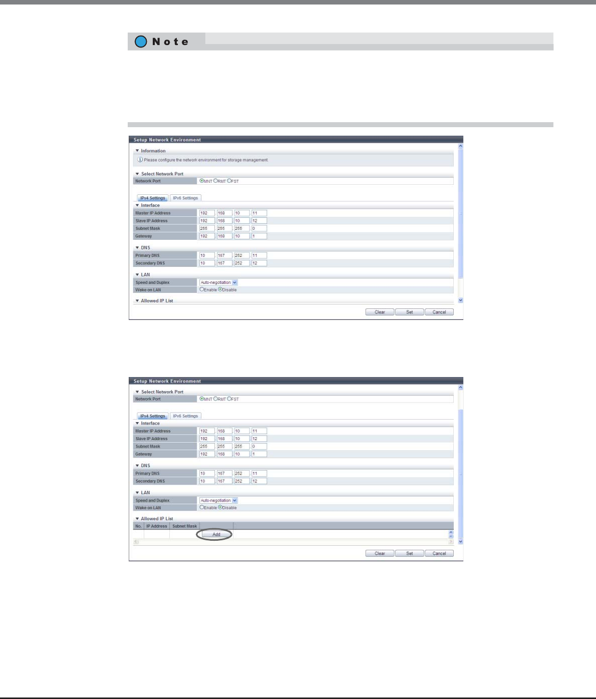
Chapter 11 System Management
11.2 Functions in the Action Area for System
ETERNUS Web GUI User’s Guide
Copyright 2013 FUJITSU LIMITED P2X0-1090-10ENZ0
748
→Returns to the [Setup Network Environment] screen.
3To allow access from a different subnetwork to the ETERNUS DX Disk storage system, click
the [Add] button.
→The [Add Allow IP] screen appears.
When two CMs are installed, a CM, to which authority to manage the ETERNUS DX Disk storage system
has been given, is called a "Master CM". The other CM is called a "Slave CM". When an error occurs in a
CM or a LAN, the Master CM is automatically switched, and the IP address of the old Master CM is
passed to the new Master CM. By specifying the IP address of the Slave CM, the Master CM can be
forcibly switched to the Slave CM when an error occurs and the Master CM cannot be connected.
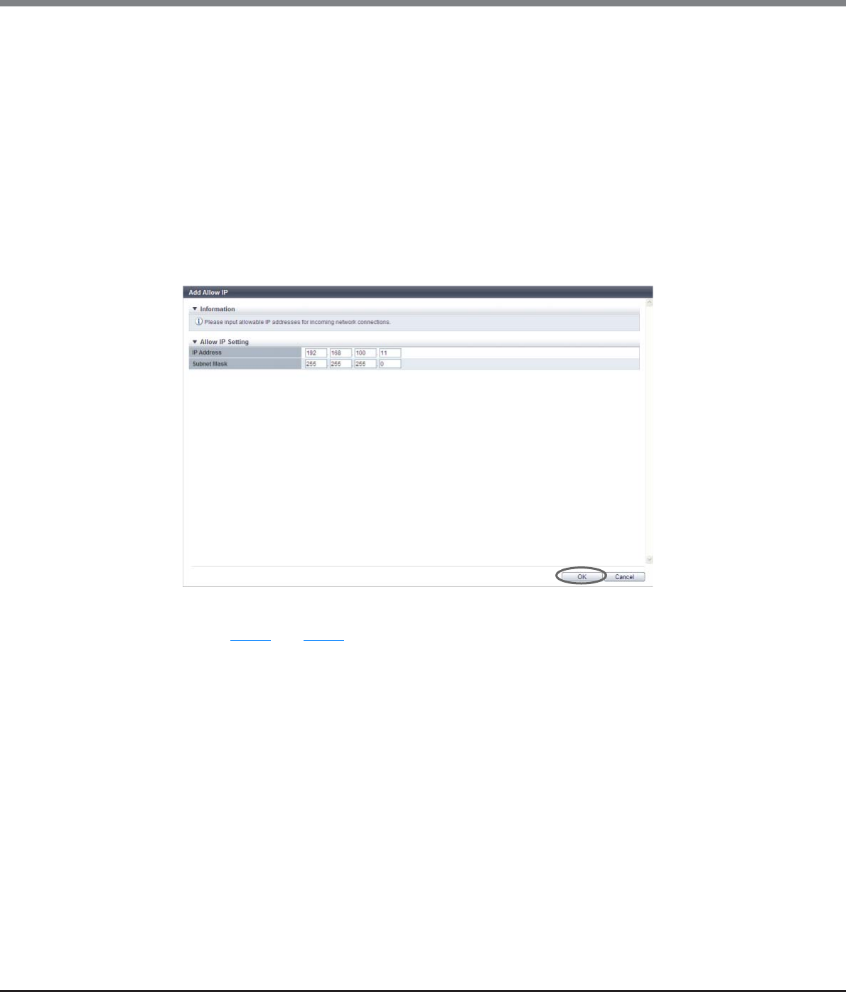
Chapter 11 System Management
11.2 Functions in the Action Area for System
ETERNUS Web GUI User’s Guide
Copyright 2013 FUJITSU LIMITED P2X0-1090-10ENZ0
749
4Input the IP address and the subnet mask, and then click the [OK] button.
If the gateway is specified, the information of the remote devices for which network access will be
allowed can be input.
●Allow IP Setting
•IP Address
Input the IP address (or the network address) for the remote device. (*1)
Up to 16 addresses can be registered.
Make sure to input the IP address (or the network address) and subnet mask together.
•Subnet Mask
Input the subnet mask for the IP address (or the network address) of the remote device. (*1)
*1: Input numeric characters ("0" - "255") for all the text boxes.
→Returns to the [Setup Network Environment] screen.
5Repeat Step 3 and Step 4 when registering several IP addresses.
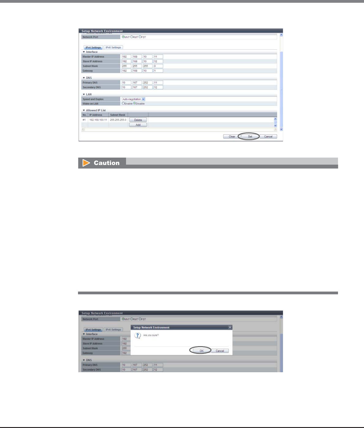
Chapter 11 System Management
11.2 Functions in the Action Area for System
ETERNUS Web GUI User’s Guide
Copyright 2013 FUJITSU LIMITED P2X0-1090-10ENZ0
750
6After registering the IP address is complete, click the [Set] button.
→A confirmation screen appears.
7Click the [OK] button.
→The network environment setting starts.
•When specifying the IP address or the subnet mask, note the following:
-IP addresses must be specified with the IPv4 format
-The IP address of the RMT port must be in a different subnetwork from the MNT port
-Specify the IP address of the Slave CM when connecting to the Slave CM. The IP address of the
Slave CM must be in the same subnetwork as the Master CM
-Specify the IP address of "Gateway" when allowing access from outside of the subnetwork. The
IP address must be in the same subnetwork as the port
-For "Allowed IP List", specify the IP address or the network address that allows access to the
ETERNUS DX Disk storage system. These settings are not required for access from the network
address (same subnetwork) which the ETERNUS DX Disk storage system belongs to
•Click the [Clear] button to delete setting parameters.
•When using the ETERNUS DX80 S2/DX90 S2, the MNT port setting cannot be deleted.
•When using the ETERNUS DX410 S2/DX440 S2 or the ETERNUS DX8100 S2/DX8700 S2, the FST port
setting cannot be deleted.

Chapter 11 System Management
11.2 Functions in the Action Area for System
ETERNUS Web GUI User’s Guide
Copyright 2013 FUJITSU LIMITED P2X0-1090-10ENZ0
751
8Click the [Done] button to return to the [Network] screen.
End of procedure
■When using IPv6
The procedure to set network environment using IPv6 address is as follows:
Procedure
1Click [Setup Network] in [Action].
2Select the network port and specify each item.
●Select Network Port
•Network Port
Select the port to configure from "MNT", "RMT", and "FST".
-For ETERNUS DX80 S2/DX90 S2: MNT or RMT
-For ETERNUS DX410 S2/DX440 S2: MNT, RMT, or FST
-For ETERNUS DX8100 S2/DX8700 S2: MNT, RMT, or FST
●Interface
•Master IP Link Local Address
Input the link local address (interface ID) for the Master CM of the ETERNUS DX Disk storage system.
Note that the link local address is only available within the same network and cannot be connected
to the Internet. Connection via a router is not available.
Refer to "Available IPv6 Address" (page 757) for details.
Note that the current setting is displayed by an abbreviation.
The following input condition applies:
-fe80::xxxx:xxxx:xxxx:xxxx
xxxx: 0 - ffff (FFFF) (hexadecimal, alphanumeric characters)
Refer to "IPv6 Address Notation (Setup Network Environment)" (page 757) for details.
•Master Connect IP Address
Input the connect IP address for the Master CM of the ETERNUS DX Disk storage system.
"Master Connect IP Address" corresponds to "Master IP Address" for IPv4.
The following IPv6 addresses can be used; "global address", "unique local address", and "6to4
address". Refer to "Available IPv6 Address" (page 757) for details.
Note that the current setting is displayed by an abbreviation.
The following input condition applies:
-xxxx:xxxx:xxxx:xxxx:xxxx:xxxx:xxxx:xxxx
xxxx: 0 - ffff (FFFF) (hexadecimal, alphanumeric characters)
Refer to "IPv6 Address Notation (Setup Network Environment)" (page 757) for details.
Device management operation cannot be continued if the IP address of the ETERNUS DX Disk storage
system has been changed. Logging in again with the new IP address is required.

Chapter 11 System Management
11.2 Functions in the Action Area for System
ETERNUS Web GUI User’s Guide
Copyright 2013 FUJITSU LIMITED P2X0-1090-10ENZ0
752
•Slave IP Link Local Address
Input the link local address (interface ID) for the Slave CM of the ETERNUS DX Disk storage system.
The link local address of the Slave CM is used when an error occurs in the Master CM.
Refer to "Available IPv6 Address" (page 757) for details.
This item is not displayed for the 1CM model.
Note that the current setting is displayed by an abbreviation.
The following input condition applies:
-fe80::xxxx:xxxx:xxxx:xxxx
xxxx: 0 - ffff (FFFF) (hexadecimal, alphanumeric characters)
Refer to "IPv6 Address Notation (Setup Network Environment)" (page 757) for details.
•Slave Connect IP Address
Input the connect IP address for the Slave CM of the ETERNUS DX Disk storage system.
The connect IP address of the Slave CM is used when an error occurs in the Master CM.
"Slave Connect IP Address" corresponds to "Slave IP Address" for IPv4.
The following IPv6 addresses can be used; "global address", "unique local address", and "6to4
address". Refer to "Available IPv6 Address" (page 757) for details.
This item is not displayed for the 1CM model.
Note that the current setting is displayed by an abbreviation.
The following input condition applies:
-xxxx:xxxx:xxxx:xxxx:xxxx:xxxx:xxxx:xxxx
xxxx: 0 - ffff (FFFF) (hexadecimal, alphanumeric characters)
Refer to "IPv6 Address Notation (Setup Network Environment)" (page 757) for details.
•Length of Subnet Prefix
Input the prefix length of the connect IP address (unit: bit).
"Length of Subnet Prefix" corresponds to "Subnet Mask" for IPv4.
Refer to "Available IPv6 Address" (page 757) for details.
•Gateway
Input the IP address of the gateway.
The following IPv6 addresses can be used; "link local address", "global address", "unique local
address", and "6to4 address". Refer to "Available IPv6 Address" (page 757) for details.
Note that the current setting is displayed by an abbreviation.
The following input condition applies:
-xxxx:xxxx:xxxx:xxxx:xxxx:xxxx:xxxx:xxxx
xxxx: 0 - ffff (FFFF) (hexadecimal, alphanumeric characters)
Refer to "IPv6 Address Notation (Setup Network Environment)" (page 757) for details.
●DNS
•Primary DNS
Input the IP address of the Primary DNS server.
The following IPv6 addresses can be used; "global address", "unique local address", and "6to4
address". Refer to "Available IPv6 Address" (page 757) for details.
Note that the current setting is displayed by an abbreviation.
The following input condition applies:
-xxxx:xxxx:xxxx:xxxx:xxxx:xxxx:xxxx:xxxx
xxxx: 0 - ffff (FFFF) (hexadecimal, alphanumeric characters)
Refer to "IPv6 Address Notation (Setup Network Environment)" (page 757) for details.
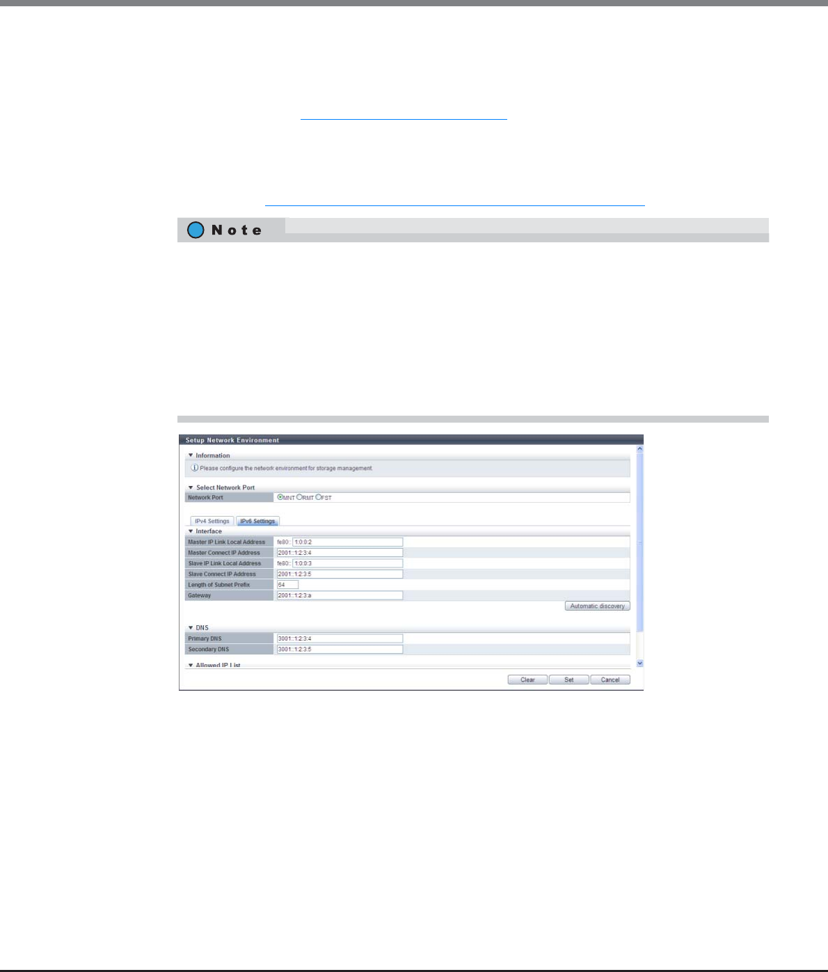
Chapter 11 System Management
11.2 Functions in the Action Area for System
ETERNUS Web GUI User’s Guide
Copyright 2013 FUJITSU LIMITED P2X0-1090-10ENZ0
753
•Secondary DNS
Input the IP address of the Secondary DNS server.
The Secondary DNS server must be specified after the Primary DNS server.
The following IPv6 addresses can be used; "global address", "unique local address", and "6to4
address". Refer to "Available IPv6 Address" (page 757) for details.
Note that the current setting is displayed by an abbreviation.
The following input condition applies:
-xxxx:xxxx:xxxx:xxxx:xxxx:xxxx:xxxx:xxxx
xxxx: 0 - ffff (FFFF) (hexadecimal, alphanumeric characters)
Refer to "IPv6 Address Notation (Setup Network Environment)" (page 757) for details.
•Click the [Automatic discovery] button to automatically obtain "Master IP Link Local Address",
"Master Connect IP Address", "Slave IP Link Local Address", "Slave Connect IP Address", "Length of
Subnet Prefix", and "Gateway". Input the IPv6 address of the DNS server if required.
•When two CMs are installed, a CM, to which authority to manage the ETERNUS DX Disk storage
system has been given, is called a "Master CM". The other CM is called a "Slave CM". When an error
occurs in a CM or a LAN, the Master CM is automatically switched, and the IP address of the old
Master CM is passed to the new Master CM. By specifying the IP address of the Slave CM, the
Master CM can be forcibly switched to the Slave CM when an error occurs and the Master CM cannot
be connected.
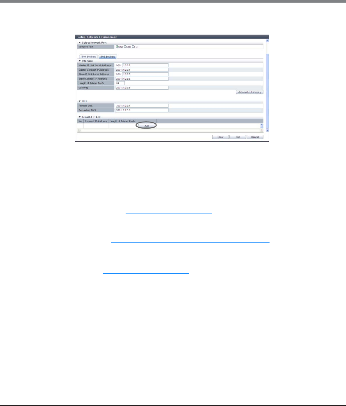
Chapter 11 System Management
11.2 Functions in the Action Area for System
ETERNUS Web GUI User’s Guide
Copyright 2013 FUJITSU LIMITED P2X0-1090-10ENZ0
754
3To allow access from a different subnetwork to the ETERNUS DX Disk storage system, click
the [Add] button.
→The [Add Allow IP] screen appears.
4Input "Connect IP Address" and "Length of Subnet Prefix", and click the [OK] button.
●Allow IP Setting
•Connect IP Address
Input the connect IP address that is to be displayed.
The following IPv6 addresses can be used; "global address", "unique local address", and "6to4
address". Refer to "Available IPv6 Address" (page 757) for details.
The following input condition applies:
-xxxx:xxxx:xxxx:xxxx:xxxx:xxxx:xxxx:xxxx
xxxx: 0 - ffff (FFFF) (hexadecimal, alphanumeric characters)
Refer to "IPv6 Address Notation (Setup Network Environment)" (page 757) for details.
Make sure to input "Connect IP Address" and "Length of Subnet Prefix" together.
•Length of Subnet Prefix
Input the prefix length of the connect IP address for the remote device (unit: bit).
Refer to "Available IPv6 Address" (page 757) for details.
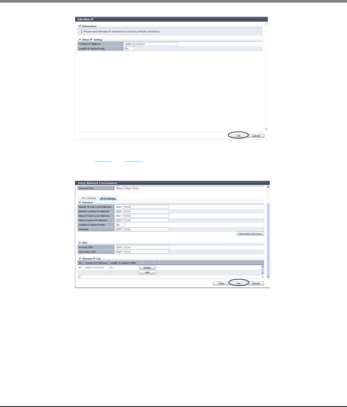
Chapter 11 System Management
11.2 Functions in the Action Area for System
ETERNUS Web GUI User’s Guide
Copyright 2013 FUJITSU LIMITED P2X0-1090-10ENZ0
755
→Returns to the [Setup Network Environment] screen.
5Repeat Step 3 and Step 4 when registering several connect IP addresses.
6After registering the connect IP address is complete, click the [Set] button.
→A confirmation screen appears.
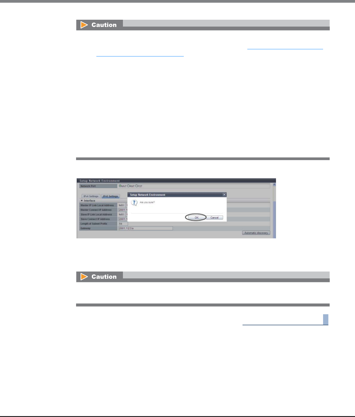
Chapter 11 System Management
11.2 Functions in the Action Area for System
ETERNUS Web GUI User’s Guide
Copyright 2013 FUJITSU LIMITED P2X0-1090-10ENZ0
756
7Click the [OK] button.
→The network environment setting starts.
8Click the [Done] button to return to the [Network] screen.
End of procedure
•Note the following points when specifying an IP address:
-IP addresses must be specified with the IPv6 format. Refer to "IPv6 Address Notation (Setup
Network Environment)" (page 757) for details
-The connect IP address of the RMT port must be in a different subnetwork from the MNT port
-Specify the connect IP address of the Slave CM when connecting to the Slave CM The connect IP
address of the Slave CM must be in the same subnetwork as the Master CM
-Specify the IP address of "Gateway" when allowing access from outside of the subnetwork The
IP address must be in the same subnetwork as the port
-For "Allowed IP List", specify the IP address or the network address that allows access to the
ETERNUS DX Disk storage system. These settings are not required for access from the network
address (same subnetwork) which the ETERNUS DX Disk storage system belongs to
•Click the [Clear] button to delete setting parameters
•When using the ETERNUS DX80 S2/DX90 S2, the MNT port setting cannot be deleted
•When using the ETERNUS DX410 S2/DX440 S2 or the ETERNUS DX8100 S2/DX8700 S2, the FST port
setting cannot be deleted
Device management operation cannot be continued if the IP address of the ETERNUS DX Disk storage
system has been changed. Logging in again with the new IP address is required.
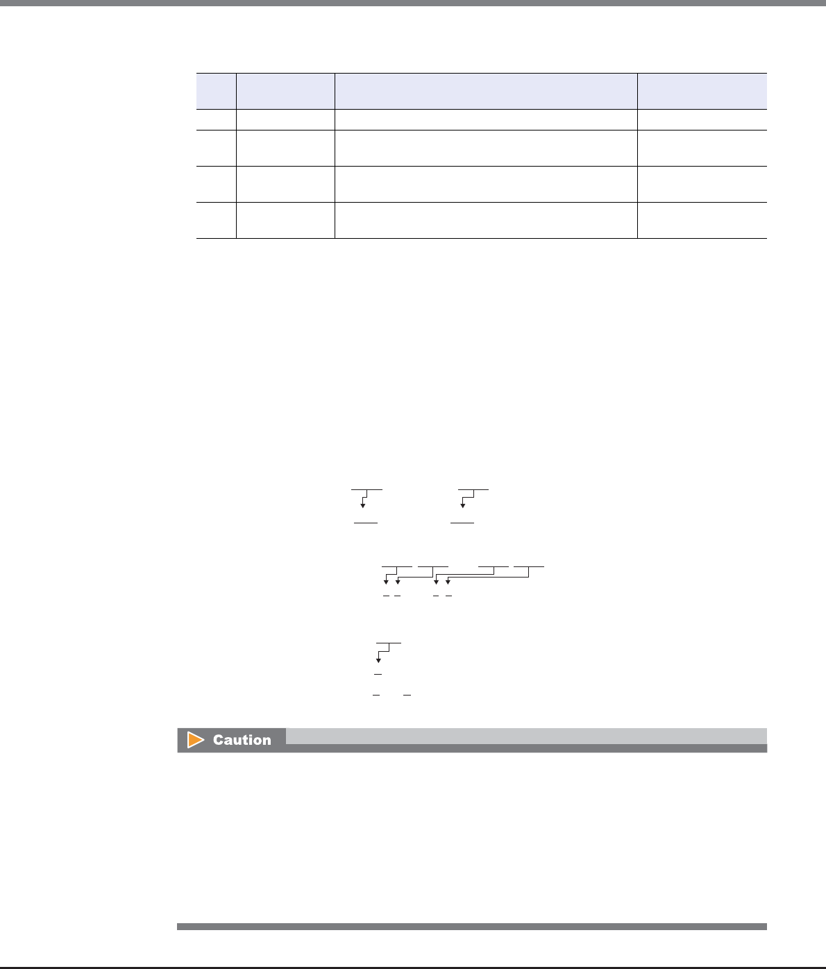
Chapter 11 System Management
11.2 Functions in the Action Area for System
ETERNUS Web GUI User’s Guide
Copyright 2013 FUJITSU LIMITED P2X0-1090-10ENZ0
757
●Available IPv6 Address
●IPv6 Address Notation (Setup Network Environment)
Since the IPv6 address is 128-bit and extremely long, this address is displayed using "xxxx", which
describes 16-bit in hexadecimals as being one block that is separated by colons (":").
xxxx:xxxx:xxxx:xxxx:xxxx:xxxx:xxxx:xxxx
-Use 0 - ffff (FFFF) (hexadecimal, alphanumeric characters) for inputting an IPv6 address.
-The current setting is displayed with 0 - ffff (hexadecimal, "a" - "f" are lowercase letters)
-Up to 128-bit
-The first 64-bit (prefix) of the link local address is fixed to "fe80::".
The following three abbreviation methods are available for IPv6 addresses:
(1) Omission of the first "0" of a block that follows consecutive zeros.
(2) Replacement of "0000" blocks with "0".
(3) Replacement of a block with consecutive zeros by "::" is performed only once.
No. Allocated
addresses
Settable range for addresses Length of
subnet prefix
1 Global address 2000::1 - 3fff:ffff:ffff:ffff:ffff:ffff:ffff:ffff 3 - 128
2 Unique local
address
fc00::1 - fdff:ffff:ffff:ffff:ffff:ffff:ffff:ffff 7 - 128
3 Link local
address
fe80::1 - fe80::ffff:ffff:ffff:ffff 64-bit static IP
address
4 6to4 address 2002:<IPv4 address in hexadecimal>::1 - 2002:<IPv4
address in hexadecimal>::ffff:ffff:ffff:ffff
48 - 128
The following IP addresses cannot be specified:
•Link local addresses for which all of the values for the low 64-bit are "0"
•Connect IP addresses (*1) for which the first 3-bit are not "001" or the first 7-bit are not "1111110"
*1: The connect IP address indicates a "global address", "unique local address", or "6to4 address".
•The first 64-bit of the gateway is "fe80::" and all of the values for low 64-bit are "0"
•Network addresses for which the first 3-bit of the gateway are "001"
•Network addresses for which the first 7-bit of the gateway are "1111110"
•DNS server IP addresses for which the first 3-bit are not "001" or the first 7-bit are not "1111110"
[Example] 2001:1000:0120:0000:0000:0123:0000:0000
2001:1000:120:0000:0000:123:0000:0000
[Example] 2001:1000:120:0000:0000:123:0000:0000
2001:1000:120:0:0:123:0:0
[Example] 2001:1000:120:0:0:123:0:0
2001:1000:120::123:0:0 is OK
2001:1000:120::123:: is not allowed
(Replacement of a block with consecutive zeros by "::" is allowed only once.)
Chapter 11 System Management
11.2 Functions in the Action Area for System
ETERNUS Web GUI User’s Guide
Copyright 2013 FUJITSU LIMITED P2X0-1090-10ENZ0
758
■Supplementary Information
•When accessing of the ETERNUS DX Disk storage system from a different subnetwork is not allowed
Specify "IP Address" and "Subnet Mask" of the ETERNUS DX Disk storage system.
Only accessing from the same subnetwork is allowed.
•When accessing of the ETERNUS DX Disk storage system from a different subnetwork is allowed (*1)
Specify "Gateway" and "Allowed IP List ("IP Address" (or the network address) and "Subnet Mask")".
*1: Allowing access from a different subnetwork is required when using GUI or CLI of PCs in a different
network to log in to the ETERNUS DX Disk storage system. Allowing access from a different subnetwork is
also required when using Systemwalker Centric Manager or SNMP Manager that is connected to a
different subnetwork to monitor the ETERNUS DX Disk storage system.
[Example] Allowed IP List (for IPv4)
-When accessing of the ETERNUS DX Disk storage system from a specific client outside the
subnetwork is allowed, specify "IP Address" and "Subnet Mask".
IP Address: 10.20.30.40
Subnet Mask: 255.255.255.0
-When accessing of the ETERNUS DX Disk storage system from a specific subnetwork outside the
subnetwork is allowed, specify "Network Address" and "Subnet Mask".
IP Address: 10.20.30.0
Subnet Mask: 255.255.255.0
For IPv6, "IP Address" corresponds to "Connect IP Address", and "Subnet Mask" corresponds to
"Length of Subnet Prefix".
11.2.3.2 Setup Firewall
This function configures a firewall for each service.
Configuration is required for each MNT, RMT and FST port.
•MNT port
The MNT port is used for general communication between the ETERNUS DX Disk storage system and the
external hosts.
•RMT port
The RMT port is used when the line must be separated from the MNT port.
•FST port
The FST port is used for maintaining the ETERNUS DX Disk storage system.
•The FST port settings are only required when the storage system is ETERNUS DX410 S2/DX440 S2 or ETER-
NUS DX8100 S2/DX8700 S2.
•If both the HTTP connection and the HTTPS connection have been disabled, GUI cannot access the
ETERNUS DX Disk storage system.
•If both the Telnet connection and the SSH connection have been disabled, CLI cannot access the ETERNUS
DX Disk storage system.
•If ports of all the services are disabled, access to the ETERNUS DX Disk storage system is not allowed.
•When the firewall setting is changed, it takes approximately 10 seconds to update the storage system
information. To display the most recently updated screen, wait at least 10 seconds and click the [ ] icon
in the [Network] screen or click [Network] in the category.
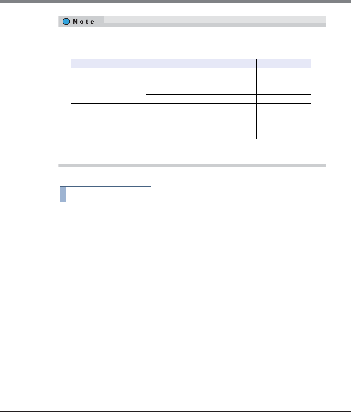
Chapter 11 System Management
11.2 Functions in the Action Area for System
ETERNUS Web GUI User’s Guide
Copyright 2013 FUJITSU LIMITED P2X0-1090-10ENZ0
759
The procedure to set a firewall is as follows:
Procedure
1Click [Setup Firewall] in [Action].
2Specify whether to enable or disable the connection of each service, and click the [Modify]
button.
●New Setting
•HTTP
Specify whether to enable or disable the HTTP connection. Select the checkbox to enable the
connection.
HTTP is used when accessing from GUI.
•HTTPS
Specify whether to enable or disable the HTTPS connection. Select the checkbox to enable the
connection.
HTTPS is used when accessing from GUI. This connection uses the data encryption for data
transferring.
•Telnet
Specify whether to enable or disable the Telnet connection. Select the checkbox to enable the
connection.
Telnet is used when accessing from CLI.
•SSH
Specify whether to enable or disable the SSH connection. Select the checkbox to enable the
connection.
Secure Shell (SSH) is used when accessing from CLI. This connection uses the data encryption for
data transferring.
•To configure the network environment of the ETERNUS DX Disk storage system, use the procedure in
"11.2.3.1 Setup Network Environment" (page 745).
•The following table shows the protocols, the port numbers, and the direction for each service.
*1: The direction of the first communication. "From" indicates that the first communication is performed from an exter-
nal server or an external client to the ETERNUS DX Disk storage system.
Service Protocol Port number Direction (*1)
Web GUI HTTP 80 from
HTTPS 443 from
CLI Telnet 23 from
SSH 22 from
Ping ICMP – from
Maintenance Secure Unique protocol 1372 from
SNMP (excluding SNMP trap) SNMP 161 from
RCIL IPMI 623 from
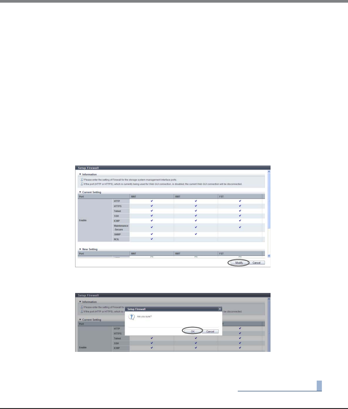
Chapter 11 System Management
11.2 Functions in the Action Area for System
ETERNUS Web GUI User’s Guide
Copyright 2013 FUJITSU LIMITED P2X0-1090-10ENZ0
760
•ICMP
Specify whether to enable or disable the ICMP connection. Select the checkbox to enable the
connection.
The Internet Control Message Protocol (ICMP) is used when sending the ping command from a PC.
•Maintenance-Secure
Specify whether to enable or disable the Maintenance-Secure connection. Select the checkbox to
enable the connection.
Maintenance Secure is used when connecting with the monitoring software, or performing a
firmware update from the peer storage system using the Remote Support function. This connection
uses the data encryption for data transferring.
•SNMP
Specify whether to enable or disable the SNMP connection. Select the checkbox to enable the
connection.
The Simple Network Management Protocol (SNMP) is used when accessing from SNMP Manager.
•RCIL
Specify whether to enable or disable the RCIL connection. Select the checkbox to enable the
connection.
Whether to enable or disable RCIL can only be set for the MNT port. The Remote Cabinet Interface
over LAN (RCIL) controls the power of the ETERNUS DX Disk storage system from a host via Ethernet
by using the Intelligent Platform Management Interface (IPMI), which is a general protocol.
→A confirmation screen appears.
3Click the [OK] button.
→Setting of the firewall starts.
4Click the [Done] button to return to the [Network] screen.
End of procedure
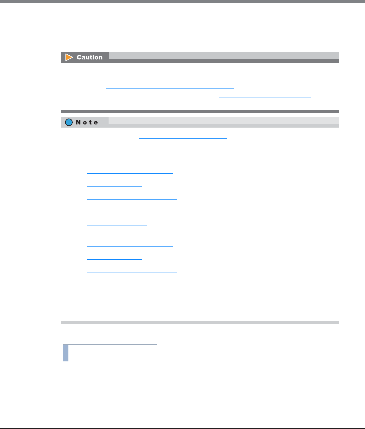
Chapter 11 System Management
11.2 Functions in the Action Area for System
ETERNUS Web GUI User’s Guide
Copyright 2013 FUJITSU LIMITED P2X0-1090-10ENZ0
761
11.2.3.3 Setup SNMP Agent Basic Interface
This function sets up the SNMP Agent basic interface in the ETERNUS DX Disk storage system.
SNMP is a standard protocol used for network management.
The procedure to set the basic information of SNMP Agent is as follows:
Procedure
1Click [Setup SNMP Interface] in [Action].
2Specify the parameters, and click the [Set] button.
•SNMP Function
Select whether to enable or disable the SNMP function.
•When SNMP Manager exists in a different subnetwork from where the ETERNUS DX Disk storage system
belongs, specify the IP address or the network address of SNMP Manager in "Allowed IP List" using the
procedure in "11.2.3.1 Setup Network Environment" (page 745).
•Before enabling the SNMP function, use the procedure in "11.2.3.2 Setup Firewall" (page 758) to allow
the "SNMP" connection for the setting target LAN port.
•By using the procedure in "Chapter 3 Initial Setup" (page 38), the SNMP Agent environment can be
configured with the wizard. When the [Initial Setup] function is not used, configure the SNMP Agent
environment in the following order:
-When using SNMPv1 or SNMPv2c for SNMP communication
(1)Setup SNMP Agent Basic Interface
(2)Setup SNMP Manager
(3)Setup SNMP Agent MIB Access View
(4)Setup SNMP Agent Community
(5)Setup SNMP Agent Trap
-When using SNMPv3 for SNMP communication
(1)Setup SNMP Agent Basic Interface
(2)Setup SNMP Manager
(3)Setup SNMP Agent MIB Access View
(4)Setup SNMP Agent User
(5)Setup SNMP Agent Trap
•The parameter settings specified using this function remain even when the "SNMP Function" setting is
changed from "Enable" to "Disable".
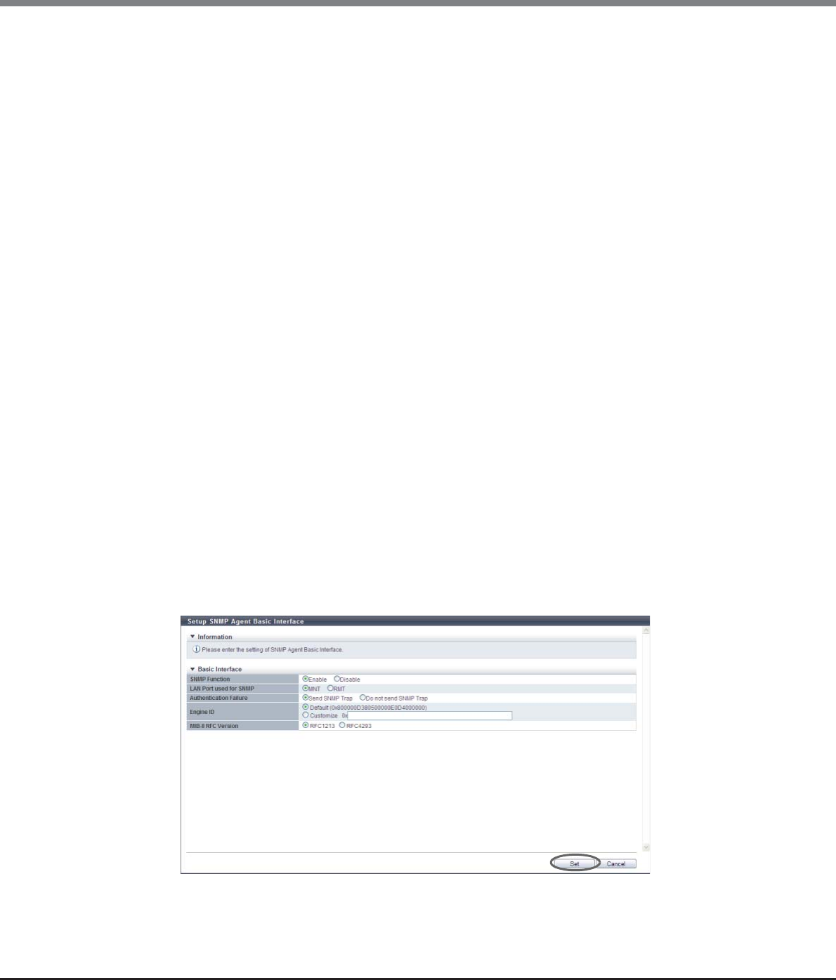
Chapter 11 System Management
11.2 Functions in the Action Area for System
ETERNUS Web GUI User’s Guide
Copyright 2013 FUJITSU LIMITED P2X0-1090-10ENZ0
762
•LAN Port used for SNMP
When enabling the SNMP function, select the port used for SNMP from "MNT" or "RMT".
When sending a SNMPv1 trap, the agent-address of the trap sender is the Master CM IP address of
the selected port.
•Authentication Failure
When enabling the SNMP function, select "Send SNMP Trap" or "Do not send SNMP Trap" when
authentication fails.
•Engine ID
When enabling the SNMP function, enter the engine ID of the SNMP.
The engine ID is a unique identifier used to distinguish the connection target storage system
between the SNMP Manager and the SNMP Agent.
It is not necessary to change the default setting for normal use. The default engine ID of the
ETERNUS DX Disk storage system is as follows:
Octet 1 - 4: Bitwise OR between the company code (fujitsu=211) and 0x80000000
Octet 5: 0x80 (fixed)
Octet 6 - 13: WWN of the ETERNUS DX Disk storage system (8 bytes)
The following input conditions apply:
-Alphanumeric characters (0 - 9, A - F, a - f)
-Inputting only "0" or "F" for the "Engine ID" field is not allowed
-10 - 64 characters (even number)
•MIB-II RFC Version
When enabling the SNMP function, select either "RFC1213" or "RFC4293" as the MIB-II support RFC
version.
Although it is not necessary to change the default setting ("RFC1213") for normal use, select the RFC
version that is supported by the SNMP manager.
-RFC1213
This mode is used for MIB-II that supports RFC1213.
This RFC supports IPv4 addresses.
-RFC4293
This mode is used for MIB-II that supports RFC4293.
This RFC supports IPv4 addresses and IPv6 addresses. This RFC is an extended definition for
RFC1213.
→A confirmation screen appears.
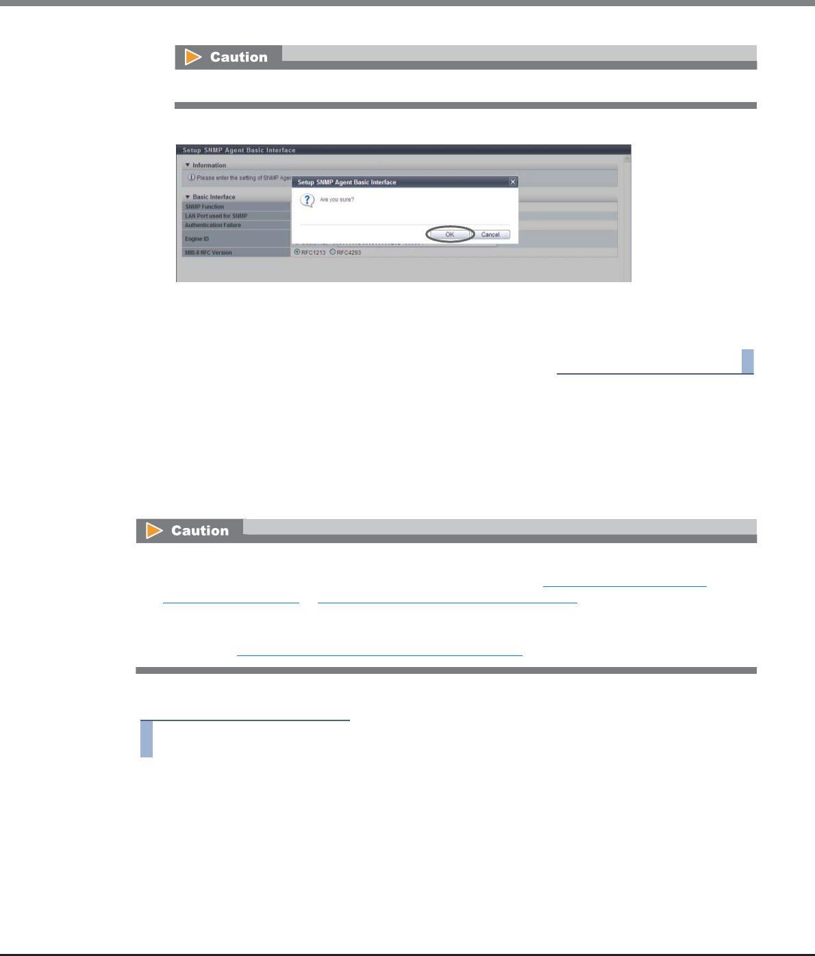
Chapter 11 System Management
11.2 Functions in the Action Area for System
ETERNUS Web GUI User’s Guide
Copyright 2013 FUJITSU LIMITED P2X0-1090-10ENZ0
763
3Click the [OK] button.
→Setting of the SNMP Agent basic interface starts.
4Click the [Done] button to return to the [Network] screen.
End of procedure
11.2.3.4 Setup SNMP Manager
This function specifies the IP address of the SNMP Manager.
The SNMP Manager is used when accessing the ETERNUS DX Disk storage system using the community name
or the user name, or when sending a trap from the ETERNUS DX Disk storage system to the SNMP Manager.
Up to ten SNMP Managers can be specified for each ETERNUS DX Disk storage system.
The procedure to set the SNMP Manager is as follows:
Procedure
1Click [Setup SNMP Manager] in [Action].
If the entered engine ID does not satisfy the input conditions, an error screen appears.
•If the "SNMP Function" is disabled, this function cannot be used.
•The IP address of the SNMP Manager that is used in the settings in "11.2.3.7 Setup SNMP Agent
Community" (page 771) or "11.2.3.8 Setup SNMP Agent Trap" (page 774) cannot be changed or deleted.
•When SNMP Manager exists in a different subnetwork from where the ETERNUS DX Disk storage system
belongs, specify the IP address or the network address of SNMP Manager in the "Allowed IP List" using the
procedure in "11.2.3.1 Setup Network Environment" (page 745).
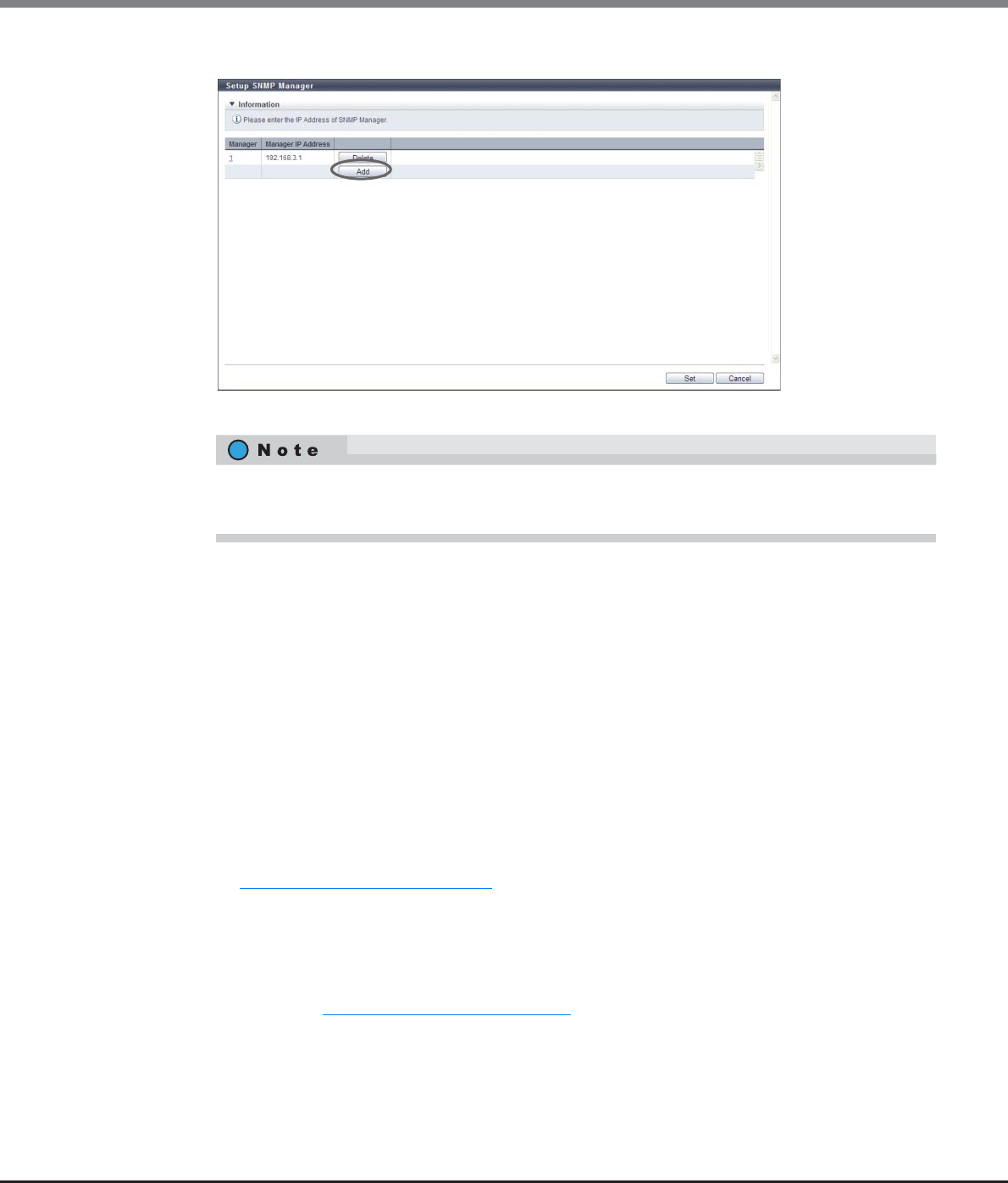
Chapter 11 System Management
11.2 Functions in the Action Area for System
ETERNUS Web GUI User’s Guide
Copyright 2013 FUJITSU LIMITED P2X0-1090-10ENZ0
764
2Click the [Add] button.
→The [Manager] screen appears.
3Input or edit the IP address, and click the [OK] button.
•IP Version
Select "IPv4" or "IPv6" for the IP version of the SNMP Manager IP address.
•Manager IP Address (IPv4)
Input the IP address of the SNMP Manager with the IPv4 format.
The IP address which has already been used cannot be entered.
This setting is enabled when "IPv4" is selected for "IP Version".
The following input condition applies:
-xxx.xxx.xxx.xxx
•First text box: "1" - "255"
•Other text boxes: "0" - "255"
•Manager IP Address (IPv6)
Input the IP address of the SNMP Manager with the IPv6 format. The following IPv6 addresses can
be used; "link local address", "global address", "unique local address", and "6to4 address". Refer to
"Available IPv6 Address" (page 757) for details. The IP address which has already been used cannot
be entered.
This setting is enabled when "IPv6" is selected for "IP Version".
The following input condition applies:
-xxxx:xxxx:xxxx:xxxx:xxxx:xxxx:xxxx:xxxx
xxxx: 0 - ffff (FFFF) (hexadecimal, alphanumeric characters)
Refer to "IPv6 Address Notation" (page 378) for details.
•Click the [Manager] link to edit the existing IP address for the target SNMP manager area.
•Click the [Delete] button to delete the existing IP address for the target SNMP Manager area.
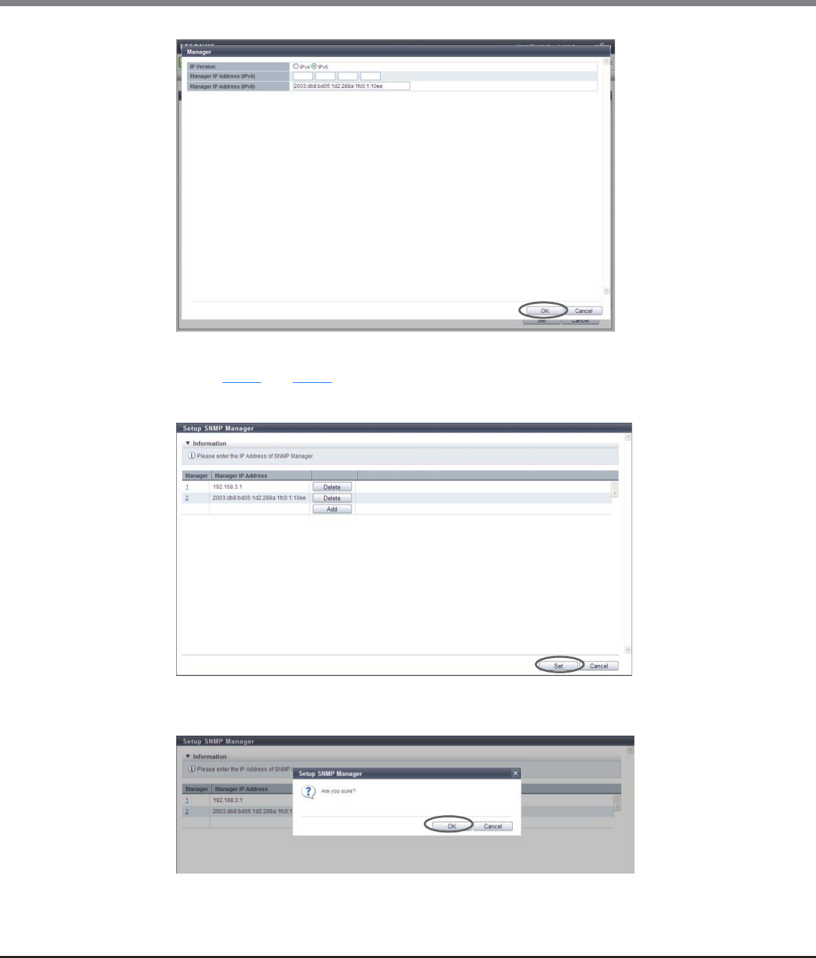
Chapter 11 System Management
11.2 Functions in the Action Area for System
ETERNUS Web GUI User’s Guide
Copyright 2013 FUJITSU LIMITED P2X0-1090-10ENZ0
765
→Returns to the original screen.
4Repeat Step 2 and Step 3 to configure multiple IP addresses.
5After adding or editing the IP address, click the [Set] button.
→A confirmation screen appears.
6Click the [OK] button.
→Setting of the SNMP Manager starts.
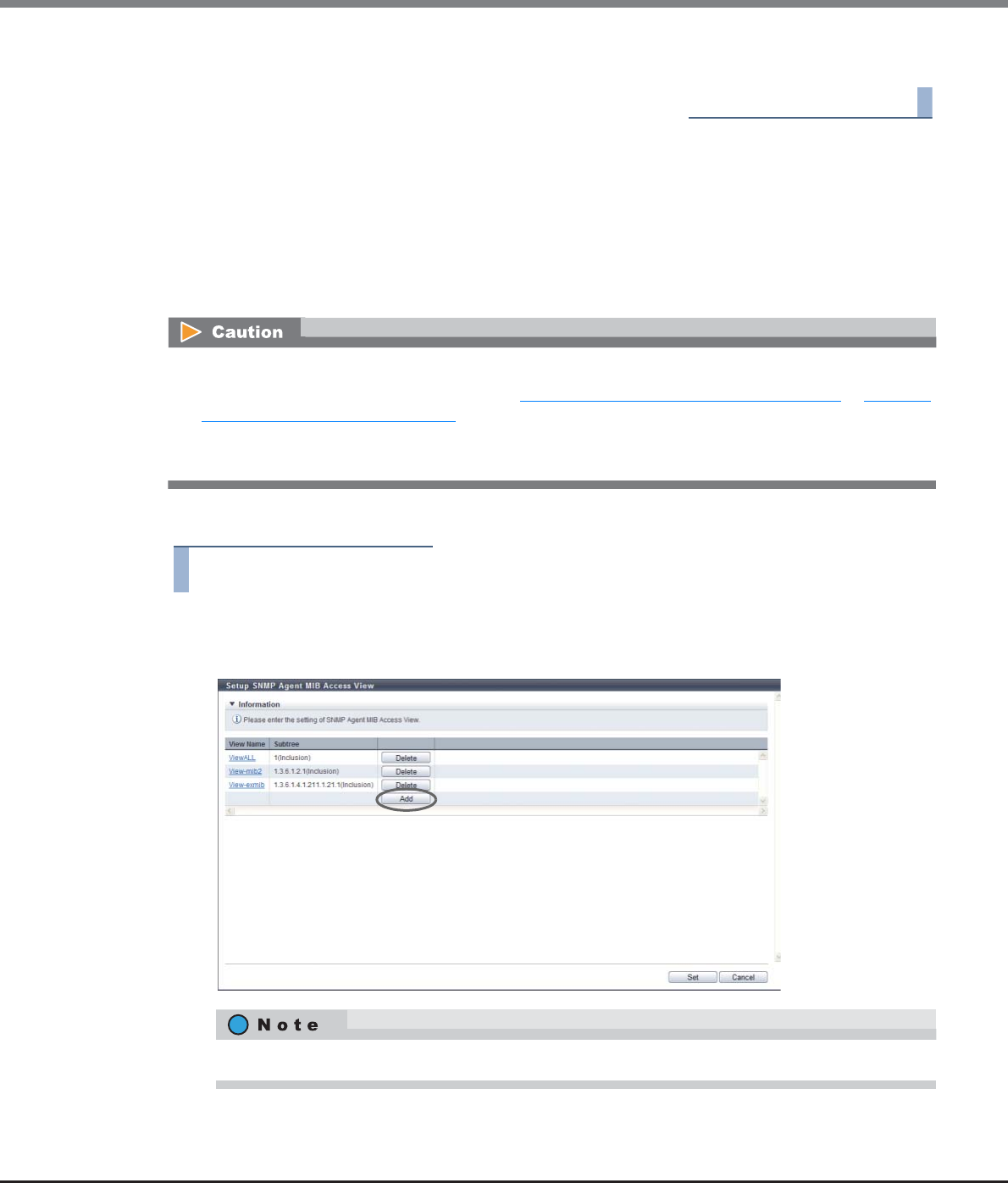
Chapter 11 System Management
11.2 Functions in the Action Area for System
ETERNUS Web GUI User’s Guide
Copyright 2013 FUJITSU LIMITED P2X0-1090-10ENZ0
766
7Click the [Done] button to return to the [Network] screen.
End of procedure
11.2.3.5 Setup SNMP Agent MIB Access View
This function sets up the SNMP Agent MIB View.
MIB View is used for defining the accessible area in the Management Information Base (MIB) database, with
a tree type structure. Use this item when defining the accessible area in the MIB database.
Up to ten MIB Views, including the default view, can be created for each ETERNUS DX Disk storage system.
There are three types of default views: "ViewALL", "View-mib2", and "View-exmib".
The procedure to change the SNMP Agent MIB view is as follows:
Procedure
1Click [Setup SNMP MIB View] in [Action].
2Click the [Add] button.
•If the "SNMP Function" is disabled, the [Setup SNMP Manager] function cannot be used.
•The view name that is used in the settings in "11.2.3.6 Setup SNMP Agent User" (page 768) or "11.2.3.6
Setup SNMP Agent User" (page 768) cannot be changed or deleted. However, note that the MIB View
(Subtree) can be changed.
•The default view can be changed or deleted.
Click the [View Name] link to edit the existing MIB View.
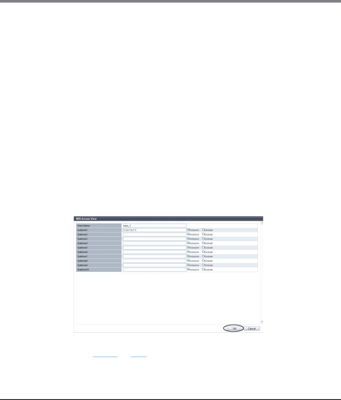
Chapter 11 System Management
11.2 Functions in the Action Area for System
ETERNUS Web GUI User’s Guide
Copyright 2013 FUJITSU LIMITED P2X0-1090-10ENZ0
767
3Input or edit the MIB View, and click the [OK] button.
•View Name
Input the MIB View name.
The view name which has already been used cannot be entered.
The following input conditions apply:
-Up to 32 alphanumeric characters and symbols
-"! (exclamation mark)", "# (hash mark)", "& (ampersand)", "_ (underscore)", "+ (plus)", "-
(hyphen)", "* (asterisk)" and "/ (slash)" can be used
-Spaces
•Subtree1 - Subtree10
Specify the MIB access range of the corresponding view in the subtree. Input the subtree in the
Object ID format (*1).
Select whether to include as or exclude from each subtree as the MIB access range.
One or more subtrees are required per view.
The same subtree cannot be specified multiple times in a single view. However, the same subtree
can be configured to different views.
The following input conditions apply:
-Up to 251 alphabetic characters and numeric characters ("1" - "65535")
-Spaces
*1: The "Object ID" is indicated by using "." (periods) in a format such as "1.3.6.1.2.1.1". The setting range of
each value that is separated using "." (periods) is 1 - 65535. A total of up to 251 characters can be
entered (including periods). The following values cannot be entered in the ETERNUS DX Disk storage
system:
(1) Values starting with a period: ".1.3.6.1.2.1.1"
(2) Value ending with a period: "1.3. 6.1.2.1.1."
(3) Values with two consecutive periods: "1. . 3. 6. 1. 2. 1. 1"
(4) Values including "0": "1.3.6.1.2.0.1"
→Returns to the original screen.
4Repeat Step 11.2 and Step 3 to configure multiple MIB Views.
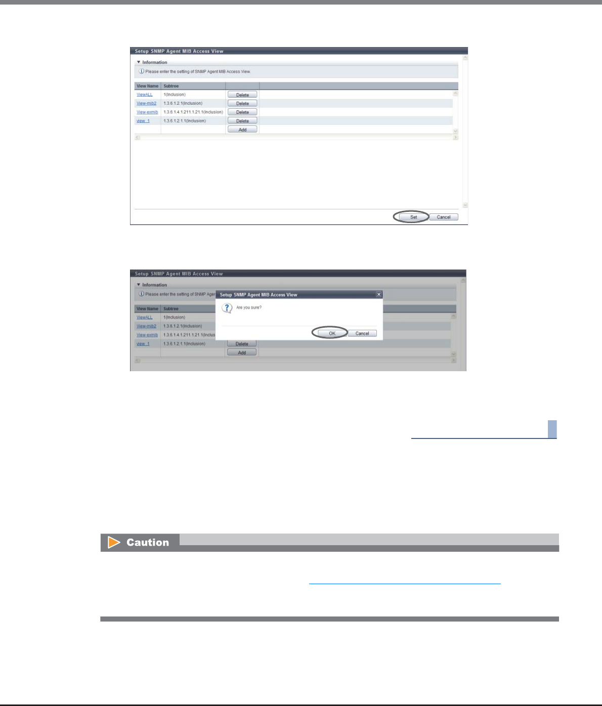
Chapter 11 System Management
11.2 Functions in the Action Area for System
ETERNUS Web GUI User’s Guide
Copyright 2013 FUJITSU LIMITED P2X0-1090-10ENZ0
768
5After adding or editing the MIB View, click the [Set] button.
→A confirmation screen appears.
6Click the [OK] button.
→Setting of the SNMP Agent MIB View starts.
7Click the [Done] button to return to the [Network] screen.
End of procedure
11.2.3.6 Setup SNMP Agent User
This function sets up the user which accesses the SNMP Agent.
The security level and the MIB access range are configured for each user.
Up to ten users can be specified for each ETERNUS DX Disk storage system.
•If the "SNMP Function" is disabled, the [Setup SNMP Manager] function cannot be used.
•The user name that is used in the settings in "11.2.3.8 Setup SNMP Agent Trap" (page 774) cannot be
changed or deleted. However, note that some of the user information (MIB View Setting, Authentication,
and Encryption) can be changed.
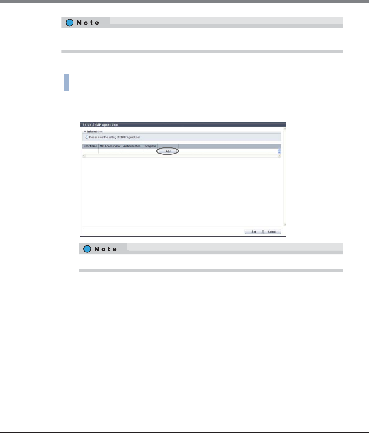
Chapter 11 System Management
11.2 Functions in the Action Area for System
ETERNUS Web GUI User’s Guide
Copyright 2013 FUJITSU LIMITED P2X0-1090-10ENZ0
769
The procedure to set the user to access the SNMP Agent is as follows:
Procedure
1Click [Setup SNMP User] in [Action].
2Click the [Add] button.
3Input or edit the user information, and click the [OK] button.
•User Name
Input the user name which accesses the SNMP Agent.
The user name which has already been used cannot be entered.
The following input conditions apply:
-8 - 32 alphanumeric characters and symbols
-"! (exclamation mark)", "# (hash mark)", "& (ampersand)", "_ (underscore)", "+ (plus)", "-
(hyphen)", "* (asterisk)" and "/ (slash)" can be used
-Spaces
•MIB View Setting
Select the view name to specify the MIB access range for the user.
A "blank" means accessing the MIB is not allowed.
•Authentication
Select whether to enable or disable the authentication.
•Authentication Method
When enabling authentication, select the authentication method from "MD5" (Message Digest 5) or
"SHA" (Secure Hash Algorithm).
The authentication and encryption can be enabled/disabled, and also the MIB access range can be specified,
for each user.
Click the [User Name] link to edit the existing user.
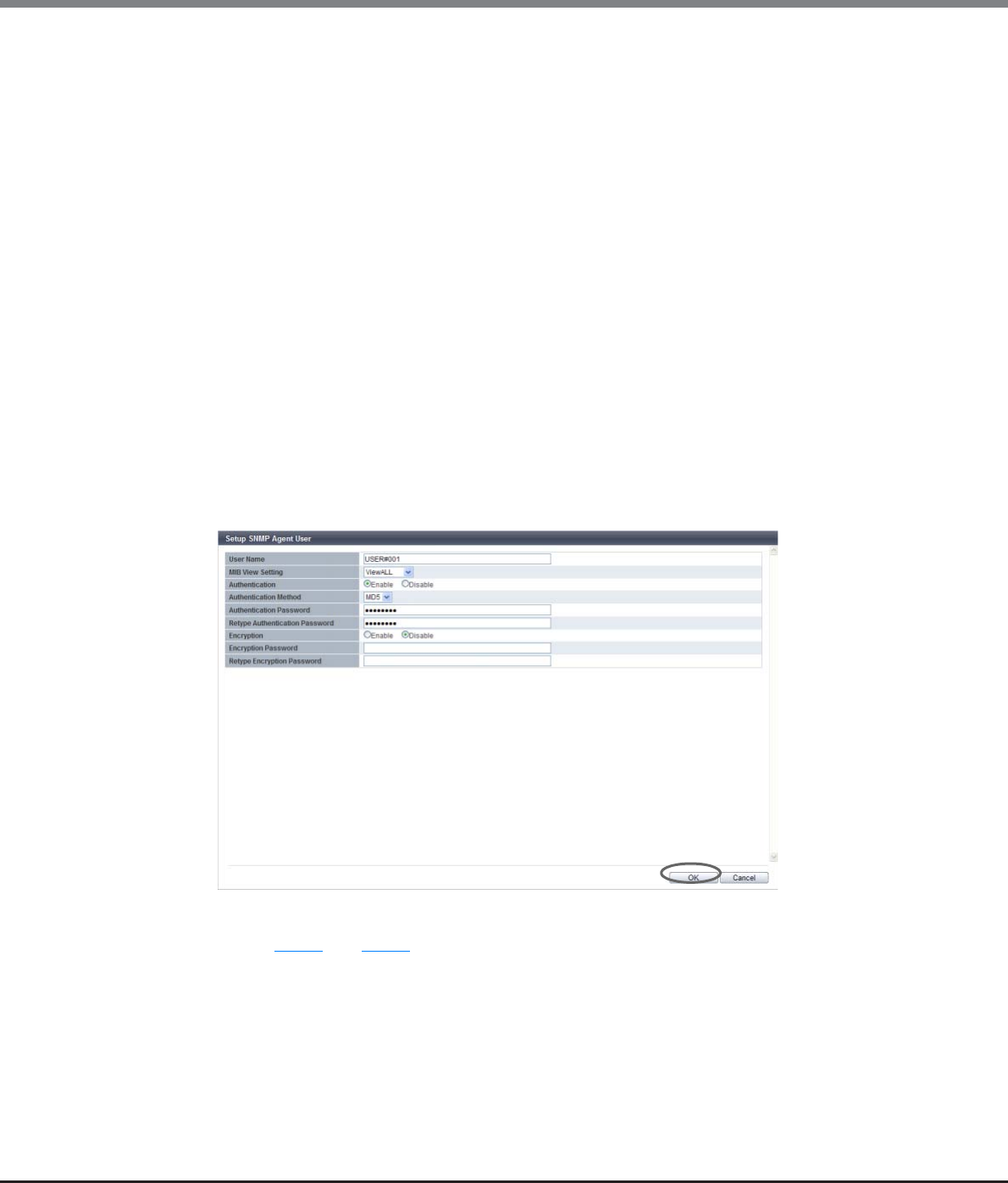
Chapter 11 System Management
11.2 Functions in the Action Area for System
ETERNUS Web GUI User’s Guide
Copyright 2013 FUJITSU LIMITED P2X0-1090-10ENZ0
770
•Authentication Password
When enabling authentication, enter the authentication password.
The following input conditions apply:
-8 - 64 alphanumeric characters and symbols
-"! (exclamation mark)", "# (hash mark)", "& (ampersand)", "_ (underscore)", "+ (plus)", "-
(hyphen)", "* (asterisk)" and "/ (slash)" can be used
-Spaces
•Retype Authentication Password
When enabling authentication, enter the authentication password again.
•Encryption
Select whether to enable or disable the encryption.
If the "Authentication" setting is "Disable", the encryption setting cannot be selected.
•Encryption Password
When enabling encryption, enter the encryption password.
The following input conditions apply:
-8 - 64 alphanumeric characters and symbols
-"! (exclamation mark)", "# (hash mark)", "& (ampersand)", "_ (underscore)", "+ (plus)", "-
(hyphen)", "* (asterisk)" and "/ (slash)" can be used
-Spaces
•Retype Encryption Password
When enabling the encryption, enter the encryption password again.
→Returns to the original screen.
4Repeat Step 2 and Step 3 to configure multiple users.
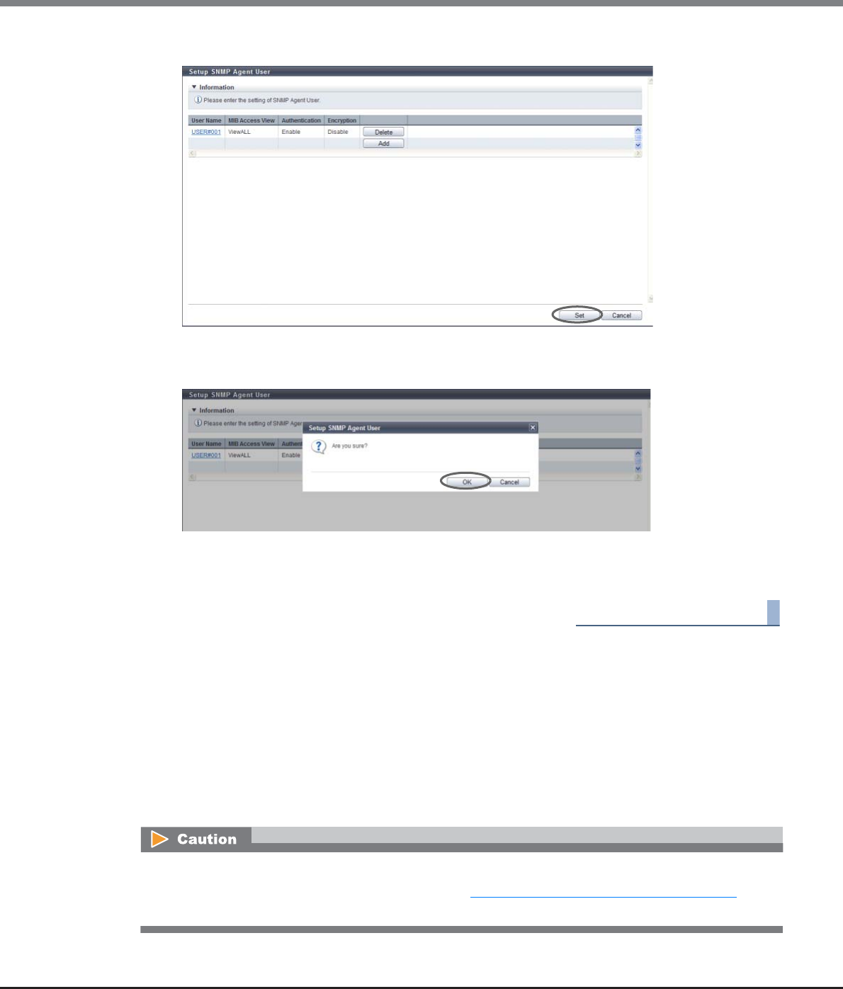
Chapter 11 System Management
11.2 Functions in the Action Area for System
ETERNUS Web GUI User’s Guide
Copyright 2013 FUJITSU LIMITED P2X0-1090-10ENZ0
771
5After adding or editing the user information, click the [Set] button.
→A confirmation screen appears.
6Click the [OK] button.
→Setting of the SNMP Agent user starts.
7Click the [Done] button to return to the [Network] screen.
End of procedure
11.2.3.7 Setup SNMP Agent Community
This function sets up the SNMP Agent Community.
The Community is a range of available networks for SNMP.
The setting value is used as the password for SNMP Manager to access the SNMP Agent of the ETERNUS DX
Disk storage system.
The SNMP Agent only accepts a request from SNMP Manager if the specified community names for SNMP
Manager and SNMP Agent are the same.
Up to ten communities can be specified for each ETERNUS DX Disk storage system.
•If the "SNMP Function" is disabled, the [Setup SNMP Manager] function cannot be used.
•The community name that is used in the settings in "11.2.3.8 Setup SNMP Agent Trap" (page 774) cannot
be changed or deleted.
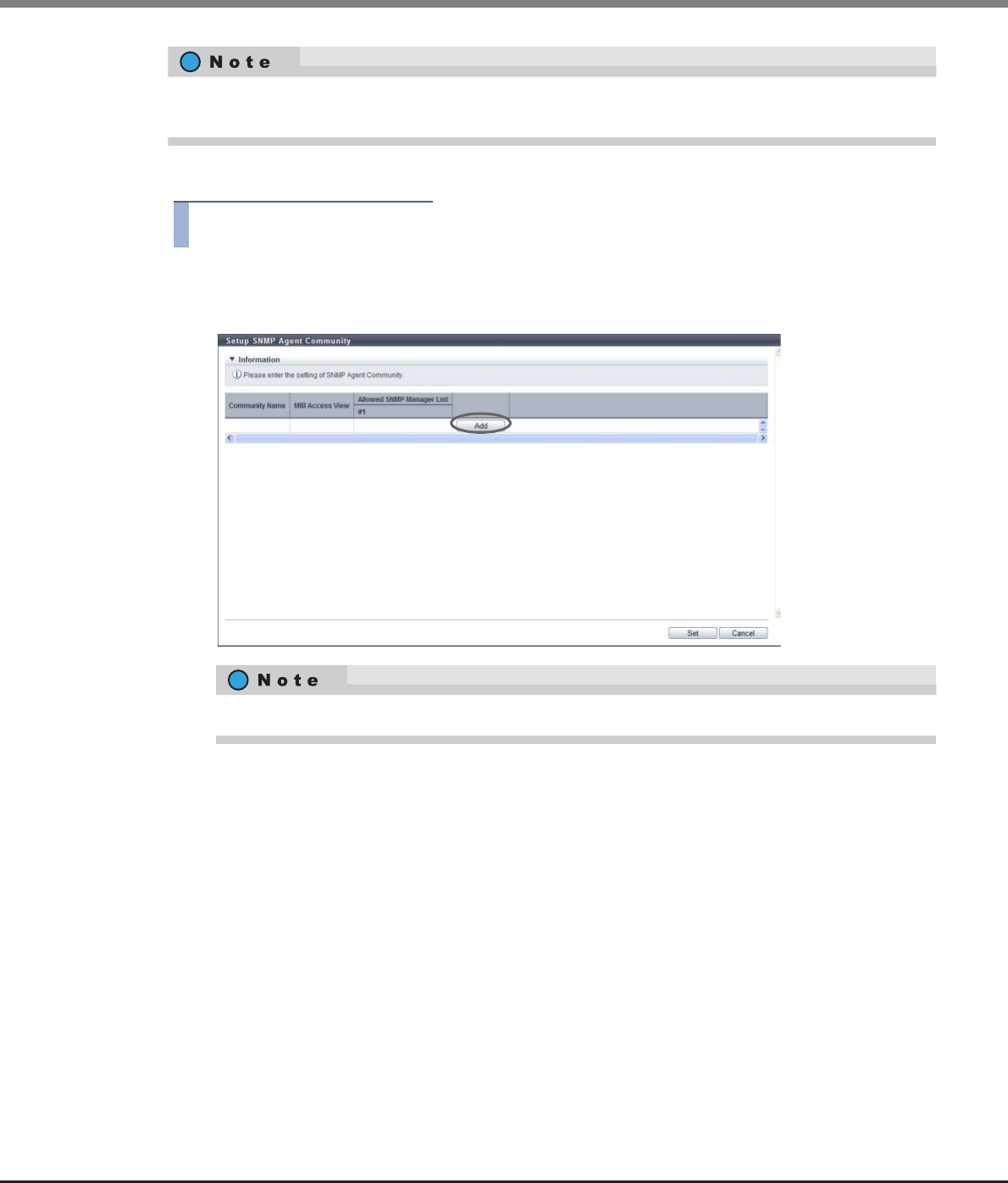
Chapter 11 System Management
11.2 Functions in the Action Area for System
ETERNUS Web GUI User’s Guide
Copyright 2013 FUJITSU LIMITED P2X0-1090-10ENZ0
772
The procedure to set the SNMP Agent community is as follows:
Procedure
1Click [Setup SNMP Community] in [Action].
2Click the [Add] button.
3Input or edit the community, and click the [OK] button.
•Community Name
Input the community name to be used when accessing a MIB or sending a trap.
The community name which has already been used cannot be entered.
The following input conditions apply:
-Up to 32 alphanumeric characters and symbols
-"! (exclamation mark)", "# (hash mark)", "& (ampersand)", "_ (underscore)", "+ (plus)", "-
(hyphen)", "* (asterisk)" and "/ (slash)" can be used
-Spaces
•View Name
Select the view name to specify the MIB access range for the community.
A "blank" means accessing the MIB is not allowed.
The SNMP Managers which are allowed to access, and the MIB access range, can be specified for each
community.
Click the [Community Name] link to edit the existing community information.
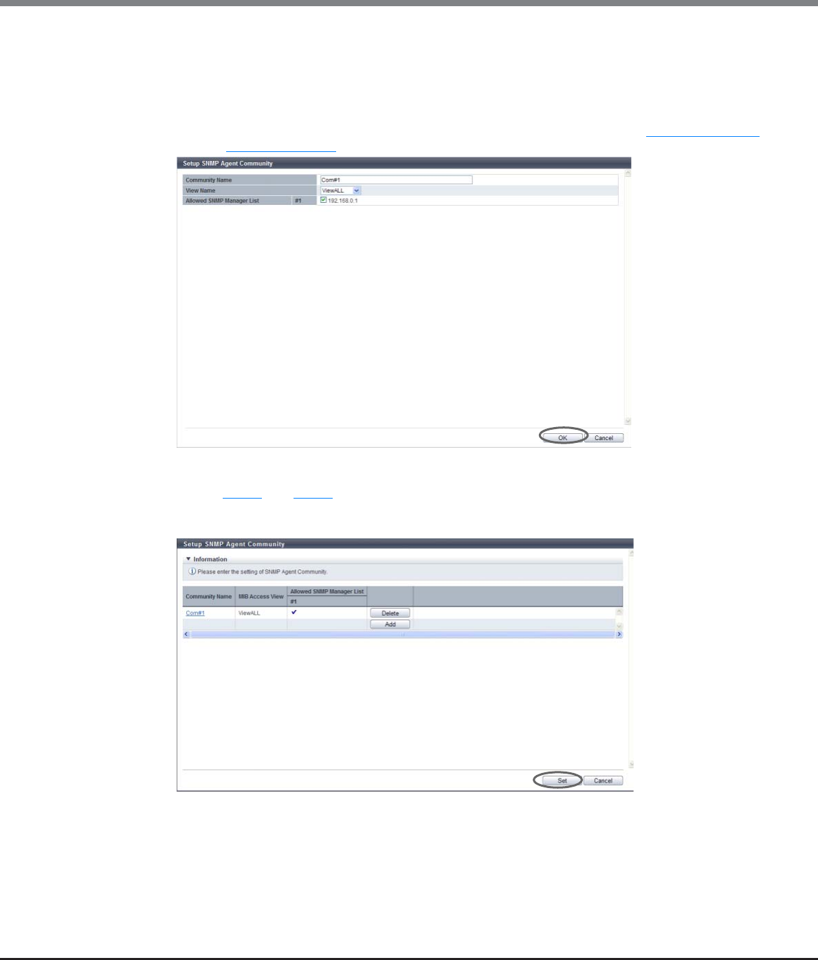
Chapter 11 System Management
11.2 Functions in the Action Area for System
ETERNUS Web GUI User’s Guide
Copyright 2013 FUJITSU LIMITED P2X0-1090-10ENZ0
773
•Allowed SNMP Manager List
Select the IP address of the SNMP Manager which is allowed to access in the community.
Only the selected SNMP Manager is allowed to access.
However, if the Allowed SNMP Manager List has been left blank, all of the SNMP Managers (*1) are
allowed to access.
*1: Not only the SNMP Manager which has been registered using the procedure in "11.2.3.4 Setup SNMP
Manager" (page 763), but also the other SNMP Managers are allowed to access.
→Returns to the original screen.
4Repeat Step 2 and Step 3 to configure multiple communities.
5After adding or editing the community, click the [Set] button.
→A confirmation screen appears.
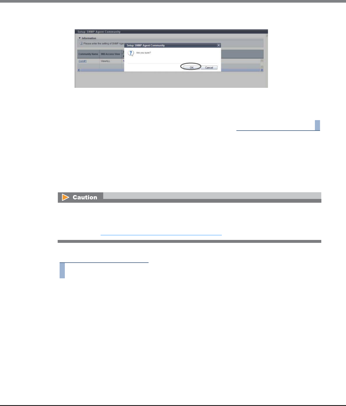
Chapter 11 System Management
11.2 Functions in the Action Area for System
ETERNUS Web GUI User’s Guide
Copyright 2013 FUJITSU LIMITED P2X0-1090-10ENZ0
774
6Click the [OK] button.
→Setting of the SNMP Agent Community starts.
7Click the [Done] button to return to the [Network] screen.
End of procedure
11.2.3.8 Setup SNMP Agent Trap
This function notifies events that occur in the ETERNUS DX Disk storage system to the SNMP Manager by an
SNMP Trap.
This function configures the trap destination, the trap version, etc.
Up to ten traps can be specified for each ETERNUS DX Disk storage system.
The procedure to set the SNMP Agent trap is as follows:
Procedure
1Click [Setup SNMP Trap] in [Action].
•If the "SNMP Function" is disabled, the [Setup SNMP Manager] function cannot be used.
•When SNMP Manager exists in a different subnetwork from where the ETERNUS DX Disk storage system
belongs, specify the IP address or the network address of SNMP Manager in the "Allowed IP List" using the
procedure in "11.2.3.1 Setup Network Environment" (page 745).
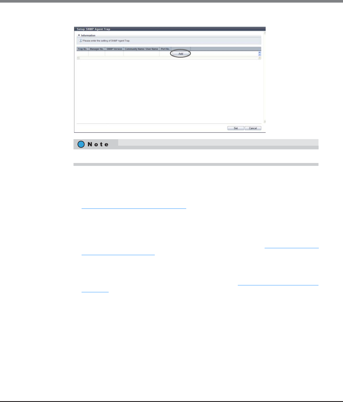
Chapter 11 System Management
11.2 Functions in the Action Area for System
ETERNUS Web GUI User’s Guide
Copyright 2013 FUJITSU LIMITED P2X0-1090-10ENZ0
775
2Click the [Add] button.
3Add or edit the trap information, and click the [OK] button.
•Manager No.
Select a manager number from "Manager01" to "Manager10".
The management number of the SNMP Manager, which has been registered using the procedure in
"11.2.3.4 Setup SNMP Manager" (page 763), is displayed as an option.
•SNMP Version
Select the trap SNMP version from "v1", "v2c", or "c3".
•Community Name
Select the community name used when sending a trap.
The community name, which has been registered using the procedure in "11.2.3.7 Setup SNMP
Agent Community" (page 771), is displayed as an option.
If "v1" or "v2c" is selected as the "SNMP Version", the "Community Name" must be specified.
•User Name
Select the user name used when sending a trap.
The user name, which has been registered using the procedure in "11.2.3.6 Setup SNMP Agent User"
(page 768), is displayed as an option.
If "v3" has been selected as the "SNMP Version", the "User Name" must be specified.
•Port No.
Input the port number of the trap destination between 1 - 65535.
When changing a port number, enter a unique port number.
Click the [Trap No.] link to edit the existing trap.
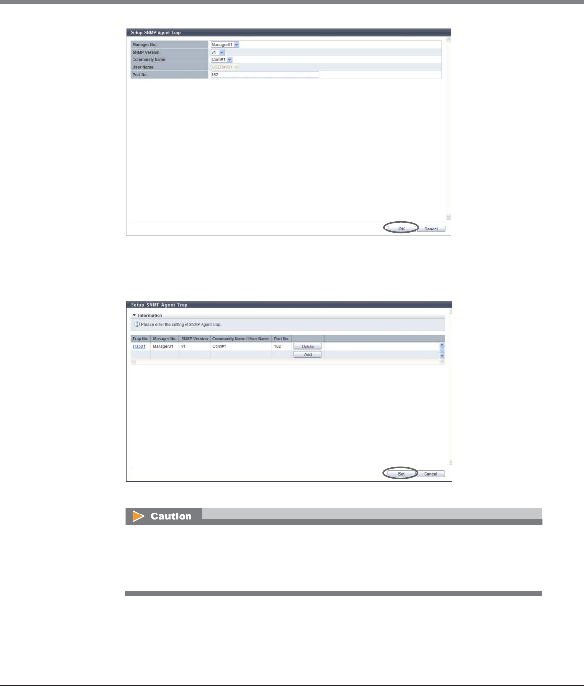
Chapter 11 System Management
11.2 Functions in the Action Area for System
ETERNUS Web GUI User’s Guide
Copyright 2013 FUJITSU LIMITED P2X0-1090-10ENZ0
776
→Returns to the original screen.
4Repeat Step 2 and Step 3 to configure multiple traps.
5After adding or editing the trap information, click the [Set] button.
→A confirmation screen appears.
An error screen appears in the following conditions:
•When "Manager No. " or "Community Name/User Name" is not input
•When a trap with the same parameters (except the "Trap No. ") exists
•When a trap with the same parameters (except the "Trap No. " and the "Port No. ") exists
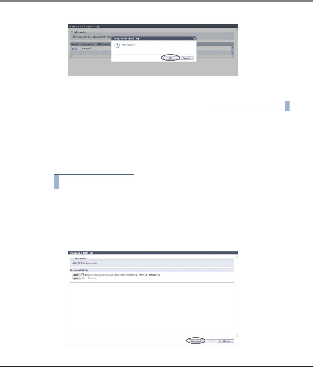
Chapter 11 System Management
11.2 Functions in the Action Area for System
ETERNUS Web GUI User’s Guide
Copyright 2013 FUJITSU LIMITED P2X0-1090-10ENZ0
777
6Click the [OK] button.
→Setting of the SNMP Agent Trap starts.
7Click the [Done] button to return to the [Network] screen.
End of procedure
11.2.3.9 Download MIB File
This function downloads the MIB definition file in the ETERNUS DX Disk storage system.
MIB is the information for managing SNMP Agent that is transferred by using SNMP Manager with the SNMP.
The MIB definition file is used by the application which uses SNMP (SNMP Manager).
The procedure to download an MIB file as follows:
Procedure
1Click [Download MIB File] in [Action].
2Specify the parameters, and click the [Download] button.
•Option
Select the "The ServerView control code is added to the comment line of the MIB definition file"
checkbox when downloading the MIB file used for storage system monitoring by ServerView.
•Version
Select the SNMP Trap version used for storage system monitoring from "v1", or "v2c/v3".
→A confirmation screen appears.
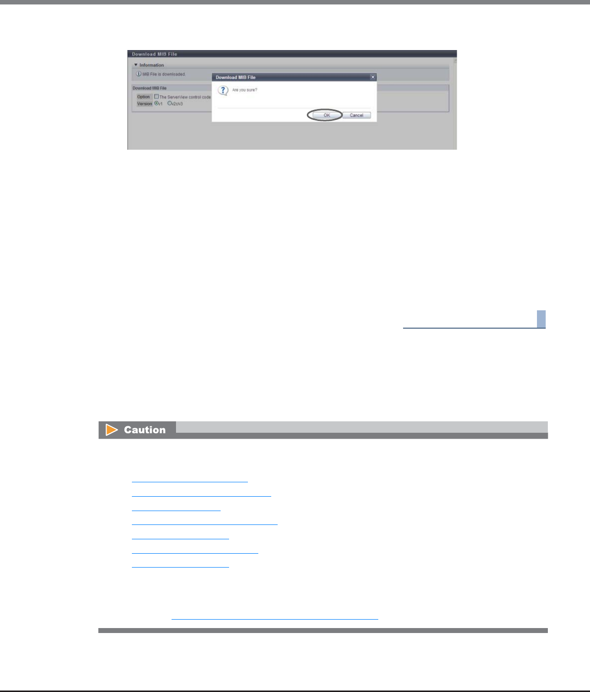
Chapter 11 System Management
11.2 Functions in the Action Area for System
ETERNUS Web GUI User’s Guide
Copyright 2013 FUJITSU LIMITED P2X0-1090-10ENZ0
778
3Click the [OK] button.
→A dialog box to download the file appears.
4Save the downloaded file.
The file name is as follows:
•ETERNUS DX80 S2/DX90 S2: "FJDARY-E100.MIB"
•ETERNUS DX410 S2/DX440 S2: "FJDARY-E100.MIB"
•ETERNUS DX8100 S2: "FJDARY-E100.MIB"
•ETERNUS DX8700 S2: "FJDARY-E102.MIB"
→The downloaded file is saved.
5Click the [Done] button to return to the [Network] screen.
End of procedure
11.2.3.10 Send SNMP Trap Test
This function transmits the test trap from the SNMP Agent to the SNMP Manager.
The SNMP Trap is the event information reported by the ETERNUS DX Disk storage system (SNMP Agent).
Perform SNMP Agent and SNMP Manager settings before executing this test.
•Perform the following settings before executing this test. If the SNMP function is disabled, the trap test
cannot be performed.
-Setup Network Environment
-Setup SNMP Agent Basic Interface
-Setup SNMP Manager
-Setup SNMP Agent MIB Access View
-Setup SNMP Agent User
-Setup SNMP Agent Community
-Setup SNMP Agent Trap
•This function transmits a test trap.
•When SNMP Manager exists in a different subnetwork from where the ETERNUS DX Disk storage system
belongs, specify the IP address or the network address of SNMP Manager in the "Allowed IP List" using the
procedure in "11.2.3.1 Setup Network Environment" (page 745).
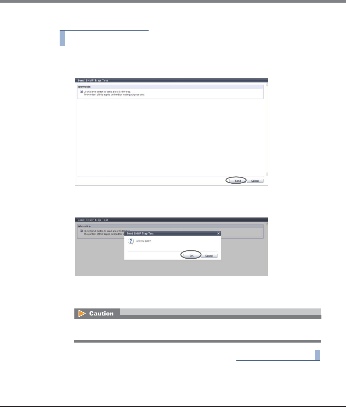
Chapter 11 System Management
11.2 Functions in the Action Area for System
ETERNUS Web GUI User’s Guide
Copyright 2013 FUJITSU LIMITED P2X0-1090-10ENZ0
779
The procedure to perform the SNMP Trap test is as follows:
Procedure
1Click [Send SNMP Trap] in [Action].
2Click the [Send] button.
→A confirmation screen appears.
3Click the [OK] button.
→The SNMP Trap test is performed.
4Click the [Done] button to return to the [Network] screen.
End of procedure
Confirm that the trap has been successfully received by SNMP Manager after the SNMP Trap test has
been performed.
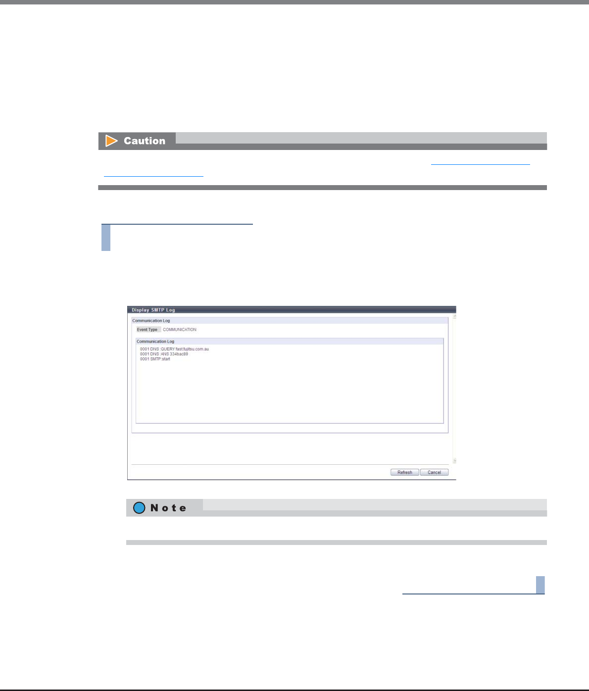
Chapter 11 System Management
11.2 Functions in the Action Area for System
ETERNUS Web GUI User’s Guide
Copyright 2013 FUJITSU LIMITED P2X0-1090-10ENZ0
780
11.2.3.11 Display SMTP Log
This function displays the E-Mail communication log between the ETERNUS DX Disk storage system and the E-
Mail server. If the E-Mail communication is not operated properly, this function may identify the cause of
problem.
The E-Mail communication log contains requests from the ETERNUS DX Disk storage system to the server and
responses from the server to the ETERNUS DX Disk storage system. Only the E-Mail communication log for the
last executed event is displayed.
The procedure to display SMTP log is as follows:
Procedure
1Click [Display SMTP Log] in [Action].
2Check the displayed "Event Type" and the "Communication Log".
3Click the [Cancel] button to return to the [Network] screen.
End of procedure
Server connection related settings for the server is required in advance. Refer to "11.2.3.12 Setup E-Mail
Notification" (page 781) for details.
Click the [Refresh] button to update to the latest screen.
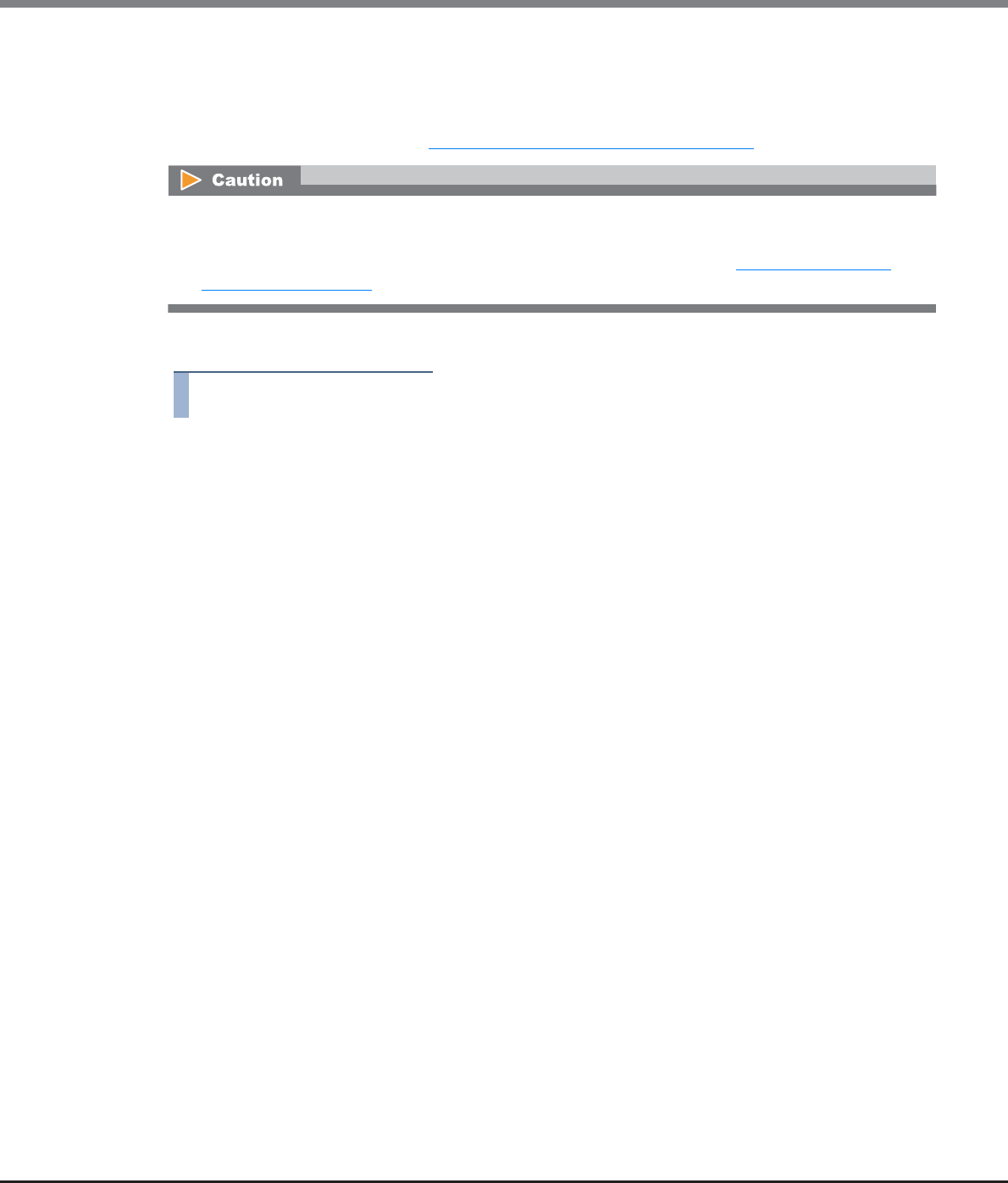
Chapter 11 System Management
11.2 Functions in the Action Area for System
ETERNUS Web GUI User’s Guide
Copyright 2013 FUJITSU LIMITED P2X0-1090-10ENZ0
781
11.2.3.12 Setup E-Mail Notification
This function is used to configure the E-mail Notification settings for the various events detected by the
ETERNUS DX Disk storage system.
To specify event notification, refer to "11.2.9.1 Setup Event Notification" (page 880).
The procedure to set a E-Mail notification is as follows:
Procedure
1Click [Setup E-Mail Notification] in [Action].
2Specify the parameters, and click the [Set] button.
●Notification E-Mail
•Notification E-Mail
Select whether to enable ("Yes") or disable ("No") the E-Mail notification function.
•Destination E-Mail Address
Specify the E-Mail destination address.
At least one address must be specified. Up to five addresses can be specified.
The following input condition applies:
-Up to 63 alphanumeric characters and symbols (except spaces)
•Comment
Input the message (comment) to be added to the E-Mail. The comment can be omitted.
The following input conditions apply:
-Up to 225 characters
-Within ten lines
-Alphanumeric characters, symbols, and spaces
●Mail Server Settings
•LAN Port used for SMTP Connection
Select the LAN port connecting to the SMTP server from "MNT" or "RMT".
•Sender E-Mail Address
Input the E-Mail address of the ETERNUS DX Disk storage system.
The following input condition applies:
-Up to 63 alphanumeric characters and symbols (except spaces)
When stopping the event notification via E-Mail, perform one of the following procedures.
•Disable the "Notification E-Mail"
•Clear the E-Mail checkbox of the notification method using the procedure in "11.2.9.1 Setup Event
Notification" (page 880).

Chapter 11 System Management
11.2 Functions in the Action Area for System
ETERNUS Web GUI User’s Guide
Copyright 2013 FUJITSU LIMITED P2X0-1090-10ENZ0
782
•SMTP Server
Specify the IP address or domain name of the SMTP server to be used.
There are two methods to specify an IP address; "IPv4" and "IPv6". The following IPv6 addresses can
be used; "link local address", "global address", "unique local address", and "6to4 address". Refer to
"Available IPv6 Address" (page 757) for details.
When the current setting is displayed, the IPv6 address is displayed as an abbreviation.
The following input condition applies:
-For IPv4 address
•xxx.xxx.xxx.xxx
xxx: 1 - 255 for the top field (decimal)
xxx: 0 - 255 for other fields (decimal)
-For IPv6 address
•xxxx:xxxx:xxxx:xxxx:xxxx:xxxx:xxxx:xxxx
xxxx: 0 - ffff (FFFF) (hexadecimal, alphanumeric characters)
Refer to "IPv6 Address Notation" (page 378) for details.
-For "Domain Name"
•Up to 63 alphanumeric characters and symbols
•SNMP Port No.
Specify the port number used by the SMTP server between 1 - 65535.
•SMTP requires authentication
Select the user authorization method to connect to the SMTP server from "None" or "AUTH SMTP".
•User Name
If "AUTH SMTP" is selected for "SMTP Authentication Information", specify the sender user name.
The following input condition applies:
-Up to 32 alphanumeric characters and symbols
•Password
When "AUTH SMTP" is selected for "SMTP Authentication Information", specify the sender password.
The following input condition applies:
-Up to 64 alphanumeric characters and symbols
•Authentication Method
If "AUTH SMTP" is selected for "SMTP Authentication Information", select the authentication method
from "Automatic", "CRAM-MD5", "PLAIN", or "LOGIN".
●Retry Setting
•Maximum Retries
Specify the maximum number of retries ("0" or "1").
•Retry Interval
Specify the interval between retries ("1" to "5") in units of seconds.
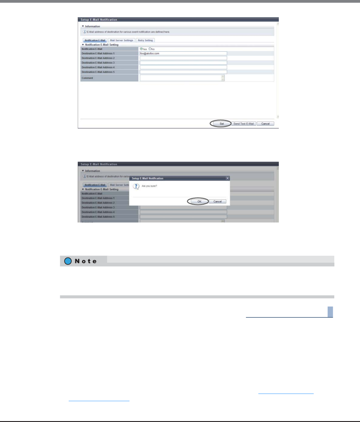
Chapter 11 System Management
11.2 Functions in the Action Area for System
ETERNUS Web GUI User’s Guide
Copyright 2013 FUJITSU LIMITED P2X0-1090-10ENZ0
783
→A confirmation screen appears.
3Click the [OK] button.
→The specified E-mail notification setting is performed.
4Click the [Done] button to return to the [Network] screen.
End of procedure
11.2.3.13 Setup Syslog
This function sets up external servers (Syslog server) for sending logs of events that are detected by the
ETERNUS DX Disk storage system.
Up to two Syslog servers can be registered.
The following events are sent as Syslogs:
•All the notification target events that are configured using the procedure in "11.2.9.1 Setup Event
Notification" (page 880)
•Logins and logouts from GUI and CLI
Click the [Send Test E-Mail] button to confirm that an E-Mail can be sent to the specified address. When
sending a test E-Mail, select "Enable" for the "Notification E-Mail" setting. Note that clicking [Set] button is
required when changing the parameters before sending a test E-Mail to enable the new settings.
Chapter 11 System Management
11.2 Functions in the Action Area for System
ETERNUS Web GUI User’s Guide
Copyright 2013 FUJITSU LIMITED P2X0-1090-10ENZ0
784
The procedure to set up the Syslog is as follows:
Procedure
1Click [Setup Syslog] in [Action].
2Specify the parameters, and click the [Set] button.
•Send Log
Select from "on (RFC3164)", "on (RFC5424)", or "off" for Syslog sending.
Logs are send in the selected RFC message format.
•Domain Name / IP Address
Input the domain name or the IP address of the Syslog server.
There are two methods to specify an IP address; "IPv4" and "IPv6". The following IPv6 addresses can
be used; "link local address", "global address", "unique local address", and "6to4 address". Refer to
"Available IPv6 Address" (page 757) for details.
When the current setting is displayed, the IPv6 address is displayed as an abbreviation.
The following input conditions apply:
-For "Domain Name"
Up to 63 alphanumeric characters and symbols
-For IPv4 address
xxx.xxx.xxx.xxx
xxx: 1 - 255 for the top field (decimal)
xxx: 0 - 255 for other fields (decimal)
-For IPv6 address
xxxx:xxxx:xxxx:xxxx:xxxx:xxxx:xxxx:xxxx
xxxx: 0 - ffff (FFFF) (hexadecimal, alphanumeric characters)
Refer to "IPv6 Address Notation" (page 378) for details.
•Port No.
Input the port number used to send a Syslog.
The following input conditions apply:
-Numeric characters
-"1" - "65535"
•Select whether to send ("on") or not send ("off") Syslogs for each ETERNUS DX Disk storage system.
•Confirm that the Syslog has been successfully sent to the Syslog server by logging in and out from GUI or
CLI and performing a transmission test to the Syslog server.
•Even if a communication error occurs between the ETERNUS DX Disk storage system and the Syslog server,
the Syslog is not sent again.
•Use the procedure in "11.2.9.1 Setup Event Notification" (page 880) for specifying events to be notified as
a Syslog.
•Syslogs are sent to both Syslog servers at the same time.
•The parameter settings for Syslog remain even when the "Send Log" setting is changed to "off".
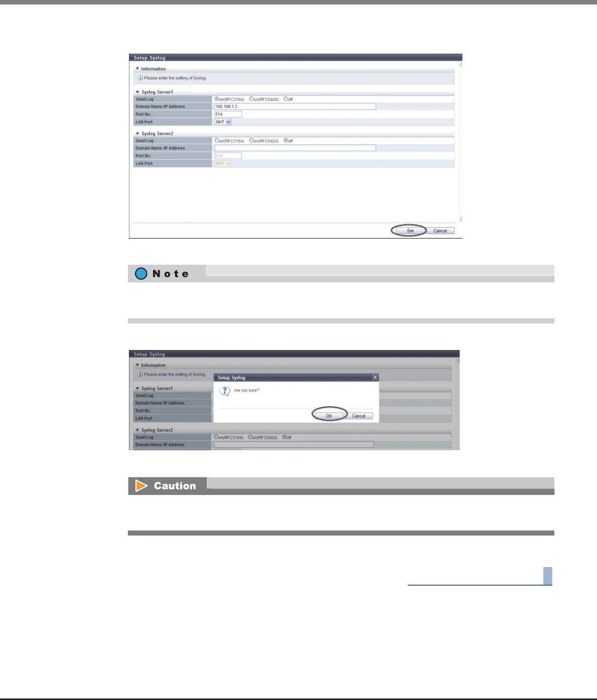
Chapter 11 System Management
11.2 Functions in the Action Area for System
ETERNUS Web GUI User’s Guide
Copyright 2013 FUJITSU LIMITED P2X0-1090-10ENZ0
785
•LAN Port
Select the LAN port from "MNT" or "RMT" that is to be used to send a Syslog.
→A confirmation screen appears.
3Click the [OK] button.
→Setting of the Syslog starts.
4Click the [Done] button to return to the [Network] screen.
End of procedure
Up to two Syslog servers can be configured. When configuring a second Syslog server, specify the
required parameters in "Syslog Server2".
An error screen appears if the specified IP address of the Syslog server conflicts with the internal IP
address of the ETERNUS DX Disk storage system.
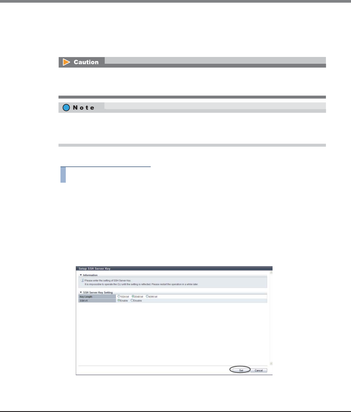
Chapter 11 System Management
11.2 Functions in the Action Area for System
ETERNUS Web GUI User’s Guide
Copyright 2013 FUJITSU LIMITED P2X0-1090-10ENZ0
786
11.2.3.14 Setup SSH Server Key
This function sets up the SSH server key that is used when encrypting communication using Secure SHell
(SSH).
SSH is used when accessing from CLI.
The procedure to set SSH server key is as follows:
Procedure
1Click [Setup SSH Server Key] in [Action].
2Specify the parameters, and click the [Set] button.
•Key Length
Select the SSH server key length from "1024 bit", "2048 bit", and "4096 bit".
The SSH server key length is equivalent to the encryption level. In general, the longer the key is, the
higher the encryption level becomes (difficult to decrypt the encrypted data).
•SSH v1
Select whether to enable or disable the SSH Version 1 connection.
If the SSH Version 1 connection is disabled, only an SSH Version 2 connection is allowed.
→A confirmation screen appears.
After the SSH server key setting has been changed, the information must be updated in the storage system
before accessing from CLI via the SSH connection. Log out from CLI and wait a few minutes before logging in
again.
•The SSH server key is specified in the factory settings (Key Length: 2048 bits).
•Even if the SSH server key setting has been changed, the setting PC, which has logged into CLI via the
Telnet connection, will not be affected.
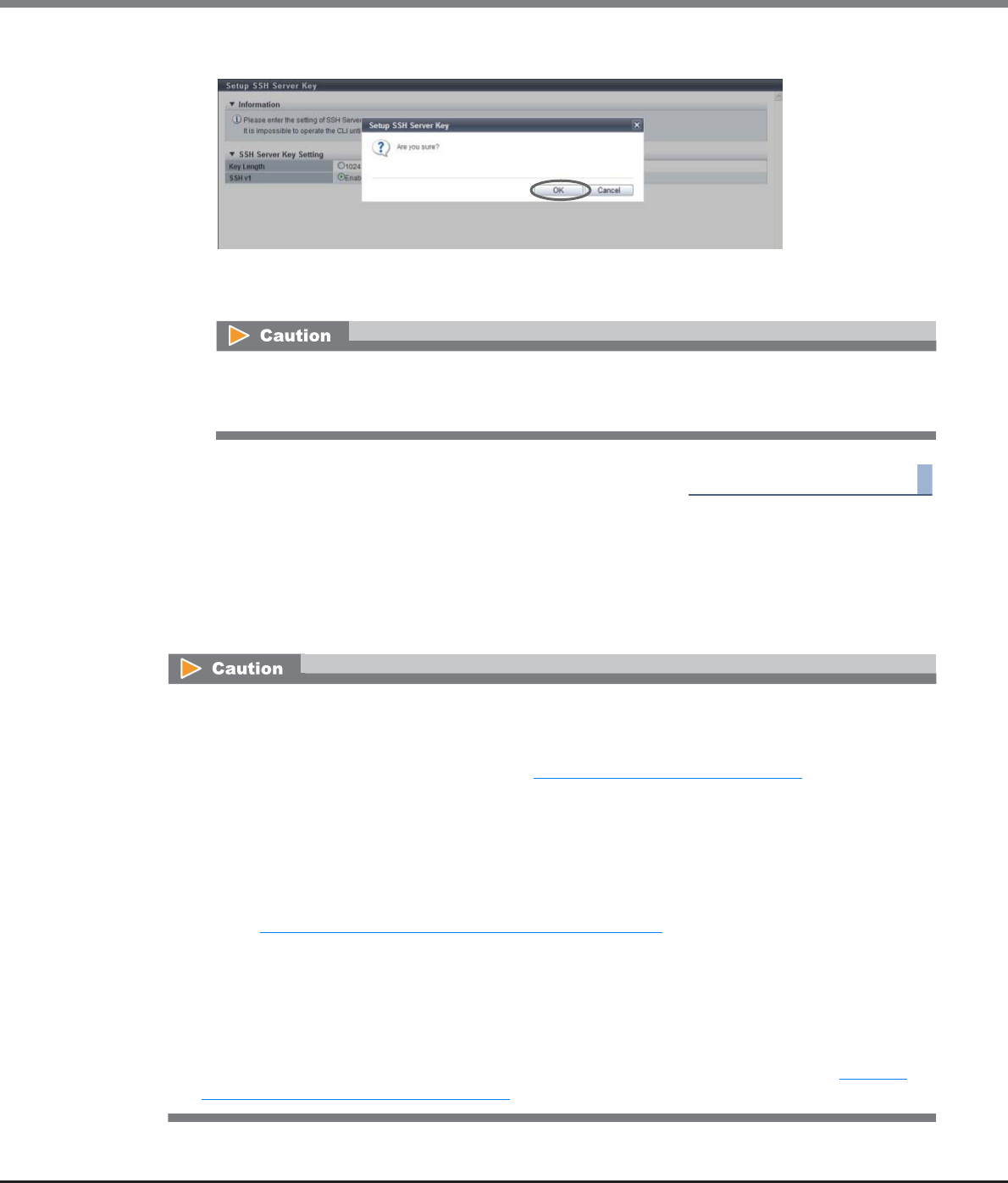
Chapter 11 System Management
11.2 Functions in the Action Area for System
ETERNUS Web GUI User’s Guide
Copyright 2013 FUJITSU LIMITED P2X0-1090-10ENZ0
787
3Click the [OK] button.
→Setting of the SSH server key starts.
4Click the [Done] button to return to the [Network] screen.
End of procedure
11.2.3.15 Create Self-signed SSL Certificate
This function performs settings for creating the SSL server key and the self-signed SSL certificate to be used
when encrypting communication using Secure Socket Layer (SSL).
SSL is used when accessing from GUI via the HTTPS connection.
After setting the SSH server key, the information must be updated in the ETERNUS DX Disk storage
system before being accessed from CLI via the SSH connection. Log out from CLI and wait a few
minutes before logging in again.
•The HTTPS connection from GUI is disabled in the factory settings.
•There are two types of SSL certificate formats: the "self-signed SSL certificate" and the "SSL server
certificate". The "self-signed SSL certificate" is created by using this function and the "SSL server
certificate" is created by using the procedure in "11.2.3.16 Create Key/CSR" (page 790). Register one of
the certificates in the ETERNUS DX Disk storage system when using the HTTPS connection.
•After the SSL server key and the self-signed SSL certificate have been created, the information must be
updated in the storage system before accessing from GUI via the HTTPS connection. Log out from GUI and
wait a few minutes before logging in again.
•The self-signed SSL certificate must be registered on the browser in the setting PC. Until the registration
has been completed, a warning message is displayed when accessing from GUI via the HTTPS connection.
•Refer to "Appendix C Installing the Security Certificate" (page 981) for procedure to install the self-signed
SSL certificate.
•When using the key server for SED authentication key management , a self-signed SSL certificate or an
SSL server certificate is required to establish the communication between the ETERNUS DX Disk storage
system and the key server. These certificates are used as trusted SSL certificates of the ETERNUS DX Disk
storage system. When using the key management server linkage function, create the self-signed SSL cer-
tificate for the ETERNUS DX Disk storage system. The created self-signed SSL certificate is transferred to
the key server from the ETERNUS DX Disk storage system when the key is updated. Refer to "11.2.6.9
Update SED Authentication Key" (page 849) for details.

Chapter 11 System Management
11.2 Functions in the Action Area for System
ETERNUS Web GUI User’s Guide
Copyright 2013 FUJITSU LIMITED P2X0-1090-10ENZ0
788
The procedures to create SSL server key and the self-signed SSL certificate are as follows:
Procedure
1Click [Create SSL Certificate] in [Action].
2Specify the parameters, and click the [Create] button.
•Key Length
Select the SSL server key length from "1024 bit", "2048 bit", and "4096 bit".
The SSL server key length is equivalent to the encryption level. In general, the longer the key is, the
higher the encryption level becomes (difficult to decrypt the encrypted data).
•Common Name
Specify Main IP Address or Fully Qualified Domain Name (FQDN) for ports (MNT and RMT) which are
used to access from GUI via HTTPS connection (required).
There are two methods to specify the main IP address; "IPv4" and "IPv6". The following IPv6
addresses can be used; "link local address", "global address", "unique local address", and "6to4
address". Refer to "Available IPv6 Address" (page 757) for details. When the current setting is
displayed, the IPv6 address is displayed as an abbreviation.
The following input conditions apply:
-Main IP Address
•For IPv4 address
-xxx.xxx.xxx.xxx
xxx: 1 - 255 for the top field (decimal)
xxx: 0 - 255 for other fields (decimal)
-Class must be A, B, or C.
•For IPv6 address
-xxxx:xxxx:xxxx:xxxx:xxxx:xxxx:xxxx:xxxx
xxxx: 0 - ffff (FFFF) (hexadecimal, alphanumeric characters)
Refer to "IPv6 Address Notation" (page 378) for details.
-Fully Qualified Domain Name (FQDN)
•Alphanumeric characters (A - Z, 0 - 9)
•Symbols (except "<", ">", "?", "!", "@", "#", "$", "%", "?", "\", "?", "&", and space)
•Up to 63 characters
•Subject Alt Name
Specify Main IP Address or FQDN for ports (MNT and RMT) which are used to access from GUI via
HTTPS connection.
There are two methods to specify the main IP address; "IPv4" and "IPv6". The following IPv6
addresses can be used; "link local address", "global address", "unique local address", and "6to4
address". Refer to "Available IPv6 Address" (page 757) for details. When the current setting is
displayed, the IPv6 address is displayed as an abbreviation.
-Main IP Address
The following input conditions apply:
•For IPv4 address
-xxx.xxx.xxx.xxx
xxx: 1 - 255 for the top field (decimal)
xxx: 0 - 255 for other fields (decimal)
-Class must be A, B, or C.
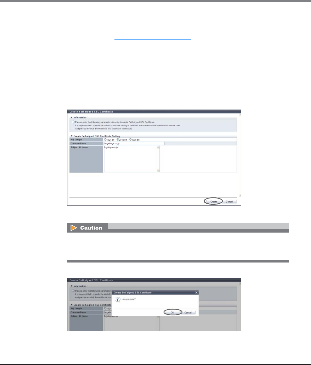
Chapter 11 System Management
11.2 Functions in the Action Area for System
ETERNUS Web GUI User’s Guide
Copyright 2013 FUJITSU LIMITED P2X0-1090-10ENZ0
789
•For IPv6 address
-xxxx:xxxx:xxxx:xxxx:xxxx:xxxx:xxxx:xxxx
xxxx: 0 - ffff (FFFF) (hexadecimal, alphanumeric characters)
Refer to "IPv6 Address Notation" (page 378) for details.
-Fully Qualified Domain Name (FQDN)
The following input conditions apply:
•Alphanumeric characters
•Symbols (except "<", ">", "?", "!", "@", "#", "$", "%", "?", "\", "?", "&", and space)
•Up to 511 characters (A linefeed code is also counted as one character.)
Multiple IP addresses and FQDNs can be specified. Start a new line for each IP address or FQDN
when specifying multiple IP addresses and FQDNs.
If IPv4 addresses, IPv6 addresses, and FQDNs are specified together, up to 511 characters can be
specified, including symbols (":" (colon), "." (period), and linefeed code).
→A confirmation screen appears.
3Click the [OK] button.
→Creation of the self-signed SSL certificate starts.
An error screen appears in the following conditions:
•When items do not satisfy the input conditions
•When all of the required items are not input
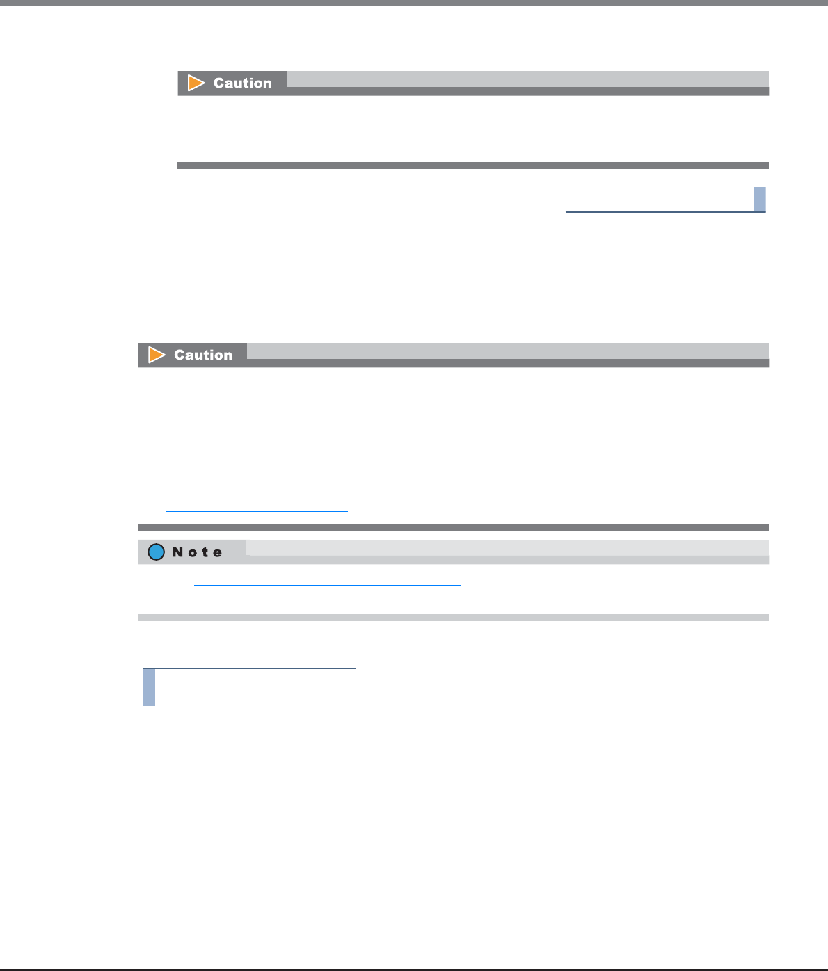
Chapter 11 System Management
11.2 Functions in the Action Area for System
ETERNUS Web GUI User’s Guide
Copyright 2013 FUJITSU LIMITED P2X0-1090-10ENZ0
790
4Click the [Done] button to return to the [Network] screen.
End of procedure
11.2.3.16 Create Key/CSR
This function performs settings for creating and exporting the SSL server key and the Certificate Signing
Request (CSR) which are used to acquire a SSL server certificate.
CSR is a certificate application form to submit to the certification authority.
The procedure to create a CSR is as follows:
Procedure
1Click [Create Key/CSR] in [Action].
2Specify the parameters, and click the [Create] button.
•Key Length
Select the SSL server key length from "1024 bit", "2048 bit", and "4096 bit".
The SSL server key length is equivalent to the encryption level. In general, the longer the key is, the
higher the encryption level becomes (difficult to decrypt the encrypted data).
After registering the SSL server key or SSL server certificate, the information must be updated in the
ETERNUS DX Disk storage system before being accessed from GUI via the HTTPS connection. Log out
from GUI and wait a few minutes before logging in again.
•Check the necessary items for authentication beforehand.
•When using the key server for SED authentication key management , a self-signed SSL certificate or an
SSL server certificate is required to establish the communication between the ETERNUS DX Disk storage
system and the key server. These certificates are used as trusted SSL certificates of the ETERNUS DX Disk
storage system. When using the key management server linkage function, register the SSL server certifi-
cate for the ETERNUS DX Disk storage system. The registered SSL server certificate is transferred to the key
server from the ETERNUS DX Disk storage system when the key is updated. Refer to "11.2.6.9 Update SED
Authentication Key" (page 849) for details.
Refer to "11.2.3.17 Register SSL Certificate" (page 795) for detailed procedure to register the SSL server key
and SSL server certificate.

Chapter 11 System Management
11.2 Functions in the Action Area for System
ETERNUS Web GUI User’s Guide
Copyright 2013 FUJITSU LIMITED P2X0-1090-10ENZ0
791
•Country Name
Input the country code which conforms to ISO-3166 A2 (required).
[Example] Japan: JP
The following input conditions apply:
-Alphabetic characters (upper case) (A - Z)
-Two fixed letters
•State or Province Name
Input the prefecture where the organization is located (required).
[Example] Kanagawa
The following input conditions apply:
-Alphabetic characters (A - Z, a - z)
-Spaces
-Up to 63 characters
•Locality Name
Input the municipality where the organization is located (required).
[Example] Kawasaki
The following input conditions apply:
-Alphabetic characters (A - Z, a - z)
-Spaces
-Up to 63 characters
•Organization Name
Input the organization name (required).
[Example] XXX LIMITED
The following input conditions apply:
-Alphabetic characters (A - Z, a - z)
-Numeric characters (0 - 9)
-Spaces
-Up to 63 characters
•Organization Unit Name
Input the department/division name of the organization (required).
[Example] YYYYY Division
The following input conditions apply:
-Alphabetic characters (A - Z, a - z)
-Numeric characters (0 - 9)
-Spaces
-Up to 63 characters
•Common Name
Specify Main IP Address or FQDN for ports (MNT and RMT) which are used to access from GUI via
HTTPS connection.
There are two methods to specify the main IP address; "IPv4" and "IPv6". The following IPv6
addresses can be used; "link local address", "global address", "unique local address", and "6to4
address". Refer to "Available IPv6 Address" (page 757) for details. When the current setting is
displayed, the IPv6 address is displayed as an abbreviation.

Chapter 11 System Management
11.2 Functions in the Action Area for System
ETERNUS Web GUI User’s Guide
Copyright 2013 FUJITSU LIMITED P2X0-1090-10ENZ0
792
The following input conditions apply:
-Main IP Address
•For IPv4 address
-xxx.xxx.xxx.xxx
xxx: 1 - 255 for the top field (decimal)
xxx: 0 - 255 for other fields (decimal)
-Class must be A, B, or C.
•For IPv6 address
-xxxx:xxxx:xxxx:xxxx:xxxx:xxxx:xxxx:xxxx
xxxx: 0 - ffff (FFFF) (hexadecimal, alphanumeric characters)
Refer to "IPv6 Address Notation" (page 378) for details.
-Fully Qualified Domain Name (FQDN)
•Alphanumeric characters (A - Z, 0 - 9)
•Symbols (except "<", ">", "?", "!", "@", "#", "$", "%", "?", "\", "?", "&", and space)
•Up to 63 characters
•Subject Alt Name
Specify Main IP Address or FQDN for ports (MNT and RMT) which are used to access from GUI via
HTTPS connection.
There are two methods to specify the main IP address; "IPv4" and "IPv6". The following IPv6
addresses can be used; "link local address", "global address", "unique local address", and "6to4
address". Refer to "Available IPv6 Address" (page 757) for details. When the current setting is
displayed, the IPv6 address is displayed as an abbreviation.
-Main IP Address
The following input conditions apply:
•For IPv4 address
-xxx.xxx.xxx.xxx
xxx: 1 - 255 for the top field (decimal)
xxx: 0 - 255 for other fields (decimal)
-Class must be A, B, or C.
•For IPv6 address
-xxxx:xxxx:xxxx:xxxx:xxxx:xxxx:xxxx:xxxx
xxxx: 0 - ffff (FFFF) (hexadecimal, alphanumeric characters)
Refer to "IPv6 Address Notation" (page 378) for details.
-Fully Qualified Domain Name (FQDN)
The following input conditions apply:
•Alphanumeric characters
•Symbols (except "<", ">", "?", "!", "@", "#", "$", "%", "?", "\", "?", "&", and space)
•Up to 511 characters (A linefeed code is also counted as one character.)
Multiple IP addresses and FQDNs can be specified. Start a new line for each IP address or FQDN
when specifying multiple IP addresses and FQDNs.
If IPv4 addresses, IPv6 addresses, and FQDNs are specified together, up to 511 characters can be
specified, including symbols (":" (colon), "." (period), and linefeed code).
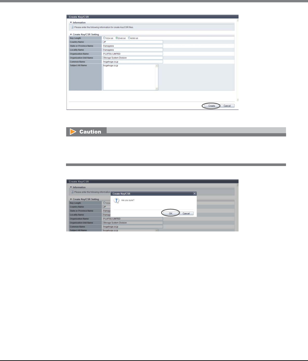
Chapter 11 System Management
11.2 Functions in the Action Area for System
ETERNUS Web GUI User’s Guide
Copyright 2013 FUJITSU LIMITED P2X0-1090-10ENZ0
793
→A confirmation screen appears.
3Click the [OK] button.
→The creation of the CSR starts. When the creation of the CSR is complete, the screen for downloading
the file is displayed.
An error screen appears in the following conditions:
•When items do not satisfy the input conditions
•When all of the required items are not input
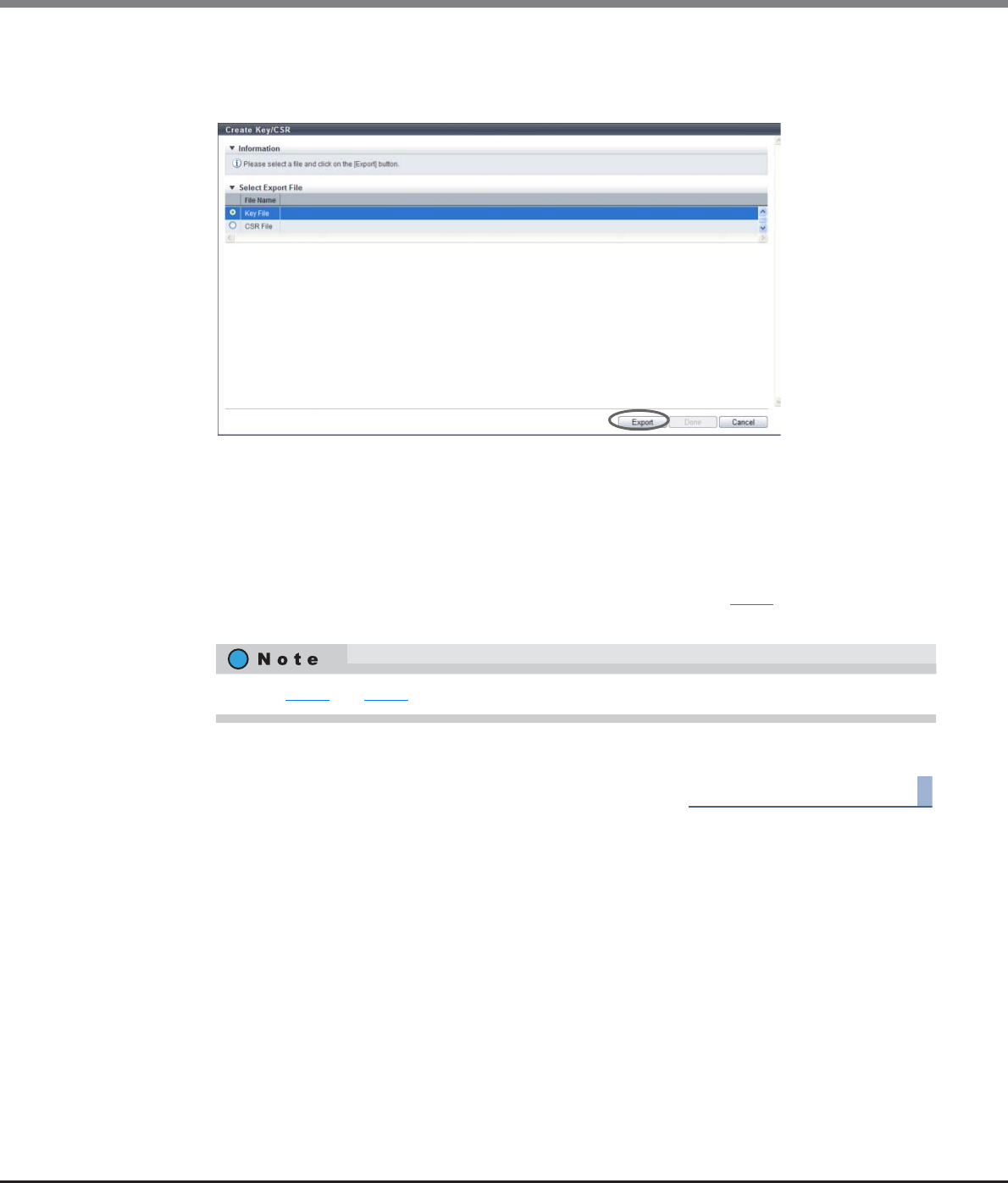
Chapter 11 System Management
11.2 Functions in the Action Area for System
ETERNUS Web GUI User’s Guide
Copyright 2013 FUJITSU LIMITED P2X0-1090-10ENZ0
794
4Select the file that is to be downloaded, and click the [Export] button.
•File Name
Select the target file to download from "Key File" or "CSR File".
→A dialog box to download the file appears.
5Save both the key file and the CSR file.
The default key file name is "ServerKey_serial number for the ETERNUS DX Disk storage system_YYYY-
MM-DD_hh-mm-ss.txt".
The default CSR file name is "ServerCsr_serial number for the ETERNUS DX Disk storage system_YYYY-
MM-DD_hh-mm-ss.txt".
(YYYY-MM-DD_hh-mm-ss: the date and time when the download screen (Step 4) is displayed.)
→The files are saved.
6Click the [Done] button to return to the [Network] screen.
End of procedure
Perform Step 4 and Step 5 for each server key file and CSR file that is to exported.

Chapter 11 System Management
11.2 Functions in the Action Area for System
ETERNUS Web GUI User’s Guide
Copyright 2013 FUJITSU LIMITED P2X0-1090-10ENZ0
795
11.2.3.17 Register SSL Certificate
This function registers the SSL server key, which was downloaded by using the [Create Key/CSR] function, and
the SSL server certificate which was acquired from the certification authority.
The procedures to create SSL server key and the SSL server certificate are as follows:
Procedure
1Click [Register SSL Certificate] in [Action].
•The HTTPS connection from GUI is disabled in the factory settings.
•There are two types of SSL certificate formats: the "SSL server certificate" and the "self-signed SSL
certificate". The "SSL server certificate" is registered by using this function and the "self-signed SSL
certificate" is created by using the procedure in "11.2.3.15 Create Self-signed SSL Certificate" (page 787).
Register one of the certificates in the ETERNUS DX Disk storage system when using the HTTPS connection.
•To obtain the "SSL server certificate", the Certificate Signing Request (CSR) that is downloaded using the
procedure in "11.2.3.16 Create Key/CSR" (page 790) must be send to the certification authority.
•Register the SSL server key and the SSL server certificate as a pair in the ETERNUS DX Disk storage system.
If the combination of the SSL server key and the SSL server certificate is incorrect, accessing from GUI via
the HTTPS connection is not possible.
•After the SSL server key and the SSL server certificate have been created, the information must be
updated in the storage system before accessing from GUI via the HTTPS connection. Log out from GUI and
wait a few minutes before logging in again.
•When the SSL server key and the SSL server certificate have been registered in the ETERNUS DX Disk
storage system, the setting PC, which has accessed from GUI via the HTTPS connection, will be forced to
disconnect.
The SSL server key downloaded using the procedure in "11.2.3.16 Create Key/CSR" (page 790) and the
"SSL server certificate" acquired from the certification authority are required before this action.
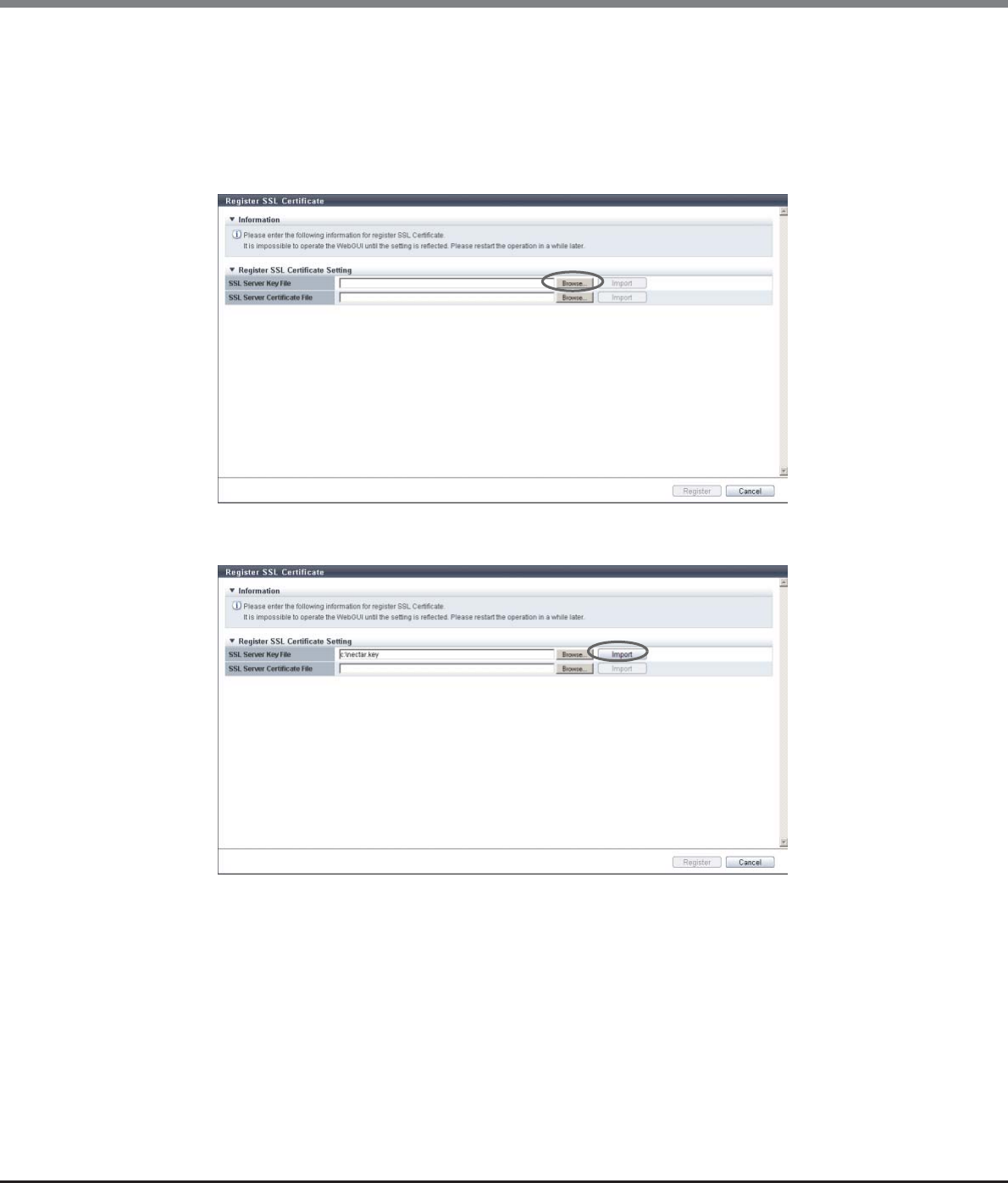
Chapter 11 System Management
11.2 Functions in the Action Area for System
ETERNUS Web GUI User’s Guide
Copyright 2013 FUJITSU LIMITED P2X0-1090-10ENZ0
796
2Click the [Browse...] button to specify the path to the "SSL Server Key File".
•SSL Server Key File
Click the [Browse...] button to specify the SSL server key file, or directly input the path to the SSL
server key file.
Click the [Import] button to import the SSL server key file to GUI. When importing has been
completed, "Imported" is displayed.
3Click the [Import] button.
→"Imported" is displayed.

Chapter 11 System Management
11.2 Functions in the Action Area for System
ETERNUS Web GUI User’s Guide
Copyright 2013 FUJITSU LIMITED P2X0-1090-10ENZ0
797
4Click the [Browse...] button to specify the path to the "SSL Server Certificate File".
•SSL Server Certificate File
Click the [Browse...] button to specify the SSL server certificate file, or directly input the path to the
SSL server certificate file.
Click the [Import] button to import the SSL server certificate file to GUI. When importing has been
completed, "Imported" is displayed.
5Click the [Import] button.
→"Imported" is displayed.
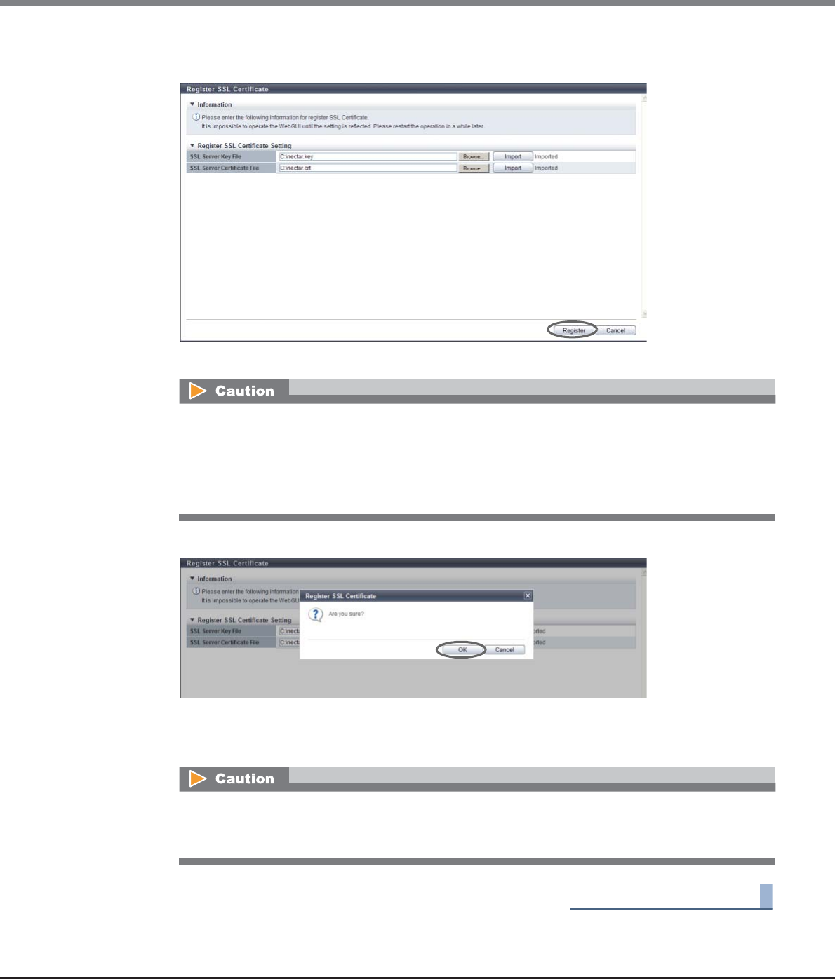
Chapter 11 System Management
11.2 Functions in the Action Area for System
ETERNUS Web GUI User’s Guide
Copyright 2013 FUJITSU LIMITED P2X0-1090-10ENZ0
798
6Confirm that the "SSL server key file" and the "SSL server certificate file" have been imported,
and click the [Register] button.
→A confirmation screen appears.
7Click the [OK] button.
→ The registration of the SSL server key and SSL server certificate starts.
8Click the [Done] button to return to the [Network] screen.
End of procedure
An error screen appears in the following conditions:
•When the imported file was not the "SSL server key file"
•When the imported file was not the "SSL server certificate file"
•When the imported "SSL server certificate file" was not the certificate which corresponds to the SSL
server key
After registering the SSL server key or SSL server certificate, the information must be updated in the
ETERNUS DX Disk storage system before being accessed from GUI via the HTTPS connection. Log out
from GUI and wait a few minutes before logging in again.
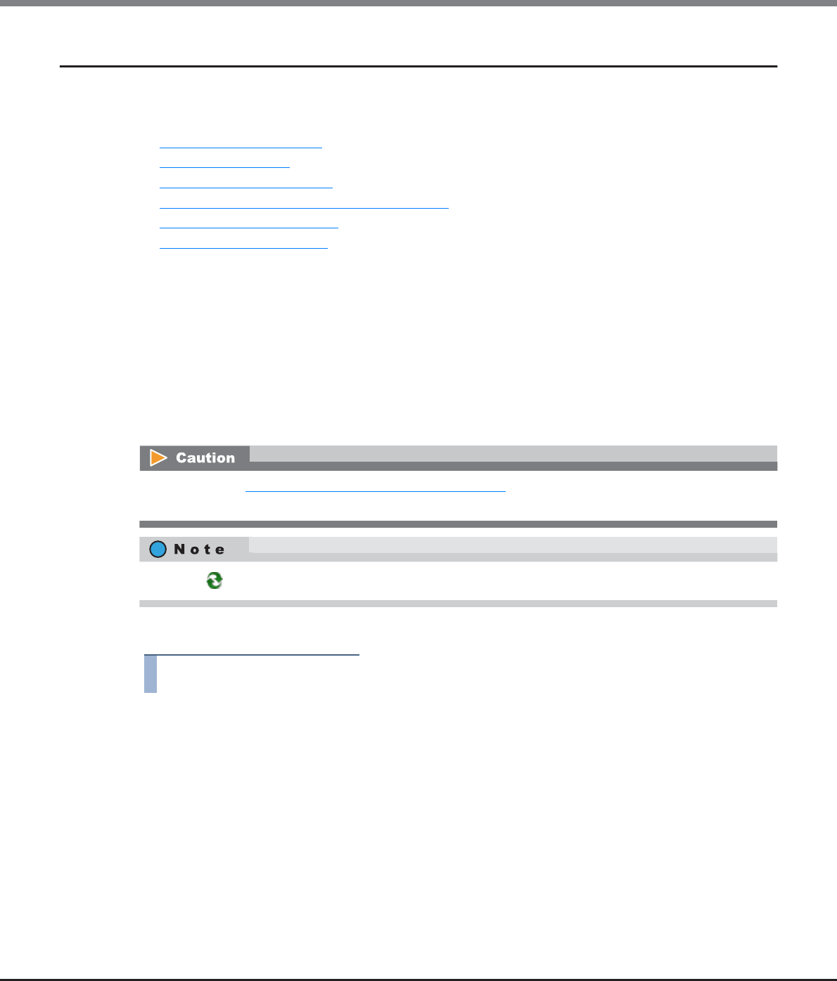
Chapter 11 System Management
11.2 Functions in the Action Area for System
ETERNUS Web GUI User’s Guide
Copyright 2013 FUJITSU LIMITED P2X0-1090-10ENZ0
799
11.2.4 Remote Support (REMCS) for Regions other than EMEA
This section describes remote support management (by REMCS) for regions other than EMEA.
Remote support management (by REMCS) provides the following functions:
•Display Communication Log
•Setup Remote Support
•Update Customer Information
•Update Communication Environment Information
•Setup Log Sending Parameters
•Stop/Restart Remote Support
11.2.4.1 Display Communication Log
This function displays the communication log between the ETERNUS DX Disk storage system and REMCS
center using the Remote Support function.
When the Remote Support function cannot be operated properly, for example, cannot be connected to the
REMCS center, use this log to identify the cause of the problem.
The communication log includes requests from the ETERNUS DX Disk storage system to the server, and
responses from the server to the ETERNUS DX Disk storage system. Only the communication log of the last
executed event is displayed.
The procedure to display communication log is as follows:
Procedure
1Click [Display Communication Log] in [Action].
If the settings in "11.2.4.2 Setup Remote Support" (page 800) has not been completed in advance, this
function cannot be used.
Click the [ ] icon or the [Refresh] button to update to the latest screen.
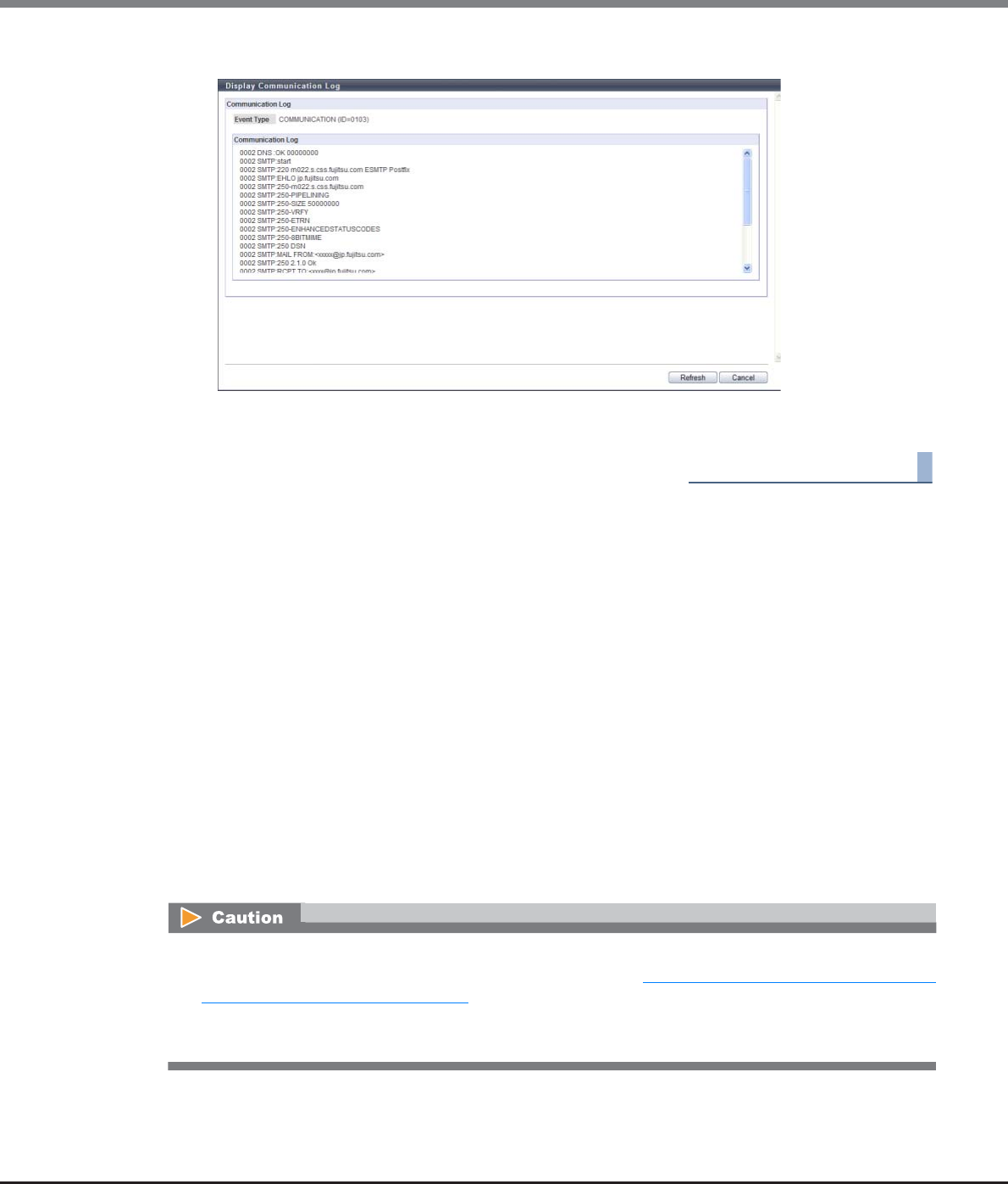
Chapter 11 System Management
11.2 Functions in the Action Area for System
ETERNUS Web GUI User’s Guide
Copyright 2013 FUJITSU LIMITED P2X0-1090-10ENZ0
800
2Check the displayed "Event Type" and the "Communication Log".
3Click the [Cancel] button to return to the screen when starting this function in Step 1.
End of procedure
11.2.4.2 Setup Remote Support
This function registers the customer information and communication environment information required to
receive Remote Support from the REMote Customer Support system (REMCS) center.
"REMCS" is a unique remote maintenance system offered by Fujitsu. REMCS provides maintenance functions as
follows:
•Failure Notice
This function reports various failures that occur in the ETERNUS DX Disk storage system to the REMCS
center. The maintenance engineer is notified of a failure immediately.
•Information Transfer
This function sends information such as logs and configuration information to be used when checking a
failure. It reduces the time required to collect information that is to be transferred to the REMCS center.
•Firmware Download
The latest firmware in the REMCS center is automatically registered in the ETERNUS DX Disk storage system.
This function ensures that the latest firmware is registered in the ETERNUS DX Disk storage system, and
prevents known errors from occurring. Firmware can also be registered manually.
•REMCS cannot be used when the AIS Connect function is being used. Disable the AIS Connect function,
and then set the remote support (REMCS) parameters. Refer to "11.1.4 Remote Support (AIS Connect) for
Regions other than Japan" (page 719) for details (for regions other than Japan).
•Use the IPv4 addresses for the IP addresses of the proxy server, the SMTP server, the POP server, and the
HTTP server. IPv6 addresses cannot be used.
Chapter 11 System Management
11.2 Functions in the Action Area for System
ETERNUS Web GUI User’s Guide
Copyright 2013 FUJITSU LIMITED P2X0-1090-10ENZ0
801
The procedure to specify the Remote Support settings is as follows:
Procedure
1Click [Setup Remote Support] in [Action].
2Specify the parameters, and click the [Set] button.
●Information File
•Customer Information File
Import the "customer information file", which was created using the REMCS ESAT, to the ETERNUS DX
Disk storage system.
Click the [Browse...] button to specify the "customer information file", or directly input the path to
the "customer information file".
•Customer Information File
Import the "communication environment information file", which was created using the REMCS
ESAT, to the ETERNUS DX Disk storage system.
Click the [Browse...] button to specify the communication environment information file, or directly
input the path to the communication environment information file.
●Customer Information
•When changing the registered information, use the procedure in "11.2.4.3 Update Customer Information"
(page 805) and the "11.2.4.4 Update Communication Environment Information" (page 808).
•The information files (customer information file and communication environment information file)
created by using REMCS Environment Setup Assist Tool (REMCS ESAT) can be imported to the storage
system, to simplify the input operation required to be set for each storage system.
-Only the common device information can be imported from the information file. The individual device
information is required to be specified after importing the information file.
-Just importing the information file will not automatically update the information in the ETERNUS DX
Disk storage system. After specifying all the necessary information, click the [Set] button.
When importing Remote Support settings to the ETERNUS DX Disk storage system all at once, click
the [Browse...] button to specify the location where the settings file has been stored, and click the
[Import] button.
Refer to Step 2 in the "11.2.4.3 Update Customer Information" (page 805) for setting items.

Chapter 11 System Management
11.2 Functions in the Action Area for System
ETERNUS Web GUI User’s Guide
Copyright 2013 FUJITSU LIMITED P2X0-1090-10ENZ0
802
●Communication Environment Information
●Detailed Configuration Information
•Data Transmission Method
Select whether to "Split" or "Do not Split" into the specified size.
Select "Split large E-mail into multiple E-mails" or "Split large data into multiple E-mails", and
specify the segment size, when segmenting outgoing mail.
If the mail server does not allow the sending of segmented mail using "Split large E-mail into
multiple E-mails", select "Split large data into multiple E-mails" or "Do not Split".
-Split
Outgoing mail is segmented. There are two methods for mail message fragmentation: "Split
large E-mail into multiple E-mails" and "Split large data into multiple E-mails".
•Split large E-mail into multiple E-mails
Outgoing mail is segmented into the specified size (64 - 6400KB).
•Split large data into multiple E-mails
The file attached to the E-mail is segmented into several pieces, turned into one E-mail in
the specified size (64 - 512KB), and sent in several transmissions.
-Do not Split
The message is sent as one E-mail without being segmented.
•Specify Storage System Name for HELO/EHLO Announcement when Sending Mail
Select "Specify" or "Do not specify" for the ETERNUS DX Disk storage system name for HELO/EHLO
announcement when sending mail.
When "Specify" is selected, enter the domain.
The following input condition applies:
-Up to 63 alphanumeric characters and symbols (except space)
The domain of the HELO/EHLO Announcement must be specified in the mail protocol.
If "Do not specify" has been selected, E-mails are sent using the strings after the "@" of the sender
mail addresses as domains.
If the mail server does not allow using the section after the "@" of the sender mail address as the
domain, select "Specify" and input the appropriate domain.
●Result notification information
•Administrator
Select "Notification" or "Not Notification" for the customer manager of the setting confirmation
result at the REMCS center.
Select "Notification" for the "Administrator" or the "Connection check operator" and confirm the
result.
Refer to Step 2 in the "11.2.4.4 Update Communication Environment Information" (page 808) for
setting items.
Chapter 11 System Management
11.2 Functions in the Action Area for System
ETERNUS Web GUI User’s Guide
Copyright 2013 FUJITSU LIMITED P2X0-1090-10ENZ0
803
•Connection check operator
Select "Notification (Standard E-Mail format)", "Notification (Simple E-Mail format for cell phone)"
or "Not Notification" for the connection check operator of the setting confirmation result at the
REMCS center.
If notifying, input the "Connection check operator E-Mail Address".
Specify the "Connection check operator" if there is another person who needs to be notified of the
setting confirmation result, other than the administrator.
•Connection check operator E-Mail Address
If notifying the connection check operator of the setting confirmation result at the REMCS center,
input the E-mail address.
The following input condition applies:
-Up to 60 alphanumeric characters and symbols (except space)
●Time Information
•SMTP Response Timeout (sec.)
Input the timeout limit when using SMTP connection.
The following input condition applies:
-Numeric characters ("1" - "3600")
•SMTP Retry Count
Input the retry number of SMTP.
The following input condition applies:
-Numeric characters ("1" - "60")
•SMTP Retry Interval (sec.)
Input the intervals for retrying SMTP.
The following input condition applies:
-Numeric characters ("1" - "3600")
•HTTP Timeout (sec.)
Input the timeout limit when using HTTP connection.
The following input condition applies:
-Numeric characters ("1" - "3600")
•HTTP Retry Count
Input the retry number of HTTP.
The following input condition applies:
-Numeric characters ("1" - "60")
•HTTP Retry Interval (sec.)
Input the intervals for retrying HTTP.
The following input condition applies:
-Numeric characters ("1" - "3600")
•Queue Time before Sending Mails (msec.) (only when POP Before SMTP authentication is enabled)
Input the waiting time for sending mail.
The following input condition applies:
-Numeric characters ("1" - "3600")
The timer parameter settings do not normally require modification.
If changing the default value, select the "Change following Timing Parameter items" checkbox.
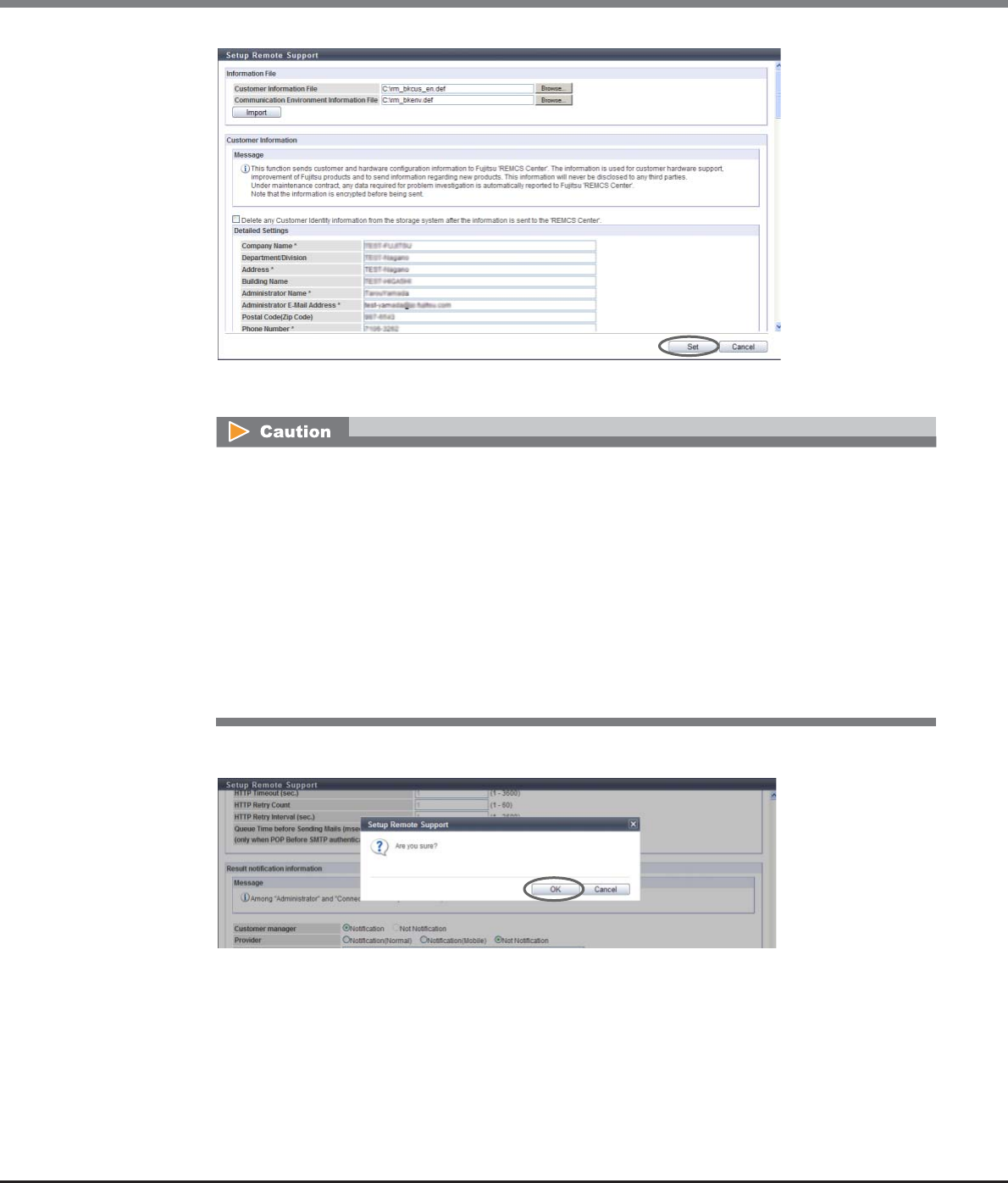
Chapter 11 System Management
11.2 Functions in the Action Area for System
ETERNUS Web GUI User’s Guide
Copyright 2013 FUJITSU LIMITED P2X0-1090-10ENZ0
804
→A confirmation screen appears.
3Click the [OK] button.
→Setting of the remote support starts.
An error screen appears in the following conditions:
•When the [Set] button is clicked without setting the required item (items with "*")
•When the [Set] button is clicked while invalid values had been specified
•When the selected customer information file is not correct
•When file format of the selected customer information file is not correct
•When "MNT" is specified for the "LAN Port used for Remote Support" and when the IP Address of the
Proxy server/SMTP server/POP server is the same as the broadcast address of the MNT port
•When "RMT" is specified for the "LAN Port used for Remote Support" and the IP Address of the Proxy
server/SMTP server/POP server is the same as the broadcast address of the RMT port
•When the IP address of the Proxy server/SMTP server/POP server is the same as the local host
address
Chapter 11 System Management
11.2 Functions in the Action Area for System
ETERNUS Web GUI User’s Guide
Copyright 2013 FUJITSU LIMITED P2X0-1090-10ENZ0
805
4Click the [Done] button to return to the screen when starting this function in Step 1.
End of procedure
11.2.4.3 Update Customer Information
This function updates the customer information that is registered for the REMCS center.
The procedure to update customer information is as follows:
Procedure
1Click [Update Customer Info] in [Action].
2Set the customer information again, and click the [Set] button.
●Information File
•Customer Information File
Import the "Customer Information File", which was created using the REMCS ESAT, to the ETERNUS
DX Disk storage system.
Click the [Browse...] button to specify the "Customer Information file", or directly input the path to
the "Customer Information File".
After completing the setting, the REMCS center sends the setting confirmation result to the
"Administrator E-Mail Address" or the "Connection check operator E-Mail Address". Make sure to
confirm the setting results.
•If the settings in "11.2.4.2 Setup Remote Support" (page 800) has not been completed in advance, this
function cannot be used.
•When Remote Support is "Stopped", customer information cannot be updated.
•Customer information saved in the ETERNUS DX Disk storage system (*1) can be deleted after
transmitting the information to the REMCS center. Select the "Delete any Customer Identity information
from the storage system after the information is sent to the 'REMCS Center'. " checkbox to delete the
information. Note that selecting the checkbox requires entering customer information whenever
updating the information.
*1: Customer Identity information means "Administrator Name", "Administrator E-Mail Address ", "Phone Number",
"FAX Number", and "Field Engineer E-Mail Address".
•The Remote Support setting information file (customer information file) created by using REMCS
Environment Setup Assist Tool (REMCS ESAT) can be imported to the ETERNUS DX Disk storage system, to
simplify the input operation required to be set for each storage system.
Chapter 11 System Management
11.2 Functions in the Action Area for System
ETERNUS Web GUI User’s Guide
Copyright 2013 FUJITSU LIMITED P2X0-1090-10ENZ0
806
●Customer Information
•Checkbox
If the "Delete any Customer Identity information from the storage system after the information is
sent to the 'REMCS Center'." checkbox is selected, customer information saved on the ETERNUS DX
disk storage system is deleted after transmitting the information to the REMCS center.
●Detailed Settings ("*" indicates the required setting items)
•Company Name *
Input the company name that owns the ETERNUS DX Disk storage system. The following input
condition applies:
-Up to 60 alphanumeric characters and symbols
•Department/Division
Input the department or division that owns the ETERNUS DX Disk storage system.
The following input condition applies:
-Up to 40 alphanumeric characters and symbols
•Address*
Input the address of the company that owns the ETERNUS DX Disk storage system.
The following input condition applies:
-Up to 60 alphanumeric characters and symbols
•Building Name
Input the building name where the company that owns the ETERNUS DX Disk storage.
The following input condition applies:
-Up to 40 alphanumeric characters and symbols
•Administrator Name*
Input the system administrator's name that manages the ETERNUS DX Disk storage system.
The following input condition applies:
-Up to 40 alphanumeric characters and symbols
•Administrator E-Mail Address*
Input the E-mail address of the system administrator who manages the ETERNUS DX Disk storage
system.
The following input condition applies:
-Up to 60 alphanumeric characters and symbols (except space)
When importing customer information to the ETERNUS DX Disk storage system all at once, click the
[Browse...] button to specify the location where the customer information file has been stored,
and click the [Import] button.
If the [Import] button is clicked in the following conditions, an error screen appears.
•When the selected customer information file is not correct
•When file format of the selected customer information file is not correct

Chapter 11 System Management
11.2 Functions in the Action Area for System
ETERNUS Web GUI User’s Guide
Copyright 2013 FUJITSU LIMITED P2X0-1090-10ENZ0
807
•Postal Code (Zip Code)
Input the postal code for the company that owns ETERNUS DX Disk storage system.
The following input condition applies:
-Up to 10 alphanumeric characters and symbols
•Phone Number*
Input the phone number for the company that owns the ETERNUS DX Disk storage system.
The following input condition applies:
-Up to 20 numeric characters and symbols (except space)
•FAX Number
Input the FAX number for the company that owns the ETERNUS DX Disk storage system.
The following input condition applies:
-Up to 20 numeric characters and symbols (except space)
•Storage System Unique Name
Input the nickname for the ETERNUS DX Disk storage system.
The following input condition applies:
-Up to 32 alphanumeric characters and symbols (except space)
•Country of Installation (ISO3166 A2)* Example: JP, US, DE, etc.
Input the country code for the country where the ETERNUS DX Disk storage system is located.
(required)
The following input conditions apply:
-Two fixed letters
-Capital letters or "99"
●Installation Location
•Address
Input the address where the ETERNUS DX Disk storage system is located.
The following input condition applies:
-Up to 60 alphanumeric characters and symbols
•Building Name
Input the building name where the ETERNUS DX Disk storage system is located.
The following input condition applies:
-Up to 40 alphanumeric characters and symbols
●Information filled by Field Engineers
•Installation Date
Input the date when the ETERNUS DX Disk storage system is installed.
-YYYY-MM (YYYY: Year (AD), MM: Month (01 - 12))
•Field Engineer E-Mail Address
Input the E-mail address for the field engineer who installed the ETERNUS DX Disk storage system.
The following input condition applies:
-Up to 60 alphanumeric characters and symbols (except space)
•Customer Code
Input the customer code.
The following input condition applies:
-Up to 8 alphanumeric characters and symbols (except space)
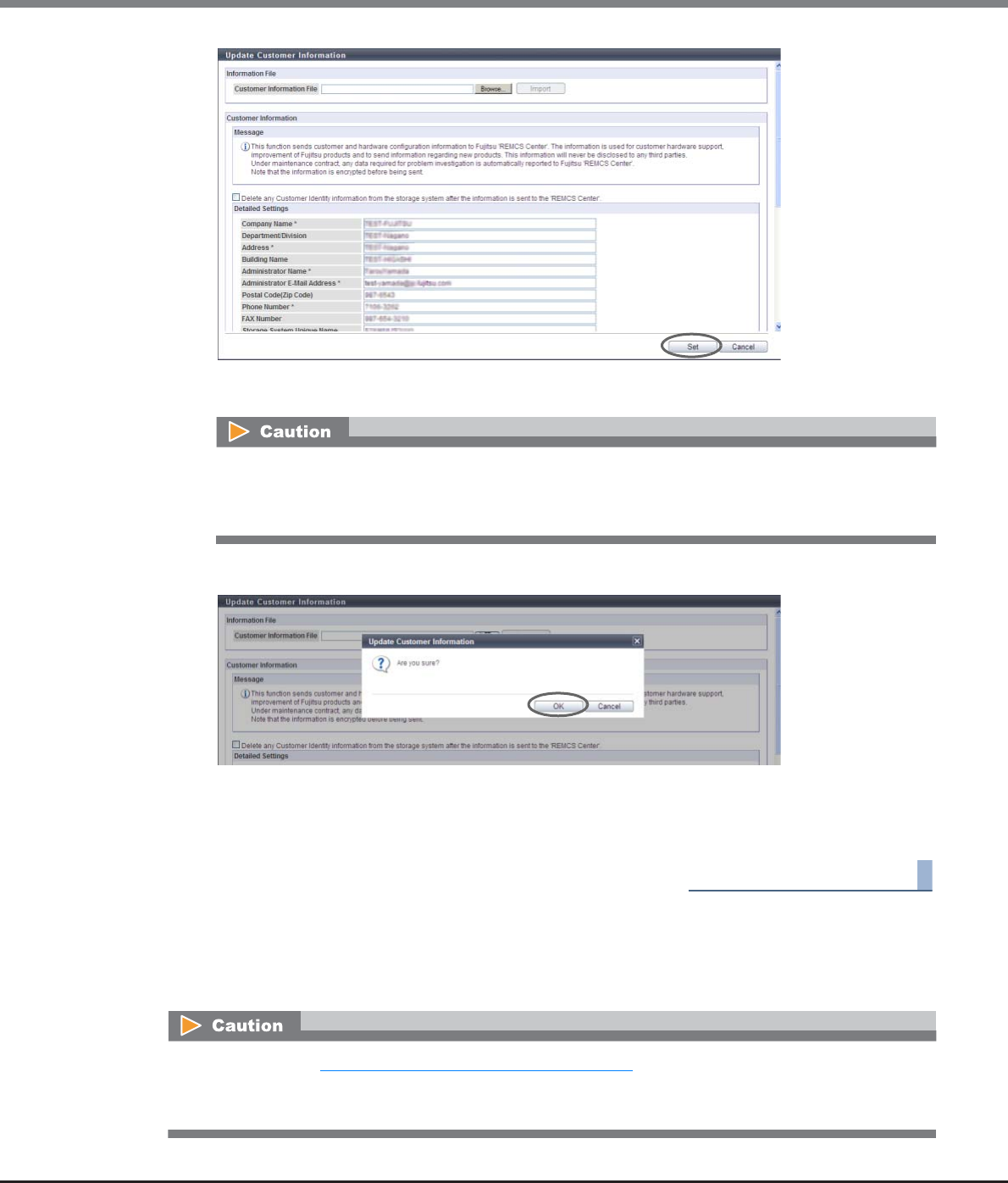
Chapter 11 System Management
11.2 Functions in the Action Area for System
ETERNUS Web GUI User’s Guide
Copyright 2013 FUJITSU LIMITED P2X0-1090-10ENZ0
808
→A confirmation screen appears.
3Click the [OK] button.
→The customer information is updated.
4Click the [Done] button to return to the screen when starting this function in Step 1.
End of procedure
11.2.4.4 Update Communication Environment Information
This function updates the customer information that is registered for the REMCS center.
If the [Set] button is clicked in the following conditions, an error screen appears.
•When required items (items with "*") are not specified
•When wrong values are entered
•If the settings in "11.2.4.2 Setup Remote Support" (page 800) has not been completed in advance, this
function cannot be used.
•When Remote Support is "Stopped", communication environment information cannot be updated.
Chapter 11 System Management
11.2 Functions in the Action Area for System
ETERNUS Web GUI User’s Guide
Copyright 2013 FUJITSU LIMITED P2X0-1090-10ENZ0
809
The procedure to update communication environment information is as follows:
Procedure
1Click [Update Connection Info] in [Action].
2Specify the parameters, and click the [Set] button.
●Information File
•Communication Environment Information File
Import the "communication environment information file", which was created using the REMCS
ESAT, to the ETERNUS DX Disk storage system.
Click the [Browse...] button to specify the communication environment information file, or directly
input the path to the communication environment information file.
●Communication Environment Information
•Connection
-Connection Type
Select the connection type when using the REMCS operation.
•Internet Connection
•Internet Connection (Mail only)
•P-P Connection
•P-P Connection (Mail only)
•P-P Connection (VPN Connection)
•P-P Connection (VPN Connection Mail only)
-LAN Port used for Remote Support
Select the LAN port of the ETERNUS DX Disk storage system that is used for REMCS operation
from "MNT" or "RMT".
The Remote Support setting information file (customer information file) created by using REMCS
Environment Setup Assist Tool (REMCS ESAT) can be imported to the ETERNUS DX Disk storage system, to
simplify the input operation required to be set for each storage system.
When importing Remote Support settings to the ETERNUS DX Disk storage system all at once, click
the [Browse...] button to specify the location where the settings file has been stored, and click the
[Import] button.

Chapter 11 System Management
11.2 Functions in the Action Area for System
ETERNUS Web GUI User’s Guide
Copyright 2013 FUJITSU LIMITED P2X0-1090-10ENZ0
810
•Service
-Scheduled Connection Time *
Input the time for scheduled REMCS connection. (*1)
The following input conditions apply:
•Numeric characters
•Hour ("00" - "23")
•Minute ("00" - "59")
*1: Different times are specified in the factory settings in order to disperse the load on the REMCS center.
-Scheduled Connection Period *
Select the term for scheduled REMCS connection.
•Every Day
•Every Day (except Sunday)
•Every Day (except Saturday and Sunday)
•Once per Week
-Specify the Day of the Week
When "Once per Week" is selected for "Scheduled Connection Period", select the day of the week
to execute scheduled REMCS connection.
•Sunday
•Monday
•Tuesday
•Wednesday
•Thursday
•Friday
•Saturday
•Proxy Server
-Proxy Server
Input the IP address or the domain name of the proxy server that is used for REMCS operation.
The following input condition applies:
•Up to 63 alphanumeric characters and symbols (except space)
-Port No.
Input the port number of the proxy server.
The following input condition applies:
•Numeric characters ("0" - "65535")
-User Name
Input the user name when using the proxy server.
The following input condition applies:
•Up to 32 alphanumeric characters and symbols (except space)
-Password
Input the password of the user name when using the proxy server.
The following input condition applies:
•Up to 64 alphanumeric characters and symbols (except space)

Chapter 11 System Management
11.2 Functions in the Action Area for System
ETERNUS Web GUI User’s Guide
Copyright 2013 FUJITSU LIMITED P2X0-1090-10ENZ0
811
•SMTP Server
-SMTP Server *
Input the IP address or the domain name of the SMTP server that is used for REMCS operation.
The following input condition applies:
•Up to 63 alphanumeric characters and symbols (except space)
-Port No. *
Input the port number of the SMTP server.
The following input condition applies:
•Numeric characters ("0" - "65535")
-Sender Mail Address *
Input the sender E-Mail address of mails sent by the ETERNUS DX Disk storage system for REMCS
operations.
The following input condition applies:
•Up to 63 alphanumeric characters and symbols (except space)
•SMTP Authentication Information
-Authentication Type
Select the SMTP authentication type.
•No SMTP Authentication
•POP Before SMTP Authentication
•AUTH SMTP Authentication
-Authentication Method
When "AUTH SMTP Authentication" is selected for "Authentication Type", specify the SMTP
authentication method.
•Automatic
•CRAM-MD5
•PLAIN
•LOGIN
-POP Server
When the "Authentication Type" is "POP Before SMTP Authentication", enter the domain name or
the IP address of the POP server that is used for SMTP Authentication.
The following input condition applies:
•Up to 63 alphanumeric characters and symbols (except space)
-Port No.
Input the port number that is used when communicating with the POP server.
The following input condition applies:
•Numeric characters ("0" - "65535")
-User Name
Input the user name that is used when communicating with the POP server.
This setting is enabled when selecting "POP Before SMTP Authentication" or "AUTH SMTP
Authentication" for the "SMTP Authentication Type".
The following input condition applies:
•Up to 32 alphanumeric characters and symbols (except space)
-Password
Input the password that is used when communicating with the POP server.
This setting is enabled when selecting "POP Before SMTP Authentication" or "AUTH SMTP
Authentication" for the "SMTP Authentication Type".
The following input conditions applies:
•Up to 64 alphanumeric characters and symbols (except space)
Chapter 11 System Management
11.2 Functions in the Action Area for System
ETERNUS Web GUI User’s Guide
Copyright 2013 FUJITSU LIMITED P2X0-1090-10ENZ0
812
•REMCS Center
-REMCS Center *
Select the REMCS center (in each country) where the ETERNUS DX Disk storage system is
connected (required).
•Blank (default setting)
•Fujitsu America
•Australia
•Brazil
•Hong-Kong
•China
•Indonesia
•Korea
•Malaysia
•Philippine
•Singapore
•Taiwan
•Thailand
•Vietnam
•Individual support in Hawaii
•OSC
●Detailed Configuration Information
●Result notification information
●Time Information
If "Direct Input Setting" is displayed, the center cannot be changed to another location.
Refer to Step 2 (page 801) in "11.2.4.2 Setup Remote Support" (page 800) for setting items.
Refer to Step 2 (page 801) in "11.2.4.2 Setup Remote Support" (page 800) for setting items.
Refer to Step 2 (page 801) in "11.2.4.2 Setup Remote Support" (page 800) for setting items.
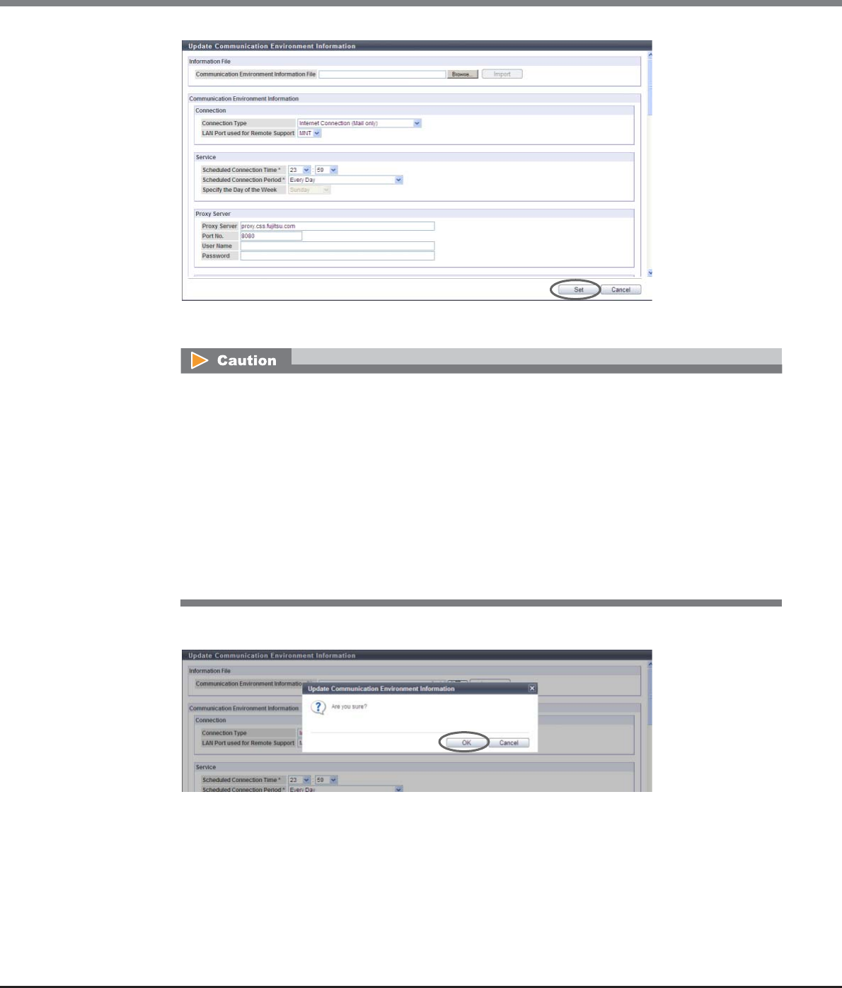
Chapter 11 System Management
11.2 Functions in the Action Area for System
ETERNUS Web GUI User’s Guide
Copyright 2013 FUJITSU LIMITED P2X0-1090-10ENZ0
813
→A confirmation screen appears.
3Click the [OK] button.
→Changing of the communication environment information starts.
An error screen appears in the following conditions:
•When the [Set] button is clicked without setting the required item (items with "*")
•When the [Set] button is clicked while invalid values had been specified
•When the selected setting information file is not correct
•When file format of the selected setting information file is not correct
•When "MNT" is specified for the "LAN Port used for Remote Support" and when the IP Address of the
Proxy server/SMTP server/POP server is the same as the broadcast address of the MNT port
•When "RMT" is specified for the "LAN Port used for Remote Support" and the IP Address of the Proxy
server/SMTP server/POP server is the same as the broadcast address of the RMT port
•When the IP address of the Proxy server/SMTP server/POP server is the same as the local host
address

Chapter 11 System Management
11.2 Functions in the Action Area for System
ETERNUS Web GUI User’s Guide
Copyright 2013 FUJITSU LIMITED P2X0-1090-10ENZ0
814
4Click the [Done] button to return to the screen when starting this function in Step 1.
End of procedure
11.2.4.5 Setup Log Sending Parameters
This function transfers the internal log of the ETERNUS DX Disk storage system to the REMCS center.
There are two log sending methods: "Automatic" and "Manual".
•Configure Automatic Log Transmission
The ETERNUS DX Disk storage system sends log periodically or when an event occurs.
•Immediately Send Log Manually
The log is sent manually.
The procedure to send log is as follows:
■Configure Automatic Log Transmission
The ETERNUS DX Disk storage system sends log periodically or when an event occurs.
Procedure
1Click [Setup Log Sending Parameters] in [Action].
2Specify the parameters, and click the [Set] button.
●Send Log based on Events
•Send Log when Errors Occur
To send logs automatically in the case of a failure, select the "Send" checkbox. The default state of
"Send Log when Errors Occur" setting is, if the Remote Support setting using the [Setup Remote
Support] function has been completed, "Send" will be enabled.
After completing the setting, the REMCS center sends the setting confirmation result to the
"Administrator E-Mail Address" or the "Connection check operator E-Mail Address". Make sure to
confirm the setting results.
This function cannot be used under the following conditions:
•When the procedure in "11.2.4.2 Setup Remote Support" (page 800) is not performed.
•When a problem is detected in the Remote Support settings
•When the "Receiver Mail Address" (REMCS center) is not specified for the Remote Support
•The Remote Support is stopped

Chapter 11 System Management
11.2 Functions in the Action Area for System
ETERNUS Web GUI User’s Guide
Copyright 2013 FUJITSU LIMITED P2X0-1090-10ENZ0
815
●Send Log Periodically
•Periodical Transmission of Log
To send log periodically, select the "Enable" checkbox. The default state of "Periodical Transmission
of Log" is, if the Remote Support setting using the [Setup Remote Support] function has been
completed, "Enable" will be selected.
•Time
Specify between "0:00" and "23:59" for the time to send logs periodically. A time between "10:00"
and "15:00" is set for the default setting. (*1)
•Period
Specify the cycle when sending logs periodically.
-Once per Week
-Every Day
•Day of the Week
Specify the day of the week when sending logs periodically. The day of the week can be specified
only when "Once per week" has been specified as the cycle when sending logs periodically. A day
between "Monday" and "Friday" is set for the default setting. (*1)
-Sunday
-Monday
-Tuesday
-Wednesday
-Thursday
-Friday
-Saturday
*1: Different days and times are specified in the factory settings in order to disperse the load on the REMCS
center.
→A confirmation screen appears.
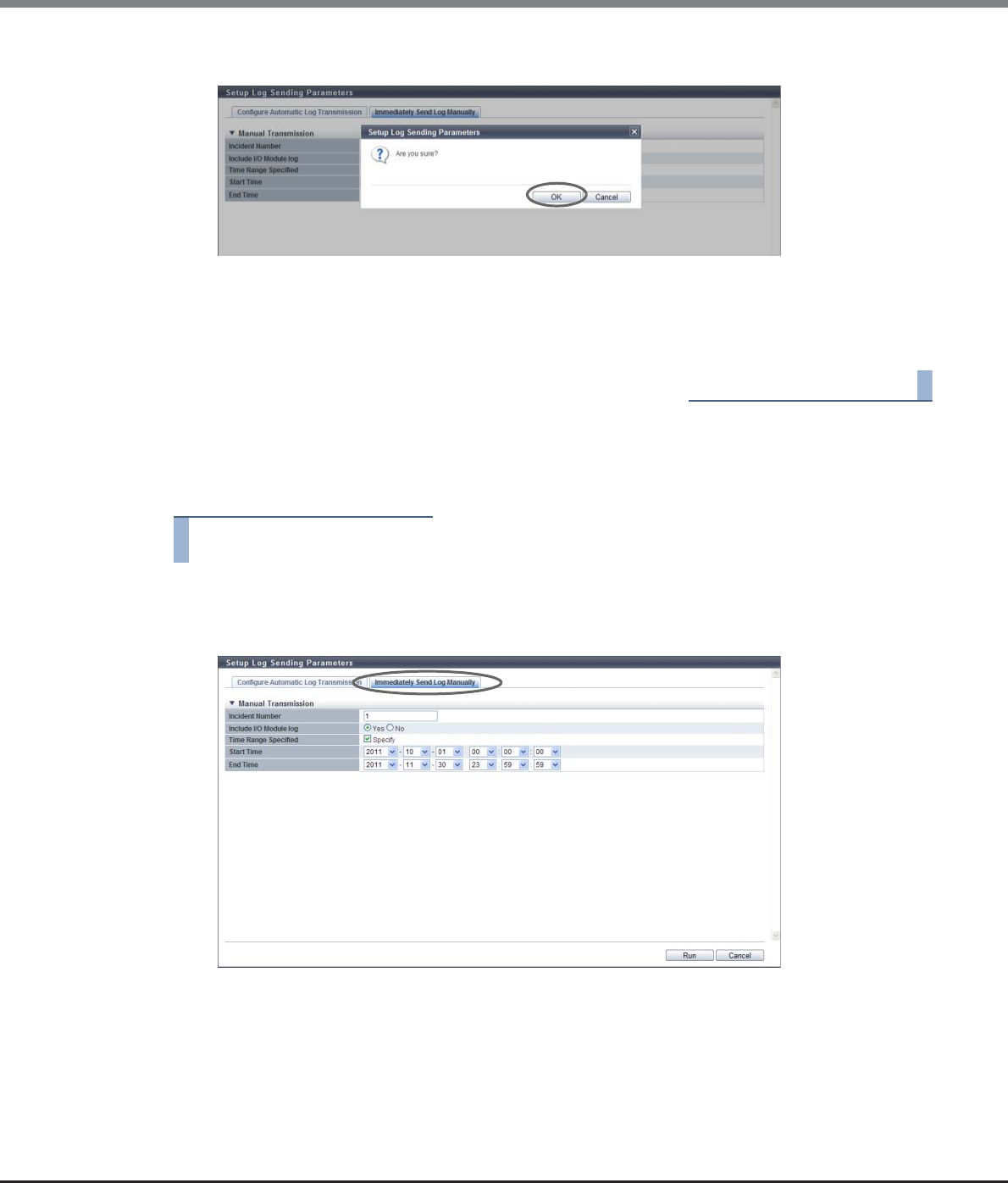
Chapter 11 System Management
11.2 Functions in the Action Area for System
ETERNUS Web GUI User’s Guide
Copyright 2013 FUJITSU LIMITED P2X0-1090-10ENZ0
816
3Click the [OK] button.
→The parameter settings of log transmission (Automatic Log Transmission) are updated in the
storage system.
4Click the [Done] button to return to the screen when starting this function in Step 1.
End of procedure
■Immediately Send Log Manually
In this screen, send log manually and immediately.
Procedure
1Click [Setup Log Sending Parameters] in [Action].
2Click the [Immediately Send Log Manually] tab to change the screen.
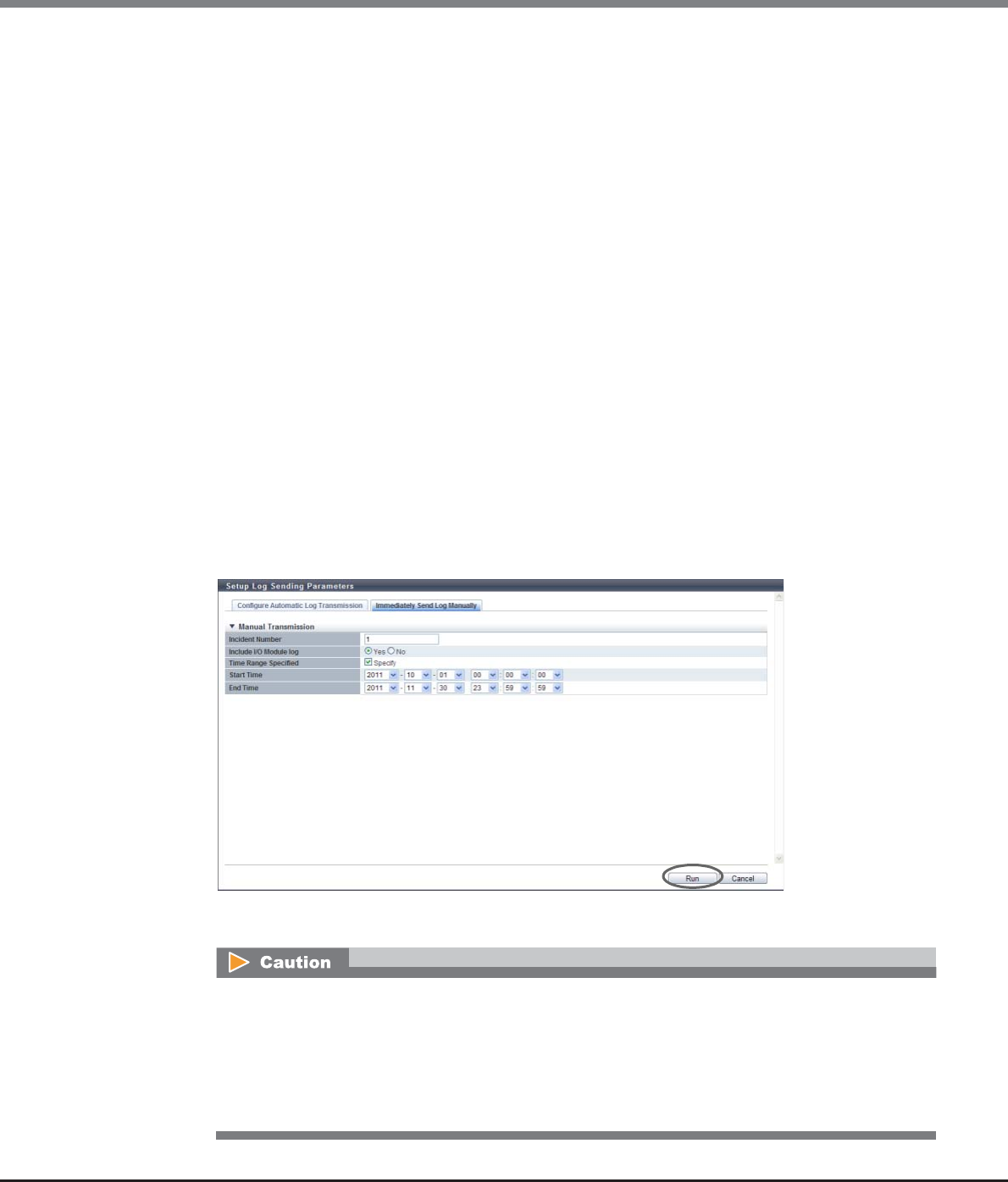
Chapter 11 System Management
11.2 Functions in the Action Area for System
ETERNUS Web GUI User’s Guide
Copyright 2013 FUJITSU LIMITED P2X0-1090-10ENZ0
817
3Specify the parameters, and click the [Run] button.
•Incident Number
Input the incident number to be added to the log to be sent.
The following input condition applies:
-Up to 15 alphanumeric characters and symbols (except spaces)
•Include I/O Module log
Specify whether to collect the I/O module log. To obtain the I/O module log, select the "Yes"
checkbox.
•Time Range Specified
Select whether to specify the time range to export logs.
To specify the time to send log, select the "Specify" checkbox, and specify the start and end time.
If the time range has been specified, some of the logs just before and after the specified time range
may also be collected.
•Start Time
When "Specify" has been selected for "Time Range Specified", specify the start time for collecting
logs.
-YYYY-MM-DD hh:mm:ss (YYYY: Year (AD), MM: Month (01 - 12), DD: Day (01 - 31), hh: Hour (00 -
23), mm: Minute (00 - 59), ss: Second (00 - 59))
•End Time
When "Specify" has been selected for "Time Range Specified", specify the end time for collecting
logs.
-YYYY-MM-DD hh:mm:ss (YYYY: Year (AD), MM: Month (01 - 12), DD: Day (01 - 31), hh: Hour (00 -
23), mm: Minute (00 - 59), ss: Second (00 - 59))
→A confirmation screen appears.
An error screen appears in the following conditions:
•The incident number has not been entered or is incorrect
•When "Specify" has been selected for "Time Range Specified", but the start time or the end time
has not been entered
•When "Specify" has been selected for "Time Range Specified", and the date specified for start time
is earlier than the specified end time
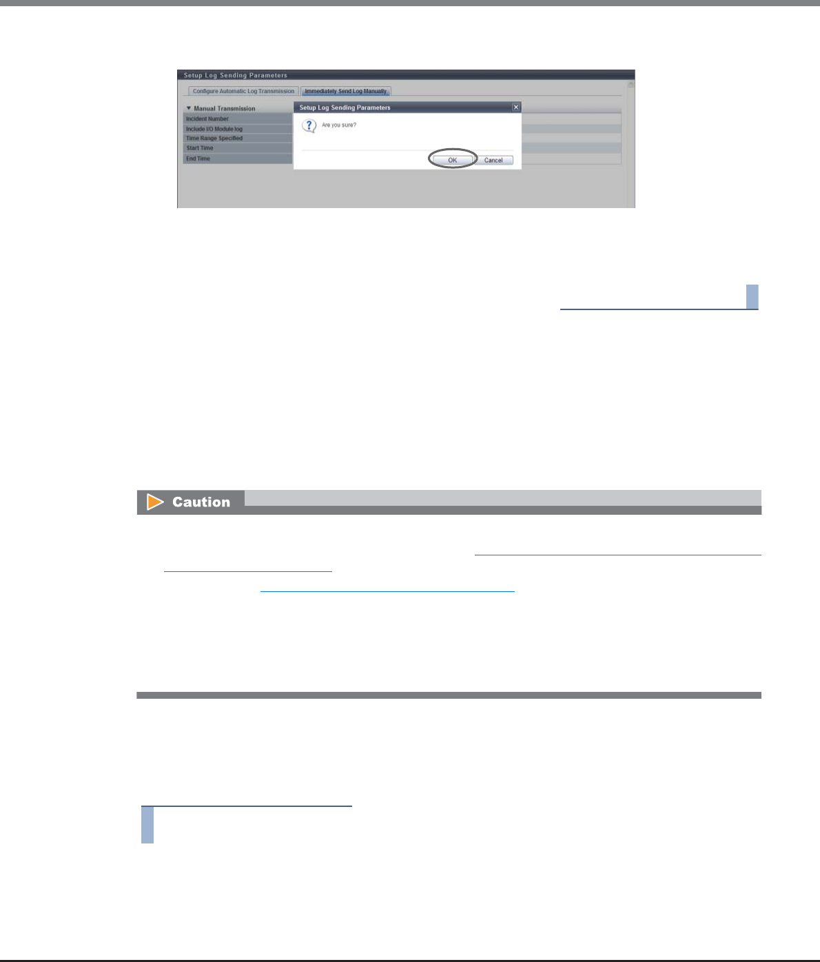
Chapter 11 System Management
11.2 Functions in the Action Area for System
ETERNUS Web GUI User’s Guide
Copyright 2013 FUJITSU LIMITED P2X0-1090-10ENZ0
818
4Click the [OK] button.
→Log transmission (Immediately Send Log Manually) is executed.
5Click the [Done] button to return to the screen when starting this function in Step 1.
End of procedure
11.2.4.6 Stop/Restart Remote Support
This function temporarily stops the Remote Support function and starts again.
This function is used when the ETERNUS DX Disk storage system is stopped for a prolonged period such as for
relocation.
This function switches the support status from "Operating" to "Stopped" or from "Stopped" to "Operating". In
"Stopped", all the Remote Support functions, such as automatic notification of the ETERNUS DX Disk storage
system errors to the REMCS center, are stopped.
■Stopping Remote Support
This function temporarily stops the Remote Support. The Remote Support can be stopped only when it is
"Operating". The procedure to stop Remote Support is as follows:
Procedure
1Click [Stop/Restart Remote Support] in [Action].
→The current Remote Support status is displayed.
•REMCS cannot be used when the AIS Connect function is being used. Disable the AIS Connect function,
and then restart the remote support (REMCS). Refer to "11.1.4 Remote Support (AIS Connect) for Regions
other than Japan" (page 719) for details (for regions other than Japan).
•If the settings in "11.2.4.2 Setup Remote Support" (page 800) has not been completed in advance, this
function cannot be used.
•This function is not available when the ETERNUS DX Disk storage system status is "Maintenance Mode
ON".
•The event of temporary stopping or restarting of the Remote Support function is transferred from the
ETERNUS DX Disk storage system to the REMCS center.
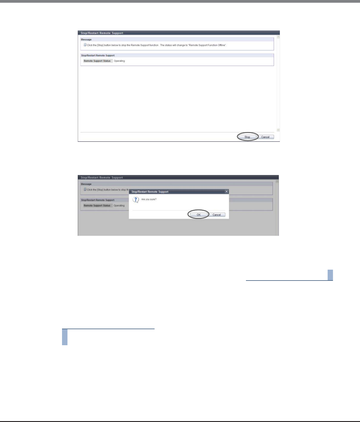
Chapter 11 System Management
11.2 Functions in the Action Area for System
ETERNUS Web GUI User’s Guide
Copyright 2013 FUJITSU LIMITED P2X0-1090-10ENZ0
819
2Click the [Stop] button.
→A confirmation screen appears.
3Click the [OK] button.
→The Remote Support is stopped.
4Click the [Done] button to return to the screen when starting this function in Step 1.
End of procedure
■Restarting Remote Support
This function restarts the Remote Support. The Remote Support can be restarted only when it is "Stopped". The
procedure to restart Remote Support is as follows:
Procedure
1Click [Stop/Restart Remote Support] in [Action].
→The current Remote Support status is displayed.
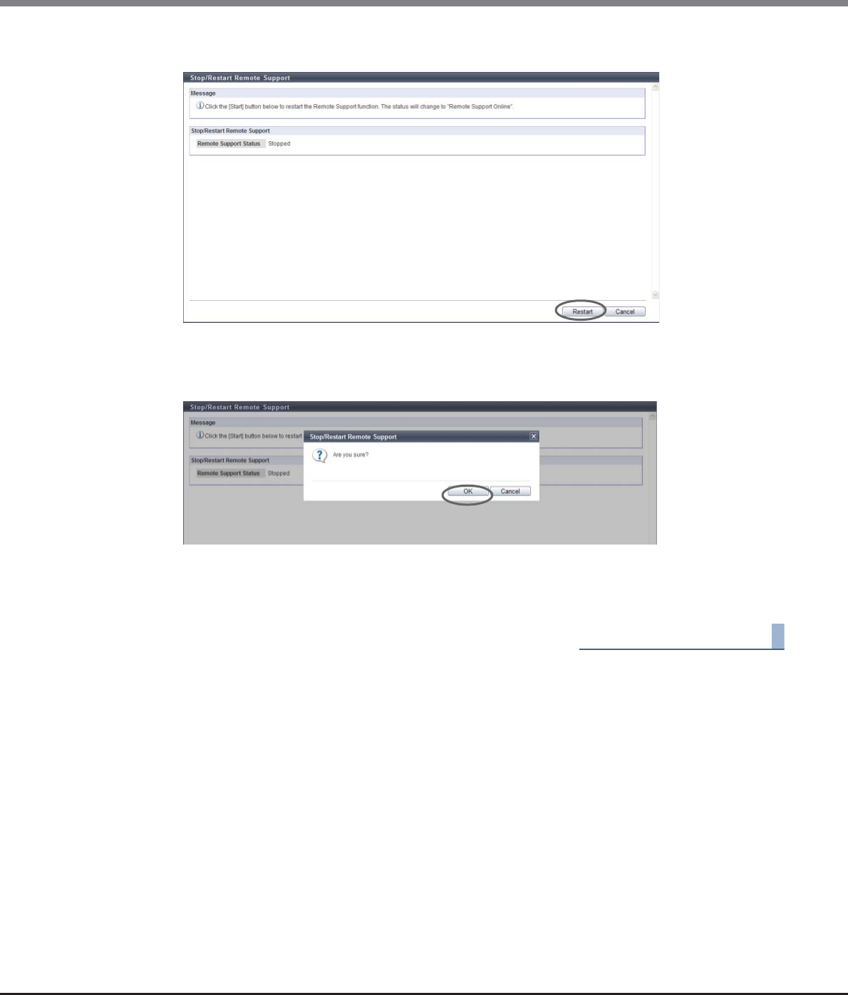
Chapter 11 System Management
11.2 Functions in the Action Area for System
ETERNUS Web GUI User’s Guide
Copyright 2013 FUJITSU LIMITED P2X0-1090-10ENZ0
820
2Click the [Restart] button.
→A confirmation screen appears.
3Click the [OK] button.
→The Remote Support is restarted.
4Click the [Done] button to return to the screen when starting this function in Step 1.
End of procedure
Chapter 11 System Management
11.2 Functions in the Action Area for System
ETERNUS Web GUI User’s Guide
Copyright 2013 FUJITSU LIMITED P2X0-1090-10ENZ0
821
11.2.5 Remote Support (AIS Connect) for Regions other than Japan
This section describes remote support management (by AIS Connect) for regions other than Japan.
Remote support management (by AIS Connect) provides the following functions:
•Setup AIS Connect Environment
•Setup Remote Session Permission
•Send Log
•Test Server Connectivity
•Send AIS Connect Test Event
•Import Root Certificate
11.2.5.1 Setup AIS Connect Environment
This function sets up the basic information for AIS Connect.
The procedure to set the AIS Connect information is as follows:
Procedure
1Click [Setup AIS Connect Environment] in [Action].
•AIS Connect is not available when REMCS is being used. Suspend REMCS and then enable AIS Connect.
Refer to "11.2.4.6 Stop/Restart Remote Support" (page 818) for details (for regions other than EMEA).
•Before using AIS Connect, make sure to read the terms and conditions regarding the handling of personal
information with extreme caution. To agree with the terms and conditions, click the [I agree] button.
Agreement is required only once before setting "Country of Installation (Country Code : Country Name)".
•Note that setting parameters for AIS Connect is applied only when "Enable" is selected for "AIS Connect".
Even if the "AIS Connect" setting is changed to "Disable", the basic AIS Connect information in the ETERNUS
DX Disk storage system is retained.
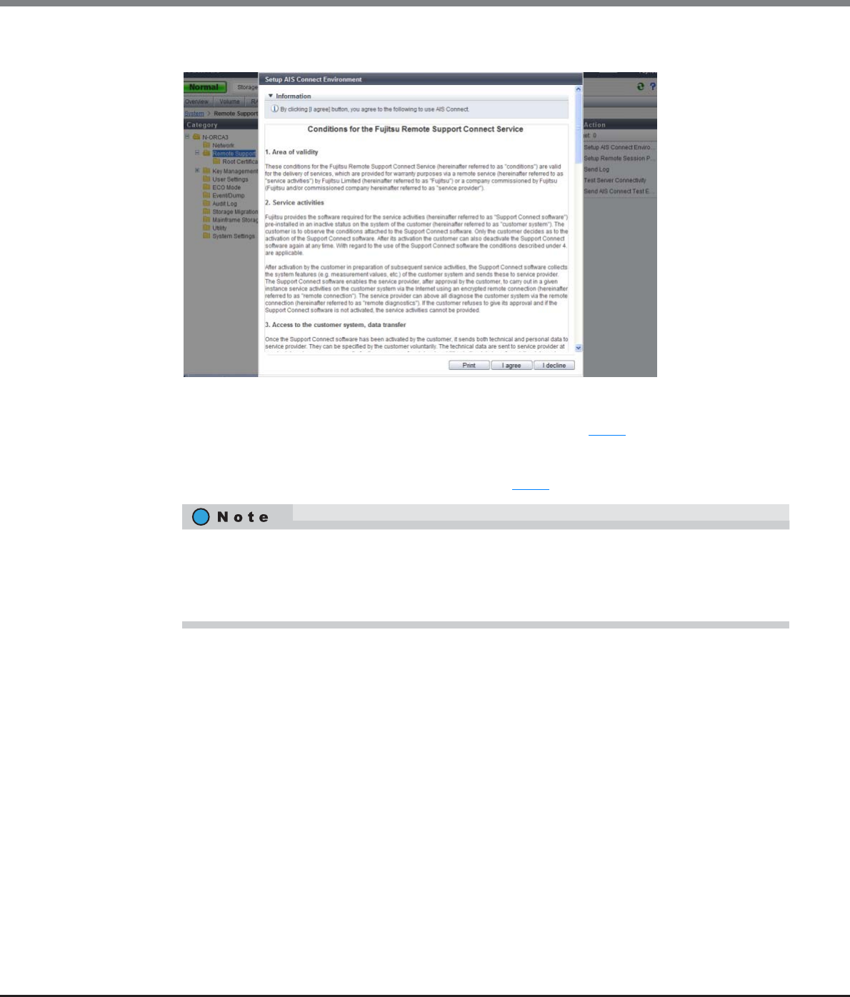
Chapter 11 System Management
11.2 Functions in the Action Area for System
ETERNUS Web GUI User’s Guide
Copyright 2013 FUJITSU LIMITED P2X0-1090-10ENZ0
822
2Check the terms and conditions regarding the handling of personal information.
■When the [I agree] button is clicked
→The [Setup AIS Connect Environment] screen appears. Proceed to Step 3.
■When the [I decline] button is clicked
→Returns to the screen when starting this function in Step 1.
3Specify the parameters, and click the [Set] button.
•AIS Connect
Select whether to enable or disable the AIS Connect function.
•Country of Installation (Country Code : Country Name)
Select the country name to which the ETERNUS DX Disk storage system is shipped (where the
storage system locates).
Options for this item are displayed in "Country code : Country name" format. The country name is
listed in English alphabetical order. "ISO 3166-1 numeric" is used as the country code.
•Use LAN Port
Select the LAN port from "MNT" or "RMT" that is to be used for communication with the AIS Connect
server.
•The terms and conditions regarding the handling of personal information are displayed only when
"Country of Installation (Country Code : Country Name)" is not specified.
•To print the terms and conditions regarding the handling of personal information, click the [Print]
button.

Chapter 11 System Management
11.2 Functions in the Action Area for System
ETERNUS Web GUI User’s Guide
Copyright 2013 FUJITSU LIMITED P2X0-1090-10ENZ0
823
•SSL Server Certification
To use SSL server certification for communication with the AIS Connect server, select "Enable". To not
use SSL server certification, select "Disable".
When "Enable" is selected, server certification is performed with the root certificate that is registered
in the ETERNUS DX Disk storage system for AIS Connect server communication. When there is no
appropriate root certificate that authenticates server certification that is received from the AIS
Connect server or when the root certificate has expired, communication with the AIS Connect server
fails. The expiration date of the root certificate can be checked from the [Root Certificate] screen.
Refer to "11.1.4.1 Root Certificate" (page 721) for details.
•Auto Send Log
Select whether to enable or disable the automatic log transmission.
When "Auto Send Log" is enabled and notification of Error Severity Level or Warning Level occurs, a
log is collected and sent to the AIS Connect server in approximately five minutes. The maximum size
of a log is 1.44MB. Note that I/O Module logs are not included.
If a send log request is already performed once log collection is complete, send log requests are not
performed. If a communication error occurs and a connection to the AIS Connect server cannot be
established, logs cannot be sent. A log that fails to be sent is not resent.
•Proxy Server
Input the IPv4 address or the Fully Qualified Domain Name (FQDN) of the proxy server. Make sure to
input "Proxy Server" and "Port No." together.
If a proxy server is not used, this item does not need to be set.
-IPv4 address
xxx.xxx.xxx.xxx
xxx: 1 - 255 for the top field (decimal)
xxx: 0 - 255 for other fields (decimal)
-FQDN
Up to 63 alphanumeric characters and symbols ("." (dot), ":" (colon), "-" (hyphen), and "_ "
(underscore) can be used)
•Port No.
Input the port number of the proxy server between 0 and 65535. Make sure to input "Proxy Server"
and "Port No." together.
If a proxy server is not used, this item does not need to be set.
•Connection Type
Select the communication method for the proxy server.
-HTTP
Basic/NTLM HTTP authentication
-SOCKS
SOCKSv5 authentication
•User Name
Specify the user name for the proxy server authentication.
If a proxy server is not used, this item does not need to be set.
The following input condition applies:
-Up to 32 alphanumeric characters
•Change Password
To change the proxy server authentication password, select the checkbox.
•Password
Select the "Change Password" checkbox and then input the password for proxy server
authentication. When inputting the password, "*" is displayed to hide the specified value.
If a proxy server is not used, this item does not need to be set.
The following input condition applies:
-Up to 64 alphanumeric characters and symbols
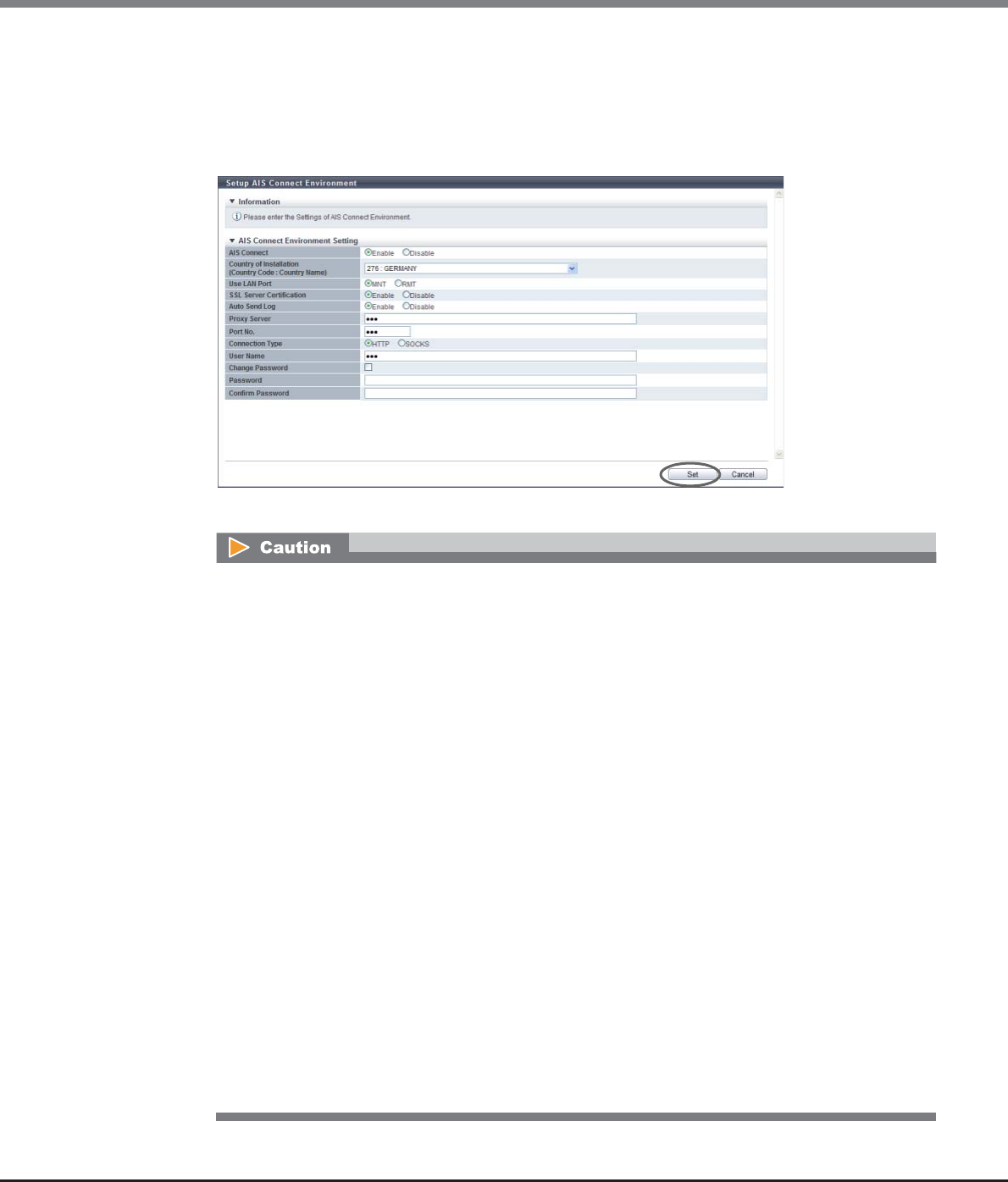
Chapter 11 System Management
11.2 Functions in the Action Area for System
ETERNUS Web GUI User’s Guide
Copyright 2013 FUJITSU LIMITED P2X0-1090-10ENZ0
824
•Confirm Password
Select the "Change Password" checkbox and then input the password for proxy server authentication
again. When inputting the password, "*" is displayed to hide the specified value.
If a proxy server is not used, this item does not need to be set.
The following input condition applies:
-Up to 64 alphanumeric characters and symbols
→A confirmation screen appears.
•An error screen appears in the following conditions (when "Enable" is selected for the AIS Connect
function and a proxy server is specified):
-When the specified "Proxy Server" does not satisfy the input conditions
-When the same IP address is specified for "Proxy Server" and the MNT port or the RMT port
-When the IP address for "Proxy Server" and the network address for the MNT port or the RMT
port are the same
-When the IP address for "Proxy Server" and the broadcast address for the MNT port or the RMT
port are the same
-When the same IP address is specified for "Proxy Server" and "AIS Connect Server"
-When either of the "Proxy Server" or the "Port No." has been specified
-When "Port No." does not satisfy the input conditions
-When the "User Name" is not entered
-When the "User Name" does not satisfy the input conditions
-When "Password" is not entered (only when "Change Password" checkbox is selected)
-When "Password" does not satisfy the input conditions (only when "Change Password"
checkbox is selected)
-When "Confirm Password" is not entered (only when "Change Password" checkbox is selected)
-When "Confirm Password" does not satisfy the input conditions (only when "Change Password"
checkbox is selected)
-When "Password" does not match "Confirm Password" (only when "Change Password" checkbox
is selected)
•When "Enable" is selected for "AIS Connect" and "Country of Installation (Country Code : Country
Name)" is not specified, an error screen appears.
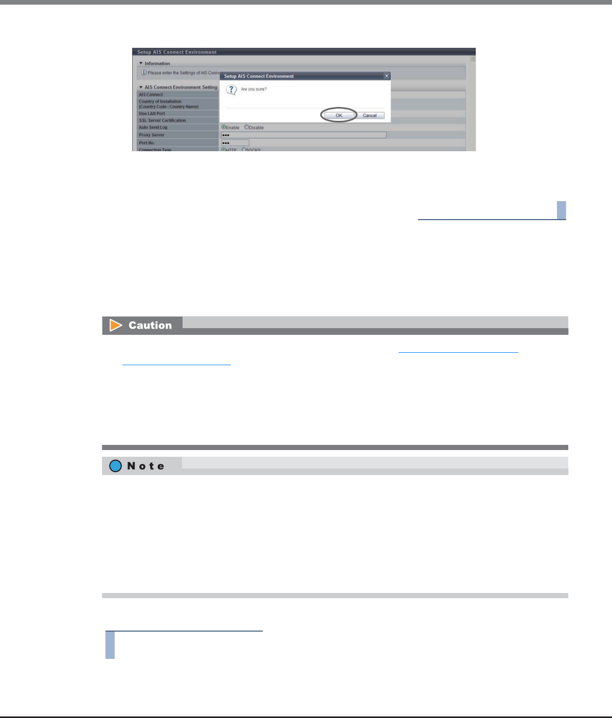
Chapter 11 System Management
11.2 Functions in the Action Area for System
ETERNUS Web GUI User’s Guide
Copyright 2013 FUJITSU LIMITED P2X0-1090-10ENZ0
825
4Click the [OK] button.
→AIS Connect setting starts.
5Click the [Done] button to return to the screen when starting this function in Step 1.
End of procedure
11.2.5.2 Setup Remote Session Permission
This function performs permission settings for remote sessions with the AIS Connect function. If a remote ses-
sion is permitted, remotely controlling the ETERNUS DX80 S2/DX90 S2, ETERNUS DX410 S2/DX440 S2, or ETER-
NUS DX8100 S2/DX8700 S2 from a remote server (AIS Connect server) becomes available.
The procedure to set the remote support permission is as follows:
Procedure
1Click [Setup Remote Session Permission] in [Action].
•Settings can be changed when "AIS Connect" is enabled. Refer to "11.2.5.1 Setup AIS Connect
Environment" (page 821) for details.
•The permission setting of a remote session is released if one of the following conditions applies:
-When a remote session is not detected before the timeout period that is specified for the timeout
setting
-When this function forbids remote sessions
-When "AIS Connect" is disabled
•The permission settings are retained even if the ETERNUS DX Disk storage system is rebooted or after
recovery from a power failure. Note that the timer that monitors remote session connection is reset to
"0"in this case.
•If the setting of this function is changed to forbid while a remote session is being performed, operations
for this remote session are permitted until the user logs out. However, once this remote session is logged
out from, this remote session cannot be logged into while the remote session is forbid.
•When "AIS Connect" is disabled, all remote sessions that are currently being performed are immediately
disconnected.
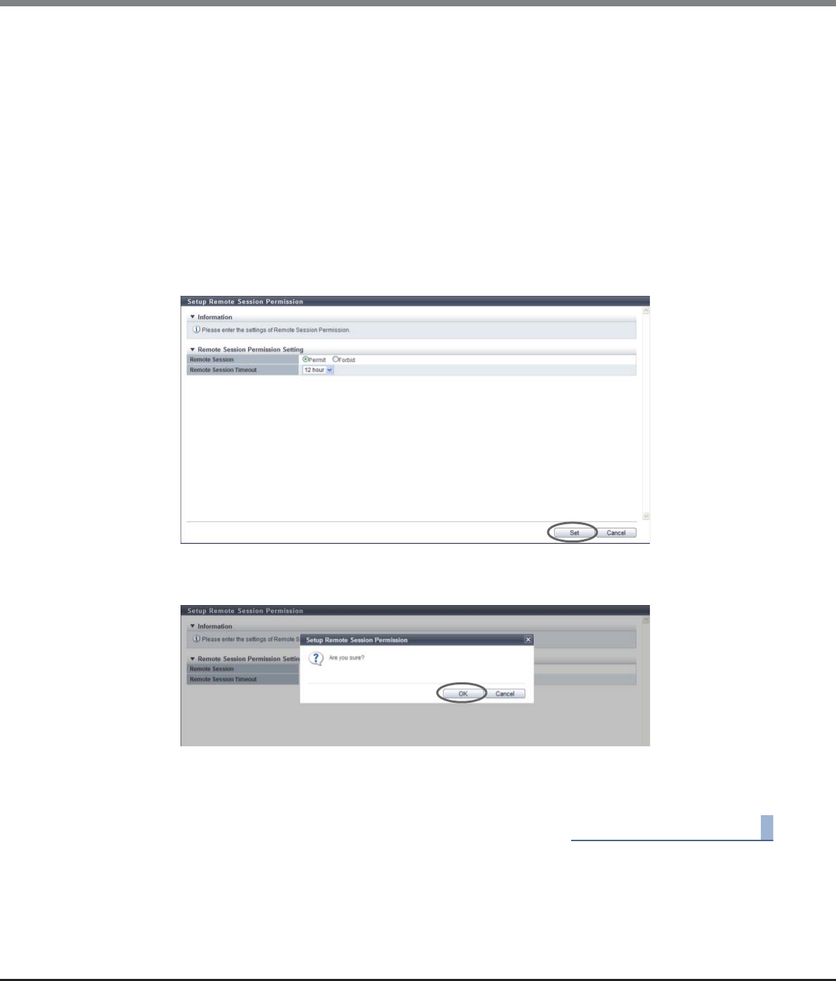
Chapter 11 System Management
11.2 Functions in the Action Area for System
ETERNUS Web GUI User’s Guide
Copyright 2013 FUJITSU LIMITED P2X0-1090-10ENZ0
826
2Specify the parameters, and click the [Set] button.
•Remote Session
Select whether to permit or forbid a remote session from the AIS Connect server.
•Remote Session Timeout
Select the timeout limit for remote session connection. When not setting the timeout limit, select
"Unlimited".
When "Permit" is selected for "Remote Session", monitoring of the remote sessions starts. If the time
exceeds the specified value without a remote session connection, remote session permission is
automatically disabled and the setting status changes to "Forbid". If a remote session connection is
detected while monitoring is being performed, the timer is suspended during connection. After
connection is complete, the timer is reset to "0" and monitoring starts again.
Selecting the timeout limit is only available when "Permit" is selected for "Remote Session".
-1 - 24 hour
-Unlimited
→A confirmation screen appears.
3Click the [OK] button.
→The permission settings for remote session are applied.
4Click the [Done] button to return to the screen when starting this function in Step 1.
End of procedure
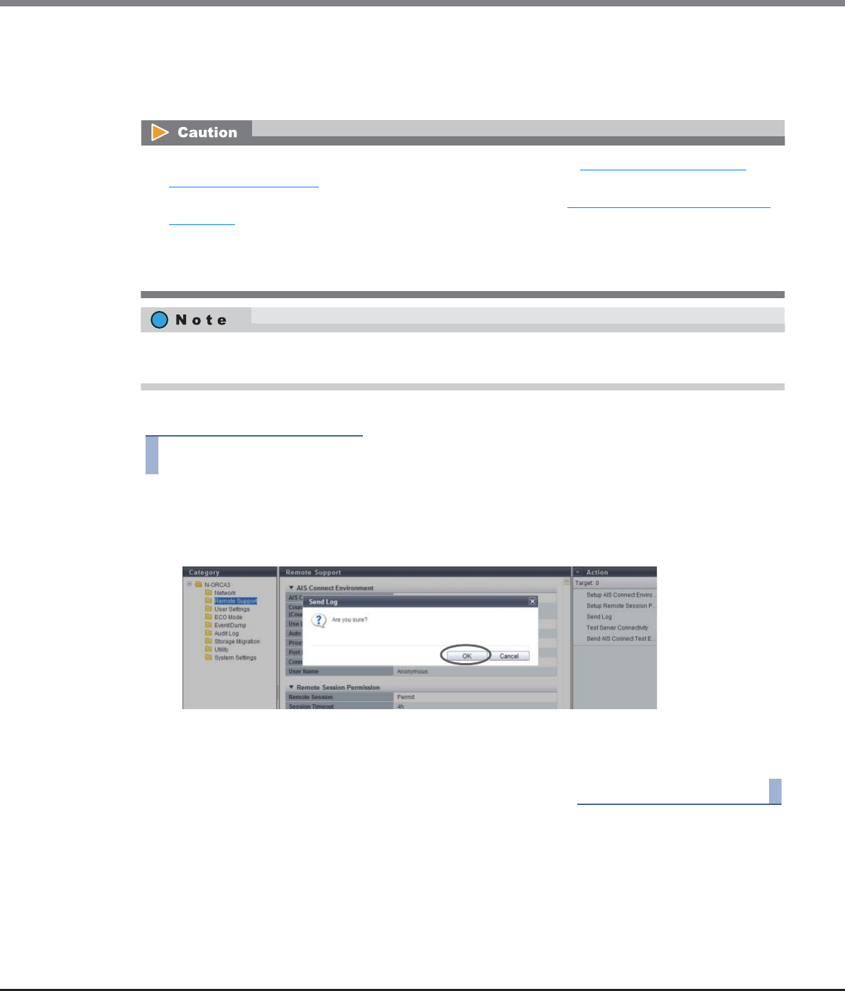
Chapter 11 System Management
11.2 Functions in the Action Area for System
ETERNUS Web GUI User’s Guide
Copyright 2013 FUJITSU LIMITED P2X0-1090-10ENZ0
827
11.2.5.3 Send Log
This function manually sends a storage system log to the remote server (AIS Connect server) when the AIS
Connect function is in operation.
The procedure to send log is as follows:
Procedure
1Click [Send Log] in [Action].
→A confirmation screen appears.
2Click the [OK] button.
→Sending log starts.
3Click the [Done] button to return to the screen when starting this function in Step 1.
End of procedure
•Sending logs is only available when "AIS Connect" is enabled. Refer to "11.2.5.1 Setup AIS Connect
Environment" (page 821) for details.
•Check the connection to the AIS Connect server in advance. Refer to "11.2.5.4 Test Server Connectivity"
(page 828) for details. If a communication error occurs and a connection to the AIS Connect server cannot
be established, logs cannot be sent. A log that fails to be sent is not resent.
•If a send log request is already performed once log collection is complete, send log requests are not
performed.
This function collects logs (including I/O Module logs) at the time when performing the [Send Log] function.
Log files are divided into 640MB increments and sent to the AIS Connect server.
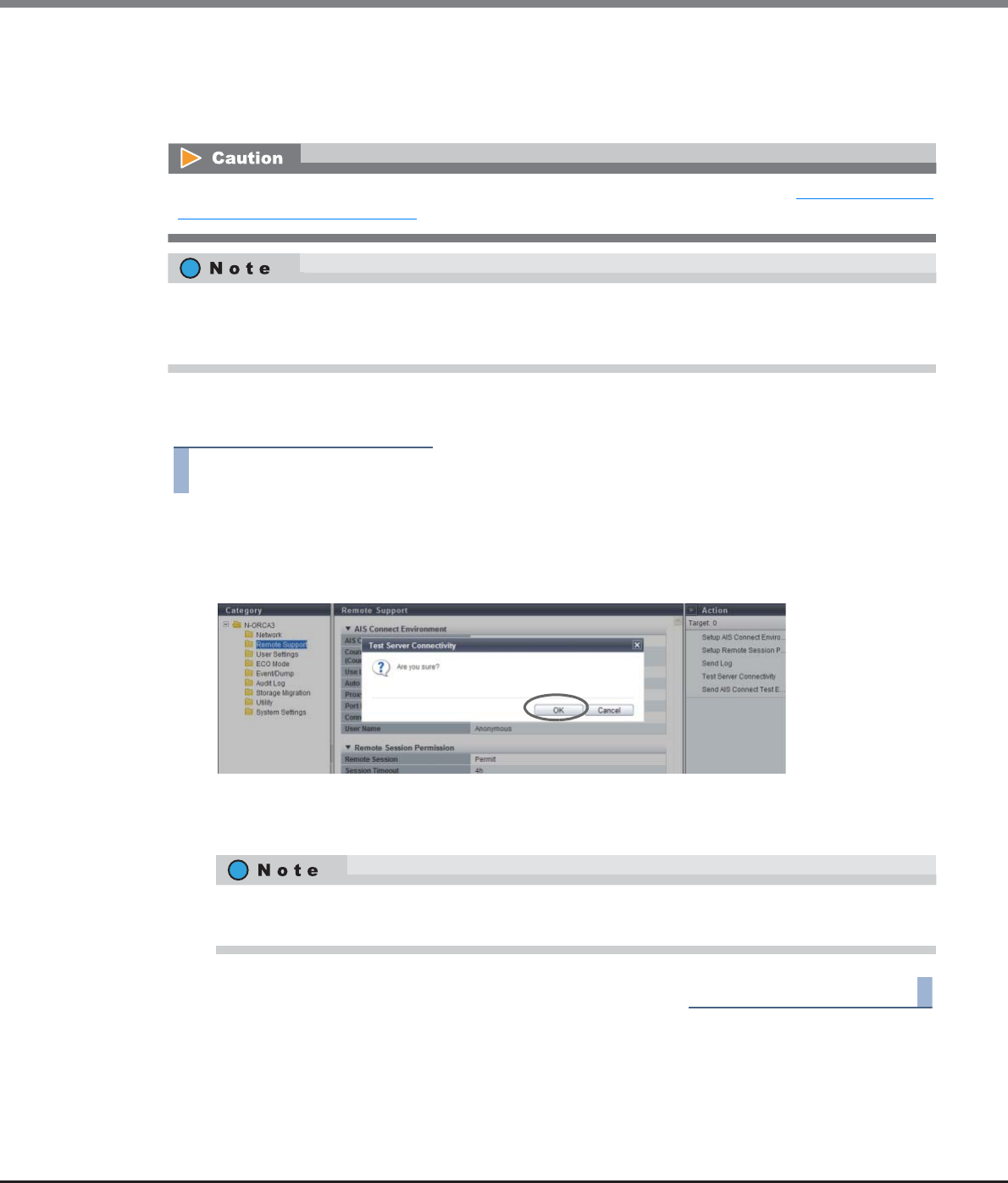
Chapter 11 System Management
11.2 Functions in the Action Area for System
ETERNUS Web GUI User’s Guide
Copyright 2013 FUJITSU LIMITED P2X0-1090-10ENZ0
828
11.2.5.4 Test Server Connectivity
This function checks the connection status between the ETERNUS DX80 S2/DX90 S2, the ETERNUS DX410 S2/
DX440 S2, or the ETERNUS DX8100 S2/DX8700 S2, and a remote server (AIS Connect server).
The procedure to check the connection status between the ETERNUS DX Disk storage system and the AIS Con-
nect server is as follows:
Procedure
1Click [Test Server Connectivity] in [Action].
→A confirmation screen appears.
2Click the [OK] button.
→Checking of the server connection status starts.
3Click the [Done] button to return to the screen when starting this function in Step 1.
End of procedure
Checking the connection status is only available when "AIS Connect" is enabled. Refer to "11.2.5.1 Setup AIS
Connect Environment" (page 821) for details.
This function checks the connection status of the AIS Connect server by using the AIS Connect information in
the ETERNUS DX Disk storage system. After using the [Setup AIS Connect Environment] function, use the [Test
Server Connectivity] function to check the connection status.
The check result of the server connection status is displayed in the [Test Server Connectivity Result]
screen. If server connection fails, the cause of the error is displayed.
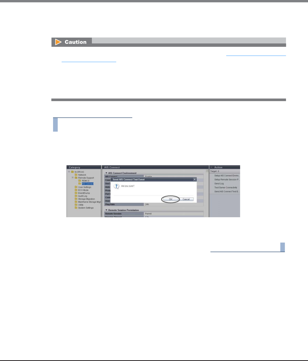
Chapter 11 System Management
11.2 Functions in the Action Area for System
ETERNUS Web GUI User’s Guide
Copyright 2013 FUJITSU LIMITED P2X0-1090-10ENZ0
829
11.2.5.5 Send AIS Connect Test Event
This function sends a test event to the remote server (AIS Connect server).
The procedure to send a test event to the AIS Connect server is as follows:
Procedure
1Click [Send AIS Connect Test Event] in [Action].
→A confirmation screen appears.
2Click the [OK] button.
→Sending of the AIS Connect test event starts.
3Click the [Done] button to return to the screen when starting this function in Step 1.
End of procedure
•Sending a test event is only available when "AIS Connect" is enabled. Refer to "11.2.5.1 Setup AIS Connect
Environment" (page 821) for details.
•The [Send AIS Connect Test Event] function only sends an event. Note that this function cannot be used to
check the network connection status between the ETERNUS DX Disk storage system and the AIS Connect
server. Use the [Test Server Connectivity] function to check the connection status. After checking the
connection status, use the [Send AIS Connect Test Event] function to send a test event. Check the AIS
Connect server to confirm that the event is successfully received.
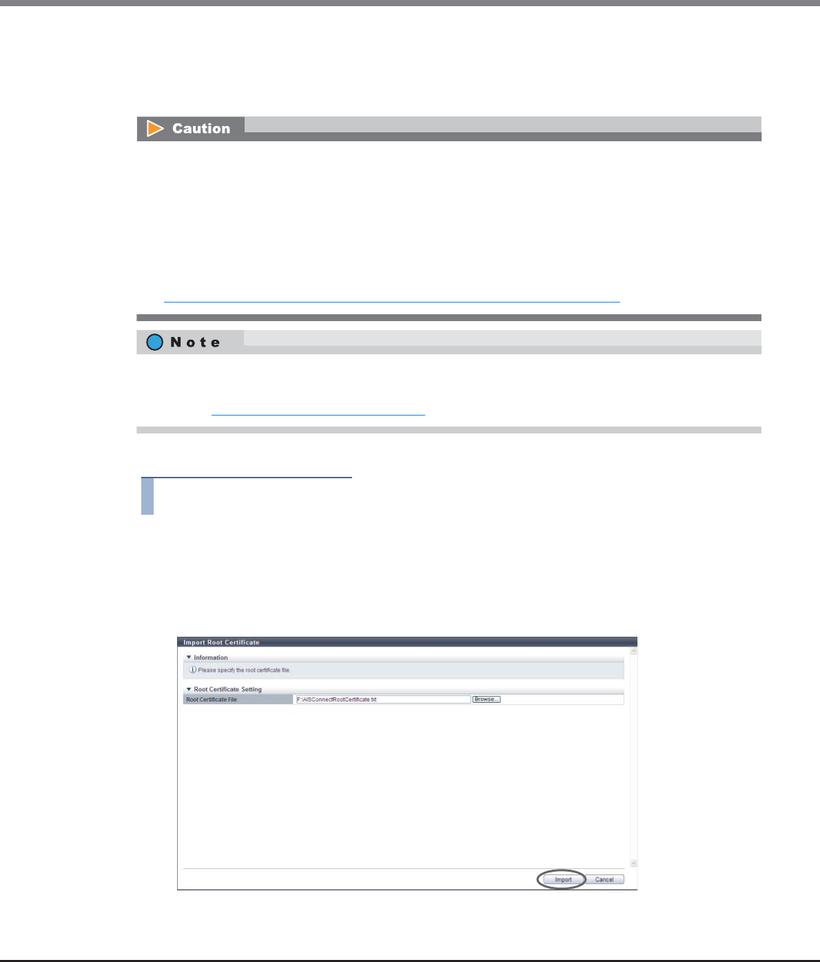
Chapter 11 System Management
11.2 Functions in the Action Area for System
ETERNUS Web GUI User’s Guide
Copyright 2013 FUJITSU LIMITED P2X0-1090-10ENZ0
830
11.2.5.6 Import Root Certificate
This function updates the root certificate that is used for SSL communication with the AIS Connect server.
A root certificate file includes multiple certificates. The maximum file size of a root certificate is 12288 byte.
The procedure to updates the root certificate is as follows:
Procedure
1Click [Import Root Certificate] in [Action].
2Specify the root certificate file and click the [Import] button.
•Root Certificate File
Click the [Browse...] button to specify the root certificate file, or directly input the path to the root
certificate file.
→A confirmation screen appears.
•A default root certificate is already registered in the ETERNUS DX Disk storage system. Check the
expiration date of the default root certificate from the [Root Certificate] screen. The root certificate must
be updated before the expiration date. This function overwrites the root certificate. Only the latest root
certificate is saved in the ETERNUS DX Disk storage system.
•The root certificate cannot be updated when both the "AIS Connect" setting and the "SSL Server
Certification" setting are enabled. To update the root certificate while the AIS Connect function is being
used, temporarily disable the "AIS Connect" setting and then update the certificate. The current settings
for "AIS Connect" and "SSL Server Certification" can be checked from the [AIS Connect] screen. Refer to
"11.1.4 Remote Support (AIS Connect) for Regions other than Japan" (page 719) for details.
•The root certificate is only used for authentication with the AIS Connect server.
•The expiration date of the updated root certificate can be checked from the [Root Certificate] screen.
Refer to "11.1.4.1 Root Certificate" (page 721) for details.
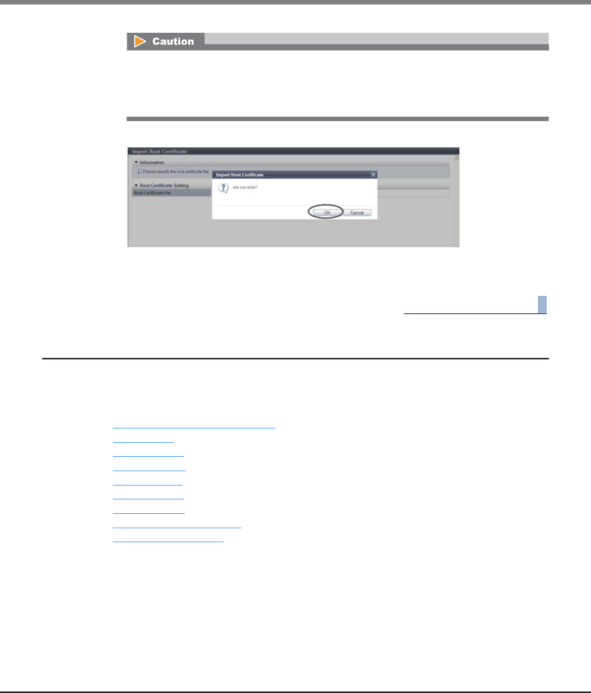
Chapter 11 System Management
11.2 Functions in the Action Area for System
ETERNUS Web GUI User’s Guide
Copyright 2013 FUJITSU LIMITED P2X0-1090-10ENZ0
831
3Click the [OK] button.
→Updating of the root certificate starts.
4Click the [Done] button to return to the [Root Certificate] screen.
End of procedure
11.2.6 Key Management
This section describes key management.
In this section, the SED authentication key is referred to as "key".
Key management provides the following functions:
•Setup Key Management Machine Name
•Add Key Server
•Delete Key Server
•Modify Key Server
•Create Key Group
•Delete Key Group
•Modify Key Group
•Update SED Authentication Key
•Import SSL/KMIP Certificate
An error screen appears in the following conditions:
•When the imported file is not "root certificate file"
•When the imported file size exceeds 12288 bytes
•When both the "AIS Connect" setting and "SSL Server Certification" setting are enabled
Chapter 11 System Management
11.2 Functions in the Action Area for System
ETERNUS Web GUI User’s Guide
Copyright 2013 FUJITSU LIMITED P2X0-1090-10ENZ0
832
11.2.6.1 Required Settings for the Key Management Function
Security on preventing the leakage of information can be improved by storing the key for Self Encrypting Drive
(SED) authentication in an external secure place (key server), and updating the key regularly.
■Required settings for the key management function
This section describes preparation that needs to be performed before using the key management function,
how to check the key status, and how to perform key group settings for RAID groups.
Perform the required settings in the following order.
●Preparation
(1)Register SED authentication key
Register the key (common key) that is managed in the ETERNUS DX Disk storage system.
Refer to "11.2.13.7 Register SED Authentication Key" (page 944) for details.
If the common key is used to manage all of the SEDs in the ETERNUS DX Disk storage system, the
required settings for key management are complete.
To manage the key in the key server, perform the following procedures ("(2) Create self-signed SSL
certificate" (page 832) onward).
RAID groups that use the common key and RAID groups that use the key in the key server (RAID groups
that are registered in the key group) can be used in the same storage system.
(2)Create self-signed SSL certificate
To establish communication between the ETERNUS DX Disk storage system and the key server, create a
self-signed SSL certificate as the SSL certificate of the ETERNUS DX Disk storage system.
Refer to "11.2.3.15 Create Self-signed SSL Certificate" (page 787).
•If an SED is installed without registering the common key, rebooting the ETERNUS DX Disk storage
system is required after registering the key.
•The common key setting cannot be changed or deleted.
•The "Register SED Authentication Key" function can only be used once. If an SED authentication key
is already registered in the "Register SED Authentication Key" screen of the initial setup, this
operation is not required. Use the [System Settings] screen to check whether the SED
authentication key is already registered. Refer to "11.1.12 System Settings" (page 731) for details.
•Even if a self-signed SSL certificate has already been created and registered, perform the [Create
Self-signed SSL Certificate] function again. Since the self-signed SSL certificate has changed,
reregistration to the ETERNUS DX Disk storage system is required. Refer to "Appendix C Installing
the Security Certificate" (page 981) for details.
•A "self-signed SSL certificate" or an "SSL server certificate" can be used as the SSL certificate of the
ETERNUS DX Disk storage system. Refer to "11.2.3.16 Create Key/CSR" (page 790) and "11.2.3.17
Register SSL Certificate" (page 795) for details.
Chapter 11 System Management
11.2 Functions in the Action Area for System
ETERNUS Web GUI User’s Guide
Copyright 2013 FUJITSU LIMITED P2X0-1090-10ENZ0
833
(3)Setup key management device name
Set the name (Key Management Machine Name) for the device that communicates with the key server.
Refer to "11.2.6.2 Setup Key Management Machine Name" (page 835).
(4)Add key server
Register the IP address or the domain name of the key server that manages the key. Up to two key
servers can be registered in the ETERNUS DX Disk storage system.
Refer to "11.2.6.3 Add Key Server" (page 836).
(5)Create key group
Create a key group. The key group combines all of the RAID groups that use the same key. Only one key
group can be created in the ETERNUS DX disk storage system.
Refer to "11.2.6.6 Create Key Group" (page 841).
(6)Import SSL/KMIP certificate
Register the SSL/KMIP certificate that is exported from the key server in the ETERNUS DX Disk storage
system.
Refer to "11.2.6.10 Import SSL/KMIP Certificate" (page 851).
(7)Update SED authentication key
Obtain the key that is to be registered in the key group from the key server.
Refer to "11.2.6.9 Update SED Authentication Key" (page 849).
Select a network port (MNT or RMT) that is specified in the [Setup Network Environment] function for
the LAN port that is used to communicate with the key server.
For details on how to export the SSL/KMIP certificate, refer to the manuals of the key management
software "ETERNUS SF KM".
When the [Update SED Authentication Key] function is performed at the first time, the process ends
with an error. Use the [Update SED Authentication Key] function until the key is successfully obtained.
When the key is successfully obtained, the key server status becomes "Normal". Up to three key updat-
ing processes may need to be performed. The [Update SED Authentication Key] ends with an error
until the key is obtained.
•When the key updating function is used for the first time, the ETERNUS DX Disk storage system
sends the SSL certificate to the key server. The key server waits for the SSL certificate to be regis-
tered. Register the SSL certificate in the key server.
•When the key updating function is used for the second time, the key server waits for the ETERNUS
DX Disk storage system to be accessed.
•When the key updating function is used for the third time, the ETERNUS DX Disk storage system
can obtain the key from the key server.
The key server status can be checked on the [Key Group] screen. Refer to "11.1.5.1 Key Group" (page
723) for details.
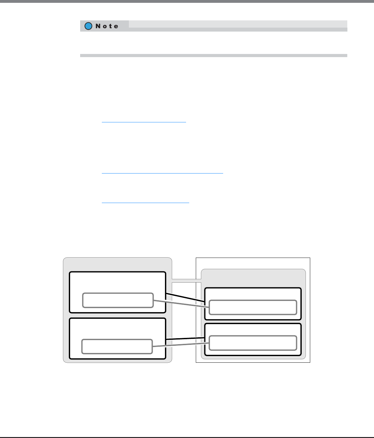
Chapter 11 System Management
11.2 Functions in the Action Area for System
ETERNUS Web GUI User’s Guide
Copyright 2013 FUJITSU LIMITED P2X0-1090-10ENZ0
834
●Check key status
(1)Key group
Check the communication status between the ETERNUS DX Disk storage system and the key server. If
the key status and the key server status are "Normal", communication between the ETERNUS DX Disk
storage system and the key server has been successfully established.
Refer to "11.1.5.1 Key Group" (page 723).
●Key group settings for the RAID group
(1)Set key group
Register any RAID groups that use the same key from the key server in the key group.
Refer to "6.2.8 Set Key Group (RAID Group)" (page 195).
(2)SED key group
Check the key group setting status of the RAID group.
Refer to "6.1.4 SED Key Group" (page 167).
■Relation between the ETERNUS DX Disk storage system and the key server
The following figure shows the relation between the ETERNUS DX Disk storage system and the key server.
Figure 11.1 Relation between the ETERNUS DX Disk storage system and the key server
The ETERNUS DX Disk storage system obtains the key from the key server by using the "Storage System Group
Name", "Key Management Machine Name", and "Key Group Name" as the password.
For details on how to register the SSL certificate and accept the ETERNUS DX Disk storage system, refer
to the manuals of the key management software "ETERNUS SF KM".
Key Server
Device Group Name
(Default name: ETERNUS_DX)
Storage System Group Name
Storage system A
Machine ID
Key Management Machine Name #1
Storage system B Machine ID
Key Management Machine Name #2
Key Group Name
Serial No. for storage system A
Key Group Name Serial No. for storage system B
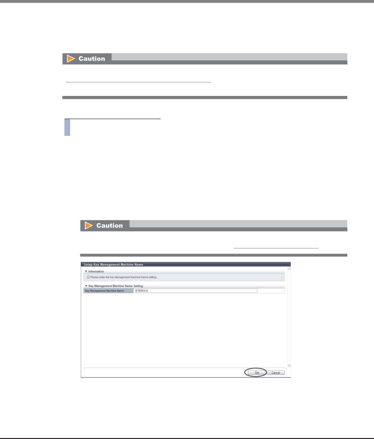
Chapter 11 System Management
11.2 Functions in the Action Area for System
ETERNUS Web GUI User’s Guide
Copyright 2013 FUJITSU LIMITED P2X0-1090-10ENZ0
835
11.2.6.2 Setup Key Management Machine Name
This function specifies the name of the key management device (Key Management Machine).
The key management device name is used for the device that is to be used to connect to the key server.
The procedure to set the key management device name is as follows:
Procedure
1Click [Setup Key Machine Name] in [Action].
2Specify the key management device name, and click the [Set] button.
•Key Management Machine Name
Input the name of the device that is to be used to connect to the key server.
The key management device name corresponds to "Machine ID" in the key server.
The following input conditions apply:
-Up to 48 alphanumeric characters and symbols (underscore "_")
-The first letter must be an alphabetic character
→A confirmation screen appears.
The key management device name cannot be specified when a common key (*1) is not registered. Refer to
"11.2.13.7 Register SED Authentication Key" (page 944) for details.
*1: The common key for SEDs that are managed in the ETERNUS DX Disk storage system.
Do not change the key management device name after the key status changes to "Normal". The key
status can be checked on the [Key Group] screen. Refer to "11.1.5.1 Key Group" (page 723) for details.
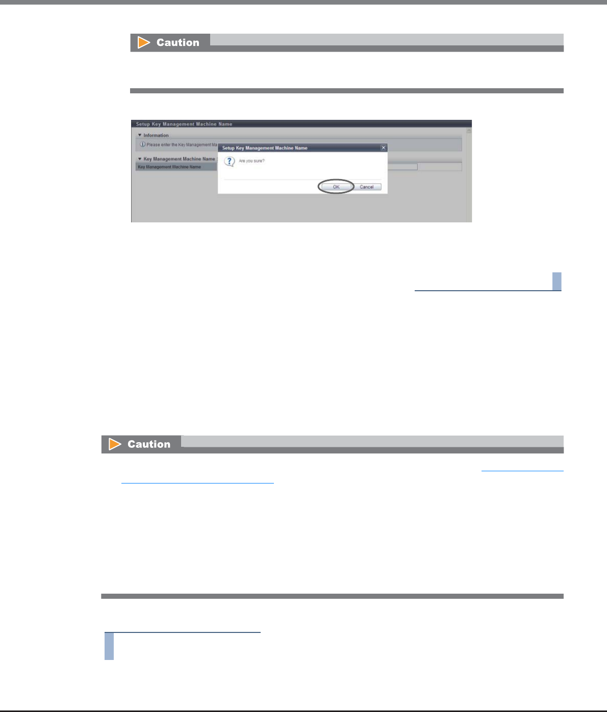
Chapter 11 System Management
11.2 Functions in the Action Area for System
ETERNUS Web GUI User’s Guide
Copyright 2013 FUJITSU LIMITED P2X0-1090-10ENZ0
836
3Click the [OK] button.
→Setting of the key management device name starts.
4Click the [Done] button to return to the [Key Management] screen.
End of procedure
11.2.6.3 Add Key Server
This function adds a key server.
A key server is an external server that manages the key. By using the key server to obtain and update the key
via SSL to establish secure communication with the ETERNUS DX Disk storage system, an environment in
which the key can be managed more safely can be created. Up to two key servers can be registered.
For the key server, use a server in which "ETERNUS SF KM" (key management software that applies the Key
Management Interoperability Protocol (KMIP)), is installed. Note that "IBM Tivoli Key Lifecycle Manager" is
also available as the key management software.
The procedure to add a key server is as follows:
Procedure
1Click [Add Key Server] in [Action].
If the entered "Key Management Machine Name" does not satisfy the input conditions, an error screen
appears.
•The key server cannot be added when the common key (*1) is not registered. Refer to "11.2.13.7 Register
SED Authentication Key" (page 944) for details.
*1: The common key for SEDs that are managed in the ETERNUS DX Disk storage system.
•By using a key server to manage the key, the ETERNUS DX Disk storage system can obtain the key from
the key server when required. For example, the key is obtained when RAID groups are added to the key
group or when maintenance is performed for SEDs that configure a RAID group in the key group. Make
sure that communication is always maintained between the ETERNUS DX Disk storage system and the key
server. To obtain the key from a key server, the key server must respond to the ETERNUS DX Disk storage
system within 30 seconds. Do not use the key server function in an environment in which a network
timeout may occur.
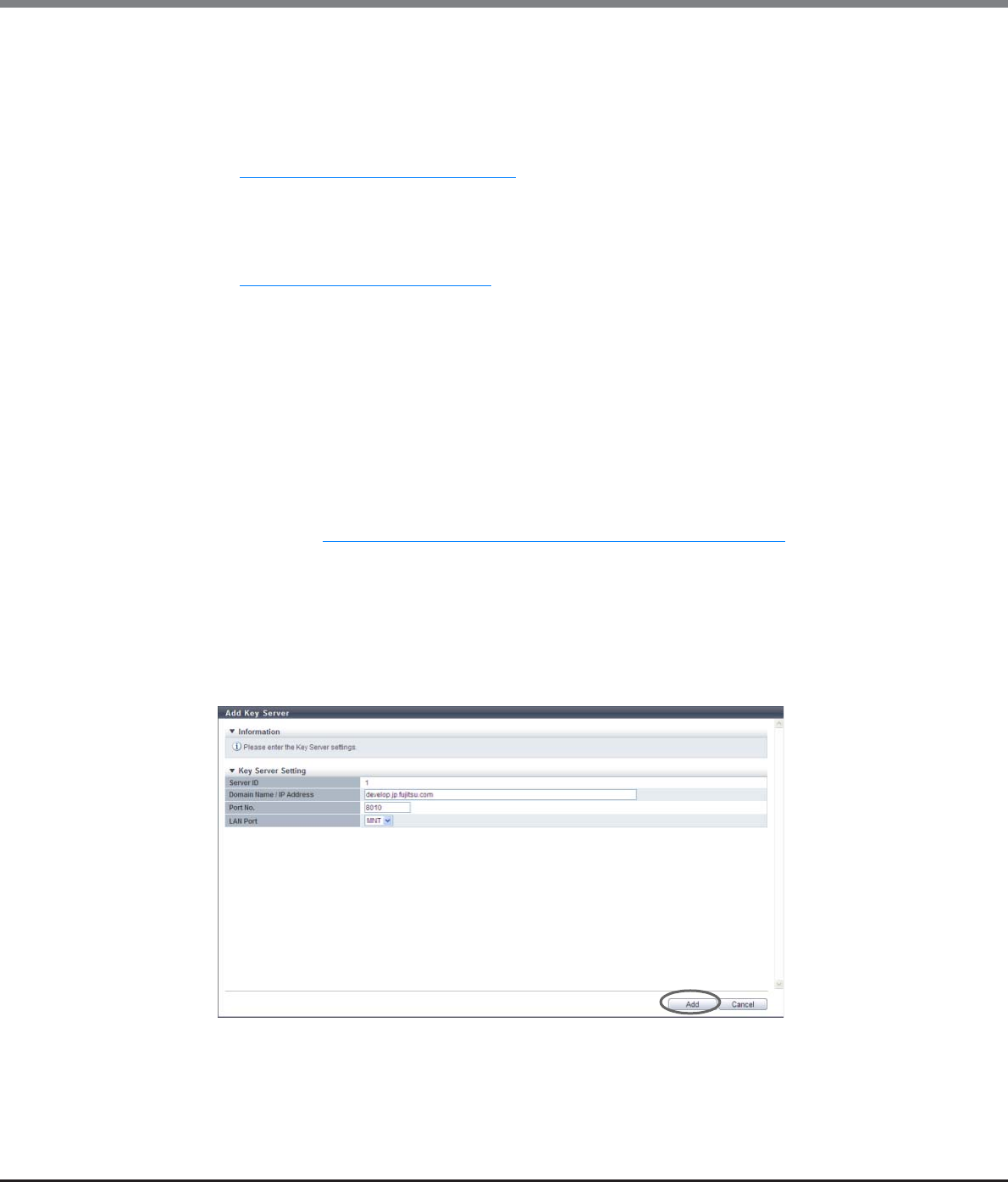
Chapter 11 System Management
11.2 Functions in the Action Area for System
ETERNUS Web GUI User’s Guide
Copyright 2013 FUJITSU LIMITED P2X0-1090-10ENZ0
837
2Specify the parameters, and click the [Add] button.
•Server ID
"1" or "2" is displayed as the ID for unregistered servers. When a key server is registered for "1", "2" is
displayed.
The server ID for the master or the slave server is specified when creating the key group. Refer to
"11.2.6.6 Create Key Group" (page 841) for details.
•Domain Name / IP Address
Input the domain name (FQDN) or the IP address of the key server.
There are two methods to specify an IP address; "IPv4" and "IPv6". The following IPv6 addresses can
be used; "link local address", "global address", "unique local address", and "6to4 address". Refer to
"Available IPv6 Address" (page 757) for details.
When the current setting is displayed, the IPv6 address is displayed as an abbreviation.
The following input conditions apply:
-For "Domain Name"
Up to 63 alphanumeric characters and symbols
-For IPv4 address
xxx.xxx.xxx.xxx
xxx: 1 - 255 for the top field (decimal)
xxx: 0 - 255 for other fields (decimal)
-For IPv6 address
xxxx:xxxx:xxxx:xxxx:xxxx:xxxx:xxxx:xxxx
xxxx: 0 - ffff (FFFF) (hexadecimal, alphanumeric characters)
Refer to "IPv6 Address Notation (Setup Network Environment)" (page 757) for details.
•Port No.
Input the port number used to communicate with the key server.
The following input conditions apply:
-Numeric characters
-1 - 65535
•LAN Port
Select "MNT" or "RMT" for the LAN port that is to be used to communicate with the key server.
→A confirmation screen appears.
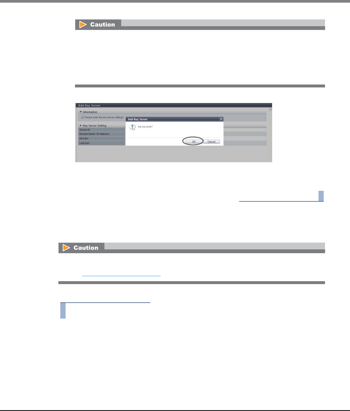
Chapter 11 System Management
11.2 Functions in the Action Area for System
ETERNUS Web GUI User’s Guide
Copyright 2013 FUJITSU LIMITED P2X0-1090-10ENZ0
838
3Click the [OK] button.
→Adding of the key server starts.
4Click the [Done] button to return to the [Key Management] screen.
End of procedure
11.2.6.4 Delete Key Server
This function deletes key servers.
The procedure to delete key servers is as follows:
Procedure
1Select the key server that is to be deleted (multiple selections can be made) and click
[Delete Key Server] in [Action].
→A confirmation screen appears.
An error screen appears in the following conditions:
•When each parameter fails to satisfy the input conditions
•When inputting a domain name or an IP address that is already used for another key server
•When the IP address that was input and the IP address of the LAN port (MNT or RMT) are the same
•When the IP address that was input and the network address of the LAN port (MNT or RMT)are the
same
A key server that is allocated to a key group cannot be deleted. Refer to the "Master Server" field and the
"Slave Server" field in the [Key Group] screen to check whether the key server is allocated to the key group.
Refer to "11.1.5.1 Key Group" (page 723) for details.
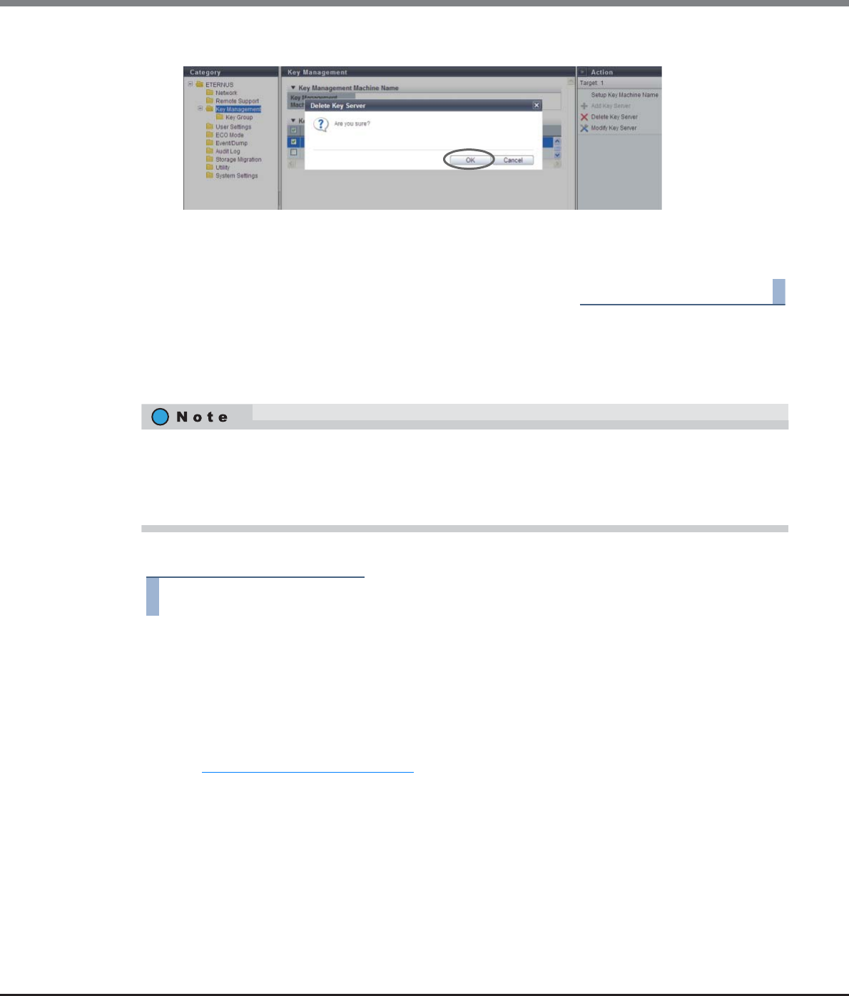
Chapter 11 System Management
11.2 Functions in the Action Area for System
ETERNUS Web GUI User’s Guide
Copyright 2013 FUJITSU LIMITED P2X0-1090-10ENZ0
839
2Click the [OK] button.
→Deleting of the key server starts.
3Click the [Done] button to return to the [Key Management] screen.
End of procedure
11.2.6.5 Modify Key Server
This function changes the key server settings.
The procedure to change the key server settings is as follows:
Procedure
1Select the key server that is to be changed and click [Modify Key Server] in [Action].
2Specify the parameters, and click the [Modify] button.
•Domain Name / IP Address
Input the domain name (FQDN) or the IP address of the key server.
There are two methods to specify an IP address; "IPv4" and "IPv6". The following IPv6 addresses can
be used; "link local address", "global address", "unique local address", and "6to4 address". Refer to
"Available IPv6 Address" (page 757) for details.
When the current setting is displayed, the IPv6 address is displayed as an abbreviation.
The following input conditions apply:
-For "Domain Name"
Up to 63 alphanumeric characters and symbols
-For IPv4 address
xxx.xxx.xxx.xxx
xxx: 1 - 255 for the top field (decimal)
xxx: 0 - 255 for other fields (decimal)
•Key server settings that are allocated to a key group can be changed.
•This function can be used to change "Domain Name / IP Address", "Port No.", and "LAN Port".
•This function can be used even when operations are being performed for the volumes that configures a
key management target RAID group.
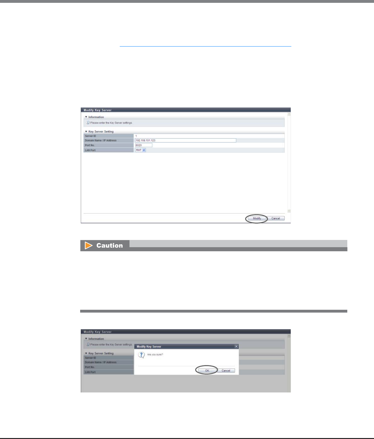
Chapter 11 System Management
11.2 Functions in the Action Area for System
ETERNUS Web GUI User’s Guide
Copyright 2013 FUJITSU LIMITED P2X0-1090-10ENZ0
840
-For IPv6 address
xxxx:xxxx:xxxx:xxxx:xxxx:xxxx:xxxx:xxxx
xxxx: 0 - ffff (FFFF) (hexadecimal, alphanumeric characters)
Refer to "IPv6 Address Notation (Setup Network Environment)" (page 757) for details.
•Port No.
Input the port number used to communicate with the key server.
The following input conditions apply:
-Numeric characters
-1 - 65535
•LAN Port
Select "MNT" or "RMT" for the LAN port that is to be used to communicate with the key server.
→A confirmation screen appears.
3Click the [OK] button.
→Changing of the key server settings starts.
An error screen appears in the following conditions:
•When each parameter fails to satisfy the input conditions
•When inputting a domain name or an IP address that is already used for another key server
•When the IP address that was input and the IP address of the LAN port (MNT or RMT) are the same
•When the IP address that was input and the network address for the LAN port (MNT or RMT) are
the same
Chapter 11 System Management
11.2 Functions in the Action Area for System
ETERNUS Web GUI User’s Guide
Copyright 2013 FUJITSU LIMITED P2X0-1090-10ENZ0
841
4Click the [Done] button to return to the [Key Management] screen.
End of procedure
11.2.6.6 Create Key Group
This function creates a key group.
The key group combines all of the RAID groups that use the same key. One key group can be created in the
ETERNUS DX Disk storage system.
The procedure to create a key group is as follows:
Procedure
1Click [Create Key Group] in [Action].
2Specify the parameters, and click the [Create] button.
•Name
Input a key group name.
The key group name corresponds to "Serial Number", which is managed in the key server.
The following input conditions apply:
-Up to 32 alphanumeric characters and symbols (underscore "_")
-The first letter must be an alphabetic character
The key group cannot be created when a common key (*1) is not registered. Refer to "11.2.13.7 Register SED
Authentication Key" (page 944) for details.
*1: The common key for SEDs that are managed in the ETERNUS DX Disk storage system.
•The key group can be created even when the key server is not registered.
•The key group can be created even when communication with the key server is not available.
•Register RAID groups that use the same key in the key group. Refer to "6.2.8 Set Key Group (RAID Group)"
(page 195) for details.
•The RAID groups that are registered in the key group can be checked by using the [SED Key Group] screen.
Refer to "6.1.4 SED Key Group" (page 167) for details.
•There are two types of SED keys: a common key and a key that is managed in the key server. RAID groups
that use the common key and RAID groups that use the key managed in the key server (RAID groups that
are registered in the key group) can be created in the same storage system.
•Specify a unique key group name that is different from the other storage systems that use the
same key server.
•Do not change the key group name after the key status changes to "Normal". The key status can
be checked on the [Key Group] screen. Refer to "11.1.5.1 Key Group" (page 723) for details.
Chapter 11 System Management
11.2 Functions in the Action Area for System
ETERNUS Web GUI User’s Guide
Copyright 2013 FUJITSU LIMITED P2X0-1090-10ENZ0
842
•Storage System Group Name
Input the storage system group name.
The storage system group combines the key management device (Key Management Machine)
name that is managed by the user with the key groups. The storage system group name
corresponds to "Device Group Name", which is managed in the key server. If the default setting is
used, input "ETERNUS_DX". Note that "ETERNUS_DX" is specified as the default device group name
when an ETERNUS DX Disk storage system is shipped with "ETERNUS SF KM" (key management
software).
The following input conditions apply:
-Up to 16 alphanumeric characters and symbols (underscore "_")
-The first letter must be an alphabetic character
-"ETERNUS_DX" (When using the default setting)
•Security Level
Select the security level of the key group from "High" or "Low".
"Security Level" indicates the handling level when application of the SED key to the target RAID
group fails. If the key for the relevant RAID group cannot be obtained from the key server due to a
communication error and the SEDs that configure the RAID group are changed to hot spares or
changed to new SEDs due to failure or maintenance, the ETERNUS DX Disk storage system performs
operations according to the selected security level.
-High
Rebuilding to hot spares for which the key cannot be changed after SED failure is not performed.
The RAID group loses its redundancy (" Exposed" or " Partially Exposed" (for High Reliabil-
ity (RAID6))).
When SED maintenance is being performed, replacing a SED with a new SED for which the key
cannot be changed does not complete successfully. If this action is performed, the status of the
new SED changes to " Not Exist".
When communication between the key server and the ETERNUS DX Disk storage system returns
to normal and the key can be obtained, the SED status changes to normal. Rebuilding to the SED
for which the status changed to normal is performed after the key is changed. Note that
"Modifying" may be displayed for the key status for few minutes even though the SED key has
already changed. After changing the key, maintenance of the SEDs is complete.
-Low
Rebuilding or maintenance is performed by using the common key if changing of the key in the
key server fails due to a network error.
Even if the security level is changed from "High" to "Low", the rebuilding process does not start
immediately after the level is changed. Rebuilding processes start after the ETERNUS DX Disk
storage system recognizes that changing of the security level and the key is complete.
•For the storage system group name, specify the same name as "Device Group Name", which is
registered in the key server.
•Do not change the storage system group name after the key status changes to "Normal". The
key status can be checked on the [Key Group] screen. Refer to "11.1.5.1 Key Group" (page 723)
for details.
Chapter 11 System Management
11.2 Functions in the Action Area for System
ETERNUS Web GUI User’s Guide
Copyright 2013 FUJITSU LIMITED P2X0-1090-10ENZ0
843
•Recovery Mode
Select the recovery mode of the key group from "Auto" or "Manual".
The recovery mode is a method to recover locked (*1) RAID groups or SEDs after communication
with the key server is resolved. For RAID groups in locked status, " SED Locked" is displayed. For
SEDs in locked status, " Not Exist" is displayed.
*1: A blocked status that occurs when the key of the RAID groups cannot be obtained.
-Auto
This mode recovers locked RAID groups or SEDs when the communication error with the key
server is resolved.
-Manual
Use the [Recovery SED] function of GUI to recover the locked RAID groups or SEDs when the
communication error with the key server is resolved.
•Key Valid Period
Select a key expiration period that is based on the date when the key from the server is obtained for
the first time (beginning of use).
When the key expires, a new key is obtained from the key server and the expired key is
automatically replaced. The key expiration period is checked every eight hours.
-Unlimited
The same key is used until exactly 20 years elapses since the key was first used.
-1 month - 12 month
The same key is used until the date and time in the specified month elapses since the key was
first used. If the same date does not exist in the specified month (such as April 31st), the
expiration date of the key becomes the last date of the specified month.
•Key Server
-Master
-Slave
Select the key server ID that is assigned for the master or slave server. "None" and the registered
key server ID are displayed as options.
•None
•1
•2
•The same server ID (except for "None") cannot be selected for both the master and slave
servers.
•The key can only be updated when the master server is specified. Refer to "11.2.6.9 Update SED
Authentication Key" (page 849) for details.
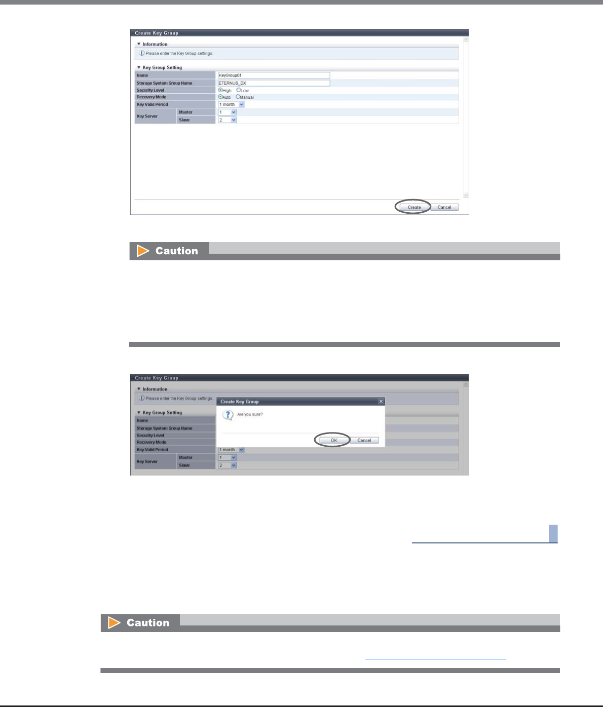
Chapter 11 System Management
11.2 Functions in the Action Area for System
ETERNUS Web GUI User’s Guide
Copyright 2013 FUJITSU LIMITED P2X0-1090-10ENZ0
844
→A confirmation screen appears.
3Click the [OK] button.
→Key group creation starts.
4Click the [Done] button to return to the [Key Group] screen.
End of procedure
11.2.6.7 Delete Key Group
This function deletes the key group.
An error screen appears in the following conditions:
•When the "Name" is not entered
•When the "Storage System Group Name" is not entered
•When each parameter fails to satisfy the input conditions
•When the same server ID is specified for both the master and slave servers
A key group in which RAID groups are registered cannot be deleted. Use the [SED Key Group] screen to check
whether RAID groups are registered in the key group. Refer to "6.1.4 SED Key Group" (page 167) for details.
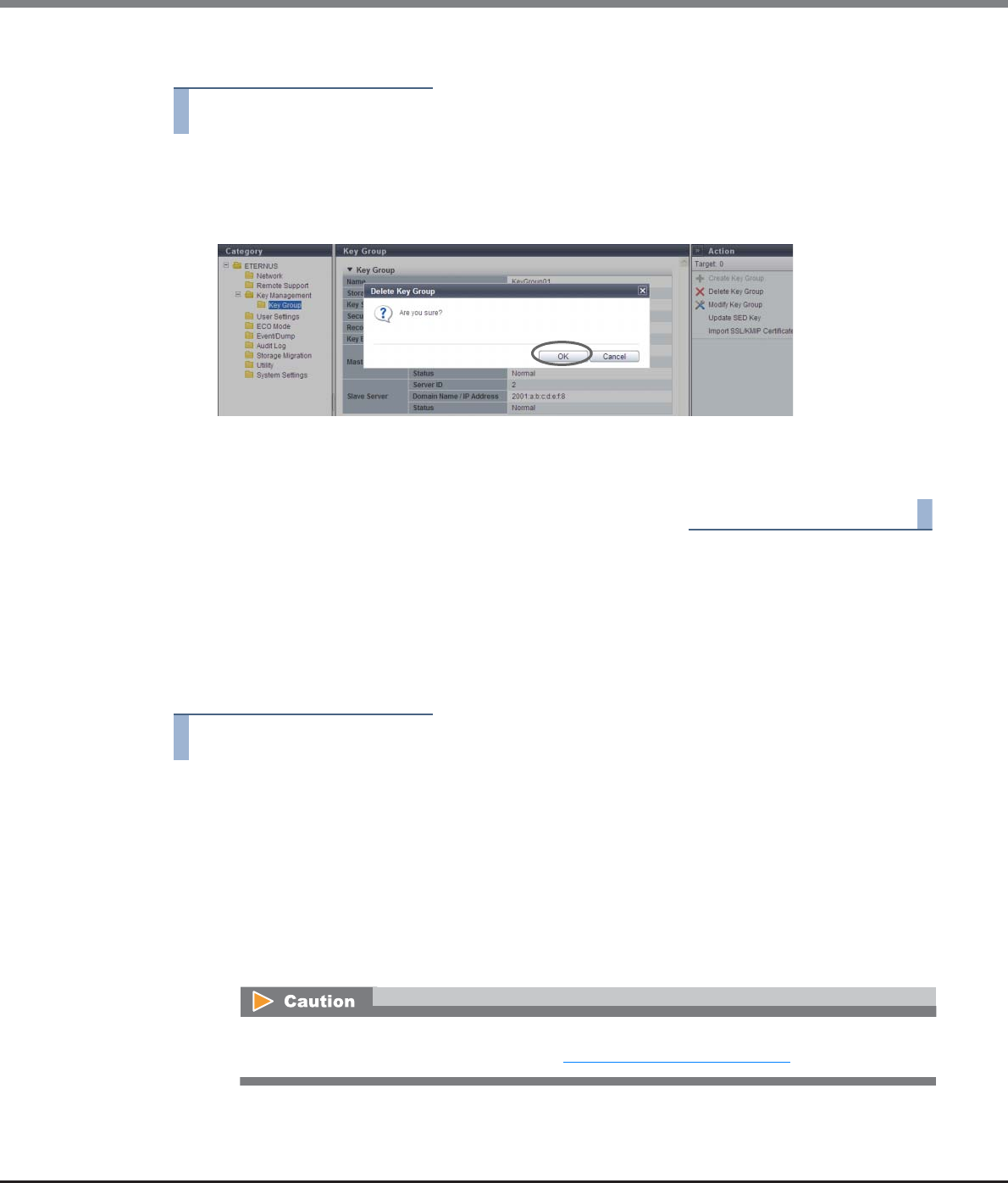
Chapter 11 System Management
11.2 Functions in the Action Area for System
ETERNUS Web GUI User’s Guide
Copyright 2013 FUJITSU LIMITED P2X0-1090-10ENZ0
845
The procedure to delete a key group is as follows:
Procedure
1Click [Delete Key Group] in [Action].
→A confirmation screen appears.
2Click the [OK] button.
→Deleting of the key group starts.
3Click the [Done] button to return to the [Key Group] screen.
End of procedure
11.2.6.8 Modify Key Group
This function changes the key group settings.
The key group combines all of the RAID groups that use the same key.
The procedure to change the key group settings is as follows:
Procedure
1Click [Modify Key Group] in [Action].
2Specify the parameters, and click the [Modify] button.
•Name
Input a key group name.
The key group name corresponds to "Serial Number", which is managed in the key server.
The following input conditions apply:
-Up to 32 alphanumeric characters and symbols (underscore "_")
-The first letter must be an alphabetic character
Do not change the key group name after the key status changes to "Normal". The key status can be
checked on the [Key Group] screen. Refer to "11.1.5.1 Key Group" (page 723) for details.
Chapter 11 System Management
11.2 Functions in the Action Area for System
ETERNUS Web GUI User’s Guide
Copyright 2013 FUJITSU LIMITED P2X0-1090-10ENZ0
846
•Storage System Group Name
Input the storage system group name.
The storage system group combines the key management device (Key Management Machine)
name that is managed by the user with the key groups. The storage system group name
corresponds to "Device Group Name", which is managed in the key server.
The following input conditions apply:
-Up to 16 alphanumeric characters and symbols (underscore "_")
-The first letter must be an alphabetic character
•Security Level
Select the security level of the key group from "High" or "Low".
"Security Level" indicates the handling level when application of the SED key to the target RAID
group fails. If the key for the relevant RAID group cannot be obtained from the key server due to a
communication error and the SEDs that configure the RAID group are changed to hot spares or
changed to new SEDs due to failure or maintenance, the ETERNUS DX Disk storage system performs
operations according to the selected security level.
-High
Rebuilding to hot spares for which the key cannot be changed after SED failure is not performed.
The RAID group loses its redundancy (" Exposed" or " Partially Exposed" (for High Reliabil-
ity (RAID6))).
When SED maintenance is being performed, replacing a SED with a new SED for which the key
cannot be changed does not complete successfully. If this action is performed, the status of the
new SED changes to " Not Exist".
When communication between the key server and the ETERNUS DX Disk storage system returns
to normal and the key can be obtained, the SED status changes to normal. Rebuilding to the SED
for which the status changed to normal is performed after the key is changed. Note that
"Modifying" may be displayed for the key status for few minutes even though the SED key has
already changed. After changing the key, maintenance of the SEDs is complete.
-Low
Rebuilding or maintenance is performed by using the common key if changing of the key in the
key server fails due to a network error.
Even if the security level is changed from "High" to "Low", the rebuilding process does not start
immediately after the level is changed. Rebuilding processes start after the ETERNUS DX Disk
storage system recognizes that changing of the security level and the key is complete.
•Recovery Mode
Select the recovery mode of the key group from "Auto" or "Manual".
The recovery mode is a method to recover locked (*1) RAID groups or SEDs after communication
with the key server is resolved. For RAID groups in locked status, " SED Locked" is displayed. For
SEDs in locked status, " Not Exist" is displayed.
*1: A blocked status that occurs when the key of the RAID groups cannot be obtained.
Do not change the storage system group name after the key status changes to "Normal". The key
status can be checked on the [Key Group] screen. Refer to "11.1.5.1 Key Group" (page 723) for
details.

Chapter 11 System Management
11.2 Functions in the Action Area for System
ETERNUS Web GUI User’s Guide
Copyright 2013 FUJITSU LIMITED P2X0-1090-10ENZ0
847
-Auto
This mode recovers locked RAID groups or SEDs when the communication error with the key
server is resolved.
-Manual
Use the [Recovery SED] function of GUI to recover the locked RAID groups or SEDs when the
communication error with the key server is resolved.
•Key Valid Period
Select a key expiration period that is based on the date when the key from the server is obtained for
the first time (beginning of use).
When the key expires, a new key is obtained from the key server and the expired key is
automatically replaced. If the key expiration period is changed, the same key is used from the first
date of use until the key expired. Note that the "first date" indicates the first day of use instead of
the first day of the key changed.
-Unlimited
The same key is used until exactly 20 years elapses since the key was first used.
-1 month - 12 month
The same key is used until the date and time in the specified month elapses since the key was
first used. If the same date does not exist in the specified month (such as April 31st), the
expiration date of the key becomes the last date of the specified month.
•Key Server
-Master
-Slave
Select the key server ID that is assigned for the master or slave server. "None" and the registered
key server ID are displayed as options.
•None
•1
•2
•The same server ID (except for "None") cannot be selected for both the master and slave
servers. Note that "None" cannot be selected for both of the servers when RAID groups are reg-
istered in the key group.
•The key can only be updated when the master server is specified. Refer to "11.2.6.9 Update SED
Authentication Key" (page 849) for details.
•To perform maintenance of the key server, the key server setting parameters must be released
temporality. Select "None" for the target key server before starting maintenance. After
maintenance is complete, set the key server parameters again.
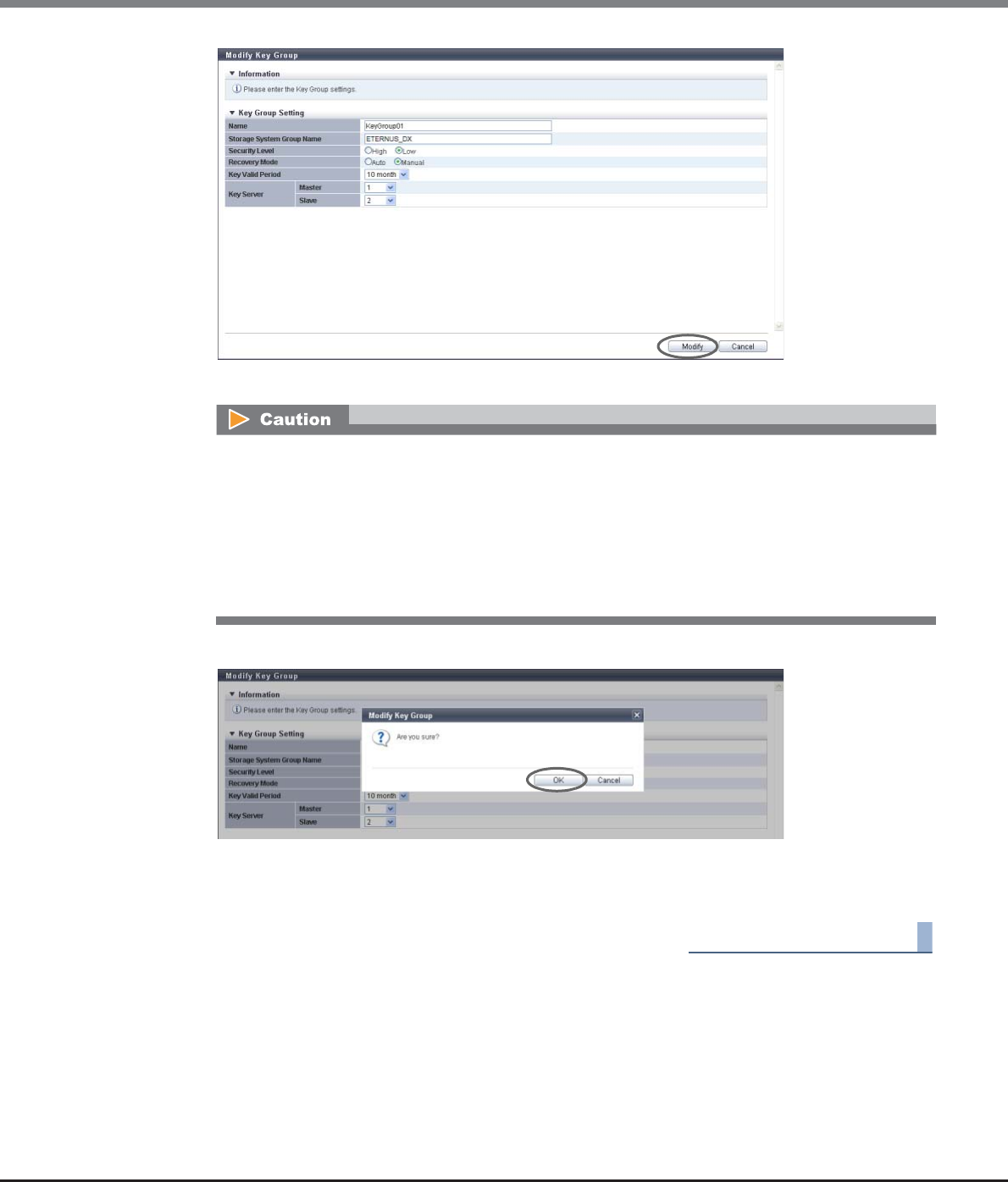
Chapter 11 System Management
11.2 Functions in the Action Area for System
ETERNUS Web GUI User’s Guide
Copyright 2013 FUJITSU LIMITED P2X0-1090-10ENZ0
848
→A confirmation screen appears.
3Click the [OK] button.
→Changing of the key group settings starts.
4Click the [Done] button to return to the [Key Group] screen.
End of procedure
An error screen appears in the following conditions:
•When the "Name" is not entered
•When the "Storage System Group Name" is not entered
•When each parameter fails to satisfy the input conditions
•When the same server ID is specified for both the master and slave servers
•When "None" is selected for both of the servers (master and slave) while RAID groups are
registered in the key group
Chapter 11 System Management
11.2 Functions in the Action Area for System
ETERNUS Web GUI User’s Guide
Copyright 2013 FUJITSU LIMITED P2X0-1090-10ENZ0
849
11.2.6.9 Update SED Authentication Key
This function updates the key in the key group. Updating of the key is performed in the following ways:
•When no key is registered in the key group, a key that has not expired is obtained from the key server.
•When the key is valid and has not expired, this key is replaced with a new key from the key server.
The ETERNUS DX Disk storage system monitors the key on a regular basis and automatically replaces an
expired key with a new key. This function is used when a new key is required before the key expiration date
has been reached because the user loses the SEDs that were disconnected for maintenance. This function asks
whether to use the current key again when replacing the key.
The procedure to update a key in the key group is as follows:
Procedure
1Click [Update SED Key] in [Action].
•Replacing a key is only available when the master server is registered. Check the registration status of the
master server in the [Key Group] screen. To replace the key, register the master server in advance. Refer to
"11.2.6.8 Modify Key Group" (page 845) for details.
•The key is updated only when communication with the master server is normal.
•If no key is registered in the key group, an error occurs when the first update of the key is performed. In
this case, register the SSL certificate of the ETERNUS DX Disk storage system in the key server, accept
access from the ETERNUS DX Disk storage system, and then update the key again. The key status changes
to "Normal". An SSL certificate of the ETERNUS DX Disk storage system indicates a "self-signed SSL certifi-
cate" or an "SSL server certificate".
•The key can only be updated when the SEDs that configure the RAID groups in the key group are in the
normal status. If there are SEDs without normal status in the RAID group, make sure to perform
maintenance for these SEDs in advance. If the key is updated before required maintenance is performed
for the SEDs, the RAID group status changes to " Exposed" and updating of the key for the RAID group
is not complete (the key status of the key group is not changed from "Modifying"). Updating of the key is
complete after performing the SED maintenance and the status of all the RAID groups has returned to
" Available" (the key status of the key group has changed to "Normal").
•If the RAID groups in the key group are blocked (the status is " SED Locked"), the RAID group status is
not changed to " Available" even after the key is updated. Make sure to recover SEDs before updating
the key. Refer to "6.2.9 Recovery SED" (page 197) for details.
•When "Disabled Key" is selected for "Current Key", make sure to compromise (*1) the key in the key server
by using CLI for the key server. Note that GUI for the key server does not support the key compromising
function.
*1: The key becomes unavailable in the key server.
•This function can be used to replace a key when the expiration date of the key is set to "Unlimited".
•This function can also be used to update the key in a key group in which no RAID groups are registered.
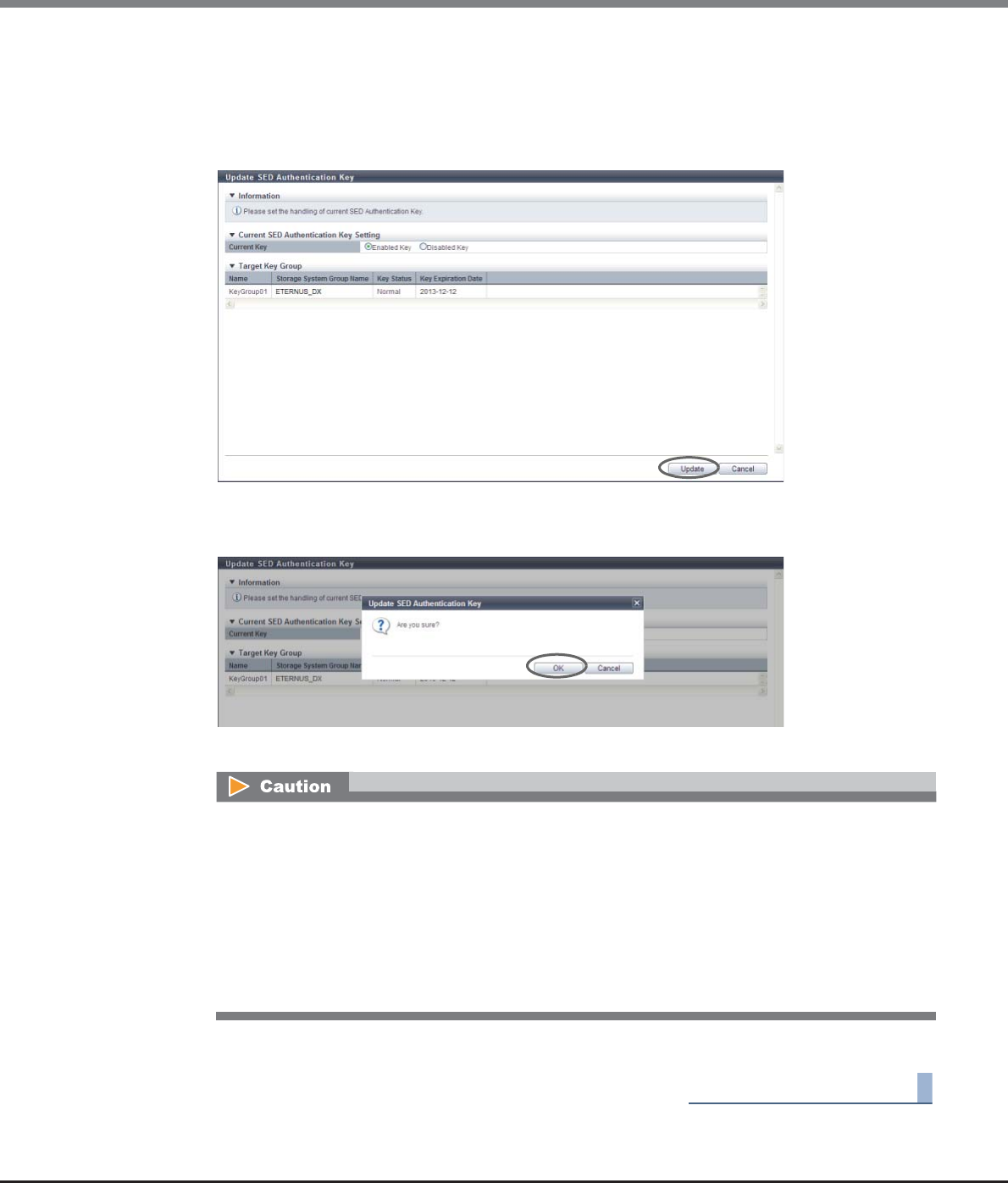
Chapter 11 System Management
11.2 Functions in the Action Area for System
ETERNUS Web GUI User’s Guide
Copyright 2013 FUJITSU LIMITED P2X0-1090-10ENZ0
850
2Select whether to use the current key again, and then click the [Update] button.
•Current Key
Select whether to enable ("Enabled Key") or disable ("Disabled Key") the current key.
-Enabled Key
-Disabled Key
→A confirmation screen appears.
3Click the [OK] button.
→Updating of the SED Authentication Key starts.
4Click the [Done] button to return to the [Key Group] screen.
End of procedure
An error screen appears in the following conditions:
•When the master server for the key group is not registered
•When one of the following statuses applies to the key in the key group:
-Unregistered Server Certificate
-Expired Server Certificate
-No SSL Certificate
-Network Error
-Key Server Error
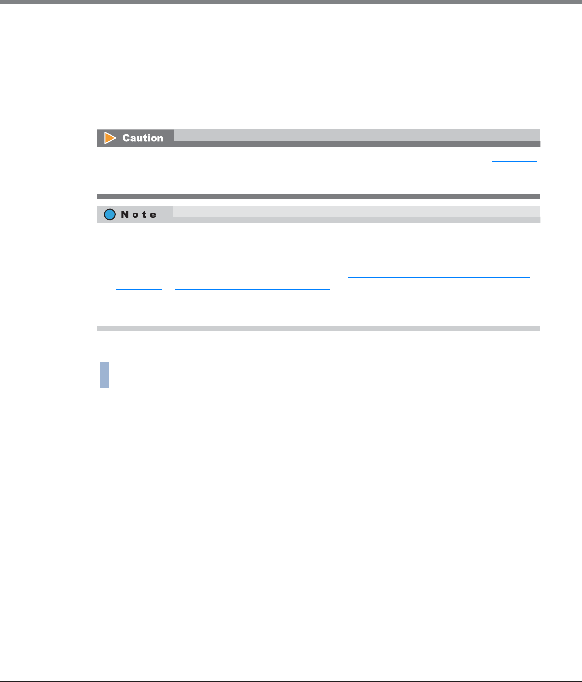
Chapter 11 System Management
11.2 Functions in the Action Area for System
ETERNUS Web GUI User’s Guide
Copyright 2013 FUJITSU LIMITED P2X0-1090-10ENZ0
851
11.2.6.10 Import SSL/KMIP Certificate
This function registers the SSL/KMIP certificate in the ETERNUS DX Disk storage system. The SSL/KMIP certifi-
cate is used for communication with the key server.
When performing management of the key in the key server, communication between the key server and the
ETERNUS DX80 S2/DX90 S2, the ETERNUS DX410 S2/DX440 S2, or the ETERNUS DX8100 S2/DX8700 S2 is
required. To establish communication, register the "SSL/KMIP certificate" (a reliable certificate of the key
server) in the ETERNUS DX Disk storage system.
The procedure to register the SSL/KMIP certificate is as follows:
Procedure
1Click [Import SSL/KMIP Certificate] in [Action].
2Click the [Browse...] button to specify the path to the "SSL/KMIP Certificate File".
•SSL/KMIP Certificate File
Click the [Browse...] button to specify the SSL/KMIP certificate file, or directly input the path to the
SSL/KMIP certificate file.
The SSL/KMIP certificate cannot be registered when a common key (*1) is not specified. Refer to "11.2.13.7
Register SED Authentication Key" (page 944) for details.
*1: The common key for SEDs that are managed in the ETERNUS DX Disk storage system.
•Export the SSL/KMIP certificate from the key server and register this certificate in the ETERNUS DX Disk
storage system.
•To establish communication between the key server and the ETERNUS DX Disk storage system, the SSL
certificate of the storage system is also required. Refer to "11.2.3.15 Create Self-signed SSL Certificate"
(page 787) or "11.2.3.16 Create Key/CSR" (page 790) for details.
•The SSL / KMIP certificate can be registered even when the key server is not specified.
•The SSL / KMIP certificate can be registered even when the key group is not created.
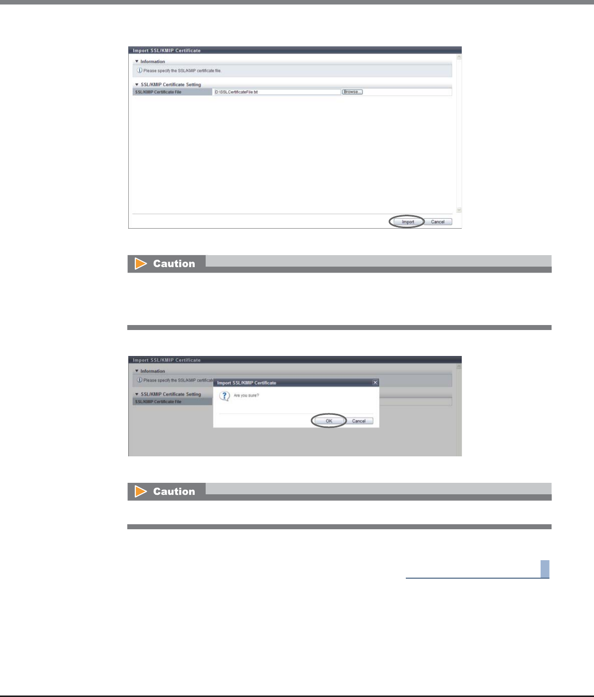
Chapter 11 System Management
11.2 Functions in the Action Area for System
ETERNUS Web GUI User’s Guide
Copyright 2013 FUJITSU LIMITED P2X0-1090-10ENZ0
852
3Click the [Import] button.
→A confirmation screen appears.
4Click the [OK] button.
→Importing of the SSL/KMIP certificate starts.
5Click the [Done] button to return to the [Key Group] screen.
End of procedure
An error screen appears in the following conditions:
•When reading of the "SSL / KMIP Certificate" failed
•When the "SSL / KMIP Certificate" file is larger than 4096 bytes
When the imported file was not the "SSL/KMIP Certificate File", an error screen appears.
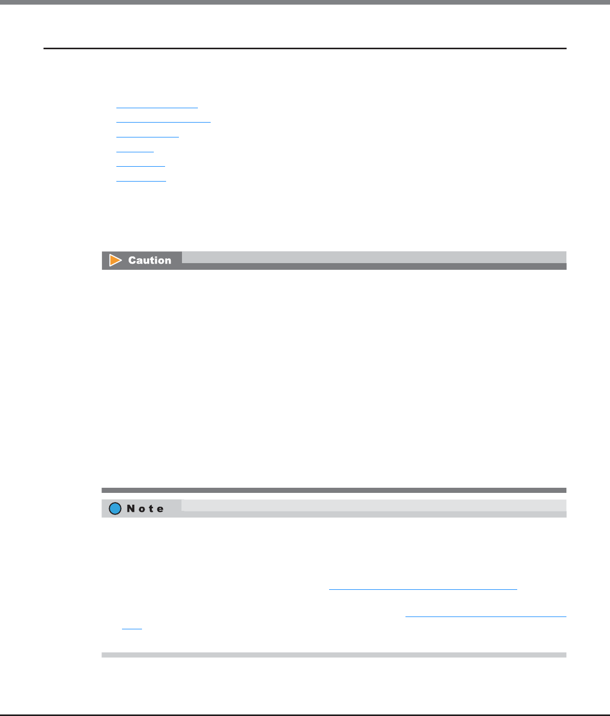
Chapter 11 System Management
11.2 Functions in the Action Area for System
ETERNUS Web GUI User’s Guide
Copyright 2013 FUJITSU LIMITED P2X0-1090-10ENZ0
853
11.2.7 Define Role
This section describes user management.
User management provides the following functions:
•Setup User Account
•Initialize User Account
•Modify RADIUS
•Add Role
•Delete Role
•Modify Role
11.2.7.1 Setup User Account
This function adds, edits, and deletes the user account.
•Up to 60 user accounts can be set.
•When using the SSH Client Key authentication, create a pair of the SSH client public key and the SSH
client secret key in advance, using the creation tool. One public key can be registered per user account.
When the [Setup User Account] function is executed, the public key is registered in the ETERNUS DX Disk
storage system.
•The following types (formats) of public keys can be used:
-RSA for SSH1 (OpenSSH)
-DSA for SSH2 (IETF)
-RSA for SSH1 (IETF)
The supported maximum encryption strength for the public key is 4096-bit.
•"User Name" for user accounts cannot be changed.
•The current user account (your account) can be changed or deleted. When deleting a user account, at
least one user account with administrator privileges (role of "Admin") added must remain. Changed or
deleted settings become available at the next login.
•The last user account with administrator privileges (role of "Admin") added cannot be deleted.
•For a user account, the following items can be changed: "New Password", "User Role", whether to enable
or disable "Account", and whether to register "SSH Public Key" or not.
•When a user account is deleted, the SSH client public key registered in the ETERNUS DX Disk storage
system is also deleted.
•To initialize a user account, use the procedure in "11.2.7.2 Initialize User Account" (page 860). When a
user account is initialized, the password for the default account can be initialized.
•To change the current user's (your) password, use the procedure in "11.2.1 Change User Password" (page
742).
•When RADIUS Authentication is used for login, the current user's (your) password cannot be changed.
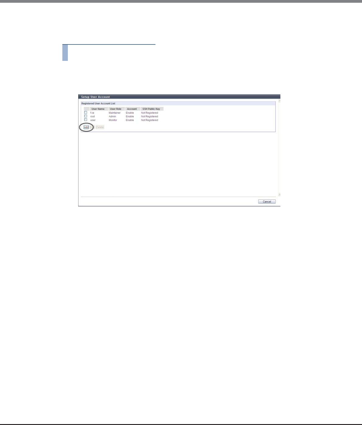
Chapter 11 System Management
11.2 Functions in the Action Area for System
ETERNUS Web GUI User’s Guide
Copyright 2013 FUJITSU LIMITED P2X0-1090-10ENZ0
854
■Add User Account
The procedure to add a user accounts is as follows:
Procedure
1Click [Setup User Account] in [Action].
2Click the [Add] button.
3Specify the parameters, and click the [Apply] button.
•User Name
Input a user name.
An existing user name cannot be used. Entered letters are case-sensitive.
The following input condition applies:
-Up to 32 alphanumeric characters and symbols ('!', '-', '_', '.')
•New Password
Input a password.
Entered letters are case-sensitive.
The following input condition applies:
-4 - 64 alphanumeric characters and symbols ('!', '-', '_', '.')
•Confirm New Password
Input the same character string as the value entered in the "New Password" field for confirmation.
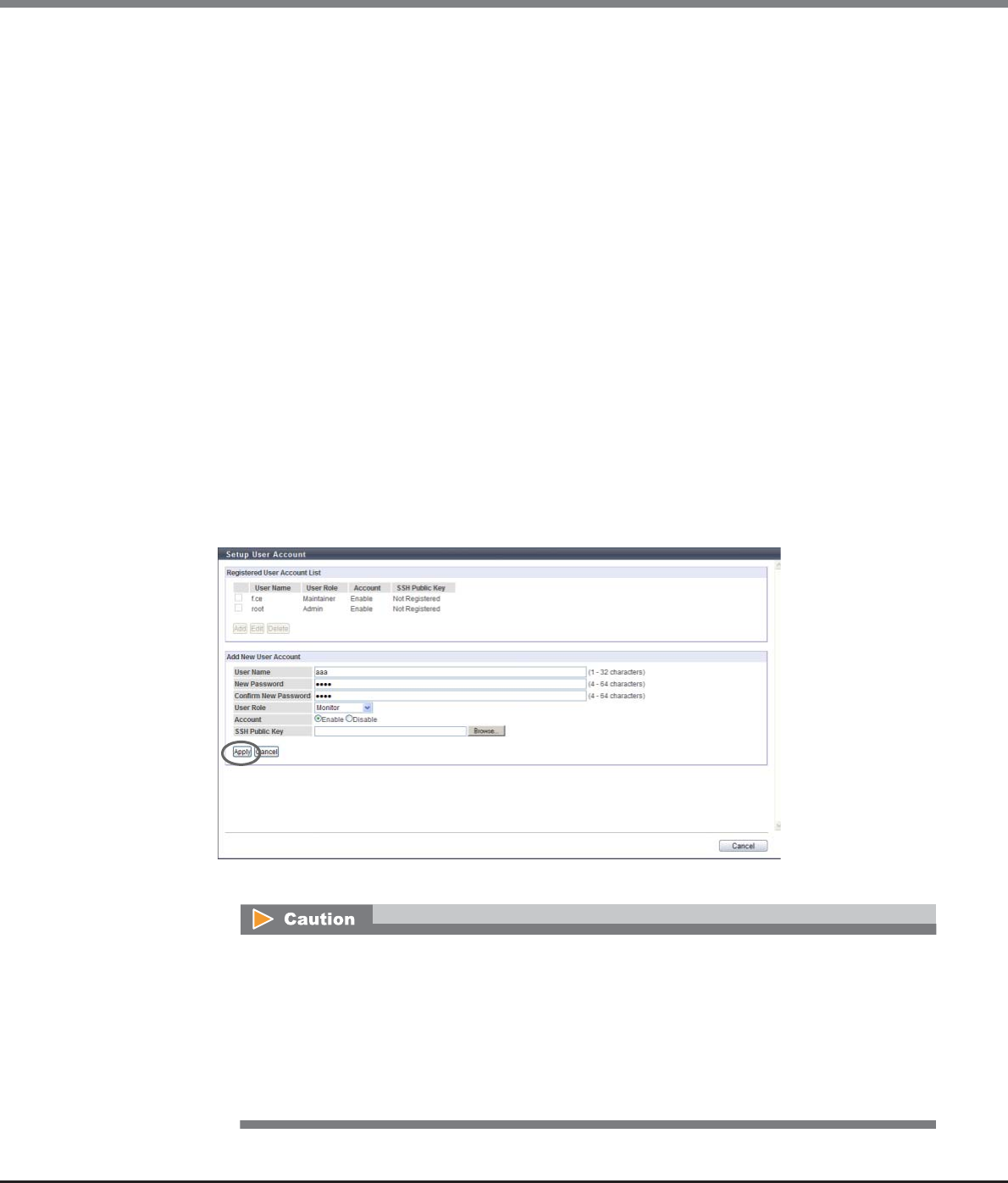
Chapter 11 System Management
11.2 Functions in the Action Area for System
ETERNUS Web GUI User’s Guide
Copyright 2013 FUJITSU LIMITED P2X0-1090-10ENZ0
855
•User Role
Select the user role to be added to the user name.
The default and custom roles registered in the ETERNUS DX Disk storage system are displayed as the
options.
-Monitor
-Admin
-StorageAdmin
-AccountAdmin
-SecurityAdmin
-Maintainer
-Software
-Custom role
•Account
Select whether to "Enable" or "Disable" the user account.
If the user account is disabled, that user account is registered but cannot be used.
•SSH Public Key
Register the SSH client public key used for login authentication from CLI in the ETERNUS DX Disk
storage system.
Click the [Browse...] button and specify the public key to be registered.
When using the SSH client key authentication, register the SSH public key in the ETERNUS DX Disk
storage system and prepare the SSH secret key, corresponding to the public key in the client PC in
advance.
→A confirmation screen appears.
•"Software" is the dedicated role that is used for external software. A user account with the
"Software" role cannot log in to GUI.
•An error screen appears in the following conditions:
-When a parameter does not satisfy the input conditions
-When the user name is already registered
-When "User Name", "New Password" and/or "Confirm New Password" is not input
-When "New Password" does not match "Confirm New Password"
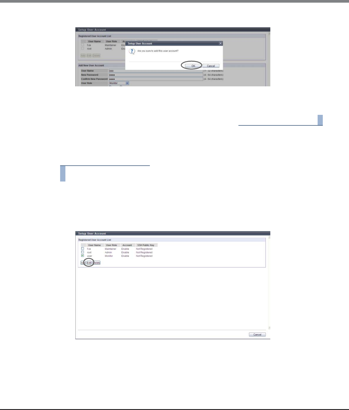
Chapter 11 System Management
11.2 Functions in the Action Area for System
ETERNUS Web GUI User’s Guide
Copyright 2013 FUJITSU LIMITED P2X0-1090-10ENZ0
856
4Click the [OK] button.
→The user account setup starts.
5Click the [Done] button to return to the [Define Role] screen.
End of procedure
■Edit User Account
The procedure to edit a user accounts is as follows:
Procedure
1Click [Setup User Account] in [Action].
2Select the user account to be modified and click the [Edit] button.
•Checkbox
Select the checkbox for the user account to be modified.

Chapter 11 System Management
11.2 Functions in the Action Area for System
ETERNUS Web GUI User’s Guide
Copyright 2013 FUJITSU LIMITED P2X0-1090-10ENZ0
857
3Change the parameters, and click the [Apply] button.
●Edit User Account
•Change Password
Only when changing the password, select the "Change Password" checkbox.
When the "Change Password" checkbox is selected, enter a new password in "New Password" and
"Confirm New Password".
•New Password
Input a new password.
Entered letters are case-sensitive.
The following input condition applies:
-4 - 64 alphanumeric characters and symbols ('!', '-', '_', '.')
•Confirm New Password
Input the same character string as the value entered in the "New Password" field for confirmation.
•User Role
Select the user role to be added to the user name.
The default and custom roles registered in the ETERNUS DX Disk storage system are displayed as the
options.
-Monitor
-Admin
-StorageAdmin
-AccountAdmin
-SecurityAdmin
-Maintainer
-Software
-Custom role
•Account
Select whether to "Enable" or "Disable" the user account.
If the user account is disabled, that user account is registered but cannot be used.
•SSH Public Key
Register the SSH client public key used for login authentication from CLI in the ETERNUS DX Disk
storage system.
Click the [Browse...] button and specify the public key to be registered.
When using the SSH Client Key authentication, register the SSH public key in the ETERNUS DX Disk
storage system and prepare the SSH secret key, corresponding to the public key in the client PC in
advance.
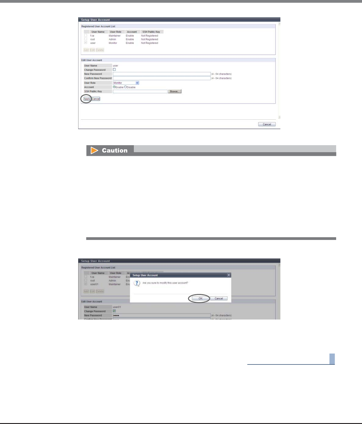
Chapter 11 System Management
11.2 Functions in the Action Area for System
ETERNUS Web GUI User’s Guide
Copyright 2013 FUJITSU LIMITED P2X0-1090-10ENZ0
858
→A confirmation screen appears.
4Click the [OK] button.
→The user account setup starts.
5Click the [Done] button to return to the [Define Role] screen.
End of procedure
•"Software" is the dedicated role that is used for external software. A user account with the
"Software" role cannot log in to GUI.
•To change the password, select the "Change Password" checkbox.
•An error screen appears in the following conditions:
-When a parameter does not satisfy the input conditions
-When the "Change Password" checkbox is selected and "New Password" and/or "Confirm
New Password" is not input
-When the "Change Password" checkbox is selected and "New Password" does not match
"Confirm New Password"
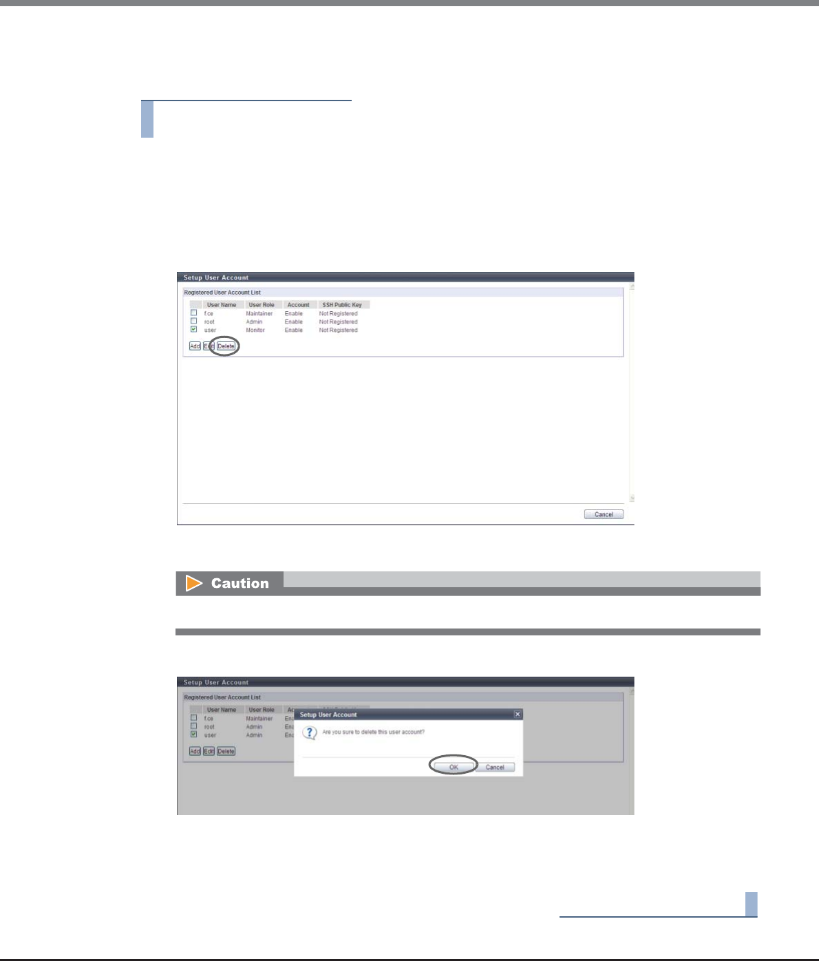
Chapter 11 System Management
11.2 Functions in the Action Area for System
ETERNUS Web GUI User’s Guide
Copyright 2013 FUJITSU LIMITED P2X0-1090-10ENZ0
859
■Delete User Account
The procedure to delete a user accounts is as follows:
Procedure
1Click [Setup User Account] in [Action].
2Select the deletion target user accounts (multiple selections can be made), and click the
[Delete] button.
•Checkbox
Select the checkbox for the user account to be deleted.
→A confirmation screen appears.
3Click the [OK] button.
→The user account deletion starts.
4Click the [Done] button to return to the [Define Role] screen.
End of procedure
When the last user account with the administrator privileges is selected, an error screen appears.
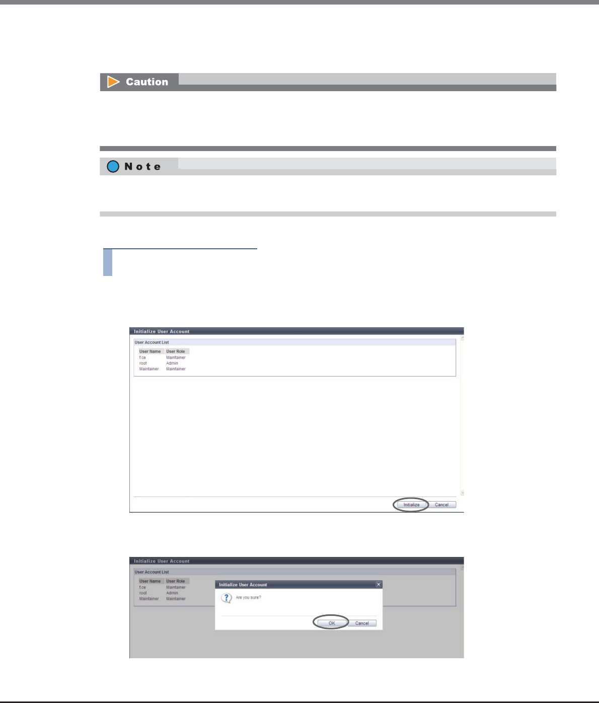
Chapter 11 System Management
11.2 Functions in the Action Area for System
ETERNUS Web GUI User’s Guide
Copyright 2013 FUJITSU LIMITED P2X0-1090-10ENZ0
860
11.2.7.2 Initialize User Account
This function initializes the user accounts to the default status.
The procedure to initialize user accounts is as follows:
Procedure
1Click [Initialize User Account] in [Action].
2Click the [Initialize] button.
→A confirmation screen appears.
3Click the [OK] button.
→The user account initialization starts.
•By using this function, all the registered user accounts are deleted and only the default account remains.
•The password for the default account is restored to the default password.
•The user accounts deleted by this function will be unavailable for the next login.
When the user accounts are initialized, the SSH client public keys for all the users registered in the ETERNUS
DX Disk storage system are also deleted.
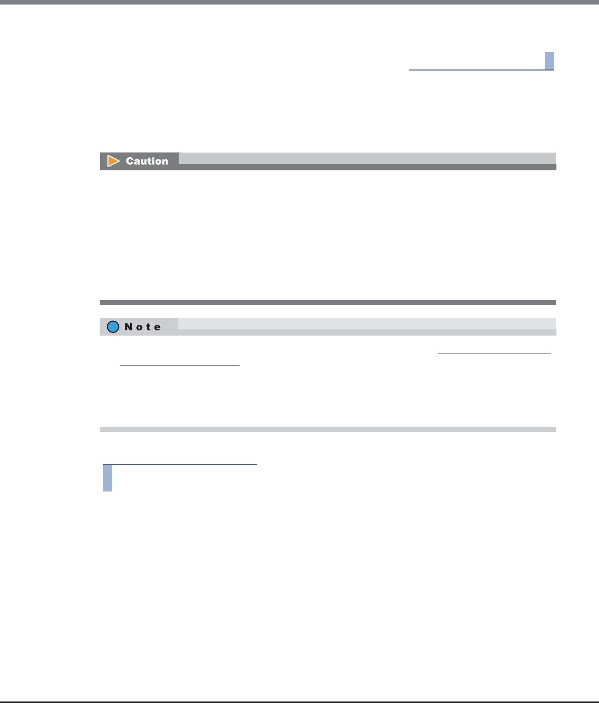
Chapter 11 System Management
11.2 Functions in the Action Area for System
ETERNUS Web GUI User’s Guide
Copyright 2013 FUJITSU LIMITED P2X0-1090-10ENZ0
861
4Click the [Done] button to return to the [Define Role] screen.
End of procedure
11.2.7.3 Modify RADIUS
This function specifies the external server (RADIUS server) that is used for authentication when logging in.
Up to two RADIUS Authentication servers can be registered.
The procedure to modify RADIUS is as follows:
Procedure
1Click [Modify RADIUS] in [Action].
2Specify the parameters, and click the [Modify] button.
●RADIUS Setting
•RADIUS Authentication
Select whether to "Enable" or "Disable" RADIUS Authentication.
-Enable
Use RADIUS Authentication.
-Disable
Use Internal Authentication.
•Enable or disable RADIUS Authentication for each storage system.
•If RADIUS Authentication fails when "No" has been selected for "Recovery Mode" in the RADIUS Setting
field, logging in to GUI will not be available.
•RADIUS Authentication cannot be used when logging in to the Slave CM.
•When "Yes (Communication error)" has been selected for "Recovery Mode" in the RADIUS Setting field,
Internal Authentication (*1) is performed if authentication fails in both the primary and the secondary
servers due to a network error in either or both of the servers.
*1: This is the standard authentication type. Internal Authentication uses user account information stored in the
storage system to verify the input user account.
•There are supplementary notes when using RADIUS Authentication. Refer to "Appendix G Using RADIUS
Authentication" (page 1013) for details.
•When using RADIUS Authentication, registering user account information (user name, password, and
role) in RADIUS server is required. For details, refer to the manuals provided with the server.
•Even if the RADIUS Authentication function has been changed to "Disable", RADIUS setting information in
the ETERNUS DX Disk storage system is maintained.

Chapter 11 System Management
11.2 Functions in the Action Area for System
ETERNUS Web GUI User’s Guide
Copyright 2013 FUJITSU LIMITED P2X0-1090-10ENZ0
862
•Recovery Mode
When "Enable" has been specified in the "RADIUS Authentication" field, select the desired operation
if RADIUS Authentication fails.
If RADIUS Authentication fails when "No" has been selected for "Recovery Mode", logging in to GUI
will not be available.
Selecting "Yes" is recommended.
-Yes (Communication error / Authentication error)
When communication with the RADIUS server fails or communication with the RADIUS server
succeeds but authentication fails, internal authentication is performed.
-Yes (Communication error)
When communication with the RADIUS server fails, internal authentication is performed.
-No
Even when communication with the RADIUS server fails, or communication with the RADIUS
server succeeds but authentication fails, internal authentication is not performed.
●Primary Server (required) / Secondary Server
•Domain Name / IP Address
Input the domain name or the IP address of the RADIUS server.
There are two methods to specify an IP address; "IPv4" and "IPv6". The following IPv6 addresses can
be used; "link local address", "global address", "unique local address", and "6to4 address". Refer to
"Available IPv6 Address" (page 757) for details.
When the current setting is displayed, the IPv6 address is displayed as an abbreviation.
The following input conditions apply:
-For IPv4 address
xxx.xxx.xxx.xxx
xxx: 1 - 255 for the top field (decimal)
xxx: 0 - 255 for other fields (decimal)
-For IPv6 address
xxxx:xxxx:xxxx:xxxx:xxxx:xxxx:xxxx:xxxx
xxxx: 0 - ffff (FFFF) (hexadecimal, alphanumeric characters)
Refer to "IPv6 Address Notation" (page 378) for details.
•Port No.
Input the port number that is used for RADIUS Authentication.
The following input condition applies:
-Numeric characters ("1" - "65535")
•LAN Port
Select the LAN port from "MNT" or "RMT" that is to be used for RADIUS Authentication.
•Authentication Mode
Select the authentication mode for RADIUS Authentication from "CHAP" and "PAP".
•Shared Secret
Input the same Shared Secret as the RADIUS server.
The following input condition applies:
-Up to 64 alphanumeric characters and symbols
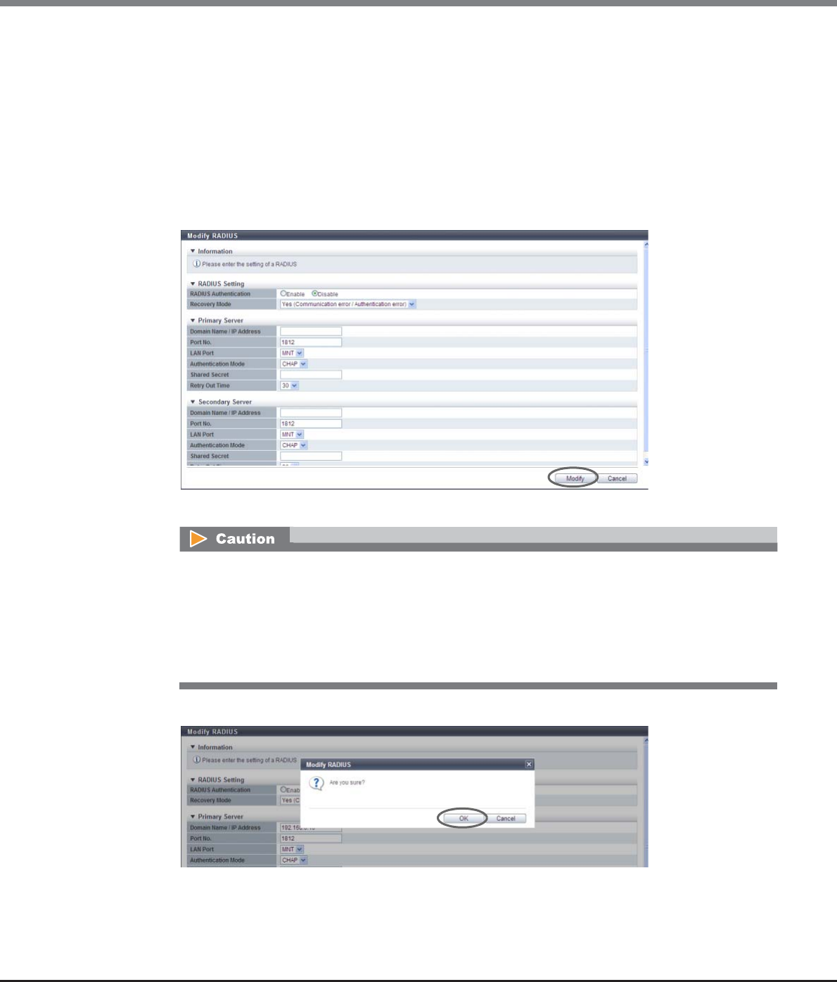
Chapter 11 System Management
11.2 Functions in the Action Area for System
ETERNUS Web GUI User’s Guide
Copyright 2013 FUJITSU LIMITED P2X0-1090-10ENZ0
863
•Retry Out Time
Select the total time (seconds) for waiting for a response from the RADIUS server.
ETERNUS DX Disk storage system retries authentication during the specified time (seconds), and if
there is no response in the specific time, regards the situation as a network error.
-10
-20
-30
-40
-50
-60
→A confirmation screen appears.
3Click the [OK] button.
→Setting of the RADIUS Authentication starts.
An error screen appears in the following conditions:
•When each parameter fails to satisfy the input conditions
•When the primary server is not specified
•When there is an unspecified parameter for the server
•When the "Domain Name / IP Address" of the Primary server overlaps with that of the Secondary
server

Chapter 11 System Management
11.2 Functions in the Action Area for System
ETERNUS Web GUI User’s Guide
Copyright 2013 FUJITSU LIMITED P2X0-1090-10ENZ0
864
4Click the [Done] button to return to the [Define Role] screen.
End of procedure
11.2.7.4 Add Role
This function combines several user policies and creates a user-specific role (custom role).
Up to 20 roles can be created per storage system.
Policy
The 14 types of access privileges shown below are available.
An error screen appears if the specified IP address of the RADIUS server conflicts with the internal IP
address of the ETERNUS DX Disk storage system.
Policies Description
Status Display Status display functions (storage system status, RAID group list, volume list,
copy session list, etc.)
RAID Group Management RAID group, Thin Provisioning Pool, ECO mode, hot spare disk setting
functions, etc.
Volume - Create / Modify Volume setting functions (register/modify/expand), etc.
Volume - Delete / Format Volume setting functions (delete/format), etc.
Host Interface Management Host interface management functions (host group settings, port group
settings, LUN group settings, host affinity settings), etc.
Advanced Copy Management Local Advanced Copy setting functions, Remote Advanced Copy setting
functions, etc.
Copy Session Management Advanced Copy session management functions (start/stop/delete), etc.
Storage Migration Management Storage Migration setting functions (start/suspend/stop/restart/delete path),
etc.
Storage Management Configuration setting functions of the ETERNUS DX Disk storage system (date
and time, network, remote support), etc.
User Management User account setting functions (create/change/delete), etc.
Authentication / Role External authentication and role setting functions (create/change/delete),
etc.
Security Setting Encryption setting functions of drives, etc.
Maintenance Information Exporting and deleting functions of maintenance information (performance
information, configuration information, events, storage system logs, panic
dumps), etc.
Maintenance Operation Maintenance operation/preventive maintenance operation of hardware and
firmware
A role without any user policies cannot be created.

Chapter 11 System Management
11.2 Functions in the Action Area for System
ETERNUS Web GUI User’s Guide
Copyright 2013 FUJITSU LIMITED P2X0-1090-10ENZ0
865
The procedure to add a user role is as follows:
Procedure
1Click [Add Role] in [Action].
2Input the role name, select the policies for the role, and click the [Create] button.
●Role Setting
•Name
Input a role name.
The role name, which has previously been used (including the default role name), cannot be used.
The following input condition applies:
-Up to 16 alphanumeric characters and symbols (except ", (comma)" and "?")
●Target Policy
•Policies
Select the policies that are to be allocated to the user roles.
-Status Display
-RAID Group Management
-Volume - Create / Modify
-Volume - Delete / Format
-Host Interface Management
-Advanced Copy Management
-Copy Session Management
-Storage Migration Management
-Storage Management
-User Management
-Authentication / Role
-Security Setting
-Maintenance Information
-Maintenance Operation
•The ETERNUS DX Disk storage system has default roles. Refer to "Default Role" (page 948) for details.
•Multiple policies can be allocated to one role.
•A role that is created can be allocated to a user account by using the procedure in "11.2.7.1 Setup User
Account" (page 853).
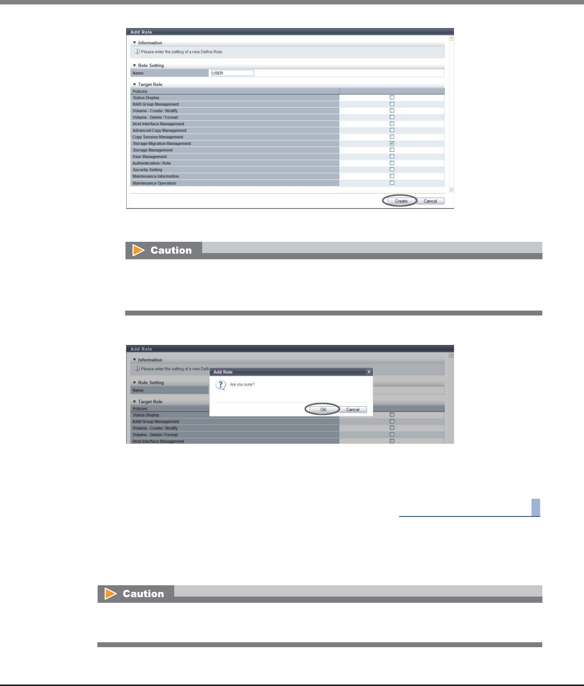
Chapter 11 System Management
11.2 Functions in the Action Area for System
ETERNUS Web GUI User’s Guide
Copyright 2013 FUJITSU LIMITED P2X0-1090-10ENZ0
866
→A confirmation screen appears.
3Click the [OK] button.
→Application of the role settings starts.
4Click the [Done] button to return to the [Define Role] screen.
End of procedure
11.2.7.5 Delete Role
This function deletes the user role (custom role) which was registered by a user.
An error screen appears in the following conditions:
•When the "Name" does not satisfy the input conditions
•When the "Name" has already been used
•The existing role (default role) cannot be deleted.
•The user role which is allocated to a user account cannot be deleted.
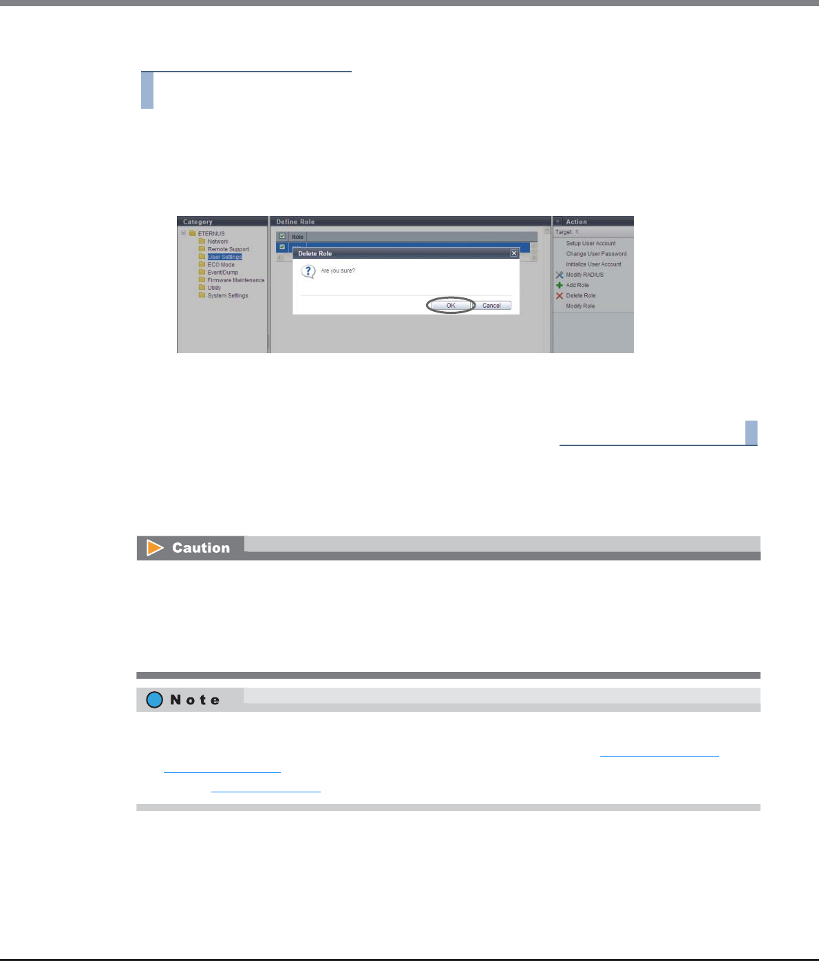
Chapter 11 System Management
11.2 Functions in the Action Area for System
ETERNUS Web GUI User’s Guide
Copyright 2013 FUJITSU LIMITED P2X0-1090-10ENZ0
867
The procedure to delete a role is as follows:
Procedure
1Select the user role to be deleted (multiple selections can be made) and click [Delete Role]
in [Action].
→A confirmation screen appears.
2Click the [OK] button.
→The user role is deleted.
3Click the [Done] button to return to the [Define Role] screen.
End of procedure
11.2.7.6 Modify Role
This function modifies the policies of the user-specific role (custom role).
•Policies of the existing role (default role) cannot be changed.
•Policies which have been granted to the user account while logged in, can also be modified. Note that
the modifications become valid only after the next login.
•A role without any policies cannot be created.
•The [Modify Role] function can be used when a custom role is created.
•Multiple policies can be allocated to one role.
•The modified role can be granted to the user account using the procedure in "11.2.7.1 Setup User
Account" (page 853).
•Refer to "Policy" (page 864) for available policies.
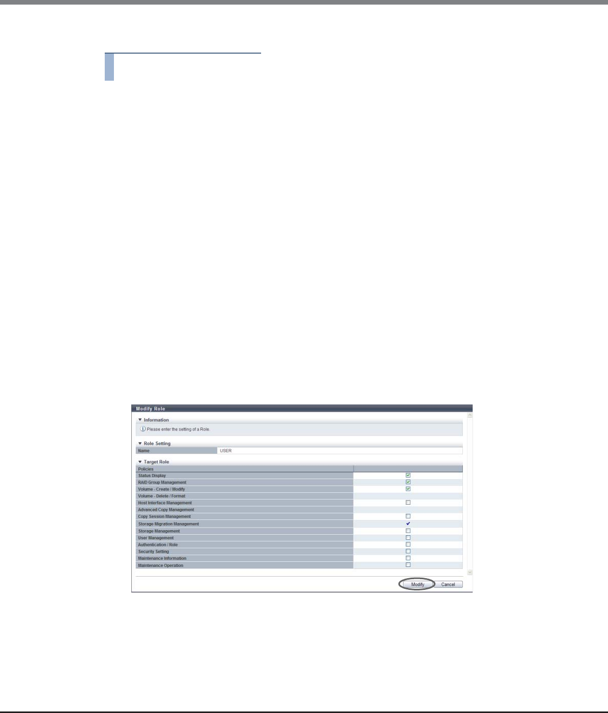
Chapter 11 System Management
11.2 Functions in the Action Area for System
ETERNUS Web GUI User’s Guide
Copyright 2013 FUJITSU LIMITED P2X0-1090-10ENZ0
868
The procedure to modify a user role is as follows:
Procedure
1Select the role to be modified, and click [Modify Role] in [Action].
2Change the role settings, and click the [Modify] button.
●Target Role
•Policies
Checkbox of the current user policies are selected. Set the new policies for the role.
-Status Display
-RAID Group Management
-Volume - Create / Modify
-Volume - Delete / Format
-Host Interface Management
-Advanced Copy Management
-Copy Session Management
-Storage Migration Management
-Storage Management
-User Management
-Authentication / Role
-Security Setting
-Maintenance Information
-Maintenance Operation
→A confirmation screen appears.
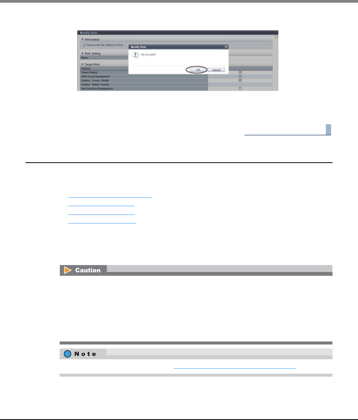
Chapter 11 System Management
11.2 Functions in the Action Area for System
ETERNUS Web GUI User’s Guide
Copyright 2013 FUJITSU LIMITED P2X0-1090-10ENZ0
869
3Click the [OK] button.
→Modification of the role settings starts.
4Click the [Done] button to return to the [Define Role] screen.
End of procedure
11.2.8 ECO Mode Management
This section describes ECO mode management.
ECO mode management provides the following functions:
•Modify ECO Mode General Setting
•Create ECO Mode Schedule
•Delete ECO Mode Schedule
•Modify ECO Mode Schedule
11.2.8.1 Modify ECO Mode General Setting
This function enables or disables the ECO mode setting for ETERNUS DX Disk storage system.
ECO mode is not available for the following drives:
•Hot Spares (except Dedicated Hot Spares)
•SSD
•Drives in a RAID group that satisfy the following conditions:
-A RAID group where no volumes are registered
-A RAID group where SDPVs are registered
-RAID group that is registered as an REC Disk Buffer
To create a new ECO mode schedule, refer to "11.2.8.2 Create ECO Mode Schedule" (page 871).
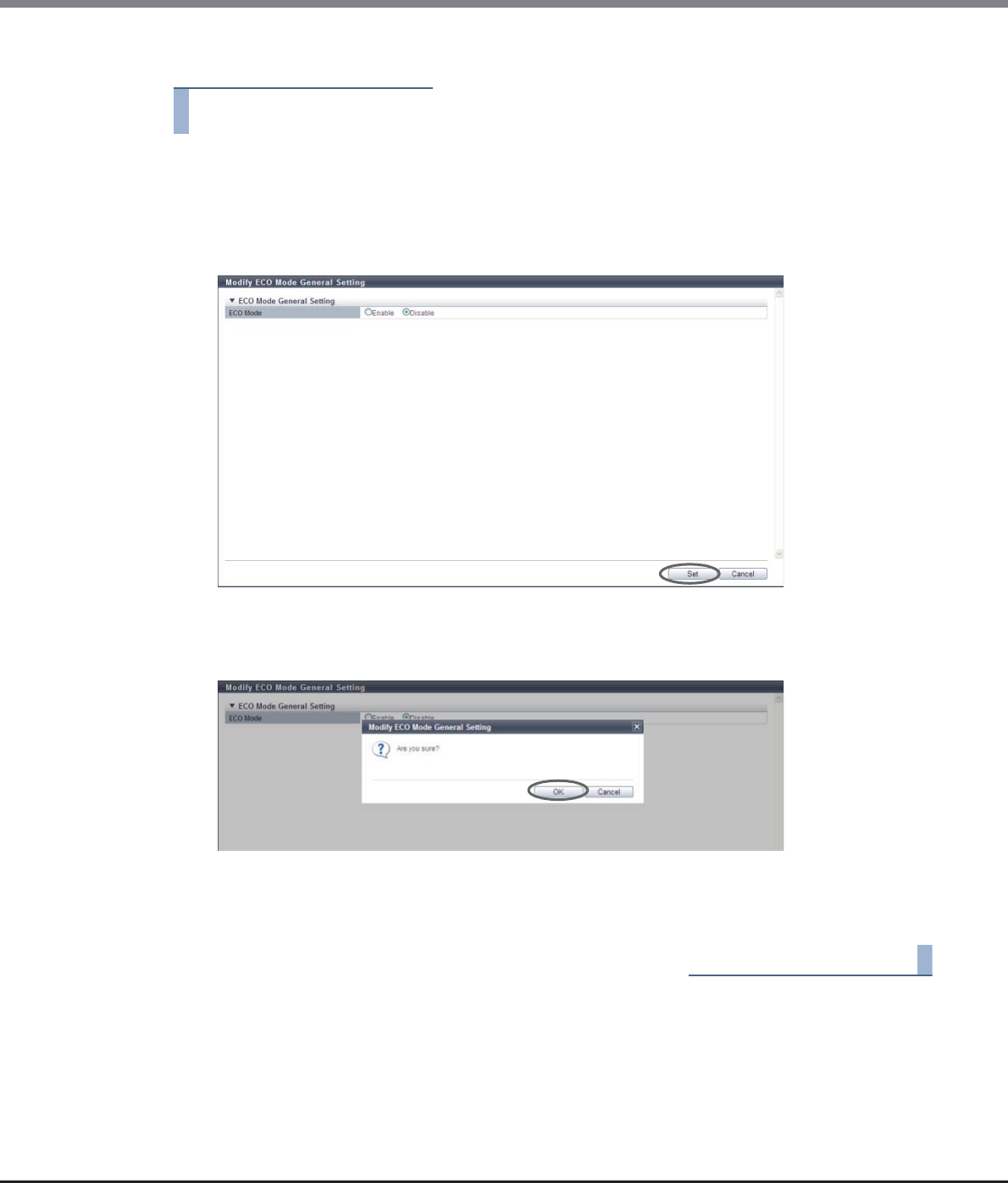
Chapter 11 System Management
11.2 Functions in the Action Area for System
ETERNUS Web GUI User’s Guide
Copyright 2013 FUJITSU LIMITED P2X0-1090-10ENZ0
870
The procedure to set the ECO mode schedule for a RAID group is as follows:
Procedure
1Click [Modify ECO Mode Setting] in [Action].
2Specify the parameters, and click the [Set] button.
•ECO Mode
Select whether to "Enable" or "Disable" the ECO mode for the ETERNUS DX Disk storage system.
→A confirmation screen appears.
3Click the [OK] button.
→The application of the ECO mode general settings starts.
4Click the [Done] button to return to the [ECO Mode] screen.
End of procedure
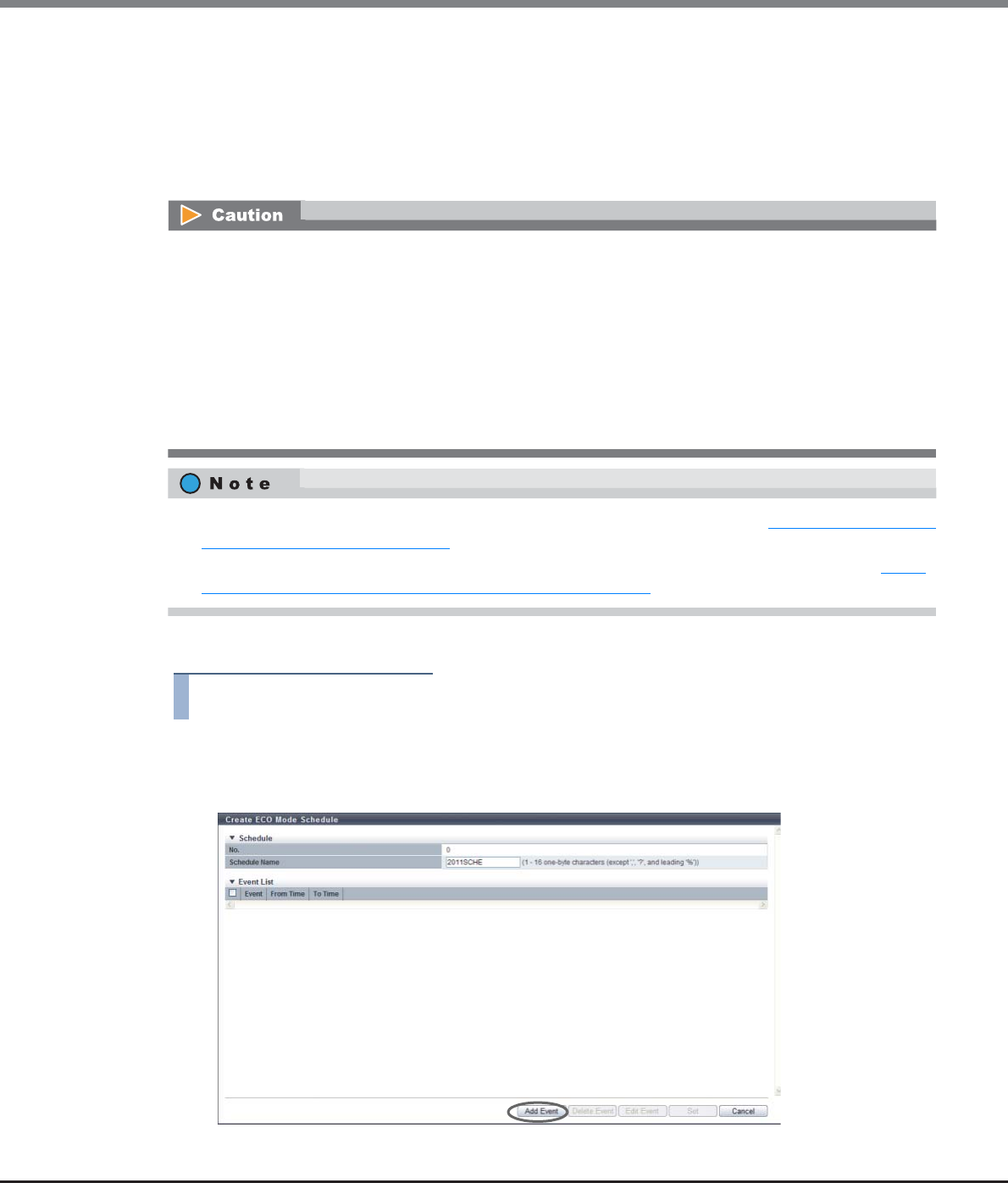
Chapter 11 System Management
11.2 Functions in the Action Area for System
ETERNUS Web GUI User’s Guide
Copyright 2013 FUJITSU LIMITED P2X0-1090-10ENZ0
871
11.2.8.2 Create ECO Mode Schedule
This function specifies the disk operating time (term for activating disk motor constantly) as an ECO mode
schedule.
•Up to 64 ECO mode schedules can be created for each storage system.
•Up to eight events can be specified for a single ECO mode schedule.
The procedure to create an ECO Mode schedule is as follows:
Procedure
1Click [Create Schedule] in [Action].
2Specify the schedule name, and click the [Add Event] button.
•To perform schedule operations using this function, the ECO mode setting for the ETERNUS DX Disk
storage system must be enabled.
•Disk operation time varies depending on the ECO mode schedule settings and disk access. A disk is spun
up even if it is outside of disk operation time in the following conditions:
-If disk access occurs while the disk motor is stopped:
The disk is immediately spun up and can be accessed within 1 - 5 minutes.
-If a disk is activated more than a set amount of times in a day:
A state of increased access frequency is assumed and the ECO mode will cease stopping the disk
motor.
•To apply the created ECO Mode schedule to RAID groups, refer to the procedure in "6.2.7 Assign ECO Mode
Schedule (RAID Group)" (page 192).
•To apply the created ECO Mode schedule to each Thin Provisioning Pool, refer to the procedure in "7.2.9
Assign ECO Mode Schedule (Thin Provisioning Pool)" (page 242).

Chapter 11 System Management
11.2 Functions in the Action Area for System
ETERNUS Web GUI User’s Guide
Copyright 2013 FUJITSU LIMITED P2X0-1090-10ENZ0
872
3Select an event type, set the event details, and then click the [Apply] button.
•Event Type
Select the event type. The settings vary depending on the event type.
-everyday
-Every week
-Specific days
-Specific week
•Event Type
-everyday
Select this to add or edit the daily schedule.
When "everyday" is selected, enter the start time ("From Time") and the end time ("To Time").
If the "From Time" is later than the "To Time", the end time is treated as the next day.
•From Time: 00:00 - 23:30 (Can be specified at intervals of 30 minutes)
•To Time: 00:00 - 23:30 (Can be specified at intervals of 30 minutes)
-Every week
Select this to add or edit the weekly schedule.
When "Every week" is selected, enter the term ("Period"), the start time ("From Time"), and the
end time ("To Time").
If the "From Time" is later than the "To Time", the end time is treated as the next day.
•Period (start day): Monday - Sunday
•Period (end day): Monday - Sunday
•From Time: 00:00 - 23:30 (Can be specified at intervals of 30 minutes)
•To Time: 00:00 - 23:30 (Can be specified at intervals of 30 minutes)
-Specific days
Select this to add or edit the schedule based on specific days.
When "Specific days" is selected, enter the month ("Month"), the term ("Period"), the start time
("From Time"), and the end time ("To Time").
If the "From Time" is later than the "To Time", the end time is treated as the next day.
•Month: Every Month, January - December
•Period (start date): 01 - 31
•Period (term): One day only, 2 days - 7 days
•From Time: 00:00 - 23:30 (Can be specified at intervals of 30 minutes)
•To Time: 00:00 - 23:30 (Can be specified at intervals of 30 minutes)
-Specific week
Select this to add or edit the schedule based on a specific week.
When "Specific week" is selected, enter the month ("Month"), the term ("Period"), the start time
("From Time"), and the end time ("To Time").
If the "From Time" is later than the "To Time", the end time is treated as the next day.
•Month: Every Month, January - December
•Period (nth week): 1st - 4th, Last
•Period (start day): Monday - Sunday
•Period (end day): Monday - Sunday
•From Time: 00:00 - 23:30 (Can be specified at intervals of 30 minutes)
•To Time: 00:00 - 23:30 (Can be specified at intervals of 30 minutes)
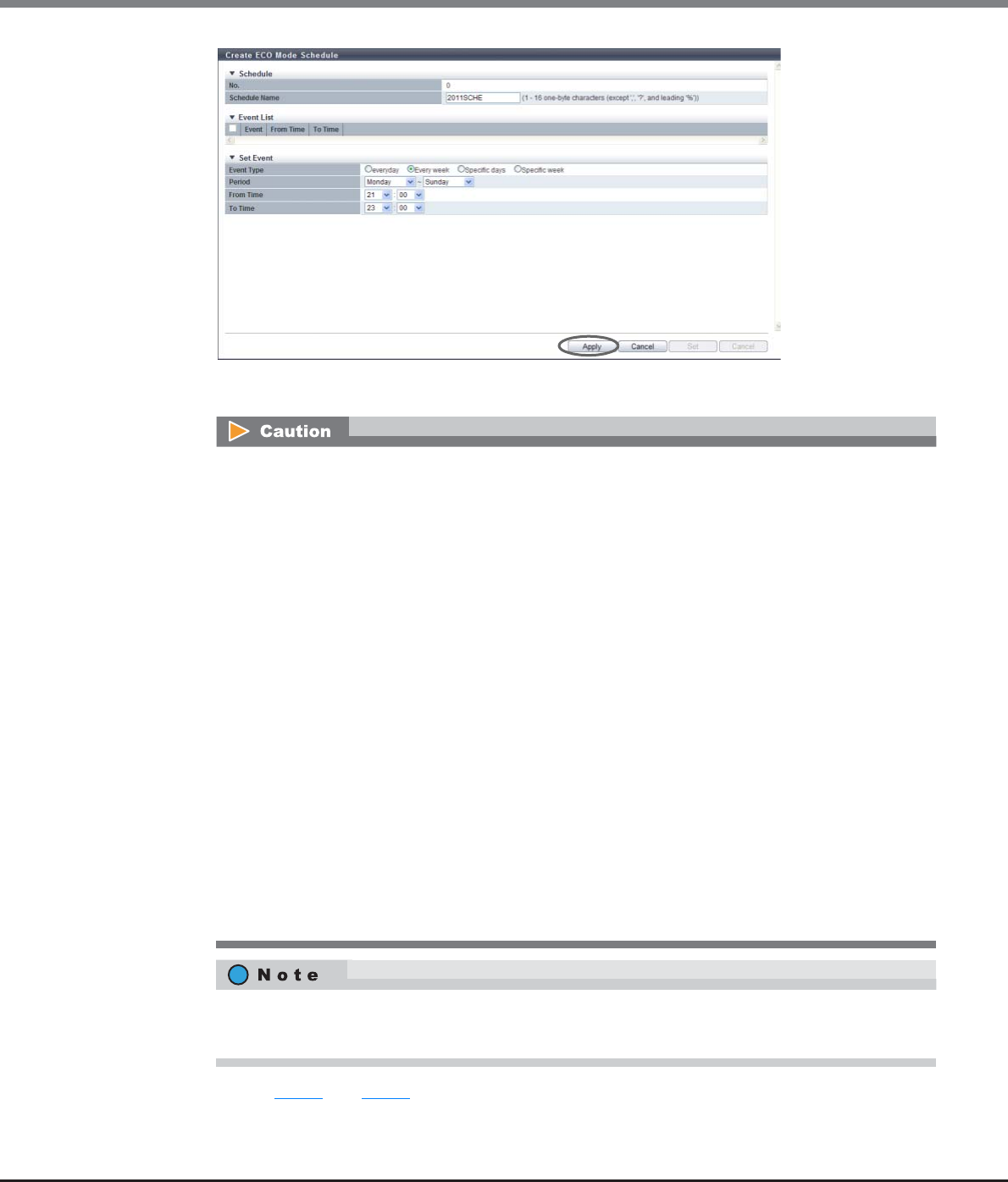
Chapter 11 System Management
11.2 Functions in the Action Area for System
ETERNUS Web GUI User’s Guide
Copyright 2013 FUJITSU LIMITED P2X0-1090-10ENZ0
873
→The event is added to the "Event List".
4Repeat Step 2 and Step 3 to configure multiple events.
An error screen appears in the following conditions:
•"everyday" is selected for the event type when the start time and end time are the same
•"Every week" is selected for the event type when the start day and the end day are the same, and
the start time and the end time are also the same
•"Every week" is selected for the event type when the start day is later than the end day
•"Every week" is selected for the event type when the start day and the end day are the same, and
the start time is later than the end time
•"Specific days" is selected for the event type, and a non-existent date (for example, February 30) is
set
•"Specific days" is selected for the event type when "One day only" is selected for the period, and the
start time and end time are the same
•"Specific days" is selected for the event type when "One day only" is selected for the period, and the
start time is later than the end time
•"Specific week" is selected for the event type when the start day and the end day are the same, and
the start time and the end time are the same
•"Specific week" is selected for the event type when the start day is later than the end day
•"Specific week" is selected for the event type when the start day and the end day are the same, and
start time is later than the end time
•The period is set to include Sunday
•The period is 1 week or longer (the end date is set to "7 days" when the end time is later than the
start time)
•When deleting the added event, select the event, and click the [Delete] button.
•When changing the added event, select the event, and click the [Edit] button.
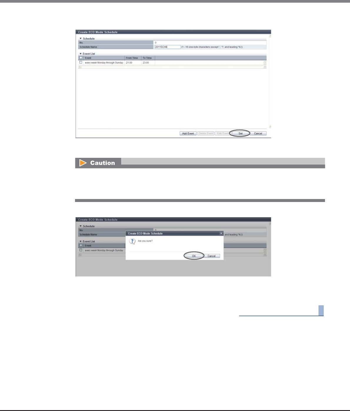
Chapter 11 System Management
11.2 Functions in the Action Area for System
ETERNUS Web GUI User’s Guide
Copyright 2013 FUJITSU LIMITED P2X0-1090-10ENZ0
874
5After adding all the events, click the [Set] button.
→A confirmation screen appears.
6Click the [OK] button.
→Creation of the ECO mode schedule starts.
7Click the [Done] button to return to the [ECO Mode] screen.
End of procedure
An error screen appears in the following conditions:
•"Schedule Name" has not been entered
•"Schedule Name" matches with an existing schedule name
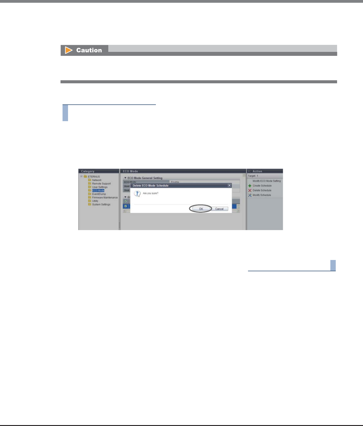
Chapter 11 System Management
11.2 Functions in the Action Area for System
ETERNUS Web GUI User’s Guide
Copyright 2013 FUJITSU LIMITED P2X0-1090-10ENZ0
875
11.2.8.3 Delete ECO Mode Schedule
This function deletes the ECO mode schedule.
The procedure to delete an ECO Mode schedule is as follows:
Procedure
1Select the schedule that is to be deleted (multiple selections can be made) and click [Delete
Schedule] in [Action].
→A confirmation screen appears.
2Click the [OK] button.
→Deletion of the ECO mode schedule starts.
3Click the [Done] button to return to the [ECO Mode] screen.
End of procedure
•An ECO mode schedule that is allocated to a RAID group cannot be deleted.
•An ECO mode schedule that is allocated to a Thin Provisioning Pool cannot be deleted.
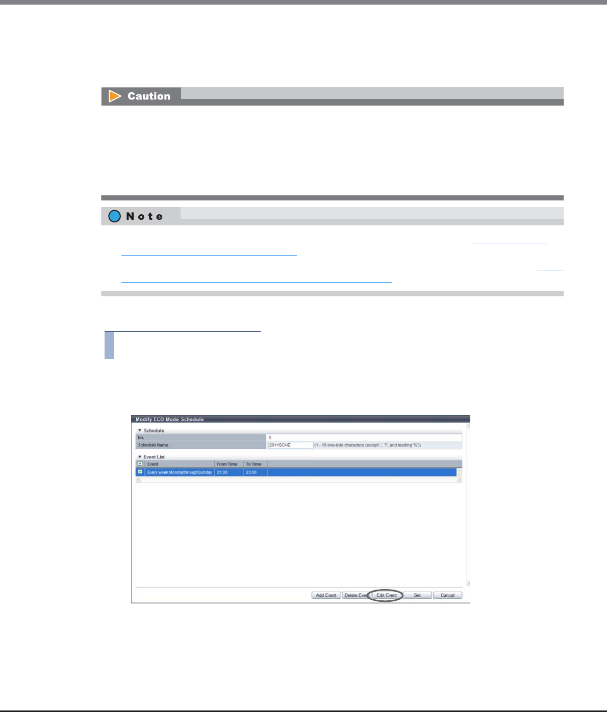
Chapter 11 System Management
11.2 Functions in the Action Area for System
ETERNUS Web GUI User’s Guide
Copyright 2013 FUJITSU LIMITED P2X0-1090-10ENZ0
876
11.2.8.4 Modify ECO Mode Schedule
This function modifies the ECO mode schedule.
Up to eight events can be specified for a single ECO mode schedule.
The procedure to edit an ECO Mode schedule is as follows:
Procedure
1Select the ECO mode schedule that is to be edited and click [Modify Schedule] in [Action].
2Select the event that is to be modified and click the [Edit Event] button.
Disk operation time varies depending on the ECO mode schedule settings and disk access.
A disk is spun up even if it is outside of disk operation time in the following conditions:
•If disk access occurs while the disk motor is stopped:
The disk is immediately spun up and can be accessed within 1 - 5 minutes.
•If a disk is activated more than a set amount of times in a day:
A state of increased access frequency is assumed and the ECO mode will cease stopping the disk motor.
•To apply the modified ECO Mode schedule to RAID groups, refer to the procedure in "6.2.7 Assign ECO
Mode Schedule (RAID Group)" (page 192).
•To apply the modified ECO Mode schedule to each Thin Provisioning Pool, refer to the procedure in "7.2.9
Assign ECO Mode Schedule (Thin Provisioning Pool)" (page 242).

Chapter 11 System Management
11.2 Functions in the Action Area for System
ETERNUS Web GUI User’s Guide
Copyright 2013 FUJITSU LIMITED P2X0-1090-10ENZ0
877
3After the event content is modified, click the [Apply] button.
•Event Type
Select the event type. The settings vary depending on the event type.
-everyday
-Every week
-Specific days
-Specific week
•Event Type
-everyday
Select this to add or edit the daily schedule.
When "everyday" is selected, enter the start time ("From Time") and the end time ("To Time").
If the "From Time" is later than the "To Time", the end time is treated as the next day.
•From Time: 00:00 - 23:30 (Can be specified at intervals of 30 minutes)
•To Time: 00:00 - 23:30 (Can be specified at intervals of 30 minutes)
-Every week
Select this to add or edit the weekly schedule.
When "Every week" is selected, enter the term ("Period"), the start time ("From Time"), and the
end time ("To Time").
If the "From Time" is later than the "To Time", the end time is treated as the next day.
•Period (start day): Monday - Sunday
•Period (end day): Monday - Sunday
•From Time: 00:00 - 23:30 (Can be specified at intervals of 30 minutes)
•To Time: 00:00 - 23:30 (Can be specified at intervals of 30 minutes)
-Specific days
Select this to add or edit the schedule based on specific days.
When "Specific days" is selected, enter the month ("Month"), the term ("Period"), the start time
("From Time"), and the end time ("To Time").
If the "From Time" is later than the "To Time", the end time is treated as the next day.
•Month: Every Month, January - December
•Period (start date): 01 - 31
•Period (term): One day only, 2 days - 7 days
•From Time: 00:00 - 23:30 (Can be specified at intervals of 30 minutes)
•To Time: 00:00 - 23:30 (Can be specified at intervals of 30 minutes)
-Specific week
Select this to add or edit the schedule based on a specific week.
When "Specific week" is selected, enter the month ("Month"), the term ("Period"), the start time
("From Time"), and the end time ("To Time").
If the "From Time" is later than the "To Time", the end time is treated as the next day.
•Month: Every Month, January - December
•Period (nth week): 1st - 4th, Last
•Period (start day): Monday - Sunday
•Period (end day): Monday - Sunday
•From Time: 00:00 - 23:30 (Can be specified at intervals of 30 minutes)
•To Time: 00:00 - 23:30 (Can be specified at intervals of 30 minutes)
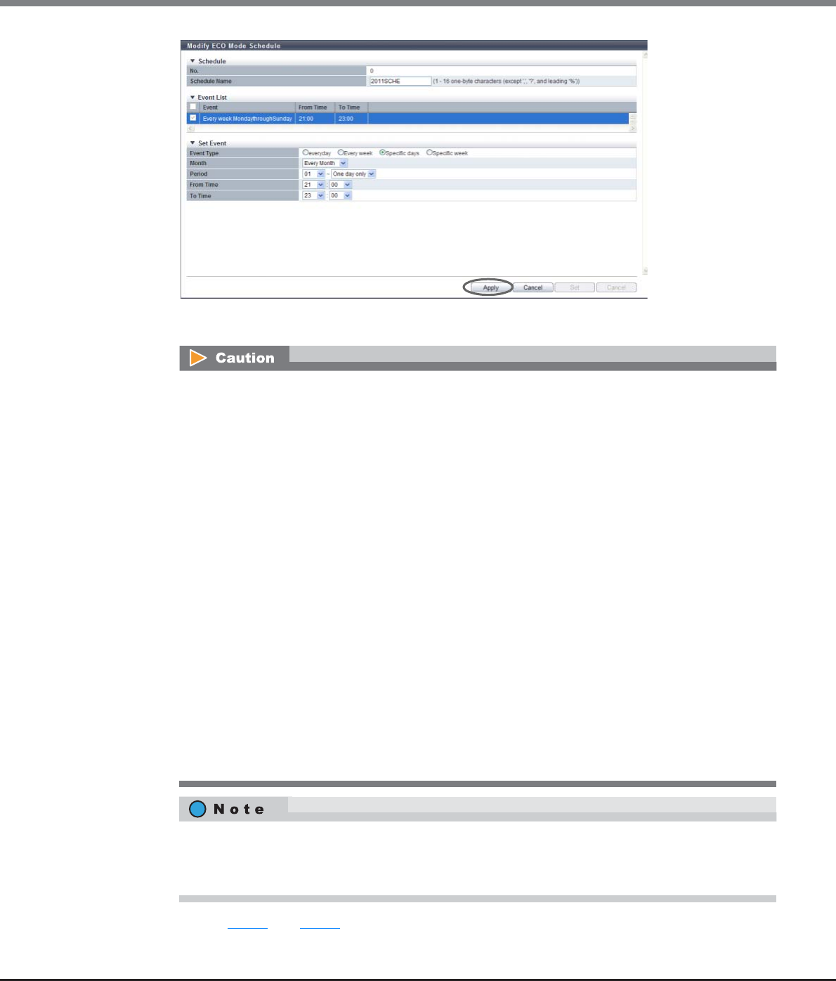
Chapter 11 System Management
11.2 Functions in the Action Area for System
ETERNUS Web GUI User’s Guide
Copyright 2013 FUJITSU LIMITED P2X0-1090-10ENZ0
878
→The "Event List" is updated.
4Repeat Step 2 and Step 3 to edit multiple events.
An error screen appears in the following conditions:
•"everyday" is selected for the event type when the start time and end time are the same
•"Every week" is selected for the event type when the start day and the end day are the same, and
the start time and the end time are also the same
•"Every week" is selected for the event type when the start day is later than the end day
•"Every week" is selected for the event type when the start day and the end day are the same, and
the start time is later than the end time
•"Specific days" is selected for the event type, and a non-existent date (for example, February 30) is
set
•"Specific days" is selected for the event type when "One day only" is selected for the period, and the
start time and end time are the same
•"Specific days" is selected for the event type when "One day only" is selected for the period, and the
start time is later than the end time
•"Specific week" is selected for the event type when the start day and the end day are the same, and
the start time and the end time are the same
•"Specific week" is selected for the event type when the start day is later than the end day
•"Specific week" is selected for the event type when the start day and the end day are the same, and
start time is later than the end time
•The period is set to include Sunday
•The period is 1 week or longer (the end date is set to "7 days" when the end time is later than the
start time)
•When adding an event, click the [Add] button.
•When deleting the event, select the target event(s) that is to be deleted, and click the [Delete]
button.
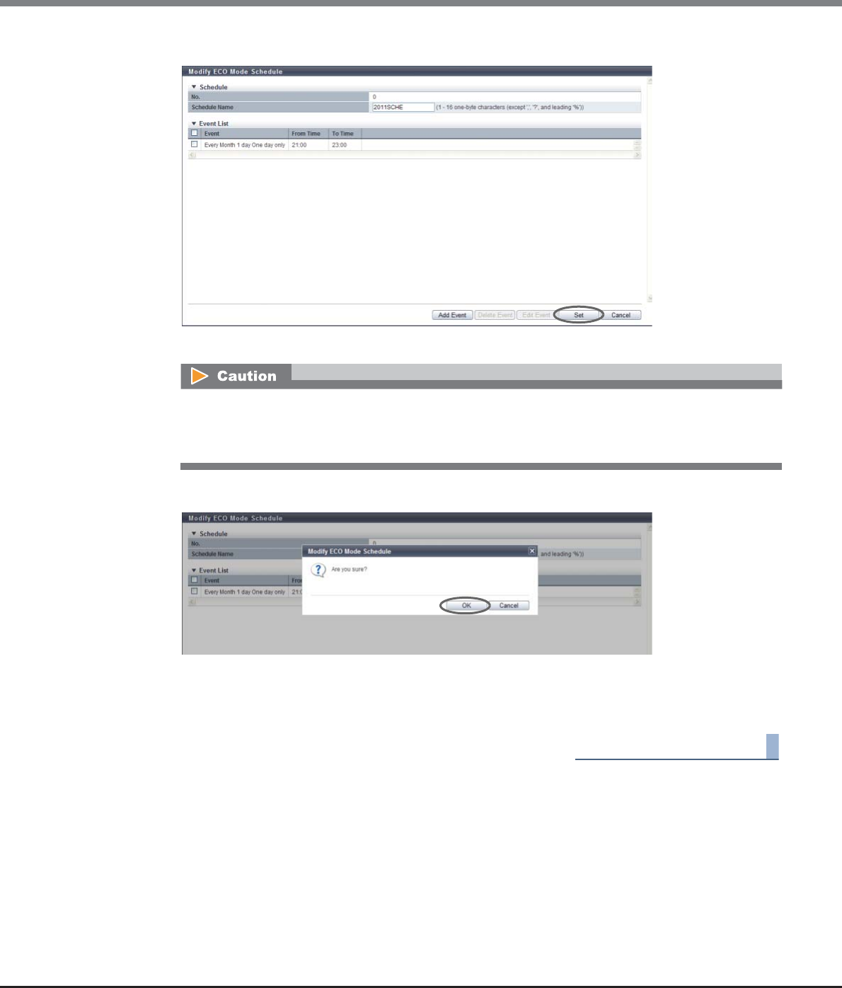
Chapter 11 System Management
11.2 Functions in the Action Area for System
ETERNUS Web GUI User’s Guide
Copyright 2013 FUJITSU LIMITED P2X0-1090-10ENZ0
879
5After editing all the events, click the [Set] button.
→A confirmation screen appears.
6Click the [OK] button.
→Modification of the ECO mode schedule starts.
7Click the [Done] button to return to the [ECO Mode] screen.
End of procedure
An error screen appears in the following conditions:
•"Schedule Name" has not been entered
•"Schedule Name" matches with an existing schedule name
Chapter 11 System Management
11.2 Functions in the Action Area for System
ETERNUS Web GUI User’s Guide
Copyright 2013 FUJITSU LIMITED P2X0-1090-10ENZ0
880
11.2.9 Event/Dump Management
This section describes event/dump management.
Event/dump management provides the following functions:
•Setup Event Notification
•Display Event Log
•Export/Delete Log
•Export Panic Dump
11.2.9.1 Setup Event Notification
This function specifies whether to report events that are detected in the ETERNUS DX Disk storage system.
There are six methods for event notification: Host Sense Key Code Qualifier, SNMP Trap, E-Mail, syslog, REMCS
(for regions other than EMEA), and AIS Connect (for regions other than Japan).
A notification setting can be selected for each type of event.
•For SNMP Trap notification, performing procedures in "11.2.3.3 Setup SNMP Agent Basic Interface" (page
761), "11.2.3.4 Setup SNMP Manager" (page 763), "11.2.3.5 Setup SNMP Agent MIB Access View" (page
766), "11.2.3.6 Setup SNMP Agent User" (page 768), "11.2.3.7 Setup SNMP Agent Community" (page
771), and "11.2.3.8 Setup SNMP Agent Trap" (page 774) is required.
•For E-Mail notification, performing procedure in "11.2.3.12 Setup E-Mail Notification" (page 781) is
required.
•For syslog notification, performing procedure in "11.2.3.13 Setup Syslog" (page 783) is required.
•For REMCS notification, performing procedure in "11.2.4.2 Setup Remote Support" (page 800) is required
(for regions other than EMEA).
•For AIS Connect notification, performing procedure in "11.2.5.1 Setup AIS Connect Environment" (page
821) is required (for regions other than Japan).
•When selecting REMCS for event notification, only the REC related error event settings can be changed.
•In the following sections, "REMCS (for regions other than EMEA)" is referred to as "REMCS" and "AIS Con-
nect (for regions other than Japan)" is referred to as "AIS Connect".
Chapter 11 System Management
11.2 Functions in the Action Area for System
ETERNUS Web GUI User’s Guide
Copyright 2013 FUJITSU LIMITED P2X0-1090-10ENZ0
881
The procedure to set the event notification is as follows:
Procedure
1Click [Setup Event Notification] in [Action].
2Specify whether to notify each event, and click the [Set] button.
●Setting based on Severity
Select whether to notify of an event by levels. Checkboxes are displayed for selectable notification
methods.
• All Error Events
Select whether to notify when an error level event occurs. When notifying, select the notification
method.
By selecting or clearing the checkbox, the same setting can be applied for all the "Error Severity
Level" events.
• All Warning Events
Select whether to notify when a warning level event occurs. When notifying, select the notification
method.
By selecting or clearing the checkbox, the same setting can be applied for all the "Warning Severity
Level" events.
• All Informational Events
Select whether to notify when a informational level event occurs. When notifying, select the
notification method.
By selecting or clearing the checkbox, the same setting can be applied for all the "Informational
Level" events.
•Individual Settings within Severity Level
"Yes" is displayed when the target notification method ("Host Sense Key Code Qualifier", "SNMP
Trap", "E-Mail", "syslog", "REMCS", or "AIS Connect") is specified for any event in "Error Severity Level",
"Warning Level", or "Informational Level", if not, "No" is displayed.
•Blink Fault LED at warning
Select "Enable" when setting the Fault LED in the front panel to blink while a warning level event
occurs, and select "Disable" when setting the Fault LED not to blink.
•Turn on Fault LED when redundant copy is completed
Select "Enable" when setting the Fault LED of the drive to turn on while a warning level event
occurs, and select "Disable" when setting the Fault LED not to turn on.
The events are classified into three levels: "Error Severity Level", "Warning Level", and "Informational
Level".
Click the [Setting based on Severity] tab, [Error Severity Level] tab, [Warning Level] tab or
[Informational Level] tab to display the setting fields for each level.
Chapter 11 System Management
11.2 Functions in the Action Area for System
ETERNUS Web GUI User’s Guide
Copyright 2013 FUJITSU LIMITED P2X0-1090-10ENZ0
882
•Display parts (except disk) with error status on LCD
Select "Enable" when displaying the part (other than disk) error message in the LCD, and select
"Disable" to not display the message in the LCD. This setting is available only when using the
ETERNUS DX8700 S2.
•Display parts (except disk) with warning status on LCD
Select "Enable" when displaying the part (other than disk) warning message in the LCD, and select
"Disable" to not display the message in the LCD. This setting is available only when using the
ETERNUS DX8700 S2.
•Display disks with error status on LCD
Select "Enable" when displaying the drive error message in the LCD for each condition shown below,
and select "Disable" to not display the message in the LCD. This setting is available only when using
the ETERNUS DX8700 S2.
-Any Time
Always notifies when a drive error occurs.
-when HS<0
Notifies only if a drive error occurs when available hot spare disk is " 0". This item can be selected
only when the "Display disks with error status on LCD (Any Time)" checkbox is cleared.
•Display disks with warning status on LCD
Select "Enable" when displaying the part (other than disk) warning message in the LCD, and select
"Disable" to not display the message in the LCD. This function is available only when using the
ETERNUS DX8700 S2.
-Any Time
Always notifies when a drive warning status occurs.
-when HS<0
Notifies only if a drive warning status occurs when available hot spare disk is " 0". This item can
be selected only when the "Display disks with warning status on LCD (Any Time)" checkbox is
cleared.
●Error Severity Level
Select whether to notify of the error event for each event type.
• Parts Error
Select whether to notify when a failure occurs in a part other than the drive. When notifying, select
the notification method.
• Disk Error
Select whether to notify when a drive failure occurs for each condition shown below. When
notifying, select the notification method.
-Any Time
Always notifies when a drive failure occurs.
-when HS<0
Notifies only if a drive failure occurs when available hot spare disk is " 0" (*1).
*1: When rebuilding cannot be performed because there are no hot spares that can be used as a
substitute for the failed drive.
For the ETERNUS DX8700 S2, whether to display the LCD message in the Overview screen and the LCD
panel on the Operation panel is determined by the notification setting that is specified for this
function.

Chapter 11 System Management
11.2 Functions in the Action Area for System
ETERNUS Web GUI User’s Guide
Copyright 2013 FUJITSU LIMITED P2X0-1090-10ENZ0
883
• Temperature Error
Select whether to notify when a temperature error status is detected by the sensor. When notifying,
select the notification method.
• End of battery life
Select whether to notify when a battery expires. When notifying, select the notification method.
"End of battery life" notification is available only for the ETERNUS DX410 S2/DX440 S2 or the
ETERNUS DX8100 S2/DX8700 S2.
• Rebuild/Copyback w/ redundant
Select whether to notify when rebuilding or copy backing (with redundancy) (*1) is performed.
When notifying, select the notification method.
*1: "Rebuilding to hot spare disk is complete", "Copyback starts" and "Copyback complete" are equivalent
to "Redundancy".
• Rebuild/Copyback w/o redundant
Select whether to notify when rebuilding or copy backing (without redundancy) (*1) occurs for each
condition shown below. When notifying, select the notification method.
-Any Time
Always notifies when rebuilding or copy backing (without redundancy) occurs.
-when HS<0
Notifies only if rebuilding or copy backing (without redundancy) occurs when the available hot
spare disk is "0".
*1: "Rebuild to hot spare disk is started", "Rebuild to hot spare disk failed" and "Copyback failed" are
equivalent to "Without redundancy".
• Redundant
Select whether to notify when a redundant copy starts or ends abnormally for each condition shown
below. When notifying, select the notification method.
-Any Time
Always notifies when a redundant copy starts or ends abnormally.
-when HS<0
Notifies only if a redundant copy starts or ends abnormally when the available hot spare disk is
"0".
• Complete Redundant Copy
Select whether to notify when a redundant copy is complete. When notifying, select the notification
method.
• Complete rebuild
Select whether to notify when a bad sector (*1) is detected in the hot spare where rebuilding is
completed. When notifying, select the notification method.
*1: A bad sector is the location information (address and length) where an error such as data reading error
occurs during rebuild, copyback, or redundant copy.
• Bad data
Select whether to notify when a bad sector is detected in the drive. When notifying, select the
notification method.

Chapter 11 System Management
11.2 Functions in the Action Area for System
ETERNUS Web GUI User’s Guide
Copyright 2013 FUJITSU LIMITED P2X0-1090-10ENZ0
884
• Pinned data
Select whether to notify when pinned data (*1) is detected or disappears. When notifying, select
the notification method.
*1: "Pinned data" is the data left in the cache due to unsuccessful write-back to the drive from the cache
area.
• Not ready
Select whether to notify when the ETERNUS DX Disk storage system is in "Not ready" status (*1).
When notifying, select the notification method.
*1: "Not ready" is the status in which the ETERNUS DX Disk storage system cannot operate properly due to a
cause such as failures in multiple parts.
• Remote Path Error
Select whether to notify when a copy path error occurs. When notifying, select the notification
method.
• REC Buffer Halt (Path Error)
Select whether to notify when an REC Buffer halt caused by copy path error occurs. When notifying,
select the notification method.
• REC Buffer Halt (Overload)
Select whether to notify when an REC Buffer halt caused by overload occurs. When notifying, select
the notification method.
• REC Buffer Halt (Other Error)
Select whether to notify when an REC Buffer halt caused by an error occurs. When notifying, select
the notification method.
• Copy Session Error
Select whether to notify when an error is detected in the Advanced Copy session or when a failed
Advanced Copy session is recovered. When notifying, select the notification method.
• Thin Provisioning Pool Rate
Select whether to notify when the TPP usage changes (*1). When notifying, select the notification
method.
*1: Notify when the TPP usage changes as follows:
-From "Normal" to "Attention"
-From "Normal" or "Attention" to "Warning"
-The TPP capacity is exhausted
• SED Network Error
Select whether to notify when the communication between the ETERNUS DX Disk storage system
and the key server is disconnected. When notifying, select the notification method.
Chapter 11 System Management
11.2 Functions in the Action Area for System
ETERNUS Web GUI User’s Guide
Copyright 2013 FUJITSU LIMITED P2X0-1090-10ENZ0
885
●Warning Severity Level
Select whether to notify of a warning event for each event type.
• Parts Warning
Select whether to notify when a warning level event occurs in a part other than the drive. When
notifying, select the notification method.
• Disk Warning
Select whether to notify when a warning level event occurs in the drive for each condition shown
below. When notifying, select the notification method.
-Any Time
Always notifies when a warning level event occurs in the drive.
-when HS<0
Notifies only if a warning level event occurs in the drive when available hot spare disk is "0" (*1).
*1: When rebuilding cannot be performed because there are no hot spares that can be used as a
substitute for the failed drive.
• Temperature Warning
Select whether to notify when a temperature warning status is detected by the sensor. When
notifying, select the notification method.
• Battery life Warning
Select whether to notify a battery expiration in advance (*1). When notifying, select the notification
method.
"Battery life Warning" notification is available only for ETERNUS DX410 S2/DX440 S2 or ETERNUS
DX8100 S2/DX8700 S2.
*1: Advance notice of battery expiration is issued once "6 months before", once "a week before", and once a
day during the period from "6 days before" to "the expiration date".
●Informational Level
Select whether to notify of an informational event for each event type.
• Recovery module
Select whether to notify when the failed part is recovered by taking actions such as replacement.
When notifying, select the notification method.
• Temperature restoration
Select whether to notify when a temperature error or warning status is recovered to the normal
status. When notifying, select the notification method.
• User login/logout
Select whether to notify when a User login/logout is detected. When notifying, select the
notification method.
• Operated RAID Group
Select whether to notify when the RAID group has been created or deleted. When notifying, select
the notification method.
• Added/Released Hot Spare
Select whether to notify when the hot spare disk has been registered or released. When notifying,
select the notification method.

Chapter 11 System Management
11.2 Functions in the Action Area for System
ETERNUS Web GUI User’s Guide
Copyright 2013 FUJITSU LIMITED P2X0-1090-10ENZ0
886
• Operated Volume
Select whether to notify when the volume has been created or deleted. When notifying, select the
notification method.
• Power off/on Apply Firmware
Select whether to notify when the ETERNUS DX Disk storage system is turned off/on or when the
controller firmware is changed in hot mode. When notifying, select the notification method.
• SDP Usage Rate Over Lv1
Select whether to notify when an SDP Policy Level 1 (Informational) event occurs. When notifying,
select the notification method.
• SDP Usage Rate Over Lv2
Select whether to notify when an SDP Policy Level 2 (Warning) event occurs. When notifying, select
the notification method.
• SDP Usage Rate Over Lv3
Select whether to notify when an SDP Policy Level 3 (Error) event occurs. When notifying, select the
notification method.
• Copy Table Size Usage Rate Over
Select whether to notify when the copy table usage exceeds the threshold. When notifying, select
the notification method.
• Trial copy license expired
Select whether to notify when a copy trial license expiration event occurs. When notifying, select the
notification method.
• No Free Space on ODX Buffer Volume
Select whether to notify when an insufficient free space event for an ODX Buffer volume occurs.
When notifying, select the notification method.
• SED Network Error Recovered
Select whether to notify when the communication between the ETERNUS DX Disk storage system
and the key server is recovered. When notifying, select the notification method.
• FC CA Port Link Status Changed
Select whether to notify when a link down occurs after an FC link is established and the link status is
changed. When notifying, select the notification method. Note that a change in the link status due
to user operation is not notified.
A change in the link status for all the FCs is notified. The notification is reported regardless of the
type (8G FC or 16G FC), the port mode (CA, RA, CA/RA, Initiator), and the transfer rate. The following
FC link status types can be detected and notified:
-The link status between the ETERNUS DX Disk storage system and a directly connected server
-The link status between the ETERNUS DX Disk storage system and switches
The FC link status can be checked in the [Port Detail] screen. Refer to "10.1.2.3 All Channel
Adapters" (page 636) for details.
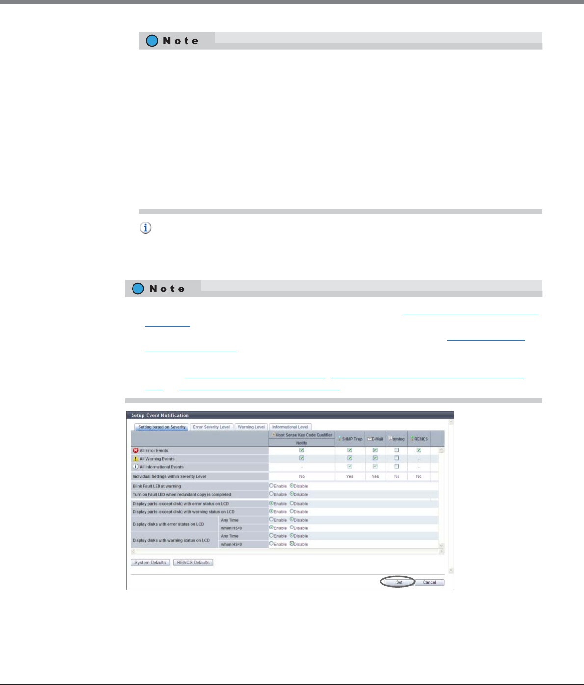
Chapter 11 System Management
11.2 Functions in the Action Area for System
ETERNUS Web GUI User’s Guide
Copyright 2013 FUJITSU LIMITED P2X0-1090-10ENZ0
887
• Host Login Over
Select whether to notify when the number of connected hosts for each CA port exceeds the
maximum value (256 hosts). When notifying, select the notification method.
This item is notified regardless of the CA type (FC, iSCSI, SAS, and FCoE).
→A confirmation screen appears.
•Only the FC link status is notified. Note that a change in link status for iSCSI, SAS, and FCoE is
not notified.
•Link up and Link down that occur due to the following user operations are not notified.
-Rebooting of the ETERNUS DX Disk storage system
-Hot maintenance of a CA or a CM in which a CA is installed
-Preventive maintenance of a CA or a CM in which a CA is installed
-Chip reset due to a change in the FC port parameters
•If the occurrence of link down and link up repeats within a 10 second interval, the first two sets
of link down and link up are notified. Notification of this event is suspended for 20 minutes
after the notification.
•Note that the link status between a server and a switch cannot be detected.
•Threshold of SDP usage can be specified using the procedure in "8.2.11 Modify Copy Parameters"
(page 316).
•Threshold of copy table size usage can be specified using the procedure in "8.2.7 Modify Copy
Table Size" (page 301).
•If free space of an ODX Buffer volume is insufficient, expand the volume capacity. Refer to the pro-
cedure in "5.2.5 Expand Volume" (page 117), "5.2.6 Expand Thin Provisioning Volume" (page
121), or "5.2.7 Start RAID Migration" (page 123) for details.
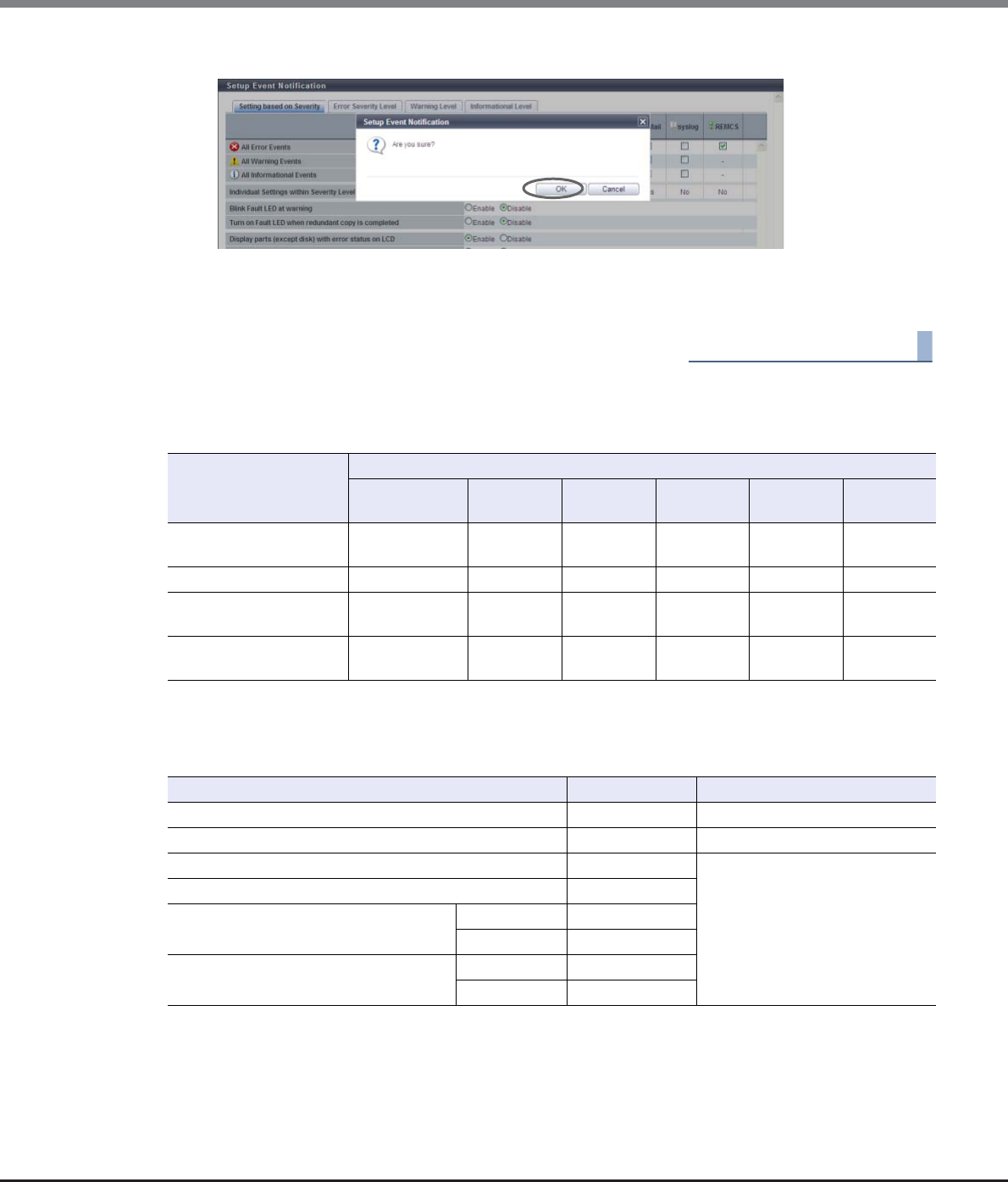
Chapter 11 System Management
11.2 Functions in the Action Area for System
ETERNUS Web GUI User’s Guide
Copyright 2013 FUJITSU LIMITED P2X0-1090-10ENZ0
888
3Click the [OK] button.
→Setting of the event notification starts.
4Click the [Done] button to return to the [Event/Dump] screen.
End of procedure
System Defaults
The initial state of event notification is as follows:
Selected: Notify
Cleared: Not notify
Selected/Cleared: Some events are notified and other events are not notified
–: Not applicable to notification
Item Notification method
Host Sense Key
Code Qualifier
SNMP Trap E-Mail syslog REMCS AIS
Connect
All Error Events Selected/
Cleared
Selected/
Cleared
Selected/
Cleared
Cleared Selected/
Cleared
Selected/
Cleared
All Warning Events Selected Selected Selected Cleared – Selected
All Informational Events – Selected/
Cleared
Selected/
Cleared
Cleared – Selected/
Cleared
Individual Settings
within Severity Level
Yes Yes Yes No Yes Yes
Event Notification Remarks
Blink Fault LED at warning Enable
Turn on Fault LED when redundant copy is completed Disable
Display parts (except disk) with error status on LCD Enable This setting is available only when
using the ETERNUS DX8700 S2.
Display parts (except disk) with warning status on LCD Enable
Display disks with error status on LCD Any Time Enable
when HS<0 Disable
Display disks with warning status on LCD Any Time Enable
when HS<0 Disable

Chapter 11 System Management
11.2 Functions in the Action Area for System
ETERNUS Web GUI User’s Guide
Copyright 2013 FUJITSU LIMITED P2X0-1090-10ENZ0
889
Level Event Notification method
Host Sense
Key Code
Qualifier
SNMP Trap E-Mail syslog REMCS AIS
Connect
Error
Parts Error Selected Selected Selected Cleared Selected
(fixed)
Selected
Disk Error Any Time Selected Selected Selected Cleared Selected
(fixed)
Selected
when
HS<0
Cleared Cleared Cleared Cleared – Cleared
Temperature Error Selected Selected Selected Cleared Selected
(fixed)
Selected
End of battery life Selected Selected Selected Cleared Selected
(fixed)
Selected
Rebuild/Copyback w/
redundant
Selected Cleared Cleared Cleared Cleared Cleared
Rebuild/
Copyback w/o
redundant
Any Time Selected Cleared Cleared Cleared Cleared Cleared
when
HS<0
Cleared Cleared Cleared Cleared – Cleared
Redundant Any Time Cleared Cleared Cleared Cleared Cleared Cleared
when
HS<0
Cleared Cleared Cleared Cleared – Cleared
Complete Redundant Copy Cleared Cleared Cleared Cleared Selected Selected
Complete rebuild Selected Selected Selected Cleared Selected
(fixed)
Selected
Bad data Selected Selected Selected Cleared Selected
(fixed)
Selected
Pinned data Selected
(*1)
Selected Selected Cleared Selected
(fixed)
Selected
Not ready Selected Selected Selected Cleared Selected
(fixed)
Selected
Remote Path Error Selected Selected Selected Cleared Selected Selected
REC Buffer Halt (Path
Error)
– Selected Selected Cleared Selected Selected
REC Buffer Halt (Overload) – Selected Selected Cleared Selected Selected
REC Buffer Halt (Other
Error)
– Selected Selected Cleared Selected Selected
Copy Session Error – Cleared Cleared Cleared Cleared Cleared
Thin Provisioning Pool
Rate
– Selected Selected Cleared – Cleared
SED Network Error – Selected Selected Cleared Cleared Cleared

Chapter 11 System Management
11.2 Functions in the Action Area for System
ETERNUS Web GUI User’s Guide
Copyright 2013 FUJITSU LIMITED P2X0-1090-10ENZ0
890
Selected: Notify
Cleared: Not notify
Selected (fixed): Always notify (This setting cannot be changed with this function.)
–: Not applicable to notification
*1: Host Sense Key Code Qualifier is not notified when pinned data disappears.
Warning
Parts Warning Selected Selected Selected Cleared Selected
(fixed)
Selected
Disk Warning Any Time Selected Selected Selected Cleared Selected
(fixed)
Selected
when
HS<0
Cleared Cleared Cleared Cleared – Cleared
Temperature Warning Selected Selected Selected Cleared Selected
(fixed)
Selected
Battery life Warning Selected Selected Selected Cleared Selected
(fixed)
Selected
Informational
Recovery module – Cleared Cleared Cleared – Cleared
Temperature restoration – Cleared Cleared Cleared – Cleared
User login/logout – Cleared Cleared Cleared – Cleared
Operated RAID Group – Cleared Cleared Cleared – Cleared
Added/Released Hot Spare – Cleared Cleared Cleared – Cleared
Operated Volume – Cleared Cleared Cleared – Cleared
Power off/on Apply
Firmware
– Cleared Cleared Cleared – Cleared
SDP Usage Rate Over Lv1 – Cleared Cleared Cleared – Cleared
SDP Usage Rate Over Lv2 – Cleared Cleared Cleared – Cleared
SDP Usage Rate Over Lv3 – Cleared Cleared Cleared – Cleared
Copy Table Size Usage
Rate Over
– Cleared Cleared Cleared – Cleared
Trial copy license expired – Selected Selected Cleared – Cleared
No Free Space on ODX
Buffer Volume
– Cleared Cleared Cleared – Cleared
SED Network Error
Recovered
– Selected Selected Cleared – –
FC CA Port Link Status
Changed
– Cleared Cleared Cleared – Cleared
Host Login Over – Cleared Cleared Cleared – Cleared
Level Event Notification method
Host Sense
Key Code
Qualifier
SNMP Trap E-Mail syslog REMCS AIS
Connect
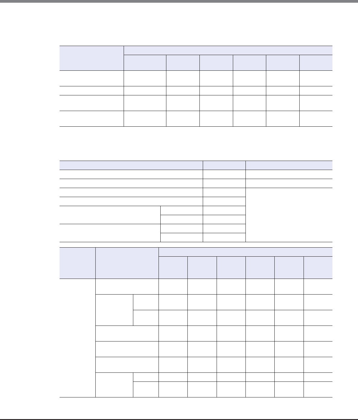
Chapter 11 System Management
11.2 Functions in the Action Area for System
ETERNUS Web GUI User’s Guide
Copyright 2013 FUJITSU LIMITED P2X0-1090-10ENZ0
891
REMCS Defaults
The REMCS recommended pattern of event notification is as follows. For the notification methods indicated
with "*", notification setting has been changed from the system default.
Selected: Notify
Cleared: Not notify
Selected/Cleared: Some events are notified and other events are not notified
–: Not applicable to notification
Item Notification method
Host Sense Key
Code Qualifier
SNMP Trap E-Mail syslog REMCS AIS
Connect
All Error Events Selected/
Cleared
Selected/
Cleared
Selected/
Cleared
Cleared Selected/
Cleared
Selected/
Cleared
All Warning Events Cleared * Cleared * Cleared * Cleared – Cleared *
All Informational Events – Selected/
Cleared
Selected/
Cleared
Cleared – Selected/
Cleared
Individual Settings
within Severity Level
Yes Yes Yes No Yes Yes
Event Notification Remarks
Blink Fault LED at warning Disable *
Turn on Fault LED when redundant copy is completed Disable
Display parts (except disk) with error status on LCD Enable This setting is available only when
using the ETERNUS DX8700 S2.
Display parts (except disk) with warning status on LCD Disable *
Display disks with error status on LCD Any Time Disable *
when HS<0 Enable *
Display disks with warning status on LCD Any Time Disable *
when HS<0 Disable
Level Event Notification method
Host Sense
Key Code
Qualifier
SNMP Trap E-Mail syslog REMCS AIS
Connect
Error
Parts Error Selected Selected Selected Cleared Selected
(fixed)
Selected
Disk Error Any Time Cleared * Cleared * Cleared * Cleared Selected
(fixed)
Cleared *
when
HS<0
Cleared Selected * Selected * Cleared – Selected *
Temperature Error Selected Selected Selected Cleared Selected
(fixed)
Selected
End of battery life Selected Selected Selected Cleared Selected
(fixed)
Selected
Rebuild/Copyback w/
redundant
Cleared * Cleared Cleared Cleared Cleared Cleared
Rebuild/
Copyback w/o
redundant
Any Time Cleared * Cleared Cleared Cleared Cleared Cleared
when
HS<0
Selected * Cleared Cleared Cleared – Cleared

Chapter 11 System Management
11.2 Functions in the Action Area for System
ETERNUS Web GUI User’s Guide
Copyright 2013 FUJITSU LIMITED P2X0-1090-10ENZ0
892
Error
Redundant Any Time Cleared Cleared Cleared Cleared Cleared Cleared
when
HS<0
Cleared Cleared Cleared Cleared – Cleared
Complete Redundant Copy Cleared Cleared Cleared Cleared Selected Selected
Complete rebuild Selected Selected Selected Cleared Selected
(fixed)
Selected
Bad data Selected Selected Selected Cleared Selected
(fixed)
Selected
Pinned data Selected
(*1)
Selected Selected Cleared Selected
(fixed)
Selected
Not ready Selected Selected Selected Cleared Selected
(fixed)
Selected
Remote Path Error Selected Selected Selected Cleared Selected Selected
REC Buffer Halt (Path
Error)
– Selected Selected Cleared Selected Selected
REC Buffer Halt (Overload) – Selected Selected Cleared Selected Selected
REC Buffer Halt (Other
Error)
– Selected Selected Cleared Selected Selected
Copy Session Error – Cleared Cleared Cleared Cleared Cleared
Thin Provisioning Pool
Rate
– Selected Selected Cleared – Cleared
SED Network Error – Selected Selected Cleared – Cleared
Warning
Parts Warning Cleared * Cleared * Cleared * Cleared Selected
(fixed)
Cleared *
Disk Warning Any Time Cleared * Cleared * Cleared * Cleared Selected
(fixed)
Cleared *
when
HS<0
Cleared Cleared Cleared Cleared – Cleared
Temperature Warning Cleared * Cleared * Cleared * Cleared Selected
(fixed)
Cleared *
Battery life Warning Cleared * Cleared * Cleared * Cleared Selected
(fixed)
Cleared *
Informational
Recovery module – Cleared Cleared Cleared – Cleared
Temperature restoration – Cleared Cleared Cleared – Cleared
User login/logout – Cleared Cleared Cleared – Cleared
Operated RAID Group – Cleared Cleared Cleared – Cleared
Added/Released Hot Spare – Cleared Cleared Cleared – Cleared
Operated Volume – Cleared Cleared Cleared – Cleared
Power off/on Apply
Firmware
– Cleared Cleared Cleared – Cleared
SDP Usage Rate Over Lv1 – Cleared Cleared Cleared – Cleared
SDP Usage Rate Over Lv2 – Cleared Cleared Cleared – Cleared
SDP Usage Rate Over Lv3 – Cleared Cleared Cleared – Cleared
Level Event Notification method
Host Sense
Key Code
Qualifier
SNMP Trap E-Mail syslog REMCS AIS
Connect
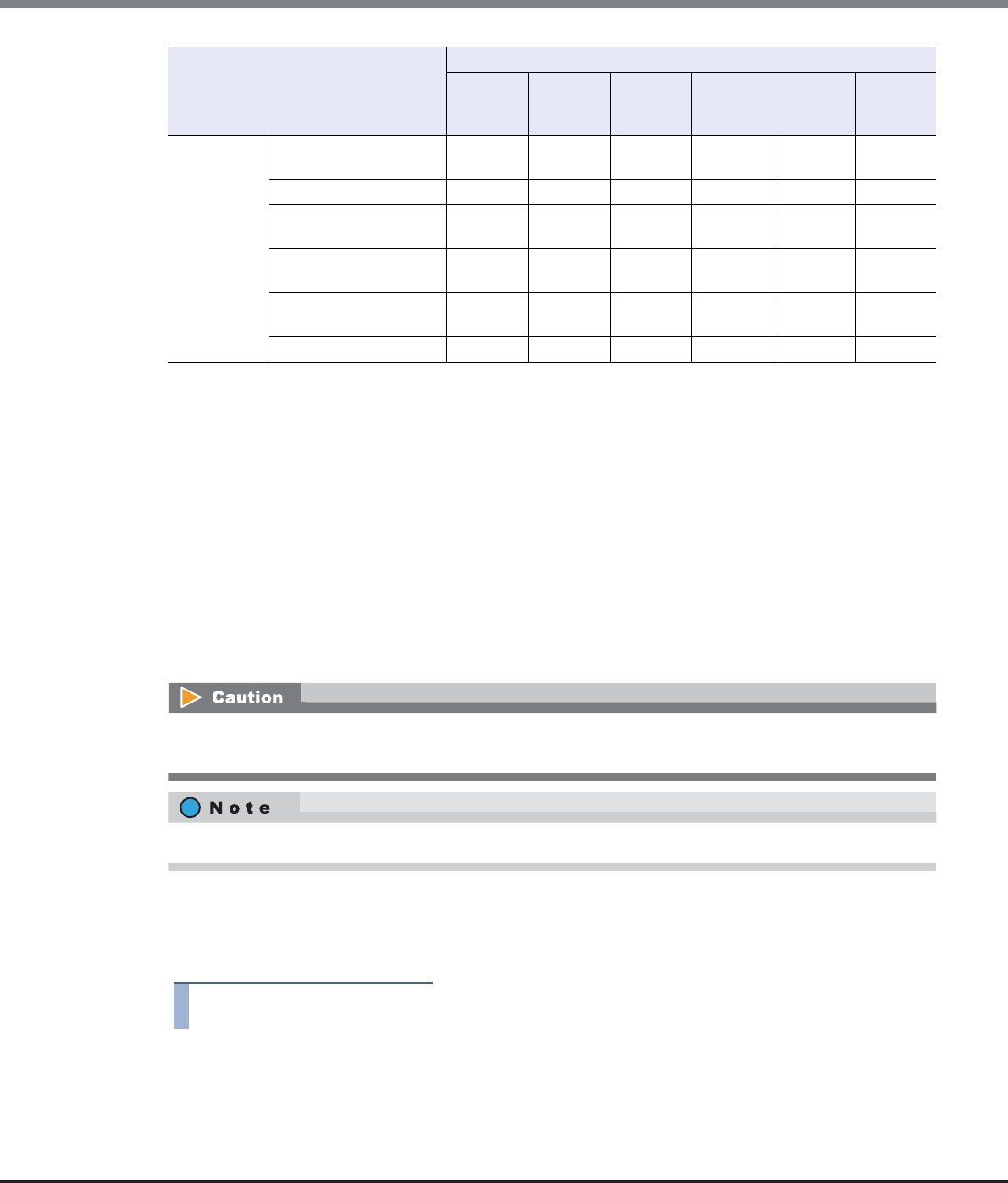
Chapter 11 System Management
11.2 Functions in the Action Area for System
ETERNUS Web GUI User’s Guide
Copyright 2013 FUJITSU LIMITED P2X0-1090-10ENZ0
893
Selected: Notify
Cleared: Not notify
Selected (fixed): Always notify (This setting cannot be changed with this function.)
–: Not applicable to notification
*1: Host Sense Key Code Qualifier is not notified when pinned data disappears.
11.2.9.2 Display Event Log
This function displays the event history of the ETERNUS DX Disk storage system.
The event log is one of the internal logs stored in the ETERNUS DX Disk storage system. The event log contains
a history of events that are related to configuration information changes, such as module failures and volume
creation.
Up to 6400 (400 per CM-CPU) event logs can be displayed. Once the recorded event log is no longer required,
it can also be deleted.
■Display event logs
The procedure to display event logs is as follows:
Procedure
1Click [Display/Delete Event Log] in [Action].
Informational
Copy Table Size Usage
Rate Over
– Cleared Cleared Cleared – Cleared
Trial copy license expired – Selected Selected Cleared – Cleared
No Free Space on ODX
Buffer Volume
– Cleared Cleared Cleared – Cleared
SED Network Error
Recovered
– Selected Selected Cleared – –
FC CA Port Link Status
Changed
– Cleared Cleared Cleared – Cleared
Host Login Over – Cleared Cleared Cleared – Cleared
Level Event Notification method
Host Sense
Key Code
Qualifier
SNMP Trap E-Mail syslog REMCS AIS
Connect
Even after deleting the event log using the [Delete Event Log] function, the maintenance information log
remains stored in the ETERNUS DX Disk storage system.
All event logs are deleted in a single operation.
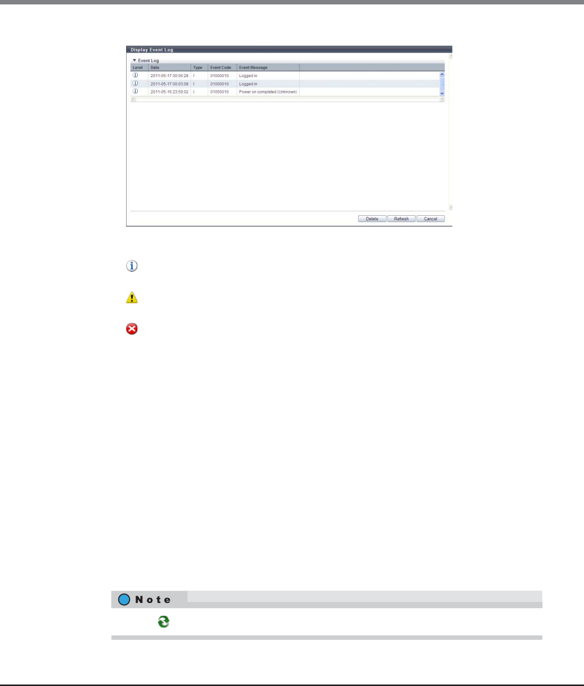
Chapter 11 System Management
11.2 Functions in the Action Area for System
ETERNUS Web GUI User’s Guide
Copyright 2013 FUJITSU LIMITED P2X0-1090-10ENZ0
894
2Check the displayed event logs.
•Level
The event level is displayed with an icon.
- (Information)
This icon indicates that the level of importance of the log is "Information".
- (Warning)
This icon indicates that the level of importance of the log is "Warning".
- (Error)
This icon indicates that the level of importance of the log is "Error".
•Date
The date and time when the event occurs are displayed.
-YYYY-MM-DD hh:mm:ss (YYYY: Year (AD), MM: Month (01 - 12), DD: Day (01 - 31), hh: Hour (00 - 23),
mm: Minute (00 - 59), ss: Second (00 - 59))
•Type
The event level is displayed using the following symbols.
-I
-J
-P
-M
-R
-O (Other)
•Event Code
The event code is displayed.
•Event Message
The detailed event information is displayed.
Click the [ ] icon to display the latest screen.
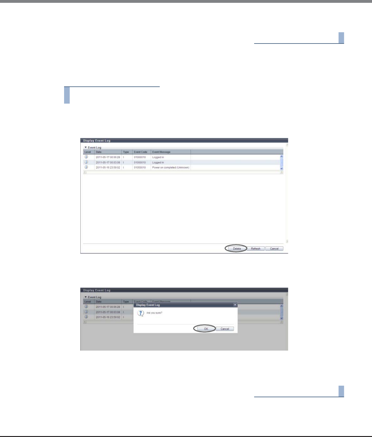
Chapter 11 System Management
11.2 Functions in the Action Area for System
ETERNUS Web GUI User’s Guide
Copyright 2013 FUJITSU LIMITED P2X0-1090-10ENZ0
895
3Click the [Cancel] button to return to the [Display Event Log] screen.
End of procedure
■Delete event logs
The procedure to delete event logs is as follows:
Procedure
1Click [Display/Delete Event Log] in [Action].
2Click the [Delete] button.
→A confirmation screen appears.
3Click the [OK] button.
→Deletion of event logs starts.
4Click the [Done] button to return to the [Event/Dump] screen.
End of procedure
Chapter 11 System Management
11.2 Functions in the Action Area for System
ETERNUS Web GUI User’s Guide
Copyright 2013 FUJITSU LIMITED P2X0-1090-10ENZ0
896
11.2.9.3 Export/Delete Log
This function exports and saves the ETERNUS DX Disk storage system maintenance information (log) in
accordance with user-specified time settings.
An exported log can be stored on a floppy disk or hard disk, or sent by E-mail.
Also, users can select a log segment size to suit the destination it is to be saved.
•The maintenance information to be exported
Log to be exported includes an "internal log" and "configuration information".
-Internal log
Detected errors, warnings, and traces
-Configuration definition information
Configuration information exported from the ETERNUS DX Disk storage system
The procedure to export log is as follows:
Procedure
1Click [Export/Delete Log] in [Action].
2Set the detailed information for exporting a log, and click the [Export] button.
•Specify Time Range
To specify a time range for exporting logs, select "Yes". Select "No" if not specifying. To export logs
from the last 24 hours, select the "Last 24 hours".
•Start Time
When a time range is to be specified, specify the date and time to start exporting logs.
-YYYY-MM-DD hh:mm:ss (YYYY: Year (AD), MM: Month (01 - 12), DD: Date (01 - 31), hh: Hour (00
- 23), mm: Minute (00 - 59), ss: Second (00 - 59))
•End Time
When a time range is to be specified, specify the date and time to finish exporting logs.
-YYYY-MM-DD hh:mm:ss (YYYY: Year (AD), MM: Month (01 - 12), DD: Date (01 - 31), hh: Hour (00
- 23), mm: Minute (00 - 59), ss: Second (00 - 59))
•Include I/O Module log
When exporting the I/O module logs, select "Yes". When not exporting, select "No".
•Log File Size
Select the log file size (segment size) when saving the exported log from the following.
-Non-segmentation
-4.27MB
-1.44MB (Floppy Disk)
-640KB (E-Mail)
•The internal log and configuration information cannot be exported separately.
•When exporting of the log has been completed, save the log file immediately.
•The various pieces of maintenance information are combined together, compressed, and then
segmented into the user specified segment size before being exported.
Special tools to read these logs are required.
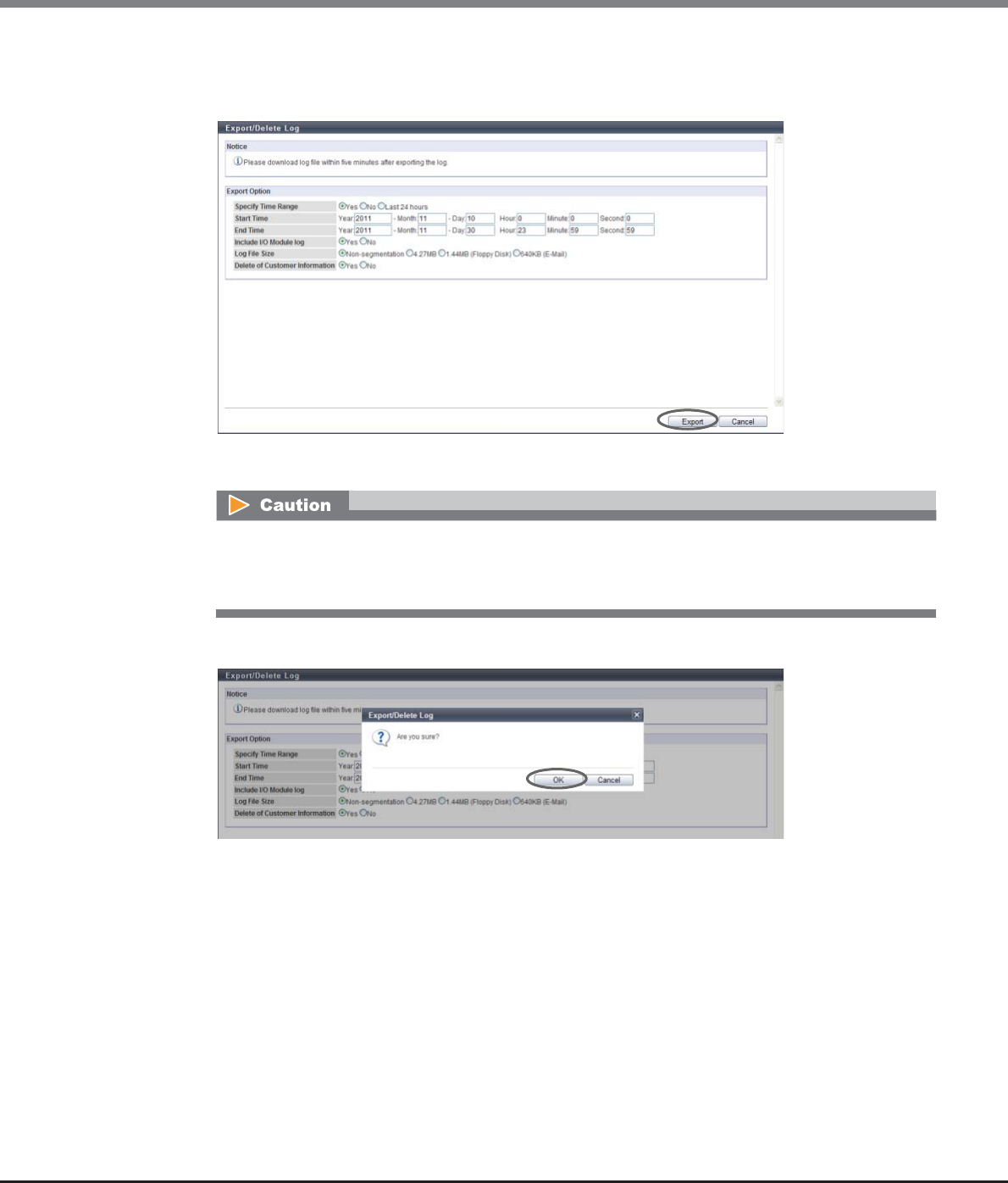
Chapter 11 System Management
11.2 Functions in the Action Area for System
ETERNUS Web GUI User’s Guide
Copyright 2013 FUJITSU LIMITED P2X0-1090-10ENZ0
897
•Delete of Customer Information
When deleting the customer information (information to identify the customer such as; user name,
box ID and IP address) from the exported log, select "Yes". When not deleting, select "No".
→A confirmation screen appears.
3Click the [OK] button.
→Export log starts. The progress screen is displayed. After the log export is finished, a screen to
execute downloading the file is displayed.
When clicking the [Export] button in the following conditions, an error screen appears.
•When the input date and/or time are not valid (For example: February 31st)
•When the end time is earlier than the start time
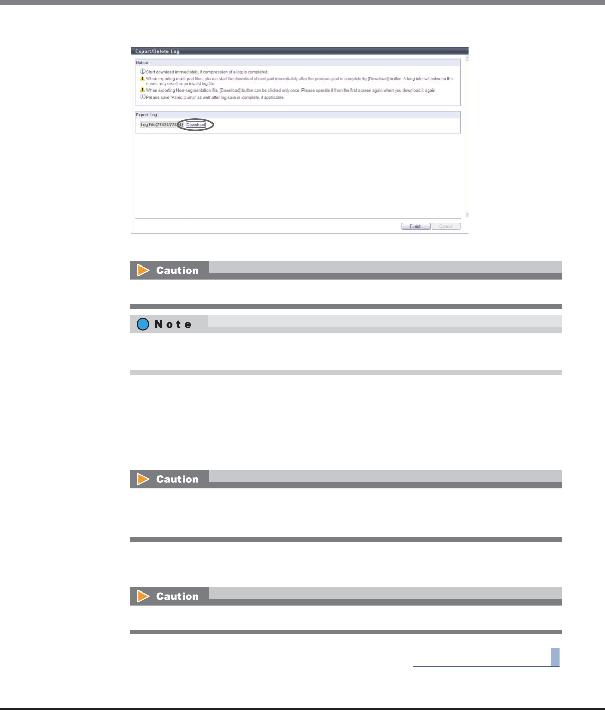
Chapter 11 System Management
11.2 Functions in the Action Area for System
ETERNUS Web GUI User’s Guide
Copyright 2013 FUJITSU LIMITED P2X0-1090-10ENZ0
898
4Click the [Download] button to save the exported log.
→A dialog box to download the file appears.
5Save the log file.
The default file name is "Log_serial number for the ETERNUS DX Disk storage system_YYYY-MM-DD_hh-
mm-ss_serial number for log file.zlg".
(YYYY-MM-DD_hh-mm-ss: the date and time when the download screen (Step 4) is displayed. When a
log file is segmented, the segmented log files are given the same name and numbered serially (01 -).)
→If the log file is segmented, download and save the next segment (save all the segmented files).
6Click the [Finish] button to return to the [Event/Dump] screen.
→Exporting log has been completed.
End of procedure
When exporting of the log has been completed, save the log file immediately.
If "Non-segmentation" is selected in the "Log File Size" field, the [Download] button becomes inactive
after the log file has been saved. Proceed to Step 5.
When exporting segmented log files, make sure to export the segment within five minutes. If five
minutes passes before exporting the next segment, the log export fails. After finishing saving each
segment, save the following segment immediately.
When exporting of the log has been completed, make sure to export a panic dump.
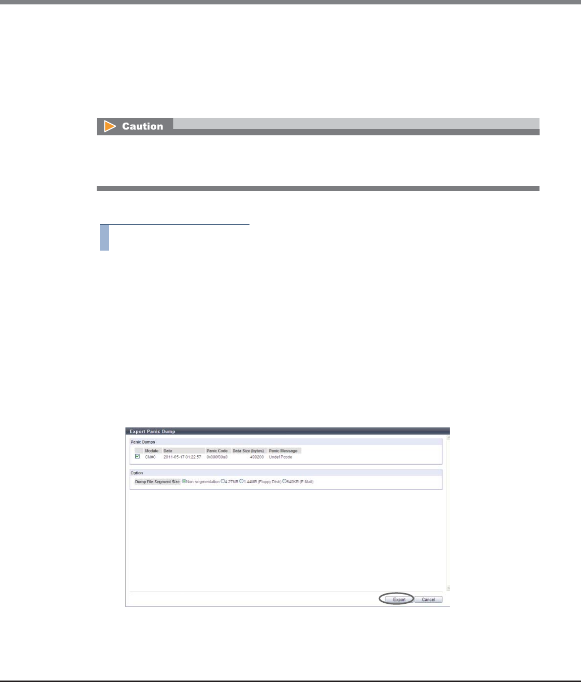
Chapter 11 System Management
11.2 Functions in the Action Area for System
ETERNUS Web GUI User’s Guide
Copyright 2013 FUJITSU LIMITED P2X0-1090-10ENZ0
899
11.2.9.4 Export Panic Dump
"Panic Dump" is the action of outputting (dump) memory information when an error (panic) occurs, and also
the name of the output information itself. This function exports and saves the memory information of the
Controller Module that is stored in the panic dump data, in a segment size specified by the user. An exported
panic dump can be stored on a floppy disk or hard disk, or sent by E-mail.
Panic dump is used to analyze the cause of a firmware abnormality or hardware error.
The procedure to export the panic dump is as follows:
Procedure
1Click [Export Panic Dump] in [Action].
2Specify the panic dump to be exported and the segment file size, and click the [Export]
button.
•Panic Dumps
Select a checkbox for the panic dump to be exported (only one panic dump can be selected).
•Dump File Segment Size
Select the file size (segment size) when saving the exported panic dump from the following:
-Non-segmentation
-4.27MB
-1.44MB (Floppy Disk)
-640KB (E-Mail)
→A confirmation screen appears.
•This function cannot be used when there is no panic dump to be exported in the ETERNUS DX Disk storage
system.
•Up to two panic dumps can be stored in a single CM.
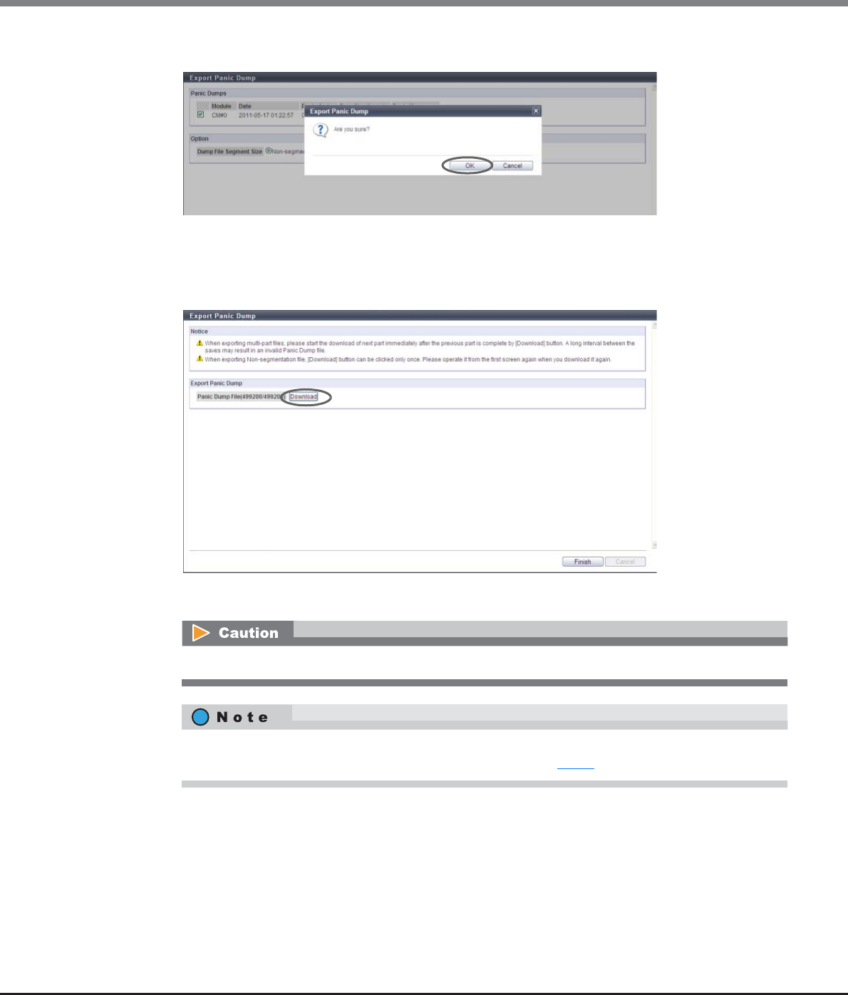
Chapter 11 System Management
11.2 Functions in the Action Area for System
ETERNUS Web GUI User’s Guide
Copyright 2013 FUJITSU LIMITED P2X0-1090-10ENZ0
900
3Click the [OK] button.
→Exporting of the panic dump starts. The progress screen is displayed. After the panic dump export is
finished, a screen to execute downloading the file is displayed.
4Click the [Download] button to save the exported panic dump.
→A dialog box to download the file appears.
When exporting of the panic dump has been completed, save the panic dump immediately.
If "Non-segmentation" is selected in the "Dump File Segment Size" field, the [Download] button
becomes inactive after the log file has been saved. Proceed to Step 5.
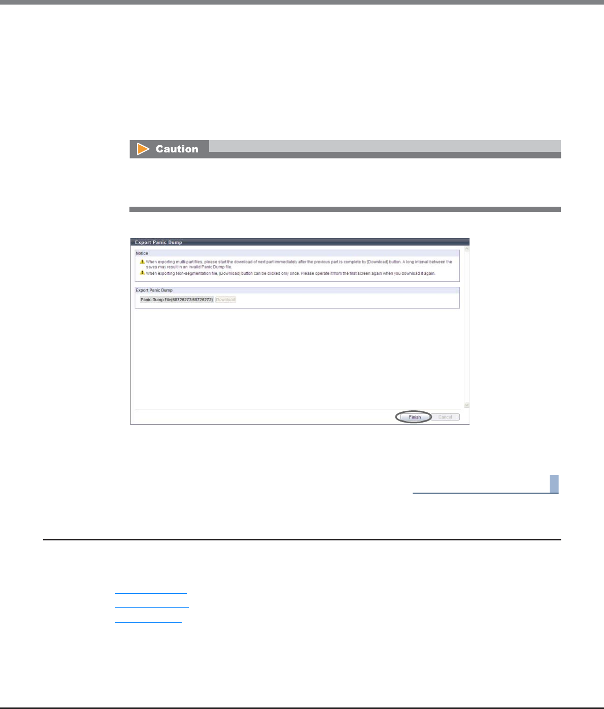
Chapter 11 System Management
11.2 Functions in the Action Area for System
ETERNUS Web GUI User’s Guide
Copyright 2013 FUJITSU LIMITED P2X0-1090-10ENZ0
901
5Save the panic dump.
The default file name is "Panic_serial number for the ETERNUS DX Disk storage system_YYYY-MM-
DD_hh-mm-ss_CMx_serial number for panic dump file.zlg".
(YYYY-MM-DD_hh-mm-ss: the date and time when the panic has occurred. x: CM number in which the
panic has occurred. When a panic dump file is segmented, the segmented panic dump files are given
the same name and numbered serially (01 -).)
→If the panic dump file is segmented, download and save the next segment (save all the segmented
files).
6Click the [Finish] button.
→A confirmation screen appears.
7Click the [OK] button to return to the [Event/Dump] screen.
End of procedure
11.2.10 Audit Log Management
This section describes audit log management.
The following functions are available with Audit log management:
•Enable Audit Log
•Disable Audit Log
•Setup Audit Log
When saving segmented panic dump files, make sure to save the segment within five minutes. If five
minutes passes before exporting the next segment, the panic dump export fails. After finishing
saving each segment, save the following segment immediately.
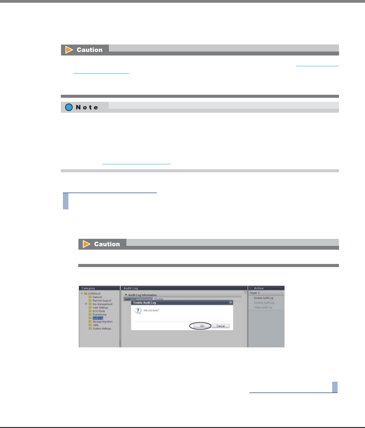
Chapter 11 System Management
11.2 Functions in the Action Area for System
ETERNUS Web GUI User’s Guide
Copyright 2013 FUJITSU LIMITED P2X0-1090-10ENZ0
902
11.2.10.1 Enable Audit Log
This function enables the audit log function.
The procedure to enable the audit log function is as follows:
Procedure
1Click [Enable Audit Log] in [Action].
→A confirmation screen appears.
2Click the [OK] button.
→Enabling of the audit log starts.
3Click the [Done] button to return to the [Audit Log] screen.
End of procedure
•Enable the "Audit Log" setting, and then specify the destination external server. Refer to "11.2.10.3 Setup
Audit Log" (page 903) for details. Audit logs are sent after the external server is specified.
•Note that the ETERNUS DX Disk storage system does not save the audit log. The audit log is only sent to
the specified external server.
The conditions for collecting audit logs are as follows:
•The interface must be GUI, CLI, or software that accesses the ETERNUS DX Disk storage system via CLI or
SMI-S
•The user who logs in or is newly logged in when the external server is set after the "Audit Log" is enabled
•Audit log collection target operations (*1)
*1: Refer to "11.1.9 Audit Log" (page 728) for details about log collection target operations.
If the audit log function has already been enabled, [Enable Audit Log] cannot be clicked.
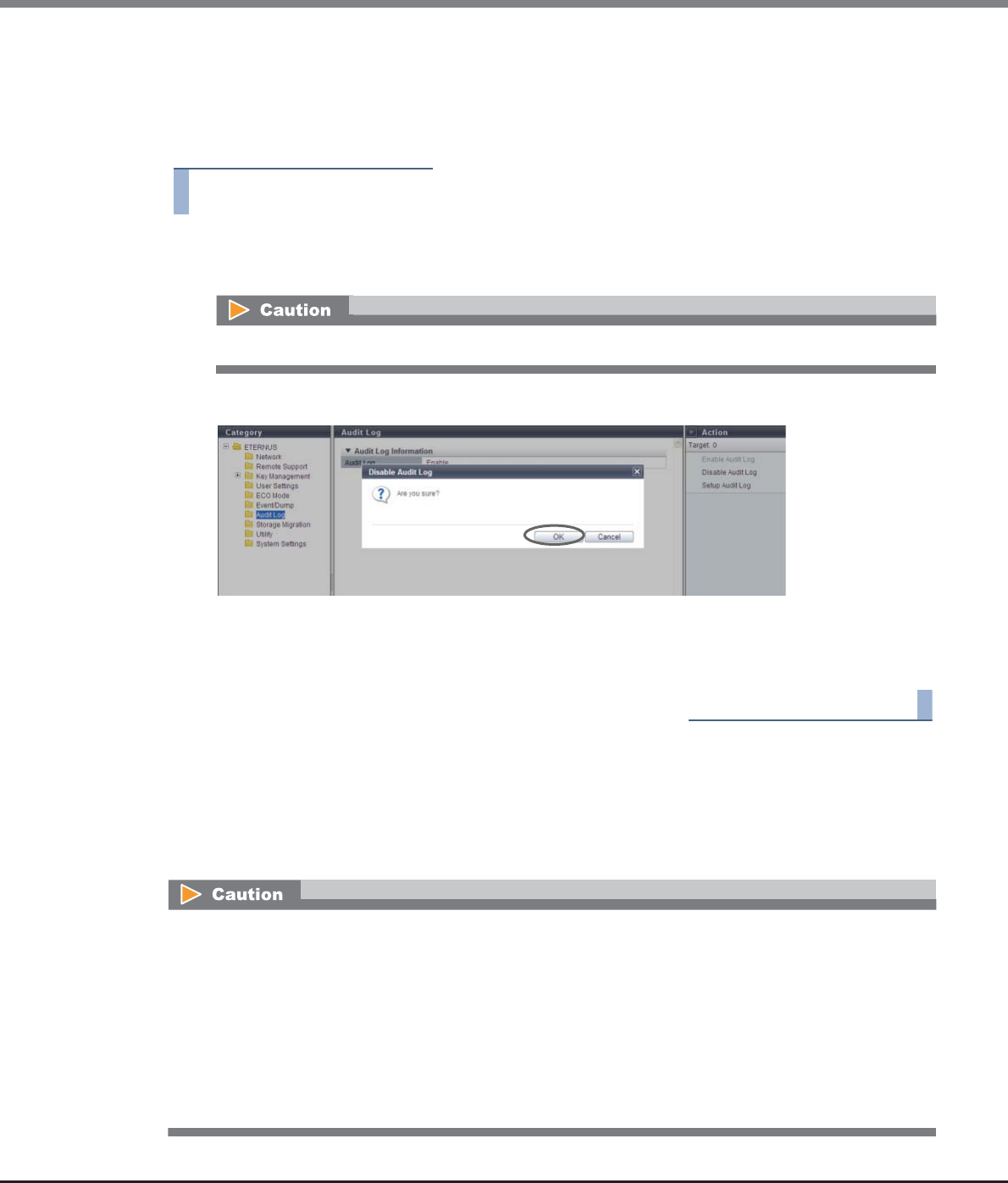
Chapter 11 System Management
11.2 Functions in the Action Area for System
ETERNUS Web GUI User’s Guide
Copyright 2013 FUJITSU LIMITED P2X0-1090-10ENZ0
903
11.2.10.2 Disable Audit Log
This function disables the audit log function.
The procedure to disable the audit log function is as follows:
Procedure
1Click [Disable Audit Log] in [Action].
→A confirmation screen appears.
2Click the [OK] button.
→Disabling of the audit log starts.
3Click the [Done] button to return to the [Audit Log] screen.
End of procedure
11.2.10.3 Setup Audit Log
This function sets up external servers (Syslog servers) for sending audit logs that are detected by the ETERNUS
DX Disk storage system.
Up to two Syslog servers can be registered.
If the audit log function has already been disabled, [Disable Audit Log] cannot be clicked.
•Enable the "Audit Log" setting, and then configure the destination Syslog server. Audit logs are sent after
the Syslog server is specified.
•Confirm that the audit log has been successfully sent to the Syslog server by logging in and out from GUI
or CLI and performing a transmission test to the Syslog server.
•Even if a communication error occurs between the ETERNUS DX Disk storage system and the Syslog server,
the audit log is not sent again.
•Changing the Syslog server setting is only available when the "Audit Log" setting is "Enable". Note that
once "on" is selected for the "Send Audit Log" setting, the "Send Audit Log" setting cannot be changed to
"off" for both of the Syslog servers (at least one Syslog server must be "on").

Chapter 11 System Management
11.2 Functions in the Action Area for System
ETERNUS Web GUI User’s Guide
Copyright 2013 FUJITSU LIMITED P2X0-1090-10ENZ0
904
The procedure to set up the servers for sending audit logs is as follows:
Procedure
1Click [Setup Audit Log] in [Action].
2Specify the parameters, and click the [Set] button.
•Send Audit Log
Select from "on (RFC3164)", "on (RFC5424)", or "off" for the audit log sending.
Logs are send in the selected RFC message format.
•Domain Name / IP Address
Input the domain name or the IP address of the Syslog server.
There are two methods to specify an IP address; "IPv4" and "IPv6". The following IPv6 addresses can
be used; "link local address", "global address", "unique local address", and "6to4 address". Refer to
"Available IPv6 Address" (page 757) for details.
When the current setting is displayed, the IPv6 address is displayed as an abbreviation.
The following input conditions apply:
-For "Domain Name"
Up to 63 alphanumeric characters and symbols
-For IPv4 address
xxx.xxx.xxx.xxx
xxx: 1 - 255 for the top field (decimal)
xxx: 0 - 255 for other fields (decimal)
-For IPv6 address
xxxx:xxxx:xxxx:xxxx:xxxx:xxxx:xxxx:xxxx
xxxx: 0 - ffff (FFFF) (hexadecimal, alphanumeric characters)
Refer to "IPv6 Address Notation" (page 378) for details.
•Port No.
Input the port number used to send an audit log.
The following input conditions apply:
-Numeric characters
-"1" - "65535"
•LAN Port
Select the LAN port from "MNT" or "RMT" that is to be used to send an audit log.
•The audit log function uses the destination server that has the same interface as the Syslog server. The
same server as the Syslog server is also available.
•The audit logs are sent to both Syslog servers at the same time.
•Even if the "Audit Log" setting changed to "Disable", the audit log setting information in the ETERNUS DX
Disk storage system is maintained.
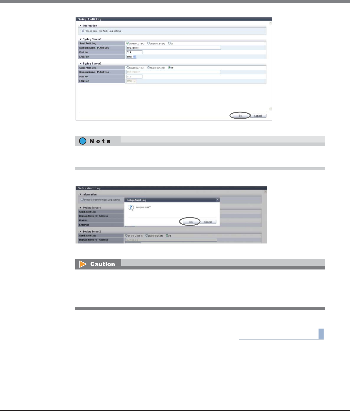
Chapter 11 System Management
11.2 Functions in the Action Area for System
ETERNUS Web GUI User’s Guide
Copyright 2013 FUJITSU LIMITED P2X0-1090-10ENZ0
905
→A confirmation screen appears.
3Click the [OK] button.
→Setting of the audit log starts.
4Click the [Done] button to return to the [Audit Log] screen.
End of procedure
Up to two Syslog servers can be configured. When configuring a second Syslog server, specify the
required parameters in "Syslog Server2".
An error screen appears in the following conditions:
•When the "Audit Log" setting is "Disable"
•When the specified IP address of the Syslog server conflicts with the internal IP address of the
ETERNUS DX Disk storage system.

Chapter 11 System Management
11.2 Functions in the Action Area for System
ETERNUS Web GUI User’s Guide
Copyright 2013 FUJITSU LIMITED P2X0-1090-10ENZ0
906
11.2.11 Storage Migration Management
This section describes Storage Migration management.
Storage Migration management provides the following functions:
•Start Storage Migration
•Download Template File for Storage Migration Settings
•Delete Storage Migration Path
•Download Storage Migration Result
•Restart Storage Migration
•Suspend Storage Migration
•Stop Storage Migration
11.2.11.1 Start Storage Migration
This function loads the Storage Migration setting file and starts migration.
Storage Migration is the function for migrating data by connecting other storage systems (migration source)
and the ETERNUS DX disk storage system (migration destination). Data migration is possible regardless of the
server and the OS, and without using server resources.
•Data migration is performed in volume units.
•Up to 16 storage systems can be specified as migration source storage systems.
•Up to 8 migration paths can be specified per migration source storage system.
•Up to 512 data migration LUNs can be specified per migration path.
To perform Storage Migration, the destination storage systems, the source storage systems, and the
destination volumes must satisfy the conditions below.
Requirements for a source storage system and a source LUN:
•An FC interface is available as the host interface
•The storage system is in normal status
•FC ports can be only used for data migration
•The migration source LUN is a type that is accessible from the host (Standard, TPV, SDV, etc.)
•Storage Migration is not yet started
Requirements for a destination storage system and a destination volume:
•An FC interface is available as the host interface
•The storage system is in normal status
•The CA port used for migration is in normal status
•The destination volume is in normal status
•The type of the destination volume is "Standard", "WSV", "TPV", or "FTV"
•The destination volume has the same or larger capacity than the source LUN
•The mirroring reservation attribute (*1) is not applied to the destination volume
*1: The mirroring reservation attribute is applied to the volumes that are being created as an REC copy path by the
Dynamic LUN Mirroring function. Volumes that are not successfully created may have this attribute. Volumes that
have the mirroring reservation attribute can be checked in the "Forbid Advanced Copy" field on the [Volume]
screen. Refer to "5.1.1 Volume (Basic Information)" (page 74) for details.
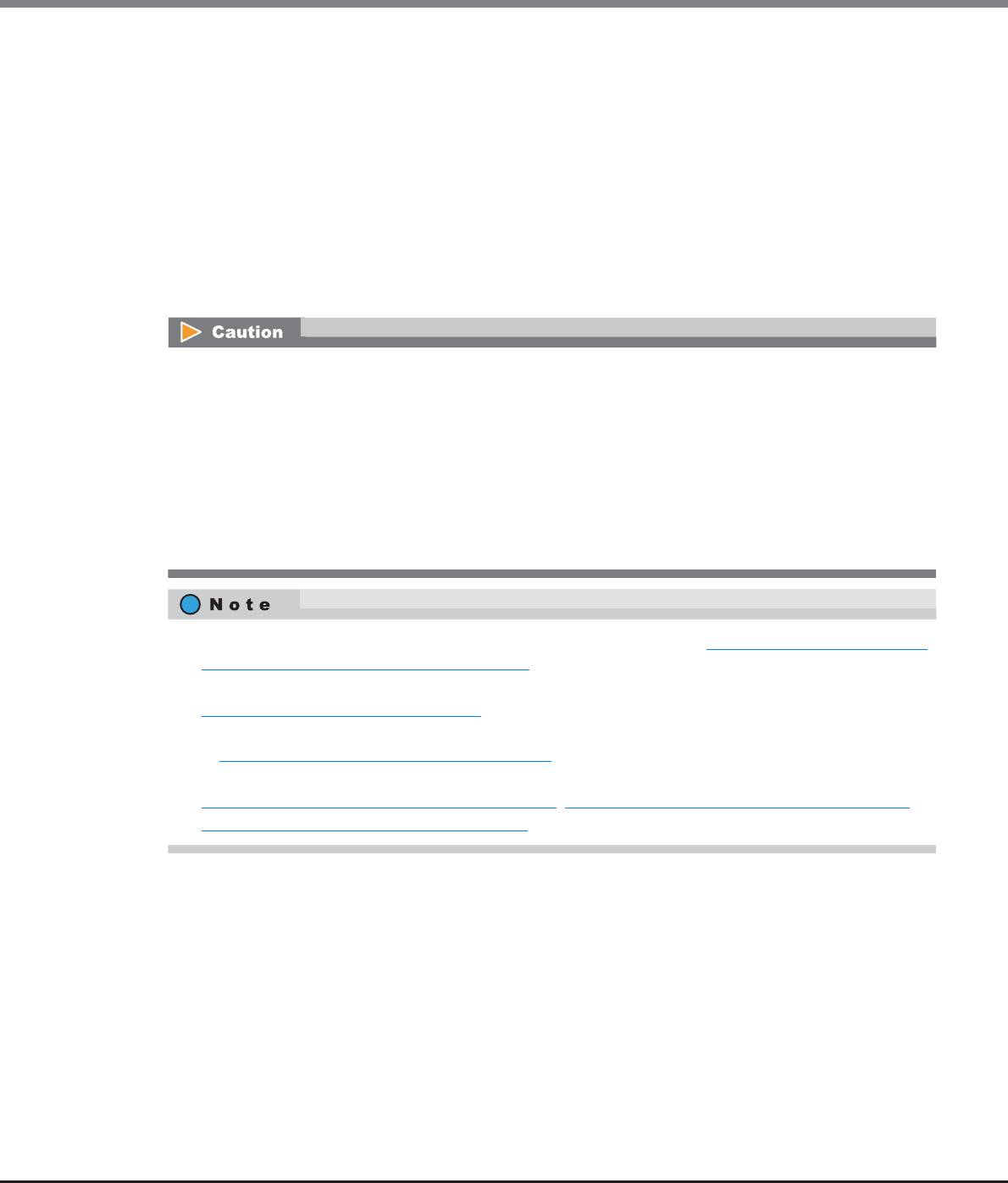
Chapter 11 System Management
11.2 Functions in the Action Area for System
ETERNUS Web GUI User’s Guide
Copyright 2013 FUJITSU LIMITED P2X0-1090-10ENZ0
907
•A storage system or volume cannot be specified as the destination in the following cases:
-Concurrent upgrade of firmware is in progress at the destination storage system
-The RAID group to which the destination volume belongs to has an ECO mode schedule configured
-The Thin Provisioning Pool (TPP) to which the destination volume belongs has an ECO mode schedule
configured
-The destination volume is specified as a RAID migration source or destination
-The capacity of the RAID group to which the destination volume belongs is being expanded
-Encryption is in progress for the destination volume
-The capacity of the destination volume is being expanded
-The destination volume is specified as the destination for another Storage Migration operation
-An ODX Buffer volume is selected as a migration destination volume
•Stop access from the host to both the source LUN and destination volume.
When "Migration + Full Compare" or "Full Compare" is specified for the operation mode, stop the host
access to all of the volumes in the migration destination storage system.
•Do not specify a volume that has copy sessions as a source or destination.
•Do not specify a volume as the source when formatting is in progress.
•Do not execute the [Start RAID Group Diagnosis] function or the [Start Disk Diagnosis] function on the
destination storage system.
•When "Migration + Full Compare" or "Full Compare" is specified for the operation mode, the time to com-
plete the operation after data migration is increased significantly.
•Download a template to create a Storage Migration setting file. Refer to "11.2.11.2 Download Template
File for Storage Migration Settings" (page 912) for details.
•Change the mode of the FC port that is used on the destination storage system to "Initiator". Refer to
"9.2.3.11 Modify Port Mode" (page 571) for details.
•Specify detailed parameters for the FC-Initiator port that is used on the destination storage system. Refer
to "9.2.3.7 Modify FC Port Parameters" (page 531) for details.
•A started Storage Migration can be suspended, restarted, and stopped in volume units. Refer to
"11.2.11.6 Suspend Storage Migration" (page 917), "11.2.11.5 Restart Storage Migration" (page 916), or
"11.2.11.7 Stop Storage Migration" (page 918) for details.

Chapter 11 System Management
11.2 Functions in the Action Area for System
ETERNUS Web GUI User’s Guide
Copyright 2013 FUJITSU LIMITED P2X0-1090-10ENZ0
908
Data migration flow using the Storage Migration function
The workflow sequence for Storage Migration is described below.
The host environment must be confirmed and saved before performing the Storage Migration. Ask the system
administrator to do it.
(1)Preparation
a Check and save the host environment so that the ETERNUS DX disk storage system can be used in
the same environment after migration.
b Check the status of the source and destination storage systems and clear any sense information that
has not been reported (*1).
c When migrating data with multipath, make the configuration so that the same affinity group (LUN
group) can be accessed from the multiple FC ports used for migration at the source storage system.
d Create a destination volume in the destination storage system, or format an existing volume for use
as the destination volume.
(2) Download a template for the Storage Migration setting file ("11.2.11.2 Download Template File for Storage
Migration Settings" (page 912)).
(3)Create the Storage Migration setting file. Refer to "Appendix I Storage Migration Setting Files" (page 1019)
for details.
(4)Stop access from the host to the source volume.
(5)Change the mode of the FC port used for migration in the destination storage system to "Initiator"
("9.2.3.11 Modify Port Mode" (page 571)).
(6)Set port parameters to the FC-Initiator port ("9.2.3.7 Modify FC Port Parameters" (page 531)).
(7)Connect the source and destination storage systems using an FC cable, or use a switch to connect the
source and destination storage systems.
(8)Load the "Storage Migration setting file" that has been created in Step (3) to start Storage Migration
("11.2.11.1 Start Storage Migration" (page 906)).
(9)Check the progress of Storage Migration.
(10)Operation after Storage Migration is complete:
a Delete the migration path after Storage Migration is completed successfully ("11.2.11.3 Delete
Storage Migration Path" (page 914)).
b Change the FC-Initiator port mode from "Initiator" to "CA" ("9.2.3.11 Modify Port Mode" (page 571)).
c Set port parameters to the FC-CA port ("9.2.3.7 Modify FC Port Parameters" (page 531)).
d Set host affinity to the FC-CA port ("9.2.1.1 Create Host Affinity" (page 414) or "9.2.1.3 Modify Host
Affinity" (page 428)).
e Confirm that the destination storage system and volumes can be accessed correctly from the host.
*1: Operations that can be performed when logged in using a user account with the "Maintenance Operation" policy.
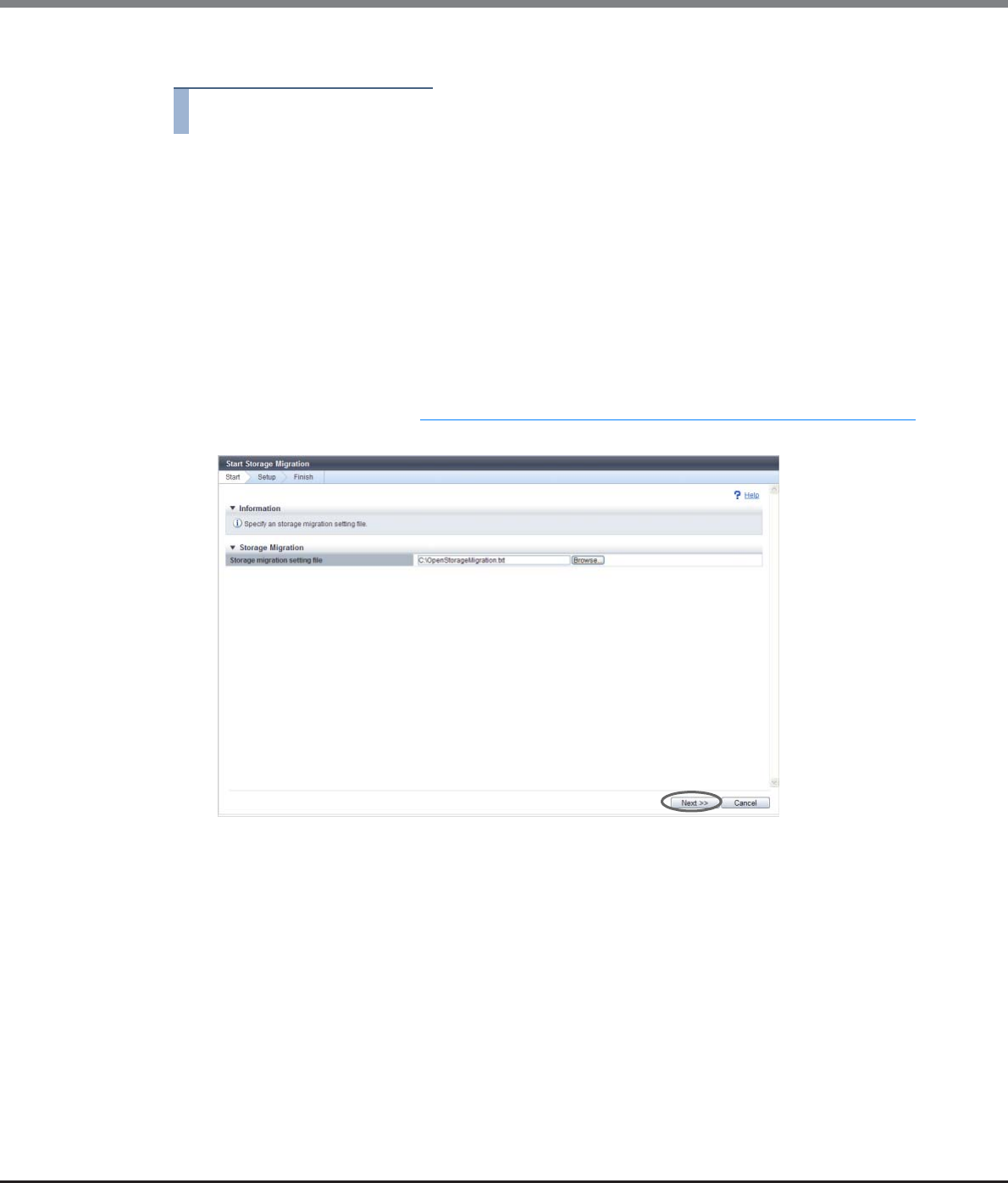
Chapter 11 System Management
11.2 Functions in the Action Area for System
ETERNUS Web GUI User’s Guide
Copyright 2013 FUJITSU LIMITED P2X0-1090-10ENZ0
909
The procedure to start Storage Migration is as follows:
Procedure
1Click [Start] in [Action].
2Click the [Browse...] button to select a Storage Migration setting file, and click the [Next >>]
button.
•Storage migration setting file
Input the location where the Storage Migration setting file is stored.
Click the [Browse...] button to specify the location, or input the location directly.
There are two types of template files for Storage Migration setting; new format (*1) template files
and old format (*1) template files. Storage Migration setting files in both formats can be used
when the controller firmware version is V10L30 or later.
*1: A template file in the new format can be downloaded when the controller firmware version is V10L30 or
later. A template file in the old format can be downloaded when the controller firmware version is older
than V10L30. Refer to "11.2.11.2 Download Template File for Storage Migration Settings" (page 912) for
details.

Chapter 11 System Management
11.2 Functions in the Action Area for System
ETERNUS Web GUI User’s Guide
Copyright 2013 FUJITSU LIMITED P2X0-1090-10ENZ0
910
•An error screen is displayed when a timeout occurs during the retrieval of destination device
information.
•An error screen is displayed when the Storage Migration setting file is in the following conditions:
-The Storage Migration setting file is not specified
-A character code other than the space or tab is placed before the keyword on the left of "="
-The number of the parameters on the right of "=" does not coincided with the specified number
of parameters of the keyword
-The identification code is invalid (only when using a Storage Migration setting file with the
new format)
-"Type" is not "Open"
-The "GROUP" is in the following conditions
•Invalid characters are input
-When a value other than a 1-digit hexadecimal number is input for a Storage Migration
setting file in the old format
-When a value other than a 1-digit hexadecimal number is input after the "0x" prefix for a
Storage Migration setting file in the new format
•Out of range (not in the 0 - F range)
•The same value is duplicated in the Storage Migration setting file
-The Operation mode is not one of the following items: "M", "M+QC", "M+FC", "QC", "FC"
-The destination CA port being set for "PATH" is in the following conditions:
•The setting is not correct
•The mode is not "Initiator"
•The status is abnormal
•The same value is duplicated in the Storage Migration setting file
•The value is already used in a Storage Migration in execution.
-The source WWN being set for "PATH" is in the following conditions:
•The number of characters is not 16
•The value is out of range
•The first character is "0" or all characters are "F"
•The same value is duplicated in the Storage Migration setting file
-The source LUN is in the following conditions:
•Invalid characters are input
-When inputting a value other than 4-digit hexadecimal number for a Storage Migration
setting file with the old format
-When the Storage Migration setting file is in the new format and the one of the following
conditions applies to the value that is input:
•The value is not a decimal or hexadecimal number
•The value is a decimal number that exceeds 256
•The value is not a 4-digit or 16-digit hexadecimal number
•The same value is duplicated in the Storage Migration setting file
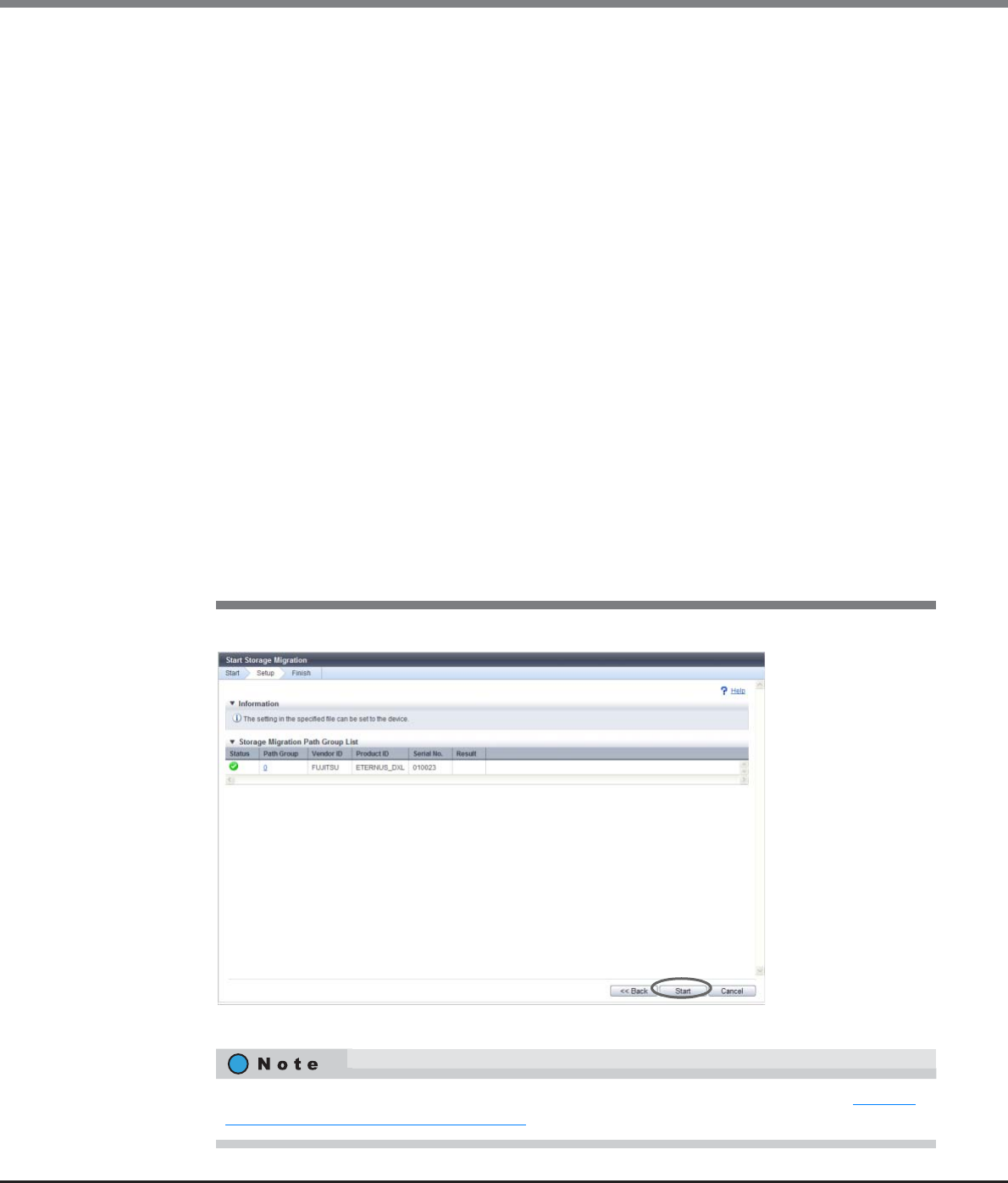
Chapter 11 System Management
11.2 Functions in the Action Area for System
ETERNUS Web GUI User’s Guide
Copyright 2013 FUJITSU LIMITED P2X0-1090-10ENZ0
911
3Check the path group, and click the [Start] button.
→A confirmation screen appears.
-The destination volume is in the following conditions:
•Invalid characters are input
-When inputting a value other than 4-digit hexadecimal number for a Storage Migration
setting file with the old format
-When inputting a value that is not a decimal number or a 4-digit hexadecimal number
for a Storage Migration setting file in the new format
•The volume number is out of range
•Not specified
•The status is abnormal
•The volume type is not "Standard", "WSV", "TPV", or "FTV".
•The same value is duplicated in the Storage Migration setting file
•The value is already used in a Storage Migration in execution
•When an error is detected in the script analysis
•An error screen is displayed when the obtained destination device information is in the following
conditions:
-When two or more source storage systems are specified in single "GROUP".
-The source storage system has other Storage Migration instance already started.
-When the source storage system status is not normal
-The source WWN being set for "PATH" does not exist
-The source LUN is in the following conditions:
•The source device information is not exist.
•An unusable status is detected.
•The capacity exceeds that of the destination volume.
Click the [Path Group] link to display the [Path Group Detail Information] screen. Refer to "11.1.14
Path Group Detail Information" (page 734) for display items.
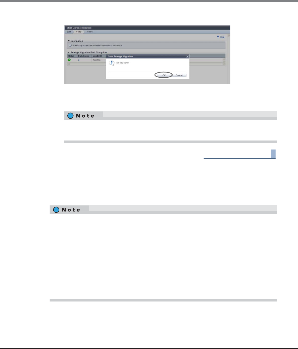
Chapter 11 System Management
11.2 Functions in the Action Area for System
ETERNUS Web GUI User’s Guide
Copyright 2013 FUJITSU LIMITED P2X0-1090-10ENZ0
912
4Click the [OK] button.
→Storage Migration starts.
5Click the [Done] button to return to the [Storage Migration] screen.
End of procedure
11.2.11.2 Download Template File for Storage Migration Settings
This function downloads the template of the Storage Migration setting file.
In the Storage Migration setting file, specify the destination CA port, source WWN, source LUN, and
destination volumes.
•Refer to the [Storage Migration] screen for progress status of Storage Migration.
•Click the [Path Group] link to display the "11.1.14 Path Group Detail Information" (page 734).
•There are two types of template files for Storage Migration; new format template files and old format
template files. A template file in the new format can be downloaded when the controller firmware
version is V10L30 or later. A template file in the old format can be downloaded when the controller
firmware version is older than V10L30. A template file with the new format supports the following items:
-The operation mode for the Storage Migration can be specified.
-If a source LUN is between "0" and "255", the source LUN can be specified with a decimal number.
-Destination volumes can be specified with decimal numbers.
•To distinguish between a new format and an old format template file, check whether the identification
code "eternus-storage-migration-0101" is included. A template file with the new format has an
identification code. Identification codes are not included in old format template files.
•Refer to "Appendix I Storage Migration Setting Files" (page 1019) for details about the Storage Migration
setting files.
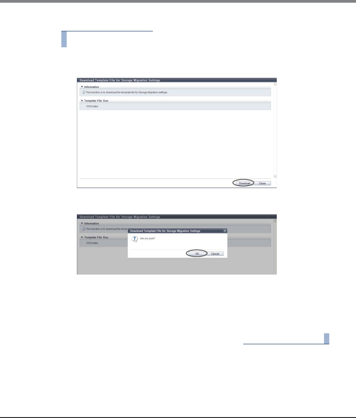
Chapter 11 System Management
11.2 Functions in the Action Area for System
ETERNUS Web GUI User’s Guide
Copyright 2013 FUJITSU LIMITED P2X0-1090-10ENZ0
913
The procedure to download the template is as follows:
Procedure
1Click [Download Template] in [Action].
2Click the [Download] button.
→A confirmation screen appears.
3Click the [OK] button.
→A dialog box to download file appears.
4Save the template file.
The default file name is "StMigTemplate.txt".
→Downloading of the template file starts.
5Click the [Close] button to return to the [Storage Migration] screen.
End of procedure
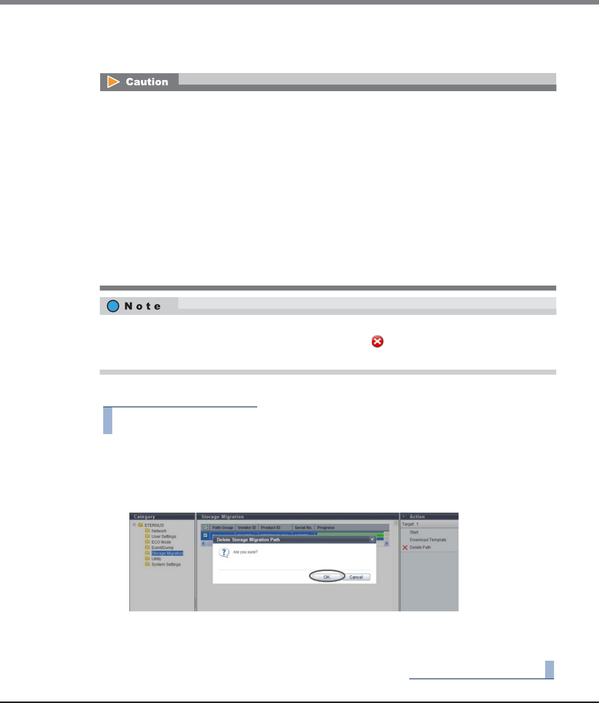
Chapter 11 System Management
11.2 Functions in the Action Area for System
ETERNUS Web GUI User’s Guide
Copyright 2013 FUJITSU LIMITED P2X0-1090-10ENZ0
914
11.2.11.3 Delete Storage Migration Path
This function deletes path groups for Storage Migration.
The procedure to delete the Storage Migration path is as follows:
Procedure
1Select the path group that is to be deleted (multiple selections can be made) and click
[Delete Path] in [Action].
→A confirmation screen appears.
2Click the [OK] button.
→Deletion of the Storage Migration path starts.
3Click the [Done] button to return to the [Storage Migration] screen.
End of procedure
The path groups must be deleted after the data migration is complete. The following operations are not
available before path groups are deleted:
•Concurrent upgrade of firmware at the destination storage system
•ECO mode schedule setting of the RAID group to which the destination volume belongs
•ECO mode schedule setting of the Thin Provisioning Pool (TPP) to which the destination volume belongs
•Capacity expansion of the RAID group to which the destination volume belongs
•RAID migration of the destination volume
•Encryption of the destination volume
•Capacity expansion of the destination volume
•Deletion of the destination volume
•Port mode modification of the destination FC-Initiator port
•Port parameter setting of the destination FC-Initiator port
•Reduction of the CA to which the destination FC-Initiator port belongs
The path group can be deleted if all configured paths are in any of the following state:
•"Source LUN Status" of the Storage Migration Volume List is " Not Exist".
•"Migration Status" of the Storage Migration is "Normal End", "Stop", "Initial", or "Waiting".
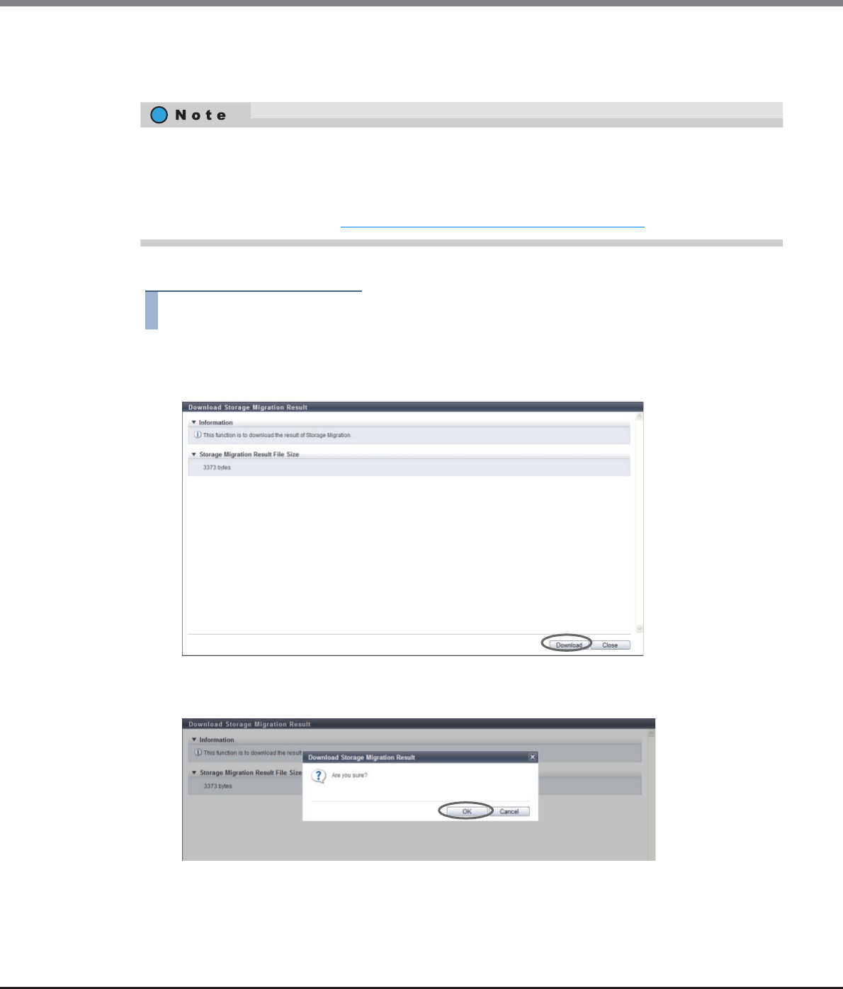
Chapter 11 System Management
11.2 Functions in the Action Area for System
ETERNUS Web GUI User’s Guide
Copyright 2013 FUJITSU LIMITED P2X0-1090-10ENZ0
915
11.2.11.4 Download Storage Migration Result
This function downloads the execution result of the Storage Migration.
The procedure to download the Storage Migration result is as follows:
Procedure
1Click [Download Result] in [Action].
2Click the [Download] button.
→A confirmation screen appears.
3Click the [OK] button.
→A dialog box to download file appears.
•Download of Storage Migration results is made in path group units.
•Storage Migration results can be downloaded not only after completion of data migration but also during
data migration.
•The Storage Migration results are text files. The template is the same as the [Path Group Detail
Information] screen. Refer to "11.1.14 Path Group Detail Information" (page 734) for details.
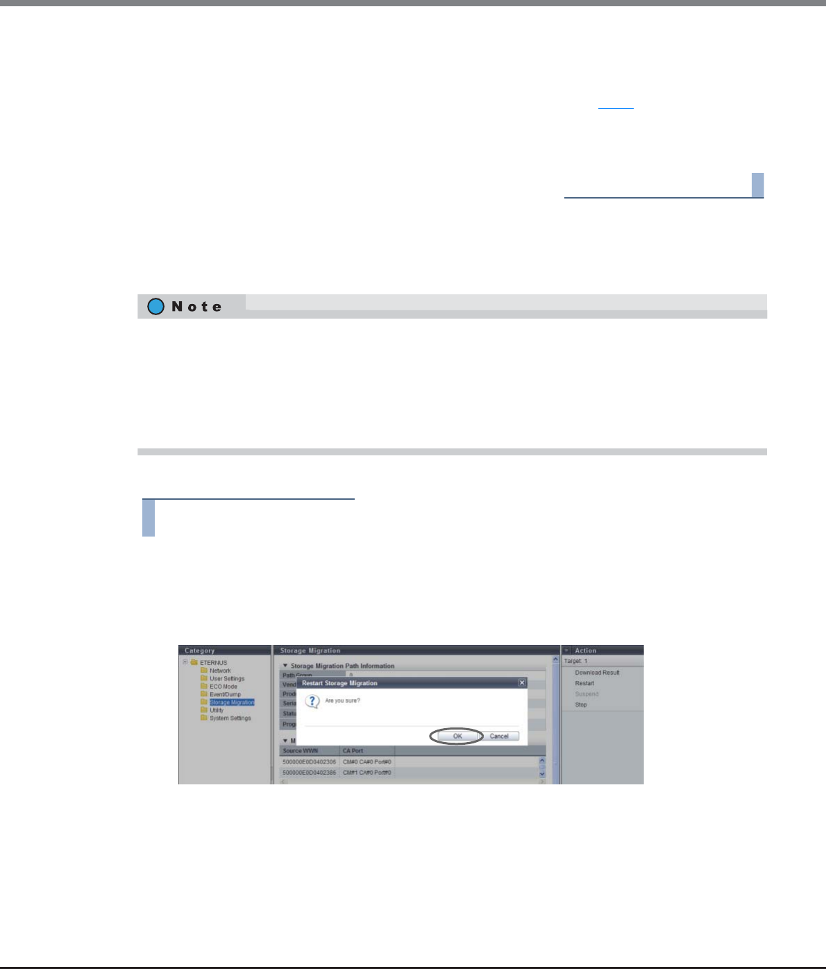
Chapter 11 System Management
11.2 Functions in the Action Area for System
ETERNUS Web GUI User’s Guide
Copyright 2013 FUJITSU LIMITED P2X0-1090-10ENZ0
916
4Save the Storage Migration result file.
The default file name is "StMigResult_serial number for the ETERNUS DX Disk storage system_YYYY-MM-
DD_hh-mm-ss.txt".
(YYYY-MM-DD_hh-mm-ss: the date and time when the download screen (Step 2) is displayed.)
→Downloading of the Storage Migration result file starts.
5Click the [Close] button to return to the [Path Group Detail Information] screen.
End of procedure
11.2.11.5 Restart Storage Migration
This function restarts Storage Migration when it is suspended, stopped, or error-stopped.
The procedure to restart the Storage Migration is as follows:
Procedure
1Select the source LUN from which Storage Migration is to be restarted (multiple selections
can be made) and click [Restart] in [Action].
→A confirmation screen appears.
2Click the [OK] button.
→Storage Migration restarts.
•Storage Migration is restarted in volume units.
•Storage Migration can be restarted when its "Migration Status" is "Suspend", "Stop" or "Error".
•If Storage Migration is restarted when its "Migration Status" is "Suspend" or "Error", data migration is
started from the point of LUN suspension.
•If Storage Migration is restarted when its "Migration Status" is "Stop", data migration of the LUN is started
over from scratch.
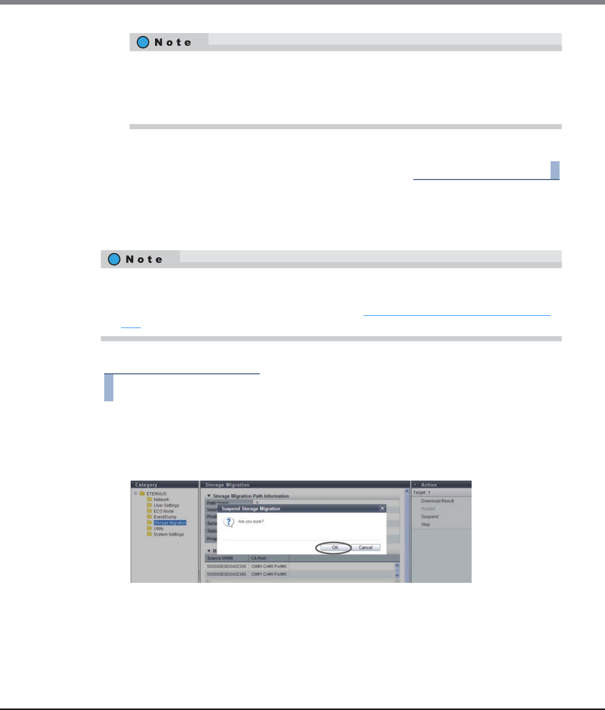
Chapter 11 System Management
11.2 Functions in the Action Area for System
ETERNUS Web GUI User’s Guide
Copyright 2013 FUJITSU LIMITED P2X0-1090-10ENZ0
917
3Click the [Done] button to return to the [Path Group Detail Information] screen.
End of procedure
11.2.11.6 Suspend Storage Migration
This function suspends Storage Migration that is awaiting migration or running.
The procedure to suspend the Storage Migration is as follows:
Procedure
1Select the source LUN for which Storage Migration is to be suspended (multiple selections
can be made) and click [Suspend] in [Action].
→A confirmation screen appears.
2Click the [OK] button.
→Storage Migration suspends.
[Restart] cannot be clicked if one or more source LUNs are selected for which the migration status is
unavailable for restarting. Note that if the migration status of some LUNs changes to unavailable
status after clicking [Restart], only the available LUNs among the selected LUNs are restarted. If LUNs
for which the migration status is not unavailable for restarting exist, a message that indicates that
the restarting process for these LUNs failed is displayed.
•Storage Migration is suspended in volume units.
•Storage Migration can be suspended when its "Migration Status" is "Waiting" or "Running".
•A suspended Storage Migration can be restarted. Refer to "11.2.11.5 Restart Storage Migration" (page
916) for details.
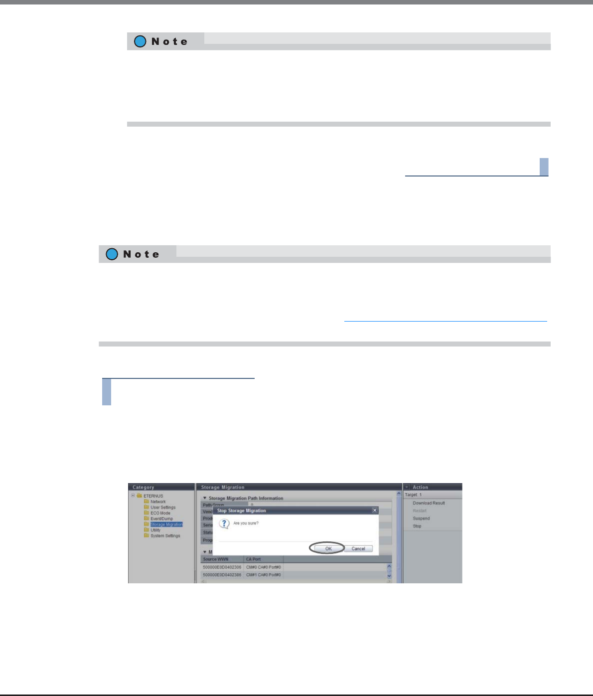
Chapter 11 System Management
11.2 Functions in the Action Area for System
ETERNUS Web GUI User’s Guide
Copyright 2013 FUJITSU LIMITED P2X0-1090-10ENZ0
918
3Click the [Done] button to return to the [Path Group Detail Information] screen.
End of procedure
11.2.11.7 Stop Storage Migration
This function stops Storage Migration when it is awaiting, migrating, suspended, or error-stopped.
The procedure to stop the Storage Migration is as follows:
Procedure
1Select the source LUN for which Storage Migration is to be stopped (multiple selections can
be made) and click [Stop] in [Action].
→A confirmation screen appears.
2Click the [OK] button.
→Storage Migration stops.
[Suspend] cannot be clicked if one or more source LUNs are selected for which the migration status is
unavailable for suspending. Note that if the migration status of some LUNs changes to unavailable
status after clicking [Suspend], only the available LUNs among the selected LUNs are suspended. If
LUNs for which the migration status is not unavailable for suspending exist, a message that indicates
that the suspending process for these LUNs failed is displayed.
•Storage Migration is stopped in volume units.
•Storage Migration can be stopped when its "Migration Status" is "Waiting", "Running", "Suspend" or
"Error".
•A stopped Storage Migration can be restarted. Refer to "11.2.11.5 Restart Storage Migration" (page 916)
for details.
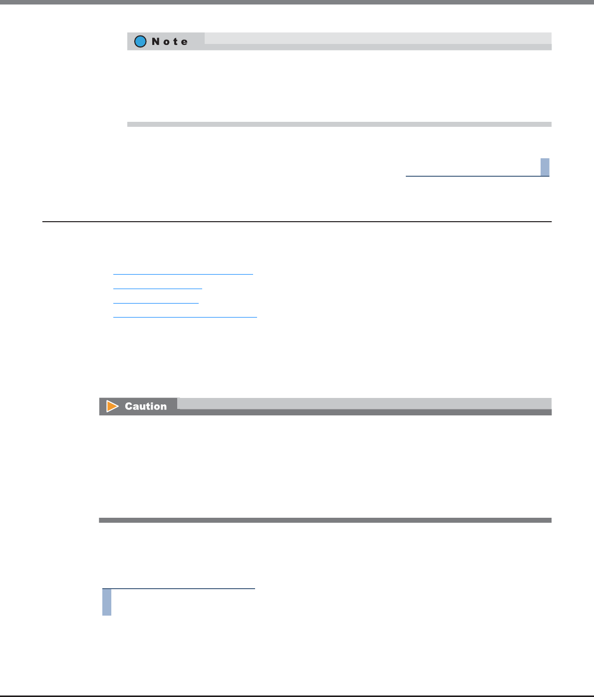
Chapter 11 System Management
11.2 Functions in the Action Area for System
ETERNUS Web GUI User’s Guide
Copyright 2013 FUJITSU LIMITED P2X0-1090-10ENZ0
919
3Click the [Done] button to return to the [Path Group Detail Information] screen.
End of procedure
11.2.12 Utility Management
This section describes utility management.
Utility management provides the following functions:
•Shutdown/Restart Storage System
•Backup Configuration
•Export Configuration
•Start/Stop Performance Monitoring
11.2.12.1 Shutdown/Restart Storage System
When the ETERNUS DX disk storage system cannot be shut down directly, perform the shutdown or restart on
the screen.
■Shutdown the ETERNUS DX Disk storage system
The procedure to shut down the ETERNUS DX Disk storage system is as follows:
Procedure
1Click [Shutdown/Restart] in [Action].
[Stop] cannot be clicked if one or more source LUNs are selected for which the migration status is
unavailable for stopping. Note that if the migration status of some LUNs changes to unavailable
status after clicking [Stop], only the available LUNs among the selected LUNs are stopped. If LUNs for
which the migration status is not unavailable for stopping exist, a message that indicates that the
stopping process for these LUNs failed is displayed.
•This function can be used regardless of whether the "Setup Power Management" is enabled or disabled.
•Note that the ETERNUS DX Disk storage system may reboot automatically when "Setup Power
Management" is enabled. For example, an ETERNUS DX Disk storage system that is turned off reboots
when receiving a power on request from a server during turning off the power.
•This function cannot be used when the ETERNUS DX Disk storage system is in the machine down status.
Restart the browser after completion of the process, and then access the login screen after rebooting of
the ETERNUS DX Disk storage system is complete.
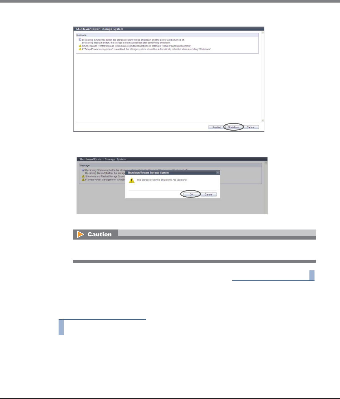
Chapter 11 System Management
11.2 Functions in the Action Area for System
ETERNUS Web GUI User’s Guide
Copyright 2013 FUJITSU LIMITED P2X0-1090-10ENZ0
920
2Click the [Shutdown] button.
→A confirmation screen appears.
3Click the [OK] button.
→The ETERNUS DX disk storage system shuts down after 30 seconds.
End of procedure
■Restart the ETERNUS DX Disk storage system
The procedure to restart the ETERNUS DX Disk storage system is as follows:
Procedure
1Click [Shutdown/Restart] in [Action].
Note that the ETERNUS DX Disk storage system may reboot automatically when "Setup Power
Management" is enabled.
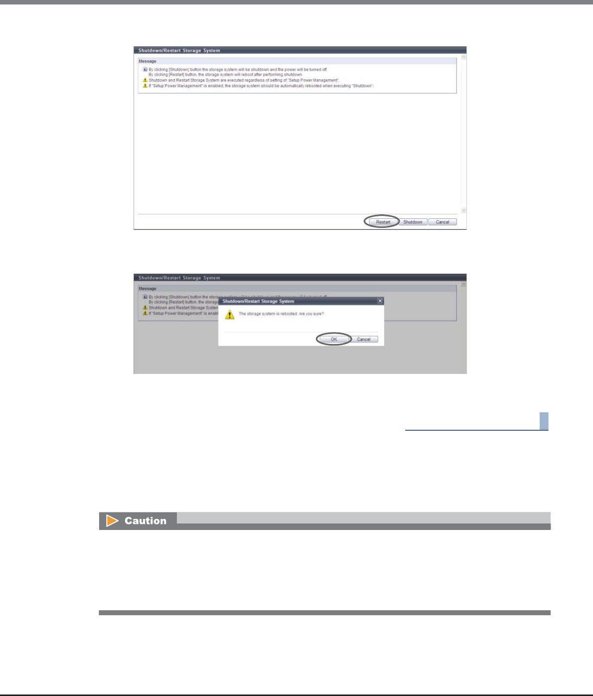
Chapter 11 System Management
11.2 Functions in the Action Area for System
ETERNUS Web GUI User’s Guide
Copyright 2013 FUJITSU LIMITED P2X0-1090-10ENZ0
921
2Click the [Restart] button.
→A confirmation screen appears.
3Click the [OK] button.
→The ETERNUS DX disk storage system shuts down after 30 seconds. After shutdown, the ETERNUS DX
disk storage system restarts.
End of procedure
11.2.12.2 Backup Configuration
This function backs up the configuration definition data to the Bootup and Utility Device (BUD) in the CM. Up
to four generations of configuration definition data can be stored.
This function cannot be used under the following conditions:
•When no configuration definition data file is selected
•When no data exists in the configuration definition data file
•When an error exists with the configuration definition data file size
•When an error exists in the configuration definition data file
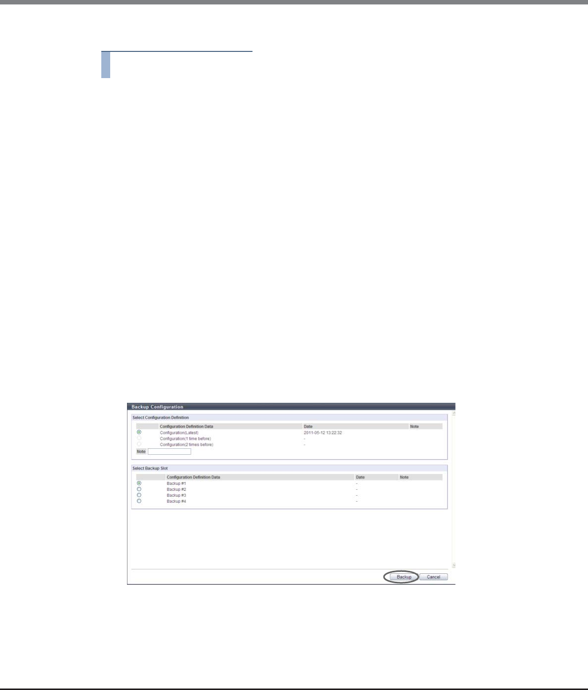
Chapter 11 System Management
11.2 Functions in the Action Area for System
ETERNUS Web GUI User’s Guide
Copyright 2013 FUJITSU LIMITED P2X0-1090-10ENZ0
922
The procedure to backup configuration definition file is as follows:
Procedure
1Click [Backup Configuration] in [Action].
2Specify the parameters, and click the [Backup] button.
●Select Configuration Definition
•Configuration Definition Data
Select configuration definition data to be backed up from "Configuration (Latest)", "Configuration (1
time before)", or "Configuration (2 times before)".
If "Configuration (1 time before)", or "Configuration (2 times before)" do not exist, the radio button
for the corresponding configuration definition data cannot be specified.
•Note (text box)
In the "Note" field, remarks which have been added to the selected configuration definition data to
be backed up are displayed. If no remarks exist, this field is blank. The "Note" field can be edited
(entered).
The following input condition applies:
-Up to 16 alphanumeric characters and symbols (except ", (comma)" and "?")
●Select Backup Slot
•Configuration Definition Data
Select backup destination of the configuration definition data from "Backup #1", "Backup #2",
"Backup #3", or "Backup #4".
If a backup destination, on which configuration definition data has already been stored, is selected,
the old configuration definition data will be overwritten.
→A confirmation screen appears.
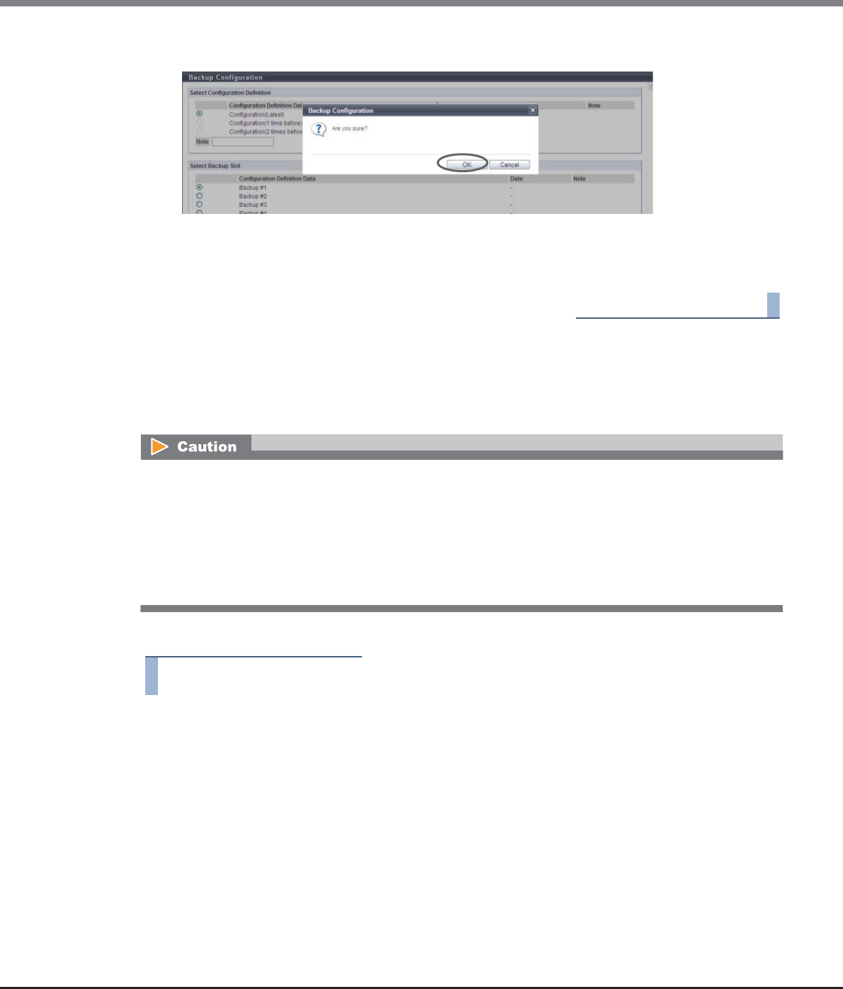
Chapter 11 System Management
11.2 Functions in the Action Area for System
ETERNUS Web GUI User’s Guide
Copyright 2013 FUJITSU LIMITED P2X0-1090-10ENZ0
923
3Click the [OK] button.
→The configuration definition data is backed up.
4Click the [Done] button to return to the [Utility] screen.
End of procedure
11.2.12.3 Export Configuration
This function exports the configuration file from the ETERNUS DX Disk storage system as a configuration
information file and stores it in the local PC, or other medium.
The procedure to export configuration definition file is as follows:
Procedure
1Click [Export Configuration] in [Action].
•The obtained configuration information files may be required to restore the ETERNUS DX Disk storage
system if an error occurs. When altering the ETERNUS DX Disk storage system configuration information,
it is recommended to backup the configuration information file before making any changes.
•When exporting of the configuration information has been completed, save the file immediately. The
extension of the file to be saved must be ". cfg".
•Applying configuration information must be performed by a maintenance engineer with a user account
that has the "Maintenance Operation" policy.
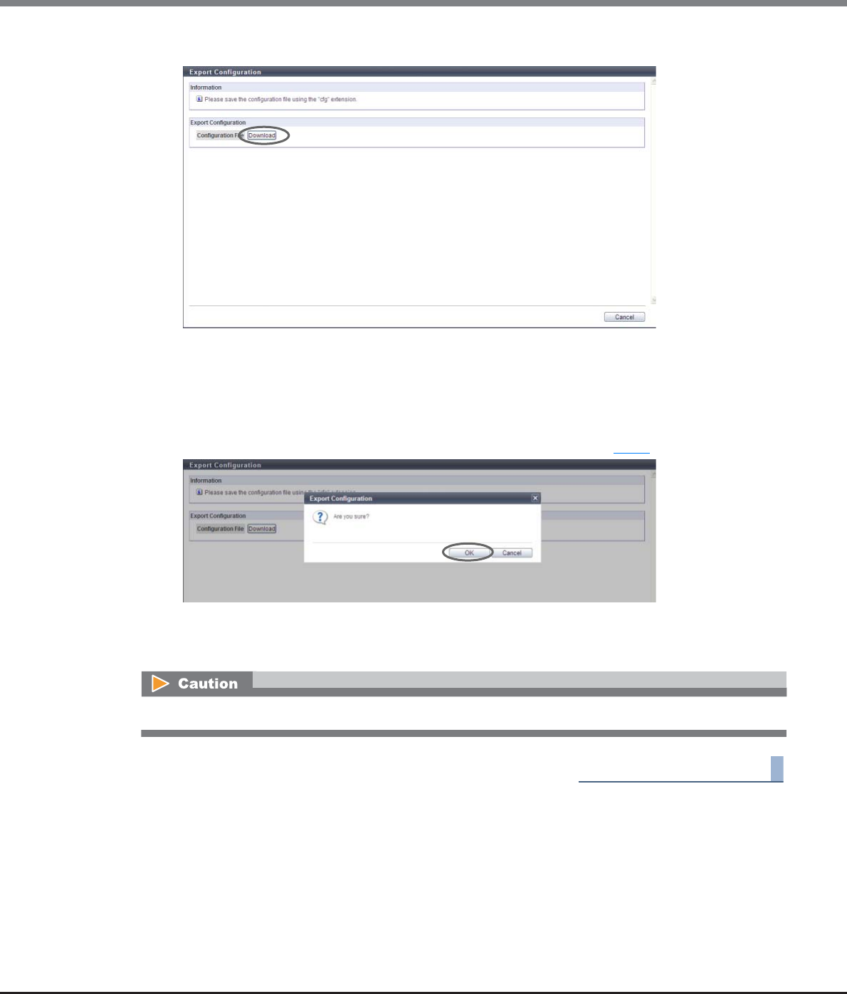
Chapter 11 System Management
11.2 Functions in the Action Area for System
ETERNUS Web GUI User’s Guide
Copyright 2013 FUJITSU LIMITED P2X0-1090-10ENZ0
924
2Click the [Download] button to save the setup information.
→A confirmation screen appears.
3Click the [OK] button.
The extension of the file to be saved must be ".cfg".
The default file name is "Conf_serial number for the ETERNUS DX Disk storage system_YYYY-MM-DD_hh-
mm-ss.cfg".
(YYYY-MM-DD_hh-mm-ss: the date and time when the download screen (Step 2) is displayed.)
→The configuration information is exported.
4Click the [Cancel] button to return to the [Utility] screen.
End of procedure
When exporting of the configuration information has been completed, save the log immediately.
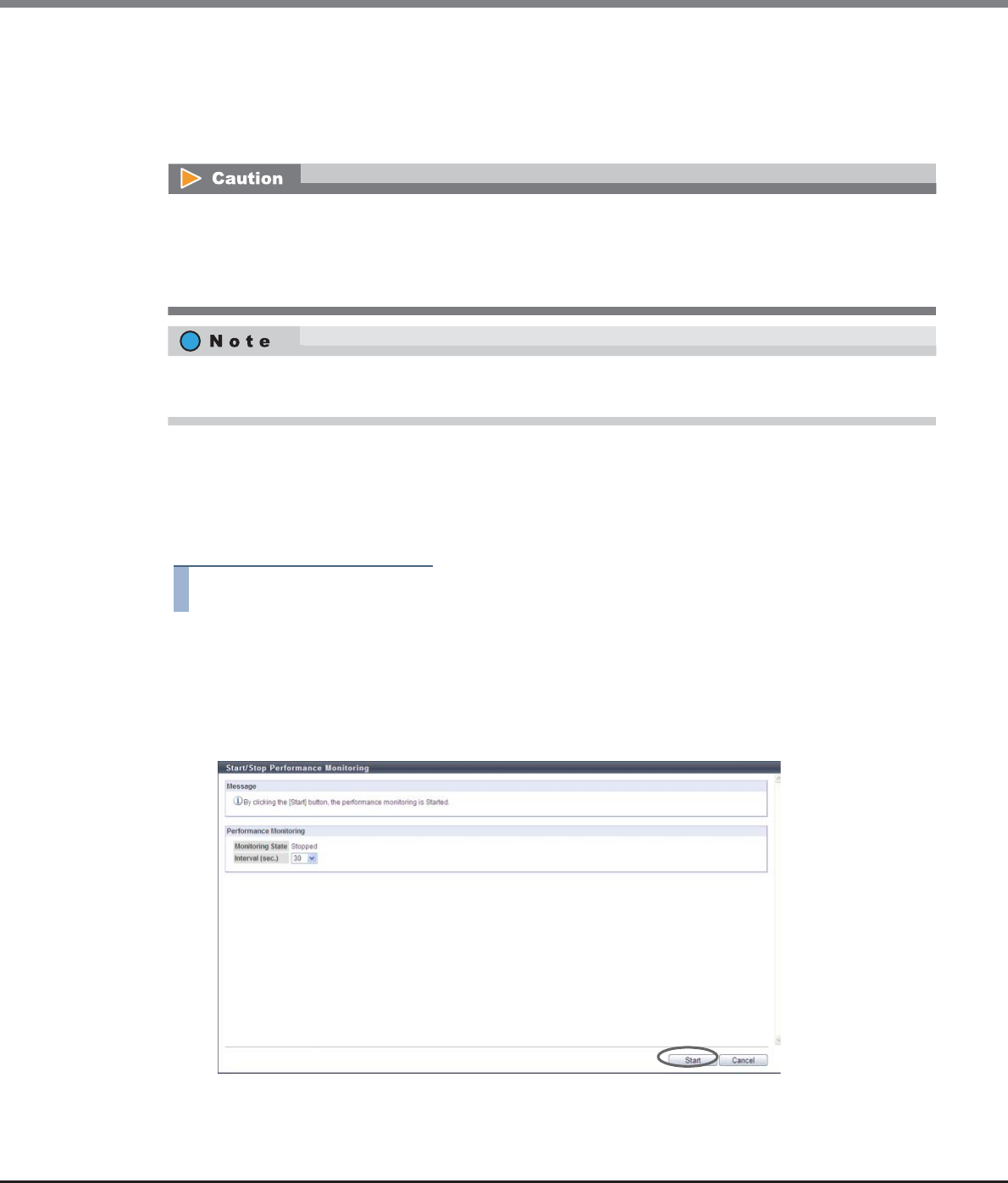
Chapter 11 System Management
11.2 Functions in the Action Area for System
ETERNUS Web GUI User’s Guide
Copyright 2013 FUJITSU LIMITED P2X0-1090-10ENZ0
925
11.2.12.4 Start/Stop Performance Monitoring
This function acquires performance information and displays the result.
The Start/Stop Performance Monitoring function is used to start or stop acquiring the ETERNUS DX Disk storage
system performance information. Acquired information can be checked using the [Performance] function.
The procedure to start or stop performance monitoring is as follows:
■Starting performance monitoring
The [Start] button is displayed when the "Monitoring State" is "Stopped".
Procedure
1Click [Start/Stop Perfmon] in [Action].
2Specify the interval, and click the [Start] button.
•Interval (sec.)
Input the interval to acquire the performance information between 30 and 300 (sec.) in units of 30
seconds.
→A confirmation screen appears.
•When the ETERNUS DX Disk storage system is rebooted, the performance monitoring process is stopped.
•If performance monitoring is started from other monitoring software, GUI cannot stop the process.
•If performance monitoring is started from GUI, the process can be stopped from other monitoring
software.
If performance monitoring is started from CLI, GUI can stop the process. If performance monitoring is started
from GUI, CLI can stop the process.
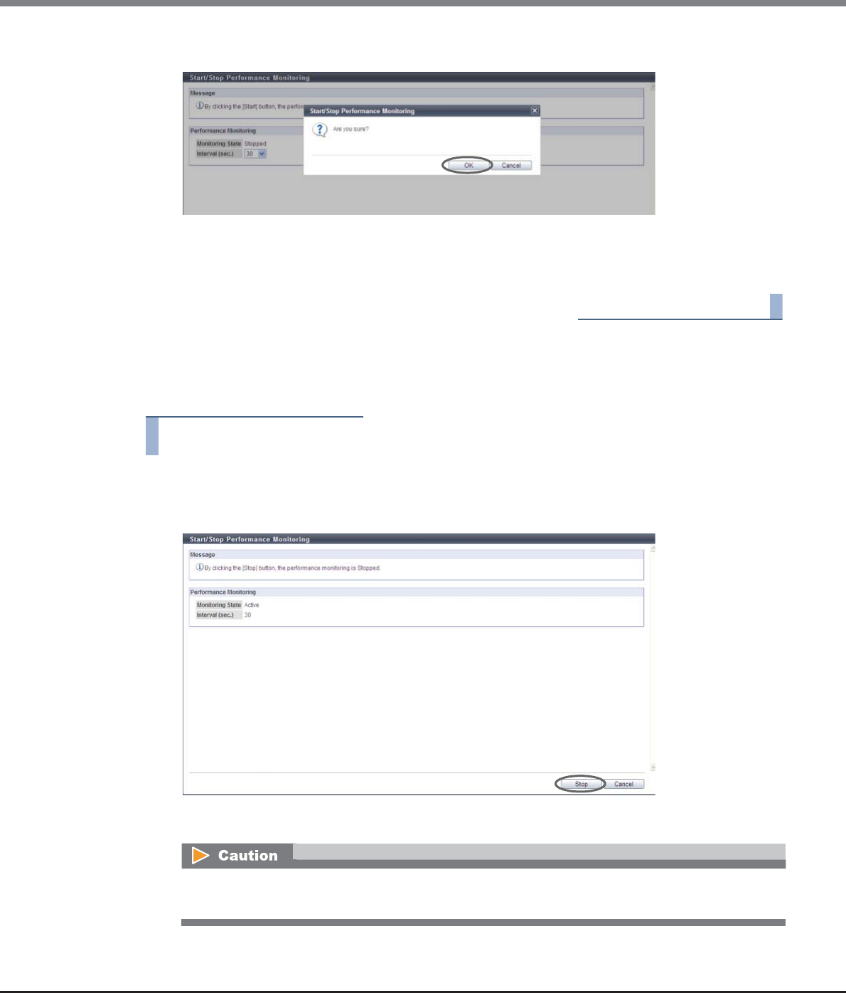
Chapter 11 System Management
11.2 Functions in the Action Area for System
ETERNUS Web GUI User’s Guide
Copyright 2013 FUJITSU LIMITED P2X0-1090-10ENZ0
926
3Click the [OK] button.
→Acquisition of performance information starts.
4Click the [Done] button to return to the [Utility] screen.
End of procedure
■Stopping performance monitoring
The [Stop] button is displayed when "Monitoring State" is "Active".
Procedure
1Click [Start/Stop Perfmon] in [Action].
2Click the [Stop] button.
→A confirmation screen appears.
If the [Stop] button is clicked after starting performance monitoring from other monitoring software,
an error screen is displayed.
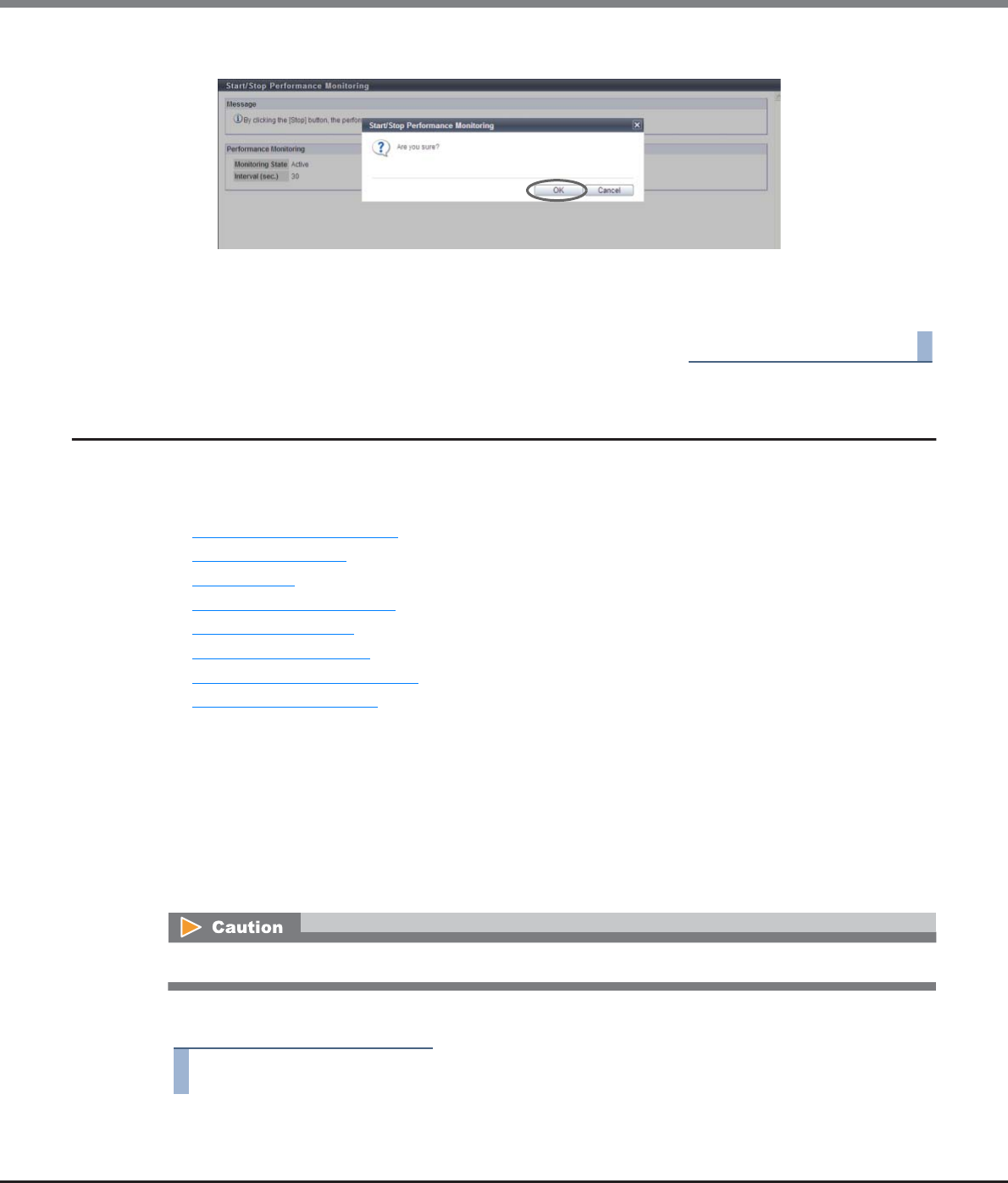
Chapter 11 System Management
11.2 Functions in the Action Area for System
ETERNUS Web GUI User’s Guide
Copyright 2013 FUJITSU LIMITED P2X0-1090-10ENZ0
927
3Click the [OK] button.
→Acquisition of performance information stops.
4Click the [Done] button to return to the [Utility] screen.
End of procedure
11.2.13 System Management
This section describes system management.
System management provides the following functions:
•Modify Storage System Name
•Modify Date and Time
•Change Box ID
•Setup Subsystem Parameters
•Setup Encryption Mode
•Setup SMI-S Environment
•Register SED Authentication Key
•Setup Power Management
11.2.13.1 Modify Storage System Name
This function registers the name, administrator, and the installation site of the ETERNUS DX Disk storage
system.
Information registered in this screen is used for the following functions and screens:
•Network management using SNMP
•Storage system name displayed in the login screen and the operation screens
The procedure to change the storage system name is as follows:
Procedure
1Click [Modify Storage Name] in [Action].
Once the storage system name has been specified, it cannot be deleted (it can be changed).
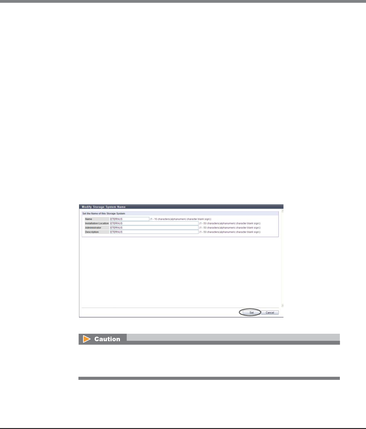
Chapter 11 System Management
11.2 Functions in the Action Area for System
ETERNUS Web GUI User’s Guide
Copyright 2013 FUJITSU LIMITED P2X0-1090-10ENZ0
928
2Specify the parameters, and click the [Set] button.
•Name
Specify the storage system name (required).
The following input conditions apply:
-Up to 16 alphanumeric characters and symbols (except ", (comma)" and "?")
-Spaces
•Installation Location
Specify the installation location of the ETERNUS DX Disk storage system (required).
The following input conditions apply:
-Up to 50 alphanumeric characters and symbols (except ", (comma)" and "?")
-Spaces
•Administrator
Specify the administrator information (the administrator name, contact information, etc) of the
ETERNUS DX Disk storage system (required).
The following input conditions apply:
-Up to 50 alphanumeric characters and symbols (except ", (comma)" and "?")
-Spaces
•Description
Specify the description of the ETERNUS DX Disk storage system (required).
The following input conditions apply:
-Up to 50 alphanumeric characters and symbols (except ", (comma)" and "?")
-Spaces
→A confirmation screen appears.
An error screen appears in the following conditions:
•When an unspecified parameter exists
•When a parameter does not satisfy the input conditions
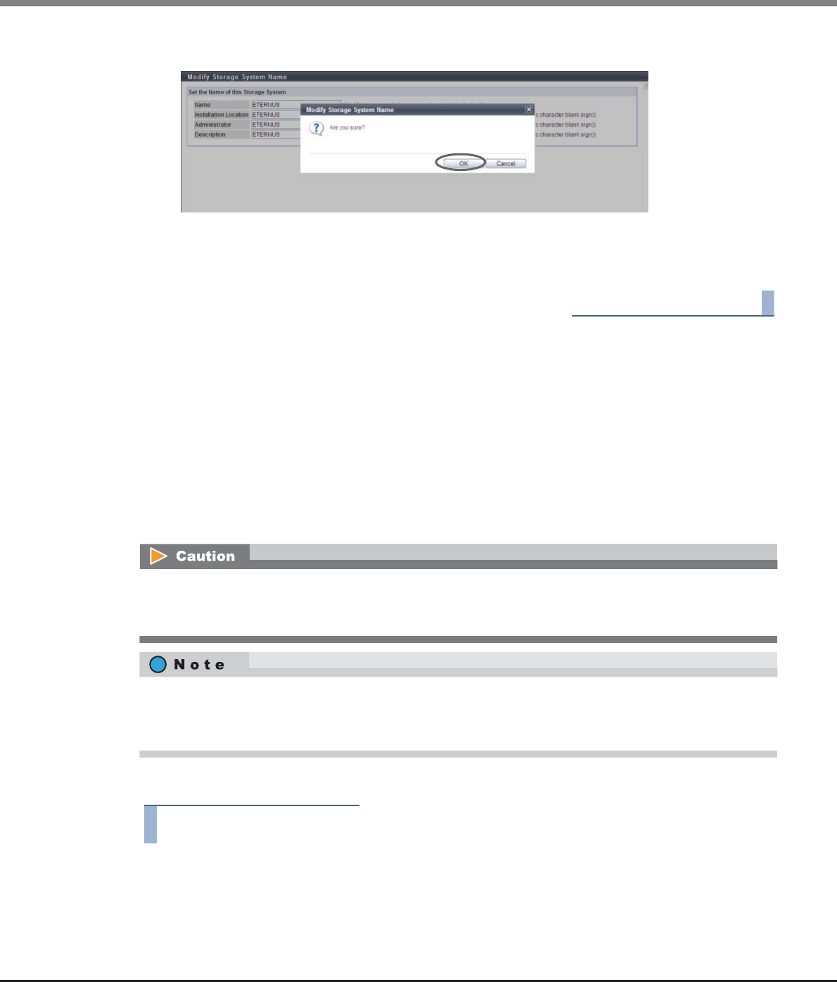
Chapter 11 System Management
11.2 Functions in the Action Area for System
ETERNUS Web GUI User’s Guide
Copyright 2013 FUJITSU LIMITED P2X0-1090-10ENZ0
929
3Click the [OK] button.
→Setting of the storage system name starts.
4Click the [Done] button to return to the [System Settings] screen.
End of procedure
11.2.13.2 Modify Date and Time
This function sets the date/time and time zone (storage system location) of the internal clock in the ETERNUS
DX Disk storage system.
The clock is used for checking the internal log of the ETERNUS DX Disk storage system and in the ECO mode,
etc. The time zone setting is used for the Remote Support function.
This function is used when moving the ETERNUS DX Disk storage system to a new installation site, and/or
changing the system date/time.
It is possible to setup the NTP server to automatically set the time. If the NTP server cannot be used, resetting
the time once a month is recommended.
The procedure to set the date and time is as follows:
Procedure
1Click [Modify Date and Time] in [Action].
When using ECO mode, make sure to set the time/date correctly.
If the date/time of the ETERNUS DX Disk storage system is wrong, processes for stopping and starting the disk
motor cannot be performed in accordance with the ECO mode schedule.
•When using the NTP server, the time modification method is the step mode (modify immediately).
•When using the NTP server, the ETERNUS DX Disk storage system is synchronized with the NTP server
every three hours.

Chapter 11 System Management
11.2 Functions in the Action Area for System
ETERNUS Web GUI User’s Guide
Copyright 2013 FUJITSU LIMITED P2X0-1090-10ENZ0
930
2Specify the parameters, and click the [Set] button.
●Date/Time Information
•Date
To change the current date and time settings, input the new values.
-YYYY-MM-DD hh:mm:ss (YYYY: Year (2001 - 2037), MM: Month (01 - 12), DD: Day (01 - 31), hh:
Hour (00 - 23), mm: Minute (00 - 59), ss: Second (00 - 59))
●Time Zone
•Time Zone
Select the Time Zone from the list box. If the appropriate Time Zone does not exist, select
"Manually".
•Time Zone (time difference setting)
When selecting "Manually" in the "Time Zone" field, specify the time difference from GMT using [+]/
[-] in hours and minutes.
-Time difference
Select "+" or "-".
-Hour
00 - 12
-Minute
00, 15, 30, 45
●Daylight Saving Time
•Set
Select whether to set the Daylight Saving Time "ON" or "OFF" with the radio button.
•Range (by day of the week)
If Daylight Saving Time is enabled, and "by day of the week" is selected for the term, specify the start
day, end day, and start time and end time.
-Start day and end day (Month: January - December, Week: 1st - 4th week and the last week of
month, Day: Monday - Sunday)
-Start time and end time (Hour: 00 - 23)
•Range (by Date)
If Daylight Saving Time is enabled, and "by Date" is selected for the period, specify the start date,
end date, and start time and end time.
-Start date and end date (Month: January - December, Day: 01 - 31 and the Last Date)
-Start time and end time (Hour: 00 - 23)
●NTP Service
•NTP server
Select whether to use the NTP server.
When NTP is enabled, input the IP address or the server name for the NTP server in the text box.
There are two methods to specify an IP address; "IPv4" and "IPv6". The following IPv6 addresses can
be used; "link local address", "global address", "unique local address", and "6to4 address". Refer to
"Available IPv6 Address" (page 757) for details.
When the current setting is displayed, the IPv6 address is displayed as an abbreviation.
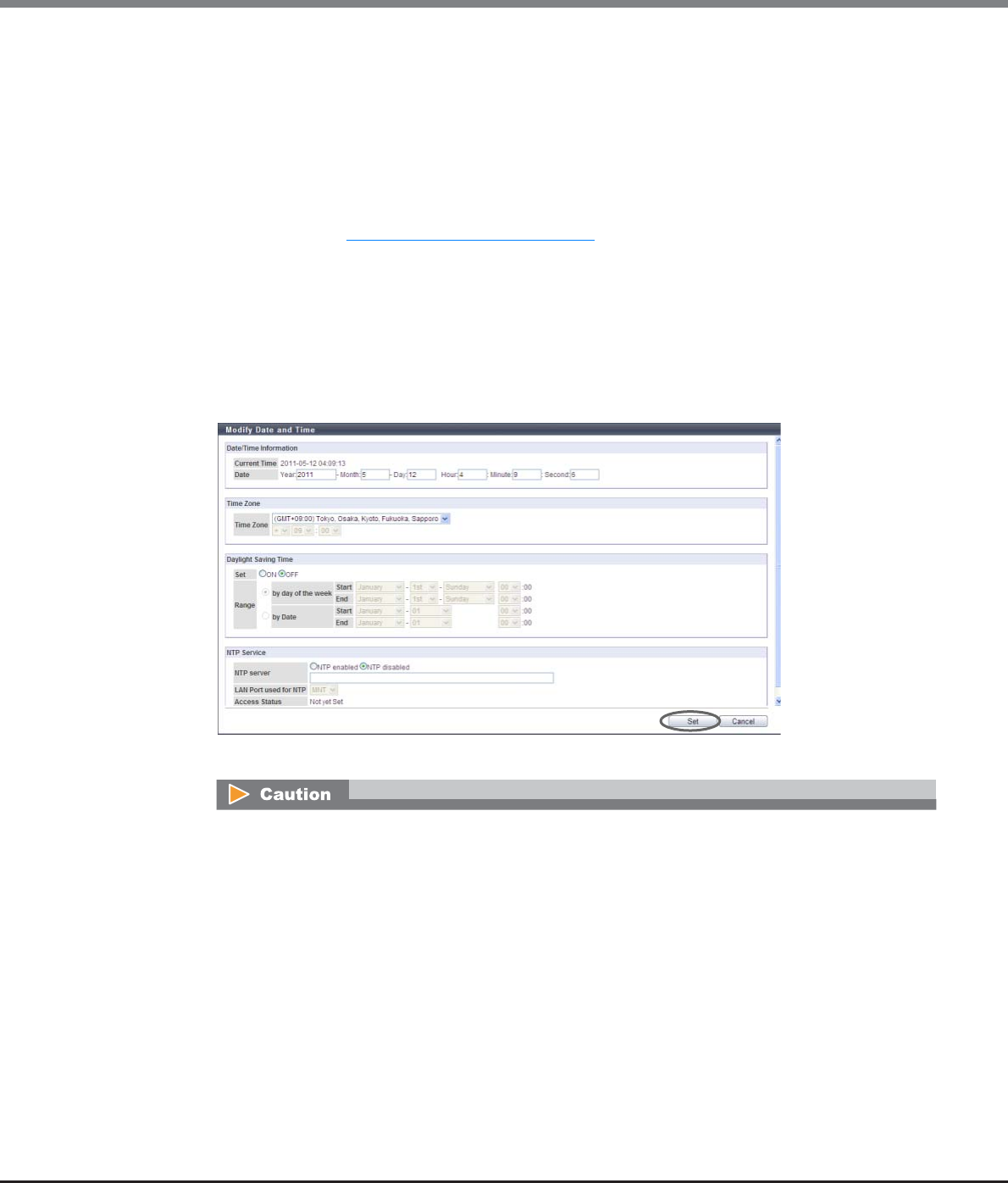
Chapter 11 System Management
11.2 Functions in the Action Area for System
ETERNUS Web GUI User’s Guide
Copyright 2013 FUJITSU LIMITED P2X0-1090-10ENZ0
931
The following input conditions apply:
-For IPv4 address
•xxx.xxx.xxx.xxx
xxx: 1 - 255 for the top field (decimal)
xxx: 0 - 255 for other fields (decimal)
-For IPv6 address
•xxxx:xxxx:xxxx:xxxx:xxxx:xxxx:xxxx:xxxx
xxxx: 0 - ffff (FFFF) (hexadecimal, alphanumeric characters)
Refer to "IPv6 Address Notation" (page 378) for details.
-For server name specification
The following input condition applies:
•Up to 63 alphanumeric characters and symbols
•LAN Port used for NTP
When the NTP server is enabled, select the port to be used for NTP connection.
-MNT
-RMT
→A confirmation screen appears.
An error screen appears in the following conditions:
•When a non-existent date has been specified in "New Time"
•When "by day of the week" is selected in Daylight Saving Time, and the same day and time is input
for both start day/time and end day/time.
•When "by Date" is selected in Daylight Saving Time, and the same date/time is input for both start
date/time and end date/time
•When "by Date" is selected in Daylight Saving Time, and a nonexistent date has been specified as
the start date
•When "by Date" is selected in Daylight Saving Time, and a non-existent date has been specified as
the end date
•When the "NTP enabled " is selected for "NTP server" and MNT is selected as the "LAN Port used for
NTP", the IPv4 address of the NTP server and the broadcast address of the MNT port are the same
•When the "NTP enabled " is selected for "NTP server" and RMT is selected as the "LAN Port used for
NTP", the IPv4 address of the NTP server and the broadcast address of the RMT port are the same
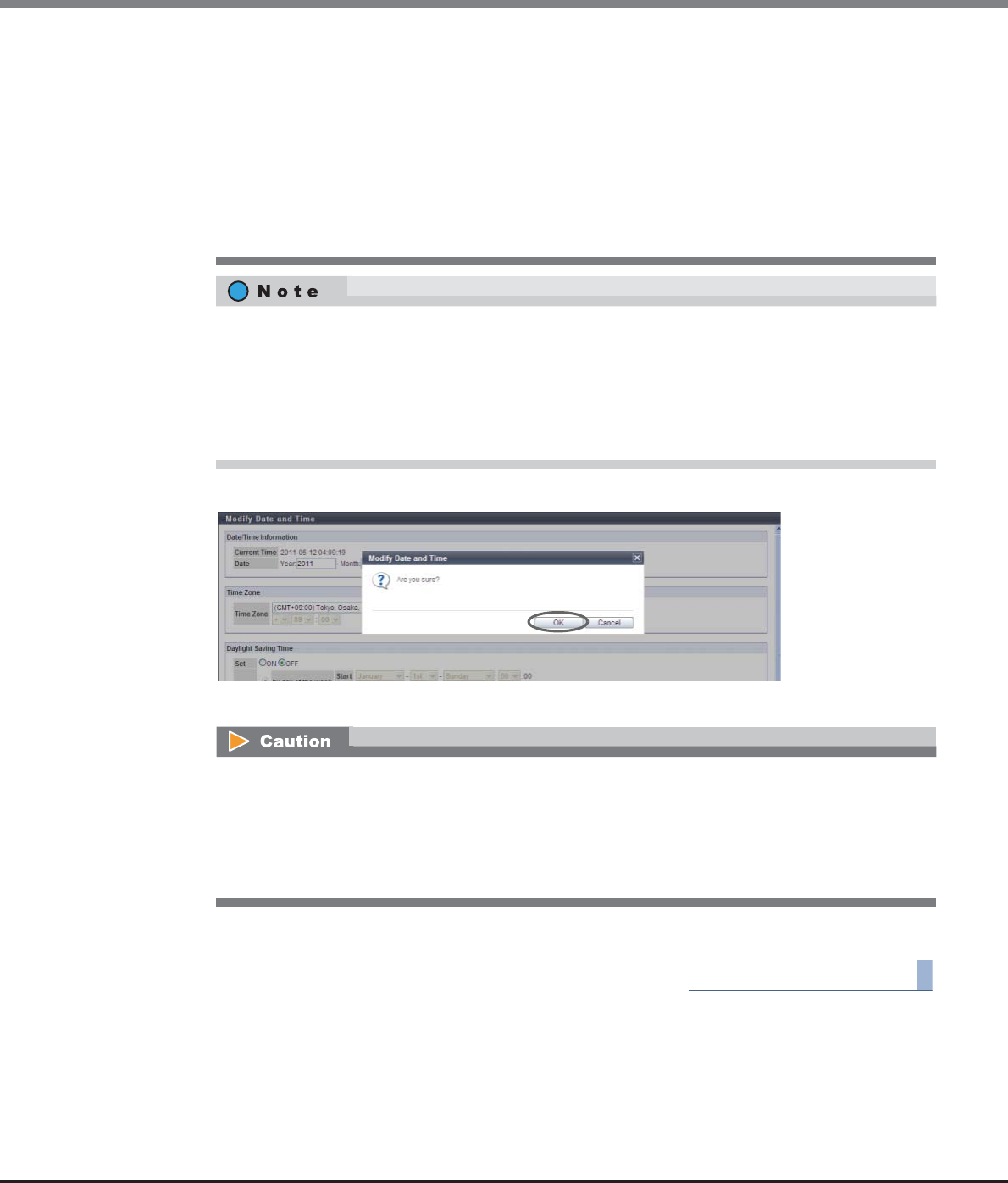
Chapter 11 System Management
11.2 Functions in the Action Area for System
ETERNUS Web GUI User’s Guide
Copyright 2013 FUJITSU LIMITED P2X0-1090-10ENZ0
932
3Click the [OK] button.
→Date/time information is specified.
4Click the [Done] button to return to the [System Settings] screen.
End of procedure
•When "NTP enabled " is selected for "NTP server" and one of the following conditions applies to the
IP address (IPv4 address or IPv6 address):
-The IPv4 address for the NTP server and the local host address are the same
-The IP address (IPv4 address or IPv6 address) for the NTP server and the network address are
the same
-The IP address (IPv4 address or IPv6 address) for the NTP server and the IP address for the MNT
port are the same
-The IP address (IPv4 address or IPv6 address) for the NTP server and the IP address for the RMT
port are the same
•Click the [Date/Time Information] tab and the [NTP Service] tab to specify each parameter of date/
time information and the NTP service.
•When "by day of the week" is selected in Daylight Saving Time, "Last" can be selected to specify the
start or end week.
•When "by Date" is selected in Daylight Saving Time, "Last Date" of the selected month can be
selected to specify the start or end date.
If "NTP enabled" is selected for "NTP server" when there is no NTP server connection or when
communication with the NTP server is unstable, the required time for the date and time setting may
take longer. Wait until the screen is updated. Even if connection to the NTP server fails, the date and
time setting appear as though they have completed. To confirm that the ETERNUS DX Disk storage
system is successfully connected to the NTP server, start this function again and check "Access Status"
in the "NTP Service" field.

Chapter 11 System Management
11.2 Functions in the Action Area for System
ETERNUS Web GUI User’s Guide
Copyright 2013 FUJITSU LIMITED P2X0-1090-10ENZ0
933
11.2.13.3 Change Box ID
This function changes the Box ID that identifies an ETERNUS DX Disk storage system in the user system.
Box ID is used as information to identify the ETERNUS DX Disk storage system from applications connected to
the ETERNUS DX Disk storage system. The initial Box ID is a device ID that is created by combining device
information (series name, model, serial number, etc.).
If upgrading or replacing the ETERNUS DX Disk storage system, the existing Box ID will change with the
ETERNUS DX Disk storage system change. Therefore, there is a risk that the backup data saved in the previous
ETERNUS DX Disk storage system cannot be used, so it is necessary to reconfigure the user system after the
ETERNUS DX Disk storage system is upgraded or replaced. This function changes the device BOX ID to the
same ID as that of the previous ETERNUS DX Disk storage system in order to avoid any problems and also use
the same backup data in the new storage system.
The procedure to set the Box ID is as follows:
Procedure
1Click [Change Box ID] in [Action].
•A Box ID is a unique name in the user system. Make the Box ID different from that of other ETERNUS DX
Disk storage systems in the user system. If the Box ID is not changed, the Device ID is used as a Box ID.
•If the ETERNUS DX Disk storage system Box ID is changed after setting the Advanced Copy path
information, Remote Advanced Copy (REC) will no longer run. Create Advanced Copy path information
again with the new Box ID, and then specify the new information to all the related ETERNUS DX Disk
storage systems.
•The use of spaces that was applied for specifying a Box ID with controller firmware version V10L2x or
earlier has changed. When using controller firmware version V10L3x or later, spaces in the Box ID are
changed to "#" (hash keys). Note that spaces in the existing Box ID (a Box ID that was set with controller
firmware version V10L2x or earlier) is not changed even after controller firmware V10L3x is applied. The
existing Box ID can be used. If the Box ID is changed (or the [Set] button is clicked without changing the
Box ID) after applying new controller firmware, any spaces in the existing Box ID are changed to "#" (hash
keys). When a REC path is already configured in the ETERNUS DX Disk storage system, the Advanced Copy
path information must be created and specified again with new Box IDs.
•This function cannot be used when an Advanced Copy session (except ODX and XCOPY) exists in the
ETERNUS DX Disk storage system.
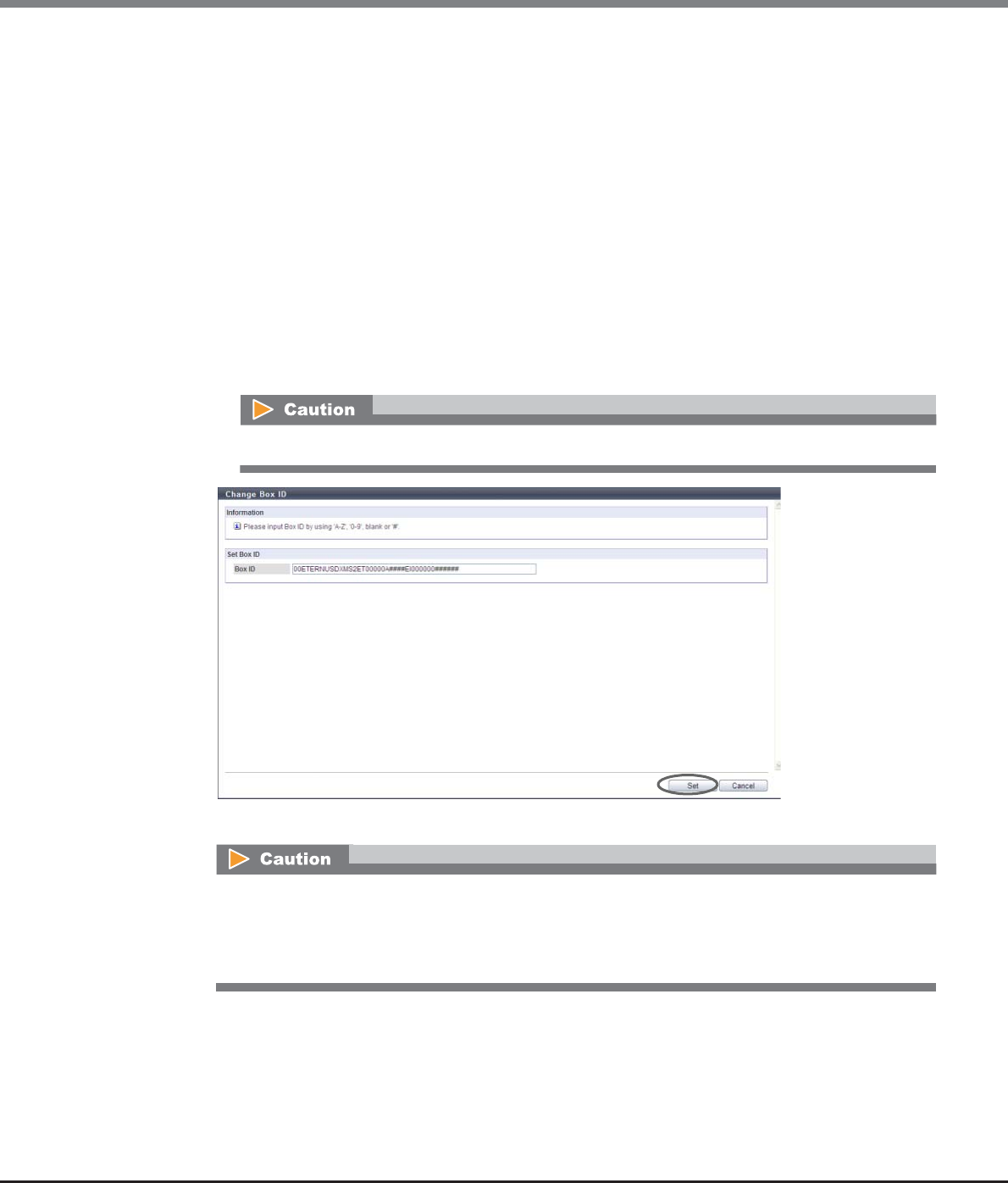
Chapter 11 System Management
11.2 Functions in the Action Area for System
ETERNUS Web GUI User’s Guide
Copyright 2013 FUJITSU LIMITED P2X0-1090-10ENZ0
934
2The current Box ID setting appears. To change the value, enter a new Box ID and click the
[Set] button.
•Box ID
The Box ID setting of the ETERNUS DX Disk storage system is displayed.
If the ETERNUS DX Disk storage system is changed, correct the Box ID. The initial Box ID displayed is
a 40-digit code (device ID) that is created by combining device information (series name, model,
serial number, etc.).
If the Box ID entered is less than 40 characters, a "#" hash key character is appended to the Box ID
for each character short.
The following input conditions apply:
-Capital letters
-Numeric characters
-Spaces
-"#" (hash key character)
-40 characters (fixed)
→A confirmation screen appears.
When spaces are input for the Box ID, the spaces are changed to "#" (hash keys).
If the [Set] button is clicked in the following conditions, an error screen appears:
•When a Box ID is not input
•When the entered value of a Box ID contains a character other than alphabetic characters (upper
case), numeric characters, hash key characters (#), or spaces
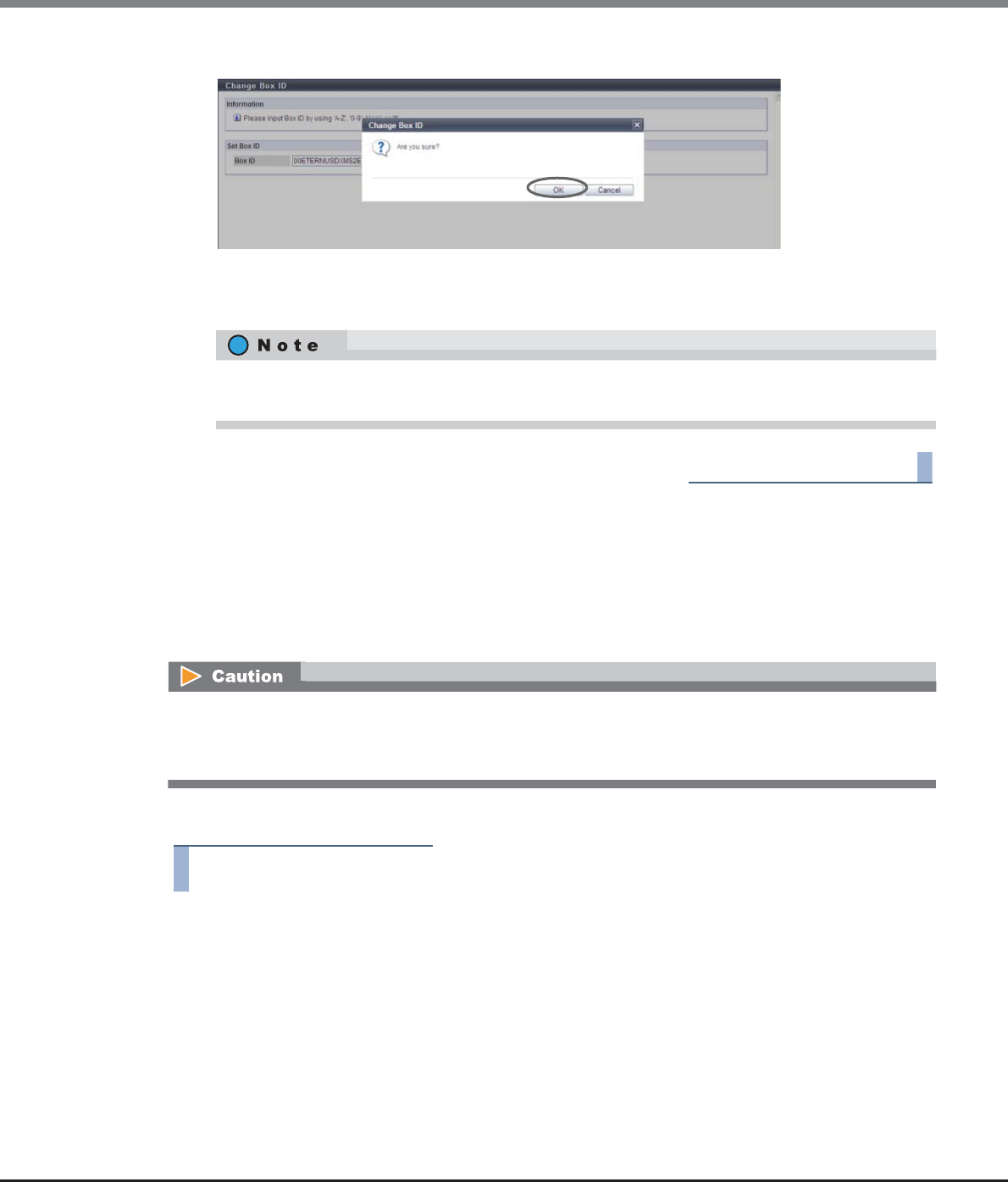
Chapter 11 System Management
11.2 Functions in the Action Area for System
ETERNUS Web GUI User’s Guide
Copyright 2013 FUJITSU LIMITED P2X0-1090-10ENZ0
935
3Click the [OK] button.
→The specified Box ID is registered.
4Click the [Done] button to return to the [System Settings] screen.
End of procedure
11.2.13.4 Setup Subsystem Parameters
This function specifies the subsystem parameters.
Subsystem parameters are the information which controls the ETERNUS DX Disk storage system operation
when it is connected to hosts. The ETERNUS DX Disk storage system operates according to the specified
subsystem parameters, for all the hosts to be connected.
The procedure to set the subsystem parameters is as follows:
Procedure
1Click [Setup Subsystem Parameters] in [Action].
If the Box ID entered is less than 40 characters, a "#" hash key character is appended to the Box ID for
each character short. Then, the 40-digit Box ID is registered in the ETERNUS DX Disk storage system.
•Do not change the setting after installing the ETERNUS DX Disk storage system, unless a maintenance
engineer instructs otherwise.
•To set the subsystem parameters using this function, set them after stopping all host access.
Chapter 11 System Management
11.2 Functions in the Action Area for System
ETERNUS Web GUI User’s Guide
Copyright 2013 FUJITSU LIMITED P2X0-1090-10ENZ0
936
2Specify the parameters, and click the [Set] button.
●Setup Subsystem Parameters
•Load Balance
Set whether to enable or disable the load balance for the ETERNUS DX Disk storage system.
When load balance is enabled and the ETERNUS DX Disk storage system is overloaded, the ETERNUS
DX Disk storage system responds with the sense that is specified in the "Load Balance Response"
field described in "9.2.5.3 Modify Host Response" (page 589).
If the load balance is disabled, the warning sense response is suppressed and the ETERNUS DX Disk
storage system does not respond to any host connecting to the storage system.
•Reject INQUIRY from Unauthorized Host
Select whether to reject the "Inquiry" command from an unauthorized host. Select "Enable" to reject.
When the "Inquiry" command is rejected, ETERNUS DX Disk storage system returns an Affinity Error
(5/25/81) for the "Inquiry" command from the unauthorized host. When the command is not
rejected, the ETERNUS DX Disk storage system responds normally.
•Thin Provisioning Allocation Mode
Select "TPP balancing" or "TPV balancing" for the allocation mode of Thin Provisioning.
This mode is applied only for Thin Provisioning pools. Note that this setting is not applied for pools
that are created by the Flexible Tier (automatic storage layering) function.
-TPP balancing
Physical area is allocated almost evenly from the RAID groups that configure a TPP. Allocation is
performed in order of writing to the TPV. This is a conventional method.
-TPV balancing
Physical area is allocated almost evenly from the RAID groups that configure a TPP. Allocation is
performed by distributing RAID groups evenly for each TPV.
•Load balance for all hosts is disabled when "Disable" is selected for "Load Balance". If the
ETERNUS DX Disk storage system is in overload in this status, the warning sense response is
suppressed.
•When connecting the ETERNUS DX Disk storage system and HP-UX hosts, disable the Load
Balance setting. If "Enable" is selected for "Load Balance", incorrect logs may be recorded in the
host.
•Load balancing by Multipath Driver is operated regardless of whether the "Load Balance" of
this function is enabled/disabled.
When using the VERITAS Volume Manager Dynamic Multipathing (VxVM DMP), select "Enable".
When VxVM DMP is not used, the setting of this parameter does not affect the state of the
ETERNUS DX Disk storage system.
Chapter 11 System Management
11.2 Functions in the Action Area for System
ETERNUS Web GUI User’s Guide
Copyright 2013 FUJITSU LIMITED P2X0-1090-10ENZ0
937
[Example]
Three TPVs (TPV#0, TPV#1, and TPV#2) are registered in a single TPP.
A single TPP is configured with four RAID groups (RAID group #0, RAID group #1, RAID group #2, and
RAID group #3).
-TPP balancing
Physical area is allocated in the following order regardless of the TPV in which the data is
written.
RAID group#0 → RAID group#1 → RAID group#2 → RAID group#3 → RAID group#0 → ...
-TPV balancing
When data is written in TPVs that are registered in the TPP, the physical area is allocated in the
following order.
TPV#0:
RAID group#0 → RAID group#1 → RAID group#2 → RAID group#3 → RAID group#0 → ...
TPV#1:
RAID group#1 → RAID group#2 → RAID group#3 → RAID group#0 → RAID group#1 → ...
TPV#2:
RAID group#2 → RAID group#3 → RAID group#0 → RAID group#1 → RAID group#2 → ...
•Cache Mirroring
Select whether to enable or disable the cache mirroring.
To change the setting, select the "Change" checkbox, and then select "Enable" or Disable". If the
"Change" checkbox is cleared after the setting is changed, the value returns to the previous state
when this function is first started.
The cache mirroring function duplicates user data in the cache memory with 2CMs to prevent user
data from being lost when the ETERNUS DX Disk storage system fails or while maintenance
operations are being performed.
-Enable
This mode protects user data from being lost when the ETERNUS DX Disk storage system fails or
while maintenance operations are being performed.
By duplicating the user data in the cache memory, the user data is protected even when one of
the CM fails.
-Disable
This mode is used only when a user can recover the data (for example, when High Performance
Computing is used).
This mode gives priority to improving sequential write performance over reliability. In this case,
user data is lost when the ETERNUS DX Disk storage system fails or maintenance is performed.
The "Thin Provisioning Allocation Mode" is available only when the Thin Provisioning license has
been registered.
•It is not necessary to change the default setting ("Enable") for normal use.
•Rebooting the ETERNUS DX Disk storage system is required to enable the new configuration.
The current cache mirroring setting and the cache mirroring setting after rebooting can be
checked. Refer to "11.1.12 System Settings" (page 731) for details.

Chapter 11 System Management
11.2 Functions in the Action Area for System
ETERNUS Web GUI User’s Guide
Copyright 2013 FUJITSU LIMITED P2X0-1090-10ENZ0
938
•The following conditions apply when "Disable" is selected:
-User data in the cache memory is not duplicated.
-The parity information for RAID groups for which the type is High Capacity (RAID5), High
Reliability (RAID6), or Reliability (RAID5+0) is not duplicated.
-If a CM is disconnected when the ETERNUS DX Disk storage system fails, the user data in this
CM is lost.
-If a CM is disconnected during one of the following maintenance operations, the user data
in this CM is lost.
•When the maintenance of the CM is performed
•When maintenance of the components in the CM (memory, BUD, FAN, or CA (*1)) is
performed
•When the preventive maintenance of the CM is performed
•When preventive maintenance of the components in the CM (memory, BUD, FAN, or CA
(*1)) is performed
•When components in the CM (memory or CA (*1)) are added
•When a component in the CM (CA) is removed (*1)
•When force disable is performed for the CM
•When force disable of components in the DE (IOM or QSFP cable) is performed (*2)
*1: When using the ETERNUS DX80 S2/DX90 S2
*2: A CM may become disconnected when the relevant component is disabled depending on the
storage system status.
Note that maintenance, preventive maintenance, adding, removing, or forcibly disabling
components can be performed by a maintenance engineer who has the "Maintenance
Operation" policy.
-User data in "Standard (including concatenated volumes using the LUN concatenation
function)" and "WSV" type volumes may be lost.
-The parity information for High Capacity (RAID5), High Reliability (RAID6), or Reliability
(RAID5+0) type RAID groups is lost when a CM is disconnected. If this occurs, volumes in the
relevant RAID groups lose data consistency and cannot be used any more. Format the
volume after maintenance of the CM is complete.
•The following operating conditions are required when "Disable" is selected:
-A single path configuration must be used. If a multipath configuration is used, sequential
write performance is not improved and user data may be lost without realizing it. If
operation continues after user data is lost, the ETERNUS DX Disk storage system reads the
user data before updating, and any data inconsistency may be detected in the host.
-Make sure to configure straight access paths between the controlling CM and the RAID
group to which the volume belongs. If cross access paths are configured, the expected
sequential write performance might not be achieved.
•If the [Apply Configuration] function is performed with "Initialize" or "Restore", the contents of
the setting are maintained.
•For an ETERNUS DX80 S2 1CM model, "Disable" can be selected but performance is not
improved.
•This item is not displayed for ETERNUS DX8100 S2/DX8700 S2.

Chapter 11 System Management
11.2 Functions in the Action Area for System
ETERNUS Web GUI User’s Guide
Copyright 2013 FUJITSU LIMITED P2X0-1090-10ENZ0
939
•Checkcode Enforcement
Select whether to enable or disable the Checkcode Enforcement mode.
-Enable
Error detection function in the ETERNUS DX Disk storage system is enhanced.
When data is duplicated, the check codes of all the data blocks are checked.
-Disable
Error detection in the ETERNUS DX Disk storage system is performed with the normal procedure.
•I/O Offloading
Select whether to enable or disable I/O offloading.
-Enable
Performs some of the I/O processes in ROE to reduce the CPU usage ratio and improve the maxi-
mum performance.
-Disable
Performs only the encryption processes and parity creation for RAID5 or RAID6 in ROE, which is
the conventional method.
●Web GUI Settings
•Function to Add Host
Select which function for adding hosts is to be used.
-Use "Add Host Group"
Create a host group and register the hosts as members. When the "Use "Add Host Group"" check-
box is selected, the actions for creating host groups are displayed.
-Use "Add Host"
Register hosts without creating host groups. When the "Use "Add Host"" checkbox is selected, the
actions for adding hosts are displayed.
If "Enable" is selected, write access performance is reduced.
•When the existing controller firmware is updated to version V10L50 by using the [Apply
Controller Firmware] function, "Disable" is selected for this item. For newly purchased ETERNUS
DX Disk storage systems, "Enable" is selected for this item. Note that the [Apply Controller Firm-
ware] function can be performed by a maintenance engineer who has the "Maintenance Oper-
ation" policy.
•Rebooting the ETERNUS DX Disk storage system is required to enable the new configuration.
The current I/O offloading setting and the I/O offloading setting after rebooting can be
checked. Refer to "11.1.12 System Settings" (page 731) for details.
•Performance may not be improved even when this item is enabled if the existing ROE busy
ratio is high. Refer to "10.1.2.2 Controller Module (Performance)" (page 633) for ROE busy
ratio.
•This item is available only for ETERNUS DX8700 S2.
Selecting either "Use "Add Host Group"" or "Use "Add Host"" is recommended. If both of these
checkboxes are not selected, the [Set] button cannot be clicked.

Chapter 11 System Management
11.2 Functions in the Action Area for System
ETERNUS Web GUI User’s Guide
Copyright 2013 FUJITSU LIMITED P2X0-1090-10ENZ0
940
→A confirmation screen appears.
3Click the [OK] button.
→Setting of the subsystem parameter starts.
4Click the [Done] button to return to the [System Settings] screen.
End of procedure
Select "Use "Add Host"" only when using the previous procedure for registering hosts in older
storage systems (such as ETERNUS DX410/DX440 and ETERNUS DX8100/DX8400/DX8700). Both
checkboxes can be selected at the same time. The "Use "Add Host"" checkbox is cleared by default.
•"Cache Mirroring " is not displayed for ETERNUS DX8100 S2/DX8700 S2.
•"I/O Offloading" is not displayed for ETERNUS DX80 S2/DX90 S2, ETERNUS DX410 S2/DX440 S2, or
ETERNUS DX8100 S2.
•Reboot the ETERNUS DX Disk storage system to enable the cache mirroring setting.
•Reboot the ETERNUS DX Disk storage system to enable the I/O offloading setting.
Chapter 11 System Management
11.2 Functions in the Action Area for System
ETERNUS Web GUI User’s Guide
Copyright 2013 FUJITSU LIMITED P2X0-1090-10ENZ0
941
11.2.13.5 Setup Encryption Mode
This function sets the encryption mode to encrypt volumes by using the CM.
The procedure to set the encryption mode is as follows:
Procedure
1Click [Setup Encryption Mode] in [Action].
2Select the encryption mode and click the [Set] button.
•Encryption Mode
The current encryption mode is displayed.
When changing the encryption mode, select "Disable", "Fujitsu Original" or "AES".
-Disable
"Disable" means no encryption function is used. When changing the encryption mode from
"Fujitsu Original" to "Disable" or from "AES" to "Disable", reboot the ETERNUS DX Disk storage
system.
-Fujitsu Original
"Fujitsu Original" is an encryption method which uses a Fujitsu proprietary algorithm. Compared
to AES, its practical security level is almost equal while it allows faster processing than AES.
-AES
"Advanced Encryption Standard (AES: Standard encryption used for information processing by
the US federal government)" is a standardized encryption method. The ETERNUS DX80 S2/DX90
S2, the ETERNUS DX410 S2/DX440 S2, and the ETERNUS DX8100 S2/DX8700 S2 adopt the AES
128-bit encryption.
•Encryption related functions are only available after enabling the encryption mode.
•When disabling the encryption mode, reboot the ETERNUS DX Disk storage system.
•When changing the encryption mode, delete all the encrypted volumes and volumes being encrypted in
advance.
•Once a volume has been encrypted, it cannot be changed back to a non-encrypted volume.
•This function cannot be changed in the following conditions:
-Encrypted volumes exist
-Volumes being encrypted exist
•If a CM has a cache capacity that is 6GB or less in an ETERNUS DX8700 S2, the encryption mode cannot be
enabled ("Fujitsu Original" or "AES" cannot be selected).
When using the encryption function, set the encryption mode to "Fujitsu Original" or "AES".
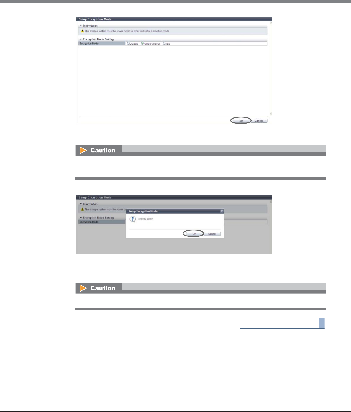
Chapter 11 System Management
11.2 Functions in the Action Area for System
ETERNUS Web GUI User’s Guide
Copyright 2013 FUJITSU LIMITED P2X0-1090-10ENZ0
942
→A confirmation screen appears.
3Click the [OK] button.
→The encryption mode setting is performed.
4Click the [Done] button to return to the [System Settings] screen.
End of procedure
11.2.13.6 Setup SMI-S Environment
This function enables or disables the Storage Management Initiative - Specification (SMI-S).
SMI-S is a standard specification concerning storage management technologies by Storage Networking
Industry Association (SNIA).
When enabling the SMI-S, the ETERNUS DX Disk storage system can be managed from general storage
management applications that support the SMI-S.
If the [Set] button is clicked when encrypted volumes or volumes being encrypted exist, an error
screen is displayed.
When disabling the encryption mode, reboot the ETERNUS DX Disk storage system.
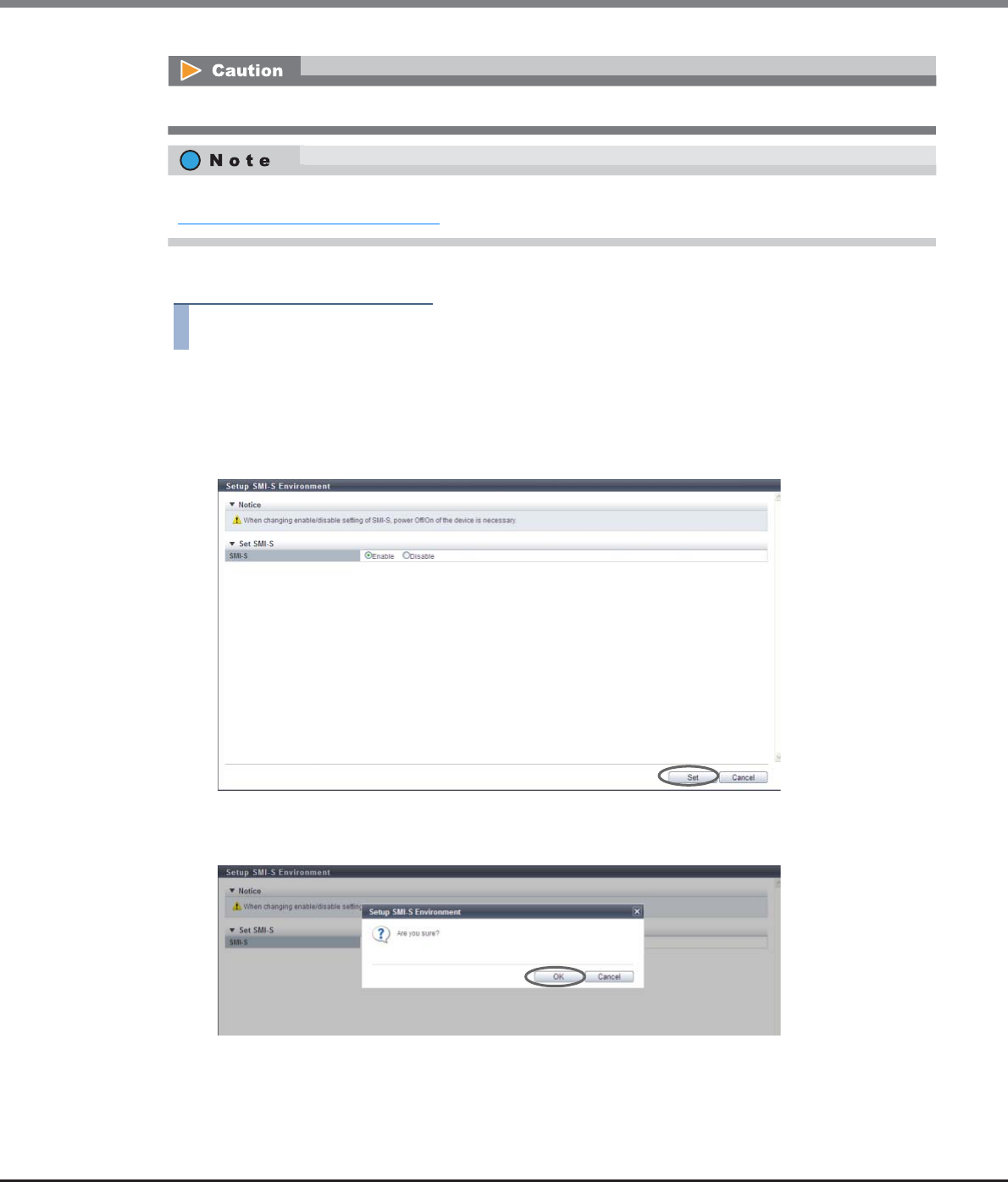
Chapter 11 System Management
11.2 Functions in the Action Area for System
ETERNUS Web GUI User’s Guide
Copyright 2013 FUJITSU LIMITED P2X0-1090-10ENZ0
943
The procedure to enable or disable the SMI-S function is as follows:
Procedure
1Click [Setup SMI-S Environment] in [Action].
2Select the parameters, and click the [Set] button.
•SMI-S
Select whether to "Enable" or "Disable" the SMI-S function.
→A confirmation screen appears.
3Click the [OK] button.
→The SMI-S setting is performed.
Reboot the ETERNUS DX Disk storage system to apply the new setting.
This function can be used to check the current SMI-S setting and the SMI-S setting after rebooting. Refer to
"11.1.12 System Settings" (page 731) for details.
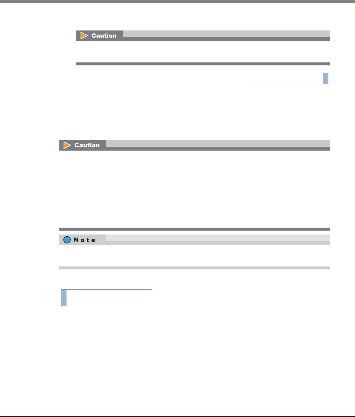
Chapter 11 System Management
11.2 Functions in the Action Area for System
ETERNUS Web GUI User’s Guide
Copyright 2013 FUJITSU LIMITED P2X0-1090-10ENZ0
944
4Click the [Done] button to return to the [System Settings] screen.
End of procedure
11.2.13.7 Register SED Authentication Key
This function registers the SED authentication key (common key) that is managed in the ETERNUS DX Disk
storage system.
SEDs are used to prevent the leakage of the stored data when physically removed disks are stolen or lost.
The procedure to register SED authentication key is as follows:
Procedure
1Click [Register SED Key] in [Action].
After switching the SMI-S setting between enabled or disabled, reboot the ETERNUS DX Disk storage
system.
•Register the SED authentication key before installing SEDs in the ETERNUS DX Disk storage system. If a
SED is installed without registering the SED authentication key, data leakage in a SED that is removed
may occur.
•If a SED is installed before registering the SED authentication key, register the SED authentication key
and reboot the ETERNUS DX Disk storage system.
•The SED authentication key can only be set once in the ETERNUS DX Disk storage system. The SED
authentication key cannot be changed or deleted after being set.
•Registering a common key is also required when the SED authentication key that is managed in the key
server is used.
After this function is executed, the SED authentication key is automatically generated and registered in the
SED.
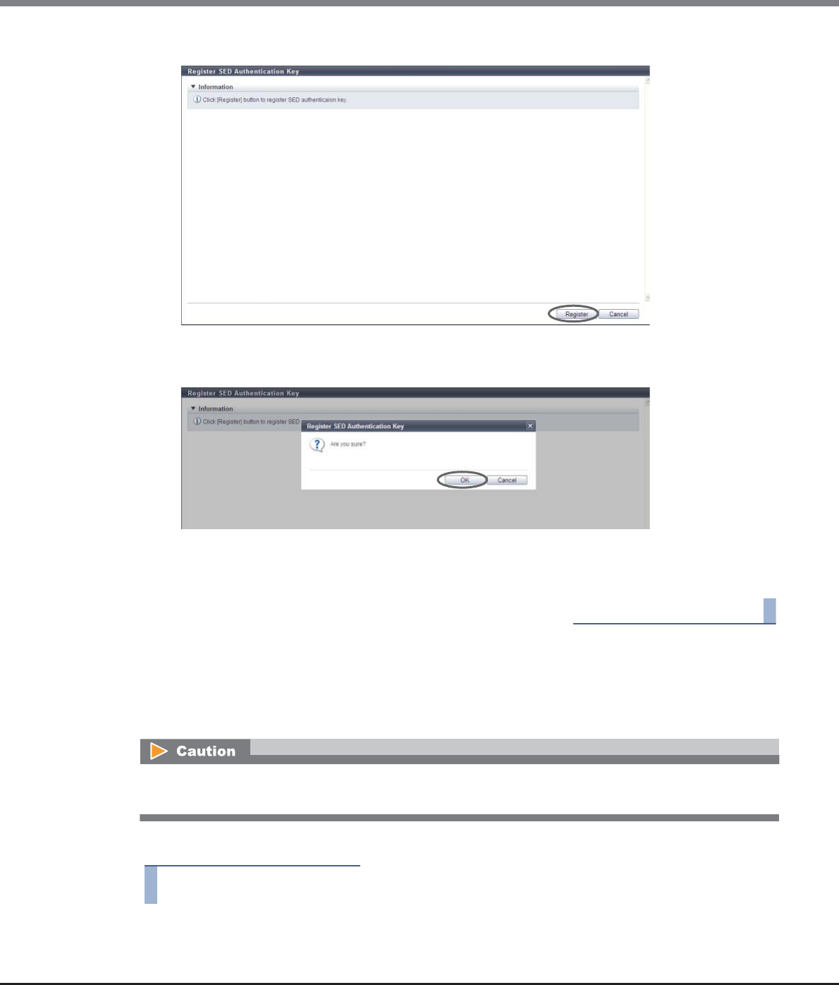
Chapter 11 System Management
11.2 Functions in the Action Area for System
ETERNUS Web GUI User’s Guide
Copyright 2013 FUJITSU LIMITED P2X0-1090-10ENZ0
945
2Click the [Register] button.
→A confirmation screen appears.
3Click the [OK] button.
→The SED authentication key registration starts.
4Click the [Done] button to return to the [System Settings] screen.
End of procedure
11.2.13.8 Setup Power Management
This function connects the external input device and controls (shuts down) the ETERNUS DX Disk storage
system power.
The procedure to perform power management setting is as follows:
Procedure
1Click [Setup Power Management] in [Action].
If this function is enabled by mistake, the ETERNUS DX Disk storage system may shut down unexpectedly.
Make sure to check setting contents before performing settings.
Chapter 11 System Management
11.2 Functions in the Action Area for System
ETERNUS Web GUI User’s Guide
Copyright 2013 FUJITSU LIMITED P2X0-1090-10ENZ0
946
2Specify the parameters, and click the [Set] button.
•Enable
Select the checkbox for the Controller Module to enable power management by an external input
device (multiple selections can be made).
•Auto Power
Select whether to "Enable" or "Disable" the AC power interlock mode (the function to automatically
power on when AC power is supplied).
When PMAN is connected, enable the "Auto Power".
When the power synchronized unit is connected, disable the "Auto Power".
•Power Resume
Select whether to "Enable" or "Disable" the auto power recovery mode (the function to automatically
power on at power recovery after a power failure).
•Delay until Shutdown (min.)
Specify the delay time (minutes) before starting shutdown after receiving a shut down notification
signal from the external input device between 0 - 15.
When PMAN is connected, specify the delay time before starting shutdown after receiving a low
battery signal. Specify a delay time longer than the time required for the server shutdown process
so that the ETERNUS DX Disk storage system is turned off after the server shutdown is complete.
•Set management unit interface
Select the external input device connected via RS232C interface from "Power Synchronized Unit",
"PMAN", or "Manual".
The "Manual" setting is for particular use, thus should not be used during normal operation.
•Power Failure Signal
Select the signal logic for power failure signal when the power failure occurs from "Positive" or
"Negative" (Positive: positive logic, Negative: negative logic).
When "Power Synchronized Unit" or "PMAN" is selected for the "Set management unit interface"
field, this item is automatically set.
•Low Battery Signal
Select the signal logic for a low battery signal when a low battery charge occurs from "Positive" or
"Negative" (Positive: positive logic, Negative: negative logic).
When "Power Synchronized Unit" or "PMAN" is selected for the "Set management unit interface"
field, this item is automatically set.
•UPS Shutdown Signal
When enabling the UPS shutdown signal, select the "Enable" checkbox. Also, select the signal logic
for UPS shutdown signal from "Positive" or "Negative" (Positive: positive logic, Negative: negative
logic). Select "Disable". (Be sure not to select the "Enable" checkbox.)
The following items are only required for the ETERNUS DX80 S2/DX90 S2.
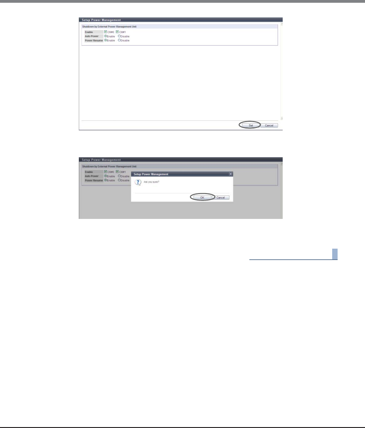
Chapter 11 System Management
11.2 Functions in the Action Area for System
ETERNUS Web GUI User’s Guide
Copyright 2013 FUJITSU LIMITED P2X0-1090-10ENZ0
947
→A confirmation screen appears.
3Click the [OK] button.
→Setting of the power management starts.
4Click the [Done] button to return to the [System Settings] screen.
End of procedure
ETERNUS Web GUI User’s Guide
Copyright 2013 FUJITSU LIMITED P2X0-1090-10ENZ0
948
Appendix A
User Roles and Policies
This chapter describes user roles and policies.
A.1 Roles
When creating a user account, at least one role must be applied.
There are two types of roles: a default role and a custom role. The default role is already prepared in the
ETERNUS DX Disk storage system and the custom role can be managed by the user.
■Default Role
Use the default roles for normal operation. Default roles cannot be deleted. The default role settings cannot
be changed.
The following table shows the default roles and policies that are applied to each default role.
OK: Available
NG: Not available
*1: "Software" is the role that is used for external software. A user account with the "Software" role cannot log in to GUI.
Policies Default Roles
Monitor Admin Storage
Admin
Account
Admin
Security
Admin
Main-
tainer
Software
(*1)
Status Display OKOKOKNGOKOKNG
RAID Group Management NG OK OK NG NG OK NG
Volume - Create / Modify NG OK OK NG NG OK NG
Volume - Delete / Format NG OK OK NG NG OK NG
Host Interface Management NG OK OK NG NG OK NG
Advanced Copy Management NG OK OK NG NG OK NG
Copy Session Management NG OK OK NG NG OK NG
Storage Migration Management NG OK OK NG NG OK NG
Storage Management NG OK NG NG NG OK NG
User Management NG OK NG OK NG NG NG
Authentication / Role NG OK NG OK NG NG NG
Security Setting NG OK NG NG OK NG NG
Maintenance Information NG OK NG NG OK OK NG
Maintenance Operation NG NG NG NG NG OK NG

Appendix A User Roles and Policies
A.1 Roles
ETERNUS Web GUI User’s Guide
Copyright 2013 FUJITSU LIMITED P2X0-1090-10ENZ0
949
■Custom Roles
Create custom roles when the operating environment cannot be configured by default roles.
Custom roles have unique names that do not match the existing roles. Policies are applied for custom roles.
Multiple policies can be applied to one custom role.
Refer to the following sections for the procedure on how to set custom roles.
•Add Role
This function creates custom roles.
•Delete Role
This function deletes custom roles.
•Modify Role
This function changes custom role settings.
Appendix A User Roles and Policies
A.2 Availability of Functions for each Policy
ETERNUS Web GUI User’s Guide
Copyright 2013 FUJITSU LIMITED P2X0-1090-10ENZ0
950
A.2 Availability of Functions for each Policy
Functions that can be used vary depending on the policy.
The following tables show the availability of functions for each policy.
"Software" is the default role that is used for external software. A user account with the "Software" role cannot
log in to GUI. "Software" is omitted in the following tables.
■Overview (Display)
■Start Initial Setup (Action)
*1: The setting items varies depending on the login user role.
■Volume Management (Display)
Function Required Policy for
this Function
Availability of Executions in the Default Role
Monitor Admin Storage
Admin
Account
Admin
Security
Admin
Main-
tainer
Overview Any policy OK OK OK OK OK OK
Function Required Policy for
this Function
Availability of Executions in the Default Role
Monitor Admin Storage
Admin
Account
Admin
Security
Admin
Main-
tainer
Start Initial Setup
(*1)
Any of the following
policies:
•Storage
Management
•Security Setting
•Storage Migration
Management
NG OK OK NG OK OK
Function Required Policy for
this Function
Availability of Executions in the Default Role
Monitor Admin Storage
Admin
Account
Admin
Security
Admin
Main-
tainer
Volume (Basic
Information)
Any of the
following policy:
•Status Display
•Volume - Create /
Modify
•Volume - Delete /
Format
•Host Interface
Management
•Maintenance
Operation
OK OK OK NG OK OK
Performance (Host
I/O)
Volume - Create /
Modify
NG OK OK NG NG OK

Appendix A User Roles and Policies
A.2 Availability of Functions for each Policy
ETERNUS Web GUI User’s Guide
Copyright 2013 FUJITSU LIMITED P2X0-1090-10ENZ0
951
■Volume Management (Action)
Performance
(Advanced Copy)
Status Display OKOKOKNGOKOK
LUN Group Any of the following
policy:
•Status Display
•Host Interface
Management
OK OK OK NG OK OK
Reservation OKOKOKNGOKOK
Pinned Data Any of the following
policy:
•Status Display
•Maintenance
Operation
OK OK OK NG OK OK
Bad Sector OK OK OK NG OK OK
Balancing Thin
Provisioning
Volume
Any of the following
policy:
•Status Display
•Volume - Create /
Modify
OK OK OK NG OK OK
Function Required Policy for
this Function
Availability of Executions in the Default Role
Monitor Admin Storage
Admin
Account
Admin
Security
Admin
Main-
tainer
Function Required Policy for
this Function
Availability of Executions in the Default Role
Monitor Admin Storage
Admin
Account
Admin
Security
Admin
Main-
tainer
Create Volume Volume - Create /
Modify
NG OK OK NG NG OK
Delete Volume Volume - Delete /
Format
NG OK OK NG NG OK
Rename Volume Volume - Create /
Modify
NG OK OK NG NG OK
Format Volume Volume - Delete /
Format
NG OK OK NG NG OK
Expand Volume Volume - Create /
Modify
NG OK OK NG NG OK
Expand Thin
Provisioning
Volume
NG OK OK NG NG OK
Start RAID Migration
(*1)
NG OK OK NG NG OK
Stop RAID Migration NGOKOKNGNGOK
Start Zero
Reclamation
RAID Group
Management
NG OK OK NG NG OK
Stop Zero
Reclamation
NG OK OK NG NG OK

Appendix A User Roles and Policies
A.2 Availability of Functions for each Policy
ETERNUS Web GUI User’s Guide
Copyright 2013 FUJITSU LIMITED P2X0-1090-10ENZ0
952
*1: When performing migration from an encrypted volume to a non-encrypted volume, the "Security Setting" policy is
also required.
Delete Snap Data
Pool Volume
Volume - Delete /
Format
NG OK OK NG NG OK
Force Delete Snap
Data Pool Volume
NG OK OK NG NG OK
Modify Threshold
Thin Provisioning
Volume
Volume - Create /
Modify
NG OK OK NG NG OK
Initialize Snap Data
Volume
Volume - Delete /
Format
NG OK OK NG NG OK
Encrypt Volume Volume - Create /
Modify
NG OK OK NG NG OK
Forbid Advanced
Copy
NG OK OK NG NG OK
Permit Advanced
Copy
NG OK OK NG NG OK
Modify Cache
Parameters
NG OK OK NG NG OK
Export Cache
Parameters
NG OK OK NG NG OK
Export Performance
Information
Status Display OKOKOKNGOKOK
Release Reservation Host Interface
Management
NG OK OK NG NG OK
Start Balancing of
Thin Provisioning
Volume
Volume - Create /
Modify
NG OK OK NG NG OK
Stop Balancing of
Thin Provisioning
Volume
NG OK OK NG NG OK
Function Required Policy for
this Function
Availability of Executions in the Default Role
Monitor Admin Storage
Admin
Account
Admin
Security
Admin
Main-
tainer

Appendix A User Roles and Policies
A.2 Availability of Functions for each Policy
ETERNUS Web GUI User’s Guide
Copyright 2013 FUJITSU LIMITED P2X0-1090-10ENZ0
953
■RAID Group Management (Display)
■RAID Group Management (Action)
Function Required Policy for
this Function
Availability of Executions in the Default Role
Monitor Admin Storage
Admin
Account
Admin
Security
Admin
Main-
tainer
RAID Group (Basic
Information)
Any of the following
policy:
•Status Display
•RAID Group
Management
•Volume - Create /
Modify
•Maintenance
Operation
OK OK OK NG OK OK
Tuning Any of the following
policy:
•Status Display
•RAID Group
Management
OK OK OK NG OK OK
ECO Mode Schedule
(RAID Group)
OK OK OK NG OK OK
SED Key Group OKOKOKNGOKOK
Function Required Policy for
this Function
Availability of Executions in the Default Role
Monitor Admin Storage
Admin
Account
Admin
Security
Admin
Main-
tainer
Create RAID Group RAID Group
Management
NG OK OK NG NG OK
Delete RAID Group NG OK OK NG NG OK
Rename RAID Group NGOKOKNGNGOK
Change Controlling
CM
NG OK OK NG NG OK
Expand RAID Group NGOKOKNGNGOK
Modify RAID Group
Parameters
NG OK OK NG NG OK
Assign ECO Mode
Schedule (RAID
Group)
NG OK OK NG NG OK
Set Key Group (RAID
Group)
All of the following
policies:
•RAID Group
Management
•Security Setting
NG OK NG NG NG NG
Recovery SED NGOKNGNGNGNG

Appendix A User Roles and Policies
A.2 Availability of Functions for each Policy
ETERNUS Web GUI User’s Guide
Copyright 2013 FUJITSU LIMITED P2X0-1090-10ENZ0
954
■Thin Provisioning Management (Display)
Function Required Policy for
this Function
Availability of Executions in the Default Role
Monitor Admin Storage
Admin
Account
Admin
Security
Admin
Main-
tainer
Thin Provisioning
Pool (Basic Informa-
tion)
Any of the following
policy:
•Status Display
•RAID Group
Management
•Volume - Create /
Modify
•Volume - Delete /
Format
OK OK OK NG OK OK
Threshold (Thin
Provisioning Pool)
Any of the following
policy:
•Status Display
•RAID Group
Management
OK OK OK NG OK OK
ECO Mode Schedule
(Thin Provisioning
Pool)
OK OK OK NG OK OK
License (Thin
Provisioning)
Any of the following
policy:
•RAID Group
Management
•Storage
Management
NG OK OK NG NG OK
Flexible Tier Pool
(Basic Information)
Any of the following
policy:
•Status Display
•RAID Group
Management
•Volume - Delete /
Format
OK OK OK NG OK OK

Appendix A User Roles and Policies
A.2 Availability of Functions for each Policy
ETERNUS Web GUI User’s Guide
Copyright 2013 FUJITSU LIMITED P2X0-1090-10ENZ0
955
■Thin Provisioning Management (Action)
Function Required Policy for
this Function
Availability of Executions in the Default Role
Monitor Admin Storage
Admin
Account
Admin
Security
Admin
Main-
tainer
Create Thin
Provisioning Pool
RAID Group
Management
NG OK OK NG NG OK
Delete Thin
Provisioning Pool
NG OK OK NG NG OK
Rename Thin
Provisioning Pool
NG OK OK NG NG OK
Expand Thin
Provisioning Pool
NG OK OK NG NG OK
Format Thin
Provisioning Pool
(All Area)
NG OK OK NG NG OK
Format Thin
Provisioning Pool
(Unformatted Area)
NG OK OK NG NG OK
Modify Threshold
Thin Provisioning
Pool
NG OK OK NG NG OK
Modify Cache
Parameters (Thin
Provisioning Pool)
NG OK OK NG NG OK
Assign ECO Mode
Schedule (Thin
Provisioning Pool)
NG OK OK NG NG OK
Register Thin
Provisioning License
Storage Management NG OK NG NG NG OK
Delete Thin
Provisioning License
NG OK NG NG NG OK
Start Balancing
Flexible Tier Pool
Volume - Create /
Modify
NG OK OK NG NG OK
Stop Balancing
Flexible Tier Pool
NG OK OK NG NG OK

Appendix A User Roles and Policies
A.2 Availability of Functions for each Policy
ETERNUS Web GUI User’s Guide
Copyright 2013 FUJITSU LIMITED P2X0-1090-10ENZ0
956
■Advanced Copy Management (Display)
*1: When displaying the setting status for the Advanced Copy license, the "Storage Management" policy is also required.
Function Required Policy for
this Function
Availability of Executions in the Default Role
Monitor Admin Storage
Admin
Account
Admin
Security
Admin
Main-
tainer
Advanced Copy
(Basic Information)
Any of the following
policy:
•Status Display
•Advanced Copy
Management
•Copy Session
Management
•Storage
Management
OK OK OK NG OK OK
Advanced Copy (All
Local Sessions)
Any of the following
policy:
•Status Display
•Copy Session
Management
OK OK OK NG OK OK
EC OK OK OK NG OK OK
OPC OKOKOKNGOKOK
QuickOPC OK OK OK NG OK OK
SnapOPC OKOKOKNGOKOK
SnapOPC+ OK OK OK NG OK OK
Monitor OKOKOKNGOKOK
Advanced Copy (All
Remote Sessions)
OK OK OK NG OK OK
REC OKOKOKNGOKOK
Advanced Copy
(ODX)
OK OK OK NG OK OK
Advanced Copy
(XCOPY)
OK OK OK NG OK OK
Setting (Advanced
Copy)
Any of the following
policy:
•Status Display
•Advanced Copy
Management
•Copy Session
Management
•Storage
Management
(*1)
OK OK OK NG OK OK
Snap Data Pool Any of the following
policy:
•Status Display
•Advanced Copy
Management
OK OK OK NG OK OK
Copy Path OK OK OK NG OK OK
REC Buffer OK OK OK NG OK OK
REC Disk Buffer OK OK OK NG OK OK

Appendix A User Roles and Policies
A.2 Availability of Functions for each Policy
ETERNUS Web GUI User’s Guide
Copyright 2013 FUJITSU LIMITED P2X0-1090-10ENZ0
957
■Advanced Copy Management (Action)
Function Required Policy for
this Function
Availability of Executions in the Default Role
Monitor Admin Storage
Admin
Account
Admin
Security
Admin
Main-
tainer
Start SnapOPC+ Copy Session
Management
NG OK OK NG NG OK
Stop Copy Session NG OK OK NG NG OK
Register Advanced
Copy License
Storage Management NG OK NG NG NG OK
Delete Advanced
Copy License
NG OK NG NG NG OK
Modify EC/OPC
Priority
Advanced Copy
Management
NG OK OK NG NG OK
Modify Copy Table
Size
NG OK OK NG NG OK
Modify Copy
Parameters
NG OK OK NG NG OK
Enable ODX Any of the following
policy:
•Volume - Create /
Modify
•Volume - Delete /
Format
•Advanced Copy
Management
NG OK OK NG NG OK
Disable ODX NGOKOKNGNGOK
Create ODX Buffer
Volume
NG OK OK NG NG OK
Set Copy Path Advanced Copy
Management
NG OK OK NG NG OK
Delete All Copy Path NG OK OK NG NG OK
Export All Copy Path NG OK OK NG NG OK
Export Storage
Information
NG OK OK NG NG OK
Convert Copy Path NG OK OK NG NG OK
Measure Round Trip
Time
NG OK OK NG NG OK
Modify REC
Multiplicity
NG OK OK NG NG OK
Modify REC Buffer NG OK OK NG NG OK
Assign REC Disk
Buffer
NG OK OK NG NG OK
Create REC Disk
Buffer
NG OK OK NG NG OK
Delete REC Disk
Buffer
NG OK OK NG NG OK
Format REC Disk
Buffer
NG OK OK NG NG OK
Appendix A User Roles and Policies
A.2 Availability of Functions for each Policy
ETERNUS Web GUI User’s Guide
Copyright 2013 FUJITSU LIMITED P2X0-1090-10ENZ0
958
■Connectivity Management (Display)
■Connectivity Management (Action)
Host Affinity Management
Function Required Policy for
this Function
Availability of Executions in the Default Role
Monitor Admin Storage
Admin
Account
Admin
Security
Admin
Main-
tainer
Connectivity (Basic
Information)
Any of the following
policy:
•Status Display
•Host Interface
Management
OK OK OK NG OK OK
Host Group OKOKOKNGOKOK
FC Host OK OK OK NG OK OK
iSCSI Host OK OK OK NG OK OK
SAS Host OK OK OK NG OK OK
Port Group OKOKOKNGOKOK
FC Port OK OK OK NG OK OK
iSCSI Port OK OK OK NG OK OK
SAS Port OK OK OK NG OK OK
FCoE Port OK OK OK NG OK OK
LUN Group OKOKOKNGOKOK
Host Response OK OK OK NG OK OK
CA Reset Group OKOKOKNGOKOK
Host-LU QoS Host Interface
Management
NG OK OK NG NG Ok
Host QoS (Basic) NG OK OK NG NG Ok
FC/FCoE Host
QoS
NG OK OK NG NG Ok
iSCSI Host
QoS
NG OK OK NG NG Ok
SAS Host
QoS
NG OK OK NG NG Ok
Port QoS (Basic) NG OK OK NG NG Ok
FC Port QoS NG OK OK NG NG Ok
iSCSI Port
QoS
NG OK OK NG NG Ok
SAS Port QoS NG OK OK NG NG Ok
FCoE Port
QoS
NG OK OK NG NG Ok
LU QoS Group NG OK OK NG NG Ok
Function Required Policy for
this Function
Availability of Executions in the Default Role
Monitor Admin Storage
Admin
Account
Admin
Security
Admin
Main-
tainer
Create Host Affinity Host Interface
Management
NG OK OK NG NG OK
Delete Host Affinity NG OK OK NG NG OK
Modify Host Affinity NG OK OK NG NG OK

Appendix A User Roles and Policies
A.2 Availability of Functions for each Policy
ETERNUS Web GUI User’s Guide
Copyright 2013 FUJITSU LIMITED P2X0-1090-10ENZ0
959
Host Group Management
CA Port Group Management
Function Required Policy for
this Function
Availability of Executions in the Default Role
Monitor Admin Storage
Admin
Account
Admin
Security
Admin
Main-
tainer
Add FC/FCoE Host
Group
Host Interface
Management
NG OK OK NG NG OK
Add iSCSI Host
Group
NG OK OK NG NG OK
Add SAS Host Group NGOKOKNGNGOK
Delete Host Group NGOKOKNGNGOK
Modify Host Group NGOKOKNGNGOK
Add FC/FCoE Host NG OK OK NG NG OK
Add iSCSI Host NG OK OK NG NG OK
Add SAS Host NG OK OK NG NG OK
Delete FC/FCoE Host NG OK OK NG NG OK
Delete iSCSI Host NG OK OK NG NG OK
Delete SAS Host NG OK OK NG NG OK
Modify FC/FCoE Host NG OK OK NG NG OK
Modify iSCSI Host NG OK OK NG NG OK
Modify SAS Host NG OK OK NG NG OK
Function Required Policy for
this Function
Availability of Executions in the Default Role
Monitor Admin Storage
Admin
Account
Admin
Security
Admin
Main-
tainer
Create FC Port Group Host Interface
Management
NG OK OK NG NG OK
Create iSCSI Port
Group
NG OK OK NG NG OK
Create SAS Port
Group
NG OK OK NG NG OK
Create FCoE Port
Group
NG OK OK NG NG OK
Delete CA Port
Group
NG OK OK NG NG OK
Modify CA Port
Group
NG OK OK NG NG OK
Modify FC Port
Parameters
NG OK OK NG NG OK
Modify iSCSI Port
Parameters
NG OK OK NG NG OK
Modify SAS Port
Parameters
NG OK OK NG NG OK
Modify FCoE Port
Parameters
NG OK OK NG NG OK
Modify Port Mode NG OK OK NG NG OK
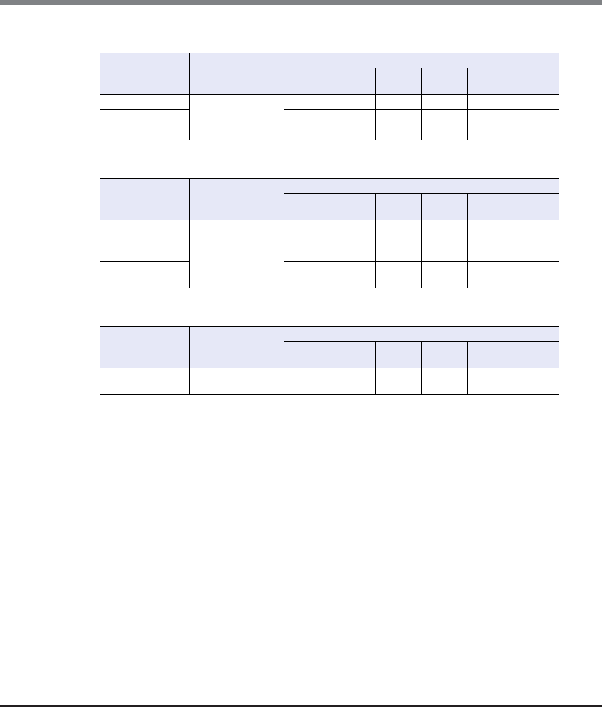
Appendix A User Roles and Policies
A.2 Availability of Functions for each Policy
ETERNUS Web GUI User’s Guide
Copyright 2013 FUJITSU LIMITED P2X0-1090-10ENZ0
960
LUN Group Management
Host Response Management
Modify CA Reset Group
Function Required Policy for
this Function
Availability of Executions in the Default Role
Monitor Admin Storage
Admin
Account
Admin
Security
Admin
Main-
tainer
Add LUN Group Host Interface
Management
NG OK OK NG NG OK
Delete LUN Group NGOKOKNGNGOK
Modify LUN Group NGOKOKNGNGOK
Function Required Policy for
this Function
Availability of Executions in the Default Role
Monitor Admin Storage
Admin
Account
Admin
Security
Admin
Main-
tainer
Add Host Response Host Interface
Management
NG OK OK NG NG OK
Delete Host
Response
NG OK OK NG NG OK
Modify Host
Response
NG OK OK NG NG OK
Function Required Policy for
this Function
Availability of Executions in the Default Role
Monitor Admin Storage
Admin
Account
Admin
Security
Admin
Main-
tainer
Modify CA Reset
Group
Host Interface
Management
NG OK OK NG NG OK
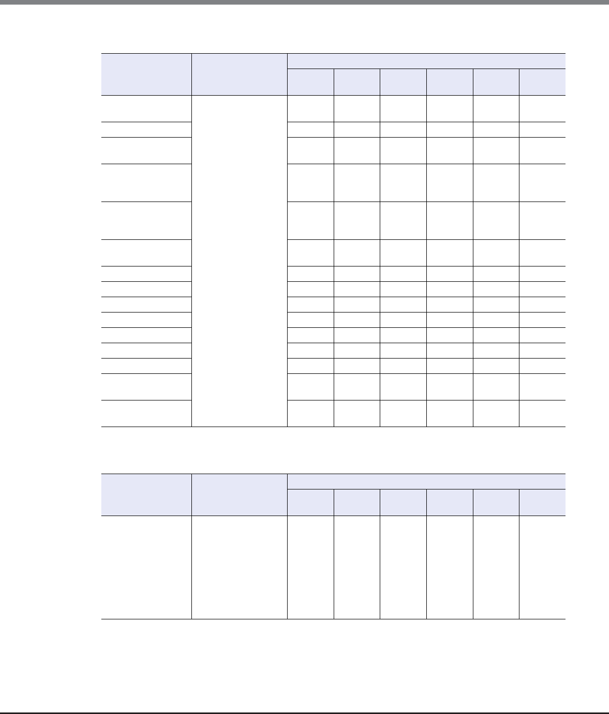
Appendix A User Roles and Policies
A.2 Availability of Functions for each Policy
ETERNUS Web GUI User’s Guide
Copyright 2013 FUJITSU LIMITED P2X0-1090-10ENZ0
961
Host-LU QoS Management
■Component Management (Display)
Function Required Policy for
this Function
Availability of Executions in the Default Role
Monitor Admin Storage
Admin
Account
Admin
Security
Admin
Main-
tainer
Enable/Disable
Host-LU QoS
Host Interface
Management
NG OK OK NG NG OK
Set Host-LU QoS NGOKOKNGNGOK
Release Host-LU
QoS
NG OK OK NG NG OK
Start Host-LU QoS
Performance
Monitoring
NG OK OK NG NG OK
Stop Host-LU QoS
Performance
Monitoring
NG OK OK NG NG OK
Set FC/FCoE Host
QoS
NG OK OK NG NG OK
Set iSCSI Host QoS NGOKOKNGNGOK
Set SAS Host QoS NGOKOKNGNGOK
Set FC Port QoS NGOKOKNGNGOK
Set iSCSI Port QoS NGOKOKNGNGOK
Set SAS Port QoS NGOKOKNGNGOK
Set FCoE Port QoS NGOKOKNGNGOK
Add LU QoS Group NGOKOKNGNGOK
Delete LU QoS
Group
NG OK OK NG NG OK
Modify LU QoS
Group
NG OK OK NG NG OK
Function Required Policy for
this Function
Availability of Executions in the Default Role
Monitor Admin Storage
Admin
Account
Admin
Security
Admin
Main-
tainer
Storage (Basic
Information)
Any of the following
policy:
•Status Display
•Storage
Management
(*1)
•Maintenance
Operation
OK OK OK NG OK OK

Appendix A User Roles and Policies
A.2 Availability of Functions for each Policy
ETERNUS Web GUI User’s Guide
Copyright 2013 FUJITSU LIMITED P2X0-1090-10ENZ0
962
Controller Enclosure Any of the following
policy:
•Status Display
•Maintenance
Operation
OK OK OK NG OK OK
Controller
Module
OK OK OK NG OK OK
Controller
Module
(Performanc
e)
OK OK OK NG OK OK
All Channel
Adapters
Any of the following
policy:
•Status Display
•Storage
Management
(*1)
•Maintenance
Operation
OK OK OK NG OK OK
Channel
Adapter
Ports
(Performanc
e)
Any of the following
policy:
•Status Display
•Maintenance
Operation
OK OK OK NG OK OK
Frontend Router
(*2)
OK OK OK NG OK OK
Backend Router
(*2)
OK OK OK NG OK OK
Service
Controller (*2)
OK OK OK NG OK OK
Power Supply
Unit (CE)
OK OK OK NG OK OK
Battery (*3) OK OK OK NG OK OK
FAN Unit (*2) OK OK OK NG OK OK
Operation Panel
(*2)
OK OK OK NG OK OK
Drive Enclosure Any of the following
policy:
•Status Display
•Maintenance
Operation
OK OK OK NG OK OK
I/O Module OK OK OK NG OK OK
Port Error
Statistics
Status Display OKOKOKNGOKOK
Power Supply
Unit (DE)
Any of the following
policy:
•Status Display
•Maintenance
Operation
OK OK OK NG OK OK
Function Required Policy for
this Function
Availability of Executions in the Default Role
Monitor Admin Storage
Admin
Account
Admin
Security
Admin
Main-
tainer

Appendix A User Roles and Policies
A.2 Availability of Functions for each Policy
ETERNUS Web GUI User’s Guide
Copyright 2013 FUJITSU LIMITED P2X0-1090-10ENZ0
963
*1: This function is available only when using the ETERNUS DX80 S2/DX90 S2.
*2: This function is available only when using the ETERNUS DX8700 S2.
*3: This function is available only when using the ETERNUS DX410 S2/DX440 S2 or the ETERNUS DX8100 S2/DX8700 S2.
■Component Management (Action)
Disks Any of the following
policy:
•Status Display
•RAID Group
Management
•Maintenance
Information
•Maintenance
Operation
OK OK OK NG OK OK
Disks
(Performance)
Any of the following
policy:
•Status Display
•Maintenance
Information
OK OK OK NG OK OK
Disk Error
Statistics
Maintenance Infor-
mation
NG OK NG NG OK OK
Function Required Policy for
this Function
Availability of Executions in the Default Role
Monitor Admin Storage
Admin
Account
Admin
Security
Admin
Main-
tainer
Function Required Policy for
this Function
Availability of Executions in the Default Role
Monitor Admin Storage
Admin
Account
Admin
Security
Admin
Main-
tainer
Add Drive Enclosure Any of the following
policy:
•Status Display
(*1)
•Maintenance
Operation
NG OK NG NG NG OK
Turn on Locator
Beacon/Turn off
Locator Beacon
Status Display OKOKOKNGOKOK
Add Channel
Adapter Port (*1)
Any of the following
policy:
•Status Display
•Maintenance
Operation
NG OK NG NG NG OK

Appendix A User Roles and Policies
A.2 Availability of Functions for each Policy
ETERNUS Web GUI User’s Guide
Copyright 2013 FUJITSU LIMITED P2X0-1090-10ENZ0
964
*1: This function is available only when using the ETERNUS DX80 S2/DX90 S2.
■System Management (Display)
Assign Global Hot
Spare
RAID Group
Management
NG OK OK NG NG OK
Release Global Hot
Spare
NG OK OK NG NG OK
Assign Dedicated
Hot Spare
NG OK OK NG NG OK
Release Dedicated
Hot Spare
NG OK OK NG NG OK
Export Performance
Information
Status Display OKOKOKNGOKOK
Clear Disk Error
Statistics (All Disks)
Maintenance
Information
NG OK NG NG OK OK
Clear Disk Error
Statistics (Selected
Disks)
NG OK NG NG OK OK
Function Required Policy for
this Function
Availability of Executions in the Default Role
Monitor Admin Storage
Admin
Account
Admin
Security
Admin
Main-
tainer
Function Required Policy for
this Function
Availability of Executions in the Default Role
Monitor Admin Storage
Admin
Account
Admin
Security
Admin
Main-
tainer
System (Basic Infor-
mation)
Any of the following
policy:
•Status Display
•Storage
Management
•User
Management
•Authentication /
Role
•Security Setting
•Maintenance
Information
•Maintenance
Operation
OK OK OK OK OK OK
Network Any of the following
policy:
•Status Display
•Storage
Management
OK OK OK NG OK OK

Appendix A User Roles and Policies
A.2 Availability of Functions for each Policy
ETERNUS Web GUI User’s Guide
Copyright 2013 FUJITSU LIMITED P2X0-1090-10ENZ0
965
Remote Support
(REMCS)
for Regions other
than EMEA
Any of the following
policy:
•Status Display
•Storage
Management
•Maintenance
Operation
OK OK OK NG OK OK
Remote Support
(AIS Connect)
for Regions other
than Japan
OK OK OK NG OK OK
Root Certificate Status Display OK OK OK NG OK OK
Key Management OK OK OK NG OK OK
Key Group OKOKOKNGOKOK
Define Role Any of the following
policy:
•User
Management
•Authentication /
Role
NG OK NG OK NG NG
ECO Mode Any of the following
policy:
•Status Display
•RAID Group
Management
•Maintenance
Operation
OK OK OK NG OK OK
Event/Dump Any of the following
policy:
•Status Display
•Storage
Management
•Maintenance
Information
•Maintenance
Operation
OK OK OK NG OK OK
Audit Log Security Setting NG OK NG NG OK NG
Storage Migration Any of the following
policy:
•Status Display
•Storage Migration
Management
OK OK OK NG OK OK
Function Required Policy for
this Function
Availability of Executions in the Default Role
Monitor Admin Storage
Admin
Account
Admin
Security
Admin
Main-
tainer

Appendix A User Roles and Policies
A.2 Availability of Functions for each Policy
ETERNUS Web GUI User’s Guide
Copyright 2013 FUJITSU LIMITED P2X0-1090-10ENZ0
966
■System Management (Action)
Network Management
Utility Any of the following
policy:
•Storage
Management
•Maintenance
Information
•Maintenance
Operation
NG OK NG NG OK OK
System Settings Any of the following
policy:
•Status Display
•Advanced Copy
Management
•Storage
Management
•Security Setting
•Maintenance
Operation
OK OK OK NG OK OK
Function Required Policy for
this Function
Availability of Executions in the Default Role
Monitor Admin Storage
Admin
Account
Admin
Security
Admin
Main-
tainer
Function Required Policy for
this Function
Availability of Executions in the Default Role
Monitor Admin Storage
Admin
Account
Admin
Security
Admin
Main-
tainer
Change User
Password
Any policy OK OK OK OK OK OK
Set SSH Public Key OKOKOKOKOKOK
Function Required Policy for
this Function
Availability of Executions in the Default Role
Monitor Admin Storage
Admin
Account
Admin
Security
Admin
Main-
tainer
Setup Network
Environment
Storage Management NG OK NG NG NG OK
Setup Firewall NGOKNGNGNGOK
Setup SNMP Agent
Basic Interface
NG OK NG NG NG OK
Setup SNMP
Manager
NG OK NG NG NG OK
Setup SNMP Agent
MIB View
NG OK NG NG NG OK
Setup SNMP Agent
User
NG OK NG NG NG OK
Setup SNMP Agent
Community
NG OK NG NG NG OK

Appendix A User Roles and Policies
A.2 Availability of Functions for each Policy
ETERNUS Web GUI User’s Guide
Copyright 2013 FUJITSU LIMITED P2X0-1090-10ENZ0
967
Remote Support (REMCS) for Regions other than EMEA
Setup SNMP Agent
Trap
Storage Management NG OK NG NG NG OK
Download MIB File NG OK NG NG NG OK
Send SNMP Trap
Test
NG OK NG NG NG OK
Display SMTP Log NGOKNGNGNGOK
Setup E-Mail
Notification
NG OK NG NG NG OK
Setup Syslog NG OK NG NG NG OK
Setup SSH Server
Key
NG OK NG NG NG OK
Create Self-signed
SSL Certificate
NG OK NG NG NG OK
Create Key/CSR NG OK NG NG NG OK
Register SSL
Certificate
NG OK NG NG NG OK
Function Required Policy for
this Function
Availability of Executions in the Default Role
Monitor Admin Storage
Admin
Account
Admin
Security
Admin
Main-
tainer
Display
Communication Log
Storage Management NG OK NG NG NG OK
Setup Remote
Support
NG OK NG NG NG OK
Update Customer
Information
NG OK NG NG NG OK
Update
Communication
Environment
Information
NG OK NG NG NG OK
Setup Log Sending
Parameters
NG OK NG NG NG OK
Stop/Restart Remote
Support
NG OK NG NG NG OK
Function Required Policy for
this Function
Availability of Executions in the Default Role
Monitor Admin Storage
Admin
Account
Admin
Security
Admin
Main-
tainer
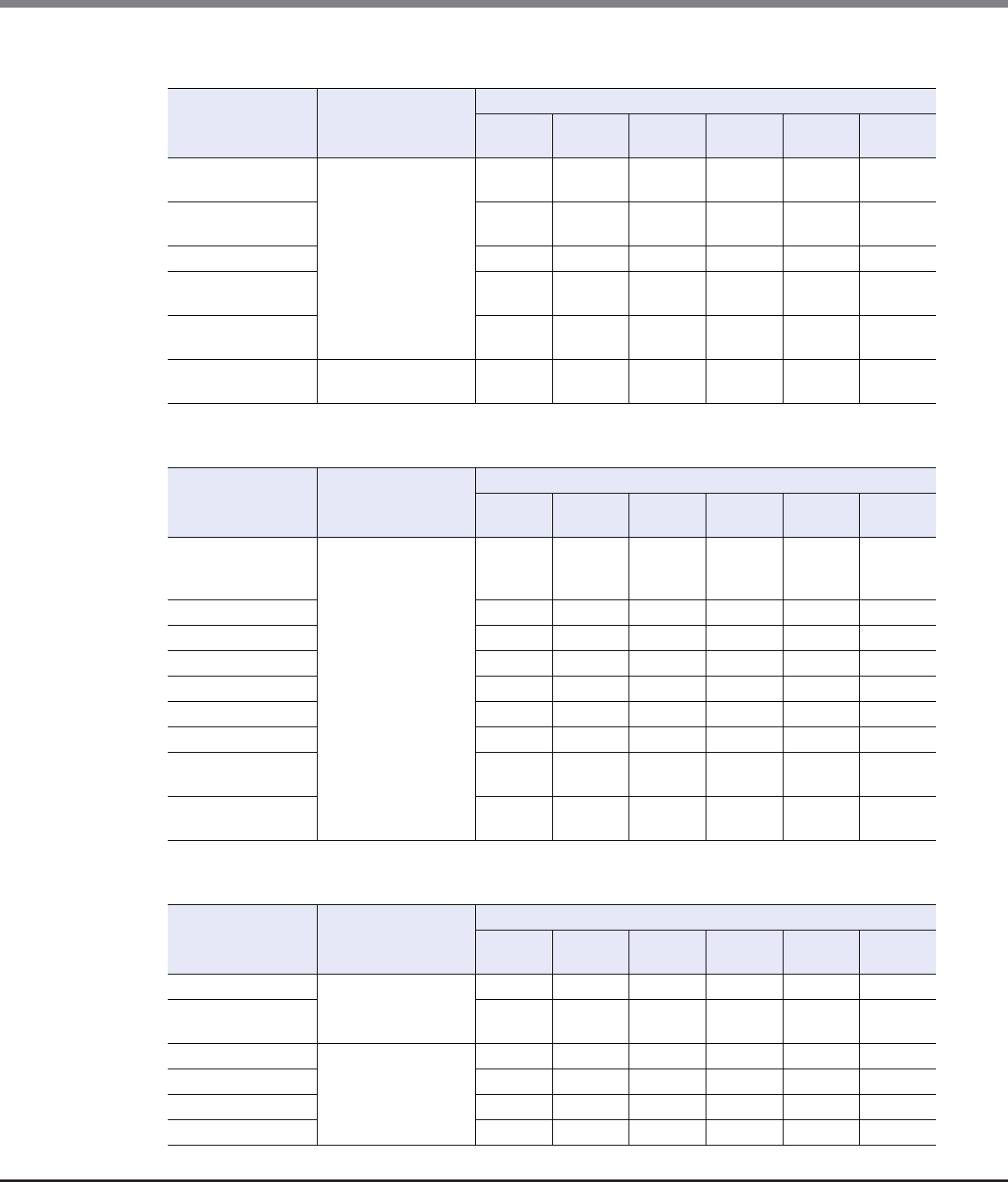
Appendix A User Roles and Policies
A.2 Availability of Functions for each Policy
ETERNUS Web GUI User’s Guide
Copyright 2013 FUJITSU LIMITED P2X0-1090-10ENZ0
968
Remote Support (AIS Connect) for Regions other than Japan
Key Management
User Management
Function Required Policy for
this Function
Availability of Executions in the Default Role
Monitor Admin Storage
Admin
Account
Admin
Security
Admin
Main-
tainer
Setup AIS Connect
Environment
Any of the following
policy:
•Storage
Management
•Maintenance
Operation
NG OK NG NG NG OK
Setup Remote
Session Permission
NG OK NG NG NG OK
Send Log NGOKNGNGNGOK
Test Server
Connectivity
NG OK NG NG NG OK
Send AIS Connect
Test Event
NG OK NG NG NG OK
Import Root
Certificate
Storage Management NG OK NG NG NG OK
Function Required Policy for
this Function
Availability of Executions in the Default Role
Monitor Admin Storage
Admin
Account
Admin
Security
Admin
Main-
tainer
Setup Key
Management
Machine Name
Security Setting NG OK NG NG OK NG
Add Key Server NG OK NG NG OK NG
Delete Key Server NG OK NG NG OK NG
Modify Key Server NG OK NG NG OK NG
Create Key Group NGOKNGNGOKNG
Delete Key Group NGOKNGNGOKNG
Modify Key Group NGOKNGNGOKNG
Update SED
Authentication Key
NG OK NG NG OK NG
Import SSL/KMIP
Certificate
NG OK NG NG OK NG
Function Required Policy for
this Function
Availability of Executions in the Default Role
Monitor Admin Storage
Admin
Account
Admin
Security
Admin
Main-
tainer
Setup User Account User Management NG OK NG OK NG NG
Initialize User
Account
NG OK NG OK NG NG
Modify RADIUS Authentication / Role NG OK NG OK NG NG
Add Role NG OK NG OK NG NG
Delete Role NG OK NG OK NG NG
Modify Role NG OK NG OK NG NG

Appendix A User Roles and Policies
A.2 Availability of Functions for each Policy
ETERNUS Web GUI User’s Guide
Copyright 2013 FUJITSU LIMITED P2X0-1090-10ENZ0
969
ECO Mode Management
Event/Dump Management
*1: The "Maintenance Operation" policy is also required for deleting logs.
*2: The "Maintenance Operation" policy is also required for deleting panic dumps.
Audit Log
Function Required Policy for
this Function
Availability of Executions in the Default Role
Monitor Admin Storage
Admin
Account
Admin
Security
Admin
Main-
tainer
Modify ECO Mode
General Setting
Any of the following
policy:
•Storage
Management
•Maintenance
Operation
NG OK OK NG NG OK
Create ECO Mode
Schedule
RAID Group
Management
NG OK OK NG NG OK
Delete ECO Mode
Schedule
NG OK OK NG NG OK
Modify ECO Mode
Schedule
NG OK OK NG NG OK
Function Required Policy for
this Function
Availability of Executions in the Default Role
Monitor Admin Storage
Admin
Account
Admin
Security
Admin
Main-
tainer
Setup Event
Notification
Storage Management NG OK NG NG NG OK
Display Event Log Maintenance
Information
NG OK NG NG OK OK
Export/Delete Log
(*1)
NG OK NG NG OK OK
Export Panic Dump
(*2)
NG OK NG NG OK OK
Function Required Policy for
this Function
Availability of Executions in the Default Role
Monitor Admin Storage
Admin
Account
Admin
Security
Admin
Main-
tainer
Enable Audit Log Security Setting NG OK NG NG OK NG
Disable Audit Log NG OK NG NG OK NG
Setup Audit Log NG OK NG NG OK NG

Appendix A User Roles and Policies
A.2 Availability of Functions for each Policy
ETERNUS Web GUI User’s Guide
Copyright 2013 FUJITSU LIMITED P2X0-1090-10ENZ0
970
Storage Migration Management
Utility Management
Function Required Policy for
this Function
Availability of Executions in the Default Role
Monitor Admin Storage
Admin
Account
Admin
Security
Admin
Main-
tainer
Start Storage
Migration
Storage Migration
Management
NG OK OK NG NG OK
Download Template
File for Storage
Migration Settings
NG OK OK NG NG OK
Delete Storage
Migration Path
NG OK OK NG NG OK
Download Storage
Migration Result
NG OK OK NG NG OK
Restart Storage
Migration
NG OK OK NG NG OK
Suspend Storage
Migration
NG OK OK NG NG OK
Stop Storage
Migration
NG OK OK NG NG OK
Function Required Policy for
this Function
Availability of Executions in the Default Role
Monitor Admin Storage
Admin
Account
Admin
Security
Admin
Main-
tainer
Shutdown/Restart
Storage System
Storage Management NG OK NG NG NG OK
Backup
Configuration
Maintenance
Information
NG OK NG NG OK OK
Export
Configuration
NG OK NG NG OK OK
Start/Stop
Performance
Monitoring
Storage Management NG OK NG NG NG OK

Appendix A User Roles and Policies
A.2 Availability of Functions for each Policy
ETERNUS Web GUI User’s Guide
Copyright 2013 FUJITSU LIMITED P2X0-1090-10ENZ0
971
System Management
OK: Available function
NG: Unavailable function
Function Required Policy for
this Function
Availability of Executions in the Default Role
Monitor Admin Storage
Admin
Account
Admin
Security
Admin
Main-
tainer
Modify Storage
Name
Storage Management NG OK NG NG NG OK
Modify Date and
Time
NG OK NG NG NG OK
Change Box ID Advanced Copy
Management
NG OK OK NG NG OK
Setup Subsystem
Parameters
Any of the following
policy:
•Storage
Management
•Maintenance
Operation
NG OK NG NG NG OK
Setup Encryption
Mode
Security Setting NG OK NG NG OK NG
Setup SMI-S
Environment
Storage Management NG OK NG NG NG OK
Register SED
Authentication Key
Security Setting NG OK NG NG OK NG
Setup Power
Management
Storage Management NG OK NG NG NG OK
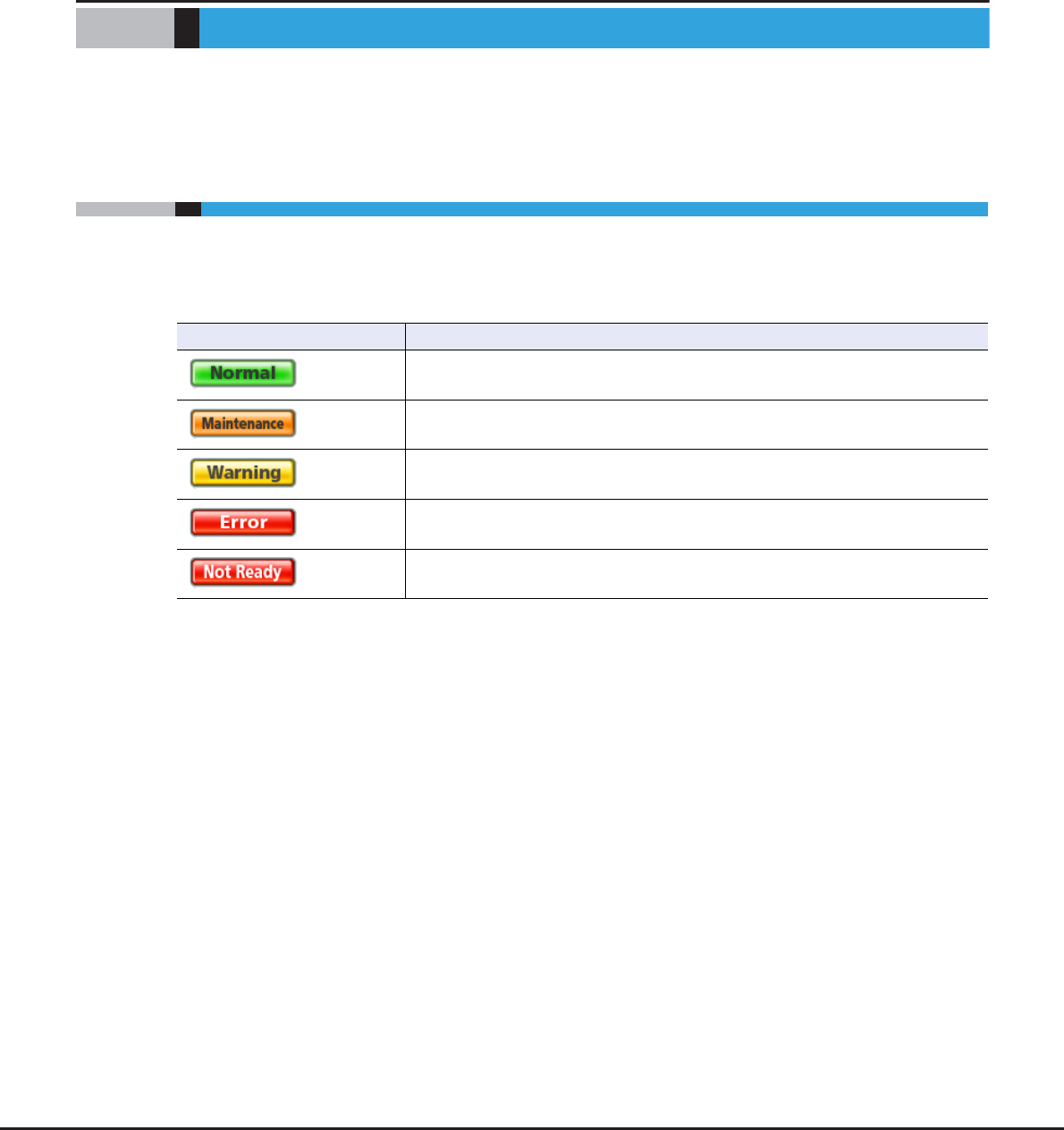
ETERNUS Web GUI User’s Guide
Copyright 2013 FUJITSU LIMITED P2X0-1090-10ENZ0
972
Appendix B
Status List
This chapter describes the meaning of status icon.
B.1 Device General Status
The general status of the ETERNUS DX Disk storage system is displayed as an icon with character strings.
A "Normal (green)" general status icon indicates normal status, while other color images indicate a failure.
The meaning of each general status icon is described below.
Device general status Description
(Green) The ETERNUS DX Disk storage system is in normal state.
(Orange) The ETERNUS DX Disk storage system is under maintenance.
(Yellow) The ETERNUS DX Disk storage system is in warning state.
(Red) The ETERNUS DX Disk storage system is in failed status.
(Red)
"Not Ready" is a status where an abnormality is detected at a power-off, and I/O
access from the host cannot be received.
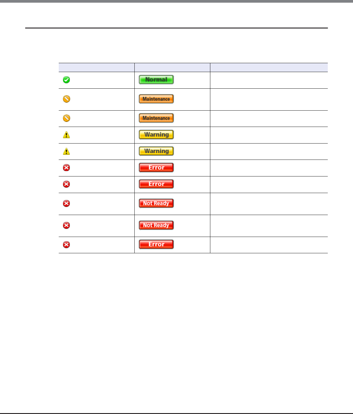
Appendix B Status List
B.1 Device General Status
ETERNUS Web GUI User’s Guide
Copyright 2013 FUJITSU LIMITED P2X0-1090-10ENZ0
973
B.1.1 Device General Status (Detail)
The detailed information of the ETERNUS DX Disk storage system general status is displayed with an icon and
character strings in the [Storage] screen under the [Component] navigation.
The meaning of ETERNUS DX Disk storage system general status (detail) is described below.
Device general status (detail) Device general status Description
Normal (Green)
The ETERNUS DX Disk storage system is in normal
state.
Maintenance (Orange)
Components that are undergoing maintenance
exist in the ETERNUS DX Disk storage system.
Rebuild or copyback is being performed.
Change Controlling CM (Orange)
Changing of the controlling CM is required.
Pinned Data (Yellow)
Pinned data is detected.
Warning (Yellow)
A component requires preventive maintenance.
A bad sector is detected.
Error (Red)
A component has an error.
Loop Down (Red)
There is a SAS cascade that cannot access all of
the DEs due to an error.
Not Ready (Red)
A failure is detected when starting or turning off
the ETERNUS DX Disk storage system. I/O from the
host cannot be received normally.
Subsystem Down (Red)
The ETERNUS DX Disk storage system is in failed
status. I/O from the host cannot be received
normally.
Unknown (Red)
A status other than the ones listed above.
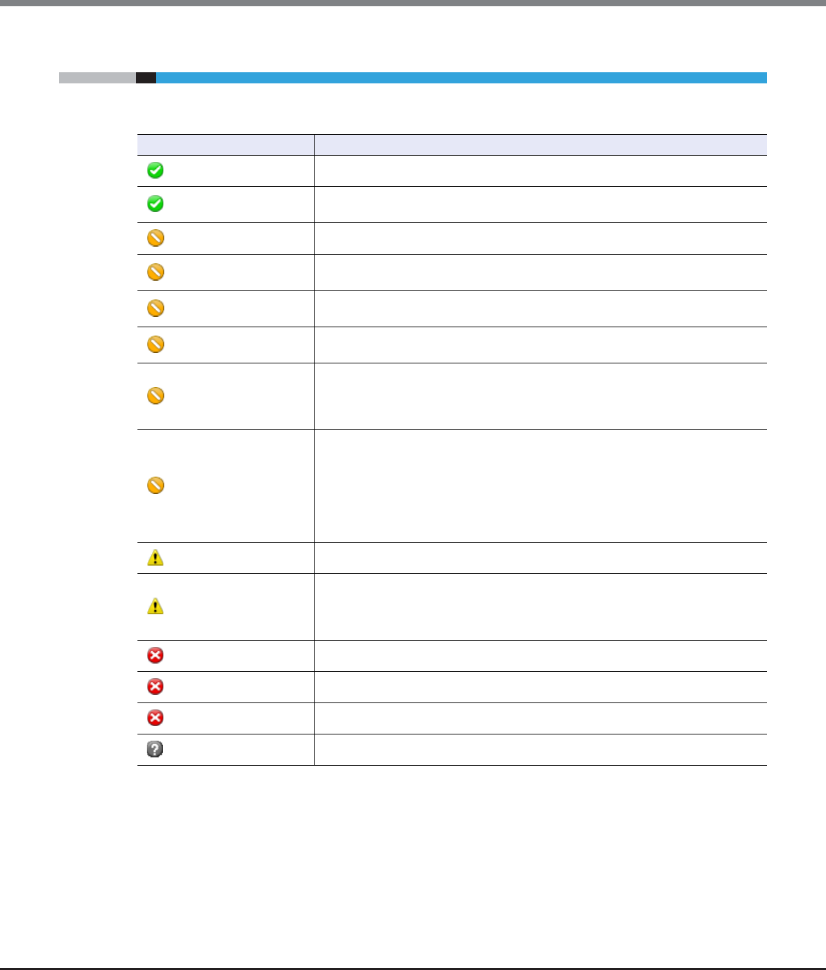
Appendix B Status List
B.2 Volume Status
ETERNUS Web GUI User’s Guide
Copyright 2013 FUJITSU LIMITED P2X0-1090-10ENZ0
974
B.2 Volume Status
Volume status is displayed with an icon and the status name. The volume status is described below.
Status Description
Available The volume is operating normally.
Spare in Use The RAID group to which the volume belongs manages redundancy by using the hot
spare disk.
Readying The volume is not formatted.
Rebuild Rebuilding from a failed data disk to the hot spare disk or to the replaced disk is
being performed in the RAID group to which the volume belongs.
Copyback Copyback is being performed from the hot spare disk to the new data disk in the
RAID group to which the volume belongs.
Redundant Copy Redundant copy to the hot spare disk is being performed in the RAID group to which
the volume belongs.
Partially Exposed Rebuild
Rebuilding from the first failed data disk to the hot spare disk or to the replaced disk
is being performed in the RAID group to which the volume belongs.
This status is displayed only when the RAID type of the RAID group to which the
volume belongs is "High Reliability (RAID6)".
Exposed Rebuild
Two of the data disks for the RAID group to which the volume belongs have failed.
Rebuilding from the first failed data disk to the hot spare disk or to the replaced disk
is being performed. In addition, all the hot spare disks have already been used. As a
result, the second failed data disk is waiting for the hot spare disk to become
available.
This status is displayed only when the type of the RAID group to which the volume
belongs is "High Reliability (RAID6)".
Exposed The RAID group to which the volume belongs lost redundancy due to disk failure.
Partially Exposed
One of the disks that configures the RAID group to which the volume belongs has
failed.
This status is displayed only when the type of the RAID group to which the volume
belongs is "High Reliability (RAID6)".
Not Ready The RAID group to which the volume belongs is blocked.
Broken The volume is broken.
Data Lost Data in the volume is lost. Reading or writing of data cannot be performed.
Unknown A status other than the ones listed above.
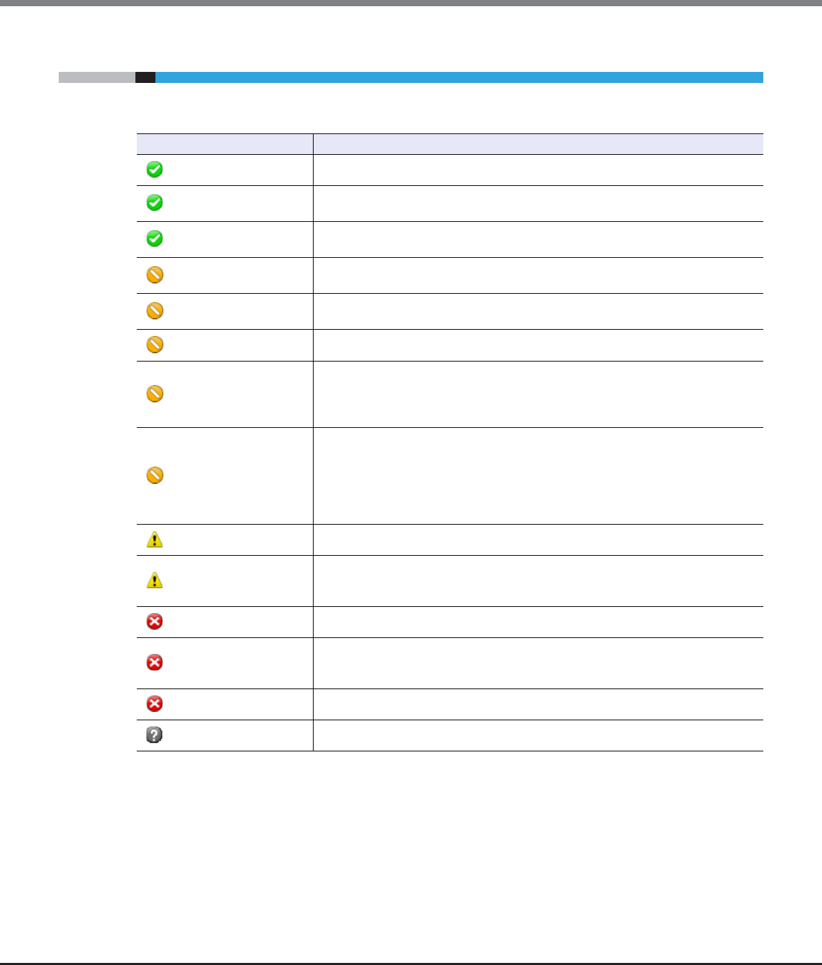
Appendix B Status List
B.3 RAID Group Status
ETERNUS Web GUI User’s Guide
Copyright 2013 FUJITSU LIMITED P2X0-1090-10ENZ0
975
B.3 RAID Group Status
RAID group status is displayed with an icon and the status name. The RAID group status is described below.
Status Description
Available The RAID group is operating normally.
Spare in Use Rebuilding to the hot spare disk is complete. The RAID group manages redundancy
by using the hot spare disk.
Readying The RAID group that is registered as an REC Disk Buffer is not formatted. This status is
displayed only for a RAID group that is registered as an REC Disk Buffer.
Rebuild Rebuilding from a failed data disk to the hot spare disk or to the replaced disk is
being performed in the RAID group.
Copyback Copyback from the hot spare disk to the new data disk is being performed in the
RAID group.
Redundant Copy Redundant copy to the hot spare disk is being performed in the RAID group.
Partially Exposed Rebuild
Rebuilding from the first failed data disk to the hot spare disk or to the replaced disk
is being performed in the RAID group.
This status is displayed only when the RAID type of the RAID group is "High Reliability
(RAID6)".
Exposed Rebuild
Two of the data disks for the RAID group have failed. Rebuilding from the first failed
data disk to the hot spare disk or to the replaced disk is being performed. In
addition, all the hot spare disks have already been used. As a result, the second
failed data disk is waiting for the hot spare disk to become available.
This status is displayed only when the RAID type of the RAID group is "High Reliability
(RAID6)".
Exposed The RAID group lost redundancy due to disk failure.
Partially Exposed
One of the disks that configures the RAID group has failed.
This status is displayed only when the type of the RAID group is "High Reliability
(RAID6)".
No Disk Path The RAID group is blocked.
SED Locked
The RAID group is blocked.
If an SED authentication key cannot be obtained from the key server, "SED Locked" is
displayed.
Broken The RAID group is broken.
Unknown A status other than the ones listed above.
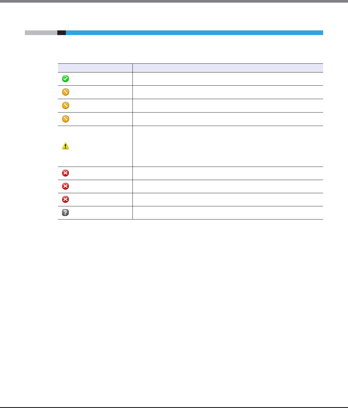
Appendix B Status List
B.4 Thin Provisioning Pool Status
ETERNUS Web GUI User’s Guide
Copyright 2013 FUJITSU LIMITED P2X0-1090-10ENZ0
976
B.4 Thin Provisioning Pool Status
Thin Provisioning Pool (TPP) status is displayed with an icon and the status name. The TPP status is described
below.
Status Description
Available The TPP is operating normally.
Maintenance Forcible recovery of the TPP is being performed.
Readying All the physical area in the TPP is not formatted.
Partially Readying Some parts of the physical area in the TPP is not formatted.
Exposed
The TPP is available.
The "Exposed" status of the TPP is displayed not only when the RAID group that
configures the TPP has lost redundancy and is in "Exposed" status, but also when the
RAID group maintains redundancy in "Spare in Use" status. The "Exposed" status of
TPP indicates that the RAID group in the TPP is not in normal status because of any
causes such as the disk failure.
Blockade The TPP is blocked.
Broken The TPP is broken.
Data Lost Data in the TPP is lost. Reading or writing of data cannot be performed.
Unknown A status other than the ones listed above.
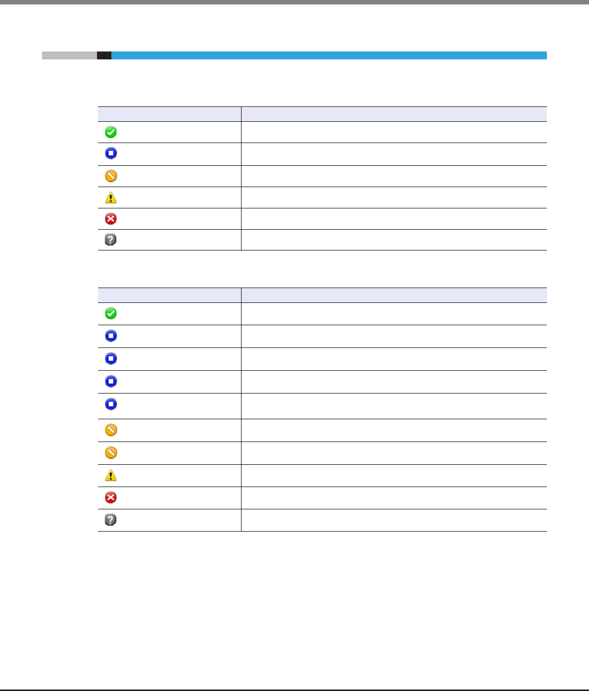
Appendix B Status List
B.5 Component Status
ETERNUS Web GUI User’s Guide
Copyright 2013 FUJITSU LIMITED P2X0-1090-10ENZ0
977
B.5 Component Status
This section explains the component status.
The status of the components is displayed with an icon for each device image in the view screen.
In the list screen and the detailed information screen, the status of the components is displayed with an icon
and the status name.
Status Description
The component is operating normally.
The component is installed, but not used.
The component is under maintenance.
The component requires preventive maintenance.
An error has occurred in the component.
A status other than the ones listed above.
Status Description
Normal The component is operating normally.
Unconnected A faulty component exists in the ETERNUS DX Disk storage system.
Undefined The component is installed, but not used.
Undefined (Error) The component, which is not being used, is in error state.
Normal (Unused parts inside) There is an unused component that is installed in the ETERNUS DX Disk storage
system.
Check1 The component is being rebooted.
Maintenance The component is under maintenance.
Warning The component requires preventive maintenance.
Error An error has occurred in the component.
Unknown A status other than the ones listed above.
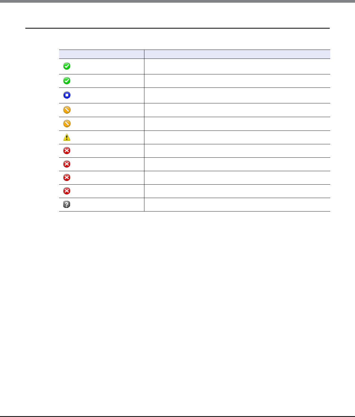
Appendix B Status List
B.5 Component Status
ETERNUS Web GUI User’s Guide
Copyright 2013 FUJITSU LIMITED P2X0-1090-10ENZ0
978
B.5.1 Drive Status
Drive status is displayed with an icon and the status name. The drive status is described below.
Status Description
Available The drive is in normal status.
The drive is used in the RAID group.
Spare The drive is an unused hot spare.
Present The drive is not used (not registered as a RAID group or hot spare), or is waiting
for rebuild/copy back.
Readying The drive is starting up.
Rebuild/Copyback Rebuild or copy back is being performed in the drive.
Redundant Copy A Redundant copy is being performed in the drive.
Not Supported The drive is not supported. [Example] Drive capacity is insufficient.
Not Exist The drive cannot be recognized.
Failed Usable An error involving RAID group failure has occurred in the drive.
Broken An error has occurred in the drive.
Unknown A status other than the ones listed above.

Appendix B Status List
B.6 Key Status
ETERNUS Web GUI User’s Guide
Copyright 2013 FUJITSU LIMITED P2X0-1090-10ENZ0
979
B.6 Key Status
Key status is displayed with the status name. The key status is described below.
*1: "Self-signed SSL certificate" or "SSL server certificate"
Status Description
Normal A valid key is registered for the SEDs. The key is in normal state.
Unregistered Server Certificate
The "SSL / KMIP Certificate" (key server certification) is not registered in the
ETERNUS DX Disk storage system. Communication between the ETERNUS DX Disk
storage system and the key server cannot be performed.
Expired Server Certificate
The "SSL / KMIP Certificate" (key server certification) has expired. Communication
between the ETERNUS DX Disk storage system and the key server cannot be
performed.
No SSL Certificate
An SSL certificate (*1) for the ETERNUS DX Disk storage system has not been
created. Communication between the ETERNUS DX Disk storage system and the
key server cannot be performed.
Network Error The key cannot be obtained due to a network error between the ETERNUS DX Disk
storage system and the key server.
Not Acquired
The required key for starting key server management is not obtained.
The allocation of the Master server and the Slave server to the key group has
been deleted.
Expiration An expired key is registered in the SED.
The key has expired, but a new key can be obtained from the server.
Key Server Error The network between the ETERNUS DX Disk storage system and the key server is
in normal status, but no SED key is stored in the key server.
Modifying
A RAID group in which the key is being modified exists in the key group.
"RAID group of which key is modifying" indicates the following conditions:
•The key is being updated manually from GUI or CLI
•The key is automatically being updated because it expired
•Updating of the key stopped due to an error
•SEDs are maintained while a network error occurs when the security level is
"Low"

Appendix B Status List
B.7 Key Server Status
ETERNUS Web GUI User’s Guide
Copyright 2013 FUJITSU LIMITED P2X0-1090-10ENZ0
980
B.7 Key Server Status
Key server status is displayed with the status name. The key server status is described below.
*1: "Self-signed SSL certificate" or "SSL server certificate"
Status Description
Normal
The communication between the ETERNUS DX Disk storage system and the key
server is normal. The key can be obtained successfully. The key server is in
normal state.
Setting
"Setting" indicates the following conditions:
•The "SSL / KMIP Certificate" (key server certification) or SSL certificate (*1) is
not registered.
•The network between the ETERNUS DX Disk storage system and the key
server is normal, but connection to the key server is forbidden.
Network Error The network between the ETERNUS DX Disk storage system and the key server is
not connected normally.
Key Acquisition Failure The key that is requested from the ETERNUS DX Disk storage system does not
exist in the key server.
Key Server Error An error due to a failure other than key acquisition failure is detected.
Internal Error Communication to the key server could not be performed due to an internal
failure of the ETERNUS DX Disk storage system.
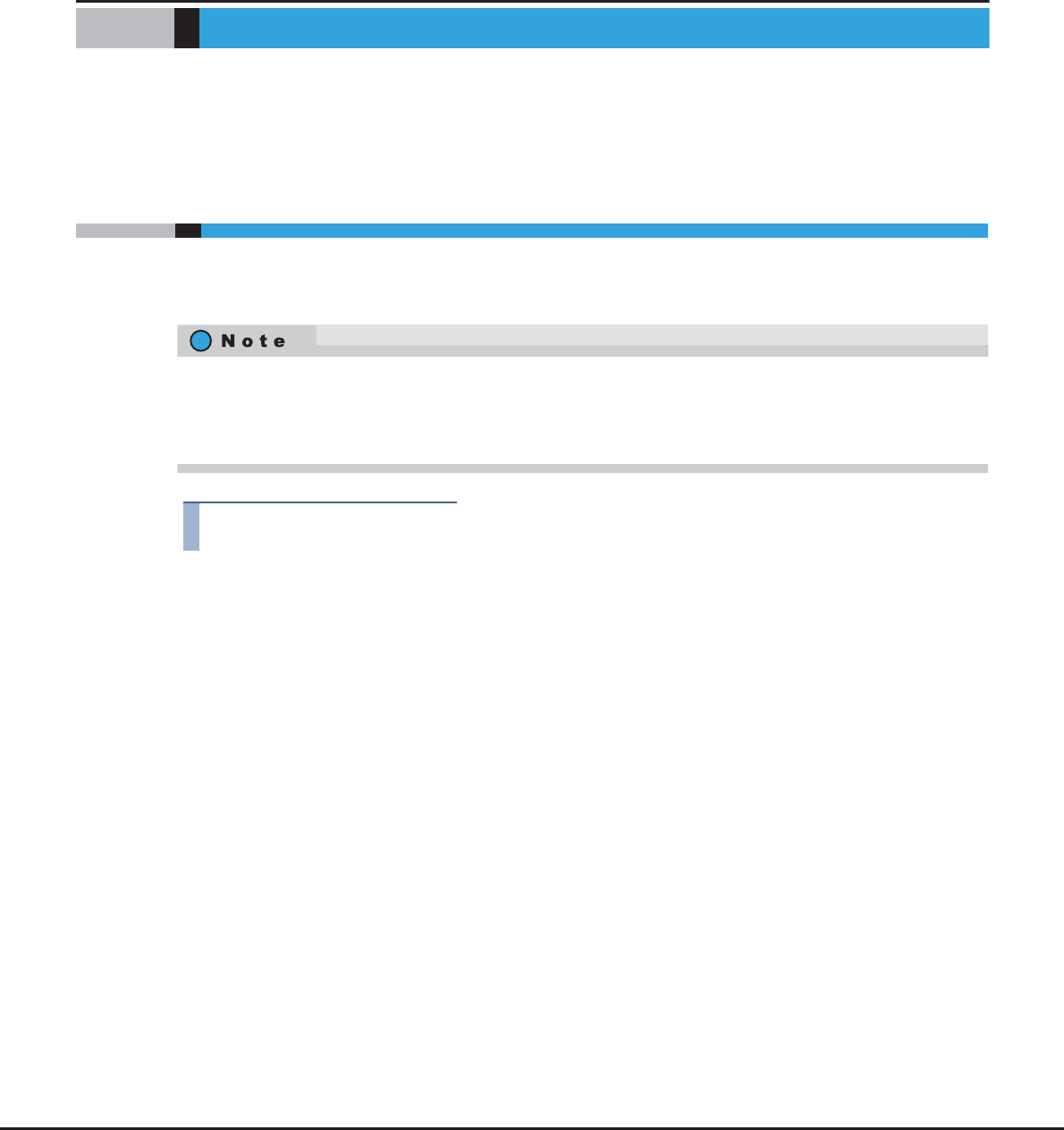
ETERNUS Web GUI User’s Guide
Copyright 2013 FUJITSU LIMITED P2X0-1090-10ENZ0
981
Appendix C
Installing the Security Certificate
This chapter describes how to install the web-site certificate.
This chapter provides an example of when using Internet Explorer and Firefox.
C.1 For Internet Explorer
This section describes the procedure to install security certificate.
The procedure to install security certificate for Internet Explorer 8 is as follows:
Procedure
1Enter the URL to the address bar in the web browser.
Specify "https://IP address of the ETERNUS DX Disk storage system" (Default IP address is
"192.168.1.1").
→A confirmation screen for security certificate appears.
Register the URL of the ETERNUS DX Disk storage system in "Trusted Sites" before installing the security
certificate.
Use the Internet Option and specify the URL to be used for connecting to the ETERNUS DX Disk storage
system (https ://IP address of the ETERNUS DX Disk storage system) to the "Trusted Sites".
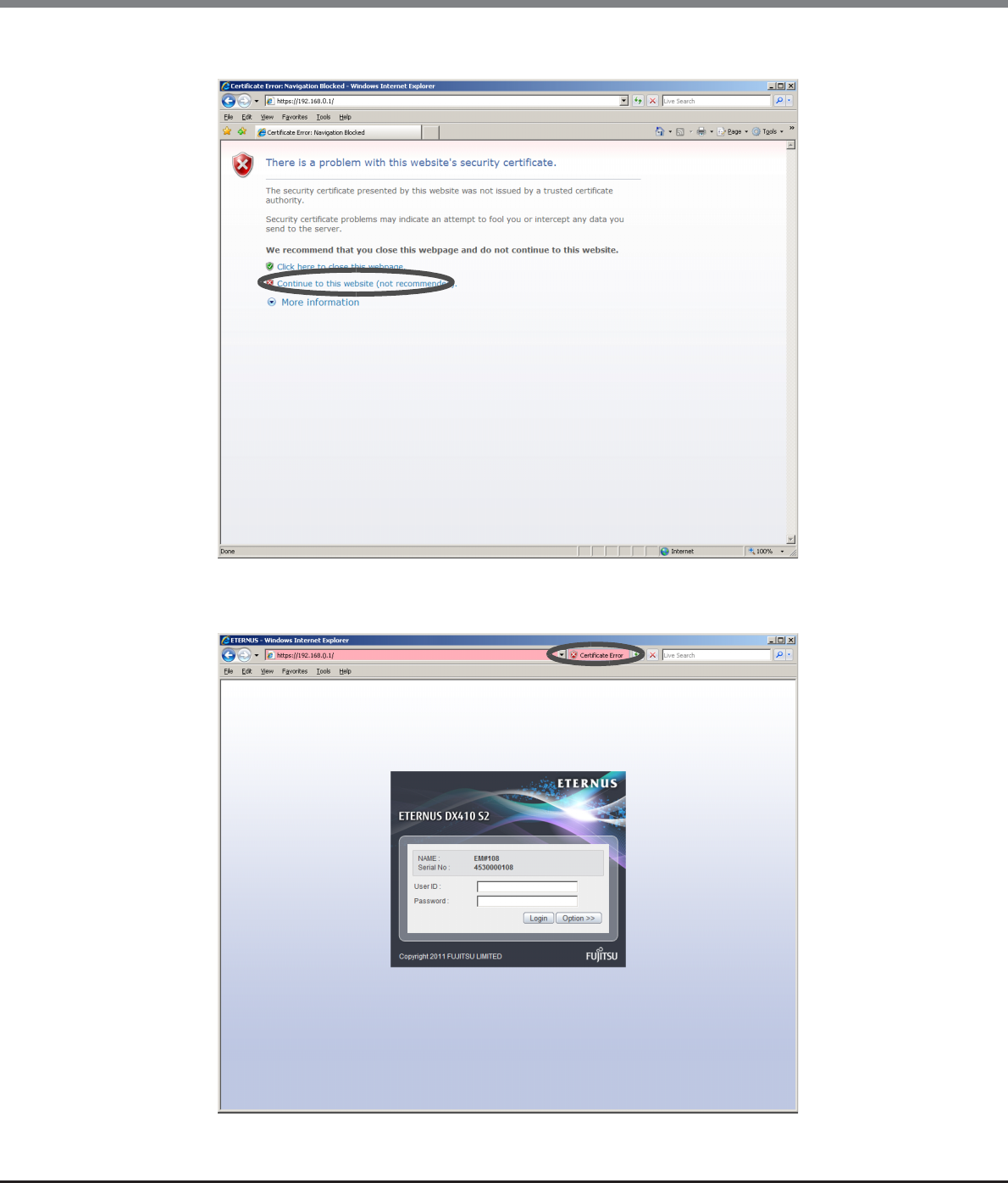
Appendix C Installing the Security Certificate
C.1 For Internet Explorer
ETERNUS Web GUI User’s Guide
Copyright 2013 FUJITSU LIMITED P2X0-1090-10ENZ0
982
2Click the [Continue to this website (not recommended)] link.
→The login screen for GUI is displayed.
3Click the "Certificate Error".
→A warning message appears.
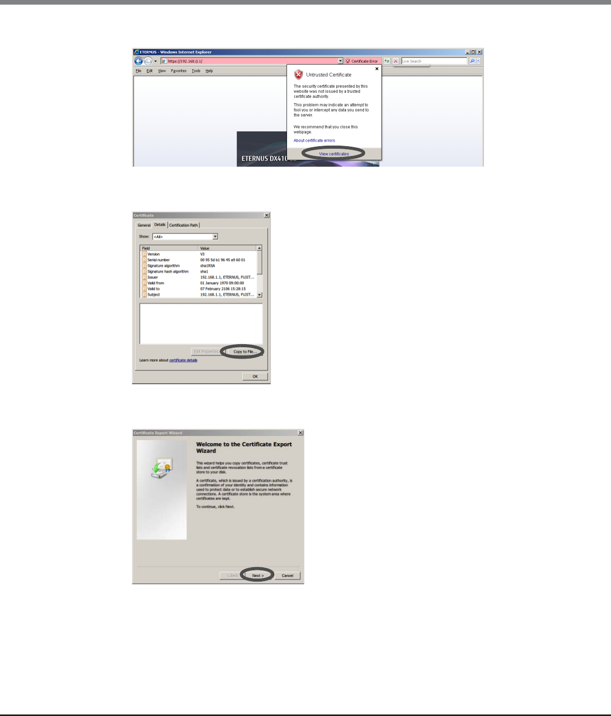
Appendix C Installing the Security Certificate
C.1 For Internet Explorer
ETERNUS Web GUI User’s Guide
Copyright 2013 FUJITSU LIMITED P2X0-1090-10ENZ0
983
4Click the [View certificates] link.
→The site certificate information appears.
5Click the [Copy to File...] button on the [Details] tab.
→The [Certificate Export Wizard] screen appears.
6Click the [Next >] button.
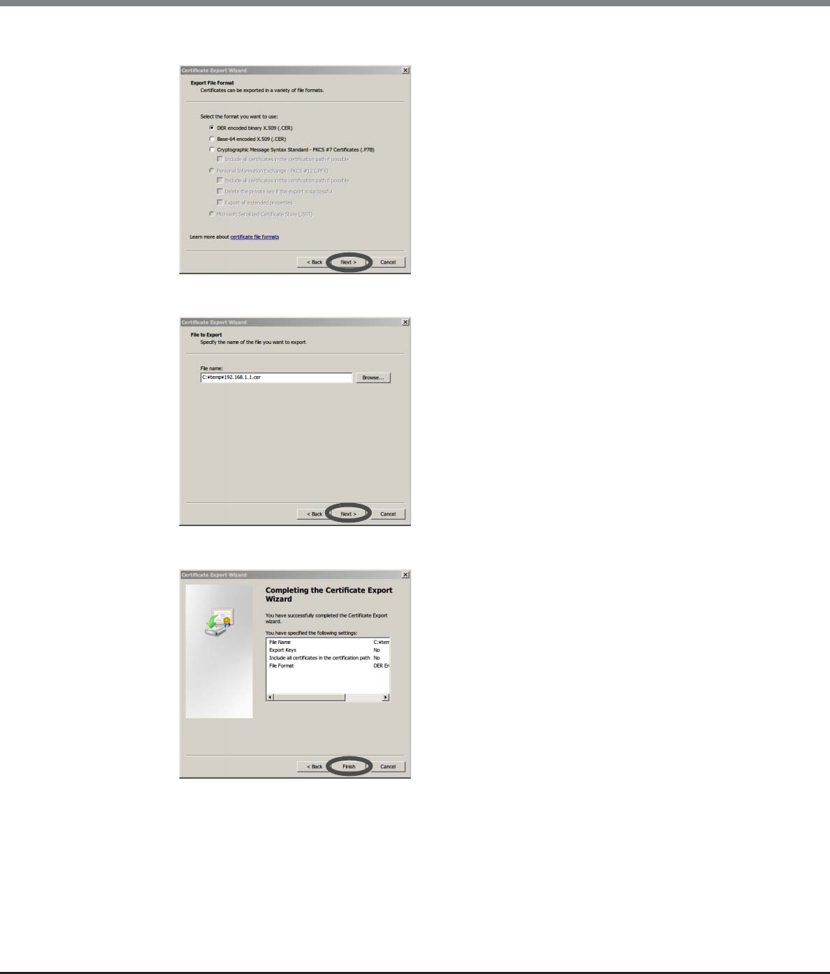
Appendix C Installing the Security Certificate
C.1 For Internet Explorer
ETERNUS Web GUI User’s Guide
Copyright 2013 FUJITSU LIMITED P2X0-1090-10ENZ0
984
7Select "DER encoded binary X.509 (.CER)" and click the [Next >] button.
8Select the file name that is to be exported, and then click the [Next >] button.
9Click the [Finish] button.
→The information of the exported certificate is displayed.
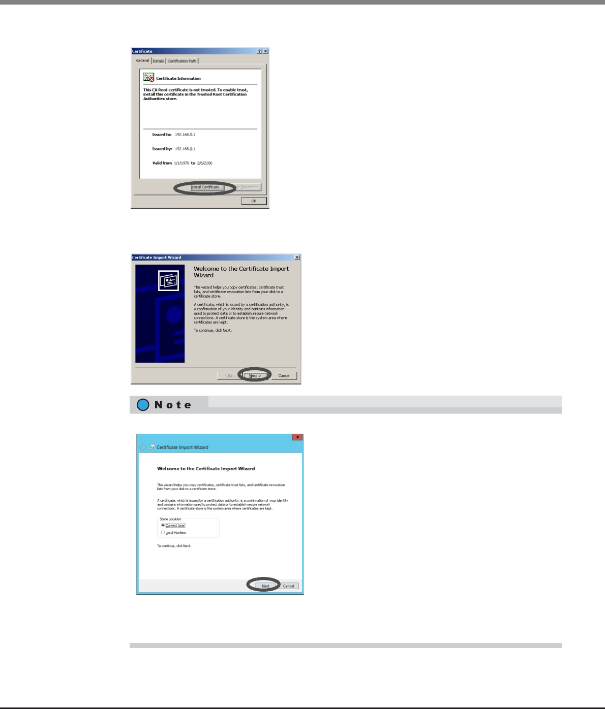
Appendix C Installing the Security Certificate
C.1 For Internet Explorer
ETERNUS Web GUI User’s Guide
Copyright 2013 FUJITSU LIMITED P2X0-1090-10ENZ0
985
10 Click the [Install Certificate] button on the [General] tab.
→The [Certificate Import Wizard] screen appears.
11 Click the [Next >] button.
The following screen is displayed when using Internet Explorer 10.0.
Select "Current User" or "Local Machine" on the start screen.
To accept only the currently logged in user with the current PC, select "Current User".
To accept other users that log in with the current PC, select "Local Machine".
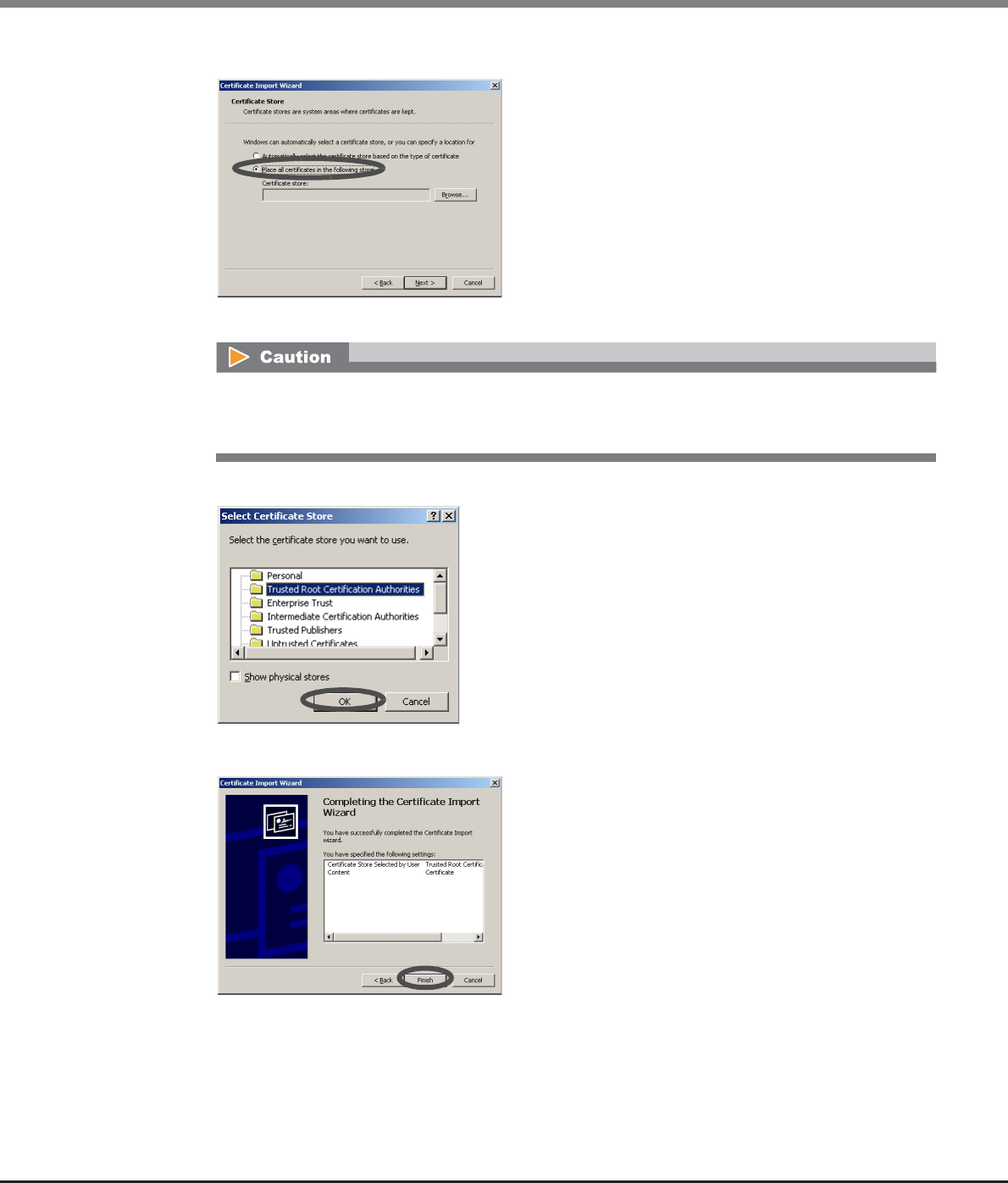
Appendix C Installing the Security Certificate
C.1 For Internet Explorer
ETERNUS Web GUI User’s Guide
Copyright 2013 FUJITSU LIMITED P2X0-1090-10ENZ0
986
12 Select "Place all certificates in the following store".
→The [Select Certificate Store] screen appears.
13 Select the "Trusted Root Certification Authorities", and click the [OK] button.
14 Click the [Finish] button.
→The [Security Warning] dialog box appears.
If "Automatically select the certificate store based on the type of certificate" is selected in the
"Certificate Import Wizard", an error may occur in the security certificate according to the customer
environment.
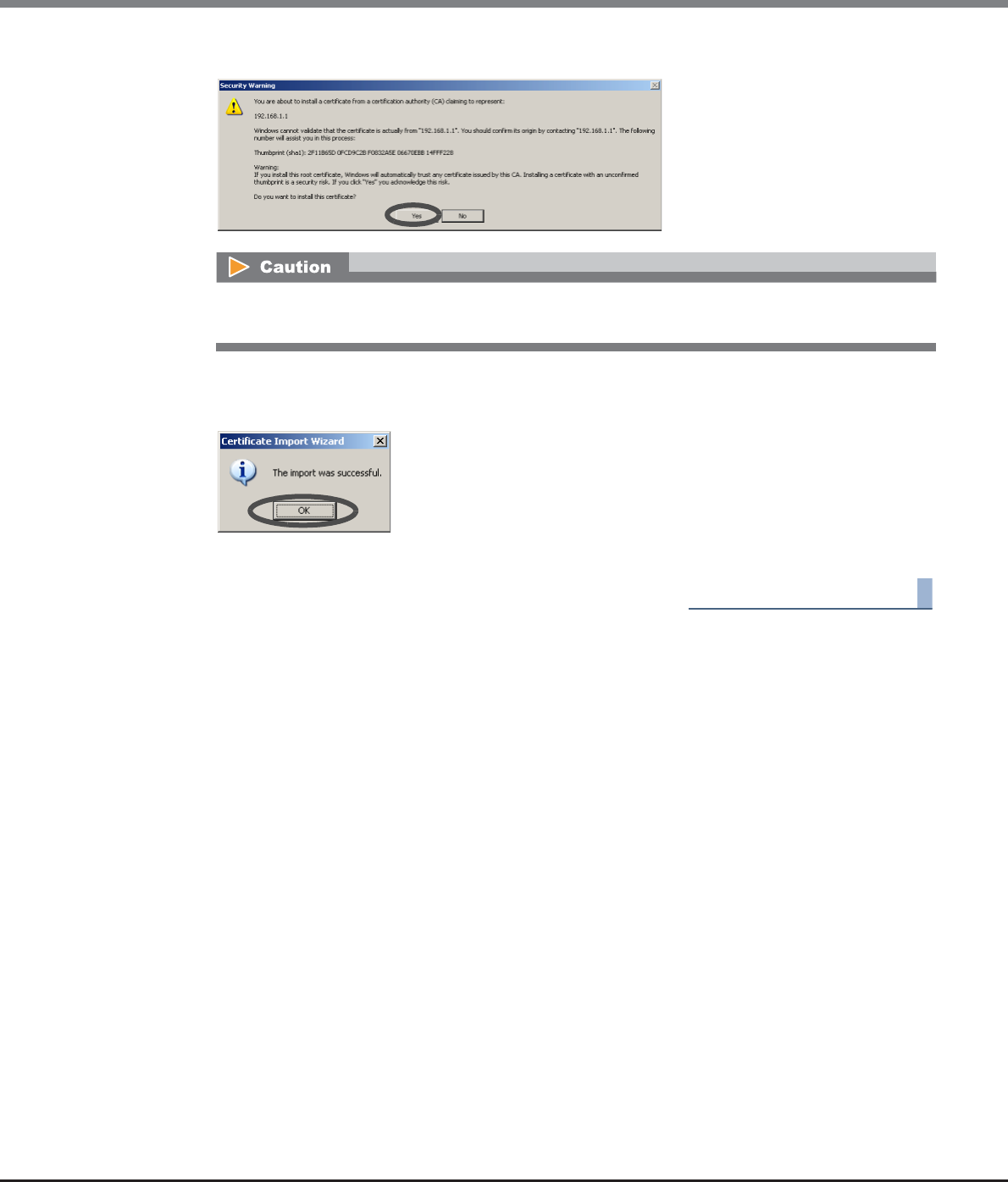
Appendix C Installing the Security Certificate
C.1 For Internet Explorer
ETERNUS Web GUI User’s Guide
Copyright 2013 FUJITSU LIMITED P2X0-1090-10ENZ0
987
15 Click the [Yes] button.
→The completion screen appears.
16 Click the [OK] button.
→The security certificate is installed. Restart the web browser.
End of procedure
After clicking the [No] button, the operation may not be continuable. If this occurs, restart the web
browser.
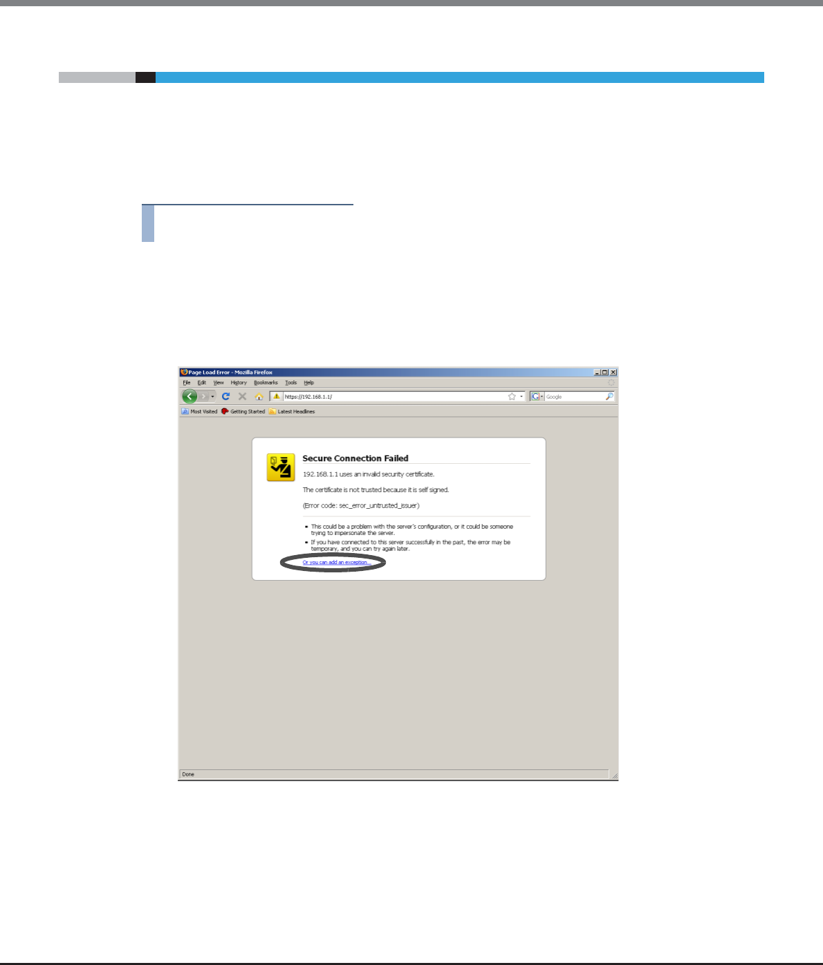
Appendix C Installing the Security Certificate
C.2 For Firefox
ETERNUS Web GUI User’s Guide
Copyright 2013 FUJITSU LIMITED P2X0-1090-10ENZ0
988
C.2 For Firefox
This section provides the procedure to install the security certificate.
The example when installing security certificate for Firefox 3.6. X is as follows:
■When installing a new security certificate
Procedure
1Enter the URL to the address bar in the web browser.
Specify "https://IP address of the ETERNUS DX Disk storage system" (Default IP address is
"192.168.1.1").
→A confirmation screen for security certificate appears.
2Click the "Or you can add an exception..." link.
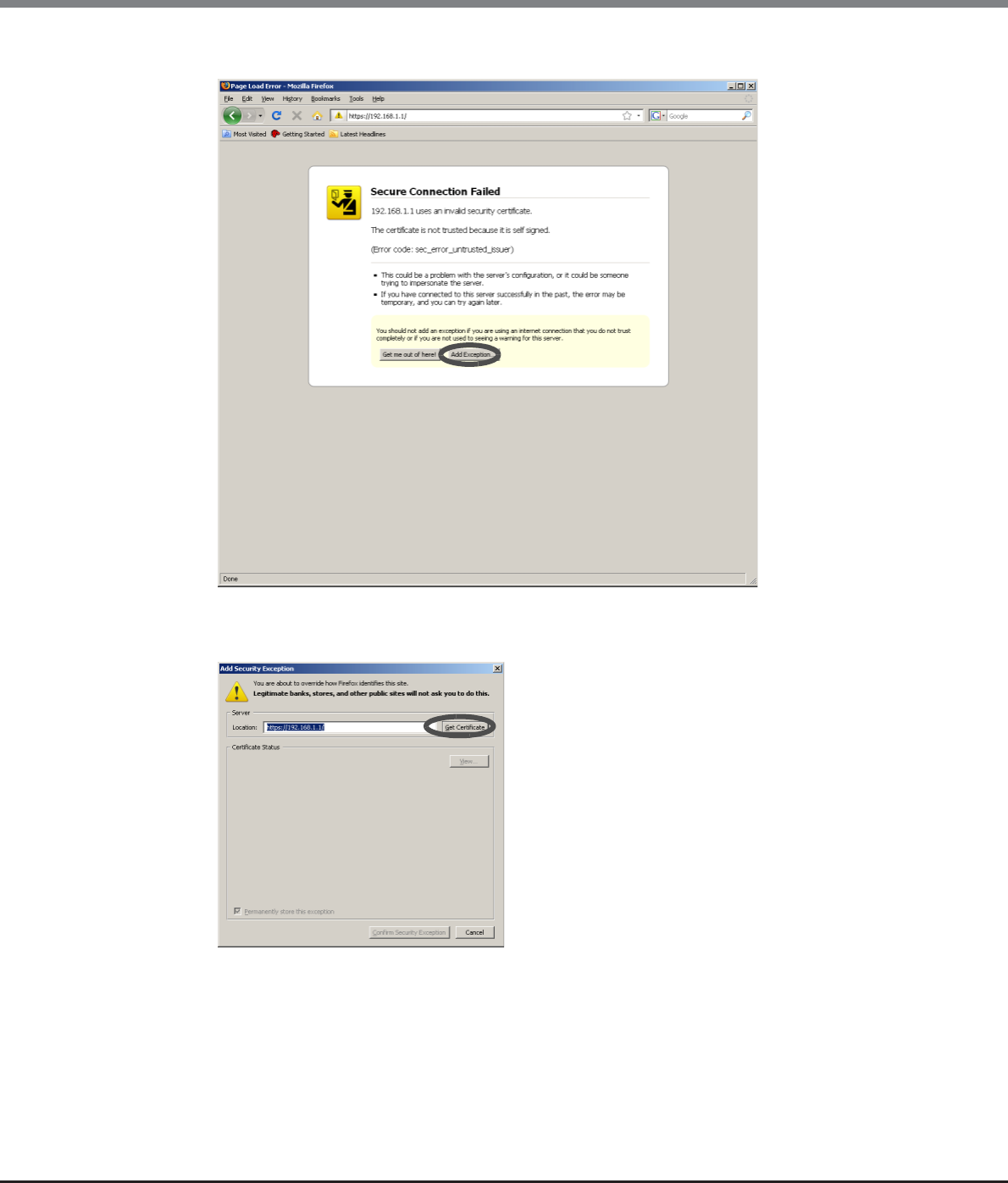
Appendix C Installing the Security Certificate
C.2 For Firefox
ETERNUS Web GUI User’s Guide
Copyright 2013 FUJITSU LIMITED P2X0-1090-10ENZ0
989
3Click the [Add Exception...] button.
→The [Add Exception] screen appears.
4Click the [Get Certificate] button.
→The status of certificate is displayed.
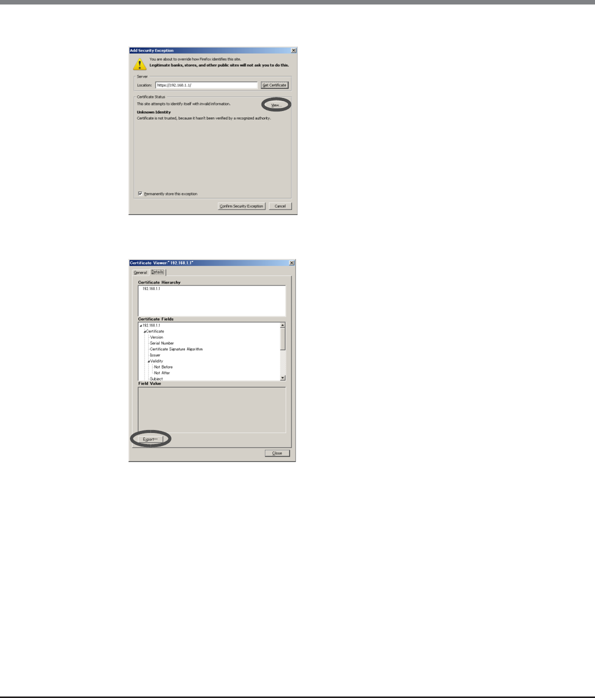
Appendix C Installing the Security Certificate
C.2 For Firefox
ETERNUS Web GUI User’s Guide
Copyright 2013 FUJITSU LIMITED P2X0-1090-10ENZ0
990
5Click the [View...] button.
→The [Certificate Viewer] screen appears.
6Click the [Export...] button on the [Details] tab.
7Specify the file name and save the certificate.
→Returns to the [Add Security Exception] screen.
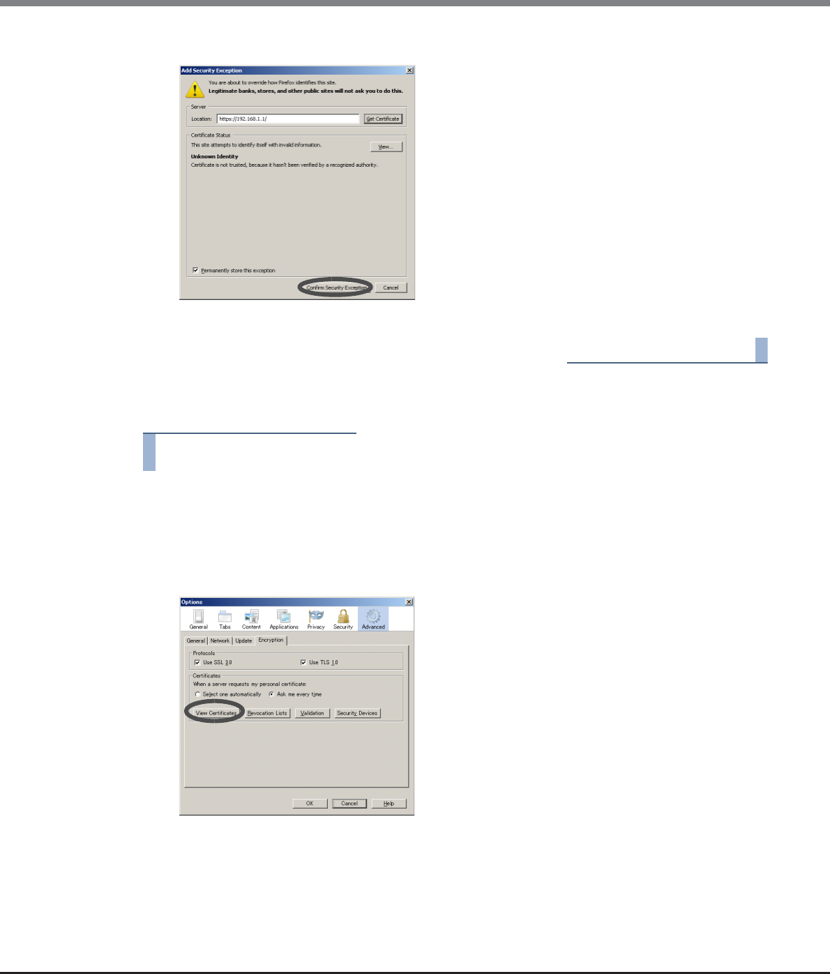
Appendix C Installing the Security Certificate
C.2 For Firefox
ETERNUS Web GUI User’s Guide
Copyright 2013 FUJITSU LIMITED P2X0-1090-10ENZ0
991
8Click the [Confirm Security Exception] button.
→The security certificate is installed. Restart the web browser.
End of procedure
■When a security certificate is already registered
Procedure
1Enter the URL to the address bar in the web browser.
Specify "https://IP address of the ETERNUS DX Disk storage system" (Default IP address is
"192.168.1.1").
2Select [Tools] → [Options] → [Advanced], and click the [View Certificates] button on the
[Encryption] tab.
→The [Certificate Manager] screen appears.
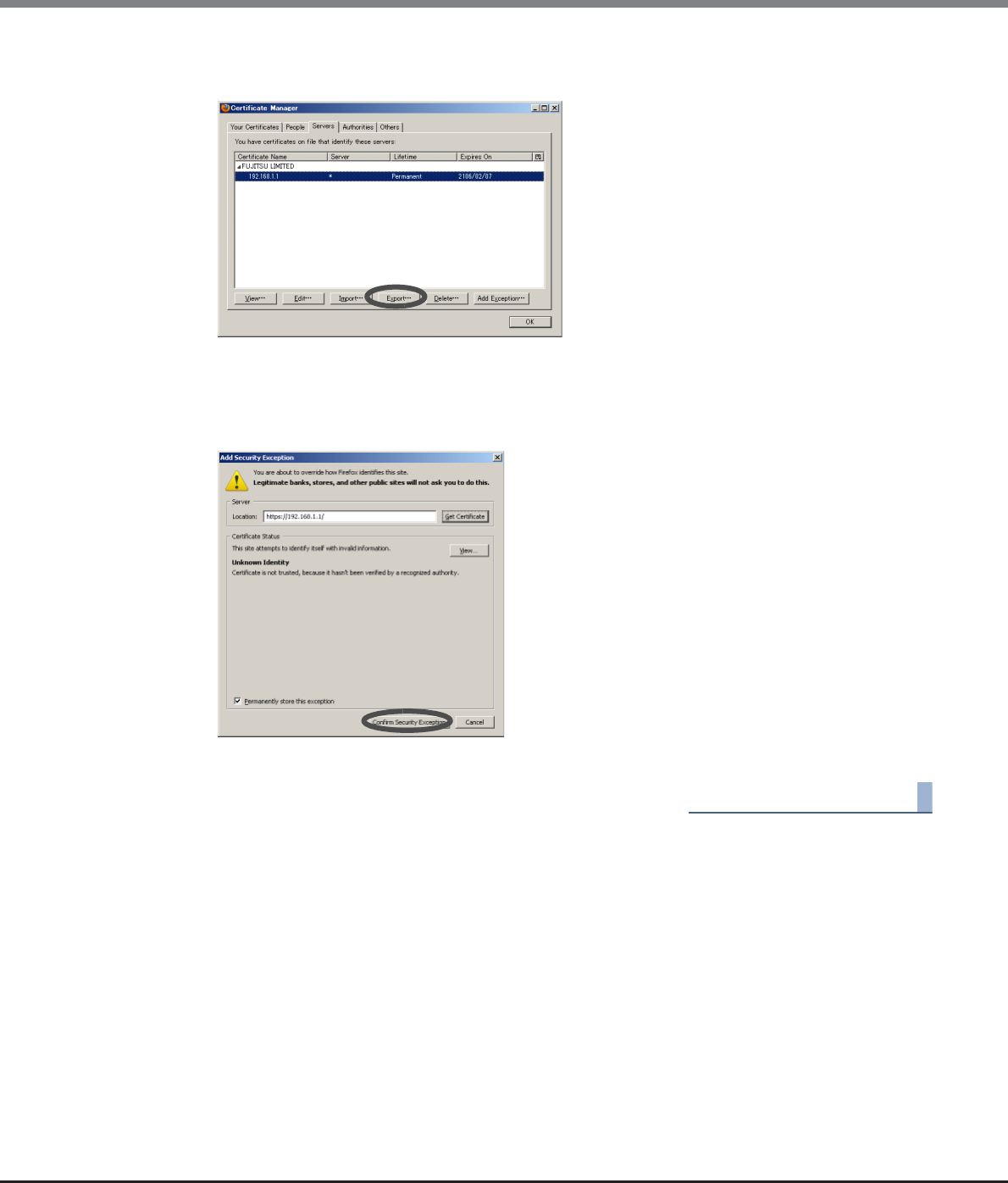
Appendix C Installing the Security Certificate
C.2 For Firefox
ETERNUS Web GUI User’s Guide
Copyright 2013 FUJITSU LIMITED P2X0-1090-10ENZ0
992
3Select the certificate for the IP address of "ETERNUS server" on the [Servers] tab, and then
click the [Export] button.
4Specify the file name and save the certificate.
→The [Add Security Exception] screen appears.
5Click the [Confirm Security Exception] button.
→The security certificate is installed. Restart the web browser.
End of procedure

ETERNUS Web GUI User’s Guide
Copyright 2013 FUJITSU LIMITED P2X0-1090-10ENZ0
993
Appendix D
Naming Conventions of Volumes and Hosts
This chapter describes the naming conventions for volumes and hosts.
D.1 Naming Convention of Volumes
■Naming conventions for creating volumes
The following naming conventions apply when creating volumes:
•When creating multiple volumes, the specified "Name" and the suffix numbers "x" (serial numbers starting
with "0") are automatically added to volumes.
[Example]
When specifying "StandardVolume" (14 characters) as the volume name
Names such as "StandardVolume0" and "StandardVolume1" are used for new volumes.
•When the volume name including the suffix number "x" has more than 16 characters, the excess number
of characters is deleted from the "Name", starting with the last character and a suffix number "~x" will be
added. Then, the name will contain only 16 characters.
[Example]
When specifying "Standard_Volume0" (16 characters) as the volume name
Names such as "Standard_Volume~0" and "Standard_Volume~1" are used for new volumes.
•When a volume name including the suffix number already exists, the suffix number is increased by one
(+1). The suffix number is increased by one (+1) until no volume names overlap.
■Naming conventions for renaming volumes
The following naming conventions apply when renaming volumes.
•When changing multiple volume names, the specified "Name" and the suffix numbers "x" are
automatically added to volumes. Note that if the start suffix is "00" or "000", "0" will be added to the
"Name".
[Example]
When specifying "StandardVolume" (14 characters) as the volume name and specifying "1" for "Start of
Suffix"
Names such as "StandardVolume1" and "StandardVolume2" are used for new volumes.
•When the volume name including the suffix number has more than 16 characters, the excess number of
characters is deleted from the "Name", starting with the last character and a suffix number "~x" will be
added. Then, the name will contain only 16 characters.
[Example]
When specifying "Standard_Volume1" (16 characters) as the volume name and specifying "100" for
"Start of Suffix"
Names such as "Standard_Volume~100" and "Standard_Volume~101" are used for new volumes.
•When a volume name including the suffix number already exists, the suffix number is increased by one
(+1). The suffix number is increased by one (+1) until no volume names overlap.

Appendix D Naming Conventions of Volumes and Hosts
D.2 Naming Convention of Hosts
ETERNUS Web GUI User’s Guide
Copyright 2013 FUJITSU LIMITED P2X0-1090-10ENZ0
994
D.2 Naming Convention of Hosts
■Naming conventions for adding hosts
The following naming conventions apply when adding hosts:
•A name is automatically added to a host with the "host group name" and a suffix number "_x" (serial
numbers starting with "0").
[Example]
When specifying "HOST_Group_001" (14 characters) as the host group name
Names such as "HOST_Group_001_0" and "HOST_Group_001_1" are used for host groups.
•When the host name including the suffix number "_x" has more than 16 characters, the excess number of
characters is deleted from the "host group name", starting with the last character and a suffix number "~x"
will be added. Then, the name will contain only 16 characters.
[Example]
When specifying "HOST_Group_ABCDE" (16 characters) as the host group name
Names such as "HOST_Group_ABC~0" and "HOST_Group_ABC~1" are used for host groups.
•When a host name including the suffix number already exists, the suffix number is increased by one (+1).
The suffix number is increased by one (+1) until no host names overlap.
•The hosts, which were selected on the [Now Connected] screen, are named, and then the hosts, which
were specified on the [Manual Input] screen, are named next.
•The name of the existing member host will not be changed.

ETERNUS Web GUI User’s Guide
Copyright 2013 FUJITSU LIMITED P2X0-1090-10ENZ0
995
Appendix E
Basic Size and MWC Input Condition for RAID
Groups
This chapter describes the basic size for each RAID type and the input conditions for the Multi Writeback Count
(MWC) of each RAID group.
E.1 Basic Size for each RAID Group
This section describes the basic size for each RAID type.
The allowed input for the basic size varies depending on the RAID type, the drive configuration, and the Stripe
Depth value.
E.1.1 Basic Size when Using the Default Stripe Depth Value (For Standard, TPV, or
SDPV Type Volumes)
When using the default Stripe Depth value, refer to the following table for basic size:
■Basic size of each RAID group when using the default Stripe Depth value
RAID type Drive configuration (*1) Basic size (MB) (Lowest exact MB multiple) (*2)
(Stripe Depth = 64KB (default))
Mirroring (RAID1) 1D+1M 1
High Performance
(RAID1+0)
2D+2M 1
3D+3M 3
4D+4M 1
5D+5M 5
6D+6M 3
7D+7M 7
8D+8M 1
9D+9M 9
10D+10M 5
11D+11M 11
12D+12M 3
13D+13M 13
14D+14M 7
15D+15M 15
16D+16M 1

Appendix E Basic Size and MWC Input Condition for RAID Groups
E.1 Basic Size for each RAID Group
ETERNUS Web GUI User’s Guide
Copyright 2013 FUJITSU LIMITED P2X0-1090-10ENZ0
996
High Capacity
(RAID5)
2D+1P 1
3D+1P 3
4D+1P 1
5D+1P 5
6D+1P 3
7D+1P 7
8D+1P 1
9D+1P 9
10D+1P 5
11D+1P 11
12D+1P 3
13D+1P 13
14D+1P 7
15D+1P 15
Reliability
(RAID5+0)
(2D+1P) × 21
(3D+1P) × 23
(4D+1P) × 21
(5D+1P) × 25
(6D+1P) × 23
(7D+1P) × 27
(8D+1P) × 21
(9D+1P) × 29
(10D+1P) × 25
(11D+1P) × 211
(12D+1P) × 23
(13D+1P) × 213
(14D+1P) × 27
(15D+1P) × 215
High Reliability
(RAID6)
3D+2P 3
4D+2P 1
5D+2P 5
6D+2P 3
7D+2P 7
8D+2P 1
9D+2P 9
10D+2P 5
11D+2P 11
12D+2P 3
13D+2P 13
14D+2P 7
RAID type Drive configuration (*1) Basic size (MB) (Lowest exact MB multiple) (*2)
(Stripe Depth = 64KB (default))
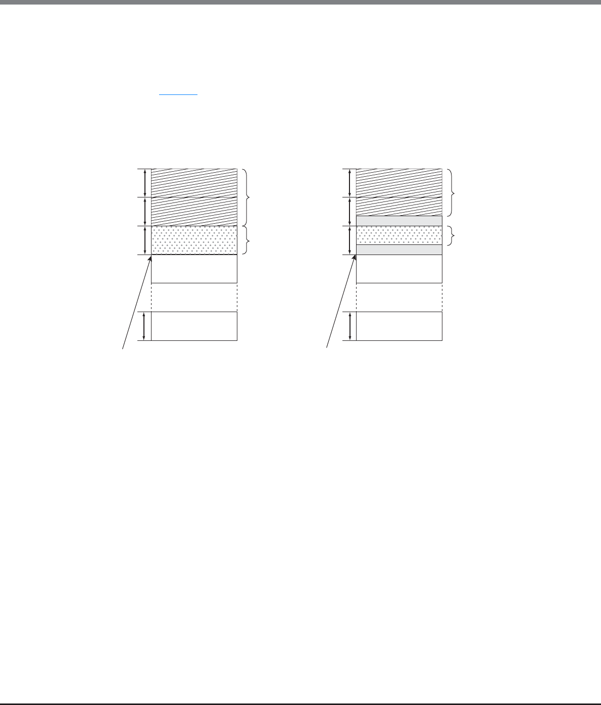
Appendix E Basic Size and MWC Input Condition for RAID Groups
E.1 Basic Size for each RAID Group
ETERNUS Web GUI User’s Guide
Copyright 2013 FUJITSU LIMITED P2X0-1090-10ENZ0
997
*1: D: Data, M: Mirror, P: Parity
*2: Basic size when creating volumes.
ETERNUS DX80 S2/DX90 S2, ETERNUS DX410 S2/DX440 S2, and ETERNUS DX8100 S2/DX8700 S2 manages volumes in
units of stripe size. If the volume size is not an exact multiple of the basic size (stripe size), then when a RAID group
is created the remainder at the end of the last stripe used will be lost. Stripe size is independent of the disk drive
capacity. Figure E.1 shows what happens when the volume size is an integral multiple of the basic size and what
happens when it is not.
Figure E.1 Basic size when creating volumes
Unusable area
Unusable area
RAID Group B
Volume 1
Volume 2
Basic size
RAID group A
Volume 1
Volume 2
Basic size
Volume size is the exact multiple of basic size Volume size is not the exact multiple of basic size
Next volume is created from the next boundary Next volume is created from the next boundary
J J

Appendix E Basic Size and MWC Input Condition for RAID Groups
E.1 Basic Size for each RAID Group
ETERNUS Web GUI User’s Guide
Copyright 2013 FUJITSU LIMITED P2X0-1090-10ENZ0
998
E.1.2 Basic Size when Using the Default Stripe Depth Value (For WSV Type Volumes)
When using the default Stripe Depth value, refer to the following table for basic size:
■Basic size of each RAID group when using the default Stripe Depth value
For WSVs, the basic size is a multiple of the number of concatenations (the number of RAID groups that are to
be concatenated).
When the Wide Stripe Size is "Normal"
RAID type Drive configuration (*1) Basic size (MB) (Lowest exact MB multiple) (*2)
(Stripe Depth = 64KB (default))
Mirroring (RAID1) 1D+1M 16 × Number of concatenations
High Performance
(RAID1+0)
2D+2M 16 × Number of concatenations
3D+3M 255 × Number of concatenations
4D+4M 16 × Number of concatenations
5D+5M 255 × Number of concatenations
6D+6M 63 × Number of concatenations
7D+7M 63 × Number of concatenations
8D+8M 16 × Number of concatenations
9D+9M 63 × Number of concatenations
10D+10M 125 × Number of concatenations
11D+11M 253 × Number of concatenations
12D+12M 63 × Number of concatenations
13D+13M 247 × Number of concatenations
14D+14M 63 × Number of concatenations
15D+15M 255 × Number of concatenations
16D+16M 16 × Number of concatenations
High Capacity
(RAID5)
2D+1P 16 × Number of concatenations
3D+1P 255 × Number of concatenations
4D+1P 16 × Number of concatenations
5D+1P 255 × Number of concatenations
6D+1P 63 × Number of concatenations
7D+1P 63 × Number of concatenations
8D+1P 16 × Number of concatenations
9D+1P 63 × Number of concatenations
10D+1P 125 × Number of concatenations
11D+1P 253 × Number of concatenations
12D+1P 63 × Number of concatenations
13D+1P 247 × Number of concatenations
14D+1P 63 × Number of concatenations
15D+1P 255 × Number of concatenations

Appendix E Basic Size and MWC Input Condition for RAID Groups
E.1 Basic Size for each RAID Group
ETERNUS Web GUI User’s Guide
Copyright 2013 FUJITSU LIMITED P2X0-1090-10ENZ0
999
*1: D: Data, M: Mirror, P: Parity
*2: Basic size when creating volumes.
ETERNUS DX80 S2/DX90 S2, ETERNUS DX410 S2/DX440 S2, and ETERNUS DX8100 S2/DX8700 S2 manages volumes in
units of stripe size. If the volume size is not an exact multiple of the basic size (stripe size), then when a RAID group
is created the remainder at the end of the last stripe used will be lost. Stripe size is independent of the disk drive
capacity. Figure E.1 shows what happens when the volume size is an integral multiple of the basic size and what
happens when it is not.
Reliability
(RAID5+0)
(2D+1P) × 2 16 × Number of concatenations
(3D+1P) × 2 63 × Number of concatenations
(4D+1P) × 2 16 × Number of concatenations
(5D+1P) × 2 125 × Number of concatenations
(6D+1P) × 2 63 × Number of concatenations
(7D+1P) × 2 63 × Number of concatenations
(8D+1P) × 2 16 × Number of concatenations
(9D+1P) × 2 63 × Number of concatenations
(10D+1P) × 2 15 × Number of concatenations
(11D+1P) × 2 121 × Number of concatenations
(12D+1P) × 2 15 × Number of concatenations
(13D+1P) × 2 117 × Number of concatenations
(14D+1P) × 2 63 × Number of concatenations
(15D+1P) × 2 15 × Number of concatenations
High Reliability
(RAID6)
3D+2P 255 × Number of concatenations
4D+2P 16 × Number of concatenations
5D+2P 255 × Number of concatenations
6D+2P 63 × Number of concatenations
7D+2P 63 × Number of concatenations
8D+2P 16 × Number of concatenations
9D+2P 63 × Number of concatenations
10D+2P 125 × Number of concatenations
11D+2P 253 × Number of concatenations
12D+2P 63 × Number of concatenations
13D+2P 247 × Number of concatenations
14D+2P 63 × Number of concatenations
RAID type Drive configuration (*1) Basic size (MB) (Lowest exact MB multiple) (*2)
(Stripe Depth = 64KB (default))

Appendix E Basic Size and MWC Input Condition for RAID Groups
E.1 Basic Size for each RAID Group
ETERNUS Web GUI User’s Guide
Copyright 2013 FUJITSU LIMITED P2X0-1090-10ENZ0
1000
When the Wide Stripe Size is "Small"
RAID type Drive configuration (*1) Basic size (MB) (Lowest exact MB multiple) (*2)
(Stripe Depth = 64KB (default))
Mirroring (RAID1) 1D+1M 2 × Number of concatenations
High Performance
(RAID1+0)
2D+2M 2 × Number of concatenations
3D+3M 15 × Number of concatenations
4D+4M 2 × Number of concatenations
5D+5M 15 × Number of concatenations
6D+6M 15 × Number of concatenations
7D+7M 7 × Number of concatenations
8D+8M 2 × Number of concatenations
9D+9M 27 × Number of concatenations
10D+10M 15 × Number of concatenations
11D+11M 11 × Number of concatenations
12D+12M 3 × Number of concatenations
13D+13M 13 × Number of concatenations
14D+14M 7 × Number of concatenations
15D+15M 15 × Number of concatenations
16D+16M 2 × Number of concatenations
High Capacity
(RAID5)
2D+1P 2 × Number of concatenations
3D+1P 15 × Number of concatenations
4D+1P 2 × Number of concatenations
5D+1P 15 × Number of concatenations
6D+1P 15 × Number of concatenations
7D+1P 7 × Number of concatenations
8D+1P 2 × Number of concatenations
9D+1P 27 × Number of concatenations
10D+1P 15 × Number of concatenations
11D+1P 11 × Number of concatenations
12D+1P 3 × Number of concatenations
13D+1P 13 × Number of concatenations
14D+1P 7 × Number of concatenations
15D+1P 15 × Number of concatenations

Appendix E Basic Size and MWC Input Condition for RAID Groups
E.1 Basic Size for each RAID Group
ETERNUS Web GUI User’s Guide
Copyright 2013 FUJITSU LIMITED P2X0-1090-10ENZ0
1001
*1: D: Data, M: Mirror, P: Parity
*2: Basic size when creating volumes.
ETERNUS DX80 S2/DX90 S2, ETERNUS DX410 S2/DX440 S2, and ETERNUS DX8100 S2/DX8700 S2 manages volumes in
units of stripe size. If the volume size is not an exact multiple of the basic size (stripe size), then when a RAID group
is created the remainder at the end of the last stripe used will be lost. Stripe size is independent of the disk drive
capacity. Figure E.1 shows what happens when the volume size is an integral multiple of the basic size and what
happens when it is not.
Reliability
(RAID5+0)
(2D+1P) × 22 × Number of concatenations
(3D+1P) × 2 15 × Number of concatenations
(4D+1P) × 22 × Number of concatenations
(5D+1P) × 2 15 × Number of concatenations
(6D+1P) × 23 × Number of concatenations
(7D+1P) × 27 × Number of concatenations
(8D+1P) × 22 × Number of concatenations
(9D+1P) × 29 × Number of concatenations
(10D+1P) × 25 × Number of concatenations
(11D+1P) × 2 11 × Number of concatenations
(12D+1P) × 23 × Number of concatenations
(13D+1P) × 2 13 × Number of concatenations
(14D+1P) × 27 × Number of concatenations
(15D+1P) × 2 15 × Number of concatenations
High Reliability
(RAID6)
3D+2P 15 × Number of concatenations
4D+2P 2 × Number of concatenations
5D+2P 15 × Number of concatenations
6D+2P 15 × Number of concatenations
7D+2P 7 × Number of concatenations
8D+2P 2 × Number of concatenations
9D+2P 27 × Number of concatenations
10D+2P 15 × Number of concatenations
11D+2P 11 × Number of concatenations
12D+2P 3 × Number of concatenations
13D+2P 13 × Number of concatenations
14D+2P 7 × Number of concatenations
RAID type Drive configuration (*1) Basic size (MB) (Lowest exact MB multiple) (*2)
(Stripe Depth = 64KB (default))
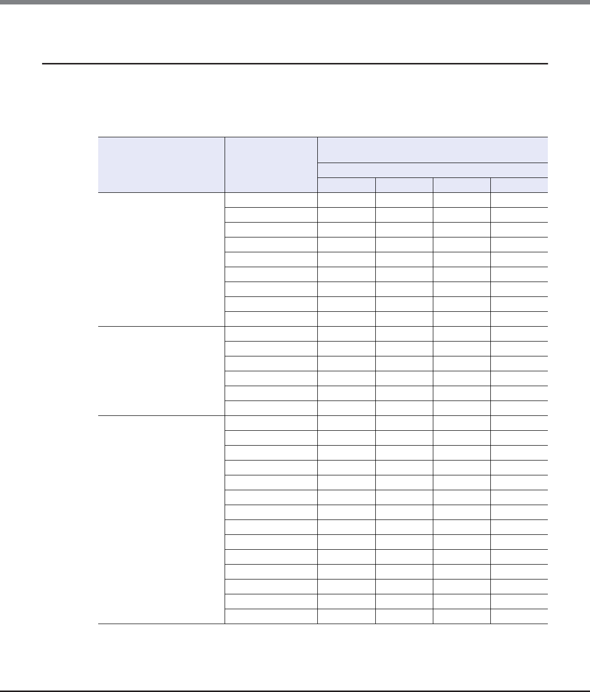
Appendix E Basic Size and MWC Input Condition for RAID Groups
E.1 Basic Size for each RAID Group
ETERNUS Web GUI User’s Guide
Copyright 2013 FUJITSU LIMITED P2X0-1090-10ENZ0
1002
E.1.3 Basic Size When Stripe Depth is Tuned (For Standard, TPV, or SDPV Type
Volumes)
Refer to the following table for the basic size of RAID groups when the Stripe Depth value is changed:
■Basic size of each RAID group when the Stripe Depth value is tuned
RAID type Drive configuration
(*1)
Basic size (MB)
(Lowest exact MB multiple) (*2)
When the Stripe Size is ...
128KB 256KB 512KB 1024KB
High Performance (RAID1+0)
2D+2M 1112
3D+3M 3333
4D+4M 1124
5D+5M 5555
6D+6M 3336
7D+7M 7777
8D+8M 1248
9D+9M 9999
10D+10M 5 5 5 10
High Performance (RAID1+0)
11D+11M 11 11 11 11
12D+12M 3 3 6 12
13D+13M 13 13 13 13
14D+14M 7 7 7 14
15D+15M 15 15 15 15
16D+16M 2 4 8 16
High Capacity (RAID5)
2D+1P 111–
3D+1P 333–
4D+1P 112–
5D+1P 55––
6D+1P 33––
7D+1P 77––
8D+1P 12––
9D+1P 9–––
10D+1P 5–––
11D+1P 11 – – –
12D+1P 3–––
13D+1P 13 – – –
14D+1P 7–––
15D+1P 15 – – –
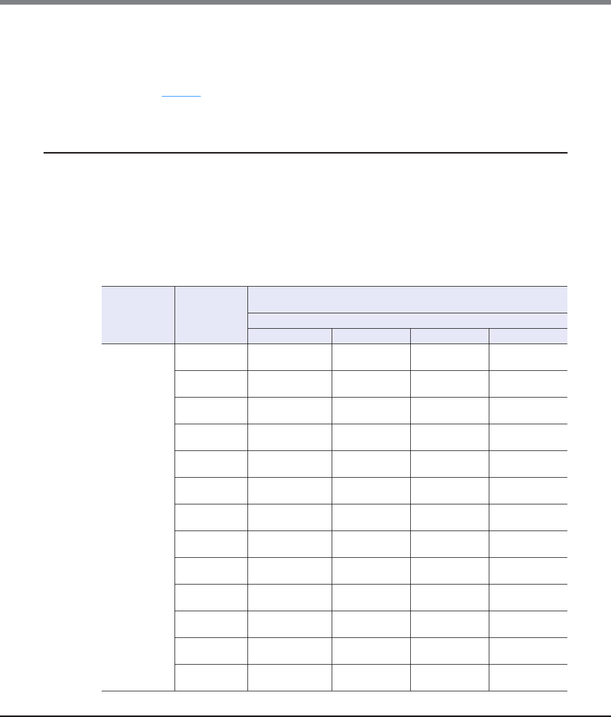
Appendix E Basic Size and MWC Input Condition for RAID Groups
E.1 Basic Size for each RAID Group
ETERNUS Web GUI User’s Guide
Copyright 2013 FUJITSU LIMITED P2X0-1090-10ENZ0
1003
*1: D: Data, M: Mirror, P: Parity
*2: Basic size when creating volumes.
ETERNUS DX80 S2/DX90 S2, ETERNUS DX410 S2/DX440 S2, and ETERNUS DX8100 S2/DX8700 S2 manages volumes in
units of stripe size. If the volume size is not an exact multiple of the basic size (stripe size), then when a RAID group
is created the remainder at the end of the last stripe used will be lost. Stripe size is independent of the disk drive
capacity. Figure E.1 shows what happens when the volume size is an integral multiple of the basic size and what
happens when it is not.
E.1.4 Basic Size When Stripe Depth is Tuned (For WSV Type Volumes)
Refer to the following table for the basic size of RAID groups when the Stripe Depth value is changed:
■Basic size of each RAID group when the Stripe Depth value is tuned
For WSVs, the basic size is a multiple of the number of concatenations (the number of RAID groups that are to
be concatenated).
When the Wide Stripe Size is "Normal"
RAID type Drive
configuration
(*1)
Basic size (MB)
(Lowest exact MB multiple) (*2)
When the Stripe Size is ...
128KB 256KB 512KB 1024KB
High
Performance
(RAID1+0)
2D+2M 16 × Number of
concatenations
16 × Number of
concatenations
16 × Number of
concatenations
16 × Number of
concatenations
3D+3M 63 × Number of
concatenations
63 × Number of
concatenations
15 × Number of
concatenations
15 × Number of
concatenations
4D+4M 16 × Number of
concatenations
16 × Number of
concatenations
16 × Number of
concatenations
16 × Number of
concatenations
5D+5M 125 × Number of
concatenations
15 × Number of
concatenations
15 × Number of
concatenations
15 × Number of
concatenations
6D+6M 63 × Number of
concatenations
15 × Number of
concatenations
15 × Number of
concatenations
12 × Number of
concatenations
7D+7M 63 × Number of
concatenations
63 × Number of
concatenations
14 × Number of
concatenations
14 × Number of
concatenations
8D+8M 16 × Number of
concatenations
16 × Number of
concatenations
16 × Number of
concatenations
16 × Number of
concatenations
9D+9M 63 × Number of
concatenations
63 × Number of
concatenations
27 × Number of
concatenations
9 × Number of
concatenations
10D+10M 15 × Number of
concatenations
15 × Number of
concatenations
15 × Number of
concatenations
10 × Number of
concatenations
11D+11M 121 × Number of
concatenations
55 × Number of
concatenations
11 × Number of
concatenations
11 × Number of
concatenations
12D+12M 15 × Number of
concatenations
15 × Number of
concatenations
12 × Number of
concatenations
12 × Number of
concatenations
13D+13M 117 × Number of
concatenations
13 × Number of
concatenations
13 × Number of
concatenations
13 × Number of
concatenations
14D+14M 63 × Number of
concatenations
14 × Number of
concatenations
14 × Number of
concatenations
14 × Number of
concatenations

Appendix E Basic Size and MWC Input Condition for RAID Groups
E.1 Basic Size for each RAID Group
ETERNUS Web GUI User’s Guide
Copyright 2013 FUJITSU LIMITED P2X0-1090-10ENZ0
1004
*1: D: Data, M: Mirror, P: Parity
*2: Basic size when creating volumes.
ETERNUS DX80 S2/DX90 S2, ETERNUS DX410 S2/DX440 S2, and ETERNUS DX8100 S2/DX8700 S2 manages volumes in
units of stripe size. If the volume size is not an exact multiple of the basic size (stripe size), then when a RAID group
is created the remainder at the end of the last stripe used will be lost. Stripe size is independent of the disk drive
capacity. Figure E.1 shows what happens when the volume size is an integral multiple of the basic size and what
happens when it is not.
High
Performance
(RAID1+0)
15D+15M 15 × Number of
concatenations
15 × Number of
concatenations
15 × Number of
concatenations
15 × Number of
concatenations
16D+16M 16 × Number of
concatenations
16 × Number of
concatenations
16 × Number of
concatenations
16 × Number of
concatenations
High Capacity
(RAID5)
2D+1P 16 × Number of
concatenations
16 × Number of
concatenations
16 × Number of
concatenations
–
3D+1P 63 × Number of
concatenations
63 × Number of
concatenations
15 × Number of
concatenations
–
4D+1P 16 × Number of
concatenations
16 × Number of
concatenations
16 × Number of
concatenations
–
5D+1P 125 × Number of
concatenations
15 × Number of
concatenations
––
6D+1P 63 × Number of
concatenations
15 × Number of
concatenations
––
7D+1P 63 × Number of
concatenations
63 × Number of
concatenations
––
8D+1P 16 × Number of
concatenations
16 × Number of
concatenations
––
9D+1P 63 × Number of
concatenations
–––
10D+1P 15 × Number of
concatenations
–––
11D+1P 121 × Number of
concatenations
–––
12D+1P 15 × Number of
concatenations
–––
13D+1P 117 × Number of
concatenations
–––
14D+1P 63 × Number of
concatenations
–––
15D+1P 15 × Number of
concatenations
–––
RAID type Drive
configuration
(*1)
Basic size (MB)
(Lowest exact MB multiple) (*2)
When the Stripe Size is ...
128KB 256KB 512KB 1024KB

Appendix E Basic Size and MWC Input Condition for RAID Groups
E.1 Basic Size for each RAID Group
ETERNUS Web GUI User’s Guide
Copyright 2013 FUJITSU LIMITED P2X0-1090-10ENZ0
1005
When the Wide Stripe Size is "Small"
RAID type Drive
configuration
(*1)
Basic size (MB)
(Lowest exact MB multiple) (*2)
When the Stripe Size is ...
128KB 256KB 512KB 1024KB
High
Performance
(RAID1+0)
2D+2M 2 × Number of
concatenations
2 × Number of
concatenations
2 × Number of
concatenations
2 × Number of
concatenations
3D+3M 15 × Number of
concatenations
3 × Number of
concatenations
3 × Number of
concatenations
3 × Number of
concatenations
4D+4M 2 × Number of
concatenations
2 × Number of
concatenations
2 × Number of
concatenations
4 × Number of
concatenations
5D+5M 15 × Number of
concatenations
5 × Number of
concatenations
5 × Number of
concatenations
5 × Number of
concatenations
6D+6M 3 × Number of
concatenations
3 × Number of
concatenations
3 × Number of
concatenations
6 × Number of
concatenations
7D+7M 7 × Number of
concatenations
7 × Number of
concatenations
7 × Number of
concatenations
7 × Number of
concatenations
8D+8M 2 × Number of
concatenations
2 × Number of
concatenations
4 × Number of
concatenations
8 × Number of
concatenations
9D+9M 9 × Number of
concatenations
9 × Number of
concatenations
9 × Number of
concatenations
9 × Number of
concatenations
10D+10M 5 × Number of
concatenations
5 × Number of
concatenations
5 × Number of
concatenations
10 × Number of
concatenations
11D+11M 11 × Number of
concatenations
11 × Number of
concatenations
11 × Number of
concatenations
11 × Number of
concatenations
12D+12M 3 × Number of
concatenations
3 × Number of
concatenations
6 × Number of
concatenations
12 × Number of
concatenations
13D+13M 13 × Number of
concatenations
13 × Number of
concatenations
13 × Number of
concatenations
13 × Number of
concatenations
14D+14M 7 × Number of
concatenations
7 × Number of
concatenations
7 × Number of
concatenations
14 × Number of
concatenations
15D+15M 15 × Number of
concatenations
15 × Number of
concatenations
15 × Number of
concatenations
15 × Number of
concatenations
16D+16M 2 × Number of
concatenations
4 × Number of
concatenations
8 × Number of
concatenations
16 × Number of
concatenations
High Capacity
(RAID5)
2D+1P 2 × Number of
concatenations
2 × Number of
concatenations
2 × Number of
concatenations
–
3D+1P 15 × Number of
concatenations
3 × Number of
concatenations
3 × Number of
concatenations
–
4D+1P 2 × Number of
concatenations
2 × Number of
concatenations
2 × Number of
concatenations
–
5D+1P 15 × Number of
concatenations
5 × Number of
concatenations
––
6D+1P 3 × Number of
concatenations
3 × Number of
concatenations
––
7D+1P 7 × Number of
concatenations
7 × Number of
concatenations
––

Appendix E Basic Size and MWC Input Condition for RAID Groups
E.1 Basic Size for each RAID Group
ETERNUS Web GUI User’s Guide
Copyright 2013 FUJITSU LIMITED P2X0-1090-10ENZ0
1006
*1: D: Data, M: Mirror, P: Parity
*2: Basic size when creating volumes.
ETERNUS DX80 S2/DX90 S2, ETERNUS DX410 S2/DX440 S2, and ETERNUS DX8100 S2/DX8700 S2 manages volumes in
units of stripe size. If the volume size is not an exact multiple of the basic size (stripe size), then when a RAID group
is created the remainder at the end of the last stripe used will be lost. Stripe size is independent of the disk drive
capacity. Figure E.1 shows what happens when the volume size is an integral multiple of the basic size and what
happens when it is not.
High Capacity
(RAID5)
8D+1P 2 × Number of
concatenations
2 × Number of
concatenations
––
9D+1P 9 × Number of
concatenations
–––
10D+1P 5 × Number of
concatenations
–––
11D+1P 11 × Number of
concatenations
–––
12D+1P 3 × Number of
concatenations
–––
13D+1P 13 × Number of
concatenations
–––
14D+1P 7 × Number of
concatenations
–––
15D+1P 15 × Number of
concatenations
–––
RAID type Drive
configuration
(*1)
Basic size (MB)
(Lowest exact MB multiple) (*2)
When the Stripe Size is ...
128KB 256KB 512KB 1024KB

Appendix E Basic Size and MWC Input Condition for RAID Groups
E.2 Input Conditions for MWC
ETERNUS Web GUI User’s Guide
Copyright 2013 FUJITSU LIMITED P2X0-1090-10ENZ0
1007
E.2 Input Conditions for MWC
This section describes the allowed input values for the Multi Writeback Count (MWC).
The allowed input for the MWC varies depending on the RAID type, the drive configuration, and the Stripe
Depth value.
E.2.1 Allowed Input for the MWC When Using the Default Stripe Depth Value
When using the default Stripe Depth value, refer to the following table for the allowed MWC value:
■Allowed input for MWC when using the default Stripe Depth value (Volume)
RAID type Drive configuration (*1) Allowed input for MWC (initial state)
Stripe Depth = 64KB (default)
Striping (RAID0)
2D 1 – 16 (4)
3D 1 – 10 (3)
4D 1 – 8 (2)
5D 1 – 6 (2)
6D 1 – 5 (2)
7D 1 – 4 (2)
8D 1 – 4 (1)
9D 1 – 3 (1)
10D 1 – 3 (1)
11D – 16D 1 – 2 (1)
Mirroring (RAID1) 1D+1M 1 – 16 (8)
High Performance (RAID1+0)
2D+2M 1 – 16 (4)
3D+3M 1 – 10 (3)
4D+4M 1 – 8 (2)
5D+5M 1 – 6 (2)
6D+6M 1 – 5 (2)
7D+7M 1 – 4 (2)
8D+8M 1 – 4 (1)
9D+9M 1 – 3 (1)
10D+10M 1 – 3 (1)
11D+11M – 16D+16M 1 – 2 (1)

Appendix E Basic Size and MWC Input Condition for RAID Groups
E.2 Input Conditions for MWC
ETERNUS Web GUI User’s Guide
Copyright 2013 FUJITSU LIMITED P2X0-1090-10ENZ0
1008
*1: D: Data drives, M: Mirror drives, P: Parity drives
■Allowed input for MWC when using the default Stripe Depth value (TPP)
High Capacity (RAID5)
2D+1P 1 – 8 (4)
3D+1P 1 – 8 (3)
4D+1P 1 – 8 (2)
5D+1P 1 – 6 (2)
6D+1P 1 – 5 (2)
7D+1P 1 – 4 (2)
8D+1P 1 – 4 (1)
9D+1P 1 – 3 (1)
10D+1P 1 – 3 (1)
11D+1P – 15D+1P 1 – 2 (1)
Reliability (RAID5+0)
(2D+1P) × 24 (fixed)
(3D+1P) × 22 (fixed)
(4D+1P) × 22 (fixed)
(5D+1P) × 2 – (15D+1P) × 21 (fixed)
High Reliability (RAID6)
3D+2P 1 – 8 (3)
4D+2P 1 – 8 (2)
5D+2P 1 – 6 (2)
6D+2P 1 – 5 (2)
7D+2P 1 – 4 (2)
8D+2P 1 – 4 (1)
9D+2P 1 – 3 (1)
10D+2P 1 – 3 (1)
11D+2P – 14D+2P 1 – 2 (1)
RAID type Drive configuration (*1) Allowed input for MWC (initial state)
Stripe Depth = 64KB (default)
RAID type Drive configuration (*1) Allowed input for MWC (initial state)
Stripe Depth = 64KB (default)
Striping (RAID0) 4D 1 – 8 (2)
Mirroring (RAID1) 1D+1M 1 – 16 (8)
High Performance (RAID1+0)
2D+2M 1 – 16 (4)
4D+4M 1 – 8 (2)
8D+8M 1 – 4 (1)
12D+12M 1 – 2 (1)
High Capacity (RAID5)
3D+1P 1 – 8 (3)
4D+1P 1 – 8 (2)
7D+1P 1 – 4 (2)
8D+1P 1 – 4 (1)
12D+1P 1 – 2 (1)
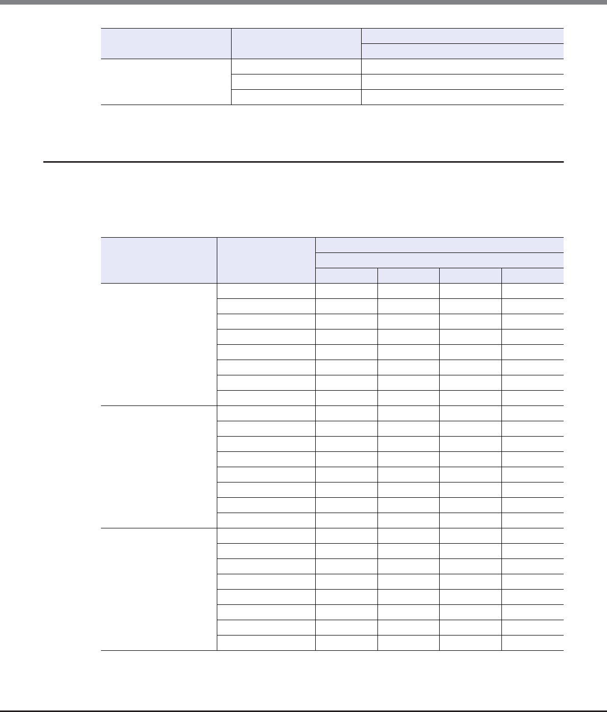
Appendix E Basic Size and MWC Input Condition for RAID Groups
E.2 Input Conditions for MWC
ETERNUS Web GUI User’s Guide
Copyright 2013 FUJITSU LIMITED P2X0-1090-10ENZ0
1009
*1: D: Data drives, M: Mirror drives, P: Parity drives
E.2.2 Allowed Input for the MWC when Performance is Tuned
Refer to the following table for the allowed MWC value when the Stripe Depth value is changed:
■Allowed Input for MWC when the Stripe Depth value is tuned (Volume)
*1: D: Data drives, M: Mirror drives, P: Parity drives, –: Stripe Depth cannot be changed
High Reliability (RAID6)
4D+2P 1 – 8 (2)
6D+2P 1 –- 5 (2)
8D+2P 1 – 4 (1)
RAID type Drive configuration (*1) Allowed input for MWC (initial state)
Stripe Depth = 64KB (default)
RAID type Drive configuration
(*1)
Allowed input for MWC (initial state)
When the Stripe Size is ...
128KB 256KB 512KB 1024KB
Striping (RAID0)
2D 1 – 8 (4) 1 – 4 (4) 1 – 2 (2) 1 (fixed)
3D 1 – 5 (3) 1 – 2 (2) 1 (fixed) 1 (fixed)
4D 1 – 4 (2) 1 – 2 (2) 1 (fixed) 1 (fixed)
5D 1 – 3 (2) 1 (fixed) 1 (fixed) 1 (fixed)
6D 1 – 2 (2) 1 (fixed) 1 (fixed) 1 (fixed)
7D 1 – 2 (2) 1 (fixed) 1 (fixed) 1 (fixed)
8D 1 – 2 (1) 1 (fixed) 1 (fixed) 1 (fixed)
9D – 16D 1 (fixed) 1 (fixed) 1 (fixed) 1 (fixed)
High Performance
(RAID1+0)
2D+2M 1 – 8 (4) 1 – 4 (4) 1 – 2 (2) 1 (fixed)
3D+3M 1 – 5 (3) 1 – 2 (2) 1 (fixed) 1 (fixed)
4D+4M 1 – 4 (2) 1 – 2 (2) 1 (fixed) 1 (fixed)
5D+5M 1 – 3 (2) 1 (fixed) 1 (fixed) 1 (fixed)
6D+6M 1 – 2 (2) 1 (fixed) 1 (fixed) 1 (fixed)
7D+7M 1 – 2 (2) 1 (fixed) 1 (fixed) 1 (fixed)
8D+8M 1 – 2 (1) 1 (fixed) 1 (fixed) 1 (fixed)
9D+9M – 16D+16M 1 (fixed) 1 (fixed) 1 (fixed) 1 (fixed)
High Capacity (RAID5)
2D+1P 1 – 4 (4) 1 – 2 (2) 1 (fixed) –
3D+1P 1 – 4 (3) 1 – 2 (2) 1 (fixed) –
4D+1P 1 – 4 (2) 1 – 2 (2) 1 (fixed) –
5D+1P 1 – 3 (2) 1 (fixed) – –
6D+1P 1 – 2 (2) 1 (fixed) – –
7D+1P 1 – 2 (2) 1 (fixed) – –
8D+1P 1 – 2 (1) 1 (fixed) – –
9D+1P – 15D+1P 1 (fixed) – – –

Appendix E Basic Size and MWC Input Condition for RAID Groups
E.2 Input Conditions for MWC
ETERNUS Web GUI User’s Guide
Copyright 2013 FUJITSU LIMITED P2X0-1090-10ENZ0
1010
■Allowed Input for MWC when the Stripe Depth value is tuned (TPP)
*1: D: Data drives, M: Mirror drives, P: Parity drives, –: Stripe Depth cannot be changed
RAID type Drive configuration
(*1)
Allowed input for MWC (initial state)
When the Stripe Size is ...
128KB 256KB 512KB 1024KB
Striping (RAID0) 4D 1 – 4 (2) 1 – 2 (2) 1 (fixed) 1 (fixed)
High Performance
(RAID1+0)
2D+2M 1 – 8 (4) 1 – 4 (4) 1 – 2 (2) 1 (fixed)
4D+4M 1 – 4 (2) 1 – 2 (2) 1 (fixed) 1 (fixed)
8D+8M 1 – 2 (1) 1 (fixed) 1 (fixed) 1 (fixed)
12D+12M 1 (fixed) 1 (fixed) 1 (fixed) 1 (fixed)
High Capacity (RAID5)
3D+1P 1 – 4 (3) 1 – 2 (2) 1 (fixed) –
4D+1P 1 – 4 (2) 1 – 2 (2) 1 (fixed) –
7D+1P 1 – 2 (2) 1 (fixed) – –
8D+1P 1 – 2 (1) 1 (fixed) – –
12D+1P 1 (fixed) – – –

ETERNUS Web GUI User’s Guide
Copyright 2013 FUJITSU LIMITED P2X0-1090-10ENZ0
1011
Appendix F
Automatic Controlling CM-CPU Setting
This chapter describes controlling CM-CPU allocation if "Automatic" is specified when setting the controlling
CM-CPU.
■For ETERNUS DX80 S2/DX90 S2 and ETERNUS DX410 S2
■For ETERNUS DX440 S2, ETERNUS DX8100 S2/DX8700 S2 (2CM)
*1: Divide the RAID group number by the number of CM-CPUs ("4").
■For ETERNUS DX8700 S2 (4CM)
*1: Divide the RAID group number by the number of CM-CPUs ("8").
RAID group number Controlling CM-CPU assignment
Even numbers CM#0 CPU#0
Odd numbers CM#1 CPU#0
Remainder when dividing
the RAID group number by "4" (*1)
Controlling CM-CPU assignment
0 CM#0 CPU#0
1 CM#1 CPU#1
2 CM#1 CPU#0
3 CM#0 CPU#1
Remainder when dividing
the RAID group number by "8" (*1)
Controlling CM-CPU assignment
0 CM#0 CPU#0
1 CM#3 CPU#1
2 CM#1 CPU#0
3 CM#2 CPU#1
4 CM#2 CPU#0
5 CM#1 CPU#1
6 CM#3CPU#0
7 CM#0 CPU#1

Appendix F Automatic Controlling CM-CPU Setting
ETERNUS Web GUI User’s Guide
Copyright 2013 FUJITSU LIMITED P2X0-1090-10ENZ0
1012
■For ETERNUS DX8700 S2 (6CM)
*1: Divide the RAID group number by the number of CM-CPUs ("12").
■For ETERNUS DX8700 S2 (8CM)
*1: Divide the RAID group number by the number of CM-CPUs ("16").
Remainder when dividing
the RAID group number by "12" (*1)
Controlling CM-CPU assignment
0 CM#0 CPU#0
1 CM#5 CPU#1
2 CM#1 CPU#0
3 CM#4 CPU#1
4 CM#2 CPU#0
5 CM#3 CPU#1
6 CM#3 CPU#0
7 CM#2 CPU#1
8 CM#4 CPU#0
9 CM#1 CPU#1
10 CM#5 CPU#0
11 CM#0 CPU#1
Remainder when dividing
the RAID group number by "16" (*1)
Controlling CM-CPU assignment
0 CM#0 CPU#0
1 CM#7 CPU#1
2 CM#1 CPU#0
3 CM#6 CPU#1
4 CM#2 CPU#0
5 CM#5 CPU#1
6 CM#3 CPU#0
7 CM#4 CPU#1
8 CM#4 CPU#0
9 CM#3 CPU#1
10 CM#5 CPU#0
11 CM#2 CPU#1
12 CM#6 CPU#0
13 CM#1 CPU#1
14 CM#7 CPU#0
15 CM#0 CPU#1
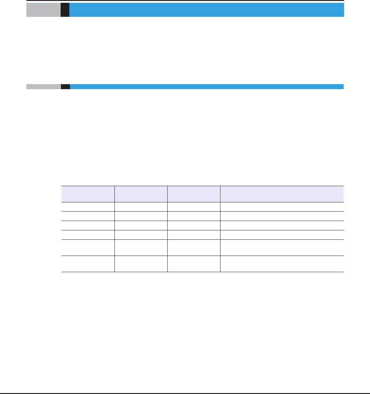
ETERNUS Web GUI User’s Guide
Copyright 2013 FUJITSU LIMITED P2X0-1090-10ENZ0
1013
Appendix G
Using RADIUS Authentication
This chapter describes supplementary notes when using RADIUS Authentication.
G.1 Using RADIUS Authentication to Access the ETERNUS DX Disk
Storage System
•RADIUS Authentication is used to authenticate logging in to the ETERNUS DX Disk storage system with GUI
or CLI.
•Up to two RADIUS servers can be connected to an ETERNUS DX Disk storage system.
•To use RADIUS Authentication, the user account information (user name, password, and role name) that is
allowed to access ETERNUS DX Disk storage system in the RADIUS server must be pre-registered.
•There are two types of authentication methods: CHAP and PAP.
•User roles are specified in the Vendor Specific Attribute (VSA) of the Access-Accept response from the
server. The following table shows the syntax of the VSA based account role on the RADIUS server.
Syntax of the Vendor Specific Attribute (VSA) based account role
*1: The server-side role names are case sensitive and must be set correctly.
[Example] RoleName0
Item Size
(octets)
Value Description
Type 1 26 Attribute number for the Vendor Specific Attribute
Length 1 7 or more Attribute size (calculated by server)
Vendor-Id 4 211 Fujitsu Limited (SMI Private Enterprise Code)
Vendor type 1 1 Eternus-Auth-Role
Vendor length 1 2 or more Attribute size described after the Vendor type
(calculated by server)
Attribute-Specific 1 or more ASCII characters List of one or more role names assignable to
successfully authenticated users (*1)

Appendix G Using RADIUS Authentication
G.2 Notes when Using RADIUS Authentication for GUI
ETERNUS Web GUI User’s Guide
Copyright 2013 FUJITSU LIMITED P2X0-1090-10ENZ0
1014
G.2 Notes when Using RADIUS Authentication for GUI
•A primary server and secondary server can be set for GUI authentication. If the primary RADIUS server
times out, the secondary server is tried.
•If RADIUS Authentication fails and "Do not use Internal Authentication" has been selected for
"Authentication Error Recovery", it will not be possible to login to GUI or CLI.
•When "Use Internal Authentication (Network Error Case)" has been selected for "Authentication Error
Recovery", Internal Authentication is only performed if RADIUS Authentication fails on both primary and
secondary RADIUS servers, and at least one of these failures is due to network error.
•So long as there is no RADIUS Authentication response the ETERNUS DX Disk storage system will keep
retrying to authenticate the user for the entire "Timeout" period set on the "Set RADIUS Authentication
(Initial)" menu. Authentication not succeeding before the timeout occurs is considered a RADIUS
Authentication failure.
•When using RADIUS Authentication, if the role that is received from the server is unknown (not set) for the
storage system, RADIUS Authentication fails.
G.3 Setting Up the RADIUS Server
Windows Server 2008 R2 Example
The RADIUS setup procedure described below uses a Windows Server 2008 R2 as an example. It must be noted
that this setup procedure is not necessarily guaranteed to work for all network environments. Make sure to
obtain your system administrator's help in setting up the system.
The procedure for setting up the RADIUS service on Windows Server 2008 R2 is as follows.
(1)Install the Network Policy and Access Services
For details on installing "Network Policy and Access Services", refer to the Microsoft web-site.
(2)Enable the Challenge Handshake Authentication Protocol (CHAP)
If CHAP Authentication is required, set Windows to store passwords using reversible encryption, rather than
relying on the default setting.
(3)Configure the users
Network Policy Server (NPS) is the Microsoft implementation of a RADIUS server and proxy. When using
NPS to check the User login certificate, a list of user groups is displayed instead of a list of specific users.
Each user group must be associated with a role that logs into a specific ETERNUS DX Disk storage system.
For example, after setting the "root", "Admin", and "user" user groups, those users that are to be allowed to
login must be added to the proper group.
If the current password is already stored by using irreversible encryption, the current password setting is
not changed even when enabling the password to be stored by using reversible encryption. To use
reversible encryption to store the current password, set the user password again or specify that the
password for each user is changed for the next login.

Appendix G Using RADIUS Authentication
G.3 Setting Up the RADIUS Server
ETERNUS Web GUI User’s Guide
Copyright 2013 FUJITSU LIMITED P2X0-1090-10ENZ0
1015
●Create Users and User Groups
(1) Select [Start] → [Administrative Tools] → [Computer Management].
(2) Select [System Tools] → [Local Users and Groups] → [Users].
Right-click [Users] and select [New User].
Create an ETERNUS DX Disk storage system login user as the [New User].
(3) Select [System Tools] → [Local Users and Groups] → [Groups].
Right-click [Groups] and select [New Group].
Create an ETERNUS DX Disk storage system group as the [New Group] and add the user created
in Step (2).
(4)Set the Network Policy and Access Services
The following three steps must be performed:
-Register the ETERNUS DX Disk storage system as a RADIUS client
-Set the accessible user group and the authentication method
-Set the role with Vendor Specific Attribute (VSA)
●Register the ETERNUS DX Disk storage system as a RADIUS client
(1) Select [Start] → [Administrative Tools] → [Server Manager].
(2) Select [Roles] → [Network Policy and Access Services] → [NPS] → [RADIUS Clients and Servers]
→ [RADIUS Clients].
Right-click [RADIUS Clients] and select [New RADIUS Client], and set the various items.
•For the "Address (IP or DNS)", set the IP address of the client ETERNUS DX Disk storage
system.
•For the "Vendor name", set "RADIUS Standard".
•For the "Shared secret", set the shared key that is registered on the client ETERNUS DX Disk
storage system.
●Set the Accessible User Group and the Authentication Method
(1) Select [Start] → [Administrative Tools] → [Server Manager].
(2) Select [Roles] → [Network Policy and Access Services] → [NPS] → [Policies] → [Network
Policies].
Right-click [Network Policies], select [New], and set the various items.
•Click "Add" in the "Conditions" tab and add "Windows Groups". For "Windows Groups", add the
group that was created for the ETERNUS DX Disk storage system.
•For the "secure authentication methods", check "Encryption authentication (CHAP(C))" or
"Unencrypted authentication (PAP,SPAP)(S)". Select the same setting as is set on the
ETERNUS DX Disk storage system.

Appendix G Using RADIUS Authentication
G.3 Setting Up the RADIUS Server
ETERNUS Web GUI User’s Guide
Copyright 2013 FUJITSU LIMITED P2X0-1090-10ENZ0
1016
●Set the role with Vendor Specific Attribute (VSA)
(1) Select [Start] → [Administrative Tools] → [Server Manager].
(2) Select [Roles] → [Network Policy and Access Services] → [NPS] → [Policies] → [Network
Policies].
Select and double-click the newly added policy.
(3) Set the following items using the [Add] button under [Vendor Specific] on the [Settings] tab.
•For the "Attributes", add "Vendor-Specific/RADIUS Standard".
•For the "Enter Vendor Code", enter "211".
•For the "RADIUS RFC", click "Yes, it conforms".
•For the "Vendor-assigned attribute number", enter "1".
•For the "Attribute format", select "String".
•For the "Attribute Value", enter the role name(s) that are registered on the ETERNUS DX Disk
storage system, and which the users who belong to the added "Groups" can select when
logging in to the ETERNUS DX Disk storage system. The server-side role names are case
sensitive and must be input correctly.
[Example] RoleName0

ETERNUS Web GUI User’s Guide
Copyright 2013 FUJITSU LIMITED P2X0-1090-10ENZ0
1017
Appendix H
Estimated Advanced Copy Source Capacity
This chapter describes the maximum copy source capacity for each copy type.
The estimated values in the following tables are examples of typical Advanced Copy sessions (the maximum
memory area required for Advanced Copy management is secured and the number of copy sessions is 400).
Actual values can be calculated by using the procedure in "How to calculate the copy table size" (page 308) of
"8.2.7 Modify Copy Table Size" (page 301).
ETERNUS DX
Disk storage
system
Copy type Resolution
× 1 × 2 × 4 × 8 × 16
ETERNUS
DX80 S2/
DX90 S2
(Table size =
256MB)
EC/REC (*1)/
OPC,
QuickOPC,
SnapOPC, and
SnapOPC+
without using
Restore OPC
16184GB
(15.8TB)
32368GB
(31.6TB)
64736GB
(63.2TB)
129472GB
(126.4TB)
258944GB
(252.8TB)
OPC,
QuickOPC,
SnapOPC, and
SnapOPC+
using Restore
OPC
7992GB
(7.8TB)
15984GB
(15.6TB)
31968GB
(31.2TB)
63936GB
(62.4TB)
127872GB
(124.8TB)
ETERNUS
DX410 S2
(Table size =
512MB)
EC/REC/
OPC,
QuickOPC,
SnapOPC, and
SnapOPC+
without using
Restore OPC
32568GB
(31.8TB)
65136GB
(63.6TB)
130272GB
(127.2TB)
260544GB
(254.4TB)
521088GB
(508.8TB)
OPC,
QuickOPC,
SnapOPC, and
SnapOPC+
using Restore
OPC
16184GB
(15.8TB)
32368GB
(31.6TB)
64736GB
(63.2TB)
129472GB
(126.4TB)
258944GB
(252.8TB)
ETERNUS
DX440 S2
(Table size =
1024MB [1GB])
EC/REC/
OPC,
QuickOPC,
SnapOPC, and
SnapOPC+
without using
Restore OPC
65336GB
(63.8TB)
130672GB
(127.6TB)
261344GB
(255.2TB)
522688GB
(510.4TB)
1045376GB
(1020.8TB)
OPC,
QuickOPC,
SnapOPC, and
SnapOPC+
using Restore
OPC
32568GB
(31.8TB)
65136GB
(63.6TB)
130272GB
(127.2TB)
260544GB
(254.4TB)
521088GB
(508.8TB)
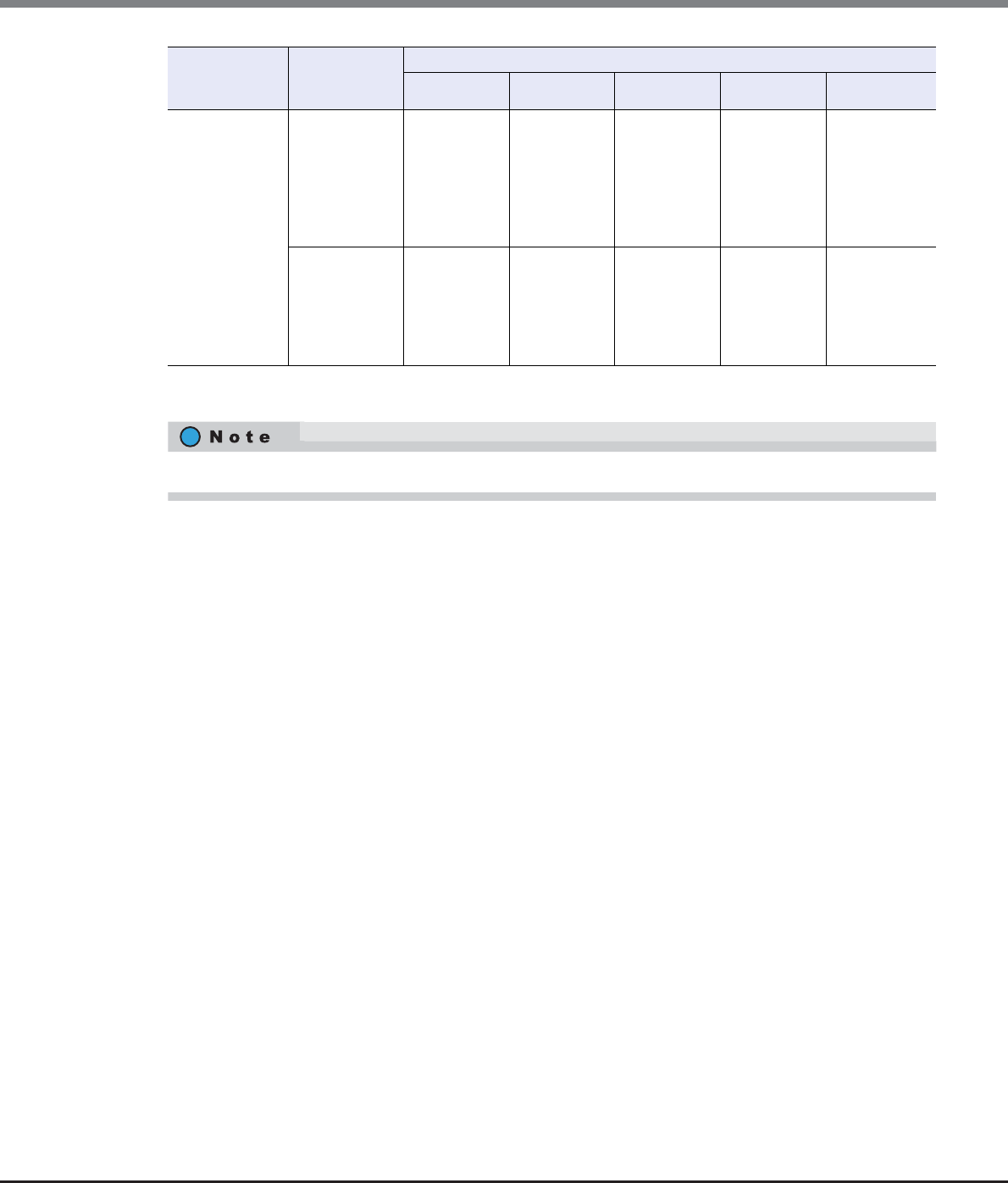
Appendix H Estimated Advanced Copy Source Capacity
ETERNUS Web GUI User’s Guide
Copyright 2013 FUJITSU LIMITED P2X0-1090-10ENZ0
1018
(Values in brackets assume that 1024GB = 1TB and are displayed to one decimal place.)
*1: REC is only available for the ETERNUS DX90 S2.
ETERNUS
DX8700 S2
(Table size =
12288MB
[12GB])
EC/REC/
OPC,
QuickOPC,
SnapOPC, and
SnapOPC+
without using
Restore OPC
786232GB
(767.8TB)
1572464GB
(1535.6TB)
3144928GB
(3071.2TB)
6289856GB
(6142.4TB)
12579712GB
(12284.9TB)
OPC,
QuickOPC,
SnapOPC, and
SnapOPC+
using Restore
OPC
393016GB
(383.8TB)
786032GB
(767.6TB)
1572064GB
(1535.2TB)
3144128GB
(3070.4TB)
6288256GB
(6140.9TB)
The copy source capacity is assumed that almost 100% of the copy table size is used.
ETERNUS DX
Disk storage
system
Copy type Resolution
× 1 × 2 × 4 × 8 × 16
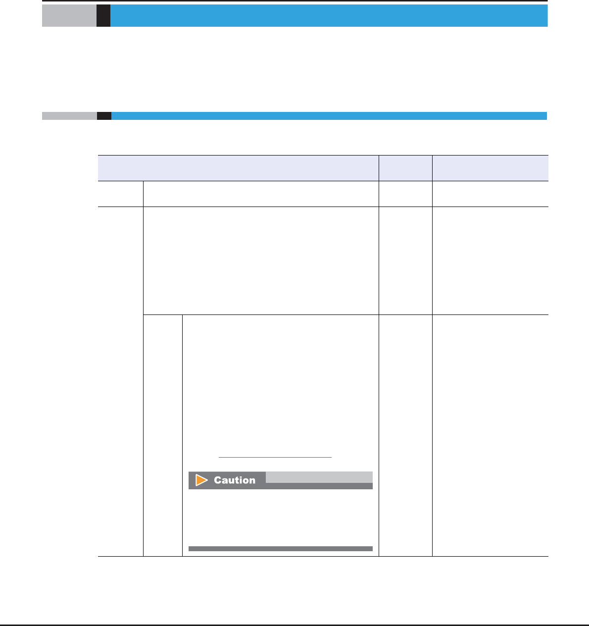
ETERNUS Web GUI User’s Guide
Copyright 2013 FUJITSU LIMITED P2X0-1090-10ENZ0
1019
Appendix I
Storage Migration Setting Files
This chapter describes Storage Migration setting files.
I.1 Template File for Storage Migration Settings
The following table shows the details of a template file for storage migration settings.
Keyword Number of
settings
Allowed input
Type Specify the type of Storage Migration.
(Example) Type = Open
1Open
GROUP Specify a path group for each source storage system.
Up to 16 path groups can be specified.
•New format
Specify "0x" (2-digit) + 0 - F (1-digit) with hexadecimal
numbers.
[Example] GROUP=0x0
•Old format
Specify 0 - F (1-digit) with hexadecimal numbers.
[Example] GROUP=0
1•New format
0x0 - 0xF
("0x" + 1-digit
hexadecimal)
•Old format
0 - F
(1-digit hexadecimal)
OPE-
MODE
[New format only]
Specify one of the operation modes (M/M+QC/
M+FC/QC/FC) for the Storage Migration.
The following symbols are used for the operation
modes:
M: Migration
M+QC: Migration + Quick Compare
M+FC: Migration + Full Compare
QC: Quick Compare
FC: Full Compare
OPEMODE can be omitted. When this parameter is
not specified, "Migration" is used.
Refer to "Operation Mode" (page 1021) for details.
[Example] OPEMODE=M+QC
OPEMODE is available only when using a template
file with the new format. When a template file
with an old format is used, the conventional mode
("Migration") is used.
1M
M+QC
M+FC
QC
FC
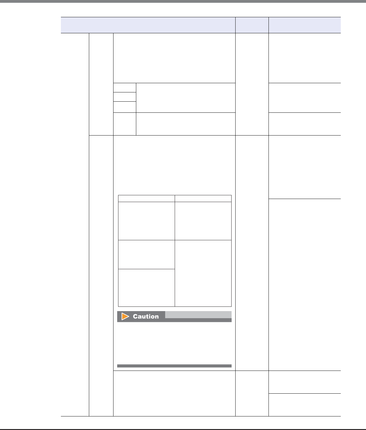
Appendix I Storage Migration Setting Files
I.1 Template File for Storage Migration Settings
ETERNUS Web GUI User’s Guide
Copyright 2013 FUJITSU LIMITED P2X0-1090-10ENZ0
1020
GROUP PATH Specify the path information of the destination
and source storage systems.
Up to 8 paths per path group can be specified.
[Example]
PATH=CMx,CAy,Pz,wwwwwwwwwwwwwwww
x: CM number, y: CA number, z: Port number
wwwwwwwwwwwwwwww: WWN
4–
CM Specify the location information (CMx,
CAy, Pz) of the destination FC-Initiator
port to which the path is configured.
CMx, CAy, Pz
x: CM number
y: CA number
z: Port number
CA
P
WWN Specify the World Wide Name (WWN) of
the source FC-Initiator port to which the
path is configured.
16-digit hexadecimal
VOL [New format]
Specify the source LUN (Y) and the destination
volume (Z).
The maximum number of source LUNs for each
migration path (PATH) is 512.
[Example] VOL=Y, Z
Example of specifying source LUNs and
destination volumes
Specifying VOL with a decimal number is only
available when a template file with the new
format is used. When using a template file with
the old format, use a 4-digit hexadecimal as the
conventional method.
Source LUN:
0 - 255
(decimal)
0xYYYY
(4-digit hexadecimal)
0xYYYYYYYYYYYYYYYY
(16-digit hexadecimal)
Destination volume:
Z (decimal)
0xZZZZ
(4-digit hexadecimal)
[Old format]
Specify the source LUN (xxxx) and the destination
volume (yyyy).
The maximum number of source LUNs for each
migration path (PATH) is 512.
[Example] VOL=xxxx, yyyy
2Source LUN:
0000 - 01FF
(4-digit hexadecimal)
Destination volume: 0000 -
3FFF
(4-digit hexadecimal)
Keyword Number of
settings
Allowed input
Source LUN Destination volume
Input a decimal number
Specification method: "0x"
is not added on top of the
value.
Decimal numbers can be
used only when the source
LUN is from "0" to "255".
Input a decimal number
Specification method:
"0x" is not added on top of
the value.
Input a hexadecimal number
(4-digit)
Specification method:
Add "0x" on top of the value.
Input in "0xYYYY" format.
Input a hexadecimal number
(4-digit)
Specification method:
Add "0x" on top of the value.
Input in "0xZZZZ" format.
Input a hexadecimal number
(16-digit)
Specification method:
Add "0x" on top of the value.
Input in
"0xYYYYYYYYYYYYYYYY"
format.
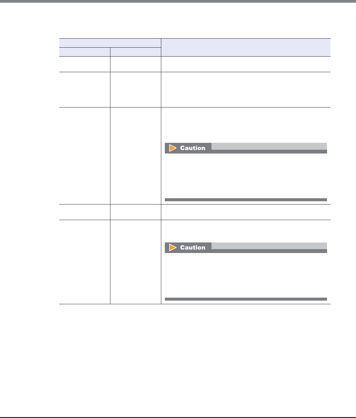
Appendix I Storage Migration Setting Files
I.1 Template File for Storage Migration Settings
ETERNUS Web GUI User’s Guide
Copyright 2013 FUJITSU LIMITED P2X0-1090-10ENZ0
1021
Operation Mode
The following table explains the details of the operation mode.
OPEMODE Description
Specification code Meaning
MMigration Data migration from the source storage system to the destination storage
system is performed.
M+QC
Migration +
Quick Compare
Data migration from the source storage system to the destination storage
system and a data comparison of source LUNs and destination volumes
are performed. "Quick Compare" compares data in a part of the volume
area. "Migration + Quick Compare" consecutively executes "data
migration" and "data comparison" for each volume.
M+FC
Migration +
Full Compare
Data migration from the source storage system to the destination storage
system and a data comparison of source LUNs and destination volumes
are performed. "Full Compare" compares data in entire volume area.
"Migration + Full Compare" consecutively executes "data migration" and
"data comparison" for each volume.
•Host access to the destination storage system must be stopped when
"Migration + Full Compare" is specified.
•When "Migration + Full Compare" is specified for the operation mode,
the time to complete the operation after data migration is increased
significantly.
QC Quick Compare A data comparison of source LUNs and destination volumes is performed.
"Quick Compare" compares data in a part of the volume area.
FC
Full Compare A data comparison of source LUNs and destination volumes is performed.
"Full Compare" compares data in entire volume area.
and "data comparison" for each volume.
•Host access to the destination storage system must be stopped when
"Full Compare" is specified.
•When "Full Compare" is specified for the operation mode, the time to
complete the operation after data migration is increased
significantly.

Appendix I Storage Migration Setting Files
I.2 Coding Conventions for the Storage Migration Setting File
ETERNUS Web GUI User’s Guide
Copyright 2013 FUJITSU LIMITED P2X0-1090-10ENZ0
1022
I.2 Coding Conventions for the Storage Migration Setting File
The following table shows the coding conventions for a Storage Migration setting file.
Keyword Coding conventions
Common •The Storage Migration setting file must be saved in the text format.
•Contents of the file must be described in alphanumeric characters.
•A keyword (Type, GROUP, OPEMODE, PATH, VOL) and its setting value must be connected
with "=" (equal). (*1)
•Only a tab or space can be placed before a keyword (Type, GROUP, OPEMODE, PATH, VOL).
(*1)
•The number of setting values assigned to a keyword (Type, GROUP, OPEMODE, PATH, VOL)
with "=" must coincide with the number specified for each keyword. For more information on
the number of setting values for each keyword, refer to "I.1 Template File for Storage
Migration Settings" (page 1019) (*1).
•Add the following information for each GROUP.
PATH (CMx, CAy, Pz, WWN), VOL
•There must not be an overlap with the content of the Storage Migration setting file or the
migration information (GROUP, destination CA port, source WWN, source LUN, or destination
volume) of the path already configured.
*1: "OPEMODE" is only available when using a template file with the new format.
GROUP •Up to 16 GROUPs can be specified.
•For the setting range for each GROUP, refer to "I.1 Template File for Storage Migration
Settings" (page 1019).
OPEMODE •Specify "M", "M+QC", "M+FC", "QC", or "FC" for each GROUP (when OPEMODE is omitted, it is
regarded as though "M" is specified and only migration is performed).
•For the setting range for each OPEMODE, refer to "I.1 Template File for Storage Migration
Settings" (page 1019).
PATH •Enclose the PATH and VOL for each GROUP with "{ }" (bracket symbols).
•Describe all "PATHs" and then all "VOLs" for each GROUP.
•Up to 8 PATHs per GROUP can be specified.
•Separate the PATH setting values with "," (comma).
•For the setting range of PATH, refer to "I.1 Template File for Storage Migration Settings"
(page 1019).
•Describe the PATH in the following order.
•Start a new line for each PATH. Multiple PATHs cannot be described without breaking.
PATH=CMx, CAy, Pz, wwwwwwwwwwwwwwww
CM#, CA#, and Port# for the destination FC-Initiator port
WWN for the source FC-CA port

Appendix I Storage Migration Setting Files
I.2 Coding Conventions for the Storage Migration Setting File
ETERNUS Web GUI User’s Guide
Copyright 2013 FUJITSU LIMITED P2X0-1090-10ENZ0
1023
VOL •Keep the number of VOLs to 512 or less, so they can be accessed from the source FC-CA port.
•Separate the VOL setting values with "," (comma).
•For the setting range of VOL, refer to "I.1 Template File for Storage Migration Settings" (page
1019).
•Describe the VOL in the following order.
•Start a new line for each VOL. Multiple VOLs cannot be described without breaking.
Other information •Entered letters are not case-sensitive.
•A line that starts with "#" is a comment.
•A file can be any text string.
Keyword Coding conventions
VOL=xxxx, yyyy
Destination volume number
Source LUN

Appendix I Storage Migration Setting Files
I.3 Setting Example of the Storage Migration Setting File
ETERNUS Web GUI User’s Guide
Copyright 2013 FUJITSU LIMITED P2X0-1090-10ENZ0
1024
I.3 Setting Example of the Storage Migration Setting File
A setting example of the Storage Migration setting file (in the new format) is shown below:
The above example describes the case where the following paths and migration volumes are configured for
three source storage systems (GROUP#0, 1, 2).
# Setting Example
eternus-storage-migration-0101
Type=Open
GROUP=0
OPEMODE=M+QC
{
PATH=CM0,CA0,P0,0000000011111111
PATH=CM1,CA0,P1,2222222233333333
VOL=0x0000,0x0040
VOL=0x0001,0x0041
VOL=0x00FF,0x013F
}
GROUP=1
OPEMODE=M+QC
{
PATH=CM0,CA1,P0,8888888888888888
VOL=4,10
}
GROUP=2
OPEMODE=M
{
PATH=CM0,CA1,P1,9999999999999999
VOL=0x0000011000000000,0x0141
}

Appendix I Storage Migration Setting Files
I.3 Setting Example of the Storage Migration Setting File
ETERNUS Web GUI User’s Guide
Copyright 2013 FUJITSU LIMITED P2X0-1090-10ENZ0
1025
A setting example of the Storage Migration setting file (in the old format) is shown below:
Path group
(OPEMODE)
Migration information
GROUP=0
(M+QC)
Path Location information of the
destination FC-Initiator port
WWN for the
source FC-CA port
CM0,CA0,P0 0000000011111111
CM1,CA0,P1 2222222233333333
Migration volume Source LUN Destination volume number
0x0000 0x0040
0x0001 0x0041
0x00FF 0x013F
GROUP=1
(M+QC)
Path Location information of
the destination FC-Initiator port
WWN for the source FC-CA port
CM0,CA1,P0 8888888888888888
Migration volume Source LUN Destination volume number
410
GROUP=2
(M)
Path Location information of
the destination FC-Initiator port
WWN for the source FC-CA port
CM0,CA1,P1 9999999999999999
Migration volume Source LUN Destination volume number
0x0000011000000000 0x0141
# Setting Example
Type=Open
GROUP=0
{
PATH=CM0,CA0,P0,0000000011111111
PATH=CM1,CA0,P1,2222222233333333
VOL=0000,0040
VOL=0001,0041
VOL=00FF,013F
}
GROUP=1
{
PATH=CM0,CA1,P0,8888888888888888
PATH=CM0,CA1,P1,9999999999999999
PATH=CM1,CA1,P0,aaaaAAAAbbbbBBBB
PATH=CM1,CA1,P1,EEEEeeeeFFFFffff
VOL=0100,0140
VOL=0101,0141
VOL=01FF,023F
}

Appendix I Storage Migration Setting Files
I.3 Setting Example of the Storage Migration Setting File
ETERNUS Web GUI User’s Guide
Copyright 2013 FUJITSU LIMITED P2X0-1090-10ENZ0
1026
The above example describes the case where the following paths and migration volumes are configured for
two sets of source storage systems (GROUP#0, 1).
Path group Migration information
GROUP=0 Path Location information of the
destination FC-Initiator port
WWN for the
source FC-CA port
CM0,CA0,P0 0000000011111111
CM1,CA0,P1 2222222233333333
Migration volume Source LUN Destination volume number
0000 0040
0001 0041
00FF 013F
GROUP=1 Path Location information of
the destination FC-Initiator port
WWN for the source FC-CA port
CM0,CA1,P0 8888888888888888
CM0,CA1,P1 9999999999999999
CM1,CA1,P0 aaaaAAAAbbbbBBBB
CM1,CA1,P1 EEEEeeeeFFFFffff
Migration volume Source LUN Destination volume number
0100 0140
0101 0141
01FF 023F

ETERNUS Web GUI User’s Guide
Copyright 2013 FUJITSU LIMITED P2X0-1090-10ENZ0
1027
Appendix J
Factory Default List
This chapter describes the default settings for the following management functions.
•Advanced Copy
•Connectivity
•System
The following table shows the factory default values. Note that functions and setting items that do not have
default settings are not listed in the following tables.
J.1 Advanced Copy
Function Setting item Default value Allowed input
Register Advanced
Copy License
Registration
Method
Input License Key For ETERNUS DX80 S2/DX90 S2
•Input License Key
•Use Free License/VAAI
For ETERNUS DX410 S2/DX440 S2 and
ETERNUS DX8100 S2/DX8700 S2
•Input License Key
•Use VAAI
Modify EC/OPC
Priority
EC/OPC Priority Automatic Priority •Automatic Priority
•High Priority
•Middle Priority
•Low Priority
•Very Low Priority
Copy Schedule
Mode
Session Balancing •Session Balancing
•Destination RAID Group Balancing
Modify Copy Table
Size
Resolution × 1 •× 1
•× 2
•× 4
•× 8
•× 16

Appendix J Factory Default List
J.1 Advanced Copy
ETERNUS Web GUI User’s Guide
Copyright 2013 FUJITSU LIMITED P2X0-1090-10ENZ0
1028
Modify Copy Table
Size
Table Size (MB) 0 For ETERNUS DX80 S2/DX90 S2
•0 – 256
For ETERNUS DX410 S2
•0 – 512
For ETERNUS DX440 S2
•0 – 4096
For ETERNUS DX8100 S2
•0 – 1024
For ETERNUS DX8700 S2
•0 – 12288
Table Size
Threshold (%)
80 •1 – 100
ODX Operation mode Disable •Enable
•Disable
The ODX function is disabled by
default and only the [Enable ODX]
function is available.
Create ODX Buffer
Volume
(Unit) GB •TB
•GB
•MB
Type Standard •Standard
•Thin Provisioning
Use all Largest
Free Space
Cleared Enable
•Selected
Use the largest available free
space
•Cleared
Do not use the largest available
free space
Encryption by CM When the encryption mode is
enabled
•Off
When the encryption mode is
disabled
•Not displayed
•On
•Off
•Not displayed
Radio buttons to
select a RAID
group (when
"Type" is
"Standard")
Off •On
Select a RAID group
•Off
Do not select a RAID group
Radio buttons to
select a TPP (when
"Type" is "Thin
Provisioning")
Off •On
Select a Thin Provisioning Pool
•Off
Do not select a Thin Provisioning
Pool
Function Setting item Default value Allowed input

Appendix J Factory Default List
J.1 Advanced Copy
ETERNUS Web GUI User’s Guide
Copyright 2013 FUJITSU LIMITED P2X0-1090-10ENZ0
1029
Modify Copy
Parameters
Policy Level 1
(Informational)
Threshold
50 •1 – 97 (%)
Policy Level 2
(Warning)
Threshold
70 •2 – 98 (%)
Policy Level 3
(Error) Threshold
99 •3 – 99 (%)
SDPE 1 •1 (GB)
•2 (GB)
•4 (GB)
Set Copy Path Operation Mode Create Copy Path •Create Copy Path
•Apply Copy Path
Base Information Backup Path File •Backup Path File
•Path File
•Not use
Initiator / Target
Setting
(for
ETERNUS6000)
Initiator •Initiator
•Target
IP Version IPv4 •IPv4
•IPv6 (Link Local)
•IPv6 (Connect IP)
Device Type ETERNUS DX8700 S2 •ETERNUS DX8700 S2
•ETERNUS DX8100 S2
•ETERNUS DX410 S2/DX440 S2
•ETERNUS DX90 S2
•ETERNUS DX90
•ETERNUS DX410/DX440/DX8100/
DX8400/DX8700
•ETERNUS4000/ETERNUS8000
MODEL400/600/800/1200/2200
•ETERNUS4000/ETERNUS8000
MODEL300/500/700/900/1100/
2100
•ETERNUS6000
Connection Type Direct •Remote
•Direct
Link Speed 1 •1 – 65535 (Mbit/s)
(Line setting) Cleared •Selected
A copy path is specified
•Cleared
A copy path is not specified
The checkbox is displayed only for
combinations of paths that can be
used to specify a copy path.
Function Setting item Default value Allowed input

Appendix J Factory Default List
J.1 Advanced Copy
ETERNUS Web GUI User’s Guide
Copyright 2013 FUJITSU LIMITED P2X0-1090-10ENZ0
1030
Modify REC
Multiplicity
Priority Level When "Connection Type" is
"Direct"
•Auto
When "Connection Type" is
"Remote"
•"-" (hyphen)
When "Connection Type" is "Direct"
•Auto
•1 (corresponds to "Very Low
Priority")
•2 (corresponds to "Low Priority")
•3
•4
•5
•6
•7
•8 (corresponds to "High Priority")
Modify REC
Multiplicity
Specification
Mode
When "Connection Type" is
"Remote"
•Auto
When "Connection Type" is
"Direct"
•"-" (hyphen)
When "Connection Type" is "Remote"
•Auto
•Manual
Multiplicity When "Specification Mode" is
"Manual"
•1
When "Specification Mode" is
"Auto"
•"-" (hyphen)
When "Specification Mode" is "Manual"
•1 – 1024
Copy Schedule
Mode
Session Balancing •Session Balancing
•Destination RAID Group Balancing
Modify REC Buffer Usage Unused •Send
•Receive
•Unused
Remote Box ID When "Usage" is "Send" or
"Receive"
•Remote Box ID
When "Usage" is "Unused"
•"-" (hyphen)
When "Usage" is "Send" or "Receive"
•Remote Box ID
Function Setting item Default value Allowed input

Appendix J Factory Default List
J.1 Advanced Copy
ETERNUS Web GUI User’s Guide
Copyright 2013 FUJITSU LIMITED P2X0-1090-10ENZ0
1031
Modify REC Buffer Size When "Usage" is "Send" or
"Receive"
•128 MB
When "Usage" is "Unused"
•"-" (hyphen)
When "Usage" is "Send" or "Receive"
•For ETERNUS DX90 S2
-128 MB
-256 MB
-512 MB
•For ETERNUS DX410 S2/DX440 S2
-128 MB
-256 MB
-512 MB
-1024 MB
-2048 MB
•For ETERNUS DX8100 S2/DX8700
S2
-128 MB
-256 MB
-512 MB
-1024 MB
-2048 MB
Forwarding
Interval
When "Usage" is "Send" or
"Receive"
•1 sec.
When "Usage" is "Unused"
•"-" (hyphen)
When "Usage" is "Send" or "Receive"
•1 sec.
•2 sec.
•4 sec.
•8 sec.
•15 sec.
•30 sec.
•45 sec.
•60 sec.
•75 sec.
•90 sec.
•105 sec.
•120 sec.
Function Setting item Default value Allowed input

Appendix J Factory Default List
J.1 Advanced Copy
ETERNUS Web GUI User’s Guide
Copyright 2013 FUJITSU LIMITED P2X0-1090-10ENZ0
1032
Modify REC Buffer Monitoring Time When "Usage" is "Send" or
"Receive"
•5 min.
When "Usage" is "Unused"
•"-" (hyphen)
When "Usage" is "Send" or "Receive"
•0 min.
•1 min.
•2 min.
•3 min.
•4 min.
•5 min.
•6 min.
•7 min.
•8 min.
•9 min.
•10 min.
•11 min.
•12 min.
•13 min.
•14 min.
•15 min.
HALT Wait Timer When "Usage" is "Send" or
"Receive"
•15 sec.
When "Usage" is "Unused"
•"-" (hyphen)
When "Usage" is "Send" or "Receive"
•0 sec.
•5 sec.
•10 sec.
•15 sec.
I/O Priority Mode When "Usage" is "Send" or
"Receive"
•Disable
When "Usage" is "Unused"
•"-" (hyphen)
When "Usage" is "Send" or "Receive"
•Enable
•Disable
Immediate HALT
Mode
When "Usage" is "Send" or
"Receive"
•Disable
When "Usage" is "Unused"
•"-" (hyphen)
When "Usage" is "Send" or "Receive"
•Enable
•Disable
Create REC Disk
Buffer
Controlling CM Automatic •Automatic
•CM#x CPU#y (x: CM number,
y: CPU number)
Encryption by CM Off •On
•Off
Stripe Depth 64KB •64KB
•128KB
•256KB
•512KB
•1024KB
Function Setting item Default value Allowed input

Appendix J Factory Default List
J.2 Connectivity
ETERNUS Web GUI User’s Guide
Copyright 2013 FUJITSU LIMITED P2X0-1090-10ENZ0
1033
J.2 Connectivity
Function Setting item Default value Allowed input
Add Host Group
•FC/FCoE
•iSCSI
•SAS
Host Response Default •Solaris MPxIO
•HP-UX
•AIX EMPD
•AIX VxVM
•AIX Single Path
•VS850/SVC
•Host responses created in the
ETERNUS DX Disk storage
system
•Default
Add Host
•FC/FCoE
•iSCSI
•SAS
Modify FC Port
Parameters
(When the port
mode is "CA" or
"CA/RA")
Connection FC-AL •Fabric
•FC-AL
Set Loop ID Manual •Manual
•Auto
Loop ID When "Set Loop ID" is "Manual"
•0x0
When "Set Loop ID" is "Auto"
•Ascending
When "Set Loop ID" is "Manual"
•0x0 – 0x7D
When "Set Loop ID" is "Auto"
•Ascending
•Descending
Transfer Rate Auto-negotiation •Auto-negotiation
•1 Gbit/s
•2 Gbit/s
•4 Gbit/s
•8 Gbit/s
•16 Gbit/s
The available transfer rate varies
depending on the CA type.
Frame Size 2048 •512 (bytes)
•1024 (bytes)
•2048 (bytes)
Reset Scope I_T_L •I_T_L
•T_L
Release
Reservation if Chip
is Reset
Disable •Enable
•Disable
REC Line No. 0 •0 – 127
This item is displayed only when
"Port Mode" is "CA/RA".

Appendix J Factory Default List
J.2 Connectivity
ETERNUS Web GUI User’s Guide
Copyright 2013 FUJITSU LIMITED P2X0-1090-10ENZ0
1034
Modify FC Port
Parameters
(When the port
mode is "CA" or
"CA/RA")
REC Transfer Mode
•Sync
•Async Stack
•Async
Consistency
•Async Through
Enable •Enable
•Disable
This item is displayed only when
"Port Mode" is "CA/RA".
Modify FC Port
Parameters
(When the port
mode is "RA")
Connection FC-AL •Fabric
•FC-AL
Set Loop ID Manual •Manual
•Auto
Loop ID When "Set Loop ID" is "Manual"
•0x0
When "Set Loop ID" is "Auto"
•Ascending
When "Set Loop ID" is "Manual"
•0x0 – 0x7D
When "Set Loop ID" is "Auto"
•Ascending
•Descending
Transfer Rate Auto-negotiation •Auto-negotiation
•1 Gbit/s
•2 Gbit/s
•4 Gbit/s
•8 Gbit/s
•16 Gbit/s
The available transfer rate varies
depending on the CA type.
Frame Size 2048 •512 (bytes)
•1024 (bytes)
•2048 (bytes)
REC Line No. 0 •0 – 127
REC Transfer Mode
•Sync
•Async Stack
•Async
Consistency
•Async Through
Enable •Enable
•Disable
Function Setting item Default value Allowed input

Appendix J Factory Default List
J.2 Connectivity
ETERNUS Web GUI User’s Guide
Copyright 2013 FUJITSU LIMITED P2X0-1090-10ENZ0
1035
Modify FC Port
Parameters
(When the port
mode is "Initiator")
Connection FC-AL •Fabric
•FC-AL
Set Loop ID Manual •Manual
•Auto
Loop ID When "Set Loop ID" is "Manual"
•0x0
When "Set Loop ID" is "Auto"
•Ascending
When "Set Loop ID" is "Manual"
•0x0 – 0x7D
When "Set Loop ID" is "Auto"
•Ascending
•Descending
Transfer Rate Auto-negotiation •Auto-negotiation
•1 Gbit/s
•2 Gbit/s
•4 Gbit/s
•8 Gbit/s
•16 Gbit/s
The available transfer rate varies
depending on the CA type.
Frame Size 2048 •512 (bytes)
•1024 (bytes)
•2048 (bytes)
WWN (Port Name) WWPN of the ETERNUS DX Disk
storage system •WWPN (16-digit hexadecimal)
WWN (Node Name) WWNN of the ETERNUS DX Disk
storage system •WWNN (16-digit hexadecimal)
Modify iSCSI Port
Parameters
(When the port
mode is "CA")
IP Version IPv4 •IPv4
•IPv6
•IPv4 / IPv6
IP Address 192.168.xxx.xxx •Up to 3 numeric characters
•First text box
1 – 255
•Other text boxes
0 – 255
Subnet Mask 255.255.255.0 •Up to 3 numeric characters
•All text boxes
0 – 255
IPv6 Link Local
Address
Address that is obtained from the
WWN of the ETERNUS DX Disk
storage system
•fe80::xxxx:xxxx:xxxx:xxxx
xxxx: 0 – ffff (FFFF)
(hexadecimal, alphanumeric
characters)
TCP Port No. 3260 •0 – 28671
TCP Window Scale 2 •0 – 14
Congestion Control
Option
Enable •Enable
•Disable
Function Setting item Default value Allowed input

Appendix J Factory Default List
J.2 Connectivity
ETERNUS Web GUI User’s Guide
Copyright 2013 FUJITSU LIMITED P2X0-1090-10ENZ0
1036
Modify iSCSI Port
Parameters
(When the port
mode is "CA")
iSNS Server Disable •IPv4
•IPv6
•Disable
iSNS Server Port No. 3205 •0 – 65535
iSCSI Name iqn.2000-09.com.fujitsu:storage-
system.eternus-
xxxx
:000
yyyyy
The default value varies depend-
ing on the factory setting. Refer to
"The default value for "iSCSI
Name"" (page 1043) for details.
•Alphabetic characters (lower
case) and numeric characters
•Symbols "-" (hyphen), "."
(period), and ":" (colon)
•The name starts with "iqn." or
"eui."
•4 – 223 characters
Jumbo Frame Disable •Enable
•Disable
VLAN ID Disable (*)
* When "VLAN ID" is "Enable", "0" is
displayed as a default value in the
text box.
•Enable
•Disable
When "VLAN ID" is "Enable"
•0 – 4095
Reset Scope I_T_L •I_T_L
•T_L
Release
Reservation if Chip
is Reset
Disable •Enable
•Disable
CmdSN Count Unlimited •Unlimited
•180
•100
•80
•40
•20
CHAP OFF •ON
•OFF
Header Digest OFF •OFF
•CRC32C
Data Digest OFF •OFF
•CRC32C
Function Setting item Default value Allowed input

Appendix J Factory Default List
J.2 Connectivity
ETERNUS Web GUI User’s Guide
Copyright 2013 FUJITSU LIMITED P2X0-1090-10ENZ0
1037
Modify iSCSI Port
Parameters
(When the port
mode is "RA")
IP Version IPv4 •IPv4
•IPv6
•IPv4 / IPv6
IP Address 192.168.xxx.xxx •Up to 3 numeric characters
•First text box
1 – 255
•Other text boxes
0 – 255
Subnet Mask 255.255.255.0 •Up to 3 numeric characters
•All text boxes
0 – 255
IPv6 Link Local
Address
Address that is obtained from the
WWN of the ETERNUS DX Disk
storage system
•fe80::xxxx:xxxx:xxxx:xxxx
xxxx: 0 - ffff (FFFF)
(hexadecimal, alphanumeric
characters)
TCP Port No. 3260 •0 – 28671
TCP Window Scale 2 •0 – 14
Congestion Control
Option
Enable •Enable
•Disable
iSCSI Name iqn.2000-09.com.fujitsu:storage-
system.eternus-
xxxx
:000
yyyyy
The default value varies depend-
ing on the factory setting. Refer to
"The default value for "iSCSI
Name"" (page 1043) for details.
•Alphabetic characters (lower
case) and numeric characters
•Symbols "-" (hyphen), "."
(period), and ":" (colon)
•The name starts with "iqn." or
"eui."
•4 – 223 characters
VLAN ID Disable (*)
* When "VLAN ID" is "Enable", "0" is
displayed as a default value in the
text box.
•Enable
•Disable
When "VLAN ID" is "Enable"
•0 – 4095
MTU 1300 When "IP Version" is "IPv4"
•576 – 9000 (bytes)
When "IP Version" is "IPv6" or "IPv4
/ IPv6"
•1280 – 9000 (bytes)
CHAP OFF •ON
•OFF
REC Line No. 0 •0 – 127
REC Transfer Mode
•Sync
•Async Stack
•Async
Consistency
•Async Through
Enable •Enable
•Disable
Function Setting item Default value Allowed input

Appendix J Factory Default List
J.2 Connectivity
ETERNUS Web GUI User’s Guide
Copyright 2013 FUJITSU LIMITED P2X0-1090-10ENZ0
1038
Modify iSCSI Port
Parameters
(When the port
mode is "CA/RA")
IP Version IPv4 •IPv4
•IPv6
•IPv4 / IPv6
IP Address 192.168.xxx.xxx •Up to 3 numeric characters
•First text box
1 – 255
•Other text boxes
0 – 255
Subnet Mask 255.255.255.0 •Up to 3 numeric characters
•All text boxes
0 – 255
IPv6 Link Local
Address
Address that is obtained from the
WWN of the ETERNUS DX Disk
storage system
•fe80::xxxx:xxxx:xxxx:xxxx
xxxx: 0 - ffff (FFFF)
(hexadecimal, alphanumeric
characters)
TCP Port No. 3260 •0 – 28671
TCP Window Scale 2 •0 – 14
Congestion Control
Option
Enable •Enable
•Disable
iSNS Server Disable •IPv4
•IPv6
•Disable
iSNS Server Port No. 3205 •0 – 65535
iSCSI Name iqn.2000-09.com.fujitsu:storage-
system.eternus-
xxxx
:000
yyyyy
The default value varies depend-
ing on the factory setting. Refer to
"The default value for "iSCSI
Name"" (page 1043) for details.
•Alphabetic characters (lower
case) and numeric characters
•Symbols "-" (hyphen), "."
(period), and ":" (colon)
•The name starts with "iqn." or
"eui."
•4 - 223 characters
VLAN ID Disable (*)
* When "VLAN ID" is "Enable", "0" is
displayed as a default value in the
text box.
•Enable
•Disable
When "VLAN ID" is "Enable"
•0 – 4095
Reset Scope I_T_L •I_T_L
•T_L
Release
Reservation if Chip
is Reset
Disable •Enable
•Disable
CmdSN Count Unlimited •Unlimited
•180
•100
•80
•40
•20
Function Setting item Default value Allowed input

Appendix J Factory Default List
J.2 Connectivity
ETERNUS Web GUI User’s Guide
Copyright 2013 FUJITSU LIMITED P2X0-1090-10ENZ0
1039
Modify iSCSI Port
Parameters
(When the port
mode is "CA/RA")
MTU When changing the port mode
from "CA" to "CA/RA"
•1500
When changing the port mode
from "RA" to "CA/RA"
•1300
When "IP Version" is "IPv4"
•576 – 9000 (bytes)
When "IP Version" is "IPv6" or "IPv4
/ IPv6"
•1280 – 9000 (bytes)
CHAP (CA) OFF •ON
•OFF
CHAP (RA) OFF •ON
•OFF
Header Digest OFF •OFF
•CRC32C
Data Digest OFF •OFF
•CRC32C
REC Line No. 0 •0 – 127
REC Transfer Mode
•Sync
•Async Stack
•Async
Consistency
•Async Through
Enable •Enable
•Disable
Modify iSCSI Port
Parameters
(When the port
mode is "iSCSI-RA
(for older storage
system
connection)")
IP Address 192.168.xxx.xxx •Up to 3 numeric characters
•First text box
1 – 255
•Other text boxes
0 – 255
Subnet Mask 255.255.255.0 •Up to 3 numeric characters
•All text boxes
0 – 255
Transfer Rate 1 Gbit/s •1 Gbit/s
•100Mbit/s
•Auto-negotiation
MTU 1300bytes •1000bytes
•1050bytes
•1100bytes
•1150bytes
•1200bytes
•1250bytes
•1300bytes
•1350bytes
•1400bytes
•1438bytes
Limit Band Width 400 •10 – 400 (Mbit/s)
Function Setting item Default value Allowed input

Appendix J Factory Default List
J.2 Connectivity
ETERNUS Web GUI User’s Guide
Copyright 2013 FUJITSU LIMITED P2X0-1090-10ENZ0
1040
Modify iSCSI Port
Parameters
(When the port
mode is "iSCSI-RA
(for older storage
system
connection)")
CHAP OFF •ON
•OFF
REC Line No. 0 •0 – 127
REC Transfer Mode
•Sync
•Async Stack
•Async
Consistency
•Async Through
Enable •Enable
•Disable
Modify iSCSI Port
Parameters
Send Number 1 •1 – 10 (Transmission count of
the ping command)
Modify SAS Port
Parameters
Transfer Rate Auto-negotiation •Auto-negotiation
•1.5 Gbit/s
•3 Gbit/s
•6 Gbit/s
Reset Scope I_T_L •I_T_L
•T_L
Release
Reservation if Chip
is Reset
Disable •Enable
•Disable
Modify FCoE Port
Parameters
Transfer Rate 10Gbit/s •10Gbit/s
Set VLAN ID Auto •Auto
•Fixed
VLAN ID 0 •0 – 4095
Set Fabric Name Auto •Auto
•Fixed
Fabric Name 0 •WWN of FCoE (16-digit
hexadecimal)
Frame Size 2048 •512 (bytes)
•1024 (bytes)
•2048 (bytes)
Reset Scope I_T_L •I_T_L
•T_L
Release
Reservation if Chip
is Reset
Disable •Enable
•Disable
Add LUN Group Number of LUNs 0 •0 – 4096
Start Host LUNs The smallest LUN among the
available LUNs •0 – 4095
Number of LUNs 1 •1 – 4096
Add Host Response Byte-0 of Inquiry
Response
No Conversion (Default) •No Conversion (Default)
•0x7F Conversion mode
•0x20 Conversion mode
Function Setting item Default value Allowed input

Appendix J Factory Default List
J.2 Connectivity
ETERNUS Web GUI User’s Guide
Copyright 2013 FUJITSU LIMITED P2X0-1090-10ENZ0
1041
Add Host Response Inquiry VPD ID Type Type3 (Default) •Type3 (Default)
•Type1
•Type1 + Type3
Inquiry Standard
Data Version
Version 5 (Default) •Version 5 (Default)
•Version 4
•Version 3
Command Timeout
Interval
Default (25sec.) •Default (25sec.)
•Customize
10 – 255 (sec.)
Load Balance
Response
Unit Attention (Default) •Unit Attention (Default)
•Busy
•Queue Full
Reservation Conflict
Response for Test
Unit Ready
Normal (Default) •Normal (Default)
•Conflict
Change Volume
Mapping
No Report (Default) •No Report (Default)
•Report
Volume Capacity
Expansion
No Report (Default) •No Report (Default)
•Report
Vendor Unique
Sense Code
No Report (Default) •No Report (Default)
•Report
Host Specific Mode Normal (Default) •Normal (Default)
•AIX Mode
•HP-UX Mode
•NR1000V Mode
•BS2000 Mode
Asymmetric /
Symmetric Logical
Unit Access
For ETERNUS DX80 S2/DX90 S2,
ETERNUS DX410 S2/DX440 S2,
ETERNUS DX8100 S2
•ACTIVE-ACTIVE /
PREFERRED_PATH (Default)
For ETERNUS DX8700 S2
•ACTIVE / ACTIVE (Default)
For ETERNUS DX80 S2/DX90 S2,
ETERNUS DX410 S2/DX440 S2,
ETERNUS DX8100 S2
•ACTIVE-ACTIVE /
PREFERRED_PATH (Default)
•ACTIVE / ACTIVE
For ETERNUS DX8700 S2
•ACTIVE-ACTIVE /
PREFERRED_PATH
•ACTIVE / ACTIVE (Default)
iSCSI Discovery
Reply Mode
All - Reply All Ports (Default) •All - Reply All Ports (Default)
•Port - Reply Target Port Only
TPGS Mode Enable (Default) •Enable (Default)
•Disable
TPG Referrals Disable (Default) •Enable
•Disable (Default)
iSCSI Reservation
Range
CA Port (Default) •CA Port (Default)
•Storage System
Function Setting item Default value Allowed input

Appendix J Factory Default List
J.2 Connectivity
ETERNUS Web GUI User’s Guide
Copyright 2013 FUJITSU LIMITED P2X0-1090-10ENZ0
1042
Add Host Response Sense Data
Conversion
No Conversion (Default) •No Conversion (Default)
•Customize
Modify CA Reset
Group
Checkbox to select
a port
All checkboxes are selected •Selected
Select the port
•Cleared
Do not select the port
Host-LU QoS Operation mode Disable •Enable
•Disable
The Host-LU QoS function is
disabled by default and only the
[Enable Host-LU QoS] function is
available.
Set FC/FCoE Host
QoS
Set iSCSI Host QoS
Set SAS Host QoS
Bandwidth Limit Unlimited •Unlimited
•15000 IOPS (800 MB/s)
•12600 IOPS (700 MB/s)
•10020 IOPS (600 MB/s)
•7500 IOPS (500 MB/s)
•5040 IOPS (400 MB/s)
•3000 IOPS (300 MB/s)
•1020 IOPS (200 MB/s)
•780 IOPS (100 MB/s)
•600 IOPS (70 MB/s)
•420 IOPS (40 MB/s)
•300 IOPS (25 MB/s)
•240 IOPS (20 MB/s)
•180 IOPS (15 MB/s)
•120 IOPS (10 MB/s)
•60 IOPS (5 MB/s)
Set FC Port QoS
Set iSCSI Port QoS
Set SAS Port QoS
Set FCoE Port QoS
Bandwidth Limit Unlimited •Unlimited
•27000 IOPS (1000 MB/s)
•21000 IOPS (850 MB/s)
•15000 IOPS (700 MB/s)
•10020 IOPS (600 MB/s)
•8040 IOPS (500 MB/s)
•6000 IOPS (400 MB/s)
•5040 IOPS (300 MB/s)
•4020 IOPS (250 MB/s)
•3000 IOPS (200 MB/s)
•2040 IOPS (160 MB/s)
•1020 IOPS (125 MB/s)
•720 IOPS (90 MB/s)
•480 IOPS (60 MB/s)
•240 IOPS (30 MB/s)
•120 IOPS (15 MB/s)
Function Setting item Default value Allowed input

Appendix J Factory Default List
J.2 Connectivity
ETERNUS Web GUI User’s Guide
Copyright 2013 FUJITSU LIMITED P2X0-1090-10ENZ0
1043
The default value for "iSCSI Name"
The default "iSCSI Name" varies depending on the factory setting. The setting for "iSCSI Name" is as follows:
iqn.2000-09.com.fujitsu:storage-system.eternus-
xxxx
:000
yyyyy
•
xxxx
The following character strings are specified for each model.
-For ETERNUS DX80 S2/DX90 S2
dxl
-For ETERNUS DX410 S2/DX440 S2
dx400
-For ETERNUS DX8100 S2/DX8700 S2
dx8000
•
yyyyy
"Model ID + unique number" for WWN is specified.
Add LU QoS Group Bandwidth Limit Unlimited •Unlimited
•15000 IOPS (800 MB/s)
•12600 IOPS (700 MB/s)
•10020 IOPS (600 MB/s)
•7500 IOPS (500 MB/s)
•5040 IOPS (400 MB/s)
•3000 IOPS (300 MB/s)
•1020 IOPS (200 MB/s)
•780 IOPS (100 MB/s)
•600 IOPS (70 MB/s)
•420 IOPS (40 MB/s)
•300 IOPS (25 MB/s)
•240 IOPS (20 MB/s)
•180 IOPS (15 MB/s)
•120 IOPS (10 MB/s)
•60 IOPS (5 MB/s)
Function Setting item Default value Allowed input

Appendix J Factory Default List
J.3 System
ETERNUS Web GUI User’s Guide
Copyright 2013 FUJITSU LIMITED P2X0-1090-10ENZ0
1044
J.3 System
■Network Management
Function Setting item Default value Allowed input
Setup Network
Environment
(When using IPv4)
Network Port MNT
For ETERNUS DX80 S2/DX90 S2
•MNT
•RMT
For ETERNUS DX410 S2/DX440 S2,
ETERNUS DX8100 S2/DX8700 S2
•MNT
•RMT
•FST
Master IP Address For ETERNUS DX80 S2/DX90 S2
•MNT port
192.168.1.1
For ETERNUS DX410 S2/DX440
S2, ETERNUS DX8100 S2/
DX8700 S2
•FST port
192.168.1.1
•Up to 3 numeric characters
•All the text boxes
0 – 255
Subnet Mask For ETERNUS DX80 S2/DX90 S2
•MNT port
255.255.255.0
For ETERNUS DX410 S2/DX440
S2, ETERNUS DX8100 S2/
DX8700 S2
•FST port
255.255.255.0
•Up to 3 numeric characters
•All the text boxes
0 – 255
Speed and Duplex Auto-negotiation •Auto-negotiation
•1Gbit/s
•100Mbit/s Half
•100Mbit/s Full
•10Mbit/s Half
•10Mbit/s Full
Wake on LAN Disable •Enable
•Disable
This item is displayed only when
"Network Port" is "MNT" or "RMT".

Appendix J Factory Default List
J.3 System
ETERNUS Web GUI User’s Guide
Copyright 2013 FUJITSU LIMITED P2X0-1090-10ENZ0
1045
Setup Network
Environment
(When using IPv6)
Network Port MNT
For ETERNUS DX80 S2/DX90 S2
•MNT
•RMT
For ETERNUS DX410 S2/DX440 S2,
ETERNUS DX8100 S2/DX8700 S2
•MNT
•RMT
•FST
Setup Firewall HTTP Selected •Selected
Enable the HTTP connection
•Cleared
Disable the HTTP connection
HTTPS Selected •Selected
Enable the HTTPS connection
•Cleared
Disable the HTTPS connection
Telnet Selected •Selected
Enable the Telnet connection
•Cleared
Disable the Telnet connection
SSH Selected •Selected
Enable the SSH connection
•Cleared
Disable the SSH connection
ICMP Selected •Selected
Enable the ICMP connection
•Cleared
Disable the ICMP connection
Maintenance-
Secure
Selected •Selected
Enable the Maintenance-Secure
connection
•Cleared
Disable the Maintenance-Secure
connection
SNMP Selected •Selected
Enable the SNMP connection
•Cleared
Disable the SNMP connection
RCIL Cleared •Selected
Enable the RCIL connection
•Cleared
Disable the RCIL connection
Whether RCIL is enabled or disabled is
only displayed when "Network Port" is
"MNT".
Function Setting item Default value Allowed input

Appendix J Factory Default List
J.3 System
ETERNUS Web GUI User’s Guide
Copyright 2013 FUJITSU LIMITED P2X0-1090-10ENZ0
1046
Setup SNMP Agent
Basic Interface
SNMP Function Disable •Enable
•Disable
LAN Port used for
SNMP
MNT •MNT
•RMT
Authentication
Failure
Send SNMP Trap •Send SNMP Trap
•Do not send SNMP Trap
Engine ID Default •Default
•Customize
Allowed input when "Customize" is
selected
-Alphanumeric characters (0 –
9, A – F, a – f)
-Inputting only "0" or "F" for the
"Engine ID" field is not allowed
-10 - 64 characters (even
number)
MIB-II RFC Version RFC1213 •RFC1213
•RFC4293
Setup SNMP
Manager
IP Version IPv4 •IPv4
•IPv6
Setup SNMP Agent
MIB Access View
Subtree1 -
Subtree10
Inclusion •Inclusion
•Exclude
Setup SNMP Agent
User
MIB View Setting ViewALL •ViewALL
•View-mib2
•View-exmib
•View name that is registered in
"11.2.3.5 Setup SNMP Agent MIB
Access View" (page 766).
When accessing the MIB is not allowed
•Blank
If "ViewALL", "View-mib2", or "View-
exmib" is deleted in "11.2.3.5 Setup
SNMP Agent MIB Access View" (page
766), the deleted options are not
displayed in the "MIB View Setting"
field.
Authentication Disable •Enable
•Disable
Authentication
Method
MD5 •MD5
•SHA
Encryption Disable •Enable
•Disable
Function Setting item Default value Allowed input

Appendix J Factory Default List
J.3 System
ETERNUS Web GUI User’s Guide
Copyright 2013 FUJITSU LIMITED P2X0-1090-10ENZ0
1047
Setup SNMP Agent
Community
View Name ViewALL •ViewALL
•View-mib2
•View-exmib
•View name that is registered in
"11.2.3.5 Setup SNMP Agent MIB
Access View" (page 766).
When accessing the MIB is not allowed
•Blank
If "ViewALL", "View-mib2", or "View-
exmib" is deleted in "11.2.3.5 Setup
SNMP Agent MIB Access View" (page
766), the deleted options are not
displayed in the "View Name" field.
Allowed SNMP
Manager List
Cleared •Selected
The SNMP Manager is allowed to
access
•Cleared
The SNMP Manager is not allowed
to access
If the Allowed SNMP Manager List has
been left blank, all of the SNMP
Managers are allowed to access.
Setup SNMP Agent
Trap
Manager No. Manager01 •Manager01 – Manager10
SNMP Version v1 •v1
•v2c
•v3
Community Name The community name that is
displayed at the top of the list
box.
The community name that is
registered using the [Setup SNMP
Agent Community] function.
User Name The user name that is displayed
at the top of the list box.
The user name that is registered using
the [Setup SNMP Agent User] function.
Port No. 162 •Numeric characters
1 – 65535
Download MIB File Option
(The ServerView
control code is
added to the
comment line of
the MIB definition
file)
Cleared •Selected
Download the MIB file with the
ServerView control code
•Cleared
Download the MIB file without the
ServerView control code
Version v1 •v1
•v2c/v3
Function Setting item Default value Allowed input

Appendix J Factory Default List
J.3 System
ETERNUS Web GUI User’s Guide
Copyright 2013 FUJITSU LIMITED P2X0-1090-10ENZ0
1048
Setup E-Mail
Notification
(Notification E-
Mail)
Notification E-Mail No •Yes
•No
Setup E-Mail
Notification
(Mail Server
Settings)
LAN Port used for
SMTP Connection
MNT •MNT
•RMT
SMTP Port No. 25 •Numeric characters
1 – 65535
SMTP requires
authentication
None •None
•AUTH SMTP
Authentication
Method
Automatic •Automatic
•CRAM-MD5
•PLAIN
•LOGIN
Setup E-Mail
Notification
(Retry Setting)
Maximum Retries 0 •0
•1
Retry Interval 1 •Numeric characters
1 – 5 (sec.)
Setup Syslog Send Log off •on (RFC3164)
•on (RFC5424)
•off
Port No. 514 •Numeric characters
1 – 65535
LAN Port MNT •MNT
•RMT
Setup SSH Server
Key
Key Length 2048 bit •1024 bit
•2048 bit
•4096 bit
SSH v1 Enable •Enable
•Disable
Create Self-signed
SSL Certificate
Key Length 2048 bit •1024 bit
•2048 bit
•4096 bit
Create Key/CSR Key Length 2048 bit •1024 bit
•2048 bit
•4096 bit
Function Setting item Default value Allowed input

Appendix J Factory Default List
J.3 System
ETERNUS Web GUI User’s Guide
Copyright 2013 FUJITSU LIMITED P2X0-1090-10ENZ0
1049
■Remote Support (REMCS) for Regions other than EMEA
Function Setting item Default value Allowed input
Setup Remote
Support
Customer
Information
Checkbox
(Delete any
Customer
Identity
information from
the storage
system after the
information is
sent to the
'REMCS Center'.)
Cleared •Selected
The customer information
saved on the ETERNUS DX
disk storage system is
deleted after transmitting
the information to the
REMCS center.
•Cleared
The customer information
saved on the ETERNUS DX
disk storage system is
retained after transmitting
the information to the
REMCS center.
Country of
Installation
(ISO3166 A2)
When logged with
"Japanese" as the
selected language
•JP
When logged with
"English" as the
selected language
•Blank
•Two fixed letters
•Capital letters or "99"
Installation Date 2001-01 YYYY-MM
•Numeric characters
•2001 - 2037
Year (YYYY)
•01 – 12
Month (MM)
Communication
Environment
Information
Connection Type Internet Connection •Internet Connection
•Internet Connection (Mail
only)
•P-P Connection
•P-P Connection (Mail only)
•P-P Connection (VPN
Connection)
•P-P Connection (VPN
Connection Mail only)
LAN Port used for
Remote Support
MNT •MNT
•RMT

Appendix J Factory Default List
J.3 System
ETERNUS Web GUI User’s Guide
Copyright 2013 FUJITSU LIMITED P2X0-1090-10ENZ0
1050
Setup Remote
Support
Communication
Environment
Information
Scheduled
Connection Time
Undefined Hour : Minute
•Numeric characters
•00 - 23
Hour
•00 - 59
Minute
•Undefined (10:00 - 15:00)
Different times are
specified in the factory
settings.
Scheduled
Connection
Period
Every Day •Every Day
•Every Day (except Sunday)
•Every Day (except Saturday
and Sunday)
•Once per Week
Specify the Day
of the Week
Sunday •Sunday
•Monday
•Tuesday
•Wednesday
•Thursday
•Friday
•Saturday
Port No. (Proxy
Server)
0•Numeric characters
0 – 65535
Port No. (SMTP
Server)
25 •Numeric characters
0 – 65535
Authentication
Type
No SMTP
Authentication •No SMTP Authentication
•POP Before SMTP
Authentication
•AUTH SMTP Authentication
Authentication
Method
Automatic •Automatic
•CRAM-MD5
•PLAIN
•LOGIN
Port No. (POP
Server)
110 •Numeric characters
0 – 65535
Function Setting item Default value Allowed input

Appendix J Factory Default List
J.3 System
ETERNUS Web GUI User’s Guide
Copyright 2013 FUJITSU LIMITED P2X0-1090-10ENZ0
1051
Setup Remote
Support
Communication
Environment
Information
REMCS Center Blank •Blank
•Fujitsu America
•Australia
•Brazil
•Hong-Kong
•China
•Indonesia
•Korea
•Malaysia
•Philippine
•Singapore
•Taiwan
•Thailand
•Vietnam
•Individual support in
Hawaii
•OSC
•Direct Input Setting
Detailed
Configuration
Information
Data
Transmission
Method
Split •Split
•Do not Split
When "Split" is
selected
•Split large data
into multiple E-
mails
512KB
When "Split" is selected
•Split large E-mail into
multiple E-mails
64 – 6400KB
•Split large data into
multiple E-mails
64 – 512KB
Specify Storage
System Name for
HELO/EHLO
Announcement
when Sending
Mail
Do not specify •Specify
•Do not specify
Result
notification
information
Administrator Notification •Notification
•Not Notification
Connection check
operator
Not Notification •Notification(Standard E-
Mail format)
•Notification(Simple E-Mail
format for cell phone)
•Not Notification
Function Setting item Default value Allowed input

Appendix J Factory Default List
J.3 System
ETERNUS Web GUI User’s Guide
Copyright 2013 FUJITSU LIMITED P2X0-1090-10ENZ0
1052
Setup Remote
Support
Time
Information
SMTP Response
Timeout (sec.)
60 •Numeric characters
1 – 3600
SMTP Retry
Count
5•Numeric characters
1 – 60
SMTP Retry
Interval (sec.)
30 •Numeric characters
1 – 3600
HTTP Timeout
(sec.)
30 •Numeric characters
1 – 3600
HTTP Retry Count 5 •Numeric characters
1 – 60
HTTP Retry
Interval (sec.)
5•Numeric characters
1 – 3600
Queue Time
before Sending
Mails (msec.)
(only when POP
Before SMTP
authentication is
enabled)
1000 •Numeric characters
1 – 3600
Setup Log Sending
Parameters
(Configure
Automatic Log
Transmission)
Send Log when Errors Occur When the Remote
Support setting has
not been completed
•Cleared
When the Remote
Support setting has
been completed
•Selected
•Selected
Send log when errors occur
•Cleared
Periodical Transmission of Log When the Remote
Support setting has
not been completed
•Cleared
When the Remote
Support setting has
been completed
•Selected
•Selected
Send log periodically
•Cleared
Time Undefined •Numeric characters
•00 - 23
Hour
•00 - 59
Minute
•Undefined (10:00 - 15:00)
Different times are
specified for each ETERNUS
DX Disk storage system in
the factory settings.
Period Once per Week •Once per Week
•Everyday
Function Setting item Default value Allowed input

Appendix J Factory Default List
J.3 System
ETERNUS Web GUI User’s Guide
Copyright 2013 FUJITSU LIMITED P2X0-1090-10ENZ0
1053
■Remote Support (AIS Connect) for Regions other than Japan
Setup Log Sending
Parameters
(Configure
Automatic Log
Transmission)
Day of the Week Undefined •Sunday
•Monday
•Tuesday
•Wednesday
•Thursday
•Friday
•Saturday
•Undefined (Any day from
Monday to Friday)
Different days are specified
for each ETERNUS DX Disk
storage system in the
factory settings
Setup Log Sending
Parameters
(Immediately Send
Log Manually)
Include I/O Module log Yes •Yes
•No
Time Range Specified Cleared •Selected
Specify the time range
•Cleared
Function Setting item Default value Allowed input
Function Setting item Default value Allowed input
Setup AIS Connect
Environment
AIS Connect Disable •Enable
•Disable
Use LAN Port MNT •MNT
•RMT
SSL Server Certification Enable •Enable
•Disable
Auto Send Log Disable •Enable
•Disable
Connection Type HTTP •HTTP
•SOCKS
Change Password Cleared •Selected
Change the password
•Cleared
Do not change the password
Setup Remote
Session Permission
Remote Session Forbid •Permit
•Forbid
Remote Session Timeout 1 hour •1 – 24 hour
•Unlimited
Add Key Server Port No. 5696 •Numeric characters
1 – 65535
LAN Port MNT •MNT
•RMT

Appendix J Factory Default List
J.3 System
ETERNUS Web GUI User’s Guide
Copyright 2013 FUJITSU LIMITED P2X0-1090-10ENZ0
1054
■Define Role
Create Key Group Security Level High •High
•Low
Recovery Mode Auto •Auto
•Manual
Key Valid Period Unlimited •Unlimited
•1 month – 12 month
Key Server Master None •None
•1
•2
Slave None
Update SED
Authentication Key
Current Key Enabled Key •Enabled Key
•Disabled Key
Function Setting item Default value Allowed input
Function Setting item Default value Allowed input
Setup User Account User Role Monitor •Monitor
•Admin
•StorageAdmin
•AccountAdmin
•SecurityAdmin
•Maintainer
•Software
•Custom role
Account Enable •Enable
•Disable
Modify RADIUS RADIUS Authentication Disable •Enable
•Disable
Recovery Mode Yes (Communication
error / Authentication
error)
•Yes (Communication error /
Authentication error)
•Yes (Communication error)
•No
Port No. 1812 •Numeric characters
1 – 65535
LAN Port MNT •MNT
•RMT
Authentication Mode CHAP •CHAP
•PAP

Appendix J Factory Default List
J.3 System
ETERNUS Web GUI User’s Guide
Copyright 2013 FUJITSU LIMITED P2X0-1090-10ENZ0
1055
■ECO Mode Management
Modify RADIUS Retry Out Time 30 •10
•20
•30
•40
•50
•60
Add Role Policies
•Status Display
•RAID Group Management
•Volume - Create / Modify
•Volume - Delete / Format
•Host Interface Management
•Advanced Copy Management
•Copy Session Management
•Storage Migration
Management
•Storage Management
•User Management
•Authentication / Role
•Security Setting
•Maintenance Information
•Maintenance Operation
All cleared •Selected
Set the policy
•Cleared
Do not set the policy
Function Setting item Default value Allowed input
Function Setting item Default value Allowed input
Modify ECO Mode
General Setting
ECO Mode Disable •Enable
•Disable
Create ECO Mode
Schedule
Event Type everyday •everyday
•Every week
•Specific days
•Specific week
Event Type everyday From Time
•00:00
To Time
•00:00
From Time
•00:00 – 23:30
(Can be specified at
intervals of 30 minute)
To Time
•00:00 – 23:30
(Can be specified at
intervals of 30 minute)

Appendix J Factory Default List
J.3 System
ETERNUS Web GUI User’s Guide
Copyright 2013 FUJITSU LIMITED P2X0-1090-10ENZ0
1056
Create ECO Mode
Schedule
Event Type Every week Period (start day)
•Monday
Period (end day)
•Monday
From Time
•00:00
To Time
•00:00
Period (start day)
•Monday – Sunday
Period (end day)
•Monday – Sunday
From Time
•00:00 – 23:30
(Can be specified at
intervals of 30 minute)
To Time
•00:00 – 23:30
(Can be specified at
intervals of 30 minute)
Specific days Month
•Every Month
Period (start date)
•01
Period (term)
•One day only
From Time
•00:00
To Time
•00:00
Month
•Every Month, January -
December
Period (start date)
•01 - 31
Period (term)
•One day only, 2 days - 7 days
From Time
•00:00 – 23:30
(Can be specified at
intervals of 30 minute)
To Time
•00:00 – 23:30
(Can be specified at
intervals of 30 minute)
Specific week Month
•Every Month
Period (nth week)
•1st
Period (start day)
•Monday
Period (end day)
•Monday
From Time
•00:00
To Time
•00:00
Month
•Every Month, January -
December
Period (nth week)
•1st – 4th, Last
Period (start day)
•Monday – Sunday
Period (end day)
•Monday – Sunday
From Time
•00:00 – 23:30
(Can be specified at
intervals of 30 minute)
To Time
•00:00 – 23:30
(Can be specified at
intervals of 30 minute)
Function Setting item Default value Allowed input

Appendix J Factory Default List
J.3 System
ETERNUS Web GUI User’s Guide
Copyright 2013 FUJITSU LIMITED P2X0-1090-10ENZ0
1057
■Event/Dump Management
Function Setting item Default value Allowed input
Setup Event
Notification
Setting based on Severity Refer to "System
Defaults" (page 888)
in "11.2.9.1 Setup
Event Notification"
(page 880) for
details.
•Selected (normal checkbox)
Notify all events
•Selected (lighter colored
checkbox)
Some events are notified
and some events are not
notified
•Cleared
No events are notified
•-
Not applicable to
notification
•Error Severity Level
•Warning Severity Level
•Informational Level
•Selected
Notify
•Cleared
Not notify
•-
Not applicable to
notification
Export/Delete Log Specify Time Range No •Yes
•No
•Last 24 hours
Include I/O Module log Yes •Yes
•No
Log File Size Non-segmentation •Non-segmentation
•4.27MB
•1.44MB (Floppy Disk)
•640KB (E-Mail)
Delete of Customer Information No •Yes
•No
Export Panic Dump Panic Dumps Cleared •Select
Export the panic dump
•Cleared
Do not export the panic
dump
Dump File Segment Size Non-segmentation •Non-segmentation
•4.27MB
•1.44MB (Floppy Disk)
•640KB (E-Mail)

Appendix J Factory Default List
J.3 System
ETERNUS Web GUI User’s Guide
Copyright 2013 FUJITSU LIMITED P2X0-1090-10ENZ0
1058
■Audit Log Management
■Utility Management
Function Setting item Default value Allowed input
Audit Log Operation mode Disable •Enable
•Disable
The Audit Log function is
disabled by default and only the
[Enable Audit Log] function can
be performed.
Setup Audit Log Send Audit Log off •on (RFC3164)
•on (RFC5424)
•off
Port No. 514 •Numeric characters
1 – 65535
LAN Port MNT •MNT
•RMT
Function Setting item Default value Allowed input
Backup
Configuration
Select Configuration Definition Configuration(Latest) •Configuration(Latest)
•Configuration(1 time
before)
•Configuration(2 times
before)
Select Backup Slot Backup #1 •Backup #1
•Backup #2
•Backup #3
•Backup #4
Start/Stop
Performance
Monitoring
Interval (sec.) 30 •30 – 300
(Can be specified at intervals of
30 minute)

Appendix J Factory Default List
J.3 System
ETERNUS Web GUI User’s Guide
Copyright 2013 FUJITSU LIMITED P2X0-1090-10ENZ0
1059
■System Management
Function Setting item Default value Allowed input
Modify Date and
Time
Date Current date and time
(When the ETERNUS
DX Disk storage
system is installed in
Japan, the local time
for Japan is
displayed)
YYYY-MM-DD hh:mm:ss
•Numeric characters
•2001 - 2037
Year (YYYY)
•01 – 12
Month (MM)
•01 – 31
Date (DD)
•00 – 23
Hour (hh)
•00 – 59
Minute (mm)
•00 – 59
Second (ss)
Time Zone When the ETERNUS
DX Disk storage
system is shipped
from Japan and
shipped to Japan
•(GMT+09:00)
Tokyo, Osaka,
Kyoto, Fukuoka,
Sapporo
When the ETERNUS
DX Disk storage
system is shipped
from Japan to regions
other than Japan
•(GMT+00:00)
Dublin, London,
Manchester,
Lisbon
* The default value
depends on the
shipment
information
•Refer to "Allowed input for
"Time Zone"" (page 1063)

Appendix J Factory Default List
J.3 System
ETERNUS Web GUI User’s Guide
Copyright 2013 FUJITSU LIMITED P2X0-1090-10ENZ0
1060
Modify Date and
Time
Time Zone (time difference
setting)
When selecting
"Manually" in the
"Time Zone" field
•+ 00 : 00
When selecting "Manually" in
the "Time Zone" field
•+/-
Time difference
•00 – 12
Hour
•00,15, 30, 45
Minute
Daylight Saving
Time
Set OFF •ON
•OFF
Range (by day
of the week) •Start
January
1st
Sunday
00 : 00
•End
January
1st
Sunday
00 : 00
•January – December
Month
•1st – 4th, Last
Week
•Monday – Sunday
Day of the week
•00 – 23
Hour
Range (by
Date) •Start
January
01
00 : 00
•End
January
01
00 : 00
•January – December
Month
•01 – 31, Last Day
Date
•00 – 23
Hour
NTP Service NTP server NTP disabled •NTP enabled
•NTP disabled
LAN Port used
for NTP
MNT •MNT
•RMT
Change Box ID Box ID Device ID A combination of 1 to 40 of the
following characters.
•Capital letters
•Numeric characters
•Spaces
•"#" (hash keys)
Function Setting item Default value Allowed input

Appendix J Factory Default List
J.3 System
ETERNUS Web GUI User’s Guide
Copyright 2013 FUJITSU LIMITED P2X0-1090-10ENZ0
1061
Setup Subsystem
Parameters
Load Balance Enable •Enable
•Disable
Reject INQUIRY from Unauthorized
Host
Disable •Enable
•Disable
Thin Provisioning Allocation Mode TPP balancing •TPP balancing
•TPV balancing
Cache Mirroring When the "Change"
checkbox is cleared
•Enable
•Enable
•Disable
When changing the setting
"Change" checkbox
•Selected
Change the settings
•Cleared
The value returns to the
previous state when this
function is first started.
Checkcode Enforcement Disable •Enable
•Disable
I/O Offloading When the ETERNUS
DX Disk storage
system is shipped
•Enable
When the firmware
version is updated to
"V10L50" or later
•Disable
•Enable
•Disable
Web GUI
Settings
Function to Add
Host
"Use "Add Host
Group"" checkbox
•Selected
"Use "Add Host""
checkbox
•Cleared
Use "Add Host Group"
•Selected
Use "Add Host Group"
function
•Cleared
Do not use "Add Host Group"
function
Use "Add Host"
•Selected
Use "Add Host" function
•Cleared
Do not use "Add Host"
function
Setup Encryption
Mode
Encryption Mode Disable •Disable
•Fujitsu Original
•AES
Function Setting item Default value Allowed input

Appendix J Factory Default List
J.3 System
ETERNUS Web GUI User’s Guide
Copyright 2013 FUJITSU LIMITED P2X0-1090-10ENZ0
1062
Setup SMI-S
Environment
SMI-S When the ETERNUS
DX Disk storage
system is shipped to
EMEA region
•Enable
When the ETERNUS
DX Disk storage
system is shipped to
regions other than
EMEA
•Disable
•Enable
•Disable
Setup Power
Management
Enable Cleared •Selected
Enable the power
management by an external
input device
•Cleared
Disable the power
management by an external
input device
Auto Power Disable •Enable
•Disable
Power Resume Disable •Enable
•Disable
For ETERNUS
DX80 S2/DX90
S2
Delay until
Shutdown
(min.)
0•0 – 15
Set
management
unit interface
PMAN •Power Synchronized Unit
•PMAN
•Manual
Power Failure
Signal
Positive •Positive
•Negative
Low Battery
Signal
Positive •Positive
•Negative
UPS Shutdown
Signal
Cleared •Selected
Enable the UPS shutdown
signal
•Cleared
Disable the UPS shutdown
signal
When "UPS Shutdown
Signal" is enabled
•Positive
•Signal logic when "UPS
Shutdown Signal" is enabled
•Positive
•Negative
Function Setting item Default value Allowed input

Appendix J Factory Default List
J.3 System
ETERNUS Web GUI User’s Guide
Copyright 2013 FUJITSU LIMITED P2X0-1090-10ENZ0
1063
Allowed input for "Time Zone"
Select the time zone from the following;
•(GMT-12:00) Eniwetok, Kwajalein
•(GMT-11:00) Samoa
•(GMT-10:00) Honolulu
•(GMT-09:00) Alaska
•(GMT-08:00) Los Angeles, San Francisco, San Diego
•(GMT-07:00) Phoenix, Calgary, Denver
•(GMT-06:00) Chicago, Mexico City
•(GMT-05:00) New York, Bogota
•(GMT-04:00) Caracas
•(GMT-03:30) Newfoundland
•(GMT-03:00) Sao Paulo, Brasilia
•(GMT-02:00) Mid-Atlantic
•(GMT-01:00) Azores Island, Cape Verde
•(GMT+00:00) Dublin, London, Manchester, Lisbon
•(GMT+01:00) Paris, Madrid, Stockholm
•(GMT+01:00) Rome, Vienna, Berlin
•(GMT+01:00) Milan, Amsterdam
•(GMT+02:00) Athens, Helsinki, Cairo
•(GMT+02:00) Beirut, Cape Town
•(GMT+03:00) Nairobi, Moscow
•(GMT+04:00) Abu Dhabi
•(GMT+05:00) Islamabad, Karachi
•(GMT+05:30) New Delhi
•(GMT+06:00) Dhaka
•(GMT+07:00) Bangkok, Jakarta
•(GMT+08:00) Hong Kong, Manila, Singapore
•(GMT+08:00) Beijing, Taipei, Kuala Lumpur, Perth
•(GMT+09:00) Tokyo, Osaka, Kyoto, Fukuoka, Sapporo
•(GMT+09:00) Seoul
•(GMT+09:30) Adelaide
•(GMT+10:00) Guam, Sydney, Melbourne
•(GMT+11:00) Solomon Islands, New Caledonia
•(GMT+12:00) Wellington, Auckland, Fiji
•Manually
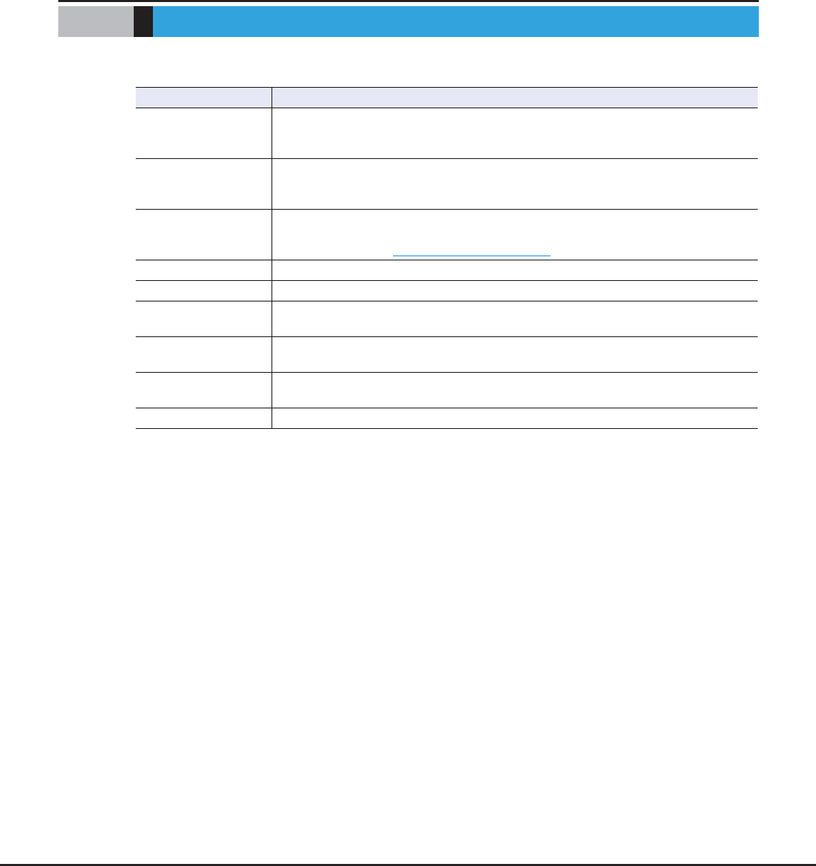
ETERNUS Web GUI User’s Guide
Copyright 2013 FUJITSU LIMITED P2X0-1090-10ENZ0
1064
Appendix K
Error Code
The error codes for copy sessions are described below.
Error code Description
0x10 – 0x1F
An error that is caused by a copy source volume occurs.
Some copy source volumes cannot be accessed because a failure has occurred in a compo-
nent (e.g. drives and drive enclosures).
0x20 – 0x2F
An error that is caused by a copy destination volume occurs.
Some copy destination volumes cannot be accessed because a failure has occurred in a
component (e.g. drives and drive enclosures).
0x30 – 0x3F
An error that is caused by an REC path occurs.
The error location (Suspected Spot) is displayed in the "Detail Information" field on the [Copy
Path] screen. Refer to "8.1.6.2 Copy Path" (page 271) for details.
0xBA A bad sector is detected.
0xBB SDV/SDP capacity is insufficient.
0xBD Overload status is detected in a copy destination volume or a copy destination storage
system.
0xBE A line has failed. Data is stored in the REC Buffer.
This error is displayed only when the "Type" is "REC".
0xBF A line has failed. Data is stored in the REC Disk Buffer.
This error is displayed only when the "Type" is "REC".
Other than above An error other than the ones listed above occurs.

ETERNUS Web GUI User's Guide
ETERNUS DX80 S2/DX90 S2, ETERNUS DX410 S2/DX440 S2,
ETERNUS DX8100 S2/DX8700 S2
P2X0-1090-10ENZ0
Date of issuance: June 2013
Issuance responsibility: FUJITSU LIMITED
• The content of this manual is subject to change without notice.
• This manual was prepared with the utmost attention to detail.
However, Fujitsu shall assume no responsibility for any operational problems as the result of
errors, omissions, or the use of information in this manual.
• Fujitsu assumes no liability for damages to third party copyrights or other rights arising from
the use of any information in this manual.
• The content of this manual may not be reproduced or distributed in part or in its entirety
without prior permission from Fujitsu.