Fujitsu M10 4 Users Manual 4/Fujitsu 4S/SPARC 4/SPARC 4S Service
2015-01-29
: Fujitsu Fujitsu-M10-4-Users-Manual-219334 fujitsu-m10-4-users-manual-219334 fujitsu pdf
Open the PDF directly: View PDF ![]() .
.
Page Count: 520 [warning: Documents this large are best viewed by clicking the View PDF Link!]
- Fujitsu M10-4/Fujitsu M10-4S/SPARC M10-4/SPARC M10-4S Service Manual
- Contents
- Preface
- Chapter 1 Before Starting Maintenance Work
- Chapter 2 Understanding the System Components
- Chapter 3 Troubleshooting
- 3.1 Suspected Failure Conditions
- 3.2 Determining the Causes of Individual Failures
- 3.3 Identifying a Failure
- 3.3.1 Checking the LED indications
- 3.3.2 Checking error messages
- 3.3.3 Checking the status of a component
- 3.3.4 Checking the status of a PCI expansion unit
- 3.3.5 Checking log information
- 3.3.6 Checking the messages output by the predictive self-repairing tool
- 3.3.7 Identifying the location of the chassis requiring maintenance
- 3.4 Downloading Error Log Information
- Chapter 4 Preparing for Maintenance
- Chapter 5 Understanding the Preparations for Enabling Maintenance
- Chapter 6 Understanding the Preparations for Restoring the System
- Chapter 7 Maintaining the CPU Memory Units
- Chapter 8 Maintaining the Memory
- Chapter 9 Maintaining the Crossbar Units
- Chapter 10 Maintaining the Power Supply Units
- Chapter 11 Maintaining the Fan Units
- Chapter 12 Maintaining the Internal Disks
- Chapter 13 Maintaining the PCI Express Cards
- Chapter 14 Maintaining the PSU Backplane Unit
- Chapter 15 Maintaining the Operation Panel
- Chapter 16 Maintaining the Crossbar Units of the Crossbar Box
- Chapter 17 Maintaining the XSCF Unit of the Crossbar Box
- Chapter 18 Maintaining the Power Supply Units of the Crossbar Box
- Chapter 19 Maintaining the Fan Units of the Crossbar Box
- Chapter 20 Maintaining the XSCF Interface Unit of the Crossbar Box
- Chapter 21 Maintaining the Crossbar Backplane Unit of the Crossbar Box
- Chapter 22 Maintaining the Fan Backplane of the Crossbar Box
- Chapter 23 Maintaining the Operation Panel of the Crossbar Box
- Chapter 24 Maintaining the Crossbar Cables (Electrical)
- Chapter 25 Maintaining the Crossbar Cables (Optical)
- Chapter 26 Maintaining the XSCF BB Control Cables
- Chapter 27 Maintaining the XSCF DUAL Control Cables
- Chapter 28 Maintaining the Cable Kit of the Crossbar Box
- Chapter 29 Maintaining the Dedicated Power Distribution Unit Mounted on the Rack for Expanded Connection
- 29.1 Configuration of the Dedicated Power Distribution Unit
- 29.2 Before Maintaining the Dedicated Power Distribution Unit
- 29.3 Enabling the Removal of the Dedicated Power Distribution Unit
- 29.4 Removing the Dedicated Power Distribution Unit
- 29.5 Installing the Dedicated Power Distribution Unit
- 29.6 Restoring the System
- Appendix A Component List
- Appendix B Component Specifications
- Appendix C Oracle Solaris Troubleshooting Commands
- Appendix D External Interface Specifications
- Index

Fujitsu M10-4/Fujitsu M10-4S/
SPARC M10-4/SPARC M10-4S
Service Manual
Manual Code: C120-E682-06EN
December 2013

Copyright © 2007, 2013, Fujitsu Limited. All rig
h
ts reserved.
Oracle and/or its affiliates provided technical input and review on portions of this material.
Oracle and/or its affiliates and Fujitsu Limited each own or control intellectual property rights relating to products and technology described in this document, and such products,
technology and this document are protected by copyright laws, patents, and other intellectual property laws and international treaties.
This document and the product and technology to which it pertains are distributed under licenses restricting their use, copying, distribution, and decompilation. No part of such
product or technology, or of this document, may be reproduced in any form by any means without prior written authorization of Oracle and/or its affiliates and Fujitsu Limited, and
their applicable licensors, if any. The furnishings of this document to you does not give you any rights or licenses, express or implied, with respect to the product or technology to
which it pertains, and this document does not contain or represent any commitment of any kind on the part of Oracle or Fujitsu Limited or any affiliate of either of them.
This document and the product and technology described in this document may incorporate third-party intellectual property copyrighted by and/or licensed from the suppliers to
Oracle and/or its affiliates and Fujitsu Limited, including software and font technology.
Per the terms of the GPL or LGPL, a copy of the source code governed by the GPL or LGPL, as applicable, is available upon request by the End User. Please contact Oracle and/or its
affiliates or Fujitsu Limited. This distribution may include materials developed by third parties. Parts of the product may be derived from Berkeley BSD systems, licensed from the
University of California.
UNIX is a registered trademark of The Open Group.
Oracle and Java are registered trademarks of Oracle and/or its affiliates.
Fujitsu and the Fujitsu logo are registered trademarks of Fujitsu Limited.
SPARC Enterprise, SPARC64, SPARC64 logo and all SPARC trademarks are trademarks or registered trademarks of SPARC International, Inc. in the United States and other
countries and used under license.
Other names may be trademarks of their respective owners.
If this is software or related documentation that is delivered to the U.S. Government or anyone licensing it on behalf of the U.S. Government, the following notice is applicable:
U.S. GOVERNMENT END USERS: Oracle programs, including any operating system, integrated software, any programs installed on the hardware, and/or documentation, delivered
to U.S. Government end users are "commercial computer software" pursuant to the applicable Federal Acquisition Regulation and agency-specific supplemental regulations. As such,
use, duplication, disclosure, modification, and adaptation of the programs, including any operating system, integrated software, any programs installed on the hardware, and/or
documentation, shall be subject to license terms and license restrictions applicable to the programs. No other rights are granted to the U.S. Government.
Disclaimer: The only warranties granted by Oracle and Fujitsu Limited, and/or any affiliate in connection with this document or any product or technology described herein are those
expressly set forth in the license agreement pursuant to which the product or technology is provided.
EXCEPT AS EXPRESSLY SET FORTH IN SUCH AGREEMENT, ORACLE OR FUJITSU LIMITED, AND/OR THEIR AFFILIATES MAKE NO REPRESENTATIONS OR WARRANTIE
S OF ANY KIND (EXPRESS OR IMPLIED) REGARDING SUCH PRODUCT OR TECHNOLOGY OR THIS DOCUMENT, WHICH ARE ALL PROVIDED AS IS, AND ALL EXPRESS
OR IMPLIED CONDITIONS, REPRESENTATIONS AND WARRANTIES, INCLUDING WITHOUT LIMITATION ANY IMPLIED WARRANTY OF MERCHANTABILITY, FITNESS
FOR A PARTICULAR PURPOSE OR NONINFRINGEMENT, ARE DISCLAIMED, EXCEPT TO THE EXTENT THAT SUCH DISCLAIMERS ARE HELD TO BE LEGALLY INVALID.
Unless otherwise expressly set forth in such agreement, to the extent allowed by applicable law, in no event shall Oracle or Fujitsu Limited, and/or any of their affiliates have any
liability to any third party under any legal theory for any loss of revenues or profits, loss of use or data, or business interruptions, or for any indirect, special, incidental or
consequential damages, even if advised of the possibility of such damages.
DOCUMENTATION IS PROVIDED "AS IS" AND ALL EXPRESS OR IMPLIED CONDITIONS, REPRESENTATIONS AND WARRANTIES, INCLUDING ANY IMPLIED
WARRANTY OF MERCHANTABILITY, FITNESS FOR A PARTICULAR PURPOSE OR NON-INFRINGEMENT, ARE DISCLAIMED, EXCEPT TO THE EXTENT THAT SUCH
DISCLAIMERS ARE HELD TO BE LEGALLY INVALID.
Copyright © 2007, 2013, Fujitsu Limited. Tous droits réservés.
Oracle et/ou ses affiliés ont fourni et vérifié des données techniques de certaines parties de ce composant.
Oracle et/ou ses affiliés et Fujitsu Limited détiennent et contrôlent chacun des droits de propriété intellectuelle relatifs aux produits et technologies décrits dans ce document. De
même, ces produits, technologies et ce document sont protégés par des lois sur le droit d’auteur, des brevets, et d'autres lois sur la propriété intellectuelle et des traités internationaux.
Ce document, le produit et les technologies afférents sont exclusivement distribués avec des licences qui en restreignent l'utilisation, la copie, la distribution et la décompilation.
Aucune partie de ce produit, de ces technologies ou de ce document ne peut être reproduite sous quelque forme que ce soit, par quelque moyen que ce soit, sans l'autorisation écrite
préalable d'Oracle et/ou ses affiliés et de Fujitsu Limited, et de leurs éventuels concédants de licence. Ce document, bien qu'il vous ait été fourni, ne vous confère aucun droit et
aucune licence, exprès ou tacites, concernant le produit ou la technologie auxquels il se rapporte. Par ailleurs, il ne contient ni ne représente aucun engagement, de quelque type que
ce soit, de la part d'Oracle ou de Fujitsu Limited, ou des sociétés affiliées de l'une ou l'autre entité.
Ce document, ainsi que les produits et technologies qu'il décrit, peuvent inclure des droits de propriété intellectuelle de parties tierces protégés par le droit d’auteur et/ou cédés sous
licence par des fournisseurs à Oracle et/ou ses sociétés affiliées et Fujitsu Limited, y compris des logiciels et des technologies relatives aux polices de caractères.
Conformément aux conditions de la licence GPL ou LGPL, une copie du code source régi par la licence GPL ou LGPL, selon le cas, est disponible sur demande par l'Utilisateur Final.
Veuillez contacter Oracle et/ou ses affiliés ou Fujitsu Limited. Cette distribution peut comprendre des composants développés par des parties tierces. Des parties de ce produit
pourront être dérivées des systèmes Berkeley BSD licenciés par l'Université de Californie.
UNIX est une marque déposée de The OpenGroup.
Oracle et Java sont des marques déposées d'Oracle Corporation et/ou de ses affiliés.
Fujitsu et le logo Fujitsu sont des marques déposées de Fujitsu Limited.
SPARC Enterprise, SPARC64, le logo SPARC64 et toutes les marques SPARC sont utilisées sous licence et sont des marques déposées de SPARC International, Inc., aux Etats-Unis et
dans d'autres pays.
Tout autre nom mentionné peut correspondre à des marques appartenant à leurs propriétaires respectifs.
Si ce logiciel, ou la documentation qui l'accompagne, est concédé sous licence au Gouvernement des Etats-Unis, ou à toute entité qui délivre la licence de ce logiciel ou l'utilise pour le
compte du Gouvernement des Etats-Unis, la notice suivante s'applique :
U.S. GOVERNMENT END USERS: Oracle programs, including any operating system, integrated software, any programs installed on the hardware, and/or documentation, delivered
to U.S. Government end users are "commercial computer software" pursuant to the applicable Federal Acquisition Regulation and agency-specific supplemental regulations. As such,
use, duplication, disclosure, modification, and adaptation of the programs, including any operating system, integrated software, any programs installed on the hardware, and/or
documentation, shall be subject to license terms and license restrictions applicable to the programs. No other rights are granted to the U.S. Government.
Avis de non-responsabilité : les seules garanties octroyées par Oracle et Fujitsu Limited et/ou toute société affiliée de l'une ou l'autre entité en rapport avec ce document ou tout
produit ou toute technologie décrits dans les présentes correspondent aux garanties expressément stipulées dans le contrat de licence régissant le produit ou la technologie fournis.
SAUF MENTION CONTRAIRE EXPRESSEMENT STIPULEE AU DIT CONTRAT, ORACLE OU FUJITSU LIMITED ET/OU LES SOCIETES AFFILIEES A L'UNE OU L'AUTRE
ENTITE DECLINENT TOUT ENGAGEMENT OU GARANTIE, QUELLE QU'EN SOIT LA NATURE (EXPRESSE OU IMPLICITE) CONCERNANT CE PRODUIT, CETTE
TECHNOLOGIE OU CE DOCUMENT, LESQUELS SONT FOURNIS EN L'ETAT. EN OUTRE, TOUTES LES CONDITIONS, DECLARATIONS ET GARANTIES EXPRESSES OU
TACITES, Y COMPRIS NOTAMMENT TOUTE GARANTIE IMPLICITE RELATIVE A LA QUALITE MARCHANDE, A L'APTITUDE A UNE UTILISATION PARTICULIERE OU A
L'ABSENCE DE CONTREFACON, SONT EXCLUES, DANS LA MESURE AUTORISEE PAR LA LOI APPLICABLE. Sauf mention contraire expressément stipulée dans ce contrat,
dans la mesure autorisée par la loi applicable, en aucun cas Oracle ou Fujitsu Limited et/ou l'une ou l'autre de leurs sociétés affiliées ne sauraient être tenues responsables envers une
quelconque partie tierce, sous quelque théorie juridique que ce soit, de tout manque à gagner ou de perte de profit, de problèmes d'utilisation ou de perte de données, ou
d'interruptions d'activités, ou de tout dommage indirect, spécial, secondaire ou consécutif, même si ces entités ont été préalablement informées d'une telle éventualité.
LA DOCUMENTATION EST FOURNIE "EN L'ETAT" ET TOUTE AUTRE CONDITION, DECLARATION ET GARANTIE, EXPRESSE OU TACITE, EST FORMELLEMENT
EXCLUE, DANS LA MESURE AUTORISEE PAR LA LOI EN VIGUEUR, Y COMPRIS NOTAMMENT TOUTE GARANTIE IMPLICITE RELATIVE A LA QUALITE MARCHANDE,
A L'APTITUDE A UNE UTILISATION PARTICULIERE OU A L'ABSENCE DE CONTREFACON.

Contents
Preface xxi
Chapter 1 Before Starting Maintenance Work 1
1.1 Warning/Caution Indications 1
1.2 Warning Labels 2
1.3 Labels/Tags 2
1.4 Safety Precautions 5
1.5 Notes Regarding Static Electricity 6
1.6 Other Precautions 7
1.7 Emergency Power Off 8
Chapter 2 Understanding the System Components 11
2.1 Identifying the Names and Locations of Components 11
2.2 Confirming the Functions of the Operation Panel 16
2.2.1 Display function of the operation panel 19
2.2.2 Control function of the operation panel 20
2.3 Checking the LED Indications 23
2.3.1 Operation panel LEDs 23
2.3.2 LEDs on the rear panel (System locator) 24
2.3.3 LEDs on each component 26
2.4 Confirming the Types of Cable 29
2.4.1 Types of cable 29
2.4.2 Cable connection ports 29
iii
Chapter 3 Troubleshooting 33
3.1 Suspected Failure Conditions 33
3.2 Determining the Causes of Individual Failures 33
3.3 Identifying a Failure 34
3.3.1 Checking the LED indications 35
3.3.2 Checking error messages 35
3.3.3 Checking the status of a component 35
3.3.4 Checking the status of a PCI expansion unit 37
3.3.5 Checking log information 38
3.3.6 Checking the messages output by the predictive self-repairing
tool 39
3.3.7 Identifying the location of the chassis requiring maintenance 40
3.4 Downloading Error Log Information 40
Chapter 4 Preparing for Maintenance 41
4.1 Preparing Tools Required for Maintenance 41
4.2 Confirming the System Configuration 41
4.2.1 Confirming the hardware configuration 42
4.2.2 Confirming the software and firmware configurations 42
4.3 Understanding Types of Maintenance 44
Chapter 5 Understanding the Preparations for Enabling Maintenance 53
5.1 Releasing an FRU from the System with the replacefru Command 53
5.2 Releasing a Chassis from the Physical Partition 56
5.3 Powering Off the Physical Partition Requiring Maintenance 60
5.4 Stopping the Entire System 62
5.4.1 Stopping the system with the XSCF command 63
5.4.2 Stopping the system from the operation panel 63
5.5 Accessing Components 64
5.5.1 Lowering the cable support 64
5.5.2 Removing the power cord 65
5.5.3 Removing the front cover 67
Chapter 6 Understanding the Preparations for Restoring the System 69
Fujitsu M10-4/Fujitsu M10-4S/SPARC M10-4/SPARC M10-4S Service Manual • December 2013iv
6.1 Incorporating an FRU into the System with the replacefru Command
69
6.2 Incorporating a Chassis into a Physical Partition 71
6.3 Powering On the Physical Partition Requiring Maintenance 73
6.4 Starting the Entire System 74
6.4.1 Starting the system with an XSCF command 75
6.4.2 Starting the system from the operation panel 75
6.5 Restoring the Chassis 76
6.5.1 Installing the power cord 76
6.5.2 Fixing the cable support 78
6.5.3 Installing the front cover 79
Chapter 7 Maintaining the CPU Memory Units 83
7.1 Configuration of the CPU Memory Units 83
7.2 Before Maintaining a CPU Memory Unit 85
7.2.1 Types of maintenance 85
7.2.2 Maintenance flow 86
7.2.3 Precautions for replacement 87
7.2.4 Precautions for installation 87
7.2.5 Precautions for removal 88
7.3 Enabling the Removal of a CPU Memory Unit 88
7.3.1 Active/Cold maintenance 89
7.3.2 Inactive/Cold maintenance 89
7.3.3 System-stopped maintenance 90
7.4 Removing a CPU Memory Unit 91
7.4.1 Accessing a CPU memory unit 92
7.4.2 Removing the CPU memory unit lower 96
7.4.3 Removing the CPU memory unit upper 98
7.4.4 Removing a PCI Express cable 105
7.5 Installing a CPU Memory Unit 124
7.5.1 Installing a PCI Express cable 124
7.5.2 Installing the CPU memory unit upper 136
Contents v
7.5.3 Installing the CPU memory unit lower 146
7.5.4 Restoring the chassis 146
7.6 Restoring the System 147
7.6.1 Active/Cold maintenance 148
7.6.2 Inactive/Cold maintenance 149
7.6.3 System-stopped maintenance 152
Chapter 8 Maintaining the Memory 159
8.1 Memory Configuration 159
8.2 Memory Configuration Rules 163
8.2.1 Memory mounting rules 164
8.2.2 Checking memory information 167
8.3 Before Maintaining Memory 168
8.3.1 Types of maintenance 168
8.3.2 Maintenance flow 169
8.3.3 Precautions for replacement 169
8.3.4 Precautions for installation 169
8.3.5 Precautions for removal 170
8.4 Enabling the Removal of Memory 170
8.4.1 Active/Cold maintenance 170
8.4.2 Inactive/Cold maintenance 171
8.4.3 System-stopped maintenance 172
8.5 Removing Memory 173
8.5.1 Accessing memory 173
8.5.2 Removing memory 173
8.6 Installing Memory 174
8.6.1 Installing memory 174
8.6.2 Restoring the chassis 175
8.7 Restoring the System 175
8.7.1 Active/Cold maintenance 175
8.7.2 Inactive/Cold maintenance 176
8.7.3 System-stopped maintenance 178
Fujitsu M10-4/Fujitsu M10-4S/SPARC M10-4/SPARC M10-4S Service Manual • December 2013vi
Chapter 9 Maintaining the Crossbar Units 179
9.1 Configuration of the Crossbar Units 179
9.2 Before Maintaining a Crossbar Unit 180
9.2.1 Types of maintenance 180
9.2.2 Maintenance flow 181
9.3 Enabling the Removal of a Crossbar Unit 181
9.3.1 Active/Cold maintenance 182
9.3.2 Inactive/Cold maintenance 182
9.3.3 System-stopped maintenance 183
9.4 Removing a Crossbar Unit 184
9.4.1 Accessing a crossbar unit 184
9.4.2 Removing a crossbar unit 184
9.5 Installing a Crossbar Unit 186
9.5.1 Installing a crossbar unit 187
9.5.2 Restoring the chassis 187
9.6 Restoring the System 187
9.6.1 Active/Cold maintenance 187
9.6.2 Inactive/Cold maintenance 188
9.6.3 System-stopped maintenance 190
Chapter 10 Maintaining the Power Supply Units 191
10.1 Configuration of the Power Supply Units 191
10.2 Before Maintaining a Power Supply Unit 192
10.2.1 Types of maintenance 192
10.2.2 Maintenance flow 193
10.2.3 Precautions for replacement 193
10.3 Enabling the Removal of a Power Supply Unit 194
10.3.1 Active/Hot maintenance 194
10.3.2 Active/Cold maintenance 195
10.3.3 Inactive/Hot maintenance 196
10.3.4 Inactive/Cold maintenance 197
10.3.5 System-stopped maintenance 198
Contents vii
10.4 Removing a Power Supply Unit 198
10.4.1 Accessing a power supply unit 199
10.4.2 Removing a power supply unit 199
10.5 Installing a Power Supply Unit 200
10.5.1 Installing a power supply unit 200
10.5.2 Restoring the chassis 200
10.6 Restoring the System 200
10.6.1 Active/Hot maintenance 201
10.6.2 Active/Cold maintenance 201
10.6.3 Inactive/Hot maintenance 202
10.6.4 Inactive/Cold maintenance 202
10.6.5 System-stopped maintenance 203
Chapter 11 Maintaining the Fan Units 205
11.1 Configuration of the Fan Units 205
11.2 Before Maintaining a Fan Unit 206
11.2.1 Types of maintenance 207
11.2.2 Maintenance flow 207
11.2.3 Precautions for replacement 207
11.3 Enabling the Removal of a Fan Unit 208
11.3.1 Active/Hot maintenance 208
11.3.2 Active/Cold maintenance 209
11.3.3 Inactive/Hot maintenance 209
11.3.4 Inactive/Cold maintenance 211
11.3.5 System-stopped maintenance 211
11.4 Removing a Fan Unit 212
11.4.1 Accessing a fan unit 213
11.4.2 Removing a fan unit 213
11.5 Installing a Fan Unit 214
11.5.1 Installing a fan unit 214
11.5.2 Restoring the chassis 214
11.6 Restoring the System 214
Fujitsu M10-4/Fujitsu M10-4S/SPARC M10-4/SPARC M10-4S Service Manual • December 2013viii
11.6.1 Active/Hot maintenance 215
11.6.2 Active/Cold maintenance 215
11.6.3 Inactive/Hot maintenance 216
11.6.4 Inactive/Cold maintenance 216
11.6.5 System-stopped maintenance 217
Chapter 12 Maintaining the Internal Disks 219
12.1 Configuration of the Internal Disks 219
12.1.1 Identification of disk slot 220
12.2 Before Maintaining an Internal Disk 226
12.2.1 Types of maintenance 226
12.2.2 Maintenance flow 226
12.2.3 Precautions for installation 227
12.2.4 Precautions for removal 227
12.3 Enabling the Removal of an Internal Disk 227
12.3.1 Active/Hot maintenance 228
12.3.2 Active/Cold maintenance 229
12.3.3 Inactive/Hot maintenance 230
12.3.4 Inactive/Cold maintenance 230
12.3.5 System-stopped maintenance 231
12.4 Removing an Internal Disk 231
12.4.1 Accessing an internal disk 232
12.4.2 Removing an internal disk 232
12.5 Installing an Internal Disk 233
12.5.1 Installing an internal disk 233
12.5.2 Restoring the chassis 234
12.6 Restoring the System 234
12.6.1 Active/Hot maintenance 234
12.6.2 Active/Cold maintenance 235
12.6.3 Inactive/Hot maintenance 236
12.6.4 Inactive/Cold maintenance 236
12.6.5 System-stopped maintenance 237
Contents ix
Chapter 13 Maintaining the PCI Express Cards 239
13.1 Configuration of the PCI Express Cards 239
13.2 Before Maintaining a PCI Express Card 241
13.2.1 Types of maintenance 241
13.2.2 Maintenance flow 241
13.2.3 Precautions for replacement 242
13.2.4 Precautions for installation 242
13.2.5 Precautions for removal 242
13.3 Checking If PCI Hot Plug (PHP) Can Be Used 243
13.4 Enabling the Removal of a PCI Express Card 246
13.4.1 Active/Hot maintenance (with PHP) 246
13.4.2 Active/Hot maintenance (with DR) 250
13.4.3 Inactive/Hot maintenance 252
13.4.4 System-stopped maintenance 252
13.5 Removing a PCI Express Card 253
13.5.1 Accessing a PCI Express card cassette 253
13.5.2 Removing a PCI Express card cassette 253
13.5.3 Removing a PCI Express card 255
13.6 Installing a PCI Express Card 258
13.6.1 Installing a PCI Express card 258
13.6.2 Installing a PCI Express card cassette 260
13.6.3 Restoring the chassis 260
13.7 Restoring the System 260
13.7.1 Active/Hot maintenance (with PHP) 261
13.7.2 Active/Hot maintenance (with DR) 262
13.7.3 Inactive/Hot maintenance 262
13.7.4 System-stopped maintenance 263
Chapter 14 Maintaining the PSU Backplane Unit 265
14.1 Location of the PSU Backplane Unit 265
14.2 Before Maintaining the PSU Backplane Unit 266
14.2.1 Types of maintenance 267
Fujitsu M10-4/Fujitsu M10-4S/SPARC M10-4/SPARC M10-4S Service Manual • December 2013x
14.2.2 Maintenance flow 267
14.3 Enabling the Removal of the PSU Backplane Unit 267
14.3.1 Active/Cold maintenance 268
14.3.2 Inactive/Cold maintenance 269
14.3.3 System-stopped maintenance 269
14.4 Removing the PSU Backplane Unit 270
14.4.1 Accessing the PSU backplane unit 271
14.4.2 Removing the PSU backplane unit 273
14.5 Installing the PSU Backplane Unit 274
14.5.1 Installing the PSU backplane unit 274
14.5.2 Restoring the chassis 275
14.6 Restoring the System 276
14.6.1 Active/Cold maintenance 276
14.6.2 Inactive/Cold maintenance 277
14.6.3 System-stopped maintenance 278
Chapter 15 Maintaining the Operation Panel 281
15.1 Location of the Operation Panel 281
15.2 Before Maintaining the Operation Panel 282
15.2.1 Types of maintenance 282
15.2.2 Maintenance flow 283
15.2.3 Precautions for replacement 283
15.3 Enabling the Removal of the Operation Panel 283
15.3.1 Active/Cold maintenance 284
15.3.2 Inactive/Cold maintenance 285
15.3.3 System-stopped maintenance 285
15.4 Removing the Operation Panel 286
15.4.1 Accessing the operation panel 287
15.4.2 Removing the operation panel 289
15.5 Installing the Operation Panel 290
15.5.1 Installing the operation panel 290
15.5.2 Restoring the chassis 291
Contents xi
15.6 Restoring the System 292
15.6.1 Active/Cold maintenance 292
15.6.2 Inactive/Cold maintenance 293
15.6.3 System-stopped maintenance 294
Chapter 16 Maintaining the Crossbar Units of the Crossbar Box 297
16.1 Configuration of the Crossbar Units 297
16.2 Before Maintaining a Crossbar Unit 298
16.2.1 Types of maintenance 298
16.2.2 Maintenance flow 299
16.3 Enabling the Removal of a Crossbar Unit 299
16.3.1 Active/Cold maintenance 299
16.3.2 Inactive/Cold maintenance 300
16.3.3 System-stopped maintenance 301
16.4 Removing a Crossbar Unit 301
16.5 Installing a Crossbar Unit 303
16.6 Restoring the System 304
16.6.1 Active/Cold maintenance 304
16.6.2 Inactive/Cold maintenance 305
16.6.3 System-stopped maintenance 305
Chapter 17 Maintaining the XSCF Unit of the Crossbar Box 307
17.1 Location of the XSCF Unit 307
17.2 Before Maintaining the XSCF Unit 308
17.2.1 Types of maintenance 308
17.2.2 Maintenance flow 309
17.3 Enabling the Removal of the XSCF Unit 309
17.3.1 Active/Hot maintenance 310
17.3.2 Inactive/Hot maintenance 310
17.3.3 System-stopped maintenance 311
17.4 Removing the XSCF Unit 312
17.5 Installing the XSCF Unit 314
17.6 Restoring the System 315
Fujitsu M10-4/Fujitsu M10-4S/SPARC M10-4/SPARC M10-4S Service Manual • December 2013xii
17.6.1 Active/Hot maintenance 315
17.6.2 Inactive/Hot maintenance 315
17.6.3 System-stopped maintenance 316
Chapter 18 Maintaining the Power Supply Units of the Crossbar Box 317
18.1 Configuration of the Power Supply Units 317
18.2 Before Maintaining a Power Supply Unit 318
18.2.1 Types of maintenance 318
18.2.2 Maintenance flow 319
18.2.3 Precautions for replacement 319
18.3 Enabling the Removal of a Power Supply Unit 319
18.3.1 Active/Hot maintenance 320
18.3.2 Inactive/Hot maintenance 320
18.3.3 System-stopped maintenance 321
18.4 Removing a Power Supply Unit 322
18.5 Installing a Power Supply Unit 323
18.6 Restoring the System 324
18.6.1 Active/Hot maintenance 324
18.6.2 Inactive/Hot maintenance 324
18.6.3 System-stopped maintenance 325
Chapter 19 Maintaining the Fan Units of the Crossbar Box 327
19.1 Configuration of the Fan Units 327
19.2 Before Maintaining a Fan Unit 328
19.2.1 Types of maintenance 329
19.2.2 Maintenance flow 329
19.2.3 Precautions for replacement 329
19.3 Enabling the Removal of a Fan Unit 329
19.3.1 Active/Hot maintenance 330
19.3.2 Inactive/Hot maintenance 330
19.3.3 System-stopped maintenance 331
19.4 Removing a Fan Unit 332
19.4.1 Accessing a fan unit 332
Contents xiii
19.4.2 Removing a fan unit 332
19.5 Installing a Fan Unit 333
19.5.1 Installing a fan unit 333
19.5.2 Restoring the chassis 333
19.6 Restoring the System 333
19.6.1 Active/Hot maintenance 334
19.6.2 Inactive/Hot maintenance 334
19.6.3 System-stopped maintenance 334
Chapter 20 Maintaining the XSCF Interface Unit of the Crossbar Box 337
20.1 Location of the XSCF Interface Unit 337
20.2 Before Maintaining the XSCF Interface Unit 338
20.2.1 Types of maintenance 338
20.2.2 Maintenance flow 339
20.3 Enabling the Removal of the XSCF Interface Unit 339
20.4 Removing the XSCF Interface Unit 340
20.5 Installing the XSCF Interface Unit 342
20.6 Restoring the System 342
Chapter 21 Maintaining the Crossbar Backplane Unit of the Crossbar Box
343
21.1 Location of the Crossbar Backplane Unit 343
21.2 Before Maintaining the Crossbar Backplane Unit 344
21.2.1 Types of maintenance 344
21.2.2 Maintenance flow 345
21.3 Enabling the Removal of the Crossbar Backplane Unit 345
21.4 Removing the Crossbar Backplane Unit 346
21.5 Installing the Crossbar Backplane Unit 353
21.6 Restoring the System 354
Chapter 22 Maintaining the Fan Backplane of the Crossbar Box 357
22.1 Configuration of the Fan Backplane 357
22.2 Before Maintaining the Fan Backplane 358
22.2.1 Types of maintenance 359
Fujitsu M10-4/Fujitsu M10-4S/SPARC M10-4/SPARC M10-4S Service Manual • December 2013xiv
22.2.2 Maintenance flow 359
22.3 Enabling the Removal of the Fan Backplane 359
22.4 Removing the Fan Backplane 360
22.4.1 Accessing the fan backplane 360
22.4.2 Removing the fan backplane 361
22.5 Installing the Fan Backplane 365
22.5.1 Installing the fan backplane 365
22.5.2 Restoring the chassis 366
22.6 Restoring the System 366
Chapter 23 Maintaining the Operation Panel of the Crossbar Box 367
23.1 Location of the Operation Panel 367
23.2 Before Maintaining the Operation Panel 368
23.2.1 Types of maintenance 368
23.2.2 Maintenance flow 369
23.2.3 Precautions for replacement 369
23.3 Enabling the Removal of the Operation Panel 369
23.4 Removing the Operation Panel 370
23.4.1 Accessing the operation panel 370
23.4.2 Removing the operation panel 373
23.5 Installing the Operation Panel 375
23.5.1 Installing the operation panel 376
23.5.2 Restoring the chassis 377
23.6 Restoring the System 378
Chapter 24 Maintaining the Crossbar Cables (Electrical) 379
24.1 Configuration of the Ports for the Crossbar Cables (Electrical) 379
24.2 Before Maintaining a Crossbar Cable (Electrical) 381
24.2.1 Types of maintenance 381
24.2.2 Maintenance flow 381
24.2.3 Precautions for replacement 382
24.3 Enabling the Removal of a Crossbar Cable (Electrical) 382
24.3.1 Inactive/Cold maintenance 382
Contents xv
24.3.2 System-stopped maintenance 383
24.4 Removing a Crossbar Cable (Electrical) 384
24.5 Installing a Crossbar Cable (Electrical) 385
24.6 Restoring the System 386
24.6.1 Inactive/Cold maintenance 386
24.6.2 System-stopped maintenance 387
Chapter 25 Maintaining the Crossbar Cables (Optical) 389
25.1 Configuration of the Ports for the Crossbar Cables (Optical) 389
25.2 Before Maintaining a Crossbar Cable (Optical) 392
25.2.1 Types of maintenance 392
25.2.2 Maintenance flow 392
25.2.3 Precautions for replacement 392
25.3 Enabling the Removal of a Crossbar Cable (Optical) 393
25.3.1 Inactive/Cold maintenance 393
25.3.2 System-stopped maintenance 394
25.4 Removing a Crossbar Cable (Optical) 394
25.5 Installing a Crossbar Cable (Optical) 396
25.6 Restoring the System 397
25.6.1 Inactive/Cold maintenance 397
25.6.2 System-stopped maintenance 398
Chapter 26 Maintaining the XSCF BB Control Cables 401
26.1 Configuration of the Ports for the XSCF BB Control Cables 401
26.2 Before Maintaining an XSCF BB Control Cable 403
26.2.1 Types of maintenance 403
26.2.2 Maintenance flow 403
26.3 Enabling the Removal of an XSCF BB Control Cable 404
26.3.1 Active/Hot maintenance 404
26.3.2 Active/Cold maintenance 405
26.3.3 Inactive/Hot maintenance 405
26.3.4 Inactive/Cold maintenance 406
26.3.5 System-stopped maintenance 406
Fujitsu M10-4/Fujitsu M10-4S/SPARC M10-4/SPARC M10-4S Service Manual • December 2013xvi
26.4 Removing an XSCF BB Control Cable 407
26.5 Installing an XSCF BB Control Cable 409
26.6 Restoring the System 410
26.6.1 Active/Hot maintenance 410
26.6.2 Active/Cold maintenance 410
26.6.3 Inactive/Hot maintenance 411
26.6.4 Inactive/Cold maintenance 411
26.6.5 System-stopped maintenance 411
Chapter 27 Maintaining the XSCF DUAL Control Cables 413
27.1 Configuration of the XSCF DUAL Control Ports 413
27.2 Before Maintaining an XSCF DUAL Control Cable 415
27.2.1 Types of maintenance 415
27.2.2 Maintenance flow 415
27.3 Enabling the Removal of an XSCF DUAL Control Cable 416
27.3.1 Active/Hot maintenance 416
27.3.2 Active/Cold maintenance 417
27.3.3 Inactive/Hot maintenance 417
27.3.4 Inactive/Cold maintenance 418
27.3.5 System-stopped maintenance 418
27.4 Removing an XSCF DUAL Control Cable 419
27.5 Installing an XSCF DUAL Control Cable 421
27.6 Restoring the System 421
27.6.1 Active/Hot maintenance 421
27.6.2 Active/Cold maintenance 422
27.6.3 Inactive/Hot maintenance 422
27.6.4 Inactive/Cold maintenance 423
27.6.5 System-stopped maintenance 423
Chapter 28 Maintaining the Cable Kit of the Crossbar Box 425
28.1 Configuration of the Cable Kit 425
28.1.1 Cables for the connection between the crossbar backplane unit
and terminal board 425
Contents xvii
28.1.2 Cables for the connection between the terminal board and fan
backplane 427
28.1.3 Locations for the cable kit 428
28.2 Before Maintaining the Cable Kit 429
28.2.1 Types of maintenance 429
28.2.2 Maintenance flow 430
28.3 Enabling the Removal of the Cable Kit 430
28.4 Removing the Cable Kit 431
28.4.1 Removing the cables for the connection between the crossbar
backplane unit and terminal board 431
28.4.2 Removing the cables for the connection between the terminal
board and fan backplane 436
28.5 Installing the Cable Kit 444
28.5.1 Installing a cable between the crossbar backplane unit and
terminal board 444
28.5.2 Installing a cable for the connection between the terminal board
and fan backplane 445
28.6 Restoring the System 451
Chapter 29 Maintaining the Dedicated Power Distribution Unit Mounted on
the Rack for Expanded Connection 453
29.1 Configuration of the Dedicated Power Distribution Unit 453
29.2 Before Maintaining the Dedicated Power Distribution Unit 455
29.2.1 Types of maintenance 455
29.2.2 Maintenance flow 455
29.2.3 Precautions for replacement 455
29.3 Enabling the Removal of the Dedicated Power Distribution Unit 456
29.3.1 Active/Cold maintenance 456
29.3.2 System-stopped maintenance 456
29.4 Removing the Dedicated Power Distribution Unit 457
29.5 Installing the Dedicated Power Distribution Unit 461
29.6 Restoring the System 461
Fujitsu M10-4/Fujitsu M10-4S/SPARC M10-4/SPARC M10-4S Service Manual • December 2013xviii
29.6.1 Active/Cold maintenance 462
29.6.2 System-stopped maintenance 462
Appendix A Component List 463
Appendix B Component Specifications 467
B.1 CPU Memory Unit 467
B.2 Crossbar Unit 468
B.3 XSCF Unit 469
B.4 Power Supply Unit 470
B.5 Fan Unit 471
B.6 Internal Disk Drive 471
B.7 PCI Express Card 472
B.8 XSCF Interface Unit 472
B.9 Backplanes 473
B.10 Operation Panel 476
Appendix C Oracle Solaris Troubleshooting Commands 477
C.1 iostat(1M) Command 477
C.2 prtdiag(1M) Command 479
C.3 prtconf(1M) Command 482
C.4 netstat(1M) Command 485
C.5 ping(1M) Command 486
C.6 ps(1) Command 488
C.7 prstat(1M) Command 489
Appendix D External Interface Specifications 491
D.1 Serial Port 491
D.1.1 Wire connection chart for serial cable 492
D.2 USB Port 492
D.3 SAS Port 493
D.4 RESET Switch 493
Index 495
Contents xix
Fujitsu M10-4/Fujitsu M10-4S/SPARC M10-4/SPARC M10-4S Service Manual • December 2013xx

Preface
This document describes the maintenance procedure for Oracle or Fujitsu SPARC
M10-4/M10-4S and the crossbar box. The maintenance work should be performed by
service engineers and/or field engineers.
Fujitsu M10 is sold as SPARC M10 Systems by Fujitsu in Japan.
Fujitsu M10 and SPARC M10 Systems are identical products.
The preface includes the following sections:
■Audience
■Related Documentation
■Text Conventions
■Notes on Safety
■Syntax of the Command-Line Interface (CLI)
■Document Feedback
Audience
This document is intended for service engineers and field engineers who perform
maintenance work on the system.
xxi
Documentation Related to SPARC M10 Systems (*1)
Fujitsu M10/SPARC M10 Systems Getting Started Guide (*2)
Fujitsu M10/SPARC M10 Systems Quick Guide
Fujitsu M10/SPARC M10 Systems Important Legal and Safety Information (*2)
Software License Conditions for Fujitsu M10/SPARC M10 Systems
Fujitsu M10/SPARC M10 Systems Safety and Compliance Guide
Fujitsu M10/SPARC M10 Systems Security Guide
Fujitsu M10/SPARC M10 Systems/SPARC Enterprise/PRIMEQUEST Common Installation Planning Manual
Fujitsu M10/SPARC M10 Systems Installation Guide
Fujitsu M10-1/SPARC M10-1 Service Manual
Fujitsu M10-4/Fujitsu M10-4S/SPARC M10-4/SPARC M10-4S Service Manual
PCI Expansion Unit for Fujitsu M10/SPARC M10 Systems Service Manual
Fujitsu M10/SPARC M10 Systems System Operation and Administration Guide
Fujitsu M10/SPARC M10 Systems Domain Configuration Guide
Fujitsu M10/SPARC M10 Systems XSCF Reference Manual
Fujitsu M10/SPARC M10 Systems Product Notes
Fujitsu M10/SPARC M10 Systems Glossary
*1 The listed manuals are subject to change without notice.
*2 Printed manuals are provided with the product.
Related Documentation
All documents for your server are available online at the following locations.
■Sun Oracle software-related documents (Oracle Solaris, etc.)
http://www.oracle.com/documentation/
■Fujitsu documents
Japanese site
http://jp.fujitsu.com/platform/server/sparc/manual/
Global site
http://www.fujitsu.com/global/services/computing/server/sparc/downloads/manual/
The following table lists documents related to SPARC M10 Systems.
Fujitsu M10-4/Fujitsu M10-4S/SPARC M10-4/SPARC M10-4S Service Manual • December 2013xxii
Font/Symbol Meaning Example
A
aBbCc123 What you type, when contrasted with on-screen
computer output.
This font indicates an example of command input.
XSCF> adduser jsmith
AaBbCc123 The names of commands, files, and directories;
on-screen computer output.
This font indicates an example of command input
in the frame.
XSCF> showuser -P
User Name: jsmith
Privileges: useradm
auditadm
Italic Indicates the name of a reference manual. See the Fujitsu M10/SPARC M10
Systems Installation Guide.
" " Indicates the names of chapters, sections, items,
buttons, or menus.
See "Chapter 2 Network Connection."
Text Conventions
This manual uses the following fonts and symbols to express specific types of
information.
Command syntax in the text
While the XSCF commands have a section number of (8) or (1), it is omitted from the
text.
The Oracle Solaris commands have a section number such as (1M) in the text.
Each command has a section number in a command name to prompt users to refer to
it.
Notes on Safety
Read the following documents thoroughly before using or handling any SPARC M10
Systems.
■Fujitsu M10/SPARC M10 Systems Important Legal and Safety Information
■Fujitsu M10/SPARC M10 Systems Safety and Compliance Guide
Preface xxiii

Syntax of the Command-Line Interface
(CLI)
The command syntax is as follows:
■A variable that requires the input of a value must be put in Italics.
■An optional element must be enclosed in [].
■A group of options for an optional keyword must be enclosed in [] and delimited
by |.
Document Feedback
If you have any comments or requests regarding this document, please take a
moment to share it with us by indicating the manual code, manual title, and page,
and stating your points specifically through the following websites:
■Japanese site
http://jp.fujitsu.com/platform/server/sparc/manual/
■Global site
http://www.fujitsu.com/global/services/computing/server/sparc/downloads/manual/
Fujitsu M10-4/Fujitsu M10-4S/SPARC M10-4/SPARC M10-4S Service Manual • December 2013xxiv
Warning - "WARNING" indicates a potential hazard that could result in death or
serious personal injury if the user does not perform the procedure correctly.
Caution - "CAUTION" indicates a potential hazard that could result in minor or
moderate personal injury if the user does not perform the procedure correctly. This
also indicates that damage to the unit or other property may occur if the user does
not perform the procedure correctly.
Chapter 1
Before Starting Maintenance Work
This chapter describes the safety precautions that must be observed before starting
any maintenance work.
Note the meanings of each of the following symbols and labels to ensure that the
work is done correctly.
■Warning/Caution Indications
■Warning Labels
■Labels/Tags
■Safety Precautions
■Notes Regarding Static Electricity
■Other Precautions
■Emergency Power Off
1.1 Warning/Caution Indications
This manual uses the following conventions to indicate warning and alert messages,
which are intended to prevent injury to the user and others as well as damage to
property.
1
Caution - Never peel off the labels.
A
AA
A
Note - The contents of the labels and tags may differ from those that are actually affixed.
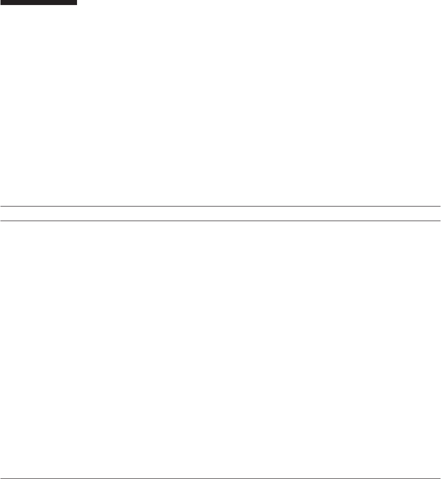
1.2 Warning Labels
Observe the warning labels (A in the figure) affixed on the SPARC M10-4/M10-4S
and the crossbar box during the maintenance work. The warning label on the
crossbar box also describes certification standards.
Figure 1-1 Location of warning labels (SPARC M10-4/M10-4S)
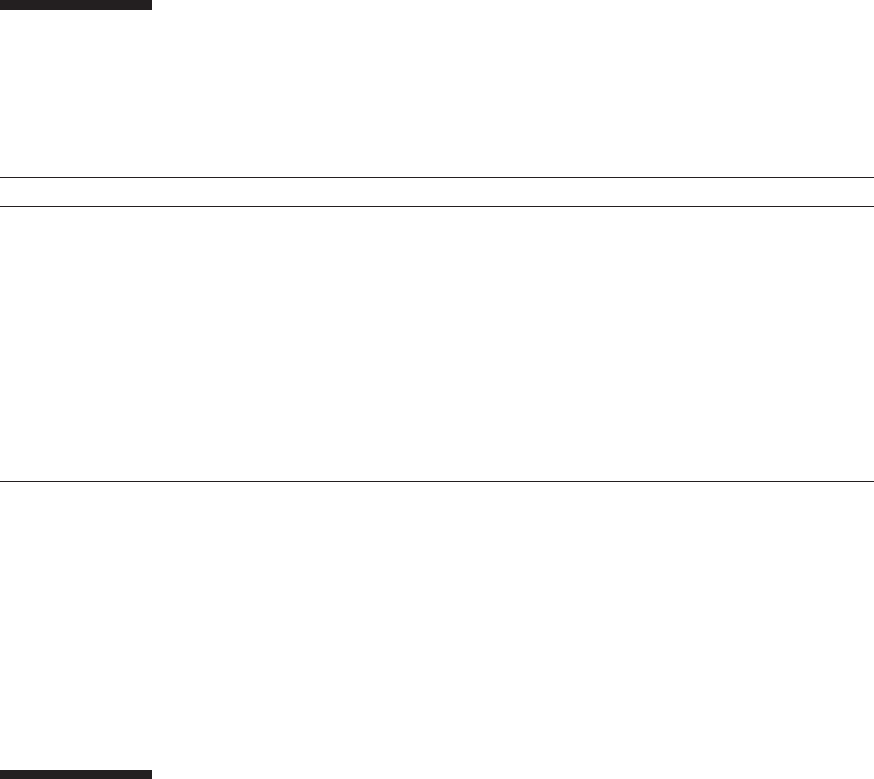
Figure 1-2 Location of warning labels (crossbar box)
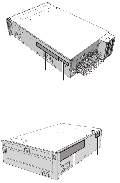
1.3 Labels/Tags
This section explains labels and tags that are affixed on the SPARC M10-4/M10-4S
and the crossbar box.
Fujitsu M10-4/Fujitsu M10-4S/SPARC M10-4/SPARC M10-4S Service Manual ・December 20132
A
B
B
A
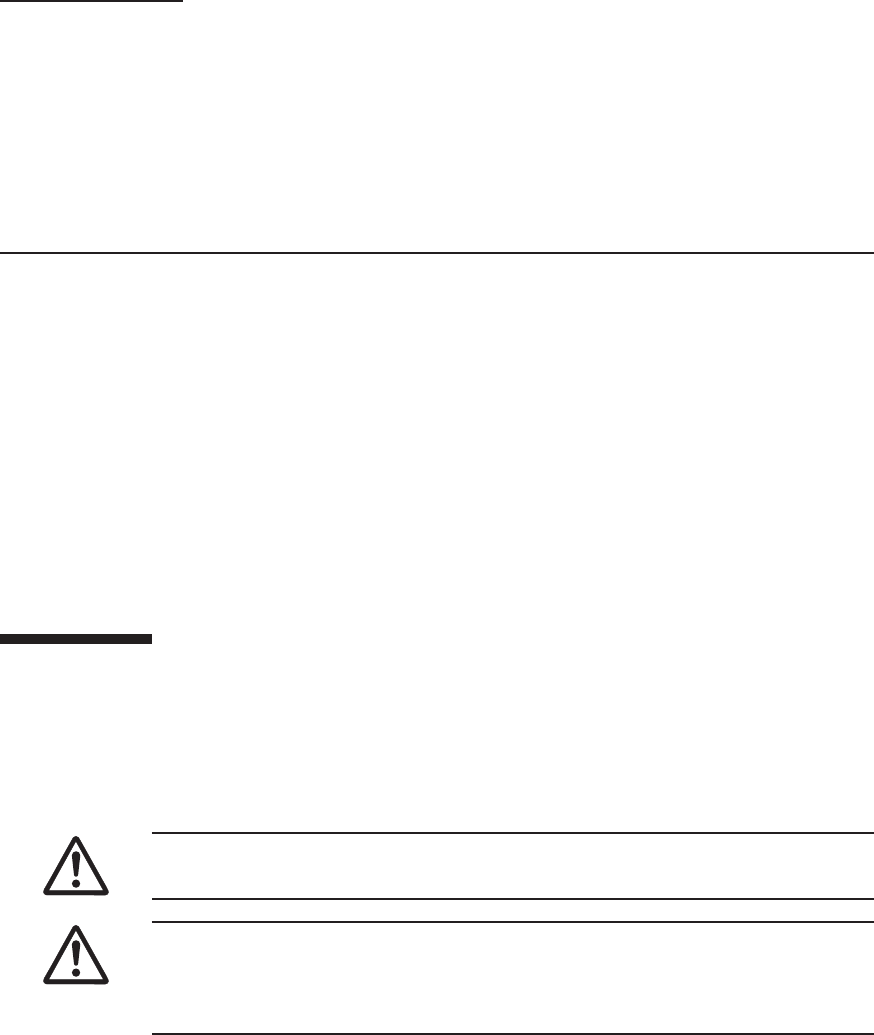
■The system name plate label (A in the figure) describes the model number, serial
number, and version required for maintenance and management.
■The standard label (B in the figure) describes the following certification standards.
The warning label on the crossbar box describes certification standards.
SPARC M10-4/M10-4S
■Safety: NRTL/C
■Radio wave: VCCI-A, FCC-A, DOC-A, KCC, and C-Tick
■Safety and radio wave: CE, BSMI, and GOST-R
Crossbar box
■Safety: NRTL/C
■Radio wave: VCCI-A, FCC-A, DOC-A, KCC, and C-Tick
■Safety and radio wave: CE and CU
Figure 1-3 Location of the system name plate label and standard label (SPARC
M10-4/M10-4S)
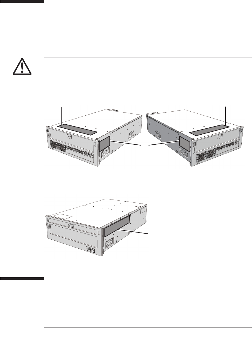
Figure 1-4 Location of the system name plate label and warning label (crossbar
box)
Chapter 1 Before Starting Maintenance Work 3
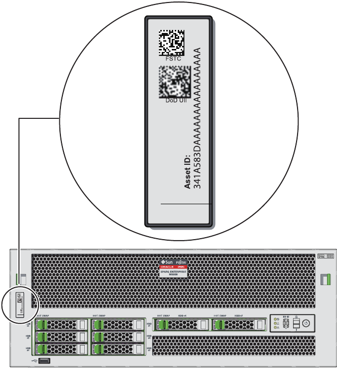
■The RFID tag carries an Asset ID. The RFID tag of the SPARC M10-4/M10-4S is
affixed on the front cover.
Figure 1-5 RFID tag (SPARC M10-4/M10-4S)
Fujitsu M10-4/Fujitsu M10-4S/SPARC M10-4/SPARC M10-4S Service Manual ・December 20134
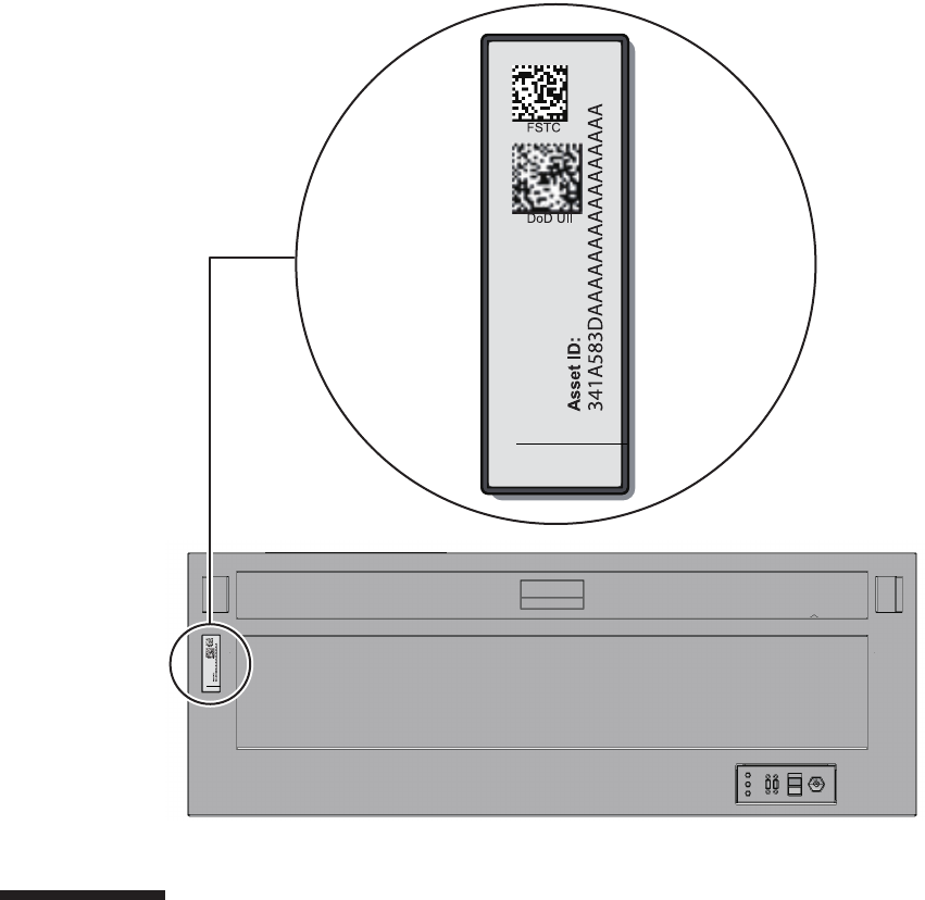
Figure 1-6 RFID tag (crossbar box)
1.4 Safety Precautions
Observe the following precautions to protect yourself when performing maintenance.
■Observe all the precautions, warnings, and instructions described on the chassis.
■Do not insert foreign objects into the openings in the chassis. Any such foreign
object could come into contact with high-voltage circuitry or could short circuit
the components, causing a fire or an electric shock.
■Contact a service engineer to inspect the chassis.
Chapter 1 Before Starting Maintenance Work 5

Table 1-1 ESD precautions
Item Precaution
Wrist strap Wear an antistatic wrist strap when handling printed boards.
ESD mat An approved ESD mat provides protection from static damage
when used with a wrist strap. The mat also acts as a cushion to
protect the small parts that are attached to printed boards.
Antistatic bag/
ESD safe packaging box
After removing a printed board or component, place it in the
antistatic bag or ESD safe packaging box.
Safety precautions on electricity
■Confirm that the voltage and frequency of your input power supply match those
shown on the electric rating label affixed on the chassis.
■Wear a wrist strap when handling a hard disk drive, CPU memory unit, or other
printed boards.
■Use grounded power outlets.
■Do not attempt to make any mechanical or electrical modifications. Fujitsu shall
not be responsible for the regulatory compliance of a chassis that has been modified.
Safety precautions on the racks
■The racks should be fixed on the floor, ceiling, or the adjacent frame.
■The racks may be supplied with a quakeresistant options kit. The use of the
quakeresistant options kit prevents the racks from falling over during installation
or maintenance service on the chassis.
■Prior to installation or maintenance, a safety assessment should be conducted by a
service engineer in the following cases:
■When the quakeresistant options kit is not supplied and the rack is not fixed on
the floor with bolts: Check for the safety such as whether the rack should not
fall over.
■If multiple chassis are mounted in a rack, perform maintenance for each of the
chassis.
For details of the racks, see "Chapter 2 Planning and Preparing for System
Installation" in the Fujitsu M10/SPARC M10 Systems Installation Guide.
1.5 Notes Regarding Static Electricity
Observe the precautions concerning the electrostatic discharge (ESD) as described in
Table 1-1 to ensure the safety of personnel and the system.
Fujitsu M10-4/Fujitsu M10-4S/SPARC M10-4/SPARC M10-4S Service Manual ・December 20136
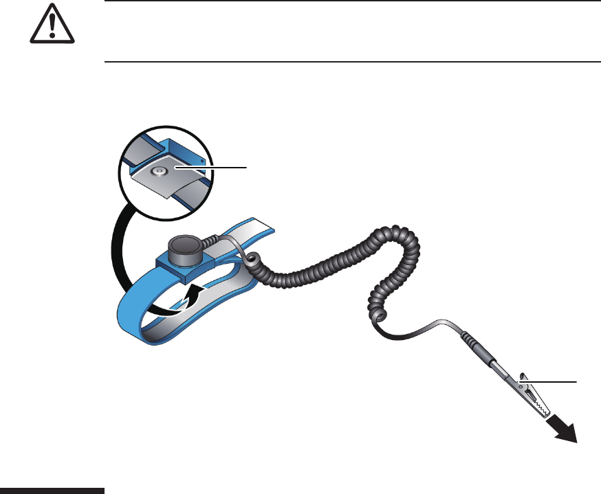
Caution - Do not connect the wrist strap clip to the ESD mat. By connecting the wrist
strap clip to the chassis, the operator and components have the same level of
potential, thus eliminating the danger of static damage.
A
B
How to use a wrist strap
Wear a wrist strap in such a way that the inner metal surface (A in the figure) of the
wrist strap band is in contact with your skin. Connect the clip (B in the figure)
directly to the chassis.
Figure 1-7 Wrist strap connection destination
1.6 Other Precautions
■Printed boards in the chassis can be easily damaged by static electricity. To
prevent damage to printed boards, wear a wrist strap and ground it to the chassis
prior to starting maintenance.
■When mounting any component in the chassis, check the connectors on both of the
chassis and component beforehand to confirm that none of the pins are bent and
that all the pins are neatly arranged in lines. If a component is mounted with a
bent pin in a connector, the chassis or component may be damaged. Also, carefully
proceed with the work to prevent any pin from being bent.
Chapter 1 Before Starting Maintenance Work 7
Caution - In an emergency (such as smoke or flames coming from the chassis),
immediately stop using the unit and turn off the power supply. Regardless of the
operation you are performing, give top priority to fire prevention.
■If excessive force is applied to the CPU memory unit, the components mounted on
printed boards may be damaged. When handling the CPU memory unit, observe
the following precautions:
■Hold the CPU memory unit by the metal frame.
■When removing the CPU memory unit from the packaging, keep the CPU
memory unit horizontal until you lay it on the cushioned ESD mat.
■Connectors and components on the CPU memory unit have thin pins that bend
easily. Therefore, do not place the CPU memory unit on a hard surface.
■Be careful not to damage the small parts located on both sides of the CPU
memory unit.
■Theheatsinkscanbedamagedbyincorrecthandling.Donottouchtheheatsinks
with your hands or other objects while replacing or removing CPU memory units.
If a heat sink is disconnected or broken, obtain a replacement CPU memory unit.
When storing or carrying a CPU memory unit, ensure that the heat sinks are
sufficiently protected.
■When removing a cable such as the LAN cable, if you cannot reach the latch lock
of the connector, use a flat headed screwdriver etc. to push the latch and release
the cable. If you use force to remove the cable, the LAN port of the CPU memory
unit or the PCI Express (PCIe) cards may be damaged.
■Do not use any power cord other than the specified one.
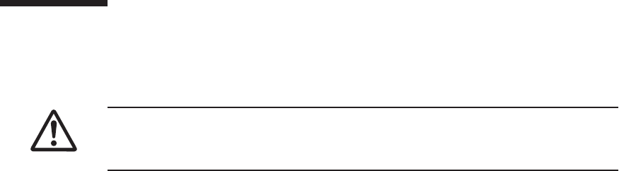
1.7 Emergency Power Off
This section explains the procedure for powering off the system in an emergency.
1. Remove all the power cords from the power supply unit.
Fujitsu M10-4/Fujitsu M10-4S/SPARC M10-4/SPARC M10-4S Service Manual ・December 20138
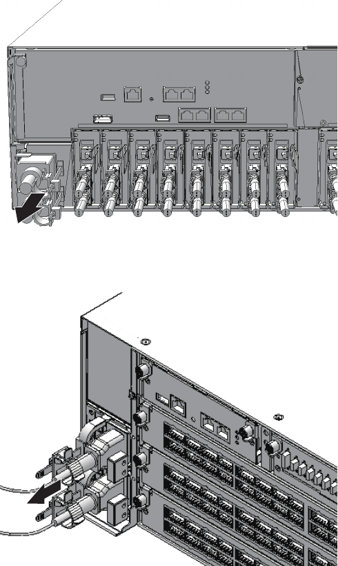
Figure 1-8 Removing the power cord (SPARC M10-4/M10-4S)
Figure 1-9 Removing the power cord (crossbar box)
Chapter 1 Before Starting Maintenance Work 9
Fujitsu M10-4/Fujitsu M10-4S/SPARC M10-4/SPARC M10-4S Service Manual ・December 201310

Chapter 2
Understanding the System
Components
This chapter describes the components mounted in the SPARC M10-4/M10-4S and
the crossbar box.
It is necessary to confirm and fully understand the configurations of the components
mounted in the chassis as well as the LED indications before starting any maintenance
work.
■Identifying the Names and Locations of Components
■Confirming the Functions of the Operation Panel
■Checking the LED Indications
■Confirming the Types of Cable
For the specifications of each component, see "Appendix B Component Specifications."
2.1 Identifying the Names and Locations of
Components
This section describes the names and locations of the components mounted in the
SPARC M10-4/M10-4S and the crossbar box.
Components that can be accessed from the front
You can access the fan unit and power supply unit only after removing the front
cover.
11
(1)
(2) (3)
Location number Component
1Fanunit
2 Internal disk
3 Power supply unit
(1)
Figure 2-1 Locations of components that can be accessed from the front (SPARC
M10-4/M10-4S)
Figure 2-2 Location of a component that can be accessed from the front (crossbar
box)
Fujitsu M10-4/Fujitsu M10-4S/SPARC M10-4/SPARC M10-4S Service Manual ・December 201312
Location number Component
1Fanunit
(2)(1)
Location number Component
1 PCI-Express (PCIe) card cassette
2 Crossbar unit (Only for the SPARC M10-4S. The SPARC M10-4
incorporates three PCIe card cassettes.)
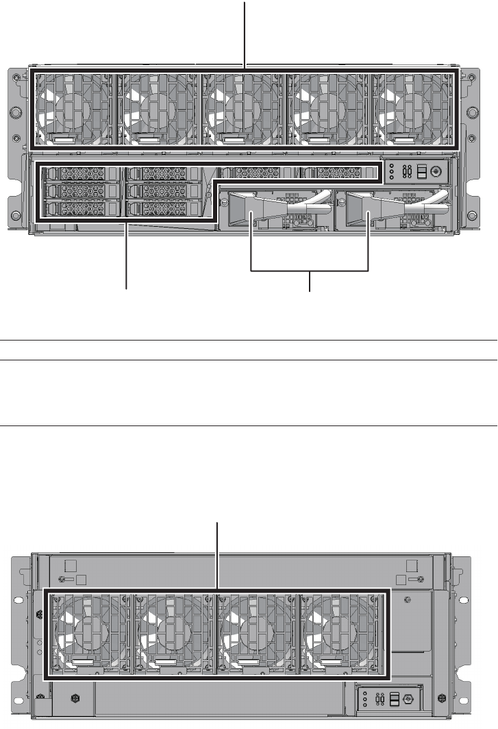
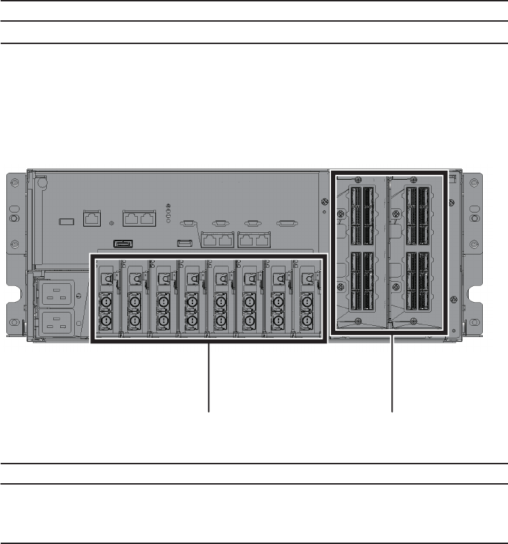
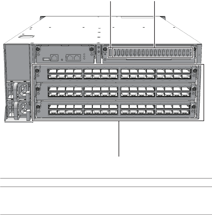
Components that can be accessed from the rear
Figure 2-3 Locations of components that can be accessed from the rear (SPARC
M10-4/M10-4S)
Chapter 2 Understanding the System Components 13
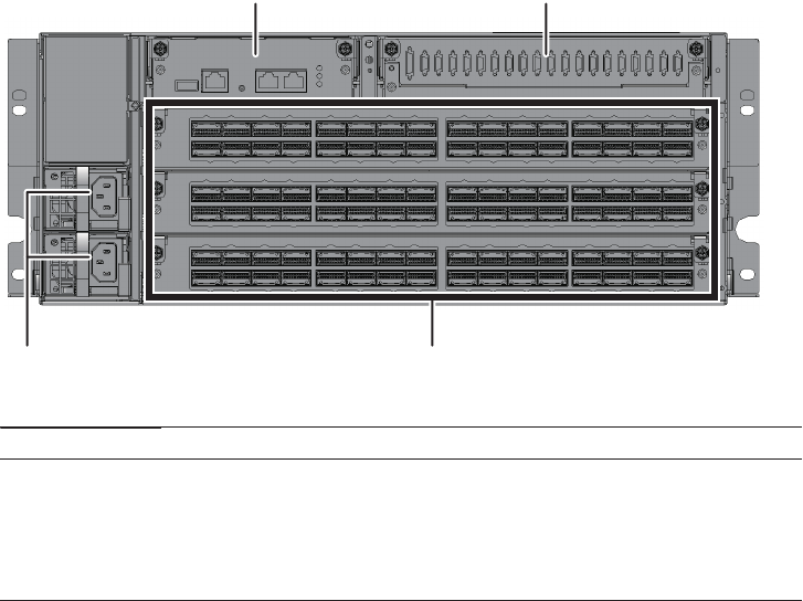
(4)(1)
(2) (3)
Location number Component
1 Power supply unit
2XSCFunit
3 XSCF interface unit
4 Crossbar unit
Figure 2-4 Locations of components that can be accessed from the rear (crossbar
box)
Internal components
To access the internal components, remove the CPU memory unit from the SPARC
M10-4/M10-4S, and the fan shelf from the crossbar box.
Fujitsu M10-4/Fujitsu M10-4S/SPARC M10-4/SPARC M10-4S Service Manual ・December 201314
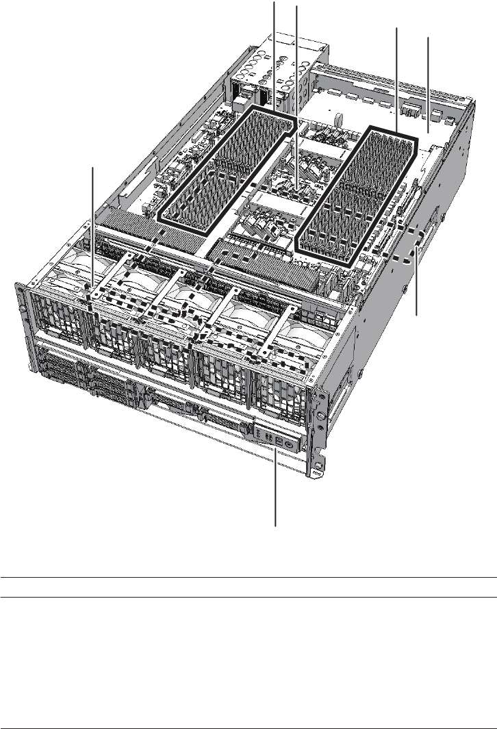
(6)
(4)
(5)
(3)
(3) (2)
(1)
Location number Component
1 CPU memory unit upper
2 CPU memory unit lower
3Memory
4 PSU backplane unit
5 HDD backplane
6 Operation panel
Figure 2-5 Locations of internal components (SPARC M10-4/M10-4S)
Chapter 2 Understanding the System Components 15
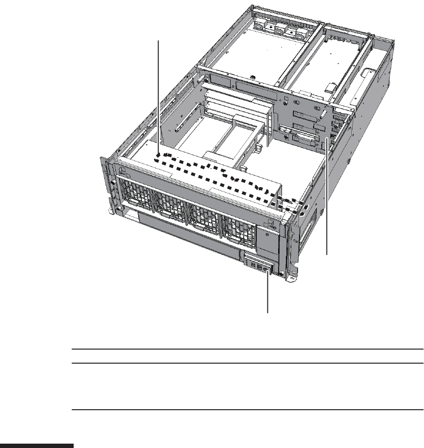
(2)
(1)
(3)
Location number Component
1 Fan backplane
2 Crossbar backplane unit
3 Operation panel
Figure 2-6 Locations of internal components (crossbar box)
2.2 Confirming the Functions of the
Operation Panel
This section describes the functions of the operation panels of the SPARC M10-4/
M10-4S and the crossbar box.
Fujitsu M10-4/Fujitsu M10-4S/SPARC M10-4/SPARC M10-4S Service Manual ・December 201316
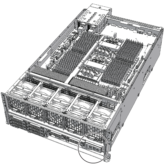
The operation panel provides the system's display and control functions. A field
engineer and the system administrator can specify the operation mode or control the
starting/stopping of the system while checking the system operation status by
referring to the LED indications.
Figure 2-7 Location of the operation panel (SPARC M10-4/M10-4S)
Chapter 2 Understanding the System Components 17
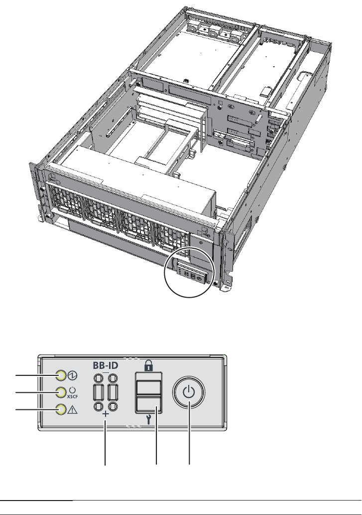
㩿㪈㪀
㩿㪉㪀
㩿㪊㪀
㩿㪋㪀 㩿㪌㪀 㩿㪍㪀
Location number Component
1POWERLED
2 XSCF STANDBY LED
Figure 2-8 Location of the operation panel (crossbar box)
Figure 2-9 Appearance of operation panel (SPARC M10-4/M10-4S and crossbar
box)
Fujitsu M10-4/Fujitsu M10-4S/SPARC M10-4/SPARC M10-4S Service Manual ・December 201318
Location number Component
3 CHECK LED
4 ID switch (SPARC M10-4S and crossbar box only)
5Modeswitch
6 Power switch
Table 2-1 Display and operation status of operation panel
LEDs/switches on
operation panel
If the SPARC M10-4S or the crossbar box is acting
as the master XSCF
If the SPARC M10-4S or the crossbar box is acting
as an XSCF other than the master XSCF
POWER LED Enabled (Displays the start or stop status of
the SPARC M10-4S or the crossbar box)
Enabled (Displays the start or stop status of
the SPARC M10-4S or the crossbar box)
XSCF STANDBY
LED
Enabled (Displays the XSCF status of the
system)
Enabled (Displays the XSCF status of the
SPARC M10-4S or the crossbar box)
CHECK LED Enabled (Displays an abnormal status of
the SPARC M10-4S or the crossbar box)
Enabled (Displays an abnormal status of
the SPARC M10-4S or the crossbar box)
ID switch Enabled (Registration of ID number) Enabled (Registration of ID number)
Mode switch (*) Enabled (Mode operation of the system) Disabled
Power switch Enabled (Start/stop operation of the system) Disabled
*: Set the same mode for the SPARC M10-4S systems and crossbar boxes with the master XSCF and XCCF in the standby state. If the
settings are different, an asterisk (*) is displayed beside the components in the output of the showhardconf or showstatus command.
For a building block configuration, an operation panel is mounted in each chassis of
the SPARC M10-4S or the crossbar box. However, the only operation panel on which
all of the LEDs and switches are enabled is that of the chassis housing the master
XSCF.
Table 2-1 shows the display and operation status of the operation panel.
2.2.1 Display function of the operation panel
The operation panel has three LED indicators to implement its display function. The
LED indicators indicate the following. For details, see "2.3.1 Operation panel LEDs."
■General system status
■System error warning
■System error location
Chapter 2 Understanding the System Components 19
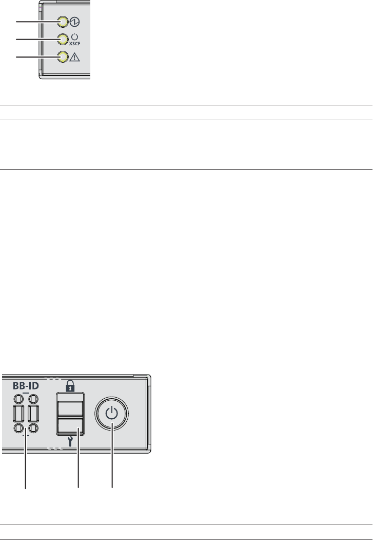
㩿㪈㪀
㩿㪉㪀
㩿㪊㪀
Location number Component
1POWERLED
2 XSCF STANDBY LED
3 CHECK LED
㩿㪈㪀 㩿㪉㪀 㩿㪊㪀
Location number Component
1 ID switch (SPARC M10-4S and crossbar box only)
2Modeswitch
Figure 2-10 LEDs on operation panel (SPARC M10-4/M10-4S and crossbar box)
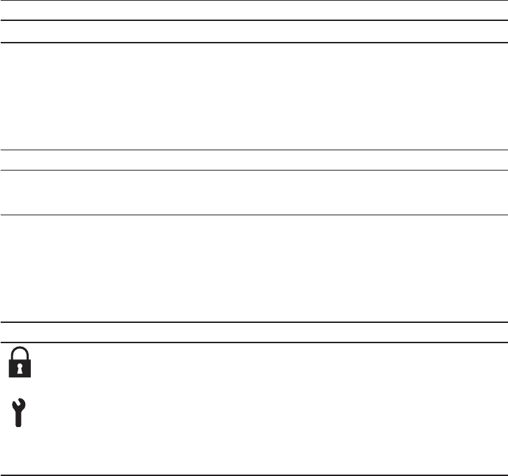
2.2.2 Control function of the operation panel
The operation panel has the following switches to implement its control function:
■ID switch
Identifies the SPARC M10-4S and the crossbar box.
■Mode switch (slide switch)
Specifies the operation mode.
■Power switch
Controls start/stop of the system.
Figure 2-11 Operation panel switches
Fujitsu M10-4/Fujitsu M10-4S/SPARC M10-4/SPARC M10-4S Service Manual ・December 201320
Location number Component
3 Power switch
Table 2-2 How to operate the ID switch
Operation Description
Pressing the + side. The ID number increases by 1.
Pressing the - side The ID number decreases by 1.
Table 2-3 Functions of the mode switch
Icon Name Description
Locked mode This mode is used for normal operation.
- The power switch can be used to start the system but not to
stop it.
Service mode This mode is used for maintenance.
- The power switch cannot be used to start the system but can be
used to stop it.
- Place the system in Service mode to perform maintenance
work with the system stopped.
Use the ID switch to set the ID number of the SPARC M10-4S or the crossbar box. Set
#0 to #15 for the SPARC M10-4S and #80 to #83 for the crossbar box. Table 2-2
describes how to operate the ID switch.
Use the mode switch to set the operation mode for the system. The Locked and
Service operation modes can be switched by sliding the mode switch.
Table 2-3 describes the difference between the modes.
Use the power switch to start or stop the system. The system starts/stops differently
depending on how the power switch is pressed.
Table 2-4 describes how system start/stop varies depending on how the power switch
is pressed.
Chapter 2 Understanding the System Components 21
Table 2-4 Functions of the power switch
Icon Operation Description
Brief press
(For 1 second or
more and less than 4
seconds)
If the system has been
started in Service mode (*):
Operation is ignored.
If the system is stopped in
Service mode:
Operation is ignored.
If the system has been
started in Locked mode (*):
Operation is ignored.
If the system is stopped in
Locked mode:
Starts the system.
At this time, if a wait time for the air conditioning
facilities or a warm-up time is set on the XSCF,
the processing for waiting for the power-on of the
air conditioning facilities and the completion of
warm-upisomitted.
Long press
(For 4 seconds or
more)
If the system has been
started in Service mode (*):
Perform the system shutdown process to stop the
system.
If the system startup
processisinprogressin
Service mode:
Cancels the system startup process and then
stops the system.
If the system stop process
is in progress in Service
mode:
Continues the system stop process.
If the system is stopped in
Service mode:
Operation is ignored.
Even a long press does not start the system.
If the system is stopped in
Locked mode:
Starts the system.
If a wait time for the air conditioning facilities or
a warm-up time is set on the XSCF, the
processing for waiting for the power-on of the air
conditioning facilities and the completion of
warm-upisomitted.
If the system is not
stopped in Locked mode:
Operation is ignored.
*: If the system has been started, it means that at least one physical partition has been powered on.
Table 2-5 Functions of the mode switch
Function Mode switch
Locked Service
Starting/Stopping the system
by the power switch
Only system startup is enabled. A long press
shuts down the
system.
Table 2-5 describes the functions of the mode switch.
Fujitsu M10-4/Fujitsu M10-4S/SPARC M10-4/SPARC M10-4S Service Manual ・December 201322
Table 2-5 Functions of the mode switch (continued)
Function Mode switch
Locked Service
Inhibition of break signal
reception
Enabled. Using the setpparmode
command, it is possible to specify
whether break signal reception is
allowed or inhibited for each physical
partition.
Disabled
Table 2-6 System operation status indicated by LEDs
Icon Name Color Description
POWER Green Indicates the startup or stop status of the system for
each chassis.
●On: System is started.
●Off: System is stopped.
●Blinking (*): System stop process is in progress.
XSCF
STANDBY
Green Indicates the status of the XSCF for the entire system or
for each chassis.
●On: XSCF is functioning normally.
●Off: XSCF is stopped.
●Blinking (*): System is being initialized after
power-on.
2.3 Checking the LED Indications
This section describes the statuses of the LEDs mounted on the SPARC M10-4/M10-
4S and the crossbar box.
LEDs are mounted on the operation panel on the front of the chassis, on the rear
panel of the chassis, and on each component that can be maintained. If an error
occurs, the LED indication enables you to determine which system requires
maintenance.
2.3.1 Operation panel LEDs
The three LEDs on the operation panel indicate the operation status of the overall
system. In addition, the LEDs enable you to check the system status by their
combination of being on, blinking, or off.
Table 2-6 lists the system operation status indicated by the LEDs, while Table 2-7 lists
the system status indicated by the combination of LEDs.
Chapter 2 Understanding the System Components 23
Table 2-6 System operation status indicated by LEDs (continued)
Icon Name Color Description
CHECK Amber Indicates the system operation status for each chassis.
●On: An error that prevents startup was detected.
●Off: Normal, or the power is disconnected or not
being supplied.
●Blinking (*): Indicates that the chassis requires
maintenance (this function is also referred to as the
"locator").
* The blink interval is 1 second (1 Hz).
Table 2-7 System status indicated by combination of LEDs
LED state Description
POWER XSCF
STANDBY
CHECK
OffOffOffPowerisdisconnected.
Off Off On Power has just been turned on.
Off Blinking (*) Off The XSCF is being initialized.
Off Off On The XSCF has detected an error.
Off On Off The XSCF is in the standby state.
The system is waiting for power-on of the air
conditioning facilities (in the data center).
On On Off Warm-up standby processing is in progress. After
the end of this processing, the system starts up.
System startup processing is in progress.
The system is operating.
Blinking (*) On Off System stop processing is in progress. After the
end of processing, the fan unit stops.
* The blink interval is 1 second (1 Hz).
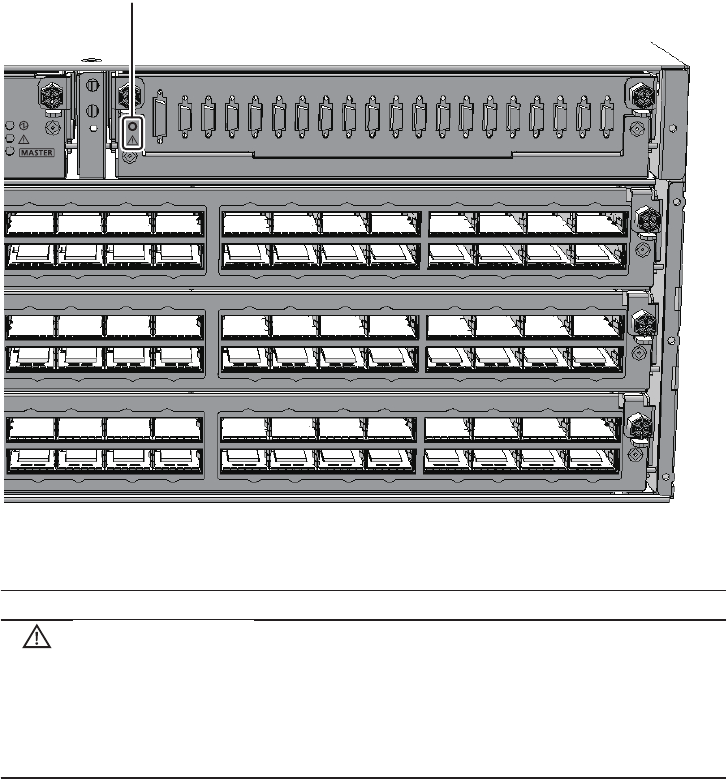
2.3.2 LEDs on the rear panel (System locator)
The field engineer or system administrator can identify the chassis requiring
maintenance by using the CHECK LED (A in the figure) on the rear panel. The
CHECK LED on the rear panel is referred to as the system locator, and has the same
function as the CHECK LED on the operation panel.
Fujitsu M10-4/Fujitsu M10-4S/SPARC M10-4/SPARC M10-4S Service Manual ・December 201324
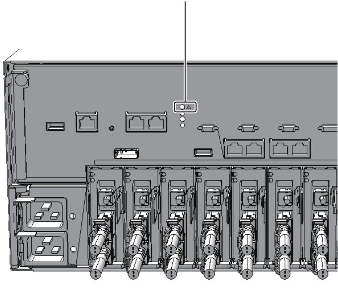
A
Figure 2-12 Location of system locator (SPARC M10-4/M10-4S)
Chapter 2 Understanding the System Components 25
A
Table 2-8 Status of the system locator
Icon Name Color Description
CHECK Amber Indicates the system operation status for each chassis.
●On: An error that prevents startup was detected.
●Off: Normal, or the power is disconnected or not being
supplied.
●Blinking (*): Indicates that the chassis requires
maintenance (this function is also referred to as the
"locator").
* The blink interval is 1 second (1 Hz).
Figure 2-13 Location of system locator (crossbar box)
2.3.3 LEDs on each component
Each component of the SPARC M10-4/M10-4S and the crossbar box has an LED
mounted. These LEDs light to indicate that a component requires maintenance if that
component experiences a fault. Start maintenance work after checking the LED status.
The LEDs on each component and their statuses are as follows:
Fujitsu M10-4/Fujitsu M10-4S/SPARC M10-4/SPARC M10-4S Service Manual ・December 201326
Table 2-9 LEDs on the XSCF or XSCF unit and their statuses (SPARC M10-4/M10-4S and
crossbar box)
Name Color Status Description
READY Green On Indicates that the component is operating.
The component cannot be released and
removed from the system.
Blinking (*) Indicates that the component is currently
being mounted on the system or being
disconnected from the system.
Off Indicates that the component is disconnected
from the system. Indicates that the
component can be removed and replaced.
CHECK Amber On Indicates that an error has occurred.
Blinking (*) Indicates that the component requires
maintenance (This function is also referred to
as the "locator").
Off Indicates the normal state.
MASTER Green On Master chassis
Off Slave chassis
Table 2-10 LEDs on the XSCF-LAN port and their statuses (SPARC M10-4/M10-4S and
crossbar box)
Name Color Status Description
ACT Green On Indicates that communication is being
performed.
Off Indicates that communication is not being
performed.
LINK SPEED Amber On Indicates that the communication speed is 1
Gbps.
Green Blinking (*) Indicates that the communication speed is
100 Mbps.
Off Indicates that the communication speed is 10
Mbps.
* The blink interval is 1 second (1 Hz).
Table 2-11 LED on the fan unit and its status (SPARC M10-4/M10-4S and crossbar box)
Name Color Status Description
CHECK Amber On Indicates that an error has occurred.
Blinking (*) Indicates that the component requires
maintenance (This function is also referred to
as the "locator").
Off Indicates the normal state.
* The blink interval is 1 second (1 Hz).
Chapter 2 Understanding the System Components 27
Table 2-12 LED on the power supply unit and its status (SPARC M10-4/M10-4S and
crossbar box)
Name Color Status Description
CHECK Green On Indicates that the input power is turned on
and power is being supplied normally.
Blinking (*) Indicates that the input power is being
disconnected.
Amber On Indicates that an error has occurred.
Indicates that the input power to this power
supply unit is turned off in redundant
operation.
Blinking (*) Indicates a warning (An error has occurred
but this power supply unit is operating).
Off Indicates that power is not being supplied.
* The blink interval is 1 second (1 Hz).
Table 2-13 LEDs on the PCIe card slot and their statuses (SPARC M10-4/M10-4S)
Name Color Status Description
POWER Green On Indicates that power is being supplied.
Off Indicates that power is not being supplied.
ATTENTION Amber On Indicates that an error has occurred.
Blinking (*) Indicates that the component requires
maintenance (This function is also referred to
as the "locator").
Off Indicates the normal state.
* The blink interval is 1 second (1 Hz).
Table 2-14 LEDs on the internal disk and their statuses (SPARC M10-4/M10-4S)
Name Color Status Description
READY Green Blinking Indicates that the disk is being accessed. This
LED is normally on, but it blinks while the
disk is being accessed.
While the LED is blinking, maintenance work
such as the removal of the disk cannot be
performed.
Off Indicates that maintenance work such as the
removal of the disk can be performed.
CHECK Amber On Indicates that an error has occurred.
Blinking (*) Indicates that the component requires
maintenance (This function is also referred to
as the "locator").
Off Indicates the normal state.
* The blink interval is 1 second (1 Hz).
Fujitsu M10-4/Fujitsu M10-4S/SPARC M10-4/SPARC M10-4S Service Manual ・December 201328

2.4 Confirming the Types of Cable
This section describes the types of the cables that are connected to the SPARC
M10-4/M10-4S and the crossbar box, as well as the locations of the cable ports.
The types and number of the cables to be used vary depending on the configuration.
2.4.1 Types of cable
In a building block configuration, the following cables are used for making a
connection between the SPARC M10-4S systems and between the SPARC M10-4S
and the crossbar box:
■Crossbar cable (electrical)
This is used to connect the SPARC M10-4S systems in a building block configuration
without the crossbar box.
■Crossbar cable (optical)
This is used to connect the SPARC M10-4S with the crossbar box in a building
block configuration with the crossbar box.
■XSCF BB control cable
This is used to connect the XSCFs mounted in the SPARC M10-4S or crossbar box
chassis.
An XSCF mounted in a chassis becomes the master XSCF and monitors or controls
the entire system. XSCFs other than the master XSCF act as slaves and monitor or
control each chassis.
■XSCF DUAL control cable
This is used to connect the master XSCF to a standby XSCF and duplicate XSCF.
One of the slave XSCFs functions as the standby XSCF. If an abnormality occurs
with the master XSCF, the standby XSCF becomes the master XSCF and continues
the monitoring or control of the system.
Each table has a tag that is used for maintenance recording and management.
2.4.2 Cable connection ports
Figure 2-14 and Figure 2-15 show the locations of the cable connection ports of the
SPARC M10-4S and the crossbar box, respectively. See the following chapters for the
procedures for maintaining the cables:
■Chapter 24 Maintaining the Crossbar Cables (Electrical)
■Chapter 25 Maintaining the Crossbar Cables (Optical)
■Chapter 26 Maintaining the XSCF BB Control Cables
■Chapter 27 Maintaining the XSCF DUAL Control Cables
Chapter 2 Understanding the System Components 29
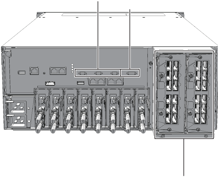
(2)
(1)
(3)
Figure 2-14 Locations of cable connection ports (SPARC M10-4S)
Fujitsu M10-4/Fujitsu M10-4S/SPARC M10-4/SPARC M10-4S Service Manual ・December 201330
(1) (2)
(3)
Location number Connection port
1 XSCF DUAL control port
2 XSCF BB control port
3 Crossbar cable connection port
Figure 2-15 Locations of cable connection ports (crossbar box)
Chapter 2 Understanding the System Components 31
Fujitsu M10-4/Fujitsu M10-4S/SPARC M10-4/SPARC M10-4S Service Manual ・December 201332

Chapter 3
Troubleshooting
This chapter describes how to determine and confirm the cause if an error occurs.
■Suspected Failure Conditions
■Determining the Causes of Individual Failures
■Identifying a Failure
■Downloading Error Log Information
3.1 Suspected Failure Conditions
This section explains suspected failure conditions. Use the flow to determine the
cause of a failure and identify the failure location in the following cases. For details
on the flow for determining the cause of a failure, see "3.2 Determining the Causes
of Individual Failures."
■When the CHECK LED is on
■When an error message is displayed on the console
■When an error is displayed as a result of executing a command for checking the
status
■When an error is displayed in the error log
3.2 Determining the Causes of Individual
Failures
This section explains the flow for determining the causes of failures. This flow is also
applied to failures of the PCI expansion unit.
33
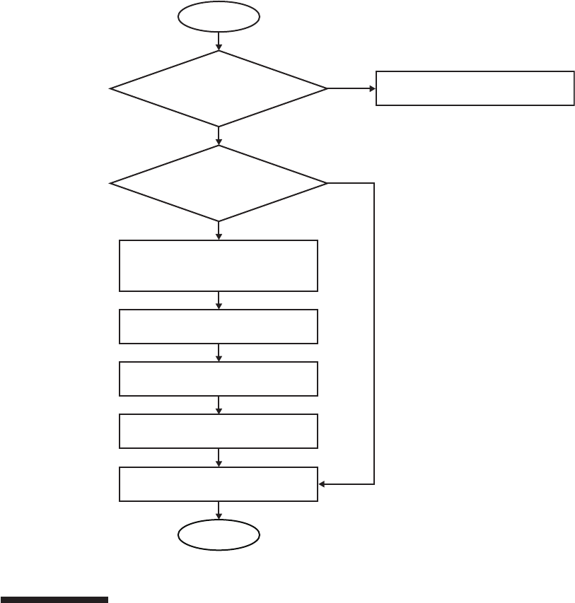
Start
End
Is the LED on the power
supply unit off?
Check the connection of the power
supply unit and power cords.
YES
NO
NO
YES
Was e-mail sent by the
XSCF mail function?
Check /var/adm/messages on
Oracle Solaris.
Write down the displayed failure
information.
Contact our service engineer.
Confirm that an error message is
displayed on the OS and XSCF
consoles.
Execute showlogs on XSCF to
display failure information.
Figure 3-1 Troubleshooting flow
3.3 Identifying a Failure
This section explains the method for identifying a failure. Use the flow described in
"3.2 Determining the Causes of Individual Failures" to determine the appropriate
way of checking for a failure.
Fujitsu M10-4/Fujitsu M10-4S/SPARC M10-4/SPARC M10-4S Service Manual ・December 201334
3.3.1 Checking the LED indications
Check the LEDs on the operation panel, rear panel, and on each component to
identify which component requires maintenance. Check the status of a component
from its LED before starting any maintenance work on that component.
■Operation panel LEDs
You can check the status of the system by checking the LEDs on the operation
panel. For details, see "2.3.1 Operation panel LEDs."
■LEDs on the rear panel
You can check the status of the system by noting the CHECK LED on the rear
panel of the chassis, which has the same function as the CHECK LED on the
operation panel. For details, see "2.3.2 LEDs on the rear panel (System locator)."
■LED on each component
You can determine the location of an error by checking the LED on the component
that incorporates the failed hardware if an error occurs in the hardware within the
chassis. For details, see "2.3.3 LEDs on each component."
Note that some components such as memory are not provided with LEDs. To
check the status of a component that does not have an LED, execute XSCF shell
commands such as the showhardconf command from the maintenance terminal.
For details, see "3.3.3 Checking the status of a component."
3.3.2 Checking error messages
Display error messages to check the log information and obtain an error overview.
You can use either of the following two methods to check the error messages:
■Checking error log information using the XSCF shell
For details, see "12.1 Checking a Log Saved by the XSCF" in the Fujitsu M10/
SPARC M10 Systems System Operation and Administration Guide.
■Checking messages on Oracle Solaris
For details, see "12.2 Checking Warning and Notification Messages" in the Fujitsu
M10/SPARC M10 Systems System Operation and Administration Guide.
3.3.3 Checking the status of a component
Execute the XSCF firmware commands to check the system hardware configuration
and the status of each component.
showhardconf command
Execute the showhardconf command to check the information for a list of components.
1. LogintotheXSCFshell.
2. Execute the showhardconf command to check the list of components.
A failed component is indicated by an asterisk (*) at the beginning of the line.
Chapter 3 Troubleshooting 35
XSCF> showhardconf
SPARC M10-4S;
+ Serial:2081229003; Operator_Panel_Switch:Service;
+ System_Power:On; System_Phase:Cabinet Power On;
Partition#0 PPAR_Status:Running;
BB#00 Status:Normal; Role:Master; Ver:2050h; Serial:2081229003;
+ FRU-Part-Number:CA07361-D202 A0 ;
+ Power_Supply_System: ;
+ Memory_Size:320 GB;
------------------------Ommitted------------------------
PCI#0 Status:Normal; Name_Property:pci;
+ Vendor-ID:108e; Device-ID:9020;
+ Subsystem_Vendor-ID:0000; Subsystem-ID:0000;
+ Model:;
+ Connection:7001;
* PCIBOX#7001; Status:Faulted; Ver:1110h; Serial:2121237001;
+ FRU-Part-Number:;
IOB Status:Normal; Serial:PP123403JE ;
+ FRU-Part-Number:CA20365-B66X 008AG ;
LINKBOARD Status:Normal; Serial:PP1234026P ;
+ FRU-Part-Number:CA20365-B60X 001AA ;
PCI#1 Name_Property:ethernet;
+ Vendor-ID:1077; Device-ID:8000;
+ Subsystem_Vendor-ID:1077; Subsystem-ID:017e;
+ Model:;
------------------------Ommitted-----------------------
XSCF> showstatus
MBU Status:Normal;
* MEM#0A Status:Faulted;
Table 3-1 Status of components
Display Description
Normal The unit is in the normal state.
Faulted The unit is faulty and is not operating.
Degraded A part of the unit has failed or degraded, but the unit is running.
showstatus command
Execute the showstatus command to check the status of the components.
1. Log in to the XSCF shell.
2. Execute the showstatus command to check the status.
A failed component is indicated by an asterisk (*) at the beginning of the line.
The status of the component is displayed following "Status:".
Table 3-1 describes the status of the components.
Fujitsu M10-4/Fujitsu M10-4S/SPARC M10-4/SPARC M10-4S Service Manual ・December 201336

Table 3-1 Status of components (continued)
Display Description
Deconfigured Due to the failure or degradation of another unit, the target unit and
components of its underlying layer has been degraded, though there
is no problem in them.
Maintenance Maintenance is being performed. The replacefru, addfru, or initbb
command is being executed.
XSCF> ioxadm env -te PCIBOX#2008
Location Sensor Value Resolution Units
PCIBOX#2008 AIRFLOW 180.000 0.000 CHM
PCIBOX#2008 P_CONSUMPTION 68.000 0.000 W
PCIBOX#2008/PSU#0 FAN 3936.000 0.000 RPM
PCIBOX#2008/PSU#1 FAN 3584.000 0.000 RPM
PCIBOX#2008/FAN#0 FAN 3374.000 0.000 RPM
PCIBOX#2008/FAN#1 FAN 3374.000 0.000 RPM
PCIBOX#2008/FAN#2 FAN 3374.000 0.000 RPM
PCIBOX#2008/IOBT T_INTAKE 26.000 0.000 C
PCIBOX#2008/IOBT T_PART_NO0 31.500 0.000 C
PCIBOX#2008/IOBT T_PART_NO1 30.750 0.000 C
PCIBOX#2008/IOBT T_PART_NO2 31.500 0.000 C
PCIBOX#2008/IOBT V_12_0V 12.069 0.000 V
PCIBOX#2008/IOBT V_3_3_NO0 3.293 0.000 V
PCIBOX#2008/IOBT V_3_3_NO1 3.295 0.000 V
PCIBOX#2008/IOBT V_3_3_NO2 3.291 0.000 V
PCIBOX#2008/IOBT V_3_3_NO3 3.300 0.000 V
PCIBOX#2008/IOBT V_1_8V 1.804 0.000 V
PCIBOX#2008/IOBT V_0_9V 0.900 0.000 V
3.3.4 Checking the status of a PCI expansion unit
If a PCI expansion unit is connected, execute the ioxadm command from the XSCF
shell to check the status of the PCI expansion unit.
ioxadm command
Execute the ioxadm command to check the environmental conditions (temperature,
voltage, etc.) or LED indications for the PCI expansion unit.
1. LogintotheXSCFshell.
2. Execute the ioxadm command to check the environmental conditions of the
specified PCI expansion unit.
To specify a PCI expansion unit, enter the serial number of the PCI expansion
unit after determining it by executing the ioxadm list command.
The following example shows the environmental conditions for the PCIBOX#2008
"2008" are the last four digits of the serial number of the PCI expansion unit.
Chapter 3 Troubleshooting 37

XSCF> showlogs error
Date: Oct 20 12:45:31 JST 2012
Code: 00112233-445566778899aabbcc-8899aabbcceeff0011223344
Status: Alarm Occurred: Oct 20 12:45:31.000 JST 2012
FRU: PSU#1,PSU#2
Msg: ACFAIL occurred (ACS=3)(FEP type = A1)
Date: Oct 20 15:45:31 JST 2012
Code: 00112233-445566778899aabbcc-8899aabbcceeff0011223344
Status: Warning Occurred: Oct 20 15:45:31.000 JST 2012
FRU: PSU#1,PSU#2
Msg: ACFAIL occurred (ACS=3)(FEP type = A1)
Date: Oct 20 17:45:31 JST 2012
Code: 00112233-445566778899aabbcc-8899aabbcceeff0011223344
Status: Alarm Occurred: Oct 20 17:45:31.000 JST 2012
FRU: PSU#1,PSU#2, PSU#3,*
Msg: ACFAIL occurred (ACS=3)(FEP type = A1)
Table 3-2 Operands of the showlogs command and the log to be displayed
Operand Description
error Lists the error log.
event Lists the event log.
power Lists the power log.
env Lists the temperature history.
monitor Lists the monitoring message log.
console Lists the console message log.
ipl Lists the IPL message log.
panic Lists the panic message log.
3.3.5 Checking log information
Execute the showlogs command to check the error log information.
1. Log in to the XSCF shell.
2. Execute the showlogs command to check the log information.
The log information is listed in the order of date, with the oldest appearing first.
The following example shows that an Alarm status occurred in PSU#1 and
PSU#2 at 12:45:31 on Oct 20, the Alarm status changed to a Warning status at
15:45:31 on the same day, and then the Alarm status further expanded to PSU#1,
PSU#2, and PSU#3 at 17:45:31 on the same day.
Table 3-2 shows what log information each operand of the showlogs command can
display.
Fujitsu M10-4/Fujitsu M10-4S/SPARC M10-4/SPARC M10-4S Service Manual ・December 201338

Table 3-3 Predictive self-repairing messages
Output Displayed Description
Nov 1 16:30:20 dt88-292 EVENT-TIME:Tue
Nov 1 16:30:20 PST 2005
EVENT-TIME: Time stamp for the
diagnosis
Nov 1 16:30:20 dt88-292 PLATFORM:
ORCL,SPARC64-X, CSN:-,HOSTNAME:dt88-292
PLATFORM: Description of the
chassis in which the error occurred
Nov 1 16:30:20 dt88-292 SOURCE:eft, REV:1.13 SOURCE: Information regarding
the diagnosis engine used to
identify the error
Nov 1 16:30:20 dt88-292 EVENT-ID:
afc7e660-d609-4b2f-86b8-ae7c6b8d50c4
EVENT-ID: Universally unique
event ID for this error
Nov 1 16:30:20 dt88-292 DESC:
Nov 1 16:30:20 dt88-292 A problem was detected in
the PCI Express subsystem
DESC: Basic description of the error
Nov 1 16:30:20 dt88-292 Refer to http://support.
oracle.com/msg/SUN4-8000-0Y for more information.
Website: Where to find specific
information and countermeasures
for this error
Nov 1 16:30:20 dt88-292 AUTO-RESPONSE:
One or more device instances may be disabled.
AUTO-RESPONSE: What the
system has done (if anything) to
alleviate any subsequent problems
Nov 1 16:30:20 dt88-292 IMPACT:Loss of services
provided by the device instances associated with this
fault.
IMPACT: Description of the
assumed impact of the failure
3.3.6 Checking the messages output by the predictive
self-repairing tool
Check the messages output from the Oracle Solaris Fault Manager predictive
self-repairing tool, running on Oracle Solaris. Oracle Solaris Fault Manager has the
following functions:
■Receives telemetry information about errors.
■Performs troubleshooting
■Disables the components that have experienced errors.
■Turns on the LED of a component that has experienced an error and displays the
details in the system console message.
Table 3-3 lists typical messages that are generated if an error occurs. These messages
indicate that the fault has already been diagnosed. If there are corrective actions that
can be taken by the system, they have already been taken. In addition, if the system is
running, corrective actions continue to be applied.
Messages are displayed on the console and are recorded in the /var/adm/messages
file.
Chapter 3 Troubleshooting 39
Table 3-3 Predictive self-repairing messages (continued)
Output Displayed Description
Nov 1 16:30:20 dt88-292 REC-ACTION:
Schedule a repair procedure to replace the affected
device.Use Nov 1 16:30:20 dt88-292 fmdump -v –u
EVENT_ID to identify the device or contact Sun for
support.
REC-ACTION: Brief description of
the corrective action the system
administrator should apply
XSCF> setlocator -b 1 blink
3.3.7 Identifying the location of the chassis requiring
maintenance
Execute the setlocator command to identify the location of the chassis requiring
maintenance by causing the CHECK LED on the operation panel and the CHECK
LED (locator) on the rear panel to blink.
1. Log in to the XSCF shell.
2. Execute the setlocator command to blink the CHECK LED of the chassis
requiring maintenance, and determine its location.
The CHECK LEDs on the operation and rear panels blink.
An execution example in which the chassis requiring maintenance is the master
chassis is shown below. When specifying a different chassis such as BB#01, set
"setlocator -b 1 blink."
For details on where to find and how to check the CHECK LEDs, see "2.3
Checking the LED Indications."
3.4 Downloading Error Log Information
This section describes the operation for downloading error log information.
To download error log information, use the XSCF log fetch function. The XSCF unit
has a maintenance USB port so that maintenance information such as error logs can
be obtained easily.
For details, see "12.1.15 Saving a log to a file with snapshot" and "12.1.16 Saving a
log to a local USB device" in the Fujitsu M10/SPARC M10 Systems System Operation
and Administration Guide.
Fujitsu M10-4/Fujitsu M10-4S/SPARC M10-4/SPARC M10-4S Service Manual ・December 201340
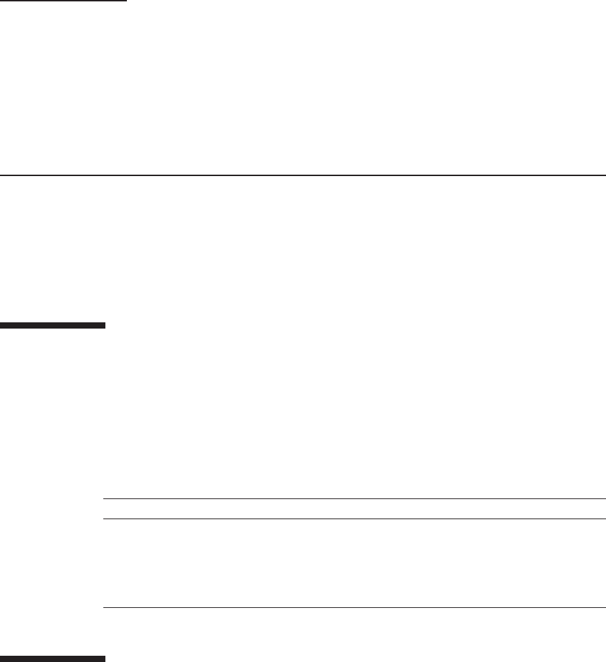
Table 4-1 Maintenance tools
Item Use
1 Phillips screwdriver (No.2) Removing or replacing screws
2 Flathead screwdriver (small) Removing or replacing screws
3 Wrist strap For grounding static
4 ESD mat For grounding static
Chapter 4
Preparing for Maintenance
This chapter describes the preparations that must be completed prior to performing
any maintenance as well as the types of maintenance.
■Preparing Tools Required for Maintenance
■Confirming the System Configuration
■Understanding Types of Maintenance
4.1 Preparing Tools Required for
Maintenance
This section explains tools required for maintenance. Table 4-1 lists the tools required
for maintenance on a Field Replaceable Unit (FRU).
4.2 Confirming the System Configuration
This section explains how to check the hardware and software configurations.
After completing any maintenance, it is necessary to confirm that the the system
configuration is the same as that before starting the work. If an error occurs in the
41

XSCF> showhardconf
Table 4-2 Commands for checking the software configuration
Command Description
pkg(1) (Oracle Solaris 11)
showrev(1M) (Oracle Solaris 10)
Displays Oracle Solaris correction information
and version.
ldm(1M)
Displays logical domain configuration information.
system, record the system configuration and the states of the components before
starting maintenance. Then, confirm that the system configuration is the same after
maintenance as it was before.
4.2.1 Confirming the hardware configuration
Execute the showhardconf command to confirm the configuration and status of the
components mounted in the chassis. Before performing any maintenance work, check
and record the hardware configuration of the chassis.
1. Log in to the XSCF shell.
2. Execute the showhardconf command to confirm the hardware configuration
information.
The following information is displayed:
■Current configuration and status
■Number of mounted Field Replaceable Units (FRUs)
■Status of the unit in which a physical partition error or degradation occurred
■Information on the PCI expansion unit
■Name properties of the PCI Express (PCIe) card
4.2.2 Confirming the software and firmware
configurations
The software and firmware configurations and versions affect the operation of the
system. To change the configuration or investigate a problem, check the latest state
and check for any problems in the software.
Confirming the software configuration
Use Oracle Solaris commands to check the software configuration.
If you are logged in to the XSCF console, switch to the control domain console by
executing the console command beforehand.
Table 4-2 lists the commands used for checking the software configuration.
Fujitsu M10-4/Fujitsu M10-4S/SPARC M10-4/SPARC M10-4S Service Manual ・December 201342
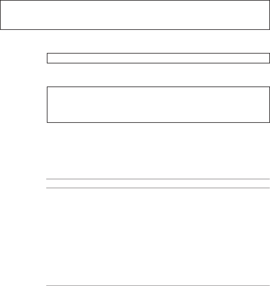
#pkg info entire
Name: entire
Summary: entire incorporation including Support Repository Update
(Oracle Solaris 11.1.12.5.0).
#showrev -p
#ldm -V
Logical Domains Manager (v 3.1)
Hypervisor control protocol v 1.9
Using Hypervisor MD v 1.3
Table 4-3 Commands for checking the firmware configuration
Command Description
version Displays the current firmware version information.
showhardconf Displays information on components mounted in the chassis.
showstatus Displays the status of a component. Of the FRUs comprising the
system, this command displays information on a unit or
component that is faulty or degraded.
showboards Displays information on a physical system board (PSB). Displays
information on a physical system board that belongs to the
specified physical partition and information on all the physical
system boards that are mounted.
showpcl Displays the configuration information for a physical partition
(hardware resource information).
showfru Displays the setting information for a device.
1. Log in to the control domain console of the physical partition where the
component to be maintained is mounted.
For information on logging in to the control domain console, see "8.2 Switching
to the Control Domain Console from the XSCF Shell" in the Fujitsu M10/SPARC
M10 Systems System Operation and Administration Guide.
2. Execute the pkg(1) command to display Oracle Solaris correction information
and version.
- For Oracle Solaris 11, execute the pkg(1) command.
- For Oracle Solaris 10, execute the showrev(1M) command.
FortheOracleVMServerforSPARCversion,executetheldm(1M)command.
Confirming the firmware configuration
Use XSCF shell commands to check the firmware configuration.
Table 4-3 lists the commands for checking the firmware configuration.
Chapter 4 Preparing for Maintenance 43
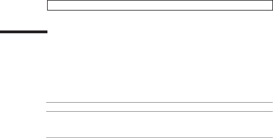
XSCF> version -c xcp
Table 4-4 System configuration
Configuration Description
Single-chassis configuration Configuration in which a single SPARC M10-4 is used
Building block configuration Configuration in which 2 or more SPARC M10-4S's are
combined and used
1. Log in to the XSCF shell.
2. Execute the version command to determine the firmware version information.
In the following example, "-c xcp" is entered to determine the overall XCP version.
4.3 Understanding Types of Maintenance
This section explains the types of maintenance.
The single-chassis configuration and building block configuration denote the
following system configurations.
There are the following five types of maintenance.
■Active/hot maintenance
Maintenance work is performed while the physical partition remains turned on
and the input power to the chassis in which the target Field Replaceable Unit
(FRU) is mounted is on (power cord is connected). Active/hot maintenance can be
performed only on FRUs that have a redundant configuration or which support
PCI hot plugging (PHP).
Fujitsu M10-4/Fujitsu M10-4S/SPARC M10-4/SPARC M10-4S Service Manual ・December 201344
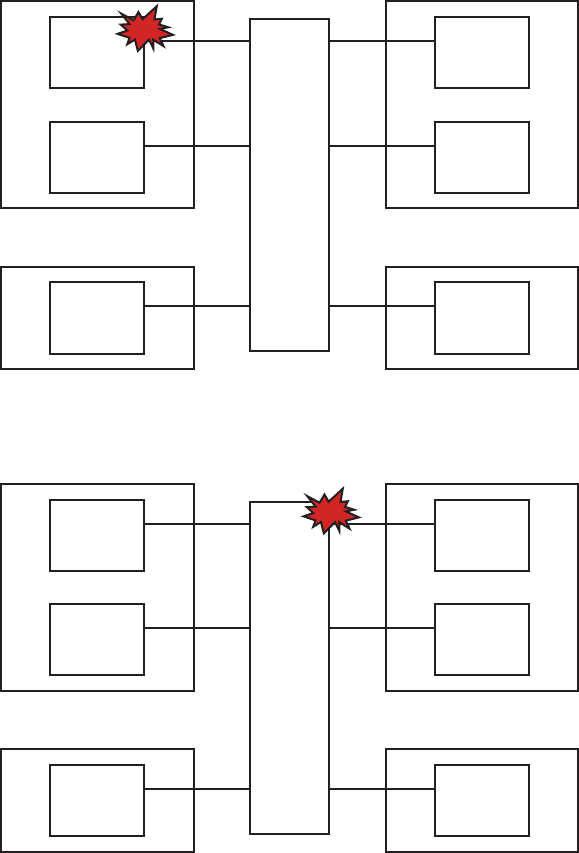
Physical partition (active)
BB#0
Hot
XBBOX
Hot
BB#1
Hot
Physical partition (active)
BB#3
Hot
BB#4
Hot
Physical partition (active)
BB#2
Hot
Physical partition (active)
BB#5
Hot
Physical partition (active)
BB#0
Hot
XBBOX
Hot
BB#1
Hot
Physical partition (active)
BB#3
Hot
BB#4
Hot
Physical partition (active)
BB#2
Hot
Physical partition (active)
BB#5
Hot
Figure 4-1 Active/hot maintenance (for SPARC M10-4S maintenance)
Figure 4-2 Active/hot maintenance (for crossbar box maintenance)
■Active/cold maintenance
Maintenance work is performed while the physical partition to which the
maintenance-target FRU belongs remains turned on but the input power to the
chassis in which the target FRU is mounted is off (power cord is disconnected). It
is necessary to use dynamic reconfiguration (DR) to disconnect a chassis requiring
maintenance from the physical partition. For a single-chassis configuration, since
the chassis cannot be disconnected with DR, active/cold maintenance cannot be
performed.
Chapter 4 Preparing for Maintenance 45
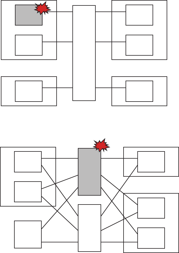
Physical partition (active)
BB#0
Cold
XBBOX
Hot
BB#1
Hot
Physical partition (active)
BB#3
Hot
BB#4
Hot
Physical partition (active)
BB#2
Hot
Physical partition (active)
BB#5
Hot
Physical partition (active)
BB#0
Hot
PDU
Cold
PDU
Hot
BB#1
Hot
XBBOX
Hot
Physical partition (active)
BB#2
Hot
BB#3
Hot
BB#4
Hot
Physical partition (active)
Figure 4-3 Active/cold maintenance (for SPARC M10-4S maintenance)
Figure 4-4 Active/cold maintenance (for dedicated power distribution unit
maintenance)
■Inactive/hot maintenance
Maintenance work is performed while the physical partition to which the
maintenance-target FRU belongs is powered off but the input power to the chassis
in which the target FRU is mounted is on (power cord is connected).
Fujitsu M10-4/Fujitsu M10-4S/SPARC M10-4/SPARC M10-4S Service Manual ・December 201346
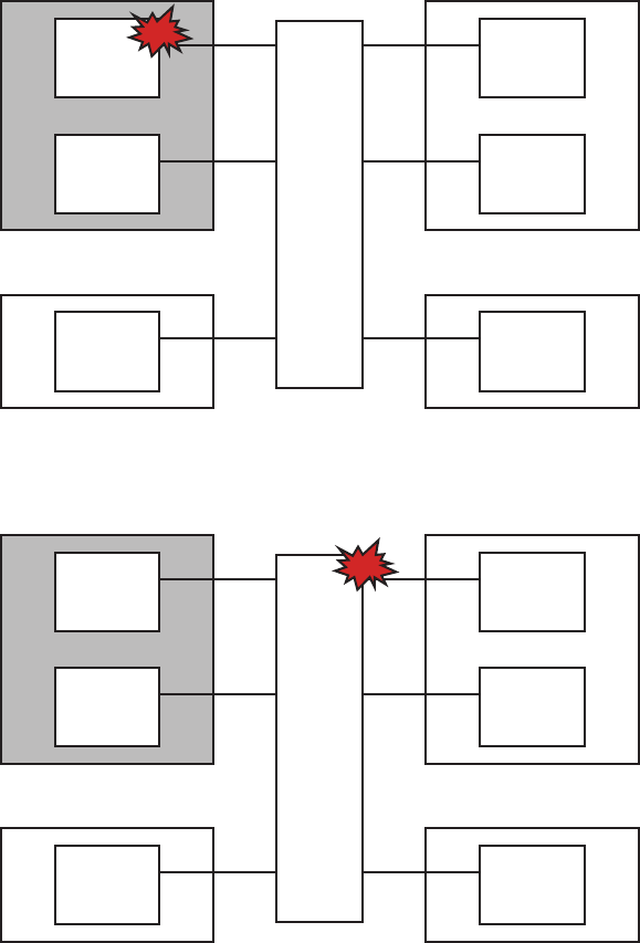
Physical partition (stopped)
BB#0
Hot
XBBOX
Hot
BB#1
Hot
Physical partition (active)
BB#3
Hot
BB#4
Hot
Physical partition (active)
BB#2
Hot
Physical partition (active)
BB#5
Hot
Physical partition (stopped)
BB#0
Hot
XBBOX
Hot
BB#1
Hot
Physical partition (active)
BB#3
Hot
BB#4
Hot
Physical partition (active)
BB#2
Hot
Physical partition (active)
BB#5
Hot
Figure 4-5 Inactive/hot maintenance (for SPARC M10-4S maintenance)
Figure 4-6 Inactive/hot maintenance (for crossbar box maintenance)
■Inactive/cold maintenance
Maintenance work is performed while the physical partition to which the
maintenance-target FRU belongs is powered off and the input power to the chassis
in which the target FRU is mounted is off (power cord is disconnected).
Chapter 4 Preparing for Maintenance 47
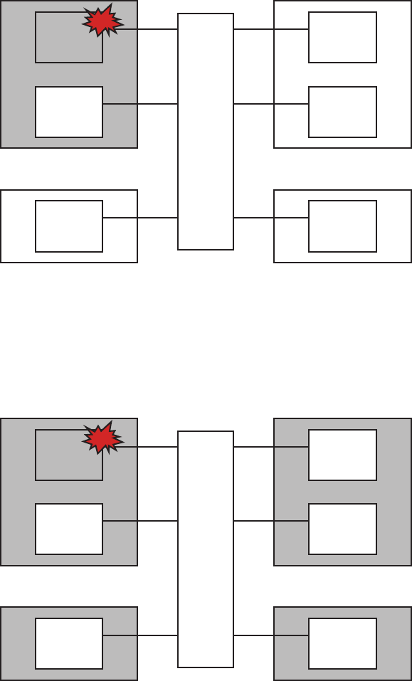
Physical partition (stopped)
BB#0
Cold
XBBOX
Hot
BB#1
Hot
Physical partition (active)
BB#3
Hot
BB#4
Hot
Physical partition (active)
BB#2
Hot
Physical partition (active)
BB#5
Hot
Physical partition (stopped)
BB#0
Cold
XBBOX
Hot
BB#1
Hot
Physical partition (stopped)
BB#3
Hot
BB#4
Hot
Physical partition (stopped)
BB#2
Hot
Physical partition (stopped)
BB#5
Hot
Figure 4-7 Inactive/cold maintenance (for SPARC M10-4S maintenance)
■System-stopped maintenance
Maintenance work is performed while all the physical partitions are powered off
and input power to the chassis in which the target FRU is mounted is off (power
cord is disconnected).
Figure 4-8 System-stopped maintenance (for SPARC M10-4S maintenance)
Fujitsu M10-4/Fujitsu M10-4S/SPARC M10-4/SPARC M10-4S Service Manual ・December 201348
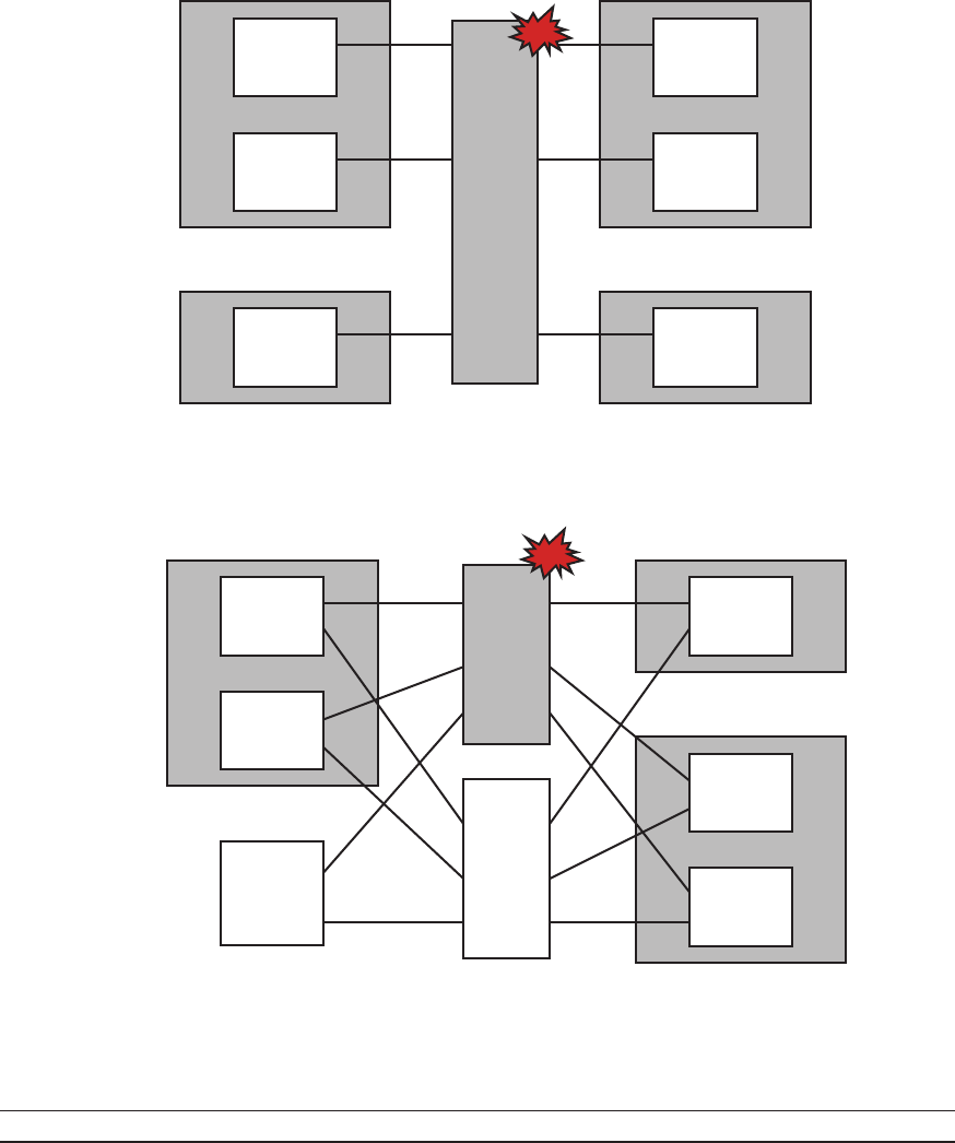
Physical partition (stopped)
BB#0
Hot
XBBOX
Cold
BB#1
Hot
Physical partition (stopped)
BB#3
Hot
BB#4
Hot
Physical partition (stopped)
BB#2
Hot
Physical partition (stopped)
BB#5
Hot
Physical partition (stopped)
BB#0
Hot
PDU
Cold
PDU
Hot
BB#1
Hot
XBBOX
Hot
Physical partition (stopped)
BB#2
Hot
BB#3
Hot
BB#4
Hot
Physical partition (stopped)
Table 4-5 Types of maintenance for SPARC M10-4
Supported: Maintenance can be performed / Unsupported: Maintenance cannot be performed
FRU Active/hot Active/cold Inactive/hot
Inactive/cold (*1)
System stopped Reference
CPU memory unit Unsupported Unsupported Unsupported Supported Supported Chapter
7
Figure 4-9 System-stopped maintenance (for crossbar box maintenance)
Figure 4-10 System-stopped maintenance (for dedicated power distribution unit
maintenance)
The following describes the types of maintenance for FRUs.
Chapter 4 Preparing for Maintenance 49
Table 4-5 Types of maintenance for SPARC M10-4 (continued)
Supported: Maintenance can be performed / Unsupported: Maintenance cannot be performed
FRU Active/hot Active/cold Inactive/hot
Inactive/cold (*1)
System stopped Reference
Memory Unsupported Unsupported Unsupported Supported Supported Chapter
8
Power supply unit Supported Unsupported Supported Supported Supported Chapter
10
Fan unit Supported Unsupported Supported Supported Supported Chapter
11
Internal disk Supported
(*2)
Unsupported Supported Supported Supported Chapter
12
PCIe card (*3) - - - - - Chapter
13
PSU backplane unit Unsupported Unsupported Unsupported Supported Supported Chapter
14
Operation panel Unsupported Unsupported Unsupported Supported Supported Chapter
15
*1: The inactive/cold maintenance procedure is the same as that for stopping the system, therefore see the procedure for system-stopped
maintenance.
*2: Supported only for internal disks of devices other than boot devices. If, however, the boot device has a redundant configuration
(RAID configuration), active/hot maintenance is supported.
*3: The types of maintenance for PCIe cards are different from those of other FRUs. For details, see Table 13-1.
Table 4-6 Types of maintenance for SPARC M10-4S
Supported: Maintenance can be performed / Unsupported: Maintenance cannot be performed
FRU Active/hot Active/cold Inactive/hot
Inactive/cold (*1)
System stopped Reference
CPU memory unit Unsupported Supported
(*2)
Unsupported Supported Supported Chapter
7
Memory Unsupported Supported
(*2)
Unsupported Supported Supported Chapter
8
Crossbar unit Unsupported Supported
(*2)
Unsupported Supported Supported Chapter
9
Power supply unit Supported
(*3)
Supported
(*2)
Supported Supported Supported Chapter
10
Fan unit Supported Supported
(*2)
Supported Supported Supported Chapter
11
Internal disk Supported
(*4)
Supported
(*2)
Supported Supported Supported Chapter
12
PCIe card (*5) - - - - - Chapter
13
PSU backplane unit Unsupported Supported
(*2)
Unsupported Supported Supported Chapter
14
Fujitsu M10-4/Fujitsu M10-4S/SPARC M10-4/SPARC M10-4S Service Manual ・December 201350

Table 4-6 Types of maintenance for SPARC M10-4S (continued)
Supported: Maintenance can be performed / Unsupported: Maintenance cannot be performed
FRU Active/hot Active/cold Inactive/hot
Inactive/cold (*1)
System stopped Reference
Operation panel Unsupported Supported
(*2)
Unsupported Supported Supported Chapter
15
*1: For a single-chassis configuration, the inactive/cold maintenance procedure is the same as that for stopping the system, therefore see
the procedure for system-stopped maintenance.
*2: It is necessary to use dynamic reconfiguration (DR) to disconnect a chassis requiring maintenance from the physical partition.
*3: Active/hot replacement can be performed only with a redundant configuration.
*4: Supported only for internal disks of devices other than boot devices. If, however, the boot device has a redundant configuration
(RAID configuration), active/hot maintenance is supported.
*5: The types of maintenance for PCIe cards are different from those of other FRUs. For details, see Table 13-1.
Table 4-7 Types of maintenance for crossbar box
Supported: Maintenance can be performed / Unsupported: Maintenance cannot be performed
FRU Active/hot Active/cold Inactive/hot Inactive/cold System stopped Reference
Crossbar unit Unsupported Supported
(*1)
Unsupported Supported Supported
(*3)
Chapter
16
XSCF unit Supported
(*4)
Unsupported
(*2)
Supported Unsupported
(*2)
Supported
(*3)
Chapter
17
Power supply unit Supported
(*5)
Unsupported
(*2)
Supported Unsupported
(*2)
Supported
(*3)
Chapter
18
Fan unit Supported Unsupported
(*2)
Supported Unsupported
(*2)
Supported
(*3)
Chapter
19
XSCF interface unit Unsupported Unsupported
(*2)
Unsupported Unsupported
(*2)
Supported
(*3)
Chapter
20
Crossbar backplane
unit
Unsupported Unsupported
(*2)
Unsupported Unsupported
(*2)
Supported
(*3)
Chapter
21
Fan backplane Unsupported Unsupported
(*2)
Unsupported Unsupported
(*2)
Supported
(*3)
Chapter
22
Operation panel Unsupported Unsupported
(*2)
Unsupported Unsupported
(*2)
Supported
(*3)
Chapter
23
*1: If any physical partition mounted on two or more chassis is currently operating, the crossbar box cannot be powered off.
*2: If any physical partition is currently operating, the crossbar box cannot be powered off.
*3: All the physical partitions must be powered off, and the system must be completely shut down.
*4: The XSCF must be configured as a slave before maintenance is started. If the XSCF is operating as the master XSCF, switch it to a
standby XSCF.
*5: Active/hot replacement can be performed only with a redundant configuration.
Table 4-8 Types of maintenance for cables and dedicated power distribution unit
Supported: Maintenance can be performed / Unsupported: Maintenance cannot be performed
FRU Active/hot Active/cold Inactive/hot Inactive/cold System stopped Reference
Crossbar cable
(electrical)
Unsupported Unsupported Unsupported Supported Supported Chapter
24
Crossbar cable
(optical)
Unsupported Unsupported Unsupported Supported Supported Chapter
25
Chapter 4 Preparing for Maintenance 51
Table 4-8 Types of maintenance for cables and dedicated power distribution unit (continued)
Supported: Maintenance can be performed / Unsupported: Maintenance cannot be performed
FRU Active/hot Active/cold Inactive/hot Inactive/cold System stopped Reference
XSCF BB control
cable
Supported
(*1)
Supported Supported Supported Supported Chapter
26
XSCF DUAL control
cable
Supported
(*1)
Supported Supported Supported Supported Chapter
27
Cable kit Unsupported Unsupported
(*2)
Unsupported Unsupported
(*2)
Supported
(*3)
Chapter
28
Dedicated power
distribution unit
Unsupported Supported Unsupported Unsupported Supported Chapter
29
*1: The XSCF must be configured as a slave before maintenance is started. If the XSCF is operating as the master XSCF, switch it to a
standby XSCF.
*2: If any physical partition is currently operating, the crossbar box cannot be powered off.
*3: All the physical partitions must be powered off, and the system must be completely shut down.
Fujitsu M10-4/Fujitsu M10-4S/SPARC M10-4/SPARC M10-4S Service Manual ・December 201352
Caution - Do not operate a target Field Replaceable Unit (FRU) while OpenBoot
PROM is running (the ok prompt is displayed). After powering off the physical
partition or starting Oracle Solaris, operate the target FRU.
Chapter 5
Understanding the Preparations for
Enabling Maintenance
This chapter describes the preparations that must be completed before you physically
remove a component. See this chapter, as required, when performing the maintenance
work on each component described in Chapter 7 onwards.
■Releasing an FRU from the System with the replacefru Command
■Releasing a Chassis from the Physical Partition
■Powering Off the Physical Partition Requiring Maintenance
■Stopping the Entire System
■Accessing Components
5.1 Releasing an FRU from the System
with the replacefru Command
This section describes the procedure for releasing an FRU requiring maintenance
from the system. The following FRUs can be the target of maintenance:
■Power supply units of the SPARC M10-4/M10-4S and the crossbar box
■Fan units of the SPARC M10-4/M10-4S and the crossbar box
■XSCF unit of the crossbar box
■SPARC M10-4/M10-4S chassis itself and crossbar box chassis itself
1. LogintotheXSCFshell.
2. Execute the replacefru command to display the maintenance menu.
53
XSCF> replacefru
------------------------------------------------------------------------------
Maintenance/Replacement Menu
Please select a type of model which has FRU to be replaced.
1. BB (4s Building Block Model)
2. XBBOX (XB-BOX Model)
------------------------------------------------------------------------------
Select [1,2|c:cancel] :1
------------------------------------------------------------------------------
Maintenance/Replacement Menu
Please select the chassis including replaced FRU.
No. FRU Status
--- ------------------- --------------
1 /BB#0 Degraded
2 /BB#1 Normal
3 /BB#2 Unmount
4 /BB#3 Unmount
5 /BB#4 Unmount
6 /BB#5 Unmount
7 /BB#6 Unmount
8 /BB#7 Unmount
9 /BB#8 Unmount
10 /BB#9 Unmount
11 /BB#10 Unmount
12 /BB#11 Unmount
------------------------------------------------------------------------------
Select [1-12|c:cancel] :1
------------------------------------------------------------------------------
Maintenance/Replacement Menu
Please select the BB or a type of FRU to be replaced.
3. Select the FRU requiring maintenance by specifying it with a numeric key.
When the system is configured without a crossbar box, the following screen is
not displayed. Proceed to step 4.
In the following example, since the SPARC M10-4S chassis itself is selected, "1" is
entered.
4. Select the FRU requiring maintenance by specifying it with a numeric key.
In the following example, since BB#0 is showing "Degraded" indicating
abnormality, "1" is entered.
5. Select the FRU requiring maintenance by specifying it with a numeric key.
In the following example, since the SPARC M10-4S chassis itself is faulty, "1" is
entered.
Fujitsu M10-4/Fujitsu M10-4S/SPARC M10-4/SPARC M10-4S Service Manual ・December 201354
1. BB itself
2. FAN (Fan Unit)
3. PSU (Power Supply Unit)
------------------------------------------------------------------------------
Select [1-3|c:cancel] :1
------------------------------------------------------------------------------
Maintenance/Replacement Menu
Please select a FRU to be replaced.
No. FRU Status
--- ------------------- --------------
1 /BB#0 Degraded
------------------------------------------------------------------------------
Select [1|b:back] :1
You are about to replace BB#0.
Do you want to continue?[r:replace|c:cancel] :r
Please execute the following steps:
1) Confirm the XSCF STANDBY LED of BB#0 is not lit.
2) Turn off the breaker of BB#0.
3) Remove BB#0.
4) Execute either the following:
4-1) After the exchanged device is connected with the system,
turn on the breaker of BB#0, and please select 'finish'.
4-2) If you want to suspend the maintenance without exchanging device,
please select 'cancel'.
[f:finish|c:cancel] :
6. Select the faulty FRU by specifying it with a numeric key.
Since it was confirmed in step 4 that BB#0 is faulty, "1" is also entered here.
7. After confirming that the selected FRU is displayed, enter "r".
8. Confirm that the CHECK LED of the FRU is on or blinking.
To release a SPARC M10-4S or crossbar box chassis itself, confirm that the
system locator on the chassis is blinking.
For details on the locations of LEDs, see "2.3.2 LEDs on the rear panel (System
locator)"and"2.3.3 LEDs on each component."
You can now start FRU maintenance.
Chapter 5 Understanding the Preparations for Enabling Maintenance 55
Note - When there is no free space on a physical partition or when all the resources are
assigned to the control domain, DR cannot be applied to the physical partition.
XSCF> switchscf -t Standby
The XSCF unit switch between the Master and Standby states.
Continue? [y|n] :y
XSCF> showpparstatus -p 0
PPAR-ID PPAR Status
00 Running
XSCF> showdomainstatus -p 0
Logical Domain Name Status
primary Solaris running
guest0 Solaris running
guest1 Solaris running
domain01 Solaris running
5.2 Releasing a Chassis from the Physical
Partition
This section describes the procedure for releasing a chassis requiring maintenance
from the physical partition by using dynamic reconfiguration (DR). DR can be used
only for a building block configuration.
1. Log in to the XSCF shell.
2. When the chassis requiring maintenance is operating as the master chassis,
execute the switchscf command to switch the master XSCF to a standby
XSCF.
In response to the confirmation message, enter "y".
When the chassis requiring maintenance is a slave XSCF, proceed to step 4.
3. Log in to the XSCF again.
4. Execute the showpparstatus command to confirm the operating condition of
the physical partition.
In the following example, [Status] of PPAR-ID 00 displays "Running", which
indicates that the physical partition is operating.
5. Execute the showdomainstatus command to confirm the operating condition
of the logical domain.
In the following example, [Status] of the logical domain displays "Solaris
running", which indicates that Oracle Solaris is operating.
Fujitsu M10-4/Fujitsu M10-4S/SPARC M10-4/SPARC M10-4S Service Manual ・December 201356

#ldm list-domain
NAME STATE FLAGS CONS VCPU MEMORY UTIL UPTIME
primary active -n-cv- UART 14 8G 64% 2h 54m
guest0 active -n---- 5000 16 8G 42% 2h 54m
guest1 active -n---- 5001 16 8G 11% 2h 54m
domain01 active -n---- 5002 16 8G 7.3% 2h 54m
#ldm list-devices -a
CORE
ID %FREE CPUSET
00(0,1)
40(8,9)
8 0 (16, 17)
------------------------Ommitted------------------------
184 0 (368, 369)
188 100 (376, 377)
512 100 (1024, 1025)
516 100 (1032, 1033)
520 100 (1040, 1041)
524 100 (1048, 1049)
------------------------Ommitted------------------------
VCPU
PID %FREE PM
00no
10no
80no
90no
------------------------Ommitted------------------------
369 0 no
376 100 ---
377 100 ---
1024 100 ---
1025 100 ---
1032 100 ---
1033 100 ---
------------------------Ommitted-----------------------
6. Connect to the control domain console of the physical partition.
7. Execute the ldm list-domain command to confirm the operating condition of
the logical domain.
In the following example, the [STATE] of the control domain and three guest
domains displays "active", which indicates that the logical domain is operating.
8. Execute the ldm list-devices -a command to check the usage status of the
resource.
The following example shows the resources that are bound to a logical domain
and the resources that are not bound to a logical domain.
9. Execute the ldm list-io command to check the usage status of the I/O device.
In the following example, values displayed under [TYPE] are all "BUS" for PCIE0
to PCIE11 under [NAME], which indicates that they are PCIe root complexes.
Chapter 5 Understanding the Preparations for Enabling Maintenance 57
#ldm list-io
NAME TYPE BUS DOMAIN STATUS
---- ---- --- ------ ------
PCIE0 BUS PCIE0 primary IOV
PCIE1 BUS PCIE1 primary IOV
PCIE2 BUS PCIE2 primary IOV
PCIE3 BUS PCIE3 primary IOV
PCIE8 BUS PCIE8 domain01 IOV
PCIE9 BUS PCIE9 domain01 IOV
PCIE10 BUS PCIE10 domain01 IOV
PCIE11 BUS PCIE11 domain01 IOV
/BB0/CMUL/NET0 PCIE PCIE0 primary OCC
/BB0/CMUL/SASHBA PCIE PCIE0 primary OCC
/BB0/PCI0 PCIE PCIE1 primary EMP
/BB0/PCI3 PCIE PCIE2 primary EMP
/BB0/PCI4 PCIE PCIE2 primary EMP
/BB0/PCI7 PCIE PCIE3 primary EMP
/BB0/PCI8 PCIE PCIE3 primary EMP
/BB1/CMUL/NET0 PCIE PCIE8 domain01 OCC
/BB1/CMUL/SASHBA PCIE PCIE8 domain01 OCC
/BB1/PCI0 PCIE PCIE9 domain01 EMP
/BB1/PCI3 PCIE PCIE10 domain01 EMP
/BB1/PCI4 PCIE PCIE10 domain01 EMP
/BB1/PCI7 PCIE PCIE11 domain01 EMP
/BB1/PCI8 PCIE PCIE11 domain01 EMP
#ldm stop domain01
#ldm rm-io PCIE8 domain01
#ldm rm-io PCIE9 domain01
#ldm rm-io PCIE10 domain01
#ldm rm-io PCIE11 domain01
#ldm list-io
NAME TYPE BUS DOMAIN STATUS
---- ---- --- ------ ------
PCIE0 BUS PCIE0 primary IOV
Values displayed under [DOMAIN] are "primary" or "domain01", which
indicates that they are assigned to the control domain or domain01.
10. Delete all the I/O devices from the domain to which the I/O devices of the
system board to be deleted are assigned.
In the following example, domain01 is stopped and the PCIe root complexes that
are owned by domain01 and related to the system board to be deleted are
released.
11. Execute the ldm list-io command again to check the usage status of the I/O
devices.
The following example shows that the values displayed under [DOMAIN] for
PCIE8, PCIE9, PCIE10, and PCIE11, which were used by domain01, are deleted
and the I/O devices are released.
Fujitsu M10-4/Fujitsu M10-4S/SPARC M10-4/SPARC M10-4S Service Manual ・December 201358
PCIE1 BUS PCIE1 primary IOV
PCIE2 BUS PCIE2 primary IOV
PCIE3 BUS PCIE3 primary IOV
PCIE8 BUS PCIE8
PCIE9 BUS PCIE9
PCIE10 BUS PCIE10
PCIE11 BUS PCIE11
/BB0/CMUL/NET0 PCIE PCIE0 primary OCC
/BB0/CMUL/SASHBA PCIE PCIE0 primary OCC
/BB0/PCI0 PCIE PCIE1 primary EMP
/BB0/PCI3 PCIE PCIE2 primary EMP
/BB0/PCI4 PCIE PCIE2 primary EMP
/BB0/PCI7 PCIE PCIE3 primary EMP
/BB0/PCI8 PCIE PCIE3 primary EMP
/BB1/CMUL/NET0 PCIE PCIE8
/BB1/CMUL/SASHBA PCIE PCIE8
/BB1/PCI0 PCIE PCIE9
/BB1/PCI3 PCIE PCIE10
/BB1/PCI4 PCIE PCIE10
/BB1/PCI7 PCIE PCIE11
/BB1/PCI8 PCIE PCIE11
XSCF> showboards -a
PSB PPAR-ID(LSB) Assignment Pwr Conn Conf Test Fault
---- ------------ ----------- ---- ---- ---- ------- --------
00-000(00) AssignedyyyPassedNormal
01-000(01) AssignedyyyPassedDegraded
02-000(02) AssignedyyyPassedNormal
03-000(03) AssignednnnPassedFaulted
XSCF> deleteboard -c disconnect 01-0
12. Execute the showboards command to check the state of the chassis requiring
maintenance.
The BB-ID of the chassis requiring maintenance is indicated by the system board
(PSB) number.
In the following example, [Fault] of PSB 01-0 displays "Degraded", which
indicates that the system board is operating but has some faulty parts.
13. Execute the deleteboard command to release the chassis requiring
maintenance from the physical partition.
In the following example, PSB 01-0 is released from the physical partition.
14. Execute the showboards command to confirm that the chassis requiring
maintenance has been released from the physical partition.
In the following example, all of [Pwr], [Conn], and [Conf] of PSB 01-0 display
"n", which indicates that PSB 01-0 has been released.
Chapter 5 Understanding the Preparations for Enabling Maintenance 59
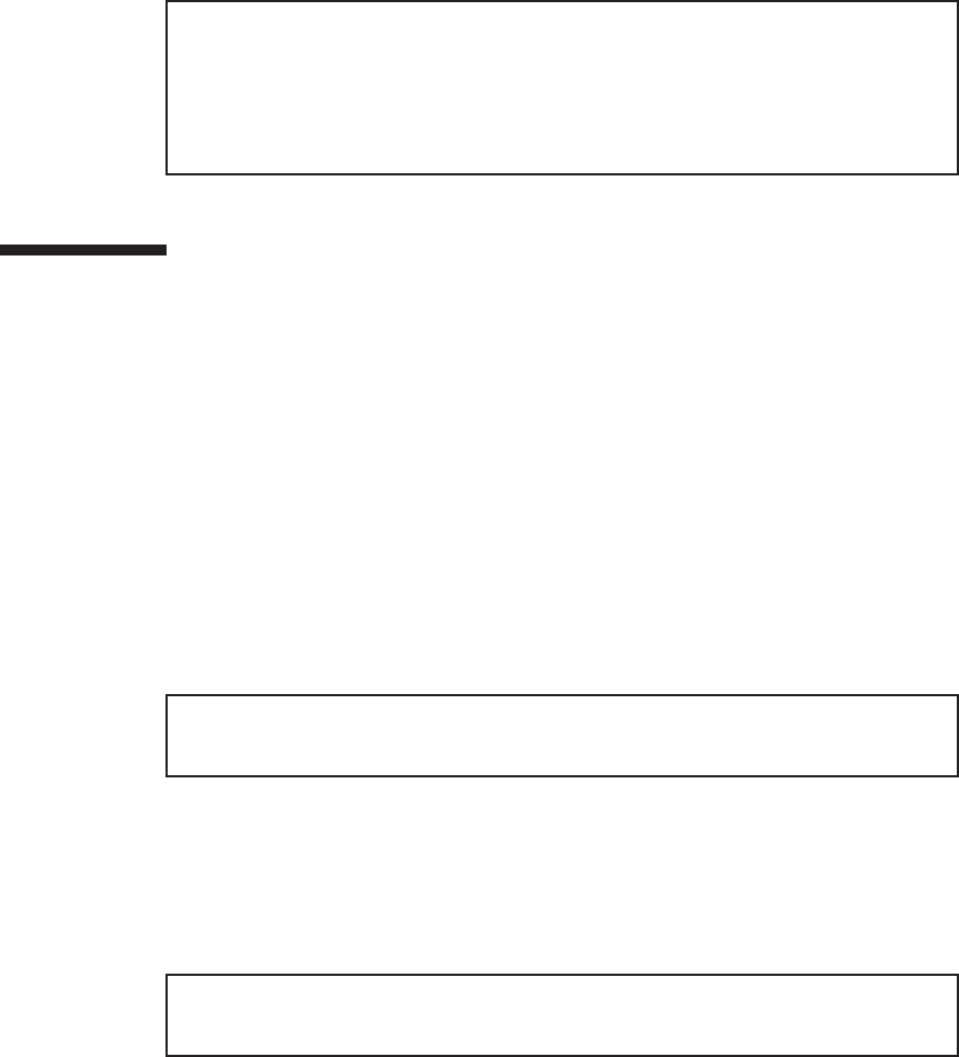
XSCF> showboards -a
PSB PPAR-ID(LSB) Assignment Pwr Conn Conf Test Fault
---- ------------ ----------- ---- ---- ---- ------- --------
00-000(00) AssignedyyyPassedNormal
01-000(01) AssignednnnPassedDegraded
02-000(02) AssignedyyyPassedNormal
03-000(03) AssignednnnPassedFaulted
XSCF> switchscf -t Standby
The XSCF unit switch between the Master and Standby states.
Continue? [y|n] :y
XSCF> showpparstatus -p 0
PPAR-ID PPAR Status
00 Running
5.3 Powering Off the Physical Partition
Requiring Maintenance
This section describes the procedure for powering off the physical partition requiring
maintenance. This is applicable if the system has a building block configuration and
has multiple physical partitions.
1. Log in to the XSCF shell.
2. When the chassis requiring maintenance is operating as the master chassis,
execute the switchscf command to switch the master XSCF to a standby
XSCF.
In response to the confirmation message, enter "y".
When the chassis requiring maintenance is a slave XSCF, proceed to step 4.
3. Log in to the master XSCF again.
4. Execute the showpparstatus command to confirm the operating condition of
the physical partition.
In the following example, [PPAR Status] of PPAR-ID 00 displays "Running",
which indicates that the physical partition is operating.
5. Execute the showdomainstatus command to confirm the operating condition
of the logical domain.
In the following example, [Status] of the logical domain displays "Solaris
running", which indicates that Oracle Solaris is operating.
Fujitsu M10-4/Fujitsu M10-4S/SPARC M10-4/SPARC M10-4S Service Manual ・December 201360

XSCF> showdomainstatus -p 0
Logical Domain Name Status
primary Solaris running
4S-159-D0-G0 Solaris running
4S-159-D0-G1 Solaris running
4S-159-D0-G2 Solaris running
XSCF> showboards -a
PSB PPAR-ID(LSB) Assignment Pwr Conn Conf Test Fault
---- ------------ ----------- ---- ---- ---- ------- --------
00-000(00) AssignedyyyPassedNormal
01-000(01) AssignedyyyPassedNormal
XSCF> poweroff -p 0
PPAR-IDs to power off:00
Continue? [y|n] :y
00 : Powering off
XSCF> showpparstatus -p 0
PPAR-ID PPAR Status
00 Powered Off
6. Execute the showboards command to check the state of the chassis requiring
maintenance.
The BB-ID of the chassis requiring maintenance is indicated by the system board
(PSB) number.
In the following example, we can see that [PPAR-ID] of PSB 01-0 is "00".
7. Execute the poweroff command to stop all the logical domains on the
physical partition requiring maintenance.
In response to the confirmation message, enter "y".
8. Execute the showpparstatus command to confirm that the power to the
physical partition is turned off.
In the following example, [PPAR Status] of PPAR-ID 00 displays "Powered Off",
which indicates that the power to the physical partition has been turned off.
9. Switch the mode switches for the master chassis and those chassis whose
XSCFs are in the standby state to Service mode.
-For a building block configuration (without crossbar box)
Switch the mode switches of BB-ID#00 and #01 to Service mode.
-For a building block configuration (with crossbar box)
Switch the mode switches of BB-ID#80 and #81 to Service mode.
Chapter 5 Understanding the Preparations for Enabling Maintenance 61
Note - Before stopping the system, inform the users that the system will be stopped.
Note - When a physical partition is stopped by operating the XSCF command or the
operation panel, all the logical domains on the physical partition are stopped. Stop
applications as required.
XSCF> showpparstatus -a
PPAR-ID PPAR Status
00 Powered Off
01 Powered Off
02 Powered Off
XSCF> showdomainstatus -p 0
Logical Domain Name Status
primary Solaris powering down
4S-159-D0-G0 Solaris powering down
4S-159-D0-G1 Solaris powering down
4S-159-D0-G2 Solaris powering down
5.4 Stopping the Entire System
This section describes the procedure for stopping the entire system. To undertake
system-stopped maintenance, power off all the physical partitions to stop the entire
system before physically removing any components.
There are two ways of stopping the system, as follows:
■Stopping the system with the XSCF command
■Stopping the system from the operation panel
1. Stop the entire system.
For details, see "5.4.1 Stopping the system with the XSCF command"or"5.4.2
Stopping the system from the operation panel."
2. Execute the showpparstatus command to confirm that the power to the
physical partition is turned off.
In the following example, [PPAR Status] of PPAR-IDs 00, 01, and 02 display
"Powered Off", which indicates that the power to all the physical partitions has
been turned off.
3. Execute the showdomainstatus command to confirm the operating condition
of the logical domain.
In the following example, [Status] of the logical domain displays "Solaris
powering down", which indicates that Oracle Solaris is shutting down.
Fujitsu M10-4/Fujitsu M10-4S/SPARC M10-4/SPARC M10-4S Service Manual ・December 201362
Note - For a building block configuration, switch the mode switches of the master chassis
and those chassis whose XSCFs are in the standby state.
XSCF> poweroff -a
PPAR-IDs to power off:00,01
Continue? [y|n] :y
00 : Powering off
01 : Powering off
Note - For a building block configuration, check the POWER LEDs on all the chassis that
make up the system.
Note - For a building block configuration, switch the mode switches of the master chassis
and those chassis whose XSCFs are in the standby state.
5.4.1 Stopping the system with the XSCF command
1. Switch the mode switch on the operation panel to Service mode.
For details, see "2.2.2 Control function of the operation panel."
2. LogintotheXSCFshell.
3. Execute the poweroff command.
In response to the confirmation message, enter "y".
In the following example, the status of PPAR-IDs 00 and 01 displays "Powering
off", which indicates that the power to the physical partitions is being turned off.
The following processes are performed.
- Oracle Solaris is completely shut down.
- The system stops and enters the POWERON READY state (The XSCF is running).
For details, see "6.2.2 Stopping the whole system" in the Fujitsu M10/SPARC M10
Systems System Operation and Administration Guide.
4. Check that the POWER LED on the operation panel is off.
5.4.2 Stopping the system from the operation panel
1. Switch the mode switch on the operation panel to Service mode.
For details, see "2.2.2 Control function of the operation panel."
2. Press the power switch on the operation panel for 4 seconds or more.
For details, see "2.2.2 Control function of the operation panel."
Chapter 5 Understanding the Preparations for Enabling Maintenance 63

Note - For a building block configuration, press the power switch on the master chassis. The
power switches of the other chassis are disabled.
Note - For a building block configuration, check the POWER LEDs on all the chassis that
make up the system.
3. Check that the POWER LED on the operation panel is off.
5.5 Accessing Components
This section describes the operations that must be completed prior to accessing a
component requiring maintenance.
5.5.1 Lowering the cable support
For a component that is accessed from the rear of the SPARC M10-4/M10-4S, the
cable support must be lowered and then the cables removed.
1. Loosen the right and left screws fixing the cable support, and unlock it by
pulling the upper and lower metal fittings towards you (in the direction of the
arrow).
Fujitsu M10-4/Fujitsu M10-4S/SPARC M10-4/SPARC M10-4S Service Manual ・December 201364
Figure 5-1 Locations of screws holding the cable support
2. Lower the cable support.
5.5.2 Removing the power cord
When removing the power cord of the SPARC M10-4S or the crossbar box to perform
maintenance work on a component, do so only after removing the cable clamp from
the power cord.
1. Release the latch (A in the figure) of the cable clamp.
Pulling the cable clamp toward the rear of the chassis facilitates release of the
latch.
Chapter 5 Understanding the Preparations for Enabling Maintenance 65
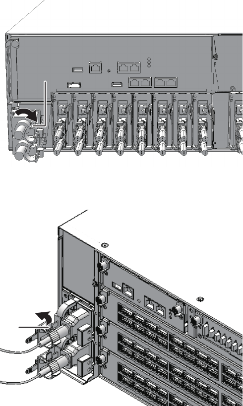
A
A
Figure 5-2 Releasing the cable clamp (SPARC M10-4/M10-4S)
Figure 5-3 Releasing the cable clamp (crossbar box)
2. Remove the power cord of the SPARC M10-4S from the PSU backplane unit,
or remove the power cord of the crossbar box from the power supply unit.
Fujitsu M10-4/Fujitsu M10-4S/SPARC M10-4/SPARC M10-4S Service Manual ・December 201366

Figure 5-4 Removing the power cord (SPARC M10-4/M10-4S)
Figure 5-5 Removing the power cord (crossbar box)
5.5.3 Removing the front cover
When performing maintenance on a component from the front of a SPARC M10-4S
or crossbar box chassis, remove the front cover before starting the work.
1. Release the right and left slide locks of the front cover and pull it towards the
front.
Chapter 5 Understanding the Preparations for Enabling Maintenance 67
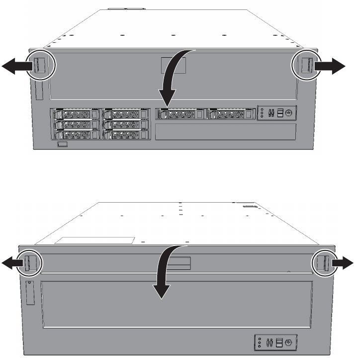
Figure 5-6 Releasing the slide locks of the front cover (SPARC M10-4/M10-4S)
Figure 5-7 Releasing the slide locks of the front cover (crossbar box)
2. Lift the front cover upwards to remove it.
Fujitsu M10-4/Fujitsu M10-4S/SPARC M10-4/SPARC M10-4S Service Manual ・December 201368
Please execute the following steps:
1) Confirm the XSCF STANDBY LED of BB#0 is not lit.
2) Turn off the breaker of BB#0.
3) Remove BB#0.
4) Execute either the following:
4-1) After the exchanged device is connected with the system,
turn on the breaker of BB#0, and please select 'finish'.
4-2) If you want to suspend the maintenance without exchanging device,
please select 'cancel'.
[f:finish|c:cancel] :f
Chapter 6
Understanding the Preparations for
Restoring the System
This chapter describes the procedures required to restore the system after component
maintenance. See this chapter, as required, when performing maintenance on each
component described in Chapter 7 onwards.
■Incorporating an FRU into the System with the replacefru Command
■Incorporating a Chassis into a Physical Partition
■Powering On the Physical Partition Requiring Maintenance
■Starting the Entire System
■Restoring the Chassis
6.1 Incorporating an FRU into the System
with the replacefru Command
This section describes the procedure for incorporating a Field Replaceable Unit (FRU)
into the system after maintenance. To do this, resume the replacefru command,
which is running, to incorporate the FRU into the system.
1. After completing maintenance of the target FRU, return to the operation of the
replacefru command of the XSCF firmware, and enter "f".
The following is displayed. Wait until the processing is complete.
69
Waiting for BB#0 to enter install state.
[This operation may take up to 20 minute(s)]
(progress scale reported in seconds)
0..... 30.. done
Waiting for BB#0 to enter ready state.
[This operation may take up to 45 minute(s)]
(progress scale reported in seconds)
0..... 30..... 60..... done
Do you want to start to diagnose BB#0?[s:start|c:cancel] :s
Diagnostic tests for BB#0 have started.
Initial diagnosis is about to start, Continue?[y|n] :y
SB#00-0 power on sequence started.
0..... 30..... 60....end
Initial diagnosis started. [1800sec]
0..... 30..... 60..... 90.....120.....150.....180.....210.....240.....|
270.....300.....330.....360..end
Initial diagnosis has completed.
SB power off sequence started. [1200sec]
0..... 30..... 60..... 90.....120....end
SB powered off.
PSB Test Fault
---- ------- --------
00-0 Passed Normal
done
------------------------------------------------------------------------------
Maintenance/Replacement Menu
Status of the replaced FRU.
FRU Status
------------------- --------------
/BB#0 Normal
------------------------------------------------------------------------------
The replacement of BB#0 has completed normally.[f:finish] :f
2. After confirming that the FRU to be diagnosed is displayed, enter "s".
3. After confirming again that the FRU to be diagnosed is displayed, enter "y".
The following is displayed. Wait until the processing is complete.
4. Confirm that the status is normal ("Normal") after diagnosis, and then enter
"f".
5. When the maintenance menu appears, enter "c" to exit the operation.
Fujitsu M10-4/Fujitsu M10-4S/SPARC M10-4/SPARC M10-4S Service Manual ・December 201370

------------------------------------------------------------------------------
Maintenance/Replacement Menu
Please select a type of model which has FRU to be replaced.
1. BB (4s Building Block Model)
2. XBBOX (XB-BOX Model)
------------------------------------------------------------------------------
Select [1,2|c:cancel] :c
Note - When you incorporate a system board with the addboard command, the target system
board is incorporated into the physical partition after its hardware diagnosis. Therefore, it
may take time for the command execution to complete.
XSCF> addboard -c configure -p 0 01-0
PSB#01-0 will be configured into PPAR-ID 0. Continue?[y|n] :y
Start connecting PSB to PPAR. [3600sec]
0..... 30..... 60..... 90.....120.....150.....180.....210.....240.....
270.....300.....330.....360.....390.....420.....450.....480.....510.....
540.....570.....600.....630.....660.....690.....720.....750.....780.....
810.....840.....870.....900.....930.....960.....end
Connected PSB to PPAR.
Start configuring PSB to Logical Domains (LDoms) Manager. [1800sec]
0.....end
Configured PSB to Logical Domains (LDoms) Manager.
Operation has completed.
6.2 Incorporating a Chassis into a Physical
Partition
This section describes the procedure for incorporating a chassis into a physical
partition by using dynamic reconfiguration (DR) after FRU maintenance.
1. LogintotheXSCFshell.
2. Execute the addboard command to incorporate the target chassis into the
physical partition.
In response to the confirmation message, enter "y".
In the following example, PSB 01-0 is incorporated into PPAR-ID 0.
3. Execute the showresult command to check the end status of the addboard
command that was just executed.
The following example shows that "0" is returned as the end status and the
execution of the addboard command has been completed successfully.
Chapter 6 Understanding the Preparations for Restoring the System 71

XSCF> showresult
0
XSCF> showboards -a
PSB PPAR-ID(LSB) Assignment Pwr Conn Conf Test Fault
---- ------------ ----------- ---- ---- ---- ------- --------
00-000(00) AssignedyyyPassedNormal
01-000(01) AssignedyyyPassedNormal
#ldm add-io PCIE8 domain01
#ldm add-io PCIE9 domain01
#ldm add-io PCIE10 domain01
#ldm add-io PCIE11 domain01
#ldm remove-io /BB1/PCI0 domain01 (*1)
#ldm add-io /BB1/PCI0 iodomain (*1)
Note - Start the root domain first, and then start I/O domains.
#ldm start-domain domain01
#ldm start-domain iodomain
4. Execute the showboards command to confirm that the target chassis has
been incorporated into the physical partition.
The BB-ID of the chassis requiring maintenance is indicated by the system board
(PSB) number.
In the following example, [Fault] of PSB 01-0 displays "Normal", which indicates
that the system board is operating normally.
5. If you performed maintenance on a PCIe card using dynamic reconfiguration
(DR), restore the devices that were released before the maintenance to their
original configurations.
Reassign the devices that were released from the root domain and I/O domains.
*1: PCIe slots are automatically assigned to the root domain. Therefore, to
reassign them to I/O domains, they must be released and then reassigned.
6. Start the root domain and I/O domains.
If a virtual service is provided, the virtual service is automatically restarted.
7. If there is a guest domain that uses a virtual device, log in to the guest domain
to restart the use of the device or incorporate it into the duplication function
again.
Fujitsu M10-4/Fujitsu M10-4S/SPARC M10-4/SPARC M10-4S Service Manual ・December 201372
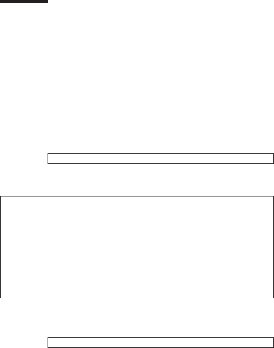
XSCF> showstatus
XSCF> showhardconf
SPARC M10-4S;
+ Serial:2081235006; Operator_Panel_Switch:Locked;
+ System_Power:Off; System_Phase:Cabinet Power Off;
Partition#0 PPAR_Status:Powered Off;
BB#00 Status:Normal; Role:Master; Ver:2047h; Serial:2081235006;
+ FRU-Part-Number:CA07361-D202 A1 ;
+ Power_Supply_System: ;
+ Memory_Size:160 GB;
------------------------Ommitted------------------------
BB#01 Status:Normal; Role:Standby; Ver:2047h; Serial:2081228004;
+ FRU-Part-Number:CA07361-D202 A0 ;
+ Power_Supply_System: ;
+ Memory_Size:128 GB;
------------------------Ommitted-----------------------
XSCF> switchscf -t Standby
6.3 Powering On the Physical Partition
Requiring Maintenance
This section describes the procedure for powering on a physical partition requiring
maintenance.
1. Switch the mode switches of the master chassis and those chassis whose
XSCFs are in the standby state to Locked mode.
-For a building block configuration (without crossbar box)
Switch the mode switches of BB-ID#00 and #01 to Locked mode.
-For a building block configuration (with crossbar box)
Switch the mode switches of BB-ID#80 and #81 to Locked mode.
2. LogintotheXSCFshell.
3. Execute the showstatus command to confirm that there is no problem with
the FRU after the completion of maintenance.
If there is no problem, nothing is displayed.
4. Execute the showhardconf command to check the hardware configuration
and the status of each component.
5. If the state of the master chassis requiring maintenance has been switched to
the standby state before maintenance, execute the switchscf command to
switch the chassis to the master XSCF.
6. Execute the poweron command to power on the stopped physical partition.
Chapter 6 Understanding the Preparations for Restoring the System 73
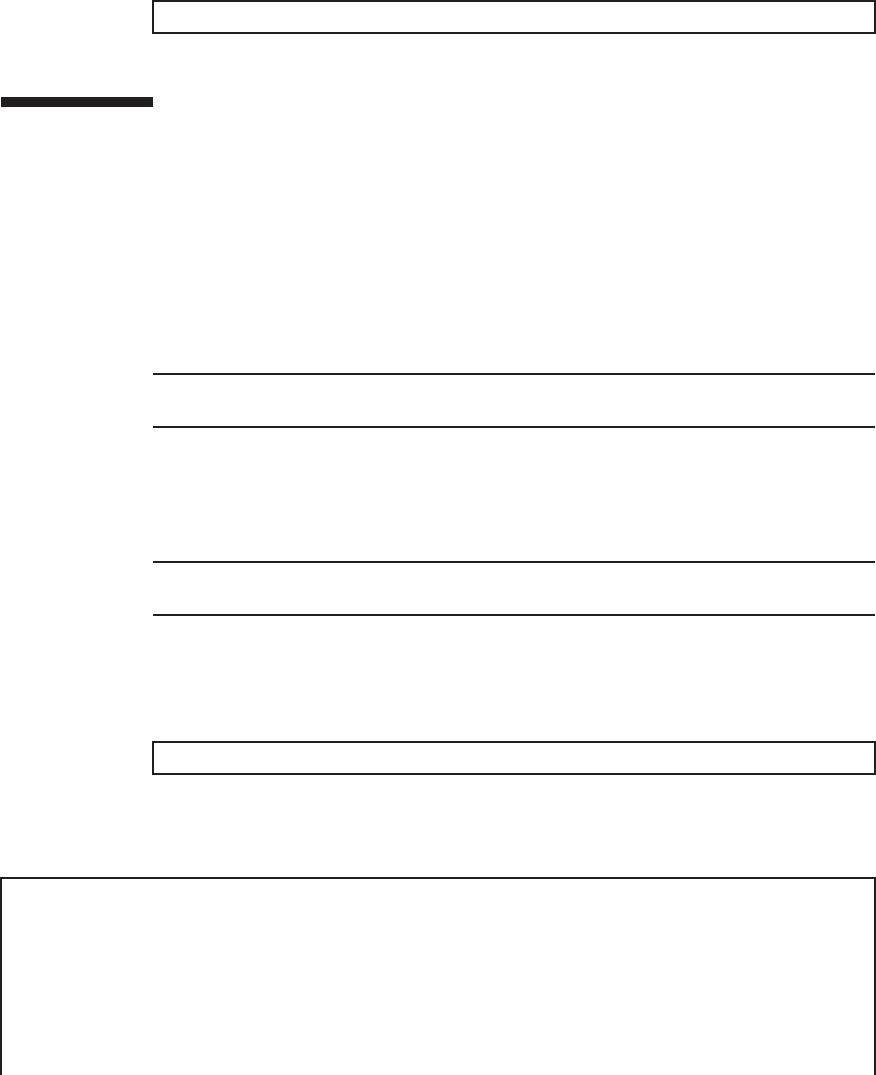
XSCF> poweron -p 0
Note - For a building block configuration, check the XSCF STANDBY LEDs of all the chassis
constituting the system.
Note - For a building block configuration, switch the mode switches of the master chassis
and those chassis whose XSCFs are in the standby state.
XSCF> showstatus
XSCF> showhardconf
SPARC M10-4S;
+ Serial:2081229003; Operator_Panel_Switch:Service;
+ System_Power:On; System_Phase:Cabinet Power On;
Partition#0 PPAR_Status:Running;
BB#00 Status:Normal; Role:Master; Ver:2050h; Serial:2081229003;
+ FRU-Part-Number:CA07361-D202 A0 ;
+ Power_Supply_System: ;
+ Memory_Size:320 GB;
Enter the PPAR-ID you noted in advance by using the showboards command.
In the following example, PPAR-ID 0 is specified.
6.4 Starting the Entire System
This section describes the procedure for starting the entire system.
The system can be started in either of the following two ways:
■Starting the system with an XSCF command
■Starting the system from the operation panel
1. Check that the XSCF STANDBY LED on the operation panel is on.
2. Log in to the XSCF shell.
3. Switch the mode switch on the operation panel to Locked mode.
For details, see "2.2.2 Control function of the operation panel."
4. Execute the showstatus command to confirm that there is no problem with
the FRU after the completion of maintenance.
If there is no problem, nothing is displayed.
5. Execute the showhardconf command to check the hardware configuration
and the status of each component.
Fujitsu M10-4/Fujitsu M10-4S/SPARC M10-4/SPARC M10-4S Service Manual ・December 201374

------------------------Ommitted------------------------
PCI#0 Status:Normal; Name_Property:pci;
+ Vendor-ID:108e; Device-ID:9020;
+ Subsystem_Vendor-ID:0000; Subsystem-ID:0000;
+ Model:;
+ Connection:7001;
PCIBOX#7001; Status:Normal; Ver:1110h; Serial:2121237001;
+ FRU-Part-Number:;
IOB Status:Normal; Serial:PP123403JE ;
+ FRU-Part-Number:CA20365-B66X 008AG ;
LINKBOARD Status:Normal; Serial:PP1234026P ;
+ FRU-Part-Number:CA20365-B60X 001AA ;
PCI#1 Name_Property:ethernet;
+ Vendor-ID:1077; Device-ID:8000;
+ Subsystem_Vendor-ID:1077; Subsystem-ID:017e;
+ Model:;
------------------------Ommitted-----------------------
XSCF> poweron -a
PPAR-IDs to power on:00,01
Continue? [y|n] :y
00 : Powering on
01 : Powering on
For details, see "3.3.3 Checking the status of a component."
6. Start the entire system.
For details, see "6.4.1 Starting the system with an XSCF command"or"6.4.2
Starting the system from the operation panel."
After a short while, the following processes are performed.
■The POWER LED on the operation panel will be turned on.
■The power-on self-test (POST; self diagnosis when powering on) will be
executed.
Then, the system starts up. For details, see "6.1 Starting the System" in the
Fujitsu M10/SPARC M10 Systems System Operation and Administration Guide.
6.4.1 Starting the system with an XSCF command
1. Execute the poweron command.
In response to the confirmation message, enter "y".
6.4.2 Starting the system from the operation panel
1. Press the power switch on the operation panel for 1 second or more (less
Chapter 6 Understanding the Preparations for Restoring the System 75
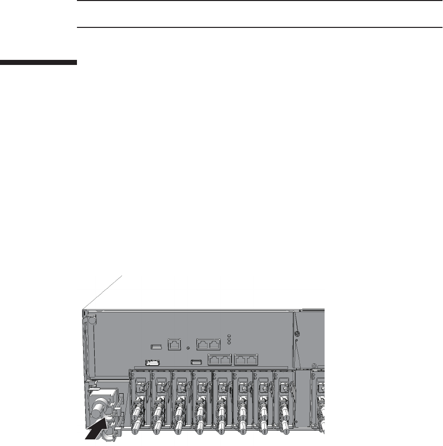
Note - For a building block configuration, press the power switch on the master chassis. The
power switches of the other chassis are disabled.
than 4 seconds).
For details, see "2.2.2 Control function of the operation panel."
6.5 Restoring the Chassis
This section describes operations required to restore the chassis.
6.5.1 Installing the power cord
If the power cord of the SPARC M10-4S or the crossbar box was removed to perform
the maintenance work, connect the power cord and then attach the cable clamp to the
power cord.
1. Connect the power cord of the SPARC M10-4S to the PSU backplane unit, or
connect the power cord of the crossbar box to the power supply unit.
Figure 6-1 Installing the power cord (SPARC M10-4/M10-4S)
Fujitsu M10-4/Fujitsu M10-4S/SPARC M10-4/SPARC M10-4S Service Manual ・December 201376
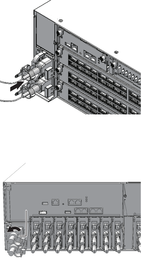
A
Figure 6-2 Installing the power cord (crossbar box)
2. Clip the cable clamp around the power cord and then fix the cable clamp.
The cable clamp is firmly fixed by locking the latch (A in the figure) and then
pushing the cable clamp towards the front of the chassis.
Figure 6-3 Locking the cable clamp (SPARC M10-4/M10-4S)
Chapter 6 Understanding the Preparations for Restoring the System 77
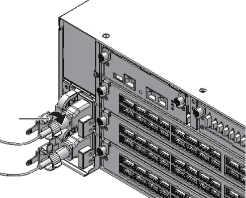
A
Figure 6-4 Locking the cable clamp (crossbar box)
6.5.2 Fixing the cable support
After performing maintenance on a component at the rear of the SPARC M10-4/M10-
4S, lift the cable support and fix it in place.
1. Lift the cable support and lock it in place by pushing the upper and lower
screw fittings towards the back (direction of the arrow).
Fujitsu M10-4/Fujitsu M10-4S/SPARC M10-4/SPARC M10-4S Service Manual ・December 201378
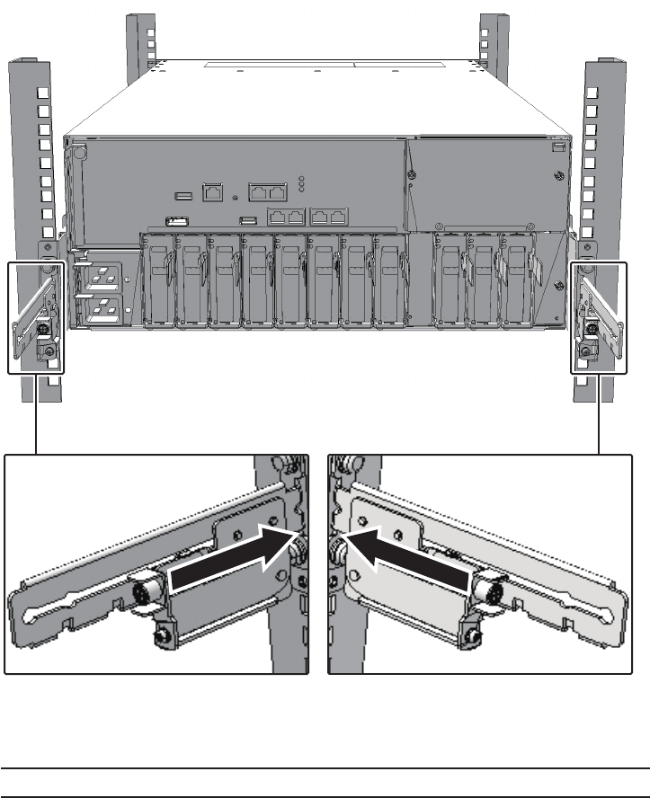
Note - Check that the cable support is firmly attached and fixed.
Figure 6-5 Locking the cable support
2. Tighten the right and left screws to fix the cable support.
6.5.3 Installing the front cover
If the front cover of the SPARC M10-4S or the crossbar box was removed to perform
maintenance, install it after installing the components at the front of or inside the
chassis.
1. To install the front cover, insert the tabs of the front cover into the notches at
Chapter 6 Understanding the Preparations for Restoring the System 79
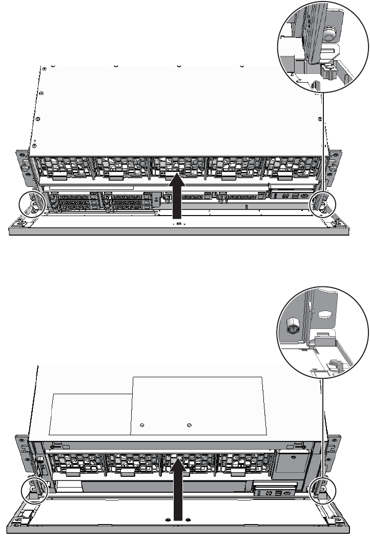
the bottom front of the chassis.
Figure 6-6 Installing the front cover (SPARC M10-4/M10-4S)
Figure 6-7 Installing the front cover (crossbar box)
Fujitsu M10-4/Fujitsu M10-4S/SPARC M10-4/SPARC M10-4S Service Manual ・December 201380

Note - Check that the front cover is firmly attached and fixed.
Chapter 6 Understanding the Preparations for Restoring the System 81
Fujitsu M10-4/Fujitsu M10-4S/SPARC M10-4/SPARC M10-4S Service Manual ・December 201382

Chapter 7
Maintaining the CPU Memory Units
This chapter describes the procedure for maintaining the CPU memory unit mounted
on the SPARC M10-4/M10-4S. The CPU memory unit lower can only be replaced. The
CPU memory unit upper can be replaced, expanded, and reduced.
■Configuration of the CPU Memory Units
■Before Maintaining a CPU Memory Unit
■Enabling the Removal of a CPU Memory Unit
■Removing a CPU Memory Unit
■Installing a CPU Memory Unit
■Restoring the System
7.1 Configuration of the CPU Memory
Units
This section describes the configuration and locations of the CPU memory units.
A CPU memory unit is composed of the following two parts: the CPU memory unit
lower and the CPU memory unit upper.
83
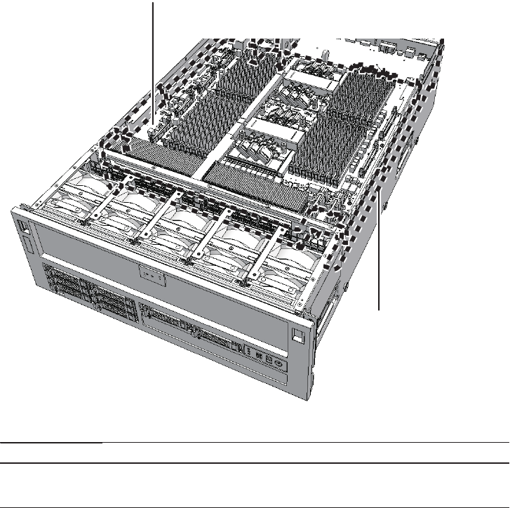
(1)
(2)
Location number Component
1 CPU memory unit lower (CMUU)
2 CPU memory unit upper (CMUL)
Figure 7-1 Location of CPU memory unit
There are two types of CPU memory units: FRAME-A and FRAME-B. The type of a
CPU memory unit can be determined from the indication on the label (A in the
figure). If a CPU memory unit does not have the "FRAME-B" indication, it is a
FRAME-A unit.
Fujitsu M10-4/Fujitsu M10-4S/SPARC M10-4/SPARC M10-4S Service Manual ・December 201384
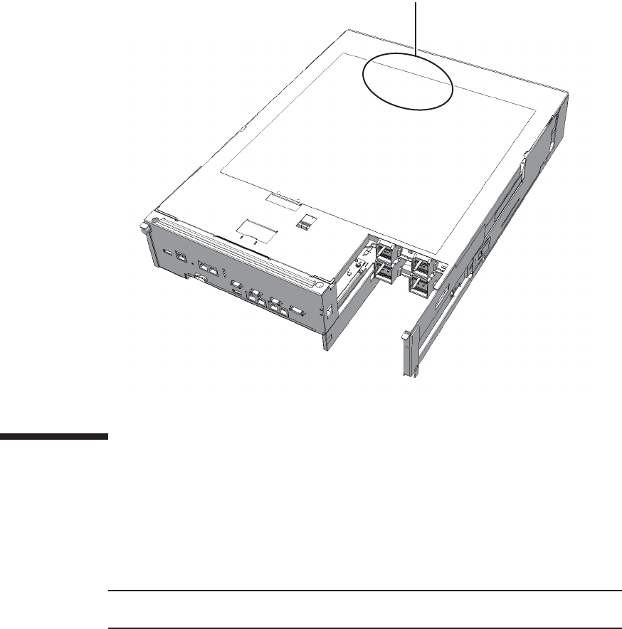
A
Note - Read and understand the instructions in this chapter before starting the maintenance
work. Also see the contents of "Chapter 1 Before Starting Maintenance Work."
Figure 7-2 Type of CPU memory unit
7.2 Before Maintaining a CPU Memory
Unit
This section describes the types and the flow of maintenance of the CPU memory
units, as well as some precautions.
7.2.1 Types of maintenance
Table 7-1 lists the types of maintenance for the CPU memory units. For the definition
of maintenance, see "4.3 Understanding Types of Maintenance."
Chapter 7 Maintaining the CPU Memory Units 85
Table 7-1 Type of maintenance for CPU memory unit
Configuration Active/hot Active/cold Inactive/hot Inactive/cold (*1) System stopped
Single-chassis configuration
Unsupported Unsupported Unsupported Supported Supported
Building block configuration
Unsupported Supported (*2) Unsupported Supported Supported
*1: For a single-chassis configuration, the inactive/cold maintenance procedure is the same as that for stopping the system, therefore see
the procedure for system-stopped maintenance.
*2: It is necessary to use dynamic reconfiguration (DR) to disconnect a chassis requiring maintenance from the physical partition.
Table 7-2 Maintenance flow
Task Lower unit
replacement
Upper unit
replacement
Upper unit
expansion
Upper unit
reduction
1 Preparation 7.3 7.3 7.3 7.3
2 Accessing a CPU memory
unit
7.4.1 7.4.1 7.4.1 7.4.1
3 Removing a CPU memory
unit lower
7.4.2 7.4.2 7.4.2 7.4.2
4 Removing a CPU memory
unit upper
7.4.3 7.4.3 -(*) 7.4.3
5 Removing a PCIe cable 7.4.4 -7.4.4 7.4.4
6 Installing a PCIe cable 7.5.1 -7.5.1 7.5.1
7 Installing a CPU memory
unit upper
7.5.2 7.5.2 7.5.2 -(*)
8 Installing a CPU memory
unit lower
7.5.3 7.5.3 7.5.3 7.5.3
9 Restoring the chassis 7.5.4 7.5.4 7.5.4 7.5.4
10 Restoring the system 7.6 7.6 7.6 7.6
* It is necessary to remove or install a filler unit.
7.2.2 Maintenance flow
Table 7-2 lists the sequence of the maintenance procedure for the CPU memory units.
To expand/reduce the CPU memory unit upper, it is necessary to remove/install the
CPU memory unit lower.
The procedure for expanding a CPU memory unit upper is the same as that for
installing a CPU memory unit upper. The procedure for reducing a CPU memory
unit upper is the same as that for removing a CPU memory unit upper.
In addition, the CPU memory unit upper and CPU memory unit lower are connected
by the PCI Express (PCIe) cable. The PCIe cable should be replaced when the CPU
memory unit upper is replaced. Similarly, the cable is installed when the CPU
memory unit upper is expanded, and removed when it is reduced.
Fujitsu M10-4/Fujitsu M10-4S/SPARC M10-4/SPARC M10-4S Service Manual ・December 201386
7.2.3 Precautions for replacement
Note the following points when you replace a CPU memory unit:
■Do not replace a CPU memory unit at the same time as the PSU backplane unit. If
you replace both a CPU memory unit and the PSU backplane unit at the same
time, the system will fail to operate normally. Replace the CPU memory unit or
PSU backplane unit, and then confirm that the newly installed part operates
normally by executing the showhardconf or showstatus command. Then, replace
the other Field Replaceable Units (FRUs).
■When replacing the CPU memory unit, memory modules should be removed
from the old unit and remounted in the new one. Mount the new unit in the same
position as the old unit.
■The weight of the CPU memory unit is 17 kg (37.4 lb). Maintenance must be done
by two people if the CPU memory unit is mounted at the 24 or higher U of the
rack. If you attempt to perform the maintenance work alone, you may injure
yourself or cause damage to the chassis.
■For both the CPU memory unit upper and CPU memory unit lower, there are
eight types based on the combinations of CPU type and the number of memory
slots. Each type of CPU memory unit, both upper and lower, can be used in
combination with one another.
■Before replacing the CPU memory unit lower, execute the dumpconfig command
to save the system setting information. When the CPU memory unit lower is
replaced, the CPU Activation setting information and CPU Activation keys may
be deleted. To restore the CPU Activation setting information and CPU Activation
keys that have been saved with the dumpconfig command, execute the restoreconfig
command.
■The XCP firmware version must be the same before and after replacement of the
CPU memory unit lower. For checking the version, see "4.2.2 Confirming the
software and firmware configurations."
7.2.4 Precautions for installation
Note the following points when you expand a CPU memory unit upper:
■You need to add four PCIe cables when connecting the CPU memory unit upper
to the CPU memory unit lower.
■The 2-CPU configuration of the SPARC M10-4/M10-4S has four root complexes,
and the 4-CPU configuration can have four, seven or eight root complexes. If you
change a 2-CPU configuration into a 4-CPU configuration by adding CPU
memory units on site, Fujitsu recommends a configuration with four root
complexes. This configuration inherits the configuration and mounting rules of
the I/O bus of the 2-CPU configuration. Adopting a configuration with seven or
eight root complexes increases the maximum number of mounted PCIe cards.
However, since the I/O bus is reconfigured, the physical partition needs to be
reconfigured.
Chapter 7 Maintaining the CPU Memory Units 87
Note - See the procedure for system-stopped maintenance for inactive/cold maintenance in a
single-chassis configuration.
Caution - To completely shut down the system, all the power cords must be
removed. If the power cords are not removed, an electrical failure may occur.
A root complex consists of an I/O controller on a processor, PCI switches, and PCI
devices under the I/O controller.
■For SPARC M10-4/M10-4S with two CPUs installed, if a CPU memory unit is
expanded in order to add two CPUs when the I/O bus reconfiguration is
"enabled", it will change the device paths of the I/O devices that have been used.
Before adding the memory unit, execute the setpparmode command by specifying
"false" for ioreconfigure with the -m function=mode option to "disable" the I/O bus
reconfiguration function.
7.2.5 Precautions for removal
Note the following points when you reduce a CPU memory unit upper:
■You must also reduce the four PCIe cables for connecting the CPU memory unit
upper with the CPU memory unit lower.
■If a CPU memory unit is diminished to remove two CPUs, it will eliminate the
root complexes for the two CPUs in use up to then, making some PCIe slots
unavailable. To make the PCIe slots available, execute the setpparmode command
by specifying "true" or "nextboot" for ioreconfigure with the -m function=mode
option to "enable" the I/O bus reconfiguration function. Since the I/O bus is
reconfigured, the physical partition must also be reconfigured.
7.3 Enabling the Removal of a CPU
Memory Unit
This section describes the preparations that must be completed prior to removing a
CPU memory unit. The preparation procedure differs depending on the maintenance
type as follows:
■Active/Cold maintenance
■Inactive/Cold maintenance
■System-stopped maintenance
Fujitsu M10-4/Fujitsu M10-4S/SPARC M10-4/SPARC M10-4S Service Manual ・December 201388
Note - Use the DR of the system board on a physical partition for active/cold maintenance.
For the XCP and Oracle VM Server for SPARC/SRU versions that correspond to the DR, see
the latest Product Notes.
Note - Active/cold maintenance can be performed only for a building block configuration.
XSCF> showlogs error
XSCF> replacefru
Note - Inthecaseofadualpowerfeed,makeanoteofthelocationsofthepowercords
before disconnecting them to ensure that they are reinstalled correctly.
Note - See the procedure for system-stopped maintenance for inactive/cold maintenance in a
single-chassis configuration.
7.3.1 Active/Cold maintenance
1. Open the rack door.
2. LogintotheXSCFshell.
3. Execute the showlogs command to identify the component requiring
maintenance.
For details, see "3.3.5 Checking log information."
4. Confirm the hardware and software configurations.
For details, see "4.2 Confirming the System Configuration."
5. Release the chassis, in which the CPU memory unit requiring maintenance is
mounted, from the physical partition.
For details, see "5.2 Releasing a Chassis from the Physical Partition."
6.
Execute the replacefru command to release the chassis requiring maintenance
from the system.
For details, see "5.1 Releasing an FRU from the System with the replacefru
Command."
7. Remove all the power cords from the PSU backplane unit of the chassis
requiring maintenance.
For details, see "5.5.2 Removing the power cord."
7.3.2 Inactive/Cold maintenance
Chapter 7 Maintaining the CPU Memory Units 89
XSCF> showlogs error
Note - When you add or remove CPU memory units, confirm that no error has occurred.
XSCF> replacefru
Note - In the case of a dual power feed, make a note of the locations of the power cords
before disconnecting them to ensure that they are reinstalled correctly.
Note - When the CPU memory unit lower is replaced, all of the XSCF setting information
may be lost. Perform this operation only after backing up the XSCF setting information.
1. Open the rack door.
2. Log in to the XSCF shell.
3. Execute the showlogs command to identify the component requiring
maintenance.
For details, see "3.3.5 Checking log information."
4. Confirm the hardware and software configurations.
For details, see "4.2 Confirming the System Configuration."
5. Power off the physical partition requiring maintenance.
For details, see "5.3 Powering Off the Physical Partition Requiring Maintenance."
6.
Execute the replacefru command to release the chassis requiring maintenance
from the system.
For details, see "5.1 Releasing an FRU from the System with the replacefru
Command."
7. Remove all the power cords from the PSU backplane unit of the chassis
requiring maintenance.
For details, see "5.5.2 Removing the power cord."
7.3.3 System-stopped maintenance
1. Open the rack door.
2. Log in to the XSCF shell.
3. Execute the dumpconfig command to backup the XSCF setting information
only when replacing the CPU memory unit lower in a singe-chassis
configuration.
For details, see "10.9.2 Saving XSCF setting information" in the Fujitsu
M10/SPARC M10 Systems System Operation and Administration Guide.
Fujitsu M10-4/Fujitsu M10-4S/SPARC M10-4/SPARC M10-4S Service Manual ・December 201390
XSCF> dumpconfig
XSCF> showlogs error
Note - When you add or remove CPU memory units, confirm that no error has occurred.
XSCF> replacefru
Note - Inthecaseofadualpowerfeed,makeanoteofthelocationsofthepowercords
before disconnecting them to ensure that they are reinstalled correctly.
If you are not replacing the CPU memory unit lower, backup is not necessary.
Proceed to step 4.
4. Execute the showlogs command to identify the component requiring
maintenance.
For details, see "3.3.5 Checking log information."
5. Confirm the hardware and software configurations.
For details, see "4.2 Confirming the System Configuration."
6. Stop the entire system.
For details, see "5.4 Stopping the Entire System."
7.
Execute the replacefru command to release the chassis requiring maintenance
from the system.
For a single-chassis configuration, you do not have to release the chassis.
Proceed to step 8.
For details, see "5.1 Releasing an FRU from the System with the replacefru
Command."
8. Remove all the power cords from the PSU backplane unit of the chassis
requiring maintenance.
For details, see "5.5.2 Removing the power cord."
7.4 Removing a CPU Memory Unit
This section describes the procedure for removing a CPU memory unit. Remove the
CPU memory unit lower first, then remove the CPU memory unit upper. Enable the
removal of the CPU memory unit before attempting to remove it. For details, see "7.3
Enabling the Removal of a CPU Memory Unit."
Unless otherwise specified, the figures explained in this section use the SPARC
Chapter 7 Maintaining the CPU Memory Units 91
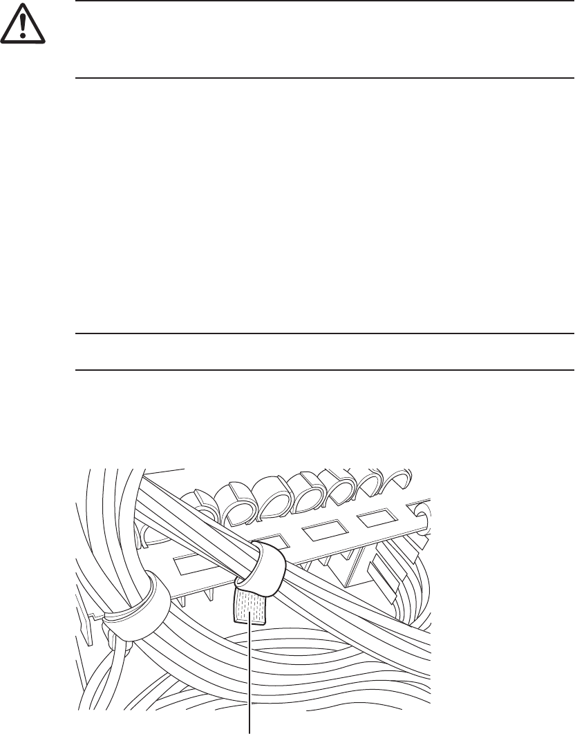
Caution - Before you handle any components, wear a wrist strap to ground any static
electricity. If you perform this procedure without a wrist strap, individual
components or the overall system may be damaged. For details, see "1.5 Notes
Regarding Static Electricity."
Note - Record the positions of the cables before removing them to ensure that they are
reinstalled correctly.
A
M10-4S with a FRAME-A CPU memory unit.
7.4.1 Accessing a CPU memory unit
1. Remove the crossbar cables from the cable support.
Perform this procedure only when using equipment rack model 26xx or
equipment rack model 16xx. The procedure may vary depending on the model
of the equipment rack.
If you are not using equipment rack model 26xx or equipment rack model 16xx,
proceed on to step 2.
Procedure when equipment rack model 26xx is used
a. Remove all the crossbar cables from the crossbar unit.
b. Remove the hook-and-loop fastener of the cable support (A in the figure) to
which the crossbar cables are fixed.
Figure 7-3 Hook-and-loop fastener of the cable support
Fujitsu M10-4/Fujitsu M10-4S/SPARC M10-4/SPARC M10-4S Service Manual ・December 201392
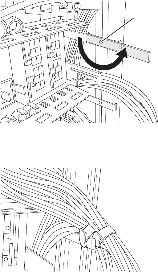
A
c. Remove the screw securing the cable holder (A in the figure) that is fixed to
the supporting column on the rear of the rack, and then install the cable
holder by rotating it 180 degrees.
Figure 7-4 Cable holder screw
d. Use the hook-and-loop fastener to fix the crossbar cables to the cable
holder.
Figure 7-5 Fixing crossbar cables
Procedure when equipment rack model 16xx is used
a. Remove all the crossbar cables from the crossbar unit.
Chapter 7 Maintaining the CPU Memory Units 93
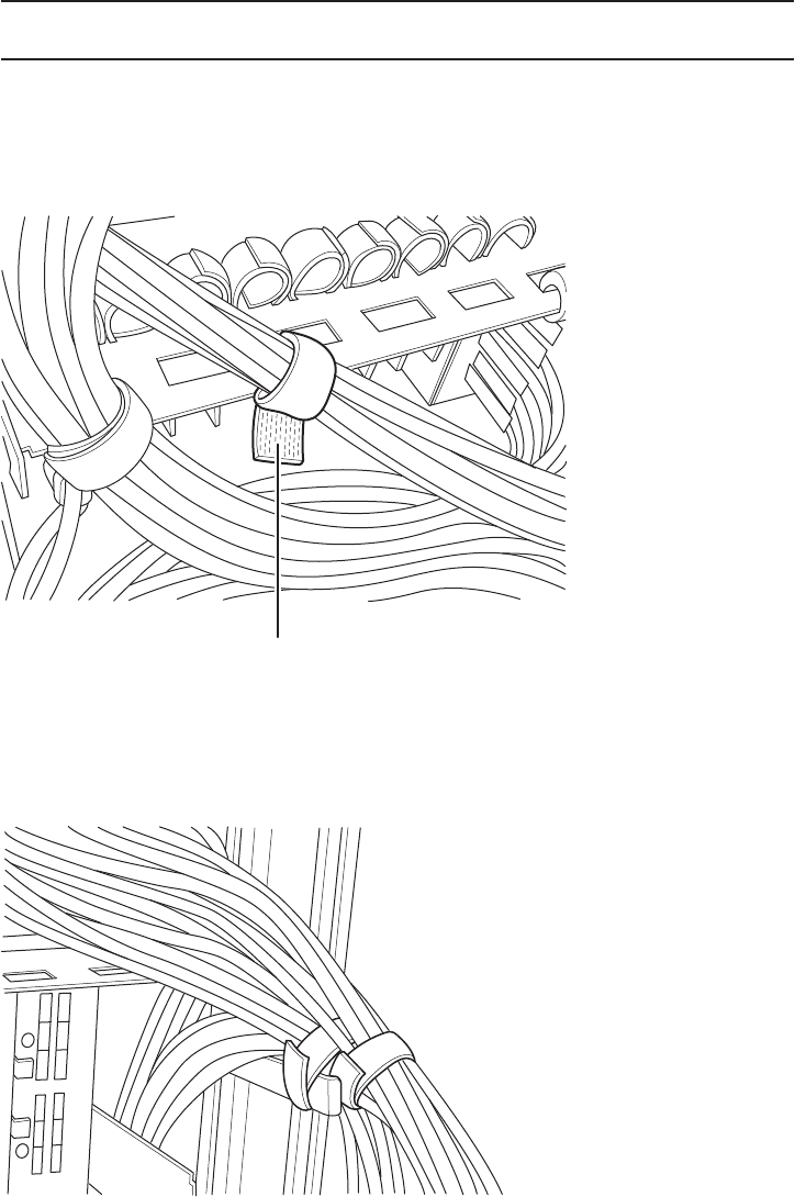
Note - Record the positions of the cables before removing them to ensure that they are
reinstalled correctly.
A
b. Remove the hook-and-loop fastener of the cable support (A in the figure) to
which the crossbar cables are fixed.
Figure 7-6 Hook-and-loop fastener of the cable support
c. Use the hook-and-loop fastener to fix the crossbar cables to the cable
holder installed on the supporting column on the rear of the rack.
Figure 7-7 Fixing crossbar cables
2. Lower the cable support.
For details, see "5.5.1 Lowering the cable support."
Fujitsu M10-4/Fujitsu M10-4S/SPARC M10-4/SPARC M10-4S Service Manual ・December 201394
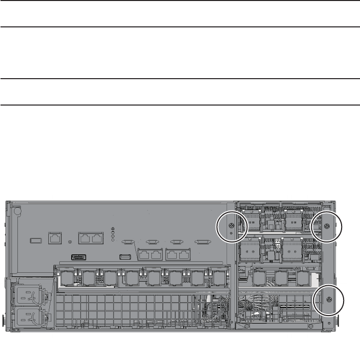
Note - Record the positions of the cables before removing them to ensure that they are
reinstalled correctly.
Note - Make a note of the positions of the PCIe card cassettes before removing them to ensure
that they are reinstalled correctly.
3. Remove all the cables connected to the external interface on the rear of the
chassis.
The cables to be removed are as follows.
■Interface cable connected to the PCI Express (PCIe) card
■Crossbar cables (They may have been removed in step 1.)
■XSCF BB control cable
■XSCF DUAL control cable
■XSCF-LAN cable
■Serial cable
■LAN cable
■SAS cable
■USB cable
4. Remove all the PCIe card cassettes.
For details, see "13.5.2 Removing a PCI Express card cassette."
5. If any crossbar units are mounted, remove them.
For details, see "9.4.2 Removing a crossbar unit."
6. Loosen the three screws holding the mounting frame and then remove it.
Figure 7-8 Screws securing the mounting frame
Chapter 7 Maintaining the CPU Memory Units 95
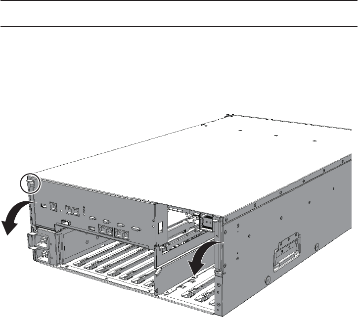
Note - To expand or reduce a CPU memory unit upper, it is first necessary to remove the
CPU memory unit lower.
7.4.2 Removing the CPU memory unit lower
This section describes the procedure for removing a CPU memory unit lower.
1. Loosen the screws securing the levers of the CPU memory unit lower (rear
left side) and then lower the right and left levers of the CPU memory unit
lower to the horizontal position.
Figure 7-9 Position of the screws and the levers of the CPU memory unit lower
2. Hold the right and left levers of the CPU memory unit lower and pull out the
CPU memory unit lower about 10 cm (3.9 in.)
Fujitsu M10-4/Fujitsu M10-4S/SPARC M10-4/SPARC M10-4S Service Manual ・December 201396
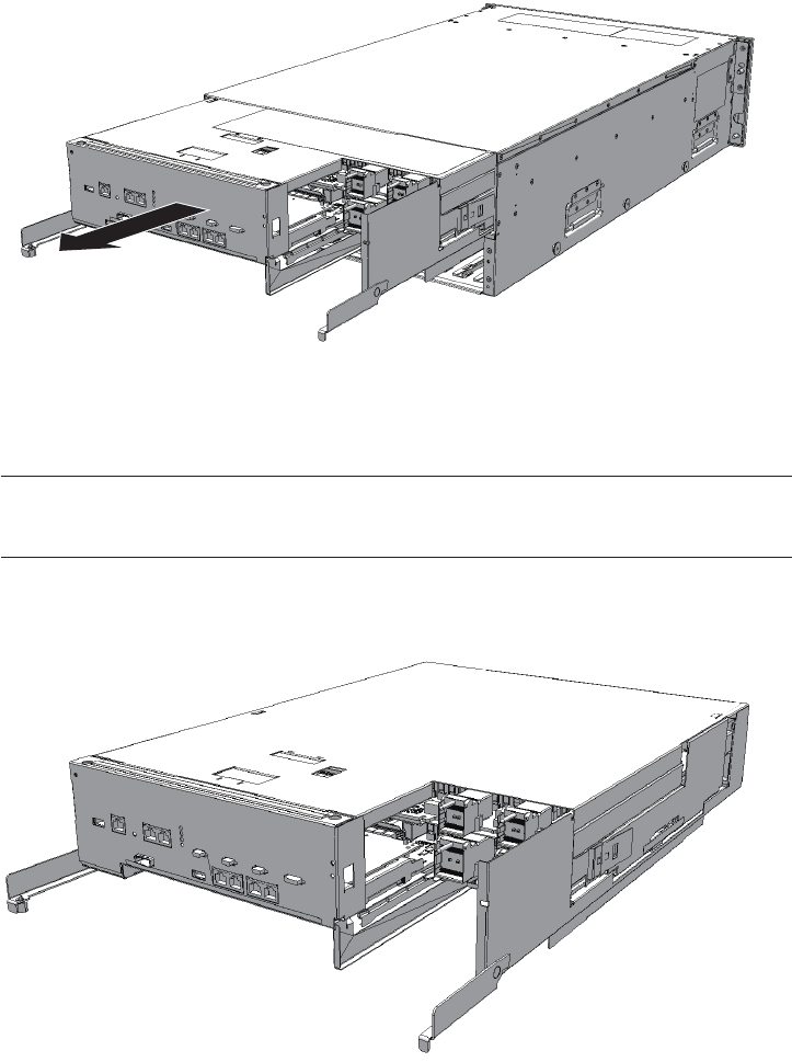
Note - Place the removed CPU memory unit lower on a grounded antistatic ESD mat.
Note - Be careful not to damage the right and left levers when placing the CPU memory unit
on the ESD mat.
Figure 7-10 Pulling out CPU memory unit lower
3. Remove the CPU memory unit lower while supporting it from below with one
hand.
Figure 7-11 Removing the CPU memory unit lower
4. Remove the CPU memory unit upper or the filler unit for the CPU memory unit
upper.
For details, see "7.4.3 Removing the CPU memory unit upper."
You can expand the CPU memory unit upper by performing the above steps.
You do not have to perform step 5.
Chapter 7 Maintaining the CPU Memory Units 97
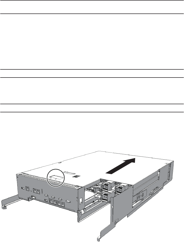
Note - Mount the memory in the same position as it was mounted in the removed CPU
memory unit lower.
Note - This work should all be performed from the rear of the rack.
Note - Place the removed CPU memory unit lower on a grounded antistatic ESD mat.
5. Remove the memory modules from the CPU memory unit lower and install
them in the new CPU memory unit lower.
For details, see "8.5 Removing Memory"and"8.6 Installing Memory."
7.4.3 Removing the CPU memory unit upper
Removal of a CPU memory unit upper is performed after removal of the CPU
memory unit lower. Perform reduction using the same procedure. You can remove a
filler unit by performing the procedure up to step 9.
1. Remove the CPU memory unit lower.
For details, see "7.4.2 Removing the CPU memory unit lower."
2. Unlock (push) the top cover of the CPU memory unit and remove the cover by
sliding it in the direction of the arrow.
Figure 7-12 Releasing the lock
3. Unlock (push) the right-side guide and remove it by sliding it in the direction
of the arrow.
Fujitsu M10-4/Fujitsu M10-4S/SPARC M10-4/SPARC M10-4S Service Manual ・December 201398
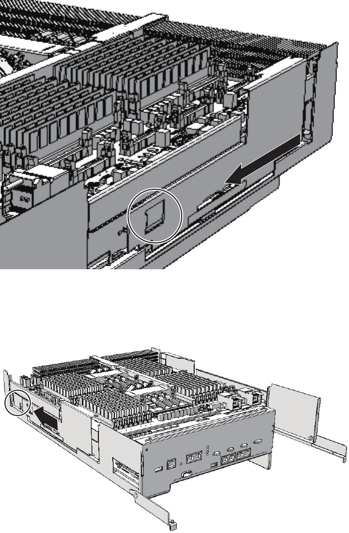
Figure 7-13 Removing right-side guide
4. Unlock (push) the left-side guide (when viewed from the rear) and remove it
by sliding it in the direction of the arrow.
Figure 7-14 Removing left-side guide
5. Remove the two PCIe cables (A in the figure) on the right side that connect
Chapter 7 Maintaining the CPU Memory Units 99
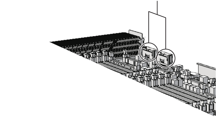
A
the CPU memory units upper and lower, from the CPU memory unit upper.
In the case of a filler unit, you can omit this step because PCIe cables are not
present.
Figure 7-15 Removing the right-side PCIe cables
6. Remove the two PCIe cables (A in the figure) on the left side that connect the
CPU memory units upper and lower, from the CPU memory unit upper.
In the case of a filler unit, you can omit this step because PCIe cables are not
present.
Fujitsu M10-4/Fujitsu M10-4S/SPARC M10-4/SPARC M10-4S Service Manual ・December 2013100
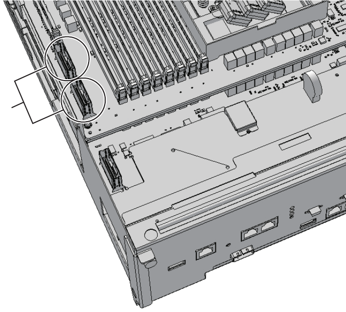
A
Figure 7-16 Removing the left-side cables
7. Of the two PCIe cables on the left side, also remove the rear one from the CPU
memory unit lower, as it is short.
In the case of a filler unit, you can omit this step because PCIe cables are not
present.
Chapter 7 Maintaining the CPU Memory Units 101
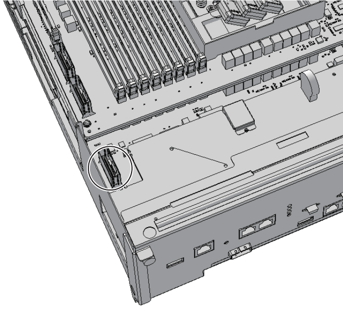
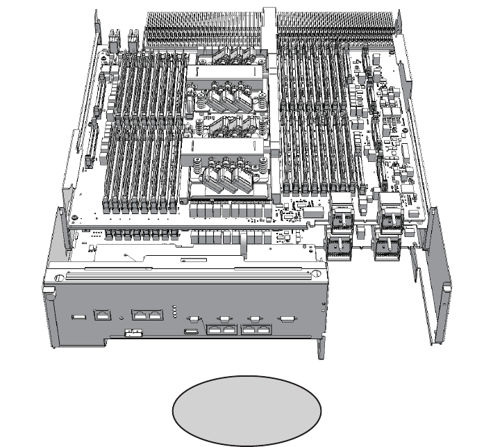
A
Figure 7-18 Standing position of a field engineer
8. Raise the levers (A in the figure) on the right and left sides to release the CPU
memory unit upper.
Chapter 7 Maintaining the CPU Memory Units 103
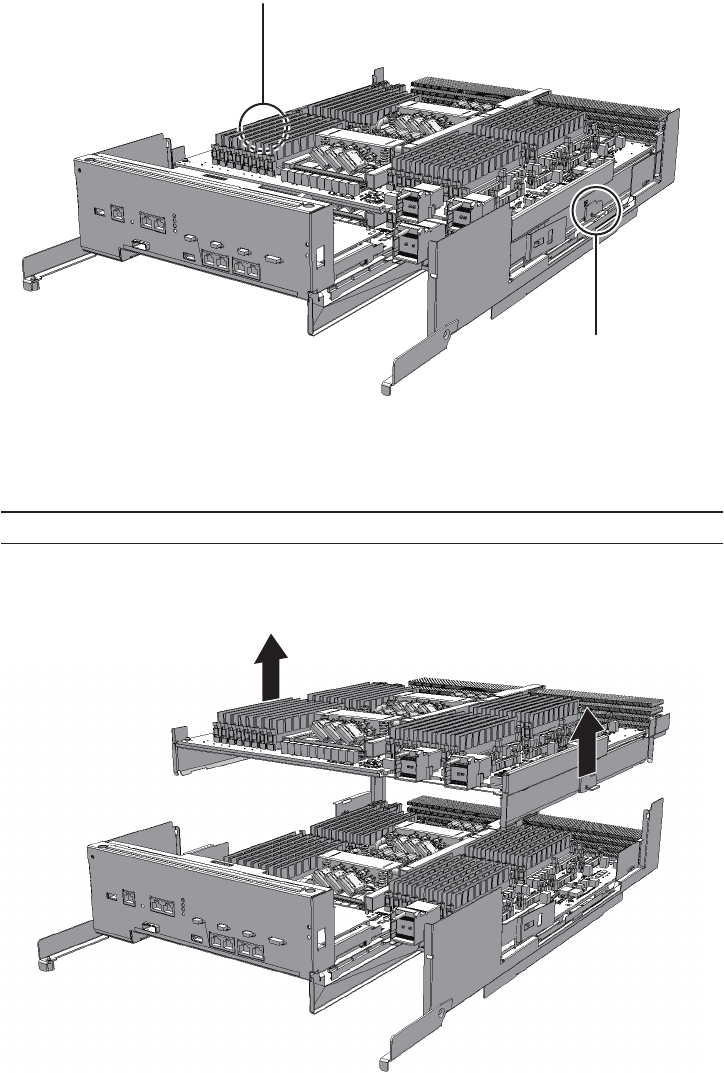
A
A
Note - Place the removed CPU memory unit upper on a grounded antistatic ESD mat.
Figure 7-19 Positions of right and left levers
9. While holding the levers, slightly lift the CPU memory unit upper.
10. Lift the CPU memory unit upwards and then remove it carefully.
Figure 7-20 Removing CPU memory unit upper
Fujitsu M10-4/Fujitsu M10-4S/SPARC M10-4/SPARC M10-4S Service Manual ・December 2013104
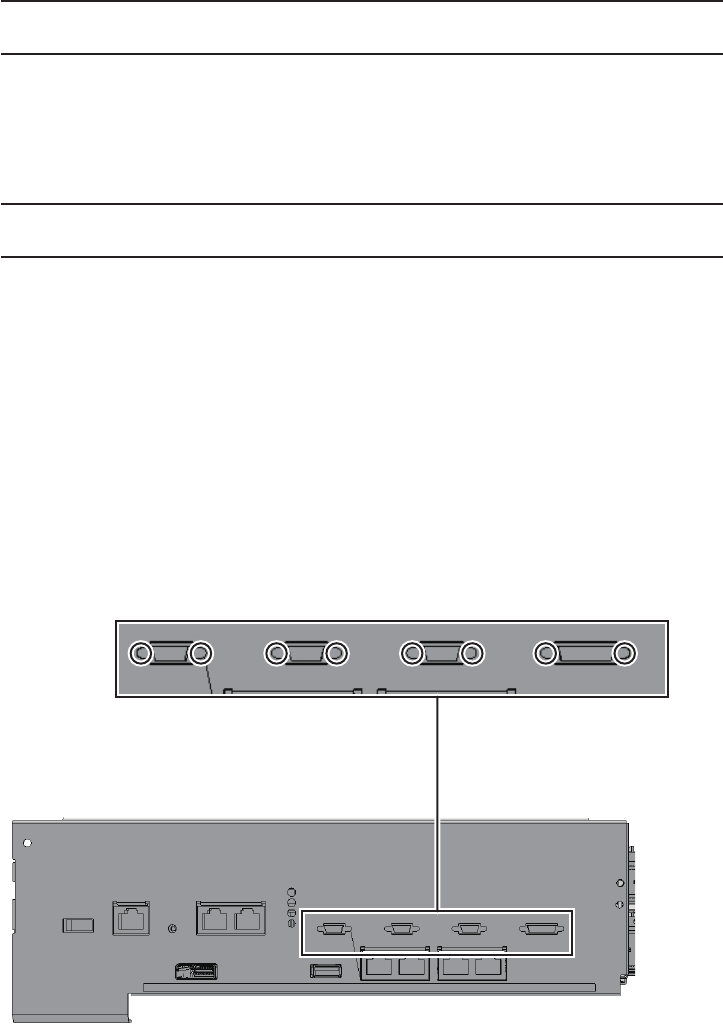
Note - Mount the memory in the same position as it was mounted in the removed CPU
memory unit upper.
Note - A part of the procedure varies depending on the CPU memory unit type. To
determine the CPU memory unit type, check the label in Figure 7-2.
11. Remove the memory modules from the removed CPU memory unit upper and
then install them in the new CPU memory unit upper.
For details, see "8.5 Removing Memory"and"8.6 Installing Memory."
7.4.4 Removing a PCI Express cable
When reducing a CPU memory unit upper or when replacing a PCIe cable, remove
the PCIe cable. You can expand a CPU memory unit upper by performing the above
procedure up to step 9.
For the SPARC M10-4 with a FRAME-A CPU memory unit and the SPARC M10-4S
with a FRAME-B CPU memory unit, perform the procedure from step 2.
1. Remove the eight screws at both ends of the XSCF cable connection port on
the rear of the CPU memory unit lower.
Use a flathead screwdriver (small) to remove them.
For the SPARC M10-4 with a FRAME-A CPU memory unit and the SPARC
M10-4S with a FRAME-B CPU memory unit, this step is not necessary.
Figure 7-21 Screws for both ends of the XSCF cable connection ports (for the
SPARC M10-4S with a FRAME-A CPU memory unit)
Chapter 7 Maintaining the CPU Memory Units 105
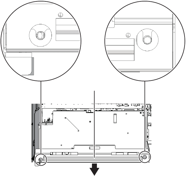
A
2. Loosen the two screws holding the upper rear side of the CPU memory unit
lower. Then, remove the rear cover (A in the figure) by pulling it in the
direction of the arrow.
Figure 7-22 Removing the rear cover
3. Remove the XSCF board.
-For the SPARC M10-4 with a FRAME-A CPU memory unit
Remove the three screws fixing the XSCF board (A in the figure) and rear
cover. Tilt the right lever of the XSCF mount with your fingers about 5 mm (0.2
in.) to the right (B in the figure). Lift up the right side of the XSCF board and
release the connection of the connector (C in the figure).
Fujitsu M10-4/Fujitsu M10-4S/SPARC M10-4/SPARC M10-4S Service Manual ・December 2013106
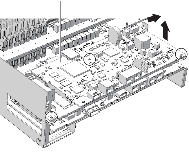
A
B
C
Figure 7-23 Releasing a connected XSCF board (for SPARC M10-4 with a
FRAME-A CPU memory unit)
-For the SPARC M10-4S with a FRAME-A CPU memory unit
Remove the four screws fixing the XSCF board (A in the figure). Then, lift the
right side of the XSCF board to release the connector.
Chapter 7 Maintaining the CPU Memory Units 107
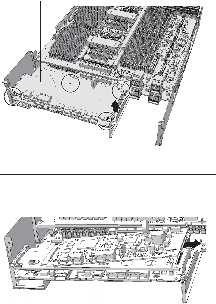
A
Note - Place the removed XSCF board on a grounded antistatic ESD mat.
Figure 7-24 Releasing a connected XSCF board (for the SPARC M10-4S with a
FRAME-A CPU memory unit)
4. Pull out the XSCF board diagonally to the right (arrow).
Figure 7-25 Pulling out an XSCF board (for the SPARC M10-4 with a FRAME-A
CPU memory unit)
Fujitsu M10-4/Fujitsu M10-4S/SPARC M10-4/SPARC M10-4S Service Manual ・December 2013108
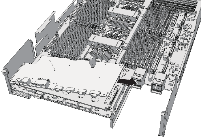
Figure 7-26 Pulling out an XSCF board (for the SPARC M10-4S with a FRAME-A
CPU memory unit)
5. Remove the screw fixing the XSCF mount.
-For the SPARC M10-4/M10-4S with a FRAME-A CPU memory unit
Remove the one screw fixing the XSCF mount (A in the figure).
Chapter 7 Maintaining the CPU Memory Units 109
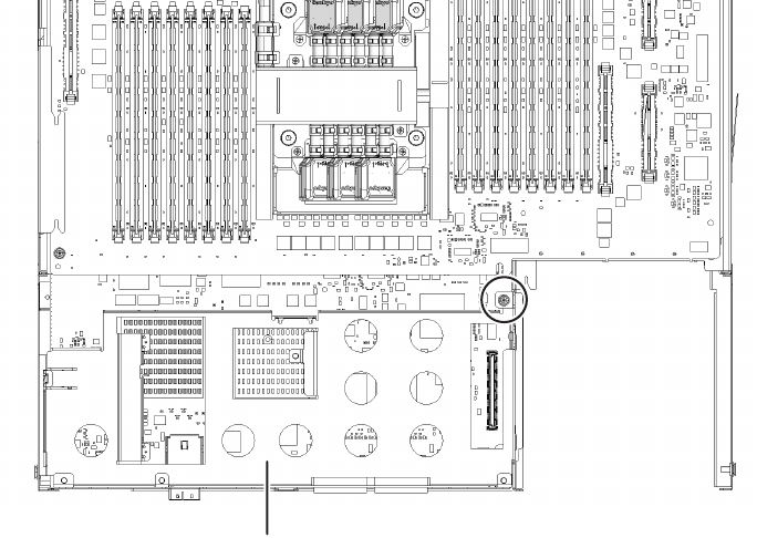
A
Figure 7-27 Screw for the XSCF mount (for the SPARC M10-4 with a FRAME-A
CPU memory unit)
Fujitsu M10-4/Fujitsu M10-4S/SPARC M10-4/SPARC M10-4S Service Manual ・December 2013110
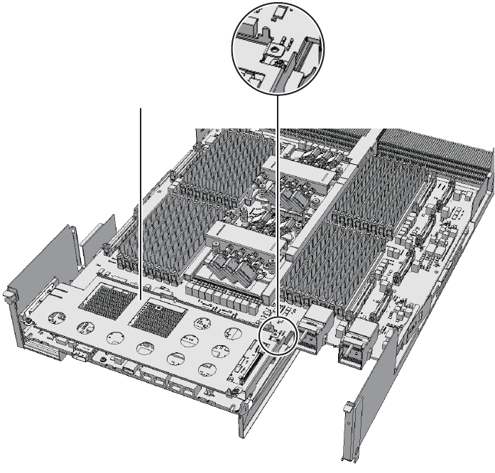
A
Figure 7-28 Screw for the XSCF mount (for the SPARC M10-4S with a FRAME-A
CPU memory unit)
-For the SPARC M10-4S with a FRAME-B CPU memory unit
Remove the two screws fixing the XSCF mount (A in the figure).
Chapter 7 Maintaining the CPU Memory Units 111
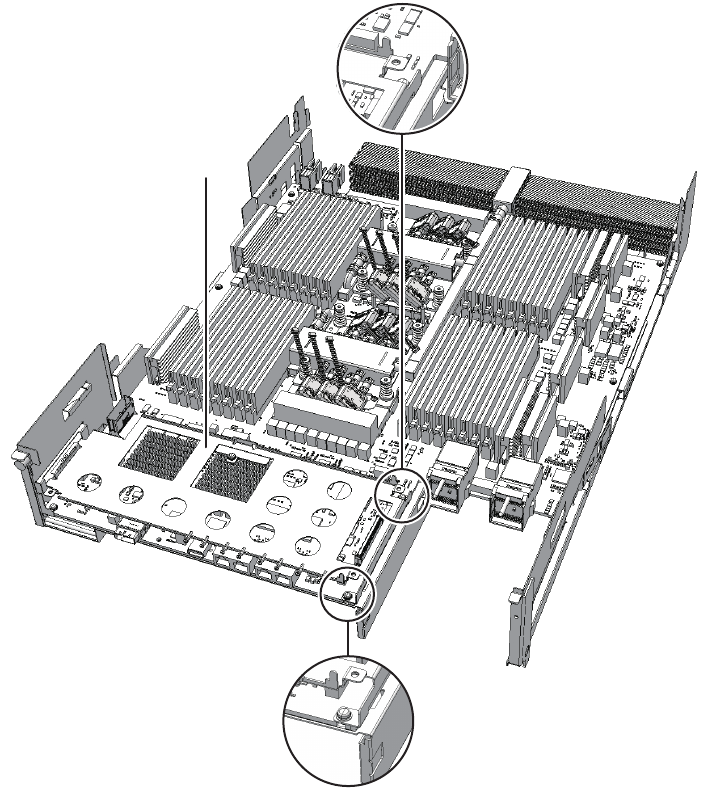
A
Figure 7-29 Screw for the XSCF mount (for the SPARC M10-4S with a FRAME-B
CPU memory unit)
6. Remove the XSCF mount.
-For the SPARC M10-4/M10-4S with a FRAME-A CPU memory unit
Raise the protruding left lever (B in the figure) of the XSCF mount (A in the
figure) by about 2 mm (0.1 in.) with your fingers, and slide it about 8 mm (0.4
in.) toward the front (C in the figure). Then, remove it upward (D in the
figure).
Fujitsu M10-4/Fujitsu M10-4S/SPARC M10-4/SPARC M10-4S Service Manual ・December 2013112
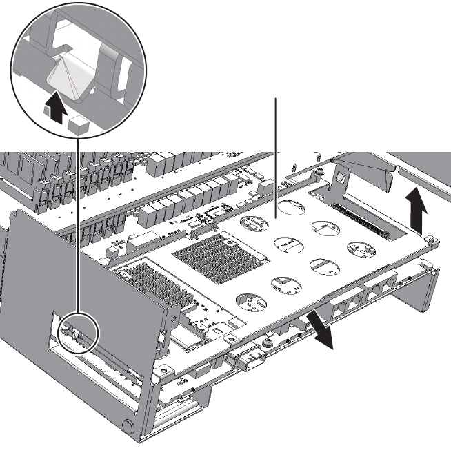
A
B
C
D
D
Figure 7-30 Removing the XSCF mount (for the SPARC M10-4 with a FRAME-A
CPU memory unit)
Chapter 7 Maintaining the CPU Memory Units 113
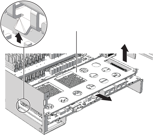
A
B
B
C
D
Figure 7-31 Removing the XSCF mount (for the SPARC M10-4S with a FRAME-A
CPU memory unit)
-For the SPARC M10-4S with a FRAME-B CPU memory unit
Remove the XSCF mount (A in the figure) upward (B in the figure).
Fujitsu M10-4/Fujitsu M10-4S/SPARC M10-4/SPARC M10-4S Service Manual ・December 2013114
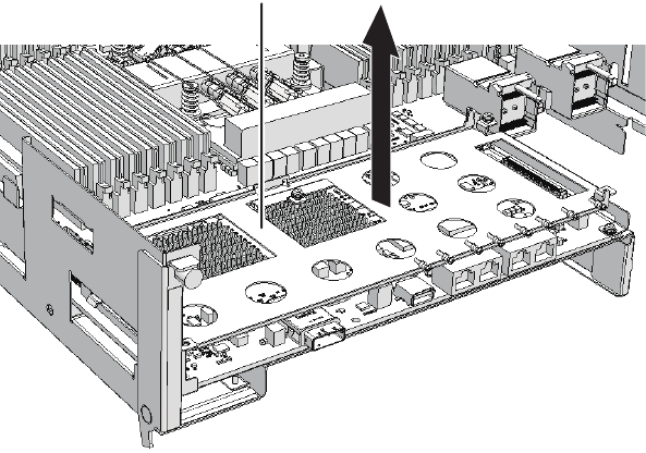
AB
Figure 7-32 Removing the XSCF mount (for the SPARC M10-4S with a FRAME-B
CPU memory unit)
7. Remove the screw fixing the CPU memory unit board.
-For the SPARC M10-4/M10-4S with a FRAME-A CPU memory unit
Remove the one black screw (A in the figure) fixing the center part of the
radiator on the front and the four screws fixing the CPU memory unit board (B
in the figure).
Chapter 7 Maintaining the CPU Memory Units 115
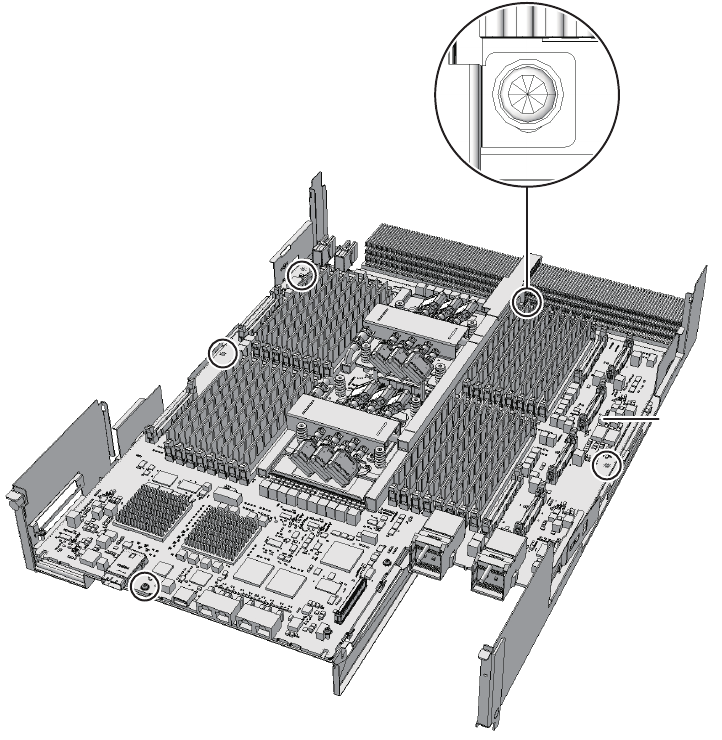
B
A
Figure 7-33 Screws on the CPU memory unit board (for the SPARC M10-4/M10-
4S with a FRAME-A CPU memory unit)
-For SPARC M10-4S with a FRAME-B CPU memory unit
Remove the one black screw (A in the figure) fixing the center part of the
radiator on the front and the six screws fixing the CPU memory unit board (B
in the figure).
Fujitsu M10-4/Fujitsu M10-4S/SPARC M10-4/SPARC M10-4S Service Manual ・December 2013116
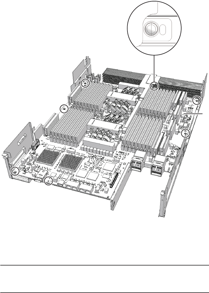
A
B
Note - Be careful not to touch or catch your clothes or wrist strap on a connector pin located
onthebacksideoftheCPUmemoryunitboard.
Note - Hard objects such as a machine tools should not come in contact with the connector
located on the back side of the CPU memory unit board.
Figure 7-34 Screws on the CPU memory unit board (for the SPARC M10-4S with
a FRAME-B CPU memory unit)
8. Place your thumb on the frame located at the center of the right and left sides
of the CPU memory unit board (A in the figure) and insert your fingers under
the CPU memory unit board (B in the figure) from the side of the connector
unit.
Chapter 7 Maintaining the CPU Memory Units 117
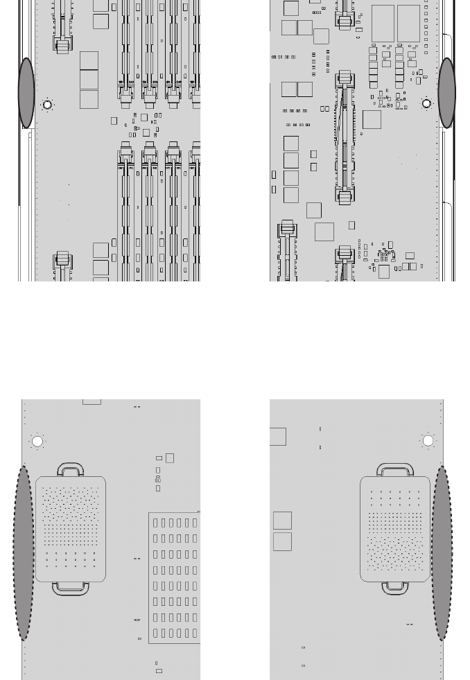
AA
RightLeft
B B
Right Left
Figure 7-35
Finger position when releasing the connection of the connector (surface)
Figure 7-36 Finger position when releasing the connection of the connector (rear
surface)
9. Supporting the frame with your thumb (A in the figure), disconnect the
connection of the connector by pushing up the left and right sides at the
Fujitsu M10-4/Fujitsu M10-4S/SPARC M10-4/SPARC M10-4S Service Manual ・December 2013118
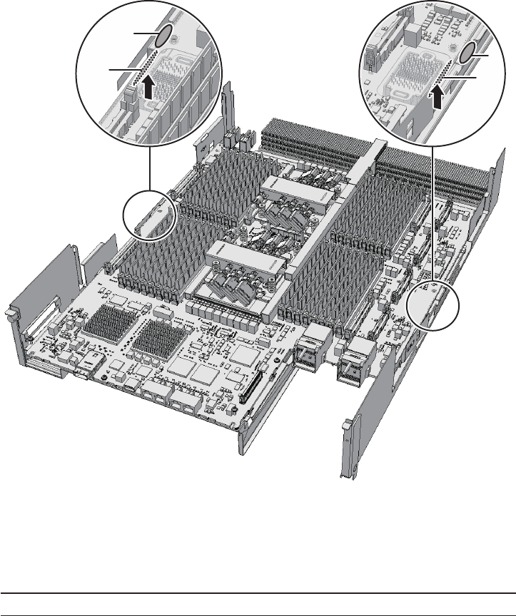
A
B
A
B
Note - Place the removed CPU memory unit board on a grounded antistatic ESD mat.
same time with the fingers that are inserted under the CPU memory unit board
(B in the figure).
Figure 7-37 How to disconnect the connection of the connector
10. Place your thumb on the connector unit located at the center of the right and
left sides of the CPU memory unit board (A in the figure) and hold the board
by inserting your fingers under the CPU memory unit board (B in the figure)
from the side of the connector unit.
Chapter 7 Maintaining the CPU Memory Units 119
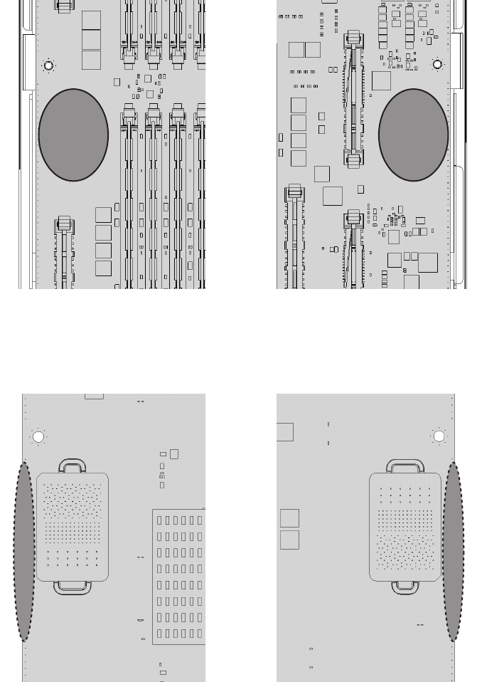
RightLeft
AA
B B
Right Left
Figure 7-38 Finger position when holding the board (surface)
Figure 7-39 Finger position when holding the board (rear surface)
11. Lift the CPU memory unit board in the horizontal position and remove it from
the frame.
Fujitsu M10-4/Fujitsu M10-4S/SPARC M10-4/SPARC M10-4S Service Manual ・December 2013120
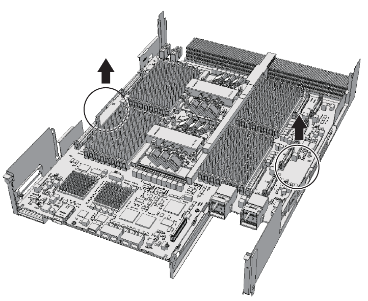
Figure 7-40 Removing the CPU memory unit board
12. Remove the sheet (A in the figure).
You can expand the CPU memory unit upper by performing the above
procedure. You do not have to perform step 10.
Chapter 7 Maintaining the CPU Memory Units 121
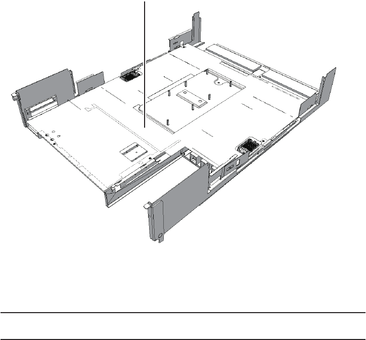
A
Note - Do not attempt to remove a PCIe cable in the wrong direction. If excessive force is
used to remove a PCIe cable, it may be damaged.
Figure 7-41 Removing the sheet
13. Remove the three PCIe cables.
The direction in which the PCIe cables are removed varies depending on the
type of the CPU memory unit.
-The connectors for the three PCIe cables facing the outside of the CPU
memory unit
Fujitsu M10-4/Fujitsu M10-4S/SPARC M10-4/SPARC M10-4S Service Manual ・December 2013122
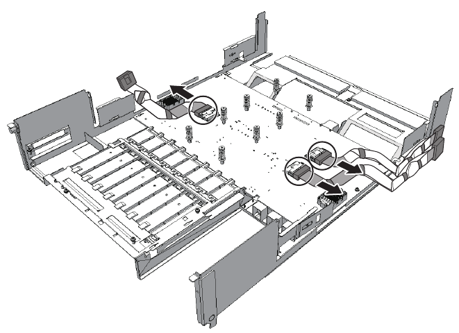
Figure 7-42 Removing the PCIe cables (with the connectors for the three PCIe
cables facing the outside of the CPU memory unit)
-The connector for one PCIe cable facing the outside of the CPU memory unit
and the other two facing the front of the CPU memory unit
Chapter 7 Maintaining the CPU Memory Units 123
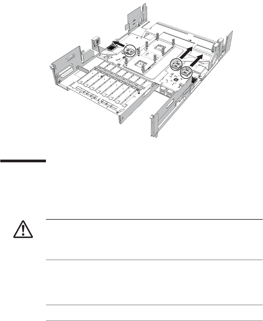
Note - When mounting a CPU memory unit, check the connectors on both of the
chassis and CPU memory unit beforehand to confirm that no pin is bent and all the
pinsareneatlyarrangedinlines.Ifthereisabentpininaconnector,mountinga
CPU memory unit may damage the chassis or CPU memory unit. Also, carefully
proceed with the work to prevent any pin from being bent.
Note - A part of the procedure varies depending on the CPU memory unit type. To
determine the CPU memory unit type, check the label in Figure 7-2.
Figure 7-43 Removing the PCIe cables (with the connector for one PCIe cable
facing the outside and the other two facing the front of the CPU
memory unit)
7.5 Installing a CPU Memory Unit
This section describes the procedure for installing a CPU memory unit.
Unless otherwise specified, the figures explained in this section use the SPARC
M10-4S with a FRAME-A CPU memory unit.
7.5.1 Installing a PCI Express cable
Fujitsu M10-4/Fujitsu M10-4S/SPARC M10-4/SPARC M10-4S Service Manual ・December 2013124
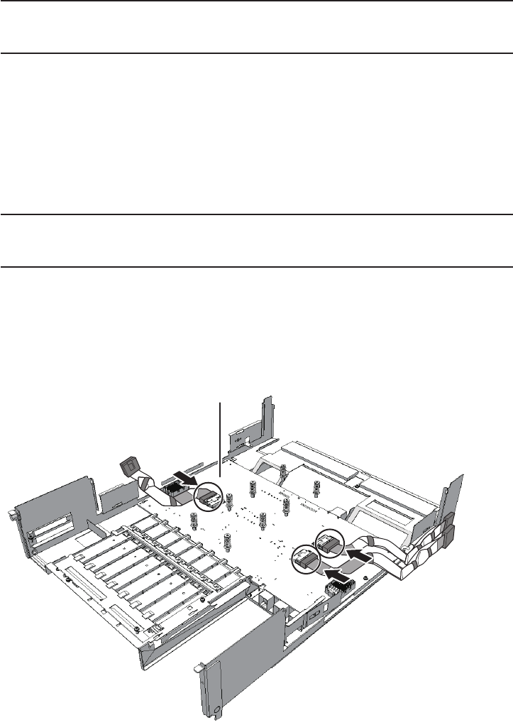
Note - When expanding a CPU memory unit upper, first connect the PCIe cable to the CPU
memoryunitlower.ThePCIecablesareattachedasanaccessoryoftheCPUmemoryunit
upper.
Note - Do not attempt to install a PCIe cable in the wrong direction. If excessive force is used
to install a PCIe cable, it may be damaged.
Note - Ensure that the PCIe cables are firmly connected and secure.
A
When expanding the CPU memory unit upper or when replacing a PCIe cable,
connect the PCIe cable. You can reduce a CPU memory unit upper by performing the
procedure from step 2.
1. Connect the three PCIe cables by matching their position labels of the PCle
cable with the corresponding position marks on the PCIBP board (A in the
figure).
The direction in which the PCIe cables are installed varies depending on the type
of the CPU memory unit.
When reducing a CPU memory unit upper, you do not have to perform this step
because the PCIe cables are not present.
-The connectors for the three PCIe cables facing the outside of the CPU
memory unit
Figure 7-44 Installing the PCIe cables (with the connectors for the three PCIe
cables facing the outside of the CPU memory unit)
-The connector for one PCIe cable facing the outside of the CPU memory
Chapter 7 Maintaining the CPU Memory Units 125
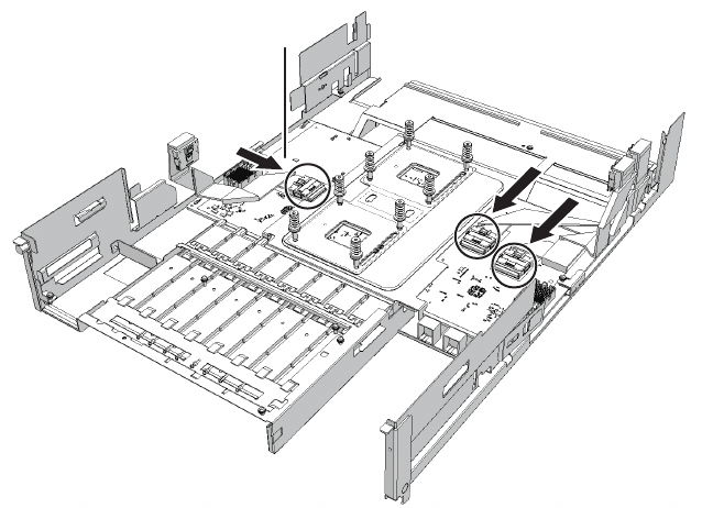
A
unit and the other two facing the front of the CPU memory unit
Figure 7-45 Installing the PCIe cables (with the connector for one PCIe cable
facing the outside and the two facing the front of the CPU memory
unit)
2. Install the sheet (A in the figure).
Fujitsu M10-4/Fujitsu M10-4S/SPARC M10-4/SPARC M10-4S Service Manual ・December 2013126

A
Note - Do not tilt the CPU memory unit board when installing it. The board may be damaged
by hitting the back side of the board against a protruding part or the frame guide.
Figure 7-46 Installing sheet
3. Hold the connector unit at the center of the CPU memory unit board and
install it on the frame in the horizontal position.
For how to hold the CPU memory unit board, see Figure 7-38 and Figure 7-39.
Chapter 7 Maintaining the CPU Memory Units 127
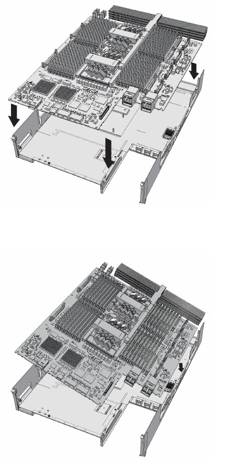
OK
NO
Figure 7-47 Correct position of the CPU memory unit board
Figure 7-48 Wrong position of the CPU memory unit board
-For the SPARC M10-4/M10-4S with a FRAME-A CPU memory unit
Install the frame so that the bent tip of the frame (C in the figure) can be
inserted into the space (B in the figure) between the end face of the far side of
the CPU memory unit board and the radiator (A in the figure).
a. Insert the board carefully into the frame, keeping it horizontal.
b. If the threaded hole of the board and the threaded hole of the frame (D in
the figure) do not match when inserting the frame, place the board by
adjusting the position of the frame so that the outer circumference of the
Fujitsu M10-4/Fujitsu M10-4S/SPARC M10-4/SPARC M10-4S Service Manual ・December 2013128
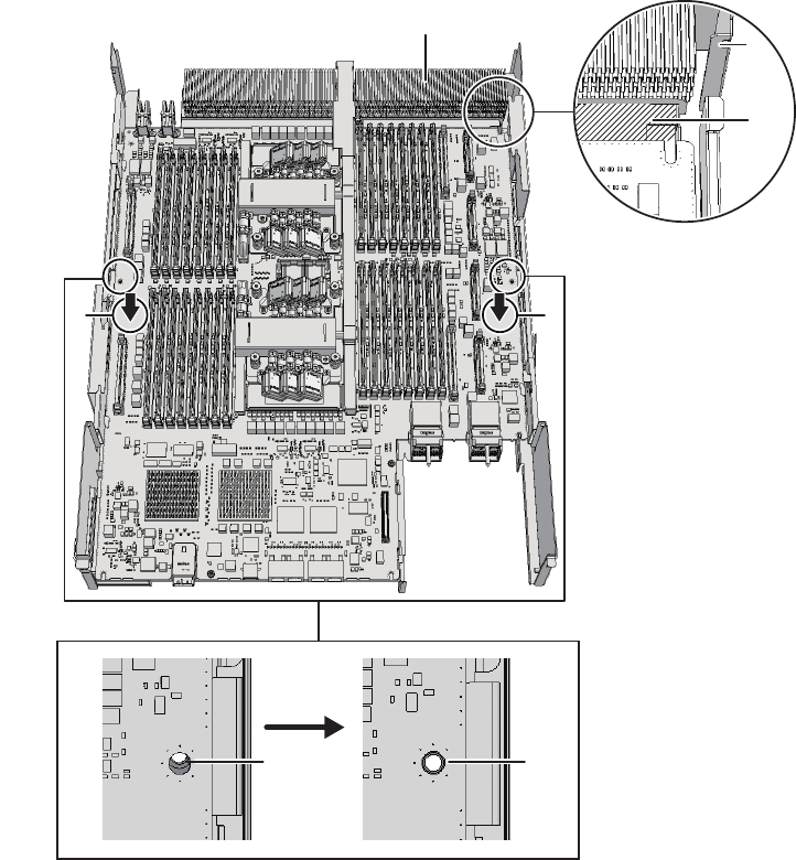
D E
C
B
FG
A
threaded hole of the frame can be seen (E in the figure).
c. Attach the connector by pressing down the connector units (F and G in the
figure) located at the center of the right and left sides of the board at the same
time.
Figure 7-49 Installing the CPU memory unit board (for the SPARC M10-4/M10-4S
with a FRAME-A CPU memory unit)
-For the SPARC M10-4S with a FRAME-B CPU memory unit
Install the CPU memory unit board with the left and right guides (A and B in
the figure) and the left guide on the board (C in the figure) as a guide.
a. Insert the board carefully into the frame, keeping it horizontal.
b. Attach the connector by pressing down the connector units (D and E in the
figure) located at the center of the right and left sides of the board at the same
time.
Chapter 7 Maintaining the CPU Memory Units 129
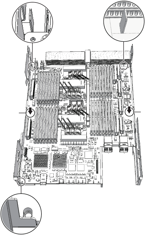
AB
C
DE
Figure 7-50 Installing the CPU memory unit board (for the SPARC M10-4S with a
FRAME-B CPU memory unit)
4. Fix the CPU memory unit board with screws.
-For the SPARC M10-4/M10-4S with a FRAME-A CPU memory unit
Fix the CPU memory unit board with four screws and the center part of the
radiatoronthefrontwithoneblackscrew.
Fujitsu M10-4/Fujitsu M10-4S/SPARC M10-4/SPARC M10-4S Service Manual ・December 2013130
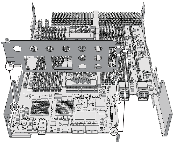
-For the SPARC M10-4S with a FRAME-B CPU memory unit
Fix the CPU memory unit board with six screws.
5. Install the XSCF mount and fix it with screws.
-For the SPARC M10-4/M10-4S with a FRAME-A CPU memory unit
Align the one point on the left and two points on the right of the XSCF mount
with the frame guides of the CPU memory unit lower. Then, install the XSCF
mount by sliding it to the front and fix it with one screw.
Figure 7-51 Installing the XSCF mount (for the SPARC M10-4/M10-4S with a
FRAME-A CPU memory unit)
-For the SPARC M10-4S with a FRAME-B CPU memory unit
Align the left protruding part (A in the figure) of the XSCF mount with the
frame guide of the CPU memory unit lower to install the XSCF mount. Then,
fix it with two screws (B in the figure).
Chapter 7 Maintaining the CPU Memory Units 131
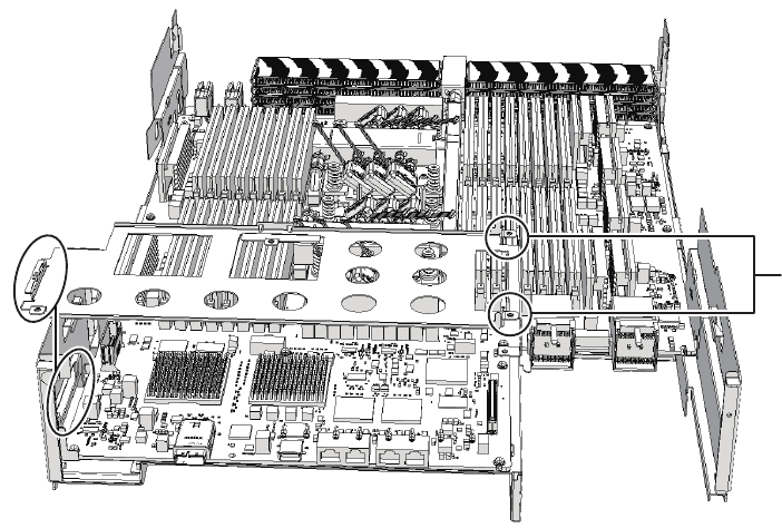
B
A
Figure 7-52 Installing the XSCF mount (for the SPARC M10-4S with a FRAME-B
CPU memory unit)
6. Install the XSCF board.
-For the SPARC M10-4 with FRAME-A CPU memory unit
Insert the XSCF board into guides at the two locations (A in the figure) on the
mount (B in the figure), and push the right lever of the mount about 5 mm (0.2
in.) to the right (C in the figure) to attach (E in the figure) the connector unit (D
in the figure). Then, fix it with one screw (F in the figure).
Fujitsu M10-4/Fujitsu M10-4S/SPARC M10-4/SPARC M10-4S Service Manual ・December 2013132
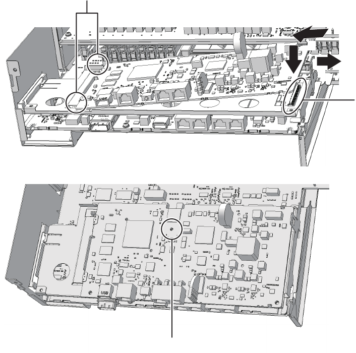
A
F
B
C
E
D
Figure 7-53 Installing the XSCF board (for the SPARC M10-4 with a FRAME-A
CPU memory unit)
-For the SPARC M10-4S with FRAME-A CPU memory unit
Insert the XSCF board into the left guide (A in the figure), and press down the
right connector unit (B in the figure) to attach the connector. Then, fix it with
two screws.
Chapter 7 Maintaining the CPU Memory Units 133
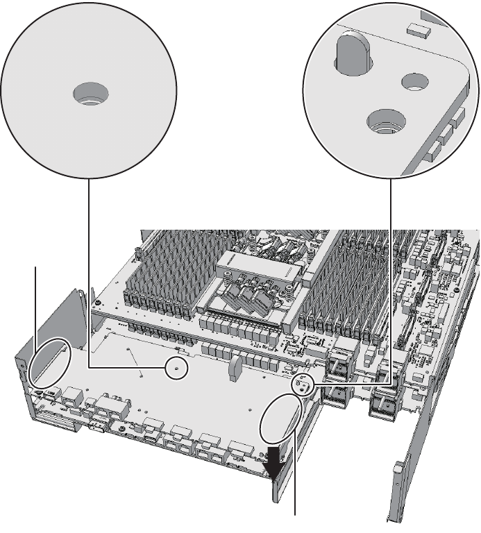
B
A
Figure 7-54 Installing the XSCF board (for the SPARC M10-4S with a FRAME-A
CPU memory unit)
7. Attach the rear cover with two screws from the upper part of the rear side of
the CPU memory unit lower.
Fujitsu M10-4/Fujitsu M10-4S/SPARC M10-4/SPARC M10-4S Service Manual ・December 2013134
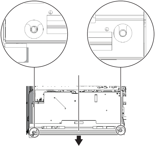
A
Figure 7-55 Screws for rear cover
8. Install the eight screws at both ends of the XSCF cable connection port on the
rear of the CPU memory unit lower.
For the SPARC M10-4 with a FRAME-A CPU memory unit and the SPARC
M10-4S with a FRAME-B CPU memory unit, this step is not necessary.
Chapter 7 Maintaining the CPU Memory Units 135
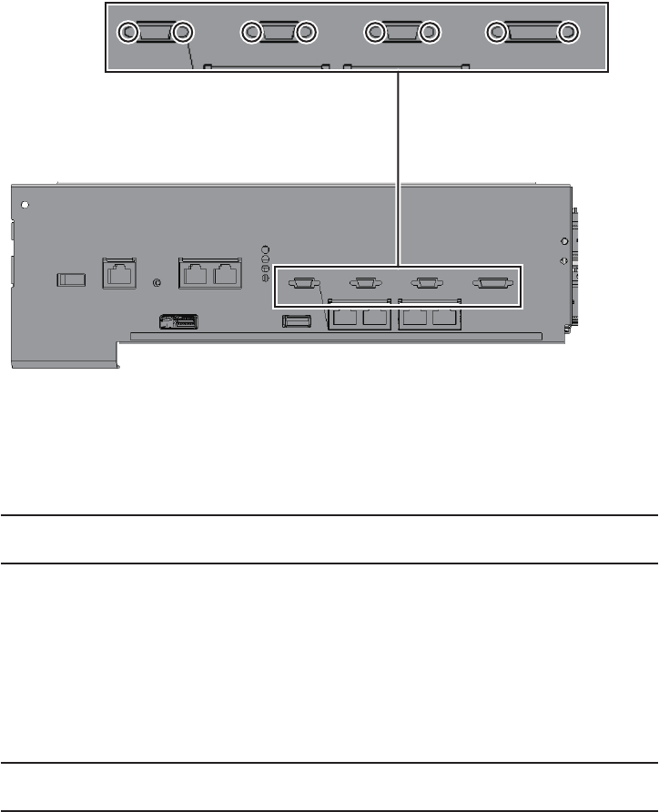
Note - A part of the procedure varies depending on the CPU memory unit type. To
determine the CPU memory unit type, check the label in Figure 7-2.
Note - Confirm that the levers on the left and right sides of the CPU memory unit upper are
closed.
Figure 7-56 Screws for both ends of the XSCF cable connection ports (for the
SPARC M10-4S with a FRAME-A CPU memory unit)
7.5.2 Installing the CPU memory unit upper
Install the CPU memory unit upper to the CPU memory unit lower. Perform
expansion using the same procedure.
1. Install the CPU memory unit upper on the CPU memory unit lower.
-When installing the CPU memory unit upper
Carefully install the CPU memory unit upper by setting the four guides (A in
the figure) of the CPU memory unit upper into the grooves (B in the figure) of
the CPU memory unit lower.
Fujitsu M10-4/Fujitsu M10-4S/SPARC M10-4/SPARC M10-4S Service Manual ・December 2013136
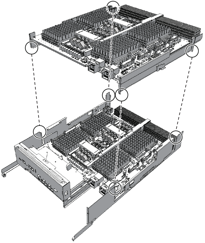
A
A
A
A
B
B
B
B
Figure 7-57 Guide positions of the CPU memory unit upper
-When installing the filler unit for the CPU memory unit upper
Carefully install the filler unit for the CPU memory unit upper by setting the
two guides (A in the figure) of the filler unit in the groove (B in the figure) of
the CPU memory unit lower.
Chapter 7 Maintaining the CPU Memory Units 137
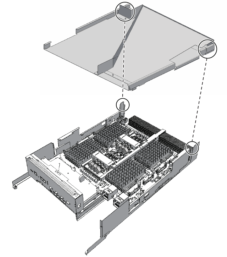
A
A
B
B
Figure 7-58 Guide positions of the filler unit for the CPU memory unit upper
2. Install the CPU memory unit upper by holding it down from the center where
the label "PUSH" is applied, and then push it into place.
Firmly push the unit so that there is no space between the CPU memory unit
upper and the frame of the CPU memory unit lower.
Fujitsu M10-4/Fujitsu M10-4S/SPARC M10-4/SPARC M10-4S Service Manual ・December 2013138
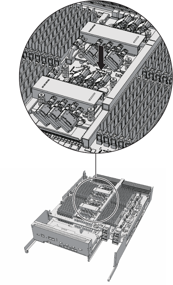
Figure 7-59 Position where the CPU memory unit upper is pushed
3. Connect, to the CPU memory unit upper, the four right and left PCIe cables
connecting the CPU memory units upper and lower.
While pressing the pin that locks the PCIe cable, insert it vertically.
Chapter 7 Maintaining the CPU Memory Units 139
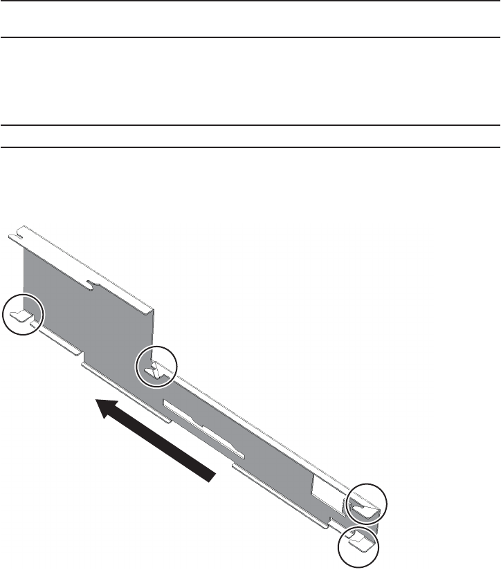
Note - Of the two PCIe cables on the right side, also install the one (short) cable on the rear of
the CPU memory unit lower.
Note - Be careful not to damage the PCIe cable when installing the left- and right-side guides.
4. Install the right- and left-side guides.
Each guide has four clips. Install the guides using the clips, and slide each guide
while pushing its lock.
Figure 7-60 Positions of the clips on the left- and right-side guides (for the
SPARC M10-4/M10-4S with a FRAME-A CPU memory unit)
Fujitsu M10-4/Fujitsu M10-4S/SPARC M10-4/SPARC M10-4S Service Manual ・December 2013140
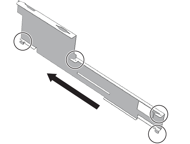
Figure 7-61 Positions of the clips on the left- and right-side guides (for the
SPARC M10-4S with a FRAME-B CPU memory unit)
Chapter 7 Maintaining the CPU Memory Units 141
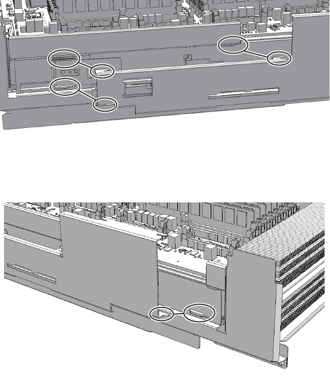
Figure 7-62 CPU memory unit upper and positions of the clips on the side guide
(for the SPARC M10-4/M10-4S with a FRAME-A CPU memory unit)
Fujitsu M10-4/Fujitsu M10-4S/SPARC M10-4/SPARC M10-4S Service Manual ・December 2013142
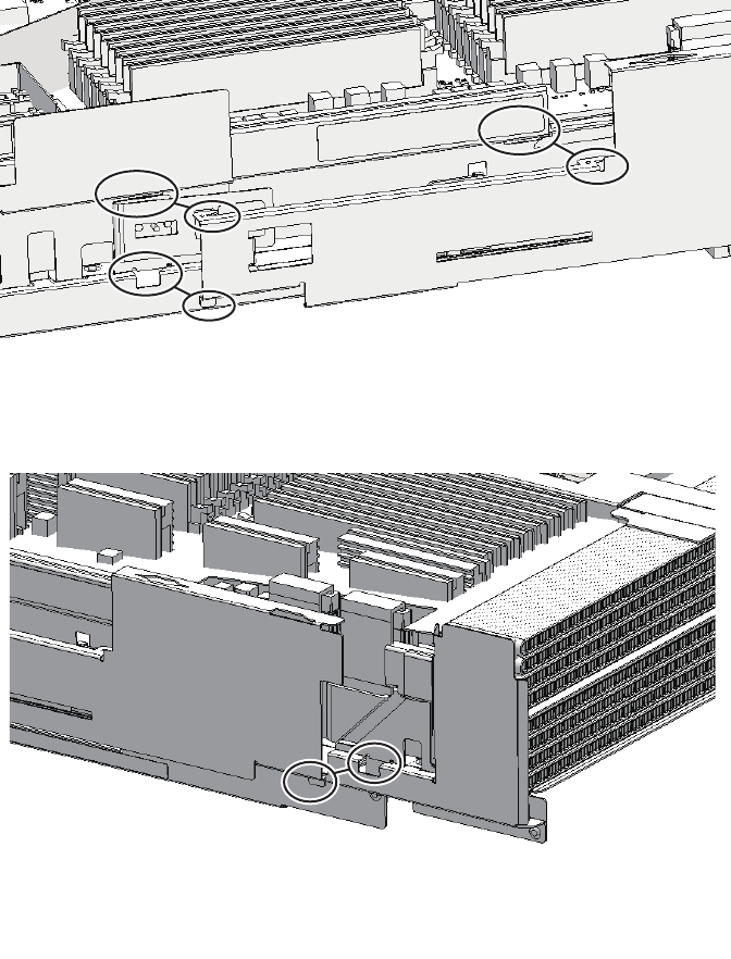
Figure 7-63 CPU memory unit upper and positions of the clips on the side guide
(for the SPARC M10-4S with a FRAME-B CPU memory unit)
Chapter 7 Maintaining the CPU Memory Units 143
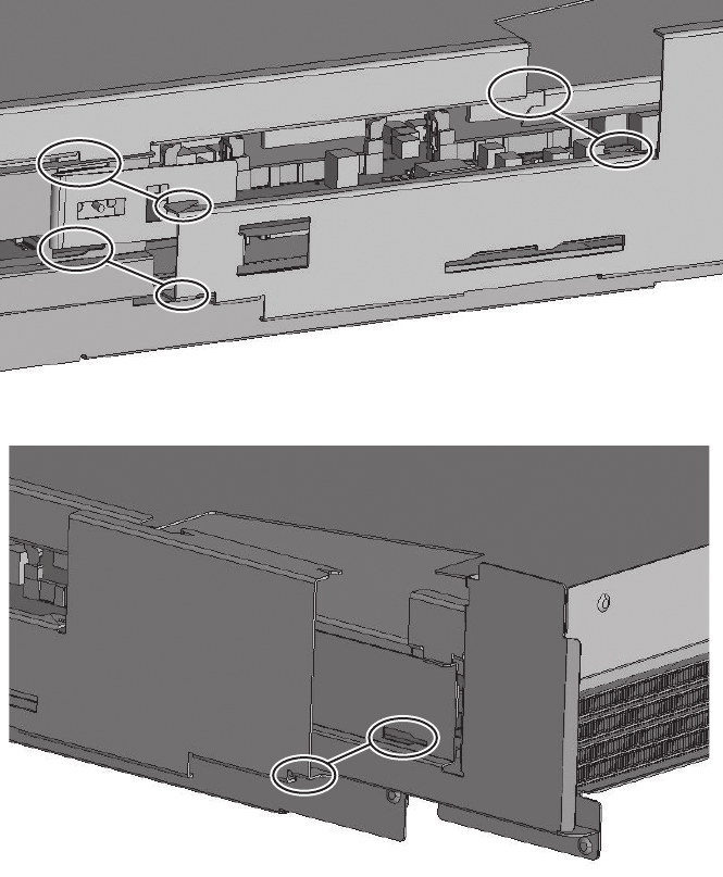
Figure 7-64 Filler unit of the CPU memory unit upper and positions of the clips
on the side guide (for the SPARC M10-4/M10-4S with a FRAME-A
CPU memory unit)
Fujitsu M10-4/Fujitsu M10-4S/SPARC M10-4/SPARC M10-4S Service Manual ・December 2013144
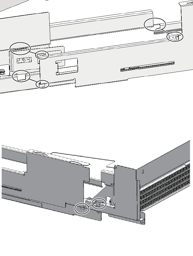
Figure 7-65 Filler unit of the CPU memory unit upper and positions of the clips
on the side guide (for the SPARC M10-4S with a FRAME-B CPU
memory unit)
5. Install the top-side cover of the CPU memory unit.
6. Install the CPU memory unit lower in the chassis.
For details, see "7.5.3 Installing the CPU memory unit lower."
Chapter 7 Maintaining the CPU Memory Units 145

Note - If the CPU memory unit lower is inserted as far as it will go, it may not be possible to
lift the lever. Lift the lever just before the CPU memory unit lower hits the rear and then
push it fully home.
Note - Reinstall the PCIe card cassettes in their original positions by referring to the notes
that you made prior to the start of maintenance.
7.5.3 Installing the CPU memory unit lower
1. Install the CPU memory unit upper or a filler unit for a CPU memory unit
upper.
For details, see "7.5.2 Installing the CPU memory unit upper."
2. Insert the CPU memory unit lower into the chassis while supporting it from
below with one hand.
3. Raise the right and left levers of the CPU memory unit lower to secure it.
7.5.4 Restoring the chassis
1. If a crossbar unit was mounted, install the mounting frame and then tighten
the three screws.
2. If any crossbar units were mounted, reinstall all of them.
For details, see "9.5 Installing a Crossbar Unit."
3. Install all the PCIe card cassettes.
For details, see "13.6.2 Installing a PCI Express card cassette."
4. Connect all the cables for the external interface.
The cables to be connected are as follows.
■Interface cable connected to the PCIe card
■Crossbar cables (If equipment rack model 26xx or equipment rack model 16xx
is used, connect them in step 6.)
■XSCF BB control cable
■XSCF DUAL control cable
■XSCF-LAN cable
■Serial cable
■LAN cable
■SAS cable
■USB cable
Fujitsu M10-4/Fujitsu M10-4S/SPARC M10-4/SPARC M10-4S Service Manual ・December 2013146

Note - Reinstall the cables in the correct positions by referring to the notes you made before
starting maintenance.
Note - Connect the crossbar cables in their original positions by referring to the notes that
you made before the start of maintenance.
Note - Connect the crossbar cables in their original positions by referring to the notes that
you made before the start of maintenance.
5. Lift the cable support to fix it.
For details, see "6.5.2 Fixing the cable support."
If you are not using equipment rack model 26xx or equipment rack model 16xx,
the procedure ends here. You do not have to perform step 6.
6. Connect the crossbar cables to the cable support.
Perform this procedure only when equipment rack model 26xx or equipment
rack model 16xx is used. The procedure may vary depending on the model of
the equipment rack.
Procedure when equipment rack model 26xx is used
a. Remove the hook-and-loop fastener of the crossbar cables from the cable
holder.
b. Remove the screw securing the cable holder, and then rotate the cable
holder through 180 degrees to install it on the supporting column at the
rear of the rack.
c. Connect all the crossbar cables to the crossbar unit.
d. Use the hook-and-loop fastener to fix the crossbar cables to the cable
support.
Procedure when equipment rack model 16xx is used
a. Remove the crossbar cables from the hook-and-loop fastener installed on
the supporting column on the rear of the rack.
b. Connect all the crossbar cables to the crossbar unit.
c. Use the hook-and-loop fastener to fix the crossbar cables to the cable
support.
7.6 Restoring the System
This section describes the procedure for restoring the system after a CPU memory
unit is replaced, expanded, or reduced. The restoration procedure differs depending
on the maintenance type as follows:
Chapter 7 Maintaining the CPU Memory Units 147
Note - See the procedure for system-stopped maintenance for inactive/cold maintenance in a
single-chassis configuration.
Note - Use the DR of the system board on a physical partition for active/cold maintenance.
For the XCP and Oracle VM Server for SPARC/SRU versions that correspond to the DR, see
the latest Product Notes.
Note - Active/cold maintenance can be performed only for a building block configuration.
Note - In the case of a dual power feed, connect the power cords in their original positions by
referring to the record that you made before the start of maintenance.
XSCF> diagxbu -y -b 00 -p 02
XSCF> showlogs error
■Active/Cold maintenance
■Inactive/Cold maintenance
■System-stopped maintenance
7.6.1 Active/Cold maintenance
1. Connect all the power cords to the PSU backplane unit of the chassis
requiring maintenance.
For details, see "6.5.1 Installing the power cord."
2. Return to the operation of the XSCF firmware replacefru command to confirm
that the chassis has been incorporated into the system.
For details, see "6.1 Incorporating an FRU into the System with the replacefru
Command."
3. Execute the diagxbu command to diagnose the crossbar cables.
Diagnosis is performed when the system board of the chassis connected with the
crossbar cables is incorporated into the physical partition, and the physical
partition is powered on.
The example below specifies the following:
00: BB-ID of the chassis to start the diagnosis
02: PPAR-ID of the destination where the chassis to start the diagnosis is
connected (You can specify only one of these.)
4. Execute the showlogs command to confirm that the system is operating
normally.
Fujitsu M10-4/Fujitsu M10-4S/SPARC M10-4/SPARC M10-4S Service Manual ・December 2013148
Note - See the procedure for system-stopped maintenance for inactive/cold maintenance in a
single-chassis configuration.
Note - In the case of a dual power feed, connect the power cords in their original positions by
referring to the record that you made before the start of maintenance.
XSCF> diagxbu -y -b 00 -t 01
For details, see "3.3.5 Checking log information."
5.
Incorporate the chassis, in which the CPU memory unit requiring maintenance
is mounted, into the physical partition.
For details, see "6.2 Incorporating a Chassis into a Physical Partition."
6. Close the rack door.
7.6.2 Inactive/Cold maintenance
When the system is configured without a hardware RAID
1. Connect all the power cords to the PSU backplane unit of the chassis
requiring maintenance.
For details, see "6.5.1 Installing the power cord."
2. Return to the operation of the XSCF firmware replacefru command to confirm
that the chassis has been incorporated into the system.
For details, see "6.1 Incorporating an FRU into the System with the replacefru
Command."
3. Execute the diagxbu command to diagnose the crossbar cables.
Diagnosis is performed when the system board of the chassis connected with the
crossbar cables is not incorporated into the physical partition, or when the
physical partition into which the chassis is incorporated is powered off.
The example below specifies the following:
00: BB-ID of the chassis to start the diagnosis
01: BB-ID of the destination where the chassis to start the diagnosis is connected
(You can specify one or more of these.)
To specify multiple connection destination BB-IDs, enter a command like
"diagxbu -y -b 00 -t 01 -t 02".
4. Execute the showlogs command to confirm that the system is operating
normally.
Chapter 7 Maintaining the CPU Memory Units 149
XSCF> showlogs error
XSCF> showstatus
XSCF> showhardconf
Note - In the case of a dual power feed, connect the power cords in their original positions by
referring to the record that you made before the start of maintenance.
For details, see "3.3.5 Checking log information."
5. Switch the mode switches of the master chassis and those chassis whose
XSCFs are in the standby state to Locked mode.
-For a building block configuration (without crossbar box)
Switch the mode switches of BB-ID#00 and #01 to Locked mode.
-For a building block configuration (with crossbar box)
Switch the mode switches of BB-ID#80 and #81 to Locked mode.
6. Execute the showstatus command to confirm that the CPU memory unit is
operating normally after maintenance.
If there is no problem, nothing is displayed.
7. Execute the showhardconf command to check the hardware configuration
and the status of each component.
Confirm that no asterisk (*) is displayed in front of each component.
8. Start the system.
For details, see "6.4.1 Starting the system with an XSCF command"or"6.4.2
Starting the system from the operation panel."
9. Close the rack door.
When the system is configured with a hardware RAID
1. Connect all the power cords to the PSU backplane unit of the chassis
requiring maintenance.
For details, see "6.5.1 Installing the power cord."
2. Return to the operation of the XSCF firmware replacefru command to confirm
that the chassis has been incorporated into the system.
For details, see "6.1 Incorporating an FRU into the System with the replacefru
Command."
3. Execute the diagxbu command to diagnose the crossbar cables.
Diagnosis is performed when the system board of the chassis connected with the
crossbar cables is not incorporated into the physical partition, or when the
physical partition into which the chassis is incorporated is powered off.
Fujitsu M10-4/Fujitsu M10-4S/SPARC M10-4/SPARC M10-4S Service Manual ・December 2013150
XSCF> diagxbu -y -b 00 -t 01
XSCF> showlogs error
XSCF> setpparparam -p 0 -s bootscript "setenv auto-boot? false"
XSCF> setpparmode -p 0 -m guestboot=off
XSCF> setpparparam -p 0 -s bootscript "setenv auto-boot? true"
The example below specifies the following:
00: BB-ID of the chassis to start the diagnosis
01: BB-ID of the destination where the chassis to start the diagnosis is connected
(You can specify one or more of these.)
To specify multiple connection destination BB-IDs, enter a command like
"diagxbu -y -b 00 -t 01 -t 02".
4. Execute the showlogs command to confirm that the system is operating
normally.
For details, see "3.3.5 Checking log information."
5. Execute the setpparparam command to deactivate the Autoboot function of
the control domain.
In the following example, PPAR-ID 0 is set for Auto boot.
6. Execute the setpparmode command to deactivate the Autoboot function of
the guest domain.
In the following example, PPAR-ID 0 is set for Auto boot.
7. Start the system.
For details, see "6.4.1 Starting the system with an XSCF command"or"6.4.2
Starting the system from the operation panel."
8. The ok prompt appears.
9. Enable the RAID volume to check the status.
For details, see "14.2.11 Re-enabling a hardware RAID volume" in the Fujitsu
M10/SPARC M10 Systems System Operation and Administration Guide.
10. Execute the setpparparam command to activate the Autoboot function of the
control domain.
In the following example, PPAR-ID 0 is set for Auto boot.
11. Switch the mode switches of the master chassis and those chassis whose
XSCFs are in the standby state to Locked mode.
-For a building block configuration (without crossbar box)
Chapter 7 Maintaining the CPU Memory Units 151

XSCF> showstatus
XSCF> showhardconf
Note - In the case of a dual power feed, connect the power cords in their original positions by
referring to the record that you made before the start of maintenance.
Switch the mode switches of BB-ID#00 and #01 to Locked mode.
-For a building block configuration (with crossbar box)
Switch the mode switches of BB-ID#80 and #81 to Locked mode.
12. Execute the showstatus command to confirm that the CPU memory unit is
operating normally after maintenance.
If there is no problem, nothing is displayed.
13. Execute the showhardconf command to check the hardware configuration
and the status of each component.
Confirm that no asterisk (*) is displayed in front of each component.
14. Close the rack door.
7.6.3 System-stopped maintenance
When the system is configured without a hardware RAID
1. Connect all the power cords to the PSU backplane unit of the chassis
requiring maintenance.
For details, see "6.5.1 Installing the power cord."
2. Return to the operation of the XSCF firmware replacefru command to confirm
that the chassis has been incorporated into the system.
For details, see "6.1 Incorporating an FRU into the System with the replacefru
Command."
For a single-chassis configuration, you do not have to incorporate the chassis.
Proceed to step 4.
3. Execute the diagxbu command to diagnose the crossbar cables.
Diagnosis is performed when the system board of the chassis connected with the
crossbar cables is not incorporated into the physical partition, or when the
physical partition into which the chassis is incorporated is powered off.
The example below specifies the following:
00: BB-ID of the chassis to start the diagnosis
01: BB-ID of the destination where the chassis to start the diagnosis is connected
Fujitsu M10-4/Fujitsu M10-4S/SPARC M10-4/SPARC M10-4S Service Manual ・December 2013152
XSCF> diagxbu -y -b 00 -t 01
Note - If you cannot log in with an XSCF user account and password, use the default user
account of the XSCF to log in to the XSCF. For details, see "6.3 Logging In to the XSCF" in
the Fujitsu M10/SPARC M10 Systems Installation Guide.
XSCF> restoreconfig
XSCF> showlogs error
(You can specify one or more of these.)
To specify multiple connection destination BB-IDs, enter a command like
"diagxbu -y -b 00 -t 01 -t 02".
4. Execute the restoreconfig command to restore the XSCF setting information
only when the CPU memory unit lower in a singe-chassis configuration has
been replaced.
If the CPU memory unit lower is has not been replaced, restoration is not
necessary. Proceed to step 5.
a. LogintotheXSCFshell.
b. Execute the restoreconfig command to restore the XSCF setting
information that has been saved with the dumpconfig command.
For details, see "10.9.3 Restoring XSCF setting information" in the Fujitsu
M10/SPARC M10 Systems System Operation and Administration Guide.
c. Execute the version command to confirm the firmware version information.
If the version does not match the one before the replacement, update the
firmware.
For details, see "16.1.3 Updating firmware" in the Fujitsu M10/SPARC M10
Systems System Operation and Administration Guide.
5. Execute the showlogs command to confirm that the system is operating
normally.
For details, see "3.3.5 Checking log information."
6. Execute the testsb command to confirm that the CPU memory unit requiring
maintenance is normally recognized.
For a building block configuration, you do not have to execute the testsb
command. Proceed to step 7.
When you input optional "-y" for the testsb command, the system automatically
answers "y" (yes) in response to an inquiry.
The following example shows the diagnosis of system board 00-0.
Chapter 7 Maintaining the CPU Memory Units 153
XSCF> testsb -v -y -s 00-0
XSCF> showstatus
XSCF> showhardconf
XSCF> showdate
XSCF> setdate -s 102016592013.00
Note - In the case of a dual power feed, connect the power cords in their original positions by
referring to the record that you made before the start of maintenance.
7. Execute the showstatus command to confirm that the CPU memory unit is
operating normally after maintenance.
If there is no problem, nothing is displayed.
8. Execute the showhardconf command to check the hardware configuration
and the status of each component.
Confirm that no asterisk (*) is displayed in front of each component.
9. Execute the showdate command to confirm the XSCF time.
There is no need to set the time if the NTP server is set to the XSCF. Proceed to
step 11.
10. If the XSCF time is different from the current time, execute the setdate
command to set the time.
Specify the time in either of the following formats:
yyyy.MM.DD-hh:mm:ss year.month.day-hour (24-hour clock):minute:second
MMDDhhmmyyyy.ss monthdayhour (24-hour clock) minuteyear.second
In the following example, "October 20, 2013 16:59:00" is specified.
11. Start the system.
For details, see "6.4.1 Starting the system with an XSCF command"or"6.4.2
Starting the system from the operation panel."
12. Close the rack door.
When the system is configured with a hardware RAID
1. Connect all the power cords to the PSU backplane unit of the chassis
requiring maintenance.
For details, see "6.5.1 Installing the power cord."
Fujitsu M10-4/Fujitsu M10-4S/SPARC M10-4/SPARC M10-4S Service Manual ・December 2013154
XSCF> diagxbu -y -b 00 -t 01
Note - If you cannot log in with an XSCF user account and password, use the default user
account of the XSCF to log in to the XSCF. For details, see "6.3 Resetting the System" in the
Fujitsu M10/SPARC M10 Systems Installation Guide.
XSCF> restoreconfig
2. Return to the operation of the XSCF firmware replacefru command to confirm
that the chassis has been incorporated into the system.
For details, see "6.1 Incorporating an FRU into the System with the replacefru
Command."
For a single-chassis configuration, you do not have to incorporate the chassis.
Proceed to step 4.
3. Execute the diagxbu command to diagnose the crossbar cables.
Diagnosis is performed when the system board of the chassis connected with the
crossbar cables is not incorporated into the physical partition, or when the
physical partition into which the chassis is incorporated is powered off.
The example below specifies the following:
00: BB-ID of the chassis to start the diagnosis
01: BB-ID of the destination where the chassis to start the diagnosis is connected
(You can specify one or more of these.)
To specify multiple connection destination BB-IDs, enter a command like
"diagxbu -y -b 00 -t 01 -t 02".
4. Execute the restoreconfig command to restore the XSCF setting information
only when the CPU memory unit lower in a singe-chassis configuration has
been replaced.
If the CPU memory unit lower is has not been replaced, restoration is not
necessary. Proceed to step 5.
a. LogintotheXSCFshell.
b. Execute the restoreconfig command to restore the XSCF setting
information that has been saved with the dumpconfig command.
For details, see "6.3 Logging In to the XSCF" in the Fujitsu M10/SPARC M10
Systems System Operation and Administration Guide.
c. Execute the version command to confirm the firmware version information.
If the version does not match the one before the replacement, update the
firmware.
For details, see "16.1.3 Updating firmware" in the Fujitsu M10/SPARC M10
Systems System Operation and Administration Guide.
5. Execute the showlogs command to confirm that the system is operating
Chapter 7 Maintaining the CPU Memory Units 155
XSCF> showlogs error
XSCF> testsb -v -y -s 00-0
XSCF> setpparparam -p 0 -s bootscript "setenv auto-boot? false"
XSCF> setpparmode -p 0 -m guestboot=off
XSCF> setpparmode -p 0 -m guestboot=on
normally.
For details, see "3.3.5 Checking log information."
6. Execute the testsb command to confirm that the CPU memory unit requiring
maintenance is normally recognized.
For a building block configuration, you do not have to execute the testsb
command. Proceed to step 7.
When you input optional "-y" for the testsb command, the system automatically
answers "y" (yes) in response to an inquiry.
The following example shows the diagnosis of system board 00-0.
7. Execute the setpparparam command to deactivate the Autoboot function of
the control domain.
In the following example, PPAR-ID 0 is set for Auto boot.
8. Execute the setpparmode command to deactivate the Autoboot function of
the guest domain.
In the following example, PPAR-ID 0 is set for Auto boot.
9. Start the system.
For details, see "6.4.1 Starting the system with an XSCF command"or"6.4.2
Starting the system from the operation panel."
10. The ok prompt appears.
11. Enable the RAID volume to check the status.
For details, see "14.2.11 Re-enabling a hardware RAID volume" in the Fujitsu
M10/SPARC M10 Systems System Operation and Administration Guide.
12. Execute the setpparmode command to activate the Autoboot function of the
guest domain.
In the following example, PPAR-ID 0 is set for Auto boot.
13. Execute the showstatus command to confirm that the CPU memory unit is
operating normally after maintenance.
Fujitsu M10-4/Fujitsu M10-4S/SPARC M10-4/SPARC M10-4S Service Manual ・December 2013156
XSCF> showstatus
XSCF> showhardconf
XSCF> showdate
XSCF> setdate -s 102016592013.00
If there is no problem, nothing is displayed.
14. Execute the showhardconf command to confirm the hardware configuration
and the status of each CPU memory unit.
Confirm that no asterisk (*) is displayed in front of each component.
15. Execute the showdate command to confirm the XSCF time.
There is no need to set the time if the NTP server is set to the XSCF. Proceed to
step 17.
16. If the XSCF time is different from the current time, execute the setdate
command to set the time.
Specify the time in either of the following formats:
yyyy.MM.DD-hh:mm:ss year.month.day-hour (24-hour clock):minute:second
MMDDhhmmyyyy.ss monthdayhour (24-hour clock) minuteyear.second
In the following example, "October 20, 2013 16:59:00" is specified.
17. Close the rack door.
Chapter 7 Maintaining the CPU Memory Units 157
Fujitsu M10-4/Fujitsu M10-4S/SPARC M10-4/SPARC M10-4S Service Manual ・December 2013158

Chapter 8
Maintaining the Memory
This chapter describes the procedure for maintaining the memory mounted on the
SPARC M10-4/M10-4S. Memory can be replaced, expanded, and reduced.
■Memory Configuration
■Memory Configuration Rules
■Before Maintaining Memory
■Enabling the Removal of Memory
■Removing Memory
■Installing Memory
■Restoring the System
8.1 Memory Configuration
This section describes the configuration and location of memory.
A maximum of 32 memory modules can be implemented in one CPU memory unit.
One chassis can contain two CPU memory units; the CPU memory unit upper and
lower. Therefore, the maximum number of memory modules that can be implemented
in one chassis is 64.
Figure 8-1 shows the memory locations and the memory groups of the CPU memory
unit lower, while Figure 8-2 shows those of the CPU memory unit upper.
159
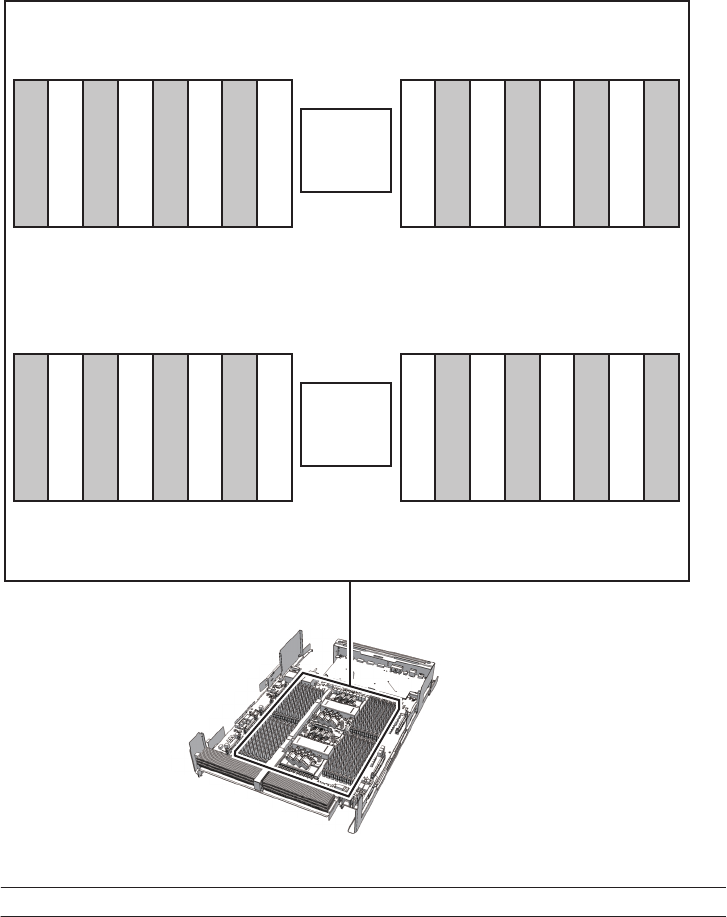
CPU#0
CMUL
Front
CPU#1
(2) (1) (4) (3) (10) (9) (12) (11)
(22) (21) (24) (23) (30) (29) (32) (31)
(15) (16) (13) (14) (7) (8) (5) (6)
(27) (28) (25) (26) (19) (20) (17) (18)
Location number Component Group
1 Memory (CMUL/MEM#00A) A
2 Memory (CMUL/MEM#00B) B
3 Memory (CMUL/MEM#01A) A
4 Memory (CMUL/MEM#01B) B
5 Memory (CMUL/MEM#02A) A
6 Memory (CMUL/MEM#02B) B
Figure 8-1 Memory locations (CPU memory unit lower)
Fujitsu M10-4/Fujitsu M10-4S/SPARC M10-4/SPARC M10-4S Service Manual ・December 2013160

Location number Component Group
7 Memory (CMUL/MEM#03A) A
8 Memory (CMUL/MEM#03B) B
9 Memory (CMUL/MEM#04A) A
10 Memory (CMUL/MEM#04B) B
11 Memory (CMUL/MEM#05A) A
12 Memory (CMUL/MEM#05B) B
13 Memory (CMUL/MEM#06A) A
14 Memory (CMUL/MEM#06B) B
15 Memory (CMUL/MEM#07A) A
16 Memory (CMUL/MEM#07B) B
17 Memory (CMUL/MEM#10A) A
18 Memory (CMUL/MEM#10B) B
19 Memory (CMUL/MEM#11A) A
20 Memory (CMUL/MEM#11B) B
21 Memory (CMUL/MEM#12A) A
22 Memory (CMUL/MEM#12B) B
23 Memory (CMUL/MEM#13A) A
24 Memory (CMUL/MEM#13B) B
25 Memory (CMUL/MEM#14A) A
26 Memory (CMUL/MEM#14B) B
27 Memory (CMUL/MEM#15A) A
28 Memory (CMUL/MEM#15B) B
29 Memory (CMUL/MEM#16A) A
30 Memory (CMUL/MEM#16B) B
31 Memory (CMUL/MEM#17A) A
32 Memory (CMUL/MEM#17B) B
Chapter 8 Maintaining the Memory 161
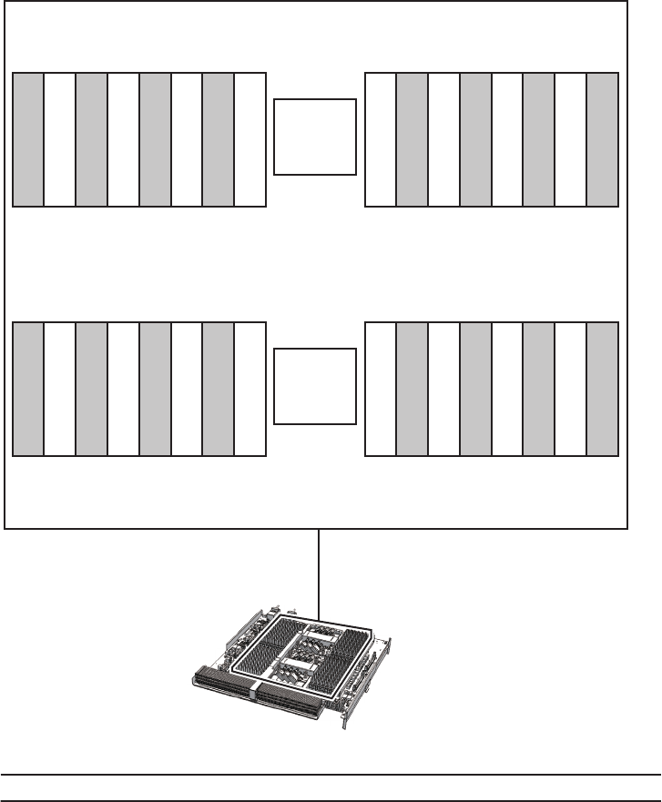
CPU#0
CMUU
CPU#1
(34) (33) (36) (35) (42) (41) (44) (43)
(54) (53) (56) (55) (62) (61) (64) (63)
(47) (48) (45) (46) (39) (40) (37) (38)
(59) (60) (57) (58) (51) (52) (49) (50)
Front
Location number Component Group
33 Memory (CMUU/MEM#00A) A
34 Memory (CMUU/MEM#00B) B
35 Memory (CMUU/MEM#01A) A
36 Memory (CMUU/MEM#01B) B
37 Memory (CMUU/MEM#02A) A
38 Memory (CMUU/MEM#02B) B
39 Memory (CMUU/MEM#03A) A
Figure 8-2 Memory locations (CPU memory unit upper)
Fujitsu M10-4/Fujitsu M10-4S/SPARC M10-4/SPARC M10-4S Service Manual ・December 2013162

Location number Component Group
40 Memory (CMUU/MEM#03B) B
41 Memory (CMUU/MEM#04A) A
42 Memory (CMUU/MEM#04B) B
43 Memory (CMUU/MEM#05A) A
44 Memory (CMUU/MEM#05B) B
45 Memory (CMUU/MEM#06A) A
46 Memory (CMUU/MEM#06B) B
47 Memory (CMUU/MEM#07A) A
48 Memory (CMUU/MEM#07B) B
49 Memory (CMUU/MEM#10A) A
50 Memory (CMUU/MEM#10B) B
51 Memory (CMUU/MEM#11A) A
52 Memory (CMUU/MEM#11B) B
53 Memory (CMUU/MEM#12A) A
54 Memory (CMUU/MEM#12B) B
55 Memory (CMUU/MEM#13A) A
56 Memory (CMUU/MEM#13B) B
57 Memory (CMUU/MEM#14A) A
58 Memory (CMUU/MEM#14B) B
59 Memory (CMUU/MEM#15A) A
60 Memory (CMUU/MEM#15B) B
61 Memory (CMUU/MEM#16A) A
62 Memory (CMUU/MEM#16B) B
63 Memory (CMUU/MEM#17A) A
64 Memory (CMUU/MEM#17B) B
8.2 Memory Configuration Rules
This section describes the memory mounting rules and the method for checking
memory information.
Chapter 8 Maintaining the Memory 163
8.2.1 Memory mounting rules
Install the memory in accordance with the following rules:
■Mount memory in units of eight modules.
■Within a unit of eight modules, all the memory modules must be of the same
capacity and rank.
■For memory for one CPU, use only R-DIMM (Registered DIMM: 8 GB/16 GB/32
GB) or only LR-DIMM (Load Reduced DIMM: 64 GB).
■First mount memory group A and then mount memory group B.
Figure 8-3 shows the mounting locations of all the memory modules. Each
eight-module unit of mounted memory is indicated by letters a to f. Table 8-1,Table
8-2 and Table 8-3 list the supported memory installation configurations. The memory
mounting locations may vary depending on the number of mounted CPU memory
units. Refer to this figure and table when you expand or reduce memory.
As for the mounting order of memory group B, give priority to using a uniform
memory type of either R-DIMM or LR-DIMM for one CPU over the memory
mounting patterns in Table 8-1,Table 8-2,andTable 8-3.
Fujitsu M10-4/Fujitsu M10-4S/SPARC M10-4/SPARC M10-4S Service Manual ・December 2013164
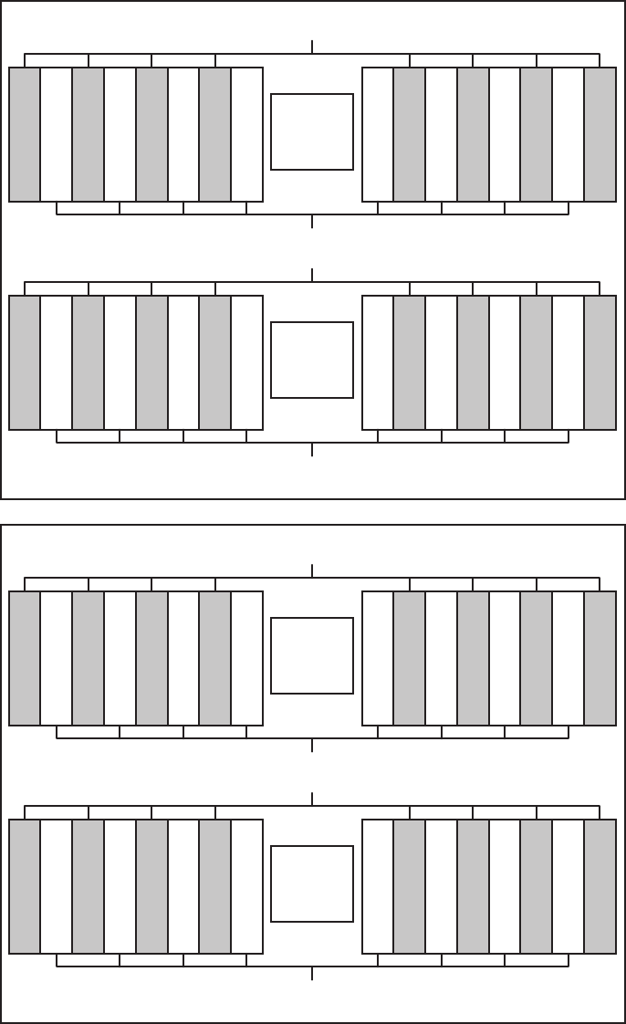
g
c
h
d
e
a
f
b
CPU#0
MEM#00B
MEM#00A
MEM#01B
MEM#01A
MEM#04B
MEM#04A
MEM#05B
MEM#05A
MEM#07A
MEM#07B
MEM#06A
MEM#06B
MEM#03A
MEM#03B
MEM#02A
MEM#02B
CPU#1
MEM#12A
MEM#13A
MEM#16A
MEM#17A
MEM#12B
MEM#13B
MEM#16B
MEM#17B
MEM#15A
MEM#14A
MEM#11A
MEM#10A
MEM#15B
MEM#14B
MEM#11B
MEM#10B
CPU#0
CPU#1
MEM#00B
MEM#00A
MEM#01B
MEM#01A
MEM#04B
MEM#04A
MEM#05B
MEM#05A
MEM#07A
MEM#07B
MEM#06A
MEM#06B
MEM#03A
MEM#03B
MEM#02A
MEM#02B
Front
CMUL
Front
MEM#12A
MEM#13A
MEM#16A
MEM#17A
MEM#12B
MEM#13B
MEM#16B
MEM#17B
MEM#15A
MEM#14A
MEM#11A
MEM#10A
MEM#15B
MEM#14B
MEM#11B
MEM#10B
CMUU
Figure 8-3 Mounting locations and units of memory
Chapter 8 Maintaining the Memory 165
Table 8-1 Memory mounting configurations (CMUL only)
Number of memory
modules
Mounted memory
8ainFigure 8-3 ---
16 a in Figure 8-3 binFigure 8-3 --
24 a in Figure 8-3 binFigure 8-3 einFigure 8-3 -
32 a in Figure 8-3 binFigure 8-3 einFigure 8-3 finFigure 8-3
Table 8-2 Memory mounting patterns (CMUL and CMUU)
Number of
memory
modules
Mounted memory
8ain
Figure 8-3
-------
16 a in
Figure 8-3
bin
Figure 8-3
------
24 a in
Figure 8-3
bin
Figure 8-3
cin
Figure 8-3
-----
32 a in
Figure 8-3
bin
Figure 8-3
cin
Figure 8-3
din
Figure 8-3
----
40 a in
Figure 8-3
bin
Figure 8-3
cin
Figure 8-3
din
Figure 8-3
ein
Figure 8-3
---
48 a in
Figure 8-3
bin
Figure 8-3
cin
Figure 8-3
din
Figure 8-3
ein
Figure 8-3
finFigure
8-3
--
56 a in
Figure 8-3
bin
Figure 8-3
cin
Figure 8-3
din
Figure 8-3
ein
Figure 8-3
finFigure
8-3
gin
Figure 8-3
-
64 a in
Figure 8-3
bin
Figure 8-3
cin
Figure 8-3
din
Figure 8-3
ein
Figure 8-3
finFigure
8-3
gin
Figure 8-3
hin
Figure 8-3
When only the CPU memory unit lower is mounted
When both the CPU memory unit lower and the CPU memory unit upper
are mounted
When expanding a CPU memory unit upper to a chassis in which only a
CPU memory unit lower is mounted
If you mount memory by expanding a CPU memory unit upper to a chassis in which
only a CPU memory unit lower is mounted, you do not have to remove the memory
mounted on the CPU memory unit lower.
Fujitsu M10-4/Fujitsu M10-4S/SPARC M10-4/SPARC M10-4S Service Manual ・December 2013166

Table 8-3 Memory mounting configurations (CMUL and expanded CMUU)
Number of
memory
modules
Mounted memory
8ain
Figure 8-3
-
16 a in
Figure 8-3
bin
Figure 8-3
------
24 a in
Figure 8-3
bin
Figure 8-3
ein
Figure 8-3
-----
32 a in
Figure 8-3
bin
Figure 8-3
ein
Figure 8-3
finFigure
8-3
----
40 a in
Figure 8-3
bin
Figure 8-3
ein
Figure 8-3
finFigure
8-3
cin
Figure 8-3
---
48 a in
Figure 8-3
bin
Figure 8-3
ein
Figure 8-3
finFigure
8-3
cin
Figure 8-3
din
Figure 8-3
--
56 a in
Figure 8-3
bin
Figure 8-3
ein
Figure 8-3
finFigure
8-3
cin
Figure 8-3
din
Figure 8-3
gin
Figure 8-3
-
64 a in
Figure 8-3
bin
Figure 8-3
ein
Figure 8-3
finFigure
8-3
cin
Figure 8-3
din
Figure 8-3
gin
Figure 8-3
hin
Figure 8-3
XSCF> showhardconf
------------------------Ommitted------------------------
MBU Status:Normal; Ver:2004h; Serial:USDA-P00007 ;
+ FRU-Part-Number:CA20366-B10X 002AB/LGA-MBU -01 ;
+ Power_Supply_System: Dual ;
+ Memory_Size:32 GB;
CPU#0 Status:Normal; Ver:4142h; Serial: 00010448;
+ Freq:2.800 GHz; Type:0x10;
+ Core:16; Strand:2;
MEM#00A Status:Normal;
+ Code:ce8002M393B5270DH0-YH9 0000-85A8EFD9;
+ Type:01; Size:4 GB;
MEM#01A Status:Normal;
Install it by observing the mounting configurations shown in either Table 8-3or Table
8-2.
8.2.2 Checking memory information
Check the type and size of the memory by using the showhardconf command of the
XSCF firmware.
1. LogintotheXSCFshell.
2. Execute the showhardconf command to check the memory information.
The capacity and rank of the memory are displayed.
Chapter 8 Maintaining the Memory 167
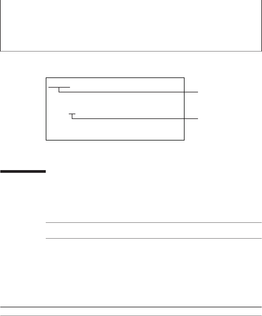
+ Code:ce8002M393B5270DH0-YH9 0000-85A8EF57;
+ Type:01; Size:4 GB;
MEM#02A Status:Normal;
+ Code:ce8002M393B5270DH0-YH9 0000-85A8EF65;
+ Type:01; Size:4 GB;
MEM#03A Status:Normal;
+ Code:ce8002M393B5270DH0-YH9 0000-85A8EE2C;
+ Type:01; Size:4 GB;
MEM#00A Status:Normal;
+ Code:ce8002M393B5270DHO-YH9 0000-83AE9A65;
+ Type:04; Size:8 GB;
Memory slot
Capacity and rank
04: R-DIMM (8GB 1rank)
07: R-DIMM (16GB 2rank)
09: R-DIMM (32GB 4rank)
47: LR-DIMM (64GB 8rank)
Note - Read and understand the instructions in this chapter before starting the maintenance
work. Also see the contents of "Chapter 1 Before Starting Maintenance Work."
Table 8-4 Types of maintenance for memory
Configuration Active/hot Active/cold Inactive/hot Inactive/cold (*1) System stopped
Single-chassis configuration
Unsupported Unsupported Unsupported Supported Supported
Figure 8-4 Viewing memory information
8.3 Before Maintaining Memory
This section describes the types and flow of maintenance of the memory, as well as
some precautions.
8.3.1 Types of maintenance
Table 8-4 lists the types of memory maintenance. For the definition of maintenance,
see "4.3 Understanding Types of Maintenance."
Fujitsu M10-4/Fujitsu M10-4S/SPARC M10-4/SPARC M10-4S Service Manual ・December 2013168
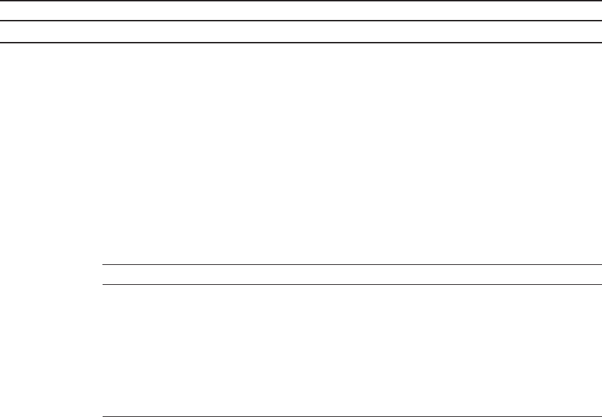
Table 8-4 Types of maintenance for memory (continued)
Configuration Active/hot Active/cold Inactive/hot Inactive/cold (*1) System stopped
Building block configuration
Unsupported Supported (*2) Unsupported Supported Supported
*1: For a single-chassis configuration, the inactive/cold maintenance procedure is the same as that for stopping the system, therefore see
the procedure for system-stopped maintenance.
*2: It is necessary to use dynamic reconfiguration (DR) to disconnect a chassis requiring maintenance from the physical partition.
Table 8-5 Maintenance flow
Details of update process Replacement Expansion Reduction
1 Preparation 8.4 8.4 8.4
2 Removing a CPU memory unit 7.4 7.4 7.4
3 Removing memory 8.5 -8.5
4 Installing memory 8.6 8.6 -
5 InstallingaCPUmemoryunit 7.5 7.5 7.5
6 Restoring the system 8.7 8.7 8.7
8.3.2 Maintenance flow
Table 8-5 lists the sequence of the maintenance procedure for memory. The
procedure for expanding memory is the same as that for installing memory. The
procedure for reducing memory is the same as that for removing memory.
8.3.3 Precautions for replacement
Note the following points when replacing memory:
■When you replace a memory module, make sure that you install the new module
in the same position as the original one.
8.3.4 Precautions for installation
Note the following points when expanding memory:
■Observe the memory installation rules when you expand memory. For details, see
"8.2.1 Memory mounting rules."
■Apply XCP 2080 or later when you expand 64 GB memory.
Chapter 8 Maintaining the Memory 169
Note - See the procedure for system-stopped maintenance for inactive/cold maintenance in a
single-chassis configuration.
Caution - To completely shut down the system, all the power cords must be
removed. If the power cords are not removed, an electrical failure may occur.
Note - Use the DR of the system board on a physical partition for active/cold maintenance.
For the XCP and Oracle VM Server for SPARC/SRU versions that correspond to the DR, see
the latest Product Notes.
Note - Active/cold maintenance can be performed only for a building block configuration.
XSCF> showlogs error
8.3.5 Precautions for removal
Note the following points when removing memory:
■Observe the memory installation rules when you remove memory. For details, see
"8.2.1 Memory mounting rules."
8.4 Enabling the Removal of Memory
This section describes the preparations that must be completed prior to the removal
of memory. The preparation procedure differs depending on the maintenance type as
follows:
■Active/Cold maintenance
■Inactive/Cold maintenance
■System-stopped maintenance
8.4.1 Active/Cold maintenance
1. Open the rack door.
2. Log in to the XSCF shell.
3. Execute the showlogs command to identify the component requiring
maintenance.
For details, see "3.3.5 Checking log information."
Fujitsu M10-4/Fujitsu M10-4S/SPARC M10-4/SPARC M10-4S Service Manual ・December 2013170
Note - When you add or remove CPU memory units, confirm that no error has occurred.
XSCF> replacefru
Note - Inthecaseofadualpowerfeed,makeanoteofthelocationsofthepowercords
before disconnecting them to ensure that they are reinstalled correctly.
Note - Inactive/cold maintenance can be performed only for a building block configuration.
See the procedure for system-stopped maintenance for inactive/cold maintenance in a
single-chassis configuration.
XSCF> showlogs error
Note - When you add or remove CPU memory units, confirm that no error has occurred.
4. Confirm the hardware and software configurations.
For details, see "4.2 Confirming the System Configuration."
5. Release the building block, in which the memory requiring maintenance is
mounted, from the physical partition.
For details, see "5.2 Releasing a Chassis from the Physical Partition."
6.
Execute the replacefru command to release the chassis requiring maintenance
from the system.
For details, see "5.1 Releasing an FRU from the System with the replacefru
Command."
7. Remove all the power cords from the PSU backplane unit of the chassis
requiring maintenance.
For details, see "5.5.2 Removing the power cord."
8.4.2 Inactive/Cold maintenance
1. Open the rack door.
2. LogintotheXSCFshell.
3. Execute the showlogs command to identify the component requiring
maintenance.
For details, see "3.3.5 Checking log information."
4. Confirm the hardware and software configurations.
For details, see "4.2 Confirming the System Configuration."
Chapter 8 Maintaining the Memory 171

XSCF> replacefru
Note - In the case of a dual power feed, make a note of the locations of the power cords
before disconnecting them to ensure that they are reinstalled correctly.
XSCF> showlogs error
Note - When you add or remove CPU memory units, confirm that no error has occurred.
Note - In the case of a dual power feed, make a note of the locations of the power cords
before disconnecting them to ensure that they are reinstalled correctly.
5. Power off the physical partition requiring maintenance.
For details, see "5.3 Powering Off the Physical Partition Requiring Maintenance."
6.
Execute the replacefru command to release the chassis requiring maintenance
from the system.
For details, see "5.1 Releasing an FRU from the System with the replacefru
Command."
7. Remove all the power cords from the PSU backplane unit of the chassis
requiring maintenance.
For details, see "5.5.2 Removing the power cord."
8.4.3 System-stopped maintenance
1. Open the rack door.
2. Log in to the XSCF shell.
3. Execute the showlogs command to identify the component requiring
maintenance.
For details, see "3.3.5 Checking log information."
4. Confirm the hardware and software configurations.
For details, see "4.2 Confirming the System Configuration."
5. Stop the entire system.
For details, see "5.4 Stopping the Entire System."
6. Remove all the power cords from the PSU backplane unit of the chassis
requiring maintenance.
For details, see "5.5.2 Removing the power cord."
Fujitsu M10-4/Fujitsu M10-4S/SPARC M10-4/SPARC M10-4S Service Manual ・December 2013172
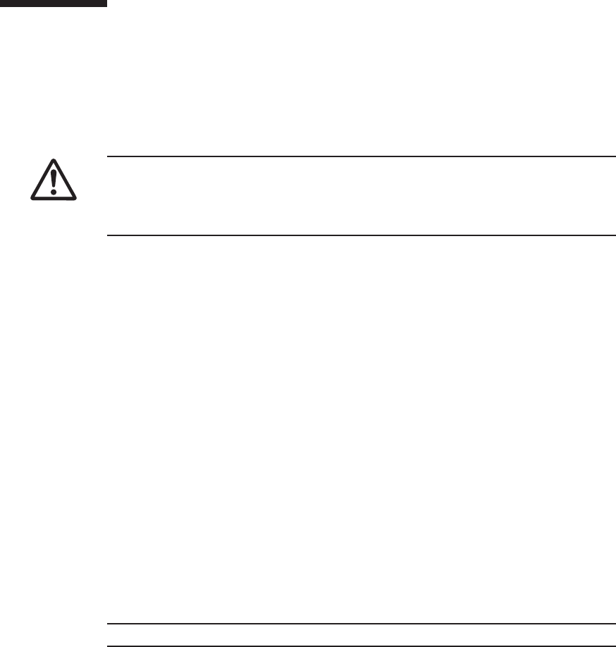
Caution - Before you handle any components, wear a wrist strap to ground any static
electricity. If you perform this procedure without a wrist strap, individual
components or the overall system may be damaged. For details, see "1.5 Notes
Regarding Static Electricity."
Note - Place the removed memory on a grounded static-removal ESD mat.
8.5 Removing Memory
This section describes the procedure for removing memory. Perform reduction using
thesameprocedure.
Enable the removal of the memory before you attempting to remove it. For details,
see "8.4 Enabling the Removal of Memory."
8.5.1 Accessing memory
1. Perform the preparations that must be completed prior to removing the CPU
memory unit.
For details, see "7.4.1 Accessing a CPU memory unit."
2. Remove the CPU memory unit.
To remove the memory mounted on the CPU memory unit upper, see steps 1
through 3 as described in "7.4.2 Removing the CPU memory unit lower."
To remove the memory mounted on the CPU memory unit lower, see "7.4.2
Removing the CPU memory unit lower"andsteps1through10in"7.4.3
Removing the CPU memory unit upper."
8.5.2 Removing memory
1. Open the clip of the memory slot outwards and remove the memory by pulling
it straight up.
Chapter 8 Maintaining the Memory 173
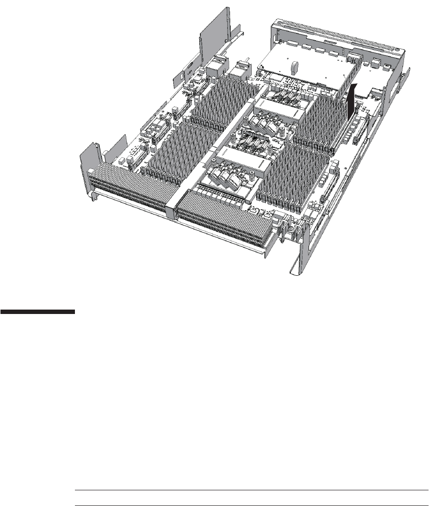
Note - Confirm that the clip of the memory slot has returned to its original position.
Figure 8-5 Removing memory
8.6 Installing Memory
This section describes the procedure for installing a memory module. Perform
expansion using the same procedure.
8.6.1 Installing memory
1.
Place the memory module by aligning the notched section with the corresponding
part of the memory slot connector.
2. Push the memory module into the slot evenly.
Fujitsu M10-4/Fujitsu M10-4S/SPARC M10-4/SPARC M10-4S Service Manual ・December 2013174

Note - See the procedure for system-stopped maintenance for inactive/cold maintenance in a
single-chassis configuration.
Note - Use the DR of the system board on a physical partition for active/cold maintenance.
For the XCP and Oracle VM Server for SPARC/SRU versions that correspond to the DR, see
the latest Product Notes.
Note - Active/cold maintenance can be performed only for a building block configuration.
Note - In the case of a dual power feed, connect the power cords in their original positions by
referring to the record that you made before the start of maintenance.
8.6.2 Restoring the chassis
1. Install the CPU memory unit.
If you have installed the memory of the CPU memory unit upper, see "7.5.2
Installing the CPU memory unit upper."
If you have installed the memory of the CPU memory unit lower, see "7.5.2
Installing the CPU memory unit upper"and"7.5.3 Installing the CPU memory
unit lower."
2. Restore the chassis.
For details, see "7.5.4 Restoring the chassis."
8.7 Restoring the System
This section describes the procedure for restoring the system after replacement,
addition, and removal of memory. The restoration procedure differs depending on
the maintenance type as follows:
■Active/Cold maintenance
■Inactive/Cold maintenance
■System-stopped maintenance
8.7.1 Active/Cold maintenance
1. Connect all the power cords to the PSU backplane unit of the chassis
requiring maintenance.
For details, see "6.5.1 Installing the power cord."
2. Return to the operation of the XSCF firmware replacefru command to confirm
Chapter 8 Maintaining the Memory 175

XSCF> diagxbu -y -b 00 -p 02
XSCF> showlogs error
Note - Inactive/cold maintenance can be performed only for a building block configuration.
See the procedure for system-stopped maintenance for inactive/cold maintenance in a
single-chassis configuration.
Note - In the case of a dual power feed, connect the power cords in their original positions by
referring to the record that you made before the start of maintenance.
that the chassis has been incorporated into the system.
For details, see "6.1 Incorporating an FRU into the System with the replacefru
Command."
3. Execute the diagxbu command to diagnose the crossbar cables.
Diagnosis is performed when the system board of the chassis connected with the
crossbar cables is incorporated into the physical partition, and the physical
partition is powered on.
The example below specifies the following:
00: BB-ID of the chassis to start the diagnosis
02: PPAR-ID of the destination where the chassis to start the diagnosis is
connected (You can specify only one of these.)
4. Execute the showlogs command to confirm that the system is operating
normally.
For details, see "3.3.5 Checking log information."
5. Incorporate the chassis, in which the memory requiring maintenance is
mounted, into the physical partition.
For details, see "6.2 Incorporating a Chassis into a Physical Partition."
6. Close the rack door.
8.7.2 Inactive/Cold maintenance
1. Connect all the power cords to the PSU backplane unit of the chassis
requiring maintenance.
For details, see "6.5.1 Installing the power cord."
2. Return to the operation of the XSCF firmware replacefru command to confirm
that the chassis has been incorporated into the system.
Fujitsu M10-4/Fujitsu M10-4S/SPARC M10-4/SPARC M10-4S Service Manual ・December 2013176

XSCF> diagxbu -y -b 00 -t 01
XSCF> showlogs error
XSCF> showstatus
XSCF> showhardconf
For details, see "6.1 Incorporating an FRU into the System with the replacefru
Command."
3. Execute the diagxbu command to diagnose the crossbar cables.
Diagnosis is performed when the system board of the chassis connected with the
crossbar cables is not incorporated into the physical partition, or when the
physical partition into which the chassis is incorporated is powered off.
The example below specifies the following:
00: BB-ID of the chassis to start the diagnosis
01: BB-ID of the destination where the chassis to start the diagnosis is connected
(You can specify one or more of these.)
To specify multiple connection destination BB-IDs, enter a command like
"diagxbu -y -b 00 -t 01 -t 02".
4. Execute the showlogs command to confirm that the system is operating
normally.
For details, see "3.3.5 Checking log information."
5. Switch the mode switches of the master chassis and those chassis whose
XSCFs are in the standby state to Locked mode.
-For a building block configuration (without crossbar box)
Switch the mode switches of BB-ID#00 and #01 to Locked mode.
-For a building block configuration (with crossbar box)
Switch the mode switches of BB-ID#80 and #81 to Locked mode.
6. Execute the showstatus command to confirm that there is no problem with
the memory after the completion of maintenance.
7. Execute the showhardconf command to check the hardware configuration
and the status of each component.
8. Start the system.
For details, see "6.4.1 Starting the system with an XSCF command"or"6.4.2
Starting the system from the operation panel."
9. Close the rack door.
Chapter 8 Maintaining the Memory 177
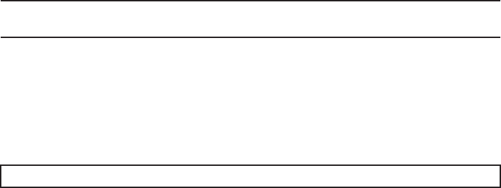
Note - In the case of a dual power feed, connect the power cords in their original positions by
referring to the record that you made before the start of maintenance.
XSCF> testsb -a
8.7.3 System-stopped maintenance
1. Connect all the power cords to the PSU backplane unit of the chassis
requiring maintenance.
For details, see "6.5.1 Installing the power cord."
2. Start the system.
For details, see "6.4.1 Starting the system with an XSCF command"or"6.4.2
Starting the system from the operation panel."
3.
Execute the testsb command to confirm that the memory requiring maintenance
is recognized.
4. Close the rack door.
Fujitsu M10-4/Fujitsu M10-4S/SPARC M10-4/SPARC M10-4S Service Manual ・December 2013178

Chapter 9
Maintaining the Crossbar Units
This chapter describes the procedure for maintaining the crossbar units mounted on
a SPARC M10-4S.
■Configuration of the Crossbar Units
■Before Maintaining a Crossbar Unit
■Enabling the Removal of a Crossbar Unit
■Removing a Crossbar Unit
■Installing a Crossbar Unit
■Restoring the System
9.1 Configuration of the Crossbar Units
This section describes the configuration and the locations of the crossbar units.
The crossbar units of the SPARC M10-4S are connected to the crossbar units of other
SPARC M10-4S units or to a crossbar box for system extension. Two crossbar units
are mounted on a SPARC M10-4S. When performing maintenance, perform the work
oneunitatatime.
179
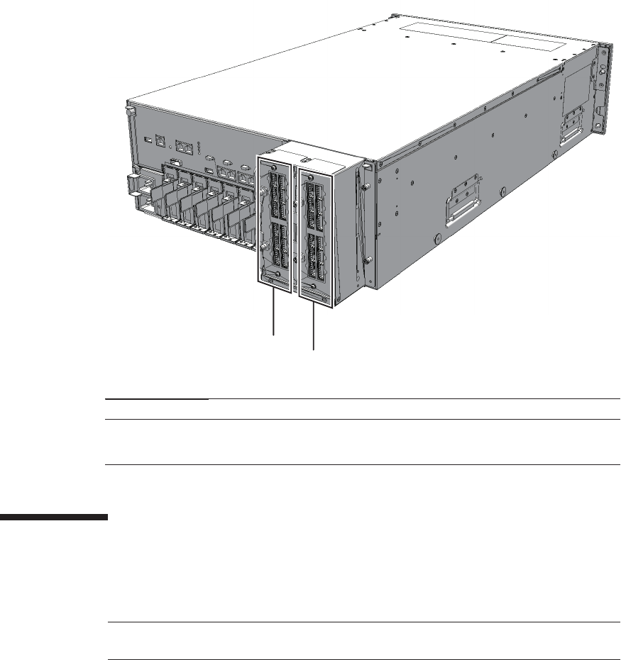
㩿㪈㪀
㩿㪉㪀
Location number Component
1 Crossbar unit (XBU#0)
2 Crossbar unit (XBU#1)
Note - Read and understand the instructions in this chapter before starting the maintenance
work. Also see the contents of "Chapter 1 Before Starting Maintenance Work."
Figure 9-1 Location of crossbar units
9.2 Before Maintaining a Crossbar Unit
This section describes the types and flow of maintenance of the crossbar units.
9.2.1 Types of maintenance
Table 9-1 lists the types of maintenance for the crossbar units. For the definition of
maintenance, see "4.3 Understanding Types of Maintenance."
Fujitsu M10-4/Fujitsu M10-4S/SPARC M10-4/SPARC M10-4S Service Manual ・December 2013180
Table 9-1 Types of maintenance for the crossbar unit
Configuration Active/hot Active/cold Inactive/hot Inactive/cold System stopped
Building block configuration
Unsupported Supported (*) Unsupported Supported Supported
*: It is necessary to use dynamic reconfiguration (DR) to disconnect a chassis requiring maintenance from the physical partition.
Table 9-2 Maintenance flow
Details of update process Replacement
1 Preparation 9.3
2 Removing the crossbar units 9.4
3 Installing the crossbar unit 9.5
4 Restoring the system 9.6
Caution - To completely shut down the system, all the power cords must be
removed. If the power cords are not removed, an electrical failure may occur.
9.2.2 Maintenance flow
Table 9-2 lists the sequence of the maintenance procedure for the crossbar units.
9.3 Enabling the Removal of a Crossbar
Unit
This section describes preparation that must be completed prior to removing a
crossbar unit. The procedure for the preparation varies depending on the maintenance
type, as follows:
■Active/Cold maintenance
■Inactive/Cold maintenance
■System-stopped maintenance
Chapter 9 Maintaining the Crossbar Units 181
Note - Use the DR of the system board on a physical partition for active/cold maintenance.
For the XCP and Oracle VM Server for SPARC/SRU versions that correspond to the DR, see
the latest Product Notes.
XSCF> showlogs error
XSCF> replacefru
Note - In the case of a dual power feed, make a note of the locations of the power cords
before disconnecting them to ensure that they are reinstalled correctly.
9.3.1 Active/Cold maintenance
1. Open the rack door.
2. Log in to the XSCF shell.
3. Execute the showlogs command to identify the component requiring
maintenance.
For details, see "3.3.5 Checking log information."
4. Confirm the hardware and software configurations.
For details, see "4.2 Confirming the System Configuration."
5. Release the building block, in which the memory requiring maintenance is
mounted, from the physical partition.
For details, see "5.2 Releasing a Chassis from the Physical Partition."
6.
Execute the replacefru command to release the chassis requiring maintenance
from the system.
For details, see "5.1 Releasing an FRU from the System with the replacefru
Command."
7. Remove all the power cords from the PSU backplane unit of the chassis
requiring maintenance.
For details, see "5.5.2 Removing the power cord."
9.3.2 Inactive/Cold maintenance
1. Open the rack door.
2. Log in to the XSCF shell.
3. Execute the showlogs command to identify the component requiring
maintenance.
Fujitsu M10-4/Fujitsu M10-4S/SPARC M10-4/SPARC M10-4S Service Manual ・December 2013182
XSCF> showlogs error
XSCF> replacefru
Note - Inthecaseofadualpowerfeed,makeanoteofthelocationsofthepowercords
before disconnecting them to ensure that they are reinstalled correctly.
XSCF> showlogs error
XSCF> replacefru
For details, see "3.3.5 Checking log information."
4. Confirm the hardware and software configurations.
For details, see "4.2 Confirming the System Configuration."
5. Power off the physical partition requiring maintenance.
For details, see "5.3 Powering Off the Physical Partition Requiring Maintenance."
6.
Execute the replacefru command to release the chassis requiring maintenance
from the system.
For details, see "5.1 Releasing an FRU from the System with the replacefru
Command."
7. Remove all the power cords from the PSU backplane unit of the chassis
requiring maintenance.
For details, see "5.5.2 Removing the power cord."
9.3.3 System-stopped maintenance
1. Open the rack door.
2. LogintotheXSCFshell.
3. Execute the showlogs command to identify the component requiring
maintenance.
For details, see "3.3.5 Checking log information."
4. Confirm the hardware and software configurations.
For details, see "4.2 Confirming the System Configuration."
5. Stop the entire system.
For details, see "5.4 Stopping the Entire System."
6.
Execute the replacefru command to release the chassis requiring maintenance
from the system.
Chapter 9 Maintaining the Crossbar Units 183
Note - In the case of a dual power feed, make a note of the locations of the power cords
before disconnecting them to ensure that they are reinstalled correctly.
Caution - Before you handle any components, wear a wrist strap to ground any static
electricity. If you perform this procedure without a wrist strap, individual
components or the overall system may be damaged. For details, see "5.4 Stopping
theEntireSystem."
Note - If the crossbar cables are fixed to the cable support with the hook-and-loop fastener,
remove the hook-and-loop fastener.
Note - Make a note of the positions of the crossbar cables before disconnecting them to
ensure that they are reinstalled correctly.
For details, see "5.1 Releasing an FRU from the System with the replacefru
Command."
7. Remove all the power cords from the PSU backplane unit of the chassis
requiring maintenance.
For details, see "5.5.2 Removing the power cord."
9.4 Removing a Crossbar Unit
This section describes the procedure for removing a crossbar unit.
Enable the removal of the crossbar unit before attempting to remove it. For details,
see "9.3 Enabling the Removal of a Crossbar Unit."
9.4.1 Accessing a crossbar unit
1. Lower the cable support.
For details, see "5.5.1 Lowering the cable support."
2. Remove all the crossbar cables connected to the crossbar units requiring
maintenance.
9.4.2 Removing a crossbar unit
1. Loosen the two screws securing the crossbar unit.
Fujitsu M10-4/Fujitsu M10-4S/SPARC M10-4/SPARC M10-4S Service Manual ・December 2013184
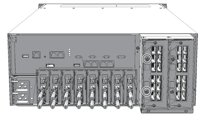
Figure 9-2 Location of screws securing crossbar units
2. Open the eject levers (A in the figure) upwards and downwards, respectively,
and then pull the crossbar unit out of the CPU memory unit.
Chapter 9 Maintaining the Crossbar Units 185
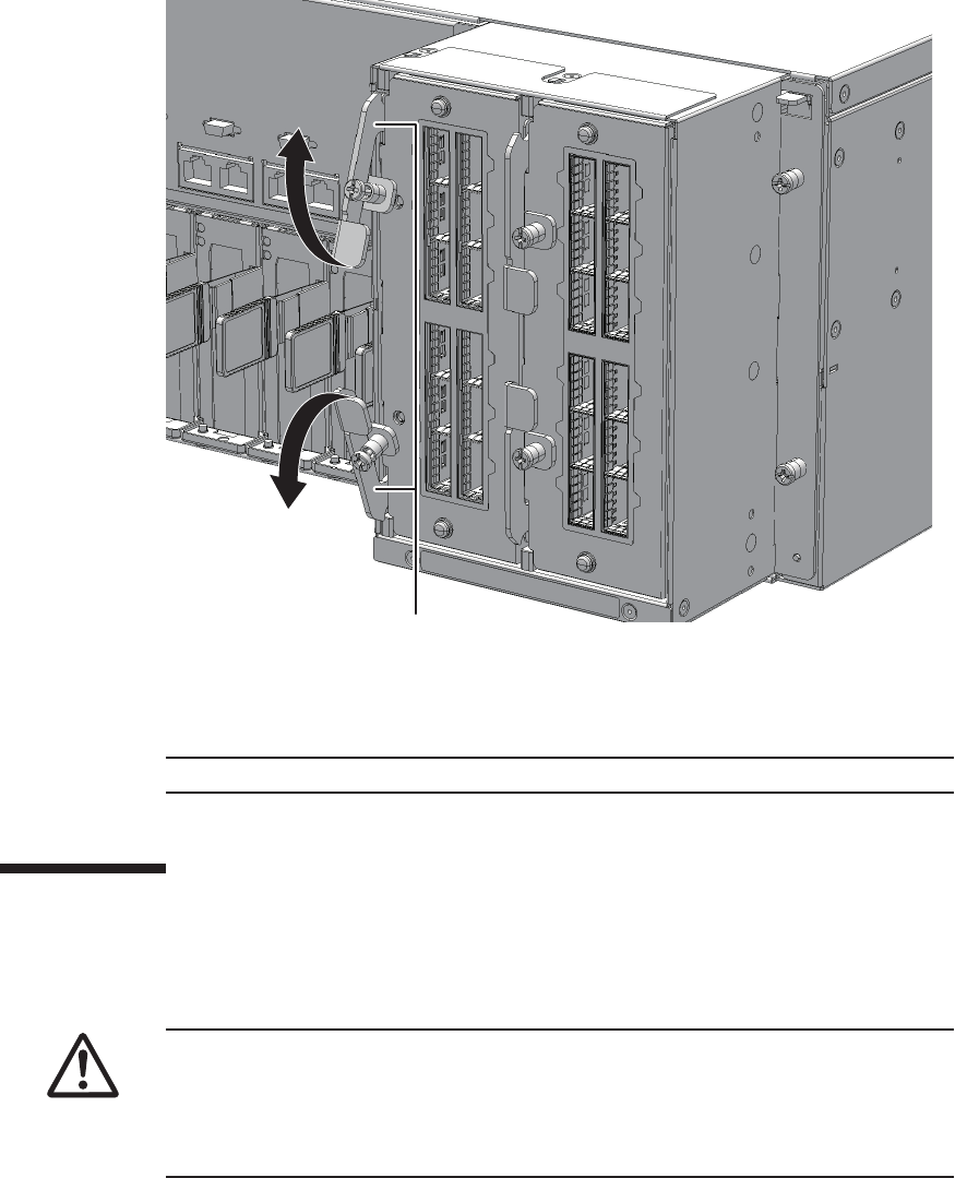
A
Note - Place the removed crossbar unit on a grounded antistatic ESD mat.
Note - When mounting a crossbar unit, check the connectors on both of the chassis
and crossbar unit beforehand to confirm that no pin is bent and all the pins are neatly
arranged in lines. If a crossbar unit is mounted with a bent pin in a connector, the
chassis or crossbar unit may be damaged. Also, carefully proceed with the work to
prevent any pin from being bent.
Figure 9-3 Opening the eject levers
3. Support the crossbar unit from below with one hand and carefully remove it
from the mounting frame.
9.5 Installing a Crossbar Unit
This section describes the procedure for installing a crossbar unit.
Fujitsu M10-4/Fujitsu M10-4S/SPARC M10-4/SPARC M10-4S Service Manual ・December 2013186

Note - Connect the crossbar cables in their original positions by referring to the notes that
you made before the start of maintenance.
Note - Use the DR of the system board on a physical partition for active/cold maintenance.
For the XCP and Oracle VM Server for SPARC/SRU versions that correspond to the DR, see
the latest Product Notes.
9.5.1 Installing a crossbar unit
1. Open the eject levers of the crossbar unit.
2. Support the crossbar unit from below with one hand and then carefully insert
it into the mounting frame.
3. Close the eject levers and tighten the two screws securing the crossbar unit.
9.5.2 Restoring the chassis
1. Connect all the crossbar cables to the crossbar unit.
2. Lift the cable support to fix it.
For details, see "6.5.2 Fixing the cable support."
9.6 Restoring the System
This section describes the procedure for restoring the system after installing the
crossbar units. The restoration procedure differs depending on the maintenance type
as follows:
■Active/Cold maintenance
■Inactive/Cold maintenance
■System-stopped maintenance
9.6.1 Active/Cold maintenance
1. Connect all the power cords to the PSU backplane unit of the chassis
requiring maintenance.
For details, see "6.5.1 Installing the power cord."
Chapter 9 Maintaining the Crossbar Units 187

Note - In the case of a dual power feed, connect the power cords in their original positions by
referring to the record that you made before the start of maintenance.
XSCF> diagxbu -y -b 00 -p 02
XSCF> showlogs error
Note - In the case of a dual power feed, connect the power cords in their original positions by
referring to the record that you made before the start of maintenance.
2. Return to the operation of the XSCF firmware replacefru command to confirm
that the chassis has been incorporated into the system.
For details, see "6.1 Incorporating an FRU into the System with the replacefru
Command."
3. Execute the diagxbu command to diagnose the crossbar cables.
Diagnosis is performed when the system board of the chassis connected with the
crossbar cables is incorporated into the physical partition, and the physical
partition is powered on.
The example below specifies the following:
00: BB-ID of the chassis to start the diagnosis
02: PPAR-ID of the destination where the chassis to start the diagnosis is
connected (You can specify only one of these.)
4. Execute the showlogs command to confirm that the system is operating
normally.
For details, see "3.3.5 Checking log information."
5.
Incorporate the chassis, in which the CPU memory unit requiring maintenance
is mounted, into the physical partition.
For details, see "6.2 Incorporating a Chassis into a Physical Partition."
6. Close the rack door.
9.6.2 Inactive/Cold maintenance
1. Connect all the power cords to the PSU backplane unit of the chassis
requiring maintenance.
For details, see "6.5.1 Installing the power cord."
2. Return to the operation of the XSCF firmware replacefru command to confirm
that the chassis has been incorporated into the system.
Fujitsu M10-4/Fujitsu M10-4S/SPARC M10-4/SPARC M10-4S Service Manual ・December 2013188

XSCF> diagxbu -y -b 00 -t 01
XSCF> showlogs error
XSCF> showstatus
XSCF> showhardconf
For details, see "6.1 Incorporating an FRU into the System with the replacefru
Command."
3. Execute the diagxbu command to diagnose the crossbar cables.
Diagnosis is performed when the system board of the chassis connected with the
crossbar cables is not incorporated into the physical partition, or when the
physical partition into which the chassis is incorporated is powered off.
The example below specifies the following:
00: BB-ID of the chassis to start the diagnosis
01: BB-ID of the destination where the chassis to start the diagnosis is connected
(You can specify one or more of these.)
To specify multiple connection destination BB-IDs, enter a command like
"diagxbu -y -b 00 -t 01 -t 02".
4. Execute the showlogs command to confirm that the system is operating
normally.
For details, see "3.3.5 Checking log information."
5. Switch the mode switches of the master chassis and those chassis whose
XSCFs are in the standby state to Locked mode.
-For a building block configuration (without crossbar box)
Switch the mode switches of BB-ID#00 and #01 to Locked mode.
-For a building block configuration (with crossbar box)
Switch the mode switches of BB-ID#80 and #81 to Locked mode.
6. Execute the showstatus command to confirm that there is no problem with
the crossbar units after the completion of maintenance.
7. Execute the showhardconf command to check the hardware configuration
and the status of each component.
8. Start the system.
For details, see "6.4.1 Starting the system with an XSCF command"or"6.4.2
Starting the system from the operation panel."
9. Close the rack door.
Chapter 9 Maintaining the Crossbar Units 189
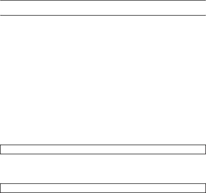
Note - In the case of a dual power feed, connect the power cords in their original positions by
referring to the record that you made before the start of maintenance.
XSCF> diagxbu -y -b 00 -t 01
XSCF> showlogs error
9.6.3 System-stopped maintenance
1. Connect all the power cords to the PSU backplane unit.
For details, see "6.5.1 Installing the power cord."
2. Return to the operation of the XSCF firmware replacefru command to confirm
that the chassis has been incorporated into the system.
For details, see "6.1 Incorporating an FRU into the System with the replacefru
Command."
3. Execute the diagxbu command to diagnose the crossbar cables.
Diagnosis is performed when the system board of the chassis connected with the
crossbar cables is not incorporated into the physical partition, or when the
physical partition into which the chassis is incorporated is powered off.
The example below specifies the following:
00: BB-ID of the chassis to start the diagnosis
01: BB-ID of the destination where the chassis to start the diagnosis is connected
(You can specify one or more of these.)
To specify multiple connection destination BB-IDs, enter a command like
"diagxbu -y -b 00 -t 01 -t 02".
4. Execute the showlogs command to confirm that the system is operating
normally.
For details, see "3.3.5 Checking log information."
5. Start the entire system.
For details, see "6.4 Starting the Entire System."
6. Close the rack door.
Fujitsu M10-4/Fujitsu M10-4S/SPARC M10-4/SPARC M10-4S Service Manual ・December 2013190

Chapter 10
Maintaining the Power Supply Units
This chapter describes the procedure for maintaining the power supply units
mounted in the SPARC M10-4/M10-4S.
■Configuration of the Power Supply Units
■Before Maintaining a Power Supply Unit
■Enabling the Removal of a Power Supply Unit
■RemovingaPowerSupplyUnit
■Installing a Power Supply Unit
■Restoring the System
10.1 Configuration of the Power Supply
Units
This section describes the configuration and the locations of the power supply units.
The power supply units feed power to the individual components. The components
can have the 1+1 redundant configuration. Active/hot maintenance can be performed.
191
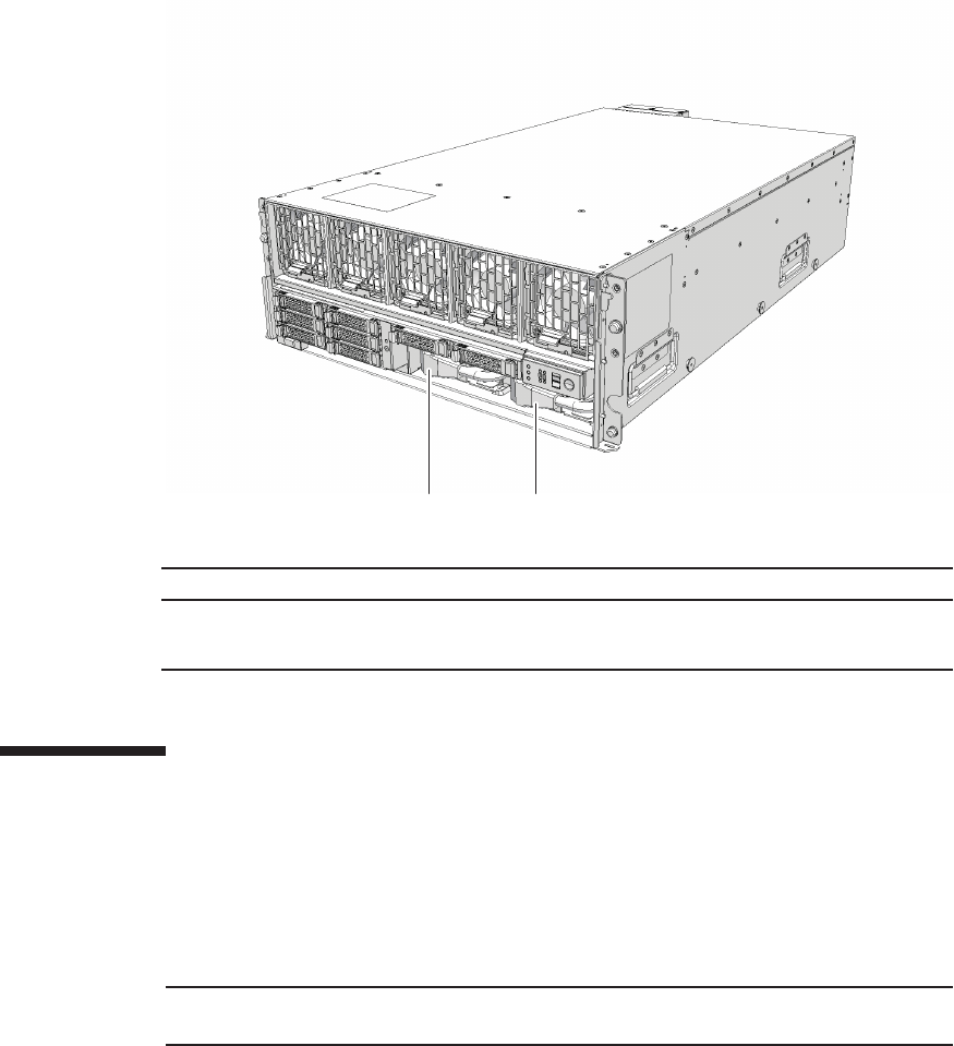
(1) (2)
Location number Component
1 Power supply unit (PSU#0)
2 Power supply unit (PSU#1)
Note - Read and understand the instructions in this chapter before starting the maintenance
work. Also see the contents of "Chapter 1 Before Starting Maintenance Work."
Figure 10-1 Location of power supply unit
10.2 Before Maintaining a Power Supply
Unit
This section describes the types and flow of maintenance of the power supply units,
as well as some precautions.
10.2.1 Types of maintenance
Table 10-1 lists the types of maintenance for the power supply units. For the
Fujitsu M10-4/Fujitsu M10-4S/SPARC M10-4/SPARC M10-4S Service Manual ・December 2013192
Table 10-1 Types of maintenance for the power supply unit
Configuration Active/hot Active/cold Inactive/hot Inactive/cold (*1) System stopped
Single-chassis configuration
Supported Unsupported Supported Supported Supported
Building block configuration
Supported (*2) Supported (*3) Supported Supported Supported
*1: For a single-chassis configuration, the inactive/cold maintenance procedure is the same as that for stopping the system, therefore see
the procedure for system-stopped maintenance.
*2: Active/hot replacement can be performed only with a redundant configuration.
*3: It is necessary to use dynamic reconfiguration (DR) to disconnect a chassis requiring maintenance from the physical partition.
Table 10-2 Maintenance flow
Details of update process Replacement
1 Preparation 10.3
2 Removing a power supply unit 10.4
3 Installing a power supply unit 10.5
4 Restoring the system 10.6
definition of maintenance, see "4.3 Understanding Types of Maintenance."
10.2.2 Maintenance flow
Table 10-2 lists the sequence of the maintenance procedure for the power supply
units.
10.2.3 Precautions for replacement
Note the following points when replacing a power supply unit:
■There are two power supply units. Thus, the system can continue operating even
if one of the units fails. Do not, however, operate the system for an extended
period while one unit has failed.
■When replacing multiple power supply units, replace one unit at a time. If
redundancy of the power supply unit cannot be assured, then system-stopped
maintenance must be performed.
■Do not force push the power supply unit into its slot. Using excessive force may
damage the component or the chassis.
Chapter 10 Maintaining the Power Supply Units 193
Note - See the procedure for system-stopped maintenance for inactive/cold maintenance in a
single-chassis configuration.
Caution - To completely shut down the system, all the power cords must be
removed. If the power cords are not removed, an electrical failure may occur.
Note - Active/hot maintenance is supported only for a redundant configuration.
XSCF> showlogs error
XSCF> replacefru
10.3 Enabling the Removal of a Power
Supply Unit
This section describes the preparations that must be completed prior to the removal
of a power supply unit. The preparation procedure differs depending on the
maintenance type as follows:
■Active/Hot maintenance
■Active/Cold maintenance
■Inactive/Hot maintenance
■Inactive/Cold maintenance
■System-stopped maintenance
10.3.1 Active/Hot maintenance
1. Open the rack door.
2. Log in to the XSCF shell.
3. Execute the showlogs command to identify the component requiring
maintenance.
For details, see "3.3.5 Checking log information."
4. Confirm the hardware and software configurations.
For details, see "4.2 Confirming the System Configuration."
5. Execute the replacefru command to release the power supply unit requiring
maintenance from the system.
Fujitsu M10-4/Fujitsu M10-4S/SPARC M10-4/SPARC M10-4S Service Manual ・December 2013194

Note - Use the DR of the system board on a physical partition for active/cold maintenance.
For the XCP and Oracle VM Server for SPARC/SRU versions that correspond to the DR, see
the latest Product Notes.
Note - Active/cold maintenance can be performed only for a building block configuration.
XSCF> showlogs error
XSCF> replacefru
Note - Inthecaseofadualpowerfeed,makeanoteofthelocationsofthepowercords
before disconnecting them to ensure that they are reinstalled correctly.
For details, see "5.1 Releasing an FRU from the System with the replacefru
Command."
10.3.2 Active/Cold maintenance
1. Open the rack door.
2. LogintotheXSCFshell.
3. Execute the showlogs command to identify the component requiring
maintenance.
For details, see "3.3.5 Checking log information."
4. Confirm the hardware and software configurations.
For details, see "4.2 Confirming the System Configuration."
5. Release the chassis, in which the power supply unit requiring maintenance is
mounted, from the physical partition.
For details, see "5.2 Releasing a Chassis from the Physical Partition."
6.
Execute the replacefru command to release the chassis requiring maintenance
from the system.
For details, see "5.1 Releasing an FRU from the System with the replacefru
Command."
7. Remove all the power cords from the PSU backplane unit of the chassis
requiring maintenance.
For details, see "5.5.2 Removing the power cord."
Chapter 10 Maintaining the Power Supply Units 195

XSCF> showlogs error
XSCF> showpparstatus -a
XSCF> replacefru
XSCF> showlogs error
10.3.3 Inactive/Hot maintenance
For a single-chassis configuration
1. Open the rack door.
2. Log in to the XSCF shell.
3. Execute the showlogs command to identify the component requiring
maintenance.
For details, see "3.3.5 Checking log information."
4. Confirm the hardware and software configurations.
For details, see "4.2 Confirming the System Configuration."
5. Stop the entire system.
For details, see "5.4 Stopping the Entire System."
6. Execute the showpparstatus command to confirm that the physical partition
requiring maintenance is powered off.
7. Execute the replacefru command to release the power supply unit requiring
maintenance from the system.
For details, see "5.1 Releasing an FRU from the System with the replacefru
Command."
For a building-block configuration
1. Open the rack door.
2. Log in to the XSCF shell.
3. Execute the showlogs command to identify the component requiring
maintenance.
For details, see "3.3.5 Checking log information."
4. Confirm the hardware and software configurations.
For details, see "4.2 Confirming the System Configuration."
Fujitsu M10-4/Fujitsu M10-4S/SPARC M10-4/SPARC M10-4S Service Manual ・December 2013196
XSCF> replacefru
Note - Inactive/cold maintenance can be performed only for a building block configuration.
The inactive/cold maintenance procedure for a single-chassis configuration is the same as
that for stopping the system.
XSCF> showlogs error
XSCF> replacefru
Note - Inthecaseofadualpowerfeed,makeanoteofthelocationsofthepowercords
before disconnecting them to ensure that they are reinstalled correctly.
5. Power off the physical partition requiring maintenance.
For details, see "5.3 Powering Off the Physical Partition Requiring Maintenance."
6. Execute the replacefru command to release the power supply unit requiring
maintenance from the system.
For details, see "5.1 Releasing an FRU from the System with the replacefru
Command."
10.3.4 Inactive/Cold maintenance
1. Open the rack door.
2. LogintotheXSCFshell.
3. Execute the showlogs command to identify the component requiring
maintenance.
For details, see "3.3.5 Checking log information."
4. Confirm the hardware and software configurations.
For details, see "4.2 Confirming the System Configuration."
5. Power off the physical partition requiring maintenance.
For details, see "5.3 Powering Off the Physical Partition Requiring Maintenance."
6.
Execute the replacefru command to release the chassis requiring maintenance
from the system.
For details, see "5.1 Releasing an FRU from the System with the replacefru
Command."
7. Remove all the power cords from the PSU backplane unit of the chassis
requiring maintenance.
For details, see "5.5.2 Removing the power cord."
Chapter 10 Maintaining the Power Supply Units 197
XSCF> showlogs error
XSCF> replacefru
Note - In the case of a dual power feed, make a note of the locations of the power cords
before disconnecting them to ensure that they are reinstalled correctly.
10.3.5 System-stopped maintenance
1. Open the rack door.
2. Log in to the XSCF shell.
3. Execute the showlogs command to identify the component requiring
maintenance.
For details, see "3.3.5 Checking log information."
4. Confirm the hardware and software configurations.
For details, see "4.2 Confirming the System Configuration."
5. Stop the entire system.
For details, see "5.4 Stopping the Entire System."
6.
Execute the replacefru command to release the chassis requiring maintenance
from the system.
For a single-chassis configuration, you do not have to release the chassis.
Proceed to step 7.
For details, see "5.1 Releasing an FRU from the System with the replacefru
Command."
7. Remove all the power cords from the PSU backplane unit of the chassis
requiring maintenance.
For details, see "5.5.2 Removing the power cord."
10.4 Removing a Power Supply Unit
This section describes the procedure for removing a power supply unit. Enable the
removal of the power supply unit before attempting to remove it. For details, see
"10.3 Enabling the Removal of a Power Supply Unit."
Fujitsu M10-4/Fujitsu M10-4S/SPARC M10-4/SPARC M10-4S Service Manual ・December 2013198
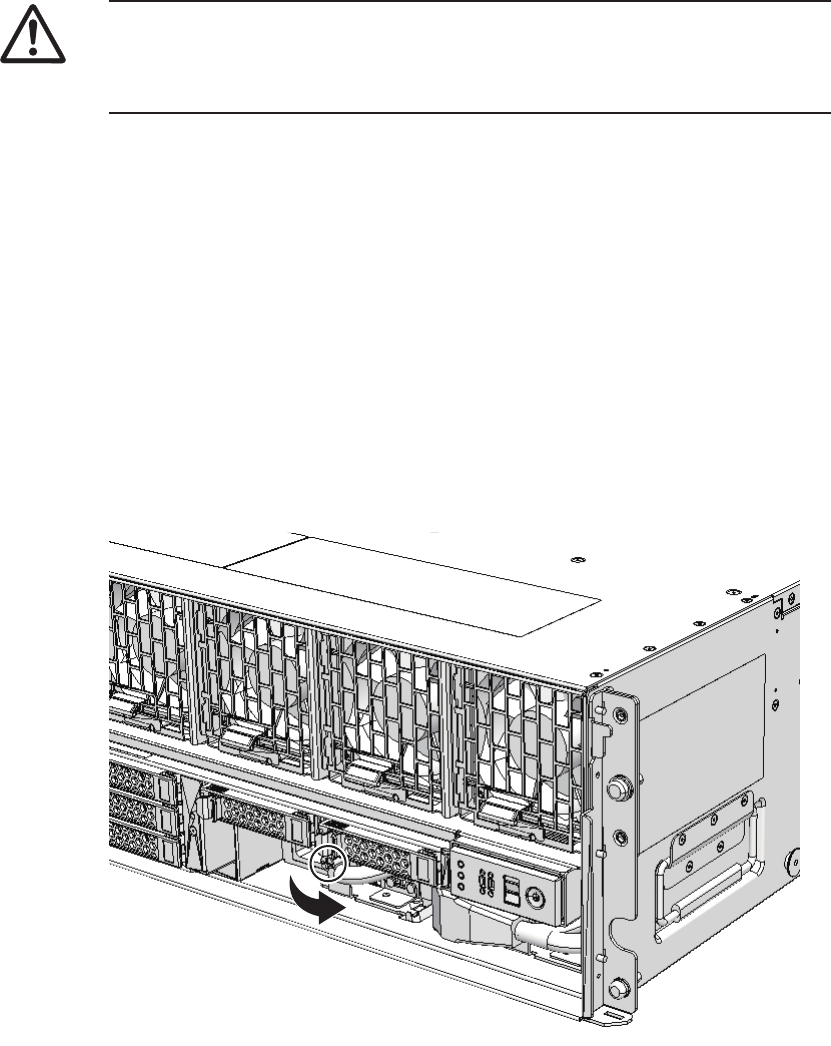
Caution - Before you handle any components, wear a wrist strap to ground any static
electricity. If you perform this procedure without a wrist strap, individual
components or the overall system may be damaged. For details, see "1.5 Notes
Regarding Static Electricity."
10.4.1 Accessing a power supply unit
1. Remove the front cover.
For details, see "5.5.3 Removing the front cover."
10.4.2 Removing a power supply unit
1. Remove the power cord from the power supply unit requiring maintenance.
2. Loosen the screws securing the power supply unit and open the lever.
Figure 10-2 Screws securing power supply unit
3. Hold the lever and pull the power supply unit out of the chassis.
4. Support the power supply unit from below with one hand and remove it
carefully from its slot.
Chapter 10 Maintaining the Power Supply Units 199

Note - Place the removed power supply unit on a grounded antistatic ESD mat.
Note - Do not forcibly push the power supply unit into its slot. Using excessive force may
damage the component or the chassis.
Note - See the procedure for system-stopped maintenance for inactive/cold maintenance in a
single-chassis configuration.
10.5 Installing a Power Supply Unit
This section describes the procedure for installing a power supply unit.
10.5.1 Installing a power supply unit
1. Support the power supply unit from below with one hand and insert it
carefully into its slot.
2. Firmly push the power supply unit into its mounting position.
3. Close the lever and then tighten the screws.
4. Connect the power cords to the power supply unit.
10.5.2 Restoring the chassis
1. Connect the power cords to the PSU backplane unit of the chassis requiring
maintenance.
2. Confirm that the LED (green) on the power supply unit is blinking.
3. Install the front cover.
For details, see "6.5.3 Installing the front cover."
10.6 Restoring the System
This section describes the procedure for restoring the system after installing a power
supply unit. The restoration procedure differs depending on the maintenance type as
follows:
Fujitsu M10-4/Fujitsu M10-4S/SPARC M10-4/SPARC M10-4S Service Manual ・December 2013200

XSCF> showstatus
XSCF> showhardconf
Note - Use the DR of the system board on a physical partition for active/cold maintenance.
For the XCP and Oracle VM Server for SPARC/SRU versions that correspond to the DR, see
the latest Product Notes.
Note - Active/cold maintenance can be performed only for a building block configuration.
Note - In the case of a dual power feed, connect the power cords in their original positions by
referring to the record that you made before the start of maintenance.
■Active/Hot maintenance
■Active/Cold maintenance
■Inactive/Hot maintenance
■Inactive/Cold maintenance
■System-stopped maintenance
10.6.1 Active/Hot maintenance
1. Return to the operation of the XSCF firmware replacefru command to confirm
that the power supply unit has been incorporated into the system.
For details, see "6.1 Incorporating an FRU into the System with the replacefru
Command."
2. Execute the showstatus command to confirm that there is no problem with
the power supply unit after the completion of maintenance.
3. Execute the showhardconf command to check the hardware configuration
and the status of each component.
4. Close the rack door.
10.6.2 Active/Cold maintenance
1. Connect all the power cords to the PSU backplane unit of the chassis
requiring maintenance.
For details, see "6.5.1 Installing the power cord."
2. Return to the operation of the XSCF firmware replacefru command to confirm
that the chassis has been incorporated into the system.
Chapter 10 Maintaining the Power Supply Units 201

Note - Inactive/cold maintenance can be performed only for a building block configuration.
The inactive/cold maintenance procedure for a single-chassis configuration is the same as
that for stopping the system.
For details, see "6.1 Incorporating an FRU into the System with the replacefru
Command."
3.
Incorporate the chassis, in which the power supply unit requiring maintenance
is mounted, into the physical partition.
For details, see "6.2 Incorporating a Chassis into a Physical Partition."
4. Close the rack door.
10.6.3 Inactive/Hot maintenance
For a single-chassis configuration
1. Log in to the XSCF shell.
2. Return to the operation of the XSCF firmware replacefru command to confirm
that the power supply unit has been incorporated into the system.
For details, see "6.1 Incorporating an FRU into the System with the replacefru
Command."
3. Start the entire system.
For details, see "6.4 Starting the Entire System."
4. Close the rack door.
For a building-block configuration
1. Log in to the XSCF shell.
2. Return to the operation of the XSCF firmware replacefru command to confirm
that the power supply unit has been incorporated into the system.
For details, see "6.1 Incorporating an FRU into the System with the replacefru
Command."
3. Power on the physical partition requiring maintenance.
For details, see "6.3 Powering On the Physical Partition Requiring Maintenance."
4. Close the rack door.
10.6.4 Inactive/Cold maintenance
1. Connect all the power cords to the PSU backplane unit of the chassis
requiring maintenance.
For details, see "6.5.1 Installing the power cord."
Fujitsu M10-4/Fujitsu M10-4S/SPARC M10-4/SPARC M10-4S Service Manual ・December 2013202

Note - In the case of a dual power feed, connect the power cords in their original positions by
referring to the record that you made before the start of maintenance.
Note - In the case of a dual power feed, connect the power cords in their original positions by
referring to the record that you made before the start of maintenance.
2. Return to the operation of the XSCF firmware replacefru command to confirm
that the chassis has been incorporated into the system.
For details, see "6.1 Incorporating an FRU into the System with the replacefru
Command."
3. Power on the physical partition requiring maintenance.
For details, see "6.3 Powering On the Physical Partition Requiring Maintenance."
4. Close the rack door.
10.6.5 System-stopped maintenance
1. Connect all the power cords to the PSU backplane unit.
For details, see "6.5.1 Installing the power cord."
2. Return to the operation of the XSCF firmware replacefru command to confirm
that the chassis has been incorporated into the system.
For details, see "6.1 Incorporating an FRU into the System with the replacefru
Command."
For a single-chassis configuration, you do not have to incorporate the chassis.
Proceed to step 3.
3. Start the entire system.
For details, see "6.4 Starting the Entire System."
4. Close the rack door.
Chapter 10 Maintaining the Power Supply Units 203
Fujitsu M10-4/Fujitsu M10-4S/SPARC M10-4/SPARC M10-4S Service Manual ・December 2013204

Chapter 11
Maintaining the Fan Units
This chapter describes the procedure for maintaining the fan units mounted in the
SPARC M10-4/M10-4S.
■Configuration of the Fan Units
■Before Maintaining a Fan Unit
■Enabling the Removal of a Fan Unit
■RemovingaFanUnit
■Installing a Fan Unit
■Restoring the System
11.1 Configuration of the Fan Units
This section describes the configuration and the locations of the fan units.
Five fan units are mounted in each chassis. Each fan unit has two cooling fans that
cool the components in the chassis.
If a fault occurs with a cooling fan during system operation, the XSCF detects the
error. However, the system can continue operating because the fans have a
redundant configuration.
205
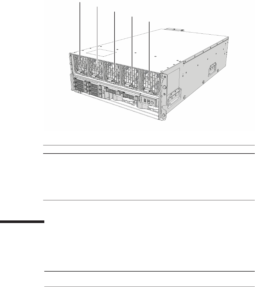
(1)
(2)
(3)
(4)
(5)
Location number Component
1Fanunit(FANU#0)
2Fanunit(FANU#1)
3Fanunit(FANU#2)
4Fanunit(FANU#3)
5Fanunit(FANU#4)
Note - Read and understand the instructions in this chapter before starting the maintenance
work. Also see the contents of "Chapter 1 Before Starting Maintenance Work."
Figure 11-1 Location of fan units
11.2 Before Maintaining a Fan Unit
This section describes the types and the flow of maintenance of the fan units, as well
as some precautions.
Fujitsu M10-4/Fujitsu M10-4S/SPARC M10-4/SPARC M10-4S Service Manual ・December 2013206
Table 11-1 Types of maintenance for fan unit
Configuration Active/hot Active/cold Inactive/hot Inactive/cold (*1) System stopped
Single-chassis configuration
Supported Unsupported Supported Supported Supported
Building block configuration
Supported Supported (*2) Supported Supported Supported
*1: For a single-chassis configuration, the inactive/cold maintenance procedure is the same as that for stopping the system, therefore see
the procedure for system-stopped maintenance.
*2: It is necessary to use dynamic reconfiguration (DR) to disconnect a chassis requiring maintenance from the physical partition.
Table 11-2 Maintenance flow
Details of update process Replacement
1 Preparation 11.3
2 Removing a fan unit 11.4
3 Installingafanunit 11.5
4 Restoring the system 11.6
11.2.1 Types of maintenance
Table 11-1 lists the types of maintenance for the fan units. For the definition of
maintenance, see "4.3 Understanding Types of Maintenance."
11.2.2 Maintenance flow
Table 11-2 shows the maintenance procedure for the fan units.
11.2.3 Precautions for replacement
Note the following points when replacing a fan unit:
■When replacing multiple fan units, replace one unit at a time. If redundancy of the
fan units cannot be preserved, system-stopped maintenance must be performed.
■The cooling fans have a redundant configuration. Thus, the system can continue
operating even if one of the fans in the fan units fails. Avoid operating the system
with a faulty fan for an extended period and replace the fan unit containing the
failed fan as soon as possible.
Chapter 11 Maintaining the Fan Units 207
Note - See the procedure for system-stopped maintenance for inactive/cold maintenance in a
single-chassis configuration.
Caution - To completely shut down the system, all the power cords must be
removed. If the power cords are not removed, an electrical failure may occur.
XSCF> showlogs error
XSCF> replacefru
11.3 Enabling the Removal of a Fan Unit
This section describes the preparations that must be completed prior to removing a
fan unit. The preparation procedure differs depending on the maintenance type as
follows:
■Active/Hot maintenance
■Active/Cold maintenance
■Inactive/Hot maintenance
■Inactive/Cold maintenance
■System-stopped maintenance
11.3.1 Active/Hot maintenance
1. Open the rack door.
2. Log in to the XSCF shell.
3. Execute the showlogs command to identify the component requiring
maintenance.
For details, see "3.3.5 Checking log information."
4. Confirm the hardware and software configurations.
For details, see "4.2 Confirming the System Configuration."
5.
Execute the replacefru command to release the fan unit requiring maintenance
from the system.
For details, see "5.1 Releasing an FRU from the System with the replacefru
Command."
Fujitsu M10-4/Fujitsu M10-4S/SPARC M10-4/SPARC M10-4S Service Manual ・December 2013208
Note - Use the DR of the system board on a physical partition for active/cold maintenance.
For the XCP and Oracle VM Server for SPARC/SRU versions that correspond to the DR, see
the latest Product Notes.
Note - Active/cold maintenance can be performed only for a building block configuration.
XSCF> showlogs error
XSCF> replacefru
Note - Inthecaseofadualpowerfeed,makeanoteofthelocationsofthepowercords
before disconnecting them to ensure that they are reinstalled correctly.
11.3.2 Active/Cold maintenance
1. Open the rack door.
2. LogintotheXSCFshell.
3. Execute the showlogs command to identify the component requiring
maintenance.
For details, see "3.3.5 Checking log information."
4. Confirm the hardware and software configurations.
For details, see "4.2 Confirming the System Configuration."
5. Release the chassis, in which the fan unit requiring maintenance is mounted,
from the physical partition.
For details, see "5.2 Releasing a Chassis from the Physical Partition."
6.
Execute the replacefru command to release the fan unit requiring maintenance
from the system.
For details, see "5.1 Releasing an FRU from the System with the replacefru
Command."
7. Remove all the power cords from the PSU backplane unit of the chassis
requiring maintenance.
For details, see "5.5.2 Removing the power cord."
11.3.3 Inactive/Hot maintenance
For a single-chassis configuration
1. Open the rack door.
Chapter 11 Maintaining the Fan Units 209

XSCF> showlogs error
XSCF> showpparstatus -a
XSCF> replacefru
XSCF> showlogs error
XSCF> replacefru
2. Log in to the XSCF shell.
3. Execute the showlogs command to identify the component requiring
maintenance.
For details, see "3.3.5 Checking log information."
4. Confirm the hardware and software configurations.
For details, see "4.2 Confirming the System Configuration."
5. Stop the entire system.
For details, see "5.4 Stopping the Entire System."
6. Execute the showpparstatus command to confirm that the physical partition
requiring maintenance is powered off.
7.
Execute the replacefru command to release the fan unit requiring maintenance
from the system.
For details, see "5.1 Releasing an FRU from the System with the replacefru
Command."
For a building-block configuration
1. Open the rack door.
2. Log in to the XSCF shell.
3. Execute the showlogs command to identify the component requiring
maintenance.
For details, see "3.3.5 Checking log information."
4. Confirm the hardware and software configurations.
For details, see "4.2 Confirming the System Configuration."
5. Power off the physical partition requiring maintenance.
For details, see "5.3 Powering Off the Physical Partition Requiring Maintenance."
6.
Execute the replacefru command to release the fan unit requiring maintenance
from the system.
Fujitsu M10-4/Fujitsu M10-4S/SPARC M10-4/SPARC M10-4S Service Manual ・December 2013210
Note - Inactive/cold maintenance can be performed only for a building block configuration.
The inactive/cold maintenance procedure for a single-chassis configuration is the same as
that for stopping the system.
XSCF> showlogs error
XSCF> replacefru
Note - Inthecaseofadualpowerfeed,makeanoteofthelocationsofthepowercords
before disconnecting them to ensure that they are reinstalled correctly.
For details, see "5.1 Releasing an FRU from the System with the replacefru
Command."
11.3.4 Inactive/Cold maintenance
1. Open the rack door.
2. LogintotheXSCFshell.
3. Execute the showlogs command to identify the component requiring
maintenance.
For details, see "3.3.5 Checking log information."
4. Confirm the hardware and software configurations.
For details, see "4.2 Confirming the System Configuration."
5. Power off the physical partition requiring maintenance.
For details, see "5.3 Powering Off the Physical Partition Requiring Maintenance."
6.
Execute the replacefru command to release the chassis requiring maintenance
from the system.
For details, see "5.1 Releasing an FRU from the System with the replacefru
Command."
7. Remove all the power cords from the PSU backplane unit of the chassis
requiring maintenance.
For details, see "5.5.2 Removing the power cord."
11.3.5 System-stopped maintenance
The procedure in the case of system-stopped maintenance is same for the building
block configuration and single-chassis configuration.
1. Open the rack door.
Chapter 11 Maintaining the Fan Units 211

XSCF> showlogs error
XSCF> replacefru
Note - In the case of a dual power feed, make a note of the locations of the power cords
before disconnecting them to ensure that they are reinstalled correctly.
Caution - Before you handle any components, wear a wrist strap to ground any static
electricity. If you perform this procedure without a wrist strap, individual
components or the overall system may be damaged. For details, see "1.5 Notes
Regarding Static Electricity."
2. Log in to the XSCF shell.
3. Execute the showlogs command to identify the component requiring
maintenance.
For details, see "3.3.5 Checking log information."
4. Confirm the hardware and software configurations.
For details, see "4.2 Confirming the System Configuration."
5. Stop the entire system.
For details, see "5.4 Stopping the Entire System."
6.
Execute the replacefru command to release the chassis requiring maintenance
from the system.
For a single-chassis configuration, you do not have to release the chassis.
Proceed to step 7.
For details, see "5.1 Releasing an FRU from the System with the replacefru
Command."
7. Remove all the power cords from the PSU backplane unit of the chassis
requiring maintenance.
For details, see "5.5.2 Removing the power cord."
11.4 Removing a Fan Unit
This section describes the procedure for removing a fan unit. Complete the necessary
preparations prior to attempting the removal. For details, see "11.3 Enabling the
Removal of a Fan Unit."
Fujitsu M10-4/Fujitsu M10-4S/SPARC M10-4/SPARC M10-4S Service Manual ・December 2013212
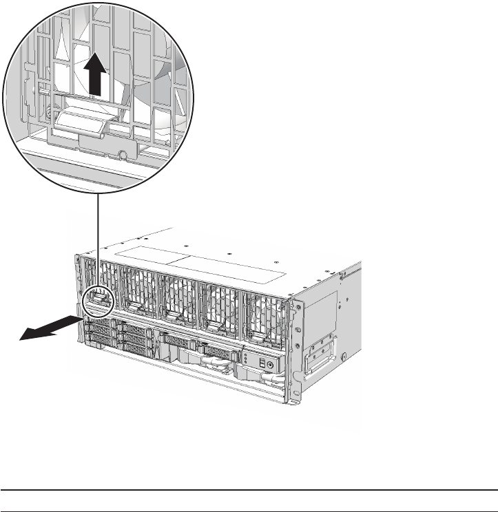
Note - Place the removed fan unit on a grounded antistatic ESD mat.
11.4.1 Accessing a fan unit
1. Remove the front cover.
For details, see "5.5.3 Removing the front cover."
11.4.2 Removing a fan unit
1. Pull out the fan unit while raising its lever.
Figure 11-2 Lever of fan unit
2. Carefully remove the fan unit from its slot.
Chapter 11 Maintaining the Fan Units 213

Note - Do not force the fan unit into the slot. Using excessive force may damage the
component or the chassis.
Note - Check that the fan unit is fully inserted and secured.
Note - See the procedure for system-stopped maintenance for inactive/cold maintenance in a
single-chassis configuration.
11.5 Installing a Fan Unit
This section describes the procedure for installing a fan unit.
11.5.1 Installing a fan unit
1. Carefully insert the fan unit into its slot.
2. Push the fan unit fully home.
11.5.2 Restoring the chassis
1. Install the front cover.
For details, see "6.5.3 Installing the front cover."
11.6 Restoring the System
This section describes the procedure for restoring the system after installing a fan
unit. The restoration procedure differs depending on the maintenance type as follows:
■Active/Hot maintenance
■Active/Cold maintenance
■Inactive/Hot maintenance
■Inactive/Cold maintenance
■System-stopped maintenance
Fujitsu M10-4/Fujitsu M10-4S/SPARC M10-4/SPARC M10-4S Service Manual ・December 2013214

XSCF> showstatus
XSCF> showhardconf
Note - Use the DR of the system board on a physical partition for active/cold maintenance.
For the XCP and Oracle VM Server for SPARC/SRU versions that correspond to the DR, see
the latest Product Notes.
Note - Active/cold maintenance can be performed only for a building block configuration.
Note - In the case of a dual power feed, connect the power cords in their original positions by
referring to the record that you made before the start of maintenance.
11.6.1 Active/Hot maintenance
1. Return to the operation of the XSCF firmware replacefru command to confirm
that the fan unit has been incorporated into the system.
For details, see "6.1 Incorporating an FRU into the System with the replacefru
Command."
2. Execute the showstatus command to confirm that there is no problem with
the fan unit after the completion of maintenance.
3. Execute the showhardconf command to check the hardware configuration
and the status of each component.
4. Close the rack door.
11.6.2 Active/Cold maintenance
1. Connect all the power cords to the PSU backplane unit of the chassis
requiring maintenance.
For details, see "6.5.1 Installing the power cord."
2. Return to the operation of the XSCF firmware replacefru command to confirm
that the chassis has been incorporated into the system.
For details, see "6.1 Incorporating an FRU into the System with the replacefru
Command."
3. Incorporate the chassis, in which the fan unit requiring maintenance is
mounted, into the physical partition.
For details, see "6.2 Incorporating a Chassis into a Physical Partition."
4. Close the rack door.
Chapter 11 Maintaining the Fan Units 215
Note - Inactive/cold maintenance can be performed only for a building block configuration.
The inactive/cold maintenance procedure for a single-chassis configuration is the same as
that for stopping the system.
Note - In the case of a dual power feed, connect the power cords in their original positions by
referring to the record that you made before the start of maintenance.
11.6.3 Inactive/Hot maintenance
For a single-chassis configuration
1. Log in to the XSCF shell.
2. Return to the operation of the XSCF firmware replacefru command to confirm
that the fan unit has been incorporated into the system.
For details, see "6.1 Incorporating an FRU into the System with the replacefru
Command."
3. Start the entire system.
For details, see "6.4 Starting the Entire System."
4. Close the rack door.
For a building-block configuration
1. Log in to the XSCF shell.
2. Return to the operation of the XSCF firmware replacefru command to confirm
that the fan unit has been incorporated into the system.
For details, see "6.1 Incorporating an FRU into the System with the replacefru
Command."
3. Power on the physical partition requiring maintenance.
For details, see "6.3 Powering On the Physical Partition Requiring Maintenance."
4. Close the rack door.
11.6.4 Inactive/Cold maintenance
1. Connect all the power cords to the PSU backplane unit of the chassis
requiring maintenance.
For details, see "6.5.1 Installing the power cord."
2. Return to the operation of the XSCF firmware replacefru command to confirm
that the chassis has been incorporated into the system.
For details, see "6.1 Incorporating an FRU into the System with the replacefru
Command."
Fujitsu M10-4/Fujitsu M10-4S/SPARC M10-4/SPARC M10-4S Service Manual ・December 2013216

Note - In the case of a dual power feed, connect the power cords in their original positions by
referring to the record that you made before the start of maintenance.
3. Power on the physical partition requiring maintenance.
For details, see "6.3 Powering On the Physical Partition Requiring Maintenance."
4. Close the rack door.
11.6.5 System-stopped maintenance
1. Connect all the power cords to the PSU backplane unit.
For details, see "6.5.1 Installing the power cord."
2. Return to the operation of the XSCF firmware replacefru command to confirm
that the chassis has been incorporated into the system.
For details, see "6.1 Incorporating an FRU into the System with the replacefru
Command."
For a single-chassis configuration, you do not have to incorporate the chassis.
Proceed to step 3.
3. Start the entire system.
For details, see "6.4 Starting the Entire System."
4. Close the rack door.
Chapter 11 Maintaining the Fan Units 217
Fujitsu M10-4/Fujitsu M10-4S/SPARC M10-4/SPARC M10-4S Service Manual ・December 2013218

Chapter 12
Maintaining the Internal Disks
This chapter describes the procedure for maintaining the internal disks mounted in
the SPARC M10-4/M10-4S. An internal disk can be replaced, expanded, or reduced.
■Configuration of the Internal Disks
■Before Maintaining an Internal Disk
■Enabling the Removal of an Internal Disk
■Removing an Internal Disk
■Installing an Internal Disk
■Restoring the System
12.1 Configuration of the Internal Disks
This section describes the configuration and locations of the internal disks.
The chassis provides eight slots for mounting internal disks. The system storage can
be expanded by installing extra hard disk drives (HDDs) or solid state drives (SSDs)
in these slots.
219
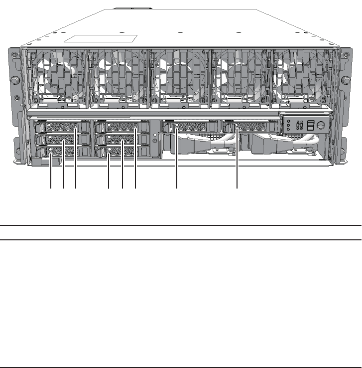
(1) (6)
(2) (5)
(3) (4) (7) (8)
Location number Component
1Internaldisk(HDD#0)
2Internaldisk(HDD#1)
3Internaldisk(HDD#2)
4Internaldisk(HDD#3)
5Internaldisk(HDD#4)
6Internaldisk(HDD#5)
7Internaldisk(HDD#6)
8Internaldisk(HDD#7)
Figure 12-1 Location of internal disks
12.1.1 Identification of disk slot
To perform active replacement of a disk drive, you need to know the physical device
name or logical device name of the drive to be installed or removed. When a disk
error is likely to occur or occurs in the system, normally you can check messages
regarding a disk that is likely to cause or has caused an error from the system
console. This information is recorded also in the /var/adm/messages file.
These error messages normally indicate the internal disk drives in which the errors
have occurred by their physical or logical device names. In addition, depending on
the application, the slot number of the disk may be reported.
The procedure to display the mounting position information of the HDD varies
Fujitsu M10-4/Fujitsu M10-4S/SPARC M10-4/SPARC M10-4S Service Manual ・December 2013220

XSCF> showhardconf
SPARC M10-4S;
+ Serial:2081238017; Operator_Panel_Switch:Service;
+ System_Power:Off; System_Phase:Cabinet Power Off;
Partition#0 PPAR_Status:Powered Off;
Partition#1 PPAR_Status:Powered Off;
BB#00 Status:Normal; Role:Master; Ver:2044h; Serial:2081238017;
+ FRU-Part-Number:CA07361-D202 A1 ;
+ Power_Supply_System: ;
+ Memory_Size:256 GB;
CMUL Status:Normal; Ver:0101h; Serial:PP123001Y1 ;
* BB#00 CMUL serial
+ FRU-Part-Number:CA07361-D941 C3 /7060911 ;
+ Memory_Size:128 GB;
CPU#0 Status:Normal; Ver:4142h; Serial:00321144;
+ Freq:3.000 GHz; Type:0x10;
+ Core:16; Strand:2;
CPU#1 Status:Normal; Ver:4142h; Serial:00322957;
+ Freq:3.000 GHz; Type:0x10;
+ Core:16; Strand:2;
------------------------Ommitted------------------------
BB#01 Status:Normal; Role:Standby; Ver:2044h; Serial:2081230011;
+ FRU-Part-Number:CA07361-D202 A1 ;
+ Power_Supply_System: ;
+ Memory_Size:256 GB;
CMUL Status:Normal; Ver:0101h; Serial:PP123203N0 ;
* BB#01 CMUL serial
+ FRU-Part-Number:CA07361-D941 C3 /7060911 ;
+ Memory_Size:128 GB;
CPU#0 Status:Normal; Ver:4142h; Serial:00320804;
+ Freq:3.000 GHz; Type:0x10;
+ Core:16; Strand:2;
CPU#1 Status:Normal; Ver:4142h; Serial:00321030;
+ Freq:3.000 GHz; Type:0x10;
+ Core:16; Strand:2;
MEM#00A Status:Normal;
+ Code:2c800118KSF1G72PZ-1G6E1 4531-1A94229F;
+ Type:04; Size:8 GB;
------------------------Ommitted-----------------------
depending on OS.
-For Oracle Solaris 11
For details, see "Using the format command (Oracle Solaris 11)"or"Using the
diskinfo command (Oracle Solaris 11)."
-For Oracle Solaris 10
For details, see "Using the diskinfo command (Oracle Solaris 10)."
Using the format command (Oracle Solaris 11)
1. Execute the showhardconf command to confirm the serial number of the
CMUL of the chassis for which mounting location information is to be displayed.
2. Execute the format command to confirm the physical disk slot.
Chapter 12 Maintaining the Internal Disks 221

#format
Searching for disks...done
AVAILABLE DISK SELECTIONS:
0. c2t50000394281B5312d0 <TOSHIBA-MBF2600RC-3706 cyl 64986 alt 2 hd 27 sec
668> <-- (1)
/pci@8800/pci@4/pci@0/pci@0/scsi@0/iport@f/disk@w50000394281b5312,0
/dev/chassis/FUJITSU-BBEXP.500000e0e06d31bf/03N0_HDD00/disk <-- (2)
(*1)
1. c2t50000394281B59D6d0 <TOSHIBA-MBF2600RC-3706 cyl 64986 alt 2 hd 27 sec
668> <-- (1)
/pci@8800/pci@4/pci@0/pci@0/scsi@0/iport@f/disk@w50000394281b59d6,0
/dev/chassis/FUJITSU-BBEXP.500000e0e06d31bf/03N0_HDD01/disk <-- (3)
2. c0t500003942823C8C6d0 <TOSHIBA-MBF2600RC-3706 cyl 64986 alt 2 hd 27 sec
668> <-- (1)
/pci@8000/pci@4/pci@0/pci@0/scsi@0/iport@f/disk@w500003942823c8c6,0
/dev/chassis/FUJITSU-BBEXP.500000e0e06d237f/01Y1_HDD00/disk <-- (4)
(*2)
3. c0t50000394281B517Ad0 <TOSHIBA-MBF2600RC-3706 cyl 64986 alt 2 hd 27 sec
668> <-- (1)
/pci@8000/pci@4/pci@0/pci@0/scsi@0/iport@f/disk@w50000394281b517a,0
/dev/chassis/FUJITSU-BBEXP.500000e0e06d237f/01Y1_HDD01/disk <-- (5)
Specify disk (enter its number):
XSCF> showhardconf
SPARC M10-4S;
+ Serial:2081238017; Operator_Panel_Switch:Service;
+ System_Power:Off; System_Phase:Cabinet Power Off;
Partition#0 PPAR_Status:Powered Off;
Partition#1 PPAR_Status:Powered Off;
BB#00 Status:Normal; Role:Master; Ver:2044h; Serial:2081238017;
+ FRU-Part-Number:CA07361-D202 A1 ;
+ Power_Supply_System: ;
+ Memory_Size:256 GB;
CMUL Status:Normal; Ver:0101h; Serial:PP123001Y1 ;
In the following example, (1) to (5) indicate the following:
(1): The logical path name of the disk.
(2):ThediskismountedintheHDD00slotofBB#01.
(3):ThediskismountedintheHDD01slotofBB#01.
(4):ThediskismountedintheHDD00slotofBB#00.
(5):ThediskismountedintheHDD01slotofBB#00.
*1: The last four digits of the BB#1_CMUL serial number
*2: The last four digits of the BB#0_CMUL serial number
Using the diskinfo command (Oracle Solaris 11)
1. Execute the showhardconf command to confirm the CMUL serial number of
the chassis that indicates the mounting position information.
Fujitsu M10-4/Fujitsu M10-4S/SPARC M10-4/SPARC M10-4S Service Manual ・December 2013222

* BB#00 CMUL serial
+ FRU-Part-Number:CA07361-D941 C3 /7060911 ;
+ Memory_Size:128 GB;
CPU#0 Status:Normal; Ver:4142h; Serial:00321144;
+ Freq:3.000 GHz; Type:0x10;
+ Core:16; Strand:2;
CPU#1 Status:Normal; Ver:4142h; Serial:00322957;
+ Freq:3.000 GHz; Type:0x10;
+ Core:16; Strand:2;
------------------------Ommitted------------------------
BB#01 Status:Normal; Role:Standby; Ver:2044h; Serial:2081230011;
+ FRU-Part-Number:CA07361-D202 A1 ;
+ Power_Supply_System: ;
+ Memory_Size:256 GB;
CMUL Status:Normal; Ver:0101h; Serial:PP123203N0 ;
* BB#01 CMUL serial
+ FRU-Part-Number:CA07361-D941 C3 /7060911 ;
+ Memory_Size:128 GB;
CPU#0 Status:Normal; Ver:4142h; Serial:00320804;
+ Freq:3.000 GHz; Type:0x10;
+ Core:16; Strand:2;
CPU#1 Status:Normal; Ver:4142h; Serial:00321030;
+ Freq:3.000 GHz; Type:0x10;
+ Core:16; Strand:2;
MEM#00A Status:Normal;
+ Code:2c800118KSF1G72PZ-1G6E1 4531-1A94229F;
+ Type:04; Size:8 GB;
------------------------Ommitted-----------------------
#diskinfo
D:devchassis-path c:occupant-compdev
----------------------------------------------------------- ------------------
/dev/chassis/SYS/BB0/CMUL/HDD0 -
/dev/chassis/SYS/BB0/CMUL/HDD1 -
/dev/chassis/SYS/BB0/CMUL/HDD2 -
/dev/chassis/SYS/BB0/CMUL/HDD3 -
/dev/chassis/SYS/BB0/CMUL/HDD4 -
/dev/chassis/SYS/BB0/CMUL/HDD5 -
/dev/chassis/SYS/BB0/CMUL/HDD6 -
/dev/chassis/SYS/BB0/CMUL/HDD7 -
2. Execute the diskinfo(1M) command to check the physical disk slot.
(1) to (4) in the example below specify the following:
(1): The device path name and logical path name of the disk mounted on the
HDD0 of BB#01.
(2): The device path name and logical path name of the disk mounted on the
HDD1 of BB#01.
(3): The device path name and logical path name of the disk mounted on the
HDD0 of BB#00.
(4): The device path name and logical path name of the disk mounted on the
HDD1 of BB#00.
Chapter 12 Maintaining the Internal Disks 223

/dev/chassis/SYS/BB1/CMUL/HDD0 -
/dev/chassis/SYS/BB1/CMUL/HDD1 -
/dev/chassis/SYS/BB1/CMUL/HDD2 -
/dev/chassis/SYS/BB1/CMUL/HDD3 -
/dev/chassis/SYS/BB1/CMUL/HDD4 -
/dev/chassis/SYS/BB1/CMUL/HDD5 -
/dev/chassis/SYS/BB1/CMUL/HDD6 -
/dev/chassis/SYS/BB1/CMUL/HDD7 -
/dev/chassis/FUJITSU-BBEXP.500000e0e06d31bf/03N0_HDD00/disk
c4t50000394281B5312d0 <-- (1) (*1)
/dev/chassis/FUJITSU-BBEXP.500000e0e06d31bf/03N0_HDD01/disk
c4t50000394281B59D6d0 <-- (2)
/dev/chassis/FUJITSU-BBEXP.500000e0e06d31bf/03N0_HDD02 -
/dev/chassis/FUJITSU-BBEXP.500000e0e06d31bf/03N0_HDD03 -
/dev/chassis/FUJITSU-BBEXP.500000e0e06d31bf/03N0_HDD04 -
/dev/chassis/FUJITSU-BBEXP.500000e0e06d31bf/03N0_HDD05 -
/dev/chassis/FUJITSU-BBEXP.500000e0e06d31bf/03N0_HDD06 -
/dev/chassis/FUJITSU-BBEXP.500000e0e06d31bf/03N0_HDD07 -
/dev/chassis/FUJITSU-BBEXP.500000e0e06d237f/01Y1_HDD00/disk
c2t500003942823C8C6d0 <-- (3) (*2)
/dev/chassis/FUJITSU-BBEXP.500000e0e06d237f/01Y1_HDD01/disk
c2t50000394281B517Ad0 <-- (4)
/dev/chassis/FUJITSU-BBEXP.500000e0e06d237f/01Y1_HDD02 -
/dev/chassis/FUJITSU-BBEXP.500000e0e06d237f/01Y1_HDD03 -
/dev/chassis/FUJITSU-BBEXP.500000e0e06d237f/01Y1_HDD04 -
/dev/chassis/FUJITSU-BBEXP.500000e0e06d237f/01Y1_HDD05 -
/dev/chassis/FUJITSU-BBEXP.500000e0e06d237f/01Y1_HDD06 -
/dev/chassis/FUJITSU-BBEXP.500000e0e06d237f/01Y1_HDD07 -
#diskinfo -ap
Enclosure path: 2081210007-physical-hba-0
Chassis Serial Number: 2081210007-physical-hba-0
Chassis Model: ORCL,SPARC64-X
Enclosure path: /dev/es/ses0
Chassis Serial Number: 500000e0e06d233f
Chassis Model: FUJITSU-BBEXP
*1: The last four digits of the BB#01_CMUL serial number
*2: The last four digits of the BB#00_CMUL serial number
Using the diskinfo command (Oracle Solaris 10)
1. Execute the diskinfo command to check the physical disk slot and physical
system board.
(1) to (4) in the example below specify the following:
(1): The logical path name of the disk mounted on the HDD0.
(2): The device path of the disk mounted on the HDD0 of LSB#0.
(3): The logical path name of the disk mounted on the HDD1.
(4): The device path of the disk mounted on the HDD1 of LSB#0.
Fujitsu M10-4/Fujitsu M10-4S/SPARC M10-4/SPARC M10-4S Service Manual ・December 2013224
Label Disk name Vendor Product Vers
-------- ---------------------- -------- -------------- ----
HDD_0 c0t50000393D8289180d0 TOSHIBA MBF2600RC 3706 <-- (1)
Physical path
--------------------------------
0: /pci@8000/pci@4/pci@0/pci@0/scsi@0/iport@f/disk@w50000393D8289180,0<--(2)
* LSB#0
HDD_1 c0t50000393D82891D0d0 TOSHIBA MBF2600RC 3706 <-- (3)
Physical path
--------------------------------
0: /pci@8000/pci@4/pci@0/pci@0/scsi@0/iport@f/disk@w50000393D82891D0,0<--(4)
* LSB#0
Table 12-1 Disk slot number
LSB number Device path
LSB#0 /pci@8000/pci@4/pci@0/pci@0/scsi@0/iport@f/disk@wWWN,0
LSB#1 /pci@8800/pci@4/pci@0/pci@0/scsi@0/iport@f/disk@wWWN,0
LSB#2 /pci@9000/pci@4/pci@0/pci@0/scsi@0/iport@f/disk@wWWN,0
LSB#3 /pci@9800/pci@4/pci@0/pci@0/scsi@0/iport@f/disk@wWWN,0
LSB#4 /pci@a000/pci@4/pci@0/pci@0/scsi@0/iport@f/disk@wWWN,0
LSB#5 /pci@a800/pci@4/pci@0/pci@0/scsi@0/iport@f/disk@wWWN,0
LSB#6 /pci@b000/pci@4/pci@0/pci@0/scsi@0/iport@f/disk@wWWN,0
LSB#7 /pci@b800/pci@4/pci@0/pci@0/scsi@0/iport@f/disk@wWWN,0
LSB#8 /pci@c000/pci@4/pci@0/pci@0/scsi@0/iport@f/disk@wWWN,0
LSB#9 /pci@c800/pci@4/pci@0/pci@0/scsi@0/iport@f/disk@wWWN,0
LSB#10 /pci@d000/pci@4/pci@0/pci@0/scsi@0/iport@f/disk@wWWN,0
LSB#11 /pci@d800/pci@4/pci@0/pci@0/scsi@0/iport@f/disk@wWWN,0
LSB#12 /pci@e000/pci@4/pci@0/pci@0/scsi@0/iport@f/disk@wWWN,0
LSB#13 /pci@e800/pci@4/pci@0/pci@0/scsi@0/iport@f/disk@wWWN,0
LSB#14 /pci@f000/pci@4/pci@0/pci@0/scsi@0/iport@f/disk@wWWN,0
LSB#15 /pci@f800/pci@4/pci@0/pci@0/scsi@0/iport@f/disk@wWWN,0
Device paths differ depending on the system configuration.
Table 12-1 lists examples of the device paths of logical system boards in SPARC
M10 systems.
This table can be used for mapping of the device paths of internal disk drives
and the logical system board numbers. The letters "WWN" in the table represents
the WWN assigned to the disk.
2. Execute the showboards command to confirm the BB-ID of the chassis in
which the disk requiring maintenance is mounted.
Identify the BB-ID from the LSB number confirmed in step 1. The BB-ID of the
Chapter 12 Maintaining the Internal Disks 225
XSCF> showboards -a
PSB PPAR-ID(LSB) Assignment Pwr Conn Conf Test Fault
---- ------------ ----------- ---- ---- ---- ------- --------
00-0 00(00) Assigned y y y Passed Normal
*BB#0 *LSB#0
01-0 00(01) Assigned y y y Passed Normal
Note - Read and understand the instructions in this chapter before starting the maintenance
work. Also see the contents of "Chapter 1 Before Starting Maintenance Work."
Table 12-2 Types of maintenance for internal disk
Configuration Active/hot Active/cold Inactive/hot Inactive/cold (*1) System stopped
Single-chassis configuration
Supported (*2) Unsupported Supported Supported Supported
Building block configuration
Supported (*2) Supported (*3) Supported Supported Supported
*1: For a single-chassis configuration, the inactive/cold maintenance procedure is the same as that for stopping the system, therefore see
the procedure for system-stopped maintenance.
*2: Supported only for internal disks of devices other than boot devices. If, however, the boot device has a redundant configuration
(RAID configuration), active/hot maintenance can be performed.
*3: It is necessary to use dynamic reconfiguration (DR) to disconnect a chassis requiring maintenance from the physical partition.
chassis requiring maintenance is indicated by the system board (PSB) number.
12.2 Before Maintaining an Internal Disk
This section describes the types and the flow of maintenance of the internal disks, as
well as some precautions.
12.2.1 Types of maintenance
Table 12-2 lists the types of maintenance for the internal disks. For the definition of
maintenance, see "4.3 Understanding Types of Maintenance."
12.2.2 Maintenance flow
Table 12-3 lists the sequence of the maintenance procedure for the internal disks. The
procedure for expanding an internal disk is the same as that for installing an internal
disk. The procedure for reducing an internal disk is the same as that for removing an
internal disk.
Fujitsu M10-4/Fujitsu M10-4S/SPARC M10-4/SPARC M10-4S Service Manual ・December 2013226

Table 12-3 Maintenance flow
Details of update process Replacement Expansion Reduction
1 Preparation 12.3 12.3 12.3
2 Removing an internal disk 12.4 -12.4
3 Installing an internal disk 12.5 12.5 -
4 Restoring the system 12.6 12.6 12.6
Note - See the procedure for system-stopped maintenance for inactive/cold maintenance in a
single-chassis configuration.
12.2.3 Precautions for installation
Note the following points when expanding internal disks:
■To expand an internal disk, remove the hard disk drive filler unit from the slot in
which you will install the internal disk.
■Store the removed internal disk filler unit safely, such that it can be used again if
you subsequently reduce the internal disk.
12.2.4 Precautions for removal
Note the following points when removing internal disks:
■When you reduce the internal disk, install the hard disk drive filler unit in the slot
from which you have removed the internal disk.
12.3 Enabling the Removal of an Internal
Disk
This section describes the preparations that must be completed prior to removing an
internal disk. The preparation procedure differs depending on the maintenance type
as follows:
■Active/Hot maintenance
■Active/Cold maintenance
■Inactive/Hot maintenance
■Inactive/Cold maintenance
■System-stopped maintenance
Chapter 12 Maintaining the Internal Disks 227
Caution - To completely shut down the system, all the power cords must be
removed. If the power cords are not removed, an electrical failure may occur.
Note - Unless the system has a redundant configuration, data on the hard disk drive will be
lost. Thus, perform this operation only after backing up the data on the hard disk drive. In
addition, active/hot maintenance of the boot device cannot be performed in a non-redundant
configuration.
#cfgadm -a
12.3.1 Active/Hot maintenance
Before performing maintenance, check the hardware configuration and software
configuration. For details, see "4.2 Confirming the System Configuration."
The procedure may vary depending on the configuration of the hard disk drive.
When the system is configured with a hardware RAID
Proceed only after checking the failed hard disk drive. For details, see "14.2.8
Checking the disk drive status" and "14.2.9 Checking for a failed disk drive" in the
Fujitsu M10/SPARC M10 Systems System Operation and Administration Guide.
When the system is configured with a software RAID
See your software manual.
When the system is configured without either a hardware RAID or software
RAID
To add an internal disk, perform the procedure up to step 2.
1. Open the rack door.
2. Display the Oracle Solaris super-user prompt.
3. Execute the cfgadm(1M) command to check the configuration of the internal
disk.
If you replace or reduce an internal disk, use the cfgadm -a command to check
theAp_IDofthediskrequiringmaintenanceandmakeanoteofit.TheAp_ID
refers to a string such as "c4::dsk/c4t5000039428298FFEd0".
If you install an internal disk, use the cfgadm -a command to check the number
of disks mounted.
4. Stop all applications from using the internal disk.
5. Execute the cfgadm(1M) command to release the internal disk requiring
maintenance from the system.
Enter the Ap_ID you noted in advance.
Fujitsu M10-4/Fujitsu M10-4S/SPARC M10-4/SPARC M10-4S Service Manual ・December 2013228
#cfgadm -c unconfigure Ap_ID
#cfgadm -x led=fault,mode=blink Ap_ID
#cfgadm -a
Note - Use the DR of the system board on a physical partition for active/cold maintenance.
For the XCP and Oracle VM Server for SPARC/SRU versions that correspond to the DR, see
the latest Product Notes.
Note - Active/cold maintenance can be performed only for a building block configuration.
XSCF> showlogs error
XSCF> replacefru
6. Execute the cfgadm(1M) command to blink the CHECK LED of the internal
disk requiring maintenance, and determine its location.
Enter the Ap_ID you noted in advance.
7. Execute the cfgadm(1M) command to confirm that the internal disk requiring
maintenance is disconnected.
The disconnected internal disk is displayed as "unconfigured."
12.3.2 Active/Cold maintenance
1. Open the rack door.
2. LogintotheXSCFshell.
3. Execute the showlogs command to identify the component requiring
maintenance.
For details, see "3.3.5 Checking log information."
4. Confirm the hardware and software configurations.
For details, see "4.2 Confirming the System Configuration."
5. Release the chassis, in which the internal disk requiring maintenance is
mounted, from the physical partition.
For details, see "5.2 Releasing a Chassis from the Physical Partition."
6.
Execute the replacefru command to release the chassis requiring maintenance
from the system.
For details, see "5.1 Releasing an FRU from the System with the replacefru
Command."
Chapter 12 Maintaining the Internal Disks 229
Note - In the case of a dual power feed, make a note of the locations of the power cords
before disconnecting them to ensure that they are reinstalled correctly.
Note - Inactive/cold maintenance can be performed only for a building block configuration.
The inactive/cold maintenance procedure for a single-chassis configuration is the same as
that for stopping the system.
7. Remove all the power cords from the PSU backplane unit of the chassis
requiring maintenance.
For details, see "5.5.2 Removing the power cord."
12.3.3 Inactive/Hot maintenance
For a single-chassis configuration
1. Open the rack door.
2. Confirm the hardware and software configurations.
For details, see "4.2 Confirming the System Configuration."
3. Stop the entire system.
For details, see "5.4 Stopping the Entire System."
For a building-block configuration
1. Open the rack door.
2. Confirm the hardware and software configurations.
For details, see "4.2 Confirming the System Configuration."
3. Power off the physical partition requiring maintenance.
For details, see "5.3 Powering Off the Physical Partition Requiring Maintenance."
12.3.4 Inactive/Cold maintenance
1. Open the rack door.
2. Confirm the hardware and software configurations.
For details, see "4.2 Confirming the System Configuration."
3. Power off the physical partition requiring maintenance.
For details, see "5.3 Powering Off the Physical Partition Requiring Maintenance."
4. Remove all the power cords from the PSU backplane unit of the chassis
requiring maintenance.
For details, see "5.5.2 Removing the power cord."
Fujitsu M10-4/Fujitsu M10-4S/SPARC M10-4/SPARC M10-4S Service Manual ・December 2013230
Note - Inthecaseofadualpowerfeed,makeanoteofthelocationsofthepowercords
before disconnecting them to ensure that they are reinstalled correctly.
XSCF> replacefru
Note - Inthecaseofadualpowerfeed,makeanoteofthelocationsofthepowercords
before disconnecting them to ensure that they are reinstalled correctly.
Caution - Before you handle any components, wear a wrist strap to ground any static
electricity. If you perform this procedure without a wrist strap, individual
components or the overall system may be damaged. For details, see "1.5 Notes
Regarding Static Electricity."
12.3.5 System-stopped maintenance
1. Open the rack door.
2. Confirm the hardware and software configurations.
For details, see "4.2 Confirming the System Configuration."
3. Stop the entire system.
For details, see "5.4 Stopping the Entire System."
4.
Execute the replacefru command to release the chassis requiring maintenance
from the system.
For a single-chassis configuration, you do not have to release the chassis.
Proceed to step 5.
For details, see "5.1 Releasing an FRU from the System with the replacefru
Command."
5. Remove all the power cords from the PSU backplane unit of the chassis
requiring maintenance.
For details, see "5.5.2 Removing the power cord."
12.4 Removing an Internal Disk
This section describes the procedure for removing an internal disk. Perform
reduction using the same procedure.
Make the internal disk ready for removal before attempting to remove it. For details,
see "12.3 Enabling the Removal of an Internal Disk."
Chapter 12 Maintaining the Internal Disks 231
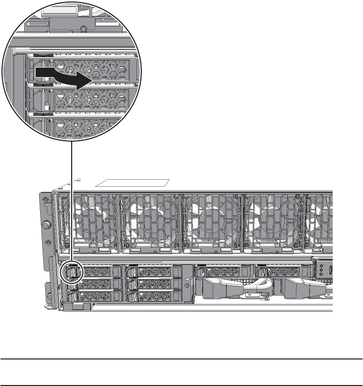
Note - When performing active/hot maintenance, at this point wait until the motor stops
rotating (about 1 minute).
12.4.1 Accessing an internal disk
1. Remove the front cover.
For details, see "5.5.3 Removing the front cover."
12.4.2 Removing an internal disk
1. Push the knob on the internal disk to unlock it and then raise the lever to a
45-degree angle.
Figure 12-2 Knob on internal disk
2. Hold the lever and pull out the internal disk by about 3 cm (1.2 in.)
Fujitsu M10-4/Fujitsu M10-4S/SPARC M10-4/SPARC M10-4S Service Manual ・December 2013232
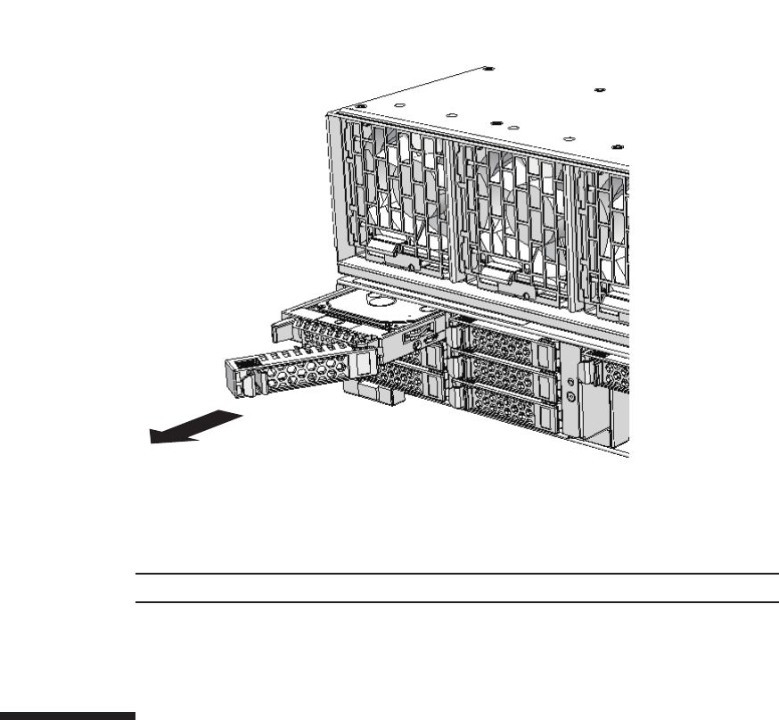
Note - Place the removed internal disk on the grounded antistatic ESD mat.
Figure 12-3 Removing an internal disk
3. Carefully remove the internal disk from its slot.
4. When reducing an internal disk, install the the internal disk filler unit in the
slot from which the disk was removed.
12.5 Installing an Internal Disk
This section describes the procedure for installing an internal disk. Perform
expansion using the same procedure.
12.5.1 Installing an internal disk
1. When expanding an internal disk, remove the internal disk filler unit from the
slot in which the disk is to be installed.
Chapter 12 Maintaining the Internal Disks 233
Note - Do not force the internal disk into the slot. Using excessive force may damage the
component or the chassis.
Note - Ensure that the internal disks are firmly inserted and secured.
Note - See the procedure for system-stopped maintenance for inactive/cold maintenance in a
single-chassis configuration.
2. With the lever opened, hold the internal disk.
3. Carefully insert the internal disk into the slot.
4. Close the lever to secure the internal disk.
12.5.2 Restoring the chassis
1. Install the front cover.
For details, see "6.5.3 Installing the front cover."
12.6 Restoring the System
This section describes the procedures for restoring the system after replacement,
addition, and removal of internal disks. The restoration procedure differs depending
on the maintenance type as follows:
■Active/Hot maintenance
■Active/Cold maintenance
■Inactive/Hot maintenance
■Inactive/Cold maintenance
■System-stopped maintenance
12.6.1 Active/Hot maintenance
The procedure may vary depending on the configuration of the hard disk drive.
When the system is configured with a hardware RAID
The operation varies depending on the hardware RAID configuration (RAID 0, RAID
1, or RAID 1E). For details, see "14.2.9 Checking for a failed disk drive" in the
Fujitsu M10/SPARC M10 Systems System Operation and Administration Guide.
Fujitsu M10-4/Fujitsu M10-4S/SPARC M10-4/SPARC M10-4S Service Manual ・December 2013234

#cfgadm -a
#cfgadm -c configure Ap_ID
#cfgadm -a
Note - Use the DR of the system board on a physical partition for active/cold maintenance.
For the XCP and Oracle VM Server for SPARC/SRU versions that correspond to the DR, see
the latest Product Notes.
Note - Active/cold maintenance can be performed only for a building block configuration.
Note - In the case of a dual power feed, connect the power cords in their original positions by
referring to the record that you made before the start of maintenance.
When the system is configured with a software RAID
See your software manual.
When the system is configured without either a hardware RAID or software
RAID
To replace or remove an internal disk, perform the procedure from step 2.
1. Return to the operation of the cfgadm(1M) command of Oracle Solaris
super-user prompt and confirm that the number of internal disks has increased.
If you installed an internal disk, make note of the Ap_ID of the added disk. The
Ap_ID refers to a string such as "c4::dsk/c4t5000039428298FFEd0".
If you replaced or reduced an internal disk, you do not have to perform this step.
2. Execute the cfgadm(1M) command to incorporate the internal disk requiring
maintenance into Oracle Solaris.
Enter the Ap_ID you noted in advance.
3. Execute the cfgadm(1M) command to confirm that the internal disk requiring
maintenance has been incorporated.
The incorporated internal disk is displayed as "configured."
4. Close the rack door.
12.6.2 Active/Cold maintenance
1. Connect all the power cords to the PSU backplane unit of the chassis
requiring maintenance.
For details, see "6.5.1 Installing the power cord."
Chapter 12 Maintaining the Internal Disks 235

XSCF> testsb -y -p 00-0
Note - Inactive/cold maintenance can be performed only for a building block configuration.
The inactive/cold maintenance procedure for a single-chassis configuration is the same as
that for stopping the system.
2. Return to the operation of the XSCF firmware replacefru command to confirm
that the chassis has been incorporated into the system.
For details, see "6.1 Incorporating an FRU into the System with the replacefru
Command."
3. Execute the testsb command to confirm that the internal disk requiring
maintenance is normally recognized.
When you enter the "-y" option for the testsb command, the system automatically
answers "y" (yes) in response to an inquiry.
The following example shows the diagnosis of system board 00-0.
During the diagnosis processing, the probe-scsi-all command of the OpenBoot
PROM is executed, and the result is displayed.
4. Incorporate the chassis, in which the internal disk requiring maintenance is
mounted, into the physical partition.
For details, see "6.2 Incorporating a Chassis into a Physical Partition."
5. Close the rack door.
12.6.3 Inactive/Hot maintenance
For a single-chassis configuration
1. Start the entire system.
For details, see "6.4 Starting the Entire System."
2. Close the rack door.
For a building-block configuration
1. Power on the physical partition requiring maintenance.
For details, see "6.3 Powering On the Physical Partition Requiring Maintenance."
2. Close the rack door.
12.6.4 Inactive/Cold maintenance
1. Connect all the power cords to the PSU backplane unit of the chassis
requiring maintenance.
Fujitsu M10-4/Fujitsu M10-4S/SPARC M10-4/SPARC M10-4S Service Manual ・December 2013236
Note - In the case of a dual power feed, connect the power cords in their original positions by
referring to the record that you made before the start of maintenance.
XSCF> testsb -y -p 00-0
Note - In the case of a dual power feed, connect the power cords in their original positions by
referring to the record that you made before the start of maintenance.
For details, see "6.5.1 Installing the power cord."
2. Return to the operation of the XSCF firmware replacefru command to confirm
that the chassis has been incorporated into the system.
For details, see "6.1 Incorporating an FRU into the System with the replacefru
Command."
3. Execute the testsb command to confirm that the internal disk requiring
maintenance is normally recognized.
When you enter the "-y" option for the testsb command, the system automatically
answers "y" (yes) in response to an inquiry.
The following example shows the diagnosis of system board 00-0.
During the diagnosis processing, the probe-scsi-all command of the OpenBoot
PROM is executed, and the result is displayed.
4. Power on the physical partition requiring maintenance.
For details, see "6.3 Powering On the Physical Partition Requiring Maintenance."
5. Close the rack door.
12.6.5 System-stopped maintenance
1. Connect all the power cords to the PSU backplane unit.
For details, see "6.5.1 Installing the power cord."
2. Return to the operation of the XSCF firmware replacefru command to confirm
that the chassis has been incorporated into the system.
For details, see "6.1 Incorporating an FRU into the System with the replacefru
Command."
For a single-chassis configuration, you do not have to incorporate the chassis.
Proceed to step 3.
3. Execute the testsb command to confirm that the internal disk requiring
maintenance is normally recognized.
When you enter the "-y" option for the testsb command, the system automatically
answers "y" (yes) in response to an inquiry.
The following example shows the diagnosis of system board 00-0.
Chapter 12 Maintaining the Internal Disks 237

XSCF> testsb -y -p 00-0
During the diagnosis processing, the probe-scsi-all command of the OpenBoot
PROM is executed, and the result is displayed.
4. Start the entire system.
For details, see "6.4 Starting the Entire System."
5. Close the rack door.
Fujitsu M10-4/Fujitsu M10-4S/SPARC M10-4/SPARC M10-4S Service Manual ・December 2013238

Chapter 13
Maintaining the PCI Express Cards
This chapter describes the procedure for maintaining a PCI Express (PCIe) card
mounted in a SPARC M10-4/M10-4S. A PCIe card can be replaced, expanded, and
reduced.
■Configuration of the PCI Express Cards
■Before Maintaining a PCI Express Card
■Checking If PCI Hot Plug (PHP) Can Be Used
■Enabling the Removal of a PCI Express Card
■Removing a PCI Express Card
■Installing a PCI Express Card
■Restoring the System
13.1 Configuration of the PCI Express
Cards
This section describes the configuration and locations of the PCIe cards.
Up to eight PCIe cards can be mounted in a SPARC M10-4S with a crossbar unit. Up
to 11 PCIe cards can be mounted in a SPARC M10-4 without a crossbar unit.
239
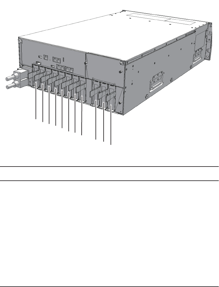
(1)(2)(3)
(9)(10)
(4)(5)(6)(7)(8)
(11)
Location
number
Component
1 PCIe card (PCI#0)
2 PCIe card (PCI#1)
3 PCIe card (PCI#2)
4 PCIe card (PCI#3)
5 PCIe card (PCI#4)
6 PCIe card (PCI#5)
7 PCIe card (PCI#6)
8 PCIe card (PCI#7)
9 PCIe card (PCI#8) (*)
10 PCIe card (PCI#9) (*)
11 PCIe card (PCI#10) (*)
*: Can be mounted only on a SPARC M10-4.
Figure 13-1 Location of the PCIe card
Fujitsu M10-4/Fujitsu M10-4S/SPARC M10-4/SPARC M10-4S Service Manual ・December 2013240
Note - Read and understand the instructions in this chapter before starting the maintenance
work. Also see the contents of "Chapter 1 Before Starting Maintenance Work."
Table 13-1 Types of maintenance for PCIe cards
Configuration Active/hot
(with PHP)
Active/hot
(with DR)
Inactive/hot System stopped
Single-chassis
configuration
Supported (*1) Unsupported Unsupported (*3) Supported
Building block
configuration
Supported (*1) Supported (*2) Supported Supported
*1: Perform maintenance work using PCI hot plug (PHP). See "13.3 Checking If PCI Hot Plug (PHP) Can Be Used" to check whether
PHP can be used.
If SE0X7SA2F (an SAS card) is used, PCIe card release using PHP may fail. If the release fails, perform inactive replacement.
*2: It is necessary to use dynamic reconfiguration (DR) for the physical partition to disconnect a chassis requiring maintenance from the
physical partition.
*3: For a single-chassis configuration, system-stopped maintenance should be performed.
13.2 Before Maintaining a PCI Express
Card
This section describes the types and the flow of the maintenance of the PCIe cards, as
well as some precautions.
13.2.1 Types of maintenance
Table 13-1 lists the types of maintenance for the PCIe cards. For the definition of
maintenance, see "4.3 Understanding Types of Maintenance."
The PCIe cards can be removed/installed while the input power to the chassis is on
(power cord is connected).
This section explains how to perform all types of maintenance work while the power
cord of the chassis remains connected.
13.2.2 Maintenance flow
Table 13-2 lists the sequence of the maintenance procedure for PCIe cards. The
procedure for expanding a PCIe card is the same as that for installing a PCIe card.
The procedure for reducing a PCIe card is the same as that for removing a PCIe card.
Chapter 13 Maintaining the PCI Express Cards 241
Table 13-2 Maintenance flow
Details of update process Replacement Expansion Reduction
1Pre-check 13.3 13.3 13.3
2 Preparation 13.4 13.4 13.4
3 Removing a PCIe card or the filler for a
PCIe card
13.5 13.5 13.5
4 Installing a PCIe card or the filler for a
PCIe card
13.6 13.6 13.6
5 Restoring the system 13.7 13.7 13.7
13.2.3 Precautions for replacement
Note the following points when replacing PCIe cards.
■For active maintenance by PHP, a multipath setting is necessary depending on the
use of the PCIe cards.
13.2.4 Precautions for installation
Note the following points when performing PCIe card expansion.
■Set a multipath depending on the use of the PCIe card when performing active/hot
maintenance or active/cold maintenance with PHP.
■If you are performing PCIe card expansion, remove the filler for the PCIe card
from the PCIe card cassette.
■Keep the removed filler because it will be needed if PCIe card reduction is
subsequently done.
13.2.5 Precautions for removal
Note the following points when removing PCIe cards.
■Set a multipath depending on the use of the PCIe card when performing active/hot
maintenance or active/cold maintenance with PHP.
■If you are removing a PCIe card, attach the filler for the PCIe card after removing
the PCIe card from the PCIe card cassette.
Fujitsu M10-4/Fujitsu M10-4S/SPARC M10-4/SPARC M10-4S Service Manual ・December 2013242
XSCF> showlogs error
#ldm list-io -l
NAME TYPE BUS DOMAIN STATUS
---- ---- --- ------ ------
PCIE0 BUS PCIE0 primary
[pci@8000]
PCIE1 BUS PCIE1 primary <--(*1)
[pci@8100]
PCIE2 BUS PCIE2 primary IOV <--(*2)
[pci@8200]
PCIE3 BUS PCIE3 rootdom <--(*3)
[pci@8300]
PCIE4 BUS PCIE4 primary
[pci@8400]
PCIE5 BUS PCIE5 primary IOV
[pci@8500]
PCIE6 BUS PCIE6 rootdom IOV <--(*4)
[pci@8600]
PCIE7 BUS PCIE7 primary IOV
13.3 Checking If PCI Hot Plug (PHP) Can
Be Used
PHP enables you to perform maintenance for the PCIe cards while Oracle Solaris is
operating. This section checks whether the PCIe card requiring maintenance can use
PHP.
1. LogintotheXSCFshell.
2. Execute the showlogs command to identify the PCIe card requiring
maintenance.
For details, see "3.3.5 Checking log information."
3. Confirm the hardware and software configurations.
For details, see "4.2 Confirming the System Configuration."
4. Check whether the PCIe card requiring maintenance supports PHP.
The following PCIe cards do not support PHP:
[FCoE] SP1X7FAR2F, SP1X7FAS2F, SP1X7FBR2F, and SP1X7FBS2F
[IB] SE1X7BA12F and 7104073 (7104074)
If the PCIe card requiring maintenance does not support PHP or if you do not
use PHP, you do not have to perform step 5 and the subsequent step.
5. If the PCIe card requiring maintenance supports PHP, execute the ldm list-io -l
command to confirm the logical domain to which the PCIe card is assigned
and the logical domain to which the PCIe root complex the PCIe card belongs
to is assigned.
Chapter 13 Maintaining the PCI Express Cards 243

[pci@8700]
/BB0/CMUL/NET0 PCIE PCIE0 primary OCC
[pci@8000/pci@4/pci@0/pci@9]
network@0
network@0,1
/BB0/CMUL/SASHBA PCIE PCIE0 primary OCC
[pci@8000/pci@4/pci@0/pci@0]
scsi@0/iport@f/disk@w50000393a82368b2,0
scsi@0/iport@f/smp@w500000e0e06d03bf
scsi@0/iport@f/enclosure@w500000e0e06d03bd,0
scsi@0/iport@v0
/BB0/PCI0 PCIE PCIE1 primary OCC <--(*5)
[pci@8100/pci@4/pci@0/pci@0]
/BB0/PCI3 PCIE PCIE2 primary EMP
[pci@8200/pci@4/pci@0/pci@0]
/BB0/PCI4 PCIE PCIE2 iodom1 OCC <--(*6)
[pci@8200/pci@4/pci@0/pci@8]
/BB0/PCI7 PCIE PCIE3 rootdom EMP
[pci@8300/pci@4/pci@0/pci@0]
/BB0/PCI8 PCIE PCIE3 rootdom EMP <--(*7)
[pci@8300/pci@4/pci@0/pci@8]
/BB0/CMUL/NET2 PCIE PCIE4 primary OCC
[pci@8400/pci@4/pci@0/pci@a]
network@0
network@0,1
/BB0/PCI1 PCIE PCIE5 rootdom EMP
[pci@8500/pci@4/pci@0/pci@8]
/BB0/PCI2 PCIE PCIE5 rootdom OCC
[pci@8500/pci@4/pci@0/pci@9]
/BB0/PCI5 PCIE PCIE6 iodom2 OCC <--(*8)
[pci@8600/pci@4/pci@0/pci@9]
/BB0/PCI6 PCIE PCIE6 rootdom OCC
[pci@8600/pci@4/pci@0/pci@11]
/BB0/PCI9 PCIE PCIE7 primary OCC
[pci@8700/pci@4/pci@0/pci@9]
/BB0/PCI10 PCIE PCIE7 primary OCC
[pci@8700/pci@4/pci@0/pci@11]
-Logical domain to which the PCIe card is assigned
The name shown under [DOMAIN] (of the row containing "/BBx/PCIx" under
[NAME]) for the slot of the PCIe card requiring maintenance represents the
logical domain to which the PCIe card is assigned. (*5 to *8 in the execution
example)
*5: /BB0/PCI0 is assigned to primary, and PCIE1 is also assigned to primary.
*6: /BB0/PCI4 is assigned to iodom1, and PCIE2 is assigned to primary.
*7: /BB0/PCI8 is assigned to rootdom, and PCIE3 is also assigned to rootdom.
*8: /BB0/PCI5 is assigned to iodom2, and PCIE6 is assigned to rootdom.
-Logical domain to which the PCIe root complex the PCIe card belongs to is
assigned
The name "PCIEx" shown under [BUS] of the row described above is the name
of the PCIe root complex the PCIe card belongs to. The name shown under
[DOMAIN] (of the row containing "PCIEx" under [NAME]) for the same PCIe
root complex represents the logical domain to which the PCIe root complex the
Fujitsu M10-4/Fujitsu M10-4S/SPARC M10-4/SPARC M10-4S Service Manual ・December 2013244
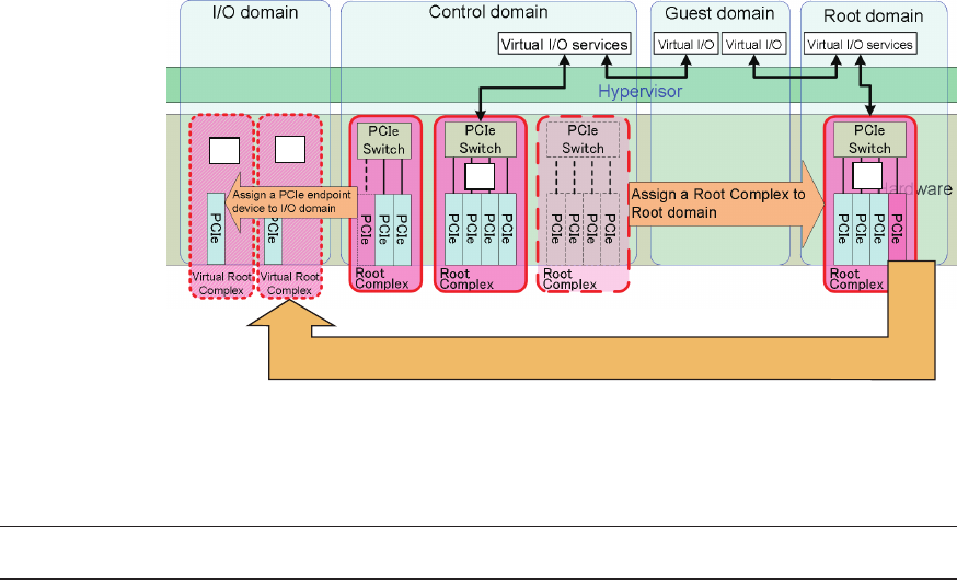
*6 *8
*5 *7
*5 to *8 in the figure correspond to the above ldm list-io -l command execution example.
Assign a PCIe endpoint device to I/O domain
Table 13-3 Whether PHP can be used
Root Complex PCIe slot Can PHP be
used?
Remarks Reference
Control domain Control domain Yes See *5 in the example of
executing the ldm list-io -l
commandand*5inFigure
13-2.
"13.4.1 Active/Hot
maintenance (with PHP)"
PCIe card belongs to is assigned. (*1 to *4 in the execution example)
*1: PCIE1 is assigned to primary.
*2: PCIE2 is assigned to primary.
*3: PCIE3 is assigned to rootdom.
*4: PCIE6 is assigned to rootdom.
6.
Determine whether PHP can be used, combining the two pieces of information
described above based on the confirmation results obtained in step 5.
- Suppose that both of the logical domains to which the PCIe slot and the PCIe
root complex are assigned are found to be a control domain (primary). In this
case, active/hot maintenance can be performed using PHP from the control
domain. (*5 in Figure 13-2)
- Suppose that both of the logical domains to which the PCIe slot and the PCIe
root complex are assigned are found not to be a control domain but the same
logical domain (root domain). In this case, active/hot maintenance can be
performed using PHP from the root domain. (*7 in Figure 13-2)
- In cases other than the above (those where the domains are found to be I/O
domains), PHP cannot be used. Thus, see Table 13-4 for an appropriate
maintenance procedure. (*6 and *8 in Figure 13-2)
Figure 13-2 Confirming assignment to logical domains
Chapter 13 Maintaining the PCI Express Cards 245
Table 13-3 Whether PHP can be used (continued)
Root Complex PCIe slot Can PHP be
used?
Remarks Reference
Control domain I/O domain No See *6 in the example of
executing the ldm list-io -l
command and *6 in Figure
13-2.
"Table 13-4 Operations
when PHP cannot be used
or you do not use PHP"
Root domain Root domain Yes See *7 in the example of
executing the ldm list-io -l
command and *7 in Figure
13-2.
"13.4.1 Active/Hot
maintenance (with PHP)"
Root domain I/O domain No See *8 in the example of
executing the ldm list-io -l
command and *8 in Figure
13-2.
"Table 13-4 Operations
when PHP cannot be used
or you do not use PHP"
Table 13-4 Operations when PHP cannot be used or you do not use PHP
System configuration Operation Reference
Building block Use building block configuration DR to
release the target chassis from the physical
partition (*1).
"13.4.2 Active/Hot maintenance
(with DR)"
Single-chassis configuration
Stop the system, and then perform
maintenance.
"13.4.4 System-stopped maintenance"
*1: If you do not use DR, the same procedure as for a single-chassis configuration should be performed.
13.4 Enabling the Removal of a PCI
Express Card
This section describes the preparations that must be completed prior to the removal
of a PCIe card. The preparation procedure differs depending on the maintenance
type as follows:
■Active/Hot maintenance (with PHP)
■Active/Hot maintenance (with DR)
■Inactive/Hot maintenance
■System-stopped maintenance
13.4.1 Active/Hot maintenance (with PHP)
1. Open the rack door.
Fujitsu M10-4/Fujitsu M10-4S/SPARC M10-4/SPARC M10-4S Service Manual ・December 2013246

#ldm list-bindings rootdom
------------------------Ommitted------------------------
VSW
NAME MAC NET-DEV ID DEVICE LINKPROP
DEFAULT-VLAN-ID PVID ......
vsw0 xx:xx:xx:xx:xx:xx net4(*1) 0 switch@0 1
1
PEER MAC PVID VID
MTU MAXBW .....
vnet0@guest1(*2) xx:xx:xx:xx:xx:xx 1
1500
------------------------Ommitted-----------------------
#dladm show-phys -L
LINK DEVICE LOC
net0 igb0 /BB0/CMUL
net1 igb1 /BB0/CMUL
net2 igb2 /BB0/CMUU
net3 igb3 /BB0/CMUU
net4 ixgbe0 BB#0-PCI#0 <--*
net5 ixgbe1 BB#0-PCI#0
2. Connect to the control domain console of the physical partition.
3. Check whether there is any guest domain that is virtually using the PCIe card
requiring maintenance.
- For Ethernet card
a. Execute the ldm list-bindings <domain name> command from the control
domain to check virtual network switch [VSW] information for the physical
network interface name ([NET-DEV] value) that is assigned to a virtual
network switch.
In the following example, "rootdom", the logical domain name to which the
PCIe card is assigned, is specified.
*1: Physical network interface
*2: Virtual network device and guest domain serviced by vsw0
b. Log in to the logical domain to which the PCIe card is assigned. Then,
determine the physical location of the physical network interface above,
and check whether it corresponds to the PCIe card requiring maintenance.
- For Oracle Solaris 11, execute the dladm show-phys -L command to determine
[LOC] (physical location) of the physical network interface corresponding to
[NET-DEV] in step a.
- For Oracle Solaris 10, execute the /etc/path_to_inst command to confirm the
physical device path, and compare it with the physical device path displayed
by the ldm list-io -l command to determine the physical location.
Chapter 13 Maintaining the PCI Express Cards 247
#grep " 0 \"ixgbe"\" /etc/path_to_inst
"/pci@8100/pci@4/pci@0/pci@0/network@0" 0 "ixgbe"
#ldm list-bindings rootdom
------------------------Ommitted------------------------
VDS
NAME VOLUME OPTIONS MPGROUP DEVICE
vds0 vol0 /export/
vdisks/vdisk.img (*1)
vol1 /dev/zvol/
dsk/rpool/zvdisk1
vol2 /dev/dsk/
cxtxxxxxxxxxxxxxxxxdxsx
CLIENT VOLUME
vdisk1@guest1 vol0 (*2)
vdisk2@guest2 vol1
vdisk3@guest3 vol2
------------------------Ommitted-----------------------
c. If the virtual network switch to which the PCIe card requiring maintenance
is assigned is found in steps a and b, see the [PEER] part of the virtual
network switch displayed in step a. Confirm the part for the virtual network
device and guest domain that use the services of the virtual network
switch.
The display format is "<virtual network device>@<guest domain>."
- For SAS card or FibreChannel card
a. Execute the ldm list-bindings command from the control domain to check
virtual disk service [VDS] information for the virtual disk backend
([DEVICE] value) that is assigned to the virtual disk service.
For information on the types that can be assigned to a virtual disk backend,
see "Virtual Disk Backend" in the Oracle VM Server for SPARC Administration
Guide.
In the following example, "rootdom", the logical domain name to which the
PCIe card is assigned, is specified.
*1: Virtual disk backend
*2: Virtual disk name and guest domain name to which the backend of vol0 is
assigned
b. Log in to the logical domain to which the PCIe card is assigned to identify
the physical disk from the backend. Then, identify the PCIe card in use
from the physical disk.
For details of the procedure, see documents for the software that manages
respective file system and volume.
For example, suppose that the backend is a file on the ZFS file system. In this
case, execute the zfs list command to confirm the ZFS storage pool corresponding
to the mount point of the directory in which the file is located. Then, execute
zpool status <zpool name>toconfirmthephysicaldevicepathofthePCIecard
to which a LU or hard disk is connected.
Fujitsu M10-4/Fujitsu M10-4S/SPARC M10-4/SPARC M10-4S Service Manual ・December 2013248
#ldm remove-vnet <virtual network><
guest domain>
#ldm remove-vswitch <virtual network switch>
#ldm remove-vdisk <virtual disk><
guest domain>
#ldm remove-vdiskserver <virtual disk service>
#svcadm enable hotplug
If MPxIO performs management, use the mpathadm command to display the
device path of the physical hard disk corresponding to a LU. Then, confirm
the physical device path of the PCIe card that is connected to the physical
hard disk.
c. If the virtual disk service to which the PCIe card requiring maintenance is
assigned is found in steps a and b, see the [CLIENT] part for the virtual disk
service displayed in step a. Confirm the virtual disk and guest domain to
which the backend of the virtual disk service is assigned.
The display format is "<virtual disk>@<guest domain>."
4. If there is any guest domain that is virtually using the PCIe card requiring
maintenance, delete the virtual device (vnet, vdisk) and the virtual service
(vsw, vds).
a. Log in to the guest domain to stop the use of the virtual device.
If the virtual device is used by the duplication function, release it using the
duplication function so as not to use the target virtual device.
b. Delete the virtual device and the virtual service using the ldm command
from the control domain.
If you need to restore the original configuration after performing maintenance
on the PCIe card, make a note of the setting information in advance.
- For virtual network
- For virtual disk
5. If the PCIe card requiring maintenance belongs to the root domain, connect to
the console of the root domain.
If it belongs to the control domain, operations are performed from the control
domain console. Thus, you do not have to perform this step.
6. Execute the svcadm enable command to activate the hotplug service.
7. Execute the cfgadm -a command to confirm the Ap_ID of the PCIe card
requiring maintenance and its status.
Confirm the Ap_ID and make a note of it.
In the following example, [Receptacle] and [Occupant] contain "connected" and
"configured", respectively, which indicates that the PCIe card requiring
maintenance is incorporated into the logical domain.
Chapter 13 Maintaining the PCI Express Cards 249
#cfgadm -a
Ap_Id Type Receptacle Occupant Condition
BB#0-PCI#0 pci-pci/hp connected configured ok
#cfgadm -c unconfigure Ap_Id
#cfgadm -c disconnect Ap_Id
#cfgadm -a
Ap_Id Type Receptacle Occupant Condition
BB#0-PCI#0 pci-pci/hp disconnected unconfigured ok
#cfgadm -x led=attn,mode=blink Ap_Id
Note - To perform active/hot maintenance without using PHP, use DR of the system board
on the physical partition. For information on the versions of XCP and Oracle VM Server for
SPARC/SRU that support DR, see the latest Product Notes.
Note - Active/hot maintenance without using PHP can be performed only for a building
block configuration.
8. Execute the cfgadm -c command to release the PCIe card requiring
maintenance from the logical domain.
Enter the Ap_ID you noted in advance.
9. Execute the cfgadm -c command to stop the power supply to the PCIe card
requiring maintenance.
Enter the Ap_ID you noted in advance.
10. Execute the cfgadm -a command to confirm the status of the PCIe card again.
In the following example, [Receptacle] and [Occupant] contain "disconnected"
and "unconfigured", respectively, which indicates that the PCIe card requiring
maintenance is released from the logical domain.
11. Execute the cfgadm -x command to cause the ATTENTION LED on the PCIe
card cassette requiring maintenance to blink.
Enter the Ap_ID you noted in advance.
13.4.2 Active/Hot maintenance (with DR)
1. Open the rack door.
2. Confirm the hardware and software configurations.
For details, see "4.2 Confirming the System Configuration."
Fujitsu M10-4/Fujitsu M10-4S/SPARC M10-4/SPARC M10-4S Service Manual ・December 2013250

#ldm list-bindings rootdom
------------------------Ommitted------------------------
VSW
NAME MAC NET-DEV ID DEVICE LINKPROP
DEFAULT-VLAN-ID PVID ......
vsw0 xx:xx:xx:xx:xx:xx net4 0 switch@0 1
1
PEER MAC PVID VID
MTU MAXBW .....
vnet0@guest1(*1) xx:xx:xx:xx:xx:xx 1
1500
------------------------Ommitted------------------------
VDS
NAME VOLUME OPTIONS MPGROUP DEVICE
vds0 vol0 /export/
vdisks/vdisk.img (*2)
vol1 /dev/zvol/
dsk/rpool/zvdisk1
vol2 /dev/dsk/
cxtxxxxxxxxxxxxxxxxdxsx
CLIENT VOLUME
vdisk1@guest1 vol0 (*1)
vdisk2@guest2 vol1 (*1)
vdisk3@guest3 vol2 (*1)
------------------------Ommitted-----------------------
3. Release from the physical partition the chassis in which the PCIe card
requiring maintenance is mounted.
a. Referencing step 5 in "13.3 Checking If PCI Hot Plug (PHP) Can Be Used,"
confirm the logical domains to which the PCIe root complex and PCIe slot
of the chassis with the maintenance target mounted are assigned.
b. Execute the ldm list-bindings <domain name> command for these logical
domains to confirm the name of the guest domain to which the virtual
service (vsw, vds) is provided.
In the following example, "rootdom", the logical domain name to which the
PCIe card is assigned, is specified.
*1: Guest domain that uses the virtual device
*2: Virtual disk backend
c. If the guest domain that uses the virtual device is found in step b, log in to
the guest domain to stop the use of the virtual device.
If the virtual device is used by the duplication function, release it using the
duplication function so as not to use the target virtual device.
d. If the logical domains confirmed in step a are I/O domains, stop the I/O
domains and delete the assigned PCIe slot.
If you need to restore the original configuration after performing maintenance
onthePCIecard,makeanoteofthedeletedPCIeslotandthedomainname
in advance.
Chapter 13 Maintaining the PCI Express Cards 251
#ldm stop iodomain
#ldm remove-io /BB1/PCI0 iodomain
XSCF> replacefru
Note - Inactive/hot maintenance can be performed only for a building block configuration.
For a single-chassis configuration, system-stopped maintenance should be performed.
e. Release from the physical partition the chassis in which the PCIe card
requiring maintenance is mounted.
For details, see "5.2 Releasing a Chassis from the Physical Partition."
4.
Execute the replacefru command to release the chassis requiring maintenance
from the system.
For details, see "5.1 Releasing an FRU from the System with the replacefru
Command."
13.4.3 Inactive/Hot maintenance
1. Open the rack door.
2. Confirm the hardware and software configurations.
For details, see "4.2 Confirming the System Configuration."
3. Power off the physical partition requiring maintenance.
For details, see "5.3 Powering Off the Physical Partition Requiring Maintenance."
13.4.4 System-stopped maintenance
The PCIe cards can be removed/installed while the input power to the chassis is on
(power cord is connected). System-stopped maintenance is also described as
maintenance performed while the power cord remains connected.
1. Open the rack door.
2. Confirm the hardware and software configurations.
For details, see "4.2 Confirming the System Configuration."
3. Stop the entire system.
For details, see "5.4 Stopping the Entire System."
Fujitsu M10-4/Fujitsu M10-4S/SPARC M10-4/SPARC M10-4S Service Manual ・December 2013252
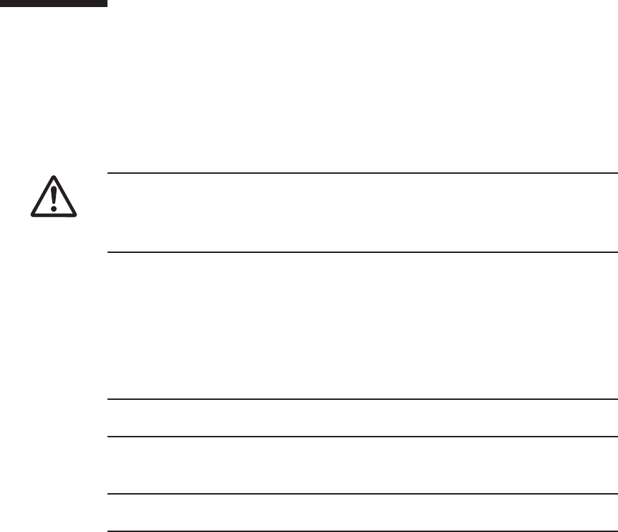
Caution - Before you handle any components, wear a wrist strap to ground any static
electricity. If you perform this procedure without a wrist strap, individual
components or the overall system may be damaged. For details, see "1.5 Notes
Regarding Static Electricity."
Note - If the crossbar cables are fixed to the cable support with the hook-and-loop fastener,
remove the hook-and-loop fastener.
Note - Record the positions of the cables before removing them to ensure that they are
reinstalled correctly.
13.5 Removing a PCI Express Card
This section describes the procedure for removing a PCIe card. Perform reduction
using the same procedure.
For installation, remove the filler for a PCIe card instead of removing a PCIe card.
Enable the removal of the PCIe card before attempting to remove it. For details, see
"13.4 Enabling the Removal of a PCI Express Card."
13.5.1 Accessing a PCI Express card cassette
1. Lower the cable support.
For details, see "5.5.1 Lowering the cable support."
2.
Remove the cables connected to the PCIe card cassette requiring maintenance.
13.5.2 Removing a PCI Express card cassette
There are two types of PCIe card cassettes. The shapes of the latch (A in the figure)
and lever (B in the figure) vary depending on the type of the PCIe card cassette, but
the same removal procedure applies. For the types of PCIe card cassettes, see "Figure
13-3."
Unless otherwise specified, the figures explained in this section use Type-1.
Chapter 13 Maintaining the PCI Express Cards 253
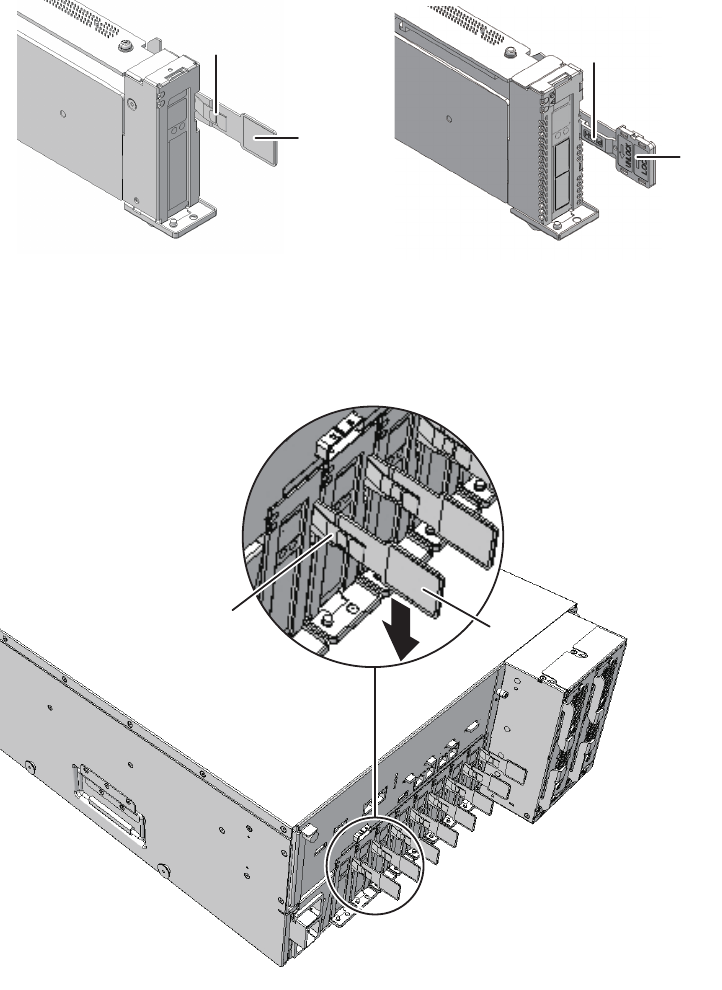
B
A
B
A
Type-1 Type-2
B
A
Figure 13-3 Types of PCIe card cassettes
1. Lower the lever (B in the figure) of the PCIe card cassette while pushing the
latch(Ainthefigure).
Figure 13-4 Lever of PCIe card cassette
2. Hold the lever and carefully pull the PCIe card cassette out of the PCI slot to
remove it.
Fujitsu M10-4/Fujitsu M10-4S/SPARC M10-4/SPARC M10-4S Service Manual ・December 2013254
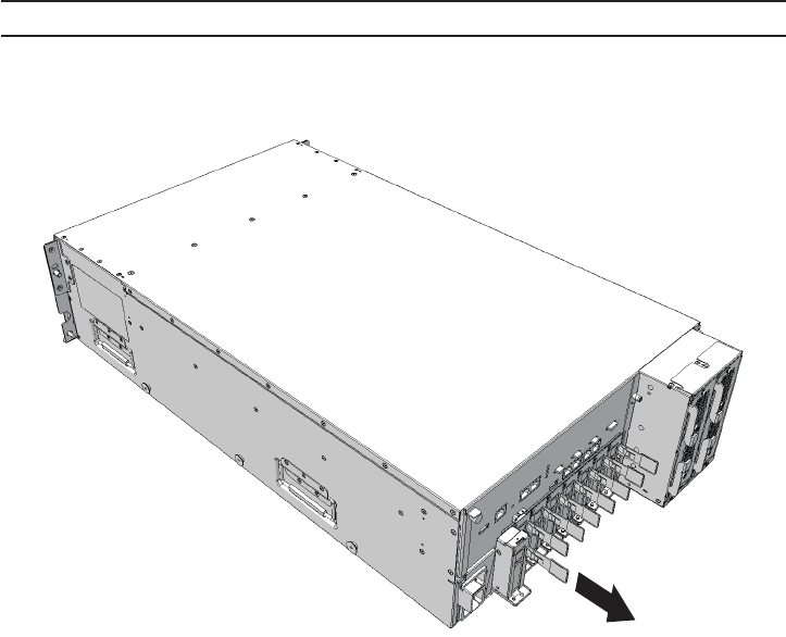
Note - Place the removed PCIe card cassette on a grounded antistatic ESD mat.
Figure 13-5 Removing the PCIe card cassette
13.5.3 Removing a PCI Express card
1. Remove the cover while pushing the clip (A in the figure) at the rear of the
cover.
Chapter 13 Maintaining the PCI Express Cards 255
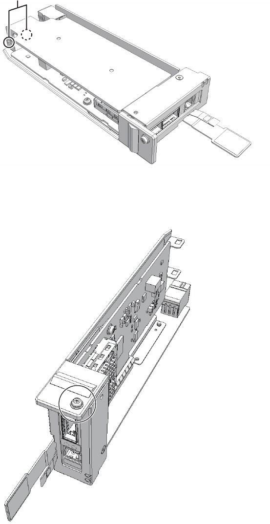
A
Figure 13-6 Clip at rear of cover
2. Remove the screw securing the PCIe card cassette.
Figure 13-7 Removing the screw
Fujitsu M10-4/Fujitsu M10-4S/SPARC M10-4/SPARC M10-4S Service Manual ・December 2013256
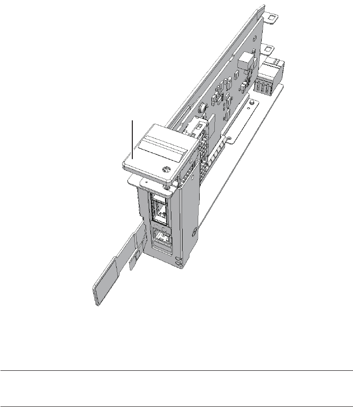
A
Note - Do not forcibly remove the PCIe card from the PCIe card cassette. If excessive force is
used to remove the PCIe card, it may be damaged.
Note - Place the removed PCIe card on a grounded antistatic ESD mat.
3. Remove the bracket (A in the figure) from the PCIe card.
Figure 13-8 Removing the bracket
4. Remove the PCIe card from the PCIe card cassette.
For installation, you do not have to perform this step. Remove the filler for the
PCIe card from the PCIe card cassette.
Chapter 13 Maintaining the PCI Express Cards 257
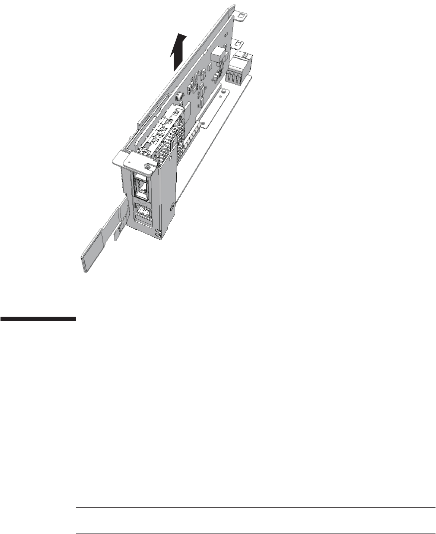
Note - Confirm that the tab of the PCIe card or the tab of the filler for the PCIe card is
inserted in the notch of the PCIe card cassette.
Figure 13-9 Removing the PCIe card
13.6 Installing a PCI Express Card
This section describes the procedure for installing a PCIe card. Perform expansion
using the same procedure. When removing a PCIe card, install the filler unit instead
of another PCIe card after removing the PCIe card.
13.6.1 Installing a PCI Express card
1.
Install the PCIe card by inserting it into the connector of the PCIe card cassette.
For removal of a PCIe card, you do not have to perform this step. Attach the
filler for the PCIe card to the PCIe card cassette.
Fujitsu M10-4/Fujitsu M10-4S/SPARC M10-4/SPARC M10-4S Service Manual ・December 2013258
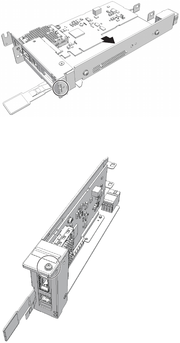
Figure 13-10 Installing a PCIe card
2. Install the bracket for the PCIe card, and secure it with the screw.
Figure 13-11 Installing the bracket
Chapter 13 Maintaining the PCI Express Cards 259
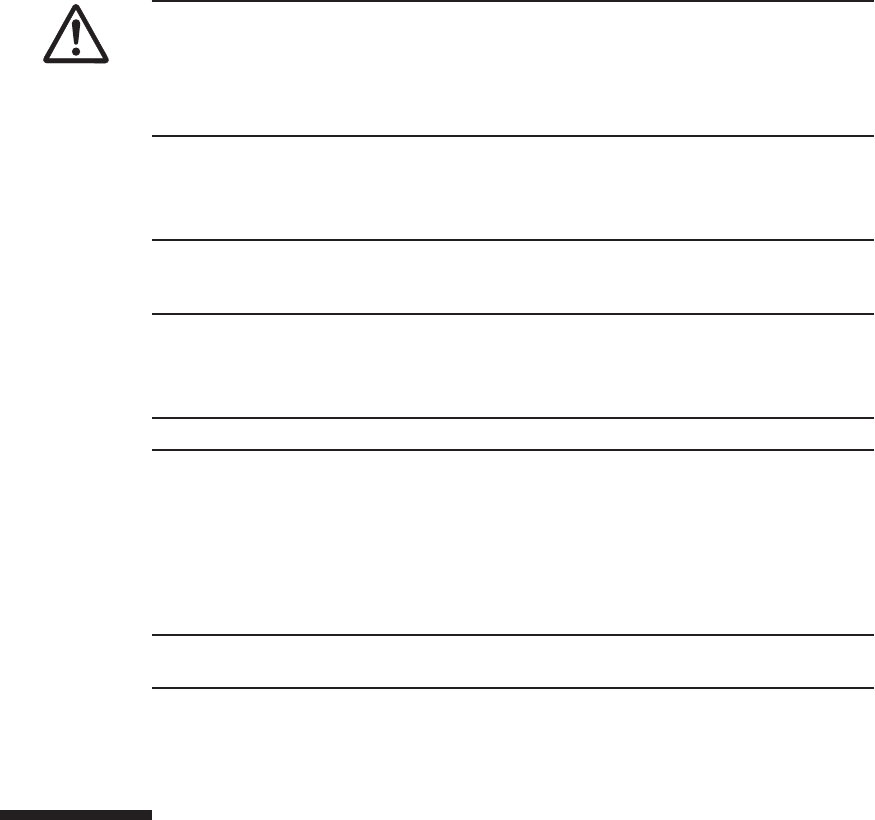
Note - When mounting a PCIe card cassette, check the connectors on both of the
chassis and PCIe card cassette beforehand to confirm that no pin is bent and all the
pins are neatly arranged in lines. If a PCIe card cassette is mounted with a bent pin in
a connector, the chassis or PCIe card cassette may be damaged. Also, carefully
proceed with the work to prevent any pin from being bent.
Note - Slide the PCIe card cassette along the rail at the bottom of the PCIe slot.
Note - Do not forcibly push the PCIe card cassette into the PCIe slot. Using excessive force
may damage the component or the chassis.
Note - Ensure that the PCIe card cassette is firmly inserted and secured.
Note - Reinstall the cables of the PCIe card cassettes in their original positions by referring to
notes that you made prior to the start of maintenance.
3. Mount the cover on the PCIe card cassette.
13.6.2 Installing a PCI Express card cassette
1. Hold the lever of the PCIe card cassette, and carefully insert it into the PCIe
slot.
2. Raise the lever of the PCIe card cassette while pushing the latch and secure
it.
13.6.3 Restoring the chassis
1. Connect the cables to the PCIe card cassette.
2. Lift the cable support to fix it.
For details, see "6.5.2 Fixing the cable support."
13.7 Restoring the System
This section describes the procedures for restoring the system after replacement,
addition, and removal of PCIe cards. The restoration procedure differs depending on
the maintenance type as follows:
Fujitsu M10-4/Fujitsu M10-4S/SPARC M10-4/SPARC M10-4S Service Manual ・December 2013260
Note - See the procedure for system-stopped maintenance for inactive/cold maintenance in a
single-chassis configuration.
#cfgadm -c connect Ap_Id
#cfgadm -c configure Ap_Id
#cfgadm -a
Ap_Id Type Receptacle Occupant
Condition
BB#0-PCI#0 pci-pci/hp connected configured ok
#svcadm disable hotplug
■Active/Hot maintenance (with PHP)
■Active/Hot maintenance (with DR)
■Inactive/Hot maintenance
■System-stopped maintenance
13.7.1 Active/Hot maintenance (with PHP)
1. Display the Oracle Solaris super-user prompt.
2. Execute the cfgadm -c command to start the power supply to the PCIe card
requiring maintenance.
Enter the Ap_ID you noted in advance.
3. Execute the cfgadm -c command to incorporate the PCIe card requiring
maintenance into the logical domain.
Enter the Ap_ID you noted in advance.
4. Execute the cfgadm -a command to confirm that the PCIe card requiring
maintenance has been incorporated into the logical domain.
In the following example, [Receptacle], [Occupant], and [Condition] contain
"connected", "configured", and "ok", respectively, which indicates that the PCIe
card requiring maintenance is incorporated into the logical domain.
5. Execute the svcadm disable command to disable the hotplug service.
6. If you deleted the virtual device and the virtual service in "13.4.1 Active/Hot
maintenance (with PHP)," add them based on the information you made a
note of and reassign them to the guest domain.
For details on how to add a virtual device and a virtual service, see the Oracle
VM Server for SPARC Administration Guide.
Chapter 13 Maintaining the PCI Express Cards 261

XSCF> testsb -v -y -s 00-0
XSCF> testsb -v -y -s 00-0
7. Close the rack door.
13.7.2 Active/Hot maintenance (with DR)
1. Return to the operation of the XSCF firmware replacefru command to confirm
that the chassis has been incorporated into the system.
For details, see "6.1 Incorporating an FRU into the System with the replacefru
Command."
2. Execute the testsb command to confirm that the PCIe card requiring
maintenance is recognized.
When you enter the "-y" option for the testsb command, the system automatically
answers "y" (yes) in response to an inquiry.
The following example shows the diagnosis of system board 00-0.
During the diagnosis processing, the show-devs command of OpenBoot PROM
is executed, and the result is displayed.
3. Incorporate into the physical partition the chassis in which the PCIe card
requiring maintenance is mounted.
For details, see "6.2 Incorporating a Chassis into a Physical Partition."
4. Close the rack door.
13.7.3 Inactive/Hot maintenance
1. Log in to the XSCF shell.
2. Execute the testsb command to confirm that the PCIe card requiring
maintenance is recognized.
When you input optional "-y" for the testsb command, the system automatically
answers "y" (yes) in response to an inquiry.
The following example shows the diagnosis of system board 00-0.
3. Power on the physical partition requiring maintenance.
For details, see "6.3 Powering On the Physical Partition Requiring Maintenance."
4. Close the rack door.
Fujitsu M10-4/Fujitsu M10-4S/SPARC M10-4/SPARC M10-4S Service Manual ・December 2013262

XSCF> testsb -v -y -s 00-0
13.7.4 System-stopped maintenance
1. LogintotheXSCFshell.
2. Execute the testsb command to confirm that the PCIe card requiring
maintenance is recognized.
When you input optional "-y" for the testsb command, the system automatically
answers "y" (yes) in response to an inquiry.
The following example shows the diagnosis of system board 00-0.
During the diagnosis processing, the show-devs command of OpenBoot PROM
is executed, and the result is displayed.
3. Start the entire system.
For details, see "6.4 Starting the Entire System."
4. Close the rack door.
Chapter 13 Maintaining the PCI Express Cards 263
Fujitsu M10-4/Fujitsu M10-4S/SPARC M10-4/SPARC M10-4S Service Manual ・December 2013264
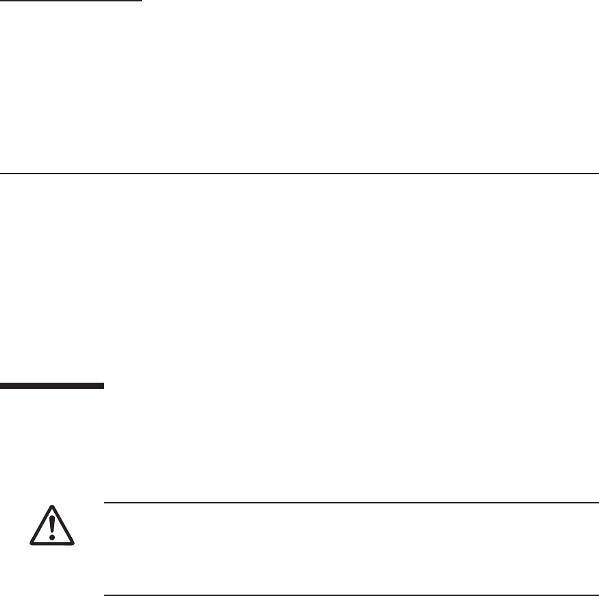
Caution - Do not replace a PSU backplane unit at the same time as a CPU memory
unit. If you replace a PSU backplane unit at the same time as a CPU memory unit, the
system may fail to operate normally. Replace a PSU backplane unit or CPU memory
unit, and confirm that the newly installed part is normal by using the showhardconf
or showstatus command. Then, replace the other Field Replaceable Unit (FRU).
Chapter 14
Maintaining the PSU Backplane Unit
This chapter describes the procedure for maintaining the PSU backplane unit
mounted in a SPARC M10-4/M10-4S.
■Location of the PSU Backplane Unit
■Before Maintaining the PSU Backplane Unit
■Enabling the Removal of the PSU Backplane Unit
■Removing the PSU Backplane Unit
■Installing the PSU Backplane Unit
■Restoring the System
14.1 Location of the PSU Backplane Unit
This section describes the location of the PSU backplane unit.
The PSU backplane unit has connectors for connecting multiple power supply units.
265
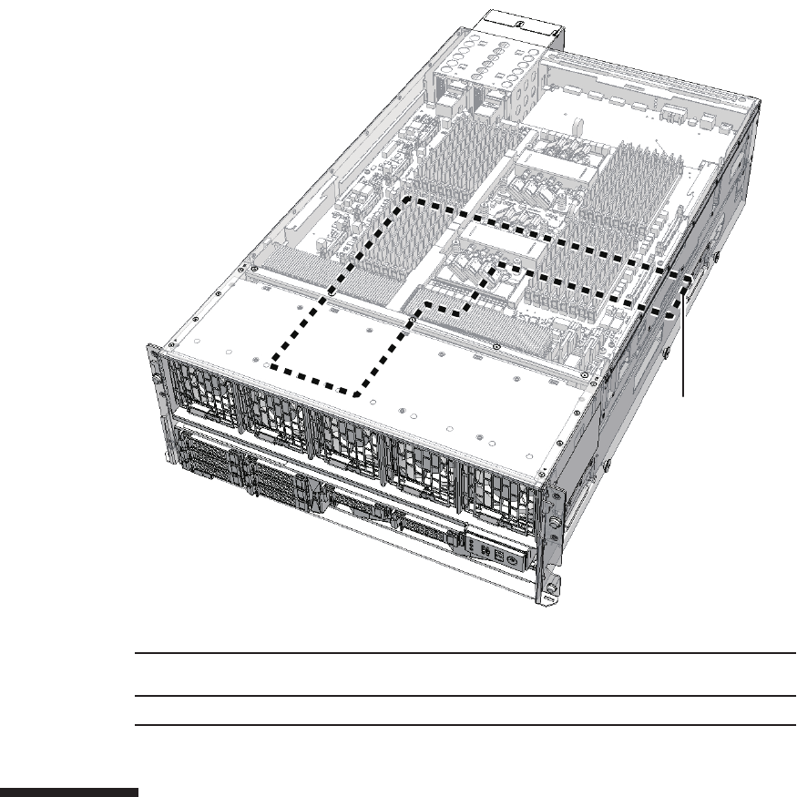
(1)
Location
number
Component
1 PSU backplane unit (PSUBP)
Figure 14-1 Location of PSU backplane unit
14.2 Before Maintaining the PSU Backplane
Unit
This section describes the types and the flow of maintenance of the PSU backplane
unit.
Fujitsu M10-4/Fujitsu M10-4S/SPARC M10-4/SPARC M10-4S Service Manual ・December 2013266
Note - Read and understand the instructions in this chapter before starting the maintenance
work. Also see the contents of "Chapter 1 Before Starting Maintenance Work."
Table 14-1 Types of maintenance for PSU backplane unit
Configuration Active/hot Active/cold Inactive/hot Inactive/cold (*1) System stopped
Single-chassis configuration
Unsupported Unsupported Unsupported Supported Supported
Building block configuration
Unsupported Supported (*2) Unsupported Supported Supported
*1: For a single-chassis configuration, the inactive/cold maintenance procedure is the same as that for stopping the system, therefore see
the procedure for system-stopped maintenance.
*2: It is necessary to use dynamic reconfiguration (DR) to disconnect a chassis requiring maintenance from the physical partition.
Table 14-2 Maintenance flow
Details of update process Replacement
1 Preparation 14.3
2 Removing the PSU backplane unit 14.4
3 Installing the PSU backplane unit 14.5
4 Restoring the system 14.6
14.2.1 Types of maintenance
Table 14-1 lists the types of maintenance for the PSU backplane unit. For the
definition of maintenance, see "4.3 Understanding Types of Maintenance."
14.2.2 Maintenance flow
Table 14-2 lists the sequence of the maintenance procedure for the PSU backplane
unit.
14.3 Enabling the Removal of the PSU
Backplane Unit
This section describes the preparation that must be completed prior to removing the
PSU backplane unit. The preparation procedure differs depending on the maintenance
type as follows:
Chapter 14 Maintaining the PSU Backplane Unit 267
Note - See the procedure for system-stopped maintenance for inactive/cold maintenance in a
single-chassis configuration.
Caution - To completely shut down the system, all the power cords must be
removed. If the power cords are not removed, an electrical failure may occur.
Note - Use the DR of the system board on a physical partition for active/cold maintenance.
For the XCP and Oracle VM Server for SPARC/SRU versions that correspond to the DR, see
the latest Product Notes.
Note - Active/cold maintenance can be performed only for a building block configuration.
XSCF> showlogs error
XSCF> replacefru
■Active/Cold maintenance
■Inactive/Cold maintenance
■System-stopped maintenance
14.3.1 Active/Cold maintenance
1. Open the rack door.
2. Log in to the XSCF shell.
3. Execute the showlogs command to identify the component requiring
maintenance.
For details, see "3.3.5 Checking log information."
4. Confirm the hardware and software configurations.
For details, see "4.2 Confirming the System Configuration."
5. Release the building block, in which the PSU backplane unit requiring
maintenance is mounted, from the physical partition.
For details, see "5.2 Releasing a Chassis from the Physical Partition."
6.
Execute the replacefru command to release the chassis requiring maintenance
from the system.
For details, see "5.1 Releasing an FRU from the System with the replacefru
Command."
7. Remove all the power cords from the PSU backplane unit of the chassis
requiring maintenance.
For details, see "5.5.2 Removing the power cord."
Fujitsu M10-4/Fujitsu M10-4S/SPARC M10-4/SPARC M10-4S Service Manual ・December 2013268
Note - Inthecaseofadualpowerfeed,makeanoteofthelocationsofthepowercords
before disconnecting them to ensure that they are reinstalled correctly.
Note - Inactive/cold maintenance can be performed only for a building block configuration.
The inactive/cold maintenance procedure for a single-chassis configuration is the same as
that for stopping the system.
XSCF> showlogs error
XSCF> replacefru
Note - Inthecaseofadualpowerfeed,makeanoteofthelocationsofthepowercords
before disconnecting them to ensure that they are reinstalled correctly.
14.3.2 Inactive/Cold maintenance
1. Open the rack door.
2. LogintotheXSCFshell.
3. Execute the showlogs command to identify the component requiring
maintenance.
For details, see "3.3.5 Checking log information."
4. Confirm the hardware and software configurations.
For details, see "4.2 Confirming the System Configuration."
5. Power off the physical partition requiring maintenance.
For details, see "5.3 Powering Off the Physical Partition Requiring Maintenance."
6.
Execute the replacefru command to release the chassis requiring maintenance
from the system.
For details, see "5.1 Releasing an FRU from the System with the replacefru
Command."
7. Remove all the power cords from the PSU backplane unit of the chassis
requiring maintenance.
For details, see "5.5.2 Removing the power cord."
14.3.3 System-stopped maintenance
The procedure in the case of system-stopped maintenance is same for the building
block configuration and single-chassis configuration.
Chapter 14 Maintaining the PSU Backplane Unit 269
XSCF> showlogs error
XSCF> replacefru
Note - In the case of a dual power feed, make a note of the locations of the power cords
before disconnecting them to ensure that they are reinstalled correctly.
Caution - Before you handle any components, wear a wrist strap to ground any static
electricity. If you perform this procedure without a wrist strap, individual
components or the overall system may be damaged. For details, see "1.5 Notes
Regarding Static Electricity."
1. Open the rack door.
2. Log in to the XSCF shell.
3. Execute the showlogs command to identify the component requiring
maintenance.
For details, see "3.3.5 Checking log information."
4. Confirm the hardware and software configurations.
For details, see "4.2 Confirming the System Configuration."
5. Stop the entire system.
For details, see "5.4 Stopping the Entire System."
6.
Execute the replacefru command to release the chassis requiring maintenance
from the system.
For a single-chassis configuration, you do not have to release the chassis.
Proceed to step 7.
For details, see "5.1 Releasing an FRU from the System with the replacefru
Command."
7. Remove all the power cords from the PSU backplane unit of the chassis
requiring maintenance.
For details, see "5.5.2 Removing the power cord."
14.4 Removing the PSU Backplane Unit
This section describes the procedure for removing the PSU backplane unit from the
SPARC M10-4/M10-4S. Enable the removal of the PSU backplane unit before
attempting to remove it. For details, see "14.3 Enabling the Removal of the PSU
Backplane Unit."
Fujitsu M10-4/Fujitsu M10-4S/SPARC M10-4/SPARC M10-4S Service Manual ・December 2013270
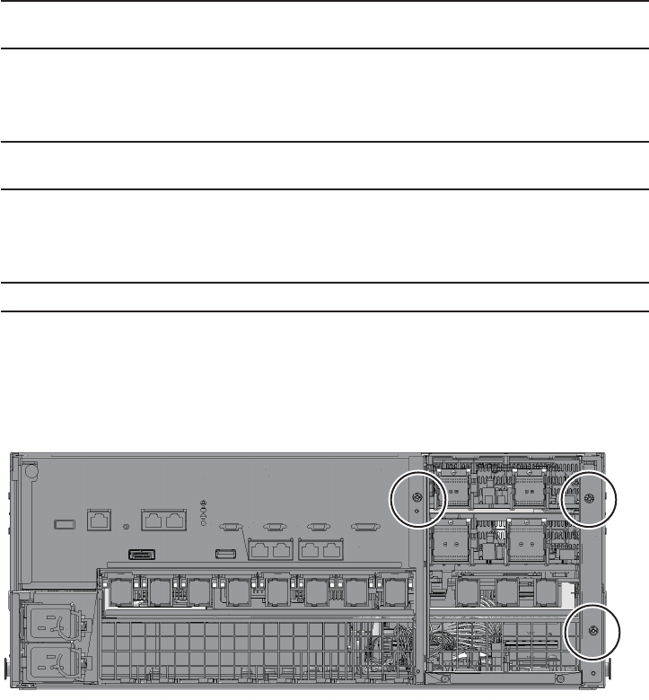
Note - Make a note of the positions of the cables connected to the external interface before
disconnecting them to ensure that they are reinstalled correctly.
Note - Make a note of the positions of the PCIe card cassettes before removing them to ensure
that they are reinstalled correctly.
Note - If no crossbar unit is mounted, proceed to step 6.
14.4.1 Accessing the PSU backplane unit
1. Lower the cable support.
For details, see "5.5.1 Lowering the cable support."
2. Remove all the cables connected to the external interface.
The cables to be removed are as follows.
■Interface cable connected to the PCI Express (PCIe) card
■Crossbar cable
■XSCF BB control cable
■XSCF DUAL control cable
■LAN cable
3. Remove all PCIe card cassettes.
For details, see "13.5.2 Removing a PCI Express card cassette."
4. Remove all the crossbar units.
For details, see "9.4.2 Removing a crossbar unit."
5. Loosen the three screws securing the mounting frame of the crossbar unit
and then remove the frame.
Figure 14-2 Screws securing the mounting frame
Chapter 14 Maintaining the PSU Backplane Unit 271
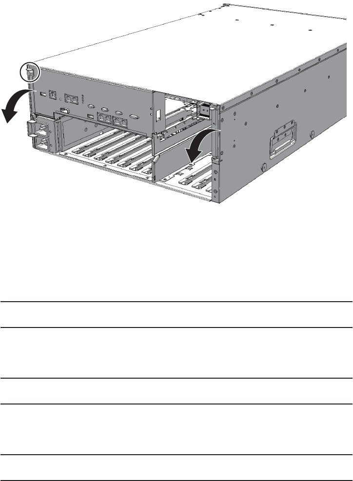
Note - Make a note of the positions of the power supply units before removing them to
ensure that they are reinstalled correctly.
Note - Make a note of the locations of the fan units before removing them to ensure that they
are reinstalled correctly.
Note - Make a note of the positions of the internal disks before removing them to ensure that
they are reinstalled correctly.
6. Loosen the screw securing the CPU memory unit and then lower the right and
left levers to the horizontal position.
Figure 14-3 Screw securing the CPU memory unit
7. Pull the CPU memory unit out by about 10 cm (3.9 in.)
8. Remove the front cover.
For details, see "5.5.3 Removing the front cover."
9. Remove all the power supply units.
For details, see "10.4 Removing a Power Supply Unit."
10. Remove all the fan units.
For details, see "11.4 Removing a Fan Unit."
11. Remove all the internal disks or the HDD filler units.
For details, see "12.4 Removing an Internal Disk."
12. Loosen the two screws in the fan slot and then remove the fan shelf.
Fujitsu M10-4/Fujitsu M10-4S/SPARC M10-4/SPARC M10-4S Service Manual ・December 2013272
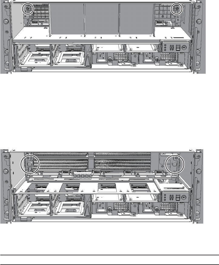
Note - Place the removed PSU backplane unit on a grounded antistatic ESD mat.
Figure 14-4 Screws in the fan slot
14.4.2 Removing the PSU backplane unit
1. Loosen the two screws securing the PSU backplane unit and then partially
pull out the PSU backplane unit.
Figure 14-5 Screws securing the PSU backplane unit
2. Pull the PSU backplane unit out a little more. Then, remove the unit by holding
its handle.
Chapter 14 Maintaining the PSU Backplane Unit 273
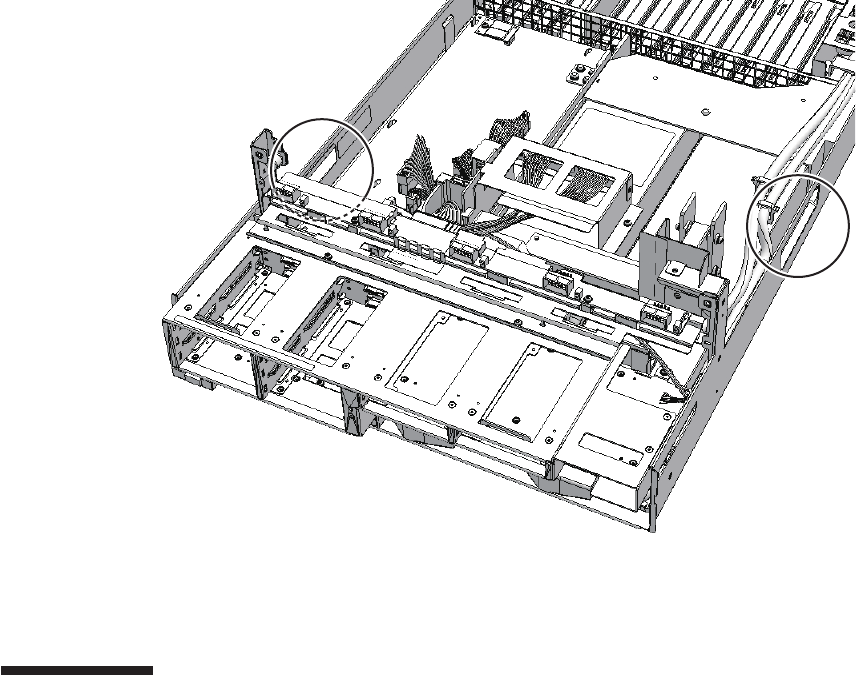
Figure 14-6 Handle of PSU backplane unit
3. Remove the operation panel.
For details, see step 2 and later in "15.4.2 Removing the operation panel."
14.5 Installing the PSU Backplane Unit
This section describes the procedure for installing the PSU backplane unit.
14.5.1 Installing the PSU backplane unit
1. Install the operation panel on the PSU backplane unit.
For details, see "15.5.1 Installing the operation panel."
2. Insert the PSU backplane unit into the chassis by holding the handle.
3. Tighten the two screws securing the PSU backplane unit.
Fujitsu M10-4/Fujitsu M10-4S/SPARC M10-4/SPARC M10-4S Service Manual ・December 2013274
Note - Install the power supply units in their original positions by referring to the notes that
you made prior to the start of maintenance.
Note - Reinstall the fan units in their original locations by referring to the notes you made
prior to the start of maintenance.
Note - Reinstall the internal disks in their original locations by referring to the notes that you
made prior to the start of maintenance.
Note - If no crossbar unit is mounted, proceed to step 10.
Note - Reinstall the PCIe card cassettes in their original positions by referring to the notes
that you made prior to the start of maintenance.
14.5.2 Restoring the chassis
1. Install the fan shelf and then tighten the two screws in the fan slot.
2. Install all the power supply units.
For details, see "10.5.1 Installing a power supply unit."
3. Install all the fan units.
For details, see "11.5.1 Installing a fan unit."
4. Install all the internal disks or HDD filler units.
For details, see "12.5 Installing an Internal Disk."
5. Install the front cover.
For details, see "6.5.3 Installing the front cover."
6. Insert the CPU memory unit in the chassis.
7. Raise the right and left levers of the CPU memory unit and then tighten the
one screw.
8. Install the mounting frame for the crossbar unit and then tighten the three
screws.
9. Install all the crossbar units.
For details, see "9.5.1 Installing a crossbar unit."
10. Install all the PCIe card cassettes.
For details, see "13.6.2 Installing a PCI Express card cassette."
11. Connect all the cables to the external interface.
Thecablestobeconnectedareasfollows.
■Interface cable connected to the PCIe card
Chapter 14 Maintaining the PSU Backplane Unit 275

Note - Reconnect the cables of the external interface in their original positions by referring to
the notes that you made prior to the start of maintenance.
Note - See the procedure for system-stopped maintenance for inactive/cold maintenance in a
single-chassis configuration.
Note - Use the DR of the system board on a physical partition for active/cold maintenance.
For the XCP and Oracle VM Server for SPARC/SRU versions that correspond to the DR, see
the latest Product Notes.
Note - Active/cold maintenance can be performed only for a building block configuration.
Note - In the case of a dual power feed, connect the power cords in their original positions by
referring to the record that you made before the start of maintenance.
■Crossbar cable
■XSCF BB control cable
■XSCF DUAL control cable
■LAN cable
12. Lift the cable support to fix it.
For details, see "6.5.2 Fixing the cable support."
14.6 Restoring the System
This section describes the procedure for restoring the system after installing the PSU
backplane unit. The restoration procedure differs depending on the maintenance
type as follows:
■Active/Cold maintenance
■Inactive/Cold maintenance
■System-stopped maintenance
14.6.1 Active/Cold maintenance
1. Connect all the power cords to the PSU backplane unit of the chassis
requiring maintenance.
For details, see "6.5.1 Installing the power cord."
2. Return to the operation of the XSCF firmware replacefru command to confirm
that the chassis has been incorporated into the system.
Fujitsu M10-4/Fujitsu M10-4S/SPARC M10-4/SPARC M10-4S Service Manual ・December 2013276

XSCF> diagxbu -y -b 00 -p 02
XSCF> showlogs error
Note - Inactive/cold maintenance can be performed only for a building block configuration.
The inactive/cold maintenance procedure for a single-chassis configuration is the same as
that for stopping the system.
Note - In the case of a dual power feed, connect the power cords in their original positions by
referring to the record that you made before the start of maintenance.
For details, see "6.1 Incorporating an FRU into the System with the replacefru
Command."
3. Execute the diagxbu command to diagnose the crossbar cables.
Diagnosis is performed when the system board of the chassis connected with the
crossbar cables is incorporated into the physical partition, and the physical
partition is powered on.
The example below specifies the following:
00: BB-ID of the chassis to start the diagnosis
02: PPAR-ID of the destination where the chassis to start the diagnosis is
connected (You can specify only one of these.)
4. Execute the showlogs command to confirm that the system is operating
normally.
For details, see "3.3.5 Checking log information."
5. Incorporate the chassis, in which the PSU backplane unit requiring
maintenance is mounted, into the physical partition.
For details, see "6.2 Incorporating a Chassis into a Physical Partition."
6. Close the rack door.
14.6.2 Inactive/Cold maintenance
1. Connect all the power cords to the PSU backplane unit of the chassis
requiring maintenance.
For details, see "6.5.1 Installing the power cord."
2. Return to the operation of the XSCF firmware replacefru command to confirm
that the chassis has been incorporated into the system.
For details, see "6.1 Incorporating an FRU into the System with the replacefru
Command."
Chapter 14 Maintaining the PSU Backplane Unit 277

XSCF> diagxbu -y -b 00 -t 01
XSCF> showlogs error
Note - In the case of a dual power feed, connect the power cords in their original positions by
referring to the record that you made before the start of maintenance.
3. Execute the diagxbu command to diagnose the crossbar cables.
Diagnosis is performed when the system board of the chassis connected with the
crossbar cables is not incorporated into the physical partition, or when the
physical partition into which the chassis is incorporated is powered off.
The example below specifies the following:
00: BB-ID of the chassis to start the diagnosis
01: BB-ID of the destination where the chassis to start the diagnosis is connected
(You can specify one or more of these.)
To specify multiple connection destination BB-IDs, enter a command like
"diagxbu -y -b 00 -t 01 -t 02".
4. Execute the showlogs command to confirm that the system is operating
normally.
For details, see "3.3.5 Checking log information."
5. Power on the physical partition requiring maintenance.
For details, see "6.3 Powering On the Physical Partition Requiring Maintenance."
6. Close the rack door.
14.6.3 System-stopped maintenance
1. Connect all the power cords to the PSU backplane unit.
For details, see "6.5.1 Installing the power cord."
2. Return to the operation of the XSCF firmware replacefru command to confirm
that the chassis has been incorporated into the system.
For details, see "6.1 Incorporating an FRU into the System with the replacefru
Command."
For a single-chassis configuration, you do not have to incorporate the chassis.
Proceed to step 5.
3. Execute the diagxbu command to diagnose the crossbar cables.
Diagnosis is performed when the system board of the chassis connected with the
crossbar cables is not incorporated into the physical partition, or when the
physical partition into which the chassis is incorporated is powered off.
Fujitsu M10-4/Fujitsu M10-4S/SPARC M10-4/SPARC M10-4S Service Manual ・December 2013278

XSCF> diagxbu -y -b 00 -t 01
XSCF> showlogs error
The example below specifies the following:
00: BB-ID of the chassis to start the diagnosis
01: BB-ID of the destination where the chassis to start the diagnosis is connected
(You can specify one or more of these.)
To specify multiple connection destination BB-IDs, enter a command like
"diagxbu -y -b 00 -t 01 -t 02".
4. Execute the showlogs command to confirm that the system is operating
normally.
For details, see "3.3.5 Checking log information."
5. Start the entire system.
For details, see "6.4 Starting the Entire System."
6. Close the rack door.
Chapter 14 Maintaining the PSU Backplane Unit 279
Fujitsu M10-4/Fujitsu M10-4S/SPARC M10-4/SPARC M10-4S Service Manual ・December 2013280

Chapter 15
Maintaining the Operation Panel
This chapter describes the procedure for maintaining the operation panel mounted
on the SPARC M10-4/M10-4S.
■Location of the Operation Panel
■Before Maintaining the Operation Panel
■Enabling the Removal of the Operation Panel
■Removing the Operation Panel
■Installing the Operation Panel
■Restoring the System
15.1 Location of the Operation Panel
This section describes the location of the operation panel.
281
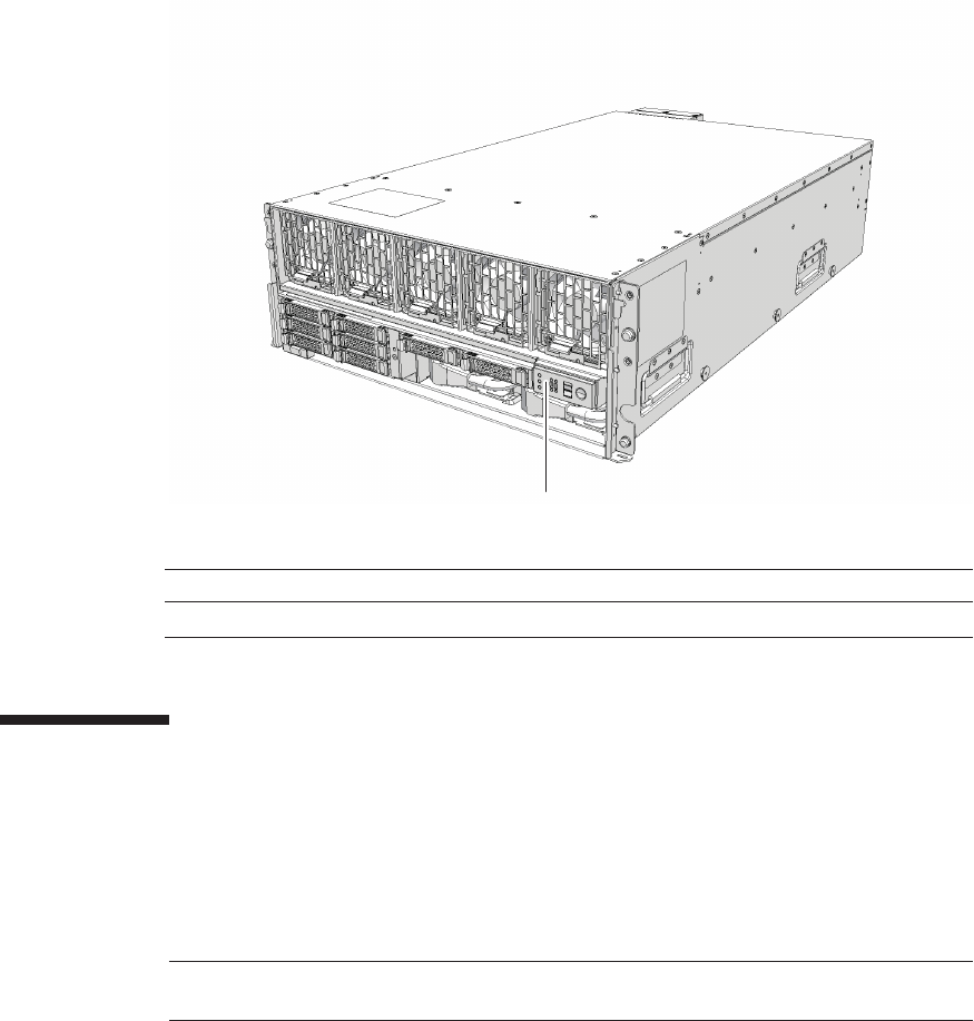
(1)
Location number Component
1 Operation panel (OPNL)
Note - Read and understand the instructions in this chapter before starting the maintenance
work. Also see the contents of "Chapter 1 Before Starting Maintenance Work."
Figure 15-1 Location of the operation panel
15.2 Before Maintaining the Operation
Panel
This section describes the types and flow of the maintenance of the operation panel,
as well as some precautions.
15.2.1 Types of maintenance
Table 15-1 lists the types of maintenance for the operation panel. For the definition of
maintenance, see "4.3 Understanding Types of Maintenance."
Fujitsu M10-4/Fujitsu M10-4S/SPARC M10-4/SPARC M10-4S Service Manual ・December 2013282
Table 15-1 Types of maintenance for operation panel
Configuration Active/hot Active/cold Inactive/hot Inactive/cold (*1) System stopped
Single-chassis configuration
Unsupported Unsupported Unsupported Supported Supported
Building block configuration
Unsupported Supported (*2) Unsupported Supported Supported
*1: For a single-chassis configuration, the inactive/cold maintenance procedure is the same as that for stopping the system, therefore see
the procedure for system-stopped maintenance.
*2: It is necessary to use dynamic reconfiguration (DR) to disconnect a chassis requiring maintenance from the physical partition.
Table 15-2 Maintenance flow
Details of update process Replacement
1 Preparation 15.3
2 Removing the operation panel 15.4
3 Installing the operation panel 15.5
4 Restoring the system 15.6
Note - See the procedure for system-stopped maintenance for inactive/cold maintenance in a
single-chassis configuration.
15.2.2 Maintenance flow
Table 15-2 lists the sequence of the maintenance procedure for the operation panel.
15.2.3 Precautions for replacement
Note the following point when replacing the operation panel:
■If you replace the operation panel, set the BB-ID for the new operation panel to the
same value as that prior to the start of maintenance.
15.3 Enabling the Removal of the Operation
Panel
This section describes the preparations that must be completed prior to the removal
of the operation panel. The preparation procedure differs depending on the
maintenance type as follows:
■Active/Cold maintenance
Chapter 15 Maintaining the Operation Panel 283
Caution - To completely shut down the system, all the power cords must be
removed. If the power cords are not removed, an electrical failure may occur.
Note - Use the DR of the system board on a physical partition for active/cold maintenance.
For the XCP and Oracle VM Server for SPARC/SRU versions that correspond to the DR, see
the latest Product Notes.
Note - Active/cold maintenance can be performed only for a building block configuration.
XSCF> showlogs error
XSCF> replacefru
Note - In the case of a dual power feed, make a note of the locations of the power cords
before disconnecting them to ensure that they are reinstalled correctly.
■Inactive/Cold maintenance
■System-stopped maintenance
15.3.1 Active/Cold maintenance
1. Open the rack door.
2. Log in to the XSCF shell.
3. Execute the showlogs command to identify the component requiring
maintenance.
For details, see "3.3.5 Checking log information."
4. Confirm the hardware and software configurations.
For details, see "4.2 Confirming the System Configuration."
5. Release the chassis, in which the operation panel requiring maintenance is
mounted, from the physical partition.
For details, see "5.2 Releasing a Chassis from the Physical Partition."
6.
Execute the replacefru command to release the chassis requiring maintenance
from the system.
For details, see "5.1 Releasing an FRU from the System with the replacefru
Command."
7. Remove all the power cords from the PSU backplane unit of the chassis
requiring maintenance.
For details, see "5.5.2 Removing the power cord."
Fujitsu M10-4/Fujitsu M10-4S/SPARC M10-4/SPARC M10-4S Service Manual ・December 2013284

Note - Inactive/cold maintenance can be performed only for a building block configuration.
The inactive/cold maintenance procedure for a single-chassis configuration is the same as
that for stopping the system.
XSCF> showlogs error
XSCF> replacefru
Note - Inthecaseofadualpowerfeed,makeanoteofthelocationsofthepowercords
before disconnecting them to ensure that they are reinstalled correctly.
15.3.2 Inactive/Cold maintenance
1. Open the rack door.
2. LogintotheXSCFshell.
3. Execute the showlogs command to identify the component requiring
maintenance.
For details, see "3.3.5 Checking log information."
4. Confirm the hardware and software configurations.
For details, see "4.2 Confirming the System Configuration."
5. Power off the physical partition requiring maintenance.
For details, see "5.3 Powering Off the Physical Partition Requiring Maintenance."
6.
Execute the replacefru command to release the chassis requiring maintenance
from the system.
For details, see "5.1 Releasing an FRU from the System with the replacefru
Command."
7. Remove all the power cords from the PSU backplane unit of the chassis
requiring maintenance.
For details, see "5.5.2 Removing the power cord."
15.3.3 System-stopped maintenance
The procedure in the case of system-stopped maintenance is same for the building
block configuration and single-chassis configuration.
1. Open the rack door.
2. LogintotheXSCFshell.
3. Execute the showlogs command to identify the component requiring
Chapter 15 Maintaining the Operation Panel 285
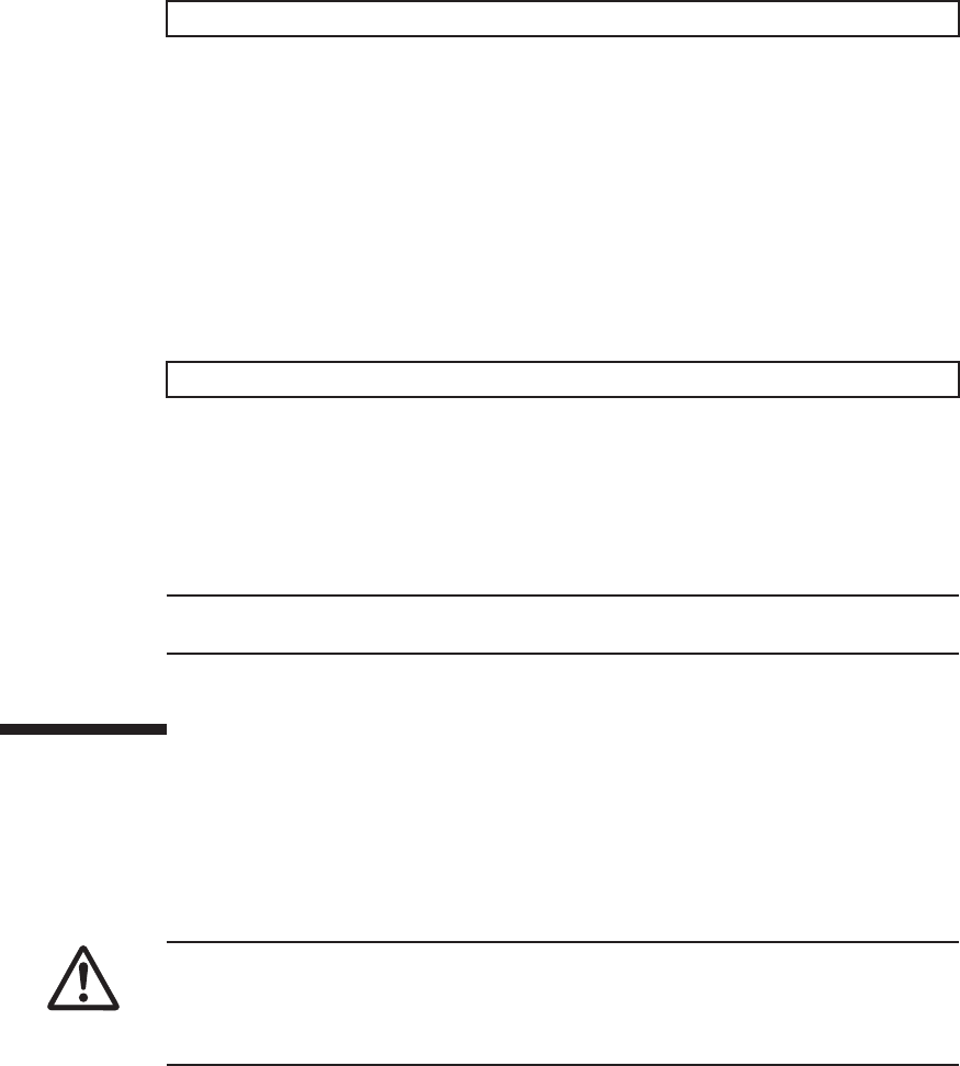
XSCF> showlogs error
XSCF> replacefru
Note - In the case of a dual power feed, make a note of the locations of the power cords
before disconnecting them to ensure that they are reinstalled correctly.
Caution - Before you handle any components, wear a wrist strap to ground any static
electricity. If you perform this procedure without a wrist strap, individual
components or the overall system may be damaged. For details, see "1.5 Notes
Regarding Static Electricity."
maintenance.
For details, see "3.3.5 Checking log information."
4. Confirm the hardware and software configurations.
For details, see "4.2 Confirming the System Configuration."
5. Stop the entire system.
For details, see "5.4 Stopping the Entire System."
6.
Execute the replacefru command to release the chassis requiring maintenance
from the system.
For a single-chassis configuration, you do not have to release the chassis.
Proceed to step 7.
For details, see "5.1 Releasing an FRU from the System with the replacefru
Command."
7. Remove all the power cords from the PSU backplane unit of the chassis
requiring maintenance.
For details, see "5.5.2 Removing the power cord."
15.4 Removing the Operation Panel
This section describes the procedure for removing the operation panel.
Enable the removal of the operation panel before attempting to remove it. For details,
see "15.3 Enabling the Removal of the Operation Panel."
Fujitsu M10-4/Fujitsu M10-4S/SPARC M10-4/SPARC M10-4S Service Manual ・December 2013286
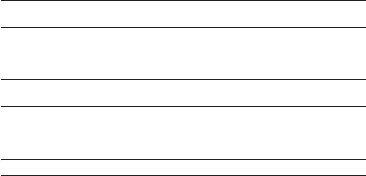
Note - Make a note of the positions of the cables connected to the external interface before
disconnecting them to ensure that they are reinstalled correctly.
Note - Make a note of the positions of the PCIe card cassettes before removing them to ensure
that they are reinstalled correctly.
Note - If no crossbar unit is mounted, proceed to step 7.
15.4.1 Accessing the operation panel
1. Check the ID switch on the operation panel and record the BB-ID set for the
chassis requiring maintenance.
2. Lower the cable support.
For details, see "5.5.1 Lowering the cable support."
3. Remove all the cables connected to the external interface.
The cables to be removed are as follows.
■Interface cable connected to the PCI Express (PCIe) card
■Crossbar cable
■XSCF BB control cable
■XSCF DUAL control cable
■LAN cable
4. Remove all PCIe card cassettes.
For details, see "13.5.2 Removing a PCI Express card cassette."
5. Remove all the crossbar units.
For details, see "9.4.2 Removing a crossbar unit."
6. Loosen the three screws securing the mounting frame of the crossbar unit
and then remove the frame.
Chapter 15 Maintaining the Operation Panel 287
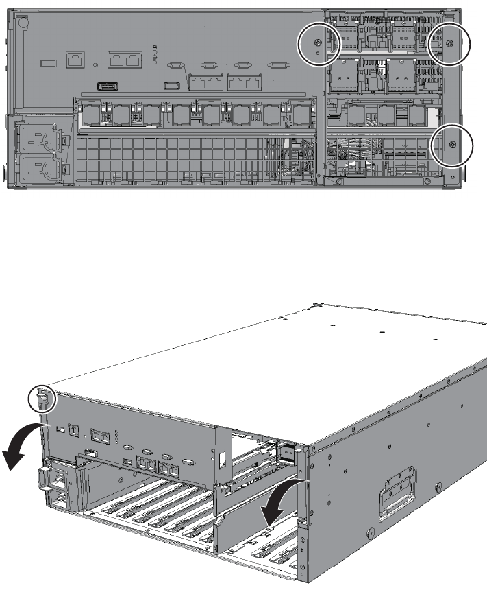
Figure 15-2 Screws securing the mounting frame
7. Loosen the screw securing the CPU memory unit and lower the right and left
levers to the horizontal position.
Figure 15-3 Screw securing CPU memory unit
8. Pull out the CPU memory unit by about 10 cm (3.9 in.)
9. Remove the front cover.
For details, see "5.5.3 Removing the front cover."
10. Pull out the power supply unit by about 10 cm (3.9 in.)
For details, see "10.4 Removing a Power Supply Unit."
11. Remove all the fan units.
For details, see "11.4 Removing a Fan Unit."
Fujitsu M10-4/Fujitsu M10-4S/SPARC M10-4/SPARC M10-4S Service Manual ・December 2013288
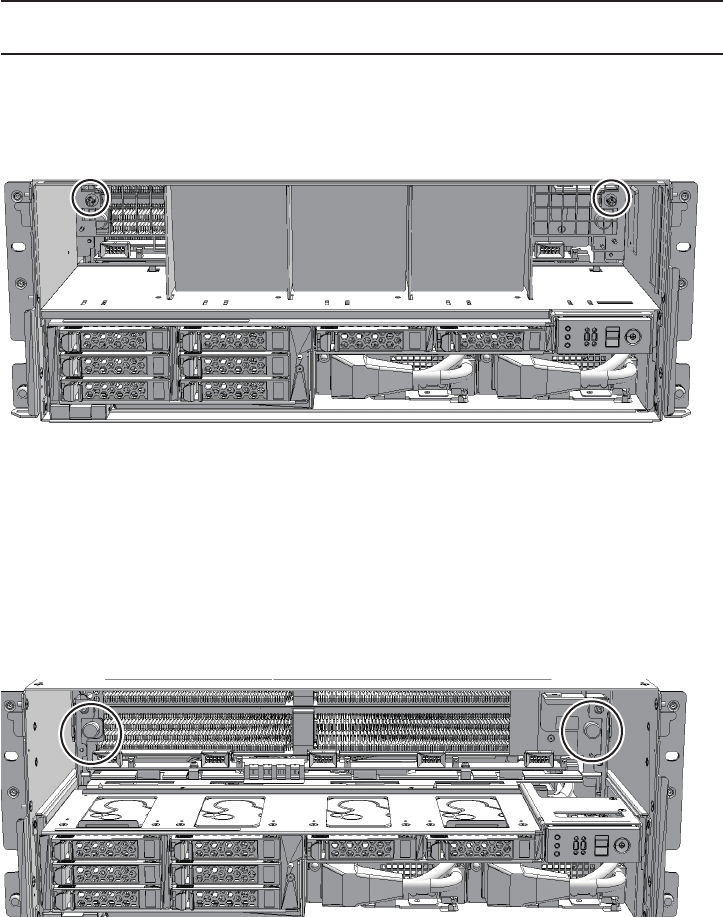
Note - Make a note of the locations of the fan units before removing them to ensure that they
are reinstalled correctly.
12. Loosen the two screws in the fan slot and then remove the fan shelf.
Figure 15-4 Screws in the fan slot
15.4.2 Removing the operation panel
1. Loosen the two screws securing the PSU backplane unit and partially pull out
the PSU backplane unit.
Figure 15-5 Screws securing the PSU backplane unit
2. Remove the cable from the operation panel and loosen one screw (A in the
figure).
Chapter 15 Maintaining the Operation Panel 289
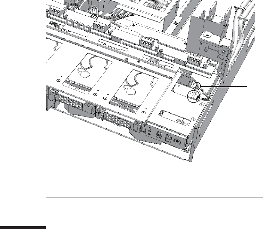
A
Note - Place the removed operation panel on a grounded antistatic ESD mat.
Figure 15-6 Cables and screws of the operation panel
3. Pull the operation panel forward to remove it.
15.5 Installing the Operation Panel
This section describes the procedure for installing the operation panel.
15.5.1 Installing the operation panel
1. Set the BB-ID of the operation panel to the value prior to the start of
maintenance.
2. Place the operation panel in the mounting position and then tighten one
screw.
Fujitsu M10-4/Fujitsu M10-4S/SPARC M10-4/SPARC M10-4S Service Manual ・December 2013290
Note - Reinstall the fan units in their original positions by referring to the notes you made
prior to the start of maintenance.
Note - Check that the front cover is firmly attached and secured.
Note - If no crossbar unit is mounted, proceed to step 11.
Note - Reinstall the PCIe card cassettes in their original positions by referring to the notes
that you made prior to the start of maintenance.
15.5.2 Restoring the chassis
1. Connect the cables to the operation panel.
2. Reinstall the PSU backplane unit in its original position and then tighten the
two screws.
3. Reinstall the fan shelf and then tighten the two screws in the fan slot.
4. Reinstall the power supply unit in its original position.
For details, see "10.5.1 Installing a power supply unit."
5. Install all the fan units.
For details, see "11.5.1 Installing a fan unit."
6. Install the front cover.
For details, see "6.5.3 Installing the front cover."
7. Insert the CPU memory unit into the chassis.
8. Raise the right and left levers of the CPU memory unit and then tighten the
one screw.
9. Install the mounting frame for the crossbar unit and then tighten the three
screws.
10. Install all the crossbar units.
For details, see "9.5.1 Installing a crossbar unit."
11. Install all the PCIe card cassettes.
For details, see "13.6.2 Installing a PCI Express card cassette."
12. Connect all the cables to the external interface.
Thecablestobeconnectedareasfollows.
■Interface cable connected to the PCIe card
■Crossbar cable
■XSCF BB control cable
■XSCF DUAL control cable
Chapter 15 Maintaining the Operation Panel 291
Note - Reconnect the cables of the external interface in their original positions by referring to
the notes that you made prior to the start of maintenance.
Note - See the procedure for system-stopped maintenance for inactive/cold maintenance in a
single-chassis configuration.
Note - Use the DR of the system board on a physical partition for active/cold maintenance.
For the XCP and Oracle VM Server for SPARC/SRU versions that correspond to the DR, see
the latest Product Notes.
Note - Active/cold maintenance can be performed only for a building block configuration.
Note - In the case of a dual power feed, connect the power cords in their original positions by
referring to the record that you made before the start of maintenance.
■LAN cable
13. Lift the cable support to fix it.
For details, see "6.5.2 Fixing the cable support."
15.6 Restoring the System
This section describes the procedure for restoring the system after installing the
operation panel. The restoration procedure differs depending on the maintenance
type as follows:
■Active/Cold maintenance
■Inactive/Cold maintenance
■System-stopped maintenance
15.6.1 Active/Cold maintenance
1. Connect all the power cords to the PSU backplane unit of the chassis
requiring maintenance.
For details, see "6.5.1 Installing the power cord."
2. Return to the operation of the XSCF firmware replacefru command to confirm
that the chassis has been incorporated into the system.
For details, see "6.1 Incorporating an FRU into the System with the replacefru
Command."
3. Execute the diagxbu command to diagnose the crossbar cables.
Fujitsu M10-4/Fujitsu M10-4S/SPARC M10-4/SPARC M10-4S Service Manual ・December 2013292

XSCF> diagxbu -y -b 00 -p 02
XSCF> showlogs error
Note - Inactive/cold maintenance can be performed only for a building block configuration.
The inactive/cold maintenance procedure for a single-chassis configuration is the same as
that for stopping the system.
Note - In the case of a dual power feed, connect the power cords in their original positions by
referring to the record that you made before the start of maintenance.
Diagnosis is performed when the system board of the chassis connected with the
crossbar cables is incorporated into the physical partition, and the physical
partition is powered on.
The example below specifies the following:
00: BB-ID of the chassis to start the diagnosis
02: PPAR-ID of the destination where the chassis to start the diagnosis is
connected (You can specify only one of these.)
4. Execute the showlogs command to confirm that the system is operating
normally.
For details, see "3.3.5 Checking log information."
5. Incorporate the chassis, in which the operation panel requiring maintenance
is mounted, into the physical partition.
For details, see "6.2 Incorporating a Chassis into a Physical Partition."
6. Close the rack door.
15.6.2 Inactive/Cold maintenance
1. Connect all the power cords to the PSU backplane unit of the chassis
requiring maintenance.
For details, see "6.5.1 Installing the power cord."
2. Return to the operation of the XSCF firmware replacefru command to confirm
that the chassis has been incorporated into the system.
For details, see "6.1 Incorporating an FRU into the System with the replacefru
Command."
3. Execute the diagxbu command to diagnose the crossbar cables.
Diagnosis is performed when the system board of the chassis connected with the
crossbar cables is not incorporated into the physical partition, or when the
Chapter 15 Maintaining the Operation Panel 293

XSCF> diagxbu -y -b 00 -t 01
XSCF> showlogs error
Note - In the case of a dual power feed, connect the power cords in their original positions by
referring to the record that you made before the start of maintenance.
physical partition into which the chassis is incorporated is powered off.
The example below specifies the following:
00: BB-ID of the chassis to start the diagnosis
01: BB-ID of the destination where the chassis to start the diagnosis is connected
(You can specify one or more of these.)
To specify multiple connection destination BB-IDs, enter a command like
"diagxbu -y -b 00 -t 01 -t 02".
4. Execute the showlogs command to confirm that the system is operating
normally.
For details, see "3.3.5 Checking log information."
5. Power on the physical partition requiring maintenance.
For details, see "6.3 Powering On the Physical Partition Requiring Maintenance."
6. Close the rack door.
15.6.3 System-stopped maintenance
1. Connect all the power cords to the PSU backplane unit.
For details, see "6.5.1 Installing the power cord."
2. Return to the operation of the XSCF firmware replacefru command to confirm
that the chassis has been incorporated into the system.
For details, see "6.1 Incorporating an FRU into the System with the replacefru
Command."
For a single-chassis configuration, you do not have to incorporate the chassis.
Proceed to step 5.
3. Execute the diagxbu command to diagnose the crossbar cables.
Diagnosis is performed when the system board of the chassis connected with the
crossbar cables is not incorporated into the physical partition, or when the
physical partition into which the chassis is incorporated is powered off.
The example below specifies the following:
Fujitsu M10-4/Fujitsu M10-4S/SPARC M10-4/SPARC M10-4S Service Manual ・December 2013294

XSCF> diagxbu -y -b 00 -t 01
XSCF> showlogs error
00: BB-ID of the chassis to start the diagnosis
01: BB-ID of the destination where the chassis to start the diagnosis is connected
(You can specify one or more of these.)
To specify multiple connection destination BB-IDs, enter a command like
"diagxbu -y -b 00 -t 01 -t 02".
4. Execute the showlogs command to confirm that the system is operating
normally.
For details, see "3.3.5 Checking log information."
5. Start the entire system.
For details, see "6.4 Starting the Entire System."
6. Close the rack door.
Chapter 15 Maintaining the Operation Panel 295
Fujitsu M10-4/Fujitsu M10-4S/SPARC M10-4/SPARC M10-4S Service Manual ・December 2013296

Chapter 16
Maintaining the Crossbar Units of the
Crossbar Box
This chapter describes the procedure for maintaining the crossbar units mounted on
the crossbar box.
■Configuration of the Crossbar Units
■Before Maintaining a Crossbar Unit
■Enabling the Removal of a Crossbar Unit
■Removing a Crossbar Unit
■Installing a Crossbar Unit
■Restoring the System
16.1 Configuration of the Crossbar Units
This section describes the configuration and the locations of the crossbar units.
297
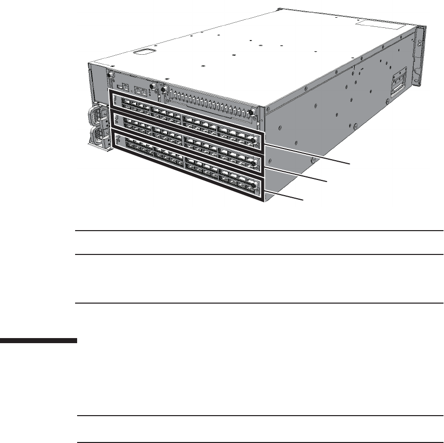
(3)
(2)
(1)
Location
number
Component
1 Crossbar unit (XBUX#0)
2 Crossbar unit (XBUX#1)
3 Crossbar unit (XBUX#2)
Note - Read and understand the instructions in this chapter before starting the maintenance
work. Also see the contents of "Chapter 1 Before Starting Maintenance Work."
Figure 16-1 Location of crossbar units
16.2 Before Maintaining a Crossbar Unit
This section describes the types and flow of maintenance of the crossbar units.
16.2.1 Types of maintenance
Table 16-1 lists the types of maintenance for the crossbar units. For the definition of
maintenance, see "4.3 Understanding Types of Maintenance."
Fujitsu M10-4/Fujitsu M10-4S/SPARC M10-4/SPARC M10-4S Service Manual ・December 2013298
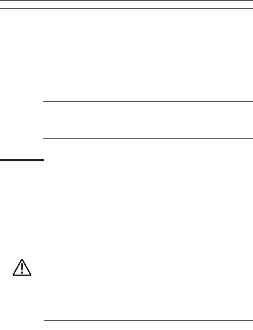
Table 16-1 Types of maintenance for the crossbar unit
Configuration Active/hot Active/cold Inactive/hot Inactive/cold System stopped
Building block configuration
Unsupported Supported (*1) Unsupported Supported Supported (*2)
*1: If any physical partition mounted on two or more chassis is currently operating, the crossbar box cannot be powered off.
*2: All the physical partitions must be powered off, and the system must be completely shut down.
Table 16-2 Maintenance flow
Details of update process Replacement
1 Preparation 16.3
2 Removing the crossbar units 16.4
3 Installing the crossbar unit 16.5
4 Restoring the system 16.6
Caution - To completely shut down the system, all the power cords must be
removed. If the power cords are not removed, an electrical failure may occur.
Note - Confirm that the POWER LED on the crossbar box is off.
16.2.2 Maintenance flow
Table 16-2 lists the sequence of the maintenance procedure for the crossbar units.
16.3 Enabling the Removal of a Crossbar
Unit
This section describes preparation that must be completed prior to removing a
crossbar unit. The preparation procedure differs depending on the maintenance type
as follows:
■Active/Cold maintenance
■Inactive/Cold maintenance
■System-stopped maintenance
16.3.1 Active/Cold maintenance
Chapter 16 Maintaining the Crossbar Units of the Crossbar Box 299

XSCF> showlogs error
Note - In the case of a dual power feed, make a note of the locations of the power cords
before disconnecting them to ensure that they are reinstalled correctly.
XSCF> showlogs error
Note - In the case of a dual power feed, make a note of the locations of the power cords
before disconnecting them to ensure that they are reinstalled correctly.
1. Open the rack door.
2. Log in to the XSCF shell.
3. Execute the showlogs command to identify the component requiring
maintenance.
For details, see "3.3.5 Checking log information."
4. Confirm the hardware and software configurations.
For details, see "4.2 Confirming the System Configuration."
5. Power off the physical partition requiring maintenance.
For details, see "5.3 Powering Off the Physical Partition Requiring Maintenance."
6. Remove all the power cords from the power supply unit of the crossbar box
requiring maintenance.
For details, see "5.5.2 Removing the power cord."
16.3.2 Inactive/Cold maintenance
1. Open the rack door.
2. Log in to the XSCF shell.
3. Execute the showlogs command to identify the component requiring
maintenance.
For details, see "3.3.5 Checking log information."
4. Confirm the hardware and software configurations.
For details, see "4.2 Confirming the System Configuration."
5. Power off the physical partition requiring maintenance.
For details, see "5.3 Powering Off the Physical Partition Requiring Maintenance."
6. Remove all the power cords from the power supply unit of the crossbar box
requiring maintenance.
For details, see "5.5.2 Removing the power cord."
Fujitsu M10-4/Fujitsu M10-4S/SPARC M10-4/SPARC M10-4S Service Manual ・December 2013300
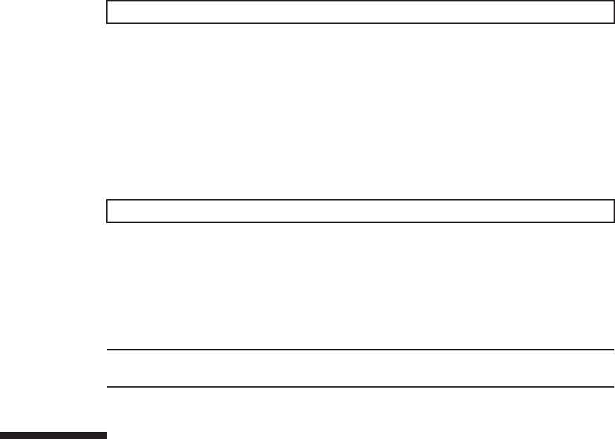
XSCF> showlogs error
XSCF> replacefru
Note - Inthecaseofadualpowerfeed,makeanoteofthelocationsofthepowercords
before disconnecting them to ensure that they are reinstalled correctly.
16.3.3 System-stopped maintenance
1. Open the rack door.
2. LogintotheXSCFshell.
3. Execute the showlogs command to identify the component requiring
maintenance.
For details, see "3.3.5 Checking log information."
4. Confirm the hardware and software configurations.
For details, see "4.2 Confirming the System Configuration."
5. Power off all the physical partitions.
For details, see "5.3 Powering Off the Physical Partition Requiring Maintenance."
6. Execute the replacefru command to release the crossbar unit requiring
maintenance from the system.
For details, see "5.1 Releasing an FRU from the System with the replacefru
Command."
7. Remove all the power cords from the power supply unit of the crossbar box
requiring maintenance.
For details, see "5.5.2 Removing the power cord."
16.4 Removing a Crossbar Unit
This section describes the procedure for removing a crossbar unit.
Enable the removal of the crossbar box before attempting to remove it. For details,
see "16.3 Enabling the Removal of a Crossbar Unit."
Chapter 16 Maintaining the Crossbar Units of the Crossbar Box 301
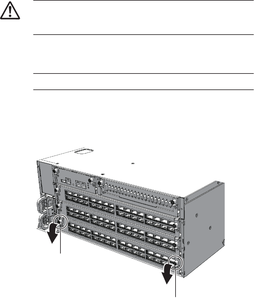
Caution - Before you handle any components, wear a wrist strap to ground any static
electricity. If you perform this procedure without a wrist strap, individual
components or the overall system may be damaged. For details, see "1.5 Notes
Regarding Static Electricity."
Note - Make a note of the positions of the crossbar cables (optical) before disconnecting them
to ensure that they are reinstalled correctly.
A
A
1. Remove all crossbar cables (optical) connected to the crossbar unit requiring
maintenance.
For details, see "25.4 Removing a Crossbar Cable (Optical)."
2. Loosen the two screws (A in the figure) on the right and left sides and lower
the levers to release the crossbar unit.
Figure 16-2 Positions of screws and levers
3. Hold the levers and partially pull out the crossbar unit.
Fujitsu M10-4/Fujitsu M10-4S/SPARC M10-4/SPARC M10-4S Service Manual ・December 2013302
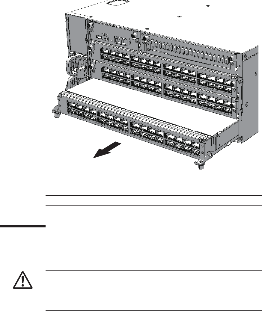
Note - Place the removed crossbar unit on a grounded antistatic ESD mat.
Note - When mounting a crossbar unit, check the connectors on both of the chassis
and crossbar unit beforehand to confirm that no pin is bent and all the pins are neatly
arranged in lines. If a crossbar unit is mounted with a bent pin in a connector, the
chassis or crossbar unit may be damaged. Also, carefully proceed with the work to
prevent any pin from being bent.
Figure 16-3 Pulling out crossbar unit
4. Support the crossbar unit from below with one hand and remove it carefully.
16.5 Installing a Crossbar Unit
This section describes the procedure for installing a crossbar unit.
1. Carefully insert the crossbar unit into the chassis.
2. Close the right and left levers of the crossbar unit and tighten two screws.
Chapter 16 Maintaining the Crossbar Units of the Crossbar Box 303
Note - Reinstall the crossbar cables (optical) in their original positions by referring to the
notes that you made prior to the start of maintenance.
Note - In the case of a dual power feed, connect the power cords in their original positions by
referring to the record that you made before the start of maintenance.
XSCF> diagxbu -y -b 00 -p 02
3. Connect all crossbar cables (optical) to the crossbar unit.
For details, see "25.5 Installing a Crossbar Cable (Optical)."
16.6 Restoring the System
This section describes the procedure for restoring the system after installing the
crossbar units. The restoration procedure differs depending on the maintenance type
as follows:
■Active/Cold maintenance
■Inactive/Cold maintenance
■System-stopped maintenance
16.6.1 Active/Cold maintenance
1. Connect all the power cords to the power supply unit of the crossbar box
requiring maintenance.
For details, see "6.5.1 Installing the power cord."
2. Execute the diagxbu command to diagnose the crossbar cables.
Diagnosis is performed when the system board of the chassis connected with the
crossbar cables is incorporated into the physical partition, and the physical
partition is powered on.
The example below specifies the following:
00: BB-ID of the chassis to start the diagnosis
02: PPAR-ID of the destination where the chassis to start the diagnosis is
connected (You can specify only one of these.)
3. Power on the physical partition requiring maintenance.
For details, see "6.3 Powering On the Physical Partition Requiring Maintenance."
4. Close the rack door.
Fujitsu M10-4/Fujitsu M10-4S/SPARC M10-4/SPARC M10-4S Service Manual ・December 2013304
Note - In the case of a dual power feed, connect the power cords in their original positions by
referring to the record that you made before the start of maintenance.
XSCF> diagxbu -y -b 00 -t 01
Note - In the case of a dual power feed, connect the power cords in their original positions by
referring to the record that you made before the start of maintenance.
16.6.2 Inactive/Cold maintenance
1. Connect all the power cords to the power supply unit of the crossbar box
requiring maintenance.
For details, see "6.5.1 Installing the power cord."
2. Execute the diagxbu command to diagnose the crossbar cables.
Diagnosis is performed when the system board of the chassis connected with the
crossbar cables is not incorporated into the physical partition, or when the
physical partition into which the chassis is incorporated is powered off.
The example below specifies the following:
00: BB-ID of the chassis to start the diagnosis
01: BB-ID of the destination where the chassis to start the diagnosis is connected
(You can specify one or more of these.)
To specify multiple connection destination BB-IDs, enter a command like
"diagxbu -y -b 00 -t 01 -t 02".
3. Power on the physical partition requiring maintenance.
For details, see "6.3 Powering On the Physical Partition Requiring Maintenance."
4. Close the rack door.
16.6.3 System-stopped maintenance
1. Connect all the power cords to the power supply unit of the crossbar box
requiring maintenance.
For details, see "6.5.1 Installing the power cord."
2. Return to the operation of the XSCF firmware replacefru command to confirm
that the crossbar unit has been incorporated into the system.
For details, see "6.1 Incorporating an FRU into the System with the replacefru
Command."
3. Execute the diagxbu command to diagnose the crossbar cables.
Chapter 16 Maintaining the Crossbar Units of the Crossbar Box 305

XSCF> diagxbu -y -b 00 -t 01
XSCF> showlogs error
Diagnosis is performed when the system board of the chassis connected with the
crossbar cables is not incorporated into the physical partition, or when the
physical partition into which the chassis is incorporated is powered off.
The example below specifies the following:
00: BB-ID of the chassis to start the diagnosis
01: BB-ID of the destination where the chassis to start the diagnosis is connected
(You can specify one or more of these.)
To specify multiple connection destination BB-IDs, enter a command like
"diagxbu -y -b 00 -t 01 -t 02".
4. Execute the showlogs command to confirm that the system is operating
normally.
For details, see "3.3.5 Checking log information."
5. Power on the physical partition requiring maintenance.
For details, see "6.3 Powering On the Physical Partition Requiring Maintenance."
6. Close the rack door.
Fujitsu M10-4/Fujitsu M10-4S/SPARC M10-4/SPARC M10-4S Service Manual ・December 2013306

Chapter 17
Maintaining the XSCF Unit of the
Crossbar Box
This chapter describes the procedure for maintaining the XSCF unit mounted in the
crossbar box.
■Location of the XSCF Unit
■Before Maintaining the XSCF Unit
■Enabling the Removal of the XSCF Unit
■Removing the XSCF Unit
■Installing the XSCF Unit
■Restoring the System
17.1 Location of the XSCF Unit
This section describes the location of the XSCF unit.
307
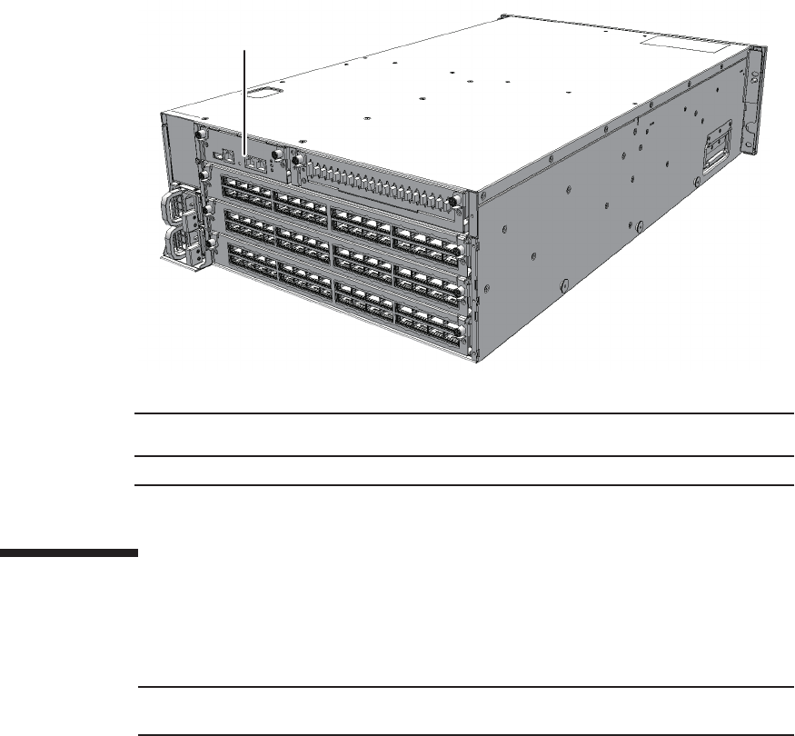
(1)
Location
number
Component
1 XSCF unit (XSCFU)
Note - Read and understand the instructions in this chapter before starting the maintenance
work. Also see the contents of "Chapter 1 Before Starting Maintenance Work."
Figure 17-1 Location of XSCF unit
17.2 Before Maintaining the XSCF Unit
This section describes the types and flow of maintenance of the XSCF unit.
17.2.1 Types of maintenance
Table 17-1 lists the types of maintenance for the XSCF unit. For the definition of
maintenance, see "4.3 Understanding Types of Maintenance."
Fujitsu M10-4/Fujitsu M10-4S/SPARC M10-4/SPARC M10-4S Service Manual ・December 2013308
Table 17-1 Type of maintenance for XSCF unit
Configuration Active/hot Active/cold Inactive/hot Inactive/cold System stopped
Building block configuration
Supported (*1) Unsupported
(*2)
Supported Unsupported
(*2)
Supported (*3)
*1: The XSCF must be configured as a slave before maintenance is started. If the XSCF is operating as the master XSCF, switch it to a
standby XSCF.
*2: If any physical partition is currently operating, the crossbar box cannot be powered off.
*3: All the physical partitions must be powered off, and the system must be completely shut down.
Table 17-2 Maintenance flow
Details of update process Replacement
1 Preparation 17.3
2 RemovinganXSCFunit 17.4
3 Installing an XSCF unit 17.5
4 Restoring the system 17.6
Caution - To completely shut down the system, all the power cords must be
removed. If the power cords are not removed, an electrical failure may occur.
17.2.2 Maintenance flow
Table 17-2 lists the sequence of the maintenance procedure for the XSCF unit.
17.3 Enabling the Removal of the XSCF
Unit
This section describes the preparations that must be completed prior to removing an
XSCF unit. The preparation procedure differs depending on the maintenance type as
follows:
■Active/Hot maintenance
■Inactive/Hot maintenance
■System-stopped maintenance
Chapter 17 Maintaining the XSCF Unit of the Crossbar Box 309
XSCF> showlogs error
XSCF> switchscf -t Standby
XSCF> replacefru
XSCF> showlogs error
17.3.1 Active/Hot maintenance
1. Open the rack door.
2. Log in to the XSCF shell.
3. Execute the showlogs command to identify the component requiring
maintenance.
For details, see "3.3.5 Checking log information."
4. Confirm the hardware and software configurations.
For details, see "4.2 Confirming the System Configuration."
5. Execute the switchscf command to switch the master XSCF to a standby
XSCF.
Perform this when the chassis requiring maintenance is operating as a master
chassis.
6. Execute the replacefru command to release the XSCF unit requiring
maintenance from the system.
For details, see "5.1 Releasing an FRU from the System with the replacefru
Command."
17.3.2 Inactive/Hot maintenance
1. Open the rack door.
2. Log in to the XSCF shell.
3. Execute the showlogs command to identify the component requiring
maintenance.
For details, see "3.3.5 Checking log information."
4. Confirm the hardware and software configurations.
For details, see "4.2 Confirming the System Configuration."
5. Stop the physical partition requiring maintenance.
Fujitsu M10-4/Fujitsu M10-4S/SPARC M10-4/SPARC M10-4S Service Manual ・December 2013310
XSCF> replacefru
XSCF> showlogs error
XSCF> replacefru
Note - Inthecaseofadualpowerfeed,makeanoteofthelocationsofthepowercords
before disconnecting them to ensure that they are reinstalled correctly.
For details, see "5.3 Powering Off the Physical Partition Requiring Maintenance."
6. Execute the replacefru command to release the XSCF unit requiring
maintenance from the system.
For details, see "5.1 Releasing an FRU from the System with the replacefru
Command."
17.3.3 System-stopped maintenance
1. Open the rack door.
2. LogintotheXSCFshell.
3. Execute the showlogs command to identify the component requiring
maintenance.
For details, see "3.3.5 Checking log information."
4. Confirm the hardware and software configurations.
For details, see "4.2 Confirming the System Configuration."
5. Power off all the physical partitions.
For details, see "5.3 Powering Off the Physical Partition Requiring Maintenance."
6. Execute the replacefru command to release the XSCF unit requiring
maintenance from the system.
For details, see "5.1 Releasing an FRU from the System with the replacefru
Command."
7. Remove all the power cords from the power supply unit of the crossbar box
requiring maintenance.
For details, see "5.5.2 Removing the power cord."
Chapter 17 Maintaining the XSCF Unit of the Crossbar Box 311
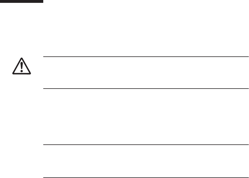
Caution - Before you handle any components, wear a wrist strap to ground any static
electricity. If you perform this procedure without a wrist strap, individual
components or the overall system may be damaged. For details, see "1.5 Notes
Regarding Static Electricity."
Note - The cables connected to the rear of the crossbar box are bundled together and fastened
to the right cable support with a hook-and-loop fastener. To remove the cables, first remove
the hook-and-loop fastener from the cable support.
Note - Record the positions of the cables before removing them to ensure that they are
reinstalled correctly.
17.4 Removing the XSCF Unit
This section describes the procedure for removing the XSCF unit.
Enable the removal of the XSCF unit before attempting to remove it. For details, see
"17.3 Enabling the Removal of the XSCF Unit."
1. Remove all the cables connected to the maintenance-target XSCF unit.
The cables to be removed are as follows.
■Serial cable
■LAN cable
■USB device
2. Loosen the two screws (A in the figure) of the XSCF unit and lower the right
and left levers to release the XSCF unit.
Fujitsu M10-4/Fujitsu M10-4S/SPARC M10-4/SPARC M10-4S Service Manual ・December 2013312
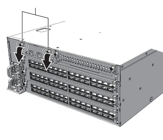
A
Figure 17-2 Positions of screws and levers
3. Hold the levers and partially pull out the XSCF unit.
Chapter 17 Maintaining the XSCF Unit of the Crossbar Box 313
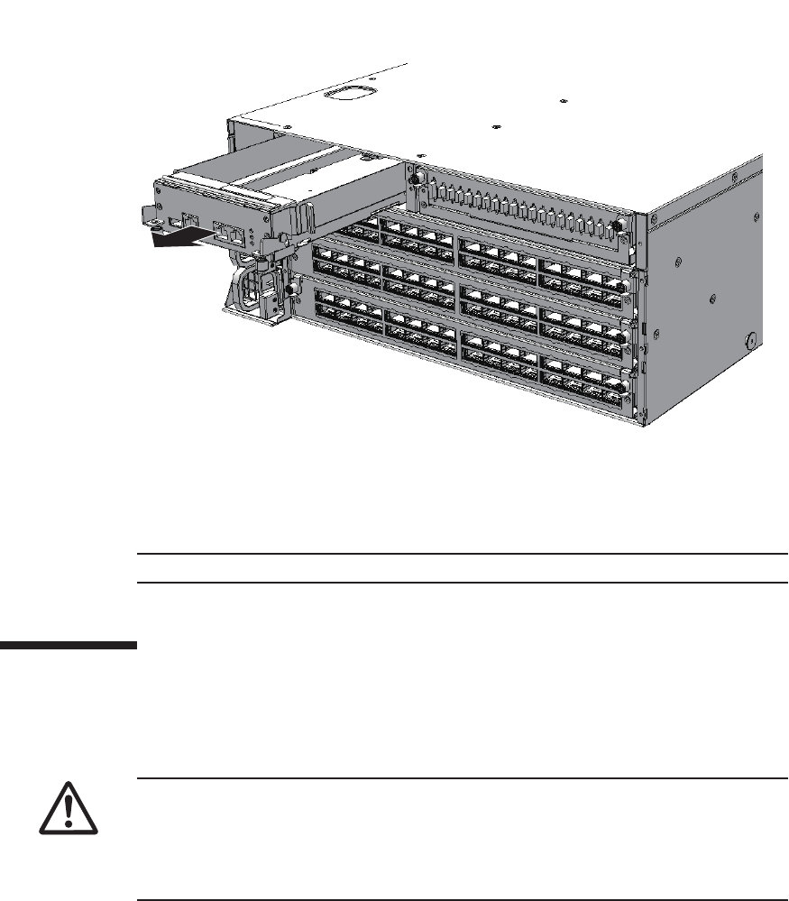
Note - Place the removed XSCF unit on a grounded antistatic ESD mat.
Note - When mounting a XSCF unit, check the connectors on both of the chassis and
XSCF unit beforehand to confirm that no pin is bent and all the pins are neatly
arranged in lines. If an XSCF unit is mounted with a bent pin in a connector, the
chassis or XSCF unit may be damaged. Also, carefully proceed with the work to
prevent any pin from being bent.
Figure 17-3 Pulling out the XSCF unit
4. Support the XSCF unit from below with one hand and then remove it carefully.
17.5 Installing the XSCF Unit
This section describes the procedure for installing the XSCF unit.
1. Carefully insert the XSCF unit into the chassis.
2. Raise the right and left levers and then tighten the two screws.
3. Reconnect all the cables to the XSCF unit.
Fujitsu M10-4/Fujitsu M10-4S/SPARC M10-4/SPARC M10-4S Service Manual ・December 2013314
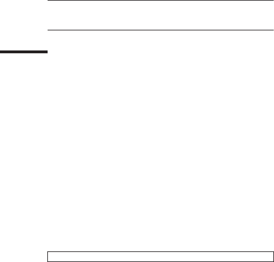
Note - Reinstall the cables in their original positions by referring to the notes that you made
prior to the start of maintenance.
Note - After connecting the cables, use the hook-and-loop fastener to bundle and fix the
cables to the cable support at the rear.
XSCF> switchscf -t Active
Thecablestobereconnectedareasfollows.
■Serial cable
■LAN cable
■USB device
17.6 Restoring the System
This section describes the procedure for restoring the system after installing the XSCF
unit. The restoration procedure differs depending on the maintenance type as follows:
■Active/Hot maintenance
■Inactive/Hot maintenance
■System-stopped maintenance
17.6.1 Active/Hot maintenance
1. Check that the XSCF STANDBY LED on the operation panel is on.
For the location of LEDs, see "2.3.3 LEDs on each component."
2. Return to the operation of the XSCF firmware replacefru command to confirm
that the XSCF unit has been incorporated into the system.
For details, see "6.1 Incorporating an FRU into the System with the replacefru
Command."
3. Execute the switchscf command to switch the standby XSCF to the master
XSCF.
Execute the command if the chassis requiring maintenance has been switched to
the standby XSCF.
4. Close the rack door.
17.6.2 Inactive/Hot maintenance
1. Return to the operation of the XSCF firmware replacefru command to confirm
Chapter 17 Maintaining the XSCF Unit of the Crossbar Box 315

Note - In the case of a dual power feed, connect the power cords in their original positions by
referring to the record that you made before the start of maintenance.
that the XSCF unit has been incorporated into the system.
For details, see "6.1 Incorporating an FRU into the System with the replacefru
Command."
2. Power on the physical partition requiring maintenance.
For details, see "6.3 Powering On the Physical Partition Requiring Maintenance."
3. Close the rack door.
17.6.3 System-stopped maintenance
1. Connect all the power cords to the power supply unit of the crossbar box
requiring maintenance.
For details, see "6.5.1 Installing the power cord."
2. Return to the operation of the XSCF firmware replacefru command to confirm
that the XSCF unit has been incorporated into the system.
For details, see "6.1 Incorporating an FRU into the System with the replacefru
Command."
3. Start all the physical partitions.
For details, see "6.3 Powering On the Physical Partition Requiring Maintenance."
4. Close the rack door.
Fujitsu M10-4/Fujitsu M10-4S/SPARC M10-4/SPARC M10-4S Service Manual ・December 2013316

Chapter 18
Maintaining the Power Supply Units of
the Crossbar Box
This chapter describes the procedure for maintaining the power supply units
mounted in a crossbar box.
■Configuration of the Power Supply Units
■Before Maintaining a Power Supply Unit
■Enabling the Removal of a Power Supply Unit
■RemovingaPowerSupplyUnit
■Installing a Power Supply Unit
■Restoring the System
18.1 Configuration of the Power Supply
Units
This section describes the configuration and the locations of the power supply units.
The power supply units can have the 1+1 redundant configuration. Active/hot
maintenance can be performed.
317
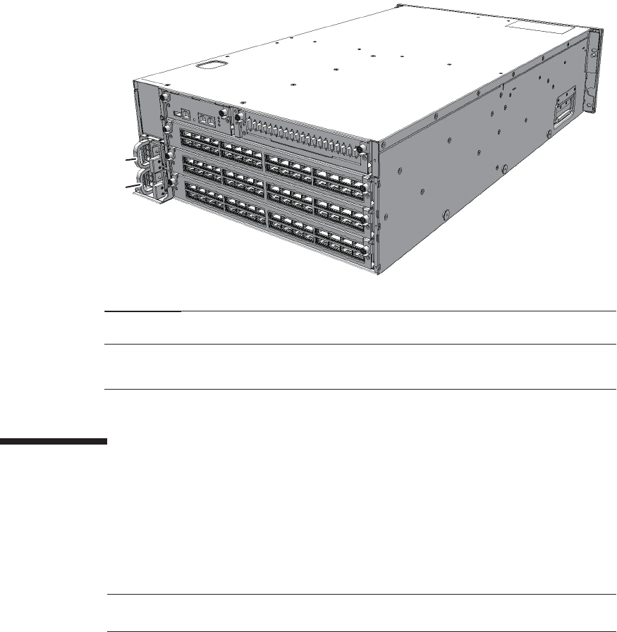
(1)
(2)
Location
number
Component
1 Power supply unit (PSU#0)
2 Power supply unit (PSU#1)
Note - Read and understand the instructions in this chapter before starting the maintenance
work. Also see the contents of "Chapter 1 Before Starting Maintenance Work."
Figure 18-1 Locations of power supply units
18.2 Before Maintaining a Power Supply
Unit
This section describes the types and flow of maintenance of the power supply units,
as well as some precautions.
18.2.1 Types of maintenance
Table 18-1 lists the types of maintenance for the power supply units. For the
definition of maintenance, see "4.3 Understanding Types of Maintenance."
Fujitsu M10-4/Fujitsu M10-4S/SPARC M10-4/SPARC M10-4S Service Manual ・December 2013318
Table 18-1 Types of maintenance for the power supply unit
Configuration Active/hot Active/cold Inactive/hot Inactive/cold System stopped
Building block configuration
Supported (*1) Unsupported
(*2)
Supported Unsupported
(*2)
Supported (*3)
*1: Active/hot replacement can be performed only with a redundant configuration.
*2: If any physical partition is currently operating, the crossbar box cannot be powered off.
*3: All the physical partitions must be powered off, and the system must be completely shut down.
Table 18-2 Maintenance flow
Details of update process Replacement
1 Preparation 18.3
2 Removing a power supply unit 18.4
3 Installing a power supply unit 18.5
4 Restoring the system 18.6
18.2.2 Maintenance flow
Table 18-2 lists the sequence of the maintenance procedure for the power supply
units.
18.2.3 Precautions for replacement
Note the following points when replacing a power supply unit:
■There are two power supply units. Thus, the system can continue operating even
if one of the units fails. Do not, however, operate the system for an extended
period while one unit has failed.
■When replacing multiple power supply units, replace one unit at a time. If
redundancy of the power supply unit cannot be assured, then system-stopped
maintenance must be performed.
■Do not force push the power supply unit into its slot. If excessive force is applied,
other components or the chassis may be damaged.
18.3 Enabling the Removal of a Power
Supply Unit
This section describes the preparations that must be completed prior to the removal
Chapter 18 Maintaining the Power Supply Units of the Crossbar Box 319
Caution - To completely shut down the system, all the power cords must be
removed. If the power cords are not removed, an electrical failure may occur.
Note - Active/hot maintenance is supported only for a redundant configuration.
XSCF> showlogs error
XSCF> replacefru
of a power supply unit. The preparation procedure differs depending on the
maintenance type as follows:
■Active/Hot maintenance
■Inactive/Hot maintenance
■System-stopped maintenance
18.3.1 Active/Hot maintenance
1. Open the rack door.
2. Log in to the XSCF shell.
3. Execute the showlogs command to identify the component requiring
maintenance.
For details, see "3.3.5 Checking log information."
4. Confirm the hardware and software configurations.
For details, see "4.2 Confirming the System Configuration."
5. Execute the replacefru command to release the power supply unit requiring
maintenance from the system.
For details, see "5.1 Releasing an FRU from the System with the replacefru
Command."
6. Remove the power cord from the power supply unit requiring maintenance.
For details, see "5.5.2 Removing the power cord."
18.3.2 Inactive/Hot maintenance
1. Open the rack door.
2. Log in to the XSCF shell.
3. Execute the showlogs command to identify the component requiring
Fujitsu M10-4/Fujitsu M10-4S/SPARC M10-4/SPARC M10-4S Service Manual ・December 2013320

XSCF> showlogs error
XSCF> replacefru
XSCF> showlogs error
XSCF> replacefru
maintenance.
For details, see "3.3.5 Checking log information."
4. Confirm the hardware and software configurations.
For details, see "4.2 Confirming the System Configuration."
5. Power off the physical partition requiring maintenance.
For details, see "5.3 Powering Off the Physical Partition Requiring Maintenance."
6. Execute the replacefru command to release the power supply unit requiring
maintenance from the system.
For details, see "5.1 Releasing an FRU from the System with the replacefru
Command."
7. Remove the power cord from the power supply unit requiring maintenance.
For details, see "5.5.2 Removing the power cord."
18.3.3 System-stopped maintenance
1. Open the rack door.
2. LogintotheXSCFshell.
3. Execute the showlogs command to identify the component requiring
maintenance.
For details, see "3.3.5 Checking log information."
4. Confirm the hardware and software configurations.
For details, see "4.2 Confirming the System Configuration."
5. Power off all the physical partitions.
For details, see "5.3 Powering Off the Physical Partition Requiring Maintenance."
6. Execute the replacefru command to release the power supply unit requiring
maintenance from the system.
For details, see "5.1 Releasing an FRU from the System with the replacefru
Command."
7. Remove all the power cords from the power supply unit of the crossbar box
Chapter 18 Maintaining the Power Supply Units of the Crossbar Box 321
Note - In the case of a dual power feed, make a note of the locations of the power cords
before disconnecting them to ensure that they are reinstalled correctly.
Caution - Before you handle any components, wear a wrist strap to ground any static
electricity. If you perform this procedure without a wrist strap, individual
components or the overall system may be damaged. For details, see "1.5 Notes
Regarding Static Electricity."
requiring maintenance.
For details, see "5.5.2 Removing the power cord."
18.4 Removing a Power Supply Unit
This section describes the procedure for removing a power supply unit.
Enable the removal of the power supply unit before attempting to remove it. For
details, see "18.3 Enabling the Removal of a Power Supply Unit."
1. While pushing the lever (A in the figure) of the power supply unit, hold the
handle (B in the figure) and pull out the power supply unit.
Fujitsu M10-4/Fujitsu M10-4S/SPARC M10-4/SPARC M10-4S Service Manual ・December 2013322
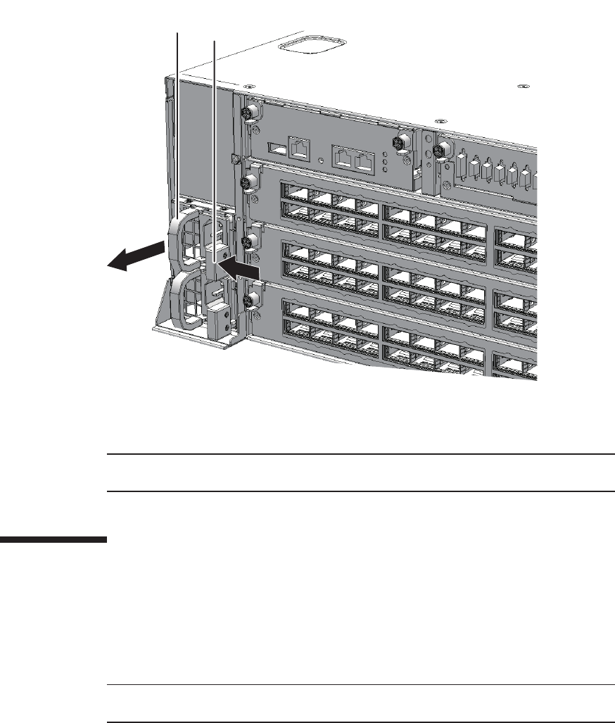
A
B
Note - Place the removed power supply unit on the grounded ESD mat to ground any static
electricity.
Note - Do not forcibly push the power supply unit into its slot. Using excessive force may
damage the component or the chassis.
Figure 18-2 Removingapowersupplyunit
2. Support the power supply unit with one hand from below and carefully pull it
out of the slot.
18.5 Installing a Power Supply Unit
This section describes the procedure for installing a power supply unit.
1. Support the power supply unit from below with one hand and insert it
carefully into its slot.
2. Push the power supply unit fully home.
Chapter 18 Maintaining the Power Supply Units of the Crossbar Box 323
Note - Check that the power supply unit is fully inserted and that the lever is fixed.
XSCF> showstatus
XSCF> showhardconf
18.6 Restoring the System
This section describes the procedure for restoring the system after installing a power
supply unit. The restoration procedure differs depending on the maintenance type as
follows:
■Active/Hot maintenance
■Inactive/Hot maintenance
■System-stopped maintenance
18.6.1 Active/Hot maintenance
1. Connect the power cords to the power supply unit requiring maintenance.
For details, see "6.5.1 Installing the power cord."
2. Confirm that the LED (green) of the power supply unit is on.
3. Return to the operation of the XSCF firmware replacefru command to confirm
that the power supply unit has been incorporated into the system.
For details, see "6.1 Incorporating an FRU into the System with the replacefru
Command."
4. Execute the showstatus command to confirm that the power supply unit is
operating normally after the completion of maintenance.
5. Execute the showhardconf command to check the hardware configuration
and the status of each component.
6. Close the rack door.
18.6.2 Inactive/Hot maintenance
1. Connect the power cords to the power supply unit requiring maintenance.
For details, see "6.5.1 Installing the power cord."
2. Confirm that the LED (green) of the power supply unit is on.
Fujitsu M10-4/Fujitsu M10-4S/SPARC M10-4/SPARC M10-4S Service Manual ・December 2013324

Note - In the case of a dual power feed, connect the power cords in their original positions by
referring to the record that you made before the start of maintenance.
3. Return to the operation of the XSCF firmware replacefru command to confirm
that the power supply unit has been incorporated into the system.
For details, see "6.1 Incorporating an FRU into the System with the replacefru
Command."
4. Power on the physical partition requiring maintenance.
For details, see "6.3 Powering On the Physical Partition Requiring Maintenance."
5. Close the rack door.
18.6.3 System-stopped maintenance
1. Connect all the power cords to the power supply unit of the crossbar box
requiring maintenance.
For details, see "6.5.1 Installing the power cord."
2. Return to the operation of the XSCF firmware replacefru command to confirm
that the power supply unit has been incorporated into the system.
For details, see "6.1 Incorporating an FRU into the System with the replacefru
Command."
3. Power on all the physical partitions.
For details, see "6.3 Powering On the Physical Partition Requiring Maintenance."
4. Close the rack door.
Chapter 18 Maintaining the Power Supply Units of the Crossbar Box 325
Fujitsu M10-4/Fujitsu M10-4S/SPARC M10-4/SPARC M10-4S Service Manual ・December 2013326

Chapter 19
Maintaining the Fan Units of the
Crossbar Box
This chapter describes the procedure for maintaining the fan units mounted in a
crossbar box.
■Configuration of the Fan Units
■Before Maintaining a Fan Unit
■Enabling the Removal of a Fan Unit
■RemovingaFanUnit
■Installing a Fan Unit
■Restoring the System
19.1 Configuration of the Fan Units
This section describes the configuration and the locations of the fan units.
Four fan units are mounted in each chassis.
If one of the cooling fans fails during system operation, the XSCF detects the error.
However, the system can continue operating because the fans have a redundant
configuration.
327
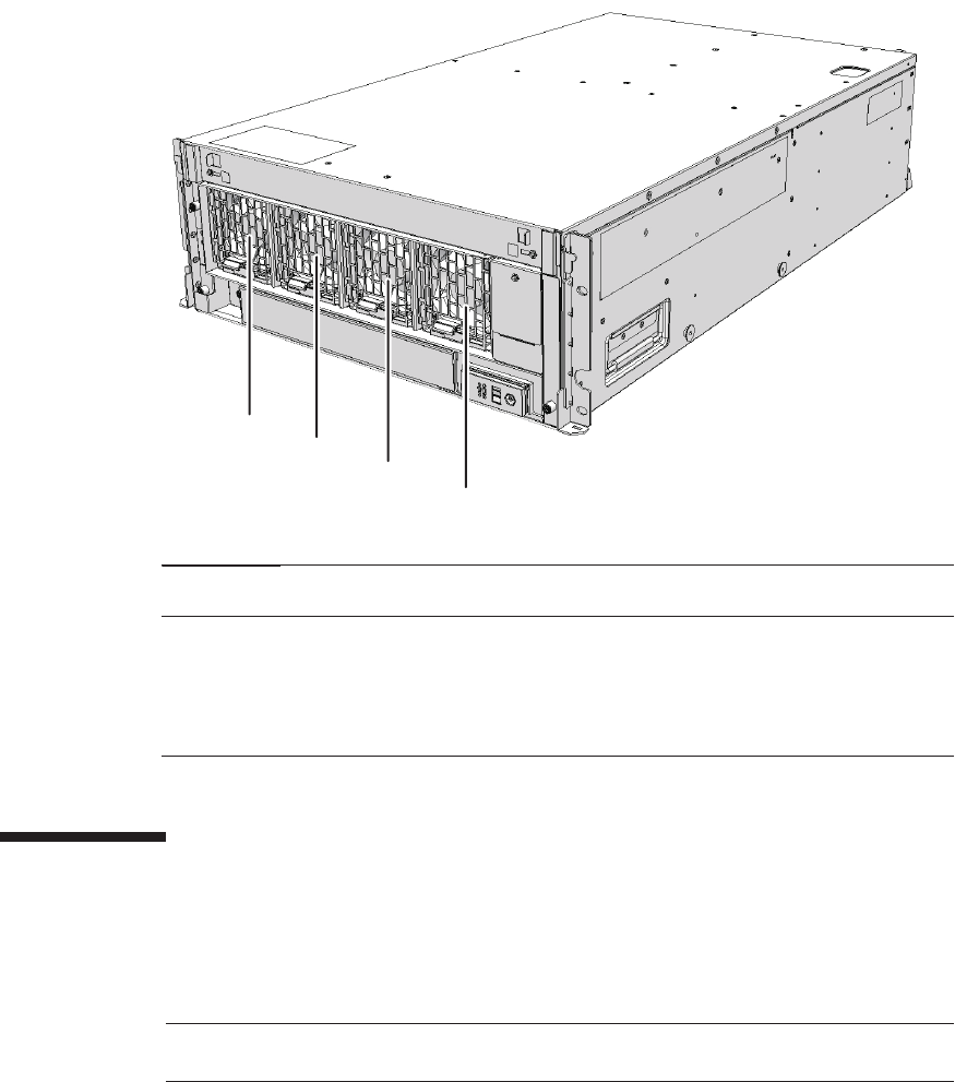
(1)
(2)
(3)
(4)
Location
number
Component
1 Fan unit (FANU#0)
2 Fan unit (FANU#1)
3 Fan unit (FANU#2)
4 Fan unit (FANU#3)
Note - Read and understand the instructions in this chapter before starting the maintenance
work. Also see the contents of "Chapter 1 Before Starting Maintenance Work."
Figure 19-1 Location of fan units
19.2 Before Maintaining a Fan Unit
This section describes the types and the flow of maintenance of the fan units, as well
as some precautions.
Fujitsu M10-4/Fujitsu M10-4S/SPARC M10-4/SPARC M10-4S Service Manual ・December 2013328
Table 19-1 Types of maintenance for fan unit
Configuration Active/hot Active/cold Inactive/hot Inactive/cold System stopped
Building block configuration
Supported Unsupported
(*1)
Supported Unsupported
(*1)
Supported (*2)
*1: If any physical partition is currently operating, the crossbar box cannot be powered off.
*2: All the physical partitions must be powered off, and the system must be completely shut down.
Table 19-2 Maintenance flow
Details of update process Replacement
1 Preparation 19.3
2 Removing a fan unit 19.4
3 Installingafanunit 19.5
4 Restoring the system 19.6
19.2.1 Types of maintenance
Table 19-1 lists the types of maintenance for the fan units. For the definition of
maintenance, see "4.3 Understanding Types of Maintenance."
19.2.2 Maintenance flow
Table 19-2 lists the sequence of the maintenance procedure for the fan units.
19.2.3 Precautions for replacement
Note the following points when replacing a fan unit:
■When replacing multiple fan units, replace one unit at a time. If a redundant
configuration cannot be assured, perform cold replacement.
■The cooling fans have a redundant configuration. Thus, the system can continue
operating even if one of the fans in the fan units experiences a failure. Avoid
operating the system with a faulty fan for an extended period and replace the fan
unit containing the failed fan as soon as possible.
19.3 Enabling the Removal of a Fan Unit
This section describes the preparations that must be completed prior to removing a
Chapter 19 Maintaining the Fan Units of the Crossbar Box 329
Caution - To completely shut down the system, all the power cords must be
removed. If the power cords are not removed, an electrical failure may occur.
XSCF> showlogs error
XSCF> replacefru
XSCF> showlogs error
fan unit. The preparation procedure differs depending on the maintenance type as
follows:
■Active/Hot maintenance
■Inactive/Hot maintenance
■System-stopped maintenance
19.3.1 Active/Hot maintenance
1. Open the rack door.
2. Log in to the XSCF shell.
3. Execute the showlogs command to identify the component requiring
maintenance.
For details, see "3.3.5 Checking log information."
4. Confirm the hardware and software configurations.
For details, see "4.2 Confirming the System Configuration."
5.
Execute the replacefru command to release the fan unit requiring maintenance
from the system.
For details, see "5.1 Releasing an FRU from the System with the replacefru
Command."
19.3.2 Inactive/Hot maintenance
1. Open the rack door.
2. Log in to the XSCF shell.
3. Execute the showlogs command to identify the component requiring
maintenance.
For details, see "3.3.5 Checking log information."
Fujitsu M10-4/Fujitsu M10-4S/SPARC M10-4/SPARC M10-4S Service Manual ・December 2013330

XSCF> replacefru
XSCF> showlogs error
XSCF> replacefru
Note - Inthecaseofadualpowerfeed,makeanoteofthelocationsofthepowercords
before disconnecting them to ensure that they are reinstalled correctly.
4. Confirm the hardware and software configurations.
For details, see "4.2 Confirming the System Configuration."
5. Power off the physical partition requiring maintenance.
For details, see "5.3 Powering Off the Physical Partition Requiring Maintenance."
6.
Execute the replacefru command to release the fan unit requiring maintenance
from the system.
For details, see "5.1 Releasing an FRU from the System with the replacefru
Command."
19.3.3 System-stopped maintenance
1. Open the rack door.
2. LogintotheXSCFshell.
3. Execute the showlogs command to identify the component requiring
maintenance.
For details, see "3.3.5 Checking log information."
4. Confirm the hardware and software configurations.
For details, see "4.2 Confirming the System Configuration."
5. Power off all the physical partitions.
For details, see "5.3 Powering Off the Physical Partition Requiring Maintenance."
6.
Execute the replacefru command to release the fan unit requiring maintenance
from the system.
For details, see "5.1 Releasing an FRU from the System with the replacefru
Command."
7. Remove all the power cords from the power supply unit of the crossbar box
requiring maintenance.
For details, see "5.5.2 Removing the power cord."
Chapter 19 Maintaining the Fan Units of the Crossbar Box 331
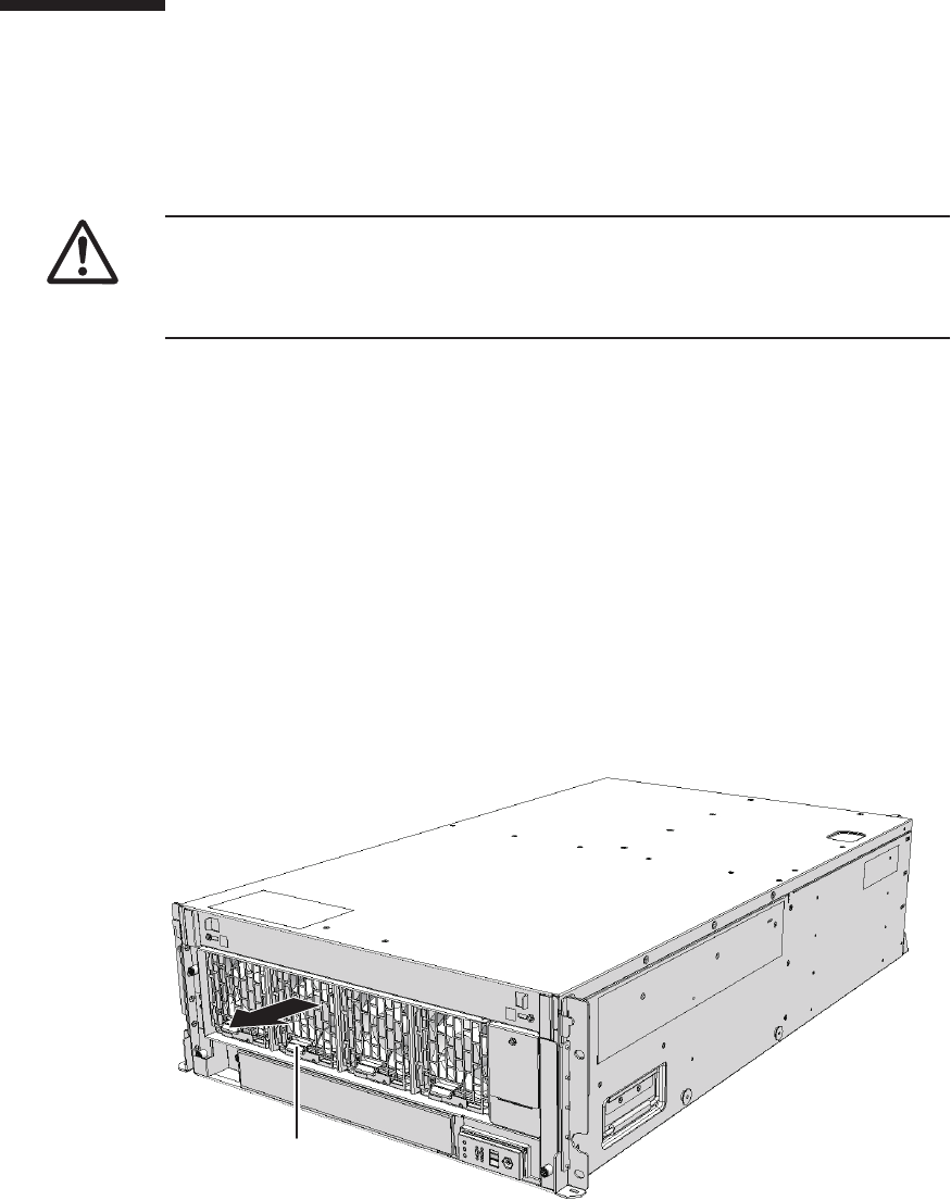
Caution - Before you handle any components, wear a wrist strap to ground any static
electricity. If you perform this procedure without a wrist strap, individual
components or the overall system may be damaged. For details, see "1.5 Notes
Regarding Static Electricity."
A
19.4 Removing a Fan Unit
This section describes the procedure for removing a fan unit.
Enable the removal of the fan unit before attempting to remove it. For details, see
"19.3 Enabling the Removal of a Fan Unit."
19.4.1 Accessing a fan unit
1. Remove the front cover.
For details, see "5.5.3 Removing the front cover."
19.4.2 Removing a fan unit
1. Pull out the fan unit while raising the lever (A in the figure) of the fan unit.
Figure 19-2 Lever of fan unit
2. Carefully remove the fan unit from its slot.
Fujitsu M10-4/Fujitsu M10-4S/SPARC M10-4/SPARC M10-4S Service Manual ・December 2013332
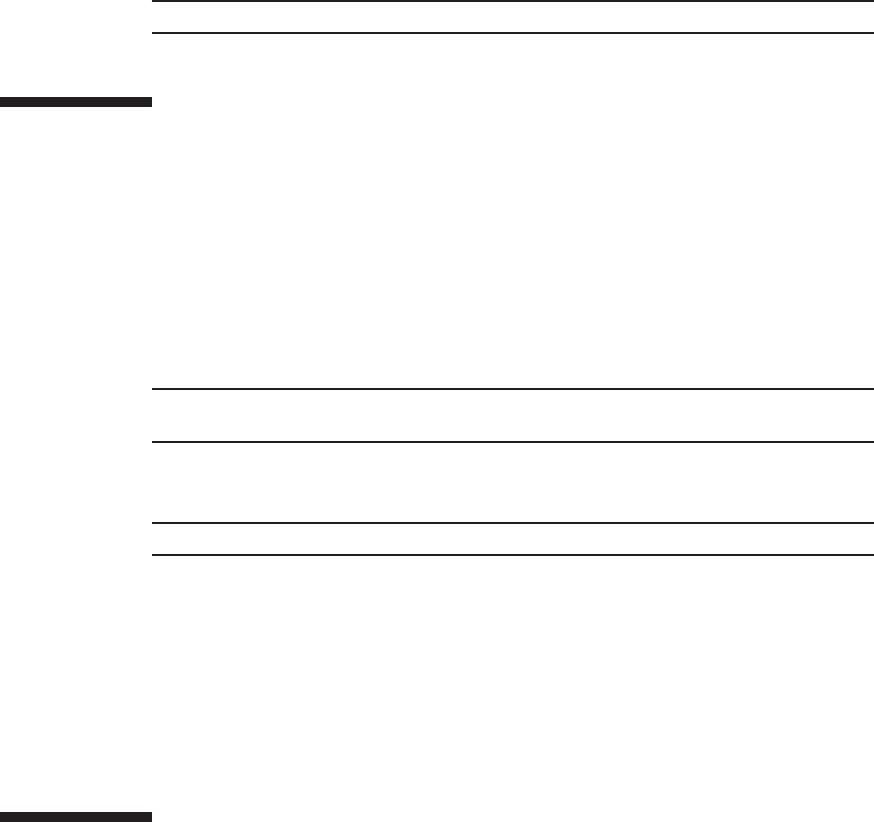
Note - Place the removed fan unit on a grounded antistatic ESD mat.
Note - Do not force the fan unit into the slot. Using excessive force may damage the
component or the chassis.
Note - Check that the fan unit is fully inserted and secured.
19.5 Installing a Fan Unit
This section describes the procedure for installing a fan unit.
19.5.1 Installing a fan unit
1. Carefully insert the fan unit into its slot.
2. Push the fan unit fully home.
19.5.2 Restoring the chassis
1. Install the front cover.
For details, see "6.5.3 Installing the front cover."
19.6 Restoring the System
This section describes the procedure for restoring the system after installing a fan
unit. The restoration procedure differs depending on the maintenance type as follows:
■Active/Hot maintenance
■Inactive/Hot maintenance
■System-stopped maintenance
Chapter 19 Maintaining the Fan Units of the Crossbar Box 333

XSCF> showstatus
XSCF> showhardconf
Note - In the case of a dual power feed, connect the power cords in their original positions by
referring to the record that you made before the start of maintenance.
19.6.1 Active/Hot maintenance
1. Return to the operation of the XSCF firmware replacefru command to confirm
that the fan unit has been incorporated into the system.
For details, see "6.1 Incorporating an FRU into the System with the replacefru
Command."
2. Execute the showstatus command to confirm that there is no problem with
the fan unit after the completion of maintenance.
3. Execute the showhardconf command to check the hardware configuration
and the status of each component.
4. Close the rack door.
19.6.2 Inactive/Hot maintenance
1. Return to the operation of the XSCF firmware replacefru command to confirm
that the fan unit has been incorporated into the system.
For details, see "6.1 Incorporating an FRU into the System with the replacefru
Command."
2. Power on the physical partition requiring maintenance.
For details, see "6.3 Powering On the Physical Partition Requiring Maintenance."
3. Close the rack door.
19.6.3 System-stopped maintenance
1. Connect all the power cords to the power supply unit of the crossbar box
requiring maintenance.
For details, see "6.5.1 Installing the power cord."
2. Return to the operation of the XSCF firmware replacefru command to confirm
that the fan unit has been incorporated into the system.
Fujitsu M10-4/Fujitsu M10-4S/SPARC M10-4/SPARC M10-4S Service Manual ・December 2013334
Fujitsu M10-4/Fujitsu M10-4S/SPARC M10-4/SPARC M10-4S Service Manual ・December 2013336

Chapter 20
Maintaining the XSCF Interface Unit of
the Crossbar Box
This chapter describes the procedure for maintaining the XSCF interface unit
mounted in a crossbar box.
■Location of the XSCF Interface Unit
■Before Maintaining the XSCF Interface Unit
■Enabling the Removal of the XSCF Interface Unit
■Removing the XSCF Interface Unit
■Installing the XSCF Interface Unit
■Restoring the System
20.1 Location of the XSCF Interface Unit
This section describes the location of the XSCF interface unit.
337
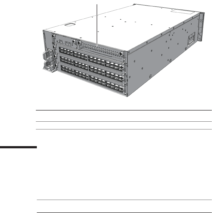
(1)
Location
number
Component
1 XSCF interface unit (XSCFIFU)
Note - Read and understand the instructions in this chapter before starting the maintenance
work. Also see the contents of "Chapter 1 Before Starting Maintenance Work."
Figure 20-1 Location of XSCF interface unit
20.2 Before Maintaining the XSCF Interface
Unit
This section describes the types and the flow of maintenance of the XSCF interface
unit.
20.2.1 Types of maintenance
Table 20-1 lists the types of maintenance for the XSCF interface unit. For the
definition of maintenance, see "4.3 Understanding Types of Maintenance."
Fujitsu M10-4/Fujitsu M10-4S/SPARC M10-4/SPARC M10-4S Service Manual ・December 2013338

Table 20-1 Type of maintenance for XSCF interface unit
Configuration Active/hot Active/cold Inactive/hot Inactive/cold System stopped
Building block configuration
Unsupported Unsupported
(*1)
Unsupported Unsupported
(*1)
Supported (*2)
*1: If any physical partition is currently operating, the crossbar box cannot be powered off.
*2: All the physical partitions must be powered off, and the system must be completely shut down.
Table 20-2 Maintenance flow
Details of update process Replacement
1 Preparation 20.3
2 Removing an XSCF interface unit 20.4
3 Installing an XSCF interface unit 20.5
4 Restoring the system 20.6
Caution - To completely shut down the system, all the power cords must be
removed. If the power cords are not removed, an electrical failure may occur.
XSCF> showlogs error
20.2.2 Maintenance flow
Table 20-2 lists the sequence of the maintenance procedure for the XSCF interface
unit.
20.3 Enabling the Removal of the XSCF
Interface Unit
This section describes the preparations that must be completed prior to removing the
XSCF interface unit.
1. Open the rack door.
2. LogintotheXSCFshell.
3. Execute the showlogs command to identify the component requiring
maintenance.
For details, see "3.3.5 Checking log information."
Chapter 20 Maintaining the XSCF Interface Unit of the Crossbar Box 339
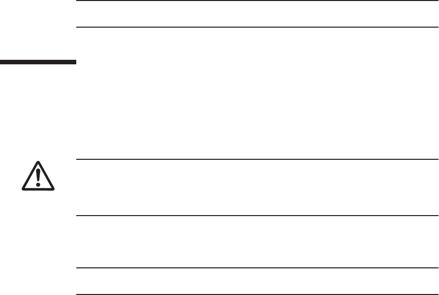
Note - In the case of a dual power feed, make a note of the locations of the power cords
before disconnecting them to ensure that they are reinstalled correctly.
Caution - Before you handle any components, wear a wrist strap to ground any static
electricity. If you perform this procedure without a wrist strap, individual
components or the overall system may be damaged. For details, see "1.5 Notes
Regarding Static Electricity."
Note - Record the positions of the cables before removing them to ensure that they are
reinstalled correctly.
4. Confirm the hardware and software configurations.
For details, see "4.2 Confirming the System Configuration."
5. Power off all the physical partitions.
For details, see "5.3 Powering Off the Physical Partition Requiring Maintenance."
6. Remove all the power cords from the power supply unit of the crossbar box
requiring maintenance.
For details, see "5.5.2 Removing the power cord."
20.4 Removing the XSCF Interface Unit
This section describes the procedure for removing an XSCF interface unit.
Enable the removal of the XSCF interface unit before attempting to remove it. For
details, see "20.3 Enabling the Removal of the XSCF Interface Unit."
1. Remove all the XSCF BB control cables and XSCF DUAL control cables
connected to the XSCF interface unit.
2. Loosen the two screws (A in the figure) of the XSCF interface unit and lower
the right and left levers to release the XSCF interface unit.
Fujitsu M10-4/Fujitsu M10-4S/SPARC M10-4/SPARC M10-4S Service Manual ・December 2013340
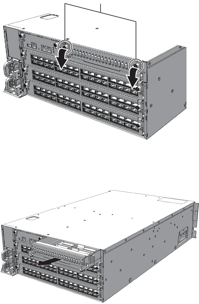
A
Figure 20-2 Positions of screws and levers
3. Hold the levers and partially pull out the XSCF interface unit.
Figure 20-3 Pulling out the XSCF interface unit
4. Support the XSCF interface unit from below with one hand and then carefully
remove it from the chassis.
Chapter 20 Maintaining the XSCF Interface Unit of the Crossbar Box 341
Note - Place the removed XSCF interface unit on a grounded antistatic ESD mat.
Note - When mounting an XSCF interface unit, check the connectors on both of the
chassis and XSCF interface unit beforehand to confirm that no pin is bent and all the
pins are neatly arranged in lines. If an XSCF interface unit is mounted with a bent pin
in a connector, the chassis or XSCF interface unit may be damaged. Also, carefully
proceed with the work to prevent any pin from being bent.
Note - Reinstall the cables in their original positions by referring to the notes that you made
before the start of maintenance.
Note - Ensure that the cables are firmly connected and secured.
Note - In the case of a dual power feed, connect the power cords in their original positions by
referring to the record that you made before the start of maintenance.
20.5 Installing the XSCF Interface Unit
This section describes the procedure for installing the XSCF interface unit.
1. Support the XSCF interface unit from below with one hand and then carefully
insert it into the chassis.
2. Raise the right and left levers and tighten the two screws.
3. Connect all the cables to the XSCF interface unit.
20.6 Restoring the System
This section describes the procedure for restoring the system after installing an XSCF
interface unit.
1. Connect all the power cords to the power supply unit of the crossbar box
requiring maintenance.
For details, see "6.5.1 Installing the power cord."
2. Power on all the physical partitions.
For details, see "6.3 Powering On the Physical Partition Requiring Maintenance."
3. Close the rack door.
Fujitsu M10-4/Fujitsu M10-4S/SPARC M10-4/SPARC M10-4S Service Manual ・December 2013342

Chapter 21
Maintaining the Crossbar Backplane
Unit of the Crossbar Box
This chapter describes the procedure for maintaining the crossbar backplane unit
mounted in a crossbar box.
■Location of the Crossbar Backplane Unit
■Before Maintaining the Crossbar Backplane Unit
■Enabling the Removal of the Crossbar Backplane Unit
■Removing the Crossbar Backplane Unit
■Installing the Crossbar Backplane Unit
■Restoring the System
21.1 Location of the Crossbar Backplane
Unit
This section describes the location of the crossbar backplane unit.
343
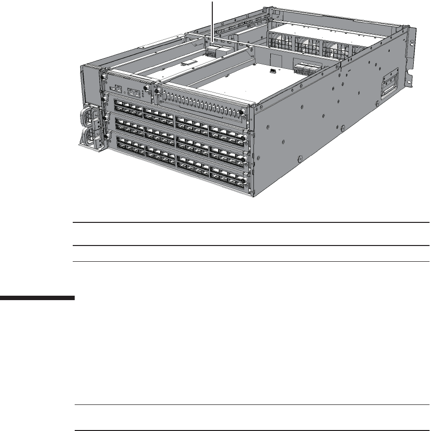
(1)
Location
number
Component
1 Crossbar backplane unit (XBBPU)
Note - Read and understand the instructions in this chapter before starting the maintenance
work. Also see the contents of "Chapter 1 Before Starting Maintenance Work."
Figure 21-1 Location of crossbar backplane unit
21.2 Before Maintaining the Crossbar
Backplane Unit
This section describes the types and the flow of maintenance of the crossbar
backplane unit.
21.2.1 Types of maintenance
Table 21-1 lists the types of maintenance for the crossbar backplane unit. For the
definition of maintenance, see "4.3 Understanding Types of Maintenance."
Fujitsu M10-4/Fujitsu M10-4S/SPARC M10-4/SPARC M10-4S Service Manual ・December 2013344
Table 21-1 Types of maintenance for crossbar backplane unit
Configuration Active/hot Active/cold Inactive/hot Inactive/cold System stopped
Building block configuration
Unsupported Unsupported
(*1)
Unsupported Unsupported
(*1)
Supported (*2)
*1: If any physical partition is currently operating, the crossbar box cannot be powered off.
*2: All the physical partitions must be powered off, and the system must be completely shut down.
Table 21-2 Maintenance flow
Details of update process Replacement
1 Preparation 21.3
2 Removing the crossbar backplane unit 21.4
3 Installing the crossbar backplane unit 21.5
4 Restoring the system 21.6
Caution - To completely shut down the system, all the power cords must be
removed. If the power cords are not removed, an electrical failure may occur.
XSCF> showlogs error
21.2.2 Maintenance flow
Table 21-2 lists the sequence of the maintenance procedure for the crossbar backplane
unit.
21.3 Enabling the Removal of the Crossbar
Backplane Unit
This section describes the preparations that must be completed prior to removing the
crossbar backplane unit.
1. Open the rack door.
2. LogintotheXSCFshell.
3. Execute the showlogs command to identify the component requiring
maintenance.
For details, see "3.3.5 Checking log information."
Chapter 21 Maintaining the Crossbar Backplane Unit of the Crossbar Box 345
XSCF> replacefru
Note - In the case of a dual power feed, make a note of the locations of the power cords
before disconnecting them to ensure that they are reinstalled correctly.
Caution - Before you handle any components, wear a wrist strap to ground any static
electricity. If you perform this procedure without a wrist strap, individual
components or the overall system may be damaged. For details, see "1.5 Notes
Regarding Static Electricity."
4. Confirm the hardware and software configurations.
For details, see "4.2 Confirming the System Configuration."
5. Power off all the physical partitions.
For details, see "5.3 Powering Off the Physical Partition Requiring Maintenance."
6. Execute the replacefru command to release the crossbar backplane unit
requiring maintenance from the system.
For details, see "5.1 Releasing an FRU from the System with the replacefru
Command."
7. Remove all the power cords from the power supply unit of the crossbar box
requiring maintenance.
For details, see "5.5.2 Removing the power cord."
21.4 Removing the Crossbar Backplane
Unit
This section describes the procedure for removing the crossbar backplane unit.
Enable the removal of the crossbar backplane unit before attempting to remove it. For
details, see "21.3 Enabling the Removal of the Crossbar Backplane Unit."
1. Partially pull out the following components, in order, from top to bottom.
You do not have to remove the cables of these components.
-XSCFunit
For details, see "17.4 Removing the XSCF Unit."
- XSCF interface unit
For details, see "20.4 Removing the XSCF Interface Unit."
- Crossbar unit or crossbar filler unit
For details, see "16.4 Removing a Crossbar Unit."
- Power supply unit
For details, see "18.4 Removing a Power Supply Unit."
Fujitsu M10-4/Fujitsu M10-4S/SPARC M10-4/SPARC M10-4S Service Manual ・December 2013346
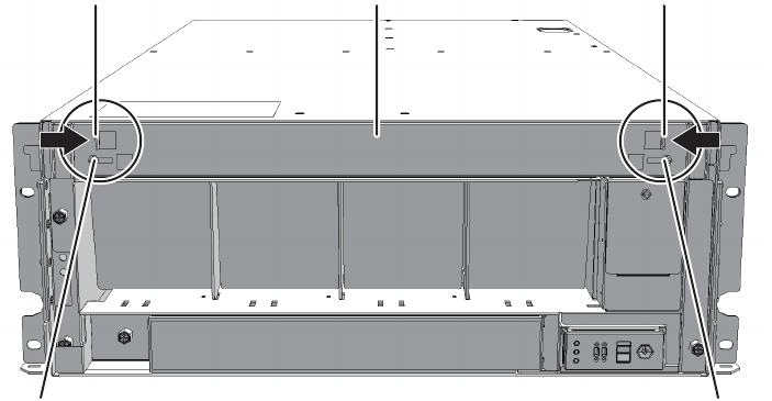
A A
BC B
2. Remove the front cover.
For details, see "5.5.3 Removing the front cover."
3. Remove all the fan units.
For details, see "19.4 Removing a Fan Unit."
4. Loosen the two screws (A in the figure) securing the upper cover and slide
the right and left stoppers (B in the figure) inwards. Then, remove the upper
cover (C in the figure).
Figure 21-2 Removing the upper cover
5. Loosen the one screw (A in the figure) securing the lower cover and then
slide the lower cover to the left to remove it.
Chapter 21 Maintaining the Crossbar Backplane Unit of the Crossbar Box 347
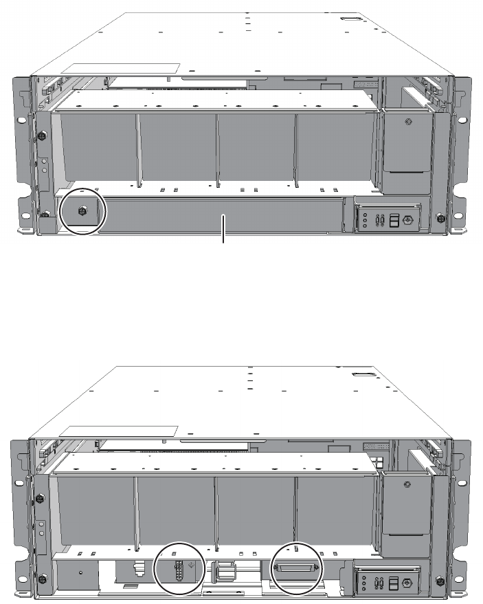
A
Figure 21-3 Removing the lower cover
6. Disconnect the two cables from the fan shelf.
Arrange the removed cables in the center.
Figure 21-4 Removing the cables
7. Loosen the three screws securing the fan shelf and partially pull out the fan
shelf.
Fujitsu M10-4/Fujitsu M10-4S/SPARC M10-4/SPARC M10-4S Service Manual ・December 2013348

Note - Remove the fan shelf while paying careful attention to the two cables arranged in the
center.
Note - Place the removed fan shelf on a grounded antistatic ESD mat.
Figure 21-5 Removing the fan shelf
8. Place a hand under the fan shelf to support it and then carefully remove it
from the chassis.
9. Loosen the two screws and remove the bracket (B in the figure) fixing the
guide plate (A in the figure).
Chapter 21 Maintaining the Crossbar Backplane Unit of the Crossbar Box 349
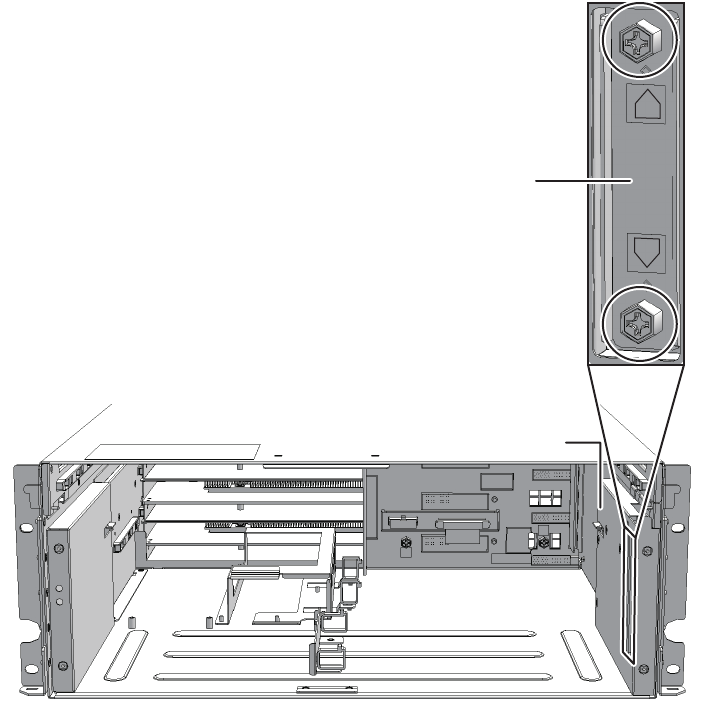
A
B
Figure 21-6 Removing the bracket
10. Slide the guide plate (A in the figure) to the front to remove it.
Fujitsu M10-4/Fujitsu M10-4S/SPARC M10-4/SPARC M10-4S Service Manual ・December 2013350
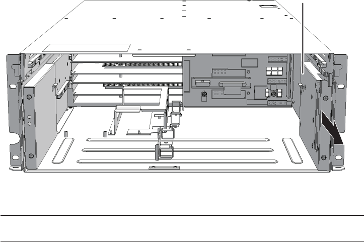
A
Note - Move the clamps back to their original positions so that they do not foul the removal
of the crossbar backplane unit.
Figure 21-7 Removing guide plate
11. Remove the cable from the clamps.
Chapter 21 Maintaining the Crossbar Backplane Unit of the Crossbar Box 351
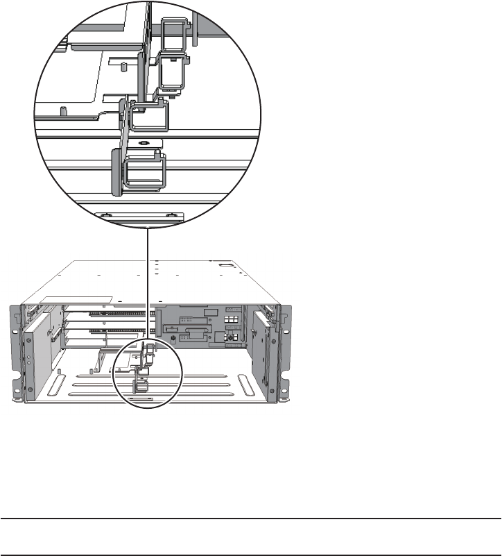
Note - Remove the unit carefully so as to not damage any cables.
Note - Place the removed crossbar backplane unit on a grounded antistatic ESD mat.
Figure 21-8 Removing the cables
12. Loosen the five screws securing the crossbar backplane unit and then pull
the crossbar backplane unit straight out by holding the center handle (A in
the figure).
Fujitsu M10-4/Fujitsu M10-4S/SPARC M10-4/SPARC M10-4S Service Manual ・December 2013352
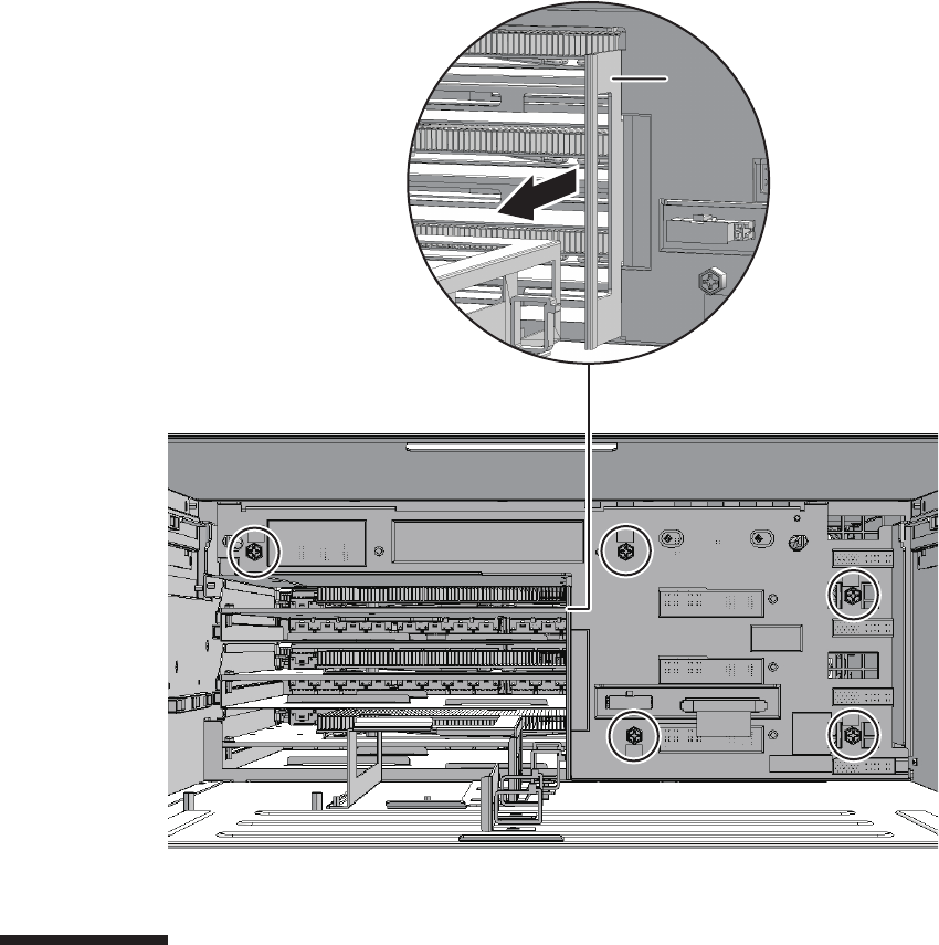
A
Figure 21-9 Removing the crossbar backplane unit
21.5 Installing the Crossbar Backplane Unit
This section describes the procedure for installing the crossbar backplane unit.
1. Insert the crossbar backplane unit into the chassis and then tighten the five
screws.
2. Fix the cables of the crossbar backplane unit with the clamps.
3. Install the guide plate by sliding it towards the rear and then tighten the two
screws.
Chapter 21 Maintaining the Crossbar Backplane Unit of the Crossbar Box 353

Note - In the case of a dual power feed, connect the power cords in their original positions by
referring to the record that you made before the start of maintenance.
Check the guide plate latch to ensure that the plate is securely installed.
4. Support the fan shelf from below with one hand and then insert it carefully
into the chassis.
Arranging the cables in the center makes it easier to install the fan shelf.
5. Tighten the three screws securing the fan shelf.
6. Connect the two cables to the fan shelf.
7. Install the lower cover and then secure it with the one screw.
8. Install the upper cover.
9. Slide the right and left stoppers of the upper cover outwards and then secure
the cover with the two screws.
10. Install all the fan units.
For details, see "19.5 Installing a Fan Unit."
11. Install the front cover.
For details, see "6.5.3 Installing the front cover."
12. Reinstall the following components in their original positions in the order
shown.
- Power supply unit
For details, see "18.5 Installing a Power Supply Unit."
- Crossbar unit or crossbar filler unit
For details, see "16.5 Installing a Crossbar Unit."
- XSCF interface unit
For details, see "20.5 Installing the XSCF Interface Unit."
-XSCFunit
For details, see "17.5 Installing the XSCF Unit."
21.6 Restoring the System
This section describes the procedure for restoring the system after installing a
crossbar backplane unit.
1. Connect all the power cords to the power supply unit of the crossbar box
requiring maintenance.
For details, see "6.5.1 Installing the power cord."
2. Return to the operation of the XSCF firmware replacefru command to confirm
that the crossbar backplane unit has been incorporated into the system.
For details, see "6.1 Incorporating an FRU into the System with the replacefru
Command."
Fujitsu M10-4/Fujitsu M10-4S/SPARC M10-4/SPARC M10-4S Service Manual ・December 2013354
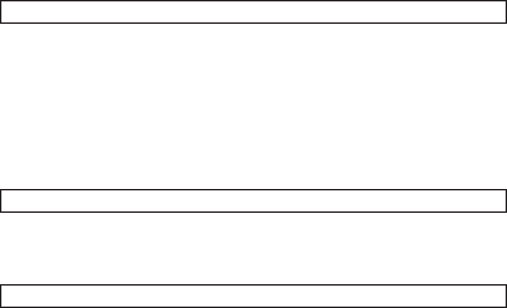
XSCF> diagxbu -y -b 00 -t 01
XSCF> diagxbu -y -b 00 -p 02
XSCF> showlogs error
3. Execute the diagxbu command to diagnose the crossbar cables.
-When the system board of the chassis connected with the crossbar cables
is not incorporated into the physical partition, or when the incorporated
physical partition is powered off:
The example below specifies the following:
00: The BB-ID of the chassis to start the diagnosis
01: The BB-ID of the destination where the chassis to start the diagnosis is
connected (You can specify more than one of these.)
To specify multiple connection destination BB-IDs, enter a command like
"diagxbu -y -b 00 -t 01 -t 02".
-When the system board of the chassis connected with the crossbar cables
is incorporated into the physical partition, and the physical partition is
powered on:
The example below specifies the following:
00: The BB-ID of the chassis to start the diagnosis
02: The PPAR-ID of the destination where the chassis to start the diagnosis is
connected (You can specify only one of these.)
4. Execute the showlogs command to confirm that the system is operating
normally.
For details, see "3.3.5 Checking log information."
5. Power on all the physical partitions.
For details, see "6.3 Powering On the Physical Partition Requiring Maintenance."
6. Close the rack door.
Chapter 21 Maintaining the Crossbar Backplane Unit of the Crossbar Box 355
Fujitsu M10-4/Fujitsu M10-4S/SPARC M10-4/SPARC M10-4S Service Manual ・December 2013356

Chapter 22
Maintaining the Fan Backplane of the
Crossbar Box
This chapter describes the procedure for maintaining the fan backplane mounted in
the crossbar box.
■Configuration of the Fan Backplane
■Before Maintaining the Fan Backplane
■Enabling the Removal of the Fan Backplane
■Removing the Fan Backplane
■Installing the Fan Backplane
■Restoring the System
22.1 Configuration of the Fan Backplane
This section describes the configuration and the location of the fan backplane.
The fan units are interconnected through the fan backplane.
357
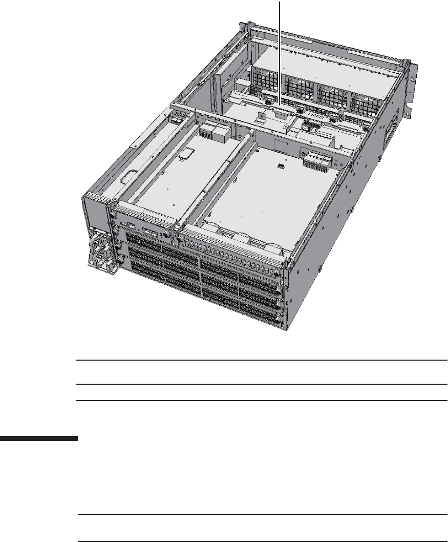
(1)
Location
number
Component
1 Fan backplane (FANBP)
Note - Read and understand the instructions in this chapter before starting the maintenance
work. Also see the contents of "Chapter 1 Before Starting Maintenance Work."
Figure 22-1 Location of fan backplane
22.2 Before Maintaining the Fan Backplane
This section describes the types and the flow of maintenance of the fan backplane.
Fujitsu M10-4/Fujitsu M10-4S/SPARC M10-4/SPARC M10-4S Service Manual ・December 2013358
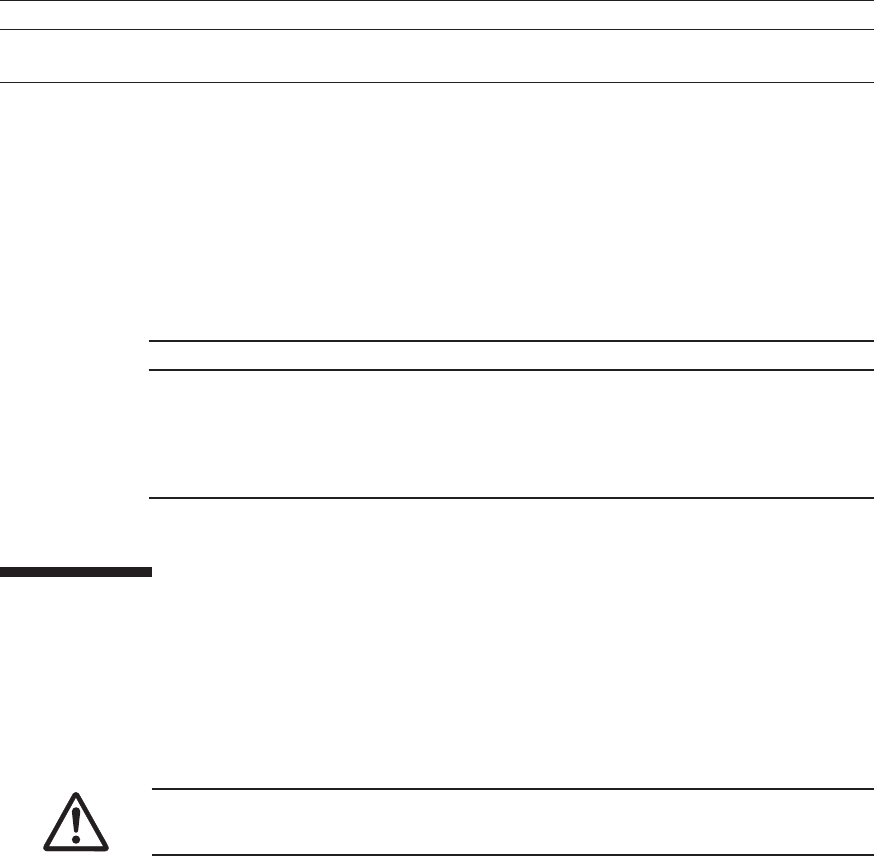
Table 22-1 Types of maintenance for fan backplane
Configuration Active/hot Active/cold Inactive/hot Inactive/cold System stopped
Building block configuration
Unsupported Unsupported
(*1)
Unsupported Unsupported
(*1)
Supported (*2)
*1: If any physical partition is currently operating, the crossbar box cannot be powered off.
*2: All of the physical partitions must be stopped, and the system must be completely shut down.
Table 22-2 Maintenance flow
Details of update process Replacement
1 Preparation 22.3
2 Removing the fan backplane 22.4
3 Installing the fan backplane 22.5
4 Restoring the system 22.6
Caution - To completely shut down the system, all the power cords must be
removed. If the power cords are not removed, an electrical failure may occur.
22.2.1 Types of maintenance
Table 22-1 lists the types of maintenance for the fan backplane. For the definition of
maintenance, see "4.3 Understanding Types of Maintenance."
22.2.2 Maintenance flow
Table 22-2 lists the sequence of the maintenance procedure for the fan backplane.
22.3 Enabling the Removal of the Fan
Backplane
This section describes the preparations that must be completed prior to removing the
fan backplane.
1. Open the rack door.
2. LogintotheXSCFshell.
3. Execute the showlogs command to identify the component requiring
Chapter 22 Maintaining the Fan Backplane of the Crossbar Box 359

XSCF> showlogs error
XSCF> replacefru
Note - In the case of a dual power feed, make a note of the locations of the power cords
before disconnecting them to ensure that they are reinstalled correctly.
Caution - Before you handle any components, wear a wrist strap to ground any static
electricity. If you perform this procedure without a wrist strap, individual
components or the overall system may be damaged. For details, see "1.5 Notes
Regarding Static Electricity."
maintenance.
For details, see "3.3.5 Checking log information."
4. Confirm the hardware and software configurations.
For details, see "4.2 Confirming the System Configuration."
5. Power off all the physical partitions.
For details, see "5.3 Powering Off the Physical Partition Requiring Maintenance."
6. Execute the replacefru command to release the fan backplane requiring
maintenance from the system.
For details, see "5.1 Releasing an FRU from the System with the replacefru
Command."
7. Remove all the power cords from the power supply unit of the crossbar box
requiring maintenance.
For details, see "5.5.2 Removing the power cord."
22.4 Removing the Fan Backplane
This section describes the procedure for removing the fan backplane.
Enable the removal of the fan backplane before attempting to remove it. For details,
see "22.3 Enabling the Removal of the Fan Backplane."
22.4.1 Accessing the fan backplane
1. Remove the front cover.
For details, see "5.5.3 Removing the front cover."
Fujitsu M10-4/Fujitsu M10-4S/SPARC M10-4/SPARC M10-4S Service Manual ・December 2013360
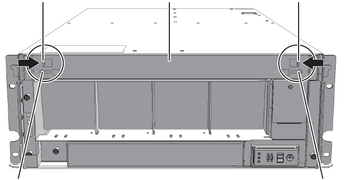
A A
BC B
2. Remove all the fan units.
For details, see "19.4 Removing a Fan Unit."
22.4.2 Removing the fan backplane
1. Loosen the two screws (A in the figure) securing the upper cover and then
slide the right and left stoppers (B in the figure) inwards. Then, remove the
upper cover (C in the figure).
Figure 22-2 Removing the upper cover
2. Loosen the one screw (A in the figure) securing the lower cover and then
slide the lower cover to the left to remove it.
Chapter 22 Maintaining the Fan Backplane of the Crossbar Box 361

A
Figure 22-3 Removing the lower cover
3. Disconnect the two cables from the fan shelf.
Arrange the removed cables in the center.
Figure 22-4 Removing the cables
4. Loosen the three screws securing the fan shelf and partially pull out the fan
shelf.
Fujitsu M10-4/Fujitsu M10-4S/SPARC M10-4/SPARC M10-4S Service Manual ・December 2013362
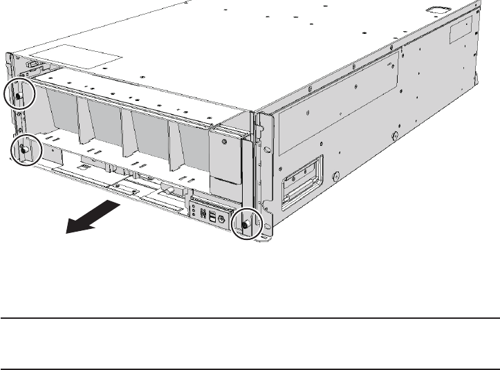
Note - Remove the fan shelf while paying careful attention to the two cables arranged in the
center.
Note - Place the removed fan shelf on a grounded antistatic ESD mat.
Figure 22-5 Removing the fan shelf
5. Place a hand under the fan shelf to support it and then carefully remove it
from the chassis.
6. Disconnect the two cables from the fan backplane.
Chapter 22 Maintaining the Fan Backplane of the Crossbar Box 363
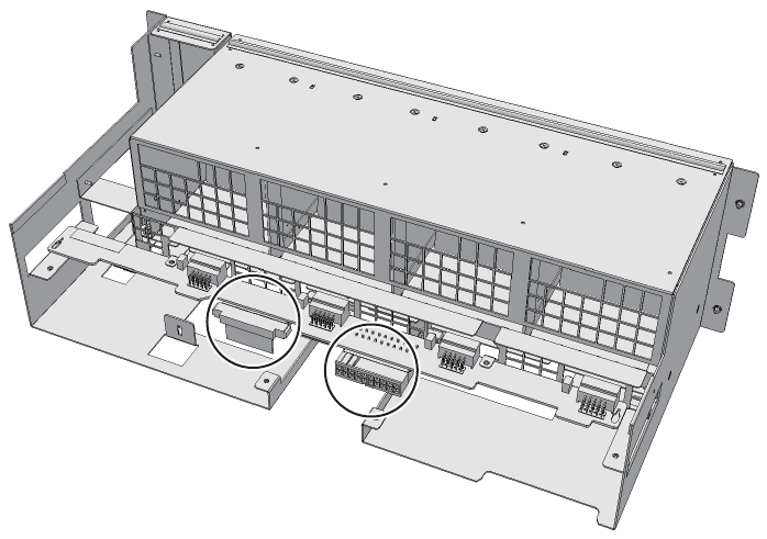
Figure 22-6 Removing the cables
7. Remove the two screws securing the fan backplane to remove the bracket (A
in the figure).
Fujitsu M10-4/Fujitsu M10-4S/SPARC M10-4/SPARC M10-4S Service Manual ・December 2013364
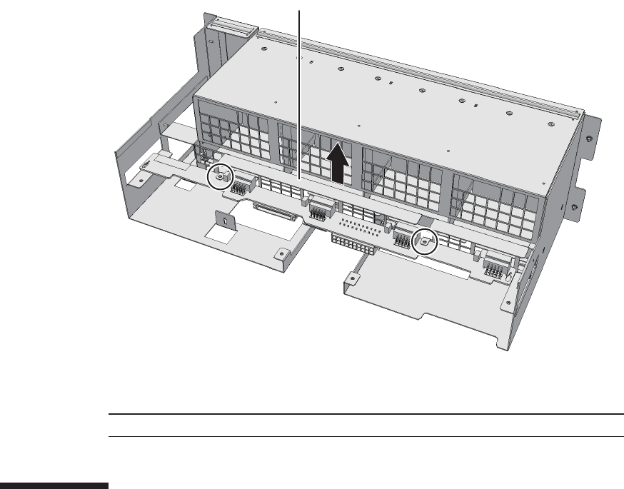
A
Note - Place the removed fan backplane on a grounded antistatic ESD mat.
Figure 22-7 Removing the screws and bracket
8. Remove the fan backplane.
22.5 Installing the Fan Backplane
This section describes the procedure for installing the fan backplane.
22.5.1 Installing the fan backplane
1. Fit the fan backplane into the right- and left-hand notches in the fan shelf.
2. Install the bracket of the fan backplane and secure it with two screws.
3. Connect the two cables to the fan backplane.
4. Support the fan shelf from below with one hand and then insert it carefully
into the chassis.
Arranging the cables in the center makes it easier to install the fan shelf.
5. Tighten the three screws securing the fan shelf.
Chapter 22 Maintaining the Fan Backplane of the Crossbar Box 365

Note - In the case of a dual power feed, connect the power cords in their original positions by
referring to the record that you made before the start of maintenance.
6. Connect the two cables to the fan shelf.
7. Install the lower cover and then secure it with the one screw.
8. Install the upper cover.
9. Slide the right and left stoppers of the upper cover outwards and then secure
the cover with the two screws.
22.5.2 Restoring the chassis
1. Install all the fan units.
For details, see "19.5.1 Installing a fan unit."
2. Install the front cover.
For details, see "6.5.3 Installing the front cover."
22.6 Restoring the System
This section describes the procedure for restoring the system after installing the fan
backplane.
1. Connect all the power cords to the power supply unit of the crossbar box
requiring maintenance.
For details, see "6.5.1 Installing the power cord."
2. Return to the operation of the XSCF firmware replacefru command to confirm
that the fan backplane has been incorporated into the system.
For details, see "6.1 Incorporating an FRU into the System with the replacefru
Command."
3. Power on all the physical partitions.
For details, see "6.3 Powering On the Physical Partition Requiring Maintenance."
4. Close the rack door.
Fujitsu M10-4/Fujitsu M10-4S/SPARC M10-4/SPARC M10-4S Service Manual ・December 2013366

Chapter 23
Maintaining the Operation Panel of the
Crossbar Box
This chapter describes the procedure for maintaining the operation panel mounted
on the crossbar box.
■Location of the Operation Panel
■Before Maintaining the Operation Panel
■Enabling the Removal of the Operation Panel
■Removing the Operation Panel
■Installing the Operation Panel
■Restoring the System
23.1 Location of the Operation Panel
This section describes the location of the operation panel.
367
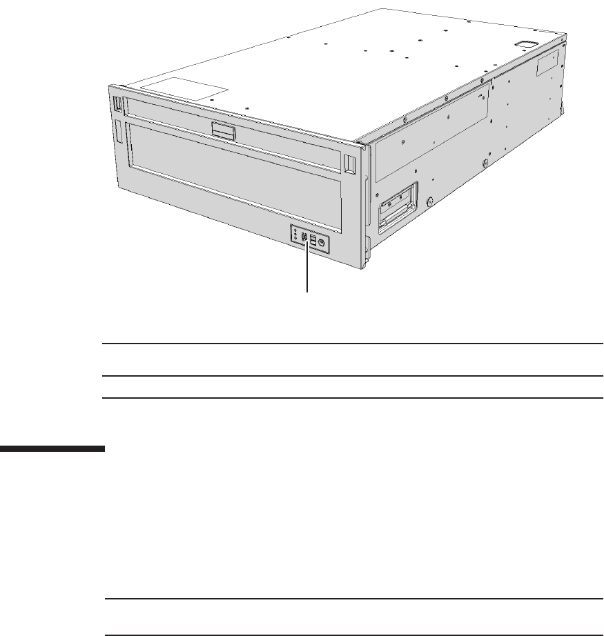
(1)
Location
number
Component
1 Operation panel (OPNL)
Note - Read and understand the instructions in this chapter before starting the maintenance
work. Also see the contents of "Chapter 1 Before Starting Maintenance Work."
Figure 23-1 Location of the operation panel
23.2 Before Maintaining the Operation
Panel
This section describes the types and flow of the maintenance of the operation panel,
as well as some precautions.
23.2.1 Types of maintenance
Table 23-1 lists the types of maintenance for the operation panel. For the definition of
maintenance, see "4.3 Understanding Types of Maintenance."
Fujitsu M10-4/Fujitsu M10-4S/SPARC M10-4/SPARC M10-4S Service Manual ・December 2013368
Table 23-1 Types of maintenance for operation panel
Configuration Active/hot Active/cold Inactive/hot Inactive/cold System stopped
Building block configuration
Unsupported Unsupported
(*1)
Unsupported Unsupported
(*1)
Supported (*2)
*1: If any physical partition is currently operating, the crossbar box cannot be powered off.
*2: All the physical partitions must be powered off, and the system must be completely shut down.
Table 23-2 Maintenance flow
Details of update process Replacement
1 Preparation 23.3
2 Removing the operation panel 23.4
3 Installing the operation panel 23.5
4 Restoring the system 23.6
Caution - To completely shut down the system, all the power cords must be
removed. If the power cords are not removed, an electrical failure may occur.
23.2.2 Maintenance flow
Table 23-2 lists the sequence of the maintenance procedure for the operation panel.
23.2.3 Precautions for replacement
Note the following point when replacing the operation panel:
■If you replace the operation panel, set the BB-ID for the new operation panel to the
same value as that prior to the start of maintenance.
23.3 Enabling the Removal of the Operation
Panel
This section describes the preparations that must be completed prior to removing the
operation panel.
1. Open the rack door.
2. LogintotheXSCFshell.
Chapter 23 Maintaining the Operation Panel of the Crossbar Box 369
XSCF> showlogs error
XSCF> replacefru
Note - In the case of a dual power feed, make a note of the locations of the power cords
before disconnecting them to ensure that they are reinstalled correctly.
Caution - Before you handle any components, wear a wrist strap to ground any static
electricity. If you perform this procedure without a wrist strap, individual
components or the overall system may be damaged. For details, see "1.5 Notes
Regarding Static Electricity."
3. Execute the showlogs command to identify the component requiring
maintenance.
For details, see "3.3.5 Checking log information."
4. Confirm the hardware and software configurations.
For details, see "4.2 Confirming the System Configuration."
5. Power off all the physical partitions.
For details, see "5.3 Powering Off the Physical Partition Requiring Maintenance."
6. Execute the replacefru command to release the operation panel requiring
maintenance from the system.
For details, see "5.1 Releasing an FRU from the System with the replacefru
Command."
7. Remove all the power cords from the power supply unit of the crossbar box
requiring maintenance.
For details, see "5.5.2 Removing the power cord."
23.4 Removing the Operation Panel
This section describes the procedure for removing the operation panel.
Enable the removal of the operation panel before attempting to remove it. For details,
see "23.3 Enabling the Removal of the Operation Panel."
23.4.1 Accessing the operation panel
1. Check the ID switch on the operation panel and record the BB-ID set for the
Fujitsu M10-4/Fujitsu M10-4S/SPARC M10-4/SPARC M10-4S Service Manual ・December 2013370

A A
BC B
crossbar box requiring maintenance.
2. Remove the front cover of the crossbar box.
For details, see "5.5.3 Removing the front cover."
3. Remove all the fan units.
For details, see "19.4.2 Removing a fan unit."
4. Loosen the two screws (A in the figure) securing the upper cover and then
slide the right and left stoppers (B in the figure) inwards. Then, remove the
upper cover (C in the figure).
Figure 23-2 Removing the upper cover
5. Loosen the one screw (A in the figure) securing the lower cover and then
slide the lower cover to the left to remove it.
Chapter 23 Maintaining the Operation Panel of the Crossbar Box 371

A
Figure 23-3 Removing the lower cover
6. Disconnect the two cables from the fan shelf.
Arrange the removed cables in the center.
Figure 23-4 Removing the cables
7. Loosen the three screws securing the fan shelf and partially pull out the fan
shelf.
Fujitsu M10-4/Fujitsu M10-4S/SPARC M10-4/SPARC M10-4S Service Manual ・December 2013372

Note - Remove the fan shelf while paying careful attention to the two cables arranged in the
center.
Note - Place the removed fan shelf on a grounded antistatic ESD mat.
Figure 23-5 Removing the fan shelf
8. Place a hand under the fan shelf to support it and then carefully remove it
from the chassis.
23.4.2 Removing the operation panel
1. Remove the cable connecting the fan shelf to the operation panel.
Chapter 23 Maintaining the Operation Panel of the Crossbar Box 373

Front
Figure 23-6 Operation panel cable
2. Loosen the one screw securing the operation panel and then remove it.
Fujitsu M10-4/Fujitsu M10-4S/SPARC M10-4/SPARC M10-4S Service Manual ・December 2013374
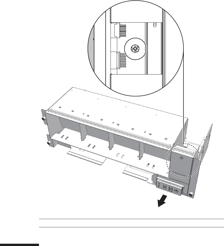
Front
Note - Place the removed operation panel on a grounded antistatic ESD mat.
Figure 23-7 Removing the operation panel
23.5 Installing the Operation Panel
This section describes the procedure for installing the operation panel.
Chapter 23 Maintaining the Operation Panel of the Crossbar Box 375
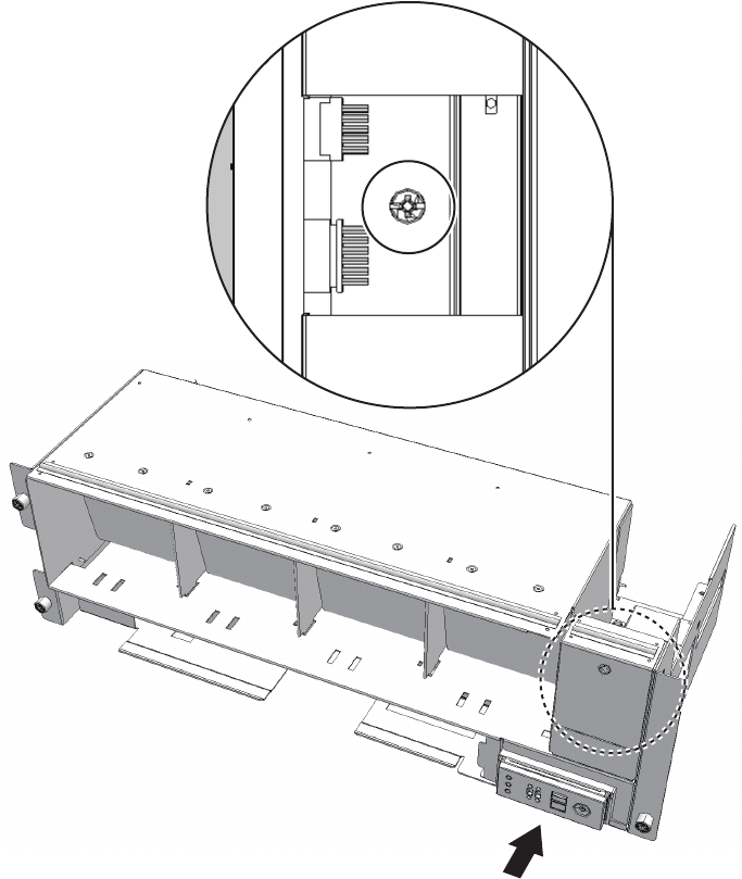
Front
23.5.1 Installing the operation panel
1. Set the BB-ID of the operation panel to the value prior to the start of
maintenance.
2. Insert the operation panel into the fan shelf and then secure it with the screw.
Figure 23-8 Installing the operation panel
3. Reinstall the cable between the fan shelf and the operation panel.
Fujitsu M10-4/Fujitsu M10-4S/SPARC M10-4/SPARC M10-4S Service Manual ・December 2013376
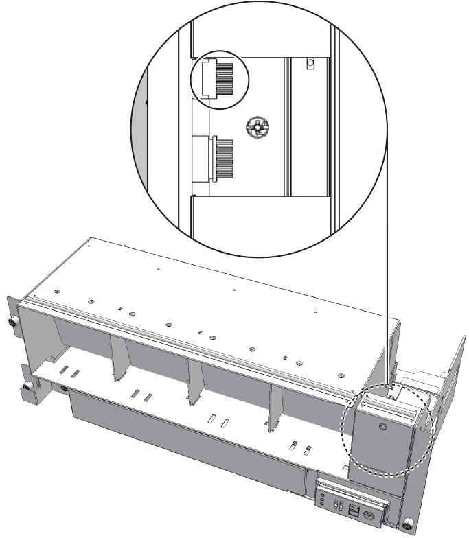
Front
Figure 23-9 Operation panel cable
23.5.2 Restoring the chassis
1. Support the fan shelf from below with one hand and insert it into the chassis.
Then, tighten the three screws.
2. Connect the two cables to the fan shelf.
3. Install the lower cover and then secure it with the one screw.
4. Install the upper cover and slide the right and left stoppers outwards. Then,
tighten the two screws to secure the upper cover.
5. Install all the fan units.
Chapter 23 Maintaining the Operation Panel of the Crossbar Box 377

Note - In the case of a dual power feed, connect the power cords in their original positions by
referring to the record that you made before the start of maintenance.
For details, see "19.5.1 Installing a fan unit."
6. Install the front cover of the crossbar box.
For details, see "6.5.3 Installing the front cover."
23.6 Restoring the System
This section describes the procedure for restoring the system after installing the
operation panel.
1. Connect all the power cords to the power supply unit of the crossbar box
requiring maintenance.
For details, see "6.5.1 Installing the power cord."
2. Return to the operation of the XSCF firmware replacefru command to confirm
that the operation panel has been incorporated into the system.
For details, see "6.1 Incorporating an FRU into the System with the replacefru
Command."
3. Power on all the physical partitions.
For details, see "6.3 Powering On the Physical Partition Requiring Maintenance."
4. Close the rack door.
Fujitsu M10-4/Fujitsu M10-4S/SPARC M10-4/SPARC M10-4S Service Manual ・December 2013378

Chapter 24
Maintaining the Crossbar Cables
(Electrical)
This chapter describes the procedure for maintaining the crossbar cables (electrical).
■Configuration of the Ports for the Crossbar Cables (Electrical)
■Before Maintaining a Crossbar Cable (Electrical)
■Enabling the Removal of a Crossbar Cable (Electrical)
■Removing a Crossbar Cable (Electrical)
■Installing a Crossbar Cable (Electrical)
■Restoring the System
24.1 Configuration of the Ports for the
Crossbar Cables (Electrical)
This section describes the configuration and the location of the ports that are used for
connecting crossbar cables (electrical).
The crossbar cables (electrical) are used make interconnections between SPARC
M10-4S systems.
Each crossbar cable (electrical) has a number that corresponds to a port number on
the chassis. A port number is assigned to each pair of ports. Crossbar cables
(electrical) should be replaced as a pair, therefore.
379
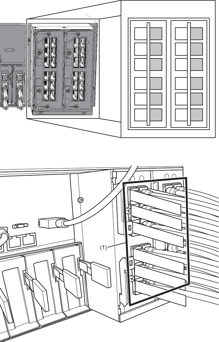
1R
2L
2R
0R
0L
1L
1R
2L
2R
0R
0L
1L
1R
2L
2R
0R
0L
1L
1R
2L
2R
0R
0L
1L
XBU#0 XBU#1
Figure 24-1 Connection ports for crossbar cables (electrical)
Figure 24-2 Crossbar cables (electrical)
Fujitsu M10-4/Fujitsu M10-4S/SPARC M10-4/SPARC M10-4S Service Manual ・December 2013380
Location
number
Component
1 Crossbar cables (electrical) (CBL)
Note - Read and understand the instructions in this chapter before starting the maintenance
work. Also see the contents of "Chapter 1 Before Starting Maintenance Work."
Table 24-1 Types of maintenance for crossbar cables (electrical)
Configuration Active/hot Active/cold Inactive/hot Inactive/cold System stopped
Without crossbar box Unsupported Unsupported Unsupported Supported Supported
Table 24-2 Maintenance flow
Task Replacement
1 Preparation 24.3
2 Removing the crossbar cables (electrical) 24.4
3 Installing the crossbar cables (electrical) 24.5
4 Restoring the system 24.6
24.2 Before Maintaining a Crossbar Cable
(Electrical)
This section describes the types and the flow of the maintenance of the crossbar
cables (electrical), as well as precautions that must be observed.
24.2.1 Types of maintenance
Table 24-1 lists the types of maintenance for the crossbar cables (electrical). For the
definition of maintenance, see "4.3 Understanding Types of Maintenance."
24.2.2 Maintenance flow
Table 24-2 lists the sequence of the maintenance procedure for the crossbar cables
(electrical).
Chapter 24 Maintaining the Crossbar Cables (Electrical) 381
Caution - To completely shut down the system, all the power cords must be
removed. If the power cords are not removed, an electrical failure may occur.
XSCF> showlogs error
XSCF> replacefru
24.2.3 Precautions for replacement
Note the following points when replacing a crossbar cable (electrical):
■Replace crossbar cables (electrical) in pairs.
24.3 Enabling the Removal of a Crossbar
Cable (Electrical)
This section describes the preparations that must be completed prior to removing the
crossbar cables (electrical). The preparation procedure differs depending on the
maintenance type as follows:
■Inactive/Cold maintenance
■System-stopped maintenance
24.3.1 Inactive/Cold maintenance
1. Open the rack door.
2. Log in to the XSCF shell.
3. Execute the showlogs command to identify the component requiring
maintenance.
For details, see "3.3.5 Checking log information."
4. Confirm the hardware and software configurations.
For details, see "4.2 Confirming the System Configuration."
5. Power off the physical partition requiring maintenance.
For details, see "5.3 Powering Off the Physical Partition Requiring Maintenance."
6.
Execute the replacefru command to release the chassis requiring maintenance
from the system.
Fujitsu M10-4/Fujitsu M10-4S/SPARC M10-4/SPARC M10-4S Service Manual ・December 2013382
Note - Inthecaseofadualpowerfeed,makeanoteofthelocationsofthepowercords
before disconnecting them to ensure that they are reinstalled correctly.
XSCF> showlogs error
XSCF> replacefru
Note - Inthecaseofadualpowerfeed,makeanoteofthelocationsofthepowercords
before disconnecting them to ensure that they are reinstalled correctly.
For details, see "5.1 Releasing an FRU from the System with the replacefru
Command."
7. Remove all the power cords from the PSU backplane unit of the chassis
requiring maintenance.
For details, see "5.5.2 Removing the power cord."
24.3.2 System-stopped maintenance
1. Open the rack door.
2. LogintotheXSCFshell.
3. Execute the showlogs command to identify the component requiring
maintenance.
For details, see "3.3.5 Checking log information."
4. Confirm the hardware and software configurations.
For details, see "4.2 Confirming the System Configuration."
5. Power off all the physical partitions.
For details, see "5.3 Powering Off the Physical Partition Requiring Maintenance."
6.
Execute the replacefru command to release the chassis requiring maintenance
from the system.
For details, see "5.1 Releasing an FRU from the System with the replacefru
Command."
7. Remove all the power cords from the PSU backplane unit of the chassis
requiring maintenance.
For details, see "5.5.2 Removing the power cord."
Chapter 24 Maintaining the Crossbar Cables (Electrical) 383
Caution - Before you handle any components, wear a wrist strap to ground any static
electricity. If you perform this procedure without a wrist strap, individual
components or the overall system may be damaged. For details, see "1.5 Notes
Regarding Static Electricity."
24.4 Removing a Crossbar Cable
(Electrical)
This section describes the procedure for removing the crossbar cables (electrical).
Enable the removal of the crossbar cables (electrical) before attempting to remove
them. For details, see "24.3 Enabling the Removal of a Crossbar Cable (Electrical)."
1. Remove the two crossbar cables (electrical) from the SPARC M10-4S.
Remove the crossbar cable (electrical) by holding the tab (A in the figure) of the
cable and pulling it straight in the direction of the arrow. At this time, do not
hold the cable part when pulling the crossbar cable. Pulling the cable part
without the connector lock completely released may cause damage.
Fujitsu M10-4/Fujitsu M10-4S/SPARC M10-4/SPARC M10-4S Service Manual ・December 2013384
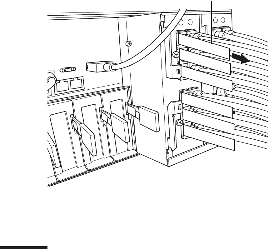
A
Figure 24-3 Removing the crossbar cables (electrical)
2. Remove the two crossbar cables (electrical) from the other chassis.
Remove the crossbar cable (electrical) by holding the tab of the cable and pulling
it straight out in the direction of the arrow. At this time, do not hold the cable
part when pulling the crossbar cable. Pulling the cable part without the
connector lock completely released may cause damage.
24.5 Installing a Crossbar Cable (Electrical)
This section describes the procedure for connecting the crossbar cables (electrical).
1. Attach the supplied connection destination label to the new replacement
crossbar cable (electrical).
For the new crossbar cable (electrical), use the same type of label as the one on
the cable requiring maintenance and write the same port number on it.
2. Connect a pair of crossbar cables (electrical) to each chassis.
Insert the crossbar cable (electrical) by holding the connector part of the cable
and inserting it straight into the opening. Do not hold the cable part when
Chapter 24 Maintaining the Crossbar Cables (Electrical) 385

Note - If you insert a connector with the tab pulled, the connector may be damaged.
Note - Check that the crossbar cables (electrical) are correctly connected and secure.
Note - In the case of a dual power feed, connect the power cords in their original positions by
referring to the record that you made before the start of maintenance.
XSCF> diagxbu -y -b 00 -t 01
inserting the cable.
24.6 Restoring the System
This section describes the procedure for restoring the system after installing the
crossbar cables (electrical). The restoration procedure differs depending on the
maintenance type as follows:
■Inactive/Cold maintenance
■System-stopped maintenance
24.6.1 Inactive/Cold maintenance
1. Connect all the power cords to the PSU backplane unit of the chassis
requiring maintenance.
For details, see "6.5.1 Installing the power cord."
2. Return to the operation of the XSCF firmware replacefru command to confirm
that the chassis has been incorporated into the system.
For details, see "6.1 Incorporating an FRU into the System with the replacefru
Command."
3. Execute the diagxbu command to diagnose the crossbar cables.
Diagnosis is performed when the system board of the chassis connected with the
crossbar cables is not incorporated into the physical partition, or when the
physical partition into which the chassis is incorporated is powered off.
The example below specifies the following:
00: BB-ID of the chassis to start the diagnosis
01: BB-ID of the destination where the chassis to start the diagnosis is connected
(You can specify one or more of these.)
To specify multiple connection destination BB-IDs, enter a command like
"diagxbu -y -b 00 -t 01 -t 02".
Fujitsu M10-4/Fujitsu M10-4S/SPARC M10-4/SPARC M10-4S Service Manual ・December 2013386
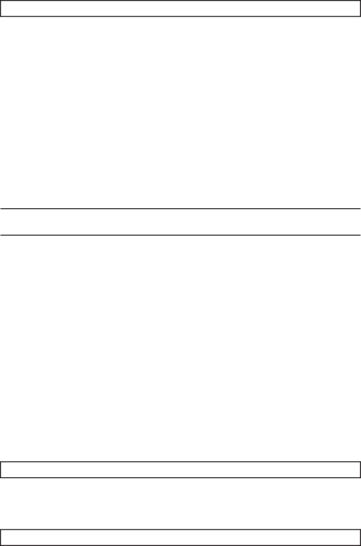
XSCF> showlogs error
Note - In the case of a dual power feed, connect the power cords in their original positions by
referring to the record that you made before the start of maintenance.
XSCF> diagxbu -y -b 00 -t 01
XSCF> showlogs error
4. Execute the showlogs command to confirm that the system is operating
normally.
For details, see "3.3.5 Checking log information."
5. Power on the physical partition requiring maintenance.
For details, see "6.3 Powering On the Physical Partition Requiring Maintenance."
6. Close the rack door.
24.6.2 System-stopped maintenance
1. Connect all the power cords to the PSU backplane unit of the chassis
requiring maintenance.
For details, see "6.5.1 Installing the power cord."
2. Return to the operation of the XSCF firmware replacefru command to confirm
that the chassis has been incorporated into the system.
For details, see "6.1 Incorporating an FRU into the System with the replacefru
Command."
3. Execute the diagxbu command to diagnose the crossbar cables.
Diagnosis is performed when the system board of the chassis connected with the
crossbar cables is not incorporated into the physical partition, or when the
physical partition into which the chassis is incorporated is powered off.
The example below specifies the following:
00: BB-ID of the chassis to start the diagnosis
01: BB-ID of the destination where the chassis to start the diagnosis is connected
(You can specify one or more of these.)
To specify multiple connection destination BB-IDs, enter a command like
"diagxbu -y -b 00 -t 01 -t 02".
4. Execute the showlogs command to confirm that the system is operating
normally.
Chapter 24 Maintaining the Crossbar Cables (Electrical) 387

Chapter 25
Maintaining the Crossbar Cables
(Optical)
This chapter describes the procedure for maintaining the crossbar cables (optical).
■Configuration of the Ports for the Crossbar Cables (Optical)
■Before Maintaining a Crossbar Cable (Optical)
■Enabling the Removal of a Crossbar Cable (Optical)
■Removing a Crossbar Cable (Optical)
■Installing a Crossbar Cable (Optical)
■Restoring the System
25.1 Configuration of the Ports for the
Crossbar Cables (Optical)
This section describes the configuration and the locations of the ports for connecting
the crossbar cables (optical).
The crossbar cables (optical) are used to connect the SPARC M10-4S to a crossbar box
in a building block configuration (with a crossbar box).
Each crossbar cable (optical) has a number that corresponds to a port number on the
chassis. A port number is assigned to each pair of ports. Crossbar cables (optical)
should be replaced as a pair, therefore.
389
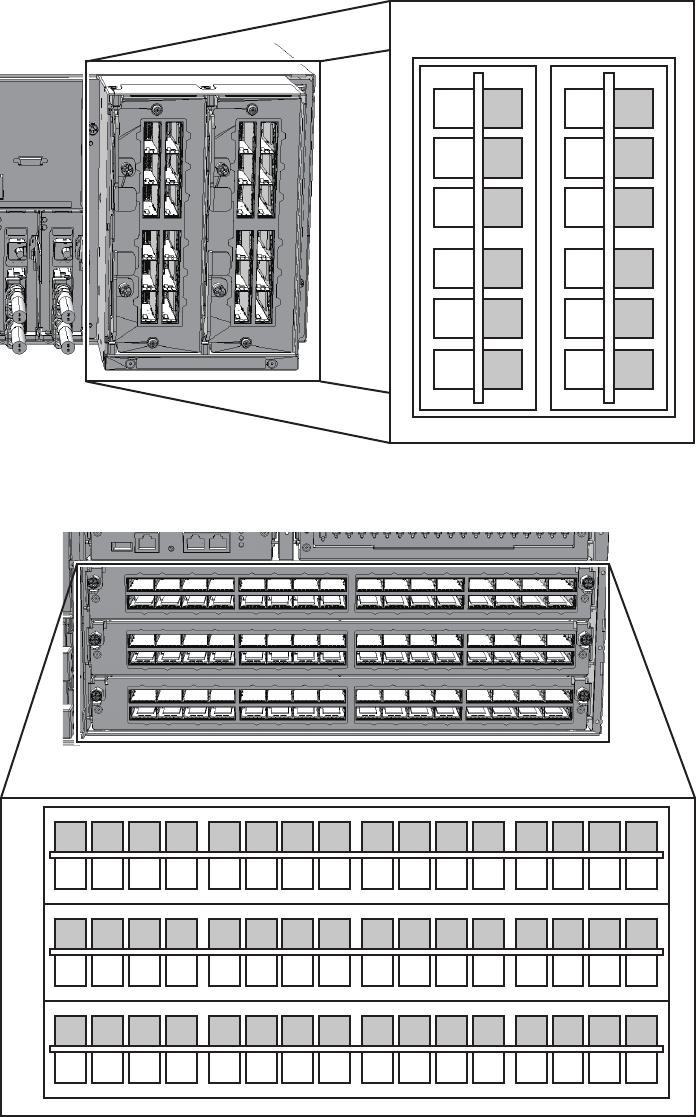
1R
2L
2R
0R
0L
1L
1R
2L
2R
0R
0L
1L
1R
2L
2R
0R
0L
1L
1R
2L
2R
0R
0L
1L
XBU#0 XBU#1
L0 L2 L3L1
L0 L2 L3L1
L4 L6 L7L5
L4 L6 L7L5
R0 R2 R3R1
R0 R2 R3R1
R4 R6 R7R5
R4 R6 R7R5
#2
#1
#0
L0 L2 L3L1
L0 L2 L3L1
L4 L6 L7L5
L4 L6 L7L5
R0 R2 R3R1
R0 R2 R3R1
R4 R6 R7R5
R4 R6 R7R5
L0 L2 L3L1
L0 L2 L3L1
L4 L6 L7L5
L4 L6 L7L5
R0 R2 R3R1
R0 R2 R3R1
R4 R6 R7R5
R4 R6 R7R5
Figure 25-1 Connection ports for crossbar cables (optical) (SPARC M10-4S)
Figure 25-2 Connection ports for crossbar cables (optical) (crossbar box)
Fujitsu M10-4/Fujitsu M10-4S/SPARC M10-4/SPARC M10-4S Service Manual ・December 2013390
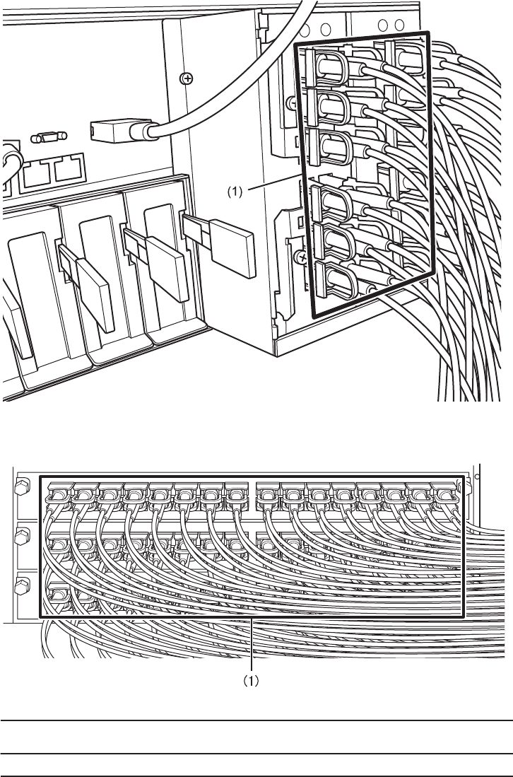
Location
number
Component
1 Crossbar cables (optical) (CBL)
Figure 25-3 Crossbar cables (optical) (SPARC M10-4S)
Figure 25-4 Crossbar cables (optical) (crossbar box)
Chapter 25 Maintaining the Crossbar Cables (Optical) 391
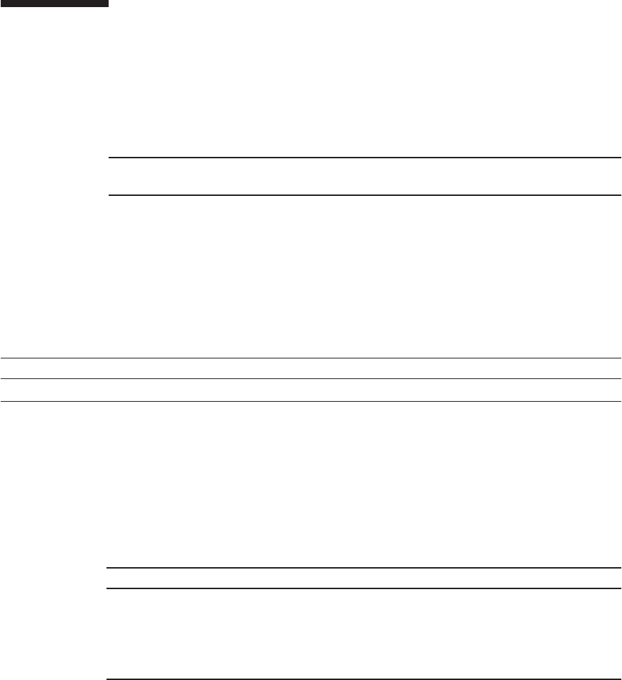
Note - Read and understand the instructions in this chapter before starting the maintenance
work. Also see the contents of "Chapter 1 Before Starting Maintenance Work."
Table 25-1 Types of maintenance for crossbar cables (optical)
Configuration Active/hot Active/cold Inactive/hot Inactive/cold System stopped
With a crossbar box Unsupported Unsupported Unsupported Supported Supported
Table 25-2 Maintenance flow
Task Replacement
1 Preparation 25.3
2 Removing the crossbar cables (optical) 25.4
3 Installing the crossbar cables (optical) 25.5
4 Restoring the system 25.6
25.2 Before Maintaining a Crossbar Cable
(Optical)
This section describes the types and the flow of the maintenance of the crossbar
cables (optical), as well as precautions that must be observed.
25.2.1 Types of maintenance
Table 25-1 lists the types of maintenance for the crossbar cables (optical). For the
definition of maintenance, see "4.3 Understanding Types of Maintenance."
25.2.2 Maintenance flow
Table 25-2 lists the sequence of the maintenance procedure for the crossbar cables
(optical).
25.2.3 Precautions for replacement
Note the following when replacing the crossbar cables (optical):
■Replace the crossbar cables (optical) in pairs.
■Do not place heavy objects on the crossbar cables (optical).
Fujitsu M10-4/Fujitsu M10-4S/SPARC M10-4/SPARC M10-4S Service Manual ・December 2013392

Caution - To completely shut down the system, all the power cords must be
removed. If the power cords are not removed, an electrical failure may occur.
XSCF> showlogs error
XSCF> replacefru
■Do not bend the crossbar cables (optical) unduly. If you unduly bend a crossbar
cable (optical), it may be damaged. Ensure that the static/dynamic bending radius
of the crossbar cable (optical) is no less than 35 mm (1.4 in.).
25.3 Enabling the Removal of a Crossbar
Cable (Optical)
This section describes the preparations that must be completed prior to removing a
crossbar cable (optical). The preparation procedure differs depending on the
maintenance type as follows:
■Inactive/Cold maintenance
■System-stopped maintenance
25.3.1 Inactive/Cold maintenance
1. Open the rack door.
2. LogintotheXSCFshell.
3. Execute the showlogs command to identify the component requiring
maintenance.
For details, see "3.3.5 Checking log information."
4. Confirm the hardware and software configurations.
For details, see "4.2 Confirming the System Configuration."
5. Power off the physical partition requiring maintenance.
For details, see "5.3 Powering Off the Physical Partition Requiring Maintenance."
6. Execute the replacefru command to release the SPARC M10-4S requiring
maintenance from the system.
For details, see "5.1 Releasing an FRU from the System with the replacefru
Command."
Chapter 25 Maintaining the Crossbar Cables (Optical) 393
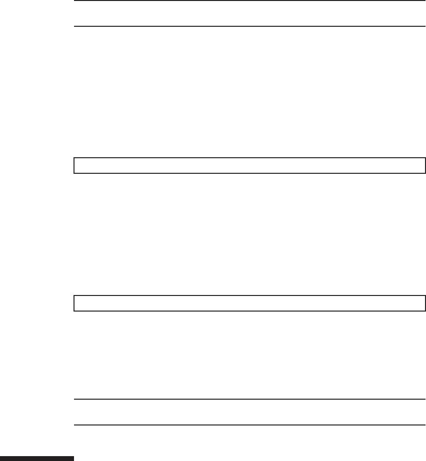
Note - In the case of a dual power feed, make a note of the locations of the power cords
before disconnecting them to ensure that they are reinstalled correctly.
XSCF> showlogs error
XSCF> replacefru
Note - In the case of a dual power feed, make a note of the locations of the power cords
before disconnecting them to ensure that they are reinstalled correctly.
7. Remove all the power cords from the SPARC M10-4S power supply unit
requiring maintenance.
For details, see "5.5.2 Removing the power cord."
25.3.2 System-stopped maintenance
1. Open the rack door.
2. Log in to the XSCF shell.
3. Execute the showlogs command to identify the component requiring
maintenance.
For details, see "3.3.5 Checking log information."
4. Confirm the hardware and software configurations.
For details, see "4.2 Confirming the System Configuration."
5. Power off all the physical partitions.
For details, see "5.3 Powering Off the Physical Partition Requiring Maintenance."
6. Execute the replacefru command to release the SPARC M10-4S requiring
maintenance from the system.
For details, see "5.1 Releasing an FRU from the System with the replacefru
Command."
7. Remove all the power cords from the SPARC M10-4S power supply unit
requiring maintenance.
For details, see "5.5.2 Removing the power cord."
25.4 Removing a Crossbar Cable (Optical)
This section describes the procedure for removing the crossbar cables (optical).
Fujitsu M10-4/Fujitsu M10-4S/SPARC M10-4/SPARC M10-4S Service Manual ・December 2013394
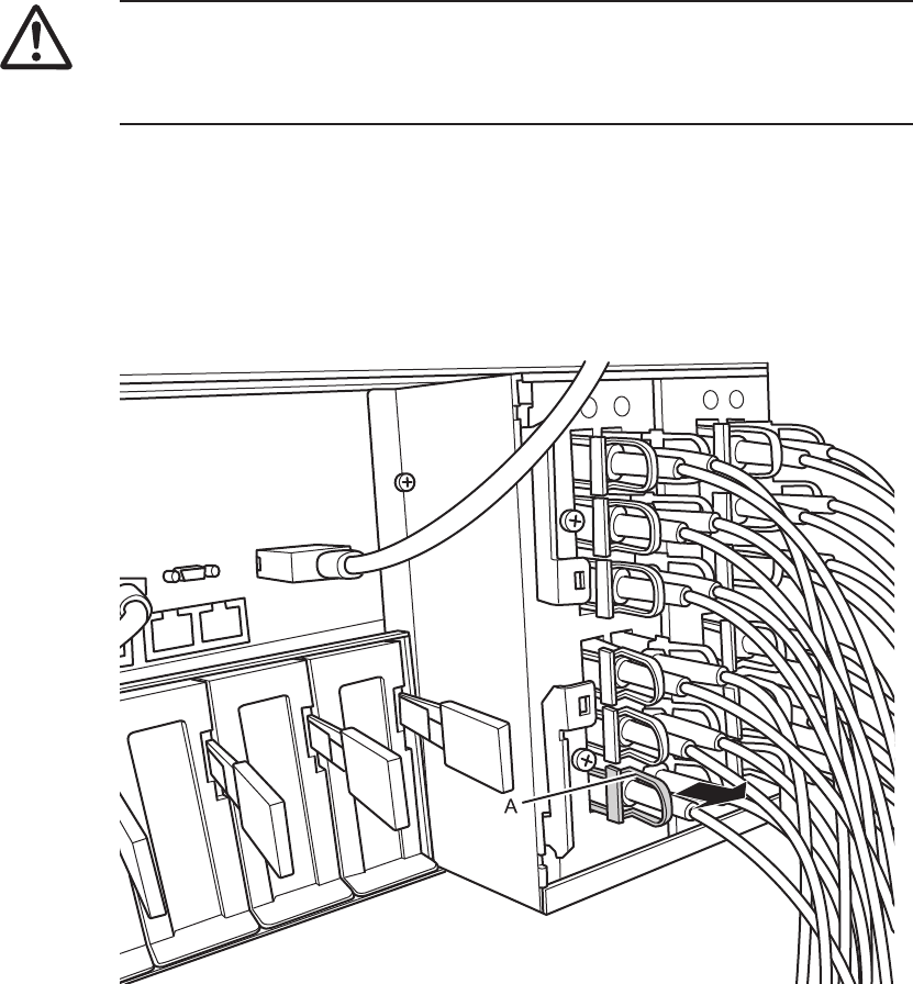
Caution - Before you handle any components, wear a wrist strap to ground any static
electricity. If you perform this procedure without a wrist strap, individual
components or the overall system may be damaged. For details, see "1.5 Notes
Regarding Static Electricity."
Enable the removal of the crossbar cables (optical) before attempting to remove them.
For details, see "25.3 Enabling the Removal of a Crossbar Cable (Optical)."
1. Remove the two crossbar cables (optical) from the SPARC M10-4S.
Remove the crossbar cable (optical) by holding the tab (A in the figure) of the
cable and pulling it straight in the direction of the arrow. At this time, do not
hold the cable part when pulling the crossbar cable. Pulling the cable part
without the connector lock completely released may cause damage.
Figure 25-5 Removing the crossbar cables (optical) (SPARC M10-4S)
2. Remove the other pair of crossbar cables (optical) from the crossbar box.
Remove the crossbar cable (optical) by holding the tab (A in the figure) of the
cable and pulling it straight in the direction of the arrow. At this time, do not
hold the cable part when pulling the crossbar cable. Pulling the cable part
without the connector lock completely released may cause damage.
Chapter 25 Maintaining the Crossbar Cables (Optical) 395
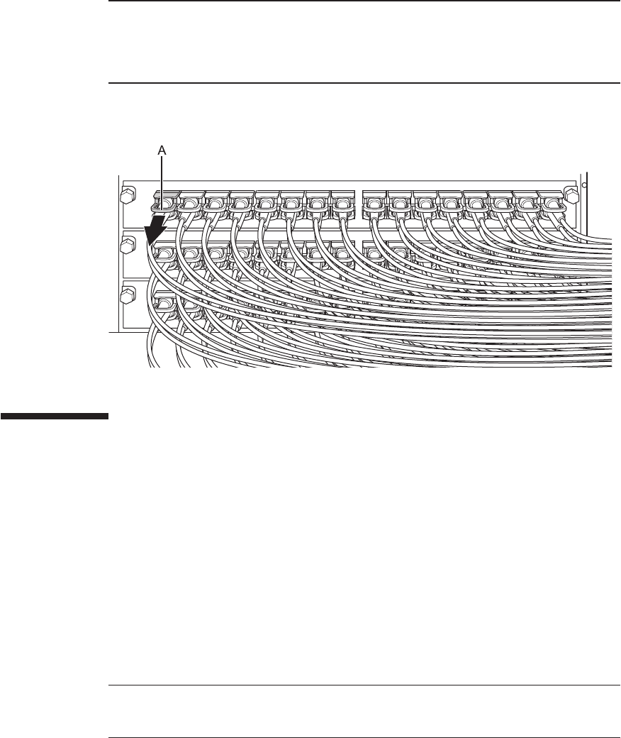
Note - There is no problem if you remove the crossbar cables at the crossbar box while
electricity is supplied.
Note - The cables at the rear of the crossbar box are bundled together and fastened to the
right-hand cable support with a hook-and-loop fastener. To remove the crossbar cables
(optical), therefore, remove the hook-and-loop fastener from the cable support.
Note - There is no problem if you connect the crossbar cables (optical) at the crossbar box
while electricity is supplied.
Note - If you insert a connector with the tab pulled, the connector may be damaged.
Figure 25-6 Removing the crossbar cables (optical) (crossbar box)
25.5 Installing a Crossbar Cable (Optical)
This section describes the procedure for connecting the crossbar cables (optical).
1. Attach the supplied connection destination label to the new replacement
crossbar cable (optical).
For the new crossbar cable (optical), use the same type of label as the one on the
cable requiring maintenance and write the same port number on it.
2. Connect a pair of crossbar cables (optical) to the SPARC M10-4S and the
crossbar box.
There are two types of crossbar cables (optical). Connect cables of the same type
to the same port number. Cables can be distinguished by tab shape. For the tab
shapes, see Figure 25-7.
Fujitsu M10-4/Fujitsu M10-4S/SPARC M10-4/SPARC M10-4S Service Manual ・December 2013396
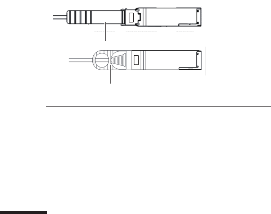
(1)
(1)
Number in
figure
Description
1Tab
Note - Confirm that the crossbar cables (optical) are correctly connected and secure.
Note - After installing the crossbar cables (optical), use the hook-and-loop fastener to bundle
the cables together and secure them to the rear cable support.
Figure 25-7 Crossbar cable (optical) shapes and tabs
Insert the crossbar cable (optical) by holding the connector part of the cable and
inserting it straight into the opening. Do not hold the cable part when inserting the
cable.
25.6 Restoring the System
This section describes the procedure for restoring the system after installing the
crossbar cable (optical). The restoration procedure differs depending on the
maintenance type as follows:
■Inactive/Cold maintenance
■System-stopped maintenance
25.6.1 Inactive/Cold maintenance
1. Connect all power cords to the SPARC M10-4S power supply unit requiring
maintenance.
For details, see "6.5.1 Installing the power cord."
Chapter 25 Maintaining the Crossbar Cables (Optical) 397
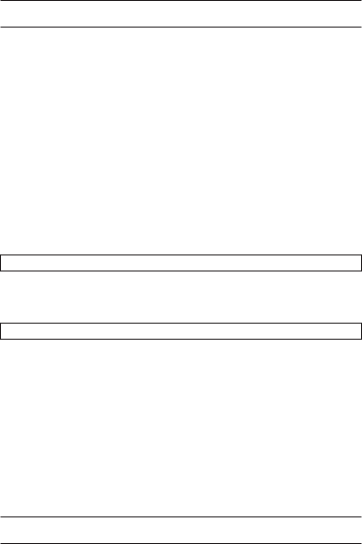
Note - In the case of a dual power feed, connect the power cords in their original positions by
referring to the record that you made before the start of maintenance.
XSCF> diagxbu -y -b 00 -t 01
XSCF> showlogs error
Note - In the case of a dual power feed, connect the power cords in their original positions by
referring to the record that you made before the start of maintenance.
2. Return to the operation of the XSCF firmware replacefru command to confirm
that SPARC M10-4S has been incorporated into the system.
For details, see "6.1 Incorporating an FRU into the System with the replacefru
Command."
3. Execute the diagxbu command to diagnose the crossbar cables.
Diagnosis is performed when the system board of the chassis connected with the
crossbar cables is not incorporated into the physical partition, or when the
physical partition into which the chassis is incorporated is powered off.
The example below specifies the following:
00: BB-ID of the chassis to start the diagnosis
01: BB-ID of the destination where the chassis to start the diagnosis is connected
(You can specify one or more of these.)
To specify multiple connection destination BB-IDs, enter a command like
"diagxbu -y -b 00 -t 01 -t 02".
4. Execute the showlogs command to confirm that the system is operating
normally.
For details, see "3.3.5 Checking log information."
5. Power on the physical partition requiring maintenance.
For details, see "6.3 Powering On the Physical Partition Requiring Maintenance."
6. Close the rack door.
25.6.2 System-stopped maintenance
1. Connect all power cords to the SPARC M10-4S power supply unit requiring
maintenance.
For details, see "6.5.1 Installing the power cord."
2. Return to the operation of the XSCF firmware replacefru command to confirm
that SPARC M10-4S has been incorporated into the system.
Fujitsu M10-4/Fujitsu M10-4S/SPARC M10-4/SPARC M10-4S Service Manual ・December 2013398
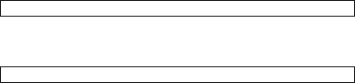
XSCF> diagxbu -y -b 00 -t 01
XSCF> showlogs error
For details, see "6.1 Incorporating an FRU into the System with the replacefru
Command."
3. Execute the diagxbu command to diagnose the crossbar cables.
Diagnosis is performed when the system board of the chassis connected with the
crossbar cables is not incorporated into the physical partition, or when the
physical partition into which the chassis is incorporated is powered off.
The example below specifies the following:
00: BB-ID of the chassis to start the diagnosis
01: BB-ID of the destination where the chassis to start the diagnosis is connected
(You can specify one or more of these.)
To specify multiple connection destination BB-IDs, enter a command like
"diagxbu -y -b 00 -t 01 -t 02".
4. Execute the showlogs command to confirm that the system is operating
normally.
For details, see "3.3.5 Checking log information."
5. Power on all the physical partitions.
For details, see "6.3 Powering On the Physical Partition Requiring Maintenance."
6. Close the rack door.
Chapter 25 Maintaining the Crossbar Cables (Optical) 399
Fujitsu M10-4/Fujitsu M10-4S/SPARC M10-4/SPARC M10-4S Service Manual ・December 2013400

Chapter 26
Maintaining the XSCF BB Control
Cables
This chapter describes the procedure for maintaining the XSCF BB control cables.
■Configuration of the Ports for the XSCF BB Control Cables
■Before Maintaining an XSCF BB Control Cable
■Enabling the Removal of an XSCF BB Control Cable
■Removing an XSCF BB Control Cable
■Installing an XSCF BB Control Cable
■Restoring the System
26.1 Configuration of the Ports for the
XSCF BB Control Cables
This section describes the configuration and the location of the ports to which the
XSCF BB control cables are connected.
The XSCF BB control cables are used to connect the XSCFs mounted in the SPARC
M10-4S or crossbar box chassis.
401
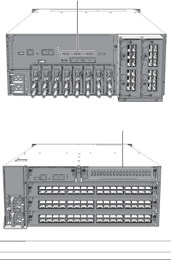
(1)
(1)
Location
number
Component
1 XSCF BB control cables (SCF_CBL)
Figure 26-1 Locations of XSCF BB control cables (SPARC M10-4S)
Figure 26-2 Locations of XSCF BB control cables (crossbar box)
Fujitsu M10-4/Fujitsu M10-4S/SPARC M10-4/SPARC M10-4S Service Manual ・December 2013402
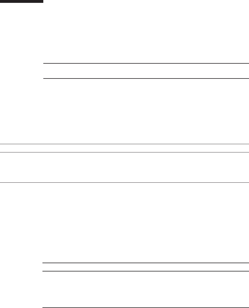
Note - Read and understand the instructions in this chapter before starting the maintenance
work. Also see the contents of "Chapter 1 Before Starting Maintenance Work."
Table 26-1 Types of maintenance for XSCF BB control cable
Configuration Active/hot Active/cold Inactive/hot Inactive/cold System stopped
Building block configuration
(without crossbar box)
Supported (*) Supported Supported Supported Supported
Building block configuration
(with crossbar box)
Supported (*) Supported Supported Supported Supported
*: The XSCF must be configured as a slave before maintenance is started. If it is operating as the master XSCF, switch it to a standby
XSCF.
Table 26-2 Maintenance flow
Details of update process Replacement
1 Preparation 26.3
2 Removing the XSCF BB control cables 26.4
3 Installing the XSCF BB control cables 26.5
4 Restoring the system 26.6
26.2 Before Maintaining an XSCF BB
Control Cable
This section describes the types and the flow of the maintenance of the XSCF BB
control cables.
26.2.1 Types of maintenance
Table 26-1 lists the types of maintenance for the XSCF BB control cables. For the
definition of maintenance, see "4.3 Understanding Types of Maintenance."
26.2.2 Maintenance flow
Table 26-2 lists the sequence of the maintenance procedure for the XSCF BB control
cables.
Chapter 26 Maintaining the XSCF BB Control Cables 403

Caution - To completely shut down the system, all the power cords must be
removed. If the power cords are not removed, an electrical failure may occur.
XSCF> showlogs error
XSCF> switchscf -t Standby
26.3 Enabling the Removal of an XSCF BB
Control Cable
This section describes preparations that must be completed prior to removing the
XSCF BB control cables. The preparation procedure differs depending on the
maintenance type as follows:
■Active/Hot maintenance
■Active/Cold maintenance
■Inactive/Hot maintenance
■Inactive/Cold maintenance
■System-stopped maintenance
26.3.1 Active/Hot maintenance
1. Open the rack door.
2. Log in to the XSCF shell.
3. Execute the showlogs command to identify the component requiring
maintenance.
For details, see "3.3.5 Checking log information."
4. Confirm the hardware and software configurations.
For details, see "4.2 Confirming the System Configuration."
5. Execute the switchscf command to switch the master XSCF to a standby
XSCF.
Perform this when the chassis requiring maintenance is operating as a master
chassis.
6.
Execute the replacefru command to release the chassis requiring maintenance
from the system.
Fujitsu M10-4/Fujitsu M10-4S/SPARC M10-4/SPARC M10-4S Service Manual ・December 2013404

XSCF> replacefru
XSCF> showlogs error
XSCF> replacefru
Note - Inthecaseofadualpowerfeed,makeanoteofthelocationsofthepowercords
before disconnecting them to ensure that they are reinstalled correctly.
XSCF> showlogs error
For details, see "5.1 Releasing an FRU from the System with the replacefru
Command."
26.3.2 Active/Cold maintenance
1. Open the rack door.
2. LogintotheXSCFshell.
3. Execute the showlogs command to identify the component requiring
maintenance.
For details, see "3.3.5 Checking log information."
4. Confirm the hardware and software configurations.
For details, see "4.2 Confirming the System Configuration."
5.
Execute the replacefru command to release the chassis requiring maintenance
from the system.
For details, see "5.1 Releasing an FRU from the System with the replacefru
Command."
6. Remove all the power cords from the PSU backplane unit or power supply
unit of the chassis requiring maintenance.
For details, see "5.5.2 Removing the power cord."
26.3.3 Inactive/Hot maintenance
1. Open the rack door.
2. LogintotheXSCFshell.
3. Execute the showlogs command to identify the component requiring
maintenance.
Chapter 26 Maintaining the XSCF BB Control Cables 405

XSCF> showlogs error
XSCF> replacefru
Note - In the case of a dual power feed, make a note of the locations of the power cords
before disconnecting them to ensure that they are reinstalled correctly.
For details, see "3.3.5 Checking log information."
4. Confirm the hardware and software configurations.
For details, see "4.2 Confirming the System Configuration."
5. Power off the physical partition requiring maintenance.
For details, see "5.3 Powering Off the Physical Partition Requiring Maintenance."
26.3.4 Inactive/Cold maintenance
1. Open the rack door.
2. Log in to the XSCF shell.
3. Execute the showlogs command to identify the component requiring
maintenance.
For details, see "3.3.5 Checking log information."
4. Confirm the hardware and software configurations.
For details, see "4.2 Confirming the System Configuration."
5. Power off the physical partition requiring maintenance.
For details, see "5.3 Powering Off the Physical Partition Requiring Maintenance."
6.
Execute the replacefru command to release the chassis requiring maintenance
from the system.
For details, see "5.1 Releasing an FRU from the System with the replacefru
Command."
7. Remove all the power cords from the PSU backplane unit or power supply
unit of the chassis requiring maintenance.
For details, see "5.5.2 Removing the power cord."
26.3.5 System-stopped maintenance
1. Open the rack door.
2. Log in to the XSCF shell.
3. Execute the showlogs command to identify the component requiring
Fujitsu M10-4/Fujitsu M10-4S/SPARC M10-4/SPARC M10-4S Service Manual ・December 2013406
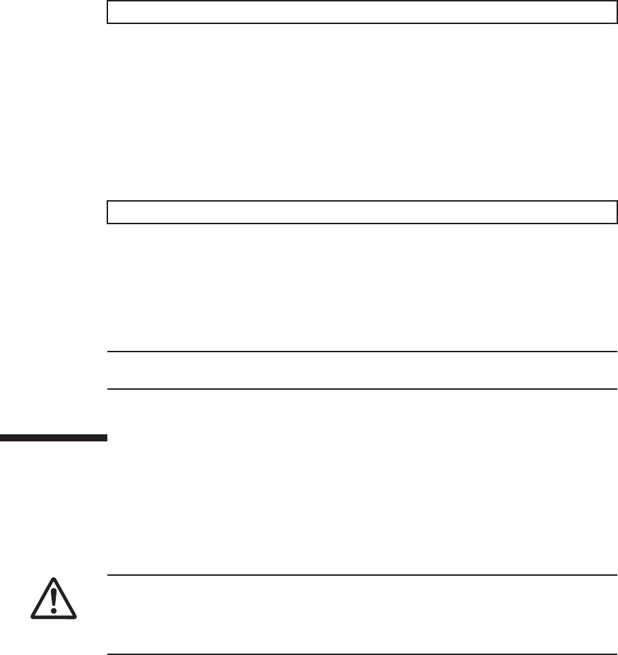
XSCF> showlogs error
XSCF> replacefru
Note - Inthecaseofadualpowerfeed,makeanoteofthelocationsofthepowercords
before disconnecting them to ensure that they are reinstalled correctly.
Caution - Before you handle any components, wear a wrist strap to ground any static
electricity. If you perform this procedure without a wrist strap, individual
components or the overall system may be damaged. For details, see "1.5 Notes
Regarding Static Electricity."
maintenance.
For details, see "3.3.5 Checking log information."
4. Confirm the hardware and software configurations.
For details, see "4.2 Confirming the System Configuration."
5. Power off all the physical partitions.
For details, see "5.3 Powering Off the Physical Partition Requiring Maintenance."
6.
Execute the replacefru command to release the chassis requiring maintenance
from the system.
For details, see "5.1 Releasing an FRU from the System with the replacefru
Command."
7. Remove all the power cords from the PSU backplane unit or power supply
unit of the chassis requiring maintenance.
For details, see "5.5.2 Removing the power cord."
26.4 Removing an XSCF BB Control Cable
This section describes the procedure for removing the XSCF BB control cables.
Enable removal of the XSCF BB control cables before attempting to remove them. For
details, see "26.3 Enabling the Removal of an XSCF BB Control Cable."
1. Remove the XSCF BB control cable from the SPARC M10-4S or the crossbar
box.
Pull out an XSCF BB control cable while pushing the lock release buttons (A in
the figure) on the both sides of the cable.
Chapter 26 Maintaining the XSCF BB Control Cables 407
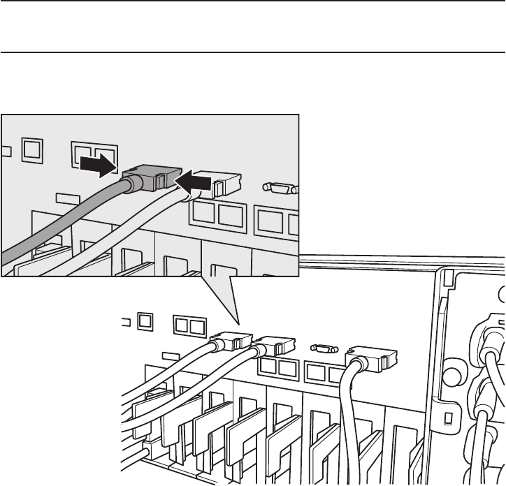
Note - The cables on the rear of the crossbar box are bundled together and fastened to the
right-hand cable support with a hook-and-loop fastener. When removing the XSCF BB
control cables, remove the hook-and-loop fastener from the cable support.
A
A
Figure 26-3 Removing the XSCF BB control cables (SPARC M10-4S)
Fujitsu M10-4/Fujitsu M10-4S/SPARC M10-4/SPARC M10-4S Service Manual ・December 2013408
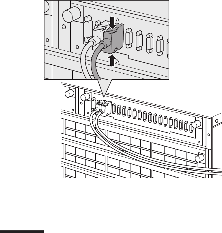
Figure 26-4 Removing the XSCF BB control cables (crossbar box)
2. Remove the XSCF BB control cables from the other chassis.
Pull out an XSCF BB control cable while pushing the lock release buttons (A in
the figure) on the both sides of the cable.
26.5 Installing an XSCF BB Control Cable
This section describes the procedure for installing the XSCF BB control cables.
1. Attach the supplied connection destination label to the new replacement
XSCF BB control cable.
For the new XSCF BB control cable, use the same type of label as the one on the
cable requiring maintenance and write the same port number on it.
2. Connect the XSCF BB control cable to SPARC M10-4S or the crossbar box.
Chapter 26 Maintaining the XSCF BB Control Cables 409
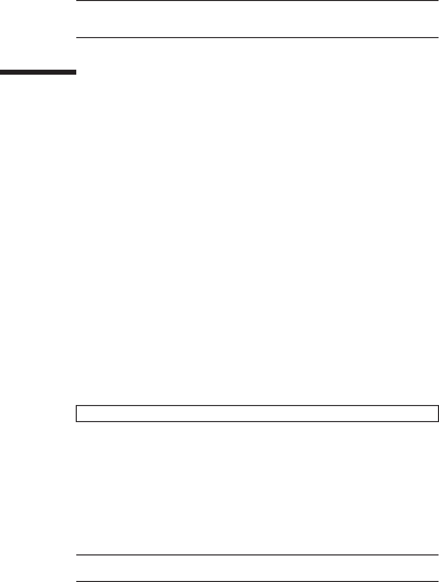
Note - Check that the XSCF BB control cables are correctly connected and secure.
Note - After connecting the XSCF BB control cable, use the hook-and-loop fastener to bundle
the cables together and secure them to the rear cable support.
XSCF> switchscf -t Active
Note - In the case of a dual power feed, connect the power cords in their original positions by
referring to the record that you made before the start of maintenance.
26.6 Restoring the System
This section describes the procedure for restoring the system after installing the XSCF
BB control cables. The restoration procedure differs depending on the maintenance
type as follows:
■Active/Hot maintenance
■Active/Cold maintenance
■Inactive/Hot maintenance
■Inactive/Cold maintenance
■System-stopped maintenance
26.6.1 Active/Hot maintenance
1. Return to the operation of the XSCF firmware replacefru command to confirm
that the chassis has been incorporated into the system.
For details, see "6.1 Incorporating an FRU into the System with the replacefru
Command."
2. Execute the switchscf command to switch the standby XSCF to the master
XSCF.
Execute the command if the chassis requiring maintenance has been switched to
the standby XSCF.
3. Close the rack door.
26.6.2 Active/Cold maintenance
1. Connect all the power cords to the PSU backplane unit or power supply unit
of the chassis requiring maintenance.
For details, see "6.5.1 Installing the power cord."
Fujitsu M10-4/Fujitsu M10-4S/SPARC M10-4/SPARC M10-4S Service Manual ・December 2013410

Note - In the case of a dual power feed, connect the power cords in their original positions by
referring to the record that you made before the start of maintenance.
2. Return to the operation of the XSCF firmware replacefru command to confirm
that the chassis has been incorporated into the system.
For details, see "6.1 Incorporating an FRU into the System with the replacefru
Command."
3. Close the rack door.
26.6.3 Inactive/Hot maintenance
1. Return to the operation of the XSCF firmware replacefru command to confirm
that the chassis has been incorporated into the system.
For details, see "6.1 Incorporating an FRU into the System with the replacefru
Command."
2. Power on the physical partition requiring maintenance.
For details, see "6.3 Powering On the Physical Partition Requiring Maintenance."
3. Close the rack door.
26.6.4 Inactive/Cold maintenance
1. Connect all the power cords to the PSU backplane unit or power supply unit
of the chassis requiring maintenance.
For details, see "6.5.1 Installing the power cord."
2. Return to the operation of the XSCF firmware replacefru command to confirm
that the chassis has been incorporated into the system.
For details, see "6.1 Incorporating an FRU into the System with the replacefru
Command."
3. Power on the physical partition requiring maintenance.
For details, see "6.3 Powering On the Physical Partition Requiring Maintenance."
4. Close the rack door.
26.6.5 System-stopped maintenance
1. Connect all the power cords to the PSU backplane unit or power supply unit
of the chassis requiring maintenance.
For details, see "6.5.1 Installing the power cord."
Chapter 26 Maintaining the XSCF BB Control Cables 411

Note - In the case of a dual power feed, connect the power cords in their original positions by
referring to the record that you made before the start of maintenance.
2. Return to the operation of the XSCF firmware replacefru command to confirm
that the chassis has been incorporated into the system.
For details, see "6.1 Incorporating an FRU into the System with the replacefru
Command."
3. Power on all the physical partitions.
For details, see "6.3 Powering On the Physical Partition Requiring Maintenance."
4. Close the rack door.
Fujitsu M10-4/Fujitsu M10-4S/SPARC M10-4/SPARC M10-4S Service Manual ・December 2013412

Chapter 27
Maintaining the XSCF DUAL Control
Cables
This chapter describes the procedure for maintaining the XSCF DUAL control cables.
■Configuration of the XSCF DUAL Control Ports
■Before Maintaining an XSCF DUAL Control Cable
■Enabling the Removal of an XSCF DUAL Control Cable
■Removing an XSCF DUAL Control Cable
■Installing an XSCF DUAL Control Cable
■Restoring the System
27.1 Configuration of the XSCF DUAL
Control Ports
This section describes configuration and location of the XSCF DUAL control ports.
The XSCF DUAL control cable is used to connect the master XSCF and a standby
XSCF that are mounted on a SPARC M10-4S or crossbar box so as to duplicate the
XSCF.
413
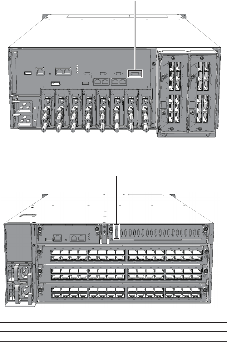
(1)
(1)
Location number Component
1 XSCF DUAL control cables (SCF_DUAL)
Figure 27-1 Location of XSCF DUAL control port (SPARC M10-4S)
Figure 27-2 Location of XSCF DUAL control port (crossbar box)
Fujitsu M10-4/Fujitsu M10-4S/SPARC M10-4/SPARC M10-4S Service Manual ・December 2013414

Note - Read and understand the instructions in this chapter before starting the maintenance
work. Also see the contents of "Chapter 1 Before Starting Maintenance Work."
Table 27-1 Types of maintenance for the XSCF DUAL control cables
Configuration Active/hot Active/cold Inactive/hot Inactive/cold System stopped
Building block configuration
(without crossbar box)
Supported (*) Supported Supported Supported Supported
Building block configuration
(with crossbar box)
Supported (*) Supported Supported Supported Supported
*: The XSCF must be configured as a slave before maintenance is started. If it is operating as the master XSCF, switch it to a standby
XSCF.
Table 27-2 Maintenance flow
Task Replacement
1 Preparation 27.3
2 Removing the XSCF DUAL control cables 27.4
3 Installing the XSCF DUAL control cables 27.5
4 Restoring the system 27.6
27.2 Before Maintaining an XSCF DUAL
Control Cable
This section describes the types and the flow of the maintenance of the XSCF DUAL
control cables.
27.2.1 Types of maintenance
Table 27-1 lists the types of maintenance for the XSCF DUAL control cables. For the
definition of maintenance, see "4.3 Understanding Types of Maintenance."
27.2.2 Maintenance flow
Table 27-2 lists the sequence of the maintenance procedure for the XSCF DUAL
control cables.
Chapter 27 Maintaining the XSCF DUAL Control Cables 415
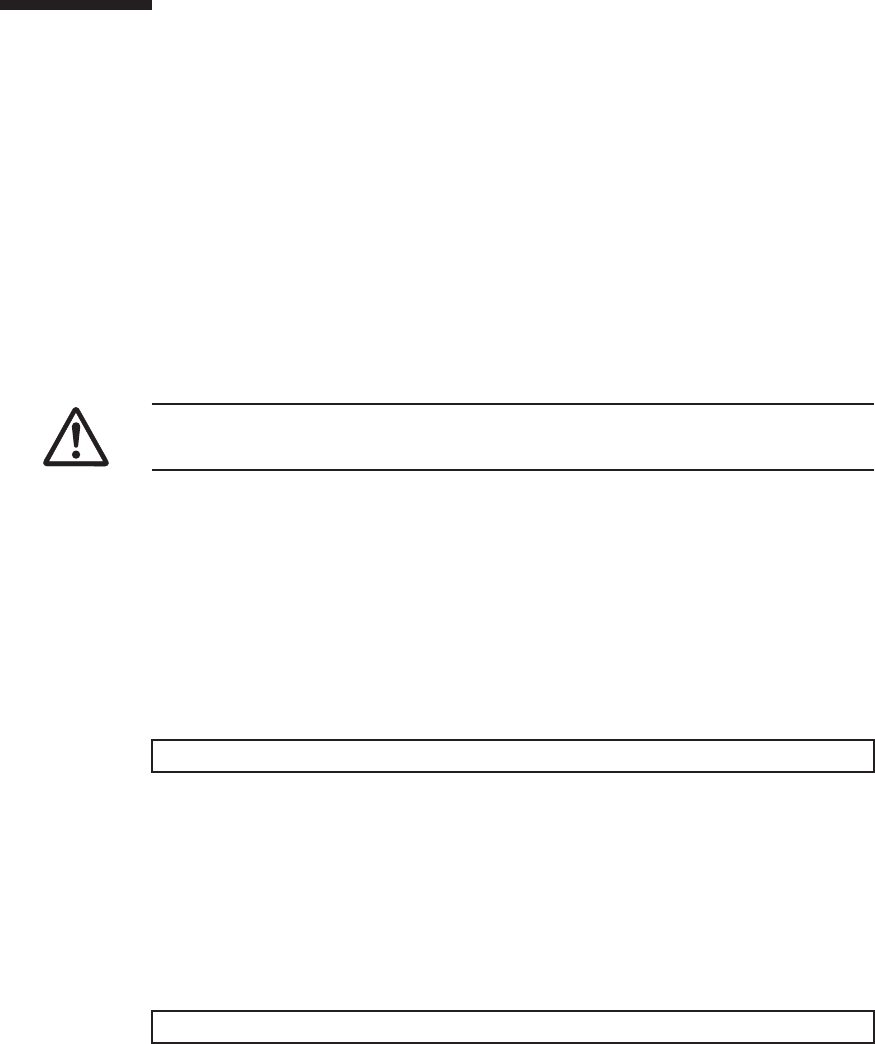
Caution - To completely shut down the system, all the power cords must be
removed. If the power cords are not removed, an electrical failure may occur.
XSCF> showlogs error
XSCF> switchscf -t Standby
27.3 Enabling the Removal of an XSCF
DUAL Control Cable
This section describes the preparation that must be completed prior to removing an
XSCF DUAL control cable. The preparation procedure differs depending on the
maintenance type as follows:
■Active/Hot maintenance
■Active/Cold maintenance
■Inactive/Hot maintenance
■Inactive/Cold maintenance
■System-stopped maintenance
27.3.1 Active/Hot maintenance
1. Open the rack door.
2. Log in to the XSCF shell.
3. Execute the showlogs command to identify the component requiring
maintenance.
For details, see "3.3.5 Checking log information."
4. Confirm the hardware and software configurations.
For details, see "4.2 Confirming the System Configuration."
5. Execute the switchscf command to switch the master XSCF to a standby
XSCF.
Perform this when the chassis requiring maintenance is operating as a master
chassis.
6. Execute the replacefru command to release the XSCF DUAL control cable
requiring maintenance from the system.
Fujitsu M10-4/Fujitsu M10-4S/SPARC M10-4/SPARC M10-4S Service Manual ・December 2013416
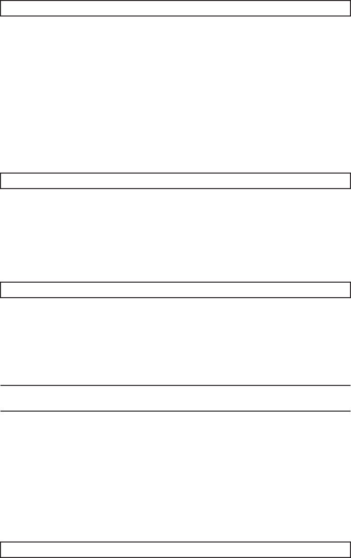
XSCF> replacefru
XSCF> showlogs error
XSCF> replacefru
Note - Inthecaseofadualpowerfeed,makeanoteofthelocationsofthepowercords
before disconnecting them to ensure that they are reinstalled correctly.
XSCF> showlogs error
For details, see "5.1 Releasing an FRU from the System with the replacefru
Command."
27.3.2 Active/Cold maintenance
1. Open the rack door.
2. LogintotheXSCFshell.
3. Execute the showlogs command to identify the component requiring
maintenance.
For details, see "3.3.5 Checking log information."
4. Confirm the hardware and software configurations.
For details, see "4.2 Confirming the System Configuration."
5. Execute the replacefru command to release the XSCF DUAL control cable
requiring maintenance from the system.
For details, see "5.1 Releasing an FRU from the System with the replacefru
Command."
6. Remove all the power cords from the PSU backplane unit or power supply
unit of the chassis requiring maintenance.
For details, see "5.5.2 Removing the power cord."
27.3.3 Inactive/Hot maintenance
1. Open the rack door.
2. LogintotheXSCFshell.
3. Execute the showlogs command to identify the component requiring
maintenance.
Chapter 27 Maintaining the XSCF DUAL Control Cables 417

XSCF> showlogs error
XSCF> replacefru
Note - In the case of a dual power feed, make a note of the locations of the power cords
before disconnecting them to ensure that they are reinstalled correctly.
For details, see "3.3.5 Checking log information."
4. Confirm the hardware and software configurations.
For details, see "4.2 Confirming the System Configuration."
5. Power off the physical partition requiring maintenance.
For details, see "5.3 Powering Off the Physical Partition Requiring Maintenance."
27.3.4 Inactive/Cold maintenance
1. Open the rack door.
2. Log in to the XSCF shell.
3. Execute the showlogs command to identify the component requiring
maintenance.
For details, see "3.3.5 Checking log information."
4. Confirm the hardware and software configurations.
For details, see "4.2 Confirming the System Configuration."
5. Power off the physical partition requiring maintenance.
For details, see "5.3 Powering Off the Physical Partition Requiring Maintenance."
6. Execute the replacefru command to release the XSCF DUAL control cable
requiring maintenance from the system.
For details, see "5.1 Releasing an FRU from the System with the replacefru
Command."
7. Remove all the power cords from the PSU backplane unit or power supply
unit of the chassis requiring maintenance.
For details, see "5.5.2 Removing the power cord."
27.3.5 System-stopped maintenance
1. Open the rack door.
2. Log in to the XSCF shell.
3. Execute the showlogs command to identify the component requiring
Fujitsu M10-4/Fujitsu M10-4S/SPARC M10-4/SPARC M10-4S Service Manual ・December 2013418
XSCF> showlogs error
XSCF> replacefru
Note - Inthecaseofadualpowerfeed,makeanoteofthelocationsofthepowercords
before disconnecting them to ensure that they are reinstalled correctly.
Caution - Before you handle any components, wear a wrist strap to ground any static
electricity. If you perform this procedure without a wrist strap, individual
components or the overall system may be damaged. For details, see "1.5 Notes
Regarding Static Electricity."
maintenance.
For details, see "3.3.5 Checking log information."
4. Confirm the hardware and software configurations.
For details, see "4.2 Confirming the System Configuration."
5. Power off all the physical partitions.
For details, see "5.3 Powering Off the Physical Partition Requiring Maintenance."
6.
Execute the replacefru command to release the chassis requiring maintenance
from the system.
For details, see "5.1 Releasing an FRU from the System with the replacefru
Command."
7. Remove all the power cords from the PSU backplane unit or power supply
unit of the chassis requiring maintenance.
For details, see "5.5.2 Removing the power cord."
27.4 Removing an XSCF DUAL Control
Cable
This section describes the procedure for removing an XSCF DUAL control cable.
Enable the removal of the XSCF DUAL control cables before attempting to remove
them. For details, see "27.2 Before Maintaining an XSCF DUAL Control Cable."
1. Remove the XSCF DUAL control cables from the SPARC M10-4S or the
crossbar box.
Pull out the XSCF DUAL control cable while pushing the lock release buttons (A
in the figure) on the both sides of the cable.
Chapter 27 Maintaining the XSCF DUAL Control Cables 419
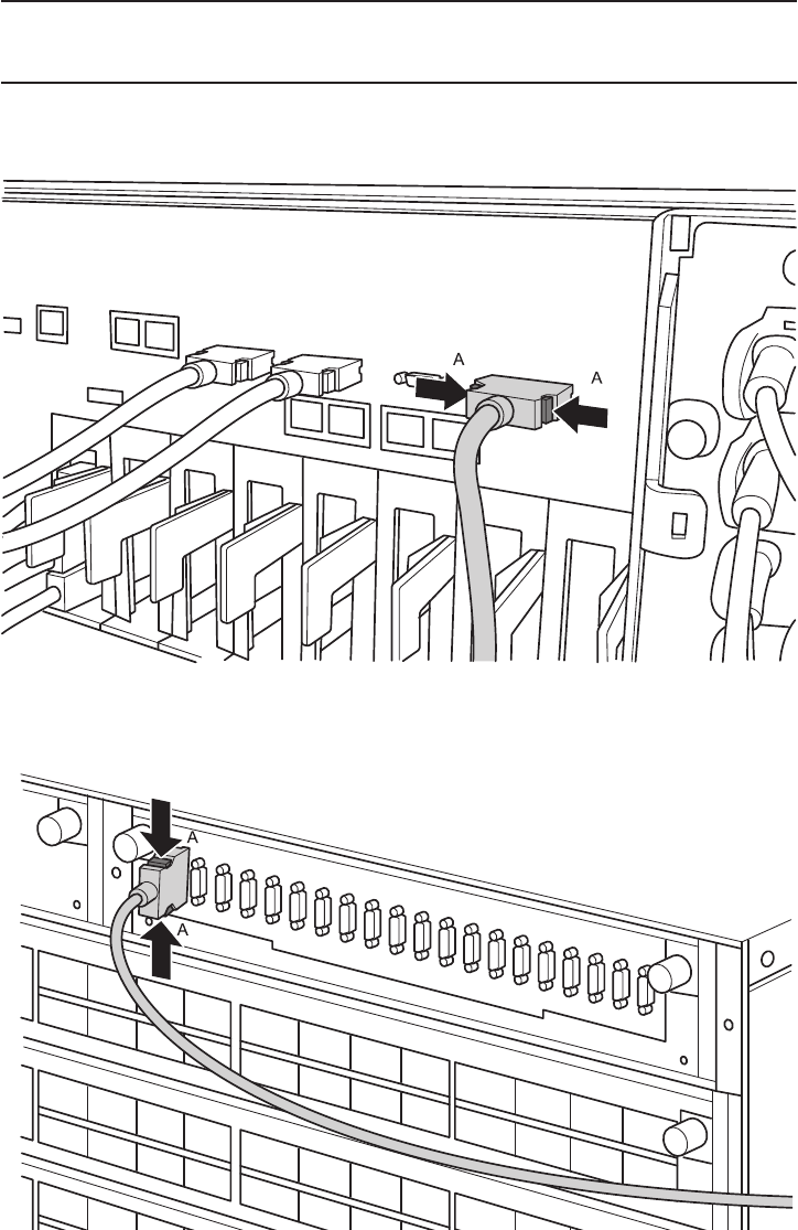
Note - The cables on the rear of the crossbar box are bundled together and fastened to the
right-hand cable support with a hook-and-loop fastener. To remove the XSCF DUAL control
cables, therefore, remove the hook-and-loop fastener from the cable support.
Figure 27-3 Removing the XSCF DUAL control cables (SPARC M10-4S)
Figure 27-4 Removing the XSCF DUAL control cables (crossbar box)
Fujitsu M10-4/Fujitsu M10-4S/SPARC M10-4/SPARC M10-4S Service Manual ・December 2013420

Note - Check that XSCF DUAL control cable is correctly connected and secure.
Note - After connecting the XSCF DUAL control cable, use the hook-and-loop fastener to
bundle the cables together and fasten them to rear cable support.
2. Remove the XSCF DUAL control cables from the other chassis.
Pull out the XSCF DUAL control cable while pushing the lock release buttons on
the both sides of the cable.
27.5 Installing an XSCF DUAL Control
Cable
This section describes the procedure for installing an XSCF DUAL control cable.
1. Attach the supplied connection destination label to the replacement XSCF
DUAL control cable.
For the new XSCF DUAL control cable, use the same type of label as the one on
the cable requiring maintenance and write the same port number on it.
2. Connect the XSCF DUAL control cable to SPARC M10-4S or the crossbar box.
27.6 Restoring the System
This section describes the procedure for restoring the system after installing the XSCF
DUAL control cables. The restoration procedure differs depending on the maintenance
type as follows:
■Active/Hot maintenance
■Active/Cold maintenance
■Inactive/Hot maintenance
■Inactive/Cold maintenance
■System-stopped maintenance
27.6.1 Active/Hot maintenance
1. Return to the operation of the XSCF firmware replacefru command to confirm
that the XSCF DUAL control cable has been incorporated into the system.
For details, see "6.1 Incorporating an FRU into the System with the replacefru
Command."
2. Execute the showstatus command to confirm that the FRU is operating
Chapter 27 Maintaining the XSCF DUAL Control Cables 421
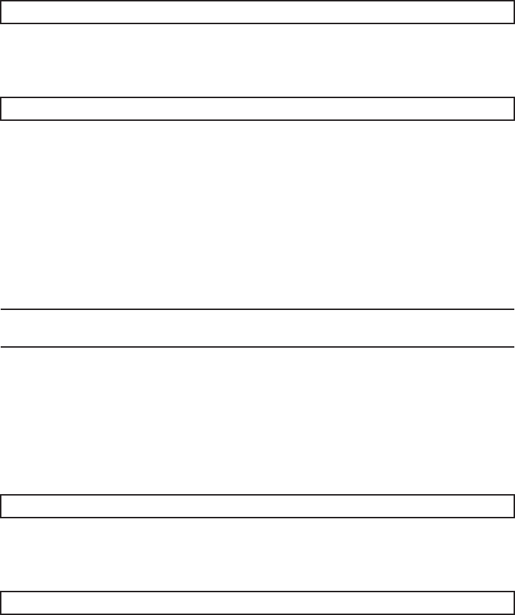
XSCF> showstatus
XSCF> showhardconf
Note - In the case of a dual power feed, connect the power cords in their original positions by
referring to the record that you made before the start of maintenance.
XSCF> showstatus
XSCF> showhardconf
normally after the completion of maintenance.
3. Execute the showhardconf command to check the hardware configuration
and the status of each component.
4. Close the rack door.
27.6.2 Active/Cold maintenance
1. Connect all the power cords to the PSU backplane unit or power supply unit
of the chassis requiring maintenance.
For details, see "6.5.1 Installing the power cord."
2. Return to the operation of the XSCF firmware replacefru command to confirm
that the XSCF DUAL control cable has been incorporated into the system.
For details, see "6.1 Incorporating an FRU into the System with the replacefru
Command."
3. Execute the showstatus command to confirm that the XSCF DUAL control
cable is operating normally after the completion of maintenance.
4. Execute the showhardconf command to check the hardware configuration
and the status of each component.
5. Close the rack door.
27.6.3 Inactive/Hot maintenance
1. Return to the operation of the XSCF firmware replacefru command to confirm
that the XSCF DUAL control cable has been incorporated into the system.
Fujitsu M10-4/Fujitsu M10-4S/SPARC M10-4/SPARC M10-4S Service Manual ・December 2013422

Note - In the case of a dual power feed, connect the power cords in their original positions by
referring to the record that you made before the start of maintenance.
Note - In the case of a dual power feed, connect the power cords in their original positions by
referring to the record that you made before the start of maintenance.
For details, see "6.1 Incorporating an FRU into the System with the replacefru
Command."
2. Power on the physical partition requiring maintenance.
For details, see "6.3 Powering On the Physical Partition Requiring Maintenance."
3. Close the rack door.
27.6.4 Inactive/Cold maintenance
1. Connect all the power cords to the PSU backplane unit or power supply unit
of the chassis requiring maintenance.
For details, see "6.5.1 Installing the power cord."
2. Return to the operation of the XSCF firmware replacefru command to confirm
that the XSCF DUAL control cable has been incorporated into the system.
For details, see "6.1 Incorporating an FRU into the System with the replacefru
Command."
3. Power on the physical partition requiring maintenance.
For details, see "6.3 Powering On the Physical Partition Requiring Maintenance."
4. Close the rack door.
27.6.5 System-stopped maintenance
1. Connect all the power cords to the PSU backplane unit or power supply unit
of the chassis requiring maintenance.
For details, see "6.5.1 Installing the power cord."
2. Return to the operation of the XSCF firmware replacefru command to confirm
that the XSCF DUAL control cable has been incorporated into the system.
For details, see "6.1 Incorporating an FRU into the System with the replacefru
Command."
3. Power on all the physical partitions.
For details, see "6.3 Powering On the Physical Partition Requiring Maintenance."
4. Close the rack door.
Chapter 27 Maintaining the XSCF DUAL Control Cables 423
Fujitsu M10-4/Fujitsu M10-4S/SPARC M10-4/SPARC M10-4S Service Manual ・December 2013424

Chapter 28
Maintaining the Cable Kit of the
Crossbar Box
This chapter describes the procedure for maintaining the cable kit mounted on the
crossbar box.
■Configuration of the Cable Kit
■Before Maintaining the Cable Kit
■Enabling the Removal of the Cable Kit
■Removing the Cable Kit
■Installing the Cable Kit
■Restoring the System
28.1 Configuration of the Cable Kit
This section describes the configuration and location of the cable kit.
The cable kit is a set of cables for connections between the crossbar backplane unit
and terminal board and between the terminal board and fan backplane.
The cable kit contains the following cables.
28.1.1 Cables for the connection between the crossbar
backplane unit and terminal board
■Cable (SIG)
Cable for the connection between the crossbar backplane unit and terminal board
(SIG)
425
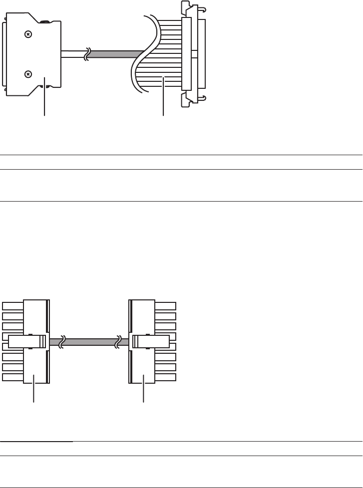
(1) (2)
Location number Component
1 Connector (terminal board (SIG) side)
2 Connector (crossbar backplane unit side)
(1) (2)
Location number Component
1 Connector (terminal board (PWR) side)
2 Connector (crossbar backplane unit side)
Figure 28-1
Cable (SIG) (between the crossbar backplane unit and terminal board)
■Cable (PWR)
Cable for the connection between the crossbar backplane unit and terminal board
(PWR)
Figure 28-2 Cable (PWR) (between the crossbar backplane unit and terminal
board)
Fujitsu M10-4/Fujitsu M10-4S/SPARC M10-4/SPARC M10-4S Service Manual ・December 2013426
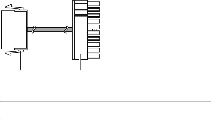
(1) (2)
Location number Component
1 Connector (terminal board side)
2 Connector (fan backplane (PWR) side)
28.1.2 Cables for the connection between the terminal
board and fan backplane
■Cable (PWR)
Cable for the connection between the terminal board and fan backplane (PWR)
Figure 28-3 Cable (PWR) (between the terminal board and fan backplane)
■Cable (SIG)
Cable for the connection of the terminal board and fan backplane (SIG) to the
operation panel
Chapter 28 Maintaining the Cable Kit of the Crossbar Box 427
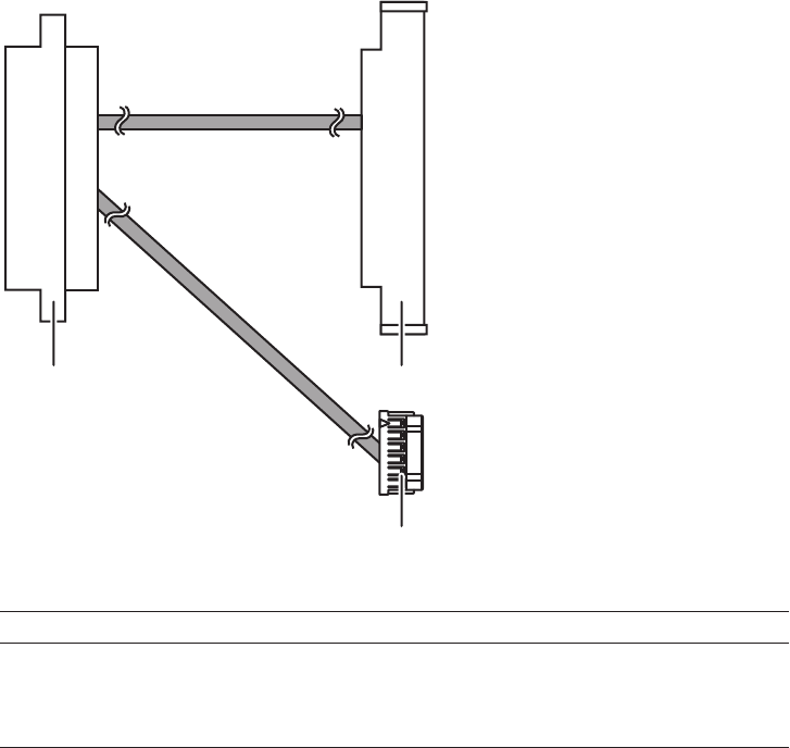
(1) (2)
(3)
Location number Component
1 Connector (terminal board side)
2 Connector (fan backplane (SIG) side)
3 Connector (operation panel side)
Figure 28-4 Cable (SIG) (for the terminal board and fan backplane to the
operation panel)
28.1.3 Locations for the cable kit
Thelocationsofcablekitconnectionsareasfollows.
Fujitsu M10-4/Fujitsu M10-4S/SPARC M10-4/SPARC M10-4S Service Manual ・December 2013428
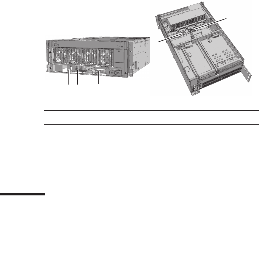
(1)
(2)(3)
(5)
(4)
Location
number
Component Connection
1 Cable (SIG) Crossbar backplane unit and terminal board (SIG)
2 Cable (PWR) Crossbar backplane unit and terminal board (PWR)
3Terminalboard
4 Cable (SIG) Terminal board (SIG) and fan backplane
5 Cable (PWR) Terminal board (PWR) and fan backplane
Note - Read and understand the instructions in this chapter before starting the maintenance
work. Also see the contents of "Chapter 1 Before Starting Maintenance Work."
Figure 28-5 Locations for the cable kit
28.2 Before Maintaining the Cable Kit
This section describes the types and the flow of maintenance of the cable kit.
28.2.1 Types of maintenance
Table 28-1 lists the types of maintenance for the cable kit. For the definition of
maintenance, see "4.3 Understanding Types of Maintenance."
Chapter 28 Maintaining the Cable Kit of the Crossbar Box 429
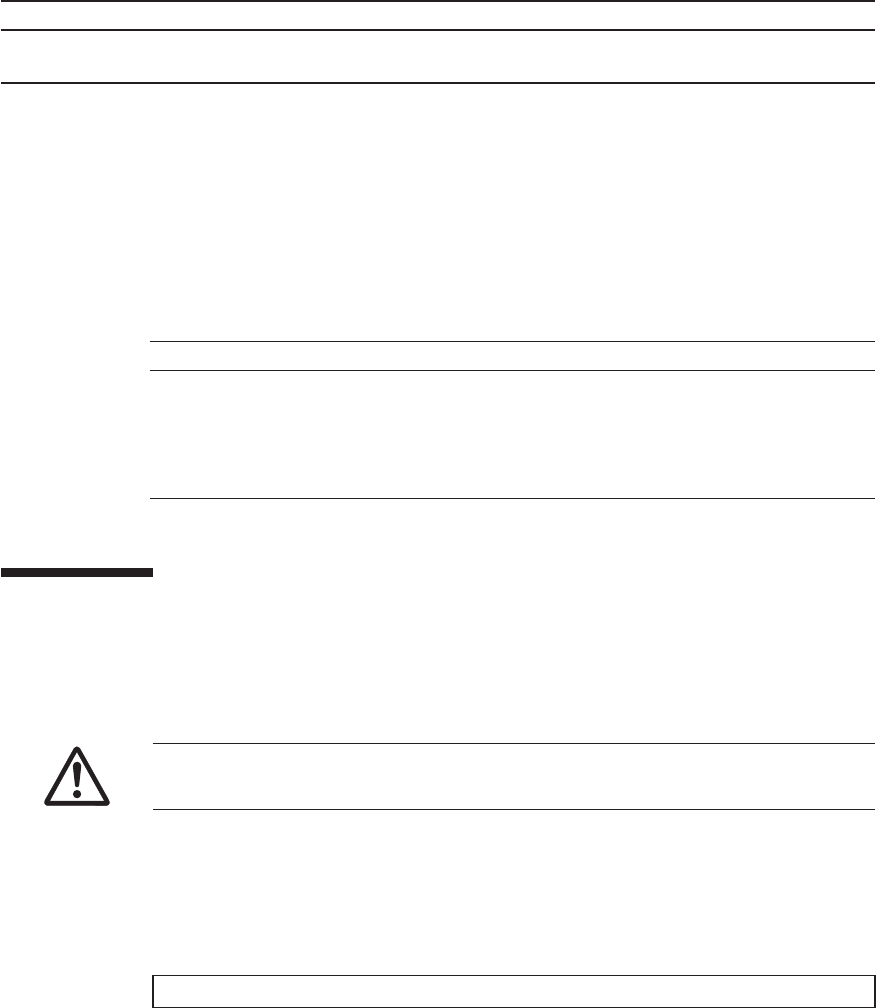
Table 28-1 Types of maintenance for cable kit
Configuration Active/hot Active/cold Inactive/hot Inactive/cold System stopped
Building block configuration
Unsupported Unsupported
(*1)
Unsupported Unsupported
(*1)
Supported (*2)
*1: If any physical partition is currently operating, the crossbar box cannot be powered off.
*2: All the physical partitions must be powered off, and the system must be completely shut down.
Table 28-2 Maintenance flow
Details of update process Replacement
1 Preparation 28.3
2 Removing the cable kit 28.4
3 Installing the cable kit 28.5
4 Restoring the system 28.6
Caution - To completely shut down the system, all the power cords must be
removed. If the power cords are not removed, an electrical failure may occur.
XSCF> showlogs error
28.2.2 Maintenance flow
Table 28-2 lists the sequence of the maintenance procedure for the cable kit.
28.3 Enabling the Removal of the Cable Kit
This section describes the preparations that must be completed prior to removing the
cable kit.
1. Open the rack door.
2. Log in to the XSCF shell.
3. Execute the showlogs command to identify the component requiring
maintenance.
For details, see "3.3.5 Checking log information."
4. Confirm the hardware and software configurations.
For details, see "4.2 Confirming the System Configuration."
Fujitsu M10-4/Fujitsu M10-4S/SPARC M10-4/SPARC M10-4S Service Manual ・December 2013430
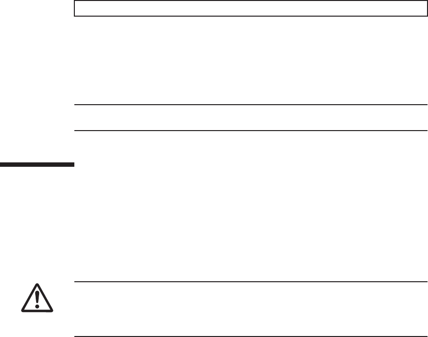
XSCF> replacefru
Note - Inthecaseofadualpowerfeed,makeanoteofthelocationsofthepowercords
before disconnecting them to ensure that they are reinstalled correctly.
Caution - Before you handle any components, wear a wrist strap to ground any static
electricity. If you perform this procedure without a wrist strap, individual
components or the overall system may be damaged. For details, see "1.5 Notes
Regarding Static Electricity."
5. Power off all the physical partitions.
For details, see "5.3 Powering Off the Physical Partition Requiring Maintenance."
6. Execute the replacefru command to release the crossbar backplane unit
requiring maintenance from the system.
For details, see "5.1 Releasing an FRU from the System with the replacefru
Command."
7. Remove all the power cords from the power supply unit of the crossbar box
requiring maintenance.
For details, see "5.5.2 Removing the power cord."
28.4 Removing the Cable Kit
This section describes the procedure for removing the cable kit at each cable
connection destination.
For the cable connection destinations, see "28.1 Configuration of the Cable Kit."
Enable the removal of the cable kit before attempting to remove it. For details, see
"28.3 Enabling the Removal of the Cable Kit."
28.4.1 Removing the cables for the connection between
the crossbar backplane unit and terminal board
Removethecable(SIG)orcable(PWR)connectingthecrossbarbackplaneunitand
terminal board.
1. Remove the front cover.
For details, see "5.5.3 Removing the front cover."
2. Remove all the fan units.
For details, see "19.4 Removing a Fan Unit."
Chapter 28 Maintaining the Cable Kit of the Crossbar Box 431
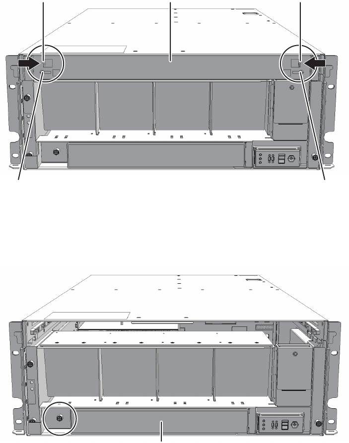
A A
BC B
A
3. Loosen the two screws (A in the figure) securing the upper cover and then
slide the right and left stoppers (B in the figure) inwards. Then, remove the
upper cover (C in the figure).
Figure 28-6 Removing the upper cover
4. Loosen the one screw (A in the figure) securing the lower cover and then
slide the lower cover to the left to remove it.
Figure 28-7 Removing the lower cover
5. Disconnect the two cables from the fan shelf.
Arrange the removed cables in the center.
Fujitsu M10-4/Fujitsu M10-4S/SPARC M10-4/SPARC M10-4S Service Manual ・December 2013432

Note - Remove the fan shelf while paying careful attention to the two cables arranged in the
center.
Note - Place the removed fan shelf on a grounded antistatic ESD mat.
Figure 28-8 Removing the cables
6. Loosen the three screws securing the fan shelf and partially pull out the fan
shelf.
Figure 28-9 Removing the fan shelf
7. Place a hand under the fan shelf to support it and then carefully remove it
from the chassis.
8.
Remove the cable connected to the crossbar backplane unit from the connector.
Chapter 28 Maintaining the Cable Kit of the Crossbar Box 433
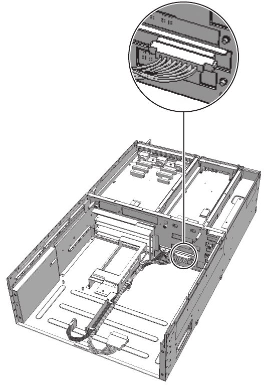
Figure 28-10 Removing the cable (cable (SIG))
Fujitsu M10-4/Fujitsu M10-4S/SPARC M10-4/SPARC M10-4S Service Manual ・December 2013434
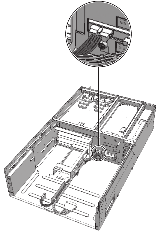
Figure 28-11 Removing the cable (cable (PWR))
9. Remove the cable from the clamps.
Chapter 28 Maintaining the Cable Kit of the Crossbar Box 435
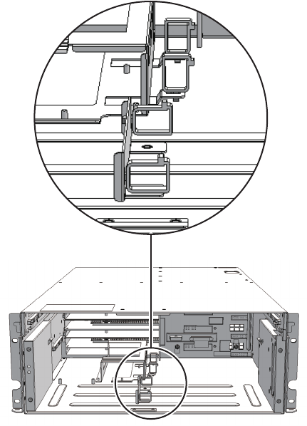
Figure 28-12 Removing the cables
28.4.2 Removing the cables for the connection between
the terminal board and fan backplane
Remove the cable (SIG) or cable (PWR) connecting the terminal board and fan
backplane.
1. Remove the front cover.
For details, see "5.5.3 Removing the front cover."
2. Remove all the fan units.
For details, see "19.4 Removing a Fan Unit."
3. Loosen the two screws (A in the figure) securing the upper cover and then
slide the right and left stoppers (B in the figure) inwards. Then, remove the
upper cover (C in the figure).
Fujitsu M10-4/Fujitsu M10-4S/SPARC M10-4/SPARC M10-4S Service Manual ・December 2013436

A A
BC B
A
Figure 28-13 Removing the upper cover
4. Loosen the one screw (A in the figure) securing the lower cover and then
slide the lower cover to the left to remove it.
Figure 28-14 Removingthelowercover
5. Disconnect the two cables from the fan shelf.
Arrange the removed cables in the center.
Chapter 28 Maintaining the Cable Kit of the Crossbar Box 437
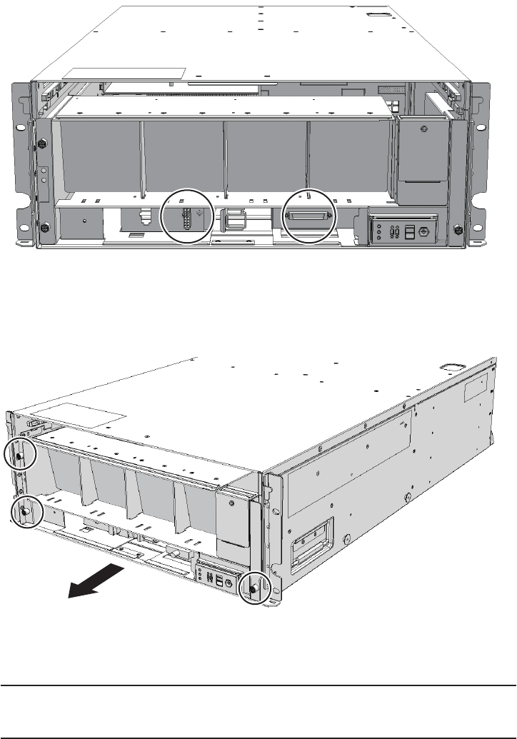
Note - Remove the fan shelf while paying careful attention to the two cables arranged in the
center.
Note - Place the removed fan shelf on a grounded antistatic ESD mat.
Figure 28-15 Removing the cables
6. Loosen the three screws securing the fan shelf and partially pull out the fan
shelf.
Figure 28-16 Removing the fan shelf
7. Place a hand under the fan shelf to support it and then carefully remove it
from the chassis.
8. Remove the cable connecting the fan backplane from the connector.
Fujitsu M10-4/Fujitsu M10-4S/SPARC M10-4/SPARC M10-4S Service Manual ・December 2013438
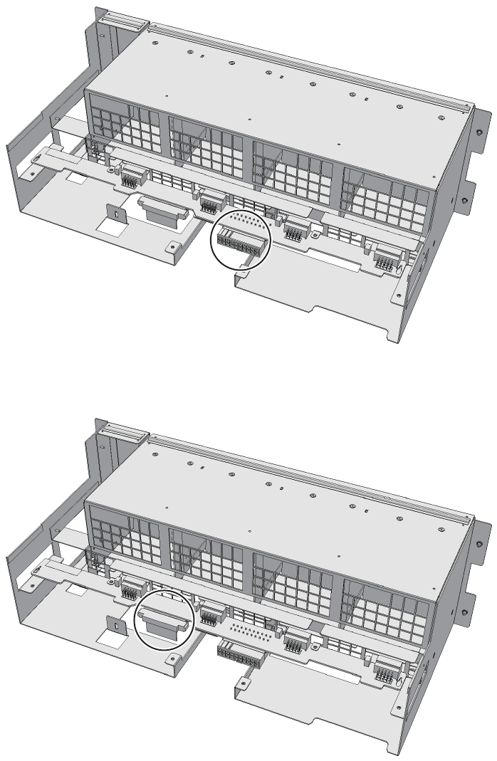
Figure 28-17 Removing the cable (cable (PWR))
Figure 28-18 Removing the cable (cable (SIG))
9. Remove the cable connecting the fan shelf and operation panel from the
Chapter 28 Maintaining the Cable Kit of the Crossbar Box 439
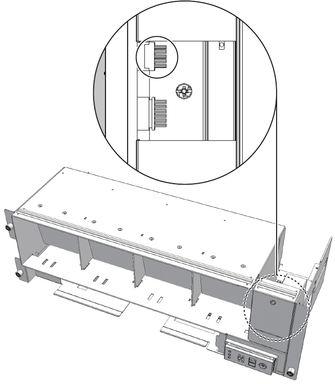
Front
connector on the operation panel.
Perform this step only when removing the cable (SIG).
To remove the cable (PWR), proceed to step 10.
Figure 28-19 Operation panel cable
10. Remove the cable from the terminal board.
■For the cable (PWR), push the connector toward the back while pushing up
the lower latch (A in the figure) with a flathead screwdriver. Confirm that the
lower latch (A in the figure) has been pushed to the back of the terminal
board. Push the connector toward the back while pushing down the upper
latch (B in the figure) with a flathead screwdriver.
Fujitsu M10-4/Fujitsu M10-4S/SPARC M10-4/SPARC M10-4S Service Manual ・December 2013440
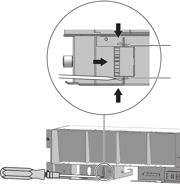
A
B
Figure 28-20 Removing the cable (cable (PWR))
■For the cable (SIG), remove the two cable connector screws with a Phillips
screwdriver (bit No. 1), and then remove the cable from the terminal board.
Chapter 28 Maintaining the Cable Kit of the Crossbar Box 441
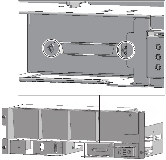
Figure 28-21 Removing the cable (cable (SIG))
11. Remove the cable from the clamps.
Fujitsu M10-4/Fujitsu M10-4S/SPARC M10-4/SPARC M10-4S Service Manual ・December 2013442
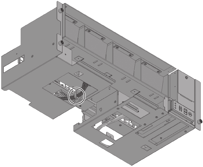
Figure 28-22 Removing the cable (cable (PWR))
Chapter 28 Maintaining the Cable Kit of the Crossbar Box 443
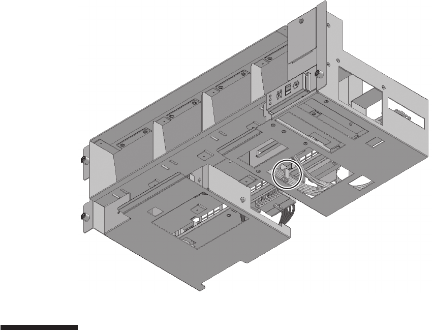
Figure 28-23 Removing the cable (cable (SIG))
28.5 Installing the Cable Kit
This section describes the procedure for installing the cable kit at each cable
connection destination.
For the cable connection destinations, see "28.1 Configuration of the Cable Kit."
Install a cable that has the same shape as the removed cable.
28.5.1 Installing a cable between the crossbar backplane
unit and terminal board
Install the cable (SIG) or cable (PWR) connecting the crossbar backplane unit and
terminal board.
1. Connect the cable to the connector of the crossbar backplane unit.
Install the cable that has the same shape as the removed cable.
Fujitsu M10-4/Fujitsu M10-4S/SPARC M10-4/SPARC M10-4S Service Manual ・December 2013444
Figure 28-24 Connector shape (cable (SIG))
2. Secure the cable with a clamp.
3. Support the fan shelf from below with one hand and then insert it carefully
into the chassis.
Arranging the cables in the center makes it easier to install the fan shelf.
4. Tighten the three screws securing the fan shelf.
5. Connect the two cables to the fan shelf.
6. Install the lower cover and then secure it with the one screw.
7. Install the upper cover.
8. Slide the right and left stoppers of the upper cover outwards and then secure
the cover with the two screws.
9. Install all the fan units.
For details, see "19.5 Installing a Fan Unit."
10. Install the front cover.
For details, see "6.5.3 Installing the front cover."
28.5.2 Installing a cable for the connection between the
terminal board and fan backplane
Install the cable (SIG) or cable (PWR) connecting the terminal board and fan backplane.
1. Install the cable on the terminal board.
- For the cable (PWR), install the connector that has latches (A in the figure) on
both ends to the terminal board.
Install the tab (B in the figure) of the connector such that it fits in the notched
section (C in the figure) of the terminal board.
Chapter 28 Maintaining the Cable Kit of the Crossbar Box 445
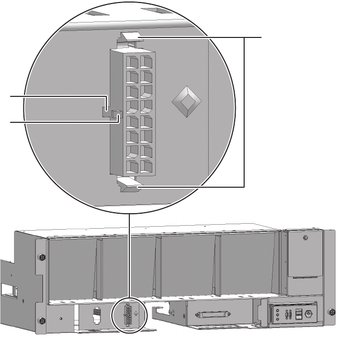
C
B
A
Figure 28-25 Installing the cable (cable (PWR))
- For the cable (SIG), install the connector that has a threaded hole to the
terminal board.
Usethescrewthatwasremovedfromthesamelocationbefore.Tightenthe
screw with a Phillips screwdriver (bit No. 1). When installing the connector,
orient the connector so that the dot mark (A in the figure) is on the left as
shown in Figure 28-26.
Fujitsu M10-4/Fujitsu M10-4S/SPARC M10-4/SPARC M10-4S Service Manual ・December 2013446
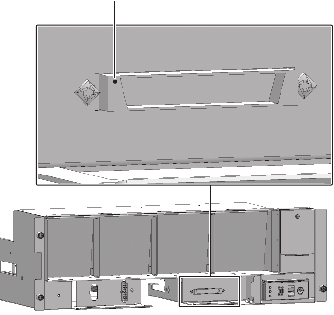
A
Figure 28-26 Installing the cable (cable (SIG))
2. Connect the cable to the connector of the fan backplane.
3. Connect the cable connecting the fan shelf and operation panel to the
connector on the operation panel.
Perform this step only when installing the cable (SIG).
To install the cable (PWR), proceed to step 4.
Chapter 28 Maintaining the Cable Kit of the Crossbar Box 447
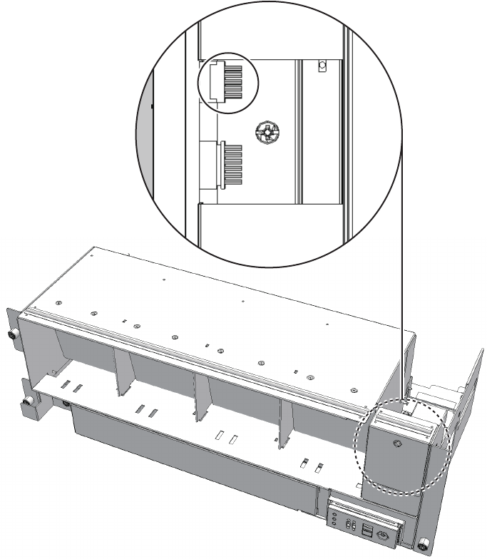
Front
Figure 28-27 Operation panel cable
4. Secure the cable with a clamp.
Fujitsu M10-4/Fujitsu M10-4S/SPARC M10-4/SPARC M10-4S Service Manual ・December 2013448

Figure 28-28 Securing the cable (cable (PWR))
Chapter 28 Maintaining the Cable Kit of the Crossbar Box 449
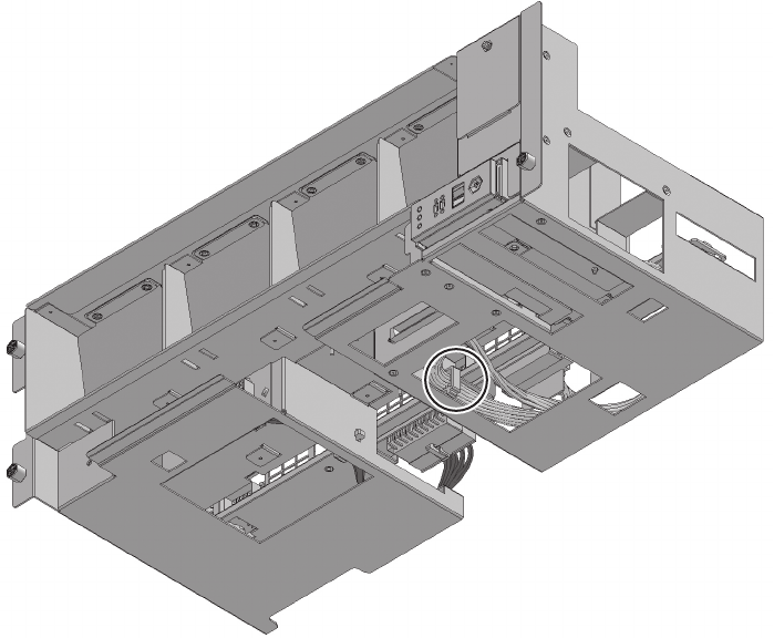
Figure 28-29 Securing the cable (cable (SIG))
5. Support the fan shelf from below with one hand and then insert it carefully
into the chassis.
Arranging the cables in the center makes it easier to install the fan shelf.
6. Tighten the three screws securing the fan shelf.
7. Connect the two cables to the fan shelf.
8. Install the lower cover and then secure it with the one screw.
9. Install the upper cover.
10. Slide the right and left stoppers of the upper cover outwards and then secure
the cover with the two screws.
11. Install all the fan units.
For details, see "19.5 Installing a Fan Unit."
12. Install the front cover.
For details, see "6.5.3 Installing the front cover."
Fujitsu M10-4/Fujitsu M10-4S/SPARC M10-4/SPARC M10-4S Service Manual ・December 2013450
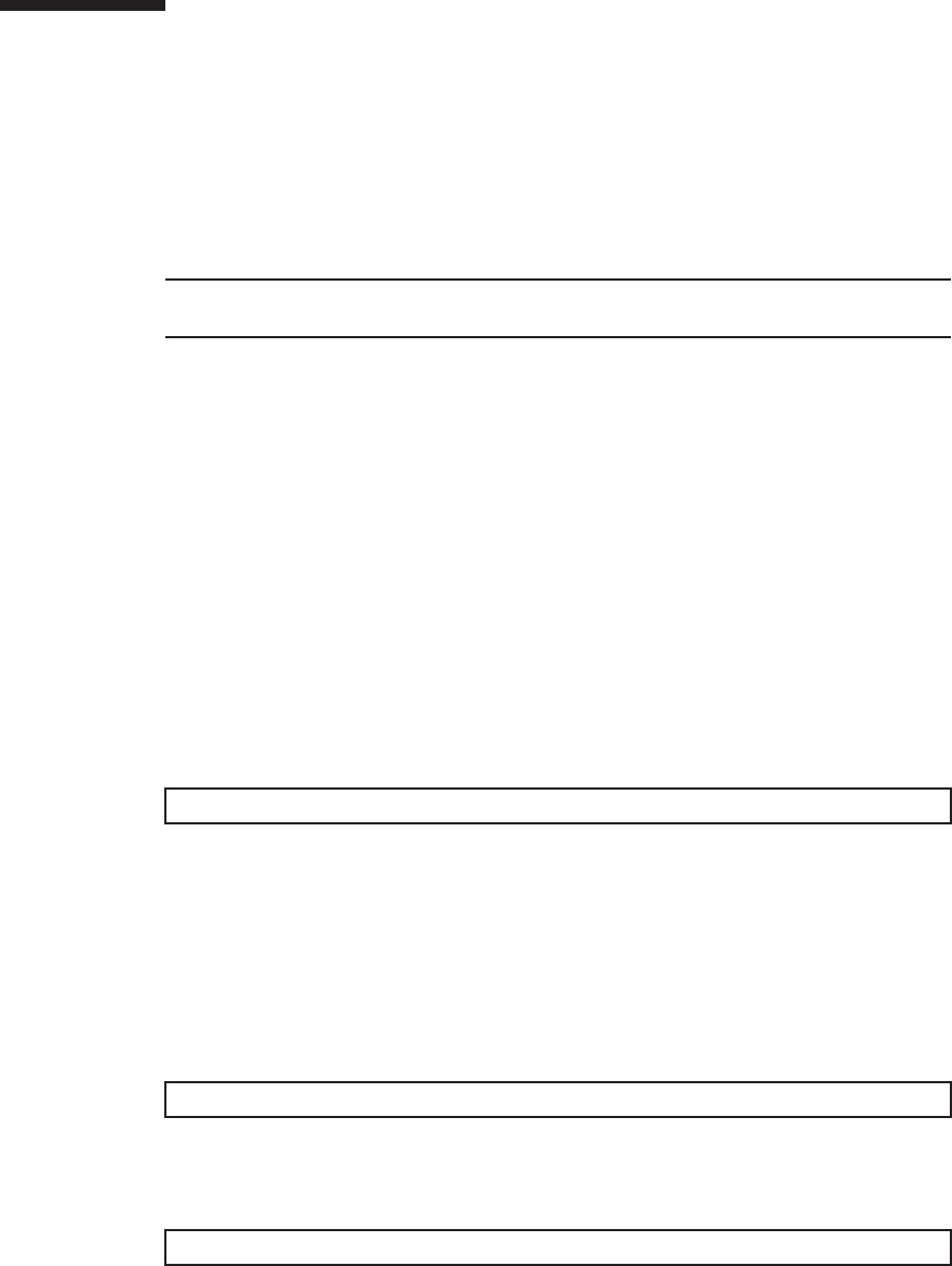
Note - In the case of a dual power feed, connect the power cords in their original positions by
referring to the record that you made before the start of maintenance.
XSCF> diagxbu -y -b 00 -t 01
XSCF> diagxbu -y -b 00 -p 02
XSCF> showlogs error
28.6 Restoring the System
This section describes the procedure for restoring the system after installing the cable
kit.
1. Connect all the power cords to the power supply unit of the crossbar box
requiring maintenance.
For details, see "6.5.1 Installing the power cord."
2. Return to the operation of the XSCF firmware replacefru command to confirm
that the crossbar backplane unit has been incorporated into the system.
For details, see "6.1 Incorporating an FRU into the System with the replacefru
Command."
3. Execute the diagxbu command to diagnose the crossbar cables.
-When the system board of the chassis connected with the crossbar cables
is not incorporated into the physical partition, or when the incorporated
physical partition is powered off:
The example below specifies the following:
00: The BB-ID of the chassis to start the diagnosis
01: The BB-ID of the destination where the chassis to start the diagnosis is
connected (You can specify more than one of these.)
To specify multiple connection destination BB-IDs, enter a command like
"diagxbu -y -b 00 -t 01 -t 02".
-When the system board of the chassis connected with the crossbar cables
is incorporated into the physical partition, and the physical partition is
powered on:
The example below specifies the following:
00: The BB-ID of the chassis to start the diagnosis
02: The PPAR-ID of the destination where the chassis to start the diagnosis is
connected (You can specify only one of these.)
4. Execute the showlogs command to confirm that the system is operating
normally.
Chapter 28 Maintaining the Cable Kit of the Crossbar Box 451

Chapter 29
Maintaining the Dedicated Power
Distribution Unit Mounted on the Rack
for Expanded Connection
This chapter describes the procedure for maintaining the dedicated power
distribution unit (PDU) mounted on the rack for expanded connection.
■Configuration of the Dedicated Power Distribution Unit
■Before Maintaining the Dedicated Power Distribution Unit
■Enabling the Removal of the Dedicated Power Distribution Unit
■Removing the Dedicated Power Distribution Unit
■Installing the Dedicated Power Distribution Unit
■Restoring the System
29.1 Configuration of the Dedicated Power
Distribution Unit
This section describes the configuration and location of the PDU.
The PDU is installed on the rack for expanded connection. It is compatible with both
single- and three-phase power feeds.
453
(4)
(3)
(2)
(1)
Rear
Location number Component
1 Dedicated power distribution unit (PDU#0)
2 Dedicated power distribution unit (PDU#1)
3 Dedicated power distribution unit (PDU#2) (*)
4 Dedicated power distribution unit (PDU#3) (*)
*: This is mounted when the two expanded connection racks have been installed.
Figure 29-1 Location of the PDU
Fujitsu M10-4/Fujitsu M10-4S/SPARC M10-4/SPARC M10-4S Service Manual ・December 2013454
Note - Read and understand the instructions in this chapter before starting the maintenance
work. Also see the contents of "Chapter 1 Before Starting Maintenance Work."
Table 29-1 Types of PDU maintenance
Configuration Active/hot Active/cold Inactive/hot Inactive/cold System stopped
Building block configuration
Unsupported Supported Unsupported Unsupported Supported
Table 29-2 Maintenance flow
Task Replacement
1 Preparation 29.3
2 Removing the PDU 29.4
3 Installing the PDU 29.5
4 Restoring the system 29.6
29.2 Before Maintaining the Dedicated
Power Distribution Unit
This section describes the types and flow of maintenance of the PDU, as well as some
precautions.
29.2.1 Types of maintenance
Table 29-1 lists the types of maintenance for the PDU. For the definition of
maintenance, see "4.3 Understanding Types of Maintenance."
29.2.2 Maintenance flow
Table 29-2 lists the sequence of the maintenance procedure for the PDU.
29.2.3 Precautions for replacement
Note the following points when you replace a PDU.
■The SPARC M10-4S and the crossbar box are connected to the two PDUs with
power cords. Thus the system can continue to operate even if one of the PDUs
fails. Do not, however, operate the system for an extended period when one unit
Chapter 29 Maintaining the Dedicated Power Distribution Unit Mounted on the Rack for Expanded Connection 455

Caution - Active/cold maintenance can be performed only when the power supply unit has a
redundant configuration.
Note - Make a note of the locations of the power cords before disconnecting them, to ensure
that they are reconnected correctly.
Note - Make a note of the locations of the power cords before disconnecting them, to ensure
that they are reconnected correctly.
has failed.
■When replacing multiple PDUs, replace one unit at a time. If redundancy of the
PDUs cannot be preserved, then system-stopped maintenance must be performed.
29.3 Enabling the Removal of the
Dedicated Power Distribution Unit
This section describes the preparations that must be completed prior to removing a
PDU. The preparation procedure differs depending on the maintenance type as follows:
■Active/Cold maintenance
■System-stopped maintenance
29.3.1 Active/Cold maintenance
1. Open the rack door.
2. Disconnect all the power cords of the SPARC M10-4S and crossbar boxes
from the PDU requiring maintenance.
29.3.2 System-stopped maintenance
1. Open the rack door.
2. Stop the entire system.
For details, see "5.4 Stopping the Entire System."
3. Disconnect all the power cords of the SPARC M10-4S and crossbar boxes
from the PDU requiring maintenance.
Fujitsu M10-4/Fujitsu M10-4S/SPARC M10-4/SPARC M10-4S Service Manual ・December 2013456
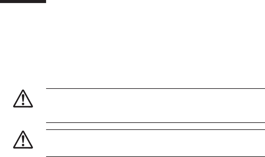
Caution - Before you handle any components, wear a wrist strap to ground any static
electricity. If you perform this procedure without a wrist strap, individual
components or the overall system may be damaged. For details, see "1.5 Notes
Regarding Static Electricity."
Caution - Two people must be present when the power cables are to be removed. If
you perform this work alone, you may injure yourself or cause damage to the PDU
because the PDU is heavy.
29.4 Removing the Dedicated Power
Distribution Unit
This section describes the procedure for removing the dedicated power distribution
unit.
Enable the removal of the dedicated power distribution unit before attempting to
remove it. For details, see "29.3 Enabling the Removal of the Dedicated Power
Distribution Unit."
1. Remove the four PDU screws.
Chapter 29 Maintaining the Dedicated Power Distribution Unit Mounted on the Rack for Expanded Connection 457
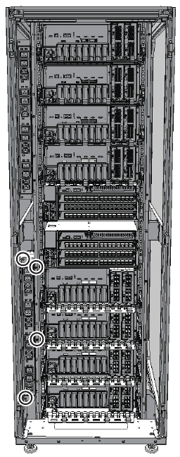
Figure 29-2 PDU screws
2. Grasp the top and bottom of the PDU, and then pull it out.
Fujitsu M10-4/Fujitsu M10-4S/SPARC M10-4/SPARC M10-4S Service Manual ・December 2013458
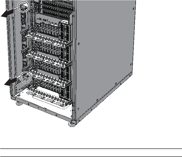
Note - Hold the plugs of the power cables, and then pull them straight out.
Figure 29-3 Pulling out the PDU
3. Disconnect all the power cables from the rear of the PDU.
Chapter 29 Maintaining the Dedicated Power Distribution Unit Mounted on the Rack for Expanded Connection 459
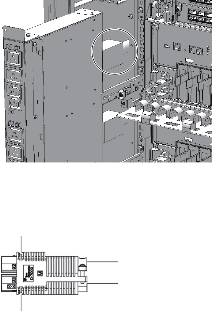
A
A
Figure 29-4 PDU power cables
The number of power cables and the plug type may vary depending on the
power environment, as follows:
-For a single-phase power feed:
Four power cables are connected to the PDU. To pull them out, push the upper
and lower latches (A in the figure).
Figure 29-5 Power cable connector for single-phase power feed
-For a three-phase power feed:
Three power cables are connected to the PDU. To pull them out, turn the ring
Fujitsu M10-4/Fujitsu M10-4S/SPARC M10-4/SPARC M10-4S Service Manual ・December 2013460
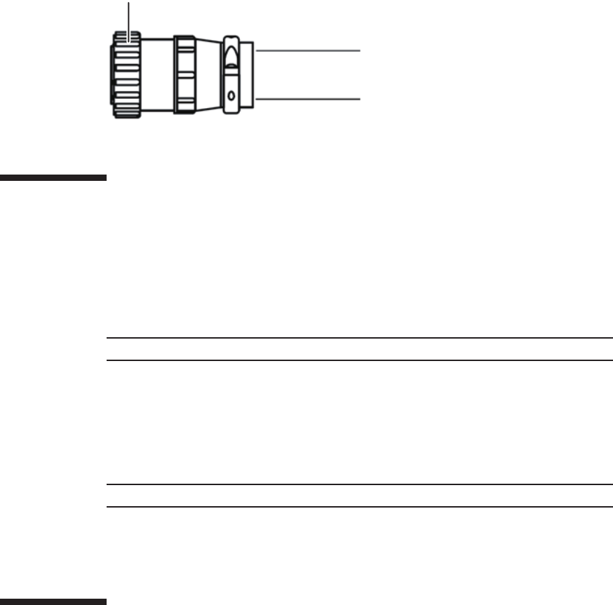
A
Note - Hold each power cable plug, and then insert it straight into the socket.
Note - Ensure that the power cables are correctly connected and secure.
(A in the figure) counterclockwise.
Figure 29-6 Power cable connector for three-phase power feed
29.5 Installing the Dedicated Power
Distribution Unit
This section describes the procedure for installing a PDU.
1. Connect all the power cables to the rear of the PDU.
-For a single-phase power feed:
Connect four power cables to the PDU.
-For a three-phase power feed
Connect three power cables to the PDU. Install each power cable by holding its
plug, and then secure it by turning the ring clockwise.
2. Install the PDU into the rack for expanded connection.
3. Install the four PDU screws.
29.6 Restoring the System
This section describes the procedure for restoring the system after installing the PDU.
The restoration procedure differs depending on the maintenance type as follows:
■Active/Cold maintenance
Chapter 29 Maintaining the Dedicated Power Distribution Unit Mounted on the Rack for Expanded Connection 461
Note - Reconnect the power cords at their original locations by referring to the notes you
made prior to the start of maintenance.
Note - Reconnect the power cords at their original locations by referring to the notes you
made prior to the start of maintenance.
■System-stopped maintenance
29.6.1 Active/Cold maintenance
1. Connect all the power cords of the SPARC M10-4S and crossbar boxes to the
PDU requiring maintenance.
2. Close the rack door.
29.6.2 System-stopped maintenance
1. Connect all the power cords of the SPARC M10-4S and crossbar boxes to the
PDU requiring maintenance.
2. Start the entire system.
For details, see "6.4 Starting the Entire System."
3. Close the rack door.
Fujitsu M10-4/Fujitsu M10-4S/SPARC M10-4/SPARC M10-4S Service Manual ・December 2013462
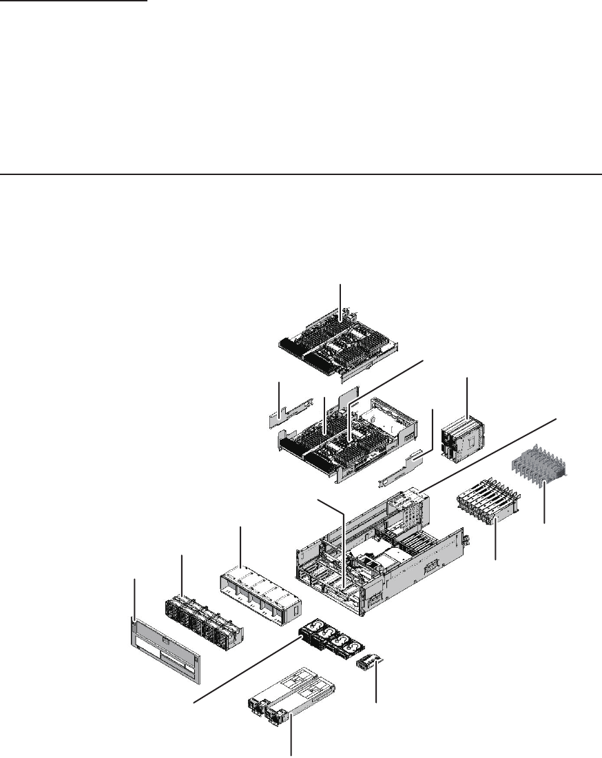
(4)
(13)
(1)
(2) (14)
(3)
(7)
(8)
(6)
(9)
(10)
(5)
(12)
(11)
(2)
(15)
Appendix A
Component List
This appendix describes components that constitute the SPARC M10-4/M10-4S, the
crossbar box, and the expanded connection rack.
Figure A-1 Locations of components of SPARC M10-4/M10-4S
463
Location number Component
1 CPU memory unit upper
2 Side cover
3 Memory
4 PSU backplane unit
5Fanshelf
6Fanunit
7 Front cover
8 Internal disk
9 Power supply unit
10 Operation panel
11 PCI Express card cassette
12 PCI Express card
13 Crossbar unit mounting frame (*)
14 Crossbar unit (*)
15 CPU memory unit lower
*: Not mounted on SPARC M10-4.
Fujitsu M10-4/Fujitsu M10-4S/SPARC M10-4/SPARC M10-4S Service Manual ・December 2013464
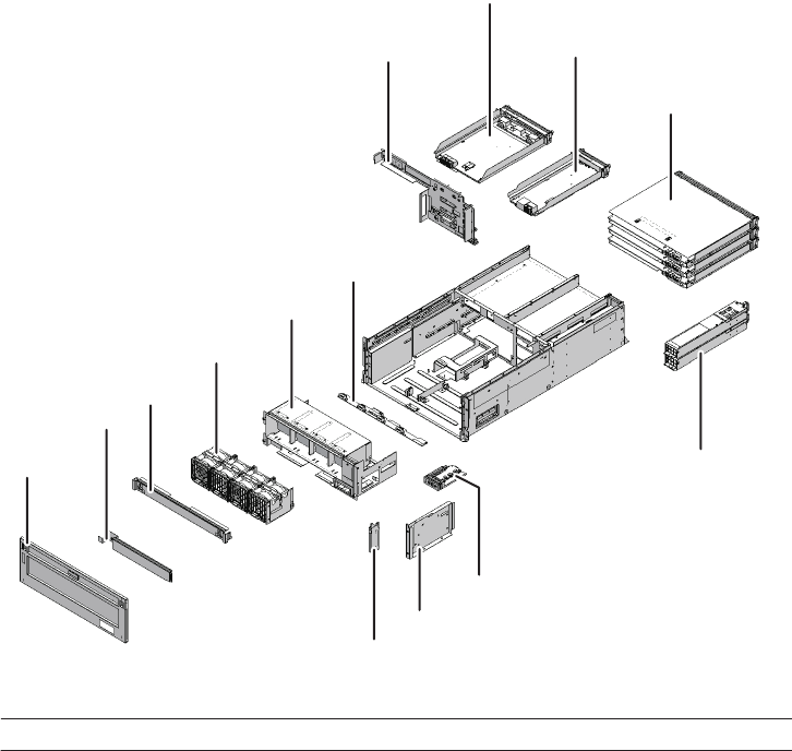
(4)
(1)
(2) (14)
(3)
(7)
(6)
(9)
(5)
(13)
(12)
(8)
(11)
(10)
Location number Component
1 XSCF interface unit
2 Crossbar backplane unit
3 Fan backplane
4Fanshelf
5Fanunit
6 Upper cover
7 Lower cover
8 Front cover
9 Guide plate fixing bracket
10 Guide plate
11 Operation panel
12 Power supply unit
13 Crossbar unit
Figure A-2 Locations of components of crossbar box
Appendix A Component List 465
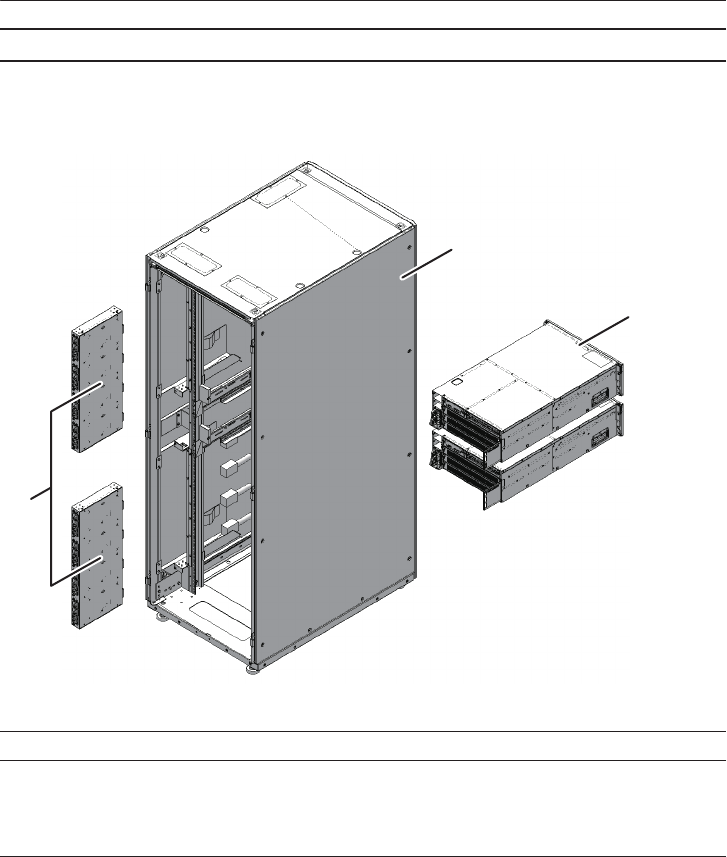
Location number Component
14 XSCF unit
(2)
(3)
(1)
Rear
Location number Component
1 Dedicated power distribution unit
2 Expanded connection rack
3 Crossbar box
Figure A-3 Locations of components of expanded connection rack
Fujitsu M10-4/Fujitsu M10-4S/SPARC M10-4/SPARC M10-4S Service Manual ・December 2013466

Appendix B
Component Specifications
This appendix provides the specifications of the components.
The components that constitute the SPARC M10-4/M10-4S and the crossbar box are
as follows.
Components that constitute the SPARC M10-4/M10-4S
■CPU Memory Unit
■Crossbar Unit
■Power Supply Unit
■Fan Unit
■Internal Disk Drive
■PCI Express Card
■Backplanes
■Operation Panel
Components that constitute the crossbar box
■Crossbar Unit
■XSCF Unit
■XSCF Interface Unit
■Power Supply Unit
■Fan Unit
■Backplanes
■Operation Panel
B.1 CPU Memory Unit
The CPU memory unit of the SPARC M10-4/M10-4S consists of two units: the upper
467
Table B-1 Specifications of CPU memory unit (SPARC M10-4/M10-4S)
Item Description
Maximum number of
CPU memory units
2
Location Inside of chassis
Type of maintenance Active/cold, inactive/cold, and system stopped
Maintenance category Replacement, expansion, and reduction
Table B-2 Specifications of crossbar unit (SPARC M10-4/M10-4S)
Item Description
Number of crossbar units 2
Location Rear of chassis
unit and lower unit.
The CPU memory unit lower consists of the following components.
■CPU
■Memory
■XSCF
■PCI Express (PCIe) backplane
The CPU memory unit upper consists of the following components.
■CPU
■Memory
CPU and XSCF are directly installed on the CPU memory unit. Thus you cannot
replace the CPU and XSCF individually.
Each CPU memory unit upper and CPU memory unit lower is available in eight
different types based on the combination of CPU type and the number of memory
slots.
Table B-1 lists the specifications of the CPU memory unit.
For the maintenance procedure, see "Chapter 7 Maintaining the CPU Memory Units."
B.2 Crossbar Unit
The crossbar units of the SPARC M10-4S and the crossbar box are crossbar switches
that logically connect the CPU memory unit and I/O unit. The crossbar unit has two
operation modes. One is normal mode that provides 2-way operation. The other is
degraded mode that provides 1-way operation, which is half of normal mode.
Table B-2 and Table B-3 list the specifications of the crossbar units of the SPARC
M10-4S and the crossbar box, respectively.
Fujitsu M10-4/Fujitsu M10-4S/SPARC M10-4/SPARC M10-4S Service Manual ・December 2013468
Table B-2 Specifications of crossbar unit (SPARC M10-4/M10-4S) (continued)
Item Description
Type of maintenance Inactive/cold and system-stopped
Maintenance category Replacement
Table B-3 Specifications of crossbar unit (crossbar box)
Item Description
Number of crossbar units 3
Location Rear of chassis
Type of maintenance System stopped
Maintenance category Replacement
Table B-4 Specifications of XSCF unit (crossbar box)
Item Description
Number of XSCF units 1
Location Rear of chassis
Type of maintenance Active/hot, inactive/hot, and system stopped
See the following chapters for details of the maintenance procedures:
SPARC M10-4S: Chapter 9 Maintaining the Crossbar Units
Crossbar box: Chapter 16 Maintaining the Crossbar Units of the Crossbar Box
B.3 XSCF Unit
The XSCF unit of the crossbar box is a control unit that is central to the system.
The functions of an XSCF are as follows:
■Controlling each unit
■Console function for each physical partition that uses the TTY communication
protocol
■Communication with each physical partition that uses a command interface
■Managing system information
■Browser-based user interface function
■Connection with a maintenance terminal
■Next remote chassis interface
■System power control and cluster control that use a power supply interlocking
function
Table B-4 lists the specifications of the XSCF unit of the crossbar box.
Appendix B Component Specifications 469

Table B-4 Specifications of XSCF unit (crossbar box) (continued)
Item Description
Maintenance category Replacement
Table B-5 Specifications of the power supply unit (SPARC M10-4/M10-4S)
Item Description
Number of power supply
units
2
Location Front of chassis
Type of maintenance Active/hot, active/cold, inactive/hot, inactive/cold, and system
stopped
Maintenance category Replacement
Table B-6 Specifications of power supply unit (crossbar box)
Item Description
Number of power supply
units
2
Location Rear of chassis
Type of maintenance Active/hot, inactive/hot, and system stopped
Maintenance category Replacement
For the maintenance procedure, see "Chapter 17 Maintaining the XSCF Unit of the
Crossbar Box."
B.4 Power Supply Unit
The power supply units of the SPARC M10-4/M10-4S and the crossbar box take
power from the input power and supply it to the system. The redundant configuration
of the power supply units allows the system to continue operating even if one of the
units fails during operation.
Table B-5 and Table B-6 list the specifications of the power supply units of the
SPARC M10-4/M10-4S and the crossbar box, respectively.
See the following chapters for details of the maintenance procedures:
SPARC M10-4/M10-4S: Chapter 10 Maintaining the Power Supply Units
Crossbar box: Chapter 18 Maintaining the Power Supply Units of the Crossbar Box
Fujitsu M10-4/Fujitsu M10-4S/SPARC M10-4/SPARC M10-4S Service Manual ・December 2013470
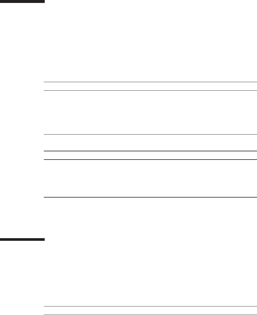
Table B-7 Specifications of fan unit (SPARC M10-4/M10-4S)
Item Description
Number of fan units 5
Location Front of chassis
Type of maintenance Active/hot, active/cold, inactive/hot, inactive/cold, and system
stopped
Maintenance category Replacement
Table B-8 Specifications of fan unit (crossbar box)
Item Description
Number of fan units 4
Location Front of chassis
Type of maintenance Active/hot, inactive/hot, and system stopped
Maintenance category Replacement
Table B-9 Specifications of the internal disk drive (SPARC M10-4/M10-4S)
Item Description
Maximum number of
internal disk drives
8
Interface SAS
B.5 Fan Unit
Five fan units are mounted on the SPARC M10-4/M10-4S and four on the crossbar
box.Theyprovideaflowofairtocooltheinsideofthechassis.Eachfanunithastwo
cooling fans.
Table B-7 and Table B-8 list the specifications of the fan units of the SPARC
M10-4/M10-4S and the crossbar box, respectively.
See the following chapters for details of the maintenance procedures:
SPARC M10-4/M10-4S: Chapter 11 Maintaining the Fan Units
Crossbar box: Chapter 19 Maintaining the Fan Units of the Crossbar Box
B.6 Internal Disk Drive
Up to eight hard disks or solid state disks can be mounted as internal disks on
SPARC M10-4/M10-4S.
Table B-9 lists the specifications of the internal disk drive.
Appendix B Component Specifications 471

Table B-9 Specifications of the internal disk drive (SPARC M10-4/M10-4S) (continued)
Item Description
Location Front of chassis
Type of maintenance Active/hot, active/cold, inactive/hot, inactive/cold, and system
stopped
Maintenance category Replacement, expansion, and reduction
Table B-10 Specifications of PCIe card (SPARC M10-4/M10-4S)
Item Description
Maximum number of
PCIe cards
11 (*)
Location Rear of chassis
Type of maintenance Active/hot, inactive/hot, and system stopped
Maintenance category Replacement, expansion, and reduction
*: Can be mounted only on a SPARC M10-4.
Table B-11 Specifications of XSCF interface unit (crossbar box)
Item Description
Number of XSCF interface
units
1
For the maintenance procedure, see "Chapter 12 Maintaining the Internal Disks."
B.7 PCI Express Card
Up to eight PCIe cards can be mounted in a SPARC M10-4S with a crossbar unit
mounted. For a SPARC M10-4 with no crossbar unit mounted, up to 11 PCIe cards
can be mounted.
Table B-10 lists the specifications of the PCIe card.
For the maintenance procedure, see "Chapter 13 Maintaining the PCI Express Cards."
B.8 XSCF Interface Unit
The XSCF interface unit of the crossbar box mounts the identification information.
The XSCF interface unit and each of the other units are connected by the crossbar
backplane unit.
Table B-11 lists the specifications of the XSCF interface unit of the crossbar box.
Fujitsu M10-4/Fujitsu M10-4S/SPARC M10-4/SPARC M10-4S Service Manual ・December 2013472

Table B-11 Specifications of XSCF interface unit (crossbar box) (continued)
Item Description
Location Rear of chassis
Type of maintenance System stopped
Maintenance category Replacement
For the maintenance procedure, see "Chapter 20 Maintaining the XSCF Interface
Unit of the Crossbar Box."
B.9 Backplanes
The backplanes of the SPARC M10-4/M10-4S and the crossbar box have connectors
for connecting replaceable units in the chassis. The PSU backplane unit of SPARC
M10-4/M10-4S mounts the memory that stores the identification information and the
user setting information.
The backplane of the SPARC M10-4/M10-4S is shown below.
■PSU backplane unit (A in the figure)
Appendix B Component Specifications 473
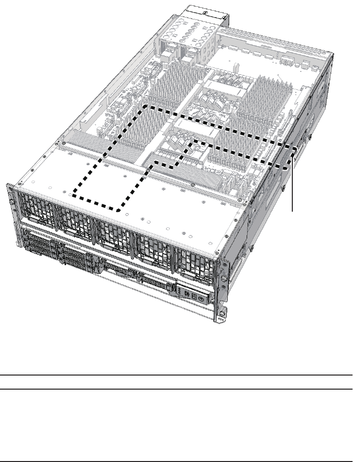
A
Table B-12 Specifications of PSU backplane unit (SPARC M10-4/M10-4S)
Item Description
Number of PSU
backplane units
1
Location Inside of chassis
Type of maintenance Active/cold, inactive/cold, and system stopped
Maintenance category Replacement
Figure B-1 Location of backplane of SPARC M10-4/M10-4S
Table B-12 lists the specifications of the PSU backplane unit.
For the maintenance procedure, see "Chapter 14 Maintaining the PSU Backplane
Unit."
The backplanes of the crossbar box are shown below.
■Crossbar backplane unit (A in the figure)
■Fan backplane (B in the figure)
Fujitsu M10-4/Fujitsu M10-4S/SPARC M10-4/SPARC M10-4S Service Manual ・December 2013474
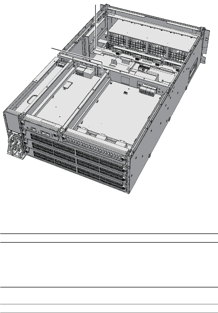
B
A
Table B-13 Specifications of crossbar backplane unit (crossbar box)
Item Description
Number of crossbar
backplane units
1
Location Inside of chassis
Type of maintenance System stopped
Maintenance category Replacement
Table B-14 Specifications of fan backplane (crossbar box)
Item Description
Number of fan backplanes 1
Figure B-2 Locations of backplanes of crossbar box
Table B-13 and Table B-14 list the specifications of the crossbar backplane and the fan
backplane units, respectively.
Appendix B Component Specifications 475

Table B-14 Specifications of fan backplane (crossbar box) (continued)
Item Description
Location Inside of chassis
Type of maintenance System stopped
Maintenance category Replacement
Table B-15 Specifications of operation panel (SPARC M10-4/M10-4S)
Item Description
Number of operation
panels
1
Location Front of chassis
Type of maintenance Active/cold, inactive/cold, and system stopped
Maintenance category Replacement
Table B-16 Specifications of operation panel (crossbar box)
Item Description
Number of operation
panels
1
Location Front of chassis
Type of maintenance System stopped
Maintenance category Replacement
See the following chapters for details of the maintenance procedures:
Crossbar backplane unit of crossbar box: Chapter 21 Maintaining the Crossbar
Backplane Unit of the Crossbar Box
Fan backplane of crossbar box: Chapter 22 Maintaining the Fan Backplane of the
Crossbar Box
B.10 Operation Panel
The operation panels of the PARC M10-4/M10-4S and the crossbar box are installed
in the front of the chassis. This panel displays the system status and is used for
operation.
Table B-15 and Table B-16 list the specifications of the operation panels of the SPARC
M10-4/M10-4S and the crossbar box, respectively.
See the following chapters for details of the maintenance procedures:
SPARC M10-4/M10-4S: Chapter 15 Maintaining the Operation Panel
Crossbar box: Chapter 23 Maintaining the Operation Panel of the Crossbar Box
Fujitsu M10-4/Fujitsu M10-4S/SPARC M10-4/SPARC M10-4S Service Manual ・December 2013476

Table C-1 iostat(1M) command options
Option Description Application
No options Reports the status of the local I/O
device.
Allows you to view the device
status concisely in 3 lines.
-c Reports the rates of periods during
which the system has been in user
mode, system mode, I/O waiting,
and idling.
Allows you to view the CPU status
as a concise report.
Appendix C
Oracle Solaris Troubleshooting
Commands
This appendix describes how to use Oracle Solaris commands to display fault
diagnosis information and to take countermeasures. The commands listed here are
useful for determining whether there are problems in the system, the network, or
some other system connected through the network.
■iostat(1M) Command
■prtdiag(1M) Command
■prtconf(1M) Command
■netstat(1M) Command
■ping(1M) Command
■ps(1) Command
■prstat(1M) Command
C.1 iostat(1M) Command
The iostat(1M) command periodically reports the CPU usage status, as well as the
terminal status, the drive status, and the I/O status.
Table C-1 lists the options of the iostat(1M) command and how those options can be
applied to solving system issues.
477

Table C-1 iostat(1M) command options (continued)
Option Description Application
-e Displays a summary of statistics on
the device errors. Displayed items
are the total number of errors,
hardware errors, software errors,
and transfer errors.
Allows you to view the accumulated
number of errors as a concise table
and to identify potentially failed
I/O devices.
-E Displays the entire statistics of the
device errors.
Allows you to view device
information (manufacturer, model
number, serial number, size, and
errors).
-n Displays the names in a descriptive
form.
Allows you to identify devices with
a descriptive display.
-x Reports the extended drive statistics
of individual drives. Statistics are
displayed in a table format.
Similar to the -e option, but differs
in that it provides rate information.
Allows you to find internal devices
and other I/O devices on the
network whose performance is low.
#iostat -En
c5t50000393D85129FAd0 Soft Errors: 0 Hard Errors: 0 Transport Errors: 0
Vendor: TOSHIBA Product: MBF2300RC Revision: 3706 Serial No:
EB25PC201AL6
Size: 300.00GB <300000000000 bytes>
Media Error: 0 Device Not Ready: 0 No Device: 0 Recoverable: 0
Illegal Request: 0 Predictive Failure Analysis: 0
c3t50000393D851FDAAd0 Soft Errors: 0 Hard Errors: 0 Transport Errors: 0
Vendor: TOSHIBA Product: MBF2300RC Revision: 3706 Serial No:
EB25PC201AMS
Size: 300.00GB <300000000000 bytes>
Media Error: 0 Device Not Ready: 0 No Device: 0 Recoverable: 0
Illegal Request: 0 Predictive Failure Analysis: 0
c4t50000393D822D2B6d0 Soft Errors: 0 Hard Errors: 0 Transport Errors: 0
Vendor: TOSHIBA Product: MBF2300RC Revision: 3706 Serial No:
EB25PC2015P8
Size: 300.00GB <300000000000 bytes>
Media Error: 0 Device Not Ready: 0 No Device: 0 Recoverable: 0
Illegal Request: 0 Predictive Failure Analysis: 0
c2t50000393E8001BB6d0 Soft Errors: 0 Hard Errors: 0 Transport Errors: 0
Vendor: TOSHIBA Product: MBF2300RC Revision: 3706 Serial No:
EB25PC301AV6
Size: 300.00GB <300000000000 bytes>
Media Error: 0 Device Not Ready: 0 No Device: 0 Recoverable: 0
Illegal Request: 0 Predictive Failure Analysis: 0
#
The following example shows the iostat(1M) command output.
Fujitsu M10-4/Fujitsu M10-4S/SPARC M10-4/SPARC M10-4S Service Manual ・December 2013478

Table C-2 prtdiag(1M) command option
Option Description Application
No options Displays a list of components. Allows you to check the CPU
information, the memory
configuration, the mounted PCI
Express (PCIe) cards, the
OpenBootPROM version, the mode
switch status, and the CPU
operation mode.
-v Displays information in detailed
(Verbose) mode.
In addition to the content displayed
when no option is specified, this
option allows you to check detailed
information of the PCIe card.
#prtdiag -v
System Configuration: Oracle Corporation sun4v SPARC M10-4
Memory size: 64000 Megabytes
================================ Virtual CPUs ================================
CPU ID Frequency Implementation Status
------ --------- ---------------------- -------
0 3000 MHz SPARC64-X on-line
1 3000 MHz SPARC64-X on-line
2 3000 MHz SPARC64-X on-line
3 3000 MHz SPARC64-X on-line
4 3000 MHz SPARC64-X on-line
5 3000 MHz SPARC64-X on-line
6 3000 MHz SPARC64-X on-line
7 3000 MHz SPARC64-X on-line
8 3000 MHz SPARC64-X on-line
9 3000 MHz SPARC64-X on-line
10 3000 MHz SPARC64-X on-line
C.2 prtdiag(1M) Command
The prtdiag(1M) command displays information on system settings and diagnosis.
Diagnosis information displays FRUs in the system that experienced errors.
The prtdiag(1M) command is in the following directory: /usr/platform/platform-
name/sbin/.
The prtdiag(1M) command may display a slot number that differs from those
supposed to be displayed according to other parts of this manual. This does not
indicate a fault.
Table C-2 lists the options of the prtdiag(1M) command and how those options are
useful for troubleshooting.
The following example shows the prtdiag(1M) command output.
Appendix C Oracle Solaris Troubleshooting Commands 479

11 3000 MHz SPARC64-X on-line
------------------------Ommitted------------------------
59 3000 MHz SPARC64-X on-line
60 3000 MHz SPARC64-X on-line
61 3000 MHz SPARC64-X on-line
62 3000 MHz SPARC64-X on-line
63 3000 MHz SPARC64-X on-line
======================= Physical Memory Configuration ========================
Segment Table:
--------------------------------------------------------------
Base Segment Interleave Bank Contains
Address Size Factor Size Modules
--------------------------------------------------------------
0x0 32 GB 4 8 GB /BB0/CMUL/CMP0/MEM00A
/BB0/CMUL/CMP0/MEM01A
8 GB /BB0/CMUL/CMP0/MEM02A
/BB0/CMUL/CMP0/MEM03A
8 GB /BB0/CMUL/CMP0/MEM04A
/BB0/CMUL/CMP0/MEM05A
8 GB /BB0/CMUL/CMP0/MEM06A
/BB0/CMUL/CMP0/MEM07A
0x20000000000 32 GB 4 8 GB /BB0/CMUL/CMP1/MEM10A
/BB0/CMUL/CMP1/MEM11A
8 GB /BB0/CMUL/CMP1/MEM12A
/BB0/CMUL/CMP1/MEM13A
8 GB /BB0/CMUL/CMP1/MEM14A
/BB0/CMUL/CMP1/MEM15A
8 GB /BB0/CMUL/CMP1/MEM16A
/BB0/CMUL/CMP1/MEM17A
================================ IO Devices ================================
Slot + Bus Name + Model Speed
Status Type Path
----------------------------------------------------------------------------
/BB0/CMUL/SASHBA PCIE scsi-pciex1000,87 LSI,2308_2 5.0GTx8
/pci@8000/pci@4/pci@0/pci@0/scsi@0
/BB0/CMUL/NET0 PCIE network-pciex14e4,1656 2.5GTx1
/pci@8000/pci@4/pci@0/pci@9/network@0
/BB0/CMUL/NET1 PCIE network-pciex14e4,1656 2.5GTx1
/pci@8000/pci@4/pci@0/pci@9/network@0,1
/BB0/CMUL/NET2 PCIE network-pciex14e4,1656 2.5GTx1
/pci@8000/pci@4/pci@0/pci@a/network@0
/BB0/CMUL/NET3 PCIE network-pciex14e4,1656 2.5GTx1
/pci@8000/pci@4/pci@0/pci@a/network@0,1
/BB0/PCI0 PCIE ethernet-pciex1077,8000 5.0GTx4
/pci@8100/pci@4/pci@0/pci@0/pci@0/pci@0/pci@0/pci@1/
pci@0/pci@0/ethernet@0
/BB0/PCI0 PCIE ethernet-pciex1077,8000 5.0GTx4
/pci@8100/pci@4/pci@0/pci@0/pci@0/pci@0/pci@0/pci@1/
pci@0/pci@0/ethernet@0,1
/BB0/PCI0 PCIE QLGC,qlc-pciex1077,8001 QLE8152 5.0GTx4
/pci@8100/pci@4/pci@0/pci@0/pci@0/pci@0/pci@0/pci@1/
Fujitsu M10-4/Fujitsu M10-4S/SPARC M10-4/SPARC M10-4S Service Manual ・December 2013480

pci@0/pci@0/QLGC,qlc@0,2
/BB0/PCI0 PCIE QLGC,qlc-pciex1077,8001 QLE8152 5.0GTx4
/pci@8100/pci@4/pci@0/pci@0/pci@0/pci@0/pci@0/pci@1/
pci@0/pci@0/QLGC,qlc@0,3
/BB0/PCI0 PCIE emlx-pciex10df,f100 LPe12002-M8-FJ2.5GTx8
/pci@8100/pci@4/pci@0/pci@0/pci@0/pci@0/pci@0/pci@1/
pci@0/pci@10/pci@0/pci@0/emlx@0
/BB0/PCI0 PCIE emlx-pciex10df,f100 LPe12002-M8-FJ2.5GTx8
/pci@8100/pci@4/pci@0/pci@0/pci@0/pci@0/pci@0/pci@1/
pci@0/pci@10/pci@0/pci@0/emlx@0,1
/BB0/PCI0 PCIE network-pciex108e,abcd SUNW,pcie-qgc2.5GTx8
/pci@8100/pci@4/pci@0/pci@0/pci@0/pci@0/pci@0/pci@1/
pci@0/pci@11/pci@0/pci@0/network@0
/BB0/PCI0 PCIE network-pciex108e,abcd SUNW,pcie-qgc2.5GTx8
/pci@8100/pci@4/pci@0/pci@0/pci@0/pci@0/pci@0/pci@1/
pci@0/pci@11/pci@0/pci@0/network@0,1
/BB0/PCI0 PCIE network-pciex108e,abcd SUNW,pcie-qgc2.5GTx8
/pci@8100/pci@4/pci@0/pci@0/pci@0/pci@0/pci@0/pci@1/
pci@0/pci@11/pci@0/pci@0/network@0,2
/BB0/PCI0 PCIE network-pciex108e,abcd SUNW,pcie-qgc2.5GTx8
/pci@8100/pci@4/pci@0/pci@0/pci@0/pci@0/pci@0/pci@1/
pci@0/pci@11/pci@0/pci@0/network@0,3
MB PCIX usb-pciclass,0c0310 --
/pci@8000/pci@4/pci@0/pci@1/pci@0/usb@4
MB PCIX usb-pciclass,0c0320 --
/pci@8000/pci@4/pci@0/pci@1/pci@0/usb@4,1
============================ Environmental Status ============================
============================ FRU Status ============================
Location Name Status
------------------------------------------------------
SYS enabled
============================ FW Version ============================
Version
------------------------------------------------------------
2002
====================== System PROM revisions =======================
Version
------------------------------------------------------------
OBP 4.34.0 2012/08/15 17:56
Chassis Serial Number
---------------------
2081203001
#
Appendix C Oracle Solaris Troubleshooting Commands 481
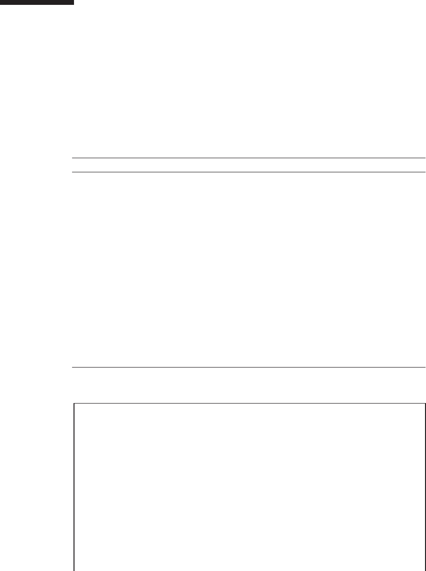
Table C-3 prtconf(1M) command options
Option Description Application
No options Displays a device tree for the
devices recognized by Oracle Solaris.
A hardware device is regarded as
operating normally if it is
recognized. If the message "(driver
not attached)" is displayed for a
device or a sub-device, the driver
for the device is corrupted or does
not exist.
-D The displayed content is similar to
the case when there are no options,
but is different in that it contains
device driver names.
Allows you to check the driver
necessary for Oracle Solaris to
enable the device, or to view a list
of drivers to be used.
-p The display content is similar to the
case when there are no options, but
is different in that the display is
simpler.
Allows you to view the devices as a
simple list.
-V Displays the version and date of the
OpenBoot PROM firmware.
Allows you to check the firmware
version quickly.
#prtconf
System Configuration: Oracle Corporation sun4v
Memory size: 131304 Megabytes
System Peripherals (Software Nodes):
ORCL,SPARC64-X
scsi_vhci, instance #0
packages (driver not attached)
SUNW,builtin-drivers (driver not attached)
SUNW,probe-error-handler (driver not attached)
deblocker (driver not attached)
disk-label (driver not attached)
terminal-emulator (driver not attached)
dropins (driver not attached)
SUNW,asr (driver not attached)
kbd-translator (driver not attached)
C.3 prtconf(1M) Command
The prtconf(1M) command displays a list of configured devices.
The prtconf(1M) command identifies hardware units recognized by Oracle Solaris.
When a software application experiences a hardware-related issue even though there
is no hardware error, this command allows you to check whether Oracle Solaris
recognizes the hardware and whether the hardware drivers are loaded.
Table C-3 lists the options of the prtconf(1M) command and how those options are
useful for troubleshooting.
The following example shows the prtconf(1M) command output.
Fujitsu M10-4/Fujitsu M10-4S/SPARC M10-4/SPARC M10-4S Service Manual ・December 2013482

obp-tftp (driver not attached)
zfs-file-system (driver not attached)
hsfs-file-system (driver not attached)
chosen (driver not attached)
openprom (driver not attached)
client-services (driver not attached)
options, instance #0
aliases (driver not attached)
memory (driver not attached)
virtual-memory (driver not attached)
iscsi-hba (driver not attached)
disk (driver not attached)
virtual-devices, instance #0
console, instance #0
rtc (driver not attached)
flashprom (driver not attached)
console (driver not attached)
channel-devices, instance #0
virtual-channel, instance #0
virtual-channel, instance #3
virtual-console-concentrator, instance #0
virtual-network-switch, instance #0
virtual-disk-server, instance #0
virtual-channel-client, instance #1
virtual-channel-client, instance #2
pciv-communication, instance #0
virtual-domain-service, instance #0
cpu (driver not attached)
cpu (driver not attached)
cpu (driver not attached)
cpu (driver not attached)
cpu (driver not attached)
------------------------Ommitted------------------------
cpu (driver not attached)
cpu (driver not attached)
cpu (driver not attached)
pci, instance #0
pci, instance #0
pci, instance #1
pci, instance #2
scsi, instance #0
iport, instance #8
smp, instance #3
disk, instance #8
enclosure, instance #3
iport, instance #11
pci, instance #3
pci, instance #5
usb, instance #0
usb, instance #0
hub, instance #0
pci, instance #4
network, instance #0
network, instance #1
pci, instance #6
Appendix C Oracle Solaris Troubleshooting Commands 483

network, instance #2
network, instance #3
pci, instance #1
pci, instance #7
pci, instance #8
pci, instance #9
pci, instance #10
pci, instance #11
pci, instance #2
pci, instance #12
pci, instance #13
pci, instance #14
pci, instance #15
pci, instance #16
pci, instance #17
pci, instance #3
pci, instance #18
pci, instance #19
pci, instance #20
pci, instance #21
pci, instance #22
pci, instance #23
pci, instance #4
pci, instance #24
pci, instance #25
pci, instance #26
scsi, instance #1
iport, instance #6
smp, instance #1
disk, instance #6
enclosure, instance #1
iport, instance #9
pci, instance #27
pci, instance #29
usb, instance #1
usb, instance #1
hub, instance #2
pci, instance #28
network, instance #4
network, instance #5
pci, instance #30
network, instance #6
network, instance #7
------------------------Ommitted------------------------
pci, instance #22
pci, instance #101
pci, instance #102
pci, instance #103
pci, instance #104
pci, instance #19
pci, instance #105
pci, instance #23
pci, instance #106
pci, instance #107
pci, instance #108
Fujitsu M10-4/Fujitsu M10-4S/SPARC M10-4/SPARC M10-4S Service Manual ・December 2013484

pci, instance #109
pci-performance-counters, instance #0
pci-performance-counters, instance #1
pci-performance-counters, instance #2
pci-performance-counters, instance #3
pci-performance-counters, instance #4
pci-performance-counters, instance #5
pci-performance-counters, instance #6
pci-performance-counters, instance #7
pci-performance-counters, instance #8
pci-performance-counters, instance #9
pci-performance-counters, instance #10
pci-performance-counters, instance #11
pci-performance-counters, instance #12
pci-performance-counters, instance #13
pci-performance-counters, instance #14
pci-performance-counters, instance #15
pci-performance-counters, instance #16
pci-performance-counters, instance #20
pci-performance-counters, instance #17
pci-performance-counters, instance #21
pci-performance-counters, instance #18
pci-performance-counters, instance #22
pci-performance-counters, instance #19
pci-performance-counters, instance #23
ramdisk-root (driver not attached)
os-io (driver not attached)
fcoe, instance #0
iscsi, instance #0
pseudo, instance #0
#
C.4 netstat(1M) Command
The netstat(1M) command displays the network status and the protocol statistics.
This command allows you to view a list of connections maintained by the host and
their status. This command also allows you to check the packet statistics and error
conditions of IP, TCP, and UDP.
Table C-4 lists the options of the netstat(1M) command and how those options can be
applied to solving issues.
Appendix C Oracle Solaris Troubleshooting Commands 485

Table C-4 netstat(1M) command options
Option Description Application
-i Displays the interface status. The
displayed content includes
information on incoming and
outgoing packets, incoming and
outgoing errors, collisions, and
queues.
Allows you to view a concise
overview of the network status.
-i interval Specifying a numeric value after the
-i option executes the netstat(1M)
command at intervals of the
specified number of seconds.
Identifies intermittent or long-term
network events. You can view
nighttime events at a glance by
piping the netstat output to a file.
-p Displays the media table. Allows you to check the MAC
addresses of the host on the
subnetwork.
-r Displays the routing table. Allows you to check the routing
information.
-n Converts a host name into an IP
address and then displays it.
Allows you to check the IP address
instead of the host name.
#netstat -p
Net to Media Table: IPv4
Device IP Address Mask Flags Phys Addr
------ -------------------- --------------- -------- ---------------
net0 4S-111-D0 255.255.255.255 SPLA b0:99:28:98:30:36
net0 10.24.187.1 255.255.255.255 00:0a:b8:50:cd:42
net0 224.0.0.22 255.255.255.255 S 01:00:5e:00:00:16
Net to Media Table: IPv6
If Physical Address Type State Destination/Mask
----- ----------------- ------- ------------ ---------------------------
net0 33:33:00:00:00:01 other REACHABLE ff02::1
net0 33:33:00:00:00:02 other REACHABLE ff02::2
net0 33:33:00:01:00:02 other REACHABLE ff02::1:2
net0 33:33:00:00:00:16 other REACHABLE ff02::16
net0 b0:99:28:98:30:36 local REACHABLE fe80::b299:28ff:fe98:3036
net0 33:33:ff:98:30:36 other REACHABLE ff02::1:ff98:3036
#
The following example shows the netstat(1M) command output.
C.5 ping(1M) Command
The ping(1M) command sends the ICMP ECHO_REQUEST packet to network hosts.
Fujitsu M10-4/Fujitsu M10-4S/SPARC M10-4/SPARC M10-4S Service Manual ・December 2013486

Table C-5 ping(1M) command options
Option Description Application
hostname When you send a probe packet to
hostname, a message is returned.
Allowsyoutoconfirmthatahostis
active on the network.
-g hostname Forces the probe packet to go
through the specified gateway.
Allows you to test the quality of
individual routes by sending the
packet to the target host via various
routes specified.
-i interface Specifies the interface to be used for
sending and receiving a probe
packet.
Allows you to easily check the
secondary network interface.
-n Converts a host name into an IP
address and then displays it.
Allows you to check the IP address
instead of the host name.
-s ping is repeated at intervals of 1
second.
Pressing the [Ctrl] + [C] keys stops
ping, and then displays the statistics.
Allows you to check intermittent or
long-term network events. You can
view nighttime network events at
one time by piping the ping output
to a file.
-svR Displays the routes that probe
packets have passed through at
intervals of 1 second.
Displays the routes and hop counts
of probe packets, allowing you to
compare multiple routes to identify
any bottleneck.
#ping -s 10.24.187.50
PING 10.24.187.50: 56 data bytes
64 bytes from 10.24.187.50: icmp_seq=0. time=0.555 ms
64 bytes from 10.24.187.50: icmp_seq=1. time=0.400 ms
64 bytes from 10.24.187.50: icmp_seq=2. time=0.447 ms
^C
----10.24.187.50 PING Statistics----
3 packets transmitted, 3 packets received, 0% packet loss
round-trip (ms) min/avg/max/stddev = 0.400/0.467/0.555/0.079
#
In certain configurations of the ping(1M) command, the command output allows you
to identify a network link or a node that has experienced a problem. The destination
host is specified by the variable: hostname.
Table C-5 lists the options of the ping(1M) command and how those options are
useful for troubleshooting.
The following example shows the ping(1M) command output.
Appendix C Oracle Solaris Troubleshooting Commands 487
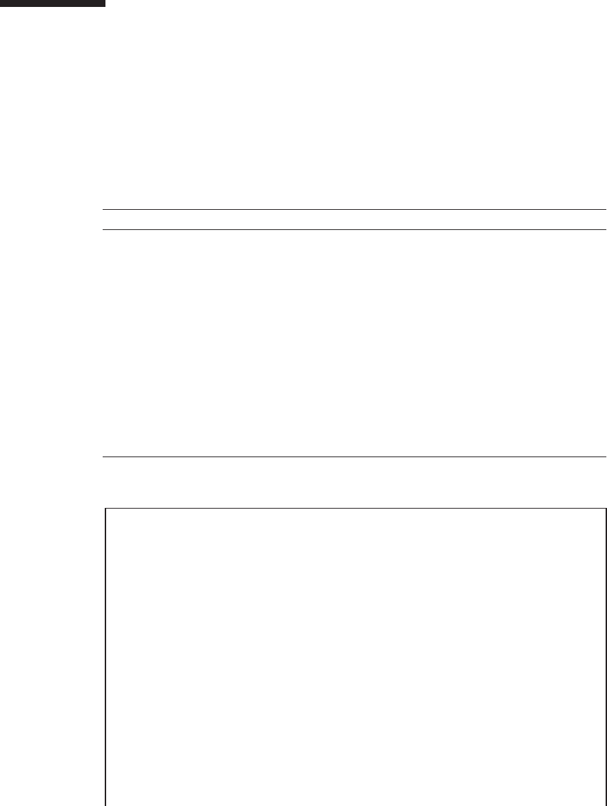
Table C-6 ps(1M) command options
Option Description Application
-e Displays information on various
processes.
Allows you to view the process IDs
and files that can be executed.
-f Generates a complete list. Allows you to view process
information such as the user ID, the
parent process ID, the execution
time, and the paths to the executed
files.
-o option Selects any items from those that
can be configured as outputs.
Options of pid, pcpu, pmem, and
comm display the process ID, CPU
usage, memory usage, and the
corresponding executable files,
respectively.
Allows you to check only the most
important information. By knowing
the resource usage rate, you can
identify processes that potentially
affect the system performance and
cause hang ups.
#ps -eo pcpu,pid,comm|sort -rn
%CPU PID COMMAND
0.0 674 sort
0.0 673 ps
0.0 637 -bash
0.0 636 login
0.0 634 /usr/sbin/in.telnetd
0.0 629 -bash
0.0 613 /usr/bin/login
0.0 602 /usr/lib/devchassis/devchassisd
0.0 600 /opt/SUNWldm/bin/ldmd
0.0 581 /usr/lib/inet/in.ndpd
0.0 580 /sbin/dhcpagent
0.0 577 /usr/lib/rmvolmgr
0.0 548 /usr/sbin/auditd
0.0 519 /usr/sbin/syslogd
0.0 508 /usr/lib/ssh/sshd
0.0 497 /usr/lib/fm/fmd/fmd
0.0 487 /usr/lib/hal/hald-addon-cpufreq
0.0 472 /usr/lib/autofs/automountd
C.6 ps(1) Command
The ps(1) command displays a list of process statuses. When no options are specified,
the command displays information of processes that have the same execution user ID
as the executing user and the same control terminal.
If you specify an option, output information is controlled by the option.
Table C-6 lists the options of the ps(1M) command and how those options are useful
for troubleshooting.
The following example shows the ps(1M) command output.
Fujitsu M10-4/Fujitsu M10-4S/SPARC M10-4/SPARC M10-4S Service Manual ・December 2013488

0.0 470 /usr/lib/autofs/automountd
0.0 468 /usr/lib/inet/inetd
0.0 458 hald-runner
0.0 453 /usr/lib/hal/hald
0.0 450 /usr/sbin/rpcbind
0.0 421 /usr/lib/inet/proftpd
0.0 413 /usr/sbin/cron
0.0 382 /lib/svc/method/iscsid
0.0 369 /usr/lib/efcode/sparcv9/efdaemon
0.0 332 /usr/sbin/nscd
0.0 297 /usr/lib/picl/picld
0.0 272 /lib/inet/nwamd
0.0 179 /usr/lib/devfsadm/devfsadmd
0.0 176 /usr/lib/zones/zonestatd
0.0 171 /usr/lib/ldoms/drd
0.0 164 /usr/lib/ldoms/ldmad
0.0 161 /usr/lib/utmpd
0.0 158 /usr/lib/dbus-daemon
0.0 128 /usr/lib/sysevent/syseventd
0.0 112 /usr/lib/pfexecd
0.0 98 /lib/inet/in.mpathd
0.0 74 /lib/crypto/kcfd
0.0 73 /lib/inet/ipmgmtd
0.0 59 /usr/sbin/dlmgmtd
0.0 38 /lib/inet/netcfgd
0.0 13 /lib/svc/bin/svc.configd
0.0 11 /lib/svc/bin/svc.startd
0.0 8 vmtasks
0.0 7 intrd
0.0 6 kmem_task
0.0 5 zpool-rpool
0.0 3 fsflush
0.0 2 pageout
0.0 1 /usr/sbin/init
0.0 0 sched
#
C.7 prstat(1M) Command
The prstat(1M) command repeatedly tests all the active processes on the system, and
provides statistics based on the specified output mode and sorting order. The output
of the prstat(1M) command is similar to that of the ps(1M) command.
Table C-7 lists the options of the prstat(1M) command and how those options can be
applied to solving issues.
Appendix C Oracle Solaris Troubleshooting Commands 489
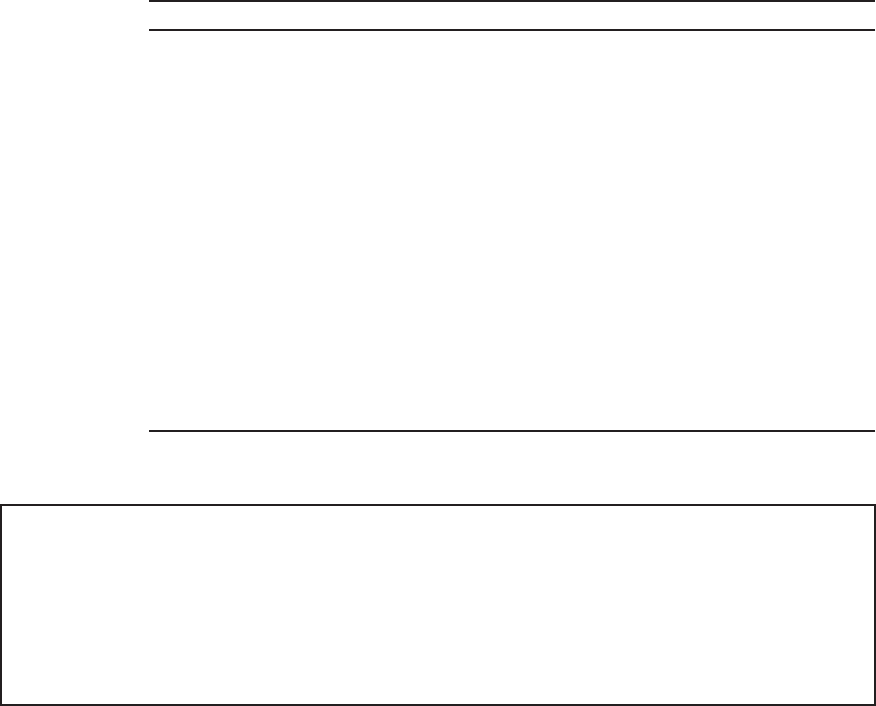
Table C-7 prstat(1M) command options
Option Description Application
No options Displays a list of processes sorted in
descending order of CPU resource
consumption. The list is restricted
by the height of the terminal
window and the number of
processes. The output is automatically
updated every 5 seconds, and is
stopped by pressing the [Ctrl] + [C]
keys.
The output allows you to view
process IDs, the User IDs, memory
usage, status, CPU usage, and
command names.
-n number Restricts the number of lines in the
output.
Limits the amount of displayed
data, so that you can identify those
processes that are consuming
excessive amounts of resources.
-s key Sorts the list by key parameter. The list can be sorted by cpu
(default), time, and size.
-v Displays the information in detailed
mode.
Allows you to view other
parameters.
#prstat -n 5 -s size
PID USERNAME SIZE RSS STATE PRI NICE TIME CPU PROCESS/NLWP
497 root 55M 49M sleep 59 0 0:01:12 0.0% fmd/37
600 root 41M 36M sleep 59 0 0:09:13 0.0% ldmd/13
11 root 37M 33M sleep 59 0 0:00:17 0.0% svc.startd/12
468 root 24M 12M sleep 59 0 0:00:00 0.0% inetd/4
13 root 20M 19M sleep 59 0 0:00:37 0.0% svc.configd/24
Total: 49 processes, 669 lwps, load averages: 0.05, 0.05, 0.04
#
The following example shows the prstat(1M) command output.
Fujitsu M10-4/Fujitsu M10-4S/SPARC M10-4/SPARC M10-4S Service Manual ・December 2013490

Appendix D
External Interface Specifications
This appendix describes the specifications of the external interface connectors and the
switch for the XSCF provided on the SPARC M10-4/M10-4S and the crossbar box.
The external interface connectors provided on the SPARC M10-4/M10-4S are as follows.
■Serial Port
■USB Port
■SAS Port
The external interface connectors provided on the crossbar box are as follows.
■Serial Port
■USB Port
The switch for the XSCF that is provided on the SPARC M10-4/M10-4S will be as
follows:
■RESET Switch
D.1 Serial Port
Table D-1 lists the specifications of the serial ports of the SPARC M10-4/M10-4S and
the crossbar box.
491
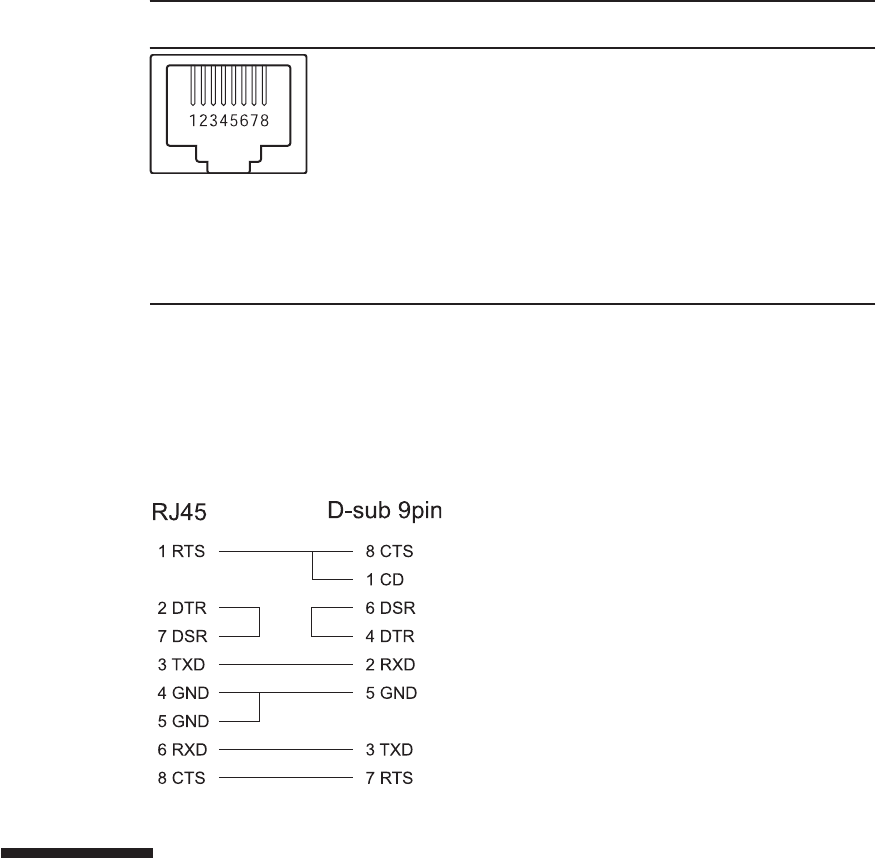
Table D-1 Serial port
Pin arrangement Pin
number
Signal
name
Input/Output Description
1 RTS Output Transmission request
2 DTR Output Data terminal ready
3 TXD Output Transmitted data
4 GND --- Ground
5 GND --- Ground
6 RXD Input Received data
7 DSR Input Data set ready
8 CTS Input Transmission possible
D.1.1 Wire connection chart for serial cable
Figure D-1 Wire connection chart of serial cable
D.2 USB Port
Table D-2 lists the specifications of the USB port of the SPARC M10-4/M10-4S and the
crossbar box.
Fujitsu M10-4/Fujitsu M10-4S/SPARC M10-4/SPARC M10-4S Service Manual ・December 2013492
Table D-2 USB port
Pin arrangement Pin
number
Signal
name
Input/Output Description
1 VBUS Output Power supply
2 -DATA Input/
Output
Data
3 +DATA Input/
Output
Data
4 GND --- Ground
D.3 SAS Port
The SAS port of the SPARC M10-4/M10-4S is used to connect external devices with
an SAS interface, such as a tape drive. The chassis has one SAS port on the rear.
Consult a service engineer for more information about compatible devices.
D.4 RESET Switch
The RESET switch of the SPARC M10-4/M10-4S is an emergency switch to restart the
XSCF. For how to use the RESET switch, see "17.2 Precautions concerning Using the
RESET Switch" in the Fujitsu M10/SPARC M10 Systems System Operation and
Administration Guide.
Figure D-2 indicates the RESET switch location of the SPARC M10-4 while Figure D-3
indicates the RESET switch location of the SPARC M10-4S. The RESET switch (A in
the figure) is located on the rear of the chassis.
Appendix D External Interface Specifications 493
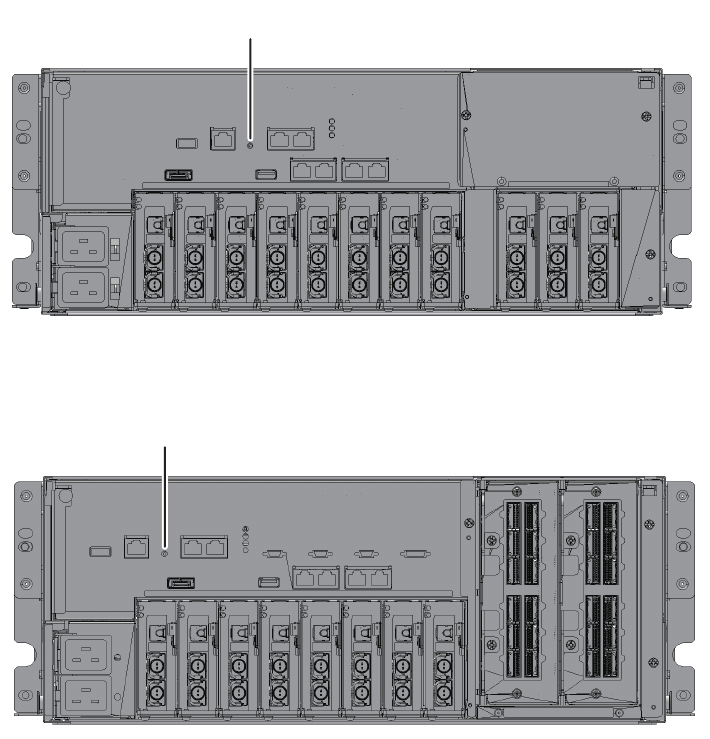
A
A
Figure D-2 RESET switch location (SPARC M10-4)
Figure D-3 RESET switch location (SPARC M10-4S)
Fujitsu M10-4/Fujitsu M10-4S/SPARC M10-4/SPARC M10-4S Service Manual ・December 2013494

Index
C
cable kit,425
cable, types of,29
component list,463
component specifications,467
components, names and locations of,11
CPU memory unit,83
crossbar backplane unit,343
crossbar cable (electrical),379
crossbar cable (optical),389
crossbar unit,179,297
D
dedicated power distribution unit,453
E
emergency power off,8
entire system, starting,74
entire system, stopping,62
external interface,491
F
failure, identifying,34
fan backplane,357
fan unit,205,327
I
internal disk,219
L
labels,2
LED indications,23
M
maintenance, preparing for,41
maintenance, types of,44
memory,159
O
operation panel,281,367
Oracle Solaris,477
P
PCI Express card,239
physical partition, powering off,60
physical partition, powering on,73
power supply unit,191,317
PSU backplane unit,265
S
system, restoring,69
T
tags,2
W
warning labels,2
495
