Fujitsu Xg Series P3Nk 4452 01Enzd Users Manual User’s Guide
2015-01-25
: Fujitsu Fujitsu-Xg-Series-P3Nk-4452-01Enzd-Users-Manual-218572 fujitsu-xg-series-p3nk-4452-01enzd-users-manual-218572 fujitsu pdf
Open the PDF directly: View PDF ![]() .
.
Page Count: 614 [warning: Documents this large are best viewed by clicking the View PDF Link!]
- Preface
- Contents
- Organization and Usage of This Manual
- End User's License Agreement
- Chapter 1 Features and Functions
- Chapter 2 Using the CLI
- 2.1 Overview of the CLI
- 2.2 Using the CLI
- 2.2.1 Using the Shell Function
- 2.2.1.1 Command execution function
- 2.2.1.2 Entry editing function
- 2.2.1.3 Command name autocomplete function
- 2.2.1.4 Command argument autocomplete function
- 2.2.1.5 Abbreviated command entry function
- 2.2.1.6 Command alias function
- 2.2.1.7 Configuration hierarchy function
- 2.2.1.8 Time of command execution display function
- 2.2.1.9 Command history function
- 2.2.1.10 List of shell key bindings
- 2.2.2 Error Messages Common to All Commands
- 2.2.3 Characters that can be entered
- 2.2.1 Using the Shell Function
- Chapter 3 Installation
- Chapter 4 Switch Functions and their Configuration
- Chapter 5 Command Reference
- 5.1 Port Information Settings
- 5.1.1 Ethernet Common Information
- 5.1.1.1 forwardingmode
- 5.1.1.2 ether use
- 5.1.1.3 ether media
- 5.1.1.4 ether mode
- 5.1.1.5 ether duplex
- 5.1.1.6 ether mdi
- 5.1.1.7 ether flowctl
- 5.1.1.8 ether type
- 5.1.1.9 ether vlan tag
- 5.1.1.10 ether vlan untag
- 5.1.1.11 ether egress permission
- 5.1.1.12 ether loopdetect use
- 5.1.1.13 ether loopdetect frame
- 5.1.1.14 ether startup
- 5.1.1.15 ether recovery limit
- 5.1.1.16 ether downrelay port
- 5.1.1.17 ether downrelay recovery mode
- 5.1.1.18 ether downrelay recovery cause
- 5.1.1.19 ether description
- 5.1.1.20 linkaggregation algorithm
- 5.1.1.21 linkaggregation mode
- 5.1.1.22 linkaggregation type
- 5.1.1.23 linkaggregation collecting minimum
- 5.1.1.24 linkaggregation icmpwatch address
- 5.1.1.25 linkaggregation icmpwatch interval
- 5.1.1.26 linkaggregation downrelay port
- 5.1.1.27 linkaggregation downrelay recovery mode
- 5.1.1.28 linkaggregation downrelay recovery cause
- 5.1.1.29 linkaggregation description
- 5.1.1.30 backup mode
- 5.1.1.31 backup standby
- 5.1.2 MAC Information
- 5.1.3 STP Information
- 5.1.4 LLDP Information
- 5.1.5 Filter Information
- 5.1.6 QoS Information
- 5.1.7 LACP Information
- 5.1.8 ether L3 Monitor Information
- 5.1.9 ether SNMP Information
- 5.1.10 ether output rate control information
- 5.1.1 Ethernet Common Information
- 5.2 LACP Information Settings
- 5.3 VLAN Information Settings
- 5.4 MAC Information
- 5.5 LAN Information Settings
- 5.6 IPv4 Related Information
- 5.7 QoS Information Settings
- 5.8 STP Information
- 5.9 LLDP Information Settings
- 5.10 IGMP Snooping Information Settings
- 5.11 Loop Detection Information Settings
- 5.12 ACL Information Settings
- 5.13 AAA Information Settings
- 5.13.1 Group ID Information
- 5.13.2 AAA User Information
- 5.13.3 RADIUS Information Settings
- 5.13.3.1 aaa radius service
- 5.13.3.2 aaa radius auth source
- 5.13.3.3 aaa radius auth message-authenticator
- 5.13.3.4 aaa radius client server-info auth secret
- 5.13.3.5 aaa radius client server-info auth address
- 5.13.3.6 aaa radius client server-info auth port
- 5.13.3.7 aaa radius client server-info auth deadtime
- 5.13.3.8 aaa radius client server-info auth priority
- 5.13.3.9 aaa radius client server-info auth source
- 5.13.3.10 aaa radius client retry
- 5.13.3.11 aaa radius client security
- 5.14 Password Information
- 5.15 Device Information Settings
- 5.15.1 SNMP Information
- 5.15.1.1 snmp service
- 5.15.1.2 snmp agent contact
- 5.15.1.3 snmp agent sysname
- 5.15.1.4 snmp agent location
- 5.15.1.5 snmp agent address
- 5.15.1.6 snmp agent engineid
- 5.15.1.7 snmp manager
- 5.15.1.8 snmp trap coldstart
- 5.15.1.9 snmp trap linkdown
- 5.15.1.10 snmp trap linkup
- 5.15.1.11 snmp trap authfail
- 5.15.1.12 snmp trap newroot
- 5.15.1.13 snmp trap topologychange
- 5.15.1.14 snmp trap noserror
- 5.15.1.15 snmp trap lldpremtableschange
- 5.15.1.16 snmp rmon
- 5.15.1.17 snmp user name
- 5.15.1.18 snmp user address
- 5.15.1.19 snmp user notification
- 5.15.1.20 snmp user auth
- 5.15.1.21 snmp user priv
- 5.15.1.22 snmp user write
- 5.15.1.23 snmp user read
- 5.15.1.24 snmp user notify
- 5.15.1.25 snmp view subtree
- 5.15.2 System Log Information
- 5.15.3 Automatic Time Setting Information
- 5.15.4 ProxyDNS Information
- 5.15.5 Host Database Information
- 5.15.6 Schedule Information
- 5.15.7 Filter/QoS Resource Information
- 5.15.8 Other
- 5.15.8.1 addact
- 5.15.8.2 watchdog service
- 5.15.8.3 consoleinfo
- 5.15.8.4 telnetinfo
- 5.15.8.5 mflag
- 5.15.8.6 dumpswitch
- 5.15.8.7 sysname
- 5.15.8.8 serverinfo ftp
- 5.15.8.9 serverinfo ftp ip6
- 5.15.8.10 serverinfo ftp filter
- 5.15.8.11 serverinfo ftp filter move
- 5.15.8.12 serverinfo ftp filter default
- 5.15.8.13 serverinfo sftp
- 5.15.8.14 serverinfo sftp ip6
- 5.15.8.15 serverinfo telnet
- 5.15.8.16 serverinfo telnet ip6
- 5.15.8.17 serverinfo telnet filter
- 5.15.8.18 serverinfo telnet filter move
- 5.15.8.19 serverinfo telnet filter default
- 5.15.8.20 serverinfo ssh
- 5.15.8.21 serverinfo ssh ip6
- 5.15.8.22 serverinfo ssh filter
- 5.15.8.23 serverinfo ssh filter move
- 5.15.8.24 serverinfo ssh filter default
- 5.15.8.25 serverinfo http
- 5.15.8.26 serverinfo http ip6
- 5.15.8.27 serverinfo http filter
- 5.15.8.28 serverinfo http filter move
- 5.15.8.29 serverinfo http filter default
- 5.15.8.30 serverinfo dns
- 5.15.8.31 serverinfo dns ip6
- 5.15.8.32 serverinfo dns filter
- 5.15.8.33 serverinfo dns filter move
- 5.15.8.34 serverinfo dns filter default
- 5.15.8.35 serverinfo sntp
- 5.15.8.36 serverinfo sntp ip6
- 5.15.8.37 serverinfo sntp filter
- 5.15.8.38 serverinfo sntp filter move
- 5.15.8.39 serverinfo sntp filter default
- 5.15.8.40 serverinfo time ip tcp
- 5.15.8.41 serverinfo time ip6 tcp
- 5.15.8.42 serverinfo time ip udp
- 5.15.8.43 serverinfo time ip6 udp
- 5.15.8.44 serverinfo time filter
- 5.15.8.45 serverinfo time filter move
- 5.15.8.46 serverinfo time filter default
- 5.15.1 SNMP Information
- 5.16 Login banner Settings
- 5.17 Mode and Terminal Operation Commands
- 5.18 System Operations and Display Commands
- 5.19 Configuration Display, Delete and Operation Commands
- 5.20 Ethernet Counter, Log, Statistics, and Status Display and Clear Operation Commands
- 5.21 USB connection Counter, Log, Statistics, and Status Display and Clear Operation Commands
- 5.22 LACP Counter, Log, Statistics, and Status Display and Clear Operation Commands
- 5.23 M1 port Status Display command
- 5.24 Interface Counter, Log, Statistics, and Status Display Commands
- 5.25 ARP Entry Display and Clear Operation Commands
- 5.26 Routing Table Entry Display Commands
- 5.27 Packet Statistics Display and Clear Operation Commands
- 5.28 Bridge Counter, Log, Statistics, and Status Display and Clear Operation Commands
- 5.29 LLDP Counter, Log, Statistics, and Status Display and Clear Operation Commands
- 5.30 VLAN Counter, Log, Statistics, and Status Display Commands
- 5.31 QoS Counter, Log, Statistics, and Status Display Commands
- 5.32 SSH Counter, Log, Statistics, and Status Display Commands
- 5.33 IGMP Snooping Counter, Log, Statistics, and Status Display and Clear Operation Commands
- 5.34 Loopdetection Counter, Log, Statistics, and Status Display and Clear Operation Commands
- 5.35 AAA Status Display and Clear Operation Commands
- 5.36 NETTIME (time/sntp) Server and Client Statistics Display and Clear Operation Commands
- 5.37 ProxyDNS Statistics Display and Clear Operation Commands
- 5.38 SNMP Statistics Display and Clear Operation Commands
- 5.39 Ethernet L3 Monitor Function Counter, Log, Statistics, and Status Display and Clear Operation Commands
- 5.40 Login Information Operations and Display Commands
- 5.41 Socket Status Display Commands
- 5.42 Trace Show and Clear Operation Commands
- 5.43 Ethernet Port Control Commands
- 5.44 RADIUS Control Commands
- 5.45 USB Port Control Commands
- 5.46 I’m here Commands
- 5.47 Other Commands
- 5.48 Effect by "commit" Command Execution
- 5.1 Port Information Settings
- Chapter 6 Managing the Device
- Chapter 7 Troubleshooting
- Appendix
- Index

Series
Series
P3NK-4452-01ENZ0
User'sGuide
User’s Guide
Introduction

XG Series User's Guide
2
Preface
You have purchased the XG series, a compact, layer 2 switch that achieves unsurpassed
standards of high throughput and low-latency performance.
This guide describes the XG series (XG0224 / XG0448 / XG2600) functions, installation procedures, configuration opera-
tions, and maintenance procedures and should be read and understood before you start using your XG series.
First edition: February 2011
This manual contains the technology regulated by "Foreign Exchange and Foreign Trade Control Law."
Therefore when this manual is exported or provided to a nonresident, the appropriate permission based on this law is
required.
Screenshots are used according to the guidelines provided by Microsoft Corporation.
Copyright FUJITSU LIMITED 2011

XG Series User’s Guide Contents
3
Contents
Preface ................................................................................................................................................................2
Organization and Usage of This Manual ..........................................................................................................16
Target Readers and Required Knowledge ............................................................................................................... 16
Areas Covered .......................................................................................................................................................... 16
Trademark Notification in This Manual .................................................................................................................. 17
How the Manuals for This Device Are Organized .................................................................................................. 18
End User's License Agreement .........................................................................................................................19
Chapter 1 Features and Functions......................................................................... 22
1.1 Hardware Specifications ........................................................................................................................23
1.1.1 Switch Specifications ............................................................................................................................... 23
1.1.2 Option ....................................................................................................................................................... 25
1.1.3 10/100/1000BASE-T Port Specifications ................................................................................................ 28
1.1.4 USB Port Specifications ........................................................................................................................... 29
1.1.5 Console Port Specifications ..................................................................................................................... 29
1.2 Software Specifications .........................................................................................................................30
1.2.1 Software Specifications ............................................................................................................................ 30
1.2.2 Initial Values ............................................................................................................................................ 32
1.2.3 System Maximum Values ........................................................................................................................ 34
Chapter 2 Using the CLI .......................................................................................... 37
2.1 Overview of the CLI ..............................................................................................................................38
2.1.1 Operating Environment for the CLI ......................................................................................................... 38
2.1.2 Command Modes and Mode Switching ................................................................................................... 39
2.1.2.1 Command Operation Procedure ............................................................................................... 39
2.1.2.2 Executable commands .............................................................................................................. 42
2.2 Using the CLI .........................................................................................................................................43
2.2.1 Using the Shell Function .......................................................................................................................... 43
2.2.1.1 Command execution function .................................................................................................. 43
2.2.1.2 Entry editing function .............................................................................................................. 43
2.2.1.3 Command name autocomplete function .................................................................................. 44
2.2.1.4 Command argument autocomplete function ............................................................................ 46
2.2.1.5 Abbreviated command entry function ......................................................................................46
2.2.1.6 Command alias function .......................................................................................................... 46
2.2.1.7 Configuration hierarchy function ............................................................................................. 47
2.2.1.8 Time of command execution display function ......................................................................... 48
2.2.1.9 Command history function ....................................................................................................... 48
2.2.1.10 List of shell key bindings ......................................................................................................... 52
2.2.2 Error Messages Common to All Commands ........................................................................................... 53
2.2.3 Characters that can be entered ................................................................................................................. 54
Chapter 3 Installation .............................................................................................. 55
3.1 Workflow for Initial Setup of the Device ..............................................................................................56
3.1.1 Configure LAN Interface ......................................................................................................................... 57
3.1.2 Telnet Connection via the LAN Interface (Optional) .............................................................................. 57
3.1.3 SNMP Configuration (Optional) .............................................................................................................. 58

XG Series User’s Guide Contents
4
Chapter 4 Switch Functions and their Configuration........................................... 59
4.1 Basic Switch Functions ..........................................................................................................................61
4.1.1 Switching Mode (XG2600) ...................................................................................................................... 61
4.1.2 MAC Address Table Management .......................................................................................................... 62
4.1.3 Jumbo Frame Support .............................................................................................................................. 63
4.1.4 Flow Control ............................................................................................................................................ 63
4.1.5 Storm Control ........................................................................................................................................... 63
4.1.6 Egress Rate Control (XG2600 Only) ....................................................................................................... 64
4.2 Port Mirroring ........................................................................................................................................65
4.3 Link Down Relay ...................................................................................................................................66
4.4 Link Aggregation ...................................................................................................................................67
4.4.1 Configuring Link Aggregation ................................................................................................................. 68
4.4.2 Frame Distribution Methods in Link Aggregation .................................................................................. 69
4.4.3 The Number of Ports That Require Linkup ............................................................................................. 70
4.4.4 Notes on Link Aggregation ...................................................................................................................... 70
4.5 Spanning Tree Protocol (STP) ...............................................................................................................71
4.5.1 Port Roles Based on Spanning Tree ......................................................................................................... 72
4.5.2 Spanning Tree Protocol Port States ......................................................................................................... 72
4.5.3 Configuring Spanning Tree ...................................................................................................................... 73
4.6 VLAN ....................................................................................................................................................74
4.6.1 Port-Based VLAN .................................................................................................................................... 74
4.6.2 Tag-Based (IEEE802.1Q) VLAN ............................................................................................................ 75
4.7 Quality of Service (QoS) .......................................................................................................................76
4.8 IGMP Snooping .....................................................................................................................................77
4.8.1 Registering Group Members .................................................................................................................... 78
4.8.2 Removing Group Members ...................................................................................................................... 79
4.8.3 Managing Group Members ...................................................................................................................... 80
4.8.4 IGMP Querier .......................................................................................................................................... 81
4.8.5 Configuring IGMP Snooping ................................................................................................................... 82
4.9 Network Management ............................................................................................................................83
4.9.1 Traffic Statistics ....................................................................................................................................... 83
4.9.2 SNMP Agent ............................................................................................................................................ 83
4.9.3 RMON ...................................................................................................................................................... 84
Chapter 5 Command Reference ............................................................................. 85
5.1 Port Information Settings .......................................................................................................................89
5.1.1 Ethernet Common Information ................................................................................................................ 90
5.1.1.1 forwardingmode ....................................................................................................................... 90
5.1.1.2 ether use ................................................................................................................................... 91
5.1.1.3 ether media ............................................................................................................................... 92
5.1.1.4 ether mode ................................................................................................................................ 93
5.1.1.5 ether duplex .............................................................................................................................. 94
5.1.1.6 ether mdi .................................................................................................................................. 95
5.1.1.7 ether flowctl ............................................................................................................................. 96
5.1.1.8 ether type .................................................................................................................................. 97
5.1.1.9 ether vlan tag .......................................................................................................................... 100
5.1.1.10 ether vlan untag ...................................................................................................................... 101
5.1.1.11 ether egress permission .......................................................................................................... 102
5.1.1.12 ether loopdetect use ................................................................................................................ 102
5.1.1.13 ether loopdetect frame ............................................................................................................ 103
5.1.1.14 ether startup ............................................................................................................................ 104

XG Series User’s Guide Contents
5
5.1.1.15 ether recovery limit ................................................................................................................ 105
5.1.1.16 ether downrelay port .............................................................................................................. 106
5.1.1.17 ether downrelay recovery mode ............................................................................................. 107
5.1.1.18 ether downrelay recovery cause ............................................................................................. 108
5.1.1.19 ether description ..................................................................................................................... 109
5.1.1.20 linkaggregation algorithm ...................................................................................................... 110
5.1.1.21 linkaggregation mode ............................................................................................................. 111
5.1.1.22 linkaggregation type ............................................................................................................... 112
5.1.1.23 linkaggregation collecting minimum ..................................................................................... 113
5.1.1.24 linkaggregation icmpwatch address ....................................................................................... 114
5.1.1.25 linkaggregation icmpwatch interval ....................................................................................... 115
5.1.1.26 linkaggregation downrelay port ............................................................................................. 116
5.1.1.27 linkaggregation downrelay recovery mode ............................................................................ 117
5.1.1.28 linkaggregation downrelay recovery cause ............................................................................ 118
5.1.1.29 linkaggregation description .................................................................................................... 119
5.1.1.30 backup mode .......................................................................................................................... 120
5.1.1.31 backup standby ....................................................................................................................... 121
5.1.2 MAC Information .................................................................................................................................. 122
5.1.2.1 ether mac storm ...................................................................................................................... 122
5.1.3 STP Information ..................................................................................................................................... 124
5.1.3.1 ether stp use ............................................................................................................................ 124
5.1.3.2 ether stp domain cost .............................................................................................................. 125
5.1.3.3 ether stp domain priority ........................................................................................................ 126
5.1.3.4 ether stp force-version ............................................................................................................ 127
5.1.4 LLDP Information .................................................................................................................................. 128
5.1.4.1 ether lldp mode ....................................................................................................................... 128
5.1.4.2 ether lldp info ......................................................................................................................... 129
5.1.4.3 ether lldp vlan ......................................................................................................................... 131
5.1.4.4 ether lldp notification ............................................................................................................. 131
5.1.5 Filter Information ................................................................................................................................... 132
5.1.5.1 ether macfilter ........................................................................................................................ 132
5.1.5.2 ether macfilter move .............................................................................................................. 136
5.1.6 QoS Information .................................................................................................................................... 137
5.1.6.1 ether qos aclmap ..................................................................................................................... 137
5.1.6.2 ether qos aclmap move ........................................................................................................... 142
5.1.6.3 ether qos priority .................................................................................................................... 143
5.1.6.4 ether qos mode ....................................................................................................................... 144
5.1.6.5 ether qos prioritymap ............................................................................................................. 145
5.1.7 LACP Information ................................................................................................................................. 146
5.1.7.1 ether lacp port-priority ........................................................................................................... 146
5.1.8 ether L3 Monitor Information ................................................................................................................ 147
5.1.8.1 ether icmpwatch address ........................................................................................................ 147
5.1.8.2 ether icmpwatch interval ........................................................................................................ 148
5.1.9 ether SNMP Information ........................................................................................................................ 149
5.1.9.1 ether snmp trap linkdown ....................................................................................................... 149
5.1.9.2 ether snmp trap linkup ............................................................................................................ 150
5.1.10 ether output rate control information ..................................................................................................... 151
5.1.10.1 ether ratecontrol ..................................................................................................................... 151
5.2 LACP Information Settings .................................................................................................................152
5.2.1 LACP Information ................................................................................................................................. 152
5.2.1.1 lacp system-priority ................................................................................................................ 152
5.2.1.2 lacp bpdu ................................................................................................................................ 153

XG Series User’s Guide Contents
6
5.3 VLAN Information Settings ................................................................................................................154
5.3.1 VLAN Common Information ................................................................................................................. 154
5.3.1.1 vlan name ............................................................................................................................... 154
5.3.1.2 vlan protocol .......................................................................................................................... 155
5.3.1.3 vlan forward ........................................................................................................................... 158
5.3.1.4 vlan description ...................................................................................................................... 159
5.3.2 IGMP Snooping Information ................................................................................................................. 160
5.3.2.1 vlan igmpsnoop router ........................................................................................................... 160
5.3.2.2 vlan igmpsnoop querier .......................................................................................................... 161
5.3.2.3 vlan igmpsnoop source ........................................................................................................... 162
5.3.2.4 vlan igmpsnoop proxy ............................................................................................................ 163
5.3.3 Filter Information ................................................................................................................................... 164
5.3.3.1 vlan macfilter ......................................................................................................................... 164
5.3.3.2 vlan macfilter move ............................................................................................................... 169
5.3.3.3 vlan ip6filter ........................................................................................................................... 170
5.3.3.4 vlan ip6filter move ................................................................................................................. 172
5.3.4 QoS Information .................................................................................................................................... 173
5.3.4.1 vlan qos aclmap ...................................................................................................................... 173
5.3.4.2 vlan ip6qos aclmap ................................................................................................................. 178
5.3.4.3 vlan ip6qos aclmap move ....................................................................................................... 180
5.4 MAC Information ................................................................................................................................181
5.4.1 MAC Information .................................................................................................................................. 181
5.4.1.1 mac learning ........................................................................................................................... 181
5.4.1.2 mac age .................................................................................................................................. 182
5.5 LAN Information Settings ...................................................................................................................183
5.5.1 IPv4 Related Information ....................................................................................................................... 183
5.5.1.1 lan description ........................................................................................................................ 183
5.5.1.2 lan ip address .......................................................................................................................... 184
5.5.1.3 lan ip route ............................................................................................................................. 185
5.5.1.4 lan ip filter .............................................................................................................................. 186
5.5.1.5 lan ip filter move .................................................................................................................... 191
5.5.1.6 lan ip dscp .............................................................................................................................. 192
5.5.1.7 lan ip dscp move .................................................................................................................... 196
5.5.1.8 lan ip arp static ....................................................................................................................... 197
5.5.2 IPv6 Related Information ....................................................................................................................... 198
5.5.2.1 lan ip6 use .............................................................................................................................. 198
5.5.2.2 lan ip6 ifid .............................................................................................................................. 198
5.5.2.3 lan ip6 address ........................................................................................................................ 199
5.5.2.4 lan ip6 ra mode ....................................................................................................................... 199
5.5.2.5 lan ip6 route ........................................................................................................................... 200
5.5.2.6 lan ip6 filter ............................................................................................................................ 201
5.5.2.7 lan ip6 filter move .................................................................................................................. 203
5.5.2.8 lan ip6 dscp ............................................................................................................................ 204
5.5.2.9 lan ip6 dscp move .................................................................................................................. 206
5.5.3 VLAN Related Information ................................................................................................................... 207
5.5.3.1 lan vlan ................................................................................................................................... 207
5.5.4 LLMNR Related Information ................................................................................................................ 208
5.5.4.1 lan llmnr use ........................................................................................................................... 208
5.5.5 Management LAN port IPv4 Related Information ................................................................................ 209
5.5.5.1 oob ip address ......................................................................................................................... 209
5.5.5.2 oob ip route ............................................................................................................................ 210

XG Series User’s Guide Contents
7
5.5.6 Management LAN port IPv6 Related Information ................................................................................ 211
5.5.6.1 oob ip6 use ............................................................................................................................. 211
5.5.6.2 oob ip6 ifid ............................................................................................................................. 211
5.5.6.3 oob ip6 address ....................................................................................................................... 212
5.5.6.4 oob ip6 ra mode ...................................................................................................................... 212
5.5.6.5 oob ip6 route .......................................................................................................................... 213
5.5.7 Management LAN port LLMNR Related Information .......................................................................... 214
5.5.7.1 oob llmnr use .......................................................................................................................... 214
5.6 IPv4 Related Information .....................................................................................................................215
5.6.1 IPv4 Related Information ....................................................................................................................... 215
5.6.1.1 ip arp age ................................................................................................................................ 215
5.7 QoS Information Settings ....................................................................................................................216
5.7.1 QoS Information .................................................................................................................................... 216
5.7.1.1 qos cosmap ............................................................................................................................. 216
5.8 STP Information ..................................................................................................................................217
5.8.1 STP Information ..................................................................................................................................... 217
5.8.1.1 stp mode ................................................................................................................................. 217
5.8.1.2 stp age .................................................................................................................................... 218
5.8.1.3 stp delay ................................................................................................................................. 219
5.8.1.4 stp hello .................................................................................................................................. 220
5.8.1.5 stp bpdu .................................................................................................................................. 221
5.8.1.6 stp domain priority ................................................................................................................. 222
5.8.1.7 stp config_id ........................................................................................................................... 223
5.8.1.8 stp domain vlan ...................................................................................................................... 223
5.8.1.9 stp max-hops .......................................................................................................................... 224
5.9 LLDP Information Settings .................................................................................................................225
5.9.1 LLDP Information .................................................................................................................................. 225
5.9.1.1 lldp send interval .................................................................................................................... 225
5.9.1.2 lldp send hold ......................................................................................................................... 226
5.9.1.3 lldp reinit delay ...................................................................................................................... 226
5.9.1.4 lldp notification interval ......................................................................................................... 227
5.10 IGMP Snooping Information Settings .................................................................................................228
5.10.1 IGMP Snooping Information ................................................................................................................. 228
5.10.1.1 igmpsnoop use ........................................................................................................................ 228
5.10.1.2 igmpsnoop localgroup ............................................................................................................ 228
5.10.1.3 igmpsnoop unknown flooding ............................................................................................... 229
5.11 Loop Detection Information Settings ..................................................................................................230
5.11.1 Loop Detection Information ................................................................................................................... 230
5.11.1.1 loopdetect use ......................................................................................................................... 230
5.11.1.2 loopdetect portdisable ............................................................................................................ 231
5.11.1.3 loopdetect portblock ............................................................................................................... 231
5.11.1.4 loopdetect interval .................................................................................................................. 232
5.11.1.5 loopdetect recovery ................................................................................................................ 232
5.12 ACL Information Settings ...................................................................................................................233
5.12.1 ACL Information .................................................................................................................................... 233
5.12.1.1 acl mac ................................................................................................................................... 233
5.12.1.2 acl vlan ................................................................................................................................... 234
5.12.1.3 acl ip ....................................................................................................................................... 235
5.12.1.4 acl ip6 ..................................................................................................................................... 237
5.12.1.5 acl tcp ..................................................................................................................................... 238
5.12.1.6 acl udp .................................................................................................................................... 239
5.12.1.7 acl icmp .................................................................................................................................. 240
5.12.1.8 acl description ........................................................................................................................ 241

XG Series User’s Guide Contents
8
5.13 AAA Information Settings ...................................................................................................................242
5.13.1 Group ID Information ............................................................................................................................ 243
5.13.1.1 aaa name ................................................................................................................................. 243
5.13.2 AAA User Information .......................................................................................................................... 244
5.13.2.1 aaa user id ............................................................................................................................... 244
5.13.2.2 aaa user password ................................................................................................................... 245
5.13.2.3 aaa user user-role ................................................................................................................... 246
5.13.3 RADIUS Information Settings ............................................................................................................... 247
5.13.3.1 aaa radius service ................................................................................................................... 247
5.13.3.2 aaa radius auth source ............................................................................................................ 248
5.13.3.3 aaa radius auth message-authenticator ................................................................................... 249
5.13.3.4 aaa radius client server-info auth secret ................................................................................. 250
5.13.3.5 aaa radius client server-info auth address .............................................................................. 251
5.13.3.6 aaa radius client server-info auth port .................................................................................... 252
5.13.3.7 aaa radius client server-info auth deadtime ............................................................................ 253
5.13.3.8 aaa radius client server-info auth priority .............................................................................. 254
5.13.3.9 aaa radius client server-info auth source ................................................................................ 255
5.13.3.10 aaa radius client retry ............................................................................................................. 256
5.13.3.11 aaa radius client security ........................................................................................................ 256
5.14 Password Information ..........................................................................................................................257
5.14.1 password format ..................................................................................................................................... 257
5.14.2 password admin set ................................................................................................................................ 258
5.14.3 password user set ................................................................................................................................... 260
5.14.4 password aaa .......................................................................................................................................... 261
5.14.5 password authtype .................................................................................................................................. 261
5.15 Device Information Settings ................................................................................................................262
5.15.1 SNMP Information ................................................................................................................................. 262
5.15.1.1 snmp service ........................................................................................................................... 262
5.15.1.2 snmp agent contact ................................................................................................................. 262
5.15.1.3 snmp agent sysname ............................................................................................................... 263
5.15.1.4 snmp agent location ............................................................................................................... 263
5.15.1.5 snmp agent address ................................................................................................................ 264
5.15.1.6 snmp agent engineid ............................................................................................................... 264
5.15.1.7 snmp manager ........................................................................................................................ 265
5.15.1.8 snmp trap coldstart ................................................................................................................. 266
5.15.1.9 snmp trap linkdown ................................................................................................................ 266
5.15.1.10 snmp trap linkup ..................................................................................................................... 267
5.15.1.11 snmp trap authfail ................................................................................................................... 267
5.15.1.12 snmp trap newroot .................................................................................................................. 268
5.15.1.13 snmp trap topologychange ..................................................................................................... 268
5.15.1.14 snmp trap noserror ................................................................................................................. 269
5.15.1.15 snmp trap lldpremtableschange .............................................................................................. 269
5.15.1.16 snmp rmon .............................................................................................................................. 270
5.15.1.17 snmp user name ...................................................................................................................... 270
5.15.1.18 snmp user address .................................................................................................................. 271
5.15.1.19 snmp user notification ............................................................................................................ 272
5.15.1.20 snmp user auth ....................................................................................................................... 273
5.15.1.21 snmp user priv ........................................................................................................................ 274
5.15.1.22 snmp user write ...................................................................................................................... 275
5.15.1.23 snmp user read ....................................................................................................................... 276
5.15.1.24 snmp user notify ..................................................................................................................... 277
5.15.1.25 snmp view subtree .................................................................................................................. 278

XG Series User’s Guide Contents
9
5.15.2 System Log Information ........................................................................................................................ 280
5.15.2.1 syslog server address .............................................................................................................. 280
5.15.2.2 syslog server pri ..................................................................................................................... 281
5.15.2.3 syslog pri ................................................................................................................................ 282
5.15.2.4 syslog facility ......................................................................................................................... 282
5.15.2.5 syslog security ........................................................................................................................ 283
5.15.2.6 syslog dupcut .......................................................................................................................... 283
5.15.2.7 syslog command-logging ....................................................................................................... 284
5.15.2.8 syslog header .......................................................................................................................... 284
5.15.2.9 syslog source address ............................................................................................................. 285
5.15.3 Automatic Time Setting Information .................................................................................................... 286
5.15.3.1 time auto server ...................................................................................................................... 286
5.15.3.2 time auto interval ................................................................................................................... 287
5.15.3.3 time zone ................................................................................................................................ 287
5.15.3.4 time summer-time .................................................................................................................. 288
5.15.4 ProxyDNS Information .......................................................................................................................... 290
5.15.4.1 proxydns domain .................................................................................................................... 290
5.15.4.2 proxydns domain move .......................................................................................................... 292
5.15.4.3 proxydns address .................................................................................................................... 293
5.15.4.4 proxydns address move .......................................................................................................... 294
5.15.4.5 proxydns unicode ................................................................................................................... 294
5.15.5 Host Database Information .................................................................................................................... 295
5.15.5.1 host name ............................................................................................................................... 295
5.15.5.2 host ip address ........................................................................................................................ 295
5.15.5.3 host ip6 address ...................................................................................................................... 296
5.15.6 Schedule Information ............................................................................................................................. 297
5.15.6.1 schedule at .............................................................................................................................. 297
5.15.6.2 schedule syslog ...................................................................................................................... 298
5.15.7 Filter/QoS Resource Information ........................................................................................................... 299
5.15.7.1 resource filter distribution ...................................................................................................... 299
5.15.8 Other ....................................................................................................................................................... 300
5.15.8.1 addact ..................................................................................................................................... 300
5.15.8.2 watchdog service .................................................................................................................... 301
5.15.8.3 consoleinfo ............................................................................................................................. 301
5.15.8.4 telnetinfo ................................................................................................................................ 302
5.15.8.5 mflag ...................................................................................................................................... 302
5.15.8.6 dumpswitch ............................................................................................................................ 303
5.15.8.7 sysname .................................................................................................................................. 303
5.15.8.8 serverinfo ftp .......................................................................................................................... 304
5.15.8.9 serverinfo ftp ip6 .................................................................................................................... 304
5.15.8.10 serverinfo ftp filter ................................................................................................................. 305
5.15.8.11 serverinfo ftp filter move ....................................................................................................... 306
5.15.8.12 serverinfo ftp filter default ..................................................................................................... 306
5.15.8.13 serverinfo sftp ........................................................................................................................ 307
5.15.8.14 serverinfo sftp ip6 .................................................................................................................. 308
5.15.8.15 serverinfo telnet ...................................................................................................................... 308
5.15.8.16 serverinfo telnet ip6 ............................................................................................................... 309
5.15.8.17 serverinfo telnet filter ............................................................................................................. 309
5.15.8.18 serverinfo telnet filter move ................................................................................................... 310
5.15.8.19 serverinfo telnet filter default ................................................................................................. 310
5.15.8.20 serverinfo ssh ......................................................................................................................... 311
5.15.8.21 serverinfo ssh ip6 ................................................................................................................... 312
5.15.8.22 serverinfo ssh filter ................................................................................................................. 313
5.15.8.23 serverinfo ssh filter move ....................................................................................................... 314

XG Series User’s Guide Contents
10
5.15.8.24 serverinfo ssh filter default .................................................................................................... 314
5.15.8.25 serverinfo http ........................................................................................................................ 315
5.15.8.26 serverinfo http ip6 .................................................................................................................. 315
5.15.8.27 serverinfo http filter ............................................................................................................... 316
5.15.8.28 serverinfo http filter move ...................................................................................................... 317
5.15.8.29 serverinfo http filter default ................................................................................................... 317
5.15.8.30 serverinfo dns ......................................................................................................................... 318
5.15.8.31 serverinfo dns ip6 ................................................................................................................... 318
5.15.8.32 serverinfo dns filter ................................................................................................................ 319
5.15.8.33 serverinfo dns filter move ...................................................................................................... 320
5.15.8.34 serverinfo dns filter default .................................................................................................... 320
5.15.8.35 serverinfo sntp ........................................................................................................................ 321
5.15.8.36 serverinfo sntp ip6 .................................................................................................................. 321
5.15.8.37 serverinfo sntp filter ............................................................................................................... 322
5.15.8.38 serverinfo sntp filter move ..................................................................................................... 323
5.15.8.39 serverinfo sntp filter default ................................................................................................... 323
5.15.8.40 serverinfo time ip tcp ............................................................................................................. 324
5.15.8.41 serverinfo time ip6 tcp ........................................................................................................... 324
5.15.8.42 serverinfo time ip udp ............................................................................................................ 325
5.15.8.43 serverinfo time ip6 udp .......................................................................................................... 325
5.15.8.44 serverinfo time filter ............................................................................................................... 326
5.15.8.45 serverinfo time filter move ..................................................................................................... 326
5.15.8.46 serverinfo time filter default .................................................................................................. 327
5.16 Login banner Settings ..........................................................................................................................328
5.16.1 Login banner Information ...................................................................................................................... 328
5.16.1.1 login banner telnet .................................................................................................................. 328
5.16.1.2 login banner ftp ...................................................................................................................... 328
5.16.1.3 login banner ssh ..................................................................................................................... 329
5.16.1.4 login banner description ......................................................................................................... 329
5.17 Mode and Terminal Operation Commands .........................................................................................330
5.17.1 Mode Operation Commands .................................................................................................................. 330
5.17.1.1 admin ...................................................................................................................................... 330
5.17.1.2 su ............................................................................................................................................ 331
5.17.1.3 exit .......................................................................................................................................... 332
5.17.1.4 configure ................................................................................................................................ 333
5.17.1.5 end .......................................................................................................................................... 334
5.17.1.6 quit ......................................................................................................................................... 334
5.17.1.7 top ........................................................................................................................................... 335
5.17.1.8 up ............................................................................................................................................ 335
5.17.1.9 ! .............................................................................................................................................. 336
5.17.2 Terminal Operation Commands ............................................................................................................. 337
5.17.2.1 terminal pager ........................................................................................................................ 337
5.17.2.2 terminal window .................................................................................................................... 340
5.17.2.3 terminal charset ...................................................................................................................... 340
5.17.2.4 terminal prompt ...................................................................................................................... 341
5.17.2.5 terminal timestamp ................................................................................................................. 342
5.17.2.6 terminal bell ........................................................................................................................... 343
5.17.2.7 terminal logging ..................................................................................................................... 344
5.17.2.8 show terminal ......................................................................................................................... 345
5.17.3 Command Execution History ................................................................................................................. 346
5.17.3.1 show logging command ......................................................................................................... 346
5.17.3.2 clear logging command .......................................................................................................... 348

XG Series User’s Guide Contents
11
5.17.4 Command Alias ...................................................................................................................................... 349
5.17.4.1 alias ........................................................................................................................................ 349
5.17.4.2 show alias ............................................................................................................................... 350
5.17.4.3 clear alias ................................................................................................................................ 350
5.17.5 Command Output ................................................................................................................................... 351
5.17.5.1 more ....................................................................................................................................... 351
5.17.5.2 tail ........................................................................................................................................... 352
5.18 System Operations and Display Commands ........................................................................................353
5.18.1 System Operations and Display Commands .......................................................................................... 353
5.18.1.1 show system information ....................................................................................................... 353
5.18.1.2 show system status ................................................................................................................. 354
5.18.1.3 show tech-support .................................................................................................................. 361
5.18.1.4 show logging error ................................................................................................................. 361
5.18.1.5 clear logging error .................................................................................................................. 365
5.18.1.6 show logging syslog ............................................................................................................... 365
5.18.1.7 clear logging syslog ............................................................................................................... 366
5.18.1.8 clear statistics ......................................................................................................................... 366
5.18.1.9 show date ................................................................................................................................ 367
5.18.1.10 date ......................................................................................................................................... 367
5.18.1.11 rdate ........................................................................................................................................ 368
5.18.1.12 reset ........................................................................................................................................ 368
5.19 Configuration Display, Delete and Operation Commands ..................................................................369
5.19.1 Configuration Display Commands ......................................................................................................... 369
5.19.1.1 show candidate-config ........................................................................................................... 369
5.19.1.2 show running-config .............................................................................................................. 370
5.19.1.3 show startup-config ................................................................................................................ 370
5.19.1.4 diff .......................................................................................................................................... 371
5.19.2 Configuration Delete Commands ........................................................................................................... 372
5.19.2.1 delete ...................................................................................................................................... 372
5.19.3 Configuration Operation Commands ..................................................................................................... 373
5.19.3.1 load ......................................................................................................................................... 373
5.19.3.2 save ......................................................................................................................................... 374
5.19.3.3 commit ................................................................................................................................... 375
5.19.3.4 commit try time ...................................................................................................................... 376
5.19.3.5 commit try cancel ................................................................................................................... 377
5.19.3.6 discard .................................................................................................................................... 378
5.19.4 File Operation Commands ..................................................................................................................... 379
5.19.4.1 dir ........................................................................................................................................... 379
5.19.4.2 copy ........................................................................................................................................ 380
5.19.4.3 remove .................................................................................................................................... 381
5.19.4.4 rename .................................................................................................................................... 381
5.19.4.5 format ..................................................................................................................................... 382
5.20 Ethernet Counter, Log, Statistics, and Status Display and Clear Operation Commands ....................383
5.20.1 Ethernet Counter, Log, Statistics, and Status Display Commands ........................................................ 383
5.20.1.1 show ether .............................................................................................................................. 383
5.20.1.2 show ether brief ...................................................................................................................... 387
5.20.1.3 show ether statistics ............................................................................................................... 389
5.20.1.4 show ether media-info ............................................................................................................ 408
5.20.1.5 show ether utilization ............................................................................................................. 410
5.20.1.6 show ether queue .................................................................................................................... 412
5.20.2 Ethernet Counter, Log, and Statistics Clear Commands ........................................................................ 414
5.20.2.1 clear ether statistics ................................................................................................................ 414

XG Series User’s Guide Contents
12
5.21 USB connection Counter, Log, Statistics, and Status Display and Clear Operation Commands ........415
5.21.1 USB connection Counter, Log, and Statistics Clear Commands ........................................................... 415
5.21.1.1 show usb hcd status ................................................................................................................ 415
5.21.1.2 show usb storage status .......................................................................................................... 416
5.22 LACP Counter, Log, Statistics, and Status Display and Clear Operation Commands ........................419
5.22.1 LACP Counter, Log, Statistics, and Status Display Commands ........................................................... 419
5.22.1.1 show lacp ................................................................................................................................ 419
5.22.1.2 show lacp statistics ................................................................................................................. 421
5.22.2 LACP Counter, Log, Statistics, and Status Clear Commands ............................................................... 422
5.22.2.1 clear lacp statistics ................................................................................................................. 422
5.23 M1 port Status Display command .......................................................................................................423
5.23.1 M1 port Status Display command .......................................................................................................... 423
5.23.1.1 show oob ................................................................................................................................ 423
5.24 Interface Counter, Log, Statistics, and Status Display Commands .....................................................424
5.24.1 Interface Counter, Log, Statistics, and Status Display Commands ....................................................... 424
5.24.1.1 show interface ........................................................................................................................ 424
5.24.1.2 show interface brief ................................................................................................................ 426
5.24.1.3 show interface summary ........................................................................................................ 427
5.25 ARP Entry Display and Clear Operation Commands ..........................................................................428
5.25.1 ARP Entry Display Commands ............................................................................................................. 428
5.25.1.1 show arp ................................................................................................................................. 428
5.25.2 ARP Entry Clear Commands ................................................................................................................. 430
5.25.2.1 clear arp .................................................................................................................................. 430
5.26 Routing Table Entry Display Commands ............................................................................................431
5.26.1 IPv4 Routing Table Entry Display Commands ...................................................................................... 431
5.26.1.1 show ip route .......................................................................................................................... 431
5.26.1.2 show ip route summary .......................................................................................................... 433
5.26.1.3 show ip route kernel ............................................................................................................... 434
5.26.2 IPv6 Routing Table Entry Display Commands ...................................................................................... 436
5.26.2.1 show ipv6 route ...................................................................................................................... 436
5.26.2.2 show ipv6 route summary ...................................................................................................... 438
5.26.2.3 show ipv6 route kernel ........................................................................................................... 439
5.26.2.4 show ipv6 ra default-router-list .............................................................................................. 441
5.26.2.5 show ipv6 ra prefix-list .......................................................................................................... 442
5.27 Packet Statistics Display and Clear Operation Commands .................................................................443
5.27.1 IPv4 Packet Statistics Display Commands ............................................................................................ 443
5.27.1.1 show ip traffic ........................................................................................................................ 443
5.27.2 IPv4 Packet Statistics Clear Commands ................................................................................................ 446
5.27.2.1 clear ip traffic ......................................................................................................................... 446
5.27.3 IPv6 Packet Statistics Display Commands ............................................................................................ 447
5.27.3.1 show ipv6 traffic .................................................................................................................... 447
5.27.4 IPv6 Packet Statistics Clear Commands ................................................................................................ 450
5.27.4.1 clear ipv6 traffic ..................................................................................................................... 450
5.28 Bridge Counter, Log, Statistics, and Status Display and Clear Operation Commands .......................451
5.28.1 Bridge Counter, Log, Statistics, and Status Display Commands ........................................................... 451
5.28.1.1 show bridge ............................................................................................................................ 451
5.28.2 Bridge Counter, Log, Statistics, and Status Clear Commands ............................................................... 453
5.28.2.1 clear bridge ............................................................................................................................. 453
5.28.3 Spanning Tree Counter, Log, Statistics, and Status Display Commands .............................................. 454
5.28.3.1 show spanning-tree ................................................................................................................ 454
5.28.3.2 show spanning-tree instance .................................................................................................. 467
5.28.4 Spanning Tree Counter, Log, Statistics, and Status Clear Commands .................................................. 479
5.28.4.1 clear spanning-tree statistics .................................................................................................. 479

XG Series User’s Guide Contents
13
5.29 LLDP Counter, Log, Statistics, and Status Display and Clear Operation Commands ........................480
5.29.1 LLDP Counter, Log, Statistics, and Status Display Commands ............................................................ 480
5.29.1.1 show lldp ................................................................................................................................ 480
5.29.1.2 show lldp summary ................................................................................................................ 486
5.29.1.3 show lldp neighbors ............................................................................................................... 486
5.29.1.4 show lldp statistics ................................................................................................................. 489
5.29.2 LLDP Counter, Log, Statistics, and Status Clear Commands ............................................................... 491
5.29.2.1 clear lldp neighbors ................................................................................................................ 491
5.29.2.2 clear lldp statistics .................................................................................................................. 491
5.30 VLAN Counter, Log, Statistics, and Status Display Commands ........................................................492
5.30.1 VLAN Counter, Log, Statistics, and Status Display Commands ........................................................... 492
5.30.1.1 show vlan ............................................................................................................................... 492
5.30.1.2 show vlan brief ....................................................................................................................... 494
5.31 QoS Counter, Log, Statistics, and Status Display Commands ............................................................495
5.31.1 COS Queue Counter, Log, Statistics, and Status Display Commands .................................................. 495
5.31.1.1 show qos cosmap ................................................................................................................... 495
5.31.1.2 show qos prioritymap ............................................................................................................. 496
5.32 SSH Counter, Log, Statistics, and Status Display Commands ............................................................497
5.32.1 SSH Counter, Log, Statistics, and Status Display Commands .............................................................. 497
5.32.1.1 show ssh server key ................................................................................................................ 497
5.33 IGMP Snooping Counter, Log, Statistics, and Status Display and Clear Operation Commands ........499
5.33.1 IGMP Snooping Counter, Log, Statistics, and Status Display Commands ........................................... 499
5.33.1.1 show igmpsnoop brief ............................................................................................................ 499
5.33.1.2 show igmpsnoop mrouter ....................................................................................................... 500
5.33.1.3 show igmpsnoop reporter ....................................................................................................... 501
5.33.1.4 show igmpsnoop statistics ...................................................................................................... 502
5.33.2 IGMP Snooping Counter, Log, Statistics, and Status Clear Commands ............................................... 504
5.33.2.1 clear igmpsnoop statistics ...................................................................................................... 504
5.33.2.2 clear igmpsnoop group ........................................................................................................... 505
5.34 Loopdetection Counter, Log, Statistics, and Status Display and Clear Operation Commands ...........506
5.34.1 Loopdetection Counter, Log, Statistics, and Status Display Commands ............................................... 506
5.34.1.1 show loopdetect ...................................................................................................................... 506
5.35 AAA Status Display and Clear Operation Commands ........................................................................508
5.35.1 AAA Status Display Commands ............................................................................................................ 508
5.35.1.1 show aaa radius client server-info .......................................................................................... 508
5.36 NETTIME (time/sntp) Server and Client Statistics Display and Clear Operation Commands ...........509
5.36.1 NETTIME (time/sntp) Statistics Display Commands ........................................................................... 509
5.36.1.1 show nettime status ................................................................................................................ 509
5.36.1.2 show nettime statistics ........................................................................................................... 510
5.36.2 NETTIME (time/sntp) Statistics Clear Commands ............................................................................... 513
5.36.2.1 clear nettime statistics ............................................................................................................ 513
5.37 ProxyDNS Statistics Display and Clear Operation Commands ..........................................................514
5.37.1 ProxyDNS Statistics Display Commands .............................................................................................. 514
5.37.1.1 show proxydns statistics ......................................................................................................... 514
5.37.2 ProxyDNS Statistics Clear Commands .................................................................................................. 516
5.37.2.1 clear proxydns statistics ......................................................................................................... 516
5.38 SNMP Statistics Display and Clear Operation Commands .................................................................517
5.38.1 SNMP Statistics Display Commands ..................................................................................................... 517
5.38.1.1 show snmp statistics ............................................................................................................... 517
5.38.2 SNMP Statistics Clear Commands ........................................................................................................ 519
5.38.2.1 clear snmp statistics ............................................................................................................... 519

XG Series User’s Guide Contents
14
5.39 Ethernet L3 Monitor Function Counter, Log, Statistics,
and Status Display and Clear Operation Commands ...........................................................................520
5.39.1 Ethernet L3 Monitor Function Counter, Log, Statistics, and Status Display Commands ..................... 520
5.39.1.1 show icmpwatch ..................................................................................................................... 520
5.39.1.2 show icmpwatch statistics ...................................................................................................... 521
5.39.2 Ethernet L3 Monitor Function Counter, Log, Statistics, and Status Clear Commands ......................... 522
5.39.2.1 clear icmpwatch statistics ....................................................................................................... 522
5.40 Login Information Operations and Display Commands ......................................................................523
5.40.1 Login Information Display Commands ................................................................................................. 523
5.40.1.1 show users .............................................................................................................................. 523
5.40.2 Login Information Operation Commands .............................................................................................. 525
5.40.2.1 clear line ................................................................................................................................. 525
5.41 Socket Status Display Commands .......................................................................................................526
5.41.1 Socket Status Display Commands ......................................................................................................... 526
5.41.1.1 show socket ............................................................................................................................ 526
5.42 Trace Show and Clear Operation Commands ......................................................................................529
5.42.1 Trace Show Commands ......................................................................................................................... 529
5.42.1.1 show trace ssh ........................................................................................................................ 529
5.42.2 Trace Clear Commands .......................................................................................................................... 531
5.42.2.1 clear trace ssh ......................................................................................................................... 531
5.43 Ethernet Port Control Commands ........................................................................................................532
5.43.1 Ethernet Port Control Commands .......................................................................................................... 532
5.43.1.1 offline ..................................................................................................................................... 532
5.43.1.2 online ...................................................................................................................................... 533
5.44 RADIUS Control Commands ..............................................................................................................534
5.44.1 RADIUS Control Commands ................................................................................................................ 534
5.44.1.1 radius recovery ....................................................................................................................... 534
5.45 USB Port Control Commands ..............................................................................................................535
5.45.1 USB Port Control Commands ................................................................................................................ 535
5.45.1.1 usbctl ...................................................................................................................................... 535
5.46 I’m here Commands .............................................................................................................................536
5.46.1 I’m here Commands ............................................................................................................................... 536
5.46.1.1 iamhere ................................................................................................................................... 536
5.47 Other Commands .................................................................................................................................537
5.47.1 Other Commands ................................................................................................................................... 537
5.47.1.1 ping ......................................................................................................................................... 537
5.47.1.2 traceroute ................................................................................................................................ 539
5.47.1.3 telnet ....................................................................................................................................... 541
5.48 Effect by "commit" Command Execution ...........................................................................................543
Chapter 6 Managing the Device............................................................................ 547
6.1 Verifying the Device Operations .........................................................................................................548
6.1.1 Verifying Hardware Status ..................................................................................................................... 548
6.1.2 Verifying System Status ......................................................................................................................... 556
6.1.3 Reviewing Log Messages ...................................................................................................................... 557
6.1.3.1 Format of System Log Message ............................................................................................. 557
6.1.3.2 Reviewing Error Logs ............................................................................................................ 558
6.2 Saving/Restoring Configuration Information ......................................................................................561
6.2.1 Saving/restoring configuration information using FTP ......................................................................... 561
6.2.2 Saving/restoring configuration information using a Compact Flash Card ............................................ 564
6.2.3 Saving/restoring configuration information using USB memory .......................................................... 565

XG Series User’s Guide Contents
15
6.3 Updating Firmware ..............................................................................................................................568
6.3.1 Updating Firmware Using FTP .............................................................................................................. 568
6.3.2 Updating Firmware Using CompactFlash card ...................................................................................... 570
6.3.3 Updating Firmware Using USB memory ............................................................................................... 572
6.4 Actions When Firmware Update Failes (Backup Firm Function) .......................................................574
6.4.1 Preparing the Device .............................................................................................................................. 574
6.4.2 Updating the Firmware .......................................................................................................................... 576
6.5 Extracting of Maintenance Information ...............................................................................................577
6.5.1 Procedure for Extracting Maintenance Information when a System/Subsystem Failure Occurred ...... 577
Chapter 7 Troubleshooting ................................................................................... 578
7.1 To Return to the Initial Shipment Settings (Initializing Switch Configuration) ..................................579
Appendix A SNMP Traps ...................................................................................... 581
A.1 Trap List ................................................................................................................................................................. 581
Appendix B List of MIBs....................................................................................... 582
B.1 Standard MIB Definitions ...................................................................................................................................... 582
B.2 Fujitsu Extension MIB ........................................................................................................................................... 599
B.3 IEEE802.1MIB ...................................................................................................................................................... 601
Index........................................................................................................................... 608
XG Series User's Guide
16
Organization and Usage of This Manual
This section describes target readers, contents, notations, etc. of this guide.
Target Readers and Required Knowledge
This guide was written for administrators, who are in charge of network construction, maintenance, and management.
To use this guide, the following knowledge is required.
• Basic knowledge of networks, the Internet, and intranets
• Basic knowledge of system security
This guide omits explanations of network protocol terms.
Areas Covered
This guide to the XGseries is composed of the following chapters.
About the Symbols
The symbols used in this guide have the following meanings.
Chapter Titles Contents
Chapter 1 Features and Functions Describes the features and functions.
Chapter 2 Using the CLI Describes operating environment of CLI and how to operate CLI.
Chapter 3 Installation Describes the necessary installation procedures.
Chapter 4 Switch Functions and their
Configuration
Describes how to use the console screen.
Chapter 5 Command Reference Describes how to use the commands.
Chapter 6 Managing the Device Describes the management of the device.
Chapter 7 Troubleshooting Describes how to solve problems in the device.
Appendix A SNMP Traps Describes message format of SNMP traps.
Appendix B List of MIBs Describes the list of MIBs supported by the SNMP agent
Indicates useful information for using this device.
Indicates precautions that must be taken when using this device.
Indicates additional information to complement operating instructions.
Indicates related matters such as operation procedures, etc.
Indicates the available model name when using functions of this device.
Indicates warning matters related to the Product Liability (P.L.) Law. Please follow them
when using this device.
Indicates cautionary notes related to the Product Liability (P.L.) Law. Please follow them
when using this device.
Hint
Precautions
Note
Reference
AvailableModel
Warning
Caution
XG Series User's Guide
17
Trademark Notification in This Manual
Microsoft, MS-DOS, Windows, Windows NT, Windows Server and Windows Vista are registered trademarks of the
Microsoft Corporation in the USA and other countries.
Adobe and Reader are trademarks or registered trademarks of Adobe Systems Incorporated in the USA and other coun-
tries.
Netscape is a trademark of Netscape Communications Corporation in the USA.
UNIX is a registered trademark of Open Group in the USA and other countries.
Other company names and product names in this manual are trademarks or registered trademarks of their respective com-
panies.
Abbreviated Product Names
The product names used in this manual are abbreviated as follows.
Product name Description in this manual
Microsoft® Windows® XP Professional operating system Windows® XP
Microsoft® Windows® XP Home Edition operating system
Microsoft® Windows® Millennium Edition operating system Windows® Me
Microsoft® Windows® 98 operating system Windows® 98
Microsoft® Windows® 95 operating system Windows® 95
Microsoft® Windows® 2000 Server Network operating system Windows® 2000
Microsoft® Windows® 2000 Professional operating system
Microsoft® Windows NT® Server network operating system Version 4.0 Windows NT® 4.0
Microsoft® Windows NT® Workstation operating system Version 4.0
Microsoft® Windows Server® 2003, Standard Edition Windows Server® 2003
Microsoft® Windows Server® 2003 R2, Standard Edition
Microsoft® Windows Server® 2003, Enterprise Edition
Microsoft® Windows Server® 2003 R2, Enterprise Edition
Microsoft® Windows Server® 2003, Datacenter Edition
Microsoft® Windows Server® 2003 R2, Datacenter Edition
Microsoft® Windows Server® 2003, Web Edition
Microsoft® Windows Server® 2003, Standard x64 Edition
Microsoft® Windows Server® 2003 R2, Standard x64 Edition
Microsoft® Windows Server® 2003, Enterprise x64 Edition
Microsoft® Windows Server® 2003 R2, Enterprise x64 Edition
Microsoft® Windows Server® 2003, Enterprise Edition for Itanium-based systems
Microsoft® Windows Server® 2003, Datacenter x64 Edition
Microsoft® Windows Server® 2003 R2, Datacenter x64 Edition
Microsoft® Windows Vista® Ultimate operating system Windows Vista®
Microsoft® Windows Vista® Business operating system
Microsoft® Windows Vista® Home Premium operating system
Microsoft® Windows Vista® Home Basic operating system
Microsoft® Windows Vista® Enterprise operating system

XG Series User's Guide
18
How the Manuals for This Device Are Organized
The following are XG series related manuals. Use these manuals as necessary.
Manual Name Description
Safety and Installation Guide This manual describes the safety and installation.
Hardware Guide Describes the hardware of the XG.
User’s Guide (This manual) This manual describes a variety of operations and procedures, including the
installation and maintenance of the XG Series.

XG Series User's Guide
19
End User's License Agreement
# @(#)COPYRIGHT 8.2 (Berkeley) 3/21/94
All of the documentation and software included in the 4.4BSD and 4.4BSD-Lite Releases is copyrighted by The Regents of the
University of California.
Copyright 1979, 1980, 1983, 1986, 1988, 1989, 1991, 1992, 1993, 1994 The Regents of the University of California. All rights
reserved.
Redistribution and use in source and binary forms, with or without modification, are permitted provided that the following
conditions are met:
1. Redistributions of source code must retain the above copyright notice, this list of conditions and the following disclaimer.
2. Redistributions in binary form must reproduce the above copyright notice, this list of conditions and the following disclaimer in
the documentation and/or other materials provided with the distribution.
3. All advertising materials mentioning features or use of this software must display the following acknowledgement: This product
includes software developed by the University of California, Berkeley and its contributors.
4. Neither the name of the University nor the names of its contributors may be used to endorse or promote products derived from
this software without specific prior written permission.
THIS SOFTWARE IS PROVIDED BY THE REGENTS AND CONTRIBUTORS "AS IS" AND ANY EXPRESS OR IMPLIED
WARRANTIES, INCLUDING, BUT NOT LIMITED TO, THE IMPLIED WARRANTIES OF MERCHANTABILITY AND
FITNESS FOR A PARTICULAR PURPOSE ARE DISCLAIMED. IN NO EVENT SHALL THE REGENTS OR
CONTRIBUTORS BE LIABLE FOR ANY DIRECT, INDIRECT, INCIDENTAL, SPECIAL, EXEMPLARY, OR
CONSEQUENTIAL DAMAGES (INCLUDING, BUT NOT LIMITED TO, PROCUREMENT OF SUBSTITUTE GOODS OR
SERVICES; LOSS OF USE, DATA, OR PROFITS; OR BUSINESS INTERRUPTION) HOWEVER CAUSED AND ON ANY
THEORY OF LIABILITY, WHETHER IN CONTRACT, STRICT LIABILITY, OR TORT (INCLUDING NEGLIGENCE OR
OTHERWISE) ARISING IN ANY WAY OUT OF THE USE OF THIS SOFTWARE, EVEN IF ADVISED OF THE
POSSIBILITY OF SUCH DAMAGE.
The Institute of Electrical and Electronics Engineers and the American National Standards Committee X3, on Information
Processing Systems have given us permission to reprint portions of their documentation.
In the following statement, the phrase "this text" refers to portions of the system documentation.
Portions of this text are reprinted and reproduced in electronic form in the second BSD Networking Software Release, from IEEE
Std 1003.1-1988, IEEE Standard Portable Operating System Interface for Computer Environments (POSIX), copyright C 1988 by
the Institute of Electrical and Electronics Engineers, Inc. In the event of any discrepancy between these versions and the original
IEEE Standard, the original IEEE Standard is the referee document.
In the following statement, the phrase "This material" refers to portions of the system documentation.
This material is reproduced with permission from American National Standards Committee X3, on Information Processing
Systems. Computer and Business Equipment Manufacturers Association (CBEMA), 311 First St., NW, Suite 500, Washington, DC
20001-2178. The developmental work of Programming Language C was completed by the X3J11 Technical Committee.

XG Series User's Guide
20
The views and conclusions contained in the software and documentation are those of the authors and should not be interpreted as
representing official policies, either expressed or implied, of the Regents of the University of California.
Copyright © 1989 Regents of the University of California. All rights reserved.
Redistribution and use in source and binary forms are permitted provided that the above copyright notice and this paragraph are
duplicated in all such forms and that any documentation, advertising materials, and other materials related to such distribution and
use acknowledge that the software was developed by the University of California, Berkeley. The name of the University may not
be used to endorse or promote products derived from this software without specific prior written permission.
THIS SOFTWARE IS PROVIDED "AS IS" AND WITHOUT ANY EXPRESS OR IMPLIED WARRANTIES, INCLUDING,
WITHOUT LIMITATION, THE IMPLIED WARRANTIES OF MERCHANTIBILITY AND FITNESS FOR A PARTICULAR
PURPOSE.
Copyright (C) 1991-2, RSA Data Security, Inc. Created 1991. All rights reserved.
License to copy and use this software is granted provided that it is identified as the "RSA Data Security, Inc. MD5 Message-Digest
Algorithm" in all material mentioning or referencing this software or this function.
License is also granted to make and use derivative works provided that such works are identified as "derived from the RSA Data
Security, Inc. MD5 Message-Digest Algorithm" in all material mentioning or referencing the derived work.
RSA Data Security, Inc. makes no representations concerning either the merchantability of this software or the suitability of this
software for any particular purpose. It is provided "as is" without express or implied warranty of any kind.
These notices must be retained in any copies of any part of this documentation and/or software.
Copyright (C) 1995-1998 Eric Young (eay@cryptsoft.com) All rights reserved.
This package is an SSL implementation written by Eric Young (eay@cryptsoft.com).
The implementation was written so as to conform with Netscapes SSL.
This library is free for commercial and non-commercial use as long as the following conditions are aheared to. The following
conditions apply to all code found in this distribution, be it the RC4, RSA, lhash, DES, etc., code; not just the SSL code. The SSL
documentation included with this distribution is covered by the same copyright terms except that the holder is Tim Hudson
(tjh@cryptsoft.com).
Copyright remains Eric Young's, and as such any Copyright notices in the code are not to be removed.If this package is used in a
product, Eric Young should be given attribution as the author of the parts of the library used.This can be in the form of a textual
message at program startup or in documentation (online or textual) provided with the package.
Redistribution and use in source and binary forms, with or without modification, are permitted provided that the following
conditions are met:
1. Redistributions of source code must retain the copyright notice, this list of conditions and the following disclaimer.
2. Redistributions in binary form must reproduce the above copyright notice, this list of conditions and the following disclaimer in
the documentation and/or other materials provided with the distribution.

XG Series User's Guide
21
3. All advertising materials mentioning features or use of this software must display the following acknowledgement:"This
product includes cryptographic software written by Eric Young (eay@cryptsoft.com)" The word 'cryptographic' can be left out if
the rouines from the library being used are not cryptographic related:-).
4. If you include any Windows specific code (or a derivative thereof) from the apps directory (application code) you must include
an acknowledgement:"This product includes software written by Tim Hudson (tjh@cryptsoft.com)"
THIS SOFTWARE IS PROVIDED BY ERIC YOUNG ``AS IS'' AND ANY EXPRESS OR IMPLIED WARRANTIES,
INCLUDING, BUT NOT LIMITED TO, THE IMPLIED WARRANTIES OF MERCHANTABILITY AND FITNESS FOR A
PARTICULAR PURPOSE ARE DISCLAIMED. IN NO EVENT SHALL THE AUTHOR OR CONTRIBUTORS BE LIABLE
FOR ANY DIRECT, INDIRECT, INCIDENTAL, SPECIAL, EXEMPLARY, OR CONSEQUENTIAL DAMAGES
(INCLUDING, BUT NOT LIMITED TO, PROCUREMENT OF SUBSTITUTE GOODS OR SERVICES; LOSS OF USE,
DATA, OR PROFITS; OR BUSINESS INTERRUPTION) HOWEVER CAUSED AND ON ANY THEORY OF LIABILITY,
WHETHER IN CONTRACT, STRICT LIABILITY, OR TORT (INCLUDING NEGLIGENCE OR OTHERWISE) ARISING IN
ANY WAY OUT OF THE USE OF THIS SOFTWARE, EVEN IF ADVISED OF THE POSSIBILITY OF SUCH DAMAGE.
Copyright (c) 1999 The OpenSSL Project. All rights reserved.
Redistribution and use in source and binary forms, with or without modification, are permitted provided that the following
conditions are met:
1. Redistributions of source code must retain the above copyright notice, this list of conditions and the following disclaimer.
2. Redistributions in binary form must reproduce the above copyright notice, this list of conditions and the following disclaimer in
the documentation and/or other materials provided with the distribution.
3. All advertising materials mentioning features or use of this software must display the following acknowledgment: "This product
includes software developed by the OpenSSL Project
for use in the OpenSSL Toolkit.
(
http://www.OpenSSL.org/)"
4. The names "OpenSSL Toolkit" and "OpenSSL Project" must not be used to endorse or promote products derived from this
software without prior written permission. For written permission, please contact licensing@OpenSSL.org.
5. Products derived from this software may not be called "OpenSSL" nor may "OpenSSL" appear in their names without prior
written permission of the OpenSSL Project.
6. Redistributions of any form whatsoever must retain the following acknowledgment: "This product includes software developed
by the OpenSSL Project for use in the OpenSSL Toolkit
(
http://www.OpenSSL.org/)"
THIS SOFTWARE IS PROVIDED BY THE OpenSSL PROJECT ``AS IS'' AND ANY EXPRESSED OR IMPLIED
WARRANTIES, INCLUDING, BUT NOT LIMITED TO, THE IMPLIED WARRANTIES OF MERCHANTABILITY AND
FITNESS FOR A PARTICULAR PURPOSE ARE DISCLAIMED. IN NO EVENT SHALL THE OpenSSL PROJECT OR ITS
CONTRIBUTORS BE LIABLE FOR ANY DIRECT, INDIRECT, INCIDENTAL, SPECIAL, EXEMPLARY, OR
CONSEQUENTIAL DAMAGES (INCLUDING, BUT NOT LIMITED TO, PROCUREMENT OF SUBSTITUTE GOODS OR
SERVICES; LOSS OF USE, DATA, OR PROFITS; OR BUSINESS INTERRUPTION) HOWEVER CAUSED AND ON ANY
THEORY OF LIABILITY, WHETHER IN CONTRACT, STRICT LIABILITY, OR TORT (INCLUDING NEGLIGENCE OR
OTHERWISE) ARISING IN ANY WAY OUT OF THE USE OF THIS SOFTWARE, EVEN IF ADVISED OF THE
POSSIBILITY OF SUCH DAMAGE.

Chapter 1
Features and
Functions
This chapter describes the features and functions of the device.
1.1 Hardware Specifications . . . . . . . . . . . . . . . . . . . . . . . . . . . . . . . . . . . . . . . . . . . . . . . . . . . . . . . . . . . . 23
1.1.1 Switch Specifications . . . . . . . . . . . . . . . . . . . . . . . . . . . . . . . . . . . . . . . . . . . . . . . . . . . . . . . . 23
1.1.2 Option . . . . . . . . . . . . . . . . . . . . . . . . . . . . . . . . . . . . . . . . . . . . . . . . . . . . . . . . . . . . . . . . . . . . . 25
1.1.3 10/100/1000BASE-T Port Specifications . . . . . . . . . . . . . . . . . . . . . . . . . . . . . . . . . . . . . . . . . 28
1.1.4 USB Port Specifications . . . . . . . . . . . . . . . . . . . . . . . . . . . . . . . . . . . . . . . . . . . . . . . . . . . . . . 29
1.1.5 Console Port Specifications . . . . . . . . . . . . . . . . . . . . . . . . . . . . . . . . . . . . . . . . . . . . . . . . . . . 29
1.2 Software Specifications . . . . . . . . . . . . . . . . . . . . . . . . . . . . . . . . . . . . . . . . . . . . . . . . . . . . . . . . . . . . . 30
1.2.1 Software Specifications. . . . . . . . . . . . . . . . . . . . . . . . . . . . . . . . . . . . . . . . . . . . . . . . . . . . . . . 30
1.2.2 Initial Values . . . . . . . . . . . . . . . . . . . . . . . . . . . . . . . . . . . . . . . . . . . . . . . . . . . . . . . . . . . . . . . . 32
1.2.3 System Maximum Values . . . . . . . . . . . . . . . . . . . . . . . . . . . . . . . . . . . . . . . . . . . . . . . . . . . . . 34

XG Series User's Guide Chapter 1 Features and Functions
Hardware Specifications
23
1.1 Hardware Specifications
This section explains the Hardware specifications for the device.
1.1.1 Switch Specifications
: supported, –: Not supported
item specification
model name XG0224 XG0448 XG2600
Interface
Console Port
specifications RS232C
number of ports 1
Baud rate (bps) 9600
connector RJ45 8-pin Modular
ETHER port
specifications IEEE802.3
10BASE-T interface
100BASE-T interface
1000BASE-T interface –
number of ports
10/100BASE-TX – 1 (Management Port)
10/100/1000BASE-T 24
Port 21 to 24 are 10/100/
1000Base-T and SFP combo
ports.
48
Port 45 to 48 are 10/100/
1000Base-T and SFP combo
ports. (*1)
–
Baud rate (bps)
10M
100M
1000M –
connector RJ45 8-pin Modular
cable length (maximum) (
m
)
100
SFP port
specifications IEEE802.3 –
number of ports 4
Port 21 to 24 are 10/100/
1000Base-T and SFP combo
ports. (*2)
4
Port 45 to 48 are 10/100/
1000Base-T and SFP combo
ports. (*1, *2)
–
connector 20-pin SFP –
SFP+ Slot (*3)
specifications –IEEE802.3
number of ports – 26
connector 20-pin SFP+
CompactFlash Slot ––
USB port
specifications – USB2.0 Compliance
number of ports – 1
connector – 4-pin USB
Expansion Slot 12 (*1) –

XG Series User's Guide Chapter 1 Features and Functions
Hardware Specifications
24
*1) When the network traffic between port1 to 24, 51, 52 and port25 to 50 exceeds 24Gbps, transfer speeds underrun
Wire speed.
*2) 100BASE-FX, 1000BASE-SX, 1000BASE-LX, 1000BASE-ZX, 1000BASE-BX-D, 1000BASE-BX-U SFP SFP
modules are available.
*3) 10GBASE-SR, 10GBASE-LR SFP+ modules are available.
Power Voltage/Frequencys AC100V-240V (50/60Hz)
Power code for 3-pin socket (grounded) (125V13A) AC:for 3-pin socket
(grounded) (125V13A)
Power cable length (m) 3.0
Maximum power consumption (W) 67 133.1 111
Dimensions (mm) (W×D×H) 441×388×44 441×430×44 430×600×43.5
Maximum weight (kg) 5.5 7.0 13
Ambient noise (dB) 45 or less 55 or less
Temperature/Humidity (°C/%RH) Temperature condition: operating:0 to 40, storage:0 to 50
Humidity condition:operating:15 to 85, storage:8 to 90
item specification
model name XG0224 XG0448 XG2600
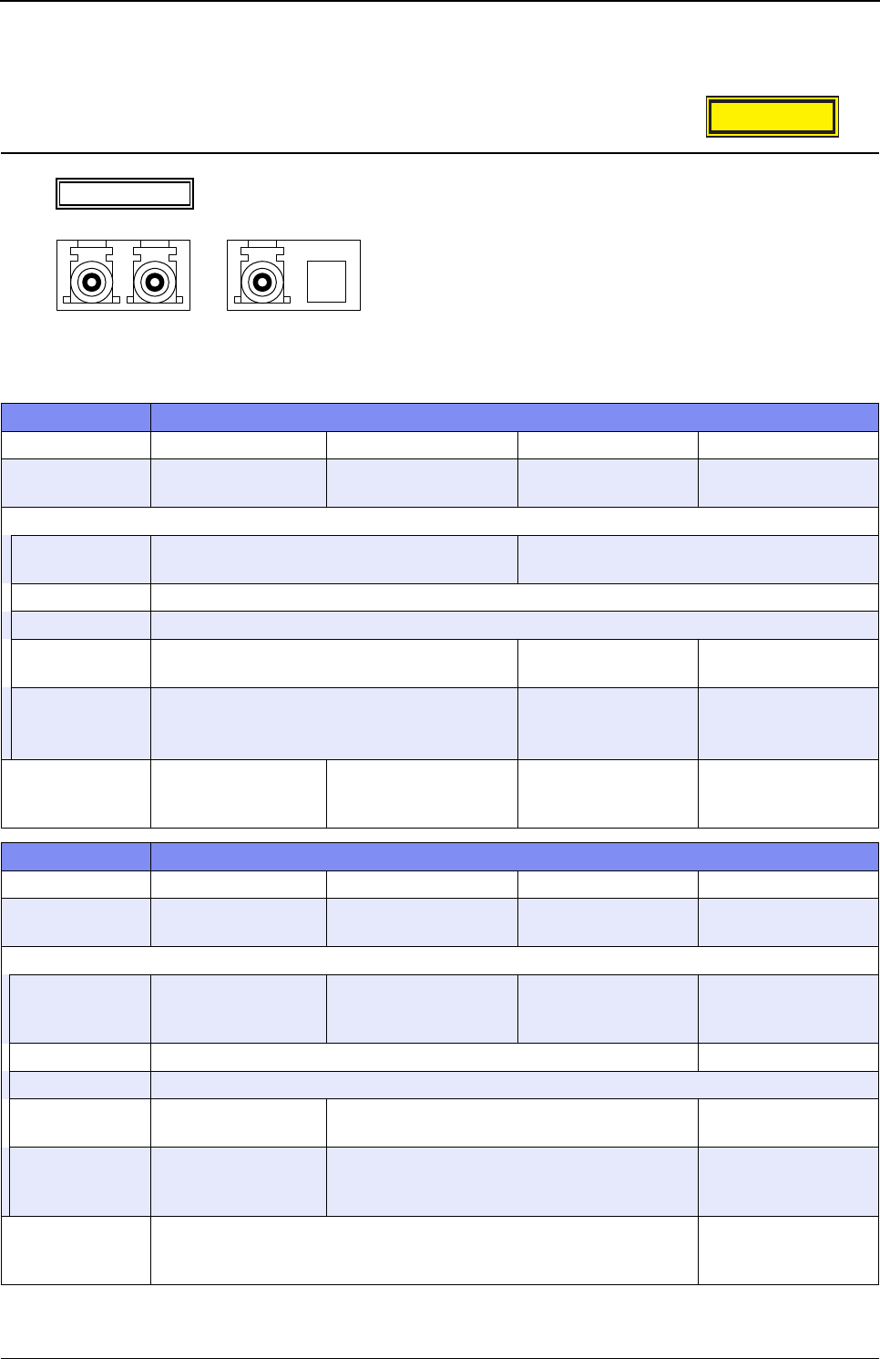
XG Series User's Guide Chapter 1 Features and Functions
Hardware Specifications
25
1.1.2 Option
SFP Module
*1) Please make sure to use 1000BASE-BX-D SFP module and 1000BASE-BX-U SFP module in pairs.
AvailableModel
XG0224 / XG0448
item specification
Vendor PN HFBR-5710L FTLF8519P2BNL HFCT-5710L SCP6P44-F7-BMH
Vendor Name AGILENT
TECHNOLOGIES FINISAR AGILENT
TECHNOLOGIES SUMITOMO ELECTRIC
Interface
specifications IEEE802.3z
(1000BASE-SX Interface)
IEEE802.3z
(1000BASE-LX Interface)
Baud rate (bps) 1000M
connector LC connector
stressed receiver
sensitivity
-17dBm or more -20dBm or more -19.5dBm or more
cable length
(maximum)
(*3)
500m (MMF:50µm),
300m (MMF:62.5µm)
550m (MMF:50µm,
62.5µm),
5km (SMF:10µm)
550m (MMF:50µm,
62.5µm),
10km (SMF:10µm)
CLASS 1 LASER
PRODUCT
specifications
EN60825-1:1994+A11,
EN60825-2:1994+A1
EN60825-
1:1994+A11+A2,
EN60825-2:2004
EN60825-
1:1994+A1+A2
IEC60825-1:2001
item specification
Vendor PN SCP6P94-F7-BMH SBP6F54-F1-BN-49 SBP6F54-F1-BT-31 HFBR-57E0P
Vendor Name SUMITOMO ELECTRIC SUMITOMO ELECTRIC SUMITOMO ELECTRI ABAGO
TECHNOLOGIES
Interface
specifications –
(1000BASE-ZX
Interface)
IEEE802.3ah
(1000BASE-BX-D
Interface)
IEEE802.3ah
(1000BASE-BX-U
Interface)
IEEE802.3u
(100BASE-FX
Interface)
Baud rate (bps) 1000M 100M
connector LC connector
stressed receiver
sensitivity
-24dBm or more -21dBm or more -31dBm or more
cable length
(maximum)
(*3)
70km (SMF:10µm) 20km (SMF:10µm) 2km (MMF:50µm)
CLASS 1 LASER
PRODUCT
specifications
IEC60825-1:2001 EN60825-
1:1994+A1+A2
CLASS1LASERPRODUCT
100BASE-FX
1000BASE-SX
1000BASE-LX
1000BASE-ZX
1000BASE-BX-D
1000BASE-BX-U
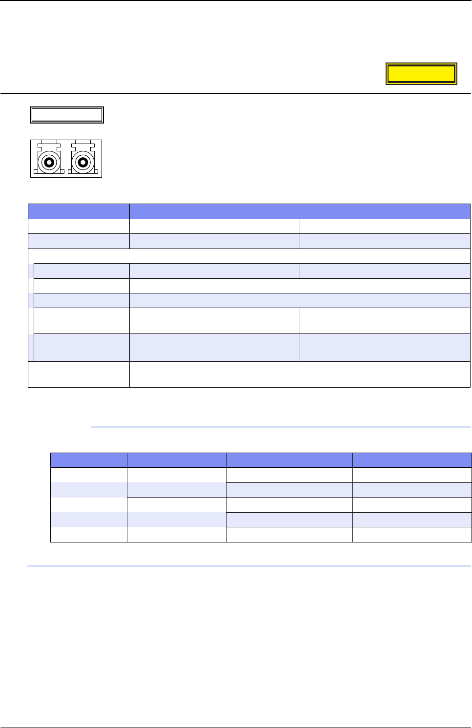
XG Series User's Guide Chapter 1 Features and Functions
Hardware Specifications
26
*2) Applicable to XG0224 only.
*3) Cable length (maximum) is under the condition that the stressed receiver sensitivity satisfy the permissible level.
SFP+ Module
*) Cable length (maximum) is under the condition that the stressed receiver sensitivity satisfy the permissible level.
Precautions
Cable length is as follows depending on the specifications of optical fiber cables.
Please use the most appropriate cable according to the environment of the installed place.
AvailableModel
XG0448 / XG2600
item specification
Vendor PN FTLX8571D3BCL FTLX1471D3BCL
Vendor Name FINISAR FINISAR
Interface
specifications IEEE802.3ae (10GBASE-SR) IEEE802.3ae (10GBASE-LR)
Baud rate (bps) 10G
connector LC connector
stressed receiver
sensitivity
-7.5dBm or more -10.3dBm or more
cable length (maximum)
(*)
300m (MMF:50µm) 10km (SMF:10µm)
CLASS 1 LASER
PRODUCT specifications
EN60825-1:1994+A1+A2, EN60825-2:2004
Type Core / Clad diameter Minimum transmission band cable length (maximum) (m)
MMF 62.5/125µm 160MHz/km 26
200MHz/km 33
50/125µm 400MHz/km 66
500MHz/km 82
2000MHz/km 300
CLASS1LASERPRODUCT
10GBASE-SR/LR
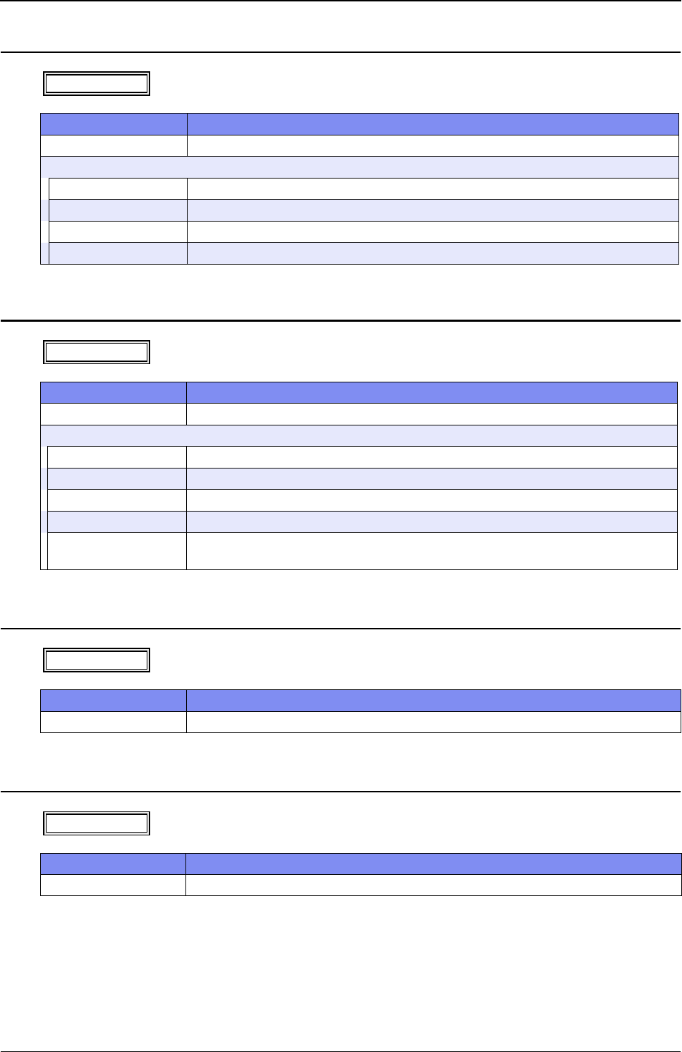
XG Series User's Guide Chapter 1 Features and Functions
Hardware Specifications
27
SFP+ Expansion Card
CX4 Expansion Card
Compact Flash Card
Power Cable (100V)
AvailableModel
XG0224 / XG0448
item specification
Type name SJ10GSFPZ
Interface (ETHER)
specifications IEEE802.3ae (10GBASE-R Interface)
number of ports 2
Baud rate (bps) 10G
connector SFP connector
AvailableModel
XG0224 / XG0448
item specification
Type name SJ10GCX4Z
Interface (ETHER)
specifications IEEE802.3ak (10GBASE-CX4 Interface)
number of ports 2
Baud rate (bps) 10G
connector 16pin, CX4connector
cable length (maximum)
(m)
15
AvailableModel
XG0224
item specification
Capacity (MBytes) 256
AvailableModel
All models
item specification
cable length (m) 3
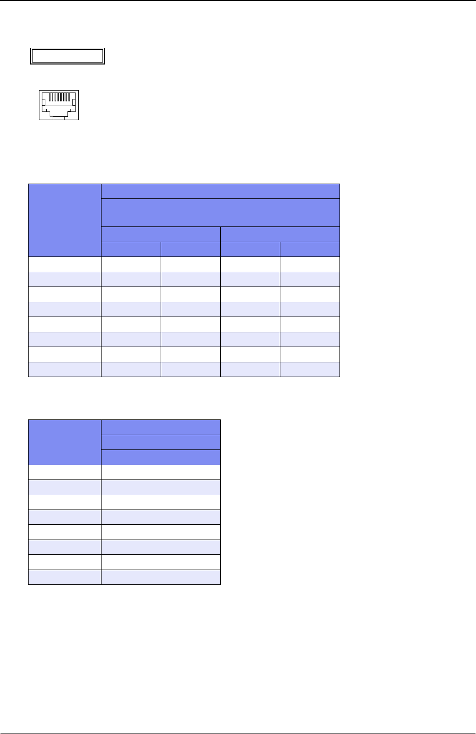
XG Series User's Guide Chapter 1 Features and Functions
Hardware Specifications
28
1.1.3 10/100/1000BASE-T Port Specifications
• XG0224 / XG0448
–: Not supported
•XG2600
–: Not supported
AvailableModel
All models
Pin numbering
Signal name
(XG0224: 1 to 24 port)
(XG0448: 1 to 48 port)
10/100BASE-TX 1000BASE-T
MDI MDI-X MDI MDI-X
1 TD+ RD+ TP0+ TP1+
2TD- RD- TP0- TP1-
3 RD+ TD+ TP1+ TP0+
4 – – TP2+ TP3+
5––TP2-TP3-
6RD- TD- TP1- TP0-
7 – – TP3+ TP2+
8 – – TP3- TP2-
Pin numbering
Signal name
10/100BASE-TX
MDI
1TD+
2TD-
3RD+
4 –
5–
6RD-
7–
8 –
connectorisRJ458pin
8
1
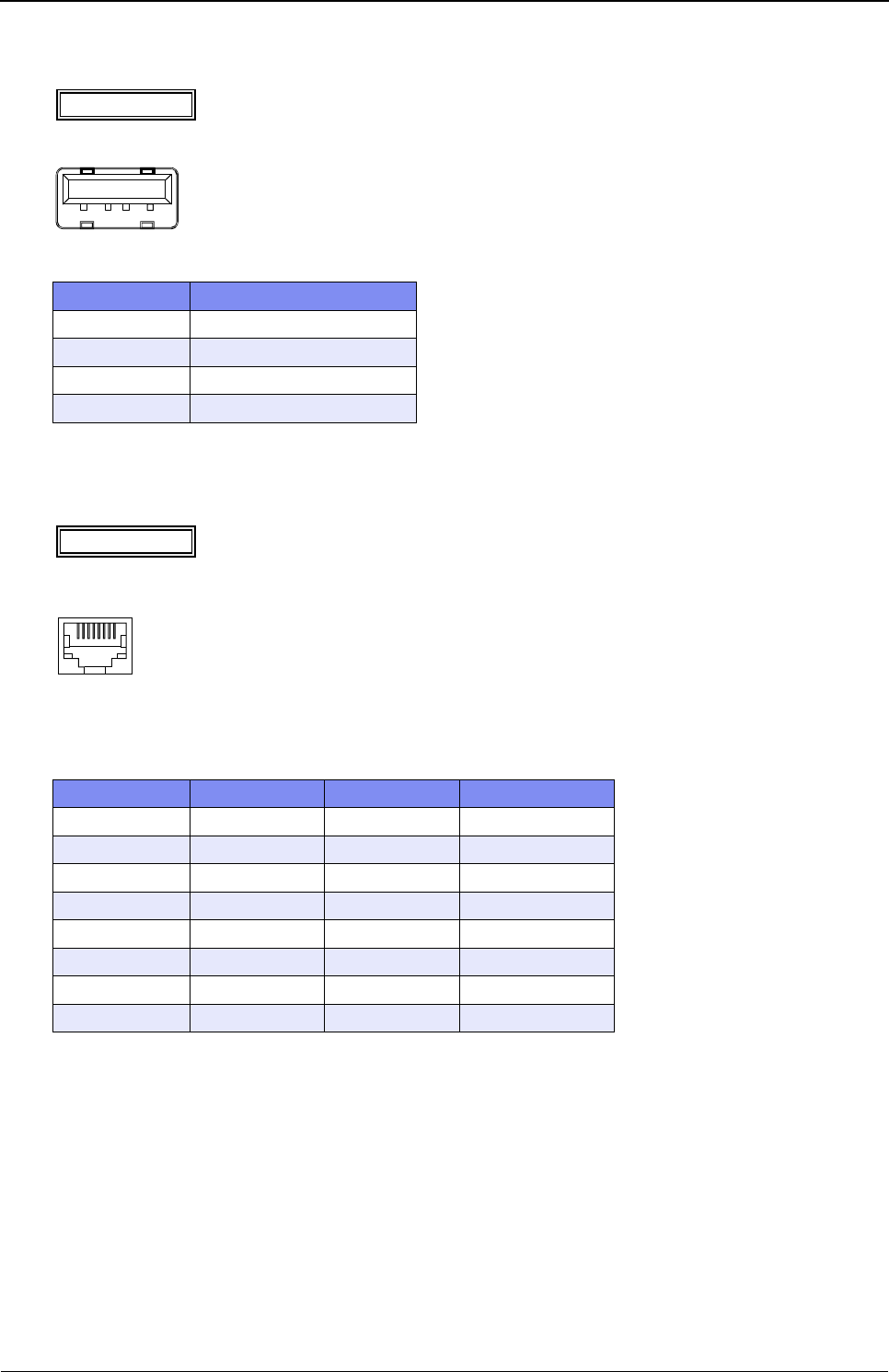
XG Series User's Guide Chapter 1 Features and Functions
Hardware Specifications
29
1.1.4 USB Port Specifications
1.1.5 Console Port Specifications
–: Not supported
AvailableModel
XG0448 / XG2600
Pin numbering Signal name
1VBUS
2D-
3D+
4GND
AvailableModel
All models
Pin numbering Signal name in / out Content
1–– –
2ER out data terminal ready
3 TD out send data
4GND –ground
5 GND – ground
6RD in receive data
7–– –
8 – – –
1234
connectorisRJ458pin
Astraightcableisused.
8
1
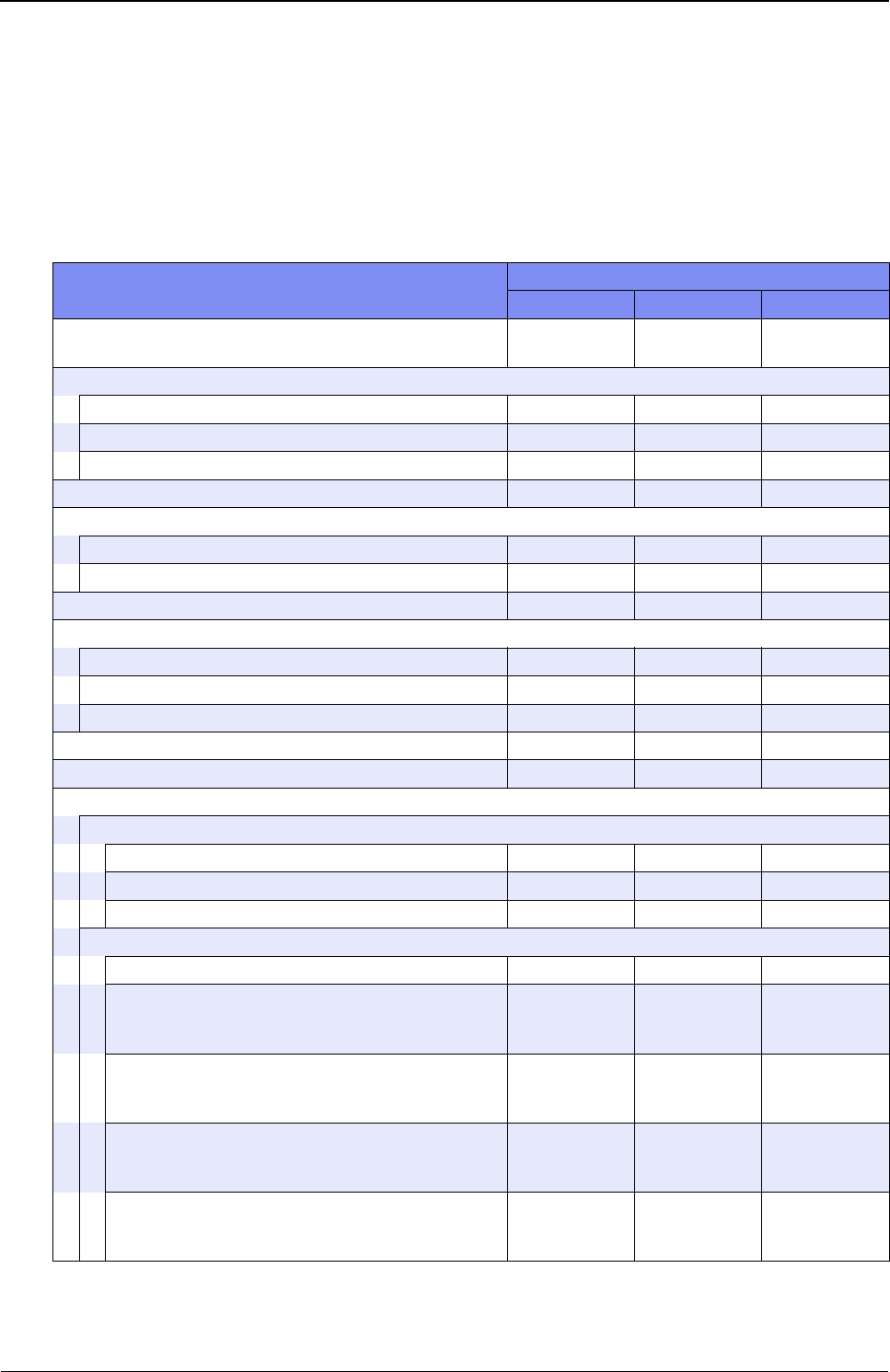
XG Series User's Guide Chapter 1 Features and Functions
Software Specifications
30
1.2 Software Specifications
This section explains the software specifications for the device.
1.2.1 Software Specifications
❍: Supported, –: Not supported
Item Features
XG0224 XG0448 XG2600
Forwarding Mode Store and
Forward
Store and
Forward Selectable
VLAN
Port VLAN ❍❍❍
Tag VLAN ❍ ❍ ❍
Protocol VLAN ❍❍❍
Link Down Relay ❍ ❍ ❍
Link aggregation
Static ❍ ❍ ❍
LACP ❍❍❍
Back up port ❍ ❍ ❍
STP
STP ❍ ❍ ❍
MSTP ❍❍❍
RSTP ❍ ❍ ❍
LLDP ❍❍❍
LLMNR ❍ ❍ ❍
QoS
QoS sending algorithm
strict ❍❍❍
DRR – – ❍
WRR ❍❍ –
Assign the priority to the queue
CoS ❍❍❍
IPv4 TOS (ip precedence)
❍
(with the use of
ACL)
❍
(with the use of
ACL)
❍
(with the use of
ACL (*1))
IPv6 TC
❍
(with the use of
ACL)
❍
(with the use of
ACL)
–
IPv4 DSCP
❍
(with the use of
ACL)
❍
(with the use of
ACL)
❍
(with the use of
ACL (*1))
IPv6 DSCP
❍
(with the use of
ACL)
❍
(with the use of
ACL)
–
XG Series User's Guide Chapter 1 Features and Functions
Software Specifications
31
Rewrite the priority
COS (user priority)
❍
(with the use of
ACL)
❍
(with the use of
ACL)
–
IPv4 TOS (ip precedence)
❍
(with the use of
ACL)
❍
(with the use of
ACL)
❍
(with the use of
ACL (*1))
IPv4 DSCP
❍
(with the use of
ACL)
❍
(with the use of
ACL)
❍
(with the use of
ACL (*1))
IPv6 DSCP
❍
(with the use of
ACL)
❍
(with the use of
ACL)
–
Security
IP/MAC filtering ❍ ❍ ❍ (*1)
Log in password ❍❍❍
Application filtering (per application server) ❍ ❍ ❍
IPv4 filter
❍
(with the use of
ACL)
❍
(with the use of
ACL)
❍
(with the use of
ACL)
IPv6 filter
❍
(with the use of
ACL)
❍
(with the use of
ACL)
–
RADIUS client ❍❍❍
Loop detection ❍ ❍ ❍
Broadcast/multicast storm control ❍❍❍
MAC table flash ❍ ❍ –
Port mirroring ❍❍❍
ether L3 watch ❍ ❍ ❍
Output rate control – – ❍
Routing
IPv4
Static ❍ ❍ ❍
Multicast
IGMP snoop (v1, v2) ❍ ❍ ❍
ProxyDNS
DNS server ❍ ❍ ❍
DNS relaying ❍❍❍
URL filtering ❍ ❍ ❍
SNMP Agent (v1, v2c, v3) ❍❍❍
Means of configuration
telnet ❍❍❍
ssh ❍ ❍ ❍
Serial (CLI) ❍❍❍
WWW browser (Web UI) ❍ ❍ ❍
Item Features
XG0224 XG0448 XG2600
XG Series User's Guide Chapter 1 Features and Functions
Software Specifications
32
*1) For the packets which applied MAC/IP filter, QoS function with the use of ACL become void.
1.2.2 Initial Values
–: Not supported
Logging
System logging ❍ ❍ ❍
Error logging ❍❍❍
Automated time adjustment ❍ ❍ ❍
Scheduling ❍❍❍
Compact flash ❍– –
USB memory – ❍❍
Item Features
XG0224 XG0448 XG2600
Port information
ETHER port 1-20 21-24 25-26 1-44 45-48 49-52 1-26 Manage
ment port
Copper/Fiber
–Auto-
detect ––
Auto-
detect –10Gbps
(Fixed)
10/
100Mbps
(Auto-
detect)
Full/half duplex
Auto-detect –Auto-detect –
Full-
duplex
(Fixed)
Auto-
detect
MDI/MDI-X Auto-detect – Auto-detect – – MDI
(Fixed)
Flow control
tx: OFF, rx: ON
tx: OFF
(Fixed)
rx: ON
(Fixed)
VLAN VID 1 (no tag) –
Protocol VLAN
Predefined protocol IPv4, IPv6, FNA
Link aggregation
Load balancing algorithm tx MAC address XOR rx MAC address
Back up port
Port selection scheme Master ports preferred
STP information
STP operating mode STP used Disabled
LLDP Disabled Used
LLMNR Enabled (lan 0,vlan1) Disabled Enabled
Loop detection Disabled
Broadcast/Multicast storm control Disabled
Egress Rate Control –Disabled
IGMP snoop Disabled
Item Features
XG0224 XG0448 XG2600
XG Series User's Guide Chapter 1 Features and Functions
Software Specifications
33
IP interface
lan0 Interface:enable IPv6, enable LLMNR
oob Interface
(Management
port):enable IPv6,
enable LLMNR
RADIUS client Disabled
Password information
User name admin
Password None
ACL information None
ProxyDNS information None
SNMP Disabled
telnet/SSH auto logoff 5 min.
Console auto logoff 8 hour
Web browser auto logoff 10min (Fixed)
System log information
Sending to the Server Disabled
Facility 23 (local7)
Priority error, warn, info
Security proxydns
Automatically current time Set Disabled
Schedule information None
Host database information None
Compact flash dump Disabled –
USB memory dump –Disabled –
Item Features
XG0224 XG0448 XG2600
XG Series User's Guide Chapter 1 Features and Functions
Software Specifications
34
1.2.3 System Maximum Values
–: Not supported
Item Features
XG0224 XG0448 XG2600
Bridge information
# of blocks registered (*1) 16000 32000 16000
# of static blocks registered 400
VLAN definition
# of VLANs (*2) 4094
# of Protocol VLAN unlimited 16 VLAN
User defined Protocol VLAN 8
Link aggregation
# of member ports 8 10
# of groups 13 26 10
Back up ports
# of groups 13 26 13
STP information
# of MSTP instances 16
# of neighbor LLDP device information (*3) 26+364 52+728 26+364
MAC filters
IPv4 128 (per device)
(*4)
64 (per device)
(*8)
IPv6 128 (per device)
(*5) –
Rewrite the priority
IPv4
COS (user priority) 128 (per device)
(*6) –
IPv4 TOS (ip precedence) 128 (per device)
(*6)
64 (per device)
(*8)
IPv4 DSCP 128 (per device)
(*6)
64 (per device)
(*8)
Assign the priority to the queue 128 (per device)
(*6)
64 (per device)
(*8)
IPv6
IPv6 DSCP 128 (per device)
(*7) –
Assign the priority to the queue 128 (per device)
(*7) –
MAC table Flushing
# of address group 4 –
# of VLAN for every address group 50 –
IGMP snoop
# of multicast group addresses registered 200 2000
Port mirroring
Tar get port 1tx: 1, rx: 1 (*9)
XG Series User's Guide Chapter 1 Features and Functions
Software Specifications
35
*1) Includes own entries of the device and static entries.
*2) Includes system use of VLANs (number of ether ports + 1).
# of ARPs registered 8000
static 200 –
# of IPv4 interfaces 100 100 (*10)
# of IPv6 interfaces 100 100 (*10)
RA information (IPv6)
# of interface receiving RA 2
# of Default Router for every interface 4
# of IPv6 prefix for every interface 4
# of Neighbor Cache entry 8000
Routing table (IPv4)
# of routes registered 200
# of static routes registered 200
Routing table (IPv6)
# of routes registered 200
# of RA routes registered 1
# of static routes registered 200
IP filtering information
IPv4 128 (per device)
(*4)
64 (per device)
(*8)
IPv6 128 (per device)
(*5) –
DSCP rewrite information
IPv4 128 (per device)
(*6)
64 (per device)
(*8)
IPv6 128 (per device)
(*7) –
# of ACL definitions 800 300
# of host database definitions 100
AAA information
# of groups 10
# of defined authenticated users 1000
# of defined RADIUS servers 4
ProxyDNS 50
SNMP information
# of max. SNMP managers registered 8
# of simultaneously connected telnet/ssh/WWW browser clients (*11) 8
System logging
# of displayed system log records 1024 or more
Max. # of system log servers registered 3
Automated time adjustment
Max. # of SNTP servers registered 4
# of schedules defined 20
Application filtering information (per application server) 30
Item Features
XG0224 XG0448 XG2600

XG Series User's Guide Chapter 1 Features and Functions
Software Specifications
36
*3) First, the maximum number of neighbor LLDP device information is 15 times of the number of total ports including
1G and 10G. (XG0224: 390, XG0448: 780, XG2600: 390)
Second, each port including 1G and 10G must have at least one LLDP information. (XG0224: 26, XG0448: 52,
XG2600: 26)
The remaining number of neighbor LLDP device information can be distributed to any ports. (XG0224: 364,
XG0448: 728, XG2600: 364)
*4) Total number of MAC filter (IPv4) and IPv4 filter definitions.
*5) Total number of MAC filter (IPv6) and IPv6 filter definitions.
*6) Total number of Rewrite the priority (IPv4) and IPv4 DSCP rewrite definitions.
*7) Total number of Rewrite the priority (IPv6) and IPv6 DSCP rewrite definitions.
*8) The total number of MAC filter, IPv4 filter, MAC QoS and IPv4 DSCP rewrite definitions may be reduced as the
number of ACL rules increase.
*9) Same port can't be used as a target port for tx and for rx.
*10) Includes Management Port Interface (oob).
*11) 4 sessions for Telnet, 1session fot WWW (http), 1session for console, 1session for ftp, 1session for ssh (sftp).

Chapter 2
Using the CLI
This chapter describes how to use the command line interface (CLI) to operate the device.
2.1 Overview of the CLI. . . . . . . . . . . . . . . . . . . . . . . . . . . . . . . . . . . . . . . . . . . . . . . . . . . . . . . . . . . . . . . . . 38
2.1.1 Operating Environment for the CLI . . . . . . . . . . . . . . . . . . . . . . . . . . . . . . . . . . . . . . . . . . . . .38
2.1.2 Command Modes and Mode Switching . . . . . . . . . . . . . . . . . . . . . . . . . . . . . . . . . . . . . . . . . . 39
2.2 Using the CLI . . . . . . . . . . . . . . . . . . . . . . . . . . . . . . . . . . . . . . . . . . . . . . . . . . . . . . . . . . . . . . . . . . . . . . 43
2.2.1 Using the Shell Function. . . . . . . . . . . . . . . . . . . . . . . . . . . . . . . . . . . . . . . . . . . . . . . . . . . . . . 43
2.2.2 Error Messages Common to All Commands. . . . . . . . . . . . . . . . . . . . . . . . . . . . . . . . . . . . . . 53
2.2.3 Characters that can be entered . . . . . . . . . . . . . . . . . . . . . . . . . . . . . . . . . . . . . . . . . . . . . . . . 54
XG Series User's Guide Chapter 2 Using the CLI
Overview of the CLI
38
2.1 Overview of the CLI
This section describes how to use the command line interface (CLI) for the XG Series.
2.1.1 Operating Environment for the CLI
There are two ways to access the device to run commands.
• Serial connection
Connect to the serial port of the device using RS232C cable via RJ45conversion cable.
The available terminal emulation type is VT100.
When initially connecting a terminal to the device, configure the serial port on the client side as shown below.
• Remote connection via LAN port
Connect a terminal or host computer using a telnet client to the management LAN port of the device TCP port of 23
Is used for the default telnet connection
The following tables list the factory defaults.
Management-LAN [XG2600] and LAN Interface initial settings
Telnet server initial settings
To use the remote connection via the management-LAN port, use the "oob ip" command to configure the management-
LAN port for the device as below. [XG2600]
To use the remote connection via the LAN port 1, use the "lan ip" command to configure the management-LAN port
Item Setting value
Baud rate 9600 bps
Character size 8 bit
Parity None
Stop bits 1 bit
Flow control None
Emulation VT100
Character set ASCII
Line feed code Transmission: CR (carriage return) only
Reception: LF is added
Item Setting value
IP address None (must be set before using the LAN interface)
Subnet address None (must be set before using the LAN interface)
Item Setting value
Use telnet Enable
Port number 23 (TCP)
Emulation VT100/VT200/xterm
BackSpace key Delete
Character set ASCII
XG2600(config)# oob ip 192.168.1.1/24 3
XG2600(config)# commit
XG2600(config)# save
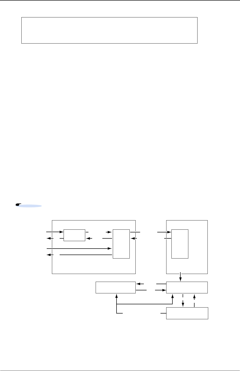
XG Series User's Guide Chapter 2 Using the CLI
Overview of the CLI
39
for the device as below.
A VT100, VT200, or xterm can be used as a terminal.
2.1.2 Command Modes and Mode Switching
The following table shows a hierarchy of command modes and mode switching.
2.1.2.1 Command Operation Procedure
The flow of system operation via command execution is as follows:
1) Login to the device.
2) Run an operation command to manage system operations.
3) Run a configure command to move to configuration mode.
4) Run a configuration command to set candidate configuration (candidate-config).
5) Run a commit command to apply the candidate configuration as a running configuration (running-config).
6) Run a save command to save the candidate configuration as a startup configuration (startup-config).
7) Run an exit or similar command to return to operation mode.
8) Repeat steps 2) through 7)
9) Run an exit command to log out.
XG2600(config)# ether 1 vlan untag 1
XG2600(config)# lan 0 vlan 1
XG2600(config)# lan 0 ip 192.168.1.1/24 3
XG2600(config)# commit
XG2600(config)# save
Reference " Login to the device" (pg.40), "2.1.2.2 Executable commands" (pg.42)
Login
username Operationmode
Operationcommand
Configurationmode
Candidateconfiguration
(candidate-config)
Runningconfiguration
(running-config)
Startupconfiguration
(startup-config)
Operationcommand
Configurationcommand
User
class
Admin
class
exit/!
exit
user
admin
admin/su Admin
class
exit/!/end/quit
load
reset/Reconnectpower
commit
exit
save load
configure

XG Series User's Guide Chapter 2 Using the CLI
Overview of the CLI
40
Login to the device
When you connect to the device via a console port, telnet, or ssh connection (*1), a login prompt like the following one
appears:
By entering the user name and password, you can run commands.
Only the administrator can log into the system for the first time. For the first time, enter "admin" for the user name, and
press ENTER for the password.
*1) For ssh connections, "Login:" does not appear. Specify the user name at the ssh client.
*2) This message warns you that system security is weak because the password is not set. This message will not appear
after you set a password with 8 or more alphanumeric characters and symbols.
*3) The model name is also shown in the prompt by default. When a prompt character string is configured, the configured
prompt is displayed.
User name and password
The user name and password are different for the administrator and general users.
•User name
The username for the administrator is "admin" and the user name for the general user is "user" (fixed user names).
By using a password aaa command and specifying use of AAA user information (aaa user id command) or RADIUS
server user information as the login user information, you can add user names as an administrator or general user.
• Password
No password is configured by default. Be sure to configure the password when you log into the system for the first
time. Use the password admin set command to configure the administrator password and the password user set
command to configure the general user password. When configuring password aaa command settings, set the
administrator and user passwords in the AAA user information stored in the system (aaa user password command) or in
the user information for the RADIUS server.
Login: Enter user name (*1)
Password: Enter password.
<WARNING> weak admin’s password:set the password (*2)
# Commands can be run. (*3)
Reference "5.14 Password Information" (pg.257)

XG Series User's Guide Chapter 2 Using the CLI
Overview of the CLI
41
Privilege classes (admin class and user class)
Two privilege classes are available; admin class (login as admin) and user class (login as user).
• admin class
All commands can be run.
However, admin commands and su commands cannot be run because it is not necessary to run them in admin class.
•user class
Only a portion of operation commands can be run. Configuration commands cannot be run. You can run an admin
command to transfer to admin class.
If a password aaa command has been used to specify use of the AAA user information (aaa user id command) or RADIUS
server user information as the login user information, the user name privilege class is determined as follows:
• When using RADIUS server
Determined according to the Filter-ID attribute information configured in the RADIUS server.
• When using user information on the device
Determined according to aaa user user-role command settings.
Use modes (operation mode and configuration mode)
Two use modes are available; operation mode and configuration mode.
• Operation mode
Only operation commands can be run.
• Configuration mode
Both configuration commands and operation commands can be run.
The use mode immediately after logging into the system is operation mode.
The table below displays user names and corresponding passwords, as well as privilege class and use mode after login.
*) To log into the system as user, configure password information for the user.
RADIUS attribute (number) Setting
Filter-ID (11) For admin class : ”administrator”
For user class : ”user”
Login user
name
Default password
information
Password configuration
command
Login privilege
class Login use mode
admin None
(blank) (Hit ENTER)
password admin set admin class Operation mode
user Not set
(login not possible [*])
password user set user class Operation mode

XG Series User's Guide Chapter 2 Using the CLI
Overview of the CLI
42
2.1.2.2 Executable commands
Command execution is restricted according to the following conditions:
• Command type
• Privilege class
• Use mode
Command type (operation commands and configuration commands)
Two command types are available; operation commands and configuration commands.
Since the use mode after logging into the system is operation mode, you can only run operation commands.
By running a configure command, the use mode changes to configuration mode and you will be able to run configuration
commands as well as operation commands.
However, since you cannot run a configure command in user class, run an admin command to change to admin class before
running the configure command.
The following table lists command types and functions.
The following table lists commands and operations.
Precautions
If you run a reset command or reconnect power without first running a save command, the running configuration and
candidate configuration will return to the state they were in before running a configuration command.
Reference " Privilege classes (admin class and user class)" (pg.41),
" Use modes (operation mode and configuration mode)" (pg.41)
Command type Command function
Operation command Display and manipulate device status, operation status, and
network status, display or delete stored information, etc.
Configuration command Operating information settings and network configuration,
etc.
Command Operation
Configuration command Sets to candidate configuration (candidate-config).
These are basically not reflected in running operations; however, as in password
information configuration, there are commands to reflect settings immediately.
commit command The candidate configuration is reflected in the running configuration (running-
config) and active operations change.
save command Saves candidate configuration to startup configuration (startup-config).
Run reset command or reconnect
power
Applies candidate configuration to the running configuration.
show candidate-config command Displays candidate configuration settings.
show running-config command Displays active configuration settings.
show startup-config command Displays startup configuration settings.
delete command Deletes configuration settings.
"5.48 Effect by "commit" Command Execution" (pg.543)
Reference
Reference

XG Series User's Guide Chapter 2 Using the CLI
Using the CLI
43
2.2 Using the CLI
2.2.1 Using the Shell Function
The shell function supports the following features in order to assist command entry:
• Command execution function
• Entry editing function
• Command name autocomplete function
• Command argument autocomplete function
• Abbreviated command entry function
• Command alias function
• Configuration hierarchy function
• Time of command execution display function
• Command history function
The following describes each function.
2.2.1.1 Command execution function
The command execution function allows you to enter a command string and hit ENTER or RETURN to run the command.
You can enter ASCII characters, EUC kanji, or Shift JIS kanji characters for the command string.
To enter a kanji character, specify its code using a terminal charset command.
The maximum length of a command string is 1,022 characters (including the prompt string) for ASCII characters. A single
kanji character is equivalent to two ASCII characters.
2.2.1.2 Entry editing function
The entry editing function allows you to move the cursor, insert or delete characters, and delete, cut, and paste words
within an entered command string.
Refer to "2.2.1.10 List of shell key bindings" (pg.52) for keys used with the entry editing function.
The entry editing function uses the VT100 terminal escape sequence to move the cursor and perform other functions.
When cursor movement or other functions do not work correctly, check that the terminal software being used supports
VT100 terminal emulation. In addition, if the screen display is not set to 24 lines and 80 columns, use the terminal window
command to configure the screen correctly.
Reference "2.2.1.10 List of shell key bindings" (pg.52)

XG Series User's Guide Chapter 2 Using the CLI
Using the CLI
44
2.2.1.3 Command name autocomplete function
The command name autocomplete function allows you to display a list of command names without entering anything by
pressing the TAB key or CTRL + I. In addition, if you press the TAB key or CTRL + I after entering part of a command,
the command string will be automatically completed. Automatically completed character strings differ depending on
conditions.
The following table details autocomplete operations for entered characters.
When you use autocomplete without entering anything, a list of commands with the command-type lines shown below is
displayed.
• --Exec commands-
Operation commands and alias commands
• -- Exec commands (config mode)--
Operation commands and aliases for configuration mode
• --Config commands--
Configuration commands
• --Config commands (current directory)--
Configuration command arguments (when the configuration hierarchy function is enabled and you are not in the top
hierarchy)
The command name autocomplete function works differently according to the number of times you hit the TAB key or
CTRL + I.
The table below lists the autocomplete operation for each number of times the TAB key or CTRL + I are hit.
Note that descriptions are displayed in Japanese (kanji characters). If they are not displayed correctly, use a terminal
charset command to specify a kanji character code which is displayed correctly.
Command name beginning with entered characters Operation
When nothing is entered A list of all command names is displayed.
When a single command applies The applicable command name is automatically completed
along with a single blank character.
When multiple commands apply, with the same string
following the entered characters
The identical character string portion is completed.
When multiple commands apply, with different strings
following the entered characters
A list of possible commands is displayed.
When no command applies Nothing is displayed.
Number of times the TAB
key or CTRL + I are hit Operation
One time A list of command names is displayed or the entered command string is automatically
completed.
Two times Command and argument names corresponding to the use mode and their descriptions are
displayed.
In operation mode, the operation command names and descriptions, and the names of
commands registered using an alias command as well as their registration content are
displayed.
In configuration mode when the configuration hierarchy function is disabled, the
configuration command names and their descriptions are displayed.
In configuration mode, when the configuration hierarchy function is enabled and you are at
the top hierarchy level, the configuration command names and descriptions are displayed.
In configuration mode, when the configuration hierarchy function is enabled and you are not
at the top hierarchy level, the command argument names available for the current hierarchy
level and their descriptions are displayed.

XG Series User's Guide Chapter 2 Using the CLI
Using the CLI
45
Three times Command forms are displayed.
In operation mode, simplified command forms are displayed.
In configuration mode, when the configuration hierarchy function is disabled, simplified
command forms are displayed.
In configuration mode, when the configuration hierarchy function is enabled and you are at
the top hierarchy level, simplified command forms are displayed.
In configuration mode, when the configuration hierarchy function is enabled and you are not
at the top hierarchy, command forms for the current hierarchy level and simplified command
forms are displayed.
Four times Returns to the operation for hitting the TAB key or CTRL + I one time.
Number of times the TAB
key or CTRL + I are hit Operation

XG Series User's Guide Chapter 2 Using the CLI
Using the CLI
46
2.2.1.4 Command argument autocomplete function
While entering configuration command arguments, the command argument autocomplete function allows you to display a
list of arguments and candidate arguments without entering anything by pressing the TAB key or CTRL + I. In addition, if
you press the TAB key or CTRL + I after entering part of an argument, the remaining character string will be automatically
completed.
The argument autocomplete function works differently according to the number of times you hit the TAB key or CTRL + I.
The table below lists the autocomplete operation for each number of times the TAB key or CTRL + I are hit.
Note that descriptions are displayed in Japanese (kanji characters). If they are not displayed correctly, use a terminal
charset command to specify a kanji character code which is displayed correctly.
2.2.1.5 Abbreviated command entry function
The abbreviated command entry function allows you to run a command with its name and argument entered only partway.
For each command name and command argument entered, the command name autocomplete and command argument
autocomplete are performed and the command is executed. When there are multiple candidates, enter characters until
candidates are narrowed to one, and then execute the command. If you execute the command while there are still multiple
candidates, the command is not autocompleted and an error occurs.
2.2.1.6 Command alias function
The command alias function allows you to register a command name and its argument(s) as a single command.
Use the alias command to register, delete, and display command aliases.
Note that commands registered with a command alias cannot be autocompleted by the abbreviated command entry
function, and you must enter the complete command name and arguments when registering them.When a command alias is
registered correctly, it will be included for command name and argument autocomplete.
Number of times the TAB
key or CTRL + I are hit Operation
One time A list of arguments and argument candidates is displayed or the entered argument
string is autocompleted.
This works in the same way as command name autocomplete.
Two times Descriptions of arguments and argument candidates are displayed.
Three times The command syntax following the current argument is displayed.
Four times Returns to the operation for hitting the TAB key or CTRL + I one time.
Note
For some command arguments, you can specify multiple arguments separated by a comma (,), or specify a range of values
delimited by a hyphen (-). The argument autocomplete function assumes that all arguments allow specifying multiple arguments
and value range, and if you autocomplete an argument after entering "," or "-", all the argument candidates will be given.

XG Series User's Guide Chapter 2 Using the CLI
Using the CLI
47
2.2.1.7 Configuration hierarchy function
The configuration hierarchy function interprets common portions of executed configuration command names and
arguments as a hierarchy level, and allows you to move between hierarchy levels.
When you execute a configuration command and the command completes successfully, in general the portion from the
command name to the argument two arguments before an argument specifying a variable value becomes a hierarchy level.
This may differ depending on the command.
Ex.)
Even in cases where an error occurs because the number of arguments is less than required, the configuration hierarchy
function assumes the entered command name and arguments to be a hierarchy level. Depending on the command, even if
arguments are incorrect the configuration hierarchy function may judge that there are not enough arguments and interpret
the entry as a hierarchy level. The portion assumed to be a hierarchy level is displayed at the command prompt. However,
if you have used a terminal prompt command to change the entry prompt string to exclude the configuration hierarchy, it is
not displayed.
After moving to a hierarchy level, you can only enter command arguments following the current level to execute the
command. When the number of arguments is still not enough, a further hierarchy level is displayed. When you have
omitted an optional argument, without moving to another hierarchy level the command is executed correctly, following
which you will move to a higher hierarchy level. Be sure to enter optional arguments as a group. To execute a command
other than at the hierarchy level you have moved to, enter it beginning with the command name.
However, in a hierarchy level for an argument which allows for arbitrary character strings, any strings other than the
commands below will be entered as configuration command arguments. To enter one of the following commands as an
argument for a configuration command, move to a higher level, and then enter so that strings matching these commands
are the second argument or following.
exit, !, end, quit, up, top, delete, show, clear, commit, discard, save, load, reset,
Comment line beginning with #
Ex.)
If you run the show command with no arguments after moving hierarchy levels, a list of configuration commands for that
level and following is displayed.
You can move to a higher hierarchy level or to the top level using an up command or top command respectively.
The configuration hierarchy function is disabled by default. Even when it has been enabled, this function is disabled after
you log out of the system. In this case, no message is displayed to indicate that the function has been disabled.
The following explains how to enable and disable the configuration hierarchy function.
• To enable the configuration hierarchy function: Press CTRL + O in configuration mode.
The following message is displayed and the configuration hierarchy function is enabled. Information which has been
partially entered will not be discarded.
(argument with variable value)
(configure)# lan 0 ip address 192.168.0.1/24 3
(Move hierarchy level to the argument two before the variable value argument)
(configure-lan-0-ip)#
(configure)# acl 0 ip (Moves to another level because there are not enough arguments.)
(configure-acl-0-ip)# any (Moves to another level because there are not enough arguments.)
(configure-acl-0-ip-any)# any (Moves to higher level because command can complete successfully
without specifying an optional argument.)
(configure-acl-0)#
<NOTICE> The configuration directory mode is enabled. To disable, type Ctrl+G.

XG Series User's Guide Chapter 2 Using the CLI
Using the CLI
48
• To disable the configuration hierarchy function: Press CTRL + G.
The following message is displayed and the configuration hierarchy function is disabled. Information which has been
partially entered will be discarded.
A command execution example is shown below.
zCommand
2.2.1.8 Time of command execution display function
The time of command execution display function allows you to display the time when the execution of a command starts.
This function is useful when a command execution log is being recorded during operations.
To enable the time of command execution display function, use the terminal timestamp command.
Although you can check command execution time with the show logging command, execution time is only displayed for
commands recorded in the command execution history. You can also use the terminal prompt command to display the date
and time in the prompt string However, this is not the time when a command was executed but the time when the prompt
was displayed.
2.2.1.9 Command history function
The command history function allows you to record command execution history and re-execute commands using this
history. You can also redisplay commands and replace commands in the history.
You can set the number of lines in the command history using a terminal logging command.
The following explains how to re-execute and redisplay commands.
You can use the history specifier and display specifier together with command character string replacement.
<NOTICE> The configuration directory mode is disabled.
# configure (Change to configuration mode.)
(config)# lan 0 ip address 192.168.1.1/24 3 (Run configuration command.)
(config-lan-0-ip)# (Hierarchy level is displayed at the command prompt.)
(config-lan-0-ip)# show (Display configuration following the current level.)
address 192.168.1.1/24 3
service server
info address 192.168.1.100/24 32
(config-lan-0-ip)# save (Enter the command name and run the command.)
(config-lan-0-ip)# top (Move to the top level.)
(config)#
Note You can also press CTRL + P and CTRL + N to sequentially display the command history items, and re-execute or re-edit and
execute a displayed command.
Reference "2.2.1.10 List of shell key bindings" (pg.52)

XG Series User's Guide Chapter 2 Using the CLI
Using the CLI
49
Re-executing commands
You can enter a history specifier at the beginning of the command string to re-execute the command. The command will be
executed after the command string for re-execution is displayed. In addition, command history and history numbers can be
viewed with the history command. Note that you can enter the history specifier only once at the beginning of the command
line. Any history specifiers entered thereafter will be treated as normal characters.
When you enter a string following the history specifier, it will be added to end of the command string invoked from the
history.
The following shows an example.
zCommand
Redisplaying commands
You can redisplay a previously run command by entering a display specifier (:p) following a history specifier. Note that the
displayed command is not re-executed yet.
Since the displayed command string is recorded as a new command history item, you can re-execute it by entering !! after
checking the command string.
When you enter a string following the display specifier, it will be added to end of the command string invoked from the
history.
A command execution example is shown below.
zCommand
History specifier Operation
!! Re-execute the last command run.
! history number Re-execute the command with the specified history number.
!-number in history Re-execute the command run the specified number of commands before in the history.
Ex.) !-3 (The third command from the newest in the history is re-executed.)
! string The last run command beginning with the specified string is re-executed.
Ex.) !net (The last run command beginning with "net" is re-executed.)
# show ip route
(The execution results of show ip route are displayed.)
# !! all (Add "all" to the last command and execute it.)
show ip route all (Display the command string to re-execute.)
(The execution results of show ip route all are displayed.)
Display specifier Operation
:p Redisplays a command.
Ex.) !net:p (The last run command beginning with "net" is redisplayed.)
# show ip route
(The execution results of show ip route are displayed.)
# !!:p all (Add "all" to the last command executed and display it.)
show ip route al (Display the command string.)
# !! (Re-execute the previous command.)
show ip route all (Display the command string to re-execute.)
(The execution results of show ip route all are displayed.)

XG Series User's Guide Chapter 2 Using the CLI
Using the CLI
50
Replacing the last command string
By entering a replacement specifier (^), replacement target string, and replacement string at the beginning of a command
string, you can re-execute the last command with the specified string replaced with a new string.
If no replacement string is specified, the target string will be deleted.
The table below lists specifiers and operations. (A: replacement target string, B: replacement string, C: additional string)
A command execution example is shown below.
zCommand
Command Operation
^A^B^ Replace A with B and execute the command string.
^A^B^:p Replace A with B and display the command string.
^A^B^C Replace A with B, add C to the command string, and execute it.
^A^B^:pC Replace A with B, add C to the command string, and display it.
^A^^ Delete A and execute the command string.
^A^^:p Delete A and display the command string.
^A^^C Delete A, add C to the command string, and execute it.
^A^^:pC Delete A, add C to the command string, and display it.
# show running-config lan 0 ip address
(Display the IP address for lan 0.)
# ^addr^rout^:p (Replace addr with rout and display the command string.)
show running-config lan 0 ip routess
# ^ess^e^ (replace ess with e and execute the command string.)
show running-config lan 0 ip route (Display the command and execute it.)
(Display the static route information for lan 0.)
XG Series User's Guide Chapter 2 Using the CLI
Using the CLI
51
Replacing command strings
By entering a single-replacement specifier (:s) or all-replacement specifier (:gs) following a history specifier and
replacement specifier, you can replace the target string and re-execute the command string.
A single-replacement specifier replaces the first matching string only, while an all-replacement specifier replaces all
matching strings.
The replacement target string and replacement string are specified as with string replacement for the preceding command;
however, arbitrary characters (@, #, %, &, ~, =, _, etc.) may be used as delimiters. You can successively enter a single-
replacement specifier, all-replacement specifier, and display specifier.
The table below lists specifiers and operations. This example uses "/" as a delimiter.
(A: replacement target string, B: replacement string, C: additional string)
A command execution example is shown below.
zCommand
Command Operation
:s/A/B/ Replace only the first instance of A with B and execute the command string.
:ps/A/B/ Replace only the first instance of A with B and display the command string.
:s/A/B/C Replace only the first instance of A with B, add C to the command string, and execute it.
:ps/A/B/C Replace only the first instance of A with B, add C to the command string, and display it.
:gs/A/B/ Replace all instances of A with B and execute the command string.
:pgs/A/B/ Replace all instances of A with B and display the command string.
:gs/A/B/C Replace all instances of A with B, add C to the command string, and execute it.
:pgs/A/B/C Replace all instances of A with B, add C to the command string, and display it.
:s/A// Delete only the first instance of A and execute the command string.
:ps/A// Delete only the first instance of A and display the command string.
:s/A//C Delete only the first instance of A, add C to the command string, and execute it.
:ps/A//C Delete only the first instance of A, add C to the command string, and display it.
:gs/A// Delete all instances of A and execute the command string.
:pgs/A// Delete all instances of A and display the command string.
:gs/A//C Delete all instances of A, add C to the command string, and execute it.
:pgs/A//C Delete all instances of A, add C to the command string, and display it.
:s/A1/B1/:gs/A2/B2/:p Replace only the first instance of A1 with B1, replace all instances of A2 with B2, and display the
command string.
# lan 0 ip address 192.168.0.1/24 3
# !!:gs/0/1/:p (Replace all instances of 0 with 1 and display the command string.)
lan 1 ip address 192.168.1.1/24 3
# !! (Re-execute the last command to run.)
lan 1 ip address 192.168.1.1/24 3
Note
When entering a command with the command history function, you can omit the last delimiter (/, ^, etc.) at the end of the
command line. However, when the last delimiter is omitted, you cannot specify a display specifier (:p), additional history
specifier, or additional string.

XG Series User's Guide Chapter 2 Using the CLI
Using the CLI
52
2.2.1.10 List of shell key bindings
The following table shows the key bindings for using the shell.
Notes)
•"Ctrl+
α" indicates pressing CTRL and α at the same time.
•"ESC
α" indicates pressing ESC followed by α.
• The arrow keys (↑,↓,← ,→ ) do not work properly on the hyper terminal. Use key combinations instead.
• When using with terminal software or telnet commands, some key combinations with CTRL may not work. Refer to
the terminal software or telnet command manual to configure the device so that so that key combinations with CTRL
work properly.
Key combination
(note)
Single
key Operation
Ctrl+A Moves the cursor to the top.
Ctrl+B ← (Note) Moves the cursor to the left by one character.
Ctrl+C Interrupts input.
Ctrl+D Deletes one character if any are input.
Logs off if there are no characters entered.
Ctrl+E Moves the cursor to the end.
Ctrl+F → (Note) Moves the cursor to the right by one character.
Ctrl+G Disables the configuration hierarchy function.
Ctrl+H BS BACKSPACE
Moves the cursor one character to the left deleting one character.
Ctrl+I Tab Autocomplete/displays autocomplete candidate list/displays argument descriptions/
displays argument syntax
Ctrl+J Return Input complete
Ctrl+K Cuts from the cursor position to the end.
Ctrl+L Updates the screen.
Ctrl+M Input complete
Ctrl+N ↓ (Note) Shows the next history item.
Ctrl+O Enables the configuration hierarchy function.
Ctrl+P ↑ (Note) Shows the previous history item.
Ctrl+R Redisplays input.
Ctrl+T Converts one character.
Ctrl+U Cuts from the cursor position to the top.
Ctrl+W Cuts from the cursor position one word to the left.
Ctrl+X Cuts from the cursor position to the top.
Ctrl+Y Paste
ESC Ctrl+H ESC BS Cuts from the cursor position one word to the left.
ESC Ctrl+I ESC TAB Displays argument description.
ESC Ctrl+K Cuts from the cursor position one word to the right.
ESC b Moves the cursor to the left by one word.
ESC f Moves the cursor to the right by one word.
ESC n Shows the next history item beginning with the string prior to the cursor position.
ESC p Shows the previous history item beginning with the string prior to the cursor position.
ESC < Shows the oldest history item.
ESC > Shows the newest history item.
XG Series User's Guide Chapter 2 Using the CLI
Using the CLI
53
2.2.2 Error Messages Common to All Commands
The table below lists error messages common to all commands and displayed when autocompleting or executing
commands.
Note that the argument position shown in these error messages indicates the place of the erroneous argument, counted from
the command name as "1."
Common error message Meaning
<ERROR> Command name: Unknown command An unknown command.
Cannot be executed in the current use mode.
Cannot be executed with the current privilege class.
<ERROR> Command name: Operation not permitted Execution of this command is not permitted.
<ERROR>: 0: missing argument The argument specification is insufficient.
<ERROR>: 0: too many argument(s) The argument specification is excessive.
<ERROR>: Argument position: format error The argument syntax is not correct.
Unknown command for configuration hierarchy.
<ERROR>: Argument position: value out of range The argument value is out of the valid range (too small, too large,
too long, etc.).
<ERROR>: Argument position: lack of table The number of arguments has reached the defined upper limit.
<ERROR>: Argument position: no such table Specified definition cannot be found.
<ERROR>: Argument position: duplicate value Already defined.
<ERROR>: Argument position: fail to request Could not execute the command.
<ERROR>: Argument position: unique password Not a unique password.
Cannot be changed from the unique format.
<ERROR>: detected HARD ERROR, cannot execute Cannot execute the command due to a hardware error.

XG Series User's Guide Chapter 2 Using the CLI
Using the CLI
54
2.2.3 Characters that can be entered
• Any letter (A-Z, a-z) and digit (0-9)
• Space (ASCII code: 0x20)
• Symbols: !, #, $, %, `, ', (, ), _, -, ~, ^, \, {, }, :, +, ,, ., @, =, [, ], &, *, ;, /, ?, |, >
Command and option separators are recognized as one or more space characters (ASCII code: 0x20).
Don't enclose a parameter in quotes (") but for instructions to use quotes (") to contain a blank space.
The commands are case-sensitive.

Chapter 3
Installation
This chapter describes the installation procedures for the device.
3.1 Workflow for Initial Setup of the Device . . . . . . . . . . . . . . . . . . . . . . . . . . . . . . . . . . . . . . . . . . . . . . . . 56
3.1.1 Configure LAN Interface . . . . . . . . . . . . . . . . . . . . . . . . . . . . . . . . . . . . . . . . . . . . . . . . . . . . . . 57
3.1.2 Telnet Connection via the LAN Interface (Optional) . . . . . . . . . . . . . . . . . . . . . . . . . . . . . . . . 57
3.1.3 SNMP Configuration (Optional) . . . . . . . . . . . . . . . . . . . . . . . . . . . . . . . . . . . . . . . . . . . . . . . . 58
Reference Refer to "chapter 2 Using the CLI" (pg.37) for details on using the CLI.
Refer to "chapter 5 Command Reference" (pg.85) for details on commands.

XG Series User's Guide Chapter 3 Installation
Workflow for Initial Setup of the Device
56
3.1 Workflow for Initial Setup of the Device
This section describes the procedures to setup the device.
1) Prepare a terminal
Prepare a terminal for the initial configuration.
2) "Besic Setting Up"
Connect the device and terminal with an RS232C cable. The band rate setting is 9,600 bps.
To configure the Device basically, carry out the following procedure.
3) Turn on the device to start the system.
Turn on the terminal and the device to start the system.
4) "Configure LAN Interface"
The initial setting of the LAN interface is for only IPv6 link-local address.
To use the following functions, set up the LAN interface:
- Telnet connection
- SNMP manager connection
- System log transmission
- Time synchronization using an NTP/SNTP server
- Configuration file upload/download
- Firmware update
- Collection of maintenance information
5) "Telnet Connection via the LAN Interface (Optional)"
The initial setting of the Telnet connection via the management LAN interface is disabled.
Enable telnet connection if necessary.
6) "SNMP Configuration (Optional)"
Initially, the SNMP agent configuration is not set.
Set the SNMP configuration as needed.
7) This is the end of the preparation procedure
Proceed with configuring the switch.
Command Task
Login:admin
Password:
Login to the device from the serial terminal. The user name is
"admin". The default password is not set.
XG2600# configure Switch to Configuration mode.
XG2600(config)# sysname HOST-NAME Set the device name (HOST-NAME).
XG2600(config)# time zone -0500 Set time zone.
XG2600(config)# date YYYY/MM/DD.hh:mm:ss Set date and time.
XG2600(config)# password admin set
Password:
Retype password:
Set the password for user "admin".
Type password.
Retype password.
XG2600(config)# save Save the configuration.
XG2600(config)# reset Reset the device.
XG Series User's Guide Chapter 3 Installation
Workflow for Initial Setup of the Device
57
3.1.1 Configure LAN Interface
The initial setting of the LAN interface is for only IPv6 link-local address.
To use the following functions, configure the LAN interface.
• Telnet connection
• SNMP manager connection
• System log transmission
• Time synchronization using an NTP/SNTP server
• Configuration file upload/download
• Firmware update
• Collection of maintenance information
To configure the LAN interface, carry out the following procedure.
3.1.2 Telnet Connection via the LAN Interface (Optional)
The "Telnet server function" is initially enabled.
The telnet session timeout period is initially 5 minutes.
To change the telnet session timeout period, carry out the following procedure in "admin" Operation mode.
Command Task
Login:admin
Password:
Login to the device from the serial terminal. The user name is
"admin". Type the password for uset "admin".
XG2600# configure Switch to Configuration mode.
XG2600(config)# oob ip address A.B.C.D/M 3 Set the IP address, subnet, and default gateway of the LAN interface
for management port. (XG2600 only)
XG2600(config)# lan 0 ip address A.B.C.D/M 3
XG2600(config)# lan 0 vlan 1
Set the IP address, subnet, and default gateway of the LAN interface
for VLAN ID 1.
XG2600(config)# proxydns domain 0 any * any
static A.B.C.D
(Optional)
Set up DNS servers.
XG2600(config)# commit Apply the configuration.
XG2600(config)# save Save the configuration.
XG2600(config)# exit Switch to Operation mode.
Command Task
XG2600# configure Switch to Configuration mode.
XG2600(config)# telnetinfo autologout 30m Set the Telnet session timeout period (30 minutes).
If the Telnet session timeout period expires the telne connection is
terminated.
XG2600(config)# commit Apply the configuration.
XG2600(config)# save Save the configuration.
XG2600(config)# exit Switch to Operation mode.

XG Series User's Guide Chapter 3 Installation
Workflow for Initial Setup of the Device
58
3.1.3 SNMP Configuration (Optional)
To operate in conjunction with an SNMP manager, the SNMP agent must be configured.
To configure the SNMP agent, carry out the following procedures in "admin" Operation mode.
Command Task
XG2600# configure Switch to Configuration mode.
XG2600(config)# snmp service on Enable SNMP function.
XG2600(config)# snmp agent contact SYSTEM-
CONTAC
Set the swith's contact (SYSTEM-CONTACT).
XG2600(config)# snmp agent location SYSTEM-
LOCATION
Set the swith's location (SYSTEM-LOCATION).
XG2600(config)# snmp agent address A.B.C.D Set the SNMP agent address. This setting is also used for the local
address at trap transmission.
Make sure to set it when using the SNMP agent function
XG2600(config)# snmp manager 0 A.B.C.D
COMMUNIT-YNAME v2c disable
Set the IP address (host name) of the SNMP manager, the commu-
nity name, sending SNMPv2 traps, and disabling writing. if the SNMP
trap notification is enabled.
XG2600(config)# commit Apply the configuration.
XG2600(config)# save Save the configuration.
XG2600(config)# exit Switch to Operation mode.
XG2600# configure Switch to Configuration mode.
XG2600(config)# snmp service on Enable SNMP function.

Chapter 4
Switch
Functions and
their Configuration
This chapter describes the functions of the device and how to configure them.
4.1 Basic Switch Functions . . . . . . . . . . . . . . . . . . . . . . . . . . . . . . . . . . . . . . . . . . . . . . . . . . . . . . . . . . . . . 61
4.1.1 Switching Mode (XG2600). . . . . . . . . . . . . . . . . . . . . . . . . . . . . . . . . . . . . . . . . . . . . . . . . . . . . 61
4.1.2 MAC Address Table Management . . . . . . . . . . . . . . . . . . . . . . . . . . . . . . . . . . . . . . . . . . . . . . 62
4.1.3 Jumbo Frame Support. . . . . . . . . . . . . . . . . . . . . . . . . . . . . . . . . . . . . . . . . . . . . . . . . . . . . . . . 63
4.1.4 Flow Control. . . . . . . . . . . . . . . . . . . . . . . . . . . . . . . . . . . . . . . . . . . . . . . . . . . . . . . . . . . . . . . . 63
4.1.5 Storm Control. . . . . . . . . . . . . . . . . . . . . . . . . . . . . . . . . . . . . . . . . . . . . . . . . . . . . . . . . . . . . . . 63
4.1.6 Egress Rate Control (XG2600 Only). . . . . . . . . . . . . . . . . . . . . . . . . . . . . . . . . . . . . . . . . . . . . 64
4.2 Port Mirroring . . . . . . . . . . . . . . . . . . . . . . . . . . . . . . . . . . . . . . . . . . . . . . . . . . . . . . . . . . . . . . . . . . . . . 65
4.3 Link Down Relay . . . . . . . . . . . . . . . . . . . . . . . . . . . . . . . . . . . . . . . . . . . . . . . . . . . . . . . . . . . . . . . . . . . 66
4.4 Link Aggregation. . . . . . . . . . . . . . . . . . . . . . . . . . . . . . . . . . . . . . . . . . . . . . . . . . . . . . . . . . . . . . . . . . . 67
4.4.1 Configuring Link Aggregation . . . . . . . . . . . . . . . . . . . . . . . . . . . . . . . . . . . . . . . . . . . . . . . . . 68
4.4.2 Frame Distribution Methods in Link Aggregation . . . . . . . . . . . . . . . . . . . . . . . . . . . . . . . . . 69
4.4.3 The Number of Ports That Require Linkup . . . . . . . . . . . . . . . . . . . . . . . . . . . . . . . . . . . . . . . 70
4.4.4 Notes on Link Aggregation . . . . . . . . . . . . . . . . . . . . . . . . . . . . . . . . . . . . . . . . . . . . . . . . . . . . 70
4.5 Spanning Tree Protocol (STP) . . . . . . . . . . . . . . . . . . . . . . . . . . . . . . . . . . . . . . . . . . . . . . . . . . . . . . . . 71
4.5.1 Port Roles Based on Spanning Tree . . . . . . . . . . . . . . . . . . . . . . . . . . . . . . . . . . . . . . . . . . . . 72
4.5.2 Spanning Tree Protocol Port States . . . . . . . . . . . . . . . . . . . . . . . . . . . . . . . . . . . . . . . . . . . . .72
4.5.3 Configuring Spanning Tree . . . . . . . . . . . . . . . . . . . . . . . . . . . . . . . . . . . . . . . . . . . . . . . . . . . . 73
4.6 VLAN . . . . . . . . . . . . . . . . . . . . . . . . . . . . . . . . . . . . . . . . . . . . . . . . . . . . . . . . . . . . . . . . . . . . . . . . . . . . 74
4.6.1 Port-Based VLAN. . . . . . . . . . . . . . . . . . . . . . . . . . . . . . . . . . . . . . . . . . . . . . . . . . . . . . . . . . . . 74
4.6.2 Tag-Based (IEEE802.1Q) VLAN. . . . . . . . . . . . . . . . . . . . . . . . . . . . . . . . . . . . . . . . . . . . . . . . .75
4.7 Quality of Service (QoS) . . . . . . . . . . . . . . . . . . . . . . . . . . . . . . . . . . . . . . . . . . . . . . . . . . . . . . . . . . . . . 76
Reference Refer to "2.1.1 Operating Environment for the CLI" (pg.38) for details on using the CLI.
Refer to "chapter 5 Command Reference" (pg.85) for details on commands.
4.8 IGMP Snooping. . . . . . . . . . . . . . . . . . . . . . . . . . . . . . . . . . . . . . . . . . . . . . . . . . . . . . . . . . . . . . . . . . . . 77
4.8.1 Registering Group Members . . . . . . . . . . . . . . . . . . . . . . . . . . . . . . . . . . . . . . . . . . . . . . . . . . 78
4.8.2 Removing Group Members . . . . . . . . . . . . . . . . . . . . . . . . . . . . . . . . . . . . . . . . . . . . . . . . . . . 79
4.8.3 Managing Group Members . . . . . . . . . . . . . . . . . . . . . . . . . . . . . . . . . . . . . . . . . . . . . . . . . . . . 80
4.8.4 IGMP Querier . . . . . . . . . . . . . . . . . . . . . . . . . . . . . . . . . . . . . . . . . . . . . . . . . . . . . . . . . . . . . . . 81
4.8.5 Configuring IGMP Snooping . . . . . . . . . . . . . . . . . . . . . . . . . . . . . . . . . . . . . . . . . . . . . . . . . . 82
4.9 Network Management . . . . . . . . . . . . . . . . . . . . . . . . . . . . . . . . . . . . . . . . . . . . . . . . . . . . . . . . . . . . . . 83
4.9.1 Traffic Statistics. . . . . . . . . . . . . . . . . . . . . . . . . . . . . . . . . . . . . . . . . . . . . . . . . . . . . . . . . . . . . 83
4.9.2 SNMP Agent. . . . . . . . . . . . . . . . . . . . . . . . . . . . . . . . . . . . . . . . . . . . . . . . . . . . . . . . . . . . . . . . 83
4.9.3 RMON . . . . . . . . . . . . . . . . . . . . . . . . . . . . . . . . . . . . . . . . . . . . . . . . . . . . . . . . . . . . . . . . . . . . . 84

XG Series User's Guide Chapter 4 Switch Functions and their Configuration
Basic Switch Functions
61
4.1 Basic Switch Functions
This section describes the basic switch functions.
4.1.1 Switching Mode (XG2600)
XG2600 provides the following two switching modes.
XG0224 and XG0448 provide store-and-forward switching modes only.
• Store-and-forward switching mode
After the device finishes receiving a frame, it checks the FCS (Frame Check Sequence) and performs a validity check
(on packet size, etc.) before forwarding the frame. If the switch receives a frame with an error frame, it discards it.
• Cut-through switching mode
The device transmits the frame to the destination as soon as the first 64 bytes of the frame are received with no errors.
Since the device starts transmitting the frame before it receives the entire frame, this mode allows forwarding at low
latency.
To change the switching modes, carry out the following procedures in "admin" Operation mode.
Command Task
XG2600# configure Switch to Configuration mode.
XG2600(config)# forwardingmode cut-through Select the (cut-through) for the switching mode.
XG2600(config)# forwardingmode store-and-forward Select the (store-and-forward) for the switching mode.
XG2600(config)# commit Apply the configuration.
XG2600(config)# save Save the configuration.
XG2600(config)# exit Switch to Operation mode.

XG Series User's Guide Chapter 4 Switch Functions and their Configuration
Basic Switch Functions
62
4.1.2 MAC Address Table Management
The MAC address table is a database used for managing the association between address information and destination ports.
XG0224 and XG2600 can learn up to 16000 entries of MAC addresses.
XG0448 can learn up to 32000 entries of MAC addresses.
• Dynamic MAC address learning
The device dynamically learns MAC addresses from received frames. If MAC addresses are not refreshed before the
aging time expires, they will be removed frame MAC address table.
To disable the dynamic learning, carry out the following procedures in "admin" Operation mode.
To change aging time period of MAC address learning table, carry out the following procedures in "admin" Operation
mode..
• Static unicast address
By registering a unicast MAC address with the MAC address table, unicast frames are forwarded to a specified port.
Static unicast addresses are not subject to MAC address removal controlled by the aging function.
To register, change or delete a static unicast address, carry out the following procedures in "admin" Operation mode.
Command Task
XG2600# configure Switch to Configuration mode.
XG2600(config)# mac learning off Disable the dynamic MAC address learning.
XG2600(config)# commit Apply the configuration.
XG2600(config)# save Save the configuration.
XG2600(config)# exit Switch to Operation mode.
Command Task
XG2600# configure Switch to Configuration mode.
XG2600(config)# mac age 1000 Change aging time period of MAC address learning table.
XG2600(config)# commit Apply the configuration.
XG2600(config)# save Save the configuration.
XG2600(config)# exit Switch to Operation mode.
Command Task
XG2600# configure Switch to Configuration mode.
XG2600(config)# vlan <vid> forward <count>
<dst_addr> <port>
Register a static unicast address, destination port and vlan with
the MAC address table (or remove them from it).
XG2600(config)# delete vlan <vid> forward
XG2600(config)# commit Apply the configuration.
XG2600(config)# save Save the configuration.
XG2600(config)# exit Switch to Operation mode.

XG Series User's Guide Chapter 4 Switch Functions and their Configuration
Basic Switch Functions
63
4.1.3 Jumbo Frame Support
The device can transmit jumbo frames of up to 9KB (9216 bytes). (XG0224,XG0448)
The device can transmit jumbo frames of up to 16KB (16128 bytes). (XG2600)
4.1.4 Flow Control
Flow control is a function that prevents frame loss when the receive buffer in the switch overflows due to temporary traffic
overload by using a PAUSE frame.
When the device receives a PAUSE frame, it temporarily stops sending frames at the receive port. If the receive buffer
overflows, it is possible to restrict frame transmission from the connected device by sending a PAUSE frame.
For each port, it is possible to select whether or not to send a PAUSE frame. Select the mode depending on whether the
destination responds to a PAUSE frame or not.
To change the flow control mode, carry out the following procedures in "admin" Operation mode.
4.1.5 Storm Control
The device discards broadcast/multicast frames when the number of received broadcast frames are over a given threshold
to prevent unnecessary waste of bandwidth due to retained broadcast frames on the network. This function is called "Storm
Control".
For each port, it is possible to configure storm control.
When broadcast/multicast frames are discarded by storm control, system logs are output.
To configure storm control, carry out the following procedures in "admin" Operation mode.
•XG2600
Command Task
XG2600# configure Switch to Configuration mode.
XG2600(config)# ether 1-3 flowctl off on Set the flow control mode disable send flow control packets and
enable receive flow control packets.
XG2600(config)# commit Apply the configuration.
XG2600(config)# save Save the configuration.
XG2600(config)# exit Switch to Operation mode.
Command Task
XG2600# configure Switch to Configuration mode.
XG2600(config)# ether 1-5 mac storm 7000000k
8000000k discard
Enable storm control, set broadcast threshold 7000000k bps,
multicast threshold 8000000k bps, and set "discard" when
broadcast and multicast traffic exceeds the threshold.
XG2600(config)# commit Apply the configuration.
XG2600(config)# save Save the configuration.
XG2600(config)# exit Switch to Operation mode.

XG Series User's Guide Chapter 4 Switch Functions and their Configuration
Basic Switch Functions
64
• XG0224/XG0448
4.1.6 Egress Rate Control (XG2600 Only)
It is possible to set an egress rate-limiting value for each port in approximately 40Mbps increments.
To set an egress rate-limiting value, carry out the following procedures in "admin" Operation mode.
Command Task
XG0224# configure Switch to Configuration mode.
XG0224(config)# ether 1-5 mac storm 20000000
discard close
Enable storm control, set threshold 20000000 pps, set "discard"
when broadcast traffic exceeds the threshold, set "close" when
multicast traffic exceeds the threshold.
XG0224(config)# commit Apply the configuration.
XG0224(config)# save Save the configuration.
XG0224(config)# exit Switch to Operation mode.
Command Task
XG2600# configure Switch to Configuration mode.
XG2600(config)# ether 1-5 ratecontrol 8000m Specify an egress rate limiting value by 8000M bps for port 1-5.

XG Series User's Guide Chapter 4 Switch Functions and their Configuration
Port Mirroring
65
4.2 Port Mirroring
It is possible to monitor the traffic by mirroring the frames sent or received by a port to another port.
Multiple ports may not be mirrored to one port. However, multiple ports may be mirrored.
To configure port mirroring, carry out the following procedure in "admin" Operation mode.
•XG2600
• XG0224/XG0448
Command Task
XG2600# configure Switch to Configuration mode.
XG2600(config)# ether 10 type mirror 0 1 rx Configure the port 10 to be destination port and the receive
frames of the source port (port 1) are mirrored.
XG2600(config)# ether 11 type mirror 0 2 tx Configure the port 11 to be destination port and the send frames
of the source port (port 2) are mirrored.
XG2600(config)# commit Apply the configuration.
XG2600(config)# save Save the configuration.
XG2600(config)# exit Switch to Operation mode.
Command Task
XG0224# configure Switch to Configuration mode.
XG0224(config)# ether 10 type mirror 0 1 both Configure the port 10 to be destination port and the receive/send
frames of the source port (port 1) are mirrored.
XG0224(config)# ether 10 type mirror 10 2 tx Configure the port 10 to be destination port and the send frames
of the source port (port 2) are mirrored.
XG0224(config)# commit Apply the configuration.
XG0224(config)# save Save the configuration.
XG0224(config)# exit Switch to Operation mode.
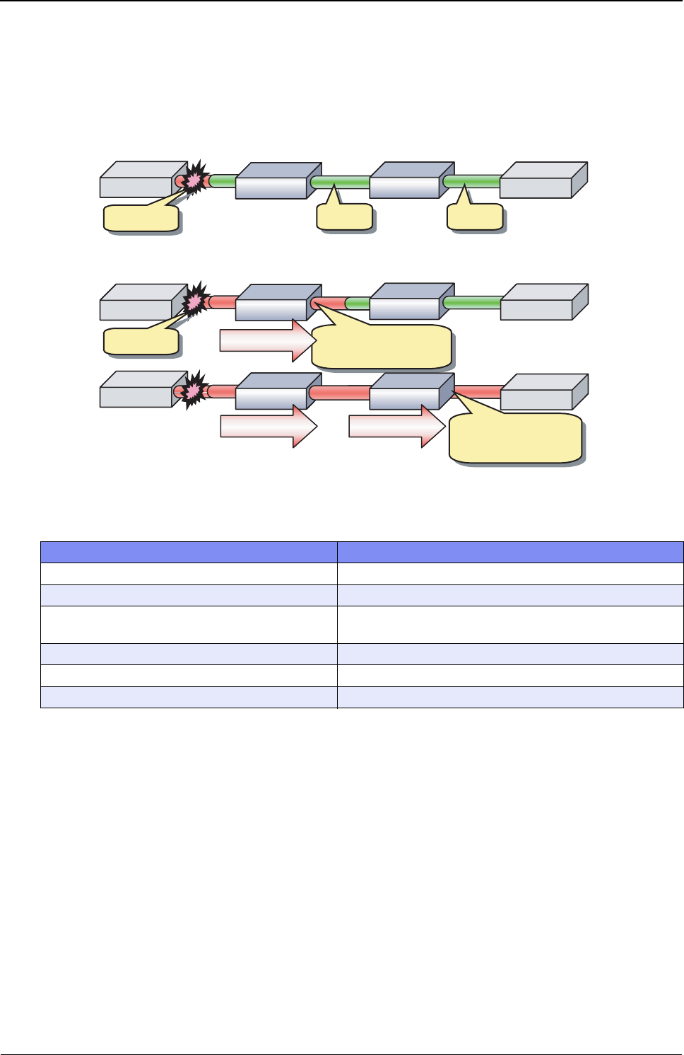
XG Series User's Guide Chapter 4 Switch Functions and their Configuration
Link Down Relay
66
4.3 Link Down Relay
Link Down Relay is a function that monitors the status of a specified port link, if a link down detected the device notifies
the device force to link down the relay port.
To configure Link Down Relay, carry out the following procedure in "admin" Operation mode.
Command Task
XG2600# configure Switch to Configuration mode.
XG2600(config)# ether 10 downrelay port 11,12 Set port 11,12 go linkdown when the port 10 linkdown.
XG2600(config)# ether 10 downrelay recovery mode
auto
Set port 11,12 go linkup when the port 10 linkup.
XG2600(config)# commit Apply the configuration.
XG2600(config)# save Save the configuration.
XG2600(config)# exit Switch to Operation mode.
(1)(1)
(2)
XG
(2)
(1)(1)
(1)When Link Down Relay is not used
(2)When Link Down Relay is used
The other end becomes
link down when a link fault
is detected.
The other end becomes
link down when a link fault
is detected.
Link Down Relay
(1)(1) (2)
XG
(2) (3)
XG
(3) (4)(4)
Link Up
Link Up
Link Down
Link Down
(3)
XG
(3)
Link Up
Link Up
Link Down
Link Down
(4)(4)
(2)
XG
(2) (4)(4)
(3)
XG
(3)
Link Down Relay Link Down Relay The other end becomes
link down when a link
fault is detected.
The other end becomes
link down when a link
fault is detected.
Link Down Relay
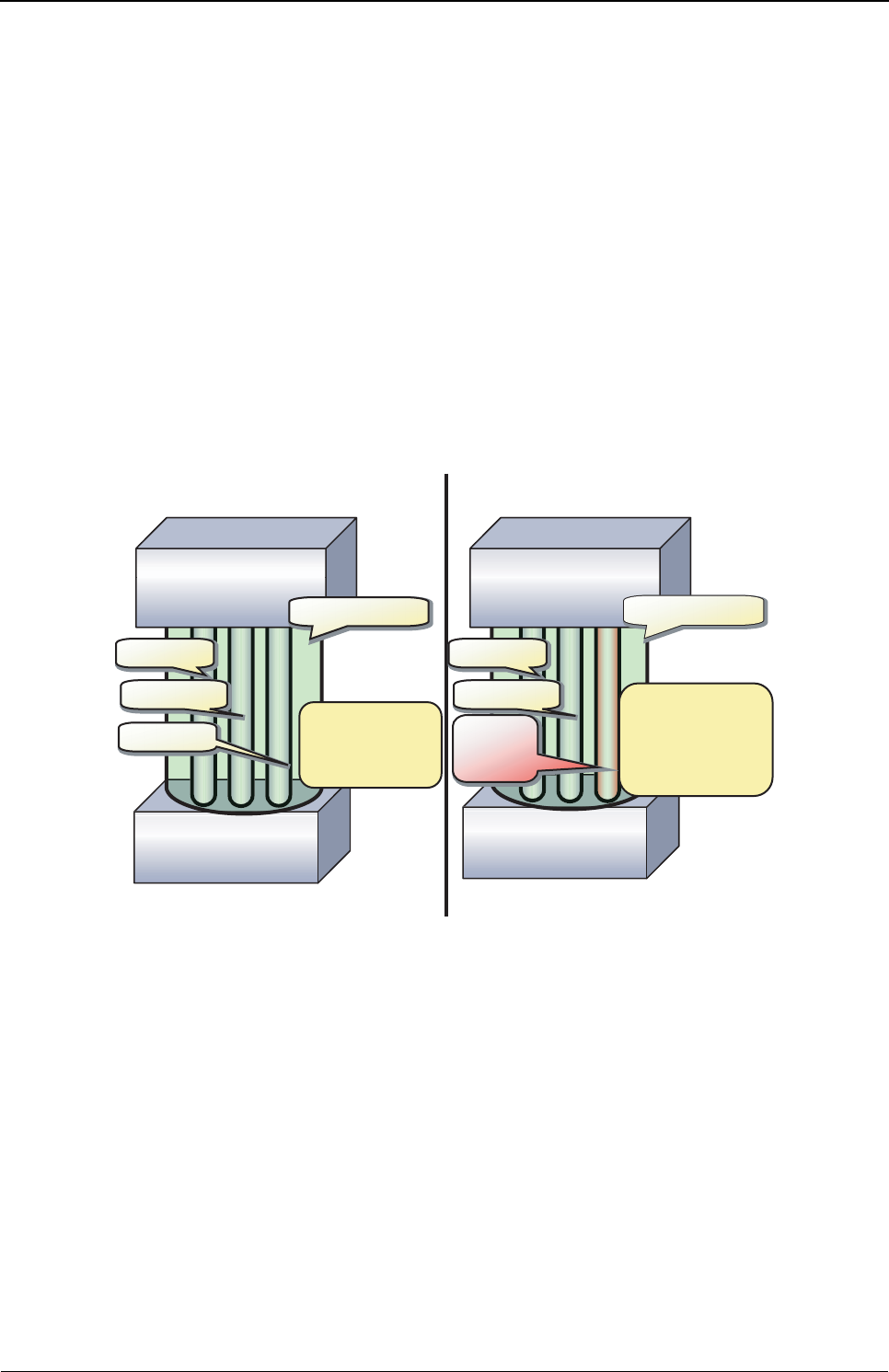
XG Series User's Guide Chapter 4 Switch Functions and their Configuration
Link Aggregation
67
4.4 Link Aggregation
Link aggregation is a function that combines multiple ports into a single logical link. A set of ports that comprise a logical
link are called an aggregation group.
Link aggregation provides:
• Increased bandwidth
By grouping multiple physical ports into a single logical link (an aggregation group), network traffic (data sent and
received) will be balanced across the physical ports, thereby providing increased bandwidth.
• Redundancy
Multiplexing ports allows uninterrupted network operations should one of the multiple links fail. Since the link status
of the logical aggregation groups remains unchanged, there are no fluctuations in network traffic, the effect of a fault
having been minimized.
Up to 10 ports can be used to create a single link aggregation group using link aggregation. Up to 10 aggregation groups
can be created.
XG
Link Aggregation
Physical Port
Physical Port
Physical Port
Physical Port
Physical Port
Physical Port
XG
Physical
Port
is down.
Physical
Port
is down.
The communication
can be continued
even though one
physical port is
down.
Bandwidth is
expanded by
bundling the
physical port.
XG
Aggregation Group
Aggregation Group
Physical Port
Physical Port
Physical Port
Physical Port
XG
Aggregation Group
Aggregation Group

XG Series User's Guide Chapter 4 Switch Functions and their Configuration
Link Aggregation
68
4.4.1 Configuring Link Aggregation
Either static or dynamic (also known as LACP) configuration can be selected for Link Aggregation.
• Static configuration
Configures aggregation groups statically.
•LACP
Configures link aggregation using Link Aggregation Control Protocol (LACP). The LACP is a switch-to-switch
control protocol that enables dynamic configuration of aggregation groups and is standardized by the IEEE802.3ad.
The LACP facilitates load balancing across the individual links aggregated between the devices connected.
Either "active" or "passive" LACP mode can be selected.
- active
The device starts LACP negotiation. Since the active mode allows the reception of LACP control frames, it is
possible to direct the device in "active" mode.
- passive
The device responds to LACP control frames but does not start LACP negotiation.
To configure static link aggregation, carry out the following procedure in "admin" Operation mode.
To configure LACP link aggregation, carry out the following procedure in "admin" Operation mode.
Command Task
XG2600# configure Switch to Configuration mode.
XG2600(config)# ether 1-8 type linkaggregation 1 Set port 1-8 to be linkaggregation group 1.
XG2600(config)# linkaggregation 1 mode static Set linkaggregation group 1 to be static.
XG2600(config)# commit Apply the configuration.
XG2600(config)# save Save the configuration.
XG2600(config)# exit Switch to Operation mode.
Command Task
XG2600# configure Switch to Configuration mode.
XG2600(config)# ether 1-8 type linkaggregation 1 Set port 1-8 to be linkaggregation group 1.
XG2600(config)# ether 11-18 type linkaggregation 2 Set port 11-18 to be linkaggregation group 2.
XG2600(config)# linkaggregation 1 mode active Set linkaggregation group 1 to be active.
XG2600(config)# linkaggregation 2 mode passive Set linkaggregation group 2 to be passive.
XG2600(config)# commit Apply the configuration.
XG2600(config)# save Save the configuration.
XG2600(config)# exit Switch to Operation mode.
XG Series User's Guide Chapter 4 Switch Functions and their Configuration
Link Aggregation
69
4.4.2 Frame Distribution Methods in Link Aggregation
How frames are distributed across physical ports that make up an aggregation group are determined by the contents of a
frame (source and destination MAC addresses).
There are 6 ways to specify how frames are distributed:
• Frame distribution based on destination MAC address (da-mac)
The destination port is determined based on the destination MAC address of the frames.
• Frame distribution based on source MAC address (sa-mac)
The destination port is determined based on the source MAC address of the frames.
• Frame distribution based on destination and source MAC addresses (both-mac)
The destination port is determined based on the destination and source MAC addresses of the frames.
• Frame distribution based on destination IP address (da-ip)
The destination port is determined based on the destination IP address of the frames.
• Frame distribution based on source IP address (sa-ip)
The destination port is determined based on the source IP address of the frames.
• Frame distribution based on destination and source IP addresses (both-ip)
The destination port is determined based on the destination and source IP addresses of the frames.
To set a distribution method, carry out the following procedure in "admin" Operation mode.
Command Task
XG2600# configure Switch to Configuration mode.
XG2600(config)# ether 1-8 type linkaggregation 1 Set port 1-8 to be linkaggregation group 1.
XG2600(config)# linkaggregation 1 algorithm both-mac Set linkaggregation group 1 uses frame distribution based on
destination and source IP address.
XG2600(config)# commit Apply the configuration.
XG2600(config)# save Save the configuration.
XG2600(config)# exit Switch to Operation mode.

XG Series User's Guide Chapter 4 Switch Functions and their Configuration
Link Aggregation
70
4.4.3 The Number of Ports That Require Linkup
It is possible to specify the number of ports that enable a linkup state for an aggregation group. If the number of active
ports that make up an aggregation group in a linkup state is less than the specified number of ports, the aggregation group
changes to a linkdown state.
• For static link aggregation
If the number of ports that make up an aggregation group in a linkup state no longer satisfies the specified number of
ports, the aggregation group changes to a linkdown state.
• For LACP link aggregation
If the number of ports that make up an established LACP aggregation group changes, the aggregation group reverts to
a linkdown state.
To set the number of ports in the aggregation group, carry out the following procedure in "admin" Operation mode.
4.4.4 Notes on Link Aggregation
• No link aggregation can be used if the half-duplex link mode has been set by the "ether duplex" command.
• All ports in the link aggregation group must be set with the same link speed.
• All ports in the link aggregation group must be set to belong to the same VLAN.
• Specify the link aggregation group in sequential ports.
No link aggregation can be used for the non-sequentially numbered port configuration.
The member ports of a link aggregation group must be specified to have the sequentially numbered ports.
• If the Ethernet port type has been set as a link aggregation port and if the definition conflict as described above has
occurred, the relevant port is not linked up and it cannot be used. Change the settings by referring to the log messages.
Command Task
XG2600# configure Switch to Configuration mode.
XG2600(config)# ether 1-8 type linkaggregation 1 Set port 1-8 to be linkaggregation group 1.
XG2600(config)# linkaggregation 1 collecting minimum 3 Set the minimum number of member ports for aggregation group
1 to 3.
XG2600(config)# commit Apply the configuration.
XG2600(config)# save Save the configuration.
XG2600(config)# exit Switch to Operation mode.
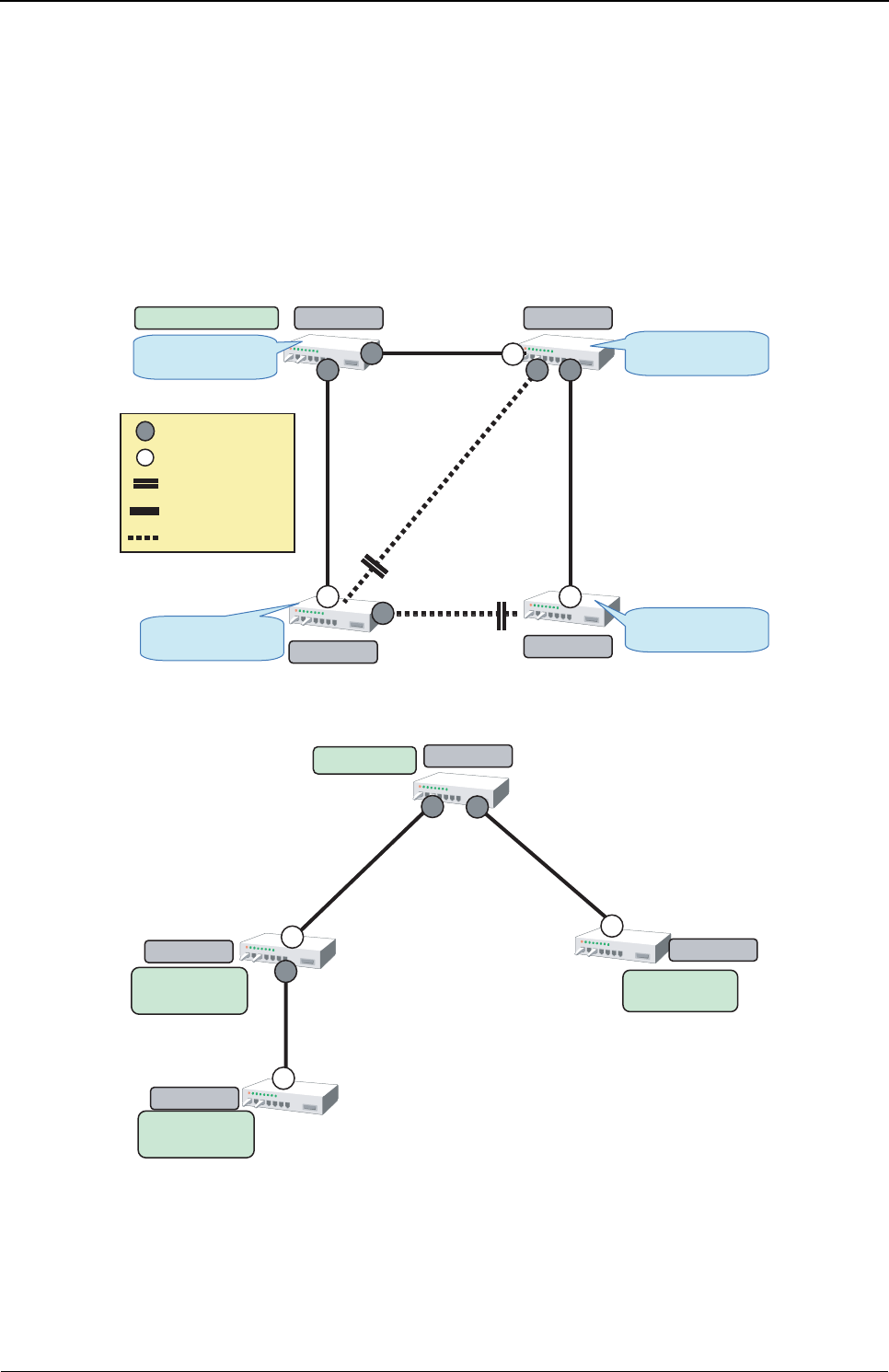
XG Series User's Guide Chapter 4 Switch Functions and their Configuration
Spanning Tree Protocol (STP)
71
4.5 Spanning Tree Protocol (STP)
The Spanning Tree Protocol (STP) is a function that prevents loops from occurring on a network. It is also possible to
provide network redundancy by intentionally creating a loop.
STP exclusively uses only one active path between network devices, and shuts out other paths, to avoid network loops. An
active path is selected by comparing path costs defined on each path. After the comparison, the lowest cost path will be
selected. If the selected path becomes disabled, STP will activate the lowest cost path amongst the paths remaining.
The device supports IEEE802.1w RSTP (Rapid Spanning Tree Protocol). The RSTP is upward compatible with
IEEE802.1D STP (Spanning Tree Protocol) and serves as a STP if the destination device only supports STP.
Switch Priority = 10
Switch A Switch B
Switch C Switch D
Switch Priority = 20
Switch Priority = 30 Switch Priority = 40
Designated port
Route port
Blocking port
Forwarding pass
Blocking pass
Path Cost = 10
Path Cost =
20
Path Cost =
15
Path Cost = 10
Pass Cost = 15
Route Switch
Physical Topology
Switch A
Switch B Switch C
Switch D
Route
Path Cost = 20
Route Switch
Route
Path Cost = 10
Route
Path Cost = 25
Path Cost = 20
Path Cost = 10
Path Cost =
15
Logical Topology by STP

XG Series User's Guide Chapter 4 Switch Functions and their Configuration
Spanning Tree Protocol (STP)
72
4.5.1 Port Roles Based on Spanning Tree
RSTP assigns one of these port roles to individual ports:
•Root port
Provides the best path (lowest cost) when the switch forwards packets to the root switch.
• Designated port
Connects to the designated switch toward the leaves of the spanning tree. The port specified connecting to the
designated port serves as a root port.
• Alternate Port
The alternative port with the second lowest path cost. In the event that the root port goes to a linkdown state, the
alternate port serves as the root port. It does not always send or receive frames while in the blocking state.
• Backup Port
Provides an alternative path to that specified. In the event that the specified port goes into a linkdown state, the backup
port serves as the new designated port. It does not always send or receive frames while it is in the blocking state.
•Disabled Port
Disabled port, it does not send or receive any frames.
4.5.2 Spanning Tree Protocol Port States
The port states defined by the STP are:
•Discard
The port is in a "discarding state. BPDUs are only received.
•Learn
The port is in a "learning" state. A port in the learning state learns the destination MAC address of the received frames
but does not participate in frame forwarding.
•Forward
The port is ready to transmit data traffic.
The STP states "blocking" and "listening" have been merged into a unique RSTP "discarding" state. The correspondence
between STP port states and RSTP port states are shown below.
Display Format STP (IEEE802.1D) RSTP (IEEE802.1w)
Discard Blocking Discarding
Discard Listening Discarding
Learn Learning Learning
Forward Forwarding Forwarding
XG Series User's Guide Chapter 4 Switch Functions and their Configuration
Spanning Tree Protocol (STP)
73
4.5.3 Configuring Spanning Tree
To configure the spanning tree protocol, carry out the following procedure in "admin" Operation mode.
Command Task
XG2600# configure Switch to Configuration mode.
XG2600(config)# stp mode stp Enable Spanning Tree Protocol.
XG2600(config)# stp domain 0 priority (0-61440)
XG2600(config)# stp hello (1s-10s)
XG2600(config)# stp age (6s-40s)
XG2600(config)# stp delay (4s-30s)
Configure Spanning Tree Protocol parameters on the device.
• Switch priority
• Hello time
• Maximum aging time (max-age)
• Forward delay time (forward-time)
XG2600(config)# ether 1-8 stp use on Enable Spanning Tree Protocol on port 1-8.
XG2600(config)# ether 9-20 stp use off Disable Spanning Tree Protocol on port 9-20.
XG2600(config)# ether 1-8 stp domain 0 priority (0-240)
XG2600(config)# ether 1-8 stp domain 0 cost
(1-200000000)
Configure the following parameters related to the spanning tree
topology:
• Port priority
• Path cost
XG2600(config)# commit Apply the configuration.
XG2600(config)# save Save the configuration.
XG2600(config)# exit Switch to Operation mode.
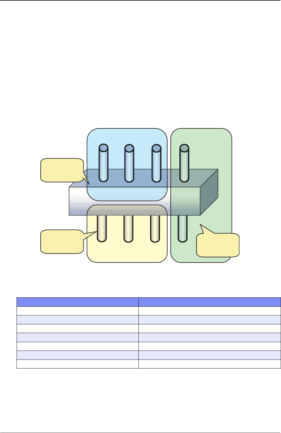
XG Series User's Guide Chapter 4 Switch Functions and their Configuration
VLAN
74
4.6 VLAN
VLAN (Virtual LAN) is a technology that divides a single network into virtually separated networks.
VLANs are separate logical networks within one physical network. A VLAN capable switch can change and define new
LAN network configurations without changing physical cable connections. This creates a flexible and extensible network
system.
The device provides for port-based or Tag-based (IEEE802.1Q) VLANs.
4.6.1 Port-Based VLAN
Port-based VLAN is a method for configuring VLAN membership on a port basis. Forwarding is based on the destination
MAC addresses and related port.
To configure a port-based VLAN, carry out the following procedures in "admin" Operation mode.
Command Task
XG2600# configure Switch to Configuration mode.
XG2600(config)# ether 1-3 vlan untag 10 Set the default port VLAN ID 10 for port 1-3.
XG2600(config)# ether 5-7 vlan untag 20 Set the default port VLAN ID 20 for port 5-7.
XG2600(config)# ether 4,8 vlan untag 30 Set the default port VLAN ID 30 for port 4,8.
XG2600(config)# commit Apply the configuration.
XG2600(config)# save Save the configuration.
XG2600(config)# exit Switch to Operation mode.
Segment 1 (VLAN10)
Segment 2 (VLAN20)
Segment 3 (VLAN30)
1234
5 6 7 8
VLAN10 consists
of Port 1, 2, 3
VLAN20 consists
of Port 5, 6, 7 VLAN30 consists
of port 4, 8
Port Base VLAN
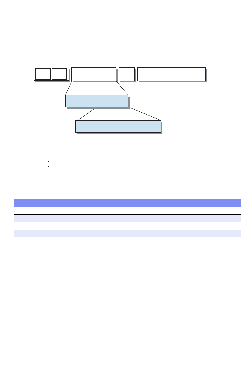
XG Series User's Guide Chapter 4 Switch Functions and their Configuration
VLAN
75
4.6.2 Tag-Based (IEEE802.1Q) VLAN
Tag-based VLAN is a method of configuring VLANs so that the frame forwarding decision is based on a tag in the MAC
header identifying the VLAN membership. 4 bytes of additional data in the header, called a VLAN tag, identifies the
VLAN frame ownership. Using a VLAN tag enables configuring a single physical link that shares multiple VLANs.
The device’s tag-based VLAN function is based on the IEEE 802.1Q standard.
The following figure shows an Ethernet frame format including a VLAN tag as specified by the IEEE 802.1Q standard.
To configure a tag-based VLAN, carry out the following procedures in "admin" Operation mode.
Command Task
XG2600# configure Switch to Configuration mode.
XG2600(config)# ether 1-8 vlan tag 100-300 Set the tag-based VLAN ID 100-300 for port 1-8.
XG2600(config)# commit Apply the configuration.
XG2600(config)# save Save the configuration.
XG2600(config)# exit Switch to Operation mode.
Protocol data (IP Packet, etc.)/
LLC,SNAP
Protocol data (IP Packet, etc.)/
LLC,SNAP
TPID (Tag Protocol Identifier) (0x8100)
TCI (Tag Control Information)
User Priority(3bit): Priority of Frames (Higher priority to larger number from 0 to 7)
CFI (Canonical Format Indicator)(1bit): ”1” when RIF field exists. Normally “0”.
VLAN ID(12bit):VLAN identifier (0 to 4095. 0 and 4095 are reserved ID)
TYPE
LENGTH
(2)
TYPE
LENGTH
(2)
VLAN tag
(4)
User
Priority
CFI VLAN ID
3 bit 1 bit 12 bit
DA
(6 )
SA
(6)
2 bytes 2 bytes
TCI
TPID
0x8100
2 bytes 2 bytes
TCI
TPID
0x8100
Tag VLAN Frame Format
XG Series User's Guide Chapter 4 Switch Functions and their Configuration
Quality of Service (QoS)
76
4.7 Quality of Service (QoS)
The device provides Quality of Service (QoS) that is based on the IEEE802.1p standard.
The device QoS determines the priority of frames at the ingress side using VLAN tag (including priority tag) or a port's
default priority. Their priorities are mapped to 8 output queues.
The queues are processed in the order of the QoS priority precedence.
The device priorities available are:
• Default priority
Set a default priority of 0 to 7 for each port.
For frames whose priority was not set (VLAN-untagged frames), the default priority is assigned according to the value
of the frame.
• Mapping to output queues
The device is equipped with 8 output queues with different levels (0 to 7). Frames are transmitted in order of output
queue priority.
Each priority is mapped to a specified output queue.
To set the default priority and output queue mapping, carry out the following procedure in "admin" Operation mode.
•XG2600
• XG0224/XG0448
Command Task
XG2600# configure Switch to Configuration mode.
XG2600(config)# ether 1-8 qos priority (0-7) Set a default priority for frames whose priority was not set
(VLANuntagged frame) when received.
XG2600(config)# ether 1-8 qos prioritymap (0-7) (0-7) Set the level of output queue to map to each frame that has a
priority value.
XG2600(config)# save Save the configuration.
XG2600(config)# reset Reset the device.
Command Task
XG0224# configure Switch to Configuration mode.
XG0224(config)# ether 1-8 qos priority (0-7) Set a default priority for frames whose priority was not set
(VLANuntagged frame) when received.
XG0224(config)# qos cosmap (0-7) (0-7) Set the level of output queue to map to each frame that has a
priority value.
XG0224(config)# save Save the configuration.
XG2600(config)# reset Reset the device.
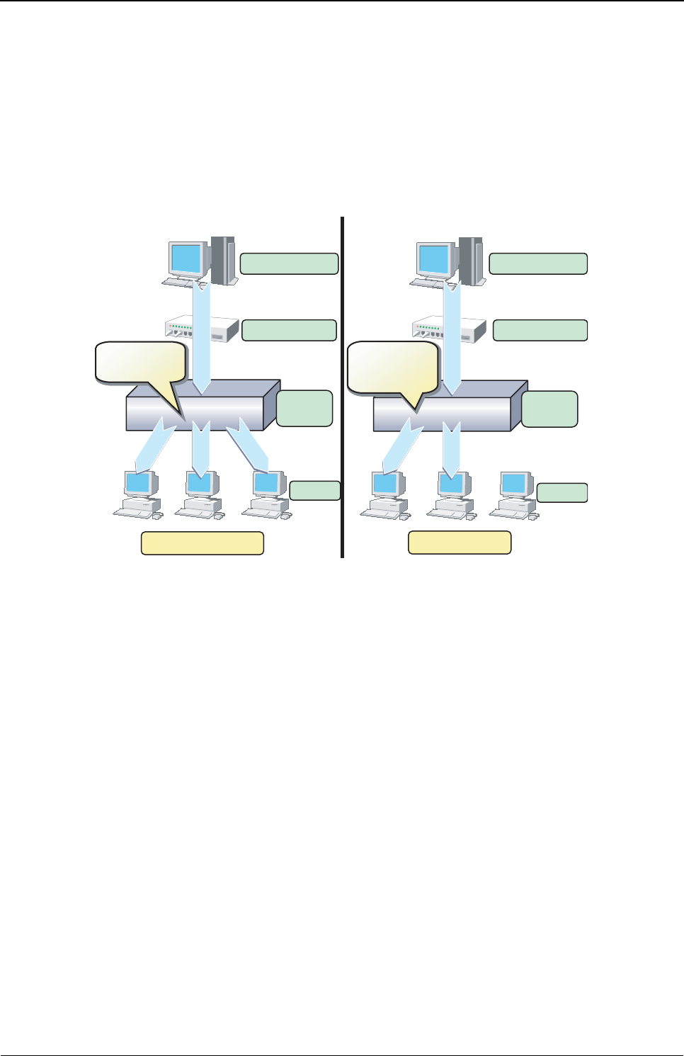
XG Series User's Guide Chapter 4 Switch Functions and their Configuration
IGMP Snooping
77
4.8 IGMP Snooping
IP multicast is often used to distribute multimedia data, including video and voice, over a network.
A layer 2 switch floods multicast frames, absorbing unnecessary network bandwidth. A layer 3 switch that supports
Internet Group Management Protocol (IGMP) manages multicast groups using IGMP packets. The device controls how IP
multicast packets are forwarded to required ports by monitoring IGMP packets generated by layer 3 switches, thereby
preventing unnecessary flooding. This function is called "IGMP Snooping".
The device supports IGMP snooping for IGMP v1/v2.
IGMP Snooping
IGMP No Snooping IGMP Snooping
Multicast Server
Multicast Router
Layer 2
Switch
Terminal
XG
Flooding to all
ports
Flooding to all
ports
Transfer only to
the required
ports
Transfer only to
the required
ports
Layer 2
Switch
Terminal
Multicast Server
Multicast Router
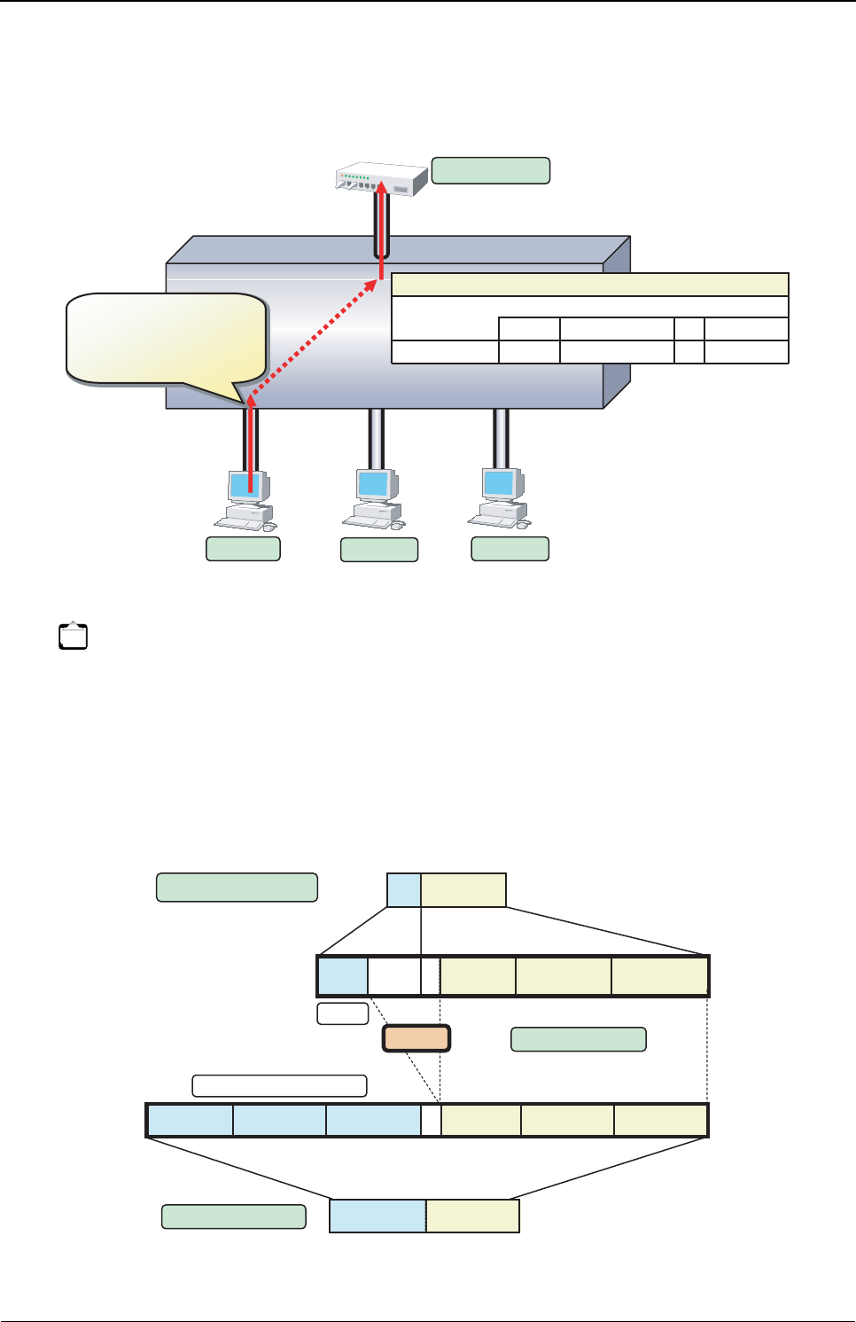
XG Series User's Guide Chapter 4 Switch Functions and their Configuration
IGMP Snooping
78
4.8.1 Registering Group Members
On receiving an IGMP Report message, the device registers a multicast MAC address to the IGMP snooping control table
for the port that received the IGMP Report message and the connecting multicast router port.
The following figure shows the relationship between the registered IP multicast address and the multicast MAC address.
MAC addresses that are registered with IGMP snooping are between 0100.5E00.0000 and 0100.5E7F.FFFF. An IP
multicast address is 32 bits. The first 4 bits are always 1110 followed by 28 bits that represent the IP multicast address
information. Of these 28 bits, the lower order 23 bits are mapped to a MAC address and the data in the higher order 5 bits
is not used.
Therefore 32 IP multicast addresses are mapped to the same single MAC address.
Note
• The device can register multicast groups up to a maximum value (Reference "1.2.3 System Maximum Values" (pg.34)).
Multicast packets that cannot be registered are those flooding all ports belonging to the same VLAN.
• If "igmpsnoop unknown flooding off" command is set, Multicast packets that cannot be registered are those not flooding all
ports belonging to the same VLAN (XG0224, XG0448).
XG
Registering Group Members
Multicast Router
Terminal 1
Port 1 Port 2 Port 3
VLAN 10
Port 8
IGMP Report
MAC : 0100.5E01.0203
Destination IP : 239.1.2.3
Group IP : 239.1.2.3
IGMP Report
MAC
Destination IP
Source IP
Group IP
Terminal 2 Terminal 3
: 0100.5E01.0203
: 239.1.2.3
: 192.168.10.20
: 239.1.2.3
1, 8
Port
0100.0501.0203
MAC Address Table
Port(MAC address)
(01:00:05:01:02:03)
IGMP snooping Control Table
VLAN(RouterPort)
VLAN
10 (8) 239.1.2.3 1
Reporter
192.168.10.20
Group IP
Multicast Address
0000001 00000011000000100010111100000000000000001 0000001 00000011000000100010111100000000000000001
1111 0000001 000000110000001001110 1111 0000001 000000110000001001110
0100.5E
01.02030100.5E
Lower 23 Bit Mapping
5 Bit Loss
Class D
Multicast MAC Address
1. 2. 3239. 1. 2. 3239.
Reserved for IPv4 Multicast
IP Multicast Address
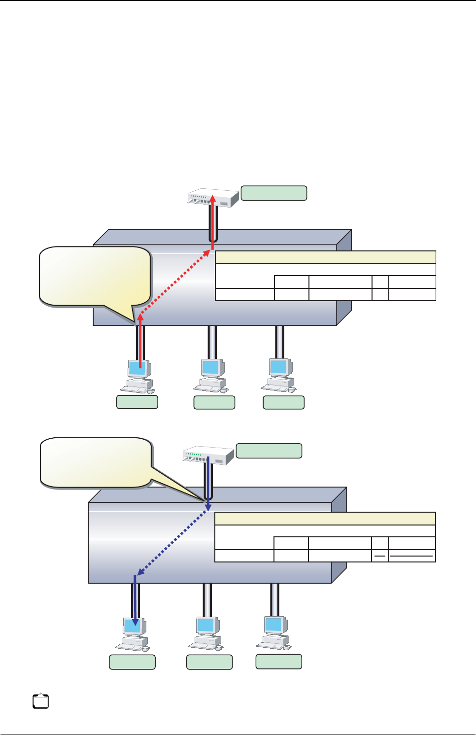
XG Series User's Guide Chapter 4 Switch Functions and their Configuration
IGMP Snooping
79
4.8.2 Removing Group Members
The group members registered by IGMP snooping are removed under the following status.
• If after receiving an IGMP Report message for group registration, the group member interval expires before the device
receives another IGMP Report message, the switch removes the host from the group member. The setting for the group
member interval is 260 seconds.
• If an IGMP Leave message is sent from a host, the multicast router sends out an IGMP Specific Query (GSQ) message
to determine whether that the host has left the group.
• If after receiving the IGMP Leave message, the last member interval expires before the device receives another IGMP
Report message, the switch removes the host from the group member. The setting for the last member interval is 2
seconds.
Note The registered Multicast Group IP is not detete form the IGMP snooping Control Table automatically.
Please use "clear igmpsnoop group" command to delete it.
XG
Removing Group Members (1)
Multicast Router
Terminal 1
Port 3
VLAN 10
Port 8
IGMP Leave
MAC : 0100.5E00.0002
Destination IP : 224.0.0.2
Group IP : 239.1.2.3
IGMP Leave
MAC
Destination IP
Source IP
Group IP
Terminal 2 Terminal 3
Port 2
Port 1
: 0100.5E00.0002
: 224.0.0.2
: 192.168.10.20
: 239.1.2.3
1, 8
Port
0100.0501.0203
MAC Address Table
Port(MAC address)
(01:00:05:01:02:03)
IGMP snooping Control Table
VLAN(RouterPort)
VLAN
10 (8) 239.1.2.3 1
Reporter
192.168.10.20
Group IP
XG
Multicast Router
VLAN 10
Port 8
IGMP Specific Query
MAC : 0100.5E01.0203
Destination IP : 239.1.2.3
Group IP : 239.1.2.3
IGMP Specific Query
MAC : 0100.5E01.0203
Destination IP : 239.1.2.3
Group IP : 239.1.2.3
Terminal 1 Terminal 2 Terminal 3
Port 1 Port 2 Port 3
Removing Group Members (2)
1, 8
Port
0100.0501.0203
MAC Address Table
1 192.168.10.20
Group IP Port(MAC address)
(01:00:05:01:02:03)
IGMP snooping Control Table
VLAN(RouterPort)
VLAN
10 (8) 239.1.2.3
Reporter
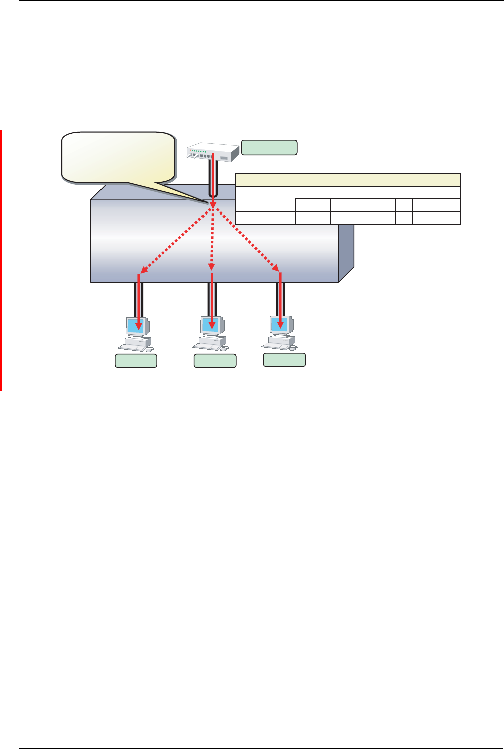
XG Series User's Guide Chapter 4 Switch Functions and their Configuration
IGMP Snooping
80
4.8.3 Managing Group Members
When network congestion causes Leave message loss or there is a host that uses IGMPv1, the multicast router does not
receive Leave messages. The multicast router sends out an IGMP General Query message to all hosts (IP address:
224.0.0.1) at intervals (query interval) to determine membership information.
Upon reception of an IGMP General Query message, the host, a member of the group, returns an IGMP Report message to
maintain membership in the group.
In consideration of General Query or Report message loss caused by network congestion, since RFC 2236 defines the
default query interval for multicast routers as 125 seconds, this device uses 126 seconds for the group member interval
when it works as a Querier.
XG
Managing Group Members
Multicast Router
Port 1 Port 2 Port 3
VLAN 10
Port 8
IGMP General Query
MAC : 0100.5E01.0001
Destination IP : 224.0.0.1
Group IP : 0.0.0.0
IGMP General Query
MAC : 0100.5E01.0001
Destination IP : 224.0.0.1
Group IP : 0.0.0.0
Terminal 1 Terminal 2 Terminal 3
1, 8
Port
0100.0501.0203
MAC Address Table
Port(MAC address)
(01:00:05:01:02:03)
IGMP snooping Control Table
VLAN(RouterPort)
VLAN
10 (8) 239.1.2.3 1
Reporter
192.168.10.20
Group IP
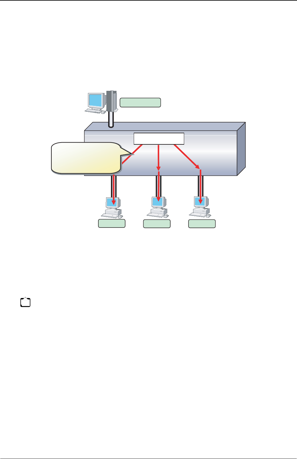
XG Series User's Guide Chapter 4 Switch Functions and their Configuration
IGMP Snooping
81
4.8.4 IGMP Querier
In a typical network configuration, the multicast router periodically sends out an IGMP General Query message to
determine if any of the hosts on the network are members of any multicast groups. Receiving a response from a host
ascertains its membership in a multicast group.
IGMP Querier is a function that acts as a proxy for a multicast router when one is not available in a network segment to
send an IGMP General Query message to all hosts.
The Query interval is 126 seconds.
Upon reception of an IGMP Leave message, the device sends an IGMP Specific Query (GSQ) message to determine that
the host is interested in leaving the group.
If an IGMP Specific Query message is sent 2 times and the host does not respond with an IGMP Report message, that host
is removed.
Note
• Generally, IGMP Querier uses "0.0.0.0" for the source IP address when sending a Query message.
Since some client software does not return a response for a Query message with the source IP address being set
to "0.0.0.0", it is recommended that an address other than "0.0.0.0" be used.
• If a multicast router exists on the network segment, the device does not send Query message even if IGMP
Querier is valid.
XG
IGMP Querier
Terminal 1
Port 1 Port 2 Port 3
IGMP General Query
MAC : 0100.5E01.0001
Destination IP : 224.0.0.1
Group IP : 0.0.0.0
IGMP General Query
MAC : 0100.5E01.0001
Destination IP : 224.0.0.1
Group IP : 0.0.0.0
IGMP Querier
Multicast Server
Terminal 2 Terminal 3
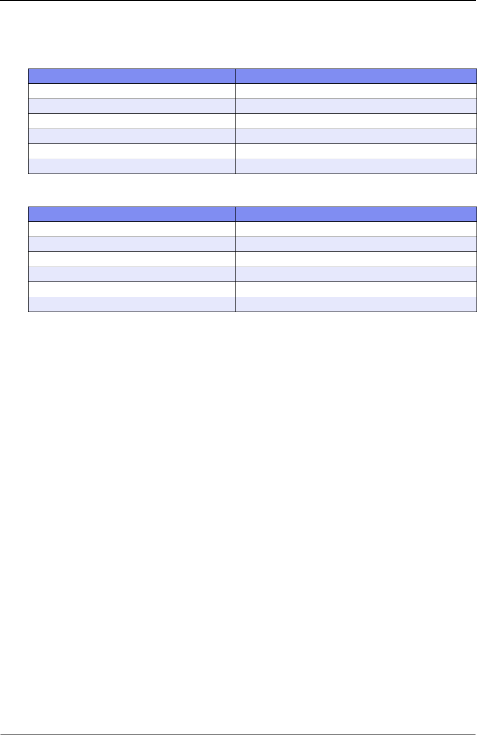
XG Series User's Guide Chapter 4 Switch Functions and their Configuration
IGMP Snooping
82
4.8.5 Configuring IGMP Snooping
To configure IGMP snooping, carry out the following procedure in "admin" Operation mode.
To enable IGMP query, carry out the following procedure in "admin" Operation mode.
Command Task
XG2600# configure Switch to Configuration mode.
XG2600(config)# igmpsnoop use on Enable global IGMP snooping on the device.
XG2600(config)# vlan 10 igmpsnoop router yes 15,16 Specify the multicast router port statically with VLAN.
XG2600(config)# commit Apply the configuration.
XG2600(config)# save Save the configuration.
XG2600(config)# exit Switch to Operation mode.
Command Task
XG2600# configure Switch to Configuration mode.
XG2600(config)# igmpsnoop use on Enable global IGMP snooping on the device.
XG2600(config)# vlan 20 igmpsnoop querier on Specify the Querier operation mode if no multicast router exists.
XG2600(config)# commit Apply the configuration.
XG2600(config)# save Save the configuration.
XG2600(config)# exit Switch to Operation mode.

XG Series User's Guide Chapter 4 Switch Functions and their Configuration
Network Management
83
4.9 Network Management
4.9.1 Traffic Statistics
The device can display traffic statistics to analyze network operations such as traffic bytes, errors, etc.
The following are the Traffic Statistics the device provides.
• Displays traffic information on outgoing and incoming frames for each port.
• Displays traffic information on incoming frames by frame size range for each port.
• Displays traffic information on incoming frames for each VLAN.
• Displays incoming traffic information by QoS priority for each port.
• Displays information related to data flow for each port.
• Displays information about errors that occur during transmission/reception for each port.
To display traffic statistics, monitor and show commands are provided.
•"show ether utilization" command
Display the usage ratio (or utilization) information of Ethernet physical ports.
•"show ether statistics" (show ether statistics detail) command
Display the statistics of Ethernet physical ports.
4.9.2 SNMP Agent
SNMP (Simple Network Management Protocol) is a protocol that monitors and manages devices on a network.
The device supports the SNMP (v1/v2c/v3) function to collect management information blocks (MIBs) from a remote
network manager (SNMP manager).
For the MIBs supported, refer to Appendix B. The device can be configured for up to 16 SNMP managers and up to 16
SNMP trap destinations (8 for v1/v2c, 8 for v3).
To configure the SNMP agent, carry out the following procedures in "admin" Operation mode.
Command Task
XG2600# configure Switch to Configuration mode.
XG2600(config)#snmp service on Enable SNMP function.
XG2600(config)#snmp agent contact
SYSTEM-CONTAC
Set the swith's contact (SYSTEM-CONTACT).
XG2600(config)#snmp agent location
SYSTEM-LOCATION
Set the swith's location (SYSTEM-LOCATION).
XG2600(config)#snmp agent address A.B.C.D Set the SNMP agent address. This setting is also used for the
local address at trap transmission.
Make sure to set it when using the SNMP agent function.
XG2600(config)# snmp manager 0 A.B.C.D
COMMUNIT-YNAME v2c disable
Set the IP address (host name) of the SNMP manager, the
community name, sending SNMPv2 traps, and disabling writing.
if the SNMP trap notification is enabled.
XG2600(config)# snmp user 0 name USERNAME
XG2600(config)# snmp user 0 address 0 A.B.C.D
Set a SNMP v3 user name.
Set a SNMP v3 host address.
XG2600(config)# snmp user 0 notification 0 A.B.C.D Set a SNMP v3 trap notification host address.
XG2600(config)# snmp user 0 auth md5
auth_password
Set the authentication protocol and password for SNMP v3.
XG2600(config)# snmp user 0 priv des priv_password Set the encryption protocol and password for SNMP v3.
XG Series User's Guide Chapter 4 Switch Functions and their Configuration
Network Management
84
4.9.3 RMON
Remote Monitoring (RMON) is a function provided to monitor communications over a network, such as traffic and errors.
RMON, used in conjunction with the SNMP agent, allows the remote monitoring of traffic on a LAN segment.
The device supports 2 RMON groups (Statistics, History).
• Statistics group
Collects traffic statistics for each port.
• History group
Records traffic statistics for each port at specified time intervals.
To configure RMON, carry out the following procedure in "admin" Operation mode.
XG2600(config)# snmp user 0 read view 0 Set MIB read permission view for SNMP v3.
XG2600(config)# snmp user 0 notify view 0 Set trap notification permission view for SNMP v3.
XG2600(config)# commit Apply the configuration.
XG2600(config)# save Save the configuration.
XG2600(config)# exit Switch to Operation mode.
Command Task
XG2600# configure Switch to Configuration mode.
XG2600(config)#snmp rmon <on|off> Specify whether to enable or disable the RMON function.
XG2600(config)# commit Apply the configuration.
XG2600(config)# save Save the configuration.
XG2600(config)# exit Switch to Operation mode.
Command Task

Chapter 5
Command
Reference
This chapter explains about Command Reference.
5.1 Port Information Settings . . . . . . . . . . . . . . . . . . . . . . . . . . . . . . . . . . . . . . . . . . . . . . . . . . . . . . . . . . . . 89
5.1.1 Ethernet Common Information . . . . . . . . . . . . . . . . . . . . . . . . . . . . . . . . . . . . . . . . . . . . . . . . .90
5.1.2 MAC Information . . . . . . . . . . . . . . . . . . . . . . . . . . . . . . . . . . . . . . . . . . . . . . . . . . . . . . . . . . . 122
5.1.3 STP Information . . . . . . . . . . . . . . . . . . . . . . . . . . . . . . . . . . . . . . . . . . . . . . . . . . . . . . . . . . . . 124
5.1.4 LLDP Information. . . . . . . . . . . . . . . . . . . . . . . . . . . . . . . . . . . . . . . . . . . . . . . . . . . . . . . . . . . 128
5.1.5 Filter Information . . . . . . . . . . . . . . . . . . . . . . . . . . . . . . . . . . . . . . . . . . . . . . . . . . . . . . . . . . . 132
5.1.6 QoS Information. . . . . . . . . . . . . . . . . . . . . . . . . . . . . . . . . . . . . . . . . . . . . . . . . . . . . . . . . . . . 137
5.1.7 LACP Information . . . . . . . . . . . . . . . . . . . . . . . . . . . . . . . . . . . . . . . . . . . . . . . . . . . . . . . . . . 146
5.1.8 ether L3 Monitor Information . . . . . . . . . . . . . . . . . . . . . . . . . . . . . . . . . . . . . . . . . . . . . . . . . 147
5.1.9 ether SNMP Information . . . . . . . . . . . . . . . . . . . . . . . . . . . . . . . . . . . . . . . . . . . . . . . . . . . . . 149
5.1.10 ether output rate control information . . . . . . . . . . . . . . . . . . . . . . . . . . . . . . . . . . . . . . . . . . 151
5.2 LACP Information Settings . . . . . . . . . . . . . . . . . . . . . . . . . . . . . . . . . . . . . . . . . . . . . . . . . . . . . . . . . 152
5.2.1 LACP Information . . . . . . . . . . . . . . . . . . . . . . . . . . . . . . . . . . . . . . . . . . . . . . . . . . . . . . . . . . 152
5.3 VLAN Information Settings . . . . . . . . . . . . . . . . . . . . . . . . . . . . . . . . . . . . . . . . . . . . . . . . . . . . . . . . . 154
5.3.1 VLAN Common Information . . . . . . . . . . . . . . . . . . . . . . . . . . . . . . . . . . . . . . . . . . . . . . . . . .154
5.3.2 IGMP Snooping Information . . . . . . . . . . . . . . . . . . . . . . . . . . . . . . . . . . . . . . . . . . . . . . . . . .160
5.3.3 Filter Information . . . . . . . . . . . . . . . . . . . . . . . . . . . . . . . . . . . . . . . . . . . . . . . . . . . . . . . . . . . 164
5.3.4 QoS Information. . . . . . . . . . . . . . . . . . . . . . . . . . . . . . . . . . . . . . . . . . . . . . . . . . . . . . . . . . . . 173
5.4 MAC Information . . . . . . . . . . . . . . . . . . . . . . . . . . . . . . . . . . . . . . . . . . . . . . . . . . . . . . . . . . . . . . . . . . 181
5.4.1 MAC Information . . . . . . . . . . . . . . . . . . . . . . . . . . . . . . . . . . . . . . . . . . . . . . . . . . . . . . . . . . . 181
5.5 LAN Information Settings. . . . . . . . . . . . . . . . . . . . . . . . . . . . . . . . . . . . . . . . . . . . . . . . . . . . . . . . . . . 183
5.5.1 IPv4 Related Information. . . . . . . . . . . . . . . . . . . . . . . . . . . . . . . . . . . . . . . . . . . . . . . . . . . . . 183
5.5.2 IPv6 Related Information. . . . . . . . . . . . . . . . . . . . . . . . . . . . . . . . . . . . . . . . . . . . . . . . . . . . . 198
5.5.3 VLAN Related Information . . . . . . . . . . . . . . . . . . . . . . . . . . . . . . . . . . . . . . . . . . . . . . . . . . . 207
5.5.4 LLMNR Related Information . . . . . . . . . . . . . . . . . . . . . . . . . . . . . . . . . . . . . . . . . . . . . . . . . . 208
5.5.5 Management LAN port IPv4 Related Information . . . . . . . . . . . . . . . . . . . . . . . . . . . . . . . . . 209
5.5.6 Management LAN port IPv6 Related Information . . . . . . . . . . . . . . . . . . . . . . . . . . . . . . . . . 211
5.5.7 Management LAN port LLMNR Related Information . . . . . . . . . . . . . . . . . . . . . . . . . . . . . . 214
5.6 IPv4 Related Information . . . . . . . . . . . . . . . . . . . . . . . . . . . . . . . . . . . . . . . . . . . . . . . . . . . . . . . . . . . 215
5.6.1 IPv4 Related Information . . . . . . . . . . . . . . . . . . . . . . . . . . . . . . . . . . . . . . . . . . . . . . . . . . . . 215
5.7 QoS Information Settings . . . . . . . . . . . . . . . . . . . . . . . . . . . . . . . . . . . . . . . . . . . . . . . . . . . . . . . . . . 216
5.7.1 QoS Information . . . . . . . . . . . . . . . . . . . . . . . . . . . . . . . . . . . . . . . . . . . . . . . . . . . . . . . . . . . 216
5.8 STP Information . . . . . . . . . . . . . . . . . . . . . . . . . . . . . . . . . . . . . . . . . . . . . . . . . . . . . . . . . . . . . . . . . . 217
5.8.1 STP Information. . . . . . . . . . . . . . . . . . . . . . . . . . . . . . . . . . . . . . . . . . . . . . . . . . . . . . . . . . . . 217
5.9 LLDP Information Settings . . . . . . . . . . . . . . . . . . . . . . . . . . . . . . . . . . . . . . . . . . . . . . . . . . . . . . . . . 225
5.9.1 LLDP Information . . . . . . . . . . . . . . . . . . . . . . . . . . . . . . . . . . . . . . . . . . . . . . . . . . . . . . . . . . 225
5.10 IGMP Snooping Information Settings. . . . . . . . . . . . . . . . . . . . . . . . . . . . . . . . . . . . . . . . . . . . . . . . . 228
5.10.1 IGMP Snooping Information. . . . . . . . . . . . . . . . . . . . . . . . . . . . . . . . . . . . . . . . . . . . . . . . . . 228
5.11 Loop Detection Information Settings . . . . . . . . . . . . . . . . . . . . . . . . . . . . . . . . . . . . . . . . . . . . . . . . . 230
5.11.1 Loop Detection Information . . . . . . . . . . . . . . . . . . . . . . . . . . . . . . . . . . . . . . . . . . . . . . . . . . 230
5.12 ACL Information Settings . . . . . . . . . . . . . . . . . . . . . . . . . . . . . . . . . . . . . . . . . . . . . . . . . . . . . . . . . . 233
5.12.1 ACL Information . . . . . . . . . . . . . . . . . . . . . . . . . . . . . . . . . . . . . . . . . . . . . . . . . . . . . . . . . . . 233
5.13 AAA Information Settings . . . . . . . . . . . . . . . . . . . . . . . . . . . . . . . . . . . . . . . . . . . . . . . . . . . . . . . . . . 242
5.13.1 Group ID Information . . . . . . . . . . . . . . . . . . . . . . . . . . . . . . . . . . . . . . . . . . . . . . . . . . . . . . . 243
5.13.2 AAA User Information. . . . . . . . . . . . . . . . . . . . . . . . . . . . . . . . . . . . . . . . . . . . . . . . . . . . . . . 244
5.13.3 RADIUS Information Settings. . . . . . . . . . . . . . . . . . . . . . . . . . . . . . . . . . . . . . . . . . . . . . . . . 247
5.14 Password Information . . . . . . . . . . . . . . . . . . . . . . . . . . . . . . . . . . . . . . . . . . . . . . . . . . . . . . . . . . . . . 257
5.14.1 password format . . . . . . . . . . . . . . . . . . . . . . . . . . . . . . . . . . . . . . . . . . . . . . . . . . . . . . . . . . . 257
5.14.2 password admin set . . . . . . . . . . . . . . . . . . . . . . . . . . . . . . . . . . . . . . . . . . . . . . . . . . . . . . . . 258
5.14.3 password user set. . . . . . . . . . . . . . . . . . . . . . . . . . . . . . . . . . . . . . . . . . . . . . . . . . . . . . . . . . 260
5.14.4 password aaa. . . . . . . . . . . . . . . . . . . . . . . . . . . . . . . . . . . . . . . . . . . . . . . . . . . . . . . . . . . . . . 261
5.14.5 password authtype . . . . . . . . . . . . . . . . . . . . . . . . . . . . . . . . . . . . . . . . . . . . . . . . . . . . . . . . . 261
5.15 Device Information Settings . . . . . . . . . . . . . . . . . . . . . . . . . . . . . . . . . . . . . . . . . . . . . . . . . . . . . . . . 262
5.15.1 SNMP Information . . . . . . . . . . . . . . . . . . . . . . . . . . . . . . . . . . . . . . . . . . . . . . . . . . . . . . . . . . 262
5.15.2 System Log Information . . . . . . . . . . . . . . . . . . . . . . . . . . . . . . . . . . . . . . . . . . . . . . . . . . . . . 280
5.15.3 Automatic Time Setting Information . . . . . . . . . . . . . . . . . . . . . . . . . . . . . . . . . . . . . . . . . . . 286
5.15.4 ProxyDNS Information . . . . . . . . . . . . . . . . . . . . . . . . . . . . . . . . . . . . . . . . . . . . . . . . . . . . . . 290
5.15.5 Host Database Information. . . . . . . . . . . . . . . . . . . . . . . . . . . . . . . . . . . . . . . . . . . . . . . . . . . 295
5.15.6 Schedule Information . . . . . . . . . . . . . . . . . . . . . . . . . . . . . . . . . . . . . . . . . . . . . . . . . . . . . . . 297
5.15.7 Filter/QoS Resource Information . . . . . . . . . . . . . . . . . . . . . . . . . . . . . . . . . . . . . . . . . . . . . . 299
5.15.8 Other. . . . . . . . . . . . . . . . . . . . . . . . . . . . . . . . . . . . . . . . . . . . . . . . . . . . . . . . . . . . . . . . . . . . . 300
5.16 Login banner Settings . . . . . . . . . . . . . . . . . . . . . . . . . . . . . . . . . . . . . . . . . . . . . . . . . . . . . . . . . . . . . 328
5.16.1 Login banner Information. . . . . . . . . . . . . . . . . . . . . . . . . . . . . . . . . . . . . . . . . . . . . . . . . . . . 328
5.17 Mode and Terminal Operation Commands. . . . . . . . . . . . . . . . . . . . . . . . . . . . . . . . . . . . . . . . . . . . . 330
5.17.1 Mode Operation Commands . . . . . . . . . . . . . . . . . . . . . . . . . . . . . . . . . . . . . . . . . . . . . . . . . 330
5.17.2 Terminal Operation Commands . . . . . . . . . . . . . . . . . . . . . . . . . . . . . . . . . . . . . . . . . . . . . . . 337
5.17.3 Command Execution History . . . . . . . . . . . . . . . . . . . . . . . . . . . . . . . . . . . . . . . . . . . . . . . . . 346
5.17.4 Command Alias . . . . . . . . . . . . . . . . . . . . . . . . . . . . . . . . . . . . . . . . . . . . . . . . . . . . . . . . . . . . 349
5.17.5 Command Output . . . . . . . . . . . . . . . . . . . . . . . . . . . . . . . . . . . . . . . . . . . . . . . . . . . . . . . . . . 351
5.18 System Operations and Display Commands . . . . . . . . . . . . . . . . . . . . . . . . . . . . . . . . . . . . . . . . . . . 353
5.18.1 System Operations and Display Commands . . . . . . . . . . . . . . . . . . . . . . . . . . . . . . . . . . . . 353
5.19 Configuration Display, Delete and Operation Commands . . . . . . . . . . . . . . . . . . . . . . . . . . . . . . . . 369
5.19.1 Configuration Display Commands. . . . . . . . . . . . . . . . . . . . . . . . . . . . . . . . . . . . . . . . . . . . . 369
5.19.2 Configuration Delete Commands. . . . . . . . . . . . . . . . . . . . . . . . . . . . . . . . . . . . . . . . . . . . . . 372
5.19.3 Configuration Operation Commands . . . . . . . . . . . . . . . . . . . . . . . . . . . . . . . . . . . . . . . . . . 373
5.19.4 File Operation Commands . . . . . . . . . . . . . . . . . . . . . . . . . . . . . . . . . . . . . . . . . . . . . . . . . . . 379
5.20 Ethernet Counter, Log, Statistics, and Status Display and Clear Operation Commands . . . . . . . 383
5.20.1 Ethernet Counter, Log, Statistics, and Status Display Commands . . . . . . . . . . . . . . . . . . 383
5.20.2 Ethernet Counter, Log, and Statistics Clear Commands. . . . . . . . . . . . . . . . . . . . . . . . . . . 414
5.21 USB connection Counter, Log, Statistics, and Status Display and Clear Operation Commands. 415
5.21.1 USB connection Counter, Log, and Statistics Clear Commands . . . . . . . . . . . . . . . . . . . . 415
5.22 LACP Counter, Log, Statistics, and Status Display and Clear Operation Commands. . . . . . . . . . 419
5.22.1 LACP Counter, Log, Statistics, and Status Display Commands . . . . . . . . . . . . . . . . . . . . . 419
5.22.2 LACP Counter, Log, Statistics, and Status Clear Commands. . . . . . . . . . . . . . . . . . . . . . . 422
5.23 M1 port Status Display command . . . . . . . . . . . . . . . . . . . . . . . . . . . . . . . . . . . . . . . . . . . . . . . . . . . . 423
5.23.1 M1 port Status Display command . . . . . . . . . . . . . . . . . . . . . . . . . . . . . . . . . . . . . . . . . . . . . 423
5.24 Interface Counter, Log, Statistics, and Status Display Commands . . . . . . . . . . . . . . . . . . . . . . . . . 424
5.24.1 Interface Counter, Log, Statistics, and Status Display Commands . . . . . . . . . . . . . . . . . . 424
5.25 ARP Entry Display and Clear Operation Commands . . . . . . . . . . . . . . . . . . . . . . . . . . . . . . . . . . . . 428
5.25.1 ARP Entry Display Commands . . . . . . . . . . . . . . . . . . . . . . . . . . . . . . . . . . . . . . . . . . . . . . . 428
5.25.2 ARP Entry Clear Commands . . . . . . . . . . . . . . . . . . . . . . . . . . . . . . . . . . . . . . . . . . . . . . . . . 430
5.26 Routing Table Entry Display Commands . . . . . . . . . . . . . . . . . . . . . . . . . . . . . . . . . . . . . . . . . . . . . . 431
5.26.1 IPv4 Routing Table Entry Display Commands . . . . . . . . . . . . . . . . . . . . . . . . . . . . . . . . . . . 431
5.26.2 IPv6 Routing Table Entry Display Commands . . . . . . . . . . . . . . . . . . . . . . . . . . . . . . . . . . . 436
5.27 Packet Statistics Display and Clear Operation Commands . . . . . . . . . . . . . . . . . . . . . . . . . . . . . . . 443
5.27.1 IPv4 Packet Statistics Display Commands . . . . . . . . . . . . . . . . . . . . . . . . . . . . . . . . . . . . . . 443
5.27.2 IPv4 Packet Statistics Clear Commands . . . . . . . . . . . . . . . . . . . . . . . . . . . . . . . . . . . . . . . . 446
5.27.3 IPv6 Packet Statistics Display Commands . . . . . . . . . . . . . . . . . . . . . . . . . . . . . . . . . . . . . . 447
5.27.4 IPv6 Packet Statistics Clear Commands . . . . . . . . . . . . . . . . . . . . . . . . . . . . . . . . . . . . . . . . 450
5.28 Bridge Counter, Log, Statistics, and Status Display and Clear Operation Commands . . . . . . . . . 451
5.28.1 Bridge Counter, Log, Statistics, and Status Display Commands . . . . . . . . . . . . . . . . . . . . 451
5.28.2 Bridge Counter, Log, Statistics, and Status Clear Commands . . . . . . . . . . . . . . . . . . . . . . 453
5.28.3 Spanning Tree Counter, Log, Statistics, and Status Display Commands . . . . . . . . . . . . . 454
5.28.4 Spanning Tree Counter, Log, Statistics, and Status Clear Commands . . . . . . . . . . . . . . . 479
5.29 LLDP Counter, Log, Statistics, and Status Display and Clear Operation Commands . . . . . . . . . . 480
5.29.1 LLDP Counter, Log, Statistics, and Status Display Commands . . . . . . . . . . . . . . . . . . . . . 480
5.29.2 LLDP Counter, Log, Statistics, and Status Clear Commands . . . . . . . . . . . . . . . . . . . . . . . 491
5.30 VLAN Counter, Log, Statistics, and Status Display Commands . . . . . . . . . . . . . . . . . . . . . . . . . . . 492
5.30.1 VLAN Counter, Log, Statistics, and Status Display Commands . . . . . . . . . . . . . . . . . . . . . 492
5.31 QoS Counter, Log, Statistics, and Status Display Commands. . . . . . . . . . . . . . . . . . . . . . . . . . . . . 495
5.31.1 COS Queue Counter, Log, Statistics, and Status Display Commands. . . . . . . . . . . . . . . . 495
5.32 SSH Counter, Log, Statistics, and Status Display Commands. . . . . . . . . . . . . . . . . . . . . . . . . . . . . 497
5.32.1 SSH Counter, Log, Statistics, and Status Display Commands . . . . . . . . . . . . . . . . . . . . . . 497
5.33 IGMP Snooping Counter, Log, Statistics, and Status Display and Clear Operation Commands . 499
5.33.1 IGMP Snooping Counter, Log, Statistics, and Status Display Commands . . . . . . . . . . . . 499
5.33.2 IGMP Snooping Counter, Log, Statistics, and Status Clear Commands . . . . . . . . . . . . . . 504
5.34 Loopdetection Counter, Log, Statistics, and Status Display and Clear Operation Commands . . 506
5.34.1 Loopdetection Counter, Log, Statistics, and Status Display Commands . . . . . . . . . . . . . 506
5.35 AAA Status Display and Clear Operation Commands . . . . . . . . . . . . . . . . . . . . . . . . . . . . . . . . . . . 508
5.35.1 AAA Status Display Commands . . . . . . . . . . . . . . . . . . . . . . . . . . . . . . . . . . . . . . . . . . . . . . 508
5.36 NETTIME (time/sntp) Server and Client Statistics Display and Clear Operation Commands . . . . 509
5.36.1 NETTIME (time/sntp) Statistics Display Commands . . . . . . . . . . . . . . . . . . . . . . . . . . . . . . 509
5.36.2 NETTIME (time/sntp) Statistics Clear Commands . . . . . . . . . . . . . . . . . . . . . . . . . . . . . . . . 513
5.37 ProxyDNS Statistics Display and Clear Operation Commands . . . . . . . . . . . . . . . . . . . . . . . . . . . . 514
5.37.1 ProxyDNS Statistics Display Commands . . . . . . . . . . . . . . . . . . . . . . . . . . . . . . . . . . . . . . . 514
5.37.2 ProxyDNS Statistics Clear Commands . . . . . . . . . . . . . . . . . . . . . . . . . . . . . . . . . . . . . . . . . 516
5.38 SNMP Statistics Display and Clear Operation Commands. . . . . . . . . . . . . . . . . . . . . . . . . . . . . . . . 517
5.38.1 SNMP Statistics Display Commands. . . . . . . . . . . . . . . . . . . . . . . . . . . . . . . . . . . . . . . . . . . 517
5.38.2 SNMP Statistics Clear Commands. . . . . . . . . . . . . . . . . . . . . . . . . . . . . . . . . . . . . . . . . . . . . 519
5.39 Ethernet L3 Monitor Function Counter, Log, Statistics, and Status Display and Clear Operation
Commands . . . . . . . . . . . . . . . . . . . . . . . . . . . . . . . . . . . . . . . . . . . . . . . . . . . . . . . . . . . . . . . . . . . . . . 520
5.39.1 Ethernet L3 Monitor Function Counter, Log, Statistics, and Status Display Commands. 520
5.39.2 Ethernet L3 Monitor Function Counter, Log, Statistics, and Status Clear Commands . . 522
5.40 Login Information Operations and Display Commands . . . . . . . . . . . . . . . . . . . . . . . . . . . . . . . . . . 523
5.40.1 Login Information Display Commands . . . . . . . . . . . . . . . . . . . . . . . . . . . . . . . . . . . . . . . . . 523
5.40.2 Login Information Operation Commands . . . . . . . . . . . . . . . . . . . . . . . . . . . . . . . . . . . . . . . 525
5.41 Socket Status Display Commands . . . . . . . . . . . . . . . . . . . . . . . . . . . . . . . . . . . . . . . . . . . . . . . . . . . 526
5.41.1 Socket Status Display Commands . . . . . . . . . . . . . . . . . . . . . . . . . . . . . . . . . . . . . . . . . . . . 526
5.42 Trace Show and Clear Operation Commands . . . . . . . . . . . . . . . . . . . . . . . . . . . . . . . . . . . . . . . . . . 529
5.42.1 Trace Show Commands . . . . . . . . . . . . . . . . . . . . . . . . . . . . . . . . . . . . . . . . . . . . . . . . . . . . . 529
5.42.2 Trace Clear Commands . . . . . . . . . . . . . . . . . . . . . . . . . . . . . . . . . . . . . . . . . . . . . . . . . . . . . 531
5.43 Ethernet Port Control Commands. . . . . . . . . . . . . . . . . . . . . . . . . . . . . . . . . . . . . . . . . . . . . . . . . . . . 532
5.43.1 Ethernet Port Control Commands . . . . . . . . . . . . . . . . . . . . . . . . . . . . . . . . . . . . . . . . . . . . . 532
5.44 RADIUS Control Commands . . . . . . . . . . . . . . . . . . . . . . . . . . . . . . . . . . . . . . . . . . . . . . . . . . . . . . . . 534
5.44.1 RADIUS Control Commands . . . . . . . . . . . . . . . . . . . . . . . . . . . . . . . . . . . . . . . . . . . . . . . . . 534
5.45 USB Port Control Commands . . . . . . . . . . . . . . . . . . . . . . . . . . . . . . . . . . . . . . . . . . . . . . . . . . . . . . . 535
5.45.1 USB Port Control Commands . . . . . . . . . . . . . . . . . . . . . . . . . . . . . . . . . . . . . . . . . . . . . . . . 535
5.46 I’m here Commands . . . . . . . . . . . . . . . . . . . . . . . . . . . . . . . . . . . . . . . . . . . . . . . . . . . . . . . . . . . . . . . 536
5.46.1 I’m here Commands . . . . . . . . . . . . . . . . . . . . . . . . . . . . . . . . . . . . . . . . . . . . . . . . . . . . . . . . 536
5.47 Other Commands . . . . . . . . . . . . . . . . . . . . . . . . . . . . . . . . . . . . . . . . . . . . . . . . . . . . . . . . . . . . . . . . . 537
5.47.1 Other Commands . . . . . . . . . . . . . . . . . . . . . . . . . . . . . . . . . . . . . . . . . . . . . . . . . . . . . . . . . . 537
5.48 Effect by "commit" Command Execution. . . . . . . . . . . . . . . . . . . . . . . . . . . . . . . . . . . . . . . . . . . . . . 543
XG Series User's Guide Chapter 5 Command Reference
Port Information Settings
89
5.1 Port Information Settings
This section explains about port information settings.
Allowed range of port definition numbers
The Ethernet definition serial number (decimal value), which is to be specified in <number> ("ether" port definition
number) of the [Option] described in each command of this section, shall be within the range of each model as shown
below.
Configuration of port types for each model
The following provides the configuration of port types according to the "ether" port definition number.
Specifying the range of port numbers
A range of multiple ports can be specified in <number> ("ether" port definition number) shown in the [Options] of each
command in this section.
• Examples of multiple ports range specification for XG2600/XG0224/XG0448.
Range Model
1 to 26 XG0224
1 to 52 XG0448
1 to 26 XG02600
Model 1000BASE-X/SerDes
(downlink)
10/100/1000BASE-T
(uplink)
1000BASE-X/SerDes
(interlink)
XG0224 ether 1 to 20 ether 21 to 24 ether 25 to 26
XG0448 ether 1 to 44 ether 45 to 48 ether 49 to 52
XG2600 ether 1 to 26
1 = port1
1-20 = port1 to port20
21-24 = port21 to port24
-4 = port1 to port4

XG Series User's Guide Chapter 5 Command Reference
Port Information Settings
90
5.1.1 Ethernet Common Information
This section explains about the commands related to ethernet common information.
5.1.1.1 forwardingmode
Function forwardingmode <mode>
Available Model XG2600
Syntax forwardingmode <mode>
Options
<mode>
•store-and-forward
store and forward mode is used
•cut-through
cut through mode (default) is used
Use Mode Configuration mode (admin class)
Explanation Set the switching mode of 10GbE ports.
Caution
•In cut-through mode, 65 byte and over error frames and 16129 byte and over frames
are forwarded. 64 byte and below frames are not forwarded.
It is forwarded as FCS error frame at the frame relay of 16129 or more.
•In store and forward mode, Error frames and 16129 byte and over frames are not
forwarded.
•Statistics for 10GbE ports is cleared when you change the switching mode.
Default It is assumed that cut through mode is used.
forwardingmode cut-through

XG Series User's Guide Chapter 5 Command Reference
Port Information Settings
91
5.1.1.2 ether use
Function Set the port use.
Available Model XG0224 / XG0448 / XG2600
Syntax ether <number> use <mode>
Options
<number>
•ether port number
Set a port number to use with a decimal value.
When setting multiple port numbers, separate them with commas (,).
When setting sequential numbers, separate them with hyphens (-). (Example: "1-8")
<mode>
Specify a port operation mode.
•on
Use the Ethernet port.
•off
Do not use the Ethernet port.
Use Mode Configuration mode (admin class)
Explanation Set to use the Ethernet port.
Default It is assumed that the Ethernet port is used.
ether <number> use on

XG Series User's Guide Chapter 5 Command Reference
Port Information Settings
92
5.1.1.3 ether media
Function Sets media type for Ethernet ports.
Available Model XG0224 / XG0448
Syntax ether <number> media <type>
Options
<number>
•Ethernet port number(s)
Configure Ethernet port number(s) to be used as base 10 value(s).
If configuring multiple port numbers, separate them with a comma.
Use hyphens to specify a range of port numbers. (ex: "1-8")
Refer to the beginning of this chapter for details on how to specify port numbers.
<type>
Media type.
•metal
Use 10/100/1000BASE-T ports (RJ45)
•fiber
Use SFP Ports.
*The 100BASE-FX module can be used by XG0224 / XG0448.
•auto
Automatically selects media type.
*However, if both Ethernet and SFP ports are connected the SFP ports are used.
Use Mode Configuration mode (admin class)
Explanation Sets the type of media to be used by the Ethernet port.
Caution
•If auto is selected and cables are connected to 10/100/1000BASE-T ports as well as to
SFP ports, the SFP ports will be selected.
•Similarly, with the auto setting, if 10/100/1000BASE-T port(s) are in a link up state and
SFP slot(s) are put into a link up state by connecting a cable to them, operation
changes to the SFP slot(s) and the 10/100/1000BASE-T port(s) change to a link down
state.
•Use the fiber setting if using the 100BASE-FX module.
(The 100BASE-FX module cannot be used with the auto setting.)
Default If unset, automatic selection of media type will be the default.
Range Model
21 to 24 XG0224
45 to 48 XG0448
ether <number> media auto

XG Series User's Guide Chapter 5 Command Reference
Port Information Settings
93
5.1.1.4 ether mode
Function Set the link speed.
Available Model XG0224 / XG0448
Syntax ether <number> mode <speed>
Options
<number>
•ether port number
Set a port number to use with a decimal value. When setting multiple port numbers,
separate them with commas (,). When setting sequential numbers, separate them with
hyphens (-). (Example: "11-16")
<speed>
Link speed
•auto
Determine the link speed through auto negotiation.
•1000
Set the 1Gbps fixed link speed.
•100
Set the 100Mbps fixed link speed.
•10
Set the 10Mbps fixed link speed.
Use Mode Configuration mode (admin class)
Explanation Set the link speed at the Ethernet port.
Caution Use the 100Mbps fixed link speed setting if using the 100BASE-FX module.
Default It is assumed that Auto Negotiation mode has been specified.
Range Model
1 to 24 XG0224
1 to 48 XG0448
ether <number> mode auto

XG Series User's Guide Chapter 5 Command Reference
Port Information Settings
94
5.1.1.5 ether duplex
Function Set the full-duplex or half-duplex link mode.
Available Model XG0224 / XG0448
Syntax ether <number> duplex <duplex>
Options
<number>
•ether port number
Set a port number to use with a decimal value. When setting multiple port numbers,
separate them with commas (,). When setting sequential numbers, separate them with
hyphens (-). (Example: "11-16")
<duplex>
Full-duplex or half-duplex link mode.
•full
Operates in full-duplex fixed link mode.
•half
Operates in half-duplex fixed link mode.
This option can be specified only when a fixed link speed has been specified by the
"ether mode" command. (This option setting is made invalid if the link speed has been
set to "auto".)
Use Mode Configuration mode (admin class)
Explanation Set the full-duplex or half-duplex link mode on the Ethernet port.
Caution
•If "1000" is specified in the "ether mode" command, this command setting is disabled
and the system operates in full-duplex link mode.
•If "auto" is specified in the "ether mode" command, this command setting is disabled
and the system operates depending on the result autonegotiated with the connected
device.
Default It is assumed that full-duplex link mode has been specified.
Range Model
1 to 24 XG0224
1 to 48 XG0448
ether <number> duplex full

XG Series User's Guide Chapter 5 Command Reference
Port Information Settings
95
5.1.1.6 ether mdi
Function Set the MDI.
Available Model XG0224 / XG0448
Syntax ether <number> mdi <mode>
Options
<number>
•ether port number
Set a port number to use with a decimal value. When setting multiple port numbers,
separate them with commas (,). When setting sequential numbers, separate them with
hyphens (-). (Example: "11-16")
<mode>
Specify the MDI mode.
•auto
Set the MDI or MDI-X auto detection mode.
•mdi
Set the fixed MDI mode.
•mdix
Set the fixed MDI-X mode.
Use Mode Configuration mode (admin class)
Explanation Set the MDI mode for the Ethernet port.
Caution
•The auto mode is enabled only when "auto" or "1000M fixed" is specified in the "ether
mode" command.
If anything other than "auto" is specified in the "ether mode" command, the port operates
as MDI-X port.
•If "1000M" is set in the "ether mode" command, the MDI-X fixed mode or the Auto
Detect mode setting is disabled. The port operates as MDI port.
•If "auto" is set in the "ether mode" command for the 10/100/1000BASE-T port, the MDI-
X fixed mode setting is disabled. The port always operates as MDI port.
Default It is assumed that MDI/MDI-X Auto Detect mode has been specified.
Range Model
1 to 24 XG0224
1 to 48 XG0448
ether <number> mdi auto

XG Series User's Guide Chapter 5 Command Reference
Port Information Settings
96
5.1.1.7 ether flowctl
Function Set the flow control function.
Available Model XG0224 / XG0448 / XG2600
Syntax ether <number> flowctl <send> <receive>
Options
<number>
•ether port number
Set a port number to use with a decimal value.
When setting multiple port numbers, separate them with commas (,).
When setting sequential numbers, separate them with hyphens (-). (Example: "1-8")
<send>
•on
Send flow control packets.
•off
Do not send flow control packets.
<receive>
•on
Controls the flow when flow control packets are received.
•off
Do not control the flow even when flow control packets are received.
Use Mode Configuration mode (admin class)
Explanation Set the operation of flow control function on the Ethernet port using the transmission and
reception functions. The backpressure function is enabled in half-duplex link mode.
The flow control function is enabled independently of the link speed being set by the
"ether mode" command.
Default It is assumed to have been specified to take the flow control only when a flow control
packet is received.
ether <number> flowctl off on
XG Series User's Guide Chapter 5 Command Reference
Port Information Settings
97
5.1.1.8 ether type
Function Set a port type.
Available Model XG0224 / XG0448 / XG2600
Syntax ether <number> type normal
ether <number> type mirror <count> <source> <mode>
ether <number> type linkaggregation <group>
ether <number> type backup <group> <priority>
Options
<number>
•ether port number
Set a port number to use with a decimal value. When setting multiple port numbers,
separate them with commas (,). When setting sequential numbers, separate them with
hyphens (-). (Example: "11-16")
normal : Normal port
mirror : Target mirroring port
linkaggregation : Link aggregation port
backup : Backup port
<count>
•Definition number
Specify the source port number with a decimal number.
<source>
•Source port number
Set the source port number with a decimal number if mirroring has been specified.
<mode>
•Mirroring mode
Set one of the following operation modes if mirroring has been specified.
rx : The receive frames of the source port are mirrored.
tx : The send frames of the source port are mirrored.
both : Both the send and receive frames of the source port are mirrored. [XG0224/XG0448]
Range Model
0 to 25 XG0224
0 to 51 XG0448
0 to 25 XG2600
Range Model
1 to 26 XG0224
0 to 52 XG0448
0 to 26 XG2600

XG Series User's Guide Chapter 5 Command Reference
Port Information Settings
98
<group>
•Group number
Set a link aggregation group number with a decimal number.
Set a backup group number with a decimal number.
<priority>
•Priority of port
Set the master port or backup port if "type backup" has been specified.
master: Master port
backup: Backup port
Use Mode Configuration mode (admin class)
Explanation Set an Ethernet port type.
Select the normal port, the mirror port, the link aggregation port, or the backup port.
Caution Cautions on linkaggregation settings
•All ports in the link aggregation group must be set to belong to the same VLAN.
•No link aggregation can be used for the non-sequentially numbered port configuration.
The member ports of a link aggregation group must be specified to have the
sequentially numbered ports.
•No link aggregation can be used if the half-duplex link mode has been set by the "ether
duplex" command.
Cautions on mirror setting
[XG2600]
•Only one target port can be configured for tx and rx respectively.
•Target ports for tx and rx can not be configured to a same port.
•Target port is the dedicated port for the mirror of source port.
•When target ports are used for tx and rx, the specified source ports are applied to both
target ports.
e.c.
#ether 1 type mirror 0 10 tx
#ether 2 type mirror 0 11 rx
In above configuration, Tx frames of source port ether10 and ether11 are mirrored to
target port ether1.
Rx frames of source port ether10 and ether11 are mirrored to the target port ether2.
•The port which has been configured to target port can not be configured to source port.
•The packet to exceed the band of the target port when there are two or more source
ports of the mirror for the target port is abandoned.
•The storm control to the port set as a mirror target port becomes invalid.
Range Model
1 to 13 XG0224
1 to 26 XG0448
1 to 10 XG2600
Range Model
1 to 13 XG0224
1 to 26 XG0448
1 to 13 XG2600
XG Series User's Guide Chapter 5 Command Reference
Port Information Settings
99
•The mirror traffic is as follows according to the state of STP/RSTP/MSTP of the source
port.
When the mirror of two or more sources is possible, traffic corresponding to each state
is mirror.
STP, RSTP, state of MSTP, and mirror frame
•The presence of the VLAN tag of the packet output to the target port: about the
mirroring of the transmission frame.
It agrees to the tagging setting of the address source port of the packet. The VLAN tag
attaches to the packet output to the target port only when there is the one of the setting
with the VLAN tag in the address source port when there are two or more addresses of
the packet like the multicast, the broadcast, and the flooding, etc., and the packet is
output from two or more source ports. The content of tag becomes tag that should be
applied to the destination.
•As for the mirroring of the reception frame, presence and the content of the VLAN tag
of the packet output to the target port are corresponding to the packet when inputting it.
•When the reception frame mirroring is done rewriting DSCP and ip precedence, the
frame not the reception frame but after it changes is mirror.
•When STP and LLDP are defined in the target port of the mirror, the port cannot be
used.
•The storm control to the same port where the mirror target port was set becomes
invalid.
[XG0224/XG0448]
•Only a single port can be set as the mirrored target port on the device.
•The port which is set to be target port, can be used for forwarding.
•The destination MAC address, the source MAC address, and the presence or absence
of VLAN tag together with its contents sent to the target port may differ from those of
the packet actually sent from or received at the source port.
Cautions on backup setting
•If multiple ports defined as master or backup exist in the same backup group, the port with a
smaller number is enabled, and the port with a larger number is not linked up and it cannot be
used.
•If the master or backup port is undefined in the same backup group, the relevant port is not
linked up and it cannot be used.
Default It is assumed that the normal port has been specified.
Source port
(in object VLAN in case of MSTP) Frame kind Target port forwarding
disable Excluding
BPDU
It is not forwarded
BPDU It is not forwarded
Blocking and listening
(Discarding in RSTP/MSTP )
Excluding
BPDU
It is not forwarded
BPDU It is forwarded
Learning Excluding It is not forwarded
BPDU It is forwarded
Forwarding Excluding It is forwarded
BPDU It is forwarded
ether <number> type normal

XG Series User's Guide Chapter 5 Command Reference
Port Information Settings
100
5.1.1.9 ether vlan tag
Function Set the tagged VLAN.
Available Model XG0224 / XG0448 / XG2600
Syntax ether <number> vlan tag <tagged_vidlist>
Options
<number>
•ether port number
Set a port number to use with a decimal value.
When setting multiple port numbers, separate them with commas (,).
When setting sequential numbers, separate them with hyphens (-). (Example: "1-8")
<tagged_vidlist>
•Tagged VLAN ID list
Set a tagged VLAN ID.
When setting multiple IDs, separate them with commas (,).
Use Mode Configuration mode (admin class)
Explanation Set a tagged VLAN ID.
Caution To add a VLAN, specify the VLAN ID list including already registered VLANs.
The M1 port internally uses maximum VLAN ID in unused.
Therefore, the communication of the M1 port is temporarily interrupted when VLAN ID
allocated in the M1 port is specified by the vlan tag command, and the TCP session is
cut. (Only XG2600)
Default N/A

XG Series User's Guide Chapter 5 Command Reference
Port Information Settings
101
5.1.1.10 ether vlan untag
Function Set the untagged VLAN.
Available Model XG0224 / XG0448 / XG2600
Syntax ether <number> vlan untag <untagged_vidlist>
Options
<number>
•ether port number
Set a port number to use with a decimal value.
When setting multiple port numbers, separate them with commas (,).
When setting sequential numbers, separate them with hyphens (-). (Example: "1-8")
<untagged_vidlist>
•Untagged VLAN ID list
Set an untagged VLAN ID.
When setting multiple IDs, separate them with commas (,).
Use Mode Configuration mode (admin class)
Explanation Set an untagged VLAN ID.
Caution
•To add a VLAN, specify the VLAN ID list including already registered VLANs.
•Although multiple vid numbers can be specified in the "untagged_vidlist", the following
conditions must be satisfied.
- Only a single port can be defined as a port VLAN.
If multiple VLANs with no protocol VLAN settings have been specified, only the VLAN
with the smallest number will be enabled.
- The protocol VLANs of up to 11 protocols (system definition protocol (ipv4/ipv6/fna)
or user definition (up to 8 definitions)) can be defined.
The M1 port internally uses maximum VLAN ID in unused.
Therefore, the communication of the M1 port is temporarily interrupted when VLAN ID
allocated in the M1 port is specified by the vlan untag command, and the TCP session is
cut. (Only XG2600)
Default On occasions when "ether vlan tag" command is not defined:
It is assumed that 1 has been specified as the default VLAN ID.
On occasions when "ether vlan tag" command is defined:
It is assumed that "ether vlan untag" command has not been specified.
ether <number> vlan untag 1

XG Series User's Guide Chapter 5 Command Reference
Port Information Settings
102
5.1.1.11 ether egress permission
Function Set the forwarding permission port list information.
Available Model XG0224 / XG0448 / XG2600
Syntax ether <number> egress permission <portlist>
Options
<number>
•ether port number
Set a port number to use with a decimal value.
When setting multiple port numbers, separate them with commas (,).
When setting sequential numbers, separate them with hyphens (-). (Example: "1-8")
<portlist>
•Forwarding permitted port list
Specify a list of the Ethernet ports that are permitted to forward data.
When setting multiple port numbers, separate them with commas (,).
When setting sequential numbers, separate them with hyphens (-). (Example: "1-8")
Use Mode Configuration mode (admin class)
Explanation Set a port list to allow forwarding via the ports.
If a link aggregation port or a backup port is specified on the port list, forwarding is
allowed via all ports of the link aggregation or backup group.
Default It is assumed that forwarding has been permitted for all ports.
5.1.1.12 ether loopdetect use
Function Set to use the Loop Detection function.
Available Model XG0224 / XG0448 / XG2600
Syntax ether <number> loopdetect use <mode>
Options
<number>
•ether port number
Set a port number to use with a decimal value.
When setting multiple port numbers, separate them with commas (,).
When setting sequential numbers, separate them with hyphens (-). (Example: "1-8")
<mode>
•on
Enable the Loop Detection function.
•off
Disable the Loop Detection function.
Use Mode Configuration mode (admin class)
Explanation Set whether or not to enable the loop detection function.
Disable if the system is stopped by the "loopdetect use" definition even if this mode is set
to be effective.
Default It is assumed that the loop detection function is enabled.
ether <number> loopdetect use on
XG Series User's Guide Chapter 5 Command Reference
Port Information Settings
103
5.1.1.13 ether loopdetect frame
Function Enable the Loop Detection Frame sender.
Available Model XG0224 / XG0448 / XG2600
Syntax ether <number> loopdetect frame <target>
Options
<number>
•ether port number
Set a port number to use with a decimal value.
When setting multiple port numbers, separate them with commas (,).
When setting sequential numbers, separate them with hyphens (-). (Example: "1-8")
<target>
Set the sender of loopdetect-frame.
•own
A Loop is detected when receiving a Loop Detection frame from this device.
•any
A Loop is detected when receiving a Loop Detection frame from any device.
Use Mode Configuration mode (admin class)
Explanation Specify the sender of Loop Detection frames used to detect a loop.
The following is the port which is blocked/offlined when a loop is detected.
Default It is assumed that set the sender as own.
<target> Sender of Loop Detection frame The port which is blocked/offlined
own This device The port reporting the Loop Detection
frame
any This device The port reportinging the Loop Detection
frame
Other device The port receiving the Loop Detection
frame
ether <number> loopdetect frame own

XG Series User's Guide Chapter 5 Command Reference
Port Information Settings
104
5.1.1.14 ether startup
Function Set the offline status when it is started up.
Available Model XG0224 / XG0448 / XG2600
Syntax ether <number> startup <mode>
Options
<number>
•ether port number
Set a port number to use with a decimal value.
When setting multiple port numbers, separate them with commas (,).
When setting sequential numbers, separate them with hyphens (-). (Example: "1-8")
<mode>
•online
The port starts operation in the online state during device startup or during dynamic
definition reflection.
•offline
The port starts operation in the offline state during device startup or during dynamic
definition reflection. Also, wait for an offline release instruction from operator.
Use Mode Configuration mode (admin class)
Explanation Set the port in offline state during device startup or during reflection of dynamic
definitions.
During device startup or during change of dynamic definitions, the relationship between
the Ethernet port state and the port offline state is as follows.
Caution If ports are offline, release them with the "online" command with port releasing.
Default It is assumed that forcible offline processing to the port is not performed during device
startup or during reflection of dynamic definitions.
<mode> Ether port state during device startup or dynamic definitions change
Linkup possible Linkup impossible Port offline
online Linkup or Communication
possible
Linkdown or
Communication
impossible
Communication
impossible
staying in offline state
offline Communication
impossible
entering offline state
Communication
impossible
entering offline state
Communication
impossible
staying in offline state
ether startup online

XG Series User's Guide Chapter 5 Command Reference
Port Information Settings
105
5.1.1.15 ether recovery limit
Function Set the upper limit number of linkdown times.
Available Model XG0224 / XG0448 / XG2600
Syntax ether <number> recovery limit <limit>
Options
<number>
•ether port number
Set a port number to use with a decimal value.
When setting multiple port numbers, separate them with commas (,).
When setting sequential numbers, separate them with hyphens (-). (Example: "1-8")
<limit>
•Number of linkdown times
Set the upper limit number of linkdown times, for the ports to go offline, with a decimal
value from 1 to 10.
Use Mode Configuration mode (admin class)
Explanation Set the number of times for linkdown as the upper limit for the relevant ports to go offline.
When the upper limit has been exceeded, the log is output to the SYSLOG and the ports
are offline.
Caution
•If ports are offline, release them with the "online" command with port releasing.
•When offline ports are released by with "online" command, the number of times for
linkdown is reset to zero again.
Default The ports are not offline during linkdown, assuming that there is no upper limit.

XG Series User's Guide Chapter 5 Command Reference
Port Information Settings
106
5.1.1.16 ether downrelay port
Function Set the linked port list information about the Linkdown Relay function.
Available Model XG0224 / XG0448 / XG2600
Syntax ether <number> downrelay port <portlist>
Options
<number>
•ether port number
Set a port number to use with a decimal value.
When setting multiple port numbers, separate them with commas (,).
When setting sequential numbers, separate them with hyphens (-). (Example: "1-8")
<portlist>
•Relay port list
Set a list of the Ethernet ports that go offline (linkdown) together with the linked
Ethernet port that has been set by this definition when the linkdown of the linked
Ethernet port occurs.
When setting multiple port numbers, separate them with commas (,).
When setting sequential numbers, separate them with hyphens (-). (Example: "1-8")
Use Mode Configuration mode (admin class)
Explanation Set a list of the Ethernet ports that go offline (linkdown) together with the linked Ethernet
port that has been set by this definition when the linkdown of the Ethernet port occurs.
If the linkdown relay operation occurs, the linked port goes offline, and the log is output to
the SYSLOG.
Caution
•If ports are offline, release them by the "online" command with port releasing.
•The definition is applied normally even if the set port is included on the relay operation
port list. However, if the set only port is included on the list, no relay operation occurs
but only the set port goes offline.
•When the Ethernet port type is a linkaggregation port, and linked port list information
for the Linkdown Relay function of the linkaggregation is set, the Linkdown Relay
function of the linkaggregation becomes enable and this definition is ignored.
•The linked port does not go offline at the Linkdown operation during the dynamic
definition change on the Ethernet port where this command is set.
Default The linkdown relay function is not executed, assuming that port list information has not
been set.

XG Series User's Guide Chapter 5 Command Reference
Port Information Settings
107
5.1.1.17 ether downrelay recovery mode
Function Set offline state release operation on the Linkdown Relay function of the Ethernet port.
Available Model XG0224 / XG0448 / XG2600
Syntax ether <number> downrelay recovery mode <mode>
Options
<number>
•The Ethernet port number
Set a port number to use with a decimal value.
When setting multiple port numbers, separate them with commas (,).
When setting sequential numbers, separate them with hyphens (-). (Example: "1-8")
<mode>
Set offline state release operation on the linked port list.
•manual
Specify offline state release with command.
•auto
Specify offline state release with linkup.
Use Mode Configuration mode (admin class)
Explanation Set offline state release operation from the offline port set on the linked port list
information of the Linkdown Relay function.
Setting "manual" for the releasing operation enables the releasing operation of the linked
port by "online" command or dynamic definition change.
If the release setting is "auto", the linked ports offline release is possible with the linkdown
relay function setting port's linkup as well as the "online" command and a dynamic
definition change.
When the releasing offline operation by linkup is executed when "auto" is set, the system
log is output.
Caution
•When the Ethernet port where the Linkdown Relay function is set is in an offline state,
release the offline state with the "online" command, setting "auto" does not change the
state to be linked up.
•Even if the linked port is in an offline state due to something other than the Linkdown
Relay, set the parameters with "linkaggregation downrelay recovery cause" command
when releasing the offline state.
•When the Ethernet port type is a linkaggregation port, and the linked port list
information for the Linkdown Relay function of the linkaggregation is set, the Linkdown
Relay function of the linkaggregation becomes enable and this definition is ignored.
•Even if "auto" is set for release operation, offline state release operation will not be
executed to the ether ports still in a linkup state since some ports are already shifting to
online or offline state.
•Linkdown Relay function operates by ether port or by linkaggregation, but not by
backup port.
For this reason, when the same link operation port is set on an ether or linkaggregation
port in the same backup group, and "auto" is set for offline state release operation, the
release operation may not be executed because the operation is performed by one port
at a time.
Default It is assumed that "manual" was specified for the linked port list offline state release
operation.
ether <number> downrelay recovery mode manual

XG Series User's Guide Chapter 5 Command Reference
Port Information Settings
108
5.1.1.18 ether downrelay recovery cause
Function Set the target parameters for releasing the offline state on the Linkdown Relay function of
the Ethernet port.
Available Model XG0224 / XG0448 / XG2600
Syntax ether <number> downrelay recovery cause <cause>
Options
<number>
•The Ethernet port number
Set a port number to use with a decimal value.
When setting multiple port numbers, separate them with commas (,).
When setting sequential numbers, separate them with hyphens (-). (Example: "1-8")
<cause>
Specify the offline parameters targeted for releasing the offline state of linked port from
the following.
•downrelay
Specify when offline parameters with the Linkdown Relay function are targeted for
release.
•all
Release all the parameters offline states.
Use Mode Configuration mode (admin class)
Explanation Set the offline parameters targeted to releasing offline state lead by linkup when "auto"
was specified on "ether downrelay recovery" command.
Set the parameters assigned for releasing of offline state during the releasing operation.
Caution
•This command is enabled only when "auto" is specified in "ether downrelay recovery
mode" command. The definition is ignored when "manual" is specified.
•The offline state is released without depending on this command definition when the
"online" command in the linked port is executed, or during dynamic definition change
accompanied by releasing of the offline state.
Default It is assumed that "downrelay" was specified for the target parameters of offline state
release of the linked port list.
ether <number> downrelay recovery cause downrelay

XG Series User's Guide Chapter 5 Command Reference
Port Information Settings
109
5.1.1.19 ether description
Function Define the text description for a ether port
Available Model XG0224 / XG0448 / XG2600
Syntax ether <number> description <description>
Options
<number>
•The Ethernet port number
Set a port number to use with a decimal value.
When setting multiple port numbers, separate them with commas (,).
When setting sequential numbers, separate them with hyphens (-). (Example: "1-8")
<description>
•Description
Define the description for a ether port with up to 50 characters from 0x21, 0x23 to 0x7e
of ASCII code.
Use Mode Configuration mode (admin class)
Explanation Defines the description text for each ether port.
Caution This description is used also for the SNMP agent function.
The SNMP agent function sets this description to ifAlias MIB (OID:1.3.6.1.2.1.31.1.1.1.18).
Default No ether port descriptions are defined.

XG Series User's Guide Chapter 5 Command Reference
Port Information Settings
110
5.1.1.20 linkaggregation algorithm
Function Set the load distribution algorithm of link aggregation.
Available Model XG0224 / XG0448 / XG2600
Syntax linkaggregation <group> algorithm <type>
Options
<group>
•Link aggregation group number
Set a link aggregation group number with a decimal number.
<type>
Specify the load distribution algorithm.
•sa-mac
Distribute frames based on the source MAC address.
•da-mac
Distribute frames based on the destination MAC address.
•both-mac
Distribute frames based on the exclusively ORed (XORed) source and destination
MAC addresses.
•sa-ip
Distribute frames based on the source IP address.
•da-ip
Distribute frames based on the destination IP address.
•both-ip
Distribute frames based on the exclusively ORed (XORed) source and destination IP
addresses.
Use Mode Configuration mode (admin class)
Explanation Set an algorithm for each link aggregation group.
Default It is assumed that "both-mac" has been set for the load distribution algorithm of the link
aggregation.
Range Model
1 to 13 XG0224
1 to 26 XG0448
1 to 10 XG2600
linkaggregation <group> algorithm both-mac
XG Series User's Guide Chapter 5 Command Reference
Port Information Settings
111
5.1.1.21 linkaggregation mode
Function Set the link aggregation operation mode.
Available Model XG0224 / XG0448 / XG2600
Syntax linkaggregation <group> mode <la_mode>
Options
<group>
•Link aggregation group number
Set a link aggregation group number with a decimal number.
<la_mode>
•Link aggregation operation mode
Set the following operation mode.
static : Static operation
active : Dynamic operation with LACP enabled by "active".
passive : Dynamic operation with LACP enabled by "passive".
Use Mode Configuration mode (admin class)
Explanation Set an operation mode of the link aggregation.
If static is specified, the static link aggregation without LACP is configured.
If active or passive is specified, the dynamic link aggregation that uses the LACP is set.
If the active mode is specified, the LACPDU's cyclic transmission is automatically sent to
the remote LACP device.
If the passive mode is specified, the LACPDU's cyclic transmission starts only when an
LACPDU is received from the remote LACP. In other words, no link aggregation is
configured if both devices are in the passive mode.
Default It is assumed that the static operation mode has been set for the link aggregation.
Range Model
1 to 13 XG0224
1 to 26 XG0448
1 to 10 XG2600
linkaggregation <group> mode static
XG Series User's Guide Chapter 5 Command Reference
Port Information Settings
112
5.1.1.22 linkaggregation type
Function Set a link aggregation type.
Available Model XG0224 / XG0448 / XG2600
Syntax linkaggregation <group> type normal
linkaggregation <group> type backup <backup_group> <priority>
Options
<group>
•Link aggregation group number
Set a link aggregation group number with a decimal number.
normal : Normal link aggregation
Multiplexed multiple ports are used as a normal ports.
backup : Backup link aggregation.
Multiplexed multiple ports are used as a backup ports.
<backup_group>
•Backup group number
Set a backup group number with a decimal number.
<priority>
•Priority of backup port
It is a priority of the link aggregation used as a backup port.
Set the master port or backup port if "type backup" has been specified.
master: Master port
backup: Backup port
Use Mode Configuration mode (admin class)
Explanation Set a link aggregation type.
Select the normal link aggregation or the backup link aggregation.
The backup link aggregation can also be used for backup of broadband ports.
Caution
Cautions on "type backup" setting
•If a link aggregation, that has the same priority as the port defined as "master" or
"backup", exists in the same backup group, the port will be enabled as a backup port
but the link aggregation will be disabled.
•If more than one master or backup link aggregation exists in the same backup group,
the link aggregation with a smaller link aggregation group number will be enabled. The
backup link aggregation with a larger link aggregation group number will be disabled.
•If the master or backup link aggregation is undefined in the same backup group, its
settings are disabled.
Range Model
1 to 13 XG0224
1 to 26 XG0448
1 to 10 XG2600
Range Model
1 to 13 XG0224
1 to 26 XG0448
1 to 13 XG2600
XG Series User's Guide Chapter 5 Command Reference
Port Information Settings
113
•If definition conditions such as described above are contradictory, the relevant ports
are not linked up for use.
Change the settings referring to the system log message.
Default It is assumed that the normal link aggregation has been specified.
5.1.1.23 linkaggregation collecting minimum
Function Set the minimum number of member ports for link aggregation.
Available Model XG0224 / XG0448 / XG2600
Syntax linkaggregation <group> collecting minimum <count>
Options
<group>
•Link aggregation group number
Set a link aggregation group number with a decimal number.
<count>
•Minimum number of member ports
Set the minimum number of member ports with a decimal number from 1 to 8, where
communication with link aggregation is allowed. However, the communication of link
aggregation is disabled if the number of ports connected to the link aggregation is less
than the minimum number of member ports.
Also, the communication of link aggregation is disabled if the number of connected
ports decreases below the minimum number of member ports due to failure or other
reasons.
Use Mode Configuration mode (admin class)
Explanation Set the minimum number of member ports to allow communication of the link
aggregation.
This command is used to stop communication until the link aggregation is assigned the
specific bandwidth in redundant configuration or other. If it is under the specific
bandwidth, the link aggregation communication is disabled.
Caution If a number larger than the number of member ports effective for the setting is specified
as the minimum number of member ports, the communication of this link aggregation is
disabled.
Default It is assumed that 1 has been specified as the minimum number of member ports for the
link aggregation.
linkaggregation <group> type normal
Range Model
1 to 13 XG0224
1 to 26 XG0448
1 to 10 XG2600
linkaggregation <group> collecting minimum 1

XG Series User's Guide Chapter 5 Command Reference
Port Information Settings
114
5.1.1.24 linkaggregation icmpwatch address
Function Set the destination address for "ether" L3 monitoring of link aggregation.
Available Model XG0224 / XG0448 / XG2600
Syntax linkaggregation <group> icmpwatch address <dst_addr>
Options
<group>
•Link aggregation group number
Set a link aggregation group number with a decimal number.
<dst_addr>
•Destination IP address to be monitored
Specify the destination IP address to be monitored.
The allowable range is as follows:
1.0.0.1 to 126.255.255.254
128.0.0.1 to 191.255.255.254
192.0.0.1 to 223.255.255.254
Use Mode Configuration mode (admin class)
Explanation Set the operation information for destination monitoring.
This command sends an ICMP ECHO packet from the specified link aggregation group to
the destination IP address, specified by <dst_addr>, and checks the presence of the
destination by receiving a response.
Caution Do not set the IP address of the local device in <dst_addr>. Also, make sure that the
specified IP address is included in the same subnet.
If any of the above three addresses is specified, the Ethernet L3 monitoring function will
not operate normally.
Default It is assumed that the Ethernet L3 monitoring function is not used for the link aggregation.
Range Model
1 to 13 XG0224
1 to 26 XG0448
1 to 10 XG2600

XG Series User's Guide Chapter 5 Command Reference
Port Information Settings
115
5.1.1.25 linkaggregation icmpwatch interval
Function Set various types of "ether" L3 monitoring intervals for link aggregation.
Available Model XG0224 / XG0448 / XG2600
Syntax linkaggregation <group> icmpwatch interval <interval> <timeout> [<retry>]
Options
<group>
•Link aggregation group number
Set a link aggregation group number with a decimal number.
<interval>
•Transmission interval of normal ICMP ECHO packets
Specify the transmission interval of normal ICMP ECHO packets to be within the range
of 1 to 60 seconds (or 1 minute).
The unit shall be m (minute) or s (second).
<timeout>
•Monitoring timeout
Specify the monitoring timeout period as between 5 to 180 seconds (or 3 minutes). If
the time exceeds, this monitoring is considered as failed.
The unit should be in m (minute) or s (second).
<retry>
•Retransmission interval of ICMP ECHO packets
Specify the retransmission interval of ICMP ECHO packets between 1 to <timeout>-1
seconds if the normal ICMP ECHO packet transmission is not acknowledged.
The unit should be in m (minute) or s (second).
The default is 1s.
Use Mode Configuration mode (admin class)
Explanation Set the operation information for destination monitoring.
The destination is monitored in the interval specified by <interval> while the response to
ICMP ECHO packet is being received normally. If the response to ICMP ECHO packet is
not received, the packet transmission is repeated at the intervals specified in <retry>. If
no response is returned within the time period specified by <timeout>, a communication
failure is assumed and an abnormal detection is reported. Accordingly, all the member
ports specified in <group> are offline.
Caution If ports are offline, release them by the "online" command.
Default It is assumed that the 10-second transmission interval during normal communication, the
5-second timeout for monitoring, and the 1-second retransmission interval have been
specified.
Range Model
1 to 13 XG0224
1 to 26 XG0448
1 to 10 XG2600
linkaggregation <group> icmpwatch interval 10s 5s 1s

XG Series User's Guide Chapter 5 Command Reference
Port Information Settings
116
5.1.1.26 linkaggregation downrelay port
Function Set the linked port list information about the linkaggregation Linkdown Relay function.
Available Model XG0224 / XG0448 / XG2600
Syntax linkaggregation <group> downrelay port <portlist>
Options
<group>
•Link aggregation group number
Set a link aggregation group number with a decimal number.
<portlist>
•Relay port list
Set a list of the Ethernet ports that places the linked port offline (linkdown) by linkdown
where this definition has been set.
When setting multiple port numbers, separate them with commas (,).
When setting sequential numbers, separate them with hyphens (-). (Example: "1-8")
Use Mode Configuration mode (admin class)
Explanation If a linkdown occurs in the linkaggregation set with this definition, set a list of the Ethernet
ports that will also linkdown (port linkdown).
If a linkdown relay operation occurs, its linked port goes to an offline state, and a system
log is output.
Caution
•If ports are offline, release them with the "online" command in port releasing.
•The definition is applied normally even if a port set with linkaggregation is included on
the relay operation port list.
•When the Ethernet port type is a linkaggregation port, and this definition is set in the
linkaggregation settings, this definition becomes enabled and the Linkdown Relay
function is ignored.
•The linked port does not change to offline status during the dynamic definition change
Linkdown operation on the Ethernet port where this command is set.
Default The Linkdown Relay function is not executed, assuming that port list information has not
been set.
Range Model
1 to 13 XG0224
1 to 26 XG0448
1 to 10 XG2600

XG Series User's Guide Chapter 5 Command Reference
Port Information Settings
117
5.1.1.27 linkaggregation downrelay recovery mode
Function Set offline state release operation on the Linkdown Relay function of linkaggregation.
Available Model XG0224 / XG0448 / XG2600
Syntax linkaggregation <group> downrelay recovery mode <mode>
Options
<group>
•Link aggregation group number
Set a link aggregation group number with a decimal number.
<mode>
Set the releasing offline state operation on the linked port list.
•manual
Specify offline state release with command.
•auto
Specify offline state release with linkup.
Use Mode Configuration mode (admin class)
Explanation Set offline state release operation from the offline port set in the linked port list
information of the Linkdown Relay function.
Setting "manual" for the release operation enables the release operation of the linked
port with the "online" command or dynamic definition change.
If the release setting is "auto", the linked ports offline release is possible with the linkdown
relay function setting port's linkup as well as the "online" command and a dynamic
definition change.
If the offline release operation with linkup is executed when "auto" is set, the system log
is output.
Caution
•When the linkaggregation port where the Linkdown Relay function is set is in its offline
state, release the offline state with the "online" command because setting "auto" does
not change the linked state.
•Even if the linked port is in its offline state due to something other than the Linkdown
Relay, set the parameters with the "linkaggregation downrelay recovery cause"
command when releasing the offline state.
•Even if "auto" is set for release operation, offline state release operation will not be
executed to the ether ports still in a linkup state since some ports are already shifting to
online or offline state.
•Linkdown Relay function operates by ether port or by linkaggregation, but not by
backup port.
For this reason, when the same link operation port is set on an ether or linkaggregation
port in the same backup group, and "auto" is set for offline state release operation, the
release operation may not be executed because the operation is performed by one port
at a time.
Range Model
1 to 13 XG0224
1 to 26 XG0448
1 to 10 XG2600

XG Series User's Guide Chapter 5 Command Reference
Port Information Settings
118
Default It is assumed that "manual" was specified for releasing the offline state operation of the
linked port list.
5.1.1.28 linkaggregation downrelay recovery cause
Function Set the target parameters for offline state release in the Linkdown Relay function of the
linkaggregation.
Available Model XG0224 / XG0448 / XG2600
Syntax linkaggregation <group> downrelay recovery cause <cause>
Options
<group>
•Link aggregation group number
Set a link aggregation group number with a decimal number.
<cause>
Specify the offline parameters targeted to offline state release of the linked port from the
following.
•downrelay
Specify when offline parameters by the Linkdown Relay function are targeted for
release.
•all
Release offline state of all parameters.
Use Mode Configuration mode (admin class)
Explanation Set the offline parameters lead by linkup assigned for releasing the offline state when
"auto" is specified in the "ether downrelay recovery" command.
Caution
•This command is enabled only when "auto" is set for offline state release operation
("ether downrelay recovery mode" command) lead by linkup.
The definition is ignored when "manual" is specified.
•The offline state is released independent of this command definition when the "online"
command in the linked port is executed, or during dynamic definition change
accompanied by releasing the offline state.
Default It is assumed that "downrelay" was specified as the target parameters for offline state
release of the linked port list.
linkaggregation <group> downrelay recovery mode manual
Range Model
1 to 13 XG0224
1 to 26 XG0448
1 to 10 XG2600
linkaggregation <group> downrelay recovery cause downrelay

XG Series User's Guide Chapter 5 Command Reference
Port Information Settings
119
5.1.1.29 linkaggregation description
Function Define the text description for a link aggregation group.
Available Model XG0224 / XG0448 / XG2600
Syntax linkaggregation <group> description <description>
Options
<group>
•Link aggregation group number
Set a link aggregation group number with a decimal number.
<description>
•Description
Define the description for a link aggregation group with up to 50 characters from 0x21,
0x23 to 0x7e of ASCII code.
Use Mode Configuration mode (admin class)
Explanation Defines the description text for each link aggregation group.
Caution This description is used also for the SNMP agent function.
The SNMP agent function sets this description to ifAlias MIB (OID:1.3.6.1.2.1.31.1.1.1.18).
Default No link aggregation group descriptions are defined.
Range Model
1 to 13 XG0224
1 to 26 XG0448
1 to 10 XG2600
XG Series User's Guide Chapter 5 Command Reference
Port Information Settings
120
5.1.1.30 backup mode
Function Set the backup port selection method.
Available Model XG0224 / XG0448 / XG2600
Syntax backup <group> mode <mode>
Options
<group>
•Backup group number
Set a backup group number with a decimal number.
<mode>
Set a port selection mode if both master and backup ports can be used.
•master
Use the master port first.
•earlier
Use the port that has been linked up first and enabled for use.
Use Mode Configuration mode (admin class)
Explanation Set how to select a method of port selection for each backup group.
Default It is assumed that the master port is set to be used first as backup switching mode.
Range Model
1 to 13 XG0224
1 to 26 XG0448
1 to 13 XG2600
backup <group> mode master

XG Series User's Guide Chapter 5 Command Reference
Port Information Settings
121
5.1.1.31 backup standby
Function Set the standby status of backup ports.
Available Model XG0224 / XG0448 / XG2600
Syntax backup <group> standby <mode>
Options
<group>
•Backup group number
Set a backup group number with a decimal number.
<mode>
Set the standby status of backup ports.
•online
The backup port in standby status does not go offline.
•offline
The backup port in standby status goes offline.
Use Mode Configuration mode (admin class)
Explanation Set the standby status of backup ports.
If the standby state is specified to offline, the backup port in standby status goes offline.
The offline port is in the same state as when the "offline" command for the Ethernet port
control is executed.
If the currently operating backup port goes down, the offline port is released.
The released port is switched unless it is still offline due to another function or has an
error.
Caution
•When the backup port selection method is set as a "master", backup priority port is not
offline even it is set to be offline in standby status.
If the backup priority port must be offline, set the backup port selection method as
"earlier".
•When backup port is set to be offline in standby status, offline port cannot be released
automatically by any function other than backup port function. The same is true for the
offline port set by "offline" command.
Default It is assumed that "online" has been specified as the standby status of backup ports.
Range Model
1 to 13 XG0224
1 to 26 XG0448
1 to 13 XG2600
backup <group> standby online

XG Series User's Guide Chapter 5 Command Reference
Port Information Settings
122
5.1.2 MAC Information
This section explains about the commands related to MAC information.
5.1.2.1 ether mac storm
Function Set the broadcast and multicast storm control information.
Available Model XG0224 / XG0448 / XG2600
Syntax
XG2600
ether <number> mac storm <threshold_broadcast> <threshold_multicast> <action>
XG0224/XG0448
ether <number> mac storm <threshold> <broadcast> <multicast>
Options
<number>
•ether port number
Set a port number to use with a decimal value.
When setting multiple port numbers, separate them with commas (,).
When setting sequential numbers, separate them with hyphens (-). (Example: "1-8")
<threshold_broadcast>
•Threshold of broadcast traffic
Set the threshold value for broadcast storm traffic with Kbit/s, Mbit/s or Gbit/s
8k - 8000000k
1m - 8000m
1g - 8g
(Storm monitoring does not start if the threshold is set to 0.)
<threshold_multicast>
•Threshold of multicast traffic
Set the threshold value for multicast storm traffic with Kbit/s, Mbit/s or Gbit/s
8k - 8000000k
1m - 8000m
1g - 8g
(Storm monitoring does not start if the threshold is set to 0.)
<action>
Set the action which occurs if the traffic exceeds the threshold.
•discard
Discard the packets which exceed the threshold
•close
Close the port (offline)
<threshold>
•Threshold
Set the traffic threshold value for the broadcast or multicast storm.
Set the number of packets per second in the following range.
(Storm monitoring does not start if the threshold is set to 0.)
Range Model
0 to 30,000,000 XG0224 / XG0448

XG Series User's Guide Chapter 5 Command Reference
Port Information Settings
123
<broadcast>
<multicast>
Set the operation that occurs if the traffic exceeds the threshold.
•off
The guard function is disabled.
•discard
Discard the packets that exceed the threshold.
•close
Close the port (offline).
Use Mode Configuration mode (admin class)
Explanation
XG0224 / XG0448
Set the broadcast or multicast storm control information.
If "discard" or "close" is specified, the systemlog is output when the threshold value is
exceeded or the device is restored.
XG2600
Set the broadcast or multicast storm control information.
If "discard" or "close" is specified, the systemlog is output when the threshold value is
exceeded or the device is restored.
Storm monitoring doesn’t start If the threshold of both broadcast and multicast is set to 0.
Caution
XG0224 / XG0448
It might be considered that broadcast/multicast roughhouse control information is set,
and "clear statistics" is restored from the state of the roughhouse once when it retreats
and the statistical information of correspondence port is cleared with the reception rate
exceeds the threshold.
Default N/A

XG Series User's Guide Chapter 5 Command Reference
Port Information Settings
124
5.1.3 STP Information
This section explains about the commands related to STP information.
5.1.3.1 ether stp use
Function Set the STP availability.
Available Model XG0224 / XG0448 / XG2600
Syntax ether <number> stp use <mode>
Options
<number>
•ether port number
Set a port number to use with a decimal value.
When setting multiple port numbers, separate them with commas (,).
When setting sequential numbers, separate them with hyphens (-). (Example: "1-8")
<mode>
•on
Specify it when STP is used.
•off
Specify it when STP is not used.
Use Mode Configuration mode (admin class)
Explanation Set whether or not to enable the STP.
Caution If the STP operation mode of the device is OFF (stp mode disabled), the "stp use on"
setting is ignored and disabled.
If the STP operation mode of the bridge is case except OFF (stp mode disabled), the
communication on the port may temporarily fail by the change of topology.
Set "stp use off" for the port where the STP is not used.
Default It is assumed that the STP is used in the ether port.
ether <number> stp use on

XG Series User's Guide Chapter 5 Command Reference
Port Information Settings
125
5.1.3.2 ether stp domain cost
Function Set the path cost.
Available Model XG0224 / XG0448 / XG2600
Syntax ether <number> stp domain <instance-id> cost {auto|<path_cost>}
Options
<number>
•ether port number
Set a port number to use with a decimal value.
When setting multiple port numbers, separate them with commas (,).
When setting sequential numbers, separate them with hyphens (-). (Example: "1-8")
<instance-id>
•STP instance ID number
Specify a decimal value from 0 to 15.
For non-MSTP operation mode, entering a value from 1 to 15 makes it invalid, although
the allowable range is set with a value from 0 to 15.
auto
Determine the cost automatically.
<path_cost>
•Path cost
Set the path cost with a decimal value from 1 to 200000000.
Use Mode Configuration mode (admin class)
Explanation Set a path cost of the STP port.
Caution The cost specified by the instance ID 1 to 15 is valid only when the device is in the MSTP
operation mode (stp mode mstp), but the set value is ignored when the device is in the
non-MSTP operation mode.
Default It is assumed that automatic setting is used for the ether port path cost.
ether <number> stp domain 0 cost auto

XG Series User's Guide Chapter 5 Command Reference
Port Information Settings
126
5.1.3.3 ether stp domain priority
Function Set the priority.
Available Model XG0224 / XG0448 / XG2600
Syntax ether <number> stp domain <instance-id> priority <priority>
Options
<number>
•ether port number
Set a port number to use with a decimal value.
When setting multiple port numbers, separate them with commas (,).
When setting sequential numbers, separate them with hyphens (-). (Example: "1-8")
<instance-id>
•Instance ID number
Specify a decimal value from 0 to 15.
For non-MSTP operation mode, entering a value from 1 to 15 makes it invalid, although
the allowable range is set with a value from 0 to 15.
<priority>
•Priority
Set the port priority with a decimal value from 0 to 240.
A smaller value has a higher priority.
Use Mode Configuration mode (admin class)
Explanation Set the port priority.
Caution Specify an integer (valid value) that can be divided by 16 in <priority>.
Valid values: 0, 16, 32, 48, 64, 80, 96, 112, 128, 144, 160, 176, 192, 208, 224, 240
If an integer other than the valid values is specified, this setting is disabled.
The priority specified by the instance ID 1 to 15 is valid only when the device is in the
MSTP operation mode (stp mode mstp), but the set value is ignored when the device is in
the non-MSTP operation mode.
Default It is assumed that 128 is used for the STP port priority.
ether <number> stp domain 0 priority 128

XG Series User's Guide Chapter 5 Command Reference
Port Information Settings
127
5.1.3.4 ether stp force-version
Function Set the STP Force Protocol Version.
Available Model XG0224 / XG0448 / XG2600
Syntax ether <number> stp force-version <version>
Options
<number>
•ether port number
Set a port number to use with a decimal value.
When setting multiple port numbers, separate them with commas (,).
When setting sequential numbers, separate them with hyphens (-). (Example: "1-8")
<version>
•STP Force protocol version
Set it with a decimal value from 0 to 3.
Use Mode Configuration mode (admin class)
Explanation Set the STP Force protocol version.
STP Force protocol version (0: STP, 1: Unsupported, 2: RSTP, 3: MSTP)
Caution If the device is in the MSTP operation mode (stp mode mstp), the STP Force protocol
version can be set within the range of 0 to 3 and the STP, RSTP or MSTP is operable.
If the device is in the RSTP operation mode (stp mode rstp), the STP Force protocol
version can be set within the range of 0 to 2 and the STP or RSTP is operable.
If the device is in the STP operation mode (stp mode stp), the STP Force protocol version
can be set to 0 only.
If a version outside of the valid range is set, this setting will be disabled.
Default The Ethernet port operates based on the device's operation mode (stp mode).

XG Series User's Guide Chapter 5 Command Reference
Port Information Settings
128
5.1.4 LLDP Information
This section explains about the commands related to LLDP Information.
5.1.4.1 ether lldp mode
Function Set LLDP function
Available Model XG0224 / XG0448 / XG2600
Syntax ether <number> lldp mode <mode>
Options
<number>
•ether port number
Set a port number to use with a decimal value.
When setting multiple port numbers, separate them with commas (,).
When setting sequential numbers, separate them with hyphens (-). (Example: "1-8")
<mode>
•LLDP function mode
disable : Not work LLDP function.
enable : Send and receive LLDP information
send : Send LLDP information
receive : receive LLDP information
Use Mode Configuration mode (admin class)
Explanation Set LLDP mode of the specified ether port.
Default It is assumed that the LLDP function is disabled.
ether lldp mode disable

XG Series User's Guide Chapter 5 Command Reference
Port Information Settings
129
5.1.4.2 ether lldp info
Function Set LLDP information which is sent
Available Model XG0224 / XG0448 / XG2600
Syntax ether <number> lldp info port-description <mode>
ether <number> lldp info system-name <mode>
ether <number> lldp info system-description <mode>
ether <number> lldp info system-capabilities <mode>
ether <number> lldp info management-address <mode>
ether <number> lldp info port-vlan-id <mode>
ether <number> lldp info port-and-protocol-vlan-id <mode>
ether <number> lldp info vlan-name <mode>
ether <number> lldp info protocol-identity <mode>
ether <number> lldp info mac-phy-configuration-status <mode>
ether <number> lldp info power-via-mdi <mode>
ether <number> lldp info link-aggregation <mode>
ether <number> lldp info maximum-frame-size <mode>
Options
<number>
•ether port number
Set a port number to use with a decimal value.
When setting multiple port numbers, separate them with commas (,).
When setting sequential numbers, separate them with hyphens (-). (Example: "1-8")
port-description
system-name
system-description
system-capabilities
management-address
port-vlan-id
port-and-protocol-vlan-id
vlan-name
protocol-identity
mac-phy-configuration-status
power-via-mdi
link-aggregation
maximum-frame-size

XG Series User's Guide Chapter 5 Command Reference
Port Information Settings
130
•LLDP Information Name
Specify LLDP Information Name (TLV of 802.1AB)
port-description : Port Description Information (Port Description TLV)
system-name : System Name Information (System Name TLV)
system-description : Sysrem description Information (System Description TLV)
system-capabilities : System Capabilities Information (System Capabilities TLV)
management-address : Management Address Information
(Management Address TLV)
port-vlan-id : Port VLAN ID Information (IEEE802.1 Port VLAN ID TLV)
port-and-protocol-vlan-id : Prootocol VLAN ID Information
(IEEE802.1 Port And Protocol VLAN ID TLV)
vlan-name : VLAN Name Information (IEEE802.1 VLAN Name TLV)
protocol-identity : Protocol VLAN Identitiy Information
(IEEE802.1 Protocol Identity TLV)
mac-phy-configuration-status
: MAC/PHY Configuration /Status Infomation
(IEEE802.3 MAC/PHY Configuration/Status TLV)
power-via-mdi : MDI Power Information (IEEE802.3 Power Via MDI TLV)
link-aggregation : Link Aggregation Information
(IEEE802.3 Link Aggregation TLV)
maximum-frame-size : Maximum Frame Size Information
(IEEE802.3 Maximum Frame Size TLV)
<mode>
•Send mode
Set whether LLDP information is sent or not
enable: send LLDP information
disable: not send LLDP information
Use Mode Configuration mode (admin class)
Explanation Set whether LLDP information is sent or not
Default It is assumed that Send mode of all LLDP Information is "enable".
ether <number> lldp info port-description enable
ether <number> lldp info system-name enable
ether <number> lldp info system-description enable
ether <number> lldp info system-capabilities enable
ether <number> lldp info management-address enable
ether <number> lldp info port-vlan-id enable
ether <number> lldp info port-and-protocol-vlan-id enable
ether <number> lldp info vlan-name enable
ether <number> lldp info protocol-identity enable
ether <number> lldp info mac-phy-configuration-status enable
ether <number> lldp info power-via-mdi enable
ether <number> lldp info link-aggregation enable
ether <number> lldp info maximum-frame-size enable

XG Series User's Guide Chapter 5 Command Reference
Port Information Settings
131
5.1.4.3 ether lldp vlan
Function Set VLAN for sending LLDP information
Available Model XG0224 / XG0448 / XG2600
Syntax ether <number> ldp vlan <vlanidlist>
Options
<number>
•ether port number
Set a port number to use with a decimal value.
When setting multiple port numbers, separate them with commas (,).
When setting sequential numbers, separate them with hyphens (-). (Example: "1-8")
vlan <vlanidlist>
Set VLAN ID for port-and-protocol-vlan-id, vlan-name,protocol-identity transmission.
Use Mode Configuration mode (admin class)
Explanation Set VLAN ID for ort-and-protocol-vlan-id, vlan-name, protocol-identitytransmission.
Default All VLAN information is sent.
5.1.4.4 ether lldp notification
Function Set SNMP Notification Trap transmission information
Available Model XG0224 / XG0448 / XG2600
Syntax ether <number> lldp notification <mode>
Options
<number>
•ether port number
Set a port number to use with a decimal value.
When setting multiple port numbers, separate them with commas (,).
When setting sequential numbers, separate them with hyphens (-). (Example: "1-8")
<mode>
•SNMP Notification Trap Transmission Mode
Set whether SNMP Notification Trap is sent or not when LLDP information of the
specified physical port is changed.
enable: Send SNMP Notification Trap
disable: Not send SNMP Notification Trap
Use Mode Configuration mode (admin class)
Explanation Set whether SNMP Notification Trap is sent or not when LLDP information of the
specified physical port is changed.
Caution When snmp service command is disabled or snmp traplldpremtableschange coomad is
disabled, SNMP Notification Trap (lldpRemTablesChange Trap) is not sent.
Default lldp notification disable.
ether <number> lldp notification disable

XG Series User's Guide Chapter 5 Command Reference
Port Information Settings
132
5.1.5 Filter Information
This section explains about the commands related to filter information.
5.1.5.1 ether macfilter
Function Set the MAC filter.
Available Model XG0224 / XG0448 / XG2600
Syntax ether <number> macfilter <count> <action> <acl>
Options
<number>
•ether port number
Set a port number to use with a decimal value.
When setting multiple port numbers, separate them with commas (,).
When setting sequential numbers, separate them with hyphens (-). (Example: "1-8")
<count>
•Priority
Set the filtering priority to be set with a decimal value.
A smaller value has a higher priority.
The specified value is sorted and renumbered in sequence. If a filtering definition with
the same value already exists, the existing one will be changed.
<action>
•pass
Transmit the packets that match the "acl mac", "acl vlan", "acl ip", "acl icmp", "acl tcp"
or "acl udp" definition of access control list.
•reject
Discard the packets that match the "acl mac", "acl vlan", "acl ip", "acl icmp", "acl tcp", or
"acl udp" definition of access control list.
<acl>
•ACL definition number
Specify the ACL definition number of the access control list where the packet pattern to
be filtered has been defined.
Use Mode Configuration mode (admin class)
Explanation Set the MAC filtering for each Ethernet port.
For the ingress packets that match the "acl mac", "acl vlan", "acl ip", "acl icmp", "acl tcp",
or "acl udp" definitions of the access control list which has been specified by <acl>, the
filter processing is executed in the way as specified by <action>.
Caution
Note 1.
If none of "acl mac", "acl vlan" and "acl ip" definitions exist on the access control list
which has been specified by <acl> or if the access control list specified by <acl> does not
exist, the packets are not filtered.
Note 2.
The packet filtering default value is "pass".
No packets are filtered if only "pass" is set in <action>.
Range Model
0 to 511 XG0224 / XG0448
0 to 63 XG2600

XG Series User's Guide Chapter 5 Command Reference
Port Information Settings
133
[XG2600]
Note 3.
"acl mac llc" definitions can not filter llc frames with the VLAN tag.
Note 4.
This command is unavailable if the allowable upper limit for the device is exceeded.
The allowable upper limits are as follows.
•Upper limit based on "commands"
64 commands for the entire device.
Up to 64 commands can be set for the entire device, including the "ether macfilter",
"vlan macfilter", "lan ip filter", "ether qos aclmap", "vlan qos aclmap", "lan ip dscp"
commands.
The priority for each command is as follows.
1) "ether macfilter" command
A smaller Ethernet port number has a higher priority among Ethernet ports.
2) "vlan macfilter" command
A smaller VLAN ID has a higher priority among VLANs.
3) "lan ip filter" command
A smaller lan definition number has a higher priority among lans.
4) "ether qos aclmap" command
A smaller Ethernet port number has a higher priority among Ethernet ports.
5) "vlan qos aclmap" command
A smaller VLAN ID has a higher priority among VLANs.
6) "lan ip dscp" command
A smaller lan definition number has a higher priority among lans.
•Upper limit based on "masks"
64 masks for the entire device.
Up to 64 masks can be set for the entire device, including the "ether macfilter", "vlan
macfilter", "lan ip filter", "ether qos aclmap", "vlan qos aclmap", "lan ip dscp", "vlan
protocol" commands.
The priority for each command is as follows.
1) "vlan protocol" commands
2) "ether macfilter" command
A smaller Ethernet port number has a higher priority among Ethernet ports.
3) "vlan macfilter" command
A smaller VLAN ID has a higher priority among VLANs.
4) "lan ip filter" command
A smaller lan definition number has a higher priority among lans.
5) "ether qos aclmap" command
A smaller Ethernet port number has a higher priority among Ethernet ports.
6) "ether qos aclmap" command
A smaller VLAN ID has a higher priority among VLANs.
7) "lan ip dscp" command
A smaller lan definition number has a higher priority among lans.
XG Series User's Guide Chapter 5 Command Reference
Port Information Settings
134
The number of masks that each command use depends on applied ACL.
When Multiple ACL are applied, the number of masks amount to sum total, and
depends on ACLs the number of masks amount to less than sum total.
The following is the number of masks for ACL.
The following is the number of masks for "vlan protocol" command.
•Upper limit based on "actions"
16 actions for the entire device.
Up to16 actions can be set for the entire device, including the "ether qos aclmap", "vlan
qos aclmap", "lan ip dscp", "vlan protocol" commands.
The following commands spend 1 action regardless of multiple use.
1) "vlan protocol" commands
2) "ether qos aclmap" command
A smaller Ethernet port number has a higher priority among Ethernet ports.
3) "vlan qos aclmap" command
A smaller VLAN ID has a higher priority among VLANs.
4) "lan ip dscp" command
A smaller lan definition number has a higher priority among lans.
The following commands spend 1 action regardless of multiple use.
- vlan <vid> protocol ipv4
- vlan <vid> protocol ipv6
ACL number of masks
"acl mac"
define LSAP of llc 3
not define LSAP of llc 1
"acl vlan" 1
not define src IP address
not define tos/dscp value 1
not define tos/dscp value 3
define src IP address
not define dst IP address 1
define dst IP address
use same netmask for src and dst IP address
not define tos/dscp value 1
not define tos/dscp value 3
use different netmask for src and dst IP address 3
"vlan protocol" definition number of masks
define vlan protocol ipv4 3
define vlan protocol ipv6 1
define vlan protocol <count> ether 1
define vlan protocol <count> llc 1

XG Series User's Guide Chapter 5 Command Reference
Port Information Settings
135
The following commands spend 1 action for each.
If same <tos_value> is used, the commands use 1 action for them.
If same <dscp_value> is used, the commands use 1 action for them.
If same <queue_value> is used, the commands use 1 action for them.
- ether <number> qos aclmap <count> tos <tos_value> <acl>
- ether <number >qos aclmap <count> dscp <dscp_value> <acl>
- ether <number> qos aclmap <count> queue <queue_value> <acl>
- vlan <vid> qos aclmap <count> tos <tos_value> <acl>
- vlan <vid> qos aclmap <count> dscp <dscp_value> <acl>
- vlan <vid> qos aclmap <count> queue <queue_value> <acl>
- lan <number> ip dscp <count> acl <acl_count> <dscp_value>
The following commands spend 1 action for each.
If same <vid> is used, the commands use 1 action for them.
- vlan <vid> protocol <count> ether
- vlan <vid> protocol <count> llc
Note 5.
When the port type of the Ethernet port is a link aggregation, the same setting is needed
in all the member ports where the link aggregation is composed.
[XG0224/XG0448]
Note 3.
This command is unavailable if the allowable upper limit for the device is exceeded.
The allowable upper limits are as follows.
•Upper limit based on "commands"
128 commands for the entire device.
Up to 128 commands can be set for the entire device, including the "ether macfilter",
"vlan macfilter" and "lan ip filter" commands.
The priority for each command is as follows.
1) "ether macfilter" command
A smaller Ethernet port number has a higher priority among Ethernet ports.
2) "vlan macfilter" command
A smaller VLAN ID has a higher priority among VLANs.
3) "lan ip filter" command
A smaller lan definition number has a higher priority among lans.
If up to 128 of "ether macfilter" commands have been defined for port ether1, the
subsequent "vlan macfilter" and "lan ip filter" command will be no longer applied.
•Upper limit based on rule
128 rules for the entire device.
For the "ether macfilter", "vlan macfilter" and "lan ip filter" commands, the number of
rules to be used varies depending on the contents of the specified acl as shown below.
The number of rules for each ACL is as follows.
- For ACL to set TCP or UDP
Result of multiplication between the number of source ports and the number of
destination ports for TCP or UDP
- For ACL to set ICMP
Result of multiplication between the number of ICMP TYPEs and the number of
ICMP CODEs for ICMP
- For ACL not to set TCP, UDP, or ICMP
1

XG Series User's Guide Chapter 5 Command Reference
Port Information Settings
136
You can expand the upper limit to use "resource filter distribution" command and
change resource distribution.
Note 4.
Up to 700 commands can be set for the entire device, including the definitions which
It is assumed that this option has not been set.refer to ACL such as "ether macfilter",
"ether qos aclmap", "vlan macfilter", "vlan ip6filter", "vlan qos aclmap", "vlan ip6qos
aclmap", "lan ip filter", "lan ip dscp", "lan ip6 filter", "lan ip6 dscp" and "serverinfo filter"
commands.
Note 5.
When the port type of the Ethernet port is a link aggregation, set it only to the anchor port
where the link aggregation is composed.
Default It is assumed that this option has not been set.
5.1.5.2 ether macfilter move
Function Change the priority of MAC filter.
Available Model XG0224 / XG0448 / XG2600
Syntax ether <number> macfilter move <count> <new_count>
Options
<number>
•ether port number
Set a port number to use with a decimal value.
When setting multiple port numbers, separate them with commas (,).
When setting sequential numbers, separate them with hyphens (-). (Example: "1-8")
<count>
•Source priority
Set the source priority with a decimal value.
<new_count>
•Destination priority
Set the destination priority with a decimal value.
Use Mode Configuration mode (admin class)
Explanation Change the priority of MAC filtering for each Ethernet port.
If the current priority is set as <count>, change the priority of this definition to
<new_count>.
When the definition is changed, the priority is renumbered.
Default N/A due to an edit command.
Range Model
0 to 511 XG0224 / XG0448
0 to 63 XG2600

XG Series User's Guide Chapter 5 Command Reference
Port Information Settings
137
5.1.6 QoS Information
This section explains about the commands related to QoS information.
5.1.6.1 ether qos aclmap
Function Set the Quality of Service (QoS) conversion.
Available Model XG0224 / XG0448 / XG2600
Syntax ether <number> qos aclmap <count> <action> <value> <acl>
Options
<number>
•ether port number
Set a port number to use with a decimal value.
When setting multiple port numbers, separate them with commas (,).
When setting sequential numbers, separate them with hyphens (-). (Example: "1-8")
<count>
•Priority
Set the QoS conversion priority with a decimal value.
A smaller value has a higher priority.
If multiple <action> are executed for the same packet and if they conflict with each
other, the <action> with a higher priority is executed.
The specified value is sorted and renumbered in sequence. If a filtering definition with
the same value already exists, the existing one will be changed.
<action>
•cos [XG0224/XG0448]
Rewrite the "cos" value (the "user priority" value in the Tag Control Information (TCI)
field of the Tagged VLAN) of packets that match the "acl mac", "acl vlan", "acl ip", "acl
icmp", "acl tcp", or "acl udp" definition of access control list.
•dscp
Rewrite the "dscp" value (the high-order 6 bits in the TOS field of IP header), if packets
that match the "acl mac", "acl vlan", "acl ip", "acl icmp", "acl tcp", or "acl udp" definition
of access control list are IP packets.
•tos
Rewrite the "ip precedence" value (the high-order 3 bits in the TOS field of IP header),
if packets that match the "acl mac", "acl vlan", "acl ip", "acl icmp", "acl tcp", or "acl udp"
definition of access control list are IP packets.
•queue
Change the queue at the output port that is used to output the input packets that match
the "acl mac", "acl vlan", "acl ip", "acl icmp", "acl tcp", or "acl udp" definition of access
control list.
Range Model
0 to 511 XG0224 / XG0448
0 to 63 XG2600

XG Series User's Guide Chapter 5 Command Reference
Port Information Settings
138
<value>
•Replacing value
If "cos" is selected in <action>:
- <cos_value>
Set the replaced "cos" value with a decimal value from 0 to 7.
-tos
Replace the "cos" value with the "ip precedence" value in the packet.
If "dscp" is selected in <action>:
- <dscp_value>
Set the replaced "dscp" value with a decimal value from 0 to 63.
If "tos" is selected in <action>:
- <tos_value>
Set the replaced "ip precedence" value with a decimal value from 0 to 7.
-cos
Replace the "ip precedence" value with the "cos" value.
If "queue" is selected in <action>:
- <queue_value>
Specify a queue number of the output port to be used.
A larger value indicates a queue with a higher output priority.
<acl>
•ACL definition number
Specify the ACL definition number of the access control list where the packet pattern to
configure QoS conversion has been defined.
Use Mode Configuration mode (admin class)
Explanation Set the QoS (quality of service) of each Ethernet port.
For the ingress packets that match the "acl mac", "acl vlan", "acl ip", "acl icmp", "acl tcp",
or "acl udp" definitions of the access control list which has been specified by <acl>, the
QoS processing is executed in the way as specified by <action>.
Caution
Note 1.
If none of "acl mac", "acl vlan" and "acl ip" definitions exist on the access control list
which has been specified by <acl> or if the access control list specified by <acl> does not
exist, the packets are not filtered.
[XG2600]
Note 2.
If a queue is selected by <action> and if this queue has not been associated with the cos
value by the "ether qos prioritymap" command, the QoS processing is not executed.
Note 3.
"acl mac llc" definitions can not filter llc frames with the VLAN tag.
Range Model
0 to 7 XG0224 / XG0448 / XG2600

XG Series User's Guide Chapter 5 Command Reference
Port Information Settings
139
Note 4.
This command is unavailable if the allowable upper limit for the device is exceeded.
The allowable upper limits are as follows.
•Upper limit based on "commands"
64 commands for the entire device.
Up to 64 commands can be set for the entire device, including the "ether macfilter",
"vlan macfilter", "lan ip filter", "ether qos aclmap", "vlan qos aclmap", "lan ip dscp"
commands.
The priority for each command is as follows.
1) "ether macfilter" command
A smaller Ethernet port number has a higher priority among Ethernet ports.
2) "vlan macfilter" command
A smaller VLAN ID has a higher priority among VLANs.
3) "lan ip filter" command
A smaller lan definition number has a higher priority among lans.
4) "ether qos aclmap" command
A smaller Ethernet port number has a higher priority among Ethernet ports.
5) "vlan qos aclmap" command
A smaller VLAN ID has a higher priority among VLANs.
6) "lan ip dscp" command
A smaller lan definition number has a higher priority among lans.
•Upper limit based on "masks"
64 masks for the entire device.
Up to 64 masks can be set for the entire device, including the "ether macfilter", "vlan
macfilter", "lan ip filter", "ether qos aclmap", "vlan qos aclmap", "lan ip dscp", "vlan
protocol" commands.
The priority for each command is as follows.
1) "vlan protocol" commands
2) "ether macfilter" command
A smaller Ethernet port number has a higher priority among Ethernet ports.A
smaller Ethernet port number has a higher priority among Ethernet ports.
3) "vlan macfilter" command
A smaller VLAN ID has a higher priority among VLANs.
4) "lan ip filter" command
A smaller lan definition number has a higher priority among lans.
5) "ether qos aclmap" command
A smaller Ethernet port number has a higher priority among Ethernet ports.
6) "vlan qos aclmap" command
A smaller VLAN ID has a higher priority among VLANs.
7) "lan ip dscp" command
A smaller lan definition number has a higher priority among lans.
The number of masks that each command use depends on applied ACL.
When Multiple ACL are applied, the number of masks amount to sum total, and
depends on ACLs the number of masks amount to less than sum total.
XG Series User's Guide Chapter 5 Command Reference
Port Information Settings
140
The following is the number of masks for ACL..
The following is the number of masks for "vlan protocol" command.
•Upper limit based on "actions"
16 actions for the entire device.
Up to16 actions can be set for the entire device, including the"ether qos aclmap", "vlan
qos aclmap", "lan ip dscp", "vlan protocol" commands.
The priority for each command is as follows.
1) "vlan protocol" commands
2) "ether qos aclmap" command
A smaller Ethernet port number has a higher priority among Ethernet ports.
3) "vlan qos aclmap" command
A smaller VLAN ID has a higher priority among VLANs.
4) "lan ip dscp" command
A smaller lan definition number has a higher priority among lans.
The following commands spend 1 action regardless of multiple use.
- vlan <vid> protocol ipv4
- vlan <vid> protocol ipv6
ACL number of masks
"acl mac"
define LSAP of llc 3
not define LSAP of llc 1
"acl vlan" 1
not define src IP address
not define tos/dscp value 1
not define tos/dscp value 3
define src IP address
not define dst IP address 1
define dst IP address
use same netmask for src and dst IP address
not define tos/dscp value 1
not define tos/dscp value 3
use different netmask for src and dst IP address 3
"vlan protocol" definition number of masks
define vlan protocol ipv4 3
define vlan protocol ipv6 1
define vlan protocol <count> ether 1
define vlan protocol <count> llc 1

XG Series User's Guide Chapter 5 Command Reference
Port Information Settings
141
The following commands spend 1 action for each.
If same <tos_value> is used, the commands use 1 action for them.
If same <dscp_value> is used, the commands use 1 action for them.
If same <queue_value> is used, the commands use 1 action for them.
- ether <number> qos aclmap <count> tos <tos_value> <acl>
- ether <number >qos aclmap <count> dscp <dscp_value> <acl>
- ether <number> qos aclmap <count> queue <queue_value> <acl>
- vlan <vid> qos aclmap <count> tos <tos_value> <acl>
- vlan <vid> qos aclmap <count> dscp <dscp_value> <acl>
- vlan <vid> qos aclmap <count> queue <queue_value> <acl>
- lan <number> ip dscp <count> acl <acl_count> <dscp_value>
The following commands spend 1 action for each.
If same <vid> is used, the commands use 1 action for them.
- vlan <vid> protocol <count> ether
- vlan <vid> protocol <count> llc
Note 5.
When the port type of the Ethernet port is a link aggregation, the same setting is needed
in all the member ports where the link aggregation is composed.
[XG0224/XG0448]
Note 2.
If a queue is selected by <action> and if this queue has not been associated with the cos
value by the "qos cosmap" command, the QoS processing is not executed.
Note 3.
This command is unavailable if the allowable upper limit for the device is exceeded.
The allowable upper limits are as follows.
•Upper limit based on "commands"
128 commands for the entire device.
Up to 128 commands can be set for the entire device, including the "ether qos aclmap",
"vlan qos aclmap" and "lan ip dscp" commands.
1) "ether qos aclmap" command
A smaller Ethernet port value has a higher priority among Ethernet ports.
2) "vlan qos aclmap" command
A smaller VLAN ID has a higher priority among VLANs.
3) "lan ip dscp" command
A smaller lan definition number has a higher priority among lans.
If up to 128 of "ether qos aclmap" commands have been defined for port ether1, the
subsequent "vlan qos aclmap" and "lan ip dscp" command will be no longer applied.
•Upper limit based on rule
128 rules for the entire device.
For the "ether qos aclmap", "vlan qos aclmap" and "lan ip dscp" commands, the
number of rules to be used varies depending on the contents of the specified acl as
shown below.
The number of rules for each ACL is as follows.
- For ACL to set TCP or UDP
Result of multiplication between the number of source ports and the number of
destination ports for TCP or UDP
- For ACL to set ICMP
Result of multiplication between the number of ICMP TYPEs and the number of
ICMP CODEs for ICMP

XG Series User's Guide Chapter 5 Command Reference
Port Information Settings
142
- For ACL not to set TCP, UDP, or ICMP
1
You can expand the upper limit to use "resource filter distribution" command and change
resource distribution.
Note 4.
Up to 700 commands can be set for the entire device, including the definitions which refer
to ACL such as "ether macfilter", "ether qos aclmap", "vlan macfilter", "vlan ip6filter",
"vlan qos aclmap", "vlan ip6qos aclmap", "lan ip filter", "lan ip dscp", "lan ip6 filter", "lan
ip6 dscp" and "serverinfo filter" commands.
Note 5.
When the port type of the Ethernet port is a link aggregation, set it only to the anchor port
where the link aggregation is composed.
Default It is assumed that this option has not been set.
5.1.6.2 ether qos aclmap move
Function Change the QoS conversion priority of the Ethernet port.
Available Model XG0224 / XG0448 / XG2600
Syntax ether <number> qos aclmap move <count> <new_count>
Options
<number>
•ether port number
Set a port number to use with a decimal value.
When setting multiple port numbers, separate them with commas (,).
When setting sequential numbers, separate them with hyphens (-). (Example: "1-8")
<count>
•Source priority
Set the source priority with a decimal value.
<new_count>
•Destination priority
Set the destination priority with a decimal value.
Use Mode Configuration mode (admin class)
Explanation Change the priority of QoS definition for each Ethernet port.
If the current priority is set as <count>, change the priority of this definition to
<new_count>.
When the definition is changed, the priority is renumbered.
Default N/A due to an edit command.
Range Model
0 to 511 XG0224 / XG0448
0 to 63 XG2600

XG Series User's Guide Chapter 5 Command Reference
Port Information Settings
143
5.1.6.3 ether qos priority
Function Set the priority.
Available Model XG0224 / XG0448 / XG2600
Syntax ether <number> qos priority <queue_priority>
Options
<number>
•ether port number
Set a port number to use with a decimal value.
When setting multiple port numbers, separate them with commas (,).
When setting sequential numbers, separate them with hyphens (-). (Example: "1-8")
<queue_priority>
•Queue priority
Set the default queue priority with a decimal value from 0 to 7.
Use Mode Configuration mode (admin class)
Explanation Set a tag priority value to be assigned to the untagged receive packet.
Default It is assumed that 0 has been specified as the queue priority.
ether <number> qos priority 0

XG Series User's Guide Chapter 5 Command Reference
Port Information Settings
144
5.1.6.4 ether qos mode
Function Set the QoS sending algorithm.
Available Model XG0224 / XG0448 / XG2600
Syntax ether <number> qos mode <mode> [ <q0> <q1> <q2> <q3> <q4> <q5> <q6> <q7>]
Options
<number>
•ether port number
Set a port number to use with a decimal value.
When setting multiple port numbers, separate them with commas (,).
When setting sequential numbers, separate them with hyphens (-). (Example: "1-8")
<mode>
•mode
strict : Use the strict priority scheduling.
drr [XG2600] : Use the deficit round robin scheduling.
wrr [XG0224/XG0448] : Use the weighted round robin scheduling.
<q0> <q1> <q2> <q3> <q4> <q5> <q6> <q7>
•Bandwidth of queues [XG2600]
Set bandwidth of 8 queues as the guaranteed minimum bandwidth if "drr" is specified in
<mode>.
Set each of them from 800m to 4000m or 1g to 4g (bps).
•Weight of queues [XG0224/XG0448]
Set the weight of 8 queues as the number of packets to send if "wrr" is specified in
<mode>.
Set each of them with a decimal number from 0 to 15.
If 0 is specified, this COS queue will be Strict Priority operation.
Use Mode Configuration mode (admin class)
Explanation Set the QoS sending algorithm.
Caution
[XG2600]
•Sum total of bandwidth in drr mode should be maximum band of port (10Gbps).
•"ether qos mode drr" command and "ether ratecontrol" command can not use at the
same time and same port.
[XG0224/XG0448]
If a queue is specified to be weighted to 0 in the wrr mode, it operates in the same way as
the strict mode, and the operation precedes the wrr operation.
Default It is assumed that the strict mode has been specified in the QoS sending algorithm.
ether <number> qos mode strict

XG Series User's Guide Chapter 5 Command Reference
Port Information Settings
145
5.1.6.5 ether qos prioritymap
Function Assign the priority to the queue
Available Model XG2600
Syntax ether <number> qos prioritymap <priority> <queue>
Options
<number>
•ether port number
Set a port number to use with a decimal value.
When setting multiple port numbers, separate them with commas (,).
When setting sequential numbers, separate them with hyphens (-). (Example: "1-8")
<priority>
Specify the priority of packets with a decimal value from 0 to 7.
<queue>
Specify the queue for the priority specified in <priority> with a decimal value from 0 to 7.
Use Mode Configuration mode (admin class)
Explanation assign packets of priority specified with <priority> to queue specified with <queue>
Default
ether <number> qos prioritymap 0 2
ether <number> qos prioritymap 1 0
ether <number> qos prioritymap 2 1
ether <number> qos prioritymap 3 3
ether <number> qos prioritymap 4 4
ether <number> qos prioritymap 5 5
ether <number> qos prioritymap 6 6
ether <number> qos prioritymap 7 7

XG Series User's Guide Chapter 5 Command Reference
Port Information Settings
146
5.1.7 LACP Information
This section explains about the commands related to LACP information.
5.1.7.1 ether lacp port-priority
Function Set the LACP port priority.
Available Model XG0224 / XG0448 / XG2600
Syntax ether <number> lacp port-priority <priority>
Options
<number>
•ether port number
Set a port number to use with a decimal value.
When setting multiple port numbers, separate them with commas (,).
When setting sequential numbers, separate them with hyphens (-). (Example: "1-8")
<priority>
•Priority of LACP port
Set the port priority with a decimal value from 1 to 65535.
A smaller value has a higher priority.
Use Mode Configuration mode (admin class)
Explanation Set the priority of LACP port. The LACP port priority is used as the priority for the
connection port to be selected by the link aggregation group. A smaller value has a
higher priority. If the priority is the same, the port with a smaller number has the higher
priority in port selection.
It indicates the priority of port selection in the local device. The final port selection for the
final connection depends on the LACP system priority.
However, this definition is no use if the active or passive is not specified for the
linkaggregation operation mode of "the linkaggregation mode".
Default It is assumed that 32768 has been specified as the LACP port priority.
ether <number> lacp port-priority 32768

XG Series User's Guide Chapter 5 Command Reference
Port Information Settings
147
5.1.8 ether L3 Monitor Information
This section explains about the commands related to ether L3 monitor information.
5.1.8.1 ether icmpwatch address
Function Set the destination address for Ethernet L3 monitoring.
Available Model XG0224 / XG0448 / XG2600
Syntax ether <number> icmpwatch address <dst_addr>
Options
<number>
•ether port number
Set a port number to use with a decimal value.
When setting multiple port numbers, separate them with commas (,).
When setting sequential numbers, separate them with hyphens (-). (Example: "1-8")
<dst_addr>
•Destination IP address of ICMP ECHO packets
Specify the destination IP address to be monitored.
The allowable range is as follows:
1.0.0.1to 126.255.255.254
128.0.0.1 to 191.255.255.254
192.0.0.1 to 223.255.255.254
Use Mode Configuration mode (admin class)
Explanation Set the operation information for destination monitoring.
The ICMP ECHO packet is sent from the specified Ethernet port to the destination IP
address specified by <dst_addr>, and its presence is checked by receiving a response.
Caution
Do not set the IP address of the local device in <dst_addr>. Also, make sure that the
specified IP address is included in the same subnet.
If any of the above three addresses are specified, the Ethernet L3 monitoring function will
not operate normally.
If the ether type is linkaggregation
The Ethernet L3 monitoring definition that has been set for the Ethernet port is disabled.
Set the Ethernet L3 monitoring definition for the "linkaggregation icmpwatch".
When using both the backup port function and the Ethernet L3 monitoring
function
The active port is monitored.
When a port is first linked up, it is used as the operation port in the earlier mode.
Therefore, set the port monitoring for both the master and backup ports.
Default It is assumed that the Ethernet L3 monitoring function is not used.

XG Series User's Guide Chapter 5 Command Reference
Port Information Settings
148
5.1.8.2 ether icmpwatch interval
Function Set various types of "ether" L3 monitoring intervals.
Available Model XG0224 / XG0448 / XG2600
Syntax ether <number> icmpwatch interval <interval> <timeout> [<retry>]
Options
<number>
•ether port number
Set a port number to use with a decimal value.
When setting multiple port numbers, separate them with commas (,).
When setting sequential numbers, separate them with hyphens (-). (Example: "1-8")
<interval>
•Transmission interval of normal ICMP ECHO packets
Specify the transmission interval of normal ICMP ECHO packets to be within the range
of 1 to 60 seconds (or 1 minute).
The unit shall be m (minute) or s (second).
<timeout>
•Monitoring timeout
Specify the monitoring timeout period as between 5 to 180 seconds (or 3 minutes). If
the time exceeds, the monitoring is considered as failed.
The unit should be in m (minute) or s (second).
<retry>
•Retransmission interval of ICMP ECHO packets
Specify the retransmission interval of ICMP ECHO packets between 1 to <timeout>-1
seconds if the normal ICMP ECHO packet transmission is not acknowledged.
The unit should be in m (minute) or s (second).
The default is 1s.
Use Mode Configuration mode (admin class)
Explanation Set the operation information for destination monitoring.
The destination is monitored in <interval> when the response of ICMP ECHO packet is
normally received.
If the response to ICMP ECHO packet is not received, the packet is resent by the <retry>.
If no response is returned within the time period specified in the <timeout>, an error is
detected assuming that any fault occurs and the Ethernet port specified in the <number>
goes offline.
Caution If ports go offline, release them with the "online" command.
Default It is assumed that the 10-second transmission interval during normal communication, the
5-second timeout for monitoring, and the 1-second retransmission interval have been
specified.
ether <number> icmpwatch interval 10s 5s 1s

XG Series User's Guide Chapter 5 Command Reference
Port Information Settings
149
5.1.9 ether SNMP Information
This section explains about the commands related to ether SNMP Information.
5.1.9.1 ether snmp trap linkdown
Function Enable/disable a linkdown trap for a specified ether port.
Available Model XG0224 / XG0448 / XG2600
Syntax ether <number> snmp trap linkdown <mode>
Options
<number>
•ether port number
Set a port number to use with a decimal value.
When setting multiple port numbers, separate them with commas (,).
When setting sequential numbers, separate them with hyphens (-). (Example: "1-8")
<mode>
Enable or disable linkdown trapping for the specified port(s).
•enable
Enable trapping.
•disable
Disable trapping.
Use Mode Configuration mode (admin class)
Explanation Enable or disable the linkdown trap for the specified ether port(s).
Caution The "snmp trap linkdown" command has a priority over this command.
Default It is assumed that the linkdown trap is enabled for all ports.
ether <number> snmp trap linkdown enable

XG Series User's Guide Chapter 5 Command Reference
Port Information Settings
150
5.1.9.2 ether snmp trap linkup
Function Enable/disable a linkup trap for a specified ether port.
Available Model XG0224 / XG0448 / XG2600
Syntax ether <number> snmp trap linkup <mode>
Options
<number>
•ether port number
Set a port number to use with a decimal value.
When setting multiple port numbers, separate them with commas (,).
When setting sequential numbers, separate them with hyphens (-). (Example: "1-8")
<mode>
Enable or disable linkup trapping for the specified port(s).
•enable
Enable trapping.
•disable
Disable trapping.
Use Mode Configuration mode (admin class)
Explanation Enable or disable the linkup trap for the specified ether port(s).
Caution The "snmp trap linkup" command has a priority over this command.
Default It is assumed that the linkup trap is enabled.
ether <number> snmp trap linkup enable

XG Series User's Guide Chapter 5 Command Reference
Port Information Settings
151
5.1.10 ether output rate control information
This section explains about the commands related to ether output rate control information.
5.1.10.1 ether ratecontrol
Function Set output rate limit of ether port
Available Model XG2600
Syntax ether <number> ratecontrol <rate>
Options
<number>
•ether port number
Set a port number to use with a decimal value.
When setting multiple port numbers, separate them with commas (,).
When setting sequential numbers, separate them with hyphens (-). (Example: "1-8")
<rate>
•Output rate
Specify output rate which is limited in the ether port with Mbps or Gbps
40m to 10000m
1g to 10g
If "10000m" or "10g" is set, packets are not limited.
Use Mode Configuration mode (admin class)
Explanation Set output rate control.
Caution "ether qos mode drr" command and "ether ratecontrol" command can not use at the
same time and same port.
Default It is assumed that the output rate limit function is not used.

XG Series User's Guide Chapter 5 Command Reference
LACP Information Settings
152
5.2 LACP Information Settings
This section explains about LACP information settings.
5.2.1 LACP Information
This section explains about the commands related to LACP information.
5.2.1.1 lacp system-priority
Function Set the LACP system priority.
Available Model XG0224 / XG0448 / XG2600
Syntax lacp system-priority <priority>
Options
<priority>
•Priority of LACP system
Set the device priority with a decimal value from 1 to 65535.
A smaller value has a higher priority.
Use Mode Configuration mode (admin class)
Explanation Set the priority of LACP system. The LACP system priority is used to determine which
has a higher priority for the information exchange between a link aggregation group and
another remote link aggregation group. If the priority is same, the system ID (the
designated MAC address +1) with a smaller number has the higher priority.
However, this definition is meaningless if the active or passive is not set for the
linkaggregation operation mode of the "linkaggregation mode".
Default It is assumed that 32768 has been specified as the LACP system priority.
lacp system-priority 32768

XG Series User's Guide Chapter 5 Command Reference
LACP Information Settings
153
5.2.1.2 lacp bpdu
Function Set the BPDU forwarding mode of the LACP.
Available Model XG0224 / XG0448 / XG2600
Syntax lacp bpdu <mode>
Options
<mode>
•on
Specify the BPDU forwarding mode.
•off
Specify the BPDU discarding mode.
Use Mode Configuration mode (admin class)
Explanation Set the BPDU forwarding mode of the LACP.
Set whether or not to forward a BPDU frame when the LACP function has been disabled.
However, the BPDU frame forwarding is disabled if the link aggregation is not set for the
device.
Caution The BPDU frame, which is not provided with the VLAN tag, is forwarded based on the
receive port setting without the VLAN tag if the BPDU forwarding mode is specified.
Default It is assumed that discarding mode is specified as BPDU forwarding mode of LACP.
lacp bpdu off

XG Series User's Guide Chapter 5 Command Reference
VLAN Information Settings
154
5.3 VLAN Information Settings
This section explains about VLAN information settings.
VLAN ID allowed range
The VLAN ID, which is to be specified in <vid> of [Options] described in each command of this section, shall be within
the range specified as shown below.
5.3.1 VLAN Common Information
This section explains about the commands related to VLAN common information.
5.3.1.1 vlan name
Function Set the VLAN name.
Available Model XG0224 / XG0448 / XG2600
Syntax vlan <vid> name <name>
Options
<vid>
•VLAN ID
Specify a VLAN ID with a decimal value.
VLAN1 has been defined as the default port VLAN during device startup, and it has
been registered as the "default" VLAN name.
<name>
•VLAN name
Specify the VLAN name using up to 32 characters from the 0x21, 0x23 to 0x7e ASCII
set.
Use Mode Configuration mode (admin class)
Explanation Set a VLAN name.
If this command is omitted, VLAN1 is set to the "default".
If a VLAN other than VLAN1 is created, it is set in the 'v'+<vid> format.
(Example: If vid=5, "v5" is set.)
Caution If "delete vlan <vid> name" is specified, the VLAN name is initialized but the VLAN itself
is not deleted. (The VLAN can be deleted by the "ether vlan" command.)
Default
When VLAN ID is 1
When VLAN ID is other than 1
Range Model
1 to 4094 XG0224 / XG0448 / XG2600
vlan 1 name default
vlan <vid> name 'v'+<vid>

XG Series User's Guide Chapter 5 Command Reference
VLAN Information Settings
155
5.3.1.2 vlan protocol
Function Set the protocol VLAN.
Available Model XG0224 / XG0448 / XG2600
Syntax vlan <vid> protocol <protocol-type>
vlan <vid> protocol <count> <frame-type> <ether-type>
Options
<vid>
•VLAN ID
Specify a decimal VLAN ID from 2 to 4094.
<protocol-type>
Select a system-defined protocol type.
•ipv4 : EthernetII Ethertype=0800,0806,8035
•ipv6 : EthernetII Ethertype=86dd
•fna : 802.3LLC LSAP=8080,0000,0001
[XG2600] The fna protocol can be assigned only untagged frames.
<count>
•Protocol definition number
Specify a decimal protocol definition value from 0 to 7 if the protocol is defined by the
user.
[XG2600]
<frame-type>
Specify it if the protocol is defined by the user.
•ethertype
Ethernet II or IEEE 802.3s with SNAP format frames
•llc
IEEE 802.3 with LLC format frames
<ether-type>
Specify the Ethertype or LLC value if the protocol is defined by the user.
•Specify the Ethertype value for Ethernet II format or IEEE 802.3 SNAP format frames,
or specify an LLC value (DSAP or SSAP) for IEEE 802.3 LLC format frames, using a 4-
digit hexadecimal value (from 0000 to ffff).
Setting example)
ipx : ethertype=8137,8138
appletalk : ethertype=809b,80f3
•This device can't appreciate Ethernet II format from IEEE 802.3 SNAP format.
If you use appletalk (SNAP format) protocol, please check on there is no Ethernet II
format frame using same ether-type of appletalk.
[XG0224/XG0448]
<frame-type>
Specify it if the protocol is defined by the user.
•ethertype
Ethernet II format frames
•snap
IEEE 802.3s with SNAP format frames
•llc
IEEE 802.3 with LLC format frames

XG Series User's Guide Chapter 5 Command Reference
VLAN Information Settings
156
<ether-type>
Specify the Ethertype or LLC value if the protocol is defined by the user.
•Specify the Ethertype value for Ethernet II format or IEEE 802.3 SNAP format frames,
or specify an LLC value (DSAP or SSAP) for IEEE 802.3 LLC format frames, using a 4-
digit hexadecimal value (from 0000 to ffff).
Setting example)
ipx : ethertype=8137,8138
appletalk : ethertype=809b,80f3
•If EthernetII format was specified, the EtherType value = 0000 to 05ff setting is
disabled.
Use Mode Configuration mode (admin class)
Explanation Set the protocol VLAN conditions using this command.
The protocol can be set by one of the following two methods.
•Selecting a system-defined protocol (ipv4/ipv6/fna).
•Directly specifying a protocol type in the user definition.
Caution
•No protocol VLANs can be set for the default VLAN (VLAN ID=1).
•Up to 8 definitions can be given to set the user-defined protocol conditions for the
entire device.
•Both the system-defined <protocol-type> definition and the user definition cannot be
specified in the same VLAN all together.
•The same protocol definition as the system-defined <protocol-type> definition can be
used as the user definition.
However, if these definitions compete against each other on the same port, only the
VLAN with a smaller identification number will be enabled. For example, the following
can be set:
ether 1 vlan untag 10
ether 2 vlan untag 20
vlan 10 protocol ipv4
vlan 20 protocol 0 ethertype 0800
However, if "ether 1 vlan untag 10,20" is set for the Ethernet port, the ether1 port is
included in VLAN10 but not included in VLAN20.
•The same protocol definition can be used for multiple different VLANs.
However, if those VLANs compete against each other on the same port, only the VLAN
with a smaller identification number will be enabled. For example, the following can be
set:
ether 1 vlan untag 10
ether 2 vlan untag 20
vlan 10 protocol ipv4
vlan 20 protocol ipv4
However, if "ether 1 vlan untag 10,20" is set for the Ethernet port, the ether1 port is
included in VLAN10 but not included in VLAN20.
•If the protocol type differs, multiple protocol VLANs can be set on the same port. For
example, the following can be set:
ether 1 vlan untag 10,20
vlan 10 protocol ipv4
vlan 20 protocol ipv6
•If "delete vlan <vid> protocol" is set, all VLAN protocol conditions are deleted, but the
VLAN itself is not deleted. (The VLAN can be deleted by the "ether vlan" command.)

XG Series User's Guide Chapter 5 Command Reference
VLAN Information Settings
157
[XG2600]
•The Max definition number of "vlan protocol" definitions is 16.
•If there are "vlan protocol" definitions over 16, the definition, the VLAN and the ports
belong to the VLAN are invalid.
•The "vlan protocol" definition uses the ACL resources,please refer "ether macfilter",
"ether qos aclmap", "vlan macfilter", "vlan qos aclmap", "lan ip filter", "lan ip dscp".
•The fna protocol can be assigned only untagged frames.
Default N/A

XG Series User's Guide Chapter 5 Command Reference
VLAN Information Settings
158
5.3.1.3 vlan forward
Function Set static forwarding rules setting.
Available Model XG0224 / XG0448 / XG2600
Syntax vlan <vid> forward <count> <dst_addr> <port>
Options
<vid>
•VLAN ID
Specify a VLAN ID with a decimal value.
<count>
•Definition number
Specify it with a decimal value from 0 to 399.
<dst_addr>
•Destination MAC address
Specify the MAC address to be added statically to the learning table.
(It must be in the xx:xx:xx:xx:xx:xx format, where "xx" is a 2-digit hexadecimal value.)
<port>
•ether port number
Specify the Ethernet port number using a decimal value.
Use Mode Configuration mode (admin class)
Explanation Set static forwarding rules.
Caution
•Address 00:00:00:00:00:00, the broadcast address, or multicast address, option
cannot be specified in <dst_addr>.
•This setting is disabled if VLAN specified in <vid> is not registered.
•This setting is disabled if the port specified by <port> is not set in the VLAN specified
by <vid>.
•If the port specified by <port> is a member of link aggregation ports, set it to forward
packets to the link aggregation ports.
•If the port specified by <port> is a backup port, set it to forward packets to the port used
for the backup port.
Default N/A

XG Series User's Guide Chapter 5 Command Reference
VLAN Information Settings
159
5.3.1.4 vlan description
Function Set description for VLAN
Available Model XG0224 / XG0448 / XG2600
Syntax vlan <vid> description <description>
Options
<vid>
•VLAN ID
Specify VLAN ID with a decimal value from 0 to 4094
<description>
•Description
Specify the VLAN description using up to 32 characters from the 0x21, 0x23 to 0x7e
ASCII set.
Use Mode Configuration mode (admin class)
Explanation Set description for VLAN
Default N/A

XG Series User's Guide Chapter 5 Command Reference
VLAN Information Settings
160
5.3.2 IGMP Snooping Information
This section explains about the commands related to IGMP snooping information.
5.3.2.1 vlan igmpsnoop router
Function Set the multicast router port.
Available Model XG0224 / XG0448 / XG2600
Syntax vlan <vid> igmpsnoop router <mode> [<portlist>]
Options
<vid>
•VLAN ID
Specify a VLAN ID with a decimal value.
<mode>
Specify how to determine the multicast router port.
•auto
Determine the multicast router port dynamically.
•yes
Specify the multicast router port statically.
Only the ports specified by <portlist> are set as the router ports.
The <portlist> option must be specified if this mode is selected.
<portlist>
Specify a list of multicast router ports. This option can be specified only if the static mode
has been selected.
When specifying multiple port numbers, separate them with commas (,). Also, when
specifying a range of values, separate them with hyphens (-). (Example:"1-3")
The available description format is as follows:
•To specify 1, 2, 3, 5 and 7 as the portlist:
Example: 1-3,5,7
•To specify 1, 3 and 5 as the portlist:
Example: 1,3,5
Use Mode Configuration mode (admin class)
Explanation Specify the multicast router connection port.
Caution
•This setting is enabled only when IGMP snooping is set to use.
This setting is ignored if IGMP snooping is not used.
•If multicast routers are connected to two or more ports of the same VLAN, set it
statically without fail. If "auto" is defined, the communication may fail.
•When connecting multiple devices to each other when IGMP snooping is enabled for
the devices, set the port as the multicast router port.
Default It is assumed that the multicast router port is determined dynamically.
vlan <vid> igmpsnoop router auto

XG Series User's Guide Chapter 5 Command Reference
VLAN Information Settings
161
5.3.2.2 vlan igmpsnoop querier
Function Set the Querier operations.
Available Model XG0224 / XG0448 / XG2600
Syntax vlan <vid> igmpsnoop querier <mode>
Options
<vid>
•VLAN ID
Specify a VLAN ID with a decimal value.
<mode>
•on
Specify the Querier operation mode if no multicast router exists.
•off
Do not operate as the Querier regardless of whether the multicast router exists or not.
Use Mode Configuration mode (admin class)
Explanation Specify the querier operation mode.
Caution
•If the querier operation is disabled and the multicast router does not exist, multicast
forwarding is stopped.
•This setting is enabled only when IGMP snooping is used.
This setting is ignored if IGMP snooping is not used.
Default It is operated as Querier if no multicast router exists.
vlan <vid> igmpsnoop querier on

XG Series User's Guide Chapter 5 Command Reference
VLAN Information Settings
162
5.3.2.3 vlan igmpsnoop source
Function Set the IP address to be used for IGMP snooping.
Available Model XG0224 / XG0448 / XG2600
Syntax vlan <vid> igmpsnoop source <address>
Options
<vid>
•VLAN ID
Specify a VLAN ID with a decimal value.
<address>
Specify the source IP address to be used for IGMP snooping.
This IP address is used as the source address for all IGMP packets.
Use Mode Configuration mode (admin class)
Explanation Specify the source address of IGMP packets sent by IGMP snooping.
Caution
•This setting is enabled only when IGMP snooping is set to use.
This setting is ignored if IGMP snooping is not used.
•When IGMP snooping is used, set the Querier IP address.
•To make the querier operation enabled, set an address whose value is greater than the
multicast router address.
•When connecting multiple IGMP snooping devices, do not set the addresses of two or
more devices within the same VLAN.
Default IGMP packets are sent with the source address 0.0.0.0.
vlan <vid> igmpsnoop source 0.0.0.0

XG Series User's Guide Chapter 5 Command Reference
VLAN Information Settings
163
5.3.2.4 vlan igmpsnoop proxy
Function Set the IGMP proxy mode.
Available Model XG0224 / XG0448 / XG2600
Syntax vlan <vid> igmpsnoop proxy <mode>
Options
<vid>
•VLAN ID
Specify a VLAN ID with a decimal value.
<mode>
Specify the proxy response mode.
•off
Do not respond any IGMP packet.
•on
Proxy responds to a querier.
Use Mode Configuration mode (admin class)
Explanation Specify the IGMP proxy's response transmission mode. If a device that uses IGMP v1
exists, specify "off".
Caution This setting is enabled only when IGMP snooping is set to use.
This setting is ignored if IGMP snooping is not used.
Default The proxy response "off" mode is applied.
vlan <vid> igmpsnoop proxy off

XG Series User's Guide Chapter 5 Command Reference
VLAN Information Settings
164
5.3.3 Filter Information
This section explains about the commands related to filter information.
5.3.3.1 vlan macfilter
Function Set the MAC filter for VLAN.
Available Model XG0224 / XG0448 / XG2600
Syntax vlan <vid> macfilter <count> <action> <acl>
Options
<vid>
•VLAN ID
Specify a VLAN ID with a decimal value.
<count>
•Priority
Set the filtering priority to be specified with a decimal value.
A smaller value has a higher priority.
The specified value is sorted and renumbered in sequence. If a filtering definition with
the same value already exists, the existing one will be changed.
<action>
•pass
Transmit the packets that match the "acl mac", "acl vlan", "acl ip", "acl icmp", "acl tcp"
or "acl udp" definition of access control list.
•reject
Discard the packets that match the "acl mac", "acl vlan", "acl ip", "acl icmp", "acl tcp", or
"acl udp" definition of access control list.
<acl>
•ACL definition number
Specify the ACL definition number of the access control list where the packet pattern to
be filtered has been defined.
Use Mode Configuration mode (admin class)
Explanation Set MAC filtering for each VLAN.
For the input packets that match the "acl mac", "acl vlan", "acl ip", "acl icmp", "acl tcp", or
"acl udp" definitions of the access control list which has been specified by <acl>, the filter
processing is executed in the way as specified by <action>.
Range Model
0 to 511 XG0224 / XG0448
0 to 63 XG2600

XG Series User's Guide Chapter 5 Command Reference
VLAN Information Settings
165
Caution
Note 1.
If none of "acl mac", "acl vlan" and "acl ip" definitions exist on the access control list
which has been specified by <acl> or if the access control list specified by <acl> does not
exist, the packets are not filtered.
Note 2.
The packet filtering default value is "pass".
No packets are filtered if only "pass" is set in <action>.
[XG2600]
Note 3.
"acl mac llc" definitions can not filter llc frames with the VLAN tag.
Note 4.
This command is unavailable if the allowable upper limit for the device is exceeded.
The allowable upper limits are as follows.
•Upper limit based on "commands"
64 commands for the entire device.
Up to 64 commands can be set for the entire device, including the"ether macfilter"",
"vlan macfilter", "lan ip filter", "ether qos aclmap", "vlan qos aclmap", "lan ip dscp"
commands.
The priority for each command is as follows.
1) "ether macfilter" command
A smaller Ethernet port number has a higher priority among Ethernet ports.
2) "vlan macfilter" command
A smaller VLAN ID has a higher priority among VLANs.
3) "lan ip filter" command
A smaller lan definition number has a higher priority among lans.
4) "ether qos aclmap" command
A smaller Ethernet port number has a higher priority among Ethernet ports.
5) "vlan qos aclmap" command
A smaller VLAN ID has a higher priority among VLANs.
6) "lan ip dscp" command
A smaller lan definition number has a higher priority among lans.
•Upper limit based on "masks"
64 masks for the entire device.
Up to 64 masks can be set for the entire device, including the "ether macfilter", "vlan
macfilter", "lan ip filter", "ether qos aclmap", "vlan qos aclmap", "lan ip dscp", "vlan
protocol" commands.
The priority for each command is as follows.
1) "vlan protocol" commands
2) "ether macfilter" command
A smaller Ethernet port number has a higher priority among Ethernet ports.
3) "vlan macfilter" command
A smaller VLAN ID has a higher priority among VLANs.
4) "lan ip filter" command
A smaller lan definition number has a higher priority among lans.
XG Series User's Guide Chapter 5 Command Reference
VLAN Information Settings
166
5) "ether qos aclmap" command
A smaller Ethernet port number has a higher priority among Ethernet ports.
6) "vlan qos aclmap" command
A smaller VLAN ID has a higher priority among VLANs.
7) "lan ip dscp" command
A smaller lan definition number has a higher priority among lans.
The number of masks that each command use depends on applied ACL.
When Multiple ACL are applied, the number of masks amount to sum total, and
depends on ACLs the number of masks amount to less than sum total.
The following is the number of masks for ACL.
The following is the number of masks for "vlan protocol" command.
•Upper limit based on "actions"
16 actions for the entire device.
Up to16 actions can be set for the entire device, including the "ether qos aclmap", "vlan
qos aclmap", "lan ip dscp", "vlan protocol" commands.
The following commands spend 1 action regardless of multiple use.
1) "vlan protocol" commands
2) "ether qos aclmap" command
A smaller Ethernet port number has a higher priority among Ethernet ports.
3) "vlan qos aclmap" command
A smaller VLAN ID has a higher priority among VLANs.
ACL number of masks
"acl mac"
define LSAP of llc 3
not define LSAP of llc 1
"acl vlan" 1
not define src IP address
not define tos/dscp value 1
not define tos/dscp value 3
define src IP address
not define dst IP address 1
define dst IP address
use same netmask for src and dst IP address
not define tos/dscp value 1
not define tos/dscp value 3
use different netmask for src and dst IP address 3
"vlan protocol" definition number of masks
define vlan protocol ipv4 3
define vlan protocol ipv6 1
define vlan protocol <count> ether 1
define vlan protocol <count> llc 1

XG Series User's Guide Chapter 5 Command Reference
VLAN Information Settings
167
4) "lan ip dscp" command
A smaller lan definition number has a higher priority among lans.
The following commands spend 1 action regardless of multiple use.
- vlan <vid> protocol ipv4
- vlan <vid> protocol ipv6
The following commands spend 1 action for each.
If same <tos_value> is used, the commands use 1 action for them.
If same <dscp_value> is used, the commands use 1 action for them.
If same <queue_value> is used, the commands use 1 action for them.
- ether <number> qos aclmap <count> tos <tos_value> <acl>
- ether <number >qos aclmap <count> dscp <dscp_value> <acl>
- ether <number> qos aclmap <count> queue <queue_value> <acl>
- vlan <vid> qos aclmap <count> tos <tos_value> <acl>
- vlan <vid> qos aclmap <count> dscp <dscp_value> <acl>
- vlan <vid> qos aclmap <count> queue <queue_value> <acl>
- lan <number> ip dscp <count> acl <acl_count> <dscp_value>
The following commands spend 1 action for each.
If same <vid> is used, the commands use 1 action for them.
- vlan <vid> protocol <count> ether
- vlan <vid> protocol <count> llc
[XG0224/XG0448]
Note 3.
This command is unavailable if the allowable upper limit for the device is exceeded.
The allowable upper limits are as follows.
•Upper limit based on "commands"
128 commands for the entire device.
Up to 128 commands can be set for the entire device, including the "ether macfilter",
"vlan macfilter" and "lan ip filter" commands.
The priority for each command is as follows.
1) "ether macfilter" command
A smaller Ethernet port number has a higher priority among Ethernet ports.
2) "vlan macfilter" command
A smaller VLAN ID has a higher priority among VLANs.
3) "lan ip filter" command
A smaller lan definition number has a higher priority among lans.
If up to 128 of "ether macfilter" commands have been defined for port ether1, the
subsequent "vlan macfilter" and "lan ip filter" command will be no longer applied.
•Upper limit based on rule
128 rules for the entire device.
For the "ether macfilter", "vlan macfilter" and "lan ip filter" commands, the number of
rules to be used varies depending on the contents of the specified acl as shown below.
The number of rules for each ACL is as follows.
- For ACL to set TCP or UDP
Result of multiplication between the number of source ports and the number of
destination ports for TCP or UDP

XG Series User's Guide Chapter 5 Command Reference
VLAN Information Settings
168
- For ACL to set ICMP
Result of multiplication between the number of ICMP TYPEs and the number of
ICMP CODEs for ICMP
- For ACL not to set TCP, UDP, or ICMP
1
You can expand the upper limit to use "resource filter distribution" command and
change resource distribution.
Note 4.
Up to 700 commands can be set for the entire device, including the definitions which
It is assumed that this option has not been set.refer to ACL such as "ether macfilter",
"ether qos aclmap", "vlan macfilter", "vlan ip6filter", "vlan qos aclmap", "vlan ip6qos
aclmap", "lan ip filter", "lan ip dscp", "lan ip6 filter", "lan ip6 dscp" and "serverinfo filter"
commands.
Default It is assumed that this option has not been set.

XG Series User's Guide Chapter 5 Command Reference
VLAN Information Settings
169
5.3.3.2 vlan macfilter move
Function Change the priority of VLAN MAC filter.
Available Model XG0224 / XG0448 / XG2600
Syntax vlan <vid> macfilter move <count> <new_count>
Options
<vid>
•VLAN ID
Specify a VLAN ID with a decimal value.
<count>
•Source priority
Set the source priority with a decimal value.
<new_count>
•Destination priority
Set the destination priority with a decimal value.
Use Mode Configuration mode (admin class)
Explanation Change the priority of MAC filtering for each VLAN.
If the current priority is set as <count>, change the priority of this definition to
<new_count>.
When the definition is changed, the priority is renumbered.
Default N/A due to an edit command.
Range Model
0 to 511 XG0224 / XG0448 / XG2600

XG Series User's Guide Chapter 5 Command Reference
VLAN Information Settings
170
5.3.3.3 vlan ip6filter
Function Set VLAN IPv6 filter
Available Model XG0224 / XG0448
Syntax vlan <vid> ip6filter <count> <action> <acl>
Options
<vid>
•VLAN ID
Specify the VLAN ID with a decimal value from 1 to 4094.
<count>
•Priority
Set the filtering priority with a decimal value
A smaller value has a higher priority.
<action>
•pass
Pass the packets which match "acl ip6", "acl icmp", "acl tcp" and "acl udp"
•reject
Discard the packets which match "acl ip6", "acl icmp", "acl tcp" and "acl udp"
<acl>
•ACL definition number
Specify the ACL definition number which is used for the filter
Use Mode Configuration mode (admin class)
Explanation Set IPv6 filtering per VLAN
Action specified in <action> works packets which match access control list which is
defined in "acl ip6", "acl icmp", "acl tcp" and "acl udp"
Caution
Note 1.
If none of "acl ip6" definition exist on the access control list which has been specified by
<acl> or if the access control list specified by <acl> does not exist, the packets are not
filtered.
Note 2.
The packet filtering default value is "pass".
No packets are filtered if only "pass" is set in <action>.
Note 3.
This command is unavailable if the allowable upper limit for the device is exceeded.
The allowable upper limits are as follows.
•Upper limit based on "commands"
128 commands for the entire device.
Up to 128 commands can be set for the entire device, including the "vlan ip6filter" and
"lan ip6 filter" commands.
The priority for each command is as follows.
Range Model
0 to 511 XG0224 / XG0448

XG Series User's Guide Chapter 5 Command Reference
VLAN Information Settings
171
1) "vlan ip6filter" command
A smaller VLAN ID has a higher priority among VLANs.
2) "lan ip6 filter" command
A smaller lan definition number has a higher priority among lans.
If up to 128 of "vlan ip6filter" commands have been defined, the subsequent "lan ip6
filter" command will be no longer applied.
•Upper limit based on rule
128 rules for the entire device.
For the "vlan ip6filter" and "lan ip6 filter" commands, the number of rules to be used
varies depending on the contents of the specified acl as shown below.
The number of rules for each ACL is as follows.
- For ACL to set TCP or UDP
Result of multiplication between the number of source ports and the number of
destination ports for TCP or UDP
- For ACL to set ICMP
Result of multiplication between the number of ICMP TYPEs and the number of
ICMP CODEs for ICMP
- For ACL not to set TCP, UDP, or ICMP
1
You can expand the upper limit to use "resource filter distribution" command and change
resource distribution.
Note 4.
Up to 700 commands can be set for the entire device, including the definitions which refer
to ACL such as "ether macfilter", "ether qos aclmap", "vlan macfilter", "vlan ip6filter",
"vlan qos aclmap", "vlan ip6qos aclmap", "lan ip filter", "lan ip dscp", "lan ip6 filter", "lan
ip6 dscp" and "serverinfo filter" commands.
Default N/A

XG Series User's Guide Chapter 5 Command Reference
VLAN Information Settings
172
5.3.3.4 vlan ip6filter move
Function Change the priority of VLAN IPv6 filter
Available Model XG0224 / XG0448
Syntax vlan <vid> ip6filter move <count> <new_count>
Options
<vid>
•VLAN ID
Specify VLAN ID with a decimal value from 1 to 4094
<count>
•Priority
Specify the priority with a decimal value
<new_count>
•New Priority
Specify the new priority with a decimal value
Use Mode Configuration mode (admin class)
Explanation Change the priority of IPv6 filter per VLAN
Default N/A
Range Model
0 to 511 XG0224 / XG0448

XG Series User's Guide Chapter 5 Command Reference
VLAN Information Settings
173
5.3.4 QoS Information
This section explains about the commands related to QoS information.
5.3.4.1 vlan qos aclmap
Function Set the QoS conversion of the VLAN.
Available Model XG0224 / XG0448 / XG2600
Syntax vlan <vid> qos aclmap <count> <action> <value> <acl>
Options
<vid>
•VLAN ID
Specify a VLAN ID with a decimal value.
<count>
•Priority
Set the QoS conversion priority with a decimal value.
A smaller value has a higher priority.
If multiple <action> are executed for the same packet and if they conflict with each
other, the <action> with a higher priority is executed.
The specified value is sorted and renumbered in sequence. If a filtering definition with
the same value already exists, the existing one will be changed.
<action>
•cos [XG0224/XG0448]
Rewrite the "cos" value (the "user priority" value in the Tag Control Information (TCI)
field of the Tagged VLAN) of packets that match the "acl mac", "acl vlan", "acl ip", "acl
icmp", "acl tcp", or "acl udp" definition of access control list.
•dscp
Rewrite the "dscp" value (the high-order 6 bits in the TOS field of IP header), if packets
that match the "acl mac", "acl vlan", "acl ip", "acl icmp", "acl tcp", or "acl udp" definition
of access control list are IP packets.
•tos
Rewrite the "ip precedence" value (the high-order 3 bits in the TOS field of IP header),
if packets that match the "acl mac", "acl vlan", "acl ip", "acl icmp", "acl tcp", or "acl udp"
definition of access control list are IP packets.
•queue
Change the queue at the output port that is used to output the input packets that match
the "acl mac", "acl vlan", "acl ip", "acl icmp", "acl tcp", or "acl udp" definition of access
control list.
<value>
•Replacing value
If "cos" is selected in <action>:
- <cos_value>
Set the replaced "cos" value with a decimal value from 0 to 7.
-tos
Replace the "cos" value with the "ip precedence" value in the packet.
Range Model
0 to 511 XG0224 / XG0448
0 to 63 XG2600

XG Series User's Guide Chapter 5 Command Reference
VLAN Information Settings
174
If "dscp" is selected in <action>:
- <dscp_value>
Set the replaced "dscp" value with a decimal value from 0 to 63.
If "tos" is selected in <action>:
- <tos_value>
Set the replaced "ip precedence" value with a decimal value from 0 to 7.
-cos
Replace the "ip precedence" value with the "cos" value.
If "queue" is selected in <action>:
- <queue_value>
Specify a queue number of the output port to be used.
A larger value indicates a queue with a higher output priority.
<acl>
•ACL definition number
Specify the ACL definition number of the access control list where the packet pattern to
configure QoS conversion has been defined.
Use Mode Configuration mode (admin class)
Explanation Set the QoS (quality of service) of each Ethernet port.
For the ingress packets that match the "acl mac", "acl vlan", "acl ip", "acl icmp", "acl tcp",
or "acl udp" definitions of the access control list which has been specified by <acl>, the
QoS processing is executed in the way as specified by <action>.
Caution
Note 1.
If none of "acl mac", "acl vlan" and "acl ip" definitions exist on the access control list
which has been specified by <acl> or if the access control list specified by <acl> does not
exist, the packets are not filtered.
[XG2600]
Note 2.
If a queue is selected by <action> and if this queue has not been associated with the cos
value by the "ether qos prioritymap" command, the QoS processing is not executed.
Note 3.
"acl mac llc" definitions can not filter llc frames with the VLAN tag.
Note 4.
This command is unavailable if the allowable upper limit for the device is exceeded.
The allowable upper limits are as follows.
•Upper limit based on "commands"
64 commands for the entire device.
Up to 64 commands can be set for the entire device, including the "ether macfilter",
"vlan macfilter", "lan ip filter", "ether qos aclmap", "vlan qos aclmap", "lan ip dscp"
commands.
The priority for each command is as follows.
Range Model
0 to 7 XG0224 / XG0448 / XG2600

XG Series User's Guide Chapter 5 Command Reference
VLAN Information Settings
175
1) "ether macfilter" command
A smaller Ethernet port number has a higher priority among Ethernet ports.
2) "vlan macfilter" command
A smaller VLAN ID has a higher priority among VLANs.
3) "lan ip filter" command
A smaller lan definition number has a higher priority among lans.
4) "ether qos aclmap" command
A smaller Ethernet port number has a higher priority among Ethernet ports.
5) "vlan qos aclmap" command
A smaller VLAN ID has a higher priority among VLANs.
6) "lan ip dscp" command
A smaller lan definition number has a higher priority among lans.
•Upper limit based on "masks"
64 masks for the entire device.
Up to 64 masks can be set for the entire device, including the "ether macfilter", "vlan
macfilter", "lan ip filter", "ether qos aclmap", "vlan qos aclmap", "lan ip dscp", "vlan
protocol" commands.
The priority for each command is as follows.
1) "vlan protocol" commands
2) "ether macfilter" command
A smaller Ethernet port number has a higher priority among Ethernet ports.A
smaller Ethernet port number has a higher priority among Ethernet ports.
3) "vlan macfilter" command
A smaller VLAN ID has a higher priority among VLANs.
4) "lan ip filter" command
A smaller lan definition number has a higher priority among lans.
5) "ether qos aclmap" command
A smaller Ethernet port number has a higher priority among Ethernet ports.
6) "vlan qos aclmap" command
A smaller VLAN ID has a higher priority among VLANs.
7) "lan ip dscp" command
A smaller lan definition number has a higher priority among lans.
XG Series User's Guide Chapter 5 Command Reference
VLAN Information Settings
176
The number of masks that each command use depends on applied ACL.
When Multiple ACL are applied, the number of masks amount to sum total, and
depends on ACLs the number of masks amount to less than sum total.
The following is the number of masks for ACL..
The following is the number of masks for "vlan protocol" command.
•Upper limit based on "actions"
16 actions for the entire device.
Up to16 actions can be set for the entire device, including the "ether qos aclmap", "vlan
qos aclmap", "lan ip dscp", "vlan protocol" commands.
The priority for each command is as follows.
1) "vlan protocol" commands
2) "ether qos aclmap" command
A smaller Ethernet port number has a higher priority among Ethernet ports.
3) "vlan qos aclmap" command
A smaller VLAN ID has a higher priority among VLANs.
4) "lan ip dscp" command
A smaller lan definition number has a higher priority among lans.
The following commands spend 1 action regardless of multiple use.
- vlan <vid> protocol ipv4
- vlan <vid> protocol ipv6
ACL number of masks
"acl mac"
define LSAP of llc 3
not define LSAP of llc 1
"acl vlan" 1
not define src IP address
not define tos/dscp value 1
not define tos/dscp value 3
define src IP address
not define dst IP address 1
define dst IP address
use same netmask for src and dst IP address
not define tos/dscp value 1
not define tos/dscp value 3
use different netmask for src and dst IP address 3
"vlan protocol" definition number of masks
define vlan protocol ipv4 3
define vlan protocol ipv6 1
define vlan protocol <count> ether 1
define vlan protocol <count> llc 1

XG Series User's Guide Chapter 5 Command Reference
VLAN Information Settings
177
The following commands spend 1 action for each.
If same <tos_value> is used, the commands use 1 action for them.
If same <dscp_value> is used, the commands use 1 action for them.
If same <queue_value> is used, the commands use 1 action for them.
- ether <number> qos aclmap <count> tos <tos_value> <acl>
- ether <number >qos aclmap <count> dscp <dscp_value> <acl>
- ether <number> qos aclmap <count> queue <queue_value> <acl>
- vlan <vid> qos aclmap <count> tos <tos_value> <acl>
- vlan <vid> qos aclmap <count> dscp <dscp_value> <acl>
- vlan <vid> qos aclmap <count> queue <queue_value> <acl>
- lan <number> ip dscp <count> acl <acl_count> <dscp_value>
The following commands spend 1 action for each.
If same <vid> is used, the commands use 1 action for them.
- vlan <vid> protocol <count> ether
- vlan <vid> protocol <count> llc
[XG0224/XG0448]
Note 2.
If a queue is selected by <action> and if this queue has not been associated with the cos
value by the "qos cosmap" command, the QoS processing is not executed.
Note 3.
This command is unavailable if the allowable upper limit for the device is exceeded.
The allowable upper limits are as follows.
•Upper limit based on "commands"
128 commands for the entire device.
Up to 128 commands can be set for the entire device, including the "ether qos aclmap",
"vlan qos aclmap" and "lan ip dscp" commands.
1) "ether qos aclmap" command
A smaller Ethernet port value has a higher priority among Ethernet ports.
2) "vlan qos aclmap" command
A smaller VLAN ID has a higher priority among VLANs.
3) "lan ip dscp"command
A smaller lan definition number has a higher priority among lans.
If up to 128 of "ether qos aclmap" commands have been defined for port ether1, the
subsequent "vlan qos aclmap" and "lan ip dscp" command will be no longer applied.
•Upper limit based on rule
128 rules for the entire device.
For the "ether qos aclmap", "vlan qos aclmap" and "lan ip dscp" commands, the
number of rules to be used varies depending on the contents of the specified acl as
shown below.
The number of rules for each ACL is as follows.
- For ACL to set TCP or UDP
Result of multiplication between the number of source ports and the number of
destination ports for TCP or UDP
- For ACL to set ICMP
Result of multiplication between the number of ICMP TYPEs and the number of
ICMP CODEs for ICMP
- For ACL not to set TCP, UDP, or ICMP
1

XG Series User's Guide Chapter 5 Command Reference
VLAN Information Settings
178
You can expand the upper limit to use "resource filter distribution" command and change
resource distribution.
Note 4.
Up to 700 commands can be set for the entire device, including the definitions which refer
to ACL such as "ether macfilter", "ether qos aclmap", "vlan macfilter", "vlan ip6filter",
"vlan qos aclmap", "vlan ip6qos aclmap", "lan ip filter", "lan ip dscp", "lan ip6 filter", "lan
ip6 dscp" and "serverinfo filter" commands.
Default It is assumed that this option has not been set.
5.3.4.2 vlan ip6qos aclmap
Function Set IPv6 QoS of VLAN
Available Model XG0224 / XG0448
Syntax vlan <vid> ip6qos aclmap <count> <action> <value> <acl>
Options
<vid>
•VLAN ID
Specify the VLAN ID with a decimal value from 1 to 4094
<count>
•Prioruty
Specify the priority of the QoS definition with a decimal value
A smaller value is a higher priority
If multiple <action> are executed for the same packet and if they conflict with each
other, the <action> with a higher priority is executed.
The specified value is sorted and renumbered in sequence. If a filtering definition with
the same value already exists, the existing one will be changed.
<action>
•dscp
Rewrite the "dscp" value (the high-order 6 bits in the Traffic class field of IPv6 header),
if packets thatmatch the "acl ip6", "acl icmp", "acl tcp", or "acl udp" definition of access
control list are IP packets.
•queue
Change the queue at the output port that is used to output the input packets that match
the"acl ip6", "acl icmp", "acl tcp", or "acl udp" definition of access control list.
<value>
•Rewrite Value
If dscp is selected in <action>:
•<dscp_value>
Set the rewrite "dscp" value with a decimal value from 0 to 63
If queue is selected in <action>:
•<queue_value>
Specify a queue number of the output port to be used. A larger value indicates a queue
with a higher output priority.
Range Model
0 to 511 XG0224 / XG0448
Range Model
0 to 7 XG0224 / XG0448

XG Series User's Guide Chapter 5 Command Reference
VLAN Information Settings
179
<acl>
•ACL definition number
Specify the ACL definition number of the access control list where the packet pattern to
configure QoS conversion has been defined.
Use Mode Configuration mode (admin class)
Explanation Set IPv6 QoS per VLAN
For the input packets that match the "acl ipv6", "acl icmp", "acl tcp", or "acl udp"
definitions of the access control list which has been specified by <acl>, the QoS
processing is executed in the way as specified by <action>.
Caution
Note1.
If none of "acl ip6" definition exist on the access control list which has been specified by
<acl> or if the access control list specified by <acl> does not exist, the QoS processing is
not applied to those packets.
Note2.
If a queue is selected in <action> and if this queue has not been associated with the
priority by the "qos cosmap" command, the QoS processing is not executed.
Note 3.
This command is unavailable if the allowable upper limit for the device is exceeded.
The allowable upper limits are as follows.
•Upper limit based on "commands"
128 commands for the entire device.
Up to 128 commands can be set for the entire device, including the "vlan ip6qos
aclmap" and "lan ip6 dscp" commands.
1) "vlan ip6qos aclmap" command
A smaller VLAN ID has a higher priority among VLANs.
2) "lan ip6 dscp" command
A smaller lan definition number has a higher priority among lans.
If up to 128 of "vlan ip6qos aclmap" commands have been defined, the subsequent "lan
ip6 dscp"command will be no longer applied.
•Upper limit based on rule
128 rules for the entire device.
For the "vlan ip6qos aclmap" and "lan ip6 dscp" commands, the number of rules to be
used varies depending on the contents of the specified acl as shown below.
The number of rules for each ACL is as follows.
- For ACL to set TCP or UDP
Result of multiplication between the number of source ports and the number of
destination ports for TCP or UDP
- For ACL to set ICMP
Result of multiplication between the number of ICMP TYPEs and the number of
ICMP CODEs for ICMP
- For ACL not to set TCP, UDP, or ICMP
1
You can expand the upper limit to use "resource filter distribution" command and change
resource distribution.

XG Series User's Guide Chapter 5 Command Reference
VLAN Information Settings
180
Note 4.
Up to 700 commands can be set for the entire device, including the definitions which refer
to ACL such as "ether macfilter", "ether qos aclmap", "vlan macfilter", "vlan ip6filter",
"vlan qos aclmap", "vlan ip6qos aclmap", "lan ip filter", "lan ip dscp", "lan ip6 filter", "lan
ip6 dscp" and "serverinfo filter" commands.
Default N/A
5.3.4.3 vlan ip6qos aclmap move
Function Change the priority of IPv6 QoS for VLAN
Available Model XG0224 / XG0448
Options
<vid>
•VLAN ID
Specify the VLAN ID with a decimal value from 1 to 4094
<count>
•Priority
Specify the priority with a decimal value
<new_count>
•New Priority
Specify the new priority with a decimal value
Use Mode Configuration mode (admin class)
Explanation Change the priority of IPv6 QoS definition per VLAN
If the current priority is set as <count>, change the priority of this definition to
<new_count>. When the definition is changed, the priority is renumbered.
Default N/A
Range Model
0 to 511 XG0224 / XG0448

XG Series User's Guide Chapter 5 Command Reference
MAC Information
181
5.4 MAC Information
This section explains about MAC information.
5.4.1 MAC Information
This section explains about the commands related to MAC information.
5.4.1.1 mac learning
Function Set the MAC address learning.
Available Model XG0224 / XG0448 / XG2600
Syntax mac learning <mode>
Options
<mode>
•on
Enable automatic learning of the MAC address.
•off
Disable automatic learning of the MAC address.
Use Mode Configuration mode (admin class)
Explanation Set to enable or disable the automatic MAC address learning.
Default It is assumed that MAC address learning is specified as enable.
mac learning on

XG Series User's Guide Chapter 5 Command Reference
MAC Information
182
5.4.1.2 mac age
Function Set the aging-out time of MAC address learning table.
Available Model XG0224 / XG0448 / XG2600
Syntax mac age <time>
Options
<time>
•Aging-out time
Set the aging-out time of MAC address learning table in seconds.
•Values can be set within the range of 10 to 1,000,000 seconds. (Default value is set to
300 seconds.)
Use Mode Configuration mode (admin class)
Explanation Set the aging-out time of MAC address learning table.
Default It is assumed that the aging-out time of MAC address learning table is set to 300sec.
Range Model
10 to 1,000,000 XG0224 / XG0448
10 to 3,500 XG2600
mac age 300

XG Series User's Guide Chapter 5 Command Reference
LAN Information Settings
183
5.5 LAN Information Settings
This section explains about LAN information settings.
Allowed range of lan definition numbers
The lan definition serial number (decimal value), which is to be specified in <number> ("lan" definition number) of
[Options] described in each command of this section, shall be within the range for each model as shown below.
5.5.1 IPv4 Related Information
This section explains about the commands related to IPv4 related information.
5.5.1.1 lan description
Function Define the text description for a lan interface.
Available Model XG0224 / XG0448 / XG2600
Syntax lan <number> description <description>
Options
<number>
•lan definition number
Specify a lan definition serial number with a decimal value.
The default is 0.
<description>
•Description
Define the description text for a lan with up to 50 characters from 0x21, 0x23 to 0x7e of
ASCII code.
Use Mode Configuration mode (admin class)
Explanation Defines the description for a lan interface.
Caution This description is used also for the SNMP agent function.
The SNMP agent function sets this description to ifAlias MIB (OID:1.3.6.1.2.1.31.1.1.1.18).
Default No lan interface description is defined.
Range Model
0 to 99 XG0224 / XG0448 / XG2600

XG Series User's Guide Chapter 5 Command Reference
LAN Information Settings
184
5.5.1.2 lan ip address
Function Set the IP address.
Available Model XG0224 / XG0448 / XG2600
Syntax lan [<number>] ip address <address>/<mask> <broadcast>
Options
<number>
•lan definition number
Specify a lan definition serial number with a decimal value.
The default is 0.
<address>/<mask>
•IP address/number of mask bits (or mask value)
Specify a combination of the IP address and the number of mask bits to be assigned to
the LAN interface. For the mask value, specify successive 1s following the most
significant bit (MSB).
The allowable range of IP addresses is as follows:
0.0.0.0
1.0.0.1 to 126.255.255.254
128.0.0.1 to 191.255.255.254
192.0.0.1 to 223.255.255.254
For the number of mask bits, specify a decimal value from 2 to 30.
For the mask value, specify a number 192.0.0.0 to 255.255.255.252.
The available description format is as follows:
•IP address/number of mask bits (Example: 192.168.1.1/24)
•IP address/mask value (Example: 192.168.1.1/255.255.255.0)
<broadcast>
Specify a broadcast address.
•0
Specify it for 0.0.0.0.
•1
Specify it for 255.255.255.255.
•2
Specify it when "network address + all 1s" is obtained from "<address>/<mask>".
•3
Specify it when "network address + all 1s" is obtained from "<address>/<mask>".
Use Mode Configuration mode (admin class)
Explanation Set the IP address, number of mask bits (or mask value), and broadcast address for the
LAN interface on this device.
Default It is assumed that the IP address is not specified.
lan <number> ip address 0.0.0.0/0 0

XG Series User's Guide Chapter 5 Command Reference
LAN Information Settings
185
5.5.1.3 lan ip route
Function Set the IPv4 static route information.
Available Model XG0224 / XG0448 / XG2600
Syntax lan [<number>] ip route <count> <address>/<mask> <next_hop> [<distance>]
Options
<number>
•lan definition number
Specify a lan definition serial number with a decimal value.
The default is 0.
<count>
•Static route information definition number
Specify a static route information definition number with a decimal value.
<address>/<mask>
•IPv4 address/number of mask bits (or mask value)
Specify a destination network with a combination of the IPv4 address and the number
of mask bits.
For the mask value, specify successive 1s following the most significant bit (MSB).
The available description format is as follows:
- IPv4 address/number of mask bits (Example: 192.168.1.0/24)
- IPv4 address/mask value (Example: 192.168.1.0/255.255.255.0)
•default
Specify it when the default route is set as a destination network.
Specifying 0.0.0.0/0(0.0.0.0/0.0.0.0) has the same meaning.
<next_hop>
•IPv4 address of next_hop router
Specify the IPv4 address of the next_hop router to send packets to the destination
network.
<distance>
•Priority
Specify the static route information priority with a decimal value from 1 to 254.
A smaller value has a higher priority.
The default is 1.
Use Mode Configuration mode (admin class)
Explanation
Set the IPv4 static route information.
Up to 4 IPv4 static route information can be defined for the product as a whole.
Caution Default routes can not be set with same priority.
Default It is assumed that the IPv4 static route information is not used.
Range Model
0 to 199 XG0224 / XG0448 / XG2600
Max definition number Model
200 XG0224 / XG0448 / XG2600

XG Series User's Guide Chapter 5 Command Reference
LAN Information Settings
186
5.5.1.4 lan ip filter
Function Set the IP filter.
Available Model XG0224 / XG0448 / XG2600
Syntax lan [<number>] ip filter <count> <action> acl <acl_count>
Options
<number>
•lan definition number
Specify a lan definition serial number with a decimal value.
The default is 0.
<count>
•Filtering definition number
Specify a definition number, which indicates a filtering priority, with a decimal value.
The specified value is sorted and renumbered in sequence. If a filtering definition with
the same value already exists, the existing one will be changed.
<action>
Set whether or not to transmit the packet to be filtered.
•pass
Transmit the relevant packet.
•reject
Block the relevant packet.
<acl_count>
•ACL definition number
Specify the required ACL definition number with a decimal value.
If the ACL specified in <acl_count> is not defined, the filtering definition will be disabled
and ignored.
Use the following ACL definition for IP filter.
-ip
If the ip value is not set, the filtering definition will be disabled and ignored.
-tcp
Available only when "6" is set in <protocol> of ip.
Otherwise, the set value is ignored.
If the tcp value is not set while "6" is set in <protocol> of ip, each value of tcp will be
assumed to be "any".
-udp
Available only when "17" is set in <protocol> of ip.
Otherwise, the set value is ignored.
If the udp value is not set while "17" is set in <protocol> of ip, each value of udp is
assumed to be "any".
- icmp
Available only when "1" is set in <protocol> of ip.
Otherwise, the set value is ignored.
If the icmp value is not set while "1" is set in <protocol> of ip, each value of icmp will
be assumed to be "any".
Use Mode Configuration mode (admin class)
Range Model
0 to 511 XG0224 / XG0448
0 to 63 XG2600

XG Series User's Guide Chapter 5 Command Reference
LAN Information Settings
187
Explanation Set the IP filter for the LAN interface.
The IP filter is used to transmit or reject packets that have matched the address, protocol,
TOS or DSCP value, port number, ICMP TYPE, and ICMP CODE specified in ACL.
Checking whether the conditions are satisfied or not according to the set priority, if a
packet that has satisfied those conditions is found, it is filtered, and the subsequent
setting will be ignored.
A packet that has not satisfied any conditions will be transmitted.
Caution
Note 1.
If none of "acl ip" definition exist on the access control list which has been specified by
<acl> or if the access control list specified by <acl> does not exist, the packets are not
filtered.
Note 2.
The packet filtering default value is "pass".
No packets are filtered if only "pass" is set in <action>.
[XG2600]
Note 3.
This command is unavailable if the allowable upper limit for the device is exceeded.
The allowable upper limits are as follows.
•Upper limit based on "commands"
64 commands for the entire device.
Up to 64 commands can be set for the entire device, including the "ether macfilter",
"vlan macfilter", "lan ip filter", "ether qos aclmap", "vlan qos aclmap", "lan ip dscp"
commands.
The priority for each command is as follows.
1) "ether macfilter" command
A smaller Ethernet port number has a higher priority among Ethernet ports.
2) "vlan macfilter" command
A smaller VLAN ID has a higher priority among VLANs.
3) "lan ip filter" command
A smaller lan definition number has a higher priority among lans.
4) "ether qos aclmap" command
A smaller Ethernet port number has a higher priority among Ethernet ports.
5) "vlan qos aclmap" command
A smaller VLAN ID has a higher priority among VLANs.
6) "lan ip dscp" command
A smaller lan definition number has a higher priority among lans.
•Upper limit based on "masks"
64 masks for the entire device.
Up to 64 masks can be set for the entire device, including the "ether macfilter", "vlan
macfilter", "lan ip filter", "ether qos aclmap", "vlan qos aclmap", "lan ip dscp", "vlan
protocol" commands.
The priority for each command is as follows.
1) "vlan protocol" commands
XG Series User's Guide Chapter 5 Command Reference
LAN Information Settings
188
2) "ether macfilter" command
A smaller Ethernet port number has a higher priority among Ethernet ports.
3) "vlan macfilter" command
A smaller VLAN ID has a higher priority among VLANs.
4) "lan ip filter" command
A smaller lan definition number has a higher priority among lans.
5) "ether qos aclmap" command
A smaller Ethernet port number has a higher priority among Ethernet ports.
6) "vlan qos aclmap" command
A smaller VLAN ID has a higher priority among VLANs.
7) "lan ip dscp" command
A smaller lan definition number has a higher priority among lans.
The number of masks that each command use depends on applied ACL.
When Multiple ACL are applied, the number of masks amount to sum total, and
depends on ACLs the number of masks amount to less than sum total.
The following is the number of masks for ACL.
The following is the number of masks for "vlan protocol" command.
ACL number of masks
"acl mac"
define LSAP of llc 3
not define LSAP of llc 1
"acl vlan" 1
not define src IP address
not define tos/dscp value 1
not define tos/dscp value 3
define src IP address
not define dst IP address 1
define dst IP address
use same netmask for src and dst IP address
not define tos/dscp value 1
not define tos/dscp value 3
use different netmask for src and dst IP address 3
"vlan protocol" definition number of masks
define vlan protocol ipv4 3
define vlan protocol ipv6 1
define vlan protocol <count> ether 1
define vlan protocol <count> llc 1

XG Series User's Guide Chapter 5 Command Reference
LAN Information Settings
189
•Upper limit based on "actions"
16 actions for the entire device.
Up to16 actions can be set for the entire device, including the "ether qos aclmap", "vlan
qos aclmap", "lan ip dscp", "vlan protocol"commands.
The priority for each command is as follows.
1) "vlan protocol" commands
2) "ether qos aclmap" command
A smaller Ethernet port number has a higher priority among Ethernet ports.
3) "vlan qos aclmap" command
A smaller VLAN ID has a higher priority among VLANs.
4) "lan ip dscp" command
A smaller lan definition number has a higher priority among lans.
The following commands spend 1 action regardless of multiple use.
- vlan <vid> protocol ipv4
- vlan <vid> protocol ipv6
The following commands spend 1 action for each.
If same <tos_value> is used, the commands use 1 action for them.
If same <dscp_value> is used, the commands use 1 action for them.
If same <queue_value> is used, the commands use 1 action for them.
- ether <number> qos aclmap <count> tos <tos_value> <acl>
- ether <number >qos aclmap <count> dscp <dscp_value> <acl>
- ether <number> qos aclmap <count> queue <queue_value> <acl>
- vlan <vid> qos aclmap <count> tos <tos_value> <acl>
- vlan <vid> qos aclmap <count> dscp <dscp_value> <acl>
- vlan <vid> qos aclmap <count> queue <queue_value> <acl>
- lan <number> ip dscp <count> acl <acl_count> <dscp_value>
The following commands spend 1 action for each.
If same <vid> is used, the commands use 1 action for them.
- vlan <vid> protocol <count> ether
- vlan <vid> protocol <count> llc
[XG0224/XG0448]
Note 3.
This command is unavailable if the allowable upper limit for the device is exceeded.
The allowable upper limits are as follows.
•Upper limit based on "commands"
128 commands for the entire device.
Up to 128 commands can be set for the entire device, including the "ether macfilter",
"vlan macfilter" and "lan ip filter" commands.
The priority for each command is as follows.
1) "ether macfilter" command
A smaller Ethernet port number has a higher priority among Ethernet ports.
2) "vlan macfilter" command
A smaller VLAN ID has a higher priority among VLANs.
3) "lan ip filter" command
A smaller lan definition number has a higher priority among lans.

XG Series User's Guide Chapter 5 Command Reference
LAN Information Settings
190
If up to 128 of "ether macfilter" commands have been defined for port ether1, the
subsequent "vlan macfilter" and "lan ip filter" command will be no longer applied.
•Upper limit based on rule
128 rules for the entire device.
For the "ether macfilter", "vlan macfilter" and "lan ip filter" commands, the number of
rules to be used varies depending on the contents of the specified acl as shown below.
The number of rules for each ACL is as follows.
- For ACL to set TCP or UDP
Result of multiplication between the number of source ports and the number of
destination ports for TCP or UDP
- For ACL to set ICMP
Result of multiplication between the number of ICMP TYPEs and the number of
ICMP CODEs for ICMP
- For ACL not to set TCP, UDP, or ICMP
1
You can expand the upper limit to use "resource filter distribution" command and change
resource distribution.
Note 4.
Up to 700 commands can be set for the entire device, including the definitions which refer
to ACL such as "ether macfilter", "ether qos aclmap", "vlan macfilter", "vlan ip6filter",
"vlan qos aclmap", "vlan ip6qos aclmap", "lan ip filter", "lan ip dscp", "lan ip6 filter", "lan
ip6 dscp" and "serverinfo filter" commands.
Default Transmit all packets, assuming that the IP filter is not set.

XG Series User's Guide Chapter 5 Command Reference
LAN Information Settings
191
5.5.1.5 lan ip filter move
Function Change the IP filter priority.
Available Model XG0224 / XG0448 / XG2600
Syntax lan [<number>] ip filter move <count> <new_count>
Options
<number>
•lan definition number
Specify a lan definition serial number with a decimal value.
The default is 0.
<count>
•Target filtering definition number
Specify a filtering definition number to change the priority.
<new_count>
•Destination filtering definition number
Specify a new priority for <count> with a decimal value.
If any definition with the same definition number exists, it will be inserted before the
existing one.
Use Mode Configuration mode (admin class)
Explanation Change the IP filter priority.
Range Model
0 to 511 XG0224 / XG0448
0 to 63 XG2600

XG Series User's Guide Chapter 5 Command Reference
LAN Information Settings
192
5.5.1.6 lan ip dscp
Function Set the DSCP value rewriting conditions.
Available Model XG0224 / XG0448 / XG2600
Syntax lan [<number>] ip dscp <count> acl <acl_count> <new_dscp>
Options
<number>
•lan definition number
Specify a lan definition serial number with a decimal value.
The default is 0.
<count>
•DSCP value rewriting definition number
Specify a definition number, which indicates the priority of DSCP value rewriting
conditions, with a decimal value.
The specified value is sorted and renumbered forward when setting was completed.
If any DSCP value rewriting definition with the same definition number exists, the value
of the existing definition will be changed.
<acl_count>
•ACL definition number
Specify the required ACL definition number with a decimal value.
If the ACL specified in <acl_count> is not defined, the DSCP value rewriting definition
will be disabled and ignored.
Use the following ACL definition for DSCP value rewriting.
-ip
If the ip value is not set, the DSCP value rewriting definition will be disabled and
ignored.
-tcp
Available only when "6" is set in <protocol> of ip.
Otherwise, the set value is ignored.
If the tcp value is not set while "6" is set in <protocol> of ip, each value of tcp will be
assumed to be "any".
-udp
Available only when "17" is set in <protocol> of ip.
Otherwise, the set value is ignored.
If the udp value is not set while "17" is set in <protocol> of ip, each value of udp is
assumed to be "any".
- icmp
Available only when "1" is set in <protocol> of ip.
Otherwise, the set value is ignored.
If the icmp value is not set while "1" is set in <protocol> of ip, each value of icmp will
be assumed to be "any".
<new_dscp>
•DSCP value
Specify the DSCP value to be rewritten with a decimal value from 0 to 63.
Use Mode Configuration mode (admin class)
Range Model
0 to 511 XG0224 / XG0448
0 to 63 XG2600

XG Series User's Guide Chapter 5 Command Reference
LAN Information Settings
193
Explanation Set DSCP value rewriting conditions.
Rewrite the DSCP value of a packet, which has satisfied conditions, to the specified
DSCP value.
Caution
Note 1.
If none of "acl ip" definition exist on the access control list which has been specified by
<acl> or if the access control list specified by <acl> does not exist, the packets are not
filtered.
[XG2600]
Note 2.
This command is unavailable if the allowable upper limit for the device is exceeded.
The allowable upper limits are as follows.
•Upper limit based on "commands"
64 commands for the entire device.
Up to 64 commands can be set for the entire device, including the "ether macfilter",
"vlan macfilter", "lan ip filter", "ether qos aclmap", "vlan qos aclmap", "lan ip dscp"
commands.
The priority for each command is as follows.
1) "ether macfilter" command
A smaller Ethernet port number has a higher priority among Ethernet ports.
2) "vlan macfilter" command
A smaller VLAN ID has a higher priority among VLANs.
3) "lan ip filter" command
A smaller lan definition number has a higher priority among lans.
4) "ether qos aclmap" command
A smaller Ethernet port number has a higher priority among Ethernet ports.
5) "vlan qos aclmap" command
A smaller VLAN ID has a higher priority among VLANs.
6) "lan ip dscp" command
A smaller lan definition number has a higher priority among lans.
•Upper limit based on "masks"
64 masks for the entire device.
Up to 64 masks can be set for the entire device, including the "ether macfilter", "vlan
macfilter", "lan ip filter", "ether qos aclmap", "vlan qos aclmap", "lan ip dscp", "vlan
protocol" commands.
The priority for each command is as follows.
1) "vlan protocol" commands
2) "ether macfilter" command
A smaller Ethernet port number has a higher priority among Ethernet ports.
3) "vlan macfilter" command
A smaller VLAN ID has a higher priority among VLANs.
4) "lan ip filter" command
A smaller lan definition number has a higher priority among lans.
XG Series User's Guide Chapter 5 Command Reference
LAN Information Settings
194
5) "ether qos aclmap" command
A smaller Ethernet port number has a higher priority among Ethernet ports.
6) "vlan qos aclmap" command
A smaller VLAN ID has a higher priority among VLANs.
7) "lan ip dscp" command
A smaller lan definition number has a higher priority among lans.
The number of masks that each command use depends on applied ACL.
When Multiple ACL are applied, the number of masks amount to sum total, and
depends on ACLs the number of masks amount to less than sum total.
The following is the number of masks for ACL.
The following is the number of masks for "vlan protocol" command.
•Upper limit based on "actions"
16 actions for the entire device.
Up to16 actions can be set for the entire device, including the "ether qos aclmap", "vlan
qos aclmap", "lan ip dscp", "vlan protocol" commands.
The priority for each command is as follows.
1) "vlan protocol" commands
2) "ether qos aclmap" command
A smaller Ethernet port number has a higher priority among Ethernet ports.
3) "vlan qos aclmap" command
A smaller VLAN ID has a higher priority among VLANs.
ACL number of masks
"acl mac"
define LSAP of llc 3
not define LSAP of llc 1
"acl vlan" 1
not define src IP address
not define tos/dscp value 1
not define tos/dscp value 3
define src IP address
not define dst IP address 1
define dst IP address
use same netmask for src and dst IP address
not define tos/dscp value 1
not define tos/dscp value 3
use different netmask for src and dst IP address 3
"vlan protocol" definition number of masks
define vlan protocol ipv4 3
define vlan protocol ipv6 1
define vlan protocol <count> ether 1
define vlan protocol <count> llc 1

XG Series User's Guide Chapter 5 Command Reference
LAN Information Settings
195
4) "lan ip dscp" command
A smaller lan definition number has a higher priority among lans.
The following commands spend 1 action regardless of multiple use.
- vlan <vid> protocol ipv4
- vlan <vid> protocol ipv6
The following commands spend 1 action for each.
If same <tos_value> is used, the commands use 1 action for them.
If same <dscp_value> is used, the commands use 1 action for them.
If same <queue_value> is used, the commands use 1 action for them.
- ether <number> qos aclmap <count> tos <tos_value> <acl>
- ether <number >qos aclmap <count> dscp <dscp_value> <acl>
- ether <number> qos aclmap <count> queue <queue_value> <acl>
- vlan <vid> qos aclmap <count> tos <tos_value> <acl>
- vlan <vid> qos aclmap <count> dscp <dscp_value> <acl>
- vlan <vid> qos aclmap <count> queue <queue_value> <acl>
- lan <number> ip dscp <count> acl <acl_count> <dscp_value>
The following commands spend 1 action for each.
If same <vid> is used, the commands use 1 action for them.
- vlan <vid> protocol <count> ether
- vlan <vid> protocol <count> llc
[XG0224/XG0448]
Note 2.
This command is unavailable if the allowable upper limit for the device is exceeded.
The allowable upper limits are as follows.
•Upper limit based on "commands"
128 commands for the entire device.
Up to 128 commands can be set for the entire device, including the "ether qos aclmap",
"vlan qos aclmap" and "lan ip dscp" commands.
1) "ether qos aclmap" command
A smaller Ethernet port value has a higher priority among Ethernet ports.
2) "vlan qos aclmap" command
A smaller VLAN ID has a higher priority among VLANs.
3) "lan ip dscp" command
A smaller lan definition number has a higher priority among lans.
If up to 128 of "ether qos aclmap" commands have been defined for port ether1, the
subsequent "vlan qos aclmap" and "lan ip dscp"command will be no longer applied.
•Upper limit based on rule
128 rules for the entire device.
For the "ether qos aclmap", "vlan qos aclmap" and "lan ip dscp" commands, the
number of rules to be used varies depending on the contents of the specified acl as
shown below.
The number of rules for each ACL is as follows.
- For ACL to set TCP or UDP
Result of multiplication between the number of source ports and the number of
destination ports for TCP or UDP

XG Series User's Guide Chapter 5 Command Reference
LAN Information Settings
196
- For ACL to set ICMP
Result of multiplication between the number of ICMP TYPEs and the number of
ICMP CODEs for ICMP
- For ACL not to set TCP, UDP, or ICMP
1
You can expand the upper limit to use "resource filter distribution" command and change
resource distribution.
Note 4.
Up to 700 commands can be set for the entire device, including the definitions which refer
to ACL such as "ether macfilter", "ether qos aclmap", "vlan macfilter", "vlan ip6filter",
"vlan qos aclmap", "vlan ip6qos aclmap", "lan ip filter", "lan ip dscp", "lan ip6 filter", "lan
ip6 dscp" and "serverinfo filter" commands.
Default It is assumed that DSCP value rewriting is not performed.
5.5.1.7 lan ip dscp move
Function Change the priority of DSCP value rewriting conditions.
Available Model XG0224 / XG0448 / XG2600
Syntax lan [<number>] ip dscp move <count> <new_count>
Options
<number>
•lan definition number
Specify a lan definition serial number with a decimal value.
The default is 0.
<count>
•Target DSCP value rewriting definition number
Specify a DSCP value rewriting definition number before the priority was changed.
<new_count>
•Destination DSCP value rewriting definition number
Specify a new priority for <count> with a decimal value.
If any definition with the same definition number exists, it will be inserted before the
existing one.
Use Mode Configuration mode (admin class)
Explanation Change the priority of DSCP value rewriting conditions.
Range Model
0 to 511 XG0224 / XG0448
0 to 63 XG2600

XG Series User's Guide Chapter 5 Command Reference
LAN Information Settings
197
5.5.1.8 lan ip arp static
Function Sets static ARP.
Available Model XG0224 / XG0448
Syntax lan [<number>] ip arp static <count> <dst> <mac>
Options
<number>
•Defined LAN number
The sequential number of a LAN definition expressed in base 10.
Default is 0.
<count>
•Static ARP table entry number
The static ARP table entry number, expressed as a base 10 number from 0-199.
If an entry already exists in the table at the entry number specified, the command will
modify the existing entry.
<dst>
•Destination IP address
Specifies the destination IP address to be registered in the static ARP table.
Below are the ranges of IP addresses that may be specified.
<mac>
•MAC address
Specifies the MAC address to use when sending packets to the destination IP address.
Specify in the format xx:xx:xx:xx:xx:xx (where xx is a two-digit, base 16 value).
Use Mode Configuration mode (admin class)
Explanation Sets static ARP entries in the ARP table.
Caution Multiple ARP entries may not be made for the same destination IP address.
The static ARP function will not operate for interfaces in which the IP address is not set.
MAC addresses cannot be set to broadcast or multicast.
Default If unset, the static ARP function will not be used.

XG Series User's Guide Chapter 5 Command Reference
LAN Information Settings
198
5.5.2 IPv6 Related Information
This section explains about the commands related to IPv6 Related Information.
5.5.2.1 lan ip6 use
Function Set IPv6 function
Available Model XG0224 / XG0448 / XG2600
Syntax lan [<number>] ip6 use <mode>
Options
<number>
•lan definition number
Specify lan definition number with a decimal value
<mode>
Specify whether to send and receive IPv6 packets
•on
Enable IPv6
•off
Disable Ipv6
Use Mode Configuration mode (admin class)
Explanation Set IPv6 function
Default It is assumed that the IPv6 server function is not used.
5.5.2.2 lan ip6 ifid
Function Set IPv6 interface ID
Available Model XG0224 / XG0448 / XG2600
Syntax lan [<number>] ip6 ifid <interfaceID>
Options
<number>
•lan definition number
Specify lan definition number with a decimal value
<interfaceID>
Specify ID for this interface
•auto
ID with EUI-64 format is created from MAC address
•interface ID
Specify ID for this interface with a hexadecimal number
Use Mode Configuration mode (admin class)
Explanation Set IPv6 interface ID
Default It is assumed that "auto" has been set.
lan <number> ip6 use off
lan <number> ip6 ifid auto

XG Series User's Guide Chapter 5 Command Reference
LAN Information Settings
199
5.5.2.3 lan ip6 address
Function Set IPv6 address
Available Model XG0224 / XG0448 / XG2600
Syntax lan [<number>] ip6 address [<count>] <address>/<prefixlen>
Options
<number>
•lan definition number
Specify lan definition number with a decimal value
<count>
•IPv6 address definition number
Specify IPv6 address definition number with a decimal value from 0 to 3
<address>/<prefixlen>
•IPv6 address/prefix length
Specify IPv6 address and prefix length. Link local address can not be specified.
Specify 64 for prefix length.
•auto
Address is automatically set with prefix of received RA (Router Advertisement)
message.
"lan ip6 ra mode recv" need to be set
Use Mode Configuration mode (admin class)
Explanation Set IPv6 address for this interface
Default It is assumed that IPv6 function use only IPv6 link-local addresses.
5.5.2.4 lan ip6 ra mode
Function Set RA (Router Advertisement) message mode
Available Model XG0224 / XG0448 / XG2600
Syntax lan [<number>] ip6 ra mode <mode>
Options
<number>
•lan definition number
Specify lan definition number with a decimal value
<mode>
•off
Disable RA message send/receive function
•recv
Enable RA message receive function
Use Mode Configuration mode (admin class)
Explanation Set RA message function mode
•RA message receive function
When it is enabled, ND (Neighbor Discovery) parameter, default route, global address
are configured automatically based on RA message
Default It is assumed that RA message send/receive function is disabled.
lan <number> ip6 ra mode off

XG Series User's Guide Chapter 5 Command Reference
LAN Information Settings
200
5.5.2.5 lan ip6 route
Function Set IPv6 static route information
Available Model XG0224 / XG0448 / XG2600
Syntax lan [<number>] ip6 route <count> <address>/<prefixlen> <next_hop> [<distance>]
Options
<number>
•lan definition number
Specify lan definition number with a decimal value
<count>
•Static route information definition number
Specify static route information definition number with a decimal value
<address>/<prefixlen>
•IPv6 address/prefix length
Specify the destination network with IPv6 address and prefix length.
Link local address can not be specified.
•default
Specify this when default route is set as the destination network
<next_hop>
•Next hop router IPv6 address
Set IPv6 address of next hop router
<distance>
•Priority
Set priority of this static route information with a decimal value from 1 to 254
Use Mode Configuration mode (admin class)
Explanation Set IPv6 static route information.
Default It is assumed that the IPv6 static route information is not used.
Range Model
0 to 199 XG0224 / XG0448 / XG2600

XG Series User's Guide Chapter 5 Command Reference
LAN Information Settings
201
5.5.2.6 lan ip6 filter
Function Set IPv6 filter
Available Model XG0224 / XG0448
Syntax lan [<number>] ip6 filter <count> <action> acl <acl_count>
Options
<number>
•lan definition number
Specify lan definition number with a decimal number
<count>
•filtering definition number
Set the filtering priority with a decimal value
A smaller value has a higher priority.
<action>
•pass
Pass the packets which match
•reject
Discard the packets which match
<acl_count>
•ACL definition number
Specify ACL definition number with a decimal value.
-ip
If ip value is not configured, that filter definition is ignored
-tcp
This is enabled when ip6 <protocol> value is 6
-udp
This is enabled when ip6 <protocol> value is 17
- icmp
This is enabled when ip6 <protocol> value is 58
Use Mode Configuration mode (admin class)
Explanation Set IPv6 filter for LAN interface
Caution
Note 1.
If none of "acl ip6" definition exist on the access control list which has been specified by
<acl> or if the access control list specified by <acl> does not exist, the packets are not
filtered.
Note 2.
The packet filtering default value is "pass".
No packets are filtered if only "pass" is set in <action>.
Range Model
0 to 511 XG0224 / XG0448

XG Series User's Guide Chapter 5 Command Reference
LAN Information Settings
202
Note 3.
This command is unavailable if the allowable upper limit for the device is exceeded.
The allowable upper limits are as follows.
•Upper limit based on "commands"
128 commands for the entire device.
Up to 128 commands can be set for the entire device, including the "vlan ip6filter" and
"lan ip6 filter"commands.
The priority for each command is as follows.
1) "vlan ip6filter" command
A smaller VLAN ID has a higher priority among VLANs.
2) "lan ip6 filter" command
A smaller lan definition number has a higher priority among lans.
If up to 128 of "vlan ip6filter" commands have been defined, the subsequent "lan ip6
filter" command will be no longer applied.
•Upper limit based on rule
128 rules for the entire device.
For the "vlan ip6filter" and "lan ip6 filter" commands, the number of rules to be used
varies depending on the contents of the specified acl as shown below.
The number of rules for each ACL is as follows.
- For ACL to set TCP or UDP
Result of multiplication between the number of source ports and the number of
destination ports for TCP or UDP
- For ACL to set ICMP
Result of multiplication between the number of ICMP TYPEs and the number of
ICMP CODEs for ICMP
- For ACL not to set TCP, UDP, or ICMP
1
You can expand the upper limit to use "resource filter distribution" command and change
resource distribution.
Note 4.
Up to 700 commands can be set for the entire device, including the definitions which refer
to ACL such as "ether macfilter", "ether qos aclmap", "vlan macfilter", "vlan ip6filter",
"vlan qos aclmap", "vlan ip6qos aclmap", "lan ip filter", "lan ip dscp", "lan ip6 filter", "lan
ip6 dscp" and "serverinfo filter" commands.
Default It is assumed that the IPv6 filter is not set.

XG Series User's Guide Chapter 5 Command Reference
LAN Information Settings
203
5.5.2.7 lan ip6 filter move
Function Change priority of IPv6 filter
Available Model XG0224 / XG0448
Syntax lan [<number>] ip6 filter move <count> <new_count>
Options
<number>
•lan definition number
Specify lan definition number with a decimal value
<count>
•Filterling definition number
Specify filtering definition number
<new_count>
•New filtering definition number
Specify with a decimal value
Use Mode Configuration mode (admin class)
Explanation Change priority of IPv6 filter
Default N/A
Range Model
0 to 511 XG0224 / XG0448

XG Series User's Guide Chapter 5 Command Reference
LAN Information Settings
204
5.5.2.8 lan ip6 dscp
Function Set DSCP value rewrite condition
Available Model XG0224 / XG0448
Syntax lan [<number>] ip6 dscp <count> acl <acl_count> <new_dscp>
Options
<number>
•lan definition number
Specify lan definition number with a decimal value
<count>
•DSCP rewrite definition number
Specify priority of DSCP rewrite condition with a decimal value.
<acl_count>
•ACL definition number
Specify ACL definition number with a decimal value
-ip6
If ip6 value is not configured, that filter definition is ignored
-tcp
This is enabled when ip6 <protocol> value is 6
-udp
This is enabled when ip6 <protocol> value is 17
- icmp
This is enabled when ip6 <protocol> value is 58
<new_dscp>
•DSCP value
Specify Rewrite DSCP value with a decimal value from 0 to 63
Use Mode Configuration mode (admin class)
Explanation Set DSCP value rewrite condition
Caution
Note1.
If none of "acl ip6" definition exist on the access control list which has been specified by
<acl> or if the access control list specified by <acl> does not exist, the QoS processing is
not applied to those packets.
Note2.
If a queue is selected in <action> and if this queue has not been associated with the
priority by the "qos cosmap" command, the QoS processing is not executed.
Note 3.
This command is unavailable if the allowable upper limit for the device is exceeded.
The allowable upper limits are as follows.
•Upper limit based on "commands"
128 commands for the entire device.
Up to 128 commands can be set for the entire device, including the "vlan ip6qos
aclmap" and "lan ip6 dscp" commands.
Range Model
0 to 511 XG0224 / XG0448

XG Series User's Guide Chapter 5 Command Reference
LAN Information Settings
205
1) "vlan ip6qos aclmap" command
A smaller VLAN ID has a higher priority among VLANs.
2) "lan ip6 dscp" command
A smaller lan definition number has a higher priority among lans.
If up to 128 of "vlan ip6qos aclmap" commands have been defined, the subsequent
"lan ip6 dscp"command will be no longer applied.
•Upper limit based on rule
128 rules for the entire device.
For the "vlan ip6qos aclmap" and "lan ip6 dscp" commands, the number of rules to be
used varies depending on the contents of the specified acl as shown below.
The number of rules for each ACL is as follows.
- For ACL to set TCP or UDP
Result of multiplication between the number of source ports and the number of
destination ports for TCP or UDP
- For ACL to set ICMP
Result of multiplication between the number of ICMP TYPEs and the number of
ICMP CODEs for ICMP
- For ACL not to set TCP, UDP, or ICMP
1
You can expand the upper limit to use "resource filter distribution" command and change
resource distribution.
Note 4.
Up to 700 commands can be set for the entire device, including the definitions which refer
to ACL such as "ether macfilter", "ether qos aclmap", "vlan macfilter", "vlan ip6filter",
"vlan qos aclmap", "vlan ip6qos aclmap", "lan ip filter", "lan ip dscp", "lan ip6 filter", "lan
ip6 dscp" and "serverinfo filter" commands.
Default It is assumed that DSCP value rewriting is not performed.

XG Series User's Guide Chapter 5 Command Reference
LAN Information Settings
206
5.5.2.9 lan ip6 dscp move
Function Change priority of DSCP value rewrite condition
Available Model XG0224 / XG0448
Syntax lan [<number>] ip6 dscp move <count> <new_count>
Options
<number>
•lan definition number
Specify lan definition number with a decimal value
<count>
•DSCP value rewrite definition number
Specify DSCP value rewrite definition number
<new_count>
•New DSCP value rewrite definition number
Specify new DSCP value rewrite definition number
Use Mode Configuration mode (admin class)
Explanation Change priority of DSCP value rewrite condition
Default N/A
Range Model
0 to 511 XG0224 / XG0448

XG Series User's Guide Chapter 5 Command Reference
LAN Information Settings
207
5.5.3 VLAN Related Information
This section explains about the commands related to VLAN related information.
5.5.3.1 lan vlan
Function Set a VLAN ID.
Available Model XG0224 / XG0448 / XG2600
Syntax lan [<number>] vlan <vid>
Options
<number>
•lan definition number
Specify a lan definition serial number with a decimal value.
The default is 0.
<vid>
Set a decimal VLAN ID from 1 to 4094.
Use Mode Configuration mode (admin class)
Explanation Associate a VLAN ID with a lan definition number.
Caution
•This setting is disabled if VLAN specified in <vid> is not registered.
•If VLAN specified in <vid> is set at multiple lan interfaces, only the lowest lan definition
will be enabled.
Default N/A

XG Series User's Guide Chapter 5 Command Reference
LAN Information Settings
208
5.5.4 LLMNR Related Information
This section explains about the commands related to LLMNR Related Information.
5.5.4.1 lan llmnr use
Function Set to use the LLMNR function.
Available Model XG0224 / XG0448 / XG2600
Syntax lan [<number>] llmnr use <mode>
Options
<number>
•lan definition number
Specify a lan definition serial number with a decimal value.
The default is 0.
<mode>
•on
Enable LLMNR function.
•off
Disable LLMNR function.
Use Mode Configuration mode (admin class)
Explanation Set whether or not to enable the LLMNR function on this interface.
If enabled, this device answers LLMNR Query for hostname of this device.
Sender The LLMNR function to
The hostname of this device is set by "sysname" command, and the default hostname is
Model name (e.c. XG0224).
Caution
•"lan llmnr use" (lan llmnr use on) and "oob llmnr use" (oob llmnr use on) definitions can
be set only 2 definitions for the entire device.
•Up to 2 commands can be set for the entire device, including the "lan llmnr use" (lan
llmnr use on) and "oob llmnr use" (oob llmnr use on) commands.
•If none of "lan ip address" and "lan ip6 use on" definition exist on the lan interface
LLMNR function dosn't work.
Default It is assumed that the LLMNR function is not used on the lan interface.

XG Series User's Guide Chapter 5 Command Reference
LAN Information Settings
209
5.5.5 Management LAN port IPv4 Related Information
This section explains about the commands related to Management LAN port IPv4 Related Information.
5.5.5.1 oob ip address
Function Set IP address of oob port
Available Model XG2600
Syntax oob ip address <address>/<mask> <broadcast>
Options
<address>/<mask>
•IP address/number of mask bits (or mask value)
Sepcify a combination of the IP address and mask to be assigned to Out of Band port
The allowable range of IPaddress is as follows.
0.0.0.0
1.0.0.1 - 126.255.255.254
128.0.0.1 - 191.255.255.254
192.0.0.1 - 223.255.255.254
The available description format is as follows.
•IP address/number of mask bits (Example: 192.168.1.1/24)
•IP address/mask value (Example: 192.168.1.1/255.255.255.0)
<broadcast>
Specify a broadcast address
•0
Specify it for 0.0.0.0
•1
Specify it for 255.255.255.255
•2
Specify it when "network address + all 0" is obtained from <address>/<mask>
•3
Specify it when "network address + all 1" is obtained from <address>/<mask>
Use Mode Configuration mode (admin class)
Explanation Set the IP address.
Default It is assumed that the IP address is not specified.
oob ip address 0.0.0.0/0 0

XG Series User's Guide Chapter 5 Command Reference
LAN Information Settings
210
5.5.5.2 oob ip route
Function Set the IPv4static route information
Available Model XG2600
Syntax oob ip route <count> <address>/<mask> <next_hop> [<distance>]
Options
<count>
•Static route information definition number
Specify a static route information definition number with a decimal value.
<address>/<mask>
•IPv4 address/number of mask bits (or mask value)
Specify a destination network with a combination of the IPv4 address and the number
of mask bits. For the mask value, specify successive 1s following the most significant
bit (MSB). The available description format is as follows:
- IPv4 address/number of mask bits (Example: 192.168.1.0/24)
- IPv4 address/mask value (Example: 192.168.1.0/255.255.255.0)
•default
Specify default when the default route is set as a destination network.
It’s same as specifying 0.0.0.0/0(0.0.0.0/0.0.0.0)
<next_hop>
•IPv4 address of next hop router
Specify the IPv4 address of the next hop router
<distance>
•Priority
Specify the static route information priority with a decimal value from 1 to 254.
A smallr value has a higher priority.
The default is 1.
Use Mode Configuration mode (admin class)
Explanation Set the IPv4 static route information
Caution When the same destination as static route is set, be careful about the following.
•Multiple default routes can not be cofigured with the same priority.
Default N/A
Range Model
0 to 199 XG2600
Max definition number Model
200 XG2600

XG Series User's Guide Chapter 5 Command Reference
LAN Information Settings
211
5.5.6 Management LAN port IPv6 Related Information
This section explains about the commands related to Management LAN port IPv6 Related Information.
5.5.6.1 oob ip6 use
Function Set IPv6 function of oob port
Available Model XG2600
Syntax oob ip6 use <mode>
Options
<mode>
Specify wheter or not to receive and send IPv6 packets
•on
Enable IPc6 function
•off
Disable IPv6 function
Use Mode Configuration mode (admin class)
Explanation Specify wheter or not to receive and send IPv6 packets
Default It is assumed that the IPv6 server function is not used.
5.5.6.2 oob ip6 ifid
Function Set IPv6 interface ID
Available Model XG2600
Syntax oob ip6 ifid <interfaceID>
Options
<interfaceID>
Specify ID for this interafce
•auto
Automatically generated ID (EUI-64 format) from MAC address is used
•Interface ID
Specify ID for this interface with a hexadecimal value. Separate 4 degits with " "(colon)
Normally specify "auto".
Use Mode Configuration mode (admin class)
Explanation Set IPv6 interface ID
Default It is assumed that "auto" has been set.
oob ip6 use off
oob ip6 ifid auto

XG Series User's Guide Chapter 5 Command Reference
LAN Information Settings
212
5.5.6.3 oob ip6 address
Function Set IPv6 address
Available Model XG2600
Syntax oob ip6 address [<count>] <address>/<prefixlen>
Options
<count>
•IPv6 address definition number
Specify IPv6 address definition number with a decimal value from 0 to 3.
<address>/<prefixlen>
•IPv6 address/prefix length
Specify IPv6 address and prefix length. Link local address can not be specified.
Specify 64 for prefix length.
•auto
Address is automatically set with prefix of received RA (Router Advertisement)
message.
"lan ip6 ra mode recv" need to be set
Use Mode Configuration mode (admin class)
Explanation Set IPv6 address for this interface
Default It is assumed that IPv6 function use only IPv6 link-local addresses.
5.5.6.4 oob ip6 ra mode
Function Set RA (Router Advertisement) message mode
Available Model XG2600
Syntax oob ip6 ra mode <mode>
Options
<mode>
•off
Disable RA message send/receive function
•recv
Enable RA message receive function
Use Mode Configuration mode (admin class)
Explanation Set RA message function mode
•RA message receive function
When it is enabled, ND (Neighbor Discovery) parameter, default route, global address
are configured automatically based on RA message
Default It is assumed that RA message send/receive function is disabled.
lan <number> ip6 ra mode off

XG Series User's Guide Chapter 5 Command Reference
LAN Information Settings
213
5.5.6.5 oob ip6 route
Function Set IPv6 static route information
Available Model XG2600
Syntax oob ip6 route <count> <address>/<prefixlen> <next_hop> [<distance>]
Options
<count>
•Static route information definition number
Specify static route information definition number with a decimal value
<address>/<prefixlen>
•IPv6 address/prefix length
Specify the destination network with IPv6 address and prefix length.
Link local address can not be specified.
•default
Specify this when default route is set as the destination network
<next_hop>
•Next hop router IPv6 address
Set IPv6 address of next hop router
<distance>
•Priority
Set priority of this static route information with a decimal value from 1 to 254
Use Mode Configuration mode (admin class)
Explanation Set IPv6 static route information.
Default It is assumed that the IPv6 static route information is not used.
Range Model
0 to 199 XG2600

XG Series User's Guide Chapter 5 Command Reference
LAN Information Settings
214
5.5.7 Management LAN port LLMNR Related Information
This section explains about the commands related to Management LAN port LLMNR Related Information.
5.5.7.1 oob llmnr use
Function Set to use the LLMNR function of oob interace.
Available Model XG2600
Syntax oob llmnr use <mode>
Options
<mode>
•on
Enable LLMNR function.
•off
Disable LLMNR function.
Use Mode Configuration mode (admin class)
Explanation Set whether or not to enable the LLMNR function on the oob interface.
If enabled, this device answers LLMNR Query for hostname of this device.
Sender The LLMNR function to
The hostname of this device is set by "sysname" command, and the default hostname is
Model name (e.c. XG0224).
Caution
•"lan llmnr use" (lan llmnr use on) and "oob llmnr use" (oob llmnr use on) definitions can
be set only 2 definitions for the entire device/
•Up to 2 commands can be set for the entire device, including the ""lan llmnr use" (lan
llmnr use on) and "oob llmnr use" (oob llmnr use on) commands.
•If none of "lan ip address" and "lan ip6 use on" definition exist on the lan interface
LLMNR function dosn't work.
Default It is assumed that the LLMNR function is not used on the oob interface.

XG Series User's Guide Chapter 5 Command Reference
IPv4 Related Information
215
5.6 IPv4 Related Information
This section explains about IPv4 related information.
5.6.1 IPv4 Related Information
This section explains about the commands related to IP related information.
5.6.1.1 ip arp age
Function Set a valid time of ARP entry.
Available Model XG0224 / XG0448 / XG2600
Syntax ip arp age <time>
Options
<time>
Set a valid time (minutes) of ARP entry with a decimal value from 1 to 240.
Use Mode Configuration mode (admin class)
Explanation Set a valid time of ARP entry.
Default It is assumed that 20 minutes has been set.
ip arp age 20

XG Series User's Guide Chapter 5 Command Reference
QoS Information Settings
216
5.7 QoS Information Settings
This section explains about QoS information settings.
5.7.1 QoS Information
This section explains about the commands related to QoS information.
5.7.1.1 qos cosmap
Function Set the correspondence between the COS value and storage queue for a specific packet.
Available Model XG0224 / XG0448
Syntax qos cosmap <cos> <queue>
Options
<cos>
•cos value
Set a cos value (user priority value in the Tag Control Information (TCI) field of Tagged
VLAN) of the packet where the specified queue is to be stored, with a decimal value
from 0 to 7.
<queue>
•Queue number
Set the number of a queue to store the packet, which has the cos value specified in
<cos>, with a decimal value.
A larger value has a higher priority.
Use Mode Configuration mode (admin class)
Explanation This product has 8 keys.
Packets are queued in multiple queues of an output port (including a port for the local
device). Which queues are to be selected is determined by the COS value of an output
packet.
Store the packet, which has the cos value specified in <cos>, in the queue specified in
<queue>.
A larger queue number has a higher output priority.
A queue with no cos value is unavailable.
Default
Range Model
0 to 7 XG0224 / XG0448
qos cosmap 0 2
qos cosmap 1 0
qos cosmap 2 1
qos cosmap 3 3
qos cosmap 4 4
qos cosmap 5 5
qos cosmap 6 6
qos cosmap 7 7

XG Series User's Guide Chapter 5 Command Reference
STP Information
217
5.8 STP Information
This section explains about STP information.
5.8.1 STP Information
This section explains about the commands related to STP information.
5.8.1.1 stp mode
Function Set the STP (Spanning Tree Protocol) operation mode.
Available Model XG0224 / XG0448 / XG2600
Syntax stp mode {disable | stp | rstp | mstp }
Options
disable
•Specify when STP is not used.
stp
•Specify when STP (dot1d) is used.
rstp
•Specify when RSTP (dot1w) is used.
mstp
•Specify when MSTP (dot1s) is used.
Use Mode Configuration mode (admin class)
Explanation Set the STP (Spanning Tree Protocol) operation mode.
Default It is assumed that the STP is set for STP operation mode.
stp mode stp

XG Series User's Guide Chapter 5 Command Reference
STP Information
218
5.8.1.2 stp age
Function Set a maximum valid time of bridge configuration.
Available Model XG0224 / XG0448 / XG2600
Syntax stp age <max_age>
Options
<max_age>
•Maximum valid time
Specify a valid time of the BPDU information sent from the root bridge within the range
of 6 to 40 seconds.
The unit will be s (second).
Use Mode Configuration mode (admin class)
Explanation Set a valid time for the BPDU that the root bridge sends.
Receiving no BPDU frame from the root bridge within the max age time will lead this
device to begin sending BPDU as a root bridge.
Caution <max_age> checks the relationship between the definition values of stp delay
<delay_time> and stp hello <time>.
•Check with forward delay time
max age time <= 2 × (forward delay time - 1.0 seconds)
•Check with hello time
max age time >= 2 × (hello time + 1.0 seconds)
If one or both of the above definition value is invalid, the set values of <max_age>,
<delay_time>, and <time> will be disabled.
The following shows definition conditions that are available for checking the relationship
between <max age>, <delay_time>, and <time>.
2 × (forward delay time - 1.0 second) >= max age time >= 2 × (hello time + 1.0 second)
Default It is assumed that 20 seconds are set for the valid time of the BPDU sent by the root
bridge.
stp age 20s

XG Series User's Guide Chapter 5 Command Reference
STP Information
219
5.8.1.3 stp delay
Function Set a maximum forward delay time.
Available Model XG0224 / XG0448 / XG2600
Syntax stp delay <delay_time>
Options
<delay_time>
•Maximum forward delay time
Specify a maximum forward delay time within the range of 4 to 30 seconds.
The unit will be s (second).
Use Mode Configuration mode (admin class)
Explanation Set a maximum forwarding delay time.
This setting is disabled when this device does not function as a root bridge even if it uses
an STP.
Specify the time period required to change from the listening state to the learning state or
from the leaning state to the forwarding state via an STP.
Caution <delay_time> checks the relationship with the definition value of stp age <max_age>.
•Check with max age time
max age time <= 2 × (forward delay time - 1.0 second)
If the definition value is invalid, the set values of <max_age>, <delay_time>, and <time>
will be disabled.
The following shows definition conditions that are available for checking the relationship
between <max age>, <delay_time>, and <time>.
2 × (forward delay time - 1.0 second) >= max age time >= 2 × (hello time + 1.0 second)
Default It is assumed that 15 seconds are set for a maximum forwarding delay time.
stp delay 15s

XG Series User's Guide Chapter 5 Command Reference
STP Information
220
5.8.1.4 stp hello
Function Set a Hello message transmission interval.
Available Model XG0224 / XG0448 / XG2600
Syntax stp hello <time>
Options
<time>
•Transmission interval
Specify a transmission interval of configuration BPDU to be sent periodically after this
device becomes a root bridge, within the range of 1 to 10 seconds. The unit will be s
(second).
Use Mode Configuration mode (admin class)
Explanation Specify a transmission interval of configuration BPDU to be sent when this device
functions as a root bridge.
This setting is disabled when this device does not function as a root bridge even if it uses
an STP.
Caution <time> checks the relationship with the definition value of stp age <max_age>.
•Check with max age time
max age time > = 2 × (hello time + 1.0 second)
If the definition value is invalid, the set values of <max_age>, <delay_time>, and <time>
will be disabled.
The following shows definition conditions that are available for checking the relationship
between <max age>, <delay_time>, and <time>.
2 × (forward delay time - 1.0 second) >= max age time >= 2 × (hello time + 1.0 second)
Default It is assumed that 2 seconds are set for a transmission interval of configuration BPDU.
stp hello 2s

XG Series User's Guide Chapter 5 Command Reference
STP Information
221
5.8.1.5 stp bpdu
Function Set the BPDU forwarding mode.
Available Model XG0224 / XG0448 / XG2600
Syntax stp bpdu <mode>
Options
<mode>
•on
Specify the BPDU flooding mode.
•off
Specify the BPDU unflooding mode.
Use Mode Configuration mode (admin class)
Explanation Set the BPDU flooding mode.
Set whether or not to forward a BPDU frame when the STP function has been disabled.
Caution The BPDU frame, which is not provided with the VLAN tag, is forwarded based on the
receive port setting without the VLAN tag if the BPDU flooding mode is specified.
Default It is assumed that discarding mode is specified as the BPDU forwarding mode.
stp bpdu off

XG Series User's Guide Chapter 5 Command Reference
STP Information
222
5.8.1.6 stp domain priority
Function Set the bridge priority.
Available Model XG0224 / XG0448 / XG2600
Syntax stp domain <instance-id> priority <priority>
Options
<instance-id>
•STP instance ID number
Specify a decimal value from 0 to 15.
For non-MSTP operation mode, entering a value from 1 to 15 makes it invalid, although
the allowable range is set with a value from 0 to 15.
<priority>
•Priority
Specify the priority of this device in the bridge network with a decimal value from 0 to
61440. A smaller value has a higher priority.
Use Mode Configuration mode (admin class)
Explanation Specify the priority of the bridge used for the algorithm for determining the root bridge.
Specify the minimum value for a bridge to be used as a root bridge.
Caution <priority> must be an integer (valid value) that is divisible by 4096.
•Valid values
0, 4096, 8192, 12288, 16384, 20480, 24576, 28672, 32768, 36864, 40960, 45056,
49152, 53248, 57344, 61440
If an integer other than the valid values is specified, this setting is disabled.
Default It is assumed that 32768 is set for the entire instance priority.
stp domain 0 priority 32768

XG Series User's Guide Chapter 5 Command Reference
STP Information
223
5.8.1.7 stp config_id
Function Set the MST configuration.
Available Model XG0224 / XG0448 / XG2600
Syntax stp config_id <region_name> <revision_level>
Options
<region_name>
•Region name (Configuration name)
Specify a configuration name using up to 32 characters from 0x21, 0x23 to 0x7e ASCII
set.
<revision_level>
•Revision level
Specify a decimal value from 0 to 255.
Use Mode Configuration mode (admin class)
Explanation Set MST configuration (MST region name and revision level).
Caution This command is enabled only in the MSTP operation mode.
Default It is assumed that MST for MST configuration information, "region1" for region name, and
"0" for revision level are set.
5.8.1.8 stp domain vlan
Function Set the VLAN assignment to the MSTP instance.
Available Model XG0224 / XG0448 / XG2600
Syntax stp domain <instance-id> vlan <vidlist>
Options
<instance-id>
•Instance ID number
Specify a decimal value from 1 to 15.
<vidlist>
•VLAN ID
Specify a decimal VLAN ID from 1 to 4094.
When setting multiple VLAN IDs, separate them with commas (,).
When setting sequential numbers, separate them with hyphens (-). (Example: "1-
10,100,200")
Use Mode Configuration mode (admin class)
Explanation Set VLAN assignment to an MSTP instance.
Caution This command is enabled only in the MSTP operation mode.
The definition is disabled when vlan assigned to an instance is not set to the Ethernet
port.
Default N/A
stp config_id region1 0

XG Series User's Guide Chapter 5 Command Reference
STP Information
224
5.8.1.9 stp max-hops
Function Set a maximum hop count of bridge configuration.
Available Model XG0224 / XG0448 / XG2600
Syntax stp max-hops <hop_count>
Options
<hop_count>
•Maximum hop count
Specify a decimal value from 1 to 40.
Use Mode Configuration mode (admin class)
Explanation This command is used instead of the Message Age and Max Age parameters in the MST
region.
It indicates the valid hop count for the BPDU that the root bridge sends.
When the hop count of the received BPDU is 0, this device begins to send BPDU with the
maximum hop count as a root bridge.
Caution This command is enabled only in the MSTP operation mode.
The hop count is reduced each time BPDU is forwarded via a neighboring device. If this
device functions as a root bridge with the hop count set to 1, a spanning tree will be
created only between this device and a neighboring device.
Default It is assumed that 20 is set for hop count.
stp max-hops 20

XG Series User's Guide Chapter 5 Command Reference
LLDP Information Settings
225
5.9 LLDP Information Settings
This section explains about Loop Detection information settings.
5.9.1 LLDP Information
This section explains about the commands related to LLDP Information.
5.9.1.1 lldp send interval
Function Set LLDP send interval
Available Model XG0224 / XG0448 / XG2600
Syntax lldp send interval <interval> <delay>
Options
<interval>
•LLDP send interval
Specify LLDP send interval with a decimal value with h (hours), m (minutes), s (seconds)
It can be specified from 5 seconds to 32768 seconds.
This setting corresponds to msgTxInterval in 802.1AB
<delay>
•LLDP send miimal interval
Specify LLDP send minimal interval with a decimal value with h (hours), m (minutes), s
(seconds) It can be specified from 1 second to 0.25 x <interval>seconds (Max is 8192 sec).
This setting corresponds to TxDelay in 802.1AB
Use Mode Configuration mode (admin class)
Explanation Specify LLDP send interval which this device sends LLDP information periodically with
and LLDP send minimal interval which this device sends LLDP information when LLDP
information is changed
Default It is assumed that 30sec is set for LLDP send interval and 2sec is set for LLDP send
miimal interval.
lldp send interval 30s 2s

XG Series User's Guide Chapter 5 Command Reference
LLDP Information Settings
226
5.9.1.2 lldp send hold
Function Set LLDP hold times
Available Model XG0224 / XG0448 / XG2600
Syntax lldp send hold <count>
Options
<count>
•LLDP hold times
Specify LLDP hold time which neighbor device holds LLDP information of this device.
Specify LLDP hold times with a decimal value from 2 times to 10 times.
This setting corresponds to msgTxInterval in 802.1AB
This setting corresponds to msgTxHold in 802.1AB
Use Mode Configuration mode (admin class)
Explanation Specify LLDP hold time which neighbor device holds LLDP information of this device.
Default It is assumed that 4 is set for LLDP hold times.
5.9.1.3 lldp reinit delay
Function Set LLDP reinit delay time
Available Model XG0224 / XG0448 / XG2600
Syntax lldp reinit delay <delay>
Options
<delay>
•LLDP reinit delay time
When LLDP send function is disabled, this device sends LLDP information with TTL=0
and after <delay> time, this device reinitializes the internal status.
This setting corresponds to reinitDelay in 802.1AB
Use Mode Configuration mode (admin class)
Explanation When LLDP send function is disabled, this device sends LLDP information with TTL=0
and after <delay> time, this device reinitializes the internal status.
Default It is assumed that 2sec is set for LLDP reinit delay time.
lldp send hold 4
lldp reinit delay 2s

XG Series User's Guide Chapter 5 Command Reference
LLDP Information Settings
227
5.9.1.4 lldp notification interval
Function Set minimal interval of SNMP Notification Trap
Available Model XG0224 / XG0448 / XG2600
Syntax lldp notification interval <interval>
Options
<interval>
•Trap minimal interval
Specify minimal interval of SNMP Notification Trap with a decimal value with h (hours),
m (minutes), s (seconds) from 5 seconds to 3600 seconds.
This setting corresponds to NotificationInterval in 802.1AB
Use Mode Configuration mode (admin class)
Explanation Specify minimal interval between SNMP Notification Traps
Caution When snmp service command is disabled or snmp trap lldpremtableschange is disabled
SNMP Notification Trap (lldpRemTablesChange Trap) is not sent
Default It is assumed that 5sec is set for Trap minimal interval.
lldp notification interval 5s

XG Series User's Guide Chapter 5 Command Reference
IGMP Snooping Information Settings
228
5.10 IGMP Snooping Information Settings
This section explains about IGMP snooping information settings.
5.10.1 IGMP Snooping Information
This section explains about the commands related to IGMP snooping information.
5.10.1.1 igmpsnoop use
Function Set the IGMP snooping function.
Available Model XG0224 / XG0448 / XG2600
Syntax igmpsnoop use <mode>
Options
<mode>
Specify the IGMP snooping mode.
•on
Enable IGMP snooping.
•off
Disable IGMP snooping.
Use Mode Configuration mode (admin class)
Explanation Specify the IGMP snooping mode.
Default It is assumed that the IGMP snooping function is not used.
5.10.1.2 igmpsnoop localgroup
Function Set the local group of IGMP snooping function.
Available Model XG0224 / XG0448 / XG2600
Syntax igmpsnoop localgroup <mode>
Options
<mode>
Specify the local group of IGMP snooping function.
•join
The packets are forwarded when membership report is recived for local group.
•auto
The packets are forwarded when multicast packets to local group are received.
Use Mode Configuration mode (admin class)
Explanation Specify local group behavior of IGMP snooping.
Default It is assumed that the packets are forwarded when multicast packets to local group are
received.
igmpsnoop use off
igmpsnoop localgroup auto

XG Series User's Guide Chapter 5 Command Reference
IGMP Snooping Information Settings
229
5.10.1.3 igmpsnoop unknown flooding
Function Set the unknown multicast packets handling in IGMP snooping function.
Available Model XG0224 / XG0448
Syntax igmpsnoop unknown flooding <mode>
Options
<mode>
Specify flooding mode for unknown multicast packets.
•off
Discard unknown multicast packets.
•on
Flooding to the same VLAN.
Use Mode Configuration mode (admin class)
Explanation Set the unknown multicast packets handling in IGMP snooping function.
Caution This command is valid when IGMP snooping function is enabled.
If IGMP snooping function is disabled, unknown multicast packets are flooded not
depending on this definition.
Default It is assumed that "Discard unknown multicast packets".
igmpsnoop unknown flooding off

XG Series User's Guide Chapter 5 Command Reference
Loop Detection Information Settings
230
5.11 Loop Detection Information Settings
This section explains about Loop Detection information settings.
5.11.1 Loop Detection Information
This section explains about the commands related to Loop Detection information.
5.11.1.1 loopdetect use
Function Set the Loop Detection function.
Available Model XG0224 / XG0448 / XG2600
Syntax loopdetect use <mode>
Options
<mode>
•on
Enable the Loop Detection function.
•off
Disable the Loop Detection function.
Use Mode Configuration mode (admin class)
Explanation Set whether or not to enable the loop detection function.
Default It is assumed that the loop detection function is disabled.
loopdetect use off

XG Series User's Guide Chapter 5 Command Reference
Loop Detection Information Settings
231
5.11.1.2 loopdetect portdisable
Function Set the port offline mode.
Available Model XG0224 / XG0448 / XG2600
Syntax loopdetect portdisable <mode>
Options
<mode>
•yes
Place the port offline automatically.
•no
Do not place the port offline.
Use Mode Configuration mode (admin class)
Explanation Set whether or not to place the relevant port offline when a loop is detected.
Caution If ports are placed offline, release them by the "online" command with port releasing.
Default It is assumed that the ports are not placed offline.
5.11.1.3 loopdetect portblock
Function Set the port blocking behavior after the Loop detected.
Available Model XG0224 / XG0448 / XG2600
Syntax loopdetect portblock <mode>
Options
<mode>
•yes
If the Loop detected, the ether port is blocking (without linkdown).
•no
After the Loop detected, the ether port is non-blocking.
Use Mode Configuration mode (admin class)
Explanation Specify the port blocking behavior after the Loop detected.
The blocking port will be non-blocking, if no Loop is detected while recovery monitoring
works on.
The recovery monitoring counter specified by "loopdetect recovery"command and the
monitoring interval is specified by "loopdetect interval"command.
Caution
•When the "loopdetect portdisable" (loopdetect portdisable yes) command is set, this
port blocking function is not work.
•When the STP function is enabled, this port blocking function is not work.
Default It is assumed that port blocking function is disabled.
loopdetect portdisable no
loopdetect portblock no

XG Series User's Guide Chapter 5 Command Reference
Loop Detection Information Settings
232
5.11.1.4 loopdetect interval
Function Set a transmission interval of the Loop Detection frame.
Available Model XG0224 / XG0448 / XG2600
Syntax loopdetect interval <time>
Options
<time>
•Transmission interval
Specify a transmission interval of the loop detection frame with a value from 1 to 32767
seconds.
The unit shall be h (hour), m (minute), or s (second).
Use Mode Configuration mode (admin class)
Explanation Specify a transmission interval of the Loop Detection frame.
Default It is assumed that 10 seconds have been specified.
5.11.1.5 loopdetect recovery
Function Set the upper limit of monitoring counter for blocking port recovery.
Available Model XG0224 / XG0448 / XG2600
Syntax loopdetect recovery <count>
Options
<count>
•Upper limit of monitoring counter for blocking port recovery, with a decimal value from 1
to 65535.
If the counter is expired without detecting the Loop, the blocking port is set non-
blocking again.
Use Mode Configuration mode (admin class)
Explanation Set the upper limit of monitoring counter for blocking port recovery.
If the counter is expired without detecting the Loop, the blocking port is set non-blocking
again.
If the the Loop is detected, the counter is set 0 agein.
The monitoring interval is specified by "loopdetect interval"command.
Default It is assumed 60 has been specified as the upper limit of monitoring counter.
loopdetect interval 10s
loopdetect recovery 60

XG Series User's Guide Chapter 5 Command Reference
ACL Information Settings
233
5.12 ACL Information Settings
This section explains about ACL information settings.
5.12.1 ACL Information
This section explains about the commands related to ACL information.
Specifying range for ACL definition number
5.12.1.1 acl mac
Function Set the definition of the ACL MAC.
Available Model XG0224 / XG0448 / XG2600
Syntax acl <acl_count> mac <src_mac> <dst_mac> llc <value>
acl <acl_count> mac <src_mac> <dst_mac> ether <value>
acl <acl_count> mac <src_mac> <dst_mac> any
Options
<acl_count>
•ACL definition number
Specify an ACL definition serial number with a decimal value.
<src_mac>
Specify the source MAC address for ACL.
•any
Specify it when targeting all MAC addresses.
•bcast
Specify it when targeting a broadcast MAC address.
•mcast
Specify it when targeting a multicast MAC address.
•Other than those above
Specify the target MAC address. Specify the source MAC address for ACL in the
xx:xx:xx:xx:xx:xx format, where "xx" is a 2-digit hexadecimal value.
<dst_mac>
Specify the destination MAC address for ACL.
•any
Specify it when targeting all MAC addresses.
•bcast
Specify it when targeting a broadcast MAC address.
•mcast
Specify it when targeting a multicast MAC address.
Model ACL definition number
XG0224/XG0448 Specify a range between 0 to 799 for ACL definition number (in a decimal number) to specify
"acl_count" written in the [Option] in command in this section.
XG2600 Specify a range between 0 to 299 for ACL definition number (in a decimal number) to specify
"acl_count" written in the [Option] in command in this section.

XG Series User's Guide Chapter 5 Command Reference
ACL Information Settings
234
•Messages other than those above
Specify the target MAC address. Specify the source MAC address for ACL in the
xx:xx:xx:xx:xx:xx format, where "xx" is a 2-digit hexadecimal value.
<format> <value>
•llc
Specify it when targeting the LLC-format frame in which the value of <value> matches
LSAP. In <value>, specify a hexadecimal value from 0 to ffff.
To target all LLC-format frames, specify "any" in <value>.
•ether
Specify it when targeting the Ethernet-format frame in which the value of <value>
matches the type. In <value>, specify a hexadecimal value from 5dd to ffff.
To target all Ethernet-format frames, specify "any" in <value>.
•any
Specify it when targeting all frames. <value> is not necessary.
Use Mode Configuration mode (admin class)
Explanation Specify the etherframe pattern in the ACL definition.
Default Any etherframe pattern can be specified in the ACL definition.
5.12.1.2 acl vlan
Function Set the definition of the ACL VLAN.
Available Model XG0224 / XG0448 / XG2600
Syntax acl <acl_count> vlan <vid> <cos>
Options
<acl_count>
•ACL definition number
Specify an ACL definition serial number with a decimal value.
<vid>
Specify the source VID address for ACL.
•any
Specify when targeting all VID addresses.
•Other than those above
Specify the target VID. The allowable range of VID addresses for ACL is 1 to 4094.
<cos>
Specify COS for ACL.
•any
Specify it when targeting all COS.
•Other than those above
Specify the target COS. The allowable range of COS for ACL is 0 to 7.
Use Mode Configuration mode (admin class)
Explanation Specify VLAN in the ACL definition.
Default Any VLAN ID can be specified in the ACL definition.

XG Series User's Guide Chapter 5 Command Reference
ACL Information Settings
235
5.12.1.3 acl ip
Function Set the definition of the ACL IPv4.
Available Model XG0224 / XG0448 / XG2600
Syntax acl <acl_count> ip <src_addr>/<mask> <dst_addr>/<mask> [<protocol> [any]]
acl <acl_count> ip <src_addr>/<mask> <dst_addr>/<mask> [<protocol> [tos <value>]]
acl <acl_count> ip <src_addr>/<mask> <dst_addr>/<mask> [<protocol> [dscp <value>]]
Options
<acl_count>
•ACL definition number
Specify an ACL definition serial number with a decimal value.
<src_addr>/<mask>
Specify the source IP address for ACL and the number of mask bits.
•IP address/number of mask bits (or mask value)
Specify a combination of the source IP address for ACL and the number of mask bits.
For the mask value, specify successive 1s following the most significant bit (MSB).
The available description format is as follows:
- IP address/number of mask bits (Example: 192.168.1.1/24)
•any
Specify it when all source IP addresses are subject to ACL.
The default is 0.0.0.0/0.
<dst_addr>/<mask>
Specify the destination IP address for ACL and the number of mask bits.
•IP address/number of mask bits (or mask value)
Specify a combination of the destination IP address for ACL and the number of mask
bits.
The description format is identical to for <src_addr>/<mask>.
•any
Specify it when all destination IP addresses are subject to ACL.
The default is 0.0.0.0/0.
<protocol>
Specify a protocol number for ACL.
•Protocol number
Specify the protocol number for ACL with a decimal value from 1 to 255. (Example:
ICMP:1, TCP:6, UDP:17, etc.)
•any
Specify it when all protocol numbers are subject to ACL.
The default is "any".
<type>
Specify how to identify QoS for ACL.
•tos
Specify it when identifying the ACL target with the TOS value.
•dscp
Specify it when identifying the ACL target with the DSCP value.
•any
Specify it when identifying the ACL target with all TOS and DSCP values.
<value>
Specify the TOS or DSCP value used to identify the ACL target.

XG Series User's Guide Chapter 5 Command Reference
ACL Information Settings
236
•TOS value
Specify the TOS value used to identify the ACL target with a hexadecimal value from 0
to ff.
•DSCP value
Specify the DSCP value used to identify the ACL target with a decimal value from 0 to
63.
Use Mode Configuration mode (admin class)
Explanation Specify the IPv4 packet pattern in the ACL definition.
Caution Make sure to define the acl ip when using L3 protocols such as TCP, UDP, or ICMP.
Default Any IP packet pattern can be specified in the ACL definition.
(The ACL definition is disabled if "all any" is specified or undefined.)

XG Series User's Guide Chapter 5 Command Reference
ACL Information Settings
237
5.12.1.4 acl ip6
Function Set ACL IPv6 definition
Available Model XG0224 / XG0448 / XG2600
Syntax acl <acl_count> ip6 <src_addr>/<prefixlen> <dst_addr>/<prefixlen> [<protocol> [any]]
acl <acl_count> ip6 <src_addr>/<prefixlen> <dst_addr>/<prefixlen> [<protocol> [tc <value>]]
acl <acl_count> ip6 <src_addr>/<prefixlen> <dst_addr>/<prefixlen>
[<protocol> [dscp <value>]]
Options
<acl_count>
•ACL definition number
Specify ACL definition number with a decimal number
<src_addr>/<prefixlen>
Specify source IPv6 and prefix length
•IPv6 address/prefix length
Specify IPv6 address and prefix length
•any
Any source IPv6 address
<dst_addr>/<prefixlen>
Specify destination IPv6 and prefix length
•IPv6 address/prefix length
Specify destination IPv6 and prefix length
•any
Any destination IPv6 address
<protocol>
Specify protocol number
•protocol number
Specify protocol number
•any
Any protocol number
<type>
•tc
Specify Traffic Class value value
•dscp
Specify DSCP value
•any
Specify TOS value, DSCP value
<value>
•Traffic Class value
Specify traffic class value
•DSCP value
Specify DSCP value with a decimal number from 0 to 63
Use Mode Configuration mode (admin class)
Explanation Set ACL IPv6 definition
Default N/A

XG Series User's Guide Chapter 5 Command Reference
ACL Information Settings
238
5.12.1.5 acl tcp
Function Set the definition of the ACL TCP.
Available Model XG0224 / XG0448 / XG2600
Syntax acl <acl_count> tcp <src_port> <dst_port>
Options
<acl_count>
•ACL definition number
Specify an ACL definition serial number with a decimal value.
<src_port>
Specify a source port number for ACL.
•Port number
Specify the source port number for ACL with a decimal value from 1 to 65535.
When specifying multiple port numbers, separate them with commas (,).
Using a comma (,) enables you to specify up to 10 port numbers, including <src_port>
and <dst_port>.
The available description format is as follows:
- Decimal number from 1 to 65535 (Example: 65535 = Port 65535)
- Port number, port number, ... (Example: 10,20,30 = Ports 10, 20, and 30)
•any
Specify it when all source port numbers are subject to ACL.
<dst_port>
Specify a destination port number for ACL.
•Port number
Specify the destination port number for ACL with a decimal value from 1 to 65535.
The same is true with the description format in <src_port>.
•any
Specify it when all destination port numbers are subject to ACL.
Use Mode Configuration mode (admin class)
Explanation Specify the TCP packet pattern in the ACL definition.
Caution When using this command, be sure to specify protocol (tcp 6) in the "acl ip" or "acl ip6"
command.
Default Any TCP packet pattern can be specified in the ACL definition.

XG Series User's Guide Chapter 5 Command Reference
ACL Information Settings
239
5.12.1.6 acl udp
Function Set the definition of the ACL UDP.
Available Model XG0224 / XG0448 / XG2600
Syntax acl <acl_count> udp <src_port> <dst_port>
Options
<acl_count>
•ACL definition number
Specify an ACL definition serial number with a decimal value.
<src_port>
Specify a source port number for ACL.
•Port number
Specify the source port number for ACL with a decimal value from 1 to 65535.
When specifying multiple port numbers, separate them with commas (,).
Using a comma (,) enables you to specify up to 10 port numbers, including <src_port>
and <dst_port>.
The available description format is as follows:
- Decimal number from 1 to 65535 (Example: 65535 = Port 65535)
- Port number, port number, ... (Example: 10,20,30 = Ports 10, 20, and 30)
•any
Specify it when all source port numbers are subject to ACL.
<dst_port>
Specify a destination port number for ACL.
•Port number
Specify the destination port number for ACL with a decimal value from 1 to 65535.
The same is true with the description format in <src_port>.
•any
Specify it when all destination port numbers are subject to ACL.
Use Mode Configuration mode (admin class)
Explanation Specify the UDP packet pattern in the ACL definition.
Caution When using this command, be sure to specify protocol (udp 17) in the "acl ip" or "acl ip6"
command.
Default Any UDP packet pattern can be specified in the ACL definition.

XG Series User's Guide Chapter 5 Command Reference
ACL Information Settings
240
5.12.1.7 acl icmp
Function Set the definition of the ACL ICMP.
Available Model XG0224 / XG0448 / XG2600
Syntax acl <acl_count> icmp <icmptype> <icmpcode>
Options
<acl_count>
•ACL definition number
Specify an ACL definition serial number with a decimal value.
<icmptype>
Specify ICMP TYPE for ACL.
•ICMP TYPE
Specify the source ICMP TYPE for ACL with a decimal value from 0 to 255.
When specifying multiple ICMP TYPEs, separate them with commas (,).
Using a comma (,) enables you to specify up to 10 ICMP TYPEs.
The available description format is as follows:
- Decimal number from 0 to 255 (Example: 8 = ICMP TYPE 8)
- ICMP TYPE, ICMP TYPE, ... (Example: 0, 8, 30 = ICMP TYPEs 0, 8, and 30)
•any
Specify it when all ICMP TYPEs are subject to ACL.
<icmpcode>
Specify ICMP CODE for ACL.
•ICMP CODE
Specify the source ICMP CODE for ACL with a decimal value from 0 to 255.
When specifying multiple ICMP CODEs, separate them with commas (,).
Using a comma (,) enables you to specify up to 10 ICMP CODEs.
The available description format is as follows:
- Decimal number from 0 to 255 (Example: 8 = ICMP CODE 8)
- ICMP CODE, ICMP CODE, ... (Example: 0, 8, 30 = ICMP CODEs 0, 8, and 30)
•any
Specify it when all ICMP CODEs are subject to ACL.
Use Mode Configuration mode (admin class)
Explanation Specify the ICMP packet pattern in the ACL definition.
Caution When using this command, be sure to specify <protocol> (icmp 1) using the "acl ip" or
(icmpv6 58) using the "acl ip6" command.
Default Any ICMP packet pattern can be specified in the ACL definition.

XG Series User's Guide Chapter 5 Command Reference
ACL Information Settings
241
5.12.1.8 acl description
Function Set the definition of the ACL description.
Available Model XG0224 / XG0448 / XG2600
Syntax acl <acl_count> description <description>
Options
<acl_count>
•ACL definition number
Specify an ACL definition serial number with a decimal value.
<description>
•Description of setting
Describe settings with this ACL definition number, using up to 50 characters from 0x21,
0x23 to 0x7e ASCII set.
Use Mode Configuration mode (admin class)
Explanation Describe settings with this ACL definition number.
Default It is assumed that no setting is described.
XG Series User's Guide Chapter 5 Command Reference
AAA Information Settings
242
5.13 AAA Information Settings
This section explains about AAA Information Settings.
Allowed range of group IDs
The group serial number (decimal value), which is to be specified in [<group_id>] (group ID) described in [Options] of
each command, shall be within the range as shown below.
Allowed range of AAA user information definition number
The group serial number (decimal value), which is to be specified in [<number>] (AAA user information definition
number) described in [Options] of each command, shall be within the range as shown below.
Allowed range of RADIUS server definition number
The group serial number (decimal value), which is to be specified in [<number>] (RADIUS server definition number)
described in [Options] of each command, shall be within the range as shown below.
Range Model
0 to 9 XG0224 / XG0448 / XG2600
Range Model
0 to 999 XG0224 / XG0448 / XG2600
Range Model
0 to 3 XG0224 / XG0448 / XG2600

XG Series User's Guide Chapter 5 Command Reference
AAA Information Settings
243
5.13.1 Group ID Information
This section explains about the commands related to group ID information.
5.13.1.1 aaa name
Function Set a group name.
Available Model XG0224 / XG0448 / XG2600
Syntax aaa [<group_id>] name <group_name>
Options
<group_id>
•Group ID
Specify a group ID with a serial decimal value.
The default is 0.
<group_name>
•Group name
Specify a group name using up to 32 characters from 0x21, 0x23 to 0x7e ASCII set.
Use Mode Configuration mode (admin class)
Explanation Set a group name.
Caution This command will fail if the same group name is already registered.
Default It is assumed that no group name is set.

XG Series User's Guide Chapter 5 Command Reference
AAA Information Settings
244
5.13.2 AAA User Information
This section explains about the commands related to AAA user information.
5.13.2.1 aaa user id
Function Set the authentication information (user ID).
Available Model XG0224 / XG0448 / XG2600
Syntax aaa [<group_id>] user [<number>] id <id>
Options
<group_id>
•Group ID
Specify a group ID with a serial decimal value.
The default is 0.
<number>
•AAA user information definition number
Specify a group serial number with a decimal value
The default is 0.
<id>
•User ID
Specify a user ID using up to 128 characters from 0x21, 0x23 to 0x7e ASCII set.
Use Mode Configuration mode (admin class)
Explanation Set the authentication information (user ID) for authentication protocol.
Default It is assumed that no authentication information (user ID) is set.

XG Series User's Guide Chapter 5 Command Reference
AAA Information Settings
245
5.13.2.2 aaa user password
Function Set the authentication information (password).
Available Model XG0224 / XG0448 / XG2600
Syntax aaa [<group_id>] user [<number>] password <password> [encrypted]
Options
<group_id>
•Group ID
Specify a group ID with a serial decimal value.
The default is 0.
<number>
•AAA user information definition number
Specify a group serial number with a decimal value.
The default is 0.
<password>
•Authentication password
Specify the authentication password using up to 128 characters from 0x21, 0x23 to
0x7e ASCII set.
Specify the encrypted authentication password together with "encrypted" to be
displayed with the "show" command.
Correctly specify the character string displayed in the "show" command.
encrypted
•Specify the encrypted authentication password
Specify it when setting the encrypted authentication password in <password>.
Use Mode Configuration mode (admin class)
Explanation Set the authentication information (authentication password) for authentication protocol.
Caution With the "show" command, the encrypted authentication password is displayed together
with "encrypted".
Default It is assumed that no authentication information (password) is specified.

XG Series User's Guide Chapter 5 Command Reference
AAA Information Settings
246
5.13.2.3 aaa user user-role
Function Sets user privilege class.
Available Model XG0224 / XG0448 / XG2600
Syntax aaa [<group_id>] user [<number>] user-role <class>
Options
<group_id>
•Group ID
Set group IDs using a base 10 sequential serial number.
Default is 0.
<number>
•AAA User ID
Serial number within the group, expressed as a base 10 value.
Default is 0.
<class>
Sets privilege class.
•administrator
Sets privilege class to administrator class.
•user
Sets privilege class to user class.
•none
No privilege class specified.
Use Mode Configuration mode (admin class)
Explanation When used for login user information, sets user privilege class.
Default If unset, privilege class is unspecified.

XG Series User's Guide Chapter 5 Command Reference
AAA Information Settings
247
5.13.3 RADIUS Information Settings
This section explains about the commands related to RADIUS information.
5.13.3.1 aaa radius service
Function Set the RADIUS service.
Available Model XG0224 / XG0448 / XG2600
Syntax aaa [<group_id>] radius service <service> [<type>]
Options
<group_id>
•Group ID
Specify a group ID with a serial decimal value.
The default is 0.
<service>
•client
Use it as the RADIUS client function.
•off
Do not use the RADIUS function.
<type>
This parameter is available when "client" is specified in<service>.
•auth
Enable the RADIUS authentication function.
Use Mode Configuration mode (admin class)
Explanation Set the RADIUS function used for the local device.
Default It is assumed that the RADIUS authentication function is not used.
aaa [<group_id>] radius service off

XG Series User's Guide Chapter 5 Command Reference
AAA Information Settings
248
5.13.3.2 aaa radius auth source
Function Set the local IP address of the RADIUS authentication device.
Available Model XG0224 / XG0448 / XG2600
Syntax aaa [<group_id>] radius auth source <address>
Options
<group_id>
•Group ID
Specify a group ID with a serial decimal value.
<address>
•Local IP address
Specify the IPv4 or IPv6 address of the remote RADIUS authentication device.
The allowable range is as follows:
-IPv4
1.0.0.1 to 126.255.255.254
128.0.0.1 to 191.255.255.254
192.0.0.1 to 223.255.255.254
-IPv6
::2 to fe7f:ffff:ffff:ffff:ffff:ffff:ffff:ffff
fec0:: to feff:ffff:ffff:ffff:ffff:ffff:ffff:ffff
Use Mode Configuration mode (admin class)
Explanation Set the IP address of the local RADIUS authentication device.
When using this device as a RADIUS authentication client, set the local IP address used
for communication with the RADIUS authentication server.
Default It is assumed that the local IP address used for communication with the remote RADIUS
authentication device is automatically selected.

XG Series User's Guide Chapter 5 Command Reference
AAA Information Settings
249
5.13.3.3 aaa radius auth message-authenticator
Function Set the Message-Authenticator.
Available Model XG0224 / XG0448 / XG2600
Syntax aaa [<group_id>] radius auth message-authenticator <mode>
Options
<group_id>
•Group ID
Specify a group ID with a serial decimal value.
<mode>
•off
Disable Message-Authenticator.
•on
Enable Message-Authenticator.
Use Mode Configuration mode (admin class)
Explanation Set whether to enable Message-Authenticator for authentication.
For EEE802.1x authentication, enable Message-Authenticator regardless of this setting.
This command is available only for authentication request messages in this device.
Default Disable Message-Authenticator.
aaa [<group_id>] radius auth message-authenticator off

XG Series User's Guide Chapter 5 Command Reference
AAA Information Settings
250
5.13.3.4 aaa radius client server-info auth secret
Function Set the shared key (RADIUS secret) for the RADIUS authentication server.
Available Model XG0224 / XG0448 / XG2600
Syntax aaa [<group_id>] radius client server-info auth [<number>] secret <secret> [encrypted]
Options
<group_id>
•Group ID
Specify a group ID with a serial decimal value.
The default is 0.
<number>
•Server definition number
Specify the definition number of the remote device with a decimal value.
The default is 0.
<secret>
•Shared key (RADIUS secret)
Specify the shared key (RADIUS secret), which has been determined between this
device and the RADIUS authentication server, using up to 64 characters from 0x21,
0x23 to 0x7e ASCII set.
•Encrypted shared-key (RADIUS secret)
Specify the encrypted shared-key (RARIUS secret) together with "encrypted" to be
displayed with the "show" command.
encrypted
•Specify the encrypted shared-key (RADIUS secret)
Specify it when setting the encrypted shared-key (RADIUS secret) in <secret>.
Use Mode Configuration mode (admin class)
Explanation Set the shared key (RADIUS secret) used between this device and RADIUS
authentication server.
With the "show" command, the encrypted shared-key (RADIUS secret) is displayed
together with "encrypted".
Default It is assumed that the shared key (RADIUS secret) is not set.

XG Series User's Guide Chapter 5 Command Reference
AAA Information Settings
251
5.13.3.5 aaa radius client server-info auth address
Function Set the IP address of the remote RADIUS authentication server.
Available Model XG0224 / XG0448 / XG2600
Syntax aaa [<group_id>] radius client server-info auth [<number>] address <address>
Options
<group_id>
•Group ID
Specify a group ID with a serial decimal value.
<number>
•Server definition number
Specify the definition number of the remote device with a decimal value.
The default is 0.
<address>
•Remote IP address
Specify the IPv4 or IPv6 address of the remote RADIUS authentication device.
The allowable range is as follows:
-IPv4
1.0.0.1 to 126.255.255.254
128.0.0.1 to 191.255.255.254
192.0.0.1 to 223.255.255.254
-IPv6
::2 to fe7f:ffff:ffff:ffff:ffff:ffff:ffff:ffff
fec0:: to feff:ffff:ffff:ffff:ffff:ffff:ffff:ffff
Use Mode Configuration mode (admin class)
Explanation Set the IP address of the RADIUS authentication server that communicates with this
device.
Multiple servers cannot be specified.
Default The IP address of the remote RADIUS authentication device is not set. Be sure to set this
command when using the RADIUS authentication function.

XG Series User's Guide Chapter 5 Command Reference
AAA Information Settings
252
5.13.3.6 aaa radius client server-info auth port
Function Specify UDP port of the authentication server (the old RFC specifications compatible).
Available Model XG0224 / XG0448 / XG2600
Syntax aaa [<group_id>] radius client server-info auth [<number>] port <port>
Options
<group_id>
•Group ID
Specify a group ID with a serial decimal value.
<number>
•Server definition number
Specify the definition number of the remote device with a decimal value.
The default is 0.
<port>
•1812
The UDP port number that has been assigned to the RADIUS authentication server in
the latest RFC specifications.
•1645
The UDP port number that has been assigned to the RADIUS authentication server in
the old RFC specifications.
Use Mode Configuration mode (admin class)
Explanation Set the UDP port number of the RADIUS authentication server for which a RADIUS
authentication client requests authentication.
If the RADIUS authentication server for which the authentication is requested is installed
with a UDP port based on the old RFC specifications, set the port number to 1645.
Default It is assumed that the UDP port number of the RADIUS accounting server is set to 1812.
aaa radius client server-info auth port 1812

XG Series User's Guide Chapter 5 Command Reference
AAA Information Settings
253
5.13.3.7 aaa radius client server-info auth deadtime
Function Set a recovery standby time.
Available Model XG0224 / XG0448 / XG2600
Syntax aaa [<group_id>] radius client server-info auth [<number>] deadtime <deadtime>
Options
<group_id>
•Group ID
Specify a group ID with a serial decimal value.
<number>
•Server definition number
Specify the definition number of the remote device with a decimal value.
The default is 0.
<deadtime>
•Recovery standby time
Specify a time period required to automatically restore the RADIUS server to the alive
state after it was placed into the dead state.
The unit shall be d (day), h (hour), m (minute), or s (second).
The allowable range is as follows:
0 to 86400 (seconds):
Specifying "0s" will not automatically restore the RADIUS server to the alive state.
Use Mode Configuration mode (admin class)
Explanation If the RADIUS server does not respond after the response wait time set in the "aaa radius
client retry" command lapsed, it will be placed in the dead state and set to the lowest
priority. Once the RADIUS server is placed in the dead state, it will remain disabled as
long as an alive server is active. Set a wait time to automatically recover the server from
the dead state to the alive state according to the priority setting.
To recover from the dead state to the alive state, one of the following conditions must be
satisfied.
•When the set time has elapsed:
•When a response has been returned from the RADIUS server in the dead state, to
which some packets were sent, after all the available servers were placed into the dead
state; or
•When the dead state has been manually recovered with the "radius recovery"
command.
Default It is assumed that the server is not recovered automatically.
aaa radius client server-info auth deadtime 0s

XG Series User's Guide Chapter 5 Command Reference
AAA Information Settings
254
5.13.3.8 aaa radius client server-info auth priority
Function Set the priority.
Available Model XG0224 / XG0448 / XG2600
Syntax aaa [<group_id>] radius client server-info auth [<number>] priority <priority>
Options
<group_id>
•Group ID
Specify a group ID with a serial decimal value.
<number>
•Server definition number
Specify the definition number of the remote device with a decimal value.
The default is 0.
<priority>
•Priority
Specify the priority required to enable the RADIUS server in the same group.
A smaller value has a higher priority, where "0" is assumed to be the highest priority
level and "255" to be the lowest priority level.
0 to 255:
Specifying "255" will always place the RADIUS server into the dead state.
Use Mode Configuration mode (admin class)
Explanation Specify the priority used to determine the RADIUS server for accounting among multiple
RADIUS servers in the same group. A RADIUS server with the highest priority, which is
not in the dead state, is used in the same group. If there are multiple RADIUS servers
which have the highest priority, the target RADIUS server will be determined randomly.
Default It is assumed that the highest priority has been specified.
aaa radius client server-info auth priority 0

XG Series User's Guide Chapter 5 Command Reference
AAA Information Settings
255
5.13.3.9 aaa radius client server-info auth source
Function Set the local IP address.
Available Model XG0224 / XG0448 / XG2600
Syntax aaa [<group_id>] radius client server-info auth [<number>] source <address>
Options
<group_id>
•Group ID
Specify a group ID with a serial decimal value.
<number>
•Server definition number
Specify the definition number of the remote device with a decimal value.
The default is 0.
<address>
•Local IP address
Specify the IPv4 or IPv6 address of the local RADIUS authentication server.
The allowable range is as follows:
-IPv4
1.0.0.1 to 126.255.255.254
128.0.0.1 to 191.255.255.254
192.0.0.1 to 223.255.255.254
-IPv6
::2 to fe7f:ffff:ffff:ffff:ffff:ffff:ffff:ffff
fec0:: to feff:ffff:ffff:ffff:ffff:ffff:ffff:ffff
Use Mode Configuration mode (admin class)
Explanation Set the IP address of the local RADIUS authentication device. The IP address setting of
this definition supersedes that of the local RADIUS authentication device set by "aaa
radius auth source".
Default It is assumed that the IP address setting of the local RADIUS authentication device set by
"aaa radius auth source" is applied.

XG Series User's Guide Chapter 5 Command Reference
AAA Information Settings
256
5.13.3.10 aaa radius client retry
Function Set a RADIUS packet retry count and a transmission interval.
Available Model XG0224 / XG0448 / XG2600
Syntax aaa [<group_id>] radius client retry <interval> <retry>
Options
<group_id>
•Group ID
Specify a group ID with a serial decimal value.
<interval>
•Transmission interval
Set a packet transmission interval when the RADIUS server returns no response.
The allowable range is as follows:
1 to 10 (seconds)
<retry>
•Retry count value
Set a packet retry count value when the RADIUS server returns no response.
The allowable range is as follows:
1 to 10 (times)
Use Mode Configuration mode (admin class)
Explanation Set a number of times for retransmission and a transmission interval for packet when no
response has been returned from the RADIUS server.
The time period to wait for a response from the server is transmission interval x (number
of transmission + 1) seconds.
Default Operate assuming that the transmission interval is 5 seconds and the number of times for
retransmission is 2.
In this case, the time period to wait for a response from the server is 15 seconds after the
first packet transmission was completed.
5.13.3.11 aaa radius client security
Function Set security Level when RADIUS server doesn’t respond
Available Model XG0224 / XG0448 / XG2600
Syntax aaa [<group_id>] radius client security <level>
Options
<group_id>
•Group ID
Specify group ID with a decimal value.
<level>
•high
Set security level to high
•normal
Set security level to normal
Use Mode Configuration mode (admin class)
Explanation Set security Level when RADIUS server doesn’t respond
Default aaa <group_id> client radius security high
aaa 0 client radius retry 5 2

XG Series User's Guide Chapter 5 Command Reference
Password Information
257
5.14 Password Information
This section explains about password information.
5.14.1 password format
Function Sets format for encrypted password strings.
Available Model XG0224 / XG0448 / XG2600
Syntax password format <format>
Options
<format>
Format for encrypted password strings
•common
Common password format
Encrypted password strings that can be used by other devices.
•unique
Device-specific password format
Encrypted password strings that can only be used by this device.
Use Mode Configuration mode (admin class)
Explanation When plain text passwords are set in the configuration they are converted to encrypted
password strings. When the show or save command is executed, encrypted passwords
are displayed or stored with the word "encrypted" appended.
This command configures the format in which encrypted password strings are shown and
stored. This setting applies to all passwords in the configuration.
This command takes effect immediately upon configuration.
If the Common option is set, password strings will be encrypted in the same common
password format for all devices. If a device is replaced due to failure or other
circumstances, a configuration that has been saved using the common password format
can be restored to the new device after replacement. While the common option is in
effect, passwords may be set in plain text or in the common password format. Passwords
may not be set in a device-specific format.
If the unique option is set, encrypted password strings will be in a device-specific
password format, unique to each device. A configuration shown or stored using a device-
specific password format can only be set or restored to that specific device. If the device
is replaced due to failure or other circumstances, the configuration saved in the device-
specific password format cannot be restored, so please be sure to reset the new device
with plain text passwords after replacement. While the unique option is in effect,
passwords may be set in plain text, the common password format, or the device-specific
password format displayed on the device.
If the unique option is set on devices implementing Trusted Platform Module (TPM), the
device-specific password format will use the TPM chip. In addition, when the unique
option is set, a check is run to see if the TPM chip is working properly, and if a hardware
error is detected the message below is output and the option is set to common.
Caution If set to unique, this setting cannot be re-set to common or canceled. If you wish to reset
this setting to common, run the reset clear command to restore to factory settings, then
re-set the configuration.
When the unique option has been set, all preexisting passwords will be converted to the
device-specific password format, displayed and saved.

XG Series User's Guide Chapter 5 Command Reference
Password Information
258
Default If unset, the common setting will be the default.
5.14.2 password admin set
Function Set an administrator password.
Available Model XG0224 / XG0448 / XG2600
Syntax password admin set [<password> [encrypted]]
Options
<password>
•Password
Specify a password using up to 64 characters from, 0x21,0x23 to 0x3e,0x40 to 0x7e
ASCII set.
•Encrypted password
Specify the encrypted password together with "encrypted" to be displayed with the
"show candidate-config", "show running-config", or "show startup-config" command.
Correctly specify the character string displayed in the "show candidate-config", "show
running-config", or "show startup-config" command.
encrypted
•Specify the encrypted password
Specify it when setting the encrypted password in <password>.
Use Mode Configuration mode (admin class)
Explanation Set a password for the administrator to login this device. When changing to the
administrator with the "admin" command, the administrator password set in this
command is required.
To make the password secure, it shall be set with eight or more alphanumeric characters
and symbols mixed.
If the <password> option is not set, the password is required interactivery.
This command becomes valid just after it is set.
Entering "admin" for the user name and this password for "password" makes it possible
to login as the admin class and also to use admin-class commands.
Caution Be sure to set an administrator password. When not setting the administrator password,
you can login without entering any password.
When not setting the administrator password, you can't use AAA user information (see
"aaa user id" command) and user information in RADIUS-server.
When setting a password that consists of seven or fewer characters, only alphabetic
characters, or only numeric characters, and also when deleting a setting, the setting and
the deletion are performed, but a warning message will be displayed notifying that the
password is vulnerable.
With the "show candidate-config", "show running-config", and "show startup-config"
commands, the encrypted password is displayed together with "encrypted".
Message
The <password> option is not set.
Type the password for administrator interactivery.
password format common
Password:

XG Series User's Guide Chapter 5 Command Reference
Password Information
259
The <password> option is not set.
Retype the password for administrator interactivery.
The administrator password is not set.
Set an administrator password.
The administrator password is seven or fewer characters in length.
Set an administrator password with eight or more characters.
The administrator password consists of only alphabetic characters or only numeric
characters.
Set an administrator password with alphanumeric characters and symbols mixed.
This message is also displayed at login or execution of the "admin", "load", or "discard"
command.
Default An administrator password is not set.
Retype password:
<WARNING> weak admin password: set the password
<WARNING> weak admin password: contain at least 8 characters
<WARNING> weak admin password: contain a different kind of character

XG Series User's Guide Chapter 5 Command Reference
Password Information
260
5.14.3 password user set
Function Set a general user password.
Available Model XG0224 / XG0448 / XG2600
Syntax password user set <password> [encrypted]
Options
<password>
•Password
Specify a password using up to 64 characters from 0x21, 0x23 to 0x7e ASCII set.
•Encrypted password
Specify the encrypted password together with "encrypted" to be displayed with the
"show candidate-config", "show running-config", or "show startup-config" command.
Correctly specify the character string displayed in the "show candidate-config", "show
running-config", or "show running-config" command.
encrypted
•Specify the encrypted password
Specify it when setting the encrypted password in <password>.
Use Mode Configuration mode (admin class)
Explanation Set a password for general users to login this device.
To make the password secure, it shall be set with eight or more alphanumeric characters
and symbols mixed.
This command becomes valid just after it is set.
Entering "admin" for the user name and this password for "password" makes it possible
to login as the user class and also to use user-class commands.
Caution When not setting the user password, you cannot login as the user class. When setting a
password that consists of seven or fewer characters, only alphabetic characters, or only
numeric characters, and also when deleting a setting, the setting and the deletion are
performed, but a warning message will be displayed notifying that the password is
vulnerable.
At ftp connection, a user password cannot be used for login.
If you login with a user password, the contents that were set at logout or execution of the
"admin" command will be discarded without storing the contents that were set with the
"terminal" or "alias" command.
With the "show logging" command, history numbers are discontinuous without displaying
the commands that were executed by the administrator.
With the "show candidate-config", "show running-config", and "show startup-config"
commands, the encrypted password is displayed together with "encrypted".
Message
The user password is seven or fewer characters in length.
Set a user password with eight or more characters.
The user password consists of only alphabetic characters or only numeric characters.
Set a user password with alphanumeric characters and symbols mixed.
This message is also displayed at login or execution of the "admin", "load", or "discard"
command.
Default A general user password is not set.
<WARNING> weak user password: contain at least 8 characters
<WARNING> weak user password: contain a different kind of character

XG Series User's Guide Chapter 5 Command Reference
Password Information
261
5.14.4 password aaa
Function Set AAA information of login user
Available Model XG0224 / XG0448 / XG2600
Syntax password aaa <group_id>
Options
<group_id>
•AAA Group ID
Specify AAA group ID with a decimal value
Use Mode Configuration mode (admin class)
Explanation Specify AAA group ID refered when logging in
•When using RADIUS server
Specify Filter-ID attribute registered in RADIUS server
"administrator" is admin class, "user" is user class
•When using local user information
It is diced by class (aaa user user-role) registered in AAA information
Default N/A
5.14.5 password authtype
Function Set authentication protocol for login user authentication
Available Model XG0224 / XG0448 / XG2600
Syntax password authtype <authtype>
Options
<authtype>
•chap_md5
Use MD5-CHAP as authentication protocol
•pap
Use PAP as authentication protocol
Use Mode Configuration mode (admin class)
Explanation Set authentication protocol for login user authentication
Default It is assumed to use MD5-CHAP as authentication protocol.
password authtype chap_md5

XG Series User's Guide Chapter 5 Command Reference
Device Information Settings
262
5.15 Device Information Settings
This section explains about device information settings.
5.15.1 SNMP Information
This section explains about the commands related to SNMP information.
5.15.1.1 snmp service
Function Set the SNMP agent and SNMP trap functions.
Available Model XG0224 / XG0448 / XG2600
Syntax snmp service <mode>
Options
<mode>
•on
Enable SNMP agent and SNMP trap functions.
•off
Disable SNMP agent and SNMP trap functions.
Use Mode Configuration mode (admin class)
Explanation Set whether to enable SNMP agent and SNMP trap functions.
Default It is assumed that the SNMP agent function is stopped.
5.15.1.2 snmp agent contact
Function Set the administrator name for the SNMP agent function.
Available Model XG0224 / XG0448 / XG2600
Syntax snmp agent contact <syscontact>
Options
<syscontact>
•Administrator name (sysContact value)
Specify the MIB variable, sysContact, which indicates an administrator name of this
device, with up to 40 characters.
Use Mode Configuration mode (admin class)
Explanation Set the administrator name for the SNMP agent function.
Default It is assumed that the administrator name is not set.
snmp service off

XG Series User's Guide Chapter 5 Command Reference
Device Information Settings
263
5.15.1.3 snmp agent sysname
Function Set the equipment name for the SNMP agent function.
Available Model XG0224 / XG0448 / XG2600
Syntax snmp agent sysname <sysname>
Options
<sysname>
•Equipment name (sysName value)
Specify the MIB variable, sysName, which indicates an equipment name of this device,
with up to 32 characters.
Use Mode Configuration mode (admin class)
Explanation Set the equipment name for the SNMP agent function.
Default It is assumed that the equipment name is not set.
5.15.1.4 snmp agent location
Function Set where to install the equipment for the SNMP agent function.
Available Model XG0224 / XG0448 / XG2600
Syntax snmp agent location <syslocation>
Options
<syslocation>
•Location to install the equipment in (sysLocation value)
Specify the MIB variable, sysLocation, which indicates where to install this device, with
up to 72 characters.
Use Mode Configuration mode (admin class)
Explanation Set where to install the equipment for the SNMP agent function.
Default It is assumed that the location to install the equipment is not set.

XG Series User's Guide Chapter 5 Command Reference
Device Information Settings
264
5.15.1.5 snmp agent address
Function Set the SNMP agent address.
Available Model XG0224 / XG0448 / XG2600
Syntax snmp agent address <address>
Options
<address>
•Agent address
Set the agent address of this device.
Specifying 0.0.0.0 will delete the SNMP agent address.
The allowable range is as follows:
1.0.0.1 to 126.255.255.254
128.0.0.1 to 191.255.255.254
192.0.0.1 to 223.255.255.254
Use Mode Configuration mode (admin class)
Explanation Set the SNMP agent address. This setting is also used for the local address at trap
transmission.
Make sure to set it when using the SNMP agent function.
Default It is assumed that the agent address is not set. The local IP address of trap packet is
undefined.
5.15.1.6 snmp agent engineid
Function Set a SNMP engine ID name.
Available Model XG0224 / XG0448 / XG2600
Syntax snmp agent engineid <engineID>
Options
<engineID>
•SNMP engine ID
Specify a SNMP engine ID with up to 27 characters.
Use Mode Configuration mode (admin class)
Explanation Set a SNMP engine ID under SNMPv3. In this device, the SNMP engine ID is as follows.
•When setting this command;
Octets 1 to 5: 0x800000d304 fixed
Octet 6 and above: Engine ID set in this command
•When not setting this command;
Octets 1 to 5: 0x800000d304 fixed
Octet 6 and above: Random value
Default A SNMP engine ID is generated automatically.

XG Series User's Guide Chapter 5 Command Reference
Device Information Settings
265
5.15.1.7 snmp manager
Function Set the SNMP host information.
Available Model XG0224 / XG0448 / XG2600
Syntax snmp manager <manager_number> <address> <community> <trap> [<write>]
Options <manager_number>
•SNMP host definition number
Specify a serial number of SNMP host definition with a decimal value from 0 to 7.
<address>
•Access permission/trap sending address
Specify an IP address to permit access and to send a trap to, in the
XXX.XXX.XXX.XXX format, where "XXX" indicates a 3-digit decimal value.
Specifying 0.0.0.0 will permit access by all hosts without trap sending.
The allowable range is as follows:
1.0.0.1 to 126.255.255.254
128.0.0.1 to 191.255.255.254
192.0.0.1 to 223.255.255.254
<community>
Specify the community name.
•Community name
Specify the community name for trap sending with up to 32 characters.
•public
Specify it when communicating with any of the SNMP managers.
<trap>
Specify whether or not to perform trap transmission.
•off
Specify it when not performing trap transmission.
•v1
Specify it when performing SNMPv1 trap transmission.
•v2c
Specify it when performing SNMPv2 trap transmission.
<write>
Specify whether or not to permit writing from the SNMP manager.
•enable
Specify it when enabling writing from the SNMP manager.
•disable
Specify it when disabling writing from the SNMP manager.
The default is "disable".
Use Mode Configuration mode (admin class)
Explanation Set the SNMP host information.
Default It is assumed that no SNMP host information is set.

XG Series User's Guide Chapter 5 Command Reference
Device Information Settings
266
5.15.1.8 snmp trap coldstart
Function Set the coldStart trap.
Available Model XG0224 / XG0448 / XG2600
Syntax snmp trap coldstart <mode>
Options
<mode>
Specify whether to enable or disable trapping.
•enable
Enable trapping.
•disable
Disable trapping.
Use Mode Configuration mode (admin class)
Explanation Set whether to enable or disable the coldStart trap.
Default It is assumed that the coldStart trap is enabled.
5.15.1.9 snmp trap linkdown
Function Set the linkDown trap.
Available Model XG0224 / XG0448 / XG2600
Syntax snmp trap linkdown <mode>
Options
<mode>
Specify whether to enable or disable trapping.
•enable
Enable trapping.
•disable
Disable trapping.
Use Mode Configuration mode (admin class)
Explanation Set whether to enable or disable the linkDown trap.
Default It is assumed that the linkDown trap is enabled.
snmp trap coldstart enable
snmp trap linkdown enable

XG Series User's Guide Chapter 5 Command Reference
Device Information Settings
267
5.15.1.10 snmp trap linkup
Function Set the linkUp trap.
Available Model XG0224 / XG0448 / XG2600
Syntax snmp trap linkup <mode>
Options
<mode>
Specify whether to enable or disable trapping.
•enable
Enable trapping.
•disable
Disable trapping.
Use Mode Configuration mode (admin class)
Explanation Set whether to enable or disable the linkUp trap.
Default It is assumed that the linkUp trap is enabled.
5.15.1.11 snmp trap authfail
Function Set the authenticationFailure trap.
Available Model XG0224 / XG0448 / XG2600
Syntax snmp trap authfail <mode>
Options
<mode>
Specify whether to enable or disable trapping.
•enable
Enable trapping.
•disable
Disable trapping.
Use Mode Configuration mode (admin class)
Explanation Set whether to enable or disable the authenticationFailure trap.
Default It is assumed that the authenticationFailure trap is enabled.
snmp trap linkup enable
snmp trap authfail enable

XG Series User's Guide Chapter 5 Command Reference
Device Information Settings
268
5.15.1.12 snmp trap newroot
Function Set the newRoot trap.
Available Model XG0224 / XG0448 / XG2600
Syntax snmp trap newroot <mode>
Options
<mode>
Specify whether to enable or disable trapping.
•enable
Enable trapping.
•disable
Disable trapping.
Use Mode Configuration mode (admin class)
Explanation Set whether to enable or disable the newRoot trap.
Default It is assumed that the newRoot trap is enabled.
5.15.1.13 snmp trap topologychange
Function Set the topologyChange trap.
Available Model XG0224 / XG0448 / XG2600
Syntax snmp trap topologychange <mode>
Options
<mode>
Specify whether to enable or disable trapping.
•enable
Enable trapping.
•disable
Disable trapping.
Use Mode Configuration mode (admin class)
Explanation Set whether to enable or disable the topologyChange trap.
Default It is assumed that the topologyChange trap is enabled.
snmp trap newroot enable
snmp trap topologychange enable

XG Series User's Guide Chapter 5 Command Reference
Device Information Settings
269
5.15.1.14 snmp trap noserror
Function Set the nosError trap.
Available Model XG0224 / XG0448 / XG2600
Syntax snmp trap noserror <mode>
Options
<mode>
Specify whether to enable or disable trapping.
•enable
Enable trapping.
•disable
Disable trapping.
Use Mode Configuration mode (admin class)
Explanation Set whether to enable or disable the nosError trap.
Default It is assumed that the nosError trap is enabled.
5.15.1.15 snmp trap lldpremtableschange
Function Set lldpRemTablesChange trap
Available Model XG0224 / XG0448 / XG2600
Syntax snmp trap lldpremtableschange <mode>
Options
<mode>
Set trap mode
•enable
Enable trap
•disable
Disable trap
Use Mode Configuration mode (admin class)
Explanation Set whether to enable or not lldpRemTablesChange tra
Default It is assumed that the lldpRemTablesChange trap is enabled.
snmp trap noserror enable
snmp trap lldpremtableschange enable

XG Series User's Guide Chapter 5 Command Reference
Device Information Settings
270
5.15.1.16 snmp rmon
Function Set the RMON function.
Available Model XG0224 / XG0448 / XG2600
Syntax snmp rmon <mode>
Options
<mode>
Specify whether to enable or disable the RMON function.
•on
Use the RMON function.
•off
Do not use the RMON function.
Use Mode Configuration mode (admin class)
Explanation Set whether to use the RMON function. When not using this function, the RMON-MIB
cannot be obtained.
Default It is assumed that the RMON function is used.
5.15.1.17 snmp user name
Function Set a SNMP user name.
Available Model XG0224 / XG0448 / XG2600
Syntax snmp user [<number>] name <user_name>
Options
<number>
•User definition number
Specify a user definition number with a decimal value from 0 to 7.
The default is 0.
<user_name>
•SNMP user name
Specify a SNMP user name with up to 32 characters.
Use Mode Configuration mode (admin class)
Explanation Set a SNMP user name under SNMPv3. Be sure to set it when using the SNMPv3
function.
Default It is assumed that a SNMP user name is not set.
snmp rmon on

XG Series User's Guide Chapter 5 Command Reference
Device Information Settings
271
5.15.1.18 snmp user address
Function Set a SNMP host address.
Available Model XG0224 / XG0448 / XG2600
Syntax snmp user [<number>] address [<addr_number>] <address>
Options
<number>
•User definition number
Specify a user definition number with a decimal value from 0 to 7.
The default is 0.
<addr_number>
•SNMP host definition number
Specify a SNMP host definition number with a decimal value from 0 to 7.
The default is 0.
<address>
•SNMP host address
Specify an IP address of the host, which permits SNMPv3 access, in the
XXX.XXX.XXX.XXX format, where "XXX" indicates a 3-digit decimal value.
The allowable range is as follows:
1.0.0.1 to 126.255.255.254
128.0.0.1 to 191.255.255.254
192.0.0.1 to 223.255.255.254
Use Mode Configuration mode (admin class)
Explanation Set a SNMP host address under SNMPv3. Up to eight addresses can be defined for this
device, including ones set in the "snmp user notification" command.
Default It is assumed that no SNMP host address is set.

XG Series User's Guide Chapter 5 Command Reference
Device Information Settings
272
5.15.1.19 snmp user notification
Function Set a trap notification host address.
Available Model XG0224 / XG0448 / XG2600
Syntax snmp user [<number>] notification [<addr_number>] <address>
Options
<number>
•User definition number
Specify a user definition number with a decimal value from 0 to 7.
The default is 0.
<addr_number>
•Trap notification host definition number
Specify a trap notification host definition number with a decimal value from 0 to 7.
The default is 0.
<address>
•Trap notification host address
Specify an IP address of the host, which is subject to trap notification, in the
XXX.XXX.XXX.XXX format, where "XXX" indicates a 3-digit decimal value.
The allowable range is as follows:
1.0.0.1 to 126.255.255.254
128.0.0.1 to 191.255.255.254
192.0.0.1 to 223.255.255.254
Use Mode Configuration mode (admin class)
Explanation Set a trap notification host address under SNMPv3. Up to eight addresses can be
defined for this device, including the ones set in the "snmp user address" command.
Default It is assumed that no trap notification host address is set.

XG Series User's Guide Chapter 5 Command Reference
Device Information Settings
273
5.15.1.20 snmp user auth
Function Set the authentication protocol
Available Model XG0224 / XG0448 / XG2600
Syntax snmp user [<number>] auth <protocol> [<password> [encrypted]]
Options
<number>
•User definition number
Specify the user definition number with a decimal value from 0 to 7.
The default is 0
<protocol>
Specify the authentication protocol
•none
Specify it when unusing authentication protocol.
•md5
Specify it when using MD5(HMAC-MD5-96)
•sha
Specify it when using SHA (HMAC-SHA-96)
<password>
Set the authentication password
•In the case of specifying unencryption password
•In the case of specifying encryption password
Specify the encrypted authentication password shown by show command with
"encrypted"
Specify the characters which is shown by show command
encrypted
•Specify encrypted authentication password
Specify it when specifying encrypted authentication password in <password>
Use Mode Configuration mode (admin class)
Explanation Set authentication protocol for SNMPv3
Default It is assumed that the authentication protocol is not use.
Authentication Protocol Password length
md5
sha1
8-16 characters
8-20 characters
snmp user <number> auth none
XG Series User's Guide Chapter 5 Command Reference
Device Information Settings
274
5.15.1.21 snmp user priv
Function Set encryption protocol
Available Model XG0224 / XG0448 / XG2600
Syntax snmp user [<number>] priv <protocol> [<password> [encrypted]]
Options
<number>
•User definition number
Specify the user definition number with a decimal value from 0 to 7.
The default is 0
<protocol>
Specify the encryption protocol
•none
Specify it when unusing encryption protocol.
•des
Specify when using DES (CBC-DES) as encryption protocol
<password>
Specify encrypted password
•In the case of specifying unencryption password
•In the case of specifying encryption password
Specify the encrypted encryption password shown by show command with "encrypted"
Specify the characters which is shown by show command
encrypted
•Specify encrypted encryption password
Specify it when specifying encrypted authentication password in <password>
Use Mode Configuration mode (admin class)
Explanation Set the encryption protocol for SNMPv3
Caution Specify authentication protocol when using encryption protocol
Default It is assumed that encryption protocol is not use.
Encryption Protocol Password length
des 8 to 16 characters
snmp user <number> priv none

XG Series User's Guide Chapter 5 Command Reference
Device Information Settings
275
5.15.1.22 snmp user write
Function Set the MIB write-enable view.
Available Model XG0224 / XG0448 / XG2600
Syntax snmp user [<number>] write <view_name>
Options
<number>
•User definition number
Specify a user definition number with a decimal value from 0 to 7.
The default is 0.
<view_name>
Specify the view name that indicates whether or not to permit to write in the write enabled
MIB.
•none
Specify it when not permitting all.
•all
Specify it when permitting all.
Use Mode Configuration mode (admin class)
Explanation Specify the MIB write enabled view name under SNMPv3.
Default It is assumed that nothing is permitted.

XG Series User's Guide Chapter 5 Command Reference
Device Information Settings
276
5.15.1.23 snmp user read
Function Sets MIB read permission view.
Available Model XG0224 / XG0448 / XG2600
Syntax snmp user [<number>] read <access> [<view_number>]
Options
<number>
•User ID
User ID expressed as a base 10 value from 0 to 7. Default is 0.
<access>
Sets MIB read permission view.
•all
Read permission is granted on all supported MIBs.
•none
MIB read permission is not granted.
•view
Use the MIB view information set with the "snmp view subtree" command.
<view_number>
Specifies the "snmp view subtree" command's MIB view ID number, expressed as a base
10 value from 0 to 7. The view ID can only be set when view is specified for the <access>
option.
Use Mode Configuration mode (admin class)
Explanation Sets MIB read permission view in SNMPv3.
If a "snmp view subtree" command definition corresponding to the view ID set does not
exist, MIB read permission is not granted.
Default If unset, read permission is granted on all supported MIBs.
snmp user <number> read all

XG Series User's Guide Chapter 5 Command Reference
Device Information Settings
277
5.15.1.24 snmp user notify
Function Sets trap notification permission view.
Available Model XG0224 / XG0448 / XG2600
Syntax snmp user [<number>] notify <access> [<view_number>]
Options
<number>
•User ID
User ID expressed as a base 10 value from 0 to 7. Default is 0.
<access>
Indicates trap notification permission view.
•all
Permission is granted for all supported trap notifications.
•none
Trap notification permission is not granted.
•view
Use the MIB view information set with the "snmp view subtree" command.
<view_number>
Specifies the "snmp view subtree" command's MIB view ID number, expressed as a base
10 value from 0 to 7. The view ID can only be set when view is specified for the <access>
option.
Use Mode Configuration mode (admin class)
Explanation Sets trap notification permission view in SNMPv3.
If a "snmp view subtree" command definition corresponding to the view ID set does not
exist, trap notification permission is not granted.
Default If unset, trap notification permission is granted on all supported trap notifications.
snmp user <number> notify all

XG Series User's Guide Chapter 5 Command Reference
Device Information Settings
278
5.15.1.25 snmp view subtree
Function SNMP MIB view information
Available Model XG0224 / XG0448 / XG2600
Syntax snmp view [<view_number>] subtree [<subtree_number>] <view_type> <subtree_name>
Options
<view_number>
•View definition number
Specify the view definition number with a decimal value from 0 to 7
The default is 0.
<subtree_number>
•Subtree definition number
Specify the subtree definition number with a decimal value from 0 to 15
The default is 0
<view_type>
Specify whether including <subtree_name> in MIB view or not
•include
Include <subtree_name> in MIB view
•exclude
Exclude <subtree_name> from MIB view
<subtree_name>
•Subtree name
Specify subtree name
Subtree name Object ID Remark
MIB Group name
iso 1
internet 1.3.6.1
mib2 1.3.6.1.2.1
system 1.3.6.1.2.1.1
interfaces 1.3.6.1.2.1.2
at 1.3.6.1.2.1.3
ip 1.3.6.1.2.1.4
icmp 1.3.6.1.2.1.5
tcp 1.3.6.1.2.1.6
udp 1.3.6.1.2.1.7
transmission 1.3.6.1.2.1.10
snmp 1.3.6.1.2.1.11
rmon 1.3.6.1.2.1.16
dot1dBridge 1.3.6.1.2.1.17
ifMIB 1.3.6.1.2.1.31
radiusMIB 1.3.6.1.2.1.67
enterprises 1.3.6.1.4.1
lldpMIB 1.0.8802.1.1.2

XG Series User's Guide Chapter 5 Command Reference
Device Information Settings
279
Use Mode Configuration mode (admin class)
Explanation Set MIB view information in SNMPv3
Default N/A
Trap name
coldstart 1.3.6.1.6.3.1.1.5.1
linkdown 1.3.6.1.6.3.1.1.5.3
linkup 1.3.6.1.6.3.1.1.5.4
authfail 1.3.6.1.6.3.1.1.5.5
newroot 1.3.6.1.2.1.17.0.1
topologychange 1.3.6.1.2.1.17.0.2
noserror 1.3.6.1.4.1.211.1.127.1.0.1
lldpremtableschange 1.0.8802.1.1.2.0.0.1
Subtree name Object ID Remark

XG Series User's Guide Chapter 5 Command Reference
Device Information Settings
280
5.15.2 System Log Information
This section explains about the commands related to system log information.
5.15.2.1 syslog server address
Function Set the server IP address that receives system log information.
Available Model XG0224 / XG0448 / XG2600
Syntax syslog server <number> address <address>
Options
<number>
•Definition number
Specify the definition number of the server that receives system log information
(message) with a decimal value from 0 to 2.
<address>
•IP address
Specify the IP address of the server that receives system log information (message).
The allowable range is as follows:
1.0.0.1 to 126.255.255.254
128.0.0.1 to 191.255.255.254
192.0.0.1 to 223.255.255.254
Use Mode Configuration mode (admin class)
Explanation Set the server IP address that receives system log information (message).
The following describes the procedure for outputting system log information.
1) Send information to a server the host with the IP address set in syslog server <address>.
2) Display information with the "show logging syslog" command.
Caution If STP is used, it takes a long time for transmission to be enabled after device startup.
During this time, some messages are discarded before reaching the server.
When transferring system logs to a Linux server, be sure to enable remote logging by
using the "-syslogd -r" command or editing the syslog init file to include the "-r" qualifier.
Default It is assumed that the server that receives system log information is not specified.

XG Series User's Guide Chapter 5 Command Reference
Device Information Settings
281
5.15.2.2 syslog server pri
Function Set the severity level for syslog information sent to the syslog servers.
Available Model XG0224 / XG0448 / XG2600
Syntax syslog server <number> pri <mode>
Options
<number>
•Definition number
Specify the definition number of the server that receives system log information
(message) with a decimal value from 0 to 2.
<mode>
•Priority
Specify the severity level for syslog output. When specifying multiple parameters,
separate them with commas (,).
-error
Specifies a severity level of LOG_ERROR events will be output to the syslog servers.
-warn
Specifies a severity level of LOG_WARNING will be output to the syslog servers.
- notice
Specifies a severity level of LOG_NOTICE will be output to the syslog servers.
-info
Specifies a severity of LOG_INFO will be output to the syslog servers.
Use Mode Configuration mode (admin class)
Explanation Specify severity levels to output to each syslog server from among those specified by
"syslog server address" command.
Default It is assumed that "error", "warn" and "info" are specified.

XG Series User's Guide Chapter 5 Command Reference
Device Information Settings
282
5.15.2.3 syslog pri
Function Set the severity level output to the switch syslog.
Available Model XG0224 / XG0448 / XG2600
Syntax syslog pri <mode>
Options
<mode>
•Priority
Specify the priority to output system log information from the following. When
specifying multiple numbers, separate them with commas (,).
-error
Specifies a severity level of LOG_ERROR will be output to the switch syslog.
-warn
Specifies a severity level of LOG_WARNING will be output to the switch syslog.
- notice
Specifies a severity level of LOG_NOTICE will be output to the switch syslog.
-info
Specifies a severity level of LOG_INFO will be output to the switch syslog.
Use Mode Configuration mode (admin class)
Explanation Specify the severity level output to the switch syslog.
Default It is assumed that "error", "warn" and "info" are specified.
5.15.2.4 syslog facility
Function Set a system log information facility.
Available Model XG0224 / XG0448 / XG2600
Syntax syslog facility <num>
Options
<num>
•Facility
Set a system log information facility with a decimal value from 0 to 23.
Use Mode Configuration mode (admin class)
Explanation Specify a system log information facility.
Default It is assumed that 0 has been specified.
syslog facility 0

XG Series User's Guide Chapter 5 Command Reference
Device Information Settings
283
5.15.2.5 syslog security
Function Set the security to output the system log information.
Available Model XG0224 / XG0448 / XG2600
Syntax syslog security <securetype>
Options
<securetype>
•Security type
Select one of the followings to output the security log information.
When specifying multiples, separate them with commas (,).
proxydns : Specify it when the Proxy DNS module is subject to output.
none : Specify it when all modules are out of subject to output.
Use Mode Configuration mode (admin class)
Explanation Specify the security used to output the system log information.
Default It is assumed all options have been specified.
5.15.2.6 syslog dupcut
Function Set the duplicated message output of system log information.
Available Model XG0224 / XG0448 / XG2600
Syntax syslog dupcut <cut>
Options
<cut>
•yes
Do not output the previous output message if duplicated.
•no
Output all messages without checking for duplication.
Use Mode Configuration mode (admin class)
Explanation Specify whether to output a message, which was duplicated with the previously output
message, to the system log.
Default It is assumed that duplication check is not performed.
syslog security proxydns
syslog dupcut no

XG Series User's Guide Chapter 5 Command Reference
Device Information Settings
284
5.15.2.7 syslog command-logging
Function Set command execution history output of system log information
Available Model XG0224 / XG0448 / XG2600
Syntax syslog command-logging <mode>
Options
<mode>
•enable
Output command execution history to system log
•disable
Do not Output command execution history to system log
Use Mode Configuration mode (admin class)
Explanation Specify whether to output command history to system log
Default It is assumed that the command execution history is not output to the system log.
5.15.2.8 syslog header
Function Set the RFC3164 Header information of the system log information.
Available Model XG0224 / XG0448 / XG2600
Syntax syslog header <mode>
Options
<mode>
•enable
ADD the RFC3164 Header to the system log information sent to the syslog servers.
•disable
Do not add the RFC3164 Header to the system log information sent to the syslog
servers.
Use Mode Configuration mode (admin class)
Explanation Specify whether to add the RFC3164 Header to the system log information sent to the
syslog servers.
Default It is assumed that the RFC3164 Header is not added.
syslog command-logging disable
syslog header disable

XG Series User's Guide Chapter 5 Command Reference
Device Information Settings
285
5.15.2.9 syslog source address
Function Set the source IP address of the system log information.
Available Model XG0224 / XG0448 / XG2600
Syntax syslog source address <address>
Options
<address>
Specify the source IPv4 address that is used for sending the system log information.
The allowable range is as follows:
1.0.0.1 to 126.255.255.254
128.0.0.1 to 191.255.255.254
192.0.0.1 to 223.255.255.254
Use Mode Configuration mode (admin class)
Explanation Specify the source IPv4 address that is used for sending the system log information.
If the IPv4 address is not set, the IPv4 address of the sending interface is used.
Default It is assumed that use the IPv4 address of the sending interface in used.

XG Series User's Guide Chapter 5 Command Reference
Device Information Settings
286
5.15.3 Automatic Time Setting Information
This section explains about the commands related to automatic time setting information.
5.15.3.1 time auto server
Function Specify the IP address, protocol, and priority of server(s) that supply time information.
Available Model XG0224 / XG0448 / XG2600
Syntax time auto server <count> address <address> <protocol> [<interface>]
Options
<count>
•Priority
Set the server priority with a decimal value from 0 to 3.
A smaller value has a higher priority.
<address>
•IPv4 address
Specify the IPv4 address of the server that supplies time information.
Specifying 0.0.0.0 will delete the set value.
The allowable range is as follows:
1.0.0.1 to 126.255.255.254
128.0.0.1 to 191.255.255.254
192.0.0.1 to 223.255.255.254
224.0.0.1 to 239.255.255.254 (Multicast address)
255.255.255.255 (Broadcast address)
•IPv6 address
Specify the IPv6 address of the server that supplies time information.
Specifying 0:0: 0 will delete the set value.
The allowable range is as follows:
::2 to fe7f:ffff:ffff:ffff:ffff:ffff:ffff:ffff
fec0:: to feff:ffff:ffff:ffff:ffff:ffff:ffff:ffff
<protocol>
Specify the desireded protocol.
•time
Specify the TIME protocol (TCP).
•sntp
Specify the simple NTP protocol (UDP).
<interface>
Specify the target interface.
[Note]
This option can be specified only when the <address> has been specified as an IPv4
multicast address or IPv4 broadcast address and the <protocol> has been specified as
sntp.
Use Mode Configuration mode (admin class)
Explanation Specify the working parameters for the time information server(s).
The switch clock is automatically synchronized to the time information server(s)
specified.
Default It is assumed that the time is not set automatically.

XG Series User's Guide Chapter 5 Command Reference
Device Information Settings
287
5.15.3.2 time auto interval
Function Set an automatic setting interval of time information.
Available Model XG0224 / XG0448 / XG2600
Syntax time auto interval <time>
Options
<time>
Specify the interval to set time information.
•start
Specify when setting time information only once at device power-on or restart.
•Interval
Specify the interval to set time information within the range of 0 second up to 10 days.
The unit shall be d (day), h (hour), m (minute), or s (second).
Use Mode Configuration mode (admin class)
Explanation Set an interval to automatically set the time.
Default It is assumed that time information is set only once at device power-on or restart when
using the time supply server.
5.15.3.3 time zone
Function Set the time zone of time information.
Available Model XG0224 / XG0448 / XG2600
Syntax time zone <offset>
Options
<offset>
•Difference
Specify the time zone of this device.
Specify the time differences from Greenwich Mean Time (GMT).
Use Mode Configuration mode (admin class)
Explanation Set the timezone.
Default It is assumed that Greenwich Mean Time (GMT) is set for the time zone.
time auto interval start
time zone 0

XG Series User's Guide Chapter 5 Command Reference
Device Information Settings
288
5.15.3.4 time summer-time
Function Sets summer time/daylight saving time.
Use the no form to return to the default setup.
Available Model XG0224 / XG0448 / XG2600
Syntax time summer-time <start_day> <end_day> [<offset>]
Options
<start_day>
•Specifies the day/time to start Daylight Saving Time in any form of "Mm.w.d/hhmm,"
"Jn/hhmm," or "n/hhmm."
- Mm.w.d
Specifies the day to start Daylight Saving Time in m, w, and d.
Specify month for m (1 to 12), week for w (1 to 5), and the day of the week for d (0 to 6).
w = 1 means the first week where d exists, and w = 5 means the last week.
d = 0 means Sunday, d = 6 means Saturday.
-Jn
Specifies the day to start Daylight Saving Time in day-of-year (Julian day).
In leap years, February 29th is not counted.
Specify a number in the range of 1 to 365 for n.
-n
Specifies the day to start Daylight Saving Time in day-of-year.
In leap years, February 29th is counted.
Specify a number in the range of 1 to 366 for n.
-hh
Specifies the hour to start Daylight Saving Time.
-mm
Specifies the minute to start Daylight Saving Time.
Specifies the following values, for the first day of each month in "Jn" specification and "n"
specification.
<end_day>
•Specifies the day/time to end Daylight Saving Time.
The description format is the same as <start_day>.
Month/Day Jn specification specification
Common year Leap year
January 1st J1 1 1
February 1st J32 32 32
March 1st J60 60 61
April 1st J91 91 92
May 1st J121 121 122
June 1st J152 152 153
July 1st J182 182 183
August 1st J213 213 213
September 1st J244 244 245
October 1st J274 274 275
November 1st J305 305 306
December 1st J335 335 336

XG Series User's Guide Chapter 5 Command Reference
Device Information Settings
289
<offset>
•pecifies the time set forward during Daylight Saving Time in the form of "hhmm."
-hh
Specifies the hour set forward during Daylight Saving Time with a two-digit number.
It can be set in the range of 00 to 23.
-mm
Specifies the minute set forward during Daylight Saving Time with a two-digit
number.
It can be set in the range of 00 to 59.
"0000" can not set as <offset>.
When this parameter is omitted, "0100" (an hour) is specified.
Use Mode Configuration mode (admin class)
Explanation Sets summer time/daylight saving time.
Default It is assumed that the daylight saving time is not set.

XG Series User's Guide Chapter 5 Command Reference
Device Information Settings
290
5.15.4 ProxyDNS Information
This section explains about the commands related to proxyDNS information.
5.15.4.1 proxydns domain
Function Set the forward lookup conditions for proxy DNS.
Available Model XG0224 / XG0448 / XG2600
Syntax proxydns domain <count> <qtype> <qname> <address>/<mask> reject
(Discard the request to forward)
proxydns domain <count> <qtype> <qname> <address>/<mask> static <ipaddress>
(Specify the fixed DNS server)
Options
<count>
•Destination definition number
Specify a destination definition number with a decimal value from 0 to 49.
The specified values are sorted and renumbered forward when setting was completed.
If any destination definition with a same number exists, it will be inserted before the
existing one.
<qtype>
•Query type number
Specify a decimal value from 1 to 11 or from 13 to 65535.
The following shows some part of the query types.
•any
Specify it for all types, excluding PTR (12).
<qname>
•Host name
Specify a host name used as a condition with up to 80 characters.
For the host name, the following wild cards are usable.
- * (Asterisk)
This is considered to be an arbitrary character string of 0 character or more.
- ? (Question mark)
This is considered to be an arbitrary character.
Name Number Description
A 1 Host address
NS 2An authoritative name server
CNAME 5 Canonical name for an alias
SOA 6Start of a zone of authority
PTR 12 A domain name pointer
HINFO 13 Host information
MX 15 A mail exchanger
SRV 33 Service

XG Series User's Guide Chapter 5 Command Reference
Device Information Settings
291
For the host name, the following wild cards are usable.
An execution example is given below.
The host name is checked without case sensitivity.
<address>/<mask>
Specify the target source IPv4 address/number of mask bits.
•Source IPv4 address/number of mask bits (or mask value)
Specify a combination of the target source IPv4 address and the number of mask bits.
For the mask value, specify successive 1s following the most significant bit (MSB).
•any
Specify it when targeting all addresses.
The default is 0.0.0.0/0 (0.0.0.0/0.0.0.0).
<ipaddress>
•DNS server IP address
Specify the IPv4 address of the DNS server that forwards a request.
The allowable range is as follows:
1.0.0.1 to 126.255.255.254
128.0.0.1 to 191.255.255.254
192.0.0.1 to 223.255.255.254
Use Mode Configuration mode (admin class)
Explanation Set forward lookup conditions for proxy DNS. The explanation for each command is as
follows.
•Discard the requirement for forwarding
proxydns domain <count> <qtype> <qname> <address>/<mask> reject
Set the filter that disables forwarding the specified DNS request.
The host name to be specified in <qname> is available when limiting the access to the
specified host (group) even if it is registered in the DNS database. A host name that
has satisfied filtering conditions will be discarded.
•Specify static DNS server
proxydns domain <count> <qtype> <qname> <address>/<mask> static
Set the IP address to which the specified DNS request is to be forwarded.
Default It is assumed that no forward lookup conditions for proxy DNS are set.
Execution example Matching Character String
www.*.com This is considered to match all of the following character strings.
• www.testa.com
• www.test1.test.com
*test* This is considered to match all of the following character strings.
• www.test.com
•test.com
•test.co.jp
www.test?.com This is considered to match all of the following character strings.
• www.test1.com
• www.test2.com
• www.testA.com

XG Series User's Guide Chapter 5 Command Reference
Device Information Settings
292
5.15.4.2 proxydns domain move
Function Change the forward lookup conditions for proxy DNS.
Available Model XG0224 / XG0448 / XG2600
Syntax proxydns domain move <count> <new_count>
Options
<count>
•Destination definition number before changes
Specify a destination definition number to change its order.
<new_count>
•New destination definition number
Specify a new order for <count>.
If any definition with the same definition number exists, it will be inserted before the
existing one.
Use Mode Configuration mode (admin class)
Explanation Change the order of forward lookup conditions for proxy DNS.
If a same definition number which has already existed is specified, it will be inserted
before the specified definition.

XG Series User's Guide Chapter 5 Command Reference
Device Information Settings
293
5.15.4.3 proxydns address
Function Set the reverse lookup conditions for proxy DNS.
Available Model XG0224 / XG0448 / XG2600
Syntax proxydns address <count> <address>/<mask> reject
(Discard the request to forward)
proxydns address <count> <address>/<mask> static <ipaddress>
(Specify the fixed DNS server)
Options
<count>
•Destination definition number
Specify the destination definition number with a decimal value from 0 to 49.
The specified value is sorted and renumbered forward when setting was completed.
If any destination definition with a same definition number exists, it will be inserted
before the existing one.
<address>/<mask>
Specify the IPv4 address for reverse lookup and the number of mask bits.
•IPv4 address for reverse lookup/number of mask bits (or mask value)
Specify a combination of the IPv4 address for reverse lookup and the number of mask
bits.
For the mask value, specify successive 1s following the most significant bit (MSB).
•any
Specify it when all addresses are subject to reverse lookup.
<ipaddress>
•DNS server IP address
Specify the IPv4 address of the DNS server that forwards a request.
The allowable range is as follows:
1.0.0.1 to 126.255.255.254
128.0.0.1 to 191.255.255.254
192.0.0.1 to 223.255.255.254
Use Mode Configuration mode (admin class)
Explanation Set the reverse lookup conditions for proxy DNS.
The explanation for each command is as follows.
•Discard the requirement for forwarding
proxydns address <count> <address>/<mask> reject
Set the filter that disables forwarding the specified DNS request.
The host name to be specified in <qname> is available when limiting the access to the
specified host (group) even if it is registered in the DNS database. A host name that
has satisfied filtering conditions will be discarded.
•Specify static DNS server
proxydns address <count> <address>/<mask> static <ipaddress>
Specify the IP address to which the specified DNS request is to be forwarded.
The route leading to the destination is determined based on IP routing.
Default It is assumed that no reverse lookup conditions for proxy DNS are set.

XG Series User's Guide Chapter 5 Command Reference
Device Information Settings
294
5.15.4.4 proxydns address move
Function Change the reverse lookup conditions for proxy DNS.
Available Model XG0224 / XG0448 / XG2600
Syntax proxydns address move <count> <new_count>
Options
<count>
•Destination definition number before changes
Specify a destination definition number to change its order.
<new_count>
•New destination definition number
Specify a new order for <count>.
If any definition with the same definition number exists, it will be inserted before the
existing one.
Use Mode Configuration mode (admin class)
Explanation Change the order of reverse lookup conditions for proxy DNS.
If a same destination definition number which has already existed is specified, it will be
inserted before the specified definition.
5.15.4.5 proxydns unicode
Function Set the query packets for proxy DNS.
Available Model XG0224 / XG0448 / XG2600
Syntax proxydns unicode <action>
Options
<action>
Specify whether or not to transmit packets.
•pass
Specify it when transmitting the relevant packet.
•reject
Specify it when discarding the relevant packet.
Use Mode Configuration mode (admin class)
Explanation Set whether or not to transmit a query packet that contains hidden characters in the
query name (QNAME) of proxy DNS.
Default It is assumed that the relevant packet is discarded.
proxydns unicode reject

XG Series User's Guide Chapter 5 Command Reference
Device Information Settings
295
5.15.5 Host Database Information
This section explains about the commands related to host database information.
5.15.5.1 host name
Function Set the host name of the host database information.
Available Model XG0224 / XG0448 / XG2600
Syntax host <number> name <name>
Options
<number>
•Definition number
Specify the definition number of the host database information with a decimal value
from 0 to 99.
<name>
•Host name
Specify the host name using up to 80 ASCII characters, which consist of alphanumeric
characters, hyphens (-), and periods (.).
Use Mode Configuration mode (admin class)
Explanation Set the name of the host connected under this device in the host database.
This command is available from the simple DNS server function.
Default It is assumed that the host database is not set.
5.15.5.2 host ip address
Function Set the IP address of the host database information.
Available Model XG0224 / XG0448 / XG2600
Syntax host <number> ip address <ip_address>
Options
<number>
•Definition number
Specify the definition number of the host database information with a decimal value
from 0 to 99.
<ip_address>
•IP address
Specify the IP address of the host.
Use Mode Configuration mode (admin class)
Explanation Set the IP address of the host connected under this device in the host database.
This command is available from the simple DNS server function.
Default It is assumed that the host database is not set.

XG Series User's Guide Chapter 5 Command Reference
Device Information Settings
296
5.15.5.3 host ip6 address
Function Set the IPv6 address of the host database information
Available Model XG0224 / XG0448 / XG2600
Syntax host <number> ip6 address <ip6_address>
Options
<number>
•definition number
Set the definition number of host database information with a decimal value
<ip6_address>
•IPv6 address
Specify IPv6 address of the host
Use Mode Configuration mode (admin class)
Explanation Set the IPv6 address of the host connected under this device in the host database.
This command is available from the simple DNS server function.
Default N/A

XG Series User's Guide Chapter 5 Command Reference
Device Information Settings
297
5.15.6 Schedule Information
This section explains about the commands related to schedule information.
5.15.6.1 schedule at
Function Set the command to specify day and time in the system schedule.
Available Model XG0224 / XG0448 / XG2600
Syntax schedule <number> at <day> <time> <command>
Options
<number>
Specify a schedule definition.
•Schedule definition number
Specify a schedule definition number with a decimal value from 0 to 19.
•any
Define by using unused schedule definition number.
<day>
•Day
Specify a schedule execution day or starting day with a decimal value from 1 to 31.
•Day of the week
Select a schedule execution day or starting day from the following.
sun : Sunday
mon : Monday
tue : Tuesday
wed : Wednesday
thu : Thursday
fri : Friday
sat : Saturday
When specifying multiple days, separate them with commas (,).
•any
Specify it when setting the schedule execution day or starting day to be every day.
Specify this option at system power-on or restart.
<time>
•Execution time
Specify an execution time with a 4-digit decimal value from 0 to 9.
(Example: 0635 = 06:35 a.m., 2330 = 11:30 p.m.)
•pwon
Specify it when executing the schedule at device power-on.
•rset
Specify it when executing the schedule at device restart or power-on.
<command>
Specify a command character string to be executed.
•reset
Specify when rebooting the device.
•reset config1
Specify it when switching to the configuration 1 at device restart.
•reset config2
Specify it when switching to the configuration 2 at device restart.
Specifying other commands will not assure normal operations.

XG Series User's Guide Chapter 5 Command Reference
Device Information Settings
298
Use Mode Configuration mode (admin class)
Explanation Set the system schedule.
Based on the schedule, the command is executed at the specified time.
Default It is assumed that no schedule information is set.
5.15.6.2 schedule syslog
Function Set the system log in the system schedule.
Available Model XG0224 / XG0448 / XG2600
Syntax schedule <number> syslog <syslog>
Options
<number>
Specify the schedule definition.
•Schedule definition number
Specify a schedule definition number with a decimal value from 0 to 19.
•any
Define by using unused schedule definition number.
<syslog>
•yes
Specify it when outputting command execution using the system log.
•no
Specify it when outputting command execution without using the system log.
Use Mode Configuration mode (admin class)
Explanation Specify whether or not to write a message, which was output by the command to be
activated in the schedule, to the system log.
This command is enabled only when the command activated in the schedule is specified.
Default It is assumed that no data is output to system log at a command execution.
schedule <number> syslog no

XG Series User's Guide Chapter 5 Command Reference
Device Information Settings
299
5.15.7 Filter/QoS Resource Information
This section explains about the commands related to Filter/QoS Resource Information.
5.15.7.1 resource filter distribution
Function Set the distribution of filter and QoS resources.
Available Model XG0224 / XG0448
Syntax resource filter distribution <function> <protocol>
Options
<function>
•all
Filter and QoS resources are distributed over Filter and QoS.
•filter
Filter and QoS resources are distributed to only Filter.
•qos
Filter and QoS resources are distributed to only QoS.
<protocol>
•all
Filter and QoS resources are distributed over IPv4 and IPv6.
•ipv4
Filter and QoS resources are distributed to only IPv4.
•ipv6
Filter and QoS resources are distributed to only IPv6.
Use Mode Configuration mode (admin class)
Explanation Set the distribution of filter and QoS resources.
Default Filter and QoS resources are distributed evenly.
resource filter distribution all all

XG Series User's Guide Chapter 5 Command Reference
Device Information Settings
300
5.15.8 Other
This section explains about other commands.
5.15.8.1 addact
Function Set the command execution reservation.
Available Model XG0224 / XG0448 / XG2600
Syntax addact <index> <date> <command>
Options
<index>
•Registration number
Specify the registration number of the command execution reservation information.
Make sure to specify "0".
<date>
•Execution date and time
Specify a command execution date and time in the yymmddHHMM format.
yy : Specify the last two digits of the year, up to 2036.
mm : Specify month with a decimal value from 1 to 12.
dd : Specify date with a decimal value from 1 to 31.
HH : Specify hour with a decimal value from 0 to 23.
MM : Specify minutes with a decimal value from 0 to 59.
<command>
Specify a command character string to be executed.
•reset
Specify it when rebooting the device.
•reset config1
Specify it when switching to the configuration 1 at device restart.
•reset config2
Specify it when switching to the configuration 2 at device restart.
Use Mode Configuration mode (admin class)
Explanation Set the command execution reservation.
Caution The following shows the cautions when executing a command using the schedule
function.
•Set the device time correctly.
•Make sure that the device has been turned on before the command is executed.
Execution Example
The following shows a setting example to restart the device at 02:00 a.m. in January 1,
1999 switching to configuration 2.
Default It is assumed that no reservation is set to execute a command.
# addact 0 9901010200 reset config2
# show addact
0 9901010200 reset config2
#

XG Series User's Guide Chapter 5 Command Reference
Device Information Settings
301
5.15.8.2 watchdog service
Function Sets watchdog reset.
Available Model XG0224 / XG0448 / XG2600
Syntax watchdog service <mode>
Options
<mode>
•on
Initiates watchdog reset function.
•off
Suspends watchdog reset function.
Use Mode Configuration mode (admin class)
Explanation Initiates or suspends watchdog reset function.
If <mode> is set to on, if the device hangs it will reset within 16 to 48 seconds and restart.
Explanation If <mode> is set to off, it will not reset even if it hangs.
This setting will be reflected after saving the configuration and resetting or reconnecting
the power of the device.
Default If unset, the watchdog reset function will be initiated.
5.15.8.3 consoleinfo
Function Set the serial console connection service.
Available Model XG0224 / XG0448 / XG2600
Syntax consoleinfo autologout <time>
Options
<time>
•Forced logout time
Specify a time period (from 0 to 86400 seconds (one day)) for the user to be forcibly
logged out if no commands have been executed while logging in on the serial console.
The unit shall be d (day), h (hour), m (minute), or s (second).
Specifying 0 seconds will not perform forced logout.
Use Mode Configuration mode (admin class)
Explanation Set to log out forcibly if no command was executed within the time specified in <time>
while login via serial console.
Default It is assumed that forced logout is not set.
watchdog service on
consoleinfo autologout 0s

XG Series User's Guide Chapter 5 Command Reference
Device Information Settings
302
5.15.8.4 telnetinfo
Function Set the TELNET connection service.
Available Model XG0224 / XG0448 / XG2600
Syntax telnetinfo autologout <time>
Options
<time>
•Automatic disconnection time
Specify a time period (from 0 to 86400 seconds (one day)) for the user to be
automatically disconnected when no command input/output processing has been
performed by the client while connected through telnet.
The unit shall be d (day), h (hour), m (minute), or s (second).
Use Mode Configuration mode (admin class)
Explanation Set a time period to disconnect the TELNET connection when no data is input and
output.
Default It is assumed that TELNET connection input/output is not monitored.
5.15.8.5 mflag
Function Set the CE maintenance login.
Available Model XG0224 / XG0448 / XG2600
Syntax mflag <mode>
Options
<mode>
•on
Specify it when enabling login using a CE-dedicated password.
•off
Specify it when disabling login using a CE-dedicated password.
Use Mode Configuration mode (admin class)
Explanation Set whether or not to permit CE maintenance login.
Default It is assumed that login with a CE-dedicated password is rejected.
telnetinfo autologout 0s
mflag off

XG Series User's Guide Chapter 5 Command Reference
Device Information Settings
303
5.15.8.6 dumpswitch
Function Allows/disallows dumping of data to external media.
Available Model XG0224 / XG0448
Syntax dumpswitch <mode>
Options
<mode>
•enable
Allows dumping of data to external media via a dump switch.
•disable
Disallows dumping of data to external media via a dump switch.
Use Mode Configuration mode (admin class)
Explanation Allows/disallows dumping of data to external media via a dump switch.
Default If unset, dumping of data to external media via a dump switch will be allowed.
5.15.8.7 sysname
Function Set a name of this device.
Available Model XG0224 / XG0448 / XG2600
Syntax sysname <name>
Options
<name>
•Name
Specify a name of this device using up to 32 characters from 0x21, 0x23 to 0x7e ASCII
set.
Use Mode Configuration mode (admin class)
Explanation Set a name of this device.
The name set in this command can be used as the MIB variable, sysName, which is used
for SNMP. In this case, by deleting the sysName value set in the "snmp agent sysname"
command, the host name set in this command can be used as sysName.
This command is not directly associated with the "snmp agent sysname" command
regarding the behavior on the network. However, their names should be identical for
network control purposes.
Caution When you use LLMNR function, please start "sysname" at alphabetic characters, and
use only alphameric characters, "-" and "_". Some LLMNR client can't use some symbols
and string start at numeric characters.
Default It is assumed that a name of this device is not set.
dumpswitch enable

XG Series User's Guide Chapter 5 Command Reference
Device Information Settings
304
5.15.8.8 serverinfo ftp
Function Set the FTP server function.
Available Model XG0224 / XG0448 / XG2600
Syntax serverinfo ftp ip <mode>
Options
<mode>
•on
Enable the FTP server function.
•off
Disable the FTP server function.
Use Mode Configuration mode (admin class)
Explanation Set whether or not to enable the FTP server function.
Default It is assumed that the FTP server function is enabled.
5.15.8.9 serverinfo ftp ip6
Function Set the IPv6 FTP server function FTP
Available Model XG0224 / XG0448 / XG2600
Syntax serverinfo ftp ip6 <mode>
Options
<mode>
•on
Enable IPv6 FTP server function
•off
Disable IPv6 FTP server function
Use Mode Configuration mode (admin class)
Explanation Set whether or not to enable IPv6 FTP server function
Default It is assumed that the IPv6 FTP server function is enabled.
serverinfo ftp ip on
serverinfo ftp ip6 on

XG Series User's Guide Chapter 5 Command Reference
Device Information Settings
305
5.15.8.10 serverinfo ftp filter
Function Set the application filter for the FTP server function.
Available Model XG0224 / XG0448 / XG2600
Syntax serverinfo ftp filter <count> <action> acl <acl_count>
Options
<count>
•Filtering definition number
Specify a definition number, which indicates a filtering priority, with a decimal value
from 0 to 29.
A smaller value has a higher priority.
<action>
Specify an operation when filtering conditions are satisfied.
•accept
Transmit the relevant packet.
•reject
Block the relevant packet.
<acl_count>
•ACL definition number
Set the required ACL definition number with a decimal value.
If the ACL specified in <acl_count> is not set, the filtering definition will be disabled and
ignored.
The following ACL definition is available for application filtering.
•ip
Set only the source IP address and the number of mask bits.
If the ip value is not set, the filtering definition will be disabled and ignored.
Use Mode Configuration mode (admin class)
Explanation Set the application filter for the FTP server function.
Default It is assumed that the application filter is not set for the FTP server function.

XG Series User's Guide Chapter 5 Command Reference
Device Information Settings
306
5.15.8.11 serverinfo ftp filter move
Function Change the priority of the application filter for the FTP server function.
Available Model XG0224 / XG0448 / XG2600
Syntax serverinfo ftp filter move <count> <new_count>
Options
<count>
•Target filtering definition number
Specify a filtering definition number of which the priority is to be changed.
<new_count>
•Destination filtering definition number
Specify a new priority for <count> with a decimal value from 0 to 29.
If any definition with the same definition number exists, it will be inserted before the
existing one.
Use Mode Configuration mode (admin class)
Explanation Change the priority of the application filter for the FTP server function.
5.15.8.12 serverinfo ftp filter default
Function Set the default operation of the application filter for the FTP server function.
Available Model XG0224 / XG0448 / XG2600
Syntax serverinfo ftp filter default <action>
Options
<action>
Specify how to handle a packet that did not match any application filter table for the FTP
server function.
•accept
Transmit the relevant packet.
•reject
Block the relevant packet.
Use Mode Configuration mode (admin class)
Explanation Set how to handle a packet that did not match any application filter table for the FTP
server function.
Default A packet that did not match any application filter table is transmitted.
serverinfo ftp filter default accept

XG Series User's Guide Chapter 5 Command Reference
Device Information Settings
307
5.15.8.13 serverinfo sftp
Function Set the SSH FTP server function.
Available Model XG0224 / XG0448 / XG2600
Syntax serverinfo sftp ip <mode>
Options
<mode>
•on
Enable the SSH FTP server function.
•off
Disable the SSH FTP server function.
Use Mode Configuration mode (admin class)
Explanation Set whether or not to enable the SSH FTP server function.
Setting this command OFF and the "serverinfo ssh" command Off will reject a connection
request using the IPv4 address from the sftp client.
Setting this command OFF and the "serverinfo ssh" command On will reject a connection
request using the IPv4 address from the sftp client after the password was entered.
Caution Enabling this command generates an SSH host authentication key at device power-on
and execution of the "reset" command, and it takes several tens of seconds to several
minutes for the processing time.
sftp connection is enabled after the SSH host authentication key generation was
completed.
If this device has been started to enable this function while all the ssh and sftp functions
were Off, it also takes several tens of seconds to several minutes for the processing time
to generate an SSH host authentication key. Note that other processes may be affected;
session monitoring timeout may occur, for example.
Default It is assumed that the SSH FTP server function is enabled.
serverinfo sftp ip on

XG Series User's Guide Chapter 5 Command Reference
Device Information Settings
308
5.15.8.14 serverinfo sftp ip6
Function Set the IPv6 SSH FTP server function
Available Model XG0224 / XG0448 / XG2600
Syntax serverinfo sftp ip6 <mode>
Options
<mode>
•on
Enable IPv6 SSH FTP server function
•off
Disable IPv6 SSH FTP server function
Use Mode Configuration mode (admin class)
Explanation Set whether or not to enable IPv6 SSH FTP server function
Setting this command OFF and the"serverinfo ssh ip6" command OFF will reject a
connection request using the IPv6 address from the sftp client.
Setting this command OFF and the "serverinfo ssh ip6" command ON will reject a
connection request using the IPv6 address from the sftp client after the password was
entered.
Caution Enabling this command generates an SSH host authentication key at device power-on or
execution of the "reset" command, and it takes several tens of seconds to several
minutes for the processing time. sftp connection is enabled after the SSH host
authentication key generation was completed.
If this device has been started to enable this function while all the ssh and sftp functions
were Off, it also takes several tens of seconds to several minutes for the processing time
to generate an SSH host authentication key. Note that other processes may be affected;
session monitoring timeout may occur, for example.
Default It is assumed that the IPv6 SSH FTP server function is enabled.
5.15.8.15 serverinfo telnet
Function Set the TELNET server function.
Available Model XG0224 / XG0448 / XG2600
Syntax serverinfo telnet ip <mode>
Options
<mode>
•on
Enable the TELNET server function.
•off
Disable the TELNET server function.
Use Mode Configuration mode (admin class)
Explanation Set whether or not to enable the TELNET server function.
Default It is assumed that the TELNET server function is enabled.
serverinfo sftp ip6 on
serverinfo telnet ip on

XG Series User's Guide Chapter 5 Command Reference
Device Information Settings
309
5.15.8.16 serverinfo telnet ip6
Function Set the IPv6 telnet server function
Available Model XG0224 / XG0448 / XG2600
Syntax serverinfo telnet ip6 <mode>
Options
<mode>
•on
Enable telnet server function
•off
Disable telnet server function
Use Mode Configuration mode (admin class)
Explanation Set the IPv6 telnet server function
Default It is assumed that the IPv6 TELNET server function is enabled.
5.15.8.17 serverinfo telnet filter
Function Set the application filter for the TELNET server function.
Available Model XG0224 / XG0448 / XG2600
Syntax serverinfo telnet filter <count> <action> acl <acl_count>
Options
<count>
•Filtering definition number
Specify a definition number, which indicates a filtering priority, with a decimal value
from 0 to 29.
A smaller value has a higher priority.
<action>
Specify an operation when filtering conditions are satisfied.
•accept
Transmit the relevant packet.
•reject
Block the relevant packet.
<acl_count>
•ACL definition number
Specify the required ACL definition number with a decimal value.
If the ACL specified in <acl_count> is not specified, the filtering definition will be
disabled and ignored.
The following ACL definition is available for application filtering.
•ip
Set only the source IP address and the number of mask bits.
If the ip value is not set, the filtering definition will be disabled and ignored.
Use Mode Configuration mode (admin class)
Explanation Set the application filter for the TELNET server function.
Default It is assumed that the application filter is not set for the TELNET server function.
serverinfo telnet ip6 on

XG Series User's Guide Chapter 5 Command Reference
Device Information Settings
310
5.15.8.18 serverinfo telnet filter move
Function Change the priority of the application filter for the TELNET server function.
Available Model XG0224 / XG0448 / XG2600
Syntax serverinfo telnet filter move <count> <new_count>
Options
<count>
•Target filtering definition number
Specify a filtering definition number of which the priority is to be changed.
<new_count>
•Destination filtering definition number
Specify a new priority for <count> with a decimal value from 0 to 29.
If any definition with the same definition number exists, it will be inserted before the
existing one.
Use Mode Configuration mode (admin class)
Explanation Change the priority of the application filter for the TELNET server function.
5.15.8.19 serverinfo telnet filter default
Function Set the default operation of the application filter for the TELNET server function.
Available Model XG0224 / XG0448 / XG2600
Syntax serverinfo telnet filter default <action>
Options
<action>
Specify how to handle a packet that did not match any application filter table for the
TELNET server function.
•accept
Transmit the relevant packet.
•reject
Block the relevant packet.
Use Mode Configuration mode (admin class)
Explanation Set how to handle a packet that did not match any application filter table for the TELNET
server function.
Default A packet that did not match any application filter table is transmitted.
serverinfo telnet filter default accept

XG Series User's Guide Chapter 5 Command Reference
Device Information Settings
311
5.15.8.20 serverinfo ssh
Function Set the SSH login server function.
Available Model XG0224 / XG0448 / XG2600
Syntax serverinfo ssh ip <mode>
Options
<mode>
•on
Enable the SSH login server function.
•off
Disable the SSH login server function.
Use Mode Configuration mode (admin class)
Explanation Set whether or not to enable the SSH login server function.
Setting this command Off and the "serverinfo sftp" command Off will reject a connection
request using the IPv4 address from the ssh client.
Setting this command Off and the "serverinfo sftp" command On will reject a connection
request using the IPv4 address from the ssh client after the password was entered.
Caution Enabling this command generates an SSH host authentication key at device power-on
and execution of the "reset" command, and it takes several tens of seconds to several
minutes for the processing time.
ssh connection is enabled after the SSH host authentication key generation was
completed.
If this device has been started to enable this function while all the ssh and sftp functions
were Off, it also takes several tens of seconds to several minutes for the processing time
to generate an SSH host authentication key. Note that other processes may be affected;
session monitoring timeout may occur, for example.
Default It is assumed that the SSH login server function is enabled.
serverinfo ssh ip on

XG Series User's Guide Chapter 5 Command Reference
Device Information Settings
312
5.15.8.21 serverinfo ssh ip6
Function Set the IPv6 SSH login server function
Available Model XG0224 / XG0448 / XG2600
Syntax serverinfo ssh ip6 <mode>
Options
<mode>
•on
Enable IPv6 SSH login server function
•off
Disable IPv6 SSH login server function
Use Mode Configuration mode (admin class)
Explanation Set whether or not to enable the IPv6 SSH login server function.Setting this command
Off and the "serverinfo sftp ip6" command Off will reject a connection request using the
IPv6 address from the ssh client. Setting this command Off and the "serverinfo sftp ip6"
command On will reject a connection request using the IPv6 address from the ssh client
after the password was entered.
Caution Enabling this command generates an SSH host authentication key at device power-on
and execution of the "reset" command, and it takes several tens of seconds to several
minutes for the processing time. ssh connection is enabled after the SSH host
authentication key generation was completed.If this device has been started to enable
this function while all the ssh and sftp functions were Off, it also takes several tens of
seconds to several minutes for the processing time to generate an SSH host
authentication key. Note that other processes may be affected; session monitoring
timeout may occur, for example.
Default It is assumed that the IPv6 SSH login server function is enabled.
serverinfo ssh ip6 on

XG Series User's Guide Chapter 5 Command Reference
Device Information Settings
313
5.15.8.22 serverinfo ssh filter
Function Set the application filter for the SSH server function.
Available Model XG0224 / XG0448 / XG2600
Syntax serverinfo ssh filter <count> <action> acl <acl_count>
Options
<count>
•Filtering definition number
Specify a definition number, which indicates a filtering priority, with a decimal value
from 0 to 29.
A smaller value has a higher priority.
<action>
Specify an operation when filtering conditions are satisfied.
•accept
Transmit the relevant packet.
•reject
Block the relevant packet.
<acl_count>
•ACL definition number
Specify the required ACL definition number with a decimal value.
If the ACL specified in <acl_count> is not specified, the filtering definition will be
disabled and ignored.
The following ACL definition is available for application filtering.
•ip
Set only the source IP address and the number of mask bits.
If the ip value is not set, the filtering definition will be disabled and ignored.
Use Mode Configuration mode (admin class)
Explanation Set the application filter for the SSH server function.
This definition is enabled for both the SSH login and SSH FTP server functions.
Each different filter cannot be set for the SSH login and SSH FTP server functions
separately.
Default It is assumed that the application filter is not set for the SSH server function.

XG Series User's Guide Chapter 5 Command Reference
Device Information Settings
314
5.15.8.23 serverinfo ssh filter move
Function Change the priority of the application filter for the SSH server function.
Available Model XG0224 / XG0448 / XG2600
Syntax serverinfo ssh filter move <count> <new_count>
Options
<count>
•Target filtering definition number
Specify a filtering definition number of which the priority is to be changed.
<new_count>
•Destination filtering definition number
Specify a new priority for <count> with a decimal value from 0 to 29.
If any definition with the same definition number exists, it will be inserted before the
existing one.
Use Mode Configuration mode (admin class)
Explanation Set the priority of the application filter for the SSH server function.
5.15.8.24 serverinfo ssh filter default
Function Set the default operation of the application filter for the SSH server function.
Available Model XG0224 / XG0448 / XG2600
Syntax serverinfo ssh filter default <action>
Options
<action>
Specify how to handle a packet that did not match any application filter table for the SSH
server function.
•accept
Transmit the relevant packet.
•reject
Block the relevant packet.
Use Mode Configuration mode (admin class)
Explanation Set how to handle a packet that did not match any application filter table for the SSH
server function.
Default A packet that did not match any application filter table is transmitted.
serverinfo ssh filter default accept

XG Series User's Guide Chapter 5 Command Reference
Device Information Settings
315
5.15.8.25 serverinfo http
Function Set the HTTP server function
Available Model XG0224 / XG0448 / XG2600
Syntax serverinfo http ip <mode>
Options
<mode>
•on
Enable HTTP server function
•off
Disable HTTP server function
Use Mode Configuration mode (admin class)
Explanation Set whether or not to enable HTTP server function
Default It is assumed that the HTTP server function is enabled.
5.15.8.26 serverinfo http ip6
Function Set the IPv6 HTTP server function
Available Model XG0224 / XG0448 / XG2600
Syntax serverinfo http ip6 <mode>
Options
<mode>
•on
Enable IPv6 HTTP server function
•off
Disable IPv6 HTTP server function
Use Mode Configuration mode (admin class)
Explanation Set whether or not to enable IPv6 HTTP server function
Default It is assumed that the IPv6 HTTP server function is enabled.
serverinfo http ip on
serverinfo http ip6 on

XG Series User's Guide Chapter 5 Command Reference
Device Information Settings
316
5.15.8.27 serverinfo http filter
Function Set the application filter for HTTP server function
Available Model XG0224 / XG0448 / XG2600
Syntax serverinfo http filter <count> <action> acl <acl_count>
Options
<count>
•Filtering definition number
Specify a definition number, which indicates a filtering priority, with a decimal value
from 0 to 29.
A smaller value has a higher priority
<action>
Specify the action when the packets match the filter.
•accept
Accept the packets
•reject
Reject the packets
<acl_count>
•ACL definition number
Set the required ACL definition number with a decimal value.
If the ACL specified in <acl_count> is not set, the filtering definition will be disabled and
ignored.
The following ACL definition is available for application filtering.
-ip
Source IP address and the number of mask bits are used for the filter.
If IP value has not been set, the filtering definition will be disabled and ignored.
-ip6
Source IPv6 address and the prefix length are used for the filter.
If IPv6 value has not been set, the filtering definition will be disabled and ignored.
Use Mode Configuration mode (admin class)
Explanation Set the application filter for HTTP server function
Default N/A

XG Series User's Guide Chapter 5 Command Reference
Device Information Settings
317
5.15.8.28 serverinfo http filter move
Function Change the priority of the application filter for the HTTP server function
Available Model XG0224 / XG0448 / XG2600
Syntax serverinfo http filter move <count> <new_count>
Options
<count>
•Filering definition number
Specify a filtering definition number of which the priority is to be changed
<new_count>
•Destination filtering definition number
Specify a new priority for <count> with a decimal value from 0 to 29.
If any definition with the same definition number exists, it will be inserted before the
existing one.
Use Mode Configuration mode (admin class)
Explanation Change the priority of the application filter for the HTTP server function
5.15.8.29 serverinfo http filter default
Function Set the default action of the application filter for the HTTP server function
Available Model XG0224 / XG0448 / XG2600
Syntax serverinfo http filter default <action>
Options
<action>
Specify how to handle a packet that did not match any application filter table for
the HTTP server function.
•accept
Accept the packets
•reject
Reject the packets
Use Mode Configuration mode (admin class)
Explanation Specify how to handle a packet that did not match any application filter table for the HTTP
server function.
Default A packet that did not match any application filter table is transmitted.
serverinfo http filter default accept

XG Series User's Guide Chapter 5 Command Reference
Device Information Settings
318
5.15.8.30 serverinfo dns
Function Set the DNS server function.
Available Model XG0224 / XG0448 / XG2600
Syntax serverinfo dns ip <mode>
Options
<mode>
•on
Enable the DNS server function.
•off
Disable the DNS server function.
Use Mode Configuration mode (admin class)
Explanation Set whether to enable the DNS server (static) and ProxyDNS functions.
Default It is assumed that the DNS server function is enabled.
5.15.8.31 serverinfo dns ip6
Function Set the IPv6 DNS server function.
Available Model XG0224 / XG0448 / XG2600
Syntax serverinfo dns ip6 <mode>
Options
<mode>
•on
Enable the DNS server function.
•off
Disable the DNS server function.
Use Mode Configuration mode (admin class)
Explanation Set whether to enable the IPv6 DNS server (static) and ProxyDNS functions.
Default It is assumed that the IPv6 DNS server function is enabled.
serverinfo dns ip on
serverinfo dns ip6 on

XG Series User's Guide Chapter 5 Command Reference
Device Information Settings
319
5.15.8.32 serverinfo dns filter
Function Set the application filter for the DNS server function.
Available Model XG0224 / XG0448 / XG2600
Syntax serverinfo dns filter <count> <action> acl <acl_count>
Options
<count>
•Filtering definition number
Specify a definition number, which indicates a filtering priority, with a decimal value
from 0 to 29.
A smaller value has a higher priority.
<action>
Specify an operation when filtering conditions are satisfied.
•accept
Transmit the relevant packet.
•reject
Block the relevant packet.
<acl_count>
•ACL definition number
Specify the required ACL definition number with a decimal value.
If the ACL specified in <acl_count> is not specified, the filtering definition will be
disabled and ignored.
The following ACL definition is available for application filtering.
•ip
Set only the source IP address and the number of mask bits.
If the ip value is not set, the filtering definition will be disabled and ignored.
Use Mode Configuration mode (admin class)
Explanation Set the application filter for the DNS server function.
Default It is assumed that the application filter is not set for the DNS server function.

XG Series User's Guide Chapter 5 Command Reference
Device Information Settings
320
5.15.8.33 serverinfo dns filter move
Function Change the priority of the application filter for the DNS server function.
Available Model XG0224 / XG0448 / XG2600
Syntax serverinfo dns filter move <count> <new_count>
Options
<count>
•Target filtering definition number
Specify a filtering definition number of which the priority is to be changed.
<new_count>
•Destination filtering definition number
Specify a new priority for <count> with a decimal value from 0 to 29.
If any definition with the same definition number exists, it will be inserted before the
existing one.
Use Mode Configuration mode (admin class)
Explanation Change the priority of the application filter for the DNS server function.
5.15.8.34 serverinfo dns filter default
Function Set the default operation of the application filter for the DNS server function.
Available Model XG0224 / XG0448 / XG2600
Syntax serverinfo dns filter default <action>
Options
<action>
Specify how to handle a packet that did not match any application filter table for the DNS
server function.
•accept
Transmit the relevant packet.
•reject
Block the relevant packet.
Use Mode Configuration mode (admin class)
Explanation Set how to handle a packet that did not match any application filter table for the DNS
server function.
Default A packet that did not match any application filter table is transmitted.
serverinfo dns filter default accept

XG Series User's Guide Chapter 5 Command Reference
Device Information Settings
321
5.15.8.35 serverinfo sntp
Function Set the SNTP server.
Available Model XG0224 / XG0448 / XG2600
Syntax serverinfo sntp ip <mode>
Options
<mode>
•on
Enable the SNTP server function.
•off
Disable the SNTP server function.
Use Mode Configuration mode (admin class)
Explanation Set whether or not to enable the SNTP server function.
Default It is assumed that the SNTP server function is enabled.
5.15.8.36 serverinfo sntp ip6
Function Set the IPv6 SNTP Server function
Available Model XG0224 / XG0448 / XG2600
Syntax serverinfo sntp ip6 <mode>
Options
<mode>
•on
Enable IPv6 SNTP server function
•off
Disable IPv6 SNTP server function
Use Mode Configuration mode (admin class)
Explanation Set whether or not to enable IPv6 SNTP server function
Default It is assumed that the IPv6 SNTP server function is enabled.
serverinfo sntp ip on
serverinfo sntp ip6 on

XG Series User's Guide Chapter 5 Command Reference
Device Information Settings
322
5.15.8.37 serverinfo sntp filter
Function Set the application filter for the SNTP server function.
Available Model XG0224 / XG0448 / XG2600
Syntax serverinfo sntp filter <count> <action> acl <acl_count>
Options
<count>
•Filtering definition number
Specify a definition number, which indicates a filtering priority, with a decimal value
from 0 to 29.
A smaller value has a higher priority.
<action>
Specify an operation when filtering conditions are satisfied.
•accept
Transmit the relevant packet.
•reject
Block the relevant packet.
<acl_count>
•ACL definition number
Specify the required ACL definition number with a decimal value.
If the ACL specified in <acl_count> is not specified, the filtering definition will be
disabled and ignored.
The following ACL definition is available for application filtering.
•ip
Set only the source IP address and the number of mask bits.
If the ip value is not set, the filtering definition will be disabled and ignored.
Use Mode Configuration mode (admin class)
Explanation Set the application filter for the SNTP server function.
Default It is assumed that the application filter is not set for the SNTP server function.

XG Series User's Guide Chapter 5 Command Reference
Device Information Settings
323
5.15.8.38 serverinfo sntp filter move
Function Change the priority of the application filter for the SNTP server function.
Available Model XG0224 / XG0448 / XG2600
Syntax serverinfo sntp filter move <count> <new_count>
Options
<count>
•Target filtering definition number
Specify a filtering definition number of which the priority is to be changed.
<new_count>
•Destination filtering definition number
Specify a new priority for <count> with a decimal value from 0 to 29.
If any definition with the same definition number exists, it will be inserted before the
existing one.
Use Mode Configuration mode (admin class)
Explanation Change the priority of the application filter for the SNTP server function.
5.15.8.39 serverinfo sntp filter default
Function Set the default operation of the application filter for the SNTP server function.
Available Model XG0224 / XG0448 / XG2600
Syntax serverinfo sntp filter default <action>
Options
<action>
Specify how to handle a packet that did not match any application filter table for the SNTP
server function.
•accept
Transmit the relevant packet.
•reject
Block the relevant packet.
Use Mode Configuration mode (admin class)
Explanation Set how to handle a packet that did not match any application filter table for the SNTP
server function.
Default A packet that did not match any application filter table is transmitted.
serverinfo sntp filter default accept

XG Series User's Guide Chapter 5 Command Reference
Device Information Settings
324
5.15.8.40 serverinfo time ip tcp
Function Set the TIME server function by TCP.
Available Model XG0224 / XG0448 / XG2600
Syntax serverinfo time ip tcp <mode>
Options
<mode>
•on
Enable the TIME server function by TCP.
•off
Disable the TIME server function by TCP.
Use Mode Configuration mode (admin class)
Explanation Set whether or not to enable the TCP-based TIME server function.
Default It is assumed that the TCP-based TIME server function is enabled.
5.15.8.41 serverinfo time ip6 tcp
Function Set the IPv6 TIME Server function by TCP
Available Model XG0224 / XG0448 / XG2600
Syntax serverinfo time ip6 tcp <mode>
Options
<mode>
•on
Enable IPv6 TIME server function by TCP
•off
Disable IPv6 TIME server function by TCP
Use Mode Configuration mode (admin class)
Explanation Set whether or not to enable IPv6 TIME server function by TCP
Default It is assumed that the TCP-based IPv6 TIME server function is enabled.
serverinfo time ip tcp on
serverinfo time ip6 tcp on

XG Series User's Guide Chapter 5 Command Reference
Device Information Settings
325
5.15.8.42 serverinfo time ip udp
Function Set the TIME server function by UDP.
Available Model XG0224 / XG0448 / XG2600
Syntax serverinfo time ip udp <mode>
Options
<mode>
•on
Enable the TIME server function by UDP.
•off
Disable the TIME server function by UDP.
Use Mode Configuration mode (admin class)
Explanation Set whether or not to enable the UDP-based TIME server function.
Default It is assumed that the UDP-based TIME server function is enabled.
5.15.8.43 serverinfo time ip6 udp
Function Set the IPv6 TIME Server function by UDP
Available Model XG0224 / XG0448 / XG2600
Syntax serverinfo time ip6 udp <mode>
Options
<mode>
•on
Enable IPv6 TIME server function by UDP
•off
Disable IPv6 TIME server function by UDP
Use Mode Configuration mode (admin class)
Explanation Set whether or not to enable IPv6 TIME server function by UDP
Default It is assumed that the UDP-based IPv6 TIME server function is enabled.
serverinfo time ip udp on
serverinfo time ip6 udp on

XG Series User's Guide Chapter 5 Command Reference
Device Information Settings
326
5.15.8.44 serverinfo time filter
Function Set the application filter for the TIME server function.
Available Model XG0224 / XG0448 / XG2600
Syntax serverinfo time filter <count> <action> acl <acl_count>
Options
<count>
•Filtering definition number
Specify a definition number, which indicates a filtering priority, with a decimal value
from 0 to 29.
A smaller value has a higher priority.
<action>
Specify an operation when filtering conditions are satisfied.
•accept
Transmit the relevant packet.
•reject
Block the relevant packet.
<acl_count>
•ACL definition number
Specify the required ACL definition number with a decimal value.
If the ACL specified in <acl_count> is not specified, the filtering definition will be
disabled and ignored.
The following ACL definition is available for application filtering.
•ip
Set only the source IP address and the number of mask bits.
If the ip value is not set, the filtering definition will be disabled and ignored.
Use Mode Configuration mode (admin class)
Explanation Set the application filter for the TIME server function.
Default It is assumed that the application filter is not set for the TIME server function.
5.15.8.45 serverinfo time filter move
Function Change the priority of the application filter for the TIME server function.
Available Model XG0224 / XG0448 / XG2600
Syntax serverinfo time filter move <count> <new_count>
Options
<count>
•Target filtering definition number
Specify a filtering definition number of which the priority is to be changed.
<new_count>
•Destination filtering definition number
Specify a new priority for <count> with a decimal value from 0 to 29.
If any definition with the same definition number exists, it will be inserted before the
existing one.
Use Mode Configuration mode (admin class)
Explanation Change the priority of the application filter for the TIME server function.

XG Series User's Guide Chapter 5 Command Reference
Device Information Settings
327
5.15.8.46 serverinfo time filter default
Function Set the default operation of the application filter for the TIME server function.
Available Model XG0224 / XG0448 / XG2600
Syntax serverinfo time filter default <action>
Options
<action>
Specify how to handle a packet that did not match any application filter table for the TIME
server function.
•accept
Transmit the relevant packet.
•reject
Block the relevant packet.
Use Mode Configuration mode (admin class)
Explanation Set how to handle a packet that did not match any application filter table for the TIME
server function.
Default A packet that did not match any application filter table is transmitted.
serverinfo time filter default accept

XG Series User's Guide Chapter 5 Command Reference
Login banner Settings
328
5.16 Login banner Settings
This section explains about Login banner settings.
5.16.1 Login banner Information
This section explains about the commands related to Login banner information.
5.16.1.1 login banner telnet
Function Turn on or off the telnet login banner.
Available Model XG0224 / XG0448 / XG2600
Syntax login banner telnet <mode>
Options
<mode>
Specify the desired mode.
•on
Specify "on" to enable the login banner.
•off
Specify "off" to disable the login banner.
Use Mode Configuration mode (admin class)
Explanation Enables use of the telnet login banner.
Default The telnet login banner is disabled.
5.16.1.2 login banner ftp
Function Turn on or off the ftp login banner.
Available Model XG0224 / XG0448 / XG2600
Syntax login banner ftp <mode>
Options
<mode>
Specify the desired mode.
•on
Specify "on" to enable the login banner.
•off
Specify "off" to disable the login banner.
Use Mode Configuration mode (admin class)
Explanation Enables use of the ftp login banner.
Default The ftp login banner is disabled.

XG Series User's Guide Chapter 5 Command Reference
Login banner Settings
329
5.16.1.3 login banner ssh
Function Turn on or off the ssh login banner.
Available Model XG0224 / XG0448 / XG2600
Syntax login banner ssh <mode>
Options
<mode>
Specify the desired mode.
•on
Specify "on" to enable the ssh login banner.
•off
Specify "off" to disable the ssh login banner.
Use Mode Configuration mode (admin class)
Explanation Enables use of the ssh login banner.
Default The ssh login banner is disabled.
5.16.1.4 login banner description
Function Define the login banner text.
Available Model XG0224 / XG0448 / XG2600
Syntax login banner description <count> <description>
Options
<count>
Set the definition number of login banner with a decimal value from 0 to 9.
<description>
Define the login banner text with up to 80 ASCII characters. The allowable characters are
0x20,0x21,0x23 to 0x7e.
When using blank spaces, enclose the text string with quotes(").
(Example: "this is private network system").
Use Mode Configuration mode (admin class)
Explanation Define the login banner text.
Default No login banner text is defined.

XG Series User's Guide Chapter 5 Command Reference
Mode and Terminal Operation Commands
330
5.17 Mode and Terminal Operation
Commands
This section explains about mode and terminal operation commands.
5.17.1 Mode Operation Commands
This section explains about mode operation commands.
5.17.1.1 admin
Function Switch to the admin class.
Available Model XG0224 / XG0448 / XG2600
Syntax admin
Options N/A
Use Mode Operation mode (user class)
Explanation Switch from the user class to the admin class.
This command has the same function as the "su" command.
Before switching, enter the administrator password, when asked.
To return from the admin class to the user class, execute the "exit", "end", "quit", or "!"
command.
Caution The settings of the "terminal" and "alias" commands will not be inherited by the
administrator mode.
Message
Enter an administrator password.
Switching to the admin class was failed due to the incorrect administrator password.
Enter the correct administrator password.
The administrator password is not set.
Set an administrator password.
The administrator password is seven or fewer characters in length.
Set an administrator password with eight or more characters.
The administrator password consists of only alphabetic characters or only numeric
characters.
Set an administrator password with alphanumeric characters and symbols mixed.
Password:
<ERROR> Authentication failed
<WARNING> weak admin password: set the password
<WARNING> weak admin password: contain at least 8 characters
<WARNING> weak admin password: contain a different kind of character

XG Series User's Guide Chapter 5 Command Reference
Mode and Terminal Operation Commands
331
Execution Example
5.17.1.2 su
Function Switch to the admin class.
Available Model XG0224 / XG0448 / XG2600
Syntax su
Options N/A
Use Mode Operation mode (user class)
Explanation Switch from the user class to the admin class.
This command has the same function as the "admin" command.
Before switching, enter the administrator password, when asked.
To return from the admin class to the user class, execute the "exit", "end", "quit", or "!"
command.
Caution The settings of the "terminal" and "alias" commands will not be inherited by the
administrator mode.
Message
Enter the administrator password.
Switching to the admin class was failed due to the incorrect administrator password.
Enter the correct administrator password.
The administrator password is not set.
Set an administrator password.
The administrator password is seven or fewer characters in length.
Set an administrator password with eight or more characters.
The administrator password consists of only alphabetic characters or only numeric
characters.
Set an administrator password with alphanumeric characters and symbols mixed.
Execution Example
> admin
Password:
# exit
>
Password:
<ERROR> Authentication failed
<WARNING> weak admin password: set the password
<WARNING> weak admin password: contain at least 8 characters
<WARNING> weak admin password: contain a different kind of character
> su
Password:
#
XG Series User's Guide Chapter 5 Command Reference
Mode and Terminal Operation Commands
332
5.17.1.3 exit
Function Return to the class, mode or configuration directory, or logout.
Available Model XG0224 / XG0448 / XG2600
Syntax exit
Options N/A
Use Mode Operation mode (user class/admin class)
Configuration mode (admin class)
Explanation In the operation mode, the Use Mode class returns to the user class if it has been
switched from the user class to the admin class using the "admin" command. Otherwise
logout occurs.
In the configuration mode, the current directory will be moved up to the next higher one
when the configuration directory function is enabled in a directory other than the top
directory. Otherwise, if the configuration has not been changed, the configuration mode
returns to the operation mode, but if the configuration has been changed, the
configuration mode still remains unreturned with an error message.
For the configuration directory function, refer to "5.17.1.4 configure" (pg.333).
Caution The settings by the "terminal" and "alias" commands will be discarded at logout.
Message
The configuration is not reflected.
Reflect the configuration. When returning to the operation mode without reflecting the
configuration, use the "end" or "quit" command.
Execution Example
<ERROR> The candidate-config has been changed but not committed.
(config)# exit
<ERROR> The candidate-config has been changed but not committed.
(config)# end
<WARNING> The candidate-config has been changed but not committed.
# exit
Login:

XG Series User's Guide Chapter 5 Command Reference
Mode and Terminal Operation Commands
333
5.17.1.4 configure
Function Switch to the configuration mode.
Available Model XG0224 / XG0448 / XG2600
Syntax configure
Options N/A
Use Mode Configuration mode (admin class)
Explanation Switch from the operation mode to the configuration mode.
Pressing the [Ctrl+O] keys after switching to the configuration mode will enable the
configuration directory function.
When the configuration directory function is enabled, it looks as if moved to another
directory according to the input configuration command, therefore, the configuration
command can be executed simply by entering arguments that follow the configuration
layer. A normal command also can be executed by entering its command name even
while moving between the layers.
The configuration directory is displayed at entry prompt.
To disable the configuration layer function, press the [Ctrl+G] keys.
To return to the operation mode from the configuration mode, execute the "exit", "end",
"quit", or "!" command.
Caution If the configuration has been changed, it is not possible to return to the operation mode
with the "exit" or "!" command. Using the "end" or "quit" command will makes it possible
to forcibly return to the operation mode.
When the configuration directory function is enabled, if the entry prompt character string
is changed with the "terminal prompt" command without including the configuration
directory, the configuration directory will not be displayed at entry prompt.
Execution Example
# configure
(config)# (Press the [CTRL+O] keys to enable the configuration directory function.)
<NOTICE> Directory mode is enabled. To disable, type Ctrl+G.
(config)# lan 0 ip
(config-lan-0-ip)# address 192.168.0.1/24 3
(config-lan-0-ip)# show
address 192.168.0.1/24 3
(config-lan-0-ip)# show candidate-config
lan 0 ip address 192.168.0.1/24 3
(config-lan-0-ip)# (Press the [Ctrl+g] keys to disable the configuration directory function.)
<NOTICE> Directory mode is disabled.
(config)#

XG Series User's Guide Chapter 5 Command Reference
Mode and Terminal Operation Commands
334
5.17.1.5 end
Function Return to the operation mode.
Available Model XG0224 / XG0448 / XG2600
Syntax end
Options N/A
Use Mode Configuration mode (admin class)
Explanation Return from the configuration mode to the operation mode.
If the configuration has been changed, the Use Mode returns to the operation mode with
a message.
This command has the same function as the "quit" command.
Default
The Use Mode has returned to the operation mode without reflecting the configuration.
The changed or added configuration remains unchanged.
Check whether you need to reflect the configuration.
Execution Example
5.17.1.6 quit
Function Return to the operation mode.
Available Model XG0224 / XG0448 / XG2600
Syntax quit
Options N/A
Use Mode Configuration mode (admin class)
Explanation Return from the configuration mode to the operation mode.
If the configuration has been changed, the Use Mode returns to the operation mode with
a message.
This command has the same function as the "end" command.
Message
The Use Mode has returned to the operation mode without reflecting the configuration.
The changed or added configuration remains unchanged.
Check whether you need to reflect the configuration.
Execution Example
<WARNING> The candidate-config has been changed but not committed.
(config)# end
#
<WARNING> The candidate-config has been changed but not committed.
(config)# quit
#

XG Series User's Guide Chapter 5 Command Reference
Mode and Terminal Operation Commands
335
5.17.1.7 top
Function Switch to the highest configuration directory.
Available Model XG0224 / XG0448 / XG2600
Syntax top
Options N/A
Use Mode Configuration mode (admin class)
Explanation If the configuration directory function is enabled in the configuration mode, move up to
the top directory.
Staying already in the top directory still remains unmoved.
If the configuration directory function is disabled, nothing occurs.
For the configuration directory function, refer to the "5.17.1.4 configure" (pg.333).
Execution Example
5.17.1.8 up
Function Switch to the next upper configuration directory.
Available Model XG0224 / XG0448 / XG2600
Syntax up
Options N/A
Use Mode Configuration mode (admin class)
Explanation If the configuration directory function is enabled in the configuration mode, move up to
the next configuration directory. Staying already in the top directory still remains
unmoved.
If the configuration directory function is disabled, nothing occurs.
For the configuration directory function, refer to the "5.17.1.4 configure" (pg.333).
Execution Example
(config-lan-0-ip)# top (Execute in the "lan 0 ip" directory)
(config)#
(config-lan-0-ip)# up (Execute in the "lan 0 ip" directory)
(config-lan-0)#

XG Series User's Guide Chapter 5 Command Reference
Mode and Terminal Operation Commands
336
5.17.1.9 !
Function Return to the previous class, mode or configuration directory.
Available Model XG0224 / XG0448 / XG2600
Syntax !
Options N/A
Use Mode Operation mode (admin class)
Configuration mode (admin class)
Explanation In the operation mode, the Use Mode class returns to the user class if it has been
switched from the user class to the admin class using the "admin" command. Otherwise
the operation mode still remains unchanged without logout.
In the configuration mode, the current directory will be moved up to the next higher one
when the configuration directory function is enabled in a directory other than the top
directory. Otherwise, if the configuration has not been changed, the configuration mode
returns to the operation mode, but if the configuration has been changed, the
configuration mode still remains unreturned with an error message.
For the configuration directory function, refer to the "5.17.1.4 configure" (pg.333).
This command is almost the same as for the "exit" command except that logout does not
occur in the operation mode.
Execution Example
# configure (Switch to the configuration mode)
(config)# ! (Return to the operation mode)
# ! (Still remain without logout)
#

XG Series User's Guide Chapter 5 Command Reference
Mode and Terminal Operation Commands
337
5.17.2 Terminal Operation Commands
This section explains about terminal operation commands.
5.17.2.1 terminal pager
Function Set the pager functions.
Available Model XG0224 / XG0448 / XG2600
Syntax terminal pager {enable|disable}
Options
enable
Use the pager functions.
disable
Do not use the pager functions.
Use Mode Operation mode (user class/admin class)
Configuration mode (admin class)
Explanation Specify whether or not to use the pager function.
When using the pager function, the device is placed in the key-in wait state if one screen
becomes full of output from the executed command. Pressing any keys makes it possible
to display the continued data or redisplay the previous data. If one screen does not
become full of command output, the command will exit without being placed in the key-in
wait state.
Some commands have too much output data and cannot be redisplayed back or will be
displayed up to the end without being placed in the key-in wait state.
The pager function is enabled only for command execution, but not for command
completion output (to display an argument list, argument description, and command
format).
The default screen size of the terminal is 24 lines x 80 columns. For other screen sizes,
set the number of lines and columns with the "terminal window" command. Omitting the
screen size will result in a picture distortion. When you log in with the telnet or ssh, the
number of lines and columns will be set automatically. If a picture distortion occurs, use
the "terminal window" command to adjust the number of lines and columns.
The following prompt will appear in the key-in wait state.
MORE (xx%): (xx indicates the ratio of the number of displayed bytes to the total number
of bytes.)
or
MORE: (when data cannot be redisplayed backward)
The following lists the keys and operations in the key-in wait state. ^x means pressing the
[x] key while holding down the [CTRL] key; M-x means pressing the [x] key after pressing
the [ESC] key.
Key inputs Operations
1 2 3 4 5 6 7 8 9 0 Number of lines, Line number, Number of times
(Specify it before entering the following keys)
cShow up to the end
f ^F ^V SPACE Skip one screen forward or specified number of lines forward (omit all
of the skipped lines)
b ^B M-v BS Skip one screen backward or specified number of lines backward (omit
all of the skipped lines) *1
z Skip one screen forward after specifying the number of lines for one
screen
XG Series User's Guide Chapter 5 Command Reference
Mode and Terminal Operation Commands
338
*1: Display that cannot be retraced is invalid.
When specifying a line number, specify the line number on the screen. If a one-line
command output exceeds the specified number of columns on the screen, it is handled
as multiple lines on the screen. The line number begins with 1.
The search prompt is expressed by a slash (/) or question mark (?), which makes it
possible to enter a search pattern. The allowable search pattern is 76 or fewer characters
in length. When the allowable number of screen columns is less than 80, a search pattern
input with 80 or over 80 columns results in a picture distortion. In this case, redisplay the
screen.
The following lists the special characters available for search pattern. For other
characters, the characters themselves are subject to searching.
If the target character string is found in the search process, it is highlighted.
If not found, the following prompt will appear. Press the [RETURN] key. Pressing
[CTRL+C] will halt the display of command output.
wSkip one screen backward after specifying the number of lines for one
screen *1
j ^J e ^E ^N ↓ RETURN Skip one screen forward or specified number of lines forward (show all
of the skipped lines)
k ^K y ^Y ^P ↑Skip one screen backward or specified number of lines backward
(show all of the skipped lines) *1
d ^D Skip half screen forward after specifying the number of lines for half
screen
u ^U Skip half screen backward after specifying the number of lines for half
screen *1
g < Show the first screen or all of the lines that follow the specified line
number *1
G > Show the last screen or all of the lines that follow the specified line
number
/search pattern Search forward (specified number of times) *1
?search pattern Search backward (specified number of times) *1
n Search forward again *1
NSearch backward again *1
M-x Execute x (any command) without exit after showing to the end
r ^R ^L Show screen again *1
^G Show information (number of lines, number of bytes, ratio)
h H Show help (list for key bind)
q Q ^C Exit
Special characters Search target
. An arbitrary character
^Head of line (Use with a combination of other characters)
$ End of line (Use with a combination of other characters)
\< Start word (Use with a combination of other characters)
\> Quit word (Use with a combination of other characters)
\x x (x shall be any character except < >)
MORE: pattern not found (press RETURN)
Key inputs Operations

XG Series User's Guide Chapter 5 Command Reference
Mode and Terminal Operation Commands
339
If information is displayed, the following prompt will appear.
If it cannot be displayed backward, the following prompt will appear.
Description:
a: Top line number on screen
b: Bottom line number on screen
c: Total number of lines
d: Number of displayed bytes
e: Total number of bytes
f: Ratio of total number of bytes to number of displayed bytes (d / e x 100)
When a help is displayed, the prompt below will appear following the help. Press the
[RETURN] key. Pressing [CTRL+C] will halt the display of command output.
MORE: help (press RETURN)
Caution When the allowable number of screen lines is less than 3, pager function will not work. In
addition, when the allowable number of screen columns is less than character string
prompt results in a picture distortion.
This command is an operation command; however, the contents specified in the admin
class can be saved as the configuration by executing the "save" command. This
command setting can be deleted using the "delete" command in the configuration mode.
The contents set in the user class are discarded at logout or execution of the "admin"
command, and they cannot be saved.
Default It is assumed that the pager function is not used.
MORE(line 1-22/515 lines, 1428/33473 bytes, 4%):
- -- --- ---- ----- -
a b c d e f
MORE(line 1-22 lines):
- --
a b
terminal pager disable

XG Series User's Guide Chapter 5 Command Reference
Mode and Terminal Operation Commands
340
5.17.2.2 terminal window
Function Set the terminal screen size.
Available Model XG0224 / XG0448 / XG2600
Syntax terminal window [column <column>] [line <line>]
Options
column <column>
Specify the number of digits of the terminal screen with a decimal value.
line <line>
Specify the number of lines of the terminal screen with a decimal value.
Use Mode Operation mode (user class/admin class)
Configuration mode (admin class)
Explanation Specify the screen size of the terminal.
For telnet or ssh connection, the screen size of the terminal reported from a telnet or ssh
client is used at connection or changing the screen size.
If the screen size is changed after reported, this setting value will be used.
Caution This command is an operation command; however, the contents specified in the admin
class can be saved as the configuration by executing the "save" command. This
command setting can be deleted using the "delete" command in the configuration mode.
The contents set in the user class are discarded at logout or execution of the "admin"
command, and they cannot be saved.
Specifying incorrect screen size may cause a display distortion when a command is input
or executed.
Default It is assumed that the screen size of the terminal is set to 80 columns x 24 lines.
5.17.2.3 terminal charset
Function Set the Japanese Kanji character codes.
Available Model XG0224 / XG0448 / XG2600
Syntax terminal charset {EUC|SJIS}
Options
EUC
Use the EUC Japanese Kanji character codes on the terminal.
SJIS
Use the Shift-JIS Japanese Kanji character codes on the terminal.
Use Mode Operation mode (user class/admin class)
Configuration mode (admin class)
Explanation Specify the Japanese Kanji character codes to be used on the terminal.
Caution This command is an operation command; however, the contents specified in the admin
class can be saved as the configuration by executing the "save" command. This
command setting can be deleted using the "delete" command in the configuration mode.
The contents set in the user class are discarded at logout or execution of the "admin"
command, and they cannot be saved.
Default It is assumed that the EUC Japanese Kanji character codes are used on the terminal.
terminal window column 80 line 24
terminal charset EUC

XG Series User's Guide Chapter 5 Command Reference
Mode and Terminal Operation Commands
341
5.17.2.4 terminal prompt
Function Set the input prompt.
Available Model XG0224 / XG0448 / XG2600
Syntax terminal prompt login "<prompt>"
terminal prompt user "<prompt>"
terminal prompt admin "<prompt>"
Options
login
Set the input prompt during login.
user
Set the input command prompt to be used during login with the user class.
admin
Set the input command prompt to be used during login with the admin class.
<prompt>
Specify a character string of the input prompt. Up to 80 characters are allowed.
Use Mode Operation mode (user class/admin class) (user option)
Operation mode (admin class) (login or admin option)
Configuration mode (admin class)
Explanation Specify a character string for login prompt or command input prompt.
If a space is included in a character string, enclose it in double quotation marks (").
If the prompt character string contains a special character beginning with a back slash as
shown below, it will be replaced with an expanded character string.
If this device is running with bank0 configuration, "\c" displays no information, including a
space before or after "\c".
If the device is running with bank1 configuration, "\c" displays "bank1".
"\h" or "\H" displays the host name which is set with the "sysname" command.
Special character Expanded character string
\c "config2" only if the configuration file name is config2
\C Number of file name for the configuration file (1 or 2)
\d Date (month/date format)
\h Host name or Model name (character string before ".")
\H Host name or Model name (all character string)
\m Model name
\p Prompt character string according to the class (including space)
\t Time (hour:minute:second format, 24 hour time system)
\T Time (hour:minute:second format, 12 hour time system)
\@ Time (hour:minute NN format, 12 hour time system, NN:am or pm)
\v Firmware version
\w Configuration directory
\! History number
\\ A single backslash character
XG Series User's Guide Chapter 5 Command Reference
Mode and Terminal Operation Commands
342
If the host name is not set, the model name will be displayed instead.
The following shows the standard prompts of "\p" and "\$".
Caution This command is an operation command; however, the contents specified in the admin
class can be saved as the configuration by executing the "save" command. This
command setting can be deleted using the "delete" command in the configuration mode.
The contents set in the user class are discarded at logout or execution of the "admin"
command, and they cannot be saved.
Default It is assumed that the following is set.
Execution Example
5.17.2.5 terminal timestamp
Function Set the command execution date and time display function.
Available Model XG0224 / XG0448 / XG2600
Syntax terminal timestamp {enable|disable}
Options
enable
Display the date and time when command is executed.
disable
Do not display the date and time when command is executed.
Use Mode Operation mode (user class/admin class)
Configuration mode (admin class)
Explanation Specify whether or not to display the date and time on which execute the command.
Caution This command is an operation command; however, the contents specified in the admin
class can be saved as the configuration by executing the "save" command. This
command setting can be deleted using the "delete" command in the configuration mode.
The contents set in the user class are discarded at logout or execution of the "admin"
command, and they cannot be saved.
Default It is assumed that the date and time is not displayed when the command is executed.
State Standard prompt
Before login :
When user login >
When administrator
login
#
terminal prompt login "Login: "
terminal prompt user "\h \c\w\p"
terminal prompt admin "\h \c\w\p"
# terminal prompt login "Welcome: "
# terminal prompt user "[\!]\h\w\p"
# terminal prompt admin "\h bank/\C\w\p"
#
terminal timestamp disable

XG Series User's Guide Chapter 5 Command Reference
Mode and Terminal Operation Commands
343
5.17.2.6 terminal bell
Function Set the bell function to sound in the case of an operation error.
Available Model XG0224 / XG0448 / XG2600
Syntax terminal bell {enable|disable}
Options
enable
Sound a terminal bell in the case of an operation error.
disable
Do not sound a terminal bell in the case of an operation error.
Use Mode Operation mode (user class/admin class)
Configuration mode (admin class)
Explanation Set whether or not to sound the terminal bell when:
•an attempt has been made to enter characters over the maximum number (1022
characters);
•data has been pasted over the maximum number of characters (1022 characters); or
•no implementation candidate has been found.
Caution This command is an operation command; however, the contents specified in the admin
class can be saved as the configuration by executing the "save" command. This
command setting can be deleted using the "delete" command in the configuration mode.
The contents set in the user class are discarded at logout or execution of the "admin"
command, and they cannot be saved.
Default It is assumed that the terminal bell is sounded.
terminal bell enable

XG Series User's Guide Chapter 5 Command Reference
Mode and Terminal Operation Commands
344
5.17.2.7 terminal logging
Function Set the command execution history log.
Available Model XG0224 / XG0448 / XG2600
Syntax terminal logging line <line>
Options
line <line>
Specify a number for the lines of the command execution history to be logged with a
decimal value from 0 to 100.
No command history is logged if zero (0) is specified.
Use Mode Operation mode (admin class)
Configuration mode (admin class)
Explanation Specify the number of command execution history lines.
If the number of lines is changed, the history number and history contents are inherited;
however, if the number of lines has been increased from 0, the history number will begin
with 1.
Caution This command is an operation command; however, the contents specified in the admin
class can be saved as the configuration by executing the "save" command. This
command setting can be deleted using the "delete" command in the configuration mode.
The contents set in the user class are discarded at logout or execution of the "admin"
command, and they cannot be saved.
Default It is assumed that the number of command execution history lines is set to 24.
terminal logging line 24

XG Series User's Guide Chapter 5 Command Reference
Mode and Terminal Operation Commands
345
5.17.2.8 show terminal
Function Display the terminal information.
Available Model XG0224 / XG0448 / XG2600
Syntax show terminal
Options N/A
Use Mode Operation mode (user class/admin class)
Configuration mode (admin class)
Explanation Display the terminal information.
Caution This command is an operation command; however, it can be displayed as the
configuration, where "candidate-config" and "running-config" are displayed with the same
values.
If this command is displayed as the configuration, only the set values other than the
defaults are displayed without being digit-aligned.
Execution Example
# show terminal
pager enable
window column 80 line 24
charset EUC
prompt login "\p"
prompt user "\u@\h \c\p"
prompt admin "\u@\h \c\w\p"
timestamp disable
bell enable
logging line 24
#

XG Series User's Guide Chapter 5 Command Reference
Mode and Terminal Operation Commands
346
5.17.3 Command Execution History
This section explains about command execution history.
5.17.3.1 show logging command
Function Display the command execution history.
Available Model XG0224 / XG0448 / XG2600
Syntax show logging command [brief] [all]
Options
N/A
Display detailed the command execution history on the current login line.
brief
Display a brief command execution history.
all
Display the command execution history on the all login line.
Use Mode Operation mode (user class/admin class)
Configuration mode (admin class)
Explanation Display the command execution history.
The operation mode displays the history of the commands that have been executed in
the operation mode.
The configuration mode displays the history of the commands that have been executed in
the configuration mode.
The user class displays only the history of the commands that have been executed in the
user class, with history numbers in a discontinuous manner.
The admin class displays the history of the commands that have been executed in the
user and admin classes.
On a line where the command is not yet executed because the history was being edited,
an asterisk (*) is displayed following the history number.
If "*" is displayed, it can be deleted by:
•pressing the [Ctrl+P] or [Up] key to display the line and pressing the [RETURN] key to
execute the command;
•pressing the [Ctrl+P] or [Up] key to display the line and pressing the [Ctrl+C] key to
discard the entry contents; or
•pressing the [Ctrl+P] or [Up] key to display the line, pressing the [Ctrl+U] key to blank
the line, and moving to another history.
"show logging command all" command displays asterisk (*) before the current login line.
Caution If the history number exceeds 32767, it returns to an appropriate lower history number.

XG Series User's Guide Chapter 5 Command Reference
Mode and Terminal Operation Commands
347
Execution Example
# show logging command
01/24 08:48:54 * console 0 admin 1 show system information
01/24 08:49:02 * console 0 admin 2 show date
01/24 08:49:11 * console 0 admin 3 show logging commandDec 01 15:58:55 1
show system information
# show logging command brief
1 show date
2 show logging command
3 show logging command brief
# show logging command all
01/24 08:42:21 * console 0 admin 1 show logging
01/24 08:42:24 * console 0 admin 1 show logging command
01/24 08:42:32 * console 0 admin 3 exit
01/24 08:42:34 * console 0 admin 4 exit
01/24 08:42:47 * console 0 admin 5 show logging command
01/24 08:42:59 vty 1 admin 82 show logging command
01/24 08:43:02 vty 1 admin 83 show
01/24 08:43:10 vty 1 admin 84 show users
01/24 08:43:12 vty 1 admin 85 exit
01/24 08:43:22 vty 1 admin 86 show logging command
01/24 08:51:00 * console 0 admin 6 show logging command all
# show logging command all
XG2600# show logging command brief all
86 show logging command
87 show logging command
88 !
89 show logging command
90 show system information
91 show date
92 show logging command
93 show logging command brief
94 show logging command all
95 show logging command brief all

XG Series User's Guide Chapter 5 Command Reference
Mode and Terminal Operation Commands
348
5.17.3.2 clear logging command
Function Clear the command execution history.
Available Model XG0224 / XG0448 / XG2600
Syntax clear logging command [all]
Options
N/A
Clear the command execution history on the current login login.
all
Clear the command execution history on the all login login.
Use Mode Operation mode (admin class)
Configuration mode (admin class)
Explanation Erase the command execution history in the operation and configuration modes.
The command execution history number returns to 1.
Execution Example
# clear logging command
#

XG Series User's Guide Chapter 5 Command Reference
Mode and Terminal Operation Commands
349
5.17.4 Command Alias
This section explains about commands related to command alias.
5.17.4.1 alias
Function Set the command alias information.
Available Model XG0224 / XG0448 / XG2600
Syntax alias <alias> "<command>"
Options
<alias>
Specify a command alias name to be assigned, with up to 80 characters.
This name must begin with an alphabetical character, and it can be followed by
alphanumeric characters and hyphens (-).
<command>
Specify a command name and command options, to be replaced during execution of
command alias, using a pair of double quotation marks.
If no name or option is enclosed by a pair of double quotation marks (""), the definition is
deleted.
Use Mode Operation mode (user class/admin class)
Configuration mode (admin class)
Explanation Combine the command name and some command options, and set them as a new
command. Up to 30 commands can be set.
Specifying the set command alias will delete the previously registered command and the
specified one is set.
The set command alias is reflected immediately, and it can be used promptly.
The set command alias, if executed, will be replaced with the set command name and
command options to execute the command.
When executing the command, the options that were input following the command alias
are assumed to be input succeeding the command name and command options that
were replaced with the command alias.
An input line remains in the command execution history without being replaced with a
command alias.
Caution The following command alias names cannot be registered.
•"exit", "end", "quit", "up", "top", "delete", "show", "clear", "commit", "discard", "save",
"load", "reset", "moff"
Other normal command names can be registered as command aliases; however, note
that the operations of the registered normal commands are changed.
This command is an operation command; however, the contents specified in the admin
class can be saved as the configuration by executing the "save" command. This
command setting can be deleted using the "delete" command in the configuration mode.
The contents set in the user class are discarded at logout or execution of the "admin"
command, and they cannot be saved.
Default It is assumed that no data is registered.
Execution Example
# alias history "show logging command brief"
# history
1 alias history "show logging command brief"
2 history
#

XG Series User's Guide Chapter 5 Command Reference
Mode and Terminal Operation Commands
350
5.17.4.2 show alias
Function Display the command alias information.
Available Model XG0224 / XG0448 / XG2600
Syntax show alias [<name>]
Options
N/A
Display all command alias information.
<name>
Display the information about the specified command alias name.
Use Mode Operation mode (user class/admin class)
Configuration mode (admin class)
Explanation Display command alias information.
Caution This command is an operation command; however, it can be displayed as the
configuration, where "candidate-config" and "running-config" are displayed with the same
values.
Default
5.17.4.3 clear alias
Function Clear the command alias information.
Available Model XG0224 / XG0448 / XG2600
Syntax clear alias [<name>]
Options
N/A
Delete all command alias information.
<name>
Delete the information of the specified command alias name.
Use Mode Operation mode (user class/admin class)
Configuration mode (admin class)
Explanation Delete command alias information.
Caution This command is an operation command, but it can be deleted with the "delete"
command in the configuration mode.
Execution Example
# show alias
history "show logging command brief"
dsplog "show logging syslog"
# show alias history
"show logging command brief"
#
# clear alias history
# clear alias
#

XG Series User's Guide Chapter 5 Command Reference
Mode and Terminal Operation Commands
351
5.17.5 Command Output
This section explains about commands related to command output operations.
5.17.5.1 more
Function Display the command output one screen at a time on a display screen.
Available Model XG0224 / XG0448 / XG2600
Syntax <command> | more
Options
<command>
Specify a command to execute.
Use Mode Operation mode (user class/admin class)
Configuration mode (admin class)
Explanation Display the command output result on each screen.
This command acts in the same way as when the "terminal pager enable" command has
been specified.
For details on the description, key operations, and cautions, refer to the "5.17.2.1
terminal pager" (pg.337).
Execution Example
# show running-config | more
# show running-config | more
(snip)
telnetinfo autologout 5m
MORE(86%): (Enter "q" to quit display)
#

XG Series User's Guide Chapter 5 Command Reference
Mode and Terminal Operation Commands
352
5.17.5.2 tail
Function Display the last part of command output.
Available Model XG0224 / XG0448 / XG2600
Syntax <command> | tail [<lines>]
Options
<command>
Specify a command to execute.
<lines>
Specify the number of lines to be displayed with a decimal number from 1 to 1000.
The default is 10 lines.
Use Mode Operation mode (user class/admin class)
Configuration mode (admin class)
Explanation Execute the specified command, and display the last output of the command by the
specified number of lines.
If the output of the specified command does not reach the specified number of lines, all
output will be displayed.
If the pager "5.17.2.1 terminal pager" (pg.337) is enabled, the pager will act for the output
(the last output part of the specified command) of this command.
Caution Enter a space character before and after a command pipe character ("|"). A command
pipe character can be specified only once, and the "tail" command can be specified only
once.
A sentence up to a new-line character is assumed to be one line. A statement that is too
long is divided into multiple lines on the screen, and the number of lines specified in the
argument may not match that of lines on the screen.
Specifying a command that requires a long time to execute, may result in a long wait time
until the command output.
This command acts for a "display" command such as the "show" command.
It displays all the command output for a control command such as the "telnet" command.
Execution Example
# show logging syslog | tail 3
Dec 08 15:19:27 192.168.1.1 XG2600: mstpd: Topology Change detected
Dec 08 15:19:47 192.168.1.1 XG2600: sshd: generated public/private host key pair.
Dec 08 15:19:52 192.168.1.1 XG2600: logon: login admin on console
#

XG Series User's Guide Chapter 5 Command Reference
System Operations and Display Commands
353
5.18 System Operations and Display
Commands
This sectionexplains about system operations and display commands.
5.18.1 System Operations and Display Commands
This section explains about system operations and display commands.
5.18.1.1 show system information
Function Display the system information.
Available Model XG0224 / XG0448 / XG2600
Syntax show system information
Options
N/A
Display the system information.
Use Mode Operation mode (user class/admin class)
Configuration mode (admin class)
Explanation Display the system status and information of the device.
Execution Example
1) Current time
Displays the current date and time.
2) Startup time
Displays the date and time when the device started up.
3) System
Displays the device name.
4) Serial No.
Displays the device serial number.
5) ROM Ver.
Displays the ROM version number in the xx.yy format. xx.yy is indicated by a
decimal value.
# show system information
Current time : Fri Jan 14 14:00:45 2011 ---(1)
Startup time : Fri Jan 14 08:40:05 2011 ---(2)
System : XG2600 ---(3)
Serial No. : 00000123 ---(4)
ROM Ver. : 1.3 ---(5)
ASIC Firm Ver. : 090203PL1 ---(6)
Firm Ver. : V01.00 NY0001 Tue Nov 14 17:52:15 JST 2006 ---(7)
Startup-config : Sat Jan 01 13:08:04 2011 config1 ---(8)
Running-config : Sat Jan 01 13:08:04 2011 ---(9)
MAC : 000b5d89011 ---(10)
Memory : 256MB ---(11)

XG Series User's Guide Chapter 5 Command Reference
System Operations and Display Commands
354
6) ASIC Firm Ver. (XG2600 Only)
Displays the ASIC firmware version number in the yymmddPLn format.
yymmdd is indicated by date (year-month-day).
PLn shows patch level and n is indicated by digit decimal value.
7) Firm Ver.
Displays the firmware version number in the Vxx.yy format.
"xx.yy is indicated by a two-digit decimal value.
8) Startup-config
Displays the date and time when you have saved the configuration to be read
during device startup, as well as the file name.
9) Running-config
Displays the date and time, when you applied the configuration that is currently
active.
10) MAC
Displays the MAC address with a 12-digit hexadecimal value.
11) Memory
Displays the memory size installed in the device.
5.18.1.2 show system status
Function Display the system status.
Available Model XG0224 / XG0448 / XG2600
Syntax show system status
Options
N/A
Display the system status.
Use Mode Operation mode (user class/admin class)
Configuration mode (admin class)
Explanation Display the dynamic system information of the device.
Execution Example
XG0224
When no Expansion Card is installed.
# show system status
Current-time : Wed Dec 10 06:07:43 2008 ---(1)
Startup-time : Wed Dec 10 06:05:05 2008 ---(2)
restart_cause : power on ---(3)
machine_state : RUNNING ---(4)
power0_state : NORMAL ---(5)
fan0_state : NORMAL ---(6)
inspiration_state : NORMAL ---(7)
phy_state : NORMAL
slot1_state : UNKNOWN
inspiration_temp : 26 C ---(8)
phy_temp : 40 C
slot1_temp : -- C
Slot Information
slot1 : NO_PRESENT ---(9)

XG Series User's Guide Chapter 5 Command Reference
System Operations and Display Commands
355
When a CX4 Card is installed.
When a SFP+ Card is installed.
1) Current time
Present date and time.
2) Startup time
Date and time when the system started up.
3) restart_cause
Cause for the system startup.
The following system startup causes are displayed:
power on : The power has been turned on.
reset : The reset command has been issued.
reset switch : The [RESET] switch has been pressed.
system down : System-down has occurred.
4) machine_state
State of the device
RUNNING : The device is active.
5) power0_state
State of the power unit.
NORMAL : The power unit works normally.
NO_PRESENT : The power unit is not installed.
FAIL : The power unit has been turned off.
UNKNOWN : The power unit is invalid state.
6) fan0_state
State of the fan 0.
NORMAL : The fan works normally.
ABNORMAL : The fan has been abnormal.
UNKNOWN : The fan is invalid state.
# show system status
Current-time : Wed Dec 10 05:55:40 2008 ---(1)
Startup-time : Wed Dec 10 05:52:11 2008 ---(2)
restart_cause : power on ---(3)
machine_state : RUNNING ---(4)
power0_state : NORMAL ---(5)
fan0_state : NORMAL ---(6)
inspiration_state : NORMAL ---(7)
phy_state : NORMAL
slot1_state : UNKNOWN
inspiration_temp : 25 C ---(8)
phy_temp : 40 C
slot1_temp : -- C
Slot Information
slot1 : SJ10GCX4Z ---(9)
# show system status
Current-time : Wed Dec 10 06:03:04 2008 ---(1)
Startup-time : Wed Dec 10 06:02:19 2008 ---(2)
restart_cause : reset ---(3)
machine_state : RUNNING ---(4)
power0_state : NORMAL ---(5)
fan0_state : NORMAL ---(6)
inspiration_state : NORMAL ---(7)
phy_state : NORMAL
slot1_state : NORMAL
inspiration_temp : 25 C ---(8)
phy_temp : 39 C
slot1_temp : 39 C
Slot Information
slot1 : SJ10GSFPZ ---(9)

XG Series User's Guide Chapter 5 Command Reference
System Operations and Display Commands
356
7) inspiration_state
State of environment temperature monitor.
phy_state
State of temperature monitor around PHY.
slot1_state
State of Expansion Card temperature monitor (SLOT1).
NORMAL : The temperature is normal.
HIGHWARNING : The device changes to a high temperature state.
HIGHALARM : Thermal alarm occurs in the device.
UNKNOWN : There are three following states.
The Expantion Card without Thermal Sensor is installed. (CX4).
The Invalid Expantion Card is installed.
The Expantion Card is not installed.
8) inspiration_temp
Environment temperature.
phy_temp
temperature around PHY.
slot1_temp
temperature around Expansion Card (SLOT1).
At the time of three following states, "--" is displayed.
The Expantion Card without Thermal Sensor is installed. (CX4)
The Invalid Expantion Card is installed.
The Expantion Card is not installed.
9) Slot Information
The type of Expansion Card.
SJ10GCX4Z : Installed Expansion Card is SJ10GCX4Z. (CX4)
SJ10GSFPZ : Installed Expansion Card is SJ10GSFPZ. (SFP+)
NO_PRESENT : The Expantion Card is not installed.
UNKNOWN : Installed Expansion Card is Invalid Card.
XG0448
When a CX4 Card is installed in Slot 1 and a SFP+ Card is installed in Slot 2.
1) Current time
Present date and time.
2) Startup time
Date and time when the system started up.
# show system status
Current-time : Tue Dec 9 20:43:01 2008 ---(1)
Startup-time : Tue Dec 9 20:42:48 2008 ---(2)
restart_cause : power on ---(3)
machine_state : RUNNING ---(4)
power0_state : NORMAL ---(5)
power_consumption : 79 W ---(10)
fan0_state : NORMAL ---(6)
fan1_state : NORMAL
fan2_state : NORMAL
inspiration_state : NORMAL ---(7)
phy_state : NORMAL
slot1_state : UNKNOWN
slot2_state : NORMAL
inspiration_temp : 31 C ---(8)
phy_temp : 38 C
slot1_temp : -- C
slot2_temp : 29 C
Slot Information
slot1 : SJ10GCX4Z ---(9)
slot2 : SJ10GSFPZ

XG Series User's Guide Chapter 5 Command Reference
System Operations and Display Commands
357
3) restart_cause
Cause for the system startup.
The following system startup causes are displayed:
power on : The power has been turned on.
reset : The reset command has been issued.
reset switch : The [RESET] switch has been pressed.
system down : System-down has occurred.
4) machine_state
State of the device
RUNNING: The device is active.
5) power0_state
State of the power unit.
NORMAL : The power unit works normally.
NO_PRESENT : The power unit is not installed.
FAIL : The power unit has been turned off.
UNKNOWN : The power unit is invalid state.
6) fan0_state
State of the fan 0.
fan1_state
State of the fan 1.
fan2_state
State of the fan 2.
NORMAL : The fan works normally.
ABNORMAL : The fan has been abnormal.
UNKNOWN : The fan is invalid state.
7) inspiration_state
State of environment temperature monitor.
phy_state
State of temperature monitor around PHY.
slot1_state
State of Expansion Card temperature monitor (SLOT1).
slot2_state
State of Expansion Card temperature monitor (SLOT2).
NORMAL : The temperature is normal.
HIGHWARNING : The device changes to a high temperature state.
HIGHALARM : Thermal alarm occurs in the device.
UNKNOWN : There are three following states.
The Expantion Card without Thermal Sensor is installed. (CX4).
The Invalid Expantion Card is installed.
The Expantion Card is not installed.

XG Series User's Guide Chapter 5 Command Reference
System Operations and Display Commands
358
8) inspiration_temp
Environment temperature.
phy_temp
temperature around PHY.
slot1_temp
temperature around Expansion Card (SLOT1).
At the time of three following states, "--" is displayed.
The Expantion Card without Thermal Sensor is installed. (CX4)
The Invalid Expantion Card is installed.
The Expantion Card is not installed.
slot2_temp
temperature around Expansion Card (SLOT2).
At the time of three following states, "--" is displayed.
The Expantion Card without Thermal Sensor is installed. (CX4)
The Invalid Expantion Card is installed.
The Expantion Card is not installed.
9) Slot Information
The type of Expansion Card.
SJ10GCX4Z : Installed Expansion Card is SJ10GCX4A. (CX4)
SJ10GSFPZ : Installed Expansion Card is SJ10GSFPA. (SFP+)
NO_PRESENT : The Expantion Card is not installed.
UNKNOWN : Installed Expansion Card is Invalid Card.
10) power_consumption
Power consumption of the device.
XG2600
1) Current time
Present date and time.
2) Startup time
Date and time when the system started up.
# show system status
Current-time : Thu Dec 21 16:04:50 2008 ---(1)
Startup-time : Thu Dec 21 16:04:36 2008 ---(2)
restart_cause : power on ---(3)
machine_state : RUNNING ---(4)
access_direction : front access ---(5)
power_redundancy : redundant ---(6)
PSU1 state : NORMAL ---(7)
PSU2 state : NORMAL
PSU1 type : AC ---(8)
PSU2 type : AC
power_consumption : 75 W ---(9)
FAN1 state : NORMAL ---(10)
FAN2 state : NORMAL
inspiration_state : NORMAL
inspiration_temp : NORMA ---(11)
warning time : Fri Dec 26 14:00:45 2008 ---(12)
recover time : Fri Dec 26 14:12:30 2008
internal_state : NORMAL
inspiration_temp : 35 C ---(13)
internal_temp : 32 C

XG Series User's Guide Chapter 5 Command Reference
System Operations and Display Commands
359
3) restart_cause
Cause for the system startup.
The following system startup causes are displayed:
power on : The power has been turned on.
reset : The reset command has been issued.
reset switch : The [RESET] switch has been pressed.
system down : System-down has occurred.
4) machine_state
State of the device
RUNNING : The device is active.
FALLBACK : The device is into fallback state.
5) access_direction
Direction where a device is installed in.
front access : The device should be installed forward.
rear access : The device should be installed backward.
6) power_redundancy
State of the redundant power unit.
single : The device has no redundant power unit.
redundant : The device has a redundant power unit.
7) PSU1 state
State of the power unit (PSU1).
PSU2 state
Type of the power unit (PSU2).
NORMAL : The power unit works normally.
NO PRESENT : The power unit is not installed.
NO POWER : The power unit has been turned off.
FAIL : The power unit has been abnormal.
UNKNOWN : The power unit is invalid type.
WARNING : The power unit has been incorrectly mounted.
8) PSU1 type
Type of the power unit (PSU1).
PSU2 type
Type of the power unit (PSU2).
AC : The power unit is AC.
-- : The power unit is not installed or invalid type.
9) power_consumption
Power consumption of the device.
10) FAN1 state
State of the fan module 1.
FAN2 state
State of the fan module 2.
NORMAL : The fan module works normally.
FAIL : The fan module has been abnormal.
NO PRESENT : The fan module is not installed.
UNKNOWN : The fan module is invalid direction.
WARNING : The fan module has been incorrectly mounted.

XG Series User's Guide Chapter 5 Command Reference
System Operations and Display Commands
360
11) inspiration_state
State of environment temperature monitor.
internal_state
State of device inside temperature monitor.
NORMAL : The temperature is normal.
WARNING : The device changes to a high temperature state.
ALARM : Thermal alarm occurs in the device.
12) State of changing thermal state
warning time : The time when a device changed in a high temperature state.
recover time : The time when a device returned to a normal state.
13) inspiration_temp
Environment temperature.
internal_temp
Device inside temperature.

XG Series User's Guide Chapter 5 Command Reference
System Operations and Display Commands
361
5.18.1.3 show tech-support
Function Display all the analysis information.
Available Model XG0224 / XG0448 / XG2600
Syntax show tech-support [detail] [save]
Options
N/A
Display the result of the analysis.
detail
Display or save detail report.
save
Save the result of the analysis to the external media.
Use Mode Operation mode (user class/admin class)
Configuration mode (admin class)
Explanation The analysis information such as settings and statuses of this device is collectively
displayed.
Use the output capture function of the terminal software to save the output contents of
this command, or save the result of the analysis to the external media.
Caution The output of this command is displayed constantly even when the pager function
"5.17.2.1 terminal pager" (pg.337) is enabled.
5.18.1.4 show logging error
Function Display the error log.
Available Model XG0224 / XG0448 / XG2600
Syntax show logging error
Options N/A
Use Mode Operation mode (user class/admin class)
Configuration mode (admin class)
Explanation Display the error log information about system down and hardware diagnosis errors due
to ROM or input/output driver.
Caution "Logging time:" indicates GMT (Greenwich Mean Time) if the timezone (time zone
<offset>) is not specified in the configuration.

XG Series User's Guide Chapter 5 Command Reference
System Operations and Display Commands
362
Execution Example
(To be continued)
# show logging error
Error Logs on FLASH:
[0] Error Log:
flag=80,mode=00,unit=10,regsp=00000000
Firm information:
XG2600 V01.00 PTF:NY0010
Error information:
error code [85020000]
Logging time:
2011/01/01(Sat) 11:51:17
Hardware diagnostic error information:
Detail [00142224 00142228 00000080 0000341f]
[00000000 00000000 00000000 00000000]
[00000000 00000000 00000000 00000000]
[00000000 00000000 00000000 00000000]
[00000000 00000000 00000000 00000000]
[00000000 00000000 00000000 00000000]
Extended Error Logs:
[1] Error Log:
flag=80,mode=00,unit=10,regsp=00000000
Firm information:
XG2600 V01.00 PTF:NY0010
Error information:
error code [85020000]
Logging time:
2011/01/01(Sat) 11:59:37
Hardware diagnostic error information:
Detail [00142224 00142228 00000080 00003520]
[00000000 00000000 00000000 00000000]
[00000000 00000000 00000000 00000000]
[00000000 00000000 00000000 00000000]
[00000000 00000000 00000000 00000000]
[00000000 00000000 00000000 00000000]
Error Logs on DRAM:
[0] Error Log:
flag=80,mode=00,unit=80,regsp=04ae9e60
Firm information:
XG2600 V01.00 PTF:NY0010
System down information:
down code [00000080:00000002]
Logging time:
2011/01/01(Sat) 13:05:23
Register:
srr0 [0086dab4] srr1 [0002d000] csrr0 [00000000] csrr1 [00000000]
mcsrr0 [00000000] mcsrr1 [00000000] mcar [00000000] mcsr [00000000]
lr [00886d74] dear [0087a01c] esr [00000000] tsr [00000000]
gpr00 [00000000] gpr01 [04ae9f60] gpr02 [00000005] gpr03 [01124844]
gpr04 [0087a01c] gpr05 [00000005] gpr06 [010cf924] gpr07 [a2c9bdbc]
gpr08 [c1bcb0a1] gpr09 [00000005] gpr10 [d8c4eab7] gpr11 [00000000]
gpr12 [aca5a4a5] gpr13 [00000000] gpr14 [00000000] gpr15 [00000000]
gpr16 [00000000] gpr17 [00000000] gpr18 [00000000] gpr19 [00000000]
gpr20 [00000000] gpr21 [00000000] gpr22 [00000000] gpr23 [00000000]
gpr24 [04aea1e0] gpr25 [04aea1f0] gpr26 [0121ff74] gpr27 [00000000]
gpr28 [00000000] gpr29 [ffffffff] gpr30 [0121ff7c] gpr31 [04aea174]
Peripheral Register:
err_det [00000000] l2errdet[00000000] eedr [00000000] ltesr [00000000]

XG Series User's Guide Chapter 5 Command Reference
System Operations and Display Commands
363
(Continued)
(To be continued)
User Stack:
+0 +4 +8 +C +0 +4 +8 +C
04ae9f60 04aea1d0 00886d58 04ae9fb8 04ae9fa0 ......mX........
04ae9f70 00c6fcbb fea4cebb d8c4eab7 c1bcb0a1 ................
04ae9f80 a2c9bdbc a8b7c1bc b0a4f2a5 aca5a4a5 ................
04ae9f90 c9a5e9a5 a4a5f3a4 cba4a2a4 efa4bba4 ................
04ae9fa0 eba1a30a 00000000 00000000 00000000 ................
04ae9fb0 04aea1c0 00000000 00000000 00000000 ................
04ae9fc0 85004100 04aea0b0 0000000a 00000000 ..A.............
04ae9fd0 04ae9ff0 04ae9fb0 04ae9fb0 00000100 ................
04ae9fe0 00000000 85004100 00000100 04aea068 ......A........h
04ae9ff0 04aea020 00000000 00000000 00000000 ... ............
04aea000 00000000 04aea0f0 00000007 00000000 ................
04aea010 00000001 04ae9ff0 04aea000 2066696c ............ fil
04aea020 73666572 000002bf 5472616e 01e89be0 sfer....Tran....
04aea030 42000082 00000000 00000000 00000000 B...............
04aea040 00000000 00000000 00000000 00000000 ................
04aea050 00000000 00000000 00000000 00000000 ................
04aea060 010b0000 04b22114 0000005d 00000000 ......!....]....
04aea070 04aea148 0124269c ffffffff ffffffff ...H.$&.........
04aea080 00405cfc 0002d000 ffffffff ffffffff .@\.............
04aea090 0087b9dc 00000000 00000000 42002088 ............B. .
04aea0a0 00000001 00000000 00000000 42002088 ............B. .
04aea0b0 00000001 0002d000 00000100 00000001 ................
04aea0c0 0087b6d4 00000000 00000000 42000084 ............B...
04aea0d0 00000001 00000100 00000002 035fc300 ............._..
04aea0e0 04aea110 01260af0 00004e43 00000020 .....&....NC...
04aea0f0 04aea100 01260af0 00004e43 00000020 .....&....NC...
04aea100 04aea130 0087b810 01261d28 035fcdc0 ...0.....&.(._..
04aea110 04aea140 01260af0 00004e43 42000082 ...@.&....NCB...
04aea120 04aea140 00000022 00000000 035fcdc0 ...@..."....._..
04aea130 04aea140 0087b8c0 00000000 035fcdc0 ...@........._..
04aea140 04aea170 0087a23c 00000022 01230168 ...p...<...".#.h
04aea150 04aea1d0 04b11152 00769eec 01230168 .......R.v...#.h
04aea160 00000000 00000022 04b22114 0000005d ......."..!....]
04aea170 00000000 0087a01c 00000000 00000200 ................
04aea180 04b71ee0 04b22114 01230168 00000022 ......!..#.h..."
04aea190 04aea1a0 00869238 00000000 00000000 .......8........
04aea1a0 04aea1c0 00867cd8 00000000 00000000 ......|.........
04aea1b0 010b0000 04b11152 00769eec 01230168 .......R.v...#.h
04aea1c0 04b71ee0 01240000 010ed184 01230168 .....$.......#.h
04aea1d0 04aea210 00768d20 00000000 00000000 .....v. ........
04aea1e0 04b71ee0 04aea220 01230168 0121fd30 ....... .#.h.!.0
04aea1f0 04aea210 007697d4 00769eec 01230168 .....v...v...#.h
04aea200 04b71ee0 01240000 01230168 01240000 .....$...#.h.$..
04aea210 04aea330 007685d4 04aea200 fffffffb ...0.v..........
04aea220 4649524d 57415245 2d494e46 4f000000 FIRMWARE-INFO...
04aea230 53522d53 37313643 32000000 00000000 XG2600............
04aea240 00000000 00000000 00000000 00000000 ................
04aea250 4e593030 31302056 30322e30 30000000 NY0010 V01.00...
04aea260 00000000 00000000 00000000 00000000 ................
04aea270 4d6f6e20 46656220 20372031 343a3239 Thu Jan 1 14:29
04aea280 3a353920 4a535420 32303035 00000000 :59 JST 2011....

XG Series User's Guide Chapter 5 Command Reference
System Operations and Display Commands
364
(Continued)
04aea290 00000000 00000000 00000000 00000000 ................
04aea2a0 00000000 00000000 00000000 00000000 ................
04aea2b0 00000000 00000000 00000000 000001d4 ................
04aea2c0 00000000 00000000 00000000 00000000 ................
04aea2d0 00000000 00000000 00000000 00000000 ................
04aea2e0 00000000 00000000 00000000 00000000 ................
04aea2f0 00000000 00000000 00000000 00000000 ................
04aea300 00000000 00000000 00000000 00000000 ................
04aea310 00000000 00000000 00000000 00000000 ................
04aea320 011395e0 00000004 01240000 01240000 .........$...$..
04aea330 04aea360 00769fe4 00000000 035fcdc0 ...`.v......._..
04aea340 04aea360 0087a23c 7ffffff0 01230168 ...`...<.....#.h
04aea350 00000004 04aea370 01240000 04b71ee0 .......p.$......
Interrupt Stack:
+0 +4 +8 +C +0 +4 +8 +C
04ae9e60 00000000 04aea1f0 0121ff74 00000000 .........!.t....
04ae9e70 00000000 04ae9f60 00000005 01124844 .......`......HD
04ae9e80 0087a01c 00000005 010cf924 a2c9bdbc ...........$....
04ae9e90 c1bcb0a1 00000005 d8c4eab7 00000000 ................
04ae9ea0 aca5a4a5 00000000 00000000 00000000 ................
04ae9eb0 00000000 00000000 00000000 00000000 ................
04ae9ec0 00000000 00000000 00000000 00000000 ................
04ae9ed0 04aea1e0 04aea1f0 0121ff74 00000000 .........!.t....
04ae9ee0 00000000 ffffffff 0121ff7c 04aea174 .........!.|...t
04ae9ef0 0086dab4 0002d000 00000000 00000000 ................
04ae9f00 00886d74 00000005 00000000 42000082 ..mt........B...
04ae9f10 00000001 0087a01c 00000000 00000000 ................
04ae9f20 00000000 00000000 00000000 00000000 ................
04ae9f30 00000000 00000000 00000000 00000000 ................
04ae9f40 00000000 00000000 00000000 04aea170 ...............p
04ae9f50 04ae9f60 01260af0 00004e43 00000008 ...`.&....NC....
# exit

XG Series User's Guide Chapter 5 Command Reference
System Operations and Display Commands
365
5.18.1.5 clear logging error
Function Clear the error log.
Available Model XG0224 / XG0448 / XG2600
Syntax clear logging error
Options N/A
Use Mode Operation mode (admin class)
Configuration mode (admin class)
Explanation Clear all the error logs.
Execution Example
5.18.1.6 show logging syslog
Function Display the system log information.
Available Model XG0224 / XG0448 / XG2600
Syntax show logging syslog
Options N/A
Use Mode Operation mode (user class/admin class)
Configuration mode (admin class)
Explanation Display system log information. This command can display &syslognum; pieces or more
of information in the chronological order, most recent first.
Caution Turning the device power Off or executing the clear logging syslog command will clear
system log information.
System log information is not cleared by executing the "reset" command or pressing the
[RESET] switch to reset this device; however, by way of exception, if the system is reset
after firmware was updated, system log information will be cleared.
Execution Example
# clear logging error
#
# show logging syslog
Dec 13 15:52:31 192.168.1.1 XG2600: init: system startup now.
Dec 13 15:52:31 192.168.1.1 XG2600: sshd: generating public/private host key pair.
Dec 13 15:52:40 192.168.1.1 XG2600: protocol: ether 1 link up
Dec 13 15:52:40 192.168.1.1 XG2600: protocol: lan 0 link up

XG Series User's Guide Chapter 5 Command Reference
System Operations and Display Commands
366
5.18.1.7 clear logging syslog
Function Clear the system log information.
Available Model XG0224 / XG0448 / XG2600
Syntax clear logging syslog
Options N/A
Use Mode Operation mode (admin class)
Configuration mode (admin class)
Explanation Clear all the system log information.
Execution Example
5.18.1.8 clear statistics
Function Clear all the statistics.
Available Model XG0224 / XG0448 / XG2600
Syntax clear statistics
Options N/A
Use Mode Operation mode (admin class)
Configuration mode (admin class)
Explanation Clear all the statistics.
Execution Example
# clear logging syslog
#
# clear statistics
#
XG Series User's Guide Chapter 5 Command Reference
System Operations and Display Commands
367
5.18.1.9 show date
Function Display the current date and time of the device.
Available Model XG0224 / XG0448 / XG2600
Syntax show date
Options N/A
Use Mode Operation mode (user class/admin class)
Configuration mode (admin class)
Explanation Display the current device date and time of the device.
Execution Example
1) Displays the current date and time.
5.18.1.10date
Function Display and set the current date and time of the device.
Available Model XG0224 / XG0448 / XG2600
Syntax date [YYYY/MM/DD.hh:mm:ss]
Options
N/A
Display the current device date and time of the device.
YYYY/MM/DD.hh:mm:ss
Set the specified date and time. (Effective for admin class only)
Use Mode Operation mode (user class/admin class)
Configuration mode (admin class)
Explanation Display and set the current date and time of the device.
Execution Example
To display the date and time
To set the date and time
# show date
Sat Jan 01 14:26:00 2011 ---(1)
# date
Sat Jan 01 14:26:00 2011
#
# date 2011/01/01.14:26:00
#

XG Series User's Guide Chapter 5 Command Reference
System Operations and Display Commands
368
5.18.1.11rdate
Function Set the date and time of the remote host into this device.
Available Model XG0224 / XG0448 / XG2600
Syntax rdate
Options
N/A
Set the date and time of the remote host in this device.
Use Mode Operation mode (admin class)
Configuration mode (admin class)
Explanation Obtain the date and time of the remote host (time server) specified in the time auto
server, and set them as the date and time of this device.
Execution Example
5.18.1.12reset
Function Restart the device.
Available Model XG0224 / XG0448 / XG2600
Syntax reset [<filename>]
reset clear
Options
N/A
Restart the device.
<filename>
Specify the "startup-config" file to be read during startup.
•config1
Read configuration 1.
•config2
Read configuration 2.
clear
Initialize the settings and restart the device.
Use Mode Operation mode (admin class)
Configuration mode (admin class)
Explanation Restart the device in about 6 seconds.
Execution Example
# rdate
Sat Jan 01 14:26:00 2011
#
# reset
#

XG Series User's Guide Chapter 5 Command Reference
Configuration Display, Delete and Operation Commands
369
5.19 Configuration Display, Delete and
Operation Commands
This section explains about commands related to configuration definition information.
5.19.1 Configuration Display Commands
This section explains about commands related to configuration display.
5.19.1.1 show candidate-config
Function Display the configuration being edited.
Available Model XG0224 / XG0448 / XG2600
Syntax show candidate-config [all] [<config>]
Options
all
Display all configuration including default values.
If omitted, only the modified configuration is displayed.
<config>
Display the configuration beginning with <config>.
The <config> section is NOT included in the configuration to be displayed.
If omitted, all configurations are displayed.
Use Mode Operation mode (admin class)
Configuration mode (admin class)
Explanation Display the currently edited configuration.
Execution Example
# show candidate-config lan 0
ip address 192.168.0.1/24 3
ip rip use v1 v1 0 off
#

XG Series User's Guide Chapter 5 Command Reference
Configuration Display, Delete and Operation Commands
370
5.19.1.2 show running-config
Function Display the configuration during operation.
Available Model XG0224 / XG0448 / XG2600
Syntax show running-config [all] [<config>]
Options
all
Display all configuration including default values.
If omitted, only the modified configuration is displayed.
<config>
Display the configuration beginning with <config>.
The <config> section is NOT included in the configuration to be displayed.
If omitted, all configurations are displayed.
Use Mode Operation mode (admin class)
Configuration mode (admin class)
Explanation Display the currently running configuration.
Execution Example
5.19.1.3 show startup-config
Function Display the configuration to be used for device startup.
Available Model XG0224 / XG0448 / XG2600
Syntax show startup-config [<config>]
Options
<config>
Display the configuration beginning with <config>.
The character string, containing all options, characters and digits, without changing,
displayed by the "show running-config" or "show candidate-config" command must be
specified in the <config> option.
The <config> section is not included in the configuration to be displayed.
If omitted, all configurations are displayed.
Use Mode Operation mode (admin class)
Configuration mode (admin class)
Explanation Display the configuration that was used at startup or the saved startup configuration.
Execution Example
# show running-config lan 1
ip address 192.168.1.1/24 3
ip rip use v1 v1 0 off
# show startup-config
lan 0 ip address 192.168.0.1/24 3
lan 0 vlan 1
syslog pri error,warn,info
syslog facility 23
telnetinfo autologout 5m
time zone 0900

XG Series User's Guide Chapter 5 Command Reference
Configuration Display, Delete and Operation Commands
371
5.19.1.4 diff
Function Display the configuration difference.
Available Model XG0224 / XG0448 / XG2600
Syntax diff <src_filename> <dst_filename>
Options
<src_filename>
Specify the name of the compare source file.
<dst_filename>
Specify the name of the compare target file.
Use Mode Operation mode (admin class)
Configuration mode (admin class)
Explanation Display only the differences between the specified files. The information only in
<src_filename> begins with "<" and one only in <filename2> begins with ">".
The following file names can be specified.
candidate-config : Currently edited configuration file
running-config : Running configuration file
startup-config : Startup configuration file
config1 : Configuration 1 file
config2 : Configuration 2 file
Execution Example
# diff candidate-config running-config
===
> vlan 1 name rmt1
===
< vlan 3 name rmt3
< vlan 4 name rmt4
< vlan 5 name rmt5
< vlan 6 name rmt6
---
> vlan 3 name inter3
===
< vlan 8 name rmt8
< vlan 9 name rmt9
< vlan 10 name rmt10
< syslog server 192.168.33.63
#

XG Series User's Guide Chapter 5 Command Reference
Configuration Display, Delete and Operation Commands
372
5.19.2 Configuration Delete Commands
This section explains about commands related to configuration delete.
5.19.2.1 delete
Function Delete the configuration being edited.
Available Model XG0224 / XG0448 / XG2600
Syntax delete <config>
Options
<config>
•Configuration command
Specify the name and arguments of the configuration command to be deleted.
Use Mode Configuration mode (admin class)
Explanation Delete the specified configuration to return to the default state.
All the commands that begin with the command name and arguments specified in
<config> are subject to deletion.
Specifying only the command name deletes all the configuration beginning with the
specified command name. The number of arguments that can be specified in the config
command varies depending on commands; in most cases, it is possible to specify up to
the argument that precedes a variable value.
Caution Login password information cannot be deleted unless up to "set" is specified as shown
below.
delete password set
delete password user set
Execution Example
The following shows an execution example when deleting all IPv4 address information of
lan 0.
(config)# delete lan 0 ip address

XG Series User's Guide Chapter 5 Command Reference
Configuration Display, Delete and Operation Commands
373
5.19.3 Configuration Operation Commands
This section explains about commands related to configuration definition information operations.
5.19.3.1 load
Function Read (or load) the configuration.
Available Model XG0224 / XG0448 / XG2600
Syntax load <filename>
Options
<filename>
Specify the name of the file to be read (or loaded).
Use Mode Configuration mode (admin class)
Explanation Read the specified configuration.
All the data being set will be invalid.
The following file names can be specified.
running-config : Running configuration file
startup-config : Startup configuration file
config1 : Configuration 1 file
config2 : Configuration 2 file
Message
Since the device has a high communication load, it failed in reading the configuration.
Stop the communication load, and execute the command again.
The administrator password is not set.
Set an administrator password.
The administrator password is seven or fewer characters in length.
Set an administrator password with eight or more characters.
The administrator password consists of only alphabetic characters or only numeric
characters.
Set an administrator password with alphanumeric characters and symbols mixed.
The user password is seven or fewer characters in length.
Set a user password with eight or more characters.
The user password consists of only alphabetic characters or only numeric characters.
Set a user password with alphanumeric characters and symbols mixed.
load failed: config read error
<WARNING> weak admin password: set the password
<WARNING> weak admin password: contain at least 8 characters
<WARNING> weak admin password: contain a different kind of character
<WARNING> weak user password: contain at least 8 characters
<WARNING> weak user password: contain a different kind of character

XG Series User's Guide Chapter 5 Command Reference
Configuration Display, Delete and Operation Commands
374
Execution Example
5.19.3.2 save
Function Save the configuration.
Available Model XG0224 / XG0448 / XG2600
Syntax save [<filename>]
Options
N/A
Overwrite the existing "startup-config" file with the "candidate-config" file contents.
<filename>
Overwrite the file specified with the "candidate-config" file contents.
Use Mode Configuration mode (admin class)
Explanation Overwrite the file specified with the "candidate-config" file contents.
Omitting options will overwrite the contents on the current startup-config file.
The following file names can be specified.
startup-config : Startup configuration file
config1 : Configuration 1 file
config2 : Configuration 2 file
Execution Example
# load config1
#
# save
#
XG Series User's Guide Chapter 5 Command Reference
Configuration Display, Delete and Operation Commands
375
5.19.3.3 commit
Function Commit (or dynamically activate) the configuration.
Available Model XG0224 / XG0448 / XG2600
Syntax commit
Options N/A
Use Mode Configuration mode (admin class)
Explanation Apply the configuration that was set or changed with the configuration command, without
device restart.
Caution Changing the configuration may cause the communication interface to come down once
in order to apply address information in the device, resulting in a communication
interrupt.
Message
Since unallowable configuration was added or changed, it cannot be applied.
Execute the "reset" command after the "save" command, and restart the device.
No configuration is added or changed.
It is not necessary to execute the commit command.
Execution Example
Reference "5.48 Effect by "commit" Command Execution" (pg.543)
<ERROR> Need to do reset after execute the save command.
<WARNING> The candidate-config is not changed.
# commit
#

XG Series User's Guide Chapter 5 Command Reference
Configuration Display, Delete and Operation Commands
376
5.19.3.4 commit try time
Function Try to commit (dynamically activate) the candidate config, or re-commit the startup-config
if the try time period expires.
Available Model XG0224 / XG0448 / XG2600
Syntax commit try time <time>
Options
<time>
Specify a time period (from 1m to 24h) until retrieving the startup-config.
The unit shall be d (day), h (hour), or m (minute).
Use Mode Configuration mode (admin class)
Explanation Apply the configuration that was set or changed with the configuration command, without
device restart, and retrieve the startup-config in the specified time.
Caution
During commit try time period the following cannot be executed:
•"commit"
•commit try time
•"save"
If you want to execute these commands, please cancel retrieving the startup-config,
using "commit try cancel" command.
When the configuration is retrieved, complete the cancellation with this command
sequence:
load startup-config
commit
If the startup-config (config0 or config1) is not same the configuration before editing for
try, Old configuration would be lost.
Message
Since "commit try time" command already working, it cannot be applied.
Execute after canceling retrieving the startup-config by the "commit try cancel" command.
An unallowable configuration was created and cannot be applied.
Execute the "reset" command after the "save" command to restart the device.
No configuration is added or changed.
It is not necessary to execute the commit command.
Execution Example
Reference "5.48 Effect by "commit" Command Execution" (pg.543)
<ERROR> Need to do reset after execute the save command.
<ERROR> Waiting switch-back to old configuration
<WARNING> The candidate-config is not changed.
# commit try time 10m commit
#

XG Series User's Guide Chapter 5 Command Reference
Configuration Display, Delete and Operation Commands
377
5.19.3.5 commit try cancel
Function Cancel retrieving the startup-config after using the "commit try time" command.
Available Model XG0224 / XG0448 / XG2600
Syntax commit try cancel
Options N/A
Use Mode Configuration mode (admin class)
Explanation Cancel retrieving the startup-config after using the "commit try time" command.
Message
The command is not applicable. A "commit try time" command was not previously
invoked.
Execution Example
<ERROR> Not waiting switch-back
# commit try cancel
#
XG Series User's Guide Chapter 5 Command Reference
Configuration Display, Delete and Operation Commands
378
5.19.3.6 discard
Function Discard the changes of configuration.
Available Model XG0224 / XG0448 / XG2600
Syntax discard
Options N/A
Use Mode Configuration mode (admin class)
Explanation Discard changes of candidate-config, and return to the same contents as for running-
config.
Message
The administrator password is not set.
Set an administrator password.
The administrator password is seven or fewer characters in length.
Set an administrator password with eight or more characters.
The administrator password consists of only alphabetic characters or only numeric
characters.
Set an administrator password with alphanumeric characters and symbols mixed.
The user password is seven or fewer characters in length.
Set a user password with eight or more characters.
The user password consists of only alphabetic characters or only numeric characters.
Set a user password with alphanumeric characters and symbols mixed.
Execution Example
<WARNING> weak admin password: set the password
<WARNING> weak admin password: contain at least 8 characters
<WARNING> weak admin password: contain a different kind of character
<WARNING> weak user password: contain at least 8 characters
<WARNING> weak user password: contain a different kind of character
# discard

XG Series User's Guide Chapter 5 Command Reference
Configuration Display, Delete and Operation Commands
379
5.19.4 File Operation Commands
This section explains about commands related to File Operation Commands.
5.19.4.1 dir
Function Displays a list of files.
Available Model XG0224 / XG0448 / XG2600
Syntax dir [<filename>]
Options
<filename>
Specifies the name of the file or directory to be displayed. The dir command will only
display files or directories that match this parameter. If a directory is specified, the files
inside that directory will be displayed. Wildcards may be used with this option. Valid
wildcards are listed below.
•*
matches all character strings, regardless of length.
•?
matches any single character.
•[<char>]
matches a target including any of the characters in <char>.
Use Mode Operation mode (admin class)
Configuration mode (admin class)
Explanation Displays a list of files on external media.
Execution Example
1) If CompactFlash /cf0, if USB memory /um0
2) Displays file last modified date.
3) Displays <DIR> if directory.
4) If a regular file, displays file size in bytes.
5) Displays file or directory name.
# dir
Directory of /cf0 ---(1)
(2) (3) (4) (5)
2011/01/15 11:55 1445 CONFIG2.TXT
2011/01/15 11:55 1445 CONFIG3.TXT
2011/01/15 11:55 1445 CONFIG4.TXT
2011/01/15 11:55 1445 CONFIG11.TXT
2011/01/15 11:55 1445 CONFIG1.TXT
2011/01/17 03:16 2337531 FIRM
2011/01/17 01:58 <DIR> TEST
total file 6
total directory 1
# dir test/*.*
Directory of /cf0/test
2011/01/16 10:23 3142 CONFIG2.TXT
2011/01/17 01:58 <DIR> BKUP
total file 1
total directory 1

XG Series User's Guide Chapter 5 Command Reference
Configuration Display, Delete and Operation Commands
380
5.19.4.2 copy
Function Copies a file.
Available Model XG0224 / XG0448 / XG2600
Syntax copy <src_filename> <dst_filename>
Options
<src_filename>
The source file to be copied.
<dst_filename>
The target file name.
Use Mode Operation mode (admin class)
Configuration mode (admin class)
Explanation Copies a file.
Filenames can be any of the below.
Filenames that can be used for <src_filename>:
candidate-config : candidate configuration file
running-config : Running configuration file
startup-config : Startup configuration file
config1 : Configuration 1 file
config2 : Configuration 2 file
firmware : Firmware
/cf0/anyfilename : A file on CompactFlash media
/um0/anyfilename : A file on USB memory
Filenames that can be used for <dst_filename>:
startup-config : Startup configuration file
config1 : Configuration 1 file
config2 : Configuration 2 file
firmware : Firmware
/cf0/anyfilename : A file on CompactFlash media
/um0/anyfilename : A file on USB memory
Execution Example
# copy conifg1 startup-config
#

XG Series User's Guide Chapter 5 Command Reference
Configuration Display, Delete and Operation Commands
381
5.19.4.3 remove
Function Deletes a file.
Available Model XG0224 / XG0448 / XG2600
Syntax remove <filename>
Options
<filename>
Name of file to be deleted.
Use Mode Operation mode (admin class)
Configuration mode (admin class)
Explanation Displays a list of files on external media.
Execution Example
5.19.4.4 rename
Function Renames a file.
Available Model XG0224 / XG0448 / XG2600
Syntax rename <old_filename> <new_filename>
Options
<old_filename>
The name of the file to be renamed.
<new_filename>
The new file name.
Use Mode Operation mode (admin class)
Configuration mode (admin class)
Explanation Renames a file on external media.
Execution Example
# remove config1_cf
#
# rename config1_cf config1_cf_old
#

XG Series User's Guide Chapter 5 Command Reference
Configuration Display, Delete and Operation Commands
382
5.19.4.5 format
Function Formats.
Available Model XG0224 / XG0448 / XG2600
Syntax format
Options N/A
Use Mode Operation mode (admin class)
Configuration mode (admin class)
Explanation Formats external media, restoring to factory state.
Execution Example
# format
#

XG Series User's Guide Chapter 5 Command Reference
Ethernet Counter, Log, Statistics, and Status Display and Clear Operation
Commands
383
5.20 Ethernet Counter, Log, Statistics, and
Status Display and Clear Operation
Commands
This section explains commands related to Ethernet.
5.20.1 Ethernet Counter, Log, Statistics, and Status Display
Commands
This section explains the commands related to Ethernet counter, log, statistics, and status display commands.
5.20.1.1 show ether
Function Display the Ethernet physical port information.
Available Model XG0224 / XG0448 / XG2600
Syntax show ether [line <line>]
Options
N/A
Display all information.
line <line>
•Display the specified port information.
No information is displayed if the specified port number is invalid.
When specifying multiple port numbers, separate them with commas (,).
When specifying sequential numbers, separate them with hyphens (-). (Examples: "1-8")
Use Mode Operation mode (user class/admin class)
Configuration mode (admin class)
Explanation Display the specified Ethernet port information.
If the "line" option is specified, the information of the target port is displayed.
Range Model
1 to 26 XG0224
1 to 52 XG0448
1 to 26,m1 XG02600

XG Series User's Guide Chapter 5 Command Reference
Ethernet Counter, Log, Statistics, and Status Display and Clear Operation
Commands
384
Execution Example
1) Port state
Displays the speed and state when the connection has been completed.
disable: Indicates that the port is not used based on the definition.
offline : Indicates that the port is in the offline state.
Offline also indicates the following states depending on the cause:
offline (loopdetect): Port offline by loop detection function
offline (storm): Port offline by storm control function
offline (startup): Port offline by startup-time block function
offline (recovery):
Port offline by automatic recovery stop function
offline (downrelay): Port offline by linkdown relay function
B9F# show ether line 1-7
[ETHER PORT-1]
status : down ---(1)
flow control : - ---(2)
type : Normal ---(3)
since : Jan 1 00:00:02 GMT 1970 ---(4)
config : - ---(5)
linkcontrol : online, recovery(-), downrelay(-) ---(6)
[ETHER PORT-2]
status : down
flow control : -
type : Normal
since : Jan 1 00:00:02 GMT 1970
config : -
linkcontrol : online, recovery(-), downrelay(-)
[ETHER PORT-3]
status : down
flow control : -
type : Normal
since : Jan 1 00:00:02 GMT 1970
config : -
linkcontrol : online, recovery(-), downrelay(-)
[ETHER PORT-4]
status : down
flow control : -
type : Normal
since : Jan 1 00:00:02 GMT 1970
config : -
linkcontrol : online, recovery(-), downrelay(-)
[ETHER PORT-5]
status : down
flow control : -
type : Normal
since : Jan 1 00:00:02 GMT 1970
config : -
linkcontrol : online, recovery(-), downrelay(-)
[ETHER PORT-6]
status : down
flow control : -
type : Normal
since : Jan 1 00:00:02 GMT 1970
config : -
linkcontrol : online, recovery(-), downrelay(-)
[ETHER PORT-7]
status : down
flow control : -
type : Normal
since : Jan 1 00:00:02 GMT 1970
config : -
linkcontrol : online, recovery(-), downrelay(-)
XG2600#

XG Series User's Guide Chapter 5 Command Reference
Ethernet Counter, Log, Statistics, and Status Display and Clear Operation
Commands
385
offline (backup): Port offline by backup port function
offline (icmpwatch):
Port offline by ether L3 monitoring function
down : Indicates that the port is in the linkdown state.
auto : Indicates that automatic negotiation is enabled.
10M/100M/1000M/10G:
Indicates the baud rate (10Mbps, 100Mbps, 1000Mbps or 10Gbps) of
the currently linked Ethernet port.
Full/Half:
Indicates the full duplex or half duplex mode of the currently linked port.
MDI/MDI-X:
Indicates the type of the currently linked MDI.
2) Flow control state
Displays in the sending or receiving order of the flow control.
on : Indicates that the flow control is enabled.
off : Indicates that the flow control is disabled.
- : Indicates that the port is undefined because it is not in the linkup state.
3) Port type
Indicates the port type.
Normal: Indicates that the port is used as a normal port.
Mirror : Indicates that the port is used as a target port for mirroring.
LinkAggregation:
Indicates that the port is used as a link aggregation port.
This parameter also indicates the number of the link aggregation group
that the port belongs to.
"*LinkAggregation" is displayed when the link aggregation port is not
linked up as a multiplexed link in the linkup state.
Backup:
Indicates that the port is used as a backup port.
This parameter also indicates the number of the backup group that the
port belongs to as well as the master or backup type.
"Standby" is displayed to a standby port.
Backup LA:
Indicates that the port is used as a backup link aggregation port.
This parameter also indicates the number of the link aggregation group
that the port belongs to.
It further indicates the number of the backup group that the port belongs
to as well as the master or backup type.
"Standby" is displayed to a standby port.
"*standby" is displayed when the port is not established (not switched)
as a link aggregation standby port in the linkup state.
"*LA" is displayed when the link aggregation port is not linked up as a
multiplexed link in the linkup state.
– : Indicate indetermination by unused port or definition contradiction.
4) State transition time
Displays the time when the port has changed to the current state.

XG Series User's Guide Chapter 5 Command Reference
Ethernet Counter, Log, Statistics, and Status Display and Clear Operation
Commands
386
5) Configuration
Indicates setting value of "ether mode" command and "ether mdi" command.
mode (setting value):
Indicates the setting value of "ether mode" as mode (auto).
mdi (setting value):
Indicates the setting value of "ether mdi" as mdi (auto).
- : For the server port "-" will be displayed because it only supports 1000M
fixed operation.
6) Link control information
Indicates link control information.
online : Indicates that the port runs in the online state during device startup or
during dynamic definition reflection.
offline : Indicates that the port runs in the offline state during device startup or
during dynamic definition reflection.
recovery (Upper limit: Current value):
Indicates the upper limit of the linkdown count specified in "ether
recovery limit" as well as the current linkdown count.
If the upper limit of the linkdown count is not set, the upper limit and
current value are indicated by hyphens (-) respectively.
downrelay (Link port list):
Displays link port list information when using the linkdown relay
function.
The linkdown relay function, if not used, is indicated by a hyphen (-).

XG Series User's Guide Chapter 5 Command Reference
Ethernet Counter, Log, Statistics, and Status Display and Clear Operation
Commands
387
5.20.1.2 show ether brief
Function Display the information about Ethernet physical ports briefly.
Available Model XG0224 / XG0448 / XG2600
Syntax show ether brief
Options
N/A
Display all information.
Use Mode Operation mode (user class/admin class)
Configuration mode (admin class)
Explanation Display the Ethernet port information briefly.
Execution Example
1) Port number
2) Port state
up : Indicates that the port is in the linkup state.
down : Indicates that the port is in the linkdown state.
standby : Indicates that the port is in the standby state. (backup port only)
"*standby" is displayed when the port is not established (not
switched) as a standby port in the linkup state.
offline : Indicates that the port is in the offline state.
disable : Indicates that the port is not used based on the definition.
3) Port type
normal : Indicates that the port is used as a normal port.
mirror : Indicates that the port is used as a target port for mirroring.
# show ether brief
port status type media mdi speed duplex flow
----- -------- ------------------ ------ ----- ------ ------- -----
(1) (2) (3) (4) (5) (6) (7) (8)
1 up normal metal MDIX 1000M full TxRx
2 up normal metal MDI 1000M full Rx
3 up linkaggregation1 metal - 1000M full TxRx
4 up linkaggregation1 metal - 1000M full TxRx
5 up linkaggregation1 metal - 1000M full TxRx
6 up linkaggregation1 metal - 1000M full TxRx
7 offline normal - - - - -
8 up backup1 metal MDIX 1000M full -
9 standby backup1 metal MDIX 1000M full -
10 down normal - - - - -
11 down normal - - - - -
12 up linkaggregation4 metal MDIX 1000M full Tx
13 up linkaggregation4 metal MDIX 1000M full Tx
14 disable normal - - - - -
15 disable normal - - - - -
16 down mirror - - - - -
17 up normal metal MDIX 1000M full Rx
18 up normal metal MDIX 1000M full Rx
19 up normal metal MDIX 1000M full Rx
20 up normal metal MDIX 1000M full Rx
21 up normal metal - 1000M full Rx
22 up normal metal - 1000M full Rx
23 up normal metal - 1000M full Rx
24 up normal metal - 1000M full Rx
25 up normal metal - 1000M full Rx
26 up normal metal - 1000M full Rx
#

XG Series User's Guide Chapter 5 Command Reference
Ethernet Counter, Log, Statistics, and Status Display and Clear Operation
Commands
388
linkaggregation:
Indicates that the port is used as a link aggregation port.
This parameter also indicates the number of the link aggregation
group that the port belongs to.
"*linkaggregation" is displayed when the link aggregation port is
not linked up as a multiplexed link in the linkup state.
backup : Indicates that the port is used as a backup port.
It further indicates the number of the backup group that the port
belongs to.
backup LA : Indicates that the port is used as a backup link aggregation port.
This parameter also indicates the number of the link aggregation
group that the port belongs to.
It further indicates the number of the backup group that the port
belongs to.
"*LA" is displayed when the link aggregation port is not linked up
as a multiplexed link in the linkup state.
4) Media type of the Ethernet port
Indicates that the 10/100/1000BASE-T port or 10/100BASE-TX is used.
-: Indicates that the port is undefined because it is not in the linkup state.
5) MDI state of the Ethernet port
MDI/MDIX:
Indicates the type of the currently linked MDI. (When the media type is metal)
-: Indicates that the port is undefined because it is not in the linkup state.
[Note]
For the server port, even it is in the linkup state the state stays in
"-".
6) Link speed of the Ethernet port
10M/100M/1000M/10G:
Indicates the baud rate (10Mbps, 100Mbps, 1000Mbps or 10Gbps) of the
currently linked Ethernet port.
-: Indicates that the port is undefined because it is not in the linkup state.
7) Duplex state of the Ethernet port
full/half:
Indicates the full duplex or half duplex mode of the currently linked port.
-: Indicates that the port is undefined because it is not in the linkup state, or that
the port is a Fiber port.
8) Flow control state of the Ethernet port
Tx: Indicates that the flow control sending function is enabled.
Rx: Indicates that the flow control receiving function is enabled.
-: Indicates that the port is undefined because it is not in the linkup state, and
that the flow control function is disabled.
XG Series User's Guide Chapter 5 Command Reference
Ethernet Counter, Log, Statistics, and Status Display and Clear Operation
Commands
389
5.20.1.3 show ether statistics
Function Display the statistics of Ethernet physical ports.
Available Model XG0224 / XG0448 / XG2600
Syntax show ether statistics [line <line>] [detail]
Options
N/A
Display all the statistics.
line <line>
•Display the statistics of the specified port.
No statistics are displayed if the specified port number is invalid.
The management port is specified by "m1".
The port for an internal connection that ties each switch device is specified by "C1".
When specifying multiple port numbers, separate them with commas (,).
The specification of the port simultaneously other than m1 and m1 are also possible.
The specification of the port simultaneously other than c1 to c4 and c1 to c4 are also
possible.
When specifying sequential numbers, separate them with hyphens (-). (Example: "1-8")
detail
Display the statistics of the Ethernet ports together with related detailed information.
Even if detail is specified, the content of the display is not added for the m1 port.
Use Mode Operation mode (user class/admin class)
Configuration mode (admin class)
Explanation Display the statistics of the Ethernet physical port.
Specifying only the "line" option will display the statistics of the target port.
The relation between the port number and the switch device of XG0448 is shown.
Connected port between switch devices is called an "internal connection port".
The relation between the internal connected port number and the switch device is shown.
C1 is connected with C3. C2 is connected with c4.
Caution The statistics are cleared if this device is restarted.
Range Model
1 to 26 XG0224
1 to 52, c1 to c4 XG0448
1 to 26,m1 XG02600
Range switch device
1 to 24,51,52 switch device 0
25 to 50 switch device 1
Range switch device
c1,c2 switch device 0
c3,c4 switch device 1

XG Series User's Guide Chapter 5 Command Reference
Ethernet Counter, Log, Statistics, and Status Display and Clear Operation
Commands
390
Execution Example
Example of executing XG0224
#show ether statistics line 1
[ETHER PORT-1 STATISTICS]
[Input Statistics]
Octets : 0 ---(1)
bits/sec : 0 ---(2)
Frames : 0 ---(3)
frames/sec : 0 ---(4)
Unicast : 0 ---(5)
frames/sec : 0 ---(6)
Multicast : 0 ---(7)
frames/sec : 0 ---(8)
Broadcast : 0 ---(9)
frames/sec : 0 ---(10)
Pause frames : 0 ---(11)
Discards
All DiscardsPkts : 0 ---(12)
Errors
Undersize : 0 ---(13)
FCSErrors : 0 ---(14)
AlignmentErrors : 0 ---(15)
FragmentErrors : 0 ---(16)
Jabbers : 0 ---(17)
SymbolErrors : 0 ---(18)
UnknownOpcodes : 0 ---(19)
[Output Statistics]
Octets : 0 ---(20)
bits/sec : 0 ---(21)
Frames : 0 ---(22)
frames/sec : 0 ---(23)
Unicast : 0 ---(24)
Multicast : 0 ---(25)
frames/sec : 0 ---(26)
Broadcast : 0 ---(27)
frames/sec : 0 ---(28)
Pause frames : 0 ---(29)
Discards
DelayExceededDiscards : 0 ---(30)
Queue Full Discards : 0 ---(31)
Errors
FCSErrors : 0 ---(32)
FragmentErrors : 0 ---(33)
CarrierSenseErrors : 0 ---(34)
ExcessiveCollisions : 0 ---(35)
LateCollisions : 0 ---(36)
SingleCollisionFrames : 0 ---(37)
MultipleCollisionFrames : 0 ---(38)
DeferredTransmissions : 0 ---(39)

XG Series User's Guide Chapter 5 Command Reference
Ethernet Counter, Log, Statistics, and Status Display and Clear Operation
Commands
391
Execution example when detail of XG0224 (Giga port) is specified
(To be continued)
# show ether statistics line 1 detail
[ETHER PORT-1 STATISTICS]
[Input Statistics]
Octets : 0
bits/sec : 0
Frames : 0
frames/sec : 0
Unicast : 0
frames/sec : 0
Multicast : 0
frames/sec : 0
Broadcast : 0
frames/sec : 0
Pause frames : 0
Mac Control frames : 0 ---(42)
Discards
All DiscardsPkts : 0
Resource Full : 0 ---(43)
Discards by Filter : 0 ---(44)
Port In Discards : 0 ---(45)
Policy Discards : 0 ---(46)
VLAN dropped : 0 ---(47)
Input Discards : 0 ---(48)
Errors
Undersize : 0
FCSErrors : 0
AlignmentErrors : 0
FragmentErrors : 0
Jabbers : 0
SymbolErrors : 0
UnknownOpcodes : 0
[Output Statistics]
Octets : 0
bits/sec : 0
Frames : 0
frames/sec : 0
Unicast : 0
Multicast : 0
frames/sec : 0
Broadcast : 0
frames/sec : 0
Pause frames : 0
Mac Control frames : 0 ---(49)
Jabbers : 0 ---(50)
Discards
DelayExceededDiscards : 0
Internal Discards : 0 ---(51)
Queue Full Discards : 0
Errors
FCSErrors : 0
FragmentErrors : 0
CarrierSenseErrors : 0
ExcessiveCollisions : 0
LateCollisions : 0
InternalCellErrors : 0
SingleCollisionFrames : 0
MultipleCollisionFrames : 0
DeferredTransmissions : 0

XG Series User's Guide Chapter 5 Command Reference
Ethernet Counter, Log, Statistics, and Status Display and Clear Operation
Commands
392
(Continued)
Execution example when detail of XG0224 (10Giga port) is specified
(To be continued)
[Input Detail Statistics]
Frame size frames frames/sec
64 : 0 0 ---(52)
65-127 : 0 0 ---(53)
128-255 : 0 0 ---(54)
256-511 : 0 0 ---(55)
512-1023 : 0 0 ---(56)
1024-1518 : 0 0 ---(57)
1519-2047 : 0 0 ---(58)
2048-4095 : 0 0 ---(59)
4096-9216 : 0 0 ---(60)
[Output Detail Statistics]
Frame size frames frames/sec
64 : 0 0 ---(61)
65-127 : 0 0 ---(62)
128-255 : 0 0 ---(63)
256-511 : 0 0 ---(64)
512-1023 : 0 0 ---(65)
1024-1518 : 0 0 ---(66)
1519-2047 : 0 0 ---(67)
2048-4095 : 0 0 ---(68)
4096-9216 : 0 0 ---(69)
# show ether statistics line 26 detail
[ETHER PORT-26 STATISTICS]
[Input Statistics]
Octets : 0
bits/sec : 0
Frames : 0
frames/sec : 0
Unicast : 0
frames/sec : 0
Multicast : 0
frames/sec : 0
Broadcast : 0
frames/sec : 0
Pause frames : 0
Mac Control frames : 0
Discards
All DiscardsPkts : 0
Resource Full : 0
Discards by Filter : 0
Port In Discards : 0
Policy Discards : 0
VLAN dropped : 0
Input Discards : 0
Errors
Undersize : 0
FCSErrors : 0
AlignmentErrors : 0
FragmentErrors : 0
Jabbers : 0
SymbolErrors : 0
UnknownOpcodes : 0

XG Series User's Guide Chapter 5 Command Reference
Ethernet Counter, Log, Statistics, and Status Display and Clear Operation
Commands
393
(Continued)
[Output Statistics]
Octets : 0
bits/sec : 0
Frames : 0
frames/sec : 0
Unicast : 0
Multicast : 0
frames/sec : 0
Broadcast : 0
frames/sec : 0
Pause frames : 0
Mac Control frames : 0
Discards
DelayExceededDiscards : 0
Internal Discards : 0
Queue Full Discards : 0
Errors
FCSErrors : 0
FragmentErrors : 0
CarrierSenseErrors : 0
ExcessiveCollisions : 0
LateCollisions : 0
InternalCellErrors : 0
SingleCollisionFrames : 0
MultipleCollisionFrames : 0
DeferredTransmissions : 0
[Input Detail Statistics]
Frame size frames frames/sec
64 : 0 0
65-127 : 0 0
128-255 : 0 0
256-511 : 0 0
512-1023 : 0 0
1024-1518 : 0 0
1519-2047 : 0 0
2048-4095 : 0 0
4096-9216 : 0 0
9217-16383 : 0 0 ---(70)
[Output Detail Statistics]
Frame size frames frames/sec
64 : 0 0
65-127 : 0 0
128-255 : 0 0
256-511 : 0 0
512-1023 : 0 0
1024-1518 : 0 0
1519-2047 : 0 0
2048-4095 : 0 0
4096-9216 : 0 0
9217-16383 : 0 0 ---(71)

XG Series User's Guide Chapter 5 Command Reference
Ethernet Counter, Log, Statistics, and Status Display and Clear Operation
Commands
394
Execution Example (XG0448)
XG0448(config)# show ether statistics line 1
[ETHER PORT-1 STATISTICS]
[Input Statistics]
Octets : 0 ---(1)
bits/sec : 0 ---(2)
Frames : 0 ---(3)
frames/sec : 0 ---(4)
Unicast : 0 ---(5)
frames/sec : 0 ---(6)
Multicast : 0 ---(7)
frames/sec : 0 ---(8)
Broadcast : 0 ---(9)
frames/sec : 0 ---(10)
Pause frames : 0 ---(11)
Discards
All DiscardsPkts : 0 ---(12)
Errors
Undersize : 0 ---(13)
FCSErrors : 0 ---(14)
AlignmentErrors : 0 ---(15)
FragmentErrors : 0 ---(16)
Jabbers : 0 ---(17)
SymbolErrors : 0 ---(18)
UnknownOpcodes : 0 ---(19)
[Output Statistics]
Octets : 0 ---(20)
bits/sec : 0 ---(21)
Frames : 0 ---(22)
frames/sec : 0 ---(23)
Unicast : 0 ---(24)
Multicast : 0 ---(25)
frames/sec : 0 ---(26)
Broadcast : 0 ---(27)
frames/sec : 0 ---(28)
Pause frames : 0 ---(29)
Discards
DelayExceededDiscards : 0 ---(30)
Queue Full Discards : 0 ---(31)
Errors
FCSErrors : 0 ---(32)
FragmentErrors : 0 ---(33)
CarrierSenseErrors : 0 ---(34)
ExcessiveCollisions : 0 ---(35)
LateCollisions : 0 ---(36)
SingleCollisionFrames : 0 ---(37)
MultipleCollisionFrames : 0 ---(38)
DeferredTransmissions : 0 ---(39)

XG Series User's Guide Chapter 5 Command Reference
Ethernet Counter, Log, Statistics, and Status Display and Clear Operation
Commands
395
Example of executing internal connection port of XG0448
XG0448(config)# show ether statistics line 1c1
[INTERNAL CONNECTION PORT-1 STATISTICS]
Packets from : line 1 to 24 ---(40)
: line 51 to 52 ---(41)
Connected to : C3
[Input Statistics]
Octets : 0
bits/sec : 0
Frames : 0
frames/sec : 0
Unicast : 0
frames/sec : 0
Multicast : 0
frames/sec : 0
Broadcast : 0
frames/sec : 0
Pause frames : 0
Discards
All DiscardsPkts : 0
Errors
Undersize : 0
FCSErrors : 0
AlignmentErrors : 0
FragmentErrors : 0
Jabbers : 0
SymbolErrors : 0
UnknownOpcodes : 0
[Output Statistics]
Octets : 0
bits/sec : 0
Frames : 0
frames/sec : 0
Unicast : 0
Multicast : 0
frames/sec : 0
Broadcast : 0
frames/sec : 0
Pause frames : 0
Discards
DelayExceededDiscards : 0
Queue Full Discards : 0
Errors
FCSErrors : 0
FragmentErrors : 0
CarrierSenseErrors : 0
ExcessiveCollisions : 0
LateCollisions : 0
SingleCollisionFrames : 0
MultipleCollisionFrames : 0
DeferredTransmissions : 0

XG Series User's Guide Chapter 5 Command Reference
Ethernet Counter, Log, Statistics, and Status Display and Clear Operation
Commands
396
Execution example when detail of XG0448 (Giga port) is specified
(To be continued)
# show ether statistics line 1 detail
[ETHER PORT-1 STATISTICS]
[Input Statistics]
Octets : 0
bits/sec : 0
Frames : 0
frames/sec : 0
Unicast : 0
frames/sec : 0
Multicast : 0
frames/sec : 0
Broadcast : 0
frames/sec : 0
Pause frames : 0
Mac Control frames : 0
Discards
All DiscardsPkts : 0
Resource Full : 0
Discards by Filter : 0
Policy Discards : 0
Port In Discards : 0
Input Discards : 0
Errors
Undersize : 0
FCSErrors : 0
AlignmentErrors : 0
FragmentErrors : 0
Jabbers : 0
SymbolErrors : 0
UnknownOpcodes : 0
[Output Statistics]
Octets : 0
bits/sec : 0
Frames : 0
frames/sec : 0
Unicast : 0
Multicast : 0
frames/sec : 0
Broadcast : 0
frames/sec : 0
Pause frames : 0
Mac Control frames : 0
Jabbers : 0
Discards
DelayExceededDiscards : 0
Internal Discards : 0
Queue Full Discards : 0
Errors
FCSErrors : 0
FragmentErrors : 0
CarrierSenseErrors : 0
ExcessiveCollisions : 0
LateCollisions : 0
InternalCellErrors : 0
SingleCollisionFrames : 0
MultipleCollisionFrames : 0
DeferredTransmissions : 0

XG Series User's Guide Chapter 5 Command Reference
Ethernet Counter, Log, Statistics, and Status Display and Clear Operation
Commands
397
(Continued)
Execution example when detail of XG0448 (10Giga port) is specified
(To be continued)
[Input Detail Statistics]
Frame size frames frames/sec
64 : 0 0
65-127 : 0 0
128-255 : 0 0
256-511 : 0 0
512-1023 : 0 0
1024-1518 : 0 0
1519-2047 : 0 0
2048-4095 : 0 0
4096-9216 : 0 0
[Output Detail Statistics]
Frame size frames frames/sec
64 : 0 0
65-127 : 0 0
128-255 : 0 0
256-511 : 0 0
512-1023 : 0 0
1024-1518 : 0 0
1519-2047 : 0 0
2048-4095 : 0 0
4096-9216 : 0 0
# show ether statistics line 50 detail
[ETHER PORT-50 STATISTICS]
[Input Statistics]
Octets : 0
bits/sec : 0
Frames : 0
frames/sec : 0
Unicast : 0
frames/sec : 0
Multicast : 0
frames/sec : 0
Broadcast : 0
frames/sec : 0
Pause frames : 0
Mac Control frames : 0
Discards
All DiscardsPkts : 0
Resource Full : 0
Discards by Filter : 0
Policy Discards : 0
Port In Discards : 0
Input Discards : 0
Errors
Undersize : 0
FCSErrors : 0
AlignmentErrors : 0
FragmentErrors : 0
Jabbers : 0
SymbolErrors : 0
UnknownOpcodes : 0

XG Series User's Guide Chapter 5 Command Reference
Ethernet Counter, Log, Statistics, and Status Display and Clear Operation
Commands
398
(Continued)
1) Number of octets of received data
2) Number of bits received per second (Bits/sec.)
3) Total number of received frames
4) Number of frames received per second (Frames/sec.)
5) Number of received unicast frames
6) Number of unicast frames received per second (Frames/sec.)
7) Number of received multicast frames
8) Number of multicast frames received per second (Frames/sec.)
9) Number of received broadcast frames
[Output Statistics]
Octets : 0
bits/sec : 0
Frames : 0
frames/sec : 0
Unicast : 0
Multicast : 0
frames/sec : 0
Broadcast : 0
frames/sec : 0
Pause frames : 0
Mac Control frames : 0
Discards
DelayExceededDiscards : 0
Internal Discards : 0
Queue Full Discards : 0
Errors
FCSErrors : 0
FragmentErrors : 0
CarrierSenseErrors : 0
ExcessiveCollisions : 0
LateCollisions : 0
InternalCellErrors : 0
SingleCollisionFrames : 0
MultipleCollisionFrames : 0
DeferredTransmissions : 0
[Input Detail Statistics]
Frame size frames frames/sec
64 : 0 0
65-127 : 0 0
128-255 : 0 0
256-511 : 0 0
512-1023 : 0 0
1024-1518 : 0 0
1519-2047 : 0 0
2048-4095 : 0 0
4096-9216 : 0 0
9217-16383 : 0 0
[Output Detail Statistics]
Frame size frames frames/sec
64 : 0 0
65-127 : 0 0
128-255 : 0 0
256-511 : 0 0
512-1023 : 0 0
1024-1518 : 0 0
1519-2047 : 0 0
2048-4095 : 0 0
4096-9216 : 0 0
9217-16383 : 0 0

XG Series User's Guide Chapter 5 Command Reference
Ethernet Counter, Log, Statistics, and Status Display and Clear Operation
Commands
399
10) Number of broadcast frames received per second (Frames/sec.)
11) Number of received PAUSE frames (MAC control frames)
12) Number of discarded frames out of all the received frames
13) Number of received shortsized frames (less than 64 bytes)
14) Number of frames in which FCS error is detected in 64 data size bytes or more
15) Number of received frames in which an alignment error was detected
16) Number of shortsized frames (less than 64 bytes) in which an FCS or alignment
error was detected
17) Number of oversized frames (1519 bytes or more without tag, 1523 bytes or more
with tag) in which an FCS or FCS alignment error was detected
18) Number of detected symbol errors
19) Number of unsupported MAC control frames that were received
20) Total number of sent octets
21) Number of bits sent per second (Bits/sec.)
22) Number of sent frames
23) Number of frames sent per second (Frames/sec.)
24) Number of sent unicast frames
25) Number of sent multicast frames
26) Number of multicast frames sent per second (Frames/sec.)
27) Number of sent broadcast frames
28) Number of broadcast frames sent per second (Frames/sec.)
29) Number of sent pause frames (MAC control frames)
30) Number of frames that were discarded due to an excessive delay
31) Number of frames that entered full state of cue and were abandoned
32) Number of FCS error frame transmissions of 64 data size bytes or more
33) Number of sent frames in which an FCS or FCS alignment error was detected in
the shortsized frames
34) Career undetection error generation frequency
35) Number of frames in which transmission fails by frequent occurrence of collision
36) Number of occurrences of late collisions
37) Number of frames that could be sent after a single collision occurred
38) Number of frames that could be sent after multiple collisions occurred
39) Number of frames that got into a transmission deferment because the
transmissionpath was busy

XG Series User's Guide Chapter 5 Command Reference
Ethernet Counter, Log, Statistics, and Status Display and Clear Operation
Commands
400
The following information is displayed only for an internal connected port of XG0448
40) External port in which it belongs to internal, connected port
41) Opposed internal, connected port.
The counter of an internal, connected port becomes a frame that has been
forwarded from the Giga/10Giga port with the value to which the header for an
internal control in 12 bytes is added.
42) Number of received MAC control frames
43) Number of reception frames abandoned by resource shortage or Back Pressure
44) Number of reception frames abandoned by filtering
45) Number of reception frames abandoned by be not of STP in state of forwarding.
The number of reception frames abandoned because it doesn't belong to set VLAN
is contained for XG0448.
46) Number of reception frames annulled by reception annulment setting
47) Number of reception frames abandoned because it doesn't belong to set VLAN.
48) Number of reception frames abandoned by other reasons
- When the MAC header or the IP header is the following values
All ..TTL.. ..Destination IP address 0, Source.. 0 etc. abnormal checksum and
abnormal length
- For a not corresponding frame to the entry of the IP multicast table
- For the internal control frame not forwarded to an external port in case of an internal,
connected port
- When it is annulled without being output among frames that the flooding is done
without being recognized an abnormal frame in the input port
49) Number of sent MAC control frames
50) Number of frames in which FCS error or FCS alignment error is detected with over
size (1519 bytes or more) frame
51) Number of frames abandoned in chip
52) Number of frames (with 64 byte data size) received and number of frame (with
64byte data size) received per second (Frames/sec.)
53) Number of frames (with data size of 65 to 127 bytes) sent and number of frame
(with data size of 65 to 127 bytes) sent per second (Frames/sec.)
54) Number of frames (with data size of 128 to 255 bytes) received and number of
frame (with data size of 128 to 255 bytes) received per second (Frames/sec.)
55) Number of frames (with data size of 256 to 511 bytes) received and number of
frame (with data size of 256 to 511 bytes) received per second (Frames/sec.)
56) Number of frames (with data size of 512 to 1023 bytes) received and number of
frame (with data size of 512 to 1023 bytes) received per second (Frames/sec.)
57) Number of frames (with data size of 1024 to 1518 bytes) received and number of
frame (with data size of 1024 to 1518bytes) received per second (Frames/sec.)
58) Number of frames (with data size of 1519 to 2047 bytes) received and number of
frame (with data size of 1519 to 1522bytes) received per second (Frames/sec.)
59) Number of frames (with data size of 2048 to 4095 bytes) received and number of
frame (with data size of 2048 to 4095 bytes) received per second (Frames/sec.)

XG Series User's Guide Chapter 5 Command Reference
Ethernet Counter, Log, Statistics, and Status Display and Clear Operation
Commands
401
60) Number of frames (with data size of 4096 to 9216 bytes) received and number of
frame (with data size of 4096 to 9216 bytes) received per second (Frames/sec.)
61) Number of frames (with 64 byte data size) sent and number of frame (with 64 byte
data size) sent per second (Frames/sec.)
62) Number of frames (with data size of 65 to 127 bytes) sent and number of frame
(with data size of 65 to 127 bytes) sent per second (Frames/sec.)
63) Number of frames (with data size of 128 to 255 bytes) sent and number of frame
(with data size of 128 to 255 bytes) sent per second (Frames/sec.)
64) Number of frames (with data size of 256 to 511 bytes) sent and number of frame
(with data size of 256 to 511 bytes) sent per second (Frames/sec.)
65) Number of frames (with data size of 512 to 1023 bytes) sent and number of frame
(with data size of 512 to 1023 bytes) sent per second (Frames/sec.)
66) Number of frames (with data size of 1024 to 1518 bytes) sent and number of frame
(with data size of 1024 to 1518bytes) sent per second (Frames/sec.)
67) Number of frames (with data size of 1519 to 2047 bytes) sent and number of frame
(with data size of 1519 to 1522bytes) sent per second (Frames/sec.)
68) Number of frames (with data size of 2048 to 4095 bytes) sent and number of frame
(with data size of 2048 to 4095 bytes) sent per second (Frames/sec.)
69) Number of frames (with data size of 4096 to 9216 bytes) sent and number of frame
(with data size of 4096 to 9216 bytes) sent per second (Frames/sec.)
70) Number of frame receptions of 9217-16383 data size bytes. And, it is numerical of
the frame reception of 9217-16383 size of data a second bytes (frames/sec).
However, the frame forwarding more than 9217 byte length is a unsupport.
71) Number of frame transmissions of 9217-16383 data size bytes. And, Number of
frame transmissions of 9217-16383 size of data a second bytes (frames/sec).
However, the frame forwarding more than 9217 byte length is a unsupport.

XG Series User's Guide Chapter 5 Command Reference
Ethernet Counter, Log, Statistics, and Status Display and Clear Operation
Commands
402
Example of executing 10Giga port of XG2600
# show ether statistics line 1
[ETHER PORT-1 STATISTICS]
[Input Statistics]
Octets : 1493377360 ---(1)
bits/sec : 0 ---(2)
Frames : 6706618 ---(3)
frames/sec : 0 ---(4)
Unicast : 6704279 ---(5)
frames/sec : 0 ---(6)
Multicast : 15 ---(7)
frames/sec : 0 ---(8)
Broadcast : 0 ---(9)
frames/sec : 0 ---(10)
Pause frames : 0 ---(11)
Discards
All DiscardsPkts : 94732 ---(12)
Errors
Undersize : 0 ---(13)
FCSErrors : 0 ---(14)
AlignmentErrors : 0 ---(15)
FragmentErrors : 2324 ---(16)
Jabbers : 0 ---(17)
SymbolErrors : 0 ---(18)
UnknownOpcodes : 0 ---(19)
[Output Statistics]
Octets : 804468332 ---(20)
bits/sec : 0 ---(21)
Frames : 5109155 ---(22)
frames/sec : 0 ---(23)
Unicast : 5109152 ---(24)
Multicast : 0 ---(25)
frames/sec : 0 ---(26)
Broadcast : 3 ---(27)
frames/sec : 0 ---(28)
Pause frames : 0 ---(29)
Discards
DelayExceededDiscards : 0 ---(30)
Errors
Undersize : 0 ---(31)
FCSErrors : 0 ---(32)
FragmentErrors : 0 ---(33)

XG Series User's Guide Chapter 5 Command Reference
Ethernet Counter, Log, Statistics, and Status Display and Clear Operation
Commands
403
Example of executing m1 port of XG2600 (management port)
1) Number of octets of received data
2) Number of bits received per second (Bits/sec.)
3) Total number of received frames
4) Number of frames received per second (Frames/sec.)
5) Number of received unicast frames
It doesn't contain the error frame.
6) Number of unicast frames received per second (Frames/sec.)
It doesn't contain the error frame.
7) Number of received multicast frames
It doesn't contain the error frame.
8) Number of multicast frames received per second (Frames/sec.)
It doesn't contain the error frame.
9) Number of received broadcast frames
It doesn't contain the error frame.
10) Number of broadcast frames received per second (Frames/sec.)
It doesn't contain the error frame.
# show ether statistics line m1
[ETHER PORT-1 STATISTICS]
[Input Statistics]
Octets : 148231
bits/sec : 511
Frames : 897
frames/sec : 0
Unicast : 45
frames/sec : 0
Multicast : 852 ---(34)
frames/sec : 0 ---(35)
Discards
DiscardsPkts : 0 ---(36)
Errors
Oversize : 0
FCSErrors : 0
AlignmentErrors : 0
[Output Statistics]
Octets : 4317
bits/sec : 0
Frames : 32
frames/sec : 0
Unicast : 30
Multicast : 2 ---(37)
frames/sec : 0 ---(38)
Discards
DiscardsPkts : 0 ---(39)
Errors
CarrierSenseErrors : 0 ---(40)
ExcessiveCollisions : 0 ---(41)
LateCollisions : 0 ---(42)
SingleCollisionFrames : 0 ---(43)
MultipleCollisionFrames : 0 ---(44)
DeferredTransmissions : 0 ---(45)

XG Series User's Guide Chapter 5 Command Reference
Ethernet Counter, Log, Statistics, and Status Display and Clear Operation
Commands
404
11) Number of received PAUSE frames (MAC control frames)
12) Number of discarded frames out of all the received frames
13) Number of received shortsized frames (less than 64 bytes)
14) Number of frames in which FCS error is detected in 64 data size bytes or more
15) Number of received frames in which an alignment error was detected
16) Number of shortsized frames (less than 64 bytes) in which an FCS or alignment
error was detected
17) Number of oversized frames (1519 bytes or more without tag, 1523 bytes or more
with tag) in which an FCS or FCS alignment error was detected
18) Number of detected symbol errors
19) Number of unsupported MAC control frames that were received
20) Total number of sent octets
21) Number of bits sent per second (Bits/sec.)
The number of transmission bits of error frames is not counted at the "cut-
through mode".
22) Number of sent frames
The number of frames in which the transmission discontinuance is done
because the error detection was done in the reception port after it begins to
transmit is contained at the "cut-through" mode.
It doesn't contain the error frame.
23) Number of frames sent per second (Frames/sec.)
The number of frames in which the transmission discontinuance is done
because the error detection was done in the reception port after it begins to
transmit is contained at the "cut-through" mode.
It doesn't contain the error frame.
24) Number of sent unicast frames
It doesn't contain the error frame.
25) Number of sent multicast frames
It doesn't contain the error frame.
26) Number of multicast frames sent per second (Frames/sec.)
It doesn't contain the error frame.
27) Number of sent broadcast frames
It doesn't contain the error frame.
28) Number of broadcast frames sent per second (Frames/sec.)
It doesn't contain the error frame.
29) Number of sent pause frames (MAC control frames)
30) Number of frames that were discarded due to an excessive delay
31) Number of short size (less than 64 bytes) frame transmissions

XG Series User's Guide Chapter 5 Command Reference
Ethernet Counter, Log, Statistics, and Status Display and Clear Operation
Commands
405
32) Number of FCS error frame transmissions of 64 data size bytes or more
The number of frames in which the error detection is done to the "cut-through"
mode in the reception port after it begins to transmit and the transmission
discontinuance is done is contained.
33) Number of sent frames in which an FCS or FCS alignment error was detected in
the shortsized frames (less than 64 bytes)
34) Received multicast and number of broadcast frames
35) Received multicast and number of broadcast frames a second (frames/sec)
36) Number of discarded frames out of all the received frames
37) Number of sent multicast frames or broadcast frames
38) Transmitted multicast and number of broadcast frames a second (frames/sec)
39) Number of frames abandoned when transmitting
40) Career undetection error generation frequency
41) Number of frames in which transmission fails by frequent occurrence of collision
42) Number of occurrences of late collisions
43) Number of frames that could be sent after a single collision occurred
44) Number of frames that could be sent after multiple collisions occurred
45) Number of frames that got into a transmission deferment because the transmission
path was busy

XG Series User's Guide Chapter 5 Command Reference
Ethernet Counter, Log, Statistics, and Status Display and Clear Operation
Commands
406
Execution example when detail of XG2600 (10Giga port) is specified
The following information is also displayed when "detail" is specified.
46) Number of received MAC control frames
47) Number of sent MAC control frames
48) Number of frames abandoned when transmitting
49) Number of frame sending and receiving of 64 data size bytes.
And, it is numerical of the frame sending and receiving of (with data size of 65 to
127 bytes) size of data a second bytes. (frames/sec)
# show ether statistics line 1 detail
[ETHER PORT-1 STATISTICS]
[Input Statistics]
Octets : 1493377360
bits/sec : 0
Frames : 6706618
frames/sec : 0
Unicast : 6704279
frames/sec : 0
Multicast : 15
frames/sec : 0
Broadcast : 0
frames/sec : 0
Pause frames : 0
Mac Control frames : 0 ---(46)
Discards
All DiscardsPkts : 94732
Errors
Undersize : 0
FCSErrors : 0
AlignmentErrors : 0
FragmentErrors : 2324
Jabbers : 0
SymbolErrors : 0
UnknownOpcodes : 0
[Output Statistics]
Octets : 804468332
bits/sec : 0
Frames : 5109155
frames/sec : 0
Unicast : 5109152
Multicast : 0
frames/sec : 0
Broadcast : 3
frames/sec : 0
Pause frames : 0
Mac Control frames : 0 ---(47)
Discards
DiscardsPkts : 0 ---(48)
DelayExceededDiscards : 0
Errors
Undersize : 0
FCSErrors : 0
FragmentErrors : 0
[Detail Statistics]
Frame size frames frames/sec
64 : 0 0 ---(49)
65-127 : 0 0 ---(50)
128-255 : 0 0 ---(51)
256-511 : 0 0 ---(52)
512-1023 : 0 0 ---(53)
1024-1518 : 0 0 ---(54)
1519-16128 : 0 0 ---(55)

XG Series User's Guide Chapter 5 Command Reference
Ethernet Counter, Log, Statistics, and Status Display and Clear Operation
Commands
407
50) Number of frame sending and receiving of (with data size of 65 to 127 bytes) data
size bytes. And, it is numerical of the frame sending and receiving of (with data
size of 65 to 127 bytes) size of data a second bytes. (frames/sec)
51) Number of frame sending and receiving of (with data size of 128 to 255 bytes)
data size bytes. And, it is numerical of the frame sending and receiving of (with
data size of 128 to 255 bytes) size of data a second bytes. (frames/sec)
52) Number of frame sending and receiving of (with data size of 256 to 511 bytes) data
size bytes. And, it is numerical of the frame sending and receiving of (with data
size of 256 to 511 bytes) size of data a second bytes. (frames/sec)
53) Number of frame sending and receiving of (with data size of 512 to 1023 bytes)
data size bytes. And, it is numerical of the frame sending and receiving of (with
data size of 512 to 1023 bytes) size of data a second bytes. (frames/sec)
54) Number of frame sending and receiving of (with data size of 1024 to 1518 bytes)
data size bytes. And, it is numerical of the frame sending and receiving of (with
data size of 1024 to 1518 bytes) size of data a second bytes. (frames/sec)
55) Number of frame sending and receiving of (with data size of 1519 to 16128 bytes)
data size bytes. And, it is numerical of the frame sending and receiving of (with
data size of 1519 to 16128 bytes) size of data a second bytes. (frames/sec)

XG Series User's Guide Chapter 5 Command Reference
Ethernet Counter, Log, Statistics, and Status Display and Clear Operation
Commands
408
5.20.1.4 show ether media-info
Function Display Media information of Ethernet physical port
Available Model XG0224 / XG0448 / XG2600
Syntax show ether media-info [line <line>]
Options
N/A
Display the information of all SFP+,CX4 ports and SFP ports
line <line>
Display the information of the specified port.
When specifying multiple port numbers, separate them with commas (,).
When specifying sequential numbers, separate them with hyphens (-). (Examples: "1-8")
Use Mode Operation mode (user class/admin class)
Configuration mode (admin class)
Explanation Display Media information
Execution Example
Execution Example (XG0224)
Execution Example (XG0448)
Range Model
21 to 26 XG0224
45 to 52 XG0448
1 to 26 XG2600
# show ether media-info
Port media type Vendor PN
---- ---------- ----------------
(1) (2) (3)
21 SFP(SX) HFBR-5710L
22 SFP(ZX) SCP6P94-F7-BMH
23 SFP(LX) SCP6P44-F7-BMH
24 SFP(FX) HFBR-57E0P
25 SFP+(LR) FTLX1471D3BCL
26 SFP+(SR) TRS2000EN-S002
# show ether media-info
Port media type Vendor PN
---- ---------- ----------------
(1) (2) (3)
45 NONE
46 NONE
47 SFP(LX) SCP6P44-F7-BMH
48 NONE
49 SFP+(LR) FTLX1471D3BCL
50 SFP+(SR) TRS2000EN-S002
51 SFP+(SR) TRS2000EN-S002
52 NONE

XG Series User's Guide Chapter 5 Command Reference
Ethernet Counter, Log, Statistics, and Status Display and Clear Operation
Commands
409
Execution Example (XG2600)
1) Port number
2) Media information
The type of the installed module is displayed
SFP(SX) SFP (1000BASE-SX) module is installed
SFP(LX) SFP (1000BASE-LX) module is installed
SFP(FX) SFP (1000BASE-FX) module is installed
SFP(BX-D) SFP (1000BASE-BX-D) module is installed
SFP(BX-U) SFP (1000BASE-BX-U) module is installed
SFP(ZX) SFP (1000BASE-ZX) module is installed
CX4 The CX4 expansion card is mounted. (Only for XG0448/XG0224. )
SFP+(SR) SFP+(10GBASE-SR) module is installed
SFP+(LR) SFP+(10GBASE-LR) module is installed
UNKNOWN Type of the installed module is unknown
NONE SFP+ module is not installed or the module of the unsupport is
mounted.
3) Vendor Part Number
Vendor part number of the installed module is displayed.
The information is displayed even if the type of the module is unknown.
# show ether media-info
Port media type Vendor PN
---- ---------- ----------------
(1) (2) (3)
1 SFP+(SR) FTLX8571D3BCL
2 SFP+(SR) FTLX8571D3BCL
3 SFP+(SR) FTLX8571D3BCL
4 SFP+(SR) FTLX8571D3BCL
5 SFP+(SR) FTLX8571D3BCL
6 SFP+(SR) FTLX8571D3BCL
7 SFP+(SR) FTLX8571D3BCL
8 SFP+(SR) FTLX8571D3BCL
9 SFP+(SR) FTLX8571D3BCL
10 SFP+(SR) FTLX8571D3BCL
11 SFP+(SR) FTLX8571D3BCL
12 SFP+(SR) FTLX8571D3BCL
13 SFP+(SR) FTLX8571D3BCL
14 SFP+(SR) FTLX8571D3BCL
15 SFP+(SR) FTLX8571D3BCL
16 SFP+(SR) FTLX8571D3BCL
17 SFP+(SR) FTLX8571D3BCL
18 SFP+(SR) FTLX8571D3BCL
19 SFP+(SR) FTLX8571D3BCL
20 SFP+(SR) FTLX8571D3BCL
21 SFP+(SR) FTLX8571D3BCL
22 SFP+(SR) FTLX8571D3BCL
23 SFP+(SR) FTLX8571D3BCL
24 SFP+(SR) FTLX8571D3BCL
25 NONE
26 NONE

XG Series User's Guide Chapter 5 Command Reference
Ethernet Counter, Log, Statistics, and Status Display and Clear Operation
Commands
410
5.20.1.5 show ether utilization
Function Display the usage ratio (or utilization) information of Ethernet physical ports.
Available Model XG0224 / XG0448 / XG2600
Syntax show ether utilization
Options
N/A
Display the utilization information of all Ethernet ports.
Use Mode Operation mode (user class/admin class)
Configuration mode (admin class)
Explanation Display the usage ratio of the Ethernet physical port.
Caution The usage ratio is cleared if this device is restarted.
Execution Example
Execution Example (XG0224)
# show ether utilization
Port TX/sec Util RX/sec Util
------ ---------- ------- ---------- -------
(1) (2) (3) (4) (5)
1 0 0 0 0
2 0 0 0 0
3 0 0 0 0
4 0 0 0 0
5 0 0 0 0
6 0 0 0 0
7 0 0 0 0
8 0 0 0 0
9 0 0 0 0
10 0 0 0 0
11 0 0 0 0
12 0 0 0 0
13 0 0 0 0
14 0 0 0 0
15 0 0 0 0
16 0 0 0 0
17 0 0 0 0
18 0 0 0 0
19 0 0 0 0
20 0 0 0 0
21 0 0 0 0
22 0 0 0 0
23 0 0 0 0
24 0 0 0 0
25 0 0 0 0
26 0 0 0 0
#

XG Series User's Guide Chapter 5 Command Reference
Ethernet Counter, Log, Statistics, and Status Display and Clear Operation
Commands
411
Execution Example (XG0448)
Execution Example (XG2600)
1) Port : Ethernet physical port number
The management port is displayed with M1. (Only XG2600)
An "internal connected port" is displayed with C1-C4. (Only XG0448)
2) TX/sec : Number of frames that were sent in 1 second (pps)
3) Util : Sending usage ratio (%) of physical port
4) RX/sec : Number of frames that were received in 1 second (pps)
5) Util : Receiving usage ratio (%) of physical port
# show ether utilization
Port TX/sec Util RX/sec Util
------ ---------- ------- ---------- -------
(1) (2) (3) (4) (5)
1 0 0 0 0
2 0 0 0 0
3 0 0 0 0
4 0 0 0 0
5 0 0 0 0
6 0 0 0 0
7 0 0 0 0
:
:
48 0 0 0 0
49 0 0 0 0
50 0 0 0 0
51 0 0 0 0
52 0 0 0 0
C1 0 0 0 0
C2 0 0 0 0
C3 0 0 0 0
C4 0 0 0 0
# show ether utilization
Port TX/sec Util RX/sec Util
------ ---------- ------- ---------- -------
(1) (2) (3) (4) (5)
1 0 0 0 0
2 0 0 0 0
3 0 0 0 0
4 0 0 0 0
5 710227 50 0 0
6 0 0 0 0
7 0 0 0 0
8 0 0 0 0
9 0 0 0 0
10 0 0 0 0
11 0 0 0 0
12 0 0 0 0
13 0 0 1420457 100
14 0 0 0 0
15 1420454 100 0 0
16 0 0 0 0
17 0 0 0 0
18 0 0 0 0
19 0 0 0 0
20 0 0 0 0
21 0 0 0 0
22 0 0 0 0
23 0 0 0 0
24 0 0 0 0
25 0 0 0 0
26 0 0 0 0
M1 0 0 0 0
#

XG Series User's Guide Chapter 5 Command Reference
Ethernet Counter, Log, Statistics, and Status Display and Clear Operation
Commands
412
5.20.1.6 show ether queue
Function Display the number of packets placed in the COS queue of Ethernet physical ports.
Available Model XG0224 / XG0448 / XG2600
Syntax show ether queue [line <line>]
Options
N/A
Display the number of packets placed in the COS queue of all ports.
line <line>
Display the number of packets placed in the COS queue of the specified port.
No information is displayed if the specified port number is invalid.
When specifying multiple port numbers, separate them with commas (,).
When specifying sequential numbers, separate them with hyphens (-). (Example: "1-8")
Use Mode Operation mode (user class/admin class)
Configuration mode (admin class)
Explanation Display the number of packets remaining in the COS queue of Ethernet physical ports.
If the "line" option is specified, the information of the target port is displayed.
Caution The number of packets remaining in the COS queue is cleared if this device is restarted.
Range Model
1 to 26 XG0224
1 to 52, c1 to c4 XG0448
1 to 26 XG2600

XG Series User's Guide Chapter 5 Command Reference
Ethernet Counter, Log, Statistics, and Status Display and Clear Operation
Commands
413
Execution Example
Execution Example (XG0224 / XG0448 / XG2600)
1) CoS Queue 0
Number of packets remaining in the hardware COS queue 0
# show ether queue
[ETHER PORT-1]
CoS Queue 0 : 0 ---(1)
CoS Queue 1 : 0
CoS Queue 2 : 238
CoS Queue 3 : 0
CoS Queue 4 : 0
CoS Queue 5 : 0
CoS Queue 6 : 0
CoS Queue 7 : 0
[ETHER PORT-2]
CoS Queue 0 : 0
CoS Queue 1 : 0
CoS Queue 2 : 0
CoS Queue 3 : 0
CoS Queue 4 : 0
CoS Queue 5 : 0
CoS Queue 6 : 0
CoS Queue 7 : 0
#
XG Series User's Guide Chapter 5 Command Reference
Ethernet Counter, Log, Statistics, and Status Display and Clear Operation
Commands
414
5.20.2 Ethernet Counter, Log, and Statistics Clear Commands
This section explains the commands related to Ethernet counter, log, statistics,
and statistics clear commands.
5.20.2.1 clear ether statistics
Function Clear the statistics of Ethernet physical ports.
Available Model XG0224 / XG0448 / XG2600
Syntax clear ether statistics [line <line>]
Options
N/A
Clear all the statistics.
line <line>
Clear the statistics of the specified port.
No statistics are not cleared if the specified port number is invalid.
The management port is specified by "m1".
When specifying multiple port numbers, separate them with commas (,).
The specification of the port simultaneously other than m1 and m1 are also possible.
The specification of the port simultaneously other than c1-4 and c1-4 are also possible.
When specifying sequential numbers, separate them with hyphens (-). (Example: "1-8")
Use Mode Operation mode (admin class)
Configuration mode (admin class)
Explanation Clear the statistics of the Ethernet physical port.
Specifying only the "line" option will clear the statistics of the target port.
Caution
XG0224 / XG0448
It might be considered that it restores it from the state of the roughhouse once when
broadcast/multicast roughhouse control information is set, and the statistical information
of "clear ether statistics" pertinent port is cleared with the reception rate exceeds the
threshold.
Execution Example
Range Model
1 to 26 XG0224
1 to 52, c1 to c4 XG0448
1 to 26, m1 XG02600
# clear ether statistics
#
XG Series User's Guide Chapter 5 Command Reference
USB connection Counter, Log, Statistics, and Status Display and Clear
Operation Commands
415
5.21 USB connection Counter, Log,
Statistics, and Status Display and
Clear Operation Commands
This section explains about USB connection Counter, Log, Statistics, and Status Display and Clear Operation Commands.
5.21.1 USB connection Counter, Log, and Statistics Clear
Commands
This section explains commands related to USB connection Counter, Log, and Statistics Clear Commands.
5.21.1.1 show usb hcd status
Function Displays USB port blocking status.
Available Model XG0448 / XG2600
Syntax show usb hcd status
Options N/A
Use Mode Operation mode (user class/admin class)
Configuration mode (admin class)
Explanation Displays blocking status of USB ports.
Default
1) Blocking state
Displays USB port blocking status
disable: blocked
enable: unblocked
# show usb hcd status
[USB HCD STATUS]
status : enable --- (1)

XG Series User's Guide Chapter 5 Command Reference
USB connection Counter, Log, Statistics, and Status Display and Clear
Operation Commands
416
5.21.1.2 show usb storage status
Function Displays USB mass storage controller status.
Available Model XG0448 / XG2600
Syntax show usb storage status
Options N/A
Use Mode Operation mode (user class /admin class/CE class)
Configuration mode (admin class/CE class)
Explanation Displays current status for USB mass storage controller.
Default
1) USB mass storage controller thread status
Status is displayed via the following messages:
Uninit: not initialized
Waiting for USBD active
Waiting for entry class completed
Active
The information below is displayed only when a connected USB device has
been detected.
# show usb storage status
[Thread]
Status : Active ---(1)
[Device #1]
Status : Idle ---(2)
Speed : Full ---(3)
Geometry probing : Success ---(4)
Test unit ready : Success ---(5)
Inquiry : Success
Mode sense : Success
Read capacity : Success
Read format capacities : ----
Hold data : Not exist ---(6)
Error status : Get device specs [5/5] (Read format capacities) ---(7)
Error reason : Transfer URB failure ---(8)
Error event : 0x3200000d ---(9)
Request sense code : (02, 10, 00) ---(10)
[Storage specs]
Vendor : FUJITSU ---(11)
Product : USB PortableDrive ---(12)
Product Rev. : 3.96 ---(13)
Total sectors : 500400 ---(14)
Cylinders : 695 ---(15)
Heads : 15 ---(16)
Sectors per track : 48 ---(17)
[USB specs]
Speed : Full ---(18)
Max LUN : 3 ---(19)
[USB configuration]
Device address : 1 ---(20)
Interface : 0 ---(21)
Sub class : 6 ---(22)
LUN : 0 ---(23)
BulkInEP : 0x82 ---(24)
BulkOutEP : 0x02 ---(25)

XG Series User's Guide Chapter 5 Command Reference
USB connection Counter, Log, Statistics, and Status Display and Clear
Operation Commands
417
2) USB device controller status
Status is displayed via the following messages:
Uninit: not initialized
Initializing [1/2] (Set configuration)
Initializing [2/2] (Get max lun)
Get device specs [1/5] (Test unit ready)
Get device specs [2/5] (Inquiry)
Get device specs [3/5] (Mode sense)
Get device specs [4/5] (Read capacity)
Get device specs [5/5] (Read format capacities)
Idle: waiting for transfer request
Transferring
Waiting for unplugging: failure detection
Unplugging
3) Speed
Status is displayed via the following messages.
Warning : The speed displayed is the transfer rate of the USB device, and is not
the transfer throughput.
High : high speed mode (480Mbps)
Full : full speed mode (12Mbps)
Low : low speed mode (1.5Mbps)
4) Geometry probing status
Geometry refers to the total number of sectors, cylinders, heads, and the
number of sectors per track on the mass storage device.
Status is displayed via the following messages:
Success : Success (partly guessed)
Failed : Not yet detection has not yet occurred
5) Detailed display of geometry probing status
Geometry is detected via SCSI commands (TEST_UNIT_READY, INQUIRY,
MODE SENSE(6), READ CAPACITY, READ FORMAT CAPACITIES).
The execution status of each command is displayed via the following messages.
Success
Failed (no data)
Failed (retry out)
Failed
----: not executed
6) Hold data
Displays the presence or absence of transfer requests received from the file
system.
Status is displayed via the following messages:
Exists
Not exists
Items 7), 8), 9), and 10) below are displayed only when an error occurs in which
transfer processing cannot continue.
7) Error status
When an error occurs the USB device controller status, (2) above, is displayed.
8) Error reason
The reason transfer cannot continue is displayed.
9) Error event
Internal information is displayed.

XG Series User's Guide Chapter 5 Command Reference
USB connection Counter, Log, Statistics, and Status Display and Clear
Operation Commands
418
10) Request sense code
When an error is detected by the USB device the error data established on the
USB device is displayed.
11) Vendor
Vendor information for the USB device is displayed.
12) Product
Product information for the USB device is displayed.
13) Product Rev.
Product revision information for the USB device is displayed.
14) Total sectors
The total number of sectors held on the USB device is displayed.
15) Cylinders
The number of cylinders on the USB device is displayed.
16) Heads
The number of heads on the USB device is displayed.
17) Sectors per track
The number of sectors per track (per head, per cylinder) on the USB device is
displayed.
18) Speed
The USB protocol speed is displayed. Same as (3) above.
19) Max LUN
The maximum LUN value for the USB device. This switch does not support
devices that do not have LUN=0.
20) Device address
The device number allocated by USBD in order to uniquely identify devices on
the USB bus is displayed.
21) Interface
The interface number selected by the USB mass storage controller thread is
displayed.
22) Sub class
The subclass for the USB device is displayed. Class information is 0(=mass
storage class).
23) LUN
The LUN number selected by the USB mass storage controller thread is
displayed.
24) BulkInEP
The bulk-in endpoint number selected by the USB mass storage controller
thread is displayed.
25) BulkOutEP
The bulk-out endpoint number selected by the USB mass storage controller
thread is displayed.

XG Series User's Guide Chapter 5 Command Reference
LACP Counter, Log, Statistics, and Status Display and Clear Operation
Commands
419
5.22 LACP Counter, Log, Statistics, and
Status Display and Clear Operation
Commands
This section explains the commands related to LACP.
5.22.1 LACP Counter, Log, Statistics, and Status Display
Commands
This section explains the commands related to LACP counter, log, statistics, and status display commands.
5.22.1.1 show lacp
Function Display LACP information briefly.
Available Model XG0224 / XG0448 / XG2600
Syntax show lacp
Options
N/A
Display all information.
Use Mode Operation mode (user class/admin class)
Configuration mode (admin class)
Explanation Display the LACP information in a simple format.
The information is sorted by port numbers, and separated for each group.
Execution Example
# show lacp
[group 2]
(1) (2) (3) (4) (5) (6)
port mode state LAG-ID port-parameter
---- ------- ------- --------------------------- ----------
2 Actor : passive ASCD 8000,00-0b-5d-89-02-ba,0002 8000,2
Partner: active ASCD 8000,00-0b-5d-89-01-22,0001 8000,3
3 Actor : passive ASCD 8000,00-0b-5d-89-02-ba,0002 8000,3
Partner: active ASCD 8000,00-0b-5d-89-01-22,0001 8000,2
[group 1]
port mode state LAG-ID port-parameter
---- ------- ------- --------------------------- ----------
4 Actor : passive ASCD 8000,00-0b-5d-89-02-ba,0001 8000,4
Partner: active ASCD 8000,00-0b-5d-89-01-22,0002 8000,4
5 Actor : passive ASCD 8000,00-0b-5d-89-02-ba,0001 8000,5
Partner: active ASCD 8000,00-0b-5d-89-01-22,0002 8000,5
#

XG Series User's Guide Chapter 5 Command Reference
LACP Counter, Log, Statistics, and Status Display and Clear Operation
Commands
420
1) Port number
2) Indicates that the information display at the right side is for this device (Actor) or
the remote device (Partner).
3) Indicates that the LACP mode is active or passive.
The passive is displayed if the valid LACP remote system information has not
been obtained.
4) Indicates the LACP state as follows.
T (LACP_Timeout):
The LACPDU's receive timeout has been set to Short Timeout (3
seconds).
If not shown, the Long Timeout (90 seconds) has been set.
A (Aggregation):
The links can be aggregated. If not shown, they are separate links.
S (Synchronization):
The link has been synchronized with the aggregator.
C (Collecting):
A frame is ready to receive.
D (Distributing):
A frame is ready to send.
d (defaulted):
The default parameters have been applied to the LACP remote system
(Partner) information being held by this device.
E (Expired):
The receiver of LACP remote system has expired.
5) Indicates the link aggregation ID.
All 0's indicates that the valid LACP remote system information has not been
obtained.
(a) (b) (c) (d) (e)
8000,00-0b-5d-89-02-ba,0002 8000,2
a) System priority
b) System ID (MAC address)
c) Aggregation key
d) Port priority
e) Port number
6) A value at left shows the port priority, and a value at right shows the port number.
These values are equivalent to port priority (d) and port number (e) of Item (5).

XG Series User's Guide Chapter 5 Command Reference
LACP Counter, Log, Statistics, and Status Display and Clear Operation
Commands
421
5.22.1.2 show lacp statistics
Function Display the LACP statistics.
Available Model XG0224 / XG0448 / XG2600
Syntax show lacp statistics
Options
N/A
Display all statistics.
Use Mode Operation mode (user class/admin class)
Configuration mode (admin class)
Explanation Display the LACP statistics.
Caution The statistics are cleared if the device is restarted or the valid LACP definition is not
found in the device.
The item is not displayed if its counter is zero (0). If the LACP is not operating on a port,
the item is displayed when its counter is not zero.
Execution Example
1) Port number
2) Number of sent lacpdu packets
3) Number of received lacpdu packets
4) Number of times the aggregation link is disabled, changing from the enabled state,
to send or receive packets
5) Number of times the aggregation link is disabled to send or receive packets
6) Number of times the lacpdu packet reception was timed out
7) Number of times the marker pdu packet was sent
8) Number of times the marker pdu packet was received
9) Number of lacpdu or marker pdu packets received when the LACP was disabled
10) Number of times the packet sending has failed
11) Number of times the packet reception has failed
# show lacp statistics
LACP statistics information:
[ETHER PORT-1] --- (1)
45 transmitted lacpdu --- (2)
46 received lacpdu --- (3)
12 start collecting/distributing --- (4)
13 stop collecting/distributing --- (5)
5 receive timeout lacpdu --- (6)
1 transmitted marker pdu --- (7)
1 received marker pdu --- (8)
21 received lacpdu no link --- (9)
1 transmission error --- (10)
1 received error --- (11)
[ETHER PORT-3]
53 transmitted lacpdu
52 received lacpdu
4 start collecting/distributing
3 stop collecting/distributing
#

XG Series User's Guide Chapter 5 Command Reference
LACP Counter, Log, Statistics, and Status Display and Clear Operation
Commands
422
5.22.2 LACP Counter, Log, Statistics, and Status Clear
Commands
This section explains the commands related to LACP counter, log, statistics, and status clear commands.
5.22.2.1 clear lacp statistics
Function Clear the LACP statistics.
Available Model XG0224 / XG0448 / XG2600
Syntax clear lacp statistics
Options N/A
Use Mode Operation mode (admin class)
Configuration mode (admin class)
Explanation Clear the LACP statistics.
Execution Example
# clear lacp statistics
#

XG Series User's Guide Chapter 5 Command Reference
M1 port Status Display command
423
5.23 M1 port Status Display command
This section explains the commands related to oob.
5.23.1 M1 port Status Display command
This section explains the commands related to M1 port Status Display command.
5.23.1.1 show oob
Function Display of M1 port information
Available Model XG2600
Syntax show oob
Options N/A
Use Mode Operation mode (user class/admin class)
Configuration mode (admin class)
Explanation M1 port information is displayed.
Execution Example
1) The IPv4 address in the M1 port is displayed.
2) The subnet mask in the IPv4 address in the M1 port is displayed.
3) The IPv6 address in the M1 port is displayed. When IPv6 is not used, it is not
displayed.
4) The MAC address in the M1 port is displayed.
#show oob
IP Address : 192.168.3.1 ---(1)
Subnet Mask : 255.255.255.0 ---(2)
IPv6 Address : fe80::217:42ff:fed1:a80/64 ---(3)
MAC Address : 00:17:42:d1:0a:80 ---(4)
#

XG Series User's Guide Chapter 5 Command Reference
Interface Counter, Log, Statistics, and Status Display Commands
424
5.24 Interface Counter, Log, Statistics, and
Status Display Commands
This section explains the commands related to the interface.
5.24.1 Interface Counter, Log, Statistics, and Status Display
Commands
This section explains the commands related to interface counter, log, statistics, and status display commands.
5.24.1.1 show interface
Function Display the interface information.
Available Model XG0224 / XG0448 / XG2600
Syntax show interface [interface <interface_name>]
Options
N/A
Display the status and type of all interfaces.
interface <interface_name>
Display the status and type of the specified interface.
Use Mode Operation mode (user class/admin class)
Configuration mode (admin class)
Explanation Display the interface information.
Execution Example
# show interface
lan0 MTU 1500 <UP,BROADCAST,RUNNING,SIMPLEX,MULTICAST>
-(1)- -(2)- ------------------(3)-------------------
Type: port vlan +
VLAN ID is 20 |
MAC address: 00:00:0e:f1:41:dc |
Status: up since Jan 1 19:23:45 2011 (4)
IP address/masklen: |
192.168.1.1/24 Broadcast 192.168.1.255 +
lan1 MTU 1500 <UP,BROADCAST,RUNNING,SIMPLEX,MULTICAST>
Type: protocol vlan +
VLAN ID is 30 |
MAC address: 00:00:0e:f1:41:dc |
Status: up since Jan 1 19:23:45 2011 (4)
IP address/masklen: |
192.168.3.1/24 Broadcast 192.168.3.255 +
lo0 MTU 16384 <UP,LOOPBACK,RUNNING,MULTICAST>
Type: loopback +
Status: up since Jan 1 19:23:45 2011 |
IP address/masklen: (4)
127.0.0.1/32 +
192.168.1.1/32

XG Series User's Guide Chapter 5 Command Reference
Interface Counter, Log, Statistics, and Status Display Commands
425
1) Interface name
2) MTU size
3) Interface flag
4) Type
The interface type is displayed by any of the following character strings.
port vlan : Port VLAN
protocol vlan : Protocol VLAN
loopback : Loopback interface
VLAN ID: The VLAN ID is displayed.
MAC address:The MAC address used for the interface is displayed.
Status :The interface status and the clock time when the interface
entered in this status are displayed.
up : Available
down : Unavailable
IP address/masklen:
The IPv4 address of the interface is displayed.

XG Series User's Guide Chapter 5 Command Reference
Interface Counter, Log, Statistics, and Status Display Commands
426
5.24.1.2 show interface brief
Function Display the interface information.
Available Model XG0224 / XG0448 / XG2600
Syntax Display interface information briefly.
Options
N/A
Display all interfaces briefly.
interface <interface_name>
Display the specified interface briefly.
Use Mode Operation mode (user class/admin class)
Configuration mode (admin class)
Explanation Display the interface information in a simple format.
Execution Example
1) Interface
The interface name is displayed.
2) Status
The interface status is displayed.
up : Available
down : Unavailable
3) Type
The interface type is displayed.
port vlan : Port VLAN
protocol vlan : Protocol VLAN
loopback : Loopback interface
# show interface brief
Interface Status Type
------------- -------- -----------------
(1) (2) (3)
lan0 up port vlan
lan1 up protocol vlan
lo0 up loopback
#

XG Series User's Guide Chapter 5 Command Reference
Interface Counter, Log, Statistics, and Status Display Commands
427
5.24.1.3 show interface summary
Function Display the number of interface entries (the interface summary).
Available Model XG0224 / XG0448 / XG2600
Syntax show interface summary
Options N/A
Use Mode Operation mode (user class/admin class)
Configuration mode (admin class)
Explanation Display the number of interface entries.
Execution Example
1) Loopback interface
2) Port VLAN
3) Protocol VLAN
# show interface summary
There are 4 interfaces (up status 4 interfaces)
Loopback interface : 1 (up status 1 interfaces) ---(1)
Port VLAN interface : 2 (up status 2 interfaces) ---(2)
Protocol VLAN interface : 1 (up status 1 interfaces) ---(3)
#

XG Series User's Guide Chapter 5 Command Reference
ARP Entry Display and Clear Operation Commands
428
5.25 ARP Entry Display and Clear Operation
Commands
This section explains the commands related to ARP entry.
5.25.1 ARP Entry Display Commands
This section explains the commands related to ARP entry.
5.25.1.1 show arp
Function Display the ARP entries.
Available Model XG0224 / XG0448 / XG2600
Syntax show arp [<ip_address>]
show arp summary
Options
N/A
Display the details of all ARP entries.
<ip_address>
Display the ARP entries of the specified IP address only.
summary
Display the number of ARP entries.
Use Mode Operation mode (user class/admin class)
Configuration mode (admin class)
Explanation Display the ARP table entries.
Execution Example
1) IP Address
The IP address of ARP entry is displayed.
2) MAC Address
The MAC address of ARP entry is displayed.
If not resolved, "incomplete" is displayed.
# show arp
IP Address MAC Address F Rest Interface Port
--------------- ----------------- -- ----- --------- ----
(1) (2) (3) (4) (5) (6)
20.0.0.1 00:00:e2:08:57:89 01146 lan0 12
20.0.0.2 (incomplete) lan0
20.0.0.255 00:00:02:01:14:00 P perm lan0
Entry:3 ---(7)
# show arp summary
Entry:3
# show arp 20.0.0.1
IP Address MAC Address F Rest Interface Port
--------------- ----------------- -- ----- --------- ----
20.0.0.1 00:00:e2:08:57:89 01146 lan0 12
Entry:1
#

XG Series User's Guide Chapter 5 Command Reference
ARP Entry Display and Clear Operation Commands
429
3) F
An entry type is displayed. The details are as follows.
P: A permanent entry
4) Rest
The time to live of the ARP entry is indicated in seconds. For the permanent
entry, "perm" is shown.
5) Interface
The ARP entry interface is displayed.
6) Port
The Ethernet port number used for transmission is displayed.
7) Entry
The number of ARP entries is displayed.

XG Series User's Guide Chapter 5 Command Reference
ARP Entry Display and Clear Operation Commands
430
5.25.2 ARP Entry Clear Commands
This section explains the commands related to ARP entry clear.
5.25.2.1 clear arp
Function Clear the ARP entries.
Available Model XG0224 / XG0448 / XG2600
Syntax clear arp [<ip_address>]
Options
N/A
Clear all ARP entries.
<ip_address>
Clear the ARP entries of the specified IP address.
Use Mode Operation mode (admin class)
Configuration mode (admin class)
Explanation Clear the entries from the ARP table.
Execution Example
# clear arp
#

XG Series User's Guide Chapter 5 Command Reference
Routing Table Entry Display Commands
431
5.26 Routing Table Entry Display Commands
This section explains the commands related to routing table.
5.26.1 IPv4 Routing Table Entry Display Commands
This section explains the commands related to the IPv4 routing table counter, log, statistics, and status display commands.
5.26.1.1 show ip route
Function Display the routing table information.
Available Model XG0224 / XG0448 / XG2600
Syntax show ip route [all]
show ip route connected [all]
show ip route static [all]
show ip route destination <ip_address>/<mask> [all]
show ip route destination <ip_address>/<mask> longer-prefixes [all]
Options
N/A
Display the route information that has been registered on the routing table.
all
Display all route information including route information not registered on the routing
table.
connected
Display interface route information only.
static
Display static route information only.
destination <ip_address>/<mask>
Display only the route information whose address and mask match the specified ones.
<mask> must be a number of mask bits or a mask value. For the mask value, specify
successive 1s following the most significant bit (MSB).
destination <ip_address>/<mask> longer-prefixes
Display all route information included in the specified route information.
<mask> must be a number of mask bits or a mask value. For the mask value, specify
successive 1s following the most significant bit (MSB).
Use Mode Operation mode (user class/admin class)
Configuration mode (admin class)
Explanation Display the routing table information that routing manager registered.

XG Series User's Guide Chapter 5 Command Reference
Routing Table Entry Display Commands
432
Execution Example
Display of the entire route information
1) FP
The kernel flag and the protocol type are displayed.
The following shows the kernel flags that may be displayed.
* : Indicates the route registered in the IP kernel.
Blank:
Indicates the route not registered in the IP kernel.
x : Indicates the route that cannot be registered in the IP kernel.
(The route count limit has been exceeded.)
The following shows the protocol types that may be displayed.
S : Indicates static route information.
C : Indicates the interface route information.
2) Destination/Mask
The destination address or mask length is displayed.
3) Gateway
The gateway address is displayed.
4) Distance
The routing priority is displayed.
5) UpTime
The elapsed time after the last update of route information is displayed.
01:23:45
1 hour, 23 minutes and 45 seconds have passed (if the elapsed time is within 24
hours).
6d23h45m
6 days, 23 hours and 45 minutes have passed (if the elapsed time is within 7
days).
3w6d23h
3 weeks, 6 days and 23 hours have passed.
6) Interface
The interface name through which the gateway can be reached is displayed. If
status of the interface is invalid, its name is followed by (inactive).
# show ip route all
FP Destination/Mask Gateway Distance UpTime Interface
--- --------------- -------------- -------- -------- ---------
(1) (2) (3) (4) (5) (6)
*C 192.168.10.0/24 192.168.10.50 0 00:00:01 lan0
*O 192.168.11.0/24 192.168.10.20 110 00:00:01 lan0

XG Series User's Guide Chapter 5 Command Reference
Routing Table Entry Display Commands
433
5.26.1.2 show ip route summary
Function Display the number of routing table information entries.
Available Model XG0224 / XG0448 / XG2600
Syntax show ip route summary [all]
Options
N/A
Display the number of route information sets that have been registered on the routing
table.
all
Display the number of all route information sets including route information not registered
on the routing table.
Use Mode Operation mode (user class/admin class)
Configuration mode (admin class)
Explanation Display the number of routing table information entries that routing manager registered.
Execution Example
Display of the number of route
1) Route Source
The routing protocol type is displayed.
Static : Indicates the static route information.
Connected : Indicates the interface route information.
2) Networks
The number of route is displayed.
# show ip route summary
Route Source Networks
------------ --------
(1) (2)
Static 3
Connected 7
Total 10

XG Series User's Guide Chapter 5 Command Reference
Routing Table Entry Display Commands
434
5.26.1.3 show ip route kernel
Function Display the routing table of the IP kernel.
Available Model XG0224 / XG0448 / XG2600
Syntax show ip route kernel
show ip route kernel longest-match <ip_address>
show ip route kernel summary
Options
N/A
Display the current entries on the routing table of the IP kernel.
longest-match <ip_address>
Display the entries that match the specified address on the routing table of IP kernel by
longest match.
summary
Display the number of entries (the summary) on the routing table of the IP kernel.
Use Mode Operation mode (user class/admin class)
Configuration mode (admin class)
Explanation Display the current status of IP kernel's routing table.
Execution Example
1) Destination/Masklen
The destination network address and the mask value are displayed.
If routed via the host, no mask value is displayed.
Gateway : The gateway address is displayed.
The direct route indicates the MAC address of the gateway. If the
gateway address is not resolved, link#x is shown (where, x is an
interface index number that the system automatically assigns to
each interface).
# show ip route kernel
Routing Tables for Internet
Destination/Masklen Gateway Flag Interface ---(1)
------------------- ----------------- ------ ---------
10.0.0.0/8 192.168.1.5 UGS lan0
127.0.0.1 127.0.0.1 UH lo0
192.168.1.0/24 link#1 U lan0
192.168.1.5 link#1 UH lan0
192.168.1.11 00:a0:c9:d8:90:4e UH lan0
224.0.0.0/4 127.0.0.1 UG lo0
Entry:6 ---(2)
# show ip route kernel longest-match 10.0.0.1
Routing Tables for Internet
Destination/Masklen Gateway Flag Interface
------------------- ----------------- ------ ---------
10.0.0.0/8 192.168.1.5 UGS lan0
Entry:1
# show ip route kernel longest-match 20.0.0.1
Routing Tables for Internet
Destination/Masklen Gateway Flag Interface
------------------- ----------------- ------ ---------
Entry:0
# show ip route kernel summary
Entry:6
#

XG Series User's Guide Chapter 5 Command Reference
Routing Table Entry Display Commands
435
Flag : The entry type is displayed. The details are as follows.
U (Up): Indicates that the route is enabled.
G (Gateway): Indicates the route which requires an intermediate
routing such as gateway.
H (Host): Indicates the host entry.
S (Static): Indicates the static route.
R (Reject): Indicates the discarded route (with ICMP unreach
transmission).
B (Blackhole): Indicates the discarded route (without ICMP unreach
transmission).
Interface : The destination interface is shown.
2) Entry
The number of entries, excluding the route entries used inside the device, is
displayed.

XG Series User's Guide Chapter 5 Command Reference
Routing Table Entry Display Commands
436
5.26.2 IPv6 Routing Table Entry Display Commands
This section explains the commands related to IPv6 routing table.
5.26.2.1 show ipv6 route
Function Display IPv6 routing table information
Available Model XG0224 / XG0448 / XG2600
Syntax show ipv6 route [all]
show ipv6 route connected [all]
show ipv6 route static [all]
show ipv6 route ra [all]
show ipv6 route destination <prefix>/<prefixlen> [all]
show ipv6 route destination <prefix>/<prefixlen> longer-prefixes [all]
Options
N/A
Display route IPv6 kernel routing table
all
Display all route information
connected
Display interface route information
static
Display static route information
ra
Display only RA receive route information
destination <prefix>/<prefixlen>
Display route which matched specified prefix /prefix length
Use Mode Operation mode (user class/admin class)
Configuration mode (admin class)
Explanation Display IPv6 routing table information
Execution Example
# show ipv6 route all
FP Destination/Prefixlen UpTime Distance
(1) (2) (4) (5)
Gateway Interface
(3) (6)
-- ------------------------------------------- --------- ------------------
*RA ::/0 00:00:01 12
fe80::2 lan0
*C 2001:db8:ffff:1000::/64 00:00:01 0
2001:db8:ffff:1000::1 lan0
*C 11:11::/64 00:00:08 0
11:11::22 oob0

XG Series User's Guide Chapter 5 Command Reference
Routing Table Entry Display Commands
437
1) FP
The kernel flag and the protocol type are displayed.
The following shows the kernel flags that may be displayed.
* : Indicates the route registered in the IPv6 kernel.
Blank : Indicates the route not registered in the IPv6 kernel.
The following shows the protocol types that may be displayed.
RA : Indicates default route by receiving Router Advertisement (RA).
S : Indicates static route information.
C : Indicates the interface route information.
2) Destination/Prefixlen
The destination IPv6 network address and the Prefix length are displayed.
IPv6 link-local addresses are not displayed.
3) Gateway
The gateway address is displayed.
If the default route by receiving Router Advertisement (RA) is not registered in
the IPv6 kernel, the gateway address is not displayed.
4) UpTime
The elapsed time after the last update of route information is displayed.
01:23:45 : 1 hour, 23 minutes and 45 seconds have passed (if the elapsed
time is within 24 hours).
6d23h45m : 6 days, 23 hours and 45 minutes have passed (if the elapsed
time is within 7 days).
3w6d23h : 3 weeks, 6 days and 23 hours have passed.
5) Distance
The routing priority is displayed.
6) Interface
The interface name through which the gateway can be reached is displayed.
If status of the interface is invalid, its name is followed by (inactive).
If the default route by receiving Router Advertisement (RA) is not registered in
the IPv6 kernel, the interface name is not displayed.

XG Series User's Guide Chapter 5 Command Reference
Routing Table Entry Display Commands
438
5.26.2.2 show ipv6 route summary
Function Display number of routes registered in IPv6 routing table
Available Model XG0224 / XG0448 / XG2600
Syntax show ipv6 route summary [all]
Options
N/A
Display number of routes registered in IPv6 routing table
all
Display all IPv6 route information
Use Mode Operation mode (user class/admin class)
Configuration mode (admin class)
Explanation Display number of routes registered in IPv6 routing table
Execution Example
1) Route Source
The routing protocol type is displayed.
Static : Indicates the static route information.
RA : Indicates the default route by receiving Router Advertisement (RA).
Connected : Indicates the interface route information.
Total : Indicates the total number.
2) Networks
The number of route is displayed.
# show ipv6 route summary
Route Source Networks
(1) (2)
------------ --------
Static 3
RA 0
Connected 7
Total 10

XG Series User's Guide Chapter 5 Command Reference
Routing Table Entry Display Commands
439
5.26.2.3 show ipv6 route kernel
Function Display routing table of IPv6 kernel
Available Model XG0224 / XG0448 / XG2600
Syntax show ipv6 route kernel
show ipv6 route kernel summary
Options
N/A
Display the current entry of IPv6 kernel routing table
longest-match <ipv6_address>
Display longestmatch IPv6 entry
summary
Display number of IPv6 kernel routing table entry
Use Mode Operation mode (user class/admin class)
Configuration mode (admin class)
Explanation Display IPv6 kernel routing table information
Execution Example
# show ipv6 route kernel
Routing Tables for Internet6
Destination/Masklen Flag Interface ---(1)
Gateway
------------------------------------------- ------ ---------
::1 UH lo0
::1
2001:db8:ffff:1000::/48 UGS lan0
fe80::2a0:c9ff:fed8:904e%lan0
2001:db8:ffff:2000::/64 U lan0
link#1
fe80::2a0:c9ff:fed8:904e%lan0 UH lan0
00:a0:c9:d8:90:4e
fe80::%lo0/64 U lo0
fe80::1%lo0
ff01::/32 U lo0
::1
ff02::%lan0/32 UC lan0
link#1
ff02::%lo0/32 UC lo0
fe80::1%lo0
Entry:8 ---(2)
# show ipv6 route kernel longest-match 2001:db8:ffff:1000::1
Routing Tables for Internet6
Destination/Masklen Flag Interface
Gateway
------------------------------------------- ------ ---------
2001:db8:ffff:1000::/48 UGS lan0
fe80::2a0:c9ff:fed8:904e%lan0
Entry:1
# show ipv6 route kernel longest-match 2001:db8:ffff:3000::1
Routing Tables for Internet6
Destination/Masklen Flag Interface
Gateway
------------------------------------------- ------ ---------
Entry:0
# show ipv6 route kernel summary
Entry:8
#

XG Series User's Guide Chapter 5 Command Reference
Routing Table Entry Display Commands
440
1) Destination/Masklen
The destination network address and the mask value are displayed.
If routed via the host, no mask value is displayed.
Gateway: The gateway address is displayed.
The direct route indicates the MAC address of the gateway. If the
gateway address is not resolved, link#x is shown (where, x is an
interface index number that the system automatically assigns to each
interface).
Flag : The entry type is displayed. The details are as follows.
U (Up) : Indicates that the route is enabled.
G (Gateway) : Indicates the route which requires an
intermediaterouting such as gateway.
H (Host) : Indicates the host entry.
S (Static) : Indicates the static route.
R (Reject) : Indicates the discarded route (with ICMP unreach
transmission).
B (Blackhole) : Indicates the discarded route (without ICMP unreach
transmission).
Interface: The destination interface is shown.
2) Entry
The number of entries, excluding the route entries used inside the device, is
displayed.

XG Series User's Guide Chapter 5 Command Reference
Routing Table Entry Display Commands
441
5.26.2.4 show ipv6 ra default-router-list
Function Display default router list
Available Model XG0224 / XG0448 / XG2600
Syntax show ipv6 ra default-router-list
Options
N/A
Display default router list
Use Mode Operation mode (user class/admin class)
Configuration mode (admin class)
Explanation Display default router list
Execution Example
1) Advertise Router
Indicates the source address which sending Router Advertisement (RA).
2) Lifetime
Indicates the Router Lifetime (sec) in the Router Advertisement (RA).
3) Time
Indicates the remaining time (sec) before expiry of the Router Lifetime.
4) The number of entries
Indicates the number of default router entries.
# show ipv6 ra default-router-list
lan0:
Advertise Router Lifetime Time
(1) (2) (3)
fe80::1 1800 300
The number of entries : 1 ---(4)

XG Series User's Guide Chapter 5 Command Reference
Routing Table Entry Display Commands
442
5.26.2.5 show ipv6 ra prefix-list
Function Display prefix list
Available Model XG0224 / XG0448 / XG2600
Syntax show ipv6 ra prefix-list
Options
N/A
Display prefix list
Use Mode Operation mode (user class/admin class)
Configuration mode (admin class)
Explanation Display prefix list
Execution Example
1) Prefix/Prefixlen
The IPv6 network prefix and the length in the Router Advertisement (RA).
2) Flag
The status of On-link flag and Auto Config flag in the Router Advertisement (RA).
L : On-link flag is 1
A : Auto Config flag is 1
- : flag is 0
3) Preferred Lifetime
The remaining time (sec) before expiry of the Preferred Lifetime.
The Preferred Lifetime (sec) in parentheses.
4) Valid Lifetime
The remaining time (sec) before expiry of the Valid Lifetime.
The Valid Lifetime (sec) in parentheses.
If the Valid Lifetime expire, the enrty is deleted.
5) Advertise Router
The IPv6 address of the router sending the Router Advertisement (RA).
6) Interface
The interface name through which the Router Advertisement (RA) was received.
7) The number of entries
Indicates the number of prefix entries.
# show ipv6 ra prefix-list
Prefix/Prefixlen Flag Preferred Lifetime Valid Lifetime
(1) (2) (3) (4)
Advertise Router Interface
(5) (6)
1000::/64 LA 602800(604800) 2590000(2592000)
fe80::1 lan0
2000::/64 LA 0(604800) 3599(2592000)
fe80::2 lan0
2000:2000:2000:2000::/64 -A 4800(604800) 1992000(2592000)
fe80::1000:1000:1000:1001 lan0
2001::/64 LA infinity infinity
fe80::10 oob0
The number of entries : 4 ---(7)

XG Series User's Guide Chapter 5 Command Reference
Packet Statistics Display and Clear Operation Commands
443
5.27 Packet Statistics Display and Clear
Operation Commands
This section explains the commands related to packet statistics information.
5.27.1 IPv4 Packet Statistics Display Commands
This section explains the commands related to IPv4 packet statistics display.
5.27.1.1 show ip traffic
Function Display the IP-related statistics.
Available Model XG0224 / XG0448 / XG2600
Syntax show ip traffic
show ip traffic { tcp | udp | ip | icmp | igmp | pim }
Options
N/A
Display all IP statistics.
tcp
Display the TCP packet statistics.
udp
Display the UDP packet statistics.
ip
Display the IP packet statistics.
icmp
Display the ICMP packet statistics.
Use Mode Operation mode (user class/admin class)
Configuration mode (admin class)
Explanation Display the IP statistics.

XG Series User's Guide Chapter 5 Command Reference
Packet Statistics Display and Clear Operation Commands
444
Execution Example
(to be continued)
# show ip traffic
tcp:
170 packets sent
145 data packets (29694 bytes)
1 data packet (18 bytes) retransmitted
0 resends initiated by MTU discovery
19 ack-only packets (10 delayed)
0 URG only packets
0 window probe packets
0 window update packets
5 control packets
217 packets received
145 acks (for 29706 bytes)
1 duplicate ack
0 acks for unsent data
121 packets (14492 bytes) received in-sequence
0 completely duplicate packets (0 bytes)
0 old duplicate packets
0 packets with some dup. data (0 bytes duped)
3 out-of-order packets (42 bytes)
0 packets (0 bytes) of data after window
0 window probes
0 window update packets
0 packets received after close
0 discarded for bad checksums
0 discarded for bad header offset fields
0 discarded because packet too short
3 connection requests
4 connection accepts
0 bad connection attempts
0 listen queue overflows
6 connections established (including accepts)
2 connections closed (including 1 drop)
1 connection updated cached RTT on close
1 connection updated cached RTT variance on close
0 connections updated cached ssthresh on close
1 embryonic connection dropped
145 segments updated rtt (of 145 attempts)
1 retransmit timeout
0 connections dropped by rexmit timeout
0 persist timeouts
0 connections dropped by persist timeout
22 keepalive timeouts
0 keepalive probes sent
0 connections dropped by keepalive
22 correct ACK header predictions
64 correct data packet header predictions
udp:
250 datagrams received
0 with incomplete header
0 with bad data length field
0 with bad checksum
0 dropped due to no socket
224 broadcast/multicast datagrams dropped due to no socket
0 dropped due to full socket buffers
0 not for hashed pcb
26 delivered
0 tunneling packets that can't find gif

XG Series User's Guide Chapter 5 Command Reference
Packet Statistics Display and Clear Operation Commands
445
(continued)
26 datagrams output
ip:
467 total packets received
0 bad header checksums
0 with size smaller than minimum
0 with data size < data length
0 with ip length > max ip packet size
0 with header length < data size
0 with data length < header length
0 with bad options
0 with incorrect version number
0 fragments received
0 fragments dropped (dup or out of space)
0 fragments dropped after timeout
0 packets reassembled ok
467 packets for this host
0 packets for unknown/unsupported protocol
0 packets forwarded
0 packets not forwardable
0 redirects sent
197 packets sent from this host
0 packets sent with fabricated ip header
0 output packets dropped due to no bufs, etc.
0 output packets discarded due to no route
0 output datagrams fragmented
0 fragments created
0 datagrams that can't be fragmented
0 tunneling packets that can't find gif
icmp:
0 calls to icmp_error
0 errors not generated because old message was icmp
0 messages with bad code fields
0 messages < minimum length
0 bad checksums
0 messages with bad length
0 message responses generated
#

XG Series User's Guide Chapter 5 Command Reference
Packet Statistics Display and Clear Operation Commands
446
5.27.2 IPv4 Packet Statistics Clear Commands
This section explains the commands related to IPv4 packet statistics clearing.
5.27.2.1 clear ip traffic
Function Clear the IP-related statistics.
Available Model XG0224 / XG0448 / XG2600
Syntax clear ip traffic
Options
N/A
Clear the IP-related statistics.
However, the IP packet statistics are not cleared.
Use Mode Operation mode (admin class)
Configuration mode (admin class)
Explanation Clear the IP-related statistics.
However, the IP packet statistics are not cleared.
Execution Example
# clear ip traffic
#

XG Series User's Guide Chapter 5 Command Reference
Packet Statistics Display and Clear Operation Commands
447
5.27.3 IPv6 Packet Statistics Display Commands
This section explains the commands related to IPv6 packet statistics display.
5.27.3.1 show ipv6 traffic
Function Display IPv6 packets statistics information
Available Model XG0224 / XG0448 / XG2600
Syntax show ipv6 traffic
show ipv6 traffic { tcp | udp | ip | icmp }
Options
N/A
Display all the IPv6 statistics information
tcp
Display TCP packets statistics information
udp
Display UDP packets statistics information
ip
Display IPv6 packets statistics information
icmp
Display ICMP packets statistics information
Use Mode Operation mode (user class/admin class)
Configuration mode (admin class)
Explanation Display IPv6 packets statistics information
Execution Example
(To be continued)
# show ipv6 traffic
tcp6:
0 packets sent
0 data packets (0 bytes)
0 data packets (0 bytes) retransmitted
0 ack-only packets (0 delayed)
0 URG only packets
0 window probe packets
0 window update packets
0 control packets
0 packets received
0 acks (for 0 bytes)
0 duplicate acks
0 acks for unsent data
0 packets (0 bytes) received in-sequence
0 completely duplicate packets (0 bytes)
0 old duplicate packets
0 packets with some dup. data (0 bytes duped)
0 out-of-order packets (0 bytes)
0 packets (0 bytes) of data after window
0 window probes
0 window update packets
0 packets received after close
0 discarded for bad checksums
0 discarded for bad header offset fields
0 discarded because packet too short

XG Series User's Guide Chapter 5 Command Reference
Packet Statistics Display and Clear Operation Commands
448
(Continued)
(To be continued)
0 connection requests
0 connection accepts
0 bad connection attempts
0 connections established (including accepts)
0 connections closed (including 0 drops)
0 embryonic connections dropped
0 segments updated rtt (of 0 attempts)
0 retransmit timeouts
0 connections dropped by rexmit timeout
0 persist timeouts
0 connections timed out in persist
0 keepalive timeouts
0 keepalive probes sent
0 connections dropped by keepalive
0 correct ACK header predictions
0 correct data packet header predictions
0 PCB cache misses
udp6:
0 datagrams received
0 with incomplete header
0 with bad data length field
0 with bad checksum
0 with no checksum
0 dropped due to no socket
0 multicast datagrams dropped due to no socket
0 dropped due to full socket buffers
0 delivered
0 datagrams output
ip6:
24 total packets received
0 with size smaller than minimum
0 with data size < data length
0 with bad options
0 with incorrect version number
0 fragments received
0 fragments dropped (dup or out of space)
0 fragments dropped after timeout
0 fragments that exceeded limit
0 packets reassembled ok
24 packets for this host
0 packets forwarded
0 packets not forwardable
0 redirects sent
17 packets sent from this host
0 packets sent with fabricated ip header
0 output packets dropped due to no bufs, etc.
0 output packets discarded due to no route
0 output datagrams fragmented
0 fragments created
0 datagrams that can't be fragmented
0 packets that violated scope rules
0 multicast packets which we don't join
Input histogram:
ICMP6: 24
Mbuf statistics:
0 one mbuf
24 one ext mbuf
0 two or more ext mbuf
0 packets whose headers are not continuous
0 tunneling packets that can't find gif
0 packets discarded due to too many headers
0 failures of source address selection
source addresses on an outgoing I/F
11 link-locals
source addresses of same scope
11 link-locals
11 forward cache hit
0 forward cache miss

XG Series User's Guide Chapter 5 Command Reference
Packet Statistics Display and Clear Operation Commands
449
(Continued)
icmp6:
0 calls to icmp6_error
0 errors not generated because old message was icmp6 error or so
0 errors not generated because rate limitation
Output histogram:
echo: 5
echo reply: 5
multicast listener report: 1
neighbor solicitation: 4
neighbor advertisement: 2
0 messages with bad code fields
0 messages < minimum length
0 bad checksums
0 messages with bad length
Input histogram:
echo: 5
echo reply: 15
neighbor solicitation: 2
neighbor advertisement: 2
Histogram of error messages to be generated:
0 no route
0 administratively prohibited
0 beyond scope
0 address unreachable
0 port unreachable
0 packet too big
0 time exceed transit
0 time exceed reassembly
0 erroneous header field
0 unrecognized next header
0 unrecognized option
0 redirect
0 unknown
5 message responses generated
0 messages with too many ND options
#

XG Series User's Guide Chapter 5 Command Reference
Packet Statistics Display and Clear Operation Commands
450
5.27.4 IPv6 Packet Statistics Clear Commands
This section explains the commands related to IPv6 packet statistics clearing.
5.27.4.1 clear ipv6 traffic
Function Clear IPv6 packet statistics information
Available Model XG0224 / XG0448 / XG2600
Syntax clear ipv6 traffic
Options
N/A
Clear all IPv6 statistics information
Use Mode Operation mode (user or admin class
Configuration mode (admin class)
Explanation Clear IPv6 packet statistics information
Execution Example
# clear ipv6 traffic
#

XG Series User's Guide Chapter 5 Command Reference
Bridge Counter, Log, Statistics, and Status Display and Clear Operation
Commands
451
5.28 Bridge Counter, Log, Statistics, and
Status Display and Clear Operation
Commands
This section explains the commands related to bridge.
5.28.1 Bridge Counter, Log, Statistics, and Status Display
Commands
This section explains the commands related to bridge counter, log, statistics, and status display.
5.28.1.1 show bridge
Function Display the learning table status and statistics.
Available Model XG0224 / XG0448 / XG2600
Syntax show bridge
show bridge summary
Options
N/A
Display the contents of the learning table.
summary
Display the assignment status of the learning table.
Use Mode Operation mode (user class/admin class)
Configuration mode (admin class)
Explanation Display the bridge status and statistics.
Execution Example
Display of learning table contents
1) MAC address registered on the learning table
2) VLAN ID
3) Name of the interface where the entry terminal exists
ether: Ethernet port
linkaggregation: Link aggregation port
self : Device address
# show bridge
Codes: D - Dynamic entry, S - Static entry
Address VLAN Interface Status
------------------ ----- ------------------ ------
(1) (2) (3) (4)
00:00:0e:58:a5:dc 100 linkaggregation8 D
00:0b:5d:89:00:77 10 self S
00:0b:5d:89:00:77 100 self S
00:e0:00:ad:a9:76 100 linkaggregation1 D
08:00:46:6f:19:3b 10 ether7 S
08:00:46:70:84:e4 10 ether8 D

XG Series User's Guide Chapter 5 Command Reference
Bridge Counter, Log, Statistics, and Status Display and Clear Operation
Commands
452
4) Status of learning table
One of the following is displayed.
D : Dynamic learning table
S : Static learning table
Display of learning table assignment
1) Number of learning tables currently used
2) Number of dynamically learned tables
3) Number of statically learned tables
4) Number of learned tables used inside the device
5) Number of unused learning tables
#show bridge summary
Registered station blocks : 6 --- (1)
Dynamic entry : 3 --- (2)
Static entry : 1 --- (3)
System entry : 2 --- (4)
Free station blocks : 16378 --- (5)

XG Series User's Guide Chapter 5 Command Reference
Bridge Counter, Log, Statistics, and Status Display and Clear Operation
Commands
453
5.28.2 Bridge Counter, Log, Statistics, and Status Clear
Commands
This section explains the commands related to bridge counter, log, statistics,
and status clearing.
5.28.2.1 clear bridge
Function Initialize the dynamically learned MAC address from the learning table.
Available Model XG0224 / XG0448 / XG2600
Syntax clear bridge
clear bridge port <portlist>
clear bridge mac <macaddr> <vid>
Options
N/A
Delete all dynamically learned MAC addresses from the learning table.
•port
Specify to delete port by port.
•mac
Specify to delete MAC address by MAC address.
<portlist>
•port list
Specify a list of physical port numbers to initialize learning table.
When specifying multiple port numbers, separate them with commas (,).
When setting sequential numbers, separate them with hyphens (-). (Example: "1-8").
<macaddr>
•MAC address
Specify the MAC address to be deleted from the learning table.
(It must be in the xx:xx:xx:xx:xx:xx format, where "xx" is a 2-digit hexadecimal value.)
<vid>
•VLAN ID
Specify a decimal VLAN ID from 1 to 4094.
Use Mode Operation mode (admin class)
Configuration mode (admin class)
Explanation Delete dynamically learned MAC address from the learning table.
Caution
•The address statically learned by the "vlan forward" command definition is not
initialized.
•If a member port of link aggregation is specified, all learning addresses of the link
aggregation are deleted.
Execution Example
# clear bridge
#

XG Series User's Guide Chapter 5 Command Reference
Bridge Counter, Log, Statistics, and Status Display and Clear Operation
Commands
454
5.28.3 Spanning Tree Counter, Log, Statistics, and Status
Display Commands
This section explains the commands related to spanning tree counter, log, statistics, and status display.
5.28.3.1 show spanning-tree
Function Display the spanning tree information.
Available Model XG0224 / XG0448 / XG2600
Syntax show spanning-tree
show spanning-tree root
show spanning-tree bridge
show spanning-tree active
show spanning-tree interface <interface_name>
show spanning-tree detail
Options
N/A
Display all spanning tree information briefly.
root
Display the spanning tree information of the root bridge only.
bridge
Display the spanning tree bridge information of the device only.
active
Display the spanning tree information of the active interface only.
interface <interface_name>
Display the spanning tree information of the specified interface only.
detail
Display all spanning tree information in detail.
Use Mode Operation mode (user class/admin class)
Configuration mode (admin class)
Explanation Display the status of the spanning tree function.

XG Series User's Guide Chapter 5 Command Reference
Bridge Counter, Log, Statistics, and Status Display and Clear Operation
Commands
455
Execution Example
Display of all spanning tree information in a simple format
1) Priority of root bridge
The priority of the bridge identified by the root bridge ID is displayed.
2) MAC address of the root bridge
The MAC address identified by the root bridge ID is displayed.
3) Root path cost
The path cost to the root bridge is displayed.
4) Port number and interface name
The port number and the interface name are displayed.
If this device operates as the root bridge, the following is displayed.
Port 0 (This bridge is the root)
5) Configuration BPDU send interval
The configuration BPDU send interval (in seconds) is displayed.
6) Maximum wait time
The maximum wait time (in seconds) of configuration BPDUs is displayed.
7) Maximum forwarding delay time
The maximum forwarding delay time (in seconds) is displayed.
8) Bridge priority of local device
The bridge priority used for the bridge identifier of this device is displayed.
9) MAC address of local device
The MAC address used for the bridge identifier of this device is displayed.
# show spanning-tree
Spanning tree enabled protocol IEEE
Root ID Priority 32768 ---(1)
Address 00:00:e2:08:57:89 ---(2)
Cost 200000 ---(3)
Port 1 (eth1) ---(4)
Hello Time 2 sec Max Age 20 sec Forward Delay 15 sec
---------------- -------------- --------------------
(5) (6) (7)
Bridge ID Priority 32768 ---(8)
Address 00:0b:5d:89:00:aa ---(9)
Hello Time 2 sec Max Age 20 sec Forward Delay 15 sec
---------------- -------------- --------------------
(10) (11) (12)
BPDU Mode off
-------------
(13)
STP Mode stp
------------
(14)
Interface Port ID Cost Status(Role) Sent
Designated Bridge ID Received
--------------- -------- ----------- ----------------------- ----------
eth1 128.1 200000* Forwarding(Root) 5
---- ----- ------- ----------------- ---
(15) (16) (17) (18) (19)
128.1 0 32768 00:00:e2:08:57:89 24
----- ---- ----------------------- ---
(20) (21) (22) (23)
eth2 128.2 200000* Forwarding(Designated) 25
---- ----- ------- ---------------------- ---
(15) (16) (17) (18) (19)
128.2 200000 32768 00:0b:5d:89:00:aa 0
----- ------- ----------------------- ---
(20) (21) (22) (23)

XG Series User's Guide Chapter 5 Command Reference
Bridge Counter, Log, Statistics, and Status Display and Clear Operation
Commands
456
10) Configuration BPDU send interval
The configuration BPDU send interval (in seconds) is displayed.
11) Maximum wait time
The maximum wait time (in seconds) of configuration BPDUs is displayed.
12) Maximum forwarding delay time
The maximum forwarding delay time (in seconds) is displayed.
13) BPDU forwarding function
The BPDU forwarding function (on or off) defined on this device is displayed.
14) STP operation mode
The STP operation mode (disable/stp/rstp/mstp) of this device is displayed.
15) Interface name
The interface name is displayed.
16) Port ID
The Port ID is displayed.
17) Port path cost
The path cost of the port is displayed (the cost value is followed by an asterisk
(*) if calculated automatically).
18) Port status and roles
One of the following is displayed for the port status.
Disabled : The STP is disabled.
Discarding : The port is in the discarding state (it is displayed only when
RSTP or MSTP is active).
Blocking : The port is in the blocking state.
Listening : The port is in the listening state.
Learning : The port is in the learning state.
Forwarding : The port is in the forwarding state.
One of the following is displayed for the port role.
Disabled : The STP is disabled.
Root : Root port
Designated Designated port
Blocking : Blocking port
Alternate : Alternate port (It is displayed only when RSTP or MSTP is
active.)
Backup : Backup port (It is displayed only when RSTP or MSTP is active.)
19) Number of BPDU send times
The number of BPDU send times (the total value of all BPDU types) is
displayed.
20) Port ID of designated bridge
The port ID of the designated bridge is displayed.
21) Designated path cost of configuration BPDU
The designated path cost of the configuration BPDU is displayed.
22) Designated bridge ID
The designated bridge ID (the priority and MAC address) is displayed.
23) Number of BPDU receive times
The number of BPDU receive times (the total value of all BPDU types) is
displayed.

XG Series User's Guide Chapter 5 Command Reference
Bridge Counter, Log, Statistics, and Status Display and Clear Operation
Commands
457
Display of spanning tree information of the root bridge
1) Bridge priority
The priority of the root bridge is displayed.
2) MAC address
The MAC address of the root bridge is displayed.
3) Root path cost
The path cost to the root bridge is displayed.
4) Root port
The interface name of the root port is displayed.
If this device operates as the root bridge, the following is displayed.
Port 0 (This bridge is the root)
5) Configuration BPDU send interval
The configuration BPDU send interval (in seconds) is displayed.
6) Maximum wait time (in seconds)
The maximum wait time (in seconds) of configuration BPDUs is displayed.
7) Maximum forwarding delay time (in seconds)
The maximum forwarding delay time (in seconds) is displayed.
Display of spanning tree bridge information of this device
1) Bridge priority
The bridge priority used for the bridge identifier of this device is displayed.
2) MAC address
The MAC address used for the bridge identifier of this device is displayed.
3) Configuration BPDU send interval
The configuration BPDU send interval (in seconds) is displayed.
4) Maximum wait time
The maximum wait time (in seconds) of configuration BPDUs is displayed.
5) Maximum forwarding delay time
The maximum forwarding delay time (in seconds) is displayed.
# show spanning-tree root
Root ID Priority 32768 ---(1)
Address 00:00:e2:08:57:89 ---(2)
Cost 200000 ---(3)
Port 1 (eth1) ---(4)
Hello Time 2 sec Max Age 20 sec Forward Delay 15 sec
---------------- -------------- --------------------
(5) (6) (7)
# show spanning-tree bridge
Bridge ID Priority 32768 ---(1)
Address 00:0b:5d:89:00:aa ---(2)
Hello Time 2 sec Max Age 20 sec Forward Delay 15 sec
---------------- -------------- --------------------
(3) (4) (5)
BPDU Mode off
-------------
(6)
STP Mode stp
------------
(7)

XG Series User's Guide Chapter 5 Command Reference
Bridge Counter, Log, Statistics, and Status Display and Clear Operation
Commands
458
6) BPDU forwarding function
The BPDU forwarding function (on or off) defined on this device is displayed.
7) STP operation mode
The STP operation mode (disable/stp/rstp/mstp) of this device is displayed.
Display of only spanning tree information of the active interface
(To be continued)
# show spanning-tree interface active
eth1 is Forwarding Port Version 0(STP)
------------------ -------------------
(1) (2)
Port path cost 200000(auto), Port priority 128, Port Identifier 128.1
--------------------------- ----------------- ----------------------
(3) (4) (5)
Port role is Root
-----------------
(6)
Designated root has priority 32768, address 00:00:e2:08:57:89
---------------------------------- -------------------------
(7) (8)
Designated bridge has priority 32768, address 00:00:e2:08:57:89
------------------------------------ -------------------------
(9) (10)
Designated port id is 128.1, Designated path cost 0
--------------------------- -----------------------
(11) (12)
BPDU statistics:
Config BPDU: sent 3, sent error 0
------ ------------
(13) (14)
received 112, discarded 0
------------- -----------
(15) (16)
TCN BPDU: sent 2, sent error 0
------ ------------
(17) (18)
received 0, discarded 0
---------- -----------
(19) (20)
Other error: bad protocol 0, bad version 0
-------------- -------------
(21) (22)
bad BPDU type 0
---------------
(23)
eth2 is Forwarding Port Version 0(STP)
------------------ -------------------
(1) (2)
Port path cost 200000(auto), Port priority 128, Port Identifier 128.2
--------------------------- ----------------- ----------------------
(3) (4) (5)
Port role is Designated
-----------------------
(6)
Designated root has priority 32768, address 00:00:e2:08:57:89
---------------------------------- -------------------------
(7) (8)
Designated bridge has priority 32768, address 00:0b:5d:89:00:aa
------------------------------------ -------------------------
(9) (10)
Designated port id is 128.2, Designated path cost 200000
--------------------------- ---------------------------
(11) (12)

XG Series User's Guide Chapter 5 Command Reference
Bridge Counter, Log, Statistics, and Status Display and Clear Operation
Commands
459
(Continued)
1) Interface name and port status
One of the following is displayed for the port status.
Disabled : The STP is disabled.
Discarding : The port is in the discarding state (it is displayed only when
RSTP or MSTP is active).
Blocking : The port is in the blocking state.
Listening : The port is in the listening state.
Learning : The port is in the learning state.
Forwarding : The port is in the forwarding state.
2) STP version of port
One of the following is displayed for the STP version.
- (OFF) : STP unused port
0 (STP) : 802.1d STP
2 (RSTP) : 802.1w RSTP
3 (MSTP) : 802.1s MSTP
3) Port path cost
The path cost of the relevant port is displayed.
4) Port priority
The priority of the relevant port is displayed.
5) Port ID
The port ID (the port priority and port number) is displayed.
6) Port role
One of the following is displayed for the port role.
Disabled : The STP is disabled.
Root : Root port
Designated : Designated port
Blocking : Blocking port
Alternate : Alternate port (It is displayed only when RSTP or MSTP is active.)
Backup : Backup port (It is displayed only when RSTP or MSTP is active.)
7) Priority of root bridge
The priority of the root bridge is displayed.
8) MAC address of root bridge
The MAC address of the root bridge is displayed.
BPDU statistics:
Config BPDU: sent 292, sent error 0
--------- ------------
(13) (14)
received 0, discarded 0
----------- -----------
(15) (16)
TCN BPDU: sent 0, sent error 0
------ ------------
(17) (18)
received 0, discarded 0
---------- -----------
(19) (20)
Other error: bad protocol 0, bad version 0
-------------- -------------
(21) (22)
bad BPDU type 0
---------------
(23)

XG Series User's Guide Chapter 5 Command Reference
Bridge Counter, Log, Statistics, and Status Display and Clear Operation
Commands
460
9) Designated bridge priority
The priority of the designated bridge is displayed.
10) MAC address of designated bridge
The MAC address of the designated bridge is displayed.
11) Designated port ID
The designated port ID (the port priority and port number) is displayed.
12) Designated port path cost
The path cost of the designated port is displayed.
13) Number of configuration BPDU send times
The number of configuration BPDU send times is displayed.
14) Number of configuration BPDU send error times
The number of configuration BPDU send error times is displayed.
15) Number of configuration BPDU receive times
The number of configuration BPDU receive times is displayed.
16) Number of configuration BPDU receive discarding times
The number of configuration BPDU receive discarding times is displayed.
17) Number of TCN BPDU send times
The number of TCN BPDU send times is displayed.
18) Number of TCN BPDU send error times
The number of TCN BPDU send error times is displayed.
19) Number of TCN BPDU receive times
The number of TCN BPDU receive times is displayed.
20) Number of TCN BPDU receive discarding times
The number of TCN BPDU receive discarding times is displayed.
21) Number of protocol version error times
The number of discarding times due to protocol version error is displayed.
22) Number of version error times
The number of discarding times due to version error is displayed.
23) Number of BPDU type error times
The number of discarding times due to BPDU type error is displayed.

XG Series User's Guide Chapter 5 Command Reference
Bridge Counter, Log, Statistics, and Status Display and Clear Operation
Commands
461
Display of spanning tree information of the specified interface
1) Interface name and port status
One of the following is displayed for the port status.
Disabled : The STP is disabled.
Discarding : The port is in the discarding state (it is displayed only when
RSTP or MSTP is active).
Blocking : The port is in the blocking state.
Listening : The port is in the listening state.
Learning : The port is in the learning state.
Forwarding : The port is in the forwarding state.
2) STP version of port
One of the following is displayed for the STP version.
- (OFF) : STP unused port
0 (STP) : 802.1d STP
2 (RSTP) : 802.1w RSTP
3 (MSTP) : 802.1s MSTP
3) Port path cost
The path cost of the relevant port is displayed.
4) Port priority
The priority of the relevant port is displayed.
5) Port ID
The port ID (the port priority and port number) is displayed.
# show spanning-tree interface 1
eth1 is Forwarding Port Version 0(STP)
------------------ -------------------
(1) (2)
Port path cost 200000(auto), Port priority 128, Port Identifier 128.1
--------------------------- ----------------- ----------------------
(3) (4) (5)
Port role is Root
-----------------
(6)
Designated root has priority 32768, address 00:00:e2:08:57:89
---------------------------------- -------------------------
(7) (8)
Designated bridge has priority 32768, address 00:00:e2:08:57:89
------------------------------------ -------------------------
(9) (10)
Designated port id is 128.1, Designated path cost 0
--------------------------- -----------------------
(11) (12)
BPDU statistics:
Config BPDU: sent 3, sent error 0
------ ------------
(13) (14)
received 112, discarded 0
------------- -----------
(15) (16)
TCN BPDU: sent 2, sent error 0
------ ------------
(17) (18)
received 0, discarded 0
---------- -----------
(19) (20)
Other error: bad protocol 0, bad version 0
-------------- -------------
(21) (22)
bad BPDU type 0
---------------
(23)

XG Series User's Guide Chapter 5 Command Reference
Bridge Counter, Log, Statistics, and Status Display and Clear Operation
Commands
462
6) Port role
One of the following is displayed for the port role.
Disabled : The STP is disabled.
Root : Root port
Designated : Designated port
Blocking : Blocking port
Alternate : Alternate port (It is displayed only when RSTP or MSTP is active.)
Backup : Backup port (It is displayed only when RSTP or MSTP is active.)
7) Priority of root bridge
The priority of the root bridge is displayed.
8) MAC address of root bridge
The MAC address of the root bridge is displayed.
9) Designated bridge priority
The priority of the designated bridge is displayed.
10) MAC address of designated bridge
The MAC address of the designated bridge is displayed.
11) Designated port ID
The designated port ID (the port priority and port number) is displayed.
12) Designated port path cost
The path cost of the designated port is displayed.
13) Number of configuration BPDU send times
The number of configuration BPDU send times is displayed.
14) Number of configuration BPDU send error times
The number of configuration BPDU send error times is displayed.
15) Number of configuration BPDU receive times
The number of configuration BPDU receive times is displayed.
16) Number of configuration BPDU receive discarding times
The number of configuration BPDU receive discarding times is displayed.
17) Number of TCN BPDU send times
The number of TCN BPDU send times is displayed.
18) Number of TCN BPDU send error times
The number of TCN BPDU send error times is displayed.
19) Number of TCN BPDU receive times
The number of TCN BPDU receive times is displayed.
20) Number of TCN BPDU receive discarding times
The number of TCN BPDU receive discarding times is displayed.
21) Number of protocol version error times
The number of discarding times due to protocol version error is displayed.
22) Number of version error times
The number of discarding times due to version error is displayed.
23) Number of BPDU type error times
The number of discarding times due to BPDU type error is displayed.

XG Series User's Guide Chapter 5 Command Reference
Bridge Counter, Log, Statistics, and Status Display and Clear Operation
Commands
463
To display all spanning tree information in detail
(To be continued)
# show spanning-tree detail
IEEE compatible spanning tree protocol is being executed.
Bridge Identifier has priority 32768, address 00:0b:5d:89:00:aa
------------------------------------ -------------------------
(1) (2)
Configured hello time 2, max age 20, forward delay 15
----------------------- ---------- ----------------
(3) (4) (5)
Current root has priority 32768, address 00:00:e2:08:57:89
------------------------------- -------------------------
(6) (7)
Root port is eth1, cost of root path is 200000
----------------- ---------------------------
(8) (9)
STP Mode stp, BPDU Mode off
------------ -------------
(38) (39)
Topology changes 2 Detected date 2011/01/01(Sat) 05:30:28
------------------ --------------------------------------
(33) (34)
(time since 05:30:28)
-------------------
(35)
eth1 is Forwarding Port Version 0(STP) STP-Compatible(-)
------------------ ------------------- -----------------
(10) (11) (36)
Port path cost 200000(auto), Port priority 128, Port Identifier 128.1
--------------------------- ----------------- ----------------------
(12) (13) (14)
Port role is Root
-----------------
(15)
Designated root has priority 32768, address 00:00:e2:08:57:89
---------------------------------- -------------------------
(16) (17)
Designated bridge has priority 32768, address 00:00:e2:08:57:89
------------------------------------ -------------------------
(18) (19)
Designated port id is 128.1, Designated path cost 0
--------------------------- -----------------------
(20) (21)
BPDU statistics:
Config BPDU: sent 3, sent error 0
------ ------------
(22) (23)
received 901, discarded 0
------------- -----------
(24) (25)
TCN BPDU: sent 0, sent error 0
------ ------------
(26) (27)
received 0, discarded 0
---------- -----------
(28) (29)
Other error: bad protocol 0, bad version 0
-------------- -------------
(30) (31)
bad BPDU type 0
---------------
(32)

XG Series User's Guide Chapter 5 Command Reference
Bridge Counter, Log, Statistics, and Status Display and Clear Operation
Commands
464
(Continued)
1) Bridge priority
The bridge priority used for the bridge identifier of this device is displayed.
2) MAC address
The MAC address used for the bridge identifier of this device is displayed.
3) Configuration BPDU send interval
The configuration BPDU send interval (in seconds) is displayed.
4) Maximum wait time
The maximum wait time (in seconds) of configuration BPDUs is displayed.
5) Maximum forwarding delay time
The maximum forwarding delay time (in seconds) is displayed.
6) Priority of root bridge
The priority of the root bridge is displayed.
7) MAC address of root bridge
The MAC address of the root bridge is displayed.
Other statistics:
changed to forwarding state 1
---
(37)
eth2 is Forwarding Port Version 0(STP) STP-Compatible(-)
------------------ ------------------- -----------------
(10) (11) (36)
Port path cost 200000(auto), Port priority 128, Port Identifier 128.2
--------------------------- ----------------- ----------------------
(12) (13) (14)
Port role is Designated
-----------------------
(15)
Designated root has priority 32768, address 00:00:e2:08:57:89
---------------------------------- -------------------------
(16) (17)
Designated bridge has priority 32768, address 00:0b:5d:89:00:aa
------------------------------------ -------------------------
(18) (19)
Designated port id is 128.2, Designated path cost 20000
--------------------------- --------------------------
(20) (21)
BPDU statistics:
Config BPDU: sent 902, sent error 0
--------- ------------
(22) (23)
received 0, discarded 0
------------- -----------
(24) (25)
TCN BPDU: sent 0, sent error 0
------ ------------
(26) (27)
received 0, discarded 0
---------- -----------
(28) (29)
Other error: bad protocol 0, bad version 0
-------------- -------------
(30) (31)
bad BPDU type 0
---------------
(32)
Other statistics:
Changed to forwarding state 1
---
(37)

XG Series User's Guide Chapter 5 Command Reference
Bridge Counter, Log, Statistics, and Status Display and Clear Operation
Commands
465
8) Root port
The interface name of the root port is displayed.
If this device operates as the root bridge, the root port (Item (8)) and root path
cost (Item (9)) are not displayed. Only the following message is displayed.
This bridge is the root
9) Root path cost
The path cost to the root bridge is displayed.
10) Interface name and port status
One of the following is displayed for the port status.
Disabled : The STP is disabled.
Discarding : The port is in the discarding state (it is displayed only when
RSTP or MSTP is active).
Blocking : The port is in the blocking state.
Listening : The port is in the listening state.
Learning : The port is in the learning state.
Forwarding : The port is in the forwarding state.
11) STP version of port
One of the following is displayed for the STP version.
- (OFF) : STP unused port
0 (STP) : 802.1d STP
2 (RSTP) : 802.1w RSTP
3 (MSTP) : 802.1s MSTP
12) Port path cost
The path cost of the relevant port is displayed.
13) Port priority
The priority of the relevant port is displayed.
14) Port ID
The port ID (the port priority and port number) is displayed.
15) Port role
One of the following is displayed for the port role.
Disabled : The STP is disabled.
Root : Root port
Designated : Designated port
Blocking : Blocking port
Alternate : Alternate port (It is displayed only when RSTP or MSTP is active.)
Backup : Backup port (It is displayed only when RSTP or MSTP is active.)
16) Priority of root bridge
The priority of the root bridge is displayed.
17) MAC address of root bridge
The MAC address of the root bridge is displayed.
18) Designated bridge priority
The priority of the designated bridge is displayed.
19) MAC address of designated bridge
The MAC address of the designated bridge is displayed.
20) Designated port ID
The designated port ID (the port priority and port number) is displayed.

XG Series User's Guide Chapter 5 Command Reference
Bridge Counter, Log, Statistics, and Status Display and Clear Operation
Commands
466
21) Designated port path cost
The path cost of the designated port is displayed.
22) Number of configuration BPDU send times
The number of configuration BPDU send times is displayed.
23) Number of configuration BPDU send error times
The number of configuration BPDU send error times is displayed.
24) Number of configuration BPDU receive times
The number of configuration BPDU receive times is displayed.
25) Number of configuration BPDU receive discarding times
The number of configuration BPDU receive discarding times is displayed.
26) Number of TCN BPDU send times
The number of TCN BPDU send times is displayed.
27) Number of TCN BPDU send error times
The number of TCN BPDU send error times is displayed.
28) Number of TCN BPDU receive times
The number of TCN BPDU receive times is displayed.
29) Number of TCN BPDU receive discarding times
The number of TCN BPDU receive discarding times is displayed.
30) Number of protocol version error times
The number of discarding times due to protocol version error is displayed.
31) Number of version error times
The number of discarding times due to version error is displayed.
32) Number of BPDU type error times
The number of discarding times due to BPDU type error is displayed.
33) Number of topology change detection times
The number of topology change detection times is displayed.
34) Topology change detection time
The clock time when the topology change was lastly detected.
35) Elapsed time after topology change detection
The elapsed time after the topology change was lastly detected.
36) STP (IEEE802.1D) compatibility mode
One of the following is displayed for the STP (IEEE802.1D) compatible mode
operation of the port.
STP : The port is active in the STP compatible mode when the port version is
RSTP or MSTP.
- : The port is not active in the compatible mode (but operating in the port's
operation version).
37) Number of forwarding status transition times
The number of times when the port was changed to the forwarding state is
displayed.
38) STP operation mode
The STP operation mode (disable/stp/rstp/mstp) of this device is displayed.
39) BPDU forwarding function
The BPDU forwarding function (on or off) defined on this device is displayed.

XG Series User's Guide Chapter 5 Command Reference
Bridge Counter, Log, Statistics, and Status Display and Clear Operation
Commands
467
5.28.3.2 show spanning-tree instance
Function Display the spanning tree information.
Available Model XG0224 / XG0448 / XG2600
Syntax show spanning-tree instance <instance_id> [detail]
Options
<instance_id>
Display the spanning tree information of the specified instance only.
detail
Display the spanning tree information of the specified instance in detail.
Use Mode Operation mode (user class/admin class)
Configuration mode (admin class)
Explanation Display the status of the MSTP spanning tree function.
Execution Example
Display of spanning tree information of instance 0
(To be continued)
# show spanning-tree instance 0
MSTP Configuration Information
Region Name : region1 Revision Level : 0
--------------------- ------------------
(1) (2)
Instance ID 0
-------------
(3)
Vlans 20-30
------------------------
(4)
Root ID Priority 32768 ---(5)
Address 00:00:e2:08:57:89 ---(6)
Cost 200000 ---(7)
Port 1 (eth1) ---(8)
Hello Time 2 sec Max Age 20 sec Forward Delay 15 sec
---------------- -------------- --------------------
(9) (10) (11)
Remaining Hops 20
-----------------
(12)
Bridge ID Priority 32768 ---(13)
Address 00:0b:5d:89:00:aa ---(14)
Hello Time 2 sec Max Age 20 sec Forward Delay 15 sec
---------------- -------------- --------------------
(15) (16) (17)
Hop count 20
-------------
(18)
BPDU Mode off
-------------
(19)
STP Mode mstp
-------------
(20)

XG Series User's Guide Chapter 5 Command Reference
Bridge Counter, Log, Statistics, and Status Display and Clear Operation
Commands
468
(Continued)
1) Region Name
The region name is displayed.
2) Revision Level
The revision level is displayed.
3) Instance ID
The instance ID is displayed.
4) Vlans
The VLAN ID belonging to the instance is displayed.
5) Bridge priority
The priority of MSTI root bridge is displayed.
6) MAC address
The MAC address of MSTI root bridge is displayed.
7) Root path cost
The path cost to the MSTI root bridge is displayed.
8) Root port
The interface name of the root port is displayed.
9) Configuration BPDU send interval
The configuration BPDU send interval (in seconds) is displayed.
Interface Port ID Cost Status(Role) Sent
Designated Bridge ID Received
--------------- -------- ----------- ----------------------- ----------
eth1 128.1 20000* Forwarding(Root) 137
---- ----- ------- ----------------- ---
(21) (22) (23) (24) (25)
128.1 0 0 00:00:e2:08:57:89 137
----- ---- ----------------------- ---
(26) (27) (28) (29)
eth2 128.2 20000* Forwarding(Designated) 137
128.2 0 0 00:0b:5d:89:00:bb 135
eth3 128.3 0 Discarding(Disabled) 0
0.0 0 0 00:00:00:00:00:00 0
eth4 128.4 20000* Forwarding(Designated) 137
128.4 0 0 00:0b:5d:89:00:bb 137
eth5 128.5 20000* Discarding(Backup) 137
128.4 0 0 00:0b:5d:89:00:bb 136
eth6 128.6 0 Discarding(Disabled) 0
0.0 0 0 00:00:00:00:00:00 0
eth7 128.7 0 Discarding(Disabled) 0
0.0 0 0 00:00:00:00:00:00 0
eth8 128.8 0 Discarding(Disabled) 0
0.0 0 0 00:00:00:00:00:00 0
eth9 128.9 0 Discarding(Disabled) 0
0.0 0 0 00:00:00:00:00:00 0
eth10 128.10 0 Discarding(Disabled) 0
0.0 0 0 00:00:00:00:00:00 0
eth11 128.11 0 Discarding(Disabled) 0
0.0 0 0 00:00:00:00:00:00 0
eth12 128.12 0 Discarding(Disabled) 0
0.0 0 0 00:00:00:00:00:00 0
eth13 128.13 20000* Discarding(Backup) 138
128.2 0 0 00:0b:5d:89:00:bb 137
eth14 128.14 0 Discarding(Disabled) 0
0.0 0 0 00:00:00:00:00:00 0
eth15 128.15 0 Discarding(Disabled) 0
0.0 0 0 00:00:00:00:00:00 0
eth16 128.16 0 Discarding(Disabled) 0
0.0 0 0 00:00:00:00:00:00 0

XG Series User's Guide Chapter 5 Command Reference
Bridge Counter, Log, Statistics, and Status Display and Clear Operation
Commands
469
10) Maximum wait time (in seconds)
The maximum wait time (in seconds) of configuration BPDUs is displayed.
11) Maximum forwarding delay time (in seconds)
The maximum forwarding delay time (in seconds) is displayed.
12) Remaining hop count from root bridge
The remaining hop count from the root bridge is displayed.
13) Bridge priority
The bridge priority used for the bridge identifier of this device is displayed.
14) MAC address
The MAC address used for the bridge identifier of this device is displayed.
15) Configuration BPDU send interval
The configuration BPDU send interval (in seconds) is displayed.
16) Maximum wait time
The maximum wait time (in seconds) of configuration BPDUs is displayed.
17) Maximum forwarding delay time
The maximum forwarding delay time (in seconds) is displayed.
18) Hop count of maximum forwarding delay
The maximum forwarding delay time is displayed by hop counting.
19) BPDU forwarding function
The BPDU forwarding function (on or off) defined on this device is displayed.
20) STP operation mode
The STP operation mode (disable/stp/rstp/mstp) of this device is displayed.
21) Interface name
The interface name is displayed.
22) Port ID
The Port ID is displayed.
23) Port path cost
The path cost of the port is displayed (the cost value is followed by an asterisk
(*) if calculated automatically).
24) Port status and roles
One of the following is displayed for the port status.
Disabled : The STP is disabled.
Discarding : The port is in the discarding state (it is displayed only when
RSTP or MSTP is active).
Blocking : The port is in the blocking state.
Listening : The port is in the listening state.
Learning : The port is in the learning state.
Forwarding : The port is in the forwarding state.
One of the following is displayed for the port role.
Disabled : The STP is disabled.
Root : Root port
Designated : Designated port
Blocking : Blocking port
Alternate : Blocking port
Backup : Backup port

XG Series User's Guide Chapter 5 Command Reference
Bridge Counter, Log, Statistics, and Status Display and Clear Operation
Commands
470
25) Number of BPDU send times
The number of BPDU send times (the total value of all BPDU types) is
displayed.
26) Port ID of designated bridge
The port ID of the designated bridge is displayed.
27) Designated path cost of configuration BPDU
The designated path cost of the configuration BPDU is displayed.
28) Designated bridge ID
The designated bridge ID (the priority and MAC address) is displayed.
29) Number of BPDU receive times
The number of BPDU receive times (the total value of all BPDU types) is
displayed.
Display of spanning tree information of the specified instance other than
instance 0
1) Interface name
Only the active instances are displayed.
2) Port ID of each instance
The port ID of the specified instance is displayed.
3) Port path cost of each instance
The path cost of the port of the specified instance is displayed (the cost value is
followed by an asterisk (*) if calculated automatically).
4) Port status and role of the specified instance
One of the following is displayed for the port status.
# show spanning-tree instance 1
MSTP Configuration Information
Region Name : region1 Revision Level : 0
Instance ID 1
Vlans 120-130
Root ID Priority 32768
Address 00:00:e2:08:57:89
Cost 200000
Port 1 (eth1)
Hello Time 2 sec Max Age 20 sec Forward Delay 15 sec
Remaining Hops 20
Bridge ID Priority 32768
Address 00:0b:5d:89:00:aa
Hello Time 2 sec Max Age 20 sec Forward Delay 15 sec
Hop count 20
BPDU Mode off
STP Mode mstp
Interface Port ID Cost Status(Role) Enable
Designated Bridge ID
--------------- -------- ----------- ----------------------- ----------
eth1 128.1 20000* Forwarding(Root) *
---- ----- ------- ----------------- ---
(1) (2) (3) (4) (5)
128.1 0 0 00:00:e2:08:57:89
----- ---- -----------------------
(6) (7) (8)
eth2 128.2 20000* Forwarding(Designated) *
128.2 0 32769 00:0b:5d:89:00:bb
eth4 128.4 20000* Forwarding(Designated) *
128.4 0 32769 00:0b:5d:89:00:bb
eth5 128.5 20000* Discarding(Backup) *
128.4 0 32769 00:0b:5d:89:00:bb
eth8 128.8 0 Discarding(Disabled)
0.0 0 0 00:00:00:00:00:00
eth13 128.13 20000* Discarding(Backup) *
128.2 0 32769 00:0b:5d:89:00:bb

XG Series User's Guide Chapter 5 Command Reference
Bridge Counter, Log, Statistics, and Status Display and Clear Operation
Commands
471
Disabled : The STP is disabled.
Discarding : The port is in the discarding state (it is displayed only when
RSTP or MSTP is active).
Blocking : The port is in the blocking state.
Listening : The port is in the listening state.
Learning : The port is in the learning state.
Forwarding : The port is in the forwarding state.
One of the following is displayed for the port role.
Disabled : The STP is disabled.
Root : Root port
Designated : Designated port
Blocking : Blocking port
Alternate : Master port
Backup : Backup port
5) Port operation status
The operation status of the port is displayed (an asterisk (*) is displayed when
enabled).
6) Port ID of designated bridge
The port ID of the designated bridge of the specified instance is displayed.
7) Designated path cost of BPDU
The designated path cost of BPDU of the specified instance is displayed.
8) Designated bridge ID
The designated bridge ID of the specified instance (the priority and MAC
address) is displayed.

XG Series User's Guide Chapter 5 Command Reference
Bridge Counter, Log, Statistics, and Status Display and Clear Operation
Commands
472
Display of detailed spanning tree information of instance 0
(To be continued)
# show spanning-tree instance 0 detail
MSTP Configuration Information
Region Name : region1 Revision Level : 0
Instance ID 1
Vlans 20-30
Root ID Priority 32768
Address 00:00:e2:08:57:89
Cost 200000
Port 1 (eth1)
Hello Time 2 sec Max Age 20 sec Forward Delay 15 sec
Remaining Hops 20
Bridge ID Priority 32768
Address 00:0b:5d:89:00:aa
Hello Time 2 sec Max Age 20 sec Forward Delay 15 sec
Hop count 20
BPDU Mode off
STP Mode mstp
Topology changes 2 Detected date 2011/01/01(Sat) 05:30:28
------------------ --------------------------------------
(27) (28)
(time since 05:30:28)
--------------------
(29)
eth1 is Forwarding Port Version 3(MSTP) STP-Compatible(-) Boundary(*)
------------------ -------------------- ----------------- ----------
(1) (2) (30) (31)
Port path cost 20000(auto), Port priority 128, Port Identifier 128.2
--------------------------- ----------------- ----------------------
(3) (4) (5)
Port role is Designated
-----------------------
(6)
Designated root has priority 0, address 00:0b:5d:89:00:bb
------------------------------ -------------------------
(7) (8)
Designated bridge has priority 0, address 00:0b:5d:89:00:bb
-------------------------------- -------------------------
(9) (10)
Designated port is 128.2, Designated path cost 0
------------------------- ------------------------
(11) (12)
Port info type is Mine
---- (13)
Remaining Hops 20
--- (14)
This port is external region
--------------- (15)

XG Series User's Guide Chapter 5 Command Reference
Bridge Counter, Log, Statistics, and Status Display and Clear Operation
Commands
473
(Continued)
1) Interface name and port status
One of the following is displayed for the port status.
Disabled : The STP is disabled.
Discarding : The port is in the discarding state (it is displayed only when
RSTP or MSTP is active).
Blocking : The port is in the blocking state.
Listening : The port is in the listening state.
Learning : The port is in the learning state.
Forwarding : The port is in the forwarding state.
2) STP version of port
One of the following is displayed for the STP version.
- (OFF) : STP unused port
0 (STP) : 802.1d STP
2 (RSTP) : 802.1w RSTP
3 (MSTP) : 802.1s MSTP
3) Port path cost
The path cost of the relevant port is displayed.
4) Port priority
The priority of the relevant port is displayed.
5) Port ID
The port ID (the port priority and port number) is displayed.
BPDU statistics:
Config BPDU: sent 141, sent error 0
-------- ------------
(16) (17)
received 138, discarded 1
------------ -----------
(18) (19)
TCN BPDU: sent 0, sent error 0
------ ------------
(20) (21)
received 0, discarded 0
---------- -----------
(22) (23)
Other error: bad protocol 0, bad version 0
-------------- -------------
(24) (25)
bad BPDU type 0
---------------
(26)
Other statistics:
changed to forwarding state 1
---
(32)
eth2 is Forwarding Port Version 3(MSTP) STP-Compatible(-) Boundary(-)
Port path cost 20000(auto), Port priority 128, Port Identifier 128.2
Port role is Designated
Designated root has priority 0, address 00:0b:5d:89:00:bb
Designated bridge has priority 0, address 00:0b:5d:89:00:bb
Designated port is 128.2, Designated path cost 0
Port info type is Mine
Remaining Hops 20
This port is internal region
BPDU statistics:
Config BPDU: sent 141, sent error 0
received 138, discarded 1
TCN BPDU: sent 0, sent error 0
received 0, discarded 0
Other error: bad protocol 0, bad version 0
bad BPDU type 0
Other statistics:
Changed to forwarding state 1

XG Series User's Guide Chapter 5 Command Reference
Bridge Counter, Log, Statistics, and Status Display and Clear Operation
Commands
474
6) Port role
One of the following is displayed for the port role.
Disabled : The STP is disabled.
Root : Root port
Designated : Designated port
Blocking : Blocking port
Alternate : Master port
Backup : Backup port
7) Priority of root bridge
The priority of the root bridge is displayed.
8) MAC address of root bridge
The MAC address of the root bridge is displayed.
9) Designated bridge priority
The priority of the designated bridge is displayed.
10) MAC address of designated bridge
The MAC address of the designated bridge is displayed.
11) Designated port ID
The designated port ID (the port priority and port number) is displayed.
12) Designated port path cost
The path cost of the designated port is displayed.
13) Port processing type
One of the following is displayed for the port processing type to be set by the
sent or received BPDU.
Disabled: Disabled port
Aged : The MSTP BPDU receive timeout detection port
Mine : MSTP BPDU packets sending port considered having
high port priority
Received : MSTP BPDU packets receiving port considered having
low port priority
Unknown : The port in the processing state other than above
14) Remaining hop count from root bridge
The remaining hop count from the root bridge is displayed.
15) MST region status
If the port is in a state other than "disabled", the connection status of MST region
is displayed.
internal region : Indicates the connection between the same region.
external region : Indicates the connection between different regions.
16) Number of configuration BPDU send times
The number of configuration BPDU send times is displayed.
17) Number of configuration BPDU send error times
The number of configuration BPDU send error times is displayed.
18) Number of configuration BPDU receive times
The number of configuration BPDU receive times is displayed.
19) Number of configuration BPDU receive discarding times
The number of configuration BPDU receive discarding times is displayed.

XG Series User's Guide Chapter 5 Command Reference
Bridge Counter, Log, Statistics, and Status Display and Clear Operation
Commands
475
20) Number of TCN BPDU send times
The number of TCN BPDU send times is displayed.
21) Number of TCN BPDU send error times
The number of TCN BPDU send error times is displayed.
22) Number of TCN BPDU receive times
The number of TCN BPDU receive times is displayed.
23) Number of TCN BPDU receive discarding times
The number of TCN BPDU receive discarding times is displayed.
24) Number of protocol version error times
The number of discarding times due to protocol version error is displayed.
25) Number of version error times
The number of discarding times due to version error is displayed.
26) Number of BPDU type error times
The number of discarding times due to BPDU type error is displayed.
27) Number of topology change detection times
The number of topology change detection times is displayed.
28) Topology change detection time
The clock time when the topology change was lastly detected.
29) Elapsed time after topology change detection
The elapsed time after the topology change was lastly detected.
30) STP (IEEE802.1D) compatibility mode
One of the following is displayed for the STP (IEEE802.1D) compatible mode
operation of the port.
STP : The port is active in the STP compatible mode when the port version is
RSTP or MSTP.
- : The port is not active in the compatible mode (but operating in the port's
operation version).
31) Boundary port status
The boundary port status of the region is displayed as follows.
However, if the port role at the opposite device is an alternate or backup, that
port may never receive the "BPDU". In such cases, the boundary port status is
not displayed.
* : Indicates that the port is active as the boundary port.
- : Indicates that the port is NOT active as the boundary port.
32) Number of forwarding status transition times
The number of times when the port was changed to the forwarding state is
displayed.

XG Series User's Guide Chapter 5 Command Reference
Bridge Counter, Log, Statistics, and Status Display and Clear Operation
Commands
476
Display of detailed spanning tree information of the specified instance
other than instance 0
# show spanning-tree instance 1 detail
MSTP Configuration Information
Region Name : region1 Revision Level : 0
Instance ID 1
Vlans 120-130
Root ID Priority 32768
Address 00:00:e2:08:57:89
Cost 200000
Port 1 (eth1)
Hello Time 2 sec Max Age 20 sec Forward Delay 15 sec
Remaining Hops 20
Bridge ID Priority 32768
Address 00:0b:5d:89:00:aa
Hello Time 2 sec Max Age 20 sec Forward Delay 15 sec
Hop count 20
BPDU Mode off
STP Mode mstp
Topology changes 2 Detected date 2011/01/01(Sat) 05:30:28
------------------ --------------------------------------
(15) (16)
(time since 05:30:28)
--------------------
(17)
eth2 is Forwarding Port Version 3(MSTP)
------------------ --------------------
(1) (2)
Port path cost 20000(auto), Port priority 128, Port Identifier 128.2
--------------------------- ----------------- ----------------------
(3) (4) (5)
Port role is Designated
-----------------------
(6)
Designated root has priority 40961, address 00:0b:5d:89:00:bb
---------------------------------- -------------------------
(7) (8)
Designated bridge has priority 40961, address 00:0b:5d:89:00:bb
------------------------------------ -------------------------
(9) (10)
Designated port is 128.2, Designated path cost 0
------------------------- ------------------------
(11) (12)
Port info type is Mine
-----
(13)
Remaining Hops 20
--
(14)
Other statistics:
changed to forwarding state 1
---
(18)
eth8 is Forwarding Port Version 3(MSTP)
Port path cost 20000(auto), Port priority 128, Port Identifier 128.8
Port role is Designated
Designated root has priority 40961, address 00:0b:5d:89:00:bb
Designated bridge has priority 40961, address 00:0b:5d:89:00:bb
Designated port is 128.8, Designated path cost 0
Port info type is Mine
Remaining Hops 20
Other statistics:
changed to forwarding state 1

XG Series User's Guide Chapter 5 Command Reference
Bridge Counter, Log, Statistics, and Status Display and Clear Operation
Commands
477
1) Interface name and port status of the specified instance
One of the following is displayed for the port status of the specified instance.
Disabled : The STP is disabled.
Discarding : The port is in the discarding state (it is displayed only when
RSTP or MSTP is active).
Blocking : The port is in the blocking state.
Listening : The port is in the listening state.
Learning : The port is in the learning state.
Forwarding : The port is in the forwarding state.
2) STP version of port
One of the following is displayed for the STP version.
- (OFF) : STP unused port
0 (STP) : 802.1d STP
2 (RSTP) : 802.1w RSTP
3 (MSTP) : 802.1s MSTP
3) Port path cost
The path cost of the relevant port of the specified instance is displayed.
4) Port priority
The priority of the relevant port of the specified instance is displayed.
5) Port ID
The port ID of the specified instance (the port priority and port number) is
displayed.
6) Port role
One of the following is displayed for the port role of the specified instance.
Disabled : The STP is disabled.
Root : Root port
Designated : Designated port
Blocking : Blocking port
Alternate : Master port
Backup : Backup port
Master : Master port
7) Priority of root bridge
The priority of root bridge of the specified instance is displayed.
8) MAC address of root bridge
The MAC address of root bridge of the specified instance is displayed.
9) Designated bridge priority
The priority of the designated bridge of the specified instance is displayed.
10) MAC address of designated bridge
The MAC address of the designated bridge of the specified instance is
displayed.
11) Designated port ID
The designated port ID of the specified instance (the port priority and port
number) is displayed.
12) Designated port path cost
The path cost of the designated port of the specified instance is displayed.

XG Series User's Guide Chapter 5 Command Reference
Bridge Counter, Log, Statistics, and Status Display and Clear Operation
Commands
478
13) Port processing type of the specified instance
One of the following is displayed for the port processing type to be set by the
sent or received BPDU.
Disabled : Disabled port
Aged : The MSTP BPDU receive timeout detection port
Mine : MSTP BPDU packets sending port considered having high port
priority
Received : MSTP BPDU packets receiving port considered having low port
priority
Unknown : The port in the processing state other than above
14) Remaining hop count from root bridge
The remaining hop count from the root bridge of the specified instance is
displayed.
15) Number of topology change detection times
The number of topology change detection times is displayed.
16) Topology change detection time
The clock time when the topology change was lastly detected.
17) Elapsed time after topology change detection
The elapsed time after the topology change was lastly detected.
18) Number of forwarding status transition times
The number of times when the port was changed to the forwarding state is
displayed.

XG Series User's Guide Chapter 5 Command Reference
Bridge Counter, Log, Statistics, and Status Display and Clear Operation
Commands
479
5.28.4 Spanning Tree Counter, Log, Statistics, and Status Clear
Commands
This section explains the commands related to spanning tree counter, log, statistics, and status clearing.
5.28.4.1 clear spanning-tree statistics
Function Clear the statistics relating to the spanning tree.
Available Model XG0224 / XG0448 / XG2600
Syntax clear spanning-tree statistics
Options N/A
Use Mode Operation mode (admin class)
Configuration mode (admin class)
Explanation Clear the spanning tree related statistics.
Execution Example
# clear spanning-tree statistics
#

XG Series User's Guide Chapter 5 Command Reference
LLDP Counter, Log, Statistics, and Status Display and Clear Operation
Commands
480
5.29 LLDP Counter, Log, Statistics, and
Status Display and Clear Operation
Commands
This section explains about commands related to LLDP Counter, Log, Statistics, and Status Display and Clear Operation
Commands.
5.29.1 LLDP Counter, Log, Statistics, and Status Display
Commands
This section explains about commands related to LLDP Counter, Log, Statistics, and Status Display Commands.
5.29.1.1 show lldp
Function Display LLDP Information
Available Model XG0224 / XG0448 / XG2600
Syntax show lldp [port <portlist>] [detail]
Options
N/A
Disokay all LLDP information of the ports which LLDP function is enabled on
port <portlist>
•Port list
Specify the port list to display LLDP information
When setting multiple port numbers, separate them with commas (,).
When setting sequential numbers, separate them with hyphens (-).
(Example: "1-8")
detail
Display detailed LLDP information
Use Mode Operation mode (user class/admin class)
Configuration mode (admin class)
Explanation Display LLDP information

XG Series User's Guide Chapter 5 Command Reference
LLDP Counter, Log, Statistics, and Status Display and Clear Operation
Commands
481
Execution Example
(To be continued)
# show lldp
Send Interval Time : 30 seconds ---(1)
Send Hold Count : 4 times ---(2)
Send Delay : 2 seconds ---(3)
Reinit Delay : 2 seconds ---(4)
Notification Interval Time : 5 seconds ---(5)
Port Mode Size Info P N D C A P p N I M P L F T
---- ------- ---- -------------- ------- ------- -
(6) (7) (8) (9) (10) (11) (12)
1 enable 274 P N D C A P p N I M P L F -
2 receive 0
8 send 179 P - D C A P p N - M - - - -
Entry:3 ---(30)
#
# show lldp port 1,8 detail
Send Interval Time : 30 seconds ---(1)
Send Hold Count : 4 times ---(2)
Send Delay : 2 seconds ---(3)
Reinit Delay : 2 seconds ---(4)
Notification Interval Time : 5 seconds ---(5)
[PORT 1] ---(6)
Configuration Mode : enable ---(7)
Send LLDPDU size : 274 octets ---(8)
Chassis ID : subtype=4(MAC) info=00:0b:5d:fd:05:b2 ---(13)
Port ID : subtype=5(ifName) info="1" ---(14)
Time To Live(TTL) : 120 seconds ---(15)
Port Description : info="EthernetPort(ether1)" ---(16)
System Name : info="" ---(17)
System Description : info="'SBAX2' '1.2 V01.00' 'Wed Feb 13 15:23:07
JST
2008'" ---(18)
System Capabilities : info=Bridge,Router ---(19)
enabled=Bridge
Management Address : address subtype=1(IPv4) info=192.168.2.1 ---(20)
interface number subtype=2(ifIndex) info=3
oid=""
Management Address : address subtype=6(MAC) info=00:0b:5d:fd:05:b3
interface number subtype=2(ifIndex) info=7001
oid=""
IEEE802.1
Port VLAN ID : PVID=10 ---(21)
Port And Protocol VLAN ID : flags=supported,enabled ---(22)
PPVID=20
Port And Protocol VLAN ID : flags=supported,enabled
PPVID=21
VLAN Name : VID=10 ---(23)
name="portvlan10"
VLAN Name : VID=20
name="protocolvlan20"
VLAN Name : VID=21
name="protocolvlan21"
VLAN Name : VID=30
name="taggedvlan30"
IEEE802.3
MAC/PHY Configuration/Status : support/status=supported,enabled ---(25)
capability=1(10BASE-T half duplex mode),
2(10BASE-T full duplex mode),
4(100BASE-TX half duplex mode),
5(100BASE-TX full duplex mode),
8(PAUSE for full-duplex links),
11(Asymmetric and Symmetric PAUSE
for full-duplex links),
15(1000BASE-T full duplex mode)
type=16(100BASE-TX full duplex mode)
Power Via MDI : support=PSE,not supported ---(26)
Link Aggregation : status=capable,not in aggregation ---(27)
Maximum Frame Size : size=9216 ---(28)
SNMP Notification Trap Send : disable ---(29)

XG Series User's Guide Chapter 5 Command Reference
LLDP Counter, Log, Statistics, and Status Display and Clear Operation
Commands
482
(Continued)
1) LLDPDU send interval time(s)
Setting value by lldp send interval command
2) LLDP hold count (times)
Setting value by lldp send hold command
3) LLDP Send delay time(s)
Setting value by lldp send interval command
4) LLDP Reinit delay time(s)
Seting value by lldp reinit delay command
5) LLDP SNMP Notification Trap interval time (s)
Setting value by lldp notification interval command
6) Physical port number
Ether port number
7) Mode
Setting value by lldp mode command
enable : send and recive
send : send only
receive : recive only
When mode is receive, information from (8) to (28) is not displayed.
8) LLDPDU (LLDP Protocol Data Unit) Size
LLDPDU size (octets)
[PORT 8]
Configuration Mode : send
Send LLDPDU size : 179 octets
Chassis ID : subtype=4(MAC) info=00:0b:5d:fd:05:b2ц
Port ID : subtype=5(ifName) info="8"
Time To Live(TTL) : 120 seconds
Port Description : info="EthernetPort(ether8)"
System Description : info="'SBAX2' '1.2 V01.00' 'Wed Feb 13 15:23:07 JST
2008'"
System Capabilities : info=Bridge,Router
enabled=Bridge
Management Address : address subtype=1(IPv4) info=192.168.1.1
interface number subtype=2(ifIndex) info=1
oid=""
Management Address : address subtype=6(MAC) info=00:0b:5d:fd:05:ba
interface number subtype=2(ifIndex) info=7008
oid=""
IEEE802.1
Port VLAN ID : PVID=1
Port And Protocol VLAN ID : flags=supported,disabled
PPVID=0
VLAN Name : VID=1
name="default"
IEEE802.3
MAC/PHY Configuration/Status : support/status=supported,enabled
capability=1(10BASE-T half duplex mode),
2(10BASE-T full duplex mode),
4(100BASE-TX half duplex mode),
5(100BASE-TX full duplex mode),
8(PAUSE for full-duplex links),
11(Asymmetric and Symmetric PAUSE
for full-duplex links),
15(1000BASE-T full duplex mode)
type=16(100BASE-TX full duplex mode)
SNMP Notification Trap Send : disable
Entry:2 ---(30)

XG Series User's Guide Chapter 5 Command Reference
LLDP Counter, Log, Statistics, and Status Display and Clear Operation
Commands
483
9) LLDP send information
Setting value by lldp info command
P : Send Port Description TLV
N : Send System Name TLV
D : Send System Description TLV
C : Send System Capabilities TLV
A : Send Management Address TLV
- : disable
10) IEEE802.1 LLDP send information
P : Port VLAN ID
p : Port And Protocol VLAN ID
N : VLAN Name
I : Protocol Identity
- : disable
11) IEEE802.3 LLDP send information
M : MAC/PHY Configuration/Status
P: Power Via MDI
L : Link Aggregation
F : Maximum Frame Size
- : disable
12) SNMP Trap notification
T : SNMP Notification Trap
- : disable
13) Chassis ID information
Value which is sent with Chassis ID TLV
subtype= : subtype value (4 is MAC address)
info= : representative MAC address
14) Port ID information
Value which is sent with Port ID TLV
15) LLDP TTL information (s) information
Value which is sent with Time To Live (TTL) TLV
16) Port description information
Value which is sent with Port Description TLV
When port-description is disabled by lldp info command, this value is not
displayed.
17) System name informationiweowqerwuwqurwqrqwr
Value which is sent with System Name TLV
When system-name is disabled by lldp info command, this value is not
displayed.
18) System description information
Value which is sent with System Description TLV
When system-description is disabled by lldp info command, this value is not
displayed.

XG Series User's Guide Chapter 5 Command Reference
LLDP Counter, Log, Statistics, and Status Display and Clear Operation
Commands
484
19) System Capabilities information
Value which is sent with System Capabilities TLV
info= : Available function
enabled= : Enabled function
Bridge : Bridge functon
Router : Router function
When system-description is disabled by lldp info command, this value is not
displayed.
20) Management address information
Value which is sent with Management Address TLV
When SNMP agent address is set, IPv4 address and MAC address are
displayed.
When management-address is disabled by lldp info command, this value is not
displayed.
21) Port VLAN ID information
Value which is sen with ID TLV
When port-vlan-id is disabled by lldp info command, this value is not displayed.
22) Protocol information
Value which is sent with ocol VLAN ID TLV
When port-and-protocol-vlan-id is disabled by lldp info command, this value is
not displayed.
23) VLAN name information
Value which is sent with IEEE802.1 VLAN Name TLV
When vlan-name is disabled by lldp info command, this value is not displayed.
24) Protocol ID information
Value which is sent with IEEE802.1 Protocol Identity TLV
This value is not displayed.
25) MAC/PHY Configuration/Status information
Value which is sent with IEEE802.3 MAC/PHY Configuration/Status TLV.
When mac-phy-configuration-status is disabled by lldp info command, this value
is not displayed.
26) Power via MDI information
Value which is sent with IEEE802.3 Power Via MDI TLV
support= : Function Information
PSE : Power supply function
PD : Power demand function
not supported : No function
supported : Supported
disabled : Disable function
enabled : Enable function
When power-via-mdi is disabled by lldp info command,
this value is not displayed.
27) Linkaggregation information
Value which is sent with linkaggregation TLV
When link-aggregation is disabled by lldp info command, this value is not
displayed.

XG Series User's Guide Chapter 5 Command Reference
LLDP Counter, Log, Statistics, and Status Display and Clear Operation
Commands
485
28) Maximum Frame length Size
Value which is sent with IEEE802.3 Maximum Frame Size TLV
When maximum-frame-size is disabled by lldp info command, this value is not
displayed.
29) SNMP Notification Trap
SNMP Notification Trap setting
30) Number of ports which LLDP function is enabled in
When port option is not specified, Number of port which LLDP function is
enabled
in is displayed.

XG Series User's Guide Chapter 5 Command Reference
LLDP Counter, Log, Statistics, and Status Display and Clear Operation
Commands
486
5.29.1.2 show lldp summary
Function Display LLDP summary information
Available Model XG0224 / XG0448 / XG2600
Syntax show lldp summary
Options N/A
Use Mode Operation mode (user class/admin class)
Configuration mode (admin class)
Explanation Display the number of ports which is LLDP function is enabled in
Execution Example
1) Number of ports which LLDP send is enabled in
2) Number of ports which LLDP receive is enabled in
5.29.1.3 show lldp neighbors
Function Display neighbor LLDP device information
Available Model XG0224 / XG0448 / XG2600
Syntax show lldp neighbors [port <portlist>] [detail]
Options
N/A
Display all neighbor LLDP device information
port <portlist>
•port list
Specify the port list to display neignbor LLDP device information.
When setting multiple port numbers, separate them with commas (,).
When setting sequential numbers, separate them with hyphens (-).
(Example: "1-8")
detail
Display the detailed neighbor LLDP device information
Use Mode Operation mode (user class/admin class)
Configuration mode (admin class)
Explanation Display neighbor LLDP device information
# show lldp summary
Send Entry : 2 ---(1)
Receive Entry : 2 ---(2)
#

XG Series User's Guide Chapter 5 Command Reference
LLDP Counter, Log, Statistics, and Status Display and Clear Operation
Commands
487
Execution Example
1) Physical port number
Ether port number
2) Number of neighbor devices
Number of neighbor devices information which is received
3) Neighbor ID
Neighbor ID
4) Chassis ID
Value which is received with Chassis ID TLV
subtype= : subtype value (4 is MAC address)
info= : representative MAC address
5) Port ID information
Value which is recived with Port ID TLV
6) LLDP TTL information (s) information
Value which is received with Time To Live (TTL) TLV
# show lldp neighbors
Port Neighbor Counts
---- ---------------
(1) (2)
1 1
2 0
#
# show lldp neighbors port 1-2 detail
[PORT 1] ---(1)
Neighbor Counts : 1 ---(2)
Neighbor 1 ---(3)
Chassis ID : subtype=4(MAC) info=02:00:0e:d1:47:80 ---(4)
Port ID : subtype=5(ifName) info="MB/0" ---(5)
Time To Live(TTL) : 120 seconds ---(6)
Port Description : info="EthernetPort(MB/line0)" ---(7)
System Name : info="" ---(8)
System Description : info="'Si-R180B' '128.0 V34.00' 'Wed Feb 13 13:11:14 J
ST 2008'"
System Capabilities : info=Router ---(10)
enabled=Router
Management Address : address subtype=1(IPv4) info=192.168.1.181 ---(11)
interface number subtype=2(ifIndex) info=10000
oid=""
Management Address : address subtype=6(MAC) info=02:00:0e:d1:47:80
interface number subtype=2(ifIndex) info=1
oid=""
IEEE802.1
Port VLAN ID : PVID=0 ---(12)
Port And Protocol VLAN ID : flags=not supported,disabled ---(13)
PPVID=0
VLAN Name : VID=30 ---(14)
name="lan9"
IEEE802.3
MAC/PHY Configuration/Status : support/status=supported,enabled ---(16)
capability=1(10BASE-T half duplex mode),
2(10BASE-T full duplex mode),
4(100BASE-TX half duplex mode),
5(100BASE-TX full duplex mode)
type=16(100BASE-TX full duplex mode)
Power Via MDI : support=PSE,not supported ---(17)
Link Aggregation : status=not capable ---(18)
Maximum Frame Size : size=1500 ---(19)
[PORT 2]
Neighbor Counts : 0
#

XG Series User's Guide Chapter 5 Command Reference
LLDP Counter, Log, Statistics, and Status Display and Clear Operation
Commands
488
7) Port description information
Value which is sent with Port Description TLV
8) System name informationiweowqerwuwqurwqrqwr
Value which is received with System Name TLV
9) System description information
Value which is received with System Description TLV
10) System Capabilities information
Value which is received with System Capabilities TLV
info= : Available function
enabled= : Enabled function
Bridge : Bridge functon
Router : Router function
11) Management address information
Value which is received with Management Address TLV
12) Port VLAN ID information
Value which is received with ID TLV
13) Protocol information
Value which is received with ocol VLAN ID TLV
14) VLAN name information
Value which is received with IEEE802.1 VLAN Name TLV
15) Protocol ID information
Value which is received with IEEE802.1 Protocol Identity TLV
16) MAC/PHY Configuration/Status information
Value which is received with IEEE802.3 MAC/PHY Configuration/Status TLV.
17) Power via MDI information
Value which is received with IEEE802.3 Power Via MDI TLV
18) Linkaggregation information
Value which is received with linkaggregation TLV
19) Maximum Frame length Size
Value which is received with IEEE802.3 Maximum Frame Size TLV

XG Series User's Guide Chapter 5 Command Reference
LLDP Counter, Log, Statistics, and Status Display and Clear Operation
Commands
489
5.29.1.4 show lldp statistics
Function Display LLDP statistics information
Available Model XG0224 / XG0448 / XG2600
Syntax show lldp statistics [port <portlist>] [detail]
Options
N/A
Display LLDP statistics information of all ports which LLDP function is enabled in
port <portlist>
•port list
Specify the port to display LLDP statistics information
When setting multiple port numbers, separate them with commas (,).
When setting sequential numbers, separate them with hyphens (-).
(Example: "1-8")
detail
Display the detailed LLDP informatuion
Use Mode Operation mode (user class/admin class)
Configuration mode (admin class)
Explanation Display LLDP statistics information
Execution Example
1) physical port number
2) Number of times of send
3) Number of times of receive
# show lldp statistics
Port Sent packets Received packets
---- ------------ ----------------
(1) (2) (3)
1 76 82
2 - 0
8 48 -

XG Series User's Guide Chapter 5 Command Reference
LLDP Counter, Log, Statistics, and Status Display and Clear Operation
Commands
490
1) Time which neighbor information is changed at
lldpStatsRemTablesLastChangeTime
2) Number of times which neighbor information is registered
lldpStatsRemTablesInserts
3) Number of times which neighbor device information is deleted
lldpStatsRemTablesDeletes
4) Number of times which neighbor device information is discarded
lldpStatsRemTablesDrops
5) Number of times which neighbor device information is aged out
lldpStatsRemTablesAgeouts
6) Physical port number
lldpStatsTxPortNum, lldpStatsRxPortNum
7) Number of LLDP frames which are sent
lldpStatsTxPortFramesTotal
8) Number of LLDP frames which are received
lldpStatsRxPortFramesTotal
9) Number of LLDP frames are discarded after receive
lldpStatsRxPortFramesDiscardedTotal
10) Number of Error LLDP frames
lldpStatsRxPortFramesErrors
11) Nymber of TLVs are discarded after receive
lldpStatsRxPortTLVsDiscardedTotal
12) Number of unknown TLVs
lldpStatsRxPortTLVsUnrecognizedTotal
13) Number of neighbor device information is aged out
lldpStatsRxPortAgeoutsTotal
# show lldp statistics detail
[Neighbor tables statistics]
Last changed time : Wed Feb 13 16:09:01 2008 ---(1)
Tables inserts : 3 ---(2)
Tables deletes : 0 ---(3)
Tables drops : 0 ---(4)
Tables ageouts : 2 ---(5)
[PORT 1] ---(6)
Sent packets : 77 ---(7)
Received packets : 82 ---(8)
Packets discarded total : 0 ---(9)
Packets errors : 0 ---(10)
TLVs discarded total : 0 ---(11)
TLVs unrecognized total : 0 ---(12)
Ageouts total : 2 ---(13)
[PORT 2] ----(6)
Sent packets : - ----(7)
Received packets : 0 ----(8)
Packets discarded total : 0 ----(9)
Packets errors : 0 ---(10)
TLVs discarded total : 0 ---(11)
TLVs unrecognized total : 0 ---(12)
Ageouts total : 0 ---(13)
[PORT 8] ----(6)
Sent packets : 49 ----(7)
Received packets : - ----(8)

XG Series User's Guide Chapter 5 Command Reference
LLDP Counter, Log, Statistics, and Status Display and Clear Operation
Commands
491
5.29.2 LLDP Counter, Log, Statistics, and Status Clear
Commands
This section explains about commands related to LLDP Counter, Log, Statistics, and Status Clear Commands.
5.29.2.1 clear lldp neighbors
Function Clear LLDP neighbor information
Available Model XG0224 / XG0448 / XG2600
Syntax clear lldp neighbors
Options N/A
Use Mode Operation mode (admin class)
Configuration mode (admin class)
Explanation Clear LLDP neighbor information
Execution Example
5.29.2.2 clear lldp statistics
Function Clear LLDP statistics information
Available Model XG0224 / XG0448 / XG2600
Syntax clear lldp statistics
Options N/A
Use Mode Operation mode (admin class)
Configuration mode (admin class)
Explanation Clear LLDP statistics information
Execution Example
# clear lldp neighbors
#
# clear lldp statistics
#

XG Series User's Guide Chapter 5 Command Reference
VLAN Counter, Log, Statistics, and Status Display Commands
492
5.30 VLAN Counter, Log, Statistics, and
Status Display Commands
This section explains the commands related to VLAN.
5.30.1 VLAN Counter, Log, Statistics, and Status Display
Commands
This section explains the commands related to VLAN counter, log, statistics, and status display.
5.30.1.1 show vlan
Function Display the VLAN setting Information.
Available Model XG0224 / XG0448 / XG2600
Syntax show vlan
show vlan summary
show vlan interface
show vlan vid <vlan_id>
Options
N/A
Display all VLAN information and the number of VLANs of the registered VLAN
configuration.
summary
Display only the number of VLANs of the registered VLAN configuration.
interface
Display all VLAN information about the registered VLAN configuration.
vid
Display VLAN configuration specified by the VLAN ID option.
<vlan_id>
VLAN ID: Specify it with a decimal number from 1 to 4094.
Use Mode Operation mode (user class/admin class)
Configuration mode (admin class)
Explanation Display the VLAN setting information.

XG Series User's Guide Chapter 5 Command Reference
VLAN Counter, Log, Statistics, and Status Display Commands
493
Execution Example
Display of only the number of registered VLAN
Display of the registered VLAN configuration only
1) VLAN number
2) Interface
ether : Ethernet port number
linkaggregation : Link aggregation port number
# show vlan
VID Interface Tag Type Description
---- ---------------- ------------ -------- -----------------------
(1) (2) (3) (4) (5)
1 ether5 untagged port default
ether6 untagged
10 ether7 dot1q-tagged port v10
linkaggregation1 dot1q-tagged
100 ether8 untagged port v100
200 ether13 untagged protocol v200
ether14 untagged
300 ether15 untagged ipv4 v300
ether16 untagged
1000 linkaggregation8 untagged port v1000
4000 ether11 dot1q-tagged port v4000
ether12 untagged
Category Count
----------------- -----
(6)
Port VLAN 5
Protocol VLAN 2
----------------- -----
Total 7
#
# show vlan interface
VID Interface Tag Type Description
---- ---------------- ------------ -------- -----------------------
1 ether5 untagged port default
ether6 untagged
10 ether7 dot1q-tagged port v10
linkaggregation1 dot1q-tagged
100 ether8 untagged port v100
200 ether13 untagged protocol v200
ether14 untagged
300 ether15 untagged ipv4 v300
ether16 untagged
1000 linkaggregation8 untagged port v1000
4000 ether11 dot1q-tagged port v4000
ether12 untagged
#
# show vlan vid 10
VID Interface Tag Type Description
---- -------------- ----------- ------- --------------------------
10 ether7 dot1q-tagged port v10
linkaggregation1 dot1q-tagged
#

XG Series User's Guide Chapter 5 Command Reference
VLAN Counter, Log, Statistics, and Status Display Commands
494
3) Tag type
untagged : Untagged vlan
dot1q-tagged : Tagged vlan
4) VLAN type
por : Port VLAN
ipv4 : IPv4 protocol VLAN
ipv6 : IPv6 protocol VLAN
fna : FNA protocol VLAN
protocol : Protocol VLAN
5) VLAN number
6) Number of entries of each VLAN type, and total number of VLAN entries
5.30.1.2 show vlan brief
Function Display the VLAN setting Information briefly.
Available Model XG0224 / XG0448 / XG2600
Syntax show vlan brief
Options N/A
Use Mode Operation mode (user class/admin class)
Configuration mode (admin class)
Explanation Display the VLAN setting information briefly.
Execution Example
1) VLAN number
2) Tag type
U: Untagged VLAN
P: Untagged VLAN(Protocol VLAN)
T: Tagged VLAN
-: Not in use
# show vlan brief
Codes: U - Untagged, P - Untagged(Protocol VLAN), T - Tagged
VID 1 8 9 16 17 24 25 26
---- -------- -------- -------- -- --
(1) (2)
10 UUUUUUUU -------- -------- T T
11 -------- UUUUUUUU -------- T T
12 -------- -------- PPPPPPPP T T
#

XG Series User's Guide Chapter 5 Command Reference
QoS Counter, Log, Statistics, and Status Display Commands
495
5.31 QoS Counter, Log, Statistics, and
Status Display Commands
This section explains commands related to COS queue.
5.31.1 COS Queue Counter, Log, Statistics, and Status Display
Commands
This section explains commands related to COS queue counter, log, statistics, and status display.
5.31.1.1 show qos cosmap
Function Display the correspondence between the COS value and storage queue for a packet.
Available Model XG0224 / XG0448
Syntax show qos cosmap
Options N/A
Use Mode Operation mode (user class/admin class)
Configuration mode (admin class)
Explanation Display the relationship between packet COS values and their storage queues.
Execution Example
1) COSvalue
COS value of packet
2) Queue
Storage queue
# show qos cosmap
COSvalue Queue
-------- -----
(1) (2)
0 2
1 0
2 1
3 3
4 4
5 5
6 6
7 7

XG Series User's Guide Chapter 5 Command Reference
QoS Counter, Log, Statistics, and Status Display Commands
496
5.31.1.2 show qos prioritymap
Function Display the correspondence between the COS value and storage queue for a packet.
Available Model XG2600
Syntax show qos prioritymap [line <line>]
Options N/A
Display the relationship between packet COS values and their storage queues of all
ports.
line <line>
•Display the relationship between packet COS values and their storage queues of the
specified port.
When specifying multiple port numbers, separate them with commas (,).
When specifying sequential numbers, separate them with hyphens (-). (Example: "1-8")
Use Mode Operation mode (user class/admin class)
Configuration mode (admin class)
Explanation Display the relationship between packet COS values and their storage queues.
Execution Example
1) Port : Ethernet physical port number
2) Priority value : Queue
COS value of packet :Storage queue
Range Model
1 to 26 XG02600
# show qos prioritymap line 1-5
Port Priority value : Queue, ...
---- --------------------------------------
(1) (2)
1 0:1, 1,0, 2:1, 3:3, 4:4, 5:5, 6:6, 7:7
2 0:1, 1,0, 2:1, 3:3, 4:4, 5:5, 6:7, 7:6
3 0:1, 1,0, 2:1, 3:3, 4:4, 5:5, 6:5, 7:5
4 0:1, 1,0, 2:1, 3:3, 4:5, 5:4, 6:6, 7:7
5 0:1, 1,0, 2:1, 3:3, 4:4, 5:5, 6:6, 7:7

XG Series User's Guide Chapter 5 Command Reference
SSH Counter, Log, Statistics, and Status Display Commands
497
5.32 SSH Counter, Log, Statistics, and
Status Display Commands
This section explains about commands related to SSH.
5.32.1 SSH Counter, Log, Statistics, and Status Display
Commands
This section explains about commands related to SSH counter, log, statistics, and status display commands.
5.32.1.1 show ssh server key
Function Display the public key for SSH host authentication.
Available Model XG0224 / XG0448 / XG2600
Syntax show ssh server key {dsa|rsa}
Options
dsa
Display the DSA public key for SSH host authentication of this device.
rsa
Display the RSA public key for SSH host authentication of this device.
Use Mode Operation mode (user class/admin class)
Configuration mode (admin class)
Explanation Display the public key for SSH host authentication of this device.
This key is used for SSH protocol version 2 (SSH2) host authentication.
As the DSA public key encryption system or the RSA public key encryption system is
used for SSH host authentication, specify either of the public key.
If the host authentication public key needs to be set in the ssh client or sftp client in
advance, set the information displayed by this command.
Caution If all of the SSH-related functions are disabled by the "serverinfo ssh" and "serverinfo
sftp" commands, the SSH host authentication public key is not created. Therefore,
nothing is displayed.
However, if those functions are enabled and then disabled, a public key for SSH host
authentication is created and displayed.

XG Series User's Guide Chapter 5 Command Reference
SSH Counter, Log, Statistics, and Status Display Commands
498
Execution Example
Display of the DSA public key
1) The DSA public key for host authentication of this device
Display of the RSA public key
1) The RSA public key for host authentication of this device
# show ssh server key dsa
ssh-dss AzaCJB5CpVUXI1LXjzNVo1kt/LHGhWlOleJQDj11tGeeAAAFKoNjMatP
i8JWtZhrgldtxVVmBAIAB3Nc3MAAAAAkgFa0nu7HMPdQAAAIA4sIwVzNfTpxNtjJ
Qx1gJHrDjybKeBMmpnJ/RtGTJfvZW5T/aDc/aoB7PdF+appeXx9U8FsQF+EaMNfq
P3lK2u3XAEoAzLa0JQCo6VjoDQh15YIzKFo2AVaK4lCeS3q81q8A4+jttJ0Dt0U0
rVucQoOq+BdIgaCMDuaqmJQAotGvZvZQ/RMTSh6pMh+z9DdB1DLnPNxEyt61Sftz
Vk+rjgZ29In2V7ai4yuOfIhNL61ybOrrfoZ9YQW4P9rJuDxhvn2xvZQ/RMTSh6pM
6WIwA9mlzAst/YBxbb9JcO7uPVhN8M624q8yKsQaMClW1AAAWOO+ZkaqccWLy9GU
xPksjfC+N7O22akmykT8V6iMh4+7iAIBJYE6pWpsQU5nFP9rJuDx5R/QV4Ql77od
96vNtgwv/hSseRFjyqrGxKewMb11FNjzWSAUyzW0p+GLR/mqBCFavMRl4toxEsP3
UDNRpGpFdw== root@localhost --- (1)
#
# show ssh server key rsa
ssh-rsa AA94UAATdVfYAAxsAArx3AAIF7QAsTsTwAEeKogAFAlNoAA0OAAAAj3F
AAD3C1yc2EAAAABIwAAAHsMXKAAB+shGQAHDmIABBSpjAARVYAAERAAJZ/IAAAAB
0AB9QAB+2kSY6AAUAygACvAAB3NzaA7wtAAJ/kAADRQgABwmQAThHAAUtOySgAEJ
JMBAAX4= root@localhost --- (1)
#

XG Series User's Guide Chapter 5 Command Reference
IGMP Snooping Counter, Log, Statistics, and Status Display and Clear
Operation Commands
499
5.33 IGMP Snooping Counter, Log,
Statistics, and Status Display and
Clear Operation Commands
This section explains commands related to IGMP snooping.
5.33.1 IGMP Snooping Counter, Log, Statistics, and Status
Display Commands
This section explains commands related to IGMP snooping counter, log, statistics, and status display.
5.33.1.1 show igmpsnoop brief
Function Display the brief information on IGMP snooping.
Available Model XG0224 / XG0448 / XG2600
Syntax show igmpsnoop brief
Options
N/A
Display the number of groups held by IGMP snooping.
Use Mode Operation mode (user class/admin class)
Configuration mode (admin class)
Explanation Display IGMP snooping information in a simple format.
Execution Example
1) The number of group address held by IGMP snooping
# show igmpsnoop brief
IGMP snoop briefing information:
(1) total registered entries: 0

XG Series User's Guide Chapter 5 Command Reference
IGMP Snooping Counter, Log, Statistics, and Status Display and Clear
Operation Commands
500
5.33.1.2 show igmpsnoop mrouter
Function Display the multicast router port information.
Available Model XG0224 / XG0448 / XG2600
Syntax show igmpsnoop mrouter [<vidlist>]
Options
N/A
Display information about all VLANs with the valid IGMP snooping.
<vidlist>
Specify a VID of VLAN to display the IGMP snooping information.
When specifying multiple VLANs, separate them with commas (,).
Also, when specifying the range, specify them with hyphens (-). (Example: 1-3)
The available description format is as follows:
•To specify values 1, 2, 3, 5 and 7 in the "vidlist"
Example: 1-3, 5, 7
•To specify values 1, 3 and 5 in the "vidlist"
Example: 1, 3, 5
Use Mode Operation mode (user class/admin class)
Configuration mode (admin class)
Explanation Display the multicast router port information held by IGMP snooping.
Execution Example
1) VLAN ID
2) Querier operation display
One of the following is displayed.
me : Indicates that the port is operating as the querier.
other : Indicates that the port is NOT operating as the querier.
other (off) : Indicates that the port is NOT operating as the querier due to the
settings.
3) Number of the multicast router connection port
A hyphen (-) shows that no router port exists.
# show igmpsnoop mrouter
VLAN querier port
---- ---------- --------
(1) (2) (3)
1 other(off) 1
2 other 5
3 me 5
4 me -

XG Series User's Guide Chapter 5 Command Reference
IGMP Snooping Counter, Log, Statistics, and Status Display and Clear
Operation Commands
501
5.33.1.3 show igmpsnoop reporter
Function Display the multicast listener information.
Available Model XG0224 / XG0448 / XG2600
Syntax show igmpsnoop reporter [<vidlist>]
Options
N/A
Display information about all VLANs with the valid IGMP snooping.
<vidlist>
Specify a VID of VLAN to display the IGMP snooping information.
When specifying multiple VLANs, separate them with commas (,).
Also, when specifying the range, specify them with hyphens (-). (Example: 1-3)
The available description format is as follows:
•To specify values 1, 2, 3, 5 and 7 in the "vidlist"
Example: 1-3, 5, 7
•To specify values 1, 3 and 5 in the "vidlist"
Example: 1, 3, 5
Use Mode Operation mode (user class/admin class)
Configuration mode (admin class)
Explanation Display the multicast listener information being held by IGMP snooping.
Execution Example
1) The number of source address information
2) The number of registered listener information
3) Source address and multicast group address
4) Port number
A hyphen (-) shows a group where no listener exists.
5) IP address to which the Membership-Report has been sent
A hyphen (-) shows a group where no listener exists.
6) The elapsed time after participation in the multicast group
If no listener exists, a hyphen (-) is shown.
# show igmpsnoop reporter 1-3
IGMP Snooping statistics: VLAN 1
#sources: 0 (1)
#hosts: 4 (2)
Source/Group Port Reporter Join
------------------------------- ---- --------------- --------
(3) (4) (5) (6)
0.0.0.0 /239.1.1.1 1 10.5.20.18 1:10:00
2 10.5.20.31 1:10:02
0.0.0.0 /239.1.1.2 3 10.5.20.22 1:10:03
0.0.0.0 /239.1.1.3 3 10.5.20.25 1:10:03
0.0.0.0 /239.1.1.10 - - -

XG Series User's Guide Chapter 5 Command Reference
IGMP Snooping Counter, Log, Statistics, and Status Display and Clear
Operation Commands
502
5.33.1.4 show igmpsnoop statistics
Function Display the IGMP snooping statistics.
Available Model XG0224 / XG0448 / XG2600
Syntax show igmpsnoop statistics [<vidlist>]
Options
N/A
Display information about all VLANs with the valid IGMP snooping.
<vidlist>
Specify a VID of VLAN to display the IGMP snooping information.
When specifying multiple VLANs, separate them with commas (,).
Also, when specifying the range, specify them with hyphens (-). (Example: 1-3)
The available description format is as follows:
•To specify values 1, 2, 3, 5 and 7 in the "vidlist"
Example: 1-3, 5, 7
•To specify values 1, 3 and 5 in the "vidlist"
Example: 1, 3, 5
Use Mode Operation mode (user class/admin class)
Configuration mode (admin class)
Explanation Display IGMP snooping statistics.
Caution The statistics are cleared if the device is restarted.
Execution Example
1) VLAN ID to be displayed
2) Number of received IGMP V1 or IGMP V2 Query packets
3) Number of IGMP V1 or IGMP V2 Query packets which were ignored due to packet
formatting errors or other errors
4) Number of received IGMP V3 Query packets
5) Number of IGMP V3 Query packets which were ignored due to packet formatting
errors or other errors
6) Number of received IGMP V1 Membership report packets
7) Number of received IGMP V2 Membership report packets
8) Number of received IGMP V3 Membership report packets
# show igmpsnoop statistics 4094
VLAN 4094 ---(1)
---------------------------------------- --------------------
IGMP V1/V2 query packet received count : 4 ---(2)
IGMP V1/V2 query packet ignored count : 0 ---(3)
IGMP V3 query packet received count : 0 ---(4)
IGMP V3 query packet ignored count : 0 ---(5)
IGMP V1 membership report received count : 0 ---(6)
IGMP V2 membership report received count : 16 ---(7)
IGMP V3 membership report received count : 0 ---(8)
IGMP leave received count : 0 ---(9)
membership joined count : 0 ---(10)
membership left count : 0 ---(11)
IGMP checksum error detected count : 0 ---(12)
malformed packet detected count : 0 ---(13)
failure to register count(limit over) : 0 ---(14)
failure to register count(other cause) : 0 ---(15)

XG Series User's Guide Chapter 5 Command Reference
IGMP Snooping Counter, Log, Statistics, and Status Display and Clear
Operation Commands
503
9) Number of received IGMP Leave packets
10) Number of registration times of group address entries
11) Number of deletion times of group address entries
12) Number of header received checksum error packets of IGMP packet
13) Number of received packet-format error packets, except for checksum errors
14) Number of unsuccessful registration times due to an excess of the upper limit on
the number of entries
15) Number of unsuccessful registration times due to reasons other than the excess of
the upper limit on the number of entries

XG Series User's Guide Chapter 5 Command Reference
IGMP Snooping Counter, Log, Statistics, and Status Display and Clear
Operation Commands
504
5.33.2 IGMP Snooping Counter, Log, Statistics, and Status
Clear Commands
This section explains commands related to IGMP snooping counter, log, statistics, and status clear.
5.33.2.1 clear igmpsnoop statistics
Function Clear the IGMP snooping statistics.
Available Model XG0224 / XG0448 / XG2600
Syntax clear igmpsnoop statistics [<vidlist>]
Options
N/A
Clear the statistics of all VLANs with the valid IGMP snooping.
<vidlist>
Specify a VID of VLAN to clear the IGMP snooping statistics.
When specifying multiple VLANs, separate them with commas (,). Also, when specifying
the range, specify them with hyphens (-). (Example: 1-3)
The available description format is as follows:
•To specify values 1, 2, 3, 5 and 7 in the "vidlist"
Example: 1-3, 5, 7
•To specify values 1, 3 and 5 in the "vidlist"
Example: 1, 3, 5
Use Mode Operation mode (admin class)
Configuration mode (admin class)
Explanation Clear IGMP snooping statistics.
Execution Example
# clear igmpsnoop statistics
#

XG Series User's Guide Chapter 5 Command Reference
IGMP Snooping Counter, Log, Statistics, and Status Display and Clear
Operation Commands
505
5.33.2.2 clear igmpsnoop group
Function Clear the IGMP snooping entries.
Available Model XG0224 / XG0448 / XG2600
Syntax clear igmpsnoop group <vid> <address>
Options
<vid>
Specify an ID of VLAN with the entries to clear. If "all" is specified, all VLANs are
selected.
<address>
Specify an address to clear the entry.
Use Mode Operation mode (admin class)
Configuration mode (admin class)
Explanation Clear listener information held by IGMP snooping.
Execution Example
Caution Specify "all" or the MAC address whose entry is to be cleared. If "all" is specified, then all
group addresses other than the group address entries in the range 01:00:5e:00:00:00 - ff
will be cleared. If a particular MAC address is specified, the all group address entries
using the specified address will be cleared. This means that all entries with the same
lower bytes in their group address will be cleared. To calculate the MAC address, take the
group address (A.B.C.D), convert the lower 23bits (B'.C.D) to 2-digit hexadecimal
numbers, and prepend "01:00:5e" to get "01:00:5e:B':C:D".
For example, if you would like to clear 224.129.1.1 (0e.81.01.01), please set
01:00:5e:01:01:01 as MAC address.
You can't clear 01:00:5e:00:00:01-01:00:5e:00:00:ff for 224.0.0.0-224.0.0.255.
# clear igmpsnoop group 2048 01:00:5e:01:81:19
#

XG Series User's Guide Chapter 5 Command Reference
Loopdetection Counter, Log, Statistics, and Status Display and Clear
Operation Commands
506
5.34 Loopdetection Counter, Log,
Statistics, and Status Display and
Clear Operation Commands
This section explains about commands related to Loopdetection.
5.34.1 Loopdetection Counter, Log, Statistics, and Status
Display Commands
5.34.1.1 show loopdetect
Function Displays loop detection status.
Available Model XG0224 / XG0448 / XG2600
Syntax show loopdetect
Options N/A
Use Mode Operation mode (user class/admin class)
Configuration mode (admin class)
Explanation Displays loop detection status.
Execution Example
XG0224 example:
1) Frame transmission interval for loop detection.
2) Recovery monitor count for loop detection status.
3) Ethernet port number.
# show loopdetect
interval : 10s ---(1)
recovery : 60 ---(2)
port status count
----- ---------------------- ------------
(3) (4) (5)
1 undetected -
2 undetected -
3 undetected -
4 undetected -
5 undetected -
6 undetected -
7 undetected -
8 detected(portblock) 0/60
9 detected(portblock) 0/60
10 undetected -
11 undetected -
12 undetected -
13 undetected -
14 undetected -
15 undetected -
16 undetected -

XG Series User's Guide Chapter 5 Command Reference
Loopdetection Counter, Log, Statistics, and Status Display and Clear
Operation Commands
507
4) Loop detection status
undetected : Loop has not been detected.
detected : Loop has been detected (the loop detection frame sent by this port
has been received by a port on this device).
*If the port has been disabled, "(portdisable)" is displayed.
*If the port has been blocked, "(portblock)" is displayed.
- : Loop detection on an invalid port.
5) Monitor status during loop detection
The monitor status after a loop has been detected is displayed as follows:
(consecutive number of times no loop has been detected) / (recovery monitor
count)

XG Series User's Guide Chapter 5 Command Reference
AAA Status Display and Clear Operation Commands
508
5.35 AAA Status Display and Clear
Operation Commands
This section explains about commands related to AAA status display.
5.35.1 AAA Status Display Commands
This section explains commands related to AAA status display.
5.35.1.1 show aaa radius client server-info
Function Display the RADIUS server information.
Available Model XG0224 / XG0448 / XG2600
Syntax show aaa radius client server-info [group <group_id>]
Options
N/A
Display all server information of the AAA group.
group <group_id>
Display the server information of the specified group.
Use Mode Operation mode (user class/admin class)
Configuration mode (admin class)
Explanation Display the RADIUS server status.
Execution Example
1) Server type
Auth : Authentication server
Acct : Accounting server
2) Server definition number
3) Server IP address
4) Server port number
5) Priority
6) Server status
alive : Available
dead : Unavailable due to failure of response
7) Unavailable due to failure of response
Displayed with a hyphen (-) when server status is usable.
# show aaa radius client server-info group 0
[aaa group 0]
Type No. Server Address Port Pri State recover
---- ---- ----------------------------------- ---- --- ----- -------
(1) (2) (3) (4) (5) (6) (7)
Auth 0 192.168.0.101 1812 10 dead 293/300
Auth 1 192.168.0.100 1812 20 alive -
Acct 0 192.168.0.100 1813 0 alive -

XG Series User's Guide Chapter 5 Command Reference
NETTIME (time/sntp) Server and Client Statistics Display and Clear
Operation Commands
509
5.36 NETTIME (time/sntp) Server and Client
Statistics Display and Clear Operation
Commands
This section explains about commands related to NETTIME statistics information.
5.36.1 NETTIME (time/sntp) Statistics Display Commands
This section explains commands related to NETTIME (time/sntp) statistics information display.
5.36.1.1 show nettime status
Function Display the status with the NETTIME (time/sntp) function.
Available Model XG0224 / XG0448 / XG2600
Syntax show nettime status
Options N/A
Use Mode Operation mode (user class/admin class)
Configuration mode (admin class)
Explanation Display the NETTIME (time/sntp) status.
Caution Use of the "rdate" command is not reflected in the display of
NETTIME (time/sntp) status.
Execution Example
1) status of the time information server
Active : The switch clock has been automatically synchronized.
Inactive : The switch clock has not been automatically synchronized.
2) IP address of the time information server
The IP address of the time information server is displayed.
When Server Status is Inactive, "-" is displayed.
3) Time protocol
TIME TCP : TIME protocol
TIME TCP6 : TIME protocol (IPv6)
SNTP UDP : simple NTP protocol
SNTP UDP6 : simple NTP protocol (IPv6)
When Server Status is Inactive, "-" is displayed.
4) Last update time
The time recorded when the swtich clock was last synchronized.
# show nettime status
Server Status Server Address Protocol Last Update Time
(1) (2) (3) (4)
Active 172.16.0.1 SNTP UDP Wed Jan 5 14:51:45 2011

XG Series User's Guide Chapter 5 Command Reference
NETTIME (time/sntp) Server and Client Statistics Display and Clear
Operation Commands
510
5.36.1.2 show nettime statistics
Function Display the statistics with the NETTIME (time/sntp) function.
Available Model XG0224 / XG0448 / XG2600
Syntax show nettime statistics [<mode> [<protocol>]]
Options
N/A
Display all the currently operating device information.
<mode>
Specify the display mode.
•server
Display the information of the server function (the clock data provider).
•client
Display the information of the client function (the clock data receiver).
<protocol>
Specify the protocol to display.
•time
Display the TIME protocol information.
•sntp
Display the simple NTP protocol information.
Use Mode Operation mode (user class/admin class)
Configuration mode (admin class)
Explanation Display the NETTIME (time/sntp) statistics.
Caution The time acquisition from this product by "rdate" command is not included in the
NETTIME (time/sntp) statistics.
Execution Example
The following gives an example of a command execution with each option.
<mode> <protocol>
Only the active protocol in the specified mode is displayed.
# show nettime statistics client time
NETTIME client statistics information:
[time tcp]
0 request transmission error
0 transmitted synchronized request
0 received response
0 received invalid packet
0 received clock not synchronized
0 local clock updated
#

XG Series User's Guide Chapter 5 Command Reference
NETTIME (time/sntp) Server and Client Statistics Display and Clear
Operation Commands
511
No option
If options are omitted, all NETTIME information running on this device is displayed.
# show nettime statistics
NETTIME server statistics information:
[sntp udp]
0 received synchronized request --- (1)
0 received invalid packet --- (2)
0 request discard (clock not synchronized) --- (3)
0 response transmission error --- (4)
0 transmitted response --- (5)
[sntp udp6]
0 received synchronized request
0 received invalid packet
0 request discard (clock not synchronized)
0 response transmission error
0 transmitted response
[time tcp]
0 received synchronized request
0 received invalid packet
0 request discard (clock not synchronized)
0 response transmission error
0 transmitted response
[time udp]
0 received synchronized request
0 received invalid packet
0 request discard (clock not synchronized)
0 response transmission error
0 transmitted response
[time tcp6]
0 received synchronized request
0 received invalid packet
0 request discard (clock not synchronized)
0 response transmission error
0 transmitted response
[time udp6]
0 received synchronized request
0 received invalid packet
0 request discard (clock not synchronized)
0 response transmission error
0 transmitted response
NETTIME client statistics information:
[sntp udp]
0 request transmission error --- (6)
0 transmitted synchronized request --- (7)
0 received response --- (8)
0 received invalid packet --- (9)
0 received clock not synchronized --- (10)
0 local clock updated --- (11)
[sntp udp6]
0 request transmission error
0 transmitted synchronized request
0 received response
0 received invalid packet
0 received clock not synchronized
0 local clock updated
[time tcp]
0 request transmission error
1 transmitted synchronized request
1 received response
0 received invalid packet
0 received clock not synchronized
1 local clock updated
[time tcp6]
0 request transmission error
0 transmitted synchronized request
0 received response
0 received invalid packet
0 received clock not synchronized
0 local clock updated
#

XG Series User's Guide Chapter 5 Command Reference
NETTIME (time/sntp) Server and Client Statistics Display and Clear
Operation Commands
512
•server
1) Total number of received synchronized request packets
2) Total number of invalid packets among the synchronized request packets of Item
(1)
3) Total number of discarded synchronized request packets due to the out of
synchronized status of this device
4) Total number of unsuccessful response transmission packets
5) Total number of response transmission packets
•client
6) Total number of unsuccessfully transmitted synchronized request packets
7) Total number of forwarded synchronized request packets
8) Total number of response packets received from the server
9) Total number of invalid packets among the response packets of Item (8)
10) Total number of invalid response packets among those of Item (9) due to the out of
synchronized status of the server
11) Total number of clock updating times of this device by response packets

XG Series User's Guide Chapter 5 Command Reference
NETTIME (time/sntp) Server and Client Statistics Display and Clear
Operation Commands
513
5.36.2 NETTIME (time/sntp) Statistics Clear Commands
This section explains commands related to NETTIME (time/sntp) statistics information display.
5.36.2.1 clear nettime statistics
Function Clear the NETTIME (time/sntp) statistics.
Available Model XG0224 / XG0448 / XG2600
Syntax clear nettime statistics [<mode>]
Options
N/A
Clear all NETTIME (time/sntp) statistics.
<mode>
Specify the mode to clear.
•server
Clear the server function statistics.
•client
Clear the client function statistics.
Use Mode Operation mode (admin class)
Configuration mode (admin class)
Explanation Clear the NETTIME (time/sntp) statistics.
Execution Example
# clear nettime statistics
#

XG Series User's Guide Chapter 5 Command Reference
ProxyDNS Statistics Display and Clear Operation Commands
514
5.37 ProxyDNS Statistics Display and Clear
Operation Commands
This section explains commands related to proxyDNS statistics information.
5.37.1 ProxyDNS Statistics Display Commands
This section explains commands related to proxyDNS statistics information display.
5.37.1.1 show proxydns statistics
Function Display the statistics with Proxy DNS function.
Available Model XG0224 / XG0448 / XG2600
Syntax show proxydns statistics
Options N/A
Use Mode Operation mode (user class/admin class)
Configuration mode (admin class)
Explanation Display the proxy DNS statistics.
Execution Example
1) Total number of transmitted DNS request messages
2) Total number of successful transmitted DNS inquiry messages
3) Total number of unsuccessful transmitted DNS inquiry messages
4) Total number of transmitted DNS response messages
5) Total number of successful transmitted DNS response messages
6) Total number of unsuccessful transmitted DNS response messages
7) Total number of successful transmitted DNS error response messages
8) Total number of unsuccessful transmitted DNS error response messages
9) Total number of discarded packets
10) Number of packets discarded due to invalid character codes
# show proxydns statistics
ProxyDNS statistics information:
0 Total request packets --- (1)
0 Send Query packets --- (2)
0 Send Query packets Error --- (3)
0 Total reply packets --- (4)
0 Send Reply packets --- (5)
0 Send Reply packets Error --- (6)
0 Send Error Reply packets --- (7)
0 Send Error Reply packets Error --- (8)
0 Total discard packets --- (9)
0 QTYPE Unknown Char --- (10)
0 QNAME Filter --- (11)
0 Short header --- (12)
#

XG Series User's Guide Chapter 5 Command Reference
ProxyDNS Statistics Display and Clear Operation Commands
515
11) Number of packets discarded by the URL filtering function
12) Number of packets discarded due to insufficient header length

XG Series User's Guide Chapter 5 Command Reference
ProxyDNS Statistics Display and Clear Operation Commands
516
5.37.2 ProxyDNS Statistics Clear Commands
This section explains commands related to proxyDNS statistics information clear.
5.37.2.1 clear proxydns statistics
Function Clear the ProxyDNS statistics.
Available Model XG0224 / XG0448 / XG2600
Syntax clear proxydns statistics
Options N/A
Use Mode Operation mode (admin class)
Configuration mode (admin class)
Explanation Clear the proxy DNS statistics.
Execution Example
# clear proxydns statistics
#

XG Series User's Guide Chapter 5 Command Reference
SNMP Statistics Display and Clear Operation Commands
517
5.38 SNMP Statistics Display and Clear
Operation Commands
This section explains about commands related to SNMP statistic information.
5.38.1 SNMP Statistics Display Commands
This section explains commands related to the SNMP statistic information display.
5.38.1.1 show snmp statistics
Function Display the statistics with SNMP function.
Available Model XG0224 / XG0448 / XG2600
Syntax show snmp statistics
Options N/A
Use Mode Operation mode (user class/admin class)
Configuration mode (admin class)
Explanation Display the SNMP statistics.
Execution Example
1) Total number of SNMP received messages
2) Total number of SNMP sent messages
3) Total number of unsupported SNMP received messages
# show snmp statistics
SNMP statistics information:
0 Input Packets --- (1)
0 Output Packets --- (2)
0 Input Bad Versions --- (3)
0 Input Bad Community Names --- (4)
0 Input Bad Community Uses --- (5)
0 Input ASN Parse Errors --- (6)
0 Input Too Bigs --- (7)
0 Input No Such Names --- (8)
0 Input Bad Values --- (9)
0 Input Read Only --- (10)
0 Input Gen Errors --- (11)
0 Input Total Request Vars --- (12)
0 Input Total Set Vars --- (13)
0 Input Get Requests --- (14)
0 Input Get Next --- (15)
0 Input Set Requests --- (16)
0 Input Get Responses --- (17)
0 Input Traps --- (18)
0 Output Too Bigs --- (19)
0 Output No Such Names --- (20)
0 Output Bad Values --- (21)
0 Output Gen Errors --- (22)
0 Output Get Requests --- (23)
0 Output Get Next --- (24)
0 Output Set Requests --- (25)
0 Output Get Responses --- (26)
0 Output Traps --- (27)
#

XG Series User's Guide Chapter 5 Command Reference
SNMP Statistics Display and Clear Operation Commands
518
4) Total number of SNMP received messages of the unused community
5) Total number of received messages that indicate the operations not allowed in the
community
6) Total number of received messages with ASN.1 errors
7) Total number of receive PDU packets with the tooBig error status
8) Total number of receive PDU packets with the noSuchName error status
9) Total number of receive PDU packets with the badValue error status
10) Total number of receive PDU packets with the readOnly error status
11) Total number of receive PDU packets with the genErr error status
12) Total number of successfully collected MIB objects
13) Total number of successfully set MIB objects
14) Total number of received GetRequestPDU packets
15) Total number of received GetNextRequestPDU packets
16) Total number of received SetRequestPDU packets
17) Total number of received GetResponsePDU packets
18) Total number of received trap PDU packets
19) Total number of sent PDU packets with the tooBig error status
20) Total number of sent PDU packets with the noSuchNam error status
21) Total number of sent PDU packets with the badValue error status
22) Total number of sent PDU packets with the genErr error status
23) Total number of sent GetRequestPDU packets
24) Total number of sent GetNextRequestPDU packets
25) Total number of sent SetRequestPDU packets
26) Total number of sent GetResponsePDU packets
27) Total number of sent trap PDU packets

XG Series User's Guide Chapter 5 Command Reference
SNMP Statistics Display and Clear Operation Commands
519
5.38.2 SNMP Statistics Clear Commands
This section explains commands related to the SNMP statistic clearing.
5.38.2.1 clear snmp statistics
Function Clear the SNMP statistics.
Available Model XG0224 / XG0448 / XG2600
Syntax clear snmp statistics
Options N/A
Use Mode Operation mode (admin class)
Configuration mode (admin class)
Explanation Clear the SNMP statistics.
Execution Example
# clear snmp statistics
#

XG Series User's Guide Chapter 5 Command Reference
Ethernet L3 Monitor Function Counter, Log, Statistics, and Status Display
and Clear Operation Commands
520
5.39 Ethernet L3 Monitor Function Counter,
Log, Statistics, and Status Display and
Clear Operation Commands
This section explains about commands related to Ethernet L3 monitor function.
5.39.1 Ethernet L3 Monitor Function Counter, Log, Statistics,
and Status Display Commands
This section explains about commands related to Ethernet L3 monitor function counter, log, statistics, and status display.
5.39.1.1 show icmpwatch
Function Display various information collected by the Ethernet L3 monitor function.
Available Model XG0224 / XG0448 / XG2600
Syntax show icmpwatch
Options N/A
Use Mode Operation mode (user class/admin class)
Configuration mode (admin class)
Explanation Display the monitoring information provided by the Ethernet L3 monitor function.
Execution Example
1) Ethernet port number
2) Monitoring status
Normal: Indicates that the monitoring is normal.
Error: Indicates that the monitoring is abnormal due to failure detection.
Disable: Indicates that the monitoring function is disabled.
3) Port type
Normal: Indicates that the port is used as the normal port.
Backup: Indicates that the port is used as the backup port.
The group number and the port type, master or backup, are displayed.
# show icmpwatch
[PORT-1] ---(1)
icmpwatch status : Normal ---(2)
port type : Backup (group1, master) ---(3)
destination address : 192.168.2.1 ---(4)
[PORT-2]
icmpwatch status : Disable
port type : Backup (group1, backup)
destination address : 192.168.2.1
[PORT-4]
icmpwatch status : Error
port type : Normal
destination address : 10.1.1.10
[LA GROUP-1] ---(5)
icmpwatch status : Normal
port type : Normal
destination address : 172.16.1.50

XG Series User's Guide Chapter 5 Command Reference
Ethernet L3 Monitor Function Counter, Log, Statistics, and Status Display
and Clear Operation Commands
521
4) The address to be monitored
5) Link aggregation group number
5.39.1.2 show icmpwatch statistics
Function Display the statistics of Ethernet L3 monitor function.
Available Model XG0224 / XG0448 / XG2600
Syntax show icmpwatch statistics
Options
N/A
Display all statistics.
Use Mode Operation mode (user class/admin class)
Configuration mode (admin class)
Explanation Display the statistics provided by the Ethernet L3 monitor function.
Information about the Ethernet ports where the Ethernet L3 monitor function is enabled,
and the link aggregation group is displayed.
Execution Example
1) Ethernet port number
2) Number of sent ICMP ECHO requests
3) Number of sent ICMP ECHO request errors
4) Number of received ICMP ECHO replies
5) Number of received errors
6) Number of retransmitted ICMP ECHO packets
7) The number of Timeouts
8) Link aggregation group number
# show icmpwatch statistics
[PORT-1] ---(1)
20 transmitted icmp echo request packets ---(2)
0 transmitted icmp echo request packets error ---(3)
19 received icmp echo reply packets ---(4)
0 received error ---(5)
5 retransmitted icmp echo request packets ---(6)
1 icmpwatch timeout ---(7)
[PORT-3]
37 transmitted icmp echo request packets
0 transmitted icmp echo request packets error
37 received icmp echo reply packets
0 received error
0 retransmitted icmp echo request packets
0 icmpwatch timeout
[LA GROUP-1] ---(8)
14 transmitted icmp echo request packets
1 transmitted icmp echo request packets error
14 received icmp echo reply packets
0 received error
0 retransmitted icmp echo request packets
0 icmpwatch timeout
#

XG Series User's Guide Chapter 5 Command Reference
Ethernet L3 Monitor Function Counter, Log, Statistics, and Status Display
and Clear Operation Commands
522
5.39.2 Ethernet L3 Monitor Function Counter, Log, Statistics,
and Status Clear Commands
This section explains about commands related to Ether L3 monitor function counter, log, statistics, and status clearing.
5.39.2.1 clear icmpwatch statistics
Function Clear the statistics of Ethernet L3 monitor function.
Available Model XG0224 / XG0448 / XG2600
Syntax clear icmpwatch statistics
Options N/A
Use Mode Operation mode (admin class)
Configuration mode (admin class)
Explanation Clear the statistics provided by the Ethernet L3 monitor function.
Execution Example
# clear icmpwatch statistics
#
XG Series User's Guide Chapter 5 Command Reference
Login Information Operations and Display Commands
523
5.40 Login Information Operations and
Display Commands
This section explains about commands related to Login information.
5.40.1 Login Information Display Commands
This section explains the display command related to Login information.
5.40.1.1 show users
Function Display the login information.
Available Model XG0224 / XG0448 / XG2600
Syntax show users [all]
Options
N/A
Display current login user's information.
all
Display login information about all the lines.
Use Mode Operation mode (user class/admin class)
Configuration mode (admin class)
Explanation Display login information.
Execution Example
1) The line indicator
*: Indicating the current line(executing this command).
2) The Login line number
3) The Login line name
4) The user name
If the line isn’t used, "-" is displayed.
XG2600# show users
U No Line User Name Class Remote Host Since Idle
- -- --------- --------------- ----- ------------------ ----------- ---------
(1)(2) (3) (4) (5) (6) (7) (8)
* 1 console 0 admin admin - 01/20.10:28 0:00:00
2 vty 0 admin admin 192.168.10.100 01/20.11:58 0:00:09
XG2600# show users all
U No Line User Name Class Remote Host Since Idle
- -- --------- --------------- ----- ------------------ ----------- ---------
* 1 console 0 admin admin - 01/20.10:28 0:00:00
2 vty 0 admin admin 192.168.10.100 01/20.11:58 0:00:58
3 vty 1 - - - 01/20.10:26 0:00:00
4 vty 2 - - - 01/20.10:26 0:00:00
5 vty 3 - - - 01/20.10:26 0:00:00
6 ftp 0 - - - 01/20.10:26 0:00:00
7 ssh 0 - - - 01/20.10:26 0:00:00
8 sftp 0 - - - 01/20.10:26 0:00:00
9 http 0 - - - 01/20.10:26 0:00:00

XG Series User's Guide Chapter 5 Command Reference
Login Information Operations and Display Commands
524
5) The user class
If the line isn't used, "-" is displayed.
6) The Remote Host
The Host Ip address that the user login from.
7) The date of login or logout.
8) The idle time for the line.

XG Series User's Guide Chapter 5 Command Reference
Login Information Operations and Display Commands
525
5.40.2 Login Information Operation Commands
This section explains the operation command related to Login information.
5.40.2.1 clear line
Function Logout user forcibly.
Available Model XG0224 / XG0448 / XG2600
Syntax clear line <line_number>
clear line <line_name> <interface_number>
Options
<line_number>
Specify the line number to logout.
The line number is displayed by "show users" command.
<line_name>
Specify the name of the line to logout.
- Console
-vty
-ftp
-ssh
-sftp
- http
<interface_number>
Specify the interface number of the line.
If you'd like to logout the user via vty2, please specify "vty" as <line_name> and "2" as
<interface_number>.
Use Mode Operation mode (admin class)
Configuration mode (admin class)
Explanation Logout user forcibly.
Execution Example
XG2600# clear line 2
XG2600# clear line vty 2

XG Series User's Guide Chapter 5 Command Reference
Socket Status Display Commands
526
5.41 Socket Status Display Commands
This section explains about commands related to socket status display.
5.41.1 Socket Status Display Commands
This section explains commands related to socket status display.
5.41.1.1 show socket
Function Display the socket status.
Available Model XG0224 / XG0448 / XG2600
Syntax show socket
Options
N/A
Display the status of all sockets.
Use Mode Operation mode (user class/admin class)
Configuration mode (admin class)
Explanation Display the status of sockets used by application layer software.
Execution Example
(To be continued)
# show socket
Active sockets for IPv4 (including servers)
Proto Recv-Q Send-Q Local Address Foreign Address State
----- ------ ------ ------------- --------------- -------
(1) (2) (3) (4) (5) (6)
tcp 0 0 *.22 *.* LISTEN
tcp 0 0 127.0.0.1.2600 127.0.0.1.1025 ESTABLISHED
tcp 0 0 127.0.0.1.1025 127.0.0.1.2600 ESTABLISHED
tcp 0 0 *.37 *.* LISTEN
tcp 0 0 *.21 *.* LISTEN
tcp 0 0 *.80 *.* LISTEN
tcp 0 0 *.23 *.* LISTEN
tcp 0 0 127.0.0.1.61225 *.* LISTEN
tcp 0 0 127.0.0.1.2600 *.* LISTEN
udp 0 0 127.0.0.1.2611 *.*
udp 0 0 *.68 *.*
udp 0 0 *.68 *.*
udp 0 0 *.68 *.*
udp 0 0 *.68 *.*
udp 0 0 *.68 *.*
udp 0 0 *.68 *.*
udp 0 0 *.68 *.*
udp 0 0 *.68 *.*
udp 0 0 *.68 *.*
udp 0 0 *.68 *.*
udp 0 0 *.68 *.*
udp 0 0 *.68 *.*
udp 0 0 *.68 *.*
udp 0 0 *.68 *.*
udp 0 0 *.68 *.*
udp 0 0 *.68 *.*

XG Series User's Guide Chapter 5 Command Reference
Socket Status Display Commands
527
(Continued)
1) Protocol
tcp or udp is displayed.
2) Amount of queued data awaiting readout
The amount of data awaiting readout by the application layer software is
displayed among the data received by the device.
3) Amount of data transmission awaiting acknowledgment
The amount of data, whose transmission has not been acknowledged yet, is
displayed among the data sent from application layer software.
4) Local address and port number
The local address and its port number are displayed. If omitted, an asterisk (*) is
displayed instead.
udp 0 0 *.68 *.*
udp 0 0 *.68 *.*
udp 0 0 *.68 *.*
udp 0 0 *.68 *.*
udp 0 0 *.68 *.*
udp 0 0 *.67 *.*
udp 0 0 *.67 *.*
udp 0 0 *.67 *.*
udp 0 0 *.67 *.*
udp 0 0 *.67 *.*
udp 0 0 *.67 *.*
udp 0 0 *.67 *.*
udp 0 0 *.67 *.*
udp 0 0 *.67 *.*
udp 0 0 *.67 *.*
udp 0 0 *.67 *.*
udp 0 0 *.67 *.*
udp 0 0 *.67 *.*
udp 0 0 *.67 *.*
udp 0 0 *.67 *.*
udp 0 0 127.0.0.1.2645 *.*
udp 0 0 *.67 *.*
udp 0 0 *.53 *.*
udp 0 0 *.67 *.*
udp 0 0 127.0.0.1.52000 *.*
udp 0 0 *.67 *.*
udp 0 0 *.67 *.*
udp 0 0 127.0.0.1.2642 *.*
udp 0 0 *.37 *.*
udp 0 0 *.67 *.*
udp 0 0 127.0.0.1.2639 *.*
udp 0 0 127.0.0.1.2638 *.*
udp 0 0 127.0.0.1.161 *.*
udp 0 0 127.0.0.1.8900 *.*
udp 0 0 127.0.0.1.2631 *.*
udp 0 0 *.123 *.*
udp 0 0 *.67 *.*
udp 0 0 127.0.0.1.2633 *.*
udp 0 0 127.0.0.1.2632 *.*
udp 0 0 127.0.0.1.2634 *.*
udp 0 0 127.0.0.1.2635 *.*
udp 0 0 127.0.0.1.2637 *.*
udp 0 0 *.500 *.*
udp 0 0 127.0.0.1.2628 *.*
udp 0 0 127.0.0.1.2629 *.*
udp 0 0 127.0.0.1.2621 *.*
udp 0 0 127.0.0.1.2623 *.*
udp 0 0 127.0.0.1.2627 *.*
udp 0 0 127.0.0.1.2624 *.*
udp 0 0 127.0.0.1.2625 *.*
udp 0 0 127.0.0.1.2622 *.*
#

XG Series User's Guide Chapter 5 Command Reference
Socket Status Display Commands
528
5) Remote address and port number
The remote address and its port number are displayed. If omitted, an asterisk (*)
is displayed instead.
6) Internal status of protocol
For TCP protocol, one of the following is displayed.
CLOSED : No session is established yet.
CLOSE_WAIT : After the session was released, the close processing by the
application layer software has been awaited.
CLOSING : After the close processing was requested by application layer
software, and FIN was exchanged, an ACK reception has been
awaited.
ESTABLISHED: The session has been established.
FIN_WAIT_1 : After a FIN was sent, an ACK reception has been awaited.
FIN_WAIT_2 : A FIN reception has been awaited.
LAST_ACK : After a FIN was exchanged, an ACK reception has been
awaited.
LISTEN : A session can be received.
SYN_RCVD : After a SYN-ACK was sent, an ACK reception has been
awaited.
SYN_SENT : After a SYN was sent, an SYN-ACK reception has been
awaited.
TIME_WAIT : Holding after release of session

XG Series User's Guide Chapter 5 Command Reference
Trace Show and Clear Operation Commands
529
5.42 Trace Show and Clear Operation
Commands
This section explains about commands related to trace information.
5.42.1 Trace Show Commands
This section explains about commands related to trace show.
5.42.1.1 show trace ssh
Function Show the information traced by the SSH server function.
Available Model XG0224 / XG0448 / XG2600
Syntax show trace ssh
Options N/A
Use Mode Operation mode (user class/admin class)
Configuration mode (admin class)
Explanation Display the trace information of SSH server function.
Caution The trace information of SSH server function is cleared when this device is restarted.
Execution Example
1) Trace number
A decimal trace number is displayed.
# show trace ssh
[1] sshd Sat Jan 15 14:34:37 2011
--- ---- ------------------------
(1) (2) (3)
This platform does not support both privilege separation and compression
-------------------------------------------------------------------
(4)
[2] sshd Sat Jan 15 14:34:37 2011
Compression disabled
[3] sshd Sat Jan 15 14:34:37 2011
info1: sshd version OpenSSH_3.9p1
[4] sshd Sat Jan 15 14:34:37 2011
info1: private host key: #0 type 0 RSA1
[5] sshd Sat Jan 15 14:34:37 2011
info1: read PEM private key done: type RSA
[6] sshd Sat Jan 15 14:34:37 2011
info1: private host key: #1 type 1 RSA
[7] sshd Sat Jan 15 14:34:37 2011
info1: read PEM private key done: type DSA
[8] sshd Sat Jan 15 14:34:37 2011
info1: private host key: #2 type 2 DSA
[9] sshd Sat Jan 15 14:34:37 2011
info1: Bind to port 22 on 0.0.0.0.
[10] sshd Sat Jan 15 14:34:37 2011
Server listening on 0.0.0.0 port 22.
[11] sshd Sat Jan 15 14:34:37 2011
info1: Bind to port 22 on ::.
[12] sshd Sat Jan 15 14:34:37 2011
Server listening on :: port 22.
[13] sshd Sat Jan 15 14:34:37 2011
Generating 768 bit RSA key.
[14] sshd Sat Jan 15 14:34:38 2011
RSA key generation complete.

XG Series User's Guide Chapter 5 Command Reference
Trace Show and Clear Operation Commands
530
2) Thread name
The thread name is displayed.
3) Trace dump time
The trace dump time is displayed.
4) Trace information
The trace information is displayed.

XG Series User's Guide Chapter 5 Command Reference
Trace Show and Clear Operation Commands
531
5.42.2 Trace Clear Commands
This section explains about commands related to trace clear.
5.42.2.1 clear trace ssh
Function Clear the information traced by the SSH server function.
Available Model XG0224 / XG0448 / XG2600
Syntax clear trace ssh
Options N/A
Use Mode Operation mode (admin class)
Configuration mode (admin class)
Explanation Clear the trace information of SSH server function.
Caution The trace information of SSH server function is cleared when this device is restarted.
Execution Example
# clear trace ssh
#
XG Series User's Guide Chapter 5 Command Reference
Ethernet Port Control Commands
532
5.43 Ethernet Port Control Commands
This section explains about commands related to Ethernet port control.
5.43.1 Ethernet Port Control Commands
This section explains commands related to Ethernet port control.
5.43.1.1 offline
Function Offline the Ethernet ports.
Available Model XG0224 / XG0448 / XG2600
Syntax offline ether [<port>]
Options
ether
Offline all ports (linkdown).
ether <port>
Offline the specified ports (linkdown).
When setting multiple port numbers, separate them with commas (,).
When setting sequential numbers, separate them with hyphens (-). (Example: "1-8")
Use Mode Operation mode (admin class)
Configuration mode (admin class)
Explanation Disconnect or place the port offline for communication.
Execution Example
Range Model
1 to 26 XG0224
1 to 52 XG0448
1 to 26, m1 XG2600
# offline ether 1
#

XG Series User's Guide Chapter 5 Command Reference
Ethernet Port Control Commands
533
5.43.1.2 online
Function Execute connecting or unblocking.
Available Model XG0224 / XG0448 / XG2600
Syntax online ether [<port>]
Options
ether
Online all ports.
ether <port>
Online the specified ports.
When setting multiple port numbers, separate them with commas (,).
When setting sequential numbers, separate them with hyphens (-). (Example: "1-8")
Use Mode Operation mode (admin class)
Configuration mode (admin class)
Explanation Connect or place the port online.
Execution Example
Range Model
1 to 26 XG0224
1 to 52 XG0448
1 to 26, m1 XG2600
# online ether 1
#

XG Series User's Guide Chapter 5 Command Reference
RADIUS Control Commands
534
5.44 RADIUS Control Commands
This section explains commands related to RADIUS control.
5.44.1 RADIUS Control Commands
This section explains RADIUS control commands.
5.44.1.1 radius recovery
Function Recover the RADIUS server.
Available Model XG0224 / XG0448 / XG2600
Syntax radius recovery group <group_id> auth <number>
Options
<group_id>
•Group ID
Specify the ID of AAA group to be applied by the command.
auth <number>
•Authentication server definition number
Specify the definition number of the authentication server to be applied by the
command.
Use Mode Operation mode (admin class)
Configuration mode (admin class)
Explanation The RADIUS server can be recovered manually from dead state to alive state.
Even the RADIUS server recovers from dead state, server remains dead when it cannot
communicate with the RADIUS server.
Execution Example
# radius recovery group 1 auth 2
#

XG Series User's Guide Chapter 5 Command Reference
USB Port Control Commands
535
5.45 USB Port Control Commands
This section explains about commands related to USB Port Control Commands.
5.45.1 USB Port Control Commands
5.45.1.1 usbctl
Function Disables or enables USB ports.
Available Model XG0224 / XG0448 / XG2600
Syntax usbctl <mode>
Options
<mode>
•enable
Enable USB port.
•disable
Disable USB port.
Use Mode Operation mode (admin class)
Configuration mode (admin class)
Explanation Enables/disables USB ports.
When enabled, if overcurrent status is detected, recommences supply of electricity and
clears overcurrent detection status.
When disabled, connected USB memory will appear to be disconnected in order to cease
supply of electricity.
Execution Example
# usbctl enable
#

XG Series User's Guide Chapter 5 Command Reference
I’m here Commands
536
5.46 I’m here Commands
This section explains about "I’m here" commands.
5.46.1 I’m here Commands
5.46.1.1 iamhere
Function Blink the READY LED and the CHECK LED alternately.
Available Model XG0224 / XG0448 / XG2600
Syntax iamhere <mode> [<time>]
Options
<mode>
•on
Blink the READY LED and the CHECK LED alternately.
-[<time>]
Specify the LED blinking time (1s-86400s,1m-1440m,1h-24h,1d).
The unit shall be d (day), h (hour), m (minute), or s (second).
•off
Stop blinking.
Use Mode Operation mode (admin class)
Configuration mode (admin class)
Explanation Blink the READY LED and the CHECK LED alternately. This allows visually locating a
switch quickly within a rack or series of racks.
During blinking, the following LEDs are turned off:
XG2600
STATUS LED, ERROR LED, FLASH LED, FAN LED.
XG0224/XG0448
ERROR LED, FLASH LED
Execution Example
# iamhere 0n 30m

XG Series User's Guide Chapter 5 Command Reference
Other Commands
537
5.47 Other Commands
This section explains commands not previously covered.
5.47.1 Other Commands
This section explains other commands.
5.47.1.1 ping
Function Sends ICMP echo request packets.
Available Model XG0224 / XG0448 / XG2600
Syntax ping <ip_address> [source <ip_address>] [repeat [<count>]] [size <dec>] [tos <hex>] [ttl
<dec>] [timeout <dec>] [df]
ping <host_name> [{v4|v6}] [source <ip_address>] [repeat [<count>]] [size <dec>] [tos
<hex>] [ttl <dec>] [timeout <dec>] [df]
Options
<ip_address>
•Target IP address
Specifies the target IPv4 or IPv6 address.
If specifying a link-local IPv6 address, append "%<interface>" to the address,
specifying which interface to use. For example: "fe80::1%lan0"
Either <ip_address> or <host_name> must be specified.
<host_name>
•Target host name
Specifies the target host name.
If specifying a host name, the host name must be registered in the host database or the
switch must have access to a DNS server.
Either <ip_address> or <host_name> must be specified.
{v4|v6}
•Specifies the IP version of the target host name.
When specifying the <host_name> parameter, this option specifies the version of the
IP address that the target <host_name> resolves to. Default is v4. If the version of the
resolved IP address does not match the specified version an error will occur.
source <ip_address>
•Source IP address
Specifies the source IP address. Addresses not defined on the switch cannot be
specified.
If the version does not match with the target IP address an error will occur.
repeat [<count>]
•Number of times to repeat
Specifies the number of times to repeat expressed as a base 10 value in the range of 0
to 65535. Default is 0.
size <dec>
•Data size
Specifies the length (in bytes) of the ICMP data to send as a base 10 value in the range
of 46 to 9600.
Default is 46 bytes.
XG Series User's Guide Chapter 5 Command Reference
Other Commands
538
tos <hex>
•TOS value
Specifies the TOS value as a hexadecimal value in the range of 0x00 to 0xff. Default is
0x00.
Only valid for IPv4.
ttl <dec>
•TTL value
Specifies the TTL value as a decimal value in the range of 0 to 255. Default is 128 for
IPv4, 64 for IPv6.
timeout <dec>
•Time to wait for response
Specifies the time to wait for a response (in seconds) as a base 10 value in the range of
1 to 300.
Default is 20 seconds.
df
•Don’t fragment
Sets the Don’t Fragment bit on the packets to be sent so they won’t be fragmented en
route.
Only valid for IPv4.
Use Mode Operation mode (user class/admin class)
Configuration mode (admin class)
Explanation Sends an ICMP ECHO_REQUEST to the specified host (IP address or host name), and
confirms receipt of an ICMP ECHO_RESPONSE.
Execution Example
(a) Without options (only the IP address is specified)
(b) Host name specified
(c) Host name specified (IPv6)
(b) Repeat (3 times specified)
*When specifying options, do so in the order in which they appear in the syntax.
# ping 192.168.1.1
192.168.1.1 is alive.
#
# ping jp.fujitsu.com
192.168.1.2 is alive.
#
# ping jp.fujitsu.com v6
fe80:::fffe:c100:e00:5555:80c2 is alive.
#
# ping 192.168.1.1 repeat 3
PING 192.168.1.1: 56 data bytes.
64 bytes from 192.168.1.1: icmp_seq=0 ttl=255 time=0.768 ms
64 bytes from 192.168.1.1: icmp_seq=1 ttl=255 time=0.736 ms
64 bytes from 192.168.1.1: icmp_seq=2 ttl=255 time=0.736 ms
----192.168.1.1 PING Statistics----
3 packets transmitted, 3 packets received, 0% packet loss
round-trip (ms) min/ave/max = 0.736/0.746/0.768
#

XG Series User's Guide Chapter 5 Command Reference
Other Commands
539
5.47.1.2 traceroute
Function Displays network route.
Available Model XG0224 / XG0448 / XG2600
Syntax traceroute <ip_address> [ source <src_ip_address> ] [ size <data_size> ] [ timeout
<timeout> ] [ mpls] [ df ]
Syntax traceroute <host_name> [{v4 | v6}] [ source <src_ip_address> ] [ size <data_size> ] [
timeout <timeout> ] [ mpls ] [ df ]
Options
<ip_address>
•Target IP address
Specifies the target IPv4 or IPv6 address.
Either <ip_address> or <host_name> must be specified.
<host_name>
•Target host name
Specifies the target host name.
If specifying a host name, the host name must be registered in the host database or the
switch must have access to a DNS server.
Either <ip_address> or <host_name> must be specified.
{ v4 | v6 }
•Specifies the IP version of the target host name.
When specifying the <host_name> parameter, this option specifies the version of the
IP address that the target <host_name> resolves to. Default is v4. If the version of the
resolved IP address does not match the specified version an error will occur.
source <src_ip_address>
•Source IP address
Specifies the source IP address. Addresses not defined on the switch cannot be
specified.
If the version does not match with the target IP address an error will occur.
size <data_size>
•Data size
Specifies the length (in bytes) of the packet to be sent, including the IP header, as a
base 10 value in the range of 46 to 9600. Default is 46 bytes.
If the target IP is an IPv6 address, or if the target host name’s IP version is specified as
IPv6, values in the range of 46 to 59 will automatically be read as 60.
timeout <timeout>
•Time to wait for response
Specifies the time to wait for a response (in seconds) as a base 10 value in the range of
1-300.
Default is 20 seconds.
df
•Don’t fragment
Sets the Don’t Fragment bit on the packets to be sent so they won’t be fragmented en
route.
Use Mode Operation mode (user class/admin class)
Configuration mode (admin class)

XG Series User's Guide Chapter 5 Command Reference
Other Commands
540
Explanation Displays network route.
Displays the route to the specified host (IP address or host name) by sending test
packets to the host with the time-to-live value in the IP datagram header set to 1 at first,
then incrementally increasing by 1, and analyzing the ICMP time exceeded packets and
ICMP destination unreachable packets received.
The meanings of the letter codes displayed by traceroute are listed below.
[Destination is an IPv4 address]
xx.xxx ms
: Round trip time
!N : Destination unreachable (no route to network)
!H : Destination unreachable (no route to host)
!P : Destination unreachable (protocol unreachable)
!F : Destination unreachable (fragment needed)
!S : Source route error
! : Abnormal TTL value
* : Probe timeout
[Destination is an IPv6 address]
xx.xxx ms
: Round trip time
!N : Destination unreachable (no route to network)
!H : Destination unreachable (no route to address)
!P : Destination unreachable (not a neighbor)
!F : Festination unreachable (administrative reason)
!S : Source route error
! : Abnormal HopLimit value
* : probe timeout
In addition, traceroute reports the following errors.
Cannot resolve destination IP address for <host_name> specified.
Assignment of source IP address failed.
(In cases such as when the specified address does not exist for the switch.)
Execution Example
Host is responding
No response from host
traceroute: unknown host <host_name>
traceroute: can't assign source address
# traceroute 192.168.1.1
traceroute to 192.168.1.1 from 192.168.5.2, 30 hops max, 46 byte packets
1 192.168.5.1 20.000 ms 20.000 ms 20.000 ms
2 192.168.1.1 41.000 ms 41.000 ms 41.000 ms
#
# traceroute 192.168.1.1
traceroute to 192.168.1.1 from 192.168.5.2, 30 hops max, 46 byte packets
1 * * *
2 * * *
3 * * *
4 * * *
:
30 * * *
#

XG Series User's Guide Chapter 5 Command Reference
Other Commands
541
5.47.1.3 telnet
Function Connects to a telnet server.
Available Model XG0224 / XG0448 / XG2600
Syntax telnet <host> [<port>] [{ipv4|ipv6}] [escape {<char>|none}] [srcaddr <srcaddr>] [tos
<tos>]
Options
<host>
Target host (telnet server), specified in the format below.
•Host name
•IPv4 address
•IPv6 address
If specifying a link-local address, append "%<interface>" to the address, specifying
which interface to use. For example: "fe80::1%lan0"
<port>
Port number specified as a base 10 value in the range of 1 to 65535.
Default is the telnet port, 23.
ipv4
Specified when making a telnet connection to an IPv4 address.
If a host name is specified in <host> and that host has both IPv4 and IPv6 addresses,
connect via the IPv4 address.
ipv6
Specified when making a telnet connection to an IPv6 address.
If a host name is specified in <host> and that host has both IPv4 and IPv6 addresses,
use the IPv6 address.
If both ipv4 and ipv6 options are omitted, if an address is specified in <host> connection
will be made via that address; if it is a host name connection will be made via IPv4 if it
resolves to an IPv4 address or IPv6 if it resolves to an IPv6 address, or if both an IPv4
and IPv6 address are available connection will be made via the IPv6 address.
escape {<char>|none}
Specifies the escape character. For no escape character specify "none".
To force-disconnect while connected via telnet enter the escape character followed by "q".
To set a control character as an escape character, prefix the specified character with the
"^" character. For example, to set CTRL+A as the escape character, specify "^A".
If a string of characters is specified (other than "none"), the first character in that string
will be set as the escape character.
Default is "^]" (CTRL+]).
srcaddr <srcaddr>
Source address (the address of this router), specified in the format below.
•IPv4 address
•IPv6 address
Specify an address with the same version and scope as the address specified in <host>.
The appropriate address will be set by default.
tos <tos>
TOS value specified as a hexadecimal value in the range of 0 to ff.
Default is 0.
Use Mode Operation mode (user class/admin class)
Configuration mode (admin class)

XG Series User's Guide Chapter 5 Command Reference
Other Commands
542
Explanation Allows connection to and remote operation of a host/router running a telnet server.
If the telnet server demands the following information, enter the information for this
device as listed within the parentheses.
•Terminal type (VT100)
•Terminal speed (9600bps)
•Screen size (number of lines, number of columns)
Execution Example
# telnet 192.168.1.2 Make a telnet connection to another router
Trying 192.168.1.2... connecting
Connected to 192.168.1.2. connected
Escape character is '^]' Escape character is displayed
Login: Enter login for the connected router
Password: Enter password for the connected router
# exit Execute exit command on the connected router
Connection closed by foreign host. Disconnection
# Prompt for local router is displayed

XG Series User's Guide Chapter 5 Command Reference
Effect by "commit" Command Execution
543
5.48 Effect by "commit" Command
Execution
The effects of running the commit command after changing the configuration via configuration commands are described
for each command below. In addition, modification/addition/deletion of each configuration command has the same effect.
Type Command Name Effect of "commit"
Port ether use (3)
ether media (3)
ether mode (3)
ether duplex (3)
ether mdia (3)
ether flowctl (3)
ether type mirror (5):XG2600
(1):XG0224/XG0448
ether type linkaggregation (3)
ether type backup (3)
ether vlan (1) *1 *2:XG2600
ether egress permission (1)
ether loopdetect (1)
ether startup (3)-1
ether recovery limit (1)
ether downrelay port (1)
ether description (0)
ether mac storm (3)
ether stp (1) *3
ether macfilter (6):XG2600
(1):XG0224/XG0448
ether qos aclmap (6):XG2600
(1):XG0224/XG0448
ether qos priority (3)
ether qos mode (1)
ether qos prioritymap (1):XG2600 *4:XG2600
ether lacp port-priority (1)
ether icmpwatch (1)
ether snmp trap (6)
ether ratecontrol (1)
LINKAGGREGATION linkaggregation (3)
linkaggregation mode (3)-LA
linkaggregation icmpwatch (1)
linkaggregation downrelay (1)
linkaggregation description (0)
BACKUP backup (3)
LACP lacp (1)

XG Series User's Guide Chapter 5 Command Reference
Effect by "commit" Command Execution
544
VLAN vlan name (0)
vlan protocol (1) *1 *5 *6:XG2600
(1) *1:XG0224/XG0448
vlan forward (1) *1
vlan description (0)
vlan igmpsnoop (1) *1
vlan macfilter (6):XG2600
(1):XG0224/XG0448
vlan ip6filter (1):XG0224/XG0448
vlan qos aclmap (6):XG2600
(1):XG0224/XG0448
vlan ip6qos aclmap (1):XG0224/XG0448
MAC mac age (1) *1
mac learning (1) *1
mac flush (1):XG0224/XG0448
LAN lan description (0)
lan ip address (1)
lan ip route (1)
lan ip filter (6):XG2600
(1):XG0224/XG0448
lan ip dscp (6):XG2600
(1):XG0224/XG0448
lan ip arp static (1)
lan vlan (1)
lan ip6 use (1)
lan ip6 ifid (1)
lan ip6 address (1)
lan ip6 ra mode (1)
lan ip6 route (1)
lan ip6 filter (1):XG0224/XG0448
lan ip6 dscp (1):XG0224/XG0448
lan llmnr use (1)
Management LAN port oob ip address (1):XG2600
oob ip route (1):XG2600
oob ip6 use (1):XG2600
oob ip6 ifid (1):XG2600
oob ip6 address (1):XG2600
oob ip6 ra mode (1):XG2600
oob ip6 route (1):XG2600
oob llmnr use (1):XG2600
IP ip arp age (1)
QoS qos cosmap (4):XG0224/XG0448
STP stp (1) *3
LLDP lldp (1)
Loop Detect loopdetect (1)
Type Command Name Effect of "commit"
XG Series User's Guide Chapter 5 Command Reference
Effect by "commit" Command Execution
545
(0)
The settings are enabled immediately after the command has been executed.
(1)
Only the relevant function is stopped or restarted.
(1)-1
In addition to operation (1), the relevant route is added or deleted with the route
change for this device and the neighboring routers.
(2)
The communication via the relevant logical interface is interrupted briefly.
(3)
The relevant Ethernet port is linked down or linked up.
(3)-LA
If changed from "static" to "passive" or "active" or vice versa, the relevant Ethernet
port is linked down or linked up.
If changed from "passive" to "active" or vice versa, the operation is the same as (1).
(3)-1
If changed from "online" to "offline", the relevant Ethernet port is linked down or
linked up.
If changed from "offline" to "online", the operation is the same as (1).
(4)
To enable the settings, the device needs to be restarted (or reset).
ACL acl (6)*6:XG2600
(1):XG0224/XG0448
AAA aaa (1)
Device snmp (1)
syslog (1)
time (1)
proxydns (1)
host (1)
password format (0)
password admin set (0)
password user set (0)
password aaa (1)
password authtype (1)
schedule (1)
resource (4):XG0224/XG0448
watchdog service (4)
consoleinfo (1)
telnetinfo (1)
mflag (1)
dumpswitch (1):XG0224/XG0448
sysname (4)
serverinfo (1)
Login banner login banner telnet (1)
login banner ftp (1)
login banner ssh (1)
login banner description (1)
Type Command Name Effect of "commit"

XG Series User's Guide Chapter 5 Command Reference
Effect by "commit" Command Execution
546
(5)
The port which is set to be target port, is used for monitoring function only, and
can not be used for forwarding.
(6)
Forwarding frames is interrupted briefly.
*1
The registered learning table may be deleted.
*2
If changed the VLAN ID which used by system for the Management Port, the
communication via the Management Port is interrupted briefly, and the TCP
session is closed.
*3
If the bridge network configuration is changed, the registered learning table may
be deleted or the communication via the relevant interface may be interrupted
briefly.
*4
If configured to use ACL Filter/QoS, the forwarding frames is interrupted briefly.
*5
If there are "vlan protocol" definitions over 16, the definition, the VLAN and the
ports belong to the VLAN are invalid.
*6
The system reconfigure the Protocol VLAN and the ACL Filter/QoS, the
communication via the all ports is interrupted briefly.

Chapter 6
Managing the
Device
This chapter describes the Managing the Device.
6.1 Verifying the Device Operations . . . . . . . . . . . . . . . . . . . . . . . . . . . . . . . . . . . . . . . . . . . . . . . . . . . . . 548
6.1.1 Verifying Hardware Status. . . . . . . . . . . . . . . . . . . . . . . . . . . . . . . . . . . . . . . . . . . . . . . . . . . . 548
6.1.2 Verifying System Status . . . . . . . . . . . . . . . . . . . . . . . . . . . . . . . . . . . . . . . . . . . . . . . . . . . . . 556
6.1.3 Reviewing Log Messages . . . . . . . . . . . . . . . . . . . . . . . . . . . . . . . . . . . . . . . . . . . . . . . . . . . . 557
6.2 Saving/Restoring Configuration Information . . . . . . . . . . . . . . . . . . . . . . . . . . . . . . . . . . . . . . . . . . . 561
6.2.1 Saving/restoring configuration information using FTP . . . . . . . . . . . . . . . . . . . . . . . . . . . . 561
6.2.2 Saving/restoring configuration information using a Compact Flash Card . . . . . . . . . . . . 564
6.2.3 Saving/restoring configuration information using USB memory . . . . . . . . . . . . . . . . . . . . 565
6.3 Updating Firmware . . . . . . . . . . . . . . . . . . . . . . . . . . . . . . . . . . . . . . . . . . . . . . . . . . . . . . . . . . . . . . . . 568
6.3.1 Updating Firmware Using FTP . . . . . . . . . . . . . . . . . . . . . . . . . . . . . . . . . . . . . . . . . . . . . . . .568
6.3.2 Updating Firmware Using CompactFlash card . . . . . . . . . . . . . . . . . . . . . . . . . . . . . . . . . . . 570
6.3.3 Updating Firmware Using USB memory . . . . . . . . . . . . . . . . . . . . . . . . . . . . . . . . . . . . . . . . 572
6.4 Actions When Firmware Update Failes (Backup Firm Function) . . . . . . . . . . . . . . . . . . . . . . . . . . . 574
6.4.1 Preparing the Device . . . . . . . . . . . . . . . . . . . . . . . . . . . . . . . . . . . . . . . . . . . . . . . . . . . . . . . . 574
6.4.2 Updating the Firmware . . . . . . . . . . . . . . . . . . . . . . . . . . . . . . . . . . . . . . . . . . . . . . . . . . . . . . 576
6.5 Extracting of Maintenance Information. . . . . . . . . . . . . . . . . . . . . . . . . . . . . . . . . . . . . . . . . . . . . . . . 577
6.5.1 Procedure for Extracting Maintenance Information when a System/Subsystem Failure
Occurred . . . . . . . . . . . . . . . . . . . . . . . . . . . . . . . . . . . . . . . . . . . . . . . . . . . . . . . . . . . . . . . . . . 577

XG Series User's Guide Chapter 6 Managing the Device
Verifying the Device Operations
548
6.1 Verifying the Device Operations
This chapter describes the management of the device.
• Hardware status
• System status
• Log messages
6.1.1 Verifying Hardware Status
Verify the status of hardware by entering the "show system status" command and "show ether media-info" command in the
operation mode (admin class) or the configuration mode (admin class).
The following example shows the information that is displayed when the "show system status" command is entered.
Execution Example
XG0224
When no Expansion Card is installed.
When a CX4 Card is installed.
# show system status
Current-time : Wed Dec 10 06:07:43 2008 ---(1)
Startup-time : Wed Dec 10 06:05:05 2008 ---(2)
restart_cause : power on ---(3)
machine_state : RUNNING ---(4)
power0_state : NORMAL ---(5)
fan0_state : NORMAL ---(6)
inspiration_state : NORMAL ---(7)
phy_state : NORMAL
slot1_state : UNKNOWN
inspiration_temp : 26 C ---(8)
phy_temp : 40 C
slot1_temp : -- C
Slot Information
slot1 : NO_PRESENT ---(9)
# show system status
Current-time : Wed Dec 10 05:55:40 2008 ---(1)
Startup-time : Wed Dec 10 05:52:11 2008 ---(2)
restart_cause : power on ---(3)
machine_state : RUNNING ---(4)
power0_state : NORMAL ---(5)
fan0_state : NORMAL ---(6)
inspiration_state : NORMAL ---(7)
phy_state : NORMAL
slot1_state : UNKNOWN
inspiration_temp : 25 C ---(8)
phy_temp : 40 C
slot1_temp : -- C
Slot Information
slot1 : SJ10GCX4Z ---(9)

XG Series User's Guide Chapter 6 Managing the Device
Verifying the Device Operations
549
When a SFP+ Card is installed.
1) Current time
Present date and time.
2) Startup time
Date and time when the system started up.
3) restart_cause
Cause for the system startup.
The following system startup causes are displayed:
power on : The power has been turned on.
reset : The reset command has been issued.
reset switch : The [RESET] switch has been pressed.
system down : System-down has occurred.
4) machine_state
State of the device
RUNNING : The device is active.
5) power0_state
State of the power unit.
NORMAL : The power unit works normally.
NO_PRESENT : The power unit is not installed.
FAIL : The power unit has been turned off.
UNKNOWN : The power unit is invalid state.
6) fan0_state
State of the fan 0.
NORMAL : The fan works normally.
ABNORMAL : The fan has been abnormal.
UNKNOWN : The fan is invalid state.
7) inspiration_state
State of environment temperature monitor.
phy_state
State of temperature monitor around PHY.
slot1_state
State of Expansion Card temperature monitor (SLOT1).
# show system status
Current-time : Wed Dec 10 06:03:04 2008 ---(1)
Startup-time : Wed Dec 10 06:02:19 2008 ---(2)
restart_cause : reset ---(3)
machine_state : RUNNING ---(4)
power0_state : NORMAL ---(5)
fan0_state : NORMAL ---(6)
inspiration_state : NORMAL ---(7)
phy_state : NORMAL
slot1_state : NORMAL
inspiration_temp : 25 C ---(8)
phy_temp : 39 C
slot1_temp : 39 C
Slot Information
slot1 : SJ10GSFPZ ---(9)

XG Series User's Guide Chapter 6 Managing the Device
Verifying the Device Operations
550
NORMAL : The temperature is normal.
HIGHWARNING : The device changes to a high temperature state.
HIGHALARM : Thermal alarm occurs in the device.
UNKNOWN : There are three following states.
The Expantion Card without Thermal Sensor is installed. (CX4).
The Invalid Expantion Card is installed.
The Expantion Card is not installed.
8) inspiration_temp
Environment temperature.
phy_temp
temperature around PHY.
slot1_temp
temperature around Expansion Card (SLOT1).
At the time of three following states, "--" is displayed.
The Expantion Card without Thermal Sensor is installed. (CX4)
The Invalid Expantion Card is installed.
The Expantion Card is not installed.
9) Slot Information
The type of Expansion Card.
SJ10GCX4Z : Installed Expansion Card is SJ10GCX4Z. (CX4)
SJ10GSFPZ : Installed Expansion Card is SJ10GSFPZ. (SFP+)
NO_PRESENT : The Expantion Card is not installed.
UNKNOWN : Installed Expansion Card is Invalid Card.
XG0448
When a CX4 Card is installed in Slot 1 and a SFP+ Card is installed in Slot 2.
1) Current time
Present date and time.
2) Startup time
Date and time when the system started up.
# show system status
Current-time : Tue Dec 9 20:43:01 2008 ---(1)
Startup-time : Tue Dec 9 20:42:48 2008 ---(2)
restart_cause : power on ---(3)
machine_state : RUNNING ---(4)
power0_state : NORMAL ---(5)
power_consumption : 79 W ---(10)
fan0_state : NORMAL ---(6)
fan1_state : NORMAL
fan2_state : NORMAL
inspiration_state : NORMAL ---(7)
phy_state : NORMAL
slot1_state : UNKNOWN
slot2_state : NORMAL
inspiration_temp : 31 C ---(8)
phy_temp : 38 C
slot1_temp : -- C
slot2_temp : 29 C
Slot Information
slot1 : SJ10GCX4Z ---(9)
slot2 : SJ10GSFPZ

XG Series User's Guide Chapter 6 Managing the Device
Verifying the Device Operations
551
3) restart_cause
Cause for the system startup.
The following system startup causes are displayed:
power on : The power has been turned on.
reset : The reset command has been issued.
reset switch : The [RESET] switch has been pressed.
system down : System-down has occurred.
4) machine_state
State of the device
RUNNING: The device is active.
5) power0_state
State of the power unit.
NORMAL : The power unit works normally.
NO_PRESENT : The power unit is not installed.
FAIL : The power unit has been turned off.
UNKNOWN : The power unit is invalid state.
6) fan0_state
State of the fan 0.
fan1_state
State of the fan 1.
fan2_state
State of the fan 2.
NORMAL : The fan works normally.
ABNORMAL : The fan has been abnormal.
UNKNOWN : The fan is invalid state.
7) inspiration_state
State of environment temperature monitor.
phy_state
State of temperature monitor around PHY.
slot1_state
State of Expansion Card temperature monitor (SLOT1).
slot2_state
State of Expansion Card temperature monitor (SLOT2).
NORMAL : The temperature is normal.
HIGHWARNING : The device changes to a high temperature state.
HIGHALARM : Thermal alarm occurs in the device.
UNKNOWN : There are three following states.
The Expantion Card without Thermal Sensor is installed. (CX4)
The Invalid Expantion Card is installed.
The Expantion Card is not installed.
8) inspiration_temp
Environment temperature.
phy_temp
temperature around PHY.
slot1_temp
temperature around Expansion Card (SLOT1).
At the time of three following states, "--" is displayed.
The Expantion Card without Thermal Sensor is installed. (CX4)
The Invalid Expantion Card is installed.
The Expantion Card is not installed.

XG Series User's Guide Chapter 6 Managing the Device
Verifying the Device Operations
552
slot2_temp
temperature around Expansion Card (SLOT2).
At the time of three following states, "--" is displayed.
The Expantion Card without Thermal Sensor is installed. (CX4)
The Invalid Expantion Card is installed.
The Expantion Card is not installed.
9) Slot Information
The type of Expansion Card.
SJ10GCX4Z : Installed Expansion Card is SJ10GCX4A. (CX4)
SJ10GSFPZ : Installed Expansion Card is SJ10GSFPA. (SFP+)
NO_PRESENT : The Expantion Card is not installed.
UNKNOWN : Installed Expansion Card is Invalid Card.
10) power_consumption
Power consumption of the device.
XG2600
1) Current time
Present date and time.
2) Startup time
Date and time when the system started up.
3) restart_cause
Cause for the system startup.
The following system startup causes are displayed:
power on : The power has been turned on.
reset : The reset command has been issued.
reset switch : The [RESET] switch has been pressed.
system down : System-down has occurred.
4) machine_state
State of the device
RUNNING : The device is active.
FALLBACK : The device is into fallback state.
# show system status
Current-time : Thu Dec 21 16:04:50 2008 ---(1)
Startup-time : Thu Dec 21 16:04:36 2008 ---(2)
restart_cause : power on ---(3)
machine_state : RUNNING ---(4)
access_direction : front access ---(5)
power_redundancy : redundant ---(6)
PSU1 state : NORMAL ---(7)
PSU2 state : NORMAL
PSU1 type : AC ---(8)
PSU2 type : AC
power_consumption : 75 W ---(9)
FAN1 state : NORMAL ---(10)
FAN2 state : NORMAL
inspiration_state : NORMAL
inspiration_temp : NORMA ---(11)
warning time : Fri Dec 26 14:00:45 2008 ---(12)
recover time : Fri Dec 26 14:12:30 2008
internal_state : NORMAL
inspiration_temp : 35 C ---(13)
internal_temp : 32 C

XG Series User's Guide Chapter 6 Managing the Device
Verifying the Device Operations
553
5) access_direction
Direction where a device is installed in.
front access : The device should be installed forward.
rear access : The device should be installed backward.
6) power_redundancy
State of the redundant power unit.
single : The device has no redundant power unit.
redundant : The device has a redundant power unit.
7) PSU1 state
State of the power unit (PSU1).
PSU2 state
Type of the power unit (PSU2).
NORMAL : The power unit works normally.
NO_PRESENT : The power unit is not installed.
NO_POWER : The power unit has been turned off.
FAIL : The power unit has been abnormal.
UNKNOWN : The power unit is invalid type.
WARNING : The power unit has been incorrectly mounted.
8) PSU1 type
Type of the power unit (PSU1).
PSU2 type
Type of the power unit (PSU2).
AC : The power unit is AC.
-- : The power unit is not installed or invalid type.
9) power_consumption
Power consumption of the device.
10) FAN1 state
State of the fan module 1.
FAN2 state
State of the fan module 2.
NORMAL : The fan module works normally.
FAIL : The fan module has been abnormal.
NO_PRESENT : The fan module is not installed.
UNKNOWN : The fan module is invalid direction.
WARNING : The fan module has been incorrectly mounted.
11) inspiration_state
State of environment temperature monitor.
internal_state
State of device inside temperature monitor.
NORMAL : The temperature is normal.
WARNING : The device changes to a high temperature state.
ALARM : Thermal alarm occurs in the device.
12) State of changing thermal state
warning time : The time when a device changed in a high temperature state.
recover time : The time when a device returned to a normal state.
13) inspiration_temp
Environment temperature.
internal_temp
Device inside temperature.

XG Series User's Guide Chapter 6 Managing the Device
Verifying the Device Operations
554
The following example shows the information that is displayed when the "show ether media-info" command is entered.
Execution Example
Execution Example (XG0224)
Execution Example (XG0448)
Execution Example (XG2600)
1) Port number
# show ether media-info
Port media type Vendor PN
---- ---------- ----------------
(1) (2) (3)
21 SFP(SX) HFBR-5710L
22 SFP(ZX) SCP6P94-F7-BMH
23 SFP(LX) SCP6P44-F7-BMH
24 SFP(FX) HFBR-57E0P
25 SFP+(LR) FTLX1471D3BCL
26 SFP+(SR) TRS2000EN-S002
# show ether media-info
Port media type Vendor PN
---- ---------- ----------------
(1) (2) (3)
45 NONE
46 NONE
47 SFP(LX) SCP6P44-F7-BMH
48 NONE
49 SFP+(LR) FTLX1471D3BCL
50 SFP+(SR) TRS2000EN-S002
51 SFP+(SR) TRS2000EN-S002
52 NONE
# show ether media-info
Port media type Vendor PN
---- ---------- ----------------
(1) (2) (3)
1 SFP+(SR) FTLX8571D3BCL
2 SFP+(SR) FTLX8571D3BCL
3 SFP+(SR) FTLX8571D3BCL
4 SFP+(SR) FTLX8571D3BCL
5 SFP+(SR) FTLX8571D3BCL
6 SFP+(SR) FTLX8571D3BCL
7 SFP+(SR) FTLX8571D3BCL
8 SFP+(SR) FTLX8571D3BCL
9 SFP+(SR) FTLX8571D3BCL
10 SFP+(SR) FTLX8571D3BCL
11 SFP+(SR) FTLX8571D3BCL
12 SFP+(SR) FTLX8571D3BCL
13 SFP+(SR) FTLX8571D3BCL
14 SFP+(SR) FTLX8571D3BCL
15 SFP+(SR) FTLX8571D3BCL
16 SFP+(SR) FTLX8571D3BCL
17 SFP+(SR) FTLX8571D3BCL
18 SFP+(SR) FTLX8571D3BCL
19 SFP+(SR) FTLX8571D3BCL
20 SFP+(SR) FTLX8571D3BCL
21 SFP+(SR) FTLX8571D3BCL
22 SFP+(SR) FTLX8571D3BCL
23 SFP+(SR) FTLX8571D3BCL
24 SFP+(SR) FTLX8571D3BCL
25 NONE
26 NONE

XG Series User's Guide Chapter 6 Managing the Device
Verifying the Device Operations
555
2) Media information
The type of the installed module is displayed
SFP(SX) SFP (1000BASE-SX) module is installed
SFP(LX) SFP (1000BASE-LX) module is installed
SFP(FX) SFP (1000BASE-FX) module is installed
SFP(BX-D) SFP (1000BASE-BX-D) module is installed
SFP(BX-U) SFP (1000BASE-BX-U) module is installed
SFP(ZX) SFP (1000BASE-ZX) module is installed
CX4 The CX4 expansion card is mounted. (Only for XG0448/XG0224. )
SFP+(SR) SFP+ (10GBASE-SR) module is installed
SFP+(LR) SFP+ (10GBASE-LR) module is installed
UNKNOWN Type of the installed module is unknown
NONE SFP+ module is not installed or the module of the unsupport is
mounted.
3) Vendor Part Number
Vendor part number of the installed module is displayed.
The information is displayed even if the type of the module is unknown.

XG Series User's Guide Chapter 6 Managing the Device
Verifying the Device Operations
556
6.1.2 Verifying System Status
Verify the system status by entering the "show system information" command in the operation mode (admin class) or the
configuration mode (admin class).
The following example shows the information that is displayed when the "show system information" command is entered.
Execution Example
1) Current time
Displays the current date and time.
2) Startup time
Displays the date and time when the device started up.
3) System
Displays the device name.
4) Serial No.
Displays the device serial number.
5) ROM Ver.
Displays the ROM version number in the xx.yy format. xx.yy is indicated by a
decimal value.
6) ASIC Firm Ver. (XG2600 Only)
Displays the ASIC firmware version number in the yymmddPLn format.
yymmdd is indicated by date (year-month-day). PLn shows patch level and n is
indicated by digit decimal value.
7) Firm Ver.
Displays the firmware version number in the Vxx.yy format.
"xx.yy is indicated by a two-digit decimal value.
8) Startup-config
Displays the date and time when you have saved the configuration to be read
during device startup, as well as the file name.
9) Running-config
Displays the date and time, when you applied the configuration that is currently
active.
10) MAC
Displays the MAC address with a 12-digit hexadecimal value.
11) Memory
Displays the memory size installed in the device.
# show system information
Current time : Fri Jan 14 14:00:45 2011 ---(1)
Startup time : Fri Jan 14 08:40:05 2011 ---(2)
System : XG2600 ---(3)
Serial No. : 00000123 ---(4)
ROM Ver. : 1.3 ---(5)
ASIC Firm Ver. : 090203PL1 ---(6)
Firm Ver. : V01.00 NY0001 Tue Nov 14 17:52:15 JST 2006 ---(7)
Startup-config : Sat Jan 01 13:08:04 2011 config1 ---(8)
Running-config : Sat Jan 01 13:08:04 2011 ---(9)
MAC : 000b5d89011 ---(10)
Memory : 256MB ---(11)

XG Series User's Guide Chapter 6 Managing the Device
Verifying the Device Operations
557
6.1.3 Reviewing Log Messages
6.1.3.1 Format of System Log Message
System log messages from the device are classified into 4 levels -- error, info, notice and warn.
In the default setting, 3 levels of system log messages (error,warn and info) are put.
To display system logs, run the "show logging syslog" command in the operation mode (admin class) or the configuration
mode (admin class).
An example of the format of a system log message displayed by the "show logging syslog" command is shown below.
Execution Example
# show logging syslog
Dec 13 15:52:31 192.168.1.1 XG2600: init: system startup now.
Dec 13 15:52:31 192.168.1.1 XG2600: sshd: generating public/private host key pair.
Dec 13 15:52:40 192.168.1.1 XG2600: protocol: ether 1 link up
Dec 13 15:52:40 192.168.1.1 XG2600: protocol: lan 0 link up

XG Series User's Guide Chapter 6 Managing the Device
Verifying the Device Operations
558
6.1.3.2 Reviewing Error Logs
If a fault occurred, review the error log to check fault messages.
To review error logs, enter the "show logging error" command in the operation mode (admin class) or the configuration
mode (admin class).
The following examples show the information that is displayed when the "show logging error" command is entered.
Execution Example
(To be continued)
# show logging error
Error Logs on FLASH:
[0] Error Log:
flag=80,mode=00,unit=10,regsp=00000000
Firm information:
XG2600 V01.00 PTF:NY0010
Error information:
error code [85020000]
Logging time:
2011/01/01(Sat) 11:51:17
Hardware diagnostic error information:
Detail [00142224 00142228 00000080 0000341f]
[00000000 00000000 00000000 00000000]
[00000000 00000000 00000000 00000000]
[00000000 00000000 00000000 00000000]
[00000000 00000000 00000000 00000000]
[00000000 00000000 00000000 00000000]
Extended Error Logs:
[1] Error Log:
flag=80,mode=00,unit=10,regsp=00000000
Firm information:
XG2600 V01.00 PTF:NY0010
Error information:
error code [85020000]
Logging time:
2011/01/01(Sat) 11:59:37
Hardware diagnostic error information:
Detail [00142224 00142228 00000080 00003520]
[00000000 00000000 00000000 00000000]
[00000000 00000000 00000000 00000000]
[00000000 00000000 00000000 00000000]
[00000000 00000000 00000000 00000000]
[00000000 00000000 00000000 00000000]
Error Logs on DRAM:
[0] Error Log:
flag=80,mode=00,unit=80,regsp=04ae9e60
Firm information:
XG2600 V01.00 PTF:NY0010
System down information:
down code [00000080:00000002]
Logging time:
2011/01/01(Sat) 13:05:23
Register:
srr0 [0086dab4] srr1 [0002d000] csrr0 [00000000] csrr1 [00000000]
mcsrr0 [00000000] mcsrr1 [00000000] mcar [00000000] mcsr [00000000]
lr [00886d74] dear [0087a01c] esr [00000000] tsr [00000000]
gpr00 [00000000] gpr01 [04ae9f60] gpr02 [00000005] gpr03 [01124844]
gpr04 [0087a01c] gpr05 [00000005] gpr06 [010cf924] gpr07 [a2c9bdbc]
gpr08 [c1bcb0a1] gpr09 [00000005] gpr10 [d8c4eab7] gpr11 [00000000]
gpr12 [aca5a4a5] gpr13 [00000000] gpr14 [00000000] gpr15 [00000000]
gpr16 [00000000] gpr17 [00000000] gpr18 [00000000] gpr19 [00000000]
gpr20 [00000000] gpr21 [00000000] gpr22 [00000000] gpr23 [00000000]
gpr24 [04aea1e0] gpr25 [04aea1f0] gpr26 [0121ff74] gpr27 [00000000]
gpr28 [00000000] gpr29 [ffffffff] gpr30 [0121ff7c] gpr31 [04aea174]
Peripheral Register:
err_det [00000000] l2errdet[00000000] eedr [00000000] ltesr [00000000]

XG Series User's Guide Chapter 6 Managing the Device
Verifying the Device Operations
559
(Continued)
(To be continued)
User Stack:
+0 +4 +8 +C +0 +4 +8 +C
04ae9f60 04aea1d0 00886d58 04ae9fb8 04ae9fa0 ......mX........
04ae9f70 00c6fcbb fea4cebb d8c4eab7 c1bcb0a1 ................
04ae9f80 a2c9bdbc a8b7c1bc b0a4f2a5 aca5a4a5 ................
04ae9f90 c9a5e9a5 a4a5f3a4 cba4a2a4 efa4bba4 ................
04ae9fa0 eba1a30a 00000000 00000000 00000000 ................
04ae9fb0 04aea1c0 00000000 00000000 00000000 ................
04ae9fc0 85004100 04aea0b0 0000000a 00000000 ..A.............
04ae9fd0 04ae9ff0 04ae9fb0 04ae9fb0 00000100 ................
04ae9fe0 00000000 85004100 00000100 04aea068 ......A........h
04ae9ff0 04aea020 00000000 00000000 00000000 ... ............
04aea000 00000000 04aea0f0 00000007 00000000 ................
04aea010 00000001 04ae9ff0 04aea000 2066696c ............ fil
04aea020 73666572 000002bf 5472616e 01e89be0 sfer....Tran....
04aea030 42000082 00000000 00000000 00000000 B...............
04aea040 00000000 00000000 00000000 00000000 ................
04aea050 00000000 00000000 00000000 00000000 ................
04aea060 010b0000 04b22114 0000005d 00000000 ......!....]....
04aea070 04aea148 0124269c ffffffff ffffffff ...H.$&.........
04aea080 00405cfc 0002d000 ffffffff ffffffff .@\.............
04aea090 0087b9dc 00000000 00000000 42002088 ............B. .
04aea0a0 00000001 00000000 00000000 42002088 ............B. .
04aea0b0 00000001 0002d000 00000100 00000001 ................
04aea0c0 0087b6d4 00000000 00000000 42000084 ............B...
04aea0d0 00000001 00000100 00000002 035fc300 ............._..
04aea0e0 04aea110 01260af0 00004e43 00000020 .....&....NC...
04aea0f0 04aea100 01260af0 00004e43 00000020 .....&....NC...
04aea100 04aea130 0087b810 01261d28 035fcdc0 ...0.....&.(._..
04aea110 04aea140 01260af0 00004e43 42000082 ...@.&....NCB...
04aea120 04aea140 00000022 00000000 035fcdc0 ...@..."....._..
04aea130 04aea140 0087b8c0 00000000 035fcdc0 ...@........._..
04aea140 04aea170 0087a23c 00000022 01230168 ...p...<...".#.h
04aea150 04aea1d0 04b11152 00769eec 01230168 .......R.v...#.h
04aea160 00000000 00000022 04b22114 0000005d ......."..!....]
04aea170 00000000 0087a01c 00000000 00000200 ................
04aea180 04b71ee0 04b22114 01230168 00000022 ......!..#.h..."
04aea190 04aea1a0 00869238 00000000 00000000 .......8........
04aea1a0 04aea1c0 00867cd8 00000000 00000000 ......|.........
04aea1b0 010b0000 04b11152 00769eec 01230168 .......R.v...#.h
04aea1c0 04b71ee0 01240000 010ed184 01230168 .....$.......#.h
04aea1d0 04aea210 00768d20 00000000 00000000 .....v. ........
04aea1e0 04b71ee0 04aea220 01230168 0121fd30 ....... .#.h.!.0
04aea1f0 04aea210 007697d4 00769eec 01230168 .....v...v...#.h
04aea200 04b71ee0 01240000 01230168 01240000 .....$...#.h.$..
04aea210 04aea330 007685d4 04aea200 fffffffb ...0.v..........
04aea220 4649524d 57415245 2d494e46 4f000000 FIRMWARE-INFO...
04aea230 53522d53 37313643 32000000 00000000 XG2600............
04aea240 00000000 00000000 00000000 00000000 ................
04aea250 4e593030 31302056 30322e30 30000000 NY0010 V01.00...
04aea260 00000000 00000000 00000000 00000000 ................
04aea270 4d6f6e20 46656220 20372031 343a3239 Thu Jan 1 14:29
04aea280 3a353920 4a535420 32303035 00000000 :59 JST 2011....

XG Series User's Guide Chapter 6 Managing the Device
Verifying the Device Operations
560
(Continued)
04aea290 00000000 00000000 00000000 00000000 ................
04aea2a0 00000000 00000000 00000000 00000000 ................
04aea2b0 00000000 00000000 00000000 000001d4 ................
04aea2c0 00000000 00000000 00000000 00000000 ................
04aea2d0 00000000 00000000 00000000 00000000 ................
04aea2e0 00000000 00000000 00000000 00000000 ................
04aea2f0 00000000 00000000 00000000 00000000 ................
04aea300 00000000 00000000 00000000 00000000 ................
04aea310 00000000 00000000 00000000 00000000 ................
04aea320 011395e0 00000004 01240000 01240000 .........$...$..
04aea330 04aea360 00769fe4 00000000 035fcdc0 ...`.v......._..
04aea340 04aea360 0087a23c 7ffffff0 01230168 ...`...<.....#.h
04aea350 00000004 04aea370 01240000 04b71ee0 .......p.$......
Interrupt Stack:
+0 +4 +8 +C +0 +4 +8 +C
04ae9e60 00000000 04aea1f0 0121ff74 00000000 .........!.t....
04ae9e70 00000000 04ae9f60 00000005 01124844 .......`......HD
04ae9e80 0087a01c 00000005 010cf924 a2c9bdbc ...........$....
04ae9e90 c1bcb0a1 00000005 d8c4eab7 00000000 ................
04ae9ea0 aca5a4a5 00000000 00000000 00000000 ................
04ae9eb0 00000000 00000000 00000000 00000000 ................
04ae9ec0 00000000 00000000 00000000 00000000 ................
04ae9ed0 04aea1e0 04aea1f0 0121ff74 00000000 .........!.t....
04ae9ee0 00000000 ffffffff 0121ff7c 04aea174 .........!.|...t
04ae9ef0 0086dab4 0002d000 00000000 00000000 ................
04ae9f00 00886d74 00000005 00000000 42000082 ..mt........B...
04ae9f10 00000001 0087a01c 00000000 00000000 ................
04ae9f20 00000000 00000000 00000000 00000000 ................
04ae9f30 00000000 00000000 00000000 00000000 ................
04ae9f40 00000000 00000000 00000000 04aea170 ...............p
04ae9f50 04ae9f60 01260af0 00004e43 00000008 ...`.&....NC....
# exit

XG Series User's Guide Chapter 6 Managing the Device
Saving/Restoring Configuration Information
561
6.2 Saving/Restoring Configuration
Information
This device allows you to save/restore configuration information using the following methods:
• Saving/restoring configuration information using FTP
• Saving/restoring configuration information using a CompactFlash card
• Saving/restoring configuration information using USB memory
6.2.1 Saving/restoring configuration information using FTP
This device provides FTP and SFTP server functions, and allows you to use PC or UNIXR system ftp and sftp commands
to save/restore configuration information.
This section presents an example of using the XG2600’s FTP server function with ftp commands.
To use the SFTP server function, sftp client software supporting SSH protocol version 2 is necessary. This would allow
you to use sftp commands just as you use ftp commands.
Use the following user name and password with the FTP server function:
• User name : ftp-admin
• Password : Specify the password configured with the password command
zFiles for maintenance
The FTP server function maintains files with the following names:
• Configuration information 1 : config1
• Configuration information 2 : config2
zRestart method
Enter "get reset" as a subcommand for the ftp command to restart the device.
To switch the configuration information, use "get reset1" or "get reset2" to restart the device.
• When get reset" is entered : The current configuration information takes effect after restart.
• When "get reset1" is entered : Configuration information 1 takes effect after restart.
• When "get reset2" is entered : Configuration information 2 takes effect after restart.
Precautions
• It is strongly recommended to define the password to ensure security.
While no password is defined, anyone can access to the device from the network, resulting in a very dangerous
situation.
AvailableModel
All models
Note When the password is not defined, the FTP server function works assuming that no password exists.
Reference "5.14 Password Information" (pg.257)
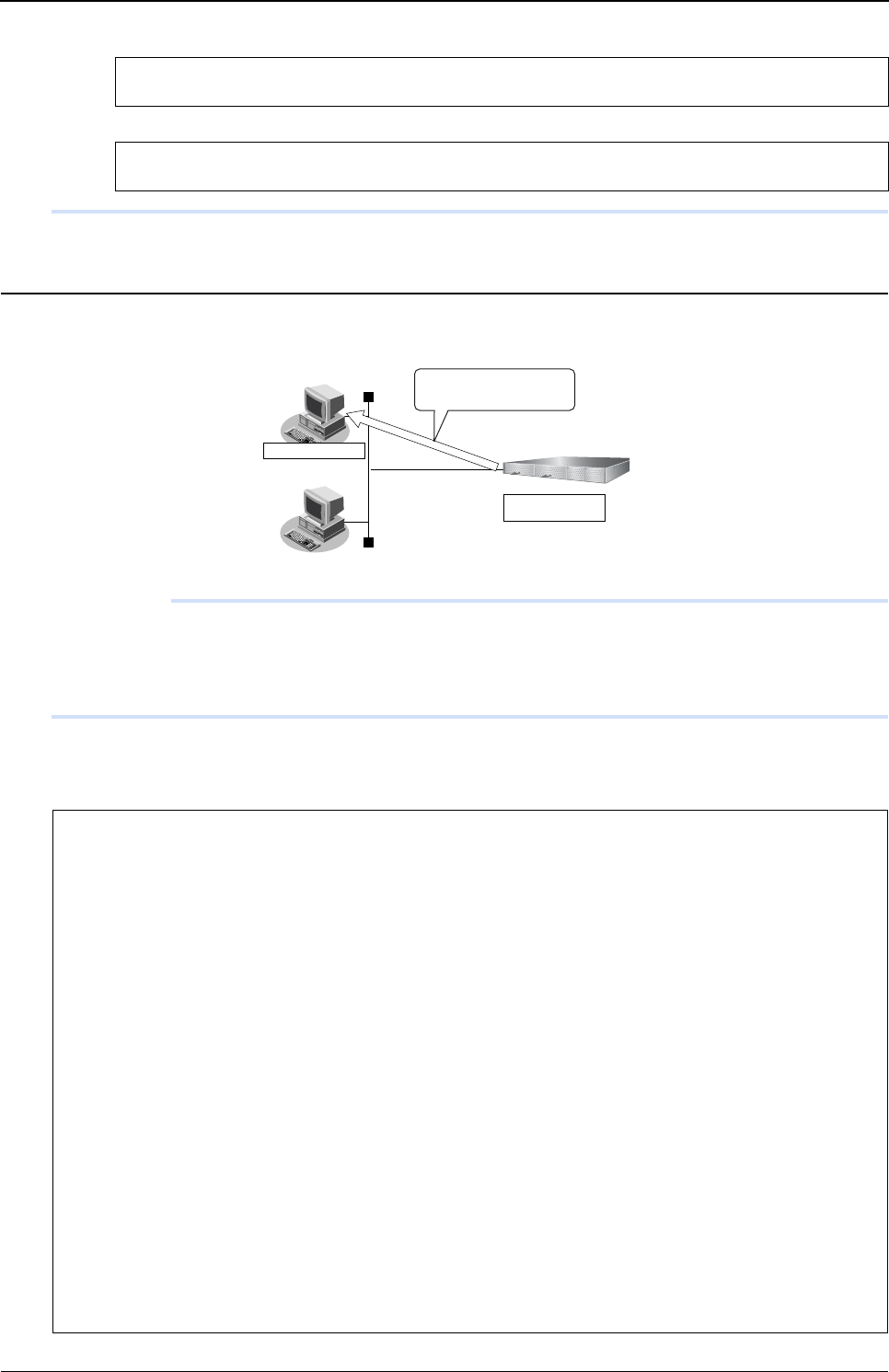
XG Series User's Guide Chapter 6 Managing the Device
Saving/Restoring Configuration Information
562
• The following error message may be displayed while using ftp commands:
If this error message is displayed, perform the following operation and retry the failed operation:
Saving configuration information using the FTP server function
The following explains how to save configuration information using ftp commands on a PC.
Precautions
Be sure to observe the following precautions while performing maintenance operations:
• Do not cut power to the device.
• Ensure that no data communication is taking place on the device.
• Perform these operations only when no configuration is taking place on the console.
zExample of using an ftp command
The following example saves configuration information 1 to the config1-1 file on the PC.
502 PASV command not implemented.
Passive mode regused.
ftp> passive : Change the passive mode.
Passive mode off.
C:\>cd Directory in which to store configuration information
C:\tmp>ftp 192.168.1.1 : Connect to the device.
Connected to 192.168.1.1.
220 XG2600 V01.00 FTP server (config1) ready.
Name(192.168.1.1:root): ftp-admin : Enter the user name.
331 Password required for ftp-admin.
Password: : Enter the password.
230 User ftp-admin logged in.
ftp>bin : Enter binary mode.
200 Type set to I.
fftp>get config1 config1-1 : Save configuration information 1 (config1) to the config1-1 file.
local: config1 remote: config1-1
200 PORT command successful.
150 Opening BINARY mode data connection for ‘config1’(2753 bytes)
•
226- Transfer complete.
2857 bytes received in 1.10 seconds (2.44 Kbytes/s)
ftp>bye : Finish
221 Goodbye.
C:\tmp>
Getconfigurationinformation
withanftpcommand
FTPclient
IPaddress
192.168.1.1

XG Series User's Guide Chapter 6 Managing the Device
Saving/Restoring Configuration Information
563
Restoring configuration information using the FTP server function
The following explains how to restore configuration information using ftp commands on a PC.
Precautions
Be sure to observe the following precautions while performing maintenance operations:
• Do not cut power to the device.
• Ensure that no data communication is taking place on the device.
• Perform only when no configuration is taking place on the console.
zExample of using an ftp command
The following example restores configuration information 1 from the config1-1 file on the PC.
Reference "5.14 Password Information" (pg.257)
C:\>cd Directory in which to store configuration information
C:\tmp>ftp 192.168.1.1 : Connect to the device.
Connected to 192.168.1.1.
220 XG2600 V01.00 FTP server (config1) ready.
Name(192.168.1.1:root): ftp-admin : Enter the user name.
331 Password required for ftp-admin.
Password: : Enter the password.
230 User ftp-admin logged in.
ftp>bin : Enter binary mode.
200 Type set to I.
ftp>put config1-1 config1 : Write the config1-1 file as configuration information 1.
local: config1-1 remote: config1
200 PORT command successful.
150 Opening BINARY mode data connection for ‘config1’
226- Transfer complete.
update : File information check now!
update : File information check ok.
•
•
226 Write complete.
2856 bytes sent in 1.10 seconds (2.44 Kbytes/s)
ftp>get reset : Restart the device.
local: reset remote: reset
200 PORT command successful.
421 Reset request ok. bye.
ftp>bye : Finish
C:\tmp>
FTPclient
IPaddress
192.168.1.1
Putconfigurationinformation
withanftpcommand

XG Series User's Guide Chapter 6 Managing the Device
Saving/Restoring Configuration Information
564
6.2.2 Saving/restoring configuration information using a
Compact Flash Card
You can save the device’s configuration information on a CompactFlash card. If necessary, you can also restore the
configuration information saved on a CompactFlash card.
zConfiguration information which can be saved
• Configuration information 1 : config1
• Configuration information 2 : config2
The following explains how to save/restore configuration information using a CompactFlash card.
Saving configuration information using a Compact Flash Card
The following explains how to save the configuration information of this device to a CompactFlash card.
1. Insert a CompactFlash card on which you will save configuration information into the CompactFlash
card slot of this device.
2. Save the configuration information to the CompactFlash card.
zExample
The following example saves configuration information 1 to the config1-1 file.
Note
Be sure to restart the device to so that the restored configuration information can take effect.
Enter "get reset" as a subcommand for the ftp command to restart.
To switch the configuration information, enter "get reset1" or "get reset2" and restart the device.
• When "get reset" is entered : The current configuration information takes effect after restart.
• When "get reset1" is entered : Configuration information 1 takes effect after restart.
• When "get reset2" is entered : Configuration information 2 takes effect after restart.
AvailableModel
XG0224
# copy config1 /cf0/config1-1
XG Series User's Guide Chapter 6 Managing the Device
Saving/Restoring Configuration Information
565
Restoring configuration information using a CompactFlash card
The following explains how to restore device configuration information that has been saved to a CompactFlash card.
1. Insert the CompactFlash card containing the configuration information into the device’s
CompactFlash card slot.
2. Restore configuration information from the CompactFlash card.
zExample
The following example restores configuration information 2 from the config2-1 file.
6.2.3 Saving/restoring configuration information using USB
memory
You can save the device’s configuration information on USB memory. If necessary, you can also restore the configuration
information saved on USB memory.
zConfiguration information which can be saved
• Candidate configuration : candidate-config
• Running configuration : running-config
• Configuration information 1 : config1
• Configuration information 2 : config2
The following explains how to save/restore configuration information using USB memory.
Saving configuration information using USB memory
The following explains how to save the configuration information of this device to USB memory.
1. Insert USB memory on which you will save the configuration information into the USB port of the
device.
2. Release the block status of the USB port.
3. Confirm that the block status of the USB port has been released.
Run a show usb hcd status command and ensure that the status displays "enable".
# copy /cf0/config2-1 config2
# reset : Restart the device.
Note Be sure to restart the device to so that the restored configuration information can take effect.
AvailableModel
XG0448 / XG2600
# usbctl enable
# show usb hcd status
[USB HCD STATUS]
status : enable

XG Series User's Guide Chapter 6 Managing the Device
Saving/Restoring Configuration Information
566
4. Save configuration information to the USB memory.
zExample
The following example saves configuration information 1 to the config1-1 file.
5. Block the USB port.
6. Confirm that the USB port has been blocked.
Run a show usb hcd status command and ensure that the status displays "disable".
7. Remove the USB memory from the device.
Restoring configuration information using USB memory
The following explains how to restore device configuration information that has been saved to USB memory.
1. Insert USB memory containing the saved configuration information into the USB port of the device.
2. Release the block status of the USB port.
3. Confirm that the block status of the USB port has been released.
Run a show usb hcd status command and ensure that the status displays "enable".
4. Restore configuration information from the USB memory.
zExample
The following example restores configuration information 2 from the config2-1 file.
5. Block the USB port.
# copy config1 /um0/config1-1
# usbctl disable
# show usb hcd status
[USB HCD STATUS]
status : disable
# usbctl enable
# show usb hcd status
[USB HCD STATUS]
status : enable
# copy /um0/config2-1 config2
# reset : Restart the device.
# usbctl disable

XG Series User's Guide Chapter 6 Managing the Device
Saving/Restoring Configuration Information
567
6. Confirm that the USB port has been blocked.
Run a show usb hcd status command and ensure that the status displays "disable".
7. Remove the USB memory from the device.
# show usb hcd status
[USB HCD STATUS]
status : disable
Note Be sure to restart the device to so that the restored configuration information can take effect.
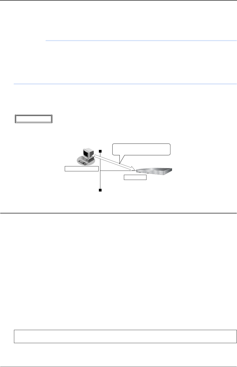
XG Series User's Guide Chapter 6 Managing the Device
Updating Firmware
568
6.3 Updating Firmware
This section explains how to update the firmware and initialize the settings of the device.
Precautions
• Before updating the firmware, do not connect the switch via the serial interface.
• While updating the firmware, do not power off or reset the device or the chassis main or remove the device from the
chassis; otherwise the device will become inoperable.
• Verify that the device is not communicating.
• Verify that no configuration work using the CLI is in process.
• Before updating the firmware, back up the configuration data to an external device.
6.3.1 Updating Firmware Using FTP
The following is an example of updating the device firmware using a FTP client.
Connect the device and the Personal Computer Using LAN
Connect the device and the personal computer (FTP client) using LAN. Set an IP address which has the same network as
the device for the personal computer. This section explains about the IP address of the device when set as "192.168.1.1",
and the subnet mask when set as "255.255.255.0" as an example.
Update the Firmware
This section explains how to update the firmware using Windows command prompt.
1. Save the new firmware in a work folder of the PC.
The storing destination and file name are explained when they are set as "D:\FIRM\XG2600SOFT.ftp" as an example.
2. Open the command prompt.
1) Click "Start" menu → "Run".
2) Type "cmd" and press the [Enter] key.
The command prompt is displayed.
3. Change the current directory to the one where the firmware is stored.
AvailableModel
All models
C:\> d:
D:\> cd \FIRM
FTPclient
192.168.1.1
UpdatethefirmwareusingFTP

XG Series User's Guide Chapter 6 Managing the Device
Updating Firmware
569
4. Log in with the account name "ftp-admin".
Log in to the device using FTP command.
Login name: ftp-admin
Password: The password is the one made with the "password set" command.
If no password has been set, there is no need to enter one.
Confirm the password with the system administrator.
5. Transfer the firmware to the device.
Transfer the firmware to the device in "binary" mode.
Input "put [the file name of the put personal computer (XG2600SOFT.ftp)] [the file name of the device (firmware)]" in the
"put" command.
6. Check that the firmware is completely transferred.
When "Write complete" message is displayed, it indicates that the process is terminated successfully.
7. Exit the ftp mode.
8. Remove the device from the chassis, wait about 10 seconds, and reinsert the device to the chassis.
The power is turned on again, and the firmware is enabled.
D:\FIRM>ftp 192.168.1.1 : Connect the device
Connected to 192.168.1.1 (Specify IP address of the device)
220 XG2600 V01.00 FTP server ready.
User (192.168.1.1:(none)): ftp-admin : Type login name
331 Password required for ftp-admin.
Password: : Type password
230 User ftp-admin logged in.
ftp>
ftp>binary : Set "binary" mode
200 Type set to I.
ftp>put XG2600SOFT.ftp firmware : Write the "XG2600SOFT.ftp" file as a firmware
local: XG2600SOFT.ftp remote: firmware
200 PORT command successful.
150 Opening BINARY mode data connection for `firmware´.
226- Transfer complete.
update : Transfer file check now!
update : Transfer file check ok.
.
.
Note When forwarding firmware to this product, the destination file name must be input as "firmware". Anything other than
"firmware" cannot be input.
.
.
226 Write complete.
ftp>
ftp> quit : Exit "ftp" command
221 Goodbye.
D:\FIRM>

XG Series User's Guide Chapter 6 Managing the Device
Updating Firmware
570
9. Check that the firmware is successfully updated.
After restarting the device, log in to the device using the telnet or the terminal PC connected via the master management
blade. Enter the "show system information" command to verify the firmware version.
6.3.2 Updating Firmware Using CompactFlash card
This section explains how to update the firmware using a compact flash card.
Firmware Update with a telnet or a console
Follow the instructions below to transfer the firmware saved in a compact flash card using the telnet command or a
console.
1. Insert the compact flash card into the compact flash card slot on the back of this device.
2. Login as admin class (admin).
3. Transfer the firmware from the compact flash card to this device.
For <filename>, enter the filename of the firmware saved in the compact flash card.
4. Make sure that the prompt is displayed.
5. Pull out the power cable of this device and insert it again.
The power is turned on again and the firmware is enabled.
6. Check that the firmware is updated correctly.
After restarting this device, login to this device using telnet or console. Run the "show system information" command to
check that the product name of this device and the firmware version are correctly displayed.
# show system information
:
System : XG2600
:
Firm Ver. : V01.00 (firmware version)
:
AvailableModel
XG0224
copy / cf0 / <filename> firmware
# show system information
:
System : XG2600 (product name)
:
Firm Ver. : V01.00 (firmware version)
:
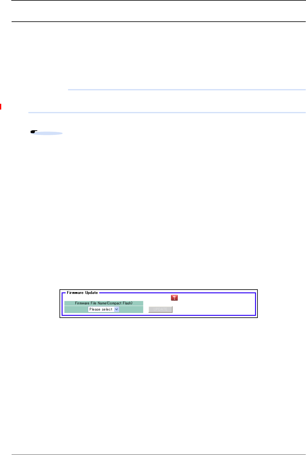
XG Series User's Guide Chapter 6 Managing the Device
Updating Firmware
571
Firmware Update with a WWW browser
Follow the instructions below to transfer the firmware saved in a compact flash card using the WWW browser.
1. Connect this device and a PC via LAN.
Set an IP address which has the same network as the device for the personal computer.
This section explains about the IP address of the device when set as "192.168.1.1", and the subnet mask when set as
"255.255.255.0" as an example.
Precautions
• The IP address of the device is not set at the initial condition,please set the IP address via serial port.
• When someone login via serial port or via telnet, you can't connect from WWW browser.
2. Insert the compact flash card into the compact flash card slot on the back of this device.
3. Start the WWW browser.
4. Specify the URL [http://192.168.1.1/] of this device.
The top page of this device will be displayed.
5. Login as admin class (admin).
6. Click [Maintenance] tab on the left side of the top page screen.
The login screen will be displayed.
7. Click [Compact flash] in the Maintenance menu.
[Compact flash ] page will be displayed.
8. Click [Update Firmware].
[Update Firmware] page will be displayed.
9. Specify Firmware file name and click [Update].
Firmware will be updated.
Reference "2.1.1 Operating Environment for the CLI"

XG Series User's Guide Chapter 6 Managing the Device
Updating Firmware
572
6.3.3 Updating Firmware Using USB memory
This section explains how to update the firmware using a compact USB memory.
Firmware Update with a telnet or a console
Follow the instructions below to transfer the firmware saved in a USB memory using the telnet command or a console.
1. Insert the USB memory into the USB port on the back of this device.
2. Login as admin class (admin).
3. Transfer the firmware from the USB memory to this device.
For <filename>, enter the filename of the firmware saved in the compact flash card.
4. Make sure that the prompt is displayed.
5. Pull out the power cable of this device and insert it again.
The power is turned on again and the firmware is enabled.
6. Check that the firmware is updated correctly.
After restarting this device, login to this device using telnet or console. Run the "show system information" command to
check that the product name of this device and the firmware version are correctly displayed.
AvailableModel
XG0448 / X2600
# copy /um0/<filename> firmware
# show system information
:
System : XG2600 (product name)
:
Firm Ver. : V01.00 (firmware version)
:
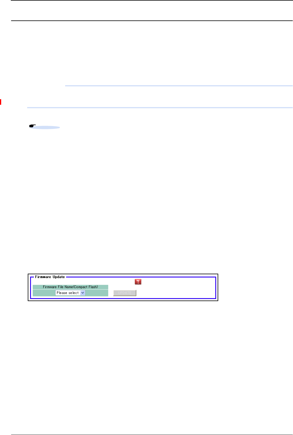
XG Series User's Guide Chapter 6 Managing the Device
Updating Firmware
573
Firmware Update with a WWW browser
Follow the instructions below to transfer the firmware saved in a USB memory using the WWW browser.
1. Connect this device and a PC via LAN.
Set an IP address which has the same network as the device for the personal computer.
This section explains about the IP address of the device when set as "192.168.1.1", and the subnet mask when set as
"255.255.255.0" as an example.
Precautions
• The IP address of the device is not set at the initial condition,please set the IP address via serial port.
• When someone login via serial port or via telnet, you can't connect from WWW browser.
2. Insert the USB memory into the USB port on the back of this device.
3. Start the WWW browser.
4. Specify the URL [http://192.168.1.1/] of this device.
The top page of this device will be displayed.
5. Login as admin class (admin).
6. Click [Maintenance] tab on the left side of the top page screen.
The login screen will be displayed.
7. Click [USB memory] in the Maintenance menu.
[USB memory ] page will be displayed.
8. Click [Update Firmware].
[Update Firmware] page will be displayed.
9. Specify Firmware file name and click [Update].
Firmware will be updated.
Reference "2.1.1 Operating Environment for the CLI"
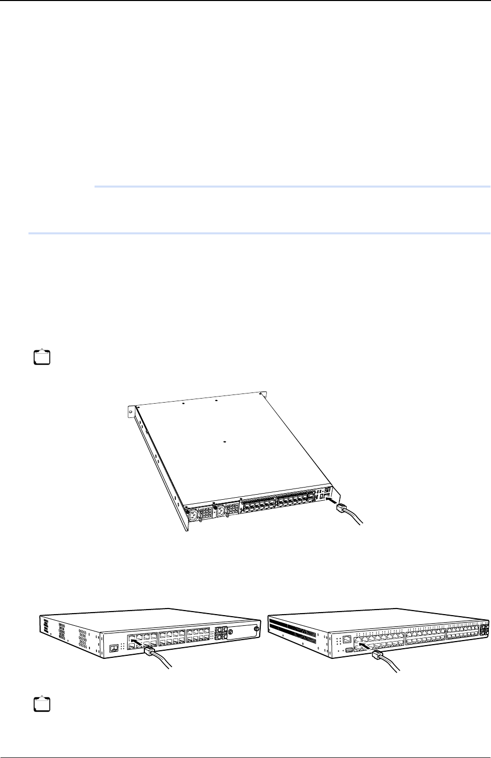
XG Series User's Guide Chapter 6 Managing the Device
Actions When Firmware Update Failes (Backup Firm Function)
574
6.4 Actions When Firmware Update
Failes (Backup Firm Function)
If the firmware update fails due to power failure or some other reason and you cannot start this device, you can restore the
device to its normal condition by starting the backup firmware and transferring the firmware with an FTP client on the
network or by a compact flash card.
6.4.1 Preparing the Device
Precautions
When the device boots up Backup Firm, the IP address of Management-port (XG2600) or LAN port (XG0224 /
XG0448) is set 192.168.1.1.
A problem has come up, so please connect only this device and a PC.
1. Make sure that the power of this device is turned off.
2. Connect this device and a PC via LAN.
•XG2600
Directly connect a cable to Management Port (10/100BASE-TX port) of this device and the PC instead of using a HUB
in between.
• XG0224 / XG0448
Directly connect a cable to 10/100/1000BASE-T ports of this device and the PC instead of using a HUB in between.
Note Management-port of XG2600 (10/100BASE-TX) is MDI fixed.
Note As this device supports AutoMDI/MDI-X function, you can connect a cable to 10/100/1000BASE-T ports without being
conscious of the PC and HUB.
[XG0224] [XG0448]
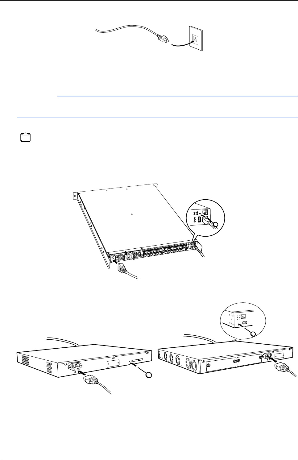
XG Series User's Guide Chapter 6 Managing the Device
Actions When Firmware Update Failes (Backup Firm Function)
575
3. Connect the power cable to the power outlet.
4. Insert the power cable into the power connector while pressing the reset switch on the back of this
device using a pointed tool. After about five seconds, release the reset switch.
The power is turned on and the backup firmware is started.
Precautions
If you do not release the reset switch within 10 seconds after turning on the device, it is regarded as reset switch failure.
Be sure release the reset switch within 10 seconds.
•XG2600
• XG0224/XG0448
Note
• It takes about one minute to start the backup firmware.
• The Ready LED blinks in green when the backup firmware is running.
• If you start the backup firmware to logon with the console connected, the "backup#" message is displayed on the console
screen.
[XG0224] [XG0448]

XG Series User's Guide Chapter 6 Managing the Device
Actions When Firmware Update Failes (Backup Firm Function)
576
6.4.2 Updating the Firmware
You can perform firmware update by transferring the firmware from an FTP client or a compact flash card.
Reference "6.3.1 Updating Firmware Using FTP" (pg.568), "6.3.2 Updating Firmware Using CompactFlash card" (pg.570),
"6.3.3 Updating Firmware Using USB memory" (pg.572)

XG Series User's Guide Chapter 6 Managing the Device
Extracting of Maintenance Information
577
6.5 Extracting of Maintenance Information
If a fault occurred, maintenance information may be requested by the device sales representative to investigate the cause of
the fault. This section provides procedures for extracting maintenance information.
6.5.1 Procedure for Extracting Maintenance Information when a
System/Subsystem Failure Occurred
This section describes the procedures for extracting maintenance information when a system or subsystem failure
occurred.
• Viewing maintenance information
Using the "show tech-support" command, you can view maintenance information.
Using the "show tech-support detail" command, you can view the detailed information.
• Saving maintenance information
Using the "show tech-support save" command, you can save the maintenance information to the external media.
Using the "show tech-support detail save" command, you can save the detailed information.


XG Series User's Guide Chapter 7 Troubleshooting
To Return to the Initial Shipment Settings (Initializing Switch
Configuration)
579
7.1 To Return to the Initial Shipment Settings
(Initializing Switch Configuration)
In case of incorrect settings or problems, this device status can be returned to its initial shipment settings.
When relocating this device, initialize the settings to the time of shipment before setting.
1. Connect to the device from the terminal PC via the master management blade using the serial
connection.
For the connecting method, refer to "6.3.1 Updating Firmware Using FTP" (pg.568).
2. Type user name and password to log in.
User name: admin
Password: Confirm with the system administrator.
3. Type "reset clear", and press the [Return] or [Enter] key.
The configuration of the device is initialized.
Note Initialization of the setting will erase all the set data. Back up the configuration data or note the contents of settings.
# reset clear <enter>
>

Appendix
This appendix explains the specification for the switch and technical information.
A SNMP Traps . . . . . . . . . . . . . . . . . . . . . . . . . . . . . . . . . . . . . . . . . . . . . . . . . . . . . . . . . . . . . . . . . . . . . . 581
A.1 Trap List . . . . . . . . . . . . . . . . . . . . . . . . . . . . . . . . . . . . . . . . . . . . . . . . . . . . . . . . . . . . . . . . . . 581
B List of MIBs . . . . . . . . . . . . . . . . . . . . . . . . . . . . . . . . . . . . . . . . . . . . . . . . . . . . . . . . . . . . . . . . . . . . . . 582
B.1 Standard MIB Definitions . . . . . . . . . . . . . . . . . . . . . . . . . . . . . . . . . . . . . . . . . . . . . . . . . . . . 582
B.2 Fujitsu Extension MIB . . . . . . . . . . . . . . . . . . . . . . . . . . . . . . . . . . . . . . . . . . . . . . . . . . . . . . . 599
B.3 IEEE802.1MIB . . . . . . . . . . . . . . . . . . . . . . . . . . . . . . . . . . . . . . . . . . . . . . . . . . . . . . . . . . . . . . 601

XG Series User's Guide Appendix
SNMP Traps
581
ASNMP Traps
This appendix lists the SNMP traps supported by the device.
A.1 Trap List
An SNMP agent can trap events and notify the SNMP manager asynchronously.
An SNMP agent sends trap when an event occurs.
The following is the list of supported traps.
• coldStart
Notified once if the device starts or restarts.
• linkDown
Notified if a link fails. May be notified at reboot or if the configuration becomes reactivated.
• linkUp
Notified if a communication link of the device becomes activated.
• authenticationFailure
Notified if SNMP authentication fails.
• newRoot
Notified if the device becomes the root bridge.
• topologyChange
Notified if a change in the bridge network configuration is detected, i.e., if the network status changes from learning to
forwarding or from forwarding to blocking.
• nosError
Notified if a hardware failure occurs. Only the occurrence of a failure is notified.
• lldpRemTablesChange
Notified if the neighbor LLDP device information table changes.
XG Series User's Guide Appendix
List of MIBs
582
B List of MIBs
This appendix lists the MIBs supported by the device.
B.1 Standard MIB Definitions
The following shows meaning of MIB ACCESS column.
RO :MIB can be read only.
RW :MIB can be read and written.
– :MIB can not be accessed.
B.1.1 system Group
*) Written MIB works on until reset.
AvailableModel
All models
No. Name Object identifier MIB ACCESS
1 sysDescr system.1 RO
2sysObjectID system.2 RO
3 sysUpTime system.3 RO
4sysContact system.4 RW (*)
5 sysName system.5 RW (*)
6sysLocation system.6 RW (*)
7 sysServices system.7 RO
XG Series User's Guide Appendix
List of MIBs
583
B.1.2 interfaces Group
B.1.3 address translation Group
B.1.4 ip Group
ip Group
No. Name Object identifier MIB ACCESS
1 ifNumber interfaces.1 RO
2ifTable interfaces.2 –
3 ifEntry ifTable.1 –
4ifIndex ifEntry.1 RO
5 ifDescr ifEntry.2 RO
6ifType ifEntry.3 RO
7 ifMtu ifEntry.4 RO
8ifSpeed ifEntry.5 RO
9 ifPhysAddress ifEntry.6 RO
10 ifAdminStatus ifEntry.7 RW
11 ifOperStatus ifEntry.8 RO
12 ifLastChange ifEntry.9 RO
13 ifInOctets ifEntry.10 RO
14 ifInUcastPkts ifEntry.11 RO
15 ifInNUcastPkts ifEntry.12 RO
16 ifInDiscards ifEntry.13 RO
17 ifInErrors ifEntry.14 RO
18 ifInUnknownProtos ifEntry.15 RO
19 ifOutOctets ifEntry.16 RO
20 ifOutUcastPkts ifEntry.17 RO
21 ifOutNUcastPkts ifEntry.18 RO
22 ifOutDiscards ifEntry.19 RO
23 ifOutErrors ifEntry.20 RO
24 ifOutQLen ifEntry.21 RO
25 ifSpecific ifEntry.22 RO
No. Name Object identifier MIB ACCESS
1 atTable at.1 –
2atEntry atTable.1 –
3 atIfIndex atEntry.1 RO
4atPhysAddress atEntry.2 RO
5 atNetAddress atEntry.3 RO
No. Name Object identifier MIB ACCESS
1 ipForwarding ip.1 RO
2ipDefaultTTL ip.2 RO
3 ipInReceives ip.3 RO
4ipInHdrErrors ip.4 RO
5 ipInAddrErrors ip.5 RO
6ipForwDatagrams ip.6 RO
7 ipInUnknownProtos ip.7 RO
8ipInDiscards ip.8 RO
9 ipInDelivers ip.9 RO
10 ipOutRequests ip.10 RO
11 ipOutDiscards ip.11 RO
12 ipOutNoRoutes ip.12 RO
13 ipReasmTimeout ip.13 RO
14 ipReasmReqds ip.14 RO
XG Series User's Guide Appendix
List of MIBs
584
ipAddr Group
ipRoute Group
ipNetToMedia Group
15 ipReasmOKs ip.15 RO
16 ipReasmFails ip.16 RO
17 ipFragOKs ip.17 RO
18 ipFragFails ip.18 RO
19 ipFragCreates ip.19 RO
20 ipRoutingDiscards ip.23 RO
No. Name Object identifier MIB ACCESS
1 ipAddrTable ip.20 –
2ipAddrEntry ipAddrTable.1 –
3 ipAdEntAddr ipAddrEntry.1 RO
4ipAdEntIfIndex ipAddrEntry.2 RO
5 ipAdEntNetMask ipAddrEntry.3 RO
6ipAdEntBcastAddr ipAddrEntry.4 RO
7 ipAdEntReasmMaxSize ipAddrEntry.5 RO
No. Name Object identifier MIB ACCESS
1 ipRouteTable ip.21 –
2ipRouteEntry ipRouteTable.1 –
3 ipRouteDest ipRouteEntry.1 RO
4ipRouteIfIndex ipRouteEntry.2 RO
5 ipRouteMetric1 ipRouteEntry.3 RO
6ipRouteMetric2 ipRouteEntry.4 RO
7 ipRouteMetric3 ipRouteEntry.5 RO
8ipRouteMetric4 ipRouteEntry.6 RO
9 ipRouteNextHop ipRouteEntry.7 RO
10 ipRouteType ipRouteEntry.8 RO
11 ipRouteProto ipRouteEntry.9 RO
12 ipRouteAge ipRouteEntry.10 RO
13 ipRouteMask ipRouteEntry.11 RO
14 ipRouteMetric5 ipRouteEntry.12 RO
15 ipRouteInfo ipRouteEntry.13 RO
No. Name Object identifier MIB ACCESS
1 ipNetToMediaTable ip.22 –
2ipNetToMediaEntry ipNetToMediaTable.1 –
3 ipNetToMediaIfIndex ipNetToMediaEntry.1 RO
4ipNetToMediaPhysAddress ipNetToMediaEntry.2 RO
5 ipNetToMediaNetAddress ipNetToMediaEntry.3 RO
6ipNetToMediaType ipNetToMediaEntry.4 RO
No. Name Object identifier MIB ACCESS
XG Series User's Guide Appendix
List of MIBs
585
ipCidrRoute Group
inetCidrRoute Group
ipv6 Group
No. Name Object identifier MIB ACCESS
1 ipCidrRouteNumber ipForward.3 RO
2ipCidrRouteTable ipForward.4 –
3 ipCidrRouteEntry ipCidrRouteTable.1 –
4ipCidrRouteDest ipCidrRouteEntry.1 RO
5 ipCidrRouteMask ipCidrRouteEntry.2 RO
6ipCidrRouteTos ipCidrRouteEntry.3 RO
7 ipCidrRouteNextHop ipCidrRouteEntry.4 RO
8ipCidrRouteIfIndex ipCidrRouteEntry.5 RO
9 ipCidrRouteType ipCidrRouteEntry.6 RO
10 ipCidrRouteProto ipCidrRouteEntry.7 RO
11 ipCidrRouteAge ipCidrRouteEntry.8 RO
12 ipCidrRouteInfo ipCidrRouteEntry.9 RO
13 ipCidrRouteNextHopAS ipCidrRouteEntry.10 RO
14 ipCidrRouteMetric1 ipCidrRouteEntry.11 RO
15 ipCidrRouteMetric2 ipCidrRouteEntry.12 RO
16 ipCidrRouteMetric3 ipCidrRouteEntry.13 RO
17 ipCidrRouteMetric4 ipCidrRouteEntry.14 RO
18 ipCidrRouteMetric5 ipCidrRouteEntry.15 RO
19 ipCidrRouteStatus ipCidrRouteEntry.16 RO
No. Name Object identifier MIB ACCESS
1 inetCidrRouteNumber ipForward.6 RO
2inetCidrRouteTable ipForward.7 –
3 inetCidrRouteEntry inetCidrRouteTable.1 –
4inetCidrRouteDestType inetCidrRouteEntry.1 –
5 inetCidrRouteDest inetCidrRouteEntry.2 –
6inetCidrRoutePfxLen inetCidrRouteEntry.3 –
7 inetCidrRoutePolicy inetCidrRouteEntry.4 –
8inetCidrRouteNextHopType inetCidrRouteEntry.5 –
9 inetCidrRouteNextHop inetCidrRouteEntry.6 –
10 inetCidrRouteIfIndex inetCidrRouteEntry.7 RO
11 inetCidrRouteType inetCidrRouteEntry.8 RO
12 inetCidrRouteProto inetCidrRouteEntry.9 RO
13 inetCidrRouteAge inetCidrRouteEntry.10 RO
14 inetCidrRouteNextHopAS inetCidrRouteEntry.11 RO
15 inetCidrRouteMetric1 inetCidrRouteEntry.12 RO
16 inetCidrRouteMetric2 inetCidrRouteEntry.13 RO
17 inetCidrRouteMetric3 inetCidrRouteEntry.14 RO
18 inetCidrRouteMetric4 inetCidrRouteEntry.15 RO
19 inetCidrRouteMetric5 inetCidrRouteEntry.16 RO
20 inetCidrRouteStatus inetCidrRouteEntry.17 RO
21 inetCidrRouteDiscards ipForward.8 RO
No. Name Object identifier MIB ACCESS
1 ipv6IpForwarding ip.25 RO
2ipv6IpDefaultHopLimit ip.26 RO
XG Series User's Guide Appendix
List of MIBs
586
ipv4Interface Group
ipv6Interface Group
ipSystemStats Group
No. Name Object identifier MIB ACCESS
1 ipv4InterfaceTableLastChange ip.27 RO
2ipv4InterfaceTable ip.28 –
3 ipv4InterfaceEntry ipv4InterfaceTable.1 –
4ipv4InterfaceIfIndex ipv4InterfaceEntry.1 –
5 ipv4InterfaceReasmMaxSize ipv4InterfaceEntry.2 RO
6ipv4InterfaceEnableStatus ipv4InterfaceEntry.3 RO
7 ipv4InterfaceRetransmitTime ipv4InterfaceEntry.4 RO
No. Name Object identifier MIB ACCESS
1 ipv6InterfaceTableLastChange ip.29 RO
2ipv6InterfaceTable ip.30 –
3 ipv6InterfaceEntry ipv6InterfaceTable.1 –
4ipv6InterfaceIfIndex ipv6InterfaceEntry.1 –
5 ipv6InterfaceReasmMaxSize ipv6InterfaceEntry.2 RO
6ipv6InterfaceIdentifier ipv6InterfaceEntry.3 RO
7 ipv6InterfaceEnableStatus ipv6InterfaceEntry.5 RO
8ipv6InterfaceReachableTime ipv6InterfaceEntry.6 RO
9 ipv6InterfaceRetransmitTime ipv6InterfaceEntry.7 RO
10 ipv6InterfaceForwarding ipv6InterfaceEntry.8 RO
No. Name Object identifier MIB ACCESS
1 ipSystemStatsTable ipTrafficStats.1 –
2ipSystemStatsEntry ipSystemStatsTable.1 –
3 ipSystemStatsIPVersion ipSystemStatsEntry.1 –
4ipSystemStatsInReceives ipSystemStatsEntry.3 RO
5 ipSystemStatsInHdrErrors ipSystemStatsEntry.7 RO
6ipSystemStatsInUnknownProtos ipSystemStatsEntry.10 RO
7 ipSystemStatsInTruncatedPkts ipSystemStatsEntry.11 RO
8ipSystemStatsInForwDatagrams ipSystemStatsEntry.12 RO
9 ipSystemStatsReasmReqds ipSystemStatsEntry.14 RO
10 ipSystemStatsReasmOKs ipSystemStatsEntry.15 RO
11 ipSystemStatsReasmFails ipSystemStatsEntry.16 RO
12 ipSystemStatsInDelivers ipSystemStatsEntry.18 RO
13 ipSystemStatsOutRequests ipSystemStatsEntry.20 RO
14 ipSystemStatsOutNoRoutes ipSystemStatsEntry.22 RO
15 ipSystemStatsOutForwDatagrams ipSystemStatsEntry.23 RO
16 ipSystemStatsOutDiscards ipSystemStatsEntry.25 RO
17 ipSystemStatsOutFragReqds ipSystemStatsEntry.26 RO
18 ipSystemStatsOutFragOKs ipSystemStatsEntry.27 RO
19 ipSystemStatsOutFragFails ipSystemStatsEntry.28 RO
20 ipSystemStatsOutFragCreates ipSystemStatsEntry.29 RO
21 ipSystemStatsOutTransmits ipSystemStatsEntry.30 RO
22 ipSystemStatsDiscontinuityTime ipSystemStatsEntry.46 RO
23 ipSystemStatsRefreshRate ipSystemStatsEntry.47 RO
XG Series User's Guide Appendix
List of MIBs
587
ipAddressPrefix Group
ipAddress Group
ipNetToPhysical Group
No. Name Object identifier MIB ACCESS
1 ipAddressPrefixTable ip.32 –
2ipAddressPrefixEntry ipAddressPrefixTable.1 –
3 ipAddressPrefixIfIndex ipAddressPrefixEntry.1 –
4ipAddressPrefixType ipAddressPrefixEntry.2 –
5 ipAddressPrefixPrefix ipAddressPrefixEntry.3 –
6ipAddressPrefixLength ipAddressPrefixEntry.4 –
7 ipAddressPrefixOrigin ipAddressPrefixEntry.5 RO
8ipAddressPrefixOnLinkFlag ipAddressPrefixEntry.6 RO
9 ipAddressPrefixAutonomousFlag ipAddressPrefixEntry.7 RO
10 ipAddressPrefixAdvPreferredLifetime ipAddressPrefixEntry.8 RO
11 ipAddressPrefixAdvValidLifetime ipAddressPrefixEntry.9 RO
No. Name Object identifier MIB ACCESS
1 ipAddressTable ip.34 –
2ipAddressEntry ipAddressTable.1 –
3 ipAddressAddrType ipAddressEntry.1 –
4ipAddressAddr ipAddressEntry.2 –
5 ipAddressIfIndex ipAddressEntry.3 RO
6ipAddressType ipAddressEntry.4 RO
7 ipAddressPrefix ipAddressEntry.5 RO
8ipAddressOrigin ipAddressEntry.6 RO
9 ipAddressStatus ipAddressEntry.7 RO
10 ipAddressCreated ipAddressEntry.8 RO
11 ipAddressLastChanged ipAddressEntry.9 RO
12 ipAddressRowStatus ipAddressEntry.10 RO
13 ipAddressStorageType ipAddressEntry.11 RO
No. Name Object identifier MIB ACCESS
1 ipNetToPhysicalTable ip.35 –
2ipNetToPhysicalEntry ipNetToPhysicalTable.1 –
3 ipNetToPhysicalIfIndex ipNetToPhysicalEntry.1 –
4ipNetToPhysicalNetAddressType ipNetToPhysicalEntry.2 –
5 ipNetToPhysicalNetAddress ipNetToPhysicalEntry.3 –
6ipNetToPhysicalPhysAddress ipNetToPhysicalEntry.4 RO
7 ipNetToPhysicalLastUpdated ipNetToPhysicalEntry.5 RO
8ipNetToPhysicalType ipNetToPhysicalEntry.6 RO
9 ipNetToPhysicalState ipNetToPhysicalEntry.7 RO
10 ipNetToPhysicalRowStatus ipNetToPhysicalEntry.8 RO
XG Series User's Guide Appendix
List of MIBs
588
B.1.5 icmp Group
icmp Group
icmpStat Group
icmpMsgStats Group
No. Name Object identifier MIB ACCESS
1 icmpInMsgs icmp.1 RO
2icmpInErrors icmp.2 RO
3 icmpInDestUnreachs icmp.3 RO
4icmpInTimeExcds icmp.4 RO
5 icmpInParmProbs icmp.5 RO
6icmpInSrcQuenchs icmp.6 RO
7 icmpInRedirects icmp.7 RO
8icmpInEchos icmp.8 RO
9 icmpInEchoReps icmp.9 RO
10 icmpInTimestamps icmp.10 RO
11 icmpInTimestampReps icmp.11 RO
12 icmpInAddrMasks icmp.12 RO
13 icmpInAddrMaskReps icmp.13 RO
14 icmpOutMsgs icmp.14 RO
15 icmpOutErrors icmp.15 RO
16 icmpOutDestUnreachs icmp.16 RO
17 icmpOutTimeExcds icmp.17 RO
18 icmpOutParmProbs icmp.18 RO
19 icmpOutSrcQuenchs icmp.19 RO
20 icmpOutRedirects icmp.20 RO
21 icmpOutEchos icmp.21 RO
22 icmpOutEchoReps icmp.22 RO
23 icmpOutTimestamps icmp.23 RO
24 icmpOutTimestampReps icmp.24 RO
25 icmpOutAddrMasks icmp.25 RO
26 icmpOutAddrMaskReps icmp.26 RO
No. Name Object identifier MIB ACCESS
1 icmpStatsTable icmp.29 –
2icmpStatsEntry icmpStatsTable.1 –
3 icmpStatsIPVersion icmpStatsEntry.1 –
4icmpStatsInMsgs icmpStatsEntry.2 RO
5 icmpStatsInErrors icmpStatsEntry.3 RO
6icmpStatsOutMsgs icmpStatsEntry.4 RO
7 icmpStatsOutErrors icmpStatsEntry.5 RO
No. Name Object identifier MIB ACCESS
1 icmpMsgStatsTable icmp.30 –
2icmpMsgStatsEntry icmpMsgStatsTable.1 –
3 icmpMsgStatsIPVersion icmpMsgStatsEntry.1 –
4icmpMsgStatsType icmpMsgStatsEntry.2 –
5 icmpMsgStatsInPkts icmpMsgStatsEntry.3 RO
6icmpMsgStatsOutPkts icmpMsgStatsEntry.4 RO
XG Series User's Guide Appendix
List of MIBs
589
B.1.6 tcp Group
tcp Group
tcpConn Group
tcpConnection Group
No. Name Object identifier MIB ACCESS
1 tcpRtoAlgorithm tcp.1 RO
2tcpRtoMin tcp.2 RO
3 tcpRtoMax tcp.3 RO
4tcpMaxConn tcp.4 RO
5 tcpActiveOpens tcp.5 RO
6tcpPassiveOpens tcp.6 RO
7 tcpAttemptFails tcp.7 RO
8tcpEstabResets tcp.8 RO
9 tcpCurrEstab tcp.9 RO
10 tcpInSegs tcp.10 RO
11 tcpOutSegs tcp.11 RO
12 tcpRetransSegs tcp.12 RO
13 tcpInErrs tcp.14 RO
14 tcpOutRsts tcp.15 RO
No. Name Object identifier MIB ACCESS
1 tcpConnTable tcp.13 –
2 tcpConnEntry tcpConnTable.1 –
3 tcpConnState tcpConnEntry.1 RO
4tcpConnLocalAddress tcpConnEntry.2 RO
5 tcpConnLocalPort tcpConnEntry.3 RO
6tcpConnRemAddress tcpConnEntry.4 RO
7 tcpConnRemPort tcpConnEntry.5 RO
No. Name Object identifier MIB ACCESS
1 tcpConnectionTable tcp.19 –
2tcpConnectionEntry tcpConnectionTable.1 –
3 tcpConnectionLocalAddressType tcpConnectionEntry.1 –
4tcpConnectionLocalAddress tcpConnectionEntry.2 –
5 tcpConnectionLocalPort tcpConnectionEntry.3 –
6tcpConnectionRemAddressType tcpConnectionEntry.4 –
7 tcpConnectionRemAddress tcpConnectionEntry.5 –
8tcpConnectionRemPort tcpConnectionEntry.6 –
9 tcpConnectionState tcpConnectionEntry.7 RO
10 tcpConnectionProcess tcpConnectionEntry.8 RO

XG Series User's Guide Appendix
List of MIBs
590
tcpListener Group
B.1.7 udp Group
udp Group
udpListener Group
udpEndpoint Group
No. Name Object identifier MIB ACCESS
1 tcpListenerTable tcp.20 –
2tcpListenerEntry tcpListenerTable.1 –
3 tcpListenerLocalAddressType tcpListenerEntry.1 –
4tcpListenerLocalAddress tcpListenerEntry.2 –
5 tcpListenerLocalPort tcpListenerEntry.3 –
6tcpListenerProcess tcpListenerEntry.4 RO
No. Name Object identifier MIB ACCESS
1 udpInDatagrams udp.1 RO
2udpNoPorts udp.2 RO
3 udpInErrors udp.3 RO
4udpOutDatagrams udp.4 RO
No. Name Object identifier MIB ACCESS
1 udpTable udp.5 –
2udpEntry udpTable.1 –
3 udpLocalAddress udpEntry.1 RO
4udpLocalPort udpEntry.2 RO
No. Name Object identifier MIB ACCESS
1 udpEndpointTable udp.7 –
2udpEndpointEntry udpEndpointTable.1 –
3 udpEndpointLocalAddressType udpEndpointEntry.1 –
4udpEndpointLocalAddress udpEndpointEntry.2 –
5 udpEndpointLocalPort udpEndpointEntry.3 –
6udpEndpointRemoteAddressType udpEndpointEntry.4 –
7 udpEndpointRemoteAddress udpEndpointEntry.5 –
8udpEndpointRemotePort udpEndpointEntry.6 –
9 udpEndpointInstance udpEndpointEntry.7 –
10 udpEndpointProcess udpEndpointEntry.8 RO
XG Series User's Guide Appendix
List of MIBs
591
B.1.8 dot3 Group
dot3Stats Group
dot3Control Group
dot3Pause Group
No. Name Object identifier MIB ACCESS
1 dot3StatsTable dot3.2 –
2dot3StatsEntry dot3StatsTable.1 –
3 dot3StatsIndex dot3StatsEntry.1 RO
4dot3StatsAlignmentErrors dot3StatsEntry.2 RO
5 dot3StatsFCSErrors dot3StatsEntry.3 RO
6dot3StatsSingleCollisionFrames dot3StatsEntry.4 RO
7 dot3StatsMultipleCollisionFrames dot3StatsEntry.5 RO
8dot3StatsSQETestErrors dot3StatsEntry.6 RO
9 dot3StatsDeferredTransmissions dot3StatsEntry.7 RO
10 dot3StatsLateCollisions dot3StatsEntry.8 RO
11 dot3StatsExcessiveCollisions dot3StatsEntry.9 RO
12 dot3StatsInternalMacTransmitErrors dot3StatsEntry.10 RO
13 dot3StatsCarrierSenseErrors dot3StatsEntry.11 RO
14 dot3StatsFrameTooLongs dot3StatsEntry.13 RO
15 dot3StatsInternalMacReceiveErrors dot3StatsEntry.16 RO
16 dot3StatsEtherChipSet dot3StatsEntry.17 RO
17 dot3StatsSymbolErrors dot3StatsEntry.18 RO
18 dot3StatsDuplexStatus dot3StatsEntry.19 RO
19 dot3StatsRateControlAbility dot3StatsEntry.20 RO
20 dot3StatsRateControlStatus dot3StatsEntry.21 RO
No. Name Object identifier MIB ACCESS
1 dot3ControlTable dot3.9 –
2dot3ControlEntry dot3ControlTable.1 –
3 dot3ControlFunctionsSupported dot3ControlEntry.1 RO
4dot3ControlInUnknownOpcodes dot3ControlEntry.2 RO
No. Name Object identifier MIB ACCESS
1 dot3PauseTable dot3.10 –
2dot3PauseEntry dot3PauseTable.1 –
3 dot3PauseAdminMode dot3PauseEntry.1 RO
4dot3PauseOperMode dot3PauseEntry.2 RO
5 dot3InPauseFrames dot3PauseEntry.3 RO
6dot3OutPauseFrames dot3PauseEntry.4 RO

XG Series User's Guide Appendix
List of MIBs
592
B.1.9 snmp Group
B.1.10 rmon Group
rmonEthernetStatistics Group
No. Name Object identifier MIB ACCESS
1 snmpInPkts snmp.1 RO
2snmpOutPkts snmp.2 RO
3 snmpInBadVersions snmp.3 RO
4snmpInBadCommunityNames snmp.4 RO
5 snmpInBadCommunityUses snmp.5 RO
6snmpInASNParseErrs snmp.6 RO
7 snmpInTooBigs snmp.8 RO
8snmpInNoSuchNames snmp.9 RO
9 snmpInBadValues snmp.10 RO
10 snmpInReadOnlys snmp.11 RO
11 snmpInGenErrs snmp.12 RO
12 snmpInTotalReqVars snmp.13 RO
13 snmpInTotalSetVars snmp.14 RO
14 snmpInGetRequests snmp.15 RO
15 snmpInGetNexts snmp.16 RO
16 snmpInSetRequests snmp.17 RO
17 snmpInGetResponses snmp.18 RO
18 snmpInTraps snmp.19 RO
19 snmpOutTooBigs snmp.20 RO
20 snmpOutNoSuchNames snmp.21 RO
21 snmpOutBadValues snmp.22 RO
22 snmpOutGenErrs snmp.24 RO
23 snmpOutGetRequests snmp.25 RO
24 snmpOutGetNexts snmp.26 RO
25 snmpOutSetRequests snmp.27 RO
26 snmpOutGetResponses snmp.28 RO
27 snmpOutTraps snmp.29 RO
28 snmpEnableAuthenTraps snmp.30 RO
No. Name Object identifier MIB ACCESS
1 etherStatsTable statistics.1 –
2etherStatsEntry etherStatsTable.1 –
3 etherStatsIndex etherStatsEntry.1 RO
4etherStatsDataSource etherStatsEntry.2 RO
5 etherStatsDropEvents etherStatsEntry.3 RO
6etherStatsOctets etherStatsEntry.4 RO
7 etherStatsPkts etherStatsEntry.5 RO
8etherStatsBroadcastPkts etherStatsEntry.6 RO
9 etherStatsMulticastPkts etherStatsEntry.7 RO
10 etherStatsCRCAlignErrors etherStatsEntry.8 RO
11 etherStatsUndersizePkts etherStatsEntry.9 RO
12 etherStatsOversizePkts etherStatsEntry.10 RO
13 etherStatsFragments etherStatsEntry.11 RO
14 etherStatsJabbers etherStatsEntry.12 RO
15 etherStatsCollisions etherStatsEntry.13 RO
16 etherStatsPkts64Octets etherStatsEntry.14 RO / – (XG2600)
17 etherStatsPkts65to127Octets etherStatsEntry.15 RO / – (XG2600)
18 etherStatsPkts128to255Octets etherStatsEntry.16 RO / – (XG2600)
19 etherStatsPkts256to511Octets etherStatsEntry.17 RO / – (XG2600)
20 etherStatsPkts512to1023Octets etherStatsEntry.18 RO / – (XG2600)
21 etherStatsPkts1024to1518Octets etherStatsEntry.19 RO / – (XG2600)
22 etherStatsOwner etherStatsEntry.20 RO
23 etherStatsStatus etherStatsEntry.21 RO
XG Series User's Guide Appendix
List of MIBs
593
rmonHistoryControl Group
rmonEthernetHistory Group
B.1.11 dot1dBridge Group
dot1dBase Group
No. Name Object identifier MIB ACCESS
1 historyControlTable history.1 –
2historyControlEntry historyControlTable.1 –
3 historyControlIndex historyControlEntry.1 RO
4historyControlDataSource historyControlEntry.2 RO
5 historyControlBucketsRequested historyControlEntry.3 RO
6historyControlBucketsGranted historyControlEntry.4 RO
7 historyControlInterval historyControlEntry.5 RO
8historyControlOwner historyControlEntry.6 RO
9 historyControlStatus historyControlEntry.7 RO
No. Name Object identifier MIB ACCESS
1 etherHistoryTable history.2 –
2etherHistoryEntry etherHistoryTable.1 –
3 etherHistoryIndex etherHistoryEntry.1 RO
4etherHistorySampleIndex etherHistoryEntry.2 RO
5 etherHistoryIntervalStart etherHistoryEntry.3 RO
6etherHistoryDropEvents etherHistoryEntry.4 RO
7 etherHistoryOctets etherHistoryEntry.5 RO
8 etherHistoryPkts etherHistoryEntry.6 RO
9 etherHistoryBroadcastPkts etherHistoryEntry.7 RO
10 etherHistoryMulticastPkts etherHistoryEntry.8 RO
11 etherHistoryCRCAlignErrors etherHistoryEntry.9 RO
12 etherHistoryUndersizePkts etherHistoryEntry.10 RO
13 etherHistoryOversizePkts etherHistoryEntry.11 RO
14 etherHistoryFragments etherHistoryEntry.12 RO
15 etherHistoryJabbers etherHistoryEntry.13 RO
16 etherHistoryCollisions etherHistoryEntry.14 RO
17 etherHistoryUtilization etherHistoryEntry.15 RO
No. Name Object identifier MIB ACCESS
1 dot1dBaseBridgeAddress dot1dBase.1 RO
2dot1dBaseNumPorts dot1dBase.2 RO
3 dot1dBaseType dot1dBase.3 RO
4dot1dBasePortTable dot1dBase.4 –
5 dot1dBasePortEntry dot1dBasePortTable.1 –
6dot1dBasePort dot1dBasePortEntry.1 RO
7 dot1dBasePortIfIndex dot1dBasePortEntry.2 RO
8dot1dBasePortCircuit dot1dBasePortEntry.3 RO
9 dot1dBasePortDelayExceededDiscards dot1dBasePortEntry.4 RO
10 dot1dBasePortMtuExceededDiscards dot1dBasePortEntry.5 RO
XG Series User's Guide Appendix
List of MIBs
594
dot1dStp Group
dot1dTp Group
dot1dExtBase Group
No. Name Object identifier MIB ACCESS
1 dot1dStpProtocolSpecification dot1dStp.1 RO
2dot1dStpPriority dot1dStp.2 RO
3 dot1dStpTimeSinceTopologyChange dot1dStp.3 RO
4dot1dStpTopChanges dot1dStp.4 RO
5 dot1dStpDesignatedRoot dot1dStp.5 RO
6dot1dStpRootCost dot1dStp.6 RO
7 dot1dStpRootPort dot1dStp.7 RO
8dot1dStpMaxAge dot1dStp.8 RO
9 dot1dStpHelloTime dot1dStp.9 RO
10 dot1dStpHoldTime dot1dStp.10 RO
11 dot1dStpForwardDelay dot1dStp.11 RO
12 dot1dStpBridgeMaxAge dot1dStp.12 RO
13 dot1dStpBridgeHelloTime dot1dStp.13 RO
14 dot1dStpBridgeForwardDelay dot1dStp.14 RO
15 dot1dStpPortTable dot1dStp.15 –
16 dot1dStpPortEntry dot1dStpPortTable.1 –
17 dot1dStpPort dot1dStpPortEntry.1 RO
18 dot1dStpPortPriority dot1dStpPortEntry.2 RO
19 dot1dStpPortState dot1dStpPortEntry.3 RO
20 dot1dStpPortEnable dot1dStpPortEntry.4 RO
21 dot1dStpPortPathCost dot1dStpPortEntry.5 RO
22 dot1dStpPortDesignatedRoot dot1dStpPortEntry.6 RO
23 dot1dStpPortDesignatedCost dot1dStpPortEntry.7 RO
24 dot1dStpPortDesignatedBridge dot1dStpPortEntry.8 RO
25 dot1dStpPortDesignatedPort dot1dStpPortEntry.9 RO
26 dot1dStpPortForwardTransitions dot1dStpPortEntry.10 RO
No. Name Object identifier MIB ACCESS
1 dot1dTpLearnedEntryDiscards dot1dTp.1 RO
2dot1dTpAgingTime dot1dTp.2 RO
3 dot1dTpFdbTable dot1dTp.3 –
4dot1dTpFdbEntry dot1dTpFdbTable.1 –
5 dot1dTpFdbAddress dot1dTpFdbEntry.1 RO
6dot1dTpFdbPort dot1dTpFdbEntry.2 RO
7 dot1dTpFdbStatus dot1dTpFdbEntry.3 RO
8dot1dTpPortTable dot1dTp.4 –
9 dot1dTpPortEntry dot1dTpPortTable.1 –
10 dot1dTpPort dot1dTpPortEntry.1 RO
11 dot1dTpPortMaxInfo dot1dTpPortEntry.2 RO
12 dot1dTpPortInFrames dot1dTpPortEntry.3 RO
13 dot1dTpPortOutFrames dot1dTpPortEntry.4 RO
14 dot1dTpPortInDiscards dot1dTpPortEntry.5 RO
No. Name Object identifier MIB ACCESS
1 dot1dDeviceCapabilities dot1dExtBase.1 RO
2dot1dTrafficClassesEnabled dot1dExtBase.2 RO
3 dot1dGmrpStatus dot1dExtBase.3 RO
4dot1dPortCapabilitiesTable dot1dExtBase.4 –
5 dot1dPortCapabilitiesEntry dot1dPortCapabilitiesTable.1 –
6dot1dPortCapabilities dot1dPortCapabilitiesEntry.1 RO

XG Series User's Guide Appendix
List of MIBs
595
dot1dPriority Group
No. Name Object identifier MIB ACCESS
1 dot1dPortPriorityTable dot1dPriority.1 –
2dot1dPortPriorityEntry dot1dPortPriorityTable.1 –
3 dot1dPortDefaultUserPriority dot1dPortPriorityEntry.1 RO
4dot1dPortNumTrafficClasses dot1dPortPriorityEntry.2 RO
5 dot1dTrafficClassTable dot1dPriority.3 –
6dot1dTrafficClassEntry dot1dTrafficClassTable.1 –
7 dot1dTrafficClassPriority dot1dTrafficClassEntry.1 –
8dot1dTrafficClass dot1dTrafficClassEntry.2 RO
XG Series User's Guide Appendix
List of MIBs
596
B.1.12 qBridgeMIB Group
dot1qBase Group
dot1qVlan Group
B.1.13 ifMIB Group
ifx Group
No. Name Object identifier MIB ACCESS
1 dot1qVlanVersionNumber dot1qBase.1 RO
2dot1qMaxVlanId dot1qBase.2 RO
3 dot1qMaxSupportedVlans dot1qBase.3 RO
4dot1qNumVlans dot1qBase.4 RO
5 dot1qGvrpStatus dot1qBase.5 RO
No. Name Object identifier MIB ACCESS
1 dot1qVlanNumDeletes dot1qVlan.1 RO
2dot1qVlanCurrentTable dot1qVlan.2 –
3 dot1qVlanCurrentEntry dot1qVlanCurrentTable.1 –
4dot1qVlanTimeMark dot1qVlanCurrentEntry.1 –
5 dot1qVlanIndex dot1qVlanCurrentEntry.2 –
6dot1qVlanCurrentEgressPorts dot1qVlanCurrentEntry.4 RO
7 dot1qVlanCurrentUntaggedPorts dot1qVlanCurrentEntry.5 RO
8dot1qVlanStatus dot1qVlanCurrentEntry.6 RO
9 dot1qVlanStaticTable dot1qVlan.3 –
10 dot1qVlanStaticEntry dot1qVlanStaticTable.1 –
11 dot1qVlanStaticName dot1qVlanStaticEntry.1 RO
12 dot1qVlanStaticEgressPorts dot1qVlanStaticEntry.2 RO
13 dot1qVlanForbiddenEgressPorts dot1qVlanStaticEntry.3 RO
14 dot1qVlanStaticUntaggedPorts dot1qVlanStaticEntry.4 RO
15 dot1qVlanStaticRowStatus dot1qVlanStaticEntry.5 RO
16 dot1qNextFreeLocalVlanIndex dot1qVlan.4 RO
17 dot1qPortVlanTable dot1qVlan.5 –
18 dot1qPortVlanEntry dot1qPortVlanTable.1 –
19 dot1qPvid dot1qPortVlanEntry.1 RO
20 dot1qPortAcceptableFrameTypes dot1qPortVlanEntry.2 RO
21 dot1qPortIngressFiltering dot1qPortVlanEntry.3 RO
22 dot1qPortGvrpStatus dot1qPortVlanEntry.4 RO
No. Name Object identifier MIB ACCESS
1 ifXTable ifMIBObjects.1 –
2ifXEntry ifXTable.1 –
3 ifName ifXEntry.1 RO
4ifInMulticastPkts ifXEntry.2 RO
5 ifInBroadcastPkts ifXEntry.3 RO
6ifOutMulticastPkts ifXEntry.4 RO
7 ifOutBroadcastPkts ifXEntry.5 RO
8ifHCInOctets ifXEntry.6 RO
9 ifHCInUcastPkts ifXEntry.7 RO
10 ifHCInMulticastPkts ifXEntry.8 RO
11 ifHCInBroadcastPkts ifXEntry.9 RO
12 ifHCOutOctets ifXEntry.10 RO
13 ifHCOutUcastPkts ifXEntry.11 RO
XG Series User's Guide Appendix
List of MIBs
597
ifStack Group
ifMIB Group
B.1.14 radiusMIB Group
radiusAuthClient Group
14 ifHCOutMulticastPkts ifXEntry.12 RO
15 ifHCOutBroadcastPkts ifXEntry.13 RO
16 ifLinkUpDownTrapEnable ifXEntry.14 RO
17 ifHighSpeed ifXEntry.15 RO
18 ifPromiscuousMode ifXEntry.16 RO
19 ifConnectorPresent ifXEntry.17 RO
20 ifAlias ifXEntry.18 RO
21 ifCounterDiscontinuityTime ifXEntry.19 RO
No. Name Object identifier MIB ACCESS
1 ifStackTable ifMIBObjects.2 –
2ifStackEntry ifStackTable.1 –
3 ifStackHigherLayer ifStackEntry.1 –
4ifStackLowerLayer ifStackEntry.2 –
5 ifStackStatus ifStackEntry.3 RO
No. Name Object identifier MIB ACCESS
1 ifTableLastChange ifMIBObjects.5 RO
2ifStackLastChange ifMIBObjects.6 RO
No. Name Object identifier MIB ACCESS
1 radiusAuthClientInvalidServerAddresses radiusAuthClient.1 RO
2radiusAuthClientIdentifier radiusAuthClient.2 RO
3 radiusAuthServerTable radiusAuthClient.3 –
4radiusAuthServerEntry radiusAuthServerTable.1 –
5 radiusAuthServerIndex radiusAuthServerEntry.1 –
6radiusAuthServerAddress radiusAuthServerEntry.2 RO
7 radiusAuthClientServerPortNumber radiusAuthServerEntry.3 RO
8radiusAuthClientRoundTripTime radiusAuthServerEntry.4 RO
9 radiusAuthClientAccessRequests radiusAuthServerEntry.5 RO
10 radiusAuthClientAccessRetransmissions radiusAuthServerEntry.6 RO
11 radiusAuthClientAccessAccepts radiusAuthServerEntry.7 RO
12 radiusAuthClientAccessRejects radiusAuthServerEntry.8 RO
13 radiusAuthClientAccessChallenges radiusAuthServerEntry.9 RO
14 radiusAuthClientMalformedAccessResponses radiusAuthServerEntry.10 RO
15 radiusAuthClientBadAuthenticators radiusAuthServerEntry.11 RO
16 radiusAuthClientPendingRequests radiusAuthServerEntry.12 RO
17 radiusAuthClientTimeouts radiusAuthServerEntry.13 RO
18 radiusAuthClientUnknownTypes radiusAuthServerEntry.14 RO
19 radiusAuthClientPacketsDropped radiusAuthServerEntry.15 RO
No. Name Object identifier MIB ACCESS

XG Series User's Guide Appendix
List of MIBs
598
radiusAccClient Group
No. Name Object identifier MIB ACCESS
1 radiusAccClientInvalidServerAddresses radiusAccClient.1 RO
2radiusAccClientIdentifier radiusAccClient.2 RO
3 radiusAccServerTable radiusAccClient.3 –
4radiusAccServerEntry radiusAccServerTable.1 –
5 radiusAccServerIndex radiusAccServerEntry.1 –
6radiusAccServerAddress radiusAccServerEntry.2 RO
7 radiusAccClientServerPortNumber radiusAccServerEntry.3 RO
8radiusAccClientRoundTripTime radiusAccServerEntry.4 RO
9 radiusAccClientRequests radiusAccServerEntry.5 RO
10 radiusAccClientRetransmissions radiusAccServerEntry.6 RO
11 radiusAccClientResponses radiusAccServerEntry.7 RO
12 radiusAccClientMalformedResponses radiusAccServerEntry.8 RO
13 radiusAccClientBadAuthenticators radiusAccServerEntry.9 RO
14 radiusAccClientPendingRequests radiusAccServerEntry.10 RO
15 radiusAccClientTimeouts radiusAccServerEntry.11 RO
16 radiusAccClientUnknownTypes radiusAccServerEntry.12 RO
17 radiusAccClientPacketsDropped radiusAccServerEntry.13 RO
XG Series User's Guide Appendix
List of MIBs
599
B.2 Fujitsu Extension MIB
The following shows meaning of MIB ACCESS column.
RO :MIB can be read only.
RW :MIB can be read and written.
– :MIB can not be accessed.
B.2.1 nonosSystem Group
B.2.2 nonosSystemError Group
B.2.3 nonosLineset Group
AvailableModel
XG0224 / XG0448 / XG2600
No. Name Object identifier MIB ACCESS
1 nosResetSystem nonosSystem.1 RW
No. Name Object identifier MIB ACCESS
1 nosSystemErrorPoint nonosSystemError.1 RO
2nosSystemErrorText1 nonosSystemError.2 RO
3 nosSystemErrorText2 nonosSystemError.3 RO
4nosSystemErrorText3 nonosSystemError.4 RO
5 nosSystemErrorText4 nonosSystemError.5 RO
6nosSystemErrorText5 nonosSystemError.6 RO
7 nosSystemErrorText6 nonosSystemError.7 RO
8nosSystemErrorText7 nonosSystemError.8 RO
9 nosSystemErrorText8 nonosSystemError.9 RO
10 nosSystemErrorText9 nonosSystemError.10 RO
11 nosSystemErrorText10 nonosSystemError.11 RO
12 nosSystemErrorText11 nonosSystemError.12 RO
13 nosSystemErrorText12 nonosSystemError.13 RO
14 nosSystemErrorText13 nonosSystemError.14 RO
15 nosSystemErrorText14 nonosSystemError.15 RO
16 nosSystemErrorText15 nonosSystemError.16 RO
17 nosSystemErrorText16 nonosSystemError.17 RO
18 nosSystemErrorText17 nonosSystemError.18 RO
19 nosSystemErrorText18 nonosSystemError.19 RO
20 nosSystemErrorText19 nonosSystemError.20 RO
21 nosSystemErrorText20 nonosSystemError.21 RO
AvailableModel
XG0224 / XG0448
No. Name Object identifier MIB ACCESS
1 nosLineset nonosLineset.1 –
2nosLinesetTable nosLineset.1 –
3 nosLinesetEntry nosLinesetTable.1 –
4nosLinesetIndex nosLinesetEntry.1 RO
5 nosLinesetId nosLinesetEntry.2 RO
6nosLinesetStatus nosLinesetEntry.4 RO

XG Series User's Guide Appendix
List of MIBs
600
B.2.4 nosDualPower Group
AvailableModel
XG2600
No. Name Object identifier MIB ACCESS
1 dualPowerBase nosDualPower.1 –
2dualPowerSet dualPowerBase.1 RO
3 dualPowerState nosDualPower.2 –
4dualPowerStateTable dualPowerState.1 –
5 dualPowerStateEntry dualPowerStateTable.1 –
6dualPowerStateUnitIndex dualPowerStateEntry.1 RO
7 dualPowerStateUnit dualPowerStateEntry.2 RO
XG Series User's Guide Appendix
List of MIBs
601
B.3 IEEE802.1MIB
The following shows meaning of MIB ACCESS column.
RO :MIB can be read only.
RW :MIB can be read and written.
– :MIB can not be accessed.
B.3.1 lldpMIB Group
lldpConfiguration Group
lldpPortConfig Group
lldpConfigManAddr Group
lldpStatistics Group
AvailableModel
All models
No. Name Object identifier MIB ACCESS
1 lldpMessageTxInterval lldpConfiguration.1 RO
2lldpMessageTxHoldMultiplier lldpConfiguration.2 RO
3 lldpReinitDelay lldpConfiguration.3 RO
4lldpTxDelay lldpConfiguration.4 RO
5 lldpNotificationInterval lldpConfiguration.5 RO
No. Name Object identifier MIB ACCESS
1 lldpPortConfigTable lldpConfiguration.6 –
2lldpPortConfigEntry lldpPortConfigTable.1 –
3 lldpPortConfigPortNum lldpPortConfigEntry.1 –
4lldpPortConfigAdminStatus lldpPortConfigEntry.2 RO
5 lldpPortConfigNotificationEnable lldpPortConfigEntry.3 RO
6lldpPortConfigTLVsTxEnable lldpPortConfigEntry.4 RO
No. Name Object identifier MIB ACCESS
1 lldpConfigManAddrTable lldpConfiguration.7 –
2lldpConfigManAddrEntry lldpConfigManAddrTable.1 –
3 lldpConfigManAddrPortsTxEnable lldpConfigManAddrEntry.1 RO
No. Name Object identifier MIB ACCESS
1 lldpStatsRemTablesLastChangeTime lldpStatistics.1 RO
2lldpStatsRemTablesInserts lldpStatistics.2 RO
3 lldpStatsRemTablesDeletes lldpStatistics.3 RO
4lldpStatsRemTablesDrops lldpStatistics.4 RO
5 lldpStatsRemTablesAgeouts lldpStatistics.5 RO
XG Series User's Guide Appendix
List of MIBs
602
lldpStatsTxPort Group
lldpStatsRxPort Group
lldpLocalSystemData Group
lldpLocPort Group
lldpLocManAddr Group
No. Name Object identifier MIB ACCESS
1 lldpStatsTxPortTable lldpStatistics.6 –
2lldpStatsTxPortTable lldpStatsTxPortTable.1 –
3 lldpStatsTxPortNum lldpStatsTxPortEntry.1 –
4lldpStatsTxPortFramesTotal lldpStatsTxPortEntry.2 RO
No. Name Object identifier MIB ACCESS
1 lldpStatsRxPortTable lldpStatistics.7 –
2lldpStatsRxPortEntry lldpStatsRxPortTable.1 –
3 lldpStatsRxPortNum lldpStatsRxPortEntry.1 –
4lldpStatsRxPortFramesDiscardedTotal lldpStatsRxPortEntry.2 RO
5 lldpStatsRxPortFramesErrors lldpStatsRxPortEntry.3 RO
6lldpStatsRxPortFramesTotal lldpStatsRxPortEntry.4 RO
7 lldpStatsRxPortTLVsDiscardedTotal lldpStatsRxPortEntry.5 RO
8lldpStatsRxPortTLVsUnrecognizedTotal lldpStatsRxPortEntry.6 RO
9 lldpStatsRxPortAgeoutsTotal lldpStatsRxPortEntry.7 RO
No. Name Object identifier MIB ACCESS
1 lldpLocChassisIdSubtype lldpLocalSystemData.1 RO
2lldpLocChassisId lldpLocalSystemData.2 RO
3 lldpLocSysName lldpLocalSystemData.3 RO
4lldpLocSysDesc lldpLocalSystemData.4 RO
5 lldpLocSysCapSupported lldpLocalSystemData.5 RO
6lldpLocSysCapEnabled lldpLocalSystemData.6 RO
No. Name Object identifier MIB ACCESS
1 lldpLocPortTable lldpLocalSystemData.7 –
2lldpLocPortEntry lldpLocPortTable.1 –
3 lldpLocPortNum lldpLocPortEntry.1 –
4lldpLocPortIdSubtype lldpLocPortEntry.2 RO
5 lldpLocPortId lldpLocPortEntry.3 RO
6lldpLocPortDesc lldpLocPortEntry.4 RO
No. Name Object identifier MIB ACCESS
1 lldpLocManAddrTable lldpLocalSystemData.8 –
2lldpLocManAddrEntry lldpLocManAddrTable.1 –
3 lldpLocManAddrSubtype lldpLocManAddrEntry.1 –
4lldpLocManAddr lldpLocManAddrEntry.2 –
5 lldpLocManAddrLen lldpLocManAddrEntry.3 RO
6lldpLocManAddrIfSubtype lldpLocManAddrEntry.4 RO
7 lldpLocManAddrIfId lldpLocManAddrEntry.5 RO
8lldpLocManAddrOID lldpLocManAddrEntry.6 RO
XG Series User's Guide Appendix
List of MIBs
603
lldpRem Group
lldpRemManAddr Group
lldpRemUnknownTLV Group
lldpRemOrgDefInfo Group
lldpXdot3PortConfig Group
No. Name Object identifier MIB ACCESS
1 lldpRemTable lldpRemoteSystemsData.1 –
2lldpRemEntry lldpRemTable.1 –
3 lldpRemTimeMark lldpRemEntry.1 –
4lldpRemLocalPortNum lldpRemEntry.2 –
5 lldpRemIndex lldpRemEntry.3 –
6lldpRemChassisIdSubtype lldpRemEntry.4 RO
7 lldpRemChassisId lldpRemEntry.5 RO
8lldpRemPortIdSubtype lldpRemEntry.6 RO
9 lldpRemPortId lldpRemEntry.7 RO
10 lldpRemPortDesc lldpRemEntry.8 RO
11 lldpRemSysName lldpRemEntry.9 RO
12 lldpRemSysDesc lldpRemEntry.10 RO
13 lldpRemSysCapSupported lldpRemEntry.11 RO
14 lldpRemSysCapEnabled lldpRemEntry.12 RO
No. Name Object identifier MIB ACCESS
1 lldpRemManAddrTable lldpRemoteSystemsData.2 –
2lldpRemManAddrEntry lldpRemManAddrTable.1 –
3 lldpRemManAddrSubtype lldpRemManAddrEntry.1 –
4lldpRemManAddr lldpRemManAddrEntry.2 –
5 lldpRemManAddrIfSubtype lldpRemManAddrEntry.3 RO
6lldpRemManAddrIfId lldpRemManAddrEntry.4 RO
7 lldpRemManAddrOID lldpRemManAddrEntry.5 RO
No. Name Object identifier MIB ACCESS
1 lldpRemUnknownTLVTable lldpRemoteSystemsData.3 –
2lldpRemUnknownTLVEntry lldpRemUnknownTLVTable.1 –
3 lldpRemUnknownTLVType lldpRemUnknownTLVEntry.1 –
4lldpRemUnknownTLVInfo lldpRemUnknownTLVEntry.2 RO
No. Name Object identifier MIB ACCESS
1 lldpRemOrgDefInfoTable lldpRemoteSystemsData.4 –
2lldpRemOrgDefInfoEntry lldpRemOrgDefInfoTable.1 –
3 lldpRemOrgDefInfoOUI lldpRemOrgDefInfoEntry.1 –
4lldpRemOrgDefInfoSubtype lldpRemOrgDefInfoEntry.2 –
5 lldpRemOrgDefInfoIndex lldpRemOrgDefInfoEntry.3 –
6lldpRemOrgDefInfo lldpRemOrgDefInfoEntry.4 RO
No. Name Object identifier MIB ACCESS
1 lldpXdot3PortConfigTable lldpXdot3Config.1 –
2lldpXdot3PortConfigEntry lldpXdot3PortConfigTable.1 –
3 lldpXdot3PortConfigTLVsTxEnable lldpXdot3PortConfigEntry.1 RO
XG Series User's Guide Appendix
List of MIBs
604
lldpXdot3LocPort Group
lldpXdot3LocPower Group
lldpXdot3LocLinkAgg Group
lldpXdot3LocMaxFrameSize Group
lldpXdot3RemPort Group
lldpXdot3RemPower Group
No. Name Object identifier MIB ACCESS
1 lldpXdot3LocPortTable lldpXdot3LocalData.1 –
2lldpXdot3LocPortEntry lldpXdot3LocPortTable.1 –
3 lldpXdot3LocPortAutoNegSupported lldpXdot3LocPortEntry.1 RO
4lldpXdot3LocPortAutoNegEnabled lldpXdot3LocPortEntry.2 RO
5 lldpXdot3LocPortAutoNegAdvertisedCap lldpXdot3LocPortEntry.3 RO
6lldpXdot3LocPortOperMauType lldpXdot3LocPortEntry.4 RO
No. Name Object identifier MIB ACCESS
1 lldpXdot3LocPowerTable lldpXdot3LocalData.2 –
2lldpXdot3LocPowerEntry lldpXdot3LocPowerTable.1 –
3 lldpXdot3LocPowerPortClass lldpXdot3LocPowerEntry.1 RO
4lldpXdot3LocPowerMDISupported lldpXdot3LocPowerEntry.2 RO
5 lldpXdot3LocPowerMDIEnabled lldpXdot3LocPowerEntry.3 RO
6lldpXdot3LocPowerPairControlable lldpXdot3LocPowerEntry.4 RO
7 lldpXdot3LocPowerPairs lldpXdot3LocPowerEntry.5 RO
8lldpXdot3LocPowerClass lldpXdot3LocPowerEntry.6 RO
No. Name Object identifier MIB ACCESS
1 lldpXdot3LocLinkAggTable lldpXdot3LocalData.3 –
2lldpXdot3LocLinkAggEntry lldpXdot3LocLinkAggTable.1 –
3 lldpXdot3LocLinkAggStatus lldpXdot3LocLinkAggEntry.1 RO
4lldpXdot3LocLinkAggPortId lldpXdot3LocLinkAggEntry.2 RO
No. Name Object identifier MIB ACCESS
1 lldpXdot3LocMaxFrameSizeTable lldpXdot3LocalData.4 –
2lldpXdot3LocMaxFrameSizeEntry lldpXdot3LocMaxFrameSizeTable.1 –
3 lldpXdot3LocMaxFrameSize lldpXdot3LocMaxFrameSizeEntry.1 RO
No. Name Object identifier MIB ACCESS
1 lldpXdot3RemPortTable lldpXdot3RemoteData.1 –
2lldpXdot3RemPortEntry lldpXdot3RemPortTable.1 –
3 lldpXdot3RemPortAutoNegSupported lldpXdot3RemPortEntry.1 RO
4lldpXdot3RemPortAutoNegEnabled lldpXdot3RemPortEntry.2 RO
5 lldpXdot3RemPortAutoNegAdvertisedCap lldpXdot3RemPortEntry.3 RO
6lldpXdot3RemPortOperMauType lldpXdot3RemPortEntry.4 RO
No. Name Object identifier MIB ACCESS
1 lldpXdot3RemPowerTable lldpXdot3RemoteData.2 –
2lldpXdot3RemPowerEntry lldpXdot3RemPowerTable.1 –
3 lldpXdot3RemPowerPortClass lldpXdot3RemPowerEntry.1 RO
4lldpXdot3RemPowerMDISupported lldpXdot3RemPowerEntry.2 RO
XG Series User's Guide Appendix
List of MIBs
605
lldpXdot3RemLinkAgg Group
lldpXdot3RemMaxFrameSize Group
lldpXdot1ConfigPortVlan Group
lldpXdot1ConfigVlanName Group
lldpXdot1ConfigProtoVlan Group
lldpXdot1ConfigProtocol Group
5 lldpXdot3RemPowerMDIEnabled lldpXdot3RemPowerEntry.3 RO
6lldpXdot3RemPowerPairControlable lldpXdot3RemPowerEntry.4 RO
7 lldpXdot3RemPowerPairs lldpXdot3RemPowerEntry.5 RO
8lldpXdot3RemPowerClass lldpXdot3RemPowerEntry.6 RO
No. Name Object identifier MIB ACCESS
1 lldpXdot3RemLinkAggTable lldpXdot3RemoteData.3 –
2lldpXdot3RemLinkAggEntry lldpXdot3RemLinkAggTable.1 –
3 lldpXdot3RemLinkAggStatus lldpXdot3RemLinkAggEntry.1 RO
4lldpXdot3RemLinkAggPortId lldpXdot3RemLinkAggEntry.2 RO
No. Name Object identifier MIB ACCESS
1 lldpXdot3RemMaxFrameSizeTable lldpXdot3RemoteData.4 –
2lldpXdot3RemMaxFrameSizeEntry lldpXdot3RemMaxFrameSizeTable.1 –
3 lldpXdot3RemMaxFrameSize lldpXdot3RemMaxFrameSizeEntry.1 RO
No. Name Object identifier MIB ACCESS
1 lldpXdot1ConfigPortVlanTable lldpXdot1Config.1 –
2lldpXdot1ConfigPortVlanEntry lldpXdot1ConfigPortVlanTable.1 –
3 lldpXdot1ConfigPortVlanTxEnable lldpXdot1ConfigPortVlanEntry.1 RO
No. Name Object identifier MIB ACCESS
1 lldpXdot1ConfigVlanNameTable lldpXdot1Config.2 –
2lldpXdot1ConfigVlanNameEntry lldpXdot1ConfigVlanNameTable.1 –
3 lldpXdot1ConfigVlanNameTxEnable lldpXdot1ConfigVlanNameEntry.1 RO
No. Name Object identifier MIB ACCESS
1 lldpXdot1ConfigProtoVlanTable lldpXdot1Config.3 –
2lldpXdot1ConfigProtoVlanEntry lldpXdot1ConfigProtoVlanTable.1 –
3 lldpXdot1ConfigProtoVlanTxEnable lldpXdot1ConfigProtoVlanEntry.1 RO
No. Name Object identifier MIB ACCESS
1 lldpXdot1ConfigProtocolTable lldpXdot1Config.4 –
2lldpXdot1ConfigProtocolEntry lldpXdot1ConfigProtocolTable.1 –
3 lldpXdot1ConfigProtocolTxEnable lldpXdot1ConfigProtocolEntry.1 RO
No. Name Object identifier MIB ACCESS
XG Series User's Guide Appendix
List of MIBs
606
lldpXdot1Loc Group
lldpXdot1LocProtoVlan Group
lldpXdot1LocVlanName Group
lldpXdot1LocProtocol Group
lldpXdot1Rem Group
lldpXdot1RemProtoVlan Group
No. Name Object identifier MIB ACCESS
1 lldpXdot1LocTable lldpXdot1LocalData.1 –
2lldpXdot1LocEntry lldpXdot1LocTable.1 –
3 lldpXdot1LocPortVlanId lldpXdot1LocEntry.1 RO
No. Name Object identifier MIB ACCESS
1 lldpXdot1LocProtoVlanTable lldpXdot1LocalData.2 –
2lldpXdot1LocProtoVlanEntry lldpXdot1LocProtoVlanTable.1 –
3 lldpXdot1LocProtoVlanId lldpXdot1LocProtoVlanEntry.1 –
4lldpXdot1LocProtoVlanSupported lldpXdot1LocProtoVlanEntry.2 RO
5 lldpXdot1LocProtoVlanEnabled lldpXdot1LocProtoVlanEntry.3 RO
No. Name Object identifier MIB ACCESS
1 lldpXdot1LocVlanNameTable lldpXdot1LocalData.3 –
2lldpXdot1LocVlanNameEntry lldpXdot1LocVlanNameTable.1 –
3 lldpXdot1LocVlanId lldpXdot1LocVlanNameEntry.1 –
4lldpXdot1LocVlanName lldpXdot1LocVlanNameEntry.2 RO
No. Name Object identifier MIB ACCESS
1 lldpXdot1LocProtocolTable lldpXdot1LocalData.4 –
2lldpXdot1LocProtocolEntry lldpXdot1LocProtocolTable.1 –
3 lldpXdot1LocProtocolIndex lldpXdot1LocProtocolEntry.1 –
4lldpXdot1LocProtocolId lldpXdot1LocProtocolEntry.2 RO
No. Name Object identifier MIB ACCESS
1 lldpXdot1RemTable lldpXdot1RemoteData.1 –
2lldpXdot1RemEntry lldpXdot1RemTable.1 –
3 lldpXdot1RemPortVlanId lldpXdot1RemEntry.1 RO
No. Name Object identifier MIB ACCESS
1 lldpXdot1RemProtoVlanTable lldpXdot1RemoteData.2 –
2lldpXdot1RemProtoVlanEntry lldpXdot1RemProtoVlanTable.1 –
3 lldpXdot1RemProtoVlanId lldpXdot1RemProtoVlanEntry.1 –
4lldpXdot1RemProtoVlanSupported lldpXdot1RemProtoVlanEntry.2 RO
5 lldpXdot1RemProtoVlanEnabled lldpXdot1RemProtoVlanEntry.3 RO

XG Series User's Guide Appendix
List of MIBs
607
lldpXdot1RemVlanName Group
lldpXdot1RemProtocol Group
No. Name Object identifier MIB ACCESS
1 lldpXdot1RemVlanNameTable lldpXdot1RemoteData.3 –
2lldpXdot1RemVlanNameEntry lldpXdot1RemVlanNameTable.1 –
3 lldpXdot1RemVlanId lldpXdot1RemVlanNameEntry.1 –
4lldpXdot1RemVlanName lldpXdot1RemVlanNameEntry.2 RO
No. Name Object identifier MIB ACCESS
1 lldpXdot1RemProtocolTable lldpXdot1RemoteData.4 –
2lldpXdot1RemProtocolEntry lldpXdot1RemProtocolTable.1 –
3 lldpXdot1RemProtocolIndex lldpXdot1RemProtocolEntry.1 –
4lldpXdot1RemProtocolId lldpXdot1RemProtocolEntry.2 RO

XG Series User's Guide Index
608
Index
Symbols
! .............................................................................. 336
Number
10/100/1000BASE-T Port Specifications ................ 28
A
aaa name ................................................................. 243
aaa radius auth message-authenticator ................... 249
aaa radius auth source ............................................ 248
aaa radius client retry ............................................. 256
aaa radius client security ........................................ 256
aaa radius client server-info auth address .............. 251
aaa radius client server-info auth deadtime ............ 253
aaa radius client server-info auth port .................... 252
aaa radius client server-info auth priority .............. 254
aaa radius client server-info auth secret ................. 250
aaa radius client server-info auth source ................ 255
aaa radius service ................................................... 247
aaa user id ............................................................... 244
aaa user password ................................................... 245
aaa user user-role .................................................... 246
Abbreviated command entry function ...................... 46
acl description ........................................................ 241
acl icmp .................................................................. 240
acl ip ....................................................................... 235
acl ip6 ..................................................................... 237
acl mac ................................................................... 233
acl tcp ..................................................................... 238
acl udp .................................................................... 239
acl vlan ................................................................... 234
addact ..................................................................... 300
address translation Group ....................................... 583
admin ...................................................................... 330
admin class ............................................................... 41
alias ........................................................................ 349
B
Backup .................................................................... 574
Backup Firm Function ............................................ 574
backup mode .......................................................... 120
backup standby ....................................................... 121
C
candidate configuration ............................................ 42
clear alias ................................................................ 350
clear arp .................................................................. 430
clear bridge ............................................................. 453
clear ether statistics ................................................ 414
clear icmpwatch statistics ....................................... 522
clear igmpsnoop group ........................................... 505
clear igmpsnoop statistics ...................................... 504
clear ip traffic ......................................................... 446
clear ipv6 traffic ..................................................... 450
clear lacp statistics ................................................. 422
clear lldp neighbors ................................................ 491
clear lldp statistics .................................................. 491
clear logging command .......................................... 348
clear logging error .................................................. 365
clear logging syslog ............................................... 366
clear nettime statistics ............................................ 513
clear proxydns statistics ......................................... 516
clear snmp statistics ............................................... 519
clear spanning-tree statistics .................................. 479
clear statistics ......................................................... 366
clear trace ssh ......................................................... 531
Command alias function .......................................... 46
Command type ......................................................... 42
commit ................................................................... 375
commit try cancel ................................................... 377
commit try time ...................................................... 376
Compact Flash Card ......................................... 27, 564
Configuration hierarchy function ............................. 47
Configuration mode ................................................. 41
configure ................................................................ 333
Console Port Specifications ..................................... 29
consoleinfo ............................................................. 301
copy ........................................................................ 380
CX4 Expansion Card ............................................... 27
D
date ......................................................................... 367
delete ...................................................................... 372
diff .......................................................................... 371
dir ........................................................................... 379
discard .................................................................... 378
dot1dBase Group .................................................... 593
dot1dExtBase Group .............................................. 594
dot1dPriority Group ............................................... 595
dot1dStp Group ...................................................... 594
dot1dTp Group ....................................................... 594
dot1qBase Group .................................................... 596
dot1qVlan Group .................................................... 596

XG Series User's Guide Index
609
dot3 Group ............................................................. 591
dot3Control Group ................................................. 591
dot3Pause Group .................................................... 591
dot3Stats Group ...................................................... 591
dumpswitch ............................................................ 303
E
end .......................................................................... 334
ether description ..................................................... 109
ether downrelay port .............................................. 106
ether downrelay recovery cause ............................. 108
ether downrelay recovery mode ............................. 107
ether duplex .............................................................. 94
ether egress permission .......................................... 102
ether flowctl ............................................................. 96
ether icmpwatch address ........................................ 147
ether icmpwatch interval ........................................ 148
ether lacp port-priority ........................................... 146
ether lldp info ......................................................... 129
ether lldp mode ....................................................... 128
ether lldp notification ............................................. 131
ether lldp vlan ......................................................... 131
ether loopdetect frame ............................................ 103
ether loopdetect use ................................................ 102
ether mac storm ...................................................... 122
ether macfilter ........................................................ 132
ether macfilter move .............................................. 136
ether mdi ................................................................... 95
ether media ............................................................... 92
ether mode ................................................................ 93
ether qos aclmap ..................................................... 137
ether qos aclmap move ........................................... 142
ether qos mode ....................................................... 144
ether qos priority .................................................... 143
ether qos prioritymap ............................................. 145
ether ratecontrol ..................................................... 151
ether recovery limit ................................................ 105
ether snmp trap linkdown ....................................... 149
ether snmp trap linkup ............................................ 150
ether startup ............................................................ 104
ether stp domain cost .............................................. 125
ether stp domain priority ........................................ 126
ether stp force-version ............................................ 127
ether stp use ............................................................ 124
ether type .................................................................. 97
ether use ................................................................... 91
ether vlan tag .......................................................... 100
ether vlan untag ...................................................... 101
exit .......................................................................... 332
F
format ..................................................................... 382
forwardingmode ....................................................... 90
H
Hardware Status ..................................................... 548
host ip address ........................................................ 295
host ip6 address ...................................................... 296
host name ............................................................... 295
I
iamhere ................................................................... 536
icmp Group ............................................................ 588
icmpMsgStats Group .............................................. 588
icmpStat Group ...................................................... 588
ifMIB Group .......................................................... 597
ifStack Group ......................................................... 597
ifx Group ................................................................ 596
igmpsnoop localgroup ............................................ 228
igmpsnoop unknown flooding ............................... 229
igmpsnoop use ........................................................ 228
inetCidrRoute Group .............................................. 585
interfaces Group ..................................................... 583
ip arp age ................................................................ 215
ip Group ................................................................. 583
ipAddr Group ......................................................... 584
ipAddress Group .................................................... 587
ipAddressPrefix Group .......................................... 587
ipCidrRoute Group ................................................. 585
ipNetToMedia Group ............................................. 584
ipNetToPhysical Group .......................................... 587
ipRoute Group ........................................................ 584
ipSystemStats Group .............................................. 586
ipv4Interface Group ............................................... 586
ipv6 Group ............................................................. 585
ipv6Interface Group ............................................... 586
K
key bindings ............................................................. 52
L
lacp bpdu ................................................................ 153
lacp system-priority ................................................ 152
lan description ........................................................ 183
lan ip address .......................................................... 184
lan ip arp static ....................................................... 197
lan ip dscp .............................................................. 192
lan ip dscp move .................................................... 196
lan ip filter .............................................................. 186
lan ip filter move .................................................... 191
lan ip route ............................................................. 185
lan ip6 address ........................................................ 199
lan ip6 dscp ............................................................ 204
lan ip6 dscp move .................................................. 206

XG Series User's Guide Index
610
lan ip6 filter ............................................................ 201
lan ip6 filter move .................................................. 203
lan ip6 ifid .............................................................. 198
lan ip6 ra mode ....................................................... 199
lan ip6 route ............................................................ 200
lan ip6 use .............................................................. 198
lan llmnr use ........................................................... 208
lan vlan ................................................................... 207
linkaggregation algorithm ...................................... 110
linkaggregation collecting minimum ..................... 113
linkaggregation description .................................... 119
linkaggregation downrelay port ............................. 116
linkaggregation downrelay recovery cause ............ 118
linkaggregation downrelay recovery mode ............ 117
linkaggregation icmpwatch address ....................... 114
linkaggregation icmpwatch interval ....................... 115
linkaggregation mode ............................................. 111
linkaggregation type ............................................... 112
lldp notification interval ......................................... 227
lldp reinit delay ...................................................... 226
lldp send hold ......................................................... 226
lldp send interval .................................................... 225
lldpConfigManAddr Group .................................... 601
lldpConfiguration Group ........................................ 601
lldpLocalSystemData Group .................................. 602
lldpLocManAddr Group ......................................... 602
lldpLocPort Group ................................................. 602
lldpPortConfig Group ............................................. 601
lldpRem Group ....................................................... 603
lldpRemManAddr Group ....................................... 603
lldpRemOrgDefInfo Group .................................... 603
lldpRemUnknownTLV Group ............................... 603
lldpStatistics Group ................................................ 601
lldpStatsRxPort Group ........................................... 602
lldpStatsTxPort Group ........................................... 602
lldpXdot1ConfigPortVlan Group ........................... 605
lldpXdot1ConfigProtocol Group ............................ 605
lldpXdot1ConfigProtoVlan Group ......................... 605
lldpXdot1ConfigVlanName Group ........................ 605
lldpXdot1Loc Group .............................................. 606
lldpXdot1LocProtocol Group ................................. 606
lldpXdot1LocProtoVlan Group .............................. 606
lldpXdot1LocVlanName Group ............................. 606
lldpXdot1Rem Group ............................................. 606
lldpXdot1RemProtocol Group ............................... 607
lldpXdot1RemProtoVlan Group ............................ 606
lldpXdot1RemVlanName Group ........................... 607
lldpXdot3LocLinkAgg Group ................................ 604
lldpXdot3LocMaxFrameSize Group ...................... 604
lldpXdot3LocPort Group ....................................... 604
lldpXdot3LocPower Group .................................... 604
lldpXdot3PortConfig Group ................................... 603
lldpXdot3RemLinkAgg Group .............................. 605
lldpXdot3RemMaxFrameSize Group .................... 605
lldpXdot3RemPort Group ...................................... 604
lldpXdot3RemPower Group .................................. 604
load ......................................................................... 373
Log Messages ......................................................... 557
login banner description ......................................... 329
login banner ftp ...................................................... 328
login banner ssh ..................................................... 329
login banner telnet .................................................. 328
Login to the device ................................................... 40
loopdetect interval .................................................. 232
loopdetect portblock ............................................... 231
loopdetect portdisable ............................................ 231
loopdetect recovery ................................................ 232
loopdetect use ......................................................... 230
M
mac age .................................................................. 182
mac learning ........................................................... 181
mflag ...................................................................... 302
more ....................................................................... 351
N
nonosLineset Group ............................................... 599
nonosSystem Group ............................................... 599
nonosSystemError Group ....................................... 599
nosDualPower Group ............................................. 600
O
offline ..................................................................... 532
online ...................................................................... 533
oob ip address ......................................................... 209
oob ip route ............................................................ 210
oob ip6 address ....................................................... 212
oob ip6 ifid ............................................................. 211
oob ip6 ra mode ...................................................... 212
oob ip6 route .......................................................... 213
oob ip6 use ............................................................. 211
oob llmnr use .......................................................... 214
Operation mode ........................................................ 41
P
Password .................................................................. 40
password aaa .......................................................... 261
password admin set ................................................ 258
password authtype .................................................. 261
password format ..................................................... 257
password user set ................................................... 260
ping ......................................................................... 537
Power Cable (100V) ................................................. 27
Privilege classes ....................................................... 41
proxydns address .................................................... 293

XG Series User's Guide Index
611
proxydns address move .......................................... 294
proxydns domain .................................................... 290
proxydns domain move .......................................... 292
proxydns unicode ................................................... 294
Q
qos cosmap ............................................................. 216
quit .......................................................................... 334
R
radius Group ........................................................... 597
radius recovery ....................................................... 534
radiusAccClient Group ........................................... 598
radiusAuthClient Group ......................................... 597
rdate ........................................................................ 368
Redisplaying commands .......................................... 49
Re-executing commands .......................................... 49
remove .................................................................... 381
rename .................................................................... 381
Replacing command strings ..................................... 51
Replacing the last command string .......................... 50
reset ........................................................................ 368
resource filter distribution ...................................... 299
Restoring configuration information using
(CompactFlash card) ........................................ 565
Restoring configuration information using
(FTP server function) ....................................... 563
Restoring configuration information using
(USB memory) ................................................. 566
rmon Group ............................................................ 592
rmonEthernetHistory Group ................................... 593
rmonEthernetStatistics Group ................................ 592
rmonHistoryControl Group .................................... 593
S
save ......................................................................... 374
Saving configuration information using
(Compact Flash Card) ...................................... 564
Saving configuration information using
(FTP server function) ....................................... 562
Saving configuration information using
(USB memory) ................................................. 565
schedule at .............................................................. 297
schedule syslog ....................................................... 298
serverinfo dns ......................................................... 318
serverinfo dns filter ................................................ 319
serverinfo dns filter default .................................... 320
serverinfo dns filter move ...................................... 320
serverinfo dns ip6 ................................................... 318
serverinfo ftp .......................................................... 304
serverinfo ftp filter ................................................. 305
serverinfo ftp filter default ..................................... 306
serverinfo ftp filter move ....................................... 306
serverinfo ftp ip6 .................................................... 304
serverinfo http ........................................................ 315
serverinfo http filter ............................................... 316
serverinfo http filter default ................................... 317
serverinfo http filter move ...................................... 317
serverinfo http ip6 .................................................. 315
serverinfo sftp ........................................................ 307
serverinfo sftp ip6 .................................................. 308
serverinfo sntp ........................................................ 321
serverinfo sntp filter ............................................... 322
serverinfo sntp filter default ................................... 323
serverinfo sntp filter move ..................................... 323
serverinfo sntp ip6 .................................................. 321
serverinfo ssh ......................................................... 311
serverinfo ssh filter ................................................. 313
serverinfo ssh filter default .................................... 314
serverinfo ssh filter move ....................................... 314
serverinfo ssh ip6 ................................................... 312
serverinfo telnet ...................................................... 308
serverinfo telnet filter ............................................. 309
serverinfo telnet filter default ................................. 310
serverinfo telnet filter move ................................... 310
serverinfo telnet ip6 ............................................... 309
serverinfo time filter ............................................... 326
serverinfo time filter default .................................. 327
serverinfo time filter move ..................................... 326
serverinfo time ip tcp ............................................. 324
serverinfo time ip udp ............................................ 325
serverinfo time ip6 tcp ........................................... 324
serverinfo time ip6 udp .......................................... 325
SFP Module .............................................................. 25
SFP+ Expansion Card .............................................. 27
SFP+ Module ........................................................... 26
Shell Function .......................................................... 43
show aaa radius client server-info .......................... 508
show alias ............................................................... 350
show arp ................................................................. 428
show bridge ............................................................ 451
show candidate-config ........................................... 369
show date ................................................................ 367
show ether .............................................................. 383
show ether brief ...................................................... 387
show ether media-info ............................................ 408
show ether queue .................................................... 412
show ether statistics ............................................... 389
show ether utilization ............................................. 410
show icmpwatch ..................................................... 520
show icmpwatch statistics ...................................... 521
show igmpsnoop brief ............................................ 499
show igmpsnoop mrouter ....................................... 500
show igmpsnoop reporter ....................................... 501
show igmpsnoop statistics ...................................... 502
show interface ........................................................ 424
show interface brief ................................................ 426

XG Series User's Guide Index
612
show interface summary ........................................ 427
show ip route .......................................................... 431
show ip route kernel ............................................... 434
show ip route summary .......................................... 433
show ip traffic ........................................................ 443
show ipv6 ra default-router-list .............................. 441
show ipv6 ra prefix-list .......................................... 442
show ipv6 route ...................................................... 436
show ipv6 route kernel ........................................... 439
show ipv6 route summary ...................................... 438
show ipv6 traffic .................................................... 447
show lacp ................................................................ 419
show lacp statistics ................................................. 421
show lldp ................................................................ 480
show lldp neighbors ............................................... 486
show lldp statistics ................................................. 489
show lldp summary ................................................ 486
show logging command ......................................... 346
show logging error ................................................. 361
show logging syslog ............................................... 365
show loopdetect ...................................................... 506
show nettime statistics ............................................ 510
show nettime status ................................................ 509
show oob ................................................................ 423
show proxydns statistics ......................................... 514
show qos cosmap .................................................... 495
show qos prioritymap ............................................. 496
show running-config .............................................. 370
show snmp statistics ............................................... 517
show socket ............................................................ 526
show spanning-tree ................................................. 454
show spanning-tree instance .................................. 467
show ssh server key ................................................ 497
show startup-config ................................................ 370
show system information ....................................... 353
show system status ................................................. 354
show tech-support .................................................. 361
show terminal ......................................................... 345
show trace ssh ........................................................ 529
show usb hcd status ................................................ 415
show usb storage status .......................................... 416
show users .............................................................. 523
show vlan ............................................................... 492
show vlan brief ....................................................... 494
snmp agent address ................................................ 264
snmp agent contact ................................................. 262
snmp agent engineid ............................................... 264
snmp agent location ................................................ 263
snmp agent sysname ............................................... 263
snmp Group ............................................................ 592
snmp manager ........................................................ 265
snmp rmon .............................................................. 270
snmp service ........................................................... 262
snmp trap authfail ................................................... 267
snmp trap coldstart ................................................. 266
snmp trap linkdown ................................................ 266
snmp trap linkup ..................................................... 267
snmp trap lldpremtableschange .............................. 269
snmp trap newroot .................................................. 268
snmp trap noserror ................................................. 269
snmp trap topologychange ..................................... 268
snmp user address .................................................. 271
snmp user auth ....................................................... 273
snmp user name ...................................................... 270
snmp user notification ............................................ 272
snmp user notify ..................................................... 277
snmp user priv ........................................................ 274
snmp user read ....................................................... 276
snmp user write ...................................................... 275
snmp view subtree .................................................. 278
stp age .................................................................... 218
stp bpdu .................................................................. 221
stp config_id ........................................................... 223
stp delay ................................................................. 219
stp domain priority ................................................. 222
stp domain vlan ...................................................... 223
stp hello .................................................................. 220
stp max-hops .......................................................... 224
stp mode ................................................................. 217
su ............................................................................ 331
syslog command-logging ....................................... 284
syslog dupcut .......................................................... 283
syslog facility ......................................................... 282
syslog header .......................................................... 284
syslog pri ................................................................ 282
syslog security ........................................................ 283
syslog server address .............................................. 280
syslog server pri ..................................................... 281
syslog source address ............................................. 285
sysname .................................................................. 303
system Group ......................................................... 582
System Status ......................................................... 556
T
tail ........................................................................... 352
tcp Group ................................................................ 589
tcpConn Group ....................................................... 589
tcpConnection Group ............................................. 589
tcpListener Group .................................................. 590
telnet ....................................................................... 541
telnetinfo ................................................................ 302
terminal bell ........................................................... 343
terminal charset ...................................................... 340
terminal logging ..................................................... 344
terminal pager ........................................................ 337
terminal prompt ...................................................... 341
terminal timestamp ................................................. 342
terminal window .................................................... 340

XG Series User's Guide Index
613
time auto interval .................................................... 287
time auto server ...................................................... 286
time summer-time .................................................. 288
time zone ................................................................ 287
top ........................................................................... 335
traceroute ................................................................ 539
U
udp Group ............................................................... 590
udpEndpoint Group ................................................ 590
udpListener Group ................................................. 590
up ............................................................................ 335
Updating the Firmware .......................................... 576
USB memory .......................................................... 565
USB Port .................................................................. 29
usbctl ...................................................................... 535
Use modes ................................................................ 41
user class .................................................................. 41
User name ................................................................. 40
V
vlan description ...................................................... 159
vlan forward ........................................................... 158
vlan igmpsnoop proxy ............................................ 163
vlan igmpsnoop querier .......................................... 161
vlan igmpsnoop router ............................................ 160
vlan igmpsnoop source ........................................... 162
vlan ip6filter ........................................................... 170
vlan ip6filter move ................................................. 172
vlan ip6qos aclmap ................................................. 178
vlan ip6qos aclmap move ....................................... 180
vlan macfilter ......................................................... 164
vlan macfilter move ................................................ 169
vlan name ............................................................... 154
vlan protocol ........................................................... 155
vlan qos aclmap ...................................................... 173
W
watchdog service .................................................... 301

XG Series User’s Guide
P3NK-4452-01ENZ0
Issued on February, 2011
Issued by FUJITSU LIMITED
• The contents may be revised without prior notice.
• Fujitsu assumes no liability for damages to third party copyrights or other rights arising from the use of
any information in this manual.
• No part of this manual may be reproduced in any form without the prior written permission of Fujitsu.
