Fujitsu FTR F3 (5A 1 Form C) Cc
User Manual: Fujitsu FTR-F3 (5A 1 form C) Datasheet - Fujitsu United States
Open the PDF directly: View PDF ![]() .
.
Page Count: 7
1
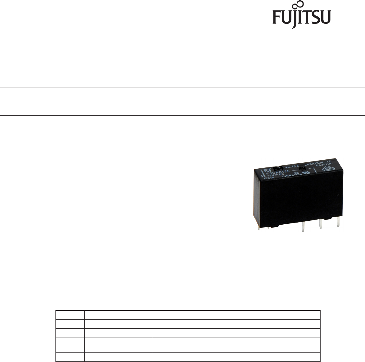
POWER RELAY
1 POLE - 5A Change Over Relay
FTR-F3 Series
■FEATURES
• High density mounting
Height: 15mm
Mounting space: 164mm2
• High insulation
Insulation distance: 7mm between coil and contacts
(conforms to IEC 60065)
Dielectric strength: 4KV
Surge strength: 10KV
• Cadmium free contact for eco-program
• Safety standards
UL, CSA, VDE
• Plastic sealed relay, RTIII
• RoHS compliant
Please see page 6 for more information
■Part Numbers
[Example] FTR-F3 C A 012 E
(a) (b) (c) (d) (e)
(a) Relay type FTR-F3 : FTR-F3 series
(b) C : 1 form C
(c) Coil type (power) A : 360mW
(d) Coil rated voltage 012 : 5..... 24VDC
Coil rating table at page 3
(e) Contact material E : AgNi
Actual marking does not carry the type name: "FTR"
E.g.: Ordering code: FTR-F3CA012E Actual marking: F3CA012E

2
FTR-F3 Series
■Specications
Item FTR-F3 Remarks / conditions
Contact
data
1 form C
Construction Single
Material AgNi
Resistance Max. 100mOhm Initial at 1A, 6VDC
Contact rating 5A, 250VAC, 30VDC Resistive
Max. carrying current 5A
Max. switching voltage 277VAC, 30VDC
Max. switching power 1,250VA, 150W
Min. switching load *1 10 mA, 5VDC
Coil Rated power (20oC) 360mW
Operating temperature range -40ºC ~ +70ºC (at rated voltage) No frost
Timing
data
Operate Max. 10ms without bounce
Release Max. 10ms without bounce
Life Mechanical
Electrical (resistive) Min. 100 x 10 operations
(3A, 250VAC/30VDC)
Min. 50 x 10³ operations
(5A, 250VAC/30VDC)
At rated load
Insula-
tion
Insulation resistance
Dielectric
strength
Open contacts 750VAC (50/60Hz), 1 minute
Coil contact 4000VAC (50/60Hz), 1 minute
Surge strength Coil to contacts 10,000V / 1.2 x 50μs standard wave
Clearance 7mm
Creepage 7mm
EN61810-1,
VDE0435
Voltage 250V
Pollution 2
Material group III
Other Vibration resis-
tance
Misoperation 10Hz ~ 55Hz ~ 10Hz single amplitude
0.75mm
Endurance 10Hz ~ 55Hz ~ 10Hz single amplitude
0.75mm
Shock resis-
tance
Min. 100m/s² (11 ± 1ms)
Endurance Min. 1,000m/s² (6 ± 1ms)
Dimensions / weight 7.0 x 23.4 x 15.0 mm / approx. 6g
Sealing Plastic sealed RTIII
*1
before production since reference values may vary according to switching frequencies, environmental contions
3
FTR-F3 Series
■Coil Data
Coil
code
Rated Coil Voltage
(VDC)
Coil Resistance +/-10%
Must Operate Voltage*
(VDC)
Must Release Voltage*
(VDC)
Rated Power
(mW)
005 5 69 3.75 0.5
360
006 6 100 4.5 0.6
009 9 225 6.75 0.9
012 12 400 9 1.2
018 18 900 13.5 1.8
024 24 1,600 18 2.4
Note: All values in the table are valid at 20o
*
Note: Please use at rated coil voltage. Please refer to characteristic data and set up adequate voltage in case of use at over voltage.
■Safety Standards
Type Compliance Contact rating
UL UL 508 Flammability: UL 94-V-0 (plastics)
File No. E63614 5A, 30 VDC / 250VAC (resistive)
3A, 30 VDC / 250 VAC (resistive)
CSA C22.2 No. 14
File No. LR 40304
VDE IEC/EN61810-1
EN60065 clause 14.6.1
5A, 250 VAC, cosφ=1
5A, 30 VDC L/R=0ms
3A, 250 VAC, cosφ=1
3A, 30 VDC L/R=0ms
CQC GB15092.1 / GB/T21811.1
17002164382, 04001010925
5A 250VAC / 30VDC
4
FTR-F3 Series
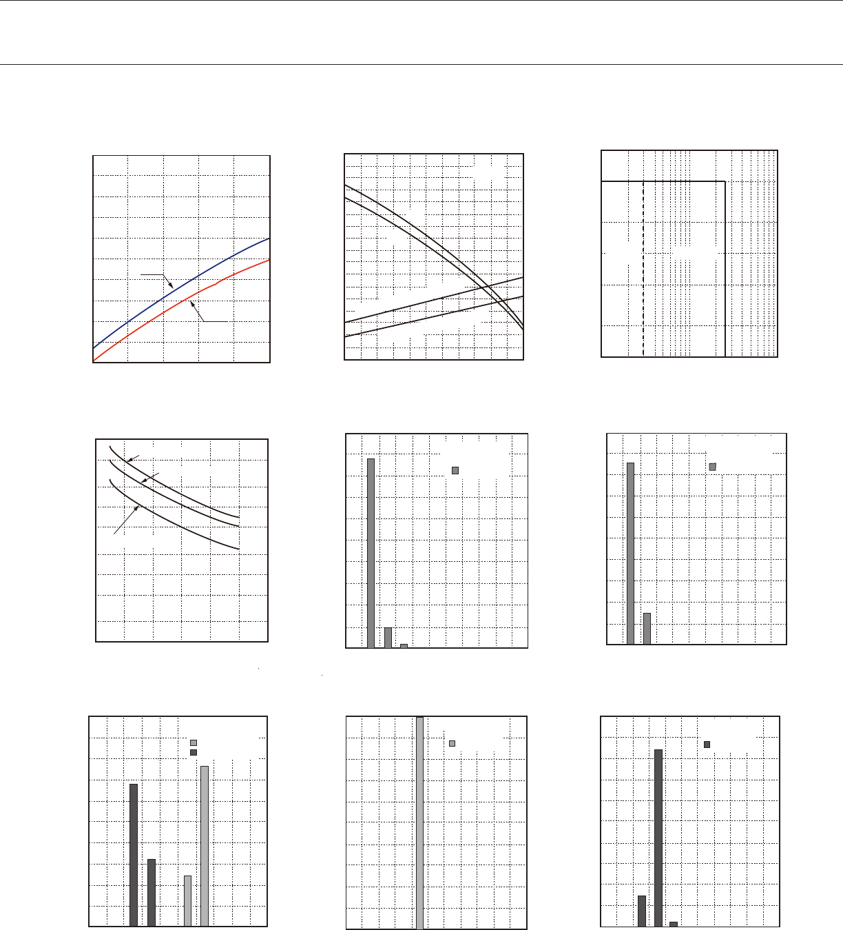
■Characteristic Data (Reference)
* Characteristic data is not guaranteed value but measured values of samples from production line.
100
90
80
70
60
50
40
30
20
10
0
0 0.1 0.2 0.3 0.4 0.5
FTR-F3C
5A
0A
Coil Temperature Rise
Coil Temperature Rise(°C)
Coil Power (W)
Must operate voltage (hot coil)
Must operate voltage (cool coil)
5A
0A
FTR-F3C
2.2
2.0
1.8
1.6
1.4
1.2
1.0
0.8
0.6
0 10 20 30 40 50 60 70 80 90 100 110
Ambient Temperature(°C)
Operating Range
Nominal voltage multiplying factor
10
5
2
1
0.5
0.2
0.1
10 20 50 100 200 500 1000
DC
resistive AC resistive
Maximum Switching Power
Switching Current (A)
Contact Voltage (V)
1000
500
200
100
50
20
10
5
2
0
0
1 2 3 4 5 6
Life Curve
125VAC resistive
250VAC/30VDC resistive
250VAC cos=φ0.4
Contact Current (A)
Service Life (X103 operations)
100
80
60
40
20
00 20 40 60 80 100
N.O.contact
Distribution of Contact Resistance (N.O.)
Contact Resistance (mΩ)
Distribution (%)
FTR-F3CA012E
n=100
100
80
60
40
20
0
0 20 40 60 80 100
Distribution of Contact Resistance (N.C.)
Contact Resistance (mΩ)
Distribution (%)
FTR-F3CA012E
n=100
N.C.contact
100
80
60
40
20
00 20 40 60 80 100
Release voltage
FTR-F3CA012E
n=100
10 30 70 90
Operate voltage
Distribution of Operation & Release Voltage
Distribution (%)
Nominal Voltage Multiplying Factor (%)
100
80
60
40
20
00.0 2.0 4.0 6.0 8.0 10.0
FTR-F3CA012E
n=100
Operate time
Distribution of Operation Time
Distribution (%)
Time (ms)
100
80
60
40
20
00.0 2.0 4.0 6.0 8.0 10.0
Release time
FTR-F3CA012E
n=100 個
Distribution of Release Time
Distribution (%)
Time (ms)
5
FTR-F3 Series
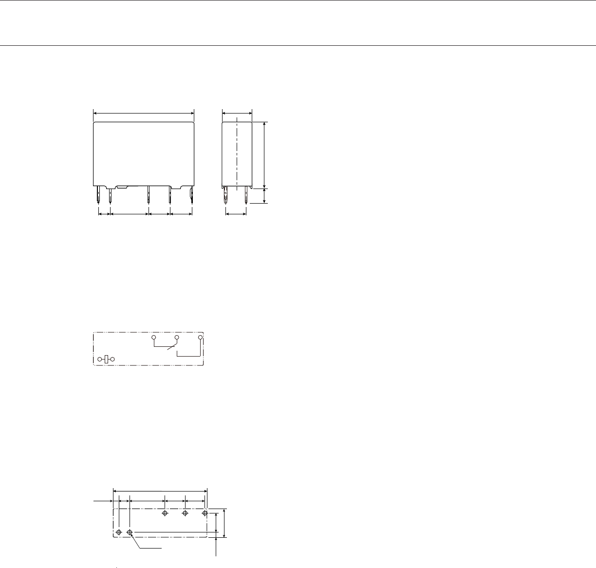
■Dimensions
• Dimensions
Changeover contact type
* Dimensions of the terminals do not include thickness of pre-solder.
• Schematics
(BOTTOM VIEW)
• PC Board Mounting Hole Layout
(BOTTOM VIEW)
( ): Reference value
Unit: mm
23.4 7
+0.2
+0.3
+0.2
2.7 8.8 5 5 4.7
3.3 15
NC COM NO
1 2 3
5 6
(23.4)
(1.32) 2.7 8.8 5 5
4.7
(7)
(1.25)
5 -φ1.1
6
FTR-F3 Series
GENERAL INFORMATION
1. ROHS Compliance
• All relays produced by Fujitsu Components are compliant with RoHS directive 2011/65/EU including amend-
ments.
• Use of Cadmium in electrical contacts is exempted as per Annex III of the RoHS directive 2011/65/EU.
Please consider expiry date of exemption. Relays with Cadmium containing contacts are not to be used for
new designs.
• All relays are lead-free. Please refer to Lead-Free Status Info for older date codes at:
http://www.fujitsu.com/downloads/MICRO/fcai/relays/lead-free-letter.pdf
• Characteristic data is not guaranteed values, but measured values of samples from production line.
2. Recommended lead free solder condition
• Recommended solder for assembly: Sn-3.0Ag-0.5Cu.
3. Moisture Sensitivity
• Moisture Sensitivity Level standard is not applicable to electromechanical relays, unless otherwise indicat-
ed.
4. Tin Whiskers
• Dipped SnAgCu solder is known as presenting a low risk to tin whisker development. No considerable
length whisker was found by our in house test.
We highly recommend that you conrm your actual solder conditions
Flow Solder Condition:
within 90 sec.
Soldering: dip within 5 sec. at
Relay must be cooled by air immediately
after soldering
Solder by Soldering Iron:
Soldering Iron: 30-60W
Duration: maximum 3 sec.

7
FTR-F3 Series
Fujitsu Components International Headquarter Ofces
©2017 Fujitsu Components Europe B.V. All rights reserved. All trademarks or registered trademarks are the property of their respective owners.
The contents, data and information in this datasheet are provided by Fujitsu Component Ltd. as a service only to its user and only for general
information purposes.
The use of the contents, data and information provided in this datasheet is at the users’ own risk.
Fujitsu has assembled this datasheet with care and will endeavor to keep the contents, data and information correct, accurate, comprehensive,
complete and up to date.
employees, for any loss or damage, direct, indirect or consequential, with respect to this datasheet, its contents, data, and information and related
graphics and the correctness, reliability, accuracy, comprehensiveness, usefulness, availability and completeness thereof.
with respect to these datasheets, its contents, data, information and related graphics and the correctness, reliability, accuracy, comprehensiveness,
usefulness, availability and completeness thereof. Rev. September 26th, 2017
Japan
FUJITSU COMPONENT LIMITED
Shinagawa Seaside Park Tower 19F,
12-4, Higashi-shinagawa 4-chome, Shinagawa-ku,
Tokyo,140-0002, Japan
Tel: (81-3) 3450-1682
Fax: (81-3) 3474-2385
Email: fcl-contact@cs.jp.fujitsu.com
Web: www.fujitsu.com/jp/fcl/
North and South America
FUJITSU COMPONENTS AMERICA, INC
2290 North First Street, Suite 212
San Jose, CA 95131, USA
Tel: (1-408) 745-4900
Fax: (1-408) 745-4970
Email: components@us.fujitsu.com
Web: us.fujitsu.com/components
Europe
FUJITSU COMPONENTS EUROPE B.V.
Diamantlaan 25
2132 WV Hoofddorp
Netherlands
Tel: (31-23) 5560910
Fax: (31-23) 5560950
Email: info@fceu.fujitsu.com
Web: www.fujitsu.com/uk/components
Asia Pacic
FUJITSU COMPONENTS ASIA, LTD.
102E Pasir Panjang Road
#01-01 Citilink Warehouse Complex
Singapore 118529
Tel: (65) 6375-8560
Fax: (65) 6273-3021
Email: fcal@sg.fujitsu.com
Web: www.fujitsu.com/sg/products/devices/components
China
FUJITSU ELECTRONIC COMPONENTS (SHANGHAI) CO., LTD.
Unit 4306, InterContinental Center
100 Yu Tong Road, Shanghai 200070,
China
Tel: (86-21) 3253 0998
Fax: (86-21) 3253 0997
Email: fcal@sg.fujitsu.com
Web: www.fujitsu.com/sg/products/devices/components
Hong Kong
FUJITSU COMPONENTS HONG KONG CO., LTD
Unit 506, Inter-Continental Plaza
No.94 Granville Road, Tsim Sha Tsui, Kowloon,
Hong Kong
Tel: (852) 2881-8495
Tex: (852) 2894-9512
Email: fcal@sg.fujitsu.com
Web: www.fujitsu.com/sg/products/devices/components/
Korea
FUJITSU COMPONENTS KOREA LIMITED
Alpha Tower #403, 645 Sampyeong-dong,
Bundang-gu, Seongnam-si, Gyeonggi-do,
13524 Korea
Tel: (82) 31-708-7108
Fax: (82) 31-709-7108
Email: fcal@sg.fujitsu.com
www.fujitsu.com/sg/products/devices/components/
