Fujitsu FTR P6 Series
User Manual: Fujitsu FTR-P6 Series Datasheet - Fujitsu United States
Open the PDF directly: View PDF ![]() .
.
Page Count: 8

1
MINIATURE SURFACE MOUNT RELAY
For automotive applications
1 POLE - 25A
FTR-P6 Series
■FEATURES
• Surface mount relays for automotive applications
• Miniature size (67% of the volume of FTR-P3 relays)
• High contact capacity with proven contact material
(100,000 operations, 14V, 25A)
• Low coil power dissipation
(800mW nominal achieved with state-of-the-art magnetic design)
• Semi low noise (average acoustic noise level: 60dB distance 5cm)
• Application examples: Power window, door lock, power seat, sunroof, wiper
• RoHS compliant
Please see page 7 for more information
■Part Numbers
[Example] FTR-P6 G N 012 WA **
(a) (b) (c) (d) (e) (f)
(a) Relay type FTR-P6 : FTR-P6 series
(b) Contact conguration G : 1 form C
(c) Contact gap N : 0.25mm gap
(d) Contact rated voltage 012 : 10..... 12VDC
Coil rating table at page 3
(e) Contact material WA : Silver-tin oxide indium
(f) Special type None
DP
Others
: Standard package
: Dry package
: To be assigned custom specication
Actual marking does not carry the type name: "FTR"
E.g.: Ordering code: FTR-P6GN012WA Actual marking: P6GN012WA

2
FTR-P6 Series
■Specications
Item FTR-P6
Remarks / conditions
Contact
data
Conguration 1 form C
Material Silver-tin oxide
Voltage drop Max. 100 mV At 1A, 12VDC (resistance)
Contact rating 25A, 14VDC Motor locked
Max. carrying current 25A / 1h 25°C, nominal voltage applied to coil
Max. inrush current 35A
Min. switching load * 1A, 6VDC Reference
Coil Coil power consumption Approx. 0.8W At rated coil voltage
Operating temperature
range
-40ºC ~ +85ºC No frost
Storage temperature range -40ºC ~ +100ºC No frost
Operating humidity 45 to 85% RH
Timing
data
Operate Max. 10ms
Release Max. 5ms
Life Mechanical Min. 1 x 10⁶ operations
Electrical Min. 100 x 10³ operations 14VDC, 25A locked motor
Insula-
tion
Insulation resistance Min. 100MΩ at 500VDC Initial
Dielectric
withstanding
voltage
Open con-
tacts
500VAC (50/60Hz), 1 minute
Coil contact 500VAC (50/60Hz), 1 minute
Other Vibration
resistance
Misoperation 10 to 200Hz, 44m/s2 (4.5G),
constant acceleration
Endurance 10 to 200Hz, 44m/s2 (4.5G),
constant acceleration
Shock resis-
tance
Misoperation Min. 100m/s² (11 ± 1ms)
Endurance Min. 1,000m/s² (6 ± 1ms)
Dimensions / weight 9.0 x 12.0 x 10.3 mm / approx. 3.3g
*: Minimum switching loads mentioned above are reference values. Please perform the conrmation test with actual
load before production since reference values may vary according to switching frequencies, environmental conditions
and expected reliability levels.
Note: Care shall be taken on the heat generated on PC board when maximum carrying current exceeds 10A.
Please perform the conrmation test with actual conditions.
3
FTR-P6 Series
■Coil Data
Coil
code
Rated Coil Voltage
(VDC)
Coil Resistance +/-10%
(Ω)
Must Operate Voltage*
(VDC)
Must Release Voltage*
(VDC)
010 10 125 6.5 (at 20ºC)
8.2 (at 85ºC)
0.8 (at 20ºC)
1.0 (at 85ºC)
012 12 180 7.3 (at 20ºC)
9.2 (at 85ºC)
1.0 (at 20ºC)
1.3 (at 85ºC)
Note: All values in the table are valid at 20oC and zero contact current, unless otherwise specied.
*: Specied operated values are valid for pulse wave voltage.
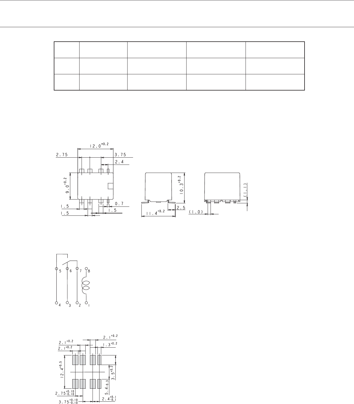
■Dimensions
• Dimensions
*Dimensions of the terminals do not include thickness of pre-solder.
• Schematics
(TOP VIEW)
• PC Board Mouting Hole Layout
(TOP VIEW)
( ): Reference value
Unit: mm

4
FTR-P6 Series
■Packaging
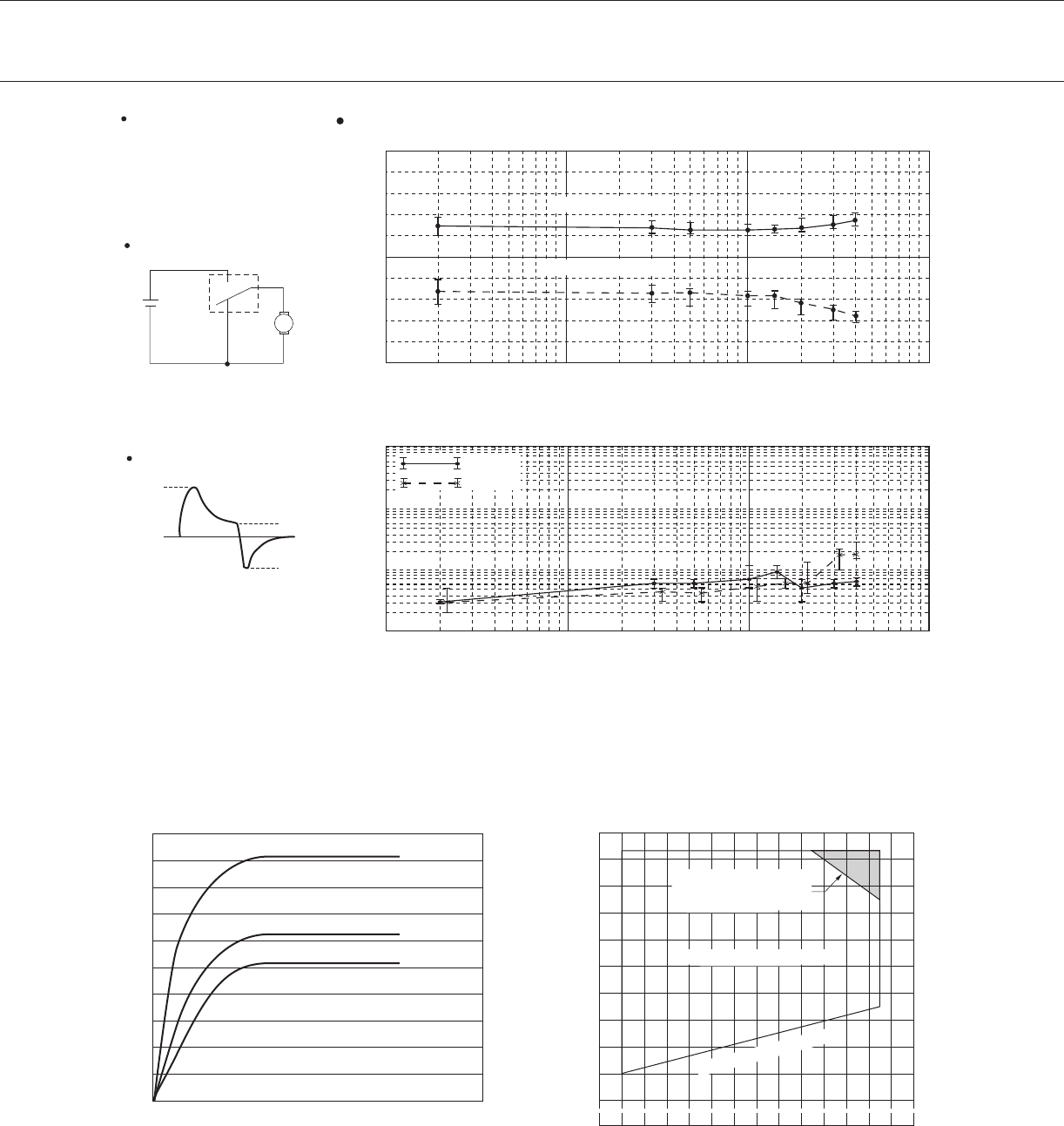
■Characteristic Data (Reference)
Top cover tape
Embossed carrier tape
25.5
0.4 2.0 4.0
11.0 11.9 24.0
φ
13.0
φ
1.55
φ
2.2
φ
380
12.5
11.5 1.75
24.0
11.0
0.4 4.0
2.0
24.0
11.5 1.75
24.0
12.5
11.9
Ø 2.2
Ø 55.1
M
N.O.
RL
N.C.
0 A 5 A
20 A
19 A
0
5
10
1001010.1
0.1
100101
100
1000
10
1
(
RL-1
)
6 sec
25 A
0 A
0.5 sec 0.5 sec
M
RL-1
RL-2
N.O.
N.C.
N.O.
N.C. 0
5
10
1001010.1
0.1
100101
100
1000
10
1
Life test (example)
Number of operations (x104)
Test condition
25A 16VDC
motor lock
100,000 operations min.
0.5 sec. ON, 5.5 sec. OFF
Test condition
Inrush current 20A, 16VDC
motor free
400,000 operations min.
1.5 sec. ON, 2.0 sec. OFF
Test circuit
Current wave form
Voltage (V)
Contact resistance (mΩ)
(Measured at DC 6V, 1A wet)
Initial
Operate voltage
Make
Break
Release voltage
Number of operations (x104)
Initial
Contact resistance (mΩ)
(Measured at DC 6V, 1A wet)
Make
Break
Number of operations (x104)
Initial
Operate / release voltage
Number of operations (x104)
Voltage (V)
Initial
Operate voltage
Release voltage
Operate / release voltage
Test circuit
Current wave form
5
FTR-P6 Series
M
N.O.
RL
N.C.
0 A 5 A
20 A
19 A
0
5
10
1001010.1
0.1
100101
100
1000
10
1
(
RL-1
)
6 sec
25 A
0 A
0.5 sec 0.5 sec
M
RL-1
RL-2
N.O.
N.C.
N.O.
N.C. 0
5
10
1001010.1
0.1
100101
100
1000
10
1
Life test (example)
Number of operations (x104)
Test condition
25A 16VDC
motor lock
100,000 operations min.
0.5 sec. ON, 5.5 sec. OFF
Test condition
Inrush current 20A, 16VDC
motor free
400,000 operations min.
1.5 sec. ON, 2.0 sec. OFF
Test circuit
Current wave form
Voltage (V)Contact resistance (mΩ)
(Measured at DC 6V, 1A wet)
Initial
Operate voltage
Make
Break
Release voltage
Number of operations (x104)
Initial
Contact resistance (mΩ)
(Measured at DC 6V, 1A wet)
Make
Break
Number of operations (x104)
Initial
Operate / release voltage
Number of operations (x104)
Voltage (V)
Initial
Operate voltage
Release voltage
Operate / release voltage
Test circuit
Current wave form
Must operate voltage
-30 -20 0 20 40 60 80 100
40
60
80
100
120
140
Y
Z
X
10
50
100
10 50 100 500 1000 2000
5 1 0.5 0.1 0.01
44
m/s2
0
200
400
600
800
1,000
X1 X2 Y1 Y2 Z1 Z2
Z2
Z1
Y1
Y2
X2
X1
0.8 W
0.8 W
0.8 W
10 20 30 40
10
0
30
50
70
90
20
40
60
80
100
Coil temperature rise
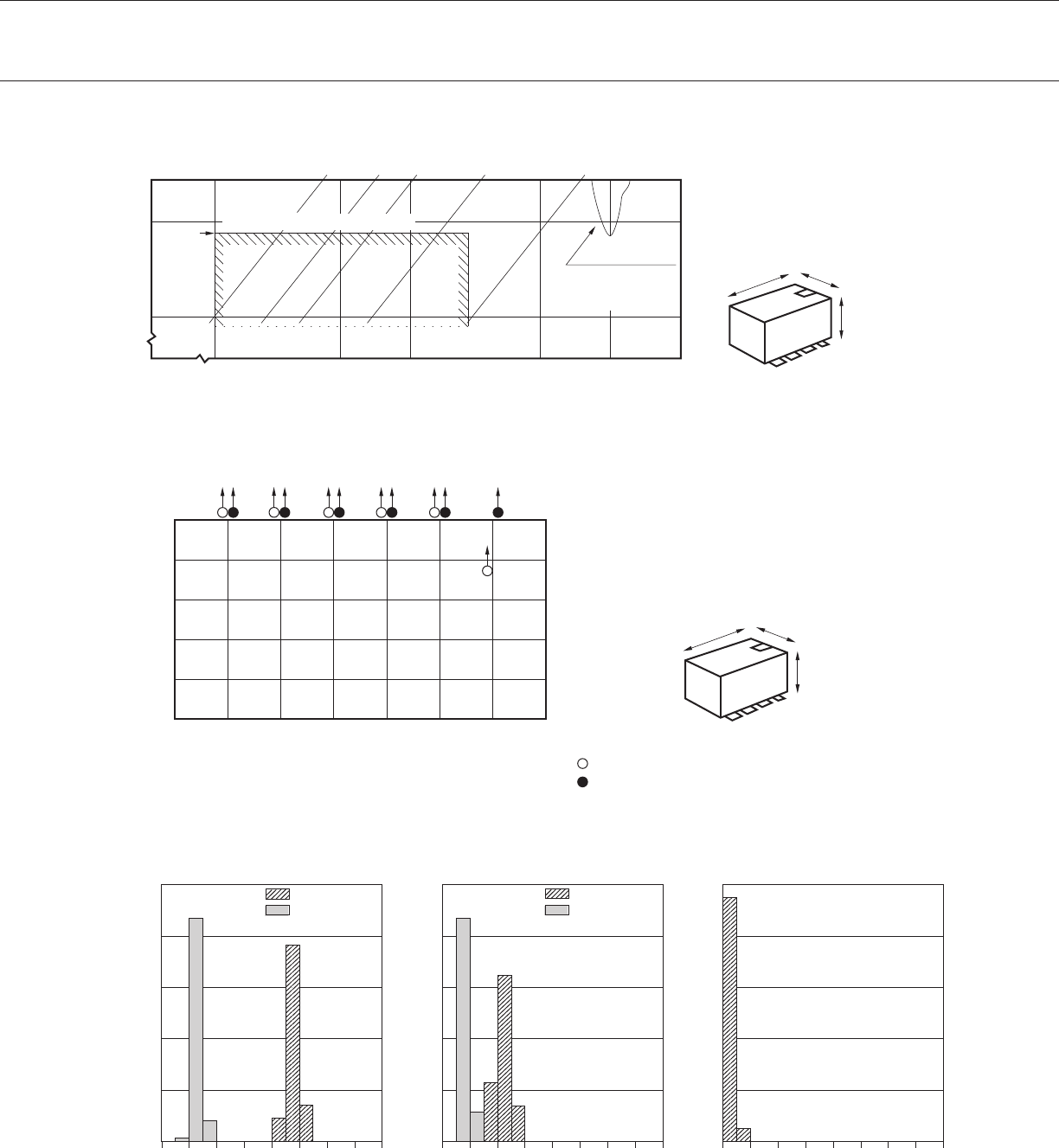
Vibration resistance characteristics
Shock resistance characteristics
Operating coil voltage range
(FTR-P6GN012WA)
Coil temperature rise(℃)
Applied time (minutes)
Dual amplitude (mm)
Frequency: 10 to 2000Hz
Acceleration: 100m/s2 max.
Direction of vibration: See diagram below
Direction level: chatter > 1ms
Shock application time: 6±1ms, half-sine wave
Test condition: Coil energized and de-energized
Shock direction: See diagram below
Direction level: chatter > 1ms
Frequency (Hz)
: Break contact (coil de-energized)
: Make contact (coil energized)
Shock direction
Shock level (m/s2)Acceleration (m/s2)
Ambient temperature (℃)
Ratio to nominal coil voltage (%)
Contact carry current 20A
Continuous coil operation
Intermittent operations
need to be at 15A
continuous current
Contact carry current 10A
Contact carry current 0A
Range where
chattering occurs
N.O.contact coil
not energized on
X-direction
Automotive electronics standard
6
FTR-P6 Series
Must operate voltage
-30 -20 0 20 40 60 80 100
40
60
80
100
120
140
Y
Z
X
10
50
100
10 50 100 500 1000 2000
5 1 0.5 0.1 0.01
44
m/s2
0
200
400
600
800
1,000
X1 X2 Y1 Y2 Z1 Z2
Z2
Z1
Y1
Y2
X2
X1
0.8 W
0.8 W
0.8 W
10 20 30 40
10
0
30
50
70
90
20
40
60
80
100
Coil temperature rise
Vibration resistance characteristics
Shock resistance characteristics
Operating coil voltage range
(FTR-P6GN012WA)
Coil temperature rise(℃)
Applied time (minutes)
Dual amplitude (mm)
Frequency: 10 to 2000Hz
Acceleration: 100m/s2 max.
Direction of vibration: See diagram below
Direction level: chatter > 1ms
Shock application time: 6±1ms, half-sine wave
Test condition: Coil energized and de-energized
Shock direction: See diagram below
Direction level: chatter > 1ms
Frequency (Hz)
: Break contact (coil de-energized)
: Make contact (coil energized)
Shock direction
Shock level (m/s2)Acceleration (m/s2)
Ambient temperature (℃)
Ratio to nominal coil voltage (%)
Contact carry current 20A
Continuous coil operation
Intermittent operations
need to be at 15A
continuous current
Contact carry current 10A
Contact carry current 0A
Range where
chattering occurs
N.O.contact coil
not energized on
X-direction
Automotive electronics standard
0 10 20 30 40 50 60 70 80
0
20
40
60
80
100
0
20
40
60
100
80
0
20
40
60
100
80
FTR-P6GN012WA Operate voltage
Release voltage
Operate voltage
Release voltage
(without diode)
n
=
100 FTR-P6GN012WA
n
=
100 FTR-P6GN012WA
n
=
100
0 10 20 30 40 50 60 70 800 1 2 3 4 5 6 7 8
Distribution of operate/release voltage Distribution of operate/release time Distribution of contact resistance
Distribution (%)
Distribution (%)
Distribution (%)
Nominal voltage multiplying factor (%) Time (ms) Contact resistance (mΩ)

7
FTR-P6 Series
GENERAL INFORMATION
1. ROHS Compliance
• All relays produced by Fujitsu Components are compliant with RoHS directive 2011/65/EU including amend-
ments.
• Use of Cadmium in electrical contacts is exempted as per Annex III of the RoHS directive 2001/65/EU.
Please consider expiry date of exemption. Relays with Cadmium containing contacts are not to be used for
new designs.
• All relays are lead-free. Please refer to Lead-Free Status Info for older date codes at:
http://www.fujitsu.com/downloads/MICRO/fcai/relays/lead-free-letter.pdf
• Characteristic data is not guaranteed values, but measured values of samples from production line.
2. Recommended lead free solder condition
• Lead free solder plating on relay terminals is Sn-3.0Ag-0.5Cu, unless otherwise specied. This material has
been veried to be compatible with PbSn assembly process.
• Recommended solder for assembly: Sn-3.0Ag-0.5Cu.
3. Moisture Sensitivity
• Moisture Sensitivity Level standard is not applicable to electromechanical relays, unless otherwise indicat-
ed. -DP relay will be shipped in moisture barrier bag.
4. Tin Whiskers
• Dipped SnAgCu solder is known as presenting a low risk to tin whisker development. No considerable
length whisker was found by our in house test.
We highly recommend that you conrm your actual solder conditions
Solder by Soldering Iron:
Soldering Iron 30-60W
Temperature: maximum 340-360˚C
Duration: maximum 3 sec.
Reow Solder Condition:

8
FTR-P6 Series
Fujitsu Components International Headquarter Ofces
©2017 Fujitsu Components Europe B.V. All rights reserved. All trademarks or registered trademarks are the property of their respective owners.
The contents, data and information in this datasheet are provided by Fujitsu Component Ltd. as a service only to its user and only for general
information purposes.
The use of the contents, data and information provided in this datasheet is at the users’ own risk.
Fujitsu has assembled this datasheet with care and will endeavor to keep the contents, data and information correct, accurate, comprehensive,
complete and up to date.
Fujitsu Components Europe B.V. and afliated companies do however not accept any responsibility or liability on their behalf, nor on behalf of its
employees, for any loss or damage, direct, indirect or consequential, with respect to this datasheet, its contents, data, and information and related
graphics and the correctness, reliability, accuracy, comprehensiveness, usefulness, availability and completeness thereof.
Nor do Fujitsu Components Europe B.V. and afliated companies accept on their behalf, nor on behalf of its employees, any responsibility or liability
for any representation or warrant of any kind, express or implied, including warranties of any kind for merchantability or tness for particular use,
with respect to these datasheets, its contents, data, information and related graphics and the correctness, reliability, accuracy, comprehensiveness,
usefulness, availability and completeness thereof. Rev. March 16th, 2017
Japan
FUJITSU COMPONENT LIMITED
Shinagawa Seaside Park Tower 19F,
12-4, Higashi-shinagawa 4-chome, Shinagawa-ku,
Tokyo,140-0002, Japan
Tel: (81-3) 3450-1682
Fax: (81-3) 3474-2385
Email: fcl-contact@cs.jp.fujitsu.com
Web: www.fujitsu.com/jp/fcl/
North and South America
FUJITSU COMPONENTS AMERICA, INC
2290 North First Street, Suite 212
San Jose, CA 95131, USA
Tel: (1-408) 745-4900
Fax: (1-408) 745-4970
Email: components@us.fujitsu.com
Web: us.fujitsu.com/components
Europe
FUJITSU COMPONENTS EUROPE B.V.
Diamantlaan 25
2132 WV Hoofddorp
Netherlands
Tel: (31-23) 5560910
Fax: (31-23) 5560950
Email: info@fceu.fujitsu.com
Web: www.fujitsu.com/uk/components
Asia Pacic
FUJITSU COMPONENTS ASIA, LTD.
102E Pasir Panjang Road
#01-01 Citilink Warehouse Complex
Singapore 118529
Tel: (65) 6375-8560
Fax: (65) 6273-3021
Email: fcal@sg.fujitsu.com
Web: www.fujitsu.com/sg/products/devices/components
China
FUJITSU ELECTRONIC COMPONENTS (SHANGHAI) CO., LTD.
Unit 4306, InterContinental Center
100 Yu Tong Road, Shanghai 200070,
China
Tel: (86-21) 3253 0998
Fax: (86-21) 3253 0997
Email: fcal@sg.fujitsu.com
Web: www.fujitsu.com/sg/products/devices/components
Hong Kong
FUJITSU COMPONENTS HONG KONG CO., LTD
Unit 506, Inter-Continental Plaza
No.94 Granville Road, Tsim Sha Tsui, Kowloon,
Hong Kong
Tel: (852) 2881-8495
Tex: (852) 2894-9512
Email: fcal@sg.fujitsu.com
Web: www.fujitsu.com/sg/products/devices/components/
Korea
FUJITSU COMPONENTS KOREA LIMITED
Alpha Tower #403, 645 Sampyeong-dong,
Bundang-gu, Seongnam-si, Gyeonggi-do,
13524 Korea
Tel: (82) 31-708-7108
Fax: (82) 31-709-7108
Email: fcal@sg.fujitsu.com
www.fujitsu.com/sg/products/devices/components/
