Fujitsu FTR V1 Series
User Manual: Fujitsu FTR-V1 Series Datasheet - Fujitsu United States
Open the PDF directly: View PDF ![]() .
.
Page Count: 7
1
FTR-K1 SERIES
n FEATURES
• 1 pole 210A 1 form B relay for 12V car battery
• Low prole
• Double winding latching relay
• 210A (at 85 oC) / 120A (at 125 oC) continuous current
• Low contact resistance: Max. 0.6mΩ (initial, at 1A)
• Ambient temperature up to 125 oC)
• Plastic sealed
• Plastic material: Conforms to UL94V-0 ammability
n Applications
Disconnect of battery / capacitor, protection of battery / capacitor,
switch of 2 power supplies.
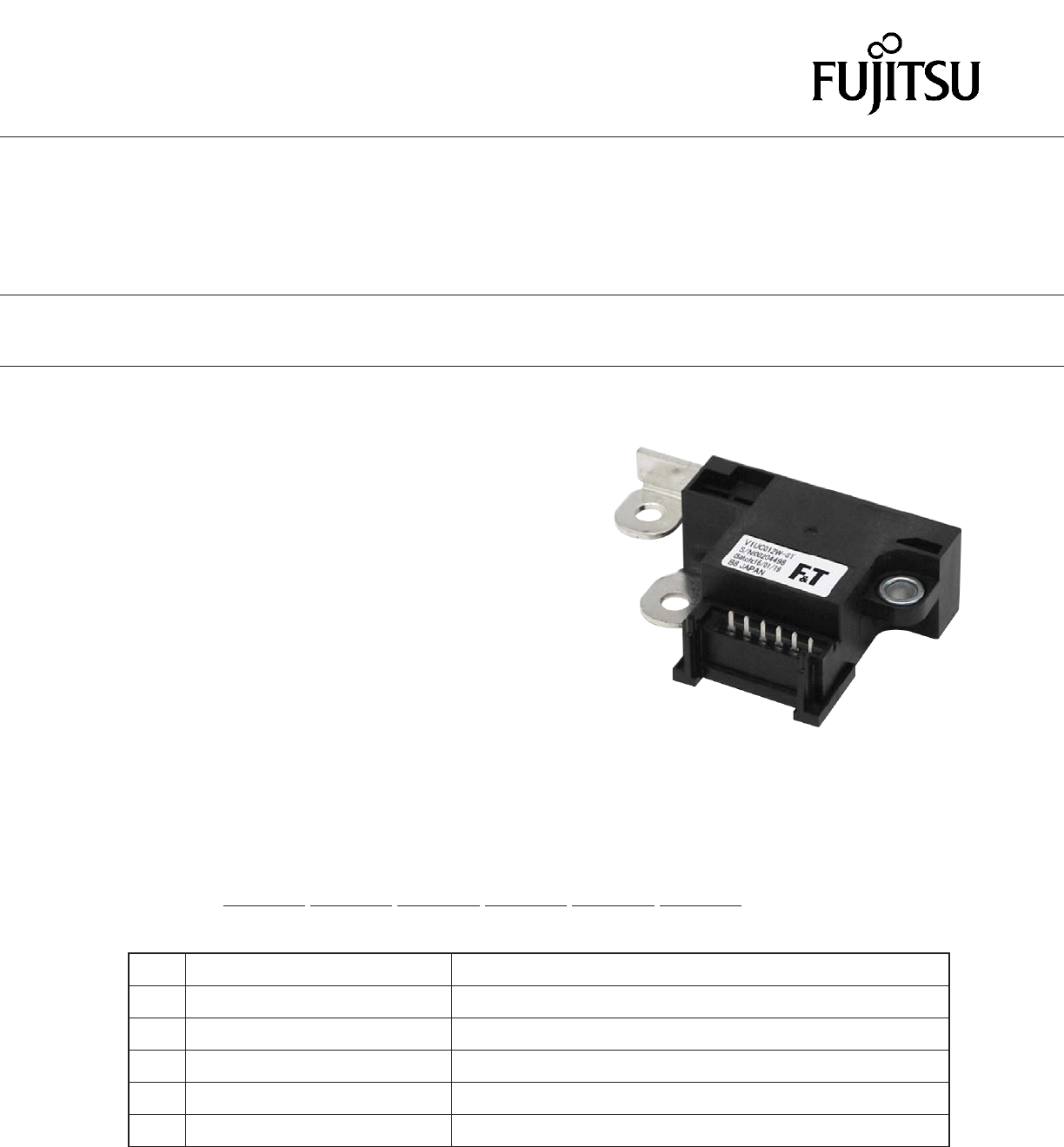
Actual marking does not carry the type name: "FTR"
E.g.: Ordering code: FTR-V1UC012W Actual marking: V1UC012W
FTR-V1 Series
COMPACT POWER RELAY
1 POLE - 210A Battery Latching relay
n PARTNUMBER INFORMATION
[Example] FTR-V1 U C 012 W ST
(a) (b) (c) (d) (e) (f)
(a) Relay type FTR-V1 : FTR-V1 Series
(b) Contact conguration U : 1b (1 form B)
(c) Coil type C : Dual coil latching
(d) Coil voltage 012 : 12VDC
(e) Contact material W : Silver alloy
(f) Special type ST : Standard
2
FTR-K1 SERIES
Note: Values of electrical characteristics are under 15 to 35 degC, 25 to 75%RH, air pressure 86kPa to 106kPa (JIS standard condition)
unless otherwise specied.
* : Minimum switching loads mentioned above are reference values. Please perform the conrmation test with actual load before produc-
tion since reference values may vary according to switching frequencies, environmental conditions and expected reliability levels.
FTR-V1 SERIES
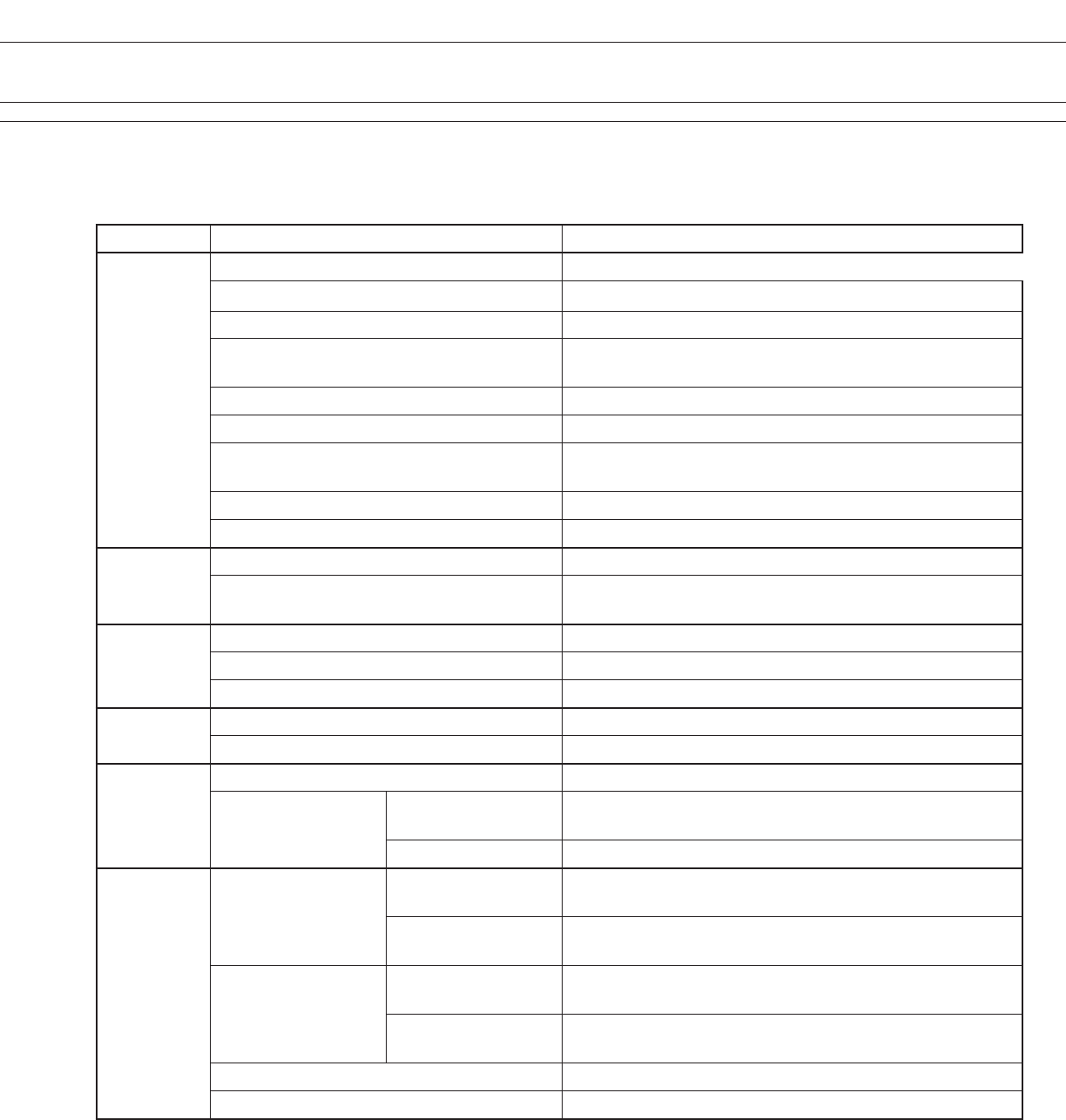
n SPECIFICATION
Item FTR-V1
Contact Data Conguration 1b (1 form B)
Material Silver alloy
Construction Twin
Contact rating Inrush: 230A 14VDC
Break:1A 14VDC
Contact voltage drop (initial) Max. 0.6mV at 1A 6VDC
Contact resistance (initial) Max. 0.6mΩ at 1A 6VDC
Continuous current 210A (at 85 degC, cable size 38mm²)
120A (at 125 degC, cable size 38mm²)
Max. breaking current 500A 12VDC resistive, 1,000 operations
Min. switching load * 6VDC, 1A (reference)
Life Mechanical 200 x 103 operations
Electrical 120 x 103 operations
(Inrush :230A 14VDC / Break:1A 14VDC)
Coil data Operating ambient temperature range -40 degC to +125 degC (no frost)
Rated power consumption 28.8W (at nominal voltage, at 20 degC)
Pulse width 50 to 100ms
Timing Data Set (at nominal voltage, at 20 degC) Max. 10ms (without bounce)
Reset (at nominal voltage, at 20 degC) Max. 10ms (without bounce)
Insulation Resistance (initial) 100M Ω at 500VAC
Dielectric withstand-
ing voltage (initial)
Between open
contacts 500VAC(50/60Hz), 1 minute
Between coil-contact 500VAC(50/60Hz), 1 minute
Other
Vibration resistance
Misoperation 10 to 200Hz, acceleration 45m/s², constant acceleration
(Detection 1ms, set/reset)
Endurance 10 to 200Hz, acceleration 45m/s², constant acceleration
(Set/reset, up/down 4 hours, left/right 2 hours)
Shock resistance
Misoperation Min. 100m/s² (11±1ms)
(Detection 1ms, set/reset 36 times each)
Endurance Min. 1,000m/s² (6±1ms)
(Set/reset 36 times total)
Weight Approximately 120 g
Sealing Sealed, RT III
3
FTR-K1 SERIES
n COIL RATING
FTR-V1 SERIES
Coil
Code
Rated Coil
Voltage (VDC)
Coil Resistance
+/- 10% (Ohm)
Must Set / Reset Voltage
(V) *
012 12 5
5.4 (20 oC)
5.8 (85 oC)
7.7 (125 oC)
Note: All values in the table are valid for 20°C and zero contact current, unless otherwise stated.
* Specied operate values are valid for pulse wave voltage.
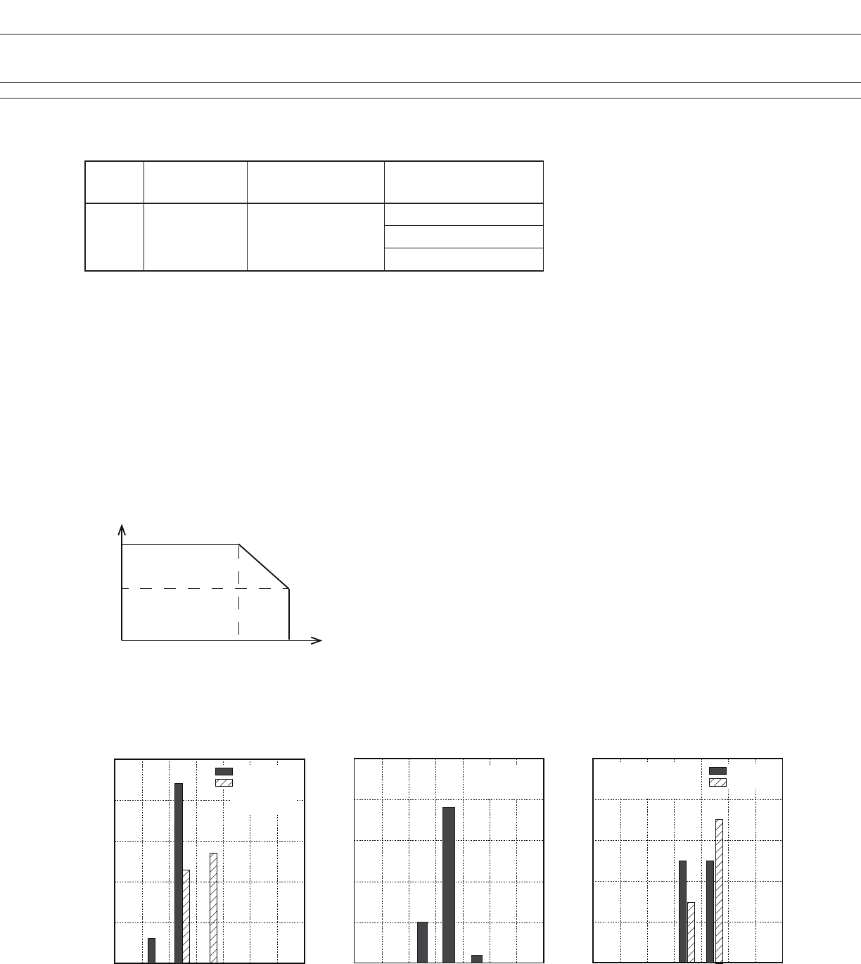
n CHARACTERISTIC DATA
210
120
00 85 125
Ambient temperature (degC)
Carrying current (A)
Cable size: 38mm2
Maximum Carrying Current
0
0
20
40
60
80
100
1 2 3 4 5 6 7
Set / reset voltage (VDC)
Distribution (%)
Reset voltage
Set voltage
0
0
20
40
60
80
100
0.1 0.2 0.3 0.4 0.5 0.6 0.7
Contact voltage drop (mV)
Contact resistance (mΩ)
Distribution (%)
Distribution of set/reset voltage Distribution of contact voltage drop
(contact resistance)
0
0
20
40
60
80
100
1 2 3 4 5 6 7
Set / reset time (ms)
Distribution (%)
Reset time
Set time
Distribution of set/reset time
n=50
at 20 degree C
n=50
at 20 degree C
1A 6VDC
n=50
at 20 degree C
rated coil voltage
4
FTR-K1 SERIES
FTR-V1 SERIES
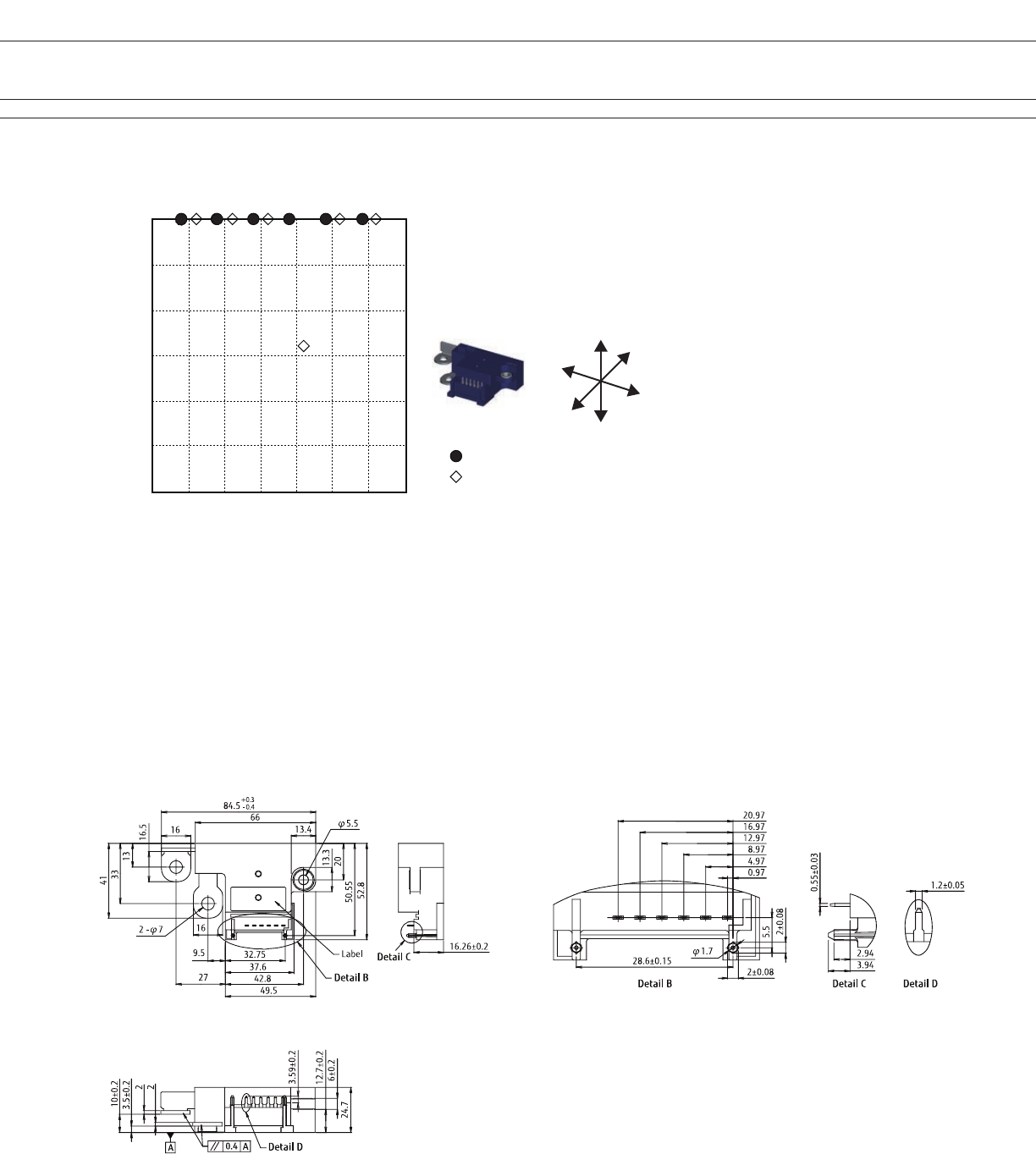
Shock resistance characteristics
X1
0
100
200
300
400
500
600
X2 Y1 Y2 Z1 Z2
Shock Direction
Acceleration (m/s2)
Half sine half wave pulse
Shock application time: 11±1ms
Detection level: chatter >1ms
Shock direction: see below diagram
: Set
: Reset
Z1
Y1
X1
Z2
Y2
X2
n DIMENSIONS
Tolerance : ±0.3mm unless otherwise specified
Unit:mm
• Notes for latching relay
• Latching relays are shipped in the state set, but state may change due to shock during transportation or
mounting. Before using the relays, it is advisable to bring the relays in necessary state (set or reset) and
program a circuit sequence. Otherwise, it will or will not operate simultaneously with power activation.
• Please connect relay coils according to specied polarity.
• Do not apply voltage to both set coil and reset coil at a time.
5
FTR-K1 SERIES
FTR-V1 SERIES
Unit: mm
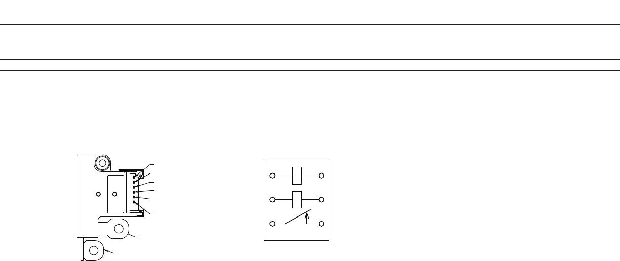
l Schematics
(BOTTOM VIEW)
(6) Coil terminal (SET side - )
(5) Coil terminal (RESET side + )
(4) Coil terminal (SET side + )
(3) Coil terminal (RESET side - )
(2) Signal terminal (Moving side)
(1) Signal terminal (Fixed side)
Fixed side terminal
Moving side terminal
(number) : Terminal number, corresponds to numbers on circuit diagram
Circuit Diagram
4
5
2
6
3
1
Circuit diagram shows set status.
Products are shipped in set status
6
FTR-K1 SERIES
FTR-V1 SERIES
1. General Information
l All automotive relays produced by Fujitsu Components are compliant with RoHS directive 2002/95EC
including amendments.
l Lead free solder plating on relay terminals is Sn-3.0Ag-0.5Cu, unless otherwise specified.
This material has been verified to be compatible with PbSn assembly process.
2. Recommended Lead Free Solder Profile
l Recommended solder Sn-3.0Ag-0.5Cu.
RoHS Compliance and Lead Free Information
3. Moisture Sensitivity
l Moisture Sensitivity Level standard is not applicable to electromechanical relays, unless otherwise indicated.
4. Tin Whiskers
l Dipped SnAgCu solder is known as presenting a low risk to tin whisker development. No considerable length
whisker was found by our in house test.
We highly recommend that you conrm your actual solder conditions
Flow Solder condition:
Pre-heating: maximum 120˚C
Soldering: dip within 5 sec. at
260˚C solder bath
Solder by Soldering Iron:
Soldering Iron
Temperature: maximum 360˚C
Duration: maximum 3 sec.

7
FTR-K1 SERIES
FTR-V1 SERIES
Fujitsu Components International Headquarter Ofces
©2016 Fujitsu Components Europe B.V. All rights reserved. All trademarks or registered trademarks are the property of their respective owners.
The contents, data and information in this datasheet are provided by Fujitsu Component Ltd. as a service only to its user and only for general
information purposes.
The use of the contents, data and information provided in this datasheet is at the users’ own risk.
Fujitsu has assembled this datasheet with care and will endeavor to keep the contents, data and information correct, accurate, comprehensive,
complete and up to date.
Fujitsu Components Europe B.V. and afliated companies do however not accept any responsibility or liability on their behalf, nor on behalf of its
employees, for any loss or damage, direct, indirect or consequential, with respect to this datasheet, its contents, data, and information and related
graphics and the correctness, reliability, accuracy, comprehensiveness, usefulness, availability and completeness thereof.
Nor do Fujitsu Components Europe B.V. and afliated companies accept on their behalf, nor on behalf of its employees, any responsibility or liability
for any representation or warrant of any kind, express or implied, including warranties of any kind for merchantability or tness for particular use,
with respect to these datasheets, its contents, data, information and related graphics and the correctness, reliability, accuracy, comprehensiveness,
usefulness, availability and completeness thereof. Rev. July 20th, 2016
Japan
FUJITSU COMPONENT LIMITED
Shinagawa Seaside Park Tower 19F,
12-4, Higashi-shinagawa 4-chome, Shinagawa-ku,
Tokyo,140-0002, Japan
Tel: (81-3) 3450-1682
Fax: (81-3) 3474-2385
Email: fcl-contact@cs.jp.fujitsu.com
Web: www.fujitsu.com/jp/fcl/
North and South America
FUJITSU COMPONENTS AMERICA, INC
2290 North First Street, Suite 212
San Jose, CA 95131, USA
Tel: (1-408) 745-4900
Fax: (1-408) 745-4970
Email: components@us.fujitsu.com
Web: us.fujitsu.com/components
Europe
FUJITSU COMPONENTS EUROPE B.V.
Diamantlaan 25
2132 WV Hoofddorp
Netherlands
Tel: (31-23) 5560910
Fax: (31-23) 5560950
Email: info@fceu.fujitsu.com
Web: www.fujitsu.com/uk/components
Asia Pacic
FUJITSU COMPONENTS ASIA, LTD.
102E Pasir Panjang Road
#01-01 Citilink Warehouse Complex
Singapore 118529
Tel: (65) 6375-8560
Fax: (65) 6273-3021
Email: fcal@sg.fujitsu.com
Web: www.fujitsu.com/sg/products/devices/components
China
FUJITSU ELECTRONIC COMPONENTS (SHANGHAI) CO., LTD.
Unit 4306, InterContinental Center
100 Yu Tong Road, Shanghai 200070,
China
Tel: (86-21) 3253 0998
Fax: (86-21) 3253 0997
Email: fcal@sg.fujitsu.com
Web: www.fujitsu.com/sg/products/devices/components
Hong Kong
FUJITSU COMPONENTS HONG KONG CO., LTD
Unit 506, Inter-Continental Plaza
No.94 Granville Road, Tsim Sha Tsui, Kowloon,
Hong Kong
Tel: (852) 2881-8495
Tex: (852) 2894-9512
Email: fcal@sg.fujitsu.com
Web: www.fujitsu.com/sg/products/devices/components/
Korea
FUJITSU COMPONENTS KOREA LIMITED
Alpha Tower #403, 645 Sampyeong-dong,
Bundang-gu, Seongnam-si, Gyeonggi-do,
13524 Korea
Tel: (82) 31-708-7108
Fax: (82) 31-709-7108
Email: fcal@sg.fujitsu.com
www.fujitsu.com/sg/products/devices/components/
