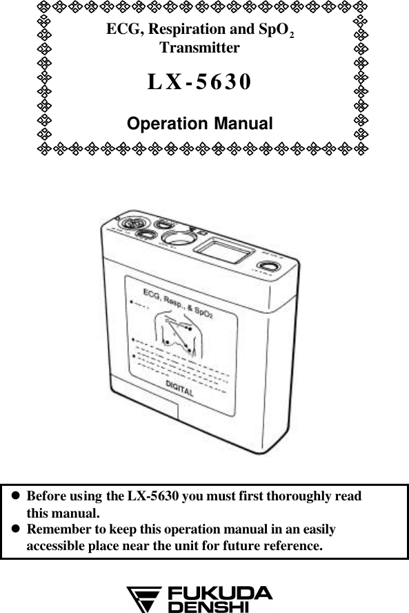
Fukuda Denshi Co LX5630 ECG, Respiration and SpO2 Transmitter User Manual LX5630 1Cover
Fukuda Denshi Co Ltd ECG, Respiration and SpO2 Transmitter LX5630 1Cover
UserManual.wiki
>
Fukuda Denshi Co
>
LX5630 User Manual
Manual
Navigation menu
Upload a User Manual
Namespaces
Wiki Guide
HTML
PDF
Info
Views
User Manual
Discussion / Help
Navigation
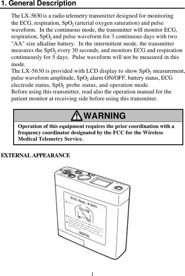
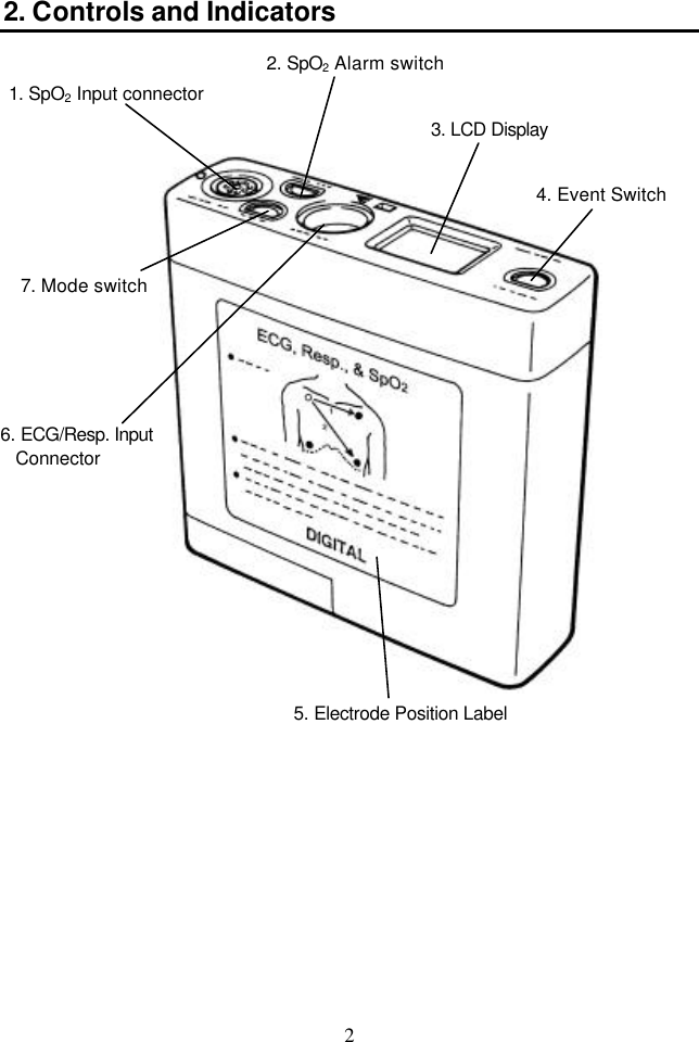
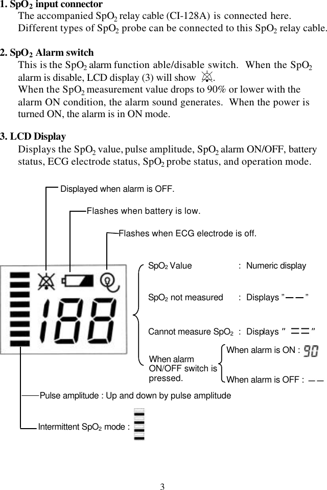
![CONTENTS 1. General Description..............................................................................1 2. Controls and Indicators.......................................................................2 3. Preparation and Operation...............................................................7 [1] Loading a Battery. .........................................................................7 [2] Turn the power switch to "ON"................................................8 [3] Attach the electrodes. ..................................................................9 [4] Connect the lead wire to the electrode...............................11 [5] Connect the lead wire to the transmitter............................11 [6] Attach the SpO2 probe.................................................................12 SR-5C (Finger Clip Probe ) Attachment................................13 TG-25 (SP-5C) (Finger Clip Probe) Attachment.................14 TG-26 (UD-5C) Attachment..........................................................15 SD-5C (20) & SD-5C (25) Attachment.......................................16 CE-5C (Earlap Probe) Attachment...........................................18 [7] Connect the SpO2 relay cable (CI-128A) and SpO2 probe to the transmitter................................................20 4. Group Code Setup.................................................................................22 5. Receiver Channel Setup.....................................................................23 6. Cleaning and Disinfection..................................................................24 7. Maintenance and Inspection............................................................25 8. Specifications..........................................................................................27 9. Accessories...............................................................................................29](https://usermanual.wiki/Fukuda-Denshi-Co/LX5630/User-Guide-348327-Page-8.png)
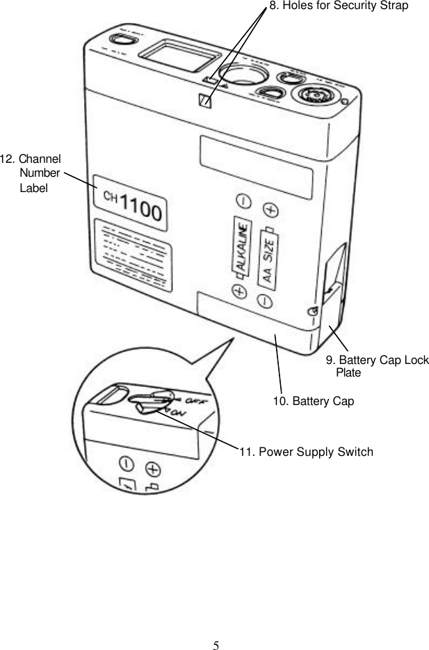
![7 3. Preparation and Operation [1] Loading a battery. The battery cap can be removed by opening the lock plate outward while pressing the top of the battery cap. The LX-5630 uses two "AA" size alkaline cell (LR-6) for its power source. When installing the battery, take note of the polarity. To close the battery compartment, insert the protrusion part of the battery cap into the rectangular hole on the transmitter, then push the batteries with the battery cap and lock the battery lock plate. CAUTION If the transmitter is not in use for a long period of time, remove the battery and store in an appropriate place. The leakage from the battery may damage the equipment.](https://usermanual.wiki/Fukuda-Denshi-Co/LX5630/User-Guide-348327-Page-15.png)
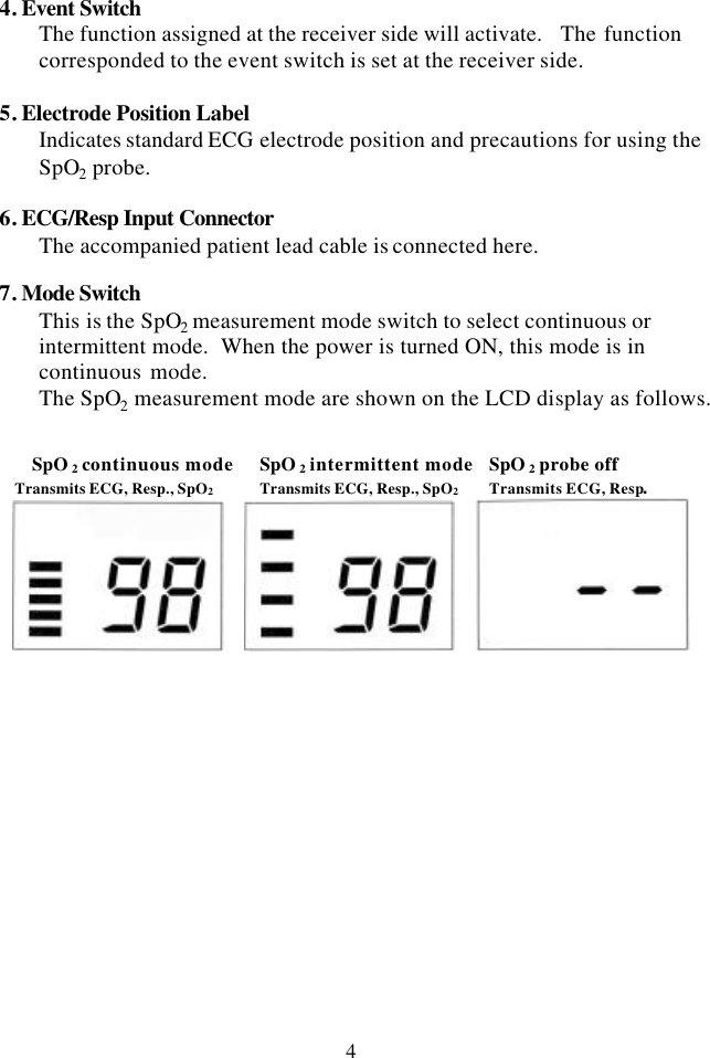
![8 [2] Turn the power switch to "ON". When the power is turned ON, the SpO2 measurement mode is in continuous mode. To change the mode to intermittent mode, press the mode switch. In the intermittent mode, the SpO2 will be measured at 30 seconds interval and no pulse waveform is sent, but ECG and respiration will be continuously measured. In the continuous SpO2 measurement mode, the SpO2 value and pulse waveform will be continuously measured. CAUTION In the intermittent mode, the SpO2 is measured at 30 seconds interval. Even when the SpO2 value suddenly changes during this interval, the transmitter will only show the last SpO2 measurement value. For the patient with the possibility of sudden change, select the continuous mode. In the intermittent mode, the battery life is about 5 days and about 3 days in continuous mode.](https://usermanual.wiki/Fukuda-Denshi-Co/LX5630/User-Guide-348327-Page-16.png)
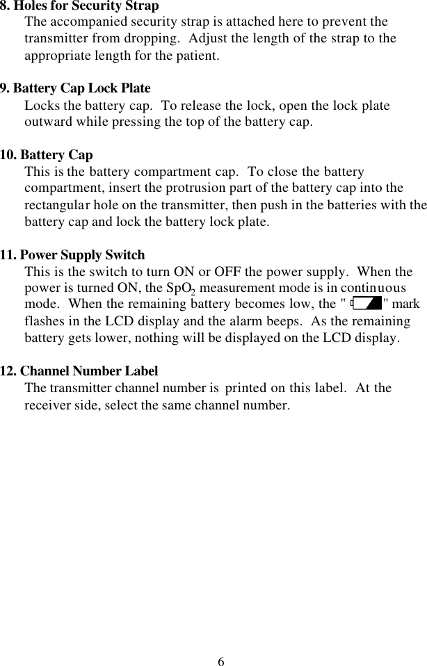
![9 [3] Attach the electrodes. For single lead ECG and respiration monitoring, use the CM-85B for AHA color code. AHA color code electrode position Respiration sensing : White and Red LEAD II LEAD CC5 LEAD MCL1 For two lead ECG and respiration monitoring, use the CM-85C for AHA color code. AHA color code electrode position LEAD I and LEAD II WhiteWhiteWhite Red Red Red Black Black Black Red WhiteBlackGreen + : Black CH 1 LEAD I − : White + : Red CH 2 LEAD II − : White Reference : Green Respiration sensing : White and Red](https://usermanual.wiki/Fukuda-Denshi-Co/LX5630/User-Guide-348327-Page-17.png)
![11 [4] Connect the lead wire to the electrode. Connect the tip of lead wire to the center of the electrode and gently swing it right and left. Refer the electrodes positions and color code in previous page. [5] Connect the lead wire to the transmitter. Connect the patient cable firmly to the ECG/Resp. input connector of the transmitter. When disconnecting the patient cable, do not disconnect the lead wire set by pulling on the wires. To send only the ECG and Resp., remove the SpO2 relay cable (CI-128A) from the transmitter. In this case, the transmitter will operate for 6 continuous days. CAUTION Confirm the direction of the keyed plug to match the transmitter's guide key on the connector. Improper connection will cause damage to the transmitter, patient cable, and will not provide proper monitoring.](https://usermanual.wiki/Fukuda-Denshi-Co/LX5630/User-Guide-348327-Page-19.png)
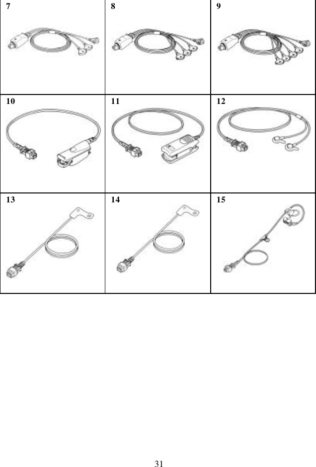
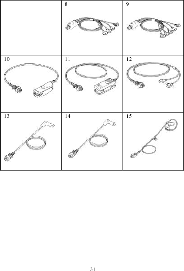
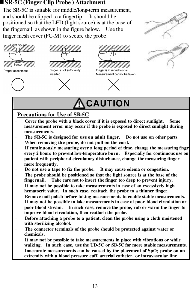
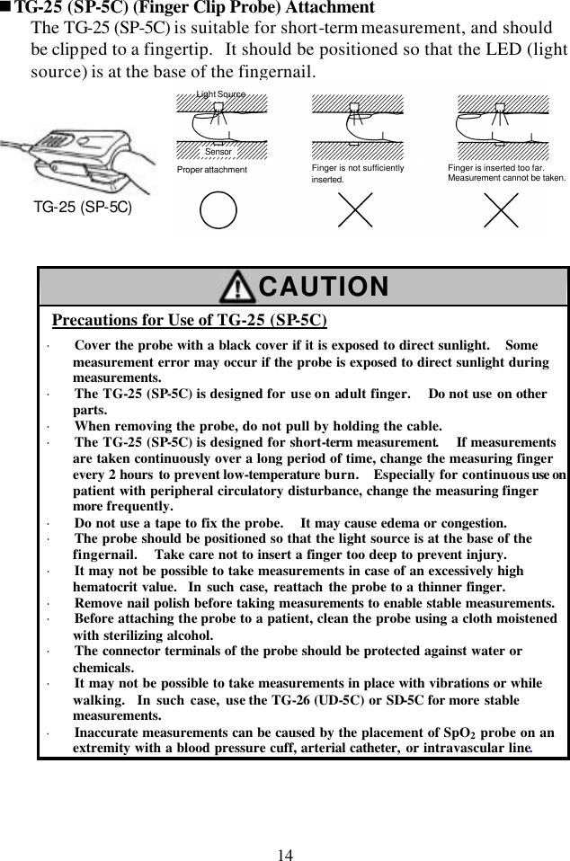
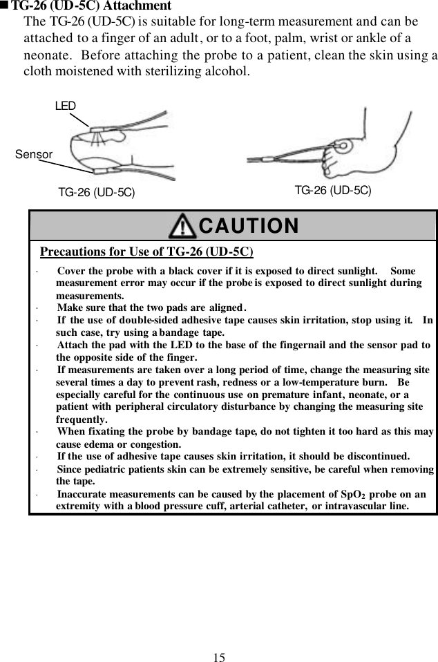
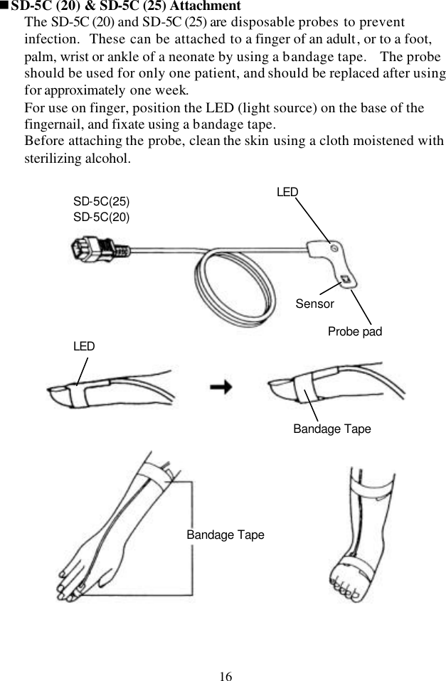
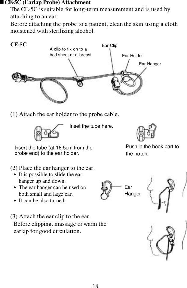
![12 [6] Attach the SpO2 probe. There are several types of SpO2 probe depending on the monitoring purpose. Select an appropriate type according to the intended use. The lightweight type such as SD-5C or TG-26(UD-5C) is suitable for the LX-5630. SR-5C TG-25(SP-5C) TG-26(UD-5C) for adult, reusable for adult, reusable for universal use SD-5C(25) for adult, semi-disposable CE-5C for earlap SD-5C(20) for pediatric, semi-disposable NOTE: The accuracy of this instrument, like that of all other dual-wavelength oximeters, can be influenced by the presence of abnormal hemogrobins such as carboxyhemoglobin (HbCO) and methemoglbin. The tables below show the errors which may occur due to these hemoglobins. The instrument may be also affected by cardiogreen or intravascular dyes. HbCO METHEMOGLOBIN SpO2 1% 5% 10% 1% 5% 10% 50% -0.1% -0.7% -1.5% 0.2% 1.3% 3.2% 70% -0.1% -0.7% -1.5% -0.6% -2.3% -3.2% 90% -0.2% -0.8% -1.6% -1.5% -6.0% -9.6% 100% -0.2% -0.8% -1.7% -1.8% -7.5% -12.2% Note The value will be displayed lower than the actual value. The value may be displayed higher than the actual value when SpO2 value is around 50%.](https://usermanual.wiki/Fukuda-Denshi-Co/LX5630/User-Guide-348327-Page-20.png)
![20 [7] Connect the SpO2 relay cable (CI-128A) and SpO2 probe to the transmitter. To connect the SpO2 relay cable (CI-128A) and SpO2 probe connector, align the marks on the socket box and the SpO2 connector. CAUTION Risk of Burn Injury by the Use of Probe · Do not use probes/cables other than those specified by Fukuda Denshi. Use of unspecified probes/cables may cause the probe to overheat, resulting in burn injury to the patient. · If any question on usable probes/cables for this transmitter, contact your local service representative. CAUTION · The pulse waveform sent from this transmitter is delayed from the ECG waveform. If the pulse waveform is used as a synchronized signal, pay attention to this delay. · Do not use the pulse waveform as a synchronized signal for other equipments. CI-128A Mark](https://usermanual.wiki/Fukuda-Denshi-Co/LX5630/User-Guide-348327-Page-28.png)