Fukuda Denshi Co LX5630 ECG, Respiration and SpO2 Transmitter User Manual LX5630 1Cover
Fukuda Denshi Co Ltd ECG, Respiration and SpO2 Transmitter LX5630 1Cover
Manual
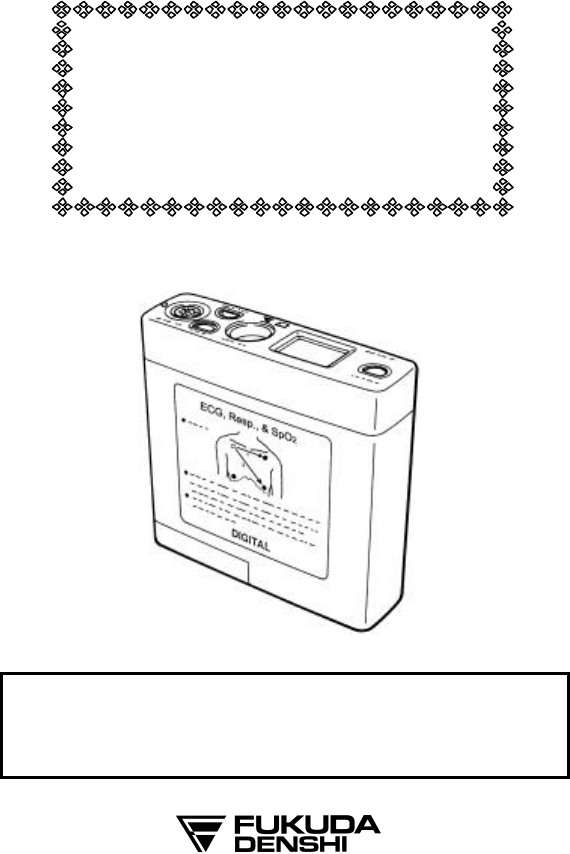
ECG, Respiration and SpO2
Transmitter
LX-5630
Operation Manual
l Before using the LX-5630 you must first thoroughly read
this manual.
l Remember to keep this operation manual in an easily
accessible place near the unit for future reference.
• Only a physician or a person under the guidance of a physician
can use this product.
• The information contained in this document is subject to change
without notice due to improvement in the equipment.
CAUTION
Federal law restricts this device to sale by or on the order of a
physician.
CAUTION
Users are advised to periodically contact the FCC or specified
frequency coordinator and determine if other or your transmitter
frequencies that may cause interference.
CAUTION
The manufacturers, installers and users of Wireless Medical
Telemetry System equipment are cautioned that the operation of this
equipment could result in harmful interference to other nearby
medical devices.
Copyright © 2003 by Fukuda Denshi Co., Ltd.
No part of this document may be copied or transmitted in any form without the
prior written permission of Fukuda Denshi Co., Ltd.
Printed in Japan
Important Information

i
TELEMETRY PRECAUTIONS
For proper management of the telemetry installation, consult your
Fukuda Denshi representative concerning the following:
• Plan the installation of your telemetry system taking into account
your entire medical facility needs and plant requirements.
• Be sure the antenna system installed meets the facility and plant
requirements.
WARNING
This radio frequency device is susceptible to interference from outside
sources. Interference may prevent the monitoring of patients
connected to this devices. If a problems exists, contact your local
service representative.
To assure safe and reliable operation, observe the following
precautions:
• Be sure that no other devices are using the frequency assigned to this
transmitter.
• This device is susceptible to interference from electrosurgical knives
and other computerized equipment. If problems occur, contact your
local Fukuda Denshi service representative.
• Any obstruction such as reinforced concrete or large metallic surfaces
between the receiver and the transmitter can affect reception.
If problems occur contact your local Fukuda Denshi service
representative.
• When the low battery alarm is present, replace the battery.
CAUTION
The manufacturers, installers and users of WMTS equipment are
cautioned that the operation of this equipment could result in harmful
interference to other nearby medical devices.

ii
Thank you for purchasing this instrument from Fukuda Denshi.
Before use, read this operation manual thoroughly for correct
handling and operation. If you are familiar with a similar type of
product, it is recommended this operation manual be read and
understood since the LX-5630 has unique operation and handling
methods.
Safety Information and Messages
• Be sure to observe the warning and cautionary messages related to
important safety information. These instructions are described
under the following message headings. Understand the meaning of
the different types of messages while reading this operation manual.
WARNING
Erroneous operation by failure to follow
this message may result in death or
serious injury to the patient, operator, or
create a fire hazard.
CAUTION
Erroneous operation by failure to follow
this message may result in injury to the
patient or operator, or may cause
damage to the LX-5630 and/or related
instruments.
NOTE
A NOTE is not a warning instruction
but offers information for correct use of
the LX-5630 to avoid erroneous
operation.

iii
Safety Considerations in Using Medical Electrical Equipment
Contents described here are general safety considerations to be
taken for proper operation of medical electrical equipment and for
the safety of both the patient and operator. Safety considerations
specific to the use of the LX-5630 are described on the next page.
WARNING
Strangulation Hazard!
l Make sure all patient cables, leadwires, and tubing are positioned
away from the patient’s head to minimize the risk of accidental
strangulation.
l Under no circumstances should any pouch be tied solely around a
patient’s neck.
CAUTION
1. Do not use the equipment unless you are familiar with its operation.
2. Observe the following when installing or storing the equipment:
· Select a place where the equipment may not be contaminated with splashing water.
· Consider the atmospheric pressure, temperature and humidity and provide
adequate ventilation. Avoid direct sunlight. The equipment should not be
installed or stored in a location where it may be
adversely affected by air containing
dust, saline or sulfur.
· Avoid inclination, vibration and shock, even during transport to ensure stable
operating conditions.
· Do not install or store the equipment where chemicals are stored or gases are
generated.
3. Precautions before Operation
· The equipment is not designed to be explosion-proof. Do not use the eq
uipment in
the presence of flammable gasses or anesthetics.
· Make sure the equipment is operating safely and normally at all times.
Ensure that all cords and cables are correctly connected.
· Improper use of multiple instruments simultaneously may result in erroneous
information or lead to a hazardous accident.
4. Precautions during Operation
· Do not operate the equipment beyond the time period required for diagnosis,
monitoring or treatment.
· Observe the equipment and patient constantly for any abnormality.
· If the equipment or patient indicates any abnormality, stop the equipment from
operating or take proper measures (e.g. disconnect transducers and electrodes) to
ensure patient safety.
· Instruct the patient not to contact the equipment.

iv
CAUTION
5. Cares after Operation
· Disconnect the cables by holding the connector plugs. Do not apply excessive
force to cords by pulling.
· Keep the equipment clean in preparation for the next use.
6. If the equipment is out of order, ensure patient safety by immediately
turning the equipment off and disconnecting electrodes and/or
transducers from the patient.
Contact your nearest Fukuda Denshi representative and label the
device as "OUT OF ORDER".
7. Do not disassemble or attempt service on the equipment. Contact
your nearest Fukuda Denshi representative for service.
8. Maintenance and Inspection
· Be sure to perform periodic inspection of the equipment and accessories.
· Before operating the equipment which has not been used for a long
period of time,
make sure that the equipment operates normally and safely.
9. When using an electrosurgical unit or defibrillator in conjunction
with this equipment, take care of the following.
· The high-frequency energy produced by electrosurgery equipment may result in
burns to the patient or possible damage to the equipment. Be
sure to observe the
precautionary instructions described in the
operation manual of the electrosurgical
unit.
· Some types of equipment may be damaged by the energy discharged by a
defibrillator. Ensure a thorough understanding of the precautionary
instructions
described in the operation manual of the equipment before using a defibrillator.
· Some types of equipment other than electrosurgical units and defibrillators may
cause accidental hazards to the patient and operator when operated under adverse
conditions. Read the operation manual attached to each individual unit and
understand the precautionary instructions prior to use.

v
CAUTION
Some pacemaker pulses are difficult or not possible to detect. This is
dependent on the amplitude and width of the pacemaker pulse in
addition to the type of pacemaker and lead type used (unipolar,
bipolar, etc.).
CAUTION
QRS detection allows for detection of low amplitude ECG. But if
excessive artifact is present on the ECG waveform, the noise may be
detected as QRS in error.
CAUTION
l Make sure each receiving telemetry channel corresponds to that of
the transmitter worn by the patient.
l Instruct the patient wearing a telemetry transmitter to remain
within the range of the antenna system.
l To avoid interference from other transmitters in the adjacent area
or hospital, make sure the proper channel identification and group
codes are used.
l Refer system settings to your Fukuda Denshi service
representative.
CAUTION
Do not use in high humidity or in areas of high oxygen concentration.
CONTENTS
1. General Description..............................................................................1
2. Controls and Indicators.......................................................................2
3. Preparation and Operation...............................................................7
[1] Loading a Battery. .........................................................................7
[2] Turn the power switch to "ON"................................................8
[3] Attach the electrodes. ..................................................................9
[4] Connect the lead wire to the electrode...............................11
[5] Connect the lead wire to the transmitter............................11
[6] Attach the SpO2 probe.................................................................12
SR-5C (Finger Clip Probe ) Attachment................................13
TG-25 (SP-5C) (Finger Clip Probe) Attachment.................14
TG-26 (UD-5C) Attachment..........................................................15
SD-5C (20) & SD-5C (25) Attachment.......................................16
CE-5C (Earlap Probe) Attachment...........................................18
[7] Connect the SpO2 relay cable (CI-128A) and
SpO2 probe to the transmitter................................................20
4. Group Code Setup.................................................................................22
5. Receiver Channel Setup.....................................................................23
6. Cleaning and Disinfection..................................................................24
7. Maintenance and Inspection............................................................25
8. Specifications..........................................................................................27
9. Accessories...............................................................................................29
1
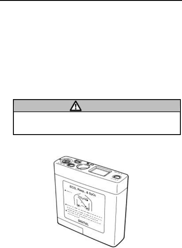
1. General Description
The LX-5630 is a radio telemetry transmitter designed for monitoring
the ECG, respiration, SpO2 (arterial oxygen saturation) and pulse
waveform. In the continuous mode, the transmitter will monitor ECG,
respiration, SpO2 and pulse waveform for 3 continuous days with two
"AA" size alkaline battery. In the intermittent mode, the transmitter
measures the SpO2 every 30 seconds, and monitors ECG and respiration
continuously for 5 days. Pulse waveform will not be measured in this
mode.
The LX-5630 is provided with LCD display to show SpO2 measurement,
pulse waveform amplitude, SpO2 alarm ON/OFF, battery status, ECG
electrode status, SpO2 probe status, and operation mode.
Before using this transmitter, read also the operation manual for the
patient monitor at receiving side before using this transmitter.
WARNING
Operation of this equipment requires the prior coordination with a
frequency coordinator designated by the FCC for the Wireless
Medical Telemetry Service.
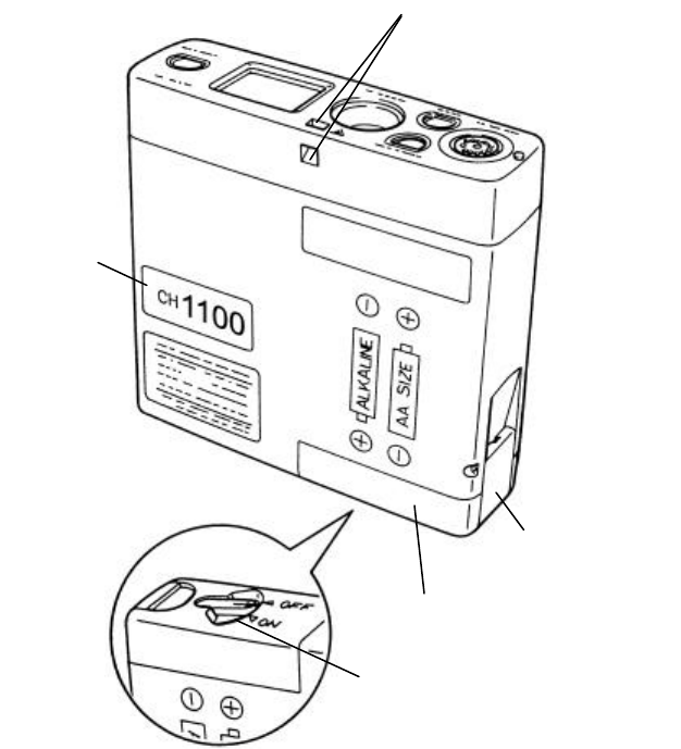
EXTERNAL APPEARANCE
2
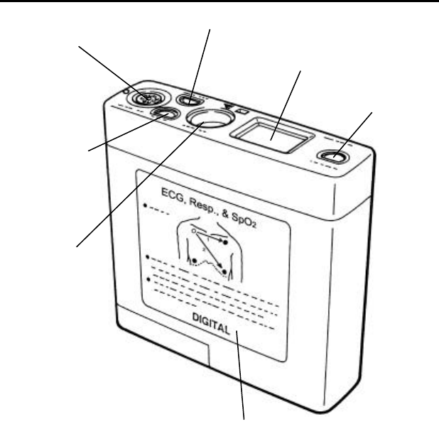
2. Controls and Indicators
1. SpO2 Input connector
3. LCD Display
7. Mode switch
6.
ECG/Resp. Input
Connector
2. SpO2 Alarm switch
4. Event Switch
5. Electrode Position Label
3
1. SpO2 input connector
The accompanied SpO2 relay cable (CI-128A) is connected here.
Different types of SpO2 probe can be connected to this SpO2 relay cable.
2. SpO2 Alarm switch
This is the SpO2 alarm function able/disable switch. When the SpO2
alarm is disable, LCD display (3) will show .
When the SpO2 measurement value drops to 90% or lower with the
alarm ON condition, the alarm sound generates. When the power is
turned ON, the alarm is in ON mode.
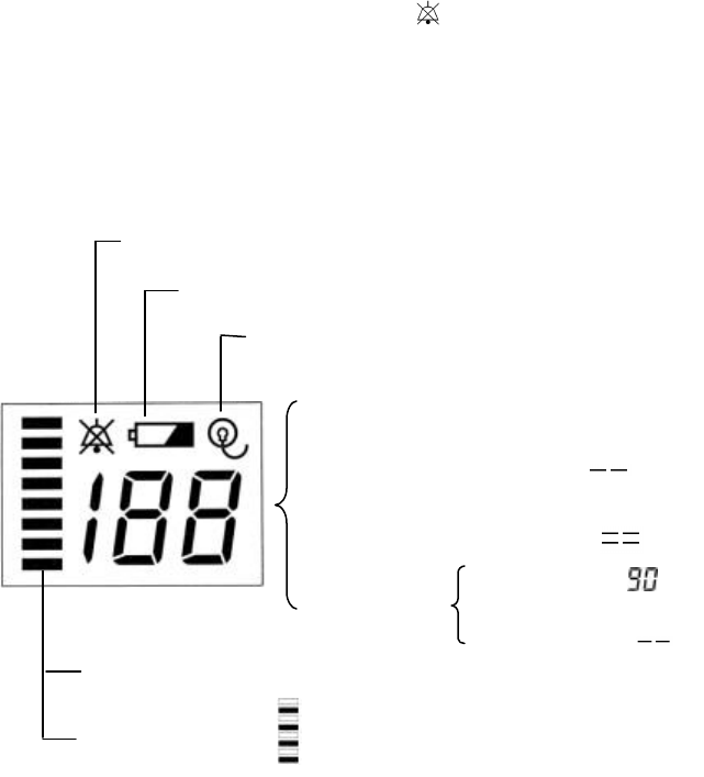
3. LCD Display
Displays the SpO2 value, pulse amplitude, SpO2 alarm ON/OFF, battery
status, ECG electrode status, SpO2 probe status, and operation mode.
Pulse amplitude : Up and down by pulse amplitude
Intermittent SpO2 mode :
Displayed when alarm is OFF.
Flashes when battery is low.
Flashes when ECG electrode is off.
SpO
2
Value
:
Numeric display
SpO2 not measured : Displays ” ”
Cannot measure SpO2 : Displays ” ”
When alarm
ON/OFF switch is
pressed.
When alarm is ON :
When alarm is OFF :

4
4. Event Switch
The function assigned at the receiver side will activate. The function
corresponded to the event switch is set at the receiver side.
5. Electrode Position Label
Indicates standard ECG electrode position and precautions for using the
SpO2 probe.
6. ECG/Resp Input Connector
The accompanied patient lead cable is connected here.
7. Mode Switch
This is the SpO2 measurement mode switch to select continuous or
intermittent mode. When the power is turned ON, this mode is in
continuous mode.
The SpO2 measurement mode are shown on the LCD display as follows.
SpO 2 continuous mode SpO 2 intermittent mode SpO 2 probe off
Transmits ECG, Resp., SpO2 Transmits ECG, Resp., SpO2 Transmits ECG, Resp.
5
8. Holes for Security Strap
12.
C
hannel
Number
Label
9.
Battery Cap Lock
Plate
10. Battery Cap
11. Power Supply Switch

6
8. Holes for Security Strap
The accompanied security strap is attached here to prevent the
transmitter from dropping. Adjust the length of the strap to the
appropriate length for the patient.
9. Battery Cap Lock Plate
Locks the battery cap. To release the lock, open the lock plate
outward while pressing the top of the battery cap.
10. Battery Cap
This is the battery compartment cap. To close the battery
compartment, insert the protrusion part of the battery cap into the
rectangular hole on the transmitter, then push in the batteries with the
battery cap and lock the battery lock plate.
11. Power Supply Switch
This is the switch to turn ON or OFF the power supply. When the
power is turned ON, the SpO2 measurement mode is in continuous
mode. When the remaining battery becomes low, the " " mark
flashes in the LCD display and the alarm beeps. As the remaining
battery gets lower, nothing will be displayed on the LCD display.
12. Channel Number Label
The transmitter channel number is printed on this label. At the
receiver side, select the same channel number.
7
3. Preparation and Operation
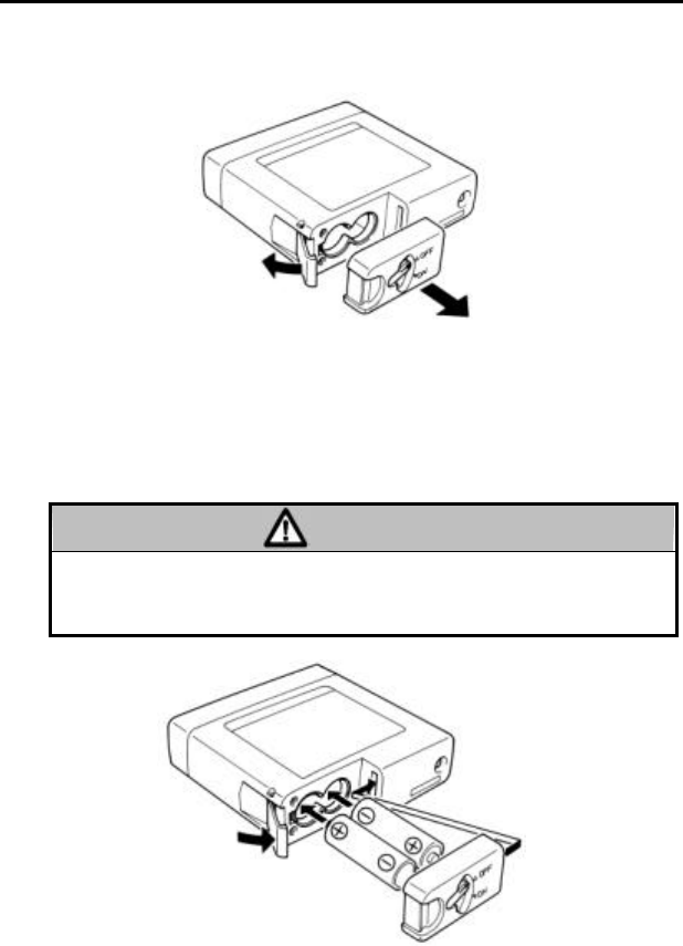
[1] Loading a battery.
The battery cap can be removed by opening the lock plate outward
while pressing the top of the battery cap.
The LX-5630 uses two "AA" size alkaline cell (LR-6) for its power
source.
When installing the battery, take note of the polarity. To close the
battery compartment, insert the protrusion part of the battery cap into
the rectangular hole on the transmitter, then push the batteries with the
battery cap and lock the battery lock plate.
CAUTION
If the transmitter is not in use for a long period of time, remove the
battery and store in an appropriate place. The leakage from the
battery may damage the equipment.
8
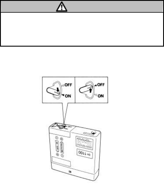
[2] Turn the power switch to "ON".
When the power is turned ON, the SpO2 measurement mode is in
continuous mode. To change the mode to intermittent mode, press the
mode switch. In the intermittent mode, the SpO2 will be measured at
30 seconds interval and no pulse waveform is sent, but ECG and
respiration will be continuously measured. In the continuous SpO2
measurement mode, the SpO2 value and pulse waveform will be
continuously measured.
CAUTION
In the intermittent mode, the SpO2 is measured at 30 seco
nds interval.
Even when the SpO2 value suddenly changes during this interval, the
transmitter will only show the last SpO2 measurement value. For the
patient with the possibility of sudden change, select the continuous
mode.
In the intermittent mode, the battery life is about 5 days and about 3
days in continuous mode.
9
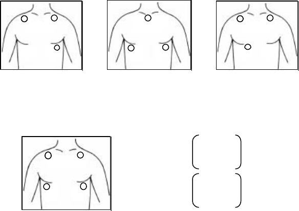
[3] Attach the electrodes.
For single lead ECG and respiration monitoring, use the CM-85B for
AHA color code.
AHA color code electrode position Respiration sensing : White and Red
LEAD II LEAD CC5 LEAD MCL1
For two lead ECG and respiration monitoring, use the CM-85C for
AHA color code.
AHA color code electrode position
LEAD I and LEAD II
White
White
White
Red
Red Red
Black
Black
Black
Red
White
Black
Green
+ : Black
CH 1 LEAD I
− : White
+ : Red
CH 2 LEAD II
− : White
Reference : Green
Respiration sensing : White and Red
10
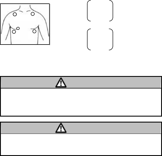
For dual channel ECG and respiration monitoring, use the CM-85D for
AHA color code patient cable (five electrodes).
AHA color code electrode position
LEAD II and LEAD MCL 1
CAUTION
Some pacemaker pulses are difficult or not possible to detect. This is
dependent on the amplitude and width of the pacemaker pulse in
addition to the type of pacemaker and lead type used (unipolar,
bipolar, etc.).
CAUTION
The time constant of ECG input is shorter than general hard wired
patient monitor. The ST level measurement may be different
compared to the general hard wired patient monitors.
Red
White
Black
Gree
n
Brown
+ : Red
CH 1 LEAD II
− : White
+ : Brown
CH 2 LEAD MCL1
− : Black
Reference : Green
Respiration sensing : White and Red
11
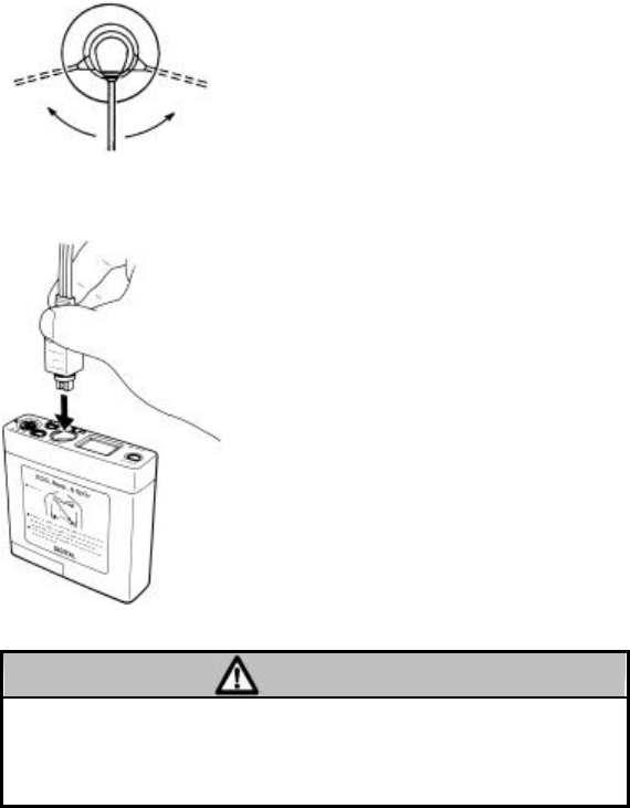
[4] Connect the lead wire to the electrode.
Connect the tip of lead wire to the center
of the electrode and gently swing it right
and left.
Refer the electrodes positions and color
code in previous page.
[5] Connect the lead wire to the transmitter.
Connect the patient cable firmly to the
ECG/Resp. input connector of the
transmitter.
When disconnecting the patient cable, do
not disconnect the lead wire set by pulling
on the wires.
To send only the ECG and Resp., remove
the SpO2 relay cable (CI-128A) from the
transmitter.
In this case, the transmitter will operate
for 6 continuous days.
CAUTION
Confirm the direction of the keyed plug to match the transmitter's
guide key on the connector. Improper connection will cause damage
to the transmitter, patient cable, and will not provide proper
monitoring.
12
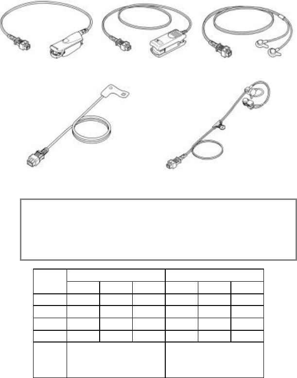
[6] Attach the SpO2 probe.
There are several types of SpO2 probe depending on the monitoring
purpose. Select an appropriate type according to the intended use.
The lightweight type such as SD-5C or TG-26(UD-5C) is suitable for
the LX-5630.
SR-5C TG-25(SP-5C) TG-26(UD-5C)
for adult, reusable for adult, reusable for universal use
SD-5C(25) for adult, semi-disposable CE-5C for earlap
SD-5C(20) for pediatric, semi-disposable
NOTE: The accuracy of this instrument, like that of all other dual-wavelength
oximeters, can be influenced by the presence of abnormal
hemogrobins such as carboxyhemoglobin (HbCO) and methemoglbin.
The tables below show the errors which may occur due to these
hemoglobins. The instrument may be also affected by cardiogreen or
intravascular dyes.
HbCO METHEMOGLOBIN
SpO2 1%
5%
10%
1%
5%
10%
50%
-0.1%
-0.7%
-1.5%
0.2%
1.3%
3.2%
70%
-0.1%
-0.7%
-1.5%
-0.6%
-2.3%
-3.2%
90%
-0.2%
-0.8%
-1.6%
-1.5%
-6.0%
-9.6%
100%
-0.2%
-0.8%
-1.7%
-1.8%
-7.5%
-12.2%
Note The value will be displayed
lower than the actual value.
The value may be displayed
higher than the actual value
when SpO2 value is around
50%.
13
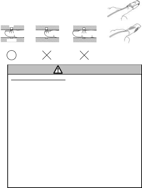
nSR-5C (Finger Clip Probe ) Attachment
The SR-5C is suitable for middle/long-term measurement,
and should be clipped to a fingertip. It should be
positioned so that the LED (light source) is at the base of
the fingernail, as shown in the figure below. Use the
finger mesh cover (FC-M) to secure the probe.
Light Source
Sensor
Proper attachment Finger is not sufficiently
inserted.
Finger is inserted too far.
Measurement cannot be taken.
CAUTION
Precautions for Use of SR-5C
· Cover the probe with a black cover if it is exposed to direct sunlight. Some
measurement error may occur if the probe is exposed to direct sunlight during
measurements.
· The SR-5C is designed for use on adult finger. Do not use on other parts.
· When removing the probe, do not pull on the cord.
· If continuously measuring over a long period of time, change the measuring finger
every 2 hours to prevent low-temperature burn. Especially
for continuous use on
patient with peripheral circulatory disturbance, change the measuring finger
more frequently.
· Do not use a tape to fix the probe. It may cause edema or congestion.
· The probe should be positioned so that the light source is at the base of the
fingernail. Take care not to insert the finger too deep to prevent injury.
· It may not be possible to take measurements in case of an excessively high
hematocrit value. In such case, reattach the probe to a thinner finger.
· Remove nail polish before taking measurements to enable stable measurements.
· It may not be possible to take measurements in case of poor blood circulation or
poor blood stream. In such case, remove the probe, rub or warm the finger to
improve blood circulation, then reattach the probe.
· Before attaching a probe to a patient, clean the probe using a cloth moistened
with sterilizing alcohol.
· The connector terminals of the probe should be protected against water or
chemicals.
· It may not be possible to take measurements in place with vibrations or while
walking. In such case, use the UD-5C or SD-5C for more stable measurements.
· Inaccurate measurements can be caused by the placement of SpO2 probe on an
extremity with a blood pressure cuff, arterial catheter, or intravascular line.
14
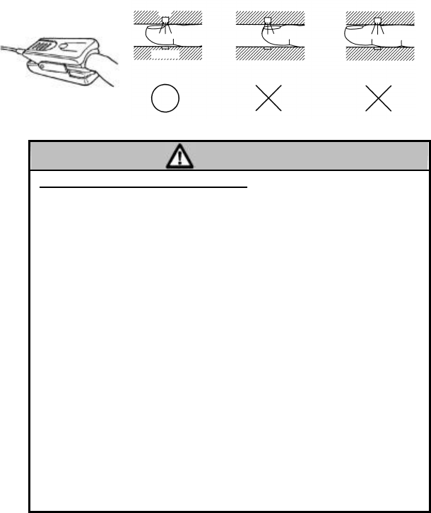
nTG-25 (SP-5C) (Finger Clip Probe) Attachment
The TG-25 (SP-5C) is suitable for short-term measurement, and should
be clipped to a fingertip. It should be positioned so that the LED (light
source) is at the base of the fingernail.
Light Source
Sensor
Proper attachment Finger is not sufficiently
inserted.
Finger is inserted too far.
Measurement cannot be taken.
CAUTION
Precautions for Use of TG-25 (SP-5C)
· Cover the probe with a black cover if it is exposed to direct sunlight. Some
measurement error may occur if the probe is exposed to direct sunlight during
measurements.
· The TG-25 (SP-5C) is designed for use on adult finger. Do not use on other
parts.
· When removing the probe, do not pull by holding the cable.
· The TG-25 (SP-5C) is designed for short-term measurement. If measurements
are taken continuously over a long period of time, change the measuring finger
every 2 hours to prevent low-temperature burn. Especially for continuou
s use on
patient with peripheral circulatory disturbance, change the measuring finger
more frequently.
· Do not use a tape to fix the probe. It may cause edema or congestion.
· The probe should be positioned so that the light source is at the base of the
fingernail. Take care not to insert a finger too deep to prevent injury.
· It may not be possible to take measurements in case of an excessively high
hematocrit value. In such case, reattach the probe to a thinner finger.
· Remove nail polish before taking measurements to enable stable measurements.
· Before attaching the probe to a patient, clean the probe using a cloth moistened
with sterilizing alcohol.
· The connector terminals of the probe should be protected against water or
chemicals.
· It may not be possible to take measurements in place with vibrations or while
walking. In such case, use the TG-26 (UD-5C) or SD-5C for more stable
measurements.
· Inaccurate measurements can be caused by the placement of SpO2 probe on an
extremity with a blood pressure cuff, arterial catheter, or intravascular line.
TG
-
25 (SP
-
5C)
15
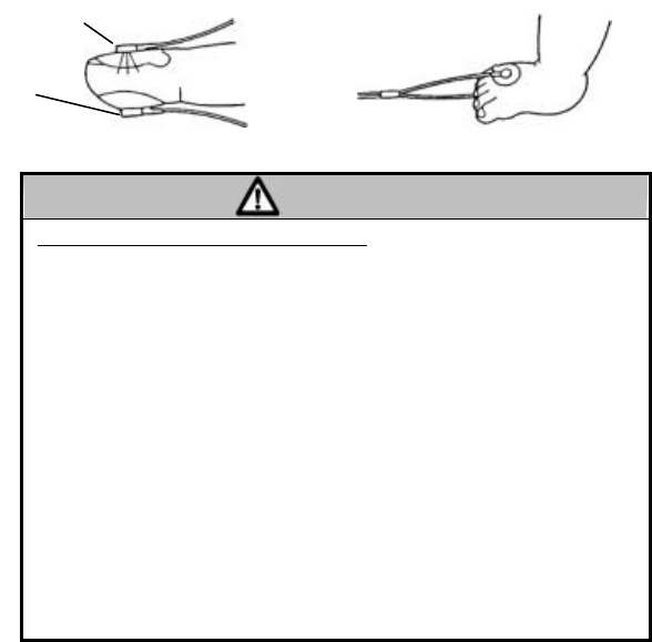
nTG-26 (UD-5C) Attachment
The TG-26 (UD-5C) is suitable for long-term measurement and can be
attached to a finger of an adult, or to a foot, palm, wrist or ankle of a
neonate. Before attaching the probe to a patient, clean the skin using a
cloth moistened with sterilizing alcohol.
CAUTION
Precautions for Use of TG-26 (UD-5C)
· Cover the probe with a black cover if it is exposed to direct sunlight. Some
measurement error may occur if the probe is exposed to direct sunlight during
measurements.
· Make sure that the two pads are aligned.
· If the use of double-sided adhesive tape causes skin irritation, stop using it.
In
such case, try using a bandage tape.
· Attach the pad with the LED to the base of the fingernail and the sensor pad to
the opposite side of the finger.
· If measurements are taken over a long period of time, change the measuring site
several times a day to prevent rash, redness or a low-temperature burn. Be
especially careful for the continuous use on premature infant, neonate, or a
patient with peripheral circulatory disturbance by changing the measuring site
frequently.
· When fixating the probe by bandage tape
, do not tighten it too hard as this may
cause edema or congestion.
· If the use of adhesive tape causes skin irritation, it should be discontinued.
·
Since pediatric patients skin can be extremely sensitive, be careful when removing
the tape.
· Inaccurate measurements can be caused by the placement of SpO2 probe on an
extremity with a blood pressure cuff, arterial catheter, or intravascular line.
LED
Sensor
TG-26 (UD-5C)
TG
-
26 (UD
-
5C)
16
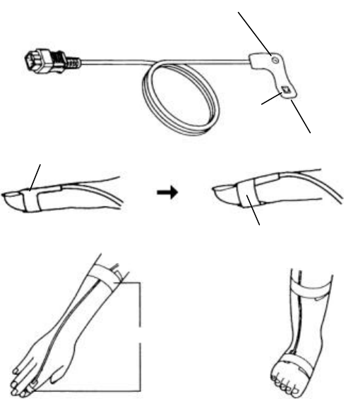
nSD-5C (20) & SD-5C (25) Attachment
The SD-5C (20) and SD-5C (25) are disposable probes to prevent
infection. These can be attached to a finger of an adult, or to a foot,
palm, wrist or ankle of a neonate by using a bandage tape. The probe
should be used for only one patient, and should be replaced after using
for approximately one week.
For use on finger, position the LED (light source) on the base of the
fingernail, and fixate using a bandage tape.
Before attaching the probe, clean the skin using a cloth moistened with
sterilizing alcohol.
SD
-
5C(25)
SD-5C(20)
LED
Sensor
Probe pad
LED
Bandage Tape
Bandage Tape

17
CAUTION
Precautions for Use of SD-5C(20), SD-5C(25)
· If measurements are taken over a long period of time, change the measuring site
several times a day to prevent rash or low-temperature burn.
· When fixating the probe by bandage tape
, do not tighten it too hard as this may
cause edema or congestion.
· Since the skin of a neonate is extremely sensitive, be careful when removing the
adhesive tape.
· Check that the LED (light source) and sensor are properly aligned. The sensor
must be on the opposite side of the LED.
· When removing the probe from the patient or removing the bandage tape from
the probe, hold the probe pad and not the cable.
· Cover the probe with a black cover if it is exposed to direct sunlight. Some
measurement error may occur if the probe is exposed to direct sunlight during
measurements.
· Do not apply excessive force on the LED and sensor, otherwise damage to the
probe may result.
· Inaccurate measurements can be caused by the placement of SpO2 probe on an
extremity with a blood pressure cuff, arterial catheter, or intravascular line.
18
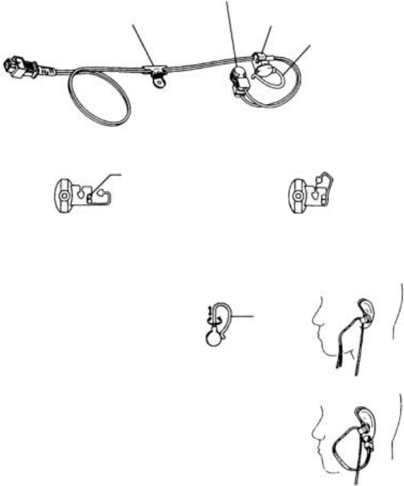
nCE-5C (Earlap Probe) Attachment
The CE-5C is suitable for long-term measurement and is used by
attaching to an ear.
Before attaching the probe to a patient, clean the skin using a cloth
moistened with sterilizing alcohol.
CE-5C
(1) Attach the ear holder to the probe cable.
(2) Place the ear hanger to the ear.
• It is possible to slide the ear
hanger up and down.
• The ear hanger can be used on
both small and large ear.
• It can be also turned.
(3) Attach the ear clip to the ear.
Before clipping, massage or warm the
earlap for good circulation.
Inset the tube here.
I
nsert the tube
(at
16.5cm from the
probe end) to the ear holder.
Push in
the
hook part
to
the
notch.
A clip to fix on to a
bed sheet or a breast
Ear Clip
Ear Holder
Ear Hanger
Ear
Hanger
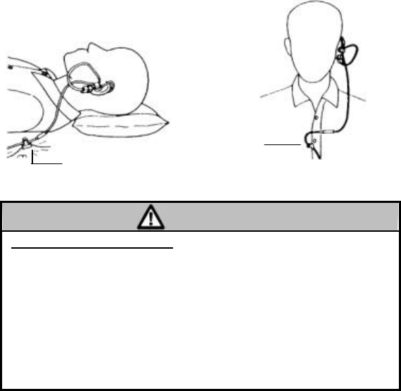
19
Use the ear clip to fix on to the bed sheet or breast as follows.
CAUTION
Precautions for Use of CE-5C
· The CE-5C is designed for use on earlap of an adult. Do not use on neonate
or
infant.
· If measurements are taken over a long period of time, change the measuring site
several times a day to prevent rash or low-temperature burn.
· Do not use a tape to fixate the probe. It may cause edema or congestion.
· Depending on the pulse condition, it may not be possible to take correct
measurements. In such case, use other types of probe and change the
measurement site.
· To prevent edema or congestion, massage or warm the measuring site several
times a day to improve blood circulation.
· When removing the probe, do not pull on the cable.
F
ixing to a bed sheet
Fixing to a breast
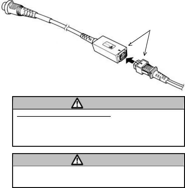
20
[7] Connect the SpO2 relay cable (CI-128A) and SpO2 probe to the
transmitter.
To connect the SpO2 relay cable (CI-128A) and SpO2 probe connector,
align the marks on the socket box and the SpO2 connector.
CAUTION
Risk of Burn Injury by the Use of Probe
· Do not use probes/cables other than those specified by Fukuda Denshi. Use of
unspecified probes/cables may cause the probe to overheat, resulting in burn
injury to the patient.
· If any question on usable probes/cables for this transmitter, contact your local
service representative.
CAUTION
· The pulse waveform sent from this transmitter is delayed from the ECG
waveform. If the pulse waveform is used as a synchronized signal,
pay attention to
this delay.
· Do not use the pulse waveform as a synchronized signal for other equipments.
CI-128A
Mark
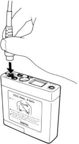
21
To connect the SpO2 relay cable (CI-128A), align the marks on the
cable and the transmitter. Firmly hold the connector part and gently
push it in.
When disconnecting the SpO2 relay cable, do not pull on the wire part.
Always hold the connector part.

22
4. Group Code Setup
The LX-5630 transmits a digitized code which includes the transmitting
channel ID and group code to prevent interference from other radio
apparatus or a neighboring hospital's transmitter.
There are 64 group codes. Zero ("0") is set as initial setting.
At the receiver side, it is required to set the same group code with the
transmitter. (Zero ("0") is set as initial setting at the receiver side.)
The receiver is continuously checking the incoming channel number
and group code with the number and code programmed to the receiver.
If changing the transmitter's group code, please contact your local
Fukuda Denshi service representative.
NOTE: The system function to preve nt interference will not work if the
receiver does not incorporate this function.
23
5. Receiver Channel Setup
Select the receiver channel at the patient monitor corresponding to the
telemetry transmitter. The channel number will be shown on the
display. Also, if the group code is set on the transmitter, it should be
also set on the receiver. (For details of channel setup and group code
setup, refer to the operation manual for the patient monitor on the
receiver side.)
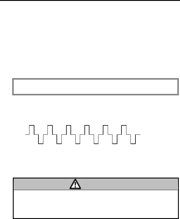
If the set channel number does not correspond to the actually received
channel number, the monitor will display a cautionary waveform as
shown below. This function will prevent interference with other
transmitters or external sources.
NOTE: This function will work only if the receiver incorporates the
interference detection function.
Example of the DS-5800N telemetry patient's display when interference
is present.
This cautionary waveform will also be displayed when a mismatch on
group code or channel number occurs.
CAUTION
This radio frequency device is susceptible to interference from outside
sources. Depending on receiving signal condition, the waveform may
include noise, false pacer spike, etc. To prevent these interferences,
it is recommended to install and use the telemetry antenna system.

24
6. Cleaning and Disinfection
Clean the transmitter, patient cable, SpO2 relay cables, and SpO2 probes
with gauze or sanitary cotton dampened with alcohol or inert soap.
Pay attention not to get cleaning liquid into the patient lead connector
or battery compartment.
Do not use cleaner containing organic solution, thinners, toluene, or
benzene.
Do not autoclave or heat the equipment and patient cable above 60 °C.
When the room is disinfected by spraying, take proper measures so the
chemical solution does not get into the connector or enter the equipment.

25
7. Maintenance and Inspection
Items in this section include routine daily and periodic checks of the
equipment to ensure it is operating properly.
It is recommended that to maintain the safety and reliability of
functions and performance of the equipment, the daily and periodic
checks given in this section be followed.
CAUTION
l Do not open the housing or attempt service. Refer service
to Fukuda Denshi.
l Do not allow excessive moisture or cleaning agents into the
connectors or inside the equipment.
nDaily Check
Perform daily checks in accordance with the recommended daily check
list.

26
No.
Date
Checker
Installation Place
Unit LX-5630
S/No.
Purchase Date
Items Details of the Check Criteria Judgement
Appearance Visually check for any damage,
cracks, chink, chips and peeled
nameplate on the housing.
No abnormality
should be found. cOK cNG
Battery
Compartment
Visually check the connecting
spring inside the device and
battery cap.
Spring should not be
transformed,
deformed or rusted.
cOK cNG
Power Turn ON/OFF power to verify
proper switch operation.
With battery
installed, the LCD
will display.
cOK cNG
ECG
Connector Visually check for connector of
main unit and patient cable.
No scratch ,chips,
dust should be
found.
cOK cNG
Patient Cable
Visually check the wire coating of
patient cable.
No cracks, kinks, or
damage should be
found.
cOK cNG
SpO2 Relay
Cable Visually check the cable sheath
and connectors.
No cracks, kinks, or
damage should be
found. cOK cNG
SpO2 Sensor Visually check for cable sheath
sensor and connectors.
No cracks, kinks,
dust, damage should
be found. cOK cNG
Wireless
Channel
Visually verify the transmit
channel ID, and group code.
Follow instructions of the
wireless channel manager for the
receiver.
Must correspond
with wireless
channel check list.
cOK cNG
Operational
function Turn ON the power and make
sure the operation is normal.
Waveform is
received without any
problem.
cOK cNG
Display
function
Turn ON the power and verify the
SpO2 data, bargraph, etc. is
properly displayed.
All data should be
properly displayed.
cOK cNG
Periodic
Check Check the date of previously
performed periodic check. Should be within
one month. cOK cNG

27
8. Specifications
Parameters : 1 or 2 channel ECG, respiration, SpO2,
Pulse waveform
ECG input impedance : 50 MO or above
ECG max. input range : +/- 5 mV
ECG freq. response : 40 Hz (refer also to the receiver filter)
ECG time constant : 0.8 seconds
Resp. measurement : Impedance pneumography
Resp. sensitivity : 1 cm/O when patient monitor sensitivity is
"1"
Resp. meas. current : 84kHz, 100 µA or less
SpO2 meas. range : 0 ~ 100%
SpO2 meas. method : Two light wavelength, pulse waveform
SpO2 accuracy : 70 ~ 100% : +/-2%
0 ~ 69% : not specified
SpO2 meas. time : Approx. 5 sec.
SpO2 built-in alarm : Lower limit fixed to 90%
LCD display : SpO2 value, pulse amplitude, electrode off,
low battery, SpO2 alarm OFF, SpO2 alarm
status, SpO2 alarm lower limit, SpO2 meas.
status, operation mode.
Alarm sound : SpO2 alarm, low battery alarm
Defibrillator protection : By protection circuit in the ECG patient
cable
Status information : Electrode off, low battery, event switch,
pacemaker detection, channel ID, 64
group codes, SpO2 probe off
Transmission freq. : 608 to 614 MHz
RF output power : 1.0 mW +/-2 dB
Channel spacing : 12.5 kHz
Occupied band width : 8.5 kHz
Modulation mode : Digital, Frequency shift keying
Power source : Two 1.5 V AA size alkaline battery
Battery polarity protection : Mechanical reverse polarity protection
Battery life : 3 days continuous, 5 days intermittent
SpO2 operation,
6 days for ECG & Resp. only
Water proof : Water-resistant

28
Weight : Approx. 190 g (including battery)
Dimensions : 94 (W) x 90 (H) x 26.5 (D) mm
Operating temperature : 10 to 40 °C
Operating humidity : 30 to 85 % RH
(without dew condensation)
Storage temperature : -10 to 60 °C
Storage humidity : 10 to 95 % RH
CAUTION
Specifications are subject to change without prior notice.
29
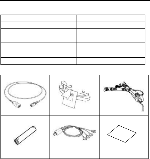
9. Accessories
nStandard Accessories
No.
Name Model Quantity
Remarks
1 SpO 2 Relay Cable CI-128A
1
2 Pouch AB-101 2
3 Security Strap OB-25 1 kit
4 Battery LR-6 2
5 Patient Cable CM-85C
1
6 Instruction Manual 1
1
2
3
4
5
6

30
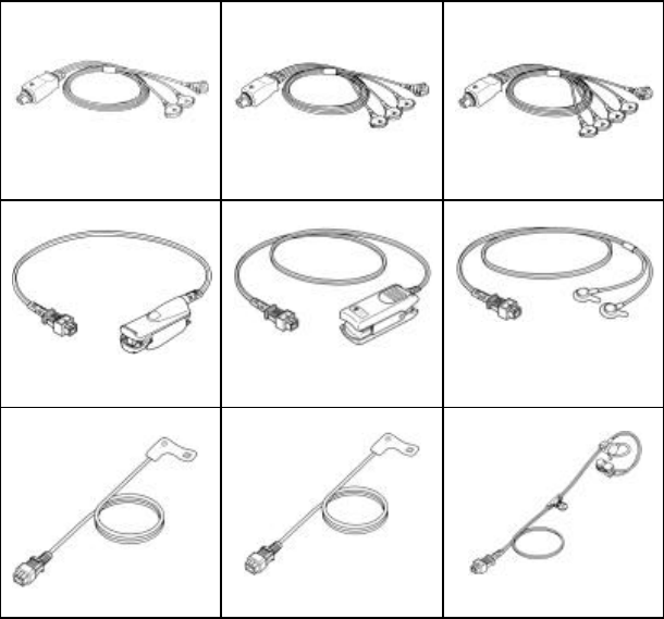
nOptional Accessories
No.
Name Model Note
7 Patient cable CM-85B For single ECG lead and
respiration.
8 Patient cable CM-85C For two ECG lead I, II and
respiration.
9 Patient cable CM-85D For dual ECG for any two
channel differential ECG and
respiration, five -electrode type.
10 SpO 2 probe for finger SR-5C For adult, reusable
11 SpO 2 probe for finger TG -25
(SP-5C) For adult, reusable
12 SpO 2 probe for universal
TG -26
(UD-5C) Universal
13 SpO 2 probe for finger SD-5C(25)
For adult, semi-disposable
14 SpO 2 probe for finger SD-5C(20)
For pediatric, semi-disposable
15 SpO 2 probe for earlap CE-5C
31
7
8
9
10
11
12
13
14
15
32
Blank Page

Head office : 39-4, Hongo 3-chome, Bunkyo-ku, Tokyo, Japan
Phone : -81-3-3815-2121
Fax : -81-3-3814-1222
4L3381 200306