Fukuda Denshi Co LX7230KM ECG, Respiration and SpO2 Transmitter User Manual
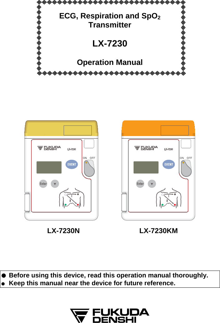
Fukuda Denshi Co Ltd ECG, Respiration and SpO2 Transmitter
UserManual.wiki
>
Fukuda Denshi Co
>
LX7230KM User Manual
User manual
Navigation menu
Upload a User Manual
Namespaces
Wiki Guide
HTML
PDF
Info
Views
User Manual
Discussion / Help
Navigation
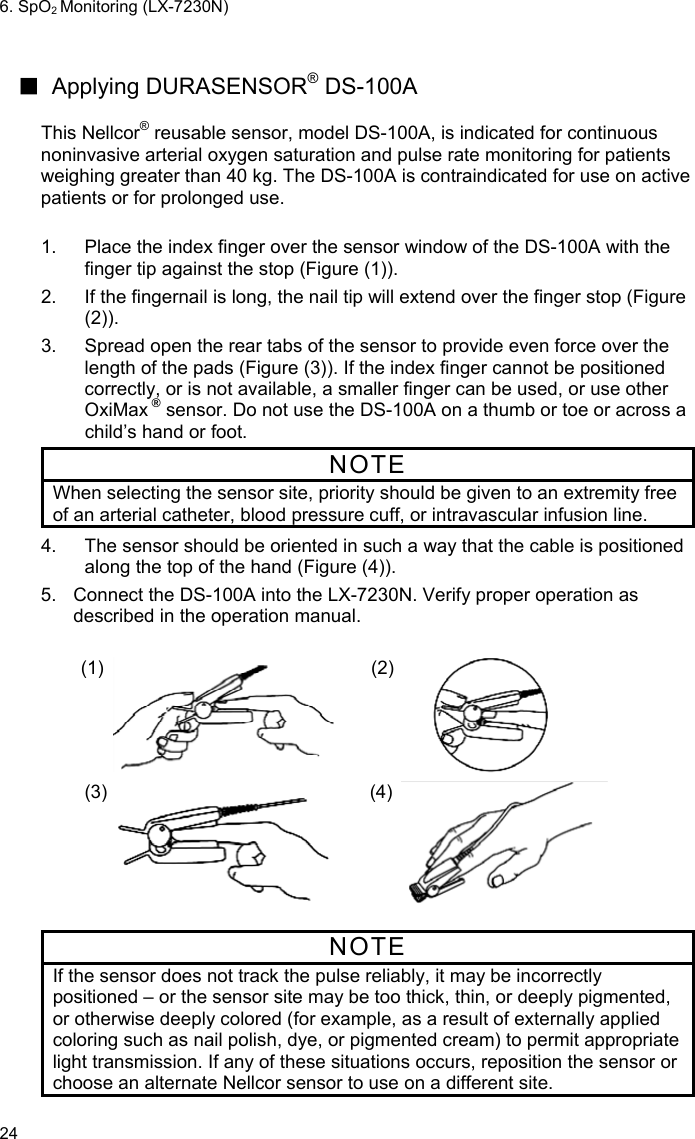
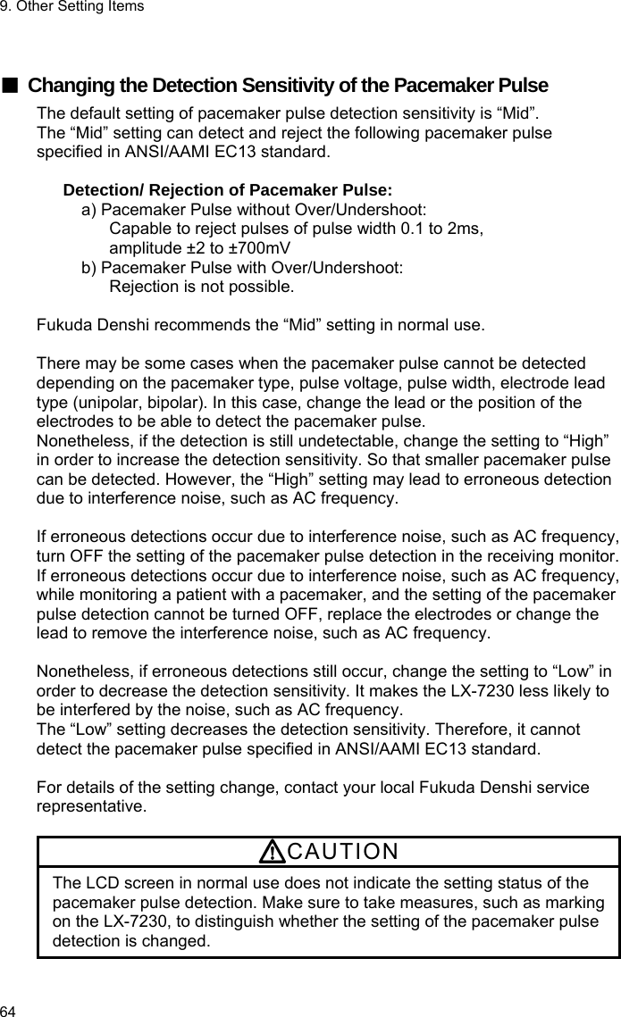
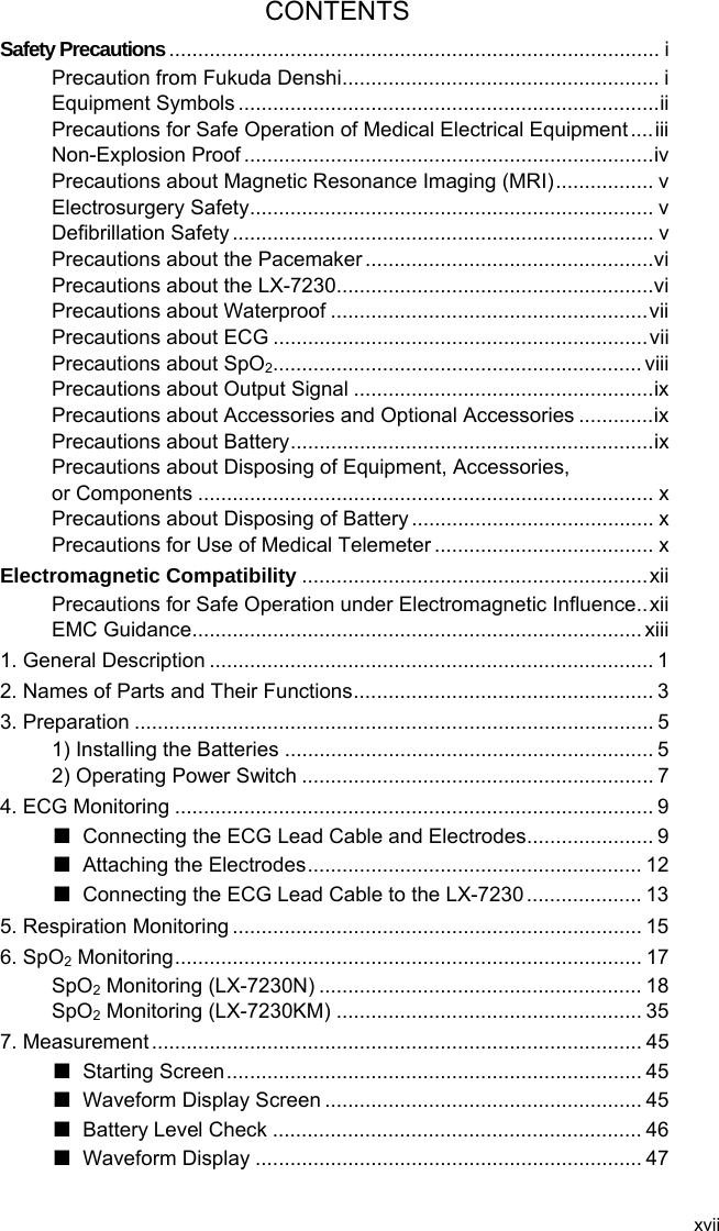
![Precautions about the Pacemaker WARNING Minute ventilation rate-adaptive implantable pacemakers can occasionally interact with certain cardiac monitoring and diagnostic equipment, causing the pacemakers to pace at their maximum programmed rate. The cardiac monitoring and diagnostic equipment may possibly send wrong information. If such event occurs, please disconnect the cardiac monitoring and diagnostic equipment, or follow the procedures described in the operation manual of the pacemaker. (For more details, contact FUKUDA DENSHI personnel, your institution’s professionals, or your pacemaker distributors.) Reference “Minute Ventilation Rate-Adaptive Pacemakers” FDA alerts health professionals that minute ventilation rate-adaptive implantable pacemakers can occasionally interact with certain cardiac monitoring and diagnostic equipment, causing pacemakers to pace at their maximum programmed rate. [October 14, 1998 (Letter: www .fda.gov/cdrh/safety.html) – FDA] ECG meter may continue to count the pacemaker rate during occurrences of cardiac arrest or arrhythmias. Do not rely entirely upon the ECG meter alarms. Keep pacemaker patients under close surveillance. Check this manual for disclosure of the pacemaker pulse rejection capability of this instrument. Precautions about the LX-7230 WARNING Do not connect cables not authorized by Fukuda Denshi to any I/O connector. If done so by mistake, the LX-7230 cannot deliver its maximum performance and may be damaged, resulting in a safety hazard. Do not use this device with multiple patients simultaneously. CAUTION Do not pick up and/or swing the LX-7230 pulling/grabbing the probe (sensor) or cord part. The cable could break or get disconnected from the LX-7230. And it may hit people or damage other equipment around. vi](https://usermanual.wiki/Fukuda-Denshi-Co/LX7230KM/User-Guide-1389401-Page-8.png)

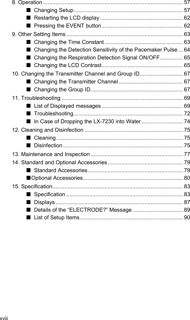


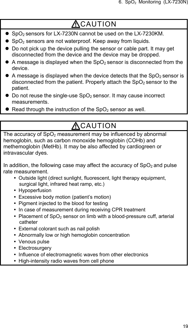
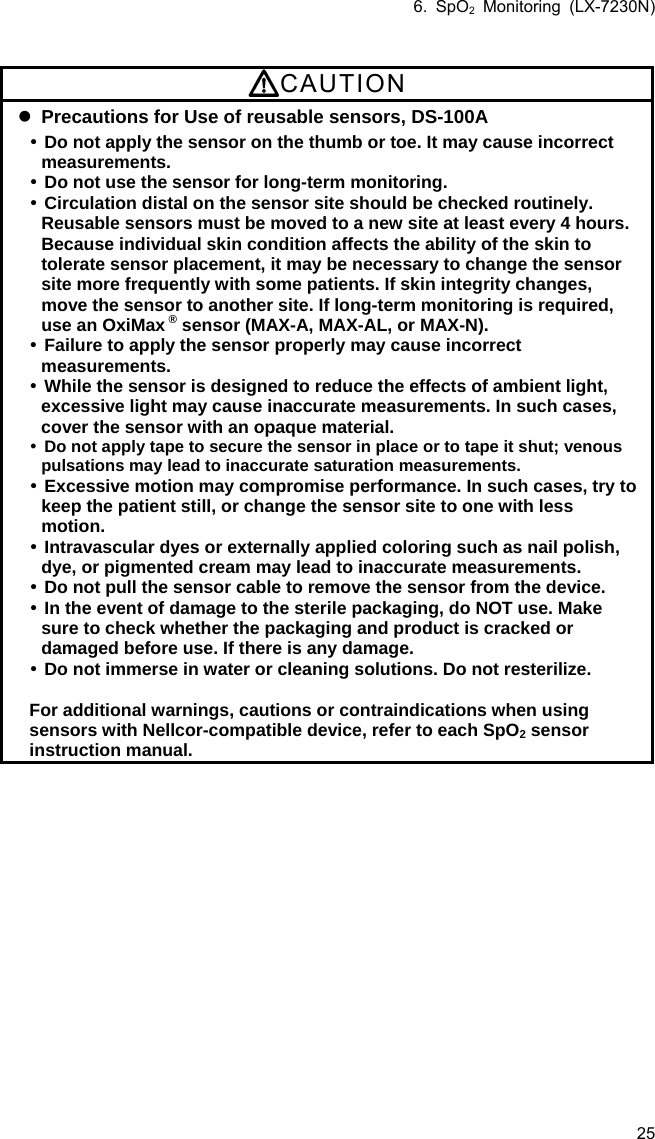
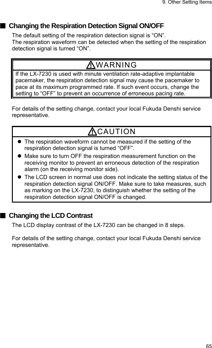
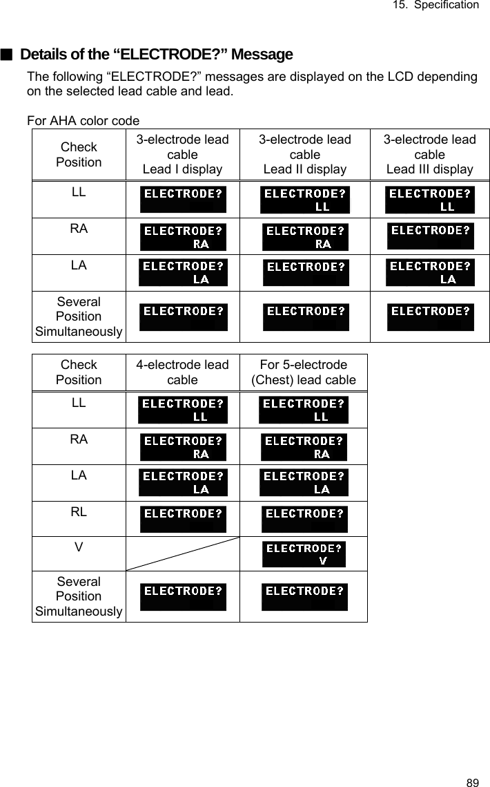
![15 5. Respiration Monitoring Follow the preparation of “4.ECG Monitoring” to allow the respiration monitoring. This respiration monitoring is performed with impedance method. The ECG electrodes are also used for detecting the respiration. Each lead cable specifies the electrodes to detect the respiration. For 3-electrode and 5-electrode (chest) lead cable, the electrodes to detect the respiration are fixed as follows. Even if lead method is switched, they are no changes. Lead Cable Color of Electrode 3-electrode White (RA) and Red (LL) 4-electrode White (RA) and Red (LL) 5-electrode (Chest) White (RA) and Red (LL) WARNING Minute ventilation rate-adaptive implantable pacemakers can occasionally interact with certain cardiac monitoring and diagnostic equipment, causing the pacemakers to pace at their maximum programmed rate. The cardiac monitoring and diagnostic equipment may possibly send wrong information. If such event occurs, please disconnect the cardiac monitoring and diagnostic equipment, or follow the procedures described in the operation manual of the pacemaker. (For more details, contact FUKUDA DENSHI personnel, your institution’s professionals, or your pacemaker distributors.) Reference “Minute Ventilation Rate-Adaptive Pacemakers” FDA alerts health professionals that minute ventilation rate-adaptive implantable pacemakers can occasionally interact with certain cardiac monitoring and diagnostic equipment, causing pacemakers to pace at their maximum programmed rate. [October 14, 1998 (Letter: www .fda.gov/cdrh/safety.html) - FDA] CAUTION Even if the electrodes are attached on the proper positions for ECG monitoring, it may not be always the proper ones for respiration monitoring as well. When a defibrillator is used during respiration monitoring, a large offset voltage will be placed on the ECG electrodes, which may cause interruption of monitoring for a few seconds.](https://usermanual.wiki/Fukuda-Denshi-Co/LX7230KM/User-Guide-1389401-Page-35.png)