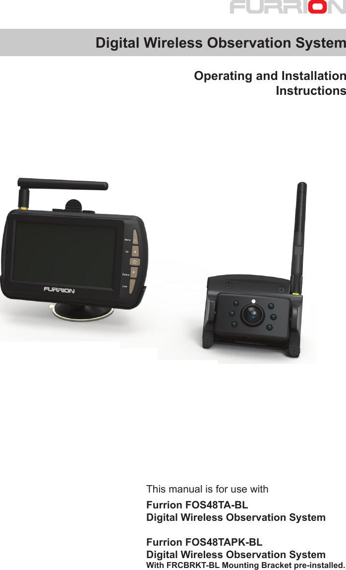
Furrion FOD43TA-BL Digital Wireless Observation System User Manual instruction manual
Furrion Ltd. Digital Wireless Observation System instruction manual
UserManual.wiki
>
Furrion
>
FOD43TA-BL User Manual
>
instruction manual
Contents
1.
instruction manual
2.
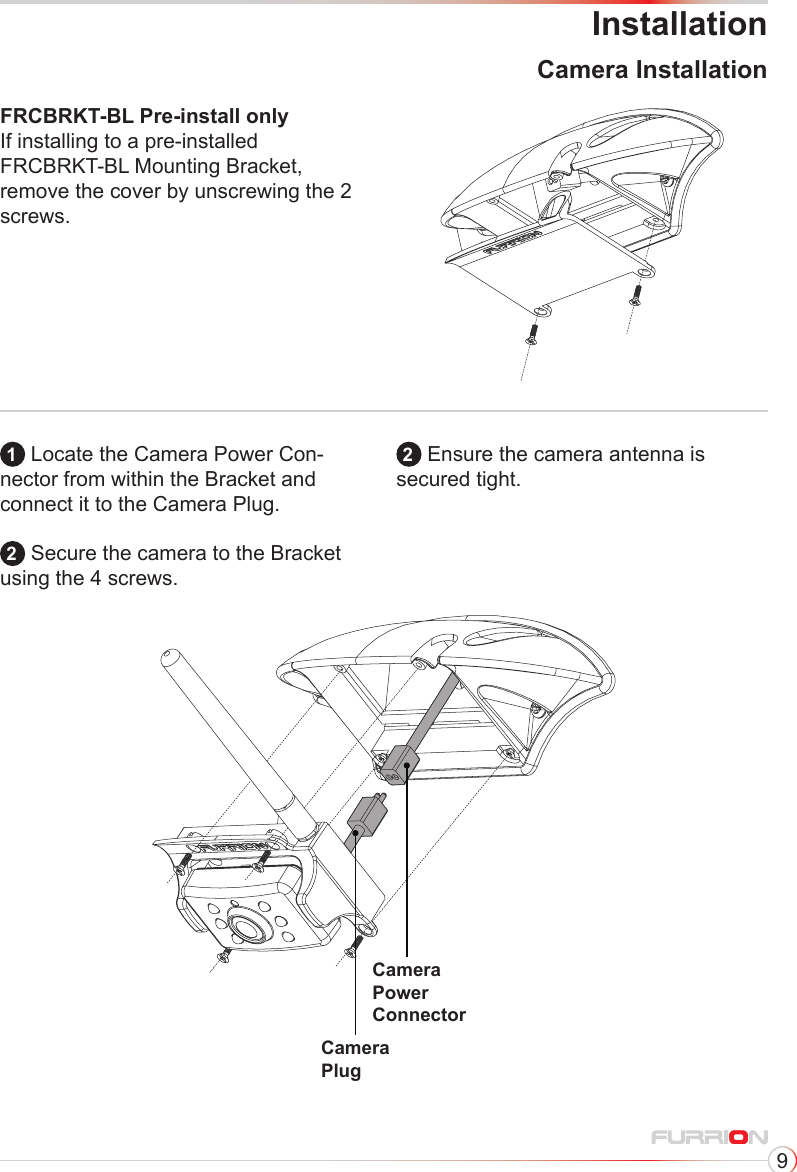
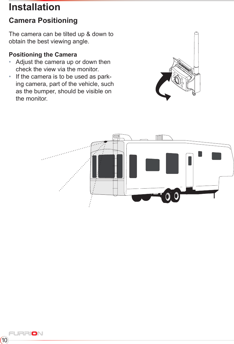
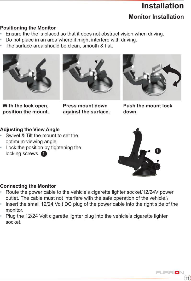
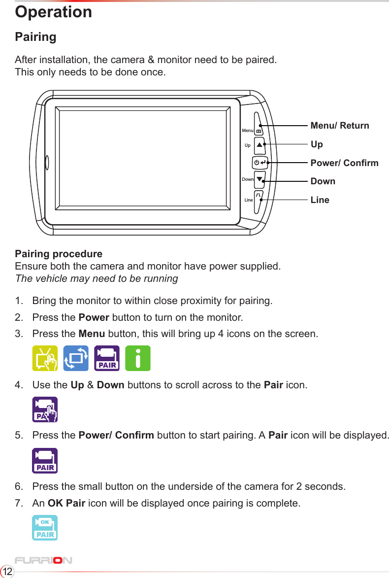
User Manual
instruction manual
Navigation menu
Upload a User Manual
Namespaces
Wiki Guide
HTML
PDF
Info
Views
User Manual
Discussion / Help
Navigation