Furuno USA 9ZWFA150 FA150 User Manual OPERATORS MANUAL
Furuno USA Inc FA150 OPERATORS MANUAL
UserManual.wiki
>
Furuno USA
>
9ZWFA150 User Manual
OPERATORS MANUAL
Navigation menu
Upload a User Manual
Namespaces
Wiki Guide
HTML
PDF
Info
Views
User Manual
Discussion / Help
Navigation

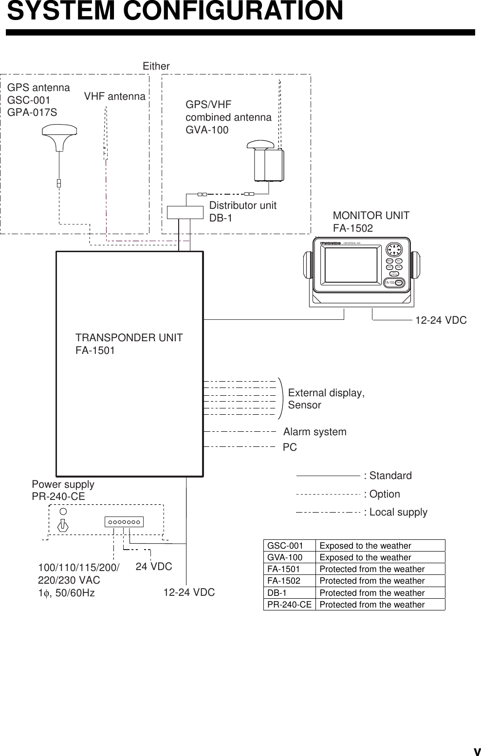

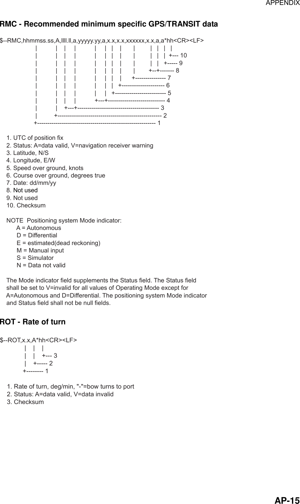
![1. OPERATION 1-2 1.2 Turning the Power On and Off Press the [PWR] key to turn the equipment on or off. When powered, the equipment sounds a beep for several seconds and then proceeds in the sequence shown below. [STARTUP TEST]PROGRAM No.: 2450021-**.**ROM : OKRAM : OKBACKUP DATA : OK**.**: Program Version No.AUTOMATIC IDENTIFICATION SYSTEMFURUNO ELECTRIC CORP.EQUIPMENT IDENTIFICATIONSCREENSTARTUP SCREEN[- - - - - - - -]HDG: - - -°SOG: - - .-ktCOG: - - -.-CPA: - - -.-TCPA: - -'- -"INTRD: 0 RNG: 6 DETAIL:[ENT]nmnmNOW INITIALIZINGPLOTTER DISPLAY Startup sequence The startup screen displays the program version number and the results of the ROM, RAM and backup data test, showing OK or “NG” (No Good) as the result. If “NG” (No Good) appears for any of the check results, try resetting the power to restore normal operation. If that does not work, contact your dealer for advice. After the startup test is completed the plotter display appears, showing the message “NOW INITIALIZING,” which means the transponder is initializing itself. After completion of initialization the equipment is ready for use. If there is no response from the transponder unit, the message “COMMUNICATION ERROR” appears at the startup screen. Press any key to erase the message. Check if the transponder unit is powered. Also check the connection between the monitor unit and the transponder unit.](https://usermanual.wiki/Furuno-USA/9ZWFA150/User-Guide-505656-Page-12.png)
![1. OPERATION 1-4 1.3 Adjusting Panel Dimmer and Contrast The panel dimmer and display contrast may be adjusted as follows: 1. Press the [DIM] key to show the dialog box below. DIMMER (0~8) CONTRAST (0~63)EXIT: [ENT] 444 Panel dimmer and contrast dialog box 2. Use ▲ or ▼ to adjust panel dimmer; ◄ or ► to adjust contrast. 3. Press the [ENT] key to close the dialog box. Note: The equipment starts up with the last-used dimmer and contrast settings. Therefore, if necessary, readjust them at power up.](https://usermanual.wiki/Furuno-USA/9ZWFA150/User-Guide-505656-Page-14.png)
![1. OPERATION 1-51.4 Menu Overview You can choose the functionality of the equipment through the menu. If you get lost in operation, press the [MENU] key until you return to the main menu. The complete menu tree is provided in the Appendix. 1.4.1 Menu operating procedure 1. Press the [MENU] key to display the main menu. [MENU]MSGSENSOR STATUSINTERNAL GPSUSER SETTINGSINITIAL SETTINGSCHANNEL SETTINGSDIAGNOSTIC Main menu 2. Use the CursorPad to choose a wanted menu and then press the [ENT] key. 3. Use the CursorPad to choose a wanted sub-menu and then press the [ENT] key. There are two types of sub-menus: option selection and data entry. (Some sub-menus combine both.) Below are examples of each type of sub-menu. USER SETTINGS sub-menu(Option selection) DRAUGHT input screen(Data input)[USER SETTINGS]KEY BEEP : ONALARM BUZZER : ONDISP RCVD MSG : ABMRCVD MSG BUZZ: OFFLR MODE : AUTOCPA/TCPA ALARMQUIT[MENU][DRAUGHT] DRAUGHT 00.0 m Sample sub-menu screens 4. Use ▲ or ▼ to choose the item you wish to process and then press the [ENT] key.](https://usermanual.wiki/Furuno-USA/9ZWFA150/User-Guide-505656-Page-15.png)
![1. OPERATION 1-6 5. Depending on the sub-menu selected, you will choose an option or enter alphanumeric data. Choosing an option The example below shows how to choose an option from the USER SETTINGS menu. (See the illustration on the previous page.) a) Use ▲ or ▼ to choose the menu item desired and then press the [ENT] key. A window showing the options for the item selected is overlaid on the sub-menu selected. For example, the options for KEY BEEP are as shown below. QUIT[MENU][USER SETTINGS]KEY BEEP : ONALARM BUZZER : ONDISP RCVD MSG : ABMRCVD MSG BUZZ: OFFLR MODE : AUTOCPA/TCPA ALARMONOFFOptions window USER SETTINGS menu, showing options for KEY BEEP b) Press ▲ or ▼ to choose option desired and then press the [ENT] key. Entering alphanumeric data The example below shows how to enter numeric data on the DRAUGHT entry screen. a) Choose DRAUGHT and then push the press the [ENT] key. An underline is under the far left-hand digit. [DRAUGHT] DRAUGHT 00.0 mCursor DRAUGHT entry screen b) Use ▲ or ▼ to choose appropriate numeric. Note: For menus where you enter alphanumeric characters, pressing ▲ displays alphanumeric characters cyclically in order of blank space, alphabet, numerals and symbols. c) Use ► to shift the cursor to the adjacent place, and then use ▲ or ▼ to choose numeric. d) Repeat step c) to finish entering data for the item selected. e) Press the [ENT] key to register data. 6. Press the [DISP] key to close the menu and return to the plotter display.](https://usermanual.wiki/Furuno-USA/9ZWFA150/User-Guide-505656-Page-16.png)
![1. OPERATION 1-71.5 Setting Up for a Voyage There are five items on the NAV STATUS menu that you will need to enter at the start of a voyage: navigation status, destination, arrival date and time, number of crew, and your vessel type. 1. Press the [NAV STATUS] key to open the NAV STATUS menu. [NAV STATUS] NAV STATUS: 0 ***STATUS DETAIL*** UNDER WAY USING ENGINE NAV STATUS menu, page 1, nav status entry screen 2. If your navigation status is different from that shown, follow the procedure below. If not, go to step 3. a) Press the [ENT] key. b) Press ▲ or ▼ to choose appropriate status and then press the [ENT] key. Refer to the data below to choose appropriate nav status. 00: Underway using engine 01: At anchor 02: Not under command 03: Restricted maneuverability 04: Constrained by draught 05: Moored 06: Aground 07: Engaged in fishing 08: Under way by sailing 09: Reserved for high speed craft (HSC) 10: Reserved for wing in ground (WIG) 11-14: Reserved for future use 15: Not defined (default) 3. Press ► to show page 2 of the NAV STATUS menu. [DESTINATION *************(0/0)[NEW?] NAV STATUS menu, page 2](https://usermanual.wiki/Furuno-USA/9ZWFA150/User-Guide-505656-Page-17.png)
![1. OPERATION 1-8 4. NEW is selected; press the [ENT] key. [DESTINATION] ENTER A NEW DESTINATIONQUIT:[NAV STATUS] NAV STATUS menu, page 2 (destination entry screen) 5. Press the [ENT] key. Use the CursorPad to enter destination. You may use up to 20 alphanumeric characters, and you may enter 20 destinations. Pressing ▲ displays alphanumeric characters in order of blank space, alphabet, numerals and symbols. (For how to enter alphanumeric characters, see “Entering alphanumeric data” on page 1-6.) SELECTEDITDELETE DESTINATION DELETE. ARE YOU SURE? YES NO[DESTINATION]COTE D'IVOIRE*************(0/3)[NEW?]SEATTLESAN FRANCISCOCOTE D'IVOIRECurrent destinationDestination listPROCESSING DESTINATIONSIf you have already registered some destinations, page 2 of the NAV STATUSmenu looks something like the one below. From this screen you can select,edit or delete destinations.1) Use the CursorPad to choose appropriate destination and then press the [ENT] key to show the options window below.2) Use the CursorPad to choose SELECT, EDIT or DELETE as appropriate and then press the [ENT] key. Do one of the following according to your objective. Select a destination: Press the [ENT] key. Edit a destination: Edit the destination as appropriate; press the [ENT] key. Delete a destination: The prompt below appears. Press to choose YES; press the [ENT] key.](https://usermanual.wiki/Furuno-USA/9ZWFA150/User-Guide-505656-Page-18.png)
![1. OPERATION 1-96. Press ► to show page 3 of the NAV STATUS menu. [ARRIVAL TIME] WX DATE : 25/APRTIME: 0:00 NAV STATUS menu, page 3 (date and time of arrival entry screen) 7. DATE is selected; press the [ENT] key. 8. Use the CursorPad to enter the date of arrival and then press the [ENT] key. 9. TIME is selected; press the [ENT] key. 10. Use the CursorPad to enter the estimated time of arrival and then press the [ENT] key. Use 24-hour notation. 11. Press ► to show page 4 of the NAV STATUS menu. [CARGO TYPE & CREW] W CREW: 0TYPE NO: 00**** TYPE DETAIL****CARGO SHIPALL SHIPS OFTHIS TYPE NAV STATUS menu, page 4 (cargo type and crew entry screen) 12. CREW is selected; press the [ENT] key. 13. Use the CursorPad to enter number of crew (setting range: 0-8191) and then press the [ENT] key. 14. TYPE is selected; press the [ENT] key. 15. Use the CursorPad to choose type of vessel, referring to the table on the next page, and then press the [ENT] key. Note 1: Only the second digit of the vessel class may be entered here; the first digit is entered on the initial settings menu, during installation. Note 2: When “Tanker” is chosen, output power is automatically switched to 1 W when ship’s speed is less than 3 kts for more than one minute.](https://usermanual.wiki/Furuno-USA/9ZWFA150/User-Guide-505656-Page-19.png)
![1. OPERATION 1-10 10 FUTURE USEALL SHIPS OF THIS TYPE 60 PASSENGER SHIPS ALL SHIPS OF THIS TYPE11 FUTURE USE CARRYING DG, HS, OR MP(A) 61 PASSENGER SHIPS CARRYING DG, HS, OR MP(A)12 FUTURE USE CARRYING DG, HS, OR MP(B) 62 PASSENGER SHIPS CARRYING DG, HS, OR MP(B)13 FUTURE USE CARRYING DG, HS, OR MP(C) 63 PASSENGER SHIPS CARRYING DG, HS, OR MP(C)14 FUTURE USE CARRYING DG, HS, OR MP(D) 64 PASSENGER SHIPS CARRYING DG, HS, OR MP(D)15 FUTURE USE FUTURE USE 65 PASSENGER SHIPS FUTURE USE16 FUTURE USE FUTURE USE 66 PASSENGER SHIPS FUTURE USE17 FUTURE USE FUTURE USE 67 PASSENGER SHIPS FUTURE USE18 FUTURE USE FUTURE USE 68 PASSENGER SHIPS FUTURE USE19 FUTURE USE NONE 69 PASSENGER SHIPS NONE20 WIGALL SHIPS OF THIS TYPE 70 CARGO SHIPSALL SHIPS OF THIS TYPE21 WIG CARRYING DG, HS, OR MP(A) 71 CARGO SHIPS CARRYING DG, HS, OR MP(A)22 WIG CARRYING DG, HS, OR MP(B) 72 CARGO SHIPS CARRYING DG, HS, OR MP(B)23 WIG CARRYING DG, HS, OR MP(C) 73 CARGO SHIPS CARRYING DG, HS, OR MP(C)24 WIG CARRYING DG, HS, OR MP(D) 74 CARGO SHIPS CARRYING DG, HS, OR MP(D)25 WIG FUTURE USE 75 CARGO SHIPS FUTURE USE26 WIG FUTURE USE 76 CARGO SHIPS FUTURE USE27 WIG FUTURE USE 77 CARGO SHIPS FUTURE USE28 WIG FUTURE USE 78 CARGO SHIPS FUTURE USE29 WIG NONE 79 CARGO SHIPS NONE30 FISHING 80 TANKERALL SHIPS OF THIS TYPE31 TOWING 81 TANKER CARRYING DG, HS, OR MP(A)32 LENGTH OF THE TOW EXCEEDS 200M OR BREADTH EXCEEDS 25M 82 TANKER CARRYING DG, HS, OR MP(B)33 ENGAGED IN DREDGING OR UNDERWATER OPERATIONS 83 TANKER CARRYING DG, HS, OR MP(C)34 ENGAGED IN DIVING OPEARATIONS 84 TANKER CARRYING DG, HS, OR MP(D)35 ENGAGED IN MILITARY OPEARATIONS 85 TANKER FUTURE USE36 SAILING 86 TANKER FUTURE USE37 PLEASURE CRAFT 87 TANKER FUTURE USE38 FUTURE USE 88 TANKER FUTURE USE39 FUTURE USE 89 TANKER NONE40 HSCALL SHIPS OF THIS TYPE 90 OTHER TYPE OF SHIP ALL SHIPS OF THIS TYPE41 HSC CARRYING DG, HS, OR MP(A) 91 OTHER TYPE OF SHIP42 HSC CARRYING DG, HS, OR MP(B) 92 OTHER TYPE OF SHIP43 HSC CARRYING DG, HS, OR MP(C) 93 OTHER TYPE OF SHIP )44 HSC CARRYING DG, HS, OR MP(D) 94 OTHER TYPE OF SHIP )45 HSC FUTURE USE 95 OTHER TYPE OF SHIP46 HSC FUTURE USE 96 OTHER TYPE OF SHIP47 HSC FUTURE USE 97 OTHER TYPE OF SHIP48 HSC FUTURE USE 98 OTHER TYPE OF SHIP49 HSC NONE 99 OTHER TYPE OF SHIPCARRYING DG, HS, OR MP(A)CARRYING DG, HS, OR MP(B)CARRYING DG, HS, OR MP(CCARRYING DG, HS, OR MP(DFUTURE USEFUTURE USEFUTURE USEFUTURE USENONE50 PILOT51 SEARCH AND RESCUE VESSELS52 TUGS53 PORT TENDERS54 VESSELS WITH ANTI-POLL UTION FACILITIES OR EQUIPMENT55 LAW ENFORCEMENT VESSELS 56 SPARE-FOR ASSIGNMENTS TO LOCAL VESSELS57 SPARE-FOR ASSIGNMENTS TO LOCAL VESSELS58 MEDICAL TRANSPORTS59 SHIPS ACCORDING TO RESOLUTION NO 18WIG:Wing in groundHSC:High speed craftDG:Dangerous goodsHS:Harmful substancesMP:Marine pollutants0-9:Undefined 16. Press ► to go to page 5 of the NAV STATUS menu. [DRAUGHT] DRAUGHT 0.0 m NAV STATUS menu, page 5 (draught entry screen) 17. Press the [ENT] key. 18. Use the CursorPad to enter ship’s draft (setting range: 0-25.5(m)), and then press the [ENT] key. 19. Press the [DISP] key to close the menu and return to the plotter display.](https://usermanual.wiki/Furuno-USA/9ZWFA150/User-Guide-505656-Page-20.png)
![1. OPERATION 1-111.6 Setting CPA/TCPA Set the CPA (Closest Point of Approach) and TCPA (Time to Closest Point of Approach) range for which you want to be alerted to AIS targets close to own ship. When a ship’s CPA and TCPA are lower than that set here, the buzzer sounds (if active) and the message COLLISION ALARM appears. 1. Press the [MENU] key to open the main menu. 2. Use ▲ or ▼ to choose USER SETTINGS and then press the [ENT] key. 3. Use ▲ or ▼ to choose CPA/TCPA ALARM and then press the [ENT] key. [CPA/TCPA ALARM]CPA : 6.00 nmTCPA : 60 minALARM MODE : ONALARM BUZZER: ONQUIT[MENU] CPA/TCPA ALARM sub-menu 3. CPA is selected; press the [ENT] key. 4. Use the CursorPad to enter CPA (setting range: 0-6.00 nm) and then press the [ENT] key. 5. TCPA is selected; press the [ENT] key. 6. Use the CursorPad to enter TCPA (setting range: 0-60 min) and then press the [ENT] key. 7. ALARM MODE is selected; press the [ENT] key. 8. Choose ON to enable the CPA/TCPA alarm feature; OFF to disable it. Press the [ENT] key. 9. ALARM BUZZER is selected; press the [ENT] key. 10. Choose ON to enable the CPA/TCPA audio alarm, or OFF to disable it. Press the [ENT] key. 11. Press the [DISP] key to close the menu and return to the plotter display.](https://usermanual.wiki/Furuno-USA/9ZWFA150/User-Guide-505656-Page-21.png)
![1. OPERATION 1-12 1.7 Choosing a Display Use the [DISP] key to choose a display. Each time the key is pressed, the display changes in the sequence shown below. TARGET LIST DANGEROUSLIST OWN STATICDATA 1 OWN STATICDATA 2 OWN STATICDATA 3 OWN STATICDATA 4 OWN STATICDATA 5 OWN DYNAMIC DATA ALARM STATUS PLOTTERDISPLAYOWN SHIP'S STATIC DATASwitch among these displays with . (See para. 1.7.4.)ALARM STATUS DISPLAY(See para. 2.5.)OWN SHIP'S DYNAMIC DATA(See para. 1.7.5.)DANGEROUS (TARGET) LIST(See para. 1.7.3.)When a dangerous targetexists the dangerous targetlist has priority.TARGET LIST(See para. 1.7.2. )PLOTTER DISPLAY(See para. 1.7.1.)Switch between thesedisplays with , . Display selection sequence](https://usermanual.wiki/Furuno-USA/9ZWFA150/User-Guide-505656-Page-22.png)
![1. OPERATION 1-131.7.1 Plotter display The plotter display, which automatically appears at power-on, shows the range and course of AIS-equipped ships within the range set by the equipment. The position and course of your ship are also displayed. [FURUNO]HDG: 111°SOG: 10ktCOG: 111°CPA: 6.19TCPA: 12'59INTRD: 0Selected target(circle filled in black)Target (hollow circle)Own shipcourse markerDisplay range RNG: 6 DETAIL:[ENT]Target nameHeadingSpeed CourseCPATCPAnmnmDangerous target(Target whose CPA/TCPA are lowerthan CPA and TCPA alarm settings.) Lost targetNumber of dangeroustargetsData for target selected Plotter display A target marker (hollow circle w/vector) indicates the presence of a vessel equipped with AIS in a certain location and course. If you desire to know more about a vessel’s data, see the next paragraph. Operations on the plotter display 1. Press the [DISP] key to show the PLOTTER display. 2. Use ▼ or ▲ to choose the range. The available ranges are (in nm) 0.125, 0.25, 0.5, 0.75, 1.5, 3, 6, 12, and 24. 3. To find a target’s data, see paragraph 1.7.2. Note 1: If no signal is received from an AIS target for three minutes and twenty seconds it is declared a lost target. Six minutes and forty seconds later it is erased from the screen. Note 2: When a target’s CPA and TCPA are lower than set in paragraph 1.6, the target flashes and the audio alarm sounds (if active). Press any key to stop the flashing and silence the audio alarm. Take suitable measures to avoid collision. Note 3: "DNGR" (DANGER) appears at the end of the HDG field when a target's CPA and TCPA are lower than the CPA and TCPA alarm settings. "LOST" appears at the end of the HDG field when the signal from a target is lost. Three minutes after the signal is lost the target's data is erased.](https://usermanual.wiki/Furuno-USA/9ZWFA150/User-Guide-505656-Page-23.png)
![1. OPERATION 1-14 1.7.2 Target list (displaying target data) 1. At the plotter display, press the [DISP] key to show the TARGET LIST, which lists all AIS targets being detected by the FA-150. Note: You may also choose the target directly on the plotter display. Press ◄ or ► to color the circle of the wanted target in black and then press the [ENT] key. The display then looks something like the one shown at the top of the illustration on the next page. If you wish to see other data of the target, go to step 3 below. Target's name, andrange and bearing(from north) from own ship to targetPress to switch to Dangerous List.(See para. 1.7.3.)nm NAME RNG( ) BRG(°)FURUNO 2.9 276.1VOYAGE 3.1 292.9 QUEST 4.3 279.5 SEADOG 15.6 82.0 INTREP 21.1 123.1 GLOBER 28.8 246.3 1/ 10 [] DTL[ENT] DNG[][TARGET LIST]+Target type symbolsNone: Ship+: Base station: SAR: AtoN Target list 2. Use ▼ or ▲ to choose the target whose data you wish to view, and then press the [ENT] key. The display then looks something like one of the displays shown on the next several pages, according to type of target. (If there is no data for the target selected the message NO SEL appears. Hit any key to escape.) 3. Use ▼ or ▲ to scroll the display to see other data.](https://usermanual.wiki/Furuno-USA/9ZWFA150/User-Guide-505656-Page-24.png)
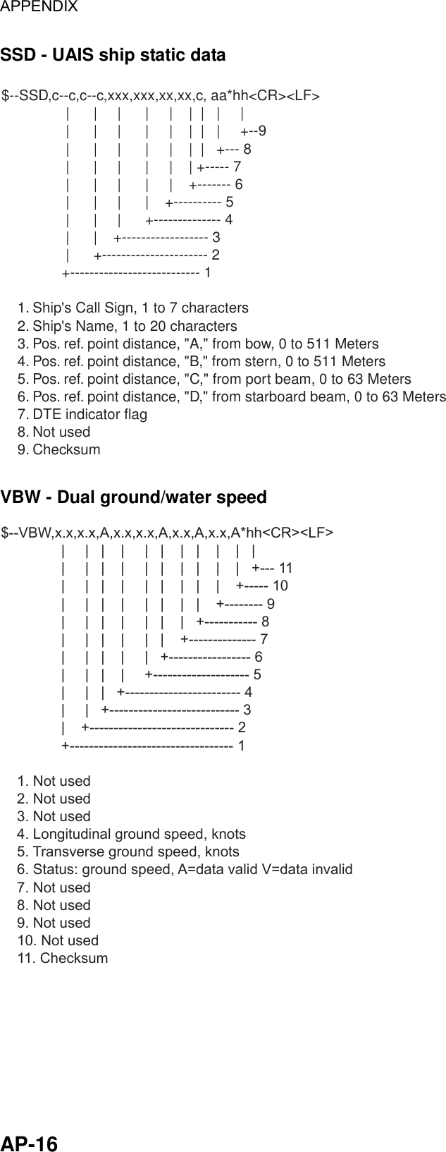
![1. OPERATION 1-15Target data display, mobile class A [DETAILS SHIP] 1/6MMSI [A]: 431099806NAME : FURUNOC. SIGN : ZL6DEF1IMO No. : 109873421CPA : 0.02 nmTCPA : 0'17"Call signMMSI no.NameIMO no.CPATCPA[DETAILS SHIP] 2/6MMSI [A]: 431099806LAT : 34°03.5442'NLON : 134°30.3883'ES/C : 17.8 kt/ 213.5°HDG : 278° PA: HR/B : 25.12 nm/351.5°ROT : R 0.1°/minHeading, Position Accuracy (H, High, L, Low) Range and bearing from own ship LatitudeRate of Turn (L: Left, R: Rightt)Longitude[DETAILS SHIP] 3/6MMSI [A] : 431099806MMSI no.[DETAILS SHIP] 5/6MMSI [A] : 431099806NAV STATUS : 0 ****STATUS DETAIL**** UNDER WAY USINGENGINE (DEFAULT)Navigation status descriptionMMSI no.Navigation status no.[DETAILS SHIP] 4/6MMSI [A] : 431099806TYPE OF SHIP : 25 ****TYPE DETAIL****FUTURE USE Type descriptionMMSI no.Type no.A : 100 mB : 23 mC : 6 mD : 6 mLENGTH: 123 mBEAM : 12 mDistance from bow to GPS antenna positionDistance from stern to GPS antenna positionDistance from port to GPS antenna positionDistance from starboard to GPS antenna positionLength of shipBeam of ship"DNGR" (DANGER) appears(in reverse video) when a target's CPA and TCPAare lower than the CPA/TCPAsetting."LOST" appears (in reverse video)when signal from a target is lost.Three minutes after loss of signal the target's data is erased.Speed over ground, course over groundABC D[DETAILS SHIP] 6/6MMSI [A]: 431099806DESTINATION TOKYODATE: 05/MAYTIME: 23:42Date of arrival at destinationEstimated time of arrivalDestination MMSI No.MMSI no. Target data display, mobile class A](https://usermanual.wiki/Furuno-USA/9ZWFA150/User-Guide-505656-Page-25.png)
![1. OPERATION 1-16 Target data display, mobile class B [DETAILS SHIP] 1/4MMSI [B]: 431099806NAME : FURUNOCPA : 0.02 nmTCPA : 0'17"CPAMMSI No.NameTCPA[DETAILS SHIP] 2/4MMSI [B]: 431099806LAT : 34°03.5442'NLON : 134°30.3883'ES/C : 17.8 kt/ 213.5°HDG : 278° PA: HR/B : 25.12 nm/351.5°Heading, Position Accuracy (H, High, L, Low) Range and bearing from own ship LatitudeLongitude[DETAILS SHIP] 3/4MMSI [B] : 431099806MMSI No.[DETAILS SHIP] 4/4MMSI [B] : 431099806TYPE OF SHIP : 25 ****TYPE DETAIL****FUTURE USE Type descriptionMMSI No.Type No.A : 100 mB : 23 mC : 6 mD : 6 mLENGTH: 123 mBEAM : 12 mDistance from bow to GPS antenna positionDistance from stern to GPS antenna positionDistance from port to GPS antenna positionDistance from starboard to GPS antenna positionLength of shipBeam of ship"DNGR" (DANGER) appears(in reverse video) when a target's CPA and TCPAare lower than the CPA/TCPAsetting."LOST" appears (in reverse video)when signal from a target is lost.Three minutes after loss of signal the target's data is erased.Speed over ground, course over groundABC D MMSI No. Target data display, mobile class B](https://usermanual.wiki/Furuno-USA/9ZWFA150/User-Guide-505656-Page-26.png)
![1. OPERATION 1-17Target data display, base station [DETAILS BS] 1/1MMSI : 431099806CPA : 0.02 nmTCPA : 0'17"LAT : 34°03.5442'NLON: 134°30.3883'EPA : HR/B : 25.12 nm/351.5°MMSI no.CPAPosition Accuracy (H, High, L, Low) Range and bearing from own ship TCPALatitude"DNGR" (DANGER) appears(in reverse video) when a target's CPA and TCPAare lower than the CPA/TCPAsetting."LOST" appears (in reverse video)when signal from a target is lost.Three minutes after loss of signal the target's data is erased.Longitude Target data display, base station Target data display, SAR (Search and Rescue) [DETAILS SAR] 1/2MMSI : 431099806CPA : 0.02 nmTCPA : 0'17"CPAMMSI No.NameTCPA[DETAILS SAR] 2/2MMSI : 431099806LAT: 34°03.5442'NLON: 134°30.3883'ES/C: 17.8 kt/ 213.5°PA: HR/B: 25.12 nm/351.5°Position Accuracy (H, High, L, Low) Range and bearing from own ship LatitudeLongitude"DNGR" (DANGER) appears(in reverse video) when a target's CPA and TCPAare lower than the CPA/TCPAsetting."LOST" appears (in reverse video)when signal from a target is lost.Three minutes after loss of signal the target's data is erased.Speed over ground, course over ground MMSI No.](https://usermanual.wiki/Furuno-USA/9ZWFA150/User-Guide-505656-Page-27.png)
![1. OPERATION 1-18 Target data display, AtoN (Aid to Navigation) [DETAILS AtoN] 1/4MMSI : 431099806NAME: FURUNOCPA : 0.02 nmTCPA : 0'17"CPAMMSI No.NameTCPA[DETAILS AtoN] 2/4MMSI : 431099806LAT : 34°03.5442'NLON : 134°30.3883'EPA : HR/B : 25.12 nm/351.5°PI : ON POSITIONRange and bearing from own ship Off Position or On Position LatitudeLongitude[DETAILS AtoN] 3/4MMSI : 431099806MMSI No.[DETAILS AtoN] 4/4MMSI : 431099806VIRTUAL AtoNTYPE OF AtoN: 20****TYPE OF DETAIL****CARDINAL MARK N Type of AtoN (See next page.)MMSI No.AtoN existence (real or virtual)A : 100 mB : 23 mC : 6 mD : 6 mLENGTH: 123 mBEAM : 12 mDistance from bow to GPS antenna positionDistance from stern to GPS antenna positionDistance from port to GPS antenna positionDistance from starboard to GPS antenna positionLength of shipBeam of ship"DNGR" (DANGER) appears(in reverse video) when a target's CPA and TCPAare lower than the CPA/TCPAsetting."LOST" appears (in reverse video)when signal from a target is lost.Three minutes after loss of signal the target's data is erased.Position Accuracy (H, High, L, Low)ABC D MMSI No.Description of AtoN](https://usermanual.wiki/Furuno-USA/9ZWFA150/User-Guide-505656-Page-28.png)
![1. OPERATION 1-20 1.7.3 Dangerous (target) list You can easily find dangerous ships whose CPA and TCPA are lower than the CPA and TCPA alarm settings. 1. At the plotter display, press the [DISP] key to show the Target List (see paragraph 1.7.2). 2. Press ► to show the Dangerous List. [DANGEROUS LIST] NAME CPA TCPAnm( )Target name,CPA and TCPA FURUNO 0.50 3'20"EXPLOR 1.20 3'35"INTREP 1.80 3'50"VOYAGE 1.90 3'55"SEADOG 2.00 4'00" 1/ 10 [] DTL[ENT] RNG[]Press to sort and viewtargets in order of range fromown ship. Dangerous list 3. To find detailed information about a dangerous target, use ▼ or ▲ to choose the target and then press the [ENT] key. Use the CursorPad to view other data; ▼ or ► to go forward, ▲ or ◄ to go back. (If there is no data for the target selected the message “NO SEL” appears. Hit any key to escape.) Note: The message “LOST” appears at the top of the Dangerous List when no AIS signal is received from the selected target. 1.7.4 Own ship’s static data The OWN STATIC DATA display shows own ship’s static data, which includes MMSI, call sign and name, IMO number, length and beam, type of ship and location of position fixing antenna, on five pages. This data should be checked once per voyage or once per month whichever is shorter. Data may be changed only on the authority of the master. 1. At the plotter display, press the [DISP] key twice to show “OWN STATIC DATA 1/5”. See the next page. 2. Use the CursorPad to view other own static data; ▼ or ► to go forward, ▲ or ◄ to go back. See the illustration on the next page for own ship’s static data examples.](https://usermanual.wiki/Furuno-USA/9ZWFA150/User-Guide-505656-Page-30.png)
![1. OPERATION 1-21[OWN STATIC DATA] 1/5 NAME : FURUNO VOYAGERCALL SIGN: CAL0001MMSI : 123456789IMO No. : 623498071[OWN STATIC DATA] 2/5 DESTINATION: TOKYO DATE: 12/DECTIME : 10:25[OWN STATIC DATA] 4/5 CPA : 1.50 nmTCPA : 10 minANT POS INT EXTLENGTH A : 75 m 77 mLENGTH B : 20 m 18 mLENGTH C : 15 m 18 mLENGTH D : 15 m 12 m[OWN STATIC DATA] 5/5 CREW : 12TYPE OF SHIP: 36 CLASS : A****TYPE DETAIL****SAILING[OWN STATIC DATA] 3/5 DRAUGHT : 12.1 mNAV STATUS: 00***STATUS DETAIL***UNDER WAY USINGENGINE (DEFAULT)DestinationNameCall signIMO no.Estimated date of arrivalEstimated time of arrivalNavigation status no.DraughtCPA (preset value)TCPA (preset value)Navigation status descriptionShip classNumber of crewShip typeMMSI no.Distance from bow to GPS antenna positionDistance from stern to GPS antenna positionDistance from port to GPS antenna positionDistance from starboard to GPS antenna positionINT: Internal GPS, EXT: External GPSType detail OWN STATIC DATA displays](https://usermanual.wiki/Furuno-USA/9ZWFA150/User-Guide-505656-Page-31.png)
![1. OPERATION 1-22 1.7.5 Own dynamic data display The OWN DYNAMIC DATA display shows your ship’s dynamic data, which includes time, date, ship’s position, course over ground (COG), speed over ground (SOG), rate of turn (ROT), and heading. The OOW should periodically check position, speed over ground and sensor information. At the plotter display, press the [DISP] key three times to show the OWN DYNAMIC DATA display. [OWN DYNAMIC DATA] 01/MAY/2004 13:24:55 LAT : 34°45.2132' N LON : 135°21.2345' E SOG: 8.1 kt INT GPS COG: 118.5° HDG:118° ROT: R10.3°/min* PA: H RAIM: USEDDate, timeLatitudeLongitudeSpeed over groundCourse over ground, HeadingRate of turnPosition accuracy(H: High, L: Low),RAIM status(USED or UNUSED)Display flashes when transmitting* = If no ROT device is connected and HDGsentence is input from a gyrocompass, etc.,the following is displayed:Rate of turn less than 10°/min.: 0.0Rate of turn 10°/min. rightward or higher: R>10Rate of turn 10°/min. leftward or higher: L>10GPS receiver in useINT GPS: Internal GPSINT DGPS: Internal DGPSEXT GPS: External GPSEXT DGPS: External DGPSNO FIX: No position fix OWN DYNAMIC DATA display 1.7.6 Alarm status display The alarm status display shows the date and time alarms were violated. For further details, see paragraph 2.5.](https://usermanual.wiki/Furuno-USA/9ZWFA150/User-Guide-505656-Page-32.png)
![1. OPERATION 1-231.8 Messages You may send and receive messages via the VHF link, to a specified destination (MMSI) or all ships in the area. Messages can be sent to warn of safety of navigation; for example, an iceberg sighted. Routine messages are also permitted. Short safety-related messages are only an additional means to broadcast safety information. They do not remove the requirements of the GMDSS. When a message is received, the equipment beeps and the indication “MESSAGE” appears. The contents of the message may be viewed on the receive message log. 1.8.1 Sending a message 1. Press the [MENU] key to open the main menu. 2. Use ▼ or ▲ to choose MSG and then press the [ENT] key [MSG]CREATE MSGTX LOGRX LOG MSG sub-menu 3. CREATE MSG is selected; press the [ENT] key. [CREATE MSG]SET MSG TYPESET MSGSEND MSG CREATE MSG sub-menu 4. SET MSG TYPE is selected; press the [ENT] key. [SET MSG TYPE] ADRS TYPE: BROAD CASTMMSI : - - - - - - - - -MSG TYPE : NORMAL CHANNEL: ALTERNATE MMS SET MSG TYPE sub-menu](https://usermanual.wiki/Furuno-USA/9ZWFA150/User-Guide-505656-Page-33.png)
![1. OPERATION 1-24 5. ADRS TYPE is selected; press the [ENT] key. BROAD CASTADRS CAST 6. Choose ADRS CAST to send a message to a specific ship, or BROAD CAST to send a message to all ships. Press the [ENT] key. 7. For BROAD CAST, go to step 8. For ADDRESS-CAST, “MMSI” is selected; press the [ENT] key, use the CursorPad to enter MMSI number of receiving vessel and then press the [ENT] key. 8. MSG TYPE is chosen; press the [ENT] key. SAFETYNORMAL 9. Choose message type: NORMAL (message other than safety) or SAFETY (important navigational or meteorological warning). Press the [ENT] key. 10. CHANNEL is chosen; press the [ENT] key. ALTERNATEBOTH A & BAB 11. Choose which channel to transmit your message over. 12. Press the [ENT] key. 13. Press the [MENU] key to return to the CREATE MSG sub-menu. 14. Choose SET MSG and press the [ENT] key. Number ofcharactersused/available[SET MSG]0(151)* QUIT[MENU] *: Up to 161 characters can be entered, but recipients receive the following number of characters. NORMAL message with BROAD-CAST : 156 characters NORMAL message with ADDRESS-CAST: 151 characters SAFETY message with BROAD-CAST : 161 characters SAFETY message with ADDRESS-CAST : 156 characters SET MSG screen 15. Use the CursorPad to enter your message. Use ▼ or ▲ to choose character; ◄ or ► to shift the cursor. 16. Press the [ENT] key to return to the CREATE MSG sub-menu. 17. Choose SEND MSG and then press the [ENT] key to send your message.](https://usermanual.wiki/Furuno-USA/9ZWFA150/User-Guide-505656-Page-34.png)
![1. OPERATION 1-25The screen shows message status as follows: AIS message status messages and their meanings Message Meaning NOW PROCESSING. Message is being sent. SEND MESSAGE COMPLETE. PRESS ANY KEY. Transmission of message completed. (MMSI is additionally shown in case of addressed message.) SEND MESSAGE UNSUCCESSFUL.PRESS ANY KEY. Message could not be sent. SEND MESSAGE UNSUCCESSFUL. MMSI: XXXXXXXXX PRESS ANY KEY. Message sent successfully, however there is no reply from receiver of message. NOW WAITING RESPONSE. PRESS ANY KEY. You tried to send a message while the transponder is awaiting receive confirmation (successful or unsuccessful) for the first-sent message. After confirmation is received, the next sequential message will be sent. 1.8.2 Receiving messages How to view a received message When a message is received, the window below appears on the display. To view the contents of the message follow the procedure below. MESSAGE ! PRESS ANY KEY Message received 1. Press any key to erase the “message received” window. 2. Press the [MENU] key to show the main menu. 3. Choose MSG and then press the [ENT] key. 4. Choose RX LOG and then press the [ENT] key. Date and timemessage received("NEW" displayed forunread message)1/10[ ] MSG[ENT] QUIT[MENU]MMSI of sender, type of messageN-ABM: Normal, addressed binaryS-ABM: Safety, addressed binaryN-BBM: Normal, broadcast binary S-BBM: Safety, broadcast binary [RX LOG] 03/MAY 13:25 NEW FROM: 431099111 N-ABM28/MAR 03:43 FROM: 431099111 S-ABM22/MAR 18:00 FROM: 431099111 N-ABM Received message log 5. To view the contents of an unread message, use the CursorPad to choose the message and then press the [ENT] key. Below is an example of a received message.](https://usermanual.wiki/Furuno-USA/9ZWFA150/User-Guide-505656-Page-35.png)
![1. OPERATION 1-26 SCROLL[] QUIT[MENU][RCVD MSG]I HAVE CHANGED MY COURSE TO 350 DEGREE. Received message example 6. Press the [MENU] key several times to close the log and return to the plotter display. Automatically displaying received messages You may automatically display incoming messages as follows: 1. Press the [MENU] key to open the menu. 2. Use the CursorPad to choose USER SETTINGS and then press the [ENT] key. QUIT[MENU][USER SETTINGS]KEY BEEP : ONALARM BUZZER : ONDISP RCVD MSG : ALLRCVD MSG BUZZ: ONLR MODE : AUTOCPA/TCPA ALARM USER SETTINGS sub-menu 3. Use the CursorPad to choose DISP RCVD MSG and then press the [ENT] key. ALLABMOFF 4. Use the CursorPad to choose which category of receive message you want to display automatically and then press the [ENT] key. ALL: Display any message upon receipt ABM: Display only addressed binary messages upon their receipt OFF: Disable automatic displaying of incoming messages 5. Press the [DISP] key to close the menu and return to the plotter display.](https://usermanual.wiki/Furuno-USA/9ZWFA150/User-Guide-505656-Page-36.png)
![1. OPERATION 1-271.8.3 Message logs The FA-150 stores the latest five transmitted and received messages in respective message logs. When a log becomes full, the oldest message in the log is automatically deleted to make room for the latest. To display a message log, do the following: 1. Press the [MENU] key to open the menu. 2. Choose MSG and then press the [ENT] key. 3. Choose TX LOG or RX LOG as appropriate and then press the [ENT] key. Below is an example of the Tx log. For the appearance of the Rx log, see paragraph 1.8.2. Date and time messagetransmitted, message statusOK: Message transmitted successfullyNG (No Good): Messagecould not be transmitted[TX LOG] 31/APR 13:25 OK TO: 431099111 N-ABM27/MAR 03:43 TO: 431099111 S-ABM19/MAR 18:00 TO: 431099111 N-ABM1/10[T ] MSG[ENT] QUIT[MENU]MMSI of receiver, type of messageN-ABM: Normal, addressed binaryS-ABM: Safety, addressed binaryN-BBM: Normal, broadcast binaryS-BBM: Safety, broadcast binary TX message log 4. To view the contents of a message, choose it with ▼ or ▲ and then press the [ENT] key. Below is an example of a transmitted message. For an example of a received message, see paragraph 1.8.2. SCROLL[ST] QUIT[MENU][TX LOG]CHANGE YOUR COURSE TO350 DEGREE. Transmitted message example 5. Press the [MENU] key several times to close the log and return to the plotter display.](https://usermanual.wiki/Furuno-USA/9ZWFA150/User-Guide-505656-Page-37.png)
![1. OPERATION 1-28 1.9 Regional Operating Channels AIS operates primarily on two dedicated VHF channels, CH 2087 and CH2088. Where these channels are not available regionally, the AIS is capable of being automatically switching to designated alternate channels by means of a message from a shore facility. Where no shore based AIS or GMDSS sea area A1 station is in place, the AIS should be switched manually as in paragraph 1.9.2. A regional operating area is set with the procedure shown below. The most recent eight areas are memorized. • Automatic setting of VHF DSC (channel 70) from shore-based AIS • Automatic setting by AIS message from shore-based AIS • Setting by shipboard system such as ECDIS • Manual setting The default area is as follows: • Tx power: 12.5 W • Channel no. 2087, 2088 • Frequency bandwidth: 25 kHz • Tx/Rx mode: Tx/Rx 1.9.1 Viewing channels, Tx power Do the following to view current channels. 1. Press the [MENU] key to open the menu. 2. Choose SET CHANNEL and then press the [ENT] key. QUIT[MENU][SET CHANNEL]VIEW CHANNELEDIT CHANNEL SET CHANNEL menu 3. Choose VIEW CHANNEL and then press the [ENT] key. [VIEW CHANNEL]POWER : 12.5W CHANNEL NO.CH-A: 2087CH-B: 2088PowerChannelQUIT[MENU] VIEW CHANNEL display 4. Press the [MENU] key several times to return to the plotter display.](https://usermanual.wiki/Furuno-USA/9ZWFA150/User-Guide-505656-Page-38.png)
![1. OPERATION 1-291.9.2 Displaying, editing regional operating area status You may display the status of regional operating areas currently memorized in the equipment. Nine of any combination of AIS message from shore-based AIS, DSC message, manual settings and commands from ECDIS or a PC may be registered and one will be a default value. About registering areas • AIS and DSC messages registered within last two hours cannot be edited. • An item labeled DEFAULT cannot be registered. (“DEFAULT” are data used for international waters not controlled by shore-based AIS.) • If two areas overlap one another the older data is deleted. • Data older than five weeks is deleted. • Area data is deleted when it is more than 500 miles from the area for which it was registered. 1. Press the [MENU] key to open the menu. 2. Choose SET CHANNEL and then press the [ENT] key. 3. Choose EDIT CHANNEL and then press the [ENT] key. [EDIT CHANNEL]SELECT NO. : 0TIME - -/- - - - -: - -: - -FROMMMSI: DEFAULTTYPE: DEFAULTQUIT [MENU] EDIT[ENT] EDIT CHANNEL sub-menu, page 1 SELECT NO.: File number, 0-9. In order of distance from own ship, from closest to furthest. TIME: Data and time equipment controlled by external source. MMSI: MMSI displayed for control by DSC or shore-based AIS. Dashes or “EMPTY” (no data) otherwise. TYPE: How channel is controlled: AIS, AIS message; PI, ECDIS or PC; DSC, DSC, MANUAL, manual control Note: MMSI and TYPE must be set to other than “DEFAULT” to edit. 4. Use ▼ or ▲ to choose desired file number from SELECT NO. and then press the [ENT] key.](https://usermanual.wiki/Furuno-USA/9ZWFA150/User-Guide-505656-Page-39.png)
![1. OPERATION 1-30 5. Press the [ENT] key to show details. Note: Power is fixed at 1W for CH No. 1013 and/1067.[EDIT CHANNEL] 1/2FROM MMSI:POWER : 12.5WCH NO. CH-A: 2087 CH-B: 2088MODE CH-A: TX/RX CH-B: TX/RXZONE: 1nm EDIT CHANNEL sub-menu, page 1 6. POWER is selected; press the [ENT] key to show the channel power options. 1W2W12.5W 7. Use ▼ or ▲ to choose power desired and then press the [ENT] key. 8. CH NO. CH-A is selected; press the [ENT] key. 9. Use the CursorPad to choose channel number for CH-A and then press the [ENT] key. 10. CH NO. CH-B is selected; press the [ENT] key. 11. Use the CursorPad to choose channel number for CH-B and then press the [ENT] key. 12. MODE CH-A is selected; press the [ENT] key. TX/RXRXUNUSED 13. Use the CursorPad to choose desired mode for CH-A and then press the [ENT] key. 14. MODE CH-B is selected; press the [ENT] key. 15. Use the CursorPad to choose desired mode for CH-B and then press the [ENT] key. 16. ZONE is selected; press the [ENT] key. 17. Key in the zone distance and then press the [ENT] key. (The setting range is 1 to 8 (nm).) Then, the following screen appears. [EDIT CHANNEL] 2/2CH AREA RIGHT TOP LAT: 0°00.0'N LON: 0°00.0'E LEFT BOTTOM LAT: 0°00.0'N LON: 0°00.0'E CHANNEL EDIT sub-menu, page 2 18. LAT of RIGHT TOP is selected; press the [ENT] key. Use the CursorPad to enter latitude for the right-top position (northeast point) of the AIS operating area and then press the [ENT] key.](https://usermanual.wiki/Furuno-USA/9ZWFA150/User-Guide-505656-Page-40.png)
![1. OPERATION 1-3119. LON of RIGHT TOP is selected; press the [ENT] key. Use the CursorPad to enter longitude for the right-top position (northeast point) of the AIS operating area and then press the [ENT] key. 20. LAT of LEFT BOTTOM is selected; press the [ENT] key. Use the CursorPad to enter latitude for the left-bottom position (southwest point) of the AIS operating area and then press the [ENT] key. 21. LON of LEFT BOTTOM is selected; press the [ENT] key. Use the CursorPad to enter longitude for the left-bottom position (southeast point) of the AIS operating area and then press the [ENT] key. Note: The available range is 20-200 nm. If the area contains overlapping data the older data will be erased. RIGHT-TOPLEFT-BOTTOMZONE1-8 nm20-200 nm20-200 nm Description of RIGHT-TOP, LEFT-BOTTOM and ZONE items 22. Press the [MENU] key. The prompt shown below appears. SAVE CHANNEL. ARE YOU SURE? YES NO 23. Press ◄ to choose YES and then press the [ENT] key. 24. Press the [DISP] key to close the menu and return to the plotter display. Note: If you enter invalid data, the message “OUT OF RANGE L/L” appears. Press any key to escape. Reenter data.](https://usermanual.wiki/Furuno-USA/9ZWFA150/User-Guide-505656-Page-41.png)
![1. OPERATION 1-32 1.10 Enabling/Disabling Buzzers, Key Beep You may turn on or off the buzzers that sound for alarms or incoming messages. Further, you may turn off the beep which sounds for valid key input. Note that the alarm buzzer is not related to a radar or ECDIS alarm. 1. Press the [MENU] key to open the menu. 2. Use the CursorPad to choose USER SETTINGS and then press the [ENT] key. QUIT[MENU][USER SETTINGS]KEY BEEP : ONALARM BUZZER : ONDISP RCVD MSG : ALLRCVD MSG BUZZ: ONLR MODE : AUTOCPA/TCPA ALARM USER SETTINGS sub-menu 3. Use the CursorPad to choose KEY BEEP, ALARM BUZZER or RCVD MSG BUZZ as appropriate and then press the [ENT] key. 4. Choose ON or OFF as appropriate and then press the [ENT] key. 5. Press the [DISP] key to close the menu and return to the plotter display.](https://usermanual.wiki/Furuno-USA/9ZWFA150/User-Guide-505656-Page-42.png)
![1. OPERATION 1-331.11 Long Range Mode The long range mode sets how to reply to a request for own ship data from a distant station, for example, Inmarsat C station. You may reply automatically or manually. 1. Press the [MENU] key to open the menu. 2. Use the CursorPad to choose USER SETTINGS and then press the [ENT] key. QUIT[MENU][USER SETTINGS]KEY BEEP : ONALARM BUZZER : ONDISP RCVD MSG : ALLRCVD MSG BUZZ: ONLR MODE : AUTOCPA/TCPA ALARM USER SETTINGS sub-menu 3. Use the CursorPad to choose LR MODE and then press the [ENT] key. AUTOMANUAL 4. Use the CursorPad to choose AUTO (auto reply) or MANUAL (manual reply) as appropriate and then press the [ENT] key. 5. Press the [DISP] key to close the menu and return to the plotter display. Manual reply For manual reply, the left-side message below appears when a request for own ship data arrives from a distant station. Press the [ENT] key to send the data, or press any key other than [ENT] to send no data. Automatic reply For automatic reply, the right-side message below appears when a request for own ship data arrives from a distant station. Ship’s data is automatically transmitted. Press the [ENT] key to erase the message. [RECEIVED LR] MMSI: 431456789 NAME: FURUNO CRESPONSE?YES: [ENT] NO: OTHERLR Message (Manual reply)[RESPONDED LR] MMSI: 431456789 NAME: FURUNO CPRESS ANY KEYLR Message (Automatic reply)Informationrequested(See tableon next page.)](https://usermanual.wiki/Furuno-USA/9ZWFA150/User-Guide-505656-Page-43.png)
![1. OPERATION 1-351.12 Viewing Initial Settings The INITIAL SETTINGS menu, which is locked with a password, is where the installer enters ship’s MMSI, internal and external antenna positions, ship type and I/O port settings. You can view the settings on this menu (without a password) as follows. 1. Press the [MENU] to open the menu. 2. Use the CursorPad to choose INITIAL SETTINGS and then press the [ENT] key. 3. Use the CursorPad to choose item to view and then press the [ENT] key. QUIT [MENU][INITIAL SETTINGS]VIEW MMSIVIEW INT ANT POS.VIEW EXT ANT POS.VIEW SHIP TYPEVIEW I/O PORT QUIT [MENU][VIEW MMSI]MMSI : 036699999IMO NO : 9241062NAME : FURUNOC. SIN : FQC3544 QUIT [MENU][VIEW SHIP TYPE]TYPE NO : 70***TYPE DETAIL*****CARGO SHIPALL SHIPS OFTHIS TYPE[VIEW EXT ANT POS.] A: 35mB: 9mC: 8mD: 5mQUIT[MENU]ABC D[VIEW INT ANT POS.] A: 50mB: 10mC: 9mD: 6mQUIT[MENU]ABC D[VIEW I/O PORT]COM1COM2COM3SENSOR PORTPCROT TIME : 1 SECPRIORITYChoose port to view andpress the [ENT] key.](https://usermanual.wiki/Furuno-USA/9ZWFA150/User-Guide-505656-Page-45.png)

![2. MAINTENANCE, TROUBLESHOOTING 2-32.3 Troubleshooting The troubleshooting table below provides common symptoms of trouble and the means to rectify them. If you cannot restore normal operation, do not attempt to check inside the equipment. Refer any repair work to a qualified technician. Troubleshooting Symptom Remedy Power Cannot turn on the power. • Check that the power connector is firmly fastened.• Check the power supply. Transmitting, receiving messages Cannot transmit or receive. • Check that the VHF antenna cable is firmly fastened. • Check the VHF antenna. • For TX message, try different TX channel. (operating sequence: [MENU], MSG, CREATE MESSAGE, SET MSG TYPE, CHANNEL) Can transmit but message is sent to wrong party. • On the SET MSG TYPE sub-menu, check that ADRS TYPE is selected to ADRS-CAST and MMSI is correct, before sending a message. (operating sequence: [MENU], MSG, CREATE MESSAGE, SET MSG TYPE, ADRS TYPE and MMSI) Position data No position data • Check the GPS antenna for damage. • Check the GPS antenna cable and its connectors.](https://usermanual.wiki/Furuno-USA/9ZWFA150/User-Guide-505656-Page-49.png)
![2. MAINTENANCE, TROUBLESHOOTING 2-42.4 Diagnostics The FA-150 provides diagnostic tests to check the monitor unit and transponder unit for proper operation. 2.4.1 Monitor unit test The monitor unit test shows program no., and checks the ROM, RAM, LCD and controls. 1. Press the [MENU] key to open the main menu. 2. Use the CursorPad to choose DIAGNOSTIC and then press the [ENT] key. For service technician.Not accessible by user.[DIAGNOSTIC]MONITOR TESTTRANSPONDER TESTPWR ON/OFF HISTORYTX ON/OFF HISTORYMEMORY CLEARFOR SERVICE DIAGNOSTIC sub-menu 3. Use the CursorPad to choose MONITOR TEST and then press the [ENT] key. The test program automatically proceeds in the sequence shown below. [MONITOR TEST]PROG NO.: 2450021-xx.xxROM :OK CONT :53SDRAM:OK DIM : 4PORT : --KEY :xx.xx = Program version no.<LCD CHECK>ALL ON 2 SEC.ALL OFF 3 SEC.PUSH KEYQUIT[MENU] 3 TIMES MONITOR TEST screens](https://usermanual.wiki/Furuno-USA/9ZWFA150/User-Guide-505656-Page-50.png)
![2. MAINTENANCE, TROUBLESHOOTING 2-5a) The first screen in the monitor test program sequence shows program no., results of ROM, RAM and I/O port (special test connector required, otherwise “- -“ appears), dimmer setting, and checks controls. The results of the ROM and RAM check are shown as OK or NG (No Good). If NG appears contact your dealer for advice. “CONT” indicates the number of times the test has been executed consecutively. b) After all devices and ports have been checked, the message “PUSH KEY” appears, in reverse video. Press each key and arrows on the CursorPad one by one. The pressed key or arrow’s name appears next to “KEY” if the control is functioning normally. c) After the controls have been checked (or there is no control pressed for a few seconds), the LCD is checked. All LCD segments turn on for two seconds and then go off for three seconds, and then the screen turns black and then turns white. d) The test is repeated. 4. To escape from the test, press the [MENU] key three times when PUSH KEY is shown in reverse video. 2.4.2 Transponder test The transponder test consists of two tests: memory test and internal GPS receiver test. Memory test The memory can be checked for proper operation and the program number displayed as follows: 1. Press the [MENU] key to open the main menu. 2. Use the CursorPad to choose DIAGNOSTIC and then press the [ENT] key. 3. Use the CursorPad to choose TRANSPONDER TEST and then press the [ENT] key. 4. Use the CursorPad to choose MEMORY TEST and then press the [ENT] key. The program no. is displayed and the ROM and RAM are checked. The results of he ROM and RAM check are shown as OK or NG (No Good). For any NG, contact your dealer for advice. [MEMORY TEST]PROGRAM NO.2450018-xx.xxMAIN ROM : OKMAIN RAM : OKSUB RAM : OKxx.xx: Program Version No. MEMORY TEST display 5. Press the [MENU] key several times to return to the DIAGNOSTIC sub-menu.](https://usermanual.wiki/Furuno-USA/9ZWFA150/User-Guide-505656-Page-51.png)
![2. MAINTENANCE, TROUBLESHOOTING 2-6Internal GPS test The internal GPS receiver can be checked for proper operation as follows: 1. Press the [MENU] key to open the main menu. 2. Use the CursorPad to choose DIAGNOSTIC and then press the [ENT] key. 3. Use the CursorPad to choose TRANSPONDER TEST and then press the [ENT] key. 4. Use the CursorPad to choose GPS TEST and then press the [ENT] key to start the test. The program no. and the test results appear as shown below. OK: Normal DATA BACKUP ERR: Data backup problem GPS COMMUNICATION ERROR: Comm. error with internal GPS receiver PARAMETER BACKUP ERR: Parameter backup problem ROM ERROR, RAM ERROR [GPS TEST]PROGRAM NO. 485026xxxxTEST: OKxxxx: Program Version No. GPS TEST display 5. Press the [MENU] key to escape. 2.4.3 Power on/off history The PWR ON/OFF HISTORY log shows the date and time of the latest 30 power-ons and power-offs. If the interval between power-on and power-off is less than 15 minutes those times are not shown. 1. Press the [MENU] key to open the main menu. 2. Use the CursorPad to choose DIAGNOSTIC and the press the [ENT] key. 3. Use the CursorPad to choose PWR ON/OFF HISTORY and then press the [ENT] key. Power turned on 17 May 2004at 05:35:54[PWR ON/OFF HISTORY]PWR-ON 17/MAY/200405:35:54PWR-OFF 17/MAY/200404:56:57PWR-ON 17/MAY/200404:06:34 QUIT[MENU] PWR ON/OFF HISTORY log 4. Use ▼ or ▲ to scroll the log. 5. Press the [MENU] key to return to the DIAGNOSTIC sub-menu.](https://usermanual.wiki/Furuno-USA/9ZWFA150/User-Guide-505656-Page-52.png)
![2. MAINTENANCE, TROUBLESHOOTING 2-72.4.4 Tx on/off history The TX ON/OFF HISTORY log shows the date and time of the latest 30 transmissions. In special cases, on and off times of 0 W transmission my also be shown. 1. Press the [MENU] key to open the main menu. 2. Use the CursorPad to choose DIAGNOSTIC and the press the [ENT] key. 3. Use the CursorPad to choose TX ON/OFF HISTORY and then press the [ENT] key. Tx at 17 May 2004at 05:35:54[TX ON/OFF HISTORY]TX-ON 17/MAY/200405:35:54TX-OFF 17/MAY/200404:34:57TX-ON 17/MAY/200404:33:57PAGE 1/2 :[] QUIT[MENU] TX ON/OFF HISTORY log 4. Use ▼ or ▲ to scroll the log. 5. Press the [MENU] key to return to the DIAGNOSTIC sub-menu.](https://usermanual.wiki/Furuno-USA/9ZWFA150/User-Guide-505656-Page-53.png)
![2. MAINTENANCE, TROUBLESHOOTING 2-82.5 Alarm Status The alarm status log shows the latest 25 dates and times alarms were violated. 1. At the plotter display, press the [DISP] key four times to show the ALARM STATUS display. [ALARM STATUS]EPFS 7/MAY 4:32:16L/L 7/MAY 4:02:01SOG 7/MAY 2:34:54COG 6/MAY 7:09:32HDG 3/MAY 8:00:21ROT 19/APR 9:05:22Alarm name,date and timeof alarm ALARM STATUS display 2. Use ▼ or ▲ to scroll the log. Alarm statuses and their meanings Alarm Status Indication Meaning TX TX malfunction ANT Antenna VSWR trouble. Continued operation possible. CH1 TDMA RX1 Board trouble. TX stopped on corresponding TX channel. CH2 TDMA RX2 Board trouble. TX stopped on corresponding TX channel. CH70 DSC RX Board trouble, transmission stopped on CH70. COG Invalid COG data EPFS No data from external navigator. Continued operation possible. FAIL General system failure HDG Invalid/nonexistent HDG data L/L No L/L data MKD Minimum input device failure ROT Invalid ROT data SOG Invalid SOG data](https://usermanual.wiki/Furuno-USA/9ZWFA150/User-Guide-505656-Page-54.png)
![2. MAINTENANCE, TROUBLESHOOTING 2-112.7 GPS Monitor The GPS monitor display shows information about the built-in GPS receiver, including position, speed over ground, course over ground, date, time, mode position accuracy, position-fixing status and RAIM status. 1. Press the [MENU] key to open the menu. 2. Use the CursorPad to choose INTERNAL GPS and then press the [ENT] key. [INTERNAL GPS]LAT : 34°44.4639'NLON : 135°21.2395'ESOG : 10.9 ktCOG : 98.9°UTC : 16/MAY/2004 6:29:02DGPS STS: 3DPA: H RAIM: USEDLatitude positionLongitude positionSpeed over groundCourse over groundDateTimeModeDGPSGPSNO FIXPosition AccuracyH: High, L: LowSTS (Status)2D:2D GPS position fix3D: 3D GPS position fixD2D: 2D DGPS position fixD3D: 3D DGPS position fixDOP: HDOP larger than 4 in 2D fix, or PDOP larger than 6 in 3D fix RAIM Status*(Receiver Autonomous Integrity Monitoring) USED or UNUSED*RAIM: Technique whereby the GPS receiver verifies the integrity of the signals received from the GPS constellation. Internal GPS monitor 4. Press the [MENU] key several times to close the display and return to the plotter display.](https://usermanual.wiki/Furuno-USA/9ZWFA150/User-Guide-505656-Page-57.png)
![2. MAINTENANCE, TROUBLESHOOTING 2-122.8 Displaying Sensor Status The SENSOR STATUS screen shows sensor status. 1. Press the [MENU] key. 2. Use the CursorPad to choose SENSOR STATUS and then press the [ENT] key. [SENSOR STATUS]UTC CLOCK LOSTSensor status message SENSOR STATUS screen 3. Press the [MENU] key to close the display. Sensor status messages and their meanings Sensor Status Message Meaning CH MANAGEMENT Channel changed EXTRL DGNSS Using external DGNSS EXTRL DGNSS BEACON Using external DGNSS beacon EXTRL GNSS Using external GNSS EXTRL SOG/COG Using external SOG/COG HDT VALID Heading data normal INTRL DGNSS Using internal DGNSS INTRL GNSS Using internal GNSS INTRL SOG/COG Using internal SOG/COG OTHER ROT Using external ROT ROT VALID ROT data normal UTC CLOCK LOST No UTC time](https://usermanual.wiki/Furuno-USA/9ZWFA150/User-Guide-505656-Page-58.png)
![2. MAINTENANCE, TROUBLESHOOTING 2-132.9 Restoring Default Settings You may clear all or specific settings to start afresh with default settings. When all data is cleared, the default settings for all items in the INIT SETTING and SYSTEM SETTINGS sub-menus are restored. GPS data is also cleared; however, MMSI and IMO numbers, ship’s name and call sign are not cleared. 1. Press the [MENU] key to open the menu. 2. Use the CursorPad to choose DIAGNOSTIC and then press the [ENT] key. 3. Use the CursorPad to choose MEMORY CLEAR and then press the [ENT] key. QUIT[MENU][MEMORY CLEAR]MONITOR CLEARSET USER DEFAULTGPS COLD START MEMORY CLEAR sub-menu 4. Use the CursorPad to choose MONITOR CLEAR, SET USER DEFAULT or GPS COLD START as appropriate and then press the [ENT] key. DISPLAY CLEAR: Restore default settings for dimmer, contrast CPA/TCPA, key beep, audible alarm, and received message alarm. USER DEFAULT: Clears all user settings except MMSI No., IMO No., ship’s name and call sign. GPS COLD START: Clears GPS Almanac to receive latest Almanac. MONITOR CLEAR. ARE YOU SURE? YES NOSET USER DEFAULT. ARE YOU SURE? YES NOGPS COLD START. ARE YOU SURE? YES NOMONITOR CLEAR USER DEFAULT GPS COLD START Confirmation screens for memory clear 3. Press ◄ to choose YES and then press the [ENT] key.](https://usermanual.wiki/Furuno-USA/9ZWFA150/User-Guide-505656-Page-59.png)

![AP-1APPENDIX Menu Tree The example screens shown in this manual may not match the screens you see on your display. The screen you see depends on your system configuration and equipment settings. [MENU] keyCREATE MSGTX LOGRX LOGSET MSG TYPESET MSGSEND MSGADRS TYPE (BROAD CAST, ADRS CAST)MMSIMSG TYPE (NORMAL, SAFETY)CHANNEL (ALTERNATE, BOTH A & B, A, B)MSGSENSOR STATUS (Display sensor status.)INTERNAL GPS (Displays data about internal GPS receiver.)CPA (0.0 - 6.00, 1 (nm))TCPA (0 - 60, 10 (min))ALARM MODE (ON, OFF)ALARM BUZZER (ON, OFF)KEY BEEP (ON, OFF)ALARM BUZZER (ON, OFF)DISP RCVD MSG (ALL, ABM, OFF)RCVD MSG BUZZ (ON, OFF)LR MODE (AUTO, MANUAL)CPA/TCPA ALARM(Continued on next page)USER SETTINGSINITIAL SETTINGS SET INT ANT POS. A (0-511 (m))B (0-511 (m))C (0-63 (m))D (0-63 (m)) SET MMSI SET EXT ANT POS.SET SHIP TYPESET IO PORTA (0-511 (m))B (0-511 (m))C (0-63 (m))D (0-63 (m)) COM1COM2COM3 (Same items,options and default settings as COM2.)SENSOR PORTCOM4 (1, 2, 3)COM5 (1, 2, 3)COM6 (1, 2, 3)MODE (LONG RANGE, EXT DISP, DISABLE)SPEED (IEC61162-1, IEC61162-2)MODE (EXT DISP, DISABLE) SPEED (IEC61162-1, IEC61162-2)COM4 (IEC61162-1, IEC61162-2)COM5 (IEC61162-1, IEC61162-2)COM6 (AD-10, IEC61162-1, IEC61162-2) MODE (STANDARD, MONITOR, SERVICE, BEACON, DISABLE) SPEED (4800BPS, 9600BPS, 19.2KBPS, 38.4KBPS)PCROT TIME (01 - 10 (sec))PRIORITY L/L, COG, SOGHDG (Same choices as L/L, COG, SOG.)ROT (Same choices as L/L, COG, SOG.)Note: The INITIAL SETTINGS sub menushown here is the one accessed with apassword, which permits changing ofsettings. It may also be accessed withouta password, in which case "SET" in a menutitle is replaced with "VIEW" and settingscannot be changed.](https://usermanual.wiki/Furuno-USA/9ZWFA150/User-Guide-505656-Page-61.png)
![APPENDIX AP-2 (Continued from previous page)DIAG-NOSTICMONITOR TEST (Displays program no.; checks ROM, RAM, LCD, controls.)TRANSPONDERTESTPWR ON/OFFHISTORY (Log for time of equipment power on and off.)TX ON/OFFHISTORY (Log for time of equipment transmission on and off.)MEMORY CLEARFOR SERVICE (For service technician. Not accessible by user.)MEMORY TEST (Displays program no.; checks ROM and RAM.)GPS TEST (Display program no. and checks internal GPS receiver.)MONITOR CLEAR (YES, NO)SET USER DEFAULT (YES, NO)GPS COLD START (YES, NO)NAV STATUS (00-15)DESTINATION ARRIVAL TIMECARGO TYPE & CREW DRAUGHT (0.0 - 25.5)DATETIMESELECTEDITDELETE[NAV STATUS]keyCREW (0-8191)TYPE NO. (10-99, 70. See page 1-8.)VIEW CHANNEL (View power and channel settings of channel in use.)EDIT CHANNELCHANNELSETTINGSFROM MMSIPOWER (1W, 2W, 12.5W)CH NO. CH-A, CH-B MODE CH-A, CH-BZONE (1-8 (nm))Press [ENT] key to display. Press [ENT] key to display.CH AREA RIGHT TOPLEFT BOTTOM LATLONLATLONSELECT NO. (0-9)TIMEFROM MMSI (HIGH SEA, MMSI, EMPTY) TYPE (HIGH SEA, AIS, PI, DSC, MANUAL, EMPTY)](https://usermanual.wiki/Furuno-USA/9ZWFA150/User-Guide-505656-Page-62.png)