Furuno USA 9ZWFA150 FA150 User Manual OPERATORS MANUAL
Furuno USA Inc FA150 OPERATORS MANUAL
OPERATORS MANUAL

UAIS TRANSPONDER
FA-150

Your Local Agent/DealerYour Local Agent/Dealer
9-52 Ashihara-cho,9-52 Ashihara-cho,
Nishinomi
y
a 662-8580, JAPANNishinomi
y
a 662-8580, JAPAN
Tele
p
hone :Tele
p
hone : 0798-65-21110798-65-2111
FaxFax 0798-65-42000798-65-4200
::
F
IRST EDITION :
F
IRST EDITION : SEPSEP.. 20042004
Printed in JapanPrinted in Japan
A
ll ri
g
hts reserved.
A
ll ri
g
hts reserved.
A1A1 :: SEPSEP.. 13, 200413, 2004
Pub. No.Pub. No. OME-44310-A1OME-44310
*
00015008100
*
*
00015008100
*
*
00015008100
*
*
00015008100
*
(( DAMIDAMI )) FA-150FA-150 * 0 0 0 1 5 0 0 8 1 0 0 ** 0 0 0 1 5 0 0 8 1 0 0 *
*
OME
44310
A
10
*
*
OME
44310
A
10
*
*
OME
44310
A
10
*
*
OME
44310
A
10
*
* O M E 4 4 3 1 0 A 1 0 ** O M E 4 4 3 1 0 A 1 0 *

i
SAFETY INSTRUCTIONS
WARNING
Immediately turn off the power at the
switchboard if water leaks into the
equipment or something is dropped in
the equipment.
Continued use of the equipment can cause
fire or electrical shock. Contact a FURUNO
agent for service.
Do not disassemble or modify the
equipment.
Fire, electrical shock or serious injury can
result.
Do not place liquid-filled containers on
the top of the equipment.
Fire or electrical shock can result if a liquid
spills into the equipment.
Immediately turn off the power at the
switchboard if the equipment is emitting
smoke or fire.
Continued use of the equipment can cause
fire or electrical shock. Contact a FURUNO
agent for service.
Make sure no rain or water splash leaks
into the equipment.
Fire or electrical shock can result if water
leaks in the equipment.
Do not operate the equipment with wet
hands.
Electrical shock can result.
ELECTRICAL SHOCK HAZARD
Do not open the equipment.
Only qualified personnel
should work inside the
equipment.
WARNING LABEL
A warning label is attached to the AC-DC
power supply. Do not remove the label.
If the label is missing or damaged, contact
a FURUNO agent or dealer about
replacement.
WARNING
To avoid electrical shock, do not
remove cover. No user-serviceable
parts inside.
Name: Warning Label (1)
Type: 86-003-1011-1
Code No.: 100-236-231

ii
TABLE OF CONTENTS
FOREWORD......................................... iii
SYSTEM CONFIGURATION...................v
PROGRAM NUMBER............................vi
SYSTEM OVERVIEW ...........................vii
1. OPERATION.................................... 1-1
1.1 Description of Controls .......................1-1
1.2 Turning the Power On and Off............1-2
1.3 Adjusting Panel Dimmer and Contrast1-4
1.4 Menu Overview...................................1-5
1.4.1 Menu operating procedure ......1-5
1.5 Setting Up for a Voyage .....................1-7
1.6 Setting CPA/TCPA............................ 1-11
1.7 Choosing a Display ..........................1-12
1.7.1 Plotter display........................1-13
1.7.2 Target list
(displaying target data) ..........1-14
1.7.3 Dangerous (target) list...........1-20
1.7.4 Own ship’s static data ...........1-20
1.7.5 Own dynamic data display ....1-22
1.7.6 Alarm status display ..............1-22
1.8 Messages .........................................1-23
1.8.1 Sending a message ..............1-23
1.8.2 Receiving messages .............1-25
1.8.3 Message logs ........................1-27
1.9 Regional Operating Channels ..........1-28
1.9.1 Viewing channels, Tx power .1-28
1.9.2 Displaying, editing regional
operating area status.............1-29
1.10 Enabling/Disabling Buzzers,
Key Beep .......................................1-32
1.11 Long Range Mode............................1-33
1.12 Viewing Initial Settings......................1-35
2. MAINTENANCE,
TROUBLESHOOTING.....................2-1
2.1 Maintenance ...................................... 2-1
2.2 Replacement of Fuse, Resetting
Breaker............................................ 2-2
2.2.1 Replacement of fuse............... 2-2
2.2.2 Resetting the breaker ............. 2-2
2.3 Troubleshooting ................................. 2-3
2.4 Diagnostics ........................................ 2-4
2.4.1 Monitor unit test ...................... 2-4
2.4.2 Transponder test..................... 2-5
2.4.3 Power on/off history................ 2-6
2.4.4 Tx on/off history ...................... 2-7
2.5 Alarm Status....................................... 2-8
2.6 Error Messages.................................. 2-9
2.7 GPS Monitor .....................................2-11
2.8 Displaying Sensor Status ................. 2-12
2.9 Restoring Default Settings ............... 2-13
APPENDIX .......................................AP-1
Menu Tree................................................AP-1
Parts List ..................................................AP-3
Parts Location ..........................................AP-4
Digital Interface (IEC 61162-1 Edition 2,
IEC 61162-2) ........................................AP-6
VHF Channel List ...................................AP-22
SPECIFICATIONS............................SP-1
INDEX................................................ IN-1

iii
FOREWORD
A Word to the Owner of the FA-150
FURUNO Electric Company thanks you for purchasing the FA-150 UAIS Transponder. We
are confident you will discover why the FURUNO name has become synonymous with
quality and reliability.
For over 50 years FURUNO Electric Company has enjoyed an enviable reputation for
quality and reliability throughout the world. This dedication to excellence is furthered by
our extensive global network of agents and dealers.
Your equipment is designed and constructed to meet the rigorous demands of the marine
environment. However, no machine can perform its intended function unless properly
operated and maintained. Please carefully read and follow the operation and maintenance
procedures set forth in this manual.
We would appreciate feedback from you, the end-user, about whether we are achieving
our purposes.
Thank you for considering and purchasing FURUNO.
Features
The FA-150 is a universal AIS (Automatic Identification System) capable of exchanging
navigation and ship data between own ship and other ships or coastal stations. It complies
with IMO MSC.74(69) Annex 3, A.694, ITU-R M.1371-1 and DSC ITU-R M.825. It also
complies with IEC 61993-2 (Type testing standard), IEC 60945 (EMC and environmental
conditions).
The FA-150 consists of VHF/GPS antennas, a transponder unit, a monitor unit, and
several associated units. The transponder contains a VHF transmitter, two TDMA
receivers on two parallel VHF channels, a DSC channel 70 receiver, interface,
communication processor, and internal GPS receiver. The internal GPS is a 12-channel
all-in-view receiver with a differential capability, and provides UTC reference for system
synchronization to eliminate clash among multiple users. It also gives position, COG and
SOG when the external GPS fails.
iv
The main features are
• Safety of navigation by automatically exchanging navigational data between ships and
between ship and coast.
• Static data:
- MMSI (Maritime Mobile Service Identity)
- IMO number (where available)
- Call sign & name
- Length and beam
- Type of ship
- Location of position-fixing antenna on the ship
• Dynamic data:
- Ship’s position with accuracy indication and integrity status
- UTC
- Course over ground (COG)
- Speed over ground (SOG)
- Heading
- Navigation status (manual input)
- Rate of turn (where available)
• Voyage-related data
- Ship’s draught
- Hazardous cargo (type)
- Destination and ETA (at master’s discretion)
• Short safety-related messages, Free messages
• LCD panel satisfying the IMO minimum requirements plus simple plotting modes
• Interfaces for radar, ECDIS, PC for future networking expansion
• GPS/VHF combined antenna for easy installation available
• CPA/TCPA alarm
• Built-in GPS receiver for UTC synchronization and backup position-fixing device
v
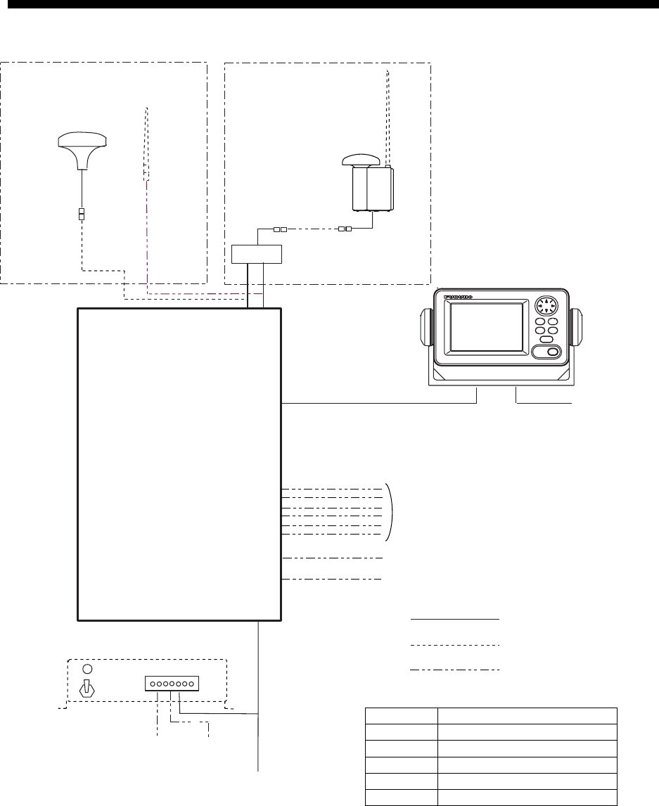
SYSTEM CONFIGURATION
: Standard
: Option
GPS/VHF
combined antenna
GVA-100
GPS antenna
GSC-001
GPA-017S
Distributor unit
DB-1
VHF antenna
Power supply
PR-240-CE
100/110/115/200/
220/230 VAC
1
φ, 50/60Hz
12-24 VDC
: Local supply
Either
24 VDC
MONITOR UNIT
FA-1502
12-24 VDC
TRANSPONDER UNIT
FA-1501
External display,
Sensor
PC
Alarm system
UNIVERSAL AIS
STATUS
NAV
FA-150 PWR
DISP DIM
MENU ENT
GSC-001 Exposed to the weather
GVA-100 Exposed to the weather
FA-1501 Protected from the weather
FA-1502 Protected from the weather
DB-1 Protected from the weather
PR-240-CE Protected from the weather

vi
PROGRAM NUMBER
PCB Location Program No. Version No. Date of Modification
CPU
(24P0062)
Monitor Unit 2450021 (Prog)
2450020 (Boot)
01.**
01.**
MAIN
(24P0035)
Transponder Unit
GPS Receiver
2450018
485026
01.**
40**
**: Minor Modification
vii
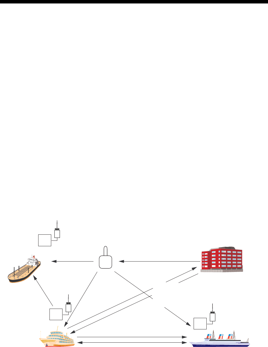
SYSTEM OVERVIEW
System overview
The Automatic Identification System (AIS) was originally developed to aid the Vessel
Traffic Services (VTS) by use of a VHF transponder working on Digital Selective Call
(DSC) at VHF CH70, and is still in use along the UK coastal areas and others. Some time
later the IMO developed a Universal AIS using the new sophisticated technology called
Self-Organized Time Division Multiple Access (SOTDMA) based on a VHF Data Link
(VDL).
The system operates in three modes – autonomous (continuous operation in all areas),
assigned (data transmission interval remotely controlled by authority in traffic monitoring
service) and polled (in response to interrogation from a ship or authority). It is
synchronized with GPS time to avoid conflict among multiple users (IMO minimum 2000
reports per minute and IEC requires 4500 reports on two channels). The VHF channels
87B and 88B are commonly used and in addition there are local AIS frequencies.
Shipborne AIS transponders exchange various data as specified by the IMO and ITU on
either frequency automatically set up by the frequency management telecommand
received by the DSC receiver on ship. VHF transmit power is also set up for 12.5 W or
2 W automatically.
VTS center
Aids to
Navigation
(AtoN)
Transponder
VTS Center transmits TDMA CH
management message including
code, type, position, etc. of buoys
every 3 min, and the AtoN broadcasts
these messages for ships.
All ships broadcast Static and Dynamic information (autonomous and
continuous mode). If OS wants to know information about ship 1, OS shall
send an interrogation in polling mode; then ship 1 will transmit her
response on the same VHF channel without operator intervention.
Interrogation and Response
Static and Dynamic information incl.
MMSI, Name, POSN, HDG, COG, SOG
Ship 1
Own ship
The VTS center transmits a command on
frequency assignment, slots, report rate,
VHF output power, channel spacing, etc.
(Assigned mode)
AIS-fitted AtoN broadcasts its
identification, type of operation,
location, displacement, etc. at
3 min intervals or at a reporting
rate designated by the
Administration authorities.
Transponder
Trans-
ponder
AIS system
viii
Not all ships carry AIS
The Officer of the Watch (OOW) should always be aware that other ships, and in particular
leisure craft, fishing boats and warships, and some coastal shore stations (including
Vessel Traffic Service centers) might not be fitted with AIS.
The OOW should also be aware that AIS fitted on other ships as a mandatory carriage
requirement might be switched off by the master if its use might compromise the security
of the vessel. Thus, users are therefore cautioned to always bear in mind that information
provided by AIS may not be giving a complete or correct “picture” of shipping traffic in their
vicinity.
Use of AIS in collision avoidance
As an anti-collision aid the AIS has the following advantages over radar:
• Information provided in near real-time
• Capable of instant presentation of target course alterations
• Not subject to target swap
• Not subject to target loss in clutter
• Not subject to target loss due to fast maneuvers
• Able to detect ships within VHF/FM coverage, including in some circumstances, around
bends and behind islands.
When using the AIS for anti-collision purposes it is important to remember that the AIS is
an additional source of navigation information. It does not replace other navigational
systems. The AIS may not be giving a complete or correct “picture” of shipping traffic in its
vicinity.
The use of the AIS does not negate the responsibility of the OOW to comply with all
collision regulation requirements, especially the maintaining of a proper look-out. The
prudent navigator uses all aids available to navigate the ship.
Erroneous information
Erroneous information implies a risk to other ships as well as your own. Poorly configured
or improperly calibrated sensors might lead to incorrect information being transmitted. It is
the user’s responsibility to ensure that all information entered into the system is correct
and up to date.
1-1
1. OPERATION
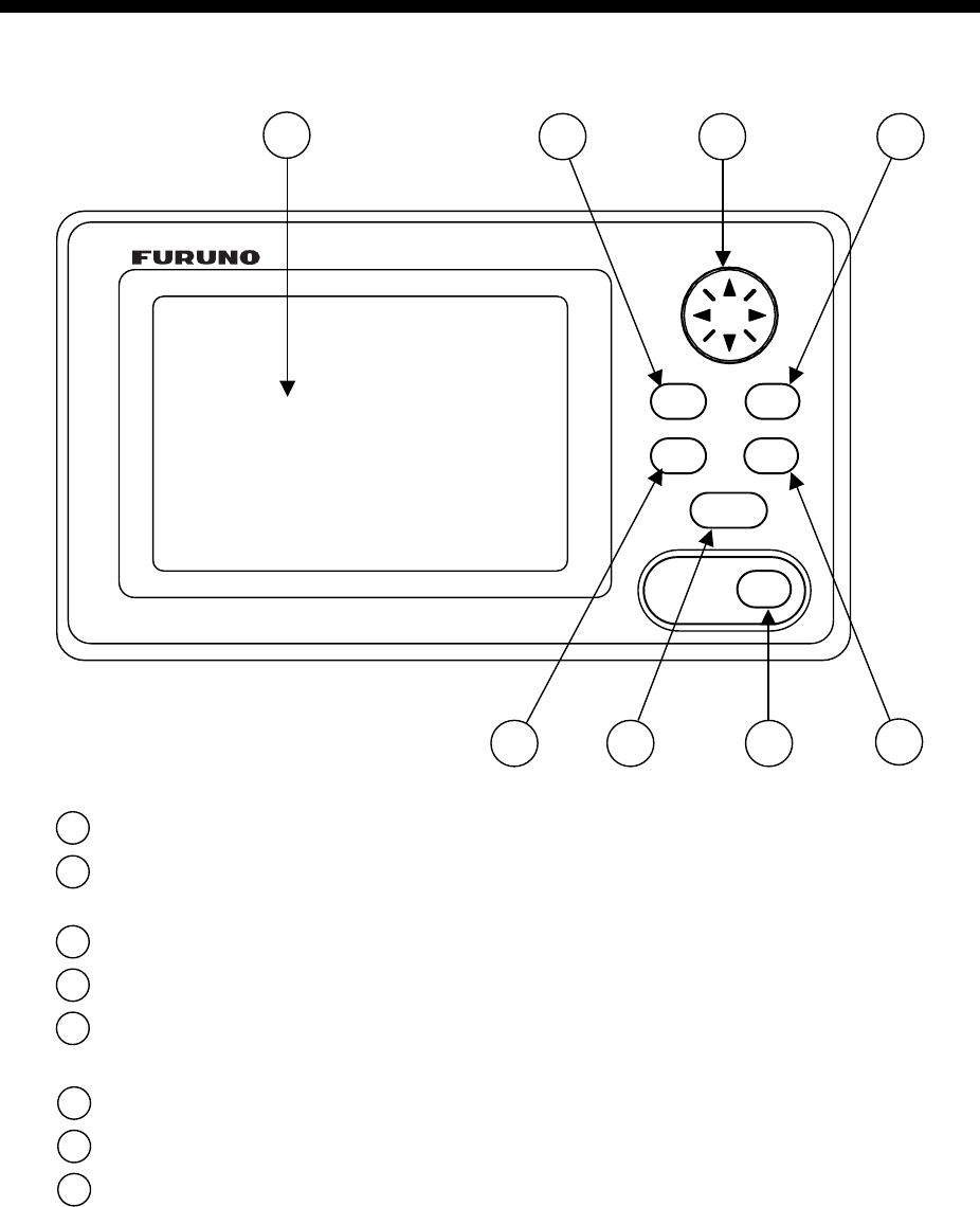
1.1 Description of Controls
MENU ENT
DISP DIM
FA-150
123 4
56
7 8
NAV
STATUS
PWR
1 LCD Screen: Displays various data.
2 CursorPad: Shifts cursor; chooses menu items and options;
enters alphanumeric data.
3 MENU key: Opens the menu.
4 ENT key: Terminates keyboard input; changes screen.
5 DISP key: Chooses a display screen; closes menu (to return to
plotter display).
6 DIM key: Adjusts panel dimmer and LCD contrast.
7 NAV STATUS key: Displays nav status menu, which sets up for a voyage.
8 PWR key: Turns the power on and off.
UNIVERSAL AIS
FA-150 Monitor unit

1. OPERATION
1-2
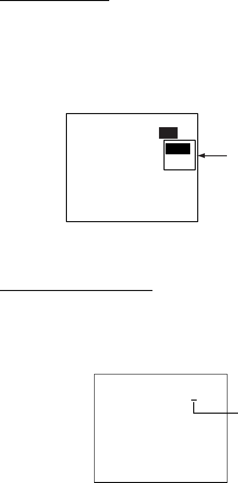
1.2 Turning the Power On and Off
Press the [PWR] key to turn the equipment on or off. When powered, the
equipment sounds a beep for several seconds and then proceeds in the
sequence shown below.
[STARTUP TEST]
PROGRAM No.:
2450021-**.**
ROM : OK
RAM : OK
BACKUP DATA : OK
**.**: Program Version No.
AUTOMATIC
IDENTIFICATION
SYSTEM
FURUNO ELECTRIC CORP.
EQUIPMENT IDENTIFICATION
SCREEN
STARTUP SCREEN
[- - - - - - - -]
HDG: - - -°
SOG: - - .-kt
COG: - - -.-
CPA: - - -.-
TCPA: - -'- -"
INTRD: 0
RNG: 6 DETAIL:[ENT]
n
m
n
m
NOW INITIALIZING
PLOTTER DISPLAY
Startup sequence
The startup screen displays the program version number and the results of the
ROM, RAM and backup data test, showing OK or “NG” (No Good) as the result.
If “NG” (No Good) appears for any of the check results, try resetting the power
to restore normal operation. If that does not work, contact your dealer for
advice. After the startup test is completed the plotter display appears, showing
the message “NOW INITIALIZING,” which means the transponder is initializing
itself. After completion of initialization the equipment is ready for use.
If there is no response from the transponder unit, the message
“COMMUNICATION ERROR” appears at the startup screen. Press any key to
erase the message. Check if the transponder unit is powered. Also check the
connection between the monitor unit and the transponder unit.

1. OPERATION
1-3
The FA-150 should be powered while underway or at anchor. The master may
switch off the AIS if he believes that the continual operation of the AIS might
compromise the safety or security of his ship. The AIS should be restarted
once the source of danger has disappeared.
The equipment transmits own ship static data within two minutes of start-up
and it is transmitted at six-minute intervals. Static data includes MMSI number,
IMO number, call sign, ship name, ship length and width, ship type and GPS
antenna position.
In addition to static data, ship’s dynamic data is also transmitted. This data
includes position with accuracy, SOG, COG, rate of turn, heading, etc. Dynamic
data is transmitted every 2 s to 3 min depending on ship’s speed, course
change. Voyage-related data, such as ship’s draft, hazardous cargo,
destination and estimated time of arrival are transmitted at six-minute intervals.
The FA-150 starts receiving data from AIS-equipped ships as soon as it is
turned on, and those ships’ location on the plotter display is shown with the AIS
symbol. (To learn more about the plotter display, see paragraph 1.7.) With
connection of a radar or ECDIS, the AIS target symbols may be overlaid on the
radar or ECDIS.
Note 1: If no navigation sensor is installed or a sensor such as a gyrocompass
has failed, the AIS automatically transmits “not available” data.
Note 2: The reporting intervals are as follows:
Ship’s navigation status and reporting interval
Ship’s navigation status Reporting interval
Moored 3 min
0-14 kt speed 10 s
0-14 kt speed with course change 3+1/3 s
14-23 kt speed 6 s
14-23 kt speed with course change 2 s
Speed higher than 23 kt 2 s
Speed higher than 23 kt with course change 2 s

1. OPERATION
1-4
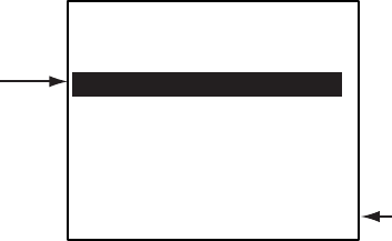
1.3 Adjusting Panel Dimmer and Contrast
The panel dimmer and display contrast may be adjusted as follows:
1. Press the [DIM] key to show the dialog box below.
DIMMER (0~8)
CONTRAST (0~63)
EXIT: [ENT]
4
44
Panel dimmer and contrast dialog box
2. Use ▲ or ▼ to adjust panel dimmer; ◄ or ► to adjust contrast.
3. Press the [ENT] key to close the dialog box.
Note: The equipment starts up with the last-used dimmer and contrast
settings. Therefore, if necessary, readjust them at power up.

1. OPERATION
1-5
1.4 Menu Overview
You can choose the functionality of the equipment through the menu. If you get
lost in operation, press the [MENU] key until you return to the main menu. The
complete menu tree is provided in the Appendix.
1.4.1 Menu operating procedure
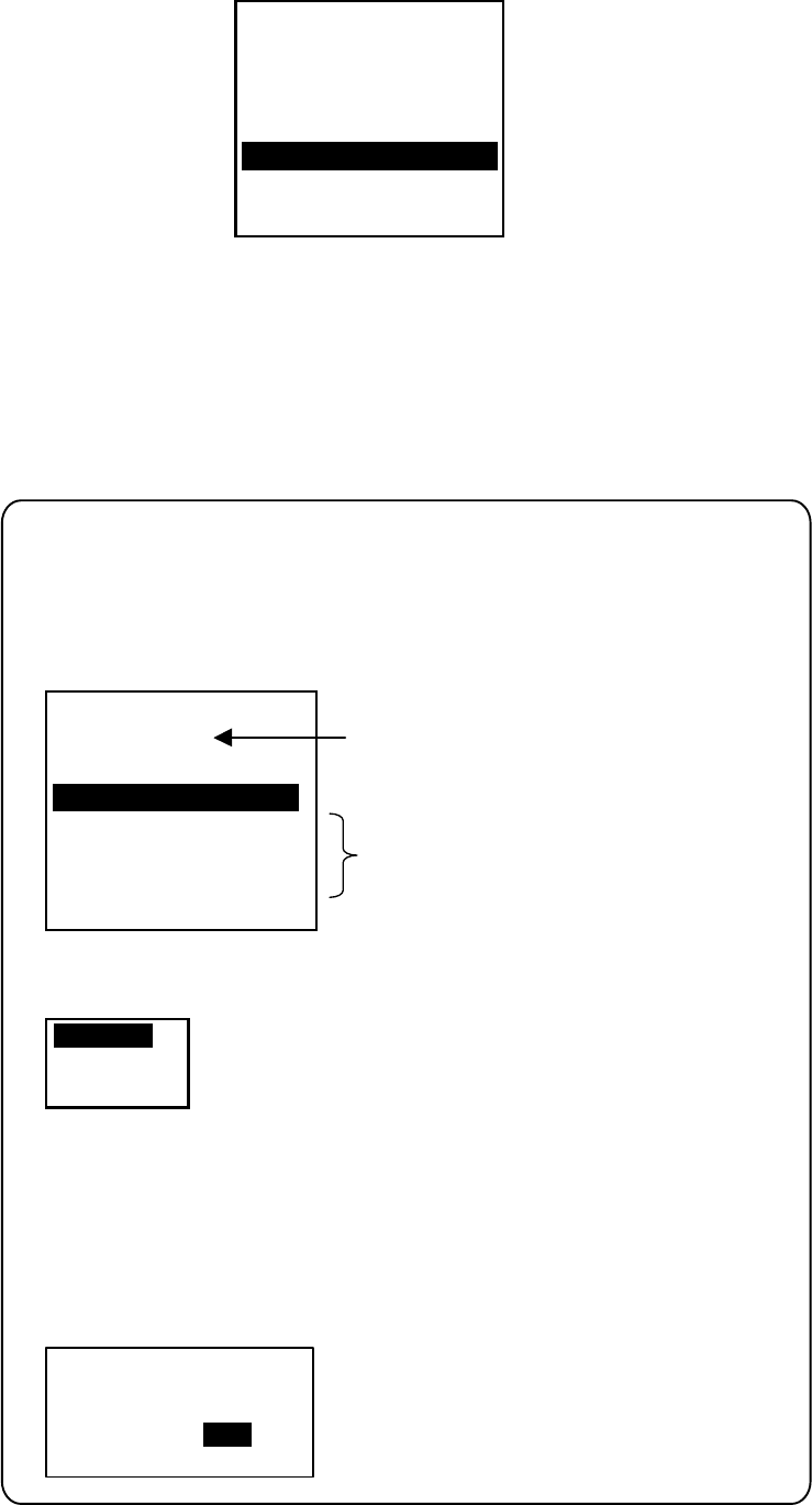
1. Press the [MENU] key to display the main menu.
[MENU]
MSG
SENSOR STATUS
INTERNAL GPS
USER SETTINGS
INITIAL SETTINGS
CHANNEL SETTINGS
DIAGNOSTIC
Main menu
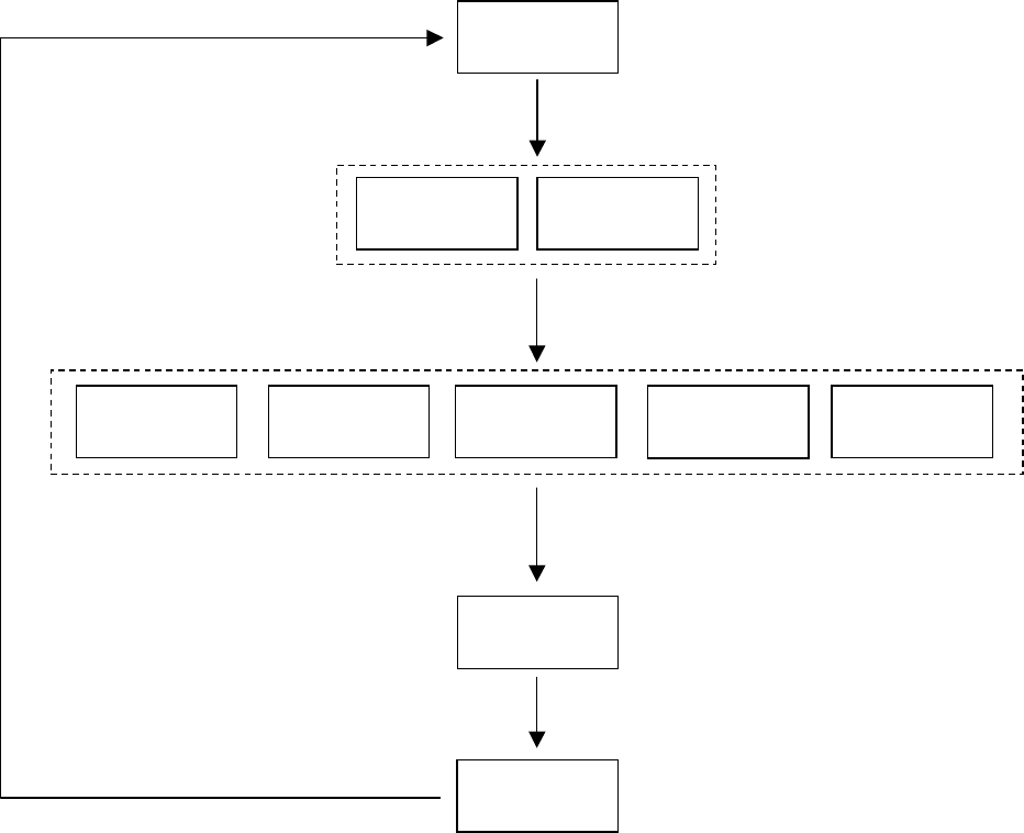
2. Use the CursorPad to choose a wanted menu and then press the [ENT]
key.
3. Use the CursorPad to choose a wanted sub-menu and then press the
[ENT] key.
There are two types of sub-menus: option selection and data entry. (Some
sub-menus combine both.) Below are examples of each type of sub-menu.
USER SETTINGS sub-menu
(Option selection) DRAUGHT input screen
(Data input)
[USER SETTINGS]
KEY BEEP : ON
ALARM BUZZER : ON
DISP RCVD MSG : ABM
RCVD MSG BUZZ: OFF
LR MODE : AUTO
CPA/TCPA ALARM
QUIT[MENU]
[DRAUGHT]
DRAUGHT 00.0 m
Sample sub-menu screens
4. Use ▲ or ▼ to choose the item you wish to process and then press the
[ENT] key.
1. OPERATION
1-6
5. Depending on the sub-menu selected, you will choose an option or enter
alphanumeric data.
Choosing an option
The example below shows how to choose an option from the USER
SETTINGS menu. (See the illustration on the previous page.)
a) Use ▲ or ▼ to choose the menu item desired and then press the [ENT]
key. A window showing the options for the item selected is overlaid on the
sub-menu selected. For example, the options for KEY BEEP are as shown
below.
QUIT[MENU]
[USER SETTINGS]
KEY BEEP : ON
ALARM BUZZER : ON
DISP RCVD MSG : ABM
RCVD MSG BUZZ: OFF
LR MODE : AUTO
CPA/TCPA ALARM
ON
OFF
Options window
USER SETTINGS menu, showing options for KEY BEEP
b) Press ▲ or ▼ to choose option desired and then press the [ENT] key.
Entering alphanumeric data
The example below shows how to enter numeric data on the DRAUGHT
entry screen.
a) Choose DRAUGHT and then push the press the [ENT] key. An underline is
under the far left-hand digit.
[DRAUGHT]
DRAUGHT 00.0 m
Cursor
DRAUGHT entry screen
b) Use ▲ or ▼ to choose appropriate numeric.
Note: For menus where you enter alphanumeric characters, pressing ▲
displays alphanumeric characters cyclically in order of blank space,
alphabet, numerals and symbols.
c) Use ► to shift the cursor to the adjacent place, and then use ▲ or ▼ to
choose numeric.
d) Repeat step c) to finish entering data for the item selected.
e) Press the [ENT] key to register data.
6. Press the [DISP] key to close the menu and return to the plotter display.

1. OPERATION
1-7
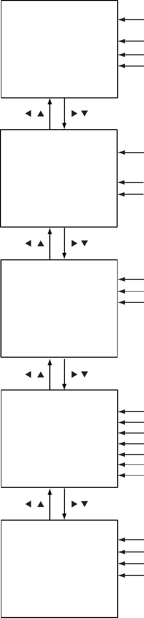
1.5 Setting Up for a Voyage
There are five items on the NAV STATUS menu that you will need to enter at
the start of a voyage: navigation status, destination, arrival date and time,
number of crew, and your vessel type.
1. Press the [NAV STATUS] key to open the NAV STATUS menu.
[NAV STATUS]
NAV STATUS: 0
***
STATUS DETAIL
***
UNDER WAY USING
ENGINE
NAV STATUS menu, page 1, nav status entry screen
2. If your navigation status is different from that shown, follow the procedure
below. If not, go to step 3.
a) Press the [ENT] key.
b) Press ▲ or ▼ to choose appropriate status and then press the [ENT] key.
Refer to the data below to choose appropriate nav status.
00: Underway using engine
01: At anchor
02: Not under command
03: Restricted maneuverability
04: Constrained by draught
05: Moored
06: Aground
07: Engaged in fishing
08: Under way by sailing
09: Reserved for high speed craft (HSC)
10: Reserved for wing in ground (WIG)
11-14: Reserved for future use
15: Not defined (default)
3. Press ► to show page 2 of the NAV STATUS menu.
[DESTINATION
*************
(0/0)
[NEW?]
NAV STATUS menu, page 2
1. OPERATION
1-8
4. NEW is selected; press the [ENT] key.
[DESTINATION]
ENTER A NEW
DESTINATION
QUIT:[NAV STATUS]
NAV STATUS menu, page 2 (destination entry screen)
5. Press the [ENT] key. Use the CursorPad to enter destination. You may use
up to 20 alphanumeric characters, and you may enter 20 destinations.
Pressing ▲ displays alphanumeric characters in order of blank space,
alphabet, numerals and symbols. (For how to enter alphanumeric
characters, see “Entering alphanumeric data” on page 1-6.)
SELECT
EDIT
DELETE
DESTINATION DELETE.
ARE YOU SURE?
YES NO
[DESTINATION]
COTE D'IVOIRE
*************
(0/3)
[NEW?]
SEATTLE
SAN FRANCISCO
COTE D'IVOIRE
Current destination
Destination list
PROCESSING DESTINATIONS
If you have already registered some destinations, page 2 of the NAV STATUS
menu looks something like the one below. From this screen you can select,
edit or delete destinations.
1) Use the CursorPad to choose appropriate destination and then press the [ENT] key
to show the options window below.
2) Use the CursorPad to choose SELECT, EDIT or DELETE as appropriate and
then press the [ENT] key. Do one of the following according to your objective.
Select a destination: Press the [ENT] key.
Edit a destination: Edit the destination as appropriate; press the [ENT] key.
Delete a destination: The prompt below appears. Press to choose YES; press
the [ENT] key.

1. OPERATION
1-9
6. Press ► to show page 3 of the NAV STATUS menu.
[ARRIVAL TIME]
WX
DATE
: 25/APR
TIME: 0:00
NAV STATUS menu, page 3 (date and time of arrival entry screen)
7. DATE is selected; press the [ENT] key.
8. Use the CursorPad to enter the date of arrival and then press the [ENT]
key.
9. TIME is selected; press the [ENT] key.
10. Use the CursorPad to enter the estimated time of arrival and then press the
[ENT] key. Use 24-hour notation.
11. Press ► to show page 4 of the NAV STATUS menu.
[CARGO TYPE & CREW]
W
CREW: 0
TYPE NO: 00
**** TYPE DETAIL****
CARGO SHIP
ALL SHIPS OF
THIS TYPE
NAV STATUS menu, page 4 (cargo type and crew entry screen)
12. CREW is selected; press the [ENT] key.
13. Use the CursorPad to enter number of crew (setting range: 0-8191) and
then press the [ENT] key.
14. TYPE is selected; press the [ENT] key.
15. Use the CursorPad to choose type of vessel, referring to the table on the
next page, and then press the [ENT] key.
Note 1: Only the second digit of the vessel class may be entered here; the
first digit is entered on the initial settings menu, during installation.
Note 2: When “Tanker” is chosen, output power is automatically switched
to 1 W when ship’s speed is less than 3 kts for more than one
minute.

1. OPERATION
1-10
10 FUTURE USE
A
LL SHIPS OF THIS TYPE 60 PASSENGER SHIPS
A
LL SHIPS OF THIS TYPE
11 FUTURE USE CARRYING DG, HS, OR MP(A) 61 PASSENGER SHIPS CARRYING DG, HS, OR MP(A)
12 FUTURE USE CARRYING DG, HS, OR MP(B) 62 PASSENGER SHIPS CARRYING DG, HS, OR MP(B)
13 FUTURE USE CARRYING DG, HS, OR MP(C) 63 PASSENGER SHIPS CARRYING DG, HS, OR MP(C)
14 FUTURE USE CARRYING DG, HS, OR MP(D) 64 PASSENGER SHIPS CARRYING DG, HS, OR MP(D)
15 FUTURE USE FUTURE USE 65 PASSENGER SHIPS FUTURE USE
16 FUTURE USE FUTURE USE 66 PASSENGER SHIPS FUTURE USE
17 FUTURE USE FUTURE USE 67 PASSENGER SHIPS FUTURE USE
18 FUTURE USE FUTURE USE 68 PASSENGER SHIPS FUTURE USE
19 FUTURE USE NONE 69 PASSENGER SHIPS NONE
20 WIG
A
LL SHIPS OF THIS TYPE 70 CARGO SHIPS
A
LL SHIPS OF THIS TYPE
21 WIG CARRYING DG, HS, OR MP(A) 71 CARGO SHIPS CARRYING DG, HS, OR MP(A)
22 WIG CARRYING DG, HS, OR MP(B) 72 CARGO SHIPS CARRYING DG, HS, OR MP(B)
23 WIG CARRYING DG, HS, OR MP(C) 73 CARGO SHIPS CARRYING DG, HS, OR MP(C)
24 WIG CARRYING DG, HS, OR MP(D) 74 CARGO SHIPS CARRYING DG, HS, OR MP(D)
25 WIG FUTURE USE 75 CARGO SHIPS FUTURE USE
26 WIG FUTURE USE 76 CARGO SHIPS FUTURE USE
27 WIG FUTURE USE 77 CARGO SHIPS FUTURE USE
28 WIG FUTURE USE 78 CARGO SHIPS FUTURE USE
29 WIG NONE 79 CARGO SHIPS NONE
30 FISHING 80 TANKER
A
LL SHIPS OF THIS TYPE
31 TOWING 81 TANKER CARRYING DG, HS, OR MP(A)
32 LENGTH OF THE TOW EXCEEDS 200M OR BREADTH EXCEEDS 25M 82 TANKER CARRYING DG, HS, OR MP(B)
33 ENGAGED IN DREDGING OR UNDERWATER OPERATIONS 83 TANKER CARRYING DG, HS, OR MP(C)
34 ENGAGED IN DIVING OPEARATIONS 84 TANKER CARRYING DG, HS, OR MP(D)
35 ENGAGED IN MILITARY OPEARATIONS 85 TANKER FUTURE USE
36 SAILING 86 TANKER FUTURE USE
37 PLEASURE CRAFT 87 TANKER FUTURE USE
38 FUTURE USE 88 TANKER FUTURE USE
39 FUTURE USE 89 TANKER NONE
40 HSC
A
LL SHIPS OF THIS TYPE 90 OTHER TYPE OF SHIP ALL SHIPS OF THIS TYPE
41 HSC CARRYING DG, HS, OR MP(A) 91 OTHER TYPE OF SHIP
42 HSC CARRYING DG, HS, OR MP(B) 92 OTHER TYPE OF SHIP
43 HSC CARRYING DG, HS, OR MP(C) 93 OTHER TYPE OF SHIP )
44 HSC CARRYING DG, HS, OR MP(D) 94 OTHER TYPE OF SHIP )
45 HSC FUTURE USE 95 OTHER TYPE OF SHIP
46 HSC FUTURE USE 96 OTHER TYPE OF SHIP
47 HSC FUTURE USE 97 OTHER TYPE OF SHIP
48 HSC FUTURE USE 98 OTHER TYPE OF SHIP
49 HSC NONE 99 OTHER TYPE OF SHIP
CARRYING DG, HS, OR MP(A)
CARRYING DG, HS, OR MP(B)
CARRYING DG, HS, OR MP(C
CARRYING DG, HS, OR MP(D
FUTURE USE
FUTURE USE
FUTURE USE
FUTURE USE
NONE
50 PILOT
51 SEARCH AND RESCUE VESSELS
52 TUGS
53 PORT TENDERS
54 VESSELS WITH ANTI-POLL UTION FACILITIES OR EQUIPMENT
55 LAW ENFORCEMENT VESSELS
56 SPARE-FOR ASSIGNMENTS TO LOCAL VESSELS
57 SPARE-FOR ASSIGNMENTS TO LOCAL VESSELS
58 MEDICAL TRANSPORTS
59 SHIPS ACCORDING TO RESOLUTION NO 18
WIG:Wing in ground
HSC:High speed craft
DG:Dangerous goods
HS:Harmful substances
MP:Marine pollutants
0-9:Undefined
16. Press ► to go to page 5 of the NAV STATUS menu.
[DRAUGHT]
DRAUGHT 0.0 m
NAV STATUS menu, page 5 (draught entry screen)
17. Press the [ENT] key.
18. Use the CursorPad to enter ship’s draft (setting range: 0-25.5(m)), and then
press the [ENT] key.
19. Press the [DISP] key to close the menu and return to the plotter display.

1. OPERATION
1-11
1.6 Setting CPA/TCPA
Set the CPA (Closest Point of Approach) and TCPA (Time to Closest Point of
Approach) range for which you want to be alerted to AIS targets close to own
ship. When a ship’s CPA and TCPA are lower than that set here, the buzzer
sounds (if active) and the message COLLISION ALARM appears.
1. Press the [MENU] key to open the main menu.
2. Use ▲ or ▼ to choose USER SETTINGS and then press the [ENT] key.
3. Use ▲ or ▼ to choose CPA/TCPA ALARM and then press the [ENT] key.
[CPA/TCPA ALARM]
CPA : 6.00 nm
TCPA : 60 min
ALARM MODE : ON
ALARM BUZZER: ON
QUIT[MENU]
CPA/TCPA ALARM sub-menu
3. CPA is selected; press the [ENT] key.
4. Use the CursorPad to enter CPA (setting range: 0-6.00 nm) and then press
the [ENT] key.
5. TCPA is selected; press the [ENT] key.
6. Use the CursorPad to enter TCPA (setting range: 0-60 min) and then press
the [ENT] key.
7. ALARM MODE is selected; press the [ENT] key.
8. Choose ON to enable the CPA/TCPA alarm feature; OFF to disable it.
Press the [ENT] key.
9. ALARM BUZZER is selected; press the [ENT] key.
10. Choose ON to enable the CPA/TCPA audio alarm, or OFF to disable it.
Press the [ENT] key.
11. Press the [DISP] key to close the menu and return to the plotter display.
1. OPERATION
1-12
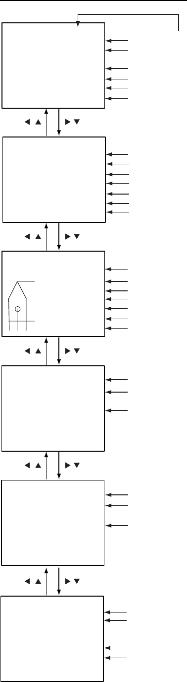
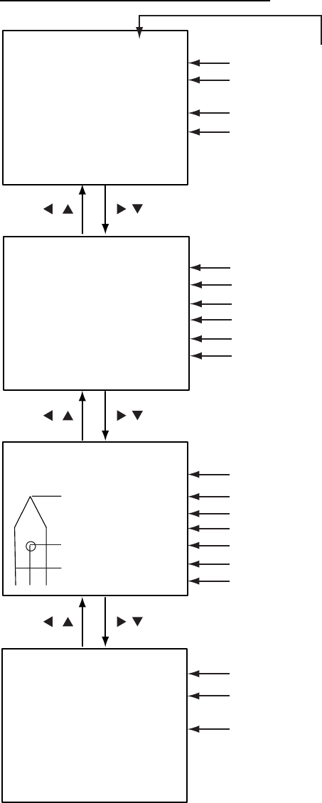
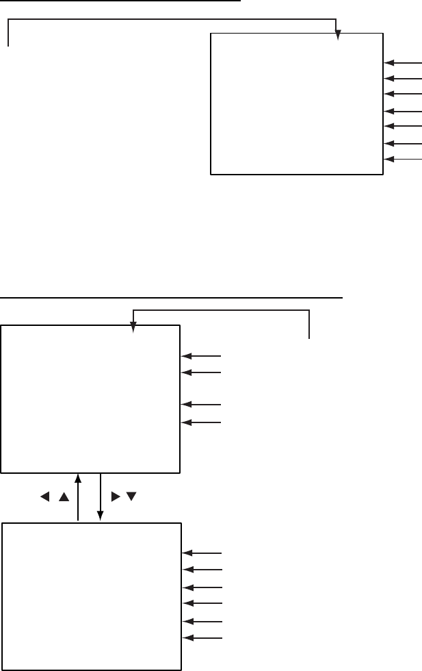
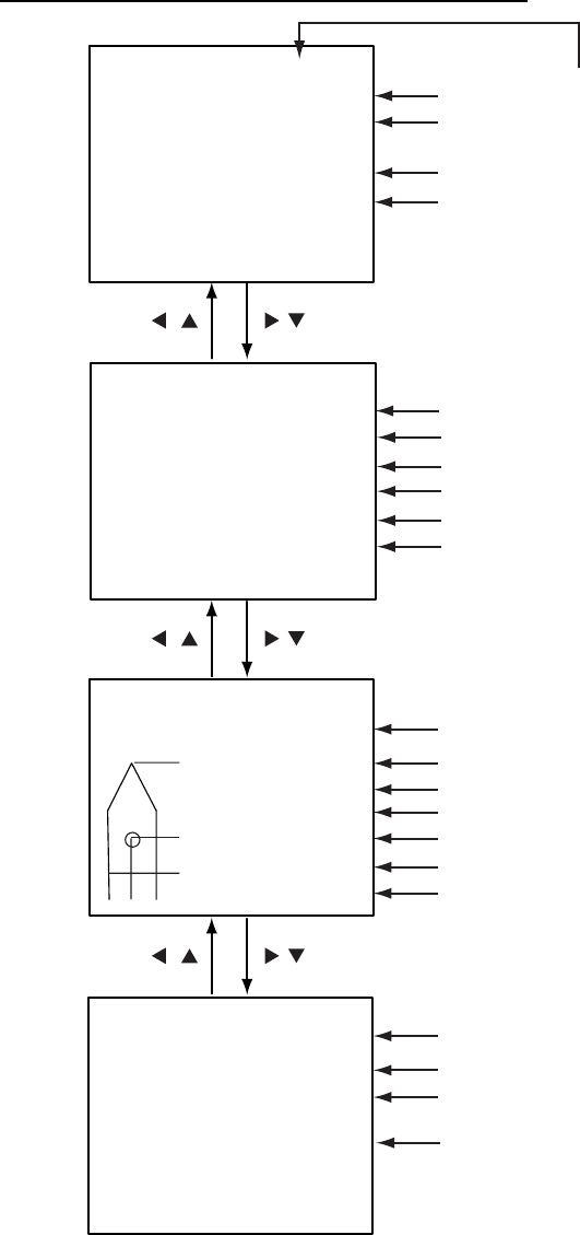
1.7 Choosing a Display
Use the [DISP] key to choose a display. Each time the key is pressed, the
display changes in the sequence shown below.
TARGET LIST DANGEROUS
LIST
OWN STATIC
DATA 1
OWN STATIC
DATA 2
OWN STATIC
DATA 3
OWN STATIC
DATA 4
OWN STATIC
DATA 5
OWN DYNAMIC
DATA
ALARM
STATUS
PLOTTER
DISPLAY
OWN SHIP'S STATIC DATA
Switch among these
displays with .
(See para. 1.7.4.)
ALARM STATUS DISPLAY
(See para. 2.5.)
OWN SHIP'S DYNAMIC DATA
(See para. 1.7.5.)
DANGEROUS (TARGET) LIST
(See para. 1.7.3.)
When a dangerous target
exists the dangerous target
list has priority.
TARGET LIST
(See para. 1.7.2. )
PLOTTER DISPLAY
(See para. 1.7.1.)
Switch between these
displays with , .
Display selection sequence
1. OPERATION
1-13
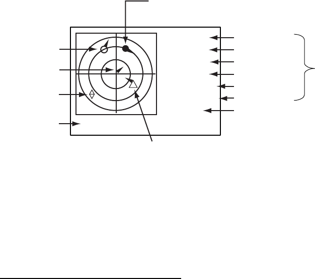
1.7.1 Plotter display
The plotter display, which automatically appears at power-on, shows the range
and course of AIS-equipped ships within the range set by the equipment. The
position and course of your ship are also displayed.
[FURUNO]
HDG: 111°
SOG: 10kt
COG: 111°
CPA: 6.19
TCPA: 12'59
INTRD: 0
Selected target
(circle filled in black)
Target (hollow circle)
Own ship
course marker
Display range RNG: 6 DETAIL:[ENT]
Target name
Heading
Speed
Course
CPA
TCPA
n
m
n
m
Dangerous target
(Target whose CPA/TCPA are lower
than CPA and TCPA alarm settings.)
Lost target
Number of dangerous
targets
Data for target
selected
Plotter display
A target marker (hollow circle w/vector) indicates the presence of a vessel
equipped with AIS in a certain location and course. If you desire to know more
about a vessel’s data, see the next paragraph.
Operations on the plotter display
1. Press the [DISP] key to show the PLOTTER display.
2. Use ▼ or ▲ to choose the range. The available ranges are (in nm) 0.125,
0.25, 0.5, 0.75, 1.5, 3, 6, 12, and 24.
3. To find a target’s data, see paragraph 1.7.2.
Note 1: If no signal is received from an AIS target for three minutes and twenty
seconds it is declared a lost target. Six minutes and forty seconds later
it is erased from the screen.
Note 2: When a target’s CPA and TCPA are lower than set in paragraph 1.6,
the target flashes and the audio alarm sounds (if active). Press any
key to stop the flashing and silence the audio alarm. Take suitable
measures to avoid collision.
Note 3: "DNGR" (DANGER) appears at the end of the HDG field when a
target's CPA and TCPA are lower than the CPA and TCPA alarm
settings. "LOST" appears at the end of the HDG field when the signal
from a target is lost. Three minutes after the signal is lost the target's
data is erased.
1. OPERATION
1-14
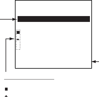
1.7.2 Target list (displaying target data)
1. At the plotter display, press the [DISP] key to show the TARGET LIST,
which lists all AIS targets being detected by the FA-150.
Note: You may also choose the target directly on the plotter display. Press
◄ or ► to color the circle of the wanted target in black and then
press the [ENT] key. The display then looks something like the one
shown at the top of the illustration on the next page. If you wish to
see other data of the target, go to step 3 below.
Target's name, and
range and bearing
(from north) from
own ship to target
Press to switch to
Dangerous List.
(See para. 1.7.3.)
n
m
NAME RNG( ) BRG(
°
)
FURUNO 2.9 276.1
VOYAGE 3.1 292.9
QUEST 4.3 279.5
SEADOG 15.6 82.0
INTREP 21.1 123.1
GLOBER 28.8 246.3
1/ 10 [
] DTL[ENT]
DNG[]
[TARGET LIST]
+
Target type symbols
None: Ship
+
: Base station
: SAR
: AtoN
Target list
2. Use ▼ or ▲ to choose the target whose data you wish to view, and then
press the [ENT] key. The display then looks something like one of the
displays shown on the next several pages, according to type of target. (If
there is no data for the target selected the message NO SEL appears. Hit
any key to escape.)
3. Use ▼ or ▲ to scroll the display to see other data.
1. OPERATION
1-15
Target data display, mobile class A
[DETAILS SHIP] 1/6
MMSI [A]: 431099806
NAME : FURUNO
C. SIGN : ZL6DEF1
IMO No. : 109873421
CPA : 0.02 nm
TCPA : 0'17"
Call sign
MMSI no.
Name
IMO no.
CPA
TCPA
[DETAILS SHIP] 2/6
MMSI [A]: 431099806
LAT : 34
°
03.5442'N
LON : 134
°
30.3883'E
S/C : 17.8 kt/ 213.5
°
HDG : 278
°
PA: H
R/B : 25.12 nm/351.5
°
ROT : R 0.1
°
/min
Heading, Position Accuracy (H, High, L, Low)
Range and bearing from own ship
Latitude
Rate of Turn (L: Left, R: Rightt)
Longitude
[DETAILS SHIP] 3/6
MMSI [A] : 431099806
MMSI no.
[DETAILS SHIP] 5/6
MMSI [A] : 431099806
NAV STATUS : 0
****STATUS DETAIL****
UNDER WAY USING
ENGINE (DEFAULT)
Navigation status description
MMSI no.
Navigation status no.
[DETAILS SHIP] 4/6
MMSI [A] : 431099806
TYPE OF SHIP : 25
****TYPE DETAIL****
FUTURE USE
Type description
MMSI no.
Type no.
A : 100 m
B : 23 m
C : 6 m
D : 6 m
LENGTH: 123 m
BEAM : 12 m
Distance from bow to GPS antenna position
Distance from stern to GPS antenna position
Distance from port to GPS antenna position
Distance from starboard to GPS antenna position
Length of ship
Beam of ship
"DNGR" (DANGER) appears
(in reverse video) when a
target's CPA and TCPA
are lower than the CPA/TCPA
setting.
"LOST" appears (in reverse video)
when signal from a target is lost.
Three minutes after loss of signal
the target's data is erased.
Speed over ground, course over ground
A
B
C D
[DETAILS SHIP] 6/6
MMSI [A]: 431099806
DESTINATION
TOKYO
DATE: 05/MAY
TIME: 23:42
Date of arrival at destination
Estimated time of arrival
Destination
MMSI No.
MMSI no.
Target data display, mobile class A
1. OPERATION
1-16
Target data display, mobile class B
[DETAILS SHIP] 1/4
MMSI [B]: 431099806
NAME : FURUNO
CPA : 0.02 nm
TCPA : 0'17"
CPA
MMSI No.
Name
TCPA
[DETAILS SHIP] 2/4
MMSI [B]: 431099806
LAT : 34
°
03.5442'N
LON : 134
°
30.3883'E
S/C : 17.8 kt/ 213.5
°
HDG : 278
°
PA: H
R/B : 25.12 nm/351.5
°Heading, Position Accuracy (H, High, L, Low)
Range and bearing from own ship
Latitude
Longitude
[DETAILS SHIP] 3/4
MMSI [B] : 431099806
MMSI No.
[DETAILS SHIP] 4/4
MMSI [B] : 431099806
TYPE OF SHIP : 25
****TYPE DETAIL****
FUTURE USE
Type description
MMSI No.
Type No.
A : 100 m
B : 23 m
C : 6 m
D : 6 m
LENGTH: 123 m
BEAM : 12 m
Distance from bow to GPS antenna position
Distance from stern to GPS antenna position
Distance from port to GPS antenna position
Distance from starboard to GPS antenna position
Length of ship
Beam of ship
"DNGR" (DANGER) appears
(in reverse video) when a
target's CPA and TCPA
are lower than the CPA/TCPA
setting.
"LOST" appears (in reverse video)
when signal from a target is lost.
Three minutes after loss of signal
the target's data is erased.
Speed over ground, course over ground
A
B
C D
MMSI No.
Target data display, mobile class B
1. OPERATION
1-17
Target data display, base station
[DETAILS BS] 1/1
MMSI : 431099806
CPA : 0.02 nm
TCPA : 0'17"
LAT : 34
°
03.5442'N
LON: 134
°
30.3883'E
PA : H
R/B : 25.12 nm/351.5
°
MMSI no.
CPA
Position Accuracy (H, High, L, Low)
Range and bearing from own ship
TCPA
Latitude
"DNGR" (DANGER) appears
(in reverse video) when a
target's CPA and TCPA
are lower than the CPA/TCPA
setting.
"LOST" appears (in reverse video)
when signal from a target is lost.
Three minutes after loss of signal
the target's data is erased.
Longitude
Target data display, base station
Target data display, SAR (Search and Rescue)
[DETAILS SAR] 1/2
MMSI : 431099806
CPA : 0.02 nm
TCPA : 0'17"
CPA
MMSI No.
Name
TCPA
[DETAILS SAR] 2/2
MMSI : 431099806
LAT: 34
°
03.5442'N
LON: 134
°
30.3883'E
S/C: 17.8 kt/ 213.5
°
PA: H
R/B: 25.12 nm/351.5
°Position Accuracy (H, High, L, Low)
Range and bearing from own ship
Latitude
Longitude
"DNGR" (DANGER) appears
(in reverse video) when a
target's CPA and TCPA
are lower than the CPA/TCPA
setting.
"LOST" appears (in reverse video)
when signal from a target is lost.
Three minutes after loss of signal
the target's data is erased.
Speed over ground, course over ground
MMSI No.
1. OPERATION
1-18
Target data display, AtoN (Aid to Navigation)
[DETAILS AtoN] 1/4
MMSI : 431099806
NAME: FURUNO
CPA : 0.02 nm
TCPA : 0'17"
CPA
MMSI No.
Name
TCPA
[DETAILS AtoN] 2/4
MMSI : 431099806
LAT : 34
°
03.5442'N
LON : 134
°
30.3883'E
PA : H
R/B : 25.12 nm/351.5
°
PI : ON POSITION
Range and bearing from own ship
Off Position or On Position
Latitude
Longitude
[DETAILS AtoN] 3/4
MMSI : 431099806
MMSI No.
[DETAILS AtoN] 4/4
MMSI : 431099806
VIRTUAL AtoN
TYPE OF AtoN: 20
****TYPE OF DETAIL****
CARDINAL MARK N
Type of AtoN (See next page.)
MMSI No.
AtoN existence (real or virtual)
A : 100 m
B : 23 m
C : 6 m
D : 6 m
LENGTH: 123 m
BEAM : 12 m
Distance from bow to GPS antenna position
Distance from stern to GPS antenna position
Distance from port to GPS antenna position
Distance from starboard to GPS antenna position
Length of ship
Beam of ship
"DNGR" (DANGER) appears
(in reverse video) when a
target's CPA and TCPA
are lower than the CPA/TCPA
setting.
"LOST" appears (in reverse video)
when signal from a target is lost.
Three minutes after loss of signal
the target's data is erased.
Position Accuracy (H, High, L, Low)
A
B
C D
MMSI No.
Description of AtoN

1. OPERATION
1-19
The table below shows all the AtoN codes which may appear on the AtoN
target data display. The AtoN name which appears on the AtoN target display is
shown in uppercase alphabet.
A to N code and description
Code Description
0 Default, Type of A to N not specified
1 Reference point
2 RACON
3 Off shore structure
4 Spare
5 Light, without sectors
6 Light, with sectors
7 Leading light front
8 Leading light rear
9 Beacon, cardinal N
10 Beacon, cardinal E
11 Beacon, cardinal S
12 Beacon, cardinal W
13 Beacon, port hand
14 Beacon, starboard hand
15 Beacon, preferred channel port hand
16 Beacon, preferred channel starboard hand
17 Beacon, isolated danger
18 Beacon, safe water
19 Beacon, special mark
20 Cardinal mark N
21 Cardinal mark E
22 Cardinal mark S
23 Cardinal mark W
24 Port hand mark
25 Starboard hand mark
26 Preferred channel port hand
27 Preferred channel starboard hand
28 Isolated danger
29 Safe water
30 Special mark
31 Light vessel / LANBY
1. OPERATION
1-20
1.7.3 Dangerous (target) list
You can easily find dangerous ships whose CPA and TCPA are lower than the
CPA and TCPA alarm settings.
1. At the plotter display, press the [DISP] key to show the Target List (see
paragraph 1.7.2).
2. Press ► to show the Dangerous List.
[DANGEROUS LIST]
NAME CPA TCPA
n
m
( )
Target name,
CPA and TCPA FURUNO 0.50 3'20"
EXPLOR 1.20 3'35"
INTREP 1.80 3'50"
VOYAGE 1.90 3'55"
SEADOG 2.00 4'00"
1/ 10 [
] DTL[ENT] RNG[
]
Press to sort and view
targets in order of range from
own ship.
Dangerous list
3. To find detailed information about a dangerous target, use ▼ or ▲ to
choose the target and then press the [ENT] key. Use the CursorPad to view
other data; ▼ or ► to go forward, ▲ or ◄ to go back. (If there is no data for
the target selected the message “NO SEL” appears. Hit any key to escape.)
Note: The message “LOST” appears at the top of the Dangerous List when no
AIS signal is received from the selected target.
1.7.4 Own ship’s static data
The OWN STATIC DATA display shows own ship’s static data, which includes
MMSI, call sign and name, IMO number, length and beam, type of ship and
location of position fixing antenna, on five pages. This data should be checked
once per voyage or once per month whichever is shorter. Data may be
changed only on the authority of the master.
1. At the plotter display, press the [DISP] key twice to show “OWN STATIC
DATA 1/5”. See the next page.
2. Use the CursorPad to view other own static data; ▼ or ► to go forward, ▲
or ◄ to go back.
See the illustration on the next page for own ship’s static data examples.
1. OPERATION
1-21
[OWN STATIC DATA] 1/5
NAME : FURUNO
VOYAGER
CALL SIGN: CAL0001
MMSI : 123456789
IMO No. : 623498071
[OWN STATIC DATA] 2/5
DESTINATION:
TOKYO
DATE: 12/DEC
TIME : 10:25
[OWN STATIC DATA] 4/5
CPA : 1.50 nm
TCPA : 10 min
ANT POS INT EXT
LENGTH A : 75 m 77 m
LENGTH B : 20 m 18 m
LENGTH C : 15 m 18 m
LENGTH D : 15 m 12 m
[OWN STATIC DATA] 5/5
CREW : 12
TYPE OF SHIP: 36
CLASS : A
****TYPE DETAIL****
SAILING
[OWN STATIC DATA] 3/5
DRAUGHT : 12.1 m
NAV STATUS: 00
***STATUS DETAIL***
UNDER WAY USING
ENGINE (DEFAULT)
Destination
Name
Call sign
IMO no.
Estimated date of arrival
Estimated time of arrival
Navigation status no.
Draught
CPA (preset value)
TCPA (preset value)
Navigation status description
Ship class
Number of crew
Ship type
MMSI no.
Distance from bow to GPS antenna position
Distance from stern to GPS antenna position
Distance from port to GPS antenna position
Distance from starboard to GPS antenna position
INT: Internal GPS, EXT: External GPS
Type detail
OWN STATIC DATA displays
1. OPERATION
1-22
1.7.5 Own dynamic data display
The OWN DYNAMIC DATA display shows your ship’s dynamic data, which
includes time, date, ship’s position, course over ground (COG), speed over
ground (SOG), rate of turn (ROT), and heading.
The OOW should periodically check position, speed over ground and sensor
information.
At the plotter display, press the [DISP] key three times to show the OWN
DYNAMIC DATA display.
[OWN DYNAMIC DATA]
01/MAY/2004 13:24:55
LAT : 34
°
45.2132' N
LON : 135
°
21.2345' E
SOG: 8.1 kt INT GPS
COG: 118.5
°
HDG:118
°
ROT: R10.3
°
/min*
PA: H RAIM: USED
Date, time
Latitude
Longitude
Speed over ground
Course over ground, Heading
Rate of turn
Position accuracy
(H: High, L: Low),
RAIM status
(USED or UNUSED)
Display flashes when transmitting
* = If no ROT device is connected and HDG
sentence is input from a gyrocompass, etc.,
the following is displayed:
Rate of turn less than 10
°
/min.: 0.0
Rate of turn 10
°
/min. rightward or higher: R>10
Rate of turn 10
°
/min. leftward or higher: L>10
GPS receiver in use
INT GPS: Internal GPS
INT DGPS: Internal DGPS
EXT GPS: External GPS
EXT DGPS: External DGPS
NO FIX: No position fix
OWN DYNAMIC DATA display
1.7.6 Alarm status display
The alarm status display shows the date and time alarms were violated. For
further details, see paragraph 2.5.

1. OPERATION
1-23
1.8 Messages
You may send and receive messages via the VHF link, to a specified
destination (MMSI) or all ships in the area. Messages can be sent to warn of
safety of navigation; for example, an iceberg sighted. Routine messages are
also permitted.
Short safety-related messages are only an additional means to broadcast
safety information. They do not remove the requirements of the GMDSS.
When a message is received, the equipment beeps and the indication
“MESSAGE” appears. The contents of the message may be viewed on the
receive message log.
1.8.1 Sending a message
1. Press the [MENU] key to open the main menu.
2. Use ▼ or ▲ to choose MSG and then press the [ENT] key
[MSG]
CREATE MSG
TX LOG
RX LOG
MSG sub-menu
3. CREATE MSG is selected; press the [ENT] key.
[CREATE MSG]
SET MSG TYPE
SET MSG
SEND MSG
CREATE MSG sub-menu
4. SET MSG TYPE is selected; press the [ENT] key.
[SET MSG TYPE]
ADRS TYPE: BROAD CAST
MMSI : - - - - - - - - -
MSG TYPE : NORMAL
CHANNEL: ALTERNATE
MMS
SET MSG TYPE sub-menu

1. OPERATION
1-24
5. ADRS TYPE is selected; press the [ENT] key.
BROAD CAST
ADRS CAST
6. Choose ADRS CAST to send a message to a specific ship, or BROAD
CAST to send a message to all ships. Press the [ENT] key.
7. For BROAD CAST, go to step 8. For ADDRESS-CAST, “MMSI” is selected;
press the [ENT] key, use the CursorPad to enter MMSI number of receiving
vessel and then press the [ENT] key.
8. MSG TYPE is chosen; press the [ENT] key.
SAFETY
NORMAL
9. Choose message type: NORMAL (message other than safety) or SAFETY
(important navigational or meteorological warning). Press the [ENT] key.
10. CHANNEL is chosen; press the [ENT] key.
ALTERNATE
BOTH A & B
A
B
11. Choose which channel to transmit your message over.
12. Press the [ENT] key.
13. Press the [MENU] key to return to the CREATE MSG sub-menu.
14. Choose SET MSG and press the [ENT] key.
Number of
characters
used/available
[SET MSG]
0(151)* QUIT[MENU]
*: Up to 161 characters can be entered, but recipients receive
the following number of characters.
NORMAL message with BROAD-CAST : 156 characters
NORMAL message with ADDRESS-CAST: 151 characters
SAFETY message with BROAD-CAST : 161 characters
SAFETY message with ADDRESS-CAST : 156 characters
SET MSG screen
15. Use the CursorPad to enter your message. Use ▼ or ▲ to choose
character; ◄ or ► to shift the cursor.
16. Press the [ENT] key to return to the CREATE MSG sub-menu.
17. Choose SEND MSG and then press the [ENT] key to send your message.

1. OPERATION
1-25
The screen shows message status as follows:
AIS message status messages and their meanings
Message Meaning
NOW PROCESSING. Message is being sent.
SEND MESSAGE COMPLETE.
PRESS ANY KEY.
Transmission of message completed. (MMSI is
additionally shown in case of addressed message.)
SEND MESSAGE UNSUCCESSFUL.
PRESS ANY KEY.
Message could not be sent.
SEND MESSAGE UNSUCCESSFUL.
MMSI: XXXXXXXXX
PRESS ANY KEY.
Message sent successfully, however there is no reply
from receiver of message.
NOW WAITING RESPONSE.
PRESS ANY KEY.
You tried to send a message while the transponder is
awaiting receive confirmation (successful or
unsuccessful) for the first-sent message. After
confirmation is received, the next sequential message
will be sent.
1.8.2 Receiving messages
How to view a received message
When a message is received, the window below appears on the display. To
view the contents of the message follow the procedure below.
MESSAGE !
PRESS ANY KEY
Message received
1. Press any key to erase the “message received” window.
2. Press the [MENU] key to show the main menu.
3. Choose MSG and then press the [ENT] key.
4. Choose RX LOG and then press the [ENT] key.
Date and time
message received
("NEW" displayed for
unread message)
1/10[
] MSG[ENT] QUIT[MENU]
MMSI of sender, type of message
N-ABM: Normal, addressed binary
S-ABM: Safety, addressed binary
N-BBM: Normal, broadcast binary
S-BBM: Safety, broadcast binary
[RX LOG]
03/MAY 13:25 NEW
FROM: 431099111 N-ABM
28/MAR 03:43
FROM: 431099111 S-ABM
22/MAR 18:00
FROM: 431099111 N-ABM
Received message log
5. To view the contents of an unread message, use the CursorPad to choose
the message and then press the [ENT] key. Below is an example of a
received message.

1. OPERATION
1-26
SCROLL[
] QUIT[MENU]
[RCVD MSG]
I HAVE CHANGED MY
COURSE TO 350 DEGREE.
Received message example
6. Press the [MENU] key several times to close the log and return to the
plotter display.
Automatically displaying received messages
You may automatically display incoming messages as follows:
1. Press the [MENU] key to open the menu.
2. Use the CursorPad to choose USER SETTINGS and then press the [ENT]
key.
QUIT[MENU]
[USER SETTINGS]
KEY BEEP : ON
ALARM BUZZER : ON
DISP RCVD MSG : ALL
RCVD MSG BUZZ: ON
LR MODE : AUTO
CPA/TCPA ALARM
USER SETTINGS sub-menu
3. Use the CursorPad to choose DISP RCVD MSG and then press the [ENT]
key.
ALL
ABM
OFF
4. Use the CursorPad to choose which category of receive message you want
to display automatically and then press the [ENT] key.
ALL: Display any message upon receipt
ABM: Display only addressed binary messages upon their receipt
OFF: Disable automatic displaying of incoming messages
5. Press the [DISP] key to close the menu and return to the plotter display.
1. OPERATION
1-27
1.8.3 Message logs
The FA-150 stores the latest five transmitted and received messages in
respective message logs. When a log becomes full, the oldest message in the
log is automatically deleted to make room for the latest.
To display a message log, do the following:
1. Press the [MENU] key to open the menu.
2. Choose MSG and then press the [ENT] key.
3. Choose TX LOG or RX LOG as appropriate and then press the [ENT] key.
Below is an example of the Tx log. For the appearance of the Rx log, see
paragraph 1.8.2.
Date and time message
transmitted, message status
OK: Message transmitted
successfully
NG (No Good): Message
could not be transmitted
[TX LOG]
31/APR 13:25 OK
TO: 431099111 N-ABM
27/MAR 03:43
TO: 431099111 S-ABM
19/MAR 18:00
TO: 431099111 N-ABM
1/10[
T
] MSG[ENT] QUIT[MENU]
MMSI of receiver, type of message
N-ABM: Normal, addressed binary
S-ABM: Safety, addressed binary
N-BBM: Normal, broadcast binary
S-BBM: Safety, broadcast binary
TX message log
4. To view the contents of a message, choose it with ▼ or ▲ and then press
the [ENT] key. Below is an example of a transmitted message. For an
example of a received message, see paragraph 1.8.2.
SCROLL[
ST
] QUIT[MENU]
[TX LOG]
CHANGE YOUR COURSE TO
350 DEGREE.
Transmitted message example
5. Press the [MENU] key several times to close the log and return to the
plotter display.

1. OPERATION
1-28
1.9 Regional Operating Channels
AIS operates primarily on two dedicated VHF channels, CH 2087 and CH2088.
Where these channels are not available regionally, the AIS is capable of being
automatically switching to designated alternate channels by means of a
message from a shore facility. Where no shore based AIS or GMDSS sea area
A1 station is in place, the AIS should be switched manually as in paragraph
1.9.2.
A regional operating area is set with the procedure shown below. The most
recent eight areas are memorized.
• Automatic setting of VHF DSC (channel 70) from shore-based AIS
• Automatic setting by AIS message from shore-based AIS
• Setting by shipboard system such as ECDIS
• Manual setting
The default area is as follows:
• Tx power: 12.5 W
• Channel no. 2087, 2088
• Frequency bandwidth: 25 kHz
• Tx/Rx mode: Tx/Rx
1.9.1 Viewing channels, Tx power
Do the following to view current channels.
1. Press the [MENU] key to open the menu.
2. Choose SET CHANNEL and then press the [ENT] key.
QUIT[MENU]
[SET CHANNEL]
VIEW CHANNEL
EDIT CHANNEL
SET CHANNEL menu
3. Choose VIEW CHANNEL and then press the [ENT] key.
[VIEW CHANNEL]
POWER : 12.5W
CHANNEL NO.
CH-A: 2087
CH-B: 2088
Power
Channel
QUIT[MENU]
VIEW CHANNEL display
4. Press the [MENU] key several times to return to the plotter display.

1. OPERATION
1-29
1.9.2 Displaying, editing regional operating area status
You may display the status of regional operating areas currently memorized in
the equipment. Nine of any combination of AIS message from shore-based AIS,
DSC message, manual settings and commands from ECDIS or a PC may be
registered and one will be a default value.
About registering areas
• AIS and DSC messages registered within last two hours cannot be edited.
• An item labeled DEFAULT cannot be registered. (“DEFAULT” are data used
for international waters not controlled by shore-based AIS.)
• If two areas overlap one another the older data is deleted.
• Data older than five weeks is deleted.
• Area data is deleted when it is more than 500 miles from the area for which it
was registered.
1. Press the [MENU] key to open the menu.
2. Choose SET CHANNEL and then press the [ENT] key.
3. Choose EDIT CHANNEL and then press the [ENT] key.
[EDIT CHANNEL]
SELECT NO. : 0
TIME
- -/- - - - -: - -: - -
FROM
MMSI: DEFAULT
TYPE: DEFAULT
QUIT [MENU] EDIT[ENT]
EDIT CHANNEL sub-menu, page 1
SELECT NO.: File number, 0-9. In order of distance from own ship,
from closest to furthest.
TIME: Data and time equipment controlled by external source.
MMSI: MMSI displayed for control by DSC or shore-based AIS.
Dashes or “EMPTY” (no data) otherwise.
TYPE: How channel is controlled: AIS, AIS message; PI, ECDIS or
PC; DSC, DSC, MANUAL, manual control
Note: MMSI and TYPE must be set to other than “DEFAULT” to edit.
4. Use ▼ or ▲ to choose desired file number from SELECT NO. and then
press the [ENT] key.

1. OPERATION
1-30
5. Press the [ENT] key to show details.
Note: Power is fixed at 1W for
CH No. 1013 and/1067.
[EDIT CHANNEL]
1/2
FROM MMSI:
POWER : 12.5W
CH NO. CH-A: 2087
CH-B: 2088
MODE CH-A: TX/RX
CH-B: TX/RX
ZONE: 1nm
EDIT CHANNEL sub-menu, page 1
6. POWER is selected; press the [ENT] key to show the channel power
options.
1W
2W
12.5W
7. Use ▼ or ▲ to choose power desired and then press the [ENT] key.
8. CH NO. CH-A is selected; press the [ENT] key.
9. Use the CursorPad to choose channel number for CH-A and then press the
[ENT] key.
10. CH NO. CH-B is selected; press the [ENT] key.
11. Use the CursorPad to choose channel number for CH-B and then press the
[ENT] key.
12. MODE CH-A is selected; press the [ENT] key.
TX/RX
RX
UNUSED
13. Use the CursorPad to choose desired mode for CH-A and then press the
[ENT] key.
14. MODE CH-B is selected; press the [ENT] key.
15. Use the CursorPad to choose desired mode for CH-B and then press the
[ENT] key.
16. ZONE is selected; press the [ENT] key.
17. Key in the zone distance and then press the [ENT] key. (The setting range
is 1 to 8 (nm).) Then, the following screen appears.
[EDIT CHANNEL] 2/2
CH AREA
RIGHT TOP
LAT: 0
°
00.0'N
LON: 0
°
00.0'E
LEFT BOTTOM
LAT: 0
°
00.0'N
LON: 0
°
00.0'E
CHANNEL EDIT sub-menu, page 2
18. LAT of RIGHT TOP is selected; press the [ENT] key. Use the CursorPad to
enter latitude for the right-top position (northeast point) of the AIS operating
area and then press the [ENT] key.
1. OPERATION
1-31
19. LON of RIGHT TOP is selected; press the [ENT] key. Use the CursorPad to
enter longitude for the right-top position (northeast point) of the AIS
operating area and then press the [ENT] key.
20. LAT of LEFT BOTTOM is selected; press the [ENT] key. Use the CursorPad
to enter latitude for the left-bottom position (southwest point) of the AIS
operating area and then press the [ENT] key.
21. LON of LEFT BOTTOM is selected; press the [ENT] key. Use the
CursorPad to enter longitude for the left-bottom position (southeast point) of
the AIS operating area and then press the [ENT] key.
Note: The available range is 20-200 nm. If the area contains overlapping
data the older data will be erased.
RIGHT-TOP
LEFT-BOTTOM
ZONE
1-8 nm
20-200 nm
20-200 nm
Description of RIGHT-TOP, LEFT-BOTTOM and ZONE items
22. Press the [MENU] key. The prompt shown below appears.
SAVE CHANNEL.
ARE YOU SURE?
YES NO
23. Press ◄ to choose YES and then press the [ENT] key.
24. Press the [DISP] key to close the menu and return to the plotter display.
Note: If you enter invalid data, the message “OUT OF RANGE L/L” appears.
Press any key to escape. Reenter data.

1. OPERATION
1-32
1.10 Enabling/Disabling Buzzers, Key Beep
You may turn on or off the buzzers that sound for alarms or incoming
messages. Further, you may turn off the beep which sounds for valid key input.
Note that the alarm buzzer is not related to a radar or ECDIS alarm.
1. Press the [MENU] key to open the menu.
2. Use the CursorPad to choose USER SETTINGS and then press the [ENT]
key.
QUIT[MENU]
[USER SETTINGS]
KEY BEEP : ON
ALARM BUZZER : ON
DISP RCVD MSG : ALL
RCVD MSG BUZZ: ON
LR MODE : AUTO
CPA/TCPA ALARM
USER SETTINGS sub-menu
3. Use the CursorPad to choose KEY BEEP, ALARM BUZZER or RCVD MSG
BUZZ as appropriate and then press the [ENT] key.
4. Choose ON or OFF as appropriate and then press the [ENT] key.
5. Press the [DISP] key to close the menu and return to the plotter display.
1. OPERATION
1-33
1.11 Long Range Mode
The long range mode sets how to reply to a request for own ship data from a
distant station, for example, Inmarsat C station. You may reply automatically or
manually.
1. Press the [MENU] key to open the menu.
2. Use the CursorPad to choose USER SETTINGS and then press the [ENT]
key.
QUIT[MENU]
[USER SETTINGS]
KEY BEEP : ON
ALARM BUZZER : ON
DISP RCVD MSG : ALL
RCVD MSG BUZZ: ON
LR MODE : AUTO
CPA/TCPA ALARM
USER SETTINGS sub-menu
3. Use the CursorPad to choose LR MODE and then press the [ENT] key.
AUTO
MANUAL
4. Use the CursorPad to choose AUTO (auto reply) or MANUAL (manual
reply) as appropriate and then press the [ENT] key.
5. Press the [DISP] key to close the menu and return to the plotter display.
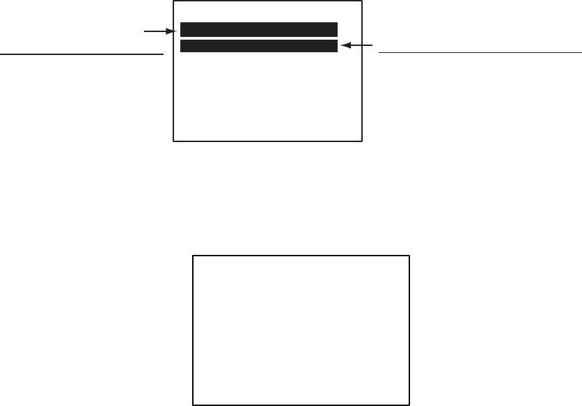
Manual reply
For manual reply, the left-side message below appears when a request for own
ship data arrives from a distant station. Press the [ENT] key to send the data,
or press any key other than [ENT] to send no data.
Automatic reply
For automatic reply, the right-side message below appears when a request for
own ship data arrives from a distant station. Ship’s data is automatically
transmitted. Press the [ENT] key to erase the message.
[RECEIVED LR]
MMSI: 431456789
NAME: FURUNO
C
RESPONSE?
YES: [ENT] NO: OTHER
LR Message (Manual reply)
[RESPONDED LR]
MMSI: 431456789
NAME: FURUNO
C
PRESS ANY KEY
LR Message (Automatic reply)
Information
requested
(See table
on next page.)

1. OPERATION
1-34
Codes used in long range messages
Code Meaning
A Ship name, call sign, IMO number
B Date message created
C Position
E Course over ground
F Speed over ground
I Waypoint, ETA
O Draft
P Ship type, Load
U Ship length, width, type
W Number of crew
1. OPERATION
1-35
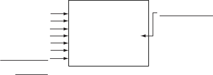
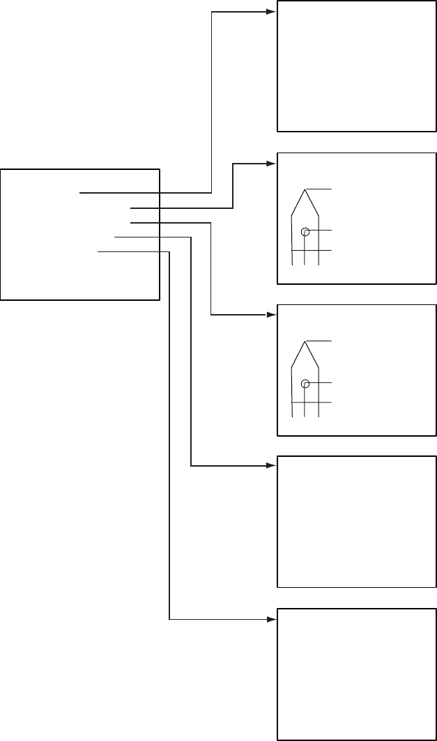
1.12 Viewing Initial Settings
The INITIAL SETTINGS menu, which is locked with a password, is where the
installer enters ship’s MMSI, internal and external antenna positions, ship type
and I/O port settings. You can view the settings on this menu (without a
password) as follows.
1. Press the [MENU] to open the menu.
2. Use the CursorPad to choose INITIAL SETTINGS and then press the [ENT]
key.
3. Use the CursorPad to choose item to view and then press the [ENT] key.
QUIT [MENU]
[INITIAL SETTINGS]
VIEW MMSI
VIEW INT ANT POS.
VIEW EXT ANT POS.
VIEW SHIP TYPE
VIEW I/O PORT
QUIT [MENU]
[VIEW MMSI]
MMSI : 036699999
IMO NO : 9241062
NAME : FURUNO
C. SIN : FQC3544
QUIT [MENU]
[VIEW SHIP TYPE]
TYPE NO : 70
***
TYPE DETAIL
*****
CARGO SHIP
ALL SHIPS OF
THIS TYPE
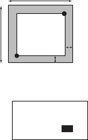
[VIEW EXT ANT POS.]
A: 35m
B: 9m
C: 8m
D: 5m
QUIT[MENU]
A
B
C D
[VIEW INT ANT POS.]
A: 50m
B: 10m
C: 9m
D: 6m
QUIT[MENU]
A
B
C D
[VIEW I/O PORT]
COM1
COM2
COM3
SENSOR PORT
PC
ROT TIME : 1 SEC
PRIORITY
Choose port to view and
press the [ENT] key.
1. OPERATION
1-36
This page intentionally left blank.

2-1
2. MAINTENANCE,
TROUBLESHOOTING
WARNING
ELECTRICAL SHOCK HAZARD
Do not open the equipment.
Only qualified personnel
should work inside the
equipment.
2.1 Maintenance
Regular maintenance is necessary to maintain performance. A monthly
maintenance program should be established and should at least include the
items listed in the table below.
Maintenance items
Item Check point
Connectors Check that all connectors on the rear panel of the transponder
unit and monitor unit are firmly connected.
Cabling Check cabling for damage. Replace if damaged.
Ground terminal Check the ground terminal on the monitor unit and transponder
unit for rust. Clean if necessary.
Ground wire Confirm that the ground wire on the monitor unit and
transponder unit is firmly fastened.
Monitor unit,
Transponder unit
Dirt and dust should be removed from units with a soft, dry
cloth. For the LCD, wipe it carefully to prevent scratching,
using tissue paper and an LCD cleaner. To remove dirt or salt
deposits, use an LCD cleaner, wiping slowly with tissue paper
so as to dissolve the dirt or salt. Change paper frequently so
the salt or dirt will not scratch the LCD. Do not use solvents
such as thinner, acetone or benzene for cleaning any unit; they
can remove paint and marks and deform the equipment.

2. MAINTENANCE, TROUBLESHOOTING
2-2
2.2 Replacement of Fuse, Resetting Breaker
2.2.1 Replacement of fuse
The power cable for the monitor unit contains a 3A fuse which protects the
equipment from overvoltage, reverse polarity and equipment fault. If the power
cannot be turned on, check if the fuse has blown. If it has blown, find the cause
before replacing the fuse. If the fuse blows again after replacement, contact
your dealer for advice.
Part Type Code No.
Fuse FGBO-A 3A AC125V 000-549-063
WARNING
Use the proper fuse.
Use of a wrong fuse can cause fire or
result in damage to the equipment.
2.2.2 Resetting the breaker
If the power cannot be turned on, the BREAKER button on the rear panel of the
transponder unit may have activated. The BREAKER button pops out when
overvoltage, reverse polarity or equipment fault is detected, to protect the
system from damage. If the button pops out, find the reason before pushing it
in to restore normal operation.
Breaker
BREAKER
10A
GPS ANT PC
VHF ANT

2. MAINTENANCE, TROUBLESHOOTING
2-3
2.3 Troubleshooting
The troubleshooting table below provides common symptoms of trouble and
the means to rectify them. If you cannot restore normal operation, do not
attempt to check inside the equipment. Refer any repair work to a qualified
technician.
Troubleshooting
Symptom Remedy
Power
Cannot turn on the power. • Check that the power connector is firmly fastened.
• Check the power supply.
Transmitting, receiving messages
Cannot transmit or
receive.
• Check that the VHF antenna cable is firmly
fastened.
• Check the VHF antenna.
• For TX message, try different TX channel.
(operating sequence: [MENU], MSG, CREATE
MESSAGE, SET MSG TYPE, CHANNEL)
Can transmit but message
is sent to wrong party.
• On the SET MSG TYPE sub-menu, check that
ADRS TYPE is selected to ADRS-CAST and
MMSI is correct, before sending a message.
(operating sequence: [MENU], MSG, CREATE
MESSAGE, SET MSG TYPE, ADRS TYPE and
MMSI)
Position data
No position data • Check the GPS antenna for damage.
• Check the GPS antenna cable and its connectors.
2. MAINTENANCE, TROUBLESHOOTING
2-4
2.4 Diagnostics
The FA-150 provides diagnostic tests to check the monitor unit and
transponder unit for proper operation.
2.4.1 Monitor unit test
The monitor unit test shows program no., and checks the ROM, RAM, LCD and
controls.
1. Press the [MENU] key to open the main menu.
2. Use the CursorPad to choose DIAGNOSTIC and then press the [ENT] key.
For service technician.
Not accessible by user.
[DIAGNOSTIC]
MONITOR TEST
TRANSPONDER TEST
PWR ON/OFF HISTORY
TX ON/OFF HISTORY
MEMORY CLEAR
FOR SERVICE
DIAGNOSTIC sub-menu
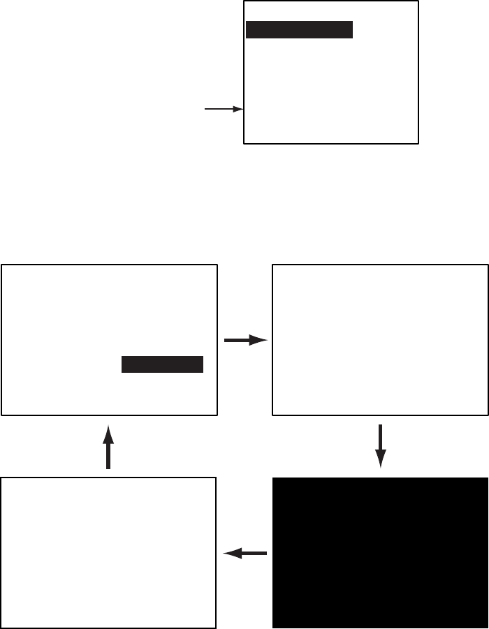
3. Use the CursorPad to choose MONITOR TEST and then press the [ENT]
key. The test program automatically proceeds in the sequence shown
below.
[MONITOR TEST]
PROG NO.:
2450021
-xx.xx
ROM :OK CONT :53
SDRAM:OK DIM : 4
PORT : --
KEY :
xx.xx = Program version no.
<LCD CHECK>
ALL ON 2 SEC.
ALL OFF 3 SEC.
PUSH KEY
QUIT[MENU] 3 TIMES
MONITOR TEST screens

2. MAINTENANCE, TROUBLESHOOTING
2-5
a) The first screen in the monitor test program sequence shows program no.,
results of ROM, RAM and I/O port (special test connector required,
otherwise
“- -“ appears), dimmer setting, and checks controls. The results of the
ROM and RAM check are shown as OK or NG (No Good). If NG appears
contact your dealer for advice. “CONT” indicates the number of times the
test has been executed consecutively.
b) After all devices and ports have been checked, the message “PUSH KEY”
appears, in reverse video. Press each key and arrows on the CursorPad
one by one. The pressed key or arrow’s name appears next to “KEY” if the
control is functioning normally.
c) After the controls have been checked (or there is no control pressed for a
few seconds), the LCD is checked. All LCD segments turn on for two
seconds and then go off for three seconds, and then the screen turns
black and then turns white.
d) The test is repeated.
4. To escape from the test, press the [MENU] key three times when PUSH
KEY is shown in reverse video.
2.4.2 Transponder test
The transponder test consists of two tests: memory test and internal GPS
receiver test.
Memory test
The memory can be checked for proper operation and the program number
displayed as follows:
1. Press the [MENU] key to open the main menu.
2. Use the CursorPad to choose DIAGNOSTIC and then press the [ENT] key.
3. Use the CursorPad to choose TRANSPONDER TEST and then press the
[ENT] key.
4. Use the CursorPad to choose MEMORY TEST and then press the [ENT]
key. The program no. is displayed and the ROM and RAM are checked.
The results of he ROM and RAM check are shown as OK or NG (No Good).
For any NG, contact your dealer for advice.
[MEMORY TEST]
PROGRAM NO.
2450018-xx.xx
MAIN ROM : OK
MAIN RAM : OK
SUB RAM : OK
xx.xx: Program Version No.
MEMORY TEST display
5. Press the [MENU] key several times to return to the DIAGNOSTIC
sub-menu.

2. MAINTENANCE, TROUBLESHOOTING
2-6
Internal GPS test
The internal GPS receiver can be checked for proper operation as follows:
1. Press the [MENU] key to open the main menu.
2. Use the CursorPad to choose DIAGNOSTIC and then press the [ENT] key.
3. Use the CursorPad to choose TRANSPONDER TEST and then press the
[ENT] key.
4. Use the CursorPad to choose GPS TEST and then press the [ENT] key to
start the test. The program no. and the test results appear as shown below.
OK: Normal
DATA BACKUP ERR: Data backup problem
GPS COMMUNICATION ERROR: Comm. error with internal GPS receiver
PARAMETER BACKUP ERR: Parameter backup problem
ROM ERROR, RAM ERROR
[GPS TEST]
PROGRAM NO.
485026xxxx
TEST: OK
xxxx: Program Version No.
GPS TEST display
5. Press the [MENU] key to escape.
2.4.3 Power on/off history
The PWR ON/OFF HISTORY log shows the date and time of the latest 30
power-ons and power-offs. If the interval between power-on and power-off is
less than 15 minutes those times are not shown.
1. Press the [MENU] key to open the main menu.
2. Use the CursorPad to choose DIAGNOSTIC and the press the [ENT] key.
3. Use the CursorPad to choose PWR ON/OFF HISTORY and then press the
[ENT] key.
Power turned on 17 May 2004
at 05:35:54
[PWR ON/OFF HISTORY]
PWR-ON 17/MAY/2004
05:35:54
PWR-OFF 17/MAY/2004
04:56:57
PWR-ON 17/MAY/2004
04:06:34
QUIT[MENU]
PWR ON/OFF HISTORY log
4. Use ▼ or ▲ to scroll the log.
5. Press the [MENU] key to return to the DIAGNOSTIC sub-menu.

2. MAINTENANCE, TROUBLESHOOTING
2-7
2.4.4 Tx on/off history
The TX ON/OFF HISTORY log shows the date and time of the latest 30
transmissions. In special cases, on and off times of 0 W transmission my also
be shown.
1. Press the [MENU] key to open the main menu.
2. Use the CursorPad to choose DIAGNOSTIC and the press the [ENT] key.
3. Use the CursorPad to choose TX ON/OFF HISTORY and then press the
[ENT] key.
Tx at 17 May 2004
at 05:35:54
[TX ON/OFF HISTORY]
TX-ON 17/MAY/2004
05:35:54
TX-OFF 17/MAY/2004
04:34:57
TX-ON 17/MAY/2004
04:33:57
PAGE 1/2 :[
] QUIT[MENU]
TX ON/OFF HISTORY log
4. Use ▼ or ▲ to scroll the log.
5. Press the [MENU] key to return to the DIAGNOSTIC sub-menu.

2. MAINTENANCE, TROUBLESHOOTING
2-8
2.5 Alarm Status
The alarm status log shows the latest 25 dates and times alarms were violated.
1. At the plotter display, press the [DISP] key four times to show the ALARM
STATUS display.
[ALARM STATUS]
EPFS 7/MAY 4:32:16
L/L 7/MAY 4:02:01
SOG 7/MAY 2:34:54
COG 6/MAY 7:09:32
HDG 3/MAY 8:00:21
ROT 19/APR 9:05:22
Alarm name,
date and time
of alarm
ALARM STATUS display
2. Use ▼ or ▲ to scroll the log.
Alarm statuses and their meanings
Alarm Status
Indication Meaning
TX TX malfunction
ANT Antenna VSWR trouble. Continued operation possible.
CH1 TDMA RX1 Board trouble. TX stopped on corresponding TX
channel.
CH2 TDMA RX2 Board trouble. TX stopped on corresponding TX
channel.
CH70 DSC RX Board trouble, transmission stopped on CH70.
COG Invalid COG data
EPFS No data from external navigator. Continued operation
possible.
FAIL General system failure
HDG Invalid/nonexistent HDG data
L/L No L/L data
MKD Minimum input device failure
ROT Invalid ROT data
SOG Invalid SOG data

2. MAINTENANCE, TROUBLESHOOTING
2-9
2.6 Error Messages
The FA-150 displays the following error messages to alert you to invalid data,
etc.
Error messages and their meanings
Message Meaning
CAN’T DISPLAY INVALID DATA Invalid own ship position.
CAN’T DISPLAY OVER LAT85° Own ship’s latitude is higher than 85°.
COLLISION ALARM AIS target within set CPA/TCPA range.
COMMUNICATION ERROR No communication with transponder
ERROR REGIST Duplicate data in overlapping sea areas.
GPS COMMUNICATION ERROR Communication error with internal GPS, shown at
internal GPS self test.
NO MESSAGE No TX message when you attempted to send a
message.
NO SEL Attempted to see detailed data for a target which has
no data.
OUT OF RANGE!: CH-A:IT
DOESN’T EXIST
Invalid CH-NO. A entered on the CHANNEL EDIT
sub-menu.
OUT OF RANGE!: CH-B:IT
DOESN’T EXIST
Invalid CH-NO. B entered on the CHANNEL EDIT
sub-menu.
OUT OF RANGE!: CPA:0-6.00 Invalid CPA range entered.
OUT OF RANGE!: CREW:0-8191 Invalid crew no. entered in SET CREW&TYPE.
OUT OF RANGE!: DAY Invalid day entered in SET DESTINATION.
OUT OF RANGE!: DRAUGHT:0-25.5 Invalid draught entered in SET SHIP DATA.
OUT OF RANGE!: HOUR:0-23 Invalid hour entered in SET DESTINATION.
OUT OF RANGE!: MINUTE:0-59 Invalid minute entered in SET DESTINATION.
OUT OF RANGE!: MONTH:1-12 Invalid month entered in SET DESTINATION.
OUT OF RANGE!: ROT CYCLE:1-10 Invalid ROT entered in SET I/O menu.
OUT OF RANGE!: TCPA:1-60 Invalid TCPA entered.
OUT OF RANGE!: YEAR Invalid year entered in SET DESTINATION.
OUT OF RANGE!: ZONE:1-8 Invalid ZONE entered on the CHANNEL EDIT
sub-menu.
SEND MESSAGE UNSUCCESSFUL Message could not be sent.
TRANSPONDER WAS REBOOTED Transponder was rebooted.
2. MAINTENANCE, TROUBLESHOOTING
2-10
Note: Detection of RX malfunction
1) Detection of TDMA RX malfunction
Frequency error
PLL chip on receiver board generates lock or unlock signal for
synthesizer.
MPU watches and sets status flag which reflects data of ALR sentence.
ID 003 for RX1, ID 004 for RX2
2) Detection of DSC RX malfunction
General error
DSC Error (ID: 005) will happen in case of DSC MPU could not receive
format specifier of the data from DSC amplifier unless RSSI exists more
than 90 seconds.
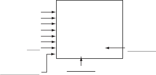
2. MAINTENANCE, TROUBLESHOOTING
2-11
2.7 GPS Monitor
The GPS monitor display shows information about the built-in GPS receiver,
including position, speed over ground, course over ground, date, time, mode
position accuracy, position-fixing status and RAIM status.
1. Press the [MENU] key to open the menu.
2. Use the CursorPad to choose INTERNAL GPS and then press the [ENT]
key.
[INTERNAL GPS]
LAT : 34
°
44.4639'N
LON : 135
°
21.2395'E
SOG : 10.9 kt
COG : 98.9
°
UTC : 16/MAY/2004
6:29:02
DGPS STS: 3D
PA: H RAIM: USED
Latitude position
Longitude position
Speed over ground
Course over ground
Date
Time
Mode
DGPS
GPS
NO FIX
Position Accuracy
H: High, L: Low
STS (Status)
2D:
2D GPS position fix
3D: 3D GPS position fix
D2D: 2D DGPS position fix
D3D: 3D DGPS position fix
DOP: HDOP larger than 4 in 2D fix,
or PDOP larger than 6 in 3D fix
RAIM Status*
(Receiver Autonomous
Integrity Monitoring)
USED or UNUSED
*RAIM: Technique whereby the GPS receiver verifies the integrity
of the signals received from the GPS constellation.
Internal GPS monitor
4. Press the [MENU] key several times to close the display and return to the
plotter display.
2. MAINTENANCE, TROUBLESHOOTING
2-12
2.8 Displaying Sensor Status
The SENSOR STATUS screen shows sensor status.
1. Press the [MENU] key.
2. Use the CursorPad to choose SENSOR STATUS and then press the [ENT]
key.
[SENSOR STATUS]
UTC CLOCK LOST
Sensor status message
SENSOR STATUS screen
3. Press the [MENU] key to close the display.
Sensor status messages and their meanings
Sensor Status Message Meaning
CH MANAGEMENT Channel changed
EXTRL DGNSS Using external DGNSS
EXTRL DGNSS BEACON Using external DGNSS beacon
EXTRL GNSS Using external GNSS
EXTRL SOG/COG Using external SOG/COG
HDT VALID Heading data normal
INTRL DGNSS Using internal DGNSS
INTRL GNSS Using internal GNSS
INTRL SOG/COG Using internal SOG/COG
OTHER ROT Using external ROT
ROT VALID ROT data normal
UTC CLOCK LOST No UTC time

2. MAINTENANCE, TROUBLESHOOTING
2-13
2.9 Restoring Default Settings
You may clear all or specific settings to start afresh with default settings. When
all data is cleared, the default settings for all items in the INIT SETTING and
SYSTEM SETTINGS sub-menus are restored. GPS data is also cleared;
however, MMSI and IMO numbers, ship’s name and call sign are not cleared.
1. Press the [MENU] key to open the menu.
2. Use the CursorPad to choose DIAGNOSTIC and then press the [ENT] key.
3. Use the CursorPad to choose MEMORY CLEAR and then press the [ENT]
key.
QUIT[MENU]
[MEMORY CLEAR]
MONITOR CLEAR
SET USER DEFAULT
GPS COLD START
MEMORY CLEAR sub-menu
4. Use the CursorPad to choose MONITOR CLEAR, SET USER DEFAULT or
GPS COLD START as appropriate and then press the [ENT] key.
DISPLAY CLEAR: Restore default settings for dimmer, contrast
CPA/TCPA, key beep, audible alarm, and received
message alarm.
USER DEFAULT: Clears all user settings except MMSI No., IMO No.,
ship’s name and call sign.
GPS COLD START: Clears GPS Almanac to receive latest Almanac.
MONITOR CLEAR.
ARE YOU SURE?
YES NO
SET USER DEFAULT.
ARE YOU SURE?
YES NO
GPS COLD START.
ARE YOU SURE?
YES NO
MONITOR CLEAR USER DEFAULT GPS COLD START
Confirmation screens for memory clear
3. Press ◄ to choose YES and then press the [ENT] key.
2. MAINTENANCE, TROUBLESHOOTING
2-14
This page intentionally left blank.

A
P-1
APPENDIX
Menu Tree
The example screens shown in this manual may not match the screens you see on your
display. The screen you see depends on your system configuration and equipment settings.
[MENU] key
CREATE MSG
TX LOG
RX LOG
SET MSG TYPE
SET MSG
SEND MSG
ADRS TYPE (BROAD CAST, ADRS CAST)
MMSI
MSG TYPE (NORMAL, SAFETY)
CHANNEL (ALTERNATE, BOTH A & B, A, B)
MSG
SENSOR STATUS (Display sensor status.)
INTERNAL GPS (Displays data about internal GPS receiver.)
CPA (0.0 - 6.00,
1
(nm))
TCPA (0 - 60,
10
(min))
ALARM MODE (ON, OFF)
ALARM BUZZER (ON, OFF)
KEY BEEP (
ON
, OFF)
ALARM BUZZER (
ON
, OFF)
DISP RCVD MSG (
ALL
, ABM, OFF)
RCVD MSG BUZZ (
ON
, OFF)
LR MODE (
AUTO
, MANUAL)
CPA/TCPA ALARM
(Continued on next page)
USER SETTINGS
INITIAL
SETTINGS SET INT ANT POS. A (
0
-511 (m))
B (
0
-511 (m))
C (
0
-63 (m))
D (
0
-63 (m))
SET MMSI
SET EXT ANT POS.
SET SHIP TYPE
SET IO PORT
A (
0
-511 (m))
B (
0
-511 (m))
C (
0
-63 (m))
D (
0
-63 (m))
COM1
COM2
COM3 (Same items,options and default settings as COM2.)
SENSOR PORT
COM4 (1,
2
, 3)
COM5 (1, 2,
3
)
COM6 (
1
, 2, 3)
MODE (
LONG RANGE
, EXT DISP, DISABLE)
SPEED (IEC61162-1,
IEC61162-2
)
MODE (
EXT DISP
, DISABLE)
SPEED (IEC61162-1,
IEC61162-2
)
COM4 (
IEC61162-1
, IEC61162-2)
COM5 (
IEC61162-1
, IEC61162-2)
COM6 (AD-10,
IEC61162-1
, IEC61162-2)
MODE (
STANDARD
, MONITOR, SERVICE, BEACON, DISABLE)
SPEED (4800BPS, 9600BPS, 19.2KBPS,
38.4KBPS
)
PC
ROT TIME (
01
- 10 (sec))
PRIORITY L/L, COG, SOG
HDG (Same choices as L/L, COG, SOG.)
ROT (Same choices as L/L, COG, SOG.)
Note: The INITIAL SETTINGS sub menu
shown here is the one accessed with a
password, which permits changing of
settings. It may also be accessed without
a password, in which case "SET" in a menu
title is replaced with "VIEW" and settings
cannot be changed.
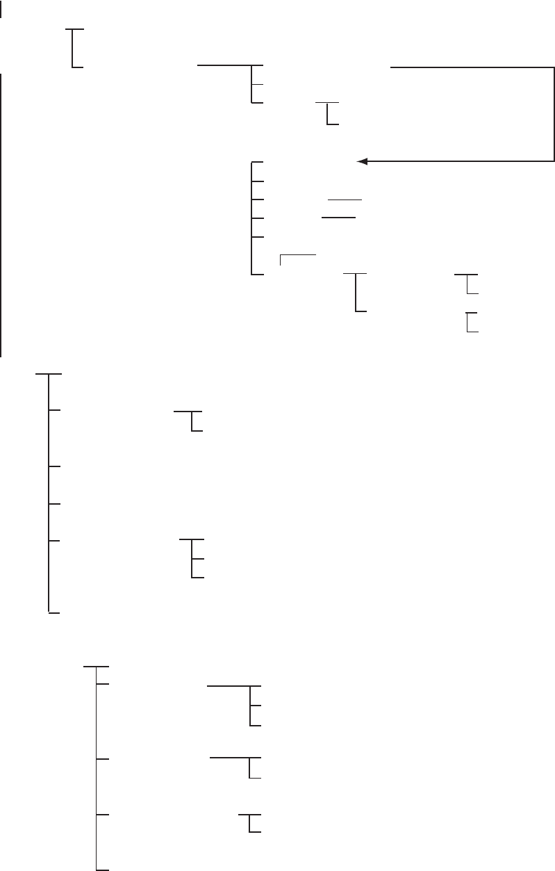
APPENDIX
AP-2
(Continued from previous page)
DIAG-
NOSTIC
MONITOR TEST (Displays program no.; checks ROM, RAM, LCD, controls.)
TRANSPONDER
TEST
PWR ON/OFFHISTORY (Log for time of equipment power on and off.)
TX ON/OFFHISTORY (Log for time of equipment transmission on and off.)
MEMORY CLEAR
FOR SERVICE (For service technician. Not accessible by user.)
MEMORY TEST (Displays program no.; checks ROM and RAM.)
GPS TEST (Display program no. and checks internal GPS receiver.)
MONITOR CLEAR (YES,
NO
)
SET USER DEFAULT (YES,
NO
)
GPS COLD START (YES,
NO
)
NAV STATUS (00-15)
DESTINATION
ARRIVAL TIME
CARGO TYPE & CREW
DRAUGHT (
0.0
- 25.5)
DATE
TIME
SELECT
EDIT
DELETE
[NAV STATUS]
key
CREW (
0
-8191)
TYPE NO. (10-99,
70
. See page 1-8.)
VIEW CHANNEL (View power and channel settings of channel in use.)
EDIT CHANNEL
CHANNEL
SETTINGS
FROM MMSI
POWER (1W, 2W, 12.5W)
CH NO. CH-A, CH-B
MODE CH-A, CH-B
ZONE (
1
-8 (nm))
Press [ENT] key to display.
Press [ENT] key to display.
CH AREA RIGHT TOP
LEFT BOTTOM
LAT
LON
LAT
LON
SELECT NO. (
0
-9)
TIME
FROM MMSI (HIGH SEA, MMSI, EMPTY)
TYPE (HIGH SEA, AIS, PI, DSC,
MANUAL, EMPTY)
APPENDIX
A
P-3
Parts List
This equipment contains complex modules in which fault diagnosis and repair down to
component level are not practical (IMO A.694(17)/8.3.1). Only some discrete components
are used. FURUNO Electric Co., Ltd. believes identifying these components is of no value
for shipboard maintenance; therefore, they are not listed in the manual. Major modules
can be located on the parts location photo on page AP-4 and AP-5.
F U R U N O
Model FA-150
Unit MONITOR UNIT,
TRANSPONDER UNIT
ELECTRICAL PARTS LIST
Blk.No.
TYPE, NAME LOCATION
PRINTED CIRCUIT BOARD
24P0062, CPU MONITOR UNIT
24P0034, DSC TRANSPONDER UNIT
24P0043, GPSTB TRANSPONDER UNIT
24P0035, MAIN TRANSPONDER UNIT
24P0036, MOT TRANSPONDER UNIT
24P0037, PWR TRANSPONDER UNIT
24P0033A, RX1 TRANSPONDER UNIT
24P0033B, RX2 TRANSPONDER UNIT
24P0032, TX TRANSPONDER UNIT
GN-8093, GPS RECEIVER TRANSPONDER UNIT
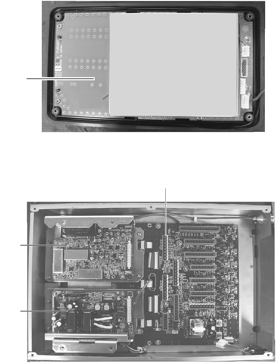
APPENDIX
AP-4
Parts Location
Monitor unit
CPU Board
24P0062
Monitor unit, rear cover opened
Transponder unit
TX Board
24P0032
PWR Board
24P0037
MOT Board
24P0036
Transponder unit, top cover removed
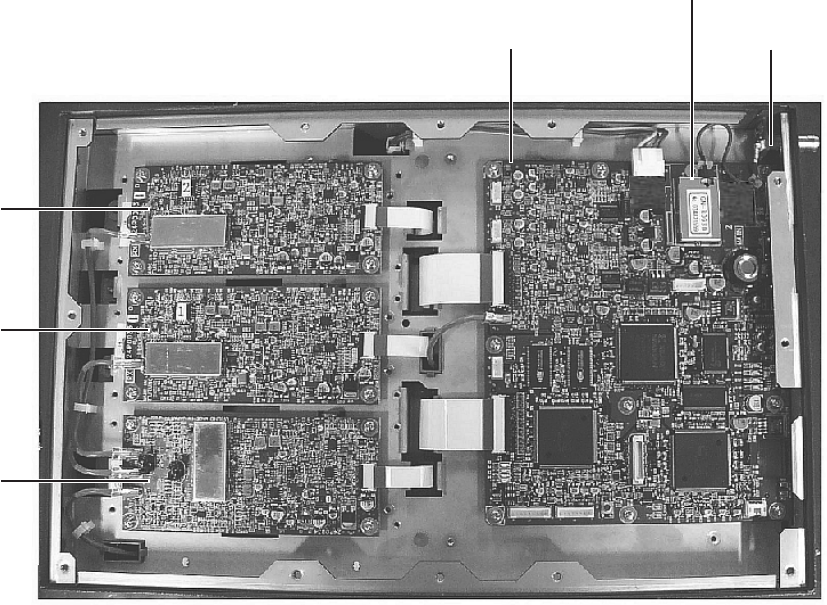
APPENDIX
A
P-5
DSC Board
24P0033
RX1 Board
24P0033
RX2 Board
24P0033
MAIN Board
24P0035 GPSTB Board
24P0043
GPS Receiver
GN-8093
Transponder unit, bottom cover removed

APPENDIX
AP-6
Digital Interface (IEC 61162-1 Edition 2, IEC 61162-2)
Sentence data
Input sentences
ABM, ACA, ACK, AIR, BBM, DTM, GBS, GGA, GLL, GNS, HDT, LRF, LRI, OSD, RMC,
ROT, SSD, VBW, VSD, VTG
Output sentences
ABK, ACA, ACS, ALR, LRF, LR1, LR2, LR3, TXT, VDM, VDO
Transmission interval
ABK: With each event
ACA, ACS: At RX
ALR: 30 s during alarm, 2 min normally no alarm
LRF, LR1, LR2, LR3: At RX
TXT: Each update
VDM: At RX
VDO: 1 s
Load requirements as listener
Isolation: Provided
Input Impedance: Input Impedance: 110 ohms (130K ohms without jumper plug)
Max. Voltage: ±14 V to GNDiso
Threshold: ±0.2 V (A-B)
Output drive capability
Differential driver output
R=50 ohm 2 v min.
R=27 ohm 1.5 V min.
Driver short-circuit current
60 mA min. 150 mA max.
Data transmission
Data is transmitted in serial asynchronous form in accordance with the standard
referenced in 2.1 of IEC 61162-1/2. The first bit is a start bit and is followed by data bits,
least-significant-bit as illustrated below.
The following parameters are used:
Baud rate: 38.4 Kbps /4800 bps
Data bits: 8 (D7 = 0), parity none
Stop bits: 1
D0 D1 D2 D3 D4 D5 D6 D7
Start
bit
Stop
bit
Data bits
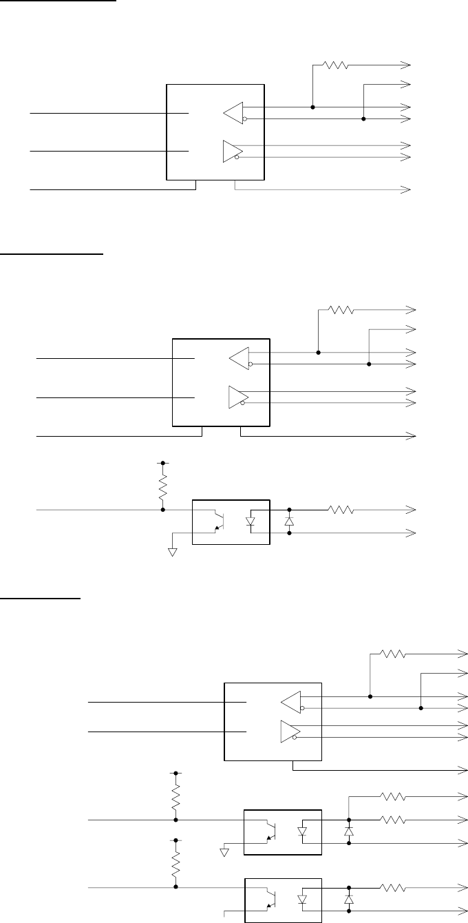
APPENDIX
A
P-7
Serial interface I/O circuit
COM1, 2, 3 port
Baud rate selectable from 4800 and 38400 (bps).
LTC1535C
COM1_RD_B
COM1_RD_A
COM1_TD_B
COM1_TD_A
GND_ISO
GND2GND
COM1_JP
COM1_JP
RD
TD
GND
110Ω
COM 4, 5 port
Baud rate selectable from 4800 and 38400 (bps).
LTC1535C
110Ω
GND2GND
TD
470Ω
PC400
COM4_JP
COM4_JP
COM4_2_RD_B
COM4_2_RD_A
COM4_TD_B
COM4_TD_A
GND_ISO
COM4_1_RD_H
COM4_1_RD_C
2.2kΩ
RD_2
GND
RD_1
COM6 port
Baud rate selectable from 4800 and 38400 (bps).
LTC1535C
110Ω
GND2
2_RD
TD
GND
220Ω
PC400
2.2kW
1_RD/A D_DATA
220Ω
PC400
AD_CLK
470Ω
2.2kW
COM6_JP
COM6_JP
COM6_2_RD_B
COM6_2_RD_A
COM6_TD_B
COM6_TD_A
GND_ISO
COM6_1_RD_H
AD_DATA_H
COM6_1_RD_C/AD_DATA_C
AD_CLK_H
AD_CLK_C
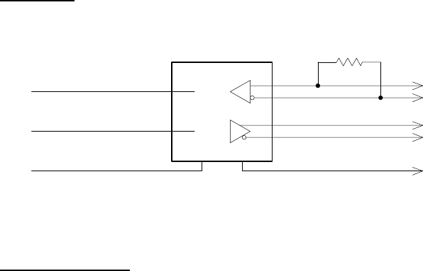
APPENDIX
AP-8
DISP port
Baud rate selectable from 4800 and 38400 (bps).
LTC1535C
GND2GND
RD
TD
GND
110Ω
DISP_RD_B
DISP_RD_A
DISP_TD_B
DISP_TD_A
GND_ISO
Sentence description
Input sentences
ABM - Addressed binary and safety related message
!--ABM,x,x,x,xxxxxxxxx,x,x.x,s--s,x*hh<CR><LF>
| | | | | | | | |
| | | | | | | | +--- 9
| | | | | | | +----- 8
| | | | | | +-------- 7
| | | | | +------------ 6
| | | | +--------------- 5
| | | +--------------------- 4
| | + --------------------------- 3
| +----------------------------- 2
+------------------------------- 1
1. Total number of sentences needed to transfer the message, 1 to 9
2. Message sentence number, 1 to 9
3. Message sequence identifier, 0 to 3
4. The MMSI of destination AIS unit for the ITU-R M.1371 message 6 or 12
5. AIS channel for broadcast of the radio message
6. VDL message number(6 or 12), see ITU-R M.1371
7. Encapsulated data
8. Number of fill-bits, 0 to 5
9. Checksum

APPENDIX
A
P-9
ACA - AIS regional channel assignment message
$--ACA,x,IIII.I, a,yyyyy.y,a,IIII.I,a,yyyyy.y,a,x,xxxx,x,xxxx,x,x,x,a,x,hhmmss.s*hh<CR><LF>
1. Sequence number, 0 to 9
2. Region Northeast corner latitude - N/S
3. Region Northeast corner longitude - E/W
4. Region Southwest corner latitude - N/S
5. Region Southwest corner longitude - E/W
6. Transition Zone Size
7. Channel A
8. Channel A bandwidth
9. Channel B
10. Channel B bandwidth
11. Tx/Rx mode control
12. Power level control
13. Not used
14. In-use flag
15. Time of in-used change
15
14
13
12
11
10
9
8
7
6
5
4
3
2
1
ACK - Acknowledge alarm
$--ACK,xxx*hh<CR><LF>
| +--------------------- 2
+------------------------ 1
1. Local alarm number(identifier)
2. Checksum
APPENDIX
AP-10
AIR - AIS interrogation request
$--AIR,xxxxxxxxx,x.x,x,x.x,x,xxxxxxxxx,x.x,x*hh<CR><LF>
| | | | | | | | |
| | | | | | | | +--- 9
| | | | | | | +----- 8
| | | | | | +-------- 7
| | | | | +--------------- 6
| | | | +--------------------- 5
| | | +------------------------ 4
| | +--------------------------- 3
| +------------------------------ 2
+------------------------------------- 1
1. MMSI of interrogated station 1
2. ITU-R M.1371 message requested from station 1
3. Message sub-section
4. Number of second message requested from station 1
5. Message sub-section
6. MMSI of interrogated station 2
7. Number of message requested from station 2
8. Message data sub-section
9. Checksum
BBM - UAIS broadcast binary message.
!--BBM,x,x,x,x,x.x,s--s,x*hh<CR><LF>
| | | | | | | |
| | | | | | | +--- 8
| | | | | | +------ 7
| | | | | +--------- 6
| | | | +------------- 5
| | | +---------------- 4
| | +------------------ 3
| +-------------------- 2
+---------------------- 1
1. Total number of sentences needed to transfer the message, 1 to 9
2. Message sentence number, 1 to 9
3. Sequential Message identifier, 0 to 9
4. AIS channel for broadcast of the radio message
5. VDL message number(8 or 14), see ITU-R M.1371
6. Binary data
7. Number of fill-bits, 0 to 5
8. Checksum
APPENDIX
A
P-11
DTM - Datum reference
$--DTM,ccc,a,x.x,a,x.x,a,x.x,ccc*hh<CR><LF>
| | | | | | | | |
| | | | | | | | +--- 7
| | | | | | | +------ 6
| | | | | | +---------- 5
| | | | +---+------------- 4
| | +---+------------------- 3
| +------------------------- 2
+---------------------------- 1
1. Local datum W84 - WGS84
W72 - WGS72
S85 - SGS85
P90 - PE90
999 - User defined
IHO datum code
2. Note used
3. Lat offset, min, N/S
4. Lon offset, min, E/W
5. Not used
6. Reference dattum W84 - WGS84
W72 - WGS72
S85 - SGS85
P90 - PE90
7. Checksum
GBS - GNSS satellite fault detection
$--GBS,hhmmss.ss,x.x,x.x,x.x,xx,x.x,x.x,x.x*hh<CR><LF>
| | | | | | | | |
| | | | | | | | +--------- 9
| | | | | | | +------------ 8
| | | | | | +---------------- 7
| | | | | +-------------------- 6
| | | | +----------------------- 5
| | | +--------------------------- 4
| | +------------------------------- 3
| +----------------------------------- 2
+------------------------------------------- 1
1. Not used
2. Expected error in latitude
3. Expected error in longitude
4. Not used
5. Not used
6. Not used
7. Not used
8. Not used
9. Checksum
APPENDIX
AP-12
GGA - Global positioning system (GPS) fix data
$--GGA,hhmmss.ss,llll.ll,a,yyyyy.yy,a,x,xx,x.x,x.x,M,x.x,M,x.x,xxxx*hh<CR><LF>
| | | | | | | | | | | | | | |
| | | | | | | | | | | | | | +-- 11
| | | | | | | | | | | | | +---- 10
| | | | | | | | | | | | +--------- 9
| | | | | | | | | | +---+------------ 8
| | | | | | | | +---+------------------ 7
| | | | | | | +------------------------- 6
| | | | | | +---------------------------- 5
| | | | | +------------------------------- 4
| | | +----+--------------------------------- 3
| +---+--------------------------------------------- 2
+------------------------------------------------------------- 1
1. Not used
2. Latitude, N/S
3. Longitude, E/W
4. GPS quality indicator
5. Not used
6. Not used
7. Not used
8. Not used
9. Not used
10. Not used
11. Checksum
GLL - Geographic position - latitude/longitude
$--GLL,llll.ll,a,yyyyy.yy,a,hhmmss.ss,A,a*hh<CR><LF>
| | | | | | | |
| | | | | | | +------- 6
| | | | | | +--------- 5
| | | | | +----------- 4
| | | | +---------------- 3
| | +------+----------------------- 2
+--+----------------------------------- 1
1. Latitude, N/S
2. Longitude, E/W
3. Not used
4. Status: A=data valid, V=data invalid
5. Mode indicator(see note)
6. Checksum
NOTE Positioning system Mode indicator:
A = Autonomous
D = Differential
E = estimated(dead reckoning)
M = Manual input
S = Simulator
N = Data not valid
The Mode indicator field supplements the Status field. The Status field shall be
set to V=invalid for all values of Operating Mode except for A=Autonomous and
D=Differential. The positioning system Mode indicator and Status field shall not
be null fields.
APPENDIX
A
P-13
GNS - GNSS fixed data
$--GNS,hhmmss.ss,llll.ll,a,yyyyy.yy,a,c--c,xx,x.x,x.x,x.x,x.x,x.x*hh<CR><LF>
| | | | | | | | | | | | |
| | | | | | | | | | | | +--- 11
| | | | | | | | | | | +------ 10
| | | | | | | | | | +---------- 9
| | | | | | | | | +-------------- 8
| | | | | | | | +------------------ 7
| | | | | | | +---------------------- 6
| | | | | | +------------------------- 5
| | | | | +------------------------------ 4
| | | +-------+--------------------------------- 3
| +--+--------------------------------------------- 2
+------------------------------------------------------------- 1
1. Not used
2. Latitude, N/S
3. Longitude, E/W
4. Mode indicator
5. Not used
6. Not used
7. Not used
8. Not used
9. Not used
10. Not used
11. Checksum
HDT - Heading - true
$--HDT,x.x,T*hh<CR><LF>
| | |
| | +--------- 2
+----+----------- 1
1. Heading, degrees true
2. Checksum
LRF - Long-range function
$--LRF,x,xxxxxxxxx,c--c,c--c,c--c*hh<CR><LF>
| | | | | |
| | | | | +--6
| | | +--- 5
| | | +------ 4
| | +----------- 3
| +------------------- 2
+------------------------- 1
1. Sequence number, 0 to 9
2. MMSI of requestor
3. Name of requestor, 1 to 20 characters
4. Function request, 1 to 26 characters
5. Function reply status
6. Checksum
APPENDIX
AP-14
LRI - Long-range interrogation
$--LRI,x,a,xxxxxxxxx,xxxxxxxxx,llll.ll,a,yyyyy.yy,a,llll.ll,a,yyyyy.yy,a*hh<CR><LF>
| | | | | | | | | | | | |
| | | | | | | | | | | | +--- 9
| | | | | | | | | | +---+----- 8
| | | | | | | | +--+---------------- 7
| | | | | | +---+-------------------------- 6
| | | | +--+------------------------------------- 5
| | | +--------------------------------------------------- 4
| | +------------------------------------------------------------- 3
| +------------------------------------------------------------------- 2
+--------------------------------------------------------------------- 1
1. Sequence number, 0 to 9
2. Control Flag
3. MMSI of requestor
4. MMSI of destination
5. Latitude - N/S(north-east coordinate)
6. Longitude - E/W(north-east coordinate)
7. Latitude - N/S(south-west coordinate)
8. Longitude - E/W(south-west coordinate)
9. Checksum
OSD - Own ship data
$--OSD,x.x,A,x.x,a,x.x,a,x.x,x.x,a*hh<CR><LF>
| | | | | | | | | |
| | | | | | | | | +--------- 10
| | | | | | | | +----------- 9
| | | | | | | +-------------- 8
| | | | | | +------------------ 7
| | | | | +--------------------- 6
| | | | +------------------------ 5
| | | +--------------------------- 4
| | +------------------------------ 3
| +--------------------------------- 2
+------------------------------------ 1
1. Heading, degrees true
2. Heading status: A=data valid, V=data invalid
3. Vessel course, degrees true
4. Course reference, B/M/W/R/P(see note)
5. Vessel speed
6. Speed reference, B/M/W/R/P(see note)
7. Not used
8. Not used
9. Speed units, K(km/h) / N(Knots) / S(statute miles/h)
10. Checksum
NOTES - Reference systems(speed/course):
B = bottom tracking log
M = manually entered
W = water referenced
R = radar tracking(of fixed target)
P = positioning system ground reference
APPENDIX
A
P-15
RMC - Recommended minimum specific GPS/TRANSIT data
$--RMC,hhmmss.ss,A,llll.ll,a,yyyyy.yy,a,x.x,x.x,xxxxxx,x.x,a,a*hh<CR><LF>
| | | | | | | | | | | | |
| | | | | | | | | | | | +--- 10
| | | | | | | | | | | +----- 9
| | | | | | | | | +--+------- 8
| | | | | | | | +--------------- 7
| | | | | | | +--------------------- 6
| | | | | | +------------------------- 5
| | | | +---+---------------------------- 4
| | +---+---------------------------------------- 3
| +--------------------------------------------------- 2
+---------------------------------------------------------- 1
1. UTC of position fix
2. Status: A=data valid, V=navigation receiver warning
3. Latitude, N/S
4. Longitude, E/W
5. Speed over ground, knots
6. Course over ground, degrees true
7. Date: dd/mm/yy
8. Not used
9. Not used
10. Checksum
NOTE Positioning system Mode indicator:
A = Autonomous
D = Differential
E = estimated(dead reckoning)
M = Manual input
S = Simulator
N = Data not valid
The Mode indicator field supplements the Status field. The Status field
shall be set to V=invalid for all values of Operating Mode except for
A=Autonomous and D=Differential. The positioning system Mode indicator
and Status field shall not be null fields.
ROT - Rate of turn
$--ROT,x.x,A*hh<CR><LF>
| | |
| | +--- 3
| +----- 2
+-------- 1
1. Rate of turn, deg/min, "-"=bow turns to port
2. Status: A=data valid, V=data invalid
3. Checksum
APPENDIX
AP-16
SSD - UAIS ship static data
$--SSD,c--c,c--c,xxx,xxx,xx,xx,c, aa*hh<CR><LF>
| | | | | | | | |
| | | | | | | | +--9
| | | | | | | +--- 8
| | | | | | +----- 7
| | | | | +------- 6
| | | | +---------- 5
| | | +-------------- 4
| | +------------------ 3
| +---------------------- 2
+--------------------------- 1
1. Ship's Call Sign, 1 to 7 characters
2. Ship's Name, 1 to 20 characters
3. Pos. ref. point distance, "A," from bow, 0 to 511 Meters
4. Pos. ref. point distance, "B," from stern, 0 to 511 Meters
5. Pos. ref. point distance, "C," from port beam, 0 to 63 Meters
6. Pos. ref. point distance, "D," from starboard beam, 0 to 63 Meters
7. DTE indicator flag
8. Not used
9. Checksum
VBW - Dual ground/water speed
$--VBW,x.x,x.x,A,x.x,x.x,A,x.x,A,x.x,A*hh<CR><LF>
| | | | | | | | | | |
| | | | | | | | | | +--- 11
| | | | | | | | | +----- 10
| | | | | | | | +-------- 9
| | | | | | | +----------- 8
| | | | | | +-------------- 7
| | | | | +----------------- 6
| | | | +-------------------- 5
| | | +------------------------ 4
| | +--------------------------- 3
| +------------------------------ 2
+---------------------------------- 1
1. Not used
2. Not used
3. Not used
4. Longitudinal ground speed, knots
5. Transverse ground speed, knots
6. Status: ground speed, A=data valid V=data invalid
7. Not used
8. Not used
9. Not used
10. Not used
11. Checksum
APPENDIX
A
P-17
VSD - UAIS voyage static data
$--VSD,x.x,x.x,x.x,c--c,hhmmss.ss,xx,xx,x.x,x.x*hh<CR><LF>
| | | | | | | | | |
| | | | | | | | | +--- 10
| | | | | | | | +------ 9
| | | | | | | +---------- 8
| | | | | | +------------- 7
| | | | | +---------------- 6
| | | | +----------------------- 5
| | | +------------------------------ 4
| | +----------------------------------- 3
| +--------------------------------------- 2
+------------------------------------------- 1
1. Type of ship and cargo category, 0 to 255
2. Maximum present static draught, 0 to 25.5 Meters
3. Persons on-board, 0 to 8191
4. Destination, 1-20 characters
5. Estimated UTC of arrival at destination
6. Estimated day of arrival at destination, 00 to 31(UTC)
7. Estimated month of arrival at destination, 00 to 12(UTC)
8. Navigational status, 0 to 15
9. Regional application flags, 0 to 15
10. Checksum
VTG - Course over ground and ground speed
$--VTG,x.x,T,x.x,M,x.x,N,x.x,K,a*hh<CR><LF>
| | | | | | | | | |
| | | | | | | | | +------- 6
| | | | | | | | +--------- 5
| | | | | | +---+----------- 4
| | | | +--+----------------- 3
| | +--+----------------------- 2
+-+----------------------------- 1
1. Course over ground, degrees true
2. Not used
3. Speed over ground, knots
4. Speed over ground, km/h
5. Mode indicator(see note)
6. Checksum
NOTE Positioning system Mode indicator:
A = Autonomous
D = Differential
E = estimated(dead reckoning)
M = Manual input
S = Simulator
N = Data not valid
The positioning system Mode indicator field shall not be a null field.

APPENDIX
AP-18
Output sentences
ABK - UAIS addressed and binary broadcast acknowledgement
$--ABK,xxxxxxxxx,a,x.x,x,x*hh<CR><LF>
| | | | | |
| | | | | +--- 6
| | | | +----- 5
| | | +------- 4
| | +---------- 3
| +------------- 2
+------------------- 1
1. MMSI of the addressed AIS unit
2. AIS channel of reception
3. Message type
4. Message sequence number
5. Type of acknowledgement
6. Checksum
ACA - See “Input sentences.”
ACS - Channel management information source
$--ACS,x,xxxxxxxxx,hhmmss.ss,xx,xx,xxxx*hh<CR><LF>
1. Sequence number, 0 to 9
2. MMSI of originator
3. UTC at receipt of regional operating settings
4. UTC day, 01- to 31
5. UTC month, 01 to 12
6. UTC year
6
5
4
3
2
1
ALR - Set alarm state
$--ALR,hhmmss.ss,xxx,A,A,c--c*hh<CR><LF>
| | | | | |
| | | | | +------------- 6
| | | | +----------------- 5
| | | +-------------------- 4
| | +---------------------- 3
| +------------------------- 2
+--------------------------------- 1
1. Time of alarm condition change, UTC
2. Local alarm number(identifier)
3. Alarm condition(A=threshold exceeded, V=not exceeded)
4. Alarm's acknowledge state, A=acknowledged V=unacknowledged
5. Alarm's description text
6. Checksum
APPENDIX
A
P-19
LRF - See “Input sentences.”
LR1 - Long-range reply with destination for function request “A”
$--LR1,x,xxxxxxxxx,xxxxxxxxx,c--c,c--c,xxxxxxxxx*hh<CR><LF>
| | | | | | |
| | | | | | +---- 7
| | | | | +---------- 6
| | | | +----------------- 5
| | | +---------------------- 4
| | +------------------------------ 3
| +---------------------------------------- 2
+---------------------------------------------- 1
1. Sequence Number
2. MMSI of responder
3. MMSI of requestor(reply destination)
4. Ship's name, 1 to 20 characters
5. Call Sign, 1 to 7 characters
6. IMO Number, 9-digit number
7. Checksum
LR2 - Long-range reply for function requests “B, C, E, and F”
$--LR2,x,xxxxxxxxx,xxxxxxxx,hhmmss.ss,llll.ll,a,yyyyy.yy,a,x.x,T,x.x,N*hh<CR><LF>
| | | | | | | | | | | | |
| | | | | | | | | | | | +--- 9
| | | | | | | | | | +---+----- 8
| | | | | | | | +--+----------- 7
| | | | | | +----+----------------- 6
| | | | +---+---------------------------- 5
| | | +------------------------------------------ 4
| | +-------------------------------------------------- 3
| +----------------------------------------------------------- 2
+----------------------------------------------------------------- 1
1. Sequence Number
2. MMSI of responder
3. Date: ddmmyyyy
4. UTC of Position
5. Latitude - N/S
6. Longitude - E/W
7. Course over ground, degrees True
8. Speed over ground, Knots
9. Checksum
APPENDIX
AP-20
LR3 - Long-range reply for function requests “I, O, P, U and W”
$--LR3,x,xxxxxxxxx,c--c,xxxxxx,hhmmss.ss,x.x,x.x,x.x,x.x,x.x,x.x*hh<CR><LF>
| | | | | | | | | | | |
| | | | | | | | | | | +---- 12
| | | | | | | | | | +------- 11
| | | | | | | | | +---------- 10
| | | | | | | | +-------------- 9
| | | | | | | +------------------ 8
| | | | | | +--------------------- 7
| | | | | +------------------------- 6
| | | | +-------------------------------- 5
| | | +---------------------------------------- 4
| | +---------------------------------------------- 3
| +------------------------------------------------------ 2
+------------------------------------------------------------ 1
1. Sequence Number
2. MMSI of responder
3. Voyage destination, 1 to 20 characters
4. ETA Date: ddmmyy
5. ETA Time
6. Draught
7. Ship/cargo(ITU-R M.1371, Table 18)
8. Ship length
9. Ship breadth
10. Ship type(ITUR-R M.1371, Table 18)
11. Persons, 0 to 8191
12. Checksum
TXT - Text transmission
$--TXT,xx,xx,xx,c--c*hh<CR><LF>
| | | | | |
| | | | | +--- 5
| | | +--+----- 4
| | +---------- 3
| +------------- 2
+---------------- 1
1. Total number of message, 01 to 99
2. Message number, 01 to 99
3. Text identifier
4. Text Message
5. Checksum
APPENDIX
A
P-21
VDM - VHF data-link message
!--VDM,x,x,x,a,s--s,x*hh<CR><LF>
| | | | | | |
| | | | | | +--- 7
| | | | | +----- 6
| | | | +-------- 5
| | | +------------ 4
| | +-------------- 3
| +---------------- 2
+------------------ 1
1. Total number of sentences needed to transfer the message, 1 to 9
2. Message sentence number, 1 to 9
3. Sequential message identifier, 0 to 9
4. AIS channel
5. Encapsulated ITU-R M.1371 radio message
6. Number of fill-bits, 0 to 5
7. Checksum
VDO - UAIS VHF data-link own-vessel report
!--VDO,x,x,x,a,s--s,x*hh<CR><LF>
| | | | | | |
| | | | | | +--- 7
| | | | | +----- 6
| | | | +-------- 5
| | | +------------ 4
| | +-------------- 3
| +---------------- 2
+------------------ 1
1. Total number of sentences needed to transfer the message, 1 to 9
2. Message sentence number, 1 to 9
3. Sequential message identifier, 0 to 9
4. AIS channel
5. Encapsulated ITU-R M.1371 radio message
6. Number of fill-bits, 0 to 5
7. Checksum

APPENDIX
AP-22
VHF Channel List
VHF Channel List (International Mode)
Ch No. FREQUENCY Ch No. FREQUENCY Ch No. FREQUENCY Ch No. FREQUENCY Ch No. FREQUENCY Ch No. FREQUENCY Ch No. FREQUENCY Ch No. FREQUENCY
1001 156.0500 1060 156.0250 1201 156.0625 1260 156.0375 2001 160.6500 2060 160.6250 2201 160.6625 2260 160.6375
1002 156.1000 1061 156.0750 1202 156.1125 1261 156.0875 2002 160.7000 2061 160.6750 2202 160.7125 2261 160.6875
1003 156.1500 1062 156.1250 1203 156.1625 1262 156.1375 2003 160.7500 2062 160.7250 2203 160.7625 2262 160.7375
1004 156.2000 1063 156.1750 1204 156.2125 1263 156.1875 2004 160.8000 2063 160.7750 2204 160.8125 2263 160.7875
1005 156.2500 1064 156.2250 1205 156.2625 1264 156.2375 2005 160.8500 2064 160.8250 2205 160.8625 2264 160.8375
6 156.3000 1065 156.2750 1206 156.3125 1265 156.2875 2065 160.8750 2206 160.9125 2265 160.8875
1007 156.3500 1066 156.3250 1207 156.3625 1266 156.3375 2007 160.9500 2066 160.9250 2207 160.9625 2266 160.9375
8 156.4000 67 156.3750 208 156.4125 267 156.3875
9 156.4500 68 156.4250 209 156.4625 268 156.4375
10 156.5000 69 156.4750 210 156.5125 269 156.4875
11 156.5500 70 156.5250 211 156.5625 270 156.5375
12 156.6000 71 156.5750 212 156.6125 271 156.5875
13 156.6500 72 156.6250 213 156.6625 272 156.6375
14 156.7000 73 156.6750 214 156.7125 273 156.6875
15 156.7500 74 156.7250 215 156.7625 274 156.7375
16 156.8000 75 156.7750 216 156.8125 275 156.7875
17 156.8500 76 156.8250 217 156.8625 276 156.8375
1018 156.9000 77 156.8750 1218 156.9125 277 156.8875 2018 161.5000 2218 161.5125
1019 156.9500 1078 156.9250 1219 156.9625 1278 156.9375 2019 161.5500 2078 161.5250 2219 161.5625 2278 161.5375
1020 157.0000 1079 156.9750 1220 157.0125 1279 156.9875 2020 161.6000 2079 161.5750 2220 161.6125 2279 161.5875
1021 157.0500 1080 157.0250 1221 157.0625 1280 157.0375 2021 161.6500 2080 161.6250 2221 161.6625 2280 161.6375
1022 157.1000 1081 157.0750 1222 157.1125 1281 157.0875 2022 161.7000 2081 161.6750 2222 161.7125 2281 161.6875
1023 157.1500 1082 157.1250 1223 157.1625 1282 157.1375 2023 161.7500 2082 161.7250 2223 161.7625 2282 161.7375
1024 157.2000 1083 157.1750 1224 157.2125 1283 157.1875 2024 161.8000 2083 161.7750 2224 161.8125 2283 161.7875
1025 157.2500 1084 157.2250 1225 157.2625 1284 157.2375 2025 161.8500 2084 161.8250 2225 161.8625 2284 161.8375
1026 157.3000 1085 157.2750 1226 157.3125 1285 157.2875 2026 161.9000 2085 161.8750 2226 161.9125 2285 161.8875
1027 157.3500 1086 157.3250 1227 157.3625 1286 157.3375 2027 161.9500 2086 161.9250 2227 161.9625 2286 161.9375
1028 157.4000 1087 157.3750 1228 157.4125 1287 157.3875 2028 162.0000 2087 161.9750 2228 162.0125 2287 161.9875
1088 157.4250 2088 162.0250
FURUNO
FA-150
SP-1
SPECIFICATIONS OF THE UAIS TRANSPONDER FA-150
1. TRANSPONDER UNIT
1.1 TX/RX Frequency 156.025 MHz to 162.025 MHz
1.2 Output Power 1W/ 2 W/ 12.5 W within ±1.5 db, selectable
1.3 Impedance 50 ohms
1.4 DSC Receiver CH70 fixed, 156.525 MHz, G2B, 1200 bps
1.5 Band Width 25 kHz/ 12.5 kHz
2. MONITOR UNIT
2.1 Display 3.5-inch, monochrome LCD,
2.2 Display Size 60 (H) x 95 (W) mm,
2.3 No. of Dots 120 x 64 dots
2.4 Menu Target data/ Plotter/ Own data/ Set MSG/ Init Settings/
System Settings/ Diagnostics
3. GPS RECEIVER
3.1 Receiving Channels 12 channels parallel, 12 satellites tracking
3.2 Rx Frequency/ Rx Code 1575.42 MHz, C/A code
3.3 Position Fixing System All in view, 8-state Kalman filter
3.4 Position Accuracy Approx. 10 m, 95% of the time, (HDOP ≤ 4)
DGPS: approx. less than 5 m, 95% of the time
3.5 Tracking Velocity 900 kts
3.6 Position-fixing Time Warm start: 12 seconds, Cold start: 90 seconds
3.7 Position Update Interval 1 second
3.8 DGPS Data Receiving RTCM SC-104 Ver 2.1 formatted
4. INTERFACES
4.1 COM1 – COM3 IEC 61162-1(2000-07)/61162-2(1998-09)
Input: VSD, SSD, ABM, BBM, ACA, ACK, AIR, DTM, GBS, GGA, GLL,
GNS, HDT, LRF, LRI, OSD, RMC, ROT, VBW, VTG
Output: VDM, VDO, ABK, ACA, ALR, TXT, LR1, LR2, LR3, LRF, LRI
4.2 SENSOR (input) IEC 61162-1(2000-07)/61162-2(1998-09)
4.3 COM4 – 6 (input) DTM, GNS, GLL, GGA, RMC, VBW, VTG, OSD, HDT, GBS, ROT*
*: Any talker. Priority: GN>GP>GL>LC
4.4 DISP RS-422, for display unit, FURUNO proprietary format
4.5 External Beacon RS-232C (PC)
4.6 PC RS-232C
4.7 Alarm Contact closure
4.8 AD-10 AD-10 format
FURUNO
FA-150
SP-2
5. POWER SUPPLY
5.1 Monitor Unit 12-24 VDC
5.2 Transponder Unit 12-24 VDC: 7 A (Max.)
5.3 AC/DC Power Supply Unit PR-240 (option) 100-115/200-230 VAC, 1 phase, 50/60 Hz
6. ENVIRONMENTAL CONDITION
6.1 Ambient Temperature
GPS Antenna Unit: -25°C to +70°C
Other Units: -15°C to +55°C
6.2 Relative Humidity 95% at 40°C
6.3 Waterproof (IEC 61529)
Antenna Unit: IPX6
Other Units: IPX0
6.4 Vibration IEC 60945 ed.3
7. COATING COLOR
7.1 GPS Antenna Unit: N9.5
7.2 Other Units: 2.5GY5/1.5

IN-1
INDEX
A
Alarm status.................................................2-8
Alarm status display ..................................1-20
B
Breaker reset ...............................................2-2
Buzzer........................................................1-30
C
Channels
setting ....................................................1-27
viewing...................................................1-26
Contrast .......................................................1-2
Controls .......................................................1-1
CPA/TCPA ...................................................1-9
D
Dangerous (target) list...............................1-18
Diagnostics
GPS test (transponder) ...........................2-6
memory test (transponder)......................2-5
monitor unit test.......................................2-4
power on/off history .................................2-6
Tx on/off history .......................................2-7
Digital interface.........................................AP-6
DIM key........................................................1-2
Dimmer ........................................................1-2
DISP key....................................................1-10
Dynamic data.............................................1-20
E
Error messages ...........................................2-9
F
Fuse replacement........................................2-2
G
GPS monitor ..............................................2-11
GPS test (transponder) ...............................2-6
I
Initial settings.............................................1-33
K
Key beep ...................................................1-30
L
Long range mode...................................... 1-31
M
Maintenance................................................ 2-1
Memory clear ............................................ 2-13
Memory test (transponder) ......................... 2-5
MENU key ................................................... 1-3
Menu tree ................................................. AP-1
Messages
automatically displaying received ......... 1-24
logs........................................................ 1-25
sending.................................................. 1-21
viewing received messages.................. 1-23
Monitor unit test .......................................... 2-4
N
NAV STATUS key........................................ 1-5
Navigation status......................................... 1-5
P
Parts location ........................................... AP-4
Plotter display............................................ 1-11
Power on/off history .................................... 2-6
Program no. ................................................ 2-4
Program number record.................................vi
PWR key ..................................................... 1-2
S
Sensor status ............................................ 2-12
Static data ................................................. 1-18
System configuration ......................................v
System overview........................................... vii
T
Target list................................................... 1-12
Troubleshooting .......................................... 2-3
Tx on/off history........................................... 2-7
V
VHF channel list..................................... AP-22