Furuno USA 9ZWFM3000 VHF Radiotelephone User Manual OPERATORS MANUAL
Furuno USA Inc VHF Radiotelephone OPERATORS MANUAL
UserManual.wiki
>
Furuno USA
>
9ZWFM3000 User Manual
OPERATORS MANUAL
Navigation menu
Upload a User Manual
Namespaces
Wiki Guide
HTML
PDF
Info
Views
User Manual
Discussion / Help
Navigation
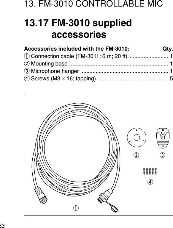
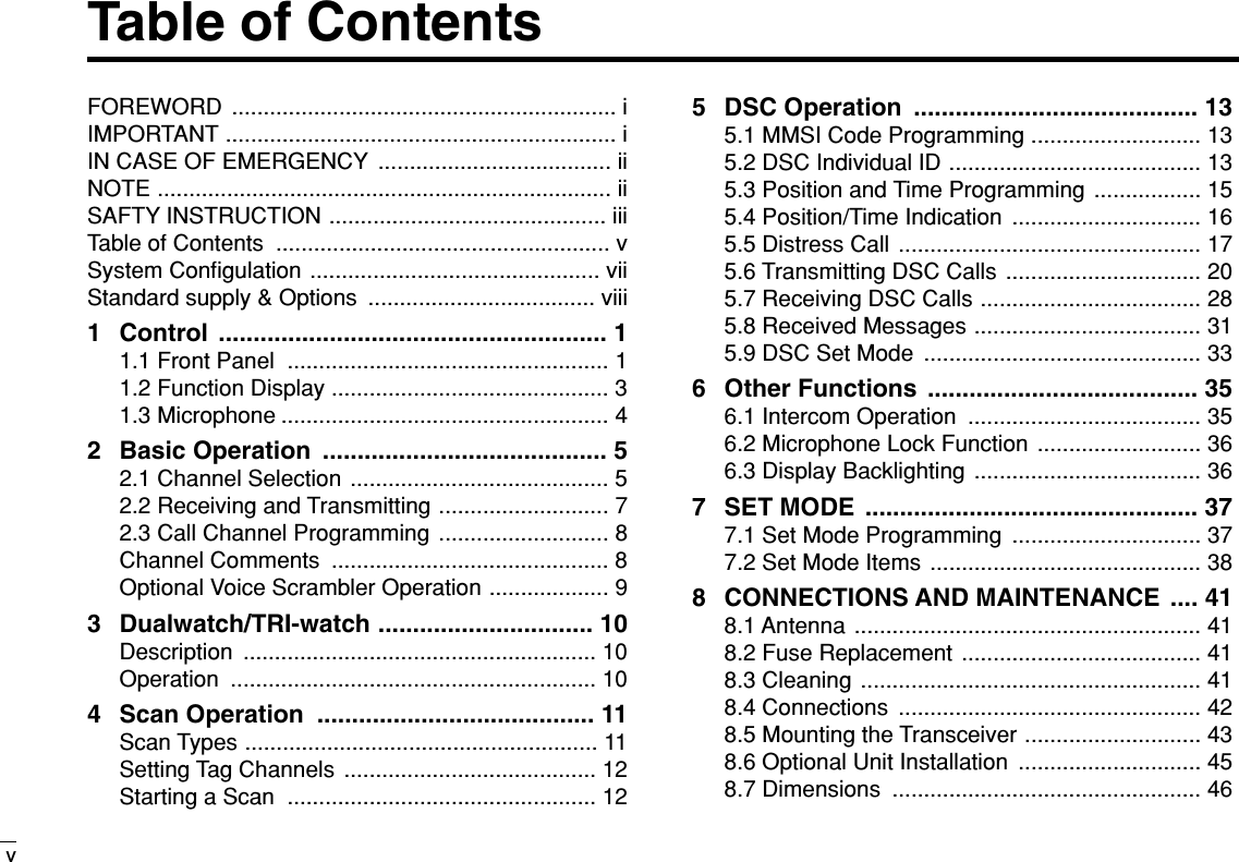
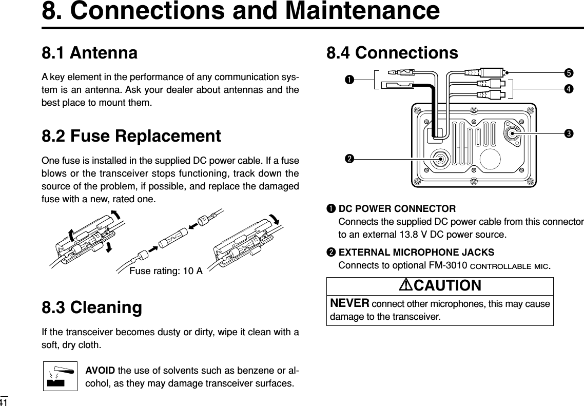
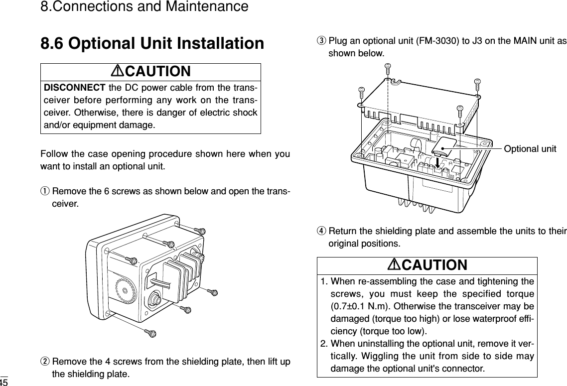
![iiCLEAN THE TRANSCEIVER AND MICROPHONETHOROUGHLY WITH FRESH WATER after exposure towater including salt water, otherwise, the keys andswitches may become inoperable due to salt crystallization.IN CASE OF EMERGENCYIf your vessel requires assistance, contact other vessels andthe Coast Guard by sending a distress call on Ch 16.Or, transmit your distress call using digital selective calling onCh 70.USING CHANNEL 16DISTRESS CALL PROCEDURE1. “MAYDAY MAYDAY MAYDAY.”2. “THIS IS ...............” (name of vessel)3. Your call sign or other indication of the vessel (AND 9-digit DSC ID if you have one).4. “LOCATED AT ...............” (your position)5. The nature of the distress and assistance required.6. Any other information which might facilitate the rescue.USING DIGITAL SELECTIVE CALLING (Ch 70)DISTRESS CALL PROCEDURE1. While lifting up the switch cover, push and hold[[DISTRESSDISTRESS]]for 5 sec. until you hear 5 short beepschange to one long beep.2. Wait for an acknowledgment from a coast station.• Channel 16 is automatically selected.3. Push and hold [[PTTPTT]], then transmit the appropriateinformation as at above.NOTEA WARNING STICKER is supplied with the transceiver.To comply with FCC regulations, this sticker must be affixed insuch a location as to be readily seen from the operating con-trols of the radio as in the diagram below. Make sure the cho-sen location is clean and dry before applying the sticker. (p. viii)EXAMPLE](https://usermanual.wiki/Furuno-USA/9ZWFM3000/User-Guide-362592-Page-3.png)
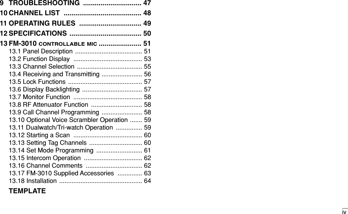
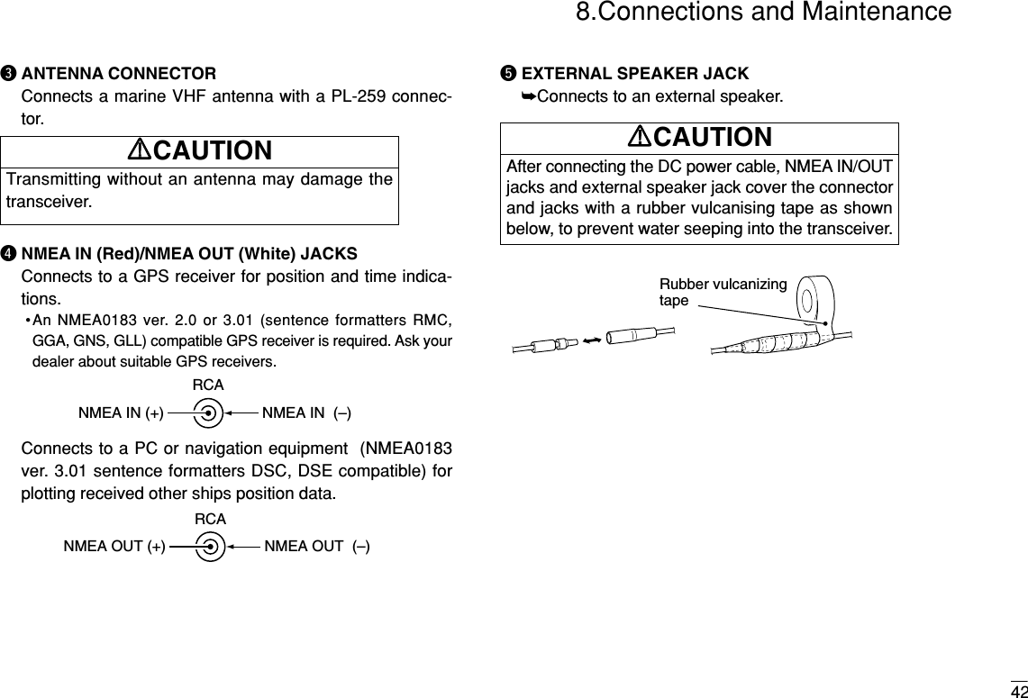
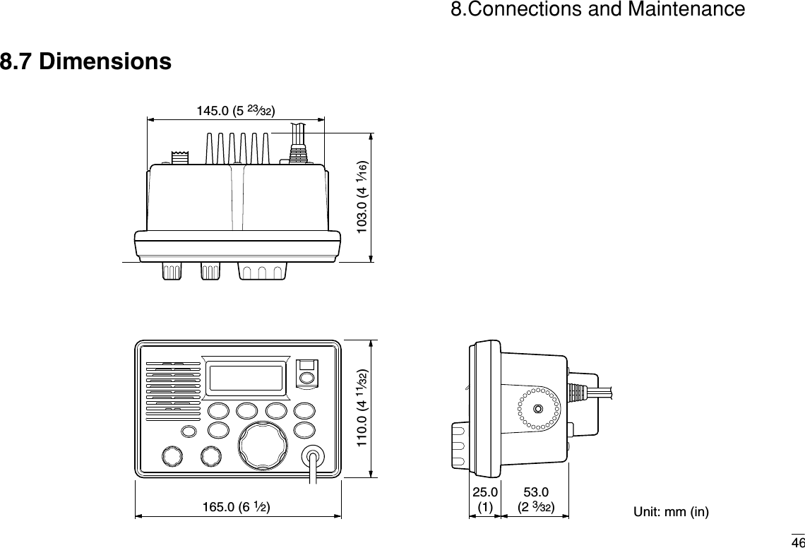
![11. Controls1.1 Front PanelVOL SQLSpeakerFunctiondisplayqw e r t y uio!0!1q[VOL] control (p. 7)Adjusts the audio level.w[POWER] keyToggles the transceiver power ON or OFF.e[SQL] control (p. 7)Sets the squelch threshold level.r[HI/LO] key➥Toggles power high or low when pushed. (p. 7)• Some channels are set to low power only.➥While pushing this key, some keys perform secondaryfunctions.t[CHANNEL] knob➥Rotate [CHANNEL]to select the operating channels,Set mode settings, etc. (pgs. 7, 37)➥While pushing [HI/LO], rotate [CHANNEL]to adjust thebrightness of the LCD and key backlight. (p.36)](https://usermanual.wiki/Furuno-USA/9ZWFM3000/User-Guide-362592-Page-10.png)
![y[LO/DX] ( ) key➥Toggles the Attenuator function ON or OFF whenpushed momentarily. (p. 7)•“LOCAL” appears when the Attenuator is in use. The order ofindication precedence is “SP OFF,” “LOCAL” and “CALL.”➥Activates an optional Intercom function when pushed for1 sec. (p. 35)➥Calls optional FM-3010 when pushed and held while inIntercom mode. (p. 35)➥While pushing [HI/LO], activates an optional Voicescrambler function. (p. 9)•The optional Voice scrambler function cannot be used onChannel 16 and 70.u[16] ( ) key➥Selects Channel 16 when pushed. (p. 5)➥Selects call channel when pushed for 1 sec. (p. 5)•“CALL” appears when call channel is selected. “SP OFF”and “LOCAL” indications have priority.➥Push for 3 sec. to enter call channel programming con-dition when call channel is selected. (p. 8)➥While pushing [HI/LO], enters channel comments pro-gramming condition. (p. 8)➥Enters Set mode when pushed while turning power ON.(p. 37)i[DISTRESS] keyTransmits Distress call when pushed for 5 sec. (p. 17)o[CH/WX] ( ) key➥Selects and toggles the regular channels and weatherchannel when pushed momentarily. (p. 6)➥While pushing [HI/LO], selects one of 3 regular chan-nels in sequence when pushed. (p. 6)•International, U.S.A. and Canadian channels are available forregular channels.➥Starts Dualwatch or Tri-watch when pushed for 1 sec. (p. 10)➥Stops Dualwatch or Tri-watch when either is activated.!0 [SCAN] ( ) key (p. 12)➥Starts and stops Normal or Priority scan when tag(scanned) channels are programmed.➥Push [SCAN]( ) for 1 sec. to set or cancel the dis-played channel as a tag (scanned) channel. ➥While pushing [HI/LO], push for 3 sec. to clear or set alltag channels.!1 [DSC/ENT] ( ) key➥Selects the DSC menu when pushed. (p. 13)➥Shows current position and time from a GPS receiver,etc. when pushed for 1 sec. (p. 16)POSTAGTAGU/I/CDW9SCRIC21.Controls](https://usermanual.wiki/Furuno-USA/9ZWFM3000/User-Guide-362592-Page-11.png)
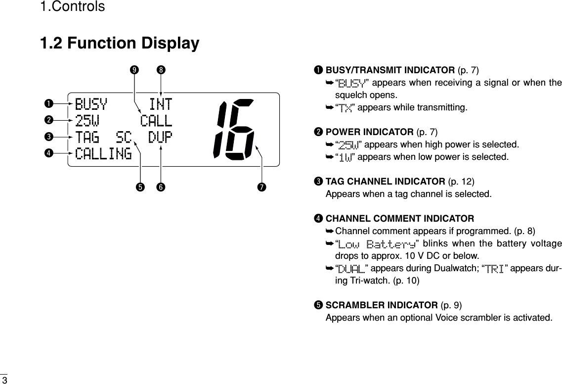
![41.ControlsyDUPLEX INDICATOR (p. 6)Appears when a duplex channel is selected.• Duplex channel has a different TX and RX frequency.uCHANNEL NUMBER READOUT➥Indicates the selected operating channel number. “A” appears when a simplex channel is selected. “b” ap-pears when a receive only channel for a Canadian chan-nel group is selected. (p. 6)➥In Set mode, indicates the selected condition. (p. 37)iCHANNEL GROUP INDICATOR (p. 6)Indicates whether an International “INT,” U.S.A. “USA,”Canadian “CAN” or weather “WEATHER” channel is se-lected.oCALL CHANNEL INDICATOR➥“CALL” appears when call channel is selected. (p. 5)➥“SP OFF” appears when the internal speaker is turnedOFF in Set mode. (p. 39)➥“LOCAL” appears when the Attenuator is in use. (p. 7)•The order of indication precedence is “SP OFF,” “LOCAL”and “CALL.”1.3 Microphoneq[PTT] switch (p. 7)Push and hold to transmit; release to receive.wCHANNEL UP/DOWN KEYS [YY]/[ZZ](pgs. 7, 37)Push either key to change the operating channel, Setmode settings, etc.e[16/9] key➥Push to select Channel 16; push for 1 sec. to sselect callchannel (default is Channel 9). (p. 5)➥While pushing [16/9], turn power ON to toggle the Lockfunction ON or OFF. (p. 36)SpeakerMicrophonewqe](https://usermanual.wiki/Furuno-USA/9ZWFM3000/User-Guide-362592-Page-13.png)
 momentarily to select Channel 16.➥Push [CH/WX]to return to the condition before selectingChannel 16, or rotate [CHANNEL]to select operatingchannel.2.1.2 Channel 9 (Call channel)Each regular channel group has a separate leisure-use callchannel. Call channel is monitored during Tri-watch. Callchannels can be programmed (p. 8) and are used to storeyour most often used channels in each channel group forquick recall.➥Push [16]( ) for 1 sec. to select call channel of the se-lected channel group.•“CALL” and call channel number appear. • Each channel group may have an independent call channel afterprogramming a call channel.➥Push [CH/WX]to return to the condition before selectingcall channel,or rotate [CHANNEL]to select an operatingchannel.Convenient: Using microphone➥Push [16/9]momentarily to select Channel 16.➥Push [16/9]for 1 sec. to select call channel.➥Push [YY]/[ZZ]to select any other operating channel.Push for1 sec.INT25W CALLTAGCALLING9INT25WTAGCALLINGPush9](https://usermanual.wiki/Furuno-USA/9ZWFM3000/User-Guide-362592-Page-14.png)
 to select a regular channel.• If a weather channel appears, push [CH/WX]( ) again.wWhile pushing [HI/LO], push [CH/WX]( ) tochange the channel group, if necessary.•U.S.A., International (INT) and Canadian channels can be se-lected in sequence.eRotate [CHANNEL]to select a channel.•“DUP” appears for duplex channels.• “A” appears for simplex channels.2.1.4 Weather channelsThere are 10 weather channels. Used for monitoring weatherchannels from the NOAA (National Oceanographic and At-mospheric Administration) broadcasts.The transceiver can detect a Weather alert tone on the se-lected weather channel while receiving that channel, duringstandby on a regular channel or while scanning. See“Weather alert” on p. 38.qPush [CH/WX]once or twice to select a weather channel.•“WEATHER” appears when a weather channel is selected.• “WX ALT” appears when the Weather alert function is in use.(p. 38)wRotate [CHANNEL]to select a channel.Push onceor twice When Weather alert is OFF.WEATHERWhen Weather alert is ON.WXALTPush +U.S.A. channelsCanadian channelsCANInternational channelsINTDUPUSAU/I/CDWU/I/CDWU/I/CDW](https://usermanual.wiki/Furuno-USA/9ZWFM3000/User-Guide-362592-Page-15.png)
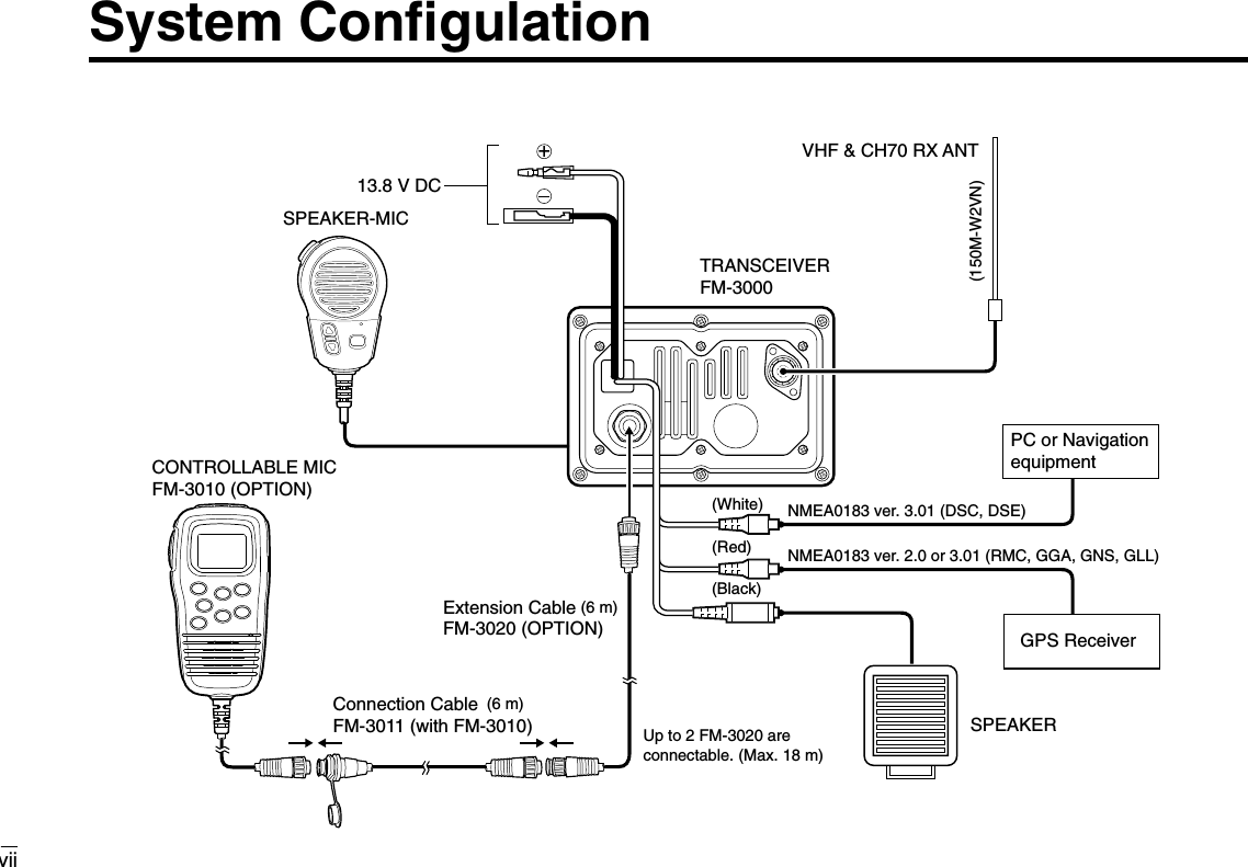
![2.2 Receiving and TransmittingqPush [POWER]to turn power ON.wSet the audio and squelch levels.➥Rotate [SQL]fully counterclockwise in advance.➥Rotate [VOL]to adjust the audio output level.➥Rotate [SQL]clockwise until the noise disappears.eTo change the channel group, push [CH/WX]( )while pushing [HI/LO]. (p. 6)rRotate [CHANNEL]or push [YY]/[ZZ]on the microphone toselect the desired channel.• When receiving a signal, “BUSY” appears and audio is emittedfrom the speaker.• Further adjustment of [VOL]may be necessary.• Use the optional Voice scrambler function for privacy. (p. 9)tPush [LO/DX]to turn the receive Attenuator function ONor OFF, if necessary.•“LOCAL” appears when the receive Attenuator is in use.yPush [HI/LO]to select the output power, if necessary.•“25W” or “1W” appears when high or low power is selected, re-spectively.• Choose low power for short range communications, choose highpower for longer distance communications.• Some channels are for selecting low power only.uPush and hold [PTT]to transmit, then speak into ∗(Mi-crophone).•“TX” appears.• Channel 70 cannot be used for transmission other than DSC.Note: Simplex channels, 3, 21, 23, 61, 64, 81, 82 and 83CANNOT be lawfully used by the general public in U.S.A.waters.iRelease [PTT]to receive.Important: To maximize the readability of your transmittedsignal, pause a few sec. after pushing [PTT], hold the micro-phone 2 to 4 inches (5 to 10 cm) from your mouth and speakinto ∗(Microphone) at a normal voice level.VOL SQL∗(Microphone)qwerrtyuiU/I/CDW2.Basic Operation7Transmitting without an antenna may damage thetransceiver.RRCAUTION](https://usermanual.wiki/Furuno-USA/9ZWFM3000/User-Guide-362592-Page-16.png)
![2.Basic Operation82.3 Call Channel ProgrammingCall channel is used to select Channel 9 (default), however,you can program the call channel with your most often-usedchannels in each channel group for quick recall.qWhile pushing [HI/LO], push [CH/WX]( ) one ormore times to select the desired channel group (U.S.A., In-ternational, Canada) to be programmed.wPush [16]( ) for 1 sec. to select call channel of the se-lected channel group.•“CALL” and call channel number appear.• The order of indication precedence is “SP OFF,” “LOCAL” and“CALL.”ePush [16]( )again for 3sec. (until a long beepchanges to 2 short beeps)to enter call channel pro-gramming condition.• Channel number starts blinking.rRotate [CHANNEL]to se-lect the desired channel.tPush [16]( ) to programthe displayed channel ascall channel.• Push [CH/WX]( ) to cancel.• The channel number stops blinking.2.4 Channel CommentsMemory channels can be tagged with alphanumeric com-ments of up to 10 characters each. Capital letters, small letters, numerals, some symbols (! " #$ % & ' ( ) * + , - ./ =) and space can be used.qSelect the desired channel.• Cancel dualwatch, Tri-watch or scan in advance.wWhile pushing [HI/LO], push [16]( ) to edit the channelcomment.• A cursor appears and blinks.eSelect the desired character by rotating [CHANNEL]or bypushing [YY]/[ZZ]on the microphone.• Push [CH/WX]or [SCAN]to move the cursor forward or back-ward, respectively.rPush [16]( ) to input and set the comment.• Push [HI/LO]to cancel.• The cursor disappears.tRepeat steps qto rto program the other channels, if de-sired.9INT25WTAGäLEASURE9U/I/CDW999U/I/CDWINT25W CALLTAGCALLINGINT25W CALLDUPTAGINTL](https://usermanual.wiki/Furuno-USA/9ZWFM3000/User-Guide-362592-Page-17.png)
![92.Basic Operation2.5 Optional Voice Scrambler Operation2.5.1 Activating the ScramblerThe optional Voice scrambler provides private communica-tions. In order to receive or send scrambled transmissionsyou must first activate the Scrambler function. To activate thefunction, an optional FM-3030 is necessary. See p. 40 for set-ting the scrambler unit. Ask your dealer for details.Note: The Scrambler function automatically turns OFF whenChannel 16 or 70 is selected.qSelect an operating channel other than Channel 16 or 70.wWhile pushing [HI/LO], push [LO/DX]( ) to turnthe optional Scrambler function ON.•“SC” appears.eTo turn the Scrambler function OFF, repeat step w.•“SC” disappears.2.5.2 Programming scrambler codesThere are 32 codes (1 to 32) available for programming whenthe optional FM-3030 is installed. In order to understand oneanother, all transceivers in your group must have the samescramble code. This function may not be available depend-ing on dealer setting.qTurn power OFF.wWhile pushing [16]( ), turn power ON to enter Set mode.eAfter the display appears, release [16]( ).rPush [16]( ) one or more times to select the scramblercode.•“Scrambler Code” appears.tRotate [CHANNEL]to select the desired scrambler code.yTurn power OFF, then ON again to exit Set mode.999SCRICSetModeBeepSetModeScramblerCodeSetModeScramblerCodeEnter Set mode Turn OFF+Select codePush one ormore times.Set mode Scrambler code item[Example]: Programming scrambler code 8.](https://usermanual.wiki/Furuno-USA/9ZWFM3000/User-Guide-362592-Page-18.png)
 for 1 sec. to start Dualwatch orTri-watch.•“DUAL” appears during Dualwatch; “TRI” appears during Tri-watch.• A beep tone sounds when a signal is received on Channel 16.rTo cancel Dualwatch or Tri-watch, push [CH/WX]( )again.U/I/CDWU/I/CDW[Example]: Operating Tri-watch on INT Channel 25.DUALWATCH/TRI-WATCH SIMULATION•If a signal is received on Channel 16, Dualwatch/Tri-watchpauses on Channel 16 until the signal disappears.•If a signal is received on call channel during Tri-watch, Tri-watchbecomes Dualwatch until the signal disappears.•To transmit on the selected channel during Dualwatch/Tri-watch,push and hold [PTT].Dualwatch Tri-watchCall channelINT25WDUP16TAGTRIINT25WDUP16TAGTRIBUSY INT25W CALL16TAGTRIBUSY INT25WDUP16TAGTRITri-watch starts.Signal is received on call channel.Signal received on Channel 16 takes priority.Tri-watch resumes after the signal disappears.](https://usermanual.wiki/Furuno-USA/9ZWFM3000/User-Guide-362592-Page-19.png)
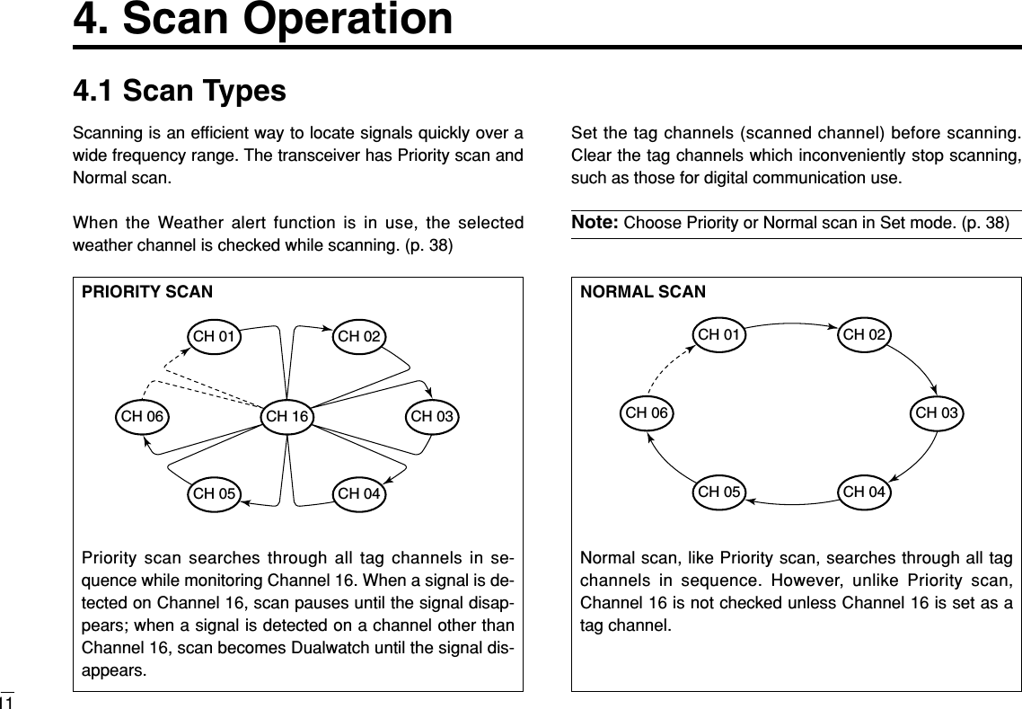
![4.Scan Operation12INT25WDUPTAGINTLINT25WDUPTAGNormalscanBUSY INT25WDUPTAGNormalscanPushScan starts. When a signal is received[Example]: Starting a Normal scan.4.2 Setting Tag ChannelsFor more efficient scanning, add desired channels as tagchannels or clear tag channels for unwanted channels. Chan-nels not tagged will be skipped during scanning. Tag chan-nels can be assigned to each channel group (U.S.A., Interna-tional, Canada) independently.qWhile pushing [HI/LO], push [CH/WX]( ) one ormore times to select the desired channel group.wSelect the desired channel to be set as a tag channel.ePush [SCAN]( ) for 1 sec. to set the displayed channelas a tag channel.•“TAG” appears in the display.rTo cancel the tag channel setting, repeat step e.•“TAG” disappears.Convinient: Clearing (setting) all tagged channels➥While pushing [[HI/LOHI/LO]], push [[SCANSCAN]](())for 3 sec. (untila long beep changes to 2 short beeps) to clear all tag chan-nels setting in the channel group.• Repeat above procedure to set all tag channels.4.3 Starting a ScanSet scan type (Priority or Normal scan) and scan resumetimer in advance using Set mode. (p. 38)qSet tag channels as described at left.wMake sure the squelch is closed to start a scan.eWhile pushing [HI/LO], push [CH/WX]( ) one ormore times to select the channel group, if desired.rPush [SCAN]to start Priority or Normal scan.•“Pri Scan 16” or “Normal Scan” appears in the functiondisplay.•When a signal is detected, scan pauses until the signal disap-pears or resumes after pausing 5 sec. according to Set modesetting. (Channel 16 is still monitored during Priority scan.)•Rotate [CHANNEL]to check the scanning tag channels, tochange the scanning direction or resume the scan manually.•“16” blinks and a beep tone sounds when a signal is receivedon Channel 16 during Priority scan.tTo stop the scan, push [SCAN].U/I/CDWTAGTAGU/I/CDW](https://usermanual.wiki/Furuno-USA/9ZWFM3000/User-Guide-362592-Page-21.png)
![135. DSC Operation5.1 MMSI Code ProgrammingThe 9-digit MMSI (Maritime Mobile Service Identity: DSC selfID) code can be programmed at power ON.Note: This function is not available when the MMSI code hasbeen programmed by the dealer. This code programming canbe performed only twice.qTurn power OFF.wWhile pushing [DSC/ENT], turn power ON to enter MMSIcode programming condition.eAfter the display appears, release [DSC/ENT].rEdit the specific MMSI code by rotating [CHANNEL].• Push [CH/WX]or [SCAN]to move the cursor forward or back-ward, respectively.tInput the 9 digit codes, then push [DSC/ENT]to set thecode.• Returns to the normal operation.5.2 DSC Individual IDA total of 40 DSC address IDs can be programmed andnamed with up to 10 characters.DDProgramming Address ID/Group IDqPush [DSC/ENT]to enter the DSC menu.wRotate [CHANNEL]to select “Set up,” push[DSC/ENT].eRotate [CHANNEL]to select “Add ID,” push [DSC/ENT].Setup˘AddIDDeleteIDOffsetTimeSelItemPOSReportDTRSSet˘SetupSetMMSIä23456789](https://usermanual.wiki/Furuno-USA/9ZWFM3000/User-Guide-362592-Page-22.png)
![145.DSC OperationrSet the individual ID and ID name.• Edit the 9 digits of the appropriate distress ID by using [CHAN-NEL].-Push [CH/WX]or [SCAN]to move the cursor forward or back-ward, respectively.Note: 1st digit ‘0’ is fixed for a group ID. Thus an address IDinput cannot started with ‘0.’ When you input 1st digit ‘0’ and other8 digits, the ID is automatically registered as a group ID.tPush [DSC/ENT]to program and exit the condition to thenormal operation.DDDeleting Address ID/Group IDqPush [DSC/ENT]to enter the DSC menu.wRotate [CHANNEL]to select “Set up,” push[DSC/ENT].eRotate [CHANNEL]to select “Delete ID,” push[DSC/ENT].•When no address ID is programmed, the transceiver exits theDSC menu automatically.rRotate [CHANNEL]to select the desired ID name fordeleting.tThe delete confirmation display will appear when[DSC/ENT]is pushed.• Push [HI/LO]to delete ID and exit the DSC Menu.• Push [DSC/ENT]to cancel deleting and exit the DSC Menu.DeleteIDRicky˘BillTomSetupAddID˘DeleteIDOffsetTimeAddIDID:NAME:](https://usermanual.wiki/Furuno-USA/9ZWFM3000/User-Guide-362592-Page-23.png)
![155.DSC Operation5.3 Position and Time ProgrammingA distress call should include the ship’s position and time. Ifno GPS is connected, your position and UTC (Universal TimeCoordinated) time should be input manually. They are in-cluded automatically when a GPS receiver (NMEA0183 ver.2.0 or 3.01) is connected.Note: This manual programming is not available when aGPS receiver (NMEA0183 ver. 2.0 or 3.01) is connected.qPush [DSC/ENT]to enter the DSC menu.w“POS Input” is selected automatically, push [DSC/ENT].eEdit the digit of your latitude data by using [CHANNEL].• Push [CH/WX]or [SCAN]to move the cursor forward or back-ward, respectively.• After editing latitude data, select “N”; North latitude or “S”; Southlatitude.• Push [HI/LO]to clear the position data.rEdit the digit of your longitude data by using [CHANNEL].• Push [CH/WX]or [SCAN]for cursor movement.•After editing longitude data, select “E”; East longitude or “W”;West longitude.• Push [HI/LO]to clear the position data.tPush [DSC/ENT]to set the position and advance to thetime setting condition.•Push [16]( ) or [LO/DX]to abandon the setting and exit theDSC menu.yEdit the digit of the current UTC time by using [CHAN-NEL].• Push [CH/WX]or [SCAN]for cursor movement.• Push [HI/LO]to clear the time data.uPush [DSC/ENT]to set the time, and exit the DSC menu.•Push [16]( ) or [LO/DX]to abandon the setting and exit theDSC menu.9InputtimeUTC:Null˘[H/L]9InputPOS°.-°.Null˘[H/L]](https://usermanual.wiki/Furuno-USA/9ZWFM3000/User-Guide-362592-Page-24.png)
 for 1 sec. to display the current po-sition and time.•“MNL” (manual) appears instead of the “GPS” indication whenno GPS is connected and the position/time data is entered man-ually.34°34.123N135°34.123EJUL1711:47CALLING34°34.123N135°34.123EGPSUTC11:47CALLING34°34.123N135°34.123EGPSLOC01:47CALLING• Sentence formatter ‘RMC’• Sentence formatteres ‘GGA,’ ‘GNS,’ ‘GLL’No offset time Offset time is–10 hours. (p.33)34°34.123N135°34.123EGPSUTC12:34CALLINGPOS1. When connecting GPS receiver is compatible severalsentence formatteres, the order of input precedence is‘RMC,’ ‘GGA,’ ‘GNS’ and ‘GLL.’2. When sentence formatter ‘RMC’ is received, time indica-tion includes a date, and UTC time only. 3. “??” may blink instead of position and time indicationswhen the GPS data is invalid, or has not been manuallyupdated after 4 hours.](https://usermanual.wiki/Furuno-USA/9ZWFM3000/User-Guide-362592-Page-25.png)
![175.DSC Operation5.5 Distress CallA Distress call should be transmitted, if in the opinion of theMaster, the ship or a person is in distress and requires imme-diate assistance.Note: DO NOT USE THE DISTRESS CALLWHEN YOUR SHIP IS NOT IN AN EMERGENCY.A DISTRESS CALL CAN BE USED ONLY WHENIMMEDIATE HELP IS NEEDED.5.5.1 Simple callqConfirm no Distress call is being received.wWhile lifting up the switch cover, push [DISTRESS]for 5sec. to transmit the Distress call.•Emergency channel (Ch 70) is automatically selected and theDistress call is transmitted.• When no GPS is connected, input your position and UTC time, ifpossible.eAfter transmitting the call, the transceiver waits for an ac-knowledgment call on Ch 70.•The Distress call is automatically transmitted every 3.5 to 4.5minutes.rWhen receiving the acknowledgment, reply using the mi-crophone.<TokyoCGDistressACKReceivedDistressCompletedWaitforACKDistressTX35°23.123N135°35.123EGPSUTC12:341. A distress alert contains (default);• Kind of distress : Undesignated distress• Position data : GPS or manual input position data held for23.5 hrs or until the power is turned OFF.2. The Distress call is repeated every 3.5–4.5 min., until re-ceiving an ‘acknowledgement.’3. Push [DISTRESS]to transmit a renewed Distress call, ifrequired.4. Push any key (except [DISTRESS]) to cancel the ‘Call re-peat’ mode.5. “??” may blink instead of position and time indicationswhen the GPS data is invalid, or has not been manuallyupdated after 4 hours.](https://usermanual.wiki/Furuno-USA/9ZWFM3000/User-Guide-362592-Page-26.png)
![185.DSC Operation5.5.2 Normal callThe nature of the Distress call should be included in the Dis-tress call.qPush [DSC/ENT]to enter the DSC menu.wRotate [CHANNEL]to select “DTRS Set,” push[DSC/ENT].eRotate [CHANNEL]to select the nature of the distress,push [DSC/ENT].•‘Undesignated,’ ‘Explosion,’ ‘Flooding,’ ‘Collision,’ ‘Grounding,’‘Capsizing,’ ‘Sinking,’ ‘Adrift (Disable adrift),’ ‘Abandoning (Aban-doning ship),’ ‘Piracy (Piracy attack)’ and ‘MOB (Man overboard)’are available.• The selected nature of the distress is stored for 10 minutes afterprogramming is finished.Note:When a GPS receiver (NMEA0183 ver. 2.0 or 3.01) isconnected, next steps r, t(Current position/time program-ming) do not appear. Go to step y. (next page)SelNature˘ExplosionUndesignFloodingSelItemPOSReportRCVCalls˘DTRSSetrThe position information appears. Set the current posi-tion, push [DSC/ENT].• Edit the digit of your position data by using [CHANNEL].-Push [CH/WX]or [SCAN]for cursor movement.-After editing latitude data, select “N”; North latitude or “S”;South latitude.-After editing longitude data, select “E”; East longitude or “W”;West longitude.- Push [HI/LO]to clear the position data.tThe time information appears. Set the current UTC time,push [DSC/ENT].• Edit the digit of the current UTC time by using [CHANNEL].-Push [CH/WX]or [SCAN]for cursor movement.- Push [HI/LO]to clear the time data.InputtimeUTC:Null˘[H/L]InputPOS°.-°.Null˘[H/L]](https://usermanual.wiki/Furuno-USA/9ZWFM3000/User-Guide-362592-Page-27.png)
![195.DSC OperationyPush [DISTRESS]for 5 sec. to transmit the Distress call.uAfter transmitting the call, the transceiver waits for an ac-knowledgment call on Ch 70.•The Distress call is automatically transmitted every 3.5 to 4.5minutes.iWhen receiving the acknowledgment, reply using the mi-crophone.<TokyoCGDistressACKReceivedDistressCompletedWaitforACKSetisOKPush[DTRS]for5sec1. A distress alert contains (default);• Kind of distress : Selected nature of the distress.• Position data : GPS or manual input position data held for23.5 hrs or until the power is turned OFF.2. The Distress call is repeated every 3.5–4.5 min., until re-ceiving an ‘acknowledgement.’3. Push [DISTRESS]to transmit a renewed Distress call, ifrequired.4. Push any key (except [DISTRESS]) to cancel the ‘Callrepeat’ mode.5. “??” may blink instead of position and time indicationswhen the GPS data is invalid, or has not been manuallyupdated after 4 hours.](https://usermanual.wiki/Furuno-USA/9ZWFM3000/User-Guide-362592-Page-28.png)
![205.DSC Operation5.6 Transmitting DSC Calls5.6.1 Transmitting Individual callThe Individual call function allows you to transmit a DSC sig-nal to a specific ship only.qPush [DSC/ENT]to enter the DSC menu.wRotate [CHANNEL]to select “Individual,” push[DSC/ENT].eRotate [CHANNEL]to select the desired pre-programmedindividual address or “Manual Input,” push[DSC/ENT].• The ID code for the Individual call can be set in advance. (p. 13)•When “Manual Input” is selected, set the 9-digit ID code(1st digit must not be ‘0’) for the individual you wish to call byusing [CHANNEL].-Push [CH/WX]or [SCAN]for cursor movement.- After 9-digit is input, push [DSC/ENT]to set the ID code.rRotate [CHANNEL]to select a desired intership channelor “Manual Input,” push [DSC/ENT].•When “Manual Input” is selected, rotate [CHANNEL]to se-lect the desired channel other than Channel 70, push [DSC/ENT].tPush [DSC/ENT]to transmit the Individual call.• If Channel 70 is busy, the transceiver stands by until the channelbecomes clear.ToCall,ToCancel[other][DSC/ENT]IndividualToCancel[other]Ch70isBUSYPush [DSC/ENT] to transmit DSC call.When Ch 70 is busy.SelChannel69˘0877SelAddressRickyManualSet˘Tom˘IndividualPOSInputGroupSelItem](https://usermanual.wiki/Furuno-USA/9ZWFM3000/User-Guide-362592-Page-29.png)
![215.DSC OperationyAfter transmitting the Individual call, standby on Channel70 until an acknowledgement is received.uWhen the acknowledgement is received, the displaychanges to the previously selected channel with beeps.iPush and hold [PTT]to communicate your message to theresponding ship.5.6.2 Transmitting Individual acknowledgementTransmit an acknowledgement (‘able to comply’ or ‘unable tocomply’) when an Individual call for you is received.qPush [DSC/ENT]to enter the DSC menu.wRotate [CHANNEL]to select “INDV ACK,” push[DSC/ENT].•“INDV ACK” item appears after an Individual call is received.eRotate [CHANNEL]to select the desired individual ad-dress or ID code, push [DSC/ENT].SelAddressTom˘RickySelItemPOS InputIndividual˘INDVACKReceived<TomAbleACKRoutineIndividualWaitforACKCompleted](https://usermanual.wiki/Furuno-USA/9ZWFM3000/User-Guide-362592-Page-30.png)
![225.DSC OperationrRotate [CHANNEL]to select an acknowledgement“Able” or “Unable,” push [DSC/ENT].tIf you select “Unable,” select the reason by rotating[CHANNEL], push [DSC/ENT].• ‘No reason given,’ ‘Congestion,’ ‘Busy,’ ‘Queue indication,’ ‘Sta-tion Barred,’ ‘No operator,’ ‘Operator Unavailable,’ ‘EquipmentDisable,’ ‘Channel Unable’ and ‘Mode Unable’ are available.yPush [DSC/ENT]to transmit the acknowledgement to theselected station.uAfter the Individual acknowledgement has been transmit-ted, the display changes to the channel specified by thecalling station, automatically.INDVACKCompletedToCall,ToCancel[other][DSC/ENT]SelReasonCongestionBusy˘NoReasonComplyUnable˘Able](https://usermanual.wiki/Furuno-USA/9ZWFM3000/User-Guide-362592-Page-31.png)
![235.DSC Operation5.6.3 Transmitting Group callThe Group call function allows you to transmit a DSC signalto a specific group only.qPush [DSC/ENT]to enter the DSC menu.wRotate [CHANNEL]to select “Group,” push [DSC/ENT].eRotate [CHANNEL]to select the desired pre-programmedgroup address or “Manual Input,” push [DSC/ENT].• The ID code for the Group call can be set in advance. (p. 13)•When “Manual Input” is selected, set the 9-digit ID code(must be set to ‘0’) for the group you wish to call by using[CHANNEL].-Push [CH/WX]or [SCAN]for cursor movement.- After 9-digit is input, push [DSC/ENT]to set the ID code.rRotate [CHANNEL]to select a desired intership channelor “Manual Input,” push [DSC/ENT].• When “Manual Input” is selected, rotate [CHANNEL]to se-lect the desired channel other than Channel 70, push [DSC/ENT].tPush [DSC/ENT]to transmit the Group call.• If Channel 70 is busy, the transceiver stands by until the channelbecomes clear.yAfter the Group call has been transmitted, the displaychanges to the previously selected channel.uPush and hold [PTT]to communicate your message to theresponding ship or push [DSC/ENT]to exit the condition.GroupCompletedToCall,ToCancel[other][DSC/ENT]SelChannel6713˘72SelAddressSmith GrpManualSet˘Osaka GrpSelItemIndividualINDVACK˘Group](https://usermanual.wiki/Furuno-USA/9ZWFM3000/User-Guide-362592-Page-32.png)
![245.DSC Operation5.6.4 Transmitting All Ships callLarge ships use Channel 70 as their ‘listening channel.’ Whenyou want to announce a message to these ships, use the ‘AllShips Call’ function.qPush [DSC/ENT]to enter the DSC menu.wRotate [CHANNEL]to select “All Ships,” push[DSC/ENT].ePush [DSC/ENT]to transmit the All Ships call.• Channel 70 is selected and the All Ships call is transmitted.• Routine category only is available.rAfter the All Ships call has been transmitted, the displaychanges to Channel 16 automatically.tPush any key to exit the condition and the display returnsto the normal operation.AllShipsCompletedToCall,ToCancel[other][DSC/ENT]SelItemINDVACKGroup˘AllShips](https://usermanual.wiki/Furuno-USA/9ZWFM3000/User-Guide-362592-Page-33.png)
![255.DSC Operation5.6.5 Transmitting Position Request callTransmit a Position Request call when you want to know aspecific ship’s current position, etc.qPush [DSC/ENT]to enter the DSC menu.wRotate [CHANNEL]to select “POS Request,” push[DSC/ENT].eRotate [CHANNEL]to select the desired pre-programmedindividual address or “Manual Input,” push[DSC/ENT].• The ID code for the Position Request call can be set in advance.(p. 13)•When “Manual Input” is selected, set the 9-digit ID code(1st digit must not be ‘0’) for the individual you wish to call byusing [CHANNEL].-Push [CH/WX]or [SCAN]for cursor movement.- After 9-digit is input, push [DSC/ENT]to set the ID code.rPush [DSC/ENT]to transmit the Position Request call.tAfter the Position Request call has been transmitted, thefollowing indication is displayed.yPush any key to exit the condition and return to the normaloperation.POSREQWaitforACKCompletedToCall,ToCancel[other][DSC/ENT]SelAddressRickyManualSet˘TomSelItemGroupAllships˘POSRequest](https://usermanual.wiki/Furuno-USA/9ZWFM3000/User-Guide-362592-Page-34.png)
![265.DSC Operation5.6.6 Transmitting Position Report callTransmit a Position Report call when you want to anounceyour own position to a specific ship and to get answer, etc.qPush [DSC/ENT]to enter the DSC menu.wRotate [CHANNEL]to select “POS Report,” push[DSC/ENT].eRotate [CHANNEL]to select the desired pre-programmedindividual address or “Manual Input,” push[DSC/ENT].• The ID code for the Position Report call can be set in advance.(p. 13)•When “Manual Input” is selected, set the 9-digit ID code(1st digit must not be ‘0’) for the individual you wish to call byusing [CHANNEL].-Push [CH/WX]or [SCAN]for cursor movement.- After 9-digit is input, push [DSC/ENT]to set the ID code.Note:When a GPS receiver (NMEA0183 ver. 2.0 or 3.01) isconnected, next steps r, t(Current position/time program-ming) do not appear. Go to step y. (next page)SelAddressRickyManualSet˘TomSelItemAllshipsPOSRequest˘POSReportrThe position information appears. Set the current posi-tion, push [DSC/ENT].• Edit the digit of your position data by using [CHANNEL].-Push [CH/WX]or [SCAN]for cursor movement.-After editing latitude data, select “N”; North latitude or “S”;South latitude.-After editing longitude data, select “E”; East longitude or “W”;West longitude.- Push [HI/LO]to clear the position data.tThe time information appears. Set the current UTC time,push [DSC/ENT].• Edit the digit of the current UTC time by using [CHANNEL].-Push [CH/WX]or [SCAN]for cursor movement.- Push [HI/LO]to clear the time data.InputtimeUTC:Null˘[H/L]InputPOS°.-°.Null˘[H/L]](https://usermanual.wiki/Furuno-USA/9ZWFM3000/User-Guide-362592-Page-35.png)
![275.DSC OperationyPush [DSC/ENT]to transmit the Position Report call.uAfter the Position Report call has been transmitted, the fol-lowing indication is displayediPush any key to exit the condition and return to the normaloperation.5.6.7 Transmitting Position Reply callTransmit a Position Reply call when a Position Request call isreceived.qWhen a Position Request call is received, the following in-dication is displayed.wPush [DSC/ENT]to reply to the Position Request call;push other key to ignore the Position Request call.5.6.8 Transmitting Position Report Reply callTransmit a Position Report Reply call when a Position Reportcall is received.qWhen a Position Report call is received, the following in-dication is displayed.wPush [DSC/ENT]to reply to the Position Report call; push any key to ignore the Position Report call.ReceivedAns[DSC/ENT]POSReportReceivedAns[DSC/ENT]<RickyPOSRequestPOSReportWaitforACKCompletedToCall,ToCancel[other][DSC/ENT]](https://usermanual.wiki/Furuno-USA/9ZWFM3000/User-Guide-362592-Page-36.png)
![285.DSC Operation5.7 Receiving DSC Calls5.7.1 Receiving a Distress callWhile monitoring Channel 70 and a Distress call is received:➥The emergency alarm sounds for 2 minutes.• Push any key to stop the alarm.➥“Received Distress” appears in the display; thenChannel 16 is automatically selected.➥Continue monitoring Channel 16 as a coast station may re-quire assistance.5.7.2 Receiving a Distress acknowledgementWhile monitoring Channel 70 and a Distress acknowledge-ment to other ship is received:➥The emergency alarm sounds for 2 minutes.• Push any key to stop the alarm.➥“Received Distress ACK” appears in the display;then Channel 16 is automatically selected.5.7.3 Receiving an Individual callWhile monitoring Channel 70 and an Individual call is re-ceived:➥The emergency alarm or beeps sound depending on thereceived category.➥“Received Individual” appears in the display.➥Push [DSC/ENT]to change to the channel specified by thecalling station for voice communication; push other key toignore the Individual call.5.7.4 Receiving a Group callWhile monitoring Channel 70 and a Group call is received:➥The emergency alarm or beeps sound depending on thereceived category.➥“Received Group” appears in the display.➥Push [DSC/ENT]to change to the channel specified by thecalling station for voice communication; push other key toignore the Group call.RoutineGroup< Smiths GrpReceivedRoutineIndividual< TomReceived<TokyoCG>111222345DistressACKReceived<111222345DistressReceived](https://usermanual.wiki/Furuno-USA/9ZWFM3000/User-Guide-362592-Page-37.png)
![295.DSC Operation5.7.5 Receiving an All Ships callWhile monitoring Channel 70 and an All Ships call is received:➥Emergency alarm sounds when the category is ‘Distress’or ‘Urgency’; 3 beeps sound for other categories.➥“Received All ships” appears in the display.➥Push [DSC/ENT]to change to the channel specified by thecalling station for voice communication; push other key toignore the All Ships call.➥Monitor the channel for an announcement from the callingvessel.5.7.6 Receiving a Distress Relay callWhile monitoring Channel 70 and a Distress Relay call is re-ceived:➥Emergency alarm sounds for 2 minutes.• Push any key to stop the alarm.➥“Received Distress RLY” appears in the display;then, Channel 16 is automatically selected.➥Monitor Channel 16 until the emergency communicationhas been completed.5.7.7 Receiving a Distress Relay acknowledgementWhile monitoring Channel 70 and a Distress Relay acknowl-edgement is received:➥Emergency alarm sounds for 2 minutes.• Push any key to stop the alarm.➥“Received DTRS RLY ACK” appears in the display;then, Channel 16 is automatically selected.5.7.8 Receiving a Geographical Area callWhile monitoring Channel 70 and a Geographical Area call(for the area you are in) is received:➥Emergency alarm or beeps sound depending on the re-ceived category.➥“Received Geographic” appears in the display.➥Push [DSC/ENT]to change to the channel specified by thecalling station for voice communication; push other key toignore the Geographical Area call.➥Monitor the selected channel for an announcement fromthe calling station.Note: When no GPS receiver is connected or if there is aproblem with the connected receiver, all Geographical Areacalls are received, regardless of your position.RoutineGeographic<TokyoCGReceived<Osaka BayRoutineAllShipsReceived](https://usermanual.wiki/Furuno-USA/9ZWFM3000/User-Guide-362592-Page-38.png)
![305.DSC Operation5.7.9 Receiving a Position Request callWhile monitoring Channel 70 and a Position Request call isreceived:➥“Received POS Request” appears in the display.➥Push [DSC/ENT]to reply to the Position Request call; pushother key to ignore the Position Request call.5.7.10 Receiving a Position Reply callWhile monitoring Channel 70 and a Position Reply call is re-ceived:➥“Received POS” appears in the display.5.7.11 Receiving a Position Report callWhile monitoring Channel 70 and a Position Report call is re-ceived:➥“Received POS Report” appears in the display.➥Push [DSC/ENT]to reply to the call; push other key to ig-nore the Position Report call.5.7.12 Receiving a Position Report Reply callWhile monitoring Channel 70 and a Position Report Reply callis received:➥“Received POS” appears in the display.30°30.123N<RickyReceivedPOS130°30.123EPOSReportReceivedAns[DSC/ENT]34°34.123N<TomReceivedPOS135°34.123E<RickyPOSRequestReceivedAns[DSC/ENT]](https://usermanual.wiki/Furuno-USA/9ZWFM3000/User-Guide-362592-Page-39.png)
![315.DSC Operation5.8 Received MessagesThe transceiver automatically stores up to 20 distress mes-sages and 20 other messages. The messages can be usedas an assistance to the logbook.qPush [DSC/ENT]to select the DSC menu.wRotate [CHANNEL]to select “RCV Calls,” push[DSC/ENT].5.8.1 Distress messageqRotate [CHANNEL]to select “Distress,” push[DSC/ENT].wRotate [CHANNEL]to scroll to the desired message, push[DSC/ENT].•When some messages are blinking, the messages have notbeen read.eRotate [CHANNEL]to scroll the message.rPush [DSC/ENT]to exit the DSC menu or push [HI/LO]toclear the displayed message and returns to the normal op-eration.ToClearThisDataNo[DSC/ENT]Yes[H/L]Distress<123123123ExplosionUTC:12:4832°43.212N123°45.221WToClearThisDataNo[DSC/ENT]Yes[H/L]SelDTRSMSG˘123123123111222345Chuck 3SelMessege˘DistressOtherSelItem˘RCVCallsDTRSSetSetup](https://usermanual.wiki/Furuno-USA/9ZWFM3000/User-Guide-362592-Page-40.png)
![325.DSC Operation5.8.2 Other messagesqRotate [CHANNEL]to select “Other,” push [DSC/ENT].wRotate [CHANNEL]to scroll to the desired message, push[DSC/ENT].•When some messages are blinking, the messages have notbeen read.eRotate [CHANNEL]to scroll the message.• The stored message has various information and depending onthe type of distress calls.rPush [DSC/ENT]to exit the DSC menu or push [HI/LO]toclear the displayed message and returns to the normal op-eration.ToClearThisDataNo[DSC/ENT]Yes[H/L]AllShips<TomRoutineF3ESimplexCH08ToClearThisDataNo[DSC/ENT]Yes[H/L]SelMessegeAllShipsPOS Request˘IndividualSelMessegeDistress˘Other](https://usermanual.wiki/Furuno-USA/9ZWFM3000/User-Guide-362592-Page-41.png)
![335.DSC Operation5.9 DSC Set Mode5.9.1 Add Address ID (See p.13 for detail)5.9.2 Delete Address ID (See p.14 for detail)5.9.3 Offset timeThis item sets the offset time from the UTC (Universal TimeCoordinated) time.qPush [DSC/ENT]to enter the DSC menu.wRotate [CHANNEL]to select “Set up,” push[DSC/ENT].eRotate [CHANNEL]to select “Offset time,” push[DSC/ENT].rSet the offset time from the UTC (Universal Time Coordi-nated) time.• Edit the digit of offset time by using [CHANNEL].-Push [CH/WX]or [SCAN]for cursor movement.- Push [DSC/ENT]to set the offset time.• Rotate [CHANNEL]to edit or delete “-,” when the cursor is onthe first digit.tPush [DSC/ENT]to program and to exit the DSC menu.Note:The local time indication is not available when a GPSreceiver (sentence formatter ‘RMC’) is input, the transceiver’sdisplay indicates UTC time only.OffsetTime00:00OffsetTime-12:00No offset time (default) –12 hoursSetupAddIDDeleteID˘OffsetTimeSelItemRCVCallsDTRSSet˘Setup](https://usermanual.wiki/Furuno-USA/9ZWFM3000/User-Guide-362592-Page-42.png)
![345.DSC Operation5.9.4 MMSI code checkThe programmed 9-digit MMSI (DSC self ID) code can bechecked in DSC Set mode.qPush [DSC/ENT]to enter the DSC menu.wRotate [CHANNEL]to select “Set up,” push[DSC/ENT].eRotate [CHANNEL]to select “MMSI Check,” push[DSC/ENT].rCheck the 9-digit MMSI (DSC self ID) code.tPush [DSC/ENT]to exit the DSC menu.MMSI Check123456789SetupDeleteIDOffsetTime˘MMSICheckSelItemRCVCallsDTRSSet˘Setup](https://usermanual.wiki/Furuno-USA/9ZWFM3000/User-Guide-362592-Page-43.png)
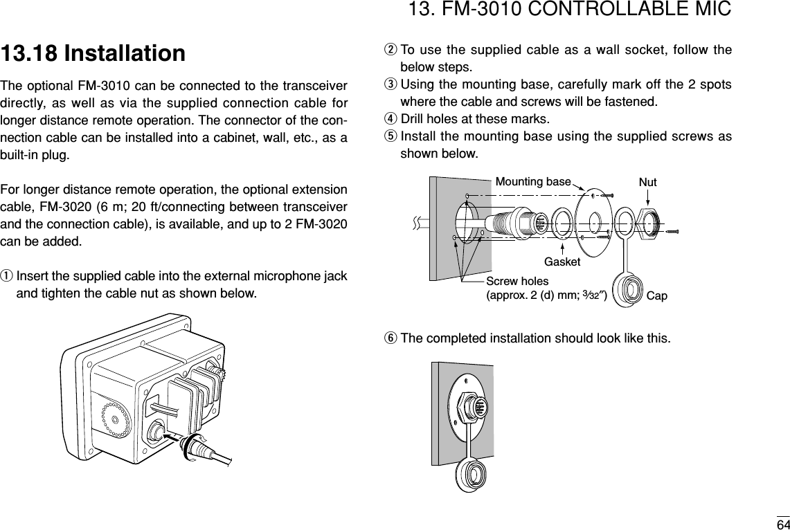
 for 1 sec. to enter Intercom mode.•The FM-3010 power is automatically turned ON, even if thepower is OFF.wPush and hold [LO/DX]( ) again to call up.• The transceiver and microphone emit call beeps.ePush and hold the PTT switch and speak at a normal voicelevel into the microphone.•“TALK” or “LSTN” appears on the caller or listener function dis-play, respectively.• To adjust the FM-3000’s speaker output level, rotate [VOL].• To adjust the FM-3010’s speaker output level, push after [VOL]pushing [YY]/[ZZ].rAfter releasing the PTT switch you can hear the responsethrough the speaker.tTo return to the normal operation, push [LO/DX]( )momentarily.• Other keys also turn the function OFF, however, the correspond-ing function is then activated (e.g. pushing [16]( ) selectsChannel 16).9SCRICIntercomINTINTTALKFM-3000 (caller) FM-3010 (listener)SCRICIntercomINTINTFM-3000 FM-3010SCRIC1. While in the Intercom mode, the transceiver functions(transmit and receive) are interrupted. If the transceiveris in transmit condition, the Intercom function is not avail-able.2.When a DSC call is received, “DSC received” ap-pears and the last received DSC message is displayedafter the Intercom use is finished.3.When a WX alert is received, “WX ALT” blinks and abeep sounds. The WX alert sounds after the Intercom useis finished.](https://usermanual.wiki/Furuno-USA/9ZWFM3000/User-Guide-362592-Page-44.png)
![366.Other Functions6.2 Microphone Lock FunctionThe Microphone lock function electrically locks the [YY]/[ZZ]and [16/9]keys on the supplied microphone. This preventsaccidental channel changes and accidental function access.➥While pushing [16/9]on supplied microphone, turn powerON to toggle the Lock function ON or OFF.6.3 Display BacklightingThe function display and keys can be backlit for better visibil-ity under low light conditions.➥While pushing [HI/LO], rotate [CHANNEL]to adjust thebrightness of the LCD and key backlight.• The backlight level is adjustable in 7 levels.[Y]/[Z][16/9]](https://usermanual.wiki/Furuno-USA/9ZWFM3000/User-Guide-362592-Page-45.png)
, turn power ON to enter Set mode.eAfter the display appears, release [16]( ).rPush [16]( ) to select the desired item.Or push [16]( ) on the FM-3010 to select the item whenusing an optional FM-3010.tRotate [CHANNEL]to select the desired condition of theitem. Use [YY]/[ZZ]when using an optional FM-3010.yTurn power OFF, then turn ON again to exit Set mode 9999•SET MODE CONSTRUCTION1. Available functions may differ depending on dealer set-ting.2. The optional FM-3010 has it’s own settings for the beeptone and LCD contrast.](https://usermanual.wiki/Furuno-USA/9ZWFM3000/User-Guide-362592-Page-46.png)
 key function as Dual-watch or Tri-watch.SetModeDUAL/TRIDualwatch (default) Tri-watchU/I/CDWSetModeWXAlertWeather alert OFF (default) Weather alert ONSetModeScanTimerScan timer OFF (default) Scan timer ONSetModeScanModeNormal scan (default) Priority scan](https://usermanual.wiki/Furuno-USA/9ZWFM3000/User-Guide-362592-Page-47.png)
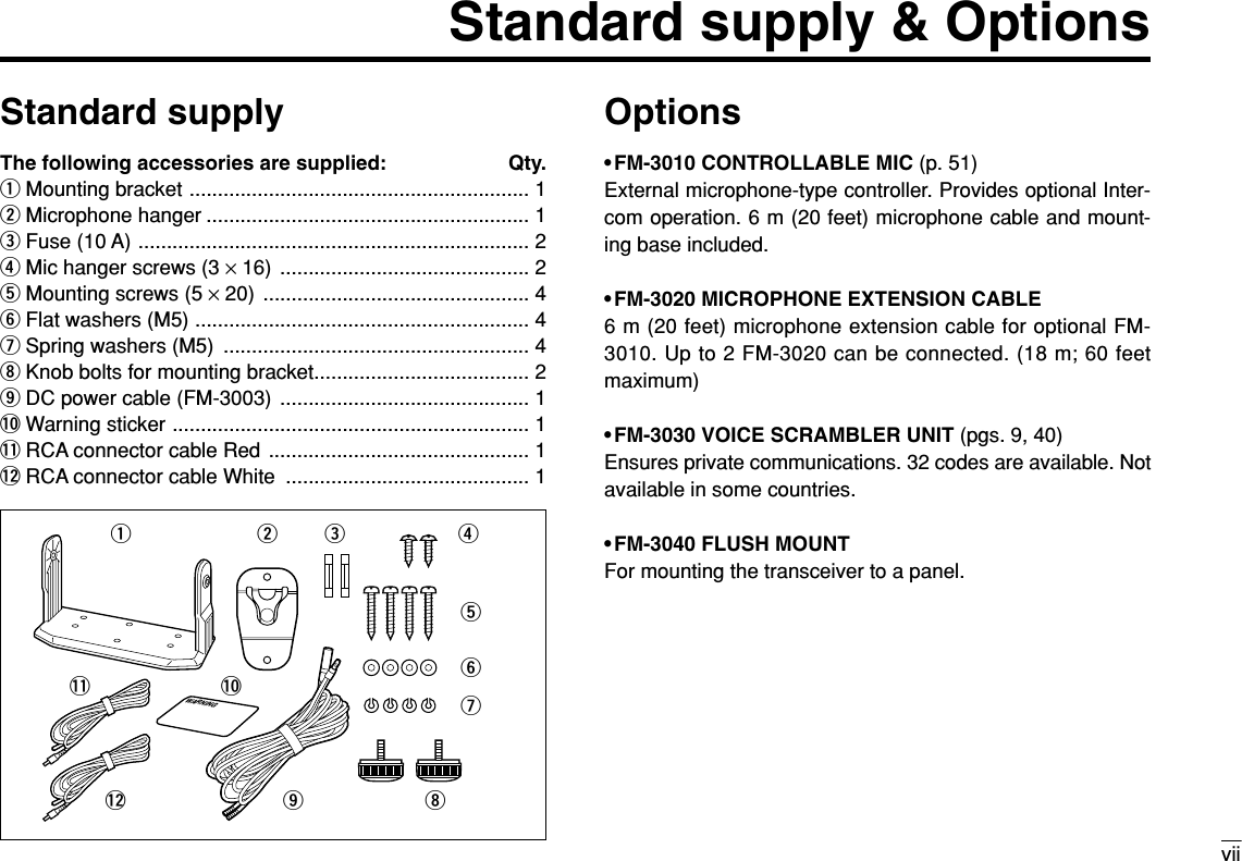
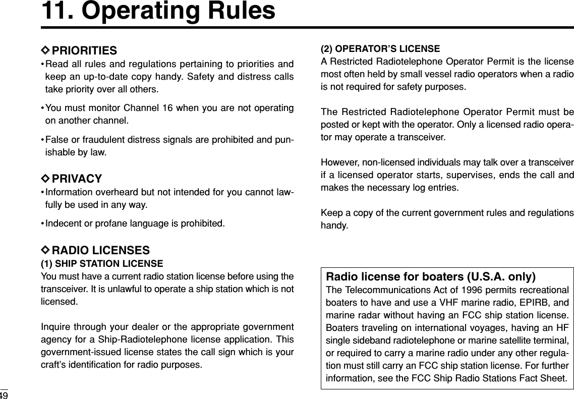
![9. Troubleshooting47PROBLEM POSSIBLE CAUSE SOLUTION REF.No power comes ON. •Bad connection to the power supply. •Check the connection to the transceiver. p. 42No sound comes fromthe speaker.•Squelch level is too high.•Volume level is too low.•Speaker has been exposed to water.•Internal speaker is turned OFF.•Set squelch to the threshold point.•Set [VOL] to a suitable level.•Drain water from the speaker.•Turn the internal speaker ON in Set mode.p. 7p. 7—p. 39Transmitting is impossi-ble, or high power caner can-not be selected.•Some channels are for low power or re-ceive only.•The output power is set to low.•Change channels.•Push [HI/LO] to select high power.pgs.5, 48p. 7Scan does not start. •‘TAG’ channel is not prog rammed. •Set the desired channels as ‘TAG’ chan-nels.p. 12No beep sounds. •Beep tone is turned OFF.•The squelch is open.•Turn the beep tone ON in Set mode.•Set squelch to the threshold point.p. 39p. 7Receive signal cannotbe understood.•Optional voice scrambler is turned OFF.•Scramble code is not set correctly.•Turn the optional voice scrambler ON.•Reset the scramble code.p. 9p. 40Sensitivity is low. •The attenuator is activated. •Push [LO/DX] to turn the function OFF. p. 7Distress call cannot betransmitted.•MMSI (DSC self ID) code is not pro-grammed.•Program the MMSI (DSC self ID) code. p. 13](https://usermanual.wiki/Furuno-USA/9ZWFM3000/User-Guide-362592-Page-56.png)
Push and hold to transmit; release to receive.wCHANNEL UP/DOWN KEYS [YY]/[ZZ] ➥Push either key to change the operating channel, Setmode settings, etc. (pgs. 7, 56)➥Push either key to adjust audio level or noise squelchlevel after [VOL]or [SQL]is pushed, respectively. (pgs.7, 56)➥Push either key to adjust the brightness of the LCD andkey backlight after [VOL]is pushed for 1 sec. (p. 57)➥In Set mode, changes setting of the selected item. (pgs.37, 61)➥Checks tag channels or changes scanning direction dur-ing scan. (pgs. 12, 60)eCHANNEL 16/CALL CHANNEL KEY [16]( )➥Selects Channel 16 when pushed. (pgs. 5, 55)➥Selects call channel when pushed for 1 sec. (pgs. 5, 55)•“CALL” appears when call channel is selected.➥Push for 3 sec. to enter call channel programming con-dition when call channel is selected. (pgs. 8, 58)➥While pushing [H/L], enters channel comments pro-gramming condition. (pgs. 8, 62)➥Enters Set mode when pushed while turning power ON.(pgs. 37, 61)9Top keysqewytru](https://usermanual.wiki/Furuno-USA/9ZWFM3000/User-Guide-362592-Page-60.png)
➥Selects and toggles the regular channels and weatherchannel when pushed momentarily. (pgs. 5, 6, 55)➥While pushing [H/L], selects one of 3 regular channelsin sequence when pushed. (pgs. 6, 55)•International, U.S.A. and Canadian channels are available forregular channels.➥Starts Dualwatch or Tri-watch when pushed for 1 sec. (pgs. 10, 59)➥Stops Dualwatch or Tri-watch when either is activated.tATTENUATOR/INTERCOM/SCRAMBLER KEY[LO/DX]( )➥Toggles the Attenuator function ON or OFF whenpushed momentarily. (pgs. 7, 56)•“LOCAL” appears when the Attenuator is in use.➥Activates the Intercom function when pushed for 1 sec.(pgs. 35, 62)➥Calls the FM-3000 when pushed and held while in Inter-com mode. (pgs. 35, 62)➥While pushing [H/L], activates an optional Voice scram-bler function. (pgs. 9, 59)•The optional Voice scrambler function cannot be used onChannel 16 and 70.ySQUELCH/MONITOR/LOCK KEY [SQL]( )➥[YY]/[ZZ]sets the squelch threshold level after pushing[SQL]. (p. 56)➥Push [SQL]( ) for 1 sec. to turn the monitor func-tion ON. (p. 58)➥While pushing [H/L], push [SQL]( ) to toggle the(microphone) Key lock function ON or OFF. (p. 57)•“ T” appears while Key lock function is in use.•[PWR], [PTT], [VOL], [SQL]and [H/L]still function when the(microphone) Key lock function is turned ON.➥Advance the cursor while in channel comment program-ming condition. (pgs. 8, 62)uVOLUME/DIMMER KEY [VOL]( )➥[YY]/[ZZ]adjusts the audio level after pushing [VOL](p. 56) ➥Push [VOL]( ) for 1 sec. to adjust the brightness ofthe LCD and key backlight. (p. 57)➥Move the cursor backward while in channel commentprogramming condition. (pgs. 8, 62)DIMDIMLMONILMONILMONISCRICU/I/CDW](https://usermanual.wiki/Furuno-USA/9ZWFM3000/User-Guide-362592-Page-61.png)
![5313. FM-3010 CONTROLLABLE MIC13.1.2 Top keysqPOWER KEY [PWR] (pgs. 7, 56)Push for 2 sec. to turn the FM-3010 power ON or OFFwhen the FM-3000 power is turned ON.wSCAN KEY [SCAN]( ) (pgs. 12, 60)➥Starts and stops Normal or Priority scan when tag chan-nels are programmed.➥Push [SCAN]( ) for 1 sec. to set the displayed chan-nel as a tag (scanned) channel. ➥While pushing [H/L], push for 3 sec. to clear or set alltag channels.eTRANSMIT POWER KEY [H/L] ➥Toggles high or low power when pushed. (pgs. 7, 56)• Some Channels are set to low power only.➥While pushing this key, other keys perform secondaryfunctions.➥Toggles the All key lock function ON or OFF whenpushed while turning power ON. (p. 57)•“ T” blinks while the All key lock function is in use.•Only [PWR]and [PTT]function when the All key lock functionis in use.13.2 Function DisplayqCHANNEL GROUP INDICATOR (pgs. 6, 55)Indicates whether an International (INT), U.S.A. (USA) orCanadian (CAN) channel is selected.wKEY LOCK INDICATOR (p. 57)➥Appears while the Key lock function is in use.➥Blinks while the All key lock function is in use.CALLWX ALTDUPP SCANSCRMLOCALTRIDUALLOWTAGCANUSAINTLTX BUSYVOLSQLqwrte!8 !7 !4!5 !3!2!1!0oiuy!6TAGTAGPWR SCAN H/LTAGqew](https://usermanual.wiki/Furuno-USA/9ZWFM3000/User-Guide-362592-Page-62.png)
![5513. FM-3010 CONTROLLABLE MIC13.3 Channel Selection13.3.1 Channel 16qPush [16]to select Channel 16.wPush [CH/WX]to return to thecondition before selecting Chan-nel 16, or push [YY]or [ZZ]to se-lect an operating channel.13.3.2 Call channelqPush [16]( ) for 1 sec. to selectcall channel.wPush [CH/WX]to return to thecondition before selecting callchannel, or push [YY]or [ZZ]toselect an operating channel.13.3 3 Weather channelsqPush [CH/WX]once or twice toselect the weather channel group.wPush [YY]or [ZZ]to select aweather channel.ePush [CH/WX]to return xto thecondition before selecting theweather channel group.13.3.4 U.S.A., International and Canadian channelsqPush [CH/WX]( ) to select a regular channel.• Push [CH/WX]( ) again, if a weather channel appears.wWhile pushing [H/L], push [CH/WX]( ) to select achannel group.• U.S.A., International and Canadian channels can be selected insequence.U/I/CDWU/I/CDWU/I/CDW9PushPush for 1 sec.PushPush while pushingU.S.A. channelsCanadian channelsInternational channels+](https://usermanual.wiki/Furuno-USA/9ZWFM3000/User-Guide-362592-Page-64.png)
![5613. FM-3010 CONTROLLABLE MIC13.4 Receiving and TransmittingqPush [PWR]to turn power ON.wPush [VOL], then [YY]/[ZZ]to adjust audio output level.• Push [SQL], then push [YY]/[ZZ]to mute any audio noise, if nec-essary.ePush [YY]/[ZZ]to select the desired channel.•When receiving a signal, “ ” appears and audio is emittedfrom the speaker.• Further adjustment of the audio level may be necessary at thispoint.•Use the optional Voice scrambler function for privacy. (pgs. 9, 59)rPush [H/L]to select the output power, if necessary.• “LOW” appears when low power is selected.•Choose low power to reduce an intermodulation for other sta-tions, choose high power for longer distance communications.• Some channels are for selecting low power only.tPush and hold [PTT]to transmit, then speak into the mi-crophone.• “ ” appears.• Channel 70 cannot be used for transmission.Note: Simplex channels, 3, 21, 23, 61, 64, 81, 82 and 83CANNOT be lawfully used by the general public in U.S.A.waters.yRelease [PTT]to receive.IMPORTANT: To maximize the readability of your transmit-ted signal (voice), pause a few sec. after pushing [PTT], holdthe microphone 2 to 4 inches (5 to 10 cm) from your mouthand speak at a normal voice level.w Set volumew Set squelch, if requiredr Set output powert Speak into microphoneq Turn power ONe Set channelt Push to transmity Release to receive](https://usermanual.wiki/Furuno-USA/9ZWFM3000/User-Guide-362592-Page-65.png)
![5713. FM-3010 CONTROLLABLE MIC13.5 Lock FunctionsThe Lock function electronically locks keys to prevent acci-dental changes and function access from the microphone.• All keys and controllers on the transceiver are functional.13.5.1 Activating the Lock function➥While pushing [H/L], push[SQL]( ) to turn the Lockfunction ON or OFF.• “ ” appears.•Only [PWR], [PTT], [H/L], [SQL]( ), [VOL]+[YY]/[ZZ]and [SQL]+[YY]/[ZZ]are functional.13.5.2 Activating the All key lock function➥While pushing [H/L], turn thepower ON by pushing [PWR]to turn the All key lock functionON or OFF.• “ ” blinks.• Only [PWR]and [PTT]are func-tional.13.6 Display BacklightingThe function display and keys can be backlit for better visibil-ity under low light conditions. The backlighting condition canalso be adjusted independently from the transceiver.qPush [VOL]( ) for 1 sec.to enter Backlight adjustingmode.•“ ” with the number of thebacklight level appears in thechannel comment indicator.wPush [YY]/[ZZ]to adjust thebacklight level.• The backlight level is adjustablebetween 0 (light OFF) and 7(brightest).For your reference:Pushing [YY]/[ZZ], while [H/L] is pushed, also adjusts backlightlevel.• No backlight level indication is available.DIMLMONILMONIAppears when the lockfunction is in use. Appears while in the Backlight adjustment mode. Blinks when the all lockfunction is in use.](https://usermanual.wiki/Furuno-USA/9ZWFM3000/User-Guide-362592-Page-66.png)
![5813. FM-3010 CONTROLLABLE MIC13.7 Monitor FunctionThe monitor function releases the noise squelch mute of themicrophone only. (An independent noise squelch system isemployed.)13.8 RF Attenuator Function➥Push [LO/DX]to turn the RFattenuator function ON andOFF.13.9 Call Channel ProgrammingqPush [CH/WX]( ) severaltimes while pushing [H/L]to selectthe desired channel group (USA,INT, CAN) to be programmed.wPush [16]( ) for 1 sec. to selectcall channel of the selected chan-nel group.•“CALL” and call channel number ap-pear.ePush [16]( ) again for 3 sec. (untila long beep changes to 2 shortbeeps) to enter call channel pro-gramming condition.•The channel number and channelgroup to be programmed blinks.rPush [YY]/[ZZ]to select the desiredchannel.tPush [16]( ) to program the dis-played channel as call channel.•The channel number and channelgroup stop flashing.999U/I/CDWAppears when the RF attenuator function is in use. Blinks when the Monitorfunction is in use. ➥Push [SQL]( ) for 1 sec.to activate the Monitor func-tion.• “ ” blinks and audio is emit-ted.•Any key cancels the Monitorfunction.LMONI](https://usermanual.wiki/Furuno-USA/9ZWFM3000/User-Guide-362592-Page-67.png)
![5913. FM-3010 CONTROLLABLE MIC13.10 Optional Voice ScramblerOperation13.10.1 Activating the ScramblerqSelect an operating channel,except for Channel 16, Chan-nel 70 or weather channels.wWhile pushing [H/L], push[LO/DX]( ) to turn theVoice scrambler function ON.• “SCRM” appears.eTo turn the Scrambler func-tion OFF, repeat step w.• “SCRM” disappears.13.10.2 Programming scramble codesThere are 32 codes (01 to 32) available with the FM-3030 forprogramming. In order to understand one another, all trans-ceivers in your group must have the same scrambler code.The scrambler code is programmed in Set mode. See pgs. 9,40 for details.13.11 Dualwatch/Tri-watchOperationqPush [YY]/[ZZ]to select the desired channel.• Push [CH/WX]( ) several times while pushing [H/L]toselect the channel group (USA, INT, CAN), if desired.wPush [CH/WX]( U/I/C) for 1 sec. to start Dualwatch orTri-watch.•“DUAL” appears during Dual-watch; “TRI” appears during Tri-watch.• A beep tone sounds when a sig-nal is received on Channel 16.•Tri-watch becomes Dualwatchwhen receiving a signal on callchannel.•Dualwatch or Tri-watch can beselected in the transceiver’s Setmode.eTo cancel Dualwatch/Tri-watch, push [CH/WX]( )again.U/I/CDWDWU/I/CDWSCRICAppears when the Voicescrambler function is in useAppears when the Dual orTri-watch function is in use.](https://usermanual.wiki/Furuno-USA/9ZWFM3000/User-Guide-362592-Page-68.png)
![6013. FM-3010 CONTROLLABLE MIC13.12 Starting a ScanqWhile pushing [H/L], push [CH/WX]( ) severaltimes to select the channel group (USA, INT, CAN), if de-sired.•When the Weather alert function is in use, select the desiredweather channel with [CH/WX]and [YY]/[ZZ].wPush [SCAN]to start Priority or Normal scan.• “SCAN” appears during Normal scan.• The priority channel readout indicates “16”, and “P” and “SCAN”indicators appear during Priority scan.•When a signal is received, scan pauses until the signal disap-pears or resumes after pausing 5 sec. according to the Set modesetting (Channel 16 is still monitored during Priority scan).• Push [YY]/[ZZ]to check the scanning tag channels, to change thescanning direction or resume the scan manually.eTo stop the scan, push [SCAN]( ).• “SCAN” disappears.• Pushing [PTT], [16]( ) or [CH/WX]also stops the scan.13.13 Setting Tag ChannelsqWhile pushing [H/L], push [CH/WX]( ) severaltimes to select the channel group (USA, INT, CAN), if de-sired.wPush [YY]/[ZZ]to select the desired channel to set as a tagchannel.ePush [SCAN]( ) for 1 sec. to set the displayed channelas a tag channel.• “ ” appears.rTo cancel the tag channel setting, push [SCAN]( ) for1 sec.• “ ” disappears.Convenient: Clearing (setting) all tagged channels➥While pushing [H/L], push [SCAN]()for 3 sec. (until along beep changes to 2 short beeps) to clear all tagchannels setting in the channel group.• After cleared all tag channels, same way to set all tag channels.TAGTAGTAGU/I/CDW9TAGU/I/CDW](https://usermanual.wiki/Furuno-USA/9ZWFM3000/User-Guide-362592-Page-69.png)
, turn power ON.•After a beep emission, a Set mode item (in the channel comment in-dicator and the condition in the channel number readout) is displayed.ePush [16]( ) to select the desired item, if necessary.rPush [YY]/[ZZ]to select the desired condition of the item.tTurn power OFF, then ON to exit Set mode.•Beep tone “BEEP”➥Push [YY]to turn ON, [ZZ]to turn OFF the beep output. •LCD contrast “LCD CONTRAST”➥Push [YY]/[ZZ]to adjust to a suitable LCD contrast.PushPush99](https://usermanual.wiki/Furuno-USA/9ZWFM3000/User-Guide-362592-Page-70.png)
 for 1 sec.to activate the Intercom function.•“IC” appears in the priority channelreadout.• The channel comment disappears.wPush [PTT]to talk.• “ ” appears in the channel com-ment indicator.eRelease [PTT]to listen.•“ ” appears in the channel comment indicator when thetransceiver is in talking mode.rPush [LO/DX]( ) to cancel the Intercom function.• Pushing [16]also cancels the Intercom function.For your reference:In case the Intercom mode is selected with the transceiverwhile the microphone power is OFF, the microphone power isautomatically turned ON and the Intercom mode is selected.DDIntercom beep function➥Push [LO/DX]( ) for more than 1 sec.• Emits the Intercom beep while holding.13.16 Channel CommentsqPush [YY]/[ZZ]to select a channel to program a channelcomment.• Push [CH/WX]( ) several times while pushing [H/L]toselect the channel group (USA, INT, CAN), if desired.wWhile pushing [H/L], push [16]( ).• The 1st character of the currently programmed comment blinks.ePush [YY]/[ZZ]to select a character.rPush [SQL]to move to forward; then push [YY]/[ZZ]to se-lect a character.• Push [VOL]to move to backward.tContinue until the desired characters have been selected,then push [16]( ) to return to normal operation.•Available characters99U/I/CDWSCRICSCRICSCRIC(r)(s) (t) (u) (v) (w) (x) (y) (z)(q)(3)(D)(N)(X)(h)(+)(4)(E)(O)(Y)(i)(–)(5)(F)(P)(Z)(j)(✱)(6)(G)(Q)(a)(k)(/)(7)(H)(R)(b)(l)(,)(8)(I)(S)(c)(m)(space)(9)(T)(d)(n)(0)(A)(U)(e)(o)(1)(B)(V)(f)(p)(2)(C)(J) (K) (L)(M)(W)(g)(.)( ))(( )(’)(&)(%)($)(#)(")(!)Appears when the inter-com function is in use.](https://usermanual.wiki/Furuno-USA/9ZWFM3000/User-Guide-362592-Page-71.png)