Furuno USA 9ZWFM4000 VHF Radiotelephone User Manual FM 4000 pmd
Furuno USA Inc VHF Radiotelephone FM 4000 pmd
UserManual.wiki
>
Furuno USA
>
9ZWFM4000 User Manual
>
users manual part 1
Contents
1.
users manual part 1
2.
users manual part 2
users manual part 1
Navigation menu
Upload a User Manual
Namespaces
Wiki Guide
HTML
PDF
Info
Views
User Manual
Discussion / Help
Navigation
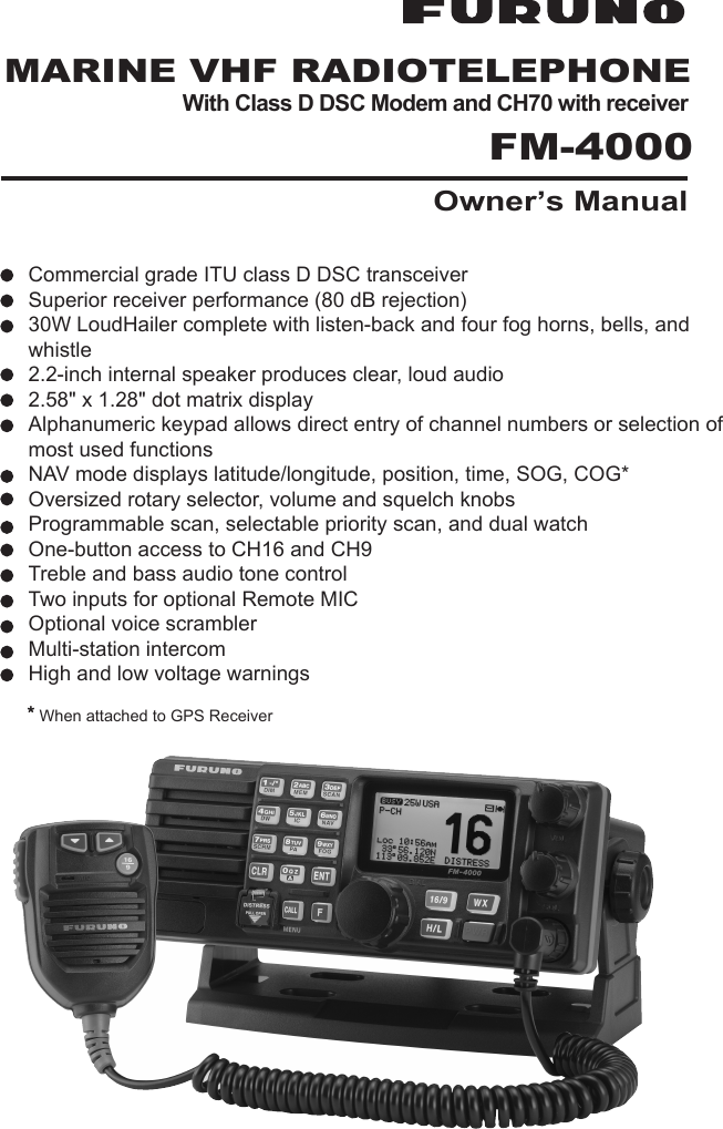
![FM-4000Page 41 GENERAL INFORMATION1.1 INTRODUCTIONThe FURUNO FM-4000 is a Marine VHF Radiotelphone designed for use inthe frequency range of 156.025 to 163.275 MHz. The FM-4000 can be pow-ered with 11 to 16 VDC power and has a switchable RF output power of 1 Wattor 25 Watts.The FM-4000 operates on all currently allocated marine channels. Channelsare switchable for use with USA, International, or Canadian regulations. Emer-gency CH16 can be immediately selected by pressing the red [16/9] key. NOAAweather channels can also be accessed immediately by pressing the [WX]key.The FM-4000 incorporates DSC (Digital Selective Calling) Class D facilitieswhich comply with ITU-R M.493-11 (DSC Class D). Class D operation pro-vides continuous watch on DSC CH70 even if the radio is receiving a call.Two Remote MICs (CMP30, remote-control speaker/microphone with display)are available.The main features arezCommercial grade ITU class D DSC transceiverzSuperior receiver performance (80 dB rejection)z30W LoudHailer complete with listen-back and four fog horns, bells, andwhistlez2.2-inch internal speaker produces clear, loud audioz2.58” x 1.28” dot matrix displayzAlphanumeric keypad allows direct entry of channel numbers or selectionof most used functionszNAV mode displays latitude/longitude, position, time, SOG, COGÚzOversized rotary selector, volume and squelch knobszProgrammable scan, selectable priority scan, and dual watchzOne-button access to CH16 and CH9zTreble and bass audio tone controlzTwo inputs for optional Remote MICzOptional voice scramblerzMulti-station intercomzHigh and low voltage warningsÚWhen connected to a GPS receiver.](https://usermanual.wiki/Furuno-USA/9ZWFM4000.users-manual-part-1/User-Guide-1194860-Page-4.png)
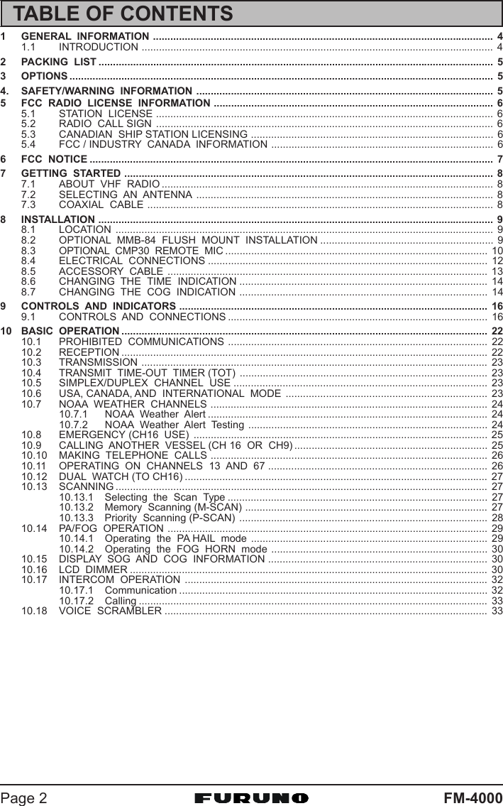
![Page 11FM-4000Remote MIC or External Speaker SelectionBy default the internal speaker is turned on, however it can be turned off to usethe external speaker, when the Remote MIC is installed.Remote MIC procedure1. Press and hold down the [CALL(MENU)] key untilthe “Radio SetupRadio SetupRadio SetupRadio SetupRadio Setup” menu appears.2. Press the [ENT] key, then use the [S] or [T] key toselect “Ext SpeakerExt SpeakerExt SpeakerExt SpeakerExt Speaker.”3. Press the [ENT] key.4. Press the [S] or [T] key to select “OffOffOffOffOff” (Externalspeaker off) or “OnOnOnOnOn” (External speaker on).6. Press the [ENT] key to save the selection, then pressthe [16/9] key to return to radio operation.](https://usermanual.wiki/Furuno-USA/9ZWFM4000.users-manual-part-1/User-Guide-1194860-Page-11.png)
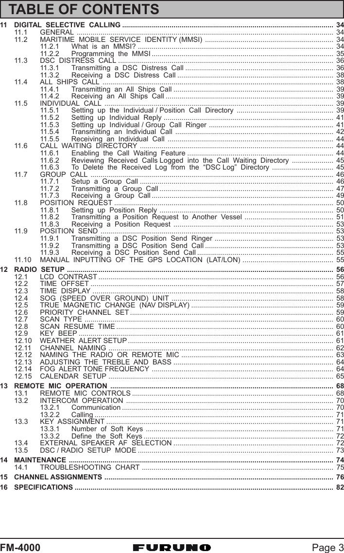
![FM-4000Page 148.6 CHANGING THE TIME INDICATIONSet the radio to show UTC time, or local time with the offset inputted in section“8.5 CHANGING THE GPS TIME.”1. Press and hold down the [CALL(MENU)] key untilthe “Radio SetupRadio SetupRadio SetupRadio SetupRadio Setup” menu appears.2. Press the [ENT] key, then use the CHANNEL selec-tor knob to select “Time DisplayTime DisplayTime DisplayTime DisplayTime Display”.3. Press the [ENT] key.4. Turn the CHANNEL selector knob to select “UTCUTCUTCUTCUTC” or“LocalLocalLocalLocalLocal.”5. Press the [ENT] key to store the selected setting.6. Press the [CLR] key to return to the “Radio SetupRadio SetupRadio SetupRadio SetupRadio Setup”menu, then press the [CLR] key again to return toradio operation.8.7 CHANGING THE COG INDICATIONGPS Course Over Ground can be shown in True or Magnetic bearing. To changethe COG indication, do as follows:1. Press and hold down the [CALL(MENU)] key untilthe “Radio SetupRadio SetupRadio SetupRadio SetupRadio Setup” menu appears.2. Press the [ENT] key, then use the CHANNEL selec-tor knob to select “MagneticMagneticMagneticMagneticMagnetic”.3. Press the [ENT] key.4. Turn the CHANNEL selector knob to select “Mag-Mag-Mag-Mag-Mag-neticneticneticneticnetic” or “TrueTrueTrueTrueTrue.”5. Press the [ENT] key to store the selected setting.6. Press the [CLR] key to return to the “Radio SetupRadio SetupRadio SetupRadio SetupRadio Setup”menu, then press the [CLR] key again to return toradio operation.](https://usermanual.wiki/Furuno-USA/9ZWFM4000.users-manual-part-1/User-Guide-1194860-Page-14.png)
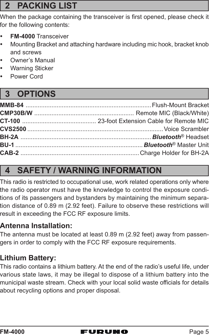
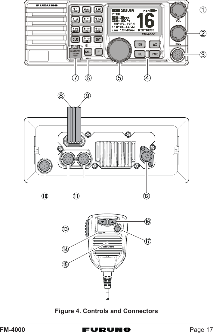
![FM-4000Page 169 CONTROLS AND INDICATIONSNOTEThis section defines each control of the transceiver. See the illustrationon the next page for the location of the controls For detailed operatinginstructions, see Chapter 10.9.1 CONTROLS AND CONNECTORSVOLUME CONTROL (VOL/PWR)Adjusts the audio volume level. Turn the control clockwise to increase theaudio volume level.Secondary UseControls the listen-back volume in the PA or Fog mode.SQUELCH CONTROL (SQL)Adjust this control clockwise to set the point at which random noise on thechannel does not activate the audio circuits but a received signal does.This point is called the squelch threshold. Be careful not to set the squelchtoo high; reception of wanted transmissions will be degraded.MIC ConnectorConnects to the supplied noise-canceling speaker microphone.KEYPAD[WX] KeyImmediately recalls the last-selected NOAA weather channel. Pressingthe [WX] key again reverts to the previously selected working channel.Secondary use:Press the [WX] key while pressing and holding the [16/9] key to switchbetween USA, International and Canadian bands.[PWR] KeyTurns the transceiver on and off. To turn the transceiver on, press andhold this key until the LCD turns on. To turn it off, press and hold this keyuntil the LCD turns off. When the power is turned on, the transceiver isset to the last-selected channel.[16/9] KeyImmediately recalls CH16. Hold down the [16/9] key to recall CH9. Pressthe [16/9] key again to revert to the previously selected working chan-nel.Secondary use:Press the [WX] key while pressing and holding the [16/9] key to switchbetween USA, International and Canadian bands.](https://usermanual.wiki/Furuno-USA/9ZWFM4000.users-manual-part-1/User-Guide-1194860-Page-16.png)
![FM-4000Page 18[H/L] KeyToggles between 25 W (High) and 1 W (Low) power. When the [H/L] keyis pressed while the transceiver is on CH13 or CH67, the power willtemporarily switch from LO to HI power until the PTT is released. The[H/L] key does not function on transmit inhibited and low-power onlychannels.CHANNEL SELECTOR KNOBThis rotary knob selects channels and to chooses menu items (such asthe DSC menu, Radio Setup and DSC Setup menu). The [UP(S)] /[DOWN(T)] keys on the microphone can also be used to select channelsand menu items.Secondary UseyPress the [F] key first then press the [3(SCAN)] key, and turn the CHAN-NEL selector knob while holding down the [3(SCAN)] key to confirmmemory channels for scanning.yAdjusts the PA output level while in PA/FOG mode.KEYPAD[1(DIM)] KeyWhen in the radio mode, this key directly inputs the digit “1” in a channelnumber.Secondary usePress the [F] key first, then press the [1(DIM)] key to access the LCDDimmer menu. See section “10.16 LCD DIMMER” for details.[2(MEM)] KeyWhen in the radio mode, this key directly inputs the digit “2” in a channelnumber.Secondary usePress the [F] key first then press the [2(MEM)] key to memorize theselected channel into the transceiver scan memory for scanning. Re-peating the same procedure ([F] Æ [2(MEM)]), deletes the channel fromthe scan memory. See section “10.13 SCANNING” for details.[3(SCAN)] KeyWhen in the radio mode, this key directly inputs the digit “3” in a channelnumber.Secondary use (Depends on the transceiver version)Press the [F] key first then press the [3(SCAN)] key to start and stop thescanning of programmed channels. See section “10.13 SCANNING” fordetails.](https://usermanual.wiki/Furuno-USA/9ZWFM4000.users-manual-part-1/User-Guide-1194860-Page-18.png)
![Page 19FM-4000[4(DW)] KeyWhen in the radio mode, this key directly inputs the digit “4” in a channelnumber.Secondary usePress the [F] key first then press the [4(DW)] key to scan for voice com-munications on the priority channel and another selected channel untila signal is received on either channel (Dual Watch). See section “10.12DUAL WATCH (TO CH16)” for details.[5(IC)] KeyWhen in the radio mode, this key directly inputs the digit “5” in a channelnumber.Secondary usePress the [F] key first then press the [5(IC)] key, when the optional Re-mote MIC is connected, to activates Intercom function between radioand Remote MIC. See section “10.17 INTERCOM OPERATION” for de-tails.[6(NAV)] KeyWhen in the radio mode, this key directly inputs the digit “6” in a channelnumber.Secondary usePress the [F] key first then press the [6(NAV)] key, and the LCD displaysNAV GPS Data; Time, SOG (Speed Over Ground), and COG (CourseOver Ground). Requires a GPS receiver, connected to the FM-4000with the accessory cable. See section “8.5 ACCESSORY CABLE” fordetails.[7(SCRM)] KeyWhen in radio mode, this key directly inputs the digit “7” in a channelnumber.Secondary usePress the [F] key first then press the [7(SCRM)] key, when the optionalCVS2500 Voice Scrambler Unit is installed, to operate the Voice Scram-bler function. See section “10.18 VOICE SCRAMBLER” for details.[8(PA)] KeyWhen in the radio mode, this key directly inputs the digit “8” in a channelnumber.Secondary usePress the [F] key first then press the [8(PA)] key to operate the 30 WattPA function. See section “10.14 PA/FOG OPERATION” for details.](https://usermanual.wiki/Furuno-USA/9ZWFM4000.users-manual-part-1/User-Guide-1194860-Page-19.png)
![FM-4000Page 20[9(FOG)] KeyWhen in the radio mode, this key directly inputs the digit “9” in a channelnumber.Secondary usePress the [F] key first then press the [9(FOG)] key to operate the FogHorn function. See section “10.14 PA/FOG OPERATION” for details.[0] KeyWhen in the radio mode, this key directly inputs the digit “0” in a channelnumber.[CLR] KeyCancels the menu selection and/or key input.[ENT] KeyConfirms the menu selection and/or key input.[CALL(MENU)] KeyOpens the DSC OPERATION menu. The “Individual CallIndividual CallIndividual CallIndividual CallIndividual Call,” “Group CallGroup CallGroup CallGroup CallGroup Call,”and “All Ship CallAll Ship CallAll Ship CallAll Ship CallAll Ship Call” functions can be accessed from the DSC OPERA-TION menu.Secondary usePress and hold the [CALL(MENU)] key to access the “Radio SetupRadio SetupRadio SetupRadio SetupRadio Setup” menu(see section “12 RADIO SETUP”) or “DSC SetupDSC SetupDSC SetupDSC SetupDSC Setup” menu (see section “11DIGITAL SELECTIVE CALLING”).[F] KeyPress the [F] key to activate the “Alternate” key function.[DISTRESS] KeySend a DSC Distress Call. For details, see section “11.3.1 Transmitting aDSC Distress Call.”DSC SETUP menuIndividual DirectoryIndividual ReplyIndividual AckIndividual RingerGroup DirectoryPosition ReplyPosition InputÚDSC BeepUser MMSIÚ: Shown when a GPS re-ceiver is not connected.RADIO SETUP menuContrastTime OffsetTime DisplaySOG UnitMagneticPriority CHSCAN TypeSCAN ResumeKey BeepWeather AlertCH NameUnit NameTone ControlFOG FrequencyCalendar](https://usermanual.wiki/Furuno-USA/9ZWFM4000.users-manual-part-1/User-Guide-1194860-Page-20.png)
![Page 21FM-4000ACCESSORY CONNECTION CABLEConnects the FM-4000 to a GPS receiver, a PA speaker, and an externalspeaker.DC INPUT CABLEConnects the radio to a DC power supply capable of delivering 12 to 16 VDC.FRONT PANEL REMOTE MIC ConnectorConnects the supplied Hand Microphone if desired. This connector is usedto remote the front panelspeaker MIC. This allowsthe connection of twoMICs, one at the frontpanel and one on therear panel.REMOTE MIC CONNECTORSConnects the FM-4000 to the Remote MIC. See section “13 REMOTE MICOPERATION” for details.ANTENNA JACKConnects an antenna to the transceiver. Use a marine VHF antenna withan impedance of 50 ohms.PTT (Push-To-Talk) SWITCHKeys the transmitter when the transceiver is in the radio mode. If the trans-ceiver is in the Intercom mode (between the Remote MIC and the FM-4000),it activates the FM-4000’s microphone for voice communications.MICROPHONETransmits the voice message with reduction of background noise, usingClear Voice Noise Reduction Technology.MICROPHONE SPEAKERThe same audio heard through internal radio speaker is heard throughmicrophone speaker.[UP(S)] / [DOWN(T)] KEYSThese keys function the same as the CHANNEL selector knob on the frontpanel of the transceiver.[16/9] KeyImmediately recalls CH16. Press and hold the [16/9] key to recall CH9.Press the [16/9] key again to revert the radio to the previously selectedchannel.](https://usermanual.wiki/Furuno-USA/9ZWFM4000.users-manual-part-1/User-Guide-1194860-Page-21.png)
![FM-4000Page 2210 BASIC OPERATION10.1 PROHIBITED COMMUNICATIONSThe FCC prohibits the following communications:• False distress or emergency messages;• Messages to “any boat” except in emergencies and radio tests;• Messages to or from a vessel on land;• Transmission while on land;• Obscene, indecent, or profane language (potential fine of $10,000).10.2 RECEPTION1. After the transceiver has been installed, ensure that the power supply andantenna are properly connected.2. Press and hold the PWR key until the radio turns on.3. Turn the SQL knob fully counterclockwise. This state is known as “squelchoff”.4. Rotate the VOL knob clockwise until noise or audio from the speaker is ata comfortable level.5. Turn the SQL knob clockwise until the random noise disappears. This stateis known as the “squelch threshold.”6. Turn the CHANNEL selector knob to select the desired channel. Refer tothe channel chart on page 91 for available channels.7. The keypad on the front panel may be used to directly select channels. Forexample, to select CH68:1. Press [6(NAV)].2. Press [8(PA)].3. Press [ENT].In the USA and Canadian modes, press and hold down the [0] key to se-lect the “A” channel. Example to select CH22A:1. Press [2(MEM)].2. Press [2(MEM)].3. Press [0] until “A” appears to the right of the channel number.4. Press [ENT].8. When a message is received, adjust the volume to the desired listeninglevel. The “ ” indicator appears if the channel is busy.](https://usermanual.wiki/Furuno-USA/9ZWFM4000.users-manual-part-1/User-Guide-1194860-Page-22.png)
![Page 23FM-400010.3 TRANSMISSION1. Perform steps 1 through 6 in 10.2 RECEPTION.2. Before transmitting, monitor the channel to ensure it is clear.THIS IS AN FCC REQUIREMENT!3. Press the PTT (push-to-talk) switch, and the indication “ ”appears.4. Speak slowly and clearly into the microphone.5. When you have finished transmitting, release the PTT switch.NOTEThis is a noise-canceling microphone. Position the oval slot labeled “MIC”within one-inch (2.5 cm) from your mouth for optimum performance.10.4 TRANSMIT TIME - OUT TIMER (TOT)When the PTT switch on the microphone is held down, transmit time is limited tofive minutes. This limits unintentional transmissions due to a stuck microphone.About 10 seconds before automatic transmitter shutdown, a warning beep soundsfrom the speaker(s). The transceiver will automatically go to the receive mode,even if the PTT switch is continually held down. Before transmitting again, thePTT switch must first be released and then pressed again.10.5 SIMPLEX/DUPLEX CHANNEL USERefer to the VHF MARINE CHANNEL CHART (page 77) for instructions onuse of simplex and duplex channels.NOTEAll channels are factory-programmed in accordance with FCC (USA),Industry Canada (Canada), and International regulations. Mode of op-eration cannot be altered from simplex to duplex or vice-versa.10.6 USA, CANADA, AND INTERNATIONAL MODE1. To change the mode, hold the [16/9] key, then press the [WX] key. Themode changes from USA to International to Canadian with each press ofthe [WX] key.“USA” appears for the USA mode, “INTL” for the International mode, and“CAN” for the Canadian mode.2. See the VHF MARINE CHANNEL CHART (page 77) for allocated chan-nels in each mode.](https://usermanual.wiki/Furuno-USA/9ZWFM4000.users-manual-part-1/User-Guide-1194860-Page-23.png)
![FM-4000Page 2410.7 NOAA WEATHER CHANNELS1. To receive a NOAA (National Oceanic and Atmospheric Administration)weather channel, press the [WX] key. The transceiver will go to the last-selected weather channel.2. Turn the CHANNEL selector knob on the radio or [UP(S)] / [DOWN(T)]keys on the microphone to select a different NOAA weather channel.3. To exit from the NOAA weather channels, press the [WX] key. The trans-ceiver returns to the channel it was on prior to a weather channel.10.7.1 NOAA Weather AlertIn the event of extreme weather disturbances, such as storms and hurricanes,the NOAA sends a weather alert accompanied by a 1050 Hz tone and subse-quent weather report on one of the NOAA weather channels. When the WeatherAlert feature is enabled (see section “12.10 WEATHER ALERT (ON/OFF)”),the transceiver is capable of receiving this alert if you do the following:1. Program NOAA weather channels into the transceiver’s memory for scan-ning. Program by the same procedure as for regular channels, referring tosection “10.13.2 Memory Scanning (M-SCAN).”2. Press the [SCAN] key once to start memory scanning.3. The programmed NOAA weather channels will be scanned along with theregular-programmed channels. However, scanning will not stop on a nor-mal weather broadcast unless a NOAA alert is received.4. When an alert is received on a NOAA weather channel, scanning will stopand the transceiver will emit a loud beep to alert the user to a NOAA broad-cast.5. Press the [WX] key to stop the alert tone and receive the weather report.NOTEIf the [WX] key is not pressed at step 5, the alert tone will be emitted forfive minutes and then the weather report will be received.NOTEThe Weather Alert feature is also engaged while the transceiver is re-ceiving on one of the NOAA weather channels.10.7.2 NOAA Weather Alert TestingNOAA tests the alert system every Wednesday between 11AM and 1PM. Totest the FM-4000’s NOAA Weather feature at that time, setup as directed insection “10.7.1 NOAA Weather Alert” and confirm that you receive the alert.](https://usermanual.wiki/Furuno-USA/9ZWFM4000.users-manual-part-1/User-Guide-1194860-Page-24.png)
![FM-4000Page 26and then go back to either CH16 or CH9 for your initial contact.When the hailing channel (16 or 9) is clear, state the name of the other vesselyou wish to call and then “this is” followed by the name of your vessel andyour Station License (Call Sign). When the other vessel returns your call, im-mediately request another channel by saying “go to,” the number of the otherchannel, and “over.” Then switch to the new channel. When the new channelis not busy, call the other vessel.After a transmission, say “over,” and release the microphone’s push-to-talk(PTT) switch. When all communication with the other vessel is completed, endthe last transmission by stating your Call Sign and the word “out.” Note that itis not necessary to state your Call Sign with each transmission, only at thebeginning and end of the contact.Remember to return to CH16 when not using another channel. Some radiosautomatically monitor CH16 even when set to other channels or when scan-ning.10.10 MAKING TELEPHONE CALLSTo make a radiotelephone call, use a channel designated for this purpose, Thefastest way to learn which channels are used for radiotelephone traffic is toask at a local marina. Channels available for such traffic are designated Pub-lic Correspondence channels on the channel charts in this manual. Someexamples for USA use are Channels 24, 25, 26, 27, 28, 84, 85, 86, and 87.Call the marine operator and identify yourself by your vessel’s name. The marineoperator will then ask you how you will pay for the call (telephone credit card,collect, etc.) and then link your radio transmission to the telephone lines.The marine telephone company managing the VHF channel you are usingmay charge a link-up fee in addition to the cost of the call.10.11 OPERATING ON CHANNELS 13 AND 67CH13 is used at docks and bridges and by vessels maneuvering in port. Mes-sages on this channel must concern navigation only, such as meeting andpassing in restricted waters.CH67 is used for navigational traffic between vessels.By regulation, power is normally limited to 1 Watt on these channels. Yourradio is programmed to automatically reduce power to this limit on these chan-nels. However, in certain situations it may be necessary to temporarily use ahigher power. See page 18 ([H/L] key) for how to temporarily override the low-power limit on these two channels.](https://usermanual.wiki/Furuno-USA/9ZWFM4000.users-manual-part-1/User-Guide-1194860-Page-26.png)
![Page 27FM-400010.12 DUAL WATCH (TO CH16)1. Adjust the SQL knob until the background noise disappears.2. Select the channel you wish to dual watch with CH16.3. Press the [F] key followed by the [4(DW)] key. The display will scan be-tween CH16 and the channel that was selected instep 2.If a transmission is received on the channel selectedin step 2, the FM-4000 watches it and CH16.4. To stop Dual Watch, press the [F] key followed by the [4(DW)] key again.10.13 SCANNINGScanning allows the user to select the scan type from Memory scan or Priorityscan. “Memory scan” scans the channels that were programmed into memory.“Priority scan” scans the channels programmed in memory with the prioritychannel.10.13.1 Selecting the Scan Type1. Press and hold down the [CALL(MENU)] key untilthe “Radio SetupRadio SetupRadio SetupRadio SetupRadio Setup” menu appears.2. Press the [ENT] key, then use the CHANNEL selec-tor knob to select “SCAN TypeSCAN TypeSCAN TypeSCAN TypeSCAN Type”.3. Press the [ENT] key.4. Turn the CHANNEL selector knob to select “PriorityPriorityPriorityPriorityPrioritySCANSCANSCANSCANSCAN” or “Memory SCANMemory SCANMemory SCANMemory SCANMemory SCAN.”5. Press the [ENT] key to store the selected setting.6. Press the [CLR] key to return to the “Radio SetupRadio SetupRadio SetupRadio SetupRadio Setup”menu, then press the [CLR] key again to return toradio operation.10.13.2 Memory Scanning (M-SCAN)1. Adjust the SQL knob until background noise disappears.2. Use the CHANNEL selector knob to select the channel to scan. Press the[F] key followed by the [2(MEM)] key. “MEM” ap-pears on the LCD, which indicates that the channelis programmed into the transceiver’s memory.3. Repeat step 2 to select other channels to scan.4. To DELETE a channel from the transceiver’s memory, select the channelthen press the [F] key followed by the [2(MEM)] key. “MEM” disappearsfrom the LCD.5. To start scanning, press the [F] key followed by the [3(SCAN)] key,“M-SCANM-SCANM-SCANM-SCANM-SCAN” appears on the LCD. Scanning will proceed from the lowest to](https://usermanual.wiki/Furuno-USA/9ZWFM4000.users-manual-part-1/User-Guide-1194860-Page-27.png)
![FM-4000Page 28the highest programmed channel number and willstop on a channel when a transmission is received.6. The channel number will blink during reception.7. To stop scanning, press the [CLR], [16/9], or [WX]key.10.13.3 Priority Scanning (P-SCAN)In the default setting, Channel 16 is set as the priority channel. You may changethe priority channel to the desired channel from CH16 on the Radio Setupmenu. See section “10.13.1 Selecting the Scan Type,” and “12.6 PRIORITYCHANNEL SET.”1. Adjust the SQL knob until background noise disappears.2. Use the CHANNEL selector knob to select the channel to scan. Press the[F] key followed by the [2(MEM)] key. “MEM” ap-pears on the display, which indicates that the chan-nel is programmed into the transceiver’s memory.3. Repeat step 2 to select all the channels to scan.4. To DELETE a channel from the transceiver’s memory, select the channelthen press the [F] key followed by the [2(MEM)] key. “MEM” is removedfrom the display.5. To start priority scanning, press the [F] key followed by the [3(SCAN)] key.“P-SCANP-SCANP-SCANP-SCANP-SCAN” appears on the LCD. Scanning will pro-ceed between the memorized channels and the pri-ority channel. The priority channel will be scannedafter each programmed channel.6. To stop scanning, press the [CLR], [16/9], or [WX] key.You may change the scan resume time in the Radio Setup menu. See section“12.8 SCAN RESUME TIME.”](https://usermanual.wiki/Furuno-USA/9ZWFM4000.users-manual-part-1/User-Guide-1194860-Page-28.png)
![Page 29FM-400010.14 PA/FOG OPERATIONThe FM-4000 has a 30W Hailer that can be used with any 4 Ohm PA horn.When in the Hail mode, the PA speaker listens back (acts as a microphoneand sends sound to the front panel speaker and the speaker MIC) through thePA horn speaker which provides two-way communications through the PA hornspeaker.NOTEBefore entering the PA or Fog mode, the FM-4000 receives on the last-selected VHF channel to receive DSC calls.NOTEIn some areas powerful AM broadcast stations may be heard when inthe listen-back mode. In this case change the speaker wire to 2-con-ductor shielded audio cable. See section “8.5 ACCESSORY CABLE.”PA Hail mode:PA Hail mode allows the transceiver to be used as a power hailer when aHAIL/PA speaker is installed. The PA Hail mode has a listen-back featurewhich provides two-way communication through the HAIL/PA speaker.Fog Horn mode:Automatic signaling is transmitted through the HAIL/PA speaker. When theFog Horn, Bells or Whistle signal is not being outputted, the FM-4000 lis-tens back through the connected PA Horn speaker.10.14.1 Operating the PA Hail mode1. Press the [F] key followed by the [2(MEM)] key toactivate the PA Hail mode.2. Press the PTT switch to speak through the HAIL/PAspeaker.Rotate the CHANNEL selector knob to control theAF output level. The AF output level can be set from0 to 30 watts.3. When the fog signal is not outputted, rotate the VOLknob to adjust the listen-back volume.4. To exit the PA Hail mode, press the [CLR] key.](https://usermanual.wiki/Furuno-USA/9ZWFM4000.users-manual-part-1/User-Guide-1194860-Page-29.png)
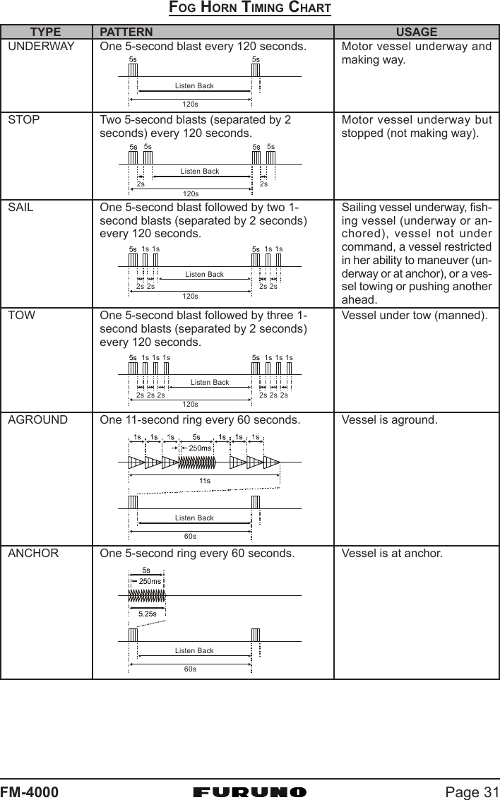
![FM-4000Page 3010.14.2 Operating the Fog Horn modeOperator can select from Underway, Stop, Sail, Tow, Aground, Anchor, Hornand Siren. Refer to the Fog Horn Timing Chart on the next page.1. Press the [F] key followed by the [9(FOG)] key.2. Turn the CHANNEL selector knob to select one ofthe eight functions described above.3. Press the [ENT] key.4. On the Horn and Siren modes, press the PTT switchto activate the tone through the HAIL/PA speaker.Rotate the CHANNEL selector knob to control theAF output level. The AF output level can be set from0 to 30 watts.5. When the fog signal is not outputted, rotate the VOLknob to adjust the listen-back volume.6. To exit the Fog Horn mode, press the [CLR] key.10.15 DISPLAYING SOG AND COG INFORMATIONThe transceiver has the ability to display the time, SOG and COG data, as wellas the vessel’s position (LAT/LON), when connected to a GPS receiver.1. Press the [F] key followed by the [6(NAV)] key todisplay SOG and COG information.2. To hide SOG and COG information, press the [F]key followed by the [6(NAV)] key again.10.16 LCD DIMMERYou can adjust the LCD dimmer as follows:1. Press the [F] key followed by the [1(DIM)] key to enable adjustment of thebacklight intensity.2. Turn the CHANNEL selector knob to select the de-sired backlight intensity.3. Press the [CLR] key to return to “Radio” mode.](https://usermanual.wiki/Furuno-USA/9ZWFM4000.users-manual-part-1/User-Guide-1194860-Page-30.png)
![FM-4000Page 3210.17 INTERCOM OPERATIONConnecting the optional CMP30 Remote MIC to the FM-4000 allows Intercomcommunications. See section “13.2 INTERCOM OPERATION” for operationof the CMP30.10.17.1 Communication1. Press and hold the [5(IC)] key while in the “Radio” mode to change to the“Intercom” mode.2. If your FM-4000 is equipped two Remote MICs, use the CHANNEL selec-tor knob select the one of use (RAM1RAM1RAM1RAM1RAM1, RAM2RAM2RAM2RAM2RAM2, orALLALLALLALLALL), then press the [ENT] key.3. When the “Intercom” feature is activated, “IntercomIntercomIntercomIntercomIntercom”appears on the FM-4000 and CMP30.4. Press the PTT switch. “TalkTalkTalkTalkTalk”appears on the display.NOTE: A warning beep is emit-ted when the FM-4000microphone’s PTT switch ispressed while the RemoteMIC’s PTT switch is pressed.5. Speak slowly and clearly intothe microphone, holding themicrophone about 1/2 inchaway from your mouth.6. When finished, release thePTT switch.7. Press the [CLR] key to returnto the “Radio” mode.(FM-4000 display)(CMP30 display)(FM-4000’s PTT switch is pressed)(CMP30’s PTT switch is pressed)ALLRAM 1 RAM 2ÙRADIO RAM 2ÙRADIO RAM 1ÙRAM 1 RAM 2DISTRESSPULL OPEN-/*JKLRAM 1 RAM 2DISTRESSPULL OPEN-/*JKLRAM 1 RAM 2DISTRESSPULL OPEN-/*JKLRAM 1 RAM 2DISTRESSPULL OPEN-/*JKL](https://usermanual.wiki/Furuno-USA/9ZWFM4000.users-manual-part-1/User-Guide-1194860-Page-32.png)
![Page 33FM-400010.17.2 CallingHold down the [5(IC)] key when the “Intercom” mode is activated to send acalling beep to the Remote MIC.NOTEWhen both Remote MICs are set to the Intercommode, the FM-4000 is temporarily disabled untilboth Remote MICs exit the Intercom mode.10.18 VOICE SCRAMBLERIf privacy of communications is desired, an optional CVS2500 four-code voicescrambler (VS) can be installed in the transceiver. Contact your dealer to havethe CVS2500 installed.1. Turn the CHANNEL selector knob to select the channel to be scramble.Note: The voice scrambler is inoperative on CH16 and CH70.2. Press the [F] key followed by the [7(SCRM)] key toactivate the voice scrambler. “VSVSVSVSVS” and scramblernumber (“00000,” “11111,” “22222,” or “33333”) appear.3. Press the [F] key, then press and hold down the[7(SCRM)] key until the “ScramblerScramblerScramblerScramblerScrambler” menu appears.4. Turn the CHANNEL selector knob to change thescrambler code. The scrambler code can be set from“00000” to “33333.”5. Press the [ENT] key to save the scrambler code and return to the radiooperation mode (with voice scrambler).6. Monitor the channel before transmitting.7. To disable the voice scrambler, press the [F] key followed by the [7(SCRM)]key again. “VSVSVSVSVS” and scrambler number (“00000,” “11111,” “22222,” or “33333”) disappear.](https://usermanual.wiki/Furuno-USA/9ZWFM4000.users-manual-part-1/User-Guide-1194860-Page-33.png)
![Page 35FM-4000THIS NUMBER MUST BE PROGRAMMED INTO THE RADIO TO OPERATETHE DSC FUCTIONS.How can I obtain an MMSI assignment?In the USA, visit the following websites to register:http://www.boatus.com/mmsi/ orhttp://seatow.com/boating_safety/mmsi.aspIn the Canada, visithttp://strategis.ic.gc.ca/epic/site/smt-gst.nsf/vwapj/cpc_2307e.pdf/$FILE/cpc_2307e.pdf11.2.2 Programming the MMSIWARNINGAn MMSI can be inputted only once. Therefore please be careful notto input the incorrect MMSI number. If the user needs to change theMMSI number after it has been entered, the radio will have to be re-turned to the factory.1. Press and hold down the [CALL(MENU)] keyuntil the “Radio SetupRadio SetupRadio SetupRadio SetupRadio Setup” menu appears.2. Turn the CHANNEL selector knob to the left toselect the “DSC SetupDSC SetupDSC SetupDSC SetupDSC Setup” menu.3. Press the [ENT] key, then use the CHANNELselector knob to select “User MMSIUser MMSIUser MMSIUser MMSIUser MMSI.”4. Press the [ENT] key.5. Turn the CHANNEL selector knob or press the[UP(S)] / [DOWN(T)] key on the microphone to se-lect the first number of your MMSI, then pressthe [ENT] key to go to the next number.6. Repeat step 5 to set your MMSI (nine digits).7. When finished programming the number, pressand hold the [ENT] key. A confirmation mes-sage appears on the display. Set your MMSIagain, then press and hold the [ENT] key.8. Press the [ENT] key to store the number in thememory.9. Press the [CLR] key twice to return to the “RadioRadioRadioRadioRadioSetupSetupSetupSetupSetup” menu, then press the [CLR] key againto return to radio operation.](https://usermanual.wiki/Furuno-USA/9ZWFM4000.users-manual-part-1/User-Guide-1194860-Page-35.png)
![FM-4000Page 3611.3 DSC DISTRESS CALLThe FM-4000 is capable of transmitting and receiving DSC distress messagesto all DSC radios. The FM-4000 may be connected to a GPS receiver to alsotransmit the latitude and longitude of your vessel.11.3.1 Transmitting a DSC Distress CallNOTETo transmit a DSC Distress call, an MMSI number must be programmed.See section “11.2.2 Programming the MMSI.”In order for your ship’s location to be transmitted a GPS receiver must beconnected to the FM-4000. See section “8.5 ACCESSORY CABLE.”1. Lift the red spring-loaded DISTRESS cover, then the[DISTRESS] key. The “DISTRESS ALERTDISTRESS ALERTDISTRESS ALERTDISTRESS ALERTDISTRESS ALERT” menu ap-pears on the LCD.2. Press and hold the [DISTRESS] key. The radio’s dis-play counts down (5-4-3-2-1) and then the Distresscall is transmitted. The backlight of the LCD and key-pad flash while the radio’s display is counting down.3. When the distress signal is sent, CH70 and “ ”icon appear on the LCD.4. The transceiver “shadow-watches” for a transmissionbetween CH16 and CH70 until an acknowledgmentsignal is received. “DISTRESS” and “WAITING” ap-pear on the LCD.5. If an acknowledgment is received, select CH16 andadvise your distress situation.6. If no acknowledgment is received, the Distress call is repeated in 4-minuteintervals until an acknowledgment is received.7. When a DSC Distress acknowledgment is received, a distress alarm soundsand CH16 is automatically selected. The LCD shows the MMSI of the shipresponding to your distress.RECEIVED ACK: Acknowledgment signal is received.RECEIVED RLY: Relay signal is received from another vessel or coaststation.8. To cancel the DSC distress alarm signal from the speaker, press any key.](https://usermanual.wiki/Furuno-USA/9ZWFM4000.users-manual-part-1/User-Guide-1194860-Page-36.png)
![Page 37FM-4000Transmitting a DSC Distress Alert with Nature of DistressThe FM-4000 is capable of transmitting a DSC Distress Alert with the following“Nature of Distress” categories:Undesignated, Fire, Flooding, Collision, Grounding, Capsizing, Sinking,Adrift, Abandoning, Piracy, MOB1. Lift the red spring-loaded DISTRESS key, then the[DISTRESS] key to show the “DISTRESS ALERTDISTRESS ALERTDISTRESS ALERTDISTRESS ALERTDISTRESS ALERT”menu.2. Turn the CHANNEL selector knob to select the de-sired nature of distress category.3. When the FM-4000 is connected to a GPS receiver,skip to step 4.When the FM-4000 is not connected to a GPS re-ceiver, you may send the latitude/longitude of yourvessel manually, if desired.a. Press the [ENT] key twice. The display looks likethe illustration at the right.b. Enter your local UTC time, then press the [ENT] key.c. Enter the latitude/longitude of your vessel, then press the [ENT] key. Toselect North (N) press the [6(NAV)] key, South (S) press the [7(SCRM)]key, East (E) press the [3(SCAN)] key or West (W) press the [9(FOG)]key.d. To store the data entered, press and hold the [ENT] key.4. Press and hold the [DISTRESS] key. The radio’s dis-play counts down (5-4-3-2-1) and then the distresscall is transmitted. The backlight of the LCD and key-pad flash during the countdown.5. When the distress signal is sent, CH70 and “ ”icon appear on the LCD.6. The transceiver will watch for a DSC acknowledgmenttransmission on CH70 and also receive calls on CH16.7. When a DSC Distress acknowledgment is received,a distress alarm sounds and channel 16 is auto-matically selected. The LCD shows the MMSI of theship responding to your distress.RECEIVED ACK: Acknowledgment signal is received.RECEIVED RLY ACK: Relay acknowledgment signal is received from an-other vessel or coast station.8. To cancel the DSC distress alarm signal from the speaker, press any key.](https://usermanual.wiki/Furuno-USA/9ZWFM4000.users-manual-part-1/User-Guide-1194860-Page-37.png)
![FM-4000Page 38Cancel a DSC Distress CallIf a DSC Distress call was sent by error, the FM-4000 allows you to send amessage to other vessels to cancel the Distress call.Press the [CLR] key, then press the [ENT] key.11.3.2 Receiving a DSC Distress Call1. When a DSC Distress call is received, an emergencyalarm sounds.Then CH16 is automatically selected.2. Press any key to stop the alarm.3. The LCD shows the position of the vessel in distress.4 If the distress data does not include latitude/longi-tude position, the display shown right appears.NOTEYou must continue monitoring CH16 as a coast station may require as-sistance in the rescue attempt.11.4 ALL SHIPS CALLThe All Ships call function allows contact to be established with other vesselstations without having their ID in the individual calling directory. Also, priorityfor the call can be designated as Urgency or Safety.URGENCY Call:This type of call is used when a vessel may not truly be indistress, but have a potential problem that may lead to a dis-tress situation. This call is the same as saying “PAN PAN PAN”on CH16.SAFETY Call: Transmit boating safety information to other vessels. This mes-sage usually contains information about an overdue boat, de-bris in the water, loss of a navigation aid or an important me-teorological message. This call is the same as saying“Securite, Securite, Securite.”](https://usermanual.wiki/Furuno-USA/9ZWFM4000.users-manual-part-1/User-Guide-1194860-Page-38.png)
![Page 39FM-400011.4.1 Transmitting an All Ships Call1. Press the [CALL(MENU)] key to show the “DSCDSCDSCDSCDSCCall MenuCall MenuCall MenuCall MenuCall Menu.”2. Turn the CHANNEL selector knob to select “AllAllAllAllAllShipsShipsShipsShipsShips.”3. Press the [ENT] key. (To cancel, turn theCHANNEL selector knob to select “ExitExitExitExitExit.”)4. Turn the CHANNEL selector knob to select thenature of call (“UrgencyUrgencyUrgencyUrgencyUrgency” or “SafetySafetySafetySafetySafety”), then pressthe [ENT] key.5. Press the [ENT] key again to transmit the selectedtype of All Ships call.6. After the All Ships call is transmitted, the transceiverswitches to CH16.7. Listen to the channel to make sure it is not busy,then key the microphone and say “PAN PAN PAN”or “Securite, Securite, Securite” depending on thepriority of the call. Then announce both your call signand the channel you wish to switch to for communi-cations.11.4.2 Receiving an All Ships Call1. When an All Ships call is received, an emergency alarm sounds.The radio will automatically change to CH16 andthe LCD shows the MMSI of the vessel transmittingthe All Ships call.2. Press any key to stop the alarm.3. Monitor CH16 or traffic channel until the Urgency voice communication iscompleted.11.5 INDIVIDUAL CALLThis feature allows the FM-4000 to contact another vessel with a DSC VHFradio and automatically switch the receiving radio to a desired communica-tions channel. This feature is similar to calling a vessel on CH16 and request-ing to go to another channel (switching to the channel is private between thetwo stations).11.5.1 Setting up the Individual / Position Call DirectoryThe FM-4000 has a DSC directory that allows you to store a vessel or person’sname and the MMSI number associated with vessels you wish to transmitIndividual calls, position requests and position send transmissions.](https://usermanual.wiki/Furuno-USA/9ZWFM4000.users-manual-part-1/User-Guide-1194860-Page-39.png)
![FM-4000Page 40To transmit an Individual call you must program this directory with informationof the persons you wish to call, similar to the telephone directory of a cellularphone.1. Press and hold down the [CALL(MENU)] keyuntil the “Radio SetupRadio SetupRadio SetupRadio SetupRadio Setup” menu appears.2. Turn the CHANNEL selector knob to select the“DSC SetupDSC SetupDSC SetupDSC SetupDSC Setup” menu.3. Press the [ENT] key, then use the CHANNELselector knob to select “Individual DirectoryIndividual DirectoryIndividual DirectoryIndividual DirectoryIndividual Directory.”4. Press the [ENT] key.5. Select “AddAddAddAddAdd” with the CHANNEL selector knob,then press the [ENT] key.6. Press applicable key to enter the first letter of thename of the vessel or person you want to referencein the directory.Example: Press the [2(MEM)] key repeatedly totoggle among the seven available characters asso-ciated with that key: 22222 Æ AAAAA Æ BBBBB Æ CCCCC Æ aaaaa Æ bbbbb Æ ccccc Æ 22222 ....If you enter a wrong charactor, press the [CLR] keyto delete the wrong character.7. Press the [ENT] key to store the first letter in the name and move to thenext letter to the right.8. Repeat steps 6 and 7 to complete the name. Thename can consist of up to 11 characters. If you donot use all 11 characters press the [ENT] key to moveto the next space. This method can also be used to enter a blank space inthe name. If you enter a wrong character, press the [H/L] key until thewrong character is selected, then enter the correct character.9. After the 11th letter or space has been entered, press and hold the [ENT]key to advance to the MMSI (Maritime Mobile Ser-vice Identity Number) number entry.10. Enter the desired number. If you enter a wrong num-ber, press the [H/L] key until the wrong number isselected, then enter the correct number.11. To store the data entered, press and hold the [ENT]key.12. To enter another individual address, repeat steps 5through 11.13. Press the [CLR] key twice to return to the “Radio SetupRadio SetupRadio SetupRadio SetupRadio Setup” menu, then pressthe [CLR] key again to return to radio operation.](https://usermanual.wiki/Furuno-USA/9ZWFM4000.users-manual-part-1/User-Guide-1194860-Page-40.png)
![Page 41FM-400011.5.2 Setting up Individual ReplyAllows setting up the radio to automatically (default setting) or manually re-spond to a DSC Individual call requesting you to switch to a working channelfor voice communications. When Manual is selected, the MMSI of the callingvessel is shown, allowing you to see who is calling. This function is similar tothe caller ID on a cellular phone.1. Press and hold down the [CALL(MENU)] keyuntil the “Radio SetupRadio SetupRadio SetupRadio SetupRadio Setup” menu appears.2. Turn the CHANNEL selector knob to select“DSC SetupDSC SetupDSC SetupDSC SetupDSC Setup” menu.3. Press the [ENT] key, then use the CHANNELselector knob to select “Individual ReplyIndividual ReplyIndividual ReplyIndividual ReplyIndividual Reply.”4. Press the [ENT] key.5. Turn the CHANNEL selector knob to select “Au-Au-Au-Au-Au-tomatictomatictomatictomatictomatic” or “ManualManualManualManualManual.”6. Press the [ENT] key to store the selected setting.7. Press the [CLR] key twice to return to the “Radio SetupRadio SetupRadio SetupRadio SetupRadio Setup” menu, then pressthe [CLR] key again to return to radio operation.11.5.3 Setting up Individual/Group Call RingerWhen an Individual call or Group call is received the radio will produce a ring-ing tone for two minutes. This selection allows the Individual call ringer time tobe changed.1. Press and hold down the [CALL(MENU)] keyuntil “Radio SetupRadio SetupRadio SetupRadio SetupRadio Setup” menu appears.2. Turn the CHANNEL selector knob to select“DSC SetupDSC SetupDSC SetupDSC SetupDSC Setup” menu.3. Press the [ENT] key, then use the CHANNELselector knob to select “Individual RingerIndividual RingerIndividual RingerIndividual RingerIndividual Ringer.”4. Press the [ENT] key.5. Turn the CHANNEL selector knob to selectringing time for an Individual call.6. Press the [ENT] key to store the selected setting.7. Press the [CLR] key twice to return to the “Radio SetupRadio SetupRadio SetupRadio SetupRadio Setup” menu, then pressthe [CLR] key again to return to radio operation.](https://usermanual.wiki/Furuno-USA/9ZWFM4000.users-manual-part-1/User-Guide-1194860-Page-41.png)
![FM-4000Page 42The Individual call and Group call ringers can be disabled as follows:1. Press and hold down the [CALL(MENU)] keyuntil “Radio SetupRadio SetupRadio SetupRadio SetupRadio Setup” menu appears.2. Turn the CHANNEL selector knob to select the“DSC SetupDSC SetupDSC SetupDSC SetupDSC Setup” menu.3. Press the [ENT] key, then use the CHANNELselector knob to select “DSC BeepDSC BeepDSC BeepDSC BeepDSC Beep.”4. Press the [ENT] key.5. Turn the CHANNEL selector knob to select “In-In-In-In-In-dividualdividualdividualdividualdividual” if you wish to disable the Individual callringer, or “GroupGroupGroupGroupGroup” if you wish to disable the Groupcall ringer and press the [ENT] key.6. Turn the CHANNEL selector knob to select “OffOffOffOffOff.”7. Press the [ENT] key to store the selected setting.8. Press the [CLR] key twice to return to the “RadioRadioRadioRadioRadioSetupSetupSetupSetupSetup” menu, then press the [CLR] key again to re-turn to radio operation.To enable the Individual or Group ringer tone, select “OnOnOnOnOn” in step “6” in thisprocedure.11.5.4 Transmitting an Individual CallThe Individual call feature allows you to contact another vessel that has a DSCradio. This feature is similar to calling a vessel on CH16 and requesting to goto another channel.Using Pre-Programmed Vessel1. Press the [CALL(MENU)] key to show the “DSCDSCDSCDSCDSCCall MenuCall MenuCall MenuCall MenuCall Menu”.2. Turn the CHANNEL selector knob to select “In-In-In-In-In-dividualdividualdividualdividualdividual.” (To cancel, press the [CLR] key.)3. Press the [ENT] key. The transceiver beepsthen the “Individual directory” appears.4. Turn the CHANNEL selector knob to select the“Individual” you want to contact.5. Press the [ENT] key, then turn the CHANNELselector knob to select the operating channelyou want to communicate on, then press the[ENT] key.6. Press the [ENT] key again to transmit the individualDSC signal.](https://usermanual.wiki/Furuno-USA/9ZWFM4000.users-manual-part-1/User-Guide-1194860-Page-42.png)
![Page 43FM-40007. When an Individual call acknowledgment is re-ceived, the channel selected at step 5 is auto-matically selected and a ringing tone sounds.8. Press [CLR] key to listen to the channel to makesure it is not busy, then key the microphone tocall the other vessel.Manual CallingYou may enter an MMSI number manually to contact a vessel which is notstored in the Individual Directory.1. Press the [CALL(MENU)] key to show the “DSCDSCDSCDSCDSCCall MenuCall MenuCall MenuCall MenuCall Menu.”2. Turn the CHANNEL selector knob to select “In-In-In-In-In-dividualdividualdividualdividualdividual.” (To cancel, press the [CLR] key.)3. Press the [ENT] key. The transceiver beepsthen the “Individual directory” appears.4. Turn the CHANNEL selector knob to select“ManualManualManualManualManual,” then press the [ENT] key.5. Enter the MMSI number (nine digits) which you wantto contact, then press the [ENT] key.6. If you enter the wrong number in the MMSI number,press the [H/L] key until the wrong number is se-lected, then enter the correct number.7. When you are finished entering the MMSI number,press and hold the [ENT] key.8. Turn the CHANNEL selector knob to select“ManualManualManualManualManual,” then press the [ENT] key.9. Turn the CHANNEL selector knob to select theoperating channel you want to communicate on, thenpress the [ENT] key.10. Press the [ENT] key again to transmit the indi-vidual DSC signal.11. When an Individual call acknowledgment is re-ceived, the channel selected at step 5 is auto-matically selected and a ringing tone sounds.12. Press the [CLR] key to listen to the channel tomake sure it is not busy, then key the micro-phone to call the other vessel.](https://usermanual.wiki/Furuno-USA/9ZWFM4000.users-manual-part-1/User-Guide-1194860-Page-43.png)