Furuno USA 9ZWFM4000 VHF Radiotelephone User Manual FM 4000 pmd
Furuno USA Inc VHF Radiotelephone FM 4000 pmd
Contents
- 1. users manual part 1
- 2. users manual part 2
users manual part 1
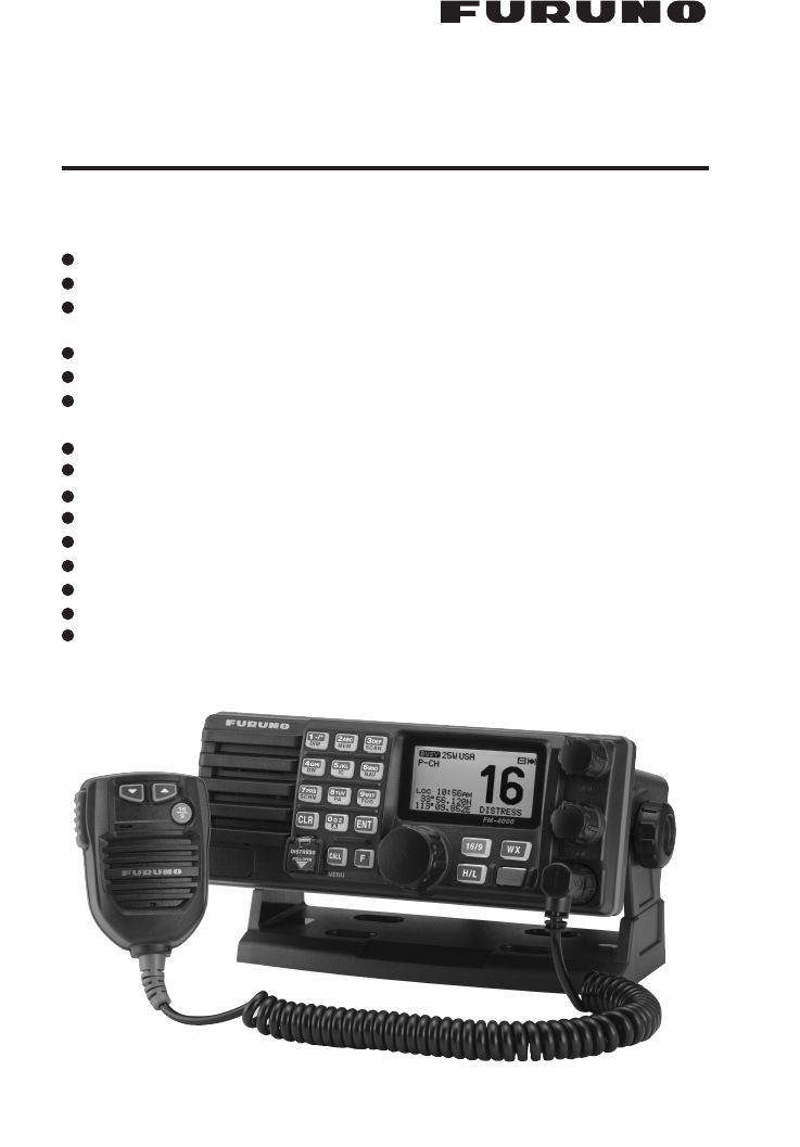
Page 1FM-4000
MARINE VHF RADIOTELEPHONE
With Class D DSC Modem and CH70 with receiver
FM-4000
Owner’s Manual
l
l
l
l
l
l
l
l
l
l
l
l
l
l
l
**
When attached to GPS Receiver
Commercial grade ITU class D DSC transceiver
Superior receiver performance (80 dB rejection)
30W LoudHailer complete with listen-back and four fog horns, bells, and
whistle
2.2-inch internal speaker produces clear, loud audio
2.58" x 1.28" dot matrix display
Alphanumeric keypad allows direct entry of channel numbers or selection of
most used functions
NAV mode displays latitude/longitude, position, time, SOG, COG*
Oversized rotary selector, volume and squelch knobs
Programmable scan, selectable priority scan, and dual watch
One-button access to CH16 and CH9
Treble and bass audio tone control
Two inputs for optional Remote MIC
Optional voice scrambler
Multi-station intercom
High and low voltage warnings

FM-4000Page 2
1 GENERAL INFORMATION ...................................................................................................................... 4
1.1 INTRODUCTION .......................................................................................................................... 4
2 PACKING LIST ......................................................................................................................................... 5
3 OPTIONS ................................................................................................................................................... 5
4. SAFETY/WARNING INFORMATION ....................................................................................................... 5
5 FCC RADIO LICENSE INFORMATION ................................................................................................. 6
5.1 STATION LICENSE ..................................................................................................................... 6
5.2 RADIO CALL SIGN ..................................................................................................................... 6
5.3 CANADIAN SHIP STATION LICENSING .................................................................................... 6
5.4 FCC / INDUSTRY CANADA INFORMATION ............................................................................. 6
6 FCC NOTICE ............................................................................................................................................ 7
7 GETTING STARTED ................................................................................................................................ 8
7.1 ABOUT VHF RADIO ................................................................................................................... 8
7.2 SELECTING AN ANTENNA .......................................................................................................8
7.3 COAXIAL CABLE ........................................................................................................................ 8
8 INSTALLATION ......................................................................................................................................... 9
8.1 LOCATION ................................................................................................................................... 9
8.2 OPTIONAL MMB-84 FLUSH MOUNT INSTALLATION ............................................................ 9
8.3 OPTIONAL CMP30 REMOTE MIC ........................................................................................... 10
8.4 ELECTRICAL CONNECTIONS ................................................................................................. 12
8.5 ACCESSORY CABLE ............................................................................................................... 13
8.6 CHANGING THE TIME INDICATION ...................................................................................... 14
8.7 CHANGING THE COG INDICATION ...................................................................................... 14
9 CONTROLS AND INDICATORS ........................................................................................................... 16
9.1 CONTROLS AND CONNECTIONS .......................................................................................... 16
10 BASIC OPERATION ............................................................................................................................... 22
10.1 PROHIBITED COMMUNICATIONS .......................................................................................... 22
10.2 RECEPTION ............................................................................................................................... 22
10.3 TRANSMISSION ........................................................................................................................ 23
10.4 TRANSMIT TIME-OUT TIMER (TOT) ...................................................................................... 23
10.5 SIMPLEX/DUPLEX CHANNEL USE ........................................................................................ 23
10.6 USA, CANADA, AND INTERNATIONAL MODE ...................................................................... 23
10.7 NOAA WEATHER CHANNELS ................................................................................................ 24
10.7.1 NOAA Weather Alert ................................................................................................. 24
10.7.2 NOAA Weather Alert Testing ................................................................................... 24
10.8 EMERGENCY (CH16 USE) ...................................................................................................... 25
10.9 CALLING ANOTHER VESSEL (CH 16 OR CH9) ................................................................... 25
10.10 MAKING TELEPHONE CALLS ................................................................................................ 26
10.11 OPERATING ON CHANNELS 13 AND 67 ............................................................................ 26
10.12 DUAL WATCH (TO CH16) ......................................................................................................... 27
10.13 SCANNING ................................................................................................................................. 27
10.13.1 Selecting the Scan Type .......................................................................................... 27
10.13.2 Memory Scanning (M-SCAN) .................................................................................... 27
10.13.3 Priority Scanning (P-SCAN) ...................................................................................... 28
10.14 PA/FOG OPERATION ............................................................................................................... 29
10.14.1 Operating the PA HAIL mode .................................................................................. 29
10.14.2 Operating the FOG HORN mode ........................................................................... 30
10.15 DISPLAY SOG AND COG INFORMATION ............................................................................ 30
10.16 LCD DIMMER ............................................................................................................................ 30
10.17 INTERCOM OPERATION ......................................................................................................... 32
10.17.1 Communication ........................................................................................................... 32
10.17.2 Calling ......................................................................................................................... 33
10.18 VOICE SCRAMBLER ................................................................................................................ 33
TABLE OF CONTENTS

Page 3FM-4000
11 DIGITAL SELECTIVE CALLING ........................................................................................................... 34
11.1 GENERAL .................................................................................................................................. 34
11.2 MARITIME MOBILE SERVICE IDENTITY (MMSI) ................................................................. 34
11.2.1 What is an MMSI? ................................................................................................... 34
11.2.2 Programming the MMSI ............................................................................................ 35
11.3 DSC DISTRESS CALL ............................................................................................................. 36
11.3.1 Transmitting a DSC Distress Call ........................................................................... 36
11.3.2 Receiving a DSC Distress Call ............................................................................... 38
11.4 ALL SHIPS CALL ..................................................................................................................... 38
11.4.1 Transmitting an All Ships Call ................................................................................. 39
11.4.2 Receiving an All Ships Call ..................................................................................... 39
11.5 INDIVIDUAL CALL .................................................................................................................... 39
11.5.1 Setting up the Individual / Position Call Directory ................................................. 39
11.5.2 Setting up Individual Reply ...................................................................................... 41
11.5.3 Setting up Individual / Group Call Ringer ............................................................... 41
11.5.4 Transmitting an Individual Call ................................................................................ 42
11.5.5 Receiving an Individual Call .................................................................................... 44
11.6 CALL WAITING DIRECTORY .................................................................................................. 44
11.6.1 Enabling the Call Waiting Feature .......................................................................... 44
11.6.2 Reviewing Received Calls Logged into the Call Waiting Directory ..................... 45
11.6.3 To Delete the Received Log from the “DSC Log” Directory ............................... 45
11.7 GROUP CALL ........................................................................................................................... 46
11.7.1 Setup a Group Call .................................................................................................. 46
11.7.2 Transmitting a Group Call ........................................................................................ 47
11.7.3 Receiving a Group Call ............................................................................................ 49
11.8 POSITION REQUEST ............................................................................................................... 50
11.8.1 Setting up Position Reply ........................................................................................ 50
11.8.2 Transmitting a Position Request to Another Vessel ............................................. 51
11.8.3 Receiving a Position Request ................................................................................. 53
11.9 POSITION SEND ...................................................................................................................... 53
11.9.1 Transmitting a DSC Position Send Ringer ............................................................ 53
11.9.2 Transmitting a DSC Position Send Call ................................................................. 53
11.9.3 Receiving a DSC Position Send Call ..................................................................... 55
11.10 MANUAL INPUTTING OF THE GPS LOCATION (LAT/LON) .............................................. 55
12 RADIO SETUP ....................................................................................................................................... 56
12.1 LCD CONTRAST ....................................................................................................................... 56
12.2 TIME OFFSET ........................................................................................................................... 57
12.3 TIME DISPLAY .......................................................................................................................... 58
12.4 SOG (SPEED OVER GROUND) UNIT .................................................................................. 58
12.5 TRUE MAGNETIC CHANGE (NAV DISPLAY) ........................................................................ 59
12.6 PRIORITY CHANNEL SET ....................................................................................................... 59
12.7 SCAN TYPE .............................................................................................................................. 60
12.8 SCAN RESUME TIME .............................................................................................................. 60
12.9 KEY BEEP ................................................................................................................................. 61
12.10 WEATHER ALERT SETUP ........................................................................................................ 61
12.11 CHANNEL NAMING .................................................................................................................. 62
12.12 NAMING THE RADIO OR REMOTE MIC ............................................................................. 63
12.13 ADJUSTING THE TREBLE AND BASS ................................................................................. 64
12.14 FOG ALERT TONE FREQUENCY ............................................................................................ 64
12.15 CALENDAR SETUP .................................................................................................................. 65
13 REMOTE MIC OPERATION ................................................................................................................. 68
13.1 REMOTE MIC CONTROLS ...................................................................................................... 68
13.2 INTERCOM OPERATION .........................................................................................................70
13.2.1 Communication ........................................................................................................... 70
13.2.2 Calling ......................................................................................................................... 71
13.3 KEY ASSIGNMENT ................................................................................................................... 71
13.3.1 Number of Soft Keys ............................................................................................... 71
13.3.2 Define the Soft Keys ................................................................................................ 72
13.4 EXTERNAL SPEAKER AF SELECTION ................................................................................. 72
13.5 DSC / RADIO SETUP MODE ................................................................................................... 73
14 MAINTENANCE ...................................................................................................................................... 74
14.1 TROUBLESHOOTING CHART ................................................................................................. 75
15 CHANNEL ASSIGNMENTS .................................................................................................................... 76
16 SPECIFICATIONS ................................................................................................................................... 82
TABLE OF CONTENTS

FM-4000Page 4
1 GENERAL INFORMATION
1.1 INTRODUCTION
The FURUNO FM-4000 is a Marine VHF Radiotelphone designed for use in
the frequency range of 156.025 to 163.275 MHz. The FM-4000 can be pow-
ered with 11 to 16 VDC power and has a switchable RF output power of 1 Watt
or 25 Watts.
The FM-4000 operates on all currently allocated marine channels. Channels
are switchable for use with USA, International, or Canadian regulations. Emer-
gency CH16 can be immediately selected by pressing the red [16/9] key. NOAA
weather channels can also be accessed immediately by pressing the [WX]
key.
The FM-4000 incorporates DSC (Digital Selective Calling) Class D facilities
which comply with ITU-R M.493-11 (DSC Class D). Class D operation pro-
vides continuous watch on DSC CH70 even if the radio is receiving a call.
Two Remote MICs (CMP30, remote-control speaker/microphone with display)
are available.
The main features are
zCommercial grade ITU class D DSC transceiver
zSuperior receiver performance (80 dB rejection)
z30W LoudHailer complete with listen-back and four fog horns, bells, and
whistle
z2.2-inch internal speaker produces clear, loud audio
z2.58” x 1.28” dot matrix display
zAlphanumeric keypad allows direct entry of channel numbers or selection
of most used functions
zNAV mode displays latitude/longitude, position, time, SOG, COGÚ
zOversized rotary selector, volume and squelch knobs
zProgrammable scan, selectable priority scan, and dual watch
zOne-button access to CH16 and CH9
zTreble and bass audio tone control
zTwo inputs for optional Remote MIC
zOptional voice scrambler
zMulti-station intercom
zHigh and low voltage warnings
ÚWhen connected to a GPS receiver.

Page 5FM-4000
2 PACKING LIST
When the package containing the transceiver is first opened, please check it
for the following contents:
yFM-4000 Transceiver
yMounting Bracket and attaching hardware including mic hook, bracket knob
and screws
yOwner’s Manual
yWarning Sticker
yPower Cord
3 OPTIONS
MMB-84 .........................................................................Flush-Mount Bracket
CMP30B/W .......................................................... Remote MIC (Black/White)
CT-100 ........................................... 23-foot Extension Cable for Remote MIC
CVS2500 ...............................................................................Voice Scrambler
BH-2A ............................................................................ Bluetooth® Headset
BU-1 .......................................................................... Bluetooth® Master Unit
CAB-2 ..................................................................... Charge Holder for BH-2A
4 SAFETY / WARNING INFORMATION
This radio is restricted to occupational use, work related operations only where
the radio operator must have the knowledge to control the exposure condi-
tions of its passengers and bystanders by maintaining the minimum separa-
tion distance of 0.89 m (2.92 feet). Failure to observe these restrictions will
result in exceeding the FCC RF exposure limits.
Antenna Installation:
The antenna must be located at least 0.89 m (2.92 feet) away from passen-
gers in order to comply with the FCC RF exposure requirements.
Lithium Battery:
This radio contains a lithium battery. At the end of the radio’s useful life, under
various state laws, it may be illegal to dispose of a lithium battery into the
municipal waste stream. Check with your local solid waste officials for details
about recycling options and proper disposal.

FM-4000Page 6
5 FCC RADIO LICENSE INFORMATION
FURUNO radios comply with the Federal Communication Commission (FCC)
requirements that regulate the Maritime Radio Service.
5.1 STATION LICENSE
An FCC ship station license is no longer required for any vessel traveling in
U.S. waters (except Hawaii) which is less than 20 meters in length. However,
any vessel required to carry a marine radio on an international voyage, carry-
ing an HF single sideband radiotelephone or marine satellite terminal is re-
quired to have a ship station license. FCC license forms, including applica-
tions for ship (506) and land station licenses can be downloaded via the Internet
at www.fcc.gov/forms. To obtain a form from the FCC, call (888) 225-5322.
5.2 RADIO CALL SIGN
Currently the FCC does not require recreational boaters to have a Ship Radio
Station License. The USCG recommends that you use your boat's registration
number and the state in which it is registered.
5.3 CANADIAN SHIP STATION LICENSING
You may need a license when traveling in Canada. If you do need a license
contact their nearest field office or regional office or write:
Industry Canada
Radio Regulatory Branch
Attn: DOSP
300 Slater Street
Ottawa, Ontario
Canada, KIA 0C8
5.4 FCC / INDUSTRY CANADA INFORMATION
The following data pertaining to the transceiver is necessary to fill out the li-
cense application.
Type Acceptance ......................................................................... FCC Part 80
Output Power ...............................................1 Watt (low) and 25 Watts (high)
Emission ......................................................................... 16K0G3E, 16K0G2B
Frequency Range .................................................... 156.025 to 163.275 MHz
FCC Type Number ...................................................................K6630283X3S
Industry Canada Type Approval ............................................ 511B-30283X3S

Page 7FM-4000
6 FCC NOTICE
NOTICE
Unauthorized changes or modifications to this equipment may void com-
pliance with FCC Rules. Any change or modification must be approved
in writing by STANDARD HORIZON.
NOTICE
This equipment has been tested and found to comply with the limits for
a Class B digital device, pursuant to Part 15 of the FCC Rules. These
limits are designed to provide reasonable protection against harmful
interference in a residential installation. This equipment generates, uses
and can radiate radio frequency energy and, if not installed and used in
accordance with the instructions, may cause harmful interference to ra-
dio communications. However, there is no guarantee that interference
will not occur in a particular installation. If this equipment does cause
harmful interference to radio or television reception, which can be de-
termined by turning the equipment off and on, the user is encouraged to
try to correct the interference by one or more of the following measures:
- Reorient or relocate the receiving antenna.
- Increase the separation between the equipment and receiver.
- Connect the equipment into an outlet on a circuit different from that to
which the receiver is connected.
- Consult the dealer or an experienced radio/TV technician for help.
FM-4000Page 8
7 GETTING STARTED
7.1 ABOUT VHF RADIO
The radio frequencies used in the VHF marine band lie between 156 and 158
MHz with some shore stations available between 161 and 163 MHz. The ma-
rine VHF band provides communications over distances that are essentially
“line of sight” (VHF signals do not travel well through objects such as buildings,
hills or trees). Actual transmission range depends much more on antenna type,
gain and height than on the power output of the transmitter. On a fixed mount
25 W radio transmission expected distances can be greater than 15 miles, for
a portable 5 W radio transmission the expected distance can be greater than 5
miles in “line of sight”.
7.2 SELECTING AN ANTENNA
Marine antennas are made to radiate signals equally in all horizontal direc-
tions, but not straight up. The objective of a marine antenna is to enhance the
signal toward the horizon. The degree to which this is accomplished is called
the antenna’s gain. It is measured in decibels (dB) and is one of the major
factors in choosing an antenna. In terms of effective radiated power (ERP),
antennas are rated on the basis of how much gain they have over a theoretical
antenna with zero gain. A 3-foot, 3 dB gain antenna represents twice as much
gain over the imaginary antenna.
Typically a 3-foot 3 dB gain stainless steel whip is used on a sailboat mast. The
longer 8-foot 6 dB fiberglass whip is primarily used on powerboats that require
the additional gain.
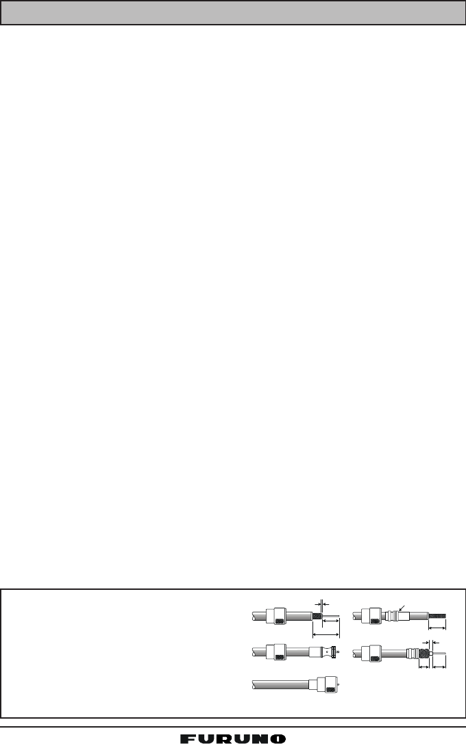
7.3 COAXIAL CABLE
VHF antennas are connected to the transceiver by means of a coaxial cable –
a shielded transmission line. Coaxial cables are specified by their diameters
and construction.
For runs less than 20 feet, RG-58/U, about 1/4-inch in diameter, is a good
choice. For runs over 20 feet but less than 50 feet, the larger diameter RG-8X
or RG-213/U should be used. Cable runs over 50 feet should use RG-8X. For
installation of the connector onto the coaxial cable see the figure below.
To get your coaxial cable through a
fitting and into your boat’s interior, you
may have to cut off the end plug and
reattach it later. You can do this if you
follow the directions that come with the
connector. Be sure to make good sol-
dered connections.
1/16''
3/4''
1 1/ 8 ''
3/4''
Adapter
1/8''
5/8''3/8''
Page 9FM-4000
8 INSTALLATION
8.1 LOCATION
The radio can be mounted at any angle. Choose a mounting location that:
• is far enough from any compass to avoid any deviation in compass read-
ing due to the speaker magnet (see the compass safe distances in the
Safety Instructions)
• provides easy access to the front panel controls and rear connectors
• allows connection to a power source and an antenna
• has nearby space for installation of a microphone hanger
• the antenna must be mounted at least three feet from the radio
Note: To insure the radio does not affect the compass or the radio’s perfor-
mance is not affected by the antenna location, temporarily connect the radio in
the desired location and:
a. Examine the compass to see if the radio causes any deviation.
b. Connect the antenna and key the radio. Check to ensure the radio is
operating correctly by requesting a radio check.
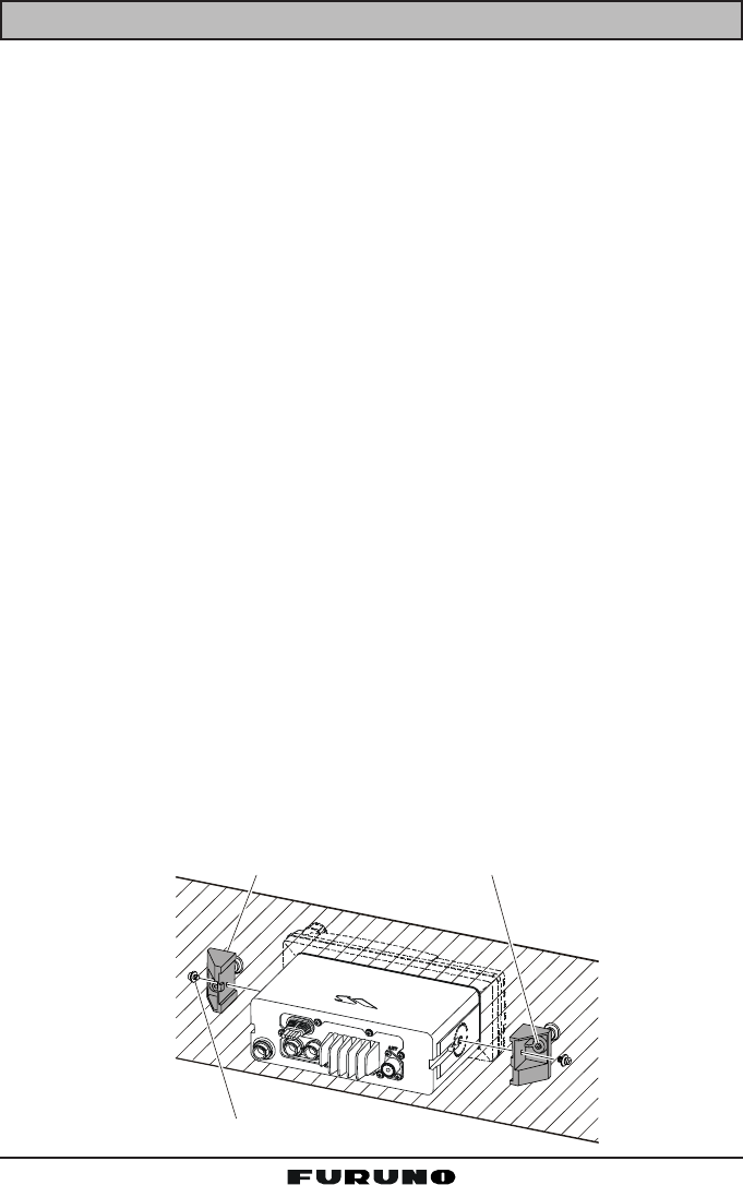
8.2 OPTIONAL MMB-84 FLUSH MOUNT INSTALLATION
1. Make a rectangular template for the flush mount measuring 2.9” H x 8.1”
W (72 x 205 mm).
2. Use the template to mark the location where the rectangular hole is to be
cut. Confirm that the space behind the dash or panel is deep enough to
accommodate the transceiver (at least six inches deep).
There should be at least 1/2 inch between the transceiver's heatsink and
any wiring, cables or structures.
3. Cut out the rectangular hole and insert the transceiver.
4. Fasten the brackets to the sides of the transceiver with the lock washer nut
combination so that the mounting screw base faces the mounting surface.
5. Turn the adjusting screw to adjust the tension so that the transceiver is
tight against the mounting surface.
Bracket
A
djusting Screw
Lock-washer nut combination
FM-4000Page 10
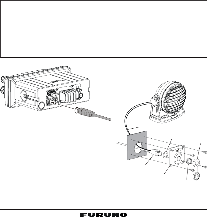
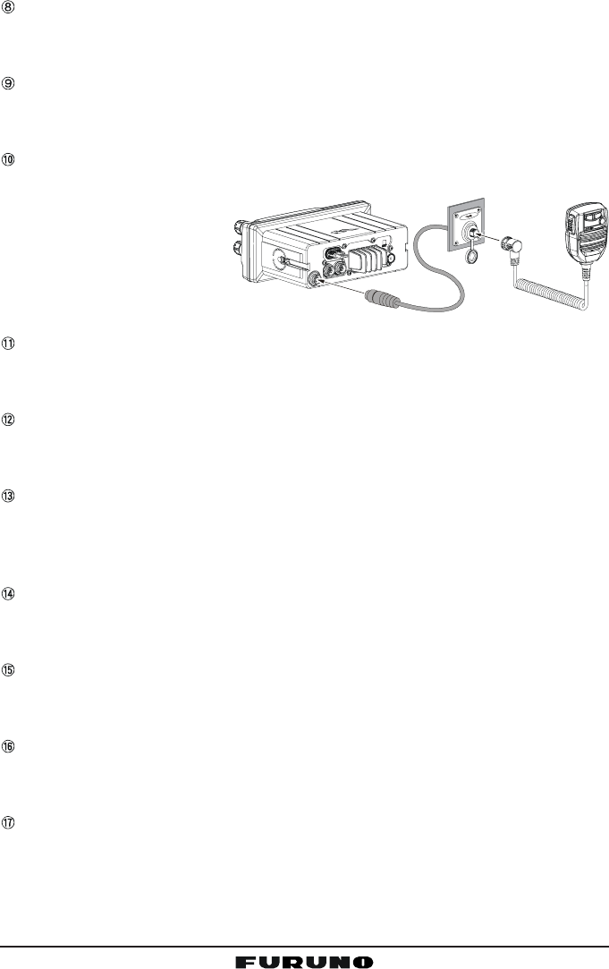
8.3 OPTIONAL CMP30 REMOTE MIC
The CMP30 Remote MIC permits remote control of the FM-4000’s radio, DSC
and PA/Fog functions. In addition the FM-4000 can operate as a full function
intercom system.
1. Connect the extension cable to the remote MIC eight pin connector on the
rear panel, then tighten the cable nut (See Figure 3).
2. Referring to Figure 3, make a 1.2” (30 mm) hole in the wall, then insert the
extension cable into this hole. Connect the gasket and mounting base to
the extension cable connector using the nut.
3. Drill the four screw holes (approx. 2 mm) on the wall, then install the mount-
ing base to the wall using four screws.
Put the rubber cap onto the nut. The installation is now complete.
NOTE
The routing cable can be cut and spliced, however care needs to be
taken when reconnecting the wires to ensure water integrity.
Before cutting the cable, make sure it is not plugged into the radio. After
cutting you will notice there are the following wires:
Yellow, Green, Brown, Purple, Blue, Green, RedÚ, ShieldÚ
ÚThe red and shield wires are wrapped in foil. Remove the foil, and
separate the red and shield wires.
Wall
Gasket
Mounting Bracket
Routing Cable
Cap
Nut
External Speaker Connections
Page 11FM-4000
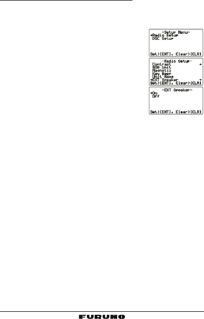
Remote MIC or External Speaker Selection
By default the internal speaker is turned on, however it can be turned off to use
the external speaker, when the Remote MIC is installed.
Remote MIC procedure
1. Press and hold down the [CALL(MENU)] key until
the “Radio SetupRadio Setup
Radio SetupRadio Setup
Radio Setup” menu appears.
2. Press the [ENT] key, then use the [S] or [T] key to
select “Ext SpeakerExt Speaker
Ext SpeakerExt Speaker
Ext Speaker.”
3. Press the [ENT] key.
4. Press the [S] or [T] key to select “OffOff
OffOff
Off” (External
speaker off) or “OnOn
OnOn
On” (External speaker on).
6. Press the [ENT] key to save the selection, then press
the [16/9] key to return to radio operation.
FM-4000Page 12
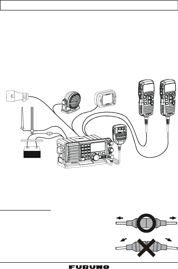
8.4 ELECTRICAL CONNECTIONS
CAUTION
Reverse polarity connections will damage the radio!
Connect the power cord and antenna to the radio. Antenna and power supply
connections are as follows:
1. Mount the antenna at least three feet away from the radio. At the rear of
the radio, connect the antenna cable. It must have a PL259 connector.
2. Connect the red power wire to a 13.8 VDC ±20% power source. Connect
the black power wire to a negative ground.
3. It is advisable to have a certified marine technician check the power output
and the standing wave ratio of the antenna after installation.
GPS Navigation Receiver
Accessory Cable
Optional Speaker
Antenna
Fuse
Red
Power Source
Black
Water proof
Deck Outlet
Optional CMP30 Remote MIC
Optional HAIL/PA Horn
Fuse Replacement
To take out the fuse from the fuse holder, hold the
both ends of the fuse holder and pull the fuse holder
apart, do not bend the fuse holder. When you re-
place the fuse, please confirm that the fuse is tightly
fixed on the metal contact located inside the fuse
holder. If the metal contact holding the fuse is loose,
the fuse holder may heat up.
Page 13FM-4000
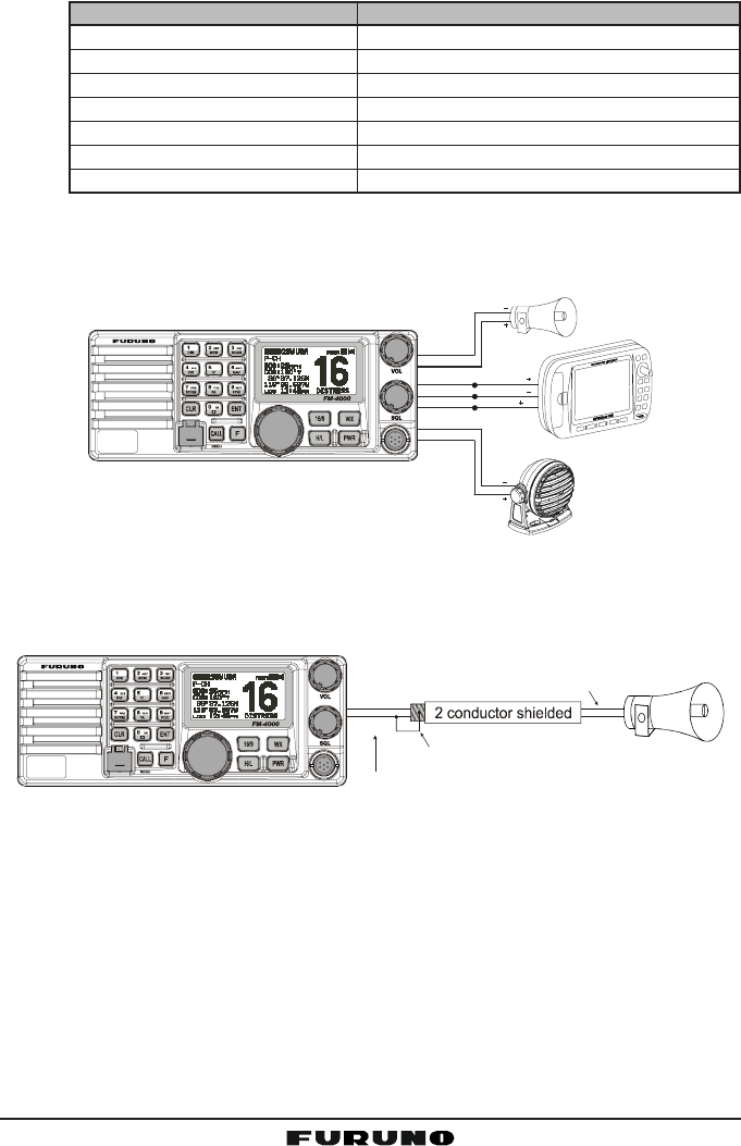
8.5 ACCESSORY CABLE
Wire Color/Description
WHITE - External Speaker (+)
SHIELD - External Speaker (–)
RED - PA Speaker (+)
SHIELD - PA Speaker (–)
GREEN - NMEA Ground
BLUE- NMEA Input (+)
GRAY-NMEA Output (+)
Connection Examples
Connect to external 4 Ohm audio speaker
Connect to external 4 Ohm audio speaker
Connect to external 4 Ohm PA speaker
Connect to external 4 Ohm PA speaker
Connect to NMEA (–) connection of GPS
Connect to NMEA (+) output of GPS
Connect to NMEA (+) input of GPS
When connecting the PA speaker, external speaker or GPS receiver, strip off
about 1 inch (2.5 cm) of the specified wire’s insulation, then splice the ends
together.
Note: In some areas powerful AM broadcast stations may be heard when in
listen-back mode. In this case change the speaker wire to 2-conductor shielded
audio cable. See the illustration below for connections.
• The GPS receiver must have its NMEA output turned on and baud rate set
to “4800” in the Setup menu. If there is a selection for parity, select “None”.
• For further information on interfacing /setting up your GPS receiver, please
refer to its Operator’s Manual.
•FM-4000 can read NMEA-0183 version 2.0 or higher.
• The NMEA supported sentences are:
Input: GLL, GGA, RMC and GNS (RMC sentence is recommended)
Output: DSC and DSE
(DSC sentences to FURUNO plotter for position polling)
External Speaker
GPS Receiver
PA Sp e a ker
Green
Blue NMEA OUT
NMEA OUT
NMEA IN
( )
( )
( )
Gray
Shield
Shield
Red
White
DISTRESS
PULL OPEN
-/*
JKL
Red
Bare
Connect the bare wire from the GX5500S
to one wire and to the shielded.
Make Red and bare connections short as possible
Shield of cable is not
attached on PA Speaker end
PA Speaker
DISTRESS
PULL OPEN
-/*
JKL
FM-4000Page 14
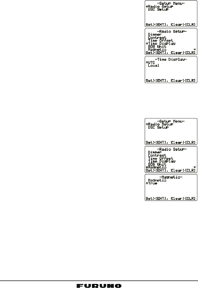
8.6 CHANGING THE TIME INDICATION
Set the radio to show UTC time, or local time with the offset inputted in section
“8.5 CHANGING THE GPS TIME.”
1. Press and hold down the [CALL(MENU)] key until
the “Radio SetupRadio Setup
Radio SetupRadio Setup
Radio Setup” menu appears.
2. Press the [ENT] key, then use the CHANNEL selec-
tor knob to select “Time DisplayTime Display
Time DisplayTime Display
Time Display”.
3. Press the [ENT] key.
4. Turn the CHANNEL selector knob to select “UTCUTC
UTCUTC
UTC” or
“LocalLocal
LocalLocal
Local.”
5. Press the [ENT] key to store the selected setting.
6. Press the [CLR] key to return to the “Radio SetupRadio Setup
Radio SetupRadio Setup
Radio Setup”
menu, then press the [CLR] key again to return to
radio operation.
8.7 CHANGING THE COG INDICATION
GPS Course Over Ground can be shown in True or Magnetic bearing. To change
the COG indication, do as follows:
1. Press and hold down the [CALL(MENU)] key until
the “Radio SetupRadio Setup
Radio SetupRadio Setup
Radio Setup” menu appears.
2. Press the [ENT] key, then use the CHANNEL selec-
tor knob to select “MagneticMagnetic
MagneticMagnetic
Magnetic”.
3. Press the [ENT] key.
4. Turn the CHANNEL selector knob to select “Mag-Mag-
Mag-Mag-
Mag-
neticnetic
neticnetic
netic” or “TrueTrue
TrueTrue
True.”
5. Press the [ENT] key to store the selected setting.
6. Press the [CLR] key to return to the “Radio SetupRadio Setup
Radio SetupRadio Setup
Radio Setup”
menu, then press the [CLR] key again to return to
radio operation.

Page 15FM-4000
MEMO
FM-4000Page 16
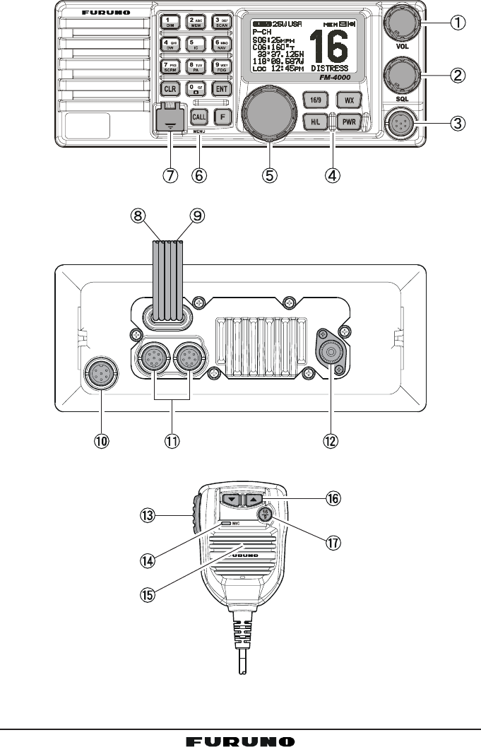
9 CONTROLS AND INDICATIONS
NOTE
This section defines each control of the transceiver. See the illustration
on the next page for the location of the controls For detailed operating
instructions, see Chapter 10.
9.1 CONTROLS AND CONNECTORS
VOLUME CONTROL (VOL/PWR)
Adjusts the audio volume level. Turn the control clockwise to increase the
audio volume level.
Secondary Use
Controls the listen-back volume in the PA or Fog mode.
SQUELCH CONTROL (SQL)
Adjust this control clockwise to set the point at which random noise on the
channel does not activate the audio circuits but a received signal does.
This point is called the squelch threshold. Be careful not to set the squelch
too high; reception of wanted transmissions will be degraded.
MIC Connector
Connects to the supplied noise-canceling speaker microphone.
KEYPAD
[WX] Key
Immediately recalls the last-selected NOAA weather channel. Pressing
the [WX] key again reverts to the previously selected working channel.
Secondary use:
Press the [WX] key while pressing and holding the [16/9] key to switch
between USA, International and Canadian bands.
[PWR] Key
Turns the transceiver on and off. To turn the transceiver on, press and
hold this key until the LCD turns on. To turn it off, press and hold this key
until the LCD turns off. When the power is turned on, the transceiver is
set to the last-selected channel.
[16/9] Key
Immediately recalls CH16. Hold down the [16/9] key to recall CH9. Press
the [16/9] key again to revert to the previously selected working chan-
nel.
Secondary use:
Press the [WX] key while pressing and holding the [16/9] key to switch
between USA, International and Canadian bands.
Page 17FM-4000
DISTRESS
PULL OPEN
-/*
JKL
Figure 4. Controls and Connectors

FM-4000Page 18
[H/L] Key
Toggles between 25 W (High) and 1 W (Low) power. When the [H/L] key
is pressed while the transceiver is on CH13 or CH67, the power will
temporarily switch from LO to HI power until the PTT is released. The
[H/L] key does not function on transmit inhibited and low-power only
channels.
CHANNEL SELECTOR KNOB
This rotary knob selects channels and to chooses menu items (such as
the DSC menu, Radio Setup and DSC Setup menu). The [UP(S)] /
[DOWN(T)] keys on the microphone can also be used to select channels
and menu items.
Secondary Use
yPress the [F] key first then press the [3(SCAN)] key, and turn the CHAN-
NEL selector knob while holding down the [3(SCAN)] key to confirm
memory channels for scanning.
yAdjusts the PA output level while in PA/FOG mode.
KEYPAD
[1(DIM)] Key
When in the radio mode, this key directly inputs the digit “1” in a channel
number.
Secondary use
Press the [F] key first, then press the [1(DIM)] key to access the LCD
Dimmer menu. See section “10.16 LCD DIMMER” for details.
[2(MEM)] Key
When in the radio mode, this key directly inputs the digit “2” in a channel
number.
Secondary use
Press the [F] key first then press the [2(MEM)] key to memorize the
selected channel into the transceiver scan memory for scanning. Re-
peating the same procedure ([F] Æ [2(MEM)]), deletes the channel from
the scan memory. See section “10.13 SCANNING” for details.
[3(SCAN)] Key
When in the radio mode, this key directly inputs the digit “3” in a channel
number.
Secondary use (Depends on the transceiver version)
Press the [F] key first then press the [3(SCAN)] key to start and stop the
scanning of programmed channels. See section “10.13 SCANNING” for
details.

Page 19FM-4000
[4(DW)] Key
When in the radio mode, this key directly inputs the digit “4” in a channel
number.
Secondary use
Press the [F] key first then press the [4(DW)] key to scan for voice com-
munications on the priority channel and another selected channel until
a signal is received on either channel (Dual Watch). See section “10.12
DUAL WATCH (TO CH16)” for details.
[5(IC)] Key
When in the radio mode, this key directly inputs the digit “5” in a channel
number.
Secondary use
Press the [F] key first then press the [5(IC)] key, when the optional Re-
mote MIC is connected, to activates Intercom function between radio
and Remote MIC. See section “10.17 INTERCOM OPERATION” for de-
tails.
[6(NAV)] Key
When in the radio mode, this key directly inputs the digit “6” in a channel
number.
Secondary use
Press the [F] key first then press the [6(NAV)] key, and the LCD displays
NAV GPS Data; Time, SOG (Speed Over Ground), and COG (Course
Over Ground). Requires a GPS receiver, connected to the FM-4000
with the accessory cable. See section “8.5 ACCESSORY CABLE” for
details.
[7(SCRM)] Key
When in radio mode, this key directly inputs the digit “7” in a channel
number.
Secondary use
Press the [F] key first then press the [7(SCRM)] key, when the optional
CVS2500 Voice Scrambler Unit is installed, to operate the Voice Scram-
bler function. See section “10.18 VOICE SCRAMBLER” for details.
[8(PA)] Key
When in the radio mode, this key directly inputs the digit “8” in a channel
number.
Secondary use
Press the [F] key first then press the [8(PA)] key to operate the 30 Watt
PA function. See section “10.14 PA/FOG OPERATION” for details.
FM-4000Page 20
[9(FOG)] Key
When in the radio mode, this key directly inputs the digit “9” in a channel
number.
Secondary use
Press the [F] key first then press the [9(FOG)] key to operate the Fog
Horn function. See section “10.14 PA/FOG OPERATION” for details.
[0] Key
When in the radio mode, this key directly inputs the digit “0” in a channel
number.
[CLR] Key
Cancels the menu selection and/or key input.
[ENT] Key
Confirms the menu selection and/or key input.
[CALL(MENU)] Key
Opens the DSC OPERATION menu. The “Individual CallIndividual Call
Individual CallIndividual Call
Individual Call,” “Group CallGroup Call
Group CallGroup Call
Group Call,”
and “All Ship CallAll Ship Call
All Ship CallAll Ship Call
All Ship Call” functions can be accessed from the DSC OPERA-
TION menu.
Secondary use
Press and hold the [CALL(MENU)] key to access the “Radio SetupRadio Setup
Radio SetupRadio Setup
Radio Setup” menu
(see section “12 RADIO SETUP”) or “DSC SetupDSC Setup
DSC SetupDSC Setup
DSC Setup” menu (see section “11
DIGITAL SELECTIVE CALLING”).
[F] Key
Press the [F] key to activate the “Alternate” key function.
[DISTRESS] Key
Send a DSC Distress Call. For details, see section “11.3.1 Transmitting a
DSC Distress Call.”
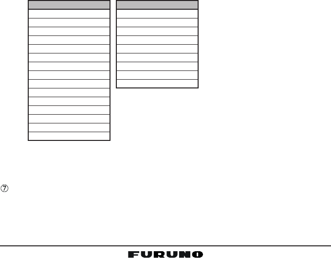
DSC SETUP menu
Individual Directory
Individual Reply
Individual Ack
Individual Ringer
Group Directory
Position Reply
Position InputÚ
DSC Beep
User MMSI
Ú: Shown when a GPS re-
ceiver is not connected.
RADIO SETUP menu
Contrast
Time Offset
Time Display
SOG Unit
Magnetic
Priority CH
SCAN Type
SCAN Resume
Key Beep
Weather Alert
CH Name
Unit Name
Tone Control
FOG Frequency
Calendar
Page 21FM-4000
ACCESSORY CONNECTION CABLE
Connects the FM-4000 to a GPS receiver, a PA speaker, and an external
speaker.
DC INPUT CABLE
Connects the radio to a DC power supply capable of delivering 12 to 16 V
DC.
FRONT PANEL REMOTE MIC Connector
Connects the supplied Hand Microphone if desired. This connector is used
to remote the front panel
speaker MIC. This allows
the connection of two
MICs, one at the front
panel and one on the
rear panel.
REMOTE MIC CONNECTORS
Connects the FM-4000 to the Remote MIC. See section “13 REMOTE MIC
OPERATION” for details.
ANTENNA JACK
Connects an antenna to the transceiver. Use a marine VHF antenna with
an impedance of 50 ohms.
PTT (Push-To-Talk) SWITCH
Keys the transmitter when the transceiver is in the radio mode. If the trans-
ceiver is in the Intercom mode (between the Remote MIC and the FM-4000),
it activates the FM-4000’s microphone for voice communications.
MICROPHONE
Transmits the voice message with reduction of background noise, using
Clear Voice Noise Reduction Technology.
MICROPHONE SPEAKER
The same audio heard through internal radio speaker is heard through
microphone speaker.
[UP(S)] / [DOWN(T)] KEYS
These keys function the same as the CHANNEL selector knob on the front
panel of the transceiver.
[16/9] Key
Immediately recalls CH16. Press and hold the [16/9] key to recall CH9.
Press the [16/9] key again to revert the radio to the previously selected
channel.

FM-4000Page 22
10 BASIC OPERATION
10.1 PROHIBITED COMMUNICATIONS
The FCC prohibits the following communications:
• False distress or emergency messages;
• Messages to “any boat” except in emergencies and radio tests;
• Messages to or from a vessel on land;
• Transmission while on land;
• Obscene, indecent, or profane language (potential fine of $10,000).
10.2 RECEPTION
1. After the transceiver has been installed, ensure that the power supply and
antenna are properly connected.
2. Press and hold the PWR key until the radio turns on.
3. Turn the SQL knob fully counterclockwise. This state is known as “squelch
off”.
4. Rotate the VOL knob clockwise until noise or audio from the speaker is at
a comfortable level.
5. Turn the SQL knob clockwise until the random noise disappears. This state
is known as the “squelch threshold.”
6. Turn the CHANNEL selector knob to select the desired channel. Refer to
the channel chart on page 91 for available channels.
7. The keypad on the front panel may be used to directly select channels. For
example, to select CH68:
1. Press [6(NAV)].
2. Press [8(PA)].
3. Press [ENT].
In the USA and Canadian modes, press and hold down the [0] key to se-
lect the “A” channel. Example to select CH22A:
1. Press [2(MEM)].
2. Press [2(MEM)].
3. Press [0] until “A” appears to the right of the channel number.
4. Press [ENT].
8. When a message is received, adjust the volume to the desired listening
level. The “ ” indicator appears if the channel is busy.
Page 23FM-4000
10.3 TRANSMISSION
1. Perform steps 1 through 6 in 10.2 RECEPTION.
2. Before transmitting, monitor the channel to ensure it is clear.
THIS IS AN FCC REQUIREMENT!
3. Press the PTT (push-to-talk) switch, and the indication “ ”appears.
4. Speak slowly and clearly into the microphone.
5. When you have finished transmitting, release the PTT switch.
NOTE
This is a noise-canceling microphone. Position the oval slot labeled “MIC”
within one-inch (2.5 cm) from your mouth for optimum performance.
10.4 TRANSMIT TIME - OUT TIMER (TOT)
When the PTT switch on the microphone is held down, transmit time is limited to
five minutes. This limits unintentional transmissions due to a stuck microphone.
About 10 seconds before automatic transmitter shutdown, a warning beep sounds
from the speaker(s). The transceiver will automatically go to the receive mode,
even if the PTT switch is continually held down. Before transmitting again, the
PTT switch must first be released and then pressed again.
10.5 SIMPLEX/DUPLEX CHANNEL USE
Refer to the VHF MARINE CHANNEL CHART (page 77) for instructions on
use of simplex and duplex channels.
NOTE
All channels are factory-programmed in accordance with FCC (USA),
Industry Canada (Canada), and International regulations. Mode of op-
eration cannot be altered from simplex to duplex or vice-versa.
10.6 USA, CANADA, AND INTERNATIONAL MODE
1. To change the mode, hold the [16/9] key, then press the [WX] key. The
mode changes from USA to International to Canadian with each press of
the [WX] key.
“USA” appears for the USA mode, “INTL” for the International mode, and
“CAN” for the Canadian mode.
2. See the VHF MARINE CHANNEL CHART (page 77) for allocated chan-
nels in each mode.

FM-4000Page 24
10.7 NOAA WEATHER CHANNELS
1. To receive a NOAA (National Oceanic and Atmospheric Administration)
weather channel, press the [WX] key. The transceiver will go to the last-
selected weather channel.
2. Turn the CHANNEL selector knob on the radio or [UP(S)] / [DOWN(T)]
keys on the microphone to select a different NOAA weather channel.
3. To exit from the NOAA weather channels, press the [WX] key. The trans-
ceiver returns to the channel it was on prior to a weather channel.
10.7.1 NOAA Weather Alert
In the event of extreme weather disturbances, such as storms and hurricanes,
the NOAA sends a weather alert accompanied by a 1050 Hz tone and subse-
quent weather report on one of the NOAA weather channels. When the Weather
Alert feature is enabled (see section “12.10 WEATHER ALERT (ON/OFF)”),
the transceiver is capable of receiving this alert if you do the following:
1. Program NOAA weather channels into the transceiver’s memory for scan-
ning. Program by the same procedure as for regular channels, referring to
section “10.13.2 Memory Scanning (M-SCAN).”
2. Press the [SCAN] key once to start memory scanning.
3. The programmed NOAA weather channels will be scanned along with the
regular-programmed channels. However, scanning will not stop on a nor-
mal weather broadcast unless a NOAA alert is received.
4. When an alert is received on a NOAA weather channel, scanning will stop
and the transceiver will emit a loud beep to alert the user to a NOAA broad-
cast.
5. Press the [WX] key to stop the alert tone and receive the weather report.
NOTE
If the [WX] key is not pressed at step 5, the alert tone will be emitted for
five minutes and then the weather report will be received.
NOTE
The Weather Alert feature is also engaged while the transceiver is re-
ceiving on one of the NOAA weather channels.
10.7.2 NOAA Weather Alert Testing
NOAA tests the alert system every Wednesday between 11AM and 1PM. To
test the FM-4000’s NOAA Weather feature at that time, setup as directed in
section “10.7.1 NOAA Weather Alert” and confirm that you receive the alert.

Page 25FM-4000
10.8 EMERGENCY (CH16 USE)
CH16 is known as the Hail and Distress channel. An emergency may be de-
fined as a threat to life or property. In such instances, be sure the transceiver is
on and set it to CH16. Then do as follows:
1. Press the microphone push-to-talk switch and say “Mayday, Mayday, May-
day. This is , , ” (your vessel’s name).
2. Then repeat once: “Mayday, ” (your vessel’s name).
3. Now report your position in latitude/longitude, or by giving a true or mag-
netic bearing (state which) to a well-known landmark such as a navigation
aid or geographic feature such as an island or harbor entry.
4. Explain the nature of your distress (sinking, collision, aground, fire, heart
attack, life-threatening injury, etc.).
5. State the kind of assistance you desire (pumps, medical aid, etc.).
6. Report the number of persons aboard and condition of any injured.
7. Estimate the present seaworthiness and condition of your vessel.
8. Give your vessel’s description: length, design (power or sail), color and
other distinguishing marks. The total transmission should not exceed one
minute.
9. End the message by saying “OVER”. Release the microphone push-to-
talk and listen.
10. If there is no answer, repeat the above procedure. If there is still no re-
sponse, try another channel.
10.9 CALLING ANOTHER VESSEL (CH16 OR CH9)
Channel 16 may be used for initial contact (hailing) with another vessel.
However, its most important use is for emergency messages. This channel
must be monitored at all times except when actually using another channel.
It is monitored by the U.S. and Canadian Coast Guards and by other vessels.
Use of CH16 for hailing must be limited to initial contact only. Calling
should not exceed 30 seconds, but may be repeated three times at 2-minute
intervals. In areas of heavy radio traffic, congestion on CH16 resulting from its
use as a hailing channel can be reduced significantly in U.S. waters by using
CH9 as the initial contact (hailing) channel for non-emergency communica-
tions. Here, also, calling time should not exceed 30 seconds but may be re-
peated three times at 2-minute intervals.
Prior to making contact with another vessel, refer to the channel charts in this
manual, then select an appropriate channel for communications after initial
contact. For example, CH68 and CH69 of the U.S. VHF charts are some of the
channels available to non-commercial (recreational) boaters. Monitor your de-
sired channel in advance to make sure you will not be interrupting other traffic,

FM-4000Page 26
and then go back to either CH16 or CH9 for your initial contact.
When the hailing channel (16 or 9) is clear, state the name of the other vessel
you wish to call and then “this is” followed by the name of your vessel and
your Station License (Call Sign). When the other vessel returns your call, im-
mediately request another channel by saying “go to,” the number of the other
channel, and “over.” Then switch to the new channel. When the new channel
is not busy, call the other vessel.
After a transmission, say “over,” and release the microphone’s push-to-talk
(PTT) switch. When all communication with the other vessel is completed, end
the last transmission by stating your Call Sign and the word “out.” Note that it
is not necessary to state your Call Sign with each transmission, only at the
beginning and end of the contact.
Remember to return to CH16 when not using another channel. Some radios
automatically monitor CH16 even when set to other channels or when scan-
ning.
10.10 MAKING TELEPHONE CALLS
To make a radiotelephone call, use a channel designated for this purpose, The
fastest way to learn which channels are used for radiotelephone traffic is to
ask at a local marina. Channels available for such traffic are designated Pub-
lic Correspondence channels on the channel charts in this manual. Some
examples for USA use are Channels 24, 25, 26, 27, 28, 84, 85, 86, and 87.
Call the marine operator and identify yourself by your vessel’s name. The marine
operator will then ask you how you will pay for the call (telephone credit card,
collect, etc.) and then link your radio transmission to the telephone lines.
The marine telephone company managing the VHF channel you are using
may charge a link-up fee in addition to the cost of the call.
10.11 OPERATING ON CHANNELS 13 AND 67
CH13 is used at docks and bridges and by vessels maneuvering in port. Mes-
sages on this channel must concern navigation only, such as meeting and
passing in restricted waters.
CH67 is used for navigational traffic between vessels.
By regulation, power is normally limited to 1 Watt on these channels. Your
radio is programmed to automatically reduce power to this limit on these chan-
nels. However, in certain situations it may be necessary to temporarily use a
higher power. See page 18 ([H/L] key) for how to temporarily override the low-
power limit on these two channels.
Page 27FM-4000
10.12 DUAL WATCH (TO CH16)
1. Adjust the SQL knob until the background noise disappears.
2. Select the channel you wish to dual watch with CH16.
3. Press the [F] key followed by the [4(DW)] key. The display will scan be-
tween CH16 and the channel that was selected in
step 2.
If a transmission is received on the channel selected
in step 2, the FM-4000 watches it and CH16.
4. To stop Dual Watch, press the [F] key followed by the [4(DW)] key again.
10.13 SCANNING
Scanning allows the user to select the scan type from Memory scan or Priority
scan. “Memory scan” scans the channels that were programmed into memory.
“Priority scan” scans the channels programmed in memory with the priority
channel.
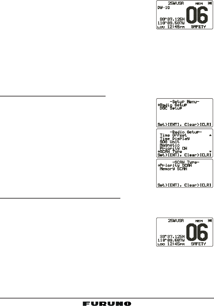
10.13.1 Selecting the Scan Type
1. Press and hold down the [CALL(MENU)] key until
the “Radio SetupRadio Setup
Radio SetupRadio Setup
Radio Setup” menu appears.
2. Press the [ENT] key, then use the CHANNEL selec-
tor knob to select “SCAN TypeSCAN Type
SCAN TypeSCAN Type
SCAN Type”.
3. Press the [ENT] key.
4. Turn the CHANNEL selector knob to select “PriorityPriority
PriorityPriority
Priority
SCANSCAN
SCANSCAN
SCAN” or “Memory SCANMemory SCAN
Memory SCANMemory SCAN
Memory SCAN.”
5. Press the [ENT] key to store the selected setting.
6. Press the [CLR] key to return to the “Radio SetupRadio Setup
Radio SetupRadio Setup
Radio Setup”
menu, then press the [CLR] key again to return to
radio operation.
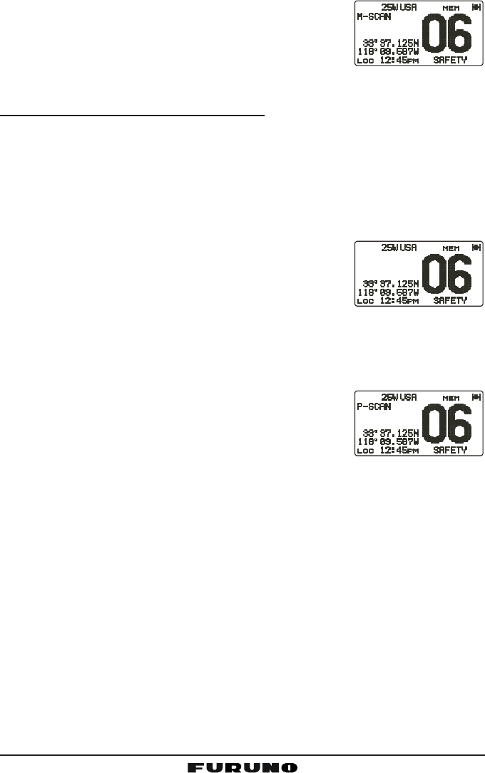
10.13.2 Memory Scanning (M-SCAN)
1. Adjust the SQL knob until background noise disappears.
2. Use the CHANNEL selector knob to select the channel to scan. Press the
[F] key followed by the [2(MEM)] key. “MEM” ap-
pears on the LCD, which indicates that the channel
is programmed into the transceiver’s memory.
3. Repeat step 2 to select other channels to scan.
4. To DELETE a channel from the transceiver’s memory, select the channel
then press the [F] key followed by the [2(MEM)] key. “MEM” disappears
from the LCD.
5. To start scanning, press the [F] key followed by the [3(SCAN)] key,
“M-SCANM-SCAN
M-SCANM-SCAN
M-SCAN” appears on the LCD. Scanning will proceed from the lowest to
FM-4000Page 28
the highest programmed channel number and will
stop on a channel when a transmission is received.
6. The channel number will blink during reception.
7. To stop scanning, press the [CLR], [16/9], or [WX]
key.
10.13.3 Priority Scanning (P-SCAN)
In the default setting, Channel 16 is set as the priority channel. You may change
the priority channel to the desired channel from CH16 on the Radio Setup
menu. See section “10.13.1 Selecting the Scan Type,” and “12.6 PRIORITY
CHANNEL SET.”
1. Adjust the SQL knob until background noise disappears.
2. Use the CHANNEL selector knob to select the channel to scan. Press the
[F] key followed by the [2(MEM)] key. “MEM” ap-
pears on the display, which indicates that the chan-
nel is programmed into the transceiver’s memory.
3. Repeat step 2 to select all the channels to scan.
4. To DELETE a channel from the transceiver’s memory, select the channel
then press the [F] key followed by the [2(MEM)] key. “MEM” is removed
from the display.
5. To start priority scanning, press the [F] key followed by the [3(SCAN)] key.
“P-SCANP-SCAN
P-SCANP-SCAN
P-SCAN” appears on the LCD. Scanning will pro-
ceed between the memorized channels and the pri-
ority channel. The priority channel will be scanned
after each programmed channel.
6. To stop scanning, press the [CLR], [16/9], or [WX] key.
You may change the scan resume time in the Radio Setup menu. See section
“12.8 SCAN RESUME TIME.”
Page 29FM-4000
10.14 PA/FOG OPERATION
The FM-4000 has a 30W Hailer that can be used with any 4 Ohm PA horn.
When in the Hail mode, the PA speaker listens back (acts as a microphone
and sends sound to the front panel speaker and the speaker MIC) through the
PA horn speaker which provides two-way communications through the PA horn
speaker.
NOTE
Before entering the PA or Fog mode, the FM-4000 receives on the last-
selected VHF channel to receive DSC calls.
NOTE
In some areas powerful AM broadcast stations may be heard when in
the listen-back mode. In this case change the speaker wire to 2-con-
ductor shielded audio cable. See section “8.5 ACCESSORY CABLE.”
PA Hail mode:
PA Hail mode allows the transceiver to be used as a power hailer when a
HAIL/PA speaker is installed. The PA Hail mode has a listen-back feature
which provides two-way communication through the HAIL/PA speaker.
Fog Horn mode:
Automatic signaling is transmitted through the HAIL/PA speaker. When the
Fog Horn, Bells or Whistle signal is not being outputted, the FM-4000 lis-
tens back through the connected PA Horn speaker.
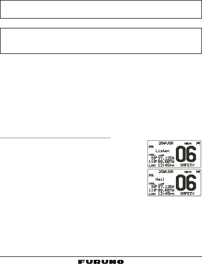
10.14.1 Operating the PA Hail mode
1. Press the [F] key followed by the [2(MEM)] key to
activate the PA Hail mode.
2. Press the PTT switch to speak through the HAIL/PA
speaker.
Rotate the CHANNEL selector knob to control the
AF output level. The AF output level can be set from
0 to 30 watts.
3. When the fog signal is not outputted, rotate the VOL
knob to adjust the listen-back volume.
4. To exit the PA Hail mode, press the [CLR] key.
FM-4000Page 30
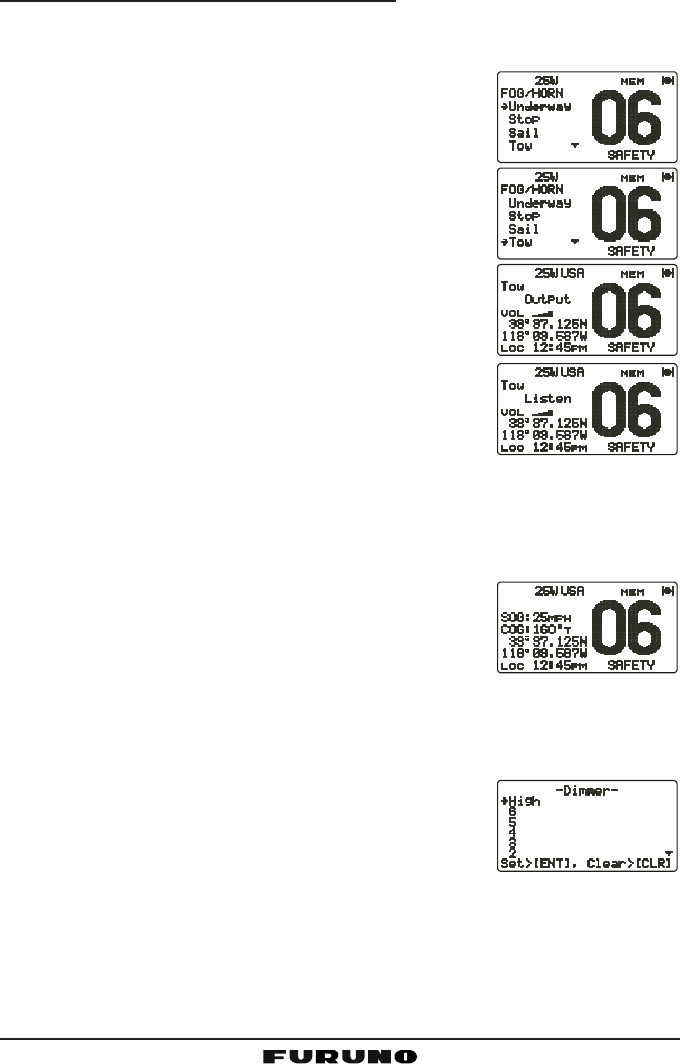
10.14.2 Operating the Fog Horn mode
Operator can select from Underway, Stop, Sail, Tow, Aground, Anchor, Horn
and Siren. Refer to the Fog Horn Timing Chart on the next page.
1. Press the [F] key followed by the [9(FOG)] key.
2. Turn the CHANNEL selector knob to select one of
the eight functions described above.
3. Press the [ENT] key.
4. On the Horn and Siren modes, press the PTT switch
to activate the tone through the HAIL/PA speaker.
Rotate the CHANNEL selector knob to control the
AF output level. The AF output level can be set from
0 to 30 watts.
5. When the fog signal is not outputted, rotate the VOL
knob to adjust the listen-back volume.
6. To exit the Fog Horn mode, press the [CLR] key.
10.15 DISPLAYING SOG AND COG INFORMATION
The transceiver has the ability to display the time, SOG and COG data, as well
as the vessel’s position (LAT/LON), when connected to a GPS receiver.
1. Press the [F] key followed by the [6(NAV)] key to
display SOG and COG information.
2. To hide SOG and COG information, press the [F]
key followed by the [6(NAV)] key again.
10.16 LCD DIMMER
You can adjust the LCD dimmer as follows:
1. Press the [F] key followed by the [1(DIM)] key to enable adjustment of the
backlight intensity.
2. Turn the CHANNEL selector knob to select the de-
sired backlight intensity.
3. Press the [CLR] key to return to “Radio” mode.
Page 31FM-4000
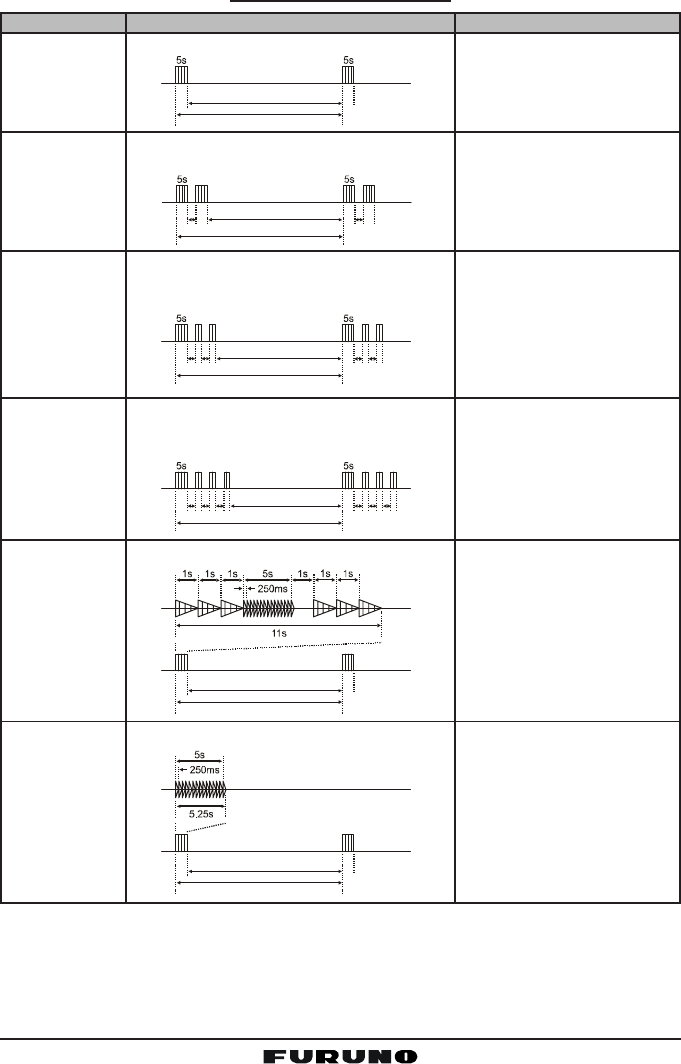
TYPE PATTERN USAGE
120s
Listen Back
5s 5s
2s 2s
120s
Listen Back
1s 1s1s 1s
2s 2s2s 2s
120s
Listen Back
1s 1s1s 1s1s 1s
2s 2s2s 2s2s 2s
120s
Listen Back
60s
Listen Back
60s
Listen Back
UNDERWAY
STOP
SAIL
TOW
AGROUND
ANCHOR One 5-second ring every 60 seconds.
One 5-second blast every 120 seconds.
Two 5-second blasts (separated by 2
seconds) every 120 seconds.
One 5-second blast followed by two 1-
second blasts (separated by 2 seconds)
every 120 seconds.
One 5-second blast followed by three 1-
second blasts (separated by 2 seconds)
every 120 seconds.
One 11-second ring every 60 seconds.
Motor vessel underway and
making way.
Motor vessel underway but
stopped (not making way).
Sailing vessel underway, fish-
ing vessel (underway or an-
chored), vessel not under
command, a vessel restricted
in her ability to maneuver (un-
derway or at anchor), or a ves-
sel towing or pushing another
ahead.
Vessel under tow (manned).
Vessel is aground.
Vessel is at anchor.
FOG HORN TIMING CHART
FM-4000Page 32
10.17 INTERCOM OPERATION
Connecting the optional CMP30 Remote MIC to the FM-4000 allows Intercom
communications. See section “13.2 INTERCOM OPERATION” for operation
of the CMP30.
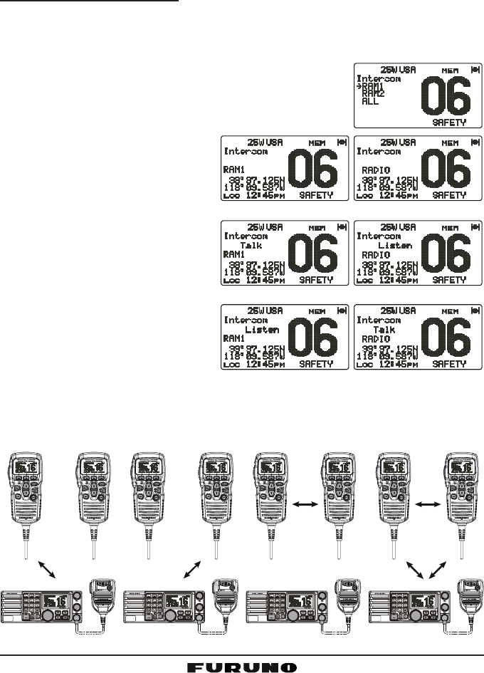
10.17.1 Communication
1. Press and hold the [5(IC)] key while in the “Radio” mode to change to the
“Intercom” mode.
2. If your FM-4000 is equipped two Remote MICs, use the CHANNEL selec-
tor knob select the one of use (RAM1RAM1
RAM1RAM1
RAM1, RAM2RAM2
RAM2RAM2
RAM2, or
ALLALL
ALLALL
ALL), then press the [ENT] key.
3. When the “Intercom” feature is activated, “IntercomIntercom
IntercomIntercom
Intercom”
appears on the FM-4000 and CMP30.
4. Press the PTT switch. “TalkTalk
TalkTalk
Talk”
appears on the display.
NOTE: A warning beep is emit-
ted when the FM-4000
microphone’s PTT switch is
pressed while the Remote
MIC’s PTT switch is pressed.
5. Speak slowly and clearly into
the microphone, holding the
microphone about 1/2 inch
away from your mouth.
6. When finished, release the
PTT switch.
7. Press the [CLR] key to return
to the “Radio” mode.
(FM-4000 display)(
CMP30 display)
(FM-4000’s PTT switch is pressed)
(CMP30’s PTT switch is pressed)
ALLRAM 1 RAM 2
Ù
RADIO RAM 2
Ù
RADIO RAM 1
Ù
RAM 1 RAM 2
DISTRESS
PULL OPEN
-/*
JKL
RAM 1 RAM 2
DISTRESS
PULL OPEN
-/*
JKL
RAM 1 RAM 2
DISTRESS
PULL OPEN
-/*
JKL
RAM 1 RAM 2
DISTRESS
PULL OPEN
-/*
JKL
Page 33FM-4000
10.17.2 Calling
Hold down the [5(IC)] key when the “Intercom” mode is activated to send a
calling beep to the Remote MIC.
NOTE
When both Remote MICs are set to the Intercom
mode, the FM-4000 is temporarily disabled until
both Remote MICs exit the Intercom mode.
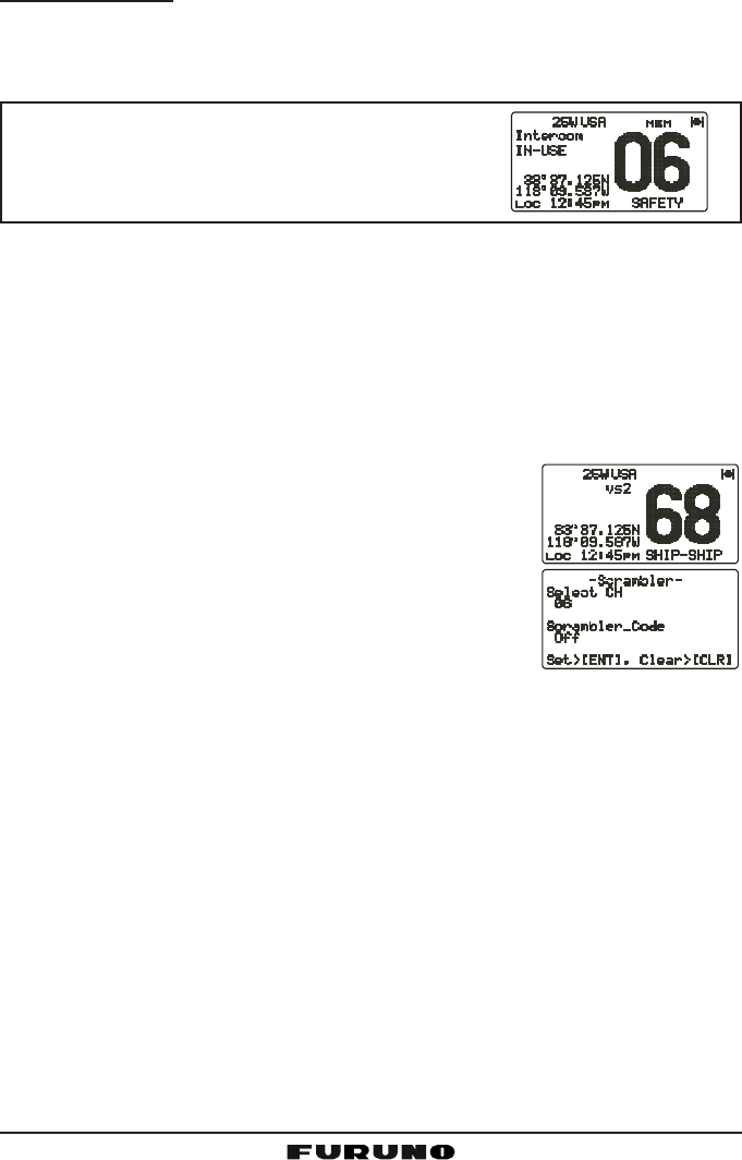
10.18 VOICE SCRAMBLER
If privacy of communications is desired, an optional CVS2500 four-code voice
scrambler (VS) can be installed in the transceiver. Contact your dealer to have
the CVS2500 installed.
1. Turn the CHANNEL selector knob to select the channel to be scramble.
Note: The voice scrambler is inoperative on CH16 and CH70.
2. Press the [F] key followed by the [7(SCRM)] key to
activate the voice scrambler. “VSVS
VSVS
VS” and scrambler
number (“00
00
0,” “11
11
1,” “22
22
2,” or “33
33
3”) appear.
3. Press the [F] key, then press and hold down the
[7(SCRM)] key until the “ScramblerScrambler
ScramblerScrambler
Scrambler” menu appears.
4. Turn the CHANNEL selector knob to change the
scrambler code. The scrambler code can be set from
“00
00
0” to “33
33
3.”
5. Press the [ENT] key to save the scrambler code and return to the radio
operation mode (with voice scrambler).
6. Monitor the channel before transmitting.
7. To disable the voice scrambler, press the [F] key followed by the [7(SCRM)]
key again. “VSVS
VSVS
VS” and scrambler number (“00
00
0,” “11
11
1,” “22
22
2,” or “33
33
3”) disappear.
FM-4000Page 34
11 DIGITAL SELECTIVE CALLING
11.1 GENERAL
WARNING
This radio is designed to generate a digital maritime distress and safety
call to facilitate search and rescue. To be effective as a safety device,
this equipment must be used only within communication range of a shore-
based VHF marine CH70 distress and safety watch system. The range
of the signal may vary but under normal conditions should be approxi-
mately 20 nautical miles.
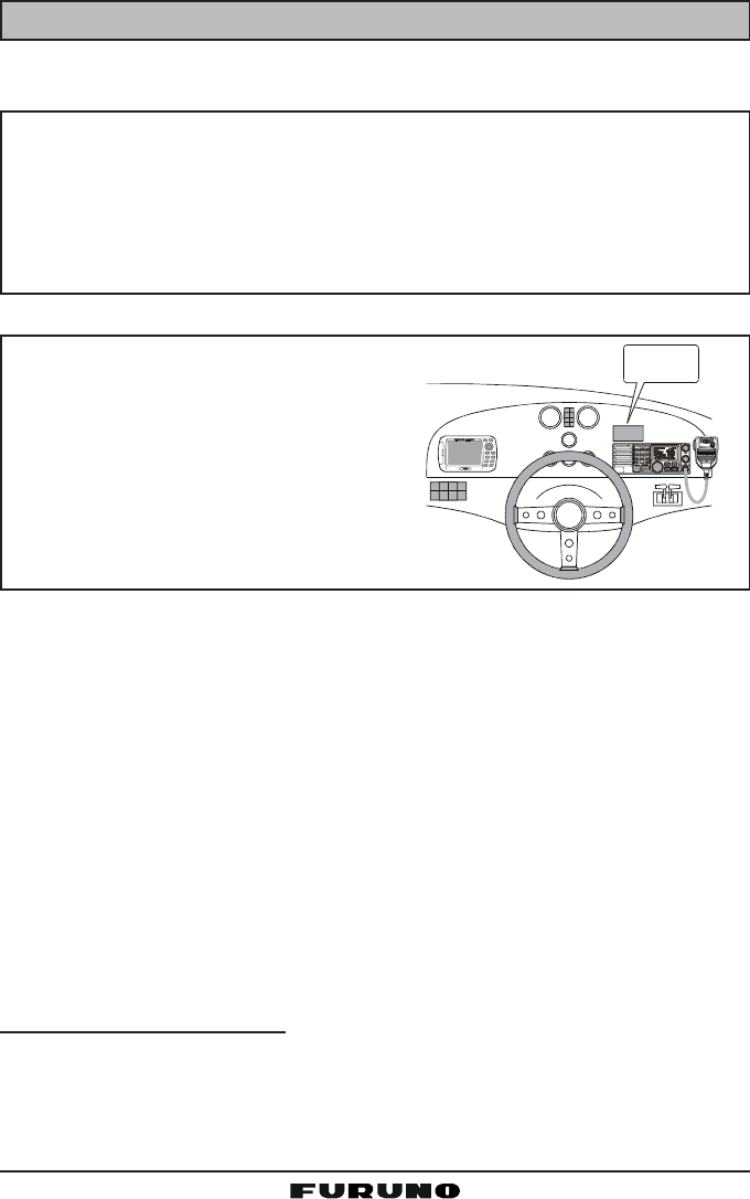
NOTE
A DSC warning sticker is included with
the FM-4000. To comply with FCC regu-
lations, this sticker must be mounted in
a location that can be easily viewed from
the location of the FM-4000.
Digital Selective Calling is a semi-automated method of establishing a radio
call. DSC has been designated by the International Maritime Organization (IMO)
as an international standard for establishing VHF, MF and HF radio calls. It has
also been designated as a part of the Global Maritime Distress and Safety
System (GMDSS). It is planned that DSC will eventually replace aural watches
on distress frequencies and will be used to announce routine and urgent mari-
time safety information broadcasts.
This new system allows mariners to instantly send a Distress call with GPS posi-
tion (when connected to the transceiver) to the US Coast Guard and other ves-
sels within range of the transmission. DSC will also allow mariners to initiate or
receive Distress, Urgency, Safety, Routine, Position Request, Position Send, and
Group calls to or from another vessel equipped with a DSC transceiver.
11.2 MARITIME MOBILE SERVICE IDENTITY (MMSI)
11.2.1 What is an MMSI?
An MMSI is a nine-digit number used on marine transceivers capable of using
DSC. This number is used like a telephone number to selectively call other ves-
sels.
DIST R ES S
PULL OPEN
-/*
JKL
WARNING
STICKER
Page 35FM-4000
THIS NUMBER MUST BE PROGRAMMED INTO THE RADIO TO OPERATE
THE DSC FUCTIONS.
How can I obtain an MMSI assignment?
In the USA, visit the following websites to register:
http://www.boatus.com/mmsi/ or
http://seatow.com/boating_safety/mmsi.asp
In the Canada, visit
http://strategis.ic.gc.ca/epic/site/smt-gst.nsf/vwapj/cpc_2307e.pdf/$FILE/
cpc_2307e.pdf
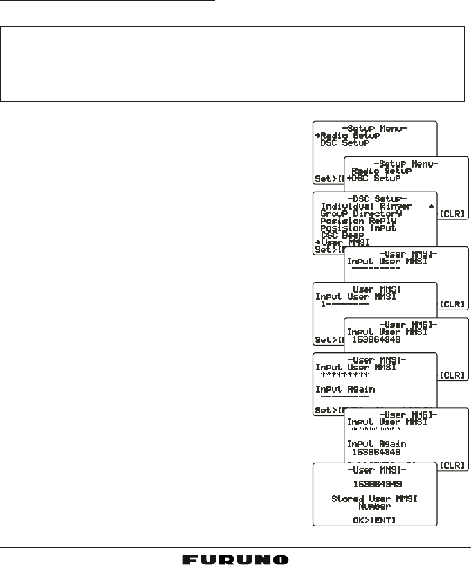
11.2.2 Programming the MMSI
WARNING
An MMSI can be inputted only once. Therefore please be careful not
to input the incorrect MMSI number. If the user needs to change the
MMSI number after it has been entered, the radio will have to be re-
turned to the factory.
1. Press and hold down the [CALL(MENU)] key
until the “Radio SetupRadio Setup
Radio SetupRadio Setup
Radio Setup” menu appears.
2. Turn the CHANNEL selector knob to the left to
select the “DSC SetupDSC Setup
DSC SetupDSC Setup
DSC Setup” menu.
3. Press the [ENT] key, then use the CHANNEL
selector knob to select “User MMSIUser MMSI
User MMSIUser MMSI
User MMSI.”
4. Press the [ENT] key.
5. Turn the CHANNEL selector knob or press the
[UP(S)] / [DOWN(T)] key on the microphone to se-
lect the first number of your MMSI, then press
the [ENT] key to go to the next number.
6. Repeat step 5 to set your MMSI (nine digits).
7. When finished programming the number, press
and hold the [ENT] key. A confirmation mes-
sage appears on the display. Set your MMSI
again, then press and hold the [ENT] key.
8. Press the [ENT] key to store the number in the
memory.
9. Press the [CLR] key twice to return to the “RadioRadio
RadioRadio
Radio
SetupSetup
SetupSetup
Setup” menu, then press the [CLR] key again
to return to radio operation.
FM-4000Page 36
11.3 DSC DISTRESS CALL
The FM-4000 is capable of transmitting and receiving DSC distress messages
to all DSC radios. The FM-4000 may be connected to a GPS receiver to also
transmit the latitude and longitude of your vessel.
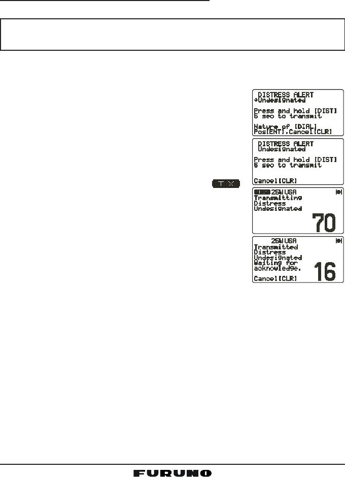
11.3.1 Transmitting a DSC Distress Call
NOTE
To transmit a DSC Distress call, an MMSI number must be programmed.
See section “11.2.2 Programming the MMSI.”
In order for your ship’s location to be transmitted a GPS receiver must be
connected to the FM-4000. See section “8.5 ACCESSORY CABLE.”
1. Lift the red spring-loaded DISTRESS cover, then the
[DISTRESS] key. The “DISTRESS ALERTDISTRESS ALERT
DISTRESS ALERTDISTRESS ALERT
DISTRESS ALERT” menu ap-
pears on the LCD.
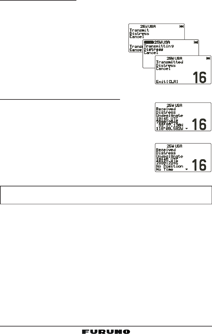
2. Press and hold the [DISTRESS] key. The radio’s dis-
play counts down (5-4-3-2-1) and then the Distress
call is transmitted. The backlight of the LCD and key-
pad flash while the radio’s display is counting down.
3. When the distress signal is sent, CH70 and “ ”
icon appear on the LCD.
4. The transceiver “shadow-watches” for a transmission
between CH16 and CH70 until an acknowledgment
signal is received. “DISTRESS” and “WAITING” ap-
pear on the LCD.
5. If an acknowledgment is received, select CH16 and
advise your distress situation.
6. If no acknowledgment is received, the Distress call is repeated in 4-minute
intervals until an acknowledgment is received.
7. When a DSC Distress acknowledgment is received, a distress alarm sounds
and CH16 is automatically selected. The LCD shows the MMSI of the ship
responding to your distress.
RECEIVED ACK: Acknowledgment signal is received.
RECEIVED RLY: Relay signal is received from another vessel or coast
station.
8. To cancel the DSC distress alarm signal from the speaker, press any key.
Page 37FM-4000
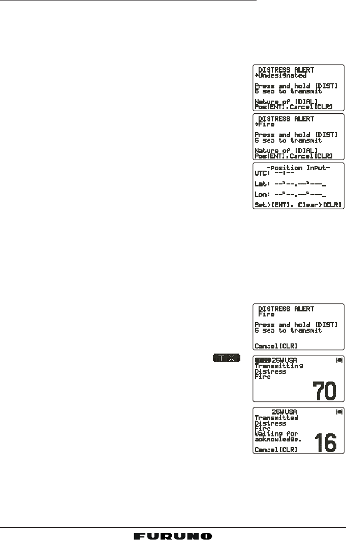
Transmitting a DSC Distress Alert with Nature of Distress
The FM-4000 is capable of transmitting a DSC Distress Alert with the following
“Nature of Distress” categories:
Undesignated, Fire, Flooding, Collision, Grounding, Capsizing, Sinking,
Adrift, Abandoning, Piracy, MOB
1. Lift the red spring-loaded DISTRESS key, then the
[DISTRESS] key to show the “DISTRESS ALERTDISTRESS ALERT
DISTRESS ALERTDISTRESS ALERT
DISTRESS ALERT”
menu.
2. Turn the CHANNEL selector knob to select the de-
sired nature of distress category.
3. When the FM-4000 is connected to a GPS receiver,
skip to step 4.
When the FM-4000 is not connected to a GPS re-
ceiver, you may send the latitude/longitude of your
vessel manually, if desired.
a. Press the [ENT] key twice. The display looks like
the illustration at the right.
b. Enter your local UTC time, then press the [ENT] key.
c. Enter the latitude/longitude of your vessel, then press the [ENT] key. To
select North (N) press the [6(NAV)] key, South (S) press the [7(SCRM)]
key, East (E) press the [3(SCAN)] key or West (W) press the [9(FOG)]
key.
d. To store the data entered, press and hold the [ENT] key.
4. Press and hold the [DISTRESS] key. The radio’s dis-
play counts down (5-4-3-2-1) and then the distress
call is transmitted. The backlight of the LCD and key-
pad flash during the countdown.
5. When the distress signal is sent, CH70 and “ ”
icon appear on the LCD.
6. The transceiver will watch for a DSC acknowledgment
transmission on CH70 and also receive calls on CH16.
7. When a DSC Distress acknowledgment is received,
a distress alarm sounds and channel 16 is auto-
matically selected. The LCD shows the MMSI of the
ship responding to your distress.
RECEIVED ACK: Acknowledgment signal is received.
RECEIVED RLY ACK: Relay acknowledgment signal is received from an-
other vessel or coast station.
8. To cancel the DSC distress alarm signal from the speaker, press any key.
FM-4000Page 38
Cancel a DSC Distress Call
If a DSC Distress call was sent by error, the FM-4000 allows you to send a
message to other vessels to cancel the Distress call.
Press the [CLR] key, then press the [ENT] key.
11.3.2 Receiving a DSC Distress Call
1. When a DSC Distress call is received, an emergency
alarm sounds.
Then CH16 is automatically selected.
2. Press any key to stop the alarm.
3. The LCD shows the position of the vessel in distress.
4 If the distress data does not include latitude/longi-
tude position, the display shown right appears.
NOTE
You must continue monitoring CH16 as a coast station may require as-
sistance in the rescue attempt.
11.4 ALL SHIPS CALL
The All Ships call function allows contact to be established with other vessel
stations without having their ID in the individual calling directory. Also, priority
for the call can be designated as Urgency or Safety.
URGENCY Call:This type of call is used when a vessel may not truly be in
distress, but have a potential problem that may lead to a dis-
tress situation. This call is the same as saying “PAN PAN PAN”
on CH16.
SAFETY Call: Transmit boating safety information to other vessels. This mes-
sage usually contains information about an overdue boat, de-
bris in the water, loss of a navigation aid or an important me-
teorological message. This call is the same as saying
“Securite, Securite, Securite.”

Page 39FM-4000
11.4.1 Transmitting an All Ships Call
1. Press the [CALL(MENU)] key to show the “DSCDSC
DSCDSC
DSC
Call MenuCall Menu
Call MenuCall Menu
Call Menu.”
2. Turn the CHANNEL selector knob to select “AllAll
AllAll
All
ShipsShips
ShipsShips
Ships.”
3. Press the [ENT] key. (To cancel, turn the
CHANNEL selector knob to select “ExitExit
ExitExit
Exit.”)
4. Turn the CHANNEL selector knob to select the
nature of call (“UrgencyUrgency
UrgencyUrgency
Urgency” or “SafetySafety
SafetySafety
Safety”), then press
the [ENT] key.
5. Press the [ENT] key again to transmit the selected
type of All Ships call.
6. After the All Ships call is transmitted, the transceiver
switches to CH16.
7. Listen to the channel to make sure it is not busy,
then key the microphone and say “PAN PAN PAN”
or “Securite, Securite, Securite” depending on the
priority of the call. Then announce both your call sign
and the channel you wish to switch to for communi-
cations.
11.4.2 Receiving an All Ships Call
1. When an All Ships call is received, an emergency alarm sounds.
The radio will automatically change to CH16 and
the LCD shows the MMSI of the vessel transmitting
the All Ships call.
2. Press any key to stop the alarm.
3. Monitor CH16 or traffic channel until the Urgency voice communication is
completed.
11.5 INDIVIDUAL CALL
This feature allows the FM-4000 to contact another vessel with a DSC VHF
radio and automatically switch the receiving radio to a desired communica-
tions channel. This feature is similar to calling a vessel on CH16 and request-
ing to go to another channel (switching to the channel is private between the
two stations).
11.5.1 Setting up the Individual / Position Call Directory
The FM-4000 has a DSC directory that allows you to store a vessel or person’s
name and the MMSI number associated with vessels you wish to transmit
Individual calls, position requests and position send transmissions.
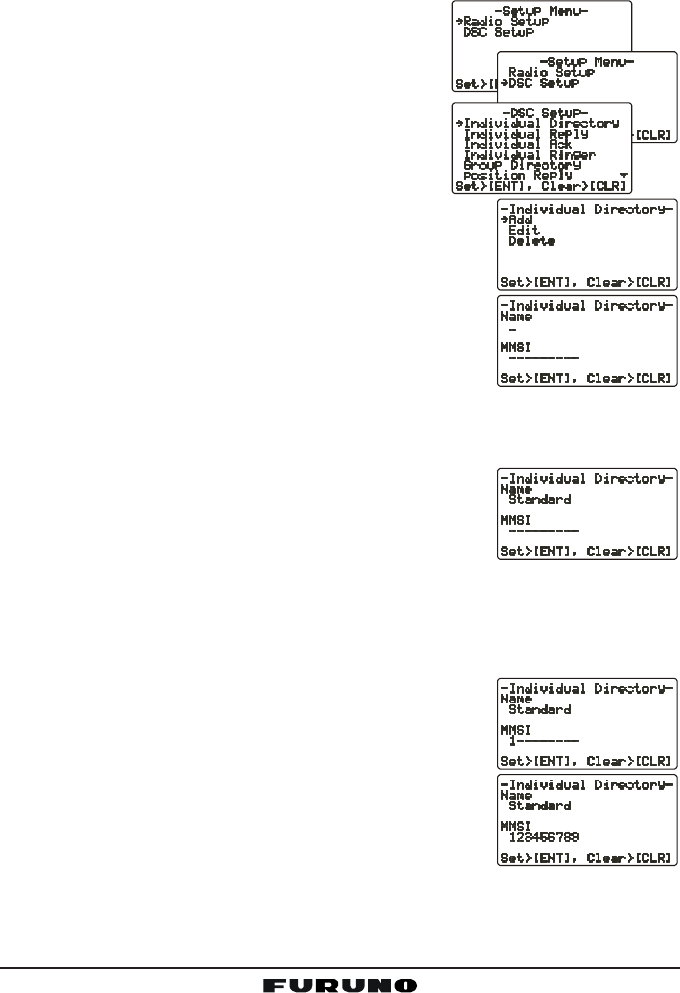
FM-4000Page 40
To transmit an Individual call you must program this directory with information
of the persons you wish to call, similar to the telephone directory of a cellular
phone.
1. Press and hold down the [CALL(MENU)] key
until the “Radio SetupRadio Setup
Radio SetupRadio Setup
Radio Setup” menu appears.
2. Turn the CHANNEL selector knob to select the
“DSC SetupDSC Setup
DSC SetupDSC Setup
DSC Setup” menu.
3. Press the [ENT] key, then use the CHANNEL
selector knob to select “Individual DirectoryIndividual Directory
Individual DirectoryIndividual Directory
Individual Directory.”
4. Press the [ENT] key.
5. Select “AddAdd
AddAdd
Add” with the CHANNEL selector knob,
then press the [ENT] key.
6. Press applicable key to enter the first letter of the
name of the vessel or person you want to reference
in the directory.
Example: Press the [2(MEM)] key repeatedly to
toggle among the seven available characters asso-
ciated with that key: 22
22
2 Æ AA
AA
A Æ BB
BB
B Æ CC
CC
C Æ aa
aa
a Æ bb
bb
b Æ cc
cc
c Æ 22
22
2 ....
If you enter a wrong charactor, press the [CLR] key
to delete the wrong character.
7. Press the [ENT] key to store the first letter in the name and move to the
next letter to the right.
8. Repeat steps 6 and 7 to complete the name. The
name can consist of up to 11 characters. If you do
not use all 11 characters press the [ENT] key to move
to the next space. This method can also be used to enter a blank space in
the name. If you enter a wrong character, press the [H/L] key until the
wrong character is selected, then enter the correct character.
9. After the 11th letter or space has been entered, press and hold the [ENT]
key to advance to the MMSI (Maritime Mobile Ser-
vice Identity Number) number entry.
10. Enter the desired number. If you enter a wrong num-
ber, press the [H/L] key until the wrong number is
selected, then enter the correct number.
11. To store the data entered, press and hold the [ENT]
key.
12. To enter another individual address, repeat steps 5
through 11.
13. Press the [CLR] key twice to return to the “Radio SetupRadio Setup
Radio SetupRadio Setup
Radio Setup” menu, then press
the [CLR] key again to return to radio operation.
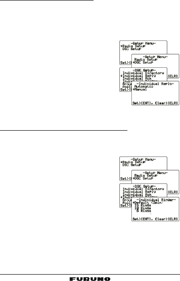
Page 41FM-4000
11.5.2 Setting up Individual Reply
Allows setting up the radio to automatically (default setting) or manually re-
spond to a DSC Individual call requesting you to switch to a working channel
for voice communications. When Manual is selected, the MMSI of the calling
vessel is shown, allowing you to see who is calling. This function is similar to
the caller ID on a cellular phone.
1. Press and hold down the [CALL(MENU)] key
until the “Radio SetupRadio Setup
Radio SetupRadio Setup
Radio Setup” menu appears.
2. Turn the CHANNEL selector knob to select
“DSC SetupDSC Setup
DSC SetupDSC Setup
DSC Setup” menu.
3. Press the [ENT] key, then use the CHANNEL
selector knob to select “Individual ReplyIndividual Reply
Individual ReplyIndividual Reply
Individual Reply.”
4. Press the [ENT] key.
5. Turn the CHANNEL selector knob to select “Au-Au-
Au-Au-
Au-
tomatictomatic
tomatictomatic
tomatic” or “ManualManual
ManualManual
Manual.”
6. Press the [ENT] key to store the selected setting.
7. Press the [CLR] key twice to return to the “Radio SetupRadio Setup
Radio SetupRadio Setup
Radio Setup” menu, then press
the [CLR] key again to return to radio operation.
11.5.3 Setting up Individual/Group Call Ringer
When an Individual call or Group call is received the radio will produce a ring-
ing tone for two minutes. This selection allows the Individual call ringer time to
be changed.
1. Press and hold down the [CALL(MENU)] key
until “Radio SetupRadio Setup
Radio SetupRadio Setup
Radio Setup” menu appears.
2. Turn the CHANNEL selector knob to select
“DSC SetupDSC Setup
DSC SetupDSC Setup
DSC Setup” menu.
3. Press the [ENT] key, then use the CHANNEL
selector knob to select “Individual RingerIndividual Ringer
Individual RingerIndividual Ringer
Individual Ringer.”
4. Press the [ENT] key.
5. Turn the CHANNEL selector knob to select
ringing time for an Individual call.
6. Press the [ENT] key to store the selected setting.
7. Press the [CLR] key twice to return to the “Radio SetupRadio Setup
Radio SetupRadio Setup
Radio Setup” menu, then press
the [CLR] key again to return to radio operation.
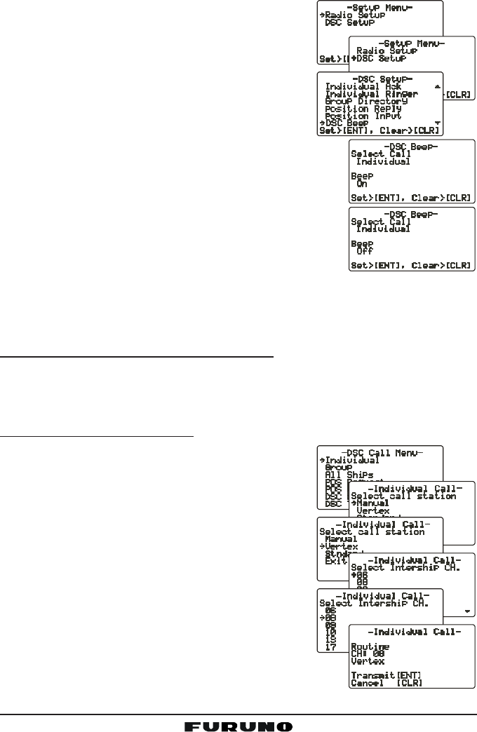
FM-4000Page 42
The Individual call and Group call ringers can be disabled as follows:
1. Press and hold down the [CALL(MENU)] key
until “Radio SetupRadio Setup
Radio SetupRadio Setup
Radio Setup” menu appears.
2. Turn the CHANNEL selector knob to select the
“DSC SetupDSC Setup
DSC SetupDSC Setup
DSC Setup” menu.
3. Press the [ENT] key, then use the CHANNEL
selector knob to select “DSC BeepDSC Beep
DSC BeepDSC Beep
DSC Beep.”
4. Press the [ENT] key.
5. Turn the CHANNEL selector knob to select “In-In-
In-In-
In-
dividualdividual
dividualdividual
dividual” if you wish to disable the Individual call
ringer, or “GroupGroup
GroupGroup
Group” if you wish to disable the Group
call ringer and press the [ENT] key.
6. Turn the CHANNEL selector knob to select “OffOff
OffOff
Off.”
7. Press the [ENT] key to store the selected setting.
8. Press the [CLR] key twice to return to the “RadioRadio
RadioRadio
Radio
SetupSetup
SetupSetup
Setup” menu, then press the [CLR] key again to re-
turn to radio operation.
To enable the Individual or Group ringer tone, select “OnOn
OnOn
On” in step “6” in this
procedure.
11.5.4 Transmitting an Individual Call
The Individual call feature allows you to contact another vessel that has a DSC
radio. This feature is similar to calling a vessel on CH16 and requesting to go
to another channel.
Using Pre-Programmed Vessel
1. Press the [CALL(MENU)] key to show the “DSCDSC
DSCDSC
DSC
Call MenuCall Menu
Call MenuCall Menu
Call Menu”.
2. Turn the CHANNEL selector knob to select “In-In-
In-In-
In-
dividualdividual
dividualdividual
dividual.” (To cancel, press the [CLR] key.)
3. Press the [ENT] key. The transceiver beeps
then the “Individual directory” appears.
4. Turn the CHANNEL selector knob to select the
“Individual” you want to contact.
5. Press the [ENT] key, then turn the CHANNEL
selector knob to select the operating channel
you want to communicate on, then press the
[ENT] key.
6. Press the [ENT] key again to transmit the individual
DSC signal.
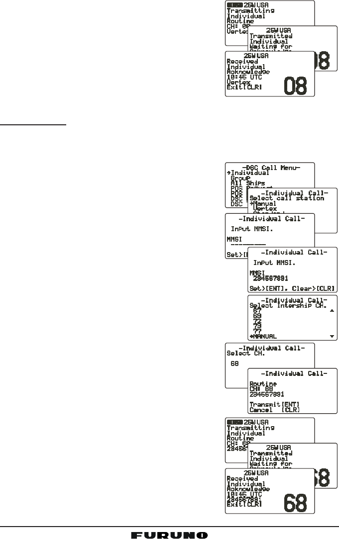
Page 43FM-4000
7. When an Individual call acknowledgment is re-
ceived, the channel selected at step 5 is auto-
matically selected and a ringing tone sounds.
8. Press [CLR] key to listen to the channel to make
sure it is not busy, then key the microphone to
call the other vessel.
Manual Calling
You may enter an MMSI number manually to contact a vessel which is not
stored in the Individual Directory.
1. Press the [CALL(MENU)] key to show the “DSCDSC
DSCDSC
DSC
Call MenuCall Menu
Call MenuCall Menu
Call Menu.”
2. Turn the CHANNEL selector knob to select “In-In-
In-In-
In-
dividualdividual
dividualdividual
dividual.” (To cancel, press the [CLR] key.)
3. Press the [ENT] key. The transceiver beeps
then the “Individual directory” appears.
4. Turn the CHANNEL selector knob to select
“ManualManual
ManualManual
Manual,” then press the [ENT] key.
5. Enter the MMSI number (nine digits) which you want
to contact, then press the [ENT] key.
6. If you enter the wrong number in the MMSI number,
press the [H/L] key until the wrong number is se-
lected, then enter the correct number.
7. When you are finished entering the MMSI number,
press and hold the [ENT] key.
8. Turn the CHANNEL selector knob to select
“ManualManual
ManualManual
Manual,” then press the [ENT] key.
9. Turn the CHANNEL selector knob to select the
operating channel you want to communicate on, then
press the [ENT] key.
10. Press the [ENT] key again to transmit the indi-
vidual DSC signal.
11. When an Individual call acknowledgment is re-
ceived, the channel selected at step 5 is auto-
matically selected and a ringing tone sounds.
12. Press the [CLR] key to listen to the channel to
make sure it is not busy, then key the micro-
phone to call the other vessel.