Furuno USA 9ZWFM4000 VHF Radiotelephone User Manual FM 4000 pmd
Furuno USA Inc VHF Radiotelephone FM 4000 pmd
Contents
- 1. users manual part 1
- 2. users manual part 2
users manual part 2
FM-4000Page 44
11.5.5 Receiving an Individual Call
When receiving an Individual call, an acknowledgment must be sent back to the
calling station, automatically or manual. The default setting is Automatic, but the
radio has a selection that allows you to manually send a reply before the radio
will switch to the requested calling channel. The default reply method is Auto-
matic, but manual reply (before the radio switches to the requested calling chan-
nel) also is available. This selection is useful if you want to see who is calling and
requesting you to switch to a channel for communications, similar to the caller ID
on a cellular phone.
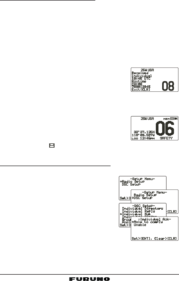
1. When an Individual call is received, the Individual call ringing alarm sounds.
The radio automatically (automatic mode selected)
switches to the requested channel and the LCD
shows the MMSI of the vessel calling.
2. Press any key to stop the alarm.
3. Press the PTT on the microphone and talk to the calling ship.
11.6 CALL WAITING DIRECTORY
The FM-4000 logs received Distress calls and Individual
calls. The DSC Call Waiting feature is similar to an an-
swering machine where calls are recorded for review.
When a call is logged while the radio is set on the DSC
Standby function, a “ ” icon appears on the LCD. The FM-4000 can memo-
rize up to 30 Distress calls, and up to 80 Individual calls.
11.6.1 Enabling the Call Waiting Feature
Follow the steps below to enable or disable the Call Waiting feature.
1. Press and hold down the [CALL(MENU)] key
until “Radio SetupRadio Setup
Radio SetupRadio Setup
Radio Setup” menu appears.
2. Turn the CHANNEL selector knob to select
“DSC SetupDSC Setup
DSC SetupDSC Setup
DSC Setup” menu.
3. Press the [ENT] key, then use the CHANNEL
selector knob to select “Individual AckIndividual Ack
Individual AckIndividual Ack
Individual Ack.”
4. Press the [ENT] key.
5. Turn the CHANNEL selector knob to select
“Able to complyAble to comply
Able to complyAble to comply
Able to comply” or “UnableUnable
UnableUnable
Unable.”
6. Press the [ENT] key to store the selected setting.
7. Press the [CLR] key twice to return to the “Radio SetupRadio Setup
Radio SetupRadio Setup
Radio Setup” menu, then press
the [CLR] key again to return to radio operation.
Page 45FM-4000
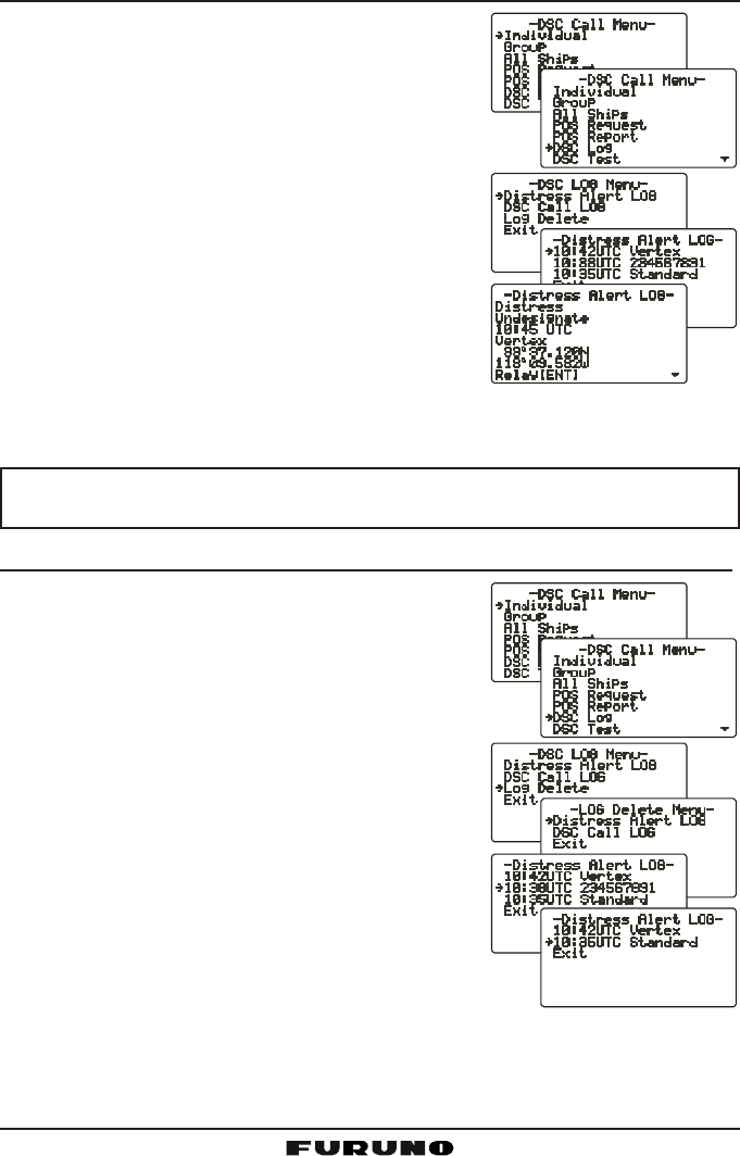
11.6.2 Reviewing Received Calls Logged into the Call Waiting Directory
1. Press the [CALL(MENU)] key to show the “DSCDSC
DSCDSC
DSC
Call MenuCall Menu
Call MenuCall Menu
Call Menu.”
2. Turn the CHANNEL selector knob to select the
“DSC LogDSC Log
DSC LogDSC Log
DSC Log” menu.
3. Press the [ENT] key, then turn the CHANNEL se-
lector knob to select the category (“DistressDistress
DistressDistress
Distress
Alert LOGAlert LOG
Alert LOGAlert LOG
Alert LOG” or “DSC Call LogDSC Call Log
DSC Call LogDSC Call Log
DSC Call Log”) you want to review
and/or call back.
4. Press the [ENT] key, then turn the CHANNEL
selector knob to select the station (name or MMSI
number) you want to review and/or call back.
5. Press the [ENT] key to review details for the
selected station.
6. Press the [ENT] key again to call the selected
station.
NOTE
When there is an unread received call, the category (“Distress Alert LOGDistress Alert LOG
Distress Alert LOGDistress Alert LOG
Distress Alert LOG”
or “DSC Call LogDSC Call Log
DSC Call LogDSC Call Log
DSC Call Log”) indication will blink.
11.6.3 To Delete the Received Log from the “DSC Log” Directory
1. Press the [CALL(MENU)] key to show the “DSCDSC
DSCDSC
DSC
Call MenuCall Menu
Call MenuCall Menu
Call Menu.”
2. Turn the CHANNEL selector knob to select the
“DSC LogDSC Log
DSC LogDSC Log
DSC Log” menu.
3. Press the [ENT] key, then turn the CHANNEL se-
lector knob to select “Log DeleteLog Delete
Log DeleteLog Delete
Log Delete.”
4. Press the [ENT] key, then turn the CHANNEL
selector knob to select the category (“DistressDistress
DistressDistress
Distress
Alert LOGAlert LOG
Alert LOGAlert LOG
Alert LOG” or “DSC Call LOGDSC Call LOG
DSC Call LOGDSC Call LOG
DSC Call LOG”) to delete.
5. Press the [ENT] key, then turn the CHANNEL
selector knob to select the station (name or
MMSI number) to delete.
6. Press and hold the [ENT] key until the station
(name or MMSI number) is removed from the
display.
7. To exit this menu and return to radio operation mode,
press the [16/9] key.
FM-4000Page 46
11.7 GROUP CALL
This feature allows the user to contact a group of specific vessels (example
members of a yacht club) that have DSC radios with Group call function to
automatically switch to a desired channel for voice communications.
11.7.1 Setting up a Group Call
For this function to operate, the same Group MMSI must be programmed into
all the DSC VHF radios within the group of vessels that use this feature. To
understand about Group MMSI programming, first a Ship MMSI has to be
understood.
Ship MMSI: The first three digits called a MID (Mobile Identity Group) of a Ship
MMSI denote the country the ship registered for a MMSI. The last six digits are
specific to the Ships ID.
Ship MMSI Example: If your MMSI is “366123456”, for example, “366” is the
MID, which denotes the country, and “123456” is the ID of your ship.
Group MMSI:
Group MMSI numbers are not assigned by the FCC or other organizations
licensed to assign Ship MMSI numbers.
The first digit of a Group MMSI is always set to “0” in accordance with
international regulations. All FURUNO radios are preset so when program-
ming a Group MMSI the first digit is set to “0”.
The USCG recommends programming the MID of a Ship MMSI into the
second, third and fourth digits of the Group MMSI as it denotes the area
the ship is located.
The last five digits are decided upon by persons in the Group. This is an
important step as all radios in the group must contain the same Group
MMSI so they can be contacted by each other. There is a chance that
another group of vessels have the same Group MMSI as yours. If this
happens, simply change one or more of the last five digits of the Group
MMSI.
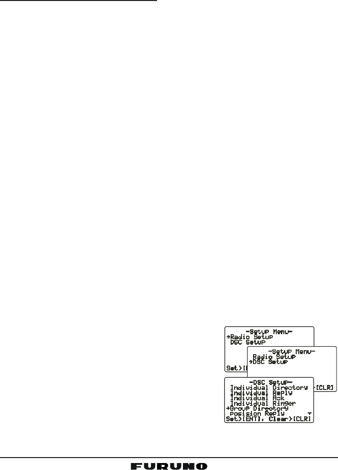
1. Press and hold down the [CALL(MENU)] key
until the “Radio SetupRadio Setup
Radio SetupRadio Setup
Radio Setup” menu appears.
2. Turn the CHANNEL selector knob to select the
“DSC SetupDSC Setup
DSC SetupDSC Setup
DSC Setup” menu.
3. Press the [ENT] key, then use the CHANNEL
selector knob to select “Group DirectoryGroup Directory
Group DirectoryGroup Directory
Group Directory.”
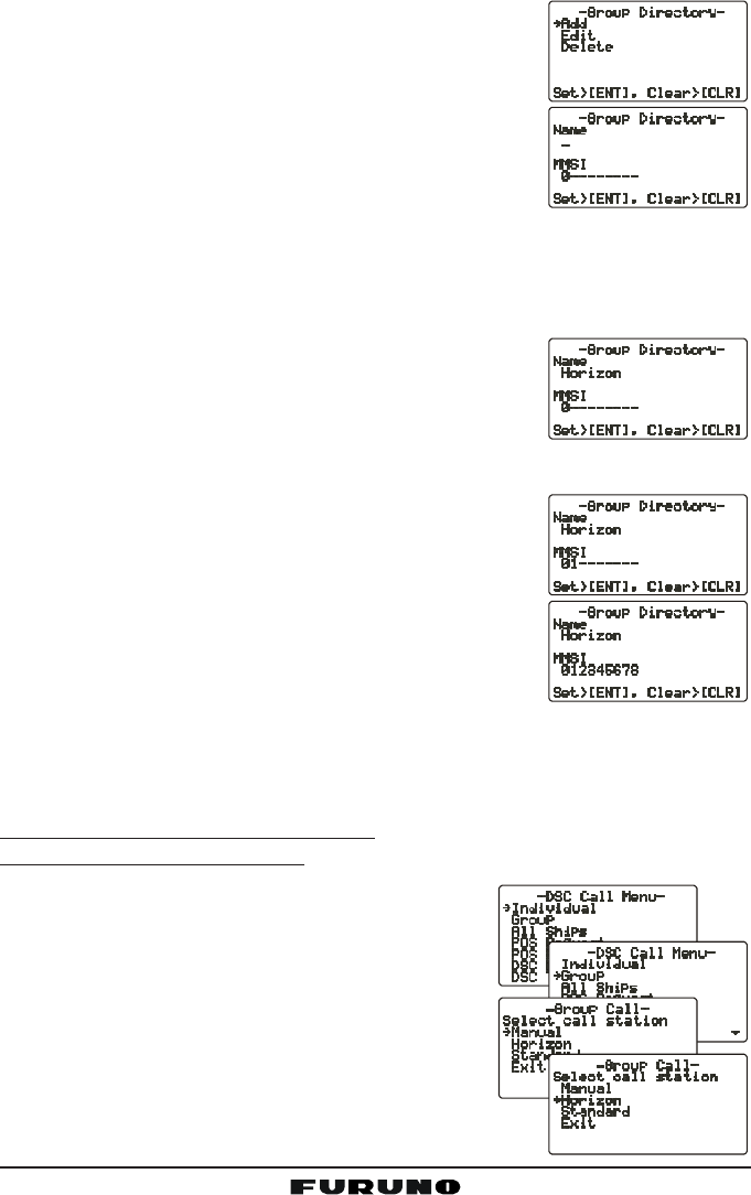
4. Press the [ENT] key, then select “AddAdd
AddAdd
Add” with the
CHANNEL selector knob.
5. Press the [ENT] key.
Page 47FM-4000
6. Press applicable key to enter the first letter of the
name of the group you want to reference in the di-
rectory.
Example: Press the [2(MEM)] key repeatedly to
toggle among the seven available characters asso-
ciated with that key: 22
22
2 Æ AA
AA
A Æ BB
BB
B Æ CC
CC
C Æ aa
aa
a Æ bb
bb
b Æ cc
cc
c Æ 22
22
2 ....
If you enter a wrong character, pres the [CLR] key
to delete the wrong character.
7. Press the [ENT] key to store the first letter in the name.
8. Repeat steps 6 and 7 to complete the name. The name can consist of up
to 11 characters. If you do not use all 11 characters, press the [ENT] key to
move to the next space. This method can also be
used to enter a blank space in the name. If you en-
ter a wrong character, press the [H/L] key until the
wrong character is selected, then enter the correct
character.
9. After the 11th letter or space has been entered, press and hold the [ENT]
key to advance to the Group MMSI (Maritime Mo-
bile Service Identity Number) number entry.
10. Enter the desired number. If you enter a wrong num-
ber, press the [H/L] key until the wrong number is
selected, then enter the correct number.
11. To store the data entered, press and hold the [ENT]
key.
12. To enter another group address, repeat steps 4
through 11.
13. Press the [CLR] key twice to return to the “Radio SetupRadio Setup
Radio SetupRadio Setup
Radio Setup” menu, then press
the [CLR] key again to return to radio operation.
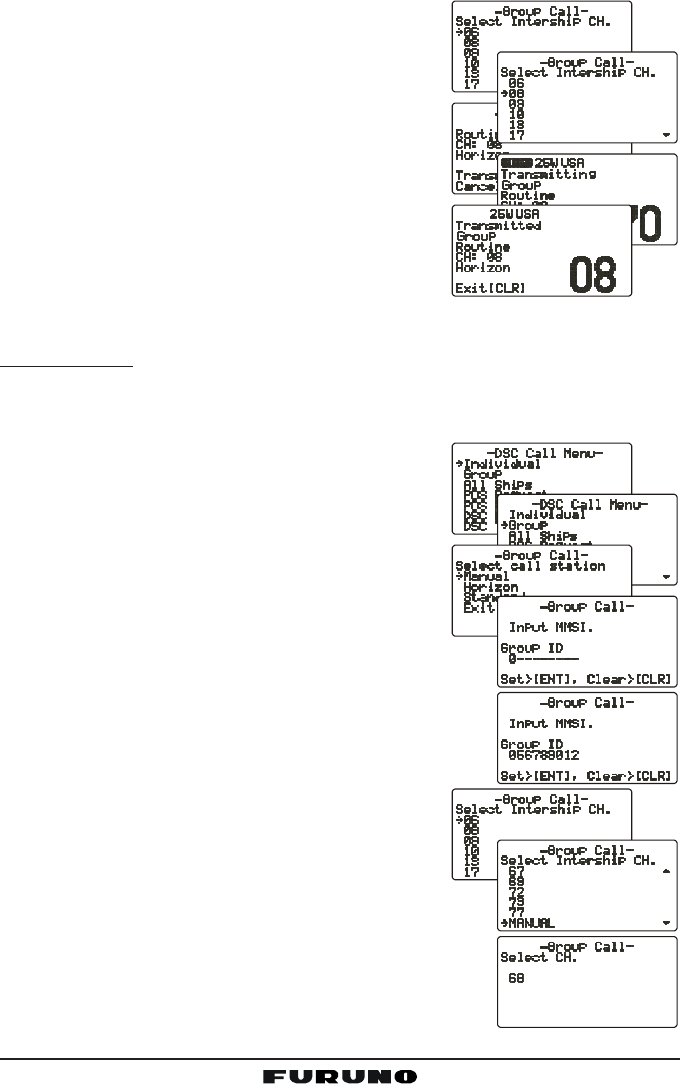
11.7.2 Transmitting a Group Call
Using Pre-Programmed Vessel
1. Press the [CALL(MENU)] key to show the “DSCDSC
DSCDSC
DSC
Call MenuCall Menu
Call MenuCall Menu
Call Menu.”
2. Turn the CHANNEL selector knob to select
“GroupGroup
GroupGroup
Group.” (To cancel, press the [CLR] key.)
3. Press the [ENT] key. The transceiver beeps,
and the “Group directory” appears.
4. Turn the CHANNEL selector knob to select the
“Group” you want to contact.
5. Press the [ENT] key, then turn the CHANNEL
selector knob to select the operating channel you
FM-4000Page 48
want to communicate on, then press the [ENT]
key.
6. Press the [ENT] key again to transmit the Group
call signal.
7. When the Group call signal is sent, the LCD
displays the information shown in the illustra-
tion at right.
8. After the Group call is transmitted, all the ra-
dios in the group switch to the designated chan-
nel.
9. Listen to the channel to make sure it is not busy,
then key the microphone and call the other ves-
sels you desire to communicate with.
Manual Calling
You may enter a Group MMSI number manually to contact a group whose
Group call number is not registered in the radio.
1. Press the [CALL(MENU)] key to show the “DSCDSC
DSCDSC
DSC
Call MenuCall Menu
Call MenuCall Menu
Call Menu.”
2. Turn the CHANNEL selector knob to select
“GroupGroup
GroupGroup
Group.” (To cancel, press the [CLR] key.)
3. Press the [ENT] key. The transceiver beeps
then the “Group Directory” appears.
4. Turn the CHANNEL selector knob to select
“ManualManual
ManualManual
Manual,” then press the [ENT] key.
5. Enter the MMSI number (nine digits: first digit per-
manently set to “0”) which you want to contact, then
press the [ENT] key.
6. If you enter a wrong number in the MMSI number,
press the [H/L] key until the wrong number is se-
lected, then enter the correct number.
7. When you have finished entering the MMSI
number, press and hold the [ENT] key.
8. Turn the CHANNEL selector knob to select
“ManualManual
ManualManual
Manual,” then press the [ENT] key.
9. Turn the CHANNEL selector knob to select the op-
erating channel you want to communicate on, then
press the [ENT] key.
10. Press the [ENT] key again to transmit the Group
call signal.
Page 49FM-4000
11. After the Group call is transmitted, all the radios in
the group switch to the designated channel.
12. Listen to the channel to make sure it is not busy,
then key the microphone and call the other
vessels.
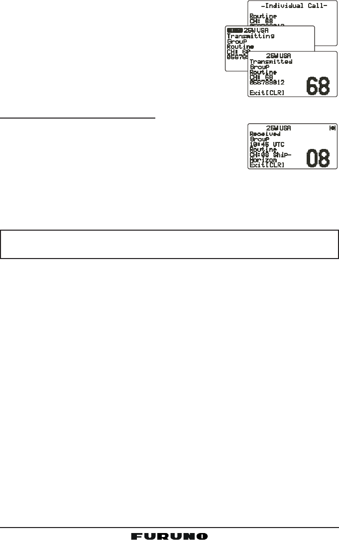
11.7.3 Receiving a Group Call
1. When a Group call is received, the FM-4000 sounds
a ringing alarm and the radio automatically switches
to the requested channel.
2. Press any key to stop the alarm.
3. Monitor the channel for a message sent by a person calling the Group.
4. If you want to respond, monitor the channel to make sure it is clear, then
press the PTT on the microphone and talk to the calling ship(s).
NOTE
After a Group call is received, the time the call was made and the ship’s
MMSI or vessel’s name appear on the LCD.
FM-4000Page 50
11.8 POSITION REQUEST
Advancements in DSC have made it possible to poll the location of another
vessel and show the position of that vessel on the display of the FM-4000.
FURUNO has taken this feature one step further. If any FURUNO GPS chart
plotters are connected to the FM-4000, the polled position of the vessel is
shown on the display of the GPS chart plotter, making it easy to navigate to the
location of the polled vessel. This is a great feature for anyone wanting to
know the position of another vessel. For example, your buddy that is catching
fish, or finding the location of a person you are cruising with.
NOTE
The other vessel must have an operating GPS receiver connected to its
DSC transceiver and must not have its transceiver set to deny position
requests. (See the section “11.5 INDIVIDUAL CALL” to enter informa-
tion into the individual directory).
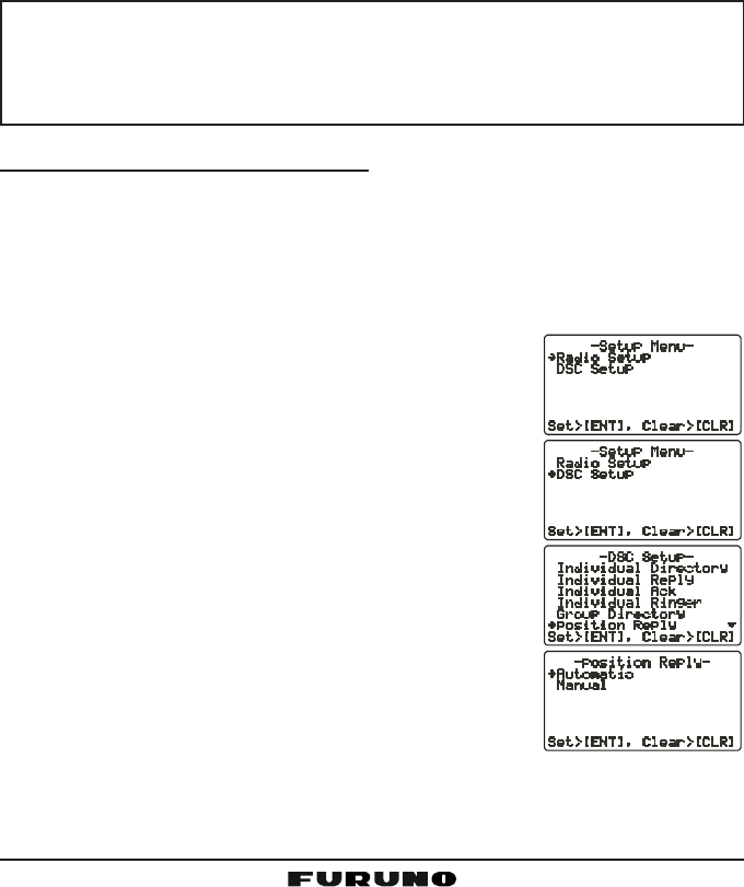
11.8.1 Setting up Position Reply
The FM-4000 can automatically or manually send your position to another
vessel. This selection is important if you are concerned about someone polling
the position of your vessel that you may not want to. In the manual mode you
will see the MMSI or person’s name shown on the display, allowing you to
choose to send your position to the requesting vessel or not.
1. Press and hold down the [CALL(MENU)] key until
the “Radio SetupRadio Setup
Radio SetupRadio Setup
Radio Setup” menu appears.
2. Turn the CHANNEL selector knob to select the “DSCDSC
DSCDSC
DSC
SetupSetup
SetupSetup
Setup” menu.
3. Press the [ENT] key, then use the CHANNEL selec-
tor knob to select “Position ReplyPosition Reply
Position ReplyPosition Reply
Position Reply.”
4. Turn the CHANNEL selector knob to select “Auto-Auto-
Auto-Auto-
Auto-
maticmatic
maticmatic
matic” or “ManualManual
ManualManual
Manual.” In the “AutomaticAutomatic
AutomaticAutomatic
Automatic” mode, after a
DSC POS Request is received, the radio will auto-
matically transmit your vessel’s position. In the
“ManualManual
ManualManual
Manual” mode, the display of the FM-4000 will show
who is requesting your position.
5. Press the [ENT] key to store the selected setting.
6. Press the [CLR] key twice to return to the “RadioRadio
RadioRadio
Radio
SetupSetup
SetupSetup
Setup” menu, then press the [CLR] key again to re-
turn to radio operation.
Page 51FM-4000
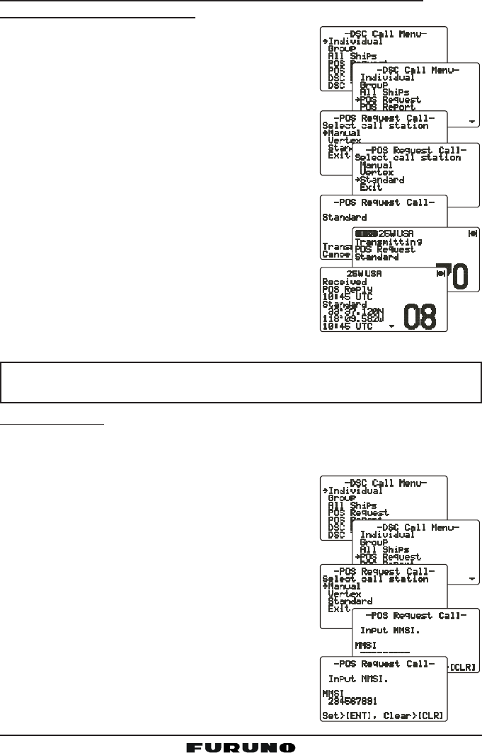
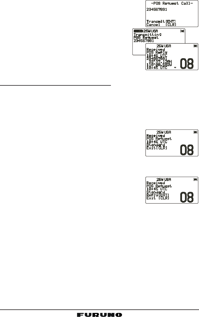
11.8.2 Transmitting a Position Request to Another Vessel
Using Pre-Programmed Vessel
1. Press the [CALL(MENU)] key to show the “DSCDSC
DSCDSC
DSC
Call MenuCall Menu
Call MenuCall Menu
Call Menu.”
2. Turn the CHANNEL selector knob to select
“Pos RequestPos Request
Pos RequestPos Request
Pos Request.”
3. Press [ENT] key to show the Position Request
Directory. This directory uses the Individual Di-
rectory information.
4. Turn the CHANNEL selector knob to select a
name, then press the [ENT] key.
5. Press the [ENT] key again to transmit the Po-
sition Request DSC call.
6. When the FM-4000 receives the position from
the polled vessel it is shown on the radio dis-
play and also transferred to the GPS chart plot-
ter.
NOTE
If the FM-4000 does not receive position data from the polled vessel,
the LCD shows “NO POSITION DATA.”
Manual Request
You may enter an MMSI number manually to request the position of a vessel
that is not registered in the Setting up the Individual / Position Call Directory.
1. Press the [CALL(MENU)] key to show the “DSCDSC
DSCDSC
DSC
Call MenuCall Menu
Call MenuCall Menu
Call Menu.”
2. Turn the CHANNEL selector knob to select
“Pos RequestPos Request
Pos RequestPos Request
Pos Request.”
3. Press the [ENT] key to show the Position Re-
quest directory. This directory uses the Indi-
vidual Directory information.
4. Turn the CHANNEL selector knob to select
“ManualManual
ManualManual
Manual,” then press the [ENT] key.
5. Enter the MMSI number (nine digits) which you
want to contact by the keypad, then press the
[ENT] key.
6. If you enter a wrong number in the MMSI num-
ber, press the [H/L] key until the wrong num-
FM-4000Page 52
ber is selected, then enter the correct number.
7. When you have finished entering the MMSI num-
ber, press and hold the [ENT] key.
8. Press the [ENT] key to transmit the Position
Request DSC call.
9. When the FM-4000 receives the position from
the polled vessel it is shown on the radio dis-
play and also transferred to the GPS chart plot-
ter.
11.8.3 Receiving a Position Request
When a Position Request call is received from another vessel, a ringing alarm
will sound and “POS REQUESTPOS REQUEST
POS REQUESTPOS REQUEST
POS REQUEST” appears. Operation and transceiver function
differ depending on the “Position ReplyPosition Reply
Position ReplyPosition Reply
Position Reply” setting in the “DSC SetupDSC Setup
DSC SetupDSC Setup
DSC Setup” menu.
Automatically reply:
1. When a Position Request call is received, a calling alarm sounds four times.
Then requested position coordinates are transmit-
ted automatically to the vessel requesting your
vessel’s position.
2. To exit from the Position Request display, press
the [CLR] key.
Manually reply:
1. When a Position Request call is received from an-
other vessel, the LCD shows the time and MMSI or
name of person requesting your vessel’s position.
2. A ringing alarm sounds four times. To send your
vessel’s position to the requesting vessel, press the [ENT] key. Or to exit
from Position Request display, press the [CLR] key.
Page 53FM-4000
11.9 POSITION SEND
The feature is similar to Position Request, however instead of requesting a
position of another vessel this function allows you to send your position to
another vessel. Your vessel must have an operating GPS receiver connected
to the FM-4000 to send your position.
NOTE
To transmit a Position Send call, you must set up the FM-4000 DSC
Individual / Position Call Directory with the name of the vessel(s) or
person and the MMSI of the DSC radio you wish to send your position
to. To setup this directory, see section “11.5.1 Setting up the Individual
/ Position Call Directory.”
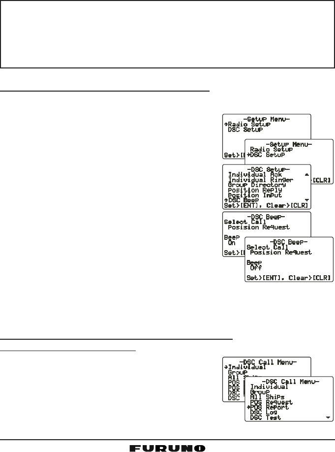
11.9.1 Setting up a Position Send Ringer
The FM-4000 has the capability to turn off the Position Send ringer as follows.
1. Press and hold down the [CALL(MENU)] key
until the “Radio SetupRadio Setup
Radio SetupRadio Setup
Radio Setup” menu appears.
2. Turn the CHANNEL selector knob to select the
“DSC SetupDSC Setup
DSC SetupDSC Setup
DSC Setup” menu.
3. Press the [ENT] key, then use the CHANNEL
selector knob to select “DSC BeepDSC Beep
DSC BeepDSC Beep
DSC Beep.”
4. Press the [ENT] key, then use the CHANNEL
selector knob to select “Position ReportPosition Report
Position ReportPosition Report
Position Report.”
5. Press the [ENT] key, then select “OffOff
OffOff
Off” with the
CHANNEL selector knob.
6. Press the [ENT] key to store the selected set-
ting.
7. Press the [CLR] key twice to return to the “RadioRadio
RadioRadio
Radio
SetupSetup
SetupSetup
Setup” menu, then press the [CLR] key again to re-
turn to radio operation.
To enable the ringer tone, select “OnOn
OnOn
On” at step “6” in this procedure.
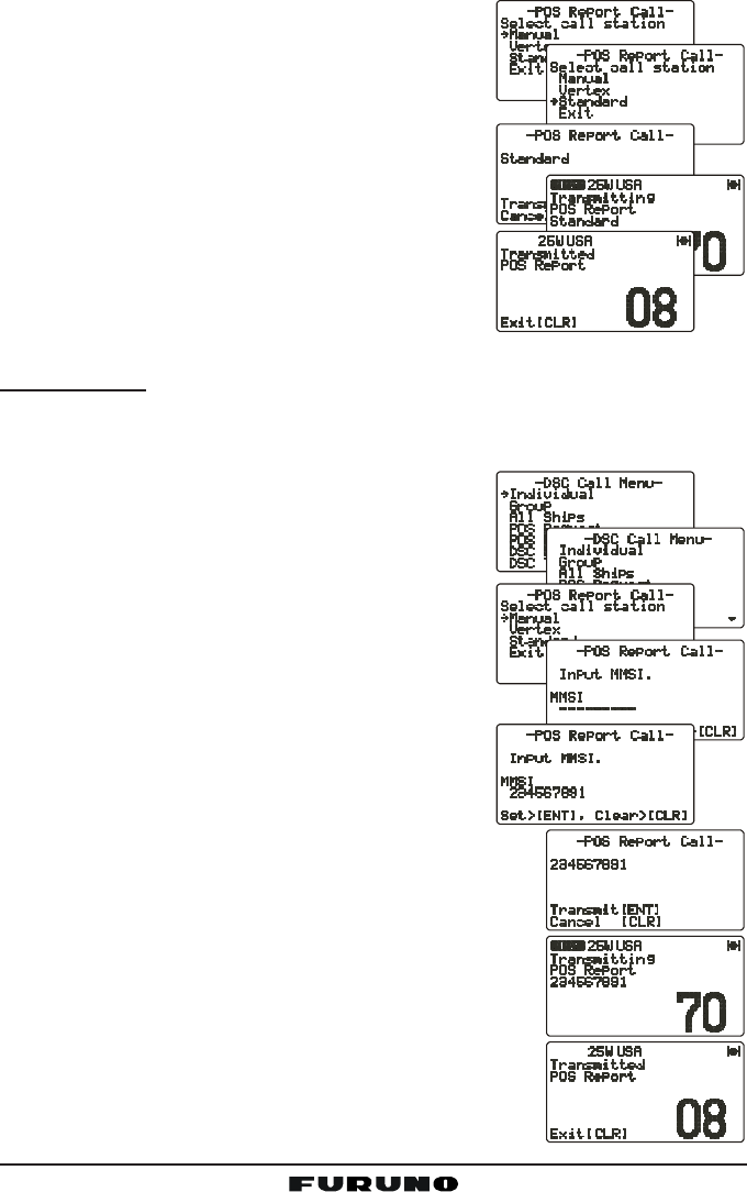
11.9.2 Transmitting a DSC Position Send Call
Using Pre-Programmed Vessel
1. Press the [CALL(MENU)] key to show the “DSCDSC
DSCDSC
DSC
Call MenuCall Menu
Call MenuCall Menu
Call Menu.”
2. Turn the CHANNEL selector knob to select
“Pos ReportPos Report
Pos ReportPos Report
Pos Report.”
FM-4000Page 54
3. Press [ENT] key to show the Position Send Di-
rectory. This directory uses the Individual Di-
rectory information.
4. Turn the CHANNEL selector knob to select a
name in the directory, then press the [ENT] key.
5. Press the [ENT] key again to send your posi-
tion to the selected vessel.
6. Press the [CLR] key twice to return to the “Ra-Ra-
Ra-Ra-
Ra-
dio Setupdio Setup
dio Setupdio Setup
dio Setup” menu, then press the [CLR] key
again to return to radio operation.
Manual Calling
You may enter an MMSI number manually to send your position to that vessel
without entering it into the Setting up the Individual / Position Call Directory.
1. Press the [CALL(MENU)] key to show the “DSCDSC
DSCDSC
DSC
Call MenuCall Menu
Call MenuCall Menu
Call Menu.”
2. Turn the CHANNEL selector knob to select
“Pos ReportPos Report
Pos ReportPos Report
Pos Report.”
3. Press [ENT] key to show the Position Send
Directory. This directory uses the Individual
Directory information.
4. Turn the CHANNEL selector knob to select
“ManualManual
ManualManual
Manual,” then press the [ENT] key.
5. Enter the MMSI number (nine digits: first digit
permanently set to “0”) which you want to con-
tact, then press the [ENT] key.
6. If you enter a wrong number in the MMSI num-
ber, press the [H/L] key until the wrong number is
selected, then enter the correct number.
7. When you have finished entering the MMSI num-
ber, press and hold the [ENT] key.
8. Press the [ENT] key to send your position to the
selected vessel.
Page 55FM-4000
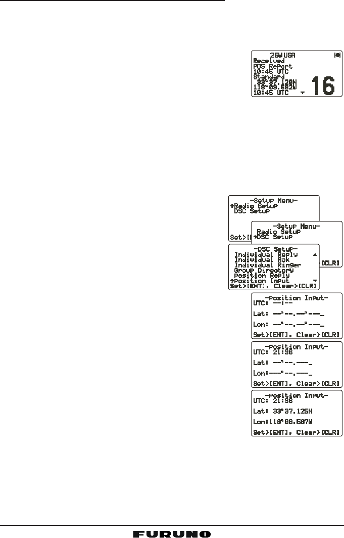
11.9.3 Receiving a DSC Position Send Call
When another vessel transmits its location to the FM-4000, the following oc-
curs:
1. A ringing sound is generated when the call is received.
2. Press any key to stop the ringing sound.
3. The position of the vessel is shown and also trans-
ferred to any FURUNO GPS chart plotter if con-
nected.
11.10 MANUAL INPUT OF POSITION (LAT/LON)
You may send the latitude/longitude of your vessel manually when the FM-
4000 is not connected to a GPS receiver.
After the position is entered, any DSC Distress, Position Request, or Position
Send will contain the manually entered position.
1. Press and hold down the [CALL(MENU)] key
until the “Radio SetupRadio Setup
Radio SetupRadio Setup
Radio Setup” menu appears.
2. Turn the CHANNEL selector knob to select the
“DSC SetupDSC Setup
DSC SetupDSC Setup
DSC Setup” menu.
3. Press the [ENT] key, then use the CHANNEL
selector knob to select “Position InputPosition Input
Position InputPosition Input
Position Input.”
4. Press the [ENT] key. The transceiver beeps,
then the display looks something like the one
in the illustration at right.
5. Enter your local UTC time in the 24-hour notation,
then press the [ENT] key.
6. Enter the latitude/longitude of your vessel, then press
the [ENT] key. To select North (N) press the [6(NAV)]
key, South (S) press the [7(SCRM)] key, East (E)
press the [3(SCAN)] key or West (W) press the
[9(FOG)] key.
7. To store the data entered, press and hold the [ENT]
key.
8. Press the [CLR] key twice to return to the “RadioRadio
RadioRadio
Radio
SetupSetup
SetupSetup
Setup” menu, then press the [CLR] key again to return to radio operation.
FM-4000Page 56
12 RADIO SETUP
NOTE
The optional CMP30 Remote MIC can also access the SETUP menu.
See page 73 for details.
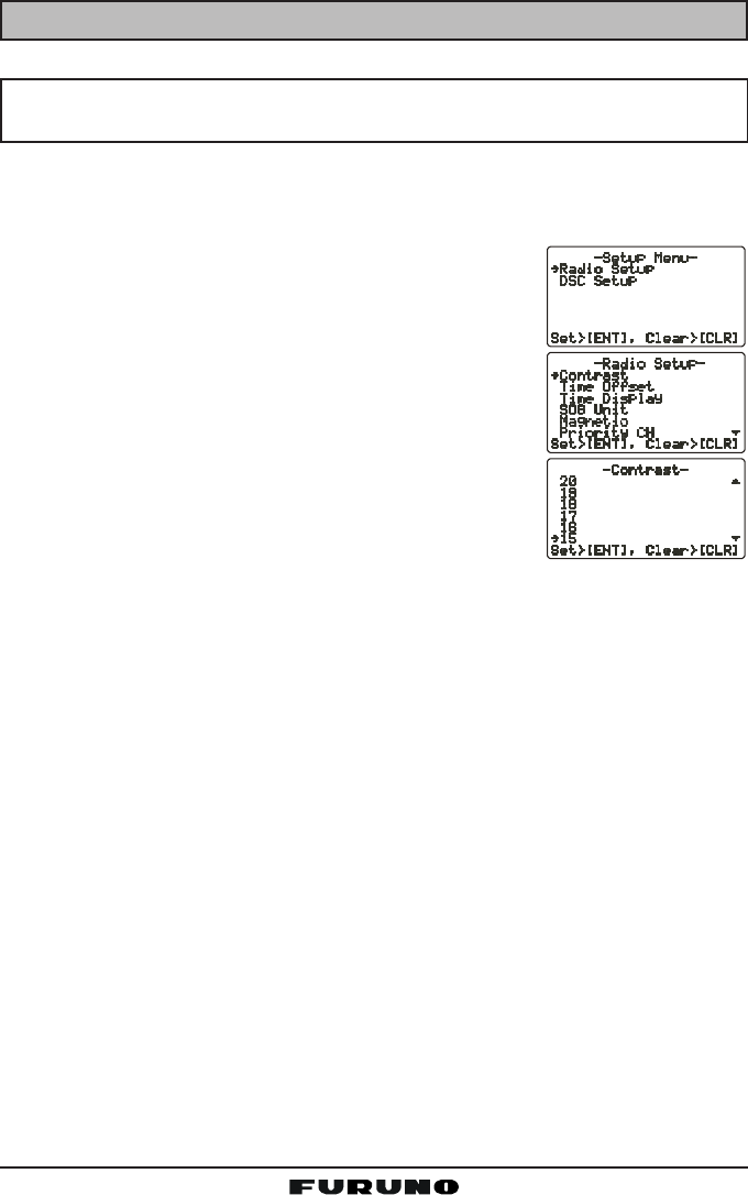
12.1 LCD CONTRAST
Adjust the LCD contrast for best viewability.
1. Press and hold down the [CALL(MENU)] key until
“Radio SetupRadio Setup
Radio SetupRadio Setup
Radio Setup” menu appears.
2. Press the [ENT] key, then use the CHANNEL selec-
tor knob to select “ContrastContrast
ContrastContrast
Contrast.”
3. Press the [ENT] key.
4. Turn the CHANNEL selector knob to select the de-
sired level. The contrast level can be set from “00
00
0” to
“3131
3131
31.”
5. Press the [ENT] key to store the selected level.
6. To exit this menu and return to radio operation mode,
press the [16/9] key.
Page 57FM-4000
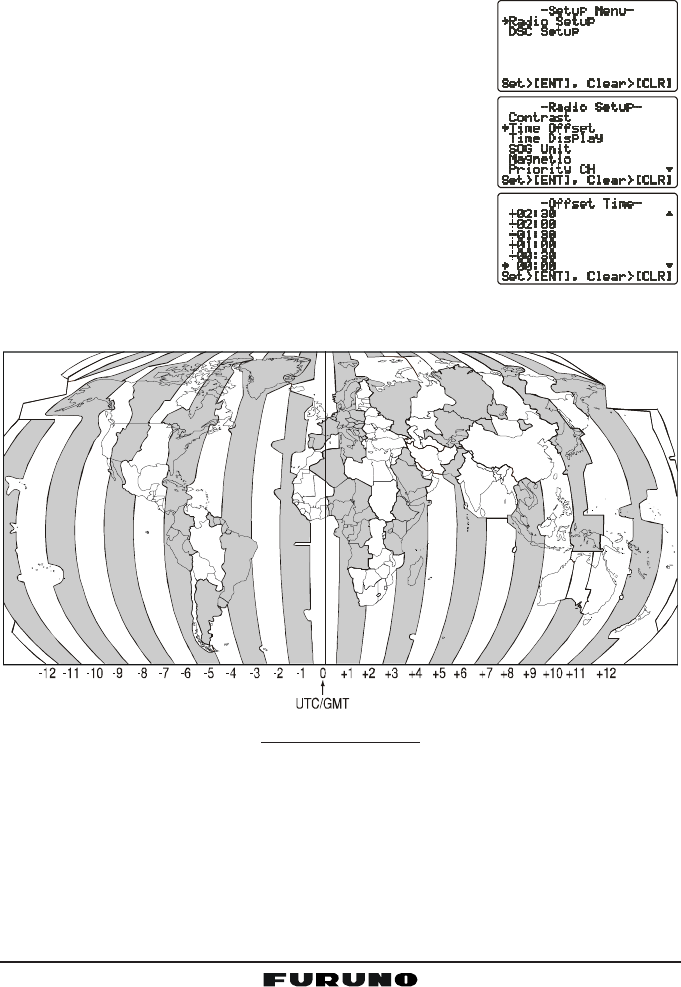
12.2 TIME OFFSET
“Time Offset” sets the time offset between local time and UTC in order to dis-
play local time. The time display requires connection of a GPS receiver.
1. Press and hold down the [CALL(MENU)] key until
the “Radio SetupRadio Setup
Radio SetupRadio Setup
Radio Setup” menu appears.
2. Press the [ENT] key, then use the CHANNEL selec-
tor knob to select “Time OffsetTime Offset
Time OffsetTime Offset
Time Offset.”
3. Press the [ENT] key.
4. Turn the CHANNEL selector knob to select time off-
set from UTC. See the illustration below to find your
offset time from UTC. If “0:000:00
0:000:00
0:00” is assigned, the time
is the same as UTC (Universal Time Coordinated or
GMT Greenwich Mean Time).
5. Press the [ENT] key to store the time offset.
6. To exit this menu and return to radio operation mode,
press the [16/9] key.
OFFSET TIME TABLE
FM-4000Page 58
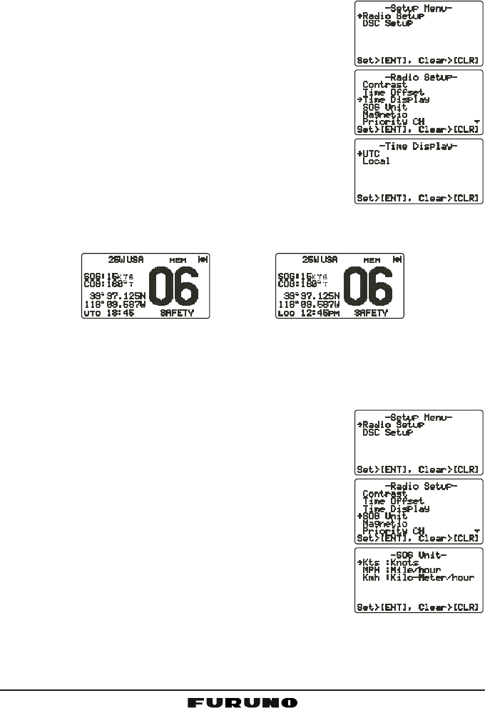
12.3 TIME DISPLAY
The time can be shown in local or UTC time. The time display requires con-
nection of a GPS receiver.
1. Press and hold down the [CALL(MENU)] key until
the “Radio SetupRadio Setup
Radio SetupRadio Setup
Radio Setup” menu appears.
2. Press the [ENT] key, then use the CHANNEL selec-
tor knob to select “Time DisplayTime Display
Time DisplayTime Display
Time Display.”
3. Press the [ENT] key.
4. Turn the CHANNEL selector knob to select “UTCUTC
UTCUTC
UTC” or
“LocalLocal
LocalLocal
Local.”
5. Press the [ENT] key to store the selected setting.
6. To exit this menu and return to radio operation mode,
press the [16/9] key.
In the local time mode, the display shows the time by
the 12-hour system, while the display shows the time by the 24-hour system in
the UTC mode.
12.4 SOG (SPEED OVER GROUND) UNIT
The SOG indication can be shown in knot, mph or kph.
1. Press and hold down the [CALL(MENU)] key until
the “Radio SetupRadio Setup
Radio SetupRadio Setup
Radio Setup” menu appears.
2. Press the [ENT] key, then use the CHANNEL selec-
tor knob to select “SOG UnitSOG Unit
SOG UnitSOG Unit
SOG Unit.”
3. Press the [ENT] key.
4. Turn the CHANNEL selector knob to select desired
unit.
5. Press the [ENT] key to store the selected setting.
6. To exit this menu and return to radio operation mode,
press the [16/9] key.
(“LOCAL” mode)(“UTC” mode)
Page 59FM-4000
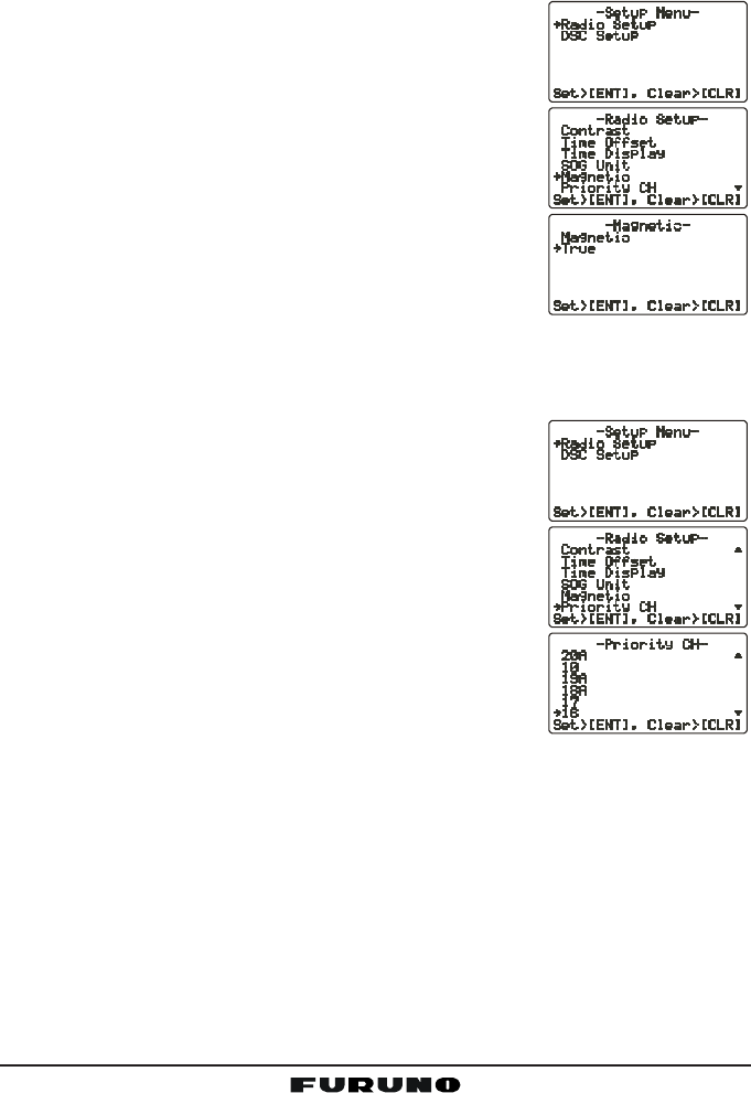
12.5 TRUE MAGNETIC CHANGE (NAV DISPLAY)
The GPS COG (Course Over Ground) indication can be shown in True or
Magnetic.
1. Press and hold down the [CALL(MENU)] key until
the “Radio SetupRadio Setup
Radio SetupRadio Setup
Radio Setup” menu appears.
2. Press the [ENT] key, then use the CHANNEL selec-
tor knob to select “MagneticMagnetic
MagneticMagnetic
Magnetic.”
3. Press the [ENT] key.
4. Turn the CHANNEL selector knob to select “Mag-Mag-
Mag-Mag-
Mag-
neticnetic
neticnetic
netic” or “TrueTrue
TrueTrue
True.”
5. Press the [ENT] key to store the selected setting.
6. To exit this menu and return to radio operation mode,
press the [16/9] key.
12.6 PRIORITY CHANNEL
You can set the priority channel to use when priority scan is enabled.
1. Press and hold down the [CALL(MENU)] key until
the “Radio SetupRadio Setup
Radio SetupRadio Setup
Radio Setup” menu appears.
2. Press the [ENT] key, then use the CHANNEL selec-
tor knob to select “Priority CHPriority CH
Priority CHPriority CH
Priority CH.”
3. Press the [ENT] key.
4. Turn the CHANNEL selector knob to select the chan-
nel to be a priority.
5. Press the [ENT] key to store the selected setting.
6. To exit this menu and return to radio operation mode,
press the [16/9] key.
FM-4000Page 60
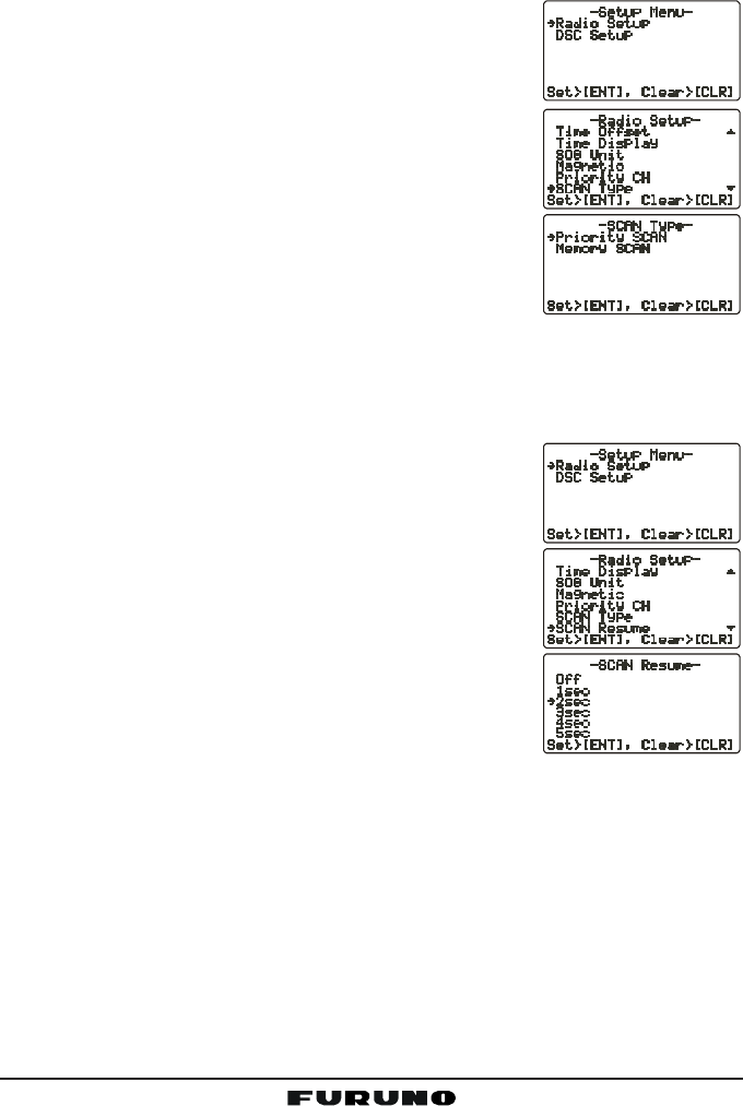
12.7 SCAN TYPE
You can set the scan mode between “Memory Scan” and “Priority Scan.”
1. Press and hold down the [CALL(MENU)] key until
the “Radio SetupRadio Setup
Radio SetupRadio Setup
Radio Setup” menu appears.
2. Press the [ENT] key, then use the CHANNEL selec-
tor knob to select “SCAN TypeSCAN Type
SCAN TypeSCAN Type
SCAN Type.”
3. Press the [ENT] key.
4. Turn the CHANNEL selector knob to select “PriorityPriority
PriorityPriority
Priority
SCANSCAN
SCANSCAN
SCAN” or “Memory SCANMemory SCAN
Memory SCANMemory SCAN
Memory SCAN.”
5. Press the [ENT] key to store the selected setting.
6. To exit this menu and return to radio operation mode,
press the [16/9] key.
12.8 SCAN RESUME TIME
Set the amount of time the FM-4000 waits after a transmission ends before
starting scanning.
1. Press and hold down the [CALL(MENU)] key until
the “Radio SetupRadio Setup
Radio SetupRadio Setup
Radio Setup” menu appears.
2. Press the [ENT] key, then use the CHANNEL selec-
tor knob to select “SCAN ResumeSCAN Resume
SCAN ResumeSCAN Resume
SCAN Resume.”
3. Press the [ENT] key.
4. Turn the CHANNEL selector knob to select the de-
sired resume time. The resume time can be set to
“1sec1sec
1sec1sec
1sec” through “5sec5sec
5sec5sec
5sec,” or “OffOff
OffOff
Off.” In the “OffOff
OffOff
Off” selection,
the scanning resumes after the other station stops
transmitting (carrier drops).
5. Press the [ENT] key to store the selected setting.
6. To exit this menu and return to radio operation mode,
press the [16/9] key.
Page 61FM-4000
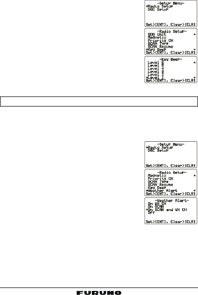
12.9 KEY BEEP
Set the beep tone volume level when a key is pressed.
1. Press and hold down the [CALL(MENU)] key until
the “Radio SetupRadio Setup
Radio SetupRadio Setup
Radio Setup” menu appears.
2. Press the [ENT] key, then use the CHANNEL selec-
tor knob to select “Key BeepKey Beep
Key BeepKey Beep
Key Beep.”
3. Press the [ENT] key.
4. Turn the CHANNEL selector knob to select the de-
sired level. The beep can be set from “Level 1Level 1
Level 1Level 1
Level 1” to
“Level 6Level 6
Level 6Level 6
Level 6,” “HighHigh
HighHigh
High,” or “OffOff
OffOff
Off.”
5. Press the [ENT] key to set the key beep condition.
6. To exit this menu and return to radio operation mode,
press the [16/9] key.
NOTE
Emergency alarm and beeps for DSC operation cannot be turned OFF.
12.10 WEATHER ALERT SETUP
The NOAA Weather alert can be enabled or disabled. The default setting is
“On SCAN and WX CH.”
1. Press and hold down the [CALL(MENU)] key until
the “Radio SetupRadio Setup
Radio SetupRadio Setup
Radio Setup” menu appears.
2. Press the [ENT] key, then use the CHANNEL selec-
tor knob to select “Weather AlertWeather Alert
Weather AlertWeather Alert
Weather Alert.”
3. Press the [ENT] key.
4. Turn the CHANNEL selector knob to select the de-
sired WX alert mode. The WX alert mode can be
set to “On WX CHOn WX CH
On WX CHOn WX CH
On WX CH,” “On SCANOn SCAN
On SCANOn SCAN
On SCAN,” “On SCAN andOn SCAN and
On SCAN andOn SCAN and
On SCAN and WXWX
WXWX
WX
CHCH
CHCH
CH,” or “OffOff
OffOff
Off.”
5. Press the [ENT] key to store the selected setting.
6. To exit this menu and return to radio operation mode,
press the [16/9] key.
FM-4000Page 62
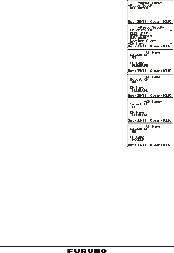
12.11 CHANNEL NAMING
You may change the name of a channel.
Example: CH84 “CALL HOME”
1. Press and hold down the [CALL(MENU)] key until
the “Radio SetupRadio Setup
Radio SetupRadio Setup
Radio Setup” menu appears.
2. Press the [ENT] key, then use the CHANNEL selec-
tor knob to select “CH NameCH Name
CH NameCH Name
CH Name.
3. Press the [ENT] key.
4. Turn the CHANNEL selector knob to select the chan-
nel to name, then press the [ENT] key.
5. Press applicable key to enter the first letter of the
channel name.
Example: Press the [4(GHI)] key repeatedly to toggle
among the seven available characters associated
with that key: 44
44
4 Æ GG
GG
G Æ HH
HH
H Æ IIIII Æ gg
gg
g Æ hh
hh
h Æ iiiii Æ 22
22
2 ....
6. Press the [ENT] key to enter the desired letter and
move the cursor one space to the right.
7. Repeat steps 5 and 6 to complete the name. The
name can consist of up to 16 characters. If you do
not use all 16 characters, press the [ENT] key to
move to the next space. This method can also be
used to enter a blank space in the name. To clear
the previous letter, press the [CLR] key.
8. Press and hold down the [ENT] key to enter the
name.
9. If you want to change the name of another channel,
repeat steps 3 through 8.
10. To exit this menu and return to radio operation mode, press the [16/9] key.
Page 63FM-4000
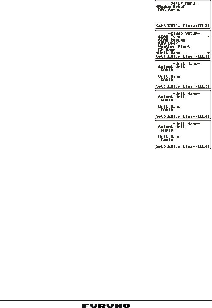
12.12 NAMING THE RADIO OR REMOTE MIC
You can change the name of the RADIO or Remote MIC. Example: “RADIO -
Cabin,” “RAM1 - Flybridge.”
1. Press and hold down the [CALL(MENU)] key until
the “Radio SetupRadio Setup
Radio SetupRadio Setup
Radio Setup” menu appears.
2. Press the [ENT] key, then use the CHANNEL selec-
tor knob to select “Unit NameUnit Name
Unit NameUnit Name
Unit Name.”
3. Press the [ENT] key.
4. With the Remote MIC connected, turn the CHAN-
NEL selector knob to select the Unit (“RadioRadio
RadioRadio
Radio” or
“RAM1RAM1
RAM1RAM1
RAM1”) to name, then press the [ENT] key, other-
wise press the [ENT] key.
5. Press applicable key to enter the first letter of chan-
nel name.
Example: Press the [2(MEM)] key repeatedly to
toggle among the seven available characters asso-
ciated with that key: 22
22
2 Æ AA
AA
A Æ BB
BB
B Æ CC
CC
C Æ aa
aa
a Æ bb
bb
b Æ cc
cc
c Æ 22
22
2 ....
6. Press the [ENT] key to enter the first letter in the
name and move to the next letter to the right.
7. Repeat steps 5 and 6 to complete the name. The
name can consist of up to eight characters. If you
do not use all eight characters press the [ENT] key
to move to the next space. This method can also be used to enter a blank
space in the name. To clear the previous letter, press the [CLR] key.
8. Press and hold the [ENT] key to enter the name and return to the “UnitUnit
UnitUnit
Unit
NameName
NameName
Name” menu.
9. If you want to enter the name of another unit, repeat steps 4 through 8.
10. To exit this menu and return to radio operation mode, press the [16/9] key.
FM-4000Page 64
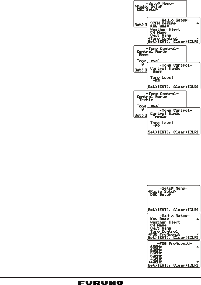
12.13 ADJUSTING THE TREBLE AND BASS
Adjust the treble and bass of the speaker audio for best listening in noisy
environments. The effect is similar to adjusting the treble and bass controls on
a stereo.
1. Press and hold down the [CALL(MENU)] key
until “Radio SetupRadio Setup
Radio SetupRadio Setup
Radio Setup” menu appears.
2. Press the [ENT] key, then use the CHANNEL
selector knob to select “Tone ControlTone Control
Tone ControlTone Control
Tone Control.”
3. Press the [ENT] key, then select “BassBass
BassBass
Bass” with the
CHANNEL selector knob.
4. Press the [ENT] key, then turn the CHANNEL
selector knob to select desired audio response
in the lower frequency range. Available selec-
tions are “––
––
–66
66
6” through “+6+6
+6+6
+6.”
5. Press the [ENT] key to store the selected setting.
6. Select “TrebleTreble
TrebleTreble
Treble” with the CHANNEL selector
knob, then press the [ENT] key.
7. Turn the CHANNEL selector knob to select de-
sired audio response in the higher frequency
range. Available selections are “––
––
–66
66
6” through
“+6+6
+6+6
+6.”
8. Press the [ENT] key to store the selected setting.
9. To exit this menu and return to radio operation mode, press the [16/9] key.
12.14 FOG ALERT TONE FREQUENCY
You can select the tone frequency for the PA/Fog operation. The available
frequency range is 200 Hz - 850 Hz, in 50 Hz steps. The default tone fre-
quency is 400 Hz.
1. Press and hold down the [CALL(MENU)] key until
the “Radio SetupRadio Setup
Radio SetupRadio Setup
Radio Setup” menu appears.
2. Press the [ENT] key, then use the CHANNEL selec-
tor knob to select “FOG FrequencyFOG Frequency
FOG FrequencyFOG Frequency
FOG Frequency..
3. Press the [ENT] key.
4. Turn the CHANNEL selector knob to select desired
tone frequency.
5. Press the [ENT] key to store the selected setting.
6. To exit this menu and return to radio operation mode,
press the [16/9] key.

Page 65FM-4000
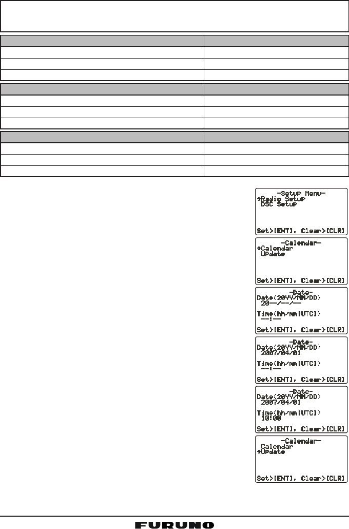
12.15 CALENDAR SETUP
Calendar Menu
The FM-4000 has a clock that remembers date, time, latitude and longitude.
Connecting a GPS receiver to the FM-4000 is very important as it not only will
be used to update the calendar automatically and also when a DSC Distress
call is transmitted will send your vessel’s location to other vessels to aid in the
rescue. See section “8.5 ACCESSORY CABLE.”
GPS Receiver Connected
When a GPS receiver is connected, the FM-4000 will automatically store the
calendar date and time information after being connected for one hour.
GPS Receiver Not Connected
If a GPS receiver is not connected to the FM-4000, manually enter the date
and time into the Calendar Menu in order for the clock to operate. The time you
will enter will be your local time in UTC format. To calculate your local UTC
time, first find your location on the Standard Time table below.
NOTE
The table below shows Standard Time. For Daylight Savings subtract
one hour from your offset.
FM-4000Page 66
Examples:
NOTE
If you are west of UTC time you will add the offset to your time.
If you are East of UTC time you will subtract the offset from your time.
1. Press and hold the [CALL(MENU)] key until the “Ra-Ra-
Ra-Ra-
Ra-
dio Setupdio Setup
dio Setupdio Setup
dio Setup” menu appears.
2. Press the [ENT] key
3. Select “CalendarCalendar
CalendarCalendar
Calendar” with the CHANNEL selector knob.
4. Press the [ENT] key
5. Select “Date Date
Date Date
Date (20YY20YY
20YY20YY
20YY/MMMM
MMMM
MM/DDDD
DDDD
DD)” with the CHANNEL se-
lector knob.
6. Press the [ENT] key.
7. Enter the current date (Yr/Mo/Day).
8. If you enter a wrong number, press the [H/L] key
until the wrong number is selected, then enter the
correct number.
9. Using the Standard time table above, calculate the
UTC time of your position.
Note: For daylight savings time subtract one hour
to the offset in your time zone.
10. To enter the time, press the [ENT] key until the first
digit in the “Time Time
Time Time
Time (hhhh
hhhh
hh/mm [UTC]mm [UTC]
mm [UTC]mm [UTC]
mm [UTC])” is selected on the
display, then enter the time.
11. Press and hold down the [ENT] key to store the se-
lected setting.
12. Select “UpdateUpdate
UpdateUpdate
Update” with the CHANNEL selector knob,
then press the [ENT] key.
City NY
Offset -5
Time (convert local time to 24 hour) 4:00PM (local) or 16:00 (24hour)
Calculate 24hour local + Offset (East of UTC) 16:00 + 05:00 = 21:00
City Rome
Offset +1
Time (convert local time to 24 hour) 4:00PM (local) or 16:00 (24hour)
Calculate 24hour local + Offset (East of UTC) 16:00 - 01:00 = 15:00
City Los Angeles
Offset -8
Time (convert local time to 24 hour) 4:00PM (local) or 16:00 (24hour)
Calculate 24hour local + Offset (East of UTC) 16:00 + 08:00 = 22:00
Page 67FM-4000
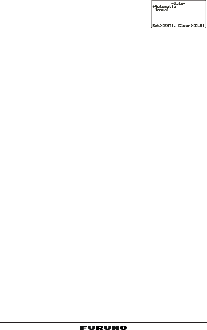
13. Turn the CHANNEL selector knob to select the
method of the time adjustment between “AutomaticAutomatic
AutomaticAutomatic
Automatic”
and “ManualManual
ManualManual
Manual.”
14. Press the [ENT] key to store the selected setting.
15. To exit this menu and return to radio operation mode, press the [16/9] key.
FM-4000Page 68
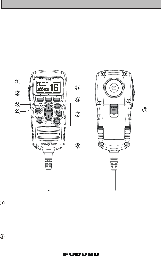
13 REMOTE MIC OPERATION
When the Remote MIC is connected to the FM-4000, most VHF, DSC, setup
menus and PA modes can be remotely operated. The Remote MIC is supplied
with 23 feet (7 m) of routing cable and can be extended up to 70 feet (21 m)
using three 23-foot extension cables model CT-100. The Intercom feature can
be used between the Remote MIC and the transceiver. In addition, speaker
wires are supplied at the panel mount of the routing cable for external speak-
ers to be connected in noisy environments.
13.1 REMOTE MIC CONTROLS
[H/L] KEY
Toggles between high and low power. When the [H/L] key is pressed while
the transceiver is on CH13 or CH67, the power is temporarily switched
from LO to HI until the PTT switch is released. The [H/L] key does not
function on transmit inhibited and low-power only channels.
PTT (Push-To-Talk) Key
Activates transmission.

Page 69FM-4000
POWER ( ) Key
Press and hold down this key to turn to the transceiver and Remote MIC
on or off.
MICROPHONE
The internal microphone is located here.
When transmitting, position your mouth about 1/2 to 1 inch (1.2 ~ 2.5 cm)
away from the small mic hole. Speak slowly and clearly into the micro-
phone.
DISPLAY
Channel display.
SOFT KEY
These three key’s functions can be customized by the Setup Menu mode.
When press one of these key briefly, the key functions will appear at the
LCD bottom. The factory defaults are shown below.
[SCAN] Key
Starts and stops scanning of programmed channels.
[DW] Key
Watches for a transmission on CH16 and another selected channel until
either signal is received. (Dual watch)
[IC] Key
Get Intercom operation between radio and the Remote MIC.
KEY PAD
[CALL/MENU] Key
Press this key to access the DSC OPERATION menu.
Press and hold this key to access the SETUP menu.
[16/9] Key
First press: channel 16 is immediately selected.
Second press: recalls the last selected channel.
Press and hold: selects channel 9.
[S](UP)/[T](DOWN) Key
These keys are used to select channels, adjust the volume and squelch
level, and to choose DSC calls, DSC setup and Radio setup function.
[VOL/SQ] Key (Volume Control / Squelch Control)
Press this key to toggle the function of the Remote MIC’s [S] or [T] key
between the channel selections, volume level adjustment, and squelch
level adjustment.
FM-4000Page 70
[CLR/WX] Key
Immediately recalls the previously selected NOAA weather channel.
Cancel the menu selection and/or keypad entry.
Secondary use
Hold down the [16/9] key while pressing the [WX] key to change the
mode from USA to International or Canadian.
[ENT] Key
This key functions as the enter key.
SPEAKER
The internal speaker is located here.
[DISTRESS] KEY
Used to send a DSC Distress call.
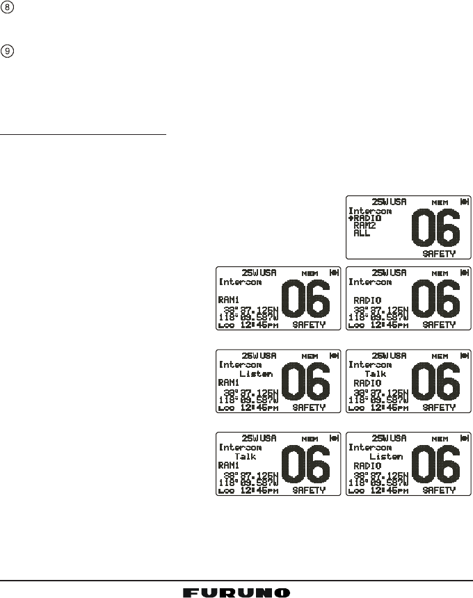
13.2 INTERCOM OPERATION
13.2.1 Communication
1. Press one of the Soft key briefly to appear the key functions at the LCD
bottom, then press the [IC] key to activate the “Intercom” mode.
2. If your FM-4000 is equipped with two Remote MICs, use the [T]/[S] key to
select the station (RADIORADIO
RADIORADIO
RADIO, RAMRAM
RAMRAM
RAM, or ALLALL
ALLALL
ALL) you wish to
communicate with, then press the [ENT] key.
3. When the “Intercom” feature is activated, “IntercomIntercom
IntercomIntercom
Intercom”
appears on the FM-4000 and CMP30.
4. Press the PTT switch and
“TALK” is displayed.
NOTE: A warning beep is emit-
ted when the Remote MIC’s
PTT switch is pressed while
the transceiver microphone’s
PTT switch is pressed.
5. Speak slowly and clearly into
the microphone, holding the
microphone about 1/2 inch
away from your mouth.
6. When finished, release the
PTT switch.
7. Press the [CLR(WX)] key
again to revert to the “RADIO” mode.
(FM-4000 display)(
CMP30 display)
(FM-4000’s PTT switch is pressed)
(CMP30’s PTT switch is pressed)
Page 71FM-4000
13.2.2 Calling
Press and hold the [DW(IC)] key for one second when the “Intercom” mode is
active. A calling beep is emitted from the speaker.
13.3 KEY ASSIGNMENT
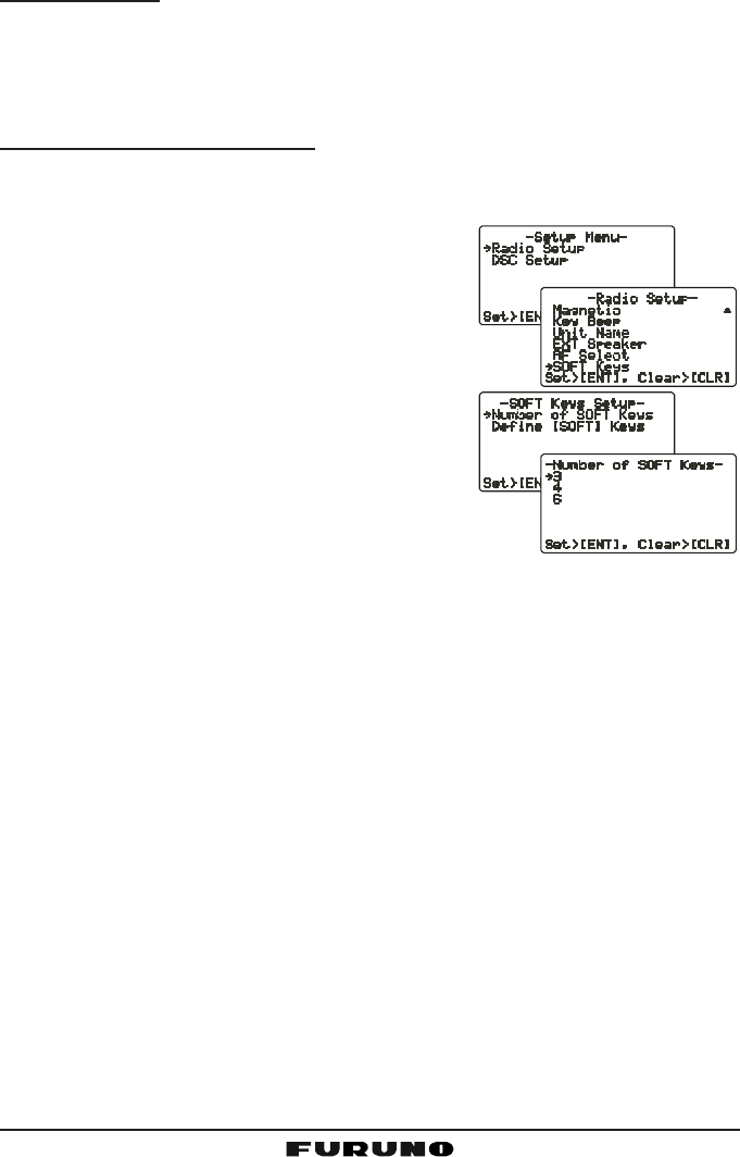
13.3.1 Number of Soft Keys
Three soft keys are set as default. However the Remote MIC allows assigning
of up to six soft keys with the instructions below:
1. Press and hold down the [CALL(MENU)] key
until “Radio SetupRadio Setup
Radio SetupRadio Setup
Radio Setup” menu appears.
2. Press the [ENT] key, then press the [T] key
to select “SOFT KeysSOFT Keys
SOFT KeysSOFT Keys
SOFT Keys.”
3. Press the [ENT] key.
4. Press the [S] or [T] key to select “Number ofNumber of
Number ofNumber of
Number of
SOFT KeysSOFT Keys
SOFT KeysSOFT Keys
SOFT Keys” and press the [ENT] key.
5. Press the [S] or [T] key to select the number
of soft keys (33
33
3, 44
44
4, or 66
66
6) and press the [ENT]
key.
6. To exit this menu and return to radio operation mode,
press the [16/9] key.
FM-4000Page 72
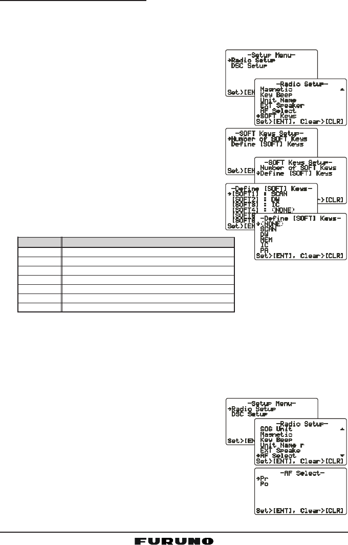
13.3.2 Define the Soft Keys
By default the soft keys are assigned as SCAN, DW and NAV, however their
function can be changed. In addition the soft keys can be increased or reas-
signed as follows:
1. Press and hold down the [CALL(MENU)] key
until “Radio SetupRadio Setup
Radio SetupRadio Setup
Radio Setup” menu appears.
2. Press the [ENT] key, then press the [T] key
to select “SOFT KeysSOFT Keys
SOFT KeysSOFT Keys
SOFT Keys.”
3. Press the [ENT] key.
4. Press the [T] key to select “Define Define
Define Define
Define [[
[[
[SOFTSOFT
SOFTSOFT
SOFT]]
]]
] Keys Keys
Keys Keys
Keys”
and press the [ENT] key.
5. Press the [S] or [T] key to select the [Soft]
key, and press the [ENT] key. Then, press the
[S] or [T] key to select the new function to
be assigned, and press the [ENT] key. Avail-
able functions are listed below.
6. To exit this menu and return to radio opera-
tion mode, press the [16/9] key.
13.4 EXTERNAL SPEAKER AF SELECTION
The “AF SelectAF Select
AF SelectAF Select
AF Select” menu allows you to set the audio output level of the Remote
MIC’s External Speaker to a fixed level regardless of the VOL level setting of
the Remote MIC, which is useful when using the amplified speaker (not op-
tion) with on/off volume control.
1. Press and hold down the [CALL(MENU)] key
until “Radio SetupRadio Setup
Radio SetupRadio Setup
Radio Setup” menu appears.
2. Press the [ENT] key, then use the [S]/[T] key
to select “AF SelectAF Select
AF SelectAF Select
AF Select.”
3. Press the [ENT] key.
4. Press the [S] or [T] key to select “PrPr
PrPr
Pr” (External
Speaker Level is “Fixed”) or “PoPo
PoPo
Po” (External Speaker
Level is “Adjustable”).
5. Press the [ENT] key to store the data entered, then
press the [16/9] key to exit this menu and return to radio operation mode.
DISPLAY
SCAN
DW
MEM
IC
PA
FOG
SCRM
FUNCTION
Stops and starts scanning.
Stops and starts Dual Watch Scan.
When pressed memorizes a channel for scanning.
Activates the Intercom function.
Operates the PA function.
Operates the Fog Horn function.
Toggles the Voice Scrambler “on” and “off”.
Page 73FM-4000
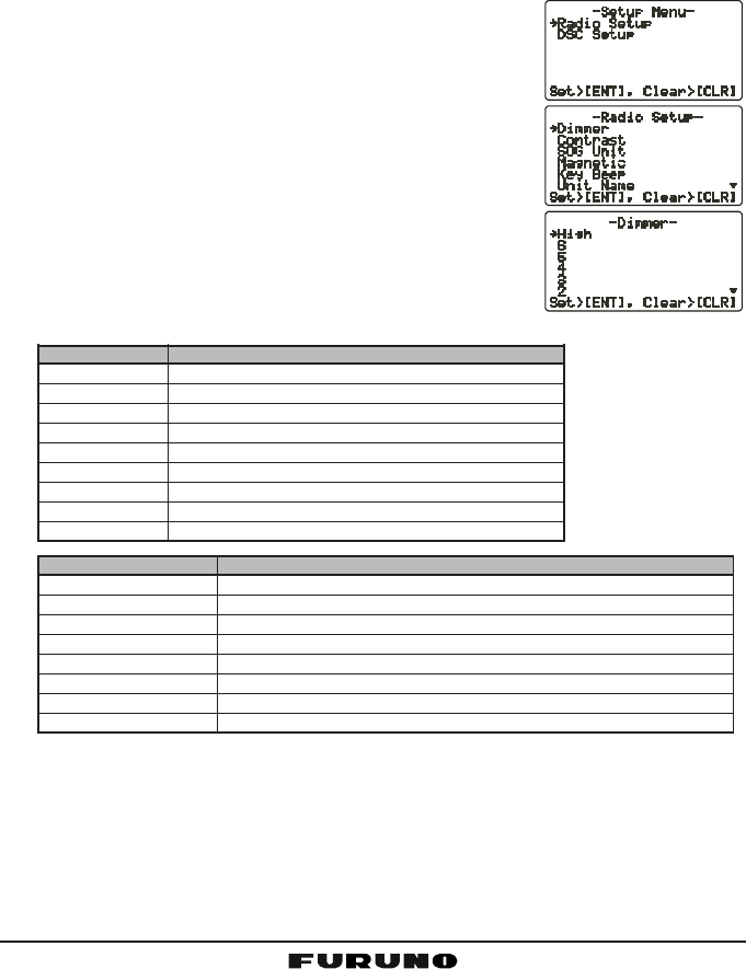
13.5 DSC/RADIO SETUP MODE
The Remote MIC can access the DSC SETUP / RADIO SETUP menu (see
section “11 DIGITAL SELECTIVE CALLING” and section “12 RADIO SETUP
MENU” for details). However, the Dimmer, Contrast, and Key Beep menu items
which are accessed from the Remote MIC only controls the Remote MIC’s
display and speaker.
DSC SETUP /RADIO SETUP menu from the Remote MIC:
1. Press and hold down the [CALL(MENU)] key until
“Radio SetupRadio Setup
Radio SetupRadio Setup
Radio Setup” menu appears.
2. Press the [S]/[T] key to select “Radio SetupRadio Setup
Radio SetupRadio Setup
Radio Setup” or “DSCDSC
DSCDSC
DSC
SetupSetup
SetupSetup
Setup.”
3. Press the [ENT] key, then use the [S]/[T] key to
select the menu item you wish to work on.
4. Press the [ENT] key.
5. Press the [S]/[T] key to change the value or condi-
tion for the menu item, then press the [ENT] key to
save the new setting.
6. Press the [16/9] key to return to the normal opera-
tion.
DSC SETUP Function
Individual Directory Sets the Individual Directory.
Individual Reply Sets how to reply to an Individual call, Automatic or Manual.
Individual Ack Sets how to acknowledge an Individual call, Able or Unable.
Individual Ringer Selects individual call ringer tone, among four choices.
Group Directory Setup the Group Directory.
Position Reply Selects how to respond to request for your position, Automatic or Manual.
Position Input Sets the latitude/longitude of your vessel manually.
DSC BEEP Turns on or off the Individual, Group, Position request or send beep.
Radio Setup Function
Dimmer Adjusts the backlight.
Contrast Adjusts display contrast.
SOG Unit Selects SOC unit, knots, MPH or KPH.
Magnetic Selects COG indication format, True or Magnetic.
Key Beep Turns key beep on or off.
Unit Name Allows changing the name of the connected MIC.
EXT Speaker Selects the speaker to use, Internal or External.
AF Select Selects the audio output,
Soft Keys Sets the key assignment.

FM-4000Page 74
14 MAINTENANCE
The inherent quality of the solid-state components used in this transceiver will
provide many years of continuous use. Taking the following precautions will
prevent damage to the transceiver.
• Keep the microphone connected or the jack covered at all times to prevent
corrosion of electrical contacts.
• Never key the microphone unless an antenna or suitable dummy load is
connected to the transceiver.
• Ensure that the supply voltage to the transceiver does not exceed 16 VDC
or fall below 11 VDC.
• Use only FURUNO-approved accessories and replacement parts.
In the unlikely event of serious problems, please contact your dealer.

Page 75FM-4000
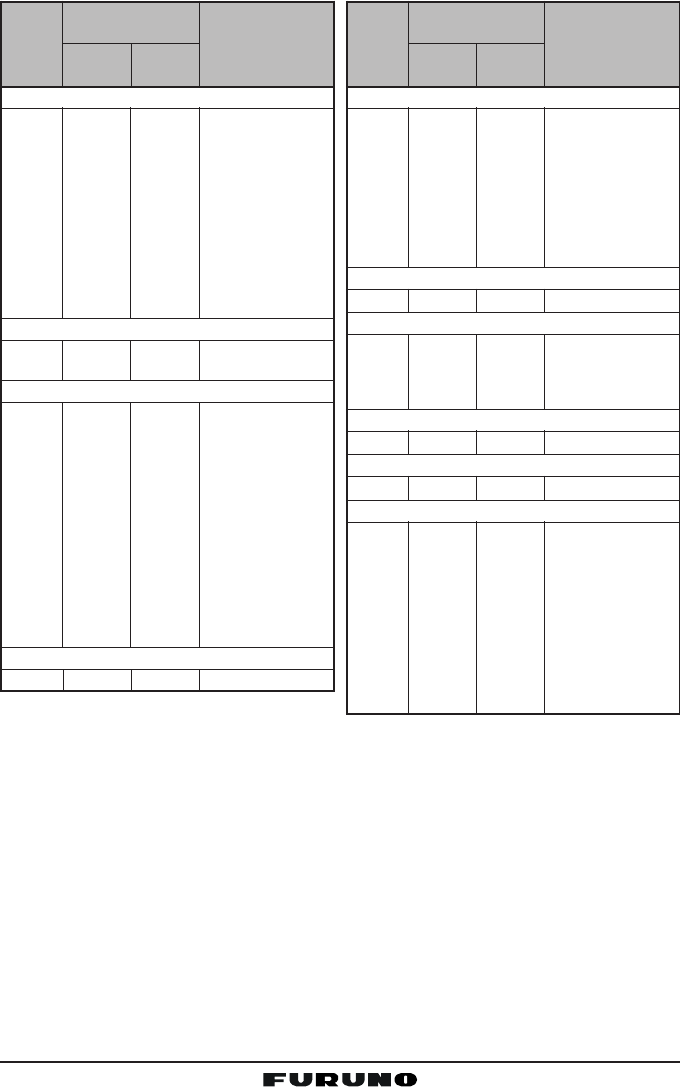
SYMPTOM
Cannot power the
transceiver.
Transceiver blows fuse
when connected to
power supply.
Popping or whining
noise from the speaker
while engine runs.
Sound is not emitted
from the internal or ex-
ternal speaker.
Sound is not emitted
from the PA speaker.
Receiving station re-
ports low TX power,
even with transceiver
set to HI power.
“HI BATTERY” or “LO
BATTERY” appears
when the power is
turned on.
“PA ERROR” or “FOG
ERROR” is shown
when the PA/FOG
mode is activated.
Your position is not dis-
played.
While in PA or Fog lis-
ten-back modes, AM
broadcasts can be
heard.
PROBABLE CAUSE
No DC voltage to the
transceiver, or blown
fuse.
Reversed power
wires.
Engine noise.
Accessory cable.
Accessory cable.
Antenna.
The power supply
voltage is too high or
too low.
Accessory cable.
Accessory cable.
Setting at the GPS
receiver.
Strong AM radio sta-
tions are being
pickup up by the
speaker wires.
REMEDY
a. Check the battery connections and the fuse.
b. The PWR switch needs to be pressed and
held to turn the radio on.
Check the power cable for DC voltage. Check
the fuse (6A 250V).
Make sure the red wire is connected to the posi-
tive (+) battery post, and the black wire is con-
nected to the negative (-) battery post. If the fuse
blows after replacement, contact your dealer for
advice.
Reroute the DC power cables away from the
engine. Add noise suppressor on the power
cable. Change to resistive spark plug wires and/
or add an alternator whine filter.
Check if the accessory cable is firmly fastened.
(Short circuit the external speaker cable WHITE/
SHIELD).
Check if the accessory cable is firmly fastened.
(Short circuit the PA speaker cable RED/
SHIELD).
Have the antenna checked or test the trans-
ceiver with another antenna. If the problem per-
sists, contact your dealer for advice.
Confirm that the connected power supply volt-
age is not over 17 volts or lower than 10 volts.
Check if the accessory cable is firmly fastened.
(Short circuit the PA speaker cable RED/
SHIELD).
Check if the accessory cable is firmly fastened.
Some GPS receivers use the battery ground line
for NMEA connection.
Check the output signal format of the GPS re-
ceiver. This radio requires NMEA0183 format
with GLL, RMB, or RMC sentence as an output
signal. If the GPS receiver has a facility for set-
ting baud rate and parity, select “4800” and
“NONE,” respectively.
Replace the speaker wires to a sheilded 2-con-
ductor wire. See section “8.5 ACCESSORY
CABLE” for cable connections.
14.1 TROUBLESHOOTING CHART

FM-4000Page 76
15 CHANNEL ASSIGNMENTS
This chapter provides the VHF Marine Channel assignments for U.S.A. and
International use. Below are listed some data about the charts.
1. VTS. Where indicated, these channels are part of the U.S. Coast Guard’s
Vessel Traffic System.
2. Alpha channel numbers, that is, channel numbers followed by the letter A
(such as Channel 07A) are simplex channels on the U.S.A. or Canadian
channel assignments whose counterparts in the International assignments
are duplex channels. International channels do not use “alpha” numbers.
If you call the Coast Guard on Channel 16, they will sometimes ask you to
“go to channel 22 Alpha.” This is a channel assigned to U.S.A, and Cana-
dian Coast Guards for handling distress and other calls. If your radio is set
for International operation you will go to Channel 22 instead of 22A, and
will not be able to communicate with the Coast Guard. To use Channel
22A, your radio must be set for USA or Canada operation, usually by a U/
I/C (USA/International/Canada) control or combination of controls. Chan-
nel 22 (without an “A”) is an International duplex channel for port opera-
tions. Some radios indicate an “A” adjacent to the alpha channels on the
display; on others “alpha” is not indicated but the proper channel is se-
lected based on the U/I/C setting.
3. Bridge-to-Bridge channels (for example, Channel 13) are for use by bridge
operators on intercoastal waterways and rivers. It is also used by marine
vessels in the vicinity of these bridges for navigation and for communicat-
ing with the bridge operators. Note that a limit of 1 Watt is specified for
these channels. See page 27 for additional information.
4. The S/D column on the chart indicates either S (simplex) or D (duplex). Sim-
plex means transmitting and receiving on the same frequency. Only one party
at a time can talk, unlike a telephone. Be sure to say “over” and release your
microphone push-to-talk switch at the end of each transmission. Duplex op-
eration involves the use of one frequency for transmitting and a separate fre-
quency for receiving. On channels specified as duplex on the charts, correct
mode of operation is established automatically by your radio when you select a
channel; you cannot change the mode. And you still must release the push-to-
talk switch after each transmission in order to listen to the radio.
5. Channels normally used by recreational boaters are those that include the
term “non-commercial” in the Channel Use column of the chart. Some of
these are shared with other users and some are used only in certain geo-
graphic regions.
6. Marine vessels equipped with VHF radios are required to monitor Channel 16.

Page 77FM-4000
VHF MARINE CHANNEL CHART
CH U C I S/D TX RX CHANNEL USE
01 X X D 156.050 160.650 Public Correspondence (Marine Operator)
01A X S 156.050 Port Operation and Commercial.
VTS in selected areas
02 X X D 156.100 160.700 Public Correspondence (Marine Operator)
03 X X D 156.150 160.750 Public Correspondence (Marine Operator)
03A X S 156.150 U.S. Government Only, Coast Guard
04 X D 156.200 160.800 Public Correspondence (Marine Operator),
Port operation, ship movement
04A X S 156.200 Pacific coast: Coast Guard, East Coast:
Commercial fishing
05 X D 156.250 160.850 Public Correspondence (Marine Operator),
Port operation, ship movement
05A X X S 156.250 Port operation. VTS in Seattle
06 X X X S 156.300 Inter-ship Sefety
07 X D 156.350 160.950 Public Correspondence (Marine Operator),
Port operation, ship movement
07A X X S 156.350 Commercial
08 X X X S 156.400 Commercial (Inter-ship only)
09 X X X S 156.450 Boater Calling channel, Commercial &
Non-commercial (Recreational)
10 X X X S 156.500 Commercial
11 X X X S 156.550 Commercial. VTS in selected areas.
12 X X X S 156.600 Port operation. VTS in selected areas.
13 X X X S 156.650 Inter-ship Navigation Safety (Bridge-to-bridge)
14 X X X S 156.700 Port operation. VTS in selected areas.
15 X S - - - 156.750 Environmental (Receive only)
15 X X S 156.750 Commercial, non-commercial, ship movement (1 W)
16 X X X S 156.800 International Distress, Safety and Calling
17 X X X S 156.850 State Controlled (1 W)
18 X D 156.900 161.500 Port operation, ship movement
18A X X S 156.900 Commercial
19 X D 156.950 161.550 Port operation, ship movement
19A X S 156.950 US: Commercial
19A X S 156.950 Coast Guard
20 X X X D 157.000 161.600 Canadian Coast Guard Only,
International: port operations and shipment
20A X S 157.000 Port operation
21 X D 157.050 161.650 Port operation, ship movement
21A X X S 157.050 U.S. Government Only, Canadian Coast Guard
22 X D 157.100 161.700 Port operation, ship movement
22A X X S 157.100 US and Canadian Coast Guard Liaison and
Maritime Safety Information Broadcasts announced
on channel 16
23 X X D 157.150 161.750 Public Correspondence (Marine Operator)
23A X S 157.150 U.S. Government Only
24 X X X D 157.200 161.800 Public Correspondence (Marine Operator)
25 X X X D 157.250 161.850 Public Correspondence (Marine Operator)
26 X X X D 157.300 161.900 Public Correspondence (Marine Operator)
27 X X X D 157.350 161.950 Public Correspondence (Marine Operator)
28 X X X D 157.400 162.000 Public Correspondence (Marine Operator)

FM-4000Page 78
VHF MARINE CHANNEL CHART
CH U C I S/D TX RX CHANNEL USE
60 X X D 156.025 160.625 Public Correspondence (Marine Operator)
61 X D 156.075 160.675 Public Correspondence (Marine Operator),
Port operation, ship movement
61A X X S 156.075 Public Coast: Coast Guard;
East Coast: commercial fishing only
62 X D 156.125 160.725 Public Correspondence (Marine Operator),
Port operation, ship movement
62A X S 156.125 Public Coast: Coast Guard;
East Coast: commercial fishing only
63 X D 156.175 160.775 Public Correspondence (Marine Operator),
Port operation, ship movement
63A X X S 156.175 Port Operation and Commercial.
VTS in selected areas.
64 X X D 156.225 160.825 Public Correspondence (Marine Operator),
Port operation, ship movement
64A X X S 156.225 Public Correspondence (Marine Operator),
Port operation, ship movement
65 X D 156.275 160.875 Public Correspondence (Marine Operator),
Port operation, ship movement
65A X X S 156.275 Port Opeations
66 X D 156.325 160.925 Public Correspondence (Marine Operator),
Port operation, ship movement
66A X X S 156.325 Port Operations
67 X X X S 156.375 US: Commercial. Used for Bridge-to-bridge com
muni-cations in lower Mississippi River. Inter-ship
only,
Canada: Commercial fishing, S&R
68 X X X S 156.425 Non-commercial (Recreational)
69 X X X S 156.475 US: Non-commercial (Recreational),
Canada: Commercial fishing only,
International: Inter-ship, Port opertions and Ship
movement
70 X X X S 156.525 Digital selective calling (voice communications not
allowed)
71 X X X S 156.575 US, Canada: Non-commercial (Recreational),
International: Port opertions and Ship movement
72 X X X S 156.625 Non-commercial (Inter-ship only)
73 X X X S 156.675 US: Port Operations,
Canada: Commercial fish ing only,
International: Inter-ship, Port opertions and Ship
movement
74 X X X S 156.725 US: Port Operations,
Canada: Commercial fishing only,
International: Inter-ship, Port opertions and Ship
movement
75 X X X S 156.775 Port Operations (Inter-ship only) (1W)
76 X X X S 156.825 Port Operations (Inter-ship only) (1W)
77 X X S 156.875 Port Operations (Inter-ship only) (1W)
77 X S 156.875 Port Operations (Inter-ship only)
78 X D 156.925 161.525 Public Correspondence (Marine Operator),
Port operation, ship-movement
78A X X S 156.925 Non-commercial (Recreational)
79 X D 156.975 161.575 Port operation and Ship movement
79A X X S 156.975 Commercial

Page 79FM-4000
VHF MARINE CHANNEL CHART
CH U C I S/D TX RX CHANNEL USE
80 X D 157.025 161.625 Port operation, ship movement
80A X X S 157.025 Commercial
81 X D 157.075 161.675 Port operation, ship movement
81A X S 157.075 U.S. Government Only -
Environmental protection operations.
81A X S 157.075 Canadian Coast Guard Only
82 X D 157.125 161.725 Public Correspondence (Marine Operator),
Port operation, ship movement
82A X X S 157.125 U.S. Government Only,
Canadian Coast Guard Only
83 X D 157.175 161.775 Canadian Coast Guard Only
83 X D 157.175 161.775 Public Correspondence (Marine Operator)
83A X X S 157.175 U.S. Government Only,
Canadian Coast Guard Only
84 X X X D 157.225 161.825 Public Correspondence (Marine Operator)
85 X X X D 157.275 161.875 Public Correspondence (Marine Operator)
86 X X X D 157.325 161.925 Public Correspondence (Marine Operator)
87 X X S 157.375 Port operation, ship movement
87A X S 157.375 Public Correspondence (Marine Operator)
88 X X S 157.425 Port operation, ship movement
88A X S 157.425 Commercial, Inter-ship Only
WX01
X X X D - - - 162.550 Weather (receive only)
WX02
X X X D - - - 162.400 Weather (receive only)
WX03
X X X D - - - 162.475 Weather (receive only)
WX04
X X X D - - - 162.425 Weather (receive only)
WX05
X X X D - - - 162.450 Weather (receive only)
WX06
X X X D - - - 162.500 Weather (receive only)
WX07
X X X D - - - 162.525 Weather (receive only)
WX08
X X X D - - - 161.650 Weather (receive only)
WX09
X X X D - - - 161.775 Weather (receive only)
WX10
X X X D - - - 163.275 Weather (receive only)
NOTE: Simplex channels, 3A, 21A, 23A, 61A, 64A, 81A, 82A and 83A CANNOT be lawfully used
by the general public in U.S.A. waters.
FM-4000Page 80
1: 156.050 MHz and 156.175 MHz are available for port operations and commercial com-
munications purposes when used only within the U.S. Coast Guard designated Vessel
Traffic Services (VTS) area of New Orleans, on the lower Mississippi River from the
various pass entrances in the Gulf of Mexico to Devil’s Swamp Light at River Mile 242.4
above head of passes near Baton Rouge.
2: 156.250 MHz is available for port operations communications use only within the U.S.
Coast Guard designated VTS radio protection areas of New Orleans and Houston de-
scribed in Sec. 80.383. 156.250 MHz is available for intership port operations communi-
cations used only within the area of Los Angeles and Long Beach harbors, within a 25-
nautical mile radius of Point Fermin, California.
3: 156.550 MHz, 156.600 MHz and 156.700 MHz are available in the U.S. Coast Guard
designated port areas only for VTS communications and in the Great Lakes available
primarily for communications relating to the movement of ships in sectors designated by
the St. Lawrence Seaway Development Corporation or the U.S. Coast Guard. The use
of these frequencies outside VTS and ship movement sector protected areas is permit-
ted provided they cause no interference to VTS and ship movement communications in
their respective designated sectors.
Noncommercial
6817 156.425 156.425
0916 156.450 156.450
69 156.475 156.475
71 156.575 156.575
72 156.625 ........ Intership only.
78A 156.925 156.925
79A 156.975 156.975 Great Lakes only.
80A 157.025 157.025 Do.
6714 156.375 ....... Internship only.
Distress, Safety and Calling
16 156.800 156.800 EPRIB
Intership Safety
06 156.300 ........ a. Intership, or
b. For SAR: Ship
and aircraft for the
U.S. Coast Guard.
Environmental
1513 ........ 156.750 Coast to ship only.
Maritime Control
179,10 156.850 156.850
Liaison, U.S. Coast Guard
22A11 157.100 157.100 Ship, aircraft, and
coast stations of
the U.S. Coast
Guard and at
Lake Mead, Nev.,
ship and coast
stations of the
National Park
Service, U.S.
Department of the
Interior.
Ship
transmit
Channel
designator
Carrier frequency
(MHz)
Points of communica-
tion (Intership and be-
tween coast and ship
unless otherwise
iandicated)
Coast
transmit
Port Operations
01A1156.050 156.050
63A1156.175 156.175
052156.250 156.250
65A 156.275 156.275
66A 156.325 156.325
123156.600 156.600
73 156.675 156.675
143156.700 156.700
74 156.725 156.725
774156.875 Intership only.
20 157.000 161.600
20A12 157.000 Intership only.
Navigational (Bridge-to-Bridge)5
136156.650 156.650
677156.375 156.375
Commercial
01A1156.050 156.050
63A1156.175 156.175
07A 156.350 156.350
677156.375 Intership only.
08 156.400 ........ Do.
09 156.450 156.450
10 156.500 156.500
113156.550 156.550
18A 156.900 156.900
19A 156.950 156.950
79A 156.975 156.975
80A 157.025 157.025
88A8157.425 ........ Intership only.
7214 156.625 ........ Internship only.
Digital Selective Calling
7015 156.525 156.525
Ship
transmit
Channel
designator
Carrier frequency
(MHz)
Points of communica-
tion (Intership and be-
tween coast and ship
unless otherwise
iandicated)
Coast
transmit

Page 81FM-4000
4: Use of 156.875 MHz is limited to communications with pilots regarding the movement
and docking of ships. Normal output power must not exceed 1 watt.
5: 156.375 MHz and 156.650 MHz are available primarily for intership navigational com-
munications. These frequencies are available between coast and ship on a secondary
basis when used on or in the vicinity of locks or drawbridges. Normal output power must
not exceed 1 watt. Maximum output power must not exceed 10 watts for coast stations or
25 watts for ship stations.
6: On the Great Lakes, in addition to bridge-to-bridge communications, 156.650 MHz is
available for vessel control purposes in established vessel traffic systems. 156.650 MHz
is not available for use in the Mississippi River from South Pass Lighted Whistle Buoy “2”
and Southwest Pass entrance Midchannel Lighted Whistle Buoy to mile 242.4 above
Head of Passes near Baton Rouge. Additionally it is not available for use in the Missis-
sippi River-Gulf Outlet, the Mississippi River-Gulf Outlet Canal, and the Inner Harbor
Navigational Canal, except to aid the transition from these areas.
7: Use of 156.375 MHz is available for navigational communications only in the Mississippi
River from South Pass Lighted Whistle Buoy “2” and Southwest Pass entrance Mid-
channel Lighted Whistle Buoy to mile 242.4 above head of Passes near Baton Rouge,
and in addition over the full length of the Mississippi River-Gulf Outlet Canal from en-
trance to its junction with the Inner Harbor Navigation Canal, and over the full length of
the Inner Harbor Navigation Canal from its junction with the Mississippi River to its entry
to Lake Pontchartrain at the New Seabrook vehicular bridge.
8: Within 120 km (75 miles) of the United States/Canada border, in the area of the Puget
Sound and the Strait of Juan de Fuca and its approaches, 157.425 MHz is half of the
duplex pair designated as Channel 88. In this area, Channel 88 is available to ship
stations for communications with public coast stations only. More than 120 km (75 miles)
from the United States/Canada border in the area of the Puget Sound and the Strait of
Juan de Fuca, its approaches, the Great Lakes, and the St. Lawrence Seaway, 157.425
MHz is available for intership and commercial communications. Outside Puget Sound
area and its approaches and the Great Lakes, 157.425 MHz is also available for commu-
nications between commercial fishing vessels and associated aircraft while engaged in
commercial fishing activities.
9: When the frequency 156.850 MHz is authorized, it may be used additionally for search
and rescue training exercises conducted by state or local governments.
10: The frequency 156.850 MHz is additionally available to coast stations on the Great Lakes
for transmission of scheduled Coded Marine Weather Forecasts (MAFOR), Great Lakes
Weather Broadcast (LAWEB) and unscheduled Notices to Mariners or Bulletins. F3C
and J3C emissions are permitted. Coast Stations on the Great Lakes must cease weather
broadcasts which cause interference to stations operating on 156.800 MHz until the
interference problem is resolved.
11: The frequency 157.100 MHz is authorized for search and rescue training exercises by
state or local government in conjunction with U.S. Coast Guard stations. Prior U.S. Coast
Guard approval is required. Use must cease immediately on U.S. Coast Guard request.
12: The duplex pair for channel 20 (157.000/161.600 MHz) may be used for ship to coast
station communications.
13: Available for assignment to coast stations, the use of which is in accord with an agreed
program, for the broadcast of information to ship stations concerning the environmental
conditions in which vessels operate, i.e., weather; sea conditions; time signals; notices
to mariners; and hazards to navigation.
14: Available only in the Puget Sound and the Strait of Juan de Fuca.
15: The frequency 156.525 MHz is to be used exclusively for distress, safety and calling
using digital selective calling techniques. No other uses are permitted.
16: The frequency 156.450 MHz is available for intership, ship and coast general purpose
calling by noncommercial vessels, such as recreational boats and private coast stations.
17: The frequency 156.425 MHz is assigned by rule to private coast stations in Alaska for
facsimile transmissions as well as voice communications.

FM-4000Page 82
16 SPECIFICATIONS
Performance specifications are nominal, unless otherwise indicated, and are
subject to change without notice.
16.1 GENERAL
Channels ............................................... All USA, International and Canadian
Input Voltage ......................................................................... 13.8 VDC ±20%
Current Drain
Standby ............................................................................................. 0.5 A
Receive ............................................................................................. 1.5 A
Transmit ..................................................................... 5.0 A (Hi); 1.5 A (Lo)
Dimensions ............................................................... 3.5” H x 9.1” W x 5.9” D
(90 H x 230 W x 150 D mm)
Flush-Mount Dimensions .......................................... 2.8” H x 8.1” W x 5.1” D
(72 H x 205 W x 130 D mm)
Weight ................................................................................... 3.2 lbs (1.45 kg)
16.2 TRANSMITTER
Frequency Range .................................................... 156.025 to 157.425 MHz
RF Output ......................................................................... 25 W (Hi); 1 W (Lo)
Conducted Spurious Emissions ................................... 80 dB (Hi); 66 dB (Lo)
Audio Response ................................................within +1/–3 of a 6 dB/octave
pre-emphasis characteristic at 300 to 3000 Hz
Audio Distortion ........................................................................................ 5 %
Modulation ........................................................ 16K0G3E, for DSC 16K0G2B
Frequency Stability (–4 °F to +140 °F; –20 °C to +60 °C) ...............±0.0005%
FM Hum and Noise ............................................................................... 50 dB
16.3 RECEIVER
Frequency Range .................................................... 156.050 to 163.275 MHz
Sensitivity
20 dB Quieting .............................................................................. 0.35 μV
12 dB SINAD ................................................................................. 0.30 μV
Squelch Sensitivity (Threshold) ..................................................... 0.13 μV
Modulation Acceptance Bandwidth ...................................................±7.5 kHz
Selectivity (Typical)
Spurious and Image Rejection ....................................................... –80 dB
Intermodulation and Rejection at 12 dB SINAD ............................. –80 dB
Audio Output ......................................................................................... 4.5 W
Audio Response ............................................... within + 1/–3 of a 6 dB/octave
de-emphasis characteristic at 300 to 3000 Hz
Frequency Stability (–4 °F to +140 °F; –20 °C to +60 °C) ..............±0.0005 %
Channel Spacing ................................................................................. 25 kHz
DSC Format ................................................................................. EN 301 025
NMEA Input/Output .......................................................... Output - DSC, DSE
Input - GLL, GGA, RMC and GNS

Page 83FM-4000
FM-4000Page 84
EM028N150