Furuno USA 9ZWFM4800 MARINE VHF RADIOTELEPHONE User Manual
Furuno USA Inc MARINE VHF RADIOTELEPHONE
UserManual.wiki
>
Furuno USA
>
9ZWFM4800 User Manual
User Manual
Navigation menu
Upload a User Manual
Namespaces
Wiki Guide
HTML
PDF
Info
Views
User Manual
Discussion / Help
Navigation
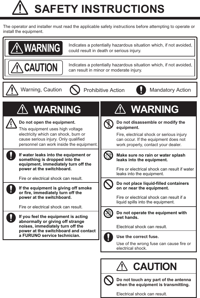
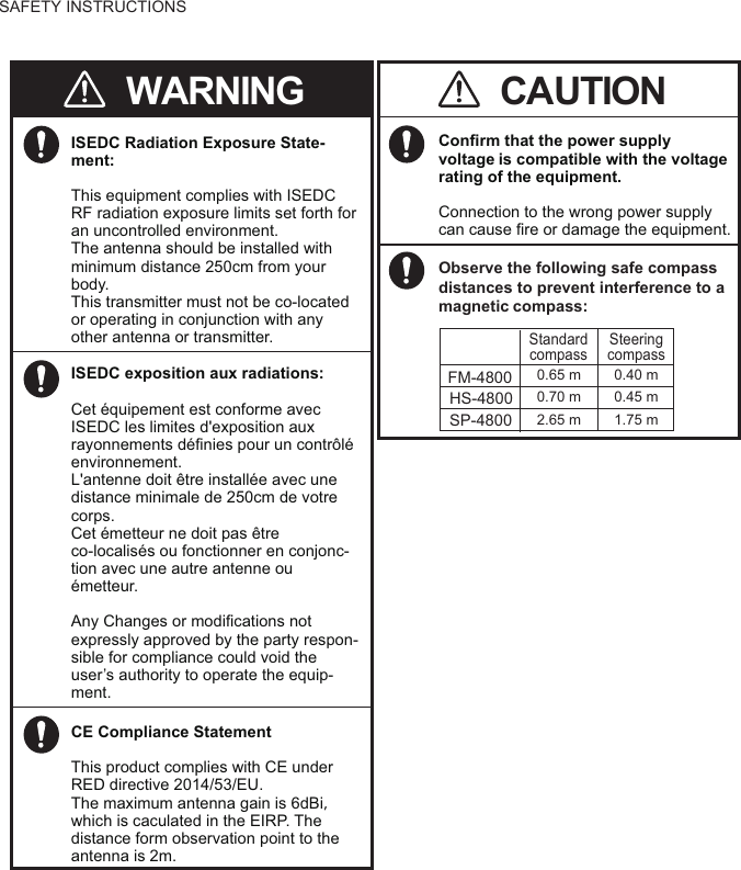
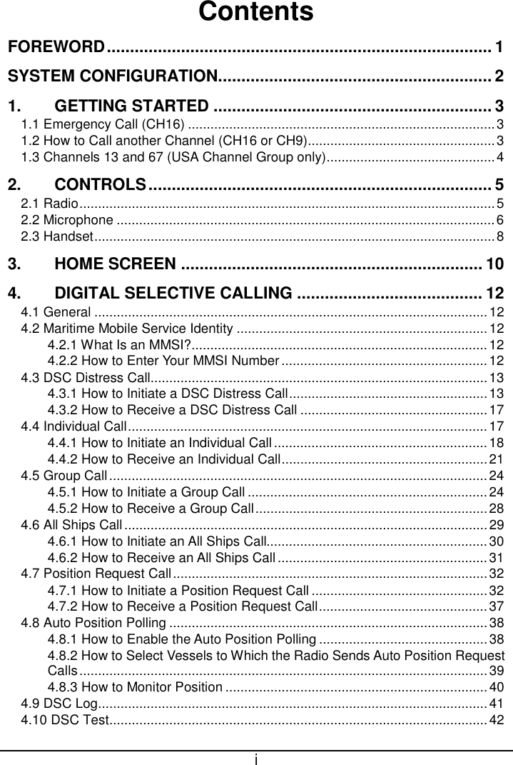
![SAFETY INSTRUCTIONSDo not open the equipment unless totally familiar with electrical circuits.The equipment uses high voltage that can cause electrical shock.WARNINGTurn off the power at the mains switchboard before beginning the installation. Post a warning sign near the switchboard to indicate that power should not be applied while the equipment is being installed. Electrical shock, serious injury or fire can result if the power is not turned off or is applied while the equipment is being installed.Do not approach the antenna closer than the distances shown below when the antenna is transmitting.The antenna emits radio waves that can be harmful to the human body.(MPE: Minimum Permissible Exposure)100 W/m20.12 m10 W/m20.39 m0.2 mW/cm21.50 mIEC 60945IEC 60945MPE by FCCRF power densityon antenna apertureDistance Descriptionrequired byMaximum Antenna Gain: 6dBi This device complies with part 15 of the FCC Rules. Operation is subject to the following two conditions:(1) This device may not cause harmful interference.(2) This device must accept any interfer-ence received, including interference that may cause undesired operation.1.2 W/m22.50 mMPE by ICThis transmitter must not be co-located or operating in conjunction with any other antenna or transmitter. Note: This equipment has been testedand found to comply with the FCCstandards.These limits are designed to provide reasonable protection against harmful interference in a commercial installation.This equipment generates uses and can radiate radio frequency energy and, if not installed and used in accordance with the instructions, may cause harmful interference to radio communications. However, there is no guarantee that interference will not occur in a particular installation. If this equipment does cause harmful interference to radio or television reception, which can be determined by turning the equipment off and on, the user is encouraged to try to correct the interference by one or more of the following measures:- Reorient or relocate the receiving antenna. - Increase the separation between the equipment and receiver. - Connect the equipment into an outlet on a circuit different from that to which the receiver is connected. - Consult the dealer or an experienced radio/TV technician for help. [Radiation Exposure Statement] This equipment complies with FCC radiation exposure limits set forth for an uncontrolled environment.This equipment complies with FCC radiation exposure limits set forth for an uncontrolled environment. This antenna should be installed withminimum distance 150cm from yourbody.ISEDC RSS warningThis device complies with Innovation, Science and Economic Development Canada Compliance RSS standard(s). Operation is subject to the following two conditions: (1) this device may not cause interference, and (2) thisdevice must accept any interference, including interference that may cause undesired operation of the device.Le présent appareil est conforme aux CNR d'Innovation, Sciences et Dével-oppement économique Canadaapplicables aux appareils radio.L'exploitation est autorisée aux deux conditions suivantes:(1) l'appareil ne doit pas produire de brouillage, et(2) l'utilisateur de l'appareil doit accepter tout brouillage radioélectrique subi, même si le brouillage estsusceptible d'en compromettre le fonctionnement.](https://usermanual.wiki/Furuno-USA/9ZWFM4800/User-Guide-3756017-Page-3.png)
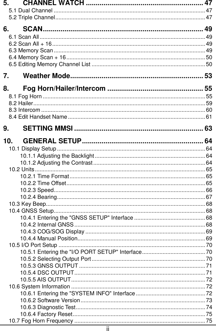
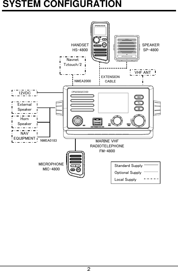
![5 2. CONTROLS This section describes the controls of the radio FM-4800, the microphone MIC-4800, the handset HS-4800. 2.1 Radio No. Description 1 [DISTRESS]: Distress Key Short press: Enter the distress nature selection and position manual input menu Long press: Press the DISTRESS key for 4 seconds to send a distress call. 2 [VOL/SQL]: Volume / Squelch Control Press: Switch between the volume adjust screen and the squelch adjust screen Rotate On "SQUELCH" or "VOLUME" screen: Adjust the squelch or volume level On other screens: Adjust the volume 3 [MENU/DSC]: Menu / Digital Selective Calling (DSC) Control On the home screen: Press: Enter "MAIN MENU" Rotate: Switch to a channel On other screens: Press: Select item or confirm the selection Rotate: Move to other item or select a number](https://usermanual.wiki/Furuno-USA/9ZWFM4800/User-Guide-3756017-Page-13.png)
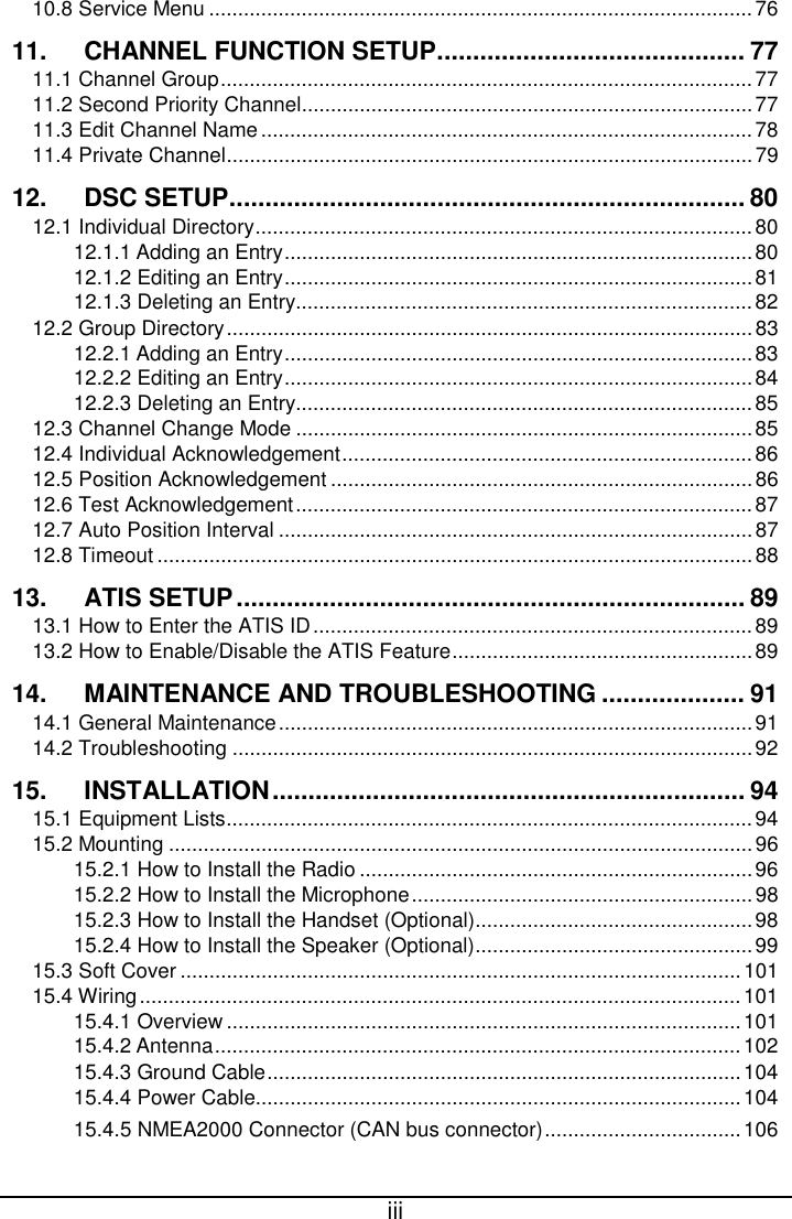
![6 No. Description 4 [ ]: On / Off Key Short press: Enter the display setup mode Long press: Power on or power off 5 [ ]: Back Key On the home screen: No function On other screens: Short press: Clear entries, cancel calls, backspace the cursor, or back up to the previous screen Long press: Return to the home screen 6 [16/+]: 16/+ Key Press the key to cancel all other modes and to tune into the priority channels (CH16 and CH9). Press the key again to return to the previously selected working channel. Note CH9 is used in some parts of the world as an alternative hailing channel to CH16. 2.2 Microphone](https://usermanual.wiki/Furuno-USA/9ZWFM4800/User-Guide-3756017-Page-14.png)
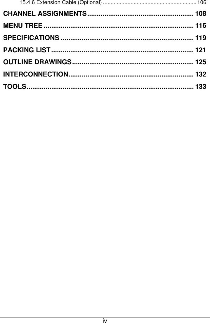
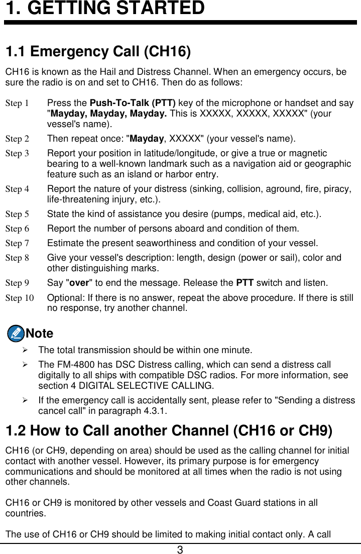
![7 No. Description 1 [PTT]: Push-to-Talk Key Press and hold the key in radio mode to enable the radio for voice communication. Note: When the PTT key on the microphone is pressed continuously, transmission time is limited to five minutes. This limits unintentional transmissions due to a stuck PTT key. In addition, Power is automatically reduced to protect against overheating due to continuous transmission. 2 []: Cursor Key Changes the channel up or down. 3 [HI/LO]: High / Low Power Switch Press the switch to toggle between 25 W (High) and 1 W (Low) 4 [16/+]: 16/+ Key Press the key to cancel all other modes and to tune into the priority channels (CH16 and CH9). Press the key again to return to the previously selected working channel. Note CH9 is used in some parts of the world as an alternative calling channel to CH16.](https://usermanual.wiki/Furuno-USA/9ZWFM4800/User-Guide-3756017-Page-15.png)
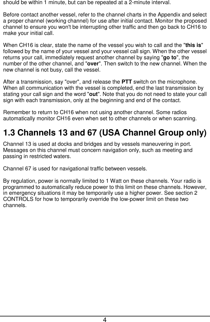
![8 2.3 Handset No. Description 1 [PTT]: Push-to-Talk Key The transmitter is enabled for voice communications with another vessel. Note: When the PTT key on the microphone is pressed continuously, transmission time is limited to five minutes. This limits unintentional transmissions due to a stuck PTT key. In addition, Power is automatically reduced to protect against overheating due to continuous transmission. 2 [MENU/DSC]: Menu / Digital Selective Calling (DSC) Control On the home screen: Press: Enter "MAIN MENU" Rotate: Switch to a channel On other screens: Press: Select item or confirm the selection Rotate: Move to other item or select a number](https://usermanual.wiki/Furuno-USA/9ZWFM4800/User-Guide-3756017-Page-16.png)
![9 No. Description 3 [VOL/SQL]: Volume / Squelch Control Press the key to switch between the volume adjust screen and the squelch adjust screen. 4 [HI/LO]: High / Low Power Switch Press the switch to toggle between 25 W (High) and 1 W (Low). 5 [DISTRESS]: Distress Key Short press: Enter the distress nature selection and position manual input menu Long press: Press the DISTRESS key for 4 seconds to send a distress call. 6 [ ]: Back Key On the home screen: No function On other screens: Short press: Clear entries, cancel calls, backspace the cursor, or back up to the previous screen Long press: Return to the home screen 7 [16/+]: 16/+ Key Press the key to cancel all other modes and to tune into the priority channels (CH16 and CH9). Press the key again to return to the previously selected working channel. Note CH9 is used in some parts of the world as an alternative calling channel to CH16. 8 [ ]: On / Off Key Press the key to turn the handset on or off.](https://usermanual.wiki/Furuno-USA/9ZWFM4800/User-Guide-3756017-Page-17.png)
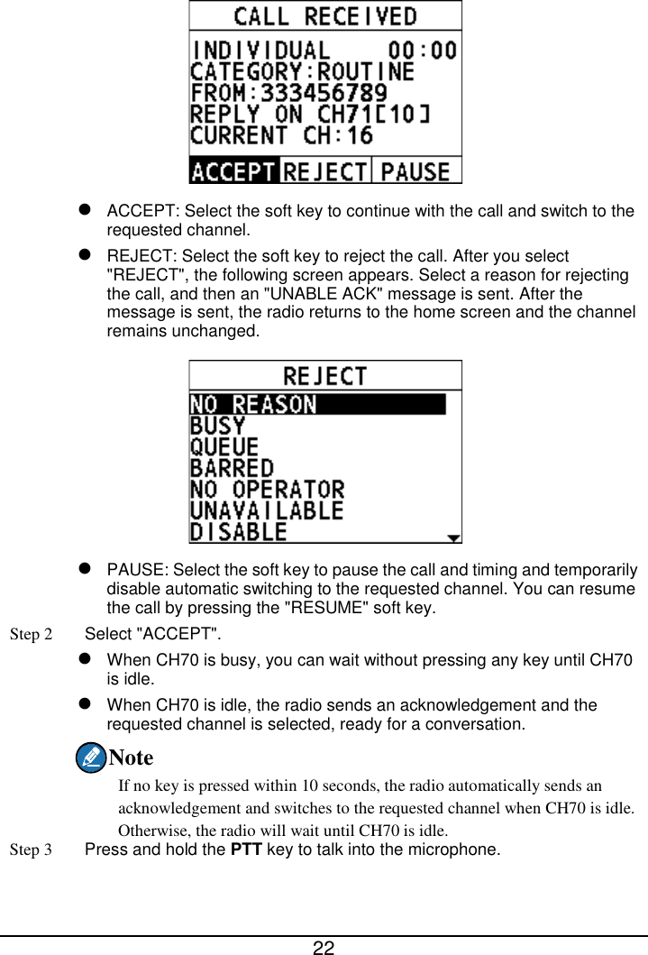
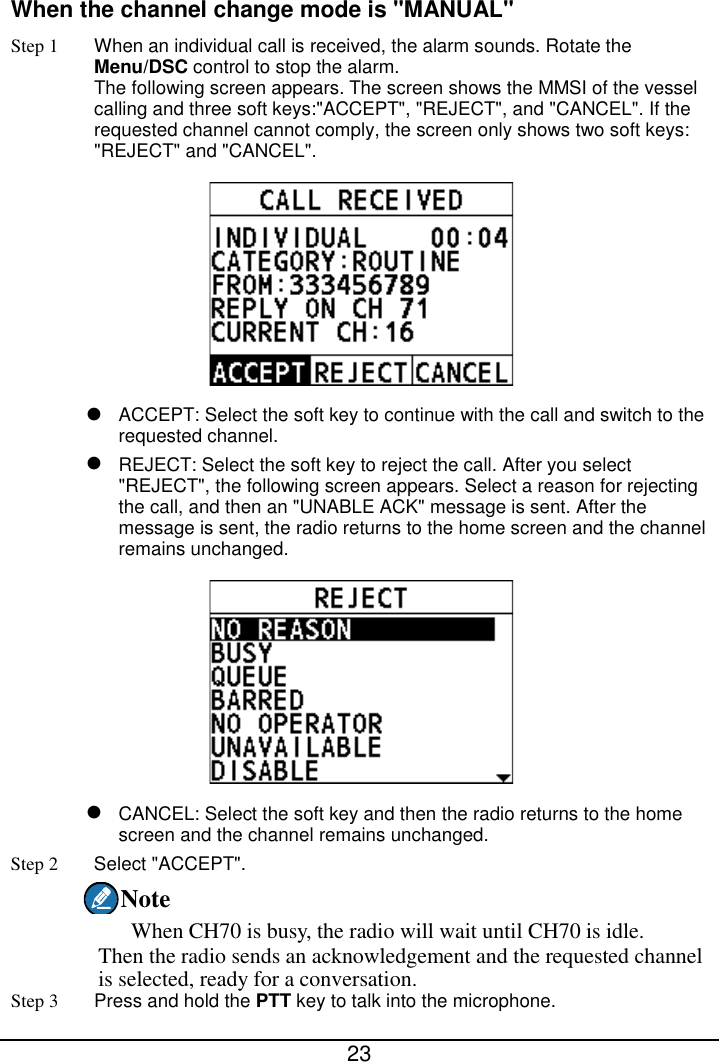
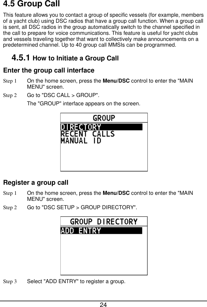

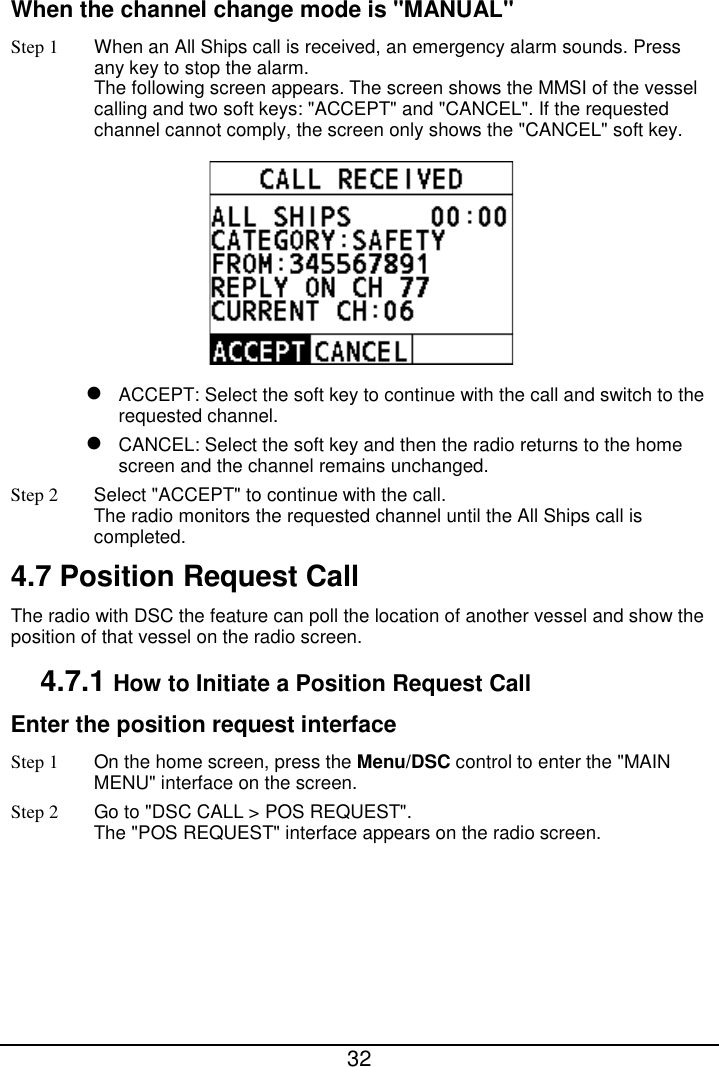
![31 4.6.2 How to Receive an All Ships Call The channel change of your radio has two modes: "AUTO" and "MANUAL". Different channel change modes lead to different operations when you receive an All Ships call. For information about how to set the channel change mode, see section 11.3 Channel Change Mode. When the channel change mode is "AUTO" Step 1 When an All Ships call is received, an emergency alarm sounds. Rotate the Menu/DSC key to stop the alarm. The following screen appears. The screen shows the MMSI of the vessel calling and three soft keys:"ACCEPT","CANCEL", and "PAUSE". If the requested channel cannot comply, the screen only shows the "CANCEL" soft key. ACCEPT: Select the soft key to continue with the call and switch to the requested channel. CANCEL: Select the soft key to cancel the automatic channel switching. The radio returns to the home screen and the channel remains unchanged. PAUSE: Select the soft key to pause the call and timing and temporarily disable automatic switching to the requested channel. You can resume the call by pressing the "RESUME" soft key. Note If no key is pressed within 10 seconds, the radio automatically switches to the requested channel. After 10 seconds, the countdown appears next to "REPLY ON CH16". [10] indicates that the 10 seconds countdown appears next to "REPLY ON CH16". Step 2 Select "ACCEPT" to continue with the call. The radio monitors the reply on channel until the All Ships call is completed.](https://usermanual.wiki/Furuno-USA/9ZWFM4800/User-Guide-3756017-Page-39.png)
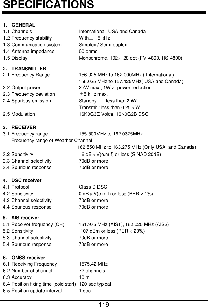
![120 7. SPEAKER POWER OUTPUT 7.1 Built-in speaker 3W (8ohm) 7.2 Microphone 1W (16ohm) 7.3 Handset 1W (16ohm) 7.4 External speaker 3W (8ohm, Via a handset extension cable) 5W (8ohm, Via pigtail) 7.5 Hailer speaker 30W max. (4 ohm) 15W (4 ohm, 1kHz, 12.0V, 10% distortion) 8. INTERFACE 8.1 Number of port NMEA0183 1 port, NMEA2000 1 port 8.2 NMEA0183 [Sentence] Input DTM, GGA, GLL, GNS, RMA, RMC Output DSC, DSE, GLL, RMC, VDM 8.3 NMEA0183 [Load requirements as a listener] Isolation Opto-coupler Input impedance 520ohm Max. voltage ±15V Threshold 1.3mA 8.4 NMEA0183 [Output drive capability] R=54 ohm, 1.5V min. Short circuit output current :±250mA 8.5 NMEA2000 [PGN] Input 059392/904, 060160/416/928, 065240, 126208, 127258, 129026/029/044 Output 059392, 060928,126208/464/993/996/998, 129025/026/029/038/039/040/041/540/793/794, 129795/797/798/801/802/808/809/810 9. POWER SUPPLY 9.1 Power voltage 12.0 V DC (-10%, + 30%) 9.2 Power consumption Transmit : 5 A (at 25W output, with all options) Receive : 2.5 A (at 3W audio output) Standby : 1 A 10. ENVIRONMENTAL CONDITION 10.1 Ambient temperature -15℃ to +55℃ 10.2 Relative humidity 93% or less at +40℃ 10.3 Degree of protection IP67 (FM-4800, HS-4800, SP-4800)](https://usermanual.wiki/Furuno-USA/9ZWFM4800/User-Guide-3756017-Page-128.png)