Furuno USA 9ZWFM4800 MARINE VHF RADIOTELEPHONE User Manual
Furuno USA Inc MARINE VHF RADIOTELEPHONE
User Manual

MARINE VHF
RADIOTELEPHONE
FM-4800
OPERATOR'S MANUAL
www.furuno.com
Model
SAFETY INSTRUCTIONS
The operator and installer must read the applicable safety instructions before attempting to operate or
install the equipment.
Indicates a potentially hazardous situation which, if not avoided,
could result in death or serious injury.
WARNING
Indicates a potentially hazardous situation which, if not avoided,
can result in minor or moderate injury.
CAUTION
Warning, Caution Prohibitive Action
Mandatory Action
CAUTION
Do not open the equipment.
This equipment uses high voltage
electricity which can shock, burn or
cause serious injury. Only qualified
personnel can work inside the equipment.
WARNING
If water leaks into the equipment or
something is dropped into the
equipment, immediately turn off the
power at the switchboard.
Fire or electrical shock can result.
If the equipment is giving off smoke
or fire, immediately turn off the
power at the switchboard.
Fire or electrical shock can result.
If you feel the equipment is acting
abnormally or giving off strange
noises, immediately turn off the
power at the switchboard and contact
a FURUNO service technician.
Do not disassemble or modify the
equipment.
Fire, electrical shock or serious injury
can occur. If the equipment does not
work properly, contact your dealer.
WARNING
Make sure no rain or water splash
leaks into the equipment.
Fire or electrical shock can result if water
leaks into the equipment.
Do not place liquid-filled containers
on or near the equipment.
Fire or electrical shock can result if a
liquid spills into the equipment.
Do not operate the equipment with
wet hands.
Electrical shock can result.
Use the correct fuse.
Use of the wrong fuse can cause fire or
electrical shock.
Do not touch any part of the antenna
when the equipment is transmitting.
Electrical shock can result.
SAFETY INSTRUCTIONS
Do not open the equipment unless
totally familiar with electrical circuits.
The equipment uses high voltage that
can cause electrical shock.
WARNING
Turn off the power at the mains
switchboard before beginning the
installation. Post a warning sign near
the switchboard to indicate that
power should not be applied while
the equipment is being installed.
Electrical shock, serious injury or fire
can result if the power is not turned off
or is applied while the equipment is
being installed.
Do not approach the antenna closer
than the distances shown below
when the antenna is transmitting.
The antenna emits radio waves that can
be harmful to the human body.
(MPE: Minimum Permissible Exposure)
100 W/m20.12 m
10 W/m20.39 m
0.2 mW/cm21.50 m
IEC 60945
IEC 60945
MPE by FCC
RF power density
on antenna aperture
Distance Description
required by
Maximum Antenna Gain: 6dBi
This device complies with part 15 of
the FCC Rules.
Operation is subject to the following
two conditions:
(1) This device may not cause harmful
interference.
(2) This device must accept any interfer-
ence received, including interference
that may cause undesired operation.
1.2 W/m22.50 m
MPE by IC
This transmitter must not be co-located
or operating in conjunction with any
other antenna or transmitter.
Note: This equipment has been tested
and found to comply with the FCC
standards.
These limits are designed to provide
reasonable protection against harmful
interference in a commercial installation.
This equipment generates uses and can
radiate radio frequency energy and, if
not installed and used in accordance
with the instructions, may cause harmful
interference to radio communications.
However, there is no guarantee that
interference will not occur in a particular
installation.
If this equipment does cause harmful
interference to radio or television
reception, which can be determined by
turning the equipment off and on, the
user is encouraged to try to correct the
interference by one or more of the
following measures:
- Reorient or relocate the receiving
antenna.
- Increase the separation between the
equipment and receiver.
- Connect the equipment into an outlet
on a circuit different from that to which
the receiver is connected.
- Consult the dealer or an experienced
radio/TV technician for help.
[Radiation Exposure Statement]
This equipment complies with FCC
radiation exposure limits set forth for
an uncontrolled environment.
This equipment complies with FCC
radiation exposure limits set forth for an
uncontrolled environment.
This antenna should be installed with
minimum distance 150cm from your
body.
ISEDC RSS warning
This device complies with Innovation,
Science and Economic Development
Canada Compliance RSS standard
(s). Operation is subject to the following
two conditions: (1) this device may not
cause interference, and (2) this
device must accept any interference,
including interference that may cause
undesired operation of the device.
Le présent appareil est conforme aux
CNR d'Innovation, Sciences et Dével-
oppement économique Canada
applicables aux appareils radio.
L'exploitation est autorisée aux deux
conditions suivantes:
(1) l'appareil ne doit pas produire de
brouillage, et
(2) l'utilisateur de l'appareil doit accepter
tout brouillage radioélectrique subi,
même si le brouillage est
susceptible d'en compromettre le
fonctionnement.
SAFETY INSTRUCTIONS
Confirm that the power supply
voltageis compatible with the voltage
rating of the equipment.
Connection to the wrong power supply
can cause fire or damage the equipment.
CAUTION
WARNING
ISEDC Radiation Exposure State-
ment:
This equipment complies with ISEDC
RF radiation exposure limits set forth for
an uncontrolled environment.
The antenna should be installed with
minimum distance 250cm from your
body.
This transmitter must not be co-located
or operating in conjunction with any
other antenna or transmitter.
Observe the following safe compass
distances to prevent interference to a
magneticcompass:
Standard
compass
Steering
compass
0.65 m 0.40 m
FM-4800
0.70 m 0.45 m
HS-4800
2.65 m 1.75 m
SP-4800
ISEDC exposition aux radiations:
Cet équipement est conforme avec
ISEDC les limites d'exposition aux
rayonnements définies pour un contrôlé
environnement.
L'antenne doit être installée avec une
distance minimale de 250cm de votre
corps.
Cet émetteur ne doit pas être
co-localisés ou fonctionner en conjonc-
tion avec une autre antenne ou
émetteur.
Any Changes or modifications not
expressly approved by the party respon-
sible for compliance could void the
user’s authority to operate the equip-
ment.
CE Compliance Statement
This product complies with CE under
RED directive 2014/53/EU.
The maximum antenna gain is 6dBi,
which is caculated in the EIRP. The
distance form observation point to the
antenna is 2m.

i
Contents
FOREWORD ................................................................................... 1
SYSTEM CONFIGURATION ........................................................... 2
1. GETTING STARTED ............................................................ 3
1.1 Emergency Call (CH16) .................................................................................. 3
1.2 How to Call another Channel (CH16 or CH9) .................................................. 3
1.3 Channels 13 and 67 (USA Channel Group only) ............................................. 4
2. CONTROLS .......................................................................... 5
2.1 Radio ............................................................................................................... 5
2.2 Microphone ..................................................................................................... 6
2.3 Handset ........................................................................................................... 8
3. HOME SCREEN ................................................................. 10
4. DIGITAL SELECTIVE CALLING ........................................ 12
4.1 General ......................................................................................................... 12
4.2 Maritime Mobile Service Identity ................................................................... 12
4.2.1 What Is an MMSI? ............................................................................... 12
4.2.2 How to Enter Your MMSI Number ....................................................... 12
4.3 DSC Distress Call.......................................................................................... 13
4.3.1 How to Initiate a DSC Distress Call ..................................................... 13
4.3.2 How to Receive a DSC Distress Call .................................................. 17
4.4 Individual Call ................................................................................................ 17
4.4.1 How to Initiate an Individual Call ......................................................... 18
4.4.2 How to Receive an Individual Call ....................................................... 21
4.5 Group Call ..................................................................................................... 24
4.5.1 How to Initiate a Group Call ................................................................ 24
4.5.2 How to Receive a Group Call .............................................................. 28
4.6 All Ships Call ................................................................................................. 29
4.6.1 How to Initiate an All Ships Call........................................................... 30
4.6.2 How to Receive an All Ships Call ........................................................ 31
4.7 Position Request Call .................................................................................... 32
4.7.1 How to Initiate a Position Request Call ............................................... 32
4.7.2 How to Receive a Position Request Call ............................................. 37
4.8 Auto Position Polling ..................................................................................... 38
4.8.1 How to Enable the Auto Position Polling ............................................. 38
4.8.2 How to Select Vessels to Which the Radio Sends Auto Position Request
Calls ............................................................................................................. 39
4.8.3 How to Monitor Position ...................................................................... 40
4.9 DSC Log ........................................................................................................ 41
4.10 DSC Test ..................................................................................................... 42

ii
5. CHANNEL WATCH ............................................................ 47
5.1 Dual Channel ................................................................................................ 47
5.2 Triple Channel ............................................................................................... 47
6. SCAN .................................................................................. 49
6.1 Scan All ......................................................................................................... 49
6.2 Scan All + 16 ................................................................................................. 49
6.3 Memory Scan ................................................................................................ 49
6.4 Memory Scan + 16 ........................................................................................ 50
6.5 Editing Memory Channel List ........................................................................ 50
7. Weather Mode .................................................................... 53
8. Fog Horn/Hailer/Intercom ................................................. 55
8.1 Fog Horn ....................................................................................................... 55
8.2 Hailer ............................................................................................................. 59
8.3 Intercom ........................................................................................................ 60
8.4 Edit Handset Name ....................................................................................... 61
9. SETTING MMSI .................................................................. 63
10. GENERAL SETUP .............................................................. 64
10.1 Display Setup .............................................................................................. 64
10.1.1 Adjusting the Backlight ...................................................................... 64
10.1.2 Adjusting the Contrast ....................................................................... 64
10.2 Units ............................................................................................................ 65
10.2.1 Time Format ...................................................................................... 65
10.2.2 Time Offset ........................................................................................ 65
10.2.3 Speed ................................................................................................ 66
10.2.4 Bearing .............................................................................................. 67
10.3 Key Beep ..................................................................................................... 68
10.4 GNSS Setup ................................................................................................ 68
10.4.1 Entering the "GNSS SETUP" Interface ............................................. 68
10.4.2 Internal GNSS ................................................................................... 68
10.4.3 COG/SOG Display ............................................................................ 69
10.4.4 Manual Position ................................................................................. 69
10.5 I/O Port Setup ............................................................................................. 70
10.5.1 Entering the "I/O PORT SETUP" Interface ........................................ 70
10.5.2 Selecting Output Port ........................................................................ 70
10.5.3 GNSS OUTPUT ................................................................................ 71
10.5.4 DSC OUTPUT ................................................................................... 71
10.5.5 AIS OUTPUT ..................................................................................... 72
10.6 System Information ..................................................................................... 72
10.6.1 Entering the "SYSTEM INFO" Interface ............................................ 72
10.6.2 Software Version ............................................................................... 73
10.6.3 Diagnostic Test .................................................................................. 74
10.6.4 Factory Reset .................................................................................... 75
10.7 Fog Horn Frequency ................................................................................... 75

15.4.5 NMEA2000 Connector (CAN bus connector)
iii
10.8 Service Menu .............................................................................................. 76
11. CHANNEL FUNCTION SETUP ........................................... 77
11.1 Channel Group ............................................................................................ 77
11.2 Second Priority Channel .............................................................................. 77
11.3 Edit Channel Name ..................................................................................... 78
11.4 Private Channel ........................................................................................... 79
12. DSC SETUP ........................................................................ 80
12.1 Individual Directory ...................................................................................... 80
12.1.1 Adding an Entry ................................................................................. 80
12.1.2 Editing an Entry ................................................................................. 81
12.1.3 Deleting an Entry ............................................................................... 82
12.2 Group Directory ........................................................................................... 83
12.2.1 Adding an Entry ................................................................................. 83
12.2.2 Editing an Entry ................................................................................. 84
12.2.3 Deleting an Entry ............................................................................... 85
12.3 Channel Change Mode ............................................................................... 85
12.4 Individual Acknowledgement ....................................................................... 86
12.5 Position Acknowledgement ......................................................................... 86
12.6 Test Acknowledgement ............................................................................... 87
12.7 Auto Position Interval .................................................................................. 87
12.8 Timeout ....................................................................................................... 88
13. ATIS SETUP ....................................................................... 89
13.1 How to Enter the ATIS ID ............................................................................ 89
13.2 How to Enable/Disable the ATIS Feature .................................................... 89
14. MAINTENANCE AND TROUBLESHOOTING .................... 91
14.1 General Maintenance .................................................................................. 91
14.2 Troubleshooting .......................................................................................... 92
15. INSTALLATION .................................................................. 94
15.1 Equipment Lists ........................................................................................... 94
15.2 Mounting ..................................................................................................... 96
15.2.1 How to Install the Radio .................................................................... 96
15.2.2 How to Install the Microphone ........................................................... 98
15.2.3 How to Install the Handset (Optional) ................................................ 98
15.2.4 How to Install the Speaker (Optional) ................................................ 99
15.3 Soft Cover ................................................................................................. 101
15.4 Wiring ........................................................................................................ 101
15.4.1 Overview ......................................................................................... 101
15.4.2 Antenna ........................................................................................... 102
15.4.3 Ground Cable .................................................................................. 104
15.4.4 Power Cable.................................................................................... 104
..................................
106

iv
15.4.6 Extension Cable (Optional) ............................................................. 106
CHANNEL ASSIGNMENTS ........................................................ 108
MENU TREE ............................................................................... 116
SPECIFICATIONS ...................................................................... 119
PACKING LIST ........................................................................... 121
OUTLINE DRAWINGS ................................................................ 125
INTERCONNECTION .................................................................. 132
TOOLS ........................................................................................ 133

1
FOREWORD
A Word to the Owner of the FM-4800
FURUNO Electric Company thanks you for purchasing the FM-4800 Marine VHF
Radiotelephone. We are confident you will discover why the FURUNO name has
become synonymous with quality and reliability.
Since 1948, FURUNO has enjoyed an enviable reputation for quality and reliability
throughout the world. This dedication to excellence is furthered by our extensive
global network of agents and dealers.
Your equipment is designed and constructed to meet the rigorous demands of the
marine environment. However, no machine can perform its intended function unless
properly installed and maintained. Please carefully read and follow the operation,
installation and maintenance procedures set forth in this manual.
We would appreciate feedback from you, the end-user, about whether we are
achieving our purposes.
Thank you for considering and purchasing FURUNO.
Features
FURUNO FM-4800 Marine VHF Radiotelephone supports the following features:
All-in-One Marine VHF Radiotelephone
25 W or 1 W RF Output Power
Class D DSC with Distress, Individual and All Ship calls
Built-in AIS receiver
Built-in high-sensitivity GNSS receiver
30 W PA/Loud Hailer with automatic fog signals and listen back
NMEA2000 & NMEA0183 interface
Dual station with optional handset HS-4800
ATIS mode available for inland waterway in Europe
Pre-programmed frequency band for USA, Canadian and International marine
channels, plus 10 weather channels where available
Initiate DSC call directly from NavNet TZtouch2 series when connected
(Version 1950152-06.01 or later)
Fully-waterproofed transceiver, microphone and handset (IP67)
Quick access to channel 16/9
Display GNSS Navigation information (LAT/LON, SOG, COG)
Program No.: FM-4800 : 0550257-01.**; HS-4800 : 0550259-01.**. (** denotes
minor modifications.)
2
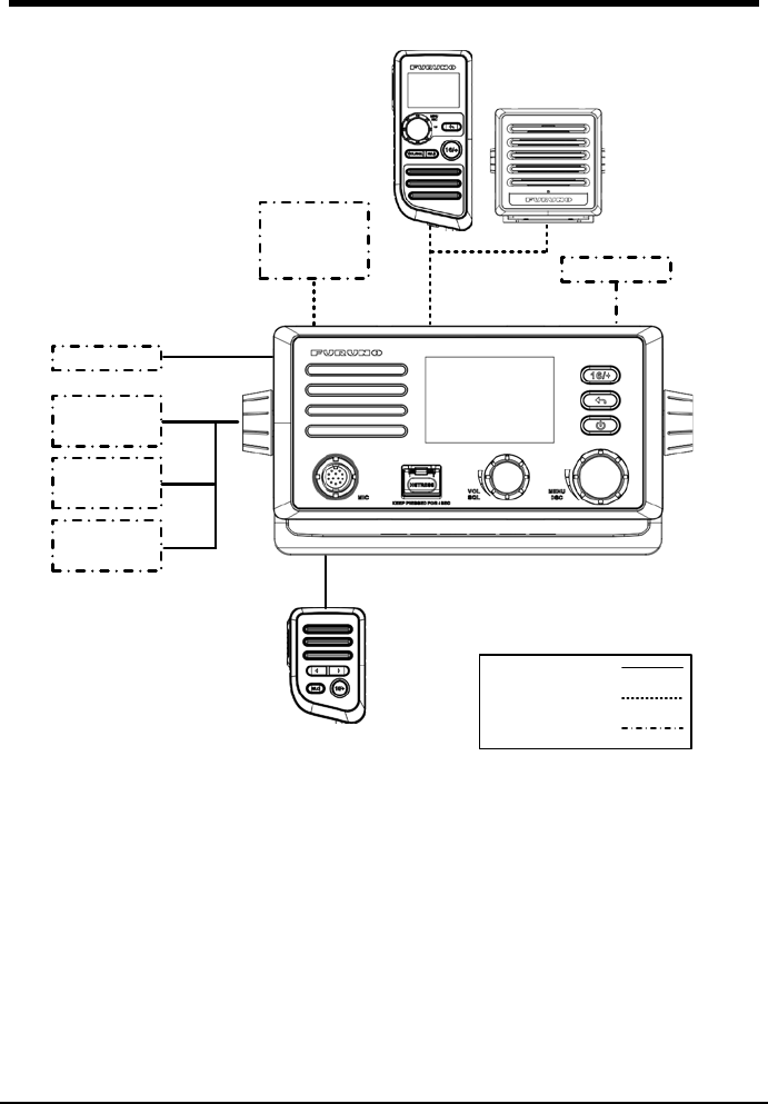
SYSTEM CONFIGURATION
12VDC
Navnet
Tztouch/2
External
Speaker
Horn
Speaker
NAV
EQUIPMENT
NMEA2000
NMEA0183
MICROPHONE
MIC-4800
HANDSET
HS-4800
EXTENSION
CABLE
SPEAKER
SP-4800
VHF ANT
Standard Supply
Optional Supply
Local Supply
MARINE VHF
RADIOTELEPHONE
FM-4800

3
1. GETTING STARTED
1.1 Emergency Call (CH16)
CH16 is known as the Hail and Distress Channel. When an emergency occurs, be
sure the radio is on and set to CH16. Then do as follows:
Step 1 Press the Push-To-Talk (PTT) key of the microphone or handset and say
"Mayday, Mayday, Mayday. This is XXXXX, XXXXX, XXXXX" (your
vessel's name).
Step 2 Then repeat once: "Mayday, XXXXX" (your vessel's name).
Step 3 Report your position in latitude/longitude, or give a true or magnetic
bearing to a well-known landmark such as a navigation aid or geographic
feature such as an island or harbor entry.
Step 4 Report the nature of your distress (sinking, collision, aground, fire, piracy,
life-threatening injury, etc.).
Step 5 State the kind of assistance you desire (pumps, medical aid, etc.).
Step 6 Report the number of persons aboard and condition of them.
Step 7 Estimate the present seaworthiness and condition of your vessel.
Step 8 Give your vessel's description: length, design (power or sail), color and
other distinguishing marks.
Step 9 Say "over" to end the message. Release the PTT switch and listen.
Step 10 Optional: If there is no answer, repeat the above procedure. If there is still
no response, try another channel.
Note
The total transmission should be within one minute.
The FM-4800 has DSC Distress calling, which can send a distress call
digitally to all ships with compatible DSC radios. For more information, see
section 4 DIGITAL SELECTIVE CALLING.
If the emergency call is accidentally sent, please refer to "Sending a distress
cancel call" in paragraph 4.3.1.
1.2 How to Call another Channel (CH16 or CH9)
CH16 (or CH9, depending on area) should be used as the calling channel for initial
contact with another vessel. However, its primary purpose is for emergency
communications and should be monitored at all times when the radio is not using
other channels.
CH16 or CH9 is monitored by other vessels and Coast Guard stations in all
countries.
The use of CH16 or CH9 should be limited to making initial contact only. A call

4
should be within 1 minute, but can be repeated at a 2-minute interval.
Before contact another vessel, refer to the channel charts in the Appendix and select
a proper channel (working channel) for use after initial contact. Monitor the proposed
channel to ensure you won't be interrupting other traffic and then go back to CH16 to
make your initial call.
When CH16 is clear, state the name of the vessel you wish to call and the "this is"
followed by the name of your vessel and your vessel call sign. When the other vessel
returns your call, immediately request another channel by saying "go to", the
number of the other channel, and "over". Then switch to the new channel. When the
new channel is not busy, call the vessel.
After a transmission, say "over", and release the PTT switch on the microphone.
When all communication with the vessel is completed, end the last transmission by
stating your call sign and the word "out". Note that you do not need to state your call
sign with each transmission, only at the beginning and end of the contact.
Remember to return to CH16 when not using another channel. Some radios
automatically monitor CH16 even when set to other channels or when scanning.
1.3 Channels 13 and 67 (USA Channel Group only)
Channel 13 is used at docks and bridges and by vessels maneuvering in port.
Messages on this channel must concern navigation only, such as meeting and
passing in restricted waters.
Channel 67 is used for navigational traffic between vessels.
By regulation, power is normally limited to 1 Watt on these channels. Your radio is
programmed to automatically reduce power to this limit on these channels. However,
in emergency situations it may be temporarily use a higher power. See section 2
CONTROLS for how to temporarily override the low-power limit on these two
channels.
5
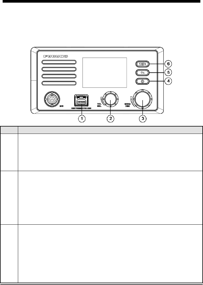
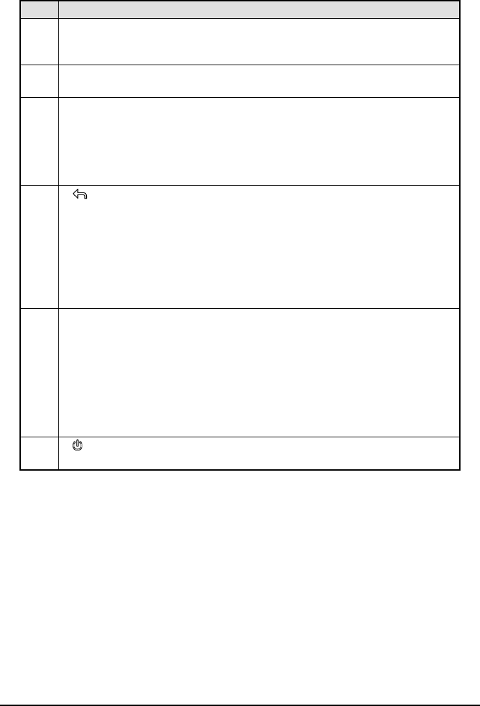
2. CONTROLS
This section describes the controls of the radio FM-4800, the microphone MIC-4800,
the handset HS-4800.
2.1 Radio
No.
Description
1
[DISTRESS]: Distress Key
Short press: Enter the distress nature selection and position manual
input menu
Long press: Press the DISTRESS key for 4 seconds to send a distress
call.
2
[VOL/SQL]: Volume / Squelch Control
Press: Switch between the volume adjust screen and the squelch adjust
screen
Rotate
On "SQUELCH" or "VOLUME" screen: Adjust the squelch or volume
level
On other screens: Adjust the volume
3
[MENU/DSC]: Menu / Digital Selective Calling (DSC) Control
On the home screen:
Press: Enter "MAIN MENU"
Rotate: Switch to a channel
On other screens:
Press: Select item or confirm the selection
Rotate: Move to other item or select a number
6
No.
Description
4
[ ]: On / Off Key
Short press: Enter the display setup mode
Long press: Power on or power off
5
[ ]: Back Key
On the home screen: No function
On other screens:
Short press: Clear
entries, cancel calls, backspace the cursor, or back
up to the previous screen
Long press: Return to the home screen
6
[16/+]: 16/+ Key
Press the key to cancel all other modes and to tune into the priority channels
(CH16 and CH9). Press the key again to r
eturn to the previously selected
working channel.
Note
CH9 is used in some parts of the world as an alternative hailing channel to
CH16.
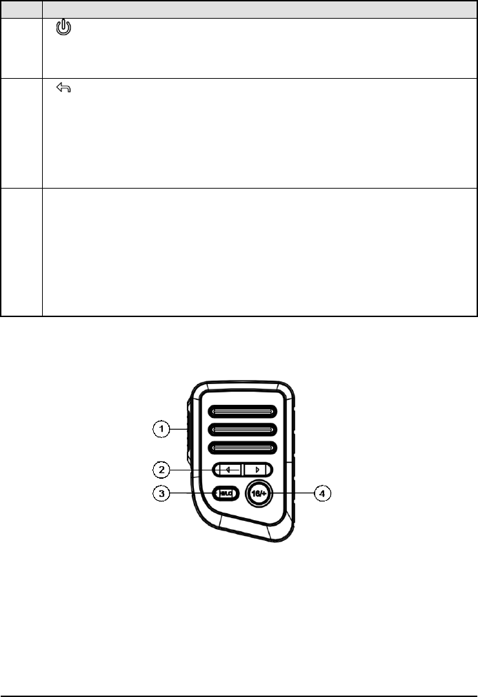
2.2 Microphone
7
No.
Description
1
[PTT]: Push-to-Talk Key
Press and hold the key in
radio mode to enable the radio for voice
communication.
Note:
When the PTT key on the microphone is pressed continuously, transmission
time is limited to five minutes. This limits unintentional transmissions due to a
stuck PTT key.
In addition, Power is au
tomatically reduced to protect against overheating
due to continuous transmission.
2
[]: Cursor Key
Changes the channel up or down.
3
[HI/LO]: High / Low Power Switch
Press the switch to toggle between 25 W (High) and 1 W (Low)
4
[16/+]: 16/+ Key
Press
the key to cancel all other modes and to tune into the priority channels
(CH16 and CH9). Press the key again to return to the previously selected
working channel.
Note
CH9 is used in some parts of the world as
an alternative calling channel to
CH16.
8
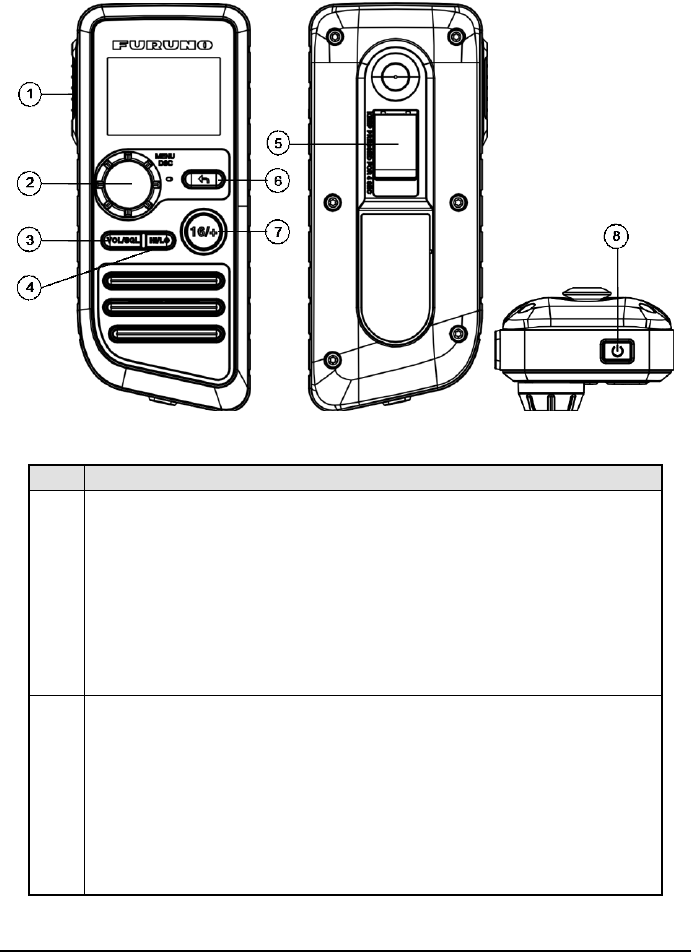
2.3 Handset
No.
Description
1
[PTT]: Push-to-Talk Key
The transmitter is enabled for voice communications with another
vessel.
Note:
When the PTT key on the microphone is pressed continuously,
transmission time is limited to
five minutes. This limits unintentional
transmissions due to a stuck PTT key.
In addition, Power is automatically reduced to protect against
overheating due to continuous transmission.
2
[MENU/DSC]: Menu / Digital Selective Calling (DSC) Control
On the home screen:
Press: Enter "MAIN MENU"
Rotate: Switch to a channel
On other screens:
Press: Select item or confirm the selection
Rotate: Move to other item or select a number
9
No.
Description
3
[VOL/SQL]: Volume / Squelch Control
Press the key to switch between the
volume adjust screen and the
squelch adjust screen.
4
[HI/LO]: High / Low Power Switch
Press the switch to toggle between 25 W (High) and 1 W (Low).
5
[DISTRESS]: Distress Key
Short press: Enter the distress nature selection and position
manual input menu
Long press: Press the DISTRESS key for 4 seconds to send a
distress call.
6
[ ]: Back Key
On the home screen: No function
On other screens:
Short press: Clear entries, cancel calls, backspace the cursor,
or back up to the previous screen
Long press: Return to the home screen
7
[16/+]: 16/+ Key
Press the key to cancel all other modes and to tune into the priority
channels (CH16 and CH9). Press the key again to return to the
previously selected working channel.
Note
CH9 is used in some parts of the world as
an alternative calling
channel to CH16.
8
[ ]: On / Off Key
Press the key to turn the handset on or off.
10
3. HOME SCREEN
No.
Description
1
-: indicates high power such as 25 W.
-: indicates low power such as 1 W.
2
: indicates internal and External GNSS.
This icon disappears if there is no GNSS data.
This icon flashes with 500ms when there is GNSS data before, but
current internal GNSS and External GNSS are not fixed.
3
: indicates unread DSC messages.
4
-: indicates the dual watch mode.
-: indicates the triple watch mode.
5
: This icon appears if user selects START of AUTO POS
POLLING->ACTIVATION.
This icon disappears if user selects END of AUTO POS
POLLING->ACTIVATION.
6
: indicates weather alert.
7
-: indicates battery strength more than 15.6V.
-: indicates battery strength lean than 10.5V.
8
Operational Status icon
(Rotates clockwise to indicate system is working)
9
-No icon
:
FM standby.
-:Indicates reception.
-
:
Indicates transmission.
11
No.
Description
10
Display location information including longitude, latitude, time, COG,
and SOG.
If there is no any information, it displays "NO GNSS DATA".
Note
There are three sensors including built-in sensor, NMEA2000 and
NMEA0183. The last two are external sensors. Their priorities in
descending order are described as follows:
1. Built-
in sensor: The GNSS data from this sensor enjoys the
highest priority.
2. NMEA2000: If no valid GNSS data is from the built-in sensor or
this sensor is disabled, the GNSS data from NMEA2000 will be
used.
3. NMEA0183: If no valid GNSS data from both the build-in sensor
and NMEA2000, the GNSS data from NMEA2000 will be used.
11
In non scan mode: display CH NAME.
In scan mode:
SCAN ALL: indicates that the user selects SCAN ALL
SCAN ALL+16: indicates that the user selects SCAN ALL+16
MEMORY SCAN: indicates that the user selects MEMORY SCAN
MEMORY SCAN +16: indicates that the user selects MEMORY
SCAN+16
12 &
13
Displays the current channel number.
Note: the channel number 12 is not displayed.
14
-
:
Indicates that the current channel is simplex.
-
:
Indicates that the current channel is duplex.
15
- : This icon appears if CH GROUP is INT.
- : This icon appears if CH GROUP is USA
- : This icon appears if CH GROUP is CAN
- : This icon appears if CH GROUP is USA or CAN, and
WEATHER MODE is ON.
12
4. DIGITAL SELECTIVE CALLING
4.1 General
Digital Selective Calling (DSC) is a semi-automated method to establish a radio call.
DSC has been designated by the International Maritime Organization (IMO) as an
international standard for establishing VHF, MF and HF radio calls. It has also been
designated as a part of the Global Maritime Distress and Safety System (GMDSS).
DSC replaces listening watches on distress frequencies and is used to broadcast
routine and urgent maritime safety information broadcasts.
This system allows mariners to instantly transmit a distress call with GNSS position
to the Coast Guard and other vessels within the range of the transmission. DSC also
allows mariners to initiate or receive distress, urgency, safety, routine, position
request, position transmit, and group calls to or from another vessel equipped with a
DSC radio.
4.2 Maritime Mobile Service Identity
4.2.1 What Is an MMSI?
An MMSI is a nine-digit number used on marine radios capable of using DSC. This
number is used like a telephone number to selectively call other vessels.
Note
To use the DSC functions, this vessel’s MMSI must be entered into the radio.
4.2.2 How to Enter Your MMSI Number
Caution
An MMSI can be entered only once. Therefore, be careful not to enter the wrong
MMSI number. If you need to change the MMSI number after it has been entered,
contact your dealer.
Step 1 Press the Menu/DSC control until the "MAIN MENU" appears.
Step 2 Go to "DSC SETUP > SET MMSI".
Step 3 Enter you MMSI number (nine digits).
If you enter a wrong digit, press the BACK key until the wrong digit is
selected, and then enter the correct digit.
Step 4 After you enter the MMSI number, press the Menu/DSC control to save
the number.
Step 5 Enter the MMSI number again, and then press the Menu/DSC control to
save the number.
13
4.3 DSC Distress Call
FM-4800 can send and receive DSC distress calls. When FM-4800 receives GNSS
signals, FM-4800 can also transmit the latitude and longitude of the vessel together
with the DSC distress call.
4.3.1 How to Initiate a DSC Distress Call
Note
To transmit a DSC distress call, this vessel’s MMSI number must be entered into
the radio. For information about how to enter the MMSI number, see section
4.2.2 How to Enter Your MMSI Number.
Initiate a DSC distress call without specifying the nature of
distress
The FM-4800 can transmit a DSC distress call without specifying the following
natural of distress categories: Undesignated, Fire, Flooding, Collision, Grounding,
Listing, Sinking, Adrift, Abandoning, Piracy, and MOB (Man Overboard).
Step 1 Open the cover labeled "DISTRESS".
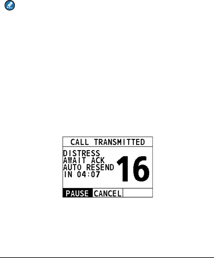
Step 2 Press and hold the Distress key (about 4 seconds). The unit beeps and
the display shows the time remaining until the distress signal is sent.
After the distress signal is sent, the radio waits for an acknowledgement with the
display showing "AWAIT ACK".
If no acknowledgement is received, the distress signal is repeated at
3.5-to-4.5-minute intervals, until a DSC acknowledgement is received.
Step 3 When you receive the DSC acknowledgement, select "ACCEPT".
If the radio does not stay on CH16, you need to select "Accept".
14
If the radio already stays on CH16, skip this step.
Step 4 Press and hold the PTT key to announce your situation on CH16.
Initiate a DSC distress call with the nature of distress specified
The FM-4800 is capable of transmitting a DSC distress call with the following
distress categories: Undesignated, Fire, Flooding, Collision, Grounding, Listing,
Sinking, Adrift, Abandoning, Piracy, and MOB (Man Overboard).
Step 1 Open the cover labeled "DISTRESS".
Step 2 Short-press the Distress key.
The "DISTRESS" screen appears.
Step 3 Select "NATURE".
The "NATURE" screen appears.
Step 4 Select the nature of the distress.
Step 5 Press and hold the Distress key (about 4 seconds). The unit beeps and
the display shows the time remaining until the distress signal is sent.
After the distress signal is sent, the radio waits for an acknowledgement with the
display showing "AWAIT ACK".
If no acknowledgement is received, the distress signal is repeated at
3.5-to-4.5-minute intervals, until a DSC acknowledgement is received.
Step 6 When you receive the DSC acknowledgement, select "ACCEPT".
Step 7 Press and hold the PTT key to announce your situation on CH16.

15
Initiate a DSC distress call with manually inputted position
If no position data is available at the time of distress, you can enter the latitude and
longitude position of your vessel manually when you send a DSC distress call.
Step 1 Open the cover labeled "DISTRESS".
Step 2 Short-press the Distress key.
The "DISTRESS" screen appears.
Step 3 Select "POS".
Step 4 Rotate and press the Menu/DSC control to enter the latitude and longitude
of your vessel and current UTC time in 24-hour format.
Step 5 Press and hold the Distress key (about 4 seconds). The unit beeps and
the display shows the time remaining until the distress signal is sent.
After the distress signal is sent, the radio waits for an
acknowledgement with the display showing "AWAIT ACK".
If no acknowledgement is received, the distress signal is repeated at
3.5-to-4.5-minute intervals, until a DSC acknowledgement is
received.
Step 6 When you receive the DSC acknowledgement, select "ACCEPT".
Step 7 Press and hold the PTT key to announce your situation on CH16.
Pause a DSC distress call
After a DSC distress call is sent, the DSC distress call is repeated at
3.5-to-4.5-minute intervals until the call is canceled by the user, until an
acknowledgement is received, or until the radio is turned off. The FM-4800 has a
provision to pause the retransmitting of the distress call. To pause the distress call,
select "PAUSE".
Restart the DSC distress call
After you select “PAUSE”, the button is switched to "RESUME". At this time, you can
select "RESUME" to restart the DSC distress call.
Sending a distress cancel call
When the emergency is released, you can cancel the distress call.
Step 1 On the "CALL TRANSMITTED" interface, select "CANCEL".

16
Step 2 Select "YES".
Step 3 Select "OK".
Step 4 Press and hold the PTT key to announce your situation.
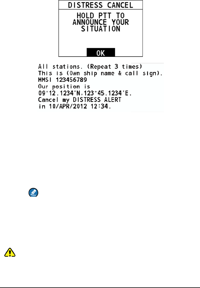
17
Step 5 Select "OK" to return to the home screen.
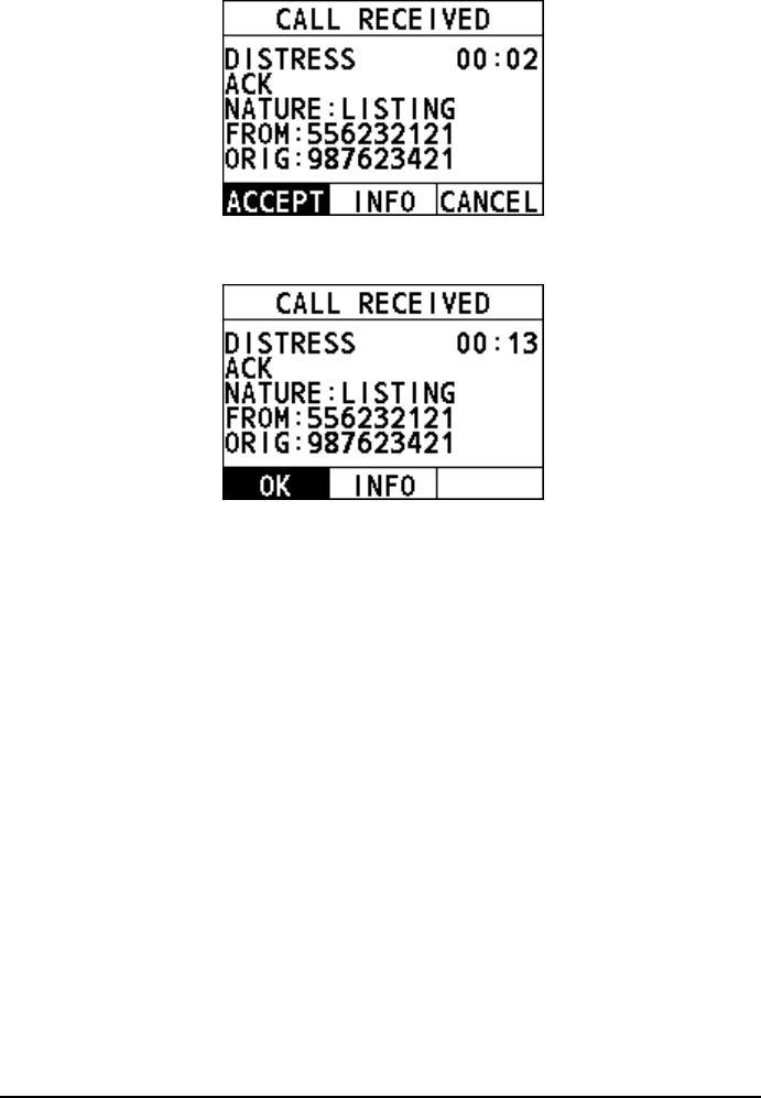
4.3.2 How to Receive a DSC Distress Call
Step 1 When a DSC distress call is received, the emergency alarm sounds.
Rotate the Menu/DSC control to stop the alarm.
Step 2 Optional: The display shows the MMSI of the vessel in distress. To show
additional information of the vessel in distress, select "INFO", and then
select "OK".
Step 3 To accept the distress call, select "ACCEPT".
The radio switches to CH16 automatically.
Note
If you press "CANCEL", the radio quits the automatic switching to
CH16 and reverts to the last selected working channel.
Step 4 Listen on CH16 for five minutes.
4.4 Individual Call
This feature allows you to contact a vessel with the DSC feature.
Caution
To make a DSC individual call, the radio of the receiving party should be set to
manually acknowledge the individual call request from the initiating party.
Otherwise, the radio of the receiving party will automatically send an "unable to
acknowledge" message and the individual call cannot be established. For
information about how to set it, see 11.4 Individual Acknowledgement.
18
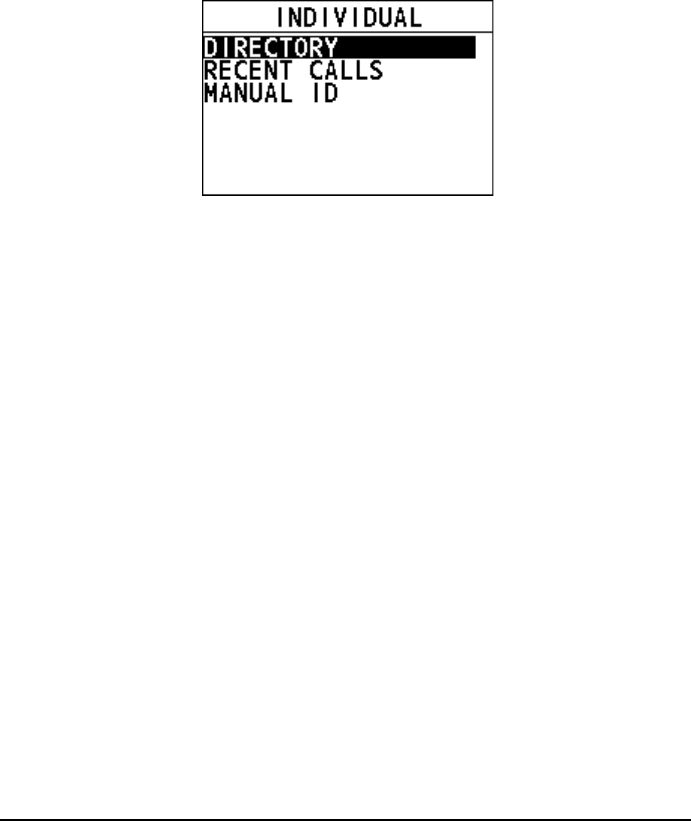
4.4.1 How to Initiate an Individual Call
Enter the individual call interface
Step 1 On the home screen, press the Menu/DSC control to enter the "MAIN
MENU" screen.
Step 2 Go to "DSC CALL > INDIVIDUAL".
The "INDIVIDUAL" interface appears on the screen.
Initiate an individual call to a vessel registered in the individual
directory
Before you initiate an individual call from the individual directory, a vessel or
person's name and the MMSI number associated with the vessel you want to
transmit the call should be added to the individual directory. For information about
how to add entries to individual directory, see section 11.1.1 Adding an Entry.
Step 1 On the "INDIVIDUAL" interface, select "DIRECTORY".
Step 2 Select an individual contact, and then press the Menu/DSC control to
enter the "SELECT CH" interface.
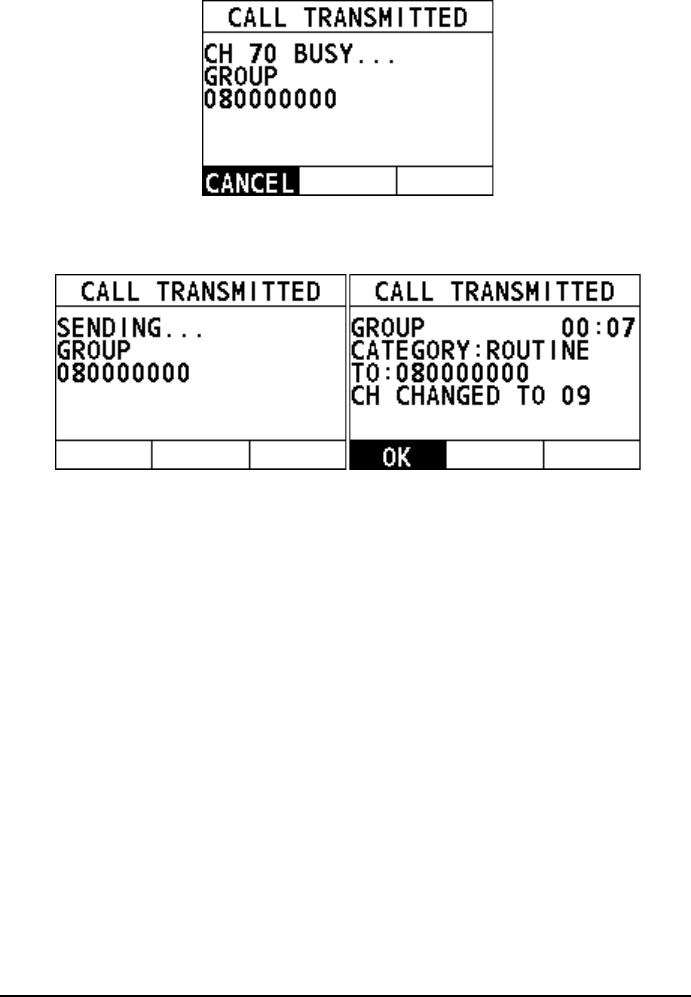
Step 3 Select a channel.
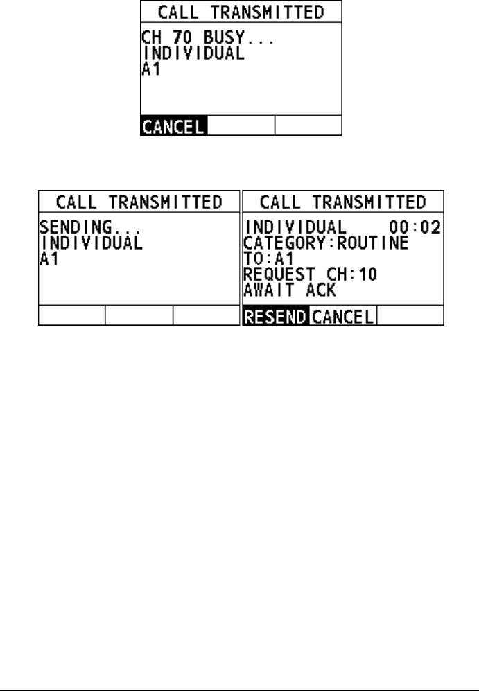
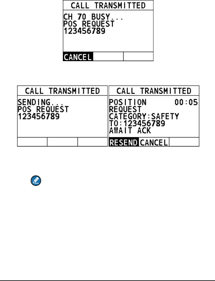
Step 4 Press the Menu/DSC control to initiate an individual call.
When CH70 is busy, the following screen appears. You can wait
without pressing any key until CH70 is idle.

19
When the CH70 is idle, the following screens appear, and the radio
waits for an acknowledgement.
Step 5 When the radio receives an acknowledgement, an alarm sounds and the
working channel changes to the channel selected in Step 3. Select "OK"
on the screen.
Step 6 Press and hold the PTT key to talk into the microphone.
Initiate an individual call from the "RECENT CALLS"
Step 1 On the "INDIVIDUAL" interface, select "RECENT CALLS".
Step 2 Select an individual contact, and then press the Menu/DSC control to
enter the "SELECT CH" interface.
Step 3 Select a channel.
Step 4 Press the Menu/DSC control to initiate an individual call.
When CH70 is busy, the following screen appears. You can wait
without pressing any key until CH70 is idle. "A1" indicates the alias of
called party. If the called party has no alias, the MMSI of called party
will appear.
20
When the CH70 is idle, the following screens appear, and the radio
waits for an acknowledgement.
Step 5 When the radio receives an acknowledgement, an alarm sounds and the
working channel changes to the channel selected in Step 3. Select "OK"
on the screen.
Step 6 Press and hold the PTT key to talk into the microphone.
Initiate an individual call by manually entering an MMSI number
Step 1 On the "INDIVIDUAL" interface, select "MANUAL ID".
Step 2 Enter the MMSI of your desired individual contact, and then press the
Menu/DSC control to enter the "SELECT CH" interface.
Step 3 Select a channel.
Step 4 Press the Menu/DSC control to initiate an individual call.
When CH70 is busy, the following screen appears. You can wait
without pressing any key until CH70 is idle.
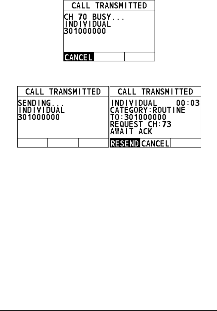
21
When the CH70 is idle, the following screens appear, and the radio
waits for an acknowledgement.
Step 5 When the radio receives an acknowledgement, an alarm sounds and the
working channel changes to the channel selected in Step 3. Select "OK"
on the screen.
Step 6 Press and hold the PTT key to talk into the microphone.
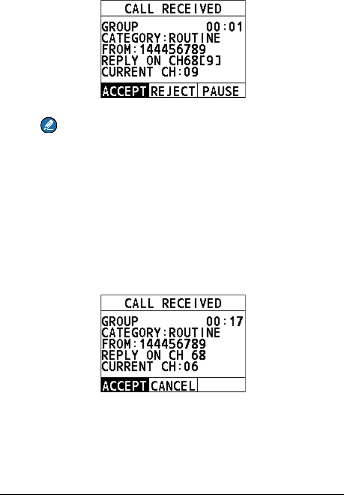
4.4.2 How to Receive an Individual Call
The channel change of your radio has two modes: "AUTO" and "MANUAL". When
you select "AUTO", the radio automatically switch to the designated channel after 10
seconds without user intervention. When selecting "MANUAL", you need to
manually change the channel. For information about how to set the channel change
mode, see section 11.3 Channel Change Mode.
When the channel change mode is "AUTO"
Step 1 When an individual call is received, the alarm sounds. Rotate the
Menu/DSC control to stop the alarm.
The radio screen shows the MMSI of the calling vessel and three soft keys:
"ACCEPT", "REJECT", and "PAUSE". If the requested channel cannot
comply, the screen only shows two soft keys: "REJECT" and "CANCEL".
22
ACCEPT: Select the soft key to continue with the call and switch to the
requested channel.
REJECT: Select the soft key to reject the call. After you select
"REJECT", the following screen appears. Select a reason for rejecting
the call, and then an "UNABLE ACK" message is sent. After the
message is sent, the radio returns to the home screen and the channel
remains unchanged.
PAUSE: Select the soft key to pause the call and timing and temporarily
disable automatic switching to the requested channel. You can resume
the call by pressing the "RESUME" soft key.
Step 2 Select "ACCEPT".
When CH70 is busy, you can wait without pressing any key until CH70
is idle.
When CH70 is idle, the radio sends an acknowledgement and the
requested channel is selected, ready for a conversation.
Note
If no key is pressed within 10 seconds, the radio automatically sends an
acknowledgement and switches to the requested channel when CH70 is idle.
Otherwise, the radio will wait until CH70 is idle.
Step 3 Press and hold the PTT key to talk into the microphone.
23
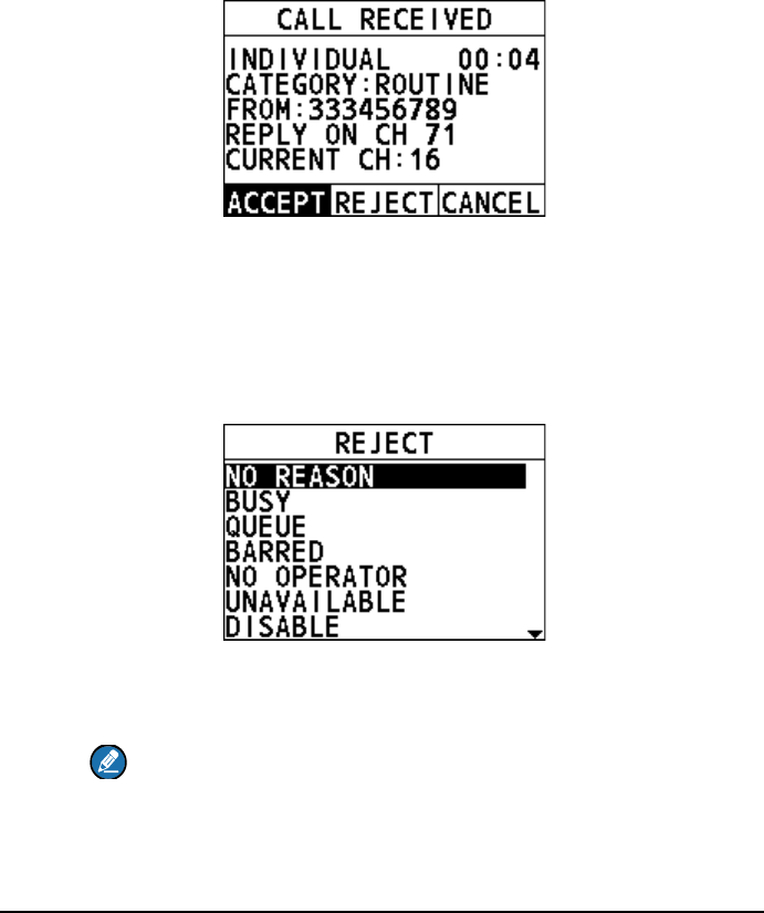
When the channel change mode is "MANUAL"
Step 1 When an individual call is received, the alarm sounds. Rotate the
Menu/DSC control to stop the alarm.
The following screen appears. The screen shows the MMSI of the vessel
calling and three soft keys:"ACCEPT", "REJECT", and "CANCEL". If the
requested channel cannot comply, the screen only shows two soft keys:
"REJECT" and "CANCEL".
ACCEPT: Select the soft key to continue with the call and switch to the
requested channel.
REJECT: Select the soft key to reject the call. After you select
"REJECT", the following screen appears. Select a reason for rejecting
the call, and then an "UNABLE ACK" message is sent. After the
message is sent, the radio returns to the home screen and the channel
remains unchanged.
CANCEL: Select the soft key and then the radio returns to the home
screen and the channel remains unchanged.
Step 2 Select "ACCEPT".
Note
When CH70 is busy, the radio will wait until CH70 is idle.
Then the radio sends an acknowledgement and the requested channel
is selected, ready for a conversation.
Step 3 Press and hold the PTT key to talk into the microphone.
24
4.5 Group Call
This feature allows you to contact a group of specific vessels (for example, members
of a yacht club) using DSC radios that have a group call function. When a group call
is sent, all DSC radios in the group automatically switch to the channel specified in
the call to prepare for voice communications. This feature is useful for yacht clubs
and vessels traveling together that want to collectively make announcements on a
predetermined channel. Up to 40 group call MMSIs can be programmed.
4.5.1 How to Initiate a Group Call
Enter the group call interface
Step 1 On the home screen, press the Menu/DSC control to enter the "MAIN
MENU" screen.
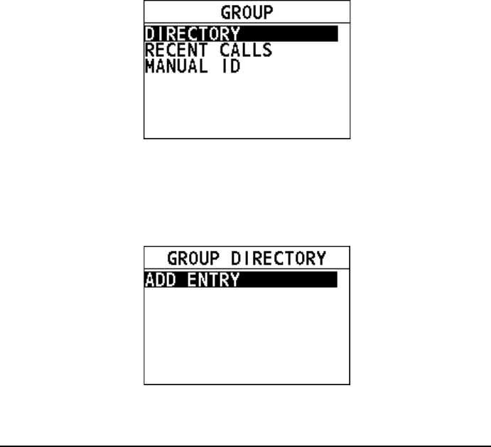
Step 2 Go to "DSC CALL > GROUP".
The "GROUP" interface appears on the screen.
Register a group call
Step 1 On the home screen, press the Menu/DSC control to enter the "MAIN
MENU" screen.
Step 2 Go to "DSC SETUP > GROUP DIRECTORY".
Step 3 Select "ADD ENTRY" to register a group.
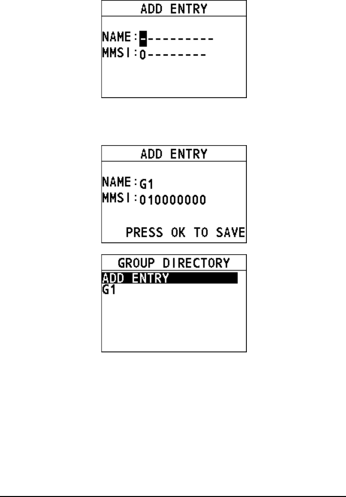
25
Step 4 Rotate and press the Menu/DSC control to enter a new group name and
MMSI.
The maximum of entries is 40.
Initiate a group call to a group registered in the directory
Step 1 On the "GROUP" interface, select "DIRECTORY".
Step 2 Select a group, and then press the Menu/DSC control to enter the
"SELECT CH" interface.
Step 3 Select a channel.
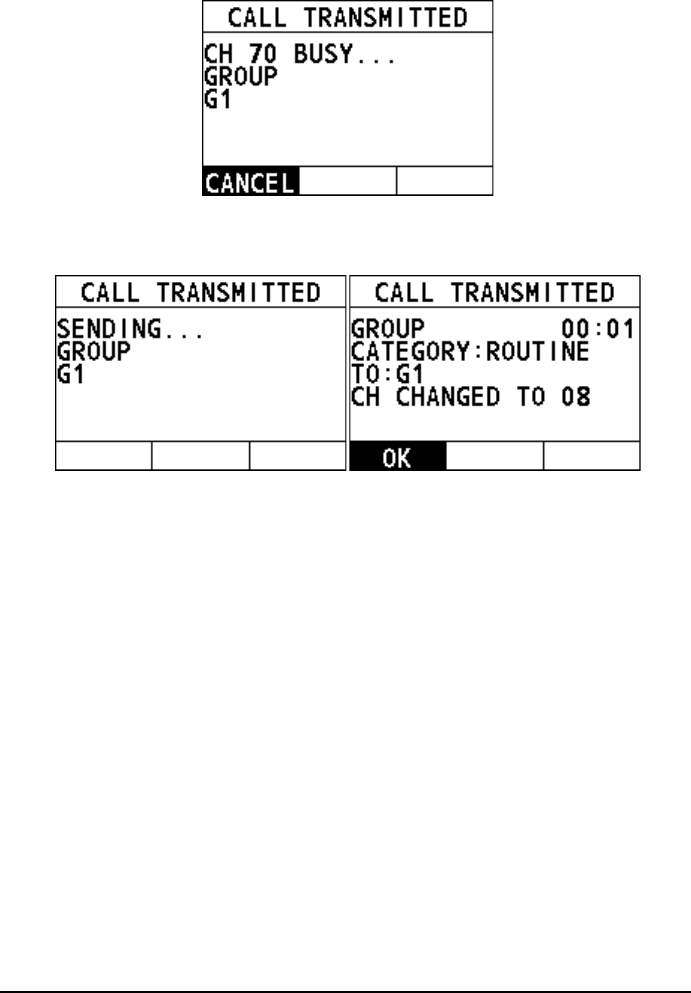
Step 4 Press the Menu/DSC control to initiate a group call.
When CH70 is busy, the following screen appears. You can wait
without pressing any key until CH70 is idle. "G1" is the alias of the
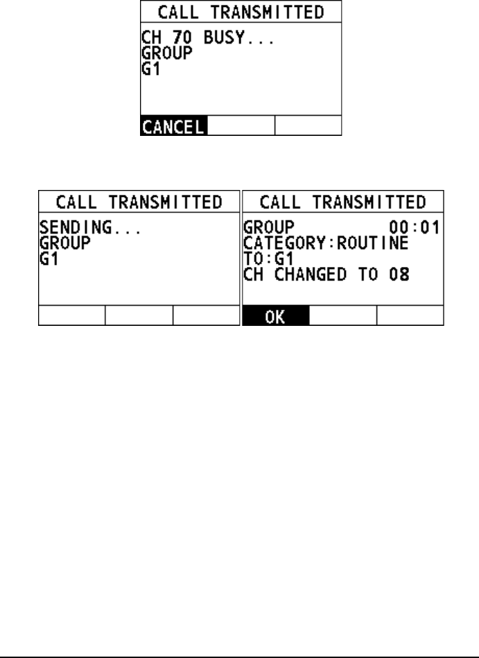
26
group to be called. If the group has no alias, the MMSI of this group will
appear.
When the CH70 is idle, the following screens appear, and the radio
waits for an acknowledgement.
Step 5 Select "OK" to return to the home screen.
Step 6 Press and hold the PTT key to talk into the microphone.
Initiate a group call from the "RECENT CALLS"
Step 1 On the "GROUP" interface, select "RECENT CALLS".
Step 2 Select a group, and then press the Menu/DSC control to enter the
"SELECT CH" interface.
Step 3 Select a channel.
Step 4 Press the Menu/DSC control to initiate a group call.
When CH70 is busy, the following screen appears. You can wait
without pressing any key until CH70 is idle.
27
When the CH70 is idle, the following screens appear, and the radio
waits for an acknowledgement.
Step 5 Select "OK" to return to the home screen.
Step 6 Press and hold the PTT key to talk into the microphone.
Initiate a group call by manually entering a group ID
Step 1 On the "GROUP" interface, select "MANUAL ID".
Step 2 Select a group, and then press the Menu/DSC control to enter the
"SELECT CH" interface.
Step 3 Select a channel.
Step 4 Press the Menu/DSC control to initiate a group call.
When CH70 is busy, the following screen appears. You can wait
without pressing any key until CH70 is idle.
28
When the CH70 is idle, the following screens appear, and the radio
waits for an acknowledgement.
Step 5 Select "OK" to return to the home screen.
Step 6 Press and hold the PTT key to talk into the microphone.
4.5.2 How to Receive a Group Call
When the channel change mode is "AUTO"
Step 1 When a DSC Distress Alert is received, the alarm sounds. Rotate the
Menu/DSC control to stop the alarm.
The screen shows the MMSI of the vessel calling and three soft keys:
"ACCEPT", "CANCEL", and "PAUSE".
ACCEPT: Select the soft key to continue with the call and switch to the
requested channel.
Cancel: Select the soft key to cancel the automatic channel switching.
The radio returns to the home screen and the channel remains
unchanged.
PAUSE: Select the soft key to pause the call and timing. You can
resume the call by pressing the "RESUME" soft key.
29
Step 2 Select "ACCEPT" to switch to the requested channel.
Note
If no key is pressed within 10 seconds, the radio automatically switches to
the requested channel.
Step 3 Press and hold the PTT key to talk into the microphone.
When the channel change mode is "MANUAL"
Step 1 When a DSC Distress Alert is received, the alarm sounds. Rotate the
Menu/DSC control to stop the alarm.
The screen shows the MMSI of the vessel calling and two soft keys:
"ACCEPT" and "PAUSE".
ACCEPT: Select the soft key to continue with the call and switch to the
requested channel.
Cancel: Select the soft key to cancel the call. The radio returns to the
home screen and the channel remains unchanged.
Step 2 Select "ACCEPT" to switch to the requested channel.
Step 3 Press and hold the PTT key to talk into the microphone.
4.6 All Ships Call
This feature allows you to initiate a safety call or an urgency call to DSC-equipped
vessels without having their MMSIs in the directory or receive a safety call or an
urgency call.
30
Safety call: This type of call is used to transmit safety information (for example,
an overdue boat, debris in the water, loss of a navigation aid, and an important
meteorological message) to other vessels. This call is the same as saying
"Security, Security, Security".
Urgency call: This type of call is used when a vessel may not truly be in distress,
but has a potential problem that may lead to a distress situation. This call is the
same as saying "Pan-Pan-Pan" on CH16.
4.6.1 How to Initiate an All Ships Call
Step 1 On the home screen, press the Menu/DSC control to enter the "MAIN
MENU" on the screen.
Step 2 Go to "DSC CALL > ALL SHIPS".
The "ALL SHIPS" interface appears on the screen.
Step 3 Select the category of the call ("SAFETY" or "URGENCY").
Step 4 Select a channel.
Step 5 Press the Menu/DSC control to initiate a group call.
When CH70 is busy, you can wait without pressing any key until CH70
is idle.
When CH70 is idle, the All Ships call is transmitted, and the radio
switches to the selected channel.
Step 6 Select "OK" to return to the home screen.
Step 7 Press and hold the PTT key to talk into the microphone.
31
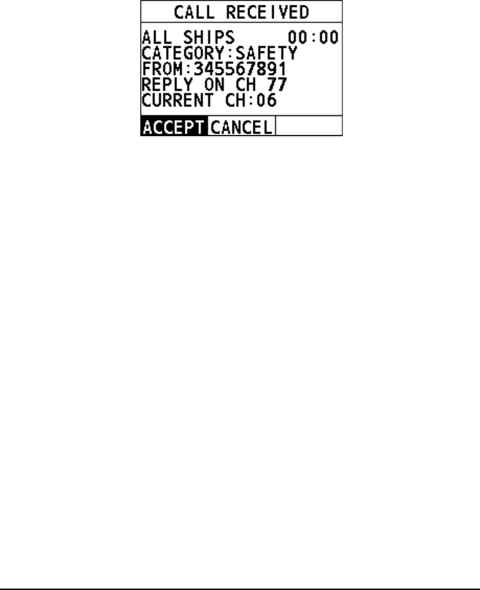
4.6.2 How to Receive an All Ships Call
The channel change of your radio has two modes: "AUTO" and "MANUAL". Different
channel change modes lead to different operations when you receive an All Ships
call. For information about how to set the channel change mode, see section 11.3
Channel Change Mode.
When the channel change mode is "AUTO"
Step 1 When an All Ships call is received, an emergency alarm sounds. Rotate
the Menu/DSC key to stop the alarm.
The following screen appears. The screen shows the MMSI of the vessel
calling and three soft keys:"ACCEPT","CANCEL", and "PAUSE". If the
requested channel cannot comply, the screen only shows the "CANCEL"
soft key.
ACCEPT: Select the soft key to continue with the call and switch to the
requested channel.
CANCEL: Select the soft key to cancel the automatic channel switching.
The radio returns to the home screen and the channel remains
unchanged.
PAUSE: Select the soft key to pause the call and timing and temporarily
disable automatic switching to the requested channel. You can resume
the call by pressing the "RESUME" soft key.
Note
If no key is pressed within 10 seconds, the radio automatically
switches to the requested channel. After 10 seconds, the
countdown appears next to "REPLY ON CH16".
[10] indicates that the 10 seconds countdown appears next to
"REPLY ON CH16".
Step 2 Select "ACCEPT" to continue with the call.
The radio monitors the reply on channel until the All Ships call is
completed.
32
When the channel change mode is "MANUAL"
Step 1 When an All Ships call is received, an emergency alarm sounds. Press
any key to stop the alarm.
The following screen appears. The screen shows the MMSI of the vessel
calling and two soft keys: "ACCEPT" and "CANCEL". If the requested
channel cannot comply, the screen only shows the "CANCEL" soft key.
ACCEPT: Select the soft key to continue with the call and switch to the
requested channel.
CANCEL: Select the soft key and then the radio returns to the home
screen and the channel remains unchanged.
Step 2 Select "ACCEPT" to continue with the call.
The radio monitors the requested channel until the All Ships call is
completed.
4.7 Position Request Call
The radio with DSC the feature can poll the location of another vessel and show the
position of that vessel on the radio screen.
4.7.1 How to Initiate a Position Request Call
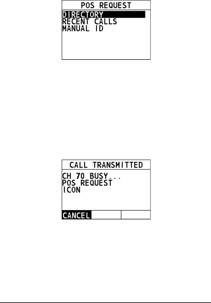
Enter the position request interface
Step 1 On the home screen, press the Menu/DSC control to enter the "MAIN
MENU" interface on the screen.
Step 2 Go to "DSC CALL > POS REQUEST".
The "POS REQUEST" interface appears on the radio screen.
33
Initiate a position request call to a vessel registered in the
directory
Before you initiate a position request call from the individual directory, a vessel or
person's name and the MMSI number associated with the vessel you want to
transmit the call should be added to the individual directory. For information about
how to add entries to individual directory, see section 11.1.1 Adding an Entry.
Step 1 On the "POS REQUEST" interface, press the Menu/DSC control to select
"DIRECTORY".
Step 2 Select an individual contact, and then press the Menu/DSC control.
When CH70 is busy, the following screen appears. You can wait
without pressing any key until CH70 is idle.
When the CH70 is idle, the following screens appear, and the radio
waits for an acknowledgement.
34
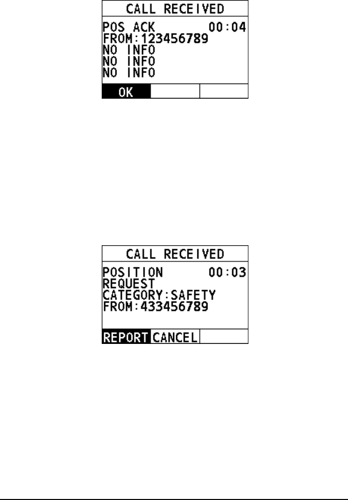
Step 3 When the radio receives an acknowledgement, the radio screen shows
the requested position information. Select the "OK" soft key or the Back
key to return to the home screen.
Note
If the requested vessel cannot obtain its position, your radio will
receive false position information as shown below.
Initiate a position request call from the "RECENT CALLS"
Step 1 On the "POS REQUEST" interface, select "RECENT CALLS".
Step 2 Select an individual contact, and then press the Menu/DSC control.
When CH70 is busy, the following screen appears. You can wait
without pressing any key until CH70 is idle.
35
When the CH70 is idle, the following screens appear, and the radio
waits for an acknowledgement.
Step 3 When the radio receives an acknowledgement, the radio screen shows
the requested position information. Select the "OK" soft key or the Back
key to return to the home screen.
Note
If the requested vessel cannot obtain its position, your radio will
receive false position information as shown below.
Initiate position request call by manually entering an MMSI
number
Step 1 On the "POS REQUEST" interface, select "MANUAL ID".
36
Step 2 Rotate and press the Menu/DSC control to enter the MMSI of an individual
contact, and then press the Menu/DSC control.
When CH70 is busy, the following screen appears. You can wait
without pressing any key until CH70 is idle.
When the CH70 is idle, the following screens appear, and the radio
waits for an acknowledgement.
Step 3 When the radio receives an acknowledgement, the radio screen shows
the requested position information. Select the "OK" soft key or the Back
key to return to the home screen.
Note
If the requested vessel cannot obtain its position, your radio will
receive false position information as shown below.
37
4.7.2 How to Receive a Position Request Call
The "POSITION ACK" has three options: "MANUAL", "AUTO", and "IGNORE". For
information about how to set the "POSITION ACK", see section 11.5 Position
Acknowledgement. When "POSITION ACK" is set to "IGNORE", your radio has no
response or log. When it is set to other values, do as follows.
When "POSITION ACK" is set to "MANUAL"
Step 1 When a DSC position request call is received, the alarm sounds. Rotate
the Menu/DSC control to stop the alarm.
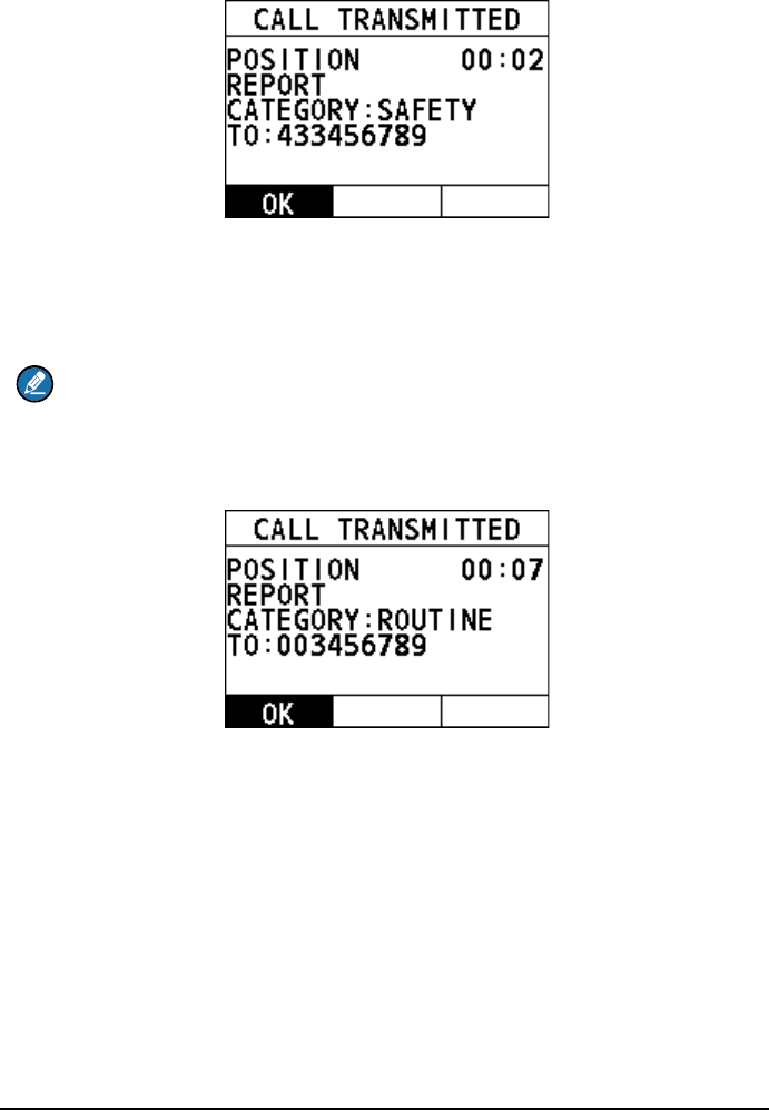
Step 2 Select "REPORT" to send your position.
When CH70 is busy, you can wait without pressing any key until CH70
is idle.
When CH70 is idle, the radio sends an acknowledgement and the
position is transmitted.
Step 3 After the position is transmitted, select "OK" to return to the home screen.
38
When "POSITION ACK" is set to "AUTO"
When a DSC position request call is received, the radio automatically sends the
position information to the requested radio.
Note
When CH70 is busy, you can wait without pressing any key until CH70 is idle.
Then the radio automatically sends the position information.
After the position information is sent, the following interface appears on the screen.
Select "OK" to return to the home screen.
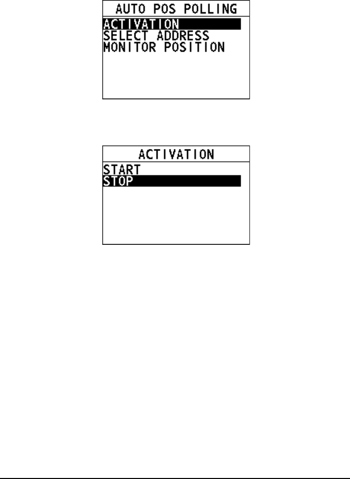
4.8 Auto Position Polling
This feature allows FM-4800 to automatically send a position request call at certain
intervals.
This feature must first be enabled from the "ACTIVATION" menu, then the vessel
addresses must be set from the "SELECT ADDRESS" menu.
Also, you can monitor the position of the selected vessel from the "MONITOR
POSITION" menu.
4.8.1 How to Enable the Auto Position Polling
Step 1 On the home screen, press the Menu/DSC control to enter the "MAIN
MENU" screen.
39
Step 2 Go to "DSC CALL > AUTO POS POLLING".
The "AUTO POS POLLING" interface appears on the screen.
Step 3 Select "ACTIVATION".
The "ACTIVATION" interface appears on the screen. The screen shows
two soft keys: "START" and "STOP".
START: Select the soft key to start automatic position polling. If there is
no address to poll, the radio rings the wrong beep.
STOP: Select the soft key to stop automatic position polling.
Step 4 Select "START" to activate the automatic position polling.
The radio returns to the previous screen.
4.8.2 How to Select Vessels to Which the Radio Sends Auto
Position Request Calls
Step 1 On the home screen, press the Menu/DSC control to enter the "MAIN
MENU" screen.
Step 2 Go to "DSC CALL > AUTO POS POLLING".
The "AUTO POS POLLING" interface appears on the screen.
40
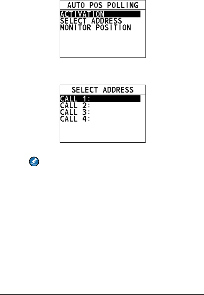
Step 3 Select "SELECT ADDRESS".
The "SELECT ADDRESS" interface appears on the screen.
You can add at most four directories.
Step 4 Select a directory.
Note
You need to select at least one directory first to start the auto
position polling.
4.8.3 How to Monitor Position
Step 1 On the home screen, press the Menu/DSC control to enter the "MAIN
MENU" screen.
Step 2 Go to "DSC CALL > AUTO POS POLLING".
The "AUTO POS POLLING" interface appears on the screen.
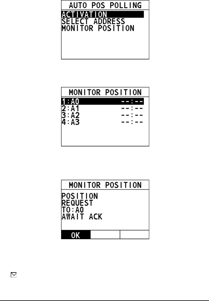
41
Step 3 Select "MONITOR POSITION".
The "MONITOR POSITION" interface appears on the screen. "A0-A3"
indicated the alias.
Step 4 Select a directory to view the latest position information of the
corresponding vessel.
If the radio does not receive an acknowledgement, the display shows the
following interface.
Step 5 Select "OK" to return to the previous screen.
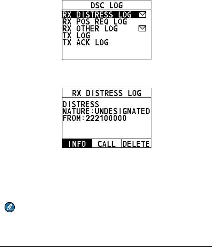
4.9 DSC Log
This feature allows the FM-4800 to record calls for review.
A icon appears in the log to indicate an unread received call message. The
FM-4800 can store logs for the latest 40 received distress calls, the latest 10
received position request calls, the latest 40 received other calls, the latest 40
transmitted calls, and the latest 10 transmitted acknowledges.
42
The "RX POS REQ LOG" and "TX ACK LOG" are cleared each time the equipment
is restarted.
To view a log, do as follows:
Step 1 On the home screen, press the Menu/DSC control to enter the "MAIN
MENU" screen.
Step 2 Select "DSC CALL".
Step 3 Select "DSC LOG" to enter the "DSC LOG" interface on the screen.
Step 4 Select the DSC log type you want to view.
Step 5 Select a log you want to view.
You can initiate the call again or delete the log by pressing the "CALL" or
"DELETE" soft key on the screen.
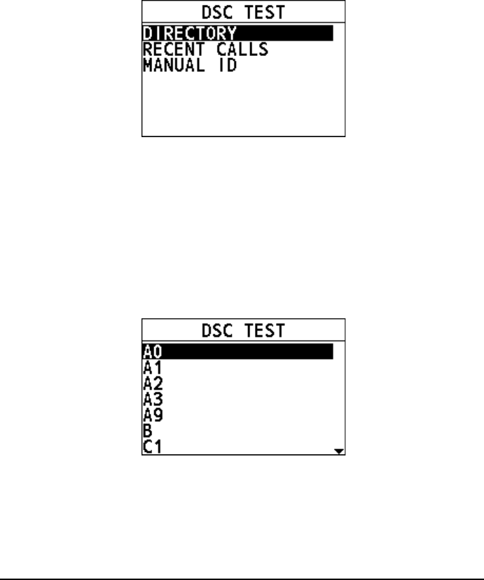
4.10 DSC Test
This feature allows you to test whether your DSC radio can communicate normally
with another DSC radio. To use this feature, the radio that you send the test call to
must have the DSC Test feature. After the DSC test, voice communication is not
allowed.
Note
To make a DSC test call, this vessel’s MMSI number must be entered into the
radio. For information about how to enter the MMSI number, see section 4.2.2
How to Enter Your MMSI Number.
43
Enter the DSC test interface
Step 1 On the home screen, press the Menu/DSC control to enter the "MAIN
MENU" screen.
Step 2 Select "DSC CALL".
Step 3 Select "DSC TEST" to enter the "DSC TEST" interface on the screen, as
shown below.
Initiate a DSC test call to a vessel registered in the individual
directory
Before you initiate a DSC test call from the individual directory, a vessel or person's
name and the MMSI number associated with the vessel you want to transmit the call
to should be added to the individual directory. For information about how to add
entries to individual directory, see section 11.1.1 Adding an Entry.
Step 1 On the "DSC TEST" interface, select "DIRECTORY".
Step 2 Select an individual contact.
Step 3 Press the Menu/DSC control to send the DSC test call.
Your radio waits for an acknowledgement from the radio you called.
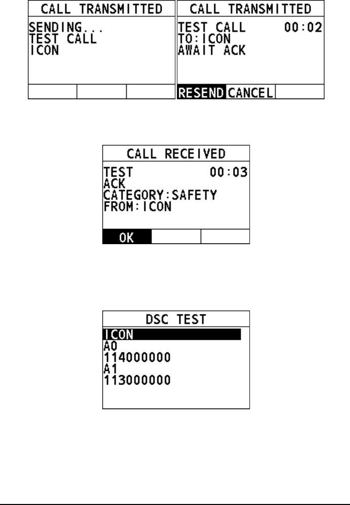
44
Step 4 When the radio receives an acknowledgement, an alarm sounds and the
following page appears. It means the radio you called has received the call.
Select "OK" to return to the previous screen.
Initiate a DSC test call from the "RECENT CALLS"
Step 1 On the "DSC TEST" interface, select "RECENT CALLS".
Step 2 Select an individual contact.
Step 3 Press the Menu/DSC control to send the DSC test call.
Your radio waits for an acknowledgement from the radio you called.
45
Step 4 When the radio receives an acknowledgement, an alarm sounds and the
following page appears. It means the radio you called has received the call.
Select "OK" to return to the previous screen.
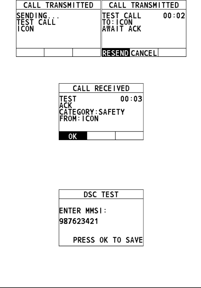
Initiate a DSC test call by manually entering an MMSI number
Step 1 On the "DSC TEST" interface, rotate and press the Menu/DSC control to
select "MANUAL ID".
Step 2 Rotate and press the MENU/DSC control to enter the MMSI of a vessel
that you want to contact.
Step 3 Press the Menu/DSC control to send the DSC test call.
Your radio waits for an acknowledgement from the radio you called.
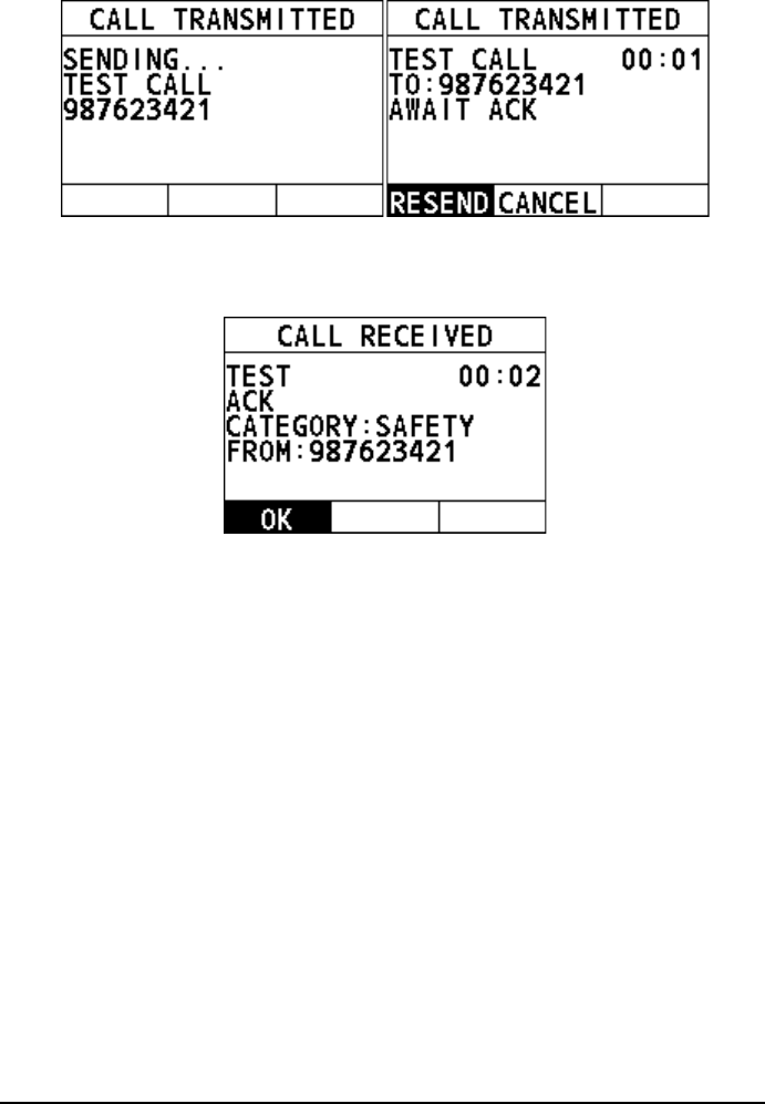
46
Step 4 When the radio receives an acknowledgement, an alarm sounds and the
following page appears. It means the radio you called has received the call.
Select "OK" to return to the previous screen.
47
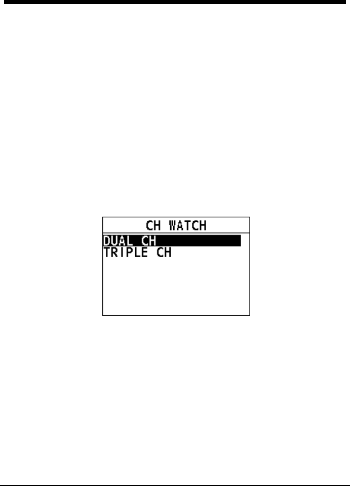
5. CHANNEL WATCH
5.1 Dual Channel
Dual channel scans two channels for communications. One channel is a normal VHF
channel and the other is CH16. The following is how the DUAL CH feature works
when a signal is received on one of the channel:
If a signal is received on the normal channel, the radio quickly switches between
the normal channel and CH16 to look for a transmission.
If a signal is received on CH16, the radio stops and listens only to CH16 until
communication ends and then starts DUAL CH scan again.
Step 1 Press and rotate the Volume/Squelch control to adjust the squelch until
the background noise disappears.
Step 2 On the home screen, rotate the Menu/DSC control to select a channel to
DUAL CH with CH16.
Step 3 Press the Menu/DSC control to enter the "MAIN MENU" interface.
Step 4 Select "CH WATCH".
Step 5 Select "DUAL WATCH".
The radio returns to the home screen. The display alternately scans
between CH16 and the channel that is selected in step 2.
Step 6 To stop DUAL WATCH, press the Back key or the Menu/DSC control.
5.2 Triple Channel
Triple channel scans three channels for communications: CH16, the second priority
channel, and a normal VHF channel. The following is how the TRIPLE CH feature
works:
If a signal is received on the normal channel, the radio quickly switches among
the normal channel, second priority channel, and CH16 to look for a
transmission.

48
If a signal is received on CH16, the radio stops and listens only to CH16 until
communication ends and then starts TRIPLE CH scan again.
For information about how to set the second priority channel, see section 10.2
Second Priority Channel.
Step 1 Press and rotate the Volume/Squelch control to adjust the squelch until
the background noise disappears.
Step 2 On the home screen, rotate the Menu/DSC control to select a channel to
watch with CH16 and the second priority channel.
Step 3 Press the Menu/DSC control to enter the "MAIN MENU" interface.
Step 4 Select "CH WATCH".
Step 5 Select "TRIPLE CH"
The radio returns to the home screen. The display alternately scans
among CH16, the second priority channel, and the channel that is selected
in step 2.
Step 6 To stop TRIPLE CH, press the Back key or the Menu/DSC control.

49
6. SCAN
This feature allows you to select a scan mode to find the broadcasting channels. The
available scan modes are as follows: SCAN ALL, SCAN ALL + 16, MEMORY SCAN,
and MEMORY SCAN + 16.
6.1 Scan All
Scan All mode scans all channels in sequence.
Step 1 On the home screen, press the Menu/DSC control to enter the "MAIN
MENU" screen.
Step 2 Go to "SCAN > SCAN ALL".
The radio starts to scan all channels.
Step 3 To stop scanning, press the Back key or the Menu/DSC control.
6.2 Scan All + 16
Scan All + 16 mode scans all channels in sequence, and checks CH16 between two
channels.
Step 1 On the home screen, press the Menu/DSC control to enter the "MAIN
MENU" screen.
Step 2 Go to "SCAN > SCAN ALL+16".
The radio starts to scan all channels in sequence, and checks CH16 after
each programmed channel.
Step 3 To stop scanning, press the Back key or the Menu/DSC control.
6.3 Memory Scan
Memory Scan mode scans all memory channels in sequence.
Note
Before you enable the Memory Scan mode, at least two channels should be set
as memory channels. For information about how to set memory channels, see
section 6.5 Editing Memory Channel List.
Step 1 On the home screen, press the Menu/DSC control to enter the "MAIN
MENU" screen.
Step 2 Go to "SCAN > MEMORY SCAN".
The radio starts to scan all memory channels in sequence.
Step 3 To stop scanning, press the Back key or the Menu/DSC control.
50
6.4 Memory Scan + 16
Memory Scan + 16 mode scans all memory channels in sequence, and checks
CH16 after each programmed channel.
Note
Before you enable the Memory Scan +16 mode, at least one channel should be
set as the memory channel. For information about how to set memory channels,
see section 6.5 Editing Memory Channel List.
Step 1 On the home screen, press the Menu/DSC control to enter the "MAIN
MENU" screen.
Step 2 Go to "SCAN > MEMORY SCAN+16".
The radio starts to scan all memory channels in sequence, and checks
CH16 after each memory channel.
Step 3 To stop scanning, press the Back key or the Menu/DSC control.
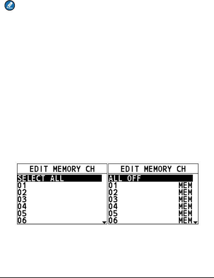
6.5 Editing Memory Channel List
This feature allows you to add channels to or remove channels from the memory
channel list. Channels in the memory channel list are what the Memory Scan mode
scans.
How to add all channels to the memory channel list
Step 1 On the home screen, press the Menu/DSC control to enter the "MAIN
MENU" screen.
Step 2 Go to "SCAN > EDIT MEMORY CH > SELECT ALL".
"MEM" icons appear after each channel number.
Step 3 Press the Back key to return to the previous screen.
How to remove all channels from the memory channel list
When all programmed channels are added to the memory channel list, you can do
as follows to remove all channels from the list.
51
Step 1 On the home screen, press the Menu/DSC control to enter the "MAIN
MENU" screen.
Step 2 Go to "SCAN > EDIT MEMORY CH > ALL OFF".
"MEM" icons disappear on the display.
Step 3 Press the Back key to return to the previous screen.
How to add a channel to the memory channel list
Step 1 On the home screen, press the Menu/DSC control to enter the "MAIN
MENU" screen.
Step 2 Select "SCAN > EDIT MEMORY CH".
Step 3 Select a channel to be scanned.
Step 4 Press the Menu/DSC control to set the channel to a memory channel.
The "MEM" icon appears on the display.
Step 5 Press the Back key to return to the previous screen.
How to remove a channel from the memory channel list
Step 1 On the home screen, press the Menu/DSC control to enter the "MAIN
MENU" screen.
Step 2 Select "SCAN > EDIT MEMORY CH".
Step 3 Rotate the Menu/DSC control to select a channel to be removed from the
memory channel list.

52
Step 4 Press the Menu/DSC control to remove the channel from the memory
channel list.
The "MEM" icon disappears on the display.
Step 5 Press the Back key to return to the previous screen.
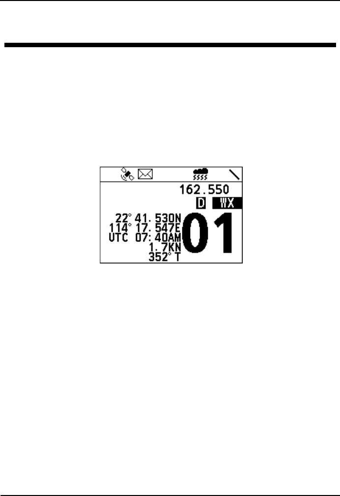
7 Weather Mode
53
7. Weather Mode
When the product works on the USA or CAN channel, the weather mode is enabled.
In this case, you can monitor the weather report from National Oceanographic and
Atmospheric Administration (NOAA).
Weather mode
Step 1 Press the Menu/DSC control until the "MAIN MENU" screen appears.
Step 2 Select "WEATHER MODE".
The weather mode interface appears on the screen.
In weather mode, you can rotate the Menu/DSC to select a NOAA channel to
monitor. What you selected would be mark as last used weather channel.
NOAA weather alert
In the event of extreme weather disturbances, such as storms and hurricanes, the
NOAA sends a weather alert accompanied by a 1050Hz tone and subsequent
weather report on one of the NOAA weather channels.
Step 1 Press the Menu/DSC control until the "MAIN MENU" screen appears.
Step 2 Select "GENERAL SETUP >WEATHER ALERT".

54
Step 3 Select ON or OFF to enable or disable the feature.
Step 4 Press the Menu/DSC control to save the setting and return to the previous
interface.
7 Fog Horn/Hailer/Intercom
55
8. Fog Horn/Hailer/Intercom
Note
When receiving DSC calls in the Fog Horn mode or the Hailer mode, the radio
exits the Fog Horn mode or the Hailer mode and enters the call receiving
interface.
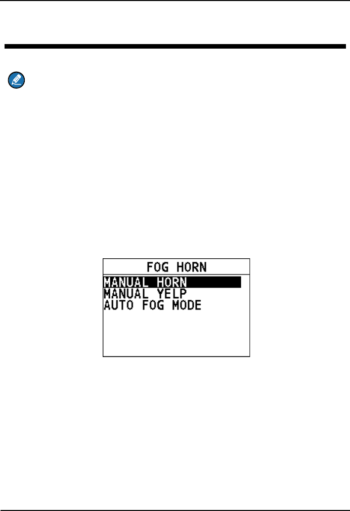
8.1 Fog Horn
This feature sounds certain international standard fog horn tones through the
speaker. This feature is available only when the radio is connected to a hailer.
Enter the "FOG HORN" interface
Step 1 On the home screen, press the Menu/DSC control to enter the "MAIN
MENU" screen.
Step 2 Go to "COMMUNICATIONS > FOG HORN".
The "FOG HORN" interface appears on the screen.
Use the manual horn
The Manual Horn feature allows you to manually start the predefined fog horn.
Step 1 On the "FOG HORN" interface, select "MANUAL HORN".
Step 2 Press and hold the PTT key to sound the fog horn.
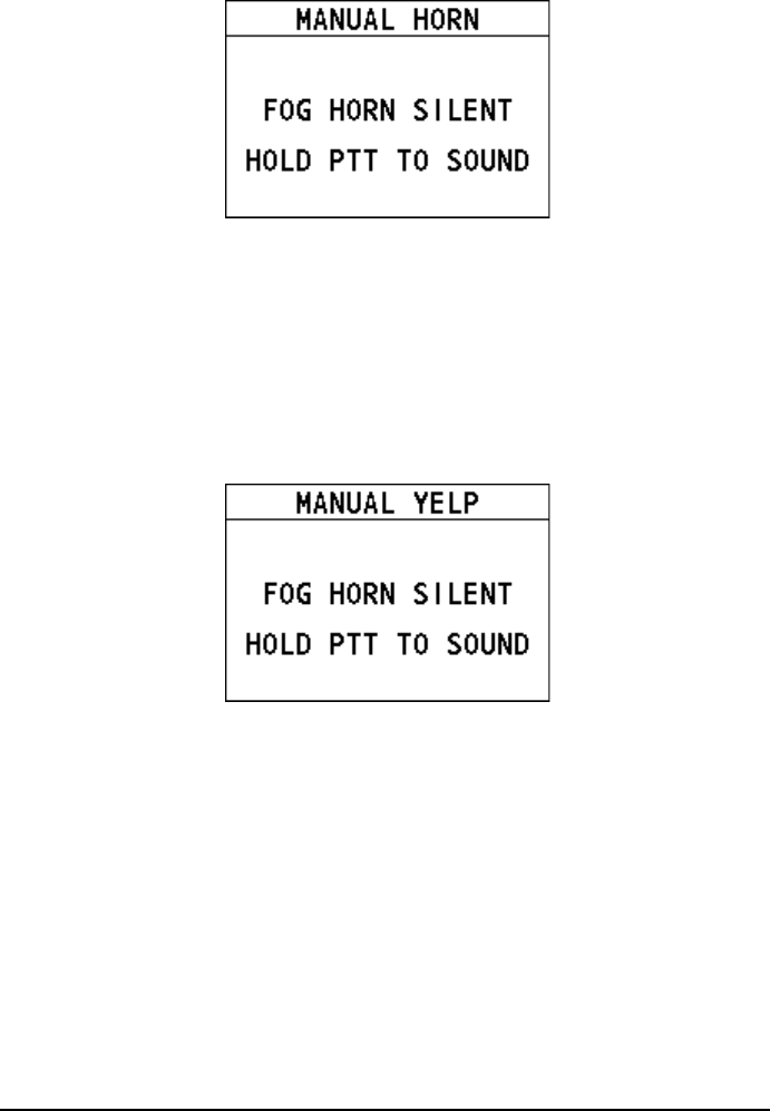
56
Step 3 To stop the fog horn, release the PTT key.
Step 4 Press the Back key to return to the previous screen.
Use the manual yelp
The Manual Yelp feature allows you to manually start the predefined alarm in
emergencies.
Step 1 On the "FOG HORN" interface, select "MANUAL YELP".
Step 2 Press and hold the PTT key to sound the alarm.
Step 3 To stop the alarm, release the PTT key.
Step 4 Press the Back key to return to the previous screen.
Use the auto horn
The Auto Horn feature allows the radio to sound certain international standard fog
horn tones. When a horn sounds, it cannot be stopped manually.
Step 1 On the "FOG HORN" interface, select "AUTO FOG MODE".
Step 2 Select a horn according to your purpose.
Then the horn sounds.
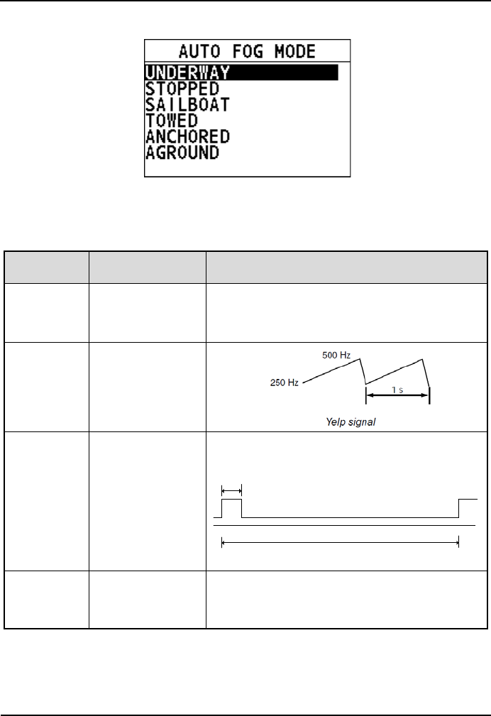
7 Fog Horn/Hailer/Intercom
57
5s
120s
Underway Signal
Step 3 When the horn is silent, press the Back key to return to the previous
screen.
Sound warning signals
Warning
Signal
Function
Remarks
Manual
For ship passing.
The lengths and timing of the horn blasts are
controlled by pressing and holding the PTT key
on the microphone.
Yelp
For emergency
siren.
Underway
For power-driven
vessels
underway.
One 5-second blast at 120-second interval.
Stopped
For power-driven
vessel that is
stationary.
Two 3-second blasts, with a 2-second interval
between each blast, repeated every 120
seconds.
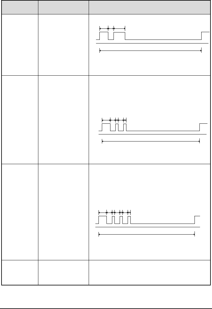
58
Warning
Signal
Function
Remarks
Sailboat
For sailboats, tug
boats and tow
boats underway.
One 3-secondblast, followed by one 2-second
interval, one 1-second blast, one
2-secondinterval and one 1-second blast.
Repeated every 120 seconds.
Towed
For vessels under
tow.
One 3-second blast, followed by one2-second
interval, one 1-second blast, one 2-second
interval, one 1-second blast, one 2-second
interval, and one 1-second blast. Repeated
every 120 seconds.
Anchored
For vessels at
anchor.
A rapidly ringing bell tone sounds for about 5
seconds, repeated at an interval of 60
seconds.
3s
120s
2s 3s
Stopped Signal
3s
120s
2s 1s 2s1s
Sailboat Signal
3s
120s
2s 1s 2s1s 1s2s
Towed Signal
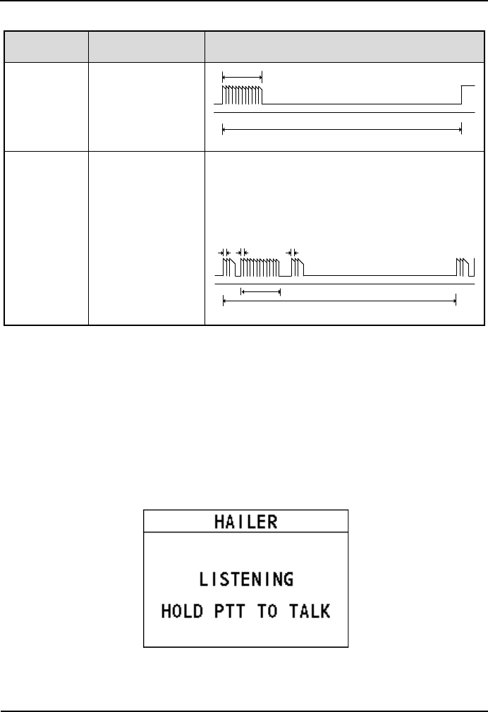
7 Fog Horn/Hailer/Intercom
59
Warning
Signal
Function
Remarks
5s
120s
Anchored Signal
Aground
For vessels
aground.
Two bell tones of 0.5 seconds, a bell tone of1.5
second followed by a rapidly ringing bell tone
for a duration of about 5 seconds, followed by
two bell tone of 0.5 seconds and a bell tone of
1.5seconds. Repeated once every 60seconds.
0.5s
60s
0.5s 0.5s
5s
Aground Signal
8.2 Hailer
The Hailer feature allows you to make an announcement at a high volume to people
using a hailer and listen to the response from the hailer.
Step 1 On the home screen, press the Menu/DSC control to enter the "MAIN
MENU" screen.
Step 2 Go to "COMMUNICATIONS > HAILER".
The "HAILER" interface appears on the screen.
You can adjust the listening volume.
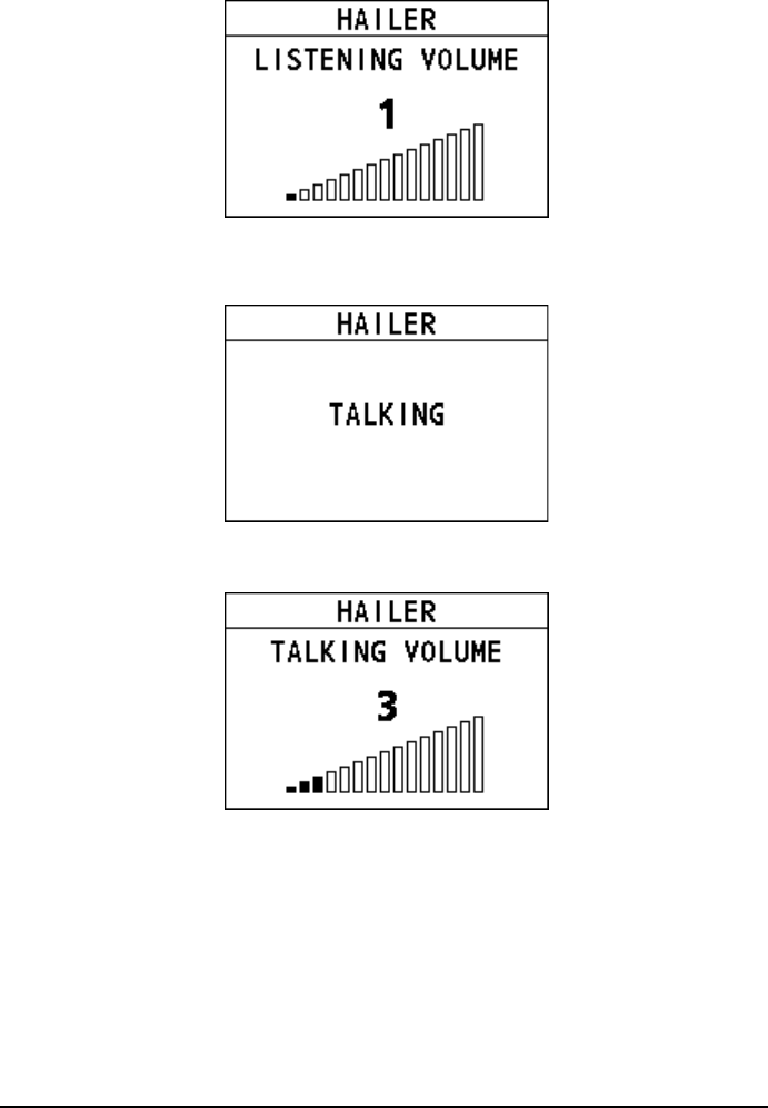
60
Step 3 Press and hold the PTT key to talk.
Step 4 Release the PTT key to listen to the response from the hailer.
You can adjust the talking volume.
Step 5 Press the Back key to return to the previous screen.
8.3 Intercom
The Intercom feature allows the intercommunication between the radio and a
handset. This feature is available only when your radio is equipped with handset, or
a microphone.
Step 1 On the home screen, press the Menu/DSC control to enter the "MAIN
MENU" screen.
Step 2 Go to "COMMUNICATIONS > INTERCOM".
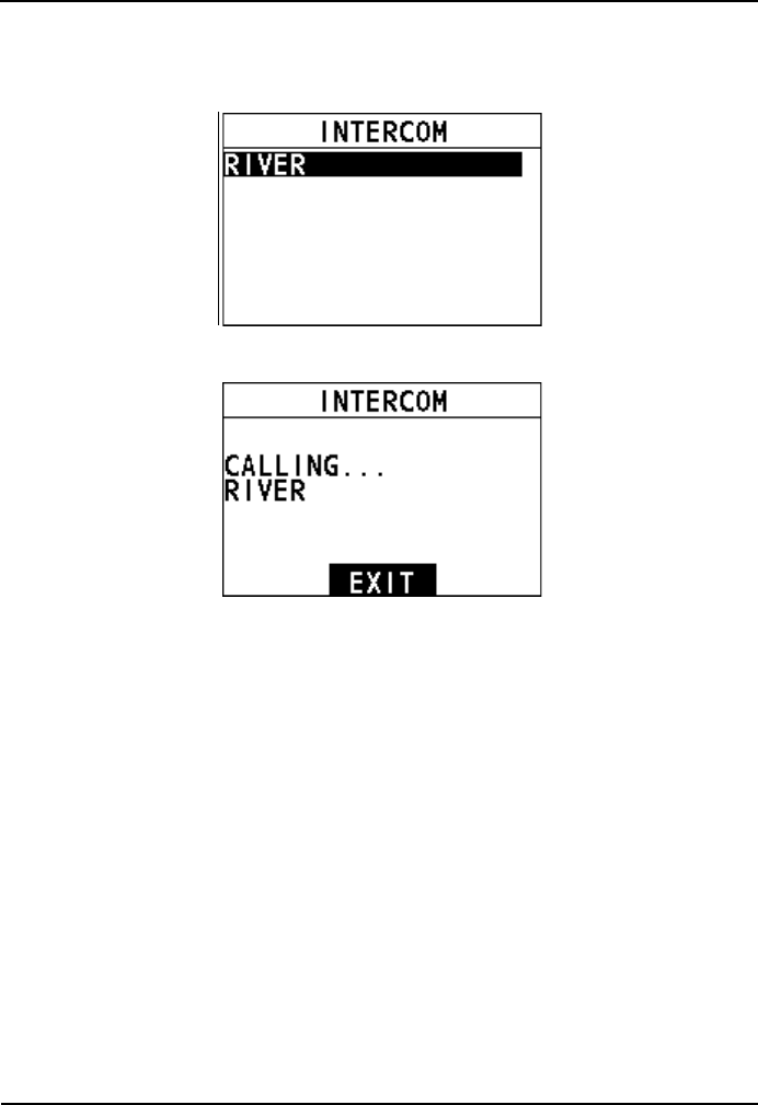
7 Fog Horn/Hailer/Intercom
61
The "INTERCOM" interface appears on the screen. Here "River" is the
alias of handset to be connected remotely.
Step 3 Select the handset to initiate a call.
Step 4 Press and hold the PTT key to talk.
Step 5 Release the PTT key to listen to the response from the handset.
You can adjust the receiving volume after releasing the PTT key.
Step 6 When the call is over, press the Back key to return to the previous screen.
8.4 Edit Handset Name
You can customize the handset name after the handset connects to the product
remotely. After that, the handset name is saved and displayed on any connected
product.
To edit the handset name, do as follows:
Step 1 Press the Menu/DSC control until the "MAIN MENU" screen appears.
Step 2 Select "FOG/HAILER/IC".
The " FOG/HAILER/IC " interface appears on the screen.
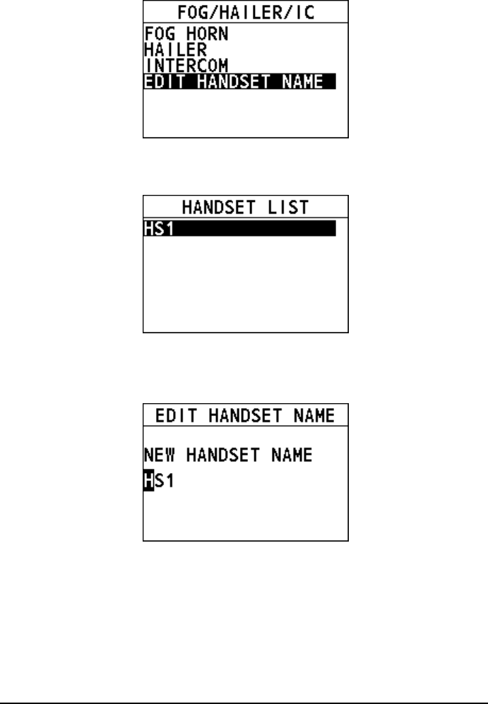
62
Step 3 Select "EDIT HANDSET NAME".
The “HANDSET LIST” interface appears on the screen.
Step 4 Select a desired handset.
Step 5 Rotate and press the Menu/DSC control to enter a new handset name for
the current selected handset.
Step 6 Press the Menu/DSC control to save the new handset name and return to
the previous screen.

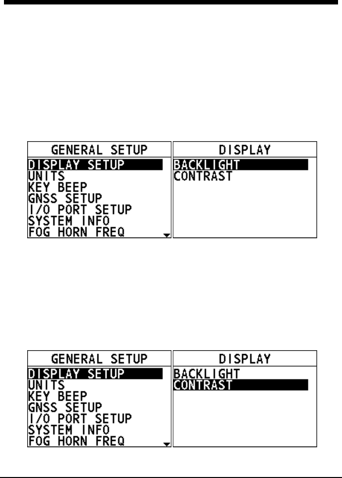
64
10. GENERAL SETUP
10.1 Display Setup
This feature allows you to set the backlight and contrast of the screen.
10.1.1 Adjusting the Backlight
Step 1 On the home screen, press the Menu/DSC control to enter the "MAIN
MENU" screen.
Step 2 Go to "GENERAL SETUP > DISPLAY SETUP".
The "DISPLAY" interface appears on the screen.
Step 3 Select "BACKLIGHT".
Step 4 Rotate the Menu/DSC control to adjust the backlight.
10.1.2 Adjusting the Contrast
Step 1 On the home screen, press the Menu/DSC control to enter the "MAIN
MENU" screen.
Step 2 Go to "GENERAL SETUP > DISPLAY SETUP".
The "DISPLAY" interface appears on the screen.
Step 3 Select "CONTRAST".
Step 4 Rotate the Menu/DSC control to adjust the contrast.
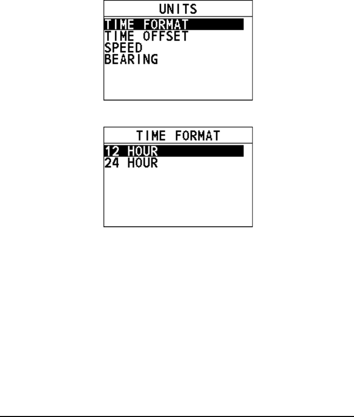
65
10.2 Units
10.2.1 Time Format
This feature allows you to set how the time displays on the radio screen.
Step 1 Press the Menu/DSC control until the "MAIN MENU" screen appears.
Step 2 Go to "GENERAL SETUP > UNITS > TIME FORMAT".
Step 3 Select "12 HOUR" or "24 HOUR".
Step 4 Press the Menu/DSC control to save the setting and return to the previous
interface.
10.2.2 Time Offset
This feature allows you to set the time difference between UTC and local time if you
want to use local time. The offset is added to or subtracted from the time received
from the GNSS receiver or chart plotter.
Step 1 Press the Menu/DSC control until the "MAIN MENU" screen appears.
Step 2 Go to "GENERAL SETUP > UNITS > TIME OFFSET".
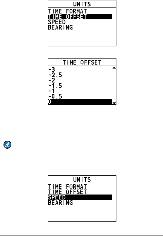
66
Step 3 Select the time offset of your location.
Step 4 Press the Menu/DSC control to save the setting and return to the previous
interface.
10.2.3 Speed
This feature allows you to set the unit of measurement for sailing speed.
Note
A GNSS receiver should be connected to the radio or the "INTERNAL GNSS"
should be set to "ON" to show the sailing speed.
Step 1 Press the Menu/DSC control until the "MAIN MENU" screen appears.
Step 2 Go to "GENERAL SETUP > UNITS > SPEED".
Step 3 Select a unit.
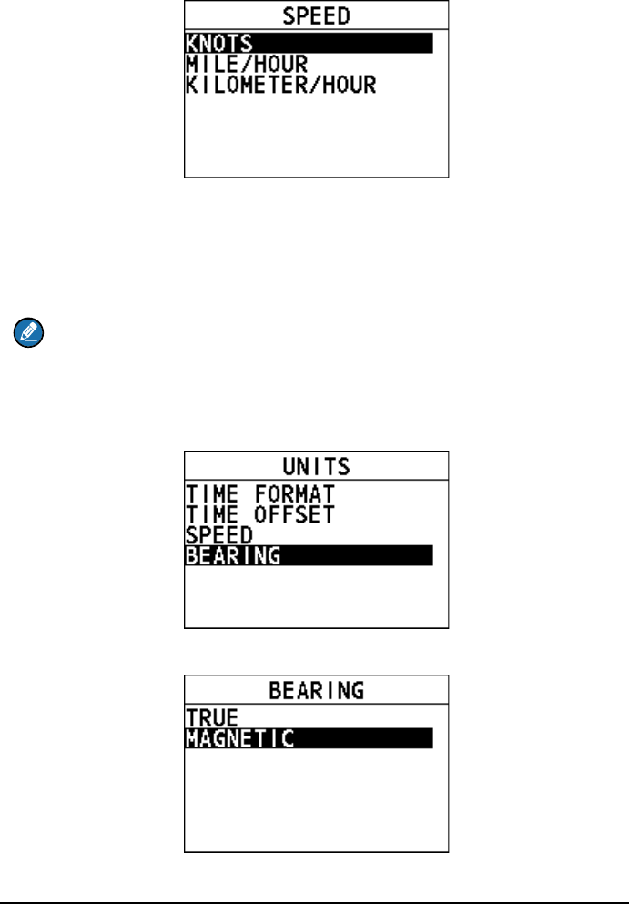
67
Step 4 Press the Menu/DSC control to save the setting and return to the previous
interface.
10.2.4 Bearing
This feature allows you to set the mode (magnetic or true).
Note
A GNSS receiver should be connected to the radio or the "INTERNAL GNSS"
should be set to "ON" to show the bearing.
Step 1 Press the Menu/DSC control until the "MAIN MENU" screen appears.
Step 2 Go to "GENERAL SETUP > UNITS > BEARING".
Step 3 Select "TRUE" or "MAGNETIC".
Step 4 Press the Menu/DSC control to save the setting and return to the previous
interface.
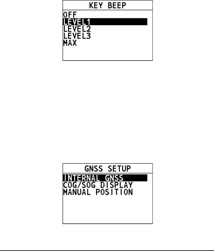
68
10.3 Key Beep
This feature allows you to set the volume level of the beep that is emitted when a key
is pressed.
Step 1 Press the Menu/DSC control until the "MAIN MENU" screen appears.
Step 2 Go to "GENERAL SETUP > KEY BEEP".
The following interface appears on the screen.
Step 3 Select a level.
Step 4 Press the Menu/DSC control to save the setting and return to the previous
interface.
10.4 GNSS Setup
This section allows you to set how to show the time and the position information of
the vessel.
10.4.1 Entering the "GNSS SETUP" Interface
Step 1 Press the Menu/DSC control until the "MAIN MENU" screen appears.
Step 2 Go to "GENERAL SETUP > GNSS SETUP".
The following interface appears on the screen.
10.4.2 Internal GNSS
This feature allows you to set whether to show the position and time information
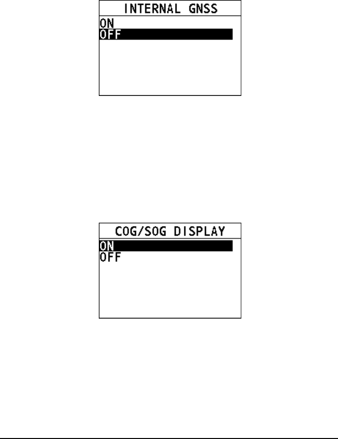
69
obtained through the internal GNSS.
Step 1 In the "GNSS SETUP" interface, select "INTERNAL GNSS".
The following interface appears on the screen.
Step 2 Select "ON" or "OFF".
Step 3 Press the Menu/DSC control to save the setting and return to the previous
interface.
10.4.3 COG/SOG Display
This feature allows you to set whether to show Course Over Ground (COG)/Speed
Over Ground (SOG) on the radio screen.
Step 1 In the "GNSS SETUP" interface, select "COG/SOG DISPLAY".
The following interface appears on the screen.
Step 2 Select "ON" or "OFF".
Step 3 Press the Menu/DSC control to save the setting and return to the previous
interface.
10.4.4 Manual Position
This feature allows you to input the time and the longitude and the latitude of the
vessel.
Step 1 In the "GNSS SETUP" interface, select "MANUAL POSITION".
The following interface appears on the screen.
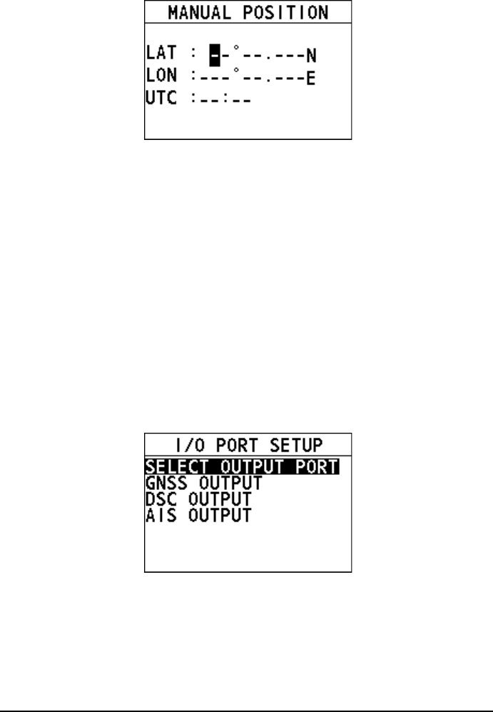
70
Step 2 Rotate and press the Menu/DSC control to input your position.
Step 3 After you input all information, press the Menu/DSC control to save the
setting and return to the previous interface.
10.5 I/O Port Setup
This section allows you to set whether to output GNSS, DSC and AIS data and
allows you to select the port for outputting these data.
There are two baud rates available for NMEA0183. When "AIS OUTPUT" is set to
"ON", the baud rate is 38400. When "AIS OUTPUT" is set to "OFF", the baud rate is
4800.
10.5.1 Entering the "I/O PORT SETUP" Interface
Step 1 Press the Menu/DSC control until the "MAIN MENU" screen appears.
Step 2 Go to "GENERAL SETUP > I/O PORT SETUP".
The following interface appears on the screen.
10.5.2 Selecting Output Port
This feature allows you to select the port for outputting GNSS, DSC and AIS data.
Step 1 In the "I/O PORT SETUP" interface, select "SELECT OUTPUT PORT".
The following interface appears on the screen.
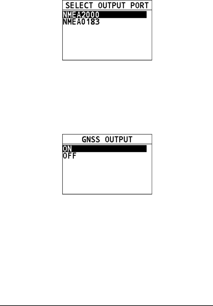
71
Step 2 Select "NMEA2000" or "NMEA0183".
Step 3 Press the Menu/DSC control to save the setting and return to the previous
interface.
10.5.3 GNSS OUTPUT
This feature allows you to set whether to output the GNSS data.
Step 1 In the "I/O PORT SETUP" interface, select "GNSS OUTPUT".
The following interface appears on the screen.
Step 2 Select "ON" or "OFF".
Step 3 Press the Menu/DSC control to save the setting and return to the previous
interface.
10.5.4 DSC OUTPUT
This feature allows you to set whether to output the DSC data.
Step 1 In the "I/O PORT SETUP" interface, select "DSC OUTPUT".
The following interface appears on the screen.
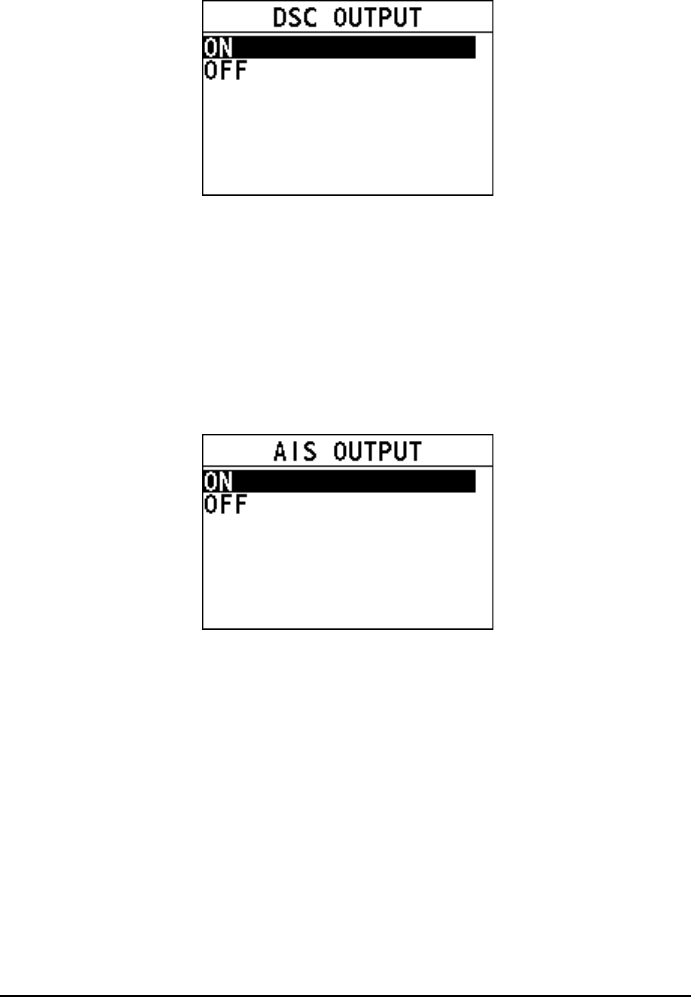
72
Step 2 Select "ON" or "OFF".
Step 3 Press the Menu/DSC control to save the setting and return to the previous
interface.
10.5.5 AIS OUTPUT
This feature allows you to set whether to output the AIS data.
Step 1 In the "I/O PORT SETUP" interface, select "AIS OUTPUT".
The following interface appears on the screen.
Step 2 Select "ON" or "OFF".
Step 3 Press the Menu/DSC control to save the setting and return to the previous
interface.
10.6 System Information
10.6.1 Entering the "SYSTEM INFO" Interface
Step 1 Press the Menu/DSC control until the "MAIN MENU" screen appears.
Step 2 Go to "GENERAL SETUP > SYSTEM INFO".
The following interface appears on the screen.
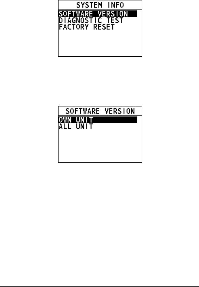
73
10.6.2 Software Version
This feature allows you to view software versions of the radio and connected units.
Step 1 In the "SYSTEM INFO" interface, select "SOFTWARE VERSION".
The "SOFTWARE VERSION" interface appears on the screen.
Step 2 Select "OWN UNIT" to view the version of the radio, or select "ALL UNIT"
to view to view the versions of the radio and connected units.
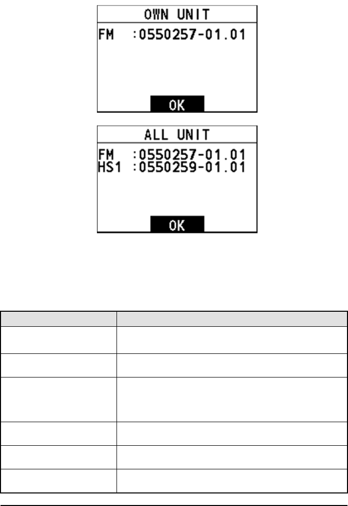
74
Step 3 After you view the information, press the Menu/DSC control to return to
the previous screen.
10.6.3 Diagnostic Test
This feature allows you to test items as shown in the following table. You can also
see explanations of testing results in the following table.
Testing Item Explanation of Testing Result
GNSS OK: There is a GNSS data source.
NG: There is no GNSS data source.
DSC
OK: The DSC feature works normally.
NG: The DSC feature doesn't work.
BATTERY
OK: The operating voltage is between 10.8 V DC and
15.6 V DC.
LOW: The operating voltage is lower than 10.8 V DC.
HIGH: The operating voltage is higher than 15.6 V DC.
AIS
OK: The AIS feature works normally.
NG: The AIS feature doesn't work.
MEMORY
OK: The internal memory is normal.
NG: The internal memory is abnormal.
REMOTE STATION
OK: Handset is connected to the radio.
NG: No handset is connected to the radio.
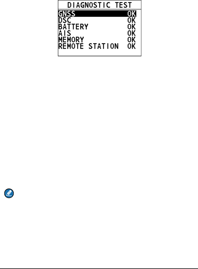
75
Step 1 In the "SYSTEM INFO" interface, select "DIAGNOSTIC TEST".
The "SYSTEM TEST" interface appears on the screen.
Step 2 Select the item requiring testing.
Step 3 Press the Menu/DSC control to start testing.
Step 4 When the test is over, press the Back key to return to the previous screen.
10.6.4 Factory Reset
This feature resets several menus and settings to their default values. For details on
which menu / settings are reset, see the underlined items in the menu tree.
Step 1 In the "FACTORY RESET" interface, select “FACTORY RESET”. The
“FACTORY RESET” interface appears on the screen.
Step 2 Select whether to reset the items to factory settings. If you select "YES",
the radio will restart and is reset to factory settings. If you select "NO", the
radio returns to the previous screen.
10.7 Fog Horn Frequency
This feature allows you to set the fog horn frequency according to the size of your
vessel.
Note
The default fog horn frequency is 400Hz. In most cases, do not change the
frequency unless the vessel is very large.
Step 1 Press the Menu/DSC control until the "MAIN MENU" screen appears.
Step 2 Go to "GENERAL SETUP > FOG HORN FREQ".
The following interface appears on the screen.

76
Step 3 Select a “FOG HORN FREQ”.
Step 4 Press the Menu/DSC control to save the setting and return to the previous
screen.
10.8 Service Menu
This menu is available only for your dealer.
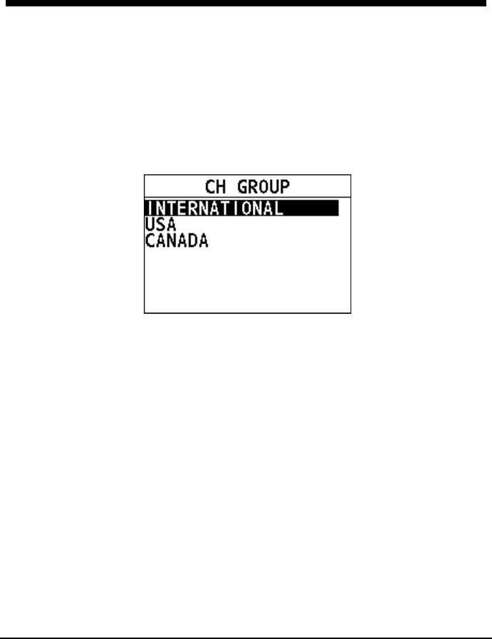
77
11. CHANNEL FUNCTION SETUP
11.1 Channel Group
This feature allows you to select a channel group among International, USA, and
Canada channel groups.
Step 1 Press the Menu/DSC control until the "MAIN MENU" screen appears.
Step 2 Go to "CH FUNCTION SETUP > CH GROUP".
The following interface appears on the screen.
Step 3 Select "INTERNATIONAL", "USA", or "CANADA".
Step 4 Press the Menu/DSC control to save the setting.
11.2 Second Priority Channel
This feature allows you to set the second priority channel which to be scanned in the
TRIPLE CH mode.
Step 1 Press the Menu/DSC control until the "MAIN MENU" screen appears.
Step 2 Go to "CH FUNCTION SETUP > 2ND PRIORITY".
The following interface appears on the screen.
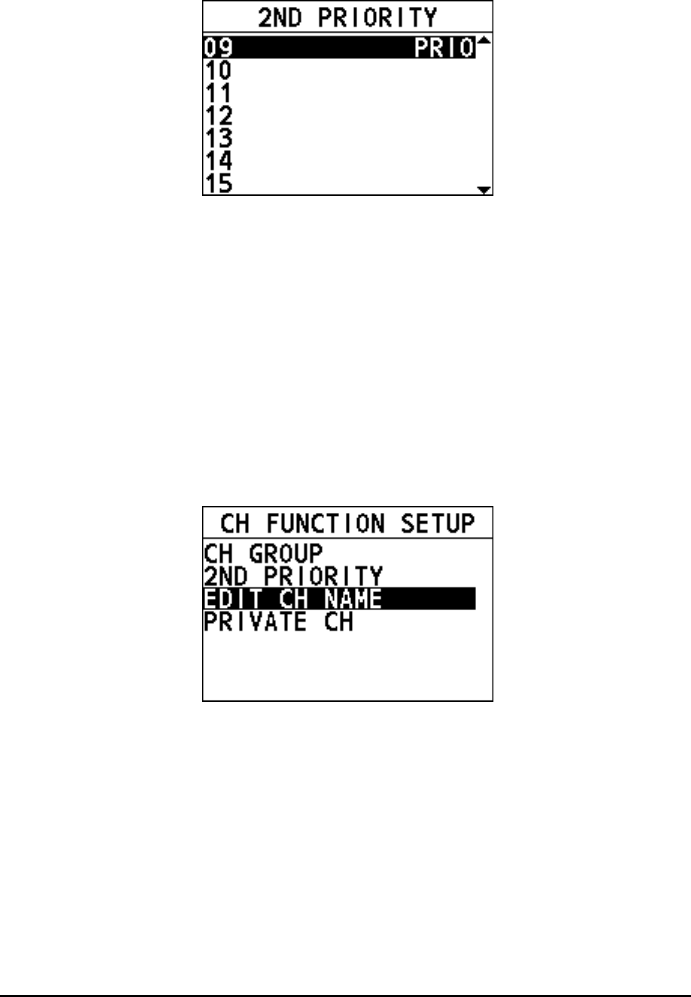
78
Step 3 Select a channel.
Step 4 Press the Menu/DSC control to set the channel to the second priority
channel and then return to the previous screen.
11.3 Edit Channel Name
When the radio mode is in use, the display shows a name under the channel number
selected. This is the name of the current channel. You can customize channel
names as follows:
Step 1 Press the Menu/DSC control until the "MAIN MENU" screen appears.
Step 2 Select "CH FUNCTION SETUP".
The "CH FUNCTION SETUP" interface appears on the screen.
Step 3 Select "EDIT CH NAME".
Step 4 Rotate and press the Menu/DSC control to enter a new channel name for
the current working channel.
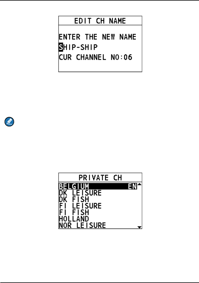
11 CHANNEL FUNCTION SETU
P
79
Step 5 Press the Menu/DSC control to save the new channel name and return to
the previous screen.
11.4 Private Channel
This feature allows you to select a private channel.
Note
The "PRIVATE CH" menu is available only when the channel group is set to
"INTERNATIONAL". For information about how to set the channel group, see
section 10.1 Channel Group.
Step 1 Press the Menu/DSC control until the "MAIN MENU" screen appears.
Step 2 Go to "CH FUNCTION SETUP > PRIVATE CH".
The following interface appears on the screen.
Step 3 Select a private channel.
Step 4 Press the Menu/DSC control to save the setting and return to the previous
screen.
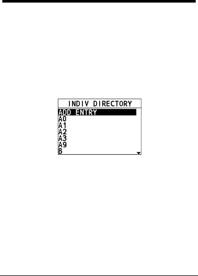
80
12. DSC SETUP
12.1 Individual Directory
This feature allows you to save vessels' names or persons' names and the MMSI
numbers associated with vessels you want to transmit individual calls, position
request calls, and DSC test calls.
12.1.1 Adding an Entry
You can add 200 entries at most.
Step 1 Press the Menu/DSC control until the "MAIN MENU" screen appears.
Step 2 Go to "DSC SETUP > INDIV DIRECTORY".
The following interface appears on the screen.
Step 3 Select "ADD ENTRY".
Step 4 Rotate and press the Menu/DSC control to add the name and the MMSI of
the contact.
Step 5 After you finish entering the information, press the Menu/DSC control to
save the setting and return to the previous screen.
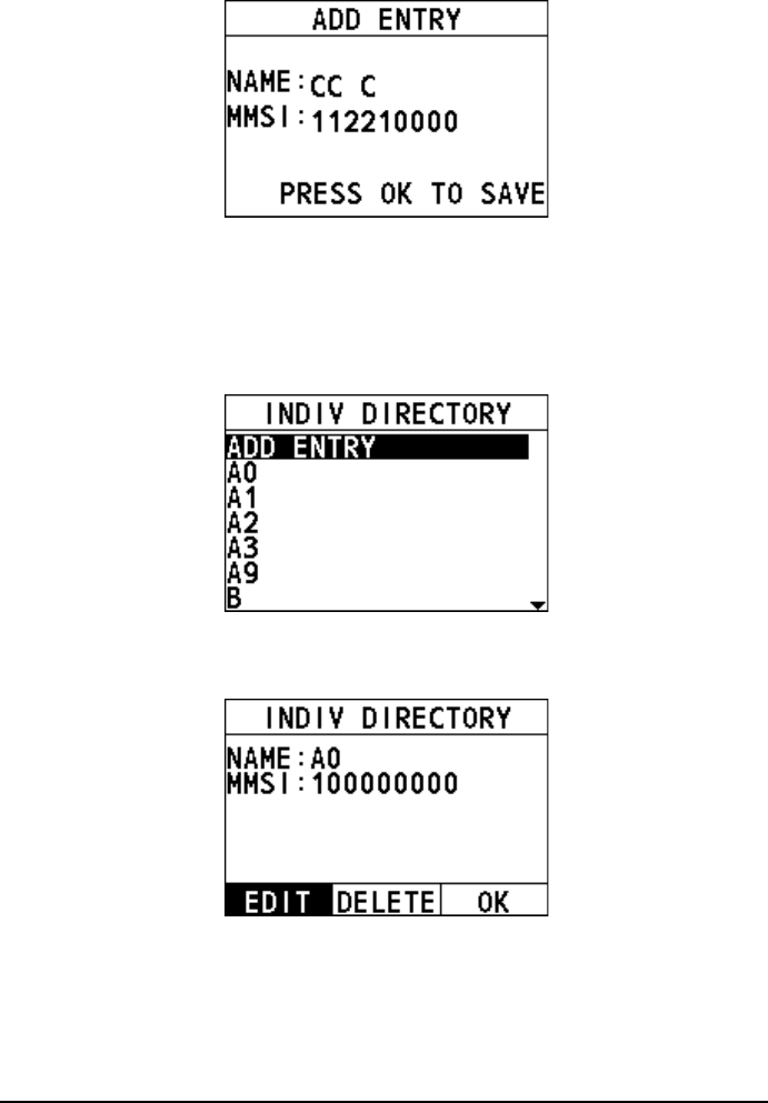
81
12.1.2 Editing an Entry
Step 1 Press the Menu/DSC control until the "MAIN MENU" screen appears.
Step 2 Go to "DSC SETUP > INDIV DIRECTORY".
The following interface appears on the screen.
Step 3 Select the entry needing editing.
The following interface appears on the screen.
Step 4 Select "EDIT".
Step 5 Rotate and press the Menu/DSC control to edit the entry.
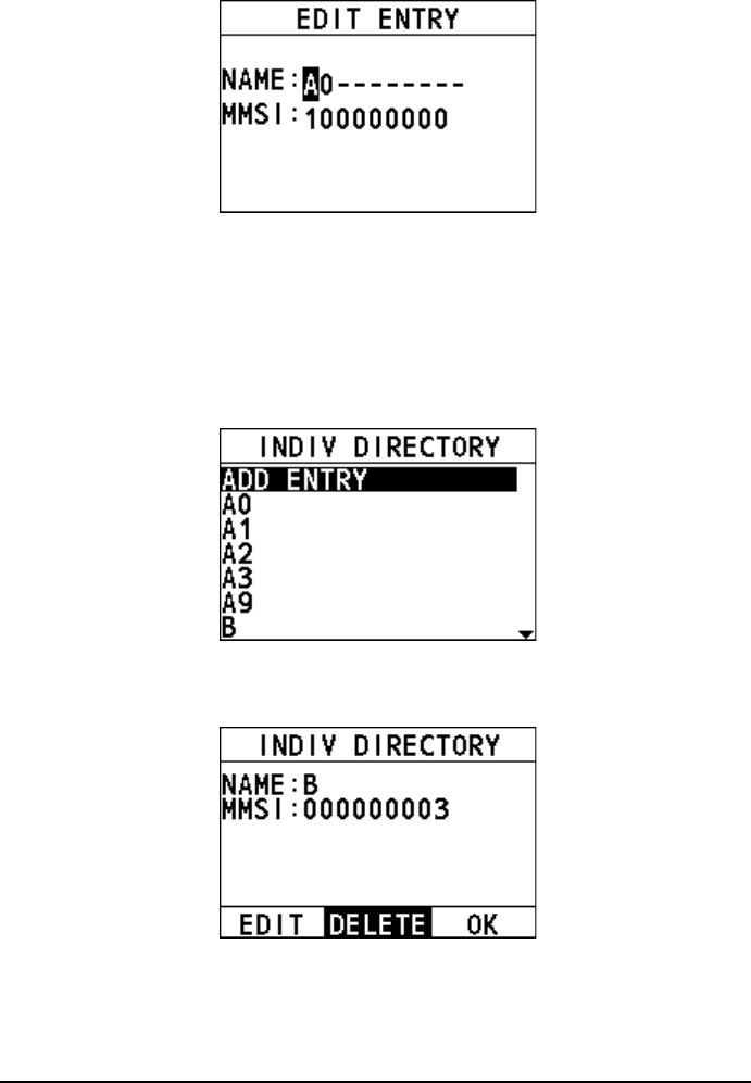
82
Step 6 After you finish entering the information, press the Menu/DSC control to
save the setting and return to the previous screen.
12.1.3 Deleting an Entry
Step 1 Press the Menu/DSC control until the "MAIN MENU" screen appears.
Step 2 Go to "DSC SETUP > INDIV DIRECTORY".
The following interface appears on the screen.
Step 3 Select the entry needing deleting.
The following interface appears on the screen.
Step 4 Select "DELETE".
The following screen appears.
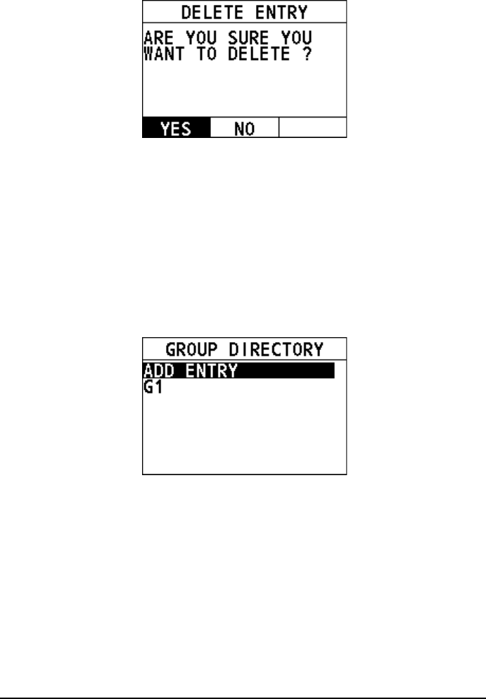
83
Step 5 Select "YES".
The directory is deleted and the radio returns to the previous screen.
12.2 Group Directory
This feature allows you to add, edit or delete groups the radio belongs to.
12.2.1 Adding an Entry
Step 1 Press the Menu/DSC control until the "MAIN MENU" screen appears.
Step 2 Go to "DSC SETUP > GROUP DIRECTORY".
The following interface appears on the screen.
Step 3 Select "ADD ENTRY".
Step 4 Rotate and press the Menu/DSC control to add the name and the MMSI of
the contact.
Step 5 After you finish entering the information, press the Menu/DSC control to
save the setting and return to the previous screen.
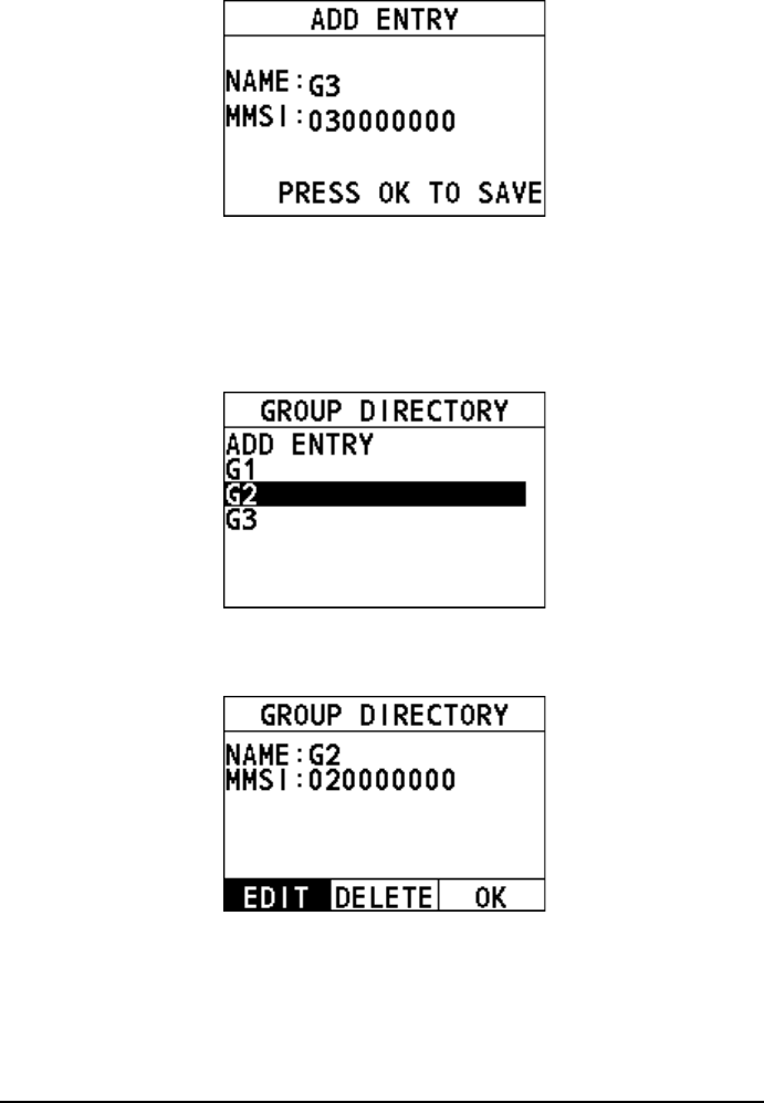
84
12.2.2 Editing an Entry
Step 1 Press the Menu/DSC control until the "MAIN MENU" screen appears.
Step 2 Go to "DSC SETUP > GROUP DIRECTORY".
The following interface appears on the screen.
Step 3 Select the entry needing editing.
The following interface appears on the screen.
Step 4 Select "EDIT".
Step 5 Rotate and press the Menu/DSC control to edit the entry.
Step 6 After you finish entering the information, press the Menu/DSC control to
save the setting and return to the previous screen.
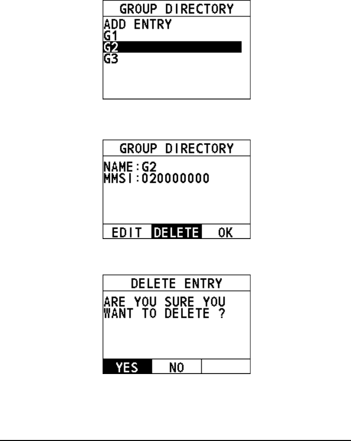
85
12.2.3 Deleting an Entry
Step 1 Press the Menu/DSC control until the "MAIN MENU" screen appears.
Step 2 Go to "DSC SETUP > GROUP DIRECTORY".
The following interface appears on the screen.
Step 3 Select the entry needing deleting.
The following interface appears on the screen.
Step 4 Select "DELETE".
The following screen appears.
Step 5 Select "YES".
The directory is deleted and the radio returns to the previous screen.
12.3 Channel Change Mode
This feature allows you to set the channel change mode of the radio. When selecting
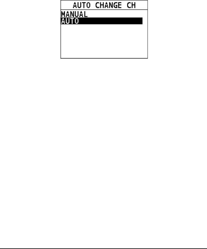
86
"MANUAL", you need to manually change the channel. When you select "AUTO",
the radio automatically switches to the designated channel after 10 seconds without
user intervention.
Step 1 Press the Menu/DSC control until the "MAIN MENU" screen appears.
Step 2 Go to "DSC SETUP > AUTO CHANGE CH".
The following interface appears on the screen.
Step 3 Select "MANUAL" or "AUTO".
Step 4 Press the Menu/DSC control to save the setting and return to the previous
screen.
12.4 Individual Acknowledgement
This feature allows you to set the acknowledgement mode of individual call requests.
Step 1 Press the Menu/DSC control until the "MAIN MENU" screen appears.
Step 2 Go to "DSC SETUP > INDIVIDUAL ACK".
The "INDIVIDUAL ACK" interface appears on the screen.
Step 3 Select "MANUAL" or "AUTO".
MANUAL: Select the soft key, and then you need to send an
acknowledgement manually upon a call request.
AUTO: Select the soft key, and then the radio sends an
unacknowledged message upon a call request.
Step 4 Press the Menu/DSC control to save the setting and return to the previous
screen.
12.5 Position Acknowledgement
This feature allows you to set the acknowledgement mode of position request calls.
Step 1 Press the Menu/DSC control until the "MAIN MENU" screen appears.
Step 2 Go to "DSC SETUP > POSITION ACK".
The "POSITION ACK" interface appears on the screen.
Step 3 Select "MANUAL", "AUTO", or "IGNORE".
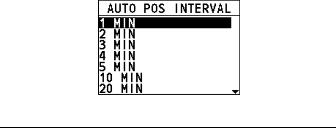
87
MANUAL: Select the soft key, and then you need to send an
acknowledgement manually upon a call request.
AUTO: Select the soft key, and then the radio sends an
acknowledgement automatically upon a call request.
IGNORE: Select the soft key, and then the radio ignores the call
request without sending an acknowledgement.
Step 4 Press the Menu/DSC control to save the setting and return to the previous
screen.
12.6 Test Acknowledgement
This feature allows you to set the acknowledgement mode of DSC test call requests.
Step 1 Press the Menu/DSC control until the "MAIN MENU" screen appears.
Step 2 Go to "DSC SETUP > TEST ACK".
The "TEST ACK" interface appears on the screen.
Step 3 Select "MANUAL" or "AUTO".
MANUAL: Select the soft key, and then you need to send an
acknowledgement manually upon a call request.
AUTO: Select the soft key, and then the radio sends an
acknowledgement automatically upon a call request.
Step 4 Press the Menu/DSC control to save the setting and return to the previous
screen.
12.7 Auto Position Interval
This feature allows you to set the interval of sending auto position polling to another
vessel.
Step 1 Press the Menu/DSC control until the "MAIN MENU" screen appears.
Step 2 Go to "DSC SETUP > AUTO POS INTERVAL".
The "AUTO POS INTERVAL" interface appears on the screen.
Step 3 Select a time interval.
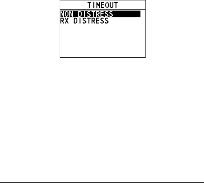
88
Step 4 Press the Menu/DSC control to save the setting and return to the previous
screen.
12.8 Timeout
This feature allows you to set the number of minutes the radio should keep a given
screen displayed before it restores the standby display, if no radio operation is
detected.
You can set a timeout for two types of screen: the non-distress screen and the
distress transmitting screen.
Step 1 Press the Menu/DSC control until the "MAIN MENU" screen appears.
Step 2 Go to "DSC SETUP > TIMEOUT ".
The "DSC SETUP" interface appears on the screen.
Step 3 Select "TIMEOUT".
The "TIMEOUT" interface appears on the screen.
Step 4 Select "NON DISTRESS" or "RX DISTRESS".
Step 5 Do one of the following:
To enable the Timeout feature, select "15 MIN ".
The message selected at step 4 is closed automatically when there is
no operation within 15 minutes.
To disable the Timeout feature, select "NO TIMEOUT ".
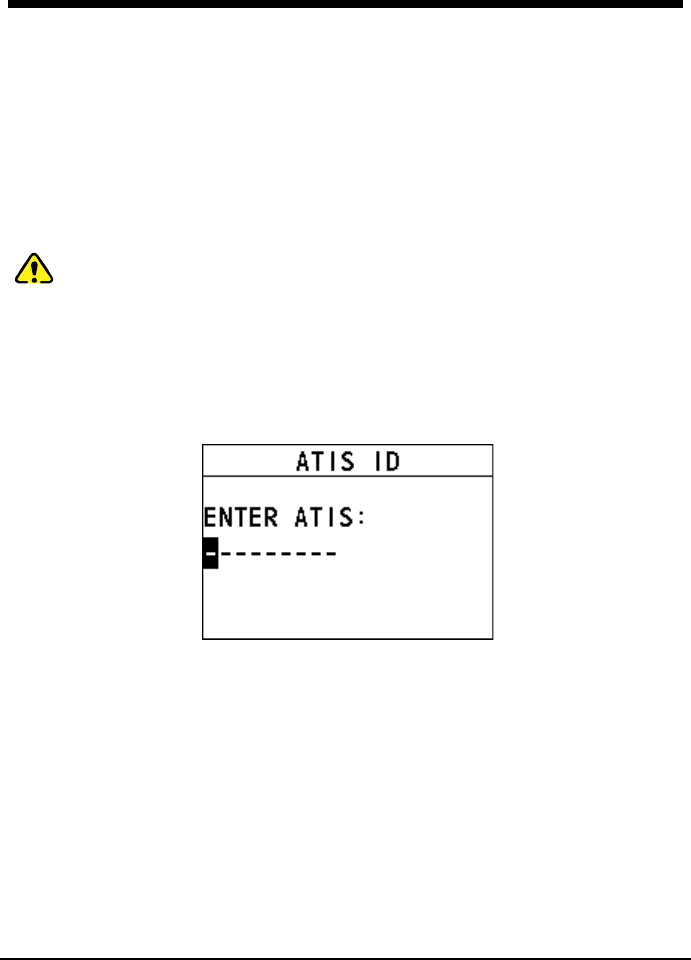
89
13. ATIS SETUP
The FM-4800 supports the Automatic Transmitter Identification System (ATIS) used
in Inland waterways in Europe. In the ATIS mode, the radio transmits a unique ATIS
code each time the PTT key is released at the end of a transmission. You should
check with your local marine regulatory authority in your country for assistance in
obtaining an ATIS code.
13.1 How to Enter the ATIS ID
You can register an ATIS ID, and also view the registered ID, as follows:
Caution
An ATIS ID can be entered only once. Therefore, be careful not to enter the
wrong ATIS ID. If you need to change the ID after it has been entered, contact
your dealer.
Step 1 Press the Menu/DSC control until the "MAIN MENU" screen appears.
Step 2 Go to "ATIS SETUP > SET ATIS ID ".
The following interface appears.
Step 3 Rotate and press the MENU/DSC control to enter your ATIS ID (nine
digits).
If you enter a wrong digit, press the BACK key until the wrong digit is
selected, and then enter a correct digit.
Step 4 After you enter the ATIS ID, press the Menu/DSC control to save it.
Step 5 Enter the ATIS ID again, and then press the Menu/DSC control to save it.
13.2 How to Enable/Disable the ATIS Feature
Step 1 Press the Menu/DSC control until the "MAIN MENU" screen appears.
Step 2 Select "ATIS SETUP".
The "ATIS SETUP" interface appears on the screen.
Step 3 Do one of the following:

90
To enable the ATIS feature, select "ON". If you haven't entered the
ATIS ID, you are required to enter the ID first.
To disable the ATIS feature, select "OFF".
91
14. MAINTENANCE AND
TROUBLESHOOTING
Warning
Do not open the equipment. This equipment uses high voltage that can cause
electrical shock.
Note
Do not apply paint, anti-corrosive sealant, or contact spray to plastic parts or
equipment coating. Those items contain products that can damage plastic parts
and equipment coating.
14.1 General Maintenance
Caution
The heat sink can get hot enough to cause a burn injury. Allow the unit to cool
before doing any maintenance procedures.
The inherent quality of the solid-state components used in this radio should provide
many years of continuous use. However, take the following precautions to prevent
damage to the radio.
Keep the microphone connected or the jack covered at all times to prevent
corrosion of electrical contacts.
Remove dust from the cabinet with a dry clean cloth. Do not use commercial
cleaners to clean the equipment. Those cleaners can remove paint and markers.
Check that all cables are tightly fastened. Check the cables for corrosion and
rust. Connect the cables that have loosened. Replace any damaged cables.
Never press and hold the PTT key and talk into the microphone to transmit your
voice unless an antenna or suitable dummy load is connected to the radio.
The supply voltage range to the radio must be within 10.8 to 15.6 VDC.
Use only FURUNO-approved accessories and replacement parts.
In the unlikely event of serious problems, please contact your dealer.

92
14.2 Troubleshooting
When the FM-4800 does not work properly, you can follow the following
troubleshooting procedures to fix it.
Phenomena
Probable
Cause
Solution
The radio cannot
be turned on.
No DC voltage
to the radio, or
blown fuse
Step 1 Check the 10.8 to 15.6 VDC
battery connections and the
fuse.
Step 2 Long press the On/Off key to
turn on the radio.
The radio blows
the fuse when
connected to the
power supply.
Reversed
polarity of
power wires
Step 1 Make sure the red wire is
connected to the positive (+)
battery post, and the black
wire is connected to the
negative (-) battery post.
Step 2 Check the power cable for DC
voltage and replace the fuse
(8A 250V).
The speaker
makes popping
or whining noise
while t
he engine
of the ship runs.
Engine noise
Step 1 Reroute the DC power cable of
the radio away from the
engine.
Step 2 Add a noise suppressor on the
power cable.
Step 3 Change to resistive spark plug
wires and/or add an alternator
whine filter.
The sound is not
emitted from the
internal or
external speaker.
Accessory
cable
Step 1 Check that the external
speaker cable (Purple &
Gray) is physically connected.
Step 2 Check whether the external
speaker cable is broken or
short-circuited.
The sound is not
emitted from the
speaker.
Accessory
cable
Step 1 Check that the cable (Red &
Black) is physically
connected.
Step 2 Check whether the speaker
cable is broken or
short-circuited.
Transmissions
are always on
low
power even
when high power
Antenna
Check the antenna or test the radio with
another antenna.
93
Phenomena
Probable
Cause
Solution
is selected.
The icon or
appears on
the home screen.
Too high or too
low power
supply voltage
Confirm that the connected power
supply voltage is within 10.8 to 15.6
VDC.
Your
position is
not displayed.
Accessory
cable
Check the NMEA2000 or NMEA0183
cable connection.
Setting of the
GNSS receiver
Choose the proper information to
check:
If the NMEA2000 or NMEA0183
cable is connected, make sure
that the output of the cable is valid.
If the NMEA2000 or NMEA0183
cable is not connected, make sure
that the internal GNSS module is
enabled and nothing blocks the
top of the radio unit.
The radio unit
displays "PLL
UNLOCK".
The phase lock
loop not
working
Restart the radio. If the problem is not
fixed, please consult your dealer.
If the above solutions cannot fix your problems, or you may have some other queries,
please contact us or your local dealer for more technical support.
94
15. INSTALLATION
15.1 Equipment Lists
Standard supply
Name
Type
Qty
Remarks
Radio
FM-4800
1
Microphone
MIC-4800
1
Installation Materials
- 1 set
Cushion, Template,
Tapping screw, UHF connector
Accessories
- 1 set
Soft cover, Hanger, Hanger knob,
Microphone Hanger
Documents
-
1 set
Manual, Packing list
Spare Parts
- 1 set
Fuse (250VAC, 8A)
2pcs
Optional supply
Name
Type
Code no.
Remarks
Handset HS-4800 001-468-560
Handset, Hanger,
Installation Materials,
Accessories
Speaker SP-4800 001-468-580
Speaker,
Installation Materials,
Accessories
Extension
Cable
EX-CBL-FM5M 001-468-600 5m
Extension
Cable
EX-CBL-FM10M 001-468-610 10m
Cable for
NMEA2000
FRU-NMEA-PMMFF-010 001-506-820
w/connectors
(light), 1m
FRU-NMEA-PMMFF-020 001-506-830
w/connectors
(light), 2m
FRU-NMEA-PMMFF-060 001-507-000
w/connectors
(light), 6m
FRU-NMEA-PFF-010 001-507-010
w/connector
(light), 1m
FRU-NMEA-PFF-020 001-507-030
w/connector
(light), 2m
FRU-NMEA-PFF-060 001-507-040
w/connector
(light), 6m

95
Name
Type
Code no.
Remarks
CB-05PM+05BF-010 000-167-968-11
w/connectors
(heavy), 1m
CB-05PM+05BF-020 000-167-969-11
w/connectors
(heavy), 2m
CB-05PM+05BF-060 000-167-970-11
w/connectors
(heavy), 6m
CB-05BFFM-010 000-167-971-11
w/connector (heavy),
1m
CB-05BFFM-020 000-167-972-11
w/connector (heavy),
2m
CB-05BFFM-060 000-167-973-11
w/connector (heavy),
6m
Connector
for
NMEA2000
FRU-MM1MF1MF1001 001-507-050
T-Connector,
Micro style:3
NC-050505-FMF-TS001 000-160-507-10
Mini style:2,
micro style:1
FRU-MM1000000001 001-507-070
Micro style, male,
termination resistor
LTWMN-05AMMT-SL8001 000-160-508-10
Mini style, male,
termination resistor
FRU-MF000000001 001-507-060
Micro style, female,
termination resistor
LTWMN-05AFFT-SL8001 000-160-509-10
Mini style, female,
termination resistor
FRU-0505-FF-IS
001-077-830-10
w/in-line terminator
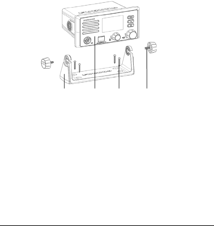
96
15.2 Mounting
15.2.1 How to Install the Radio
For desktop mounting
Step 1 Put the hanger in a location where it is easy to install the FM-4800 radio.
Step 2 Fix the hanger with four screws.
Step 3 Set the radio to the hanger.
Step 4 Tighten the knob bolts on both sides of the hanger.
For flush mounting
Step 1 Determine the position of installation holes according to the marking
template and drill the hole.
Step 2 Pry off the frame from the front panel.
Step 3 Paste the installation cushion on the back of the front panel.
Step 4 Place the FM-4800 radio in the hole and fix it with four screws.
Hanger
Radio
Tapping screw
(PA 4.0*25)
Hanger Knob
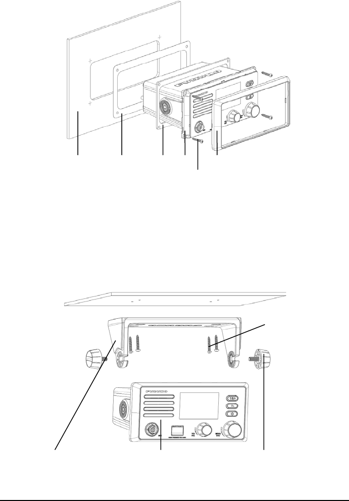
97
For hanging mounting
Step 1 Put the hanger in a location where it is easy to install the FM-4800 radio.
Step 2 Fix the hanger with four screws.
Step 3 Set the radio to the hanger.
Step 4 Tighten the knob bolts on both sides of the hanger.
Hanger Radio Hanger knob
Tapping screw
(PA4.0*25)
Panel
Template
Radio
Frame
Tapping screw (PA4.0*25)
Cushion
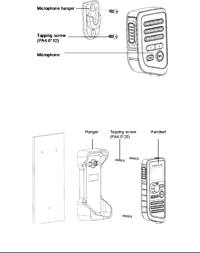
98
15.2.2 How to Install the Microphone
Step 1 Determine a location where it is easy to install the microphone hanger.
Step 2 Fix the hanger with two screws.
Step 3 Place the microphone into the hanger.
15.2.3 How to Install the Handset (Optional)
Step 1 Determine a location where it is easy to install the handset hanger.
Step 2 Fix the hanger with three screws.
Step 3 Place the handset into the hanger.
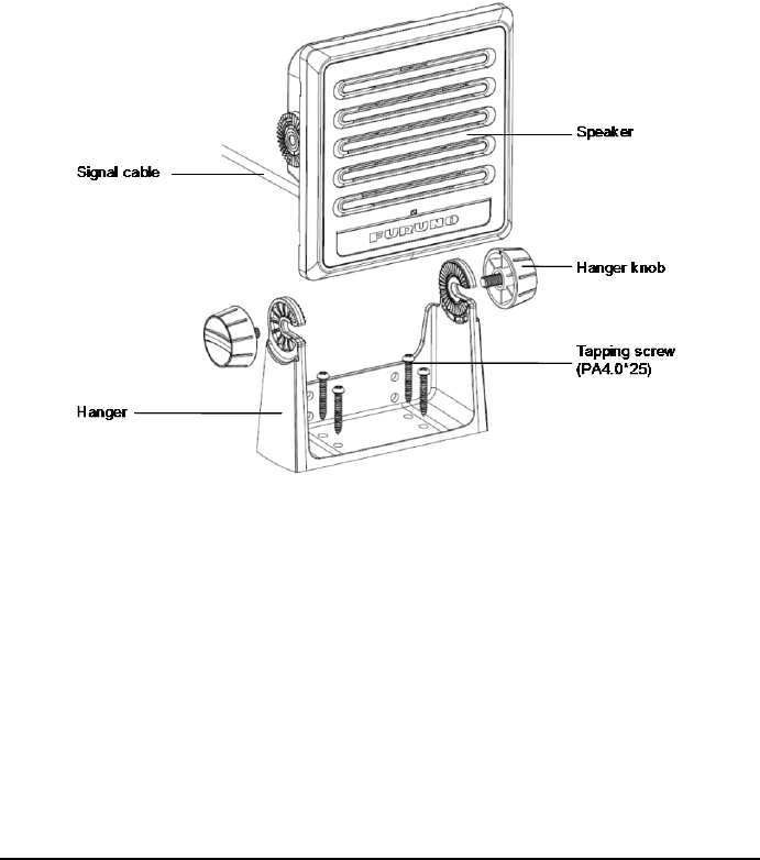
99
15.2.4 How to Install the Speaker (Optional)
For desktop mounting
Step 1 Put the hanger in a location where it is easy to install the SP-4800.
Step 2 Fix the hanger with four screws.
Step 3 Set the speaker to the bracket.
Step 4 Tighten the knob bolts on both sides of the hanger.
Step 5 Connect the signal cable.
For flush mounting
Step 1 Determine the position of installation holes according to the marking
template and drill the hole.
Step 2 Pry off the frame from the front panel.
Step 3 Paste the installation sealing gasket on the back of the front panel.
Step 4 Place the speaker in the hole and fix it with four screws.
Step 5 Connect the speaker to the radio using the color-coded signal cable.
Make sure that every signal cable is firmly connected.
Step 6 Mount the frame.
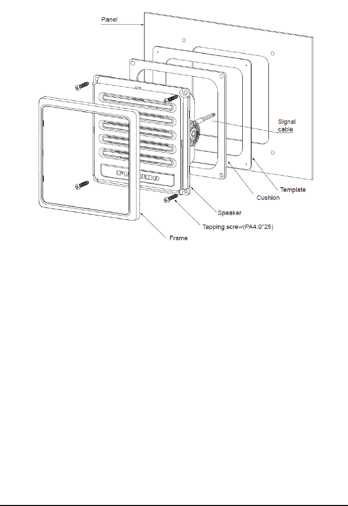
100
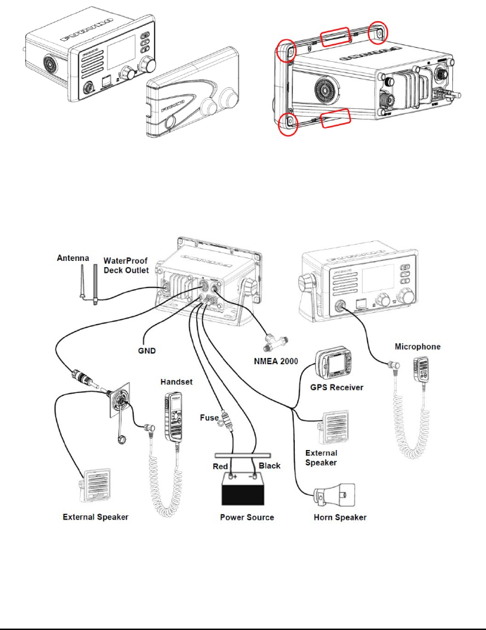
101
15.3 Soft Cover
Step 1 Remove the antenna connector cover on the rear back of the unit.
Step 2 Slightly press the four corners in circle and plastic in rectangular in place.
15.4 Wiring
15.4.1 Overview

102
15.4.2 Antenna
Requirements for the antenna
Any good quality antenna that meets the requirements shown below can be used.
Frequency range: 155 to 164 MHz
Impedance: 50 ohms
Polarization: Vertical
Handling power: 30 W or more
Quality: Withstand the marine environment
Installation location
The location and installation of different antennas on a ship is important to ensure
effective communications. Incorrectly installed antennas will degrade performance of
the radio equipment and reduce the range of communications.
Select the location for the antenna considering the following points.
VHF antennas should be placed in a position which is as elevated and free as
possible, with at least 2 meters horizontal separation from constructions made
by conductive materials.
Ideally there should not be more than one antenna on the same level.
The location of mandatory VHF antennas should be given priority compared with
mobile telephone antennas. If they are located on the same level, the distance
between them should be at least 5 meters.
Isolate the antenna from all metallic parts of the ship.
Current will overflow if the antenna touches any metal part of the ship.
Fabricating the Antenna Connector
Step 1 Strip the RG58 cable according to the dimension in the following figure.
Step 2 Put the antenna connector on the cable orderly.
Step 3 Hold the flange between the insulation and the shield.
Step 4 Tighten the nut.
Step 5 Solder the connector and core.
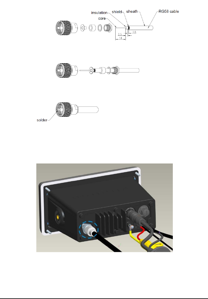
103
Wiring
Step 1 Remove the antenna connector cover on the rear back of the unit.
Step 2 Insert the antenna cable into the antenna connector.
Step 3 Tighten the antenna hand tight.
Step 4 Secure the cable with the electrical cable.
Waterproofing the Connection
Step 1 Take the Self-bonding tape in the length of about 100 mm.
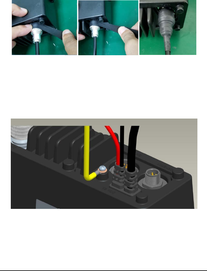
104
Step 2 Connect the UHF antenna to the radio and tighten it clockwise.
Step 3 Slightly stretch one end of the Self-bonding tape and wind it clockwise on
the antenna head.
Step 4 Wrap around the cable.
15.4.3 Ground Cable
Step 1 Loosen the screw on the rear back of the unit.
Step 2 Place the grounding wire on the screw.
Step 3 Tighten the screw again.
15.4.4 Power Cable
Step 1 Remove the outer sheath at one end of the cable on the unit.
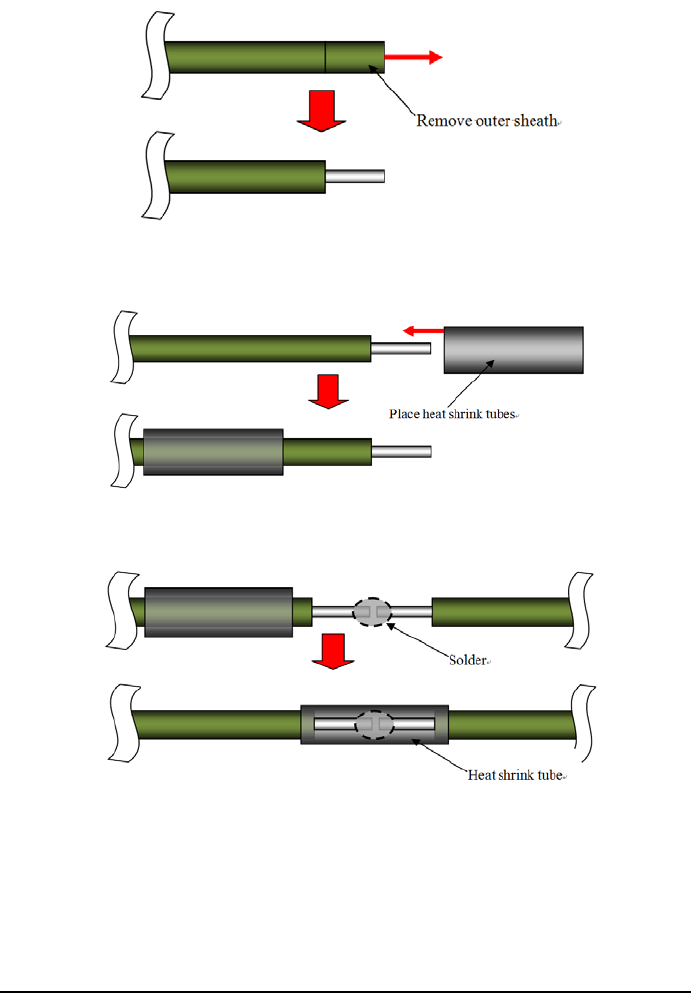
105
Step 2 Referring to the figure below, place heat shrink tubes on the wires, and
then solder the connection point.
Step 3 Move the heat shrink tubes to the soldered connection, and then apply
heat to the tubes.
Step 4 Secure the cable with electrical tape.
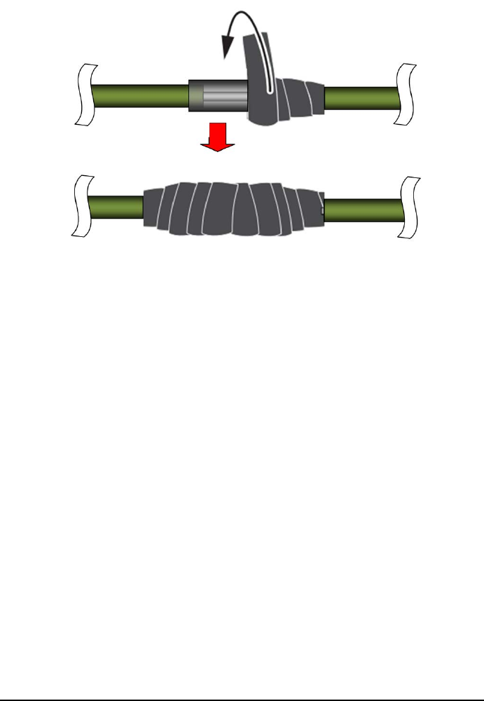
106
15.4.5
NMEA2000 Connector
(CAN bus connector)
CAN bus is a communication protocol that shares multiple data and signals through
a single backbone cable. You can simply connect any CAN bus devices onto the
backbone cable to expand your network onboard. With CAN bus, Ids are assigned to
all the devices in the network, and the status of each sensor in the network can be
detected. All the CAN bus devices can be incorporated into the NMEA2000 network.
For detailed information about CAN bus wiring, see “Furuno CAN bus Network
Design Guide”
(Type : TIE-00170)
on Tech-Net), or contact your dealer.
15.4.6
Extension Cable (Optional)
Step 1
Drill a round or square hole on the ship panel.
The diameter of the hole ranges from 23.5 mm to 25 mm.
Step 2
Thread the extended cable through the hole.
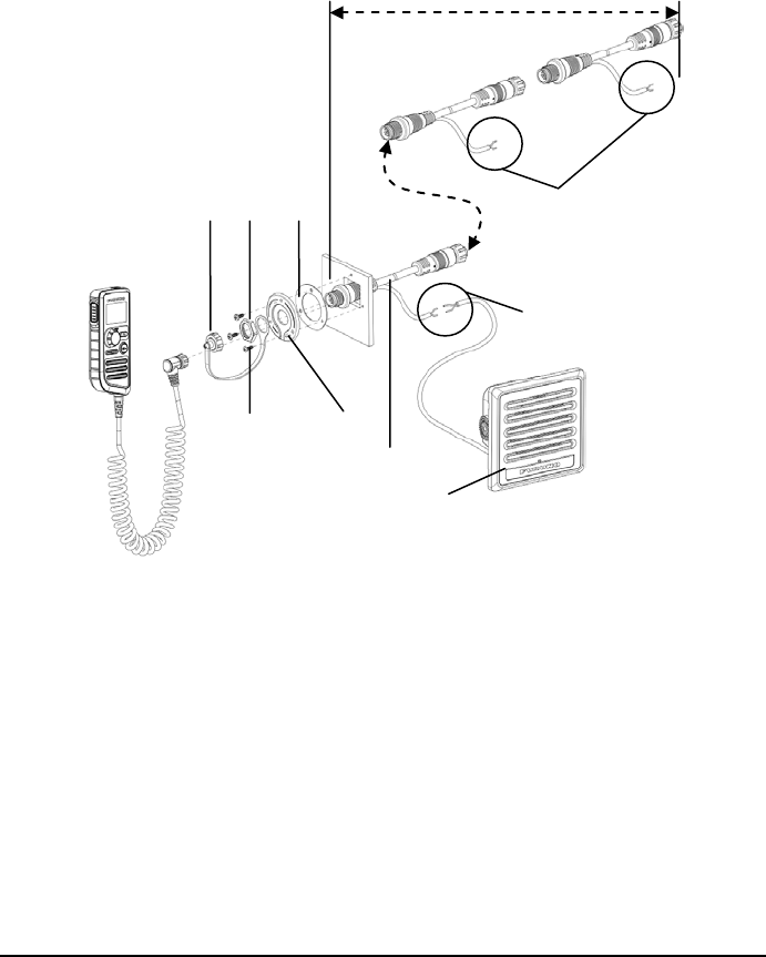
107
Step 3 Place the seal, cable holder, and waterproof cover sequentially around the
extended cable.
Step 4 Fasten the nut.
Step 5 Fasten the three tapping screws.
Step 6 Fasten the cover on the extended cable and tighten it.
Tapping
Screw
(PA3.0*10)
Cable
holder
Waterproof
cover Nut Seal
Extension
cable
Connect the cable
Speaker
Wrap the electrical tape
Max 30m

108
CHANNEL ASSIGNMENTS
The following channel charts are provided for your reference.
International Channel Chart
CH TX(MHz) RX(MHz) Mode Use
01 156.050 160.650 Duplex Public Correspondence (marine operator)
02 156.100 160.700 Duplex Public Correspondence (marine operator)
03 156.150 160.750 Duplex Public Correspondence (marine operator)
04 156.200 160.800 Duplex Public Correspondence (marine operator),
Port Operations, Ship Movement
05 156.250 160.850 Duplex Public Correspondence (marine operator),
Port Operations, Ship Movement
06 156.300 156.300 Simplex Inter-ship Safety
07 156.350 160.950 Duplex Public Correspondence (marine operator),
Port Operations, Ship Movement
08 156.400 156.400 Simplex Commercial (inter-ship only)
09 156.450 156.450 Simplex Boater calling channel, commercial &
Non-commercial (recreational)
10 156.500 156.500 Simplex Commercial
11 156.550 156.550 Simplex Commercial, VTS in selected areas
12 156.600 156.600 Simplex Port operation, VTS in selected areas
13 156.650 156.650 Simplex Inter-ship navigation safety
(bridge-to-bridge)
14 156.700 156.700 Simplex Port operation, VTS in selected areas
15 156.750 156.750 Simplex Environmental
Low power (1 W) only
16 156.800 156.800 Simplex International distress, safety and calling
17 156.850 156.850 Simplex State controlled
Low power (1 W) only
18 156.900 161.500 Duplex Port Operations, Ship Movement
19 156.950 161.550 Duplex Port Operations, Ship Movement
20 157.000 161.600 Duplex Port Operations
21 157.050 161.650 Duplex Port Operations, Ship Movement
22 157.100 161.700 Duplex Port Operations, Ship Movement
23 157.150 161.750 Duplex Public Correspondence (marine operator)
24 157.200 161.800 Duplex Public Correspondence (marine operator)
25 157.250 161.850 Duplex Public Correspondence (marine operator)
26 157.300 161.900 Duplex Public Correspondence (marine operator)
27 157.350 161.950 Duplex Public Correspondence (marine operator)
28 157.400 162.000 Duplex Public Correspondence (marine operator)

109
CH TX(MHz) RX(MHz) Mode Use
60 156.025 160.625 Duplex Public Correspondence (marine operator)
61 156.075 160.675 Duplex Public Correspondence (marine operator),
Port Operations, Ship Movement
62 156.125 160.725 Duplex Public Correspondence (marine operator),
Port Operations, Ship Movement
63 156.175 160.775 Duplex Public Correspondence (marine operator),
Port Operations, Ship Movement
64 156.225 160.825 Duplex Public Correspondence (marine operator),
Port Operations, Ship Movement
65 156.275 160.875 Duplex Public Correspondence (marine operator),
Port Operations, Ship Movement
66 156.325 160.925 Duplex Public Correspondence (marine operator),
Port Operations, Ship Movement
67 156.375 156.375 Simplex Commercial,
used for bridge-to-bridge communications
68 156.425 156.425 Simplex Non-commercial (recreational)
69 156.475 156.475 Simplex Inter-ship,
Port Operations and Ship Movement
70 156.525 156.525 Digital selective calling
(voice communications not allowed)
71 156.575 156.575 Simplex Port Operations and Ship Movement
72 156.625 156.625 Simplex Non-commercial (inter-ship only)
73 156.675 156.675 Simplex Inter-ship,
Port Operations and Ship Movement
74 156.725 156.725 Simplex International: Inter-ship,
Port Operations and Ship Movement
75 156.775 156.775 Simplex Port operations (inter-ship only)
Low power (1 W) only
76 156.825 156.825 Simplex Port operations (inter-ship only)
Low power (1 W) only
77 156.875 156.875 Simplex Port operations (inter-ship only)
78 156.925 161.525 Duplex Public Correspondence (marine operator),
Port Operations, Ship Movement
79 156.975 161.575 Duplex Port operation and Ship Movement
80 157.025 161.625 Duplex Port operation, Ship Movement
81 157.075 161.675 Duplex Port operation, Ship Movement
82 157.125 161.725 Duplex Public Correspondence (marine operator),
Port Operations, Ship Movement
83 157.175 161.775 Duplex Public Correspondence (marine operator)
84 157.225 161.825 Duplex Public Correspondence (marine operator)
85 157.275 161.875 Duplex Public Correspondence (marine operator)
86 157.325 161.925 Duplex Public Correspondence (marine operator)
87 157.375 157.375 Simplex Port operation, Ship Movement

110
CH TX(MHz) RX(MHz) Mode Use
88 157.425 157.425 Simplex Port operation, Ship Movement
1019 156.950 156.950 Simplex Port Operations, Ship Movement
1020 157.000 157.000 Simplex Port Operations, Ship Movement
1024 157.200 157.200 Simplex
1025 157.250 157.250 Simplex Inter-ship (digital only)
1026 157.300 157.300 Simplex
1027 157.350 157.350 Simplex
1028 157.400 157.400 Simplex Port Operations, Ship Movement
1078 156.925 156.925 Simplex Port Operations, Ship Movement
1079 156.975 156.975 Simplex Port Operations, Ship Movement
1084 157.225 157.225 Simplex Inter-ship (digital only)
1085 157.275 157.275 Simplex
1086 157.325 157.325 Simplex
2006 160.900 160.900 Simplex
2019 161.550 161.550 Simplex Port Operations, Ship Movement
2020 161.600 161.600 Simplex Port Operations, Ship Movement
2024 161.800 161.800 Simplex Inter-ship (digital only)
2025 161.850 161.850 Simplex
2026 161.900 161.900 Simplex
2027 161.950 161.950 Simplex
2028 162.000 162.000 Simplex
2078 161.525 161.525 Simplex Port Operations, Ship Movement
2079 161.575 161.575 Simplex Port Operations, Ship Movement
2084 161.825 161.825 Simplex
2085 161.875 161.875 Simplex
2086 161.925 161.925 Simplex
USA Channel Chart
CH TX(MHz) RX(MHz) Mode Use
1001 156.050 156.050 Simplex
Port Operations and Commercial, VTS.
Available only in New Orleans / Lower
Mississippi area.
1005 156.250 156.250 Simplex Port Operations or VTS in the Houston,
New Orleans and Seattle areas.
06 156.300 156.300 Simplex Inter-ship Safety
1007 156.350 156.350 Simplex Commercial. VDSMS
08 156.400 156.400 Simplex Commercial (Inter-ship only). VDSMS
09 156.450 156.450 Simplex
Boater Calling.
Commercial and Non-Commercial.
VDSMS
10 156.500 156.500 Simplex Commercial. VDSMS

111
CH TX(MHz) RX(MHz) Mode Use
11 156.550 156.550 Simplex Commercial. VTS in selected areas.
VDSMS
12 156.600 156.600 Simplex Port Operations. VTS in selected areas.
13 156.650 156.650 Simplex
Inter-ship Navigation Safety
(Bridge-to-bridge).
Ships > 20m length maintain a listening
watch on this channel in US waters.
Low power (1 W) initially
Power override
14 156.700 156.700 Simplex Port Operations. VTS in selected areas.
15 -- 156.750 Simplex Environmental (Receive only).
Used by Class C EPIRBs.
16 156.800 156.800 Simplex
International Distress, Safety and Calling.
Ships required to carry radio, USCG,
and most coast stations maintain a
listening watch on this channel.
High power (25 W)initially
17 156.850 156.850 Simplex State & local government maritime
control
Low power (1 W) only
1018 156.900 156.900 Simplex Commercial. VDSMS
1019 156.950 156.950 Simplex Commercial. VDSMS
20 157.000 161.600 Duplex Port Operations (duplex)
1020 157.000 157.000 Simplex Port Operations
1021 157.050 157.050 Simplex U.S. Coast Guard only
1022 157.100 157.100 Simplex Coast Guard Liaison and Maritime Safety
Information Broadcasts.
Broadcasts announced on channel 16.
1023 157.150 157.150 Simplex U.S. Coast Guard only
24 157.200 161.800 Duplex Public Correspondence
(Marine Operator). VDSMS
25 157.250 161.850 Duplex Public Correspondence
(Marine Operator). VDSMS
26 157.300 161.900 Duplex Public Correspondence
(Marine Operator). VDSMS
27 157.350 161.950 Duplex Public Correspondence
(Marine Operator). VDSMS
28 157.400 162.000 Duplex Public Correspondence
(Marine Operator). VDSMS
1063 156.175 156.175 Simplex
Port Operations and Commercial, VTS.
Available only in New Orleans
/ Lower Mississippi area.
1065 156.275 156.275 Simplex Port Operations
1066 156.325 156.325 Simplex Port Operations

112
CH TX(MHz) RX(MHz) Mode Use
67 156.375 156.375 Simplex
Commercial. Used for Bridge-to-bridge
communications in lower Mississippi
River. Inter-ship only.
Low power (1 W) initially
Power override
68 156.425 156.425 Simplex Non-Commercial. VDSMS
69 156.475 156.475 Simplex Non-Commercial. VDSMS
70 156.525 156.525 Digital Selective Calling
(voice communications not allowed)
71 156.575 156.575 Simplex
Non-Commercial. VDSMS
Low power (1 W) initially
Power override
72 156.625 156.625 Simplex Non-Commercial (Inter-ship only).
VDSMS
73 156.675 156.675 Simplex Port Operations
74 156.725 156.725 Simplex Port Operations
75 156.775 156.775 Simplex Port Operations
Low power (1 W) only
76 156.825 156.825 Simplex Port Operations
Low power (1 W) only
77 156.875 156.875 Simplex Port Operations (Inter-ship only)
Low power (1 W) only
1078 156.925 156.925 Simplex Non-Commercial. VDSMS
1079 156.975 156.975 Simplex
Commercial.
Non-Commercial in Great Lakes only.
VDSMS
1080 157.025 157.025 Simplex
Commercial.
Non-Commercial in Great Lakes only.
VDSMS
1081 157.075 157.075 Simplex U.S. Government only
- Environmental protection operations.
1082 157.125 157.125 Simplex U.S. Government only
1083 157.175 157.175 Simplex U.S. Coast Guard only
84 157.225 161.825 Duplex Public Correspondence
(Marine Operator). VDSMS
85 157.275 161.875 Duplex Public Correspondence
(Marine Operator). VDSMS
86 157.325 161.925 Duplex Public Correspondence
(Marine Operator). VDSMS
87 157.375 157.375 Simplex Public Correspondence
(Marine Operator). VDSMS
88 157.425 157.425 Simplex Commercial, Inter-ship only. VDSMS

113
Note
VDSMS (VHF Digital Small Message Services): Transmissions of short digital
messages in accordance with RTCM Standard 12301.1 are allowed.
Canada Channel Chart
CH TX(MHz) RX(MHz) Mode Use
01 156.050 160.650 Duplex Public Correspondence (Marine Operator)
02 156.100 160.700 Duplex Public Correspondence (Marine Operator)
03 156.150 160.750 Duplex Public Correspondence (Marine Operator)
04A 156.200 156.200 Simplex Pacific coast: coast guard
East coast: commercial fishing
05A 156.250 156.250 Simplex Port Operations, VTS in Seattle
06 156.300 156.300 Simplex Inter-ship safety
07A 156.350 156.350 Simplex Commercial
08 156.400 156.400 Simplex Commercial (inter-ship only)
09 156.450 156.450 Simplex Boater calling channel, commercial
& Non-commercial (recreational)
10 156.500 156.500 Simplex Commercial
11 156.550 156.550 Simplex Commercial, VTS in selected areas
12 156.600 156.600 Simplex Port Operations, VTS in selected areas
13 156.650 156.650 Simplex Inter-ship navigation safety
(bridge-to-bridge)
14 156.700 156.700 Simplex Port Operations, VTS in selected areas
15 156.750 156.750 Simplex
Commercial, non-commercial,
Ship Movement
Low power (1 W) only
16 156.800 156.800 Simplex International distress, safety and calling
High power (25 W) initially
17 156.850 156.850 Simplex State controlled
Low power (1 W) only
18A 156.900 156.900 Simplex Commercial
19A 156.950 156.950 Simplex Coast guard
20 157.000 161.600 Duplex Canadian coast guard only
21A 157.050 157.050 Simplex Canadian coast guard
21B - 161.650 Duplex (Receive only)
22A 157.100 157.100 Simplex
U.S. and Canadian coast guard liaison
and maritime safety information
broadcasts announced on channel 16
23 157.150 161.750 Duplex Public Correspondence (Marine Operator)
23B - 161.750 Duplex (Receive only)

114
CH TX(MHz) RX(MHz) Mode Use
24 157.200 161.800 Duplex Public Correspondence (Marine Operator)
25 157.250 161.850 Duplex Public Correspondence (Marine Operator)
25B - 161.850 Duplex (Receive only)
26 157.300 161.900 Duplex Public Correspondence (Marine Operator)
27 157.350 161.950 Duplex Public Correspondence (Marine Operator)
28 157.400 162.000 Duplex Public Correspondence (Marine Operator)
28B - 162.000 (Receive only)
60 156.025 160.625 Duplex Public Correspondence (Marine Operator)
61A 156.075 156.075 Simplex Public coast: coast guard
East coast: commercial fishing only
62A 156.125 156.125 Simplex Public coast: coast guard
East coast: commercial fishing only
63A 156.175 156.175 Simplex Port Operations and commercial
VTS in selected areas
64 156.225 160.825 Duplex
Public Correspondence
(Marine Operator),
Port Operations, Ship Movement
64A 156.225 156.225 Simplex
Public Correspondence
(Marine Operator),
Port Operations, Ship Movement
65A 156.275 156.275 Simplex Port Operations
66A 156.325 156.325 Simplex Port Operations
67 156.375 156.375 Simplex
U.S.: Commercial,
used for bridge-to-bridge communications
in lower Mississippi River, inter-ship only
Canada: commercial fishing, S&R
68 156.425 156.425 Simplex Non-commercial (recreational)
69 156.475 156.475 Simplex
U.S.: non-commercial (recreational)
Canada: commercial fishing only
International: inter-ship, port Operations
and Ship Movement
70 156.525 156.525 Simplex Digital selective calling
(voice communications not allowed)
71 156.575 156.575 Simplex
U.S. and Canada: non-commercial
(recreational)
International: Port Operations and Ship
Movement
72 156.625 156.625 Simplex Non-commercial (inter-ship only)
73 156.675 156.675 Simplex Commercial fishing only
74 156.725 156.725 Simplex Commercial fishing only

115
CH TX(MHz) RX(MHz) Mode Use
75 156.775 156.775 Simplex Port Operations (inter-ship only)
Low power (1 W) only
76 156.825 156.825 Simplex Port Operations (inter-ship only)
Low power (1 W) only
77 156.875 156.875 Simplex Port Operations (inter-ship only)
Low power (1 W) only
78A 156.925 156.925 Simplex Non-commercial (recreational)
79A 156.975 156.975 Simplex Commercial
80A 157.025 157.025 Simplex Commercial
81A 157.075 157.075 Simplex Canadian coast guard only
82A 157.125 157.125 Simplex Canadian coast guard only
83A 157.175 157.175 Simplex Canadian coast guard only
83B - 161.775 Duplex (Receive only)
84 157.225 161.825 Duplex Public Correspondence (Marine Operator)
85 157.275 161.875 Duplex Public Correspondence (Marine Operator)
86 157.325 161.925 Duplex Public Correspondence (Marine Operator)
87 157.375 157.375 Simplex Port Operations, Ship Movement
88 157.425 157.425 Simplex Port Operations, Ship Movement
WX01 - 162.550 Weather (receive only)
WX02 - 162.400 Weather (receive only)
WX03 - 162.475 Weather (receive only)
WX04 - 162.425 Weather (receive only)
WX05 - 162.450 Weather (receive only)
WX06 - 162.500 Weather (receive only)
WX07 - 162.525 Weather (receive only)
WX08 - 161.650 Weather (receive only)
WX09 - 161.775 Weather (receive only)
WX10 - 163.275 Weather (receive only)

116
MENU TREE
MAIN MENU Bold Italic : Default, Under Line : “FACTORY RESET” items
├ DSC CALL
│ ├ INDIVIDUAL (DIRECTORY, RECENT CALL, MANUAL ID)
│ ├ GROUP (DIRECTORY, RECENT CALL, MANUAL ID)
│ ├ ALL SHIPS (SAFETY, URGENCY)
│ ├ POS REQUEST (DIRECTORY, RECENT CALL, MANUAL ID)
│ ├ AUTO POS POLLING
│ │ ├ ACTIVATION (START, STOP)
│ │ ├ SELECT ADDRESS
│ │ └ MONITOR POSITION
│ ├ DSC LOG
│ │ (RX DISTRESS LOG, RX POS REQ LOG, RX OTHER LOG, TX LOG,
│ │ TX ACK LOG)
│ └ DSC TEST (DIRECTORY, RECENT CALLS, MANUAL ID)
├ CH WATCH
│ ├ DUAL CH
│ └ TRIPLE CH
├ SCAN
│ ├ SCAN ALL
│ ├ SCAN ALL+16
│ ├ MEMORY SCAN
│ ├ MEMORY SCAN+16
│ └ EDIT MEMORY CH (ALL OFF)
├ WEATHER MODE
├ FOG/HAILER/IC
│ ├ FOG HORN
│ │ ├ MANUAL HORN
│ │ ├ MANUAL YELP
│ │ └ AUTO FOG MODE (UNDERWAY, STOPPED, SAILBOAT, TOWED,
│ │ ANCHORED, AGROUND)
│ ├ HAILER
│ ├ INTERCOM
│ └ EDIT HANDSET NAME
├ SET MMSI
├ GENERAL SETUP
│ ├ DISPLAY SETUP
│ │ ├ BACKLIGHT (OFF, 1 to 8, MAX, 5)
│ │ ├ CONTRAST (MIN, 1 to 8, MAX, 5)
│ ├ UNITS
│ │ ├ TIME FORMAT (12 HOUR, 24 HOUR)
│ │ ├ TIME OFFSET (-13 to +13, 0)

117
│ │ ├ SPEED (KNOTS, MILE/HOUR, KILOMETER/HOUR)
│ │ └ BEARING (TRUE, MAGNETIC)
│ ├ KEY BEEP (OFF, LEVEL1, LEVEL2, LEVEL3, MAX)
│ ├ GNSS SETUP
│ │ ├ INTERNAL GNSS (ON, OFF)
│ │ ├ COG/SOG DISPLAY (ON, OFF)
│ │ └ MANUAL POSITION
│ ├ WEATHER ALERT (ON, OFF)
│ ├ I/O PORT SETUP
│ │ ├ SELECT OUTPUT PORT (NMEA2000, NMEA0183)
│ │ ├ GNSS OUTPUT (ON, OFF)
│ │ ├ DSC OUTPUT (ON, OFF)
│ │ └ AIS OUTPUT (ON, OFF)
│ ├ SYSTEM INFO
│ │ ├ SOFTWARE VERSION (OWN UNIT, ALL UNIT)
│ │ ├ DIAGNOSTIC TEST (OK/NO/NG)
│ │ └ FACTORY RESET
│ ├ FOG HORN FREQ (200Hz to 850Hz, 400Hz)
│ └ SERVICE MENU (Requires password access. For service personnel only)
├ CH FUNCTION SETUP
│ ├ CH GROUP (INTERNATIONAL, USA, CANADA)
│ ├ 2ND PRIORITY (CH 09)
│ ├ EDIT CH NAME
│ └ PRIVATE CH (NONE, BELGIUM, DK LEISURE, DK FISH, FI LEISURE, FI FISH,
│ HOLLAND, NOR LEISURE, NOR FISH, SW LEISURE, SW FISH, UK)
├ DSC SETUP
│ ├ INDIV DIRECTORY
│ ├ GROUP DIRECTORY
│ ├ AUTO CHANGE CH (MANUAL, AUTO)
│ ├ INDIVIDUAL ACK (MANUAL, AUTO)
│ ├ POSITION ACK (MANUAL, AUTO, IGNORE)
│ ├ TEST ACK (MANUAL, AUTO)
│ ├ AUTO POS INTERVAL
│ │ (1MIN, 2MIN, 3MIN, 5MIN, 10MIN, 20MIN, 30MIN, 40MIN)
│ └ TIMEOUT
│ ├ NON DISTRESS (15MIN, NO TIMEOUT)
│ └ RX DISTRESS (15 MIN, NO TIMEOUT)
└ ATIS SETUP
├ ATIS (ON, OFF)
└ SET ATIS ID
SQUELCH (OFF, 1 to 8, MAX, 3)
VOLUME (OFF, 1 to 14, MAX, 1)

118
INTERCOM VOLUME
(OFF, 1 to 14, MAX, 1)
HAILER VOLUME (OFF, 1 to 14, MAX, 1)
HAILER TAKING VOLUME (OFF, 1 to 14, MAX, 1)
HAILER LISTENING VOLUME (OFF, 1 to 14, MAX, 1)

162.550 MHz to 163.275 MHz (Only USA and Canada)
Frequency range of Weather Channel
155.500MHz to 162.0375MHz
16K0G3E Voice, 16K0G2B DSC
119
SPECIFICATIONS
1. GENERAL
1.1 Channels International, USA and Canada
1.2 Frequency stability With±1.5 kHz
1.3 Communication system Simplex / Semi-duplex
1.4 Antenna impedance 50 ohms
1.5 Display Monochrome, 192×128 dot (FM-4800, HS-4800)
2. TRANSMITTER
2.1
Frequency Range
156.025
MHz
to 162.000MHz ( International)
2.2 Output power 25W max., 1W at power reduction
2.3 Frequency deviation ±5 kHz max.
2.4 Spurious emission Standby : less than 2nW
Transmit : less than 0.25μW
2.5 Modulation
3. RECEIVER
3.1 Frequency range
3.2
Sensitivity
+6 dBμV(e.m.f) or less (SINAD 20dB)
3.3
Channel selectivity
70dB or more
3.4
Spurious response
70dB or more
4.
DSC receiver
4.1
Protocol
Class D DSC
4.2
Sensitivity
0 dBμV(e.m.f)
or less (BER < 1%)
4.3
Channel selectivity
70dB or more
4.4
Spurious response
70dB or more
5.
AIS receiver
5.1
Receiver frequency (CH)
161.975 MHz (AIS1), 162.025 MHz (AIS2)
5.2
Sensitivity
-107 dBm
or less (PER < 20%)
5.3
Channel selectivity
70dB or more
5.4
Spurious response
70dB or more
6.
GNSS
receiver
6.1
Receiving Frequency
1575.42 MHz
6.2
Number of channel
72 channels
6.3
Accuracy
10
m
6.4
Position fixing time
(cold start)
120 sec typical
6.5
Position update interval
1 sec
156.025 MHz to 157.425MHz( USA and Canada)

120
7. SPEAKER POWER OUTPUT
7.1 Built-in speaker 3W (8ohm)
7.2 Microphone 1W (16ohm)
7.3 Handset 1W (16ohm)
7.4 External speaker 3W (8ohm, Via a handset extension cable)
5W (8ohm, Via pigtail)
7.5 Hailer speaker 30W max. (4 ohm)
15W (4 ohm, 1kHz, 12.0V, 10% distortion)
8. INTERFACE
8.1 Number of port NMEA0183 1 port, NMEA2000 1 port
8.2 NMEA0183 [Sentence]
Input DTM, GGA, GLL, GNS, RMA, RMC
Output DSC, DSE, GLL, RMC, VDM
8.3 NMEA0183 [Load requirements as a listener]
Isolation Opto-coupler
Input impedance 520ohm
Max. voltage ±15V
Threshold 1.3mA
8.4 NMEA0183 [Output drive capability]
R=54 ohm, 1.5V min.
Short circuit output current :±250mA
8.5 NMEA2000 [PGN]
Input 059392/904, 060160/416/928, 065240,
126208, 127258, 129026/029/044
Output 059392, 060928,126208/464/993/996/998,
129025/026/029/038/039/040/041/540/793/794,
129795/797/798/801/802/808/809/810
9. POWER SUPPLY
9.1 Power voltage 12.0 V DC (-10%, + 30%)
9.2 Power consumption Transmit : 5 A (at 25W output, with all options)
Receive : 2.5 A (at 3W audio output)
Standby : 1 A
10. ENVIRONMENTAL CONDITION
10.1 Ambient temperature -15℃ to +55℃
10.2 Relative humidity 93% or less at +40℃
10.3 Degree of protection IP67 (FM-4800, HS-4800, SP-4800)
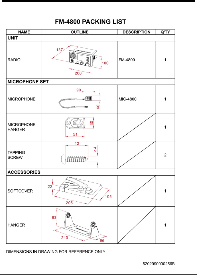
121
PACKING LIST
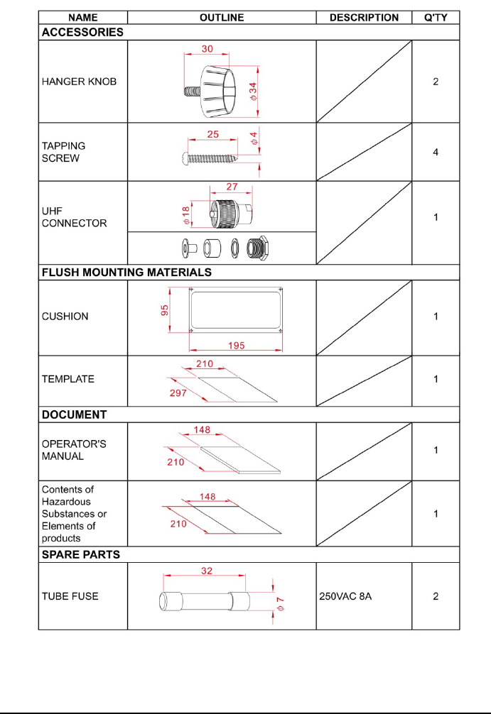
122
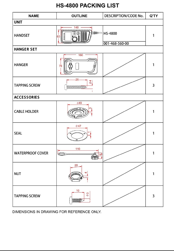
123
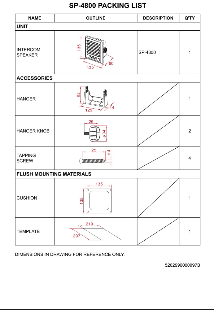
124
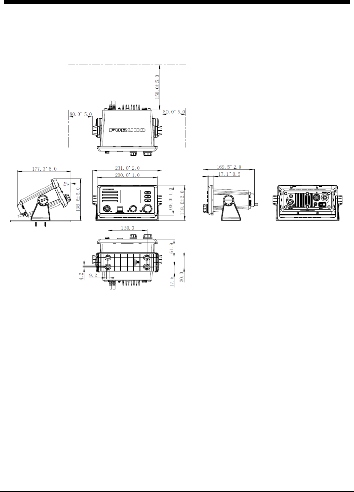
125
OUTLINE DRAWINGS
FM-4800
Desktop mounting
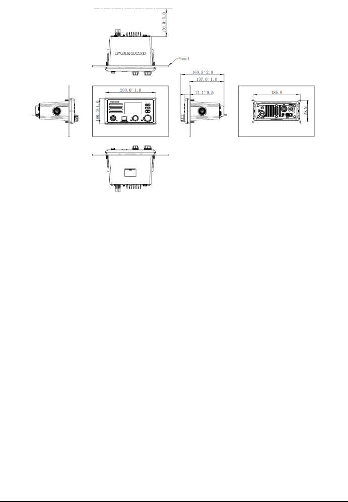
126
Flush mounting
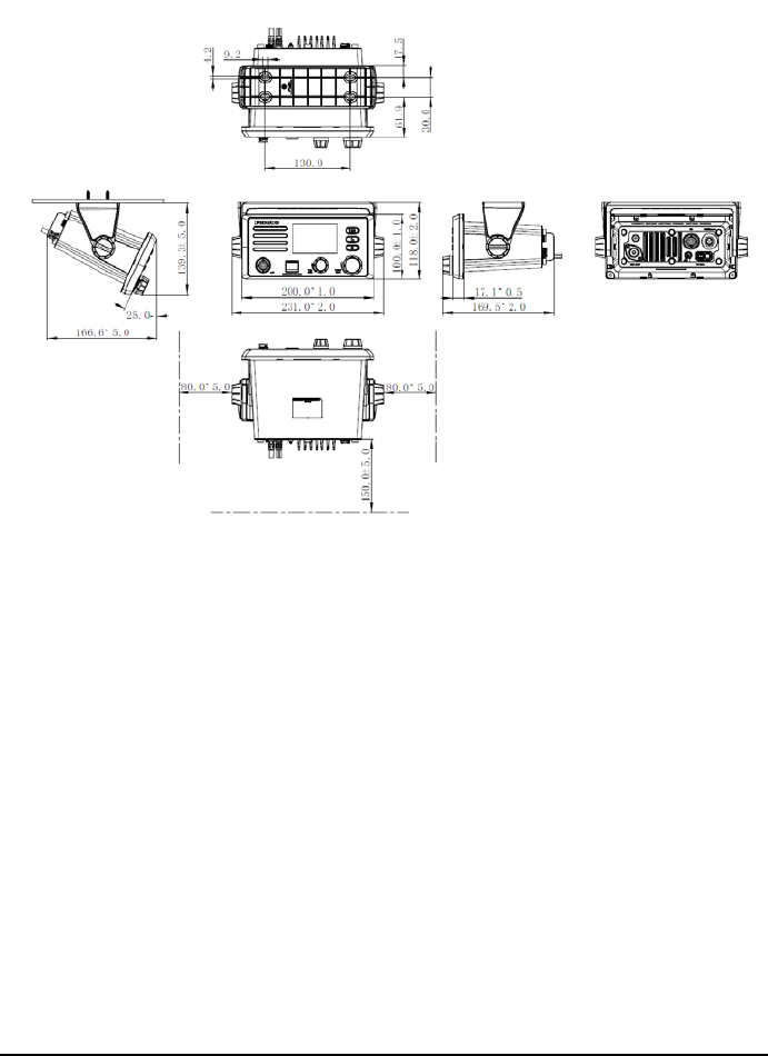
127
Hanger Mounting
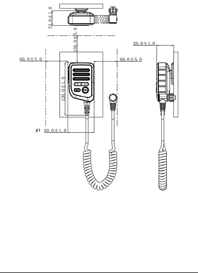
128
MIC-4800
Desktop mounting and Bulkhead (Wall)
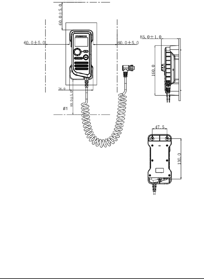
129
HS-4800
Desktop mounting and Bulkhead (Wall)
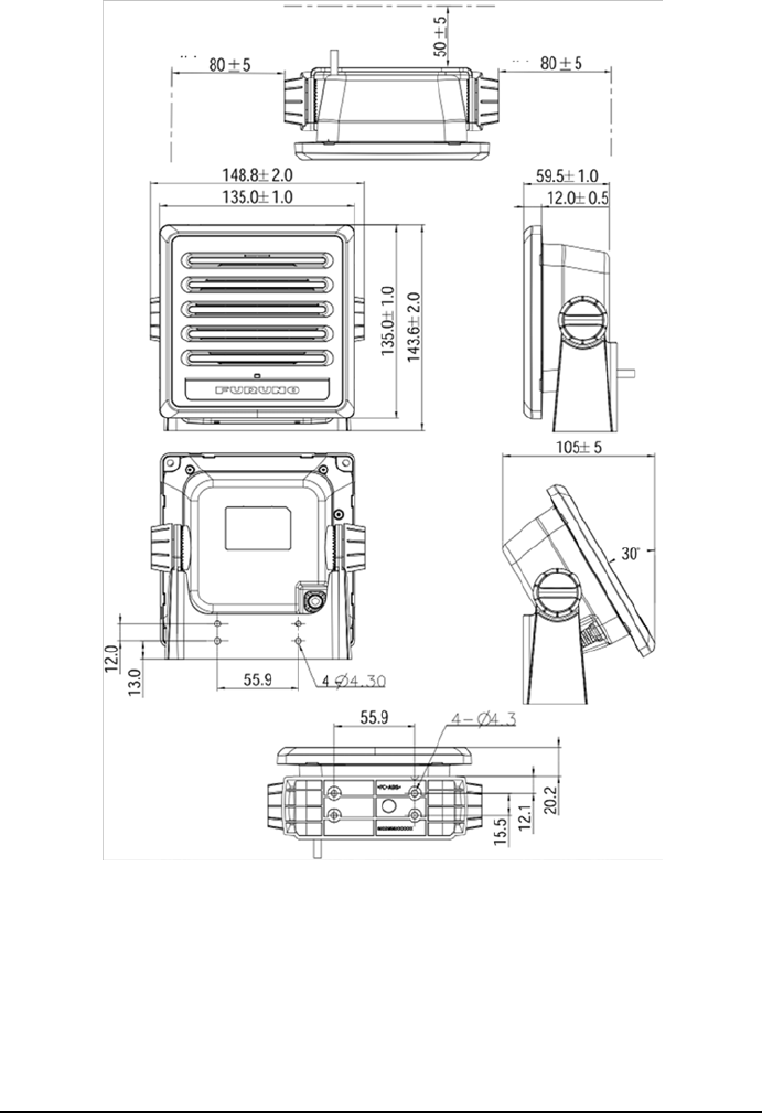
130
SP-4800
Desktop Mount
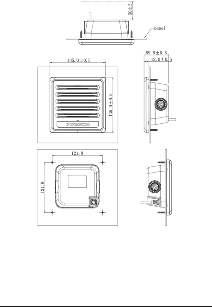
131
Flush mounting
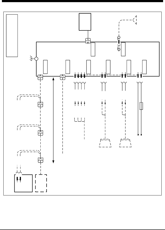
132
INTERCONNECTION
MARINE VHF
RADIOTELEPHONE
FM-4800
VHF ANT(※1)
RG-58/U 10m
MICRO
PHONE
MIC-4800
0.7m
(Max tensile 2.0m)
VHF ANT
MIC
12 12
EX-CBL-FM10M
10.0M (※2)
EX-CBL-FM5M
5.0M (※2)
0.5M
SPK- SPK+
12 12
EX-CBL-FM10M
10.0M (※2)
EX-CBL-FM5M
5.0M (※2)
0.5M
SPK- SPK+
HANDSET
HS-4800
(※2)
PURPLE
GRAY
12
Max 30.0M
5
T-CONNECTOR
FRU-NMEA-PFF MAX 6.0m (※1)
NMEA2000
HS
POWER
RED
BLACK
1
2Power (-)
EXT SPK
PURPLE
GRAY
3
4
SPK+
Hailer
RED
BLACK
Hailer-
5
6
Hailer+
VCTF 1.25sq 2C
MAX 20.0m (※1)
Speaker 8Ω ※1
Horn Speaker 4Ω※1
Power 12VDC (※1)
2.0M
0.4M
0.4M
SPK-
VCTF 1.25sq 2C
MAX 15.0m (※1)
RD (H) 9
10RD (C)
7
8TD (B)
TD (A) WHITE
BROWN
YELLOW
GREEN
MJ-A6SPF003
MAX 5.0m (※1)
0.4M
NMEA0183
8A
For example : FURUNO SP-4800
For example : Standard Horizon 240SW
Power (+)
YELLOW
GREEN
WHITE
BROWN
NAV EQUIPMENT
(※1) SHIPYARD SUPPLY.
(※2) OPTION.
GND
(※1)
SPK-2
1 SPK+
SPEAKER
SP-4800
(※2)
2.0M
0.5M
SPK- SPK+
EX-CBL-FM10M
10.0M (※2)
EX-CBL-FM5M
5.0M (※2)
0.7m
(Max tensible 2.0m)
133
TOOLS
No. Name No. Name
1 Diagonal pliers 10 Utility knife
2 Philips screwdriver 11 Wire stripper
3 Flathead screwdriver 12 Electric iron
4 Adjustable wrench 13 Heat-shrink tube
5 Heat gun 14 Waterproof adhesive tape
6 Marker 15 Electric drill
7 Multimeter 16 Drill
8 ESD-preventive gloves 17 Electric saw
9 ESD-preventive wrist strap \ \