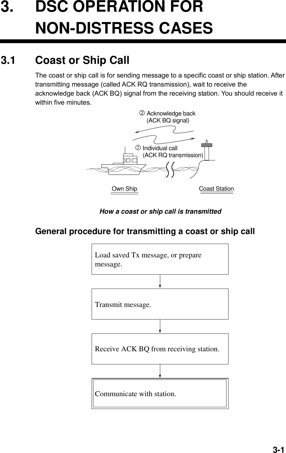
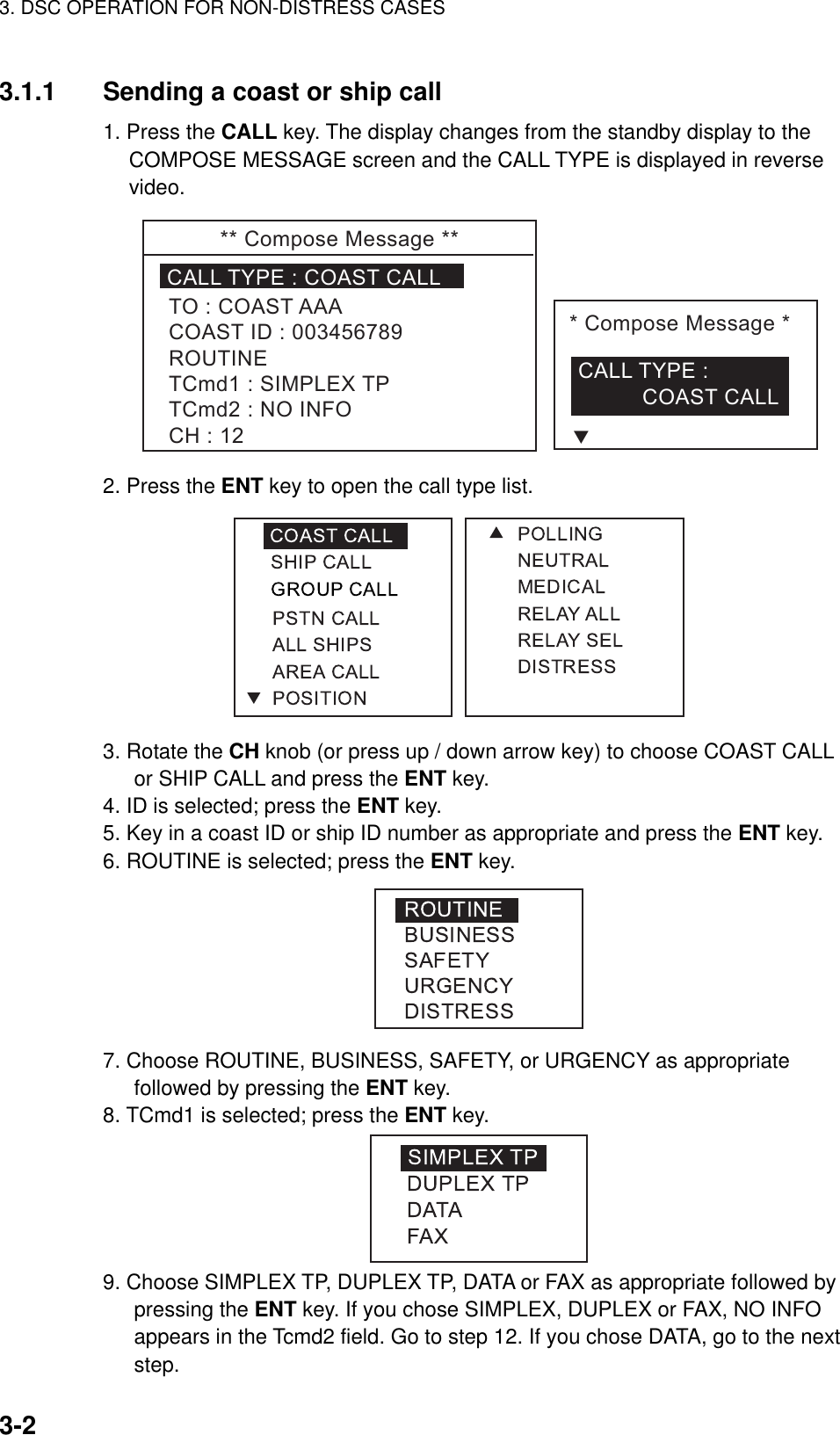
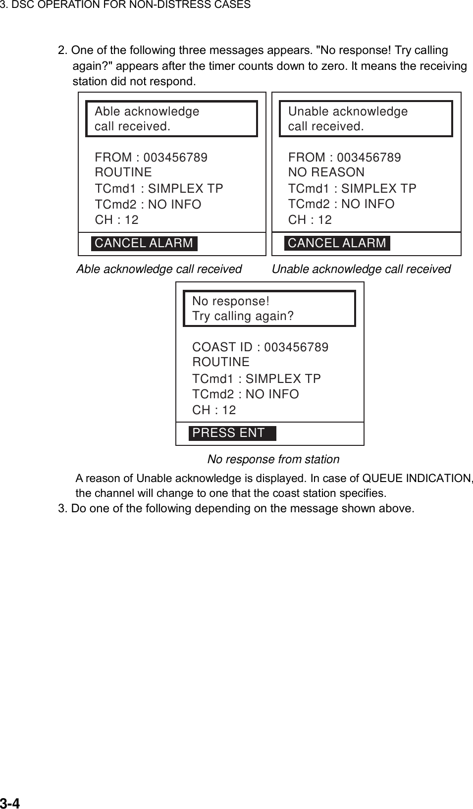
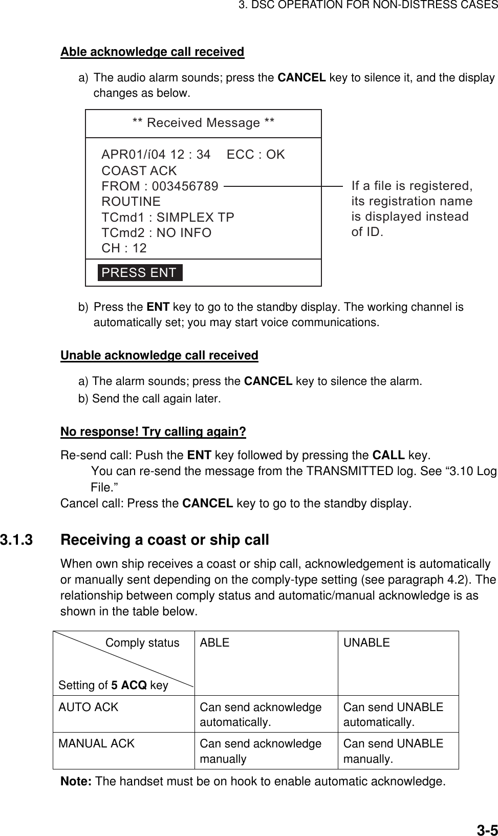
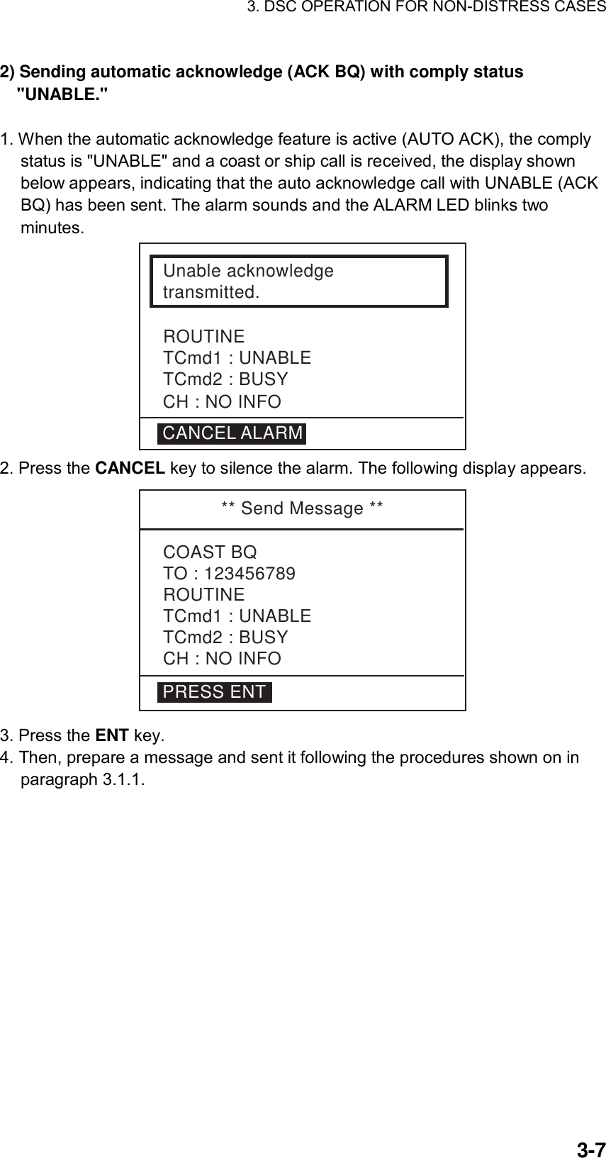
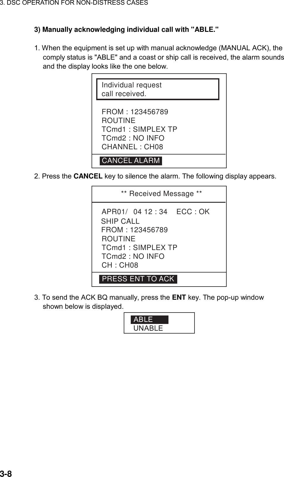
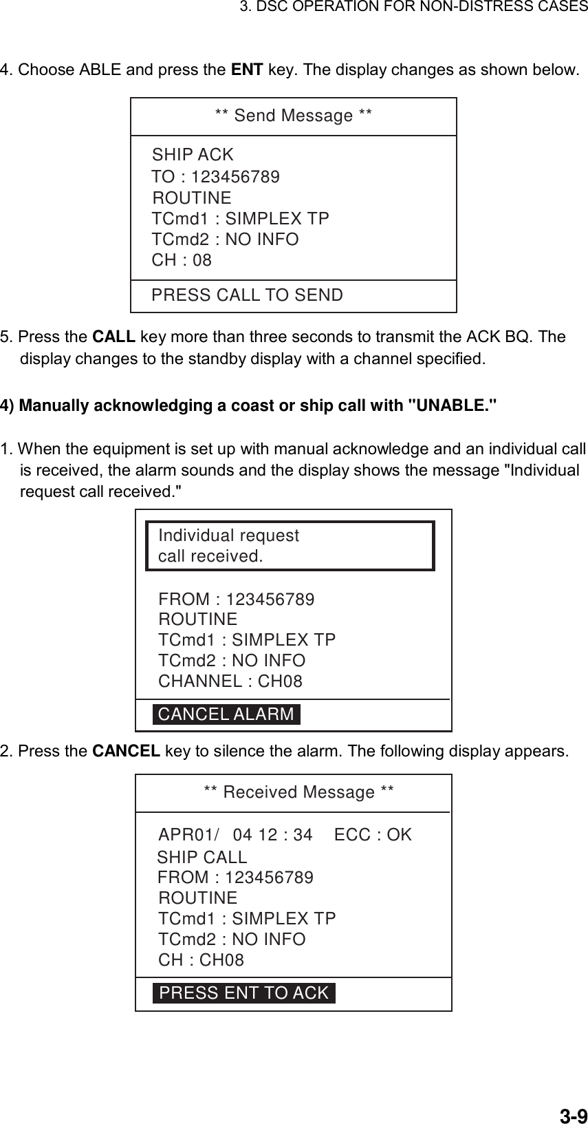
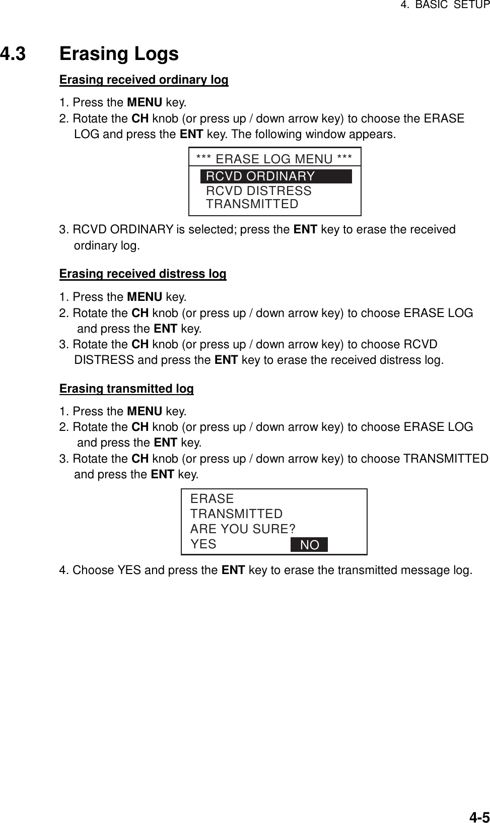
Furuno USA 9ZWFM8800D VHF MARINE RADIOTELEPHONE User Manual OPERATORS MANUAL
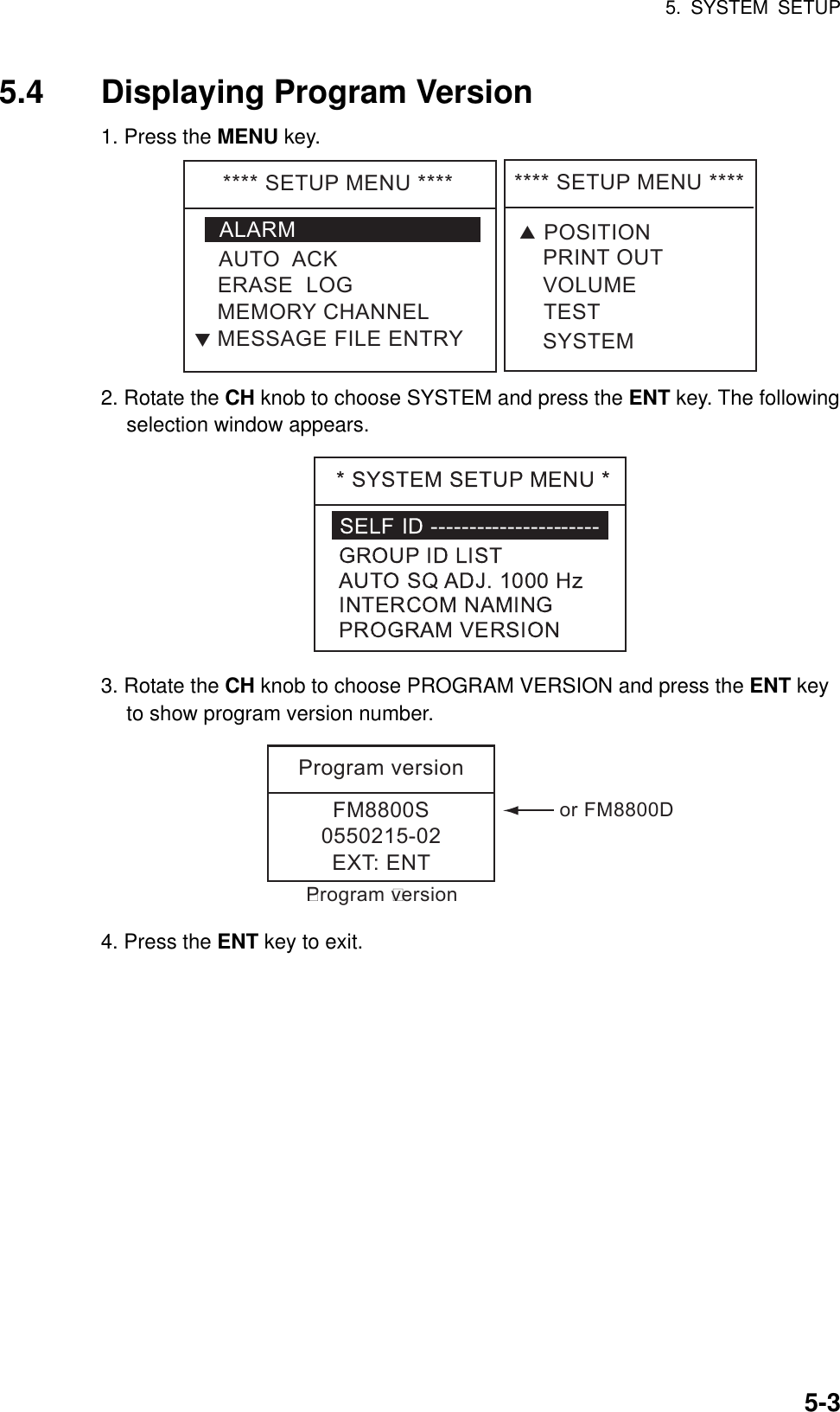
Furuno USA Inc VHF MARINE RADIOTELEPHONE OPERATORS MANUAL
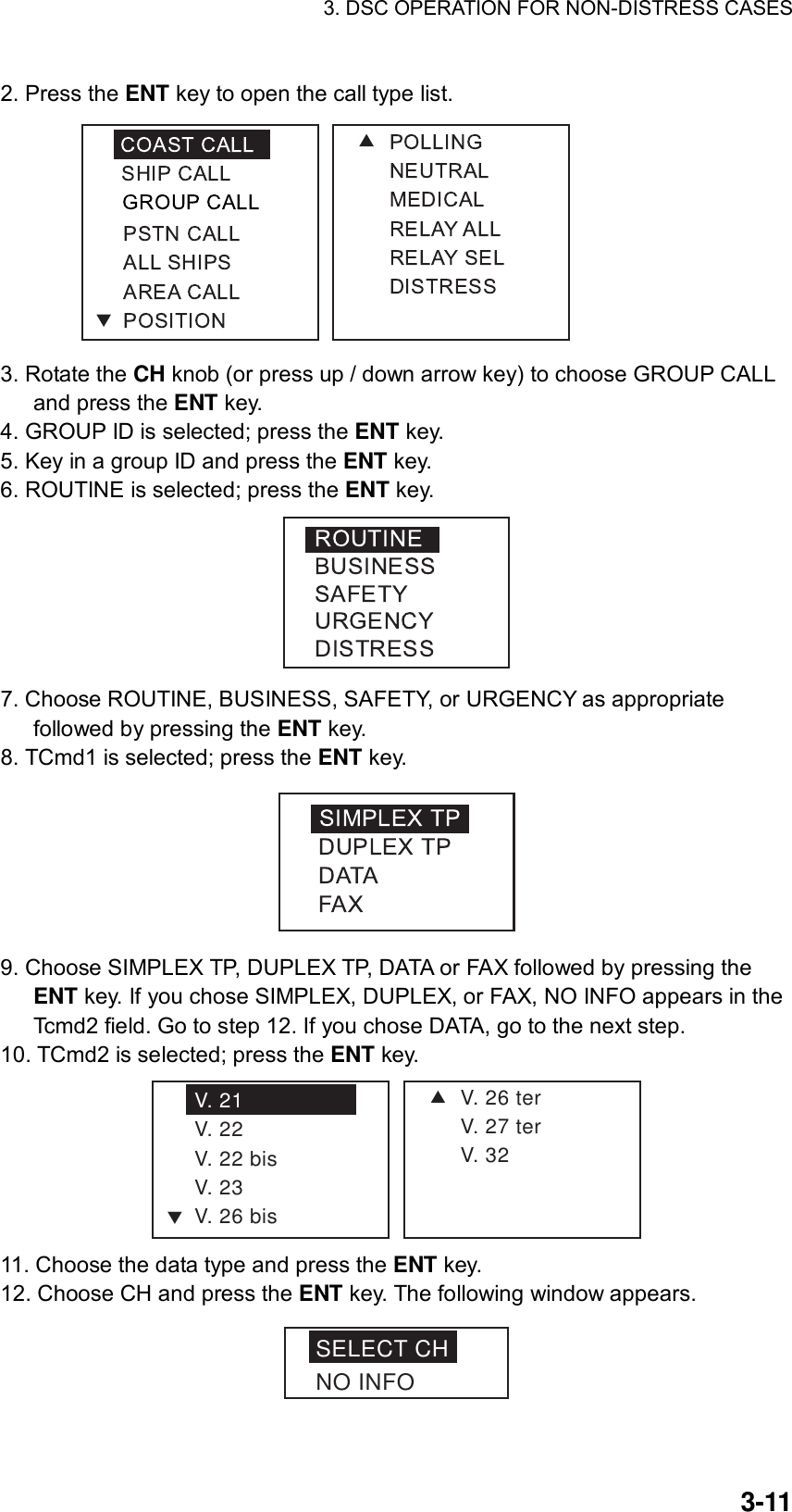
UserManual.wiki
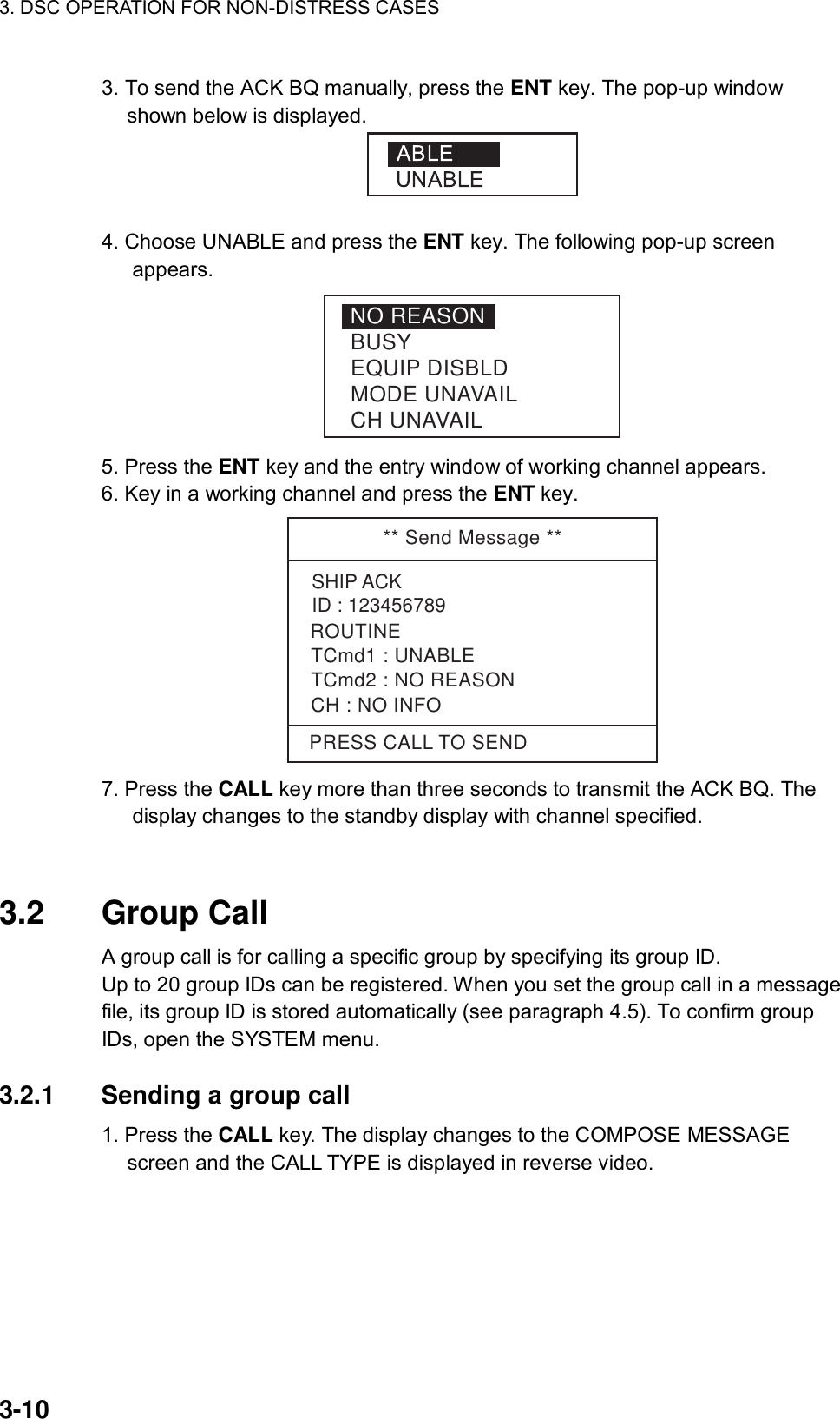
>
Furuno USA
>
9ZWFM8800D User Manual
>
OPERATORS MANUAL
Contents
1.
OPERATORS MANUAL
2.
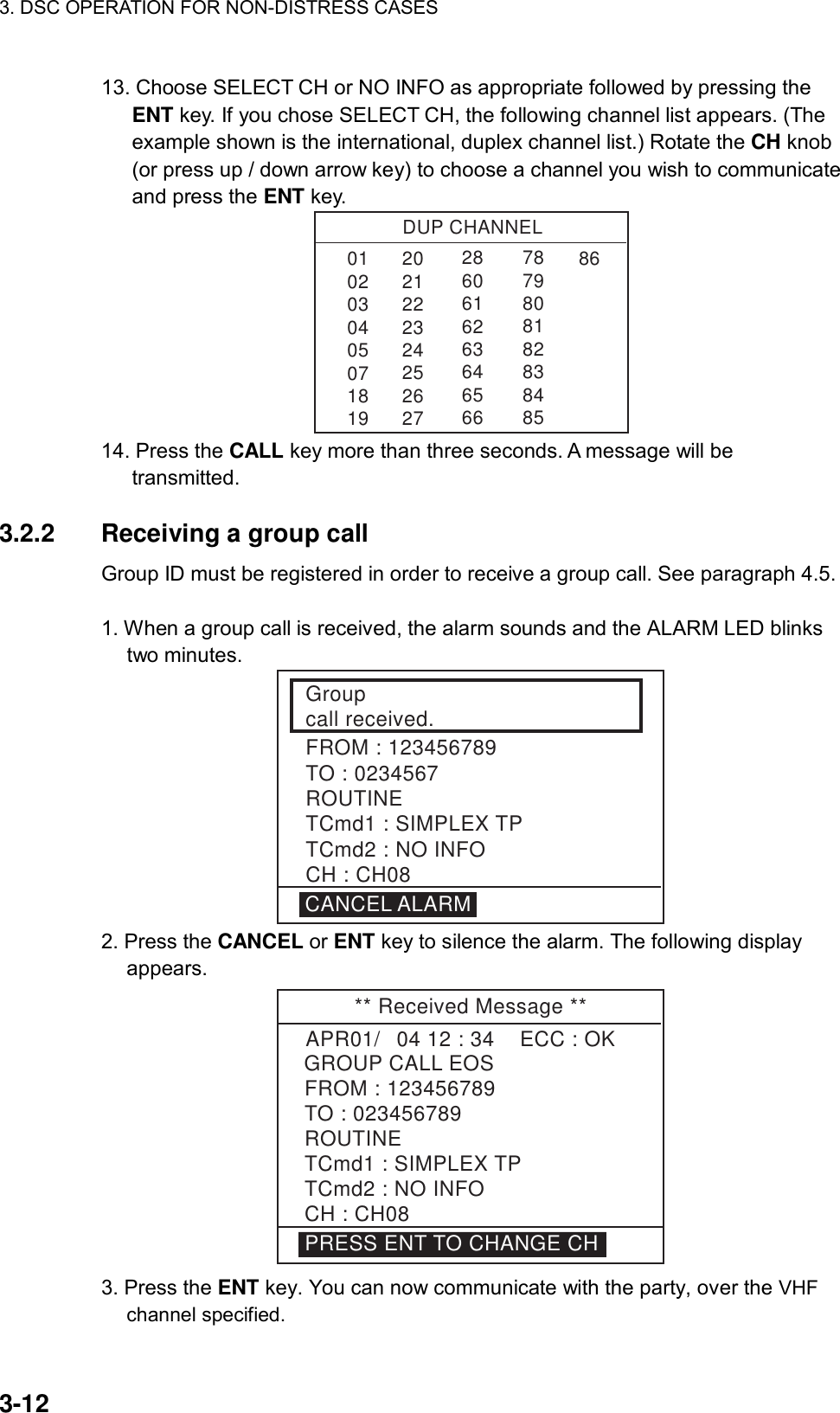
OPERATORS MANUAL PART1
3.
OPERATORS MANUAL PART2
OPERATORS MANUAL
Navigation menu
Upload a User Manual
Namespaces
Wiki Guide
HTML
PDF
Info
Views
User Manual
Discussion / Help
Navigation
![iCANCELING DISTRESS ALERTIf less than three seconds has elapsed since the [DISTRESS] key was pressed, the distress alert may be canceled by pressing the [CANCEL] key. Otherwise, do the following: 1. Switch off equipment immediately. 2. Switch equipment on and set to Channel 16. 3. Transmit message to “All Stations” giving your vessel's name, callsign and DSC number to cancel the distress alert. Example message: All Stations, All Stations, All Stations This is VESSEL'S NAME, CALLSIGN, DSC NUMBER, POSITION. Cancel my distress alert of DATE, TIME, UTC. =Master, VESSEL'S NAME, CALLSIGN. DSC NUMBER, DATE, TIME UTC.](https://usermanual.wiki/Furuno-USA/9ZWFM8800D.OPERATORS-MANUAL/User-Guide-494899-Page-3.png)


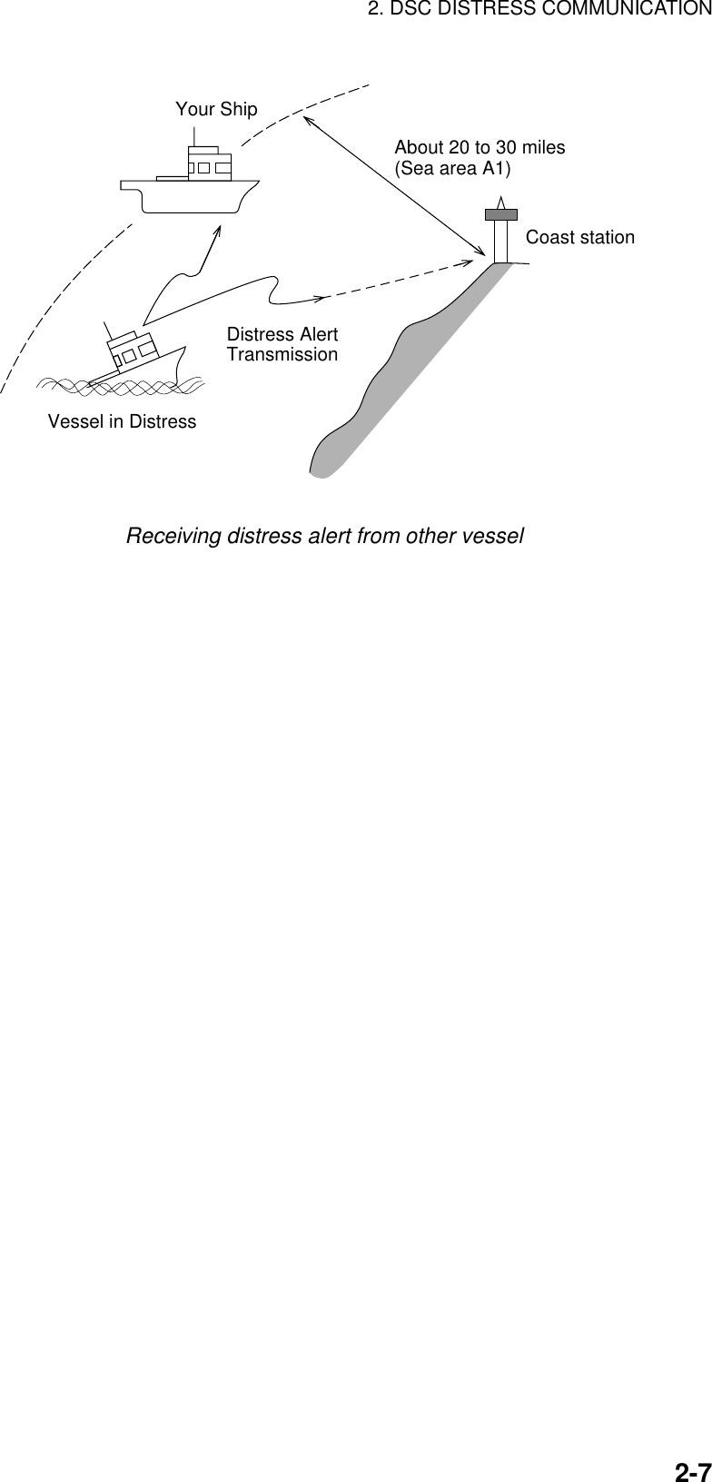
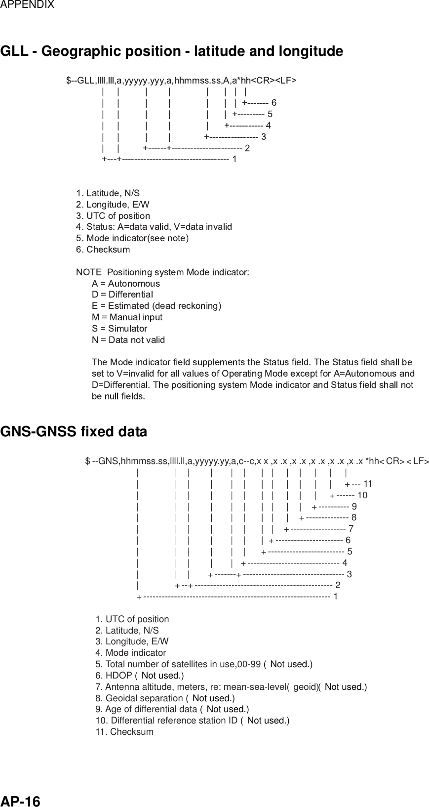
![2. DSC DISTRESS COMMUNICATION 2-8 Flow chart for determining if you should/should not transmit DIST ACK signal Press [CANCEL]key to silence alarm. DSC Distress alert received.Listen on CH16 for 5 minutes.Did you receiveacknowledge fromCS and/or RCC?Is ownvessel ableto assist?NoIs distress trafficin progress?NoIs distress callcontinuing?Acknowledge the alert byradiotelephony to the shipin distress on VHF CH16.YesNoInform CS and/or RCC.YesYes YesEnter details in log.NoCS = Coast StationRCC = Rescue Co-ordination Center1. Say "MAYDAY" ONCE.2. Say ID number of vessel in distress THREE TIMES.3. Say "This is" (your vessel's name) ONCE.4. Say ID number of your vessel THREE TIMES.5. Say "Received MAYDAY" ONCE.](https://usermanual.wiki/Furuno-USA/9ZWFM8800D.OPERATORS-MANUAL/User-Guide-494899-Page-32.png)
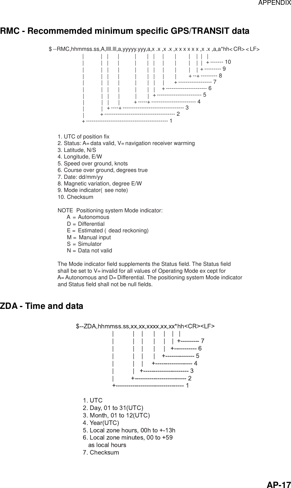
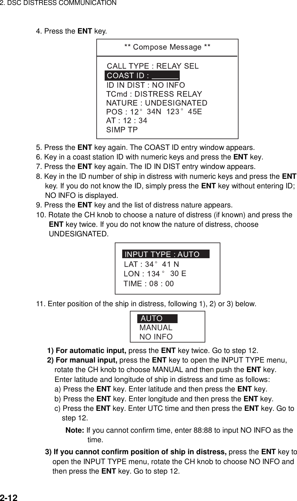
![2. DSC DISTRESS COMMUNICATION 2-112.6 Sending Distress Relay on Behalf of a Ship in Distress When you should relay a distress alert You may relay a distress alert in the following conditions: 1) When the station in distress is not itself in a position to transmit the distress message, or 2) When the master or person responsible for the vessel not in distress, or the person responsible for the coast station, considers that further help is necessary. DO NOT press the DISTRESS key to relay a distress alert; it is for use when own vessel is in distress. 2.6.1 Sending distress relay to coast station 1. Press the CALL key. The [Compose message] screen appears. ** Compose Message **CALL TYPE : COAST CALLCOAST ID : 003456789ROUTINETCmd1 : SIMPLEX TPTCmd2 : NO INFOCHANNEL : 10 2. Press the ENT key. The CALL TYPE selection window appears. 3. Rotate the CH knob (or press up / down arrow key) to choose RELAY SEL.](https://usermanual.wiki/Furuno-USA/9ZWFM8800D.OPERATORS-MANUAL/User-Guide-494899-Page-35.png)
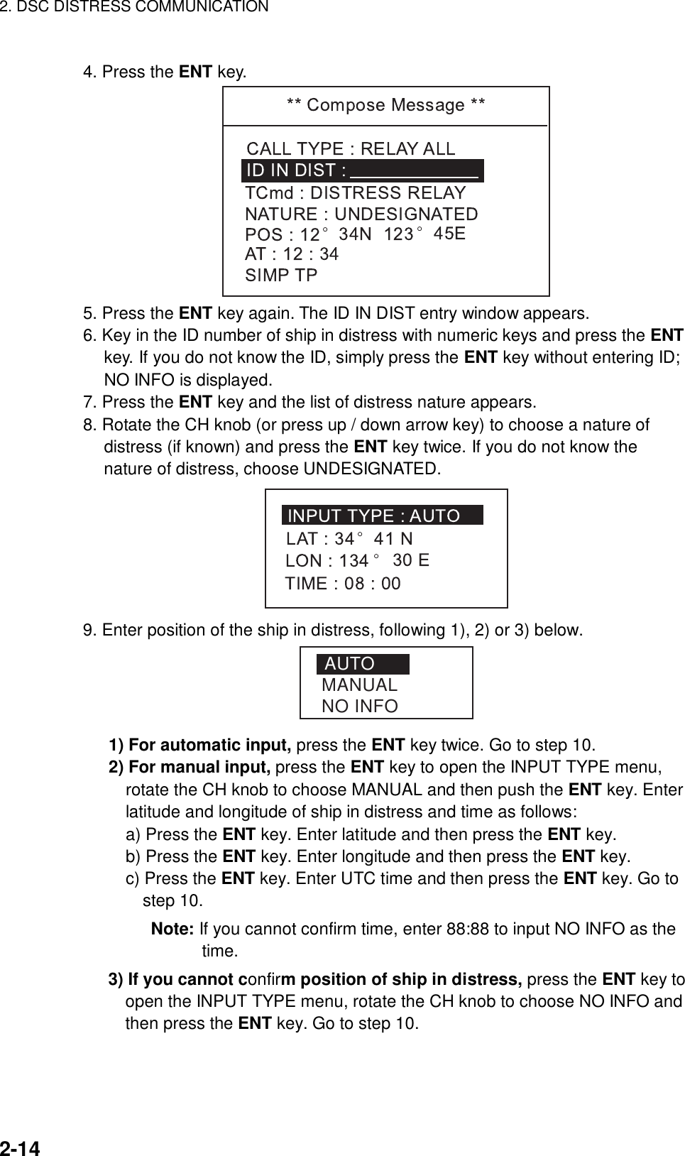
![2. DSC DISTRESS COMMUNICATION 2-1312. Press the CALL key more than three seconds to transmit the distress relay. KEEP PRESSED FOR 3S** Compose Message **CALL TYPE : RELAY SELTCmd : DISTRESS RELAYID IN DIST : NO INFOCOAST ID : NATURE : UNDESIGNATEDPOS : 12° 34N 123 ° 45EAT : 12 : 34SIMP TP When CALL key is pressed,this message appears andtimer counts down. The message will be transmitted and “Waiting for acknowledgement” will appear. 2.6.2 Sending distress relay to all ships 1. Press the CALL key. The [Compose message] screen appears. ** Compose Message **CALL TYPE : COAST CALLCOAST ID : 003456789ROUTINETCmd1 : SIMPLEX TPTCmd2 : NO INFOCHANNEL : 10 2. Press the ENT key. The CALL TYPE selection window appears. 3. Rotate the CH knob (or press up / down arrow key) to choose RELAY ALL. SHIP CALLGROUP CALLPSTN CALLALL SHIPSAREA CALLPOSITIONSTCOAST CALL POLLINGNEUTRALMEDICALRELAY ALLRELAY SELDISTRESS](https://usermanual.wiki/Furuno-USA/9ZWFM8800D.OPERATORS-MANUAL/User-Guide-494899-Page-37.png)

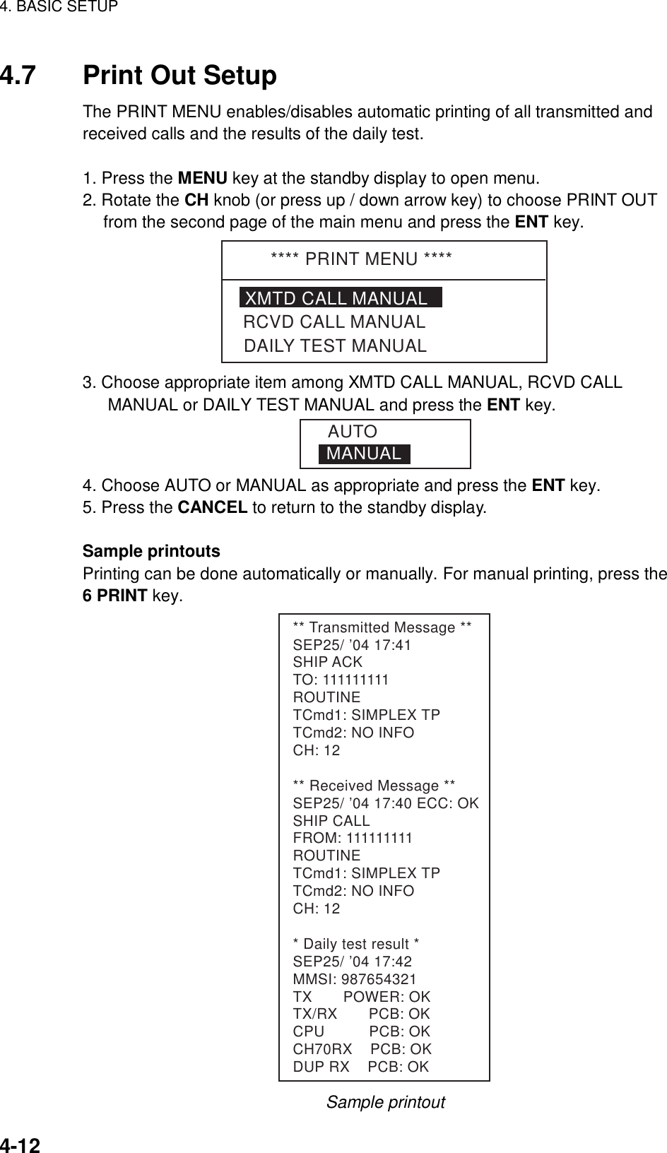
![4. BASIC SETUP 4-34.2 Auto ACK Setup The Auto Ack Menu enables/disables automatic acknowledgement of ship, coast, position and polling calls. Comply type Set of [5 ACQ] ABLE UNABLE AUTO ACK Can send acknowledge automatically. Can send UNABLE automatically. MANUAL ACK Can send acknowledge manually Can send UNABLE manually. To set COMPLY TYPE 1. Press the MENU key. 2. Rotate the CH knob (or press up / down arrow key) to choose AUTO ACK and press the ENT key. The following menu appears. **** AUTO ACK MENU ****COMPLY STATUS ABLE NO REASONPOSITION CALL ONUNABLE REASONPOLLING CALL ON 3. COMPLY STATUS is selected; press the ENT key. The following setting window appears. ABLEUNABLE 4. Rotate the CH knob (or press up / down arrow key) to choose ABLE or UNABLE as automatic acknowledgement reply to each call. 5. Press the ENT key. Note: Automatic acknowledge is automatically disabled when RX call contains error, as required by law. Further, automatic acknowledge is disabled in case of OFF HOOK.](https://usermanual.wiki/Furuno-USA/9ZWFM8800D.OPERATORS-MANUAL/User-Guide-494899-Page-79.png)
![AP-1APPENDIXMenu Tree [MENU] ALARMUNABLE REASONABLE/UNABLEAUTO ACK COMPLY STATUSPOSITION CALLNO REASON/BUSY/EQUIP DISBLD/MODE UNAVAIL/CH UNAVAILEXT ALARM4H/3H/2H/1H/0.5HOLD POSITIONPOSITION OLDERDIST/URG, ON ON/OFFON/OFFPOLLING CALL ON/OFFERASE LOG RCVD ORDINARY RCVD DISTRESS TRANSMITTEDMEMORY CHANNEL 50 entries MESSAGE FILE ENTRY 100 entries POSITION AUTO/MANUAL LAT/LONG/TIMEPRINT OUT XMTD CALL RCVD CALLDAILY TESTAUTO/MANUALAUTO/MANUALAUTO/MANUALVOLUMEOFFHOOK SPKRKEY CLICK EARPIECE LEVELINTERCOM VOLUMEON/OFF8 (0-16)9, 8 - 16 (For remote handset, 1-4)8, 1 - 16SYSTEMPROGRAM VERSIONSELF ID GROUP ID LISTINTERCOM NAMINGBold: DefaultSAFETY ON/OFFROUTINE ON/OFF[LOG] RCVD ORDINARY (50LOG)RCVD DISTRESS (50LOG)TRANSMITTED (50LOG)](https://usermanual.wiki/Furuno-USA/9ZWFM8800D.OPERATORS-MANUAL/User-Guide-494899-Page-99.png)
![APPENDIX AP-2 [CALL] COAST CALL COAST IDROUTINEGROUP CALL GROUP IDPSTN CALL COAST IDALL SHIPS BUSINESSSHIP CALL SHIP IDSAFETYURGENCYSAFETYURGENCYDISTRESSTCmd1 SIMPLEX TPDUPLEX TPDATAFAXTCmd2CH NO INFOSELECT CHROUTINEBUSINESSSAFETYURGENCYDISTRESSTCmd1 SIMPLEX TPDUPLEX TPDATAFAXTCmd2CH NO INFOSELECT CHROUTINEBUSINESSSAFETYURGENCYDISTRESSTCmd1 SIMPLEX TPDUPLEX TPDATAFAXTCmd2CH NO INFOSELECT CHTCmd1 SIMPLEX TPDUPLEX TPTCmd2: NO INFOTELDISTRESSTCmd1 SIMPLEX TPDUPLEX TPDATAFAXTCmd2: NO INFOCH NO INFOSELECT CH SIMP CHANNELDUP CHANNELAREA CALL ARE -- ---- - -- --°°°°→ ↓ROUTINEBUSINESSSAFETYURGENCYDISTRESSTCmd1 SIMPLEX TPDUPLEX TPDATAFAXTCmd2CH NO INFOSELECT CHPOSITION SHIP IDROUTINEBUSINESSSAFETYURGENCYDISTRESSTCmd1: POSITION REQUESTTCmd2: NO INFO1ROUTINECOAST ID:BUSINESSSHIP IDSAFETYURGENCYUNDESIGNATEDFireFloodingCollisionGroundingListingSinkingDisabled & AdrAbandoningPOS: AT:SIMP TPAUTOPOLLINGDISTRESSNEUTRAL URGENCYSAFETYCH: 16MEDICAL URGENCYTCmd1: SIMPLEX TPCH: 16TCmd2: MEDICAL TRSPRTRELAY ALL ID IN DISTTCmd: DISTRESS RELAYNATUREPiracyMan over boardEPIRBMANUALNO INFODISTRESS RELAY SELUNDESIGNATEDFireFloodingCollisionGroundingListingSinkingDisabled & AdrAbandoningPOS: AT:SIMP TPAUTOID IN DIST:TCmd: DISTRESS RELAYNATUREPiracyMan over boardEPIRBMANUALNO INFOUNDESIGNATEDFireFloodingCollisionGroundingListingSinkingDisabled & AdrAbandoningPOS: AT:SIMP TPAUTONATUREPiracyMan over boardEPIRBMANUALNO INFO1](https://usermanual.wiki/Furuno-USA/9ZWFM8800D.OPERATORS-MANUAL/User-Guide-494899-Page-100.png)