Furuno USA 9ZWFM8800D VHF MARINE RADIOTELEPHONE User Manual OPERATORS MANUAL
Furuno USA Inc VHF MARINE RADIOTELEPHONE OPERATORS MANUAL
Contents
- 1. OPERATORS MANUAL
- 2. OPERATORS MANUAL PART1
- 3. OPERATORS MANUAL PART2
OPERATORS MANUAL

VHF RADIOTELEPHONE
FM-8800D/8800S

Your Local Agent/DealerYour Local Agent/Dealer
9-52 Ashihara-cho,9-52 Ashihara-cho,
Nishinomi
y
a 662-8580, JAPANNishinomi
y
a 662-8580, JAPAN
Tele
p
hone :Tele
p
hone : 0798-65-21110798-65-2111
FaxFax 0798-65-42000798-65-4200
::
F
IRST EDITION :
F
IRST EDITION : SEPSEP.. 20042004
Printed in JapanPrinted in Japan
A
ll ri
g
hts reserved.
A
ll ri
g
hts reserved.
A1A1 :: SEPSEP.. 22, 200422, 2004
Pub. No.Pub. No. OME-56420OME-56420
*
00014993000
*
*
00014993000
*
*
00014993000
*
*
00014993000
*
(( TATATATA )) FM-8800D/SFM-8800D/S * 0 0 0 1 4 9 9 3 0 0 0 ** 0 0 0 1 4 9 9 3 0 0 0 *
*
OME
56420
A
10
*
*
OME
56420
A
10
*
*
OME
56420
A
10
*
*
OME
56420
A
10
*
* O M E 5 6 4 2 0 A 1 0 ** O M E 5 6 4 2 0 A 1 0 *

i
CANCELING DISTRESS ALERT
If less than three seconds has elapsed since the [DISTRESS] key was pressed,
the distress alert may be canceled by pressing the [CANCEL] key. Otherwise, do
the following:
1. Switch off equipment immediately.
2. Switch equipment on and set to Channel 16.
3. Transmit message to “All Stations” giving your vessel's name, callsign and
DSC number to cancel the distress alert.
Example message:
All Stations, All Stations, All Stations
This is VESSEL'S NAME, CALLSIGN,
DSC NUMBER, POSITION.
Cancel my distress alert of
DATE, TIME, UTC.
=Master, VESSEL'S NAME, CALLSIGN.
DSC NUMBER, DATE, TIME UTC.
ii
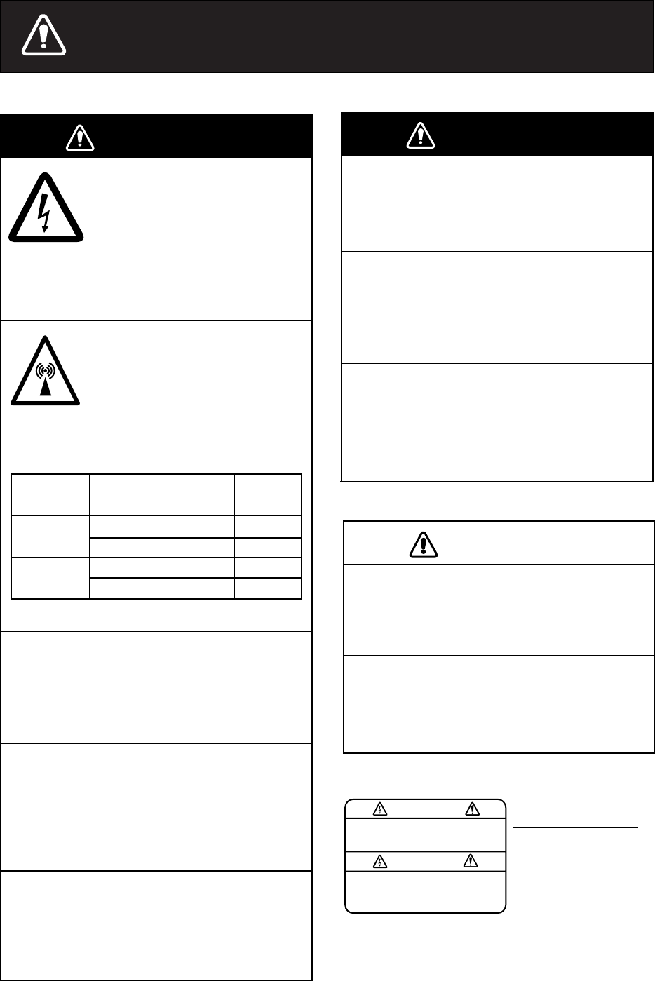
SAFETY INSTRUCTIONS
Do not disassemble or modify the
equipment.
Fire, electrical shock or serious injury
can result.
Turn off the power immediately if water
Do not open the equipment.
leaks into the equipment or the equip-
ment is emitting smoke or fire.
Continued use of the equipment can cause
fire or electrical shock.
Do not place liquid-filled containers on
the top of the equipment.
Fire or electrical shock can result if a
liquid spills into the equipment.
Any repair work must be done by a
licensed radio technician.
Improper repair work can cause electrical
shock or fire.
Do not operate the equipment with wet
hands.
Electrical shock can result.
Keep heater away from equipment.
Heat can alter equipment shape and melt
the power cord, which can cause fire or
electrical shock.
Hazardous voltage which can
cause electrical shock, burn
or serious injury exists inside
the equipment. Only qualified
personnel should work inside
the equipment.
WARNINGWARNING
CAUTION
Do not touch any part of the antenna
when the equipment is transmitting.
Electrical shock can result.
Use the proper fuse.
Use of a wrong fuse can result in fire or
cause permanent damage to the equipment.
WARNING
To avoid electrical shock, do not
remove cover. No user-serviceable
parts inside.
Terminal, Communication
Unit
Name: Warning Label (1)
Type: 86-003-1011
Code No.: 100-236-231
Do not approach the antenna
closer than 33 cm when it
is transmitting.
The antenna emits radio waves
which can be harmful to the
human body.
WARNINGWARNING
FM-8800S
RF power density
on antenna aperture distance
100 W/m20.11 m
10 W/m20.33 m
FM-8800D 100 W/m20.10 m
10 W/m20.33 m

iii
TABLE OF CONTENTS
FOREWORD ......................................................................................................... v
SYSTEM CONFIGURATION............................................................................... vii
SPECIFICATIONS........................................................................................... SP-1
1. OPERATIONAL OVERVIEW
1.1 Controls Keys and LCD Indication .............................................................................1-1
1.2 VHF Basic Operation .................................................................................................1-7
1.3 DSC Operational Overview......................................................................................1-10
1.4 Priority .....................................................................................................................1-12
2. DSC DISTRESS COMMUNICATION
2.1 Distress Alert Transmission from the DISTRESS Key................................................2-1
2.2 Distress Alert Transmission with Nature of Distress ...................................................2-3
2.3 Distress Alert Transmission From CALL Key..............................................................2-4
2.4 Canceling a False Distress Alert ................................................................................2-6
2.5 Receiving Distress Alert from Other Vessel, Transmitting DIST ACK Signal...............2-6
2.6 Sending Distress Relay on Behalf of a Ship in Distress ........................................... 2-11
2.7 Receiving Distress Relay.........................................................................................2-15
3. DSC OPERATION FOR NON-DISTRESS CASES
3.1 Coast or Ship Call......................................................................................................3-1
3.2 Group Call ...............................................................................................................3-10
3.3 PSTN Call................................................................................................................3-13
3.4 All Ships Call............................................................................................................3-16
3.5 Geographical Area Call............................................................................................3-19
3.6 Position Call.............................................................................................................3-22
3.7 Polling Call...............................................................................................................3-25
3.8 Neutral Craft Call .....................................................................................................3-29
3.9 Medical Transport Call .............................................................................................3-30
3.10 Log File....................................................................................................................3-32
4. BASIC SETUP
4.1 Alarm Setup...............................................................................................................4-1
4.2 Auto ACK Setup.........................................................................................................4-3
4.3 Erasing Logs..............................................................................................................4-5
4.4 Memory Channel Setup .............................................................................................4-6
4.5 Message File Entry....................................................................................................4-7
4.6 Position Setup.......................................................................................................... 4-11
4.7 Print Out Setup ........................................................................................................4-12
4.8 Volume Setup ..........................................................................................................4-13
TABLE OF CONTENTS
i
v
5. SYSTEM SETUP
5.1 Displaying Self ID...................................................................................................... 5-1
5.2 Displaying Group ID LIST.......................................................................................... 5-1
5.3 Naming Intercom....................................................................................................... 5-2
5.4 Displaying Program Version ...................................................................................... 5-3
6. MAINTENANCE & TROUBLESHOOTING
6.1 Maintenance.............................................................................................................. 6-1
6.2 Troubleshooting......................................................................................................... 6-1
6.3 Daily Test................................................................................................................... 6-2
6.4 Error Message........................................................................................................... 6-3
6.5 Parts Location ........................................................................................................... 6-3
APPENDIX ......................................................................................................AP-1
Menu Tree.......................................................................................................................AP-1
Marine VHF Channel Lists...............................................................................................AP-3
Digital Interface (IEC 61162-1 Edition 2)........................................................................AP-14

v
FOREWORD
A Word to FM-8800D/FM-8800S Owners
Congratulations on your choice of the FURUNO FM-8800D/FM-8800S VHF
Radiotelephone. We are confident you will see why the FURUNO name has
become synonymous with quality and reliability.
For over 50 years FURUNO Electric Company has enjoyed an enviable
reputation for quality marine electronics equipment. This dedication to
excellence is furthered by our extensive global network of agents and dealers.
This equipment is designed and constructed to meet the rigorous demands of
the marine environment. However, no machine can perform its intended function
unless operated and maintained properly. Please carefully read and follow the
recommended procedures for operation and maintenance.
We would appreciate hearing from you, the end-user, about whether we are
achieving our purposes.
Thank you for considering and purchasing FURUNO equipment.
FOREWORD
vi
Features
The FURUNO FM-8800D/FM-8800S is a cost-effective all-in-one marine VHF
radio system consisting of a 25 W VHF radiotelephone, a DSC modem, and a
CH 70 watch receiver. It complies with GMDSS carriage requirements for safety
and general communications.
The FM-8800D offers full-duplex voice communications and the FM-8800S
offers simplex voice communication on ITU channels in the marine mobile VHF
band. The features include Dual Watch which allows a continuous watch on
CH16 and another selected frequency.
Full Class-A DSC functions are provided for distress alert transmission and
reception, as well as the general call formats (Individual telephone, All Ships,
Group and Area Call). Distress alert can be readily transmitted but an
arrangement is provided to prevent accidental activation. The FM-8800D/
FM-8800S maintains a continuous watch on CH70 even while another VHF
channel is in use. Aural and visual alarms are given to incoming DSC messages.
The main features of the FM-8800D/FM-8800S are
• Compact cabinet allows for flexible and space-saving installation on a
navigation console or at the conning position
• Conforms to the following standards and regulations:
IMO A.694(17)
IMO A.803(19)
IMO A.524(13)
IMO MSC 68(68), MSC/Circ.862
IEC61097-3/7/8
IEC60945 (4th edition)
IEC61162-1 (July 2000)
ETS 300 338, 300 698, 301 925
ITU-R M.493-10, M.541-8, M.689-2
• Full-duplex communications: FM-8800D
• Precision PLL frequency synthesizer for high frequency stability as required for
DSC operation
• Dual Watch and Multiple Watch
• Continuous DSC watch on CH70
• Prevention of accidental distress alert
• File editing for emergency readiness
• Automatic entry of own ship position with manual override
Program number
FM-8800D/FM-8800S: 0550215-02
vii
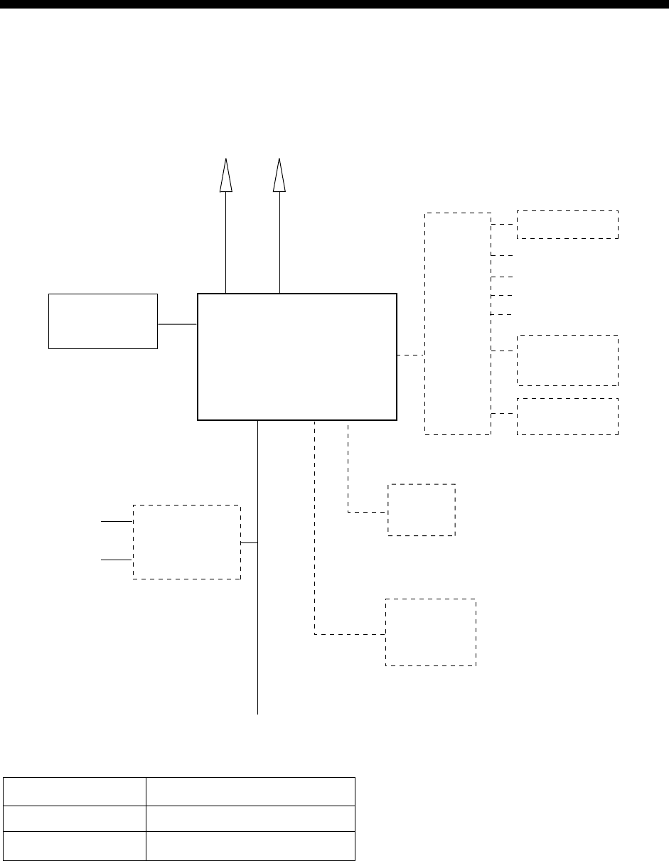
SYSTEM CONFIGURATION
The FM-8800D/FM-8800S is a highly advanced 25 W VHF transceiver with DSC
terminal. It is designed to satisfy the stringent requirements of marine
communications, and complies with GMDSS carriage requirements for safety
and general communications.
TRANSCEIVER UNIT
FM-8800D
FM-8800S
Handset
HS-2003
VHF
Antenna CH 70 RX
Antenna
AC/DC
Power Supply
Unit
PR-240-CE
100/220 VAC
50/60 Hz, 1φ
Category of units
Antenna
All other units
Exposed to weather
Protected from weather
Category
Radio Battery
24 VDC
24 VDC
Junction
Box
IF-8810 Remote box
RB-
8800/8810
HS-8800
Printer
PP-510
External
Speaker
SEM-21Q
DMC I/F
IF-8820
Wing handset
T/R AF output for VDR
MAX
2 sets
MAX
4 sets
IEC61162-1 input
DSC information output
Unit
External alarm
FM-8800D/FM-8800S system configuration
viii
This page is intentionally left blank.

SP-1
SPECIFICATIONS OF MARINE VHF RADIOTELEPHONE
FM-8800D/FM-8800S
1. GENERAL
(1) Number of Channels INTL: 57
USA: 55 (57)*
Weather: 10
Canada: 55 (57)*
INLND-WA: 55 (57)*
Private: 20 *: CH75&76 can be included
MEMORY CH: 50 for some countries.
(2) Frequency Stability Within ±1.5 kHz
(3) Communication System FM-8800S: Simplex/Semi-duplex
FM-8800D: Simplex/Full-duplex
(4) Class of Emission 16K0G3E (Voice)
16K0G2B (DSC)
(5) Antenna Impedance 50 ohms
2. TRANSMITTER
(1) Frequency Range
(2) Output Power 25 W max., 1 W at power reduction
(3) Frequency Deviation <5 kHz
3. RECEIVER
(1) Frequency Range
(2) Receiving System Double Superheterodyne
(3) Intermediate Frequency 1st: 51.2375 MHz, 2nd: 37.5 kHz
(4) Sensitivity +6 dBµV (20 dB SINAD)
(5) Adjacent Channel Selectivity 70 dB or more
(6) Spurious Response 70 dB or more
(7) AF Output Built-in Speaker: 3 W (4 ohms)
Handset earphone: 2mW (150 ohms)
4. DSC
(1) Protocol ITU-R Rec. 541-8, 493-10 (class A)
(2) Baud Rate 1200 baud ±30 ppm max.
(3) Modulation AFSK
(4) Frequency Shift 1700 ±400 Hz
Mark: 1300 Hz, Space: 2100 Hz
Simplex 155.000 to 161.475 MHz FM-8800S
Semi-duplex 155.000 to 161.475 MHz
Simplex 155.000 to 158.000 MHz FM-8800D
Full-duplex 155.000 to 158.000 MHz
Simplex 155.000 to 159.600 MHz FM-8800S
Semi-duplex 161.475 to 166.075 MHz
Simplex 155.000 to 158.000 MHz FM-8800D
Full-duplex 160.625 to 162.600 MHz

SP-2
5. CH70 WATCH RECEIVER
(1) Receiving Frequency 156.525 MHz
(2) Sensitivity Symbol error rate: Less than 1% (at 0 dBµV)
(3) Conducted Spurious Emission Less than 2 nW
6. POWER REQUIREMENTS
(1) Power Supply 24 VDC (-10%/+30%)
(2) Power Consumption
7. DIGITAL INTERFACE IEC 61162-1 (NMEA0183 Ver.3)
Sentence IN: GGA>RMC>GNS>GLL>ZDA
OUT: TLL
Talker: GP>LC>DE>II>IN>EC
8. AMBIENT CONDITIONS
(1) Temperature -15°C to 55°C (IEC60945)
(2) Relative Humidity 93% (at 40°C)
(3) Waterproofing (IEC 60529)
Transceiver Unit Chassis: IPX0
Panel: IPX4
Handset/Hanger HS-2003: IPX-4
Remote Box/Handset RB-8800: IPX-0
HS-8800:IPX-2
Junction Box IF-8810: IPX-0
DMC Interface IF-8820: IPX-0
9. COATING COLOR
(1) Transceiver Unit Chassis: Munsell 2.5GY5/1.5
Panel: Munsell N3.0
Waiting 0.5 A
Receive 1.6 A at 4 W audio output
FM-8800S
Transmit 1.6 A at 1 W output,
4.7 A at 25 W output
Waiting 0.5 A
Receive 1.6 A at 4 W audio output
Transmit 2 A at 1 W output,
6 A at 25 W output
FM-8800D
DUP Transmit 3.6 A at 1 W output,
7.6 A at 25 W output
1-1
1. OPERATIONAL OVERVIEW
The FM-8800D/FM-8800S system consists of a transceiver block and two
antennas. The transceiver block contains a VHF transmitter, receiver, and
channel 70 watch receiver module. FM-8800D additionally provides a duplexer
block. All operations are controlled on its front panel.
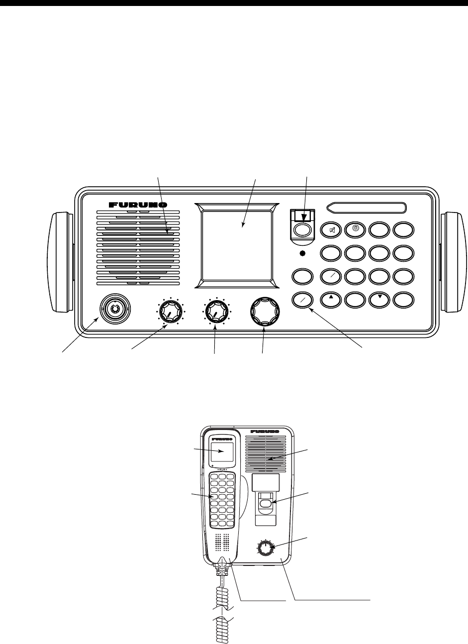
1.1 Controls Keys and LCD Indication
1.1.1 Front panel
The alert is transmitted with steady lighting.
Keep pressed for 4 s in case of DISTRESS.
MSG
CALL
SHIFT
*
0
HI/L0
7
USA
PQRS
INTL
8
SCAN
TUV
ENT
#
MENU
9DW
WXYZ
DISTRESS
4
GHI
IntCom
5
JKL
ACK
1 2
ABC
FILE
6
MNO
PRINT
CH16
3
DEF
TEST
CANCEL
LOG
ALARM
CHANNEL
PUSH TO ENTER
SQUELCH
HANDSET
VOLUME/POWER
AUTOOFF
Volume with
Power ON/OFF Squelch control
Transmits the distress alert.
Press this button three seconds continuously.
LCD
Transmits various
messages.
Channel selector
Handset port
Loudspeaker
Transceiver unit
DISTRESS
VOLUME
ALARM
LCD
Keyboard
Loudspeaker
Distress button
Volume control
HS-8800
Handset
HG-8800
Handset hanger
Remote station (option)

1. OPERATIONAL OVERVIEW
1-2
1.1.2 Controls
The functions of keys of the transceiver unit and the remote station are almost
the same. The table below shows the controls and keys for the transceiver unit.
Control Function
CHANNEL
(PUSH TO
ENTER)
• Selects a channel.
• Moves the cursor in menu opened.
• Registers selected item when pressed.
SQUELCH
• Mutes the receiver when no signal is present on
the channel selected.
• AUTO position automatically reduces white noise.
VOLUME/POWER • Turns the power on/off and adjusts the volume of the
loudspeaker.
Key Function
DISTRESS
• Transmits the distress alert after pressing three seconds.
When the key is pressed, the LED in the key blinks and the
buzzer sounds. Pressing the key three seconds
continuously the distress alert is transmitted and the LED
lights continuously and buzzer also sounds continuously.
These conditions are continued until the distress
acknowledge is received or you cancel the distress alert.
ALARM
(INDICATOR)
• Blinks in red when a distress alert or urgent call is received.
Also, the acoustic alarm sounds. To stop the blinking and
silence the buzzer, press the CANCEL key.
• Blinks in green when a safety call or routine call is received.
The acoustic alarm sounds and stops automatically five
seconds later.
CANCEL
• Stops audible and visual alarms.
• Erases an error message.
• Cancels numeric entry.
• Returns to previous menu.
• Cancels transmission or printing.
CALL
MSG
• Transmits various DSC messages. To transmit a distress
message, press this key more than three seconds.

1. OPERATIONAL OVERVIEW
1-3
1
• Enters 1, ., ,, √, ”, :, ;, -, +, *, #, , (, ), !, $, &, / character at
entry mode.
• Turns the loudspeaker on or off. Pressing the SHIFT and
then this key turns loudspeaker on or off.
In the off state, the loudspeaker icon disappears. However,
the key click actives and the alarm sounds when a distress
or urgent call is activated.
2
ABC
• Enters alphanumeric data (2, A, B, C).
• Adjusts panel illumination when proceeded by the SHIFT
key.
3
TEST
DEF
• Enters alphanumeric data (3, D, E, F).
• Performs the daily test when proceeded by the SHIFT key.
4
IntCom
GHI
• Enters alphanumeric data (4, G, H, I).
• Turns the interphone on or off when proceeded by the
SHIFT key and followed by ENT key. Available when a
remote handset is connected.
5
ACK
JKL
• Enters alphanumeric data (5, J, K, L).
• Turns auto acknowledge of routine calls on or off.
6
PRINT
MNO
• Enters alphanumeric data (6, M, N, O).
• Prints communication files, current display and daily test
result.
7
INT/USA
PQRS
• Enters alphanumeric data (7, P, Q, R, S).
• Changes the channel mode among INTL, USA**, WX**,
CANADA**, INLND-WA** and (MEMO)*.
*: If registered.
**: Required system setting by qualified serviceman only.
8
SCAN
TUV
• Enters alphanumeric data (8, T, U, V).
• Turns the scan function on or off.
9
DW
WXYZ
• Enters alphanumeric data (9, W, X, Y, Z).
• Turns the dual watch function on or off.

1. OPERATIONAL OVERVIEW
1-4
0
HI/LO
• Enters “0”.
• Changes the output power high (25 W) or low (1 W).
However, the following channels are always 1 W.
INTL mode: CH15, CH17, CH75, CH76
USA mode: CH13, CH17, CH67
▲
*
SHIFT
• Press to activate secondary function.
• Moves the screen to previous item.
▼
LOG
#
• Displays transmitting/receiving messages.
• Moves the screen to next item.
CH16 • Selects CH16 by one-touch action.
FILE • Opens the Message file list.
MENU • Opens the SETUP menu.
ENT
• Registers data input.
(Same as pressing the CH selector.)
Additional keys of the handset HS-8800
Key Function
(up arrow key)
• With the SHIFT key pressed, this key increases volumes of
internal loudspeaker of remote station.
• Increments channel number or setting value.
SQ
• Adjusts squelch level with or key.
(down arrow key)
• With the SHIFT key pressed, this key decreases volumes
for internal loudspeaker of remote station.
• Decrements channel number or setting value.
SQ auto
• With the SHIFT key pressed, this key adjusts auto squelch
level.

1. OPERATIONAL OVERVIEW
1-5
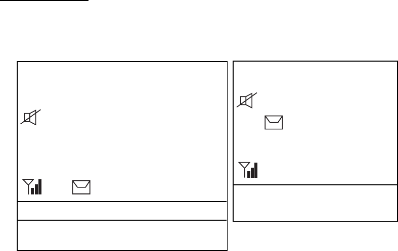
1.1.3 Indications on the LCD
Below are all the indications which appear on the standby display on the
transceiver unit.
INTL
12
3
4
5
6
7
8
910
11 12
13
14
Hi
RX
DUP
116
SCAN
SHIFT
AUTO ACK WATCH CH70 *
LAT: 34 45' N
°10:45 UTC
LON: 135 45' E
°AUTO
Standby display on the transceiver unit
Reference no. meaning
① Displays the channel mode.
(INTL / USA / WX / CANADA / INLND-WA / (MEMO))
② SHIFT is displayed if the shift function is active. Or memory number (for
example MEMO 01) is displayed at the MEMO mode.
③ Displays the scan mode: SCAN, DUAL or no display. During the scan
mode, channel indications are changed alternatively. No display means
that the unit receives continuously on the same channel.
④ Lights when the loudspeaker is off. Goes off when the loudspeaker is on.
⑤ Displays the transmission output.
(Hi=25W / Lo=1W)
⑥
Displays reception signal strength by 4 steps.
1. No signal. Only antenna mark is displayed.
2. Less than 37.6 dB (-100.6 dBm) SINAD:antenna mark and short bar
3. 40.0 dB (-96.9 dBm) SINAD and more:antenna mark and two bars
4. 41.9 dB (-92.9 dBm) SINAD and more:antenna mark and three bars
⑦ RX is displayed during reception and TX is displayed when
the RF signal detected at transmission state.
⑧ Displays the current channel.
(PRIV channel: max three digits)
⑨ Is displayed when the DSC routine call is received.
AUTO ACK: Automatic acknowledge
MANUAL ACK: Manual acknowledge
⑩ WATCH CH70 or WATCH VHF is selected at menu.
If the CH70 board is defective, WATCH CH70 NG appears.
⑪ Displays the longitude and latitude of own ship.
⑫ Displays UTC time.
⑬ Displays AUTO for automatic data input (L/L, time data) from a navigation
device or MANUAL for manual data input.
⑭ Displays when un-read message(s) exist.
*: If no MMSI is registered, the message “DSC NOT USABLE” appears.
1. OPERATIONAL OVERVIEW
1-6
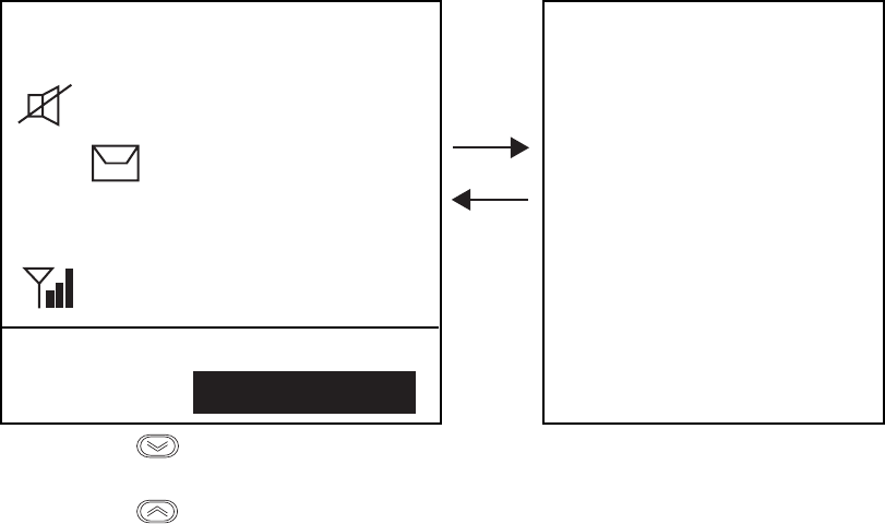
Below are the indications which appear on the standby display on the remote
handset.
INTL
Hi
RX SCAN
DUP
03
SHIFT
MANUAL ACK** 3*
T
GPS ERROR
LAT: 12 34' N
°
LON: 123 45' E
°
12:34 UTC
AUTO
T
WATCH CH70**
If you press
at the left-hand screen, right-hand screen appears for 30
seconds.
If you press
at the right-hand screen, the left-hand screen appears
immediately.
The indications are the same as those on of the transceiver unit.
The *- marked number is the terminal number of the remote station.
**: If no MMSI is registered, the message “DSC NOT USABLE” appears instead
of MANUAL ACK and WATCH CH70.
Note: The screen of the remote handset is smaller than the one of the
transceiver unit. In this manual, display examples are from the transceiver
unit. In the remote handset, scrolling with up or down arrow key displays
same information as the screen of the transceiver unit.
1.1.4 Audio alarms
When you receive a distress alert or routine call, etc., the audible and visual
alarms are released. For the distress or urgency call, the audio alarm sounds
until the CANCEL key is pressed. For all other calls, the audible alarm sounds
for one second and the automatically goes off. The tone of the alarm changes
with the call received. By becoming accustomed to the tone, you can know
which type of call you have received.

1. OPERATIONAL OVERVIEW
1-7
Alarm Frequency (interval)
Safety call received 1300 Hz and 0 Hz (250 ms)
Routine, Ship’s Business call received 880 Hz and 440 Hz (500 ms)
While DISTRESS key is pressed for
three seconds
2200 Hz and 0 Hz (125 ms)
Distress alert sent 2200 Hz, continuous
Own ship position not updated 2200 Hz (50 ms), three beeps every two
seconds
Distress alert, urgency message
received
1300 Hz and 2200 Hz (250 ms)
Message received from terrestrial
telephone line
750 Hz and 650 Hz (50 ms) 10 times
Repeat OFF one second
1.2 VHF Basic Operation
1.2.1 Turning the power on/off
To turn the power on, turn the VOLUME control clockwise until you hear a click.
To turn the power off, turn the control fully counterclockwise until you hear the
click.
1.2.2 Selecting channel modes, channels
Selecting channel modes
To change the channel mode, press the SHIFT key immediately followed by the
7 INT/USA key several times until desired mode is displayed. The following
modes are available.
INTL : International mode
USA/WX : USA mode/ Weather channel mode
CANADA : CANADA mode
INLND-WA : Rhine river mode (USED ON INLAND Waterways)
MEMO : Memory channel mode if registered
Note: Private channels are available only where permitted by the authorities.
The USA/WX, CANADA, INLND-WA can also be set by a qualified
serviceman.
Selecting channels
Rotate the CH selector clockwise (counterclockwise) to display desired channel.

1. OPERATIONAL OVERVIEW
1-8
1.2.3 Adjusting volume of loudspeaker
The VOLUME control adjusts the volume of the loudspeaker.
1.2.4 Adjusting squelch
The SQUELCH control adjusts the squelch threshold level. Adjust it so that white
noise heard in the loudspeaker just fades out. Perform this operation when no
traffic is being received. AUTO squelch automatically reduces white noise.
Usually select the AUTO position. Avoid turning the squelch too far clockwise —
you may miss a long distance communication.
Note: To obtain correct scan watch/dual watch response, adjust the SQUELCH
control precisely.
1.2.5 Transmitting
Press the PTT (Push-to-talk) switch on the handset or microphone to talk, and
release it to listen for the response. The VHF section keyboard accepts no key
input when the PTT switch is operated.
Remarks on transmitting
• Before transmitting, think about the subjects which have to be communicated
and, if necessary, prepare written notes to avoid unnecessary interruptions
and ensure that no valuable time is wasted on a busy channel.
• Listen before commencing to transmit to make certain that the channel is not
already in use.
1.2.6 Selecting output power
After pressing the SHIFT key, each press of the 0 HI/LO key selects high or low
output power. Also Hi or Lo appears on the screen depending on your selection.
The transmitter power is automatically set for low on the following channels:
International: CH15, CH17, CH75, CH76
USA: CH13, CH17, CH67; to operate USA channel 13 or 67 in high
power, keep HI/LOW pressed while talking into the handset.
1.2.7 Turning the loudspeaker on/off
To turn the loudspeaker on/off, press the SHIFT key, then the 1 key. The
loudspeaker off mark appears when the speaker is off. The loudspeaker is
automatically turned off when the telephone handset is used.

1. OPERATIONAL OVERVIEW
1-9
1.2.8 Quick selection of CH16
Press the CH16 key to select CH16, the International Calling and Safety
Channel. The use is limited to distress, safety and calling. The transmission on
CH16 (156.800 MHz) should be limited to within 1 minute except for distress
calling.
Avoid calling on CH16 for purposes other than distress, urgency and very brief
safety communications when another calling channel is available.
1.2.9 Dual watch
The dual watch function permits watch on CH16 and another selected channel.
CH16 and another channel are watched at intervals of 0.15 seconds and one
second, respectively.
To start dual watch, first select the other frequency to watch and then press the
SHIFT key and 9 DW key in that order. When the receiver finds a signal on
CH16, it locks on it and restarts dual watching after the signal on CH16 has gone.
If another channel has traffic, it still continues dual watch. The speech is heard
intermittently. If you are annoyed with the intermittence, turn off the dual watch
by pressing the PTT switch on the handset or pressing the SHIFT and 9 DW key
again.
1.2.10 Scanning
The receiver scans all channels at intervals of 0.15 seconds in the selected
channel mode in ascending channel order, watching CH16 between channels as
below:
1 16 2 16 3 16 4...
16 88 16 87 16 86 16...
To start scanning, press the SHIFT and 8 SCAN in that order. When the receiver
finds a signal, scanning is stopped on that channel and starts dual watch on it
and CH16.
1.2.11 Remarks on voice communications
Automatic acknowledge (DSC operation) is automatically changed to manual
acknowledge when voice communications begin. (The “auto” indication, however,
remains on the screen.) This is done to prevent a break in communications.
Automatic acknowledge is automatically restored once voice communications
are terminated.
1. OPERATIONAL OVERVIEW
1-10
1.3 DSC Operational Overview
Digital Selective Calling (DSC) is the global calling system adopted by the ITU-R
and IMO for selective calling of coast station and ship radio stations. The DSC
system is used for both safety and routine calling. The GMDSS requires the use
of DSC for distress alerting and safety calls.
1.3.1 LED warnings
The LED below the DISTRESS key lights continuously when the distress signal
is transmitted.
The ALARM LED blinks in red (and alarm sounds) when a distress or urgent
message is received. The LED can be extinguished and alarm silenced by
pressing the CANCEL key.
The ALARM LED blinks in green (and alarm sounds) when a message other
than distress or urgent is received. Alarm is automatically silenced five seconds
after message is received.
1.3.2 DSC operational overview
Standby display
When the FM-8800D/S is turned on, the following display appears. This display
is known as the “standby display.” This is where you will begin most operations.
INTL
Hi
RX
116
SCAN
SHIFT
AUTO ACK WATCH CH70
LAT: 34 45' N
°
10:17 UTC
LON: 135 45' E
°
AUTO
INTL
Hi
RX SCAN
SHIFT
MANUAL ACK 1
T
SCAN
116
VOL 5 SQ 2
Standby display (Transceiver unit) Standby display (Remote handset)
(Press the down arrow key of the
remote handset to view rest of
screen.)
If you get lost in operation you can return to the standby display by pressing the
CANCEL key several times.
Note: In this manual, screen examples show the transceiver’s screens. To get
the same information on the handset screen, press down or up arrow key.

1. OPERATIONAL OVERVIEW
1-11
Preparing and transmitting DSC messages
There are two methods by which you can prepare and transmit DSC messages,
and they are shown below.
● Preparing message for immediate transmission
1. Press the CALL key at the standby display.
2. Select the call type.
3. Select other party if necessary.
4. Select the communications category.
5. Select the communications channel.
6. Press the CALL key.
● Transmitting a message stored in the memory
100 messages can be saved to the memory. You may open a memory-stored
message and transmit it.
Distress alert transmission and output power
When the distress alert is transmitted (by pressing the DISTRESS key), the
output power of the FM-8800D/S is automatically set to maximum (25 W).
When keyboard input is prohibited
DSC-related controls cannot be operated while a DSC message is being
transmitted. (These controls are inoperative about 3 seconds during a DSC
distress call; 0.5 seconds for other DSC calls.)
1.3.3 Automatic acknowledge on/off
The automatic acknowledge feature of the DSC/watch receiver automatically
transmits the acknowledge back (ACK BQ) signal to the sending station when an
individual, position or polling call is received. (For position and polling calls,
respective item on the AUTO ACK menu must be turned on to enable automatic
acknowledge.) Automatic acknowledge can be turned on or off at the standby
display by pressing the SHIFT and 5 keys in this order.
The message AUTO ACK or MANUAL ACK appears at the bottom of the
standby display with each press of the keys.
Note 1: To give priority to own ship's communications while own ship is
communicating, show MANUAL ACK by the above procedure.
Note 2: Automatic acknowledge is not possible under the following conditions:
Priority: Distress, Urgency or Safety
Com Type: Fax, Data, No Info
Com Freq: No Info
Off Hook

1. OPERATIONAL OVERVIEW
1-12
1.4 Priority
If one or more remote stations are installed, the transceiver unit (main unit) has
the highest priority. You can interrupt remote station operation at any time with
the handset of the main unit. When you hook off the handset of the main unit,
“OCCUPIED FM8800” is indicated on all remote stations.
Each remote station has its own priority. The remote station ID (1-4) indicates its
priority. The priority of the system is as follows.
DSC of main unit > Wing handset > Handset of main unit > 1 > 2 > 3 > 4
If you hook off No.4 remote station, for example, “Occupied Handset.4” is
displayed on other remote stations. However, you can hook off and use No.1
handset.
How to set priority of the remote station
Two persons are required to set priority on a remote station, one at the main unit
and one at the remote station.
1. Turn off the power at the main unit.
2. While pressing the MENU key of a remote station, turn the VOLUME/
POWER control clockwise on the main unit to turn on the power.
Version No.
0550216-01.00
Now ID=01
Input
New ID (1-4)=
3. Press 1, 2, 3, or 4 key on the remote handset as appropriate followed by the
ENT key.
4. Turn off and on the power.
2-1
2. DSC DISTRESS COMMUNICATION
2.1 Distress Alert Transmission from the DISTRESS
Key
If a distress situation occurs, do as follows:
1. Open the DISTRESS key cover and press the DISTRESS key more than
three seconds. The alarm sounds and the red lamp in the key blinks. The
lamp will light steadily three seconds later and at the same time the distress
alert is transmitted for three seconds.
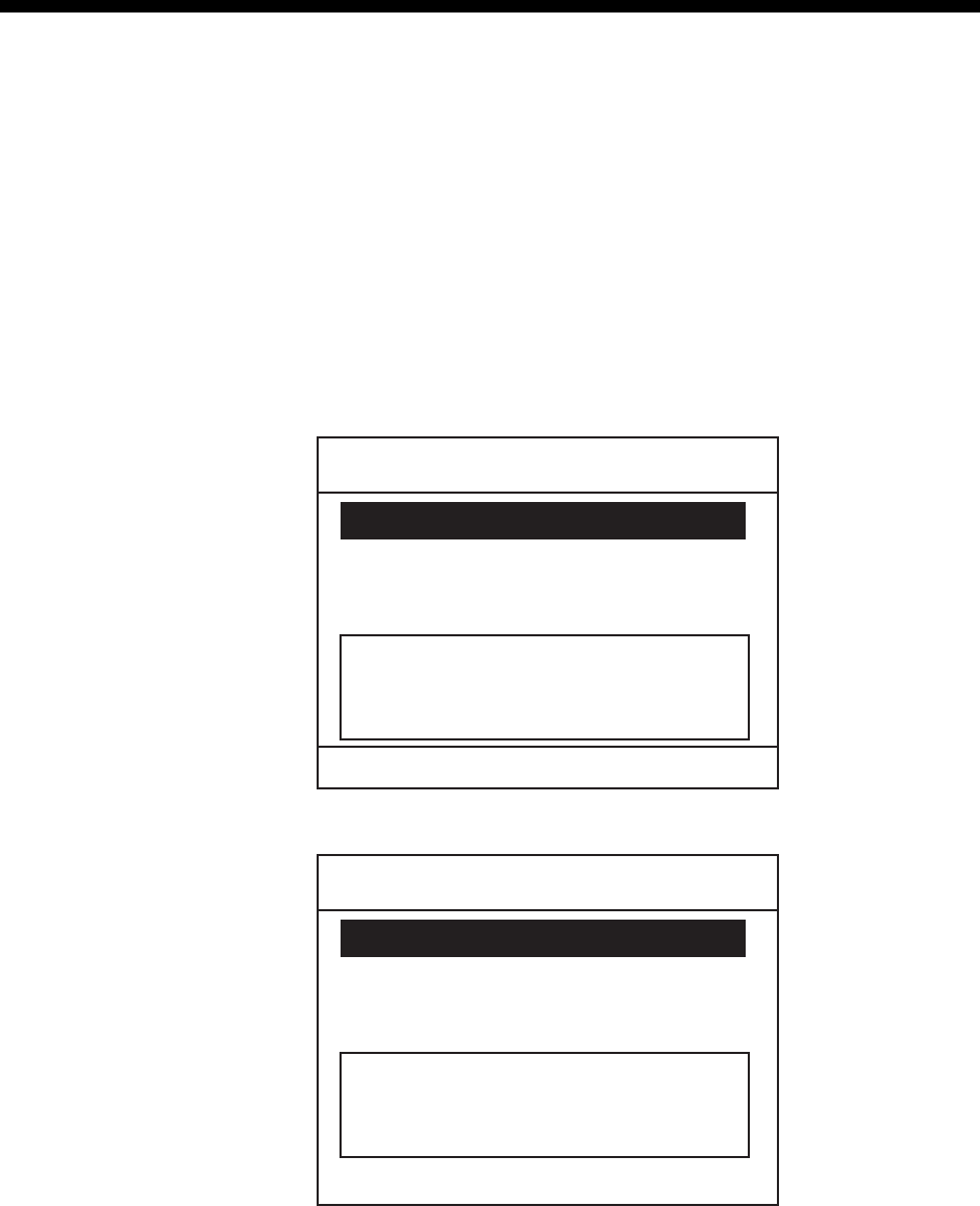
The screen changes as follows.
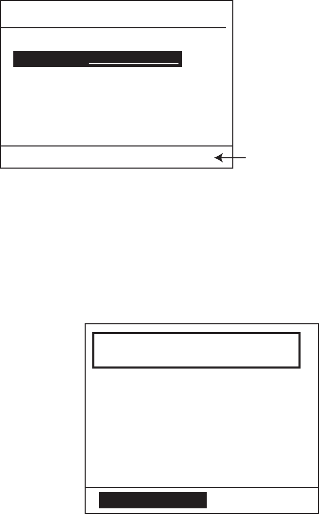
1) When the DISTRESS key is pressed and held down,
** Compose message **
CALL TYPE: DISTRESS
NATURE: UNDESIGNATED
POS : 12° 34N 123 ° 45E
AT : 12 : 34
Distress button
Pressed!
KEEP PRESSED FOR 3S
2) After the timer counts down to zero, “distress call in progress” is announced.
** Compose message **
CALL TYPE: DISTRESS
NATURE: UNDESIGNATED
POS : 12° 34N 123 ° 45E
AT : 12 : 34
Distress Call
in Progress on CH70.

2. DSC DISTRESS COMMUNICATION
2-2
3) The screen changes to “distress acknowledge (DIST ACK) waiting” display.
** Compose message **
CALL TYPE: DISTRESS
NATURE: UNDESIGNATED
POS : 12° 34N 123 ° 45E
AT : 12 : 34
Waiting for distress
acknowledgement.
CH16 Now available.
TIME TO GO : 4M 12S
4) When the DIST ACK is received,
Distress acknowledge
received.
FROM : 003456789
ID IN DIST : 123456789
CANCEL ALARM
TCmd : DISTRESS ACK
AT : 12 : 34
POS : 12
SIMP TP
NATURE : Piracy
° 34N 123 ° 45E
Note: If you do not receive the distress alert acknowledge call, the equipment
automatically re-transmits the distress alert and then awaits the
distress alert acknowledge call. This is repeated until the distress alert
is acknowledged.
2. Press the CANCEL or ENT key. The screen changes as follows.
** Received Message **
APR08/’04 18:30 ECC : OK
TCmd : DISTRESS ACK
DISTRESS ACK
NATURE : Piracy
POS : 12° 34N 123 ° 45E
AT : 12 : 34
FROM : 003456789
ID IN DIST : 123456789
PRESS ENT
2. DSC DISTRESS COMMUNICATION
2-3
3. Press the ENT key. The standby display with CH16 and Hi appears.
4. Provide the following information to the coast station, using a handset on the
transceiver unit or remote stations (if connected):
Distress call
(1) Speak slowly and distinctly, “MAYDAY, MAYDAY, MAYDAY,” pronounced as
the French expression “m’aider.”
(2) This is; "the name of your vessel and call sign" three times.
Then, begin the distress communications, which consists of:
Distress communications
(1) Position in latitude and longitude;
(2) The nature of the distress;
(3) The kind of assistance desired;
(4) Any other information which might facilitate rescue, for example, length, color,
and type of vessel, number of persons on board.
(5) Indicate the end of message by saying “Over.”
Some countries do not have sea area "A." In this case “ACK” from the coast
station does not arrive over DSC. A ship nearby will contact the vessel in
distress over CH16. After transmitting the distress alert, conduct voice
distress communications as shown above.
Note: To return to normal mode, turn off the power and on again.
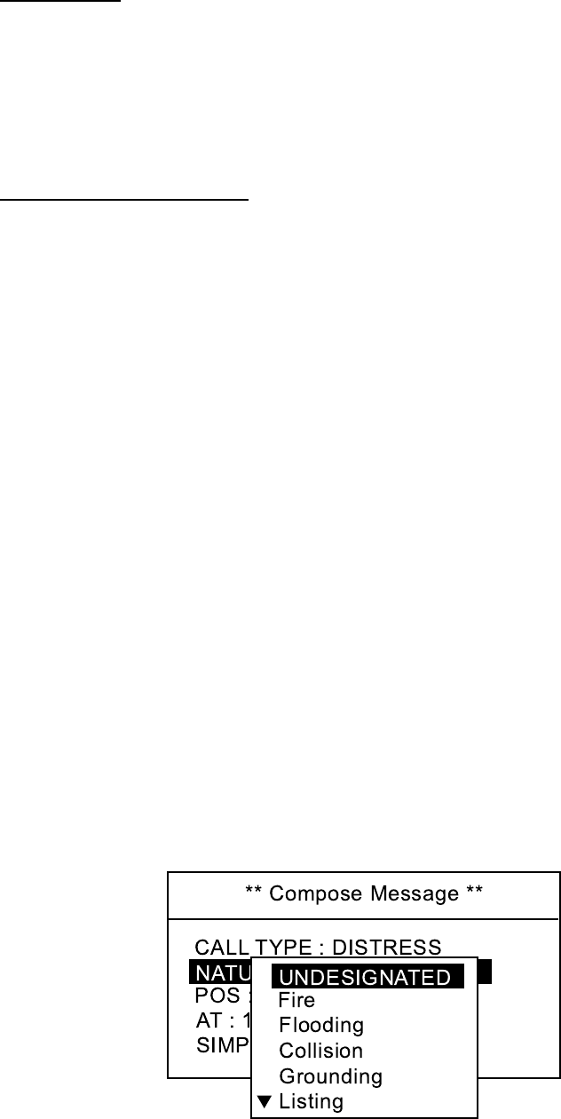
2.2 Distress Alert Transmission with Nature of
Distress
If you want to transmit the distress alert with nature of distress specified, do as
follows:
1. Open the DISTRESS key cover and press the DISTRESS key momentarily.
The alarm sounds and the red lamp in the key blinks and after releasing the
key within three seconds the alarm stops and the red lamp goes off. The
following screen appears.
2. DSC DISTRESS COMMUNICATION
2-4
2. Rotate the channel knob to choose the nature of distress. On the remote
handset, press the up or down arrow key.
3. Press the ENT key. The screen changes as follows.
** Compose Message **
CALL TYPE : DISTRESS
NATURE : Flooding
134
°
30’ E
AT : 08 : 00
POS : 34
°
41’ N
The own ship's position and current time in UTC are displayed if your
FM-8800D/S is connected to a navigation equipment, for example, GPS.
4. Press the DISTRESS key more than three seconds.
Distress button
Pressed!
NATURE : Piracy
POS : 12
°
34N 123
°
45E
AT : 12 : 34
KEEP PRESSED FOR 3S
The distress alert with nature of distress, ship's position and time are transmitted.
The sequence of display and procedures are the same as in paragraph 2.1.
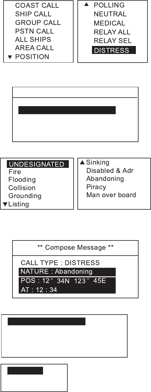
2.3 Distress Alert Transmission from CALL Key
You can transmit the distress alert with nature of distress by using CALL key.
1. Press the CALL key.
** Compose Message **
CALL TYPE : COAST CALL
TO : COAST AAA
COAST ID : 003456789
ROUTINE
TCmd1 : SIMPLEX TP
TCmd2 : NO INFO
CH : 12
* Compose Message *
CALL TYPE :
COAST CALL
T
Transceiver unit screen Remote handset screen
2. DSC DISTRESS COMMUNICATION
2-5
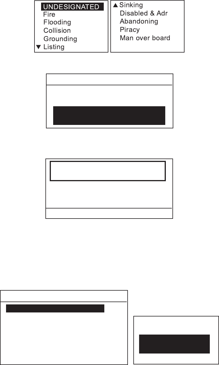
2. Press the ENT key to show the call type selection window.
3. Rotate the CH knob (or press up / down arrow key) to choose DISTRESS.
Press the ENT key.
** Compose Message **
NATURE : UNDESIGNATED
CALL TYPE : DISTRESS
POS : 12
°
34N 123
°
45E
AT : 12 : 34
SIMP TP
4. Press the ENT key to display the distress nature list.
5. Rotate the CH knob (or press up / down arrow key) to choose nature of
distress and press the ENT key.
6. Press the ENT key to show the position setup window.
INPUT TYPE : AUTO
LAT : 34
LON : 134
°
30 E
TIME : 08 : 00
°
41 N
AUTO
MANUAL*
NO INFO
*: MANUAL can not be
chosen if position data
is input.
7. After confirming the ship's position and time, press the DISTRESS key more
than three seconds to transmit the distress alert.

2. DSC DISTRESS COMMUNICATION
2-6
2.4 Canceling a False Distress Alert
If you have transmitted a distress alert by mistake, do the following to cancel it
.
1. Switch off equipment immediately.
2. Switch equipment on and set to Channel 16.
3. Transmit message to “All Stations” giving your vessel's name,
call sign and DSC number.
Example message
All Stations, All Stations, All Stations
This is VESSEL'S NAME, CALLSIGN,
DSC NUMBER, POSITION.
Cancel my distress alert of DATE, TIME, UTC.
=Master, VESSEL'S NAME, CALLSIGN.
DSC NUMBER, DATE, TIME UTC.
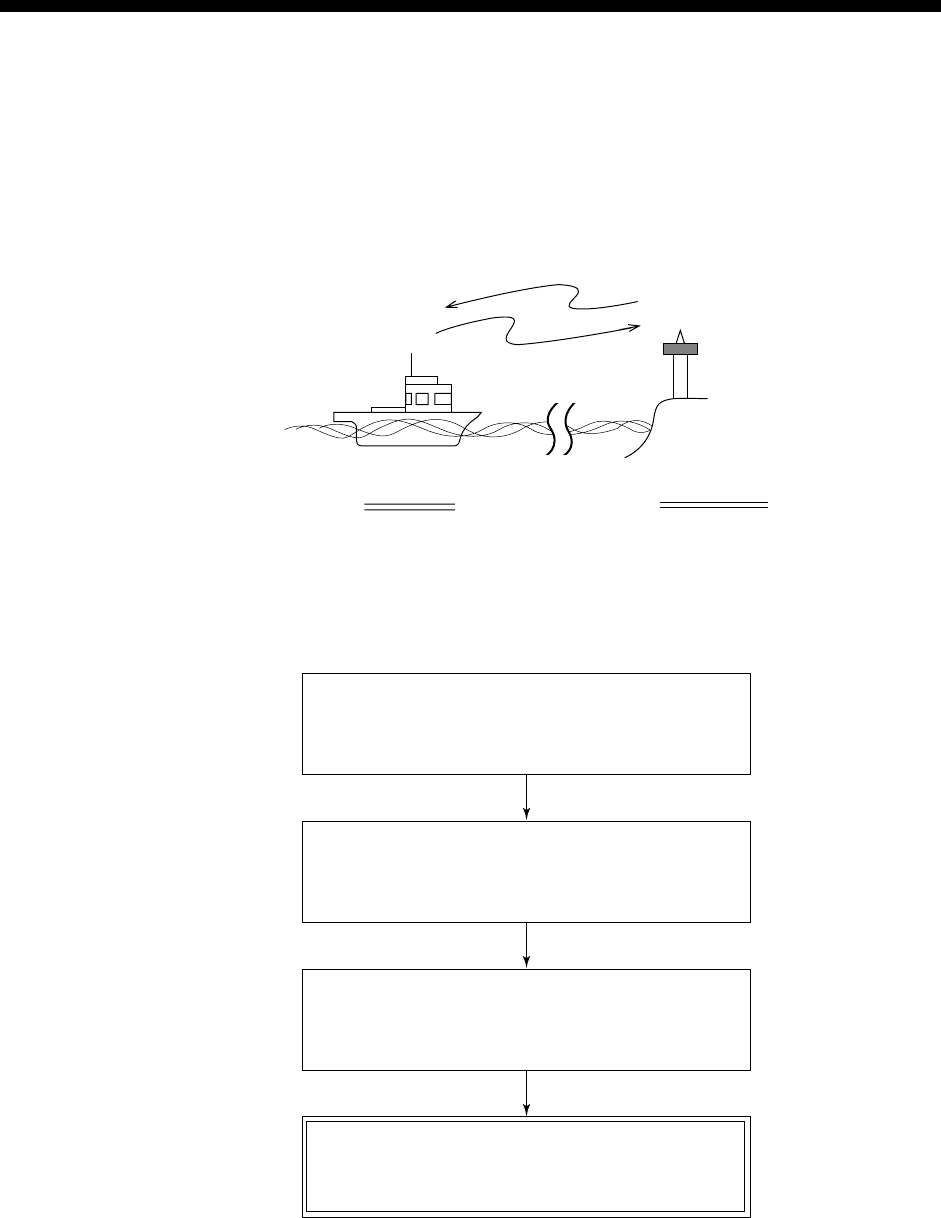
2.5 Receiving Distress Alert from Other Vessel,
Transmitting DIST ACK Signal
In no case is a ship permitted to transmit a DSC distress relay call upon receipt
of a DSC distress alert on VHF channel 70.
Procedure when in area A1
1. When the FM-8800D/8800S receives a distress alert from another vessel, the
ALARM LED (red) blinks and the FM-8800D/8800S sounds the distress
alarm.
2. Silence the alarm by pressing the CANCEL key.
3. Wait up to five minutes until the DIST ACK signal from a coast station is
received. Be prepared to follow the instructions of the coast station.
4. If you do not receive the DIST ACK signal, follow the flow chart shown on
page 2-8 to determine if your vessel should acknowledge a distress alert.
If further DSC alerts are received from the same source and the ship in distress
is beyond doubt in the vicinity, a DSC acknowledgement may, after consultation
with an Rescue Co-ordination Center (RCC) or Coast Station, be sent to
terminate the distress call.
Note 1: An asterisk (*) in a received distress alert message indicates error or
unknown at the location marked with the asterisk.
Note 2: Do not send DIST ACK in response to receipt of distress alert having the
nature of distress as “EPIRB emission”.
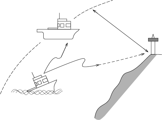
2. DSC DISTRESS COMMUNICATION
2-7
About 20 to 30 miles
(Sea area A1)
Your Ship
Coast station
Distress Alert
Transmission
Vessel in Distress
Receiving distress alert from other vessel
2. DSC DISTRESS COMMUNICATION
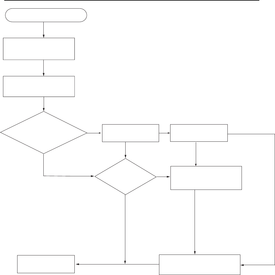
2-8
Flow chart for determining if you should/should not transmit DIST ACK signal
Press [CANCEL]
key to silence alarm.
DSC Distress alert received.
Listen on CH16 for
5 minutes.
Did you receive
acknowledge from
CS and/or RCC?
Is own
vessel able
to assist?
No
Is distress traffic
in progress?
No
Is distress call
continuing?
Acknowledge the alert by
radiotelephony to the ship
in distress on VHF CH16.
Yes
No
Inform CS and/or RCC.
Yes
Yes Yes
Enter details in log.
No
CS = Coast Station
RCC = Rescue Co-ordination Center
1. Say "MAYDAY" ONCE.
2. Say ID number of vessel
in distress THREE TIMES.
3. Say "This is" (your vessel's
name) ONCE.
4. Say ID number of your vessel
THREE TIMES.
5. Say "Received MAYDAY"
ONCE.
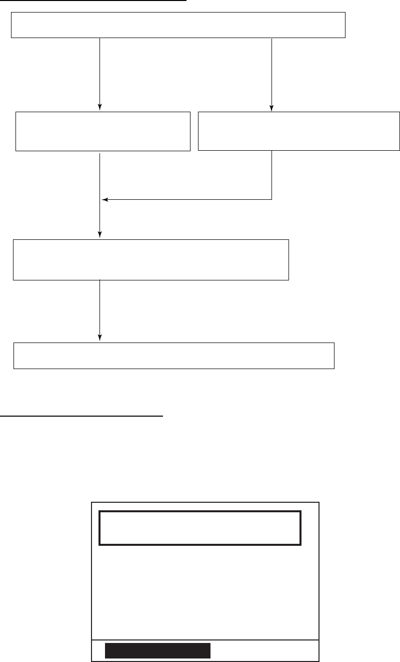
2. DSC DISTRESS COMMUNICATION
2-9
Transmitting DIST ACK over CH16
Select VHF CH16 and transmit DIST ACK to vessel in distress.
Relay the distress alert to a coast station over DSC.
Follow the instructions of the coast station.
Transmit DIST ACK to vessel in
distress over DSC CH70. Communicate with vessel in distress.
No reply Reply received
Begin search and rescue operation for the vessel in distress.
Transmitting DIST ACK signal
If your vessel meets the requirements necessary to transmit the DIST ACK
signal, do the following:
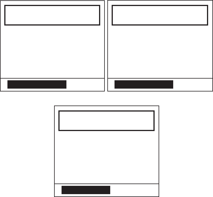
When a distress alert from other ship is received, the following screen appears.
The alarm sounds and the ALARM lamp blinks.
Distress
Call received.
NATURE : UNDESIGNATED
POS : 12
°
34’N 123
°
45’E
AT : 12 : 34
ID IN DIST : 123456789
CANCEL ALARM
SIMP TP

2. DSC DISTRESS COMMUNICATION
2-10
1. Press the CANCEL or ENT key to silence the alarm. The following message
appears.
** Received Message **
MAY10/’04 08:03 ECC : OK
NATURE : UNDESIGNATED
DISTRESS
POS : 12
°
34’N 123
°
45’E
AT : 12 : 34
ID IN DIST : 123456789
PRESS ENT TO ACK
SIMP TP
2. If you do not receive DIST ACK from coast station within five minutes and
your vessel meets requirements (see previous page) for transmitting DIST
ACK, press the ENT key, and then press the CALL key more than three
seconds to transmit the DIST ACK.
** Send Message **
DISTRESS ACK
TO : 123456789
TCmd : DISTRESS ACK
NATURE : UNDESIGNATED
POS : 12
°
34’N 123 45’E
AT : 12 : 34
SIMP TP
PRESS CALL TO SEND
°
After transmitting the DIST ACK, the standby display appears.
After transmitting DIST ACK
Begin search and rescue operations for the vessel in distress, communicating
with the vessel over CH16 (automatically set). Relay distress alert to coast
station by DSC following the instruction in the next paragraph. Finally, follow the
instructions of the coast station.
2. DSC DISTRESS COMMUNICATION
2-11
2.6 Sending Distress Relay on Behalf of a Ship in
Distress
When you should relay a distress alert
You may relay a distress alert in the following conditions:
1) When the station in distress is not itself in a position to transmit the distress
message, or
2) When the master or person responsible for the vessel not in distress, or the
person responsible for the coast station, considers that further help is
necessary.
DO NOT press the DISTRESS key to relay a distress alert; it is for use
when own vessel is in distress.
2.6.1 Sending distress relay to coast station
1. Press the CALL key. The [Compose message] screen appears.
** Compose Message **
CALL TYPE : COAST CALL
COAST ID : 003456789
ROUTINE
TCmd1 : SIMPLEX TP
TCmd2 : NO INFO
CHANNEL : 10
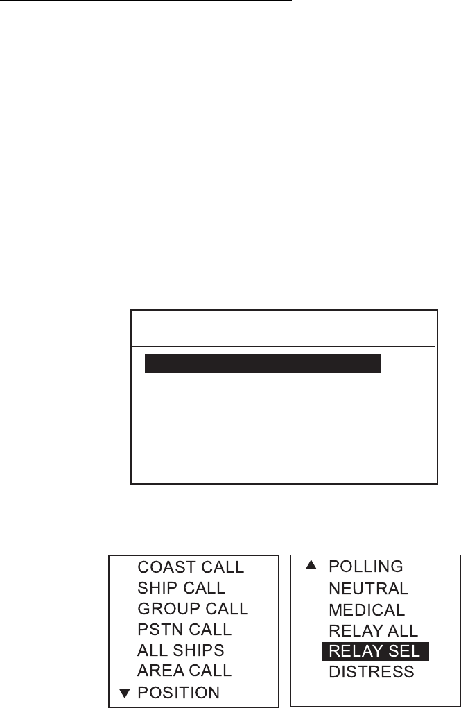
2. Press the ENT key. The CALL TYPE selection window appears.
3. Rotate the CH knob (or press up / down arrow key) to choose RELAY SEL.
2. DSC DISTRESS COMMUNICATION
2-12
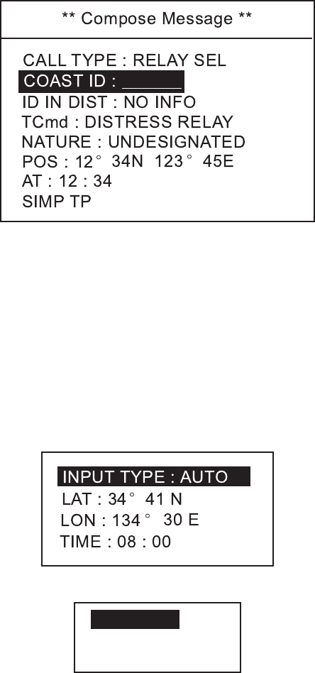
4. Press the ENT key.
5. Press the ENT key again. The COAST ID entry window appears.
6. Key in a coast station ID with numeric keys and press the ENT key.
7. Press the ENT key again. The ID IN DIST entry window appears.
8. Key in the ID number of ship in distress with numeric keys and press the ENT
key. If you do not know the ID, simply press the ENT key without entering ID;
NO INFO is displayed.
9. Press the ENT key and the list of distress nature appears.
10. Rotate the CH knob to choose a nature of distress (if known) and press the
ENT key twice. If you do not know the nature of distress, choose
UNDESIGNATED.
11. Enter position of the ship in distress, following 1), 2) or 3) below.
AUTO
MANUAL
NO INFO
1) For automatic input, press the ENT key twice. Go to step 12.
2) For manual input, press the ENT key to open the INPUT TYPE menu,
rotate the CH knob to choose MANUAL and then push the ENT key.
Enter latitude and longitude of ship in distress and time as follows:
a) Press the ENT key. Enter latitude and then press the ENT key.
b) Press the ENT key. Enter longitude and then press the ENT key.
c) Press the ENT key. Enter UTC time and then press the ENT key. Go to
step 12.
Note: If you cannot confirm time, enter 88:88 to input NO INFO as the
time.
3) If you cannot confirm position of ship in distress, press the ENT key to
open the INPUT TYPE menu, rotate the CH knob to choose NO INFO and
then press the ENT key. Go to step 12.
2. DSC DISTRESS COMMUNICATION
2-13
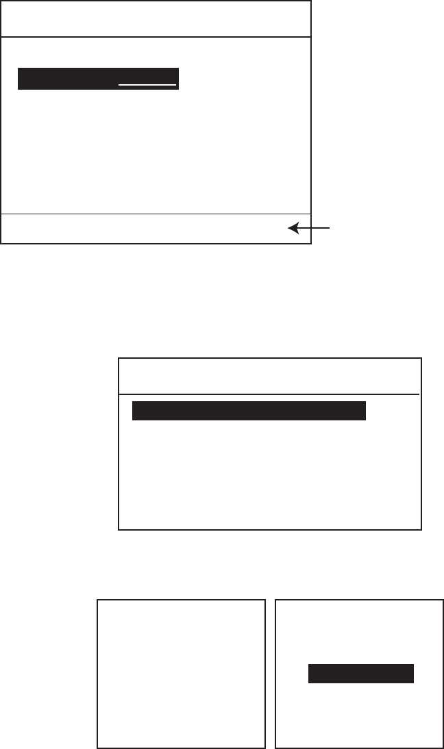
12. Press the CALL key more than three seconds to transmit the distress relay.
KEEP PRESSED FOR 3S
** Compose Message **
CALL TYPE : RELAY SEL
TCmd : DISTRESS RELAY
ID IN DIST : NO INFO
COAST ID :
NATURE : UNDESIGNATED
POS : 12° 34N 123 ° 45E
AT : 12 : 34
SIMP TP When CALL key is pressed,
this message appears and
timer counts down.
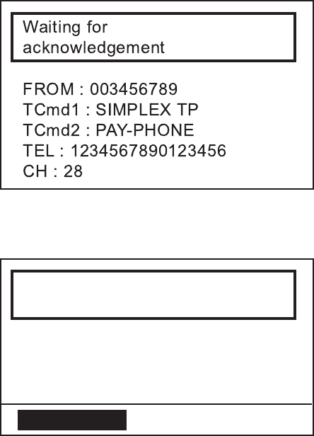
The message will be transmitted and “Waiting for acknowledgement” will appear.
2.6.2 Sending distress relay to all ships
1. Press the CALL key. The [Compose message] screen appears.
** Compose Message **
CALL TYPE : COAST CALL
COAST ID : 003456789
ROUTINE
TCmd1 : SIMPLEX TP
TCmd2 : NO INFO
CHANNEL : 10
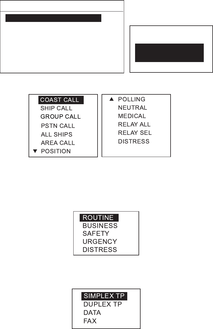
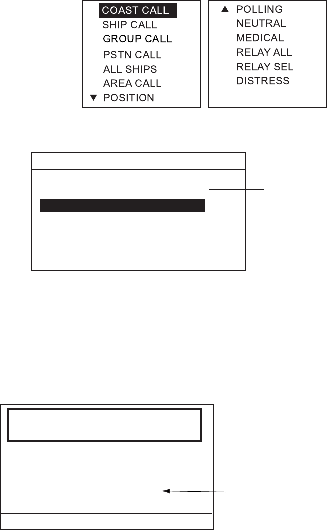
2. Press the ENT key. The CALL TYPE selection window appears.
3. Rotate the CH knob (or press up / down arrow key) to choose RELAY ALL.
SHIP CALL
GROUP CALL
PSTN CALL
ALL SHIPS
AREA CALL
POSITION
S
T
COAST CALL POLLING
NEUTRAL
MEDICAL
RELAY ALL
RELAY SEL
DISTRESS
2. DSC DISTRESS COMMUNICATION
2-14
4. Press the ENT key.
5. Press the ENT key again. The ID IN DIST entry window appears.
6. Key in the ID number of ship in distress with numeric keys and press the ENT
key. If you do not know the ID, simply press the ENT key without entering ID;
NO INFO is displayed.
7. Press the ENT key and the list of distress nature appears.
8. Rotate the CH knob (or press up / down arrow key) to choose a nature of
distress (if known) and press the ENT key twice. If you do not know the
nature of distress, choose UNDESIGNATED.
9. Enter position of the ship in distress, following 1), 2) or 3) below.
AUTO
MANUAL
NO INFO
1) For automatic input, press the ENT key twice. Go to step 10.
2) For manual input, press the ENT key to open the INPUT TYPE menu,
rotate the CH knob to choose MANUAL and then push the ENT key. Enter
latitude and longitude of ship in distress and time as follows:
a) Press the ENT key. Enter latitude and then press the ENT key.
b) Press the ENT key. Enter longitude and then press the ENT key.
c) Press the ENT key. Enter UTC time and then press the ENT key. Go to
step 10.
Note: If you cannot confirm time, enter 88:88 to input NO INFO as the
time.
3) If you cannot confirm position of ship in distress, press the ENT key to
open the INPUT TYPE menu, rotate the CH knob to choose NO INFO and
then press the ENT key. Go to step 10.
2. DSC DISTRESS COMMUNICATION
2-15
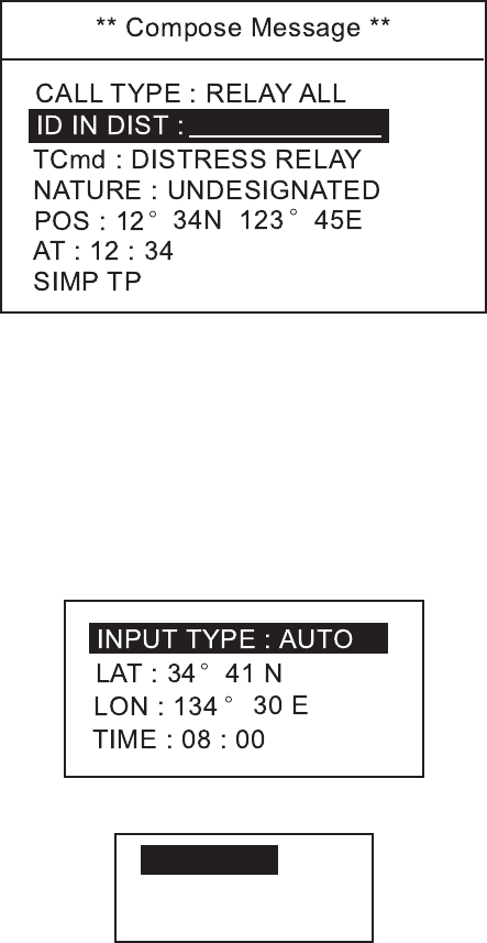
10. Press the CALL key to transmit the call.
** Compose Message **
CALL TYPE : RELAY ALL
TCmd : DISTRESS RELAY
ID IN DIST :
NATURE : UNDESIGNATED
POS : 12
°
34N 123
°
45E
AT : 12 : 34
SIMP TP
KEEP PRESSED FOR 3S
When CALL key is pressed,
this message appears and
timer counts down.
After the call is transmitted, the standby display appears.
2.7 Receiving Distress Relay
2.7.1 Receiving distress relay all call
If you receive a distress relay for all ships, continue monitoring CH16.
1. When a distress relay all ships call is received, the audio alarm sounds and
the display looks like the one below.
Distress relay all
call received.
ID IN DIST : 234567890
TCmd : DISTRESS RELAY
FROM : 123456789
NATURE : UNDESIGNATED
POS : 12° 34N 123° 45E
SIMP TP
AT : 12 : 34
CANCEL ALARM

2. DSC DISTRESS COMMUNICATION
2-16
2. Press the CANCEL key or ENT key to silence the alarm and the display
changes as below.
*ReceivedMessage*
APR01/í0412:34ECC:OK
TCmd:DISTRESSRELAY
DISTRESSRELAYALL
NATURE:UNDESIGNATED
POS:12 °34N123 °45E
AT:12:34
SIMPTP
IDINDIST:234567890
FROM:123456789
PRESSENT
3. Press the ENT key to return to the standby display with CH16.
4. Watch CH16.
2.7.2 Receiving distress relay from coast station
If you receive a distress relay call from a coast station, continue monitoring
CH16.
1. When a distress relay call from a coast station is received, the audio alarm
sounds and the display looks like the one below.
Distressrelayall
callreceived.
IDINDIST:123456789
TCmd:DISTRESSRELAY
NATURE:UNDESIGNATED
POS:12
°
34N123
°
45E
SIMPTP
AT:12:34
CANCELALARM
FROM:003456789

2. DSC DISTRESS COMMUNICATION
2-17
2. Press the CANCEL key to silence the alarm and the display changes as
below.
**ReceivedMessage**
APR01/í0412:34ECC:OK
NATURE:UNDESIGNATED
DISTRESSRELAYALL
POS:12 °34N123 °45E
AT:12:34
SIMPTP
IDINDIST:123456789
FROM:003456789
TCmd:DISTRESSRELAY
PRESSENT
3. Press the ENT key to return to the standby display with CH16.
4. Watch CH16.
2. DSC DISTRESS COMMUNICATION
2-18
This page is intentionally left blank.
3-1
3. DSC OPERATION FOR
NON-DISTRESS CASES
3.1 Coast or Ship Call
The coast or ship call is for sending message to a specific coast or ship station. After
transmitting message (called ACK RQ transmission), wait to receive the
acknowledge back (ACK BQ) signal from the receiving station. You should receive it
within five minutes.
Own Ship Coast Station
d Acknowledge back
(ACK BQ signal)
c Individual call
(ACK RQ transmission)
How a coast or ship call is transmitted
General procedure for transmitting a coast or ship call
Load saved Tx message, or prepare
message.
Transmit message.
Receive ACK BQ from receiving station.
Communicate with station.
3. DSC OPERATION FOR NON-DISTRESS CASES
3-2
3.1.1 Sending a coast or ship call
1. Press the CALL key. The display changes from the standby display to the
COMPOSE MESSAGE screen and the CALL TYPE is displayed in reverse
video.
**ComposeMessage**
CALLTYPE:COASTCALL
TO:COASTAAA
COASTID:003456789
ROUTINE
TCmd1:SIMPLEXTP
TCmd2:NOINFO
CH:12
*ComposeMessage*
CALLTYPE:
COASTCALL
T
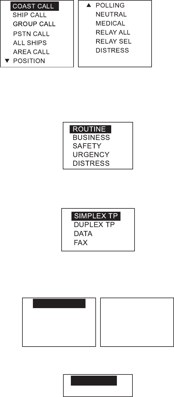
2. Press the ENT key to open the call type list.
3. Rotate the CH knob (or press up / down arrow key) to choose COAST CALL
or SHIP CALL and press the ENT key.
4. ID is selected; press the ENT key.
5. Key in a coast ID or ship ID number as appropriate and press the ENT key.
6. ROUTINE is selected; press the ENT key.
7. Choose ROUTINE, BUSINESS, SAFETY, or URGENCY as appropriate
followed by pressing the ENT key.
8. TCmd1 is selected; press the ENT key.
9. Choose SIMPLEX TP, DUPLEX TP, DATA or FAX as appropriate followed by
pressing the ENT key. If you chose SIMPLEX, DUPLEX or FAX, NO INFO
appears in the Tcmd2 field. Go to step 12. If you chose DATA, go to the next
step.

3. DSC OPERATION FOR NON-DISTRESS CASES
3-3
10. TCmd2 is selected; press the ENT key.
S
V. 26 ter
V. 27 ter
V. 32
V. 21
V. 22
V. 22 bis
V. 23
V. 26 bis
T
11. Choose the data type and press the ENT key.
12. Choose CH and press the ENT key. The following window appears.
SELECT CH
NO INFO
13. Choose SELECT CH or NO INFO as appropriate followed by pressing the
ENT key. If you chose SELECT CH, the following channel list appears. (The
example shown is the international, duplex channel list.) Rotate the CH knob
(or press up / down arrow key) to choose a channel you wish to communicate
over and then press the ENT key.
DUP CHANNEL
01
02
03
04
05
07
18
19
86
28
60
61
62
63
64
65
66
78
79
80
81
82
83
84
85
20
21
22
23
24
25
26
27
14. Press the CALL key more than three seconds to transmit the message.
3.1.2 Receiving acknowledgement of coast or ship call
1. After a coast or ship call is sent, the equipment waits for acknowledgement of
the call, showing the display below.
Waiting for
acknowledgement.
COAST ID : 003456789
ROUTINE
TCmd1 : SIMPLEX TP
TCmd2 : NO INFO
CH : 12
TIME TO GO : 3M30 S
The timer starts counting down the maximum time to wait for acknowledgement,
five minutes.
3. DSC OPERATION FOR NON-DISTRESS CASES
3-4
2. One of the following three messages appears. "No response! Try calling
again?" appears after the timer counts down to zero. It means the receiving
station did not respond.
Able acknowledge
call received.
FROM : 003456789
ROUTINE
TCmd1 : SIMPLEX TP
TCmd2 : NO INFO
CH : 12
Unable acknowledge
call received.
FROM : 003456789
NO REASON
CANCEL ALARM
TCmd1 : SIMPLEX TP
TCmd2 : NO INFO
CH : 12
CANCEL ALARM
Able acknowledge call received Unable acknowledge call received
No response!
Try calling again?
COAST ID : 003456789
ROUTINE
TCmd1 : SIMPLEX TP
TCmd2 : NO INFO
CH : 12
PRESS ENT
No response from station
A reason of Unable acknowledge is displayed. In case of QUEUE INDICATION,
the channel will change to one that the coast station specifies.
3. Do one of the following depending on the message shown above.

3. DSC OPERATION FOR NON-DISTRESS CASES
3-5
Able acknowledge call received
a) The audio alarm sounds; press the CANCEL key to silence it, and the display
changes as below.
**ReceivedMessage**
APR01/í0412:34ECC:OK
COASTACK
PRESSENT
ROUTINE
TCmd1:SIMPLEXTP
TCmd2:NOINFO
CH:12
FROM:003456789 Ifafileisregistered,
itsregistrationname
isdisplayedinstead
ofID.
b) Press the ENT key to go to the standby display. The working channel is
automatically set; you may start voice communications.
Unable acknowledge call received
a) The alarm sounds; press the CANCEL key to silence the alarm.
b) Send the call again later.
No response! Try calling again?
Re-send call: Push the ENT key followed by pressing the CALL key.
You can re-send the message from the TRANSMITTED log. See “3.10 Log
File.”
Cancel call: Press the CANCEL key to go to the standby display.
3.1.3 Receiving a coast or ship call
When own ship receives a coast or ship call, acknowledgement is automatically
or manually sent depending on the comply-type setting (see paragraph 4.2). The
relationship between comply status and automatic/manual acknowledge is as
shown in the table below.
Note: The handset must be on hook to enable automatic acknowledge.
Comply status
Setting of 5 ACQ key
ABLE UNABLE
AUTO ACK Can send acknowledge
automatically.
Can send UNABLE
automatically.
MANUAL ACK Can send acknowledge
manually
Can send UNABLE
manually.

3. DSC OPERATION FOR NON-DISTRESS CASES
3-6
Acknowledgement the call automatically or manually by doing one of the
following:
1) Send automatic acknowledge (ACK BQ) with comply status “ABLE.” See the
procedure below.
2) Sending automatic acknowledge (ACK BQ) with comply status "UNABLE."
See the procedure on page 3-7.
3) Manually acknowledging individual call with "ABLE." See the procedure on
page 3-8.
4) Manually acknowledging a coast or ship call with "UNABLE." See the
procedure on page 3-9
.
1) Sending automatic acknowledge (ACK BQ) with comply status "ABLE."
1. When the automatic acknowledge feature is active (AUTO ACK), the comply
status is "ABLE" and a coast or ship call is received, the auto acknowledge
(ACK BQ) call is sent immediately. The display shown below appears. The
alarm sounds and the ALARM LED blinks two minutes.
Able acknowledge
transmitted!
ROUTINE
TCmd1 : SIMPLEX TP
TCmd2 : NO INFO
CH : 08
CANCEL ALARM
2. Press the CANCEL key to silence the alarm. The following display appears.
** Send Message **
PRESS ENT
COAST ACK
ROUTINE
TCmd1 : SIMPLEX TP
TCmd2 : NO INFO
CH : 08
TO SHIP : 123456789
3. Press the ENT key. You can now communicate with the party, over the VHF
channel specified.

3. DSC OPERATION FOR NON-DISTRESS CASES
3-7
2) Sending automatic acknowledge (ACK BQ) with comply status
"UNABLE."
1. When the automatic acknowledge feature is active (AUTO ACK), the comply
status is "UNABLE" and a coast or ship call is received, the display shown
below appears, indicating that the auto acknowledge call with UNABLE (ACK
BQ) has been sent. The alarm sounds and the ALARM LED blinks two
minutes.
Unable acknowledge
transmitted.
ROUTINE
TCmd1 : UNABLE
TCmd2 : BUSY
CANCEL ALARM
CH : NO INFO
2. Press the CANCEL key to silence the alarm. The following display appears.
** Send Message **
COAST BQ
TO : 123456789
ROUTINE
TCmd1 : UNABLE
TCmd2 : BUSY
CH : NO INFO
PRESS ENT
3. Press the ENT key.
4. Then, prepare a message and sent it following the procedures shown on in
paragraph 3.1.1.
3. DSC OPERATION FOR NON-DISTRESS CASES
3-8
3) Manually acknowledging individual call with "ABLE."
1. When the equipment is set up with manual acknowledge (MANUAL ACK), the
comply status is "ABLE" and a coast or ship call is received, the alarm sounds
and the display looks like the one below.
Individual request
call received.
FROM : 123456789
ROUTINE
TCmd1 : SIMPLEX TP
TCmd2 : NO INFO
CHANNEL : CH08
CANCEL ALARM
2. Press the CANCEL key to silence the alarm. The following display appears.
** Received Message **
APR01/04 12 : 34 ECC : OK
SHIP CALL
ROUTINE
TCmd1 : SIMPLEX TP
TCmd2 : NO INFO
CH : CH08
FROM : 123456789
PRESS ENT TO ACK
3. To send the ACK BQ manually, press the ENT key. The pop-up window
shown below is displayed.

3. DSC OPERATION FOR NON-DISTRESS CASES
3-9
4. Choose ABLE and press the ENT key. The display changes as shown below.
** Send Message **
PRESS CALL TO SEND
SHIP ACK
ROUTINE
TCmd1 : SIMPLEX TP
TCmd2 : NO INFO
CH : 08
TO : 123456789
5. Press the CALL key more than three seconds to transmit the ACK BQ. The
display changes to the standby display with a channel specified.
4) Manually acknowledging a coast or ship call with "UNABLE."
1. When the equipment is set up with manual acknowledge and an individual call
is received, the alarm sounds and the display shows the message "Individual
request call received."
Individual request
call received.
FROM : 123456789
ROUTINE
TCmd1 : SIMPLEX TP
TCmd2 : NO INFO
CHANNEL : CH08
CANCEL ALARM
2. Press the CANCEL key to silence the alarm. The following display appears.
** Received Message **
APR01/04 12 : 34 ECC : OK
SHIP CALL
ROUTINE
TCmd1 : SIMPLEX TP
TCmd2 : NO INFO
CH : CH08
FROM : 123456789
PRESS ENT TO ACK

3. DSC OPERATION FOR NON-DISTRESS CASES
3-10
3. To send the ACK BQ manually, press the ENT key. The pop-up window
shown below is displayed.
4. Choose UNABLE and press the ENT key. The following pop-up screen
appears.
NO REASON
BUSY
EQUIP DISBLD
MODE UNAVAIL
CH UNAVAIL
5. Press the ENT key and the entry window of working channel appears.
6. Key in a working channel and press the ENT key.
** Send Message **
SHIP ACK
ID : 123456789
TCmd1 : UNABLE
TCmd2 : NO REASON
CH : NO INFO
PRESS CALL TO SEND
ROUTINE
7. Press the CALL key more than three seconds to transmit the ACK BQ. The
display changes to the standby display with channel specified.
3.2 Group Call
A group call is for calling a specific group by specifying its group ID.
Up to 20 group IDs can be registered. When you set the group call in a message
file, its group ID is stored automatically (see paragraph 4.5). To confirm group
IDs, open the SYSTEM menu.
3.2.1 Sending a group call
1. Press the CALL key. The display changes to the COMPOSE MESSAGE
screen and the CALL TYPE is displayed in reverse video.
3. DSC OPERATION FOR NON-DISTRESS CASES
3-11
2. Press the ENT key to open the call type list.
3. Rotate the CH knob (or press up / down arrow key) to choose GROUP CALL
and press the ENT key.
4. GROUP ID is selected; press the ENT key.
5. Key in a group ID and press the ENT key.
6. ROUTINE is selected; press the ENT key.
7. Choose ROUTINE, BUSINESS, SAFETY, or URGENCY as appropriate
followed by pressing the ENT key.
8. TCmd1 is selected; press the ENT key.
9. Choose SIMPLEX TP, DUPLEX TP, DATA or FAX followed by pressing the
ENT key. If you chose SIMPLEX, DUPLEX, or FAX, NO INFO appears in the
Tcmd2 field. Go to step 12. If you chose DATA, go to the next step.
10. TCmd2 is selected; press the ENT key.
S
V. 26 ter
V. 27 ter
V. 32
V. 21
V. 22
V. 22 bis
V. 23
V. 26 bis
T
11. Choose the data type and press the ENT key.
12. Choose CH and press the ENT key. The following window appears.
SELECT CH
NO INFO

3. DSC OPERATION FOR NON-DISTRESS CASES
3-12
13. Choose SELECT CH or NO INFO as appropriate followed by pressing the
ENT key. If you chose SELECT CH, the following channel list appears. (The
example shown is the international, duplex channel list.) Rotate the CH knob
(or press up / down arrow key) to choose a channel you wish to communicate
and press the ENT key.
DUP CHANNEL
01
02
03
04
05
07
18
19
86
28
60
61
62
63
64
65
66
78
79
80
81
82
83
84
85
20
21
22
23
24
25
26
27
14. Press the CALL key more than three seconds. A message will be
transmitted.
3.2.2 Receiving a group call
Group ID must be registered in order to receive a group call. See paragraph 4.5.
1. When a group call is received, the alarm sounds and the ALARM LED blinks
two minutes.
Group
call received.
FROM : 123456789
TO : 0234567
ROUTINE
TCmd1 : SIMPLEX TP
TCmd2 : NO INFO
CH : CH08
CANCEL ALARM
2. Press the CANCEL or ENT key to silence the alarm. The following display
appears.
** Received Message **
GROUP CALL EOS
APR01/04 12 : 34 ECC : OK
FROM : 123456789
TO : 023456789
ROUTINE
TCmd1 : SIMPLEX TP
TCmd2 : NO INFO
CH : CH08
PRESS ENT TO CHANGE CH
3. Press the ENT key. You can now communicate with the party, over the VHF
channel specified.
3. DSC OPERATION FOR NON-DISTRESS CASES
3-13
3.3 PSTN Call
The PSTN call allows the making and receiving of telephone calls over public
switched telephone networks. To use the PSTN call feature, use a handset
which has a HOOK ON/OFF function. The standard supply handset has this
feature.
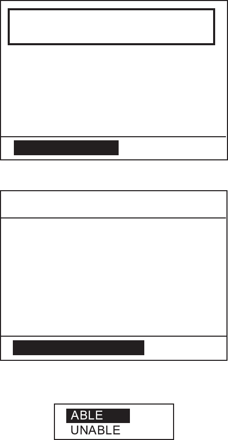
3.3.1 Sending a PSTN call
1. Press the CALL key. The display changes from standby display to the
COMPOSE MESSAGE screen and the CALL TYPE is displayed in reverse
video.
2. Press the ENT key to open the call type list.
3. Rotate the CH knob (or press up / down arrow key) to choose PSTN CALL
and press the ENT key.
** Compose Message **
CALL TYPE : PSTN CALL
TCmd1 : SIMPLEX TP
TCmd2 : NO INFO
NAME :
TEL :
COAST ID : 003456789
If MMSI is registered
in a file, its file name
is displayed. If not,
this field is blank.
4. COAST ID is selected; press the ENT key.
5. Key in a coast ID and press the ENT key.
6. TCmd1 is selected; press the ENT key.
7. Choose SIMPLEX or DUPLEX as appropriate followed by pressing the ENT
key.
8. TEL is selected; press the ENT key.
9. Key in a subscriber's telephone number (max. 16 digits).
10. Press the CALL key more than three seconds.
Call in progress
on CH70
COAST ID : 003456789
TCmd1 : SIMPLEX TP
TCmd2 : NO INFO
NAME : FURUNO
TEL : 81798631131
TIME TO GO : 5S
When TEL no. is registered,
the registered name is displayed.
3. DSC OPERATION FOR NON-DISTRESS CASES
3-14
If a response from the coast station is received within five seconds, transmit
PSTN CALL (EOS) signal and then carrier frequency during two seconds. Then
your phone rings. Press the CANCEL key to stop the calling sound and change
to standby display. Hook off and communicate with other party.
Note: If using a hand-microphone, pressing the CANCEL key is equal to
off-hook.
3.3.2 PSTN call disconnection (ship disconnects line)
1. After hanging up the handset or pressing the CANCEL key to complete your
call, the display shows the following message. The end of call signal is
transmitted; and the system then waits for a response from the coast station.
2. When the ACK from the coast station is received, the following display
appears. The communication time (charge time) is informed.
FROM : 003456789
TEL : 1234567890123456
CHARGE TIME : 00h05m18s
Able acknowledge
call received.
PRESS ENT
3. DSC OPERATION FOR NON-DISTRESS CASES
3-15
3.3.3 PSTN call disconnection (coast station disconnects line)
1. The PSTN line is disconnected by the coast station when it finds no evidence
of communications or the land subscriber hangs up. The coast station then
sends charge information as below.
FROM : 003456789
TEL : 1234567890123456
CHARGE TIME : 00h06m18s
PSTN end of call
received.
PRESS ENT
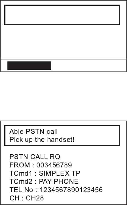
3.3.4 Receiving a PSTN call
1. When a PSTN call is received, the following display appears. Your phone
rings.
2. Hook off within 60 seconds. The channel changes automatically and you can
communicate with other party.
3. When the communication is completed, hook on the handset or press the
CANCEL key.
3. DSC OPERATION FOR NON-DISTRESS CASES
3-16
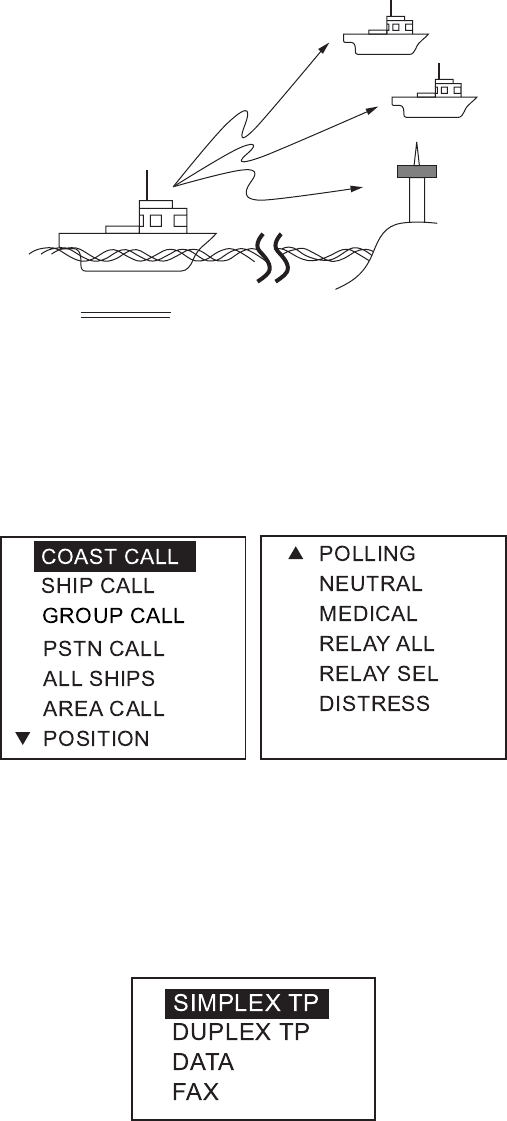
3.4 All Ships Call
When an urgent but not life-endangering situation arises on your ship, for
example, engine trouble, send an all ships call to request assistance.
After sending the call, you can communicate by voice over the radiotelephone.
Do the following before beginning actual communications:
URGENCY priority: Say PAN three times followed by your call sign.
SAFETY priority: Say SECURITE three times followed by your call sign.
Own Ship
Coast
Station
3.4.1 Sending an all ships call
1. Press the CALL key. The display changes from standby display to the
COMPOSE MESSAGE screen and the CALL TYPE is displayed in reverse
video.
2. Press the ENT key to open the call type list.
3. Rotate the CH knob (or press up / down arrow key) to choose ALL SHIPS and
press the ENT key.
4. SAFETY is selected; press the ENT key.
5. Choose SAFETY, URGENCY, or DISTRESS as appropriate followed by
pressing the ENT key.
6. TCmd1 is selected; press the ENT key.

3. DSC OPERATION FOR NON-DISTRESS CASES
3-17
7. Choose SIMPLEX TP, DUPLEX TP, DATA or FAX as appropriate followed by
pressing the ENT key. If you chose SIMPLEX, DUPLEX, or FAX, the NO
INFO appears in the Tcmd2 field. Go to the step 12. If you chose DATA, go to
the next step.
8. TCmd2 is selected; press the ENT key.
S
V. 26 ter
V. 27 ter
V. 32
V. 21
V. 22
V. 22 bis
V. 23
V. 26 bis
T
9. Choose the data type and press the ENT key.
10. Choose CH and press the ENT key. The following window appears.
SELECT CH
NO INFO
11. Choose SELECT CH or NO INFO as appropriate followed by pressing the
ENT key. If you chose SELECT CH, the following channel list appears. (The
example is the international, duplex channel list.) Rotate the CH knob (or
press up / down arrow key) to choose a channel and press the ENT key.
DUP CHANNEL
01
02
03
04
05
07
18
19
86
28
60
61
62
63
64
65
66
78
79
80
81
82
83
84
85
20
21
22
23
24
25
26
27
12. Press the CALL key more than three seconds to transmit the call.
After transmitting the message, the screen changes to standby display.
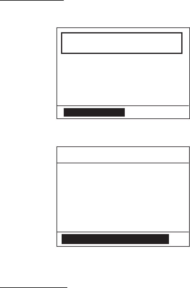
3. DSC OPERATION FOR NON-DISTRESS CASES
3-18
3.4.2 Receiving an all ships call
In case of ON HOOK
1. When an all ships call is received, the audio alarm sounds and the display
looks something like the one shown below.
All ships
call received.
FROM : 123456789
SAFETY
TCmd1 : SIMPLEX TP
TCmd2 : NO INFO
CH : 16
CANCEL ALARM
2. Press the CANCEL or ENT key to silence the alarm. The display changes as
follows.
** Received Message **
APR01/04 12 : 34 ECC : OK
ALL SHIPS CALL
SAFETY
TCmd1 : SIMPLEX TP
TCmd2 : NO INFO
CH : 16
FROM : 123456789
PRESS ENT TO CHANGE CH
3. Press the ENT key. The display changes to the standby display, and you can
watch the contents of the message.
In case of OFF HOOK
1. When an all ships call is received, the audio alarm sounds and the ALARM
LED blinks.
2. Press the ACK key. The display changes the standby display, indicating
channel specified.
3. Press the CANCEL key. The audio alarm stops and the display changes to
the receive message display.
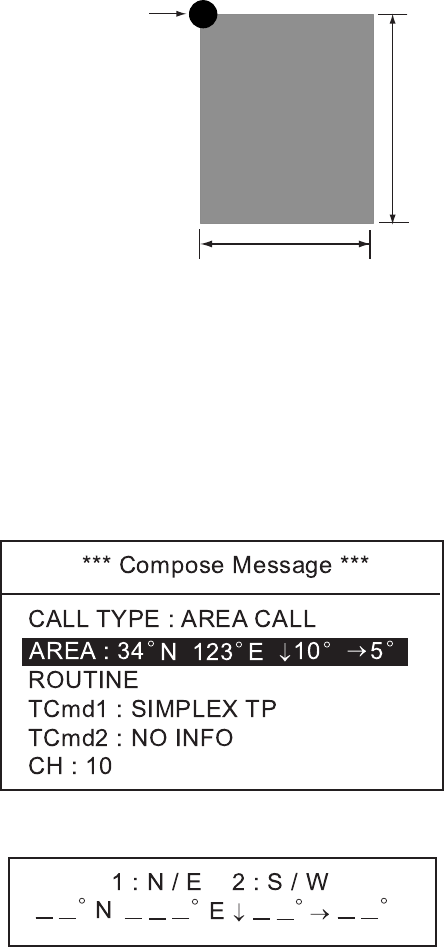
3. DSC OPERATION FOR NON-DISTRESS CASES
3-19
3.5 Geographical Area Call
The geographical area call is for sending a call to all ships within the area you
designate in your geographical area call. In the figure below, for example, the
call will be sent to all ships within 24-34°N, 135-140°W.
Reference point
(For example,
34°N 140°W)
5°
140°W135°W
10°
34°N
24°N
3.5.1 Sending a geographical area call
1. Press the CALL key. The display changes from standby display to the
COMPOSE MESSAGE screen and the CALL TYPE is displayed in reverse
video.
2. Press the ENT key to open the call type list.
3. Rotate the CH knob (or press up / down arrow key) to choose AREA CALL
and press the ENT key.
4. AREA is selected; press the ENT key.
5. Using the numeric keys, enter latitude and longitude of reference point and
southerly degrees and easterly degrees of area. To change coordinate,
choose it and press the 1 key for North or East; 2 key for South or West. After
entering data, push the ENT key.
6. ROUTINE is selected; press the ENT key.
7. Choose ROUTINE, BUSINESS, SAFETY, URGENCY, or DISTRESS as
appropriate followed by pressing the ENT key.
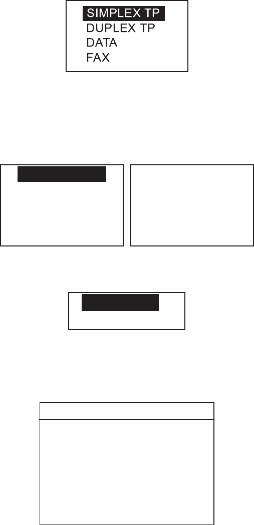
3. DSC OPERATION FOR NON-DISTRESS CASES
3-20
8. TCmd1 is selected; press the ENT key.
9. Choose SIMPLEX TP, DUPLEX TP, DATA or FAX as appropriate followed by
pressing the ENT key. If you chose SIMPLEX, DUPLEX, or FAX, NO INFO
appears in the Tcmd2 field. Go to step 12. If you chose DATA, go to the next
step.
10. TCmd2 is selected; press the ENT key.
S
V. 26 ter
V. 27 ter
V. 32
V. 21
V. 22
V. 22 bis
V. 23
V. 26 bis
T
11. Choose the data type and press the ENT key.
12. Choose CH and press the ENT key. The following window appears.
SELECT CH
NO INFO
13. Choose SELECT CH or NO INFO as appropriate followed by pressing the
ENT key. If you chose SELECT CH, the following channel list appears. (The
example is the international, duplex channel list.) Rotate the CH knob (or
press up / down arrow key) to choose a channel and press the ENT key.
DUP CHANNEL
01
02
03
04
05
07
18
19
86
28
60
61
62
63
64
65
66
78
79
80
81
82
83
84
85
20
21
22
23
24
25
26
27
14. Press the CALL key more than three seconds to transmit the message. After
the call is transmitted, the standby display appears with channel specified.

3. DSC OPERATION FOR NON-DISTRESS CASES
3-21
3.5.2 Receiving a geographical area call
1. When a geographical area call is received, the alarm sounds and the ALARM
LED blinks five seconds.
Geographical area
call received.
FROM : 123456789
ROUTINE
TCmd1 : SIMPLEX TP
TCmd2 : NO INFO
CH : 10
CANCEL ALARM
AREA : 12
°
N 123
°
E
↓
01
°→
01
°
2. Press the CANCEL key to silence the alarm. The following display appears.
** Received Message **
APR01/04 12 : 34 ECC : OK
AREA CALL
ROUTINE
TCmd1 : SIMPLEX TP
TCmd2 : NO INFO
CH : 10
FROM : 123456789
AREA : 12
°
N 123
°
E
↓
01
°→
01
°
PRESS ENT TO CHANGE CH
3. Press the ENT key. You can now watch over the VHF channel specified.
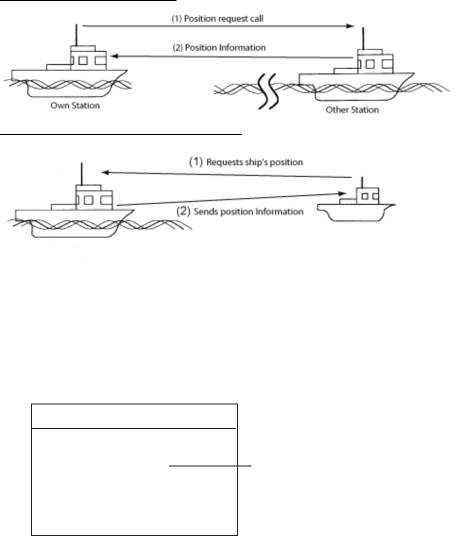
3. DSC OPERATION FOR NON-DISTRESS CASES
3-22
3.6 Position Call
There are two types of position calls: other station requires your ship's position
and your ship requests position of another ship.
Finding position of other station
Sending own ship's position to other station
OtherStation
OwnStation
3.6.1 Position call: requesting other ship's position
1. Press the CALL key. The display changes from standby display to the
COMPOSE MESSAGE screen and the CALL TYPE is displayed in reverse
video.
2. Press the ENT key to open the call type list.
3. Rotate the CH knob (or press up / down arrow key) to choose POSITION and
press the ENT key.
**ComposeMessage**
CALLTYPE:POSITION
REQUEST
TO:
SHIPID:123456789
ROUTINE
TCmd1:POSITIONREQUEST
TCmd2:NOINFO
Ifafileisregistered,
itsregistrationname
isdisplayed.
Ifnot,thisfieldisblank.
4. SHIP ID is selected; press the ENT key.
5. Key in a ship ID for which you want to know its position.
6. ROUTINE is selected; press the ENT key.
7. Choose ROUTINE, BUSINESS, SAFETY, URGENCY, or DISTRESS as
appropriate followed by pressing the ENT key.

3. DSC OPERATION FOR NON-DISTRESS CASES
3-23
8. Press the CALL key more than three seconds to transmit position request.
The following display appears. The timer counts down until a response is
received.
Waiting for
acknowledgement.
SHIP ID : 123456789
ROUTINE
TCmd1 : POSITION REQUEST
TCmd2 : NO INFO
TIME TO GO : 3M30 S
If a file is registered,
its registration name
is displayed.
If not, this field is blank.
9. When an acknowledge call is received, the following display appears and the
audio alarm sounds.
Position acknowledge
received.
TCmd1 : POSITION
TCmd2 : NO INFO
FROM : 123456789
ROUTINE
CANCEL ALARM
AT 12 : 34
POS : 12
°
34N 123
°
45E
10. Press the CANCEL key to silence the alarm. The display looks as below.
You can now confirm position of other ship.
** Received Message **
APR01/04 12 : 34 ECC : OK
POSITION ACK
AT 12 : 34
TCmd1 : POSITION
TCmd2 : NO INFO
ROUTINE
FROM : 123456789
POS : 12
°
34N 123
°
45E
PRESS ENT
11. When "No response! Try calling again?" is displayed;
Re-send call: Push the ENT key followed by the CALL key.
Cancel call: Press the CANCEL key.
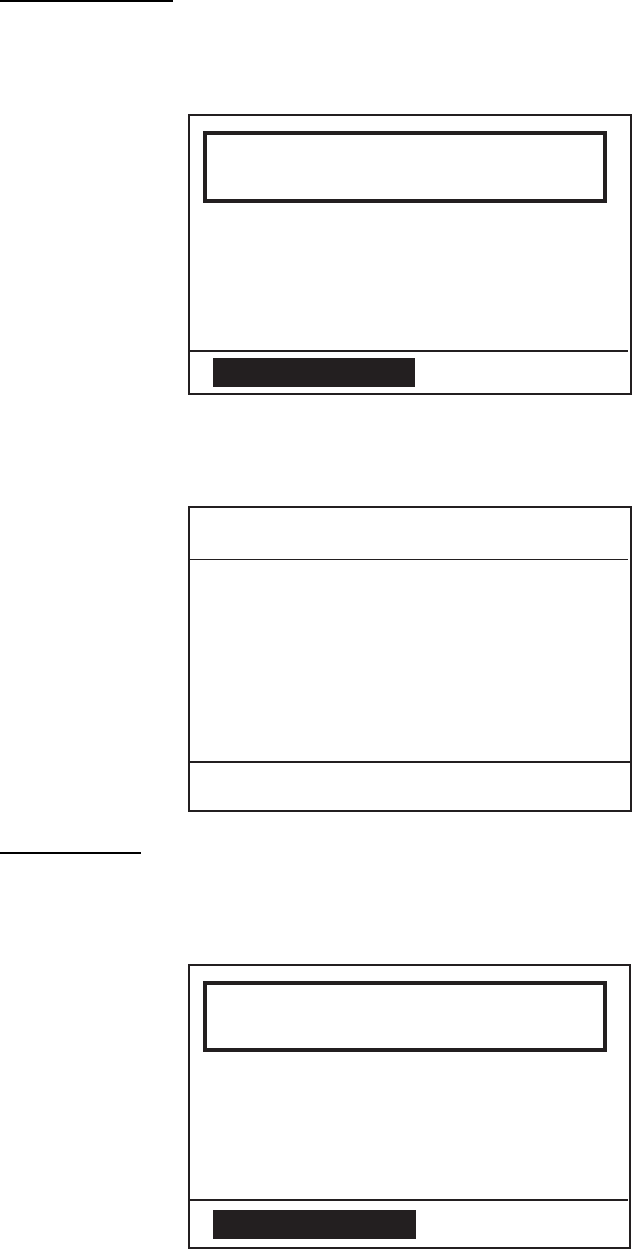
3. DSC OPERATION FOR NON-DISTRESS CASES
3-24
3.6.2 Position call: other ship requests your position
You may turn automatic acknowledge of position request on or off with
POSITION CALL in the system setup menu. For further details, see page 4-3.
Automatic reply
1. When another ship requests your position, the status of the 5 ACK key is
AUTO ACK and the setting of POSITION CALL on the system setup menu is
ON, the FM-8800D/S transmits own position data, showing the display below.
Position auto ack
transmitted.
TCmd1 : POSITION
TCmd2 : NO INFO
CANCEL ALARM
AT 12 : 34
POS : 12
°
34N 123
°
45E
2. Press the CANCEL
key to silence the alarm. The display then looks like the one below, indicating
own ship's position.
** Send Message **
POSITION ACK
TCmd1 : POSITION
TCmd2 : NO INFO
AT 12 : 34
TO : 123456789
POS : 12 ° 34N 123 ° 45E
PRESS ENT
Manual reply
1. When a position request call is received and the setting of POSITION CALL
on the system setup menu is OFF, the audio alarm sounds and the display
changes as below.
Position request
call received.
TCmd1 : POSITION REQUEST
TCmd2 : NO INFO
FROM : 123456789
ROUTINE
CANCEL ALARM
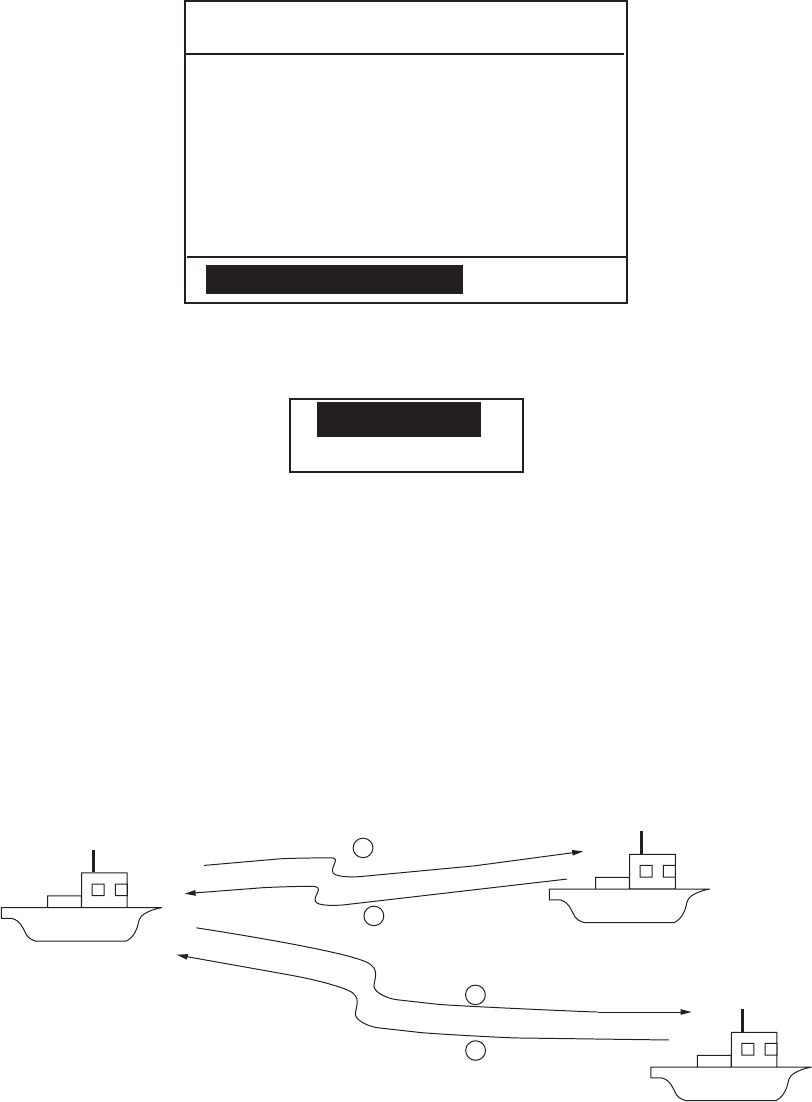
3. DSC OPERATION FOR NON-DISTRESS CASES
3-25
2. Press the CANCEL key to silence the alarm.
** Received Message **
APR01/04 12 : 34 ECC : OK
POSITION CALL
TCmd1 : POSITION
TCmd2 : NO INFO
ROUTINE
FROM : 123456789
PRESS ENT TO ACK
3. To send your position manually, press the ENT key. The following pop-up
menu appears.
ANSWER
NO ANSWER
4. Choose ANSWER by the CH knob and press the CALL key to send your
position data. Then, the standby display appears.
To send no position data, choose NO ANSWER and press the ENT key twice
to return to the standby display.
3.7 Polling Call
Polling means confirming if own station is within communicating range with other
station. This function only provides affirmative or negative response; it does not
provide position information. Note that simultaneous polling to more than one
station is not possible.
1Polling
2Acknowledge
3Polling
4Acknowledge
3.7.1 Sending a polling call
1. Press the CALL key. The display changes from standby display to the
COMPOSE MESSAGE screen and the CALL TYPE is displayed in reverse
video.
2. Press the ENT key to open the call type list.
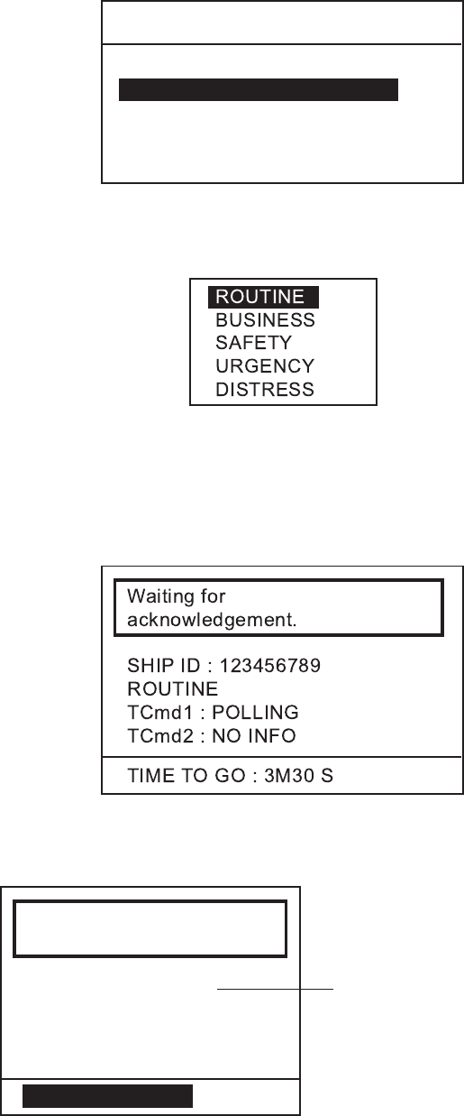
3. DSC OPERATION FOR NON-DISTRESS CASES
3-26
3. Rotate the CH knob (or press up / down arrow key) to choose POLLING and
press the ENT key.
** Compose Message **
SHIP ID :
TCmd1 : POLLING
TCmd2 : NO INFO
ROUTINE
CALL TYPE : POLLING
4. SHIP ID is selected; press the ENT key.
5. Key in a station ID with the numeric keys and press the ENT key.
6. ROUTINE is selected; press the ENT key.
7. Rotate the CH knob (or press up / down arrow key) to choose the appropriate
communications category and press the ENT key.
8. Press the CALL key more than three seconds to transmit polling call. After the
call is transmitted, the following display appears. The timer counts down until
a response is received.
9-1. When a polling acknowledge call is received, the audio alarm sounds and
the display looks something like the one below.
Polling acknowledge
received.
FROM : 123456789
ROUTINE
TCmd1 :
POLLING
TCmd2 : NO INFO
CANCEL ALARM
If a file is registered, the
registration name is
displayed.
Press the CANCEL key to silence the alarm. Press the ENT key to show the
standby display when you can confirm if called party is within communicating
range.
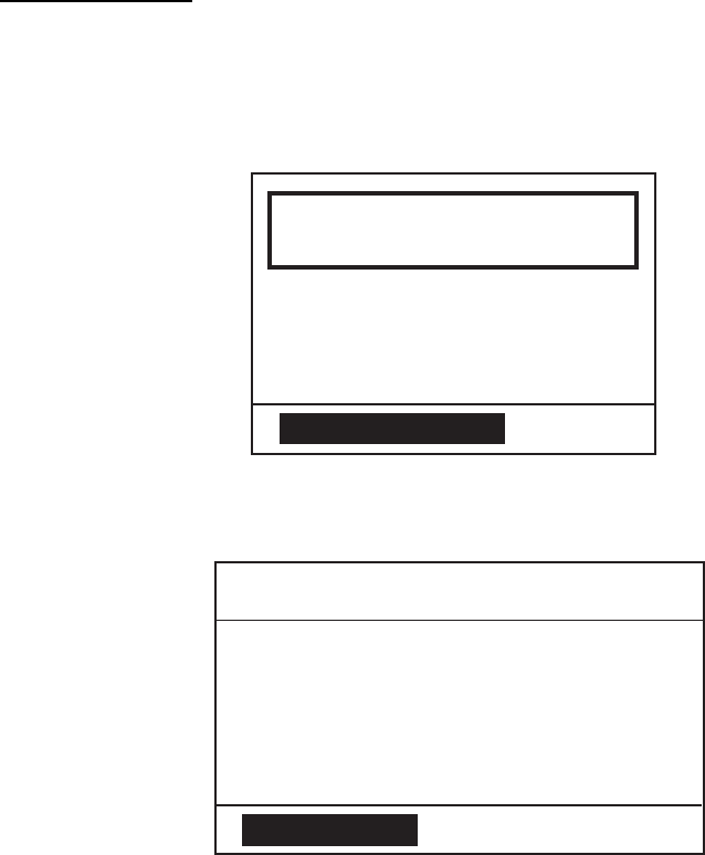
3. DSC OPERATION FOR NON-DISTRESS CASES
3-27
9-2. When "No response! Try calling again?" is displayed, do one of the
following:
Re-send call: Push the ENT key followed by the CALL key.
Cancel call: Press the CANCEL key to return to the standby display.
3.7.2 Receiving a polling call
Automatic reply
1. When a polling request is received and the equipment is set up for automatic
acknowledge POLLING on the AUTO ACK menu is ON and the ACK key is
set to show AUTO ACK on the display, the display changes as shown in the
illustration below and the audio alarm sounds.
Polling auto ack
transmitted.
ROUTINE
TCmd1 :
POLLING
TCmd2 : NO INFO
CANCEL ALARM
2. Press the CANCEL or ENT key to silence the alarm. The display changes as
below.
** Send Message **
POLLING ACK
TO : 123456789
ROUTINE
TCmd1 : POLLING
TCmd2 : NO INFO
PRESS ENT
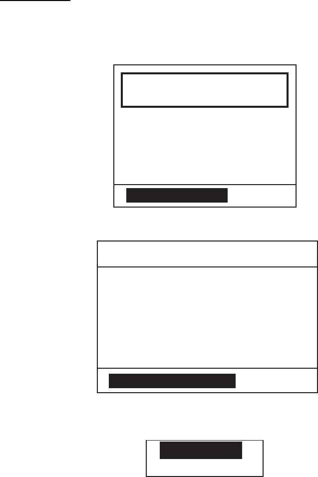
3. DSC OPERATION FOR NON-DISTRESS CASES
3-28
Manual reply
1. When a polling request call is received and the setting of POLLING CALL on
the system setup menu is OFF, the display changes as shown in the
illustration below and the audio alarm sounds.
Position request
call received.
FROM : 123456789
ROUTINE
TCmd1 :
POLLING
TCmd2 : NO INFO
CANCEL ALARM
2. Press the CANCEL key to silence the alarm. The display changes as below.
** Received Message **
APR01/04 12 : 34 ECC : OK
POLLING RQ
ROUTINE
TCmd1 : POLLING REQUEST
TCmd2 : NO INFO
FROM : 123456789
PRESS ENT TO ACK
3. To respond to the call, press the ENT key. The following pop-up window
appears.
ANSWER
NO ANSWER
4. Choose ANSWER by the CH knob and press the CALL key to send the
polling acknowledge call. Then the standby display appears.
To send no reply, choose NO ANSWER and press the ENT key twice to
return to the standby display.

3. DSC OPERATION FOR NON-DISTRESS CASES
3-29
3.8 Neutral Craft Call
The neutral craft call, which contains own ship position and ID, informs all ships
that your ship is not a participant in armed conflict. Send the call BEFORE
entering an area of armed conflict.
3.8.1 Sending a neutral craft call
1. Press the CALL key. The display changes from the standby display to the
COMPOSE MESSAGE screen and the CALL TYPE is displayed in reverse
video.
2. Press the ENT key to open the call type list.
3. Rotate the CH knob (or press up / down arrow key) to choose NEUTRAL and
press the ENT key.
** Compose Message **
CRAFT
TCmd1 : SIMPLEX TP
TCmd2 : NEUTRAL CRAFT
CH : 16
URGENCY
CALL TYPE : NEUTRAL
6. URGENCY is selected; press the ENT key.
7. Choose SAFETY, or URGENCY as appropriate followed by pressing the ENT
key.
8. Press the CALL key more than three seconds to transmit the call. After the
call is transmitted, the standby display appears.
3.8.2 Receiving a neutral craft call
1. When a neutral craft call is received, the alarm sounds and the display
changes as below.
Neutral craft
call received.
FROM : 123456789
SAFETY
TCmd1 : SIMPLEX TP
TCmd2 : NEUTRAL CRAFT
CH : 16
CANCEL ALARM
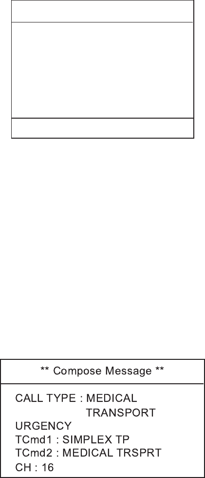
3. DSC OPERATION FOR NON-DISTRESS CASES
3-30
2. Press the CANCEL or ENT key. The audible alarm is silenced and the display
changes as below.
** Received Message **
APR01/04 12 : 34 ECC : OK
NEUTRAL CALL
APR01/04 12 : 34 ECC : OK
SAFETY
TCmd1 : SIMPLEX TP
TCmd2 : NEUTRAL CRAFT
CH : 16
FROM : 123456789
PRESS ENT TO CHANGE CH
3. Press the ENT key. The display changes to the standby display, indicating
CH16.
3.9 Medical Transport Call
The medical transport call informs all ships, by urgency priority, that own ship
carries medical supplies.
3.9.1 Sending a medical transport call
1. Press the CALL key. The display changes from the standby display to the
COMPOSE MESSAGE screen and the CALL TYPE is displayed in reverse
video.
2. Press the ENT key to open the call type list.
3. Rotate the CH knob (or press up / down arrow key) to choose the MEDICAL
and press the ENT key.
4. Press the CALL key to transmit the call. After the call is transmitted, the
standby display appears, with CH16 selected.

3. DSC OPERATION FOR NON-DISTRESS CASES
3-31
3.9.2 Receiving a medical transport call
1. When a medical call is received, the alarm sounds and the display changes as
below.
Medical call
received.
FROM : 123456789
URGENCY
TCmd1 : SIMPLEX TP
TCmd2 : MEDICAL
CH : 16
CANCEL ALARM
2. Press the CANCEL or ENT key. The audible alarm stops and the display
changes as below.
** Received Message **
APR01/04 12 : 34 ECC : OK
MEDICAL CALL
URGENCY
TCmd1 : SIMPLEX TP
TCmd2 : MEDICAL
CH : 16
FROM : 123456789
PRESS ENT
3. Press the ENT key. The display changes to the standby display, indicating
CH16.
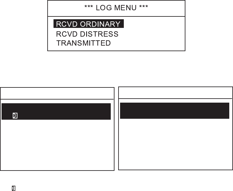
3. DSC OPERATION FOR NON-DISTRESS CASES
3-32
3.10 Log File
Three log files are provided for storage of calls: received ordinary log, received
distress log and transmitted log. Each log file stores 50 calls, on a first-in,
first-out basis. This means that the latest call is saved as log no.1 and the log no.
of all previous calls in that log increments by one. When the storage capacity is
exceeded, the oldest call is deleted to make room for the latest. An asterisk (*)
marks unread or unacknowledged calls. Received distress calls are
automatically deleted 48 hours after being read.
3.10.1 Opening a log file
The procedure for opening a log is common to all logs.
1. Press the LOG key to open the SELECT LOG FILE display.
2. Rotate the CH knob to choose RCVD ORDINARY, RCVD DISTRESS or
TRANSMITTED as appropriate and press the ENT key. For example, choose
RCVD ORDINARY or TRANSMITTED.
01: APR 10/04 12:30
RCVD ORDINARY LOG 1/13
INDIVIDUAL SHIP BQ
02: APR 15/04 10: 15
ALL SHIP
03: APR 25/04 11: 30
COAST CALL RQ
TRANSMITTED 1/13
04: MAY10/04 18: 30
COAST CALL RQ
01: APR 10/04 12:35
INDIVIDUAL SHIP
02: APR 15/04 10: 25
ALL SHIP
03: APR 25/04 12: 30
COAST CALL
04: MAY10/04 19: 30
COAST CALL
TT
3. Rotate the CH knob to choose a file you wish to browse.
The in the RCVD ORDINARY LOG indicates unread or unacknowledged
message.
4. If you wish to print the file selected, press the PRINT key.
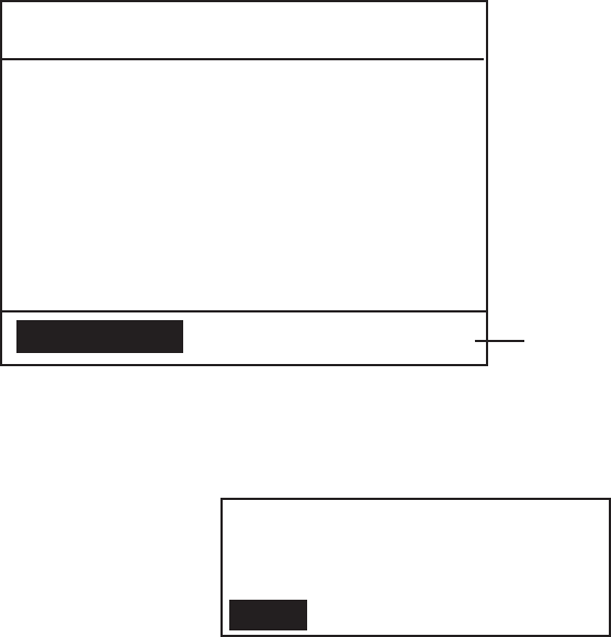
3. DSC OPERATION FOR NON-DISTRESS CASES
3-33
5. Press the ENT key to open the message. Below is a sample message.
** Received Message **
APR 10/’04 18:30 ECC : OK
INDIVIDUAL SHIP RQ
CH : 16
TCmd1 : SIMPLEX TP
TCmd2 : NO INFO
ROUTINE
FROM : 123456789
ANSWER
DELETE
For a received message
which requires a reply,
ANSWER is displayed
(for 4.5 minutes).
To reply choose it and
press the ENT key.
T
T
6. Press ▲ or ▼ key to open previous or next page on the log.
7. If you wish to delete the file selected at step 3, choose DELETE and press the
ENT key. The following confirmation window appears.
YES
DELETE
RECEIVED ORDINARY LOG
ARE YOU SURE?
NO
8. Choose YES and press the ENT key.
3. DSC OPERATION FOR NON-DISTRESS CASES
3-34
This page is intentionally left blank.
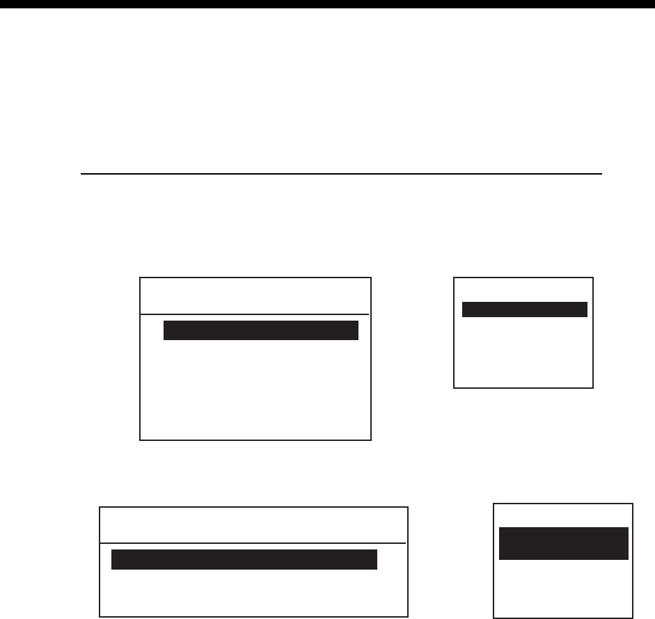
4-1
4. BASIC SETUP
4.1 Alarm Setup
This section provides the procedures for setting up various alarms. The alarm
menu enables/disables internal and external alarms. Note that the
Distress/Urgency alarm cannot be disabled.
Disabling/enabling old position alarm in manual position entry mode
This alerts the operator when manually entered position data is older by the
number of hours or minutes set in the next Position Older field.
1. Press the MENU key.
**** SETUP MENU ****
ALARM
ERASE LOG
MEMORY CHANNEL
AUTO ACK
MESSAGE FILE ENTRY
T
* SETUP MENU *
ALARM
ERASE LOG
MEMORY CH
AUTO ACK
MESSAGE FILE
T
SETUP MENU on transceiver unit SETUP MENU on remote handset
2. ALARM is selected; press the ENT key to display the ALARM menu.
**** ALARM MENU ****
POSITION OLDER 4H
EXT ALARM DSTRS/URG
OLD POSITION OFF
* ALARM MENU *
OLD POSITION
OFF
T
POSITION OLDER
4H
ALARM MENU on transceiver unit
ALARM MENU on remote handset
(You can get same information by
scrolling with up / down arrow
keys)
3. Rotate the CH knob (or press up / down arrow key) to choose OLD POSITION
from the ALARM MENU and press the ENT key. The setting window appears.
4. Rotate the CH knob (or press up / down arrow key) to choose ON or OFF as
appropriate and press the ENT key. If you chose ON, the message "Warning:
Update position" appears when manually entered position is older than the
time set on the ALARM MENU.
5. Press the CANCEL key twice to return to the standby display.
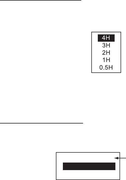
4. BASIC SETUP
4-2
To set "position older" alarm
1. Rotate the CH knob (or press up / down arrow key) to choose POSITION
OLDER (POS. OLDER for remote handset) from the ALARM MENU and
press the ENT key. The following setting window appears.
2. Rotate the CH knob (or press up / down arrow key) to choose an appropriate
value and press the ENT key.
Alarm is output when position is older by the number of hours set here.
3. Press the CANCEL key twice to return to the standby display.
To set type of alarm to output
1. Rotate the CH knob (or press up / down arrow key) to choose EXT ALARM
from the ALARM MENU and press the ENT key. The following setting window
appears.
DIST/URG : ON
SAFETY : OFF
ROUTINE : OFF
Always ON
2. Rotate the CH knob (or press up / down arrow key) to choose an appropriate.
Option. Alarm is output to external device.
DSTRS/URG: Distress or urgency call output upon receipt.
SAFETY: Safety call output upon receipt.
ROUTINE: Routine call output upon receipt.
3. Press the ENT key.
4. Press the CANCEL key twice to return to the standby display.
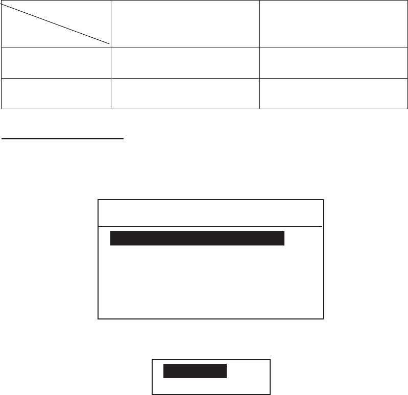
4. BASIC SETUP
4-3
4.2 Auto ACK Setup
The Auto Ack Menu enables/disables automatic acknowledgement of ship, coast,
position and polling calls.
Comply type
Set of [5 ACQ]
ABLE
UNABLE
AUTO ACK Can send acknowledge
automatically.
Can send UNABLE
automatically.
MANUAL ACK Can send acknowledge
manually
Can send UNABLE
manually.
To set COMPLY TYPE
1. Press the MENU key.
2. Rotate the CH knob (or press up / down arrow key) to choose AUTO ACK and
press the ENT key. The following menu appears.
**** AUTO ACK MENU ****
COMPLY STATUS ABLE
NO REASON
POSITION CALL ON
UNABLE REASON
POLLING CALL ON
3. COMPLY STATUS is selected; press the ENT key. The following setting
window appears.
ABLE
UNABLE
4. Rotate the CH knob (or press up / down arrow key) to choose ABLE or
UNABLE as automatic acknowledgement reply to each call.
5. Press the ENT key.
Note: Automatic acknowledge is automatically disabled when RX call
contains error, as required by law. Further, automatic acknowledge is
disabled in case of OFF HOOK.

4. BASIC SETUP
4-4
To set reason for unable
If you have chosen UNABLE as the COMPLY STATUS, set the reason as
follows:
1. Rotate the CH knob (or press up / down arrow key) to choose UNABLE
REASON from the AUTO ACK MENU and press the ENT key. The following
menu appears.
NO REASON
BUSY
EQUIP DISBLD
MODE UNAVAIL
CH UNAVAIL
2. Rotate the CH knob (or press up / down arrow key) to choose a reason for
UNABLE.
3. Press the ENT key.
Note: This menu is the same as manual acknowledgement. EQUIPMENT
DISABLE is shown in calls when EQUIP DISBLD is selected.
To set position call response
1. Rotate the CH knob (or press up / down arrow key) to choose the POSITION
CALL from the AUTO ACK MENU and press the ENT key.
2. Rotate the CH knob (or press up / down arrow key) to choose ON or OFF as
appropriate.
OFF: Disables automatic acknowledgement of position request.
ON: Enables automatic acknowledgement of position request.
3. Press the ENT key.
To set polling call response
1. Rotate the CH knob (or press up / down arrow key) to choose the POLLING
CALL from the AUTO ACK MENU and press the ENT key.
2. Rotate the CH knob (or press up / down arrow key) to choose ON or OFF as
appropriate.
OFF: Disables automatic acknowledgement of polling request.
ON: Enables automatic acknowledgement of polling request.
3. Press the ENT key.

4. BASIC SETUP
4-5
4.3 Erasing Logs
Erasing received ordinary log
1. Press the MENU key.
2. Rotate the CH knob (or press up / down arrow key) to choose the ERASE
LOG and press the ENT key. The following window appears.
RCVD ORDINARY
RCVD DISTRESS
TRANSMITTED
*** ERASE LOG MENU ***
3. RCVD ORDINARY is selected; press the ENT key to erase the received
ordinary log.
Erasing received distress log
1. Press the MENU key.
2. Rotate the CH knob (or press up / down arrow key) to choose ERASE LOG
and press the ENT key.
3. Rotate the CH knob (or press up / down arrow key) to choose RCVD
DISTRESS and press the ENT key to erase the received distress log.
Erasing transmitted log
1. Press the MENU key.
2. Rotate the CH knob (or press up / down arrow key) to choose ERASE LOG
and press the ENT key.
3. Rotate the CH knob (or press up / down arrow key) to choose TRANSMITTED
and press the ENT key.
YES
ERASE
TRANSMITTED
ARE YOU SURE?
NO
4. Choose YES and press the ENT key to erase the transmitted message log.

4. BASIC SETUP
4-6
4.4 Memory Channel Setup
You can save up to 50 channels as follows.
1. Press the MENU key.
2. Rotate the CH knob (or press up / down arrow key) to choose MEMORY
CHANNEL and press the ENT key.
* Memory Channel 1/7*
01 CH-- --------
02 : CH-- --------
T
03 : CH-- --------
04 : CH-- --------
05 : CH-- --------
06 : CH-- --------
07 : CH-- --------
08 : CH-- --------
3. Rotate the CH knob (or press up / down arrow key) to choose a vacant CH
number and press the ENT key.
INTL
USA
WX
CANADA
INLND-WA
PRIV
ERASE
*
*
*
*
*
* : Only permitted channel
modes are displayed,
which are set by the
installer of the equipment.
4. Rotate the CH knob (or press up / down arrow key) to choose appropriate
channel type and press the ENT key.
5. Rotate the CH knob (or press up / down arrow key) to choose channel number
and press the ENT key.

4. BASIC SETUP
4-7
4.5 Message File Entry
In this section you will learn how to prepare and store ship, coast, PSTN, group,
and area calls for future transmission. 100 calls can be stored.
1. At the standby display, press the MENU key to open the SETUP MENU.
**** SETUP MENU ****
ALARM
ERASE LOG
MEMORY CHANNEL
AUTO ACK
MESSAGE FILE ENTRY
T
2. Rotate the CH knob (or press up / down arrow key) to choose MESSAGE
FILE ENTRY and press the ENT key.
* MESSAGE FILE 1/13 *
1:
2:
3:
4:
5:
6:
7:
8:
T
3. Rotate the CH knob to choose a vacant number and press the ENT key. The
following selection window appears.
COAST CALL
SHIP CALL
PSTN CALL
GROUP CALL
AREA CALL
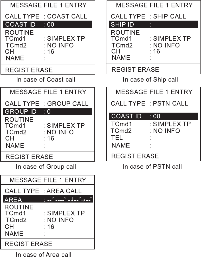
4. BASIC SETUP
4-8
4. Rotate the CH knob to choose the call type and press the ENT key. One of the
following display appears depending on the call type selected above.
Note1: The communication priority is ROUTINE only.
Note2: The group ID will be registered automatically after a group call
message file is saved.
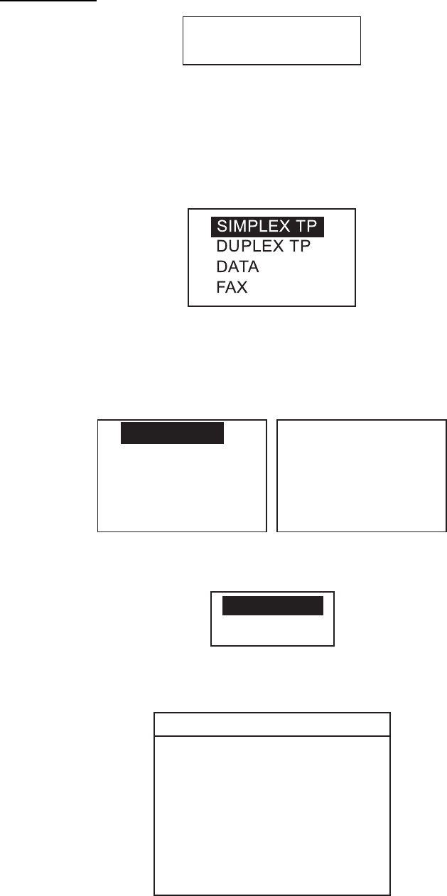
4. BASIC SETUP
4-9
5. Press the ENT key and key in each ID or AREA followed by the ENT key.
To enter area
1: N/E 2: S/W
°---
-- ↓→
N°E°
-- °
--
a) Enter latitude (degrees) and 1 for north or 2 for south of reference point.
b) Enter longitude (degrees) and 1 for east or 2 for west.
c) Enter southerly degrees of area.
d) Enter easterly degrees of area.
e) Press the ENT key.
6. TCmd1 is selected; press the ENT key.
7. Choose SIMPLEX TP, DUPLEX TP, DATA or FAX as appropriate followed by
pressing the ENT key. If you chose SIMPLEX, DUPLEX, or FAX, NO INFO
appears in the Tcmd2 field. Go to step 10. If you chose DATA, go to the next
step.
8. Tcmd2 is selected; press the ENT key.
S
V. 26 ter
V. 27 ter
V. 32
V. 21
V. 22
V. 22 bis
V. 23
V. 26 bis
T
9. Choose an appropriate data type and press the ENT key.
10. Choose CH and press the ENT key. The following window appears.
SELECT CH
NO INFO
11. Choose SELECT CH with the CH knob (or up / down arrow key) and press
the ENT key.
SIMP CHANNEL
06
08
09
10
11
12
13
14
15
16
17
67
68
69
71
72
73
74
75
76
77
87
88
In case of NO INFO, there is no channel information.
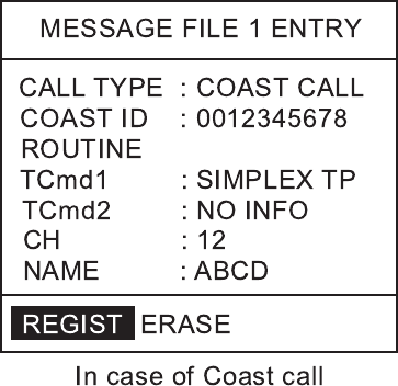
4. BASIC SETUP
4-10
12. Choose a channel with the CH knob (or up / down arrow key) and press the
ENT key.
13. Press the ENT key to open the name entry window.
14. Enter a name with the alphanumeric keys. To change a digit, rotate the CH
knob. Press the ENT key.
15. REGIST is selected; press the ENT key to register. To erase, rotate the CH
knob to select ERASE and press the ENT key.
Note: To send a message, after pressing the CALL key, choose CALL TYPE,
highlighting xxx ID, press the FILE key to show the name list. Choose
a name from the list.
To send a message file:
1) Press the CALL key.
2) Choose call type and press the ENT key.
3) Highlighting xxx ID, press the FILE key to display list of message files.
4) Choose file to send and press the ENT key..
5) Press the CALL key more than three seconds.

4. BASIC SETUP
4-11
4.6 Position Setup
This is where you enter your position, automatically or manually.
1. Press the MENU key at the standby display.
2. Rotate the CH knob (or press up / down arrow key) to choose POSITION from
the second page of the main menu.
**** SETUP MENU ****
POSITION
VOLUME
PRINT OUT
SYSTEM
T
3. Press the ENT key. The following menu appears.
INPUT TYPE: AUTO
LAT : -- °--’-
LON : ---°--’-
TIME : -- : --
N
E
4. INPUT TYPE is selected; press the ENT key. The following setting window
appears.
AUTO
MANUAL
5. Rotate the CH knob (or press up / down arrow key) to choose AUTO or
MANUAL as appropriate and press the ENT key.
If you chose AUTO, your ship's position and time appear; press the CANCEL
to close the menu and return to the standby display. These data are supplied
from the navigation equipment connected.
Note: • If the position data from a positioning sensor is available, MANUAL
can not be chosen.
• If correct position data is entered from a position source in the
setting of MANUAL, the setting changes automatically to AUTO from
MANUAL.
• If the message "No Position Data" appears after you change INPUT
TYPE from MANUAL to AUTO, confirm that the navigation device is
functioning.
If you chose MANUAL, enter your position and time as follows.
6. Enter latitude (in four digits) with the numeric keys. If necessary, switch
coordinates: 1 key to switch to North; 2 key to switch to South.
7. Press the ENT key and enter longitude (in five digits) with the numeric keys. If
necessary, switch coordinates: 1 key to switch to East; 2 key to switch to
West.
8. Press the ENT key and enter UTC time with the numeric keys.
9. Press the ENT key and CANCEL key to finish.

4. BASIC SETUP
4-12
4.7 Print Out Setup
The PRINT MENU enables/disables automatic printing of all transmitted and
received calls and the results of the daily test.
1. Press the MENU key at the standby display to open menu.
2. Rotate the CH knob (or press up / down arrow key) to choose PRINT OUT
from the second page of the main menu and press the ENT key.
**** PRINT MENU ****
XMTD CALL MANUAL
DAILY TEST MANUAL
RCVD CALL MANUAL
3. Choose appropriate item among XMTD CALL MANUAL, RCVD CALL
MANUAL or DAILY TEST MANUAL and press the ENT key.
MANUAL
AUTO
4. Choose AUTO or MANUAL as appropriate and press the ENT key.
5. Press the CANCEL to return to the standby display.
Sample printouts
Printing can be done automatically or manually. For manual printing, press the
6 PRINT key.
** Transmitted Message **
SEP25/ ’04 17:41
SHIP ACK
TO: 111111111
ROUTINE
TCmd1: SIMPLEX TP
TCmd2: NO INFO
CH: 12
** Received Message **
SEP25/ ’04 17:40 ECC: OK
SHIP CALL
FROM: 111111111
ROUTINE
TCmd1: SIMPLEX TP
TCmd2: NO INFO
CH: 12
* Daily test result *
SEP25/ ’04 17:42
MMSI: 987654321
TX POWER: OK
TX/RX PCB: OK
CPU PCB: OK
CH70RX PCB: OK
DUP RX PCB: OK
Sample printout
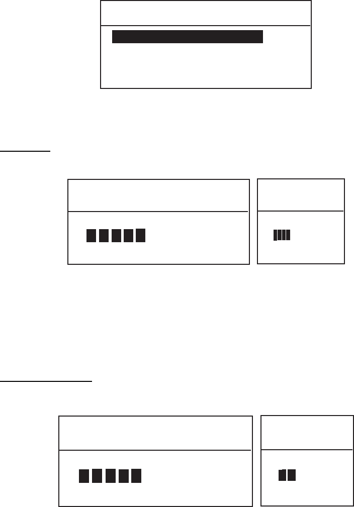
4. BASIC SETUP
4-13
4.8 Volume Setup
The VOLUME menu enables/disables key beep (acknowledges correct key
input) and adjusts the volume of the earpiece, intercom and off-hook
loudspeaker.
1. Press the MENU key at the standby display.
2. Rotate the CH knob (or press up / down arrow key) to choose VOLUME and
press the ENT key.
**** VOLUME MENU ****
KEY CLICK 8
INTERCOM VOLUME 8
EARPIECE LEVEL 9
OFF HOOK SPKR ON
Follow the appropriate procedure to adjust volume of desired item.
Key click
1. Choose KEY CLICK, and press the ENT key.
KEY CLICK LEVEL SETUP
EXT: ENT
LEVEL (0-16)
<
<
10
KEY CLICK
LEVEL SETUP
EXT: ENT
LEVEL (0-16)
<
<
4
Note: Do not confuse keyboard beep (single beep) with ACK beep (three
beeps).
2. Rotate the CH knob (or press up / down arrow key) to set the key click level.
The setting range is 0 to 16.
3. Press the ENT key.
Earpiece volume
1. Choose ERAPIECE LEVEL and press the ENT key.
EARPIECE LEVEL SETUP
EXT: ENT
LEVEL (8-16)
<
<
10
EARPIECE
LEVEL SETUP
EXT: ENT
LEVEL (1-4)
<
<
2
Transceiver unit Remote handset
2. Rotate the CH knob (or press up / down arrow key) to set the earpiece volume
level. The setting range is 8 to 16 for transceiver handset.
3. Press the ENT key.
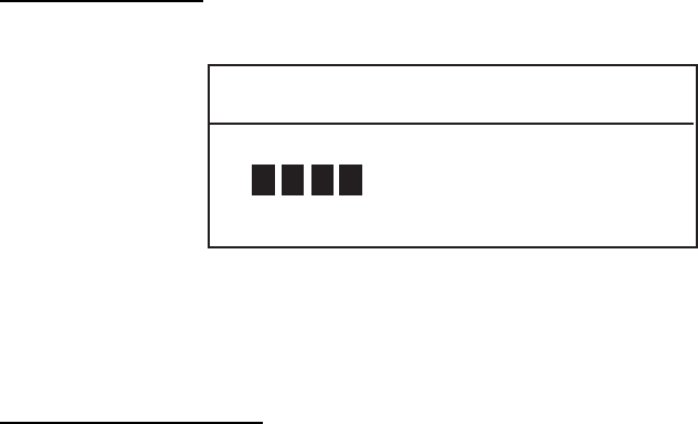
4. BASIC SETUP
4-14
Intercom volume
1. Choose INTERCOM VOLUME and press the ENT key.
INTERCOM SETUP
EXT: ENT
LEVEL (1-16)
<
<
8
2. Rotate the CH knob (or press up / down arrow key) to set the intercom volume
level. The setting range is 1 to 16.
3. Press the ENT key.
Off-hook loudspeaker
1. Choose OFFHOOK SPKR and press the ENT key.
2. Choose ON or OFF and press the ENT key.
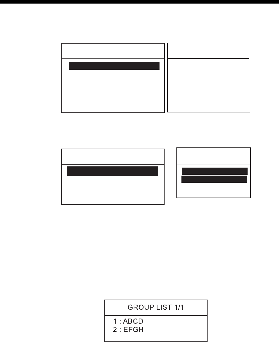
5-1
5. SYSTEM SETUP
5.1 Displaying Self ID
1. Press the MENU key.
**** SETUP MENU ****
ALARM
ERASE LOG
MEMORY CHANNEL
AUTO ACK
MESSAGE FILE ENTRY
T
**** SETUP MENU ****
VOLUME
TEST
PRINT OUT
SYSTEM
T
POSITION
2. Rotate the CH knob (or press up / down arrow key) to choose SYSTEM from
page 2 of the menu and press the ENT key. The following window appears.
The self ID is displayed on the first line.
* SYSTEM SETUP MENU *
SELF ID 123498765
GROUP ID LIST
INTERCOM NAMING
PROGRAM VERSION
* SYSTEM
SETUP MENU *
SELF ID
123498765
GROUP ID LIST
T
Transceiver unit Remote handset
5.2 Displaying Group ID LIST
1. Press the MENU key.
2. Rotate the CH knob (or press up / down arrow key) to choose SYSTEM from
page 2 of the menu and press the ENT key.
3. Rotate the CH knob (or press up / down arrow key) to choose GROUP ID
LIST and press the ENT key to show the GROUP ID list. For how to registers
group IDs, see paragraph 4.5.
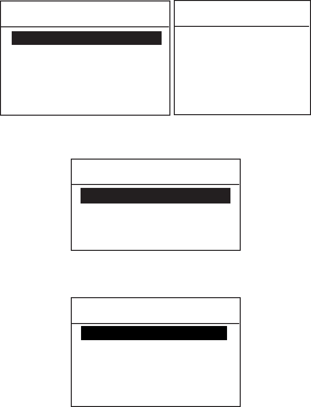
5. SYSTEM SETUP
5-2
5.3 Naming Intercom
1. Press the MENU key.
**** SETUP MENU ****
ALARM
ERASE LOG
MEMORY CHANNEL
AUTO ACK
MESSAGE FILE ENTRY
T
**** SETUP MENU ****
VOLUME
TEST
PRINT OUT
SYSTEM
T
POSITION
2. Rotate the CH knob (or press up / down arrow key) to choose SYSTEM from
page 2 of the menu and press the ENT key. The following window appears.
* SYSTEM SETUP MENU *
SELF ID ---------------------
GROUP ID LIST
INTERCOM NAMING
PROGRAM VERSION
3. Rotate the CH knob (or press up / down arrow key) to choose INTERCOM
NAMING and press the ENT key. The following window appears.
* Intercom Naming Menu *
1 : Handset 1
2 : Handset 2
3 : Handset 3
4 : Handset 4
RT : FM8800D
4. Rotate the CH knob (or press up / down arrow key) to choose a handset
number and press the ENT key.
5. Key in remote station name with alphanumeric keys and press the ENT key.
6. Repeat steps 4 and 5 to name other handsets.
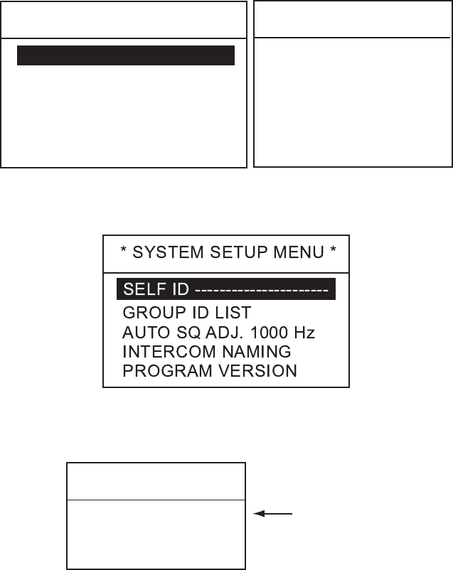
5. SYSTEM SETUP
5-3
5.4 Displaying Program Version
1. Press the MENU key.
****SETUPMENU****
ALARM
ERASELOG
MEMORYCHANNEL
AUTOACK
MESSAGEFILEENTRY
T
****SETUPMENU****
VOLUME
TEST
PRINTOUT
SYSTEM
T
POSITION
2. Rotate the CH knob to choose SYSTEM and press the ENT key. The following
selection window appears.
3. Rotate the CH knob to choose PROGRAM VERSION and press the ENT key
to show program version number.
Programversion
FM8800S
0550215-02
EXT:ENT
Program version
orFM8800D
4. Press the ENT key to exit.
5. SYSTEM SETUP
5-4
This page is intentionally left blank.

6-1
6. MAINTENANCE &
TROUBLESHOOTING
Do not open the equipment.
Hazardous voltage which can
cause electrical shock, burn or
serious injury exists inside the
equipment. Do not work inside
the equipment unless familiar
with electrical circuits.
WARNINGWARNING
6.1 Maintenance
Periodic checks
1) Check that each connector is firmly connected.
2) Clean corroded or soiled connectors.
3) Check coaxial cable for damage. If damaged, replace.
4) Check that bolts fixing the antenna are firmly tightened.
6.2 Troubleshooting
When the power cannot be turned on
1) Check if power plug is firmly connected.
2) Check fuses in the power cable. If it has tripped, replace it with a new one
(15A).
3) If power cannot be turned on (after checking 1 and 2), contact a FURUNO
agent or representative for advice.
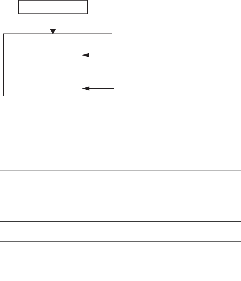
6. MAINTENANCE & TROUBLESHOOTING
6-2
6.3 Daily Test
Authorities require that the DSC be checked daily for proper operation to ensure
that it will function properly in the event of distress. Execute the daily test as
below.
1. At the standby display, press the SHIFT key and TEST key in that order. The
following display appears for test.
*** DAILY TEST ***
TX POWER : OK
TX/RX PCB : OK
CPU PCB : OK
CH70 RX PCB : OK
DUP RX PCB : OK
Test in progress (Pop-up display appears momentarily.)
If you have not pressed the PTT switch
before executing the test, "NO CHECK"
is displayed.
FM-8800D only
Result of daily test
2. To stop the daily test, press the CANCEL key.
If there is any problem, “NG” appears instead of “OK” for offending item. For any NG,
contact a FURUNO agent or representative for advice.
The table below shows the abnormal indications and causes shown in the daily test.
Indication Cause
TX POWER: NG Indicates no transmitting output power.
PA module or TX/RX pcb 05P0774 may be damaged.
TX/RX PCB: NG Indicates abnormal PLL circuit in the TX/RX pcb.
TX/RX pcb 05P0774 may be damaged.
CPU PCB: NG Indicates abnormal loop circuit inside the CPU board.
CPU pcb 05P0773 may be damaged.
CH70 RX PCB: NG Indicates abnormal loop circuit between CPU and CH70
RX pcb. CH70 RX pcb 05P0775 may be damaged.
DUP RX PCB: NG Indicates abnormal PLL circuit in the DUP RX pcb.
DUP RX pcb 05P0777 may be damaged.
If necessary, refer to Parts Location on subsequent pages.
executing
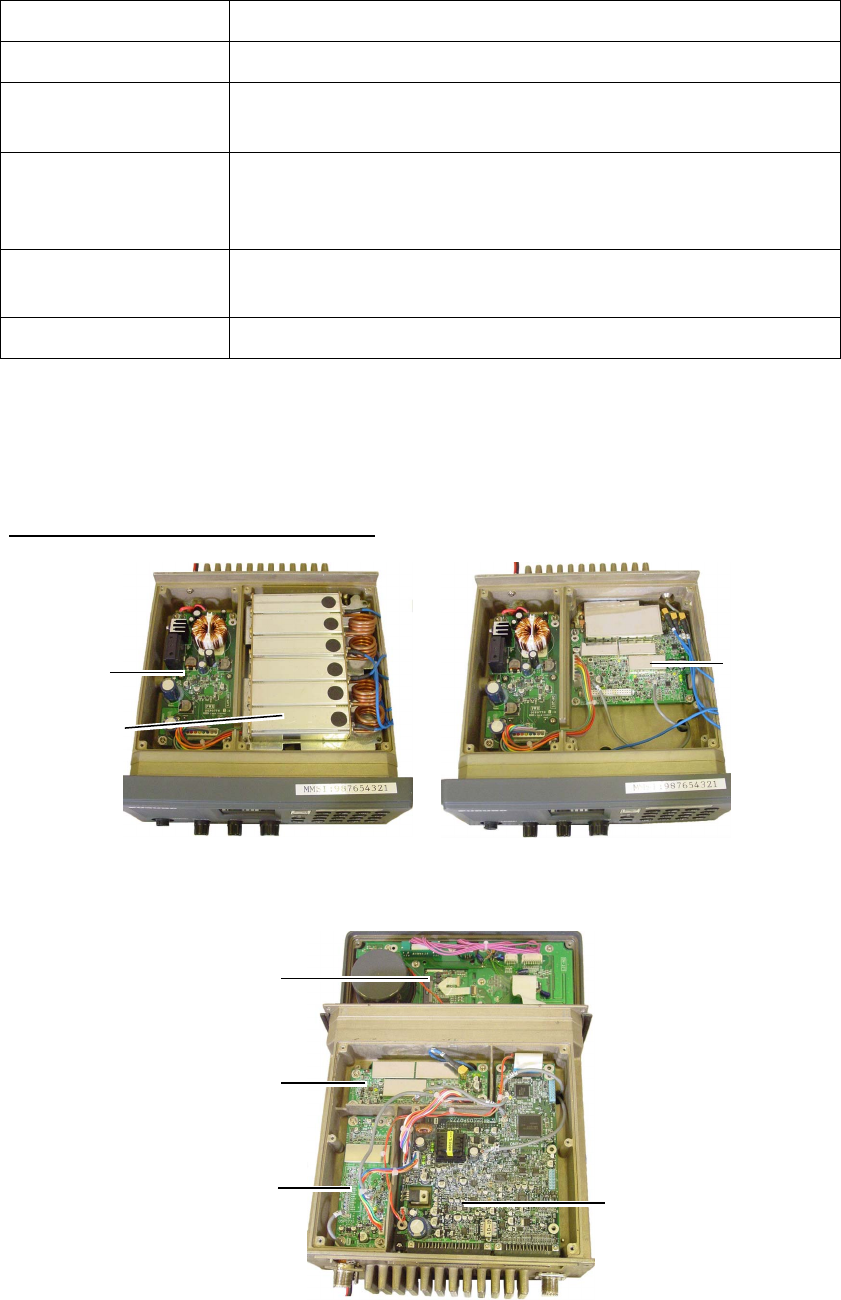
6. MAINTENANCE & TROUBLESHOOTING
6-3
6.4 Error Message
The table below shows all the error messages which may appear.
Error message Meaning
PLL1 Unlock PLL circuit on the TX/RX pcb 05P0774 has unlocked.
PLL2 Unlock PLL circuit on the DUP RX pcb 05P0777 has unlocked (only
FM-8800D).
ANT ERROR The antenna is abnormal. In this condition, if the
transmission continues more than five seconds, the output
power is reduced to approximately 10W.
GPS ERROR There is no L/L input from a positioning sensor for more than
one minute.
System Error The DSP (digital signal processor) is abnormally.
Note: If the CPU is abnormal, the beep sounds continuously until turning off the
power.
6.5 Parts Location
Transceiver unit FM-8800D/8800S
DUPLEXER
PWR pcb
05P0776
TX/RX pcb
05P0774
Top cover removed
PANEL pcb
05P0772
DUP RX pcb
05P0777
CH70 RX pcb
05P0775 CPU pcb
05P0773
Bottom cover removed
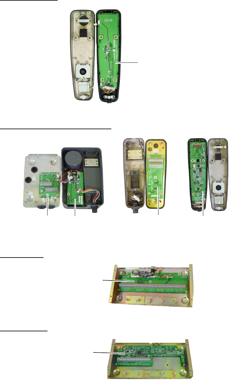
6. MAINTENANCE & TROUBLESHOOTING
6-4
Bottom cover removed
Handset HS-2003
HANDSET pcb
05P0780
Remote station RB-8800/RB-8810
TB pcb
07P0782 05P0779
REMOTE pcb TB pcb
05P0798 HS CONT pcb
05P0781
Junction box
JUNCTION pcb
05P0790
DMC Interface
DMC IF pcb
05P0778
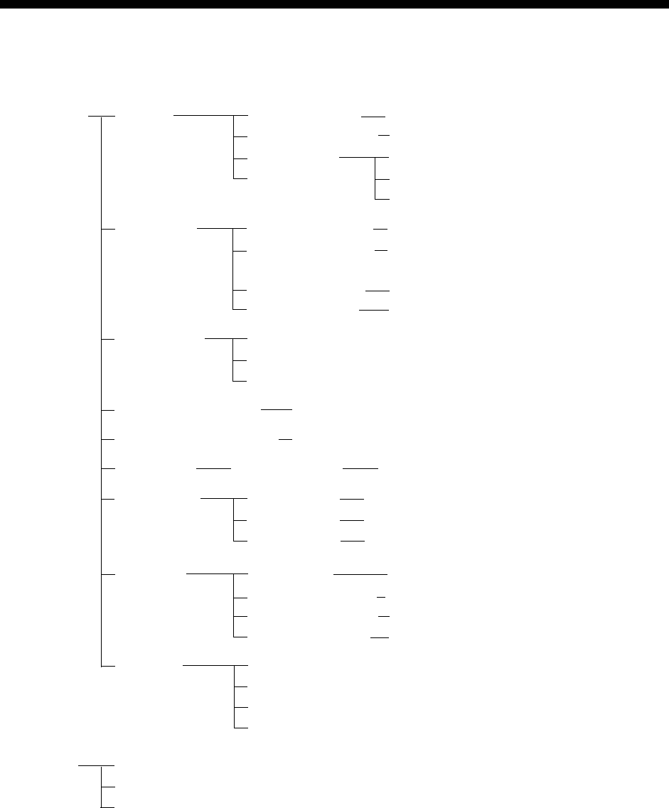
A
P-1
APPENDIX
Menu Tree
[MENU] ALARM
UNABLE REASON
ABLE/UNABLE
AUTO ACK COMPLY STATUS
POSITION CALL
NO REASON/BUSY/EQUIP DISBLD/
MODE UNAVAIL/CH UNAVAIL
EXT ALARM
4H/3H/2H/1H/0.5H
OLD POSITION
POSITION OLDER
DIST/URG, ON
ON/OFF
ON/OFF
POLLING CALL ON/OFF
ERASE LOG RCVD ORDINARY
RCVD DISTRESS
TRANSMITTED
MEMORY CHANNEL 50 entries
MESSAGE FILE ENTRY 100 entries
POSITION AUTO/MANUAL LAT/LONG/TIME
PRINT OUT XMTD CALL
RCVD CALL
DAILY TEST
AUTO/MANUAL
AUTO/MANUAL
AUTO/MANUAL
VOLUME
OFFHOOK SPKR
KEY CLICK
EARPIECE LEVEL
INTERCOM VOLUME
ON/OFF
8 (0-16)
9, 8 - 16 (For remote handset, 1-4)
8, 1 - 16
SYSTEM
PROGRAM VERSION
SELF ID
GROUP ID LIST
INTERCOM NAMING
Bold: Default
SAFETY ON/OFF
ROUTINE ON/OFF
[LOG] RCVD ORDINARY (50LOG)
RCVD DISTRESS (50LOG)
TRANSMITTED (50LOG)

APPENDIX
AP-2
[CALL] COAST CALL COAST ID
ROUTINE
GROUP CALL GROUP ID
PSTN CALL COAST ID
ALL SHIPS
BUSINESS
SHIP CALL SHIP ID
SAFETY
URGENCY
SAFETY
URGENCY
DISTRESS
TCmd1 SIMPLEX TP
DUPLEX TP
DATA
FAX
TCmd2
CH NO INFO
SELECT CH
ROUTINE
BUSINESS
SAFETY
URGENCY
DISTRESS
TCmd1 SIMPLEX TP
DUPLEX TP
DATA
FAX
TCmd2
CH NO INFO
SELECT CH
ROUTINE
BUSINESS
SAFETY
URGENCY
DISTRESS
TCmd1 SIMPLEX TP
DUPLEX TP
DATA
FAX
TCmd2
CH NO INFO
SELECT CH
TCmd1 SIMPLEX TP
DUPLEX TP
TCmd2: NO INFO
TEL
DISTRESS
TCmd1 SIMPLEX TP
DUPLEX TP
DATA
FAX
TCmd2: NO INFO
CH NO INFO
SELECT CH SIMP CHANNEL
DUP CHANNEL
AREA CALL ARE -- ---- - -- --
°°°°
→
↓
ROUTINE
BUSINESS
SAFETY
URGENCY
DISTRESS
TCmd1 SIMPLEX TP
DUPLEX TP
DATA
FAX
TCmd2
CH NO INFO
SELECT CH
POSITION SHIP ID
ROUTINE
BUSINESS
SAFETY
URGENCY
DISTRESS
TCmd1: POSITION REQUEST
TCmd2: NO INFO
1
ROUTINE
COAST ID:
BUSINESS
SHIP ID
SAFETY
URGENCY
UNDESIGNATED
Fire
Flooding
Collision
Grounding
Listing
Sinking
Disabled & Adr
Abandoning
POS:
AT:
SIMP TP
AUTO
POLLING
DISTRESS
NEUTRAL URGENCY
SAFETY
CH: 16
MEDICAL URGENCY
TCmd1: SIMPLEX TP
CH: 16
TCmd2: MEDICAL TRSPRT
RELAY ALL ID IN DIST
TCmd: DISTRESS RELAY
NATURE
Piracy
Man over board
EPIRB
MANUAL
NO INFO
DISTRESS
RELAY SEL
UNDESIGNATED
Fire
Flooding
Collision
Grounding
Listing
Sinking
Disabled & Adr
Abandoning
POS:
AT:
SIMP TP
AUTO
ID IN DIST:
TCmd: DISTRESS RELAY
NATURE
Piracy
Man over board
EPIRB
MANUAL
NO INFO
UNDESIGNATED
Fire
Flooding
Collision
Grounding
Listing
Sinking
Disabled & Adr
Abandoning
POS:
AT:
SIMP TP
AUTO
NATURE
Piracy
Man over board
EPIRB
MANUAL
NO INFO
1

APPENDIX
A
P-3
Marine VHF Channel Lists
1) International Channels
CH
TX
MHz
RX
MHz Remark CH
TX
MHz
RX
MHz Remark
01 156.050 160.650 60 156.025 160.625
02 156.100 160.700 61 156.075 160.675
03 156.150 160.750 62 156.125 160.725
04 156.200 160.800 63 156.175 160.775
05 156.250 160.850 64 156.225 160.825
06 156.300 156.300 65 156.275 160.875
07 156.350 160.950 66 156.325 160.925
08 156.400 156.400 67 156.375 156.375
09 156.450 156.450 68 156.425 156.425
10 156.500 156.500 69 156.475 156.475
11 156.550 156.550 70 - 156.525 DSC
12 156.600 156.600 71 156.575 156.575
13 156.650 156.650 72 156.625 156.625
14 156.700 156.700 73 156.675 156.675
15 156.750 156.750
Low
PWR 74 156.725 156.725
16 156.800 156.800 75 156.775 156.775
Low
PWR
17 156.850 156.850
Low
PWR 76 156.825 156.825
Low
PWR
18 156.900 161.500 77 156.875 156.875
19 156.950 161.550 78 156.925 161.525
20 157.000 161.600 79 156.975 161.575
21 157.050 161.650 80 157.025 161.625
22 157.100 161.700 81 157.075 161.675
23 157.150 161.750 82 157.125 161.725
24 157.200 161.800 83 157.175 161.775
25 157.250 161.850 84 157.225 161.825
26 157.300 161.900 85 157.275 161.875
27 157.350 161.950 86 157.325 161.925
28 157.400 162.000 87 157.375 157.375
88 157.425 157.425

APPENDIX
AP-4
2) USA Channels
CH
TX
MHz
RX
MHz Remark CH
TX
MHz
RX
MHz Remark
01 156.050 156.050 60 - -
02 - - 61 - -
03 - - 62 - -
04 - - 63 156.175 156.175
05 156.250 156.250 64 - -
06 156.300 156.300 65 156.275 156.275
07 156.350 156.350 66 156.325 156.325
08 156.400 156.400 67 156.375 156.375
Low
PWR
09 156.450 156.450 68 156.425 156.425
10 156.500 156.500 69 156.475 156.475
11 156.550 156.550 70 - 156.525 DSC
12 156.600 156.600 71 156.575 156.575
13 156.650 156.650
Low
PWR 72 156.625 156.625
14 156.700 156.700 73 156.675 156.675
15 - 156.750 74 156.725 156.725
16 156.800 156.800 75 - -
17 156.850 156.850
Low
PWR 76 - -
18 156.900 156.900 77 156.875 156.875
Low
PWR
19 156.950 156.950 78 156.925 156.925
20 157.000 157.000 79 156.975 156.975
21 157.050 157.050 80 157.025 157.025
22 157.100 157.100 81 157.075 157.075
23 157.150 157.150 82 157.125 157.125
24 157.200 161.800 83 157.175 157.175
25 157.250 161.850 84 157.225 161.825
26 157.300 161.900 85 157.275 161.875
27 157.350 161.950 86 157.325 161.925
28 157.400 162.000 87 157.375 157.375
88 157.425 157.425
US Weather Channels
WX RX MHz WX RX MHz
01 162.550 06 162.500
02 162.400 07 162.525
03 162.475 08 161.650
04 162.425 09 161.775
05 162.450 10 163.275

APPENDIX
A
P-5
3) Canadian Channels
CH
TX
MHz
RX
MHz Remark CH
TX
MHz
RX
MHz Remark
01 156.050 160.650 60 156.025 160.625
02 156.100 160.700 61 156.075 156.075
03 156.150 160.750 62 156.125 156.125
04 156.200 156.200 63
05 156.250 156.250 64 156.225 156.225
06 156.300 156.300 65 156.275 156.275
Low
PWR
07 156.350 156.350 66 156.325 156.325
08 156.400 156.400 67 156.375 156.375
09 156.450 156.450 68 156.425 156.425
10 156.500 156.500 69 156.475 156.475
11 156.550 156.550 70 - 156.525 DSC
12 156.600 156.600 71 156.575 156.575
13 156.650 156.650 72 156.625 156.625
14 156.700 156.700 73 156.675 156.675
15 156.750 156.750
Low
PWR 74 156.725 156.725
16 156.800 156.800 75 - -
17 156.850 156.850
Low
PWR 76 - -
18 156.900 156.900 77 156.875 156.875
Low
PWR
19 156.950 156.950 78 156.925 156.925
20 157.000 161.600
Low
PWR 79 156.975 156.975
21 157.050 157.050 80 157.025 157.025
22 157.100 157.100 81 157.075 157.075
23 157.150 161.750 82 157.125 157.125
24 157.200 161.800 83 157.175 157.175
25 157.250 161.850 84 157.225 161.825
26 157.300 161.900 85 157.275 161.875
27 157.350 161.950 86 157.325 161.925
28 157.400 162.000 87 157.375 157.375
88 157.425 157.425

APPENDIX
AP-6
4) Inland waterways (INLND-WA) Channels
CH
TX
MHz
RX
MHz Remark CH
TX
MHz
RX
MHz Remark
01 156.050 160.650 60 156.025 160.625
02 156.100 160.700 61 156.075 160.675
03 156.150 160.750 62 156.125 160.725
04 156.200 160.800 63 156.175 160.775
05 156.250 160.850 64 156.225 160.825
06 156.300 156.300
Low
PWR 65 156.275 160.875
07 156.350 160.950 66 156.325 160.925
08 156.400 156.400
Low
PWR 67 156.375 156.375
09 156.450 156.450 68 156.425 156.425
10 156.500 156.500
Low
PWR 69 156.475 156.475
11 156.550 156.550
Low
PWR 70 - 156.525 DSC
12 156.600 156.600
Low
PWR 71 156.575 156.575
Low
PWR
13 156.650 156.650
Low
PWR 72 156.625 156.625
Low
PWR
14 156.700 156.700
Low
PWR 73 156.675 156.675
15 156.750 156.750
Low
PWR 74 156.725 156.725
Low
PWR
16 156.800 156.800 75 - -
17 156.850 156.850
Low
PWR 76 - -
18 156.900 161.500 77 156.875 156.875
Low
PWR
19 156.950 161.550 78 156.925 161.525
20 157.000 161.600 79 156.975 161.575
21 157.050 161.650 80 157.025 161.625
22 157.100 161.700 81 157.075 161.675
23 157.150 161.750 82 157.125 161.725
24 157.200 161.800 83 157.175 161.775
25 157.250 161.850 84 157.225 161.825
26 157.300 161.900 85 157.275 161.875
27 157.350 161.950 86 157.325 161.925
28 157.400 162.000 87 157.375 157.375
88 157.425 157.425

APPENDIX
A
P-7
5) Private Channels Note: Bold for FM-8800D duplex TX frequencies
TX RX
FM-8800S FM-8800D FM-8800S FM-8800D
Simplex Sim/Dup Simplex Semi-dup Simplex Duplex
CH NO(current) Remark
155.000 155.000 159.600 180
155.025 155.025 159.625 181
155.050 155.050 159.650 182
155.075 155.075 159.675 183
155.100 155.100 159.700 184
155.125 155.125 159.725 185
155.150 155.150 159.750 186
155.175 155.175 159.775 187
155.200 155.200 159.800 188
155.225 155.225 159.825 189
155.250 155.250 159.850 190
155.275 155.275 159.875 191
155.300 155.300 159.900 192
155.325 155.325 159.925 193
155.350 155.350 159.950 194
155.375 155.375 159.975 195
155.400 155.400 155.400 160.000 155.400 196
155.425 155.425 155.425 160.025 155.425 197
155.450 155.450 155.450 160.050 155.450 198
155.475 155.475 155.475 160.075 155.475 199
155.500 155.500 155.500 160.100 155.500 120(L1)
155.525 155.525 155.525 160.125 155.525 121(L2)
155.550 155.550 155.550 160.150 155.550 122
155.575 155.575 155.575 160.175 155.575 123
155.600 155.600 155.600 160.200 155.600 124
155.625 155.625 155.625 160.225 155.625 125(F1)(P1)
155.650 155.650 155.650 160.250 155.650 126(L3)
155.675 155.675 155.675 160.275 155.675 127
155.700 155.700 155.700 160.300 155.700 128
155.725 155.725 155.725 160.325 155.725 129
155.750 155.750 155.750 160.350 155.750 130
155.775 155.775 155.775 160.375 155.775 131(F2)(P2)
155.800 155.800 155.800 160.400 155.800 132
155.825 155.825 155.825 160.425 155.825 133(F3)(P3)
155.850 155.850 155.850 160.450 155.850 134
155.875 155.875 155.875 160.475 155.875 135
155.900 155.900 155.900 160.500 155.900 136
155.925 155.925 155.925 160.525 155.925 137
155.950 155.950 155.950 160.550 155.950 138
- Continued -

APPENDIX
AP-8
TX RX
FM-8800S FM-8800D FM-8800S FM-8800D
Simplex Sim/Dup Simplex Semi-dup Simplex Duplex
CH NO(current) Remark
155.975 155.975 155.975 160.575 155.975 139
156.000 156.000 156.000 160.600 156.000 160.600 00 Min DUPch
156.025 156.025 156.025 160.625 156.025 160.625 60
156.050 156.050 156.050 160.650 156.050 160.650 01
156.075 156.075 156.075 160.675 156.075 160.675 61
156.100 156.100 156.100 160.700 156.100 160.700 02
156.125 156.125 156.125 160.725 156.125 160.725 62
156.150 156.150 156.150 160.750 156.150 160.750 03
156.175 156.175 156.175 160.775 156.175 160.775 63
156.200 156.200 156.200 160.800 156.200 160.800 04
156.225 156.225 156.225 160.825 156.225 160.825 64
156.250 156.250 156.250 160.850 156.250 160.850 05
156.275 156.275 156.275 160.875 156.275 160.875 65
156.300 156.300 156.300 160.900 156.300 160.900 06
156.325 156.325 156.325 160.925 156.325 160.925 66
156.350 156.350 156.350 160.950 156.350 160.950 07
156.375 156.375 156.375 160.975 156.375 160.975 67
156.400 156.400 156.400 161.000 156.400 161.000 08
156.425 156.425 156.425 161.025 156.425 161.025 68
156.450 156.450 156.450 161.050 156.450 161.050 09
156.475 156.475 156.475 161.075 156.475 161.075 69
156.500 156.500 156.500 161.100 156.500 161.100 10
156.525 156.525 156.525 161.125 156.525 161.125 70
156.550 156.550 156.550 161.150 156.550 161.150 11
156.575 156.575 156.575 161.175 156.575 161.175 71
156.600 156.600 156.600 161.200 156.600 161.200 12
156.625 156.625 156.625 161.225 156.625 161.225 72
156.650 156.650 156.650 161.250 156.650 161.250 13
156.675 156.675 156.675 161.275 156.675 161.275 73
156.700 156.700 156.700 161.300 156.700 161.300 14
156.725 156.725 156.725 161.325 156.725 161.325 74
156.750 156.750 156.750 161.350 156.750 161.350 15
156.775 156.775 156.775 161.375 156.775 161.375 75
156.800 156.800 156.800 161.400 156.800 161.400 16
156.825 156.825 156.825 161.425 156.825 161.425 76
156.850 156.850 156.850 161.450 156.850 161.450 17
156.875 156.875 156.875 161.475 156.875 161.475 77
156.900 156.900 156.900 161.500 156.900 161.500 18
156.925 156.925 156.925 161.525 156.925 161.525 78
156.950 156.950 156.950 161.550 156.950 161.550 19
- Continued -

APPENDIX
A
P-9
TX RX
FM-8800S FM-8800D FM-8800S FM-8800D
Simplex Sim/Dup Simplex Semi-dup Simplex Duplex
CH NO(current) Remark
156.975 156.975 156.975 161.575 156.975 161.575 79
157.000 157.000 157.000 161.600 157.000 161.600 20
157.025 157.025 157.025 161.625 157.025 161.625 80
157.050 157.050 157.050 161.650 157.050 161.650 21
157.075 157.075 157.075 161.675 157.075 161.675 81
157.100 157.100 157.100 161.700 157.100 161.700 22
157.125 157.125 157.125 161.725 157.125 161.725 82
157.150 157.150 157.150 161.750 157.150 161.750 23
157.175 157.175 157.175 161.775 157.175 161.775 83
157.200 157.200 157.200 161.800 157.200 161.800 24
157.225 157.225 157.225 161.825 157.225 161.825 84
157.250 157.250 157.250 161.850 157.250 161.850 25
157.275 157.275 157.275 161.875 157.275 161.875 85
157.300 157.300 157.300 161.900 157.300 161.900 26
157.325 157.325 157.325 161.925 157.325 161.925 86
157.350 157.350 157.350 161.950 157.350 161.950 27
157.375 157.375 157.375 161.975 157.375 161.975 87
157.400 157.400 157.400 162.000 157.400 162.000 28
157.425 157.425 157.425 162.025 157.425 162.025 88
157.450 157.450 157.450 162.050 157.450 162.050 29
157.475 157.475 157.475 162.075 157.475 162.075 89
157.500 157.500 157.500 162.100 157.500 162.100 30 Max DUPch
157.525 157.525 157.525 162.125 157.525 90
157.550 157.550 157.550 162.150 157.550 31
157.575 157.575 157.575 162.175 157.575 91
157.600 157.600 157.600 162.200 157.600 32
157.625 157.625 157.625 162.225 157.625 92
157.650 157.650 157.650 162.250 157.650 33
157.675 157.675 157.675 162.275 157.675 93
157.700 157.700 157.700 162.300 157.700 34
157.725 157.725 157.725 162.325 157.725 94
157.750 157.750 157.750 162.350 157.750 35
157.775 157.775 157.775 162.375 157.775 95
157.800 157.800 157.800 162.400 157.800 36
157.825 157.825 157.825 162.425 157.825 96
157.850 157.850 157.850 162.450 157.850 37
157.875 157.875 157.875 162.475 157.875 97
157.900 157.900 157.900 162.500 157.900 38
157.925 157.925 157.925 162.525 157.925 98
157.950 157.950 157.950 162.550 157.950 39
- Continued -

APPENDIX
AP-10
TX RX
FM-8800S FM-8800D FM-8800S FM-8800D
Simplex Sim/Dup Simplex Semi-dup Simplex Duplex
CH NO(current) Remark
157.975 157.975 157.975 162.575 157.975 99
158.000 158.000 158.000 162.600 158.000 40
158.025 158.025 162.625 158.025 100
158.050 158.050 162.650 158.050 41
158.075 158.075 162.675 158.075 101
158.100 158.100 162.700 158.100 42
158.125 158.125 162.725 158.125 102
158.150 158.150 162.750 158.150 43
158.175 158.175 162.775 158.175 103
158.200 158.200 162.800 158.200 44
158.225 158.225 162.825 158.225 104
158.250 158.250 162.850 158.250 45
158.275 158.275 162.875 158.275 105
158.300 158.300 162.900 158.300 46
158.325 158.325 162.925 158.325 106
158.350 158.350 162.950 158.350 47
158.375 158.375 162.975 158.375 107
158.400 158.400 163.000 158.400 48
158.425 158.425 163.025 158.425 108
158.450 158.450 163.050 158.450 49
158.475 158.475 163.075 158.475 109
158.500 158.500 163.100 158.500 50
158.525 158.525 163.125 158.525 110
158.550 158.550 163.150 158.550 51
158.575 158.575 163.175 158.575 111
158.600 158.600 163.200 158.600 52
158.625 158.625 163.225 158.625 112
158.650 158.650 163.250 158.650 53
158.675 158.675 163.275 158.675 113
158.700 158.700 163.300 158.700 54
158.725 158.725 163.325 158.725 114
158.750 158.750 163.350 158.750 55
158.775 158.775 163.375 158.775 115
158.800 158.800 163.400 158.800 56
158.825 158.825 163.425 158.825 116
158.850 158.850 163.450 158.850 57
158.875 158.875 163.475 158.875 117
158.900 158.900 163.500 158.900 58
158.925 158.925 163.525 158.925 118
158.950 158.950 163.550 158.950 59
- Continued -

APPENDIX
A
P-11
TX RX
FM-8800S FM-8800D FM-8800S FM-8800D
Simplex Sim/Dup Simplex Semi-dup Simplex Duplex
CH NO(current) Remark
158.975 158.975 163.575 158.975 119
159.000 159.000 163.600 159.000 200 RX.max.freq
159.025 159.025 159.025 201
159.050 159.050 159.050 202
159.075 159.075 159.075 203
159.100 159.100 159.100 204
159.125 159.125 159.125 205
159.150 159.150 159.150 206
159.175 159.175 159.175 207
159.200 159.200 159.200 208
159.225 159.225 159.225 209
159.250 159.250 159.250 210
159.275 159.275 159.275 211
159.300 159.300 159.300 212
159.325 159.325 159.325 213
159.350 159.350 159.350 214
159.375 159.375 159.375 215
159.400 159.400 159.400 216
159.425 159.425 159.425 217
159.450 159.450 159.450 218
159.475 159.475 159.475 219
159.500 159.500 159.500 220
159.525 159.525 159.525 221
159.550 159.550 159.550 222
159.575 159.575 159.575 223
159.600 159.600 159.600 224
159.625 159.625 159.625 225
159.650 159.650 159.650 226
159.675 159.675 159.675 227
159.700 159.700 159.700 228
159.725 159.725 159.725 229
159.750 159.750 159.750 230
159.775 159.775 159.775 231
159.800 159.800 159.800 232
159.825 159.825 159.825 233
159.850 159.850 159.850 234
159.875 159.875 159.875 235
159.900 159.900 159.900 236
159.925 159.925 159.925 237
159.950 159.950 159.950 238
- Continued -

APPENDIX
AP-12
TX RX
FM-8800S FM-8800D FM-8800S FM-8800D
Simplex Sim/Dup Simplex Semi-dup Simplex Duplex
CH NO(current) Remark
159.975 159.975 159.975 239
160.000 160.000 160.000 240
160.025 160.025 160.025 241
160.050 160.050 160.050 242
160.075 160.075 160.075 243
160.100 160.100 160.100 244
160.125 160.125 160.125 245
160.150 160.150 160.150 246
160.175 160.175 160.175 247
160.200 160.200 160.200 248
160.225 160.225 160.225 249
160.250 160.250 160.250 250
160.275 160.275 160.275 251
160.300 160.300 160.300 252
160.325 160.325 160.325 253
160.350 160.350 160.350 254
160.375 160.375 160.375 255
160.400 160.400 160.400 256 Added ch no.
160.425 160.425 160.425 257 Added ch no.
160.450 160.450 160.450 258 Added ch no.
160.475 160.475 160.475 259 Added ch no.
160.500 160.500 160.500 140
160.525 160.525 160.525 141
160.550 160.550 160.550 142
160.575 160.575 160.575 143
160.600 160.600 160.600 144
160.625 160.625 160.625 145
160.650 160.650 160.650 146
160.675 160.675 160.675 147
160.700 160.700 160.700 148
160.725 160.725 160.725 149
160.750 160.750 160.750 150
160.775 160.775 160.775 151
160.800 160.800 160.800 152
160.825 160.825 160.825 153
160.850 160.850 160.850 154
160.875 160.875 160.875 155
160.900 160.900 160.900 156
160.925 160.925 160.925 157
160.950 160.950 160.950 158
- Continued -

APPENDIX
A
P-13
TX RX
FM-8800S FM-8800D FM-8800S FM-8800D
Simplex Sim/Dup Simplex Semi-dup Simplex Duplex
CH NO(current) Remark
160.975 160.975 160.975 159
161.000 161.000 161.000 160
161.025 161.025 161.025 161
161.050 161.050 161.050 162
161.075 161.075 161.075 163
161.100 161.100 161.100 164
161.125 161.125 161.125 165
161.150 161.150 161.150 166
161.175 161.175 161.175 167
161.200 161.200 161.200 168
161.225 161.225 161.225 169
161.250 161.250 161.250 170
161.275 161.275 161.275 171
161.300 161.300 161.300 172
161.325 161.325 161.325 173
161.350 161.350 161.350 174
161.375 161.375 161.375 175
161.400 161.400 161.400 176
161.425 161.425 161.425 177(M2)
161.450 161.450 161.450 178
161.475 161.475 161.475 179
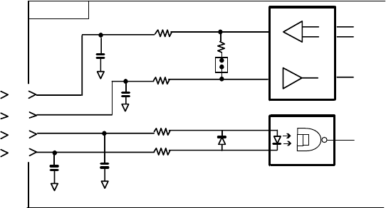
APPENDIX
AP-14
Digital Interface (IEC 61162-1 Edition 2)
Input sentences
GGA, GLL, RMC, ZDA, GNS
Schematic diagram
05P0773
7
TXD-H
J2
8
9
10
U15
6
7
1SS355
4
3
1000p
C65
TXD-C
RXD-H
RXD-C
100P
R70
10
R65
10
C64
100P
JP1
R69
120
1
220
R74 220
R73
1000p
C69 C70 CR3
1
2
PC400
4
Load requirements as listner
Isolation Optocoupler
Input impedance 560 ohms
Max. Voltage ±15V
Threshold 4 mA
Output sentence
TLL
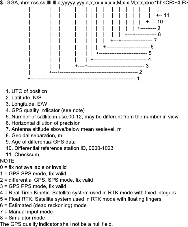
APPENDIX
A
P-15
GGA - Global positioning system (GPS) fix data
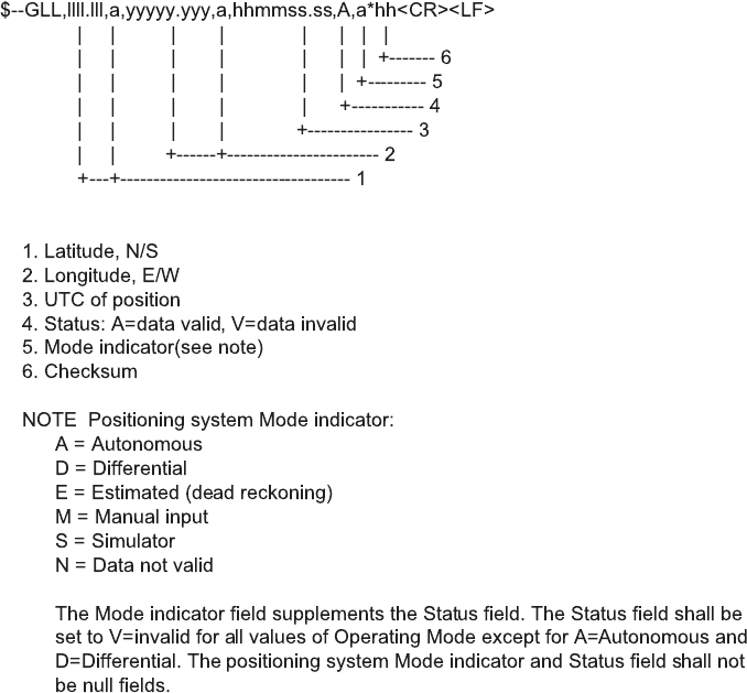
APPENDIX
AP-16
GLL - Geographic position - latitude and longitude
GNS-GNSS fixed data
$--GNS,hhmmss.ss,llll.ll,a,yyyyy.yy,a,c--c,xx,x.x,x.x,x.x,x.x,x.x*hh<CR><LF>
| | | | | | | | | | | | |
| | | | | | | | | | | | +--- 11
| | | | | | | | | | | +------ 10
| | | | | | | | | | +---------- 9
| | | | | | | | | +-------------- 8
| | | | | | | | +------------------ 7
| | | | | | | +---------------------- 6
| | | | | | +------------------------- 5
| | | | | +------------------------------ 4
| | | +-------+--------------------------------- 3
| +--+--------------------------------------------- 2
+------------------------------------------------------------- 1
1. UTC of position
2. Latitude, N/S
3. Longitude, E/W
4. Mode indicator
5. Total number of satellites in use,00-99 (Not used.)
6. HDOP (Not used.)
7. Antenna altitude, meters, re: mean-sea-level(geoid) (Not used.)
8. Geoidal separation (Not used.)
9. Age of differential data (Not used.)
10. Differential reference station ID (Not used.)
11. Checksum
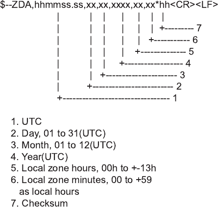
APPENDIX
A
P-17
RMC - Recommemded minimum specific GPS/TRANSIT data
1. UTC of position fix
2. Status: A=data valid, V=navigation receiver warming
3. Latitude, N/S
4. Longitude, E/W
5. Speed over ground, knots
6. Course over ground, degrees true
7. Date: dd/mm/yy
8. Magnetic variation, degree E/W
9. Mode indicator(see note)
10. Checksum
NOTE Positioning system Mode indicator:
A=Autonomous
D=Differential
E = Estimated (dead reckoning)
M = Manual input
S=Simulator
N=Data not valid
The Mode indicator field supplements the Status field. The Status field
shall be set to V=invalid for all values of Operating Mode except for
A=Autonomous and D=Differential. The positioning system Mode indicator
and Status field shall not be null fields.
$--RMC,hhmmss.ss,A,llll.lll,a,yyyyy.yyy,a,x.x,x.x,xxxxxx,x.x,a,a*hh<CR><LF>
| | | | | | | | | | | | |
| | | | | | | | | | | |
| | | | | | | | | | |
+------- 10
+--------- 9
+--+--------- 8
| | | | | | | | |
| | | | | | | |
+------------------ 7
| | | | | | | +---------------------- 6
+------------------------ 5
| | | | | |
|
+------------------------ 4+-----
| | | |
+----+--------------------------------- 3
| |
+-------------------------------------- 2
+-------------------------------------------- 1
ZDA - Time and data
APPENDIX
AP-18
TLL – Target latitude and longitude
$--TLL,xx,llll.lll,a,yyyyy.yyy,a,c--c,hhmmss.ss,a,a*hh<CR><LF>
| | | | | | | | | |
| | | | | | | | | +--------- 8
| | | | | | | | +----------- 7
| | | | | | | +------------- 6
| | | | | | +-------------------- 5
| | | | | +-------------------------- 4
| | | +-----+------------------------------ 3
| +----+------------------------------------------ 2
+----------------------------------------------------- 1
1. Target number 00 - 99
2. Latitude, N/S
3. Longitude, E/W
4. Target name
5. UTC of data
6. Target status(see note)
7. Reference target=R,null otherwise
8. Checksum
NOTE - Target status
L = lost, tracked target has beenlost
Q = query, target in the process of acquisition
T = tracking