Furuno USA 9ZWFM8800D VHF MARINE RADIOTELEPHONE User Manual OPERATORS MANUAL PART2
Furuno USA Inc VHF MARINE RADIOTELEPHONE OPERATORS MANUAL PART2
Contents
- 1. OPERATORS MANUAL
- 2. OPERATORS MANUAL PART1
- 3. OPERATORS MANUAL PART2
OPERATORS MANUAL PART2
3. DSC OPERATION FOR NON-DISTRESS CASES
3-27
9-2. When "No response! Try calling again?" is displayed, do one of the
following:
Re-send call: Push the ENT key followed by the CALL key.
Cancel call: Press the CANCEL key to return to the standby display.
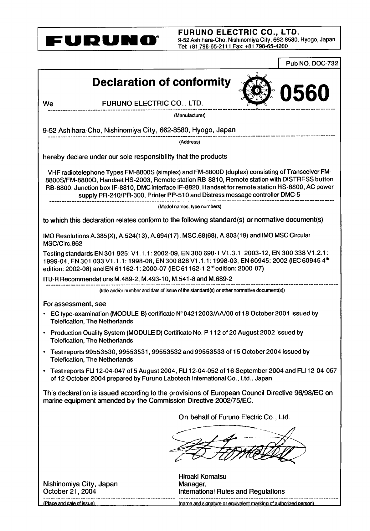
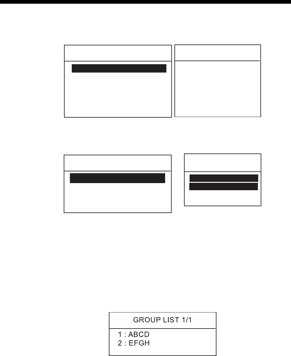
3.7.2 Receiving a polling call
Automatic reply
1. When a polling request is received and the equipment is set up for automatic
acknowledge POLLING on the AUTO ACK menu is ON and the ACK key is
set to show AUTO ACK on the display, the display changes as shown in the
illustration below and the audio alarm sounds.
Polling auto ack
transmitted.
ROUTINE
TCmd1 :
POLLING
TCmd2 : NO INFO
CANCEL ALARM
2. Press the CANCEL or ENT key to silence the alarm. The display changes as
below.
** Send Message **
POLLING ACK
TO : 123456789
ROUTINE
TCmd1 : POLLING
TCmd2 : NO INFO
PRESS ENT
3. DSC OPERATION FOR NON-DISTRESS CASES
3-28
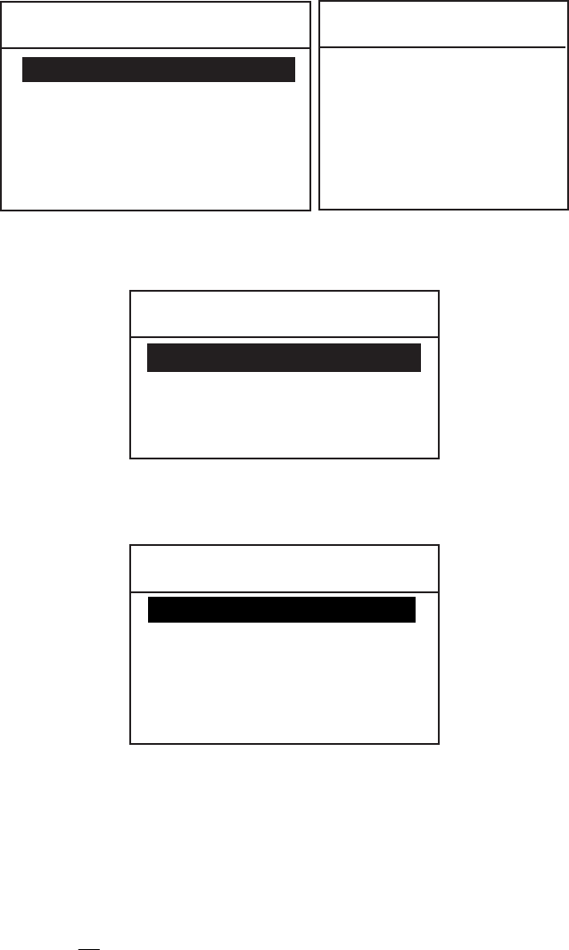
Manual reply
1. When a polling request call is received and the setting of POLLING CALL on
the system setup menu is OFF, the display changes as shown in the
illustration below and the audio alarm sounds.
Position request
call received.
FROM : 123456789
ROUTINE
TCmd1 :
POLLING
TCmd2 : NO INFO
CANCEL ALARM
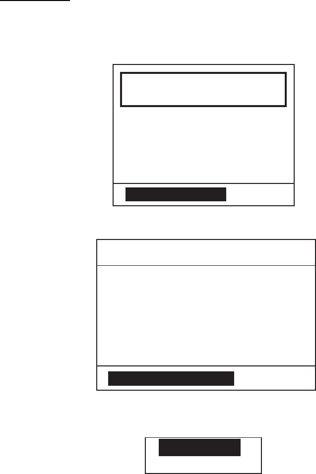
2. Press the CANCEL key to silence the alarm. The display changes as below.
** Received Message **
APR01/04 12 : 34 ECC : OK
POLLING CALL
ROUTINE
TCmd1 : POLLING
TCmd2 : NO INFO
FROM : 123456789
PRESS ENT TO ACK.
3. To respond to the call, press the ENT key. The following pop-up window
appears.
ANSWER
NO ANSWER
4. Choose ANSWER by the CH knob and press the CALL key to send the
polling acknowledge call. Then the standby display appears.
To send no reply, choose NO ANSWER and press the ENT key twice to
return to the standby display.

3. DSC OPERATION FOR NON-DISTRESS CASES
3-29
3.8 Neutral Craft Call
The neutral craft call, which contains own ship position and ID, informs all ships
that your ship is not a participant in armed conflict. Send the call BEFORE
entering an area of armed conflict.
3.8.1 Sending a neutral craft call
1. Press the CALL key. The display changes from the standby display to the
COMPOSE MESSAGE screen and the CALL TYPE is displayed in reverse
video.
2. Press the ENT key to open the call type list.
3. Rotate the CH knob (or press up / down arrow key) to choose NEUTRAL and
press the ENT key.
** Compose Message **
CRAFT
TCmd1 : SIMPLEX TP
TCmd2 : NEUTRAL CRAFT
CH : 16
URGENCY
CALL TYPE : NEUTRAL
6. URGENCY is selected; press the ENT key.
7. Choose SAFETY, or URGENCY as appropriate followed by pressing the ENT
key.
8. Press the CALL key more than three seconds to transmit the call. After the
call is transmitted, the standby display appears.
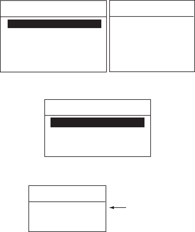
3.8.2 Receiving a neutral craft call
1. When a neutral craft call is received, the alarm sounds and the display
changes as below.
Neutral craft
call received.
FROM : 123456789
URGENCY
TCmd1 : SIMPLEX TP
TCmd2 : NEUTRAL CRAFT
CH : 16
CANCEL ALARM
3. DSC OPERATION FOR NON-DISTRESS CASES
3-30
2. Press the CANCEL or ENT key. The audible alarm is silenced and the display
changes as below.
** Received Message **
APR01/04 12 : 34 ECC : OK
NEUTRAL CALL
APR01/04 12 : 34 ECC : OK
SAFETY
TCmd1 : SIMPLEX TP
TCmd2 : NEUTRAL CRAFT
CH : 16
FROM : 123456789
PRESS ENT TO CHANGE CH
3. Press the ENT key. The display changes to the standby display, indicating
CH16.
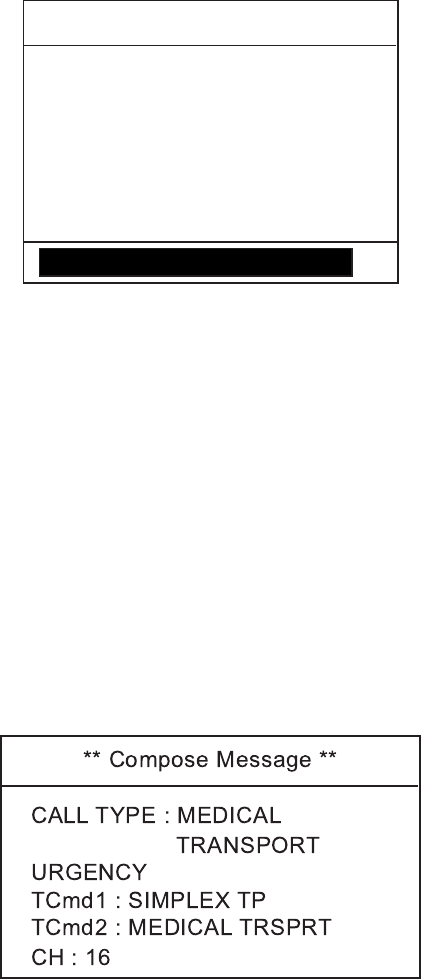
3.9 Medical Transport Call
The medical transport call informs all ships, by urgency priority, that own ship
carries medical supplies.
3.9.1 Sending a medical transport call
1. Press the CALL key. The display changes from the standby display to the
COMPOSE MESSAGE screen and the CALL TYPE is displayed in reverse
video.
2. Press the ENT key to open the call type list.
3. Rotate the CH knob (or press up / down arrow key) to choose the MEDICAL
and press the ENT key.
4. Press the CALL key more than three seconds to transmit the call. After the
call is transmitted, the standby display appears, with CH16 selected.

3. DSC OPERATION FOR NON-DISTRESS CASES
3-31
3.9.2 Receiving a medical transport call
1. When a medical call is received, the alarm sounds and the display changes as
below.
Medical call
received.
FROM : 123456789
URGENCY
TCmd1 : SIMPLEX TP
TCmd2 : MEDICAL
CH : 16
CANCEL ALARM
2. Press the CANCEL or ENT key. The audible alarm stops and the display
changes as below.
** Received Message **
APR01/04 12 : 34 ECC : OK
MEDICAL CALL
URGENCY
TCmd1 : SIMPLEX TP
TCmd2 : MEDICAL
CH : 16
FROM : 123456789
PRESS ENT TO CHANGE CH
3. Press the ENT key. The display changes to the standby display, indicating
CH16.
3. DSC OPERATION FOR NON-DISTRESS CASES
3-32
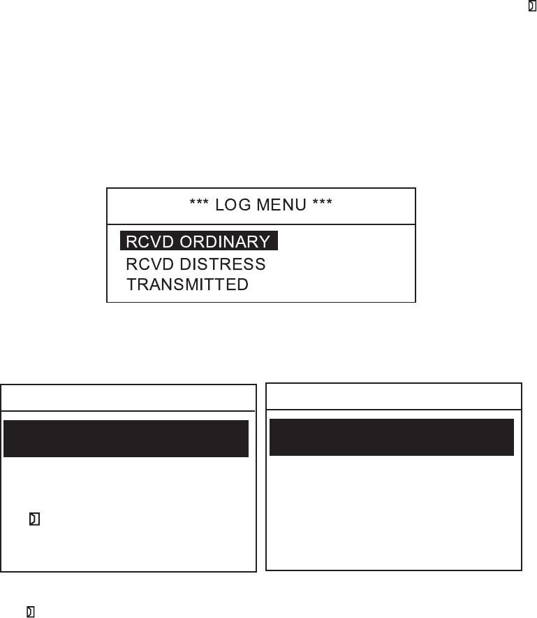
3.10 Log File
Three log files are provided for storage of calls: received ordinary log, received
distress log and transmitted log. Each log file stores 50 calls, on a first-in,
first-out basis. This means that the latest call is saved as log no.1 and the log no.
of all previous calls in that log increments by one. When the storage capacity is
exceeded, the oldest call is deleted to make room for the latest. A letter mark
shows unread or unacknowledged calls. Received distress calls are
automatically deleted 48 hours after being read.
Opening a log file
The procedure for opening a log is common to all logs.
1. Press the LOG key to open the SELECT LOG FILE display.
2. Rotate the CH knob to choose RCVD ORDINARY, RCVD DISTRESS or
TRANSMITTED as appropriate and press the ENT key. For example, choose
RCVD ORDINARY or TRANSMITTED.
01: APR 10/04 12:30
RCVD ORDINARY LOG 1/13
SHIP ACK
02: APR 15/04 10: 15
ALL SHIP
03: APR 25/04 11: 30
COAST CALL
TRANSMITTED 1/13
04: MAY10/04 18: 30
COAST CALL
01: APR 10/04 12:35
SHIP CALL
02: APR 15/04 10: 25
ALL SHIPS CALL
03: APR 25/04 12: 30
COAST CALL
04: MAY10/04 19: 30
COAST CALL
TT
3. Rotate the CH knob to choose a file you wish to browse.
The
in the RCVD ORDINARY LOG indicates unread or unacknowledged
message.
3. DSC OPERATION FOR NON-DISTRESS CASES
3-33
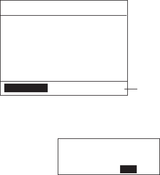
4. Press the ENT key to open the message. Below is a sample message.
** Received Message **
APR 10/’04 18:30 ECC : OK
SHIP CALL
CH : 16
TCmd1 : SIMPLEX TP
TCmd2 : NO INFO
ROUTINE
FROM : 123456789
ANSWER
DELETE
For a received message
which requires a reply,
ANSWER is displayed
(for 4.5 minutes).
To reply choose it and
press the ENT key.
T
T
5. Press ▲ or ▼ key to open previous or next page on the log.
6. If you wish to print the file selected, press the PRINT key.
7. If you wish to delete the file selected, choose DELETE and press the ENT key.
The following confirmation window appears.
YES
DELETE
RECEIVED LOG
ARE YOU SURE?
NO
8. Choose YES and press the ENT key.
3. DSC OPERATION FOR NON-DISTRESS CASES
3-34
This page is intentionally left blank.
4-1
4. BASIC SETUP
4.1 Alarm Setup
This section provides the procedures for setting up various alarms. The alarm
menu enables/disables internal and external alarms. Note that the
Distress/Urgency alarm cannot be disabled.
Old position alarm in manual position entry mode
This alerts the operator when manually entered position data is older by the
number of hours or minutes set.
1. Press the MENU key.
****SETUPMENU****
ALARM
ERASELOG
MEMORYCHANNEL
AUTOACK
MESSAGEFILEENTRY
T
*SETUPMENU*
ALARM
ERASELOG
MEMORYCH
AUTOACK
MESSAGEFILE
T
SETUP MENU on transceiver unit SETUP MENU on remote handset
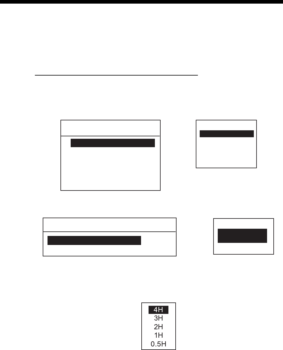
2. ALARM is selected; press the ENT key to display the ALARM menu.
****ALARMMENU****
POSITIONOLDER4H
EXTALARM
*ALARMMENU*
POS.OLDER
4H
EXTALARM
ALARM MENU on transceiver unit
ALARM MENU on remote handset
3. Rotate the CH knob (or press up / down arrow key) to choose POSITION
OLDER (POS. OLDER for remote handset) from the ALARM MENU and
press the ENT key. The following setting window appears.
4. Rotate the CH knob (or press up / down arrow key) to choose an appropriate
value and press the ENT key.
Alarm is output when position is older by the number of hours set here.
5. Press the CANCEL key twice to return to the standby display.

4. BASIC SETUP
4-2
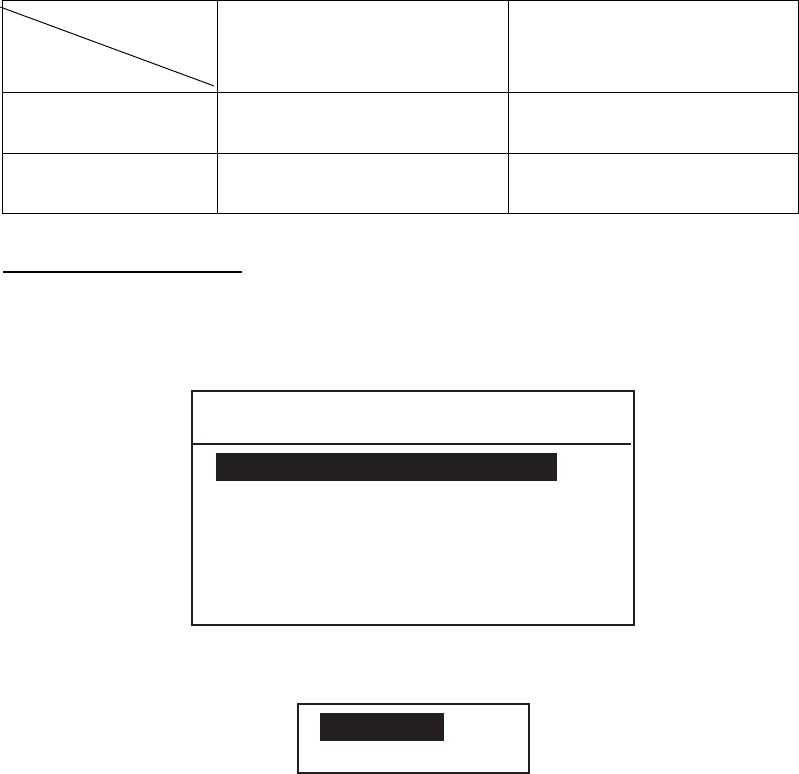
To set type of alarm to output
1. Rotate the CH knob (or press up / down arrow key) to choose EXT ALARM
from the ALARM MENU and press the ENT key. The following setting window
appears.
DIST/URG:ON
SAFETY:OFF
ROUTINE:ON
AlwaysON
2. Rotate the CH knob (or press up / down arrow key) to choose an appropriate
option. Alarm is output to external device.
DSTRS/URG: Distress or urgency call output upon receipt.
SAFETY: Safety call output upon receipt.
ROUTINE: Routine call output upon receipt.
3. Press the ENT key.
4. Choose ON or OFF as appropriate and press the ENT key.
5. Press the CANCEL key three times to return to the standby display.
Note that the setting of ROUTINE is turned to ON after turning on the power
4. BASIC SETUP
4-3
4.2 Auto ACK Setup
The Auto Ack Menu enables/disables automatic acknowledgement of ship, coast,
position and polling calls.
Comply status
Set of [5 ACQ]
ABLE
UNABLE
AUTO ACK Can send acknowledge
automatically.
Can send UNABLE
automatically.
MANUAL ACK Can send acknowledge
manually
Can send UNABLE
manually.
To set COMPLY TYPE
1. Press the MENU key.
2. Rotate the CH knob (or press up / down arrow key) to choose AUTO ACK and
press the ENT key. The following menu appears.
**** AUTO ACK MENU ****
COMPLY STATUS ABLE
NO REASON
POSITION CALL ON
UNABLE REASON
POLLING CALL ON
3. COMPLY STATUS is selected; press the ENT key. The following setting
window appears.
ABLE
UNABLE
4. Rotate the CH knob (or press up / down arrow key) to choose ABLE or
UNABLE as automatic acknowledgement reply to each call.
5. Press the ENT key.
Note: Automatic acknowledge is automatically disabled when RX call
contains error, as required by law. Further, automatic acknowledge is
disabled in case of OFF HOOK.

4. BASIC SETUP
4-4
To set reason for unable
If you have chosen UNABLE as the COMPLY STATUS, set the reason as
follows:
1. Rotate the CH knob (or press up / down arrow key) to choose UNABLE
REASON from the AUTO ACK MENU and press the ENT key. The following
menu appears.
NO REASON
BUSY
EQUIP DISBLD
MODE UNAVAIL
CH UNAVAIL
2. Rotate the CH knob (or press up / down arrow key) to choose a reason for
UNABLE.
3. Press the ENT key.
Note: This menu is the same as manual acknowledgement. EQUIPMENT
DISABLE is shown in calls when EQUIP DISBLD is selected.
To set position call response
1. Rotate the CH knob (or press up / down arrow key) to choose the POSITION
CALL from the AUTO ACK MENU and press the ENT key.
2. Rotate the CH knob (or press up / down arrow key) to choose ON or OFF as
appropriate.
OFF: Disables automatic acknowledgement of position request.
ON: Enables automatic acknowledgement of position request.
3. Press the ENT key.
To set polling call response
1. Rotate the CH knob (or press up / down arrow key) to choose the POLLING
CALL from the AUTO ACK MENU and press the ENT key.
2. Rotate the CH knob (or press up / down arrow key) to choose ON or OFF as
appropriate.
OFF: Disables automatic acknowledgement of polling request.
ON: Enables automatic acknowledgement of polling request.
3. Press the ENT key.

4. BASIC SETUP
4-5
4.3 Erasing Logs
Erasing received ordinary log
1. Press the MENU key.
2. Rotate the CH knob (or press up / down arrow key) to choose the ERASE
LOG and press the ENT key. The following window appears.
RCVD ORDINARY
RCVD DISTRESS
TRANSMITTED
*** ERASE LOG MENU ***
3. RCVD ORDINARY is selected; press the ENT key to erase the received
ordinary log.
4. Choose YES and press the ENT key to erase the received ordinary log.
Erasing received distress log
1. Press the MENU key.
2. Rotate the CH knob (or press up / down arrow key) to choose ERASE LOG
and press the ENT key.
3. Rotate the CH knob (or press up / down arrow key) to choose RCVD
DISTRESS and press the ENT key to erase the received distress log.
4. Choose YES and press the ENT key to erase the received distress log.
Erasing transmitted log
1. Press the MENU key.
2. Rotate the CH knob (or press up / down arrow key) to choose ERASE LOG
and press the ENT key.
3. Rotate the CH knob (or press up / down arrow key) to choose TRANSMITTED
and press the ENT key.
YES
ERASE
TRANSMITTED
ARE YOU SURE?
NO
4. Choose YES and press the ENT key to erase the transmitted message log.

4. BASIC SETUP
4-6
4.4 Memory Channel Setup
You can save up to 50 channels as follows.
1. Press the MENU key.
2. Rotate the CH knob (or press up / down arrow key) to choose MEMORY
CHANNEL and press the ENT key.
* Memory Channel 1/7*
01 CH-- --------
02 : CH-- --------
T
03 : CH-- --------
04 : CH-- --------
05 : CH-- --------
06 : CH-- --------
07 : CH-- --------
08 : CH-- --------
3. Rotate the CH knob (or press up / down arrow key) to choose a vacant CH
number and press the ENT key.
INTL
USA
WX
CANADA
INLND-WA
PRIV
ERASE
*
*
*
*
*
* : Only permitted channel
modes are displayed,
which are set by the
installer of the equipment.
4. Rotate the CH knob (or press up / down arrow key) to choose appropriate
channel type and press the ENT key.
5. Rotate the CH knob (or press up / down arrow key) to choose channel number
and press the ENT key.

4. BASIC SETUP
4-7
4.5 Message File Entry
In this section you will learn how to prepare and store ship, coast, PSTN, group,
and area calls for future transmission. 100 calls can be stored.
1. At the standby display, press the MENU key to open the SETUP MENU.
**** SETUP MENU ****
ALARM
ERASE LOG
MEMORY CHANNEL
AUTO ACK
MESSAGE FILE ENTRY
T
2. Rotate the CH knob (or press up / down arrow key) to choose MESSAGE
FILE ENTRY and press the ENT key.
* MESSAGE FILE 1/13 *
1:
2:
3:
4:
5:
6:
7:
8:
T
3. Rotate the CH knob to choose a vacant number and press the ENT key. The
following selection window appears.
COAST CALL
SHIP CALL
PSTN CALL
GROUP CALL
AREA CALL

4. BASIC SETUP
4-8
4. Rotate the CH knob to choose the call type and press the ENT key. One of the
following display appears depending on the call type selected above.
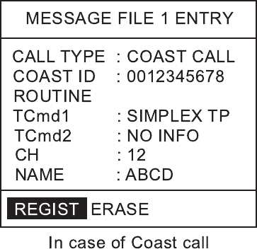
MESSAGE FILE 1 ENTRY
COAST ID : 00
ROUTINE
CH : 16
CALL TYPE : COAST CALL
NAME :
TCmd1 : SIMPLEX TP
TCmd2 : NO INFO
MESSAGE FILE 1 ENTRY
SHIP ID :
ROUTINE
CH : 16
CALL TYPE : SHIP CALL
NAME :
In case of Coast call In case of Ship call
MESSAGE FILE 1 ENTRY
GROUP ID : 0
CALL TYPE : GROUP CALL
NAME :
MESSAGE FILE 1 ENTRY
COAST ID : 00
TCmd2 : NO INFO
TEL :
CALL TYPE : PSTN CALL
NAME :
In case of Group call (
In case of Area call
In case of PSTN call
TCmd1 : DUPLEX TP
MESSAGE FILE 1 ENTRY
AREA : -- ---- - -- --
ROUTINE
CH : 16
CALL TYPE : AREA CALL
NAME :
°↓ →
°°°
REGIST ERASE REGIST ERASE
REGIST ERASE REGIST ERASE
REGIST ERASE
ROUTINE
CH : 16
TCmd1 : SIMPLEX TP
TCmd2 : NO INFO
TCmd1 : SIMPLEX TP
TCmd2 : NO INFO
TCmd1 : SIMPLEX TP
TCmd2 : NO INFO
Note3)
Note1: The communication priority is ROUTINE only.
Note2: The group ID will be registered automatically after a group call
message file is saved.
Note3: If you register a group call, its group ID becomes your own group ID.
4. BASIC SETUP
4-9
5. Press the ENT key and key in each ID or AREA followed by the ENT key.
To enter area
1: N/E 2: S/W
°---
-- ↓→
N°E°
-- °
--
a) Enter latitude (degrees) and 1 for north or 2 for south of reference point.
b) Enter longitude (degrees) and 1 for east or 2 for west.
c) Enter southerly degrees of area.
d) Enter easterly degrees of area.
e) Press the ENT key.
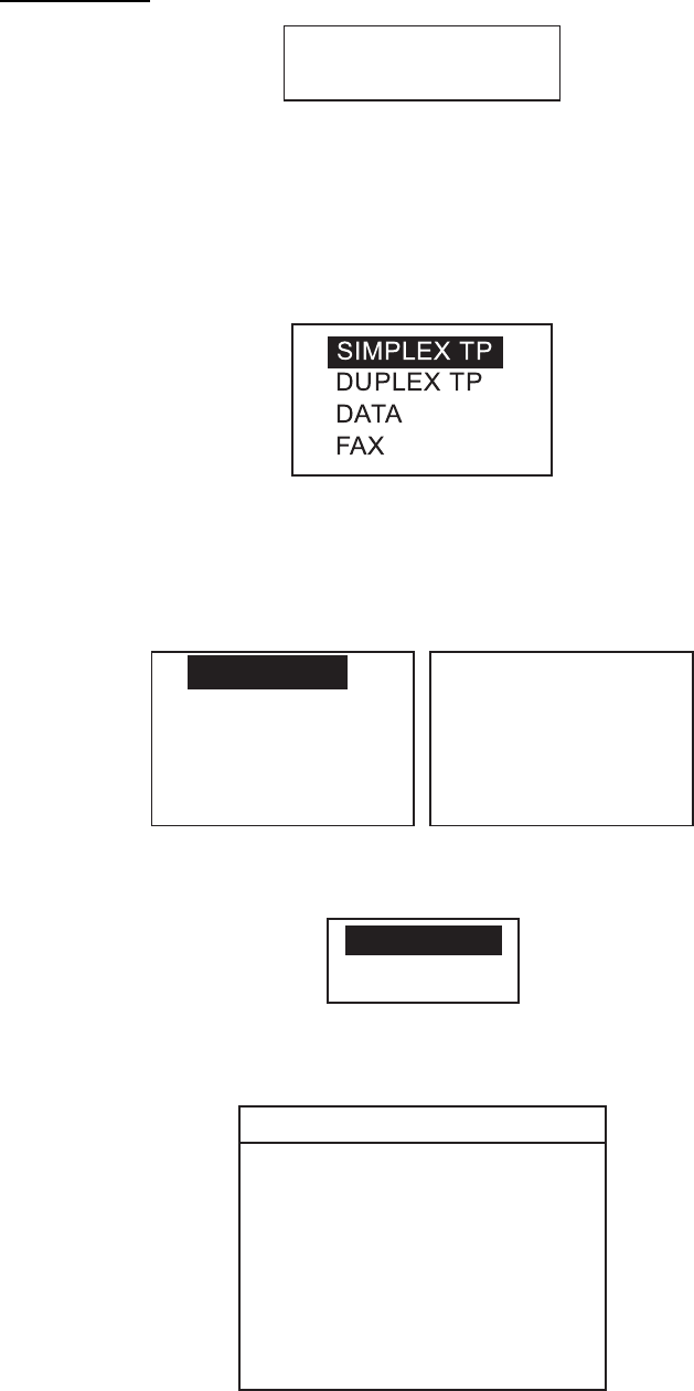
6. TCmd1 is selected; press the ENT key.
7. Choose SIMPLEX TP, DUPLEX TP, DATA or FAX as appropriate followed by
pressing the ENT key. If you chose SIMPLEX, DUPLEX, or FAX, NO INFO
appears in the Tcmd2 field. Go to step 10. If you chose DATA, go to the next
step.
8. Tcmd2 is selected; press the ENT key.
S
V. 26 ter
V. 27 ter
V. 32
V. 21
V. 22
V. 22 bis
V. 23
V. 26 bis
T
9. Choose an appropriate data type and press the ENT key.
10. Choose CH and press the ENT key. The following window appears.
SELECT CH
NO INFO
11. Choose SELECT CH with the CH knob (or up / down arrow key) and press
the ENT key.
SIMP CHANNEL
06
08
09
10
11
12
13
14
15
16
17
67
68
69
71
72
73
74
75
76
77
87
88
In case of NO INFO, there is no channel information.
4. BASIC SETUP
4-10
12. Choose a channel with the CH knob (or up / down arrow key) and press the
ENT key.
13. Press the ENT key to open the name entry window.
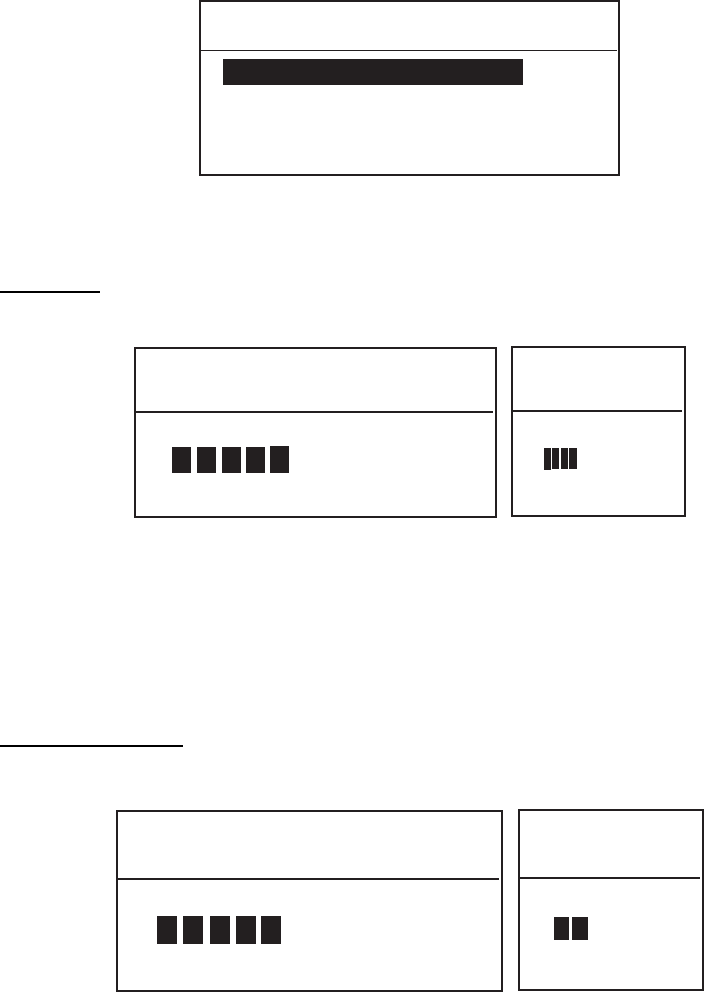
14. Enter a name with the alphanumeric keys. To change a digit, rotate the CH
knob. Press the ENT key.
15. REGIST is selected; press the ENT key to register. To erase, rotate the CH
knob to select ERASE and press the ENT key.
To send a message file:
Method1
1) Press the CALL key.
2) Choose call type and press the ENT key.
3) Highlighting xxx ID, press the FILE key to display list of message files.
4) Choose file to send and press the ENT key..
5) Set the Routine, TCmd1, TCmd2 and CH.
6) Press the CALL key more than three seconds.
Method2
1) Press the FILE key at the standby display.
2) Choose a file you want to send and press the ENT key.
3) Press the CALL key more than three seconds.

4. BASIC SETUP
4-11
4.6 Position Setup
This is where you enter your position, automatically or manually.
1. Press the MENU key at the standby display.
2. Rotate the CH knob (or press up / down arrow key) to choose POSITION from
the second page of the main menu.
**** SETUP MENU ****
POSITION
VOLUME
PRINT OUT
SYSTEM
T
3. Press the ENT key. The following menu appears.
INPUT TYPE: AUTO
LAT : -- °--’-
LON : ---°--’-
TIME : -- : --
4. INPUT TYPE is selected; press the ENT key. The following setting window
appears.
AUTO
MANUAL
Note: If the position data from a positioning sensor is available, MANUAL
can not be chosen, i.e. the above window does not open.
5. Rotate the CH knob (or press up / down arrow key) to choose AUTO or
MANUAL as appropriate and press the ENT key.
If you chose AUTO, your ship's position and time appear; press the CANCEL
to close the menu and return to the standby display. These data are supplied
from the navigation equipment connected.
Note: • If correct position data is entered from a position source during the
setting of MANUAL, the setting changes automatically to AUTO from
MANUAL.
• If the message "GPS ERR" appears after you change INPUT TYPE
from MANUAL to AUTO, confirm that the navigation device is
functioning.
If you chose MANUAL, enter your position and time as follows.
6. Enter latitude (in four digits) with the numeric keys. If necessary, switch
coordinates: 1 key to switch to North; 2 key to switch to South.
7. Press the ENT key and enter longitude (in five digits) with the numeric keys. If
necessary, switch coordinates: 1 key to switch to East; 2 key to switch to
West.
8. Press the ENT key and enter UTC time with the numeric keys.
9. Press the ENT key and CANCEL key to finish.

4. BASIC SETUP
4-12
4.7 Print Out Setup
The PRINT MENU enables/disables automatic printing of all transmitted and
received calls and the results of the daily test.
1. Press the MENU key at the standby display to open menu.
2. Rotate the CH knob (or press up / down arrow key) to choose PRINT OUT
from the second page of the main menu and press the ENT key.
**** PRINT MENU ****
XMTD CALL MANUAL
DAILY TEST MANUAL
RCVD CALL MANUAL
3. Choose appropriate item among XMTD CALL MANUAL, RCVD CALL
MANUAL or DAILY TEST MANUAL and press the ENT key.
MANUAL
AUTO
4. Choose AUTO or MANUAL as appropriate and press the ENT key.
5. Press the CANCEL key twice to return to the standby display.
In the AUTO, when a message is received, its message automatically is printed
out. In the MANUAL, open a message you want to print and press the PRINT
key (see page 3-32).
** Transmitted Message **
SEP25/ ’04 17:41
SHIP ACK
TO: 111111111
ROUTINE
TCmd1: SIMPLEX TP
TCmd2: NO INFO
CH: 12
** Received Message **
SEP25/ ’04 17:40 ECC: OK
SHIP CALL
FROM: 111111111
ROUTINE
TCmd1: SIMPLEX TP
TCmd2: NO INFO
CH: 12
* Daily test result *
SEP25/ ’04 17:42
MMSI: 987654321
TX POWER: OK
TX/RX PCB: OK
CPU PCB: OK
CH70RX PCB: OK
DUP RX PCB: OK
Note: In the AUTO,
you can print
a message as
same as Manual.
Sample printout
4. BASIC SETUP
4-13
4.8 Volume Setup
The VOLUME menu enables/disables key beep (acknowledges correct key
input) and adjusts the volume of the earpiece, intercom and off-hook
loudspeaker.
1. Press the MENU key at the standby display.
2. Rotate the CH knob (or press up / down arrow key) to choose VOLUME and
press the ENT key.
**** VOLUME MENU ****
KEY CLICK 8
INTERCOM VOLUME 8
EARPIECE LEVEL 9
OFF HOOK SPKR ON
Follow the appropriate procedure to adjust volume of desired item.
Key click
1. Choose KEY CLICK, and press the ENT key.
KEY CLICK LEVEL SETUP
EXT: ENT
LEVEL (0-16)
<
<
KEY CLICK
LEVEL SETUP
EXT: ENT
LEVEL (0-16)
<
<
4
Note: Do not confuse keyboard beep (single beep) with ACK beep (three
beeps).
2. Rotate the CH knob (or press up / down arrow key) to set the key click level.
The setting range is 0 to 16.
3. Press the ENT key. (If you press the CANCEL key, the setting is not stored.)
Earpiece volume
1. Choose ERAPIECE LEVEL and press the ENT key.
EARPIECE LEVEL SETUP
EXT: ENT
LEVEL (8-16)
<
<
EARPIECE
LEVEL SETUP
EXT: ENT
LEVEL (1-4)
<
<
2
Transceiver unit Remote handset
2. Rotate the CH knob (or press up / down arrow key) to set the earpiece volume
level. The setting range is 8 to 16 for transceiver handset and 1 to 4 for
remote handset.
3. Press the ENT key. (If you press the CANCEL key, the setting is not stored.)
4. BASIC SETUP
4-14
Intercom volume
1. Choose INTERCOM VOLUME and press the ENT key.
INTERCOM SETUP
EXT: ENT
LEVEL (1-16)
<
<
8
2. Rotate the CH knob (or press up / down arrow key) to set the intercom volume
level. The setting range is 1 to 16.
3. Press the ENT key.
Off-hook loudspeaker
You can set the loudspeaker(s) (internal and external) on or off, according to
off-hook condition.
1. Choose OFFHOOK SPKR and press the ENT key.
2. Choose ON or OFF and press the ENT key.
OFFHOOK SPKR ON: Loudspeaker(s) is activated when off-hook.
OFFHOOK SPKR OFF: Loudspeaker(s) is deactivated when off-hook.
5-1
5. SYSTEM SETUP
5.1 Displaying Self ID
1. Press the MENU key.
**** SETUP MENU ****
ALARM
ERASE LOG
MEMORY CHANNEL
AUTO ACK
MESSAGE FILE ENTRY
T
**** SETUP MENU ****
VOLUME
TEST
PRINT OUT
SYSTEM
T
POSITION
2. Rotate the CH knob (or press up / down arrow key) to choose SYSTEM from
page 2 of the menu and press the ENT key. The following window appears.
The self ID is displayed on the first line.
* SYSTEM SETUP MENU *
SELF ID 123498765
GROUP ID LIST
INTERCOM NAMING
PROGRAM VERSION
* SYSTEM
SETUP MENU *
SELF ID
123498765
GROUP ID LIST
T
Transceiver unit Remote handset
5.2 Displaying Group ID List
1. Press the MENU key.
2. Rotate the CH knob (or press up / down arrow key) to choose SYSTEM from
page 2 of the menu and press the ENT key.
3. Rotate the CH knob (or press up / down arrow key) to choose GROUP ID
LIST and press the ENT key to show the GROUP ID list. For how to registers
group IDs, see paragraph 4.5.
5. SYSTEM SETUP
5-2
5.3 Naming Intercom
1. Press the MENU key.
****SETUPMENU****
ALARM
ERASELOG
MEMORYCHANNEL
AUTOACK
MESSAGEFILEENTRY
T
****SETUPMENU****
VOLUME
TEST
PRINTOUT
SYSTEM
T
POSITION
2. Rotate the CH knob (or press up / down arrow key) to choose SYSTEM from
page 2 of the menu and press the ENT key. The following window appears.
*SYSTEMSETUPMENU*
SELFID---------------------
GROUPIDLIST
INTERCOMNAMING
PROGRAMVERSION
3. Rotate the CH knob (or press up / down arrow key) to choose INTERCOM
NAMING and press the ENT key. The following window appears.
*IntercomNamingMenu*
1:Handset1
2:Handset2
3:Handset3
4:Handset4
RT:FM8800
4. Rotate the CH knob (or press up / down arrow key) to choose a handset
number and press the ENT key.
5. Key in remote station name with alphanumeric keys and press the ENT key.
6. Repeat steps 4 and 5 to name other handsets.
To change the default name, for example, “1: Handset 1”, rotate the CH knob to
move the cursor to right of “1”.
1: Handset 1
↑
Move cursor here. And then press the ▼ key to delete the characters.
Enter a new name for the remote station.
5. SYSTEM SETUP
5-3
5.4 Displaying Program Version
1. Press the MENU key.
**** SETUP MENU ****
ALARM
ERASE LOG
MEMORY CHANNEL
AUTO ACK
MESSAGE FILE ENTRY
T
**** SETUP MENU ****
VOLUME
TEST
PRINT OUT
SYSTEM
T
POSITION
2. Rotate the CH knob to choose SYSTEM and press the ENT key. The following
selection window appears.
* SYSTEM SETUP MENU *
SELF ID ---------------------
GROUP ID LIST
INTERCOM NAMING
PROGRAM VERSION
3. Rotate the CH knob to choose PROGRAM VERSION and press the ENT key
to show program version number.
Program version
FM8800S
0550215-02
EXT: ENT
Program version
or FM8800D
4. Press the ENT key to exit.
5. SYSTEM SETUP
5-4
This page is intentionally left blank.

6-1
6. MAINTENANCE &
TROUBLESHOOTING
Do not open the equipment.
Hazardous voltage which can
cause electrical shock, burn or
serious injury exists inside the
equipment. Do not work inside
the equipment unless familiar
with electrical circuits.
WARNINGWARNING
6.1 Maintenance
Periodic checks
1) Check that each connector is firmly connected.
2) Clean corroded or soiled connectors.
3) Check coaxial cable for damage. If damaged, replace.
4) Check that bolts fixing the antenna are firmly tightened.
6.2 Troubleshooting
When the power cannot be turned on
1) Check if power plug is firmly connected.
2) Check fuses in the power cable. If it has tripped, replace it with a new one
(15A).
3) If power cannot be turned on (after checking 1 and 2), contact a FURUNO
agent or representative for advice.
6. MAINTENANCE & TROUBLESHOOTING
6-2
6.3 Daily Test
Authorities require that the DSC be checked daily for proper operation to ensure
that it will function properly in the event of distress. Execute the daily test as
below.
1. At the standby display, press the SHIFT key and TEST key in that order. The
following display appears for test. And distress alarm (visual and audible)
occurs.
*** DAILY TEST ***
TX POWER : OK
TX/RX PCB : OK
CPU PCB : OK
CH70 RX PCB : OK
DUP RX PCB : OK
Test in progress (Pop-up display appears momentarily.)
If you have not pressed the PTT switch
before executing the test, "NO CHECK"
is displayed.
FM-8800D only
Result of daily test
2. To stop ALARM, press the CANCEL key.
3. To stop the daily test, press the CANCEL key.
“NG” may be displayed depending on the receiving conditions, In this case, repeat
the daily test a couple of times. If NG is displayed always, contact a FURUNO agent
or representative for advice.
The table below shows the abnormal indications and causes shown in the daily test.
Indication Cause
TX POWER: NG Indicates no transmitting output power.
PA module or TX/RX pcb 05P0774 may be damaged.
TX/RX PCB: NG Indicates abnormal PLL circuit in the TX/RX pcb.
TX/RX pcb 05P0774 may be damaged.
CPU PCB: NG Indicates abnormal loop circuit inside the CPU board.
CPU pcb 05P0773 may be damaged.
CH70 RX PCB: NG Indicates abnormal loop circuit between CPU and CH70
RX pcb. CH70 RX pcb 05P0775 may be damaged.
DUP RX PCB: NG Indicates abnormal PLL circuit in the DUP RX pcb.
DUP RX pcb 05P0777 may be damaged.
If necessary, refer to Parts Location on subsequent pages.
executing
6. MAINTENANCE & TROUBLESHOOTING
6-3
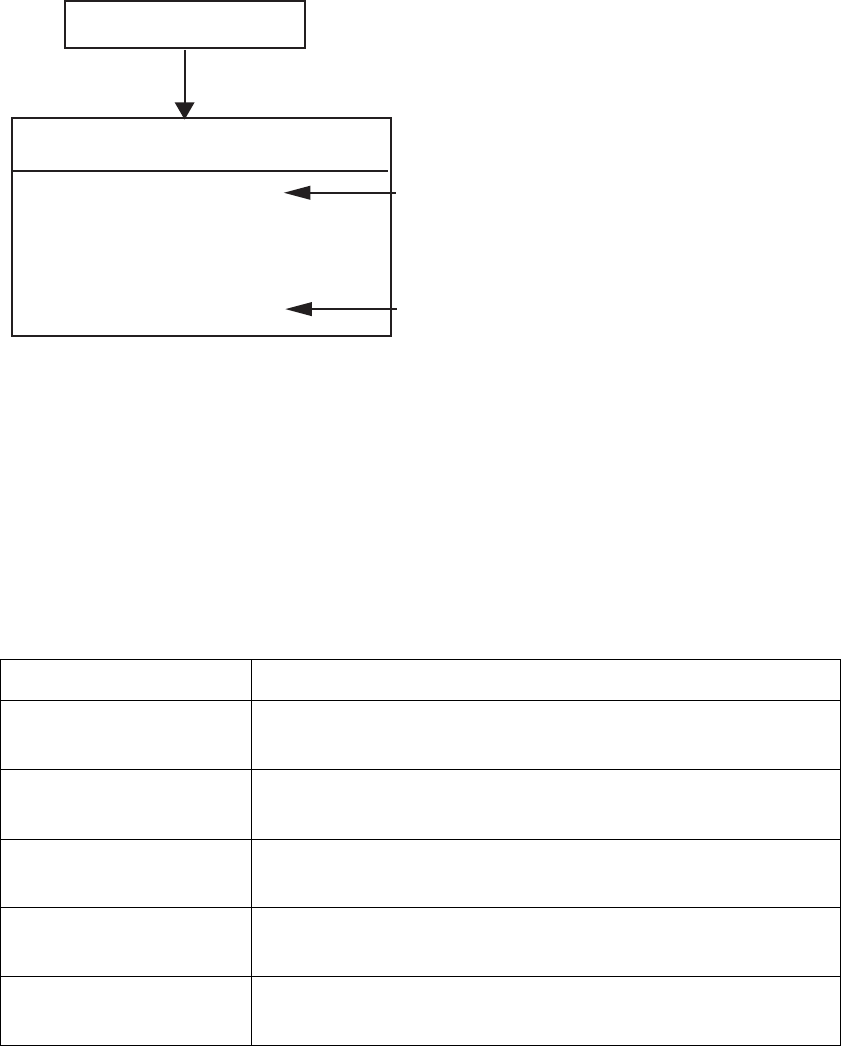
6.4 Error Message
The table below shows all the error messages which may appear.
Error message Meaning
PLL1 Unlock PLL circuit on the TX/RX pcb 05P0774 has unlocked.
PLL2 Unlock PLL circuit on the DUP RX pcb 05P0777 has unlocked (only
FM-8800D).
ANT ERROR The antenna is abnormal. In this condition, if the
transmission continues more than five seconds, the output
power is reduced to approximately 10W.
GPS ERROR There is no L/L input from a positioning sensor for more than
one minute.
System Error The DSP (digital signal processor) is abnormally.
Printer PE Printer is disconnected or paper runs out.
Note: If the CPU is abnormal, the beep sounds continuously until turning off the
power.
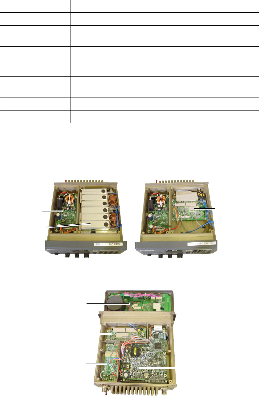
6.5 Parts Location
Transceiver unit FM-8800D/8800S
DUPLEXER
PWR pcb
05P0776
TX/RX pcb
05P0774
FM-8800D FM-8800S
Top cover removed
PANEL pcb
05P0772
DUP RX pcb
05P0777
CH70 RX pcb
05P0775 CPU pcb
05P0773
FM-8800S/D
Bottom cover removed
6. MAINTENANCE & TROUBLESHOOTING
6-4
Handset HS-2003
HANDSET pcb
05P0780
Remote station RB-8800/RB-8810
TB pcb
07P0782 05P0779
REMOTE pcb TB pcb
05P0798 HS CONT pcb
05P0781
RB-8800 RB-8810
Junction box IF-8810
JUNCTION pcb
05P0790
DMC Interface IF-8820
DMC IF pcb
05P0778

A
P-1
APPENDIX
Menu Tree
[MENU] ALARM
UNABLE REASON
ABLE/UNABLE
AUTO ACK COMPLY STATUS
POSITION CALL
NO REASON/BUSY/EQUIP DISBLD/
MODE UNAVAIL/CH UNAVAIL
EXT ALARM
4H/3H/2H/1H/0.5H
POSITION OLDER
DIST/URG, ON
ON/OFF
POLLING CALL ON/OFF
ERASE LOG RCVD ORDINARY
RCVD DISTRESS
TRANSMITTED
MEMORY CHANNEL 50 entries
MESSAGE FILE ENTRY 100 entries
POSITION AUTO/MANUAL LAT/LON/TIME
PRINT OUT XMTD CALL
RCVD CALL
DAILY TEST
AUTO/MANUAL
AUTO/MANUAL
AUTO/MANUAL
VOLUME
OFFHOOK SPKR
KEY CLICK
EARPIECE LEVEL
INTERCOM VOLUME
ON/OFF
8 (0-16)
9, 8 - 16 (For remote handset, 1-4)
8, 1 - 16
SYSTEM
PROGRAM VERSION
SELF ID
GROUP ID LIST
INTERCOM NAMING
Bold: Default
SAFETY ON/OFF
ROUTINE ON/OFF
[LOG] RCVD ORDINARY (50LOG)
RCVD DISTRESS (50LOG)
TRANSMITTED (50LOG)

APPENDIX
AP-2
[CALL] COAST CALL COAST ID
ROUTINE
GROUP CALL GROUP ID
PSTN CALL COAST ID
ALL SHIPS
BUSINESS
SHIP CALL SHIP ID
SAFETY
URGENCY
SAFETY
URGENCY
DISTRESS
TCmd1 SIMPLEX TP
DUPLEX TP
DATA
FAX
TCmd2
CH NO INFO
SELECT CH / NO INFO
ROUTINE
BUSINESS
SAFETY
URGENCY
DISTRESS
TCmd1 SIMPLEX TP
DUPLEX TP
DATA
FAX
TCmd2
CH NO INFO
SELECT CH / NO INFO
ROUTINE
BUSINESS
SAFETY
URGENCY
DISTRESS
TCmd1 SIMPLEX TP
DUPLEX TP
DATA
FAX
TCmd2
CH NO INFO
SELECT CH / NO INFO
TCmd1 SIMPLEX TP
DUPLEX TP
TCmd2: NO INFO
TEL
DISTRESS
TCmd1 SIMPLEX TP
DUPLEX TP
DATA
FAX
TCmd2: NO INFO
CH NO INFO
SELECT CH
AREA CALL ARE -- ---- - -- --
°°°°
→
↓
ROUTINE
BUSINESS
SAFETY
URGENCY
DISTRESS
TCmd1 SIMPLEX TP
DUPLEX TP
DATA
FAX
TCmd2
CH NO INFO
SELECT CH / NO INFO
POSITION SHIP ID
ROUTINE
BUSINESS
SAFETY
URGENCY
DISTRESS
TCmd1: POSITION REQUEST
TCmd2: NO INFO
1
ROUTINE
COAST ID
BUSINESS
SHIP ID
SAFETY
URGENCY
UNDESIGNATED
Fire
Flooding
Collision
Grounding
Listing
Sinking
Disabled & Adr
Abandoning
POS:
AT:
SIMP TP
AUTO
POLLING
DISTRESS
NEUTRAL URGENCY
SAFETY
CH: 16
MEDICAL URGENCY
TCmd1: SIMPLEX TP
CH: 16
TCmd2: MEDICAL TRSPRT
RELAY ALL ID IN DIST
TCmd: DISTRESS RELAY
NATURE
Piracy
Man over board
EPIRB
MANUAL
NO INFO
DISTRESS
RELAY SEL
UNDESIGNATED
Fire
Flooding
Collision
Grounding
Listing
Sinking
Disabled & Adr
Abandoning
POS:
AT:
SIMP TP
AUTO
ID IN DIST
TCmd: DISTRESS RELAY
NATURE
Piracy
Man over board
EPIRB
MANUAL
NO INFO
UNDESIGNATED
Fire
Flooding
Collision
Grounding
Listing
Sinking
Disabled & Adr
Abandoning
POS:
AT:
SIMP TP
AUTO
NATURE
Piracy
Man over board
MANUAL
NO INFO
1
TCmd1: POLLING
TCmd2: NO INFO
TCmd1: SIMPLEX TP
TCmd2: NEUTRAL CRAFT

APPENDIX
A
P-3
Marine VHF Channel Lists
1) International Channels
CH
TX
MHz
RX
MHz Remark CH
TX
MHz
RX
MHz Remark
01 156.050 160.650 60 156.025 160.625
02 156.100 160.700 61 156.075 160.675
03 156.150 160.750 62 156.125 160.725
04 156.200 160.800 63 156.175 160.775
05 156.250 160.850 64 156.225 160.825
06 156.300 156.300 65 156.275 160.875
07 156.350 160.950 66 156.325 160.925
08 156.400 156.400 67 156.375 156.375
09 156.450 156.450 68 156.425 156.425
10 156.500 156.500 69 156.475 156.475
11 156.550 156.550 70 - 156.525 DSC
12 156.600 156.600 71 156.575 156.575
13 156.650 156.650 72 156.625 156.625
14 156.700 156.700 73 156.675 156.675
15 156.750 156.750
Low
PWR 74 156.725 156.725
16 156.800 156.800 75 156.775 156.775
Low
PWR
17 156.850 156.850
Low
PWR 76 156.825 156.825
Low
PWR
18 156.900 161.500 77 156.875 156.875
19 156.950 161.550 78 156.925 161.525
20 157.000 161.600 79 156.975 161.575
21 157.050 161.650 80 157.025 161.625
22 157.100 161.700 81 157.075 161.675
23 157.150 161.750 82 157.125 161.725
24 157.200 161.800 83 157.175 161.775
25 157.250 161.850 84 157.225 161.825
26 157.300 161.900 85 157.275 161.875
27 157.350 161.950 86 157.325 161.925
28 157.400 162.000 87 157.375 157.375
88 157.425 157.425

APPENDIX
AP-4
2) USA Channels
CH
TX
MHz
RX
MHz Remark CH
TX
MHz
RX
MHz Remark
01 156.050 156.050 60 - -
02 - - 61 - -
03 - - 62 - -
04 - - 63 156.175 156.175
05 156.250 156.250 64 - -
06 156.300 156.300 65 156.275 156.275
07 156.350 156.350 66 156.325 156.325
08 156.400 156.400 67 156.375 156.375
Low
PWR
09 156.450 156.450 68 156.425 156.425
10 156.500 156.500 69 156.475 156.475
11 156.550 156.550 70 - 156.525 DSC
12 156.600 156.600 71 156.575 156.575
13 156.650 156.650
Low
PWR 72 156.625 156.625
14 156.700 156.700 73 156.675 156.675
15 - 156.750 74 156.725 156.725
16 156.800 156.800 75 - -
17 156.850 156.850
Low
PWR 76 - -
18 156.900 156.900 77 156.875 156.875
Low
PWR
19 156.950 156.950 78 156.925 156.925
20 157.000 157.000 79 156.975 156.975
21 157.050 157.050 80 157.025 157.025
22 157.100 157.100 81 157.075 157.075
23 157.150 157.150 82 157.125 157.125
24 157.200 161.800 83 157.175 157.175
25 157.250 161.850 84 157.225 161.825
26 157.300 161.900 85 157.275 161.875
27 157.350 161.950 86 157.325 161.925
28 157.400 162.000 87 157.375 157.375
88 157.425 157.425
US Weather Channels
WX RX MHz WX RX MHz
01 162.550 06 162.500
02 162.400 07 162.525
03 162.475 08 161.650
04 162.425 09 161.775
05 162.450 10 163.275

APPENDIX
A
P-5
3) Canadian Channels
CH
TX
MHz
RX
MHz Remark CH
TX
MHz
RX
MHz Remark
01 156.050 160.650 60 156.025 160.625
02 156.100 160.700 61 156.075 156.075
03 156.150 160.750 62 156.125 156.125
04 156.200 156.200 63
05 156.250 156.250 64 156.225 156.225
06 156.300 156.300 65 156.275 156.275
Low
PWR
07 156.350 156.350 66 156.325 156.325
08 156.400 156.400 67 156.375 156.375
09 156.450 156.450 68 156.425 156.425
10 156.500 156.500 69 156.475 156.475
11 156.550 156.550 70 - 156.525 DSC
12 156.600 156.600 71 156.575 156.575
13 156.650 156.650 72 156.625 156.625
14 156.700 156.700 73 156.675 156.675
15 156.750 156.750
Low
PWR 74 156.725 156.725
16 156.800 156.800 75 - -
17 156.850 156.850
Low
PWR 76 - -
18 156.900 156.900 77 156.875 156.875
Low
PWR
19 156.950 156.950 78 156.925 156.925
20 157.000 161.600
Low
PWR 79 156.975 156.975
21 157.050 157.050 80 157.025 157.025
22 157.100 157.100 81 157.075 157.075
23 157.150 161.750 82 157.125 157.125
24 157.200 161.800 83 157.175 157.175
25 157.250 161.850 84 157.225 161.825
26 157.300 161.900 85 157.275 161.875
27 157.350 161.950 86 157.325 161.925
28 157.400 162.000 87 157.375 157.375
88 157.425 157.425

APPENDIX
AP-6
4) Inland waterways (INLND-WA) Channels
CH
TX
MHz
RX
MHz Remark CH
TX
MHz
RX
MHz Remark
01 156.050 160.650 60 156.025 160.625
02 156.100 160.700 61 156.075 160.675
03 156.150 160.750 62 156.125 160.725
04 156.200 160.800 63 156.175 160.775
05 156.250 160.850 64 156.225 160.825
06 156.300 156.300
Low
PWR 65 156.275 160.875
07 156.350 160.950 66 156.325 160.925
08 156.400 156.400
Low
PWR 67 156.375 156.375
09 156.450 156.450 68 156.425 156.425
10 156.500 156.500
Low
PWR 69 156.475 156.475
11 156.550 156.550
Low
PWR 70 - 156.525 DSC
12 156.600 156.600
Low
PWR 71 156.575 156.575
Low
PWR
13 156.650 156.650
Low
PWR 72 156.625 156.625
Low
PWR
14 156.700 156.700
Low
PWR 73 156.675 156.675
15 156.750 156.750
Low
PWR 74 156.725 156.725
Low
PWR
16 156.800 156.800 75 - -
17 156.850 156.850
Low
PWR 76 - -
18 156.900 161.500 77 156.875 156.875
Low
PWR
19 156.950 161.550 78 156.925 161.525
20 157.000 161.600 79 156.975 161.575
21 157.050 161.650 80 157.025 161.625
22 157.100 161.700 81 157.075 161.675
23 157.150 161.750 82 157.125 161.725
24 157.200 161.800 83 157.175 161.775
25 157.250 161.850 84 157.225 161.825
26 157.300 161.900 85 157.275 161.875
27 157.350 161.950 86 157.325 161.925
28 157.400 162.000 87 157.375 157.375
88 157.425 157.425

APPENDIX
A
P-7
5) Private Channels Note: Bold for FM-8800D duplex TX frequencies
TX RX
FM-8800S FM-8800D FM-8800S FM-8800D
Simplex Sim/Dup Simplex Semi-dup Simplex Duplex
CH NO(current) Remark
155.000 155.000 159.600 180
155.025 155.025 159.625 181
155.050 155.050 159.650 182
155.075 155.075 159.675 183
155.100 155.100 159.700 184
155.125 155.125 159.725 185
155.150 155.150 159.750 186
155.175 155.175 159.775 187
155.200 155.200 159.800 188
155.225 155.225 159.825 189
155.250 155.250 159.850 190
155.275 155.275 159.875 191
155.300 155.300 159.900 192
155.325 155.325 159.925 193
155.350 155.350 159.950 194
155.375 155.375 159.975 195
155.400 155.400 155.400 160.000 155.400 196
155.425 155.425 155.425 160.025 155.425 197
155.450 155.450 155.450 160.050 155.450 198
155.475 155.475 155.475 160.075 155.475 199
155.500 155.500 155.500 160.100 155.500 120(L1)
155.525 155.525 155.525 160.125 155.525 121(L2)
155.550 155.550 155.550 160.150 155.550 122
155.575 155.575 155.575 160.175 155.575 123
155.600 155.600 155.600 160.200 155.600 124
155.625 155.625 155.625 160.225 155.625 125(F1)(P1)
155.650 155.650 155.650 160.250 155.650 126(L3)
155.675 155.675 155.675 160.275 155.675 127
155.700 155.700 155.700 160.300 155.700 128
155.725 155.725 155.725 160.325 155.725 129
155.750 155.750 155.750 160.350 155.750 130
155.775 155.775 155.775 160.375 155.775 131(F2)(P2)
155.800 155.800 155.800 160.400 155.800 132
155.825 155.825 155.825 160.425 155.825 133(F3)(P3)
155.850 155.850 155.850 160.450 155.850 134
155.875 155.875 155.875 160.475 155.875 135
155.900 155.900 155.900 160.500 155.900 136
155.925 155.925 155.925 160.525 155.925 137
155.950 155.950 155.950 160.550 155.950 138
- Continued -

APPENDIX
AP-8
TX RX
FM-8800S FM-8800D FM-8800S FM-8800D
Simplex Sim/Dup Simplex Semi-dup Simplex Duplex
CH NO(current) Remark
155.975 155.975 155.975 160.575 155.975 139
156.000 156.000 156.000 160.600 156.000 160.600 00 Min DUPch
156.025 156.025 156.025 160.625 156.025 160.625 60
156.050 156.050 156.050 160.650 156.050 160.650 01
156.075 156.075 156.075 160.675 156.075 160.675 61
156.100 156.100 156.100 160.700 156.100 160.700 02
156.125 156.125 156.125 160.725 156.125 160.725 62
156.150 156.150 156.150 160.750 156.150 160.750 03
156.175 156.175 156.175 160.775 156.175 160.775 63
156.200 156.200 156.200 160.800 156.200 160.800 04
156.225 156.225 156.225 160.825 156.225 160.825 64
156.250 156.250 156.250 160.850 156.250 160.850 05
156.275 156.275 156.275 160.875 156.275 160.875 65
156.300 156.300 156.300 160.900 156.300 160.900 06
156.325 156.325 156.325 160.925 156.325 160.925 66
156.350 156.350 156.350 160.950 156.350 160.950 07
156.375 156.375 156.375 160.975 156.375 160.975 67
156.400 156.400 156.400 161.000 156.400 161.000 08
156.425 156.425 156.425 161.025 156.425 161.025 68
156.450 156.450 156.450 161.050 156.450 161.050 09
156.475 156.475 156.475 161.075 156.475 161.075 69
156.500 156.500 156.500 161.100 156.500 161.100 10
156.525 156.525 156.525 161.125 156.525 161.125 70
156.550 156.550 156.550 161.150 156.550 161.150 11
156.575 156.575 156.575 161.175 156.575 161.175 71
156.600 156.600 156.600 161.200 156.600 161.200 12
156.625 156.625 156.625 161.225 156.625 161.225 72
156.650 156.650 156.650 161.250 156.650 161.250 13
156.675 156.675 156.675 161.275 156.675 161.275 73
156.700 156.700 156.700 161.300 156.700 161.300 14
156.725 156.725 156.725 161.325 156.725 161.325 74
156.750 156.750 156.750 161.350 156.750 161.350 15
156.775 156.775 156.775 161.375 156.775 161.375 75
156.800 156.800 156.800 161.400 156.800 161.400 16
156.825 156.825 156.825 161.425 156.825 161.425 76
156.850 156.850 156.850 161.450 156.850 161.450 17
156.875 156.875 156.875 161.475 156.875 161.475 77
156.900 156.900 156.900 161.500 156.900 161.500 18
156.925 156.925 156.925 161.525 156.925 161.525 78
156.950 156.950 156.950 161.550 156.950 161.550 19
- Continued -

APPENDIX
A
P-9
TX RX
FM-8800S FM-8800D FM-8800S FM-8800D
Simplex Sim/Dup Simplex Semi-dup Simplex Duplex
CH NO(current) Remark
156.975 156.975 156.975 161.575 156.975 161.575 79
157.000 157.000 157.000 161.600 157.000 161.600 20
157.025 157.025 157.025 161.625 157.025 161.625 80
157.050 157.050 157.050 161.650 157.050 161.650 21
157.075 157.075 157.075 161.675 157.075 161.675 81
157.100 157.100 157.100 161.700 157.100 161.700 22
157.125 157.125 157.125 161.725 157.125 161.725 82
157.150 157.150 157.150 161.750 157.150 161.750 23
157.175 157.175 157.175 161.775 157.175 161.775 83
157.200 157.200 157.200 161.800 157.200 161.800 24
157.225 157.225 157.225 161.825 157.225 161.825 84
157.250 157.250 157.250 161.850 157.250 161.850 25
157.275 157.275 157.275 161.875 157.275 161.875 85
157.300 157.300 157.300 161.900 157.300 161.900 26
157.325 157.325 157.325 161.925 157.325 161.925 86
157.350 157.350 157.350 161.950 157.350 161.950 27
157.375 157.375 157.375 161.975 157.375 161.975 87
157.400 157.400 157.400 162.000 157.400 162.000 28
157.425 157.425 157.425 162.025 157.425 162.025 88
157.450 157.450 157.450 162.050 157.450 162.050 29
157.475 157.475 157.475 162.075 157.475 162.075 89
157.500 157.500 157.500 162.100 157.500 162.100 30 Max DUPch
157.525 157.525 157.525 162.125 157.525 90
157.550 157.550 157.550 162.150 157.550 31
157.575 157.575 157.575 162.175 157.575 91
157.600 157.600 157.600 162.200 157.600 32
157.625 157.625 157.625 162.225 157.625 92
157.650 157.650 157.650 162.250 157.650 33
157.675 157.675 157.675 162.275 157.675 93
157.700 157.700 157.700 162.300 157.700 34
157.725 157.725 157.725 162.325 157.725 94
157.750 157.750 157.750 162.350 157.750 35
157.775 157.775 157.775 162.375 157.775 95
157.800 157.800 157.800 162.400 157.800 36
157.825 157.825 157.825 162.425 157.825 96
157.850 157.850 157.850 162.450 157.850 37
157.875 157.875 157.875 162.475 157.875 97
157.900 157.900 157.900 162.500 157.900 38
157.925 157.925 157.925 162.525 157.925 98
157.950 157.950 157.950 162.550 157.950 39
- Continued -

APPENDIX
AP-10
TX RX
FM-8800S FM-8800D FM-8800S FM-8800D
Simplex Sim/Dup Simplex Semi-dup Simplex Duplex
CH NO(current) Remark
157.975 157.975 157.975 162.575 157.975 99
158.000 158.000 158.000 162.600 158.000 40
158.025 158.025 162.625 158.025 100
158.050 158.050 162.650 158.050 41
158.075 158.075 162.675 158.075 101
158.100 158.100 162.700 158.100 42
158.125 158.125 162.725 158.125 102
158.150 158.150 162.750 158.150 43
158.175 158.175 162.775 158.175 103
158.200 158.200 162.800 158.200 44
158.225 158.225 162.825 158.225 104
158.250 158.250 162.850 158.250 45
158.275 158.275 162.875 158.275 105
158.300 158.300 162.900 158.300 46
158.325 158.325 162.925 158.325 106
158.350 158.350 162.950 158.350 47
158.375 158.375 162.975 158.375 107
158.400 158.400 163.000 158.400 48
158.425 158.425 163.025 158.425 108
158.450 158.450 163.050 158.450 49
158.475 158.475 163.075 158.475 109
158.500 158.500 163.100 158.500 50
158.525 158.525 163.125 158.525 110
158.550 158.550 163.150 158.550 51
158.575 158.575 163.175 158.575 111
158.600 158.600 163.200 158.600 52
158.625 158.625 163.225 158.625 112
158.650 158.650 163.250 158.650 53
158.675 158.675 163.275 158.675 113
158.700 158.700 163.300 158.700 54
158.725 158.725 163.325 158.725 114
158.750 158.750 163.350 158.750 55
158.775 158.775 163.375 158.775 115
158.800 158.800 163.400 158.800 56
158.825 158.825 163.425 158.825 116
158.850 158.850 163.450 158.850 57
158.875 158.875 163.475 158.875 117
158.900 158.900 163.500 158.900 58
158.925 158.925 163.525 158.925 118
158.950 158.950 163.550 158.950 59
- Continued -

APPENDIX
A
P-11
TX RX
FM-8800S FM-8800D FM-8800S FM-8800D
Simplex Sim/Dup Simplex Semi-dup Simplex Duplex
CH NO(current) Remark
158.975 158.975 163.575 158.975 119
159.000 159.000 163.600 159.000 200 RX.max.freq
159.025 159.025 159.025 201
159.050 159.050 159.050 202
159.075 159.075 159.075 203
159.100 159.100 159.100 204
159.125 159.125 159.125 205
159.150 159.150 159.150 206
159.175 159.175 159.175 207
159.200 159.200 159.200 208
159.225 159.225 159.225 209
159.250 159.250 159.250 210
159.275 159.275 159.275 211
159.300 159.300 159.300 212
159.325 159.325 159.325 213
159.350 159.350 159.350 214
159.375 159.375 159.375 215
159.400 159.400 159.400 216
159.425 159.425 159.425 217
159.450 159.450 159.450 218
159.475 159.475 159.475 219
159.500 159.500 159.500 220
159.525 159.525 159.525 221
159.550 159.550 159.550 222
159.575 159.575 159.575 223
159.600 159.600 159.600 224
159.625 159.625 159.625 225
159.650 159.650 159.650 226
159.675 159.675 159.675 227
159.700 159.700 159.700 228
159.725 159.725 159.725 229
159.750 159.750 159.750 230
159.775 159.775 159.775 231
159.800 159.800 159.800 232
159.825 159.825 159.825 233
159.850 159.850 159.850 234
159.875 159.875 159.875 235
159.900 159.900 159.900 236
159.925 159.925 159.925 237
159.950 159.950 159.950 238
- Continued -

APPENDIX
AP-12
TX RX
FM-8800S FM-8800D FM-8800S FM-8800D
Simplex Sim/Dup Simplex Semi-dup Simplex Duplex
CH NO(current) Remark
159.975 159.975 159.975 239
160.000 160.000 160.000 240
160.025 160.025 160.025 241
160.050 160.050 160.050 242
160.075 160.075 160.075 243
160.100 160.100 160.100 244
160.125 160.125 160.125 245
160.150 160.150 160.150 246
160.175 160.175 160.175 247
160.200 160.200 160.200 248
160.225 160.225 160.225 249
160.250 160.250 160.250 250
160.275 160.275 160.275 251
160.300 160.300 160.300 252
160.325 160.325 160.325 253
160.350 160.350 160.350 254
160.375 160.375 160.375 255
160.400 160.400 160.400 256 Added ch no.
160.425 160.425 160.425 257 Added ch no.
160.450 160.450 160.450 258 Added ch no.
160.475 160.475 160.475 259 Added ch no.
160.500 160.500 160.500 140
160.525 160.525 160.525 141
160.550 160.550 160.550 142
160.575 160.575 160.575 143
160.600 160.600 160.600 144
160.625 160.625 160.625 145
160.650 160.650 160.650 146
160.675 160.675 160.675 147
160.700 160.700 160.700 148
160.725 160.725 160.725 149
160.750 160.750 160.750 150
160.775 160.775 160.775 151
160.800 160.800 160.800 152
160.825 160.825 160.825 153
160.850 160.850 160.850 154
160.875 160.875 160.875 155
160.900 160.900 160.900 156
160.925 160.925 160.925 157
160.950 160.950 160.950 158
- Continued -

APPENDIX
A
P-13
TX RX
FM-8800S FM-8800D FM-8800S FM-8800D
Simplex Sim/Dup Simplex Semi-dup Simplex Duplex
CH NO(current) Remark
160.975 160.975 160.975 159
161.000 161.000 161.000 160
161.025 161.025 161.025 161
161.050 161.050 161.050 162
161.075 161.075 161.075 163
161.100 161.100 161.100 164
161.125 161.125 161.125 165
161.150 161.150 161.150 166
161.175 161.175 161.175 167
161.200 161.200 161.200 168
161.225 161.225 161.225 169
161.250 161.250 161.250 170
161.275 161.275 161.275 171
161.300 161.300 161.300 172
161.325 161.325 161.325 173
161.350 161.350 161.350 174
161.375 161.375 161.375 175
161.400 161.400 161.400 176
161.425 161.425 161.425 177(M2)
161.450 161.450 161.450 178
161.475 161.475 161.475 179
APPENDIX
AP-14
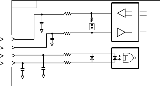
Digital Interface (IEC 61162-1 Edition 2)
Input sentences
GGA, GLL, RMC, ZDA, GNS
Schematic diagram
05P0773
7
TXD-H
J2
8
9
10
U15
6
7
1SS355
4
3
1000p
C65
TXD-C
RXD-H
RXD-C
100P
R70
10
R65
10
C64
100P
JP1
R69
120
1
220
R74 220
R73
1000p
C69 C70 CR3
1
2
PC400
4
Load requirements as listner
Isolation Optocoupler
Input impedance 560 ohms
Max. Voltage ±15V
Threshold 4 mA
Output sentence
TLL
APPENDIX
A
P-15
GGA - Global positioning system (GPS) fix data
APPENDIX
AP-16
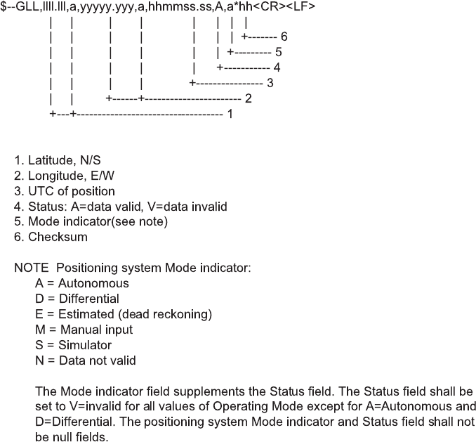
GLL - Geographic position - latitude and longitude
GNS-GNSS fixed data
$--GNS,hhmmss.ss,llll.ll,a,yyyyy.yy,a,c--c,xx,x.x,x.x,x.x,x.x,x.x*hh<CR><LF>
| | | | | | | | | | | | |
| | | | | | | | | | | | +--- 11
| | | | | | | | | | | +------ 10
| | | | | | | | | | +---------- 9
| | | | | | | | | +-------------- 8
| | | | | | | | +------------------ 7
| | | | | | | +---------------------- 6
| | | | | | +------------------------- 5
| | | | | +------------------------------ 4
| | | +-------+--------------------------------- 3
| +--+--------------------------------------------- 2
+------------------------------------------------------------- 1
1. UTC of position
2. Latitude, N/S
3. Longitude, E/W
4. Mode indicator
5. Total number of satellites in use,00-99 (Not used.)
6. HDOP (Not used.)
7. Antenna altitude, meters, re: mean-sea-level(geoid) (Not used.)
8. Geoidal separation (Not used.)
9. Age of differential data (Not used.)
10. Differential reference station ID (Not used.)
11. Checksum
APPENDIX
A
P-17
RMC - Recommemded minimum specific GPS/TRANSIT data
1. UTC of position fix
2. Status: A=data valid, V=navigation receiver warming
3. Latitude, N/S
4. Longitude, E/W
5. Speed over ground, knots
6. Course over ground, degrees true
7. Date: dd/mm/yy
8. Magnetic variation, degree E/W
9. Mode indicator(see note)
10. Checksum
NOTE Positioning system Mode indicator:
A=Autonomous
D=Differential
E = Estimated (dead reckoning)
M = Manual input
S=Simulator
N=Data not valid
The Mode indicator field supplements the Status field. The Status field
shall be set to V=invalid for all values of Operating Mode except for
A=Autonomous and D=Differential. The positioning system Mode indicator
and Status field shall not be null fields.
$--RMC,hhmmss.ss,A,llll.lll,a,yyyyy.yyy,a,x.x,x.x,xxxxxx,x.x,a,a*hh<CR><LF>
| | | | | | | | | | | | |
| | | | | | | | | | | |
| | | | | | | | | | |
+------- 10
+--------- 9
+--+--------- 8
| | | | | | | | |
| | | | | | | |
+------------------ 7
| | | | | | | +---------------------- 6
+------------------------ 5
| | | | | |
|
+------------------------ 4+-----
| | | |
+----+--------------------------------- 3
| |
+-------------------------------------- 2
+-------------------------------------------- 1
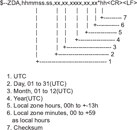
ZDA - Time and data
APPENDIX
AP-18
TLL – Target latitude and longitude
$--TLL,xx,llll.lll,a,yyyyy.yyy,a,c--c,hhmmss.ss,a,a*hh<CR><LF>
| | | | | | | | | |
| | | | | | | | | +--------- 8
| | | | | | | | +----------- 7
| | | | | | | +------------- 6
| | | | | | +-------------------- 5
| | | | | +-------------------------- 4
| | | +-----+------------------------------ 3
| +----+------------------------------------------ 2
+----------------------------------------------------- 1
1. Target number 00 - 99
2. Latitude, N/S
3. Longitude, E/W
4. Target name
5. UTC of data
6. Target status(see note)
7. Reference target=R,null otherwise
8. Checksum
NOTE - Target status
L = lost, tracked target has beenlost
Q = query, target in the process of acquisition
T = tracking

IN-1
INDEX
A
Able acknowledge call.................................3-5
ACK BQ .......................................................3-7
Alarm setup..................................................4-1
All ships call...............................................3-16
Audio alarms................................................1-6
Auto ACK setup ...........................................4-3
Automatic acknowledge .....................1-11, 3-7
C
Call key......................................................1-11
Cancel key...................................................1-6
CH16 key.....................................................1-9
Channel modes ...........................................1-7
Coast call.....................................................3-2
Contrast .......................................................1-2
Controls .......................................................1-2
D
Daily Test .....................................................6-2
DIST ACK signal..........................................2-9
Distress Alert ...............................................2-1
Distress communication ..............................2-3
Distress key....................................... 1-10, 2-1
Distress relay.............................................2-11
DSC operational ........................................1-10
Dual watch...................................................1-9
E
Earpiece volume........................................4-13
Erasing logs.................................................4-5
Error message.............................................6-3
F
Front panel...................................................1-1
G
Geographical area call ..............................3-19
Group call ..................................................3-10
Group ID list.................................................5-1
I
Intercom volume........................................4-14
K
Key click.....................................................4-13
L
LCD..............................................................1-5
Log file .......................................................3-32
Loudspeaker ................................................1-8
M
Maintenance ................................................6-1
Manually acknowledging .............................3-8
Medical transport call.................................3-30
Memory channel setup ................................4-6
Message file entry .......................................4-7
N
Naming intercom .........................................5-2
Nature of distress ........................................2-3
Neutral craft call.........................................3-29
O
Off-hook loudspeaker ................................4-14
Old position alarm........................................4-1
Output power ...............................................1-8
P
Polling call..................................................3-25
Position call................................................3-22
Position setup ............................................4-11
Print out setup............................................4-12
Priority........................................................1-12
Program version ..........................................5-3
PSTN call...................................................3-13
R
Remote station.............................................1-1
S
Scanning......................................................1-9
Self ID..........................................................5-1
Shift key .......................................................1-7
Ship call .......................................................3-2
Squelch........................................................1-8
Standby display..........................................1-10
T
Transceiver unit ...........................................1-1
Transmitting.................................................1-8
Troubleshooting ...........................................6-1
INDEX
IN-2
U
Unable acknowledge call.............................3-5
V
Volume.........................................................1-8
Volume setup.............................................4-13