Furuno USA 9ZWFS2570 MF HF GMDSS MARINE SSB RADIOTELEPHONE User Manual OPERATORS MANUAL
Furuno USA Inc MF HF GMDSS MARINE SSB RADIOTELEPHONE OPERATORS MANUAL
UserManual.wiki
>
Furuno USA
>
9ZWFS2570 User Manual
OPERATORS MANUAL
Navigation menu
Upload a User Manual
Namespaces
Wiki Guide
HTML
PDF
Info
Views
User Manual
Discussion / Help
Navigation

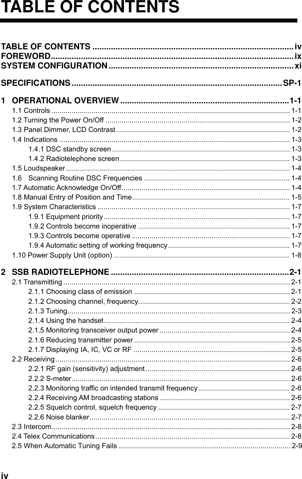
![i Distress Alert Calling Procedure Below is the procedure for transmitting a distress alert via radiotelephone. Transmit the distress alert when a life-endangering situation occurs on your vessel. 1. Open the DISTRESS button cover and press the [DISTRESS] button more than three seconds to show the following display, then release the [DISTRESS] button. TIME TO GO : 30SNATURE: UNDESIGNATEDPOS: 12˚34N 123˚45E AT 12:34TELEPHONE 2182.0 KHZ Distress call in progress! DSC FREQ : 2187.5 KHZ 2. After the distress call has been transmitted, the following displays appear in order. Wait for distress acknowledgement.TIME TO GO: 2M10SNATURE: UNDESIGNATEDPOS : 12˚34N 123˚45E AT 12:34 TELEPHONE 2182.0 KHZDSC FREQ : 2187.5 KHZSHIP IN DIST: 123456789 POS: 12˚34N 123˚45E AT 12:34TELEPHONE 2182.0 KHZFROM COAST: 001234567NATURE: UNDESIGNATEDDistress acknowledge call received. STOP ALARMWhen distress call isacknowledged by coaststation (usually within1 min to 2 min 45 seconds) 3. The audio alarm sounds; press the [CANCEL] key to silence the alarm. 4. Communicate with the coast station via radiotelephone as below. (In the dual control unit system, communication can be done from any control unit, after the distress alert has been transmitted. To restore priority to the #1 control unit after completion of distress communications, turn it off and on again.) a) Say MAYDAY three times. b) Say “This is …” name of your vessel and your call sign three times. c) Give nature of distress and assistance needed. d) Give description of your vessel (type, number of persons onboard, etc.) and any other information which may aid in rescue.](https://usermanual.wiki/Furuno-USA/9ZWFS2570/User-Guide-282811-Page-3.png)
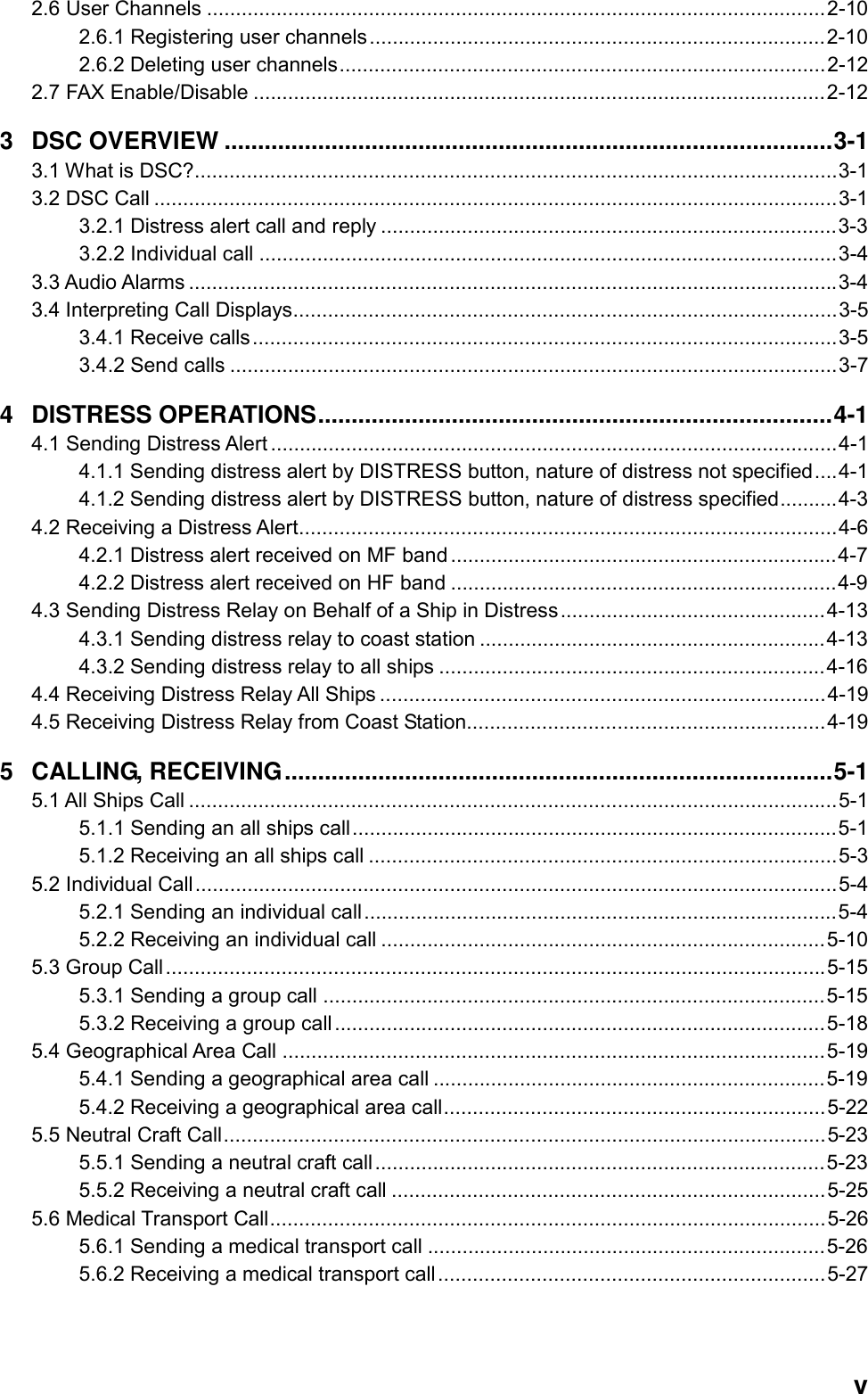
![iii Do not operate the [DISTRESS] buttonexcept in case of a life-endangeringsituation on your vessel.If the distress alert is accidentallytransmitted, contact the nearest coaststation and inform them of the accidentaltransmission as follows:a) Ship's nameb) Ship's call sign and DSC numberc) Position at time of transmissiond) Time of transmissionThis equipment is intended for maritimeuse. Do not use it in other applications.A warning label is attached to the transceiver unit and a danger label isattached to the antenna coupler.Do not remove the labels.If a label is missing or illegible,contact a FURUNO agent or dealerabout replacement. WARNINGTo avoid electrical shock, do not remove cover. No user-serviceable parts inside.Name: Warning Label (1)Type: 86-003-1011-1Code No.: 100-236-231TRANSCEIVERUNITHazardous voltage.Can shock, burn,or cause death.Do not touch antennawire, insulator andterminal.DANGERName: Danger Label Type: 05-062-0213-0Code No.: 100-199-230ANTENNACOUPLERCAUTION WARNING LABEL](https://usermanual.wiki/Furuno-USA/9ZWFS2570/User-Guide-282811-Page-5.png)
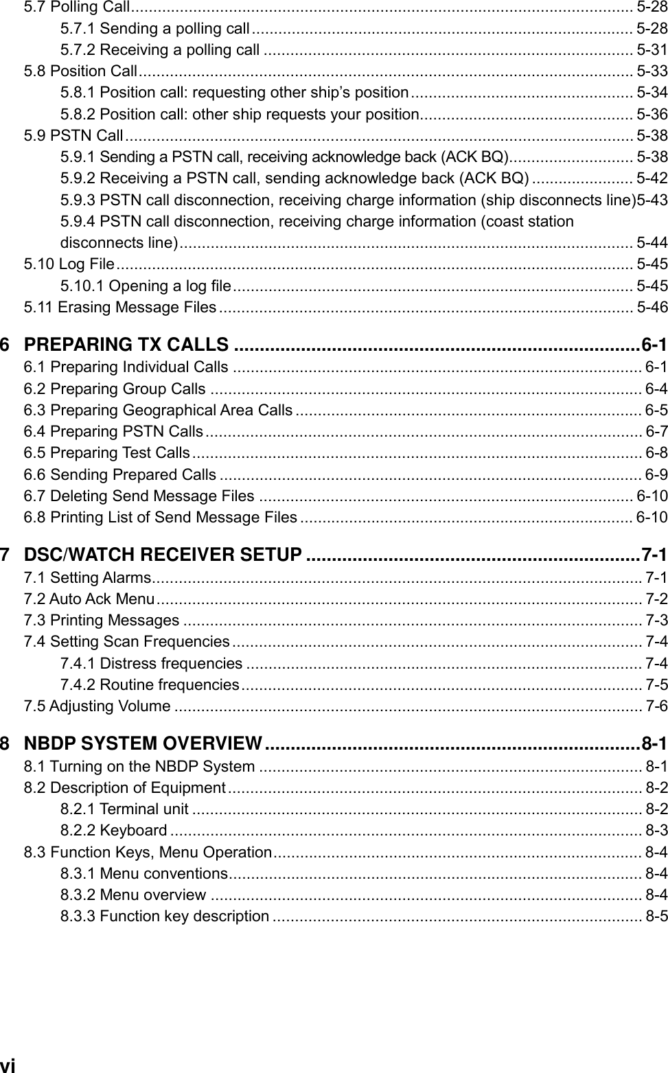

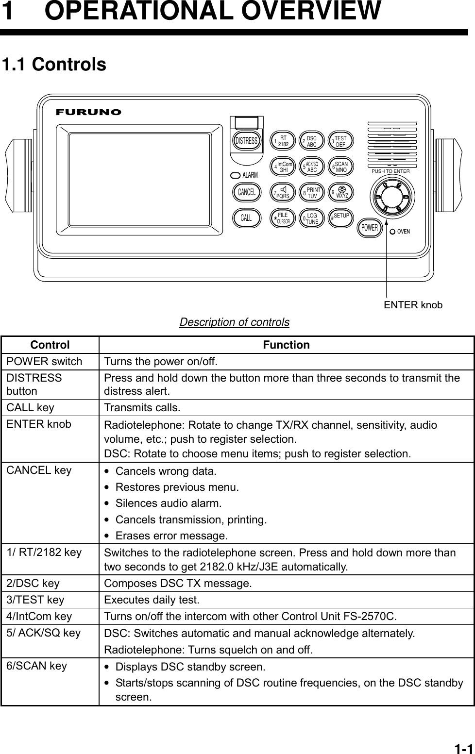
![1 OPERATIONAL OVERVIEW 1-2 7/ key • Turns loudspeaker on/off. (Note that this key does not silence the distress or urgency alarm.) 8/PRINT key Prints communications log files, current screen (except DSC standby screen and radiotelephone screen) and test results. 9/ key Adjusts panel dimmer and LCD contrast. FILE/CURSOR key • Opens the send message file list from the DSC standby screen, to send stored message. • Shifts cursor. LOG/TUNE key • Tunes antenna in radiotelephone operation. • Displays message logs, in DSC operation. #/SETUP key Opens the Setup menu. ALARM lamp • Flashes in red for distress and urgency calls. • Flashes in green (more rapidly) for business, safety and routine calls. OVEN lamp Lights (in green) when mains switchboard is on. 1.2 Turning the Power On/Off Press the [POWER] switch at the right-hand side of the control unit to power the system. Press it again to turn the system off. In the dual control unit system, the control unit connected to the CONTROLLER 1 port on the transceiver unit has priority and it controls the power for both the No.1 and No. 2 control units. The power switch of the No. 2 control unit powers on/off the No. 2 control unit only. Note: Turn on ship’s mains five minutes before turning on this equipment. 1.3 Panel Dimmer, LCD Contrast 1. Press the [9/ ] key to show the dimmer/contrast adjustment window. EXIT:[ENT]6 45DIMMER (1~8)CONTRAST (40~63) 2. Rotate the [ENTER] knob to choose DIMMER or CONTRAST, whichever you want to adjust, and then push the [ENTER] knob. DIMMER (1-8)6 CONTRAST (40-63)55Dimmer adjustment window Contrast adjustment window 3. Rotate the [ENTER] knob to adjust and then push the [ENTER] knob. 4. To quit, rotate the [ENTER] knob to choose “EXIT: [ENT]” and then push the [ENTER] knob. Note: The DIMMER is automatically set to 5 and the CONTRAST to 45 whenever the power is turned on.](https://usermanual.wiki/Furuno-USA/9ZWFS2570/User-Guide-282811-Page-22.png)
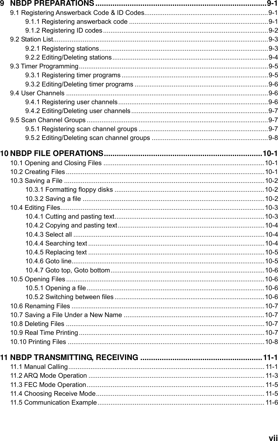
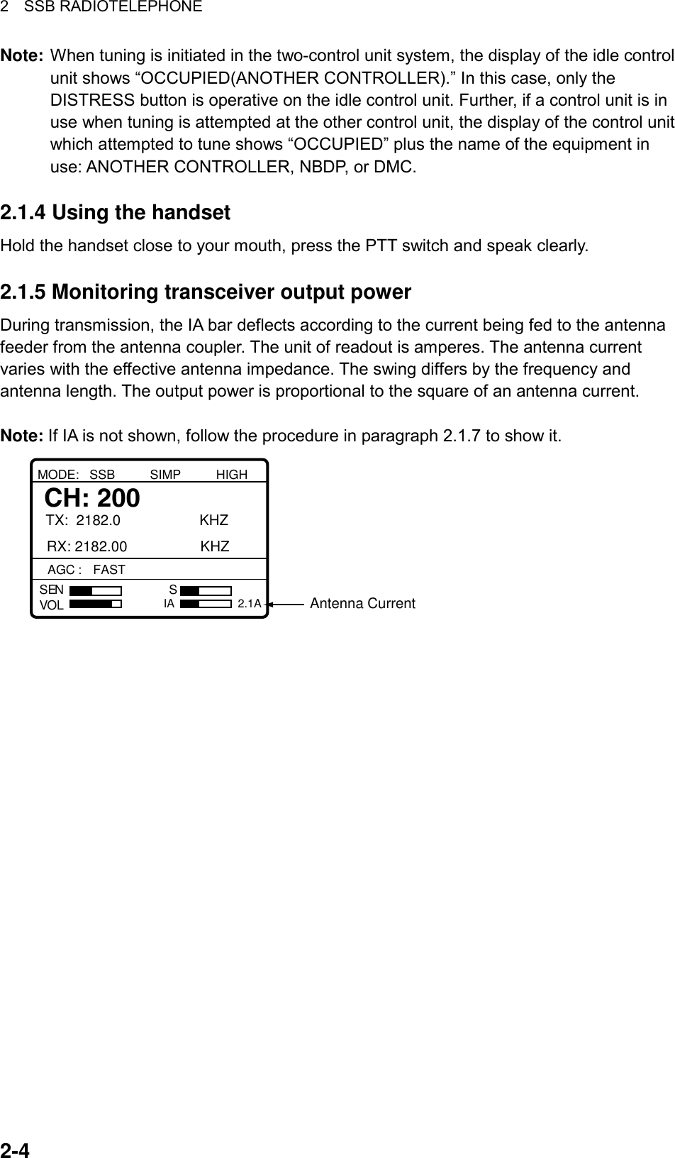
![1 OPERATIONAL OVERVIEW 1-31.4 Indications 1.4.1 DSC standby screen The DSC standby screen may be displayed by pressing the [6/SCAN] key. WATCH KEEPING2187.5 4207.5 6312.016804.5 12577.0DISTRESSROUTINE2177.0 4219.5 6331.016903.0 12657.08414.58436.5AUTO ACKPosition and time. "MANUAL" shownwhen these are input manually.Distress and routine frequenciesscanned in clockwise direction,and frequency currently beingscanned is highlighted.One cycle is completedin less than two seconds.For how to choose scanfrequencies, see paragraph 1.6.Acknowledge status(AUTO ACK or MANUAL ACK) 35°00.000N MANUAL135°00.000E 23:59 DSC standby screen 1.4.2 Radiotelephone screen Press the [1/ RT/2182] key to show the radiotelephone screen. This is where you set up the radiotelephone. Class of Emission (SSB, TLX, AM)TX FrequencyRX FrequencyAntenna Current (IA)(or IC, VC, RF)MODE: SSB SIMP HIGH CH: 200TX: 2182.0 KHZRX: 2182.00 KHZVOLSEN SAGC : FAST SQ NBIA 0.0AAGC, SquelchSensitivityVolumeS-meterOutput Power(HIGH, MID orLOW)ChannelCommunications Mode(Duplex or Simplex, display only)Noise Blanker Radiotelephone screen Note: “TX” is circumscribed with a rectangle when transmitting.](https://usermanual.wiki/Furuno-USA/9ZWFS2570/User-Guide-282811-Page-23.png)
![1 OPERATIONAL OVERVIEW 1-4 1.5 Loudspeaker 1. Press the [7/ ] key to alternately disable or enable the loudspeaker and the alarm generated for routine messages. SOUND: ON or SOUND: OFF appears with each press. 2. To adjust loudspeaker volume do the following: a) Press the [1/RT 2182] key to show the radiotelephone screen. b) Rotate the [ENTER] knob to choose VOL at the bottom of the screen and then push the [ENTER] knob. c) Rotate the [ENTER] knob to adjust volume and then push the [ENTER] knob. VOL "OFF" shown when loudspeaker is off. 1.6 Scanning Routine DSC Frequencies You can scan frequencies when using the DSC mode. For how to set frequencies, see paragraph 7.4. Radiotelephone and telex are inoperative while scanning. However, in case of the FS-2570, those modes may be used during scanning when the optional internal watch keeping receiver is installed. 1. Press the [6/SCAN] key to show the DSC standby screen. 2. Press the [6/SCAN] key to start/stop scanning. 1.7 Automatic Acknowledge On/Off The automatic acknowledge feature of the DSC/watch receiver automatically transmits the acknowledge back (ACK BQ) signal to the sending station when an individual, position or polling call is received. (For position and polling calls, respective item on the AUTO ACK menu must be turned on to enable automatic acknowledge.) Automatic acknowledge can be turned on or off at the DSC standby screen by the [5/ ACK/SQ] key. The message ACK: AUTO or ACK: MANUAL appears at the bottom of the DSC standby screen with each press of the key. Note 1: To give priority to own ship’s communications while own ship is communicating, show ACK: MANUAL by the above procedure. Note 2: Automatic acknowledge is not possible under the following conditions: Priority: Distress, Urgency or Safety Com Type: Morse, Fax, Data, No Info Com Freq: No Info Off Hook](https://usermanual.wiki/Furuno-USA/9ZWFS2570/User-Guide-282811-Page-24.png)
![1 OPERATIONAL OVERVIEW 1-51.8 Manual Entry of Position and Time If there is no EPFS (Electronic Position-Fixing System) connected to this equipment or the EPFS connected is not working (EPFS error indication appears), manually enter position and time as follows: 1. At the DSC standby screen, press the [#/SETUP] key to display the Setup menu. **** Setup menu ****SCAN FREQ VOLUME TEST SYSTEMALARM AUTO ACK ERASEMESSAGE POSITION PRINT OUT 2. Rotate the [ENTER] knob to choose POSITION and then push the [ENTER] knob. ** Position setup **INPUT TYPE: AUTO LAT : 34° 41 NORTH LON : 135° 30 EAST TIME: 09: 00 UTC 3. Push the [ENTER] knob to open the INPUT TYPE menu. ** Position setup **INPUT TYPE: AUTO LAT : 34° 41 NORTH LON : 135° 30 EAST TIME: 09: 00 UTC AUTON MANUAL Note 1: If, when INPUT TYPE is AUTO, input from the navigator is interrupted, the message “EPFS error!” appears. If this occurs, check the navigator. Note 2: When INPUT TYPE is MANUAL, the message “Warning: Update position” appears at set intervals (update interval selected with POSITION OLDER on the Alarm menu) to ask you to update position. 4. Rotate the [ENTER] knob to choose MANUAL and then push the [ENTER] knob.](https://usermanual.wiki/Furuno-USA/9ZWFS2570/User-Guide-282811-Page-25.png)
![1 OPERATIONAL OVERVIEW 1-6 5. Push the [ENTER] knob to open the latitude input window. Use the numeric keys to enter latitude. If necessary, switch coordinates: [1] key to switch to North; [2] key to switch to South. Push the [ENTER] knob. ** Position setup **INPUT TYPE: MANUAL 34˚ 41 LON : 135° 30 EAST TIME: 09: 00 UTC LAT : 34° 41 NORTH 12 34 ° 30 NORTH 12 34°30 NORTHNORTH: [1] KEYSOUTH: [2] KEYAfter last digitis entered 6. Push the [ENTER] knob to open the longitude input window. Use the numeric keys to enter longitude. If necessary, switch coordinates: [1] key to switch to East; [2] key to switch to West. Push the [ENTER] knob. ** Position setup **INPUT TYPE: MANUAL LAT: 34˚ 41 NORTH LON : 135˚ 30 EAST TIME: 09: 00 UTC LAT : 34° 30 NORTHLON : 135° 30 EAST 12 135°30 EAST 12 135°30 EASTEAST: [1] KEYWEST: [2] KEYAfter last digitis entered 7. Push the [ENTER] knob to open the time input window. INPUT TYPE: MANUAL LAT : 34˚ 41 NORTH LON : 135˚ 30 EAST TIME : 09: 00 UTC LAT : 34°30 NORTHLON : 135° 30 EAST TIME: 09: 00 UTC 12 : 34 Position setup 8. Enter UTC time with the numeric keys and then push the [ENTER] knob. The Setup menu appears. 9. Press the [CANCEL] key to return to the DSC standby screen.](https://usermanual.wiki/Furuno-USA/9ZWFS2570/User-Guide-282811-Page-26.png)
![1 OPERATIONAL OVERVIEW 1-71.9 System Characteristics 1.9.1 Equipment priority Equipment priority order is as below. 1. DMC 2. Control unit sending distress alert 3. Control unit 1 – routine use 4. Control unit 2 – routine use 5. NBDP 1.9.2 Controls become inoperative Controls become inoperative in the following conditions: • Controls of idle control unit in the two-control unit system when other control unit goes OFF HOOK. • Controls of idle control unit in the two-control unit system when other control unit switches to the DSC mode. • Distress received by DMC (Distress Message Controller). • NBDP is scanning or communicating. • Distress alert or distress relay is transmitted. • Call other than distress is transmitted (transmission time about 8 s). If it becomes necessary to unlock the keyboard before the message is transmitted, press the [CANCEL] key to cancel the call. 1.9.3 Controls become operative Controls become operative in the following conditions: • [DISTRESS] button is pressed. • Control unit having highest priority is operated. • Other control unit in two-control unit system goes ON HOOK. • Distress received by DMC is acknowledged. • NBDP stops scanning or communicating. 1.9.4 Automatic setting of working frequency The radiotelephone automatically sets working frequency in the following conditions: • ABLE ACK is sent in response to individual call. • Your ship receives ABLE ACK in response to own ship-initiated individual call. • Your ship sends all ship call. • Your ship sends distress relay. • Your ship sends distress alert. • Your ship receives group call or area call. • Your ship receives distress relay call. • Your ship receives distress alert.](https://usermanual.wiki/Furuno-USA/9ZWFS2570/User-Guide-282811-Page-27.png)
![2-12 SSB RADIOTELEPHONE You can enter desired frequency by channel or TX and RX frequencies. The handset may be ON HOOK or OFF HOOK. To set the SSB radiotelephone to 2182 kHz/J3E automatically, press the [1/ RT/2182] key more than two seconds. 2.1 Transmitting After selecting class of emission and frequency, you can transmit by pressing the PTT switch on the handset. Output power is shown on the display. 2.1.1 Choosing class of emission 1. At the radiotelephone screen, choose class of emission (mode) as follows: a) Rotate the [ENTER] knob to choose MODE and then push the [ENTER] knob. MODE: SSB SIMP HIGH CH: 800TX: 2182.0 KHZRX: 2182.00 KHZVOLSEN SAGC : FASTIA 0.0A TLXAMSSB b) Rotate the [ENTER] knob to choose mode desired and then push the [ENTER] knob. SSB: Single Sideband, TLX: Telex, AM: AM. (You cannot transmit on the AM mode.) 2. AGC is automatically selected according to mode. AGC FAST: SSB, AGC OFF: TLX, AGC SLOW: AM. However, you may change it as below. a) Rotate the [ENTER] knob to choose AGC and then push the [ENTER] knob. MODE: SSB SIMP HIGH CH: 200TX: 2182.0 KHZRX: 2182.00 KHZVOLSEN SAGC : FASTIA 0.0AFASTFASTOFFSLOWFAST b) Rotate the [ENTER] knob to choose OFF, SLOW or FAST as appropriate and then push the [ENTER] knob.](https://usermanual.wiki/Furuno-USA/9ZWFS2570/User-Guide-282811-Page-29.png)
![2 SSB RADIOTELEPHONE 2-22.1.2 Choosing channel, frequency Choosing channel 1. Rotate the [ENTER] knob to choose CH and then push the [ENTER] knob. MODE: SSB SIMP HIGH CH: 800TX: 2182.0 KHZRX: 2182.00 KHZVOLSEN SAGC : FASTIA 0.0A 200 2. Channel can be entered directly with the numeric keys, or by using the [ENTER] knob. See below for details. Entering band and band channel with the numeric keys: Use the numeric keys to enter band and band channel and then push the [ENTER] knob. Choosing band and band channel with the ENTER knob: a) Use the [FILE/CURSOR] key to place the cursor in the band or band channel position, whichever you want to change. 200 200Cursor position forselection of band channelCursor position forselection of band b) Rotate the [ENTER] knob to set band (or channel) desired. 2 4 6 8 12 16 18 22 25 01 02----- 029ITU band User band Setting RangeITU Band: 2/4/6/8/12/16/18/22/25User Band: 001-029 (leadiing zero necessary)ITU Channel: XX01 - XX236 (rendering on band or mode)User Channel: XXX01 - XXX99 c) Push the [ENTER] knob. The TX and RX frequencies of the channel entered appear.](https://usermanual.wiki/Furuno-USA/9ZWFS2570/User-Guide-282811-Page-30.png)
![2 SSB RADIOTELEPHONE 2-3Choosing frequency 1. Rotate the [ENTER] knob to choose TX or RX as appropriate and then push the [ENTER] knob. TX: 2182.0 KHZVOLSENSAGC : SLOWIA 0.0AMODE: AM SIMP HIGHCH: 200Rx: 123456.78 KHZ 2182.00 KHZ 2. Enter frequency by one of the methods below. Entering frequency with the numeric keys: Use the numeric keys to enter frequency and then push the [ENTER] knob. Be sure to including trailing zero. For example, to enter 2161 kHz, key in [2], [1], [6], [1], [0]. (Keying in 2-1-6-1 will set 216.1 kHz.) Choosing frequency with the ENTER knob (for RX only): a) Use the [FILE/CURSOR] key to choose digit to change. b) Rotate the [ENTER] knob to set digit. c) Push the [ENTER] knob. Note: To enter same frequency for both TX and RX, enter the TX frequency first. 2.1.3 Tuning Maximum transmission power is achieved only when the antenna impedance and transmitter impedance match each other. Because the antenna impedance changes with frequency, a means must be provided to match (tune) the antenna impedance with the transmitter impedance. This is done with the antenna coupler. The antenna coupler automatically tunes the transmitter to a wide range of different antenna lengths, from 7 to 30 m. To initiate the automatic tuning, do the following: 1. Press the PTT switch on the handset or the [LOG/TUNE] key on the control unit. “TUNING” appears when the [LOG/TUNE] key is pressed; “TX” pops out when the PTT switch is pressed. Tuning will be completed within 2 to 5 s for a newly selected frequency, or less than 0.5 s for a once-tuned frequency. (A memory saves coil and capacitor settings.) When the tuning process is successfully completed, TUNE: OK appears. If tuning fails, TUNE: NG appears.](https://usermanual.wiki/Furuno-USA/9ZWFS2570/User-Guide-282811-Page-31.png)
![2 SSB RADIOTELEPHONE 2-52.1.6 Reducing transmitter power To conserve energy and to minimize possible interference to other stations, reduce the transmission power. This should be done when using the transceiver in a harbor, near the shore or close to communication partner (other ship). 1. Rotate the [ENTER] knob to choose LOW, MID or HIGH (whichever is shown) at the top of the screen and then push the [ENTER] knob. FS-1570 FS-2570 LOW 68 W 70 W MID 100 W 125 WHIGH 150 W 250 W MODE: SSB SIMP HIGH CH: 200TX: 2182.0 KHZRX: 2182.00 KHZVOLSEN SAGC : FASTIA 2.1A LOWMIDHIGH 2. Rotate the [ENTER] knob to choose power among LOW, MID and HIGH as appropriate and then push the [ENTER] knob. Note: Power amplifier temperature is monitored, and when its temperature rises above a certain temperature output power is automatically reduced. 2.1.7 Displaying IA, IC, VC or RF While transmitting, you may display RF (PA output), IA (antenna current), IC (collector current) or VC (collector voltage), at the lower right corner of the radiotelephone screen. 1. Rotate the [ENTER] knob to choose RF, IA, IC or VC (whichever is displayed) at the bottom right corner. 2. Push the [ENTER] knob. MODE: SSB SIMP HIGH CH: 200TX: 2182.0 KHZRX: 2182.00 KHZVOLSEN SAGC : FASTIA 2.1A IAICVCRF 3. Rotate the [ENTER] knob to choose option desired and then push the [ENTER] knob.](https://usermanual.wiki/Furuno-USA/9ZWFS2570/User-Guide-282811-Page-33.png)
![2 SSB RADIOTELEPHONE 2-62.2 Receiving 2.2.1 RF gain (sensitivity) adjustment In normal use the sensitivity should be set for maximum. If the audio on the received channel is unclear or interfered with other signals, adjust (usually reduce) sensitivity to improve clarity. 1. Rotate the [ENTER] knob to choose SEN at the bottom of the screen and then push the [ENTER] knob. SEN 2. Rotate the [ENTER] to adjust and then push the [ENTER] knob. 2.2.2 S-meter The S-meter shows relative signal strength coming into the receiver frontend. Note that the S-meter does not function when the AGC is turned off. S-meterMODE: SSB SIMP HIGH CH: 200TX: 2182.0 KHZRX: 2182.00 KHZVOLSEN SAGC : FASTIA 0.0A 2.2.3 Monitoring traffic on intended transmit frequency When a semi-duplex channel is selected, it is recommended to monitor if there is no existing traffic on the frequency you are going to use. To do this, choose RX and then push the [ENTER] knob. The transceiver monitors traffic on the selected frequency for three s. 2.2.4 Receiving AM broadcasting stations 1. Press the [1/ RT/2182] key to show the radiotelephone screen. 2. Rotate the [ENTER] knob to choose MODE and then push the [ENTER] knob. MODE: SSB SIMP HIGH CH: 800TX: 2182.0 KHZRX: 2182.00 KHZVOLSEN SAGC : FASTIA 0.0A TLXAMSSB 3. Rotate the [ENTER] knob to choose AM and then push the [ENTER] knob. 4. Rotate the [ENTER] knob to choose RX and then push the [ENTER] knob.](https://usermanual.wiki/Furuno-USA/9ZWFS2570/User-Guide-282811-Page-34.png)
![2 SSB RADIOTELEPHONE 2-7TX: 2182.0 KHZVOLSENSAGC : SLOWIA 0.0AMODE: AM SIMP HIGHCH: 200Rx: 123456.78 KHZ 2182.00 KHZ 5. Key in RX frequency with the numeric keys and then push the [ENTER] knob. 2.2.5 Squelch control, squelch frequency Squelch on/off The squelch mutes the audio output in the absence of an incoming signal. Press the [5/ ACK/SQ key] to turn on and off the squelch alternately. When radio noise is too jarring during stand-by condition, it may be muted by activating the squelch. “SQ” appears when the squelch function is active. Squelch frequency 1. At the radiotelephone screen, press the [#/SETUP] key. **** Setup menu **** NB : OFFSQ FREQ : 600 HZFAX RX ENABLE : OFFUSER CHSYSTEM 2. Rotate the [ENTER] knob to choose SQ FREQ. 3. Push the [ENTER] knob. 4. Enter frequency (range: 500-2000 Hz, default 800 Hz) with the numeric keys and then push the [ENTER] knob. 5. Press the [CANCEL] key to return to the radiotelephone screen. 2.2.6 Noise blanker The noise blanker functions to remove noise. You may turn it on or off as follows: 1. At the radiotelephone screen, press the [#/SETUP] key. 2. Rotate the [ENTER] knob to choose NB. 3. Push the [ENTER] knob. 4. Rotate the [ENTER] knob to choose ON or OFF as appropriate and then push the [ENTER] knob. 5. Press the [CANCEL] key to return to the radiotelephone screen.](https://usermanual.wiki/Furuno-USA/9ZWFS2570/User-Guide-282811-Page-35.png)
![2 SSB RADIOTELEPHONE 2-82.3 Intercom The built-in intercom permits voice communications between two FS-2570C Control Units. 1. Press the [1/ RT/2182] key to show the radiotelephone screen. 2. Off hook the handset. 3. Press the [4/IntCom] key to show INTERCOM on the display. The called party’s handset rings. 4. When the called party picks up their handset, press the PTT switch on the handset and speak into the handset. Hang up the handset to turn the intercom off. The indication INTERCOM disappears from the screen. 2.4 Telex Communications Telex communication is performed with the NBDP Terminal Unit (option) connected to this radiotelephone. No special operation is required on the control unit; class of emission and frequencies are set on the NBDP Terminal Unit. For telex communications, see Chapters 8 through 11.](https://usermanual.wiki/Furuno-USA/9ZWFS2570/User-Guide-282811-Page-36.png)
![2 SSB RADIOTELEPHONE 2-102.6 User Channels The USER CH menu allows registration of user TX and RX channels, where permitted by the Authorities. NOTICEFURUNO will assume no responsibilityfor the disturbance caused by theunlawful or improper setting of userchannels. 2.6.1 Registering user channels “USER CH” in the System setup menu must be enabled in order to register user channels. For further details, contact your dealer. 1. At the radiotelephone screen, press the [#/SETUP] key. **** Setup menu **** NB : OFFSQ FREQ : 600 HZFAX RX ENABLE : OFFUSER CHSYSTEM 2. Rotate the [ENTER] knob to choose USER CH and then push the [ENTER] knob. The window shown below appears. ENTRYERASE 3. ENTRY is selected; push the [ENTER] knob. *** User ch entry ** MODE: SSBUP DOWN00201. TX: 2111.5 RX: 2111.500202. TX: 2222.0 RX: 2222.000203. TX: 2333.5 RX: 2333.500204. TX: 2444.0 RX: 2444.000205. TX: 2555.5 RX: 2555.5CH: 2-01 4. Push the [ENTER] knob to open the user channel options window. *** User ch entry ** MODE: SSB CH: 2-01UP DOWN00201. TX: 2111.5 RX: 2111.500202. TX: 2222.0 RX: 2222.000203. TX: 2333.5 RX: 2333.500204. TX: 2444.0 RX: 2444.000205. TX: 2555.5 RX: 2555.5MODECHFREQ](https://usermanual.wiki/Furuno-USA/9ZWFS2570/User-Guide-282811-Page-38.png)
![2 SSB RADIOTELEPHONE 2-115. Rotate the [ENTER] knob to choose MODE and then push the [ENTER] knob. *** User ch entry **UP DOWN00201. TX: 2111.5 RX: 2111.500202. TX: 2222.0 RX: 2222.000203. TX: 2333.5 RX: 2333.500204. TX: 2444.0 RX: 2444.000205. TX: 2555.5 RX: 2555.5SSBNBDPDSC MODE: CH: 2-01 6. Rotate the [ENTER] knob to choose appropriate mode among SSB, NBDP and DSC and then push the [ENTER] knob. *** User ch entry **MODE: SSBUP DOWN00201. TX: 2101.5 RX: 2101.500202. TX: 2202.0 RX: 2202.000203. TX: 2303.5 RX: 2303.500204. TX: 2404.0 RX: 2404.000205. TX: 2505.5 RX: 2505.5CH : 2-01CH:0−00- 256 channels may be registered.- Band no. setting range is 0-29 and band channel no. range is 01-99.- For DSC, four channels can be registered per band (2, 4, 6 8, 12, 16, 18, 22, 25).- "0" band is for DSC frequencies only, and they are registered under "OTHER." Four channels are available, 01-04. 7. Key in channel no. and then push the [ENTER] knob. For example, press [0], [1], [2], [3], [4] and then push the [ENTER] knob to enter channel 01234. ** User ch entry ** MODE : SSB UP DOWN01234. TX: 0.0 RX: 0.001240. TX: 12666.0 RX: 13666.001241. TX: 12777.5 RX: 13777.501242. TX: 12999.5 RX: 13999.501250. TX: 12100.0 RX: 13100.0CH : 12-34TX : 0.0 KHZRX : 0.0 KHZ 8. Enter TX frequency with the numeric keys. 9. Rotate the [ENTER] knob to choose RX. 10. Enter RX frequency with the numeric keys and then push the [ENTER] knob. 11. Rotate the [ENTER] knob to display all channels entered. 12. Press the [CANCEL] key twice to return to the radiotelephone screen.](https://usermanual.wiki/Furuno-USA/9ZWFS2570/User-Guide-282811-Page-39.png)
![2 SSB RADIOTELEPHONE 2-122.6.2 Deleting user channels Deleting individual user channels 1. At the radiotelephone screen, press the [#/SETUP] key. 2. Rotate the [ENTER] knob to choose USER CH and then push the [ENTER] knob. 3. Rotate the [ENTER] knob to choose ENTRY and then push the [ENTER] knob. 4. Push the [ENTER] knob, rotate the [ENTER] knob to choose CH and then push the [ENTER] knob. 5. Enter channel number to process and then push the [ENTER] knob. 6. Tx and Rx frequencies are shown as “0.0 kHz”; push the [ENTER] knob to delete channel. 7. Press the [CANCEL] key twice to return to the radiotelephone screen. Deleting all user channels 1. At the radiotelephone screen, press the [#/SETUP] key. 2. Rotate the [ENTER] knob to choose USER CH and then push the [ENTER] knob. 3. Rotate the [ENTER] knob to choose ERASE and then push the [ENTER] knob. 4. Rotate the [ENTER] knob to choose YES and then push the [ENTER] knob. 5. Press the [CANCEL] key to return to the radiotelephone screen. 2.7 FAX Enable/Disable You may enable or disable FAX use as follows: 1. At the radiotelephone screen, press the [#/SETUP] key to open the Setup menu. 2. Rotate the [ENTER] knob to choose FAX RX ENABLE and then push the [ENTER] knob. 3. Rotate the [ENTER] knob to choose ON or OFF as appropriate and then push the [ENTER] key. MODE: SSB SIMP HIGH CH: 800TX: 2182.0 KHZRX: 2182.00 KHZVOLSEN SAGC : FASTIA 0.0A TLXFAXAMSSB 4. Press the [CANCEL] key to close the menu.](https://usermanual.wiki/Furuno-USA/9ZWFS2570/User-Guide-282811-Page-40.png)
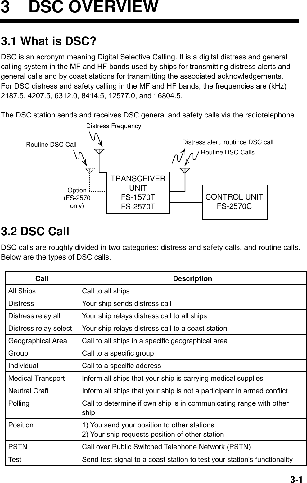
![3 DSC OVERVIEW 3-33.2.1 Distress alert call and reply This type of call is sent by own ship in the event of distress, by using the [DISTRESS] button as follows: 1. The LED in the [DISTRESS] button initially flashes, and lights when the button is pressed more than three seconds. (If the button is pressed less than three seconds, the distress alert is not sent. Once the alert is sent it cannot be cancelled.) NOTICEIN CASE OF ACCIDENTAL TRANS-MISSION OF THE DISTRESS ALERTIf the distress is accidentally transmitted,contact the nearest coast station and informthem of the accidental transmission asfollows:a) Ship's nameb) Ship's call sign and DSC numberc) Position at time of transmissiond) Time of transmission 2. The radiotelephone automatically sets the DSC distress frequency and then the equipment transmits the distress alert. 3. After the distress alert is transmitted (this takes about 40 seconds), the equipment waits for the distress acknowledgement call (DIST ACK) from a coast station. This usually takes less than three minutes. (If it is not received within 4.5 minutes, the distress alert is re-transmitted.) 4. The radiotelephone automatically sets the distress communication frequency to use to conduct voice communications (telex also available) with the coast station. CoastStation Own Ship(1) Ship in Distress(Own Ship)(3)(2)(2) (3) (1) Ship in distress sends Distress Alert(2) Coast station sends distress acknowledgement (DIST ACK).(3) Voice or telex communications between ship in distress and coast station(1)](https://usermanual.wiki/Furuno-USA/9ZWFS2570/User-Guide-282811-Page-43.png)
 Acknowledge Back (ACK BQ) Signal(3) Voice or telex communication(1)(2)(3) Basic procedure (radiotelephone) 1. Prepare call and transmit it by pressing the [CALL] key. The equipment then awaits acknowledgement of the call. 2. Receive acknowledge back (ACK BQ) signal from other party (coast station or ship station) within about five minutes. The audio alarm sounds at this time; press the [CANCEL] key to silence it. 3. After receiving the ACK BQ signal, communicate with other party; the radiotelephone automatically sets the working frequency and class of emission you specified. 3.3 Audio Alarms When you receive a distress alert or routine call addressed to your ship, the audio and visual alarms are released. For the distress or urgency call, the audio alarm sounds until the [CANCEL] key is pressed, and sounds for one second and then automatically goes off in case of other calls. The tone of the alarm changes with the call received. By becoming accustomed to the tone, you can know which type of call you have received. Alarm Frequency (interval) Safety call received 1300 Hz and 0 Hz (250 ms) Routine, Ship's Business call received 880 Hz and 440 Hz (500 ms) While DISTRESS button is pressed for three s 2200 Hz and 0 Hz (125 ms) Distress alert sent 2200 Hz, continuous Own ship position not updated 2200 Hz (50 ms), three beeps every two s Distress alert, urgency message received 1300 Hz and 2200 Hz (250 ms)](https://usermanual.wiki/Furuno-USA/9ZWFS2570/User-Guide-282811-Page-44.png)
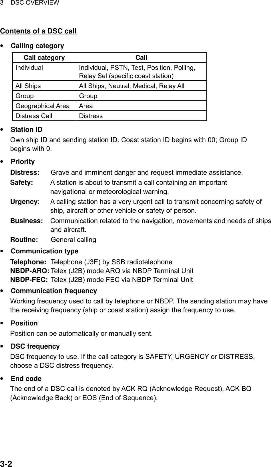
![3 DSC OVERVIEW 3-5 3.4 Interpreting Call Displays This paragraph provides the information necessary for interpreting receive and send call displays. 3.4.1 Receive calls Below are sample distress and individual receive calls. The content of other types of receive calls is similar to that of the individual call. When you receive a call, the message “INCOMING” flashes at the bottom of the display. Distress receive call * Received message * MAR-23-2002-23:59 ECC: OK DISTRESS CALLANSWERSHIP IN DIST: 123456789NATURE: UNDESIGNATEDPOS: 12°34N 123°45E AT 12:34 TELEPHONE 2182.0 KHZ ALL VIEWEND OF SEQUENCE: EOS ERROR-CHECK: OK DSC FREQUENCY : 2177.0KHZ * Received message *GO TO EASY VIEWFORMAT : DISTRESS CALLSELF-IDENTITY : 123456789NATURE OF DISTRESS: UNDESIGNATED DISTRESS * Received message *Date and time of messageECC (Error Check Character): OK or NG (No Good)Category (Distress call)Ship in Distress (ID No. of ship in distress)Nature of Distress (Undesignated, Fire, Flooding,Collision, Grounding, Listing, Sinking, Disable,Abandoning, Piracy, Man Overboard, EPIRB emission)Position of ship in distressWorking frequency to useEnd of sequence (EOS for distress)Error check (OK or NG)DSC frequency used to transmit distress callFormat (distress)ID no. of ship in distressNature of distress (problem with ship in distress, see above)Distress coordinates (position of ship in distress)Telecommand (class of emission)Rotate [ENTER] knobto switch.Push [ENTER] knobto switch.DISTRESS COORDINATES: 12°34N 123°45E AT 12:34TELECOMMAND: J3E TELEPHONE](https://usermanual.wiki/Furuno-USA/9ZWFS2570/User-Guide-282811-Page-45.png)
![3 DSC OVERVIEW 3-6Individual receive call * Received message ** Received message *MAR-23-2002-23:59 ECC: OK INDIVIDUAL REQUEST FROM SHIP: 123456789 ROUTINE TX: 2182.0 KHZ TELEPHONE RX: 2182.0 KHZ WORKING FREQ. : TX: 2182.0 KHZ RX: 2182.0 KHZEND OF SEQUENCE: ACK. RQ ERROR-CHECK: OK GO TO EASY VIEWDate and time of messageECC (Error Check Character): OK or NG (No Good)Able acknowledge ("Unable acknowledge" and reason if unable)ID No. of sending stationCategory (Routine, Business, Safety, Urgency)Working frequency to useEnd of sequence (ACK. BQ or ACK. RQ)Error check (OK or NG)DSC frequency usedWorking frequency to useNote: ANSWER is for replying to message. FORMAT : INDIVIDUAL ADDRESS : 987654321 CATEGORY : ROUTINE SELF-IDENTITY : 123456789 1ST TELECOMMAND: J3E TELEPHONE 2ND TELECOMMAND : NO INFORMATION * Received message *Format (individual)ID of your stationCategory (Routine, Business, Safety, Urgency)1st Telecommand (class of emission)2nd Telecommand (class of emission)ID of sending stationANSWER ALL VIEW Push [ENTER] knobto switch.Rotate [ENTER] knob to go to "GO TO EASY VIEW"or push it to go to previous display.DSC FREQUENCY 2177.0KHZ](https://usermanual.wiki/Furuno-USA/9ZWFS2570/User-Guide-282811-Page-46.png)
![3 DSC OVERVIEW 3-73.4.2 Send calls Below are sample distress and individual send calls. The content of other types of send calls is similar to that of the individual call. Distress send call Distress call in progress!TIME TO GO : 30SNATURE: UNDESIGNATEDPOS: 12°34N 123°45E AT 12:34 TELEPHONE 2182.0 KHZDSC FREQ : 2187.5 KHZTime to go until distress alert is transmittedNature of Distress (Undesignated, Fire, Flooding,Collision, Grounding, Listing, Sinking, Disable,Abandoning, Piracy, Man Overboard)Position of ship in distress (your ship)DSC frequency used to send distress callWorking frequency to use Individual send call COM. FREQ : CH 401PRIORITY: ROUTINECOM. TYPE : TELEPHONECALL TYPE: INDIVIDUALSTATION ID: 123456789 GO TO ALL VIEWDSC FREQ : 2M-INTLRotate [ENTER] knob to choose GO TO ALL VIEWand then push it.** Compose message ** GO TO EASY VIEWDSC FREQUENCY TX: 2177.0 KHZ RX: 2177.0 KHZWORKING FREQ. : CH 401END OF SEQUENCE: ACK. RQID of station where message is to be sentMode of communication (Telephone, NBPD-ARQ, NBDP-FEC)Working channel (or frequency)Call type (Individual)Working frequencyPriority (Routine, Business, Safety, Urgency)DSC frequencyEnd of sequence (Acknowledge request)DSC frequency used** Compose message **Calling formatOwn ship IDCommunications category1st telecommand2nd telecommand ID no. of transmitting stationRotate [ENTER] knob.FORMAT : INDIVIDUAL ADDRESS : 987654321 CATEGORY : ROUTINE SELF-IDENTITY : 123456789 1ST TELECOMMAND: J3E TELEPHONE 2ND TELECOMMAND : NO INFORMATION * Compose message *](https://usermanual.wiki/Furuno-USA/9ZWFS2570/User-Guide-282811-Page-47.png)

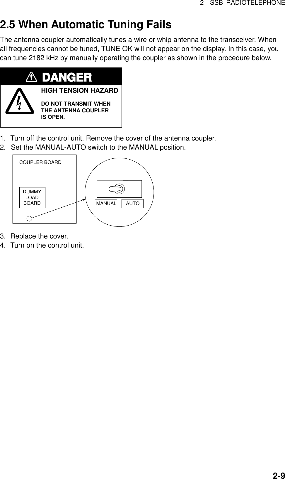
![4-1 4 DISTRESS OPERATIONS 4.1 Sending Distress Alert GMDSS ships carry a DSC terminal with which to transmit the distress alert in the event of a life-endangering situation. A coast station receives the distress alert and sends the distress alert acknowledge call to the ship in distress. Then, voice or telex communications between the ship in distress and coast station begins. Transmission of the distress alert and receiving of the distress alert acknowledgement are completely automatic - simply press the [DISTRESS] button to initiate the sequence. Russian version • Audio alarm is released continuously after transmitting distress alert. • The [CANCEL] key can be used during the transmission of the distress alert. The transmission sequence is stopped at the end of the fifth transmission. 4.1.1 Sending distress alert by DISTRESS button, nature of distress not specified 1. Open the DISTRESS button cover and press and hold down the [DISTRESS] button more than three seconds. The button flashes in red and the buzzer sounds rapidly. The display shows the contents of the distress alert call: your ship’s nature of distress, position, time and the DSC frequency over which the alert has been transmitted. The number of seconds to continue pressing the [DISTRESS] button appear at the bottom of the display. The buzzer sounds continuously and the lamp in the button lights when the button has been pressed three seconds. You can release the button at that time. KEEP PRESSED FOR 3SNATURE: UNDESIGNATEDPOS:12°34N 123°45E AT 12:34TELEPHONE 2182.0 KHZ Distress button pressed! Displays number of seconds to continuepressing the [DISTRESS] button to transmit the distress alert.DSC FREQ :2187.5 KHZNature of DistressPosition, TimeDSC DistressFrequency usedto transmit thedistress alert](https://usermanual.wiki/Furuno-USA/9ZWFS2570/User-Guide-282811-Page-49.png)
![4 DISTRESS OPERATIONS 4-2 2. The display changes as below. It takes about 40 seconds to transmit the distress alert, and the number of seconds until transmission is completed is shown at the bottom of the display. At this time the output power of the radiotelephone is automatically set to maximum. Distress call in progress!TIME TO GO : 38SNATURE: UNDESIGNATEDPOS: 12°34N 123°45E AT 12:34 TELEPHONE 2182.0 KHZDSC FREQ : 2187.5 KHZTime to go until distressalert is completely transmitted. 3. After the distress alert has been sent, the display changes as below and the audio alarm is stopped. Wait to receive the distress acknowledge call from a coast station, which usually takes 1 to 2 min 45 seconds. (The [DISTRESS] button remains lit until the equipment receives the distress acknowledge call from a coast station.) The timer counts down the number of minutes before next retransmission (if necessary), from 3.5 to 4.5 minutes, randomly set. At this time, the equipment cannot receive any calls except the distress alert acknowledge call. The distress alert you sent is recorded in the TX log. Wait for distress acknowledgement.TIME TO GO: 2M10SNATURE: UNDESIGNATEDPOS : 12°34N 123°45E AT 12:34 TELEPHONE 2182.0 KHZDSC FREQ : 2187.5 KHZ 4. When the distress acknowledge call is received, the audio alarm sounds and the display changes as below. SHIP IN DIST: 123456789 POS: 12°34N 123°45E AT 12:34TELEPHONE 2182.0 KHZFROM COAST: 001234567NATURE: UNDESIGNATEDDistress acknowledge call received. STOP ALARM Note: If you do not receive the distress alert acknowledge call, the equipment automatically re-transmits the distress alert and then awaits the distress alert acknowledge call. This is repeated until the distress alert is acknowledged. 5. Silence the alarm with the [CANCEL] key. The contents of the distress acknowledge call appear.](https://usermanual.wiki/Furuno-USA/9ZWFS2570/User-Guide-282811-Page-50.png)
![4 DISTRESS OPERATIONS 4-3 JAN-23-2002-23:59 ECC: OK DISTRESS ACKNOWLEDGESHIP IN DIST: 123456789 POS: 12°34N 123°45E AT 12:34TELEPHONE 2182.0 KHZFROM COAST: 001234567 NATURE: UNDESIGNATED Received message GO TO ALL VIEW 6. Communicate with the coast station via radiotelephone, following the instructions below. The radiotelephone automatically sets working frequency and class of emission, as specified in the distress acknowledge call. a) Say MAYDAY three times. b) Say “This is … “ name of your vessel and call sign three times. c) Give nature of distress and assistance needed. d) Give description of your vessel (type, color, number of persons onboard, etc.). 4.1.2 Sending distress alert by DISTRESS button, nature of distress specified If you have the time to designate the nature of distress, send the distress alert as follows: 1. Open the DISTRESS button cover and press the [DISTRESS] button momentarily to show the following display. CALL TYPE :Undesignated POS. COM.TYPEDSC FREQ : All ships : 987654321 : : NATURE FIREFLOODINGCOLLISIONGROUNDINGLISTING UNDESIGNATED** Compose message **DISABLEABANDONINGPIRACYMAN OVERBOARD SINKINGRotate [ENTER] knob to scroll. 2. Rotate the [ENTER] knob to choose nature of distress and then push the [ENTER] knob. 3. Push the [ENTER] knob to open the POS. menu. This is where you enter your position, automatically or manually. The INPUT TYPE option, that is, the source of position data, is selected to AUTO, MANUAL or NO INFO. For AUTO, if the position is correct, push the [ENTER] knob twice and go to step 10. For manual input, or you do not know your position, go to step 4. INPUT TYPE: AUTO LAT : 34° 41 NORTH LON : 135° 30 EAST TIME: 09: 00 UTC Note: If the message “No Position Data” appears when you change INPUT TYPE from MANUAL to AUTO, confirm that the navigation device is functioning and then choose AUTO again.](https://usermanual.wiki/Furuno-USA/9ZWFS2570/User-Guide-282811-Page-51.png)
![4 DISTRESS OPERATIONS 4-44. Push the [ENTER] knob to open the INPUT TYPE menu. INPUT TYPE: AUTO LAT : 34° 41 NORTH LON : 135° 30 EAST TIME: 09: 00 UTC AUTON MANUALNO INFO 5. Rotate the [ENTER] knob to choose MANUAL and then push the [ENTER] knob. If you cannot confirm your position, choose NO INFO, push the [ENTER] knob and then go to step 10. 6. Push the [ENTER] knob to open the latitude input window. Use the numeric keys to enter latitude (in four digits). (If necessary, switch coordinates: [1] key to switch to North; [2] key to switch to South.) Push the [ENTER] knob. 12 35°00 NNORTH: [1] KEYSOUTH: [2] KEYAfter last digitis enteredINPUT TYPE: MANUAL 34˚ 41 LON : 135° 30 EAST TIME: 09: 00 UTC LAT : 34° 41 NORTH 12 34 ° 00 N 7. Push the [ENTER] knob to open the longitude input window. Use the numeric keys to enter longitude (in five digits). (If necessary, switch coordinates: [1] key to switch to East; [2] key to switch to West.) Push the [ENTER] knob. INPUT TYPE: MANUAL LAT: 34˚ 41 NORTH LON : 135˚ 30 EAST TIME: 09: 00 UTC LAT : 35° 00 NORTHLON : 135° 30 EAST 12 135°30 E 12 135°00 EEAST: [1] KEYWEST: [2] KEYAfter last digitis entered 8. Push the [ENTER] knob to open the time input window. INPUT TYPE: MANUAL LAT : 34˚ 41 NORTH LON : 135˚ 30 EAST TIME : 09: 00 UTC LAT : 35°00 NORTHLON : 135° 00 EAST TIME: 09: 00 UTC 12 : 34 9. Key in UTC time with the numeric keys and then push the [ENTER] knob. Note: If you cannot confirm time, enter 88:88 to input NO INFO as the time.](https://usermanual.wiki/Furuno-USA/9ZWFS2570/User-Guide-282811-Page-52.png)
![4 DISTRESS OPERATIONS 4-5 10. The COMPOSE MESSAGE screen is redisplayed. Push the [ENTER] knob to open the COM. TYPE menu. NATURE: FLOODINGPOS: 35°00N 135˚00E AT 23:25DISTRESSCALL TYPE:GO TO ALL VIEWDSC FREQ : 2187.5 KHZCOM. TYPE: TELEPHONENBDP-FECTELEPHONE** Compose message ** 11. Rotate the [ENTER] knob to choose TELEPHONE or NBDP-FEC as appropriate and then push the [ENTER] knob. (Telephone is the usual mode, however NBDP may also be used.) 12. Push the [ENTER] knob to open the DSC FREQ menu. ** Compose message ** NATURE: FLOSIGNATEDPOS: 35°00N 135˚00E AT 23:34DISTRESSCALL TYPE:GO TO ALL VIEWCOM. TYPE: TELEPHONEDSC FREQ : 2187.5 KHZ 4207.5 6312.0 8414.5 12577.016804.52187.5AUTO 13. Rotate the [ENTER] knob to choose a DSC frequency (normally 2187.5 kHz) and then push the [ENTER] knob. (AUTO retransmits the distress alert on the distress and safety frequencies 2 MHz, 8 MHz, 16 MHz, 4 MHz, 12 MHz and 6 MHz in that order if the distress alert is not acknowledged.) 14. The display changes as below (example). Compose message NATURE: FLOODINGPOS: 35°00N 135°00E AT 12:34DISTRESSCALL TYPE:COM. TYPE : TELEPHONEDSC FREQ : 2187.5 KHZGO TO ALL VIEW 15. Press the [DISTRESS] button more than three seconds to send the distress alert. Distress call in progress!TIME TO GO : 38SNATURE: FLOODINGPOS: 35°00N 135°00E AT 12:34 TELEPHONE 2182.0 KHZDSC FREQ : 2187.5 KHZ 16. For telephone, follow steps 3 to 6 on page 4-2 and 4-3. For NBDP, follow the procedure below.](https://usermanual.wiki/Furuno-USA/9ZWFS2570/User-Guide-282811-Page-53.png)
![4 DISTRESS OPERATIONS 4-6Communicating by NBDP Terminal Unit 1. The message “STATION ENTRY COMPLETED FROM DSC. Press any key to escape.” appears on the NBDP’s display. Press any key on the NBDP Terminal Unit to erase the message. 2. Press the function key [F3] on the keyboard of the NBDP Terminal Unit to show the Operate menu. 3. Choose “Call Station” and then press the [Enter] key. Call StationStation ListDSCABC-6MABC-12MABC-8MFURUNOStation Set upStation : DSCID Code : Mode : ARQ FECTx Freq : 2174.50Rx Freq : 2174.50 4. “DSC” is selected; press the [Enter] key to connect the communications line. 5. “Connect” appears in reverse video. Type and transmit your message, giving the following information: a) Ship’s name and call sign b) Nature of distress and assistance needed c) Description of your vessel 6. Press the function key [F10] (BREAK) to disconnect the line. 4.2 Receiving a Distress Alert When you receive a distress alert from a ship in distress, the audio alarm sounds and the message "Distress call received." appears on the display. Press the [CANCEL] key to silence the audio alarm. Wait for the distress acknowledge call from a coast station. If you do not receive the distress acknowledge call from a coast station, which usually takes about five minutes from the time of reception of a distress alert, follow the appropriate flow chart in this section to determine your course of action. Note: An asterisk (*) appearing in a distress alert call indicates error at asterisk location. Russian version If another distress alert or urgent call is received just after pressing the [CALL] key (for distress alert relay and distress acknowledgement), the most recently received call has priority.](https://usermanual.wiki/Furuno-USA/9ZWFS2570/User-Guide-282811-Page-54.png)
![4 DISTRESS OPERATIONS 4-7 4.2.1 Distress alert received on MF band Do the following: • Continue watching on 2182 kHz. Wait for coast station to acknowledge the distress call. Watch until “SEELONCE FINI” is announced. • If multiple DSC distress alerts are received from the same ship in distress and it is beyond a doubt in your vicinity, a DSC acknowledgement may, after consultation with an RCC or Coast Station, be sent to terminate the call by DSC. • In no case is a ship permitted to transmit a DSC distress relay call upon receipt of a DSC distress alert on MF channel 2187.5 kHz. Action for ship receiving distress alert on MF band Press [CANCEL] key to silence alarm.DSC Distress alert received.Listen on 2182 kHzfor 5 minutes.Did you receiveacknowledge fromCS and/or RCC?Is ownvessel ableto aidship indistress?NoIs distress trafficin progress?NoIs the DSC distress call continuing?Acknowledge the alert byradiotelphony to the shipin distress on 2182 kHz.YesNoInform CS and/or RCC.YesYes YesEnter details in log.NoCS = Coast StationRCC = Rescue Co-ordination Center](https://usermanual.wiki/Furuno-USA/9ZWFS2570/User-Guide-282811-Page-55.png)
![4 DISTRESS OPERATIONS 4-8 Sending the distress acknowledge call to ship in distress (on MF band) Transmit the distress acknowledge call to the ship in distress only when you do not receive it from a coast station and you are able to aid the ship in distress. First, transmit the distress acknowledge to the ship in distress by telephone. If the DSC call is continuing, terminate transmission of the distress alert as follows: 1. The audio alarm sounds and the display shows the message “Distress call received.” when your ship receives a distress call. DISTRESS CALLSHIP IN DIST: 123456789NATURE: UNDESIGNATEDPOS: 12°34N 123°45E AT 12:34 TELEPHONE 2182.0 KHZDistress call received. STOP ALARM 2. Press the [CANCEL] key to silence the audio alarm and the display changes as below. * Received message * JAN-23-2002-23:59 ECC: OKDISTRESS CALLANSWERSHIP IN DIST: 123456789NATURE: UNDESIGNATEDPOS: 12˚34N 123˚45E AT 12:34 TELEPHONE 2182.0 KHZ ALL VIEW 3. If you do not receive the distress acknowledge call from a coast station and you have received the distress alert more than twice, contact the ship in distress over radiotelephone. If the distress alert continues, terminate the alert by rotating the [ENTER] knob to choose ANSWER, push the [ENTER] knob and then go to step 4 to send the distress acknowledge call to the ship in distress. 4. Push the [ENTER] knob to open the CALL TYPE menu. GO TO ALL VIEWDSC FREQ : 2182.0 KHZCOASTID IN** Compose message **CALLTYPERELAY COAST ACKNOWLEDGERELAY ALL 5. Rotate the [ENTER] knob to choose ACKNOWLEDGE and then push the [ENTER] knob. The following display appears. CALL TYPE : ALL SHIPS DISTRESS ACKNOWLEDGE ID IN DIST : 123456789 DSC FREQ : 2182.0 KHZGO TO ALL VIEW** Compose message **](https://usermanual.wiki/Furuno-USA/9ZWFS2570/User-Guide-282811-Page-56.png)
![4 DISTRESS OPERATIONS 4-9 6. Press the [CALL] key, and the message “Category distress transmit sure?” appears. Continue press the key until the message “Distress acknowledge call in progress appears, to transmit the distress acknowledge call to the ship in distress. SHIP IN DIST : 123456789Distress acknowledge call in progress!DSC FREQ : 2187.5 KHZTIME TO GO 4S[CALL] keypressed3 secondsID IN DIST: 123456789Category distresstransmit sure? DSC FREQ : 2187.5 KHZKEEP PRESSED FOR 3S 4.2.2 Distress alert received on HF band If you receive a distress alert on the HF band, the ALARM lamp lights and the audio alarm sounds. Press the [CANCEL] key to silence the audio alarm. Wait for the distress acknowledge from a coast station. If you do not receive the distress acknowledge within five minutes, follow the instructions below to determine your course of action. • Watch on the distress frequency. • Relay the distress alert in the following cases: - You have not received a distress acknowledge call from a coast station within five minutes after receiving a distress call. - You have not received a distress relay from other ship. - You cannot receive distress communications from other ship over radiotelephone. - If it is clear the ship or persons in distress are not in the vicinity and/or other crafts are better placed to assist, superfluous communications which could interfere with search and rescue activities should be avoided. Details should be recorded in the appropriate log book. - The ship relaying the distress alert should establish communications with the station controlling the distress as directed and render such assistance as required and appropriate.](https://usermanual.wiki/Furuno-USA/9ZWFS2570/User-Guide-282811-Page-57.png)
![4 DISTRESS OPERATIONS 4-10Action for ships receiving distress alert on HF band Press [CANCEL] key to silence alarm.DSC Distress alert received.Listen to associated RTF or NBDP channel(s) for 5 minutes.Is the alertacknowledged orrelayed by CS andor RCC?Is ownvessel ableto assist?NoIs distress commu-nication in progresson associated RTFchannels?NoTransmit distressrelay on HF to coaststation and informRCC.Contact RCC via mostefficient medium to offerassistance.YesYes YesEnter details in log.NoCS = Coast StationRCC = Rescue Co-ordination CenterHF DSC, RTF AND NBDP CHANNELS (kHz)DSC RTF* NBDP4207.5 4125 4177.56312.0 6215 62688414.5 8291 8376.512577.0 12290 1252016804.5 16420 16695* = Radiotelephone Sending the distress relay to coast station (on HF band) 1. The audio alarm sounds and the display changes as below when a distress call is received. DISTRESS CALLID IN DIST: 123456789NATURE: UNDESIGNATEDPOS: 12˚34N 123˚45E AT 12:34 TELEPHONE 8291.0 KHZDistress call received. STOP ALARM 2. Press the [CANCEL] key to silence the audio alarm, and the display changes as below. * Received message * JAN-23-2002-23:59 ECC: OKDISTRESS CALLANSWERSHIP IN DIST: 123456789NATURE: UNDESIGNATEDPOS: 12˚34N 123˚45E AT 12:34 TELEPHONE 8291.0 KHZ ALL VIEW 3. Rotate the [ENTER] knob to choose ANSWER and then push the [ENTER] knob.](https://usermanual.wiki/Furuno-USA/9ZWFS2570/User-Guide-282811-Page-58.png)
![4 DISTRESS OPERATIONS 4-11 4. Push the [ENTER] knob to open the CALL TYPE menu. GO TO ALL VIEWDSC FREQ : 8414.5 KHZID IN DIST: 987654321CALL TYPE* INDVIDUAL DISTRESS RELAYRELAY COAST RELAY ALL ** Compose message ** 5. If you know the ID of the nearest coast station, choose RELAY COAST and then push the [ENTER] knob. 6. Push [ENTER] knob and key in ID of coast station where to send the distress relay and then push the [ENTER] knob. GO TO EASY VIEWCALL TYPE : INDIVIDUAL DISTRESS RELAY DSC FREQ : GO TO ALL VIEW 8414.5 KHZID IN DIST: COAST ID: 000000000** Compose message ** 7. Push the [ENTER] knob to open the DSC FREQ. menu. GO TO EASY VIEW DSC FREQ KHZ GO TO ALL VIEW** Compose message ** DISTRE 123456789 COAST ID:ID IN DIST:CALL TYPE: RELAY ALL 4207.5 6312.0 12577.0 16804.52187.5 8414.5 8. Choose appropriate frequency and then push the [ENTER] knob. You should first choose 8414.5 kHz. 9. Press the [CALL] key, and the display changes as shown at the top of the next page.](https://usermanual.wiki/Furuno-USA/9ZWFS2570/User-Guide-282811-Page-59.png)
![4 DISTRESS OPERATIONS 4-12 [CALL] keypressed 3seconds. COAST ID: 001234567ID IN DIST: 123456789Category distresstransmit sure? DSC FREQ : 8414.5 KHZKEEP PRESSED FOR 3STO COAST: 001234567SHIP IN DIST: 123456789Distress relay selcall in progress! DSC FREQ : 8414.5 KHZTIME TO GO : 5STimer countsdown timeremaining(See note below.)GO TO EASY VIEWCALL TYPE : INDIVIDUAL DISTRESS RELAY TIME TO GO : 2M10S ID IN DIST: 123456789COAST ID: 001234567** Compose message **DSC FREQ : 8414.5 KHZ Note: If a coast station acknowledges the call before the timer counts down to zero, press the [CANCEL] key to cancel the distress relay call. 10. After the call is transmitted, the message “Wait for distress relay acknowledge.” appears. After you have received the distress acknowledgement from the coast station, communicate with the coast station by telephone, over the DSC frequency specified. If you do not receive the distress acknowledgement from a coast station after the timer counts down to zero, transmit the distress relay again, over a different frequency.](https://usermanual.wiki/Furuno-USA/9ZWFS2570/User-Guide-282811-Page-60.png)
![4 DISTRESS OPERATIONS 4-13 4.3 Sending Distress Relay on Behalf of a Ship in Distress 4.3.1 Sending distress relay to coast station You may send the distress relay to a coast station on behalf of a ship in distress in the following cases: • You are near the ship in distress and the ship in distress cannot transmit the distress alert. • When the master or person responsible for your ship considers that further assistance is necessary. In the above cases never use the [DISTRESS] button to transmit the distress relay. 1. Press the [2/DSC] key and then push the [ENTER] knob. ** Compose message ** STATION IDPRIORITYCOM. TYPECOM. FREQDSC FREQ: All ships: Safety : Telephone : 2187.5 kHzCALL TYPE PSTN CALLTEST CALLALL SHIPSGROUP CALLAREA CALLPOSITION INDIVIDUAL POLLINGNEUTRALMEDICALRELAY ALLRELAY SELDISTRESSRotate [ENTER]knob to scroll.GO 2. Rotate the [ENTER] knob to choose RELAY SEL and then push the [ENTER] knob. 3. Push the [ENTER] knob to open the COAST ID input window. CALL TYPE: RELAY SEL NATURE: UNDESIGNATEDPOS: NO INFORMATIONCOM. TYPE : TELEPHONEDSC FREQ. : 8414.5 KHZ COAST ID000000000GO TO ALL VIEWID IN DIST** Compose message ** 4. Key in COAST ID with the numeric keys and then push the [ENTER] knob. 5. Push the [ENTER] knob to open the ID IN DIST window. CALL TYPE NATURE : UNDESIGNATED POS.: COM.TYPE : TELEPHONEDSC FREQ : 8414.5 KHZ GO TO ALL VIEW: RELAY SEL: --------- : NO INFORMATIONID IN DISTCOAST ID:000000000 ** Compose message ** 6. Key in ID of ship in distress with the numeric keys and then push the [ENTER] knob. If you do not know the ID, simply push the [ENTER] knob without entering ID.](https://usermanual.wiki/Furuno-USA/9ZWFS2570/User-Guide-282811-Page-61.png)
![4 DISTRESS OPERATIONS 4-147. Push the [ENTER] knob to open the NATURE menu. COAST IDCALL TYPE ID IN DIST :Undesignated POS: ION. COM.TYPEDSC FREQ : All ships : 987654321 : : NATURE FIREFLOODINGCOLLISIONGROUNDINGLISTING UNDESIGNATED** Compose message ** SINKINGDISABLEABANDONINGPIRACYMAN OVERBOARDEPIRB EMISSIONRotate [ENTER] knob to scroll. 8. Rotate the [ENTER] knob to choose nature of distress and then push the [ENTER] knob. If you do not know the nature of distress, choose UNDESIGNATED. 9. Push the [ENTER] knob to open the POS. menu. COAST IDCALL TYPE DISTRESS RELAY ID IN DIST NATURE : UNDESIGNATE COM. TYPEDSC FREQ : 8414.5 KHZ : ALL SHIPS : 987654321 : POS: LAT : 34°45 NORTHLON : 135°22 EASTTIME: 10:00 UTCINPUT TYPE: AUTOGO TO ALL VIEW** Compose message ** 10. Enter position of ship in distress, following 1), 2) or 3) below. 1) For automatic input, push the [ENTER] knob twice and then go to step 11. 2) For manual input, push the [ENTER] knob to open the INPUT TYPE menu, rotate the [ENTER] knob to choose MANUAL and then push the [ENTER] knob. Enter latitude and longitude of ship in distress and time as follows: a) Push the [ENTER] knob. Enter latitude and then push the [ENTER] knob. b) Push the [ENTER] knob. Enter longitude and then push the [ENTER] knob. c) Push the [ENTER] knob. Enter UTC time and then push the [ENTER] knob. Go to step 11. Note: If you cannot confirm time, enter 88:88 to input NO INFO as the time. 3) If you cannot confirm position of ship in distress, push the [ENTER] knob to open the INPUT TYPE menu, rotate the [ENTER] knob to choose NO INFO and then push the [ENTER] knob. Go to step 11. 11. Push the [ENTER] knob to open the COM. TYPE menu. TELEPHONENATURE : UNDESIGNATED POS: 34°45N 135°22E AT 10:00 DSC FREQ : 2187.5 kHz TELEPHONENBDP-FECCOM. TYPE GO TO ALL VIEWCALL TYPE : RELAY SELID IN DIST : 123456789COAST ID: 001234567** Compose message **](https://usermanual.wiki/Furuno-USA/9ZWFS2570/User-Guide-282811-Page-62.png)
![4 DISTRESS OPERATIONS 4-15 12. Rotate the [ENTER] knob to choose TELEPHONE and then push the [ENTER] knob. (NBDP-FEC may also be used.) Push the [ENTER] knob to open the DSC FREQ menu. GO TO EASY VIEW DSC FREQ KHZ GO TO ALL VIEW** Compose message ** DISTRE 123456789 COAST ID:ID IN DIST:CALL TYPE: RELAY ALL 4207.5 6312.0 12577.0 16804.52187.5 8414.5 13. Rotate the [ENTER] knob to choose appropriate DSC (NBDP) frequency and then push the [ENTER] knob. The display now looks something like the one below in case of radiotelephone. CALL TYPE : RELAY SEL COAST ID : 001234567 ID IN DIST : NO INFO NATURE : SINKING POS: 34°45N 135°22E AT 10:00 DSC FREQ : 8414.5 KHZGO TO ALL VIEWCOM. TYPE : TELEPHONE** Compose message ** 14. Press the [CALL] key, and the message “Category distress transmit sure?” appears. Continue pressing the key until the display shows “Distress relay sel call in progress!” to send the distress relay call. Distress relay sel call in progress!DSC FREQ : 8414.5 KHZTO COAST : 001234567SHIP IN DIST : NO INFO TIME TO GO : 8S [CALL] keypressed 3 secondsCategory distress transmit sure?DSC FREQ : 8414.5 KHZTO COAST : 001234567ID IN DIST : NO INFOPOS : 34°45N 135°22E AT 10:00TELEPHONE 8291.0 KHZKEEP PRESSED FOR 3S 15. The equipment then waits for acknowledgement of the distress relay, displaying the message shown below. If the distress relay is not acknowledged within five minutes, the message “No response. Try relay again.” appears. If this occurs, send the distress relay again. Wait for distress relay acknowledge. TIME TO GO : 4M59SDSC FREQ : 8414.5 KHZFROM COAST : 001234567SHIP IN DIST: NO INFO](https://usermanual.wiki/Furuno-USA/9ZWFS2570/User-Guide-282811-Page-63.png)
![4 DISTRESS OPERATIONS 4-16 16. When you receive the distress relay acknowledge call, the audio alarm sounds and the display shown below appears. Distress relay ack call received.SHIP IN DIST : NO INFOPOS : 12°34N 123°45E AT 12:34TELEPHONE 8291.0 KHZCOAST ID : 001234567NATURE : SINKINGSTOP ALARM 17. Press the [CANCEL] key to silence the audio alarm. The following display appears. JAN-23-2002-23:59 GO TO ALL VIEW SHIP IN DIST : NO INFOPOS : 12°34N 123°45E AT 12:34TELEPHONE 8291.0 KHZCOAST ID : 001234567NATURE : SINKINGDISTRESS RELAY ACK * Received message *ECC:OK 18. Communicate with the coast station. 4.3.2 Sending distress relay to all ships Use this procedure to send the distress relay to all ships. 1. Press the [2/DSC] key and then push the [ENTER] knob. ** Compose message ** STATION IDPRIORITYCOM. TYPECOM. FREQDSC FREQ: All ships: Safety : Telephone : 2187.5 kHzCALL TYPE PSTN CALLTEST CALLALL SHIPSGROUP CALLAREA CALLPOSITION INDIVIDUAL POLLINGNEUTRALMEDICALRELAY ALLRELAY SELDISTRESSRotate [ENTER]knob to scroll.GO 2. Rotate the [ENTER] knob to choose RELAY ALL and then push the [ENTER] knob. 3. Push the [ENTER] knob to open the ID IN DIST menu. CALL TYPE: RELAY ALL NATURE: UNDESIGNATEDPOS: 34°45N 135°45E AT 9:30COM. TYPE : TELEPHONEDSC FREQ. : 8414.5 KHZ ID IN DIST000000000GO TO ALL VIEW** Compose message ** 4. Key in ID of ship in distress (if known) with the numeric keys and then push the [ENTER] knob. (If you do not know the ID enter push the [ENTER] knob without entering ID.)](https://usermanual.wiki/Furuno-USA/9ZWFS2570/User-Guide-282811-Page-64.png)
![4 DISTRESS OPERATIONS 4-17 5. Push the [ENTER] knob to open the NATURE menu. CALL TYPE ID IN DIST :Undesignated POS: ION. COM.TYPEDSC FREQ : All ships : 987654321 : : NATURE FIREFLOODINGCOLLISIONGROUNDINGLISTING UNDESIGNATED** Compose message ** 6. Rotate the [ENTER] knob to choose nature of distress and then push the [ENTER] knob. (If you do not know the nature of distress, choose UNDESIGNATED.) 7. Push the [ENTER] knob to open the POS. menu, where you enter the position of the ship in distress and time, manually or automatically. CALL TYPE DISTRESS RELAY ID IN DIST NATURE : UNDESIGNATE COM. TYPEDSC FREQ : 8414.5 KHZ : ALL SHIPS : 987654321 : POS: LAT : 34°45 NORTHLON : 135°45 EASTTIME: 09:30 UTCINPUT TYPE: AUTOGO TO ALL VIEW** Compose message ** 8. Enter position of the ship in distress, following 1), 2) or 3) below. 1) For automatic input, push the [ENTER] knob twice. Go to step 9. 2) For manual input, push the [ENTER] knob to open the INPUT TYPE menu, rotate the [ENTER] knob to choose MANUAL and then push the [ENTER] knob. Enter latitude and longitude of ship in distress and time as follows: a) Push the [ENTER] knob. Enter latitude and then push the [ENTER] knob. b) Push the [ENTER] knob. Enter longitude and then push the [ENTER] knob. c) Push the [ENTER] knob. Enter UTC time and then push the [ENTER] knob. Go to step 9. Note: If you cannot confirm time, enter 88:88 to input NO INFO as the time. 3) If you cannot confirm position of ship in distress, push the [ENTER] knob to open the INPUT TYPE menu, rotate the [ENTER] knob to choose NO INFO and then push the [ENTER] knob. Go to step 9. 9. Push the [ENTER] knob to open the COM. TYPE menu. CALL TYPE: RELAY ALL ID IN DIST: 123456789 NATURE : NDESIGNATED DSC FREQ : 8414.5 KHZ POS: 34˚45N COM. TYPE GO TO ALL VIEW: TELEPHONETELEPHONENBDP-FEC** Compose message ** 10. Rotate the [ENTER] knob to choose TELEPHONE (or NBDP-FEC) and then push the [ENTER] knob.](https://usermanual.wiki/Furuno-USA/9ZWFS2570/User-Guide-282811-Page-65.png)
![4 DISTRESS OPERATIONS 4-1811. Push the [ENTER] knob to open the DSC FREQ menu. GO TO EASY VIEW DSC FREQ KHZ GO TO ALL VIEW** Compose message **ID IN DIST: 123456789 POS: 34°45NCOM TYPE:CALL TYPE: RELAY ALL 4207.5 6312.0 12577.0 16804.52187.5 8414.5 NATURE: UN 12. Rotate the [ENTER] knob to choose appropriate frequency and then push the [ENTER] knob. The display now looks something like the one below. CALL TYPE: RELAY ALL ID IN DIST: 123456789NATURE: UNDESIGNATEDPOS: 34˚45N 135˚45E AT 09:30COM TYPE : TELEPHONEDSC FREQ : 8414.5 KHZ GO TO ALL VIEW** Compose message ** 13. Press the [CALL] key, and the message “Category distress transmit sure!” appears. Continue pressing the key until the display shows “Distress relay all call in progress!” to send the distress relay call. *** SEND MESSAGE ***CALL TYPE : ALL SHIPS SHIP IN DIST: 123456789DSC FREQ : 8414.5 KHZ TIME TO GO: 29S Distress relay allcall in progress! *** SEND MESSAGE ***CALL TYPE : ALL SHIPS NATURE: UNDESIGNATEDPOS: 34˚45N 135˚45E AT 09:30COM TYPE : TELEPHONEDSC FREQ : 8414.5 KHZ KEEP PRESSED FOR 3S Category distresstransmit sure?[CALL] keypressed 3seconds 14. After the call is sent, the radiotelephone screen automatically appears.](https://usermanual.wiki/Furuno-USA/9ZWFS2570/User-Guide-282811-Page-66.png)
![4 DISTRESS OPERATIONS 4-19 4.4 Receiving Distress Relay All Ships When you receive a distress relay for all ships, continue monitoring distress and safety frequencies. 1. The audio alarm sounds and the display looks like the one below when a distress relay all ships call is received. Distress relay all call received.SHIP IN DIST: 123456789POS: 12°34N 123°45E AT 12:34TELEPHONE 8291.5 kHZFROM SHIP: 234567890NATURE: UNDESIGNATEDSTOP ALARM 2. Press the [CANCEL] key to silence the alarm, and the display changes as below. JAN-23-2002-23:59 ECC: OK SHIP IN DIST: 123456789POS: 12°34N 123°45E AT 12:34TELEPHONE 8291.5 KHZFROM SHIP: 234567890NATURE: UNDESIGNATEDDISTRESS RELAY ALL GO TO ALL VIEWReceived message 3. Press the [CANCEL] key to go to the radiotelephone screen. 4. Watch distress/safety frequency. 4.5 Receiving Distress Relay from Coast Station When you receive a distress relay call from a coast station, continue monitoring distress and safety frequencies. 1. The audio alarm sounds and the display looks like the one in the left-hand figure below when a distress relay is received from a coast station. Press the [CANCEL] key to silence the audio alarm, and the display changes as in the right-hand figure below. Distress relay all call received.SHIP IN DIST: 123456789POS: 12°34N 123°45E AT 12:34TELEPHONE 8291.5 KHZFROM COAST: 001234567NATURE: UNDESIGNATEDSTOP ALARM Press the[CANCEL] key.JAN-23-2002-23:59 ECC: OK SHIP IN DIST: 123456789POS: 12°34N 123°45E AT 12:34TELEPHONE 8291.5 KHZFROM COAST: 001234567NATURE: UNDESIGNATEDDISTRESS RELAY ALLReceived message GO TO ALL VIEW 2. Press the [CANCEL] key to go to the radiotelephone screen. 3. Watch distress/safety frequency.](https://usermanual.wiki/Furuno-USA/9ZWFS2570/User-Guide-282811-Page-67.png)
![5-15 CALLING, RECEIVING This chapter provides the information necessary for general calling and receiving. 5.1 All Ships Call When an urgent but not life-endangering situation arises on your ship, for example, engine trouble, send an all ships call to request assistance. After sending the call, you can communicate by voice over the radiotelephone, or send a message by telex. For telephone, do the following before beginning actual communications: URGENCY priority: Say PAN three times followed by your call sign. SAFETY priority: Say SECURITE three times followed by your call sign. Own ShipCoastStation 5.1.1 Sending an all ships call 1. Press the [2/DSC] key followed by pushing the [ENTER] knob to display the CALL TYPE menu. ** Compose message ** STATION IDPRIORITYCOM. TYPECOM. FREQDSC FREQ: All ships: Safety : Telephone : 2187.5 kHzCALL TYPE PSTN CALLTEST CALLALL SHIPSGROUP CALLAREA CALLPOSITION INDIVIDUAL POLLINGNEUTRALMEDICALRELAY ALLRELAY SELDISTRESSRotate [ENTER]knob to scroll.GO 2. Rotate the [ENTER] knob to choose ALL SHIPS and then push the [ENTER] knob.](https://usermanual.wiki/Furuno-USA/9ZWFS2570/User-Guide-282811-Page-69.png)
![5 CALLING, RECEIVING 5-23. Push the [ENTER] knob to display the PRIORITY menu. CALL TYPE: ALL SHIPS COM. TYPE : TELEPHONE DSC FREQ : 2187.5 KHZGO TO ALL VIEW PRIORITY SAFETYURGENCYDISTRESS** Compose message ** 4. Rotate the [ENTER] knob to choose SAFETY or URGENCY as appropriate and then push the [ENTER] knob. (DISTRESS should be used only when there is a life endangering situation on board your vessel.) 5. Push the [ENTER] knob to open the COM. TYPE menu. CALL TYPE: ALL SHIPSPRIORITY : SAFETYCOM TYPE DSC FREQ : 2187.5 KHZ GO TO ALL VIEW COM. TYPE NBDP-FECTELEPHONE** Compose message ** 6. Rotate the [ENTER] knob to choose appropriate communications mode and then push the [ENTER] knob. 7. Push the [ENTER] knob to open the DSC FREQ menu. ** Compose message ** GO TO ALL VIEW DSC FREQCALL TYPE : ALL SHIPSPRIORITY : SAFETYCOM TYPE : TELEPHONE 2187.5KHZ 4207.5 6312.0 8414.5 12577.0 16804.52187.5 8. Rotate the [ENTER] knob to choose frequency and then push the [ENTER] knob. 9. Press the [CALL] key to send the call. For safety and urgency call the display shows “All ships call in progress.” For distress call, the display shows “Category distress transmit sure? If you are sure to transmit with distress priority, continue pressing the [CALL] key to show "All ships call in progress!". SAFETY TELEPHONE 2182.0 KHZAll shipscall in progress!DSC FREQ : 2187.5 KHZTIME TO GO: 5S 10. The radiotelephone screen automatically appears after the call is sent (timer counts down to zero). The equipment is then set up for telephone (or NBDP) and safety or urgency priority, using DSC pair frequencies.](https://usermanual.wiki/Furuno-USA/9ZWFS2570/User-Guide-282811-Page-70.png)
![5 CALLING, RECEIVING 5-3Sending message by NBDP Terminal Unit 1. The message “STATION ENTRY COMPLETED FROM DSC. Press any key to escape.” appears on the NBDP’s display. Press any key on the NBDP Terminal Unit to erase the message. 2. Press the function key [F3] on the keyboard of the NBDP Terminal Unit to show the Operate menu. 3. Choose “Call Station” and then press the [Enter] key. 4. “DSC” is selected; press the [Enter] key. “Connect” appears in reverse video. 5. Type and transmit your message. 6. When you have finished sending your message, press the [F10] key to disconnect the line. 5.1.2 Receiving an all ships call 1. When an all ships call is received, the audio alarm sounds and the display looks something like the one shown below. FROM SHIP: 123456789 SAFETY TELEPHONE 2182.0 KHZAll shipscall received.STOP ALARM 2. Press the [CANCEL] key to silence the alarm. The display shows partial contents of the all ships call as below. * Received message *MAR-23-2002-23:59 ECC: OKALL SHIPS CALL FROM SHIP: 123456789 SAFETY TELEPHONE 2182.0 KHZGO TO ALL VIEW To view detailed contents, push the [ENTER] knob. 3. Press the [CANCEL] key again to go to the radiotelephone screen. Watch for communications about all ships call on the radiotelephone.](https://usermanual.wiki/Furuno-USA/9ZWFS2570/User-Guide-282811-Page-71.png)
![5 CALLING, RECEIVING 5-45.2 Individual Call The individual call is for calling a specific station. After sending an individual call, called ACK RQ transmission, wait to receive the acknowledge back (ACK BQ) signal from the receiving station. 5.2.1 Sending an individual call 1. Press the [2/DSC] key and then push the [ENTER] knob to open the CALL TYPE menu. ** Compose message ** STATION IDPRIORITYCOM. TYPECOM. FREQDSC FREQ: All ships: Safety : Telephone : 2187.5 kHzCALL TYPE PSTN CALLTEST CALLALL SHIPSGROUP CALLAREA CALLPOSITION INDIVIDUAL POLLINGNEUTRALMEDICALRELAY ALLRELAY SELDISTRESSRotate [ENTER]knob to scroll.GO 2. Rotate the [ENTER] knob to choose INDIVIDUAL and then push the [ENTER] knob. 3. Push the [ENTER] knob to open the STATION ID menu. CALL TYPE PRIORITY COM. TYPE COM. FREQ : NO INFODSC FREQ: INDIVIDUAL: ROUTINE : TELEPHONE : 2M-INTL GO TO ALL VIEW : STATION ID : 000000000** Compose message ** 4. Use the numeric keys to key in the ID of the station where to send the call and then push the [ENTER] knob. 5. Push the [ENTER] knob to open the PRIORITY menu. CALL TYPE STATION ID COM. TYPE COM. FREQ DSC FREQ: INDIVIDUAL: --------- : TELEPHONE : NO INFOR : 2M-INTLGO TO ALL VIEW PRIORITY : BUSINESS SAFETY URGENCYROUTINE ** Compose message **](https://usermanual.wiki/Furuno-USA/9ZWFS2570/User-Guide-282811-Page-72.png)
![5 CALLING, RECEIVING 5-56. Rotate the [ENTER] knob to choose appropriate priority (normally ROUTINE) and then push the [ENTER] knob. 7. Push the [ENTER] knob to open the COM. TYPE menu. CALL TYPE STATION ID PRIORITY COM. FREQ DSC FREQ: INDIVIDUAL: --------- : ROUTINE : NO INFOR : 2M-INTLTELEPHONENBPD-ARQNBDP-FECRoutine or Business Priority For Safety orUrgency PriorityCOM. TYPE : TTY RCVTTYMORSE KEYMORSE TAPEFACSIMILEDATAMAINV32V21 V26 BISV22 V26 TERV22 BIS V27 TERV23TELEPHONENBDP-ARQNBDP-FECSPECIALPush [ENTER]knob to display.** Compose message **GO 8. Rotate the [ENTER] knob to choose communications type desired and then push the [ENTER] knob. 9. For routine and business priority, push the [ENTER] knob to open the COM. FREQ menu. For safety and urgency priority, go to step 11. CALL TYPE STATION ID : 123456789 PRIORITY COM. TYPE DSC FREQ: INDIVIDUAL : 12M-INTLCOM. FREQ FREQUENCYCHANNELPOSITION*NO INFOGO TO ALL VIEW* POSITION is displayed if a coast station is specified at step 3.** Compose message ** 10. Rotate the [ENTER] knob to choose communication frequency setting method desired and then push the [ENTER] knob. For FREQUENCY and CHANNEL, see “How to Set Working Frequency, Channel” on the next page. NO INFO and POSITION let the receiving station set the working frequency. Choose NO INFO or POSITION to send the call to a coast station; FREQUENCY or CHANNEL to send the call to a ship station.](https://usermanual.wiki/Furuno-USA/9ZWFS2570/User-Guide-282811-Page-73.png)
![5 CALLING, RECEIVING 5-6 To send a call, set the working frequency as below, to communicate with the receiving station.The working frequency can be entered by Tx and Rx frequencies or channel number.Routine or ship's business priority1. After selecting FREQUENCY or CHANNEL, one of the following pop-up windows appears. How to Set Working Frequency, Channel TX: 0.0 KHZRX: 0.0 KHZFrequency CH: 0 Channel2. Key in TX frequency or channel with the numeric keys. (For channel, push the [ENTER] knob to finish.)3. Rotate the [ENTER] knob to choose the RX field, key in RX frequency and then push the [ENTER] knob to finish.Safety or urgency priorityFor safety or urgency priority the communication frequency cannot be selected; it is automaticallyset to the pair frequency as set for the DSC frequency. 11. Follow the instructions on the next page to choose DSC frequency desired.](https://usermanual.wiki/Furuno-USA/9ZWFS2570/User-Guide-282811-Page-74.png)
![5 CALLING, RECEIVING 5-7** Compose message ** How to Set DSC Frequency GO TO ALL VIEWCALL TYPE: INDIVSTATION ID: 123456 PRIORITY: ROCOM. TYP: TELEPCOM. FREQ: NO IDSC FREQ : 2M-INTL 16 MHZ18 MHZ22 MHZ25 MHZOTHER6 MHZ8 MHZ12 MHZ4 MHZ2 MHZ** Compose message **Routine or ship’s business priority1. Rotate the [ENTER] knob to choose DSC FREQ and then push the [ENTER] knob.2. Rotate the [ENTER] knob to choose appropriate DSC band and then push the [ENTER] knob. One of the menus shown below appears depending on the band selected. GO TO ALL VIEWCALL TYPE Station ID Priority Com. type COM. FREQ: Individual : 001234567 : Routine : Telephone : No infor : 12M-INTL 6 MHz 8 MHz12 MHz4 MHzUSER CH1 :T12345.0/R12345.0USER CH2 :T12345.5/R12345.5USER CH3 :T12346.0/R12346.0USER CH4 :T12346.5/R12346.5Rotate the [ENTER] knobto scroll menu to view userchannels (if registered).12MHz menu INTL :T 12577.5/R12657.0 LOCAL1 :T 12578.0/R12657.5 LOCAL2 :T 12578.5/R12658.0 16MHz menu INTL :T 16805.0/R16903.0 LOCAL1 :T 16805.5/R16903.5 LOCAL2 :T 16806.0/R16904.0 2MHz menu INTL :T 2189.5/R 2177.0 4MHz menu INTL :T 4208.0/R 4219.5 LOCAL1 :T 4208.5/R 4220.0 LOCAL2 :T 4209.0/R 4220.5 6MHz menu INTL :T 6312.5/R 6331.0 LOCAL1 :T 6313.0/R 6331.5 LOCAL2 :T 6313.5/R 6332.0 8MHz menu INTL :T 8415.0/R 8436.5LOCAL :T 8415.5/R8437.0LOCAL :T 8416.0/R8437.5 18MHz menu INTL :T18898.5/R19703.5 LOCAL1 :T18899.0/R19704.0 LOCAL2 :T18899.5/R19704.5 22MHz menu INTL :T 22374.5/R22444.0 LOCAL1 :T 22375.0/R22444.5 LOCAL2 :T 22375.5/R22445.0 25MHz menu INTL :T 25208.5/R26121.0 LOCAL1 :T 25209.0/R26121.5 LOCAL2 :T 25209.5/R26122.0 Other menu INTL :T 458.5/R 455.5 2 MHzDSC FREQINTL : T12577.5/R12657.0LOCAL1 : T12578.0/R12657.5LOCAL2 : T12578.5/R12658.0 LOCAL = Local channel** Compose message **3. Rotate the [ENTER] knob to choose DSC frequency and then push the [ENTER] knob. The display shows the DSC frequency band selected, at "DSC FREQ".Safety or urgency priorityFor safety or urgency priority "COM. FREQ" is automatically set to the same pair frequency as theDSC frequency.1. Rotate the [ENTER] knob to choose DSC FREQ and then push the [ENTER] knob. GO TO ALL VIEWCALL TYPE:STATION ID: PRIORITYCOM. TYPEINDIVIDUAL001234567 : SAFETY: TELEPHONE DSC FREQ : 2187.5 KHZCOM. FREQ : 2182.0KHZ 4207.5 6312.0 8414.5 12577.016804.52187.52. Rotate the [ENTER] knob to choose appropriate frequency and then push the [ENTER] knob.Rotate the [ENTER]knob to scroll. OTHER: Private channel](https://usermanual.wiki/Furuno-USA/9ZWFS2570/User-Guide-282811-Page-75.png)
![5 CALLING, RECEIVING 5-812. Press the [CALL] key to send the individual call (transmission time: about seven seconds). The display shows the message "Individual request call in progress!" while the call is being sent. Individual request call in progress!TIME TO GO: 7STO SHIP: 123456789DSC FREQ : 2177.0 KHZROUTINETELEPHONE 2138.0 KHZNote: When the channel is in use, "CH BUSY" appears at the lower left-hand side of the screen.Press [CALL] key for forced transmission. 13. After the call is sent, the equipment waits for acknowledgement of the call, showing the display below. Waiting for acknowledgement.TIME TO GO: 4M30SFROM SHIP: 123456789DSC FREQ : 2177.0 KHZROUTINETELEPHONE 2138.0 KHZ 14. The timer starts counting down the maximum time to wait for acknowledgement, five minutes, randomly set. One of the following three messages appears. (“No response! Try calling again.” appears after the timer counts down to zero. It means the receiving station did not respond.) No response!Try calling again?FROM SHIP: 123456789ROUTINETELEPHONE 2138.0 KHZDSC FREQ : 2177.0 KHZCALL AGAINAble acknowledgecall received.FROM SHIP: 123456789 ROUTINE TELEPHONE 2138.0 KHZSTOP ALARMUnable acknowledgecall received.STOP ALARMFROM SHIP: 123456789ROUTINENO REASON GIVENAble acknowledge call received Unable acknowledge call received No response from station 15. Do one of the following depending on the message shown in step 14.](https://usermanual.wiki/Furuno-USA/9ZWFS2570/User-Guide-282811-Page-76.png)
![5 CALLING, RECEIVING 5-9Able acknowledge call received Communicating by radiotelephone The audio alarm sounds; press the [CANCEL] key to silence it, and the display changes as below. Press the [CANCEL] key to go to the radiotelephone screen. The working frequency is automatically set; you may start voice communications by radiotelephone. MAR-23-2002-23:59 ECC: OK ABLE ACKNOWLEDGE FROM SHIP: 123456789 ROUTINE TELEPHONE 2138.0 KHZ * Received message * GO TO ALL VIEW Sending message by NBDP Terminal Unit 1. The message “STATION ENTRY COMPLETED FROM DSC. Press any key to escape.” appears on the NBDP’s display. Press any key on the NBDP Terminal Unit to erase the message. 2. Press the function key [F3] on the keyboard of the NBDP Terminal Unit to show the Operate menu. 3. Choose “Call Station” and then press the [Enter] key. 4. “DSC” is selected; press the [Enter] key. “Connect” appears in reverse video. 5. Type and transmit your message. 6. When you have finished sending your message, press the [F10] key to disconnect the line. Unable acknowledge call received The alarm sounds; press the [CANCEL] key to silence the alarm. The display looks something like the one below. Send the call again later. If the coast station sends the message “QUEUE INDICATION,” wait until your turn arrives. * Received message *MAR-23-2002-23:59 ECC: OKUNABLE ACKOWLEDGENO REASON GIVEN GO TO ALL VIEWFROM SHIP: 123456789ROUTINEReason for unable to acknowledge:NO REASON GIVENCONGESTION AT SWITCHING CENTRE* BUSYQUEUE INDICATION*STATION BARRED*NO OPERATOR AVAILABLE*OPERATOR TEMPORARILY UNAVAILABLE* EQUIPMENT DISABLEDMODE NOT USABLECHANNEL NOT USABLE* Coast station use No response! Try calling again? Re-send call: Push the [ENTER] knob followed by pressing the [CALL] key. Cancel call: Press the [CANCEL] key to go to radiotelephone screen.](https://usermanual.wiki/Furuno-USA/9ZWFS2570/User-Guide-282811-Page-77.png)
![5 CALLING, RECEIVING 5-105.2.2 Receiving an individual call When own ship receives an individual call, acknowledgement is automatically or manually sent depending on the comply-type setting (see paragraph 7.2). The relationship between comply type and automatic/manual acknowledge is as shown in the table below. Comply type Setting of [5/ACQ /SQ] key ABLE UNABLE AUTO ACK Can send acknowledge automatically Can send UNABLE automatically. MANUAL ACK Can send acknowledge manually Can send UNABLE manually. Note: The handset must be on hook to enable automatic acknowledge. Sending automatic acknowledge (ACK BQ) with comply type “ABLE” 1. When an individual call is received and the automatic acknowledge feature is active (AUTO ACK) and the comply type is “ABLE,” the display shown below appears. This display indicates that the auto acknowledge (ACK BQ) call is being sent. Able acknowledgecall in progress!TIME TO GO: 6SDSC FREQ : 2177.0 KHZTO SHIP: 123456789 ROUTINE TELEPHONE CH 201 2. It takes about seven seconds to transmit the call, after which the audio alarm sounds and the following message appears. Able acknowledgecall transmitted.TO SHIP: 123456789ROUTINE TELEPHONE CH 201STOP ALARM 3. Press the [CANCEL] key to silence the alarm. The following display appears. * Xmitted message *MAR-23-2002-23:01ABLE ACKNOWLEDGEMENTTO SHIP: 123456789ROUTINETELEPHONE CH 201RE-SEND ALL VIEW 4. Press the [CANCEL] key. You can now communicate with the party, over the radiotelephone frequency specified or by the NBDP terminal unit.](https://usermanual.wiki/Furuno-USA/9ZWFS2570/User-Guide-282811-Page-78.png)
![5 CALLING, RECEIVING 5-11Communicating by NBDP Terminal Unit After acknowledging an individual call, do the following to send a message by NBDP Terminal Unit. 1. The control unit’s display shows “OCCUPIED” and the TX and RX frequencies. 2. The message from the other station appears on your NBDP Terminal Unit. 3. After receiving the message from other station, type your message and then transmit it. 4. Press the function key [F10] (BREAK) to disconnect the line. Sending automatic acknowledge (ACK BQ) with comply type “UNABLE” 1. When an individual call is received and the automatic acknowledge feature is active (AUTO ACK) and comply type is “UNABLE,” the display shown below appears, indicating that the auto acknowledge call with UNABLE (ACK BQ) is being sent. Unable acknowledgecall in progress!TIME TO GO : 6SDSC FREQ : 12577.5 KHZ BUSYTO SHIP : 121234567ROUTINE 2. It takes about seven seconds to transmit the call, after which the audio alarm sounds and the following message appears. Unable acknowledgecall transmitted.STOP ALARMBUSYTO SHIP : 121234567ROUTINE 3. Press the [CANCEL] key to silence the alarm. The following display appears. * Xmitted message *JUL-23-2002-23:01UNABLE ACKNOWLEDGEALL VIEWRE-SEND BUSYTO SHIP : 121234567ROUTINE 4. Push the [ENTER] knob to confirm the message. Rotate the [ENTER] knob to scroll the message. Choose GO TO EASY VIEW and then push the [ENTER] knob.](https://usermanual.wiki/Furuno-USA/9ZWFS2570/User-Guide-282811-Page-79.png)
![5 CALLING, RECEIVING 5-125. If you want to send a proposal, rotate the [ENTER] knob to choose RE-SEND and then push the [ENTER] knob. DSC FREQ : 12M-INTL GO TO ALL VIEWSTATION ID : 001234567REASON: NO REASON GIVENSTATION ID: 001234567CALL TYPE : UNABLE ACKNOWLEDGEMENT** Compose message ** a) Push the [ENTER] knob to open the CALL TYPE menu. b) Rotate the [ENTER] knob to choose ABLE and then push the [ENTER] knob. c) Prepare message as appropriate and then press the [CALL] key to transmit the message. After you receive acknowledgement from the other party you can start communications. Manually acknowledging individual call with “ABLE” 1. When an individual call is received and the equipment is set up with manual acknowledge (MANUAL ACK)and comply type “ABLE,” the alarm sounds and the display looks like the one below. Individual requestcall received.FROM SHIP:121234567ROUTINE TELEPHONE CH 401STOP ALARM 2. Press the [CANCEL] key to silence the alarm. The display changes as shown below. MAR-23-2002-23:00:00 ECC: OK INDIVIDUAL REQUEST FROM SHIP: 001234567 ROUTINE TELEPHONE CH 401 Received messageANSWER ALL VIEWTo view contents, rotate [ENTER] knobto choose ALL VIEW and then push[ENTER] knob. 3. Rotate the [ENTER] knob to choose ANSWER and then push the [ENTER] knob. Push the [ENTER] knob again to open the CALL TYPE menu. STATION ID : 001234567 COM. TYPE : TELEPHONECOM. FREQ : CH 401CALL TYPE : ABLEACKNOWLEDGEMENTDSC FREQ : 4M-INTL GO TO ALL VIEWABLE UNABLE** Compose message **](https://usermanual.wiki/Furuno-USA/9ZWFS2570/User-Guide-282811-Page-80.png)
![5 CALLING, RECEIVING 5-134. Rotate the [ENTER] knob to choose ABLE and then push the [ENTER] knob. The display changes as below. (Working frequency is automatically set as specified by other party.) DSC FREQ: 4M-INTL STATION ID: 121234567COM. TYPE: TELEPHONECOM. FREQ: CH401CALL TYPE: ABLEACKNOWLEDGEMENT** Compose message ** GO TO ALL VIEW 5. Press the [CALL] key to send the call. The display changes as below. Able acknowledgecall in progress!TIME TO GO: 7SDSC FREQ : 4208.0 KHZTO SHIP : 121234567 ROUTINETELEPHONE CH 401 6. After the call is completely sent (transmission time: 7 sec.), the radiotelephone screen appears (if the communications mode is telephone). You can begin voice communications by radiotelephone. For NBDP operation, do the following: Communicating by NBDP Terminal Unit After acknowledging an individual call, do the following to communicate by NBDP Terminal Unit. 1. The control unit’s display shows “OCCUPIED” and the TX and RX frequencies. 2. The message from the other party appears on your NBDP Terminal Unit. 3. After receiving the message from the other party, type your message and transmit it. 4. Press the function key [F10] (BREAK) to disconnect the line.](https://usermanual.wiki/Furuno-USA/9ZWFS2570/User-Guide-282811-Page-81.png)
![5 CALLING, RECEIVING 5-14Manually acknowledging individual call with “UNABLE” 1. When an individual call is received and the equipment is set up with manual acknowledge, the alarm sounds and the display shows the message "Individual request call received." Individual requestcall received.FROM SHIP:121234567ROUTINE TELEPHONE CH 401STOP ALARM 2. Press the [CANCEL] key to silence the alarm. The display changes as below. INDIVIDUAL REQUEST FROM SHIP: 121234567ROUTINE TELEPHONE CH 401 * Received message *ANSWER ALL VIEWMAR-23-2002-23:00:00 ECC: OK To view contents, rotate [ENTER] knobto choose ALL VIEW and push the[ENTER] knob. 3. Rotate the [ENTER] knob to choose ANSWER and then push the [ENTER] knob. 4. Push the [ENTER] knob to open the CALL TYPE menu. TO SHIP : 001234567 COM. TYPE : TELEPHONECOM. FREQ : CH401CALL TYPE : ABLEACKNOWLEDGEMENTDSC FREQ: 4M-INTL GO TO ALL VIEWABLE UNABLE** Compose message ** 5. Rotate the [ENTER] knob to choose UNABLE and then push the [ENTER] knob. 6. Push the [ENTER] knob to open the REASON menu. DSC FREQ : 12,577.5 KHZCALL TYPE : UNABLEREASON : NO REASONTO SHIP : 001234567ACKNOWLEDGEMENTGIVENNO REASON BUSY EQUIP DISABLED MODE NOT USABLE CH NOT USABLE** Compose message ** 7. Rotate the [ENTER] knob to choose an appropriate reason and then push the [ENTER] knob.](https://usermanual.wiki/Furuno-USA/9ZWFS2570/User-Guide-282811-Page-82.png)
![5 CALLING, RECEIVING 5-158. The display changes as below. DSC FREQ : 4M-INTL GO TO ALL VIEWCALL TYPE : UNABLEREASON : CHANNELSTATION ID : 121234567 ACKNOWLEDGEMENTNOT USABLE** Compose message ** 9. Press the [CALL] key to send the call. The display shows "Unable acknowledge call in progress!" while the call is being sent. Unable acknowledgecall in progress!TIME TO GO: 6SDSC FREQ : 4208.0 KHZROUTINETO SHIP: 121234567CHANNEL NOT USABLE 10. The timer counts down the time remaining until the call is sent (transmission time: about seven seconds). The DSC standby screen appears after the call has been transmitted. 5.3 Group Call A group call is for calling a specific group by specifying its group ID. 5.3.1 Sending a group call 1. Press the [2/DSC] key and then push the [ENTER] knob to open the CALL TYPE menu. ** Compose message ** STATION IDPRIORITYCOM. TYPECOM. FREQDSC FREQ: All ships: Safety : Telephone : 2187.5 kHzCALL TYPE PSTN CALLTEST CALLALL SHIPSGROUP CALLAREA CALLPOSITION INDIVIDUAL POLLINGNEUTRALMEDICALRELAY ALLRELAY SELDISTRESSRotate [ENTER]knob to scroll.GO 2. Choose GROUP CALL and then push the [ENTER] knob. 3. Push the [ENTER] knob to open the GROUP ID menu. GO TO ALL VIEWCALL TYPE PRIORITYCOM. TYPECOM. FREQDSC FREQ: GROUP CALL : ROUTINE: TELEPHONE: NO INFO: 2M-INTLGROUP ID000000000** Compose message ** 4. Key in group ID (nine digits) with the numeric keys and then push the [ENTER] knob.](https://usermanual.wiki/Furuno-USA/9ZWFS2570/User-Guide-282811-Page-83.png)
![5 CALLING, RECEIVING 5-165. Push the [ENTER] knob to open the PRIORITY menu. GO TO ALL VIEWCALL TYPEGROUP ID COM. TYPECOM. FREQ NO INFO DSC FREQ: GROUP CALL: 012345678 : 2M-INTLPRIORITY SAFETYURGENCYROUTINE** Compose message ** 6. Rotate the [ENTER] knob to choose priority desired and then push the [ENTER] knob. 7. Push the [ENTER] knob to open the COM. TYPE menu. GO TO ALL VIEWCALL TYPEGROUP ID PRIORITY COM. FREQDSC FREQ: GROUP CALL: 012345678 : Routine : Telephone : No infor : 2M-INTLNBDP-FECSPECIALTELEPHONECOM. TYPE TTY RCVTTYMORSE KEYMORSE TAPEFACSIMILEMAINFor RoutineRotate the [ENTER]knob to scroll. TELEPHONENBDP-FECFor Safety or Urgency** Compose message ** 8. Rotate the [ENTER] knob to choose communication type desired and then push the [ENTER] knob. 9. For routine priority, push the [ENTER] knob to open the COM. FREQ menu. For safety or urgency priority, go to step 11. CALL TYPE : GROUP CALLCOM. FREQ : 2164.0 kHzCOM. TYPE : TELEPHONEPRIORITY : ROUTINEGROUP ID : 012345678DSC FREQ : 2M-INTL GO TO ALL VIEWFREQUENCYCHANNELNO INFOGO TO ALL VIEW** Compose message ** 10. Rotate the [ENTER] knob to choose communication frequency desired and then push the [ENTER] knob. (See page 5-6 for details.) NO INFO lets other party choose communication frequency. 11. Push the [ENTER] knob to open the DSC FREQ menu. GO TO ALL VIEWCALL TYPEGROUP ID PRIORITYCOM. TYPECOM. FREQ : Individual : 001234567 : Routine : Telephone : No infor CALLEONEDSC FREQ : 12M-INTL6 MHZ8 MHZ12 MHZ4 MHZ2 MHZ16 MHZ18 MHZ22 MHZ25 MHZOTHERRotate the [ENTER]knob to select. OTHER: Private channels.** Compose message ** 12. Rotate the [ENTER] knob to choose DSC band desired and then push the [ENTER] knob to open the DSC FREQ menu. Rotate the [ENTER] knob to choose DSC frequency desired and then push the [ENTER] knob. (See “How to set DSC frequency” on page 5-7 for details.)](https://usermanual.wiki/Furuno-USA/9ZWFS2570/User-Guide-282811-Page-84.png)
![5 CALLING, RECEIVING 5-17CALL TYPE : GROUP CALLCOM. FREQ : 2164.0 KHZCOM. TYPE : TELEPHONEPRIORITY : ROUTINEGROUP ID : 012345678DSC FREQ : 2M-INTL GO TO ALL VIEW** Compose message ** 13. Press the [CALL] key to send the group call (transmission time: about seven seconds). The display shows "Group call in progress!" while the call is being sent. GROUP ID : 012345678Groupcall in progress!TIME TO GO : 6SDSC FREQ : 2177.0 KHZTELEPHONE ROUTINE2164.0 KHZ 14. The radiotelephone screen automatically appears after the call is sent, if frequency was specified. 15. If you selected TELEPHONE at step 7, communicate by radiotelephone. For NBDP, do the following: Sending message by NBDP Terminal Unit 1. The message “STATION ENTRY COMPLETED FROM DSC. Press any key to escape.” appears on the NBDP’s display. Press any key on the NBDP Terminal Unit to erase the message. 2. Press the function key [F3] on the keyboard of the NBDP Terminal Unit to show the Operate menu. 3. Choose “Call Station” and then press the [Enter] key. 4. “DSC” is selected; press the [Enter] key. “Connect” appears in reverse video. 5. Type and transmit your message. 6. When you have finished sending your message, press the [F10] key to disconnect the line.](https://usermanual.wiki/Furuno-USA/9ZWFS2570/User-Guide-282811-Page-85.png)
![5 CALLING, RECEIVING 5-185.3.2 Receiving a group call Group ID must be registered in order to receive a group call. See paragraph 6.2. 1. The audio alarm sounds and the display shows "Group call received" when a group call is received. FROM SHIP: 123456789 ROUTINETELEPHONE TX: 2164.0 KHZRX: 2164.0 KHZGroupcall received.STOP ALARM 2. Press the [CANCEL] key to silence the alarm, and the display changes as below. * Received message *MAR-23-2002-23:59 ECC: OKGROUP CALL FROM SHIP : 123456789 ROUTINETELEPHONE TX: 2164.0 KHZRX: 2164.0 KHZGO TO ALL VIEW 3. Press the [CANCEL] key to go to the radiotelephone screen. Watch on the working frequency. Receiving message by NBDP Terminal Unit After receiving a group call, do the following: 1. The controls unit’s display shows “OCCUPIED” and the TX and RX frequencies. 2. The message from the sending station appears on your NBDP Terminal Unit.](https://usermanual.wiki/Furuno-USA/9ZWFS2570/User-Guide-282811-Page-86.png)
![5 CALLING, RECEIVING 5-195.4 Geographical Area Call The geographical area call is for sending a call to all ships within the area you designate in your geographical area call. In the figure below, for example, the call will be sent to all ships within 24-34°N, 135-140°W. Reference point(For example, 34°N 140°W)5° 140°W135°W10°34°N24°N 5.4.1 Sending a geographical area call 1. Press the [2/DSC] key and then push the [ENTER] knob to open the CALL TYPE menu. ** Compose message ** STATION IDPRIORITYCOM. TYPECOM. FREQDSC FREQ: All ships: Safety : Telephone : 2187.5 kHzCALL TYPE PSTN CALLTEST CALLALL SHIPSGROUP CALLAREA CALLPOSITION INDIVIDUAL POLLINGNEUTRALMEDICALRELAY ALLRELAY SELDISTRESSRotate [ENTER]knob to scroll.GO 2. Rotate the [ENTER] knob to choose AREA CALL and then push the [ENTER] knob. 3. Push the [ENTER] knob to open the AREA menu. GO TO ALL VIEWCALL TYPEPRIORITYCOM. TYPE COM. FREQDSC FREQ: AREA CALL : ROUTINE: TELEPHONE: NO INFO : 2M-INTL00°N 000°E ↓ 00°→ 00AREA ** Compose message ** 4. Using the numeric keys, enter latitude and longitude of reference point and southerly degrees and easterly degrees of area. To change coordinate, choose it and press the [1] key for North or East; [2] key for South or West. After entering data, push the [ENTER] knob.](https://usermanual.wiki/Furuno-USA/9ZWFS2570/User-Guide-282811-Page-87.png)
![5 CALLING, RECEIVING 5-205. Push the [ENTER] knob to open the PRIORITY menu. GO TO ALL VIEWCALL TYPEAREA : 34°00N 123°W ↓12° → 5° COM. TYPECOM. FREQDSC FREQ: AREA CALL : Routine : Telephone : NO INFO : 2M-INTLSAFETY URGENCYROUTINEPRIORITY** Compose message ** 6. Rotate the [ENTER] knob to choose priority desired and then push the [ENTER] knob. 7. Push the [ENTER] knob to open the COM. TYPE menu. GO TO ALL VIEWCALL TYPEAREA : 34°00N 133°W ↓120° → 12° PRIORITY COM. FREQDSC FREQ: AREA CALL : Routine : Telephone : NO INFO : 2M-INTLNBDP-FECSPECIAL TELEPHONECOM. TYPE** Compose message **TTY RCVTTYMORSE KEYMORSE TAPEFACSIMILEMAINFor RoutineRotate the [ENTER]knob to scroll. TELEPHONENBDP-FECFor Safety or Urgency 8. Rotate the [ENTER] knob to choose communication type desired and then push the [ENTER] knob. 9. For routine priority, push the [ENTER] knob to open the COM. FREQ menu. For safety or urgency priority, go to step 12. GO TO ALL VIEWCALL TYPE AREA: 34°N 140°W ↓10° → 5°PRIORITY COM. TYPE DSC FREQ: AREA CALL: 2M-INTLCOM. FREQ FREQUENCYCHANNELNO INFO** Compose message ** 10. Rotate the [ENTER] knob to choose frequency or channel and then enter frequency or channel. (See page 5-6 for details.) 11. Push the [ENTER] knob to open the DSC FREQ menu. 12M-INTL GO TO ALL VIEWCALL TYPE:AREA: PRIORITYCOM. TYPECOM. FREQ Individual 001234567 : Routine : Telephone : No infor 6 MHZ8 MHZ12 MHZ4 MHZ2 MHZDSC FREQ : TL16 MHZ18 MHZ22 MHZ25 MHZOTHERRotate the [ENTER]knob to scroll. OTHER: Private channels.** Compose message ** 12. Rotate the [ENTER] knob to choose DSC band desired and then push the [ENTER] knob to open the DSC FREQ menu.](https://usermanual.wiki/Furuno-USA/9ZWFS2570/User-Guide-282811-Page-88.png)
![5 CALLING, RECEIVING 5-2113. Rotate the [ENTER] knob to choose DSC frequency desired and then push the [ENTER] knob. (See “How to set DSC frequency” on page 5-7 for details.) Your display should now look something like one below. CALL TYPE : AREA CALLAREA : 34°N 140°W ↓10° → 5°PRIORITY : ROUTINECOM. TYPE : TELEPHONECOM. FREQ : 2164.0 KHZDSC FREQ : 2M-INTL GO TO ALL VIEW** Compose message ** 14. Press the [CALL] key to send the geographical area call (transmission time: about seven seconds). The display shows "Geographical area call in progress!" while the call is being sent. AREA: 34°N 140°W ↓10° → 5°Geographical areacall in progress!TIME TO GO : 7SDSC FREQ : 2M-INTLTELEPHONE 2164.0 KHZROUTINE 15. After the call is sent the radiotelephone screen appears. If you chose radiotelephone at step 8, you can now communicate with the other party. For NBDP, do the following: Sending message by NBDP Terminal Unit 1. The message “STATION ENTRY COMPLETED FROM DSC. Press any key to escape.” appears on the NBDP’s display. Press any key on the NBDP Terminal Unit to erase the message. 2. Press the function key [F3] on the keyboard of the NBDP Terminal Unit to show the Operate menu. 3. Choose “Call Station” and then press the [Enter] key. 4. “DSC” is selected; press the [Enter] key. “Connect” appears in reverse video. 5. Type and transmit your message. 6. When you have finished sending your message, press the [F10] key to disconnect the line.](https://usermanual.wiki/Furuno-USA/9ZWFS2570/User-Guide-282811-Page-89.png)
![5 CALLING, RECEIVING 5-225.4.2 Receiving a geographical area call 1. The alarm sounds and the display shows "Geographical area call received" when a geographical area call is received. Geographical areacall received.FROM SHIP: 123456789ROUTINE TELEPHONE TX: 2164.0KHZ RX: 2164.0KHZSTOP ALARM 2. Press the [CANCEL] key to silence the alarm. The display changes as below. * Received message * MAR-23-2002-23:59 ECC: OK GEOGRAPHICAL AREA FROM SHIP : 123456789ROUTINE TELEPHONE GO TO ALL VIEW TX: 2164.0KHZ RX: 2164.0KHZ 3. Press the [CANCEL] key to go to the radiotelephone screen. Watch on the working frequency specified in the geographic area call. Receiving message by NBDP Terminal Unit After receiving a geographic call, do the following to watch by NBDP Terminal Unit: 1. The control unit’s display shows “OCCUPIED” and the TX and RX frequencies. 2. The message from the sending station appears on your NBDP Terminal Unit.](https://usermanual.wiki/Furuno-USA/9ZWFS2570/User-Guide-282811-Page-90.png)
![5 CALLING, RECEIVING 5-235.5 Neutral Craft Call The neutral craft call, which contains own ship position and ID, informs all ships that your ship is not a participant in armed conflict. Send the call BEFORE entering an area of armed conflict. 5.5.1 Sending a neutral craft call 1. Press the [2/DSC] key and then push the [ENTER] knob to display the CALL TYPE menu. ** Compose message ** STATION IDPRIORITYCOM. TYPECOM. FREQDSC FREQ: All ships: Safety : Telephone : 2187.5 kHzCALL TYPE PSTN CALLTEST CALLALL SHIPSGROUP CALLAREA CALLPOSITION INDIVIDUAL POLLINGNEUTRALMEDICALRELAY ALLRELAY SELDISTRESSRotate [ENTER]knob to scroll.GO 2. Rotate the [ENTER] knob to choose NEUTRAL and then push the [ENTER] knob. 3. Push the [ENTER] knob to open the PRIORITY menu. CALL TYPE COM. TYPEDSC FREQ: NEUTRAL craft : Safety : TELEPHONE: 2187.5 KHZGO TO ALL VIEW URGENCYSAFETYPRIORITY** Compose message ** 4. Rotate the [ENTER] knob to choose appropriate priority and then push the [ENTER] knob. 5. Push the [ENTER] knob to open the COM. TYPE menu. 6. Rotate the [ENTER] knob to choose communication type desired (radiotelephone or NBDP-FEC) and then push the [ENTER] knob. 7. Push the [ENTER] knob to open the DSC FREQ menu. ** Compose message **CALL TYPE PRIORITY COM. TYPE VIEW: Neutral craft : Safety : Telephone :2187.5 kHz DSC FREQ KHZGO TO ALL VIEW 4207.5 6312.0 8414.5 12577.016804.52187.5 8. Rotate the [ENTER] knob to choose appropriate frequency and then push the [ENTER] knob.](https://usermanual.wiki/Furuno-USA/9ZWFS2570/User-Guide-282811-Page-91.png)
![5 CALLING, RECEIVING 5-24CALL TYPE : NEUTRAL CRAFT PRIORITY : SAFETY COM. TYPE : TELEPHONE GO TO ALL VIEWDSC FREQ : 2187.5 KHZ** Compose message ** 9. Press the [CALL] key to send the neutral craft call (transmission time: approx. 7 sec.). Neutral craftcall in progress!SAFETY TELEPHONE 2182.0 KHZTIME TO GO: 7SDSC FREQ : 2187.5 KHZ 10. After the call is sent the radiotelephone screen appears. Inform all ships by radiotelephone that your ship is not a participant in armed conflict. Sending message by NBDP Terminal Unit 1. The message “STATION ENTRY COMPLETED FROM DSC. Press any key to escape.” appears on the NBDP’s display. Press any key on the NBDP Terminal Unit to erase the message. 2. Press the function key [F3] on the keyboard of the NBDP Terminal Unit to show the Operate menu. 3. Choose “Call Station” and then press the [Enter] key. 4. “DSC” is selected; press the [Enter] key. “Connect” appears in reverse video. 5. Type and transmit your message. 6. When you have finished sending your message, press the [F10] key to disconnect the line.](https://usermanual.wiki/Furuno-USA/9ZWFS2570/User-Guide-282811-Page-92.png)
![5 CALLING, RECEIVING 5-255.5.2 Receiving a neutral craft call 1. When a neutral craft call is received the alarm sounds and the display changes as below. Neutral craftcall received.FROM SHIP: 123456789 SAFETYTELEPHONE 2182.0 KHZSTOP ALARM 2. Press the [CANCEL] key to silence the alarm. The display changes as below. * Received message *MAR-23-2002-23:59 ECC: OKNEUTRAL CRAFT FROM SHIP: 123456789SAFETYTELEPHONE 2182.0 KHZ GO TO ALL VIEW 3. Press the [CANCEL] key to go to the radiotelephone screen. Watch on the working frequency specified by radiotelephone or NBDP. Receiving message by NBDP Terminal Unit After receiving a neutral craft call, do the following to watch by NBDP Terminal Unit. 1. The control unit’s display shows “OCCUPIED” and the TX and RX frequencies. 2. The message from the sending station appears on your NBDP Terminal Unit.](https://usermanual.wiki/Furuno-USA/9ZWFS2570/User-Guide-282811-Page-93.png)
![5 CALLING, RECEIVING 5-265.6 Medical Transport Call The medical transport call informs all ships, by urgency priority, that own ship carries medical supplies. 5.6.1 Sending a medical transport call 1. Press the [2/DSC] key and then push the [ENTER] knob to open the CALL TYPE menu. ** Compose message ** STATION IDPRIORITYCOM. TYPECOM. FREQDSC FREQ: All ships: Safety : Telephone : 2187.5 kHzCALL TYPE PSTN CALLTEST CALLALL SHIPSGROUP CALLAREA CALLPOSITION INDIVIDUAL POLLINGNEUTRALMEDICALRELAY ALLRELAY SELDISTRESSRotate [ENTER]knob to scroll.GO 2. Rotate the [ENTER] knob to choose MEDICAL and then push the [ENTER] knob. Note: PRIORITY is automatically selected to URGENCY. 3. Push the [ENTER] knob to open the COM. TYPE menu. 4. Rotate the [ENTER] knob to choose communication type desired (radiotelephone and NBDP-FEC) and then push the [ENTER] knob. 5. Push the [ENTER] knob to open the DSC FREQ menu. CALL TYPE PRIORITY COM. TYPE VIEW: Medical transport : Urgency : Telephone :2187.5 KHZ 4207.5 6312.0 8414.5 12577.016804.52187.5DSC FREQGO TO ALL VIEW** Compose message ** 6. Rotate the [ENTER] knob to choose appropriate frequency and then push the [ENTER] knob. The display changes as below. CALL TYPE : MEDICAL TRANSPORT PRIORITY : URGENCY COM. TYPE : TELEPHONE GO TO ALL VIEWDSC FREQ : 2187.5 KHZ** Compose message ** 7. Press the [CALL] key to send the call (transmission time: about seven seconds). The display shows “Medical transport call in progress!” while the call is being sent.](https://usermanual.wiki/Furuno-USA/9ZWFS2570/User-Guide-282811-Page-94.png)
![5 CALLING, RECEIVING 5-27URGENCY TELEPHONE 2182.0 KHZMedical transportcall in progress!TIME TO GO : 7SDSC FREQ : 2187.5 KHZ 8. After the call is sent the radiotelephone screen automatically appears. Inform all ships (by radiotelephone) that your ship is transporting medical supplies. For NBDP do the following: Sending message by NBDP Terminal Unit 1. The message “STATION ENTRY COMPLETED FROM DSC. Press any key to escape.” appears on the NBDP’s display. Press any key on the NBDP Terminal Unit to erase the message. 2. Press the function key [F3] on the keyboard of the NBDP Terminal Unit to show the Operate menu. 3. Choose “Call Station” and then press the [Enter] key. 4. “DSC” is selected; press the [Enter] key. “Connect” appears in reverse video. 5. Type and transmit your message. 6. When you have finished sending your message, press the [F10] key to disconnect the line. 5.6.2 Receiving a medical transport call 1. When a medical transport call is received, the alarm sounds and the display looks as below. Medical transportcall received.FROM SHIP: 123456789URGENCY TELEPHONE 2182.0 KHZSTOP ALARM 2. Press the [CANCEL] key to silence the alarm. The display changes as below. GO TO ALL VIEW * Received message * MAR-23-2002-23:59 ECC: OK MEDICAL TRANSPORT FROM SHIP: 123456789URGENCY TELEPHONE 2182.0 KHZ GO TO ALL VIEW 3. Press the [CANCEL] key to go to the radiotelephone screen to watch on frequency specified.](https://usermanual.wiki/Furuno-USA/9ZWFS2570/User-Guide-282811-Page-95.png)
![5 CALLING, RECEIVING 5-28Receiving message by NBDP Terminal Unit After receiving a neutral craft call, do the following to watch by NBDP Terminal Unit. 1. The display shows “OCCUPIED” and the TX and RX frequencies. 2. The message from the sending station appears on your NBDP Terminal Unit. 5.7 Polling Call Polling means confirming if own station is within communicating range with other station. This function only provides affirmative or negative response; it does not provide position information. Note that simultaneous polling to more than one station is not possible. 1Polling2Acknowledge3Polling4Acknowledge 5.7.1 Sending a polling call 1. Press the [2/DSC] key followed by pushing the [ENTER] knob to open the CALL TYPE menu. ** Compose message ** STATION IDPRIORITYCOM. TYPECOM. FREQDSC FREQ: All ships: Safety : Telephone : 2187.5 kHzCALL TYPE PSTN CALLTEST CALLALL SHIPSGROUP CALLAREA CALLPOSITION INDIVIDUAL POLLINGNEUTRALMEDICALRELAY ALLRELAY SELDISTRESSRotate [ENTER]knob to scroll.GO 2. Rotate the [ENTER] knob to choose POLLING and then push the [ENTER] knob. 3. Push the [ENTER] knob to open the STATION ID menu. CALL TYPE PRIORITY DSC FREQ: POLLING : --------- : ROUTINE: 2M-INTL GO TO ALL VIEW000000000STATION ID** Compose message ** 4. Key in ID of station with the numeric keys and then push the [ENTER] knob. 5. Push the [ENTER] knob to open the PRIORITY menu.](https://usermanual.wiki/Furuno-USA/9ZWFS2570/User-Guide-282811-Page-96.png)
![5 CALLING, RECEIVING 5-29CALL TYPESTATION ID DSC FREQ: Polling : 987654321 : Routine : 12M-INTL GO TO ALL VIEWBUSINESSSAFETY URGENCYROUTINE PRIORITY** Compose message ** 6. Rotate the [ENTER] knob to choose priority desired (usually ROUTINE) and then push the [ENTER] knob. 7. Push the [ENTER] knob to open the DSC FREQ menu. CALL TYPE STATION ID PRIORITY VIEW: Medical transport : Urgency : Telephone :267.5 kHz 4 MHZ 6 MHZ 8 MHZ 12 MHZ2 MHZDSC FREQ TL16 MHZ18 MHZ22 MHZ25 MHZOTHERRotate [ENTER]knob to scroll.OTHER: Private channels.** Compose message **GO TO ALL VIEW 8. Rotate the [ENTER] knob to choose appropriate DSC band and then push the [ENTER] knob. Rotate the [ENTER] knob to choose DSC frequency desired and then push the [ENTER] knob. The display changes as below. CALL TYPE : POLLING STATION ID : 123456789 PRIORITY : ROUTINE DSC FREQ : 2M-INTL GO TO ALL VIEW** Compose message ** 9. Press the [CALL] key to send the call (transmission time: about seven seconds). The display changes as below. Polling requestcall in progress!TIME TO GO: 7SDSC FREQ : 2177.0 KHZTO SHIP: 123456789 ROUTINE](https://usermanual.wiki/Furuno-USA/9ZWFS2570/User-Guide-282811-Page-97.png)
![5 CALLING, RECEIVING 5-3010. After the call is sent, the following display appears. Waiting for pollingacknowledgement.DSC FREQ : 2177.0 KHZTIME TO GO: 4M59SFROM SHIP: 123456789 ROUTINE 11. The timer counts down the time remaining to wait for acknowledgment of the call. One of the following displays appears. (“No response! Try calling again?” appears when there is no response from receiving station. The timer counts down to zero in this case.) No response! Try calling again?DSC FREQ : 2177.0 KHZFROM SHIP: 123456789 ROUTINEPolling acknowledgecall received.FROM SHIP : 123456789 ROUTINE NO INFORMATIONSTOP ALARM CALL AGAINPolling acknowledge call receivedNo response 12. Do one of the following depending on the message shown in step 11. Polling acknowledge call received The audio alarm sounds; press the [CANCEL] key to silence the alarm. The display changes as below. You can confirm if called party is within communicating range. ECC: OKPOLLING ACKNOWLEDGE FROM SHIP: 123456789 ROUTINE NO INFORMATION * Received message * GO TO ALL VIEWMAR-23-2002-23:59 No response! Try calling again? Re-send call: Push the [ENTER] knob followed by the [CALL] key. Cancel call: Press the [CANCEL] key to return to the DSC standby screen.](https://usermanual.wiki/Furuno-USA/9ZWFS2570/User-Guide-282811-Page-98.png)
![5 CALLING, RECEIVING 5-315.7.2 Receiving a polling call Automatic reply 1. The display changes as shown in the illustration below and the audio alarm sounds when a polling request call is received and the equipment is set up for automatic acknowledge: POLLING on the Auto Ack menu is ON and the [5/ACK/ SQ] key is set to show AUTO ACK on the display. For details see paragraph 7.2. Polling auto acknowledgecall in progress!TIME TO GO : 7SDSC FREQ : 2177.0 KHZTO SHIP : 123456789 ROUTINE 2. After the polling automatic acknowledge call is transmitted, the following display appears and the audio alarm sounds. Polling auto acknowledgecall transmitted.TO SHIP : 123456789ROUTINESTOP ALARM 3. Press the [CANCEL] key to silence the alarm. The display changes as below. POLLING ACKNOWLEDGE TO SHIP : 123456789 ROUTINE ** Xmitted message **ALL VIEWMAR-23-2002-23:00:09 RE-SEND 4. Press the [CANCEL] key to return to the DSC standby screen.](https://usermanual.wiki/Furuno-USA/9ZWFS2570/User-Guide-282811-Page-99.png)
![5 CALLING, RECEIVING 5-32Manual reply 1. The display changes as shown in the illustration below and the audio alarm sounds when a polling request call is received and the status of the [5/ ACK/SQ] key is MANUAL ACK. Polling request call received.STOP ALARMFROM SHIP : 987654321 ROUTINE 2. Press the [CANCEL] key to silence the alarm. The display changes as below. POLLING REQUEST FROM SHIP : 987654321 ROUTINE * Received message * ANSWER ALL VIEWMAR-23-2002-23:01 3. To respond to the call, rotate the [ENTER] knob to choose ANSWER and then push the [ENTER] knob. The display changes as below. CALL TYPE : POLLING ACKNOWLEDGEMENT STATION ID: 987654321 PRIORITY : ROUTINE DSC FREQ : 2M-INTL GO TO ALL VIEW** Compose message ** 4. Press the [CALL] key to send the polling acknowledge call. The display changes as below. Polling acknowledgecall in progress!TIME TO GO: 7SDSC FREQ : 2177.0 KHZTO SHIP : 987654321 ROUTINE After the call is sent the DSC standby screen appears.](https://usermanual.wiki/Furuno-USA/9ZWFS2570/User-Guide-282811-Page-100.png)
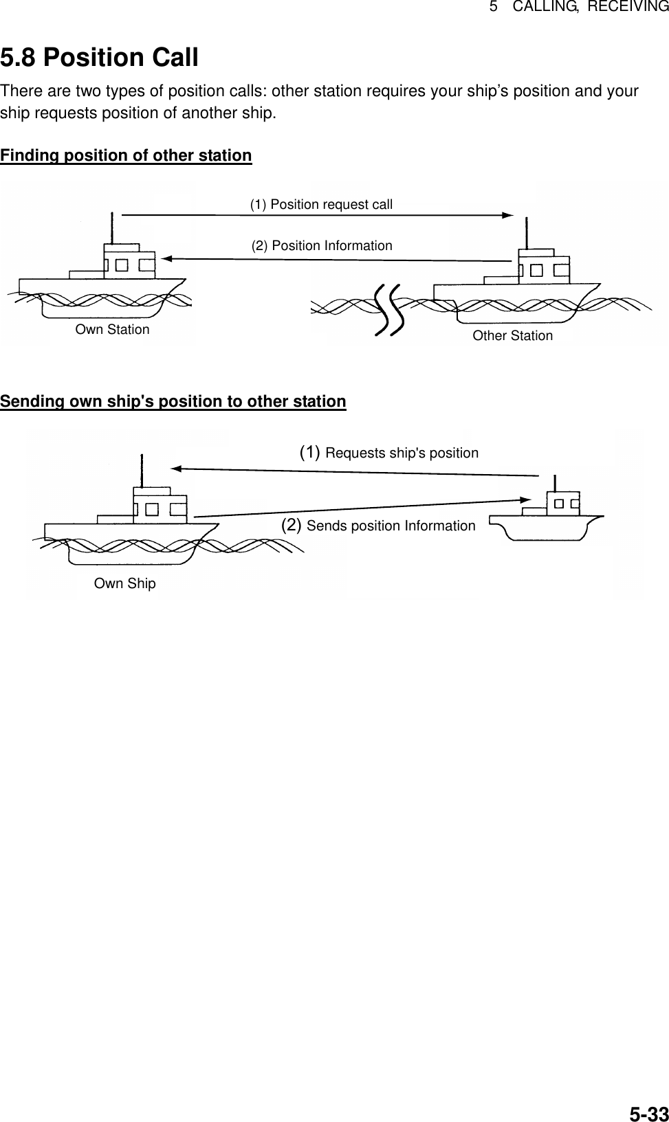
![5 CALLING, RECEIVING 5-345.8.1 Position call: requesting other ship’s position 1. Press the [2/DSC] key and then push the [ENTER] knob to open the CALL TYPE menu. ** Compose message ** STATION IDPRIORITYCOM. TYPECOM. FREQDSC FREQ: All ships: Safety : Telephone : 2187.5 kHzCALL TYPE PSTN CALLTEST CALLALL SHIPSGROUP CALLAREA CALLPOSITION INDIVIDUAL POLLINGNEUTRALMEDICALRELAY ALLRELAY SELDISTRESSRotate [ENTER]knob to scroll.GO 2. Rotate the [ENTER] knob to choose POSITION and then push the [ENTER] knob. 3. Push the [ENTER] knob to open the STATION ID menu. CALL TYPE: PRIORITY DSC FREQ POSITION REQUEST : ROUTINE:2M-INTL GO TO ALL VIEW000000000STATION ID** Compose message ** 4. Key in ID of station (nine digits) which you want to know its position and then push the [ENTER] knob. 5. Push the [ENTER] knob to open the PRIORITY menu. CALL TYPESTATION ID DSC FREQ : Position request : 987654321 : Routine :12M-INTL GO TO ALL VIEWBUSINESSSAFETY URGENCYROUTINEPRIORITY** Compose message ** 6. Rotate the [ENTER] knob to choose priority desired (usually ROUTINE) and then push the [ENTER] knob. 7. Push the [ENTER] knob to open the DSC FREQ menu. CALL TYPE : POSITION REQUESTSTATION ID : 987654321 PRIORITY : ROUTINE GO TO ALL VIEWDSC FREQ : 2M-INTL6 MHZ8 MHZ12 MHZ4 MHZ2 MHZ16 MHZ18 MHZ22 MHZ25 MHZOTHERRotate [ENTER]knob to scroll.OTHER: Special, private channels.** Compose message ** 8. Rotate the [ENTER] knob to choose appropriate DSC band and then push the [ENTER] knob. Rotate the [ENTER] knob to choose DSC frequency desired and then push the [ENTER] knob.](https://usermanual.wiki/Furuno-USA/9ZWFS2570/User-Guide-282811-Page-102.png)
![5 CALLING, RECEIVING 5-359. The display now looks something like the illustration below. CALL TYPE: POSITION REQUESTSTATION ID : 123456789PRIORITY : ROUTINE DSC FREQ : 2M-INTL GO TO ALL VIEW** Compose message ** 10. Press the [CALL] key to send the call (transmission time: about seven seconds). The following display appears. Position requestcall in progress!TIME TO GO: 7SDSC FREQ : 2177.0 KHZTO SHIP : 123456789 ROUTINE 11. After the call has been sent, the following display appears. Waiting for posacknowledgment.TIME TO GO: 4M30SDSC FREQ : 2177.0 KHZFROM SHIP : 123456789 ROUTINE 12. One of the following messages appears. (“No response! Try calling again?” appears after the time has counted down to zero, meaning there was no response from the party called.) No response!Try calling again?DSC FREQ : 2177.0 KHZ FROM SHIP : 123456789 ROUTINEPos acknowledgecall received.FROM SHIP : 123456789ROUTINE POS : 12˚34N 123˚45E AT 12:34Position acknowledge call received No response STOP ALARM CALL AGAIN](https://usermanual.wiki/Furuno-USA/9ZWFS2570/User-Guide-282811-Page-103.png)
![5 CALLING, RECEIVING 5-3613. Do one of the following depending on the message displayed at step 12. Acknowledge call received The audio alarm sounds; press the [CANCEL] key to silence the alarm. The display looks as below. You can now confirm position of other ship. POSITION ACKNOWLEDGE FROM SHIP : 123456789ROUTINE POS : 12˚34N 123˚45E AT 12:34 * Received message *GO TO ALL VIEWMAR-23-2002-23:59 ECC: OK No response! Try calling again? Re-send call: Push the [ENTER] knob followed by the [CALL] key. Cancel call: Press the [CANCEL] key. 5.8.2 Position call: other ship requests your position You may turn automatic acknowledge of position request on or off with POSITION CALL in the AUTO ACK menu. For further details, see page 8-3. Automatic reply 1. When another ship requests your position and the status of the [5/ ACK/SQ] key is AUTO ACK and the setting of POSITION CALL on the Auto ack menu is ON, the FS-1570/2570 transmits own position data (transmission time: approx. 7 sec.), showing the display below. Position auto acknowledgecall in progress!TIME TO GO : 7SDSC FREQ : 2177.0 KHZTO SHIP : 123456789 ROUTINEPOS: 35°30N 135°30E AT 23:54 2. After the call is sent the audio alarm sounds and the display below appears. Position auto acknowledge call transmitted.TO SHIP: 123456789ROUTINEPOS: 35°30N 135°30E AT 23:54STOP ALARM](https://usermanual.wiki/Furuno-USA/9ZWFS2570/User-Guide-282811-Page-104.png)
![5 CALLING, RECEIVING 5-373. Press the [CANCEL] key to silence the alarm, and the display changes as below. MAR-23-2002-23:59:09 POSITION ACKNOWLEDGE TO SHIP : 987654321 ROUTINE POS : 35°00N 135°00E AT 23:59 ** Xmitted message ** GO TO ALL VIEW 4. Press the [CANCEL] key to return to the DSC standby screen. Manual reply 1. When a position request call is received and the status of the [5/ ACK/SQ] key is MANUAL ACK, the audio alarm sounds and the display changes as below. Position requestcall received.FROM SHIP: 123456789 ROUTINESTOP ALARM 2. Press the [CANCEL] key to silence the alarm. The display changes as below. ECC: OKPOSITION REQUEST FROM SHIP : 123456789ROUTINE * Received message * ANSWER ALL VIEWMAR-23-2002-23:00:01 3. To send your ship’s position, rotate the [ENTER] knob to choose ANSWER and then push the [ENTER] knob. Your display should now look something like the one below. CALL TYPE: POSITION ACKNOWLEDGEMENT POSITION: 35 00N 135 00E AT 23:01 DSC FREQ : 2M-INTLGO TO ALL VIEW** Compose message **](https://usermanual.wiki/Furuno-USA/9ZWFS2570/User-Guide-282811-Page-105.png)
![5 CALLING, RECEIVING 5-384. Confirm the position shown and then press the [CALL] to send the position data call (transmission time: approx. 7 sec.). The display changes as below. Pos acknowledgecall in progress!TIME TO GO: 7SDSC FREQ : 2177.0 KHZTO SHIP : 123456789POS: 35˚00N 135˚00E AT 23:01ROUTINE 5. The DSC standby screen automatically appears after the call is sent. 5.9 PSTN Call The PSTN call allows the making and receiving of telephone calls over public switched telephone networks. To use the PSTN call feature, use a handset which has a HOOK ON/OFF function. The standard supply handset has this feature. 5.9.1 Sending a PSTN call, receiving acknowledge back (ACK BQ) 1. Press the [2/DSC] key and then push the [ENTER] knob to open the CALL TYPE menu. ** Compose message ** STATION IDPRIORITYCOM. TYPECOM. FREQDSC FREQ: All ships: Safety : Telephone : 2187.5 kHzCALL TYPE PSTN CALLTEST CALLALL SHIPSGROUP CALLAREA CALLPOSITION INDIVIDUAL POLLINGNEUTRALMEDICALRELAY ALLRELAY SELDISTRESSRotate [ENTER]knob to scroll.GO 2. Rotate the [ENTER] knob to choose PSTN CALL and then push the [ENTER] knob. 3. Push the [ENTER] knob to open the COAST ID menu. GO TO ALL VIEWCALL TYPE:TEL NO. : DSC FREQ PSTN CALL :12M-INTL 00000000COAST ID** Compose message ** 4. Key in ID of coast station (seven digits) with the numeric keys and then push the [ENTER] knob.](https://usermanual.wiki/Furuno-USA/9ZWFS2570/User-Guide-282811-Page-106.png)
![5 CALLING, RECEIVING 5-395. Push the [ENTER] knob to open the TEL NO. menu. GO TO ALL VIEWCALL TYPE: COAST ID DSC FREQ PSTN CALL : 001234567 :12M-INTL ----------------TEL NO.** Compose message ** 6. Enter telephone no. (up to 16 digits) with the numeric keys and then push the [ENTER] knob. 7. Push the [ENTER] knob to open the DSC FREQ menu. GO TO ALL VIEWCALL TYPE COAST ID : PSTN CALL : 123456789 TEL NO. : 123456789012345DSC FREQ :12M-INTL 6 MHz8 MHz12 MHz4 MHz2 MHz16 MHz18 MHz22 MHz25 MHzOTHEROTHER: Special, private channel** Compose message **Rotate [ENTER] knobto scroll. 8. Rotate the [ENTER] knob to choose DSC band desired and then push the [ENTER] knob to open the DSC FREQ menu. Rotate the [ENTER] knob to choose DSC frequency desired and then push the [ENTER] knob. The display changes as below. DSC FREQ : 12M-INTL GO TO ALL VIEWCALL TYPE : PSTN CALLCOAST ID : 001234567 TEL NO. : 1234567890123456** Compose message ** 9. Press the [CALL] key to send the PSTN call (transmission time: about seven seconds). The display shows the following message. PSTN requestcall in progress!TIME TO GO: 7STO COAST : 001234567 TEL NO. : 1234567890123456DSC FREQ : 12577.5 KHZ 10. One of the following three displays appears. (“No response. Try calling again.” Appears after timer counts down to zero and it means there was no response from the coast station.)](https://usermanual.wiki/Furuno-USA/9ZWFS2570/User-Guide-282811-Page-107.png)
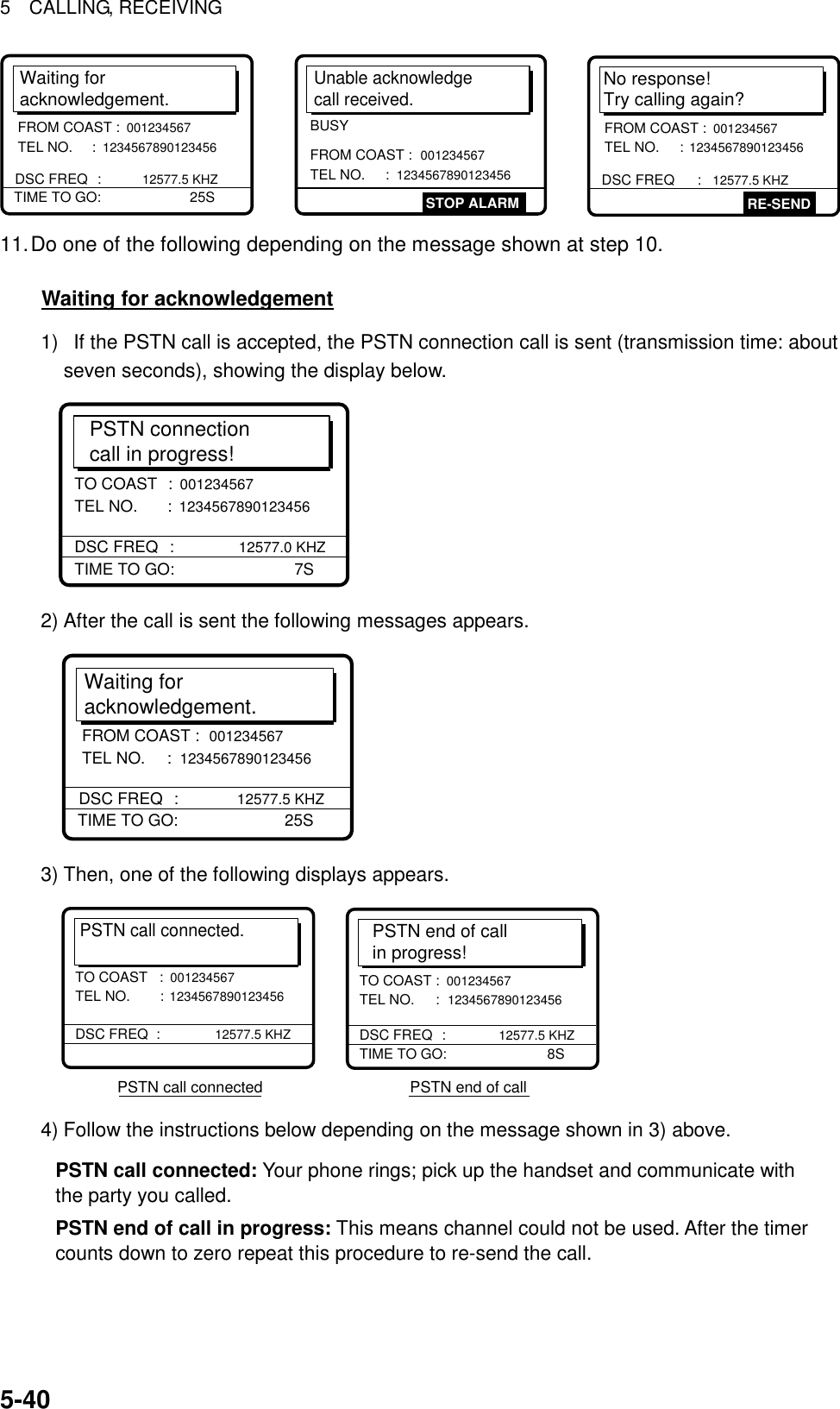
![5 CALLING, RECEIVING 5-41Unable acknowledge call received 1) The audio alarm sounds; press the [CANCEL] key or [ENTER] knob to silence the alarm. The display shown below appears. * Received message *MAR-23-2002-23:01 ECC: OKUNABLE ACKNOWLEDGE FROM COAST : 001234567 TEL NO. : 1234567890123456BUSY GO TO ALL VIEW 2) Press the [CANCEL] key to return to the DSC standby screen. Try the call again later. No response! Try calling again? Re-send call: Push the [ENTER] knob followed by the [CALL] key. Cancel call: Press the [CANCEL] key to return to the DSC standby screen.](https://usermanual.wiki/Furuno-USA/9ZWFS2570/User-Guide-282811-Page-109.png)
![5 CALLING, RECEIVING 5-425.9.2 Receiving a PSTN call, sending acknowledge back (ACK BQ) 1. The following display appears when a PSTN call is received when automatic acknowledge is turned on. Able acknowledgecall in progress!TIME TO GO: 8STO COAST : 001234567 TEL NO. : 1234567890123456 DSC FREQ : 4208.0 KHZ 2. The timer counts down to zero and then the following display appears. Pick up the handsetor press CALL key.TIME TO GO: 60SFROM COAST : 001234567 TEL NO. : 1234567890123456 DSC FREQ : 4208.0 KHZ 3. Pick up the handset or press the [CALL] key within one minute. PSTN connectioncall in progress!TIME TO GO: 7STO COAST : 001234567 TEL NO. : 1234567890123456 DSC FREQ : 4208.0 KHZ 4. When the timer counts down to zero the following message appears. Waiting foracknowledgement.TIME TO GO: 25SDSC FREQ : 4208.0 KHZFROM COAST : 001234567 TEL NO. : 1234567890123456](https://usermanual.wiki/Furuno-USA/9ZWFS2570/User-Guide-282811-Page-110.png)
![5 CALLING, RECEIVING 5-435. Shortly thereafter, one of the following messages appears. PSTN call connected.DSC FREQ : 4208.0KHZTO COAST :001234567 TEL NO. : 1234567890123456 PSTN call connected PSTN connection call in progress PSTN end of callPSTN connectioncall in progress!TIME TO GO: 25SDSC FREQ : 4208.0KHZFROM COAST : 001234567 TEL NO. : 1234567890123456PSTN end of callin progress!TIME TO GO: 7STO COAST : 001234567 TEL NO. : 1234567890123456 DSC FREQ : 4208.0KHZ 6. Do one of the following depending on the message shown at step 5. PSTN call connected: Your phone rings; communicate with party. PSTN connection call in progress!: If the channel assigned is appropriate, the message “Waiting for acknowledgment.” appears. (If the channel cannot be used the message “PSTN end of call in progress!” appears. In this case, start this procedure again.) PSTN end of call in progress!: The channel could not be used. Press the [CANCEL] key to return to the DSC standby screen. 5.9.3 PSTN call disconnection, receiving charge information (ship disconnects line) 1. After hanging up the handset or pressing the [CANCEL] key to complete your call, the display shows the following message. PSTN end of call in progress!TIME TO GO: 8STO COAST : 001234567 TEL NO. : 1234567890123456 DSC FREQ : 12577.5 KHZ 2. After the call is sent, the following messages appears. Waiting for charge information.TIME TO GO: 20SFROM COAST : 001234567 TEL NO. : 1234567890123456 DSC FREQ : 12577.5 KHZ 3. When the timer counts down to zero one of the following displays appear. Charge information call received.CHARGE TIME : 00H 12M 34S FROM COAST : 001234567 TEL NO. : 1234567890123456STOP ALARMNo response!charge information.FROM COAST : 001234567 TEL NO. : 1234567890123456](https://usermanual.wiki/Furuno-USA/9ZWFS2570/User-Guide-282811-Page-111.png)
![5 CALLING, RECEIVING 5-444. For “No response! charge information.”, the equipment reverts to step 2 in this procedure to await charge information. For “Charge information call received.”, the audio alarm sounds; press the [CANCEL] key or [ENTER] knob to silence the audio alarm. The display shown below appears. ECC: OKCHARGE INFORMATION CHARGE TIME : 00H 12M 34S FROM COAST : 001234567 TEL NO. : 1234567890123456 * Received message * GO TO ALL VIEWMAR-23-2002-23:59 5.9.4 PSTN call disconnection, receiving charge information (coast station disconnects line) 1. The PSTN line is disconnected by the coast station when it finds no evidence of communications or the land subscriber hangs up. The coast station then sends charge information as below. CHARGE INFORMATION CHARGE TIME : 00H 12M 34S FROM COAST : 001234567 TEL NO. : 1234567890123456* Received message * GO TO ALL VIEWMAR-23-2002-23:59 ECC: OK 2. For no charge information the display looks as below. CHARGE INFORMATION CHARGE TIME : NO INFO FROM COAST : 001234567 TEL NO. 1234567890123456* Received message * GO TO ALL VIEWMAR-23-2002-23:59 ECC: OK](https://usermanual.wiki/Furuno-USA/9ZWFS2570/User-Guide-282811-Page-112.png)
![5 CALLING, RECEIVING 5-455.10 Log File Three log files are provided for storage of calls: received ordinary log, received distress log and transmitted log. Each log file stores 50 calls, on a first-in, first-out basis. This means that the latest call is saved as log no.1 and the log no. of all previous calls in that log increments by one. When the storage capacity is exceeded, the oldest call is deleted to make room for the latest. An asterisk (*) marks unread or unacknowledged calls. Received distress calls are automatically deleted 48 hours after being read. 5.10.1 Opening a log file The procedure for opening a log is common to all logs. The example below shows how to open the received distress log. 1. At the DSC standby screen, press the [LOG/TUNE] key to open the Log file menu. WATCH KEEPING2187.5 4207.5 6312.016804.5 12577.0DISTRESSROUTINE2177.0 4219.5 6331.016903.0 12657.08414.58436.5AUTO ACK 35°00.000N MANUAL135°00.000E 23:59 Select log fileRECEIVED ORDINARY RECEIVED DISTRESS TRANSMITTED 2. Rotate the [ENTER] knob to choose desired log and push the [ENTER] knob. For example, choose the RECEIVED DISTRESS log and then push the [ENTER] knob. Rotate the [ENTER] knob to scroll the log. Asterisk indicates unread message. Scroll withthe [ENTER]knob.* Rcvd distress log *02.APR-10-19:56 DISTRESS03.APR-10-13:45*DISTRESS04.APR-10-11:52 DISTRESS05.APR-10-11:43 DISTRESS06.MAR-22-21:18 DISTRESS01.APR-10-19:58 DISTRESS* Rcvd distress log *46.FEB-28-19:56*DISTRESS47.FEB-28-19:48*DISTRESS48.FEB-28-19:44*DISTRESS49.FEB-21-12:36*DISTRESS45.MAR-01-23:45*DISTRESS50.FEB-17-12:34*DISTRESS OLD OLD NEW 3. To view the contents of a file, do the following: a) Rotate the [ENTER] knob to choose the file desired and then push the [ENTER] knob. DELETE DETAIL b) DETAIL is selected; push the [ENTER] knob. * Received message *FEB-17-2002-12:34:56 ECC: OKDISTRESS CALL ANSWERSHIP IN DIST : 987654321NATURE : UNDESIGNATEDPOS : 12˚34N 123˚45E AT 12:34 TELEPHONE 2182.0 KHZ ALL VIEW](https://usermanual.wiki/Furuno-USA/9ZWFS2570/User-Guide-282811-Page-113.png)
![5 CALLING, RECEIVING 5-464. To scroll the log up and down, use the [FILE/CURSOR] and [#/SETUP] keys, respectively. Use [FILE/CURSOR] key to scroll forward; the [#/SETUP] to scroll backward. 5. To print all files in the log selected, press the [8/PRINT] key. 6. To reply to an unanswered call, rotate the [ENTER] knob to choose ANSWER, press the [ENTER] knob, and then press the [CALL] key. 7. To return to the log selected, press the [CANCEL] key. Deleting files 1. Do steps 1-2 and 3a) in the previous procedure to choose the file you wish to delete. 2. Rotate the [ENTER] knob to choose DELETE and then press the [ENTER] knob. The log files are renumbered to reflect the deletion. Unread files cannot be deleted. 5.11 Erasing Message Files The Erase file menu allows you to erase the entire contents of the received ordinary log, received distress log, transmitted log and send message log. 1. Press the [#/SETUP] key. 2. Rotate the [ENTER] knob to choose ERASE and then push the [ENTER] knob to display the Erase file menu. 3. Rotate the [ENTER] knob to choose the item to erase and then push the [ENTER] knob. 4. Rotate the [ENTER] knob to choose YES and then push the [ENTER] knob. **** Erase file ****RCVD ORDINARY LOG?RCVD DISTRESS LOG?TRANSMIT?SEND MESSAGE?To cancel, press [ENTER] knob or [CANCEL] key.Item selected for erasureappears in 2nd row. To erase, select YES withthe [ENTER] knob and thenpush the [ENTER] knob.ERASEXXXXXXXXXXXXXXXXX.ARE YOU SURE?YES NO[ENTER]knob](https://usermanual.wiki/Furuno-USA/9ZWFS2570/User-Guide-282811-Page-114.png)
![6-1 6. PREPARING TX CALLS In Chapter 5 you learned how to prepare and send various types of DSC calls. In this chapter you will learn how to prepare and store individual, PSTN, group, area and test calls for future transmission. 150 calls can be stored. . 6.1 Preparing Individual Calls 1. At the DSC standby screen, press the [#/SETUP] key to open the Setup menu. **** Setup menu ****SCAN FREQ VOLUME TEST SYSTEMALARM AUTO ACK ERASEMESSAGE POSITION PRINT OUT 2. Rotate the [ENTER] knob to choose MESSAGE and then push the [ENTER] knob. 3. Push the [ENTER] knob to open the CALL TYPE menu. * Message file entry CALL TYPE STATION ID COM. TYPE COM. FREQ DSC FREQ: INDIVIDUAL : --------- : TELEPHONE : NO INFO : 2M-INTLINDIVIDUALPSTN CALLGROUP CALLAREA CALLTEST CALL 4. Rotate the [ENTER] knob to choose INDIVIDUAL and then push the [ENTER] knob. 5. Push the [ENTER] knob to open the STATION ID entry window. * Message file entry CALL TYPE STATION ID COM. TYPE COM. FREQ DSC FREQ: INDIVIDUAL : --------- : TELEPHONE : NO INFO : 2M-INTL000000000 6. Key in ID of coast station or ship station with the numeric keys and then push the [ENTER] knob.](https://usermanual.wiki/Furuno-USA/9ZWFS2570/User-Guide-282811-Page-115.png)
![6 PREPARING TX CALLS 6-2 7. Push the [ENTER] knob to open the COM. TYPE window. * Message file entry CALL TYPE STATION ID COM. TYPE COM. FREQ DSC FREQ: INDIVIDUAL : 001234567 : TELEPHONE : NO INFO : 2M-INTL: GROUP CALL: 012345678 : Routine NBDP-ARQNBDP-FECTELEPHONE 8. Rotate the [ENTER] knob to choose communication type desired and then push the [ENTER] knob. 9. Push the [ENTER] knob to open the COM. FREQ window. * Message file entry CALL TYPE: STATION ID COM. TYPE COM. FREQ DSC FREQ INDIVIDUAL : 123456789 : TELEPHONE : NO INFO : 2M-INTLNO INFOFREQUENCYCHANNELPOSITION** POSITION appears when coast station ID is entered in the field STATION ID. 10. Rotate the [ENTER] knob to choose appropriate item and then push the [ENTER] knob. Call to coast station: NO INFO or POSITION. Call to ship station: FREQUENCY or CHANNEL. Enter appropriate frequency or channel, referring to page 5-6. 11. Push the [ENTER] knob to open the DSC FREQ menu. * Message file entry CALL TYPE STATION ID COM. TYPE COM. FREQ DSC FREQ: INDIVIDUAL : 001234567 : TELEPHONE : NO INFO : 2M-INL6 MHZ8 MHZ12 MHZ4 MHZ2 MHZ16 MHZ18 MHZ22 MHZ25 MHZOTHER OTHER: Special, private channels.Rotate [ENTER] knobto scroll. 12. Rotate the [ENTER] knob to choose appropriate DSC band and then push the [ENTER] knob. 13. Rotate the [ENTER] knob to choose appropriate DSC frequency and then push the [ENTER] knob. 14. Enter file name and number as shown on the next page.](https://usermanual.wiki/Furuno-USA/9ZWFS2570/User-Guide-282811-Page-116.png)
![6 PREPARING TX CALLS 6-3* Message file entry FILE NAME: ----------------FILE NUMBER : ---FILE ENTRYHow to Enter File Name and Number1. Push the [ENTER] knob to open the file name entry window.2. Use the numeric keys and [ENTER] knob to enter file name (max. 16 characters). For example, enter FURUNO as the file name. Push the [ENTER] knob after entering.3. Push the [ENTER] knob to open the file number entry window. Key in file number in three digits with the numeric keys and then push the [ENTER] knob. For example, press [0], [0], [1], [ENTER] knob to enter file number 001.FILE ENTRY* Message file entry 4. Push the [ENTER] knob. The display shows the name and file number entered. 5. Push the [ENTER] knob to continue.How to enter "FURUNO" as file nameKey and available character, symbol[1] : 1→(blank)→1[2ABC] : 2→A→B→C→2[3DEF] : 3→D→E→F→3[4GHI] : 4→G→H→I→4[5JKL] : 5→J→K→L→5[6MNO] : 6→M→N→O→6[7PQRS] : 7→P→Q→R→S→7[8TUV] : 8→T→U→V→8[9WXYZ]: 9→W→X→Y→Z→9[0] : 0→_→ − →01. Rotate [ENTER] knob to select location.2. Press appropriate key.1. Press the [3] key to display F.2. Rotate [ENTER] knob to shift cursor.3. Press the [8] key to select U.4. Rotate [ENTER] knob to shift cursor.5. Press the [7] key to select R.6. Rotate [ENTER] knob to shift cursor.7. Press the [8] key to select U.8. Rotate [ENTER] knob to shift cursor.9. Press the [6] key to select N.10. Rotate [ENTER] knob to shift cursor.11. Press the [6] key to select O.12. Push the [ENTER] knob.FILE ENTRY: FURUNO* Message file entry FILE NAMEFILE NUMBER : ---001Note: The available file number is 001-799 and 900-999. If the file name or number exists the message"Duplicate name (number) ! Overwrite OK?" appears.Push the [ENTER] knob to write over the name, orpress the [CANCEL] key to escape.FURUNO No.001 file enteredGo to next file?YES: [ENT] keyNO: [CANCEL] key](https://usermanual.wiki/Furuno-USA/9ZWFS2570/User-Guide-282811-Page-117.png)
![6 PREPARING TX CALLS 6-46.2 Preparing Group Calls 1. At the DSC standby screen, press the [#/SETUP] key to open the Setup menu. **** Setup menu ****SCAN FREQ VOLUME TEST SYSTEMALARM AUTO ACK ERASE MESSAGE POSITION PRINT OUT 2. Rotate the [ENTER] knob to choose MESSAGE and then push the [ENTER] knob. 3. Push the [ENTER] knob to open the CALL TYPE menu. * Message file entry CALL TYPE STATION ID COM. TYPE COM. FREQ DSC FREQ: INDIVIDUAL : --------- : TELEPHONE : NO INFO : 2M-INTLINDIVIDUALPSTN CALLGROUP CALLAREA CALLTEST CALL 4. Rotate the [ENTER] knob choose GROUP CALL and then push the [ENTER] knob. 5. Push the [ENTER] knob to open the GROUP ID entry window. * Message file entry CALL TYPE: GROUP ID COM. TYPE COM. FREQ DSC FREQ GROUP CALL: 0 -------- : TELEPHONE : NO INFO : 2M-INTL 000000000 6. Key in ID of group with the numeric keys and then push the [ENTER] knob. 7. Push the [ENTER] knob to open the COM. TYPE menu. * Message file entry CALL TYPE: GROUP ID COM. TYPE COM. FREQ DSC FREQ GROUP CALL: 012345678 : TELEPHONE : NO INFO : 2M-INTL NBDP-FECTELEPHONE 8. Rotate the [ENTER] knob to choose appropriate communications type and then push the [ENTER] knob. 9. Push the [ENTER] knob to open the COM. FREQ menu.](https://usermanual.wiki/Furuno-USA/9ZWFS2570/User-Guide-282811-Page-118.png)
![6 PREPARING TX CALLS 6-5 * Message file entry CALL TYPE: GROUP ID COM. TYPE COM. FREQ DSC FREQ GROUP CALL : 012345678: TELEPHONE : NO INFO : 2M-INTLNO INFOFREQUENCYCHANNEL 10.Rotate the [ENTER] knob to choose appropriate item and then push the [ENTER] knob. Enter frequency or channel. (See page 5-6 for details for how to enter frequency and channel.) 11. Push the [ENTER] knob to open the DSC FREQ menu. Message file entry CALL TYPE GROUP ID COM. TYPE COM. FREQ DSC FREQ: INDIVIDUAL : 001234567 : TELEPHONE : NO INFO : 2M-INTL6 MHZ8 MHZ12 MHZ4 MHZ2 MHZ16 MHZ18 MHZ22 MHZ25 MHZOTHEROTHER: Special, private channels.Rotate [ENTER] knobto scroll. 12. Rotate the [ENTER] knob to choose appropriate DSC band and then push the [ENTER] knob. Choose appropriate DSC frequency and then push the [ENTER] knob. 13. Follow “How to Enter File Name and Number” on page 6-3 to enter file name and number. 6.3 Preparing Geographical Area Calls 1. At the DSC standby screen, press the [#/SETUP] key to open the Setup menu. 2. Rotate the [ENTER] knob to choose MESSAGE and then push the [ENTER] knob. 3. Push the [ENTER] knob to open the CALL TYPE menu. * Message file entry CALL TYPE STATION ID COM. TYPE COM. FREQ DSC FREQ: INDIVIDUAL : --------- : TELEPHONE : NO INFO : 2M-INTLINDIVIDUALPSTN CALLGROUP CALLAREA CALLTEST CALL 4. Rotate the [ENTER] knob to choose AREA CALL and then push the [ENTER] knob. 5. Push the [ENTER] knob to open the AREA entry window. * Message file entry CALL TYPE: AREA COM. TYPE COM. FREQ DSC FREQ AREA CALL: --˚N ---˚E ↓ --˚ → -- ˚: TELEPHONE : NO INFO : 2M-INTL00°N 000°E ↓ 00° → 00°](https://usermanual.wiki/Furuno-USA/9ZWFS2570/User-Guide-282811-Page-119.png)
![6 PREPARING TX CALLS 6-6 6. Using the numeric keys, enter latitude and longitude of reference point and southerly degrees and easterly degrees of area. To change coordinate, choose it and press the [1] key for North or East; [2] key for South or West. After entering data, push the [ENTER] knob. 7. Push the [ENTER] knob to open the COM. TYPE menu. * Message file entry CALL TYPE: AREA: 34°00N 135°00W ↓10° →10° COM. TYPE COM. FREQ DSC FREQ: TELEPHONE: NO INFO : 2M-INTL : GROUP CALLNBDP-FECTELEPHONE 8. Rotate the [ENTER] knob to choose appropriate communications type and then push the [ENTER] knob. 9. Push the [ENTER] knob to open the COM. FREQ menu. * Message file entry CALL TYPE: AREA COM. TYPE COM. FREQ DSC FREQ AREA CALL: 34°00N 135°00E ↓ 10° → 10°: TELEPHONE : NO INFO : 2M-INTLNO INFOFREQUENCYCHANNEL 10. Rotate the [ENTER] knob to choose appropriate item and then push the [ENTER] knob. Enter channel or frequency. (See page 5-6 for how to enter channel and frequency.) 11. Push the [ENTER] knob to open the DSC FREQ menu. * Message file entry *CALL TYPE AREA COM. TYPE COM. FREQ DSC FREQ: AREA CALL: 34°00N 123°E ↓12°→ 10°: TELEPHONE : NO INFO : 2M-INTL16 MHZ18 MHZ22 MHZ25 MHZOTHEROTHER: Private channels.6 MHZ8 MHZ12 MHZ4 MHZ2 MHZRotate [ENTER] knobto scroll. 12. Rotate the [ENTER] knob to choose appropriate DSC band and then push the [ENTER] knob. Choose appropriate DSC frequency and then push the [ENTER] knob. 13. Follow “How to Enter File Name and Number” on page 6-3 to enter file name and number.](https://usermanual.wiki/Furuno-USA/9ZWFS2570/User-Guide-282811-Page-120.png)
![6 PREPARING TX CALLS 6-7 6.4 Preparing PSTN Calls 1. At the DSC standby screen, press the [#/SETUP] key to open the Setup menu. 2. Rotate the [ENTER] knob to choose MESSAGE and then push the [ENTER] knob. 3. Push the [ENTER] knob to open the CALL TYPE menu. * Message file entry CALL TYPE STATION ID COM. TYPE COM. FREQ DSC FREQ: INDIVIDUAL : --------- : TELEPHONE : NO INFO : 2M-INTLINDIVIDUALPSTN CALLGROUP CALLAREA CALLTEST CALL 4. Rotate the [ENTER] knob to choose PSTN CALL and then push the [ENTER] knob. 5. Push the [ENTER] knob to open the COAST ID entry window. * Message file entry CALL TYPE COAST ID TEL NO. : DSC FREQ: PSTN CALL: 0------- ----------------: 2M-INTL000000000 6. Key in ID of coast station (seven digits) with the numeric keys then push the [ENTER] knob. 7. Push the [ENTER] knob to open the TEL. NO. entry window. * Message file entry CALL TYPE: COAST ID TEL NO. : DSC FREQ PSTN CALL: 001234567 : ----------------: 2M-INTL- 8. Key in telephone no. (up to 16 digits) with the numeric keys and then push the [ENTER] knob. 9. Push the [ENTER] knob to open the DSC FREQ menu. * Message file entry CALL TYPE: COAST ID TEL NO. : PSTN CALL 001234567 1234567890---DSC FREQ : 2M-INTL TL16 MHZ18 MHZ22 MHZ25 MHZOTHEROTHER: Special, private channels.6 MHZ8 MHZ12 MHZ4 MHZ2 MHZRotate the [ENTER] knobto scroll.](https://usermanual.wiki/Furuno-USA/9ZWFS2570/User-Guide-282811-Page-121.png)
![6 PREPARING TX CALLS 6-810. Rotate the [ENTER] knob to choose appropriate DSC band and then push the [ENTER] knob. Choose appropriate DSC frequency and then push the [ENTER] knob. 11. Follow “How to Enter File Name and Number” on page 6-3 to enter file name and number. 6.5 Preparing Test Calls 1. At the DSC standby screen, press the [#/SETUP] key to open the Setup menu. 2. Rotate the [ENTER] knob to choose MESSAGE and then push the [ENTER] knob. 3. Push the [ENTER] knob to open the CALL TYPE menu. * Message file entry CALL TYPE STATION ID COM. TYPE COM. FREQ DSC FREQ: INDIVIDUAL : --------- : TELEPHONE : NO INFO : 2M-INTLINDIVIDUALPSTN CALLGROUP CALLAREA CALLTEST CALL 4. Rotate the [ENTER] knob to choose TEST CALL and then push the [ENTER] knob. 5. Push the [ENTER] knob to open the COAST ID entry window. * Message file entry CALL TYPE DSC FREQ : 2187.5 KHZ: TEST COAST ID 000000000 6. Enter coast ID where to send the test message and then push the [ENTER] knob. 7. Push the [ENTER] knob to open the DSC FREQ menu. DSC FREQ KHZ* Message file entry CALL TYPECOAST ID: Test : 001234567 : Safety : kHz VIEW 4207.5 6312.0 8414.5 12577.016804.52187.5 8. Rotate the [ENTER] knob to choose appropriate DSC frequency and then push the [ENTER] knob. 9. Follow “How to Enter File Name and Number” on page 6-3 to enter file name and number.](https://usermanual.wiki/Furuno-USA/9ZWFS2570/User-Guide-282811-Page-122.png)
![6 PREPARING TX CALLS 6-96.6 Sending Prepared Calls Sending without modification 1. Press the [FILE/CURSOR] key at the DSC standby screen to show the send message file list. Below is an example of the send message file list. * Send message file * 001 - FURUNO JAPAN002 - FURUNO USA003 - FURUNO UK004 - FURUNO DENMARK005 - FURUNO NORWAY006 - FURUNO SPAIN DOWN 2. Rotate the [ENTER] knob to choose a file. 3. Press the [CALL] key to send the message. Editing before sending 1. Press the [FILE/CURSOR] key at the DSC standby screen to show the send message file list. 2. Rotate the [ENTER] knob to choose file desired and then push the [ENTER] knob. DELETE DETAIL 3. DETAIL is selected; push the [ENTER] knob. The message contents are shown on the “Compose message” screen. 4. Edit the message as necessary. 5. Press the [CALL] key to send the message.](https://usermanual.wiki/Furuno-USA/9ZWFS2570/User-Guide-282811-Page-123.png)
![6 PREPARING TX CALLS 6-106.7 Deleting Send Message Files 1. Press the [FILE/CURSOR] key at the DSC standby screen to show the send message file list. 2. Rotate the [ENTER] knob to choose file desired and then push the [ENTER] knob. DELETE DETAIL 3. Rotate the [ENTER] knob to choose DELETE and then push the [ENTER] knob. Note: You may collectively erase all send message files. For details see paragraph 5.11. 6.8 Printing List of Send Message Files You can print a list of send message files as follows: 1. Press the [FILE/CURSOR] key to open the Send message file list. 2. Press the [8/PRINT] key. 3. YES is selected; push the [ENTER] knob to print. ********** Send message file **********001. FURUNO JAPAN INDIVIDUAL CALL002. FURUNO USA INDIVIDUAL CALL003. FURUNO UK PSTN CALL004. FURUNO DENMARK GROUP CALL005. FURUNO NORWAY INDIVIDUAL CALL006. FURUNO SPAIN ALL SHIPS CALL007. FURUNO FRANCE INDIVIDUAL CALLNote: Message not framed in actual printout.](https://usermanual.wiki/Furuno-USA/9ZWFS2570/User-Guide-282811-Page-124.png)
![7-17 DSC/WATCH RECEIVER SETUP 7.1 Setting Alarms The Alarm menu enables/disables internal and external alarms. Note that the Distress/Urgency alarm cannot be disabled. Press the [#/SETUP] key at the DSC standby screen, choose ALARM and then push the [ENTER] knob to display the Alarm menu. **** Alarm setup ***INTERNAL AUDIO ALARM RCVD CALL OLD POSITION POSITION OLDER EXT ALARM : DSTRS/URG: ON : ON : 4.0 HOFFOFF3.02.01.00.54.0ROUTINEALLOFFDSTRS/URG35˚00.000N 135˚00.000E 23:59WATCH KEEPING2187.5 4207.5 6312.08414.516804.5 12577.0DISTRESSROUTINE2177.0 4219.5 6331.016903.0 12657.0VOLUMEWarning:Update positionDefault: ONDefault: ONDefault: 4.0 hoursDefault: DSTRS/URGDisables/enables alarm for received Safety, Ship's Business and Routine calls.Alarm is output when position is older by the number of hours set here.Sets type of call to be output to the Incoming Indicator IC-303-DSC.DSTRS/URG: Distress or urgency call output upon receipt.ROUTINE: Routine call output upon receipt.ALL: All calls output.OFF: No output.Note: Alarm for Distress and Urgency calls cannot be disabled.22AUTO ACK8436.5Disables/enables old position alarm in manualposition entry mode, which alerts the operatorwhen position data is older by the number ofhours or minutes set in the Position Older field. Message shown when manuallyentered position is older than thetime set on the Alarm setup menu.Rotate [ENTER]knob to choose.ONON](https://usermanual.wiki/Furuno-USA/9ZWFS2570/User-Guide-282811-Page-125.png)
![7 DSC/WATCH RECEIVER SETUP 7-27.2 Auto Ack Menu The Auto Ack menu enables/disables automatic acknowledgement of individual, position and polling calls. Press the [#SETUP] key, choose AUTO ACK at the DSC standby screen and then push the [ENTER] knob to display the Auto Ack setup menu. Comply type Setting of [5/ACQ /SQ] key ABLE UNABLE AUTO ACK Can send acknowledge automatically Can send UNABLE automatically. MANUAL ACK Can send acknowledge manually Can send UNABLE manually. Default: ABLE** Auto ack setup **COMPLY TYPE : ABLEUNABLE REASON :NO REASON GIVENPOSITION CALL : OFFPOLLING CALL : ON UNABLEABLEChoose ABLE or UNABLE as automatic acknowledgement reply to Individualcalls.Note: Automatic acknowledge is automatically disabled when RX call contains error, as required by law. Further, automatic acknowledge is disabled in case of OFF HOOK.Default: NO REASONNO REASONBUSYEQUIP DISABLEDMODE NOT USABLECH NOT USABLESets reason for UNABLE.Note: This menu is the same as manual acknowledgement. EQUIPMENT DISABLED is shown in calls when EQUIP DISABLED is selected.Default: ONEffective when [5/ACK/SQ] key is set for "AUTO ACK."OFF: Disables automatic acknowledgement of position request.ON: Enables automatic acknowledgement of position request.OFFONDefault: ONEffective when [5/ACK/SQ] key is set for "AUTO ACK."OFF: Disables automatic acknowledgement of polling request.ON: Enables automatic acknowledgement of polling request.OFFONRotate [ENTER]knob to choose](https://usermanual.wiki/Furuno-USA/9ZWFS2570/User-Guide-282811-Page-126.png)
![7 DSC/WATCH RECEIVER SETUP 7-37.3 Printing Messages The Print Out menu enables/disables automatic printing of all transmitted and received calls and the results of the daily test. Press the [#/SETUP] key at the DSC standby screen, choose PRINT OUT and then push the [ENTER] knob to display the Print Out menu. Default: MANUAL* Print out setup *XMIT CALL : MANUALRCVD CALL : MANUALDAILY TEST : MANUAL AUTOMANUALSelect AUTO to automatically print transmitted calls.Default: MANUALSelect AUTO to automatically print received calls.Default: MANUALSelect AUTO to automatically print results of Daily Test.AUTOMANUALAUTOMANUAL Sample printouts Printing can be done automatically or manually. For manual printing, press the [8/PRINT] key. Note that calls having more than one page (for example, received calls) are printed out in their entirety. * Received message at JAN-08-2002-16:10:12 *FORMAT : DISTRESS CALLSELF-IDENTITY : 987654321NATURE OF DISTRESS : UNDESIGNATED DISTRESSDISTRESS COORDINATES : NO INFORMATIONDISTRESS TELECOMMAND : J3E TELEPHONEEND OF SEQUENCE : EOSERROR-CHECK : OKDSC FREQUENCY TX: 2187.5 kHz RX: 2187.5 kHzSample Received Message Printout (Distress) * Received message at JAN-08-2002-16:10:12 *FORMAT : INDIVIDUAL CALLADDRESS : 111660000CATEGORY : ROUTINESELF-IDENTITY : 9876543211st TELECOMMAND : J3E TELEPHONE2nd TELECOMMAND : NO INFORMATIONWORKING FREQUENCY : NO INFORMATIONEND OF SEQUENCE : ACK. RQERROR-CHECK : OKDSC FREQUENCY TX: 2177.0 kHz RX: 2177.0 kHzSample Received Message Printout (Individual)*Transmitted message at JAN-08-2002-16:10:12 *FORMAT : INDIVIDUAL CALLADDRESS : 987654321CATEGORY : ROUTINESELF-IDENTITY : 1116600001st TELECOMMAND : J3E TELEPHONE2nd TELECOMMAND : NO INFORMATIONWORKING FREQUENCY : NO INFORMATIONEND OF SEQUENCE : ACK. RQDSC FREQUENCY TX: 2177.0 kHz RX: 2177.0 kHzSample Transmitted Message Printout (Individual)Note: Messages are not framed in actual printouts. *************** Send message *************FORMAT : INDIVIDUAL CALLADDRESS : 111660000CATEGORY : ROUTINESELF-IDENTITY : 9876543211st TELECOMMAND : J3E TELEPHONE2nd TELECOMMAND : NO INFORMATIONWORKING FREQUENCY : NO INFORMATIONEND OF SEQUENCE : ACK. RQDSC FREQUENCY TX: 2177.0 kHz RX: 2177.0 kHzSample Send Message Printout (Individual)](https://usermanual.wiki/Furuno-USA/9ZWFS2570/User-Guide-282811-Page-127.png)
![7 DSC/WATCH RECEIVER SETUP 7-47.4 Setting Scan Frequencies The Scan freq menu determines which DSC routine and distress frequencies to scan. Follow the instructions below to select/deselect DSC routine and distress frequencies to scan. 7.4.1 Distress frequencies 1. Press the [#/SETUP] key at the DSC standby screen, choose SCAN FREQ and then push the [ENTER] knob to display the SCAN FREQ menu. DISTRESS 2M : FIXED 4M : ON 6M : ON 8M : FIXED12M : ON16M : OFF** Scan freq setup *ROUTINEF1 : 2M-INTLF2 : 4M-INTLF3 : 6M-INTLF4 : 8M-INTLF5 : 12M-INTLF6 : 16M-INTL 2. Rotate the [ENTER] knob clockwise to shift the cursor to the DISTRESS column. 3. Rotate the [ENTER] knob to choose the frequency to process and then push the [ENTER] knob. For example, choose 4 MHz. ROUTINEF1 : 2M-INTLF2 : 2M-INTLF3 : 4M-INTLF4 : 8M-INTLF5 : 12M-INTLF6 : 16M-INTLDISTRESS 2M : FIXED 4M : ON 6M : ON 8M : FIXED12M : ON16M : OFF** Scan freq setup *OFFON 4. Rotate the [ENTER] knob to choose ON or OFF as appropriate and then push the [ENTER] knob. 5. Press the [CANCEL] key twice to return to the DSC standby screen. Note: Regulations require that 2 MHz and 8 MHz and one more DSC distress frequency be watched continuously. These frequencies cannot be turned off. Maximum three bands may be turned off.](https://usermanual.wiki/Furuno-USA/9ZWFS2570/User-Guide-282811-Page-128.png)
![7 DSC/WATCH RECEIVER SETUP 7-57.4.2 Routine frequencies 1. Press the [#/SETUP] key, choose SCAN FREQ and then push the [ENTER] knob to display the Scan freq menu. DISTRESS 2M : FIXED 4M : ON 6M : ON 8M : FIXED12M : ON16M : OFF** Scan freq setup *ROUTINEF1 : 2M-INTLF2 : 4M-INTLF3 : 6M-INTLF4 : 8M-INTLF5 : 12M-INTLF6 : 16M-INTL 2. Rotate the [ENTER] knob to choose the frequency to process and then push the [ENTER] knob. For example, choose F1: 2 M-INTL. ROUTINEF1 : 2M-INTLF2 : 2M-USR3F3 : 4M-INTLF4 : 8M-INTLF5 : 16M-LCL1F6 : 25M-LCL2DISTRESS 2M : FIXED 4M : ON 6M : ON 8M : FIXED12M : ON16M : OFF** Scan freq setup *OFF2 MHZ4 MHZ6 MHZ8 MHZ 3. Push the [ENTER] knob, and the display looks something like the one below. ROUTINEF1 : 2M-INTLF2 : 2M-USR3F3 : 4M-INTLF4 : 8M-INTLF5 : 16M-LCL1F6 : 25M-LCL2DISTRESS 2M : FIXED 4M : ON 6M : ON 8M : FIXED12M : ON16M : OFF** Scan freq setup *INTL : T2189.5/R 2177.0DIST : T 2187.5/R 2187.5 4. Rotate the [ENTER] knob to choose frequency desired and then push the [ENTER] knob. INTL: International channels DIST: Distress channels LOCAL1/LOCAL2: Local channels USER CH: User channels 5. Press the [CANCEL] key twice to return to the DSC standby screen. Note: Distress frequencies can be stored on the routine frequency memory. This is convenient for backing up the watch keeping receiver.](https://usermanual.wiki/Furuno-USA/9ZWFS2570/User-Guide-282811-Page-129.png)
![7 DSC/WATCH RECEIVER SETUP 7-67.5 Adjusting Volume The Volume menu enables/disables key beep (acknowledges correct key input) and adjusts the volume of the handset, ordinary alarm and distress/urgency alarm. Press the [#/SETUP] key at the standby screen, choose VOLUME and then push the [ENTER] knob to display the Volume setup menu. Default: ON*** Volume setup ***KEY CLICK : ONHANDSET : 40ORDINARY ALARM : 30DISTRESS ALARM : 63 OFFONHANDSETVOLUME (0~63) 40Turns on/off beep generated when keyboard is operated.Note: Do not confuse keyboard beep(single beep) with ACK beep (three beeps).Sets volume of handset. ORDINARY ALARMVOLUME (0~63) 30Sets loudness of Safety, Ships Business, Routine and Old Position alarms.DISTRESS ALARMVOLUME (38~63) 63Sets loudness of Distress and Urgency alarms.Rotate [ENTER] knobto set.Rotate [ENTER] knobto set.Rotate [ENTER] knobto set.](https://usermanual.wiki/Furuno-USA/9ZWFS2570/User-Guide-282811-Page-130.png)
![8-18 NBDP SYSTEM OVERVIEW 8.1 Turning on the NBDP System Turn on the terminal unit and the printer with their respective power switches. TERPOWER SwitchMAIN UNITPOWER switchPRINTER PP-510POWERSwitchFloppy Disk DriveBrilliance, Contrast ControlOperating Lamp~`2134 67890 - =_+)*(9*87^&$#@!QWERTYUIOP[]{}\|ASDF GHJ KL:+;"'TabCaps LockZXCVBNM<> ?//.,1234560ShiftFn Ctrl Alt Alt CtrlHome End PgDnPgUpShiftEnterBackspaceEsc F1 F2 F3 F4 F5 F6 F7 F8 F9 F10NumLockPrt ScSysRqScrollLock PauseBreakInsert DeleteF11 F125%CKEYBOARDTERMINAL UNIT IB-581TERMINAL UNIT IB-583Floppy DiskDrive POWER SwitchOperating Lamp NBDP terminal unit, printer and keyboard Note: The Printer PP-510 prints messages. Refer to its operator’s manual for operating information.](https://usermanual.wiki/Furuno-USA/9ZWFS2570/User-Guide-282811-Page-131.png)
![8 NBDP SYSTEM OVERVIEW 8-28.2 Description of Equipment 8.2.1 Terminal unit The terminal unit is a visual display incorporating a floppy disk drive, which provides for storage of files on floppy disks. Two models are available, IB-581 (monochrome) and IB-583 (color). Controls for power and adjustment of display brilliance and contrast are provided on the front panel of the IB-581. To adjust the brilliance on the IB-583, press [Alt] while pressing [F6] to lower the brilliance; [F7] to raise it. (The IB-583 does not have a control for adjustment of contrast.) Eight levels of brilliance are available. When the terminal unit is turned on, the communication status display, shown below, appears. This is where all phases of telex communications begin. Station Name : Frequency (T/R) : / (kHz) Comm Mode : Comm Status : Connect Send Lock Error Sending Volume : (%) ARQ Error : 0 ARQ Time : 0(sec)1:File 2:Edit 3:Operate 4:Window 5:Station 6:System 7:WRU 8:HR 9:Over 10:Break2002-10-15 2:26:45 UTC Caps-Eng Communication status display Features of the IB-583 The IB-583 is fitted with both English and Russian interface. Choose desired interface as below: English: Turn on the IB-583 while pressing the [E] key. Russian: Turn on the IB-583 while pressing the [R] key. The IB-583 has a battery (type CR2450-F2ST2L, code no. 000-144-941) on its TERM/CPU Board (16P0209) and its life is about six years. When the voltage of the battery is low, the time will be slow. When this occurs, contact your dealer about replacement of the battery.](https://usermanual.wiki/Furuno-USA/9ZWFS2570/User-Guide-282811-Page-132.png)
![8 NBDP SYSTEM OVERVIEW 8-38.2.2 Keyboard The terminal unit is operated from the keyboard, and is almost 100% keyboard controlled. Operation is simplified by the use of menus which you access by pressing a function key, labeled F1-F10 at the top of the keyboard. The figure below shows the function menus and their corresponding function keys. ~`2134 67890 - =_+)*(9*87^&$#@!QWERTYUIOP[]{}\|ASDF GHJ KL:+;"'TabCaps LockZXCVBNM<> ?//.,1234560ShiftFn Ctrl Alt Alt CtrlHome End PgDnPgUpShiftEnterBackspaceEsc F1 F2 F3 F4 F5 F6 F7 F8 F9 F10NumLockPrt ScSysRqScrollLock PauseBreakInsert DeleteFILE EDIT OPERATE WINDOW STATION SYSTEM WRU HR OVER BREAKF11 F125%C Keyboard Note: C (Euro mark) on 5%C key is not used.](https://usermanual.wiki/Furuno-USA/9ZWFS2570/User-Guide-282811-Page-133.png)
![8 NBDP SYSTEM OVERVIEW 8-4 8.3 Function Keys, Menu Operation The function keys at the top of the keyboard control most operations of this unit through a menu system. 8.3.1 Menu conventions Inverse video As you move the cursor down through a menu, a selected item, initially shown as white on black (monochrome display), inverses to black on white. This highlighting indicates that it is available for selection. Underline The underline shows current selection. In the figure below, for example, the underline is beneath "Receive." Station entry screen 8.3.2 Menu overview Selecting menus Press appropriate function key to open a menu. To display the File menu, for example, press the function key [F1]. 1: New2: Open3: Close4: Delete5: Rename6: Real Time Printing7: File to Print8: Cancel Printing9: Clear Buffer0: Floppy Disk FormatFile File menu Station EntryCreateChangeStation ListStation Set UpStation : _ ID Code :Mode : ARQ FECCH/Table : Channel ScanTableNum/Table:UnderlineInverse Video](https://usermanual.wiki/Furuno-USA/9ZWFS2570/User-Guide-282811-Page-134.png)
![8 NBDP SYSTEM OVERVIEW 8-5Selecting menu items and options Menu items can be selected by pressing appropriate numeric key or selecting item desired with the arrow keys and pressing the [Enter] key. Menu options can be selected by operating the [←] or [→] keys. After selecting option desired, press the [Enter] key to register your selection and close the menu. 8.3.3 Function key description Function key [F1]: File menu The File menu is where you will create, open, save and print telex messages. Floppy disks are also formatted from this menu. 1: New2: Open3: Close4: Delete5: Rename6: Real Time Printing7: File to Print8: Cancel Printing9: Clear Buffer0: Floppy Disk FormatFile File menu 1: New Opens a new untitled window. 2: Open Opens files. 3: Close Closes files. 4: Delete Deletes files. 5: Rename Renames files. 6: Real Time Printing Turns real time printing on/off. 7: File to Print Prints files. 8: Cancel Printing Stops printing. 9: Clear Buffer Clears the communications buffer. 0: Floppy Disk Format Formats a floppy disk.](https://usermanual.wiki/Furuno-USA/9ZWFS2570/User-Guide-282811-Page-135.png)
![8 NBDP SYSTEM OVERVIEW 8-6 Function key [F2]: Edit menu The Edit menu provides a full line of editing features. 1: Undo2: Cut3: Copy4: Paste5: Select All6: Search7: Replace8: Goto Top9: Goto Bottom0: Goto LineA: Change TextEdit Edit menu 1: Undo Cancels the last change (cut, copy or paste). 2: Cut Removes the selected text and stores it in the paste buffer. (Previous text in the paste buffer is cleared.) 3: Copy Copies the selected text and stores it in the paste buffer. (Previous text in the paste buffer is cleared.) 4: Paste Inserts the text stored in the paste buffer at the current location of the cursor. 5: Select All Selects the entire current file for cut or copy. 6: Search Searches a file for a character string. 7: Replace Replaces a word with a different word or character string. 8: Goto Top Brings the cursor to the top line of the current file. 9: Goto Bottom Brings the cursor to last line of the current file. 0: Goto Line Moves the cursor to the desired line in the current file. A: Change Text Switches between the display window 1 and 2.](https://usermanual.wiki/Furuno-USA/9ZWFS2570/User-Guide-282811-Page-136.png)
![8 NBDP SYSTEM OVERVIEW 8-7Function key [F3]: Operate menu The Operate menu mainly controls transmitting and receiving. 1: Call Station3: File to Send4: Cancel Sending5: Scan (Start/Stop)6: Manual Reception7: Timer Operation8: Manual Calling9: Set FrequencyOperate2: Macro Operation Operate menu 1: Call Station Chooses a station from the station list. 2: Macro Operation Enables macro operation. For details, see paragraph 11.10. 3: File to Send Selects a file (to transmit). 4: Cancel Sending Stops sending a file. 5: Scan Start/Stop Starts/stops frequency scanning. 6: Manual Reception Selects communication mode for reception; AUTO, ARQ, FEC DIRC. 7: Timer Operation Timer programming. 8: Manual Calling Sets TX mode and subscriber's ID number in manual calling. 9: Set Frequency Sets TX and RX frequencies in manual calling.](https://usermanual.wiki/Furuno-USA/9ZWFS2570/User-Guide-282811-Page-137.png)
![8 NBDP SYSTEM OVERVIEW 8-8 Function key [F4]: Window menu The Window menu lets you display the corresponding data of the window below. 1: Calendar2: Distress Frequency Table Window Window menu 1: Calendar Displays desired calendar month and year. To change year or month, choose item with [↑] or [↓] key and change setting with [←] or [→] key. 2: Distress Frequency Table Displays all distress frequencies. Distress FrequenciesTelephone (kHz): 2182.0 4125.0 6215.0 8291.0 12290.0 16420.0NBDP (kHz) : 2174.5 4177.5 6268.0 8376.5 12520.0 16695.0DSC (kHz) : 2187.5 4207.5 6312.0 8414.5 12577.0 16804.5](https://usermanual.wiki/Furuno-USA/9ZWFS2570/User-Guide-282811-Page-138.png)
![8 NBDP SYSTEM OVERVIEW 8-9Function key [F5]: Station menu The Station menu provides for storage of stations, timer program setup, user channel setup, and entry of various ID codes. 1: Station Entry2: Timer Operation Entry3: Scan Entry4: User Channel Entry5: Answerback Code Entry6: Group ID Entry (4/5 digit)7: Group ID Entry (9 digit)8: Select ID Entry (4/5 digit)9: Select ID Entry (9 digit)Station Station menu 1: Station Entry Registers stations. 2: Timer Operation Entry Registers timer programs. 3: Scan Entry Creates scan groups for scanning. 4: User Channel Entry Registers user channels. 5: Answerback Code Entry Registers own ship's answerback code. 6: Group ID Entry Registers own ship's group ID codes (4 or 5 digit). 7: Group ID Entry Registers own ship's group ID codes (9 digit). 8: Select ID Entry Registers own ship's selective ID codes (4 or 5 digit). 9: Select ID Entry Registers own ship's selective ID codes (4 or 5 digit).](https://usermanual.wiki/Furuno-USA/9ZWFS2570/User-Guide-282811-Page-139.png)
![8 NBDP SYSTEM OVERVIEW 8-10 Function key [F6]: System menu The System menu is mainly for use by technicians and contains diagnostic tests. To change settings, choose “Change” from the item “Setup” and operate arrow keys to choose item and option. Press the [Enter] key to register selection and close the menu. System menu Setup Locks, changes settings; restores default system settings. Slave Delay Sets the length of the slave delay timing from the end of RX to the start of TX in the ARQ mode. The default setting is suitable in most cases. ARQ modesignalsequence3 char. RX 3 char. RXRX end TX startACK signalSlave Delay Timing TX/RX MSG Save Turn on to automatically save incoming and outgoing messages to a floppy disk. “Log” appears at the top of the screen when on. Edit Before sending "OFF" transmits keying operation one by one. "ON" transmits message only when the [Enter] key is pressed after confirming text typed. Time System Chooses time system. SMT is local time and JST is Japan standard time. Time & Date Enter date and time manually. If a navigation device is connected, the time is automatically set when the power is turned on or whenever the time system is switched. Manual entry takes priority over automatic entry. Display Mode Selects display mode to normal and reverse alternately. Self Test Starts diagnostic test. Function key [F7]: WRU (Who Are You?): In the ARQ mode, requests other station's answerback code. Function key [F8]: HR (Here Is): In the ARQ mode, sends your ship's answerback code. Function key [F9]: OVER: In the ARQ mode, switches the direction of traffic; the information receiving station becomes the information sending station, the information sending station becomes the information receiving station. SetupSlave DelayTX/RX MSG SaveEdit Before sendingTime SystemTime & DateDisplay Mode*Self TestLock Change Default 8 msec (0- 50 msec)OFF O NOFF O NOFF UTC SMT JST2002/10/16 10:00:00Normal ReverseSystem* = Not shown on IB-583.](https://usermanual.wiki/Furuno-USA/9ZWFS2570/User-Guide-282811-Page-140.png)
![9-1 9 NBDP PREPARATIONS This chapter provides the procedures necessary for preparing the NBDP Terminal Unit for transmitting and receiving. For automatic telex, you will need to register the following: • Your ship's ID and answerback codes • Stations • Timer programs • Scan channel groups • User channels 9.1 Registering Answerback Code & ID Codes Enter your ship's answerback code and ID codes as shown below. Note: The answerback and ID codes cannot be changed once entered; be sure to enter the codes correctly. 9.1.1 Registering answerback code 1. Press the function key [F5] and then the [5] key. The display should look something like the illustration below. Answerback Code_Answerback Code Entry Answerback code entry screen 2. Enter your ship's answerback code (max. 20 characters, including spaces) and press the [Enter] key. The prompt “OK/Cancel” asks for verification of data. If the code is correct, press the [Enter] key again. Note: Example of answerback code: 12345789 FURU X.](https://usermanual.wiki/Furuno-USA/9ZWFS2570/User-Guide-282811-Page-141.png)
![9 NBDP PREPARATIONS 9-2 For final verification of the data, the Caution shown in the illustration below appears. Answerback Code123456789 FURU XAnswerback Code Entry O KCancelCautionConfirm the 'CODE' before pressing ENTER key.You cannot change the CODE once it has been entered. Message for confirmation of code entered 3. If the code is correct, press the [Enter] key again. 9.1.2 Registering ID codes 1. Press function key [F5] and then the [6], [7], [8] or [9] key to enter the Group ID Code (4 or 5 digits), Group ID Code (9 digits), Select ID Code (4 or 5 digits) or Select ID Code (9 digits), respectively. Select ID Code (4/5)_Select ID Entry ID code screen 2. Enter Group ID or Select ID as appropriate and then press the [Enter] key. A prompt asks you to verify data. If the ID is correct, press the [Enter] key. For final verification of the data, the Caution shown in the illustration below appears. Select ID Code (4/5)12345Select ID Entry O KCancelCautionConfirm the 'CODE' before pressing ENTER key.You cannot change the CODE once it has been entered. Message for confirmation of code entered 3. If the ID is correct, press the [Enter] key again.](https://usermanual.wiki/Furuno-USA/9ZWFS2570/User-Guide-282811-Page-142.png)
![9 NBDP PREPARATIONS 9-3 9.2 Station List The station list provides for storage of up to 50 stations, one frequency pair (RX and TX) per station. For stations which have more than one frequency pair, you might add a suffix to the station name to denote multiple frequency pairs. For example, station name FURUNO followed by -1, -2, -3, etc. for each frequency pair required. 9.2.1 Registering stations 1. Press the function key [F5] followed by the [1] key to show the Station Entry screen. Station EntryCreateChangeStation ListStation Set UpStation : _ ID Code :Mode : ARQ FECCH/Table : Channel ScanTableNum/Table: Station entry screen 2. On the right-hand side of the screen, Create and Change are shown and Create should be underlined. If it is not, underline it by pressing [→], [↑] and the [Enter] key. 3. The cursor is now choosing Station. Enter station name, using up to 18 characters. 4. Press the [↓] key to choose ID Code. Enter station ID code. 5. Press the [↓] key to choose Mode. Choose communication mode with [←] or [→] among the following: ARQ: Automatic Retransmission Request FEC: Forward Error Correction 6. Press the [↓] key to choose CH/Table. Choose ScanTable or Channel as appropriate. 7. Press the [↓] key to choose Num/Table.](https://usermanual.wiki/Furuno-USA/9ZWFS2570/User-Guide-282811-Page-143.png)
![9 NBDP PREPARATIONS 9-4 8. If you selected "Channel" at step 6, enter ITU channel number (see Appendix) or User channel number. If you selected "ScanTable" at step 6, press the [→] key to show scan group list registered. For scan group, refer to paragraph 9.5. Choose a scan group name by using the [↓] or [↑] key followed by pressing the [Enter] key. Scanning Group List INTREPIDVOYAGERGLOBAL▼ Scanning group list 9. Press the [Enter] key. The prompt OK/Cancel asks for verification of data. O KCancel OK/Cancel prompt 10. If the data are correct, press the [Enter] key. (To cancel entry, place the cursor on Cancel by pressing the [↓] key, and then hit the [Enter] key. Data entered are erased.) The station name entered at step 3 appears at the Station List window. 11. To register other stations, press the [Enter] key twice and then repeat steps 3 through 10. 12. Press the [↓] key. Check data on the Station List for correctness. Stations displayed in reverse video on the Station List are displayed on Station Set Up. 13. Press the [ESC] key to quit. Note 1: If you enter a station which already exists, the indication "Station by that name already exists. Press any key to escape." appears. Press any key to return to the Station List. Check the list. Note 2: If you enter an invalid code, the message “Input Error. (ID Code) Press any key to escape.” appears. Press any key and reenter ID code. 9.2.2 Editing/Deleting stations 1. Press the function key [F5] and then the [1] key. 2. Press the [↓] key to choose a station name from the Station List. 3. Press the [→] key followed by [↓] key to choose Change and press the [Enter] key. 4. Do one of the following; Edit station: Use [↑], [↓] and the [Backspace] key to make corrections. Delete station: Erase station name with the [Backspace] key. 5. Press the [Enter] key twice. 6. Press the [Esc] key.](https://usermanual.wiki/Furuno-USA/9ZWFS2570/User-Guide-282811-Page-144.png)
![9 NBDP PREPARATIONS 9-5 9.3 Timer Programming A built-in timer allows you to automatically receive and transmit files. 10 timer programs can be registered. 9.3.1 Registering timer programs 1. Press the function key [F5] and the [2] key to display the Timer Operation Entry screen. CreateChangeTimer Operation EntryTimer Operation ListTimer Operation Set UpOperation : _ Station :Start Time : 0: 00: 00Stop Time : 0: 00: 00Receive/Send : Receive SendFile to Send :Press [→] to show station list, file list. Timer operation entry screen 2. If Create is not underlined, press [→], [↑] and the [Enter] key to underline it. 3. Operation is selected. Enter a suitable operation name on the Operation line. Any alphanumeric characters may be used. Note: If the operation name entered already exists, the display “Operation name already exists. Press any key to escape.” Press any key and change the operation name. 4. Press the [↓] key to choose Station. Press the [→] key to display the Station List (which you registered stations in the previous paragraph.) Choose a station and press the [Enter] key. 5. Press the [↓] key to choose Start Time. Enter start time, in 24-hour notation. To have the operation start at 8:35 a. m., for example, the keying sequence would be; [0] [8] [3] [5] [0] [0] 6. Press the [↓] key to choose Stop Time. Enter stop time, in 24-hour notation. 7. Press the [↓] key to choose Receive/Send. Choose operation category; Receive or Send. If you have chosen “Send,” go to step 8. For “Receive,” go to step 9. 8. For send, insert the floppy disk which you want to send in the floppy drive, press the [↓] key to choose File to Send, press the [→] key to display the TX window, choose a file, and press the [Enter] key. 9. Press the [Enter] key. 10. Press the [Enter] key. The operation name appears in the Timer Operation List. Note: If the station name entered has not been registered, the display shows “Operation name already exists. Press any key to escape.” Press any key and change operation name.](https://usermanual.wiki/Furuno-USA/9ZWFS2570/User-Guide-282811-Page-145.png)
![9 NBDP PREPARATIONS 9-6 11. To enter another timer program, press the [Enter] key twice and the repeat steps 3-10. 12. Press the [Esc] key to finish. 9.3.2 Editing/Deleting timer programs 1. Press the function key [F5] and the [2] key. 2. Choose a timer program name from the Timer Operation List. 3. Press the [→] key to choose Change and press the [Enter] key. 4. Do one of the following; Edit program: Use [↑], [↓] and the [Backspace] key to make corrections. Delete program: Erase operation name with the [Backspace] key. 5. Press the [Enter] key twice. 6. Press the [Esc] key. 9.4 User Channels The user channel list provides storage for up to 100 user channels, numbered 0-99. Note that user channels may be used in channel scanning. 9.4.1 Registering user channels 1. Press the function key [F5] and then the [4] key to show the User Channel Entry screen. User Channel EntryCreateChangeChannel ListChannel Set UpChannel : _ Tx Freq : 0.00Rx Freq : 0.00 User channel entry screen 2. If Create is not underlined, press [→], [↑] and the [Enter] key to underline it. 3. Channel is selected. Enter channel number. (100 channels may be registered. When you attempt to register more, the message “Channel memory is full. Press any key to escape.” appears. In this case delete unnecessary channels to register new ones.) 4. Press the [↓] key to choose “Tx Freq.” Enter TX frequency. 5. Press the [↓] key to choose “Rx Freq.” Enter RX frequency. 6. Press the [Enter] key. The”OK/Cancel” confirmation window appears. 7. Press the [Enter] key. Channel number entered appears in the Channel List. (If the channel entered already exists, the message “Channel by that number already exists. Press any key to escape.” appears. Press any key and then reenter number.) 8. To quit, press the [Esc] key.](https://usermanual.wiki/Furuno-USA/9ZWFS2570/User-Guide-282811-Page-146.png)
![9 NBDP PREPARATIONS 9-7 9.4.2 Editing/Deleting user channels 1. Press function key [F5] and then the [4] key. 2. Press the [↑] or [↓] key to choose channel from the Channel List. 3. Press [→] and [↓] keys to choose Change and press the [Enter] key. 4. Do one of the following: Edit channel: Use [↑], [↓] and the [Backspace] key to make modifications. Delete channel: Erase channel number with the [Backspace] key. 5. Press the [Enter] key twice. 1. Press the [Esc] key. 9.5 Scan Channel Groups You may store up to 10 scan groups, 20 channels per group. Note that scanning is only possible in the ARQ and FEC-collective modes. The NBDP Terminal Unit can automatically control radio equipment through channel scanning. The radio equipment scans a number of channels (according to your selection), stopping when an incoming signal is found. In the ARQ mode it stops when your own ID code is detected in an incoming signal. Also, in the ARQ mode, the transmitter is then tuned to the corresponding transmitter frequency, the communication link is established and the traffic is automatically exchanged. Scanning resumes once the link is disconnected. 9.5.1 Registering scan channel groups You may register ITU and user scan channels as follows: 1. Press the function key [F5] followed by the [3] key to display the Scan Entry screen. CreateChangeScan EntryScanning Group ListScanning Set UpNo Channel Rx Freq Tx Freq 012345Pass/ScanPass/ScanPass/ScanPass/ScanPass/ScanPass/Scan▼Group Name : _ Ch Dwell Time : 4.5 sec (2.7-4.5 sec)Mode : AUTO ARQ FECAuto Search : OFF ON Scan entry screen 2. If Create is not underlined, press [→], [↑] and the [Enter] key to underline it.](https://usermanual.wiki/Furuno-USA/9ZWFS2570/User-Guide-282811-Page-147.png)
![9 NBDP PREPARATIONS 9-8 3. Group Name is selected. Enter suitable group name. (10 group names may be entered. If you attempt to enter more the message “Scan group memory is full. Press any key to escape.” appears. Press any key and then delete unnecessary group names to enter new ones.) 4. Press the [↓] key to choose CH Dwell Time. Enter channel dwell time in seconds. Dwell time is the time in seconds the receiver waits on each channel in a scan group before it selects the next frequency. 5. Press the [↓] key to choose Mode, and then choose the communication mode; AUTO, ARQ or FEC. Note: AUTO is used to register scanning channel group when both ARQ and FEC exist in the same Scanning Channel Group. When you choose scan group by the call station menu, set Mode to FEC. See paragraph 11.3. 6. Press the [↓] key to choose Auto Search. Choose Auto Search to ON or OFF. Auto Search ON: The radio stops scanning when it finds the strongest signal (highest S/N ratio). To find the strongest signal, the radio scans all channels, which may take some time. Therefore, use this setting where signal propagation is poor. Auto Search OFF: The radio stops scanning on the first signal it finds. We recommend that you set Auto Search to OFF when signal propagation is good. 7. Press the [↓] key to choose line no. 1 in the Scanning Set Up window. Enter channel number (ITU or user channels) and press the [→] key to choose "Scan.” (If you enter an invalid channel, the message “ Channel by that name does not exist. Press any key to escape.” appears. Press any key and reenter channel.) 8. Press the [↓] key to choose line No. 2. Enter channel number. 9. Enter other channel numbers and then press the [Enter] key. A confirmation message appears. 10. Press the [Enter] key again to save the data. The group name is displayed in the Scanning Group List window. (If the group name alredy exists, the message “Scan group by that name already exists. Press any key to escape.” Appears. Press any key and change the scan group name.) 11. To continue, press the [Enter] key twice and then repeat steps 3-10. 12. Press the [Esc] key to quit. 9.5.2 Editing/Deleting scan channel groups 1. Press the function key [F5] and the [3] key. Choose scan group name from the Scanning Group List. 2. Press the [→] key to choose Change and press the [Enter] key. 3. Press the [↓] key to place the cursor on the field (channel) to change. 4. Do one of the following: Editing channels: Press the [Backspace] key to delete the channel number and then enter new channel number. Adding channels: Enter channel number on a blank line. Deleting channels: Delete group name with the [Backspace] key. Disabling channels temporarily: Press the [←] key to underline Pass. 5. Press the [Enter] key twice. 6. Press the [Esc] key.](https://usermanual.wiki/Furuno-USA/9ZWFS2570/User-Guide-282811-Page-148.png)
![10-110 NBDP FILE OPERATIONS This chapter mainly describes how to create, save, open, edit and print files. The Edit menu provides a full lineup of editing facilities, including search and replace. 10.1 Opening and Closing Files To create a telex message you will need to make a new file, which you do with the File Open command. When you open a new file it is placed (opened) in one of two working areas. When both working areas are occupied you must close a file to open a new file. This is done with the File Close command. Floppy Disk MemoryFile 1File 2File 312Display Unit'sMemory(Working area)DisplayOne oftwoSwitchable from"Change Text" onEdit menu How a file is opened 10.2 Creating Files 1. Press the function key [F1] to display the File menu. 1: New2: Open3: Close4: Delete5: Rename6: Real Time Printing7: File to Print8: Cancel Printing9: Clear Buffer0: Floppy Disk FormatFile File menu 2. Press the [1] key to choose New. The title bar shows UNTITLED 1 or UNTITLED 2. The cursor marks the location where you may type text.](https://usermanual.wiki/Furuno-USA/9ZWFS2570/User-Guide-282811-Page-149.png)
![10 NBDP FILE OPERATIONS 10-2Note: When two working areas have been opened, the close confirmation window appears. See paragraph 10.3.2 below. In this case, choose Yes or No and press the [Enter] key to close an open file in order to open another file. 3. Type your message. Note: Do not use lower case letters, or the symbols #, &, *, $ and % in telex messages. Also, do not put “$$$” in the middle of a TX message, but at the end. The communication line is automatically disconnected when this string is detected. 10.3 Saving a File Use only 2HD type floppy disks. Insert floppy disk with care. Rough handling can destroy the information stored inside. To eject a disk, press the eject button on the right side of the floppy disk drive and then remove the disk. Do not eject a disk while the operating lamp is lit; the contents of the disk may become damaged. 10.3.1 Formatting floppy disks Before you can save a file to a floppy disk, the disk must be formatted. Formatting prepares the disk for use in the system. 1. Press function key [F1]. 2. Press the [0] key to choose Floppy Disk Format. 3. Press the [↑] key to choose Yes. 4. Press the [Enter] key. 5. Insert a new floppy disk in the disk drive and press the [Enter] key. After the formatting has been completed you are asked “Format another (Y/N)?” Press [N] and [Enter] to quit. 10.3.2 Saving a file 1. Press the function key [F1] to display the File menu. 2. Press the [3] key. The screen should look something like the illustration at right. Close text screen 3. Yes is selected; press the [Enter] key. Enter file name, using up to eight characters. You may use any alphabet or numeric on the keyboard. But you may not use the symbols shown below. You may add an extension at the end of the file name, for example, .TXT, to distinguish text files from macro files. | : " > < ;! 4. Press the [Enter] key. Hole opened: Write protectWrite-protect TabWrite-Protect TabSave file ?( UNTITLED1 )Close TextYesNo](https://usermanual.wiki/Furuno-USA/9ZWFS2570/User-Guide-282811-Page-150.png)
![10 NBDP FILE OPERATIONS 10-310.4 Editing Files 10.4.1 Cutting and pasting text You can delete, move and copy text by using the Cut, Copy and Paste functions in the Edit menu. 1: Undo2: Cut3: Copy4: Paste5: Select All6: Search7: Replace8: Goto Top9: Goto Bottom0: Goto LineA: Change TextEdit Edit menu Cutting text 1. Place the cursor on the first character of the text to be cut. 2. Highlight the text to be cut by pressing and holding the [Shift] key while pressing the [→]. If you highlight text which you do not want to cut, press the [←] to adjust the highlight. <[1]UNTITLED1>CONGULATULATION ON YOUR CHOICE OF DP-6INMARSAT B MOBILE EARTH STATION.WE ARE CONFIDENT THAT YOU WILL ENJOY MANY YEARS OFOPERATION WITH THIS FINE PIECE OF EQUIPMENT The highlight 3. Press the function key [F2] and the [2] key, or the [Delete] key. The highlighted text is cut and the remaining text is reformatted. If you make a mistake, you can restore the text by immediately selecting Undo from the Edit menu. Pasting text To paste the cut text to a new location, do the following: 1. Place the cursor at the exact spot in the message where the cut text is to start. 2. Press the function key [F2] and the [4] key, or the [Insert] key.](https://usermanual.wiki/Furuno-USA/9ZWFS2570/User-Guide-282811-Page-151.png)
![10 NBDP FILE OPERATIONS 10-410.4.2 Copying and pasting text You may copy a portion of text and paste it elsewhere. 1. Choose the text to copy. (See “cutting text" above for the procedure.) 2. Press the function key [F2] and the [3] key. The text selected is copied to the paste buffer memory where the cut or copied text is stored. The display returns to the normal screen. 3. Place the cursor at the exact spot in the message where the copied text is to start. 4. Press the function key [F2] and the [4] key. 10.4.3 Select all The Select All feature lets you select all of the file currently displayed. This feature can be useful when you want to combine files. The procedure below explains how to place the file loaded in working area 1 onto the end of the file loaded in working area 2. 1. Load the file to be copied from a floppy disk in working area 1. 2. Press the function key [F2] and the [5] key. The entire file appears in inverse video. 3. Press the function key [F2] and the [3] key. The file is placed in the paste buffer memory. 4. Load the file to be combined in working area 2. 5. Place the cursor at the exact spot in the message where the text now in the paste buffer memory is to start and press the [Insert] key. FloppyDiskWorking Area 1Working Area 2Paste Buffer MemoryOpenfileOpenfileTransfer(copy)Paste (Combine)1324Holds cut orcopied text Copy and paste flow diagram 10.4.4 Searching text The Search feature lets you search for text in a forward or backward direction. 1. Display a text and press the function key [F2] and the [6] key. The Search display appears. ForwardSearchSearch string : To quit: ESCBackwardDir Search screen](https://usermanual.wiki/Furuno-USA/9ZWFS2570/User-Guide-282811-Page-152.png)
![10 NBDP FILE OPERATIONS 10-52. Type the word you want to find. Use the Choose Forward or Backward to search the file in a forward or backward direction respectively from the cursor position. Press the [Enter] key to begin the search. When the unit finds the word, the cursor stops at the first character of the word. Press the [Enter] key to continue the search. If the string could not be found, the message “Not Found (To quit: ESC)” appears. Press the [Esc] key to quit. 10.4.5 Replacing text The Replace feature helps you replace every occurrence of a word or phase with another word or phase in a file. 1. Press the function key [F2] and the [7] key. The Replace display appears. ReplaceSearch string : Replace with : To quit: ESCForwardForwardBackwardDirQueryAllMode Replace screen 2. Type the word you want to replace on the "Search string" line. 3. Press the [↓] key to choose "Replace with." Type the new word. 4. Use the [↑] or [↓] key to choose Forward or Backward to search the file in a forward or backward direction respectively from the cursor position. 5. Use the [↑] or [↓] key to choose whether you want to be queried or not each time the word is found. Query: Stop at each occurrence of word to answer yes or no to replacement. All: Replace every occurrence of word without stopping to confirm. 6. Press the [Enter] key to start the replacement. 10.4.6 Goto line The Goto line feature places the cursor at the head of a line desired. 1. Press the function key [F2] and the [0] key. The following display appears. Goto LineJump to Line No. : Goto line screen 2. Key in line number and press the [Enter] key. The cursor shifts to the head of the line selected.](https://usermanual.wiki/Furuno-USA/9ZWFS2570/User-Guide-282811-Page-153.png)
![10 NBDP FILE OPERATIONS 10-610.4.7 Goto top, Goto bottom You can easily go to the top or bottom line of a file. Press [F2], [8] to go to the top line; press [F2], [9] to go to the bottom line. Note that this feature can also be executed on the editor screen by pressing the [Home] key while pressing the [Fn] key. 10.5 Opening Files Two working areas (called working area 1 and working area 2) are provided to which you can load a file, and one file may be displayed on the LCD. 10.5.1 Opening a file 1. Insert the floppy disk which contains the file you want to open. 2. Press the function key [F1] to display the File menu. 3. Press the [2] key. A chronological list of files on the floppy disk appears. Open TextLoad/Merge(TAB:Change)[B:\TEST1. ] File name Size Date & TimeLOG File 52 02-10-15 17:25TEST1. 120 02-10-15 16:30TEST2. 151 02-10-15 9:25TEST3. 180 02-10-15 20:16NBDP 169 02-10-15 6:23[ End of Directory ]4 Files exist 1454000 bytes freeTo select : ENTER To view : SPACE To quit : ESC 4. Use the [↑] or [↓] key to choose a file. 5. Press the [Enter] key. The file appears and the title bar shows the file name. You may repeat this procedure to load another file into a working area. Note: When two working areas have been opened, the close confirmation window appears. In this case, choose Yes or No and press the [Enter] key to close an open file in order to open another file. 10.5.2 Switching between files Two files can be opened and one displayed on the LCD. To switch between files do the following: 1. Press the function key [F2]. 2. Press the [A] key to switch between files.](https://usermanual.wiki/Furuno-USA/9ZWFS2570/User-Guide-282811-Page-154.png)
![10 NBDP FILE OPERATIONS 10-710.6 Renaming Files To rename a file, do the following: 1. Press the function key [F1]. 2. Press the [5] key. 3. Use the [↑] or [↓] key to choose a file and press the [Enter] key. 4. Enter a new name. 5. Press the [Enter] key. 10.7 Saving a File Under a New Name You may save a file under a new name as follows: 1. Open a file. 2. Edit the file as necessary. 3. Press the function key [F1]. 4. Press the [3] key to save the file. 5. Press the [Y] key. 6. Press the [Backspace] key to erase the original name and then enter a new name. 7. Press the [Enter] key. 10.8 Deleting Files Insert appropriate floppy disk in the drive and do the following to delete unnecessary files. 1. Press the function key [F1]. 2. Press the [4] key. 3. Use the [↑] or [↓] key to choose the file to delete and then press the [Enter] key. 4. Press the [Enter] key again. (To cancel, press the [↓] key to select NO followed by the [Enter] key.) 10.9 Real Time Printing An incoming or outgoing message can be printed out while it is being received or transmitted. 1. Press the function key [F1] to display the File menu. 2. Press the [6] key to turn real time printing on/off. “Print” appears in reverse video at the top of the display.](https://usermanual.wiki/Furuno-USA/9ZWFS2570/User-Guide-282811-Page-155.png)
![10 NBDP FILE OPERATIONS 10-810.10 Printing Files You can print files stored on floppy disks as follows: 1. Press the function key [F1]. 2. Press the [7] key. 3. Use the [↑] or [↓] key to choose a file and press the [Enter] key. 4. Press the [Y] key. To stop printing at any time, press [F1] and [8] keys. If the file could not be printed, "Cannot print. Check connection between printer and terminal. Press any key to escape." is displayed.](https://usermanual.wiki/Furuno-USA/9ZWFS2570/User-Guide-282811-Page-156.png)
![11-1 11 NBDP TRANSMITTING, RECEIVING This chapter mainly shows you how to transmit and receive telex messages. 11.1 Manual Calling NOTICEBefore calling, watch the intended TXfrequency carefully to confirm that isunoccupied. The simplest way to communicate with a telex subscriber is Manual Calling. For the ARQ mode, you may display beforehand the message to send, or type your message manually. 1. Press the function key [F3] to display the Operate menu. 1: Call Station3: File to Send4: Cancel Sending5: Scan (Start/Stop)6: Manual Reception7: Timer Operation8: Manual Calling9: Set FrequencyOperate2: Macro Operation Operate menu 2. Press the [9] key to choose Set Frequency. Set FrequencyTx Freq: 0.00RX Freq: 0.00 Set frequency screen 3. Input Tx and Rx frequency pair. 4. Press the [Enter] key.](https://usermanual.wiki/Furuno-USA/9ZWFS2570/User-Guide-282811-Page-157.png)
![11 NBDP TRANSMITTING, RECEIVING 11-2 5. Press the function key [F3] again and then the [8] key to choose Manual Calling. The following screen appears. Mode : ARQ FEC ID :Manual Calling Manual calling screen 6. Use the [←] or [→] key to choose appropriate communication mode. 7. Press the [↓] key and input party's ID number. 1. Press the [Enter] key to connect the communication line. “Channel Busy Check” appears to inform you that the equipment is checking if the line is busy. If the line is free, “Connect”, “Send” and “Lock” appear in highlight as below. Further, “HT” (High Tension) also appears when the line is connected. Station Name : Frequency (T/R) : 8765.00 / 8965.00(kHz) Comm Mode :ARQComm Status : Connect Send Lock Error Sending Volume : 100(%) ARQ Error : 0 ARQ Time : 0(sec)Caps-Eng1:File 2:Edit 3:Operate 4:Window 5:Station 6:System 7:WRU 8:HR 9:Over 10:Break2002-09-08 2:14:28 UTC HT For ARQ mode, go to step 9. For FEC mode, type your message and go to step 13. 9. Press the function key [F7] (WRU). The party's answerback code appears on the screen. Note: Step 9 and 10 are needed for ship-to-ship calling only. 10. Press the function key [F8] (HR). Your ship's answerback code is sent to the party. 11. Press the [Enter] key and type your message. 12. If you want to receive other party's response, press the function key [F9] (Over). 13. Press the function key [F10] (Break) to disconnect the line.](https://usermanual.wiki/Furuno-USA/9ZWFS2570/User-Guide-282811-Page-158.png)
![11 NBDP TRANSMITTING, RECEIVING 11-3 11.2 ARQ Mode Operation In ARQ operation, one station (information sending station) sends data to another block by block, then listens for the acknowledge signal between blocks from the information receiving station which requests either the next block or retransmission of the last block if there is error. The request may be repeated up to 32 times, until the complete block is received free of error. Establishing connection 1. Press the function key [F3] to display the Operate menu. 1: Call Station3: File to Send4: Cancel Sending5: Scan (Start/Stop)6: Manual Reception7: Timer Operation8: Manual Calling9: Set FrequencyOperate2: Macro Operation 2. Press the [1] key to choose Call Station. Caps-EngStation Name : CHOUSHI-8MFrequency (T/R) : 8765.00 / 8965.00(kHz) Comm Mode :AQWComm Status : Connect Send Lock Error Mark SpaceSending Volume : 100(%) ARQ Error : 0 ARQ Time : 0(sec)2002-01-15 14:41:09 UTCCall StationStation ListABC-4MABC-6MABC-12MABC-8MFURUNOStation SetupStation : ABC-4MID Code : 45678Mode : ARQ FECCH/Table : Channel ScantableNum/Table:1:File 2:Edit 3:Operate 4:Window 5:Station 6:System 7:WRU 8:HR 9:Over 10:Break Call Station menu 3. Choose a station. (Station must be registered for use in the ARQ mode). Press the [Enter] key. The message "Calling Station" appears. If the message "Station calling suspended. Check radio and interconnections. Press any key to escape." appears, check both the power of the radiotelephone and the connections between the radiotelephone and the NBDP Terminal Unit. 4. When an acknowledge signal is detected, "Connect" appears in reverse video on the communication status display (see below). Note: If signal conditions are poor, connection may take a while. If the line could not be connected in one minute, calling stops and "Calling failed" appears. Try step 3 again, one minute later. Should signal conditions worsen during message transmission, "Error" appears in reverse video and 30 seconds later the line is disconnected.](https://usermanual.wiki/Furuno-USA/9ZWFS2570/User-Guide-282811-Page-159.png)
![11 NBDP TRANSMITTING, RECEIVING 11-4 5. Transmit message by one of the following methods: Sending a file stored on a floppy disk a) Press the function key [F7] (WRU) to receive the answerback code of the other station. Verify that the code from the station called is correct. b) Press the function key [F8] (HR) to transmit your own identity (answerback code). c) Press the function key [F3] and then the [3] key to display the Send screen. Choose file to send and press the [Enter] key. Press the [Enter] key again, and “Send” appears in reverse video while the file is being transmitted. [B:\TEST1. ] File name Size Date & TimeLOG File 52 02-10-15 17:25TEST1. 120 02-10-10 16:30TEST2. 151 02-10-11 09:25TEST3. 180 02-10-11 20:16NBDP 169 02-10-12 06:23[ End of Directory ]4 Files exist 1454000 bytes freeTo select : ENTER To view : SPACE To quit : ESCSend File Send file screen Sending volume (percentage of message transmitted, counts upward as the message is being transmitted), ARQ error count and ARQ transmission time appear on the display. “Lock” appears in reverse video when the mark and space signals in the receive signal are normal. “Sending Volume” shows what percentage of the message has been sent. “ARQ Error” shows the number of times error was found during transmission. “ARQ Time” is the time in seconds the communication line has been established. Station Name : Frequency (T/R) : 8765.00 / 8965.00(kHz) Comm Mode :ARQComm Status : Connect Send Lock Error Sending Volume : 100(%) ARQ Error : 0 ARQ Time : 0(sec)Caps-Eng1:File 2:Edit 3:Operate 4:Window 5:Station 6:System 7:WRU 8:HR 9:Over 10:Break2002-09-08 2:14:28 UTC HT Communication status display Type a message from the keyboard After exchanging answerback code by the function key [F7] (WRU) and [F8] (HR), type your message directly from the keyboard. a) To change direction of traffic, press either function key [F9] (OVER), or [+] and [?]. Then, the other station becomes the information sending station, your station the information receiving station. b) Receive a message from the sending station, if any. c) After completion of communication, press the function key [F7] (WRU) key to receive the answerback code of the other station and then press the function key [F8] (HR) to transmit your own answerback code.](https://usermanual.wiki/Furuno-USA/9ZWFS2570/User-Guide-282811-Page-160.png)
![11 NBDP TRANSMITTING, RECEIVING 11-5 Stopping transmission 1. Press the function key [F3] and then the [4] key. “Canceled Sending” appears on the screen. Transmission is stopped but the line is still connected. 2. To disconnect the line, press the [F10] key. 11.3 FEC Mode Operation The FEC mode transmits the same data twice to yield less errors. Compared to the ARQ mode, the FEC mode is better at communicating with weak signals. 1. Press the function key [F3]. 2. Press the [1] key to display the Call Station menu. 3. Choose a station which is registered for the FEC mode. Press the [Enter] key. “CONNECT” appears in reverse video. 4. Transmit a message directly from the keyboard, or do the following to transmit a message stored on a floppy disk: Press the function key [F3] and the [3] key to choose File to Send. Choose file to send and then press the [Enter] key. 5. After the message is transmitted, press the function key [F10] (Break) to disconnect the line. 11.4 Choosing Receive Mode 1. Press the function key [F3] and then the [6] key. 2. Choose receive mode: AUTO: Automatic reception in ARQ or FEC mode ARQ: International radiotelex ARQ mode FEC: International radiotelex FEC mode DIRC: Receive message from teleprinter 3. Press the [Enter] key. The reception mode appears on the screen. All received (and transmitted) messages are saved to a floppy disk when "TX/RX Msg Save" is ON in the System menu. The file is automatically named as follows. 02 01 13 0 0. X X XYear datemonth Serial number from 000](https://usermanual.wiki/Furuno-USA/9ZWFS2570/User-Guide-282811-Page-161.png)
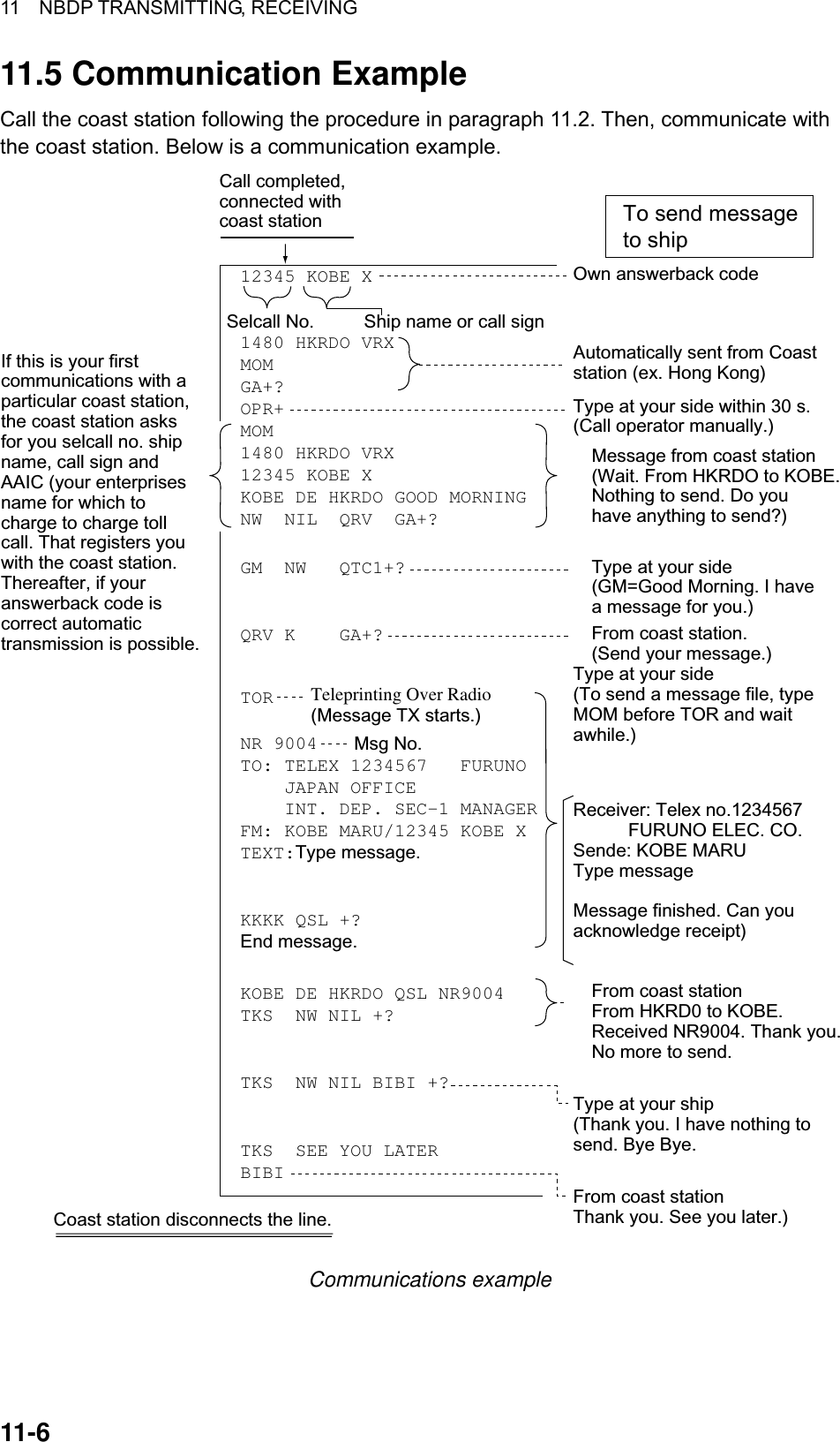
![11 NBDP TRANSMITTING, RECEIVING 11-7 Table of abbreviations noitaiverbbAnoitseuQecivdArorewsnAARQ?noitatsruoyemanehtsitahW.····sinoitatsymfoemanehTCRQehteraesirpretneetavirptahwyB noitatsruoyrofsegrahcrofstnuocca ?delttesdeltteseranoitatsymrofstnuoccaehT .····esirpretneetavirpehtybURQ?emrofgnihtynauoyevaH.uoyrofgnihtonevahIVRQ?ydaeruoyerA.ydaermaIXRQ?niagaemllacuoylliwnehW no[sruoh····taniagauoyllaclliwI .]zHk····JSQ·otdetcellocebotegrahcehtsitahW ?egrahclanretniruoygnidulcni··· ····otdetcellocebotegrahcehT ····siegrahclanretniymgnidulcni .····snarfLSQ?tpieceregdelwonkcauoynaC.tpieceregdelwonkcanacIXSQno]ngisllac[····otnetsiluoylliW ?zHk···· no]ngisllac[····otgninetsilmaI .zHk····ATQ?····rebmunegassemlecnacIllahS····rebmunegassemlecnaCCTQotuoyevahsegassemynamwoH ?dnes .uoyrofegassem····evahIUTQsinoitatsruoysruohehteratahW ?nepo ····ot····morfneposinoitatsyM .sruohnoitaiverbbAnoitinifeDKB.ssergorpnoissimsnartatpurretniotdesulangiSMFCmrifnoCED"····morF"K.timsnartotnoitativnILIN.uoyotdnesotgnihtonevahIWNwoNESPesaelPRdevieceRFER.····otecnerefeRCVS.margeletecivresagnitacidnixiferP](https://usermanual.wiki/Furuno-USA/9ZWFS2570/User-Guide-282811-Page-163.png)
![11 NBDP TRANSMITTING, RECEIVING 11-8 Command and abbreviation dnammoCnoitcnuF+MGT.margeletoidarasiegassemgniwollofehttahtetacidnioT+GSM .dlehegassemynayletaidemmidetcennocebotsdeennoitatspihsehttahtetacidnioT+RPO.rotarepollaC+GRU.egassemssertsiddnaycnegru,ytefaS+DEM.ecivdalacidemtseuqeR+TSET .noitatspihsehtgnikcehcrofegassemtsetadnesotnoitatstsaoctseuqeR+KRB.noitatstsaocehthtiwnoitcennocehtraelcoTnoitaiverbbA+AG.dnammocruoytimsnarT.ydaermaIMOM.tnemomatiaW+GSM.erohsehtmorfsegassemgnidneptseuqeRNNNNroKKKK.egassemaetanimreT 11.6 Timer Operation A built-in timer permits automatic transmission and reception of telex messages. 11.6.1 Enabling timer operation 1. Press the function key [F3] to display the Operate menu. 2. Press the [7] key to display the Timer Operation List. 3. Choose the operation (name) you wish to execute. Press the [Enter] key. An asterisk appears beside the operation selected and "T. Op" appears in reverse video on the communication status display. If a file stored on a floppy disk is to be sent, be sure the floppy disk containing the file is inserted in the drive. *1 2 3 OP4 OP5Timer Operation List Timer operation list 4. Choose another operation (name) if desired. 5. Press the [Esc] key.](https://usermanual.wiki/Furuno-USA/9ZWFS2570/User-Guide-282811-Page-164.png)
![11 NBDP TRANSMITTING, RECEIVING 11-9 When the predetermined time comes, the NBDP Terminal Unit automatically sends or receives the message. The results of timer operation are displayed as either OK or NG (No Good) on the Timer Operation List. *1 2*3*OP4*OP5OKOKOKNGTimer Operation List Timer operation list 11.6.2 Stopping timer operation 1. Press the function key [F3]. 2. Press the [7] key. 3. Choose the operation (name) which has an asterisk attached to it and then press the [Enter] key. Remove all asterisks to cancel all timer programs. 11.7 Scanning The radio equipment scans a group of operator-selected frequencies (channels), and stops scanning when an signal is received. For registering scan group, see paragraph 9.5. 1. Press the function key [F3] and then the [5] key to show the Scanning Group List on your screen. You can confirm the scan channel by pressing the [↑] or [↓] key while pressing the [Shift] key. *1 2 3Scanning Group List Scanning group list 2. Choose a scan group and press the [Enter] key. 3. The scanning starts and the indication "Scan" appears in reverse video. Further, the name of the scan group appears in the Station Name field. 2002-09-08 2:01:46 UTC Caps-Eng1:File 2:Edit 3:Operate 4:Window 5:Station 6:System 7:WRU 8:HR 9:Over 10:BreakStation Name : SAITO-1 Scan HT Frequency (T/R) : 8344.00 / 8705.00(kHz) Comm Mode : AutoComm Status : Connect Send Lock Error Sending Volume : 100(%) ARQ Error : 0 ARQ Time : 0(sec) Communication status display 4. To stop scanning, press the function key [F3] and then the [5] key. “Scan” appears in normal video on the communication status display.](https://usermanual.wiki/Furuno-USA/9ZWFS2570/User-Guide-282811-Page-165.png)
![11 NBDP TRANSMITTING, RECEIVING 11-10 11.8 Communication Buffer The communication buffer is a temporary memory which stores transmit and receive messages. To display the contents of the communication buffer, do the following: 1. Escape from the message creation screen. 2. Press the [PgDn] or [PgUp] key. The contents of the communication buffer are displayed. To print them, press the [Ctrl] and [P] keys simultaneously. To erase the contents from the screen, press the [PgDn] key while pressing the [Fn] key. To erase the contents of the buffer, press the [F1] and [9] keys. 11.9 Preparing Macrofiles for Automatic Telex 11.9.1 Automatic telex overview This section shows you how to communication with a coast station which handles automatic telex transmission, using macrofiles. You will also need to register communication channels and stations, and prepare macrofiles. Coast stations using automatic telex are MCI Marine Services (North America), Sydney Radio (Australia), Lyngby Radio (Denmark), and others. The procedure is mostly common to all coast stations, however refer to the coast station’s traffic manual for details. STORE-AND-FORWARDDIRECTDIALINGMULTI-ADDRESSINTERNATIONALTELEX NETWORKCENTRALSYSTEMSYSTEMCONTROLSUB-STATIONSHIP Sample automatic telex network The service available in automatic telex are • Message transfer between ship and coast station (store-and-forward) • Connection with landline telex (direct dialing) • Multi address.](https://usermanual.wiki/Furuno-USA/9ZWFS2570/User-Guide-282811-Page-166.png)
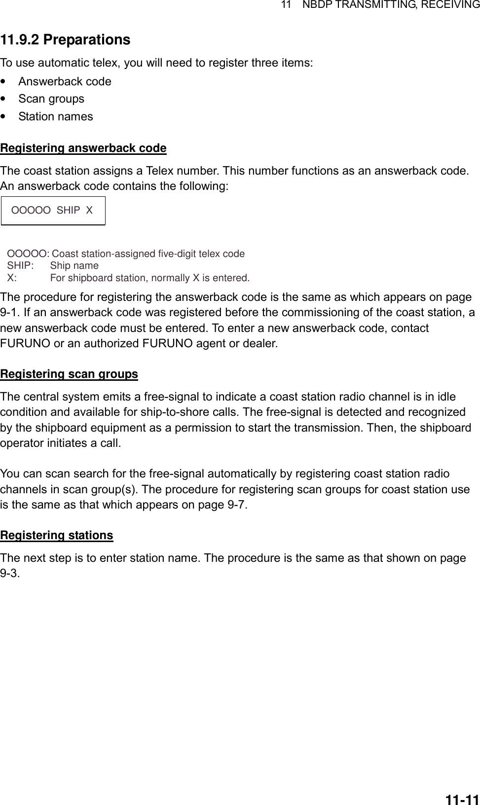
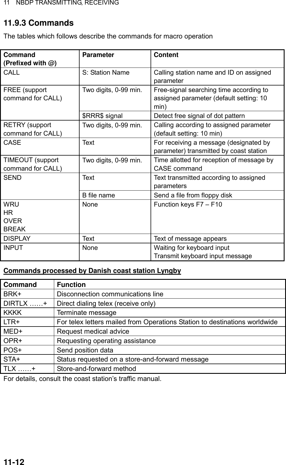
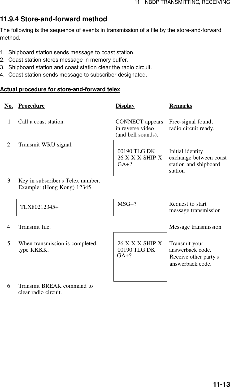
![11 NBDP TRANSMITTING, RECEIVING 11-14 Procedure for preparing a macrofile for store-and-forward method You will need a macrofile to enable automatic message transmission by store-and-forward method. After preparing it, save it to a floppy disk for future use. 1. Press function key [F1] to display the File menu. 2. Press the [1] key. 3. Prepare macrofile. Below is simple example. < [1] UNTITLED1 > @FREE $RRR$@CALL S:LYNGBY RADIO@WRU@CASE GA+?@SEND TLX80212345+@CASE MSG+?@SEND B:ABC@SEND KKKK@CASE GA+?@SEND BRK+123451 Search dot pattern free signal until it is found2 Station name (Example: LYNGBY RADIO) Who are you? Station identity exchange3 Subscriber's Telex number (in example, 802 is country code of Hong Kong) for store-and-forward method4 Location and name of file message 5 Request for termination of message Sample macrofile for store-and-forward method 4. Press function key [F1] to display the File menu. 5. Press the [3] key. The Close Text appears on the display. close Text Save File?(UNTITLED 1)NoYes Close text prompt](https://usermanual.wiki/Furuno-USA/9ZWFS2570/User-Guide-282811-Page-170.png)
![11 NBDP TRANSMITTING, RECEIVING 11-15 6. Press the [Enter] key and enter a file name as follows: OOOOOOOO.MCR ↑ ↑ File Name Extension Name (max. 8 characters) 7. Press the [Enter] key. DIRTLX macrofile Sample DIRTLX macrofile @FREE $RRR$@CALL S: LYNGBY RADIO@WRU@CASE GA+?@SEND DIRTLX725644325+@CASE MSG+?@SEND B:ABC@SEND KKKK@CASE GA+?@SEND BRK+123451 Search dot pattern free signal until it is found2 Station name (Example: LYNGBY RADIO) Who are you? Station identity exchange3 Subscriber's Telex number (in example, 72 is country code of JAPAN) for direct dialing mode4 Location and name of file message5 Request for termination of message Sample DIRLTX macrofile](https://usermanual.wiki/Furuno-USA/9ZWFS2570/User-Guide-282811-Page-171.png)
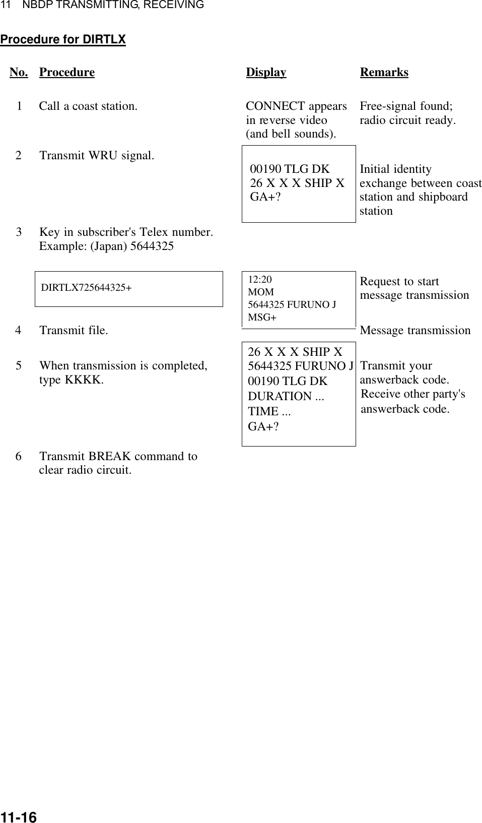
![11 NBDP TRANSMITTING, RECEIVING 11-17 11.10 Automatic Telex using Macrofile This section describes how to transmit a telex message using a macrofile. Basic procedure 1. Register answerback code (Telex number assigned by coast station). 2. Register coast station frequency and channel to scan group. 3. Register station name including scan group name. 4. Retrieve appropriate macrofile. Include station name and message file name. Type message and save file to memory. 5. Open macro operation menu and select a macrofile. (See next page for details.) Your message will be transmitted automatically. Below is the sequence of automatic message transmission to a coast station. a) Search for free-signal b) Call coast station on one of its radio channels c) After connection is established, identity exchange d) Transmission of service category and subscriber’s address e) Transmission of message f) Transmission of termination of message signal g) Identity exchange h) Clearing of radio circuit Actual procedure 1. Press function key [F3] to display the Operate menu. 1: Call Station3: File to Send4: Cancel Sending5: Scan (Start/Stop)6: Manual Reception7: Timer Operation8: Manual Calling9: Set FrequencyOperate2: Macro Operation Operate menu 2. Press the [2] key to display the Call Macro screen.](https://usermanual.wiki/Furuno-USA/9ZWFS2570/User-Guide-282811-Page-173.png)
![11 NBDP TRANSMITTING, RECEIVING 11-18 Call Macro[B:\TEST1. ] File name Size Date & TimeLOG File 52 02-10-15 17:25TEST1. 120 02-10-10 16:30TEST2. 151 02-10-11 09:25TEST3. 180 02-10-11 20:16LYNGBY1.MCR 169 02-10-13 06:23[ End of Directory ]4 Files exist 1454000 bytes freeTo select : ENTER To view : SPACE To quit : ESC Call macro screen 3. Press the [↓] key to choose a macrofile. 4. Press the [Enter] key. Call Macro: Lyngby1.MCRCall OK? NoYes 5. Press the [Enter] key to confirm the macrofile selected. The Wait for Free Signal indication appears. Your message will be transmitted automatically.](https://usermanual.wiki/Furuno-USA/9ZWFS2570/User-Guide-282811-Page-174.png)
![12-1 12. MAINTENANCE & TROUBLESHOOTING WARNINGELECTRICAL SHOCK HAZARDDo not open the equipment.Only qualified personnelshould work inside theequipment. 12.1 Daily Test Authorities require that the DSC/watch receiver be checked daily for proper operation to ensure that it will function properly in the event of distress. Execute the daily test as below. 1. At the DSC standby screen, press the [3/TEST] key to start the test. 2. After several seconds the test results, OK, for normal operation, NG for No Good. For NG (No Good) contact your dealer for advice. MAIN CPU : OK VER. XX*PANEL1 : OK VER. XX*PANEL2*1 : OK VER. XX*MODEM : OKNBDP MODEM : OK** Daily test **MAR-27-2002-15:24 RCVR1 : OKRCVR2*1 : OKTRX : OK ** Daily test ** Page 1 Page 2*: XX = Version No.*1: Shown if equipped with No. 2 control unit. Test results 3. After the test results for the items on page 2 appear, the audio alarm sounds, the ALARM lamp flashes several times and then page 1 of the daily test is displayed. 4. If auto printing is active, the test results are printed. To manually print the test results, press the [8/PRINT] key. Above is a sample test results printout. 5. Press the [CANCEL] key to quit the test and return to the DSC standby screen. Note: TEST on the DSC Setup menu is for used by service technicians. DAILY TEST MAR-27-2002-15:24:00 MMSI: 123456789 MAIN CPU: OK VER.**PANEL1 CPU: OK VER.**PANEL2 CPU:* OK VER.** NBDP MODEM: OK VER.**RCVR1: OKRCVR2:* OKTRX: OK* = PANEL2 CPU, RCVR2printed if equippedwith no. 2control unit.** = Version No.](https://usermanual.wiki/Furuno-USA/9ZWFS2570/User-Guide-282811-Page-175.png)
![12 MAINTENANCE & TROUBLESHOOTING 12-212.2 Radiotelephone Test Do the following to check the radiotelephone for proper operation: 1. At the radiotelephone screen, press the [3/TEST] key to start the test. OK or NG (No Good) appears as the test result for each item checked. For NG, contact your dealer for advice. Tx selfcheck PLL : OK RF : OK TX FIL : OK PA : OK COUPL : OK 2. Press the [CANCEL] key to quit the test and return to the previously used screen. 12.3 Antenna Coupler Test The CPU and the relays which choose capacitors and coils for tuning can be checked. For qualified technicians only. DANGERHIGH TENSION HAZARDCircuits in the antennacoupler are still alive at OFF.Discharge before servicing. 1. Open the antenna coupler cover. 2. Open the shield cover inside the coupler. 3. Turn on the #2 switch of DIP switch S2. 4. Press the TUNE switch in the antenna coupler. 5. 24 LEDs (CR1 to CR24) light one by one every second. Relays trip on with corresponding LEDs as below. CR1 ON – K1 ON CR2 ON – K2 ON . . . CR22 ON – K22 ON (CR23 not provided) CR24 ON – K24, K25 ON 6. Turn off the #2 switch of DIP switch S2. 7. Close the cover. If CPU error is detected, CR1 lights for ROM error, CR2 for RAM error, CR3 for A/D converter error. (ROM/RAM/ A/D converter is incorporated in the CPU.) COUPLER BOARD LEDDIP switch S2behind the shield caseTUNE SWITCH](https://usermanual.wiki/Furuno-USA/9ZWFS2570/User-Guide-282811-Page-176.png)
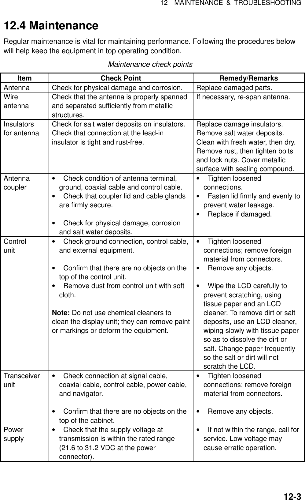
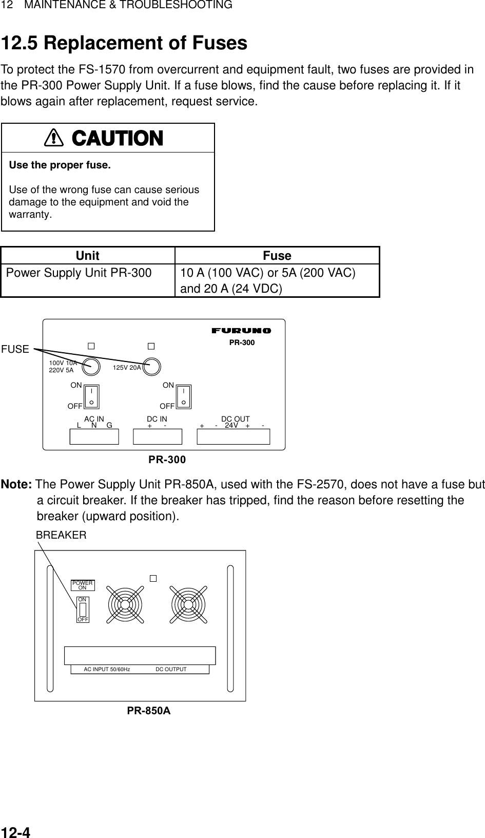
![12 MAINTENANCE & TROUBLESHOOTING 12-5 12.6 Simple Troubleshooting The table below provides common problems and the means with which to restore normal operation. If normal operation cannot be restored, do not attempt to check inside the equipment. Any servicing should be referred to a qualified technician. Problem Probable cause Remedy Power cannot be turned on. • Mains switchboard may be off. • (DC) voltage is too high. • Battery may have discharged, or poor contact at terminals. • Turn on the mains switchboard. • Check supply voltage. • Recharge battery and tighten battery terminals. Display indications do not appear but key lamps are lit. • Contrast is too low. • Operate the [9/ ] key to adjust contrast. Power is on but no sound from loudspeaker. • Loudspeaker is off. • Operate the [7/ ] key to turn on the loudspeaker. Poor articulation • Wrong class of emission may be in use. • Class of emission should match that of incoming signal. Output power reduced to LOW • Power is automatically reduced to protect against overheating due to continuous transmission. • Wait until the unit returns to normal condition. Antenna coupler cannot tune antenna • Antenna may be disconnected or shorted to ground. • Antenna is out of tunable length. • Poor grounding of antenna coupler. • Breaker in coupler has tripped. • Connection cable loosened or disconnected. • Check antenna connection. • Recommended length is 7 to 30 meters. • Check coupler ground. • Checks mains voltage and polarity. If normal, reset breaker. • Check cable.](https://usermanual.wiki/Furuno-USA/9ZWFS2570/User-Guide-282811-Page-179.png)
![12 MAINTENANCE & TROUBLESHOOTING 12-612.7 Error Messages The table below shows error messages and their meanings. Error messages Error message Meaning Remedy Busy: RT Radiotelephone is in operation. Wait until the radiotelephone is free. Channel Busy You attempted to transmit on a channel which is currently busy. (This occurs with Routine and Business priorities only.) The message is automatically erased when the channel becomes clear. EPFS error No position data from navigator for one minute. Press the [CANCEL] key to silence the alarm. Check the navigator. If it is malfunctioning, manually enter position.Incoming Incoming DSC call Message is automatically cleared when DSC signal has gone. No position data You attempted to enter position automatically when there is no position data. Check the navigator. No response: RT Radiotelephone not powered or has been disconnected. Check radiotelephone. Oven cold. Tx not ready; wait Oven too cold; cannot transmit. Wait until the oven becomes sufficiently warm. Printer not ready Automatic printed has been selected; however, printer is not powered or has been disconnected. Check printer. Trouble: Oven not ready Oven not ready; cannot transmit. Wait until the oven is ready. TRX PLL UNLOCK TRX PLL unlock. Transmission is stopped. Check if the reference oscillator is working and the coaxial cable is tightly connected. TUNE error Tuning failed for DSC or NBDP. Transmission (except distress) is stopped. Try to tune again. Warning: Update position Position data is older by the amount of time preset on the Alarm menu. Press the [CANCEL] key to silence alarm. Reenter position on the Position menu. Watchdog error. Please Power OFF Internal error (such as CPU trouble) detected. Accompanied with alarm, same type as for distress. Turn the power off and on to erase the message. Have a qualified technician check the set. WR1 PLL UNLOCK WR2 PLL UNLOCK WR1, WR2 PLL unlock. Transmission is stopped. Check if the reference oscillator is working and the coaxial cable is tightly connected.](https://usermanual.wiki/Furuno-USA/9ZWFS2570/User-Guide-282811-Page-180.png)
![12 MAINTENANCE & TROUBLESHOOTING 12-712.8 Test Call This function sends a test signal to a coast station, over one of six distress and safety frequencies. For that reason, it should not be executed unnecessarily. You can prepare a test call beforehand (see Chapter 6) or at the moment you intend to send a test call. To send a prepared test call, see page 6-9 for the procedure. 1. Press the [2/DSC] key at the DSC standby screen and then push the [ENTER] knob to open the CALL TYPE menu. ** Compose message ** STATION IDPRIORITYCOM. TYPECOM. FREQDSC FREQ: All ships: Safety : Telephone : 2187.5 kHzCALL TYPE PSTN CALLTEST CALLALL SHIPSGROUP CALLAREA CALLPOSITION INDIVIDUAL POLLINGNEUTRALMEDICALRELAY ALLRELAY SELDISTRESSRotate [ENTER]knob to scroll.GO 2. Rotate the [ENTER] knob to choose TEST CALL and then push the [ENTER] knob. 3. Push the [ENTER] knob to open the COAST ID menu. GO TO ALL VIEWCALL TYPE PRIORITYDSC FREQ : 2187.5 KHZ: TEST : SAFETYCOAST ID 000000000** Compose message ** 4. Using the numeric keys, key in the ID of the coast station ID (seven digits) where to send the call and then push the [ENTER] knob. 5. Push the [ENTER] knob to open the DSC FREQ menu. (Note that PRIORITY is automatically selected to SAFETY.) DSC FREQ KHZCALL TYPECOAST IDPRIORITY: Test : 001234567 : Safety : kHz VIEW 4207.5 6312.0 8414.5 12577.016804.52187.5** Compose message **GO TO ALL VIEW](https://usermanual.wiki/Furuno-USA/9ZWFS2570/User-Guide-282811-Page-181.png)
![12 MAINTENANCE & TROUBLESHOOTING 12-86. Rotate the [ENTER] knob to choose an appropriate frequency and then push the [ENTER] knob. The display changes as below. CALL TYPE : TEST COAST ID : 001234567 PRIORITY : SAFETY DSC FREQ : 2187.5 KHZ GO TO ALL VIEW** Compose message ** 7. Press the [CALL] key to send the test call (transmission time: about seven seconds). The display shows "Test call in progress!" while the test call is being transmitted. Testcall in progress!DSC FREQ : 2187.5 KHZTIME TO GO : 7STO COAST : 001234567 SAFETY 8. After the test call has been sent, the following message appears. Waiting for test acknowledgement.DSC FREQ : 2187.5 KHZTIME TO GO : 4M12SFROM COAST : 001234567 SAFETY 9. One of the following displays appears. (“No response! Try calling again?” appears when the timer counts down to zero, meaning no response from coast station.) No response! Try calling again?DSC FREQ : 2187.5 KHZFROM COAST: 001234567 SAFETYTest acknowledgecall received.FROM COAST: 001234567 SAFETY NO INFORMATIONSTOP ALARM CALL AGAINTest acknowledge received No response to test call 10. Do one of the following depending on the message shown in step 9.](https://usermanual.wiki/Furuno-USA/9ZWFS2570/User-Guide-282811-Page-182.png)
![12 MAINTENANCE & TROUBLESHOOTING 12-9Test acknowledge call received The audio alarm sounds; press the [CANCEL] key to silence the alarm. The display changes as below. ECC : OKTEST ACKNOWLEDGEMENT FROM COAST : 001234567 SAFETY NO INFORMATION * Received message * GO TO ALL VIEWMAR-23-2002-23:59 No response! Try calling again? Re-send call: Push the [ENTER] knob and then press the [CALL] key. Cancel call: Press the [CANCEL] key to return to the DSC standby screen. 12.9 NBDP Terminal Unit Maintenance Regular maintenance is important for good performance. A regular maintenance program should be established and should at least include the items mentioned below. 12.9.1 Cleaning the equipment Wipe of accumulated dust from the terminal unit with a soft cloth. Wipe the LCD carefully to prevent scratching, using tissue paper and an LCD cleaner. To remove dirt or salt deposits, use an LCD cleaner, wiping slowly with tissue paper so as to dissolve the dirt or salt. Change paper frequently so the salt or dirt will not scratch the LCD. Do not use solvents such as thinner, acetone or benzene for cleaning; they can remove paint and marks or deform the equipment. 12.9.2 Connectors and earth connection Periodically check the connectors for proper seating and the earth connection for rust. Remove rust to maintain a good ground system. 12.9.3 Floppy disk drive Foreign material on the floppy disk drive head can scratch the magnetic material in the floppy, resulting in loss of data. Clean the floppy disk drive head regularly with a floppy disk drive cleaning disk to prevent erasure of information stored on disks.](https://usermanual.wiki/Furuno-USA/9ZWFS2570/User-Guide-282811-Page-183.png)
![12 MAINTENANCE & TROUBLESHOOTING 12-10 12.9.4 Diagnostics General diagnostics 1. Press the function key [F6] to display the System menu. SetupSlave DelayTX/RX MSG SaveEdit Before sendingTime SystemTime & DateDisplay Mode*Self TestLock Change Default 8 msec (0- 50 msec)OFF O NOFF O NOFF UTC SMT JST2002/10/16 10:00:00Normal ReverseSystem* = Not shown on IB-583. System menu 2. Choose Change from Setup. 3. Choose Self Test (at the bottom of the screen). 4. Press the [Enter] key. The results of the self test are displayed a short time later. Selftest Terminal Unit Test : ver. X.XX :OKMain Unit Test : ver. X.XX :OKModem Unit Test : ver. X.XX :OKRadio Unit Test : ID FS1570*1 :OKDSC Unit Test : ID FS1570*1 :OKPrinter Unit Test*2: :OKX.XX = Version No.*1: Or FS2570*2: "NG" and "Printer not ready" when printer is off or is abnormal.IB-58XMAIN BoardNBDP Modem Self test results The test results are shown as OK or NG (No Good). For any NG, try the self test again. If it appears again, call for service. When the test is completed, the message “Selftest Completed. Press any key to escape.” appears.](https://usermanual.wiki/Furuno-USA/9ZWFS2570/User-Guide-282811-Page-184.png)
![12 MAINTENANCE & TROUBLESHOOTING 12-11Tone test 1. Choose Self Test from the System Menu as shown in paragraph 12.8.4. 2. While pressing and holding down the [Shift] key, press the [↓] key to show the Tone Test menu. Tone Test 1: Tone Test 1 (All Char)2: Tone Test 2 (Fox)3: Tone Test 3 (Beta)4: Tone Test 4 (Mark)5: Tone Test 5 (Space)6: Tone Test 6 (BY) Tone test menu 3. Choose a test and press the [Enter] key. You may stop a tone test at anytime by pressing the [Enter] key. Tone test 1 (All characters) This test checks for proper transmission of all figures, letters and codes. To conduct the test, call a station in the ARQ or FEC mode. Execute the test, confirming that all characters are transmitted correctly. "Now testing Tone Test 1" appears during the testing. Since the test is conducted continuously, you may press the [Esc] key twice followed by the [F10] key to stop the test and return to the tone test menu. Station Name : Frequency (T/R) : / (kHz) Comm Mode : AutoComm Status : Connect Send Lock Error Mark Space1:File 2:Edit 3:Operate 4:Window 5:Station 6:System 7:WRU 8:HR 9:Over 10:Break1996-11-15 13:26:45.45 Caps EngNow Testing Tone Test 1 (All Char).ABCDEFGHIJKLMNOPQRSTUVWXYZ1234567890-?:().,'=/+abcdefghijklmnopqrstuvwxyzABCDEFGHIJKLMNOPQRSTUVWXYZ1234567890-?:().,'=/+abcdefghijklmnopqrstuvwxyzABCDEFGHIJKLMNOPQRSTUVWXYZSystemLock Change DefaultSetup Tone test](https://usermanual.wiki/Furuno-USA/9ZWFS2570/User-Guide-282811-Page-185.png)
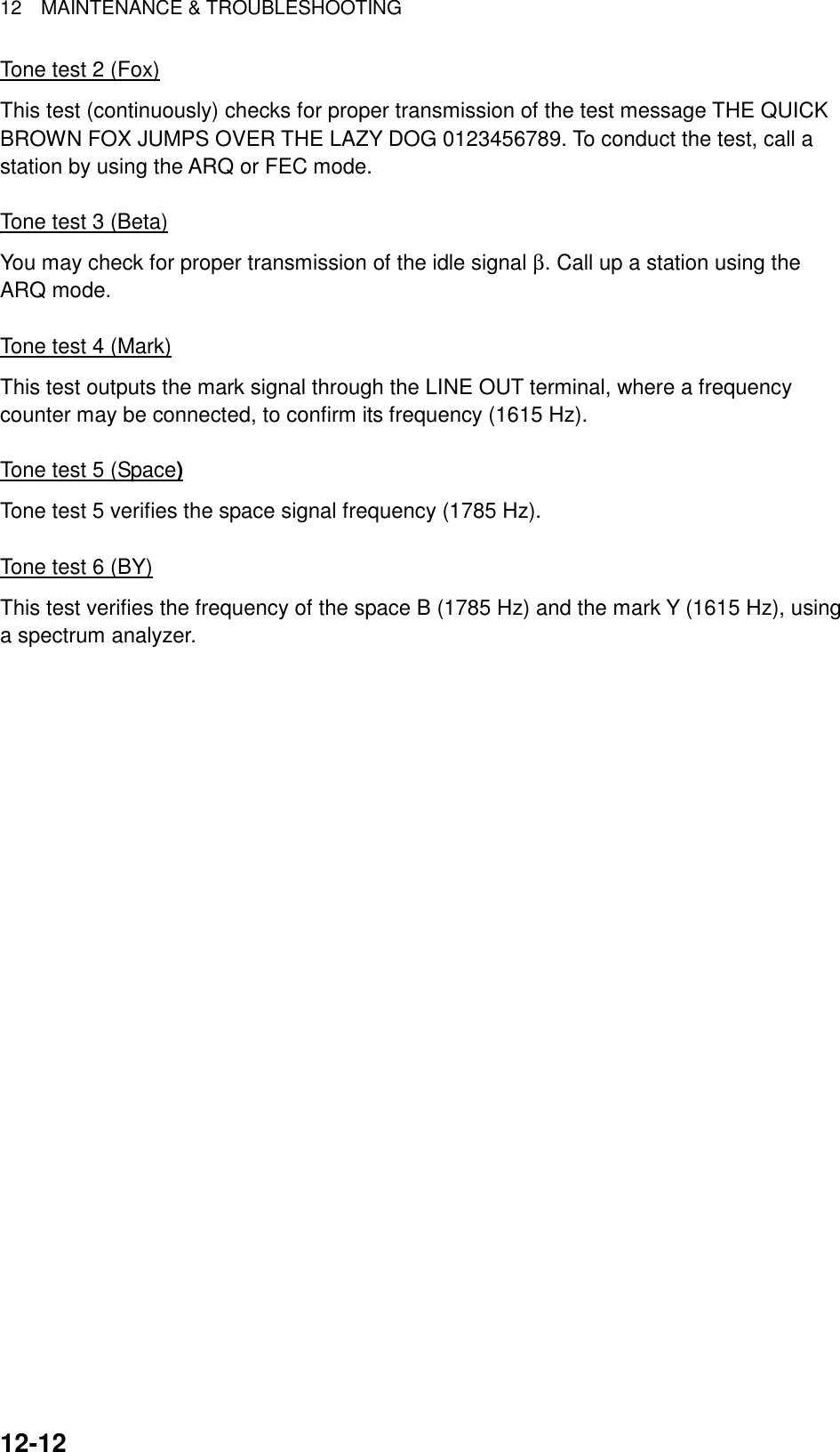
![AP-1 APPENDIX Menu Tree DSC/watch receiver INTERNAL AUDIO ALARM RCVD CALL (ON, OFF) OLD POSITION (ON, OFF) POSITION OLDER (4.0, 3.0, 2.0, 1.0, 0.5 hr)EXT ALARM (DSTRS/URG, ROUTINE, ALL, OFF)ALARM AUTO ACKERASE MESSAGE POSITIONPRINT OUTSCAN FREQ Selects DSC frequencies to scan.VOLUMETEST (For technicians)SYSTEM (For technicians)COMPLY TYPE (ABLE, UNABLE)UNABLE REASON (NO REASON, BUSY, EQUIP DISABLED, MODE NOT USABLE, CH NOT USABLE)POSITION CALL (ON, OFF)POLLING CALL (ON, OFF) RCVD ORDINARY LOGRCVD DISTRESS LOGTRANSMITTED LOGSEND MESSAGEINPUT TYPE (AUTO, MANUAL)LATLONGTIMEXMIT CALL (AUTO, MANUAL)RCVD CALL (AUTO, MANUAL)DAILY TEST (AUTO, MANUAL)KEY CLICK (ON,OFF)HANDSET (0-63, 32)ORDINARY ALARM (0-63, 8)DISTRESS ALARM (8-63, 8)[LOG/TUNE] key RECEIVED ORDINARYRECEIVED DISTRESSTRANSMITTEDDefault settingsin boldface italic.[#/SETUP] key(Pressed atDSC standbyscreen.)](https://usermanual.wiki/Furuno-USA/9ZWFS2570/User-Guide-282811-Page-187.png)
![APPENDIX AP-2 Radiotelephone [#/SETUP] key(Pressed atradiotelephonescreen.)NB (ON, OFF)SQ FREQ (500-2000 Hz, 800 Hz )FAX RX ENABLE (ON, OFF)USER CH (Set up user channels.)SYSTEM (Display system settings.) Default settingsin boldface italic.](https://usermanual.wiki/Furuno-USA/9ZWFS2570/User-Guide-282811-Page-188.png)
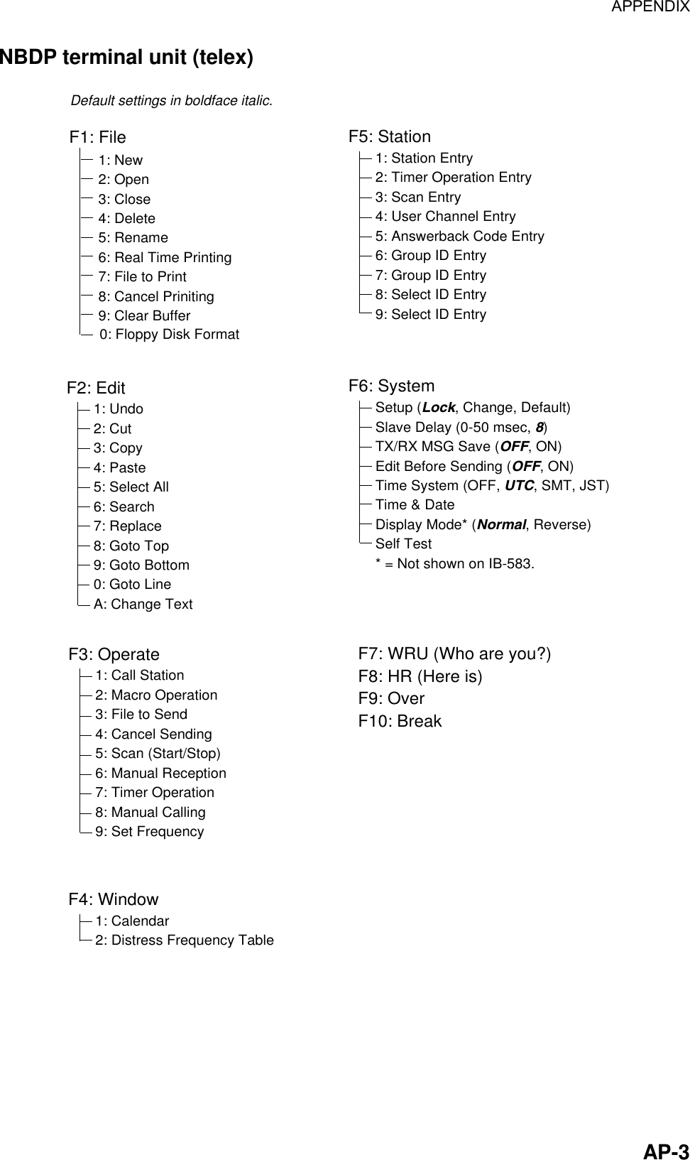
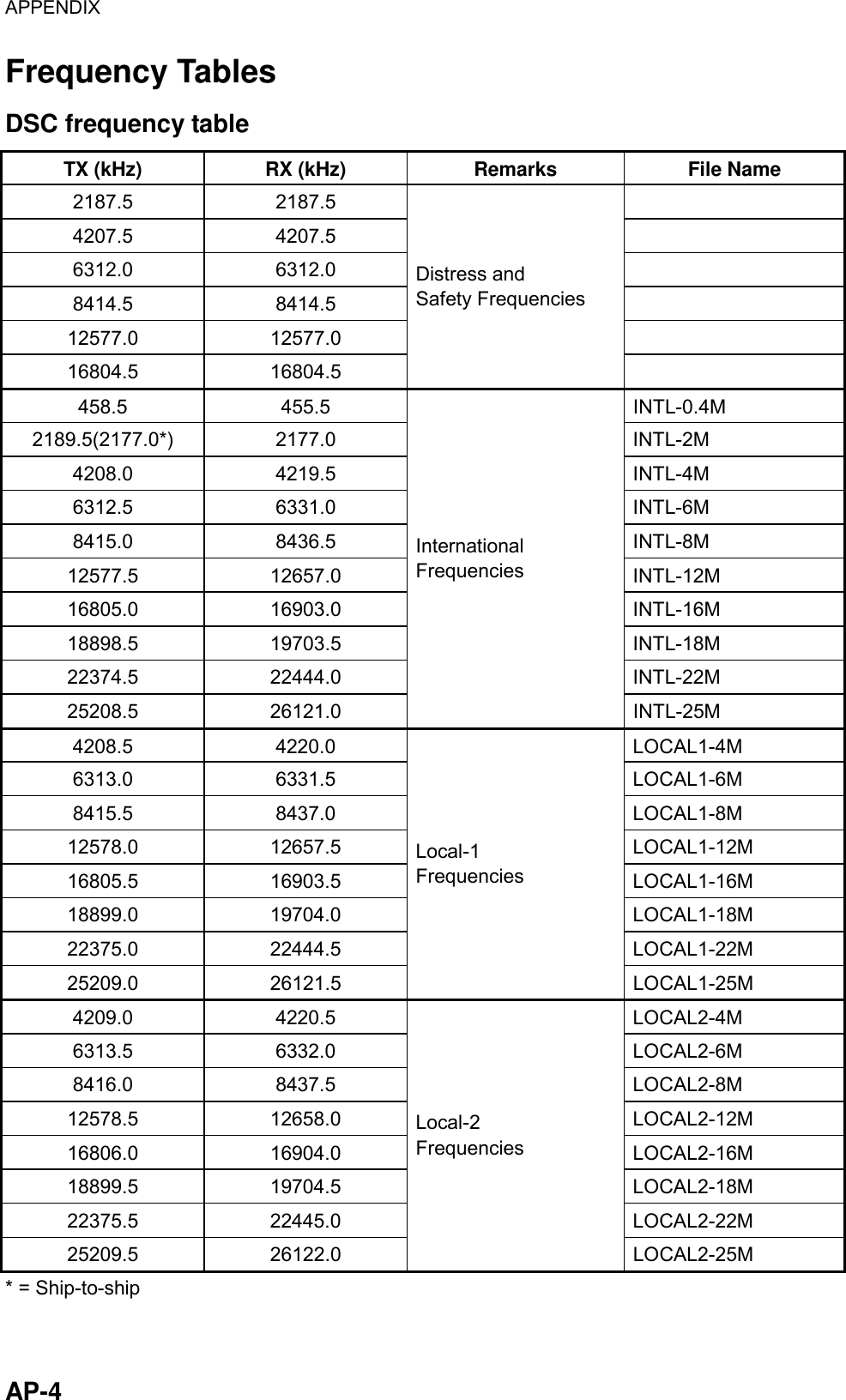
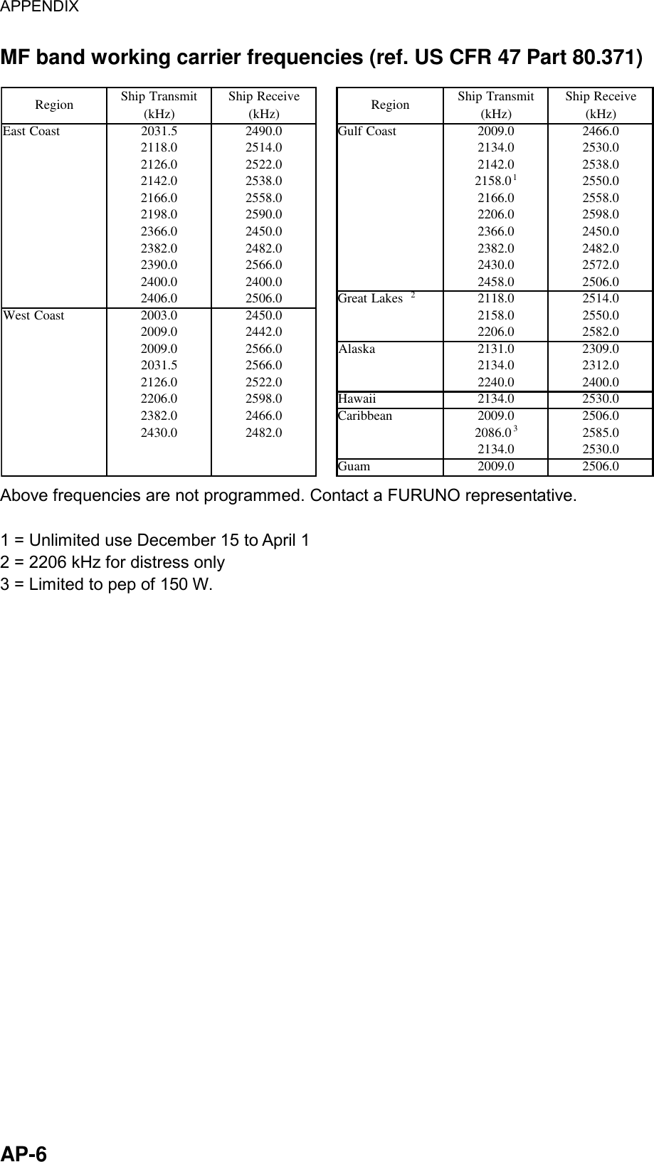
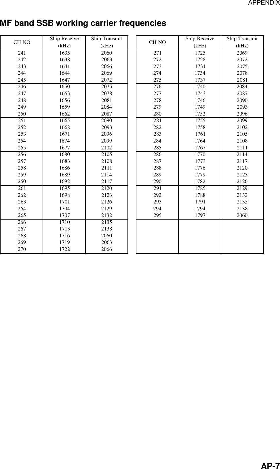
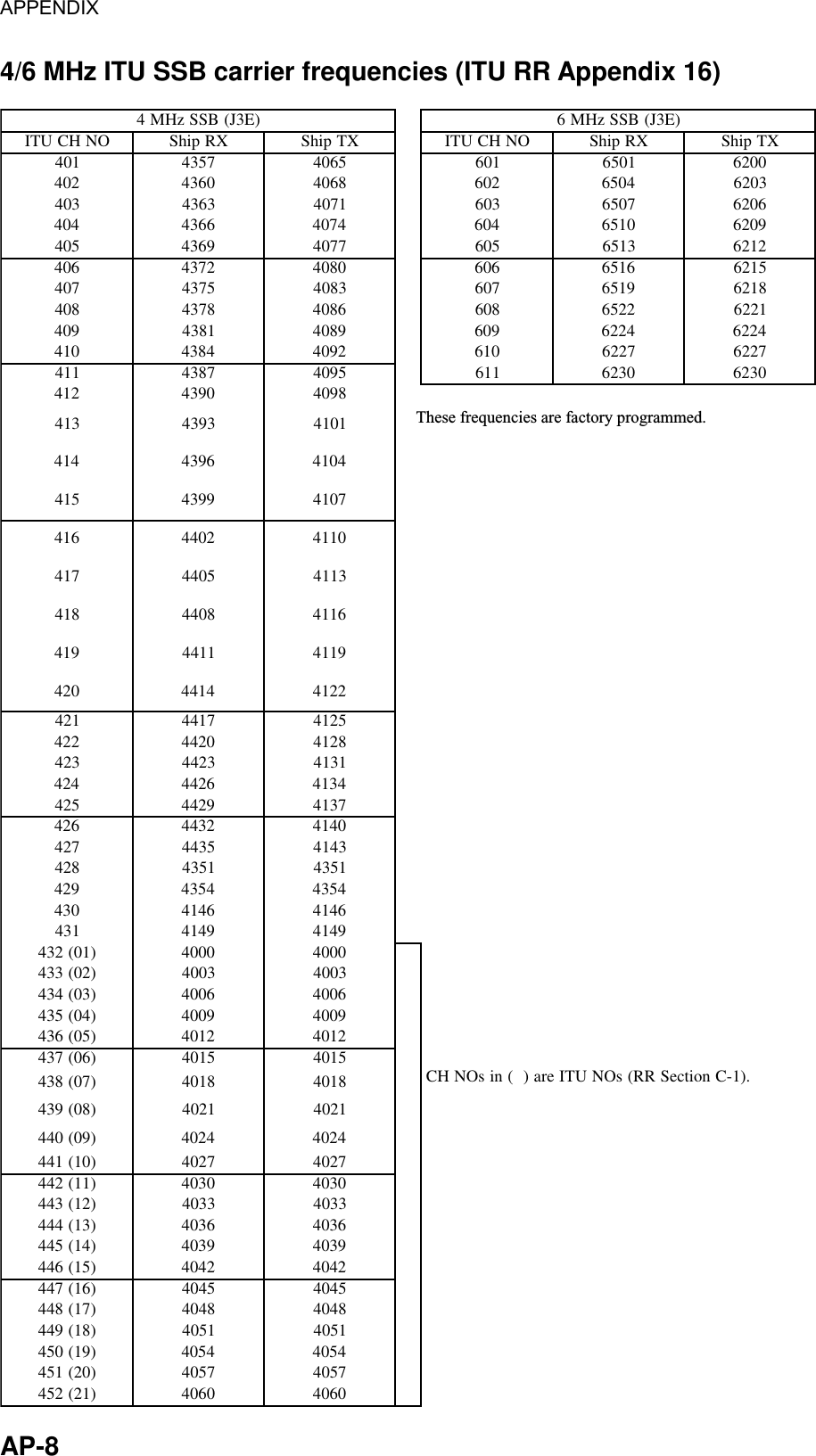
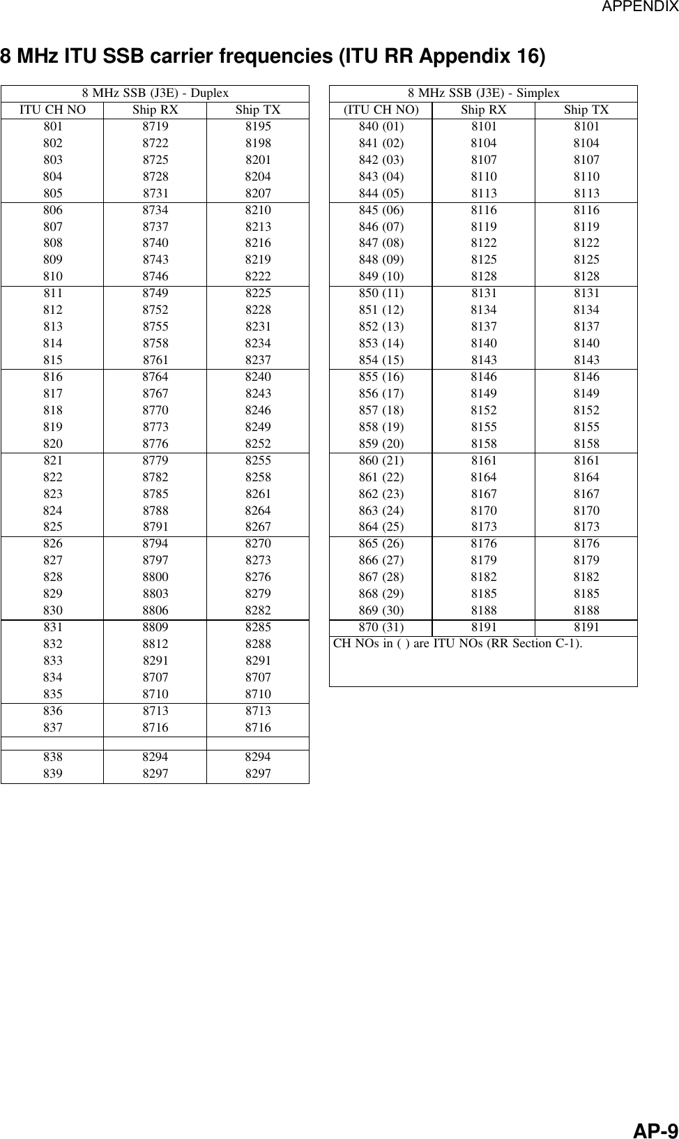
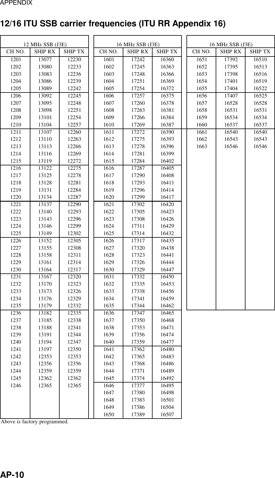
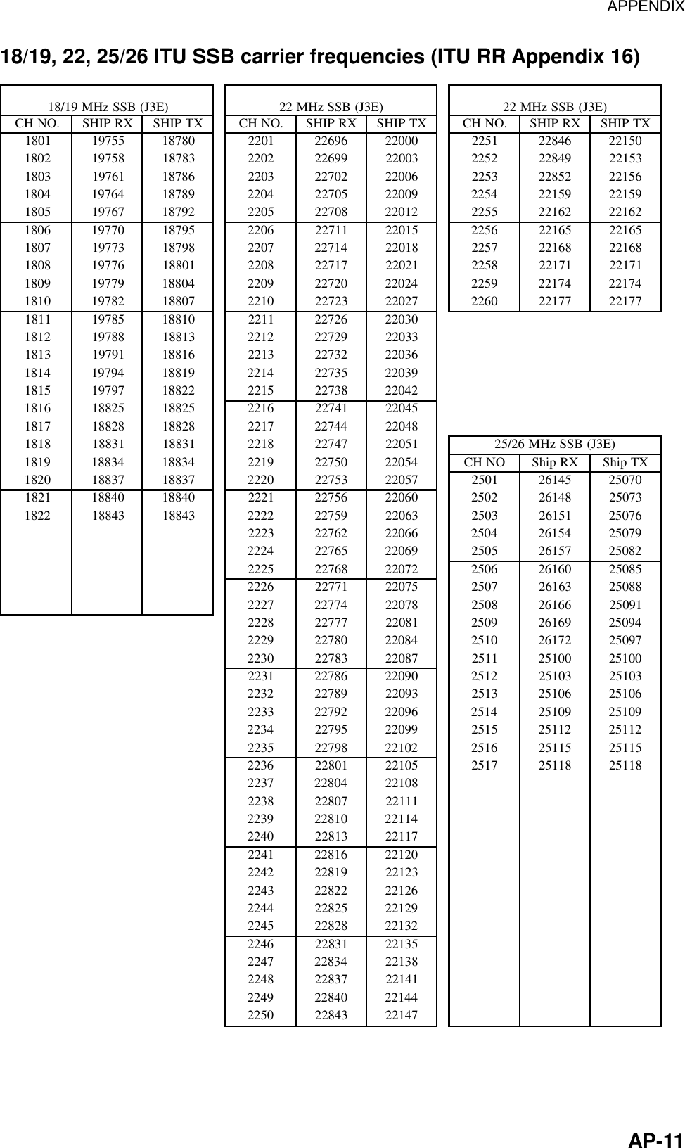
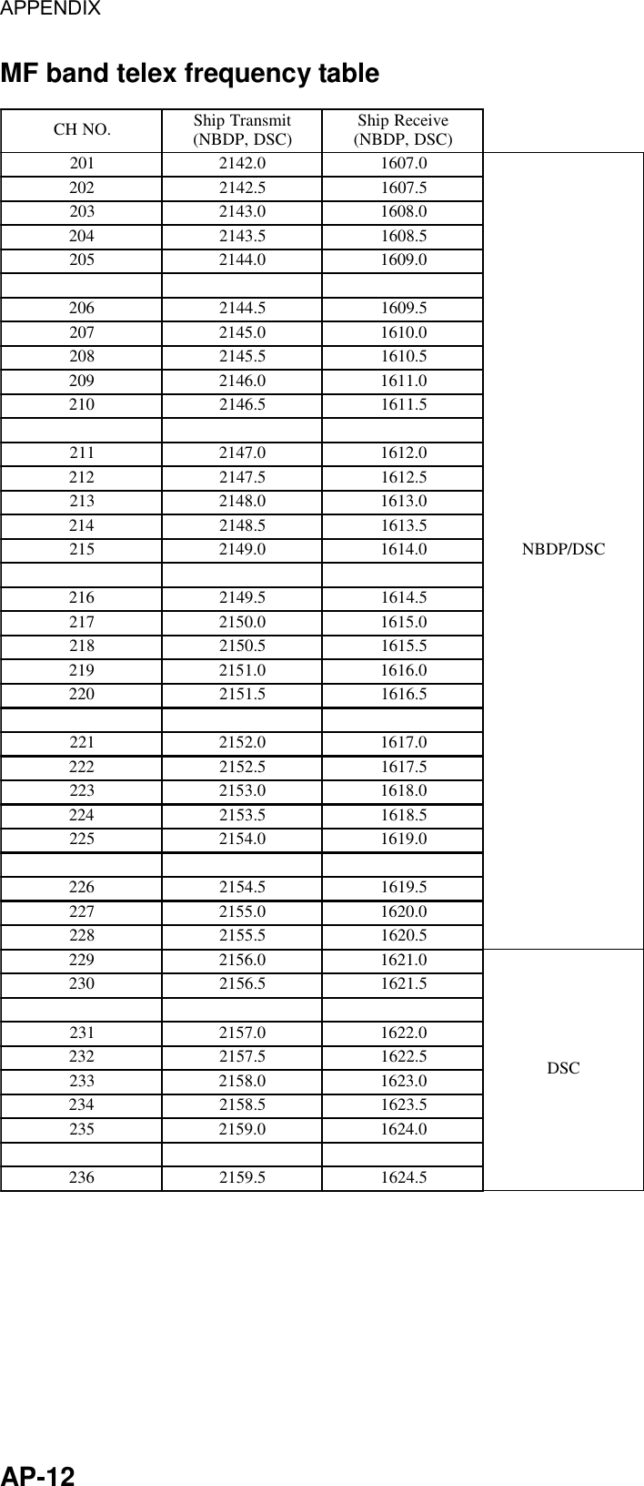
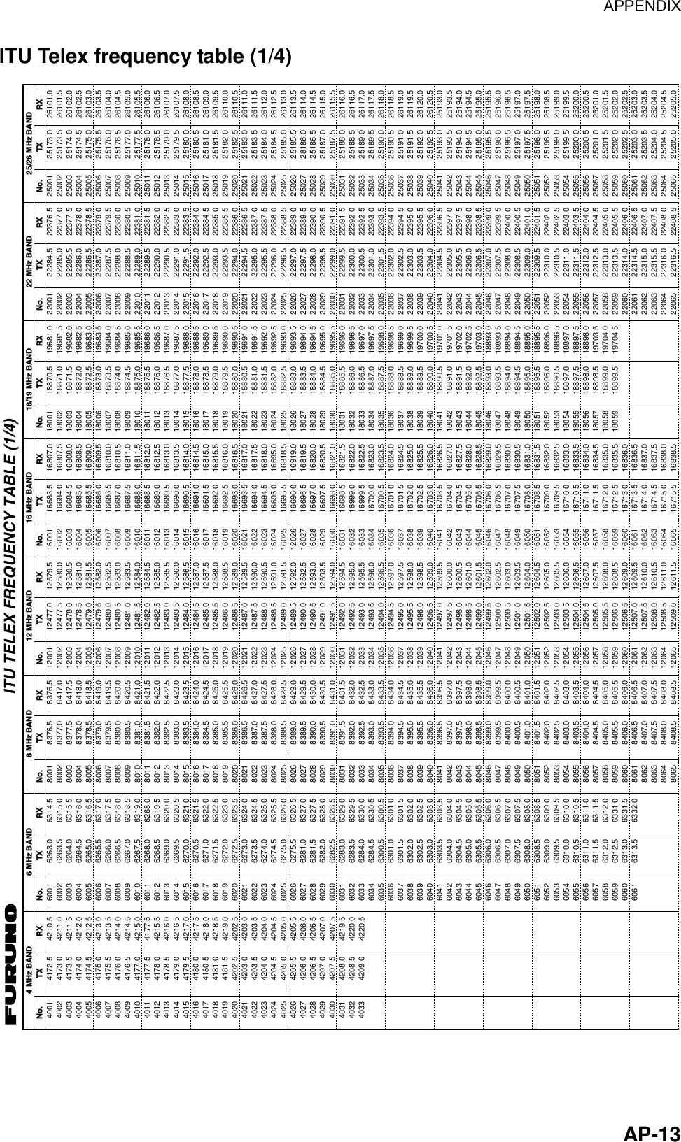
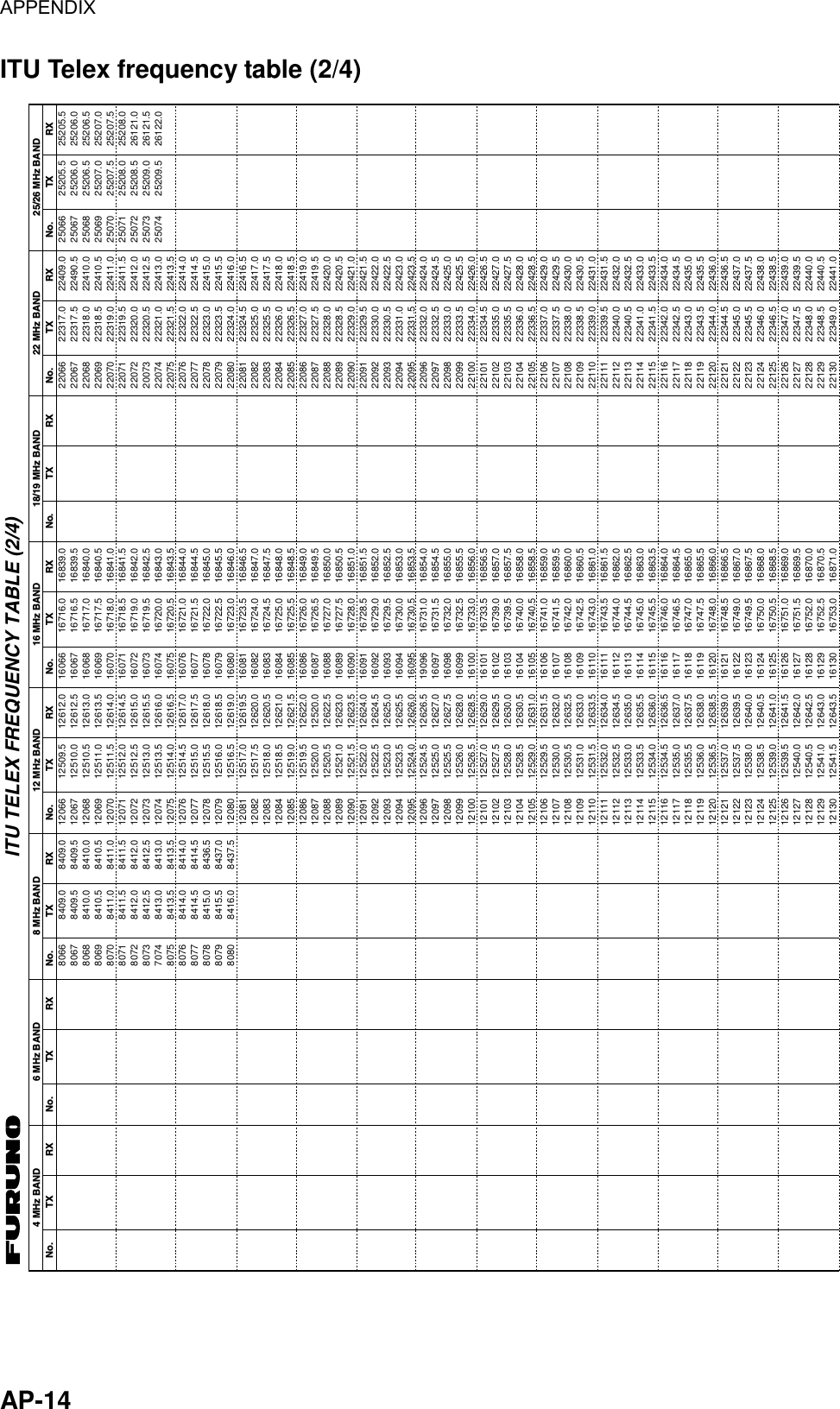
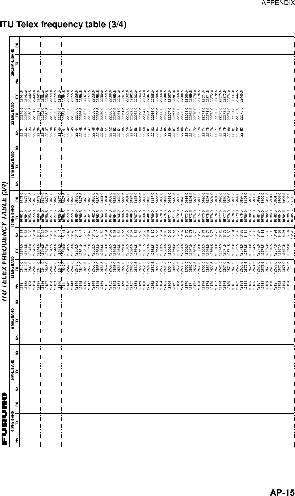
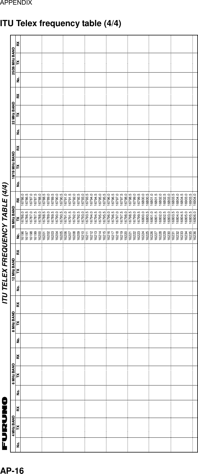
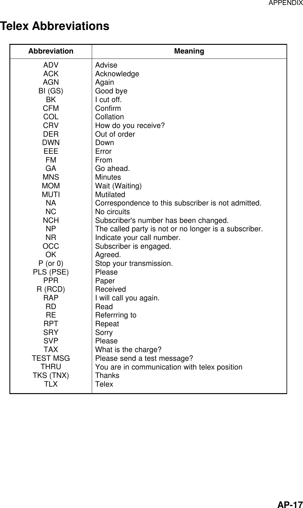
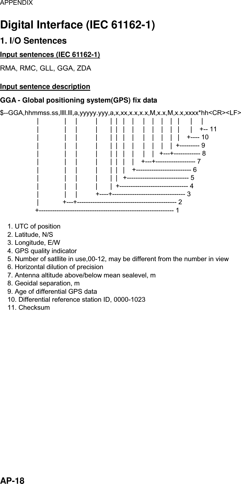
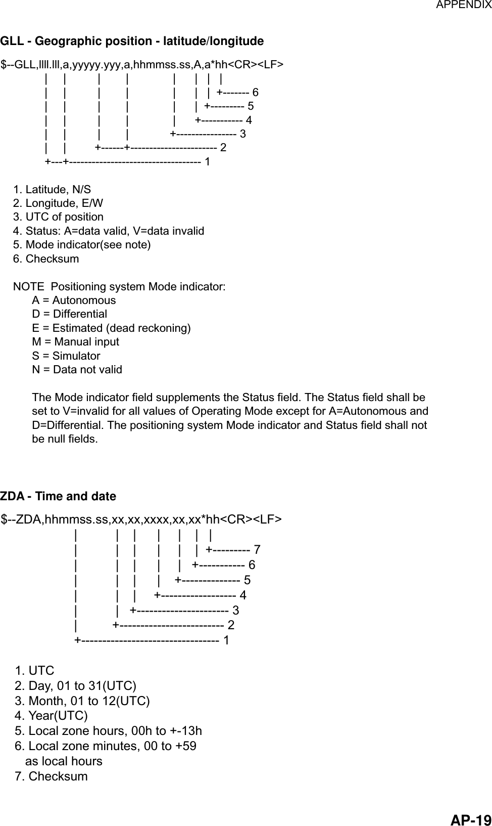
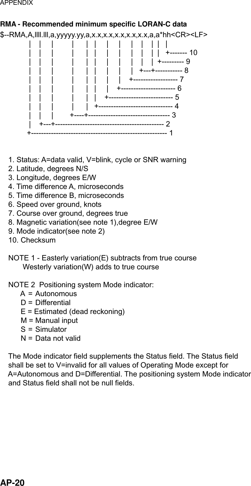
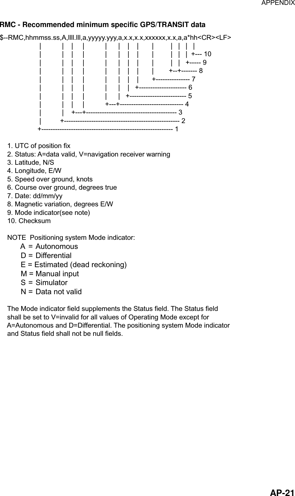
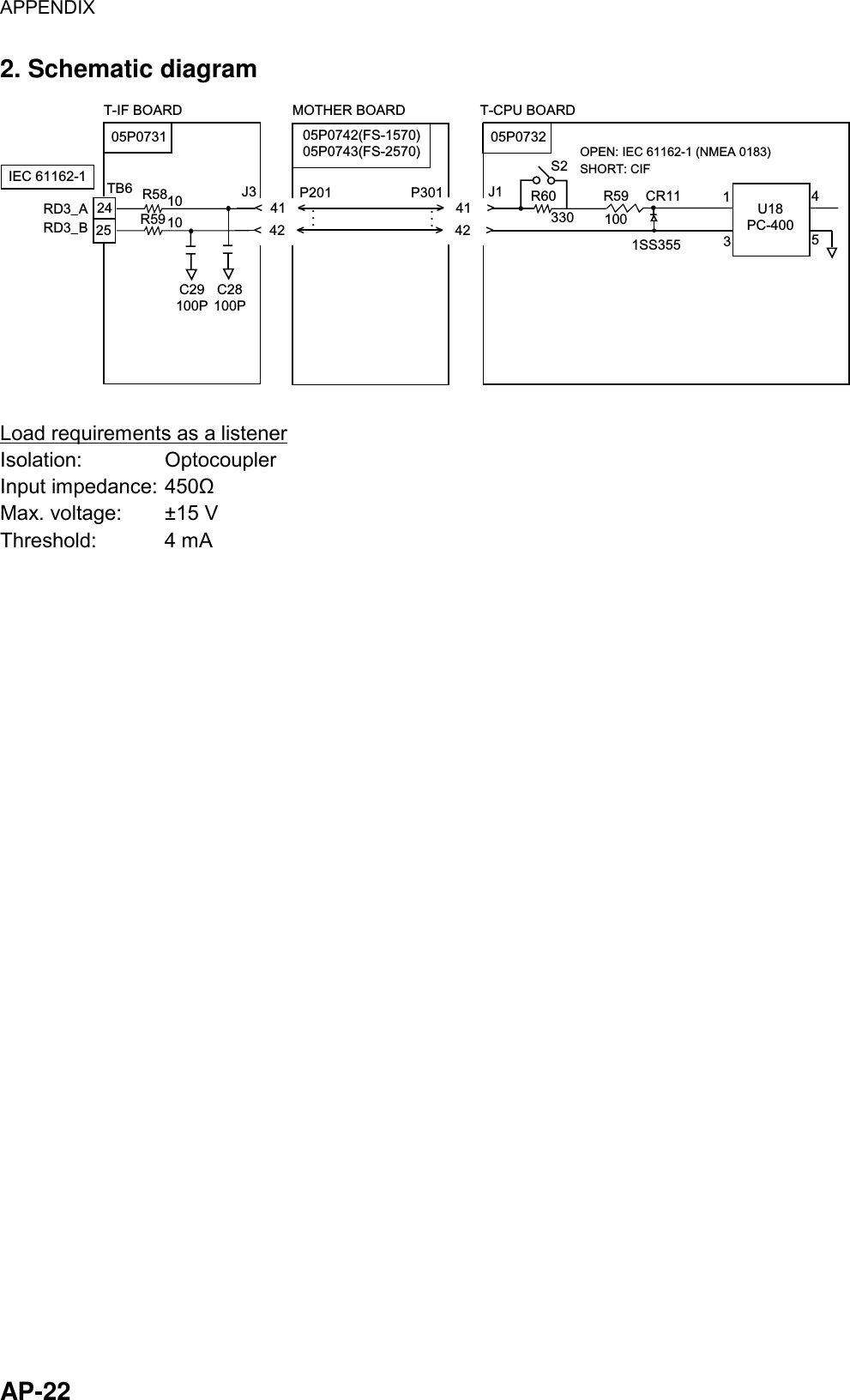
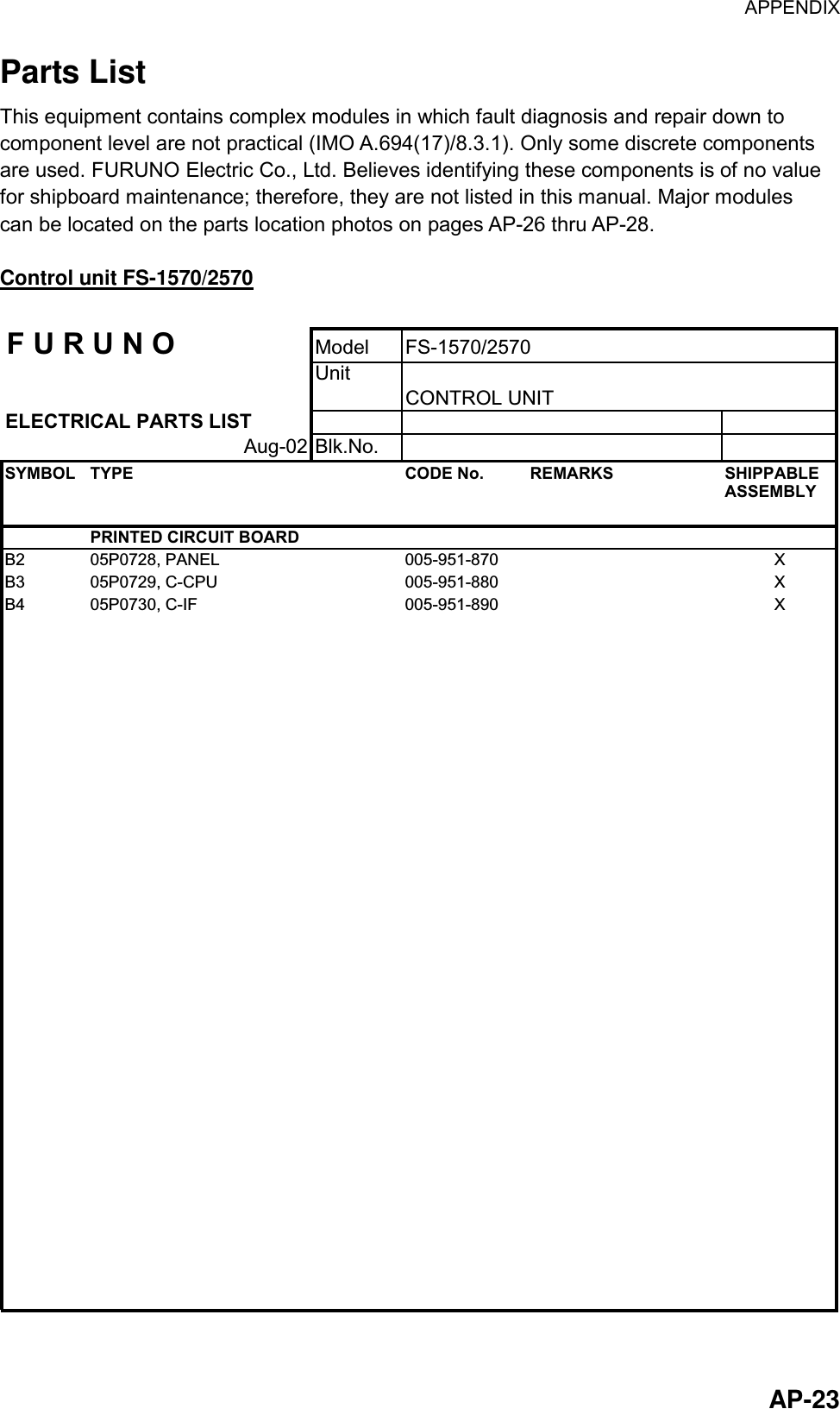
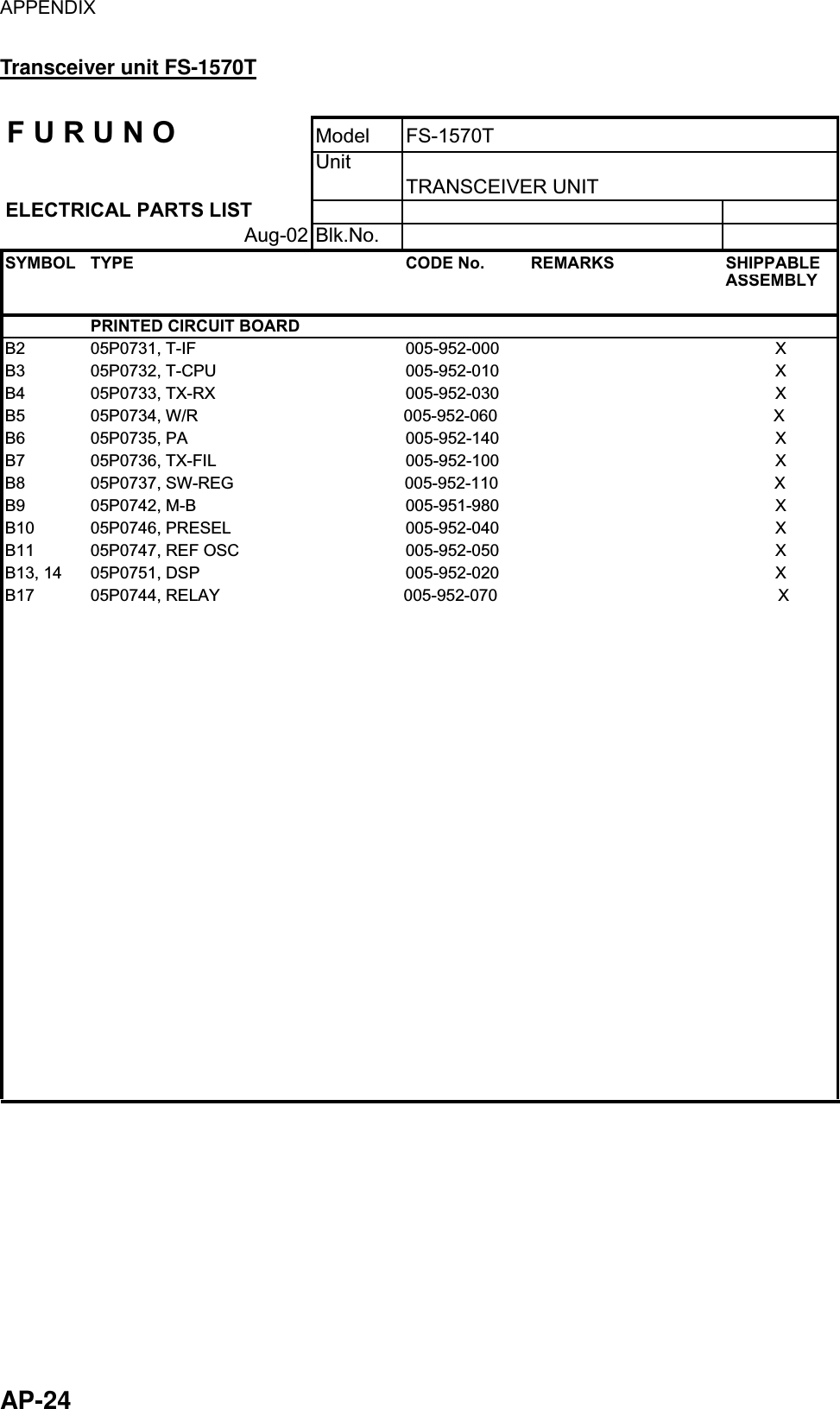
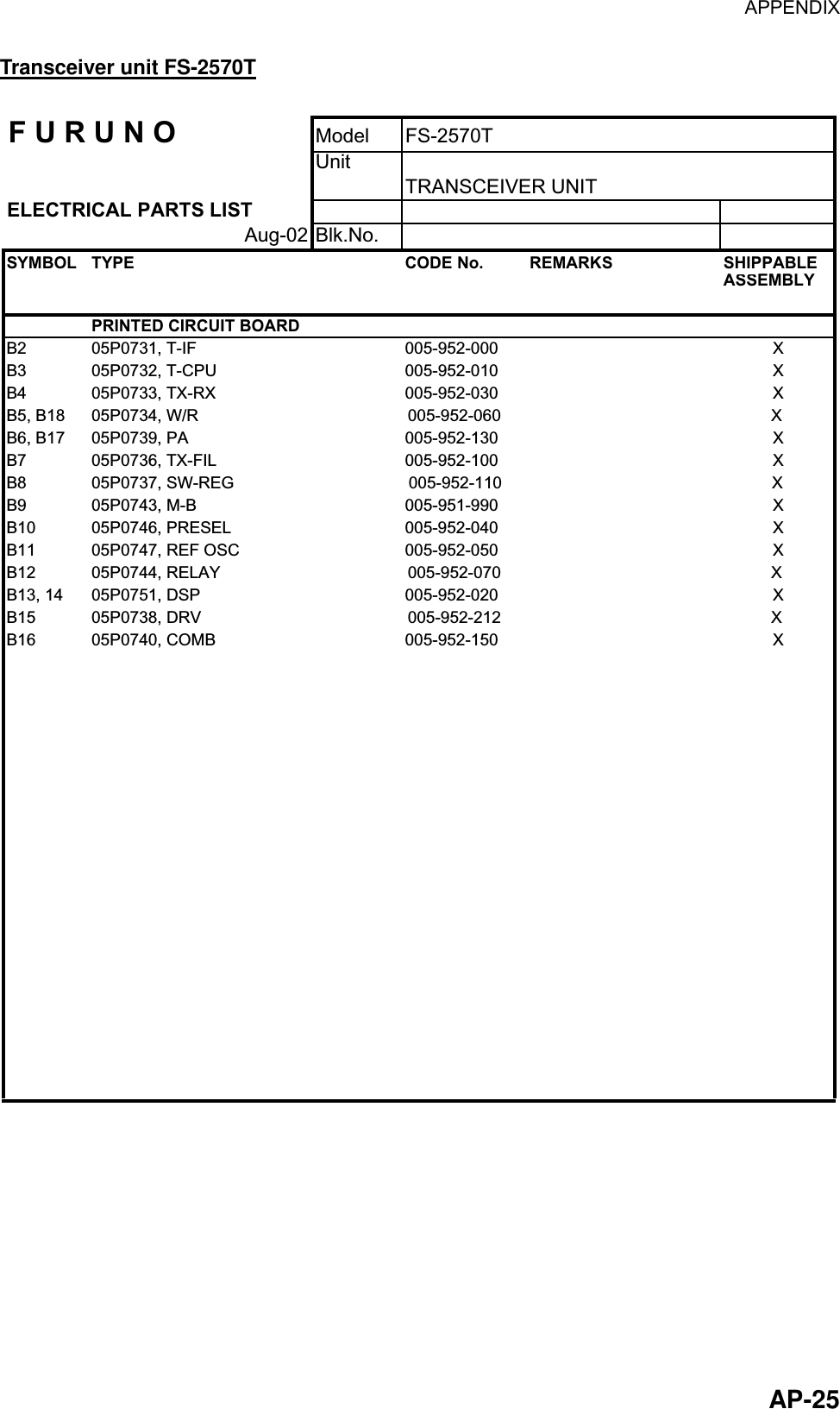
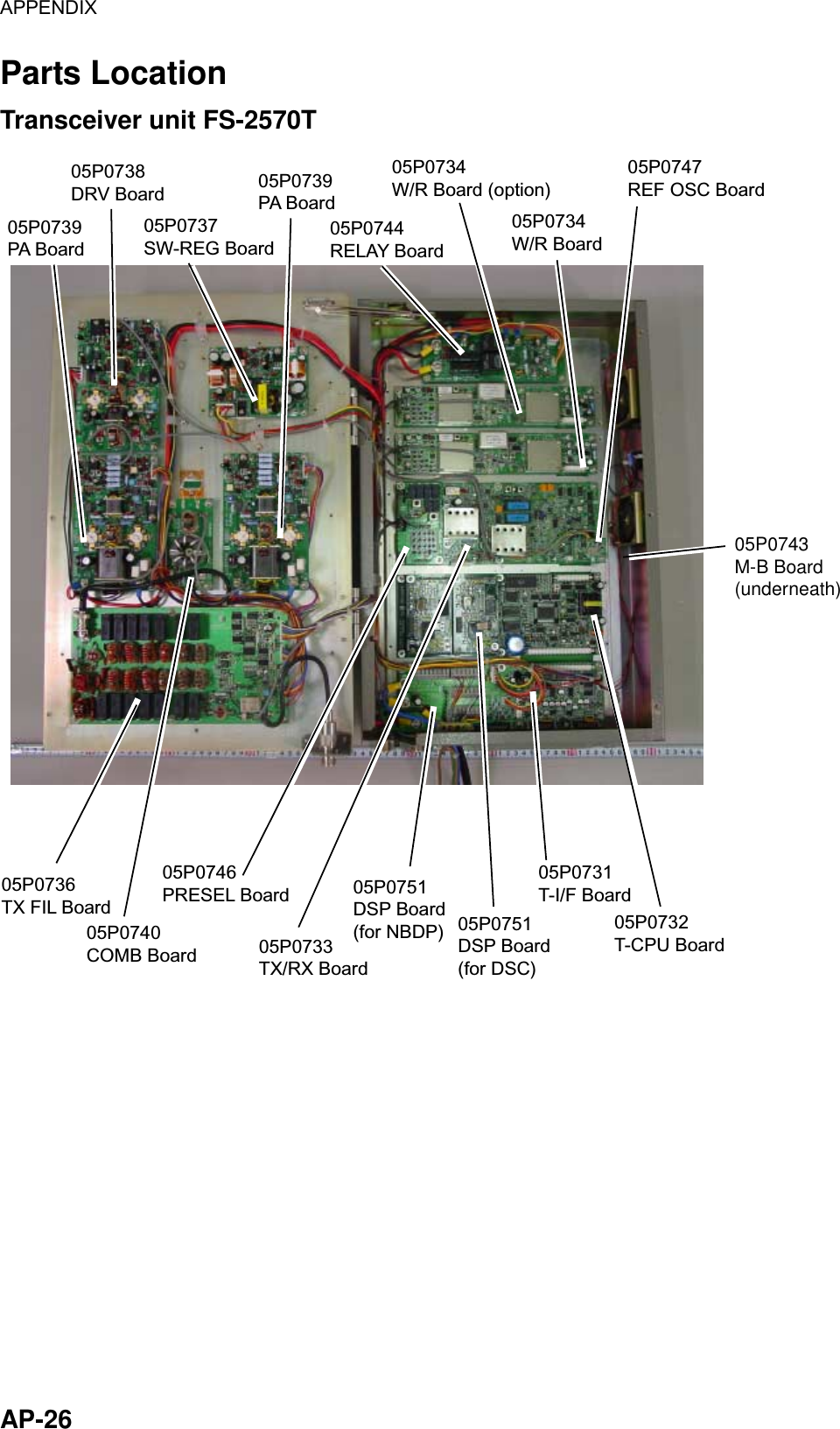
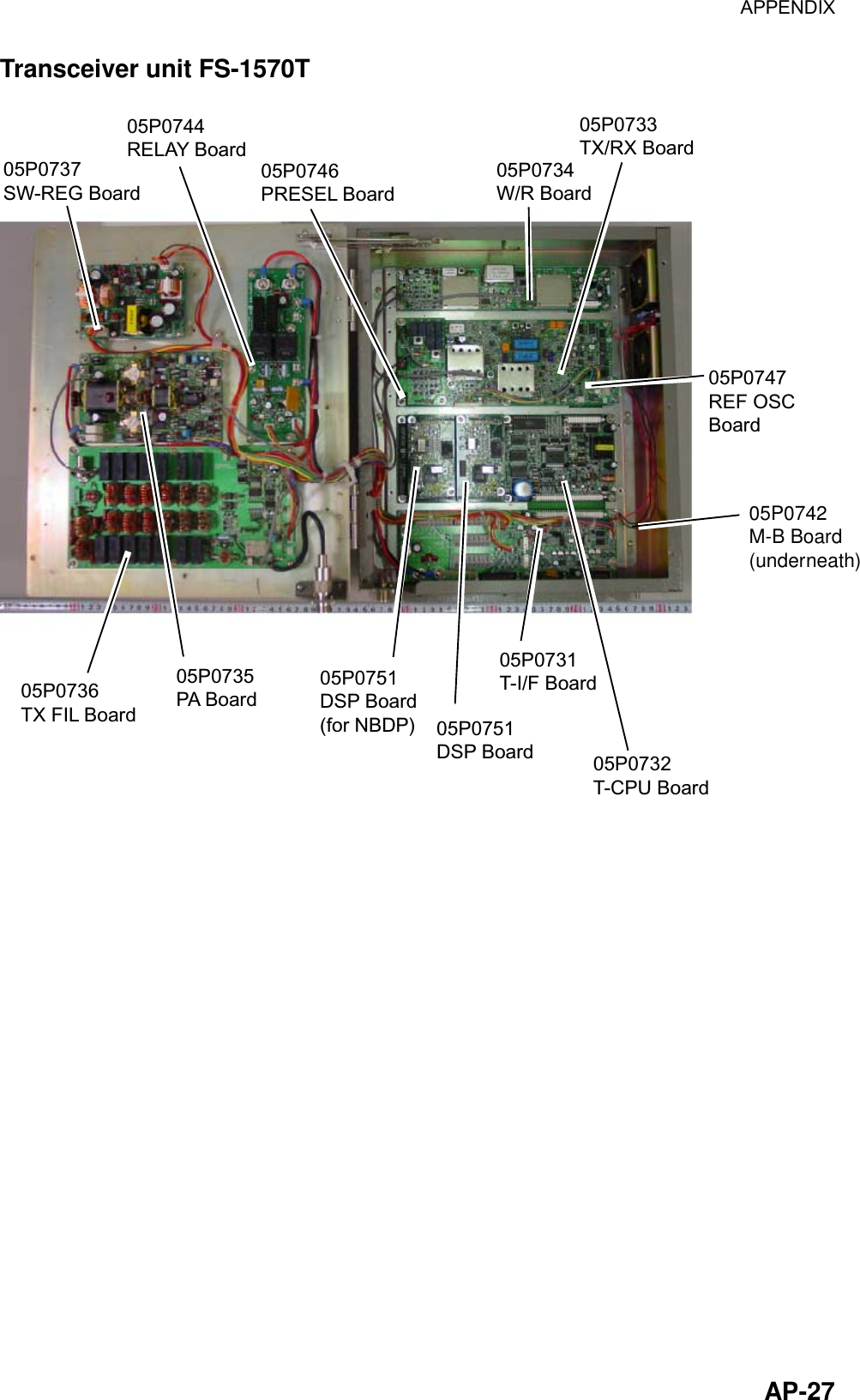
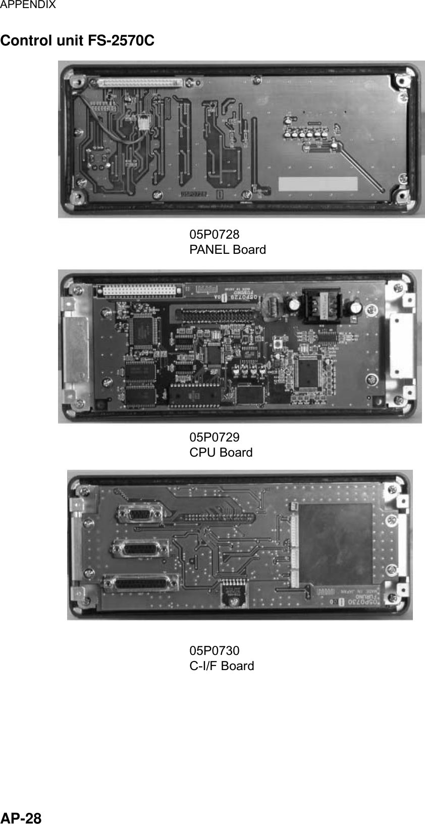
![IN-1 INDEX 1 1/ RT/2182 key............................................ 1-3 2 2/DSC key................................................... 1-1 4 4/Intcom key................................................ 2-8 5 5/ ACK/SQ key............................................ 1-4 6 6/SCAN key ......................................... 1-3, 1-4 7 7/ key ...................................................... 1-4 8 8/PRINT key................................................ 7-3 9 9/ key..................................................... 1-2 A Alarm menu................................................. 7-1 All ships call receiving.................................................. 5-3 sending ................................................... 5-1 Antenna current .......................................... 2-4 Auto ack menu............................................ 7-2 C Channel selection ....................................... 2-2 Contrast ...................................................... 1-2 Control description...................................... 1-1 D Daily test ................................................... 12-1 Dimmer ....................................................... 1-2 Distress alert receiving on either VHF channel 70 or MF channel 2187.5 ................................... 4-7 receiving on HF band.............................. 4-9 sending ................................................... 4-1 Distress relay on behalf of other ship, to all ships....... 4-16 on behalf of other ship, to coast station 4-13 receiving................................................ 4-19 to coast station on HF band.................... 4-9 DSC frequency table ...................................... 4 E Error messages .........................................12-6 F FILE/CURSOR key......................................6-9 Frequency selection ....................................2-3 G Geographical area call receiving ................................................5-22 sending ..................................................5-19 Group call receiving ................................................5-18 sending ..................................................5-15 I IA ......................................................... 2-4, 2-5 IC .................................................................2-5 Individual call automatic acknowledge.........................5-10 manual acknowledge.............................5-12 sending ....................................................5-4 Intercom.......................................................2-8 L Log file description .............................................5-45 opening..................................................5-45 LOG/TUNE key .........................................5-45 M Medical transport call receiving ................................................5-27 sending ..................................................5-26 Menu tree .................................................AP-1 N NBDP Terminal Unit answerback code registration .................9-1 ARQ mode............................................. 11-3 communications buffer .......................... 11-9 edit menu [F2] .........................................8-6 FEC mode ............................................. 11-5 file creating ............................................10-1 file deleting ............................................10-7 file editing ..............................................10-3](https://usermanual.wiki/Furuno-USA/9ZWFS2570/User-Guide-282811-Page-215.png)
![INDEX IN-2 file menu [F1] .......................................... 8-5 file opening............................................ 10-6 file renaming ......................................... 10-7 file saving.............................................. 10-2 file saving under new name.................. 10-7 general test ......................................... 12-10 ID code registration................................. 9-2 macrofiles.............................................11-10 manual calling........................................11-1 menu overview........................................ 8-4 operate menu [F3] .................................. 8-7 printing .................................................. 10-7 receive mode .........................................11-5 scan channel group editing, deleting...... 9-8 scan channel group registration ............. 9-7 scanning.................................................11-9 station editing, deleting........................... 9-4 station menu [F5] .................................... 8-9 station registration .................................. 9-3 system menu [F6] ................................. 8-10 terminal unit ............................................ 8-1 timer operation.......................................11-8 timer program editing, deleting............... 9-6 timer program registration ...................... 9-5 tone test ...............................................12-11 user channel editing, deleting................. 9-7 user channel registration ........................ 9-6 window menu [F4]................................... 8-8 Neutral craft call receiving................................................ 5-25 sending ................................................. 5-23 P Polling call receiving................................................ 5-31 sending ................................................. 5-28 Position call other ship requests your position.......... 5-36 requesting other ship’s position ............ 5-34 Position entry (manual)............................... 1-5 POWER switch ........................................... 1-2 Print out menu ............................................ 7-3 PSTN call charge information................................ 5-43 receiving................................................ 5-42 sending ................................................. 5-38 R RF................................................................2-5 S Scan freq menu...........................................7-4 Scan frequency setup .................................7-5 Scanning......................................................1-4 Send message files geographical area call .............................6-6 group call.................................................6-4 individual call ...........................................6-1 printing...................................................6-10 PSTN call.................................................6-7 sending ....................................................6-9 test call ....................................................6-8 T Test call......................................................12-7 Time entry (manual) ....................................1-5 Transmitter power .......................................2-5 Troubleshooting.........................................12-5 Tuning..........................................................2-3 U USER CH menu ........................................2-10 User channels deleting..................................................2-12 registering..............................................2-10 V VC................................................................2-5 Volume menu ..............................................7-6](https://usermanual.wiki/Furuno-USA/9ZWFS2570/User-Guide-282811-Page-216.png)