Furuno USA 9ZWFS2570 MF HF GMDSS MARINE SSB RADIOTELEPHONE User Manual OPERATORS MANUAL
Furuno USA Inc MF HF GMDSS MARINE SSB RADIOTELEPHONE OPERATORS MANUAL
OPERATORS MANUAL

SSB RADIOTELEPHONE
FS-1570 (150 W)
FS-2570 (250 W)

Your Local Agent/DealerYour Local Agent/Dealer
9-52 Ashihara-cho,9-52 Ashihara-cho,
Nishinomi
y
a, Ja
p
anNishinomi
y
a, Ja
p
an
Tele
p
hone :Tele
p
hone : 0798-65-21110798-65-2111
Telefax :Telefax : 0798-65-42000798-65-4200
FIRST EDITION :FIRST EDITION : OCT.OCT. 20022002
Printed in JapanPrinted in Japan
A
ll ri
g
hts reserved.
A
ll ri
g
hts reserved.
B :B : OCT.OCT. 18,200218,2002
PUB.No.PUB.No. OME-56360OME-56360
*00080933800**00080933800*
*00080933800**00080933800*
(( DAMIDAMI )) FS-1570/2570FS-1570/2570 * 0 0 0 8 0 9 3 3 8 0 0 ** 0 0 0 8 0 9 3 3 8 0 0 *
*OME56360B00**OME56360B00*
*OME56360B00**OME56360B00*
* O M E 5 6 3 6 0 B 0 0 ** O M E 5 6 3 6 0 B 0 0 *
i
Distress Alert Calling Procedure
Below is the procedure for transmitting a distress alert via radiotelephone. Transmit the
distress alert when a life-endangering situation occurs on your vessel.
1. Open the DISTRESS button cover and press the [DISTRESS] button more than three
seconds to show the following display, then release the [DISTRESS] button.
TIME TO GO : 30S
NATURE: UNDESIGNATED
POS: 12˚34N 123˚45E AT 12:34
TELEPHONE 2182.0 KHZ
Distress
call in progress!
DSC FREQ : 2187.5 KHZ
2. After the distress call has been transmitted, the following displays appear in order.
Wait for distress
acknowledgement.
TIME TO GO: 2M10S
NATURE: UNDESIGNATED
POS :
12˚34N 123˚45E AT 12:34
TELEPHONE
2182.0 KHZ
DSC FREQ :
2187.5 KHZ
SHIP IN DIST:
123456789
POS:
12˚34N 123˚45E AT 12:34
TELEPHONE
2182.0 KHZ
FROM COAST:
001234567
NATURE: UNDESIGNATED
Distress acknowledge
call received.
STOP ALARM
When distress call is
acknowledged by coast
station (usually within
1 min to 2 min 45 seconds)
3. The audio alarm sounds; press the [CANCEL] key to silence the alarm.
4. Communicate with the coast station via radiotelephone as below. (In the dual control
unit system, communication can be done from any control unit, after the distress alert
has been transmitted. To restore priority to the #1 control unit after completion of
distress communications, turn it off and on again.)
a) Say MAYDAY three times.
b) Say “This is …” name of your vessel and your call sign three times.
c) Give nature of distress and assistance needed.
d) Give description of your vessel (type, number of persons onboard, etc.) and any other
information which may aid in rescue.
ii
SAFETY INSTRUCTIONS
WARNING
Immediately turn off the power at the
switchboard if water leaks into the
equipment or something is dropped in
the equipment.
Continued use of the equipment can cause
fire or electrical shock. Contact a FURUNO
agent for service.
Do not disassemble or modify the
equipment.
Fire, electrical shock or serious injury can
result.
Immediately turn off the power at the
switchboard if the equipment is emitting
smoke or fire.
Continued use of the equipment can cause
fire or electrical shock. Contact a FURUNO
agent for service.
Do not operate the equipment with wet
hands.
Electrical shock can result.
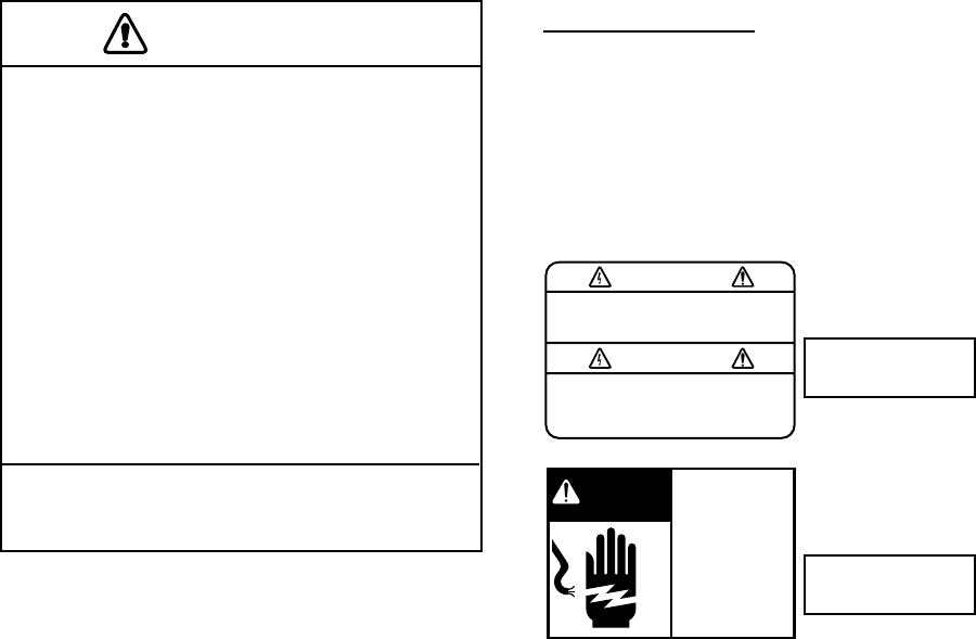
ELECTRICAL SHOCK HAZARD
Do not open the equipment.
Only qualified personnel
should work inside the
equipment.
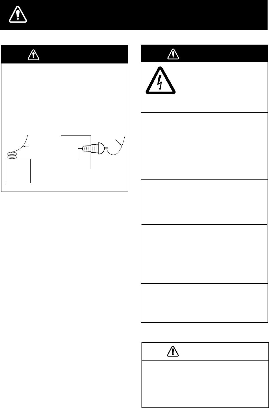
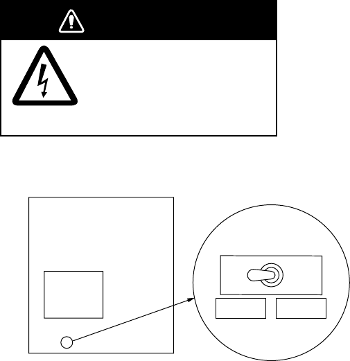
DANGER
Never touch the SSB antenna, antenna
coupler or lead-in insulator when the
SSB radiotelephone is transmitting.
High voltage which will cause death or
serious injury is present at the locations
shown in the illustration below when the
SSB radiotelephone is transmitting.
Antenna
Coupler
Antenna Wire
(High Voltage)
Indoor Antenna
Wire
Lead-in
Insulator
(High
Voltage)
Use the proper fuse.
Use of the wrong fuse can cause serious
damage to the equipment and void the
warranty.
CAUTION
iii
Do not operate the [DISTRESS] button
except in case of a life-endangering
situation on your vessel.
If the distress alert is accidentally
transmitted, contact the nearest coast
station and inform them of the accidental
transmission as follows:
a) Ship's name
b) Ship's call sign and DSC number
c) Position at time of transmission
d) Time of transmission
This equipment is intended for maritime
use. Do not use it in other applications.
A warning label is attached to the
transceiver unit and a danger label is
attached to the antenna coupler.
Do not remove the labels.
If a label is missing or illegible,
contact a FURUNO agent or dealer
about replacement.
WARNING
To avoid electrical shock, do not
remove cover. No user-serviceable
parts inside.
Name: Warning Label (1)
Type: 86-003-1011-1
Code No.: 100-236-231
TRANSCEIVER
UNIT
Hazardous voltage.
Can shock, burn,
or cause death.
Do not touch antenna
wire, insulator and
terminal.
DANGER
Name: Danger Label
Type: 05-062-0213-0
Code No.: 100-199-230
ANTENNA
COUPLER
CAUTION WARNING LABEL

iv
TABLE OF CONTENTS
TABLE OF CONTENTS .......................................................................................iv
FOREWORD.........................................................................................................ix
SYSTEM CONFIGURATION................................................................................xi
SPECIFICATIONS...........................................................................................SP-1
1 OPERATIONAL OVERVIEW.........................................................................1-1
1.1 Controls ....................................................................................................................... 1-1
1.2 Turning the Power On/Off ............................................................................................ 1-2
1.3 Panel Dimmer, LCD Contrast....................................................................................... 1-2
1.4 Indications ................................................................................................................... 1-3
1.4.1 DSC standby screen......................................................................................... 1-3
1.4.2 Radiotelephone screen..................................................................................... 1-3
1.5 Loudspeaker................................................................................................................ 1-4
1.6 Scanning Routine DSC Frequencies ......................................................................... 1-4
1.7 Automatic Acknowledge On/Off.................................................................................... 1-4
1.8 Manual Entry of Position and Time............................................................................... 1-5
1.9 System Characteristics ................................................................................................ 1-7
1.9.1 Equipment priority............................................................................................. 1-7
1.9.2 Controls become inoperative ............................................................................ 1-7
1.9.3 Controls become operative ............................................................................... 1-7
1.9.4 Automatic setting of working frequency............................................................. 1-7
1.10 Power Supply Unit (option) ........................................................................................ 1-8
2 SSB RADIOTELEPHONE .............................................................................2-1
2.1 Transmitting ................................................................................................................. 2-1
2.1.1 Choosing class of emission .............................................................................. 2-1
2.1.2 Choosing channel, frequency............................................................................ 2-2
2.1.3 Tuning............................................................................................................... 2-3
2.1.4 Using the handset............................................................................................. 2-4
2.1.5 Monitoring transceiver output power ................................................................. 2-4
2.1.6 Reducing transmitter power .............................................................................. 2-5
2.1.7 Displaying IA, IC, VC or RF .............................................................................. 2-5
2.2 Receiving..................................................................................................................... 2-6
2.2.1 RF gain (sensitivity) adjustment........................................................................ 2-6
2.2.2 S-meter............................................................................................................. 2-6
2.2.3 Monitoring traffic on intended transmit frequency.............................................. 2-6
2.2.4 Receiving AM broadcasting stations ................................................................. 2-6
2.2.5 Squelch control, squelch frequency .................................................................. 2-7
2.2.6 Noise blanker.................................................................................................... 2-7
2.3 Intercom....................................................................................................................... 2-8
2.4 Telex Communications................................................................................................. 2-8
2.5 When Automatic Tuning Fails ...................................................................................... 2-9
v
2.6 User Channels ...........................................................................................................2-10
2.6.1 Registering user channels...............................................................................2-10
2.6.2 Deleting user channels....................................................................................2-12
2.7 FAX Enable/Disable ...................................................................................................2-12
3 DSC OVERVIEW ...........................................................................................3-1
3.1 What is DSC?...............................................................................................................3-1
3.2 DSC Call ......................................................................................................................3-1
3.2.1 Distress alert call and reply ...............................................................................3-3
3.2.2 Individual call ....................................................................................................3-4
3.3 Audio Alarms ................................................................................................................3-4
3.4 Interpreting Call Displays..............................................................................................3-5
3.4.1 Receive calls.....................................................................................................3-5
3.4.2 Send calls .........................................................................................................3-7
4 DISTRESS OPERATIONS.............................................................................4-1
4.1 Sending Distress Alert ..................................................................................................4-1
4.1.1 Sending distress alert by DISTRESS button, nature of distress not specified....4-1
4.1.2 Sending distress alert by DISTRESS button, nature of distress specified..........4-3
4.2 Receiving a Distress Alert.............................................................................................4-6
4.2.1 Distress alert received on MF band...................................................................4-7
4.2.2 Distress alert received on HF band ...................................................................4-9
4.3 Sending Distress Relay on Behalf of a Ship in Distress..............................................4-13
4.3.1 Sending distress relay to coast station ............................................................4-13
4.3.2 Sending distress relay to all ships ...................................................................4-16
4.4 Receiving Distress Relay All Ships .............................................................................4-19
4.5 Receiving Distress Relay from Coast Station..............................................................4-19
5 CALLING, RECEIVING..................................................................................5-1
5.1 All Ships Call ................................................................................................................5-1
5.1.1 Sending an all ships call....................................................................................5-1
5.1.2 Receiving an all ships call .................................................................................5-3
5.2 Individual Call...............................................................................................................5-4
5.2.1 Sending an individual call..................................................................................5-4
5.2.2 Receiving an individual call .............................................................................5-10
5.3 Group Call..................................................................................................................5-15
5.3.1 Sending a group call .......................................................................................5-15
5.3.2 Receiving a group call.....................................................................................5-18
5.4 Geographical Area Call ..............................................................................................5-19
5.4.1 Sending a geographical area call ....................................................................5-19
5.4.2 Receiving a geographical area call..................................................................5-22
5.5 Neutral Craft Call........................................................................................................5-23
5.5.1 Sending a neutral craft call..............................................................................5-23
5.5.2 Receiving a neutral craft call ...........................................................................5-25
5.6 Medical Transport Call................................................................................................5-26
5.6.1 Sending a medical transport call .....................................................................5-26
5.6.2 Receiving a medical transport call...................................................................5-27
vi
5.7 Polling Call................................................................................................................. 5-28
5.7.1 Sending a polling call...................................................................................... 5-28
5.7.2 Receiving a polling call ................................................................................... 5-31
5.8 Position Call...............................................................................................................5-33
5.8.1 Position call: requesting other ship’s position.................................................. 5-34
5.8.2 Position call: other ship requests your position................................................ 5-36
5.9 PSTN Call.................................................................................................................. 5-38
5.9.1 Sending a PSTN call, receiving acknowledge back (ACK BQ)............................ 5-38
5.9.2 Receiving a PSTN call, sending acknowledge back (ACK BQ) ....................... 5-42
5.9.3 PSTN call disconnection, receiving charge information (ship disconnects line)5-43
5.9.4 PSTN call disconnection, receiving charge information (coast station
disconnects line)...................................................................................................... 5-44
5.10 Log File.................................................................................................................... 5-45
5.10.1 Opening a log file.......................................................................................... 5-45
5.11 Erasing Message Files............................................................................................. 5-46
6 PREPARING TX CALLS ...............................................................................6-1
6.1 Preparing Individual Calls ............................................................................................ 6-1
6.2 Preparing Group Calls ................................................................................................. 6-4
6.3 Preparing Geographical Area Calls .............................................................................. 6-5
6.4 Preparing PSTN Calls.................................................................................................. 6-7
6.5 Preparing Test Calls..................................................................................................... 6-8
6.6 Sending Prepared Calls ............................................................................................... 6-9
6.7 Deleting Send Message Files .................................................................................... 6-10
6.8 Printing List of Send Message Files ........................................................................... 6-10
7 DSC/WATCH RECEIVER SETUP .................................................................7-1
7.1 Setting Alarms..............................................................................................................7-1
7.2 Auto Ack Menu............................................................................................................. 7-2
7.3 Printing Messages ....................................................................................................... 7-3
7.4 Setting Scan Frequencies............................................................................................ 7-4
7.4.1 Distress frequencies ......................................................................................... 7-4
7.4.2 Routine frequencies.......................................................................................... 7-5
7.5 Adjusting Volume ......................................................................................................... 7-6
8 NBDP SYSTEM OVERVIEW.........................................................................8-1
8.1 Turning on the NBDP System ...................................................................................... 8-1
8.2 Description of Equipment............................................................................................. 8-2
8.2.1 Terminal unit ..................................................................................................... 8-2
8.2.2 Keyboard .......................................................................................................... 8-3
8.3 Function Keys, Menu Operation................................................................................... 8-4
8.3.1 Menu conventions............................................................................................. 8-4
8.3.2 Menu overview ................................................................................................. 8-4
8.3.3 Function key description ................................................................................... 8-5
vii
9 NBDP PREPARATIONS................................................................................9-1
9.1 Registering Answerback Code & ID Codes...................................................................9-1
9.1.1 Registering answerback code ...........................................................................9-1
9.1.2 Registering ID codes.........................................................................................9-2
9.2 Station List....................................................................................................................9-3
9.2.1 Registering stations...........................................................................................9-3
9.2.2 Editing/Deleting stations....................................................................................9-4
9.3 Timer Programming......................................................................................................9-5
9.3.1 Registering timer programs ...............................................................................9-5
9.3.2 Editing/Deleting timer programs ........................................................................9-6
9.4 User Channels .............................................................................................................9-6
9.4.1 Registering user channels.................................................................................9-6
9.4.2 Editing/Deleting user channels..........................................................................9-7
9.5 Scan Channel Groups ..................................................................................................9-7
9.5.1 Registering scan channel groups ......................................................................9-7
9.5.2 Editing/Deleting scan channel groups ...............................................................9-8
10 NBDP FILE OPERATIONS..........................................................................10-1
10.1 Opening and Closing Files .......................................................................................10-1
10.2 Creating Files...........................................................................................................10-1
10.3 Saving a File ............................................................................................................10-2
10.3.1 Formatting floppy disks .................................................................................10-2
10.3.2 Saving a file ..................................................................................................10-2
10.4 Editing Files..............................................................................................................10-3
10.4.1 Cutting and pasting text.................................................................................10-3
10.4.2 Copying and pasting text...............................................................................10-4
10.4.3 Select all .......................................................................................................10-4
10.4.4 Searching text ...............................................................................................10-4
10.4.5 Replacing text ...............................................................................................10-5
10.4.6 Goto line........................................................................................................10-5
10.4.7 Goto top, Goto bottom...................................................................................10-6
10.5 Opening Files ...........................................................................................................10-6
10.5.1 Opening a file................................................................................................10-6
10.5.2 Switching between files.................................................................................10-6
10.6 Renaming Files ........................................................................................................10-7
10.7 Saving a File Under a New Name ............................................................................10-7
10.8 Deleting Files ...........................................................................................................10-7
10.9 Real Time Printing....................................................................................................10-7
10.10 Printing Files ..........................................................................................................10-8
11 NBDP TRANSMITTING, RECEIVING .........................................................11-1
11.1 Manual Calling.......................................................................................................... 11-1
11.2 ARQ Mode Operation ............................................................................................... 11-3
11.3 FEC Mode Operation................................................................................................ 11-5
11.4 Choosing Receive Mode........................................................................................... 11-5
11.5 Communication Example.......................................................................................... 11-6
viii
11.6 Timer Operation ....................................................................................................... 11-8
11.6.1 Enabling timer operation ............................................................................... 11-8
11.6.2 Stopping timer operation ............................................................................... 11-9
11.7 Scanning .................................................................................................................. 11-9
11.8 Communication Buffer.............................................................................................11-10
11.9 Preparing Macrofiles for Automatic Telex.................................................................11-10
11.9.1 Automatic telex overview..............................................................................11-10
11.9.2 Preparations.................................................................................................11-11
11.9.3 Commands ..................................................................................................11-12
11.9.4 Store-and-forward method............................................................................11-13
11.9.5 DIRTLX macrofile.........................................................................................11-15
11.10 Automatic Telex using Macrofile ............................................................................11-17
12
MAINTENANCE & TROUBLESHOOTING .................................................12-1
12.1 Daily Test ................................................................................................................. 12-1
12.2 Radiotelephone Test ................................................................................................ 12-2
12.3 Antenna Coupler Test............................................................................................... 12-2
12.4 Maintenance ............................................................................................................ 12-3
12.5 Replacement of Fuses ............................................................................................. 12-4
12.6 Simple Troubleshooting............................................................................................ 12-5
12.7 Error Messages ....................................................................................................... 12-6
12.8 Test Call................................................................................................................... 12-7
12.9 NBDP Terminal Unit Maintenance ............................................................................ 12-9
12.9.1 Cleaning the equipment................................................................................ 12-9
12.9.2 Connectors and earth connection ................................................................. 12-9
12.9.3 Floppy disk drive........................................................................................... 12-9
12.9.4 Diagnostics ................................................................................................. 12-10
APPENDIX.......................................................................................................AP-1
Menu Tree ...................................................................................................................... AP-1
Frequency Tables ........................................................................................................... AP-4
Telex Abbreviations....................................................................................................... AP-17
Digital Interface (IEC 61162-1)...................................................................................... AP-18
Parts List....................................................................................................................... AP-23
Parts Location............................................................................................................... AP-26
INDEX ............................................................................................................... IN-1
Declaration of conformity

ix
FOREWORD
Thank you for purchasing the FS-1570 (150 W)/FS-2570 (250 W) SSB Radiotelephone.
We are confident you will discover why FURUNO has become synonymous with quality
and reliability.
Dedicated in the design and manufacture of marine electronics equipment for over half a
century, FURUNO Electric Company has gained an unrivaled reputation as a world leader
in the industry. This is the result of our technical excellence as well as our worldwide
distribution and service network.
Please carefully read and follow the safety information and operating and maintenance
instructions set forth in this manual before attempting to operate the equipment and
conduct any maintenance. Your unit will perform to the utmost of its ability only if it is
operated and maintained in accordance with the correct procedures.
Note: The example screens shown in this manual may not match the screens you see on
your display. The screen you see depends on your system configuration and equipment
settings.
Features
The FS-1570/FS-2570 is an MF/HF SSB Radiotelephone with a built-in DSC/Watch
Receiver, all contained in a surprisingly compact cabinet. An NBDP (Narrow Band Direct
Printing) Terminal Unit is optionally available.
Data is displayed on a large, easy-to-read backlit LCD. Operation is simplified by the use
of few keys and easy-to-follow menus.
The built-in DSC/watch receiver produces and receives digital selective calls for quick and
efficient establishment of distress, urgency, safety and routine communications with other
ships and coast stations that install any MF/HF DSC facilities.
The main features are
General
•
Fully meets the following regulations: IMO A.694(17), IMO A.804(19), IMO A.806(19),
IMO A.813(19), IMO MSC 68(68), IEC 60945, IEC 61907-3/8/9, IEC-61162-1,
EIV-300/338, ITU-R M.493-10, M.541-8, M.1082-1, EN 300 373, EN 300 338, EN 300
033 and ETS 300 067.
•
One-touch testing facility
•
Automatic entry of position with manual override
•
Optional printer can automatically print out DSC and NBDP received messages and test
results.

x
DSC/watch receiver
•
Distress, safety and routine calling
•
Scanning of DSC frequencies for distress and general calls on MF/HF
•
File editing capability for readiness in case of emergency
•
PSTN (Public Switched Telephone Network) capability standard
•
Log stores 50 each of latest ordinary, distress and transmitted messages, in separate
memory blocks.
NBDP (with optional NBDP Terminal Unit IB-581/IB-583)
•
Automatic error-free telex communications and distress message in compliance with
GMDSS requirements
•
LCD monitor and keyboard comply with ITU regulations
•
Pop-up menus for user-friendly operation
•
Memory for 100 operator-customized channels
•
Real time message printing with Printer PP-510
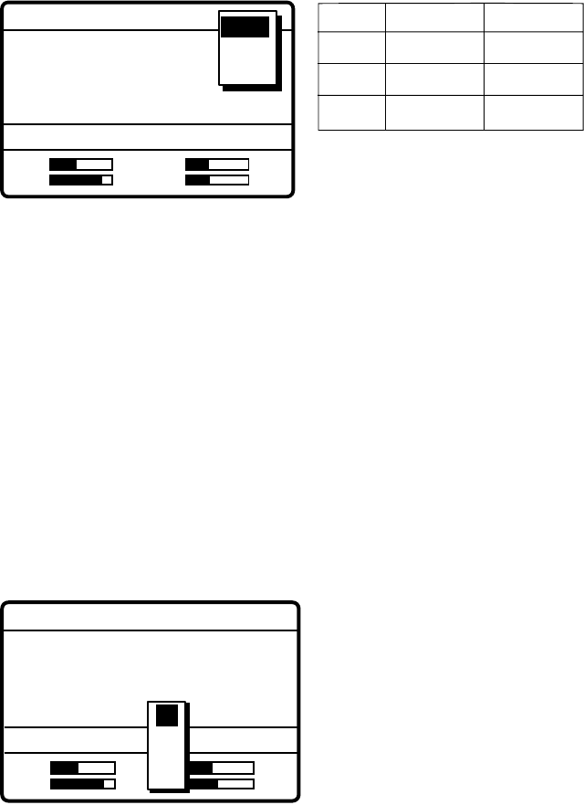
Program Number
PC Board Program No. On Display Remarks
MAIN (Transceiver Unit) 0550205101
Ver. 01 FS-1570T/FS-2570T
PANEL 1 (#1 Control Unit) 0550206101
Ver. 01 FS-2570C
PANEL 2 (#2 Control Unit) 0550206101
Ver. 01 Optional unit
MODEM (DSC) 0550207101
Ver. 01
NBDP MODEM 0550208101
Ver. 01 Optional pcb
Terminal Unit IB-581 (optional unit)
PC Board Program No. On Display Remarks
Terminal Unit 0550210122 Ver. 1.22
Terminal Unit IB-583 (optional unit)
PC Board Program No. On Display Remarks
Terminal Unit 0550209122 Ver. 1.22
xi
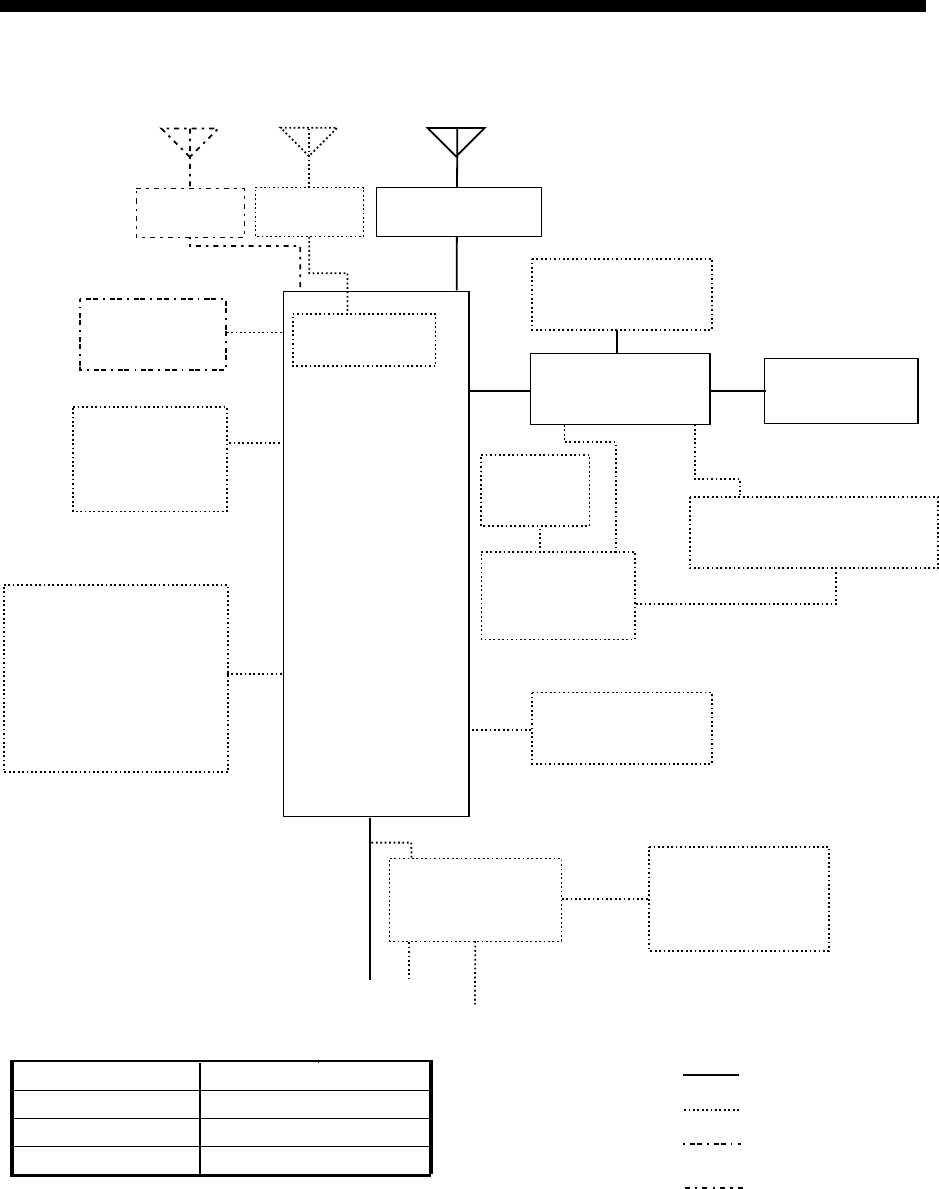
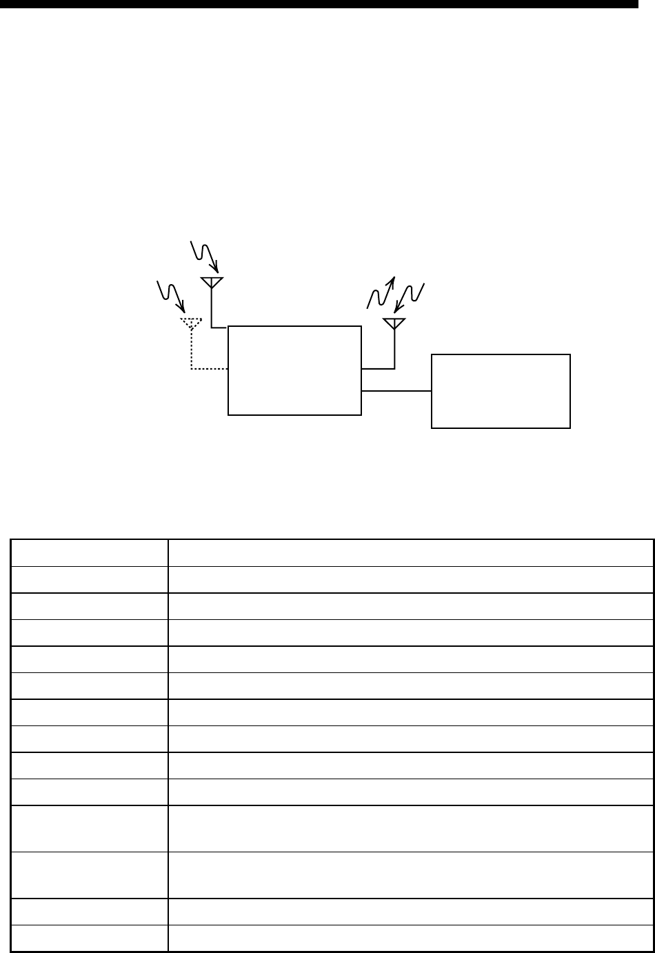
SYSTEM CONFIGURATION
FS-2570 (250 W)
TRANSCEIVER
UNIT
FS-2570T
SHIP'S MAINS
24 VDC 100-115/200-230 VAC
1φ, 50/60 Hz
INCOMING
INDICATOR
IC-303-DSC
NAVIGATOR
AC/DC POWER
SUPPLY UNIT
PR-850A
PREAMP
FAX-5
LOUDSPEAKER
SEM-21Q
HANDSET
HS-2001
Antenna Coupler
AT-1560-25
CONTROL UNIT
FS-2570C
PREAMP
FAX-5
CONTROL UNIT
FS-2570C
PRINTER
SWITCH BOX
PRINTER
PP-510 NBDP TERMINAL UNIT
IB-581/IB-583
TELEX DISTRESS
ALERT BUTTON
IC-302-DSC
or
DISTRESS MESSAGE
CONTROLLER
DMC-5
RX BOARD**
CONTROLLER 1
CONTROLLER 2
Note: The CONTROL
UNIT connected to
CONTROLLER 1
has priority.
: OPTION
: STANDARD
POWER STATUS
MONITOR
PSM-01
Unit Category
Preamp Unit Exposed to weather
Antenna Coupler
Exposed to weather
Other Units Protected from weather
* **
* = For distress watch keeping receiver
** = For DSC general frequency
watch keeping receiver
: EXTERNAL EQUIPMENT
: REQUIRED
(local supply or
option)
xii
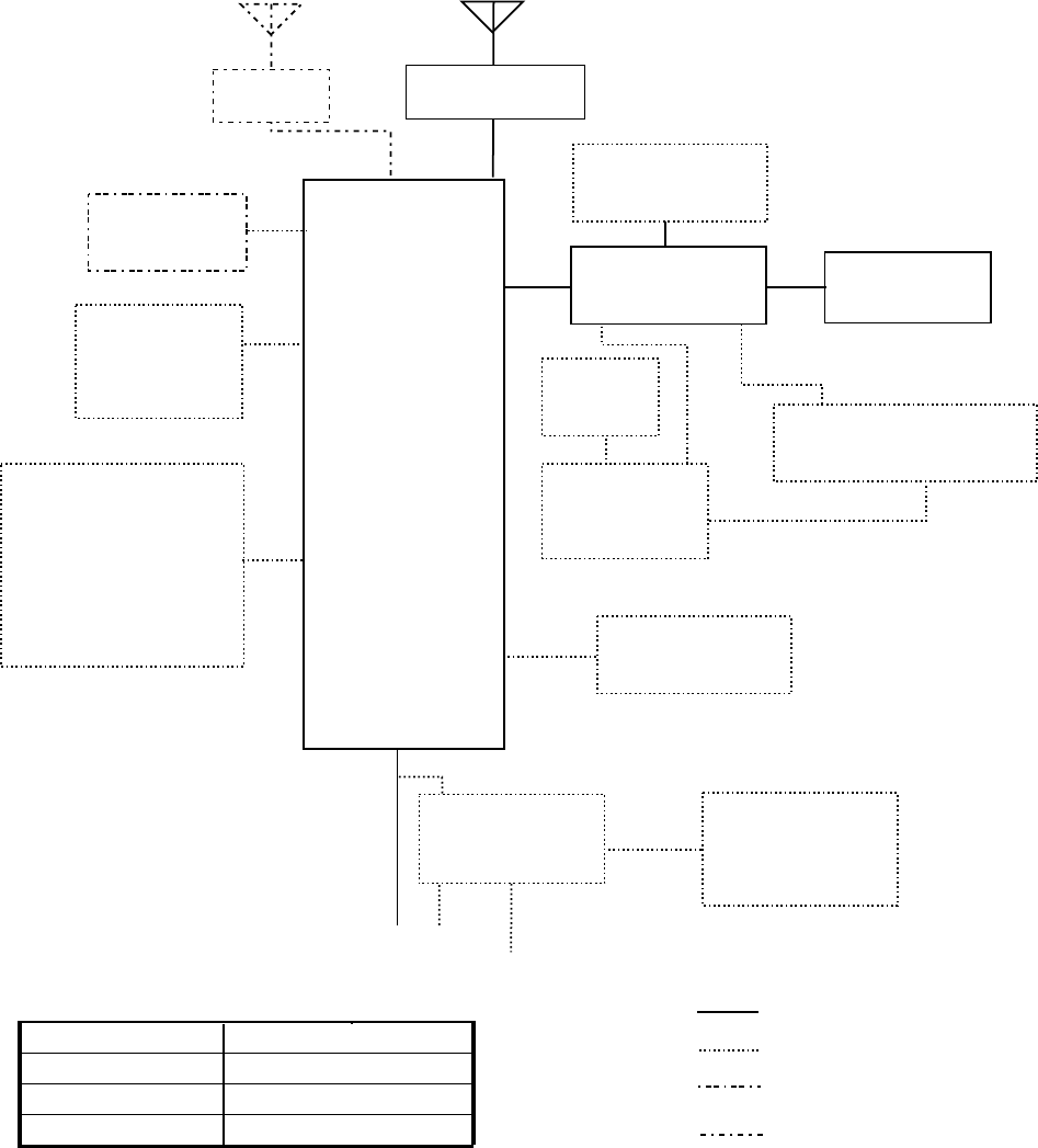
FS-1570 (150 W)
TRANSCEIVER
UNIT
FS-1570T
SHIP'S MAINS
24 VDC 100-115/200-230 VAC
1φ, 50/60 Hz
TELEX DISTRESS
ALERT BUTTON
IC-302-DSC
or
DISTRESS MESSAGE
CONTROLLER
DMC-5
INCOMING
INDICATOR
IC-303-DSC
AC/DC POWER
SUPPLY UNIT
PR-300
LOUDSPEAKER
SEM-21Q
HANDSET
HS-2001
CONTROL UNIT
FS-2570C
CONTROL UNIT
FS-2570C
PRINTER
SWITCH BOX
PRINTER
PP-510 NBDP TERMINAL UNIT
IB-581/IB-583
CONTROLLER 1
CONTROLLER 2
Note: The CONTROL
UNIT connected to
CONTROLLER 1
has priority.
POWER STATUS
MONITOR
PSM-01
Unit Category
Preamp Unit Exposed to weather
Antenna Coupler
Exposed to weather
Other Units Protected from weather
NAVIGATOR
PREAMP
FAX-5
Antenna Coupler
AT-1560-25
*
: OPTION
: STANDARD
: EXTERNAL EQUIPMENT
: REQUIRED
(local supply or
option)
* = For distress watch keeping receiver

SP - 1 E5637S01C-M
SPECIFICATIONS OF SSB TRANSCEIVER
FS-1570/2570
1 MF/HF DIGITAL RADIOTELEPHONE
1.1 GENERAL
1.1.1 Communication System Semi-duplex or simplex
1.1.2 Class of Emission J3E: Telephone
J2B (F1B): DSC or NBDP
H3E: reception only
1.1.3 Frequency Range 100.00 kHz to 29,999.99 kHz
1.1.4 Number of Channel User programmable: 255 TX/RX pairs
All ITU channels incorporated (include DSC/NBDP channels)
2182 kHz (single action)
1.1.5 Display Method Monochrome LCD (120 x 64 dots)
1.1.6 Backlight 8 tones
1.1.7 Contrast 64 steps
1.1.8 Warming up 1 minute approx. (oven 20 minutes approx.)
1.2 TRANSMITTER
1.2.1 Frequency Range 1,606.5 kHz to 27.5 MHz (100 Hz steps)
1.2.2 RF output Power FS-1570: 150 Wpep, FS-2570: 250 Wpep
1.2.3 Frequency Resolution Within ±10 Hz
1.2.4 Modulation AF Response 350 Hz to 2.7 kHz
1.2.5 Modulation System Low power balanced modulation
1.2.6 AF Input -46 dBm/600 ohms (Handset/Microphone)
-10 dBm/600 ohms (Handset HS-2001)
1.2.7 Line in 0 dBm/600 ohms
1.3 RECEIVER
1.3.1 Receiving System Double-conversion superheterodyne
1.3.2 Frequency Range 100 kHz 29,999.9 kHz (10 Hz steps)
1.3.3 Sensitivity Input level at 10 ohms+250 pF (below 4 MHz) and 50 ohms
(above 4MHz) to produce SINAD 20 dB
Frequency Range J3E/H3E
100 kHz to 300 kHz 35 dBµV
300 kHz to 1.6 MHz 25 dBµV
1.6 MHz to 4.0 MHz 13 dBµV
4.0 MHz to 30 MHz 7 dBµV
SP - 2 E5637S01C-M
1.4 Intermediate Frequency 1st: 72,455 kHz, 2nd: 455 kHz
1.5 Selectivity J3E: 2.4kHz at -6dB, H3E: 6kHz at -6dB
J2B (F1B): 300Hz at -6dB
1.6 Inter-modulation Better than 80 dBµV
1.7 Spurious Response Better than 70 dB
1.8 AGC SLOW/FAST/OFF
1.9 BFO Frequency Telex/DSC: 1,700 Hz, Facsimile: 1,900 Hz
1.10 Audio Output Power Internal speaker: 1W/ 8 ohms
External speaker: 4W/ 4 ohms
Handset: 2.5mW/ 150 ohms
Line output: 0 dBm/ 600 ohms
1.11 Standard Features Noise Blanker, Voice-activated squelch, Pre-selector
2 DSC/WATCH KEEPING RECEIVER
2.1 DIGITAL SELECTIVE CALLING
2.1.1 Frequency Shift Space: 1785.0 ± 0.5 Hz, Mark: 1615.0 ± 0.5 Hz
2.1.2 Baud Rate 100 bps ± 30 x 10-6
2.1.3 Protocol Complies with ITU-R Rec.493-10, 541-8, 1082-1
2.1.4 Modulation AFSK
2.1.5 Distress Alarm 3.5 s to 4.5 s self-repetition
2.1.6 Distress Alarm Memory 50 messages
2.2 DSC/WATCH RECEIVER
2.2.1 Frequency Range
MF/HF specification 2187.5/ 8414.5 and 4207.5/ 6312/12577/16804.5 kHz
MF specification 2187.5 kHz
2.2.2 Class of Emission F1B, J2B
2.2.3 Antenna Impedance 50 ohms
2.2.4 Local Oscillator 1st: F+54,455 kHz, 2nd: 54,000 kHz, 3rd: 456.7 kHz
2.2.5 Frequency Stability ±10 Hz
2.2.6 Intermediate Frequency 1st: 54,455 kHz, 2nd: 455 kHz
2.2.7 Selectivity -6 dB: 270 Hz to 300 Hz,
-30 dB: within ± 380 Hz,
-60 dB: within ± 550 Hz
2.2.8 Receiving System Double-conversion superheterodyne
2.2.9 Radiation within 2 mW
2.2.10 RX Error Rate 1 % or less at 1 µV input voltage
2.2.11 Spurious Response 31.6 mV non-modulated at 10µV input voltage,
SP - 3 E5637S01C-M
at error rate within 1%
2.2.12 Scanning Reception max. 6 frequencies within 2 s (MF/HF)
2.2.13 Diagnosis Transmit high frequency signal of DSC
2.3 GENERAL WATCH KEEPING RECEIVER (FS-2570 ONLY, OPTION)
2.3.1 Frequency Range 1,606.5 kHz to 27.5 MHz
2.3.2 Class of Emission J2B, F1B
2.3.3 Antenna Impedance 50 ohms
2.3.4 Local Oscillator 1st: F+54,455 kHz, 2nd: 54,000 kHz, 3rd: 456.7 kHz
2.3.5 Frequency Stability within ±10 Hz
2.3.6 Intermediate Frequency 1st: 54,455 kHz, 2nd: 455 kHz
2.3.7 Selectivity -6 dB: 270 Hz to 300 Hz,
-30 dB: within ± 380 Hz,
-60 dB: within ±550 Hz
2.3.8 Receiving System Double-conversion superheterodyne
2.3.9 Radiation within 2 mW
2.3.10 RX Error Rate 1 % or less at 1 µV input voltage
2.3.11 Spurious Response 31.6 mV non-modulated at 10µV input voltage,
at error rate within 1%
2.3.12 Scanning Reception max. 6 frequencies within 2 s (MF/HF)
2.3.13 Diagnosis Transmit high frequency signal of DSC
3 NBDP FUNCTION (OPTION)
3.1 GENERAL
3.1.1 Communication Mode ARQ, FEC, DIRC (FSK)
3.1.2 Protocol ITU-R M625-3, M476-5, M490, M491-1, M492-6
ID code 4, 5, 9 column
Line cord 4B/3Y (Intl.)
Modulation AFSK
Tone frequency 1615/1785Hz ± 0.5 Hz (mark/space)
Tracking range ±80 Hz
3.1.3 Applications
Auto-reception Setting timer and frequency (max. 10 settings available)
Frequency scanning 10 group max., 20 station as each group
User-channels 100 channels max.
4 TERMINAL UNIT (IB-583)
4.1 Display 10.4-inch color TFT 640 x 480 dots
SP - 4 E5637S01C-M
4.2 CPU HD6417615 (15.5 MHz)
4.3 Memory Flash ROM: 1 MB, S-RAM: 256 KB
4.4 FD Drive 720 KB/1.44MB 3.5”
4.5 Keyboard 82 keys, IBM PS/2
4.6 Other functions Text editor, FD control, Printer, NAV-data reception/display,
Remote control for Transceiver, Diagnosis
5 ANTENNA COUPLER
5.1 Tuning System CPU controlled fully automatic tuning system
5.2 Frequency Range 1.6 MHz to 27.5Hz
5.3 Input Impedance 50 ohms
5.4 Antenna 7m to 30m wire or whip antenna
5.5 Power Capability 150 W (FS-1570), 250 W (FS-2570)
5.6 VSWR 1.5 max
5.7 Tuning Speed Within 15 s
5.8 Dummy Load FS-1570: 10 ohms + 250 pF/200W mounted in coupler
FS-2570: 10 ohms + 250 pF/100W mounted in coupler
6 INTERFACE
6.1 Input data sentences IEC 61162-1 (NMEA 0183-3)
Ship’s Position (L/L) GGA>RMC>GLL
Time ZDA
7 POWER SUPPLY
7.1 Transceiver Unit/Control Unit
FS-1570 24 VDC: 0.8 A, max. 20 A (TX)
FS-2570 24 VDC: 1.5 A, max. 35 A (TX)
7.2 AC/DC Power Supply Unit (option) 100/110/115/220/230VAC, 1 phase, 50/60 Hz
8 ENVIRONMENTAL CONDITION
8.1 Ambient Temperature -15°C to +55°C
8.2 Relative Humidity 93 or less at 40°C
8.3 Water proofing Control Unit (Panel): IPX2
(IEC 60529) Transceiver Unit: IPX0
Antenna Coupler: IPX5
8.4 Vibration IEC 60945
SP - 5 E5637S01C-M
9 COATING COLOR
9.1 Control Unit Chassis: 2.5GY5/1.5, Panel: N3.0
9.2 Transceiver Unit 2.5GY5/1.5
9.3 Antenna Coupler N9.5 (white)
This page is intentionally left blank.
1-1
1 OPERATIONAL OVERVIEW
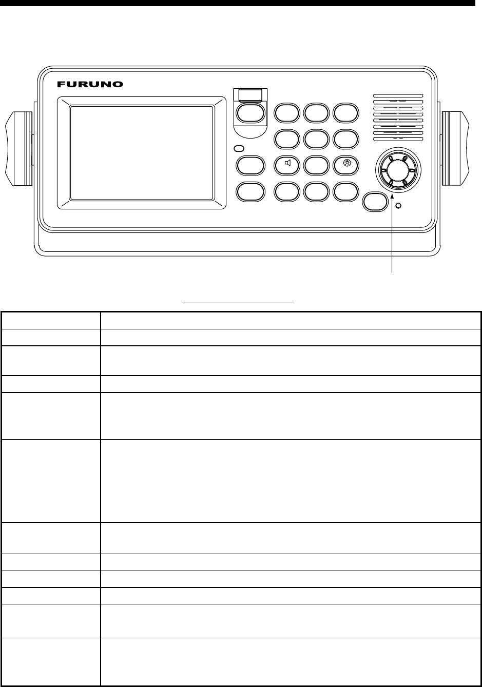
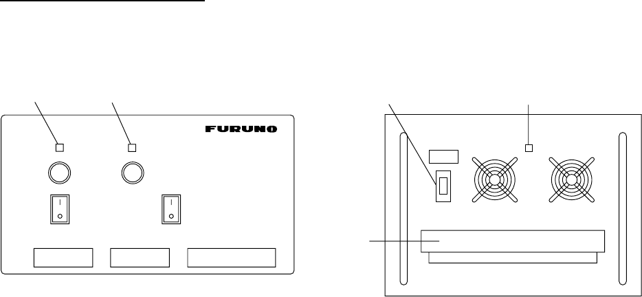
1.1 Controls
PUSH TO ENTER
ENTER knob
ALARM
DISTRESS
CANCEL
CALL
1
RT
2182
2
DSC
ABC
3
TEST
DEF
4
IntCom
GHI
5
ACK/SQ
ABC
6
SCAN
MNO
7
PQRS
8
PRINT
TUV
9
WXYZ
*
FILE
CURSOR
0
LOG
TUNE
#
SETUP
POWER
OVEN
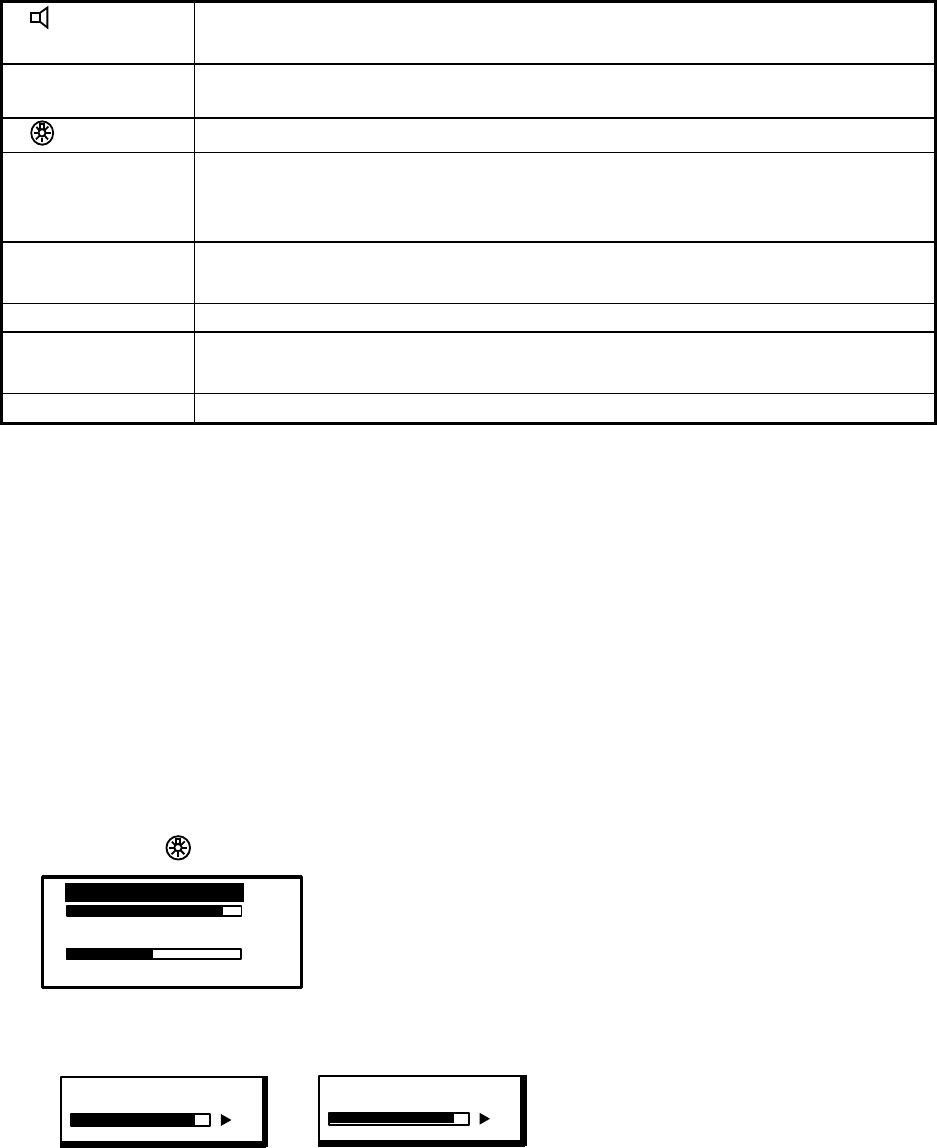
Description of controls
Control Function
POWER switch Turns the power on/off.
DISTRESS
button
Press and hold down the button more than three seconds to transmit the
distress alert.
CALL key Transmits calls.
ENTER knob Radiotelephone: Rotate to change TX/RX channel, sensitivity, audio
volume, etc.; push to register selection.
DSC: Rotate to choose menu items; push to register selection.
CANCEL key • Cancels wrong data.
• Restores previous menu.
• Silences audio alarm.
• Cancels transmission, printing.
• Erases error message.
1/ RT/2182 key Switches to the radiotelephone screen. Press and hold down more than
two seconds to get 2182.0 kHz/J3E automatically.
2/DSC key Composes DSC TX message.
3/TEST key Executes daily test.
4/IntCom key Turns on/off the intercom with other Control Unit FS-2570C.
5/ ACK/SQ key DSC: Switches automatic and manual acknowledge alternately.
Radiotelephone: Turns squelch on and off.
6/SCAN key • Displays DSC standby screen.
• Starts/stops scanning of DSC routine frequencies, on the DSC standby
screen.
1 OPERATIONAL OVERVIEW
1-2
7/ key • Turns loudspeaker on/off.
(Note that this key does not silence the distress or urgency alarm.)
8/PRINT key Prints communications log files, current screen (except DSC standby
screen and radiotelephone screen) and test results.
9/
key Adjusts panel dimmer and LCD contrast.
FILE/CURSOR
key • Opens the send message file list from the DSC standby screen, to send
stored message.
• Shifts cursor.
LOG/TUNE key • Tunes antenna in radiotelephone operation.
• Displays message logs, in DSC operation.
#/SETUP key Opens the Setup menu.
ALARM lamp • Flashes in red for distress and urgency calls.
• Flashes in green (more rapidly) for business, safety and routine calls.
OVEN lamp Lights (in green) when mains switchboard is on.
1.2 Turning the Power On/Off
Press the [POWER] switch at the right-hand side of the control unit to power the system.
Press it again to turn the system off. In the dual control unit system, the control unit
connected to the CONTROLLER 1 port on the transceiver unit has priority and it controls
the power for both the No.1 and No. 2 control units. The power switch of the No. 2 control
unit powers on/off the No. 2 control unit only.
Note: Turn on ship’s mains five minutes before turning on this equipment.
1.3 Panel Dimmer, LCD Contrast
1. Press the [9/ ] key to show the dimmer/contrast adjustment window.
EXIT:[ENT]
6
45
DIMMER (1~8)
CONTRAST (40~63)
2. Rotate the [ENTER] knob to choose DIMMER or CONTRAST, whichever you want to
adjust, and then push the [ENTER] knob.
DIMMER (1-8)
6
CONTRAST (40-63)
55
Dimmer adjustment window Contrast adjustment window
3. Rotate the [ENTER] knob to adjust and then push the [ENTER] knob.
4. To quit, rotate the [ENTER] knob to choose “EXIT: [ENT]” and then push the [ENTER]
knob.
Note: The DIMMER is automatically set to 5 and the CONTRAST to 45 whenever the
power is turned on.
1 OPERATIONAL OVERVIEW
1-3
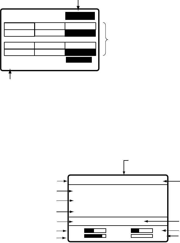
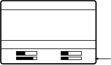
1.4 Indications
1.4.1 DSC standby screen
The DSC standby screen may be displayed by pressing the [6/SCAN] key.
WATCH KEEPING
2187.5 4207.5 6312.0
16804.5 12577.0
DISTRESS
ROUTINE
2177.0 4219.5 6331.0
16903.0 12657.0
8414.5
8436.5
AUTO ACK
Position and time. "MANUAL" shown
when these are input manually.
Distress and routine frequencies
scanned in clockwise direction,
and frequency currently being
scanned is highlighted.
One cycle is completed
in less than two seconds.
For how to choose scan
frequencies, see paragraph 1.6.
Acknowledge status
(AUTO ACK or MANUAL ACK)
35°00.000N MANUAL
135°00.000E 23:59
DSC standby screen
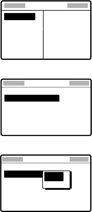
1.4.2 Radiotelephone screen
Press the [1/ RT/2182] key to show the radiotelephone screen. This is where you set up
the radiotelephone.
Class of Emission (SSB, TLX, AM)
TX Frequency
RX Frequency
Antenna Current (IA)
(or IC, VC, RF)
MODE: SSB SIMP HIGH
CH: 200
TX: 2182.0 KHZ
RX: 2182.00 KHZ
VOL
SEN S
AGC : FAST SQ NB
IA 0.0A
AGC, Squelch
Sensitivity
Volume
S-meter
Output Power
(HIGH, MID or
LOW)
Channel
Communications Mode
(Duplex or Simplex, display only)
Noise Blanker
Radiotelephone screen
Note: “TX” is circumscribed with a rectangle when transmitting.

1 OPERATIONAL OVERVIEW
1-4
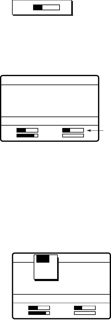
1.5 Loudspeaker
1. Press the [7/ ] key to alternately disable or enable the loudspeaker and the alarm
generated for routine messages. SOUND: ON or SOUND: OFF appears with each
press.
2. To adjust loudspeaker volume do the following:
a) Press the [1/RT 2182] key to show the radiotelephone screen.
b) Rotate the [ENTER] knob to choose VOL at the bottom of the screen and then push the
[ENTER] knob.
c) Rotate the [ENTER] knob to adjust volume and then push the [ENTER] knob.
VOL "OFF" shown when loudspeaker is off.
1.6 Scanning Routine DSC Frequencies
You can scan frequencies when using the DSC mode. For how to set frequencies, see
paragraph 7.4. Radiotelephone and telex are inoperative while scanning. However, in
case of the FS-2570, those modes may be used during scanning when the optional
internal watch keeping receiver is installed.
1. Press the [6/SCAN] key to show the DSC standby screen.
2. Press the [6/SCAN] key to start/stop scanning.
1.7 Automatic Acknowledge On/Off
The automatic acknowledge feature of the DSC/watch receiver automatically transmits the
acknowledge back (ACK BQ) signal to the sending station when an individual, position or
polling call is received. (For position and polling calls, respective item on the AUTO ACK
menu must be turned on to enable automatic acknowledge.) Automatic acknowledge can
be turned on or off at the DSC standby screen by the [5/ ACK/SQ] key. The message
ACK: AUTO or ACK: MANUAL appears at the bottom of the DSC standby screen with
each press of the key.
Note 1: To give priority to own ship’s communications while own ship is communicating,
show ACK: MANUAL by the above procedure.
Note 2:
Automatic acknowledge is not possible under the following conditions:
Priority: Distress, Urgency or Safety
Com Type: Morse, Fax, Data, No Info
Com Freq: No Info
Off Hook
1 OPERATIONAL OVERVIEW
1-5
1.8 Manual Entry of Position and Time
If there is no EPFS (Electronic Position-Fixing System) connected to this equipment or the
EPFS connected is not working (EPFS error indication appears), manually enter position
and time as follows:
1. At the DSC standby screen, press the [#/SETUP] key to display the Setup menu.
**** Setup menu ****
SCAN FREQ
VOLUME
TEST
SYSTEM
ALARM
AUTO ACK
ERASE
MESSAGE
POSITION
PRINT OUT
2. Rotate the [ENTER] knob to choose POSITION and then push the [ENTER] knob.
** Position setup **
INPUT TYPE: AUTO
LAT : 34° 41 NORTH
LON : 135° 30 EAST
TIME: 09: 00 UTC
3. Push the [ENTER] knob to open the INPUT TYPE menu.
** Position setup **
INPUT TYPE: AUTO
LAT : 34° 41 NORTH
LON : 135° 30 EAST
TIME: 09: 00 UTC
AUTO
N
MANUAL
Note 1:
If, when INPUT TYPE is AUTO, input from the navigator is interrupted, the
message “EPFS error!” appears. If this occurs, check the navigator.
Note 2:
When INPUT TYPE is MANUAL, the message “Warning: Update position”
appears at set intervals (update interval selected with POSITION OLDER on
the Alarm menu) to ask you to update position.
4. Rotate the [ENTER] knob to choose MANUAL and then push the [ENTER] knob.
1 OPERATIONAL OVERVIEW
1-6
5. Push the [ENTER] knob to open the latitude input window. Use the numeric keys to
enter latitude. If necessary, switch coordinates: [1] key to switch to North; [2] key to
switch to South. Push the [ENTER] knob.
** Position setup **
INPUT TYPE: MANUAL
34˚ 41
LON : 135
°
30 EAST
TIME: 09: 00 UTC
LAT : 34
°
41 NORTH
12
34
°
30
NORTH
12
34
°
30
NORTH
NORTH: [1] KEY
SOUTH: [2] KEY
After last digit
is entered
6. Push the [ENTER] knob to open the longitude input window. Use the numeric keys to
enter longitude. If necessary, switch coordinates: [1] key to switch to East; [2] key to
switch to West. Push the [ENTER] knob.
** Position setup **
INPUT TYPE: MANUAL
LAT: 34˚ 41 NORTH
LON : 135˚ 30 EAST
TIME: 09: 00 UTC
LAT : 34
° 30 NORTH
LON : 135° 30 EAST
12
135
°
30
EAST
12
135
°
30
EAST
EAST: [1] KEY
WEST: [2] KEY
After last digit
is entered
7. Push the [ENTER] knob to open the time input window.
INPUT TYPE: MANUAL
LAT : 34˚ 41 NORTH
LON : 135˚ 30 EAST
TIME : 09: 00 UTC
LAT : 34°30 NORTH
LON : 135° 30 EAST
TIME: 09: 00 UTC
12 : 34
Position setup
8. Enter UTC time with the numeric keys and then push the [ENTER] knob. The Setup
menu appears.
9. Press the [CANCEL] key to return to the DSC standby screen.
1 OPERATIONAL OVERVIEW
1-7
1.9 System Characteristics
1.9.1 Equipment priority
Equipment priority order is as below.
1. DMC
2. Control unit sending distress alert
3. Control unit 1 – routine use
4. Control unit 2 – routine use
5. NBDP
1.9.2 Controls become inoperative
Controls become inoperative in the following conditions:
•
Controls of idle control unit in the two-control unit system when other control unit goes
OFF HOOK.
•
Controls of idle control unit in the two-control unit system when other control unit
switches to the DSC mode.
•
Distress received by DMC (Distress Message Controller).
•
NBDP is scanning or communicating.
•
Distress alert or distress relay is transmitted.
•
Call other than distress is transmitted (transmission time about 8 s). If it becomes
necessary to unlock the keyboard before the message is transmitted, press the
[CANCEL] key to cancel the call.
1.9.3 Controls become operative
Controls become operative in the following conditions:
•
[DISTRESS] button is pressed.
•
Control unit having highest priority is operated.
•
Other control unit in two-control unit system goes ON HOOK.
•
Distress received by DMC is acknowledged.
•
NBDP stops scanning or communicating.
1.9.4 Automatic setting of working frequency
The radiotelephone automatically sets working frequency in the following conditions:
•
ABLE ACK is sent in response to individual call.
•
Your ship receives ABLE ACK in response to own ship-initiated individual call.
•
Your ship sends all ship call.
•
Your ship sends distress relay.
•
Your ship sends distress alert.
•
Your ship receives group call or area call.
•
Your ship receives distress relay call.
•
Your ship receives distress alert.
1 OPERATIONAL OVERVIEW
1-8
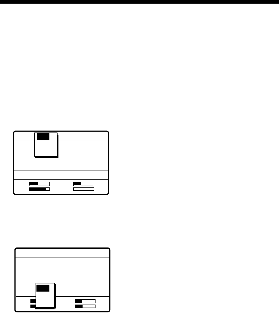
1.10 Power Supply Unit (option)
The control unit works directly on 24 VDC or through a Power Supply Unit on AC mains
supply (115 or 230 VAC). The power supply unit is type PR-300, supplying 24 VDC power
(20 A) to the FS-1570 or type PR-850A, supplying 24 VDC (40 A) to the FS-2570. Both
115/230 VAC and 24 VDC power can be connected simultaneously. In this case, the
system normally operates on the AC mains supply and when AC power is lost, the PSU
automatically switches to the DC power source.
This power supply arrangement satisfies the GMDSS requirements. The
FS-1570/FS-2570 can be operated directly from 24 VDC without a power supply.
OVEN power supply: The crystal oven is always powered even when the Power Switch
is OFF, provided the mains switchboard is turned on.
AC and DC power switches
Both AC and DC power switches on the PSU can be always kept on. (These switches are
provided to turn off the power supply for maintenance.) The control unit may be turned on
or off with the PSU kept on.
POWER
ON
ON
OFF
AC INPUT 50/60Hz DC OUTPUT
Breaker Power Lamp
Terminal
Cover
ON
OFF
100V 10A
220V 5A
ON
OFF
125V 20A
AC IN DC IN DC OUT
PR-300
LNG + - +- + -24V
Red Light Green Light
PR-300
PR-850A
Lamp (red): Lights when AC power source is in use.
Lamp (green): Lights when DC power source is in use
Power supply units
Note: Both lamps light when changing to DC power supply (PR-300). These lamps also
light when the internal temperature goes too high.
2-1
2 SSB RADIOTELEPHONE
You can enter desired frequency by channel or TX and RX frequencies. The handset may
be ON HOOK or OFF HOOK. To set the SSB radiotelephone to 2182 kHz/J3E
automatically, press the [1/ RT/2182] key more than two seconds.
2.1 Transmitting
After selecting class of emission and frequency, you can transmit by pressing the PTT
switch on the handset. Output power is shown on the display.
2.1.1 Choosing class of emission
1. At the radiotelephone screen, choose class of emission (mode) as follows:
a) Rotate the [ENTER] knob to choose MODE and then push the [ENTER] knob.
MODE: SSB SIMP HIGH
CH: 800
TX: 2182.0 KHZ
RX: 2182.00 KHZ
VOL
SEN S
AGC : FAST
IA 0.0A
TLX
AM
SSB
b) Rotate the [ENTER] knob to choose mode desired and then push the [ENTER] knob.
SSB: Single Sideband, TLX: Telex, AM: AM. (You cannot transmit on the AM mode.)
2. AGC is automatically selected according to mode. AGC FAST: SSB, AGC OFF: TLX,
AGC SLOW: AM. However, you may change it as below.
a) Rotate the [ENTER] knob to choose AGC and then push the [ENTER] knob.
MODE: SSB SIMP HIGH
CH: 200
TX: 2182.0 KHZ
RX: 2182.00 KHZ
VOL
SEN S
AGC : FAST
IA 0.0A
FAST
FAST
OFF
SLOW
FAST
b) Rotate the [ENTER] knob to choose OFF, SLOW or FAST as appropriate and then push
the [ENTER] knob.
2 SSB RADIOTELEPHONE
2-2
2.1.2 Choosing channel, frequency
Choosing channel
1. Rotate the [ENTER] knob to choose CH and then push the [ENTER] knob.
MODE: SSB SIMP HIGH
CH: 800
TX: 2182.0 KHZ
RX: 2182.00 KHZ
VOL
SEN S
AGC : FAST
IA 0.0A
200
2. Channel can be entered directly with the numeric keys, or by using the [ENTER] knob.
See below for details.
Entering band and band channel with the numeric keys: Use the numeric keys to
enter band and band channel and then push the [ENTER] knob.
Choosing band and band channel with the ENTER knob:
a) Use the [FILE/CURSOR] key to place the cursor in the band or band channel position,
whichever you want to change.
200
200
Cursor position for
selection of band channel
Cursor position for
selection of band
b) Rotate the [ENTER] knob to set band (or channel) desired.
2 4 6 8 12 16 18 22 25 01 02----- 029
ITU band User band
Setting Range
ITU Band: 2/4/6/8/12/16/18/22/25
User Band: 001-029 (leadiing zero necessary)
ITU Channel: XX01 - XX236 (rendering on band or mode)
User Channel: XXX01 - XXX99
c) Push the [ENTER] knob. The TX and RX frequencies of the channel entered
appear.
2 SSB RADIOTELEPHONE
2-3
Choosing frequency
1. Rotate the [ENTER] knob to choose TX or RX as appropriate and then push the
[ENTER] knob.
TX: 2182.0 KHZ
VOL
SE
N
S
AGC : SLOW
IA 0.0A
MODE: AM SIMP HIGH
CH: 200
Rx: 123456.78 KHZ
2182.00 KHZ
2. Enter frequency by one of the methods below.
Entering frequency with the numeric keys:
Use the numeric keys to enter frequency and then push the [ENTER] knob. Be sure to
including trailing zero. For example, to enter 2161 kHz, key in [2], [1], [6], [1], [0].
(Keying in 2-1-6-1 will set 216.1 kHz.)
Choosing frequency with the ENTER knob (for RX only):
a) Use the [FILE/CURSOR] key to choose digit to change.
b) Rotate the [ENTER] knob to set digit.
c) Push the [ENTER] knob.
Note: To enter same frequency for both TX and RX, enter the TX frequency first.
2.1.3 Tuning
Maximum transmission power is achieved only when the antenna impedance and
transmitter impedance match each other. Because the antenna impedance changes with
frequency, a means must be provided to match (tune) the antenna impedance with the
transmitter impedance. This is done with the antenna coupler. The antenna coupler
automatically tunes the transmitter to a wide range of different antenna lengths, from 7 to
30 m.
To initiate the automatic tuning, do the following:
1. Press the PTT switch on the handset or the [LOG/TUNE] key on the control unit.
“TUNING” appears when the [LOG/TUNE] key is pressed; “TX” pops out when the PTT
switch is pressed.
Tuning will be completed within 2 to 5 s for a newly selected frequency, or less than 0.5
s for a once-tuned frequency. (A memory saves coil and capacitor settings.) When the
tuning process is successfully completed, TUNE: OK appears. If tuning fails, TUNE:
NG appears.
2 SSB RADIOTELEPHONE
2-4
Note: When tuning is initiated in the two-control unit system, the display of the idle control
unit shows “OCCUPIED(ANOTHER CONTROLLER).” In this case, only the
DISTRESS button is operative on the idle control unit. Further, if a control unit is in
use when tuning is attempted at the other control unit, the display of the control unit
which attempted to tune shows “OCCUPIED” plus the name of the equipment in
use: ANOTHER CONTROLLER, NBDP, or DMC.
2.1.4 Using the handset
Hold the handset close to your mouth, press the PTT switch and speak clearly.
2.1.5 Monitoring transceiver output power
During transmission, the IA bar deflects according to the current being fed to the antenna
feeder from the antenna coupler. The unit of readout is amperes. The antenna current
varies with the effective antenna impedance. The swing differs by the frequency and
antenna length. The output power is proportional to the square of an antenna current.
Note: If IA is not shown, follow the procedure in paragraph 2.1.7 to show it.
Antenna Current
MODE: SSB SIMP HIGH
CH: 200
TX: 2182.0 KHZ
RX: 2182.00 KHZ
VOL
SEN S
AGC : FAST
IA 2.1A
2 SSB RADIOTELEPHONE
2-5
2.1.6 Reducing transmitter power
To conserve energy and to minimize possible interference to other stations, reduce the
transmission power. This should be done when using the transceiver in a harbor, near the
shore or close to communication partner (other ship).
1. Rotate the [ENTER] knob to choose LOW, MID or HIGH (whichever is shown) at the
top of the screen and then push the [ENTER] knob.
FS-1570 FS-2570
LOW 68 W 70 W
MID 100 W 125 W
HIGH 150 W 250 W
MODE: SSB SIMP HIGH
CH: 200
TX: 2182.0 KHZ
RX: 2182.00 KHZ
VOL
SEN S
AGC : FAST
IA 2.1A
LOW
MID
HIGH
2. Rotate the [ENTER] knob to choose power among LOW, MID and HIGH as
appropriate and then push the [ENTER] knob.
Note: Power amplifier temperature is monitored, and when its temperature rises above a
certain temperature output power is automatically reduced.
2.1.7 Displaying IA, IC, VC or RF
While transmitting, you may display RF (PA output), IA (antenna current), IC (collector
current) or VC (collector voltage), at the lower right corner of the radiotelephone screen.
1. Rotate the [ENTER] knob to choose RF, IA, IC or VC (whichever is displayed) at the
bottom right corner.
2. Push the [ENTER] knob.
MODE: SSB SIMP HIGH
CH: 200
TX: 2182.0 KHZ
RX: 2182.00 KHZ
VOL
SEN S
AGC : FAST
IA 2.1A
IA
IC
VC
RF
3. Rotate the [ENTER] knob to choose option desired and then push the [ENTER] knob.
2 SSB RADIOTELEPHONE
2-6
2.2 Receiving
2.2.1 RF gain (sensitivity) adjustment
In normal use the sensitivity should be set for maximum. If the audio on the received
channel is unclear or interfered with other signals, adjust (usually reduce) sensitivity to
improve clarity.
1. Rotate the [ENTER] knob to choose SEN at the bottom of the screen and then push
the [ENTER] knob.
SEN
2. Rotate the [ENTER] to adjust and then push the [ENTER] knob.
2.2.2 S-meter
The S-meter shows relative signal strength coming into the receiver frontend. Note that
the S-meter does not function when the AGC is turned off.
S-meter
MODE: SSB SIMP HIGH
CH: 200
TX: 2182.0 KHZ
RX: 2182.00 KHZ
VOL
SEN S
AGC : FAST
IA 0.0A
2.2.3 Monitoring traffic on intended transmit frequency
When a semi-duplex channel is selected, it is recommended to monitor if there is no
existing traffic on the frequency you are going to use. To do this, choose RX and then
push the [ENTER] knob. The transceiver monitors traffic on the selected frequency for
three s.
2.2.4 Receiving AM broadcasting stations
1. Press the [1/ RT/2182] key to show the radiotelephone screen.
2. Rotate the [ENTER] knob to choose MODE and then push the [ENTER] knob.
MODE: SSB SIMP HIGH
CH: 800
TX: 2182.0 KHZ
RX: 2182.00 KHZ
VOL
SEN S
AGC : FAST
IA 0.0A
TLX
AM
SSB
3. Rotate the [ENTER] knob to choose AM and then push the [ENTER] knob.
4. Rotate the [ENTER] knob to choose RX and then push the [ENTER] knob.
2 SSB RADIOTELEPHONE
2-7
TX: 2182.0 KHZ
VOL
SE
N
S
AGC : SLOW
IA 0.0A
MODE: AM SIMP HIGH
CH: 200
Rx: 123456.78 KHZ
2182.00 KHZ
5. Key in RX frequency with the numeric keys and then push the [ENTER] knob.
2.2.5 Squelch control, squelch frequency
Squelch on/off
The squelch mutes the audio output in the absence of an incoming signal. Press the [5/
ACK/SQ key] to turn on and off the squelch alternately. When radio noise is too jarring
during stand-by condition, it may be muted by activating the squelch. “SQ” appears when
the squelch function is active.
Squelch frequency
1. At the radiotelephone screen, press the [#/SETUP] key.
**** Setup menu ****
NB : OFF
SQ FREQ : 600 HZ
FAX RX ENABLE : OFF
USER CH
SYSTEM
2. Rotate the [ENTER] knob to choose SQ FREQ.
3. Push the [ENTER] knob.
4. Enter frequency (range: 500-2000 Hz, default 800 Hz) with the numeric keys and then
push the [ENTER] knob.
5. Press the [CANCEL] key to return to the radiotelephone screen.
2.2.6 Noise blanker
The noise blanker functions to remove noise. You may turn it on or off as follows:
1. At the radiotelephone screen, press the [#/SETUP] key.
2. Rotate the [ENTER] knob to choose NB.
3. Push the [ENTER] knob.
4. Rotate the [ENTER] knob to choose ON or OFF as appropriate and then push the
[ENTER] knob.
5. Press the [CANCEL] key to return to the radiotelephone screen.
2 SSB RADIOTELEPHONE
2-8
2.3 Intercom
The built-in intercom permits voice communications between two FS-2570C Control Units.
1. Press the [1/ RT/2182] key to show the radiotelephone screen.
2. Off hook the handset.
3. Press the [4/IntCom] key to show INTERCOM on the display. The called party’s
handset rings.
4. When the called party picks up their handset, press the PTT switch on the handset and
speak into the handset.
Hang up the handset to turn the intercom off. The indication INTERCOM disappears from
the screen.
2.4 Telex Communications
Telex communication is performed with the NBDP Terminal Unit (option) connected to this
radiotelephone. No special operation is required on the control unit; class of emission and
frequencies are set on the NBDP Terminal Unit. For telex communications, see Chapters 8
through 11.
2 SSB RADIOTELEPHONE
2-9
2.5 When Automatic Tuning Fails
The antenna coupler automatically tunes a wire or whip antenna to the transceiver. When
all frequencies cannot be tuned, TUNE OK will not appear on the display. In this case, you
can tune 2182 kHz by manually operating the coupler as shown in the procedure below.
DANGER
HIGH TENSION HAZARD
DO NOT TRANSMIT WHEN
THE ANTENNA COUPLER
IS OPEN.
1. Turn off the control unit. Remove the cover of the antenna coupler.
2. Set the MANUAL-AUTO switch to the MANUAL position.
COUPLER BOARD
DUMMY
LOAD
BOARD MANUAL AUTO
3. Replace the cover.
4. Turn on the control unit.
2 SSB RADIOTELEPHONE
2-10
2.6 User Channels
The USER CH menu allows registration of user TX and RX channels, where permitted by
the Authorities.
NOTICE
FURUNO will assume no responsibility
for the disturbance caused by the
unlawful or improper setting of user
channels.
2.6.1 Registering user channels
“USER CH” in the System setup menu must be enabled in order to register user channels.
For further details, contact your dealer.
1. At the radiotelephone screen, press the [#/SETUP] key.
**** Setup menu ****
NB : OFF
SQ FREQ : 600 HZ
FAX RX ENABLE : OFF
USER CH
SYSTEM
2. Rotate the [ENTER] knob to choose USER CH and then push the [ENTER] knob. The
window shown below appears.
ENTRY
ERASE
3. ENTRY is selected; push the [ENTER] knob.
*** User ch entry **
MODE: SSB
UP DOWN
00201. TX: 2111.5 RX: 2111.5
00202. TX: 2222.0 RX: 2222.0
00203. TX: 2333.5 RX: 2333.5
00204. TX: 2444.0 RX: 2444.0
00205. TX: 2555.5 RX: 2555.5
CH: 2-01
4. Push the [ENTER] knob to open the user channel options window.
***
User ch entry
**
MODE: SSB CH: 2-01
UP DOWN
00201. TX: 2111.5 RX: 2111.5
00202. TX: 2222.0 RX: 2222.0
00203. TX: 2333.5 RX: 2333.5
00204. TX: 2444.0 RX: 2444.0
00205. TX: 2555.5 RX: 2555.5
MODE
CH
FREQ
2 SSB RADIOTELEPHONE
2-11
5. Rotate the [ENTER] knob to choose MODE and then push the [ENTER] knob.
***
User ch entry
**
UP DOWN
00201. TX: 2111.5 RX: 2111.5
00202. TX: 2222.0 RX: 2222.0
00203. TX: 2333.5 RX: 2333.5
00204. TX: 2444.0 RX: 2444.0
00205. TX: 2555.5 RX: 2555.5
SSB
NBDP
DSC
MODE: CH: 2-01
6. Rotate the [ENTER] knob to choose appropriate mode among SSB, NBDP and DSC
and then push the [ENTER] knob.
*** User ch entry **
MODE: SSB
UP DOWN
00201. TX: 2101.5 RX: 2101.5
00202. TX: 2202.0 RX: 2202.0
00203. TX: 2303.5 RX: 2303.5
00204. TX: 2404.0 RX: 2404.0
00205. TX: 2505.5 RX: 2505.5
CH : 2-01
CH:0−00
- 256 channels may be registered.
- Band no. setting range is 0-29 and band channel no. range is
01-99.
- For DSC, four channels can be registered per band (2, 4, 6
8, 12, 16, 18, 22, 25).
- "0" band is for DSC frequencies only, and they are registered
under "OTHER." Four channels are available, 01-04.
7. Key in channel no. and then push the [ENTER] knob. For example, press [0], [1], [2],
[3], [4] and then push the [ENTER] knob to enter channel 01234.
**
User ch entry
**
MODE : SSB
UP DOWN
01234. TX: 0.0 RX: 0.0
01240. TX: 12666.0 RX: 13666.0
01241. TX: 12777.5 RX: 13777.5
01242. TX: 12999.5 RX: 13999.5
01250. TX: 12100.0 RX: 13100.0
CH : 12-34
TX : 0.0 KHZ
RX : 0.0 KHZ
8. Enter TX frequency with the numeric keys.
9. Rotate the [ENTER] knob to choose RX.
10. Enter RX frequency with the numeric keys and then push the [ENTER] knob.
11. Rotate the [ENTER] knob to display all channels entered.
12. Press the [CANCEL] key twice to return to the radiotelephone screen.

2 SSB RADIOTELEPHONE
2-12
2.6.2 Deleting user channels
Deleting individual user channels
1. At the radiotelephone screen, press the [#/SETUP] key.
2. Rotate the [ENTER] knob to choose USER CH and then push the [ENTER] knob.
3. Rotate the [ENTER] knob to choose ENTRY and then push the [ENTER] knob.
4. Push the [ENTER] knob, rotate the [ENTER] knob to choose CH and then push the
[ENTER] knob.
5. Enter channel number to process and then push the [ENTER] knob.
6. Tx and Rx frequencies are shown as “0.0 kHz”; push the [ENTER] knob to delete
channel.
7. Press the [CANCEL] key twice to return to the radiotelephone screen.
Deleting all user channels
1. At the radiotelephone screen, press the [#/SETUP] key.
2. Rotate the [ENTER] knob to choose USER CH and then push the [ENTER] knob.
3. Rotate the [ENTER] knob to choose ERASE and then push the [ENTER] knob.
4. Rotate the [ENTER] knob to choose YES and then push the [ENTER] knob.
5. Press the [CANCEL] key to return to the radiotelephone screen.
2.7 FAX Enable/Disable
You may enable or disable FAX use as follows:
1. At the radiotelephone screen, press the [#/SETUP] key to open the Setup menu.
2. Rotate the [ENTER] knob to choose FAX RX ENABLE and then push the [ENTER]
knob.
3. Rotate the [ENTER] knob to choose ON or OFF as appropriate and then push the
[ENTER] key.
MODE: SSB SIMP HIGH
CH: 800
TX: 2182.0 KHZ
RX: 2182.00 KHZ
VOL
SEN S
AGC : FAST
IA 0.0A
TLX
FAX
AM
SSB
4. Press the [CANCEL] key to close the menu.
3-1
3 DSC OVERVIEW
3.1 What is DSC?
DSC is an acronym meaning Digital Selective Calling. It is a digital distress and general
calling system in the MF and HF bands used by ships for transmitting distress alerts and
general calls and by coast stations for transmitting the associated acknowledgements.
For DSC distress and safety calling in the MF and HF bands, the frequencies are (kHz)
2187.5, 4207.5, 6312.0, 8414.5, 12577.0, and 16804.5.
The DSC station sends and receives DSC general and safety calls via the radiotelephone.
TRANSCEIVER
UNIT
FS-1570T
FS-2570T
Distress Frequency
Routine DSC Call Routine DSC Calls
Option
(FS-2570
only)
CONTROL UNIT
FS-2570C
Distress alert, routince DSC call
3.2 DSC Call
DSC calls are roughly divided in two categories: distress and safety calls, and routine calls.
Below are the types of DSC calls.
Call Description
All Ships Call to all ships
Distress Your ship sends distress call
Distress relay all Your ship relays distress call to all ships
Distress relay select Your ship relays distress call to a coast station
Geographical Area Call to all ships in a specific geographical area
Group Call to a specific group
Individual Call to a specific address
Medical Transport Inform all ships that your ship is carrying medical supplies
Neutral Craft Inform all ships that your ship is not a participant in armed conflict
Polling Call to determine if own ship is in communicating range with other
ship
Position 1) You send your position to other stations
2) Your ship requests position of other station
PSTN Call over Public Switched Telephone Network (PSTN)
Test Send test signal to a coast station to test your station’s functionality

3 DSC OVERVIEW
3-2
Contents of a DSC call
• Calling category
Call category Call
Individual Individual, PSTN, Test, Position, Polling,
Relay Sel (specific coast station)
All Ships All Ships, Neutral, Medical, Relay All
Group Group
Geographical Area Area
Distress Call Distress
• Station ID
Own ship ID and sending station ID. Coast station ID begins with 00; Group ID
begins with 0.
• Priority
Distress: Grave and imminent danger and request immediate assistance.
Safety: A station is about to transmit a call containing an important
navigational or meteorological warning.
Urgency: A calling station has a very urgent call to transmit concerning safety of
ship, aircraft or other vehicle or safety of person.
Business: Communication related to the navigation, movements and needs of ships
and aircraft.
Routine: General calling
• Communication type
Telephone: Telephone (J3E) by SSB radiotelephone
NBDP-ARQ: Telex (J2B) mode ARQ via NBDP Terminal Unit
NBDP-FEC: Telex (J2B) mode FEC via NBDP Terminal Unit
• Communication frequency
Working frequency used to call by telephone or NBDP. The sending station may have
the receiving frequency (ship or coast station) assign the frequency to use.
• Position
Position can be automatically or manually sent.
• DSC frequency
DSC frequency to use. If the call category is SAFETY, URGENCY or DISTRESS,
choose a DSC distress frequency.
• End code
The end of a DSC call is denoted by ACK RQ (Acknowledge Request), ACK BQ
(Acknowledge Back) or EOS (End of Sequence).
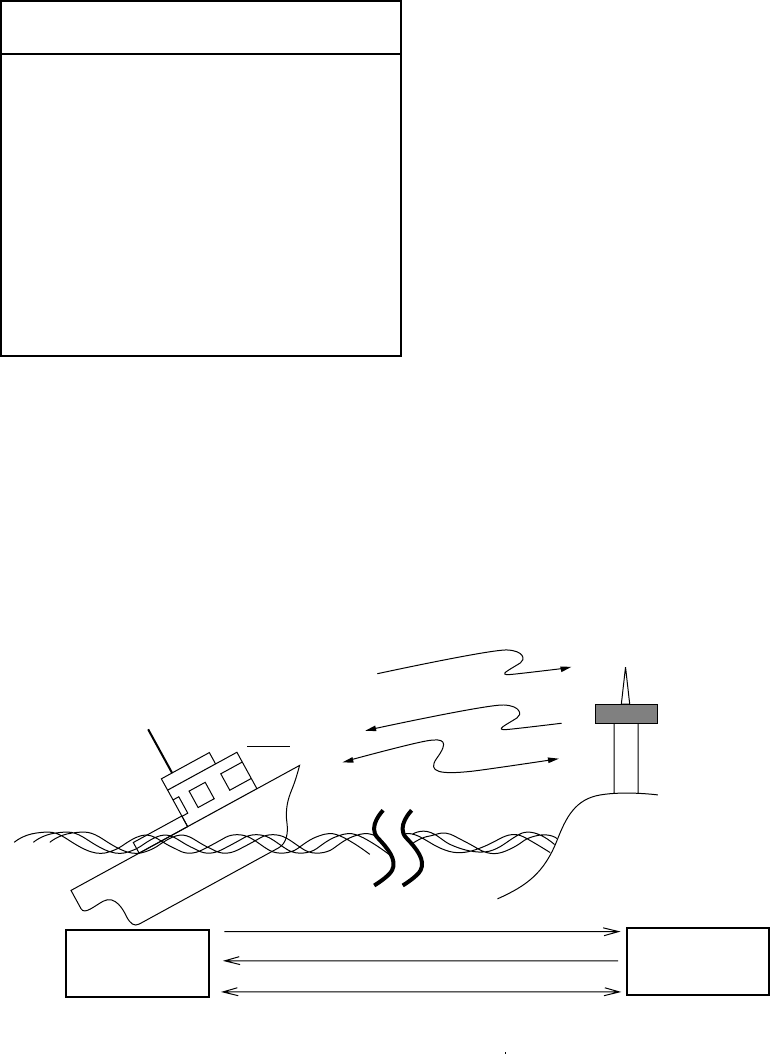
3 DSC OVERVIEW
3-3
3.2.1 Distress alert call and reply
This type of call is sent by own ship in the event of distress, by using the [DISTRESS]
button as follows:
1. The LED in the [DISTRESS] button initially flashes, and lights when the button is
pressed more than three seconds. (If the button is pressed less than three seconds,
the distress alert is not sent. Once the alert is sent it cannot be cancelled.)
NOTICE
IN CASE OF ACCIDENTAL TRANS-
MISSION OF THE DISTRESS ALERT
If the distress is accidentally transmitted,
contact the nearest coast station and inform
them of the accidental transmission as
follows:
a) Ship's name
b) Ship's call sign and DSC number
c) Position at time of transmission
d) Time of transmission
2. The radiotelephone automatically sets the DSC distress frequency and then the
equipment transmits the distress alert.
3. After the distress alert is transmitted (this takes about 40 seconds), the equipment
waits for the distress acknowledgement call (DIST ACK) from a coast station. This
usually takes less than three minutes. (If it is not received within 4.5 minutes, the
distress alert is re-transmitted.)
4. The radiotelephone automatically sets the distress communication frequency to use to
conduct voice communications (telex also available) with the coast station.
Coast
Station
Own Ship
(1)
Ship in
Distress
(Own Ship)
(3)
(2)
(2)
(3)
(1) Ship in distress sends Distress Alert
(2) Coast station sends distress acknowledgement (DIST ACK).
(3) Voice or telex communications between ship in distress and coast station
(1)
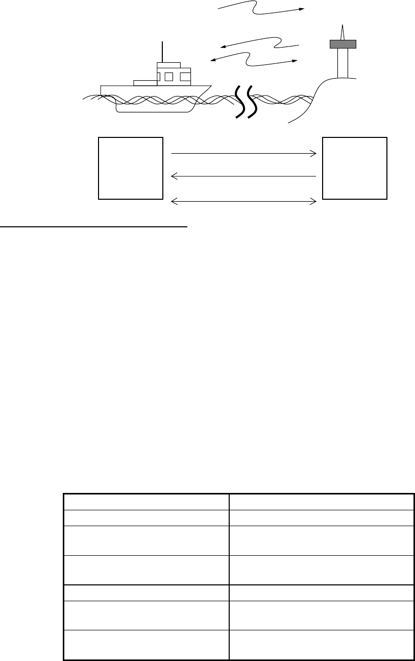
3 DSC OVERVIEW
3-4
3.2.2 Individual call
The individual call is for sending a call to a specific station.
Coast
Station
Own Ship
(1) DSC Message [Called Acknowledge
Request (ACK RQ) Signal]
(2) Acknowledge Back (ACK BQ) Signal
(3) Voice or telex communication
(1)
(2)
(3)
Basic procedure (radiotelephone)
1. Prepare call and transmit it by pressing the [CALL] key. The equipment then awaits
acknowledgement of the call.
2. Receive acknowledge back (ACK BQ) signal from other party (coast station or ship
station) within about five minutes. The audio alarm sounds at this time; press the
[CANCEL] key to silence it.
3. After receiving the ACK BQ signal, communicate with other party; the radiotelephone
automatically sets the working frequency and class of emission you specified.
3.3 Audio Alarms
When you receive a distress alert or routine call addressed to your ship, the audio and
visual alarms are released. For the distress or urgency call, the audio alarm sounds until
the [CANCEL] key is pressed, and sounds for one second and then automatically goes off
in case of other calls. The tone of the alarm changes with the call received. By becoming
accustomed to the tone, you can know which type of call you have received.
Alarm Frequency (interval)
Safety call received 1300 Hz and 0 Hz (250 ms)
Routine, Ship's Business call
received
880 Hz and 440 Hz (500 ms)
While DISTRESS button is
pressed for three s
2200 Hz and 0 Hz (125 ms)
Distress alert sent 2200 Hz, continuous
Own ship position not updated 2200 Hz (50 ms), three beeps
every two s
Distress alert, urgency
message received
1300 Hz and 2200 Hz (250 ms)
3 DSC OVERVIEW
3-5
3.4 Interpreting Call Displays
This paragraph provides the information necessary for interpreting receive and send call
displays.
3.4.1 Receive calls
Below are sample distress and individual receive calls. The content of other types of
receive calls is similar to that of the individual call. When you receive a call, the message
“INCOMING” flashes at the bottom of the display.
Distress receive call
*
Received message
*
MAR-23-2002-23:59 ECC: OK
DISTRESS CALL
ANSWER
SHIP IN DIST:
123456789
NATURE: UNDESIGNATED
POS:
12°34N 123°45E AT 12:34
TELEPHONE
2182.0 KHZ
ALL VIEW
END OF SEQUENCE: EOS
ERROR-CHECK: OK
DSC FREQUENCY : 2177.0KHZ
*
Received message
*
GO TO EASY VIEW
FORMAT : DISTRESS CALL
SELF-IDENTITY : 123456789
NATURE OF DISTRESS:
UNDESIGNATED DISTRESS
*
Received message
*
Date and time of message
ECC (Error Check Character): OK or NG (No Good)
Category (Distress call)
Ship in Distress (ID No. of ship in distress)
Nature of Distress (Undesignated, Fire, Flooding,
Collision, Grounding, Listing, Sinking, Disable,
Abandoning, Piracy, Man Overboard, EPIRB emission)
Position of ship in distress
Working frequency to use
End of sequence (EOS for distress)
Error check (OK or NG)
DSC frequency used to transmit distress call
Format (distress)
ID no. of ship in distress
Nature of distress (problem with ship in distress, see above)
Distress coordinates (position of ship in distress)
Telecommand (class of emission)
Rotate [ENTER] knob
to switch.
Push [ENTER] knob
to switch.
DISTRESS COORDINATES:
12°34N 123°45E AT 12:34
TELECOMMAND: J3E TELEPHONE
3 DSC OVERVIEW
3-6
Individual receive call
* Received message *
* Received message *
MAR-23-2002-23:59 ECC: OK
INDIVIDUAL REQUEST
FROM SHIP: 123456789
ROUTINE TX: 2182.0 KHZ
TELEPHONE RX: 2182.0 KHZ
WORKING FREQ. : TX: 2182.0 KHZ
RX: 2182.0 KHZ
END OF SEQUENCE: ACK. RQ
ERROR-CHECK: OK
GO TO EASY VIEW
Date and time of message
ECC (Error Check Character): OK or NG (No Good)
Able acknowledge ("Unable acknowledge" and reason if unable)
ID No. of sending station
Category (Routine, Business, Safety, Urgency)
Working frequency to use
End of sequence (ACK. BQ or ACK. RQ)
Error check (OK or NG)
DSC frequency used
Working frequency to use
Note: ANSWER is for replying to message.
FORMAT : INDIVIDUAL
ADDRESS : 987654321
CATEGORY : ROUTINE
SELF-IDENTITY : 123456789
1ST TELECOMMAND: J3E TELEPHONE
2ND TELECOMMAND : NO INFORMATION
* Received message *
Format (individual)
ID of your station
Category (Routine, Business, Safety, Urgency)
1st Telecommand (class of emission)
2nd Telecommand (class of emission)
ID of sending station
ANSWER ALL VIEW
Push [ENTER] knob
to switch.
Rotate [ENTER] knob to
go to "GO TO EASY VIEW"
or push it to go to previous display.
DSC FREQUENCY 2177.0KHZ
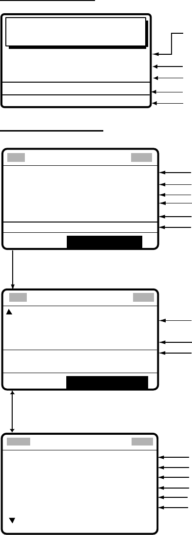
3 DSC OVERVIEW
3-7
3.4.2 Send calls
Below are sample distress and individual send calls. The content of other types of send
calls is similar to that of the individual call.
Distress send call
Distress
call in progress!
TIME TO GO : 30S
NATURE: UNDESIGNATED
POS:
12°34N 123°45E AT 12:34
TELEPHONE
2182.0 KHZ
DSC FREQ
:
2187.5 KHZ
Time to go until distress alert is transmitted
Nature of Distress (Undesignated, Fire, Flooding,
Collision, Grounding, Listing, Sinking, Disable,
Abandoning, Piracy, Man Overboard)
Position of ship in distress (your ship)
DSC frequency used to send distress call
Working frequency to use
Individual send call
COM. FREQ : CH 401
PRIORITY
: ROUTINE
COM. TYPE : TELEPHONE
CALL TYPE: INDIVIDUAL
STATION ID: 123456789
GO TO ALL VIEW
DSC FREQ : 2M-INTL
Rotate [ENTER] knob to
choose GO TO ALL VIEW
and then push it.
** Compose message **
GO TO EASY VIEW
DSC FREQUENCY TX: 2177.0 KHZ
RX: 2177.0 KHZ
WORKING FREQ. : CH 401
END OF SEQUENCE: ACK. RQ
ID of station where message is to be sent
Mode of communication (Telephone, NBPD-ARQ, NBDP-FEC)
Working channel (or frequency)
Call type (Individual)
Working frequency
Priority (Routine, Business, Safety, Urgency)
DSC frequency
End of sequence (Acknowledge request)
DSC frequency used
** Compose message **
Calling format
Own ship ID
Communications category
1st telecommand
2nd telecommand
ID no. of transmitting station
Rotate [ENTER] knob.
FORMAT : INDIVIDUAL
ADDRESS : 987654321
CATEGORY : ROUTINE
SELF-IDENTITY : 123456789
1ST TELECOMMAND: J3E TELEPHONE
2ND TELECOMMAND : NO INFORMATION
* Compose message *
3 DSC OVERVIEW
3-8
(This page intentionally left blank.)
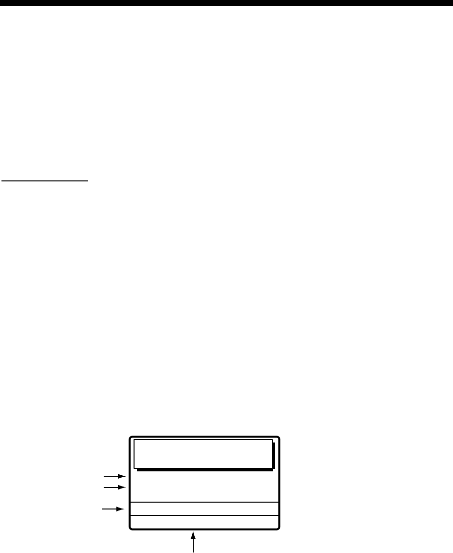
4-1
4 DISTRESS OPERATIONS
4.1 Sending Distress Alert
GMDSS ships carry a DSC terminal with which to transmit the distress alert in the event of
a life-endangering situation. A coast station receives the distress alert and sends the
distress alert acknowledge call to the ship in distress. Then, voice or telex
communications between the ship in distress and coast station begins.
Transmission of the distress alert and receiving of the distress alert acknowledgement are
completely automatic - simply press the [DISTRESS] button to initiate the sequence.
Russian version
• Audio alarm is released continuously after transmitting distress alert.
• The [CANCEL] key can be used during the transmission of the distress alert. The
transmission sequence is stopped at the end of the fifth transmission.
4.1.1 Sending distress alert by DISTRESS button, nature of distress
not specified
1. Open the DISTRESS button cover and press and hold down the [DISTRESS] button
more than three seconds. The button flashes in red and the buzzer sounds rapidly. The
display shows the contents of the distress alert call: your ship’s nature of distress,
position, time and the DSC frequency over which the alert has been transmitted.
The number of seconds to continue pressing the [DISTRESS] button appear at the
bottom of the display. The buzzer sounds continuously and the lamp in the button lights
when the button has been pressed three seconds. You can release the button at that
time.
KEEP PRESSED FOR 3S
NATURE: UNDESIGNATED
POS:
12°34N 123°45E AT 12:34
TELEPHONE
2182.0 KHZ
Distress button
pressed!
Displays number of seconds to continue
pressing the [DISTRESS] button to
transmit the distress alert.
DSC FREQ :
2187.5 KHZ
Nature of Distress
Position, Time
DSC Distress
Frequency used
to transmit the
distress alert

4 DISTRESS OPERATIONS
4-2
2. The display changes as below. It takes about 40 seconds to transmit the distress alert,
and the number of seconds until transmission is completed is shown at the bottom of
the display. At this time the output power of the radiotelephone is automatically set to
maximum.
Distress
call in progress!
TIME TO GO : 38S
NATURE: UNDESIGNATED
POS:
12°34N 123°45E AT 12:34
TELEPHONE 2182.0 KHZ
DSC FREQ
: 2187.5 KHZ
Time to go until distress
alert is completely transmitted.
3. After the distress alert has been sent, the display changes as below and the audio
alarm is stopped. Wait to receive the distress acknowledge call from a coast station,
which usually takes 1 to 2 min 45 seconds. (The [DISTRESS] button remains lit until
the equipment receives the distress acknowledge call from a coast station.) The timer
counts down the number of minutes before next retransmission (if necessary), from
3.5 to 4.5 minutes, randomly set.
At this time, the equipment cannot receive any calls except the distress alert
acknowledge call. The distress alert you sent is recorded in the TX log.
Wait for distress
acknowledgement.
TIME TO GO: 2M10S
NATURE: UNDESIGNATED
POS : 12
°
34N 123
°
45E AT 12:34
TELEPHONE
2182.0 KHZ
DSC FREQ :
2187.5 KHZ
4. When the distress acknowledge call is received, the audio alarm sounds and the
display changes as below.
SHIP IN DIST:
123456789
POS:
12°34N 123°45E AT 12:34
TELEPHONE
2182.0 KHZ
FROM COAST:
001234567
NATURE: UNDESIGNATED
Distress acknowledge
call received.
STOP ALARM
Note: If you do not receive the distress alert acknowledge call, the equipment
automatically re-transmits the distress alert and then awaits the distress alert
acknowledge call. This is repeated until the distress alert is acknowledged.
5. Silence the alarm with the [CANCEL] key. The contents of the distress acknowledge
call appear.
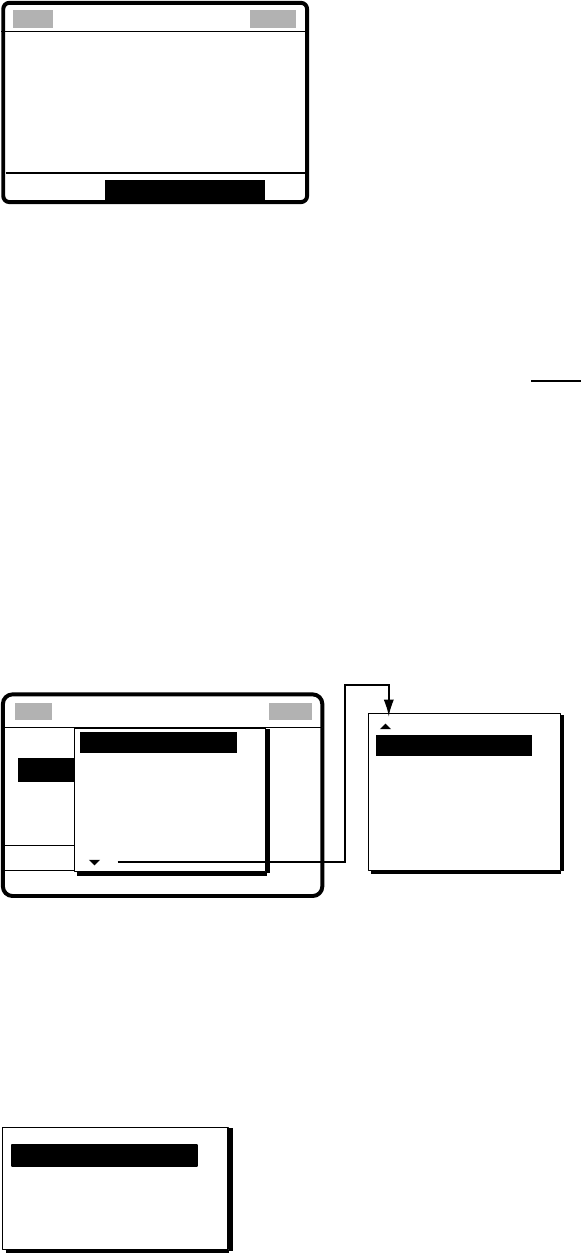
4 DISTRESS OPERATIONS
4-3
JAN-23-2002-23:59 ECC: OK
DISTRESS ACKNOWLEDGE
SHIP IN DIST:
123456789
POS:
12
°
34N 123
°
45E AT 12:34
TELEPHONE
2182.0 KHZ
FROM COAST:
001234567
NATURE: UNDESIGNATED
Received message
GO TO ALL VIEW
6.
Communicate with the coast station via radiotelephone, following the instructions
below. The radiotelephone automatically sets working frequency and class of emission,
as specified in the distress acknowledge call.
a) Say MAYDAY three times.
b) Say “This is … “ name of your vessel and call sign three times.
c) Give nature of distress and assistance needed.
d) Give description of your vessel (type, color, number of persons onboard, etc.).
4.1.2 Sending distress alert by DISTRESS button, nature of distress
specified
If you have the time to designate the nature of distress, send the distress alert as follows:
1.
Open the DISTRESS button cover and press the [DISTRESS] button momentarily to
show the following display.
CALL TYPE
:Undesignated
POS.
COM.TYPE
DSC FREQ
: All ships
: 987654321
:
:
NATURE
FIRE
FLOODING
COLLISION
GROUNDING
LISTING
UNDESIGNATED
** Compose message **
DISABLE
ABANDONING
PIRACY
MAN OVERBOARD
SINKING
Rotate [ENTER] knob to scroll.
2.
Rotate the [ENTER] knob to choose nature of distress and then push the [ENTER]
knob.
3.
Push the [ENTER] knob to open the POS. menu. This is where you enter your position,
automatically or manually. The INPUT TYPE option, that is, the source of position data,
is selected to AUTO, MANUAL or NO INFO. For AUTO, if the position is correct, push
the [ENTER] knob twice and go to step 10. For manual input, or you do not know your
position, go to step 4.
INPUT TYPE: AUTO
LAT : 34° 41 NORTH
LON : 135° 30 EAST
TIME: 09: 00 UTC
Note: If the message “No Position Data” appears when you change INPUT TYPE
from MANUAL to AUTO, confirm that the navigation device is functioning and
then choose AUTO again.
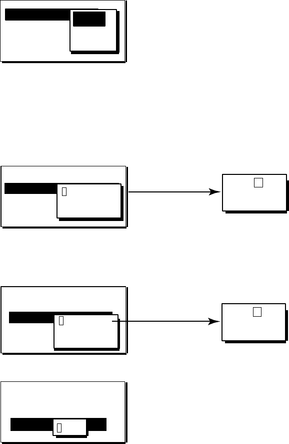
4 DISTRESS OPERATIONS
4-4
4. Push the [ENTER] knob to open the INPUT TYPE menu.
INPUT TYPE: AUTO
LAT : 34° 41 NORTH
LON : 135° 30 EAST
TIME: 09: 00 UTC
AUTO
N
MANUAL
NO INFO
5.
Rotate the [ENTER] knob to choose MANUAL and then push the [ENTER] knob. If you
cannot confirm your position, choose NO INFO, push the [ENTER] knob and then go
to step 10.
6.
Push the [ENTER] knob to open the latitude input window. Use the numeric keys to
enter latitude (in four digits). (If necessary, switch coordinates: [1] key to switch to
North; [2] key to switch to South.) Push the [ENTER] knob.
12
35°00 N
NORTH: [1] KEY
SOUTH: [2] KEY
After last digit
is entered
INPUT TYPE: MANUAL
34˚ 41
LON : 135° 30 EAST
TIME: 09: 00 UTC
LAT : 34° 41 NORTH
12
34 ° 00 N
7.
Push the [ENTER] knob to open the longitude input window. Use the numeric keys to
enter longitude (in five digits). (If necessary, switch coordinates: [1] key to switch to
East; [2] key to switch to West.) Push the [ENTER] knob.
INPUT TYPE: MANUAL
LAT: 34˚ 41 NORTH
LON : 135˚ 30 EAST
TIME: 09: 00 UTC
LAT : 35
°
00 NORTH
LON : 135
°
30 EAST
12
135°30 E 12
135°00 E
EAST: [1] KEY
WEST: [2] KEY
After last digit
is entered
8.
Push the [ENTER] knob to open the time input window.
INPUT TYPE: MANUAL
LAT : 34˚ 41 NORTH
LON : 135˚ 30 EAST
TIME : 09: 00 UTC
LAT : 35°00 NORTH
LON : 135° 00 EAST
TIME: 09: 00 UTC
12 : 34
9.
Key in UTC time with the numeric keys and then push the [ENTER] knob.
Note: If you cannot confirm time, enter 88:88 to input NO INFO as the time.

4 DISTRESS OPERATIONS
4-5
10. The COMPOSE MESSAGE screen is redisplayed. Push the [ENTER] knob to open the
COM. TYPE menu.
NATURE: FLOODING
POS: 35
°00
N 135˚00E AT 23:25
DISTRESS
CALL TYPE:
GO TO ALL VIEW
DSC FREQ : 2187.5 KHZ
COM. TYPE: TELEPHONE
NBDP-FEC
TELEPHONE
** Compose message **
11. Rotate the [ENTER] knob to choose TELEPHONE or NBDP-FEC as appropriate and
then push the [ENTER] knob. (Telephone is the usual mode, however NBDP may also
be used.)
12. Push the [ENTER] knob to open the DSC FREQ menu.
** Compose message **
NATURE: FLOSIGNATED
POS: 35
°00
N 135˚00E AT 23:34
DISTRESS
CALL TYPE:
GO TO ALL VIEW
COM. TYPE: TELEPHONE
DSC FREQ : 2187.5 KHZ
4207.5
6312.0
8414.5
12577.0
16804.5
2187.5
AUTO
13. Rotate the [ENTER] knob to choose a DSC frequency (normally 2187.5 kHz) and then
push the [ENTER] knob. (AUTO retransmits the distress alert on the distress and
safety frequencies 2 MHz, 8 MHz, 16 MHz, 4 MHz, 12 MHz and 6 MHz in that order if
the distress alert is not acknowledged.)
14. The display changes as below (example).
Compose message
NATURE: FLOODING
POS: 35
°00
N 135
°
00E AT 12:34
DISTRESS
CALL TYPE:
COM. TYPE : TELEPHONE
DSC FREQ : 2187.5 KHZ
GO TO ALL VIEW
15. Press the [DISTRESS] button more than three seconds to send the distress alert.
Distress
call in progress!
TIME TO GO : 38S
NATURE: FLOODING
POS:
35
°
00N 135
°
00E AT 12:34
TELEPHONE
2182.0 KHZ
DSC FREQ
:
2187.5 KHZ
16. For telephone, follow steps 3 to 6 on page 4-2 and 4-3. For NBDP, follow the
procedure below.

4 DISTRESS OPERATIONS
4-6
Communicating by NBDP Terminal Unit
1. The message “STATION ENTRY COMPLETED FROM DSC. Press any key to
escape.” appears on the NBDP’s display. Press any key on the NBDP Terminal Unit to
erase the message.
2. Press the function key [F3] on the keyboard of the NBDP Terminal Unit to show the
Operate menu.
3. Choose “Call Station” and then press the [Enter] key.
Call Station
Station List
DSC
ABC-6M
ABC-12M
ABC-8M
FURUNO
Station Set up
Station : DSC
ID Code :
Mode : ARQ FEC
Tx Freq : 2174.50
Rx Freq : 2174.50
4. “DSC” is selected; press the [Enter] key to connect the communications line.
5. “Connect” appears in reverse video. Type and transmit your message, giving the
following information:
a) Ship’s name and call sign
b) Nature of distress and assistance needed
c) Description of your vessel
6. Press the function key [F10] (BREAK) to disconnect the line.
4.2 Receiving a Distress Alert
When you receive a distress alert from a ship in distress, the audio alarm sounds and the
message "Distress call received." appears on the display. Press the [CANCEL] key to
silence the audio alarm. Wait for the distress acknowledge call from a coast station. If you
do not receive the distress acknowledge call from a coast station, which usually takes
about five minutes from the time of reception of a distress alert, follow the appropriate flow
chart in this section to determine your course of action.
Note: An asterisk (*) appearing in a distress alert call indicates error at asterisk location.
Russian version
If another distress alert or urgent call is received just after pressing the [CALL] key (for
distress alert relay and distress acknowledgement), the most recently received call has
priority.
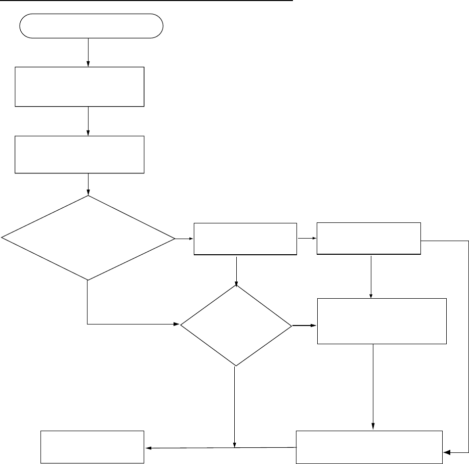
4 DISTRESS OPERATIONS
4-7
4.2.1 Distress alert received on MF band
Do the following:
• Continue watching on 2182 kHz. Wait for coast station to acknowledge the distress call.
Watch until “SEELONCE FINI” is announced.
• If multiple DSC distress alerts are received from the same ship in distress and it is
beyond a doubt in your vicinity, a DSC acknowledgement may, after consultation with an
RCC or Coast Station, be sent to terminate the call by DSC.
• In no case is a ship permitted to transmit a DSC distress relay call upon receipt of a
DSC distress alert on MF channel 2187.5 kHz.
Action for ship receiving distress alert on MF band
Press [CANCEL] key to
silence alarm.
DSC Distress alert received.
Listen on 2182 kHz
for 5 minutes.
Did you receive
acknowledge from
CS and/or RCC?
Is own
vessel able
to aid
ship in
distress?
No
Is distress traffic
in progress?
No
Is the DSC distress
call continuing?
Acknowledge the alert by
radiotelphony to the ship
in distress on 2182 kHz.
Yes
No
Inform CS and/or RCC.
Yes
Yes Yes
Enter details in log.
No
CS = Coast Station
RCC = Rescue Co-ordination Center
4 DISTRESS OPERATIONS
4-8
Sending the distress acknowledge call to ship in distress (on MF band)
Transmit the distress acknowledge call to the ship in distress only when you do not
receive it from a coast station and you are able to aid the ship in distress. First,
transmit the distress acknowledge to the ship in distress by telephone. If the DSC call is
continuing, terminate transmission of the distress alert as follows:
1. The audio alarm sounds and the display shows the message “Distress call received.”
when your ship receives a distress call.
DISTRESS CALL
SHIP IN DIST:
123456789
NATURE: UNDESIGNATED
POS:
12
°
34N 123
°
45E AT 12:34
TELEPHONE
2182.0 KHZ
Distress
call received.
STOP ALARM
2. Press the [CANCEL] key to silence the audio alarm and the display changes as below.
*
Received message
*
JAN-23-2002-23:59 ECC: OK
DISTRESS CALL
ANSWER
SHIP IN DIST: 123456789
NATURE: UNDESIGNATED
POS: 12˚34N 123˚45E AT 12:34
TELEPHONE 2182.0 KHZ
ALL VIEW
3. If you do not receive the distress acknowledge call from a coast station and you
have received the distress alert more than twice, contact the ship in distress over
radiotelephone. If the distress alert continues, terminate the alert by rotating the
[ENTER] knob to choose ANSWER, push the [ENTER] knob and then go to step 4 to
send the distress acknowledge call to the ship in distress.
4. Push the [ENTER] knob to open the CALL TYPE menu.
GO TO ALL VIEW
DSC FREQ : 2182.0 KHZ
COAST
ID IN
** Compose message **
CALLTYPE
RELAY COAST
ACKNOWLEDGE
RELAY ALL
5. Rotate the [ENTER] knob to choose ACKNOWLEDGE and then push the [ENTER]
knob. The following display appears.
CALL TYPE : ALL SHIPS
DISTRESS ACKNOWLEDGE
ID IN DIST : 123456789
DSC FREQ : 2182.0 KHZ
GO TO ALL VIEW
** Compose message **

4 DISTRESS OPERATIONS
4-9
6. Press the [CALL] key, and the message “Category distress transmit sure?” appears.
Continue press the key until the message “Distress acknowledge call in progress
appears, to transmit the distress acknowledge call to the ship in distress.
SHIP IN DIST :
123456789
Distress acknowledge
call in progress!
DSC FREQ :
2187.5 KHZ
TIME TO GO 4S
[CALL] key
pressed
3 seconds
ID IN DIST:
123456789
Category distress
transmit sure?
DSC FREQ :
2187.5 KHZ
KEEP PRESSED FOR 3S
4.2.2 Distress alert received on HF band
If you receive a distress alert on the HF band, the ALARM lamp lights and the audio alarm
sounds. Press the [CANCEL] key to silence the audio alarm. Wait for the distress
acknowledge from a coast station. If you do not receive the distress acknowledge within
five minutes, follow the instructions below to determine your course of action.
• Watch on the distress frequency.
• Relay the distress alert in the following cases:
- You have not received a distress acknowledge call from a coast station within five
minutes after receiving a distress call.
- You have not received a distress relay from other ship.
- You cannot receive distress communications from other ship over radiotelephone.
- If it is clear the ship or persons in distress are not in the vicinity and/or other crafts are
better placed to assist, superfluous communications which could interfere with search
and rescue activities should be avoided. Details should be recorded in the appropriate
log book.
- The ship relaying the distress alert should establish communications with the station
controlling the distress as directed and render such assistance as required and
appropriate.
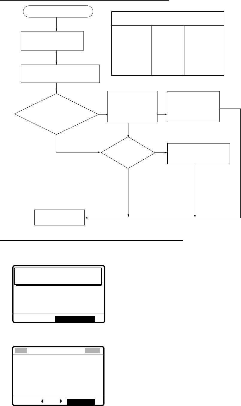
4 DISTRESS OPERATIONS
4-10
Action for ships receiving distress alert on HF band
Press [CANCEL] key to
silence alarm.
DSC Distress alert received.
Listen to associated RTF or
NBDP channel(s) for 5 minutes.
Is the alert
acknowledged or
relayed by CS and
or RCC?
Is own
vessel able
to assist?
No
Is distress commu-
nication in progress
on associated RTF
channels?
No
Transmit distress
relay on HF to coast
station and inform
RCC.
Contact RCC via most
efficient medium to offer
assistance.
Yes
Yes Yes
Enter details in log.
No
CS = Coast Station
RCC = Rescue Co-ordination Center
HF DSC, RTF AND NBDP CHANNELS (kHz)
DSC RTF* NBDP
4207.5 4125 4177.5
6312.0 6215 6268
8414.5 8291 8376.5
12577.0 12290 12520
16804.5 16420 16695
* = Radiotelephone
Sending the distress relay to coast station (on HF band)
1. The audio alarm sounds and the display changes as below when a distress call is
received.
DISTRESS CALL
ID IN DIST: 123456789
NATURE: UNDESIGNATED
POS: 12˚34N 123˚45E AT 12:34
TELEPHONE 8291.0 KHZ
Distress
call received.
STOP ALARM
2. Press the [CANCEL] key to silence the audio alarm, and the display changes as below.
*
Received message
*
JAN-23-2002-23:59 ECC: OK
DISTRESS CALL
ANSWER
SHIP IN DIST:
123456789
NATURE: UNDESIGNATED
POS:
12˚34N 123˚45E AT 12:34
TELEPHONE
8291.0 KHZ
ALL VIEW
3. Rotate the [ENTER] knob to choose ANSWER and then push the [ENTER] knob.

4 DISTRESS OPERATIONS
4-11
4. Push the [ENTER] knob to open the CALL TYPE menu.
GO TO ALL VIEW
DSC FREQ : 8414.5 KHZ
ID IN DIST: 987654321
CALL TYPE* INDVIDUAL
DISTRESS RELAY
RELAY COAST
RELAY ALL
** Compose message **
5. If you know the ID of the nearest coast station, choose RELAY COAST and then push
the [ENTER] knob.
6. Push [ENTER] knob and key in ID of coast station where to send the distress relay and
then push the [ENTER] knob.
GO TO EASY VIEW
CALL TYPE : INDIVIDUAL
DISTRESS RELAY
DSC FREQ :
GO TO ALL VIEW
8414.5 KHZ
ID IN DIST:
COAST ID:
000000000
**
Compose message
**
7. Push the [ENTER] knob to open the DSC FREQ. menu.
GO TO EASY VIEW
DSC FREQ KHZ
GO TO ALL VIEW
**
Compose message
**
DISTRE 123456789
COAST ID:
ID IN DIST:
CALL TYPE: RELAY ALL
4207.5
6312.0
12577.0
16804.5
2187.5
8414.5
8. Choose appropriate frequency and then push the [ENTER] knob. You should first
choose 8414.5 kHz.
9. Press the [CALL] key, and the display changes as shown at the top of the next page.
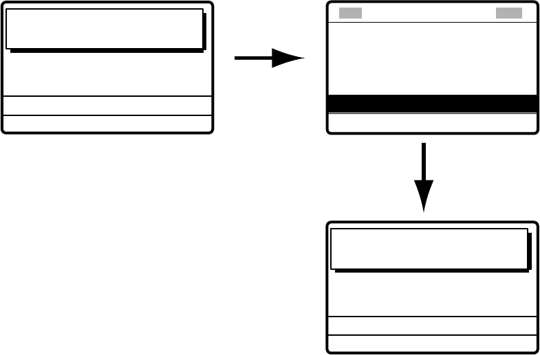
4 DISTRESS OPERATIONS
4-12
[CALL] key
pressed 3
seconds.
COAST ID:
001234567
ID IN DIST:
123456789
Category distress
transmit sure?
DSC FREQ :
8414.5 KHZ
KEEP PRESSED FOR 3S
TO COAST:
001234567
SHIP IN DIST:
123456789
Distress relay sel
call in progress!
DSC FREQ :
8414.5 KHZ
TIME TO GO : 5S
Timer counts
down time
remaining
(See note below.)
GO TO EASY VIEW
CALL TYPE : INDIVIDUAL
DISTRESS RELAY
TIME TO GO : 2M10S
ID IN DIST: 123456789
COAST ID: 001234567
** Compose message **
DSC FREQ :
8414.5 KHZ
Note: If a coast station acknowledges the call before the timer counts down to zero, press
the [CANCEL] key to cancel the distress relay call.
10. After the call is transmitted, the message “Wait for distress relay acknowledge.”
appears. After you have received the distress acknowledgement from the coast station,
communicate with the coast station by telephone, over the DSC frequency specified. If
you do not receive the distress acknowledgement from a coast station after the timer
counts down to zero, transmit the distress relay again, over a different frequency.
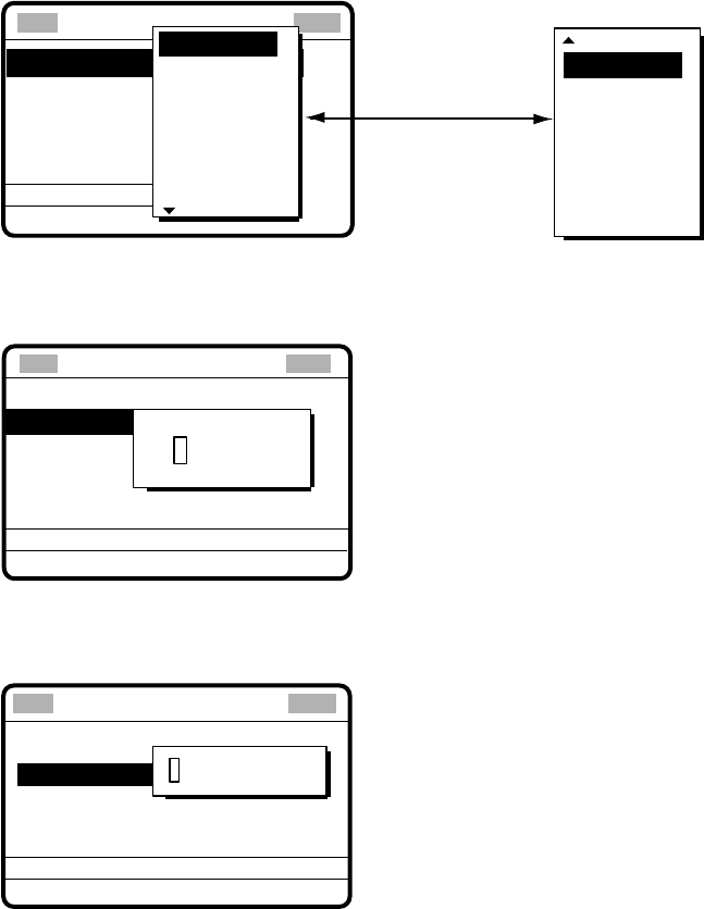
4 DISTRESS OPERATIONS
4-13
4.3 Sending Distress Relay on Behalf of a Ship in
Distress
4.3.1 Sending distress relay to coast station
You may send the distress relay to a coast station on behalf of a ship in distress in the
following cases:
• You are near the ship in distress and the ship in distress cannot transmit the distress
alert.
• When the master or person responsible for your ship considers that further assistance is
necessary.
In the above cases never use the [DISTRESS] button to transmit the distress relay.
1. Press the [2/DSC] key and then push the [ENTER] knob.
** Compose message **
STATION ID
PRIORITY
COM. TYPE
COM. FREQ
DSC FREQ
: All ships
: Safety
: Telephone
: 2187.5 kHz
CALL TYPE
PSTN CALL
TEST CALL
ALL SHIPS
GROUP CALL
AREA CALL
POSITION
INDIVIDUAL
POLLING
NEUTRAL
MEDICAL
RELAY ALL
RELAY SEL
DISTRESS
Rotate [ENTER]
knob to scroll.
GO
2. Rotate the [ENTER] knob to choose RELAY SEL and then push the [ENTER] knob.
3. Push the [ENTER] knob to open the COAST ID input window.
CALL TYPE: RELAY SEL
NATURE: UNDESIGNATED
POS: NO INFORMATION
COM. TYPE : TELEPHONE
DSC FREQ. : 8414.5 KHZ
COAST ID
000000000
GO TO ALL VIEW
ID IN DIST
** Compose message **
4. Key in COAST ID with the numeric keys and then push the [ENTER] knob.
5. Push the [ENTER] knob to open the ID IN DIST window.
CALL TYPE
NATURE : UNDESIGNATED
POS.:
COM.TYPE : TELEPHONE
DSC FREQ : 8414.5 KHZ
GO TO ALL VIEW
: RELAY SEL
: ---------
: NO INFORMATION
ID IN DIST
COAST ID:
000000000
**
Compose message
**
6. Key in ID of ship in distress with the numeric keys and then push the [ENTER] knob. If
you do not know the ID, simply push the [ENTER] knob without entering ID.
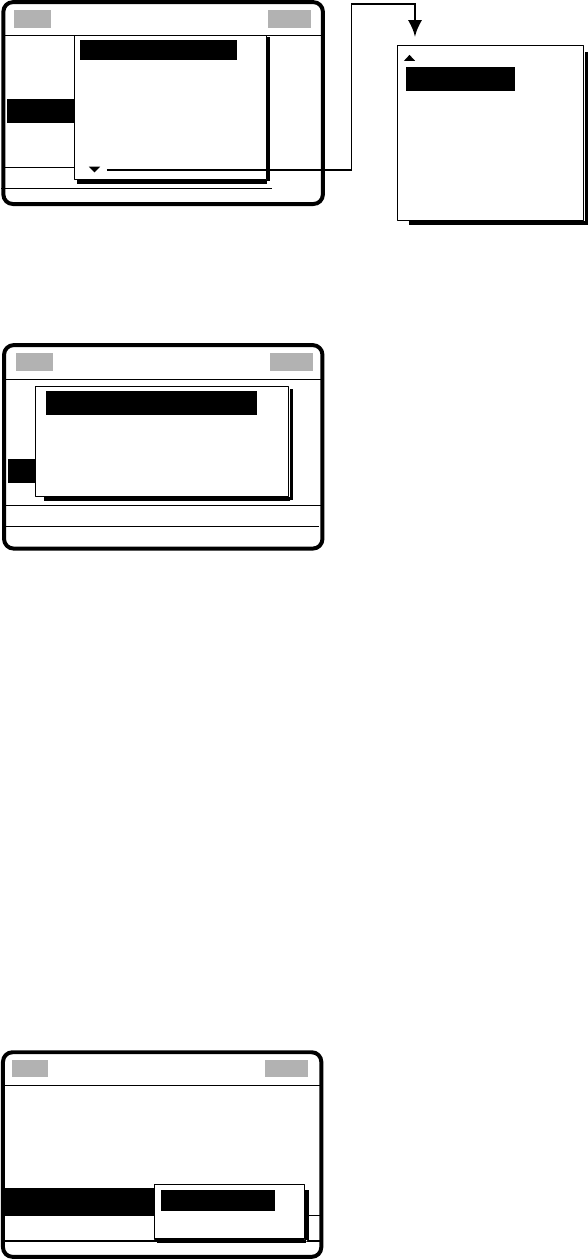
4 DISTRESS OPERATIONS
4-14
7. Push the [ENTER] knob to open the NATURE menu.
COAST ID
CALL TYPE
ID IN DIST
:Undesignated
POS: ION.
COM.TYPE
DSC FREQ
: All ships
: 987654321
:
:
NATURE
FIRE
FLOODING
COLLISION
GROUNDING
LISTING
UNDESIGNATED
** Compose message **
SINKING
DISABLE
ABANDONING
PIRACY
MAN OVERBOARD
EPIRB EMISSION
Rotate [ENTER] knob to scroll.
8. Rotate the [ENTER] knob to choose nature of distress and then push the [ENTER]
knob. If you do not know the nature of distress, choose UNDESIGNATED.
9. Push the [ENTER] knob to open the POS. menu.
COAST ID
CALL TYPE
DISTRESS RELAY
ID IN DIST
NATURE : UNDESIGNATE
COM. TYPE
DSC FREQ : 8414.5 KHZ
: ALL SHIPS
: 987654321
:
POS:
LAT : 34°45 NORTH
LON : 135°22 EAST
TIME: 10:00 UTC
INPUT TYPE: AUTO
GO TO ALL VIEW
**
Compose message
**
10. Enter position of ship in distress, following 1), 2) or 3) below.
1) For automatic input, push the [ENTER] knob twice and then go to step 11.
2) For manual input, push the [ENTER] knob to open the INPUT TYPE menu, rotate the
[ENTER] knob to choose MANUAL and then push the [ENTER] knob. Enter latitude and
longitude of ship in distress and time as follows:
a) Push the [ENTER] knob. Enter latitude and then push the [ENTER] knob.
b) Push the [ENTER] knob. Enter longitude and then push the [ENTER] knob.
c) Push the [ENTER] knob. Enter UTC time and then push the [ENTER] knob. Go to
step 11.
Note: If you cannot confirm time, enter 88:88 to input NO INFO as the time
.
3) If you cannot confirm position of ship in distress, push the [ENTER] knob to open
the INPUT TYPE menu, rotate the [ENTER] knob to choose NO INFO and then push
the [ENTER] knob. Go to step 11.
11. Push the [ENTER] knob to open the COM. TYPE menu.
TELEPHONE
NATURE : UNDESIGNATED
POS:
34
°
45N 135
°
22E AT 10:00
DSC FREQ
: 2187.5 kHz
TELEPHONE
NBDP-FEC
COM. TYPE
GO TO ALL VIEW
CALL TYPE : RELAY SEL
ID IN DIST : 123456789
COAST ID: 001234567
**
Compose message
**
4 DISTRESS OPERATIONS
4-15
12. Rotate the [ENTER] knob to choose TELEPHONE and then push the [ENTER] knob.
(NBDP-FEC may also be used.) Push the [ENTER] knob to open the DSC FREQ
menu.
GO TO EASY VIEW
DSC FREQ KHZ
GO TO ALL VIEW
** Compose message **
DISTRE 123456789
COAST ID:
ID IN DIST:
CALL TYPE: RELAY ALL
4207.5
6312.0
12577.0
16804.5
2187.5
8414.5
13. Rotate the [ENTER] knob to choose appropriate DSC (NBDP) frequency and then
push the [ENTER] knob. The display now looks something like the one below in case
of radiotelephone.
CALL TYPE : RELAY SEL
COAST ID :
001234567
ID IN DIST : NO INFO
NATURE : SINKING
POS: 34
°
45N 135
°
22E AT 10:00
DSC FREQ :
8414.5 KHZ
GO TO ALL VIEW
COM. TYPE : TELEPHONE
** Compose message **
14. Press the [CALL] key, and the message “Category distress transmit sure?” appears.
Continue pressing the key until the display shows “Distress relay sel call in progress!”
to send the distress relay call.
Distress relay sel
call in progress!
DSC FREQ : 8414.5 KHZ
TO COAST : 001234567
SHIP IN DIST : NO INFO
TIME TO GO : 8S
[CALL] key
pressed 3
seconds
Category distress
transmit sure?
DSC FREQ : 8414.5 KHZ
TO COAST : 001234567
ID IN DIST : NO INFO
POS : 34°45N 135°22E AT 10:00
TELEPHONE 8291.0 KHZ
KEEP PRESSED FOR 3S
15. The equipment then waits for acknowledgement of the distress relay, displaying the
message shown below. If the distress relay is not acknowledged within five minutes,
the message “No response. Try relay again.” appears. If this occurs, send the distress
relay again.
Wait for distress
relay acknowledge.
TIME TO GO : 4M59S
DSC FREQ
:
8414.5 KHZ
FROM COAST : 001234567
SHIP IN DIST: NO INFO
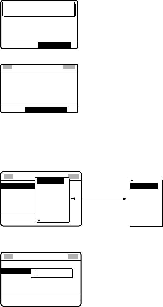
4 DISTRESS OPERATIONS
4-16
16. When you receive the distress relay acknowledge call, the audio alarm sounds and
the display shown below appears.
Distress relay ack
call received.
SHIP IN DIST : NO INFO
POS : 12°34N 123°45E AT 12:34
TELEPHONE 8291.0 KHZ
COAST ID : 001234567
NATURE : SINKING
STOP ALARM
17. Press the [CANCEL] key to silence the audio alarm. The following display appears.
JAN-23-2002-23:59
GO TO ALL VIEW
SHIP IN DIST : NO INFO
POS :
12°34N 123°45E AT 12:34
TELEPHONE
8291.0 KHZ
COAST ID :
001234567
NATURE : SINKING
DISTRESS RELAY ACK
* Received message *
ECC:OK
18. Communicate with the coast station.
4.3.2 Sending distress relay to all ships
Use this procedure to send the distress relay to all ships.
1. Press the [2/DSC] key and then push the [ENTER] knob.
** Compose message **
STATION ID
PRIORITY
COM. TYPE
COM. FREQ
DSC FREQ
: All ships
: Safety
: Telephone
: 2187.5 kHz
CALL TYPE
PSTN CALL
TEST CALL
ALL SHIPS
GROUP CALL
AREA CALL
POSITION
INDIVIDUAL
POLLING
NEUTRAL
MEDICAL
RELAY ALL
RELAY SEL
DISTRESS
Rotate [ENTER]
knob to scroll.
GO
2. Rotate the [ENTER] knob to choose RELAY ALL and then push the [ENTER] knob.
3. Push the [ENTER] knob to open the ID IN DIST menu.
CALL TYPE: RELAY ALL
NATURE: UNDESIGNATED
POS: 34
°
45N 135
°
45E AT 9:30
COM. TYPE : TELEPHONE
DSC FREQ. : 8414.5 KHZ
ID IN DIST
000000000
GO TO ALL VIEW
** Compose message **
4. Key in ID of ship in distress (if known) with the numeric keys and then push the
[ENTER] knob. (If you do not know the ID enter push the [ENTER] knob without
entering ID.)

4 DISTRESS OPERATIONS
4-17
5. Push the [ENTER] knob to open the NATURE menu.
CALL TYPE
ID IN DIST
:Undesignated
POS: ION.
COM.TYPE
DSC FREQ
: All ships
: 987654321
:
:
NATURE
FIRE
FLOODING
COLLISION
GROUNDING
LISTING
UNDESIGNATED
**
Compose message
**
6. Rotate the [ENTER] knob to choose nature of distress and then push the [ENTER]
knob. (If you do not know the nature of distress, choose UNDESIGNATED.)
7. Push the [ENTER] knob to open the POS. menu, where you enter the position of the
ship in distress and time, manually or automatically.
CALL TYPE
DISTRESS RELAY
ID IN DIST
NATURE : UNDESIGNATE
COM. TYPE
DSC FREQ : 8414.5 KHZ
: ALL SHIPS
: 987654321
:
POS:
LAT : 34°45 NORTH
LON : 135°45 EAST
TIME: 09:30 UTC
INPUT TYPE: AUTO
GO TO ALL VIEW
**
Compose message
**
8. Enter position of the ship in distress, following 1), 2) or 3) below.
1) For automatic input, push the [ENTER] knob twice. Go to step 9.
2) For manual input, push the [ENTER] knob to open the INPUT TYPE menu, rotate the
[ENTER] knob to choose MANUAL and then push the [ENTER] knob. Enter latitude and
longitude of ship in distress and time as follows:
a) Push the [ENTER] knob. Enter latitude and then push the [ENTER] knob.
b) Push the [ENTER] knob. Enter longitude and then push the [ENTER] knob.
c) Push the [ENTER] knob. Enter UTC time and then push the [ENTER] knob. Go to
step 9.
Note: If you cannot confirm time, enter 88:88 to input NO INFO as the time.
3) If you cannot confirm position of ship in distress, push the [ENTER] knob to open
the INPUT TYPE menu, rotate the [ENTER] knob to choose NO INFO and then push
the [ENTER] knob. Go to step 9.
9. Push the [ENTER] knob to open the COM. TYPE menu.
CALL TYPE: RELAY ALL
ID IN DIST: 123456789
NATURE : NDESIGNATED
DSC FREQ : 8414.5 KHZ
POS: 34˚45N
COM. TYPE
GO TO ALL VIEW
: TELEPHONE
TELEPHONE
NBDP-FEC
** Compose message **
10. Rotate the [ENTER] knob to choose TELEPHONE (or NBDP-FEC) and then push the
[ENTER] knob.
4 DISTRESS OPERATIONS
4-18
11.
Push the [ENTER] knob to open the DSC FREQ menu.
GO TO EASY VIEW
DSC FREQ KHZ
GO TO ALL VIEW
** Compose message **
ID IN DIST: 123456789
POS: 34
°
45N
COM TYPE:
CALL TYPE: RELAY ALL
4207.5
6312.0
12577.0
16804.5
2187.5
8414.5
NATURE: UN
12. Rotate the [ENTER] knob to choose appropriate frequency and then push the [ENTER]
knob. The display now looks something like the one below.
CALL TYPE: RELAY ALL
ID IN DIST: 123456789
NATURE: UNDESIGNATED
POS: 34˚45N 135˚45E AT 09:30
COM TYPE : TELEPHONE
DSC FREQ : 8414.5 KHZ
GO TO ALL VIEW
** Compose message **
13. Press the [CALL] key, and the message “Category distress transmit sure!” appears.
Continue pressing the key until the display shows “Distress relay all call in progress!” to
send the distress relay call.
*** SEND MESSAGE ***
CALL TYPE : ALL SHIPS
SHIP IN DIST: 123456789
DSC FREQ
: 8414.5 KHZ
TIME TO GO: 29S
Distress relay all
call in progress!
*** SEND MESSAGE ***
CALL TYPE : ALL SHIPS
NATURE: UNDESIGNATED
POS: 34˚45N 135˚45E AT 09:30
COM TYPE : TELEPHONE
DSC FREQ
: 8414.5 KHZ
KEEP PRESSED FOR 3S
Category distress
transmit sure?
[CALL] key
pressed 3
seconds
14.
After the call is sent, the radiotelephone screen automatically appears.
4 DISTRESS OPERATIONS
4-19
4.4 Receiving Distress Relay All Ships
When you receive a distress relay for all ships, continue monitoring distress and safety
frequencies.
1. The audio alarm sounds and the display looks like the one below when a distress relay
all ships call is received.
Distress relay all
call received.
SHIP IN DIST:
123456789
POS:
12
°
34N 123
°
45E AT 12:34
TELEPHONE
8291.5 kHZ
FROM SHIP:
234567890
NATURE: UNDESIGNATED
STOP ALARM
2. Press the [CANCEL] key to silence the alarm, and the display changes as below.
JAN-23-2002-23:59 ECC: OK
SHIP IN DIST:
123456789
POS:
12
°
34N 123
°
45E AT 12:34
TELEPHONE
8291.5 KHZ
FROM SHIP:
234567890
NATURE: UNDESIGNATED
DISTRESS RELAY ALL
GO TO ALL VIEW
Received message
3. Press the [CANCEL] key to go to the radiotelephone screen.
4. Watch distress/safety frequency.
4.5 Receiving Distress Relay from Coast Station
When you receive a distress relay call from a coast station, continue monitoring distress
and safety frequencies.
1. The audio alarm sounds and the display looks like the one in the left-hand figure below
when a distress relay is received from a coast station. Press the [CANCEL] key to
silence the audio alarm, and the display changes as in the right-hand figure below.
Distress relay all
call received.
SHIP IN DIST: 123456789
POS: 12
°
34N 123
°
45E AT 12:34
TELEPHONE 8291.5 KHZ
FROM COAST: 001234567
NATURE: UNDESIGNATED
STOP ALARM
Press the
[CANCEL] key.
JAN-23-2002-23:59 ECC: OK
SHIP IN DIST: 123456789
POS: 12
°
34N 123
°
45E AT 12:34
TELEPHONE 8291.5 KHZ
FROM COAST: 001234567
NATURE: UNDESIGNATED
DISTRESS RELAY ALL
Received message
GO TO ALL VIEW
2. Press the [CANCEL] key to go to the radiotelephone screen.
3. Watch distress/safety frequency.
4 DISTRESS OPERATIONS
4-20
(This page intentionally left blank.)
5-1
5 CALLING, RECEIVING
This chapter provides the information necessary for general calling and receiving.
5.1 All Ships Call
When an urgent but not life-endangering situation arises on your ship, for example, engine
trouble, send an all ships call to request assistance.
After sending the call, you can communicate by voice over the radiotelephone, or send a
message by telex. For telephone, do the following before beginning actual communications:
URGENCY priority: Say PAN three times followed by your call sign.
SAFETY priority: Say SECURITE three times followed by your call sign.
Own Ship
Coast
Station
5.1.1 Sending an all ships call
1. Press the [2/DSC] key followed by pushing the [ENTER] knob to display the CALL TYPE
menu.
** Compose message **
STATION ID
PRIORITY
COM. TYPE
COM. FREQ
DSC FREQ
: All ships
: Safety
: Telephone
: 2187.5 kHz
CALL TYPE
PSTN CALL
TEST CALL
ALL SHIPS
GROUP CALL
AREA CALL
POSITION
INDIVIDUAL
POLLING
NEUTRAL
MEDICAL
RELAY ALL
RELAY SEL
DISTRESS
Rotate [ENTER]
knob to scroll.
GO
2. Rotate the [ENTER] knob to choose ALL SHIPS and then push the [ENTER] knob.

5 CALLING, RECEIVING
5-2
3. Push the [ENTER] knob to display the PRIORITY menu.
CALL TYPE: ALL SHIPS
COM. TYPE : TELEPHONE
DSC FREQ : 2187.5 KHZ
GO TO ALL VIEW
PRIORITY SAFETY
URGENCY
DISTRESS
** Compose message **
4. Rotate the [ENTER] knob to choose SAFETY or URGENCY as appropriate and then
push the [ENTER] knob. (DISTRESS should be used only when there is a life
endangering situation on board your vessel.)
5. Push the [ENTER] knob to open the COM. TYPE menu.
CALL TYPE: ALL SHIPS
PRIORITY : SAFETY
COM TYPE
DSC FREQ : 2187.5 KHZ
GO TO ALL VIEW
COM. TYPE
NBDP-FEC
TELEPHONE
**
Compose message
**
6. Rotate the [ENTER] knob to choose appropriate communications mode and then push
the [ENTER] knob.
7. Push the [ENTER] knob to open the DSC FREQ menu.
**
Compose message
**
GO TO ALL VIEW
DSC FREQ
CALL TYPE : ALL SHIPS
PRIORITY : SAFETY
COM TYPE : TELEPHONE
2187.5KHZ
4207.5
6312.0
8414.5
12577.0
16804.5
2187.5
8. Rotate the [ENTER] knob to choose frequency and then push the [ENTER] knob.
9. Press the [CALL] key to send the call. For safety and urgency call the display shows “All
ships call in progress.” For distress call, the display shows “Category distress transmit
sure? If you are sure to transmit with distress priority, continue pressing the [CALL] key
to show "All ships call in progress!".
SAFETY
TELEPHONE 2182.0 KHZ
All ships
call in progress!
DSC FREQ : 2187.5 KHZ
TIME TO GO: 5S
10.
The radiotelephone screen automatically appears after the call is sent (timer counts
down to zero). The equipment is then set up for telephone (or NBDP) and safety or
urgency priority, using DSC pair frequencies.

5 CALLING, RECEIVING
5-3
Sending message by NBDP Terminal Unit
1. The message “STATION ENTRY COMPLETED FROM DSC. Press any key to escape.”
appears on the NBDP’s display. Press any key on the NBDP Terminal Unit to erase the
message.
2. Press the function key [F3] on the keyboard of the NBDP Terminal Unit to show the
Operate menu.
3. Choose “Call Station” and then press the [Enter] key.
4. “DSC” is selected; press the [Enter] key. “Connect” appears in reverse video.
5. Type and transmit your message.
6. When you have finished sending your message, press the [F10] key to disconnect the
line.
5.1.2 Receiving an all ships call
1.
When an all ships call is received, the audio alarm sounds and the display looks
something like the one shown below.
FROM SHIP:
123456789
SAFETY
TELEPHONE
2182.0 KHZ
All ships
call received.
STOP ALARM
2.
Press the [CANCEL] key to silence the alarm. The display shows partial contents of the
all ships call as below.
* Received message *
MAR-23-2002-23:59 ECC: OK
ALL SHIPS CALL
FROM SHIP:
123456789
SAFETY
TELEPHONE
2182.0 KHZ
GO TO ALL VIEW To view detailed contents,
push the [ENTER] knob.
3.
Press the [CANCEL] key again to go to the radiotelephone screen. Watch for
communications about all ships call on the radiotelephone.
5 CALLING, RECEIVING
5-4
5.2 Individual Call
The individual call is for calling a specific station. After sending an individual call, called ACK
RQ transmission, wait to receive the acknowledge back (ACK BQ) signal from the receiving
station.
5.2.1 Sending an individual call
1. Press the [2/DSC] key and then push the [ENTER] knob to open the CALL TYPE menu.
** Compose message **
STATION ID
PRIORITY
COM. TYPE
COM. FREQ
DSC FREQ
: All ships
: Safety
: Telephone
: 2187.5 kHz
CALL TYPE
PSTN CALL
TEST CALL
ALL SHIPS
GROUP CALL
AREA CALL
POSITION
INDIVIDUAL
POLLING
NEUTRAL
MEDICAL
RELAY ALL
RELAY SEL
DISTRESS
Rotate [ENTER]
knob to scroll.
GO
2. Rotate the [ENTER] knob to choose INDIVIDUAL and then push the [ENTER] knob.
3. Push the [ENTER] knob to open the STATION ID menu.
CALL TYPE
PRIORITY
COM. TYPE
COM. FREQ : NO INFO
DSC FREQ
: INDIVIDUAL
: ROUTINE
: TELEPHONE
: 2M-INTL
GO TO ALL VIEW
:
STATION ID
:
000000000
**
Compose message
**
4. Use the numeric keys to key in the ID of the station where to send the call and then push
the [ENTER] knob.
5. Push the [ENTER] knob to open the PRIORITY menu.
CALL TYPE
STATION ID
COM. TYPE
COM. FREQ
DSC FREQ
: INDIVIDUAL
: ---------
: TELEPHONE
: NO INFOR
: 2M-INTL
GO TO ALL VIEW
PRIORITY :
BUSINESS
SAFETY
URGENCY
ROUTINE
**
Compose message
**
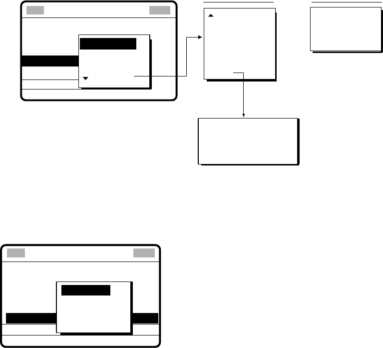
5 CALLING, RECEIVING
5-5
6. Rotate the [ENTER] knob to choose appropriate priority (normally ROUTINE) and then
push the [ENTER] knob.
7. Push the [ENTER] knob to open the COM. TYPE menu.
CALL TYPE
STATION ID
PRIORITY
COM. FREQ
DSC FREQ
: INDIVIDUAL
: ---------
: ROUTINE
: NO INFOR
: 2M-INTL
TELEPHONE
NBPD-ARQ
NBDP-FEC
Routine or
Business Priority For Safety or
Urgency Priority
COM. TYPE :
TTY RCV
TTY
MORSE KEY
MORSE TAPE
FACSIMILE
DATA
MAIN
V32
V21 V26 BIS
V22 V26 TER
V22 BIS V27 TER
V23
TELEPHONE
NBDP-ARQ
NBDP-FEC
SPECIAL
Push [ENTER]
knob to display.
** Compose message **
GO
8. Rotate the [ENTER] knob to choose communications type desired and then push the
[ENTER] knob.
9. For routine and business priority, push the [ENTER] knob to open the COM. FREQ
menu. For safety and urgency priority, go to step 11.
CALL TYPE
STATION ID : 123456789
PRIORITY
COM. TYPE
DSC FREQ
: INDIVIDUAL
: 12M-INTL
COM. FREQ
FREQUENCY
CHANNEL
POSITION*
NO INFO
GO TO ALL VIEW
* POSITION is displayed if a coast
station is specified at step 3.
**
Compose message
**
10. Rotate the [ENTER] knob to choose communication frequency setting method desired
and then push the [ENTER] knob. For FREQUENCY and CHANNEL, see “How to Set
Working Frequency, Channel” on the next page. NO INFO and POSITION let the
receiving station set the working frequency. Choose NO INFO or POSITION to send the
call to a coast station; FREQUENCY or CHANNEL to send the call to a ship station.

5 CALLING, RECEIVING
5-6
To send a call, set the working frequency as below, to communicate with the receiving station.
The working frequency can be entered by Tx and Rx frequencies or channel number.
Routine or ship's business priority
1.
After selecting FREQUENCY or CHANNEL, one of the following pop-up windows appears.
How to Set Working Frequency, Channel
TX: 0.0 KHZ
RX: 0.0 KHZ
Frequency
CH: 0
Channel
2. Key in TX frequency or channel with the numeric keys. (For channel, push the [ENTER] knob
to finish.)
3. Rotate the [ENTER] knob to choose the RX field, key in RX frequency and then push the
[ENTER] knob to finish.
Safety or urgency priority
For safety or urgency priority the communication frequency cannot be selected; it is automatically
set to the pair frequency as set for the DSC frequency.
11. Follow the instructions on the next page to choose DSC frequency desired.
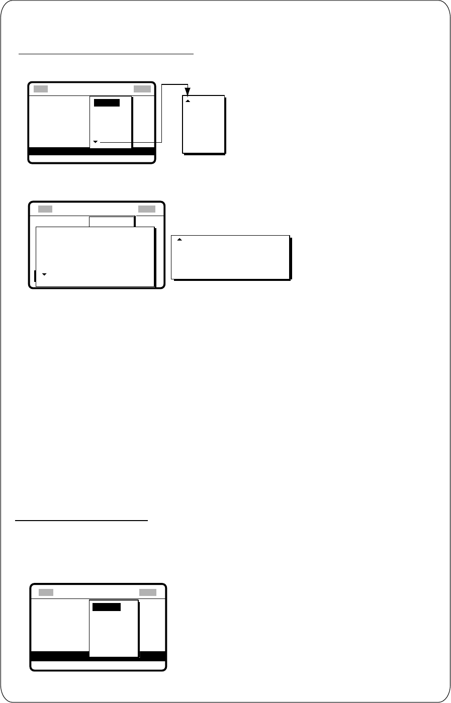
5 CALLING, RECEIVING
5-7
** Compose message **
How to Set DSC Frequency
GO TO ALL VIEW
CALL TYPE: INDIV
STATION ID: 123456
PRIORITY: RO
COM. TYP: TELEP
COM. FREQ: NO I
DSC FREQ : 2M-INTL
16 MHZ
18 MHZ
22 MHZ
25 MHZ
OTHER
6 MHZ
8 MHZ
12 MHZ
4 MHZ
2 MHZ
** Compose message **
Routine or ship’s business priority
1. Rotate the [ENTER] knob to choose DSC FREQ and then push the [ENTER] knob.
2. Rotate the [ENTER] knob to choose appropriate DSC band and then push the [ENTER] knob.
One of the menus shown below appears depending on the band selected.
GO TO ALL VIEW
CALL TYPE
Station ID
Priority
Com. type
COM. FREQ
: Individual
: 001234567
: Routine
: Telephone
: No infor
: 12M-INTL
6 MHz
8 MHz
12 MHz
4 MHz
USER CH1 :T12345.0/R12345.0
USER CH2 :T12345.5/R12345.5
USER CH3 :T12346.0/R12346.0
USER CH4 :T12346.5/R12346.5
Rotate the [ENTER] knob
to scroll menu to view user
channels (if registered).
12MHz menu
INTL :T 12577.5/R12657.0
LOCAL1 :T 12578.0/R12657.5
LOCAL2 :T 12578.5/R12658.0
16MHz menu
INTL :T 16805.0/R16903.0
LOCAL1 :T 16805.5/R16903.5
LOCAL2 :T 16806.0/R16904.0
2MHz menu
INTL :T 2189.5/R 2177.0
4MHz menu
INTL :T 4208.0/R 4219.5
LOCAL1 :T 4208.5/R 4220.0
LOCAL2 :T 4209.0/R 4220.5
6MHz menu
INTL :T 6312.5/R 6331.0
LOCAL1 :T 6313.0/R 6331.5
LOCAL2 :T 6313.5/R 6332.0
8MHz menu
INTL :T 8415.0/R 8436.5
LOCAL :T 8415.5/R8437.0
LOCAL :T 8416.0/R8437.5
18MHz menu
INTL :T18898.5/R19703.5
LOCAL1 :T18899.0/R19704.0
LOCAL2 :T18899.5/R19704.5
22MHz menu
INTL :T 22374.5/R22444.0
LOCAL1 :T 22375.0/R22444.5
LOCAL2 :T 22375.5/R22445.0
25MHz menu
INTL :T 25208.5/R26121.0
LOCAL1 :T 25209.0/R26121.5
LOCAL2 :T 25209.5/R26122.0
Other menu
INTL :T 458.5/R 455.5
2 MHz
DSC FREQ
INTL : T12577.5/R12657.0
LOCAL1 : T12578.0/R12657.5
LOCAL2 : T12578.5/R12658.0
LOCAL = Local channel
** Compose message **
3. Rotate the [ENTER] knob to choose DSC frequency and then push the [ENTER] knob. The
display shows the DSC frequency band selected, at "DSC FREQ".
Safety or urgency priority
For safety or urgency priority "COM. FREQ" is automatically set to the same pair frequency as the
DSC frequency.
1. Rotate the [ENTER] knob to choose DSC FREQ and then push the [ENTER] knob.
GO TO ALL VIEW
CALL TYPE:
STATION ID:
PRIORITY
COM. TYPE
INDIVIDUAL
001234567
: SAFETY
: TELEPHONE
DSC FREQ : 2187.5 KHZ
COM. FREQ : 2182.0KHZ
4207.5
6312.0
8414.5
12577.0
16804.5
2187.5
2. Rotate the [ENTER] knob to choose appropriate frequency and then push the [ENTER] knob.
Rotate the [ENTER]
knob to scroll.
OTHER: Private channel
5 CALLING, RECEIVING
5-8
12. Press the [CALL] key to send the individual call (transmission time: about seven
seconds). The display shows the message "Individual request call in progress!" while
the call is being sent.
Individual request
call in progress!
TIME TO GO: 7S
TO SHIP:
123456789
DSC FREQ :
2177.0 KHZ
ROUTINE
TELEPHONE 2138.0 KHZ
Note: When the channel is in use,
"CH BUSY" appears at the
lower left-hand side of the
screen.
Press [CALL] key for forced
transmission.
13. After the call is sent, the equipment waits for acknowledgement of the call, showing the
display below.
Waiting for
acknowledgement.
TIME TO GO: 4M30S
FROM SHIP:
123456789
DSC FREQ :
2177.0 KHZ
ROUTINE
TELEPHONE 2138.0 KHZ
14. The timer starts counting down the maximum time to wait for acknowledgement, five
minutes, randomly set. One of the following three messages appears. (“No response!
Try calling again.” appears after the timer counts down to zero. It means the receiving
station did not respond.)
No response!
Try calling again?
FROM SHIP: 123456789
ROUTINE
TELEPHONE 2138.0 KHZ
DSC FREQ : 2177.0 KHZ
CALL AGAIN
Able acknowledge
call received.
FROM SHIP: 123456789
ROUTINE
TELEPHONE 2138.0 KHZ
STOP ALARM
Unable acknowledge
call received.
STOP ALARM
FROM SHIP: 123456789
ROUTINE
NO REASON GIVEN
Able acknowledge call received Unable acknowledge call received No response from station
15. Do one of the following depending on the message shown in step 14.
5 CALLING, RECEIVING
5-9
Able acknowledge call received
Communicating by radiotelephone
The audio alarm sounds; press the [CANCEL] key to silence it, and the display changes as
below. Press the [CANCEL] key to go to the radiotelephone screen. The working frequency
is automatically set; you may start voice communications by radiotelephone.
MAR-23-2002-23:59 ECC: OK
ABLE ACKNOWLEDGE
FROM SHIP:
123456789
ROUTINE
TELEPHONE 2138.0 KHZ
* Received message *
GO TO ALL VIEW
Sending message by NBDP Terminal Unit
1. The message “STATION ENTRY COMPLETED FROM DSC. Press any key to escape.”
appears on the NBDP’s display. Press any key on the NBDP Terminal Unit to erase the
message.
2. Press the function key [F3] on the keyboard of the NBDP Terminal Unit to show the
Operate menu.
3. Choose “Call Station” and then press the [Enter] key.
4. “DSC” is selected; press the [Enter] key. “Connect” appears in reverse video.
5. Type and transmit your message.
6. When you have finished sending your message, press the [F10] key to disconnect the
line.
Unable acknowledge call received
The alarm sounds; press the [CANCEL] key to silence the alarm. The display looks
something like the one below. Send the call again later. If the coast station sends the
message “QUEUE INDICATION,” wait until your turn arrives.
*
Received message
*
MAR-23-2002-23:59 ECC: OK
UNABLE ACKOWLEDGE
NO REASON GIVEN
GO TO ALL VIEW
FROM SHIP: 123456789
ROUTINE
Reason for unable to acknowledge:
NO REASON GIVEN
CONGESTION AT SWITCHING CENTRE*
BUSY
QUEUE INDICATION*
STATION BARRED*
NO OPERATOR AVAILABLE*
OPERATOR TEMPORARILY UNAVAILABLE*
EQUIPMENT DISABLED
MODE NOT USABLE
CHANNEL NOT USABLE
* Coast station use
No response! Try calling again?
Re-send call: Push the [ENTER] knob followed by pressing the [CALL] key.
Cancel call: Press the [CANCEL] key to go to radiotelephone screen.
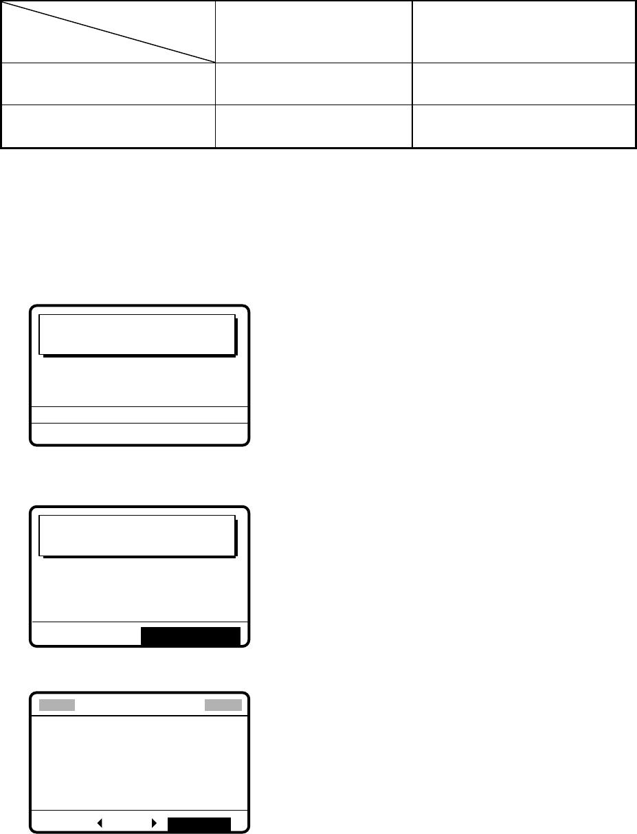
5 CALLING, RECEIVING
5-10
5.2.2 Receiving an individual call
When own ship receives an individual call, acknowledgement is automatically or manually
sent depending on the comply-type setting (see paragraph 7.2). The relationship between
comply type and automatic/manual acknowledge is as shown in the table below.
Comply type
Setting of
[5/ACQ /SQ] key
ABLE UNABLE
AUTO ACK Can send acknowledge
automatically
Can send UNABLE
automatically.
MANUAL ACK Can send acknowledge
manually
Can send UNABLE manually.
Note: The handset must be on hook to enable automatic acknowledge.
Sending automatic acknowledge (ACK BQ) with comply type “ABLE”
1. When an individual call is received and the automatic acknowledge feature is active
(AUTO ACK) and the comply type is “ABLE,” the display shown below appears. This
display indicates that the auto acknowledge (ACK BQ) call is being sent.
Able acknowledge
call in progress!
TIME TO GO: 6S
DSC FREQ :
2177.0 KHZ
TO SHIP:
123456789
ROUTINE
TELEPHONE CH 201
2. It takes about seven seconds to transmit the call, after which the audio alarm sounds
and the following message appears.
Able acknowledge
call transmitted.
TO SHIP:
123456789
ROUTINE
TELEPHONE CH 201
STOP ALARM
3. Press the [CANCEL] key to silence the alarm. The following display appears.
*
Xmitted message
*
MAR-23-2002-23:01
ABLE ACKNOWLEDGEMENT
TO SHIP:
123456789
ROUTINE
TELEPHONE CH 201
RE-SEND ALL VIEW
4. Press the [CANCEL] key. You can now communicate with the party, over the
radiotelephone frequency specified or by the NBDP terminal unit.
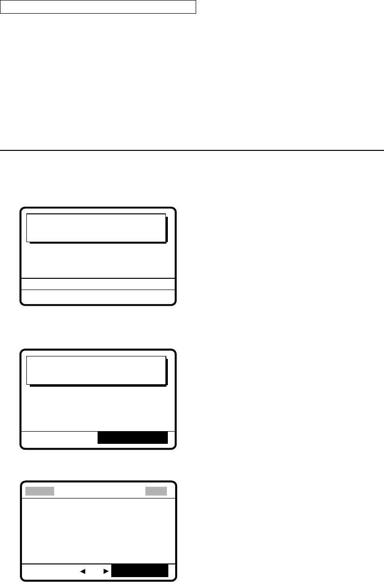
5 CALLING, RECEIVING
5-11
Communicating by NBDP Terminal Unit
After acknowledging an individual call, do the following to send a message by NBDP
Terminal Unit.
1. The control unit’s display shows “OCCUPIED” and the TX and RX frequencies.
2. The message from the other station appears on your NBDP Terminal Unit.
3. After receiving the message from other station, type your message and then transmit it.
4. Press the function key [F10] (BREAK) to disconnect the line.
Sending automatic acknowledge (ACK BQ) with comply type “UNABLE”
1. When an individual call is received and the automatic acknowledge feature is active
(AUTO ACK) and comply type is “UNABLE,” the display shown below appears,
indicating that the auto acknowledge call with UNABLE (ACK BQ) is being sent.
Unable acknowledge
call in progress!
TIME TO GO : 6S
DSC FREQ : 12577.5 KHZ
BUSY
TO SHIP : 121234567
ROUTINE
2. It takes about seven seconds to transmit the call, after which the audio alarm sounds
and the following message appears.
Unable acknowledge
call transmitted.
STOP ALARM
BUSY
TO SHIP :
121234567
ROUTINE
3. Press the [CANCEL] key to silence the alarm. The following display appears.
*
Xmitted message
*
JUL-23-2002-23:01
UNABLE ACKNOWLEDGE
ALL VIEW
RE-SEND
BUSY
TO SHIP :
121234567
ROUTINE
4. Push the [ENTER] knob to confirm the message. Rotate the [ENTER] knob to scroll the
message. Choose GO TO EASY VIEW and then push the [ENTER] knob.
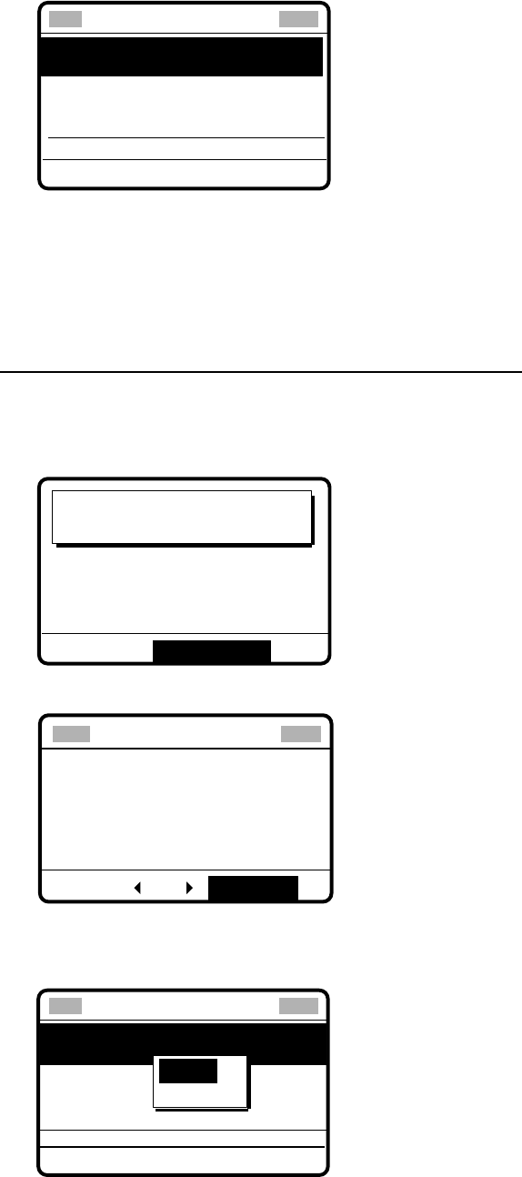
5 CALLING, RECEIVING
5-12
5. If you want to send a proposal, rotate the [ENTER] knob to choose RE-SEND and then
push the [ENTER] knob.
DSC FREQ : 12M-INTL
GO TO ALL VIEW
STATION ID :
001234567
REASON: NO REASON
GIVEN
STATION ID: 001234567
CALL TYPE : UNABLE
ACKNOWLEDGEMENT
**
Compose message
**
a) Push the [ENTER] knob to open the CALL TYPE menu.
b) Rotate the [ENTER] knob to choose ABLE and then push the [ENTER] knob.
c) Prepare message as appropriate and then press the [CALL] key to transmit the message.
After you receive acknowledgement from the other party you can start communications.
Manually acknowledging individual call with “ABLE”
1. When an individual call is received and the equipment is set up with manual
acknowledge (MANUAL ACK)and comply type “ABLE,” the alarm sounds and the
display looks like the one below.
Individual request
call received.
FROM SHIP:
121234567
ROUTINE
TELEPHONE CH 401
STOP ALARM
2. Press the [CANCEL] key to silence the alarm. The display changes as shown below.
MAR-23-2002-23:00:00 ECC: OK
INDIVIDUAL REQUEST
FROM SHIP:
001234567
ROUTINE
TELEPHONE CH 401
Received message
ANSWER ALL VIEW
To view contents, rotate [ENTER] knob
to choose ALL VIEW and then push
[ENTER] knob.
3. Rotate the [ENTER] knob to choose ANSWER and then push the [ENTER] knob. Push
the [ENTER] knob again to open the CALL TYPE menu.
STATION ID :
001234567
COM. TYPE : TELEPHONE
COM. FREQ : CH 401
CALL TYPE : ABLE
ACKNOWLEDGEMENT
DSC FREQ : 4M-INTL
GO TO ALL VIEW
ABLE
UNABLE
**
Compose message
**

5 CALLING, RECEIVING
5-13
4. Rotate the [ENTER] knob to choose ABLE and then push the [ENTER] knob. The
display changes as below. (Working frequency is automatically set as specified by other
party.)
DSC FREQ: 4M-INTL
STATION ID: 121234567
COM. TYPE: TELEPHONE
COM. FREQ: CH401
CALL TYPE: ABLE
ACKNOWLEDGEMENT
**
Compose message
**
GO TO ALL VIEW
5.
Press the [CALL] key to send the call. The display changes as below.
Able acknowledge
call in progress!
TIME TO GO: 7S
DSC FREQ : 4208.0
KHZ
TO SHIP :
121234567
ROUTINE
TELEPHONE CH 401
6.
After the call is completely sent (transmission time: 7 sec.), the radiotelephone screen
appears (if the communications mode is telephone). You can begin voice
communications by radiotelephone. For NBDP operation, do the following:
Communicating by NBDP Terminal Unit
After acknowledging an individual call, do the following to communicate by NBDP Terminal
Unit.
1. The control unit’s display shows “OCCUPIED” and the TX and RX frequencies.
2. The message from the other party appears on your NBDP Terminal Unit.
3. After receiving the message from the other party, type your message and transmit it.
4. Press the function key [F10] (BREAK) to disconnect the line.
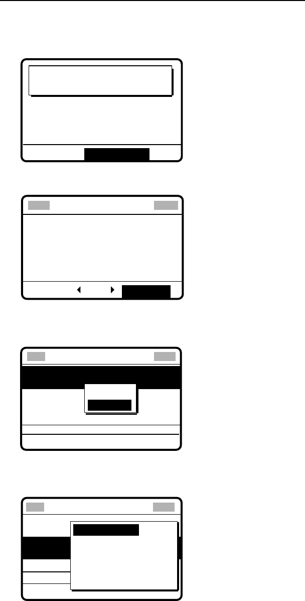
5 CALLING, RECEIVING
5-14
Manually acknowledging individual call with “UNABLE”
1. When an individual call is received and the equipment is set up with manual
acknowledge, the alarm sounds and the display shows the message "Individual request
call received."
Individual request
call received.
FROM SHIP:
121234567
ROUTINE
TELEPHONE CH 401
STOP ALARM
2. Press the [CANCEL] key to silence the alarm. The display changes as below.
INDIVIDUAL REQUEST
FROM SHIP: 121234567
ROUTINE
TELEPHONE CH 401
*
Received message
*
ANSWER ALL VIEW
MAR-23-2002-23:00:00 ECC: OK
To view contents, rotate [ENTER] knob
to choose ALL VIEW and push the
[ENTER] knob.
3. Rotate the [ENTER] knob to choose ANSWER and then push the [ENTER] knob.
4. Push the [ENTER] knob to open the CALL TYPE menu.
TO SHIP :
001234567
COM. TYPE : TELEPHONE
COM. FREQ : CH401
CALL TYPE : ABLE
ACKNOWLEDGEMENT
DSC FREQ: 4M-INTL
GO TO ALL VIEW
ABLE
UNABLE
**
Compose message
**
5. Rotate the [ENTER] knob to choose UNABLE and then push the [ENTER] knob.
6. Push the [ENTER] knob to open the REASON menu.
DSC FREQ : 12,577.5 KHZ
CALL TYPE : UNABLE
REASON : NO REASON
TO SHIP : 001234567
ACKNOWLEDGEMENT
GIVEN
NO REASON
BUSY
EQUIP DISABLED
MODE NOT USABLE
CH NOT USABLE
**
Compose message
**
7. Rotate the [ENTER] knob to choose an appropriate reason and then push the [ENTER]
knob.
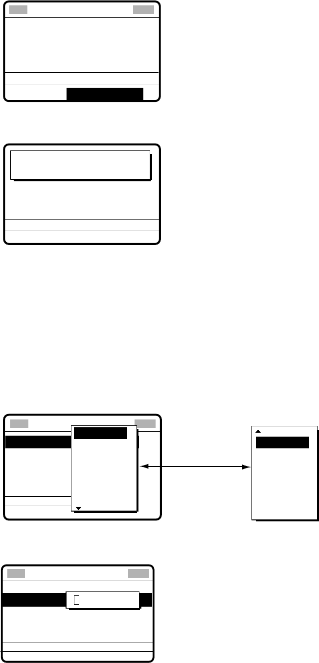
5 CALLING, RECEIVING
5-15
8. The display changes as below.
DSC FREQ :
4M-INTL
GO TO ALL VIEW
CALL TYPE : UNABLE
REASON : CHANNEL
STATION ID : 121234567
ACKNOWLEDGEMENT
NOT USABLE
**
Compose message
**
9. Press the [CALL] key to send the call. The display shows "Unable acknowledge call in
progress!" while the call is being sent.
Unable acknowledge
call in progress!
TIME TO GO: 6S
DSC FREQ :
4208.0 KHZ
ROUTINE
TO SHIP:
121234567
CHANNEL NOT USABLE
10. The timer counts down the time remaining until the call is sent (transmission time: about
seven seconds). The DSC standby screen appears after the call has been transmitted.
5.3 Group Call
A group call is for calling a specific group by specifying its group ID.
5.3.1 Sending a group call
1. Press the [2/DSC] key and then push the [ENTER] knob to open the CALL TYPE menu.
** Compose message **
STATION ID
PRIORITY
COM. TYPE
COM. FREQ
DSC FREQ
: All ships
: Safety
: Telephone
: 2187.5 kHz
CALL TYPE
PSTN CALL
TEST CALL
ALL SHIPS
GROUP CALL
AREA CALL
POSITION
INDIVIDUAL
POLLING
NEUTRAL
MEDICAL
RELAY ALL
RELAY SEL
DISTRESS
Rotate [ENTER]
knob to scroll.
GO
2. Choose GROUP CALL and then push the [ENTER] knob.
3. Push the [ENTER] knob to open the GROUP ID menu.
GO TO ALL VIEW
CALL TYPE
PRIORITY
COM. TYPE
COM. FREQ
DSC FREQ
: GROUP CALL
: ROUTINE
: TELEPHONE
: NO INFO
: 2M-INTL
GROUP ID
000000000
** Compose message **
4. Key in group ID (nine digits) with the numeric keys and then push the [ENTER] knob.
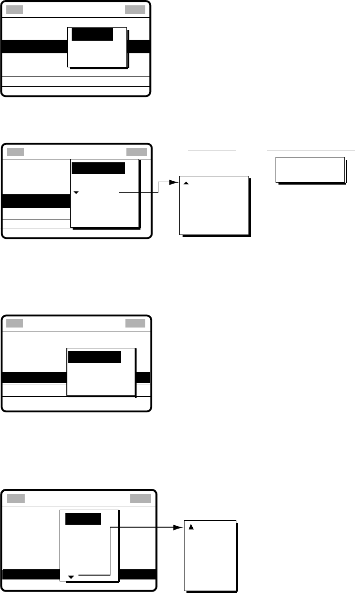
5 CALLING, RECEIVING
5-16
5. Push the [ENTER] knob to open the PRIORITY menu.
GO TO ALL VIEW
CALL TYPE
GROUP ID
COM. TYPE
COM. FREQ NO INFO
DSC FREQ
: GROUP CALL
: 012345678
: 2M-INTL
PRIORITY SAFETY
URGENCY
ROUTINE
** Compose message **
6. Rotate the [ENTER] knob to choose priority desired and then push the [ENTER] knob.
7. Push the [ENTER] knob to open the COM. TYPE menu.
GO TO ALL VIEW
CALL TYPE
GROUP ID
PRIORITY
COM. FREQ
DSC FREQ
: GROUP CALL
: 012345678
: Routine
: Telephone
: No infor
: 2M-INTL
NBDP-FEC
SPECIAL
TELEPHONE
COM. TYPE TTY RCV
TTY
MORSE KEY
MORSE TAPE
FACSIMILE
MAIN
For Routine
Rotate the [ENTER]
knob to scroll.
TELEPHONE
NBDP-FEC
For Safety or Urgency
** Compose message **
8. Rotate the [ENTER] knob to choose communication type desired and then push the
[ENTER] knob.
9. For routine priority, push the [ENTER] knob to open the COM. FREQ menu. For safety
or urgency priority, go to step 11.
CALL TYPE : GROUP CALL
COM. FREQ : 2164.0 kHz
COM. TYPE : TELEPHONE
PRIORITY : ROUTINE
GROUP ID : 012345678
DSC FREQ : 2M-INTL
GO TO ALL VIEW
FREQUENCY
CHANNEL
NO INFO
GO TO ALL VIEW
**
Compose message **
10. Rotate the [ENTER] knob to choose communication frequency desired and then push
the [ENTER] knob. (See page 5-6 for details.) NO INFO lets other party choose
communication frequency.
11. Push the [ENTER] knob to open the DSC FREQ menu.
GO TO ALL VIEW
CALL TYPE
GROUP ID
PRIORITY
COM. TYPE
COM. FREQ
: Individual
: 001234567
: Routine
: Telephone
: No infor
CALL
E
ONE
DSC FREQ : 12M-INTL
6 MHZ
8 MHZ
12 MHZ
4 MHZ
2 MHZ
16 MHZ
18 MHZ
22 MHZ
25 MHZ
OTHER
Rotate the [ENTER]
knob to select.
OTHER: Private channels.
** Compose message **
12. Rotate the [ENTER] knob to choose DSC band desired and then push the [ENTER]
knob to open the DSC FREQ menu. Rotate the [ENTER] knob to choose DSC frequency
desired and then push the [ENTER] knob. (See “How to set DSC frequency” on page 5-7
for details.)
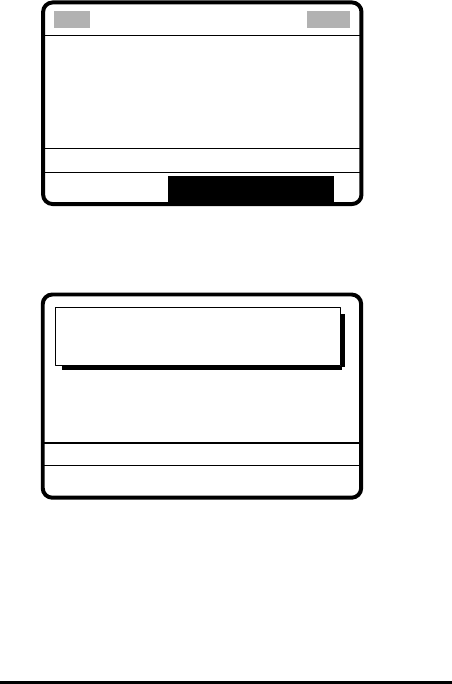
5 CALLING, RECEIVING
5-17
CALL TYPE : GROUP CALL
COM. FREQ : 2164.0 KHZ
COM. TYPE : TELEPHONE
PRIORITY : ROUTINE
GROUP ID :
012345678
DSC FREQ : 2M-INTL
GO TO ALL VIEW
** Compose message **
13. Press the [CALL] key to send the group call (transmission time: about seven seconds).
The display shows "Group call in progress!" while the call is being sent.
GROUP ID :
012345678
Group
call in progress!
TIME TO GO : 6S
DSC FREQ :
2177.0 KHZ
TELEPHONE
ROUTINE
2164.0 KHZ
14. The radiotelephone screen automatically appears after the call is sent, if frequency was
specified.
15. If you selected TELEPHONE at step 7, communicate by radiotelephone. For NBDP, do
the following:
Sending message by NBDP Terminal Unit
1. The message “STATION ENTRY COMPLETED FROM DSC. Press any key to escape.”
appears on the NBDP’s display. Press any key on the NBDP Terminal Unit to erase the
message.
2. Press the function key [F3] on the keyboard of the NBDP Terminal Unit to show the
Operate menu.
3. Choose “Call Station” and then press the [Enter] key.
4. “DSC” is selected; press the [Enter] key. “Connect” appears in reverse video.
5. Type and transmit your message.
6. When you have finished sending your message, press the [F10] key to disconnect the
line.

5 CALLING, RECEIVING
5-18
5.3.2 Receiving a group call
Group ID must be registered in order to receive a group call. See paragraph 6.2.
1. The audio alarm sounds and the display shows "Group call received" when a group call
is received.
FROM SHIP:
123456789
ROUTINE
TELEPHONE
TX: 2164.0 KHZ
RX: 2164.0 KHZ
Group
call received.
STOP ALARM
2. Press the [CANCEL] key to silence the alarm, and the display changes as below.
*
Received message
*
MAR-23-2002-23:59 ECC: OK
GROUP CALL
FROM SHIP :
123456789
ROUTINE
TELEPHONE
TX: 2164.0 KHZ
RX: 2164.0 KHZ
GO TO ALL VIEW
3. Press the [CANCEL] key to go to the radiotelephone screen. Watch on the working
frequency.
Receiving message by NBDP Terminal Unit
After receiving a group call, do the following:
1. The controls unit’s display shows “OCCUPIED” and the TX and RX frequencies.
2. The message from the sending station appears on your NBDP Terminal Unit.
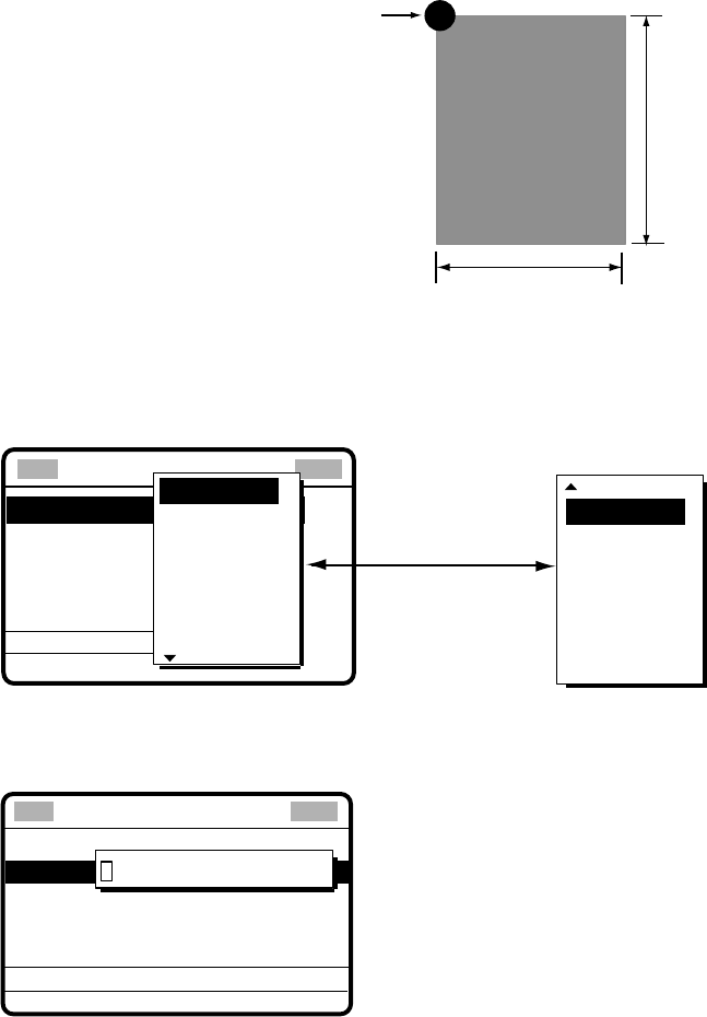
5 CALLING, RECEIVING
5-19
5.4 Geographical Area Call
The geographical area call is for sending a call to all ships within the area you designate in
your geographical area call. In the figure below, for example, the call will be sent to all ships
within 24-34°N, 135-140°W.
Reference point
(For example,
34°N 140°W)
5°
140°W135°W
10°
34°N
24°N
5.4.1 Sending a geographical area call
1. Press the [2/DSC] key and then push the [ENTER] knob to open the CALL TYPE menu.
** Compose message **
STATION ID
PRIORITY
COM. TYPE
COM. FREQ
DSC FREQ
: All ships
: Safety
: Telephone
: 2187.5 kHz
CALL TYPE
PSTN CALL
TEST CALL
ALL SHIPS
GROUP CALL
AREA CALL
POSITION
INDIVIDUAL
POLLING
NEUTRAL
MEDICAL
RELAY ALL
RELAY SEL
DISTRESS
Rotate [ENTER]
knob to scroll.
GO
2. Rotate the [ENTER] knob to choose AREA CALL and then push the [ENTER] knob.
3. Push the [ENTER] knob to open the AREA menu.
GO TO ALL VIEW
CALL TYPE
PRIORITY
COM. TYPE
COM. FREQ
DSC FREQ
: AREA CALL
: ROUTINE
: TELEPHONE
: NO INFO
: 2M-INTL
00°N 000°E ↓ 00°→ 00
AREA
**
Compose message
**
4. Using the numeric keys, enter latitude and longitude of reference point and southerly
degrees and easterly degrees of area. To change coordinate, choose it and press the
[1] key for North or East; [2] key for South or West. After entering data, push the
[ENTER] knob.
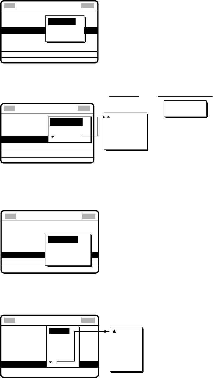
5 CALLING, RECEIVING
5-20
5. Push the [ENTER] knob to open the PRIORITY menu.
GO TO ALL VIEW
CALL TYPE
AREA : 34
°00
N 123
°
W ↓12
°
→ 5
°
COM. TYPE
COM. FREQ
DSC FREQ
: AREA CALL
: Routine
: Telephone
: NO INFO
: 2M-INTL
SAFETY
URGENCY
ROUTINE
PRIORITY
**
Compose message
**
6. Rotate the [ENTER] knob to choose priority desired and then push the [ENTER] knob.
7. Push the [ENTER] knob to open the COM. TYPE menu.
GO TO ALL VIEW
CALL TYPE
AREA : 34°00N 133°W ↓120° → 12°
PRIORITY
COM. FREQ
DSC FREQ
: AREA CALL
: Routine
: Telephone
: NO INFO
: 2M-INTL
NBDP-FEC
SPECIAL
TELEPHONE
COM. TYPE
** Compose message **
TTY RCV
TTY
MORSE KEY
MORSE TAPE
FACSIMILE
MAIN
For Routine
Rotate the [ENTER]
knob to scroll. TELEPHONE
NBDP-FEC
For Safety or Urgency
8. Rotate the [ENTER] knob to choose communication type desired and then push the
[ENTER] knob.
9. For routine priority, push the [ENTER] knob to open the COM. FREQ menu. For
safety or urgency priority, go to step 12.
GO TO ALL VIEW
CALL TYPE
AREA:
34
°
N 140
°
W ↓10
°
→ 5
°
PRIORITY
COM. TYPE
DSC FREQ
: AREA CALL
: 2M-INTL
COM. FREQ
FREQUENCY
CHANNEL
NO INFO
** Compose message **
10. Rotate the [ENTER] knob to choose frequency or channel and then enter frequency or
channel. (See page 5-6 for details.)
11. Push the [ENTER] knob to open the DSC FREQ menu.
12M-INTL
GO TO ALL VIEW
CALL TYPE:
AREA:
PRIORITY
COM. TYPE
COM. FREQ
Individual
001234567
: Routine
: Telephone
: No infor
6 MHZ
8 MHZ
12 MHZ
4 MHZ
2 MHZ
DSC FREQ : TL
16 MHZ
18 MHZ
22 MHZ
25 MHZ
OTHER
Rotate the [ENTER]
knob to scroll.
OTHER: Private channels.
** Compose message **
12. Rotate the [ENTER] knob to choose DSC band desired and then push the [ENTER]
knob to open the DSC FREQ menu.

5 CALLING, RECEIVING
5-21
13. Rotate the [ENTER] knob to choose DSC frequency desired and then push the
[ENTER] knob. (See “How to set DSC frequency” on page 5-7 for details.) Your display
should now look something like one below.
CALL TYPE : AREA CALL
AREA :
34
°
N 140
°
W ↓10
°
→ 5
°
PRIORITY : ROUTINE
COM. TYPE : TELEPHONE
COM. FREQ :
2164.0 KHZ
DSC FREQ : 2M-INTL
GO TO ALL VIEW
** Compose message **
14. Press the [CALL] key to send the geographical area call (transmission time: about
seven seconds). The display shows "Geographical area call in progress!" while the call
is being sent.
AREA:
34
°
N 140
°
W ↓10
°
→ 5
°
Geographical area
call in progress!
TIME TO GO : 7S
DSC FREQ :
2M-INTL
TELEPHONE
2164.0 KHZ
ROUTINE
15. After the call is sent the radiotelephone screen appears. If you chose radiotelephone at
step 8, you can now communicate with the other party. For NBDP, do the following:
Sending message by NBDP Terminal Unit
1. The message “STATION ENTRY COMPLETED FROM DSC. Press any key to escape.”
appears on the NBDP’s display. Press any key on the NBDP Terminal Unit to erase the
message.
2. Press the function key [F3] on the keyboard of the NBDP Terminal Unit to show the
Operate menu.
3. Choose “Call Station” and then press the [Enter] key.
4. “DSC” is selected; press the [Enter] key. “Connect” appears in reverse video.
5. Type and transmit your message.
6. When you have finished sending your message, press the [F10] key to disconnect the
line.
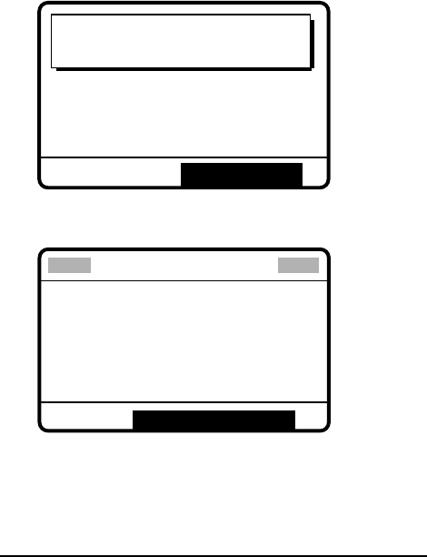
5 CALLING, RECEIVING
5-22
5.4.2 Receiving a geographical area call
1. The alarm sounds and the display shows "Geographical area call received" when a
geographical area call is received.
Geographical area
call received.
FROM SHIP:
123456789
ROUTINE
TELEPHONE
TX: 2164.0KHZ
RX: 2164.0KHZ
STOP ALARM
2. Press the [CANCEL] key to silence the alarm. The display changes as below.
* Received message *
MAR-23-2002-23:59 ECC: OK
GEOGRAPHICAL AREA
FROM SHIP :
123456789
ROUTINE
TELEPHONE
GO TO ALL VIEW
TX: 2164.0KHZ
RX: 2164.0KHZ
3. Press the [CANCEL] key to go to the radiotelephone screen. Watch on the working
frequency specified in the geographic area call.
Receiving message by NBDP Terminal Unit
After receiving a geographic call, do the following to watch by NBDP Terminal Unit:
1. The control unit’s display shows “OCCUPIED” and the TX and RX frequencies.
2. The message from the sending station appears on your NBDP Terminal Unit.
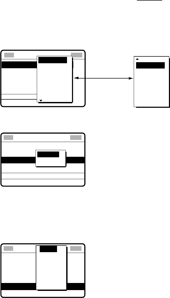
5 CALLING, RECEIVING
5-23
5.5 Neutral Craft Call
The neutral craft call, which contains own ship position and ID, informs all ships that your
ship is not a participant in armed conflict. Send the call BEFORE entering an area of armed
conflict.
5.5.1 Sending a neutral craft call
1. Press the [2/DSC] key and then push the [ENTER] knob to display the CALL TYPE
menu.
** Compose message **
STATION ID
PRIORITY
COM. TYPE
COM. FREQ
DSC FREQ
: All ships
: Safety
: Telephone
: 2187.5 kHz
CALL TYPE
PSTN CALL
TEST CALL
ALL SHIPS
GROUP CALL
AREA CALL
POSITION
INDIVIDUAL
POLLING
NEUTRAL
MEDICAL
RELAY ALL
RELAY SEL
DISTRESS
Rotate [ENTER]
knob to scroll.
GO
2. Rotate the [ENTER] knob to choose NEUTRAL and then push the [ENTER] knob.
3. Push the [ENTER] knob to open the PRIORITY menu.
CALL TYPE
COM. TYPE
DSC FREQ
: NEUTRAL
craft
: Safety
: TELEPHONE
: 2187.5 KHZ
GO TO ALL VIEW
URGENCY
SAFETY
PRIORITY
** Compose message **
4. Rotate the [ENTER] knob to choose appropriate priority and then push the [ENTER]
knob.
5. Push the [ENTER] knob to open the COM. TYPE menu.
6. Rotate the [ENTER] knob to choose communication type desired (radiotelephone or
NBDP-FEC) and then push the [ENTER] knob.
7. Push the [ENTER] knob to open the DSC FREQ menu.
**
Compose message
**
CALL TYPE
PRIORITY
COM. TYPE
VIEW
: Neutral
craft
: Safety
: Telephone
:2187.5 kHz
DSC FREQ KHZ
GO TO ALL VIEW
4207.5
6312.0
8414.5
12577.0
16804.5
2187.5
8. Rotate the [ENTER] knob to choose appropriate frequency and then push the [ENTER]
knob.
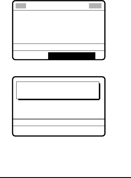
5 CALLING, RECEIVING
5-24
CALL TYPE : NEUTRAL
CRAFT
PRIORITY : SAFETY
COM. TYPE : TELEPHONE
GO TO ALL VIEW
DSC FREQ : 2187.5 KHZ
**
Compose message
**
9. Press the [CALL] key to send the neutral craft call (transmission time: approx. 7 sec.).
Neutral craft
call in progress!
SAFETY
TELEPHONE 2182.0 KHZ
TIME TO GO: 7S
DSC FREQ : 2187.5 KHZ
10. After the call is sent the radiotelephone screen appears. Inform all ships by
radiotelephone that your ship is not a participant in armed conflict.
Sending message by NBDP Terminal Unit
1. The message “STATION ENTRY COMPLETED FROM DSC. Press any key to escape.”
appears on the NBDP’s display. Press any key on the NBDP Terminal Unit to erase the
message.
2. Press the function key [F3] on the keyboard of the NBDP Terminal Unit to show the
Operate menu.
3. Choose “Call Station” and then press the [Enter] key.
4. “DSC” is selected; press the [Enter] key. “Connect” appears in reverse video.
5. Type and transmit your message.
6. When you have finished sending your message, press the [F10] key to disconnect the
line.
5 CALLING, RECEIVING
5-25
5.5.2 Receiving a neutral craft call
1. When a neutral craft call is received the alarm sounds and the display changes as
below.
Neutral craft
call received.
FROM SHIP:
123456789
SAFETY
TELEPHONE
2182.0 KHZ
STOP ALARM
2. Press the [CANCEL] key to silence the alarm. The display changes as below.
* Received message *
MAR-23-2002-23:59 ECC: OK
NEUTRAL CRAFT
FROM SHIP: 123456789
SAFETY
TELEPHONE 2182.0 KHZ
GO TO ALL VIEW
3. Press the [CANCEL] key to go to the radiotelephone screen. Watch on the working
frequency specified by radiotelephone or NBDP.
Receiving message by NBDP Terminal Unit
After receiving a neutral craft call, do the following to watch by NBDP Terminal Unit.
1. The control unit’s display shows “OCCUPIED” and the TX and RX frequencies.
2. The message from the sending station appears on your NBDP Terminal Unit.
5 CALLING, RECEIVING
5-26
5.6 Medical Transport Call
The medical transport call informs all ships, by urgency priority, that own ship carries
medical supplies.
5.6.1 Sending a medical transport call
1. Press the [2/DSC] key and then push the [ENTER] knob to open the CALL TYPE menu.
** Compose message **
STATION ID
PRIORITY
COM. TYPE
COM. FREQ
DSC FREQ
: All ships
: Safety
: Telephone
: 2187.5 kHz
CALL TYPE
PSTN CALL
TEST CALL
ALL SHIPS
GROUP CALL
AREA CALL
POSITION
INDIVIDUAL
POLLING
NEUTRAL
MEDICAL
RELAY ALL
RELAY SEL
DISTRESS
Rotate [ENTER]
knob to scroll.
GO
2.
Rotate the [ENTER] knob to choose MEDICAL and then push the [ENTER] knob.
Note: PRIORITY is automatically selected to URGENCY.
3.
Push the [ENTER] knob to open the COM. TYPE menu.
4.
Rotate the [ENTER] knob to choose communication type desired (radiotelephone and
NBDP-FEC) and then push the [ENTER] knob.
5.
Push the [ENTER] knob to open the DSC FREQ menu.
CALL TYPE
PRIORITY
COM. TYPE
VIEW
: Medical
transport
: Urgency
: Telephone
:2187.5 KHZ
4207.5
6312.0
8414.5
12577.0
16804.5
2187.5
DSC FREQ
GO TO ALL VIEW
**
Compose message
**
6.
Rotate the [ENTER] knob to choose appropriate frequency and then push the [ENTER]
knob. The display changes as below.
CALL TYPE : MEDICAL
TRANSPORT
PRIORITY : URGENCY
COM. TYPE : TELEPHONE
GO TO ALL VIEW
DSC FREQ :
2187.5 KHZ
**
Compose message
**
7.
Press the [CALL] key to send the call (transmission time: about seven seconds). The
display shows “Medical transport call in progress!” while the call is being sent.
5 CALLING, RECEIVING
5-27
URGENCY
TELEPHONE
2182.0 KHZ
Medical transport
call in progress!
TIME TO GO : 7S
DSC FREQ :
2187.5 KHZ
8.
After the call is sent the radiotelephone screen automatically appears. Inform all ships
(by radiotelephone) that your ship is transporting medical supplies. For NBDP do the
following:
Sending message by NBDP Terminal Unit
1. The message “STATION ENTRY COMPLETED FROM DSC. Press any key to escape.”
appears on the NBDP’s display. Press any key on the NBDP Terminal Unit to erase the
message.
2. Press the function key [F3] on the keyboard of the NBDP Terminal Unit to show the
Operate menu.
3. Choose “Call Station” and then press the [Enter] key.
4. “DSC” is selected; press the [Enter] key. “Connect” appears in reverse video.
5. Type and transmit your message.
6. When you have finished sending your message, press the [F10] key to disconnect the
line.
5.6.2 Receiving a medical transport call
1. When a medical transport call is received, the alarm sounds and the display looks as
below.
Medical transport
call received.
FROM SHIP:
123456789
URGENCY
TELEPHONE
2182.0 KHZ
STOP ALARM
2. Press the [CANCEL] key to silence the alarm. The display changes as below.
GO TO ALL VIEW
* Received message *
MAR-23-2002-23:59 ECC: OK
MEDICAL TRANSPORT
FROM SHIP:
123456789
URGENCY
TELEPHONE
2182.0 KHZ
GO TO ALL VIEW
3. Press the [CANCEL] key to go to the radiotelephone screen to watch on frequency
specified.
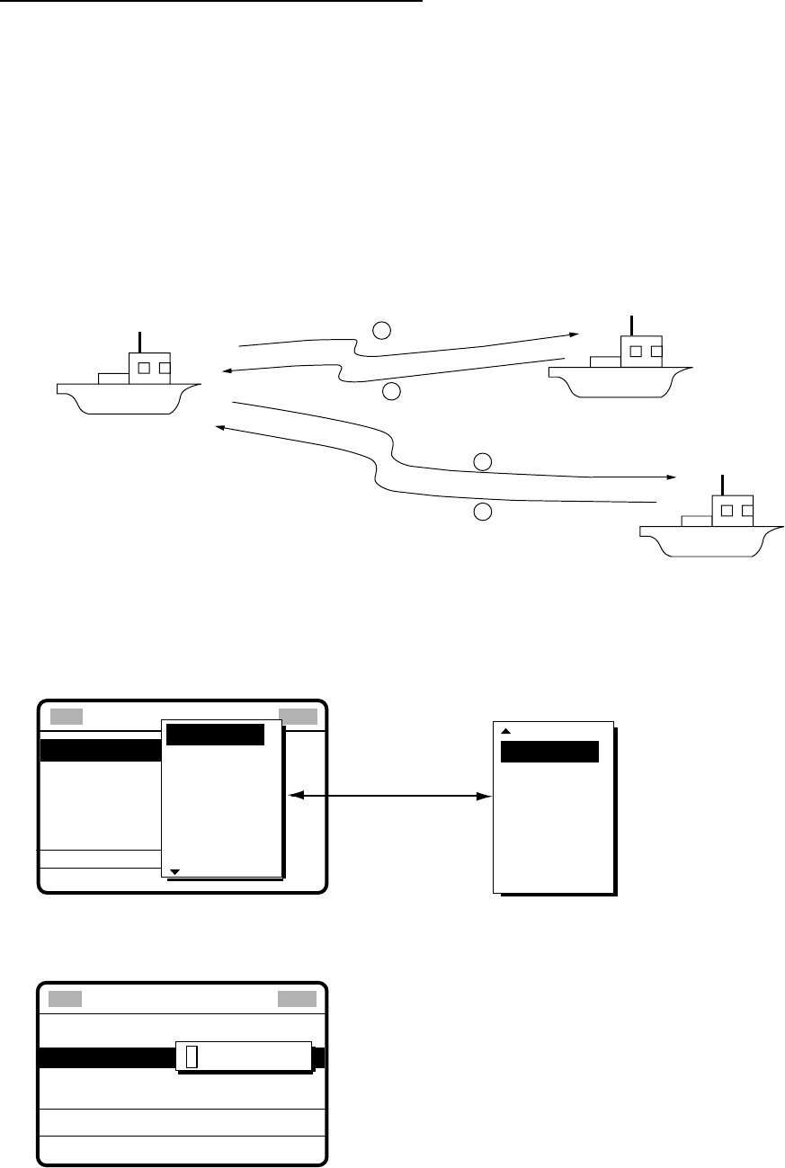
5 CALLING, RECEIVING
5-28
Receiving message by NBDP Terminal Unit
After receiving a neutral craft call, do the following to watch by NBDP Terminal Unit.
1. The display shows “OCCUPIED” and the TX and RX frequencies.
2. The message from the sending station appears on your NBDP Terminal Unit.
5.7 Polling Call
Polling means confirming if own station is within communicating range with other station.
This function only provides affirmative or negative response; it does not provide position
information. Note that simultaneous polling to more than one station is not possible.
1Polling
2Acknowledge
3Polling
4Acknowledge
5.7.1 Sending a polling call
1. Press the [2/DSC] key followed by pushing the [ENTER] knob to open the CALL TYPE
menu.
** Compose message **
STATION ID
PRIORITY
COM. TYPE
COM. FREQ
DSC FREQ
: All ships
: Safety
: Telephone
: 2187.5 kHz
CALL TYPE
PSTN CALL
TEST CALL
ALL SHIPS
GROUP CALL
AREA CALL
POSITION
INDIVIDUAL
POLLING
NEUTRAL
MEDICAL
RELAY ALL
RELAY SEL
DISTRESS
Rotate [ENTER]
knob to scroll.
GO
2. Rotate the [ENTER] knob to choose POLLING and then push the [ENTER] knob.
3. Push the [ENTER] knob to open the STATION ID menu.
CALL TYPE
PRIORITY
DSC FREQ
: POLLING
: ---------
: ROUTINE
: 2M-INTL
GO TO ALL VIEW
000000000
STATION ID
** Compose message **
4. Key in ID of station with the numeric keys and then push the [ENTER] knob.
5. Push the [ENTER] knob to open the PRIORITY menu.
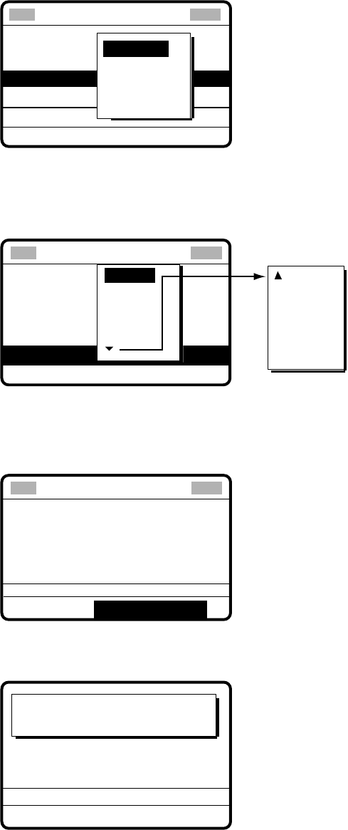
5 CALLING, RECEIVING
5-29
CALL TYPE
STATION ID
DSC FREQ
: Polling
: 987654321
: Routine
: 12M-INTL
GO TO ALL VIEW
BUSINESS
SAFETY
URGENCY
ROUTINE
PRIORITY
** Compose message **
6. Rotate the [ENTER] knob to choose priority desired (usually ROUTINE) and then push
the [ENTER] knob.
7. Push the [ENTER] knob to open the DSC FREQ menu.
CALL TYPE
STATION ID
PRIORITY
VIEW
: Medical
transport
: Urgency
: Telephone
:267.5 kHz
4 MHZ
6 MHZ
8 MHZ
12 MHZ
2 MHZ
DSC FREQ TL
16 MHZ
18 MHZ
22 MHZ
25 MHZ
OTHER
Rotate [ENTER]
knob to scroll.
OTHER: Private channels.
** Compose message **
GO TO ALL VIEW
8. Rotate the [ENTER] knob to choose appropriate DSC band and then push the [ENTER]
knob. Rotate the [ENTER] knob to choose DSC frequency desired and then push the
[ENTER] knob. The display changes as below.
CALL TYPE : POLLING
STATION ID :
123456789
PRIORITY
: ROUTINE
DSC FREQ : 2M-INTL
GO TO ALL VIEW
** Compose message **
9. Press the [CALL] key to send the call (transmission time: about seven seconds). The
display changes as below.
Polling request
call in progress!
TIME TO GO: 7S
DSC FREQ : 2177.0 KHZ
TO SHIP: 123456789
ROUTINE

5 CALLING, RECEIVING
5-30
10. After the call is sent, the following display appears.
Waiting for polling
acknowledgement.
DSC FREQ : 2177.0 KHZ
TIME TO GO: 4M59S
FROM SHIP: 123456789
ROUTINE
11. The timer counts down the time remaining to wait for acknowledgment of the call. One of
the following displays appears. (“No response! Try calling again?” appears when there
is no response from receiving station. The timer counts down to zero in this case.)
No response!
Try calling again?
DSC FREQ :
2177.0 KHZ
FROM SHIP:
123456789
ROUTINE
Polling acknowledge
call received.
FROM SHIP :
123456789
ROUTINE
NO INFORMATION
STOP ALARM CALL AGAIN
Polling acknowledge
call received
No response
12. Do one of the following depending on the message shown in step 11.
Polling acknowledge call received
The audio alarm sounds; press the [CANCEL] key to silence the alarm. The display
changes as below. You can confirm if called party is within communicating range.
ECC: OK
POLLING ACKNOWLEDGE
FROM SHIP:
123456789
ROUTINE
NO INFORMATION
*
Received message
*
GO TO ALL VIEW
MAR-23-2002-23:59
No response! Try calling again?
Re-send call: Push the [ENTER] knob followed by the [CALL] key.
Cancel call: Press the [CANCEL] key to return to the DSC standby screen.
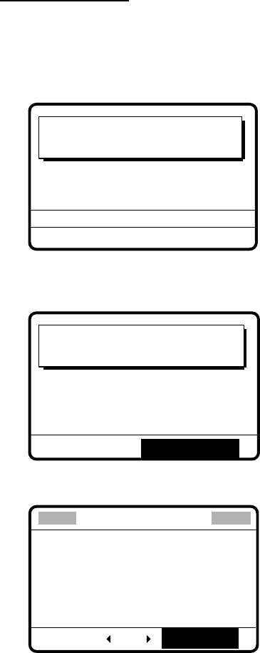
5 CALLING, RECEIVING
5-31
5.7.2 Receiving a polling call
Automatic reply
1. The display changes as shown in the illustration below and the audio alarm sounds
when a polling request call is received and the equipment is set up for automatic
acknowledge: POLLING on the Auto Ack menu is ON and the [5/ACK/ SQ] key is set to
show AUTO ACK on the display. For details see paragraph 7.2.
Polling auto acknowledge
call in progress!
TIME TO GO : 7S
DSC FREQ :
2177.0 KHZ
TO SHIP :
123456789
ROUTINE
2. After the polling automatic acknowledge call is transmitted, the following display appears
and the audio alarm sounds.
Polling auto acknowledge
call transmitted.
TO SHIP : 123456789
ROUTINE
STOP ALARM
3. Press the [CANCEL] key to silence the alarm. The display changes as below.
POLLING ACKNOWLEDGE
TO SHIP :
123456789
ROUTINE
**
Xmitted message
**
ALL VIEW
MAR-23-2002-23:00:09
RE-SEND
4. Press the [CANCEL] key to return to the DSC standby screen.
5 CALLING, RECEIVING
5-32
Manual reply
1. The display changes as shown in the illustration below and the audio alarm sounds
when a polling request call is received and the status of the [5/ ACK/SQ] key is MANUAL
ACK.
Polling request
call received.
STOP ALARM
FROM SHIP :
987654321
ROUTINE
2. Press the [CANCEL] key to silence the alarm. The display changes as below.
POLLING REQUEST
FROM SHIP : 987654321
ROUTINE
* Received message *
ANSWER
ALL VIEW
MAR-23-2002-23:01
3. To respond to the call, rotate the [ENTER] knob to choose ANSWER and then push the
[ENTER] knob. The display changes as below.
CALL TYPE : POLLING
ACKNOWLEDGEMENT
STATION ID:
987654321
PRIORITY : ROUTINE
DSC FREQ :
2M-INTL
GO TO ALL VIEW
** Compose message **
4. Press the [CALL] key to send the polling acknowledge call. The display changes as
below.
Polling acknowledge
call in progress!
TIME TO GO: 7S
DSC FREQ :
2177.0 KHZ
TO SHIP : 987654321
ROUTINE
After the call is sent the DSC standby screen appears.
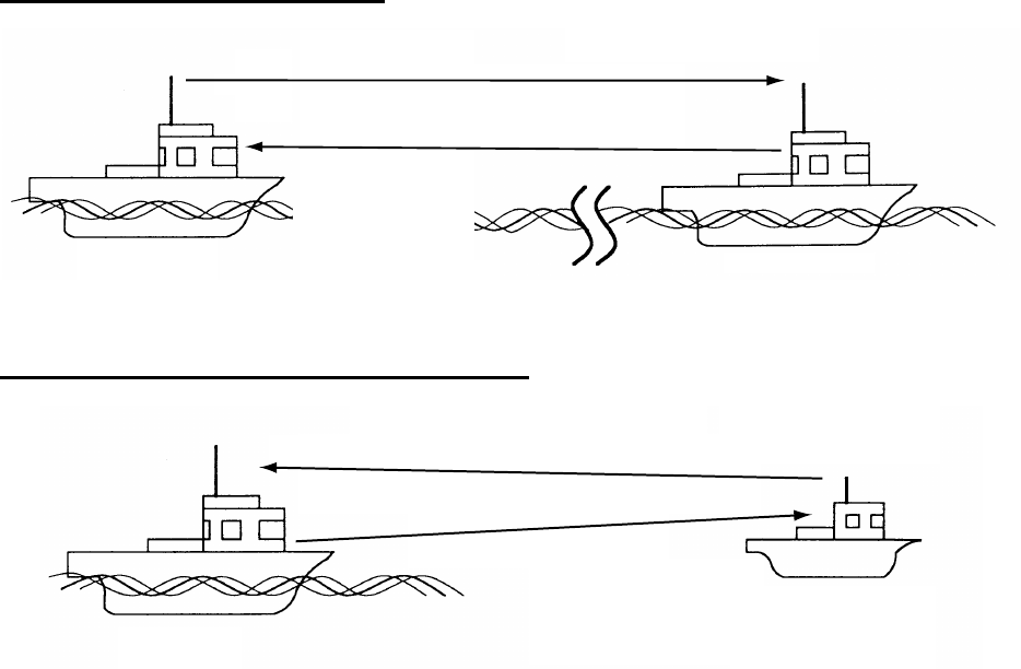
5 CALLING, RECEIVING
5-33
5.8 Position Call
There are two types of position calls: other station requires your ship’s position and your
ship requests position of another ship.
Finding position of other station
Other Station
Own Station
(1) Position request call
(2) Position Information
Sending own ship's position to other station
Own Ship
(2) Sends position Information
(1) Requests ship's position
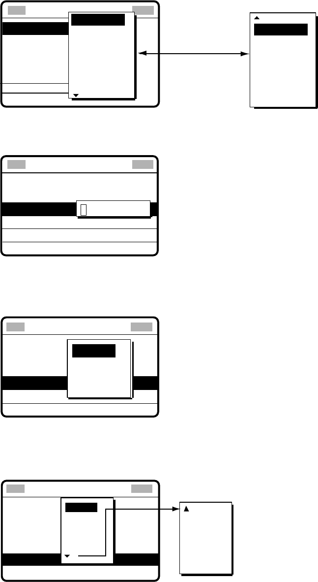
5 CALLING, RECEIVING
5-34
5.8.1 Position call: requesting other ship’s position
1. Press the [2/DSC] key and then push the [ENTER] knob to open the CALL TYPE menu.
** Compose message **
STATION ID
PRIORITY
COM. TYPE
COM. FREQ
DSC FREQ
: All ships
: Safety
: Telephone
: 2187.5 kHz
CALL TYPE
PSTN CALL
TEST CALL
ALL SHIPS
GROUP CALL
AREA CALL
POSITION
INDIVIDUAL
POLLING
NEUTRAL
MEDICAL
RELAY ALL
RELAY SEL
DISTRESS
Rotate [ENTER]
knob to scroll.
GO
2.
Rotate the [ENTER] knob to choose POSITION and then push the [ENTER] knob.
3.
Push the [ENTER] knob to open the STATION ID menu.
CALL TYPE:
PRIORITY
DSC FREQ
POSITION
REQUEST
: ROUTINE
:2M-INTL
GO TO ALL VIEW
000000000
STATION ID
** Compose message **
4. Key in ID of station (nine digits) which you want to know its position and then push the
[ENTER] knob.
5. Push the [ENTER] knob to open the PRIORITY menu.
CALL TYPE
STATION ID
DSC FREQ
: Position
request
: 987654321
: Routine
:12M-INTL
GO TO ALL VIEW
BUSINESS
SAFETY
URGENCY
ROUTINE
PRIORITY
** Compose message **
6. Rotate the [ENTER] knob to choose priority desired (usually ROUTINE) and then push
the [ENTER] knob.
7. Push the [ENTER] knob to open the DSC FREQ menu.
CALL TYPE : POSITION
REQUEST
STATION ID : 987654321
PRIORITY : ROUTINE
GO TO ALL VIEW
DSC FREQ : 2M-INTL
6 MHZ
8 MHZ
12 MHZ
4 MHZ
2 MHZ
16 MHZ
18 MHZ
22 MHZ
25 MHZ
OTHER
Rotate [ENTER]
knob to scroll.
OTHER: Special, private channels.
** Compose message **
8. Rotate the [ENTER] knob to choose appropriate DSC band and then push the [ENTER]
knob. Rotate the [ENTER] knob to choose DSC frequency desired and then push the
[ENTER] knob.
5 CALLING, RECEIVING
5-35
9.
The display now looks something like the illustration below.
CALL TYPE: POSITION
REQUEST
STATION ID : 123456789
PRIORITY : ROUTINE
DSC FREQ : 2M-INTL
GO TO ALL VIEW
**
Compose message
**
10.
Press the [CALL] key to send the call (transmission time: about seven seconds). The
following display appears.
Position request
call in progress!
TIME TO GO: 7S
DSC FREQ :
2177.0 KHZ
TO SHIP :
123456789
ROUTINE
11.
After the call has been sent, the following display appears.
Waiting for pos
acknowledgment.
TIME TO GO: 4M30S
DSC FREQ :
2177.0 KHZ
FROM SHIP :
123456789
ROUTINE
12.
One of the following messages appears. (“No response! Try calling again?” appears
after the time has counted down to zero, meaning there was no response from the party
called.)
No response!
Try calling again?
DSC FREQ : 2177.0 KHZ
FROM SHIP : 123456789
ROUTINE
Pos acknowledge
call received.
FROM SHIP :
123456789
ROUTINE
POS :
12˚34N 123˚45E AT 12:34
Position acknowledge call received No response
STOP ALARM
CALL AGAIN
5 CALLING, RECEIVING
5-36
13.
Do one of the following depending on the message displayed at step 12.
Acknowledge call received
The audio alarm sounds; press the [CANCEL] key to silence the alarm. The display looks as
below. You can now confirm position of other ship.
POSITION ACKNOWLEDGE
FROM SHIP :
123456789
ROUTINE
POS :
12˚34N 123˚45E AT 12:34
*
Received message
*
GO TO ALL VIEW
MAR-23-2002-23:59 ECC: OK
No response! Try calling again?
Re-send call: Push the [ENTER] knob followed by the [CALL] key.
Cancel call: Press the [CANCEL] key.
5.8.2 Position call: other ship requests your position
You may turn automatic acknowledge of position request on or off with POSITION CALL in
the AUTO ACK menu. For further details, see page 8-3.
Automatic reply
1. When another ship requests your position and the status of the [5/ ACK/SQ] key is AUTO
ACK and the setting of POSITION CALL on the Auto ack menu is ON, the FS-1570/2570
transmits own position data (transmission time: approx. 7 sec.), showing the display
below.
Position auto acknowledge
call in progress!
TIME TO GO : 7S
DSC FREQ :
2177.0 KHZ
TO SHIP :
123456789
ROUTINE
POS: 35
°
30N 135
°
30E AT 23:54
2. After the call is sent the audio alarm sounds and the display below appears.
Position auto acknowledge
call transmitted.
TO SHIP: 123456789
ROUTINE
POS: 35
°
30N 135
°
30E AT 23:54
STOP ALARM
5 CALLING, RECEIVING
5-37
3. Press the [CANCEL] key to silence the alarm, and the display changes as below.
MAR-23-2002-23:59:09
POSITION ACKNOWLEDGE
TO SHIP :
987654321
ROUTINE
POS :
35°00N 135°00E AT 23:59
**
Xmitted message
**
GO TO ALL VIEW
4. Press the [CANCEL] key to return to the DSC standby screen.
Manual reply
1. When a position request call is received and the status of the [5/ ACK/SQ] key is
MANUAL ACK, the audio alarm sounds and the display changes as below.
Position request
call received.
FROM SHIP: 123456789
ROUTINE
STOP ALARM
2. Press the [CANCEL] key to silence the alarm. The display changes as below.
ECC: OK
POSITION REQUEST
FROM SHIP :
123456789
ROUTINE
* Received message *
ANSWER ALL VIEW
MAR-23-2002-23:00:01
3. To send your ship’s position, rotate the [ENTER] knob to choose ANSWER and then
push the [ENTER] knob. Your display should now look something like the one below.
CALL TYPE: POSITION
ACKNOWLEDGEMENT
POSITION: 35 00N 135 00E AT 23:01
DSC FREQ : 2M-INTL
GO TO ALL VIEW
**
Compose message
**
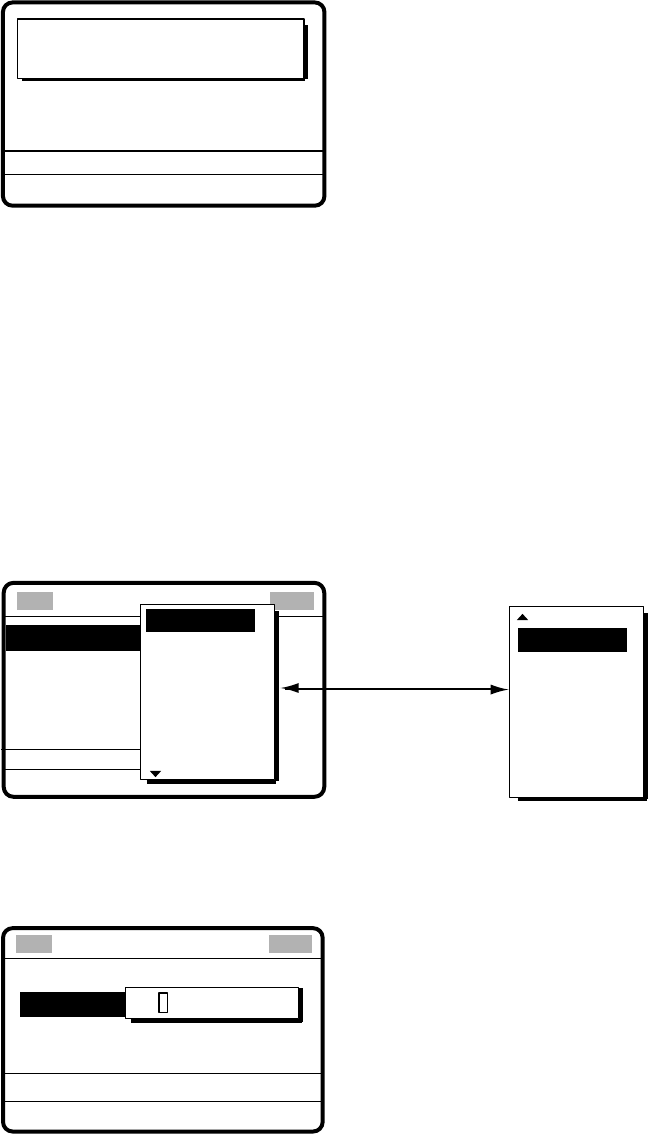
5 CALLING, RECEIVING
5-38
4. Confirm the position shown and then press the [CALL] to send the position data call
(transmission time: approx. 7 sec.). The display changes as below.
Pos acknowledge
call in progress!
TIME TO GO: 7S
DSC FREQ : 2177.0 KHZ
TO SHIP : 123456789
POS: 35˚00N 135˚00E AT 23:01
ROUTINE
5. The DSC standby screen automatically appears after the call is sent.
5.9 PSTN Call
The PSTN call allows the making and receiving of telephone calls over public switched
telephone networks. To use the PSTN call feature, use a handset which has a HOOK
ON/OFF function. The standard supply handset has this feature.
5.9.1 Sending a PSTN call, receiving acknowledge back (ACK BQ)
1. Press the [2/DSC] key and then push the [ENTER] knob to open the CALL TYPE menu.
** Compose message **
STATION ID
PRIORITY
COM. TYPE
COM. FREQ
DSC FREQ
: All ships
: Safety
: Telephone
: 2187.5 kHz
CALL TYPE
PSTN CALL
TEST CALL
ALL SHIPS
GROUP CALL
AREA CALL
POSITION
INDIVIDUAL
POLLING
NEUTRAL
MEDICAL
RELAY ALL
RELAY SEL
DISTRESS
Rotate [ENTER]
knob to scroll.
GO
2. Rotate the [ENTER] knob to choose PSTN CALL and then push the [ENTER] knob.
3. Push the [ENTER] knob to open the COAST ID menu.
GO TO ALL VIEW
CALL TYPE:
TEL NO. :
DSC FREQ
PSTN CALL
:12M-INTL
00000000
COAST ID
**
Compose message
**
4. Key in ID of coast station (seven digits) with the numeric keys and then push the
[ENTER] knob.
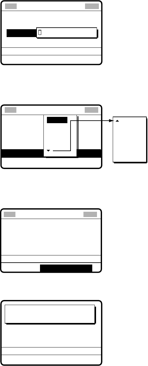
5 CALLING, RECEIVING
5-39
5. Push the [ENTER] knob to open the TEL NO. menu.
GO TO ALL VIEW
CALL TYPE:
COAST ID
DSC FREQ
PSTN CALL
: 001234567
:12M-INTL
----------------
TEL NO.
**
Compose message
**
6. Enter telephone no. (up to 16 digits) with the numeric keys and then push the [ENTER]
knob.
7. Push the [ENTER] knob to open the DSC FREQ menu.
GO TO ALL VIEW
CALL TYPE
COAST ID
: PSTN CALL
: 123456789
TEL NO. : 123456789012345
DSC FREQ :12M-INTL
6 MHz
8 MHz
12 MHz
4 MHz
2 MHz
16 MHz
18 MHz
22 MHz
25 MHz
OTHER
OTHER: Special, private channel
** Compose message **
Rotate [ENTER] knob
to scroll.
8. Rotate the [ENTER] knob to choose DSC band desired and then push the [ENTER]
knob to open the DSC FREQ menu. Rotate the [ENTER] knob to choose DSC
frequency desired and then push the [ENTER] knob. The display changes as below.
DSC FREQ : 12M-INTL
GO TO ALL VIEW
CALL TYPE : PSTN CALL
COAST ID :
001234567
TEL NO. :
1234567890123456
** Compose message **
9. Press the [CALL] key to send the PSTN call (transmission time: about seven seconds).
The display shows the following message.
PSTN request
call in progress!
TIME TO GO: 7S
TO COAST : 001234567
TEL NO. : 1234567890123456
DSC FREQ : 12577.5 KHZ
10. One of the following three displays appears. (“No response. Try calling again.” Appears
after timer counts down to zero and it means there was no response from the coast
station.)
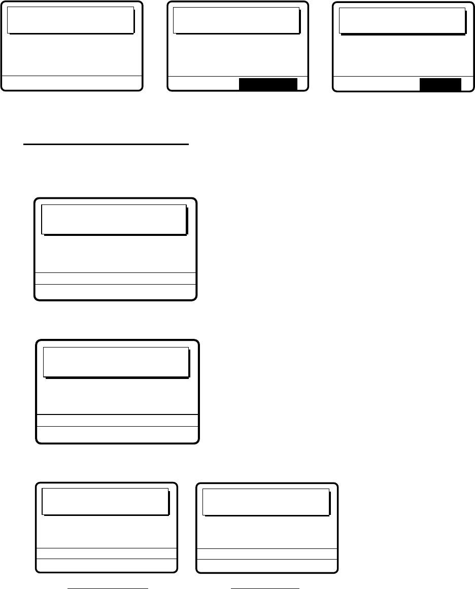
5 CALLING, RECEIVING
5-40
Waiting for
acknowledgement.
TIME TO GO: 25S
DSC FREQ :
12577.5 KHZ
FROM COAST : 001234567
TEL NO. : 1234567890123456
No response!
Try calling again?
DSC FREQ :
12577.5 KHZ
RE-SEND
FROM COAST : 001234567
TEL NO. : 1234567890123456
Unable acknowledge
call received.
STOP ALARM
FROM COAST : 001234567
TEL NO. : 1234567890123456
BUSY
11. Do one of the following depending on the message shown at step 10.
Waiting for acknowledgement
1) If the PSTN call is accepted, the PSTN connection call is sent (transmission time: about
seven seconds), showing the display below.
PSTN connection
call in progress!
TIME TO GO: 7S
TO COAST : 001234567
TEL NO. : 1234567890123456
DSC FREQ : 12577.0 KHZ
2) After the call is sent the following messages appears.
Waiting for
acknowledgement.
TIME TO GO: 25S
DSC FREQ : 12577.5 KHZ
FROM COAST : 001234567
TEL NO. : 1234567890123456
3) Then, one of the following displays appears.
PSTN call connected.
DSC FREQ :
12577.5 KHZ
TO COAST :
001234567
TEL NO. :
1234567890123456
PSTN end of call
in progress!
TIME TO GO: 8S
TO COAST :
001234567
TEL NO. :
1234567890123456
DSC FREQ :
12577.5 KHZ
PSTN call connected PSTN end of call
4) Follow the instructions below depending on the message shown in 3) above.
PSTN call connected: Your phone rings; pick up the handset and communicate with
the party you called.
PSTN end of call in progress: This means channel could not be used. After the timer
counts down to zero repeat this procedure to re-send the call.

5 CALLING, RECEIVING
5-41
Unable acknowledge call received
1) The audio alarm sounds; press the [CANCEL] key or [ENTER] knob to silence the alarm.
The display shown below appears.
*
Received message
*
MAR-23-2002-23:01 ECC: OK
UNABLE ACKNOWLEDGE
FROM COAST :
001234567
TEL NO. :
1234567890123456
BUSY
GO TO ALL VIEW
2) Press the [CANCEL] key to return to the DSC standby screen. Try the call again later.
No response! Try calling again?
Re-send call: Push the [ENTER] knob followed by the [CALL] key.
Cancel call: Press the [CANCEL] key to return to the DSC standby screen.

5 CALLING, RECEIVING
5-42
5.9.2 Receiving a PSTN call, sending acknowledge back (ACK BQ)
1. The following display appears when a PSTN call is received when automatic
acknowledge is turned on.
Able acknowledge
call in progress!
TIME TO GO: 8S
TO COAST : 001234567
TEL NO. : 1234567890123456
DSC FREQ : 4208.0 KHZ
2. The timer counts down to zero and then the following display appears.
Pick up the handset
or press CALL key.
TIME TO GO: 60S
FROM COAST :
001234567
TEL NO. :
1234567890123456
DSC FREQ :
4208.0 KHZ
3. Pick up the handset or press the [CALL] key within one minute.
PSTN connection
call in progress!
TIME TO GO: 7S
TO COAST : 001234567
TEL NO. : 1234567890123456
DSC FREQ : 4208.0 KHZ
4. When the timer counts down to zero the following message appears.
Waiting for
acknowledgement.
TIME TO GO: 25S
DSC FREQ : 4208.0 KHZ
FROM COAST : 001234567
TEL NO. : 1234567890123456
5 CALLING, RECEIVING
5-43
5. Shortly thereafter, one of the following messages appears.
PSTN call connected.
DSC FREQ :
4208.0KHZ
TO COAST :
001234567
TEL NO. :
1234567890123456
PSTN call connected PSTN connection call in progress PSTN end of call
PSTN connection
call in progress!
TIME TO GO: 25S
DSC FREQ :
4208.0KHZ
FROM COAST :
001234567
TEL NO. :
1234567890123456
PSTN end of call
in progress!
TIME TO GO: 7S
TO COAST :
001234567
TEL NO. :
1234567890123456
DSC FREQ :
4208.0KHZ
6. Do one of the following depending on the message shown at step 5.
PSTN call connected: Your phone rings; communicate with party.
PSTN connection call in progress!: If the channel assigned is appropriate, the message
“Waiting for acknowledgment.” appears. (If the channel cannot be used the message “PSTN
end of call in progress!” appears. In this case, start this procedure again.)
PSTN end of call in progress!: The channel could not be used. Press the [CANCEL]
key to return to the DSC standby screen.
5.9.3 PSTN call disconnection, receiving charge information
(ship disconnects line)
1. After hanging up the handset or pressing the [CANCEL] key to complete your call, the
display shows the following message.
PSTN end of call
in progress!
TIME TO GO: 8S
TO COAST : 001234567
TEL NO. : 1234567890123456
DSC FREQ : 12577.5 KHZ
2. After the call is sent, the following messages appears.
Waiting for
charge information.
TIME TO GO: 20S
FROM COAST :
001234567
TEL NO. :
1234567890123456
DSC FREQ :
12577.5 KHZ
3. When the timer counts down to zero one of the following displays appear.
Charge information
call received.
CHARGE TIME : 00H 12M 34S
FROM COAST : 001234567
TEL NO. : 1234567890123456
STOP ALARM
No response!
charge information.
FROM COAST : 001234567
TEL NO. : 1234567890123456

5 CALLING, RECEIVING
5-44
4. For “No response! charge information.”, the equipment reverts to step 2 in this
procedure to await charge information. For “Charge information call received.”, the
audio alarm sounds; press the [CANCEL] key or [ENTER] knob to silence the audio
alarm. The display shown below appears.
ECC: OK
CHARGE INFORMATION
CHARGE TIME : 00H 12M 34S
FROM COAST : 001234567
TEL NO. : 1234567890123456
* Received message *
GO TO ALL VIEW
MAR-23-2002-23:59
5.9.4 PSTN call disconnection, receiving charge information
(coast station disconnects line)
1. The PSTN line is disconnected by the coast station when it finds no evidence of
communications or the land subscriber hangs up. The coast station then sends charge
information as below.
CHARGE INFORMATION
CHARGE TIME : 00H 12M 34S
FROM COAST : 001234567
TEL NO. : 1234567890123456
*
Received message
*
GO TO ALL VIEW
MAR-23-2002-23:59 ECC: OK
2. For no charge information the display looks as below.
CHARGE INFORMATION
CHARGE TIME : NO INFO
FROM COAST :
001234567
TEL NO.
1234567890123456
* Received message *
GO TO ALL VIEW
MAR-23-2002-23:59 ECC: OK
5 CALLING, RECEIVING
5-45
5.10 Log File
Three log files are provided for storage of calls: received ordinary log, received distress log
and transmitted log. Each log file stores 50 calls, on a first-in, first-out basis. This means
that the latest call is saved as log no.1 and the log no. of all previous calls in that log
increments by one. When the storage capacity is exceeded, the oldest call is deleted to
make room for the latest. An asterisk (*) marks unread or unacknowledged calls. Received
distress calls are automatically deleted 48 hours after being read.
5.10.1 Opening a log file
The procedure for opening a log is common to all logs. The example below shows how to
open the received distress log.
1. At the DSC standby screen, press the [LOG/TUNE] key to open the Log file menu.
WATCH KEEPING
2187.5 4207.5 6312.0
16804.5 12577.0
DISTRESS
ROUTINE
2177.0 4219.5 6331.0
16903.0 12657.0
8414.5
8436.5
AUTO ACK
35°00.000N MANUAL
135°00.000E 23:59
Select log file
RECEIVED ORDINARY
RECEIVED DISTRESS
TRANSMITTED
2. Rotate the [ENTER] knob to choose desired log and push the [ENTER] knob. For
example, choose the RECEIVED DISTRESS log and then push the [ENTER] knob.
Rotate the [ENTER] knob to scroll the log. Asterisk indicates unread message.
Scroll with
the [ENTER]
knob.
*
Rcvd distress log
*
02.APR-10-19:56
DISTRESS
03.APR-10-13:45
*DISTRESS
04.APR-10-11:52
DISTRESS
05.APR-10-11:43
DISTRESS
06.MAR-22-21:18
DISTRESS
01.APR-10-19:58
DISTRESS
*
Rcvd distress log
*
46.FEB-28-19:56
*DISTRESS
47.FEB-28-19:48
*DISTRESS
48.FEB-28-19:44
*DISTRESS
49.FEB-21-12:36
*DISTRESS
45.MAR-01-23:45
*DISTRESS
50.FEB-17-12:34
*DISTRESS
OLD OLD NEW
3. To view the contents of a file, do the following:
a) Rotate the [ENTER] knob to choose the file desired and then push the [ENTER] knob.
DELETE
DETAIL
b) DETAIL is selected; push the [ENTER] knob.
* Received message *
FEB-17-2002-12:34:56 ECC: OK
DISTRESS CALL
ANSWER
SHIP IN DIST : 987654321
NATURE : UNDESIGNATED
POS : 12˚34N 123˚45E AT 12:34
TELEPHONE 2182.0 KHZ
ALL VIEW
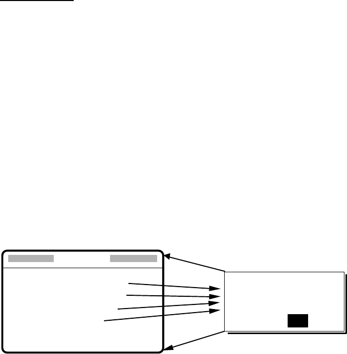
5 CALLING, RECEIVING
5-46
4. To scroll the log up and down, use the [FILE/CURSOR] and [#/SETUP] keys,
respectively. Use [FILE/CURSOR] key to scroll forward; the [#/SETUP] to scroll
backward.
5. To print all files in the log selected, press the [8/PRINT] key.
6. To reply to an unanswered call, rotate the [ENTER] knob to choose ANSWER, press
the [ENTER] knob, and then press the [CALL] key.
7. To return to the log selected, press the [CANCEL] key.
Deleting files
1. Do steps 1-2 and 3a) in the previous procedure to choose the file you wish to delete.
2. Rotate the [ENTER] knob to choose DELETE and then press the [ENTER] knob.
The log files are renumbered to reflect the deletion. Unread files cannot be deleted.
5.11 Erasing Message Files
The Erase file menu allows you to erase the entire contents of the received ordinary log,
received distress log, transmitted log and send message log.
1. Press the [#/SETUP] key.
2. Rotate the [ENTER] knob to choose ERASE and then push the [ENTER] knob to display
the Erase file menu.
3. Rotate the [ENTER] knob to choose the item to erase and then push the [ENTER] knob.
4. Rotate the [ENTER] knob to choose YES and then push the [ENTER] knob.
**** Erase file ****
RCVD ORDINARY LOG?
RCVD DISTRESS LOG?
TRANSMIT?
SEND MESSAGE?
To cancel, press [ENTER] knob or [CANCEL] key.
Item selected for erasure
appears in 2nd row.
To erase, select YES with
the [ENTER] knob and then
push the [ENTER] knob.
ERASE
XXXXXXXXXXXXXXXXX.
ARE YOU SURE?
YES NO
[ENTER]
knob
6-1
6. PREPARING TX CALLS
In Chapter 5 you learned how to prepare and send various types of DSC calls. In this
chapter you will learn how to prepare and store individual, PSTN, group, area and test
calls for future transmission. 150 calls can be stored.
.
6.1 Preparing Individual Calls
1. At the DSC standby screen, press the [#/SETUP] key to open the Setup menu.
**** Setup menu ****
SCAN FREQ
VOLUME
TEST
SYSTEM
ALARM
AUTO ACK
ERASE
MESSAGE
POSITION
PRINT OUT
2. Rotate the [ENTER] knob to choose MESSAGE and then push the [ENTER] knob.
3. Push the [ENTER] knob to open the CALL TYPE menu.
*
Message file entry
CALL TYPE
STATION ID
COM. TYPE
COM. FREQ
DSC FREQ
: INDIVIDUAL
:
---------
: TELEPHONE
: NO INFO
: 2M-INTL
INDIVIDUAL
PSTN CALL
GROUP CALL
AREA CALL
TEST CALL
4. Rotate the [ENTER] knob to choose INDIVIDUAL and then push the [ENTER] knob.
5. Push the [ENTER] knob to open the STATION ID entry window.
*
Message file entry
CALL TYPE
STATION ID
COM. TYPE
COM. FREQ
DSC FREQ
: INDIVIDUAL
:
---------
: TELEPHONE
: NO INFO
: 2M-INTL
000000000
6. Key in ID of coast station or ship station with the numeric keys and then push the
[ENTER] knob.
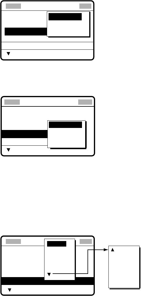
6 PREPARING TX CALLS
6-2
7. Push the [ENTER] knob to open the COM. TYPE window.
*
Message file entry
CALL TYPE
STATION ID
COM. TYPE
COM. FREQ
DSC FREQ
: INDIVIDUAL
: 001234567
: TELEPHONE
: NO INFO
: 2M-INTL
: GROUP CALL
: 012345678
: Routine
NBDP-ARQ
NBDP-FEC
TELEPHONE
8. Rotate the [ENTER] knob to choose communication type desired and then push the
[ENTER] knob.
9. Push the [ENTER] knob to open the COM. FREQ window.
* Message file entry
CALL TYPE:
STATION ID
COM. TYPE
COM. FREQ
DSC FREQ
INDIVIDUAL
: 123456789
: TELEPHONE
: NO INFO
: 2M-INTL
NO INFO
FREQUENCY
CHANNEL
POSITION*
* POSITION appears when
coast station ID is entered
in the field STATION ID.
10. Rotate the [ENTER] knob to choose appropriate item and then push the [ENTER] knob.
Call to coast station: NO INFO or POSITION.
Call to ship station: FREQUENCY or CHANNEL. Enter appropriate frequency or
channel, referring to page 5-6.
11. Push the [ENTER] knob to open the DSC FREQ menu.
*
Message file entry
CALL TYPE
STATION ID
COM. TYPE
COM. FREQ
DSC FREQ
: INDIVIDUAL
: 001234567
: TELEPHONE
: NO INFO
: 2M-INL
6 MHZ
8 MHZ
12 MHZ
4 MHZ
2 MHZ
16 MHZ
18 MHZ
22 MHZ
25 MHZ
OTHER
OTHER: Special, private channels.
Rotate [ENTER] knob
to scroll.
12. Rotate the [ENTER] knob to choose appropriate DSC band and then push the
[ENTER] knob.
13. Rotate the [ENTER] knob to choose appropriate DSC frequency and then push the
[ENTER] knob.
14. Enter file name and number as shown on the next page.
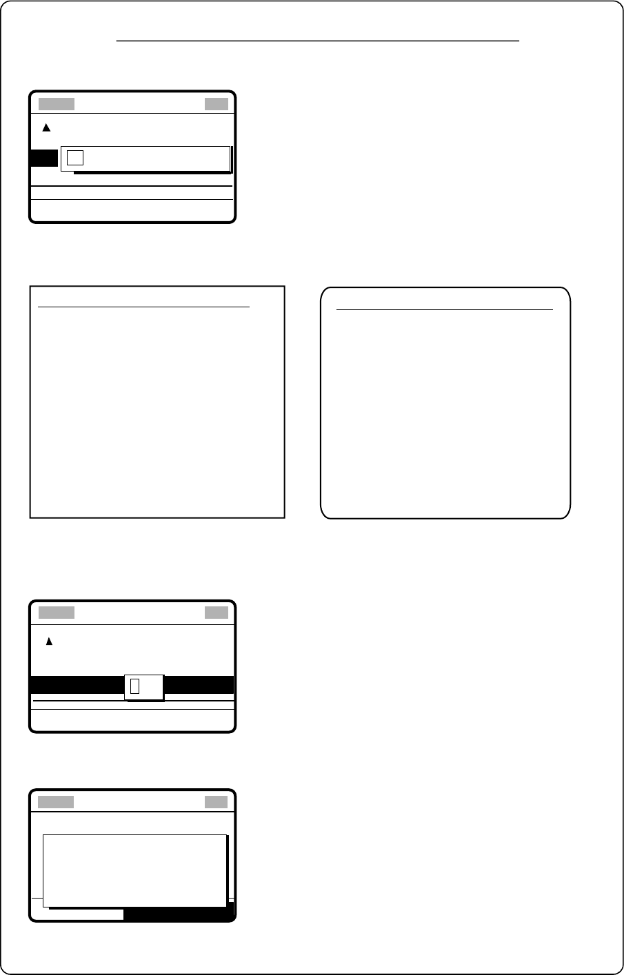
6 PREPARING TX CALLS
6-3
* Message file entry
FILE NAME
:
----------------
FILE NUMBER :
---
FILE ENTRY
How to Enter File Name and Number
1. Push the [ENTER] knob to open the file name entry window.
2. Use the numeric keys and [ENTER] knob to enter file name (max. 16 characters).
For example, enter FURUNO as the file name. Push the [ENTER] knob after entering.
3. Push the [ENTER] knob to open the file number entry window. Key in file number in three
digits with the numeric keys and then push the [ENTER] knob. For example, press [0], [0],
[1], [ENTER] knob to enter file number 001.
FILE ENTRY
* Message file entry
4. Push the [ENTER] knob. The display shows the name and file number entered.
5. Push the [ENTER] knob to continue.
How to enter "FURUNO" as file name
Key and available character, symbol
[1] : 1→(blank)→1
[2ABC] : 2→A→B→C→2
[3DEF] : 3→D→E→F→3
[4GHI] : 4→G→H→I→4
[5JKL] : 5→J→K→L→5
[6MNO] : 6→M→N→O→6
[7PQRS] : 7→P→Q→R→S→7
[8TUV] : 8→T→U→V→8
[9WXYZ]: 9→W→X→Y→Z→9
[0] : 0→_→
−
→0
1.
Rotate [ENTER] knob to select location.
2. Press appropriate key.
1. Press the [3] key to display F.
2. Rotate [ENTER] knob to shift cursor
.
3. Press the [8] key to select U.
4.
Rotate [ENTER] knob to shift cursor
.
5. Press the [7] key to select R.
6. Rotate [ENTER] knob to shift cursor
.
7. Press the [8] key to select U.
8. Rotate [ENTER] knob to shift cursor
.
9. Press the [6] key to select N.
10. Rotate [ENTER] knob to shift cursor
.
11. Press the [6] key to select O.
12. Push the [ENTER] knob.
FILE ENTRY
: FURUNO
* Message file entry
FILE NAME
FILE NUMBER :
---
001
Note: The available file number is 001-799 and
900-999.
If the file name or number exists the message
"Duplicate name (number) ! Overwrite OK?" appears.
Push the [ENTER] knob to write over the name, or
press the [CANCEL] key to escape.
FURUNO
No.001 file entered
Go to next file?
YES: [ENT] key
NO: [CANCEL] key
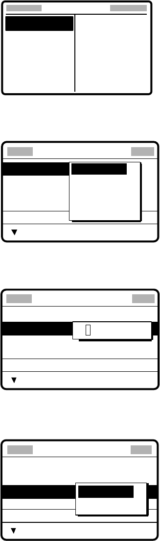
6 PREPARING TX CALLS
6-4
6.2 Preparing Group Calls
1. At the DSC standby screen, press the [#/SETUP] key to open the Setup menu.
****
Setup menu
****
SCAN FREQ
VOLUME
TEST
SYSTEM
ALARM
AUTO ACK
ERASE
MESSAGE
POSITION
PRINT OUT
2. Rotate the [ENTER] knob to choose MESSAGE and then push the [ENTER] knob.
3. Push the [ENTER] knob to open the CALL TYPE menu.
*
Message file entry
CALL TYPE
STATION ID
COM. TYPE
COM. FREQ
DSC FREQ
: INDIVIDUAL
:
---------
: TELEPHONE
: NO INFO
: 2M-INTL
INDIVIDUAL
PSTN CALL
GROUP CALL
AREA CALL
TEST CALL
4. Rotate the [ENTER] knob choose GROUP CALL and then push the [ENTER] knob.
5. Push the [ENTER] knob to open the GROUP ID entry window.
* Message file entry
CALL TYPE:
GROUP ID
COM. TYPE
COM. FREQ
DSC FREQ
GROUP CALL
: 0
--------
: TELEPHONE
: NO INFO
: 2M-INTL
000000000
6. Key in ID of group with the numeric keys and then push the [ENTER] knob.
7. Push the [ENTER] knob to open the COM. TYPE menu.
* Message file entry
CALL TYPE:
GROUP ID
COM. TYPE
COM. FREQ
DSC FREQ
GROUP CALL
: 012345678
: TELEPHONE
: NO INFO
: 2M-INTL
NBDP-FEC
TELEPHONE
8. Rotate the [ENTER] knob to choose appropriate communications type and then push
the [ENTER] knob.
9. Push the [ENTER] knob to open the COM. FREQ menu.
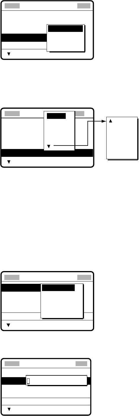
6 PREPARING TX CALLS
6-5
* Message file entry
CALL TYPE:
GROUP ID
COM. TYPE
COM. FREQ
DSC FREQ
GROUP CALL
: 012345678
: TELEPHONE
: NO INFO
: 2M-INTL
NO INFO
FREQUENCY
CHANNEL
10.Rotate the [ENTER] knob to choose appropriate item and then push the [ENTER] knob.
Enter frequency or channel. (See page 5-6 for details for how to enter frequency and
channel.)
11. Push the [ENTER] knob to open the DSC FREQ menu.
Message file entry
CALL TYPE
GROUP ID
COM. TYPE
COM. FREQ
DSC FREQ
: INDIVIDUAL
: 001234567
: TELEPHONE
: NO INFO
: 2M-INTL
6 MHZ
8 MHZ
12 MHZ
4 MHZ
2 MHZ
16 MHZ
18 MHZ
22 MHZ
25 MHZ
OTHER
OTHER: Special, private channels.
Rotate [ENTER] knob
to scroll.
12. Rotate the [ENTER] knob to choose appropriate DSC band and then push the
[ENTER] knob. Choose appropriate DSC frequency and then push the [ENTER] knob.
13. Follow “How to Enter File Name and Number” on page 6-3 to enter file name and
number.
6.3 Preparing Geographical Area Calls
1. At the DSC standby screen, press the [#/SETUP] key to open the Setup menu.
2. Rotate the [ENTER] knob to choose MESSAGE and then push the [ENTER] knob.
3. Push the [ENTER] knob to open the CALL TYPE menu.
*
Message file entry
CALL TYPE
STATION ID
COM. TYPE
COM. FREQ
DSC FREQ
: INDIVIDUAL
:
---------
: TELEPHONE
: NO INFO
: 2M-INTL
INDIVIDUAL
PSTN CALL
GROUP CALL
AREA CALL
TEST CALL
4. Rotate the [ENTER] knob to choose AREA CALL and then push the [ENTER] knob.
5. Push the [ENTER] knob to open the AREA entry window.
* Message file entry
CALL TYPE:
AREA
COM. TYPE
COM. FREQ
DSC FREQ
AREA CALL
:
--
˚N
---
˚E ↓
--
˚ →
--
˚
: TELEPHONE
: NO INFO
: 2M-INTL
00°
N 000
°
E ↓
00°
→
00°
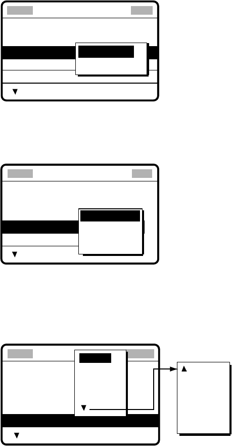
6 PREPARING TX CALLS
6-6
6. Using the numeric keys, enter latitude and longitude of reference point and southerly
degrees and easterly degrees of area. To change coordinate, choose it and press the
[1] key for North or East; [2] key for South or West. After entering data, push the
[ENTER] knob.
7. Push the [ENTER] knob to open the COM. TYPE menu.
* Message file entry
CALL TYPE:
AREA:
34
°
00N 135
°
00W ↓10
°
→10
°
COM. TYPE
COM. FREQ
DSC FREQ
: TELEPHONE
: NO INFO
: 2M-INTL
: GROUP CALL
NBDP-FEC
TELEPHONE
8. Rotate the [ENTER] knob to choose appropriate communications type and then push
the [ENTER] knob.
9. Push the [ENTER] knob to open the COM. FREQ menu.
* Message file entry
CALL TYPE:
AREA
COM. TYPE
COM. FREQ
DSC FREQ
AREA CALL
: 34°
00
N 135°
00
E ↓ 10° → 10°
: TELEPHONE
: NO INFO
: 2M-INTL
NO INFO
FREQUENCY
CHANNEL
10. Rotate the [ENTER] knob to choose appropriate item and then push the [ENTER]
knob. Enter channel or frequency. (See page 5-6 for how to enter channel and
frequency.)
11. Push the [ENTER] knob to open the DSC FREQ menu.
* Message file entry *
CALL TYPE
AREA
COM. TYPE
COM. FREQ
DSC FREQ
: AREA CALL
: 34°
00
N 123°E ↓12°→ 10°
: TELEPHONE
: NO INFO
: 2M-INTL
16 MHZ
18 MHZ
22 MHZ
25 MHZ
OTHER
OTHER: Private channels.
6 MHZ
8 MHZ
12 MHZ
4 MHZ
2 MHZ
Rotate [ENTER] knob
to scroll.
12. Rotate the [ENTER] knob to choose appropriate DSC band and then push the
[ENTER] knob. Choose appropriate DSC frequency and then push the [ENTER] knob.
13. Follow “How to Enter File Name and Number” on page 6-3 to enter file name and
number.
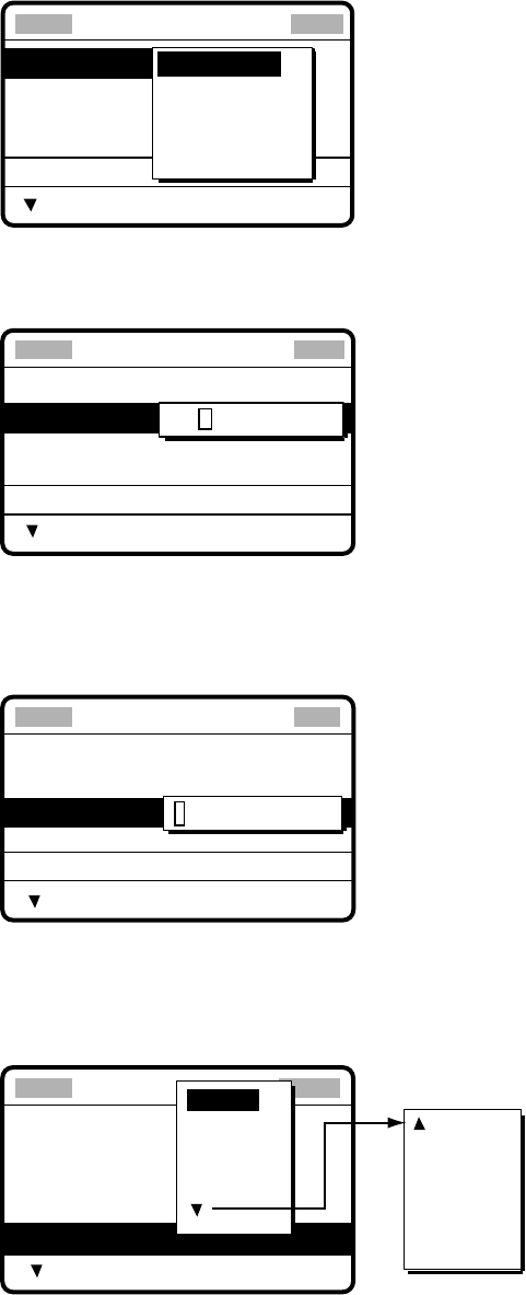
6 PREPARING TX CALLS
6-7
6.4 Preparing PSTN Calls
1. At the DSC standby screen, press the [#/SETUP] key to open the Setup menu.
2. Rotate the [ENTER] knob to choose MESSAGE and then push the [ENTER] knob.
3. Push the [ENTER] knob to open the CALL TYPE menu.
*
Message file entry
CALL TYPE
STATION ID
COM. TYPE
COM. FREQ
DSC FREQ
: INDIVIDUAL
:
---------
: TELEPHONE
: NO INFO
: 2M-INTL
INDIVIDUAL
PSTN CALL
GROUP CALL
AREA CALL
TEST CALL
4. Rotate the [ENTER] knob to choose PSTN CALL and then push the [ENTER] knob.
5. Push the [ENTER] knob to open the COAST ID entry window.
*
Message file entry
CALL TYPE
COAST ID
TEL NO. :
DSC FREQ
: PSTN CALL
: 0
-------
----------------
: 2M-INTL
000000000
6. Key in ID of coast station (seven digits) with the numeric keys then push the [ENTER]
knob.
7. Push the [ENTER] knob to open the TEL. NO. entry window.
* Message file entry
CALL TYPE:
COAST ID
TEL NO. :
DSC FREQ
PSTN CALL
: 001234567
:
----------------
: 2M-INTL
-
8. Key in telephone no. (up to 16 digits) with the numeric keys and then push the
[ENTER] knob.
9. Push the [ENTER] knob to open the DSC FREQ menu.
* Message file entry
CALL TYPE:
COAST ID
TEL NO. :
PSTN CALL
001234567
1234567890
---
DSC FREQ : 2M-INTL TL
16 MHZ
18 MHZ
22 MHZ
25 MHZ
OTHER
OTHER: Special, private channels.
6 MHZ
8 MHZ
12 MHZ
4 MHZ
2 MHZ
Rotate the [ENTER] knob
to scroll.
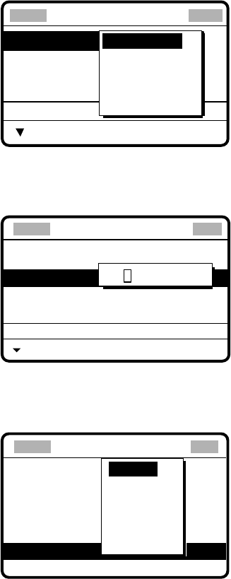
6 PREPARING TX CALLS
6-8
10. Rotate the [ENTER] knob to choose appropriate DSC band and then push the
[ENTER] knob. Choose appropriate DSC frequency and then push the [ENTER] knob.
11. Follow “How to Enter File Name and Number” on page 6-3 to enter file name and
number.
6.5 Preparing Test Calls
1. At the DSC standby screen, press the [#/SETUP] key to open the Setup menu.
2. Rotate the [ENTER] knob to choose MESSAGE and then push the [ENTER] knob.
3. Push the [ENTER] knob to open the CALL TYPE menu.
*
Message file entry
CALL TYPE
STATION ID
COM. TYPE
COM. FREQ
DSC FREQ
: INDIVIDUAL
:
---------
: TELEPHONE
: NO INFO
: 2M-INTL
INDIVIDUAL
PSTN CALL
GROUP CALL
AREA CALL
TEST CALL
4. Rotate the [ENTER] knob to choose TEST CALL and then push the [ENTER] knob.
5. Push the [ENTER] knob to open the COAST ID entry window.
* Message file entry
CALL TYPE
DSC FREQ : 2187.5 KHZ
: TEST
COAST ID 000000000
6. Enter coast ID where to send the test message and then push the [ENTER] knob.
7. Push the [ENTER] knob to open the DSC FREQ menu.
DSC FREQ KHZ
*
Message file entry
CALL TYPE
COAST ID
: Test
: 001234567
: Safety
: kHz
VIEW
4207.5
6312.0
8414.5
12577.0
16804.5
2187.5
8. Rotate the [ENTER] knob to choose appropriate DSC frequency and then push the
[ENTER] knob.
9. Follow “How to Enter File Name and Number” on page 6-3 to enter file name and
number.
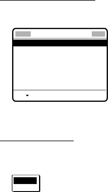
6 PREPARING TX CALLS
6-9
6.6 Sending Prepared Calls
Sending without modification
1. Press the [FILE/CURSOR] key at the DSC standby screen to show the send message
file list. Below is an example of the send message file list.
*
Send message file *
001 - FURUNO JAPAN
002 - FURUNO USA
003 - FURUNO UK
004 - FURUNO DENMARK
005 - FURUNO NORWAY
006 - FURUNO SPAIN
DOWN
2. Rotate the [ENTER] knob to choose a file.
3. Press the [CALL] key to send the message.
Editing before sending
1. Press the [FILE/CURSOR] key at the DSC standby screen to show the send message
file list.
2. Rotate the [ENTER] knob to choose file desired and then push the [ENTER] knob.
DELETE
DETAIL
3. DETAIL is selected; push the [ENTER] knob. The message contents are shown on the
“Compose message” screen.
4. Edit the message as necessary.
5. Press the [CALL] key to send the message.

6 PREPARING TX CALLS
6-10
6.7 Deleting Send Message Files
1. Press the [FILE/CURSOR] key at the DSC standby screen to show the send message
file list.
2. Rotate the [ENTER] knob to choose file desired and then push the [ENTER] knob.
DELETE
DETAIL
3. Rotate the [ENTER] knob to choose DELETE and then push the [ENTER] knob.
Note: You may collectively erase all send message files. For details see paragraph 5.11.
6.8 Printing List of Send Message Files
You can print a list of send message files as follows:
1. Press the [FILE/CURSOR] key to open the Send message file list.
2. Press the [8/PRINT] key.
3. YES is selected; push the [ENTER] knob to print.
********** Send message file **********
001. FURUNO JAPAN INDIVIDUAL CALL
002. FURUNO USA INDIVIDUAL CALL
003. FURUNO UK PSTN CALL
004. FURUNO DENMARK GROUP CALL
005. FURUNO NORWAY INDIVIDUAL CALL
006. FURUNO SPAIN ALL SHIPS CALL
007. FURUNO FRANCE INDIVIDUAL CALL
Note: Message not framed in actual printout.
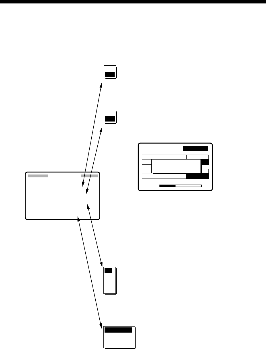
7-1
7 DSC/WATCH RECEIVER SETUP
7.1 Setting Alarms
The Alarm menu enables/disables internal and external alarms. Note that the
Distress/Urgency alarm cannot be disabled. Press the [#/SETUP] key at the DSC standby
screen, choose ALARM and then push the [ENTER] knob to display the Alarm menu.
**** Alarm setup ***
INTERNAL AUDIO ALARM
RCVD CALL
OLD POSITION
POSITION OLDER
EXT ALARM : DSTRS/URG
: ON
: ON
: 4.0 H
OFF
OFF
3.0
2.0
1.0
0.5
4.0
ROUTINE
ALL
OFF
DSTRS/URG
35˚00.000N 135˚00.000E 23:59
WATCH KEEPING
2187.5 4207.5 6312.0
8414.516804.5 12577.0
DISTRESS
ROUTINE
2177.0 4219.5 6331.0
16903.0 12657.0
VOLUME
Warning:
Update position
Default: ON
Default: ON
Default: 4.0 hours
Default: DSTRS/URG
Disables/enables alarm for received Safety,
Ship's Business and Routine calls.
Alarm is output when position is older by the
number of hours set here.
Sets type of call to be output to the
Incoming Indicator IC-303-DSC.
DSTRS/URG: Distress or urgency
call output upon receipt.
ROUTINE: Routine call output
upon receipt.
ALL: All calls output.
OFF: No output.
Note: Alarm for Distress and Urgency calls
cannot be disabled.
22
AUTO ACK
8436.5
Disables/enables old position alarm in manual
position entry mode, which alerts the operator
when position data is older by the number of
hours or minutes set in the Position Older field.
Message shown when manually
entered position is older than the
time set on the Alarm setup menu.
Rotate
[ENTER]
knob to choose.
ON
ON
7 DSC/WATCH RECEIVER SETUP
7-2
7.2 Auto Ack Menu
The Auto Ack menu enables/disables automatic acknowledgement of individual, position
and polling calls. Press the [#SETUP] key, choose AUTO ACK at the DSC standby screen
and then push the [ENTER] knob to display the Auto Ack setup menu.
Comply type
Setting of
[5/ACQ /SQ] key
ABLE UNABLE
AUTO ACK Can send acknowledge
automatically
Can send UNABLE
automatically.
MANUAL ACK Can send acknowledge
manually
Can send UNABLE manually.
Default: ABLE
**
Auto ack setup
**
COMPLY TYPE : ABLE
UNABLE REASON :
NO REASON GIVEN
POSITION CALL : OFF
POLLING CALL : ON
UNABLE
ABLE
Choose ABLE or UNABLE as automatic
acknowledgement reply to Individual
calls.
Note: Automatic acknowledge is
automatically disabled when RX
call contains error, as required by
law. Further, automatic
acknowledge is disabled in case of
OFF HOOK.
Default: NO REASON
NO REASON
BUSY
EQUIP DISABLED
MODE NOT USABLE
CH NOT USABLE
Sets reason for UNABLE.
Note: This menu is the same as manual
acknowledgement. EQUIPMENT
DISABLED is shown in calls when
EQUIP DISABLED is selected.
Default: ON
Effective when [5/ACK/SQ] key
is set for "AUTO ACK."
OFF: Disables automatic
acknowledgement of
position request.
ON: Enables automatic
acknowledgement of
position request.
OFF
ON
Default: ON
Effective when [5/ACK/SQ] key
is set for "AUTO ACK."
OFF: Disables automatic
acknowledgement of
polling request.
ON: Enables automatic
acknowledgement of
polling request.
OFF
ON
Rotate [ENTER]
knob to choose
7 DSC/WATCH RECEIVER SETUP
7-3
7.3 Printing Messages
The Print Out menu enables/disables automatic printing of all transmitted and received
calls and the results of the daily test. Press the [#/SETUP] key at the DSC standby screen,
choose PRINT OUT and then push the [ENTER] knob to display the Print Out menu.
Default: MANUAL
* Print out setup *
XMIT CALL : MANUAL
RCVD CALL : MANUAL
DAILY TEST : MANUAL
AUTO
MANUAL
Select AUTO to automatically print
transmitted calls.
Default: MANUAL
Select AUTO to automatically print
received calls.
Default: MANUAL
Select AUTO to automatically print
results of Daily Test.
AUTO
MANUAL
AUTO
MANUAL
Sample printouts
Printing can be done automatically or manually. For manual printing, press the [8/PRINT]
key. Note that calls having more than one page (for example, received calls) are printed
out in their entirety.
* Received message at JAN-08-2002-16:10:12 *
FORMAT : DISTRESS CALL
SELF-IDENTITY : 987654321
NATURE OF DISTRESS : UNDESIGNATED DISTRESS
DISTRESS COORDINATES : NO INFORMATION
DISTRESS TELECOMMAND : J3E TELEPHONE
END OF SEQUENCE : EOS
ERROR-CHECK : OK
DSC FREQUENCY TX: 2187.5 kHz
RX: 2187.5 kHz
Sample Received Message Printout (Distress)
* Received message at JAN-08-2002-16:10:12 *
FORMAT : INDIVIDUAL CALL
ADDRESS : 111660000
CATEGORY : ROUTINE
SELF-IDENTITY : 987654321
1st TELECOMMAND : J3E TELEPHONE
2nd TELECOMMAND : NO INFORMATION
WORKING FREQUENCY : NO INFORMATION
END OF SEQUENCE : ACK. RQ
ERROR-CHECK : OK
DSC FREQUENCY TX: 2177.0 kHz
RX: 2177.0 kHz
Sample Received Message Printout (Individual)
*Transmitted message at JAN-08-2002-16:10:12 *
FORMAT : INDIVIDUAL CALL
ADDRESS : 987654321
CATEGORY : ROUTINE
SELF-IDENTITY : 111660000
1st TELECOMMAND : J3E TELEPHONE
2nd TELECOMMAND : NO INFORMATION
WORKING FREQUENCY : NO INFORMATION
END OF SEQUENCE : ACK. RQ
DSC FREQUENCY TX: 2177.0 kHz
RX: 2177.0 kHz
Sample Transmitted Message Printout (Individual)
Note: Messages are not framed in actual printouts.
*************** Send message *************
FORMAT : INDIVIDUAL CALL
ADDRESS : 111660000
CATEGORY : ROUTINE
SELF-IDENTITY : 987654321
1st TELECOMMAND : J3E TELEPHONE
2nd TELECOMMAND : NO INFORMATION
WORKING FREQUENCY : NO INFORMATION
END OF SEQUENCE : ACK. RQ
DSC FREQUENCY TX: 2177.0 kHz
RX: 2177.0 kHz
Sample Send Message Printout (Individual)

7 DSC/WATCH RECEIVER SETUP
7-4
7.4 Setting Scan Frequencies
The Scan freq menu determines which DSC routine and distress frequencies to scan.
Follow the instructions below to select/deselect DSC routine and distress frequencies to
scan.
7.4.1 Distress frequencies
1. Press the [#/SETUP] key at the DSC standby screen, choose SCAN FREQ and then
push the [ENTER] knob to display the SCAN FREQ menu.
DISTRESS
2M : FIXED
4M : ON
6M : ON
8M : FIXED
12M : ON
16M : OFF
** Scan freq setup *
ROUTINE
F1 : 2M-INTL
F2 : 4M-INTL
F3 : 6M-INTL
F4 : 8M-INTL
F5 : 12M-INTL
F6 : 16M-INTL
2. Rotate the [ENTER] knob clockwise to shift the cursor to the DISTRESS column.
3. Rotate the [ENTER] knob to choose the frequency to process and then push the
[ENTER] knob. For example, choose 4 MHz.
ROUTINE
F1 : 2M-INTL
F2 : 2M-INTL
F3 : 4M-INTL
F4 : 8M-INTL
F5 : 12M-INTL
F6 : 16M-INTL
DISTRESS
2M :
FIXED
4M : ON
6M : ON
8M :
FIXED
12M : ON
16M : OFF
** Scan freq setup *
OFF
ON
4. Rotate the [ENTER] knob to choose ON or OFF as appropriate and then push the
[ENTER] knob.
5. Press the [CANCEL] key twice to return to the DSC standby screen.
Note: Regulations require that 2 MHz and 8 MHz and one more DSC distress frequency
be watched continuously. These frequencies cannot be turned off. Maximum three
bands may be turned off.
7 DSC/WATCH RECEIVER SETUP
7-5
7.4.2 Routine frequencies
1. Press the [#/SETUP] key, choose SCAN FREQ and then push the [ENTER] knob to
display the Scan freq menu.
DISTRESS
2M :
FIXED
4M :
ON
6M : ON
8M :
FIXED
12M : ON
16M : OFF
** Scan freq setup *
ROUTINE
F1 : 2M-INTL
F2 : 4M-INTL
F3 : 6M-INTL
F4 : 8M-INTL
F5 : 12M-INTL
F6 : 16M-INTL
2. Rotate the [ENTER] knob to choose the frequency to process and then push the
[ENTER] knob. For example, choose F1: 2 M-INTL.
ROUTINE
F1 : 2M-INTL
F2 : 2M-USR3
F3 : 4M-INTL
F4 : 8M-INTL
F5 : 16M-LCL1
F6 : 25M-LCL2
DISTRESS
2M :
FIXED
4M : ON
6M : ON
8M :
FIXED
12M : ON
16M : OFF
** Scan freq setup *
OFF
2 MHZ
4 MHZ
6 MHZ
8 MHZ
3. Push the [ENTER] knob, and the display looks something like the one below.
ROUTINE
F1 : 2M-INTL
F2 : 2M-USR3
F3 : 4M-INTL
F4 : 8M-INTL
F5 : 16M-LCL1
F6 : 25M-LCL2
DISTRESS
2M :
FIXED
4M : ON
6M : ON
8M :
FIXED
12M : ON
16M : OFF
** Scan freq setup *
INTL : T2189.5/R 2177.0
DIST : T 2187.5/R 2187.5
4. Rotate the [ENTER] knob to choose frequency desired and then push the [ENTER]
knob.
INTL: International channels
DIST: Distress channels
LOCAL1/LOCAL2: Local channels
USER CH: User channels
5. Press the [CANCEL] key twice to return to the DSC standby screen.
Note: Distress frequencies can be stored on the routine frequency memory. This is
convenient for backing up the watch keeping receiver.
7 DSC/WATCH RECEIVER SETUP
7-6
7.5 Adjusting Volume
The Volume menu enables/disables key beep (acknowledges correct key input) and
adjusts the volume of the handset, ordinary alarm and distress/urgency alarm. Press the
[#/SETUP] key at the standby screen, choose VOLUME and then push the [ENTER] knob
to display the Volume setup menu.
Default: ON
*** Volume setup ***
KEY CLICK : ON
HANDSET : 40
ORDINARY ALARM : 30
DISTRESS ALARM : 63
OFF
ON
HANDSET
VOLUME (0~63)
40
Turns on/off beep generated when
keyboard is operated.
Note: Do not confuse keyboard beep
(single beep) with ACK beep
(three beeps).
Sets volume of handset.
ORDINARY ALARM
VOLUME (0~63)
30
Sets loudness of Safety, Ships Business, Routine
and Old Position alarms.
DISTRESS ALARM
VOLUME (38~63)
63
Sets loudness of Distress and Urgency alarms.
Rotate [ENTER] knob
to set.
Rotate [ENTER] knob
to set.
Rotate [ENTER] knob
to set.
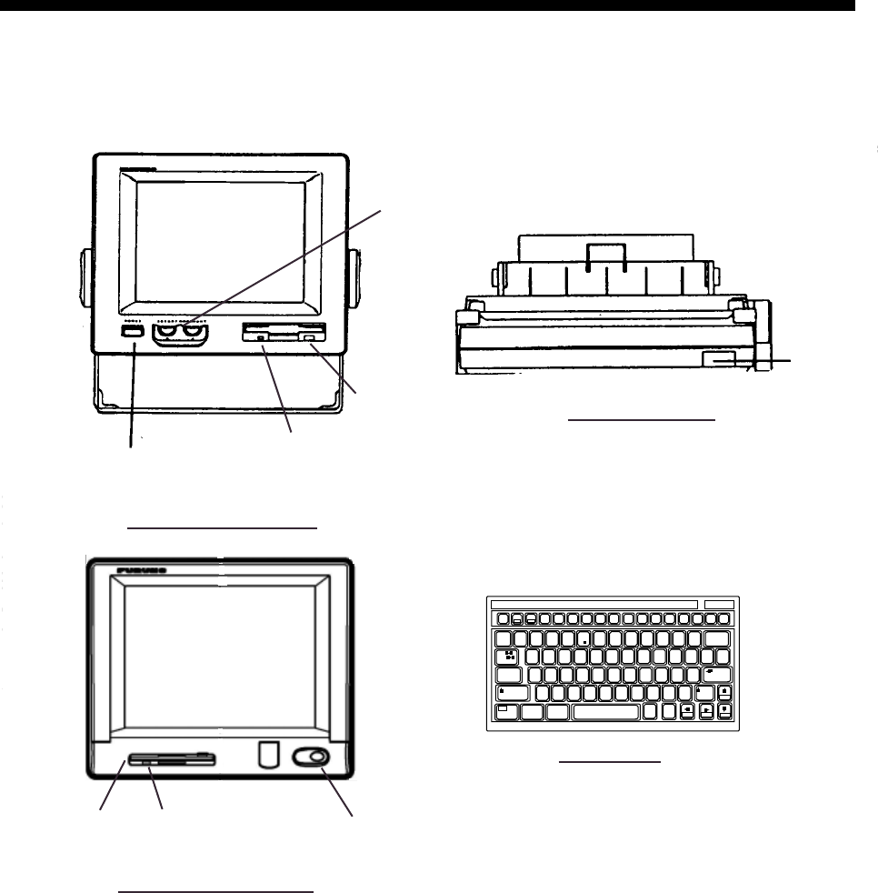
8-1
8 NBDP SYSTEM OVERVIEW
8.1 Turning on the NBDP System
Turn on the terminal unit and the printer with their respective power switches.
T
ER
POWER Switch
MAIN UNIT
POWER switch
PRINTER PP-510
POWER
Switch
Floppy Disk Drive
Brilliance, Contrast Control
Operating Lamp
~
`2
134 67890 - =
_+)
*
(
9*87
^&$#@!
QWERTYUIOP
[]
{}
\
|
ASDF GHJ KL:+
;
"
'
Tab
Caps Lock
ZXCVBNM<> ?/
/
.
,
123
456
0Shift
Fn Ctrl Alt Alt Ctrl
Home End PgDn
PgUp
Shift
Enter
Backspace
Esc F1 F2 F3 F4 F5 F6 F7 F8 F9 F10
Num
Lock
Prt Sc
SysRq
Scroll
Lock Pause
Break
Insert Delete
F11 F12
5
%
C
KEYBOARD
TERMINAL UNIT IB-581
TERMINAL UNIT IB-583
Floppy Disk
Drive POWER Switch
Operating Lamp
NBDP terminal unit, printer and keyboard
Note: The Printer PP-510 prints messages. Refer to its operator’s manual for operating
information.

8 NBDP SYSTEM OVERVIEW
8-2
8.2 Description of Equipment
8.2.1 Terminal unit
The terminal unit is a visual display incorporating a floppy disk drive, which provides for
storage of files on floppy disks. Two models are available, IB-581 (monochrome) and IB-583
(color). Controls for power and adjustment of display brilliance and contrast are provided on
the front panel of the IB-581. To adjust the brilliance on the IB-583, press [Alt] while
pressing [F6] to lower the brilliance; [F7] to raise it. (The IB-583 does not have a control for
adjustment of contrast.) Eight levels of brilliance are available.
When the terminal unit is turned on, the communication status display, shown below,
appears. This is where all phases of telex communications begin.
Station Name :
Frequency (T/R) : / (kHz) Comm Mode :
Comm Status : Connect Send Lock Error
Sending Volume : (%) ARQ Error : 0 ARQ Time : 0(sec)
1:File 2:Edit 3:Operate 4:Window 5:Station 6:System 7:WRU 8:HR 9:Over 10:Break
2002-10-15 2:26:45 UTC Caps-Eng
Communication status display
Features of the IB-583
The IB-583 is fitted with both English and Russian interface. Choose desired interface as
below:
English: Turn on the IB-583 while pressing the [E] key.
Russian: Turn on the IB-583 while pressing the [R] key.
The IB-583 has a battery (type CR2450-F2ST2L, code no. 000-144-941) on its TERM/CPU
Board (16P0209) and its life is about six years. When the voltage of the battery is low, the
time will be slow. When this occurs, contact your dealer about replacement of the battery.
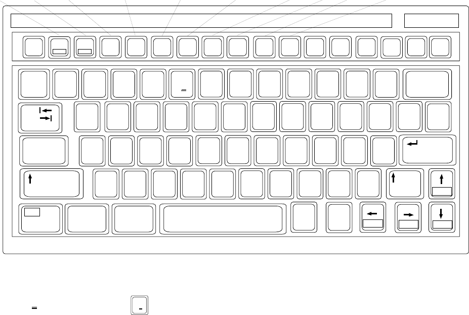
8 NBDP SYSTEM OVERVIEW
8-3
8.2.2 Keyboard
The terminal unit is operated from the keyboard, and is almost 100% keyboard controlled.
Operation is simplified by the use of menus which you access by pressing a function key,
labeled F1-F10 at the top of the keyboard. The figure below shows the function menus and
their corresponding function keys.
~
`2
134 67890 - =
_+)*(9*87^&$#@!
QWERTYUIOP
[]
{}
\
|
ASDF GHJ KL:+
;
"
'
Tab
Caps Lock
ZXCVBNM<> ?/
/
.
,
123
456
0Shift
Fn Ctrl Alt Alt Ctrl
Home End PgDn
PgUp
Shift
Enter
Backspace
Esc F1 F2 F3 F4 F5 F6 F7 F8 F9 F10
Num
Lock
Prt Sc
SysRq
Scroll
Lock Pause
Break
Insert Delete
FILE EDIT OPERATE WINDOW STATION SYSTEM WRU HR OVER BREAK
F11 F12
5
%
C
Keyboard
Note:
C
(Euro mark) on
5
%
C
key is not used.
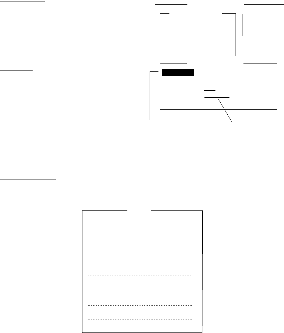
8 NBDP SYSTEM OVERVIEW
8-4
8.3 Function Keys, Menu Operation
The function keys at the top of the keyboard control most operations of this unit through a
menu system.
8.3.1 Menu conventions
Inverse video
As you move the cursor down through a
menu, a selected item, initially shown as
white on black (monochrome display),
inverses to black on white. This highlighting
indicates that it is available for selection.
Underline
The underline shows current selection. In the
figure below, for example, the underline is
beneath "Receive."
Station entry screen
8.3.2 Menu overview
Selecting menus
Press appropriate function key to open a menu. To display the File menu, for example,
press the function key [F1].
1: New
2: Open
3: Close
4: Delete
5: Rename
6: Real Time Printing
7: File to Print
8: Cancel Printing
9: Clear Buffer
0: Floppy Disk Format
File
File menu
Station Entry
Create
Change
Station List
Station Set Up
Station : _
ID Code :
Mode : ARQ FEC
CH/Table : Channel ScanTable
Num/Table:
Underline
Inverse Video

8 NBDP SYSTEM OVERVIEW
8-5
Selecting menu items and options
Menu items can be selected by pressing appropriate numeric key or selecting item desired
with the arrow keys and pressing the [Enter] key. Menu options can be selected by
operating the [←] or [→] keys. After selecting option desired, press the [Enter] key to
register your selection and close the menu.
8.3.3 Function key description
Function key [F1]: File menu
The File menu is where you will create, open, save and print telex messages. Floppy disks
are also formatted from this menu.
1: New
2: Open
3: Close
4: Delete
5: Rename
6: Real Time Printing
7: File to Print
8: Cancel Printing
9: Clear Buffer
0: Floppy Disk Format
File
File menu
1: New Opens a new untitled window.
2: Open Opens files.
3: Close Closes files.
4: Delete Deletes files.
5: Rename Renames files.
6: Real Time Printing Turns real time printing on/off.
7: File to Print Prints files.
8: Cancel Printing Stops printing.
9: Clear Buffer Clears the communications buffer.
0: Floppy Disk Format Formats a floppy disk.

8 NBDP SYSTEM OVERVIEW
8-6
Function key [F2]: Edit menu
The Edit menu provides a full line of editing features.
1: Undo
2: Cut
3: Copy
4: Paste
5: Select All
6: Search
7: Replace
8: Goto Top
9: Goto Bottom
0: Goto Line
A: Change Text
Edit
Edit menu
1: Undo Cancels the last change (cut, copy or paste).
2: Cut Removes the selected text and stores it in the paste buffer. (Previous
text in the paste buffer is cleared.)
3: Copy Copies the selected text and stores it in the paste buffer. (Previous text
in the paste buffer is cleared.)
4: Paste Inserts the text stored in the paste buffer at the current location of the
cursor.
5: Select All Selects the entire current file for cut or copy.
6: Search Searches a file for a character string.
7: Replace Replaces a word with a different word or character string.
8: Goto Top Brings the cursor to the top line of the current file.
9: Goto Bottom Brings the cursor to last line of the current file.
0: Goto Line Moves the cursor to the desired line in the current file.
A: Change Text Switches between the display window 1 and 2.

8 NBDP SYSTEM OVERVIEW
8-7
Function key [F3]: Operate menu
The Operate menu mainly controls transmitting and receiving.
1: Call Station
3: File to Send
4: Cancel Sending
5: Scan (Start/Stop)
6: Manual Reception
7: Timer Operation
8: Manual Calling
9: Set Frequency
Operate
2: Macro Operation
Operate menu
1: Call Station Chooses a station from the station list.
2: Macro Operation Enables macro operation. For details, see paragraph 11.10.
3: File to Send Selects a file (to transmit).
4: Cancel Sending Stops sending a file.
5: Scan Start/Stop Starts/stops frequency scanning.
6: Manual Reception Selects communication mode for reception; AUTO, ARQ, FEC
DIRC.
7: Timer Operation Timer programming.
8: Manual Calling Sets TX mode and subscriber's ID number in manual calling.
9: Set Frequency Sets TX and RX frequencies in manual calling.

8 NBDP SYSTEM OVERVIEW
8-8
Function key [F4]: Window menu
The Window menu lets you display the corresponding data of the window below.
1: Calendar
2: Distress Frequency Table
Window
Window menu
1: Calendar Displays desired calendar month and year. To change year
or month, choose item with [↑] or [↓] key and change setting
with [←] or [→] key.
2: Distress Frequency Table Displays all distress frequencies.
Distress Frequencies
Telephone (kHz): 2182.0 4125.0 6215.0 8291.0 12290.0 16420.0
NBDP (kHz) : 2174.5 4177.5 6268.0 8376.5 12520.0 16695.0
DSC (kHz) : 2187.5 4207.5 6312.0 8414.5 12577.0 16804.5

8 NBDP SYSTEM OVERVIEW
8-9
Function key [F5]: Station menu
The Station menu provides for storage of stations, timer program setup, user channel setup,
and entry of various ID codes.
1: Station Entry
2: Timer Operation Entry
3: Scan Entry
4: User Channel Entry
5: Answerback Code Entry
6: Group ID Entry (4/5 digit)
7: Group ID Entry (9 digit)
8: Select ID Entry (4/5 digit)
9: Select ID Entry (9 digit)
Station
Station menu
1: Station Entry Registers stations.
2: Timer Operation Entry Registers timer programs.
3: Scan Entry Creates scan groups for scanning.
4: User Channel Entry Registers user channels.
5: Answerback Code Entry Registers own ship's answerback code.
6: Group ID Entry Registers own ship's group ID codes (4 or 5 digit).
7: Group ID Entry Registers own ship's group ID codes (9 digit).
8: Select ID Entry Registers own ship's selective ID codes (4 or 5 digit).
9: Select ID Entry Registers own ship's selective ID codes (4 or 5 digit).
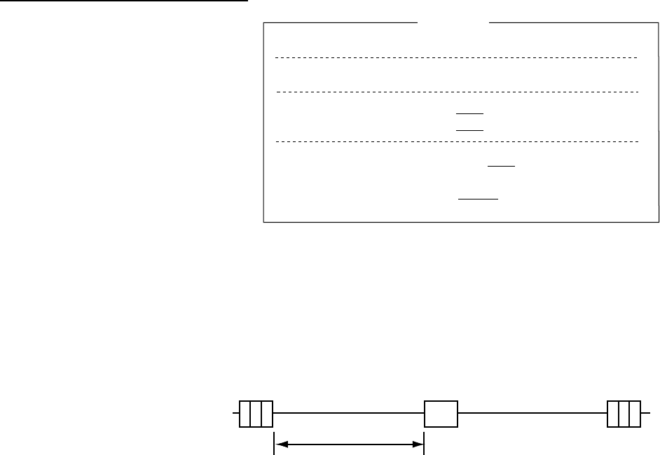
8 NBDP SYSTEM OVERVIEW
8-10
Function key [F6]: System menu
The System menu is mainly for
use by technicians and contains
diagnostic tests. To change
settings, choose “Change” from
the item “Setup” and operate
arrow keys to choose item and
option. Press the [Enter] key to
register selection and close the
menu.
System menu
Setup Locks, changes settings; restores default system settings.
Slave Delay Sets the length of the slave delay timing from the end of RX to
the start of TX in the ARQ mode. The default setting is suitable in
most cases.
ARQ mode
signal
sequence
3 char. RX 3 char. RX
RX end TX start
ACK signal
Slave Delay Timing
TX/RX MSG Save Turn on to automatically save incoming and outgoing messages to
a floppy disk. “Log” appears at the top of the screen when on.
Edit Before sending "OFF" transmits keying operation one by one. "ON" transmits
message only when the [Enter] key is pressed after confirming text
typed.
Time System Chooses time system. SMT is local time and JST is Japan
standard time.
Time & Date Enter date and time manually. If a navigation device is connected,
the time is automatically set when the power is turned on or
whenever the time system is switched. Manual entry takes priority
over automatic entry.
Display Mode Selects display mode to normal and reverse alternately.
Self Test Starts diagnostic test.
Function key [F7]: WRU (Who Are You?): In the ARQ mode, requests other station's
answerback code.
Function key [F8]: HR (Here Is): In the ARQ mode, sends your ship's answerback code.
Function key [F9]: OVER: In the ARQ mode, switches the direction of traffic; the
information receiving station becomes the information sending station, the information
sending station becomes the information receiving station.
Setup
Slave Delay
TX/RX MSG Save
Edit Before sending
Time System
Time & Date
Display Mode*
Self Test
Lock Change Default
8 msec (0- 50 msec)
OFF O N
OFF O N
OFF UTC SMT JST
2002/10/16 10:00:00
Normal Reverse
System
* = Not shown on IB-583.

9-1
9 NBDP PREPARATIONS
This chapter provides the procedures necessary for preparing the NBDP Terminal Unit for
transmitting and receiving. For automatic telex, you will need to register the following:
•
Your ship's ID and answerback codes
•
Stations
•
Timer programs
•
Scan channel groups
•
User channels
9.1 Registering Answerback Code & ID Codes
Enter your ship's answerback code and ID codes as shown below.
Note: The answerback and ID codes cannot be changed once entered; be sure to enter the
codes correctly.
9.1.1 Registering answerback code
1. Press the function key [F5] and then the [5] key. The display should look something like
the illustration below.
Answerback Code
_
Answerback Code Entry
Answerback code entry screen
2. Enter your ship's answerback code (max. 20 characters, including spaces) and press the
[Enter] key. The prompt “OK/Cancel” asks for verification of data. If the code is correct,
press the [Enter] key again.
Note: Example of answerback code: 12345789 FURU X.
9 NBDP PREPARATIONS
9-2
For final verification of the data, the Caution shown in the illustration below appears.
Answerback Code
123456789 FURU X
Answerback Code Entry
O K
Cancel
Caution
Confirm the 'CODE' before pressing ENTER key.
You cannot change the CODE once it has been entered.
Message for confirmation of code entered
3. If the code is correct, press the [Enter] key again.
9.1.2 Registering ID codes
1. Press function key [F5] and then the [6], [7], [8] or [9] key to enter the Group ID Code (4
or 5 digits), Group ID Code (9 digits), Select ID Code (4 or 5 digits) or Select ID Code (9
digits), respectively.
Select ID Code (4/5)
_
Select ID Entry
ID code screen
2. Enter Group ID or Select ID as appropriate and then press the [Enter] key. A prompt
asks you to verify data. If the ID is correct, press the [Enter] key.
For final verification of the data, the Caution shown in the illustration below appears.
Select ID Code (4/5)
12345
Select ID Entry
O K
Cancel
Caution
Confirm the 'CODE' before pressing ENTER key.
You cannot change the CODE once it has been entered.
Message for confirmation of code entered
3. If the ID is correct, press the [Enter] key again.

9 NBDP PREPARATIONS
9-3
9.2 Station List
The station list provides for storage of up to 50 stations, one frequency pair (RX and TX) per
station. For stations which have more than one frequency pair, you might add a suffix to the
station name to denote multiple frequency pairs. For example, station name FURUNO
followed by -1, -2, -3, etc. for each frequency pair required.
9.2.1 Registering stations
1. Press the function key [F5] followed by the [1] key to show the Station Entry screen.
Station Entry
Create
Change
Station List
Station Set Up
Station : _
ID Code :
Mode : ARQ FEC
CH/Table : Channel ScanTable
Num/Table:
Station entry screen
2. On the right-hand side of the screen, Create and Change are shown and Create should
be underlined. If it is not, underline it by pressing [→], [↑] and the [Enter] key.
3. The cursor is now choosing Station. Enter station name, using up to 18 characters.
4. Press the [↓] key to choose ID Code. Enter station ID code.
5. Press the [↓] key to choose Mode. Choose communication mode with [←] or [→] among
the following:
ARQ: Automatic Retransmission Request
FEC: Forward Error Correction
6. Press the [↓] key to choose CH/Table. Choose ScanTable or Channel as appropriate.
7. Press the [↓] key to choose Num/Table.

9 NBDP PREPARATIONS
9-4
8. If you selected "Channel" at step 6, enter ITU channel number (see Appendix) or User
channel number.
If you selected "ScanTable" at step 6, press the [→] key to show scan group list registered.
For scan group, refer to paragraph 9.5. Choose a scan group name by using the [↓] or [↑]
key followed by pressing the [Enter] key.
Scanning Group List
INTREPID
VOYAGER
GLOBAL
▼
Scanning group list
9. Press the [Enter] key. The prompt OK/Cancel asks for verification of data.
O K
Cancel
OK/Cancel prompt
10. If the data are correct, press the [Enter] key. (To cancel entry, place the cursor on
Cancel by pressing the [↓] key, and then hit the [Enter] key. Data entered are erased.)
The station name entered at step 3 appears at the Station List window.
11. To register other stations, press the [Enter] key twice and then repeat steps 3 through
10.
12. Press the [↓] key. Check data on the Station List for correctness. Stations displayed in
reverse video on the Station List are displayed on Station Set Up.
13. Press the [ESC] key to quit.
Note 1: If you enter a station which already exists, the indication "Station by that name
already exists. Press any key to escape." appears. Press any key to return to the
Station List. Check the list.
Note 2: If you enter an invalid code, the message “Input Error. (ID Code) Press any key to
escape.” appears. Press any key and reenter ID code.
9.2.2 Editing/Deleting stations
1. Press the function key [F5] and then the [1] key.
2. Press the [↓] key to choose a station name from the Station List.
3. Press the [→] key followed by [↓] key to choose Change and press the [Enter] key.
4. Do one of the following;
Edit station: Use [↑], [↓] and the [Backspace] key to make corrections.
Delete station: Erase station name with the [Backspace] key.
5. Press the [Enter] key twice.
6. Press the [Esc] key.
9 NBDP PREPARATIONS
9-5
9.3 Timer Programming
A built-in timer allows you to automatically receive and transmit files. 10 timer programs can
be registered.
9.3.1 Registering timer programs
1. Press the function key [F5] and the [2] key to display the Timer Operation Entry screen.
Create
Change
Timer Operation Entry
Timer Operation List
Timer Operation Set Up
Operation : _
Station :
Start Time : 0: 00: 00
Stop Time : 0: 00: 00
Receive/Send : Receive Send
File to Send :
Press [→] to show station list, file list.
Timer operation entry screen
2. If Create is not underlined, press [→], [↑] and the [Enter] key to underline it.
3. Operation is selected. Enter a suitable operation name on the Operation line. Any
alphanumeric characters may be used.
Note: If the operation name entered already exists, the display “Operation name already
exists. Press any key to escape.” Press any key and change the operation name.
4. Press the [↓] key to choose Station. Press the [→] key to display the Station List (which
you registered stations in the previous paragraph.) Choose a station and press the
[Enter] key.
5. Press the [↓] key to choose Start Time. Enter start time, in 24-hour notation. To have the
operation start at 8:35 a. m., for example, the keying sequence would be;
[0] [8] [3] [5] [0] [0]
6. Press the [↓] key to choose Stop Time. Enter stop time, in 24-hour notation.
7. Press the [↓] key to choose Receive/Send. Choose operation category; Receive or Send.
If you have chosen “Send,” go to step 8. For “Receive,” go to step 9.
8. For send, insert the floppy disk which you want to send in the floppy drive, press the [↓]
key to choose File to Send, press the [→] key to display the TX window, choose a file,
and press the [Enter] key.
9. Press the [Enter] key.
10. Press the [Enter] key. The operation name appears in the Timer Operation List.
Note: If the station name entered has not been registered, the display shows “Operation
name already exists. Press any key to escape.” Press any key and change
operation name.

9 NBDP PREPARATIONS
9-6
11. To enter another timer program, press the [Enter] key twice and the repeat steps 3-10.
12. Press the [Esc] key to finish.
9.3.2 Editing/Deleting timer programs
1. Press the function key [F5] and the [2] key.
2. Choose a timer program name from the Timer Operation List.
3. Press the [→] key to choose Change and press the [Enter] key.
4. Do one of the following;
Edit program: Use [↑], [↓] and the [Backspace] key to make corrections.
Delete program: Erase operation name with the [Backspace] key.
5. Press the [Enter] key twice.
6. Press the [Esc] key.
9.4 User Channels
The user channel list provides storage for up to 100 user channels, numbered 0-99. Note
that user channels may be used in channel scanning.
9.4.1 Registering user channels
1. Press the function key [F5] and then the [4] key to show the User Channel Entry screen.
User Channel Entry
Create
Change
Channel List
Channel Set Up
Channel : _
Tx Freq : 0.00
Rx Freq : 0.00
User channel entry screen
2. If Create is not underlined, press [→], [↑] and the [Enter] key to underline it.
3. Channel is selected. Enter channel number. (100 channels may be registered. When
you attempt to register more, the message “Channel memory is full. Press any key to
escape.” appears. In this case delete unnecessary channels to register new ones.)
4. Press the [↓] key to choose “Tx Freq.” Enter TX frequency.
5. Press the [↓] key to choose “Rx Freq.” Enter RX frequency.
6. Press the [Enter] key. The”OK/Cancel” confirmation window appears.
7. Press the [Enter] key. Channel number entered appears in the Channel List. (If the
channel entered already exists, the message “Channel by that number already exists.
Press any key to escape.” appears. Press any key and then reenter number.)
8. To quit, press the [Esc] key.
9 NBDP PREPARATIONS
9-7
9.4.2 Editing/Deleting user channels
1. Press function key [F5] and then the [4] key.
2. Press the [↑] or [↓] key to choose channel from the Channel List.
3. Press [→] and [↓] keys to choose Change and press the [Enter] key.
4. Do one of the following:
Edit channel: Use [↑], [↓] and the [Backspace] key to make modifications.
Delete channel: Erase channel number with the [Backspace] key.
5. Press the [Enter] key twice.
1. Press the [Esc] key.
9.5 Scan Channel Groups
You may store up to 10 scan groups, 20 channels per group. Note that scanning is only
possible in the ARQ and FEC-collective modes.
The NBDP Terminal Unit can automatically control radio equipment through channel
scanning. The radio equipment scans a number of channels (according to your selection),
stopping when an incoming signal is found. In the ARQ mode it stops when your own ID
code is detected in an incoming signal. Also, in the ARQ mode, the transmitter is then tuned
to the corresponding transmitter frequency, the communication link is established and the
traffic is automatically exchanged. Scanning resumes once the link is disconnected.
9.5.1 Registering scan channel groups
You may register ITU and user scan channels as follows:
1. Press the function key [F5] followed by the [3] key to display the Scan Entry screen.
Create
Change
Scan Entry
Scanning Group List
Scanning Set Up
No Channel Rx Freq Tx Freq
0
1
2
3
4
5
Pass/Scan
Pass/Scan
Pass/Scan
Pass/Scan
Pass/Scan
Pass/Scan
▼
Group Name : _
Ch Dwell Time : 4.5 sec (2.7-4.5 sec)
Mode : AUTO ARQ FEC
Auto Search : OFF ON
Scan entry screen
2. If Create is not underlined, press [→], [↑] and the [Enter] key to underline it.
9 NBDP PREPARATIONS
9-8
3. Group Name is selected. Enter suitable group name. (10 group names may be entered.
If you attempt to enter more the message “Scan group memory is full. Press any key to
escape.” appears. Press any key and then delete unnecessary group names to enter
new ones.)
4. Press the [↓] key to choose CH Dwell Time. Enter channel dwell time in seconds. Dwell
time is the time in seconds the receiver waits on each channel in a scan group before it
selects the next frequency.
5. Press the [↓] key to choose Mode, and then choose the communication mode; AUTO,
ARQ or FEC.
Note: AUTO is used to register scanning channel group when both ARQ and FEC exist
in the same Scanning Channel Group. When you choose scan group by the call
station menu, set Mode to FEC. See paragraph 11.3.
6. Press the [↓] key to choose Auto Search. Choose Auto Search to ON or OFF.
Auto Search ON: The radio stops scanning when it finds the strongest signal (highest
S/N ratio). To find the strongest signal, the radio scans all channels,
which may take some time. Therefore, use this setting where signal
propagation is poor.
Auto Search OFF: The radio stops scanning on the first signal it finds. We recommend
that you set Auto Search to OFF when signal propagation is good.
7. Press the [↓] key to choose line no. 1 in the Scanning Set Up window. Enter channel
number (ITU or user channels) and press the [→] key to choose "Scan.” (If you enter an
invalid channel, the message “ Channel by that name does not exist. Press any key to
escape.” appears. Press any key and reenter channel.)
8. Press the [↓] key to choose line No. 2. Enter channel number.
9. Enter other channel numbers and then press the [Enter] key. A confirmation message
appears.
10. Press the [Enter] key again to save the data. The group name is displayed in the
Scanning Group List window. (If the group name alredy exists, the message “Scan
group by that name already exists. Press any key to escape.” Appears. Press any key
and change the scan group name.)
11. To continue, press the [Enter] key twice and then repeat steps 3-10.
12. Press the [Esc] key to quit.
9.5.2 Editing/Deleting scan channel groups
1. Press the function key [F5] and the [3] key. Choose scan group name from the Scanning
Group List.
2. Press the [→] key to choose Change and press the [Enter] key.
3. Press the [↓] key to place the cursor on the field (channel) to change.
4. Do one of the following:
Editing channels: Press the [Backspace] key to delete the channel
number and then enter new channel number.
Adding channels: Enter channel number on a blank line.
Deleting channels: Delete group name with the [Backspace] key.
Disabling channels temporarily: Press the [←] key to underline Pass.
5. Press the [Enter] key twice.
6. Press the [Esc] key.
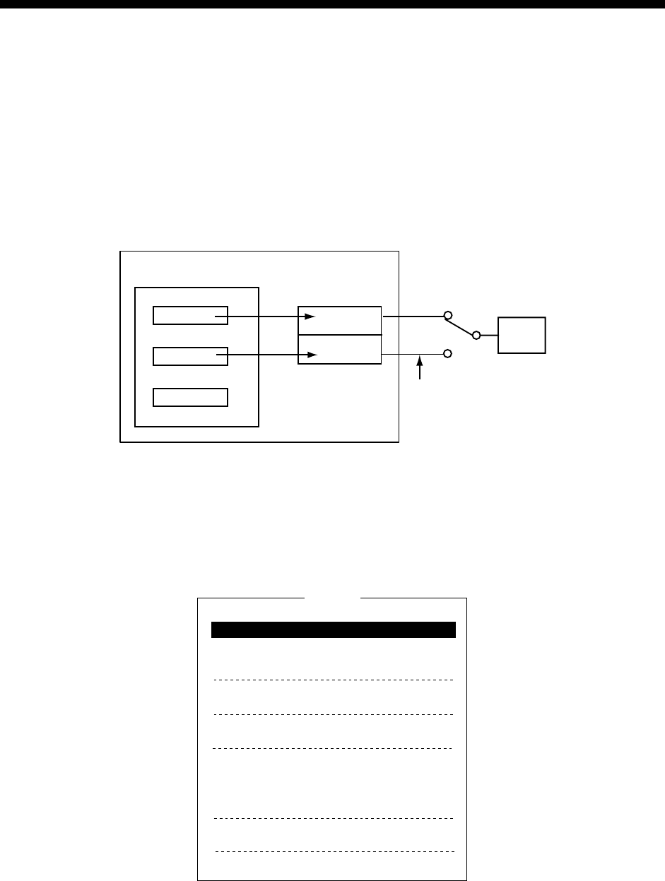
10-1
10 NBDP FILE OPERATIONS
This chapter mainly describes how to create, save, open, edit and print files. The Edit menu
provides a full lineup of editing facilities, including search and replace.
10.1 Opening and Closing Files
To create a telex message you will need to make a new file, which you do with the File
Open command. When you open a new file it is placed (opened) in one of two working
areas. When both working areas are occupied you must close a file to open a new file. This
is done with the File Close command.
Floppy Disk Memory
File 1
File 2
File 3
1
2
Display Unit's
Memory
(Working area)
Display
One of
two
Switchable from
"Change Text" on
Edit menu
How a file is opened
10.2 Creating Files
1. Press the function key [F1] to display the File menu.
1: New
2: Open
3: Close
4: Delete
5: Rename
6: Real Time Printing
7: File to Print
8: Cancel Printing
9: Clear Buffer
0: Floppy Disk Format
File
File menu
2. Press the [1] key to choose New. The title bar shows UNTITLED 1 or UNTITLED 2. The
cursor marks the location where you may type text.
10 NBDP FILE OPERATIONS
10-2
Note: When two working areas have been opened, the close confirmation window
appears. See paragraph 10.3.2 below. In this case, choose Yes or No and press
the [Enter] key to close an open file in order to open another file.
3. Type your message.
Note: Do not use lower case letters, or the symbols #, &, *, $ and % in telex messages.
Also, do not put “$$$” in the middle of a TX message, but at the end. The
communication line is automatically disconnected when this string is detected.
10.3 Saving a File
Use only 2HD type floppy disks.
Insert floppy disk with care. Rough
handling can destroy the
information stored inside. To eject a
disk, press the eject button on the
right side of the floppy disk drive
and then remove the disk. Do not eject a disk while the operating lamp is lit; the contents of
the disk may become damaged.
10.3.1 Formatting floppy disks
Before you can save a file to a floppy disk, the disk must be formatted. Formatting prepares
the disk for use in the system.
1. Press function key [F1].
2. Press the [0] key to choose Floppy Disk Format.
3. Press the [↑] key to choose Yes.
4. Press the [Enter] key.
5. Insert a new floppy disk in the disk drive and press the [Enter] key. After the formatting
has been completed you are asked “Format another (Y/N)?” Press [N] and [Enter] to
quit.
10.3.2 Saving a file
1. Press the function key [F1] to display
the File menu.
2. Press the [3] key. The screen should
look something like the illustration at right.
Close text screen
3. Yes is selected; press the [Enter] key. Enter file name, using up to eight characters.
You may use any alphabet or numeric on the keyboard. But you may not use the symbols
shown below. You may add an extension at the end of the file name, for example, .TXT, to
distinguish text files from macro files.
| : " > < ;
!
4. Press the [Enter] key.
Hole opened: Write protect
Write-protect Tab
Write-Protect Tab
Save file ?
( UNTITLED1 )
Close Text
Yes
No

10 NBDP FILE OPERATIONS
10-3
10.4 Editing Files
10.4.1 Cutting and pasting text
You can delete, move and copy text by using the Cut, Copy and Paste functions in the Edit
menu.
1: Undo
2: Cut
3: Copy
4: Paste
5: Select All
6: Search
7: Replace
8: Goto Top
9: Goto Bottom
0: Goto Line
A: Change Text
Edit
Edit menu
Cutting text
1. Place the cursor on the first character of the text to be cut.
2. Highlight the text to be cut by pressing and holding the [Shift] key while pressing the [→].
If you highlight text which you do not want to cut, press the [←] to adjust the highlight.
<[1]UNTITLED1>
CONGULATULATION ON YOUR CHOICE OF DP-6
INMARSAT B MOBILE EARTH STATION.
WE ARE CONFIDENT THAT YOU WILL ENJOY MANY YEARS OF
OPERATION WITH THIS FINE PIECE OF EQUIPMENT
The highlight
3. Press the function key [F2] and the [2] key, or the [Delete] key. The highlighted text is cut
and the remaining text is reformatted.
If you make a mistake, you can restore the text by immediately selecting Undo from the Edit
menu.
Pasting text
To paste the cut text to a new location, do the following:
1. Place the cursor at the exact spot in the message where the cut text is to start.
2. Press the function key [F2] and the [4] key, or the [Insert] key.
10 NBDP FILE OPERATIONS
10-4
10.4.2 Copying and pasting text
You may copy a portion of text and paste it elsewhere.
1. Choose the text to copy. (See “cutting text" above for the procedure.)
2. Press the function key [F2] and the [3] key.
The text selected is copied to the paste buffer memory where the cut or copied text is stored.
The display returns to the normal screen.
3. Place the cursor at the exact spot in the message where the copied text is to start.
4. Press the function key [F2] and the [4] key.
10.4.3 Select all
The Select All feature lets you select all of the file currently displayed. This feature can be
useful when you want to combine files. The procedure below explains how to place the file
loaded in working area 1 onto the end of the file loaded in working area 2.
1. Load the file to be copied from a floppy disk in working area 1.
2. Press the function key [F2] and the [5] key. The entire file appears in inverse video.
3. Press the function key [F2] and the [3] key. The file is placed in the paste buffer memory.
4. Load the file to be combined in working area 2.
5. Place the cursor at the exact spot in the message where the text now in the paste buffer
memory is to start and press the [Insert] key.
Floppy
Disk
Working
Area 1
Working
Area 2
Paste
Buffer
Memory
Open
file
Open
file
Transfer
(copy)
Paste (Combine)
1
3
2
4
Holds cut or
copied text
Copy and paste flow diagram
10.4.4 Searching text
The Search feature lets you search for text in a forward or backward direction.
1. Display a text and press the function key [F2] and the [6] key. The Search display
appears.
Forward
Search
Search string :
To quit: ESC
Backward
Dir
Search screen

10 NBDP FILE OPERATIONS
10-5
2. Type the word you want to find. Use the Choose Forward or Backward to search the file
in a forward or backward direction respectively from the cursor position. Press the
[Enter] key to begin the search.
When the unit finds the word, the cursor stops at the first character of the word. Press the
[Enter] key to continue the search. If the string could not be found, the message “Not Found
(To quit: ESC)” appears. Press the [Esc] key to quit.
10.4.5 Replacing text
The Replace feature helps you replace every occurrence of a word or phase with another
word or phase in a file.
1. Press the function key [F2] and the [7] key. The Replace display appears.
Replace
Search string :
Replace with :
To quit: ESC
Forward
Forward
Backward
Dir
Query
All
Mode
Replace screen
2. Type the word you want to replace on the "Search string" line.
3. Press the [↓] key to choose "Replace with." Type the new word.
4. Use the [↑] or [↓] key to choose Forward or Backward to search the file in a forward or
backward direction respectively from the cursor position.
5. Use the [↑] or [↓] key to choose whether you want to be queried or not each time the
word is found.
Query: Stop at each occurrence of word to answer yes or no to replacement.
All: Replace every occurrence of word without stopping to confirm.
6. Press the [Enter] key to start the replacement.
10.4.6 Goto line
The Goto line feature places the cursor at the head of a line desired.
1. Press the function key [F2] and the [0] key. The following display appears.
Goto Line
Jump to Line No. :
Goto line screen
2. Key in line number and press the [Enter] key. The cursor shifts to the head of the line
selected.

10 NBDP FILE OPERATIONS
10-6
10.4.7 Goto top, Goto bottom
You can easily go to the top or bottom line of a file. Press [F2], [8] to go to the top line; press
[F2], [9] to go to the bottom line. Note that this feature can also be executed on the editor
screen by pressing the [Home] key while pressing the [Fn] key.
10.5 Opening Files
Two working areas (called working area 1 and working area 2) are provided to which you
can load a file, and one file may be displayed on the LCD.
10.5.1 Opening a file
1. Insert the floppy disk which contains the file you want to open.
2. Press the function key [F1] to display the File menu.
3. Press the [2] key. A chronological list of files on the floppy disk appears.
Open Text
Load/Merge(TAB:Change)
[B:\TEST1. ]
File name Size Date & Time
LOG File 52 02-10-15 17:25
TEST1. 120 02-10-15 16:30
TEST2. 151 02-10-15 9:25
TEST3. 180 02-10-15 20:16
NBDP 169 02-10-15 6:23
[ End of Directory ]
4 Files exist 1454000 bytes free
To select : ENTER To view : SPACE To quit : ESC
4. Use the [↑] or [↓] key to choose a file.
5. Press the [Enter] key.
The file appears and the title bar shows the file name. You may repeat this procedure to
load another file into a working area.
Note: When two working areas have been opened, the close confirmation window appears.
In this case, choose Yes or No and press the [Enter] key to close an open file in order
to open another file.
10.5.2 Switching between files
Two files can be opened and one displayed on the LCD. To switch between files do the
following:
1. Press the function key [F2].
2. Press the [A] key to switch between files.
10 NBDP FILE OPERATIONS
10-7
10.6 Renaming Files
To rename a file, do the following:
1. Press the function key [F1].
2. Press the [5] key.
3. Use the [↑] or [↓] key to choose a file and press the [Enter] key.
4. Enter a new name.
5. Press the [Enter] key.
10.7 Saving a File Under a New Name
You may save a file under a new name as follows:
1. Open a file.
2. Edit the file as necessary.
3. Press the function key [F1].
4. Press the [3] key to save the file.
5. Press the [Y] key.
6. Press the [Backspace] key to erase the original name and then enter a new name.
7. Press the [Enter] key.
10.8 Deleting Files
Insert appropriate floppy disk in the drive and do the following to delete unnecessary files.
1. Press the function key [F1].
2. Press the [4] key.
3. Use the [↑] or [↓] key to choose the file to delete and then press the [Enter] key.
4. Press the [Enter] key again. (To cancel, press the [↓] key to select NO followed by the
[Enter] key.)
10.9 Real Time Printing
An incoming or outgoing message can be printed out while it is being received or
transmitted.
1. Press the function key [F1] to display the File menu.
2. Press the [6] key to turn real time printing on/off.
“Print” appears in reverse video at the top of the display.
10 NBDP FILE OPERATIONS
10-8
10.10 Printing Files
You can print files stored on floppy disks as follows:
1. Press the function key [F1].
2. Press the [7] key.
3. Use the [↑] or [↓] key to choose a file and press the [Enter] key.
4. Press the [Y] key.
To stop printing at any time, press [F1] and [8] keys.
If the file could not be printed, "Cannot print. Check connection between printer and terminal.
Press any key to escape." is displayed.

11-1
11 NBDP TRANSMITTING,
RECEIVING
This chapter mainly shows you how to transmit and receive telex messages.
11.1 Manual Calling
NOTICE
Before calling, watch the intended TX
frequency carefully to confirm that is
unoccupied.
The simplest way to communicate with a telex subscriber is Manual Calling. For the ARQ
mode, you may display beforehand the message to send, or type your message manually.
1. Press the function key [F3] to display the Operate menu.
1: Call Station
3: File to Send
4: Cancel Sending
5: Scan (Start/Stop)
6: Manual Reception
7: Timer Operation
8: Manual Calling
9: Set Frequency
Operate
2: Macro Operation
Operate menu
2. Press the [9] key to choose Set Frequency.
Set Frequency
Tx Freq: 0.00
RX Freq: 0.00
Set frequency screen
3. Input Tx and Rx frequency pair.
4. Press the [Enter] key.
11 NBDP TRANSMITTING, RECEIVING
11-2
5. Press the function key [F3] again and then the [8] key to choose Manual Calling. The
following screen appears.
Mode : ARQ FEC
ID :
Manual Calling
Manual calling screen
6. Use the [←] or [→] key to choose appropriate communication mode.
7. Press the [↓] key and input party's ID number.
1. Press the [Enter] key to connect the communication line. “Channel Busy Check” appears
to inform you that the equipment is checking if the line is busy. If the line is free,
“Connect”, “Send” and “Lock” appear in highlight as below. Further, “HT” (High Tension)
also appears when the line is connected.
Station Name :
Frequency (T/R) : 8765.00 / 8965.00(kHz) Comm Mode :ARQ
Comm Status : Connect Send Lock Error
Sending Volume : 100(%) ARQ Error : 0 ARQ Time : 0(sec)
Caps-Eng
1:File 2:Edit 3:Operate 4:Window 5:Station 6:System 7:WRU 8:HR 9:Over 10:Break
2002-09-08 2:14:28 UTC
HT
For ARQ mode, go to step 9. For FEC mode, type your message and go to step 13.
9. Press the function key [F7] (WRU). The party's answerback code appears on the screen.
Note: Step 9 and 10 are needed for ship-to-ship calling only.
10. Press the function key [F8] (HR). Your ship's answerback code is sent to the party.
11. Press the [Enter] key and type your message.
12. If you want to receive other party's response, press the function key [F9] (Over).
13. Press the function key [F10] (Break) to disconnect the line.
11 NBDP TRANSMITTING, RECEIVING
11-3
11.2 ARQ Mode Operation
In ARQ operation, one station (information sending station) sends data to another block by
block, then listens for the acknowledge signal between blocks from the information
receiving station which requests either the next block or retransmission of the last block if
there is error. The request may be repeated up to 32 times, until the complete block is
received free of error.
Establishing connection
1. Press the function key [F3] to display the Operate menu.
1: Call Station
3: File to Send
4: Cancel Sending
5: Scan (Start/Stop)
6: Manual Reception
7: Timer Operation
8: Manual Calling
9: Set Frequency
Operate
2: Macro Operation
2. Press the [1] key to choose Call Station.
Caps-Eng
Station Name : CHOUSHI-8M
Frequency (T/R) : 8765.00 / 8965.00(kHz) Comm Mode :AQW
Comm Status : Connect Send Lock Error Mark Space
Sending Volume : 100(%) ARQ Error : 0 ARQ Time : 0(sec)
2002-01-15 14:41:09 UTC
Call Station
Station List
ABC-4M
ABC-6M
ABC-12M
ABC-8M
FURUNO
Station Setup
Station : ABC-4M
ID Code : 45678
Mode : ARQ FEC
CH/Table : Channel Scantable
Num/Table:
1:File 2:Edit 3:Operate 4:Window 5:Station 6:System 7:WRU 8:HR 9:Over 10:Break
Call Station menu
3. Choose a station. (Station must be registered for use in the ARQ mode). Press the
[Enter] key. The message "Calling Station" appears. If the message "Station calling
suspended. Check radio and interconnections. Press any key to escape." appears,
check both the power of the radiotelephone and the connections between the
radiotelephone and the NBDP Terminal Unit.
4. When an acknowledge signal is detected, "Connect" appears in reverse video on the
communication status display (see below).
Note: If signal conditions are poor, connection may take a while. If the line could not be
connected in one minute, calling stops and "Calling failed" appears. Try step 3
again, one minute later. Should signal conditions worsen during message
transmission, "Error" appears in reverse video and 30 seconds later the line is
disconnected.

11 NBDP TRANSMITTING, RECEIVING
11-4
5. Transmit message by one of the following methods:
Sending a file stored on a floppy disk
a) Press the function key [F7] (WRU) to receive the answerback code of the other
station. Verify that the code from the station called is correct.
b) Press the function key [F8] (HR) to transmit your own identity (answerback code).
c) Press the function key [F3] and then the [3] key to display the Send screen. Choose
file to send and press the [Enter] key. Press the [Enter] key again, and “Send”
appears in reverse video while the file is being transmitted.
[B:\TEST1. ]
File name Size Date & Time
LOG File 52 02-10-15 17:25
TEST1. 120 02-10-10 16:30
TEST2. 151 02-10-11 09:25
TEST3. 180 02-10-11 20:16
NBDP 169 02-10-12 06:23
[ End of Directory ]
4 Files exist 1454000 bytes free
To select : ENTER To view : SPACE To quit : ESC
Send File
Send file screen
Sending volume (percentage of message transmitted, counts upward as the message is
being transmitted), ARQ error count and ARQ transmission time appear on the display.
“Lock” appears in reverse video when the mark and space signals in the receive signal are
normal. “Sending Volume” shows what percentage of the message has been sent. “ARQ
Error” shows the number of times error was found during transmission. “ARQ Time” is the
time in seconds the communication line has been established.
Station Name :
Frequency (T/R) : 8765.00 / 8965.00(kHz) Comm Mode :ARQ
Comm Status : Connect Send Lock Error
Sending Volume : 100(%) ARQ Error : 0 ARQ Time : 0(sec)
Caps-Eng
1:File 2:Edit 3:Operate 4:Window 5:Station 6:System 7:WRU 8:HR 9:Over 10:Break
2002-09-08 2:14:28 UTC
HT
Communication status display
Type a message from the keyboard
After exchanging answerback code by the function key [F7] (WRU) and [F8] (HR), type your
message directly from the keyboard.
a) To change direction of traffic, press either function key [F9] (OVER), or [+] and [?]. Then,
the other station becomes the information sending station, your station the information
receiving station.
b) Receive a message from the sending station, if any.
c) After completion of communication, press the function key [F7] (WRU) key to receive the
answerback code of the other station and then press the function key [F8] (HR) to
transmit your own answerback code.

11 NBDP TRANSMITTING, RECEIVING
11-5
Stopping transmission
1. Press the function key [F3] and then the [4] key. “Canceled Sending” appears on the
screen. Transmission is stopped but the line is still connected.
2. To disconnect the line, press the [F10] key.
11.3 FEC Mode Operation
The FEC mode transmits the same data twice to yield less errors. Compared to the ARQ
mode, the FEC mode is better at communicating with weak signals.
1. Press the function key [F3].
2. Press the [1] key to display the Call Station menu.
3. Choose a station which is registered for the FEC mode. Press the [Enter] key.
“CONNECT” appears in reverse video.
4. Transmit a message directly from the keyboard, or do the following to transmit a
message stored on a floppy disk:
Press the function key [F3] and the [3] key to choose File to Send. Choose file to send and
then press the [Enter] key.
5. After the message is transmitted, press the function key [F10] (Break) to disconnect the
line.
11.4 Choosing Receive Mode
1. Press the function key [F3] and then the [6] key.
2. Choose receive mode:
AUTO: Automatic reception in ARQ or FEC mode
ARQ: International radiotelex ARQ mode
FEC: International radiotelex FEC mode
DIRC: Receive message from teleprinter
3. Press the [Enter] key. The reception mode appears on the screen.
All received (and transmitted) messages are saved to a floppy disk when "TX/RX Msg
Save" is ON in the System menu. The file is automatically named as follows.
02 01 13 0 0. X X X
Year datemonth Serial number from 000

11 NBDP TRANSMITTING, RECEIVING
11-6
11.5 Communication Example
Call the coast station following the procedure in paragraph 11.2. Then, communicate with
the coast station. Below is a communication example.
12345 KOBE X
1480 HKRDO VRX
MOM
GA+?
OPR+
MOM
1480 HKRDO VRX
12345 KOBE X
KOBE DE HKRDO GOOD MORNING
NW NIL QRV GA+?
GM NW QTC1+?
QRV K GA+?
TOR Teleprinting Over Radio
(Message TX starts.)
Msg No.
KOBE DE HKRDO QSL NR9004
TKS NW NIL +?
TKS NW NIL BIBI +?
TKS SEE YOU LATER
BIBI
KKKK QSL +?
End message.
NR 9004
TO: TELEX 1234567 FURUNO
JAPAN OFFICE
INT. DEP. SEC-1 MANAGER
FM: KOBE MARU/12345 KOBE X
TEXT:Type message.
If this is your first
communications with a
particular coast station,
the coast station asks
for you selcall no. ship
name, call sign and
AAIC (your enterprises
name for which to
charge to charge toll
call. That registers you
with the coast station.
Thereafter, if your
answerback code is
correct automatic
transmission is possible.
Coast station disconnects the line.
Selcall No. Ship name or call sign
Own answerback code
Automatically sent from Coast
station (ex. Hong Kong)
Type at your side
(GM=Good Morning. I have
a message for you.)
Receiver: Telex no.1234567
FURUNO ELEC. CO.
Sende: KOBE MARU
Type message
Message finished. Can you
acknowledge receipt)
From coast station
From HKRD0 to KOBE.
Received NR9004. Thank you.
No more to send.
Type at your ship
(Thank you. I have nothing to
send. Bye Bye.
From coast station
Thank you. See you later.)
From coast station.
(Send your message.)
Type at your side
(To send a message file, type
MOM before TOR and wait
awhile.)
Type at your side within 30 s.
(Call operator manually.)
Message from coast station
(Wait. From HKRDO to KOBE.
Nothing to send. Do you
have anything to send?)
Call completed,
connected with
coast station
To send message
to ship
Communications example

11 NBDP TRANSMITTING, RECEIVING
11-7
Table of abbreviations
noitaiverbbAnoitseuQecivdArorewsnA
ARQ?noitatsruoyemanehtsitahW.····sinoitatsymfoemanehT
CRQehteraesirpretneetavirptahwyB noitatsruoyrofsegrahcrofstnuocca ?delttes
deltteseranoitatsymrofstnuoccaehT .····esirpretneetavirpehtyb
URQ?emrofgnihtynauoyevaH.uoyrofgnihtonevahI
VRQ?ydaeruoyerA.ydaermaI
XRQ?niagaemllacuoylliwnehW no[sruoh····taniagauoyllaclliwI .]zHk····
JSQ·otdetcellocebotegrahcehtsitahW ?egrahclanretniruoygnidulcni··· ····otdetcellocebotegrahcehT ····siegrahclanretniymgnidulcni .····snarf
LSQ?tpieceregdelwonkcauoynaC.tpieceregdelwonkcanacI
XSQno]ngisllac[····otnetsiluoylliW ?zHk···· no]ngisllac[····otgninetsilmaI .zHk····
ATQ?····rebmunegassemlecnacIllahS····rebmunegassemlecnaC
CTQotuoyevahsegassemynamwoH ?dnes .uoyrofegassem····evahI
UTQsinoitatsruoysruohehteratahW ?nepo ····ot····morfneposinoitatsyM .sruoh
noitaiverbbAnoitinifeD
KB.ssergorpnoissimsnartatpurretniotdesulangiS
MFCmrifnoC
ED"····morF"
K.timsnartotnoitativnI
LIN.uoyotdnesotgnihtonevahI
WNwoN
ESPesaelP
RdevieceR
FER.····otecnerefeR
CVS.margeletecivresagnitacidnixiferP

11 NBDP TRANSMITTING, RECEIVING
11-8
Command and abbreviation
dnammoCnoitcnuF
+MGT.margeletoidarasiegassemgniwollofehttahtetacidnioT
+GSM .dlehegassemynayletaidemmidetcennocebotsdeennoitatspihsehttahtetacidnioT
+RPO.rotarepollaC
+GRU.egassemssertsiddnaycnegru,ytefaS
+DEM.ecivdalacidemtseuqeR
+TSET .noitatspihsehtgnikcehcrofegassemtsetadnesotnoitatstsaoctseuqeR
+KRB.noitatstsaocehthtiwnoitcennocehtraelcoT
noitaiverbbA
+AG.dnammocruoytimsnarT.ydaermaI
MOM.tnemomatiaW
+GSM.erohsehtmorfsegassemgnidneptseuqeR
NNNNroKKKK.egassemaetanimreT
11.6 Timer Operation
A built-in timer permits automatic transmission and reception of telex messages.
11.6.1 Enabling timer operation
1. Press the function key [F3] to display the Operate menu.
2. Press the [7] key to display the Timer Operation List.
3. Choose the operation (name) you wish to execute. Press the [Enter] key. An asterisk
appears beside the operation selected and "T. Op" appears in reverse video on the
communication status display. If a file stored on a floppy disk is to be sent, be sure the
floppy disk containing the file is inserted in the drive.
*1
2
3
OP4
OP5
Timer Operation List
Timer operation list
4. Choose another operation (name) if desired.
5. Press the [Esc] key.

11 NBDP TRANSMITTING, RECEIVING
11-9
When the predetermined time comes, the NBDP Terminal Unit automatically sends or
receives the message. The results of timer operation are displayed as either OK or NG (No
Good) on the Timer Operation List.
*1
2
*3
*OP4
*OP5
OK
OK
OK
NG
Timer Operation List
Timer operation list
11.6.2 Stopping timer operation
1. Press the function key [F3].
2. Press the [7] key.
3. Choose the operation (name) which has an asterisk attached to it and then press the
[Enter] key. Remove all asterisks to cancel all timer programs.
11.7 Scanning
The radio equipment scans a group of operator-selected frequencies (channels), and stops
scanning when an signal is received. For registering scan group, see paragraph 9.5.
1. Press the function key [F3] and then the [5] key to show the Scanning Group List on
your screen.
You can confirm the scan channel by pressing the [↑] or [↓] key while pressing the [Shift]
key.
*1
2
3
Scanning Group List
Scanning group list
2. Choose a scan group and press the [Enter] key.
3. The scanning starts and the indication "Scan" appears in reverse video. Further, the
name of the scan group appears in the Station Name field.
2002-09-08 2:01:46 UTC Caps-Eng
1:File 2:Edit 3:Operate 4:Window 5:Station 6:System 7:WRU 8:HR 9:Over 10:Break
Station Name : SAITO-1 Scan HT
Frequency (T/R) : 8344.00 / 8705.00(kHz) Comm Mode : Auto
Comm Status : Connect Send Lock Error
Sending Volume : 100(%) ARQ Error : 0 ARQ Time : 0(sec)
Communication status display
4. To stop scanning, press the function key [F3] and then the [5] key. “Scan” appears in
normal video on the communication status display.
11 NBDP TRANSMITTING, RECEIVING
11-10
11.8 Communication Buffer
The communication buffer is a temporary memory which stores transmit and receive
messages. To display the contents of the communication buffer, do the following:
1. Escape from the message creation screen.
2. Press the [PgDn] or [PgUp] key. The contents of the communication buffer are
displayed.
To print them, press the [Ctrl] and [P] keys simultaneously. To erase the contents from the
screen, press the [PgDn] key while pressing the [Fn] key.
To erase the contents of the buffer, press the [F1] and [9] keys.
11.9 Preparing Macrofiles for Automatic Telex
11.9.1 Automatic telex overview
This section shows you how to communication with a coast station which handles automatic
telex transmission, using macrofiles. You will also need to register communication channels
and stations, and prepare macrofiles.
Coast stations using automatic telex are MCI Marine Services (North America), Sydney
Radio (Australia), Lyngby Radio (Denmark), and others. The procedure is mostly common
to all coast stations, however refer to the coast station’s traffic manual for details.
STORE-AND-
FORWARD
DIRECT
DIALING
MULTI-
ADDRESS
INTERNATIONAL
TELEX NETWORK
CENTRAL
SYSTEM
SYSTEM
CONTROL
SUB-STATION
SHIP
Sample automatic telex network
The service available in automatic telex are
•
Message transfer between ship and coast station (store-and-forward)
•
Connection with landline telex (direct dialing)
•
Multi address.

11 NBDP TRANSMITTING, RECEIVING
11-11
11.9.2 Preparations
To use automatic telex, you will need to register three items:
•
Answerback code
•
Scan groups
•
Station names
Registering answerback code
The coast station assigns a Telex number. This number functions as an answerback code.
An answerback code contains the following:
OOOOO SHIP X
OOOOO: Coast station-assigned five-digit telex code
SHIP: Ship name
X: For shipboard station, normally X is entered.
The procedure for registering the answerback code is the same as which appears on page
9-1. If an answerback code was registered before the commissioning of the coast station, a
new answerback code must be entered. To enter a new answerback code, contact
FURUNO or an authorized FURUNO agent or dealer.
Registering scan groups
The central system emits a free-signal to indicate a coast station radio channel is in idle
condition and available for ship-to-shore calls. The free-signal is detected and recognized
by the shipboard equipment as a permission to start the transmission. Then, the shipboard
operator initiates a call.
You can scan search for the free-signal automatically by registering coast station radio
channels in scan group(s). The procedure for registering scan groups for coast station use
is the same as that which appears on page 9-7.
Registering stations
The next step is to enter station name. The procedure is the same as that shown on page
9-3.

11 NBDP TRANSMITTING, RECEIVING
11-12
11.9.3 Commands
The tables which follows describe the commands for macro operation
Command
(Prefixed with @) Parameter Content
CALL S: Station Name Calling station name and ID on assigned
parameter
Two digits, 0-99 min. Free-signal searching time according to
assigned parameter (default setting: 10
min)
FREE (support
command for CALL)
$RRR$ signal Detect free signal of dot pattern
RETRY (support
command for CALL)
Two digits, 0-99 min. Calling according to assigned parameter
(default setting: 10 min)
CASE Text
For receiving a message (designated by
parameter) transmitted by coast station
TIMEOUT (support
command for CALL)
Two digits, 0-99 min. Time allotted for reception of message by
CASE command
Text Text transmitted according to assigned
parameters
SEND
B file name Send a file from floppy disk
WRU
HR
OVER
BREAK
None Function keys F7 – F10
DISPLAY Text Text of message appears
INPUT None
Waiting for keyboard input
Transmit keyboard input message
Commands processed by Danish coast station Lyngby
Command Function
BRK+ Disconnection communications line
DIRTLX ……+ Direct dialing telex (receive only)
KKKK Terminate message
LTR+ For telex letters mailed from Operations Station to destinations worldwide
MED+ Request medical advice
OPR+ Requesting operating assistance
POS+ Send position data
STA+ Status requested on a store-and-forward message
TLX ……+ Store-and-forward method
For details, consult the coast station’s traffic manual.

11 NBDP TRANSMITTING, RECEIVING
11-13
11.9.4 Store-and-forward method
The following is the sequence of events in transmission of a file by the store-and-forward
method.
1. Shipboard station sends message to coast station.
2. Coast station stores message in memory buffer.
3. Shipboard station and coast station clear the radio circuit.
4. Coast station sends message to subscriber designated.
Actual procedure for store-and-forward telex
.oN erudecorP yalpsiD skrameR
1.a coast station.llaCsraeppaTCENNOC oedivesreverni .)sdnuosllebdna(
;dnuoflangis-eerF .ydaertiucricoidar
2.langisURWtimsnarT 00190 TLG DK XPIHSXXX62 ?+AG
ytitnedilaitinI tsaocneewtebegnahcxe draobpihsdnanoitats noitats
3.rebmunxeleTs'rebircsbusniyeK 54321)gnoKgnoH(:elpmaxE
+54321208XLT ?+GSMtratsottseuqeR noissimsnartegassem
4.eliftimsnarT noissimsnartegasseM
5,detelpmocsinoissimsnartnehW .KKKKepyt XPIHSXXX62
00190 TLG DK
?+AG
ruoytimsnarT .edockcabrewsna
6otdnammocKAERBtimsnarT .tiucricoidarraelc
Receive other party's
answerback code.
11 NBDP TRANSMITTING, RECEIVING
11-14
Procedure for preparing a macrofile for store-and-forward method
You will need a macrofile to enable automatic message transmission by store-and-forward
method. After preparing it, save it to a floppy disk for future use.
1. Press function key [F1] to display the File menu.
2. Press the [1] key.
3. Prepare macrofile. Below is simple example.
< [1] UNTITLED1 >
@FREE $RRR$
@CALL S:LYNGBY RADIO
@WRU
@CASE GA+?
@SEND TLX80212345+
@CASE MSG+?
@SEND B:ABC
@SEND KKKK
@CASE GA+?
@SEND BRK+
1
2
3
4
5
1 Search dot pattern free signal until it is found
2 Station name (Example: LYNGBY RADIO)
Who are you?
Station identity exchange
3 Subscriber's Telex number (in example, 802 is country
code of Hong Kong) for store-and-forward method
4 Location and name of file message
5 Request for termination of message
Sample macrofile for store-and-forward method
4. Press function key [F1] to display the File menu.
5. Press the [3] key. The Close Text appears on the display.
close Text
Save File?
(UNTITLED 1)
No
Yes
Close text prompt
11 NBDP TRANSMITTING, RECEIVING
11-15
6. Press the [Enter] key and enter a file name as follows:
OOOOOOOO.MCR
↑ ↑
File Name Extension Name
(max. 8 characters)
7. Press the [Enter] key.
DIRTLX macrofile
Sample DIRTLX macrofile
@FREE $RRR$
@CALL S: LYNGBY RADIO
@WRU
@CASE GA+?
@SEND DIRTLX725644325+
@CASE MSG+?
@SEND B:ABC
@SEND KKKK
@CASE GA+?
@SEND BRK+
1
2
3
4
5
1 Search dot pattern free signal until it is found
2 Station name (Example: LYNGBY RADIO)
Who are you?
Station identity exchange
3 Subscriber's Telex number (in example, 72 is country
code of JAPAN) for direct dialing mode
4 Location and name of file message
5 Request for termination of message
Sample DIRLTX macrofile

11 NBDP TRANSMITTING, RECEIVING
11-16
Procedure for DIRTLX
.oN erudecorP yalpsiD skrameR
1.a coast station.llaCsraeppaTCENNOC oedivesreverni .)sdnuosllebdna(
;dnuoflangis-eerF .ydaertiucricoidar
2.langisURWtimsnarT 00190 TLG DK XPIHSXXX62 ?+AG
ytitnedilaitinI tsaocneewtebegnahcxe draobpihsdnanoitats noitats
3.rebmunxeleTs'rebircsbusniyeK
Example: (Japan) 5644325
tratsottseuqeR noissimsnartegassem
4.eliftimsnarT noissimsnartegasseM
5,detelpmocsinoissimsnartnehW .KKKKepyt
XPIHSXXX62
5644325 FURUNO J
00190 TLG DK
DURATION ...
TIME ...
GA+?
ruoytimsnarT .edockcabrewsna
6otdnammocKAERBtimsnarT .tiucricoidarraelc
Receive other party's
answerback code.
DIRTLX725644325+ 12:20
MOM
5644325 FURUNO J
MSG+

11 NBDP TRANSMITTING, RECEIVING
11-17
11.10 Automatic Telex using Macrofile
This section describes how to transmit a telex message using a macrofile.
Basic procedure
1. Register answerback code (Telex number assigned by coast station).
2. Register coast station frequency and channel to scan group.
3. Register station name including scan group name.
4. Retrieve appropriate macrofile. Include station name and message file name. Type
message and save file to memory.
5. Open macro operation menu and select a macrofile. (See next page for details.) Your
message will be transmitted automatically. Below is the sequence of automatic
message transmission to a coast station.
a) Search for free-signal
b) Call coast station on one of its radio channels
c) After connection is established, identity exchange
d) Transmission of service category and subscriber’s address
e) Transmission of message
f) Transmission of termination of message signal
g) Identity exchange
h) Clearing of radio circuit
Actual procedure
1. Press function key [F3] to display the Operate menu.
1: Call Station
3: File to Send
4: Cancel Sending
5: Scan (Start/Stop)
6: Manual Reception
7: Timer Operation
8: Manual Calling
9: Set Frequency
Operate
2: Macro Operation
Operate menu
2. Press the [2] key to display the Call Macro screen.
11 NBDP TRANSMITTING, RECEIVING
11-18
Call Macro
[B:\TEST1. ]
File name Size Date & Time
LOG File 52 02-10-15 17:25
TEST1. 120 02-10-10 16:30
TEST2. 151 02-10-11 09:25
TEST3. 180 02-10-11 20:16
LYNGBY1.MCR 169 02-10-13 06:23
[ End of Directory ]
4 Files exist 1454000 bytes free
To select : ENTER To view : SPACE To quit : ESC
Call macro screen
3. Press the [↓] key to choose a macrofile.
4. Press the [Enter] key.
Call Macro: Lyngby1.MCR
Call OK? No
Yes
5. Press the [Enter] key to confirm the macrofile selected. The Wait for Free Signal
indication appears. Your message will be transmitted automatically.
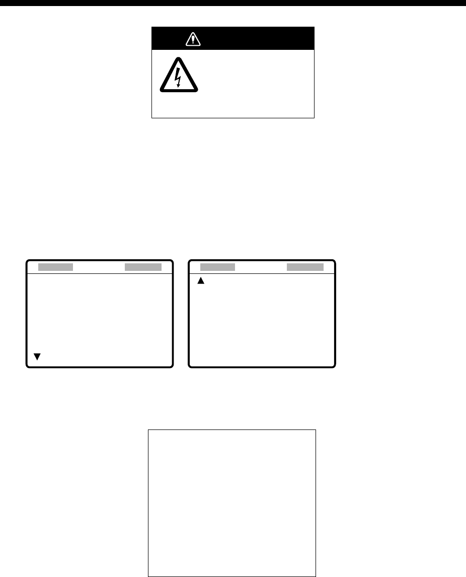
12-1
12. MAINTENANCE &
TROUBLESHOOTING
WARNING
ELECTRICAL SHOCK HAZARD
Do not open the equipment.
Only qualified personnel
should work inside the
equipment.
12.1 Daily Test
Authorities require that the DSC/watch receiver be checked daily for proper operation to
ensure that it will function properly in the event of distress. Execute the daily test as below.
1. At the DSC standby screen, press the [3/TEST] key to start the test.
2. After several seconds the test results, OK, for normal operation, NG for No Good. For
NG (No Good) contact your dealer for advice.
MAIN CPU : OK VER. XX*
PANEL1 : OK VER. XX*
PANEL2*1 : OK VER. XX*
MODEM : OK
NBDP MODEM : OK
** Daily test **
MAR-27-2002-15:24
RCVR1 : OK
RCVR2*1 : OK
TRX : OK
** Daily test **
Page 1 Page 2
*: XX = Version No.
*1: Shown if equipped with
No. 2 control unit.
Test results
3. After the test results
for the items on
page 2 appear, the
audio alarm sounds,
the ALARM lamp
flashes several
times and then page
1 of the daily test is
displayed.
4. If auto printing is
active, the test
results are printed. To manually print the test results, press the [8/PRINT] key. Above is
a sample test results printout.
5. Press the [CANCEL] key to quit the test and return to the DSC standby screen.
Note: TEST on the DSC Setup menu is for used by service technicians.
DAILY TEST
MAR-27-2002-15:24:00
MMSI: 123456789
MAIN CPU: OK VER.**
PANEL1 CPU: OK VER.**
PANEL2 CPU:* OK VER.**
NBDP MODEM: OK VER.**
RCVR1: OK
RCVR2:* OK
TRX: OK
* = PANEL2 CPU, RCVR2
printed if equipped
with no. 2
control unit.
** = Version No.
12 MAINTENANCE & TROUBLESHOOTING
12-2
12.2 Radiotelephone Test
Do the following to check the radiotelephone for proper operation:
1. At the radiotelephone screen, press the [3/TEST] key to start the test. OK or NG (No
Good) appears as the test result for each item checked. For NG, contact your dealer for
advice.
Tx selfcheck
PLL : OK
RF : OK TX FIL : OK
PA : OK COUPL : OK
2. Press the [CANCEL] key to quit the test and return to the previously used screen.
12.3 Antenna Coupler Test
The CPU and the relays which choose capacitors and coils for tuning can be checked. For
qualified technicians only.
DANGER
HIGH TENSION HAZARD
Circuits in the antenna
coupler are still alive at OFF.
Discharge before servicing.
1. Open the antenna coupler cover.
2. Open the shield cover inside the coupler.
3. Turn on the #2 switch of DIP switch S2.
4. Press the TUNE switch in the antenna coupler.
5. 24 LEDs (CR1 to CR24) light one by one every second. Relays trip on with
corresponding LEDs as below.
CR1 ON – K1 ON
CR2 ON – K2 ON
.
.
.
CR22 ON – K22 ON (CR23 not provided)
CR24 ON – K24, K25 ON
6. Turn off the #2 switch of DIP switch S2.
7. Close the cover.
If CPU error is detected, CR1 lights for ROM error, CR2 for RAM error, CR3 for A/D
converter error. (ROM/RAM/ A/D converter is incorporated in the CPU.)
COUPLER BOARD LED
DIP switch S2
behind the shield case
TUNE SWITCH

12 MAINTENANCE & TROUBLESHOOTING
12-3
12.4 Maintenance
Regular maintenance is vital for maintaining performance. Following the procedures below
will help keep the equipment in top operating condition.
Maintenance check points
Item Check Point Remedy/Remarks
Antenna Check for physical damage and corrosion. Replace damaged parts.
Wire
antenna
Check that the antenna is properly spanned
and separated sufficiently from metallic
structures.
If necessary, re-span antenna.
Insulators
for antenna
Check for salt water deposits on insulators.
Check that connection at the lead-in
insulator is tight and rust-free.
Replace damage insulators.
Remove salt water deposits.
Clean with fresh water, then dry.
Remove rust, then tighten bolts
and lock nuts. Cover metallic
surface with sealing compound.
Antenna
coupler
• Check condition of antenna terminal,
ground, coaxial cable and control cable.
• Check that coupler lid and cable glands
are firmly secure.
• Check for physical damage, corrosion
and salt water deposits.
• Tighten loosened
connections.
• Fasten lid firmly and evenly to
prevent water leakage.
• Replace if damaged.
Control
unit
• Check ground connection, control cable,
and external equipment.
• Confirm that there are no objects on the
top of the control unit.
• Remove dust from control unit with soft
cloth.
Note: Do not use chemical cleaners to
clean the display unit; they can remove paint
or markings or deform the equipment.
• Tighten loosened
connections; remove foreign
material from connectors.
• Remove any objects.
• Wipe the LCD carefully to
prevent scratching, using
tissue paper and an LCD
cleaner. To remove dirt or salt
deposits, use an LCD cleaner,
wiping slowly with tissue paper
so as to dissolve the dirt or
salt. Change paper frequently
so the salt or dirt will not
scratch the LCD.
Transceiver
unit
• Check connection at signal cable,
coaxial cable, control cable, power cable,
and navigator.
• Confirm that there are no objects on the
top of the cabinet.
• Tighten loosened
connections; remove foreign
material from connectors.
• Remove any objects.
Power
supply
• Check that the supply voltage at
transmission is within the rated range
(21.6 to 31.2 VDC at the power
connector).
• If not within the range, call for
service. Low voltage may
cause erratic operation.
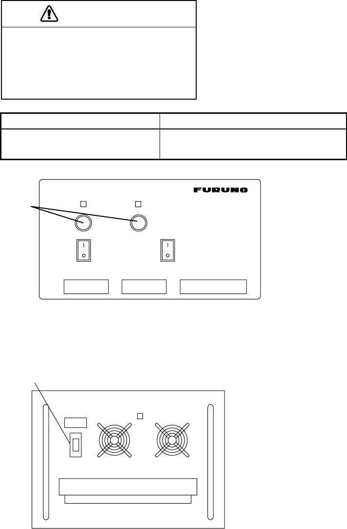
12 MAINTENANCE & TROUBLESHOOTING
12-4
12.5 Replacement of Fuses
To protect the FS-1570 from overcurrent and equipment fault, two fuses are provided in
the PR-300 Power Supply Unit. If a fuse blows, find the cause before replacing it. If it
blows again after replacement, request service.
Use the proper fuse.
Use of the wrong fuse can cause serious
damage to the equipment and void the
warranty.
CAUTION
Unit Fuse
Power Supply Unit PR-300 10 A (100 VAC) or 5A (200 VAC)
and 20 A (24 VDC)
ON
OFF
100V 10A
220V 5A
ON
OFF
125V 20A
AC IN DC IN DC OUT
PR-300
LNG + - +- + -24V
PR-300
FUSE
Note: The Power Supply Unit PR-850A, used with the FS-2570, does not have a fuse but
a circuit breaker. If the breaker has tripped, find the reason before resetting the
breaker (upward position).
POWER
ON
ON
OFF
AC INPUT 50/60Hz DC OUTPUT
BREAKER
PR-850A

12 MAINTENANCE & TROUBLESHOOTING
12-5
12.6 Simple Troubleshooting
The table below provides common problems and the means with which to restore normal
operation. If normal operation cannot be restored, do not attempt to check inside the
equipment. Any servicing should be referred to a qualified technician.
Problem Probable cause Remedy
Power cannot be
turned on. • Mains switchboard may be
off.
• (DC) voltage is too high.
• Battery may have
discharged, or poor contact
at terminals.
• Turn on the mains switchboard.
• Check supply voltage.
• Recharge battery and tighten battery
terminals.
Display
indications do
not appear but
key lamps are lit.
• Contrast is too low. • Operate the [9/ ] key to adjust
contrast.
Power is on but
no sound from
loudspeaker.
• Loudspeaker is off. • Operate the [7/ ] key to turn on the
loudspeaker.
Poor articulation • Wrong class of emission
may be in use.
• Class of emission should match that of
incoming signal.
Output power
reduced to LOW • Power is automatically
reduced to protect against
overheating due to
continuous transmission.
• Wait until the unit returns to normal
condition.
Antenna coupler
cannot tune
antenna
• Antenna may be
disconnected or shorted to
ground.
• Antenna is out of tunable
length.
• Poor grounding of antenna
coupler.
• Breaker in coupler has
tripped.
• Connection cable loosened
or disconnected.
• Check antenna connection.
• Recommended length is 7 to 30
meters.
• Check coupler ground.
• Checks mains voltage and polarity. If
normal, reset breaker.
• Check cable.

12 MAINTENANCE & TROUBLESHOOTING
12-6
12.7 Error Messages
The table below shows error messages and their meanings.
Error messages
Error message Meaning Remedy
Busy: RT Radiotelephone is in
operation.
Wait until the radiotelephone is free.
Channel Busy You attempted to transmit on
a channel which is currently
busy. (This occurs with
Routine and Business
priorities only.)
The message is automatically erased
when the channel becomes clear.
EPFS error No position data from
navigator for one minute.
Press the [CANCEL] key to silence the
alarm. Check the navigator. If it is
malfunctioning, manually enter position.
Incoming Incoming DSC call Message is automatically cleared when
DSC signal has gone.
No position data You attempted to enter
position automatically when
there is no position data.
Check the navigator.
No response: RT Radiotelephone not powered
or has been disconnected.
Check radiotelephone.
Oven cold. Tx not
ready; wait
Oven too cold; cannot
transmit.
Wait until the oven becomes sufficiently
warm.
Printer not ready Automatic printed has been
selected; however, printer is
not powered or has been
disconnected.
Check printer.
Trouble: Oven not
ready
Oven not ready; cannot
transmit.
Wait until the oven is ready.
TRX PLL UNLOCK TRX PLL unlock.
Transmission is stopped.
Check if the reference oscillator is
working and the coaxial cable is tightly
connected.
TUNE error Tuning failed for DSC or
NBDP. Transmission (except
distress) is stopped.
Try to tune again.
Warning: Update
position
Position data is older by the
amount of time preset on the
Alarm menu.
Press the [CANCEL] key to silence
alarm. Reenter position on the Position
menu.
Watchdog error.
Please Power OFF
Internal error (such as CPU
trouble) detected.
Accompanied with alarm,
same type as for distress.
Turn the power off and on to erase the
message. Have a qualified technician
check the set.
WR1 PLL UNLOCK
WR2 PLL UNLOCK
WR1, WR2 PLL unlock.
Transmission is stopped.
Check if the reference oscillator is
working and the coaxial cable is tightly
connected.
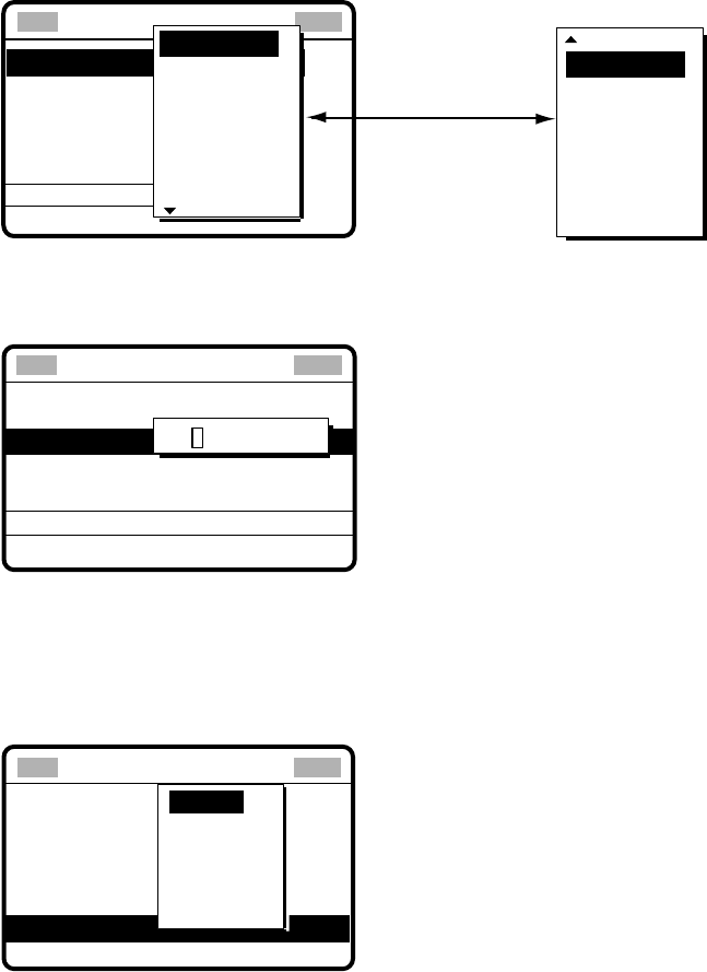
12 MAINTENANCE & TROUBLESHOOTING
12-7
12.8 Test Call
This function sends a test signal to a coast station, over one of six distress and safety
frequencies. For that reason, it should not be executed unnecessarily. You can prepare a
test call beforehand (see Chapter 6) or at the moment you intend to send a test call. To
send a prepared test call, see page 6-9 for the procedure.
1. Press the [2/DSC] key at the DSC standby screen and then push the [ENTER] knob to
open the CALL TYPE menu.
** Compose message **
STATION ID
PRIORITY
COM. TYPE
COM. FREQ
DSC FREQ
: All ships
: Safety
: Telephone
: 2187.5 kHz
CALL TYPE
PSTN CALL
TEST CALL
ALL SHIPS
GROUP CALL
AREA CALL
POSITION
INDIVIDUAL
POLLING
NEUTRAL
MEDICAL
RELAY ALL
RELAY SEL
DISTRESS
Rotate [ENTER]
knob to scroll.
GO
2. Rotate the [ENTER] knob to choose TEST CALL and then push the [ENTER] knob.
3. Push the [ENTER] knob to open the COAST ID menu.
GO TO ALL VIEW
CALL TYPE
PRIORITY
DSC FREQ : 2187.5 KHZ
: TEST
: SAFETY
COAST ID 000000000
** Compose message **
4. Using the numeric keys, key in the ID of the coast station ID (seven digits) where to
send the call and then push the [ENTER] knob.
5. Push the [ENTER] knob to open the DSC FREQ menu. (Note that PRIORITY is
automatically selected to SAFETY.)
DSC FREQ KHZ
CALL TYPE
COAST ID
PRIORITY
: Test
: 001234567
: Safety
: kHz
VIEW
4207.5
6312.0
8414.5
12577.0
16804.5
2187.5
**
Compose message
**
GO TO ALL VIEW
12 MAINTENANCE & TROUBLESHOOTING
12-8
6. Rotate the [ENTER] knob to choose an appropriate frequency and then push the
[ENTER] knob. The display changes as below.
CALL TYPE : TEST
COAST ID : 001234567
PRIORITY : SAFETY
DSC FREQ : 2187.5 KHZ
GO TO ALL VIEW
**
Compose message
**
7. Press the [CALL] key to send the test call (transmission time: about seven seconds).
The display shows "Test call in progress!" while the test call is being transmitted.
Test
call in progress!
DSC FREQ :
2187.5 KHZ
TIME TO GO : 7S
TO COAST :
001234567
SAFETY
8. After the test call has been sent, the following message appears.
Waiting for test
acknowledgement.
DSC FREQ :
2187.5 KHZ
TIME TO GO : 4M12S
FROM COAST :
001234567
SAFETY
9. One of the following displays appears. (“No response! Try calling again?” appears when
the timer counts down to zero, meaning no response from coast station.)
No response!
Try calling again?
DSC FREQ :
2187.5 KHZ
FROM COAST:
001234567
SAFETY
Test acknowledge
call received.
FROM COAST:
001234567
SAFETY
NO INFORMATION
STOP ALARM CALL AGAIN
Test acknowledge received No response to test call
10. Do one of the following depending on the message shown in step 9.

12 MAINTENANCE & TROUBLESHOOTING
12-9
Test acknowledge call received
The audio alarm sounds; press the [CANCEL] key to silence the alarm. The display
changes as below.
ECC : OK
TEST ACKNOWLEDGEMENT
FROM COAST :
001234567
SAFETY
NO INFORMATION
*
Received message
*
GO TO ALL VIEW
MAR-23-2002-23:59
No response! Try calling again?
Re-send call: Push the [ENTER] knob and then press the [CALL] key.
Cancel call: Press the [CANCEL] key to return to the DSC standby screen.
12.9 NBDP Terminal Unit Maintenance
Regular maintenance is important for good performance. A regular maintenance program
should be established and should at least include the items mentioned below.
12.9.1 Cleaning the equipment
Wipe of accumulated dust from the terminal unit with a soft cloth. Wipe the LCD carefully to
prevent scratching, using tissue paper and an LCD cleaner. To remove dirt or salt deposits,
use an LCD cleaner, wiping slowly with tissue paper so as to dissolve the dirt or salt.
Change paper frequently so the salt or dirt will not scratch the LCD. Do not use solvents
such as thinner, acetone or benzene for cleaning; they can remove paint and marks or
deform the equipment.
12.9.2 Connectors and earth connection
Periodically check the connectors for proper seating and the earth connection for rust.
Remove rust to maintain a good ground system.
12.9.3 Floppy disk drive
Foreign material on the floppy disk drive head can scratch the magnetic material in the
floppy, resulting in loss of data. Clean the floppy disk drive head regularly with a floppy disk
drive cleaning disk to prevent erasure of information stored on disks.
12 MAINTENANCE & TROUBLESHOOTING
12-10
12.9.4 Diagnostics
General diagnostics
1. Press the function key [F6] to display the System menu.
Setup
Slave Delay
TX/RX MSG Save
Edit Before sending
Time System
Time & Date
Display Mode*
Self Test
Lock Change Default
8 msec (0- 50 msec)
OFF O N
OFF O N
OFF UTC SMT JST
2002/10/16 10:00:00
Normal Reverse
System
* = Not shown on IB-583.
System menu
2. Choose Change from Setup.
3. Choose Self Test (at the bottom of the screen).
4. Press the [Enter] key. The results of the self test are displayed a short time later.
Selftest
Terminal Unit Test : ver. X.XX :OK
Main Unit Test : ver. X.XX :OK
Modem Unit Test : ver. X.XX :OK
Radio Unit Test : ID FS1570*1 :OK
DSC Unit Test : ID FS1570*1 :OK
Printer Unit Test*2: :OK
X.XX = Version No.
*1: Or FS2570
*2: "NG" and "Printer not ready" when printer is off or
is abnormal.
IB-58X
MAIN Board
NBDP Modem
Self test results
The test results are shown as OK or NG (No Good). For any NG, try the self test again. If it
appears again, call for service. When the test is completed, the message “Selftest
Completed. Press any key to escape.” appears.

12 MAINTENANCE & TROUBLESHOOTING
12-11
Tone test
1. Choose Self Test from the System Menu as shown in paragraph 12.8.4.
2. While pressing and holding down the [Shift] key, press the [↓] key to show the Tone
Test menu.
Tone Test
1: Tone Test 1 (All Char)
2: Tone Test 2 (Fox)
3: Tone Test 3 (Beta)
4: Tone Test 4 (Mark)
5: Tone Test 5 (Space)
6: Tone Test 6 (BY)
Tone test menu
3. Choose a test and press the [Enter] key. You may stop a tone test at anytime by
pressing the [Enter] key.
Tone test 1 (All characters)
This test checks for proper transmission of all figures, letters and codes. To conduct the
test, call a station in the ARQ or FEC mode. Execute the test, confirming that all
characters are transmitted correctly. "Now testing Tone Test 1" appears during the testing.
Since the test is conducted continuously, you may press the [Esc] key twice followed by
the [F10] key to stop the test and return to the tone test menu.
Station Name :
Frequency (T/R) : / (kHz) Comm Mode : Auto
Comm Status : Connect Send Lock Error Mark Space
1:File 2:Edit 3:Operate 4:Window 5:Station 6:System 7:WRU 8:HR 9:Over 10:Break
1996-11-15 13:26:45.45 Caps Eng
Now Testing Tone Test 1 (All Char).
ABCDEFGHIJKLMNOPQRSTUVWXYZ1234567890-?:().,'=/+abcdefghijklmnopqrstuv
wxyz
ABCDEFGHIJKLMNOPQRSTUVWXYZ1234567890-?:().,'=/+abcdefghijklmnopqrstuv
wxyz
ABCDEFGHIJKLMNOPQRSTUVWXYZ
System
Lock Change Default
Setup
Tone test

12 MAINTENANCE & TROUBLESHOOTING
12-12
Tone test 2 (Fox)
This test (continuously) checks for proper transmission of the test message THE QUICK
BROWN FOX JUMPS OVER THE LAZY DOG 0123456789. To conduct the test, call a
station by using the ARQ or FEC mode.
Tone test 3 (Beta)
You may check for proper transmission of the idle signal β. Call up a station using the
ARQ mode.
Tone test 4 (Mark)
This test outputs the mark signal through the LINE OUT terminal, where a frequency
counter may be connected, to confirm its frequency (1615 Hz).
Tone test 5 (Space)
Tone test 5 verifies the space signal frequency (1785 Hz).
Tone test 6 (BY)
This test verifies the frequency of the space B (1785 Hz) and the mark Y (1615 Hz), using
a spectrum analyzer.

A
P-1
APPENDIX
Menu Tree
DSC/watch receiver
INTERNAL AUDIO ALARM
RCVD CALL (
ON
, OFF)
OLD POSITION (
ON
, OFF)
POSITION OLDER (
4.0
, 3.0, 2.0, 1.0, 0.5 hr)
EXT ALARM (
DSTRS/URG
, ROUTINE, ALL, OFF)
ALARM
AUTO ACK
ERASE
MESSAGE
POSITION
PRINT OUT
SCAN FREQ Selects DSC frequencies to scan.
VOLUME
TEST (For technicians)
SYSTEM (For technicians)
COMPLY TYPE (
ABLE
, UNABLE)
UNABLE REASON (
NO REASON
, BUSY, EQUIP DISABLED,
MODE NOT USABLE, CH NOT USABLE)
POSITION CALL (
ON
, OFF)
POLLING CALL (
ON
, OFF)
RCVD ORDINARY LOG
RCVD DISTRESS LOG
TRANSMITTED LOG
SEND MESSAGE
INPUT TYPE (
AUTO
, MANUAL)
LAT
LONG
TIME
XMIT CALL (AUTO,
MANUAL
)
RCVD CALL (AUTO,
MANUAL
)
DAILY TEST (AUTO,
MANUAL
)
KEY CLICK (
ON
,OFF)
HANDSET (0-63,
32
)
ORDINARY ALARM (0-63,
8
)
DISTRESS ALARM (8-63,
8
)
[LOG/TUNE] key RECEIVED ORDINARY
RECEIVED DISTRESS
TRANSMITTED
Default settings
in boldface italic.
[#/SETUP] key
(Pressed at
DSC standby
screen.)

APPENDIX
AP-2
Radiotelephone
[#/SETUP] key
(Pressed at
radiotelephone
screen.)
NB (ON,
OFF
)
SQ FREQ (500-2000 Hz,
800 Hz
)
FAX RX ENABLE (ON,
OFF
)
USER CH (Set up user channels.)
SYSTEM (Display system settings.)
Default settings
in boldface italic.

APPENDIX
A
P-3
NBDP terminal unit (telex)
F1: File
F6: System
Setup (
Lock
, Change, Default)
Slave Delay (0-50 msec,
8
)
TX/RX MSG Save (
OFF
, ON)
Edit Before Sending (
OFF
, ON)
Time System (OFF,
UTC
, SMT, JST)
Time & Date
Display Mode* (
Normal
, Reverse)
Self Test
* = Not shown on IB-583.
F2: Edit
1: Undo
2: Cut
3: Copy
4: Paste
5: Select All
6: Search
7: Replace
8: Goto Top
9: Goto Bottom
0: Goto Line
A: Change Text
F3: Operate
1: Call Station
2: Macro Operation
3: File to Send
4: Cancel Sending
5: Scan (Start/Stop)
6: Manual Reception
7: Timer Operation
8: Manual Calling
9: Set Frequency
F5: Station
1: Station Entry
2: Timer Operation Entry
3: Scan Entry
4: User Channel Entry
5: Answerback Code Entry
6: Group ID Entry
7: Group ID Entry
8: Select ID Entry
9: Select ID Entry
1: New
2: Open
3: Close
4: Delete
5: Rename
6: Real Time Printing
7: File to Print
8: Cancel Priniting
9: Clear Buffer
0: Floppy Disk Format
F4: Window
1: Calendar
2: Distress Frequency Table
F7: WRU (Who are you?)
F8: HR (Here is)
F9: Over
F10: Break
Default settings in boldface italic.

APPENDIX
AP-4
Frequency Tables
DSC frequency table
TX (kHz) RX (kHz) Remarks File Name
2187.5 2187.5
4207.5 4207.5
6312.0 6312.0
8414.5 8414.5
12577.0 12577.0
16804.5 16804.5
Distress and
Safety Frequencies
458.5 455.5 INTL-0.4M
2189.5(2177.0*) 2177.0 INTL-2M
4208.0 4219.5 INTL-4M
6312.5 6331.0 INTL-6M
8415.0 8436.5 INTL-8M
12577.5 12657.0 INTL-12M
16805.0 16903.0 INTL-16M
18898.5 19703.5 INTL-18M
22374.5 22444.0 INTL-22M
25208.5 26121.0
International
Frequencies
INTL-25M
4208.5 4220.0 LOCAL1-4M
6313.0 6331.5 LOCAL1-6M
8415.5 8437.0 LOCAL1-8M
12578.0 12657.5 LOCAL1-12M
16805.5 16903.5 LOCAL1-16M
18899.0 19704.0 LOCAL1-18M
22375.0 22444.5 LOCAL1-22M
25209.0 26121.5
Local-1
Frequencies
LOCAL1-25M
4209.0 4220.5 LOCAL2-4M
6313.5 6332.0 LOCAL2-6M
8416.0 8437.5 LOCAL2-8M
12578.5 12658.0 LOCAL2-12M
16806.0 16904.0 LOCAL2-16M
18899.5 19704.5 LOCAL2-18M
22375.5 22445.0 LOCAL2-22M
25209.5 26122.0
Local-2
Frequencies
LOCAL2-25M
* = Ship-to-ship

APPENDIX
A
P-5
Custom channels (to be programmed by FURUNO dealers)
ONHC)zHk(evieceRpihS)zHk(timsnarTpihSskrameR

APPENDIX
AP-6
MF band working carrier frequencies (ref. US CFR 47 Part 80.371)
noigeR timsnarTpihS
)zHk(
evieceRpihS
)zHk( noigeR timsnarTpihS
)zHk(
evieceRpihS
)zHk(
tsaoCtsaE5.13020.0942tsaoCfluG0.90020.6642
0.81120.41520.43120.0352
0.62120.22520.24120.8352
0.24120.83520.8512
1
0.0552
0.66120.85520.66120.8552
0.89120.09520.60220.8952
0.66320.05420.66320.0542
0.28320.28420.28320.2842
0.09320.66520.03420.2752
0.00420.00420.85420.6052
0.60420.6052sekaLtaerG
2
0.81120.4152
tsaoCtseW0.30020.05420.85120.0552
0.90020.24420.60220.2852
0.90020.6652aksalA0.13120.9032
5.13020.66520.43120.2132
0.62120.22520.04220.0042
0.60220.8952iiawaH0.43120.0352
0.28320.6642naebbiraC0.90020.6052
0.03420.28420.6802
3
0.5852
0.43120.0352
mauG0.90020.6052
Above frequencies are not programmed. Contact a FURUNO representative.
1 = Unlimited use December 15 to April 1
2 = 2206 kHz for distress only
3 = Limited to pep of 150 W.

APPENDIX
A
P-7
MF band SSB working carrier frequencies
ONHC evieceRpihS
)zHk(
timsnarTpihS
)zHk( ONHC evieceRpihS
)zHk(
timsnarTpihS
)zHk(
1425361060217252719602
2428361360227282712702
3421461660237213715702
4424461960247243718702
5427461270257273711802
6420561570267204714802
7423561870277234717802
8426561180287264710902
9429561480297294713902
0522661780208225716902
1525661090218255719902
2528661390228285712012
3521761690238216715012
4524761990248246718012
5527761201258276711112
6520861501268207714112
7523861801278237717112
8526861111288267710212
9529861411298297713212
0622961711209228716212
1625961021219258719212
2628961321229288712312
3621071621239219715312
4624071921249249718312
5627071231259279710602
66201715312
76231718312
86261710602
96291713602
07222716602

APPENDIX
AP-8
4/6 MHz ITU SSB carrier frequencies (ITU RR Appendix 16)
)E3J(BSSzHM4)E3J(BSSzHM6
ONHCUTIXRpihSXTpihSONHCUTIXRpihSXTpihS
1047534560410610560026
2040634860420640563026
3043634170430670566026
4046634470440601569026
5049634770450631562126
6042734080460661565126
7045734380470691568126
8048734680480622561226
9041834980490642264226
0144834290401672267226
1147834590411603260326
21409348904
31439341014
41469344014
51499347014
61420440114
71450443114
81480446114
91411449114
02441442214
12471445214
22402448214
32432441314
42462444314
52492447314
62423440414
72453443414
82415341534
92445344534
03464146414
13494149414
)10(23400040004
)20(33430043004
)30(43460046004
)40(53490049004
)50(63421042104
)60(73451045104
)70(83481048104 .)1-CnoitceSRR(sONUTIera)(nisONHC
)80(93412041204
)90(04442044204
)01(14472047204
)11(24403040304
)21(34433043304
)31(44463046304
)41(54493049304
)51(64424042404
)61(74454045404
)71(84484048404
)81(94415041504
)91(05445044504
)02(15475047504
)12(25406040604
These frequencies are factory programmed.

APPENDIX
A
P-9
8 MHz ITU SSB carrier frequencies (ITU RR Appendix 16)
xelpuD-)E3J(BSSzHM8 xelpmiS-)E3J(BSSzHM8
ONHCUTIXRpihSXTpihS)ONHCUTI(XRpihSXTpihS
10891785918)10(04810181018
20822788918)20(14840184018
30852781028)30(24870187018
40882784028)40(34801180118
50813787028)50(44831183118
60843780128)60(54861186118
70873783128)70(64891189118
80804786128)80(74822182218
90834789128)90(84852185218
01864782228)01(94882188218
11894785228)11(05813181318
21825788228)21(15843184318
31855781328)31(25873187318
41885784328)41(35804180418
51816787328)51(45834183418
61846780428)61(55864186418
71876783428)71(65894189418
81807786428)81(75825182518
91837789428)91(85855185518
02867782528)02(95885188518
12897785528)12(06816181618
22828788528)22(16846184618
32858781628)32(26876187618
42888784628)42(36807180718
52819787628)52(46837183718
62849780728)62(56867186718
72879783728)72(66897189718
82800886728)82(76828182818
92830889728)92(86858185818
03860882828)03(96888188818
13890885828)13(07819181918
23821888828 .)1-CnoitceSRR(sONUTIera)(nisONHC
33819281928
43870787078
53801780178
63831783178
73861786178
83849284928
93879287928

APPENDIX
AP-10
12/16 ITU SSB carrier frequencies (ITU RR Appendix 16)
)E3J(BSSzHM21)E3J(BSSzHM61)E3J(BSSzHM61
.ONHCXRPIHSXTPIHS.ONHCXRPIHSXTPIHS.ONHCXRPIHSXTPIHS
102177031032211061242710636115612937101561
202108031332212061542713636125615937131561
302138031632213061842716636135618937161561
402168031932214061152719636145611047191561
502198031242215061452712736155614047122561
602129031542216061752715736165617047152561
702159031842217061062718736175618256182561
802189031152218061362711836185611356113561
902110131452219061662714836195614356143561
012140131752210161962717836106617356173561
112170131062211161272710936116610456104561
212101131362212161572713936126613456134561
312131131662213161872716936136616456164561
4121611319622141611827199361
5121911312722151614827120461
6121221315722161617827150461
7121521318722171610927180461
8121821311822181613927111461
9121131314822191616927141461
0221431317822102619927171461
1221731310922112612037102461
2221041313922122615037132461
3221341316922132618037162461
4221641319922142611137192461
5221941312032152614137123461
6221251315032162617137153461
7221551318032172610237183461
8221851311132182613237114461
9221161314132192616237144461
0321461317132103619237174461
1321761310232113612337105461
2321071313232123615337135461
3321371316232133618337165461
4321671319232143611437195461
5321971312332153614437126461
6321281315332163617437156461
7321581318332173610537186461
8321881311432183613537117461
9321191314432193616537147461
0421491317432104619537177461
1421791310532114612637108461
2421353213532124615637138461
3421653216532134618637168461
4421953219532144611737198461
5421263212632154614737129461
6421563215632164617737159461
74610837189461
84613837110561
94616837140561
05619837170561
.demmargorpyrotcafsievobA

APPENDIX
A
P-11
18/19, 22, 25/26 ITU SSB carrier frequencies (ITU RR Appendix 16)
)E3J(BSSzHM91/81)E3J(BSSzHM22)E3J(BSSzHM22
.ONHCXRPIHSXTPIHS.ONHCXRPIHSXTPIHS.ONHCXRPIHSXTPIHS
108155791087811022696220002215226482205122
208185791387812022996223002225229482235122
308116791687813022207226002235222582265122
408146791987814022507229002245229512295122
508176791297815022807222102255222612226122
608107791597816022117225102265225612256122
708137791897817022417228102275228612286122
808167791108818022717221202285221712217122
908197791408819022027224202295224712247122
018128791708810122327227202206227712277122
1181587910188111226272203022
2181887913188121229272233022
3181197916188131222372263022
4181497919188141225372293022
5181797912288151228372224022
6181528815288161221472254022
7181828818288171224472284022
8181138811388181227472215022)E3J(BSSzHM62/52
9181438814388191220572245022ONHCXRpihSXTpihS
028173881738810222357227502210525416207052
128104881048811222657220602220528416237052
228134881348812222957223602230521516267052
3222267226602240524516297052
4222567229602250527516228052
5222867222702260520616258052
6222177225702270523616288052
7222477228702280526616219052
8222777221802290529616249052
9222087224802201522716279052
0322387227802211520015200152
1322687220902221523015230152
2322987223902231526015260152
3322297226902241529015290152
4322597229902251522115221152
5322897222012261525115251152
6322108225012271528115281152
73224082280122
83227082211122
93220182241122
04223182271122
14226182202122
24229182232122
34222282262122
44225282292122
54228282223122
64221382253122
74224382283122
84227382214122
94220482244122
05223482274122

APPENDIX
AP-12
MF band telex frequency table
.ONHC timsnarTpihS )CSD,PDBN( evieceRpihS )CSD,PDBN(
1020.24120.7061
CSD/PDBN
2025.24125.7061
3020.34120.8061
4025.34125.8061
5020.44120.9061
6025.44125.9061
7020.54120.0161
8025.54125.0161
9020.64120.1161
0125.64125.1161
1120.74120.2161
2125.74125.2161
3120.84120.3161
4125.84125.3161
5120.94120.4161
6125.94125.4161
7120.05120.5161
8125.05125.5161
9120.15120.6161
0225.15125.6161
1220.25120.7161
2225.25125.7161
3220.35120.8161
4225.35125.8161
5220.45120.9161
6225.45125.9161
7220.55120.0261
8225.55125.0261
9220.65120.1261
CSD
0325.65125.1261
1320.75120.2261
2325.75125.2261
3320.85120.3261
4325.85125.3261
5320.95120.4261
6325.95125.4261

APPENDIX
A
P-13
ITU Telex frequency table (1/4)
4210.5
4211.0
4211.5
4212.0
4212.5
4213.0
4213.5
4214.0
4214.5
4215.0
4177.5
4215.5
4216.0
4216.5
4217.0
4217.5
4218.0
4218.5
4219.0
4202.5
4203.0
4203.5
4204.0
4204.5
4205.0
4205.5
4206.0
4206.5
4207.0
4207.5
4219.5
4220.0
4220.5
4172.5
4173.0
4173.5
4174.0
4174.5
4175.0
4175.5
4176.0
4176.5
4177.0
4177.5
4178.0
4178.5
4179.0
4179.5
4180.0
4180.5
4181.0
4181.5
4202.5
4203.0
4203.5
4204.0
4204.5
4205.0
4205.5
4206.0
4206.5
4207.0
4207.5
4208.0
4208.5
4209.0
6001
6002
6003
6004
6005
6006
6007
6008
6009
6010
6011
6012
6013
6014
6015
6016
6017
6018
6019
6020
6021
6022
6023
6024
6025
6026
6027
6028
6029
6030
6031
6032
6033
6034
6035
6036
6037
6038
6039
6040
6041
6042
6043
6044
6045
6046
6047
6048
6049
6050
6051
6052
6053
6054
6055
6056
6057
6058
6059
6060
6061
6314.5
6315.0
6315.5
6316.0
6316.5
6317.0
6317.5
6318.0
6318.5
6319.0
6268.0
6319.5
6320.0
6320.5
6321.0
6321.5
6322.0
6322.5
6323.0
6323.5
6324.0
6324.5
6325.0
6325.5
6326.0
6326.5
6327.0
6327.5
6328.0
6328.5
6329.0
6329.5
6330.0
6330.5
6300.5
6301.0
6301.5
6302.0
6302.5
6303.0
6303.5
6304.0
6304.5
6305.0
6305.5
6306.0
6306.5
6307.0
6307.5
6308.0
6308.5
6309.0
6309.5
6310.0
6310.5
6311.0
6311.5
6312.0
6331.0
6331.5
6332.0
6263.0
6263.5
6264.0
6264.5
6265.0
6265.5
6266.0
6266.5
6267.0
6267.5
6268.0
6268.5
6269.0
6269.5
6270.0
6270.5
6271.0
6271.5
6272.0
6272.5
6273.0
6273.5
6274.0
6274.5
6275.0
6275.5
6281.0
6281.5
6282.0
6282.5
6283.0
6283.5
6284.0
6284.5
6300.5
6301.0
6301.5
6302.0
6302.5
6303.0
6303.5
6304.0
6304.5
6305.0
6305.5
6306.0
6306.5
6307.0
6307.5
6308.0
6308.5
6309.0
6309.5
6310.0
6310.5
6311.0
6311.5
6312.0
6312.5
6313.0
6313.5
8001
8002
8003
8004
8005
8006
8007
8008
8009
8010
8011
8012
8013
8014
8015
8016
8017
8018
8019
8020
8021
8022
8023
8024
8025
8026
8027
8028
8029
8030
8031
8032
8033
8034
8035
8036
8037
8038
8039
8040
8041
8042
8043
8044
8045
8046
8047
8048
8049
8050
8051
8052
8053
8054
8055
8056
8057
8058
8059
8060
8061
8062
8063
8064
8065
8376.5
8417.0
8417.5
8418.0
8418.5
8419.0
8419.5
8420.0
8420.5
8421.0
8421.5
8422.0
8422.5
8423.0
8423.5
8424.0
8424.5
8425.0
8425.5
8426.0
8426.5
8427.0
8427.5
8428.0
8428.5
8429.0
8429.5
8430.0
8430.5
8431.0
8431.5
8432.0
8432.5
8433.0
8433.5
8434.0
8434.5
8435.0
8435.5
8436.0
8396.5
8397.0
8397.5
8398.0
8398.5
8399.0
8399.5
8400.0
8400.5
8401.0
8401.5
8402.0
8402.5
8403.0
8403.5
8404.0
8404.5
8405.0
8405.5
8406.0
8406.5
8407.0
8407.5
8408.0
8408.5
8376.5
8377.0
8377.5
8378.0
8378.5
8379.0
8379.5
8380.0
8380.5
8381.0
8381.5
8382.0
8382.5
8383.0
8383.5
8384.0
8384.5
8385.0
8385.5
8386.0
8386.5
8387.0
8387.5
8388.0
8388.5
8389.0
8389.5
8390.0
8390.5
8391.0
8391.5
8392.0
8392.5
8393.0
8393.5
8394.0
8394.5
8395.0
8395.5
8396.0
8396.5
8397.0
8397.5
8398.0
8398.5
8399.0
8399.5
8400.0
8400.5
8401.0
8401.5
8402.0
8402.5
8403.0
8403.5
8404.0
8404.5
8405.0
8405.5
8406.0
8406.5
8407.0
8407.5
8408.0
8408.5
12001
12002
12003
12004
12005
12006
12007
12008
12009
12010
12011
12012
12013
12014
12015
12016
12017
12018
12019
12020
12021
12022
12023
12024
12025
12026
12027
12028
12029
12030
12031
12032
12033
12034
12035
12036
12037
12038
12039
12040
12041
12042
12043
12044
12045
12046
12047
12048
12049
12050
12051
12052
12053
12054
12055
12056
12057
12058
12059
12060
12061
12062
12063
12064
12065
12579.5
12580.0
12580.5
12581.0
12581.5
12582.0
12582.5
12583.0
12583.5
12584.0
12584.5
12585.0
12585.5
12586.0
12586.5
12587.0
12587.5
12588.0
12588.5
12589.0
12589.5
12590.0
12590.5
12591.0
12591.5
12592.0
12592.5
12593.0
12593.5
12594.0
12594.5
12595.0
12595.5
12596.0
12596.5
12597.0
12597.5
12598.0
12598.5
12599.0
12599.5
12600.0
12600.5
12601.0
12601.5
12602.0
12602.5
12603.0
12603.5
12604.0
12604.5
12605.0
12605.5
12606.0
12606.5
12607.0
12607.5
12608.0
12608.5
12609.0
12609.5
12610.0
12610.5
12611.0
12611.5
12477.0
12477.5
12478.0
12478.5
12479.0
12479.5
12480.0
12480.5
12481.0
12481.5
12482.0
12482.5
12483.0
12483.5
12484.0
12484.5
12485.0
12485.5
12486.0
12486.5
12487.0
12487.5
12488.0
12488.5
12489.0
12489.5
12490.0
12490.5
12491.0
12491.5
12492.0
12492.5
12493.0
12493.5
12494.0
12494.5
12495.0
12495.5
12496.0
12496.5
12497.0
12497.5
12498.0
12498.5
12499.0
12499.5
12500.0
12500.5
12501.0
12501.5
12502.0
12502.5
12503.0
12503.5
12504.0
12504.5
12505.0
12505.5
12506.0
12506.5
12507.0
12507.5
12508.0
12508.5
12509.0
16001
16002
16003
16004
16005
16006
16007
16008
16009
16010
16011
16012
16013
16014
16015
16016
16017
16018
16019
16020
16021
16022
16023
16024
16025
12026
16027
16028
16029
16030
16031
16032
16033
16034
16035
16036
16037
16038
16039
16040
16041
16042
16043
16044
16045
16046
16047
16048
16049
16050
16051
16052
16053
16054
16055
16056
16057
16058
16059
16060
16061
16062
16063
16064
16065
16807.0
16807.5
16808.0
16808.5
16809.0
16809.5
16810.0
16810.5
16811.0
16811.5
16812.0
16812.5
16813.0
16813.5
16814.0
16814.5
16815.0
16815.5
16816.0
16816.5
16817.0
16817.5
16818.0
16695.0
16818.5
16919.0
16819.5
16820.0
16820.5
16821.0
16821.5
16822.0
16822.5
16823.0
16823.5
16824.0
16824.5
16825.0
16825.5
16826.0
16826.5
16827.0
16827.5
16828.0
16828.5
16829.0
16829.5
16830.0
16830.5
16831.0
16831.5
16832.0
16832.5
16833.0
16833.5
16834.0
16834.5
16835.0
16835.5
16836.0
16836.5
16837.0
16837.5
16838.0
16838.5
16683.5
16684.0
16684.5
16685.0
16685.5
16686.0
16686.5
16687.0
16687.5
16688.0
16688.5
16689.0
16689.5
16690.0
16690.5
16691.0
16691.5
16692.0
16692.5
16693.0
16693.5
16694.0
16694.5
16695.0
16695.5
16696.0
16696.5
16697.0
16697.5
16698.0
16698.5
16999.0
16999.5
16700.0
16700.5
16701.0
16701.5
16702.0
16702.5
16703.0
16703.5
16704.0
16704.5
16705.0
16705.5
16706.0
16706.5
16707.0
16707.5
16708.0
16708.5
16709.0
16709.5
16710.0
16710.5
16711.0
16711.5
16712.0
16712.5
16713.0
16713.5
16714.0
16714.5
16715.0
16715.5
18001
18002
18003
18004
18005
18006
18007
18008
18009
18010
18011
18012
18013
18014
18015
18016
18017
18018
18019
18020
18021
18022
18023
18024
18025
18026
18027
18028
18029
18030
18031
18032
18033
18034
18035
18036
18037
18038
18039
18040
18041
18042
18043
18044
18045
18046
18047
18048
18049
18050
18051
18052
18053
18054
18055
18056
18057
18058
18059
19681.0
19681.5
19682.0
19682.5
19683.0
19683.5
19684.0
19684.5
19685.0
19685.5
19686.0
19686.5
19687.0
19687.5
19688.0
19688.5
19689.0
19689.5
19690.0
19690.5
19691.0
19691.5
19692.0
19692.5
19693.0
19693.5
19694.0
19694.5
19695.0
19695.5
19696.0
19696.5
19697.0
19697.5
19698.0
19698.5
19699.0
19699.5
19700.0
19700.5
19701.0
19701.5
19702.0
19702.5
19703.0
18893.0
18893.5
18894.0
18894.5
18895.0
18895.5
18896.0
18896.5
18897.0
18897.5
18898.0
19703.5
19704.0
19704.5
18870.5
18871.0
18871.5
18872.0
18872.5
18873.0
18873.5
18874.0
18874.5
18875.0
18875.5
18876.0
18876.5
18877.0
18877.5
18878.0
18878.5
18879.0
18879.5
18880.0
18880.5
18881.0
18881.5
18882.0
18882.5
18883.0
18883.5
18884.0
18884.5
18885.0
18885.5
18886.0
18886.5
18887.0
18887.5
18888.0
18888.5
18889.0
18889.5
18890.0
18890.5
18891.0
18891.5
18892.0
18892.5
18893.0
18893.5
18894.0
18894.5
18895.0
18895.5
18896.0
18896.5
18897.0
18897.5
18898.0
18898.5
18899.0
18899.5
22001
22002
22003
22004
22005
22006
22007
22008
22009
22010
22011
22012
22013
22014
22015
22016
22017
22018
22019
22020
22021
22022
22023
22024
22025
22026
22027
22028
22029
22030
22031
22032
22033
22034
22035
22036
22037
22038
22039
22040
22041
22042
22043
22044
22045
22046
22047
22048
22049
22050
22051
22052
22053
22054
22055
22056
22057
22058
22059
22060
22061
22062
22063
22064
22065
22376.5
22377.0
22377.5
22378.0
22378.5
22379.0
22379.5
22380.0
22380.5
22381.0
22381.5
22382.0
22382.5
22383.0
22383.5
22384.0
22384.5
22385.0
22385.5
22386.0
22386.5
22387.0
22387.5
22388.0
22388.5
22389.0
22389.5
22390.0
22390.5
22391.0
22391.5
22392.0
22392.5
22393.0
22393.5
22394.0
22394.5
22395.0
22395.5
22396.0
22396.5
22397.0
22397.5
22398.0
22398.5
22399.0
22399.5
22400.0
22400.5
22401.0
22401.5
22402.0
22402.5
22403.0
22403.5
22404.0
22404.5
22405.0
22405.5
22406.0
22406.5
22407.0
22407.5
22408.0
22408.5
22284.5
22285.0
22285.5
22286.0
22286.5
22287.0
22287.5
22288.0
22288.5
22289.0
22289.5
22290.0
22290.5
22291.0
22291.5
22292.0
22292.5
22293.0
22293.5
22294.0
22294.5
22295.0
22295.5
22296.0
22296.5
22297.0
22297.5
22298.0
22298.5
22299.0
22299.5
22300.0
22300.5
22301.0
22301.5
22302.0
22302.5
22303.0
22303.5
22304.0
22304.5
22305.0
22305.5
22306.0
22306.5
22307.0
22307.5
22308.0
22308.5
22309.0
22309.5
22310.0
22310.5
22311.0
22311.5
22312.0
22312.5
22313.0
22313.5
22314.0
22314.5
22315.0
22315.5
22316.0
22316.5
25001
25002
25003
25004
25005
25006
25007
25008
25009
25010
25011
25012
25013
25014
25015
25016
25017
25018
25019
25020
25021
25022
25023
25024
25025
25026
25027
25028
25029
25030
25031
25032
25033
25034
25035
25036
25037
25038
25039
25040
25041
25042
25043
25044
25045
25046
25047
25048
25049
25050
25051
25052
25053
25054
25055
25056
25057
25058
25059
25060
25061
25062
25063
25064
25065
26101.0
26101.5
26102.0
26102.5
26103.0
26103.5
26104.0
26104.5
26105.0
26105.5
26106.0
26106.5
26107.0
26107.5
26108.0
26108.5
26109.0
26109.5
26110.0
26110.5
26111.0
26111.5
26112.0
26112.5
26113.0
26113.5
26114.0
26114.5
26115.0
26115.5
26116.0
26116.5
26117.0
26117.5
26118.0
26118.5
26119.0
26119.5
26120.0
26120.5
25193.0
25193.5
25194.0
25194.5
25195.0
25195.5
25196.0
25196.5
25197.0
25197.5
25198.0
25198.5
25199.0
25199.5
25200.0
25200.5
25201.0
25201.5
25202.0
25202.5
25203.0
25203.5
25204.0
25204.5
25205.0
25173.0
25173.5
25174.0
25174.5
25175.0
25175.5
25176.0
25176.5
25177.0
25177.5
25178.0
25178.5
25179.0
25179.5
25180.0
25180.5
25181.0
25181.5
25182.0
25182.5
25183.0
25183.5
25184.0
25184.5
25185.0
25185.5
28186.0
25186.5
25187.0
25187.5
25188.0
25188.5
25189.0
25189.5
25190.0
25190.5
25191.0
25191.5
25192.0
25192.5
25193.0
25193.5
25194.0
25194.5
25195.0
25195.5
25196.0
25196.5
25197.0
25197.5
25198.0
25198.5
25199.0
25199.5
25200.0
25200.5
25201.0
25201.5
25202.0
25202.5
25203.0
25203.5
25204.0
25204.5
25205.0
4001
4002
4003
4004
4005
4006
4007
4008
4009
4010
4011
4012
4013
4014
4015
4016
4017
4018
4019
4020
4021
4022
4023
4024
4025
4026
4027
4028
4029
4030
4031
4032
4033
RX
4 MHz BAND
No. TX RX
6 MHz BAND
No. TX RX
8 MHz BAND
No. TX RX
12 MHz BAND
No. TX RX
16 MHz BAND
No. TX RX
18/19 MHz BAND
No. TX RX
22 MHz BAND
No. TX RX
25/26 MHz BAND
No. TX
ITU TELEX FREQUENCY TABLE (1/4)

APPENDIX
AP-14
ITU Telex frequency table (2/4)
8066
8067
8068
8069
8070
8071
8072
8073
7074
8075
8076
8077
8078
8079
8080
8409.0
8409.5
8410.0
8410.5
8411.0
8411.5
8412.0
8412.5
8413.0
8413.5
8414.0
8414.5
8436.5
8437.0
8437.5
8409.0
8409.5
8410.0
8410.5
8411.0
8411.5
8412.0
8412.5
8413.0
8413.5
8414.0
8414.5
8415.0
8415.5
8416.0
12066
12067
12068
12069
12070
12071
12072
12073
12074
12075
12076
12077
12078
12079
12080
12081
12082
12083
12084
12085
12086
12087
12088
12089
12090
12091
12092
12093
12094
12095
12096
12097
12098
12099
12100
12101
12102
12103
12104
12105
12106
12107
12108
12109
12110
12111
12112
12113
12114
12115
12116
12117
12118
12119
12120
12121
12122
12123
12124
12125
12126
12127
12128
12129
12130
12612.0
12612.5
12613.0
12613.5
12614.0
12614.5
12615.0
12615.5
12616.0
12616.5
12617.0
12617.5
12618.0
12618.5
12619.0
12619.5
12620.0
12620.5
12621.0
12621.5
12622.0
12520.0
12622.5
12623.0
12623.5
12624.0
12624.5
12625.0
12625.5
12626.0
12626.5
12627.0
12627.5
12628.0
12628.5
12629.0
12629.5
12630.0
12630.5
12631.0
12631.5
12632.0
12632.5
12633.0
12633.5
12634.0
12634.5
12635.0
12635.5
12636.0
12636.5
12637.0
12637.5
12638.0
12638.5
12639.0
12639.5
12640.0
12640.5
12641.0
12641.5
12642.0
12642.5
12643.0
12643.5
12509.5
12510.0
12510.5
12511.0
12511.5
12512.0
12512.5
12513.0
12513.5
12514.0
12514.5
12515.0
12515.5
12516.0
12516.5
12517.0
12517.5
12518.0
12518.5
12519.0
12519.5
12520.0
12520.5
12521.0
12521.5
12522.0
12522.5
12523.0
12523.5
12524.0
12524.5
12525.0
12525.5
12526.0
12526.5
12527.0
12527.5
12528.0
12528.5
12529.0
12529.5
12530.0
12530.5
12531.0
12531.5
12532.0
12532.5
12533.0
12533.5
12534.0
12534.5
12535.0
12535.5
12536.0
12536.5
12537.0
12537.5
12538.0
12538.5
12539.0
12539.5
12540.0
12540.5
12541.0
12541.5
16066
16067
16068
16069
16070
16071
16072
16073
16074
16075
16076
16077
16078
16079
16080
16081
16082
16083
16084
16085
16086
16087
16088
16089
16090
16091
16092
16093
16094
16095
19096
16097
16098
16099
16100
16101
16102
16103
16104
16105
16106
16107
16108
16109
16110
16111
16112
16113
16114
16115
16116
16117
16118
16119
16120
16121
16122
16123
16124
16125
16126
16127
16128
16129
16130
16839.0
16839.5
16840.0
16840.5
16841.0
16841.5
16842.0
16842.5
16843.0
16843.5
16844.0
16844.5
16845.0
16845.5
16846.0
16846.5
16847.0
16847.5
16848.0
16848.5
16849.0
16849.5
16850.0
16850.5
16851.0
16851.5
16852.0
16852.5
16853.0
16853.5
16854.0
16854.5
16855.0
16855.5
16856.0
16856.5
16857.0
16857.5
16858.0
16858.5
16859.0
16859.5
16860.0
16860.5
16861.0
16861.5
16862.0
16862.5
16863.0
16863.5
16864.0
16864.5
16865.0
16865.5
16866.0
16866.5
16867.0
16867.5
16868.0
16868.5
16869.0
16869.5
16870.0
16870.5
16871.0
16716.0
16716.5
16717.0
16717.5
16718.0
16718.5
16719.0
16719.5
16720.0
16720.5
16721.0
16721.5
16722.0
16722.5
16723.0
16723.5
16724.0
16724.5
16725.0
16725.5
16726.0
16726.5
16727.0
16727.5
16728.0
16728.5
16729.0
16729.5
16730.0
16730.5
16731.0
16731.5
16732.0
16732.5
16733.0
16733.5
16739.0
16739.5
16740.0
16740.5
16741.0
16741.5
16742.0
16742.5
16743.0
16743.5
16744.0
16744.5
16745.0
16745.5
16746.0
16746.5
16747.0
16747.5
16748.0
16748.5
16749.0
16749.5
16750.0
16750.5
16751.0
16751.5
16752.0
16752.5
16753.0
22066
22067
22068
22069
22070
22071
22072
20073
22074
22075
22076
22077
22078
22079
22080
22081
22082
22083
22084
22085
22086
22087
22088
22089
22090
22091
22092
22093
22094
22095
22096
22097
22098
22099
22100
22101
22102
22103
22104
22105
22106
22107
22108
22109
22110
22111
22112
22113
22114
22115
22116
22117
22118
22119
22120
22121
22122
22123
22124
22125
22126
22127
22128
22129
22130
22409.0
22490.5
22410.0
22410.5
22411.0
22411.5
22412.0
22412.5
22413.0
22413.5
22414.0
22414.5
22415.0
22415.5
22416.0
22416.5
22417.0
22417.5
22418.0
22418.5
22419.0
22419.5
22420.0
22420.5
22421.0
22421.5
22422.0
22422.5
22423.0
22423.5
22424.0
22424.5
22425.0
22425.5
22426.0
22426.5
22427.0
22427.5
22428.0
22428.5
22429.0
22429.5
22430.0
22430.5
22431.0
22431.5
22432.0
22432.5
22433.0
22433.5
22434.0
22434.5
22435.0
22435.5
22436.0
22436.5
22437.0
22437.5
22438.0
22438.5
22439.0
22439.5
22440.0
22440.5
22441.0
22317.0
22317.5
22318.0
22318.5
22319.0
22319.5
22320.0
22320.5
22321.0
22321.5
22322.0
22322.5
22323.0
22323.5
22324.0
22324.5
22325.0
22325.5
22326.0
22326.5
22327.0
22327.5
22328.0
22328.5
22329.0
22329.5
22330.0
22330.5
22331.0
22331.5
22332.0
22332.5
22333.0
22333.5
22334.0
22334.5
22335.0
22335.5
22336.0
22336.5
22337.0
22337.5
22338.0
22338.5
22339.0
22339.5
22340.0
22340.5
22341.0
22341.5
22342.0
22342.5
22343.0
22343.5
22344.0
22344.5
22345.0
22345.5
22346.0
22346.5
22347.0
22347.5
22348.0
22348.5
22349.0
25066
25067
25068
25069
25070
25071
25072
25073
25074
25205.5
25206.0
25206.5
25207.0
25207.5
25208.0
26121.0
26121.5
26122.0
25205.5
25206.0
25206.5
25207.0
25207.5
25208.0
25208.5
25209.0
25209.5
RX
4 MHz BAND
No. TX RX
6 MHz BAND
No. TX RX
8 MHz BAND
No. TX RX
12 MHz BAND
No. TX RX
16 MHz BAND
No. TX RX
18/19 MHz BAND
No. TX RX
22 MHz BAND
No. TX RX
25/26 MHz BAND
No. TX
ITU TELEX FREQUENCY TABLE (2/4)

APPENDIX
A
P-15
ITU Telex frequency table (3/4)
12131
12132
12133
12134
12135
12136
12137
12138
12139
12140
12141
12142
12143
12144
12145
12146
12147
12148
12149
12150
12151
12152
12153
12154
12155
12156
12157
12158
12159
12160
12161
12162
12163
12164
12165
12166
12167
12168
12169
12170
12171
12172
12173
12174
12175
12176
12177
12178
12179
12180
12181
12182
12183
12184
12185
12186
12187
12188
12189
12190
12191
12192
12193
12194
12644.0
12644.5
12645.0
12645.5
12646.0
12646.5
12647.0
12647.5
12648.0
12648.5
12649.0
12649.5
12650.0
12650.5
12651.0
12651.5
12652.0
12652.5
12653.0
12653.5
12654.0
12654.5
12655.0
12655.5
12656.0
12656.5
12560.0
12560.5
12561.0
12561.5
12562.0
12562.5
12563.0
12563.5
12564.0
12564.5
12565.0
12565.5
12566.0
12566.5
12567.0
12567.5
12568.0
12568.5
12569.0
12569.5
12570.0
12570.5
12571.0
12571.5
12572.0
12572.5
12573.0
12573.5
12574.0
12574.5
12575.0
12575.5
12576.0
12576.5
12577.0
12657.0
12657.5
12658.0
12542.0
12542.5
12543.0
12543.5
12544.0
12544.5
12545.0
12545.5
12546.0
12546.5
12547.0
12547.5
12548.0
12548.5
12549.0
12549.5
12555.0
12555.5
12556.0
12556.5
12557.0
12557.5
12558.0
12558.5
12559.0
12559.5
12560.0
12560.5
12561.0
12561.5
12562.0
12562.5
12563.0
12563.5
12564.0
12564.5
12565.0
12565.5
12566.0
12566.5
12567.0
12567.5
12568.0
12568.5
12569.0
12569.5
12570.0
12570.5
12571.0
12571.5
12572.0
12572.5
12573.0
12573.5
12574.0
12574.5
12575.0
12575.5
12576.0
12576.5
12577.0
12577.5
12578.0
12578.5
16131
16132
16133
16134
16135
16136
16137
16138
16139
16140
16141
16142
16143
16144
16145
16146
16147
16148
16149
16150
16151
16152
16153
16154
16155
16156
16157
16158
16159
16160
16161
16162
16163
16164
16165
16166
16167
16168
16169
16170
16171
16172
16173
16174
16175
16176
16177
16178
16179
16180
16181
16182
16183
16184
16185
16186
16187
16188
16189
16190
16191
16192
16193
16194
16195
16871.5
16872.0
16872.5
16873.0
16873.5
16874.0
16874.5
16875.0
16875.5
16876.0
16876.5
16877.0
16877.5
16878.0
16878.5
16879.0
16879.5
16880.0
16880.5
16881.0
16881.5
16882.0
16882.5
16883.0
16883.5
16884.0
16884.5
16885.0
16885.5
16886.0
16886.5
16887.0
16887.5
16888.0
16888.5
16889.0
16889.5
16890.0
16890.5
16891.0
16891.5
16892.0
16892.5
16893.0
16893.5
16894.0
16894.5
16895.0
16895.5
16896.0
16896.5
16897.0
16897.5
16898.0
16898.5
16899.0
16899.5
16900.0
16900.5
16901.0
16901.5
16902.0
16902.5
16785.0
16785.5
16753.5
16754.0
16754.5
16755.0
16755.5
16756.0
16756.5
16757.0
16757.5
16758.0
16758.5
16759.0
16759.5
16760.0
16760.5
16761.0
16761.5
16762.0
16762.5
16763.0
16763.5
16764.0
16764.5
16765.0
16765.5
16766.0
16766.5
16767.0
16767.5
16768.0
16768.5
16769.0
16769.5
16770.0
16770.5
16771.0
16771.5
16772.0
16772.5
16773.0
16773.5
16774.0
16774.5
16775.0
16775.5
16776.0
16776.5
16777.0
16777.5
16778.0
16778.5
16779.0
16779.5
16780.0
16780.5
16781.0
16781.5
16782.0
16782.5
16783.0
16783.5
16784.0
16784.5
16785.0
16785.5
22131
22132
22133
22134
22135
22136
22137
22138
22139
22140
22141
22142
22143
22144
22145
22146
22147
22148
22149
22150
22151
22152
22153
22154
22155
22156
22157
22158
22159
22160
22161
22162
22163
22164
22165
22166
22167
22168
22169
22170
22171
22172
22173
22174
22175
22176
22177
22178
22179
22180
22181
22182
22183
22441.5
22442.0
22442.5
22443.0
22443.5
22352.0
22352.5
22353.0
22353.5
22354.0
22354.5
22355.0
22355.5
22356.0
22356.5
22357.0
22357.5
22358.0
22358.5
22359.0
22359.5
22360.0
22360.5
22361.0
22361.5
22362.0
22362.5
22363.0
22363.5
22364.0
22364.5
22365.0
22365.5
22366.0
22366.5
22367.0
22367.5
22368.0
22368.5
22369.0
22369.5
22370.0
22370.5
22371.0
22371.5
22372.0
22372.5
22373.0
22373.5
22374.0
22444.0
22444.5
22445.0
22349.5
22350.0
22350.5
22351.0
22351.5
22352.0
22352.5
22353.0
22353.5
22354.0
22354.5
22355.0
22355.5
22356.0
22356.5
22357.0
22357.5
22358.0
22358.5
22359.0
22359.5
22360.0
22360.5
22361.0
22361.5
22362.0
22362.5
22363.0
22363.5
22364.0
22364.5
22365.0
22365.5
22366.0
22366.5
22367.0
22367.5
22368.0
22368.5
22369.0
22369.5
22370.0
22370.5
22371.0
22371.5
22372.0
22372.5
22373.0
22373.5
22374.0
22374.5
22375.0
22375.5
RX
4 MHz BAND
No. TX RX
6 MHz BAND
No. TX RX
8 MHz BAND
No. TX RX
12 MHz BAND
No. TX RX
16 MHz BAND
No. TX RX
18/19 MHz BAND
No. TX RX
22 MHz BAND
No. TX RX
25/26 MHz BAND
No. TX
ITU TELEX FREQUENCY TABLE (3/4)

APPENDIX
AP-16
ITU Telex frequency table (4/4)
16196
16197
16198
16199
16200
16201
16202
16203
16204
16205
16206
16207
16208
16209
16210
16211
16212
16213
16214
16215
16216
16217
16218
16219
19220
16221
16222
16223
16224
16225
16226
16227
16228
16229
16230
16231
16232
16233
16234
16235
16236
16786.0
16786.5
16787.0
16787.5
16788.0
16788.5
16789.0
16789.5
16790.0
16790.5
16791.0
16791.5
16792.0
16792.5
16793.0
16793.5
16794.0
16794.5
16795.0
16795.5
16796.0
16796.5
16797.0
16797.5
16798.0
16798.5
16799.0
16799.5
16800.0
16800.5
16801.0
16801.5
16802.0
16802.5
16803.0
16803.5
16804.0
16804.5
16903.0
16903.5
16904.0
16786.0
16786.5
16787.0
16787.5
16788.0
16788.5
16789.0
16789.5
16790.0
16790.5
16791.0
16791.5
16792.0
16792.5
16793.0
16793.5
16794.0
16794.5
16795.0
16795.5
16796.0
16796.5
16797.0
16797.5
16798.0
16798.5
16799.0
16799.5
16800.0
16800.5
16801.0
16801.5
16802.0
16802.5
16803.0
16803.5
16804.0
16804.5
16805.0
16805.5
16806.0
RX
4 MHz BAND
No. TX RX
6 MHz BAND
No. TX RX
8 MHz BAND
No. TX RX
12 MHz BAND
No. TX RX
16 MHz BAND
No. TX RX
18/19 MHz BAND
No. TX RX
22 MHz BAND
No. TX RX
25/26 MHz BAND
No. TX
ITU TELEX FREQUENCY TABLE (4/4)

APPENDIX
A
P-17
Telex Abbreviations
noitaiverbbAgninaeM
VDA KCA NGA )SG(IB KB MFC LOC VRC RED NWD EEE MF AG SNM MOM ITUM ANCN HCN PNRN CCO KO )0ro(P )ESP(SLP RPP )DCR(R PAR DRER TPR YRS PVS XAT GSMTSET URHT )XNT(SKT XLT
esivdA egdelwonkcA niagA eybdooG .ffotucI mrifnoC noitalloC ?evieceruoyodwoH redrofotuO nwoD rorrE morF .daehaoG setuniM )gnitiaW(tiaW detalituM .dettimdatonsirebircsbussihtotecnednopserroC stiucricoN .degnahcneebsahrebmuns'rebircsbuS .rebircsbusasiregnolonrotonsiytrapdellacehT .rebmunllacruoyetacidnI .degagnesirebircsbuS .deergA .noissimsnartruoypotS esaelP repaP devieceR .niagauoyllaclliwI daeR otgnirrrefeR taepeR yrroS esaelP ?egrahcehtsitahW ?egassemtsetadnesesaelP noitisopxelethtiwnoitacinummocnierauoY sknahT xeleT

APPENDIX
AP-18
Digital Interface (IEC 61162-1)
1. I/O Sentences
Input sentences (IEC 61162-1)
RMA, RMC, GLL, GGA, ZDA
Input sentence description
GGA - Global positioning system(GPS) fix data
$--GGA,hhmmss.ss,llll.lll,a,yyyyy.yyy,a,x,xx,x.x,x.x,M,x.x,M,x.x,xxxx*hh<CR><LF>
| | | | | | | | | | | | | | |
| | | | | | | | | | | | | | +-- 11
| | | | | | | | | | | | | +---- 10
| | | | | | | | | | | | +--------- 9
| | | | | | | | | | +---+------------ 8
| | | | | | | | +---+------------------ 7
| | | | | | | +------------------------- 6
| | | | | | +---------------------------- 5
| | | | | +------------------------------- 4
| | | +----+--------------------------------- 3
| +---+--------------------------------------------- 2
+------------------------------------------------------------- 1
1. UTC of position
2. Latitude, N/S
3. Longitude, E/W
4. GPS quality indicator
5. Number of satllite in use,00-12, may be different from the number in view
6. Horizontal dilution of precision
7. Antenna altitude above/below mean sealevel, m
8. Geoidal separation, m
9. Age of differential GPS data
10. Differential reference station ID, 0000-1023
11. Checksum
APPENDIX
A
P-19
GLL - Geographic position - latitude/longitude
$--GLL,llll.lll,a,yyyyy.yyy,a,hhmmss.ss,A,a*hh<CR><LF>
| | | | | | | |
| | | | | | | +------- 6
| | | | | | +--------- 5
| | | | | +----------- 4
| | | | +---------------- 3
| | +------+----------------------- 2
+---+----------------------------------- 1
1. Latitude, N/S
2. Longitude, E/W
3. UTC of position
4. Status: A=data valid, V=data invalid
5. Mode indicator(see note)
6. Checksum
NOTE Positioning system Mode indicator:
A = Autonomous
D = Differential
E = Estimated (dead reckoning)
M = Manual input
S = Simulator
N = Data not valid
The Mode indicator field supplements the Status field. The Status field shall be
set to V=invalid for all values of Operating Mode except for A=Autonomous and
D=Differential. The positioning system Mode indicator and Status field shall not
be null fields.
ZDA - Time and date
$--ZDA,hhmmss.ss,xx,xx,xxxx,xx,xx*hh<CR><LF>
| | | | | | |
| | | | | | +--------- 7
| | | | | +----------- 6
| | | | +-------------- 5
| | | +------------------ 4
| | +---------------------- 3
| +------------------------- 2
+--------------------------------- 1
1. UTC
2. Day, 01 to 31(UTC)
3. Month, 01 to 12(UTC)
4. Year(UTC)
5. Local zone hours, 00h to +-13h
6. Local zone minutes, 00 to +59
as local hours
7. Checksum
APPENDIX
AP-20
RMA - Recommended minimum specific LORAN-C data
$--RMA,A,llll.lll,a,yyyyy.yy,a,x.x,x.x,x.x,x.x,x.x,a,a*hh<CR><LF>
| | | | | | | | | | | | |
| | | | | | | | | | | | +------- 10
| | | | | | | | | | | +--------- 9
| | | | | | | | | +---+----------- 8
| | | | | | | | +------------------ 7
| | | | | | | +---------------------- 6
| | | | | | +-------------------------- 5
| | | | | +------------------------------ 4
| | | +----+--------------------------------- 3
| +---+-------------------------------------------- 2
+------------------------------------------------------- 1
1. Status: A=data valid, V=blink, cycle or SNR warning
2. Latitude, degrees N/S
3. Longitude, degrees E/W
4. Time difference A, microseconds
5. Time difference B, microseconds
6. Speed over ground, knots
7. Course over ground, degrees true
8. Magnetic variation(see note 1),degree E/W
9. Mode indicator(see note 2)
10. Checksum
NOTE 1 - Easterly variation(E) subtracts from true course
Westerly variation(W) adds to true course
NOTE 2 Positioning system Mode indicator:
A = Autonomous
D = Differential
E = Estimated (dead reckoning)
M = Manual input
S = Simulator
N = Data not valid
The Mode indicator field supplements the Status field. The Status field
shall be set to V=invalid for all values of Operating Mode except for
A=Autonomous and D=Differential. The positioning system Mode indicator
and Status field shall not be null fields.
APPENDIX
A
P-21
RMC - Recommended minimum specific GPS/TRANSIT data
$--RMC,hhmmss.ss,A,llll.lll,a,yyyyy.yyy,a,x.x,x.x,xxxxxx,x.x,a,a*hh<CR><LF>
| | | | | | | | | | | | |
| | | | | | | | | | | | +--- 10
| | | | | | | | | | | +----- 9
| | | | | | | | | +--+------- 8
| | | | | | | | +--------------- 7
| | | | | | | +--------------------- 6
| | | | | | +------------------------- 5
| | | | +---+---------------------------- 4
| | +---+---------------------------------------- 3
| +--------------------------------------------------- 2
+---------------------------------------------------------- 1
1. UTC of position fix
2. Status: A=data valid, V=navigation receiver warning
3. Latitude, N/S
4. Longitude, E/W
5. Speed over ground, knots
6. Course over ground, degrees true
7. Date: dd/mm/yy
8. Magnetic variation, degrees E/W
9. Mode indicator(see note)
10. Checksum
NOTE Positioning system Mode indicator:
A = Autonomous
D = Differential
E = Estimated (dead reckoning)
M = Manual input
S = Simulator
N = Data not valid
The Mode indicator field supplements the Status field. The Status field
shall be set to V=invalid for all values of Operating Mode except for
A=Autonomous and D=Differential. The positioning system Mode indicator
and Status field shall not be null fields.
APPENDIX
AP-22
2. Schematic diagram
05P0731
T-IF BOARD
RD3_A
RD3_B
TB6 R58
R59
10
10
J3 P201 P301
.
.
..
.
.
24 < 41 < > 41 >
25 < 42 < > 42 >
R60
330
S2
OPEN: IEC 61162-1 (NMEA 0183)
SHORT: CIF
R59
100
CR11 1
3
U18
PC-400
4
5
05P0742(FS-1570)
05P0743(FS-2570)
MOTHER BOARD T-CPU BOARD
C29
100P
C28
100P
J1
1SS355
IEC 61162-1
05P0732
Load requirements as a listener
Isolation: Optocoupler
Input impedance: 450Ω
Max. voltage: ±15 V
Threshold: 4 mA

APPENDIX
A
P-23
Parts List
This equipment contains complex modules in which fault diagnosis and repair down to
component level are not practical (IMO A.694(17)/8.3.1). Only some discrete components
are used. FURUNO Electric Co., Ltd. Believes identifying these components is of no value
for shipboard maintenance; therefore, they are not listed in this manual. Major modules
can be located on the parts location photos on pages AP-26 thru AP-28.
Control unit FS-1570/2570
F U R U N O
Model FS-1570/2570
Unit
CONTROL UNIT
ELECTRICAL PARTS LIST
Aug-02 Blk.No.
SYMBOL TYPE CODE No. REMARKS SHIPPABLE
A
SS
EMBLY
PRINTED CIRCUIT BOARD
B2 05P0728, PANEL 005-951-870 X
B3 05P0729, C-CPU 005-951-880 X
B4 05P0730, C-IF 005-951-890 X

APPENDIX
AP-24
Transceiver unit FS-1570T
F U R U N O Model FS-1570T
Unit
TRANSCEIVER UNIT
ELECTRICAL PARTS LIST
Aug-02 Blk.No.
SYMBOL TYPE CODE No. REMARKS SHIPPABLE
A
SS
EMBLY
PRINTED CIRCUIT BOARD
B2 05P0731, T-IF 005-952-000 X
B3 05P0732, T-CPU 005-952-010 X
B4 05P0733, TX-RX 005-952-030 X
B5 05P0734, W/R 005-952-060 X
B6 05P0735, PA 005-952-140 X
B7 05P0736, TX-FIL 005-952-100 X
B8 05P0737, SW-REG 005-952-110 X
B9 05P0742, M-B 005-951-980 X
B10 05P0746, PRESEL 005-952-040 X
B11 05P0747, REF OSC 005-952-050 X
B13, 14 05P0751, DSP 005-952-020 X
B17 05P0744, RELAY 005-952-070 X

APPENDIX
A
P-25
Transceiver unit FS-2570T
F U R U N O Model FS-2570T
Unit
TRANSCEIVER UNIT
ELECTRICAL PARTS LIST
Aug-02 Blk.No.
SYMBOL TYPE CODE No. REMARKS SHIPPABLE
A
SS
EMBLY
PRINTED CIRCUIT BOARD
B2 05P0731, T-IF 005-952-000 X
B3 05P0732, T-CPU 005-952-010 X
B4 05P0733, TX-RX 005-952-030 X
B5, B18 05P0734, W/R 005-952-060 X
B6, B17 05P0739, PA 005-952-130 X
B7 05P0736, TX-FIL 005-952-100 X
B8 05P0737, SW-REG 005-952-110 X
B9 05P0743, M-B 005-951-990 X
B10 05P0746, PRESEL 005-952-040 X
B11 05P0747, REF OSC 005-952-050 X
B12 05P0744, RELAY 005-952-070 X
B13, 14 05P0751, DSP 005-952-020 X
B15 05P0738, DRV 005-952-212 X
B16 05P0740, COMB 005-952-150 X
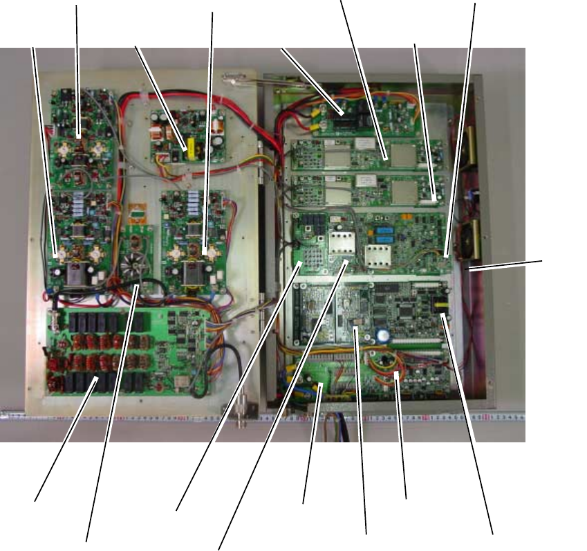
APPENDIX
AP-26
Parts Location
Transceiver unit FS-2570T
05P0744
RELAY Board
05P0747
REF OSC Board
05P0734
W/R Board
05P0733
TX/RX Board
05P0734
W/R Board (option)
05P0732
T-CPU Board
05P0731
T-I/F Board
05P0751
DSP Board
(for DSC)
05P0751
DSP Board
(for NBDP)
05P0746
PRESEL Board
05P0736
TX FIL Board
05P0740
COMB Board
05P0739
PA Board
05P0738
DRV Board
05P0737
SW-REG Board
05P0739
PA Board
05P0743
M-B Board
(underneath)
APPENDIX
A
P-27
Transceiver unit FS-1570T
05P0732
T-CPU Board
05P0744
RELAY Board
05P0734
W/R Board
05P0733
TX/RX Board
05P0737
SW-REG Board
05P0746
PRESEL Board
05P0735
PA Board
05P0736
TX FIL Board
05P0731
T-I/F Board
05P0751
DSP Board
05P0751
DSP Board
(for NBDP)
05P0747
REF OSC
Board
05P0742
M-B Board
(underneath)
APPENDIX
AP-28
Control unit FS-2570C
05P0728
PANEL Board
05P0729
CPU Board
05P0730
C-I/F Board

IN-1
INDEX
1
1/ RT/2182 key............................................ 1-3
2
2/DSC key................................................... 1-1
4
4/Intcom key................................................ 2-8
5
5/ ACK/SQ key............................................ 1-4
6
6/SCAN key ......................................... 1-3, 1-4
7
7/ key ...................................................... 1-4
8
8/PRINT key................................................ 7-3
9
9/ key..................................................... 1-2
A
Alarm menu................................................. 7-1
All ships call
receiving.................................................. 5-3
sending ................................................... 5-1
Antenna current .......................................... 2-4
Auto ack menu............................................ 7-2
C
Channel selection ....................................... 2-2
Contrast ...................................................... 1-2
Control description...................................... 1-1
D
Daily test ................................................... 12-1
Dimmer ....................................................... 1-2
Distress alert
receiving on either VHF channel 70 or MF
channel 2187.5 ................................... 4-7
receiving on HF band.............................. 4-9
sending ................................................... 4-1
Distress relay
on behalf of other ship, to all ships....... 4-16
on behalf of other ship, to coast station 4-13
receiving................................................ 4-19
to coast station on HF band.................... 4-9
DSC frequency table ...................................... 4
E
Error messages .........................................12-6
F
FILE/CURSOR key......................................6-9
Frequency selection ....................................2-3
G
Geographical area call
receiving ................................................5-22
sending ..................................................5-19
Group call
receiving ................................................5-18
sending ..................................................5-15
I
IA ......................................................... 2-4, 2-5
IC .................................................................2-5
Individual call
automatic acknowledge.........................5-10
manual acknowledge.............................5-12
sending ....................................................5-4
Intercom.......................................................2-8
L
Log file
description .............................................5-45
opening..................................................5-45
LOG/TUNE key .........................................5-45
M
Medical transport call
receiving ................................................5-27
sending ..................................................5-26
Menu tree .................................................AP-1
N
NBDP Terminal Unit
answerback code registration .................9-1
ARQ mode............................................. 11-3
communications buffer .......................... 11-9
edit menu [F2] .........................................8-6
FEC mode ............................................. 11-5
file creating ............................................10-1
file deleting ............................................10-7
file editing ..............................................10-3
INDEX
IN-2
file menu [F1] .......................................... 8-5
file opening............................................ 10-6
file renaming ......................................... 10-7
file saving.............................................. 10-2
file saving under new name.................. 10-7
general test ......................................... 12-10
ID code registration................................. 9-2
macrofiles.............................................11-10
manual calling........................................11-1
menu overview........................................ 8-4
operate menu [F3] .................................. 8-7
printing .................................................. 10-7
receive mode .........................................11-5
scan channel group editing, deleting...... 9-8
scan channel group registration ............. 9-7
scanning.................................................11-9
station editing, deleting........................... 9-4
station menu [F5] .................................... 8-9
station registration .................................. 9-3
system menu [F6] ................................. 8-10
terminal unit ............................................ 8-1
timer operation.......................................11-8
timer program editing, deleting............... 9-6
timer program registration ...................... 9-5
tone test ...............................................12-11
user channel editing, deleting................. 9-7
user channel registration ........................ 9-6
window menu [F4]................................... 8-8
Neutral craft call
receiving................................................ 5-25
sending ................................................. 5-23
P
Polling call
receiving................................................ 5-31
sending ................................................. 5-28
Position call
other ship requests your position.......... 5-36
requesting other ship’s position ............ 5-34
Position entry (manual)............................... 1-5
POWER switch ........................................... 1-2
Print out menu ............................................ 7-3
PSTN call
charge information................................ 5-43
receiving................................................ 5-42
sending ................................................. 5-38
R
RF................................................................2-5
S
Scan freq menu...........................................7-4
Scan frequency setup .................................7-5
Scanning......................................................1-4
Send message files
geographical area call .............................6-6
group call.................................................6-4
individual call ...........................................6-1
printing...................................................6-10
PSTN call.................................................6-7
sending ....................................................6-9
test call ....................................................6-8
T
Test call......................................................12-7
Time entry (manual) ....................................1-5
Transmitter power .......................................2-5
Troubleshooting.........................................12-5
Tuning..........................................................2-3
U
USER CH menu ........................................2-10
User channels
deleting..................................................2-12
registering..............................................2-10
V
VC................................................................2-5
Volume menu ..............................................7-6