Furuno USA 9ZWFS2575 MF/HF SSB Radio User Manual
Furuno USA Inc MF/HF SSB Radio
UserManual.wiki
>
Furuno USA
>
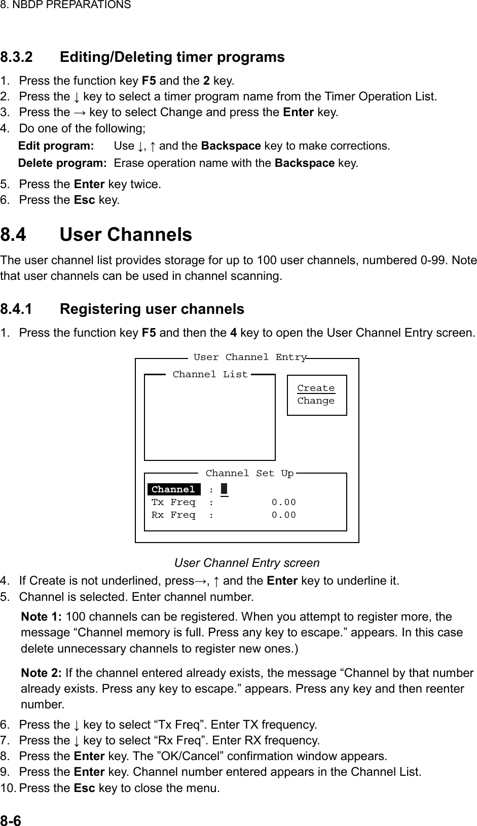
9ZWFS2575 User Manual
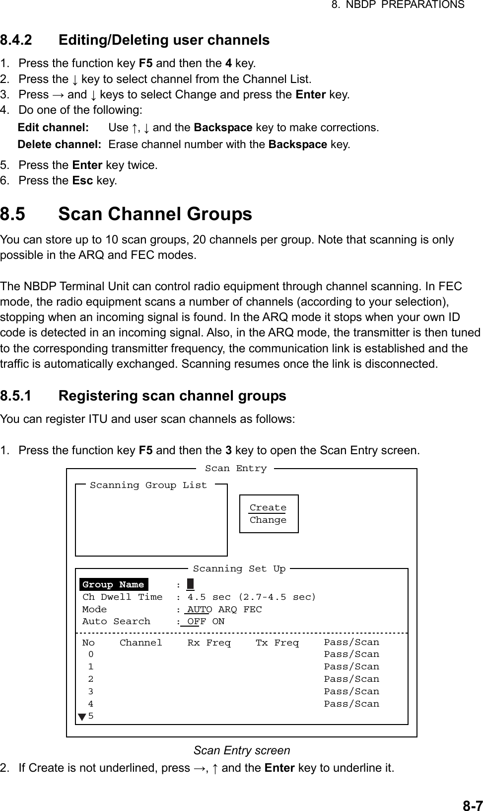
operators manual
Navigation menu
Upload a User Manual
Namespaces
Wiki Guide
HTML
PDF
Info
Views
User Manual
Discussion / Help
Navigation
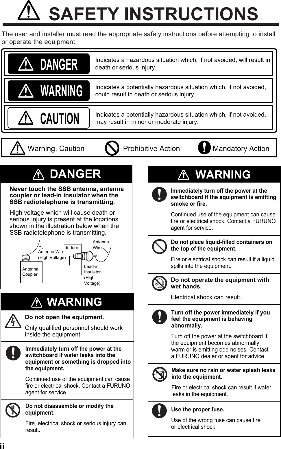
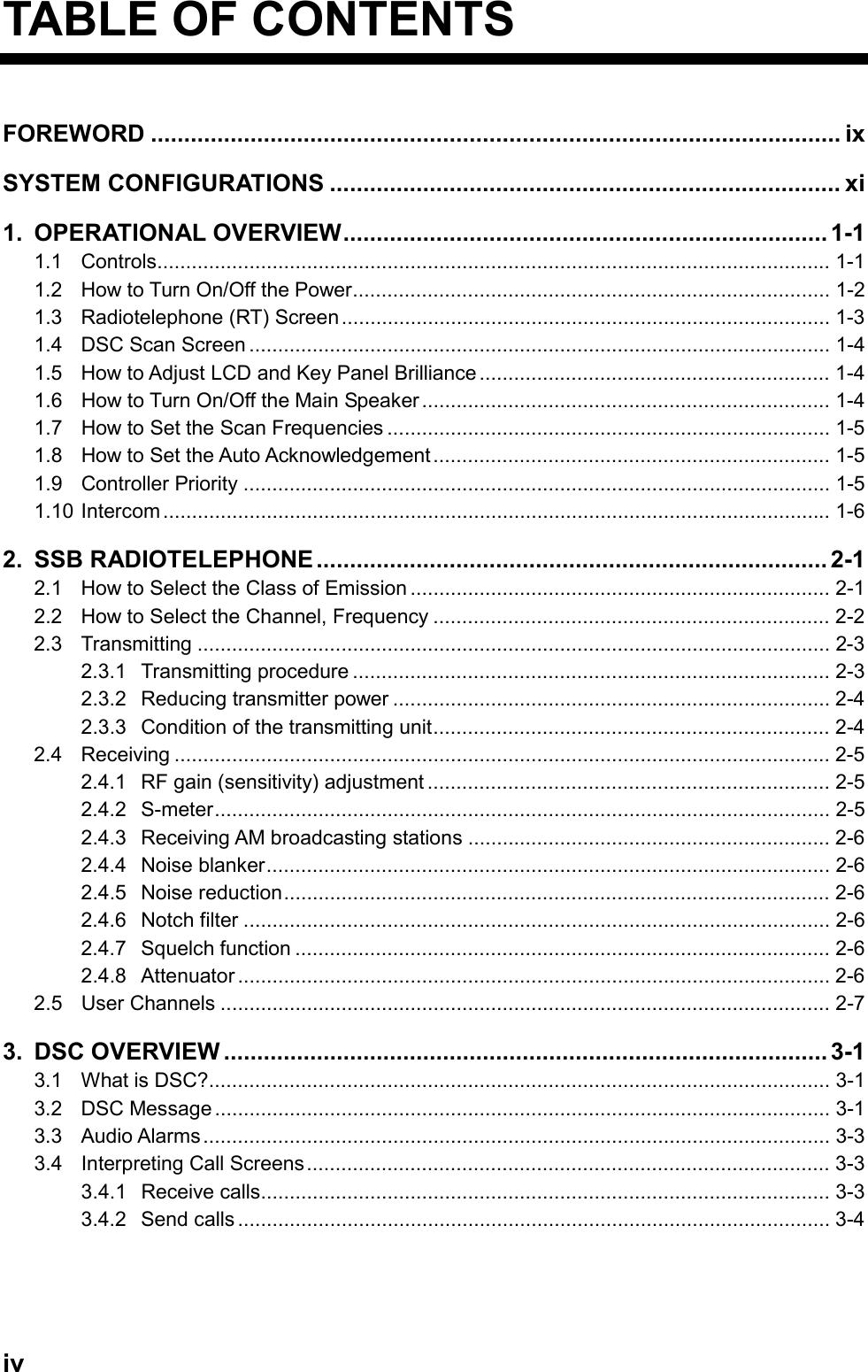
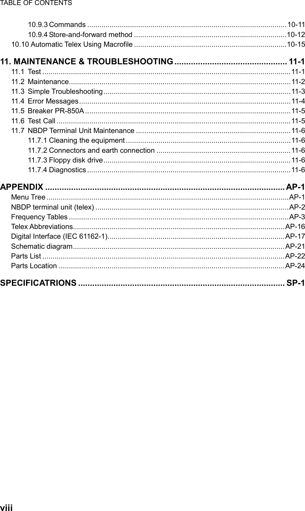
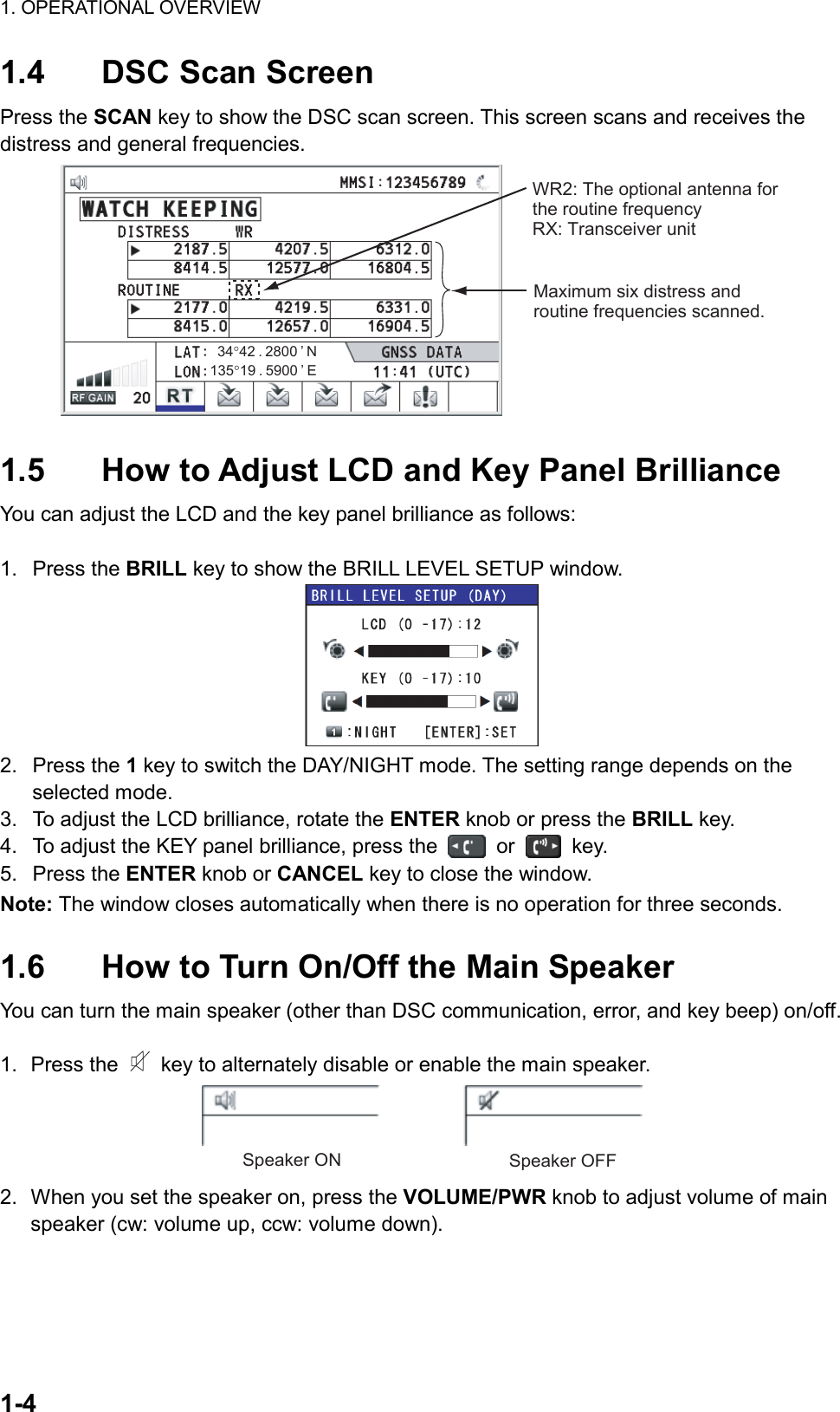
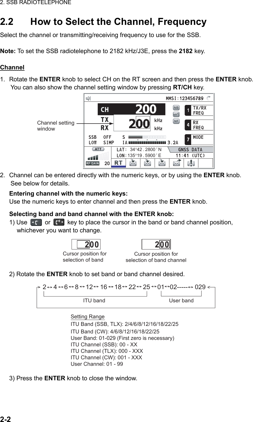
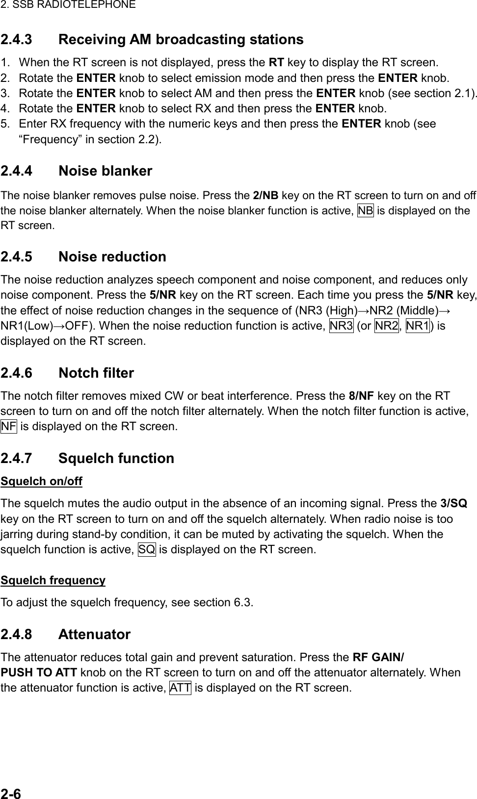
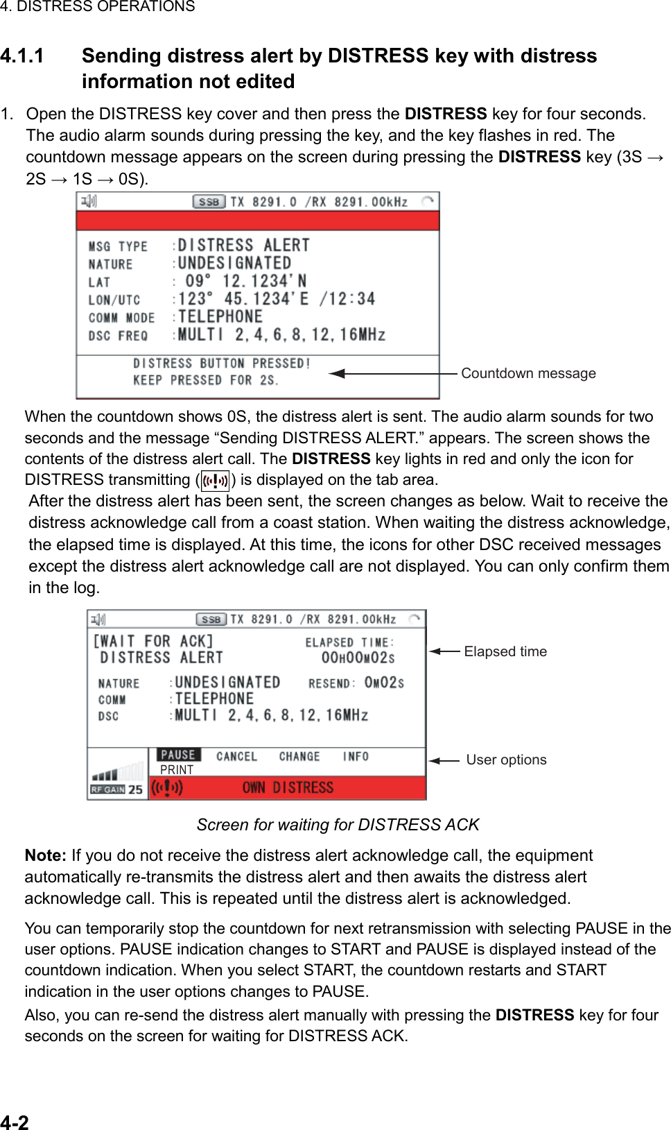
![SAFETY INSTRUCTIONS iiiThe TFT LCD is constructed using the latest LCD techniques, and displays 99.99% of its pixels. The remaining 0.01% of the pixels may drop out or blink, however this is not an indication of malfunction.About the TFT LCDWarning labels are attached to the equipment. Do not remove any label. If a label is missing or damaged, contact a FURUNO agent or dealerabout replacement.Name: Warning Label 1Type: 86-003-1011-3Code No.: 100-236-233-10WARNING CAUTIONDo not operate the [DISTRESS] button except in case of a life-endangering situation on your vessel.Operating the [DISTRESS] button transmits the distress alert. Accidental transmission may prevent search and rescue operations for actual emergency. If the distress alert is accidentally transmitted, contact the nearest station to cancel the alert.If the distress alert is accidentally transmitted, contact the nearest coast station and inform them of the accidental transmission, providing the following data:a) Ship’s nameb) Ship’s call sign and DSC numberc) Position at time of transmissiond) Time of transmissionWARNING LABELSDo not apply strong pressure to the LCD, which is made of glass.Injury can result if the LCD breaks.Name: Warning LabelType: 14-055-4202-1Code No.: 100-245-221-10Name: High Temp Warning LabelType: 05-089-2142-0Code No.: 100-301-620-00](https://usermanual.wiki/Furuno-USA/9ZWFS2575/User-Guide-1533875-Page-5.png)
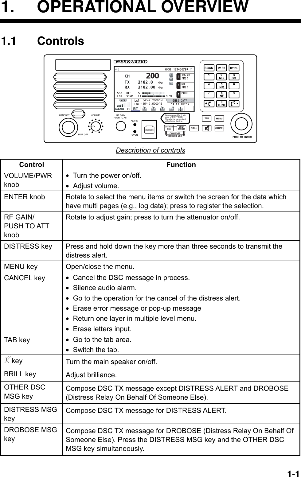
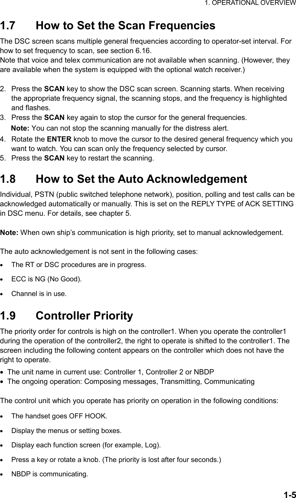
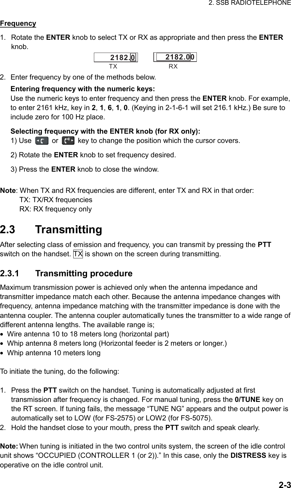
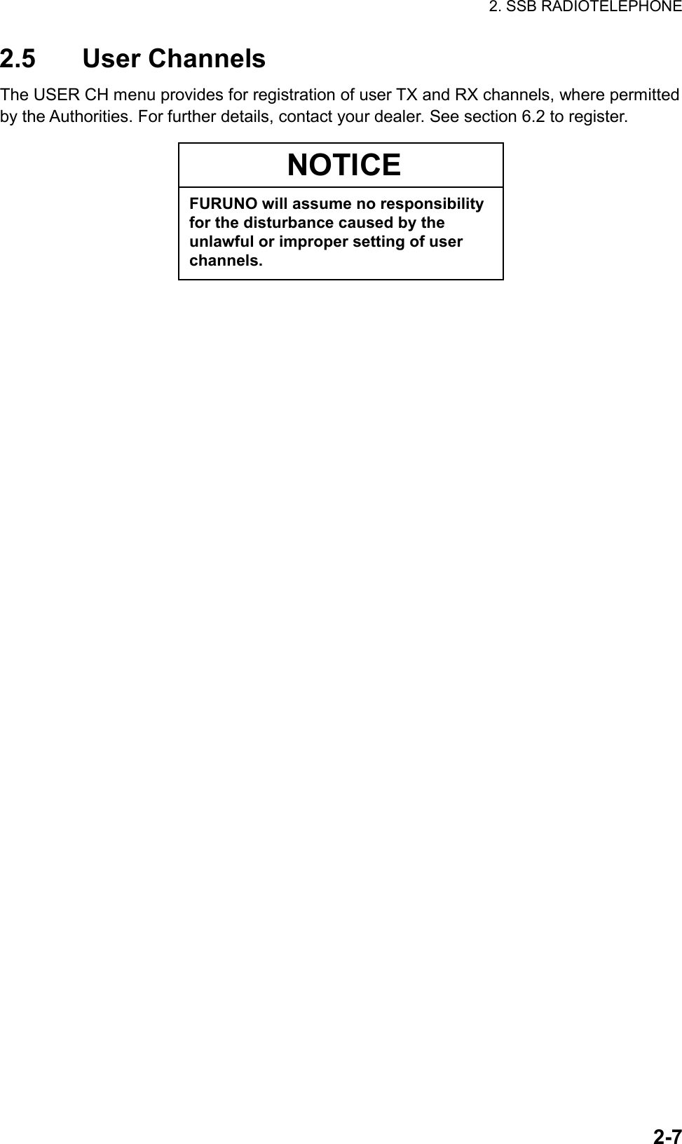
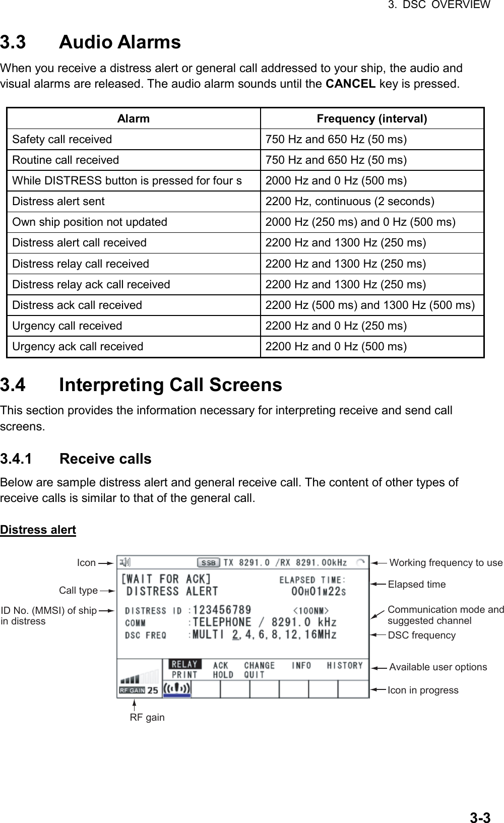
![4. DISTRESS OPERATIONS 4-3When the distress acknowledge call is received, the audio alarm sounds, the LED flashes in red, the icon for DISTRESS transmitting ( ) flashes. The screen changes as below. DISTRESS ACK received![CANCEL]: Stop alarm 2. Press the CANCEL key to silence the audio alarm. The LED and the icon stop to flash, and the pop-up message disappears. Count up the elapsed time after receiving distress acknowledge call.Icon for DISTRESS transmitting 3. Communicate with the coast station via radiotelephone, following the instructions below. When sending the distress alert with MULTI mode, the radiotelephone automatically sets working frequency on which the distress acknowledge call is received first. a) Say MAYDAY three times. b) Say “This is … “ name of your ship and call sign three times. c) Give nature of distress and assistance needed. d) Give description of your ship (type, color, number of persons onboard, etc.). 4.1.2 Sending distress alert by DISTRESS key with distress information edited If you have the time to designate the distress information, send the distress alert as follows: 1. Press the DISTRESS MSG key to display the following screen. COMPOSE MESSAGE 2. Rotate the ENTER knob to select NATURE and then press the ENTER knob.](https://usermanual.wiki/Furuno-USA/9ZWFS2575/User-Guide-1533875-Page-35.png)
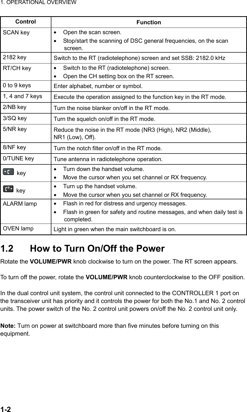
![4. DISTRESS OPERATIONS 4-5Communicating by NBDP Terminal Unit The message “STATION ENTRY COMPLETED FROM DSC. Press any key to escape.” appears on the NBDP’s screen. 1. Press any key on the NBDP terminal unit to erase the message. 2. Press the function key F3 on the keyboard of the NBDP terminal unit to open the Operate menu. 3. Select Call Station and then press the ENTER knob. Call StationStation ListDSCABC-6MABC-12MABC-8MFURUNOStation Set upStation : DSCID Code : Mode : ARQ FECTx Freq : 2174.50Rx Freq : 2174.50 4. DSC is selected; press the Enter key to connect the communications line. Connect appears in reverse video. 5. Type and transmit your message, giving the following information: • Ship’s name and call sign • Nature of distress and assistance needed • Description of your ship 6. Press the function key F10 (BREAK) to disconnect the line. For NBDP details, see chapters 7 through 10. 4.2 Receiving a Distress Alert When you receive a distress alert from a ship in distress, the audio alarm sounds and the LED flashes in red. The icon for DISTRESS receiving ( ) on the tab area flashes and the pop-up message “DISTRESS ALERT message received! [CANCEL]: Stop alarm” appears on the screen. Press the CANCEL key to silence the audio alarm and stop the flashing of the LED and the icon. Press the TAB key to select the icon for DISTRESS receiving and then press the ENTER knob. Rotate the ENTER knob to select ACTIVE (see the following “Switching the procedures”) and then press the ENTER knob. The screen for receiving the distress alert appears. Wait for the distress acknowledge call from a coast station. If you do not receive the distress acknowledge call from a coast station, which usually takes about five minutes from the time of receiving a distress alert, follow the appropriate flow chart in this section to determine your course of action. Note: An asterisk (*) appearing in a distress alert message indicates error at asterisk location. Switching the procedures When one procedure is active and another message arrives, a new procedure for the received message does not start automatically. Only one procedure always can be active. For example, when you are transmitting a DSC message and another message arrives, the](https://usermanual.wiki/Furuno-USA/9ZWFS2575/User-Guide-1533875-Page-37.png)
![4. DISTRESS OPERATIONS 4-7Sending the distress acknowledge call to ship in distress (on MF band) Note: You cannot send the distress acknowledge call for five minutes because of receiving the distress acknowledgement from the coast station. Transmit the distress acknowledge call to the ship in distress only when you do not receive it from a coast station and you are able to aid the ship in distress. First, contact the ship in distress over radiotelephone. To terminate transmission of the distress alert, send acknowledge call as follows. When you receive a distress alert from a ship in distress, the audio alarm sounds and the LED flashes in red. The icon for DISTRESS receiving on the tab area flashes and the pop-up message “DISTRESS ALERT message received! [CANCEL]: Stop alarm” appears on the screen. 1. Press the CANCEL key to silence the audio alarm and stop the flashing of the LED and the icon. 2. Press the TAB key to select the icon for DISTRESS receiving ( ) and then press the ENTER knob. DISTRESS receiving icon 3. Rotate the ENTER knob to select ACTIVE and then press the ENTER knob. The screen for receiving the distress alert appears. 4. If you do not receive the distress acknowledge call from a coast station and you have received the distress alert more than twice, contact the ship in distress over radiotelephone. 5. Rotate the ENTER knob to select ACK and then press the ENTER knob. The message “DISTRESS ACK to send? CONTINUE/RETURN” appears. 6. Rotate the ENTER knob to select CONTINUE and then press the ENTER knob to transmit the distress acknowledge call to the ship in distress. Note: You can not edit the message for the distress acknowledge call.](https://usermanual.wiki/Furuno-USA/9ZWFS2575/User-Guide-1533875-Page-39.png)
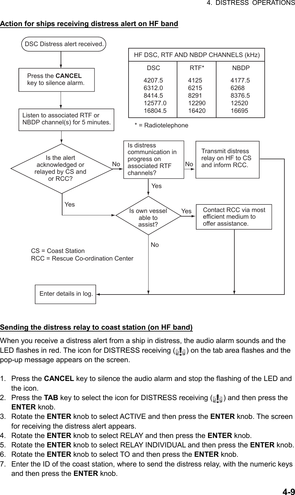
![4. DISTRESS OPERATIONS 4-8 4.2.2 Distress alert received on HF band If you receive a distress alert on the HF band, the audio alarm sounds and the LED flashes in red. The icon for DISTRESS receiving ( ) on the tab area flashes and the pop-up message “DISTRESS ALERT message received! [CANCEL]: Stop alarm” appears on the screen. Press the CANCEL key to silence the audio alarm and stop the flashing of the LED and the icon. Press the TAB key to select the icon for DISTRESS receiving. Rotate the ENTER knob to select ACTIVE and then press the ENTER knob. The screen for receiving the distress alert appears. Wait for the distress acknowledge call from a coast station. If you do not receive the distress acknowledge call from a coast station, which usually takes about five minutes from the time of receiving a distress alert, follow the appropriate flow chart in this section to determine your course of action. • Watch on the distress frequency. • Relay the distress alert in the following cases: - You have not received a distress acknowledge call from a coast station within five minutes after receiving a distress call. - You have not received a distress relay from other ship. - You cannot receive distress communications from other ship over radiotelephone. - If it is clear the ship or persons in distress are not near your ship and/or other crafts are better placed to assist, superfluous communications which could interfere with search and rescue activities should be avoided. Details should be recorded in the appropriate log book. - The ship relaying the distress alert should establish communications with the station controlling the distress as directed and render such assistance as required and appropriate. • When the received distress frequency is different from the current communication frequency do the following: 1. Rotate the ENTER knob to select CHANGE and then press the ENTER knob. 2. Rotate the ENTER knob to select the frequency same as the received distress one and then press the ENTER knob.](https://usermanual.wiki/Furuno-USA/9ZWFS2575/User-Guide-1533875-Page-40.png)
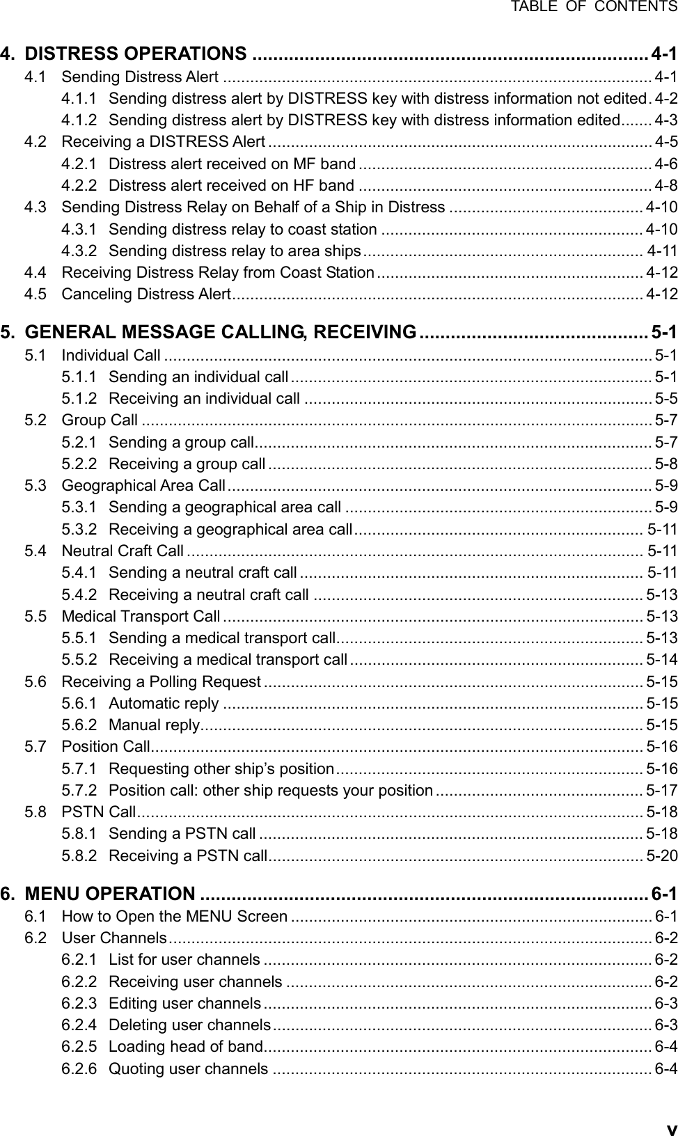
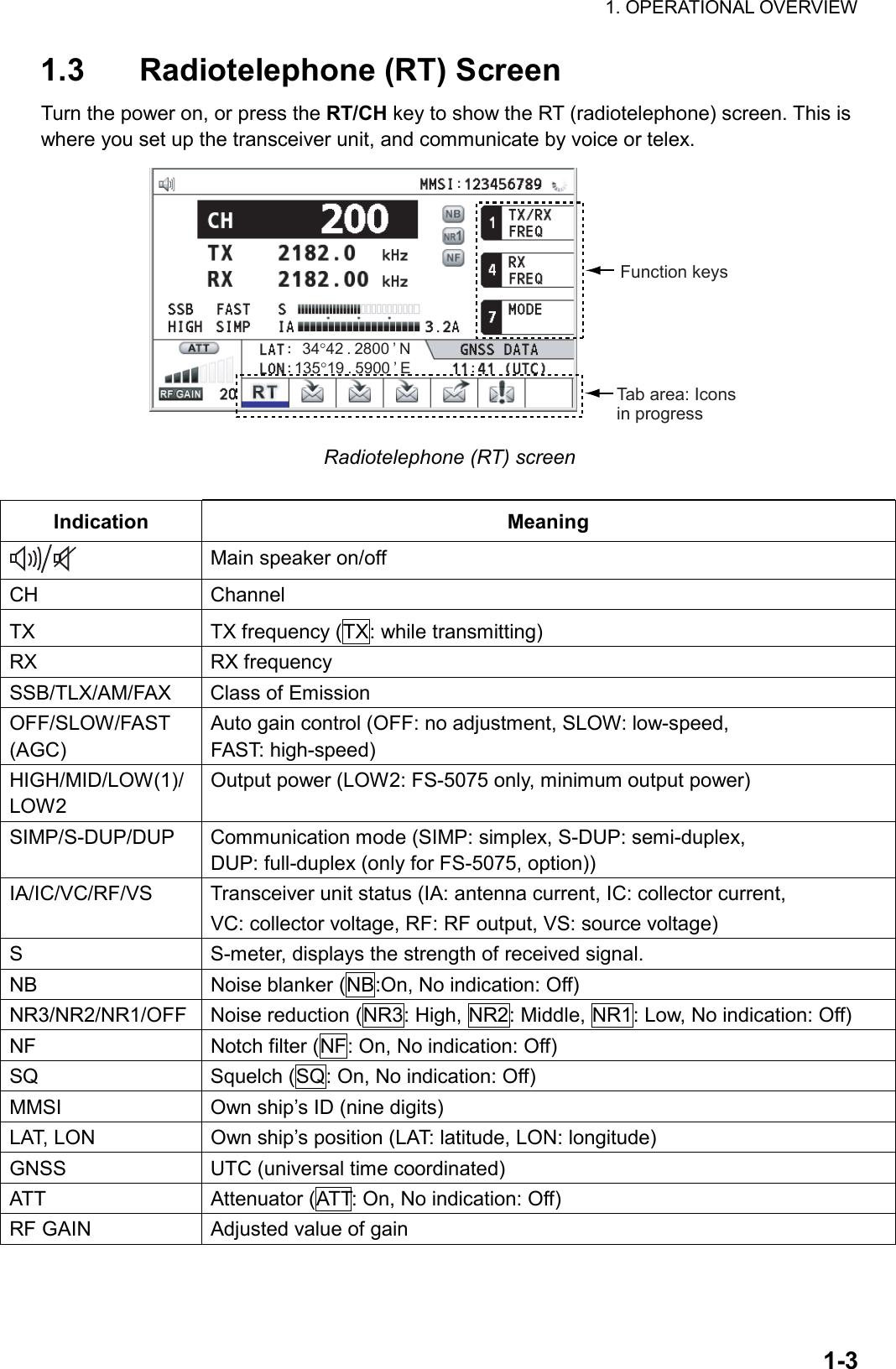
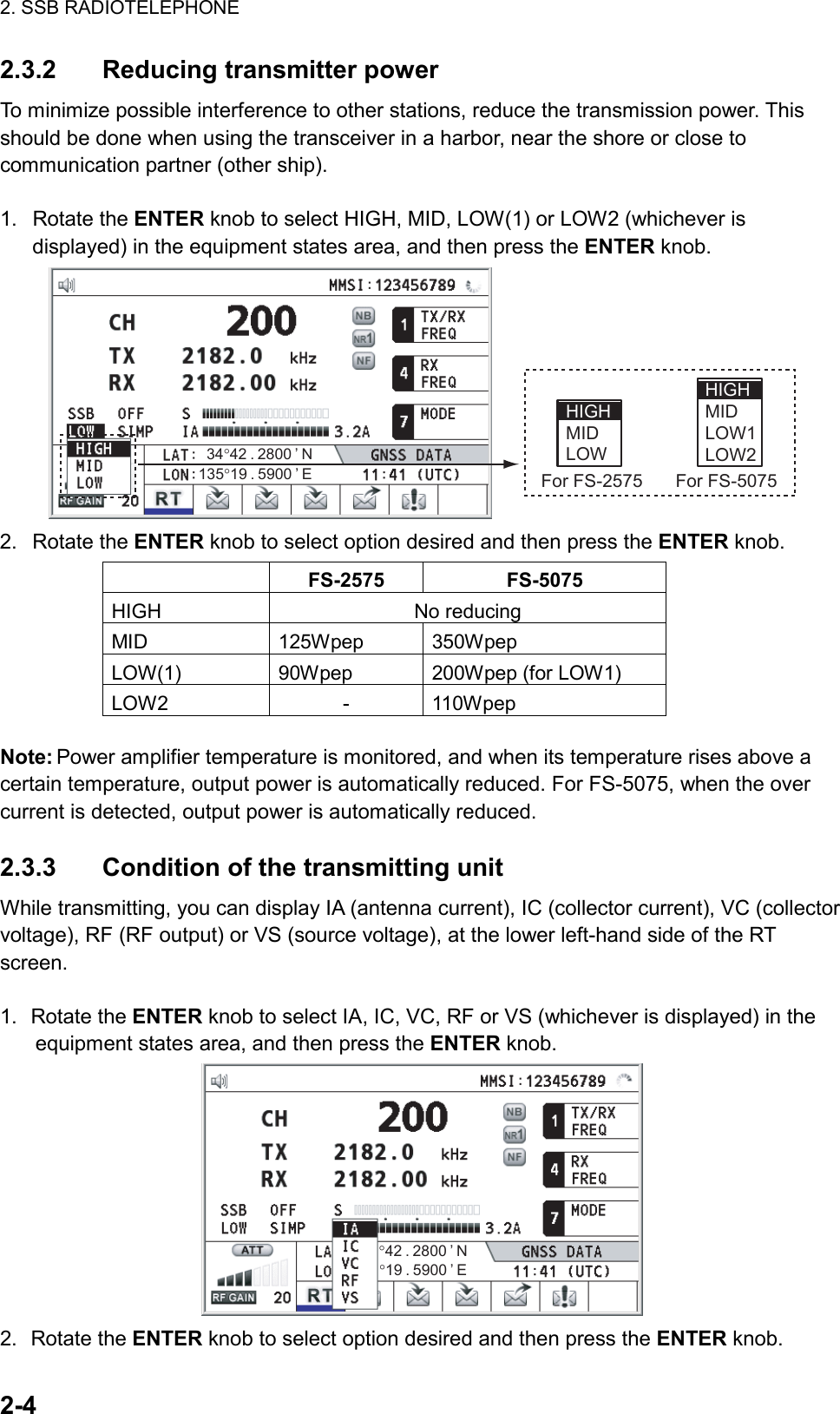
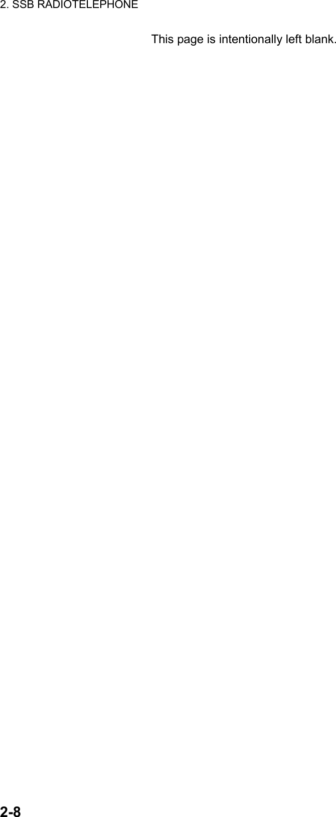
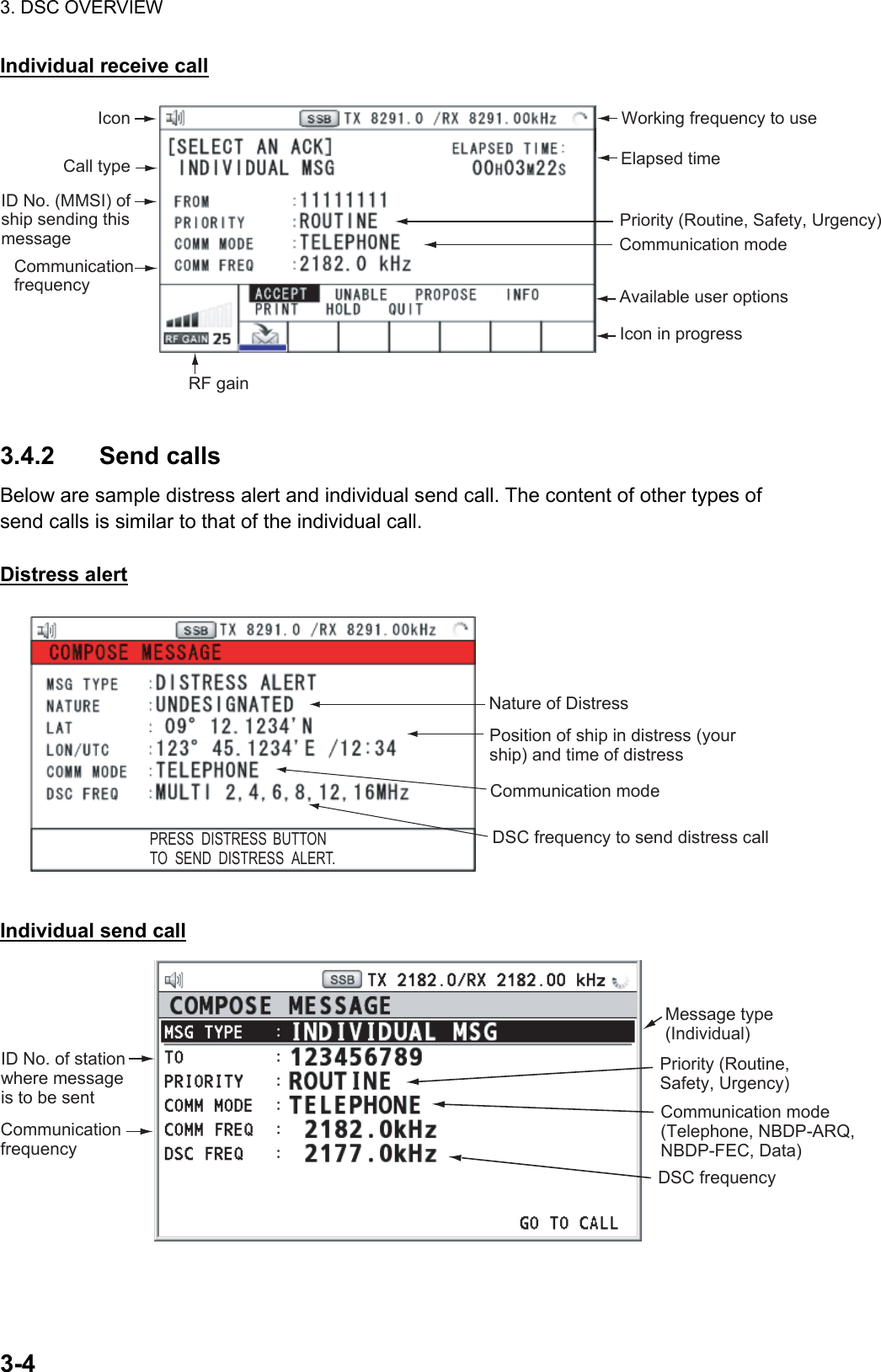
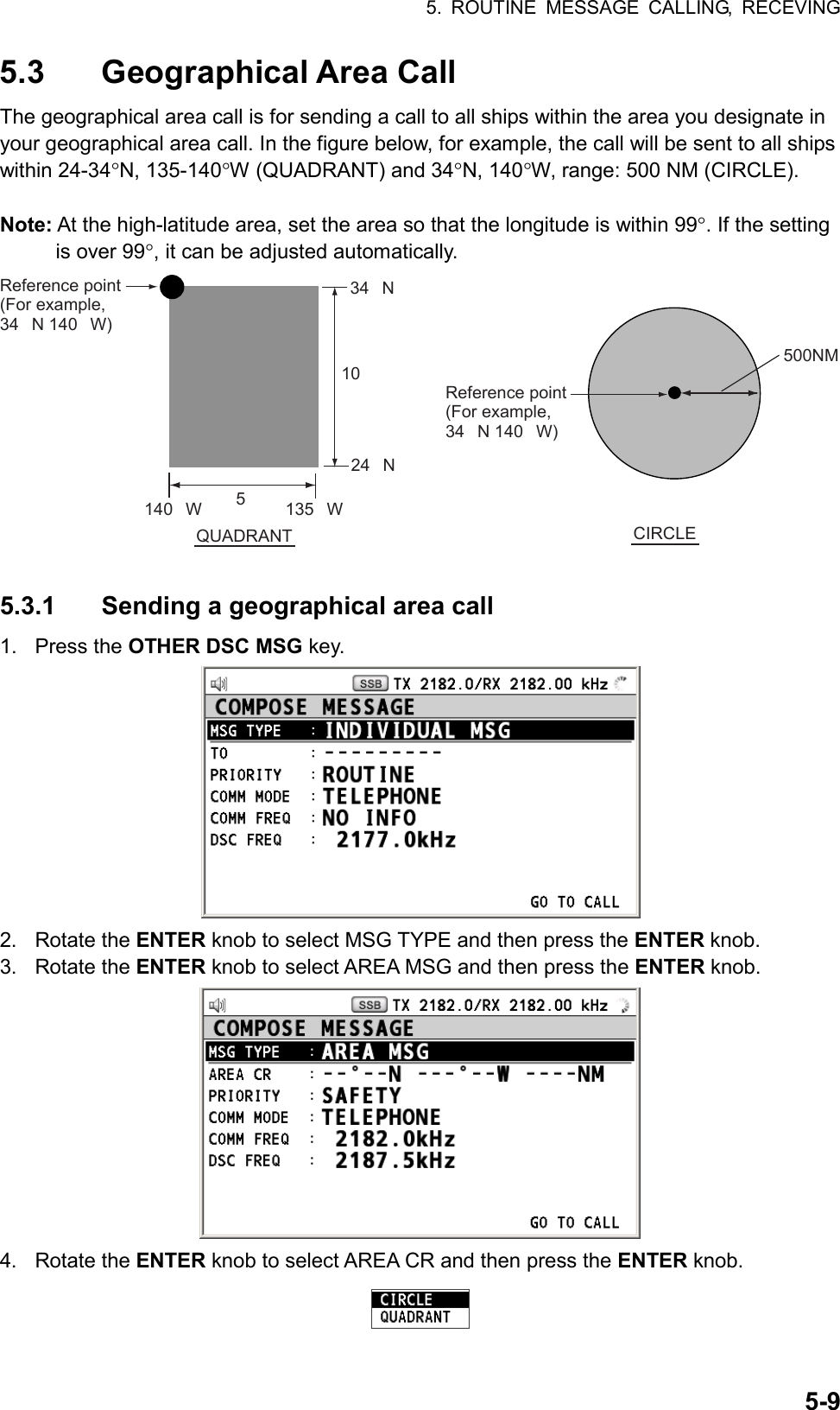
![4. DISTRESS OPERATIONS 4-1113. Rotate the ENTER knob to select appropriate frequency and then press the ENTER knob. 14. Rotate the ENTER knob to select GO TO CALL and then press the ENTER knob. The distress relay is transmitted to the coast station. The screen changes to one for transmitting. After transmitting, the screen for waiting DISTRESS RELAY INDIVIDUAL ACK appears. The elapsed time since transmitting is displayed. When you receive the distress relay individual acknowledgement from the coast station, the audio alarm sounds and the icon flashes in red. The pop-up message “RELAY INDIVIDUAL ACK received! [CANCEL]: Stop alarm” appears. Press the CANCEL key to silence the alarm and stop the flashing of the icon. The pop-up message disappears. Communicate with the coast station by telephone, over the frequency specified. To quit the distress receiving procedure, select QUIT and then press the ENTER knob. 4.3.2 Sending distress relay to area ships Use this procedure to send the distress relay to area ships. 1. Press the DISTRESS MSG key and the OTHER DSC MSG key simultaneously to open the composing screen for the distress relay individual. 2. Rotate the ENTER knob to select MSG TYPE and then press the ENTER knob. 3. Rotate the ENTER knob to select RELAY AREA and then press the ENTER knob. 4. Rotate the ENTER knob to select CR or LL and then press the ENTER knob. 5. Set the area with the numeric keys. The geographical area call is for sending a call to all ships within the area you designate in your geographical area call. In the figure below, for example, the call will be sent to all ships within 24-34°N, 135-140°W (LL) and 34°N, 140°W, range: 500 NM (CR). LL (QUAD)34° N 140° W 10° 5°34° N24° N10°5°140° W135° WReference point (For example, 34° N 140° W)500NMCR (CIRCLE)34° 00N 140° 00W 0500NMReference point (For example,34° 00N 140° 00W) 6. Rotate the ENTER knob to select DISTRESS ID and then press the ENTER knob. 7. Enter the ID of the ship in distress and then press the ENTER knob. 8. Rotate the ENTER knob to select NATURE and then press the ENTER knob. 9. Rotate the ENTER knob to select nature of distress and then press the ENTER knob. 10. Rotate the ENTER knob to select LAT or LON and then press the ENTER knob. 11. Use the numeric keys to enter latitude (or longitude) of the ship in distress. (If necessary, switch coordinates: 1 key to switch to North (East for longitude); 2 key to switch to South (West for longitude).) Press the ENTER knob. 12. Rotate the ENTER knob to select COMM MODE and then press the ENTER knob.](https://usermanual.wiki/Furuno-USA/9ZWFS2575/User-Guide-1533875-Page-43.png)
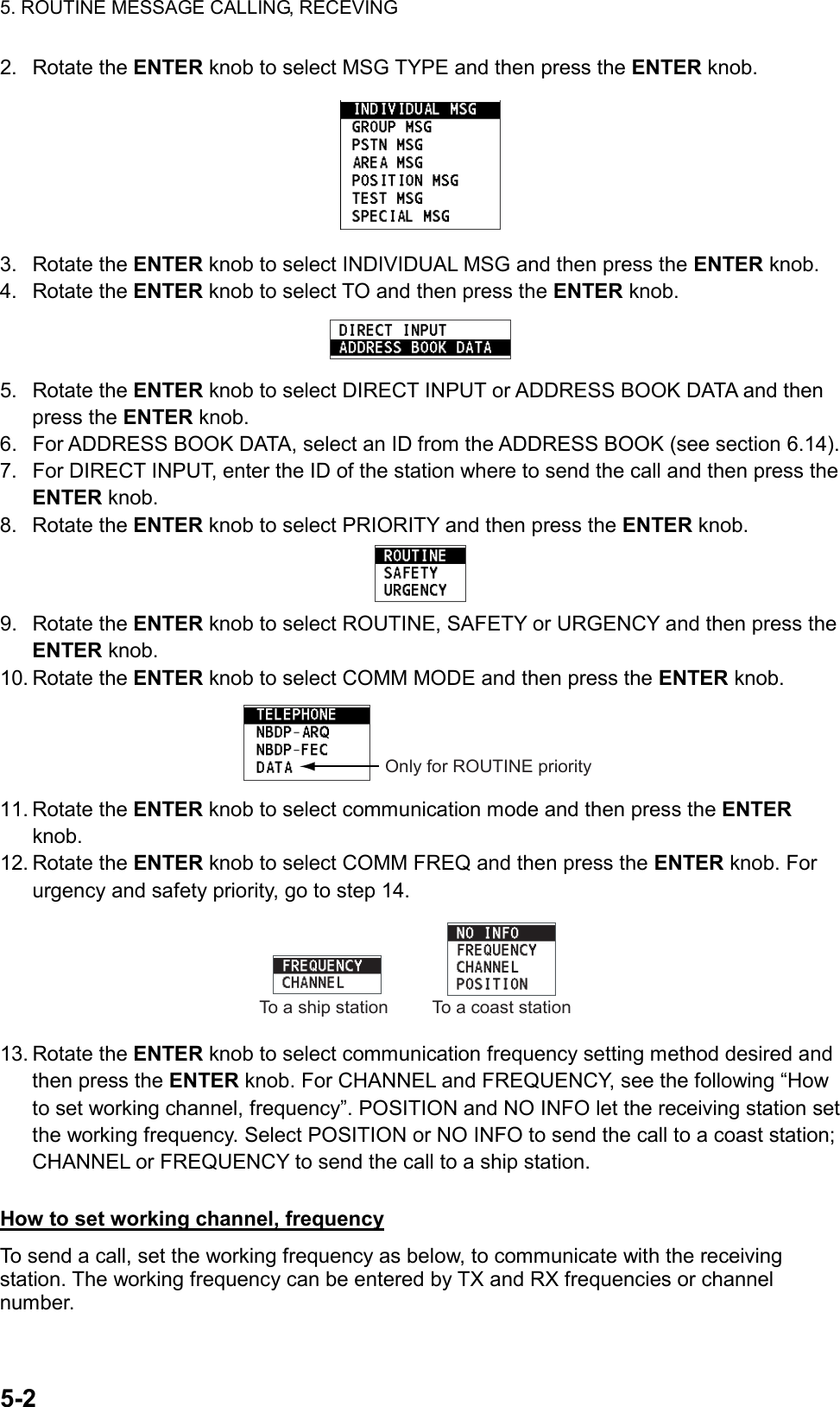
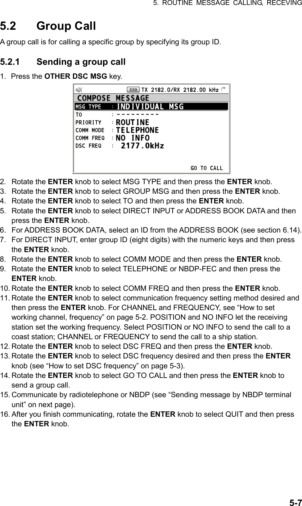
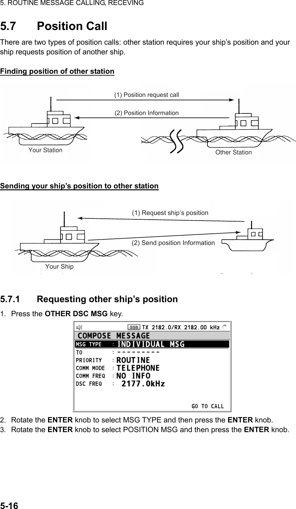
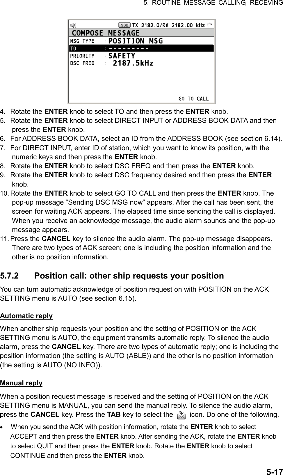
Acknowledge Back (ACK BQ) Signal(3)Voice or telex communication 5.1 Individual Call The individual call is for calling a specific station. After sending an individual call, called ACK RQ transmission, wait to receive the acknowledge back (ACK BQ) signal from the receiving station. 5.1.1 Sending an individual call 1. Press the OTHER DSC MSG key.](https://usermanual.wiki/Furuno-USA/9ZWFS2575/User-Guide-1533875-Page-47.png)
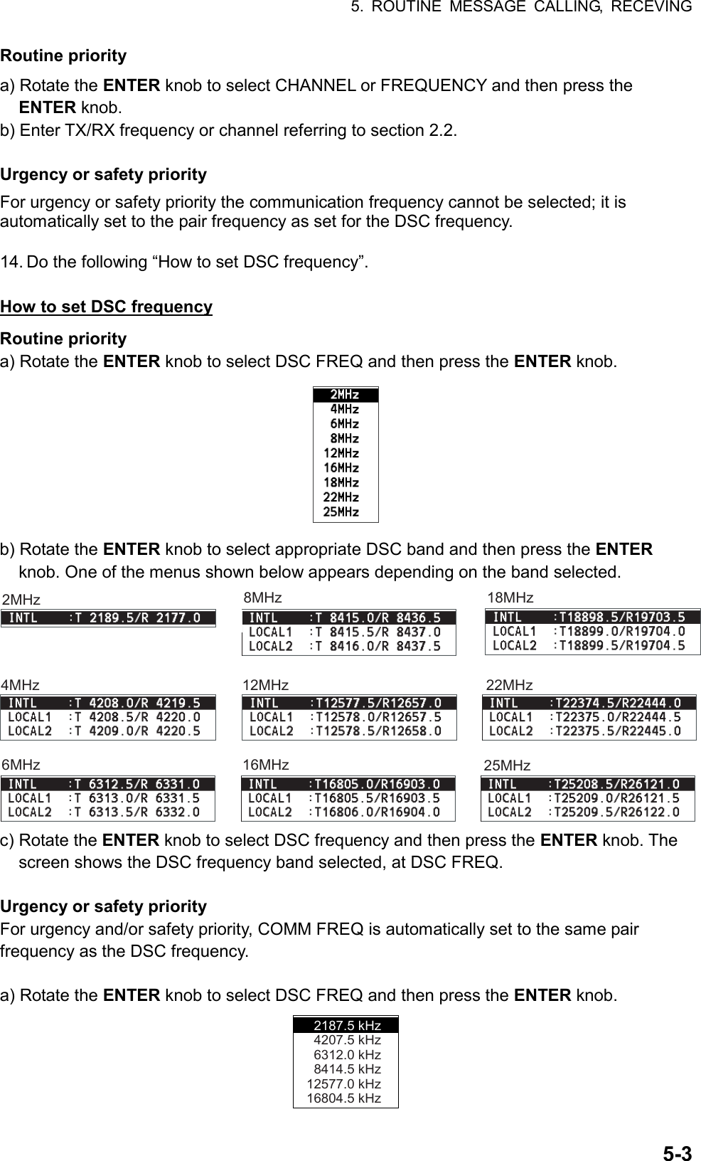
![5. ROUTINE MESSAGE CALLING, RECEVING 5-4 b) Rotate the ENTER knob to select appropriate frequency and then press the ENTER knob. 15. Rotate the ENTER knob to select GO TO CALL and then press the ENTER knob to send the individual call. The screen is changed to one for transmission and the pop-up message “Sending DSC MSG.“ appears. After the call is sent, the equipment waits for acknowledgement of the call, showing the screen for waiting for ACK. The timer starts counting up the time to wait for acknowledgement. When receiving the ACK, the audio alarm sounds and the pop-up message “ROUTINE (or SAFETY, URGENCY) INDIVIDUAL ACK received! [CANCEL]: Stop alarm” appears on the screen. The timer starts counting up the time since receiving ACK. There are three types of ACK messages; ABLE ACK, UNABLE ACK and ABLE CHANGE FREQ. 16. Do one of the following depending on the message type shown in step 15. Able acknowledge call received 1. Press the CANCEL key to silence the audio alarm. The pop-up message disappears. 2. The working frequency is automatically set; you can communicate by radiotelephone or NBDP (see the following “Sending message by NBDP terminal unit”). 3. After you finish communicating, rotate the ENTER knob to select QUIT and then press the ENTER knob. 4. Rotate the ENTER knob to select CONTINUE and then press the ENTER knob. Sending message by NBDP terminal unit The message “STATION ENTRY COMPLETED FROM DSC. Press any key to escape.” appears on the screen of the NBDP terminal unit. 1. Press any key on the NBDP terminal unit to erase the message. 2. Press the function key F3 on the keyboard of the NBDP terminal unit to open the Operate menu. 3. Select Call Station and then press the Enter key. 4. DSC is selected; press the Enter key. Connect appears in reverse video. 5. Type and transmit your message. 6. When you finished sending your message, press the function key F10 to disconnect the line. Able change frequency acknowledge call received This call means that the station you sent the individual call accepts your call with the frequency or communication mode that the station requires. 1. Press the CANCEL key to silence the audio alarm. The pop-up message disappears. 2. The working frequency is changed to one that the station requires, with showing the pop-up message. You can communicate by radiotelephone, NBDP or DATA, whichever the station requires. 3. After you finish communicating, rotate the ENTER knob to select QUIT and then press the ENTER knob. 4. Rotate the ENTER knob to select CONTINUE and then press the ENTER knob.](https://usermanual.wiki/Furuno-USA/9ZWFS2575/User-Guide-1533875-Page-50.png)
![5. ROUTINE MESSAGE CALLING, RECEVING 5-8 Sending message by NBDP terminal unit The message “STATION ENTRY COMPLETED FROM DSC. Press any key to escape.” appears on the screen of the NBDP terminal unit. 1. Press any key on the NBDP terminal unit to erase the message. 2. Press the function key F3 on the keyboard of the NBDP terminal unit to open the Operate menu. 3. Select Call Station and then press the Enter key. 4. DSC is selected; press the Enter key. Connect appears in reverse video. 5. Type and transmit your message. 6. When you finished sending your message, press the function key F10 to disconnect the line. 5.2.2 Receiving a group call Group ID must be registered in order to receive a group call (see paragraph 6.15.3). When a group call is received, the audio alarm sounds. The icon ( ) on the tab area flashes in black and white, and the pop-up message “GROUP MSG received! [CANCEL]: Stop alarm” appears. 1. Press the CANCEL key to silence the audio alarm. The pop-up message disappears. 2. Press the TAB key to select the icon. 3. Press the ENTER knob. 4. Rotate the ENTER knob to select ACTIVE and then press the ENTER knob. 5. Watch on the working frequency. Communicate by radiotelephone or NBDP (see “Receiving message by NBDP terminal unit” on next page). If there is the difference between the registered frequency and used frequency to receive, the pop-up message appears. Select Agree for the voice communication, or Disagree when you do not change the frequency. 6. After you finish communicating, rotate the ENTER knob to select QUIT and then press the ENTER knob. 7. Rotate the ENTER knob to select CONTINUE and then press the ENTER knob to finish communication. Receiving message by NBDP terminal unit After receiving a group call, confirm the following. • The control unit’s screen shows “OCCUPIED” and the TX and RX frequencies. • The message from the sending station appears on your NBDP terminal unit.](https://usermanual.wiki/Furuno-USA/9ZWFS2575/User-Guide-1533875-Page-54.png)
![5. ROUTINE MESSAGE CALLING, RECEVING 5-115.3.2 Receiving a geographical area call When you receive an area message, the audio alarm sounds. The icon ( ) on the tab area flashes in black and white, and the pop-up message “URGENCY (SAFETY) AREA MSG received! [CANCEL]: Stop alarm” appears. 1. Press the CANCEL key to silence the audio alarm. The pop-up message disappears. 2. Press the TAB key to select the icon. 3. Press the ENTER knob. 4. Rotate the ENTER knob to select ACTIVE and then press the ENTER knob. 5. Watch on the working frequency. Communicate by radiotelephone or NBDP (see “Receiving message by NBDP terminal unit” on this page). If there is the difference between the registered frequency and used frequency to receive, the pop-up message appears. Select Agree for the voice communication, or Disagree when you do not change the frequency. 6. After you finish communicating, rotate the ENTER knob to select QUIT and then press the ENTER knob. Receiving message by NBDP terminal unit After receiving a geographic area call, confirm the following. • The control unit’s screen shows “OCCUPIED” and the TX and RX frequencies. • The message from the sending station appears on your NBDP terminal unit. 5.4 Neutral Craft Call The neutral craft call, which contains your ship position and ID, informs all ships that your ship is not a participant in armed conflict. The neutral craft call is necessary the setting on the SPECIAL MSG menu. See section 6.17. 5.4.1 Sending a neutral craft call 1. Press the OTHER DSC MSG key. 2. Rotate the ENTER knob to select MSG TYPE and then press the ENTER knob. 3. Rotate the ENTER knob to select SPECIAL MSG and then press the ENTER knob.](https://usermanual.wiki/Furuno-USA/9ZWFS2575/User-Guide-1533875-Page-57.png)
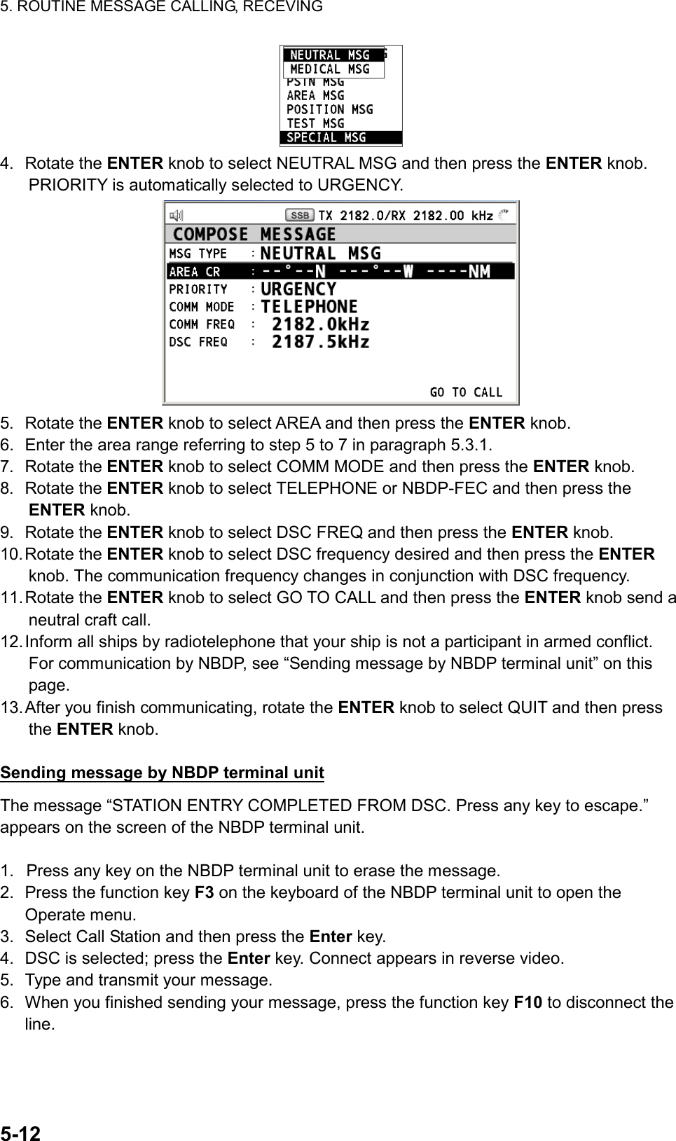
![5. ROUTINE MESSAGE CALLING, RECEVING 5-135.4.2 Receiving a neutral craft call When you receive a neutral craft call, the audio alarm sounds. The icon ( ) on the tab area flashes in black and white, and the pop-up message “NEUTRAL MSG received! [CANCEL]: Stop alarm” appears. 1. Press the CANCEL key to silence the audio alarm. The pop-up message disappears. 2. Press the TAB key to select the icon. 3. Press the ENTER knob. 4. Rotate the ENTER knob to select ACTIVE and then press the ENTER knob. 5. Watch on the working frequency. Communicate by radiotelephone or NBDP (see “Receiving message by NBDP terminal unit” on this page). If there is the difference between the registered frequency and used frequency to receive, the pop-up message appears. Select Agree for the voice communication, or Disagree when you do not change the frequency. 6. After you finish communicating, rotate the ENTER knob to select QUIT and then press the ENTER knob. Receiving message by NBDP terminal unit After receiving a neutral craft call, confirm the following. • The control unit’s screen shows “OCCUPIED” and the TX and RX frequencies. • The message from the sending station appears on your NBDP terminal unit. 5.5 Medical Transport Call The medical transport call informs all ships, by urgency priority, that your ship carries medical supplies. The medical call is necessary the setting on the SPECIAL MSG menu. See section 6.16. 5.5.1 Sending a medical transport call 1. Press the OTHER DSC MSG key. 2. Rotate the ENTER knob to select MSG TYPE and then press the ENTER knob. 3. Rotate the ENTER knob to select SPECIAL MSG and then press the ENTER knob. 4. Rotate the ENTER knob to select MEDICAL MSG and then press the ENTER knob. PRIORITY is automatically selected to URGENCY.](https://usermanual.wiki/Furuno-USA/9ZWFS2575/User-Guide-1533875-Page-59.png)
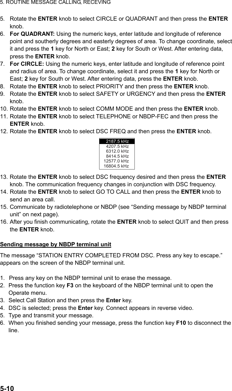
![5. ROUTINE MESSAGE CALLING, RECEVING 5-14 5. Rotate the ENTER knob to select AREA and then press the ENTER knob. 6. Enter the area range referring to step 5 to 7 in paragraph 5.3.1. 7. Rotate the ENTER knob to select COMM MODE and then press the ENTER knob. 8. Rotate the ENTER knob to select TELEPHONE or NBDP-FEC and then press the ENTER knob. 9. Rotate the ENTER knob to select DSC FREQ and then press the ENTER knob. 10. Rotate the ENTER knob to select DSC frequency desired and then press the ENTER knob. The communication frequency changes in conjunction with DSC frequency. 11. Rotate the ENTER knob to select GO TO CALL and then press the ENTER knob to send a medical transport call. 12. Inform all ships by radiotelephone that your ship is transporting medical supplies. For communication by NBDP, see “Sending message by NBDP terminal unit” on next page. 13. After you finish communicating, rotate the ENTER knob to select QUIT and then press the ENTER knob. Sending message by NBDP terminal unit The message “STATION ENTRY COMPLETED FROM DSC. Press any key to escape.” appears on the screen of the NBDP terminal unit. 1. Press any key on the NBDP terminal unit to erase the message. 2. Press the function key F3 on the keyboard of the NBDP terminal unit to open the Operate menu. 3. Select Call Station and then press the Enter key. 4. DSC is selected; press the Enter key. Connect appears in reverse video. 5. Type and transmit your message. 6. When you finished sending your message, press the function key F10 to disconnect the line. 5.5.2 Receiving a medical transport call When you receive a medical transport call, the audio alarm sounds. The icon ( ) on the tab area flashes in black and white, and the pop-up message “MEDICAL MSG received! [CANCEL]: Stop alarm” appears. 1. Press the CANCEL key to silence the audio alarm. The pop-up message disappears. 2. Press the TAB key to select the icon. 3. Press the ENTER knob. 4. Rotate the ENTER knob to select ACTIVE and then press the ENTER knob.](https://usermanual.wiki/Furuno-USA/9ZWFS2575/User-Guide-1533875-Page-60.png)
![5. ROUTINE MESSAGE CALLING, RECEVING 5-155. Watch on the working frequency. Communicate by radiotelephone or NBDP (see “Receiving message by NBDP terminal unit” on this page). If there is the difference between the registered frequency and used frequency to receive, the pop-up message appears. Select Agree for the voice communication, or Disagree when you do not change the frequency. Receiving message by NBDP terminal unit After receiving a medical transport call, confirm the following. • The control unit’s screen shows “OCCUPIED” and the TX and RX frequencies. • The message from the sending station appears on your NBDP terminal unit. 5.6 Receiving a Polling Request Polling means confirming if your ship is within communicating range with other ship. (1) Polling(2) AcknowledgeCoastStation 5.6.1 Automatic reply When a polling request message is received with AUTO setting on POLLING MSG of ACK SETTING menu, an acknowledge is sent automatically. For details see section 6.15 (PRIORITY: ROUTINE only). 5.6.2 Manual reply When you receive a polling request message, the audio alarm sounds. The icon ( ) on the tab area flashes in black and white, and the pop-up message “POLLING MSG received! [CANCEL]: Stop alarm” appears. The equipment is set up for manual acknowledge: POLLING MSG on the ACK SETTING menu is MANUAL. 1. Press the CANCEL key to silence the audio alarm. The pop-up message disappears. 2. Press the TAB key to select the icon. 3. Press the ENTER knob. 4. Rotate the ENTER knob to select ACCEPT and then press the ENTER knob. The polling acknowledge message is sent. 5. Rotate the ENTER knob to select QUIT and then press the ENTER knob. 6. Rotate the ENTER knob to select CONTINUE and then press the ENTER knob.](https://usermanual.wiki/Furuno-USA/9ZWFS2575/User-Guide-1533875-Page-61.png)
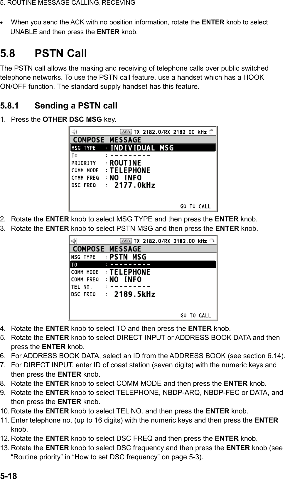
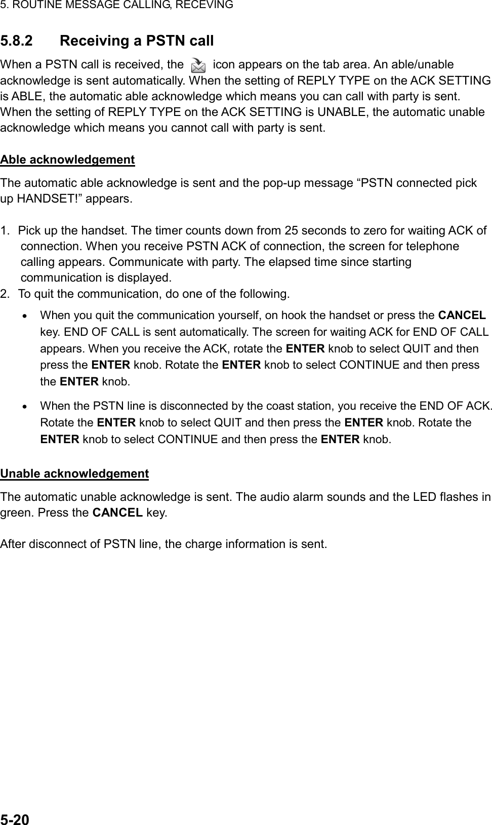
![5. ROUTINE MESSAGE CALLING, RECEVING 5-1914. Rotate the ENTER knob to select GO TO CALL and then press the ENTER knob. The PSTN call is sent. After the call has been sent, the screen for waiting ACK appears. The elapsed time since sending the call and the count down time for re-sending the call (25 seconds) is displayed. When you receive an acknowledge message, the audio alarm sounds and the pop-up message appears. 15. Do one of the following depending on ACK message. Able acknowledge message received If the PSTN call is accepted, the PSTN connection call is sent. The timer counts down from 25 seconds to zero for waiting ACK of connection. When you receive PSTN ACK of connection, the pop-up message “PSTN connected pick up HANDSET!” appears and the communication frequency changes. Note: When you do not receive PSTN ACK of connection within 25 seconds, the pop-up message “PSTN disconnected because of timeout. [CANCEL]: Close window” appears. 1. Pick up the handset and communicate with the party you called. The following is the screen for telephone calling. The elapsed time since starting communication is displayed. 2. To quit the communication, do one of the following. • When you quit the communication yourself, on hook the handset or press the CANCEL key. END OF CALL is sent automatically. The screen for waiting ACK for END OF CALL appears. When you receive the ACK, rotate the ENTER knob to select QUIT and then press the ENTER knob. Rotate the ENTER knob to select CONTINUE and then press the ENTER knob. • When the PSTN line is disconnected by the coast station, you receive the END OF ACK. Rotate the ENTER knob to select QUIT and then press the ENTER knob. Rotate the ENTER knob to select CONTINUE and then press the ENTER knob. Unable acknowledge message received When you receive an unable acknowledge message, the audio alarm sounds. The pop-up message appears. Rotate the ENTER knob to select QUIT and then press the ENTER knob. Rotate the ENTER knob to select CONTINUE and then press the ENTER knob.](https://usermanual.wiki/Furuno-USA/9ZWFS2575/User-Guide-1533875-Page-65.png)

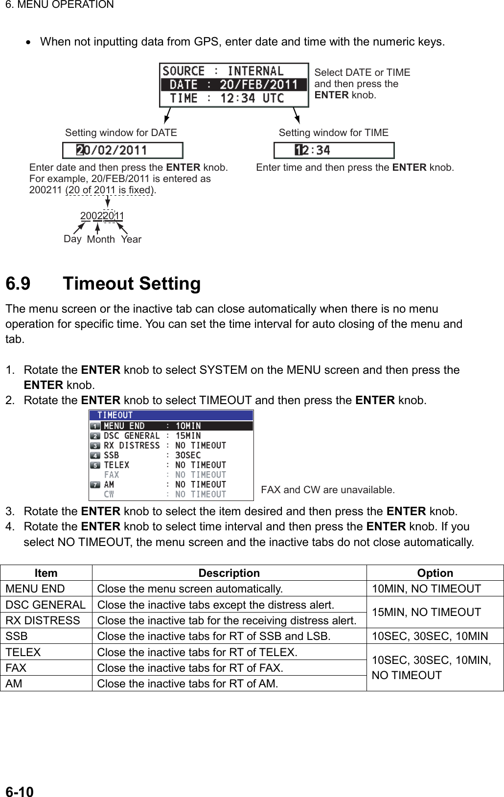
![6. MENU OPERATION 6-9Setting window for latitude Enter latitude.Setting window for longitudePress the ENTER knob.Enter longitude. Press the ENTER knob.Setting window for UTC Enter UTC and then press the ENTER knob. Note: When the setting of INPUT TYPE is MANUAL, the message “WARNING: Position data is not updated! Position data was older than 4.0H*. Update it. [CANCEL]: Stop alarm” appears at set intervals (*: update interval selected with POSITION OLDER on the POSITION menu) to ask you to update position. How to set POSITION OLDER 1. Rotate the ENTER knob to select OLDER on the POSITION menu and then press the ENTER knob. 2. Rotate the ENTER knob to select appropriate interval time and then press the ENTER knob. 6.8 Date and Time Setting Set the date and time for the system. 1. Rotate the ENTER knob to select SYSTEM on the MENU screen and then press the ENTER knob. 2. Rotate the ENTER knob to select DATE/TIME and then press the ENTER knob. • When inputting data from GPS, cannot change setting; only for viewing.](https://usermanual.wiki/Furuno-USA/9ZWFS2575/User-Guide-1533875-Page-75.png)
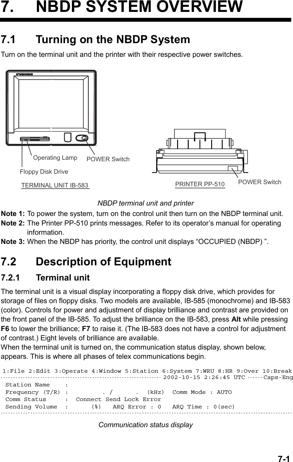
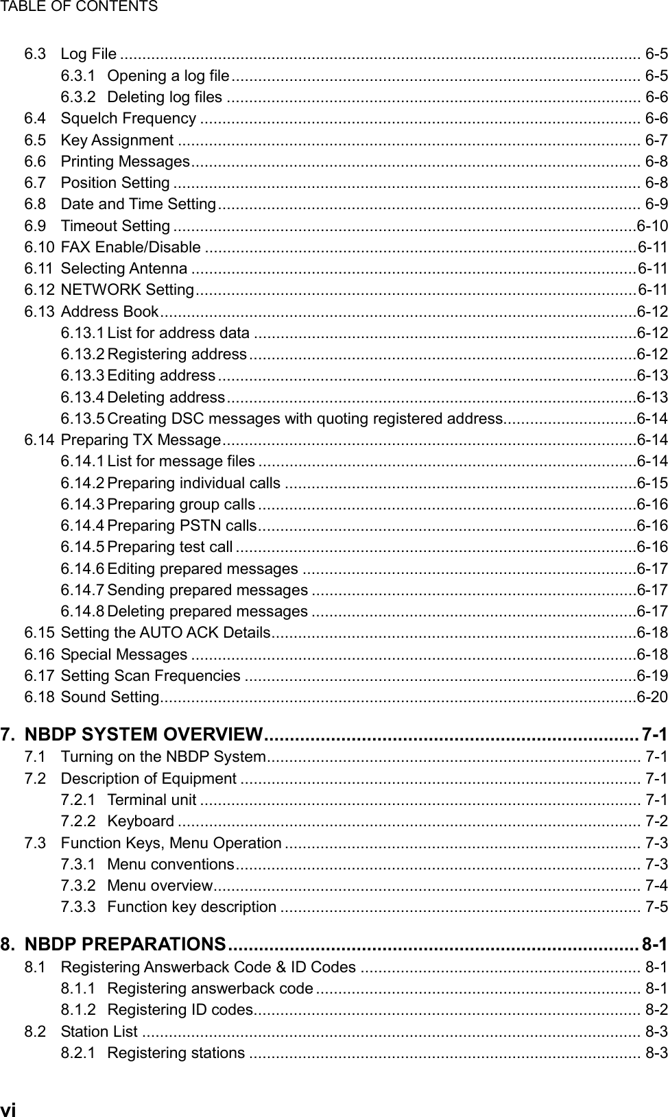
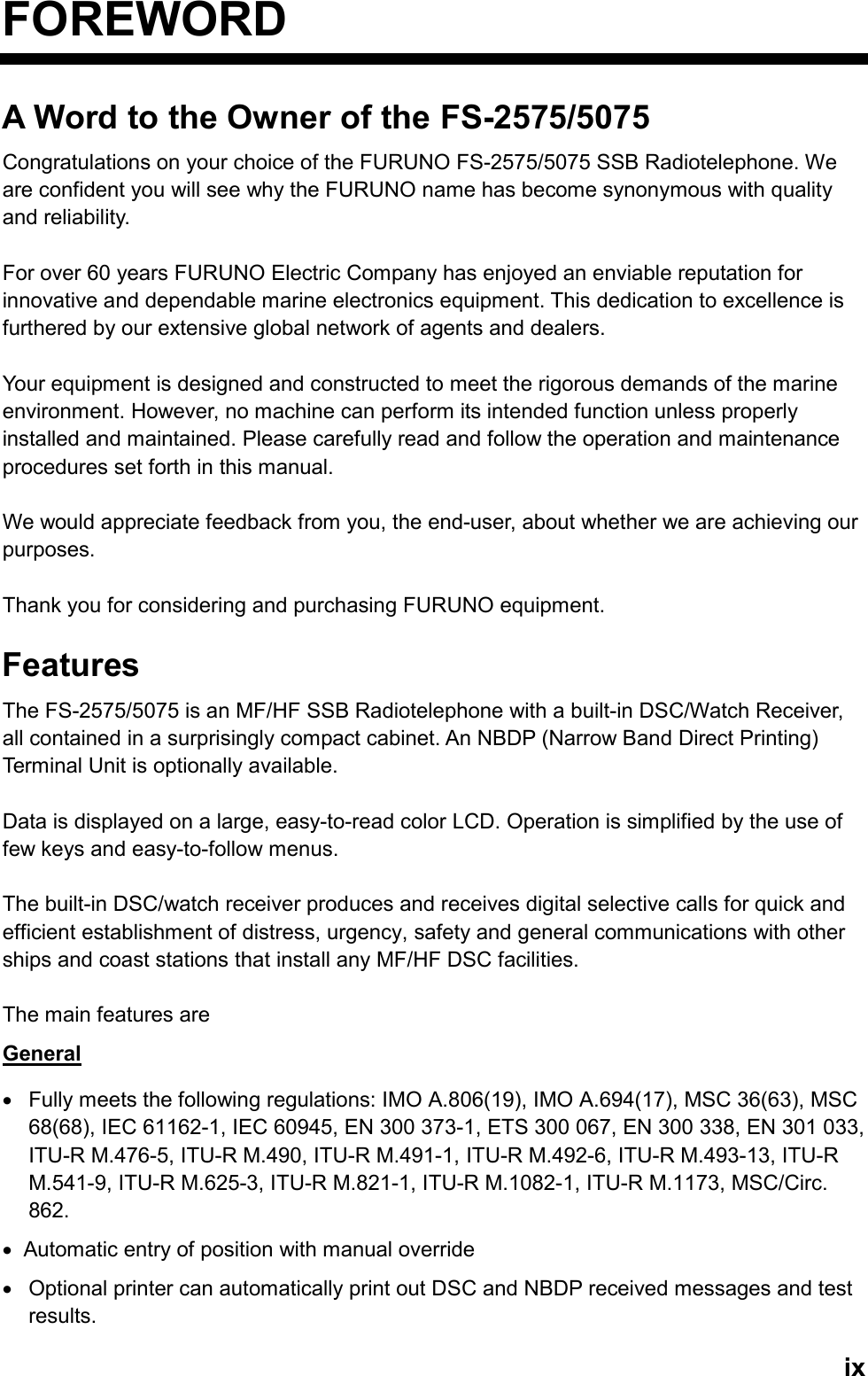
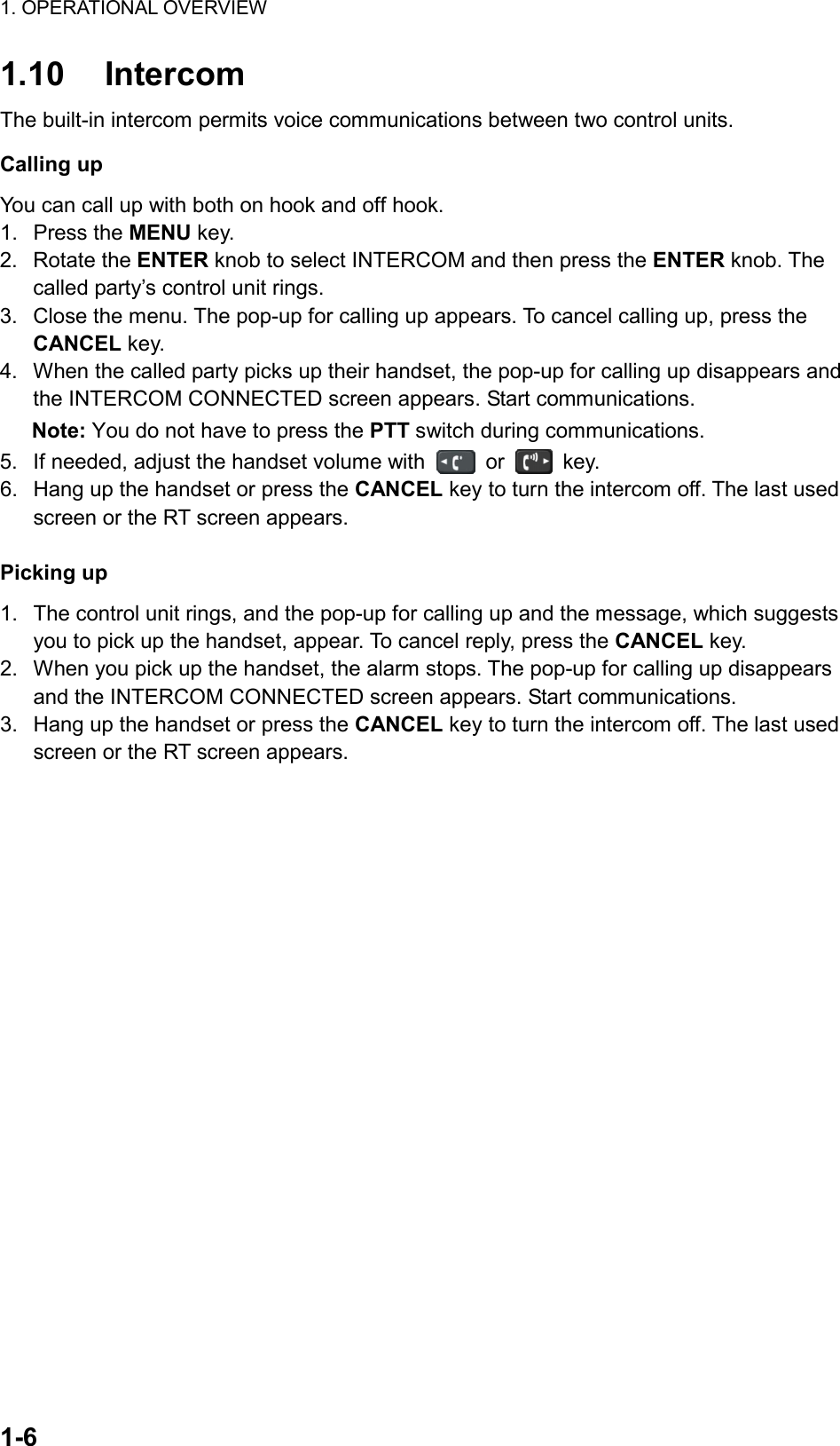
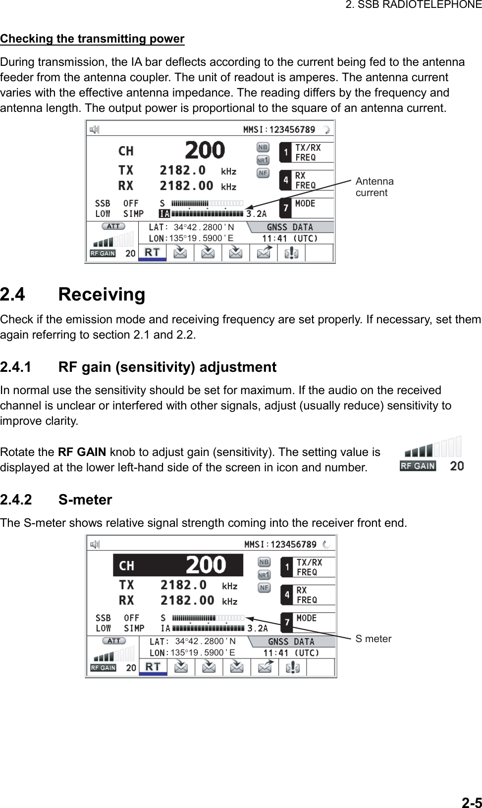
![7. NBDP SYSTEM OVERVIEW 7-2 Features of the IB-583 The IB-583 is fitted with both English and Russian interface. Select desired interface as below: English: Turn on the IB-583 while pressing the E key. Russian: Turn on the IB-583 while pressing the R key. The IB-583 has a battery (type CR2450-F2ST2L, code no. 000-144-941) on its TERM/CPU Board (16P0209) and its life is about six years. When the voltage of the battery is low, the time will be slow. When this occurs, contact your dealer about replacement of the battery. Note: To switch between Russian and English input, press Alt while holding down Shift. (This is available in Russian mode only.) 7.2.2 Keyboard The terminal unit is operated from the keyboard, and is almost 100% keyboard controlled. Operation is simplified by the use of menus which you access by pressing a function key, labeled F1-F10 at the top of the keyboard. The figure below shows the function menus and their corresponding function keys. 5!1@2#3$4%5^6+=&77(99Back-spaceHome88)0Pg UpQ W E R T Y I{[}]\TabU4O6P-Pg DnA S D F G H"’EnterEnterCapsLockJ1K2L3:;+EndShiftZ X C V B N<,?//>.M0ShiftCtrlCtrl FnAlt Alt Ins DelEsc F3 F4 F5 F6 F7 F8 F9 F10NumLockPrt ScSys RqScrollLock PauseBreakF1F11F2F125_-~,I.FILE EDITOPERATEWINDOWSTATIONSYSTEMWRUHR BREAKOVER Keyboard for IB-583](https://usermanual.wiki/Furuno-USA/9ZWFS2575/User-Guide-1533875-Page-88.png)
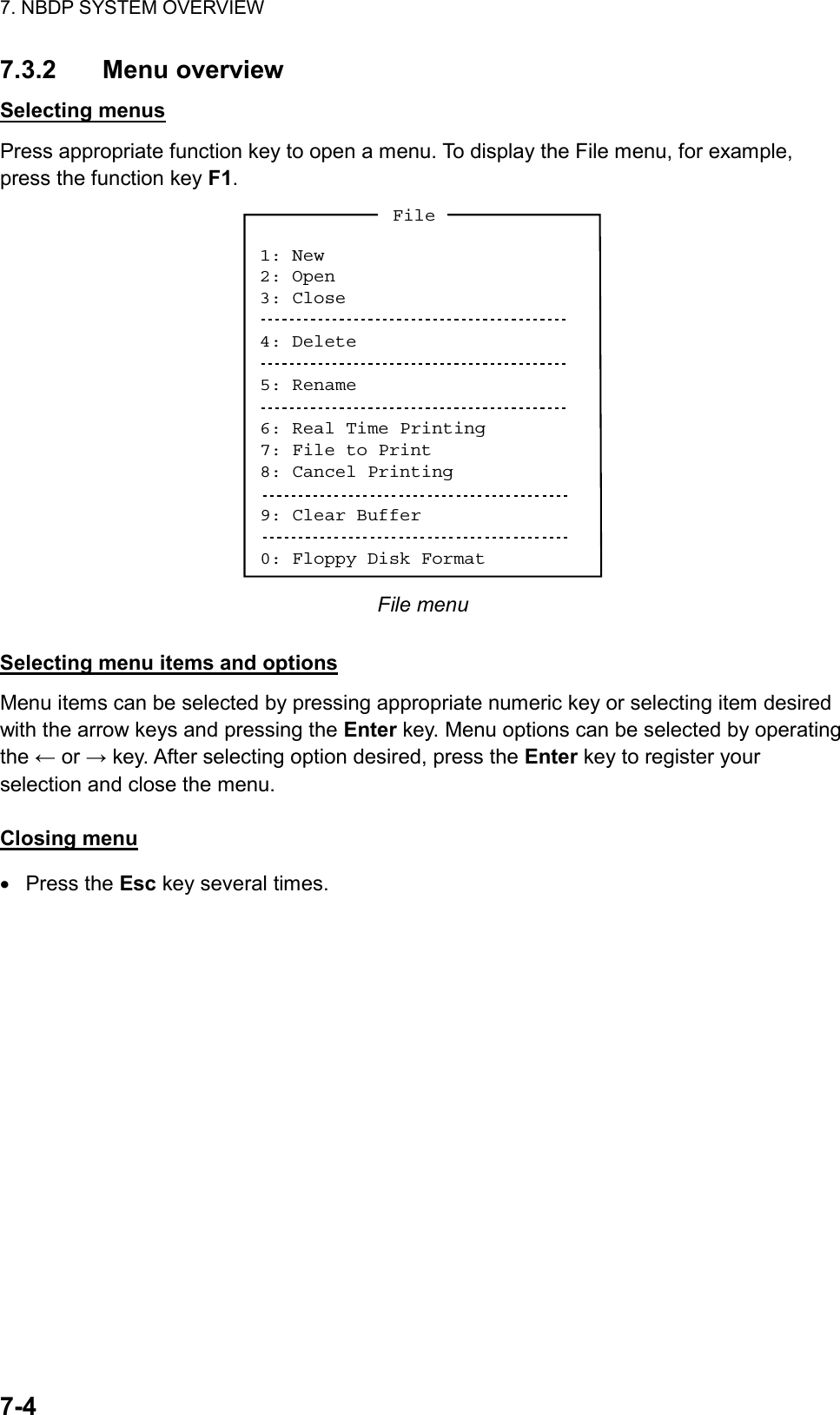
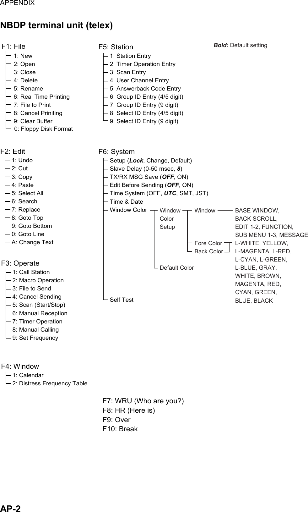
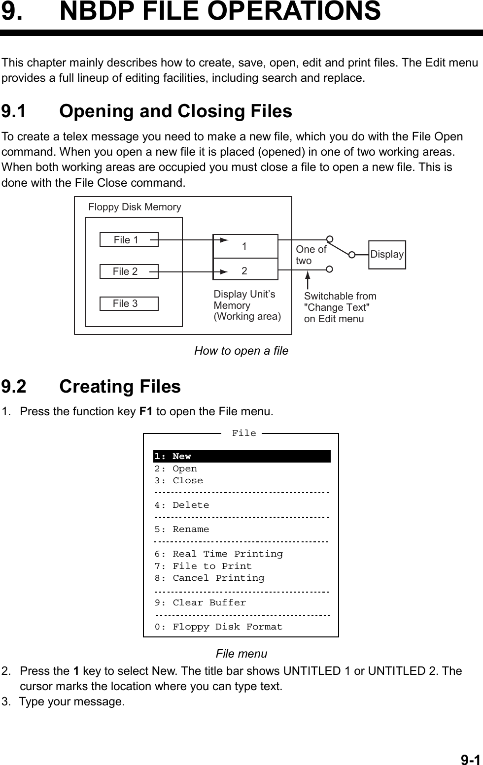
![7. NBDP SYSTEM OVERVIEW 7-57.3.3 Function key description Function key [F1]: File menu The File menu is where you will create, open, save and print telex messages. Floppy disks are also formatted from this menu. 1: New2: Open3: Close4: Delete5: Rename6: Real Time Printing7: File to Print8: Cancel Printing9: Clear Buffer0: Floppy Disk FormatFile File menu 1: New Open a new untitled window. 2: Open Open files saved on the floppy disks. 3: Close Close files. 4: Delete Delete files on the floppy disks. 5: Rename Rename files on the floppy disks. 6: Real Time Printing Turn real time printing on/off. 7: File to Print Print files on the floppy disks. 8: Cancel Printing Stop printing. 9: Clear Buffer Clear the communications buffer. 0: Floppy Disk Format Format a floppy disk.](https://usermanual.wiki/Furuno-USA/9ZWFS2575/User-Guide-1533875-Page-91.png)
![7. NBDP SYSTEM OVERVIEW 7-6 Function key [F2]: Edit menu The Edit menu provides a full line of editing features. 1: Undo2: Cut3: Copy4: Paste5: Select All6: Search7: Replace8: Goto Top9: Goto Bottom0: Goto LineA: Change TextEdit Edit menu 1: Undo Cancel the last change (cut, copy or paste). 2: Cut Remove the selected text and store it in the paste buffer. (Previous text in the paste buffer is cleared.) 3: Copy Copy the selected text and store it in the paste buffer. (Previous text in the paste buffer is cleared.) 4: Paste Insert the text stored in the paste buffer at the current location of the cursor. 5: Select All Select the entire current file for cut or copy. 6: Search Search a word or a character string. 7: Replace Replace a word with a different word or character string. 8: Goto Top Bring the cursor to the top line of the current file. 9: Goto Bottom Bring the cursor to last line of the current file. 0: Goto Line Move the cursor to the desired line in the current file. A: Change Text Switch between the display window 1 and 2.](https://usermanual.wiki/Furuno-USA/9ZWFS2575/User-Guide-1533875-Page-92.png)
![7. NBDP SYSTEM OVERVIEW 7-7Function key [F3]: Operate menu The Operate menu mainly controls transmitting and receiving. 1: Call Station3: File to Send4: Cancel Sending5: Scan (Start/Stop)6: Manual Reception7: Timer Operation8: Manual Calling9: Set FrequencyOperate2: Macro Operation Operate menu 1: Call Station Select a station from the station list. 2: Macro Operation Enable macro operation. For details, see paragraph 10.10. 3: File to Send Select a file (to transmit). 4: Cancel Sending Stop sending a file. 5: Scan Start/Stop Start/stop frequency scanning. 6: Manual Reception Select communication mode for reception; AUTO, ARQ, FEC DIRC. Note: The FS-2575/5075 is not affected by this setting. 7: Timer Operation Timer programming. 8: Manual Calling Set TX mode and subscriber’s ID number in manual calling. 9: Set Frequency Set TX and RX frequencies in manual calling.](https://usermanual.wiki/Furuno-USA/9ZWFS2575/User-Guide-1533875-Page-93.png)
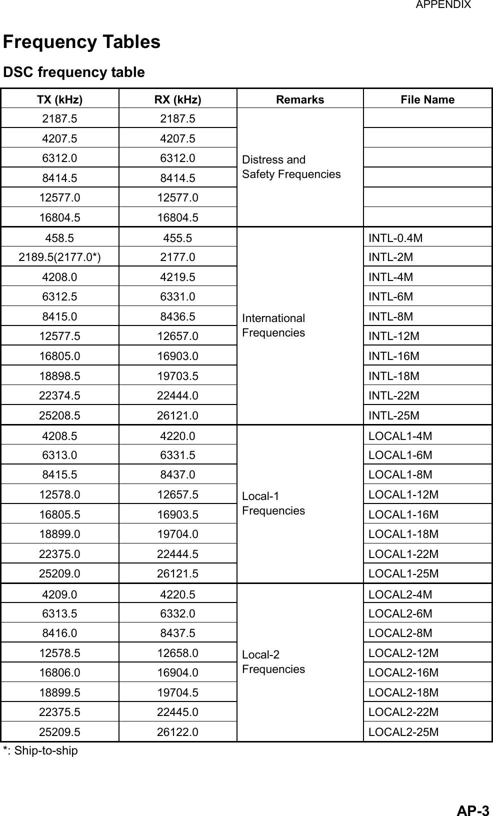
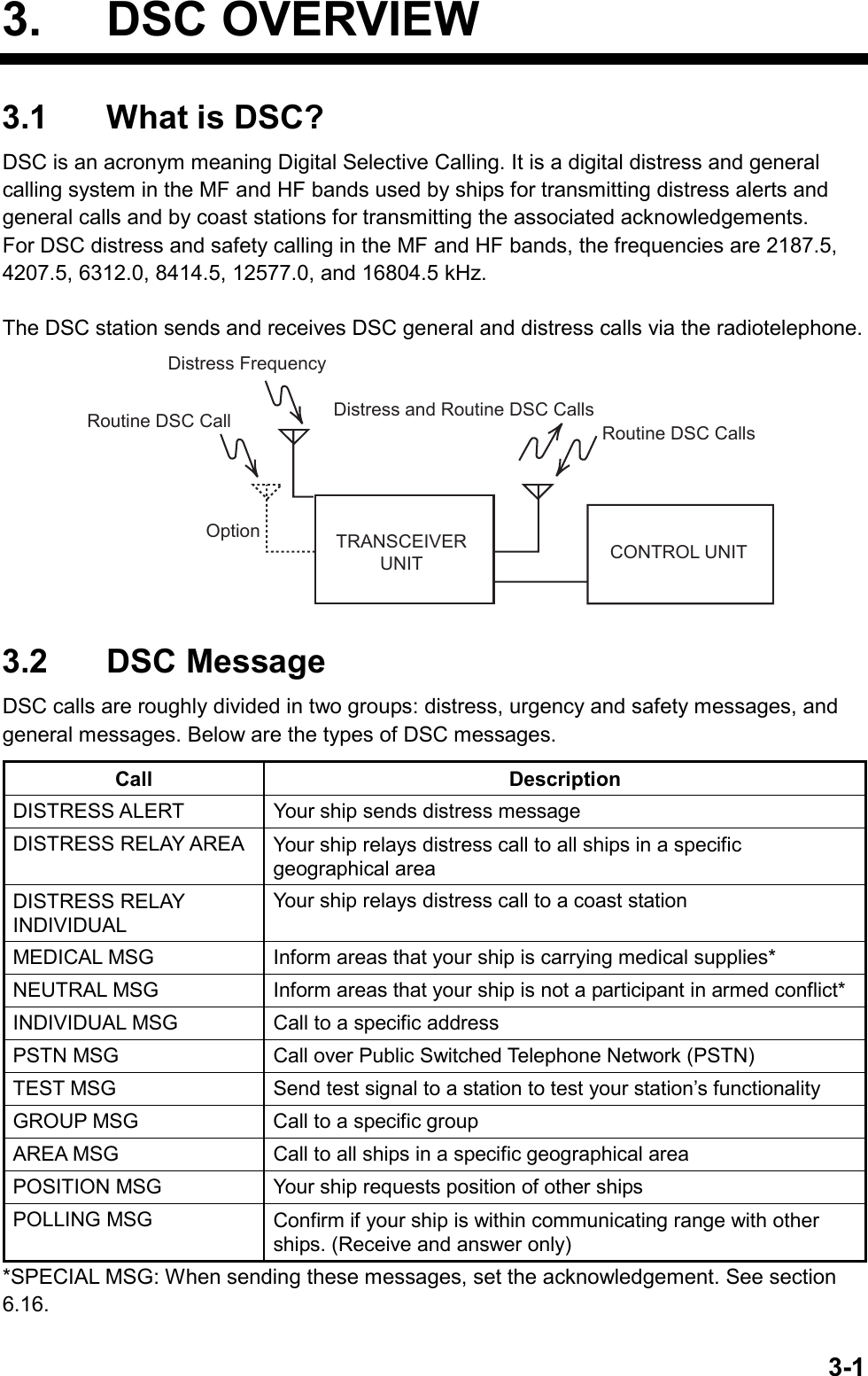
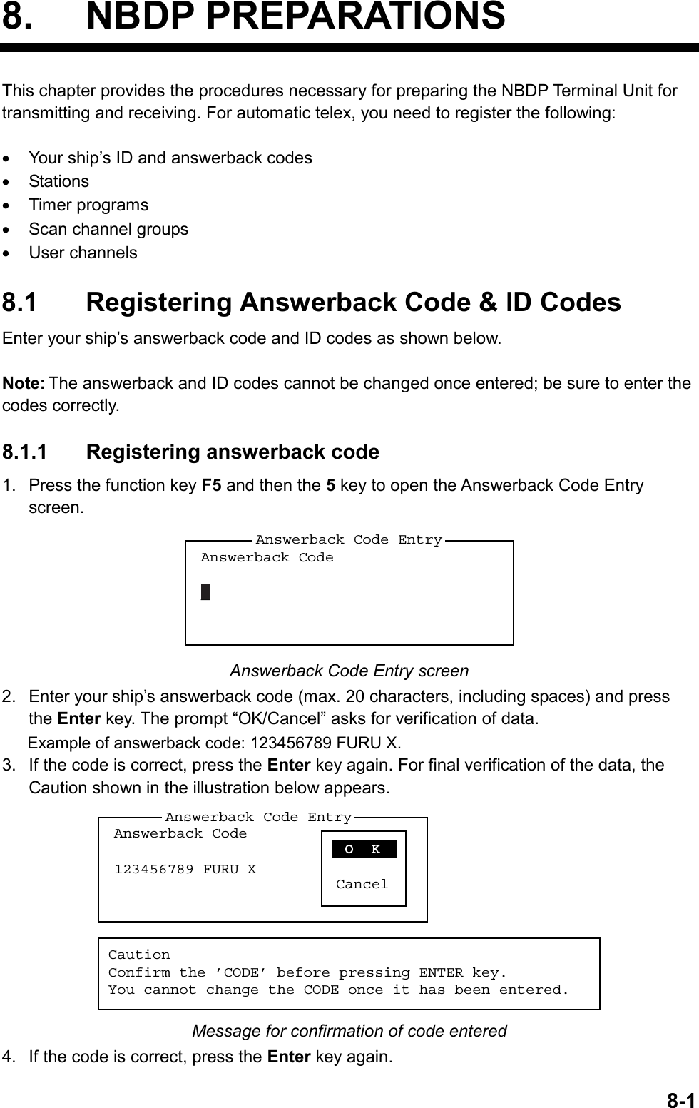
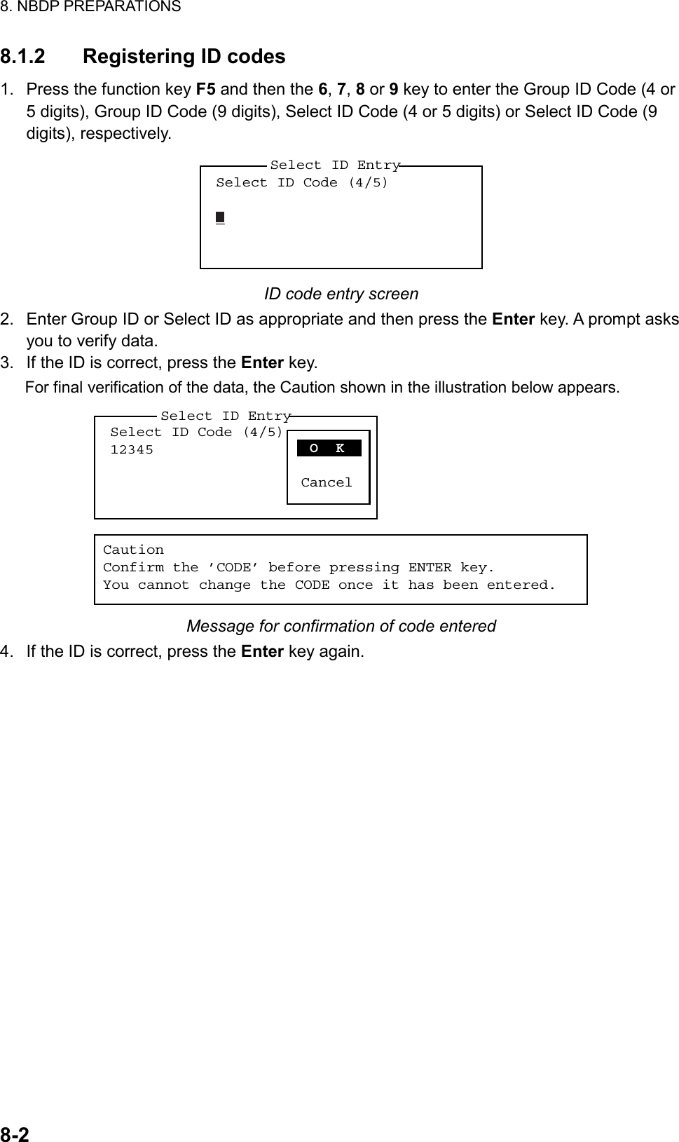
![7. NBDP SYSTEM OVERVIEW 7-8 Function key [F4]: Window menu The Window menu lets you display the corresponding data of the window below. 1: Calendar2: Distress Frequency Table Window Window menu 1: Calendar Display desired calendar month and year. To change year or month, select item with ↑ or ↓ key and change setting with ← or → key. 2: Distress Frequency Table Display all distress frequencies. Distress FrequenciesTelephone (kHz): 2182.0 4125.0 6215.0 8291.0 12290.0 16420.0NBDP (kHz) : 2174.5 4177.5 6268.0 8376.5 12520.0 16695.0DSC (kHz) : 2187.5 4207.5 6312.0 8414.5 12577.0 16804.5 Function key [F5]: Station menu The Station menu provides for storage of stations, timer program setup, user channel setup, and entry of various ID codes. 1: Station Entry2: Timer Operation Entry3: Scan Entry4: User Channel Entry5: Answerback Code Entry6: Group ID Entry (4/5 digit)7: Group ID Entry (9 digit)8: Select ID Entry (4/5 digit)9: Select ID Entry (9 digit)Station Station menu 1: Station Entry Register stations. 2: Timer Operation Entry Register timer programs. 3: Scan Entry Create scan groups for scanning. 4: User Channel Entry Register user channels.](https://usermanual.wiki/Furuno-USA/9ZWFS2575/User-Guide-1533875-Page-94.png)
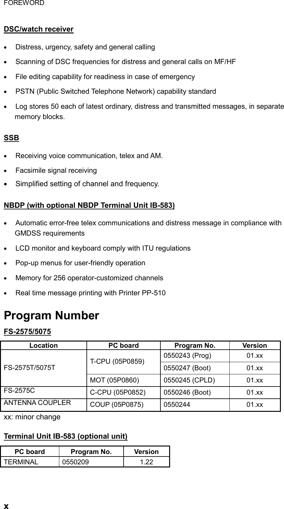
![7. NBDP SYSTEM OVERVIEW 7-95: Answerback Code Entry Register own ship’s answerback code. 6: Group ID Entry Register own ship’s group ID codes (4 or 5 digit). 7: Group ID Entry Register own ship’s group ID codes (9 digit). 8: Select ID Entry Register own ship’s selective ID codes (4 or 5 digit). 9: Select ID Entry Register own ship’s selective ID codes (9 digit). Function key [F6]: System menu The System menu is mainly for use by technicians and contains diagnostic tests. To change settings, select Change from the item Setup and operate arrow keys to select item and option. Press the Enter key to register selection and close the menu. SetupSlave DelayTX/RX MSG SaveEdit Before sendingTime SystemTime & DateWindow ColorSelf TestLock Change Default 8 msec (0- 50 msec)OFF O NOFF O NOFF UTC SMT JST2002/10/16 10:00:00System System menu Setup Lock, change settings; restore default system settings. Slave Delay Set the length of the slave delay timing from the end of RX to the start of TX in the ARQ mode. The default setting is suitable in most cases. This item cannot be adjusted by the user. ARQ mode signal sequence3 char. RX 3 char. RXSlave Delay TimingRX end TX startACK signal TX/RX MSG Save Turn on to automatically save incoming and outgoing messages to a floppy disk. “Log” appears at the top of the screen when on. Edit Before sending “OFF” transmits keying operation one by one. “ON” transmits message only when the Enter key is pressed after confirming text typed. Time System Select time system. UTC: Coordinated universal time SMT: Local time JST: Japan standard time. Time & Date Enter date and time manually. If a navigation device is connected, the time is automatically set when the power is turned on or whenever the time system is switched. Manual entry takes priority over automatic entry. This item cannot be adjusted when using JST or UTC.](https://usermanual.wiki/Furuno-USA/9ZWFS2575/User-Guide-1533875-Page-95.png)
![7. NBDP SYSTEM OVERVIEW 7-10 Window Color Select display colors. To change display colors: 1. Select Change from Setup. 2. Press the ↓ key to select Window Color and then press the Enter key. Window Color Change Window Color SetupDefault ColorTo Change: ENTER To quit: ESC 3. The cursor is selecting Window Color Setup; press the Enter key. Window Color SetupWindow : [BASE WINDOW ] Fore Color : [L-WHITE ] Back Color : [BLUE ]To Change: ENTER To Change Value: L<=>R 4. Press the → key to select the item to change: BASE WINDOW, BACK SCROLL, EDIT 1-2, FUNCTION, SUB MENU 1-3, MESSAGE. 5. Press the ↓ key to select Fore Color. 6. Press the → key to select color: L-WHITE, BLACK, BLUE, GREEN, CYAN, RED, MAGENTA, BROWN, WHITE, GRAY, L-BLUE, L-GREEN, L-CYAN, L-RED, L-MAGENTA, YELLOW. 7. Press the ↓ key to select Back Color. 8. Press the → key to select color. 9. Press the ↑ key to select Window. 10. Repeat the step 4 to 9 to set other colors. 11. Press the Enter key followed by the Esc key. Self Test: Start diagnostic test. Function key [F7]: WRU (Who Are You?): In the ARQ mode, request other station’s answerback code. Function key [F8]: HR (Here Is): In the ARQ mode, send your ship’s answerback code. Function key [F9]: OVER: In the ARQ mode, switch the direction of traffic; the information receiving station becomes the information sending station, the information sending station becomes the information receiving station. Function key [F10]: Break: Disconnect the line.](https://usermanual.wiki/Furuno-USA/9ZWFS2575/User-Guide-1533875-Page-96.png)
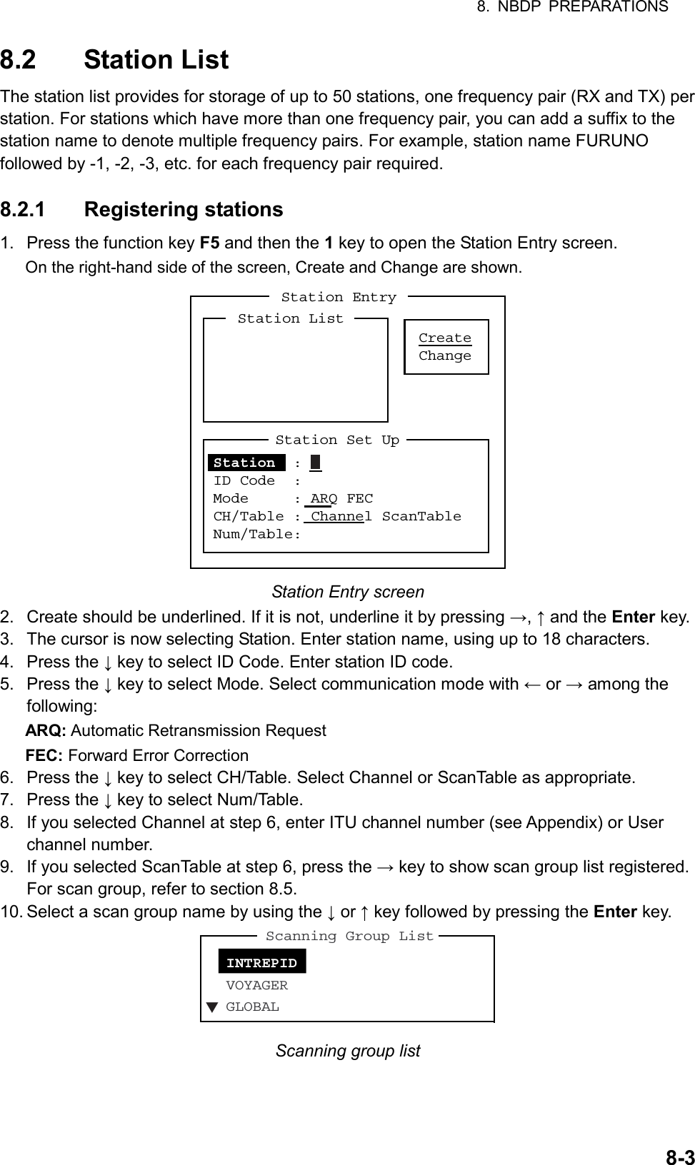
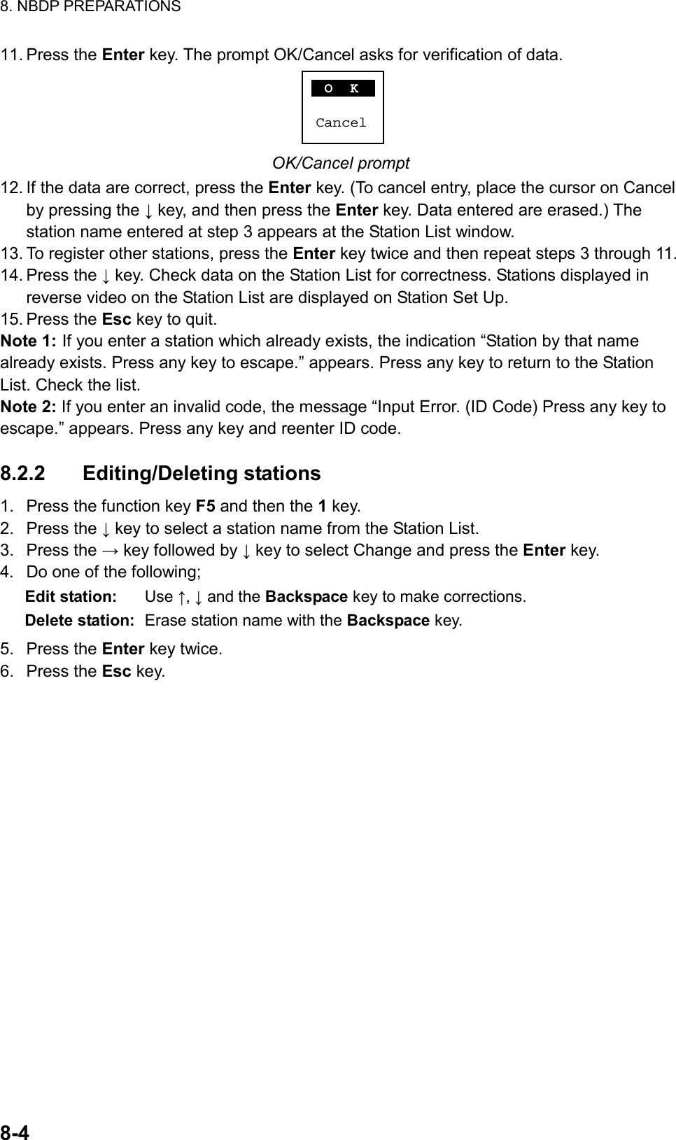
![8. NBDP PREPARATIONS 8-58.3 Timer Programming A built-in timer allows you to automatically receive and transmit files. 10 timer programs can be registered. To enable timer operation, see section 10.6. 8.3.1 Registering timer programs 1. Press the function key F5 and the 2 key to open the Timer Operation Entry screen. CreateChangeTimer Operation EntryTimer Operation ListTimer Operation Set UpOperation : Station :Start Time : 0: 00: 00Stop Time : 0: 00: 00Receive/Send : Receive SendFile to Send :Press [→] to show station list, file list. Timer Operation Entry screen 2. If Create is not underlined, press →, ↑ and the Enter key to underline it. 3. Operation is selected. Enter a suitable operation name on the Operation line. Any alphanumeric characters can be used. Note: If the operation name entered already exists, the message “Operation name already exists. Press any key to escape.” Appears. Press any key and change the operation name. 4. Press the ↓ key to select Station. 5. Press the → key to display the Station List (which you registered stations in the previous paragraph). 6. Select a station with ↓ or ↑ key and press the Enter key. 7. Press the ↓ key to select Start Time. Enter start time, in 24-hour notation. To have the operation start at 8:35 a. m., for example, the keying sequence would be; 0 8 3 5 0 0 8. Press the ↓ key to select Stop Time. Enter stop time, in 24-hour notation. 9. Press the ↓ key to select Receive/Send. Select operation category; Receive or Send. If you select “Send,” go to step 10. For “Receive,” go to step 12. 10. For send, insert the floppy disk which you want to send in the floppy drive, press the ↓ key to select File to Send. 11. Press the → key to open the TX window, select a file, and press the Enter key twice. 12. Press the Enter key. 13. Press the Enter key. The operation name appears in the Timer Operation List. 14. To enter another timer program, press the Enter key twice and repeat steps 3-11. 15. Press the Esc key to close the menu.](https://usermanual.wiki/Furuno-USA/9ZWFS2575/User-Guide-1533875-Page-101.png)
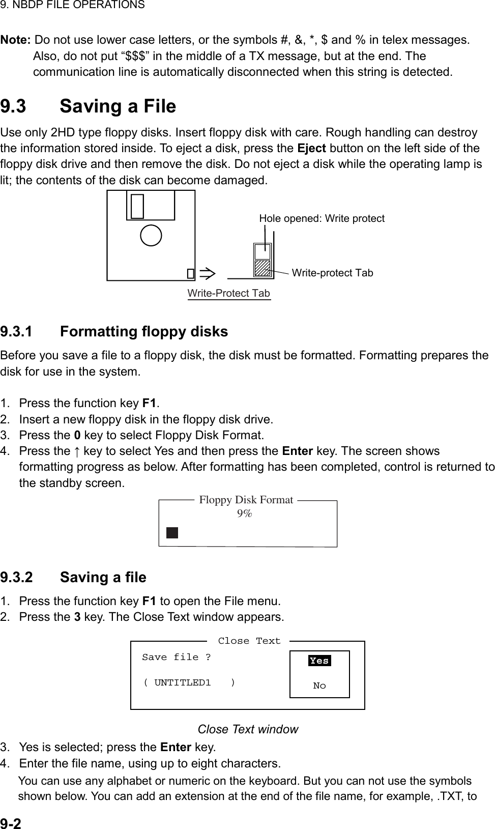
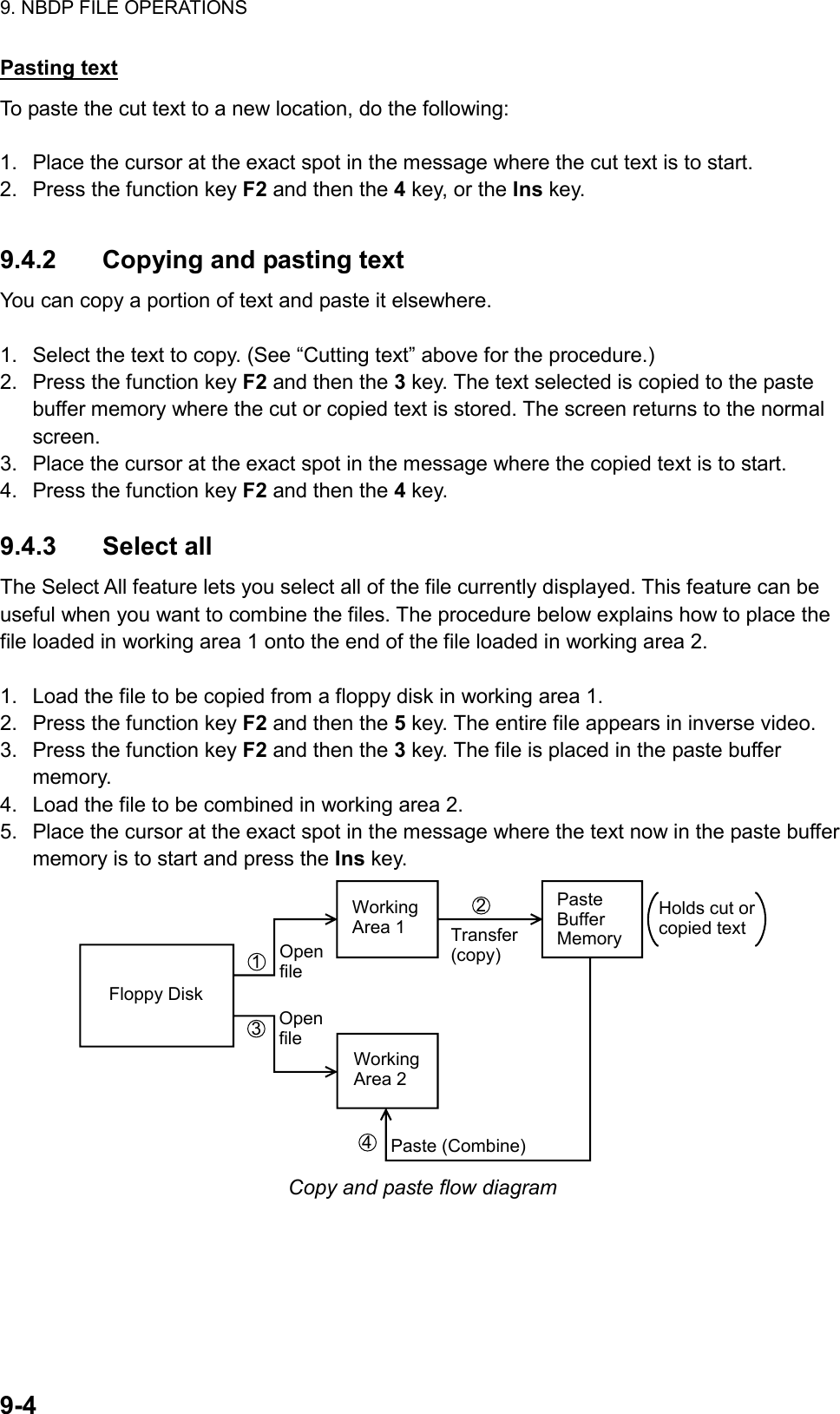
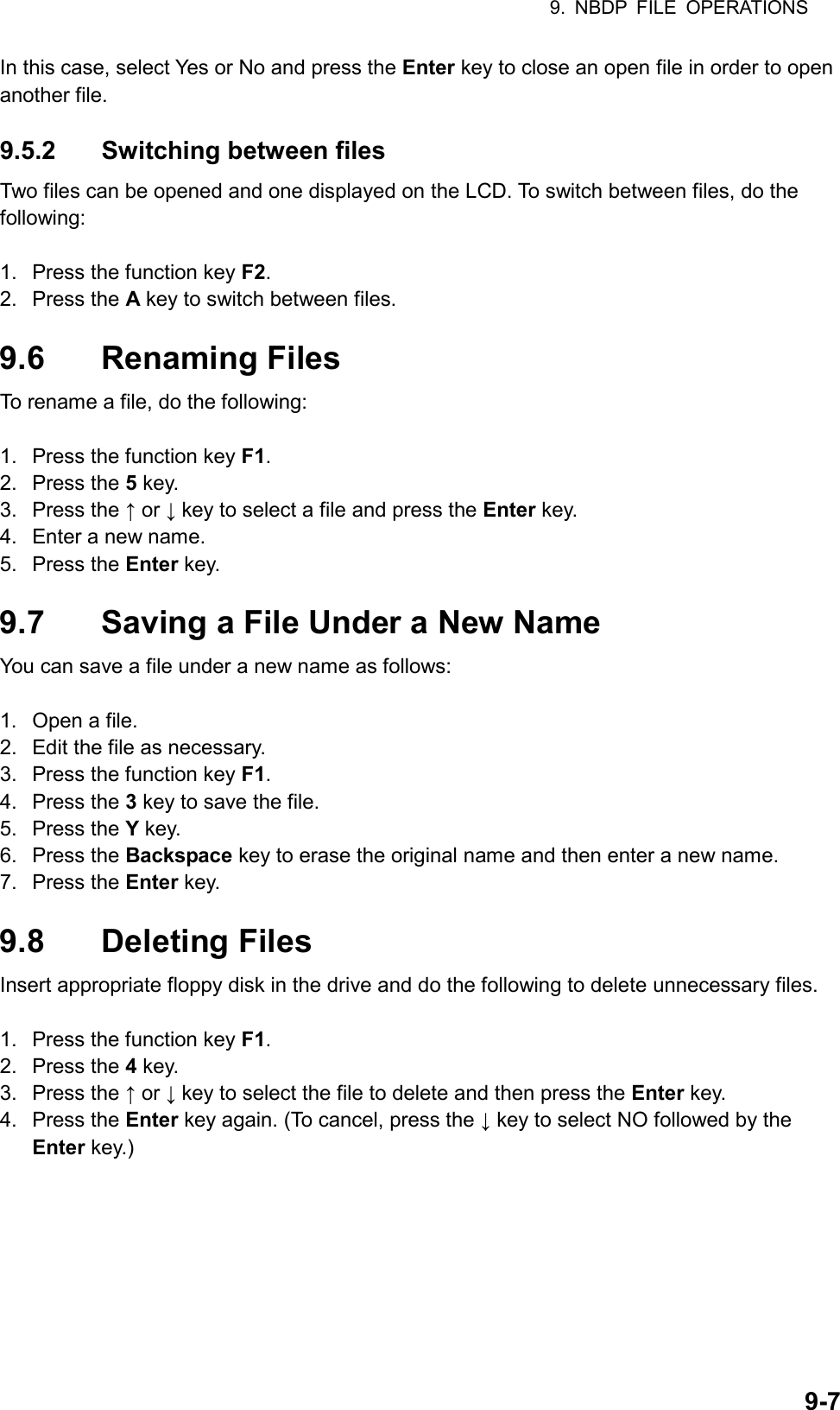
![9. NBDP FILE OPERATIONS 9-3distinguish text files from macro files. | : " > < ;! 5. Press the Enter key. 9.4 Editing Files 9.4.1 Cutting and pasting text You can delete, move and copy text by using the Cut, Copy and Paste functions in the Edit menu. 1: Undo2: Cut3: Copy4: Paste5: Select All6: Search7: Replace8: Goto Top9: Goto Bottom0: Goto LineA: Change TextEdit Edit menu Cutting text 1. Place the cursor on the first character of the text to be cut. 2. Highlight the text to be cut by pressing and holding the Shift key while pressing the→ key. If you highlight text which you do not want to cut, press the ← key to adjust the highlight. <[1]UNTITLED1>CONGULATULATION ON YOUR CHOICE OF DP-6INMARSAT B MOBILE EARTH STATION.WE ARE CONFIDENT THAT YOU WILL ENJOY MANY YEARS OFOPERATION WITH THIS FINE PIECE OF EQUIPMENT The highlight 3. Press the function key F2 and then the 2 key, or the Del key. The highlighted text is cut and the remaining text is reformatted. If you make a mistake, you can restore the text by immediately selecting Undo from the Edit menu.](https://usermanual.wiki/Furuno-USA/9ZWFS2575/User-Guide-1533875-Page-107.png)
![9. NBDP FILE OPERATIONS 9-6 9.4.6 Goto line The Goto Line feature places the cursor at the head of a line desired. 1. Press the function key F2 and then the 0 key. The Goto Line window appears. Goto LineJump to Line No. : Goto Line window 2. Key in line number and press the Enter key. The cursor shifts to the head of the line selected. 9.4.7 Goto top, Goto bottom You can easily go to the top or bottom line of a file. Press the function key F2 and then the 8 key to go to the top line; press the function key F2 and then the 9 key to go to the bottom line. Note that this feature can also be executed on the editor screen by pressing the Home or End key while pressing the Fn key. 9.5 Opening Files Two working areas (called working area 1 and working area 2) are provided to which you can load a file, and one file can be displayed on the LCD. 9.5.1 Opening a file 1. Insert the floppy disk which contains the file you want to open. 2. Press the function key F1 to open the File menu. 3. Press the 2 key. A list of files on the floppy disk appears. Open TextLoad/Merge(TAB:Change)[A:\TEST1. ] File name Size Date & TimeLOG File 52 02-10-15 17:25TEST1. 120 02-10-15 16:30TEST2. 151 02-10-15 9:25TEST3. 180 02-10-15 20:16NBDP 169 02-10-15 6:23[ End of Directory ]4 Files exist 1454000 bytes freeTo select : ENTER To view : SPACE To quit : ESC 4. Press the ↑ or ↓ key to select a file. 5. Press the Enter key. The file appears and the title bar shows the file name. You can repeat this procedure to load another file into a working area. Note: When two working areas have been opened, the close confirmation window appears.](https://usermanual.wiki/Furuno-USA/9ZWFS2575/User-Guide-1533875-Page-110.png)
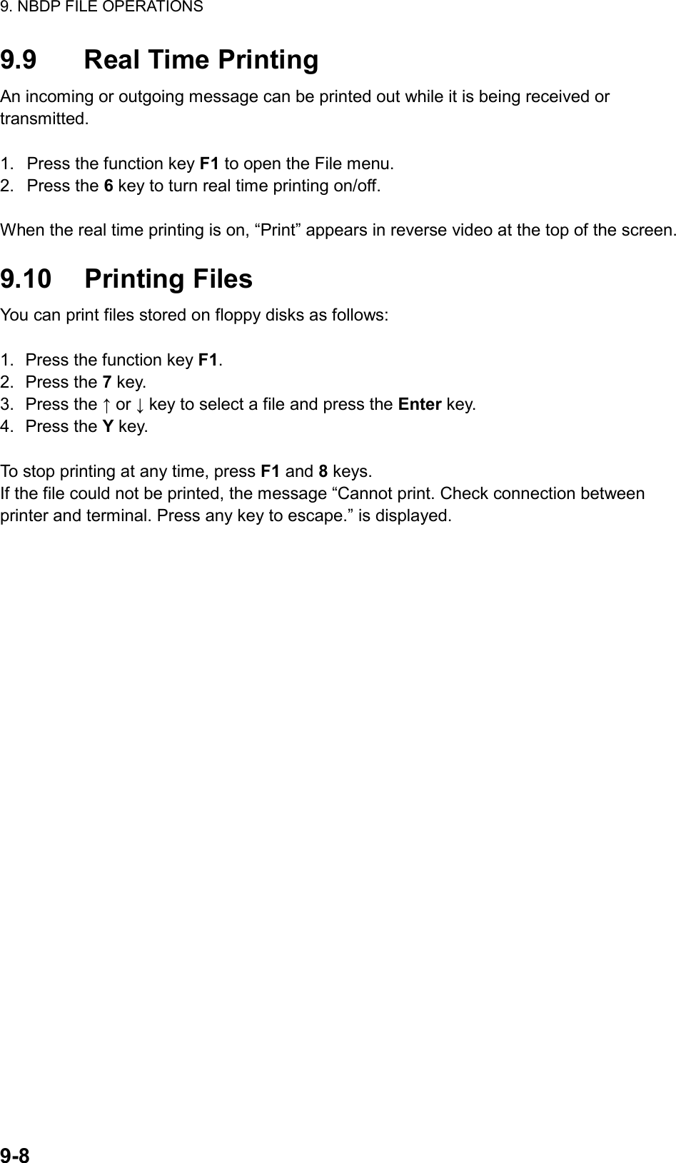
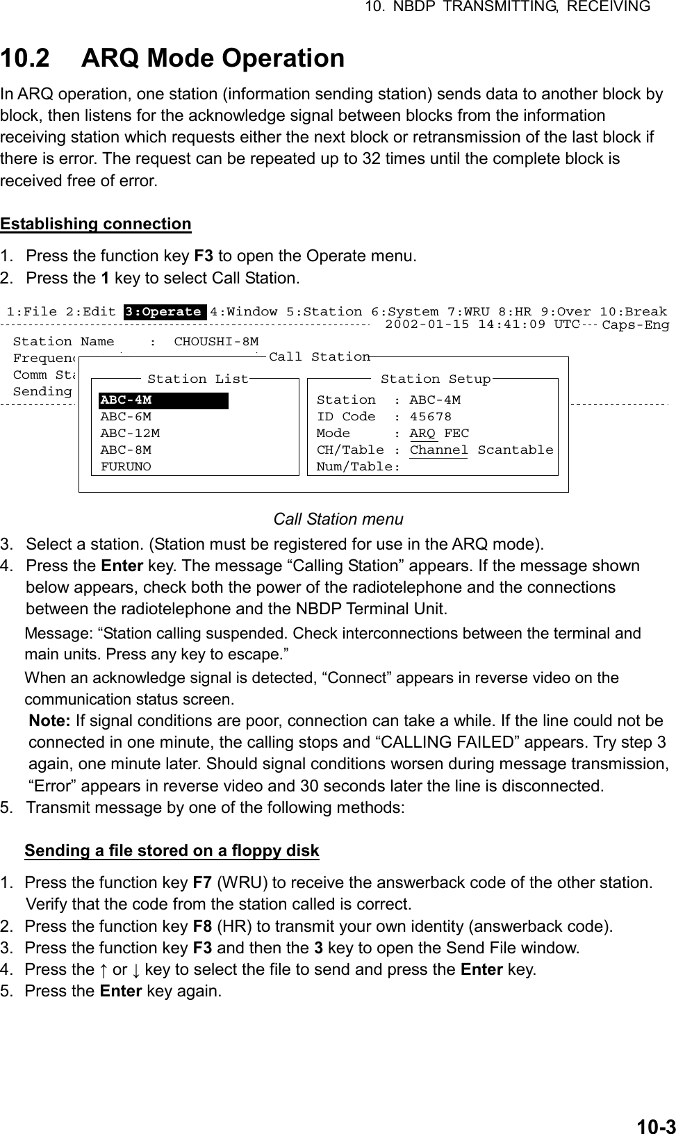
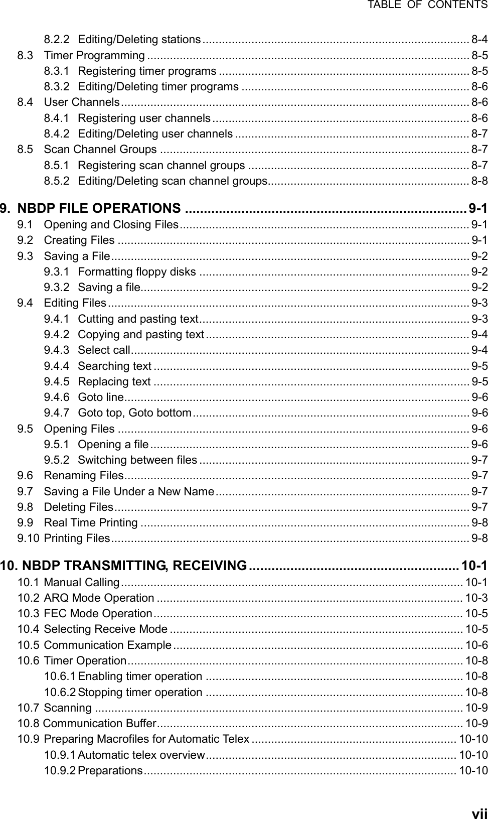
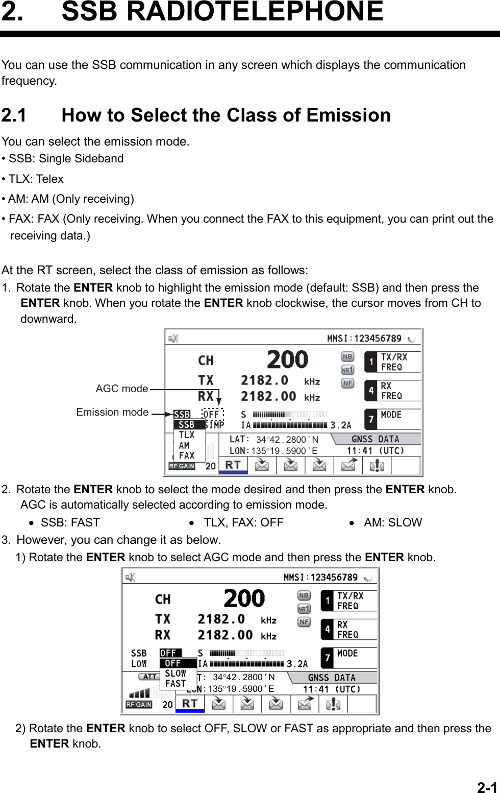
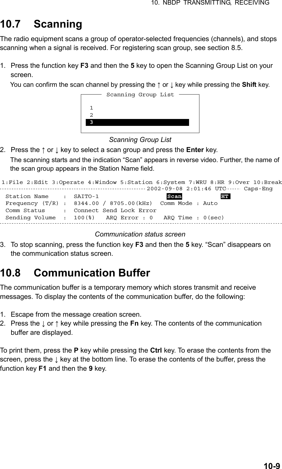
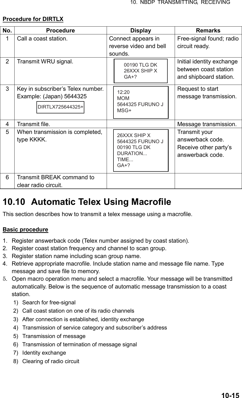
![10. NBDP TRANSMITTING, RECEIVING 10-4 [A:\TEST1. ] File name Size Date & TimeLOG File 52 02-10-15 17:25TEST1. 120 02-10-10 16:30TEST2. 151 02-10-11 09:25TEST3. 180 02-10-11 20:16NBDP 169 02-10-12 06:23[ End of Directory ]4 Files exist 1454000 bytes freeTo select : ENTER To view : SPACE To quit : ESCSend File Send File window Sending volume (percentage of message transmitted, counts upward as the message is being transmitted), ARQ error count and ARQ transmission time appear on the screen. “Lock” appears in reverse video when the mark and space signals in the receive signal are normal. “ARQ Error” shows the number of times error was found during transmission. “ARQ Time” is the time in seconds the communication line has been established. Station Name : Frequency (T/R) : 8765.00 / 8965.00(kHz) Comm Mode :ARQComm Status : Connect Send Lock Error Sending Volume : 100(%) ARQ Error : 0 ARQ Time : 0(sec)Caps-Eng1:File 2:Edit 3:Operate 4:Window 5:Station 6:System 7:WRU 8:HR 9:Over 10:Break2002-09-08 2:14:28 UTC HT Communication status screen 6. After the message is transmitted, press the function key F10 (Break) to disconnect the line. Type a message from the keyboard 1. After exchanging answerback code by the function key F7 (WRU) and F8 (HR), type your message directly from the keyboard. 2. To change the direction of traffic, press the function key F9 (Over), or +, ? in order. Then, the other station becomes the information sending station, your station becomes the information receiving station. Receive a message from the sending station. 3. After completion of communication, press the function key F7 (WRU) to receive the answerback code of the other station and 4. Press the function key F8 (HR) to transmit your own answerback code. 5. Press the function key F10 (Break) to disconnect the line. Stopping transmission 1. Press the function key F3 and then the 4 key. The message “Send Canceled” appears on the screen. Transmission is stopped but the line is still connected. 2. To disconnect the line, press the F10 (Break) key.](https://usermanual.wiki/Furuno-USA/9ZWFS2575/User-Guide-1533875-Page-116.png)
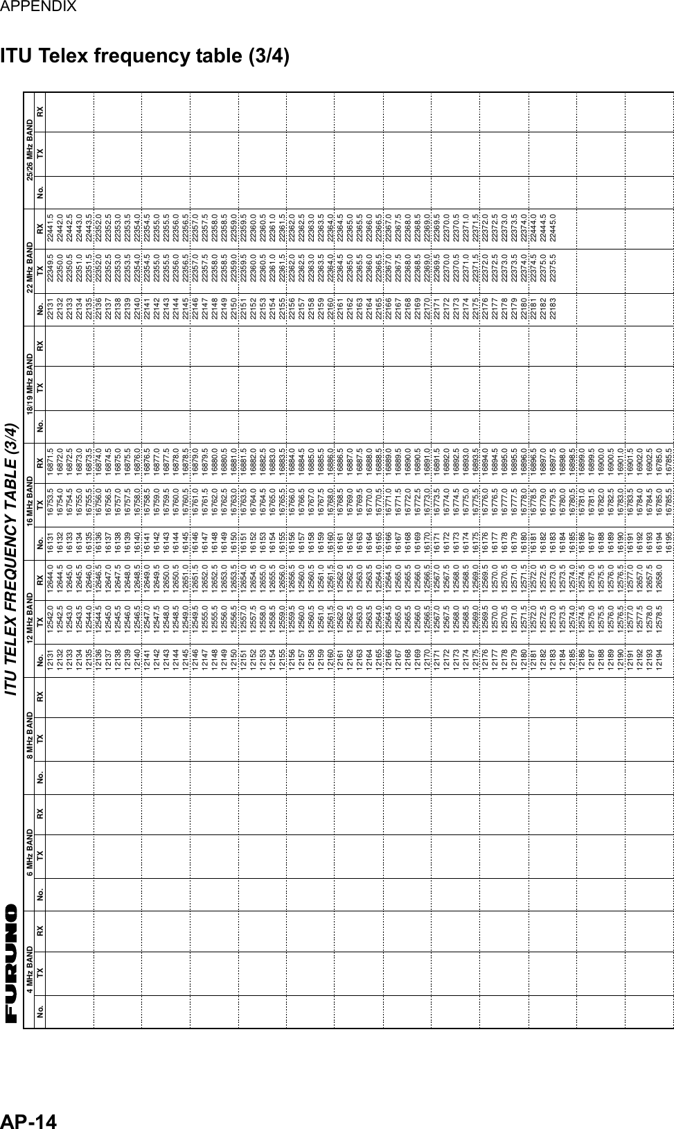
![10. NBDP TRANSMITTING, RECEIVING 10-7Table of abbreviations Abbreviation Question Answer or Advice QRA What is the name your station? The name of my station is … QRC By what private enterprise are the accounts for charges for your station settled? The accounts for my station are settled by the private enterprise… QRU Have you any thing for me? I have nothing for you. QRV Are you ready? I am ready. QRX When will you call me again? I will call you again at … hours [on … kHz]. QSJ What is the charge to be collected to … including your internal charge? The charge to be collected to … including my internal charge is … frans … QSL Can you acknowledge receipt? I can acknowledge receipt. QSX Will you listen to … [call sign] on … kHz? I am listening to … [call sign] on … kHz. QTA Shall I cancel message number …? Cancel message number … QTC How many messages have you to send? I have … message for you. QTU What are the hours your station is open? My station is open from … to … hours. Abbreviation Definition BK Signal used to interrupt a transmission progress. CFM Confirm DE “From …” K Invitation to transmit. NIL I have noting to send to you. NW Now PSE Please R Received REF Reference to … SVC Prefix indicating a service telegram. Command and abbreviation Command Function TGM+ To indicate that the following message is a radiotelegram. MSG+ To indicate that the ship station needs to be connected immediately any message held. OPR+ Call operator. URG+ Safety, urgency and distress message. MED+ Request medical advice. TEST+ Request coast station to send a test message for checking the ship station. BRK+ To clear the connection with the coast station. Abbreviation Function GA+ I am ready. Transmit your command. MOM Wait a moment. MSG+ Request pending messages from the shore. KKKK or NNNN Terminate a message. XXXXX Typo](https://usermanual.wiki/Furuno-USA/9ZWFS2575/User-Guide-1533875-Page-119.png)
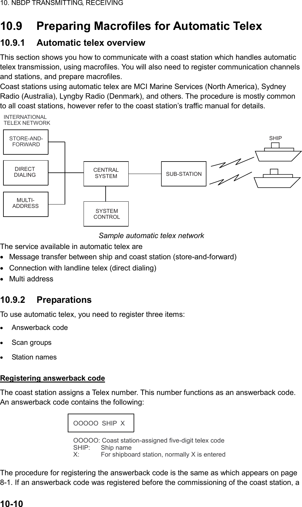
![10. NBDP TRANSMITTING, RECEIVING 10-13Procedure for preparing a macrofile for store-and-forward method You need a macrofile to enable automatic message transmission by store-and-forward method. After preparing it, save it to a floppy disk for future use. 1. Press the function key F1 to open the File menu. 2. Press the 1 key. 3. Prepare macrofile. Below is simple example. < [1] UNTITLED1 > @FREE $RRR$@CALL S:LYNGBY RADIO@WRU@CASE GA+?@SEND TLX80212345+@CASE MSG+?@SEND A: \ABC@SEND KKKK@CASE GA+?@SEND BRK+Search dot pattern free signal until it is found12345Station name (Example: LYNGBY RADIO)Who are you?Station identity exchangeSubscriber’s Telex number (in example, 802 is country code of Hong Kong) for store-and-forward methodLocation and name of file message A: \ABCRequest for termination of message12345 Sample macrofile for store-and-forward method 4. Press the function key F1 to open the File menu. 5. Press the 3 key. The Close Text appears on the screen. close Text Save File?(UNTITLED 1)NoYes Close Text window 6. Press the Enter key and enter a file name as follows: OOOOOOOO.MCR ↑ ↑ File Name Extension Name (max. 8 characters) 7. Press the Enter key.](https://usermanual.wiki/Furuno-USA/9ZWFS2575/User-Guide-1533875-Page-125.png)
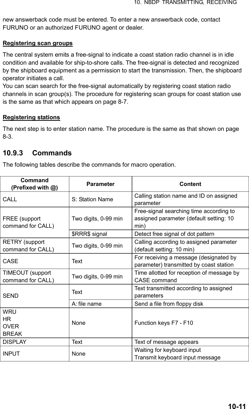
![10. NBDP TRANSMITTING, RECEIVING 10-14 DIRTLX macrofile Sample DIRTLX macrofile < [1] UNTITLED1 > @FREE $RRR$@CALL S:LYNGBY RADIO@WRU@CASE GA+?@SEND DIRTLX725644325+@CASE MSG+?@SEND A: \ABC@SEND KKKK@CASE GA+?@SEND BRK+Search dot pattern free signal until it is found12345Station name (Example: LYNGBY RADIO)Who are you?Station identity exchangeSubscriber’s Telex number (in example, 72 is country code of Japan) for direct dialing modeLocation and name of file message A: \ABCRequest for termination of message12345 Sample DIRLTX macrofile](https://usermanual.wiki/Furuno-USA/9ZWFS2575/User-Guide-1533875-Page-126.png)
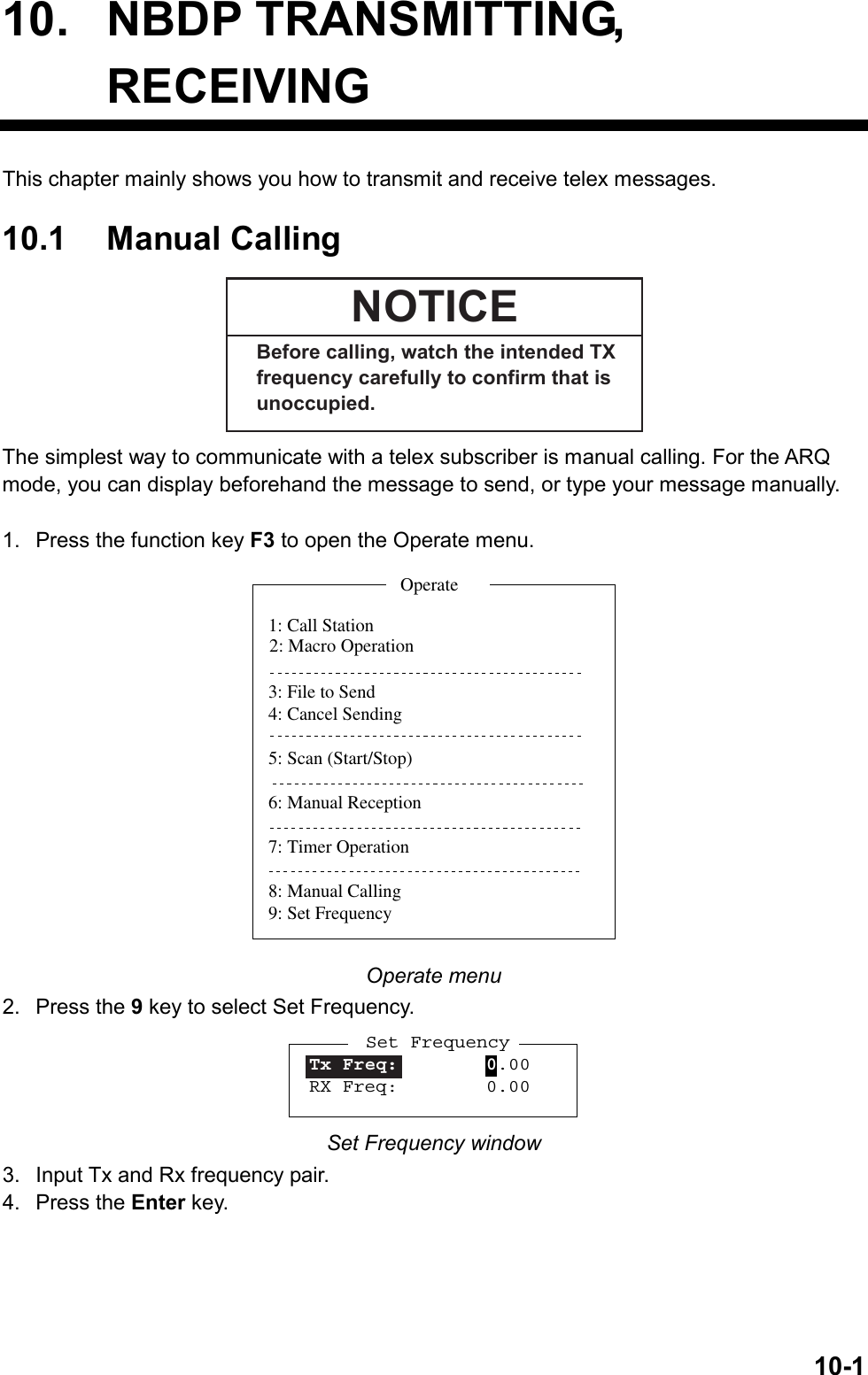
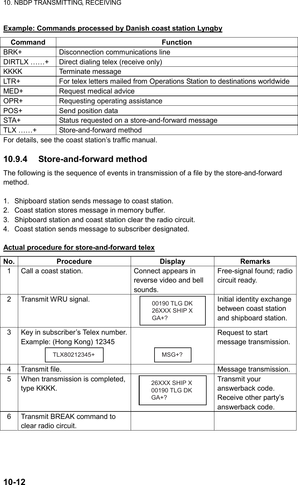
![10. NBDP TRANSMITTING, RECEIVING 10-16 Actual procedure 1. Press the function key F3 to open the Operate menu. 1: Call Station3: File to Send4: Cancel Sending5: Scan (Start/Stop)6: Manual Reception7: Timer Operation8: Manual Calling9: Set FrequencyOperate2: Macro Operation Operate menu 2. Press the 2 key to open the Call Macro window. Call Macro[A:\TEST1. ] File name Size Date & TimeLYNGBY1.MCR 169 02-10-13 06:23[ End of Directory ]1 Files exist 1454000 bytes freeTo select : ENTER To view : SPACE To quit : ESC Call Macro window 3. Press the ↓ key to select a macrofile. 4. Press the Enter key. Call Macro: Lyngby1.MCRCall OK? NoYes 5. Press the Enter key to confirm the macrofile selected. The message “Wait for Free Signal” appears. Your message will be transmitted automatically.](https://usermanual.wiki/Furuno-USA/9ZWFS2575/User-Guide-1533875-Page-128.png)
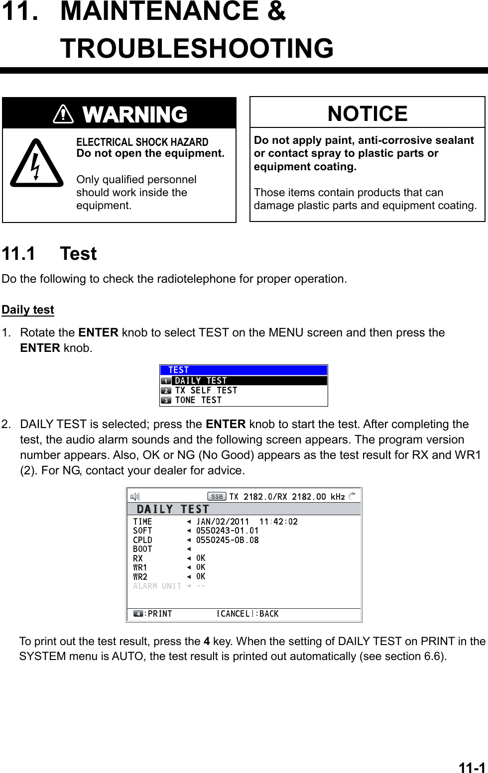
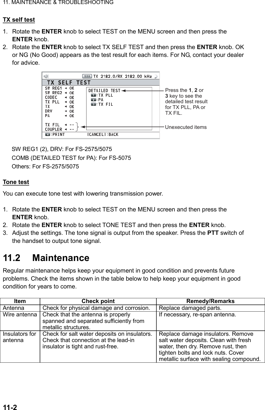
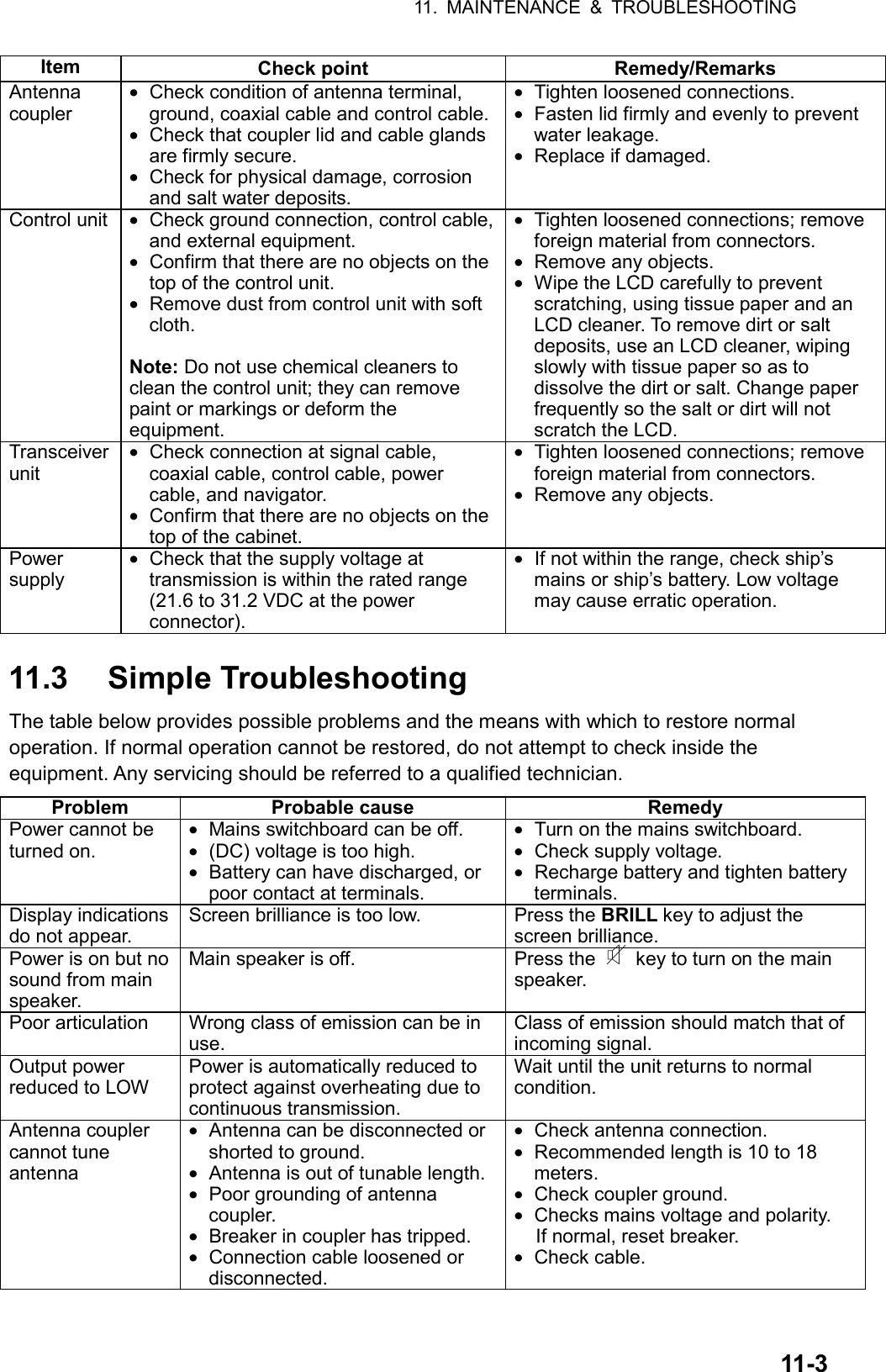
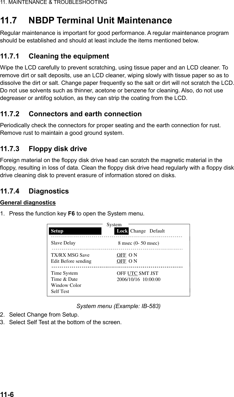
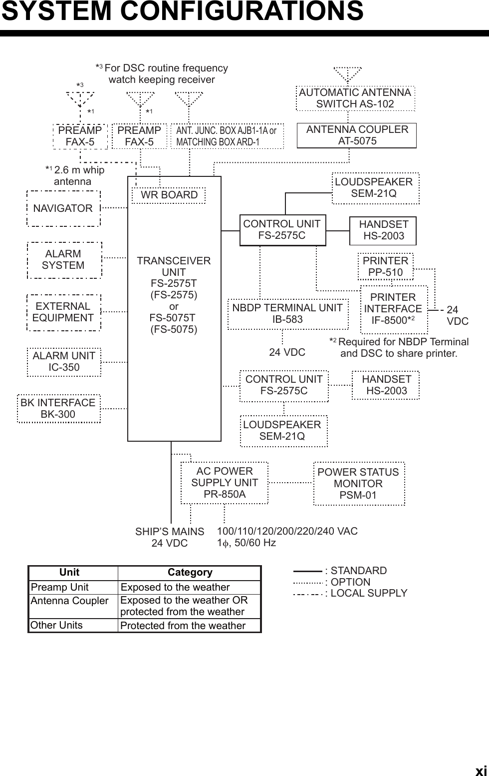
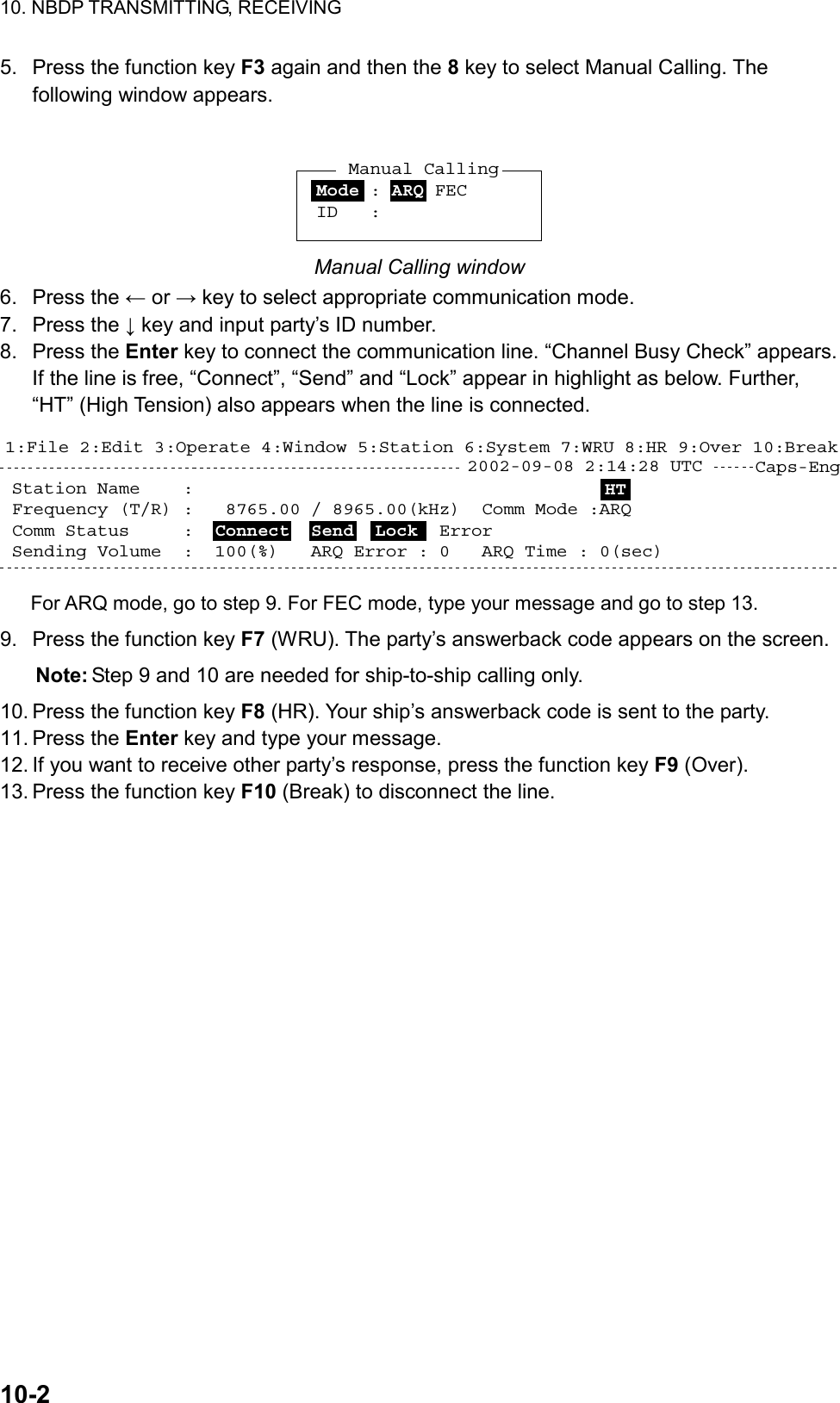
![11. MAINTENANCE & TROUBLESHOOTING 11-4 11.4 Error Messages The table below shows error messages, their meanings, and remedies. To delete the messages, press the CANCEL key. If other error occurs, contact your dealer. Error message Meaning Remedy ERROR: TX PLL UNLOCK [CANCEL]: Stop alarm TX PLL unlock. Transmission is stopped. Contact your dealer. ERROR: RX PLL UNLOCK [CANCEL]: Stop alarm RX PLL unlock. Reception is stopped. Contact your dealer. ERROR: WR1(2) PLL UNLOCK [CANCEL]: Stop alarm WR1(2) PLL unlock. Reception is stopped. Contact your dealer. ERROR: TUNE NG [CANCEL]: Stop alarm Tuning failed. Transmission power is decreased to LOW(2). For NBDP, transmission is stopped. Try to tune again. If unsuccessful, confirm if TUNE NG occurs on other frequencies. See “Antenna coupler cannot tune antenna” in section 11.3, or contact your dealer. ERROR: Tx power reduced. Main AMP heated. [CANCEL]: Stop alarm Power amplifier is too heated. Transmission power is decreased to one level lower. ERROR: Tx power reduced. Natural TUNE [CANCEL]: Stop alarm Tune error occurs. Transmission power is decreased to LOW(2). Try to tune again. If unsuccessful, confirm if TUNE NG occurs on other frequencies. See “Antenna coupler cannot tune antenna” in section 11.3, or contact your dealer. ERROR: Tx power reduced. Ship’s main failure. [CANCEL]: Stop alarm AC power is interrupted and DC power is replaced with AC power.Can use AC power with low transmission power. Check AC power and decrease the transmission power to the minimum. ERROR: Communication error! [CANCEL]: Stop alarm Communication between the transceiver unit and the control unit is lost for a certain period. Confirm if the transceiver unit and the control unit are connected. WARNING: GNSS error [CANCEL]: Stop alarm Sensor information from GNSS is lost more than one minute. Check the navigation equipment. If the navigation equipment does not work well, input the position information manually. WARNING: Printer not ready [CANCEL]: Stop alarm Automatic print is selected; however, printer is not powered or is disconnected. Check the printer. WARNING: Position data is not updated! Position was older than XH. Update it [CANCEL]: Stop alarm Position data is older by the amount of time preset on the POSITION menu (see section 6.7).Reenter position on the POSITION menu (see section 6.7). System was rebooted. Unusual working is detected. System restarts. Can use this equipment without hitch.](https://usermanual.wiki/Furuno-USA/9ZWFS2575/User-Guide-1533875-Page-132.png)
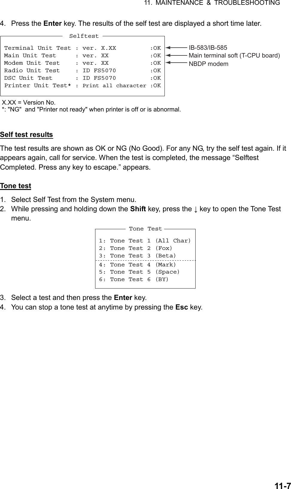
![11. MAINTENANCE & TROUBLESHOOTING 11-5 11.5 Breaker PR-850A The Power Supply Unit PR-850A, used with the equipment, has a circuit breaker. If the breaker has tripped, find the reason before resetting the breaker (upward position). POWERONONOFFAC INPUT 50/60Hz DC OUTPUTBREAKER 11.6 Test Call This function sends a test signal to a coast or ship station, over one of six distress and safety frequencies. For that reason, it should not be executed unnecessarily. You can prepare a test call beforehand and send it (see paragraph 6.13.5). 1. Press the OTHER DSC MSG key to open the COMPOSE MSG. 2. Rotate the ENTER knob to select MSG TYPE and then press the ENTER knob. 3. Rotate the ENTER knob to select TEST MSG and then press the ENTER knob. 4. Rotate the ENTER knob to select TO and then press the ENTER knob. 5. Enter the MMSI where to send the test message with the numeric keys and then press the ENTER knob. 6. Rotate the ENTER knob to select DSC FREQ and then press the ENTER knob. 7. Rotate the ENTER knob to select DSC frequency and then press the ENTER knob. 8. Rotate the ENTER knob to select GO TO CALL and then press the ENTER knob to send the test message. The screen is changed to one for transmission and the message “Sending DSC MSG now “ appears. After the call is sent, the equipment waits for acknowledgement of the call. The timer starts counting up the time to wait for acknowledgement. 9. Do one of the following. Test acknowledge message received The audio alarm sounds and the message “TEST ACK received! [CANCEL]: Stop alarm” appears. Press the CANCEL key to silence the alarm. No response Re-send call: Rotate the ENTER knob to select GO TO CALL and then press the ENTER knob. Cancel call: Press the CANCEL key to return to the radiotelephone screen.](https://usermanual.wiki/Furuno-USA/9ZWFS2575/User-Guide-1533875-Page-133.png)