Furuno USA 9ZWRTR058 MARINE RADAR User Manual operators manual part 3
Furuno USA Inc MARINE RADAR operators manual part 3
Contents
- 1. operators manual part 1
- 2. operators manual part2
- 3. operators manual part 3
- 4. operators manual part 4
operators manual part 3
3-1
3. PLOTTER OPERATION
3.1 Plotter Displays
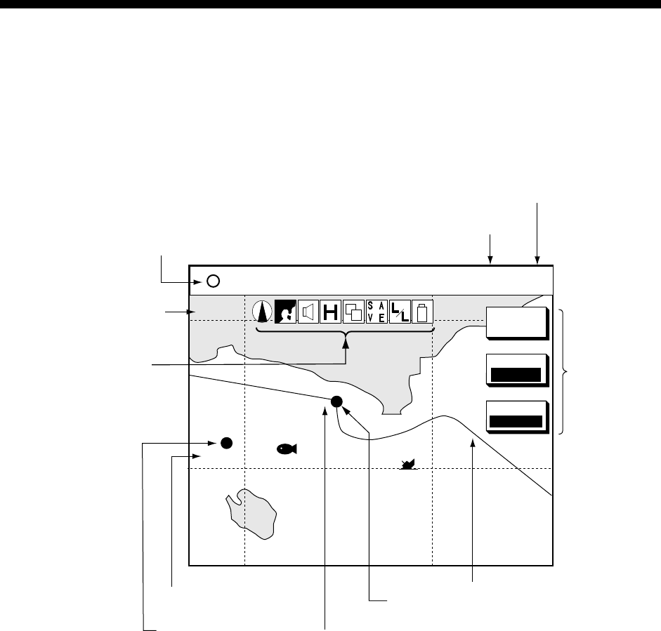
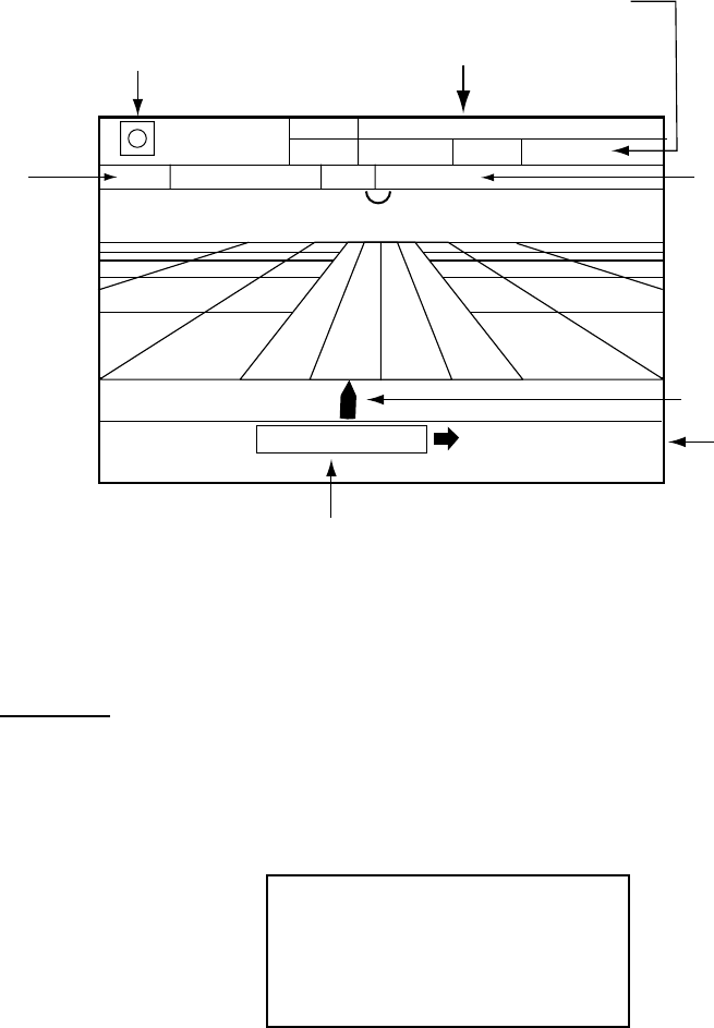
3.1.1 Normal plotter display
You may show the plotter display over the entire screen, in the overlay screen
(MODEL-1700 series only) with the radar display, or in a combination screen.
34° 22. 3456'N 359.9° TRIP NU
080° 22. 3456'E
19.9 kt 99.9 nm
BRIDGE
FISH
002WP
MARK
ENTRY
MODE
NTH-UP
NAV
POS
Nav data window
(Data changes with NAV soft
key setting and cursor
status. For details see next page.)
Course bar
Functions for
soft keys
Track
Own ship
marker
Presentation mode
(North-up)
Icon (from left)
North Marker
Chart
Alarm
Battery
Track Hold
Chart Offset
Save
L/L Offset
Battery
(See icon
table on
page A-3
for details.)
Waypoint name
Waypoint mark
1024 nm
Scale
Trip distance
Normal plotter display
3. PLOTTER OPERATION
3-2
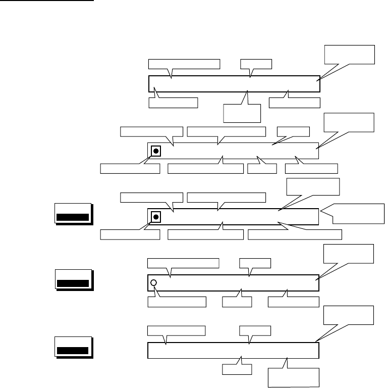
Nav data window
The data show in the nav data window depends on the status of the NAV soft key
and the cursor.
359. 9°
TTG
4d02h2h23mNU
19. 9nm
ETA
1st 13:45
Time-to-Go
to Destination
Bearing to WaypointWaypoint Name
Estimated Time of ArrivalRange to WaypointWaypoint Mark
001WPT
NAV
POS
soft key
34°24. 3456'N 359. 9° TRIP NU
124°24. 3456'W 19. 9kt 99. 9nm
CourseLatitude, Longitude
Own Ship Mark Speed Trip Distance
NAV
WAYPT
soft key
359. 9° 359. 9° 79. 9°F NU
19. 9kt 99. 9nm 345 ft
BearingCourse, Speed
Range Water Temp.,
Depth
CSE
SPD BRG
RNG TMP
DPT
NAV
S/C
soft key
359. 9°359. 9° TRIP NU
59. 9nm 59. 9kt 99. 9nm
CourseBearing to WaypointWaypoint Name
SpeedRange to WaypointWaypoint Mark Trip Distance
001WPT
Waypoint selected
with cursor
Presentation
Mode
Presentation
Mode
Presentation
Mode
34°24. 3456'N 359. 9° TRIP NU
124°24. 3456'W 59.9nm 99. 9nm
CourseLatitude, Longitude
Trip Distance
Presentation
Mode
+
Cursor Mark Range to
Cursor
Position selected
with cursor
Presentation
Mode
NAV soft key status and nav data window
3. PLOTTER OPERATION
3-3
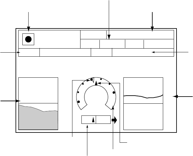
3.1.2 Compass display
The compass display, displayed at the bottom half of the screen in the
plotter/compass combination display, provides steering information. The
compass rose shows two arrows: the solid triangle shows own ship’s course
(heading) and the hollow inverted triangle shows the bearing to destination
waypoint. When own ship’s course is changed, the hollow inverted triangle
moves with course change. Ship’s course and waypoint direction are updated
every second and other information is updated every 15 seconds.
The water temperature and depth graphs shows latest 10 minutes of temperature
and depth data. The range of the depth graph is 50 feet and it is automatically
adjusted with depth.
003WPT
RANGE
SOG 10.0km/h STW 10.0km/h
9h59m
TTG 23th23:59
ETA
99.9km
350
400
80
60
N
w
E
CSE
BEARINGDEPTH TEMP
359.9
359.9°382.9ft 59.9°F
Waypoint
bearing Ship's course
Bearing scale
XTE monitor
(Amount and
distance to
steer to return
to course)
Depth
graph*
Water
temperature
graph*
TO Waypoint
Time-to-go
to destination
Range to waypoint
Speed
* = Requires appropriate
sensor
Estimated time of
arrival at destination
Compass display
3. PLOTTER OPERATION
3-4
Reading the XTE monitor
The XTE monitor, located below the compass rose, shows the direction you are
off course. In the example the monitor shows, by the solid triangle, that the vessel
is off course to the port side. Steer the vessel so the triangle keeps at the center
of the monitor scale.
Soft keys
EDIT XT-LMT: Sets the range for XTE monitor scale. See the procedure below
for how to set.
RESET XTE: Displayed when destination is set, and enables you to restart
navigation. When the key is pressed the following message is displayed.
RESTART NAVGATION TO
CURRENT WAYPOINT.
ARE YOU SURE?
YES ... PUSH ENTER KNOB
NO ... PUSH CLEAR KEY
COMPASS CNTRL: Switches control between the compass display and other
display, in a combination display.
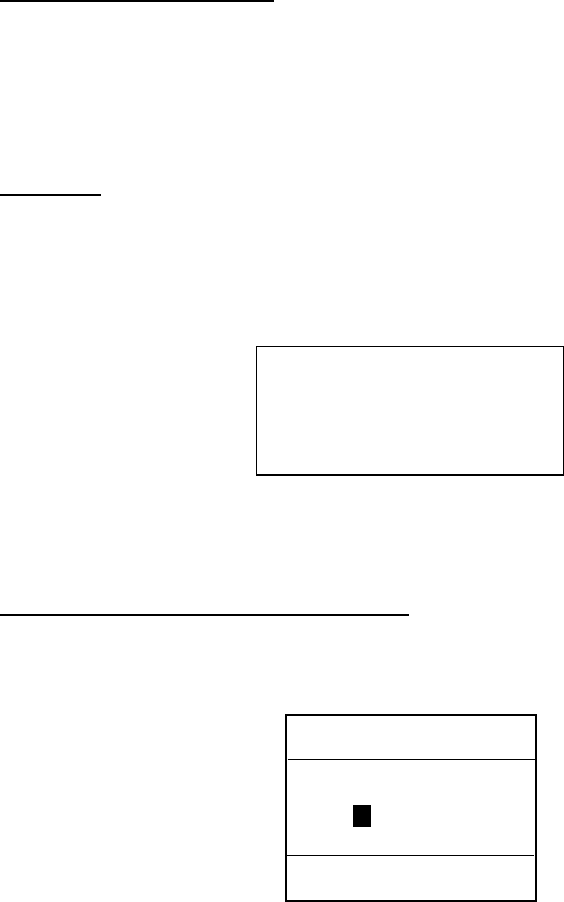
Setting the range for the XTE monitor
1. With the highway display shown, press the EDIT XT-LMT soft key to display
the following window.
XTE LIMIT
0 .1nm
DEFAULT: 0.1 nm (km, sm)
XTE range setting window
2. Use the cursor pad to select digit to change.
3. Use the [ENTER] knob to set.
4. Repeat steps 2 and 3.
5. Press the [ENTER] knob to set, or press the CANCEL soft key to cancel.
3. PLOTTER OPERATION
3-5
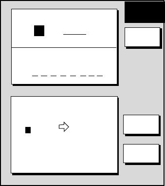
3.1.3 Highway display
The highway display, displayed at the lower half of the screen in the
plotter/highway combination display, provides a graphic presentation of ship’s
track along intended course. It is useful for monitoring ship’s progress to a
waypoint. The own ship marker shows own ship’s movement and direction. The
XTE monitor to show the direction and amount your vessel is off course. The
arrow shows the direction to steer and the numeric the amount you are off course.
Using the figure below as an example, you would steer starboard 0.009 nm to
return to course.
WPT001
RANG
SOG
10.0
km/h STW
10.0
km/h
0d9h59m
TTG 25th22:39
ETA
99.9nm
Time-to-go
to destination
Range to waypoint
Estimated time of
arrival at destination
WPT001
0.9 nm
TO Waypoint
Own ship
Speed
XTE monitor
0.009nm
0.9 nm
XTE range
Highway display
Note that all digits may be cleared by pressing the [CLEAR] key.
Soft keys
EDIT XT-LMT: Sets the range for XTE monitor scale. See the procedure on the
previous page for how to set.
RESET XTE: Displayed when destination is set, and enables you to restart
navigation. When the key is pressed the following message is displayed.
RESTART NAVGATION TO
CURRENT WAYPOINT.
ARE YOU SURE?
YES ... PUSH ENTER KNOB
NO ... PUSH CLEAR KEY
COMPASS CNTRL: Switches control between the compass display and other
display, in a combination display.
3. PLOTTER OPERATION
3-6
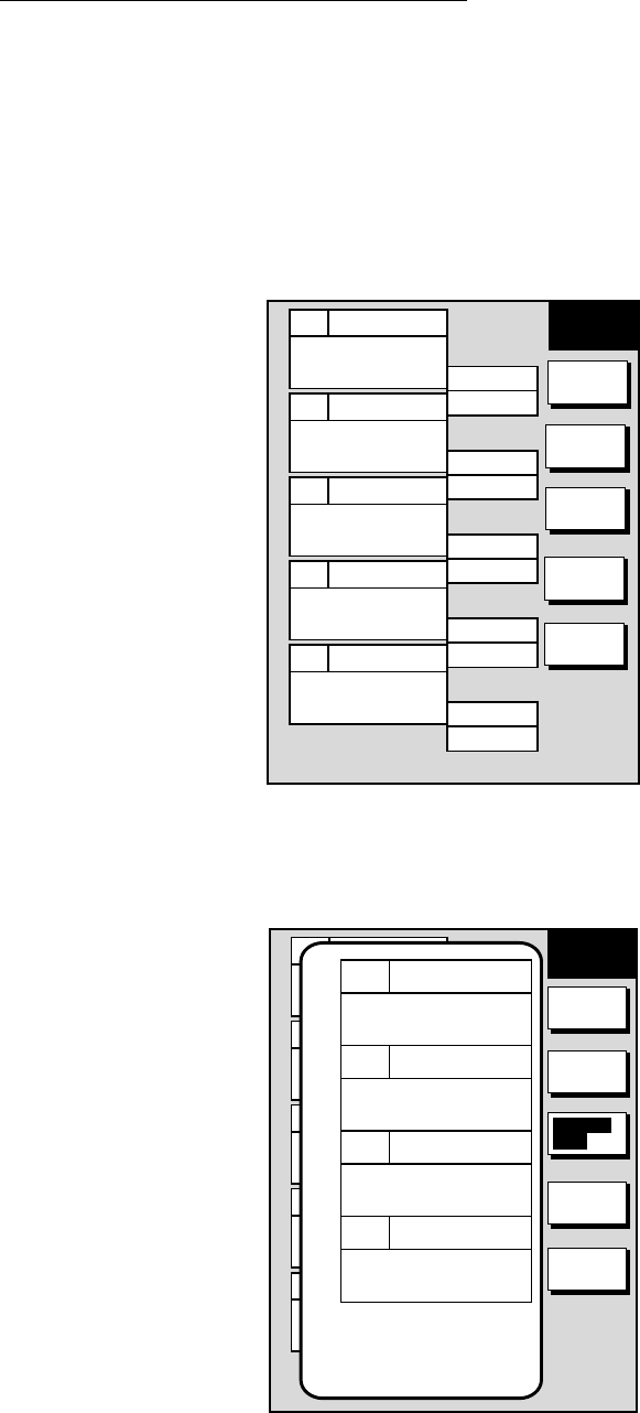
3.1.4 Nav data display
The nav data display provides comprehensive navigation data. It can be
displayed on the entire screen or in a combination display.
POS 34° 34. 5678' N
120° 34. 5678'
W
COURSE
T
359.9˚
SPEED
km/s
99.9
TEMP.
109.9
DEPTH
f t
1200
˚F
POS
34° 34. 5678' N
120° 34. 5678'
W
COURSE
T
359.9˚
SPEED
km/s
99.9
TEMP.
109.9
DEPTH
f t
1200
BEARING
359.9˚
RANG
nm
99.9
DATE 2000
24. SEP
LOG TRIP
nm
99.9
˚F
Course
Position
Date
Bearing to
waypoint
Water
temperature
Range to
waypoint
Depth
Speed
Trip distance
Half-screen display
Full-screen display
Full-screen nav data display
3. PLOTTER OPERATION
3-7
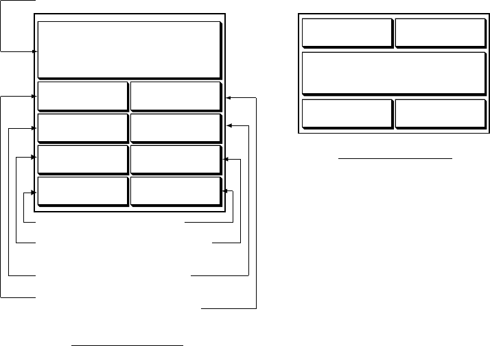
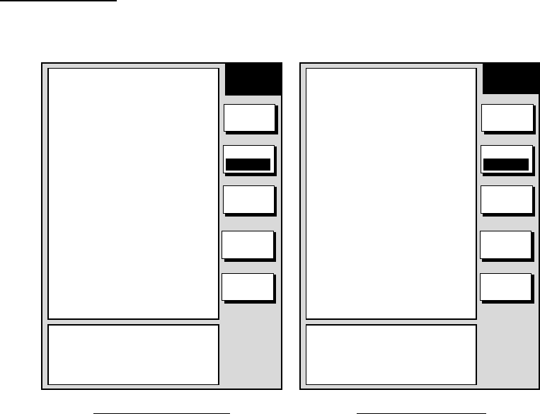
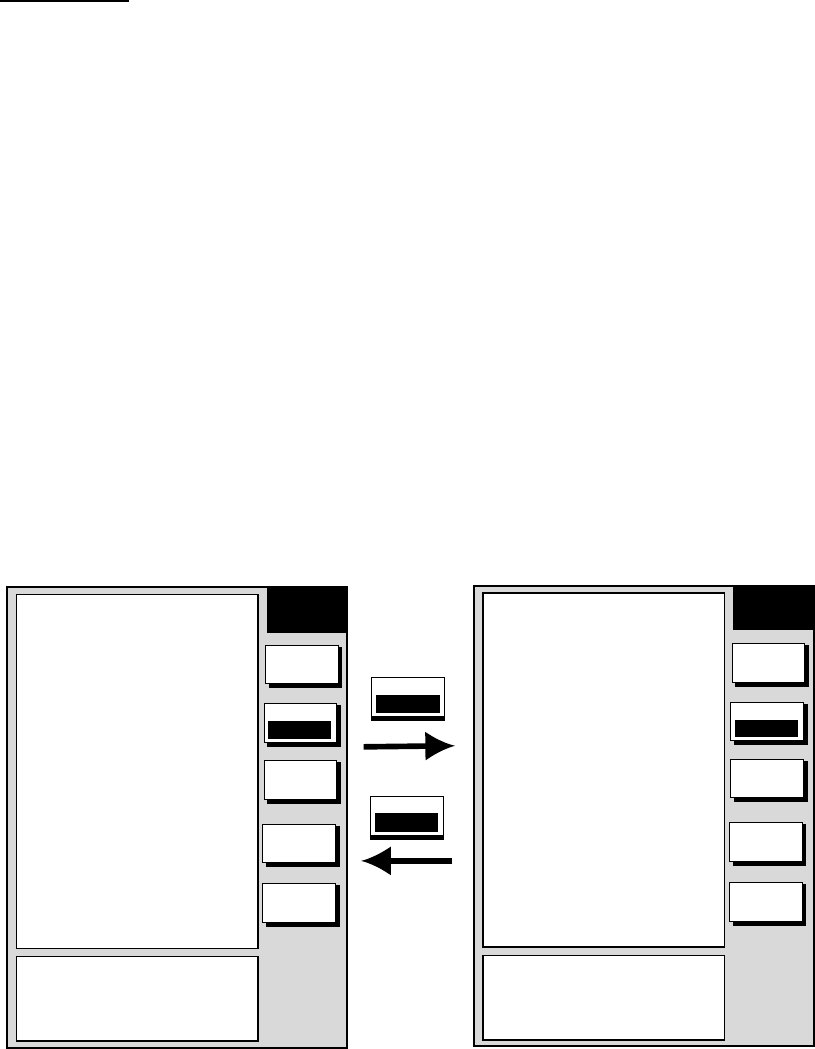
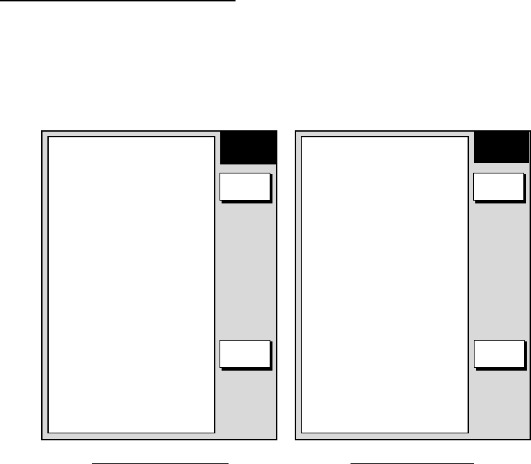
3.2 Selecting a Presentation Mode
Three types of display presentations are provided for the plotter display: north-up,
course-up and auto course-up. To change the presentation mode, use the MODE
soft key. Each press of the key changes the presentation mode and presentation
mode indication cyclically in the sequence of North-up, Course-up and Auto
course-up.
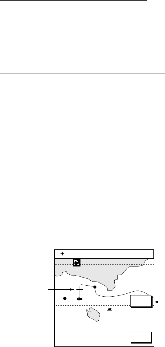
3.2.1 North-up
Press the MODE soft key to show “AC-UP.” North (zero degree) is at the top of
the display and own ship is at the center of the screen. Own ship marker is a filled
circle. This mode is useful for long-range navigation.
D.BOX
OFF
MARK
ENTRY
BRIDGE
FISH
WP-002
MODE
NTH UP
NAV
POS
34° 22. 3456'N 359.9° TRIP NU
080° 22. 3456'E
19.9 kt 99.9 nm
1024 nm
Plotter display, north-up mode
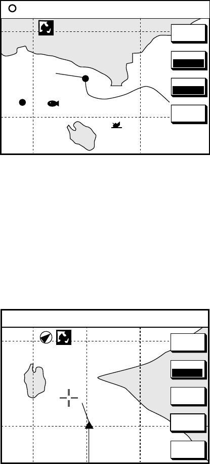
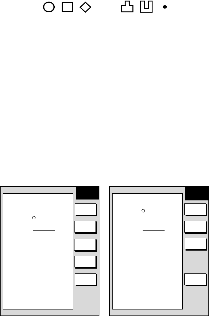
3.2.2 Course-up
Press the MODE soft key to show the indication NTH-UP. When destination is set
it is at the top of the screen, the north mark appears at the upper left side of the
screen and points to north. A filled triangle marks own ship’s position.
When destination is not set, the course or heading is upward on the screen at the
moment the course-up mode is selected.
1024 nm
34° 22. 3456'N 272.4° TRIP CU
080° 22. 3456'E
15.9 nm 99.9 nm
+
D.BOX
OFF
MARK
ENTRY
MODE
CSE UP
GO TO
CURSOR
CENTER
Plotter display, course-up mode, cursor on
3. PLOTTER OPERATION
3-8
3.2.3 Auto course-up
Press the MODE soft key to show the indication CSE-UP. The course or heading
is at the top of screen at the moment the course-up mode is selected. When own
ship is off its intended course by 22.5° or more, it is automatically brought back to
perpendicular.
1024 nm
D.BOX
OFF
MARK
ENTRY
MODE
AUT CU
GO TO
CURSOR
CENTER
34° 22. 3456'N 272.4° TRIP ACU
080° 22. 3456'E
15.9 nm 99.9 nm
+
Plotter display, auto course-up mode
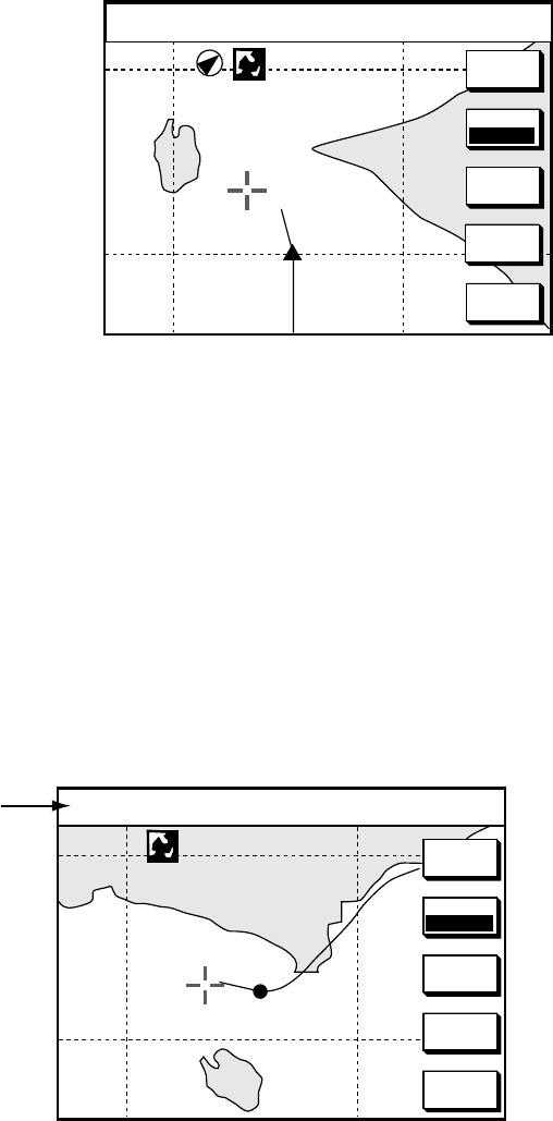
3.3 Cursor
3.3.1 Turning on the cursor, shifting the cursor
Press the cursor pad to turn the cursor on, and the cursor appears at the own
ship’s position. Operate the cursor pad to shift the cursor. The cursor moves in
the direction of the arrow or diagonal pressed on the cursor pad.
Cursor position is displayed in latitude and longitude or Loran or Decca TDs
(depending on menu setting) at the top of the plotter display when the cursor is
on.
D.BOX
OFF
GO TO
CURSOR
CENTER
MARK
ENTRY
MODE
NTH UP
Cursor data
34° 22. 3456'N 272.4° TRIP NU
080° 22. 3456'E
15.9 nm 99.9 nm
+
1024 nm
Cursor data
3.3.2 Turning off the cursor, returning own ship marker to screen
center
The CENTER soft key turns off the cursor and returns own ship marker to screen
center.
3. PLOTTER OPERATION
3-9
3.4 Shifting the Display
The display can be shifted on the plotter display as below.
1. Press the cursor pad to display the cursor.
2. Locate the cursor at a screen edge and press and hold down the cursor pad.
The screen shifts in the direction opposite of cursor location.
3.5 Selecting Chart Scale/Range
Chart scale (range) may be selected with the [-] or [+] key. The [-] key expands
the chart range; the [+] key shrinks it.
Note: When the display is expanded or shrunk beyond the range of the chart
card in use NO CHART appears, along with the appropriate chart icon. See
the table below for details.
3.6 Chart Cards
3.6.1 Chart card overview
Three types of chart cards can be used: FURUNO, Nav-Charts™ (NAVIONICS)
and C-MAP.
When you insert a suitable mini chart card in the slot and your boat is near land, a
chart appears. If a wrong card is inserted or a wrong chart scale is selected, the
land will be hollow. Insert the proper card and select a suitable chart scale. Chart
icons appear to help you select a suitable chart scale. The table below shows the
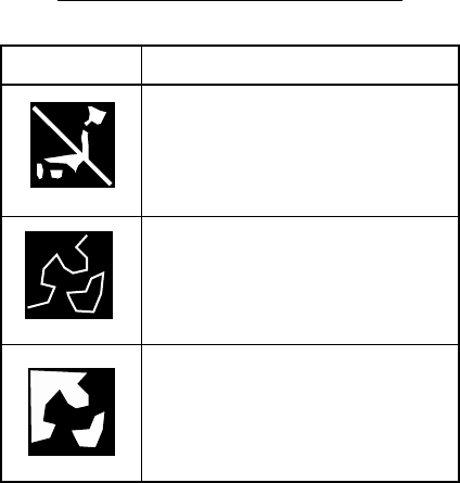
chart icons and their meanings.
Chart icons and their meanings
Icon Meaning
Proper card is not inserted or
chart scale is too small. Press
the soft key ZOOM IN to
adjust chart scale.
Chart scale is too large. Press
the soft key ZOOM OUT to
adjust chart scale.
Suitable chart scale is
selected.
3. PLOTTER OPERATION
3-10
Indices and chart enlargement
When the [-] key is operated, you will see several frames appear on the chart.
These frames are called indices and they show you what parts of the chart can be
enlarged in the current picture range. The areas circumscribed with smaller
frames can be enlarged, but the area enclosed by the largest frame cannot.
Sample chart (Japan and South Korea) showing indices
When a chart cannot be displayed
A chart will not be displayed in the following conditions:
• When the chart scale is too large or too small.
• When scrolling the chart outside the indices.
• When this happens, select proper chart scale.
3.6.3 FURUNO, Nav-Charts™
Chart symbols
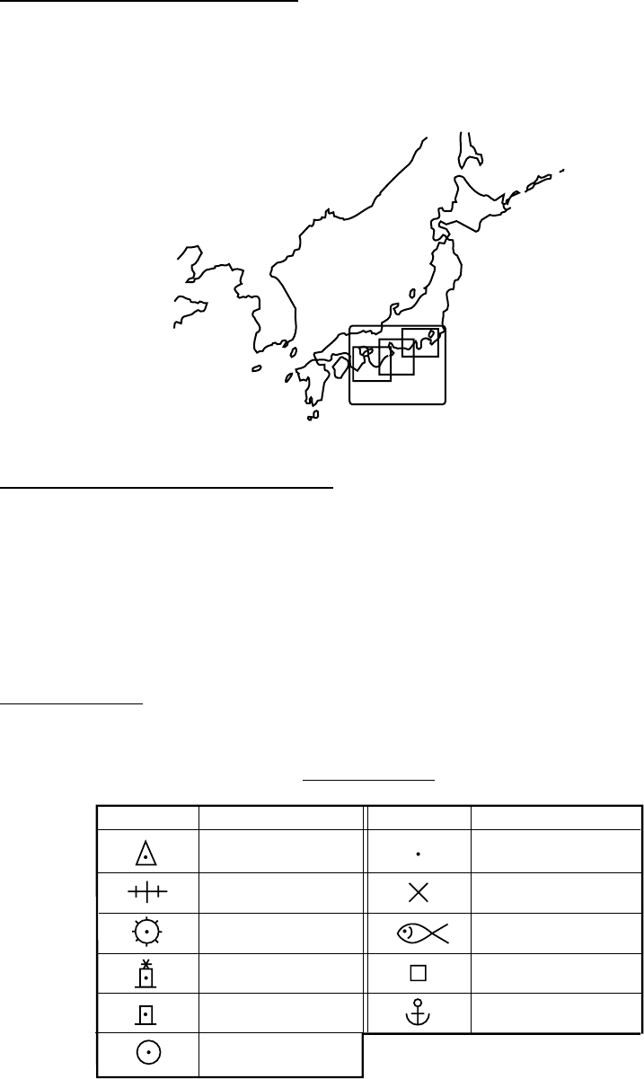
The table below shows FURUNO mini chart symbols and their meanings.
Chart symbols
Symbol Description
Summit
Wreck
Lighthouse
Lighted Buoy
Buoy
Radio Station
Symbol Description
Position of Sounding
Obstruction
Fishing Reef
Platform
Anchorage
3. PLOTTER OPERATION
3-11
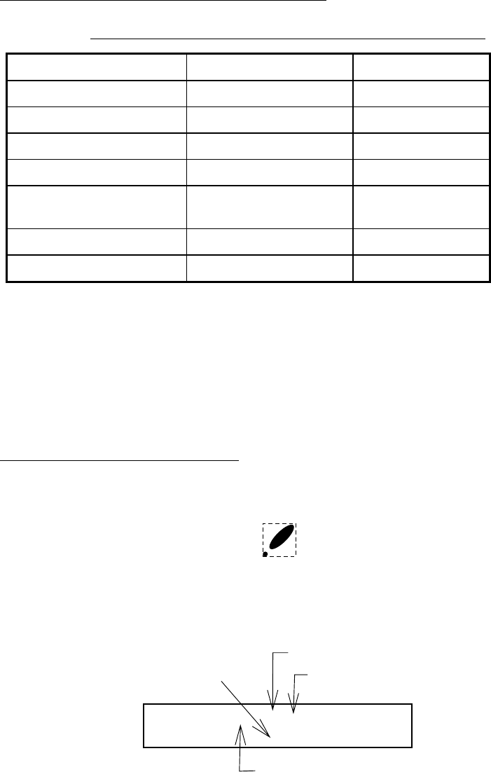
Comparison of FURUNO and Nav-Charts™
Comparison of FURUNO and Nav-Charts™ chart cards
Item FURUNO Nav-Charts™
Dot scrolling capability YES YES
Course-up display YES YES
Lighthouse data YES *3 YES
Zoom at cursor position YES *1
Range at Equator 0.125, 0.5, 1, 2…2048
nm Same as left
Chart offset YES YES
Centering YES *2
*1 Nav-Charts™ chart may not center the cursor perfectly.
*2 Nav-Charts™ chart may not center own ship's position perfectly.
*3 Newly designed chart cards containing lighthouse data. Chart cards for North
America area are completed, and others are in production.
*4 Nav-Charts™ is the registered trademark of NAVIONICS INC.
Data for aids to navigation data
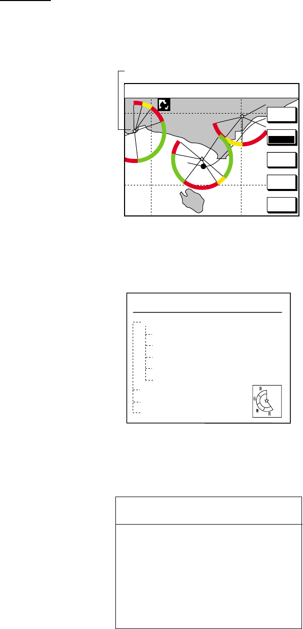
Selected FURUNO and Nav-Charts™ charts can show buoy and lighthouse data.
Simply place the cursor on the lighthouse or buoy mark.
Place the cursor on
a lighthouse or buoy mark.
Lighthouse mark
NAVAID: /FL 6S 12M
FROM OS 52.38nm 48.0°
Period (ex.: 6 seconds)
Visibility in nautical
mile (ex.: 12 miles)
FL : Flashing
F : Fixed light
F FL : Fixed and Flashing light
MO : Morse code light
Oc : Occulting light
Range and bearing
from own ship
Example of buoy, lighthouse data
3. PLOTTER OPERATION
3-12
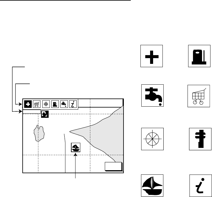
Port service icons (Nav-Charts™ cards)
Selected Nav-Charts™ mini chart cards show by icons services available at ports.
Use the cursor pad to place the cursor on the sailboat icon (denotes a port or
harbor), and then push the [ENTER] knob. The services available appear at the
top of the display.
34° 22. 3456'N 359.9° TRIP NU
080° 22. 3456'E
19.9 kt 99.9 nm
Emergency
medical service
Water
supply station
Customer
service station
Information center
Fueling station
Traveler's
service station
Marine
equipment service
Port
CANCEL
FIRST AID
Sailboat mark (Port)
Detailed information of service
selected
List of services
at the port selected
1024 nm
Plotter display showing Nav-Charts™ port service display
3. PLOTTER OPERATION
3-13
3.6.4 C-MAP cards
Cursor and data display
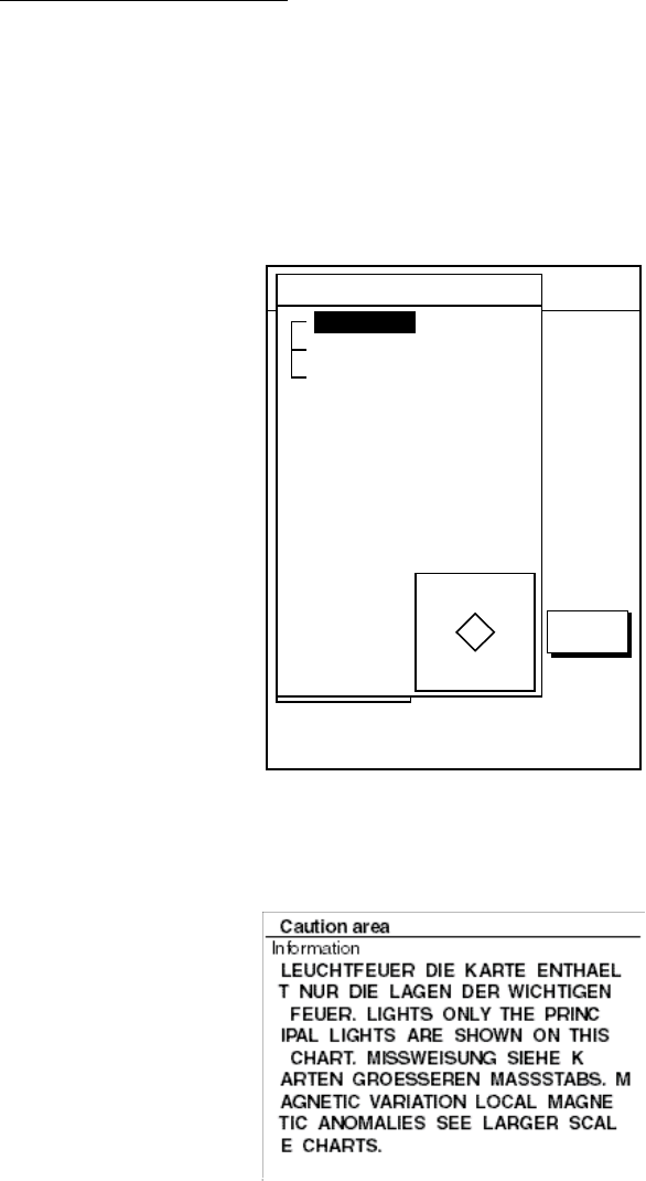
Besides its fundamental functions of providing position data, the cursor can also
show caution area, depth area, source of data, etc. Further, you can display
information about an icon by placing the cursor on it.
1. Press the cursor pad to turn the cursor on.
2. Use the cursor pad to place the cursor on the position desired.
3. Push the [ENTER] knob to open the Objects window.
34 24. 3456 N 359.9 NU
124 24. 3456 W 59.9kt 024nm
+
OBJECTS
Tide height
Cartographic area
Source of data
TRETURN
Objects window
4. Select the item desired.
5. Push the [ENTER] knob to display details for object selected.
Example of caution area window
6. Press the RETURN soft key to close the window.
7. Repeat step 4 to 6 to select other item.
8. Press the RETURN soft key to close the Objects window and the [MENU] key
to close the menu.
3. PLOTTER OPERATION
3-14
Icon data
You may place the cursor on any icon to find information about the selected icon.
1. For example, place the cursor on a lighthouse icon.
D.BOX
OFF
GO TO
CURSOR
CENTER
MARK
ENTRY
Place the cursor on a lighthouse icon.
MODE
NTH UP
34° 22. 3456'N 359.9° TRIP NU
080° 22. 3456'E
19.9 kt 99.9 nm
+
1024 nm
Lighthouse icon
2. Push the [ENTER] knob to show data. For example, the following window
appears for lighthouse.
Objects
Navigation mark, fixed
Extended navigational aid, ge
Light
Light
Light
Light
Depth contour
Land area
Source of data
Object windows
3. Select the item desired.
4. Push the [ENTER] knob to display detailed information.
Color
white
Height
7. 00 Meters
Light characteristic
occulting
XXXXXXXX
XXXXXXXX
Navigation mark, fixed
Light.
Sample lighthouse data
5. Press the RETURN soft key to close the Objects window and the [MENU] key
to close the menu.
3. PLOTTER OPERATION
3-15
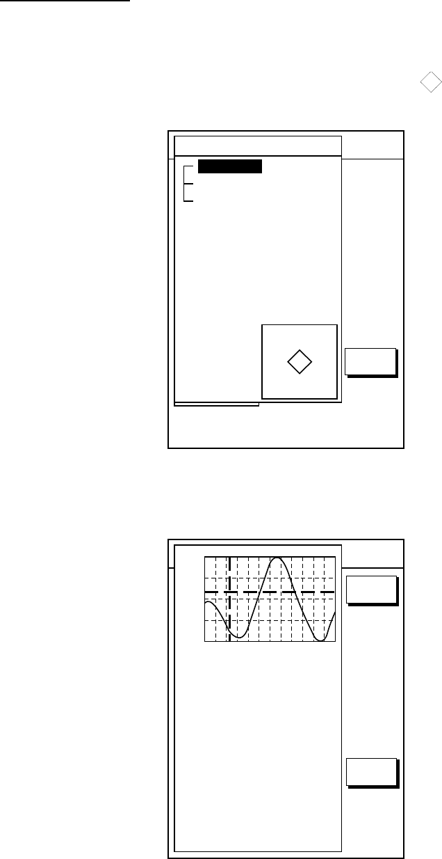
Tidal Information
The C-MAP NT-FP chart card provides for calculation of the tide heights for any
date. Additionally it displays the times of sunrise and sunset.
1. Press the cursor pad to place the cursor on a Tide icon (
T
).
2. Push the [ENTER] knob to open the Objects window.
34 24. 3456 N 359.9 NU
124 24. 3456 W 59.9kt 024nm
+
OBJECTS
Tide height
Cartographic area
Source of data
TRETURN
Objects window
3. Select Tide height.
4. Push the [ENTER] knob to open the TIDE window.
34 24. 3456 N 359.9 NU
124 24. 3456 W 59.9kt 024nm
+
Time: 04:35
Height: 0.45ft
Draught: 0.65ft
01/07/30 +13:30
43° 32.860N
010° 18.022E
Port info
LIVORNO (LEGHORN)
High Water(max)
0.86ft(13:30 L)
Low Water(min)
0.35ft(21:00 L)
Sunrise
07:52L
Sunset
16:53 L
0.86
0.74
0.61
0.48
0.3504812162024
RETURN
DATE
Tide window
3. PLOTTER OPERATION
3-16
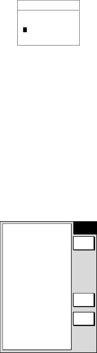
5. Press the DATE soft key to open the DATE window.
DATE
DD/MM/YYYY
01 / 01 / 2000
Date window
6. Place the cursor where desired and then rotate the [ENTER] knob to enter a
appropriate date.
7. Push the [ENTER] knob to show the tidal graph for entered date.
8. Locate the vertical cursor on the time desired. Time and height are shown to
the left of the graph.
9. Shift the level cursor. Draught is shown to the left of the graph.
10.Press the RETURN soft key to close the TIDE window.
11. Press the [MENU] key to close the menu.
3.7 Resetting Trip Distance
Trip distance is shown on the navigation data display. You can reset the trip
distance to zero as follows.
1. Press the [MENU] key.
2. Press the SYSTEM CONFIGURATION and GENERAL SETUP soft keys in
that order to show the general setup menu.
GENERAL
SETUP 1
RETURN
NEXT
PAGE
EDIT
KEY BEEP
ON
LANGUAGE
ENGLISH
RANGE/SPEED UNIT
nm, kt
TEMP UNIT
°C
DEPTH UNIT
ft
TEMP SOURCE
NMEA
DEPTH SOURCE
NMEA
RESET TRIP LOG
NO
▲
General setup menu, page 1
3. PLOTTER OPERATION
3-17
3. Select RESET TRIP LOG and press the EDIT soft key.
4. Select YES.
5. Press the RETURN soft key.
6. Press the [MENU] key to close the menu.
3.8 Working with Track
Your ship’s track is plotted on the screen using navigation data fed from a GPS
receiver. This section shows you what you can do with track, from turning it on or
off to changing its plotting interval.
3.8.1 Displaying track
Own ship track
1. Press the [MENU] key followed by CHART SETUP and TRACK & MARK
CONTROL soft keys to open the track control menu.
TRACK DISPLAY
ON
TARGET TRACK DISPLAY
ON
PLOT
TIME
TIME INTERVAL
10m00sec
DIST INTERVAL
0.1nm
TRACK MEMORY(MARK)
2000PTS(6000PTS)
OWN SHIP TRACK STATUS
TRACKING
TRACK 1234/2000
MARK 36/6000
▲
MODEL-1700 series
TRACK DISPLAY
ON
TRACK COLOR
RED
TARGET TRACK DISPLAY
ON
TARGET TRACK COLOR
WHITE
PLOT
TIME
TIME INTERVAL
10m00sec
DIST INTERVAL
0.1nm
TRACK MEMORY(MARK)
2000PTS(6000PTS)
OWN SHIP TRACK STATUS
TRACKING
TRACK 1234/2000
MARK 36/6000
▲
MODEL-1700C series
TRACK
CONTROL
EDIT
ERASE
T & M
MARK
SETUP
RETURN
TRACK
HALT
EDIT
ERASE
T & M
MARK
SETUP
RETURN
TRACK
HALT
TRACK
CONTROL
Track & mark control menu
2. Select TRACK DISPLAY.
3. Press the EDIT soft key to show the display track window.
4. Select ON (default setting) or OFF as appropriate.
5. Press the RETURN soft key.
6. Press the [MENU] key to close the menu.
Note: The number of track and mark points used appears at the TRACK STATUS
window on the track control menu. Using the figure above as an example,
1234 points (max. 2000 points) and 36 marks (max. 5000 points)
respectively have been recorded.
3. PLOTTER OPERATION
3-18
Target track
Target track, NMEA format TTM data sentence or target data fed from an ARPA
board-equipped radar, may be turned on or off as desired. The default setting is
off.
1. Press the [MENU] key followed by CHART SETUP and TRACK & MARK
CONTROL soft keys to open the track control menu.
2. Select TARGET TRACK DISPLAY.
3. Press the EDIT soft key to show the target track display window.
4. Select ON or OFF (default setting) as appropriate.
5. Press the RETURN soft key followed by the [MENU] key to close the menu.
3.8.2 Stopping, restarting plotting of own ship track
When your boat is at anchor or returning to port you probably won’t need to
record its track. You can stop recording the track, to conserve the track memory,
as follows:
1. Press the [MENU] key followed by CHART SETUP and TRACK & MARK
CONTROL soft keys to open the track control menu.
TRACK DISPLAY
ON
TRACK COLOR
RED
TARGET TRACK DISPLAY
ON
TARGET TRACK COLOR
WHITE
PLOT
TIME
TIME INTERVAL
10m00sec
DIST INTERVAL
0.1nm
TRACK MEMORY(MARK)
2000PTS(6000PTS)
OWN SHIP TRACK STATUS
NOT TRACKING
TRACK 1234/2000
MARK 36/6000
▲
TRACK DISPLAY
ON
TRACK COLOR
RED
TARGET TRACK DISPLAY
ON
TARGET TRACK COLOR
WHITE
PLOT
TIME
TIME INTERVAL
10m00sec
DIST INTERVAL
0.1nm
TRACK MEMORY(MARK)
2000PTS(6000PTS)
OWN SHIP TRACK STATUS
TRACKING
TRACK 1234/2000
MARK 36/6000
▲
TRACK
CONTROL
EDIT
ERASE
T & M
MARK
SETUP
RETURN
TRACK
HALT
EDIT
ERASE
T & M
MARK
SETUP
RETURN
TRACK
RESUME
TRACK
CONTROL
TRACK
RESUME
TRACK
HALT
Track & mark control menu (MODEL-1700C series)
2. Press the TRACK HALT soft key. The indication “TRACKING” in the TRACK
STATUS window changes to “NOT TRACKING.” Further the icon “H” is
displayed at the top of the plotter display. To restart plotting the track, press
the TRACK RESUME soft key.
3. Press the RETURN soft key.
4. Press the [MENU] key to close the menu.
3. PLOTTER OPERATION
3-19
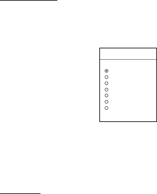
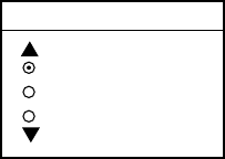
3.8.3 Changing track color (MODEL-1700C series only)
Track can be displayed in red, yellow, green, light-blue, purple, blue and white. It
can be useful to change track color on a regular basis to discriminate between
previous day's track, past track, etc. The default own ship track color is red.
Own ship’s track
1. Press the [MENU] key followed by CHART SETUP and TRACK & MARK
CONTROL soft keys to open the track control menu.
2. Select TRACK COLOR.
3. Press the EDIT soft key to display the track color window.
TRACK COLOR
▲RED
YELLOW
GREEN
LIGHT BLUE
PURPLE
BLUE
WHITE
▼
Track color window
4. Select the color desired.
5. Press the ENTER soft key.
6. Press the RETURN soft key.
7. Press the [MENU] key to close the menu.
Target track
Like own ship’s track, target tracks can be displayed in red, yellow, green, light-
blue, purple, blue and white (default setting).
1. Press the [MENU] key followed by CHART SETUP and TRACK & MARK
CONTROL soft keys to open the track control menu.
2. Select TARGET TRACK COLOR.
3. Press the EDIT soft key to display the track color window.
4. Select the color desired.
5. Press the ENTER soft key.
6. Press the RETURN soft key.
7. Press the [MENU] key to close the menu.
3. PLOTTER OPERATION
3-20
3.8.4 Track plotting method and interval for own ship track
In drawing the own ship track, first the ship’s position (fed from the blackbox GPS
unit or DGPS/GPS receiver) is stored into the unit’s memory at an interval of time
or distance. A shorter interval provides better reconstruction of the track, but the
storage time of the track is reduced. When the track memory becomes full, the
oldest track is erased to make room for the latest.
Track plotting method
Track may be plotted by time or distance interval and the default setting is “time.”
1. Press the [MENU] key followed by CHART SETUP and TRACK & MARK
CONTROL soft keys to open the track control menu.
2. Select PLOT.
3. Press the EDIT soft key to display the plot window.
PLOT
▲
TIME
DISTANCE
▼
Plot window
4. Select TIME or DISTANCE as appropriate. Distance is useful for conserving
track memory, since no track is recorded when the boat is stationary.
5. Press the ENTER soft key.
6. Press the RETURN soft key.
7. Press the [MENU] key to close the menu.
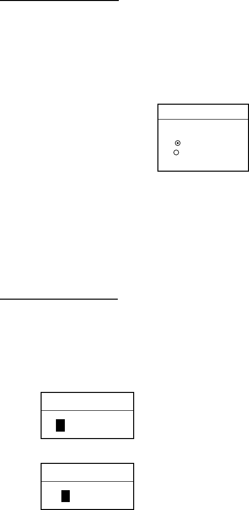
Track plotting interval
1. Press the [MENU] key followed by CHART SETUP and TRACK & MARK
CONTROL soft keys to open the track control menu.
2. Select TIME INTERVAL or DIST INTERVAL as appropriate
3. Press the EDIT soft key to display the time or distance interval window,
whichever you selected at step 2.
TIME INTERVAL
01 m 00 s
(When selecting TIME INTERVAL.)
DIST INTERVAL
00.10 nm
(When selecting DIST INTERVAL.)
Setting range: 0 min 0 sec (continuous) - 99 min 59 sec
Default setting: 10 sec
Setting range: 0 nm (continuous) - 9.9 nm (km, sm)
Default setting: 0.1 nm
Interval windows

3. PLOTTER OPERATION
3-21
4. Use the [ENTER] knob and the cursor pad to enter numeric data. The
[CLEAR] key functions to clear an entire line of data.
5. Press the ENTER soft key or the [ENTER] knob.
6. Press the RETURN soft key followed by the [MENU] key to close the menu.
3.8.5 Changing own ship track memory capacity
The equipment stores a total of 8000 points of track and marks. This amount may
be apportioned as desired, and the default setting is 2000 points of track and
6000 marks.
When you change the track memory capacity all tracks and marks in the memory
are erased. If necessary save the data to a memory card. For further details see
6.1.2 Saving data to a memory card.
1. Press the [MENU] key followed by CHART SETUP and TRACK & MARK
CONTROL soft keys to open the track control menu.
2. Select TRACK MEMORY(MARK).
3. Press the EDIT soft key to display the track memory window.
TRACK MEMORY
2000 POINTS
Track memory window
4. Use the [ENTER] knob to enter number of track memory points
5. Press the ENTER soft key or the [ENTER] knob. You are asked if you are
sure to change the track memory capacity.
6. Press the [ENTER] knob or ENTER soft key again.
7. Press the RETURN soft key.
8. Press the [MENU] key to close the menu.
3. PLOTTER OPERATION
3-22
3.8.6 Erasing track
This paragraph shows you how to erase own ship’s track and target tracks. Own
ship’s track can be erased by area, color (MODEL-1700C series only) or
collectively.
Erasing own ship track by area
You can erase own ship’s track by area as below.
1. Press the [MENU] key.
2. Press the [MENU] key followed by CHART SETUP, TRACK & MARK
CONTROL and ERASE T & M soft keys to show the erase menu.
ERASE ALL TRACK
ERASE TRACK BY AREA
ERASE TARGET TRACK
ERASE ALL MARKS & LINES
ERASE MARKS BY AREA
▲
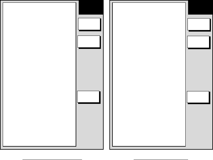
MODEL-1700 series
ERASE ALL TRACK
ERASE TRACK BY AREA
ERASE TRACK BY COLOR
ERASE TARGET TRACK
ERASE ALL MARKS & LINES
ERASE MARKS BY AREA
▲
MODEL-1700C series
ERASE ERASE
RETURNRETURN
EDIT EDIT
Erase menu
2. Select ERASE TRACK BY AREA and press the EDIT soft key. The menu is
erased and the plotter display appears.
3. Use the cursor pad to place the cursor at one of the corners which will
encompass the area to process.
4. Press the [ENTER] knob.
5. Drag the cursor diagonally to enclose all the track to be erased.
6. Press the [ENTER] knob. You are asked if it is all right to delete the track.
7. Push the [ENTER] knob to delete the track selected.
8. Press the RETURN soft key.
9. Press the [MENU] key to close the menu.
3. PLOTTER OPERATION
3-23
Erasing own ship track by color (MODEL-1700C series only)
You may erase own ship’s track by color as follows:
1. Press the [MENU] key followed by CHART SETUP, TRACK & MARK
CONTROL and ERASE T & M soft keys to show the erase menu.
2. Select ERASE TRACK BY COLOR and press the EDIT soft key.
TRACK COLOR
▲RED
YELLOW
GREEN
LIGHT BLUE
PURPLE
BLUE
WHITE
▼
Track color window
3. Use the cursor pad to select the color you want to erase and push the
[ENTER] knob.
4. Press the [ENTER] knob to erase track color selected.
5. Press the RETURN soft key.
6. Press the [MENU] key to close the menu.
Erasing all own ship track
1. Press the [MENU] key followed by CHART SETUP, TRACK & MARK
CONTROL and ERASE T & M soft keys to show the erase menu.
2. Select ERASE ALL TRACK and press the EDIT soft key.
3. Push the [ENTER] knob to erase all track.
4. Press the RETURN soft key.
5. Press the [MENU] key to close the menu.
Erasing all target tracks
1. Press the [MENU] key followed by CHART SETUP, TRACK & MARK
CONTROL and ERASE T & M soft keys to show the erase menu.
2. Select ERASE TARGET TRACK and press the EDIT soft key.
3. Push the [ENTER] knob to erase all target tracks.
4. Press the RETURN soft key.
5. Press the [MENU] key to close the menu.
3. PLOTTER OPERATION
3-24
3.9 Marks
Marks are useful for denoting important events such as a good fishing spot.
Marks can be inscribed in colors (MODEL-1700C series only) of red, yellow,
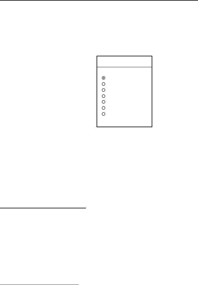
green, light-blue, purple, blue and white and seven shapes.
✕
Mark shapes
3.9.1 Entering a mark
1. Place the cursor on the location desired for a mark.
2. Press the MARK ENTRY soft key.
The mark is inscribed in the size, color (MODEL-1700C series only) and shape
selected on the mark setup menu. The default mark attributes are size, normal;
color, yellow, and shape, hollow circle
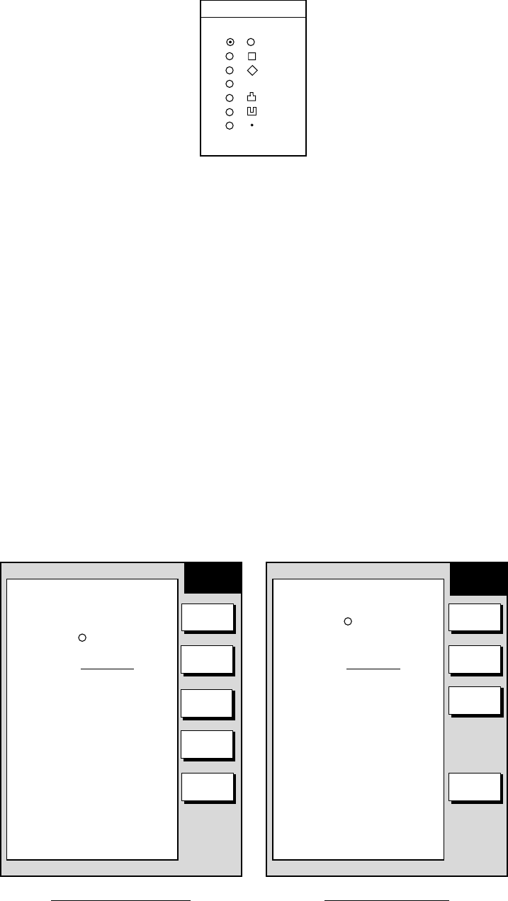
3.9.2 Changing mark attributes
You can select the shape, size and color (MODEL-1700C series only) of marks
on the mark
1. Press the [MENU] key to show the menu.
2. Press the CHART SETUP, TRACK CONTROL and MARK & LINE soft keys
to show the mark & line menu.
MARK & LINE COLOR
YELLOW
MARK SHAPE
LINE STYLE
MARK SIZE
NORMAL
MODEL-1700C series
MARK &
LINE
MARK SHAPE
LINE STYLE
MARK SIZE
NORMAL
MODEL-1700 series
MARK &
LINE
RETURN
MARK
SHAPE
RETURN
MARK
COLOR
MARK
SHAPE
LINE
STYLE
MARK
SIZE
LINE
STYLE
MARK
SIZE
Mark & line menu
3. For the GD-1700C only, do the following to select mark & line color.
a) Select MARK & LINE COLOR.
b) Press the EDIT soft key.
c) Choose color desired (default setting; yellow).
3. PLOTTER OPERATION
3-25
d) Press the ENTER soft key or [ENTER] knob.
4. Select MARK SHAPE.
5. Press the EDIT soft key.
MARK SHAPE
▲
▼
✕
Mark shape window
3. Select mark shape and press the ENTER soft key.
4. Select MARK SIZE.
5. Press the EDIT soft key.
6. Select NORMAL (default setting) or SMALL.
7. Press the ENTER soft key or [ENTER] knob.
8. Press the RETURN soft key.
9. Press the [MENU] key to close the menu.
3.9.3 Connecting marks
You may wish to connect marks with lines. This feature can be used to mark
boundaries, etc.
1. Press the [MENU] key followed by CHART SETUP, TRACK & MARK
CONTROL and MARK & LINE SETUP soft keys to show the mark & line
menu.
MARK & LINE COLOR
YELLOW
MARK SHAPE
LINE STYLE
MARK SIZE
NORMAL
MODEL-1700C series
MARK &
LINE
MARK SHAPE
LINE STYLE
MARK SIZE
NORMAL
MODEL-1700 series
MARK &
LINE
RETURN
MARK
SHAPE
RETURN
MARK
COLOR
MARK
SHAPE
LINE
STYLE
MARK
SIZE
LINE
STYLE
MARK
SIZE
Mark & line setup menu

3. PLOTTER OPERATION
3-26
2. Select MARK STYLE.
3. Press the EDIT soft key.
MARK LINE
▲
▼
Mark line window
4. Select line style desired and press the ENTER soft key or [ENTER] knob.
5. Press the RETURN soft key followed by the [MENU] key to close the menu.
When you wish to enter marks without connection them with lines, select the line
style “single dot” at step 5 in the above procedure.
3.9.4 Erasing marks
Erasing an individual mark
1. Operate the cursor pad to place the cursor on the mark you want to erase.
2. Press the [CLEAR] key to erase the mark.
Note: To erase a line, place the cursor on the mark which encloses the line, and
then press the [CLEAR] key. Place the cursor at the intersecting points of
two lines will erase both lines.
Erasing all marks, lines
You can erase all marks and lines. Be absolutely sure you want to erase all marks
and lines; erased marks and lines cannot be restored.
1. Press the [MENU] key followed by CHART SETUP, TRACK & MARK
CONTROL and ERASE T & M soft keys to show the erase menu.
2. Select ERASE ALL MARKS & LINES and press the EDIT soft key.
3. Push the [ENTER] knob to erase all marks and lines.
4. Press the RETURN soft key.
5. Press the [MENU] key to close the menu.

3. PLOTTER OPERATION
3-27
3.10 Waypoints
In navigation terminology, a waypoint is a particular location on a voyage whether
it be a starting, intermediate or destination point. A waypoint is the simplest piece
of information your equipment requires to get you to a destination, in the shortest
distance possible.
This unit has 1000 waypoints into which you can enter position information. There
are five methods by which you can enter a waypoint: at own ship position, at
MOB position, by cursor, by range and bearing, and through the waypoint list
(manual input of latitude and longitude).
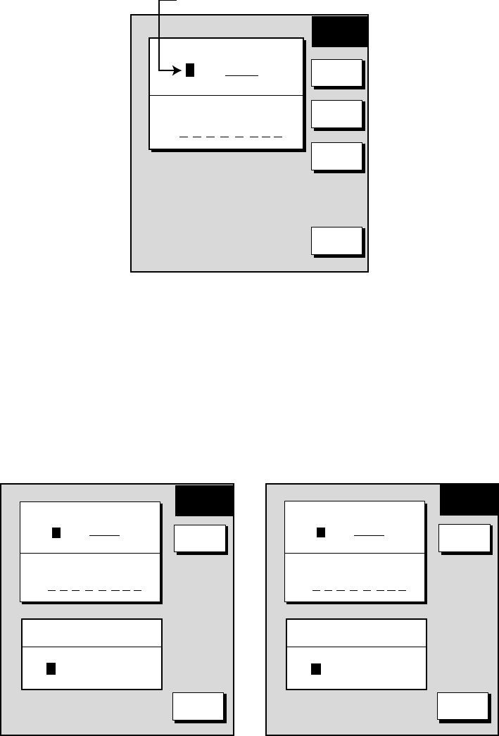
3.10.1 Entering waypoints
Entering a waypoint at own ship position
Press the [SAVE/MOB] key with a touch-and-release action to store your position.
This new waypoint will automatically be saved in the waypoint list under the
youngest empty waypoint number.
3. PLOTTER OPERATION
3-28
Entering a waypoint with the cursor
1. Press the [MENU] key to open the menu.
2. Press the WAYPOINT/ROUTE, WAYPOINTS and WAYPOINT BY CURSOR
soft keys. The plotter display appears.
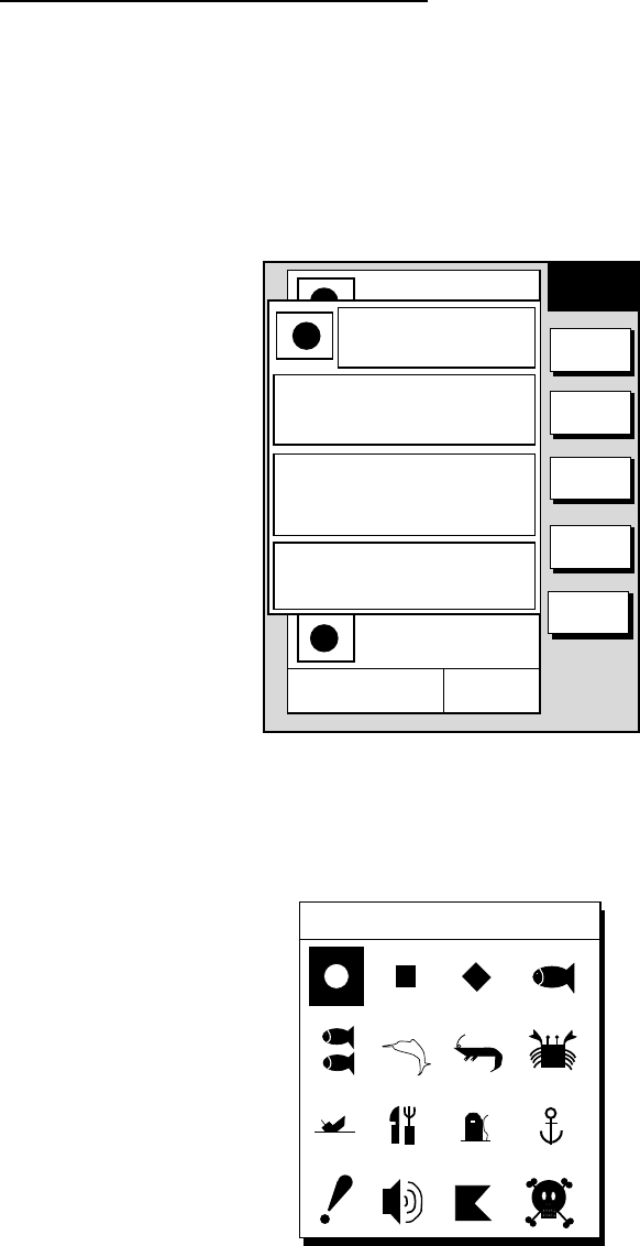
3. Operate the cursor pad to place the cursor on the location desired.
4. Press the NEW WPT soft key. The waypoint window appears and it shows
mark shape, waypoint name, comment (default: date), position of waypoint
and proximity alarm radius.
NEW
WPT
▲
001WPT
00:00 01JAN00
34°44.000'N
135°21.000'W 359.9°
0.00nm
002WPT
00:00 01JAN00
34°44.000'N
135°21.000'W 359.9°
0.00nm
003WPT
00:00 01JAN00
34°44.000'N
135°21.000'W 359.9°
0.00nm
004WPT
00:00 01JAN00
34°44.000'N
135°21.000'W 359.9°
0.00nm
NAME
001WP
COMMENT
02:36 09SEP00
POSITION
34°
12. 345N
134°
12. 345N
PROXIMITY ALARM RADIUS
1. 23n
SELECT
MARK
COORD
TYPE
N
⇔
S
E
⇔
W
SAVE
RETURN
Waypoint window
5. If you do not need to change the waypoint data, go to step 16.
6. Press the SELECT MARK soft key.
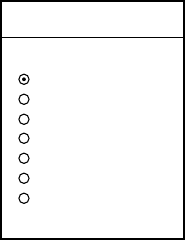
7. Press the MARK SHAPE soft key to open the mark shape selection window.
SELECT MARK
Mark shape selection window
8. Operate the cursor pad to select shape desired.
9. Press the ENTER soft key.
10.Press the RETURN soft key.
3. PLOTTER OPERATION
3-29
11. For the MODEL-1700C series, press the SELECT MARK and MARK COLOR
soft keys to open the mark color selection window. Select the color desired,
and then press the ENTER soft key.
SELECT COLOR
▲RED
YELLOW
GREEN
LIGHT BLUE
PURPLE
BLUE
WHITE
▼
Mark color selection window
Note: You cannot change the shape and color of a waypoint when the
proximity alarm radius for it is other than “zero.” To change shape or
color, enter all zeroes as the proximity alarm radius.
12.You can change the name (1 to 6 characters), comment (13 characters), L/L
position and the proximity alarm radius as follows:
a) Select the NAME, COMMENT or PROXIMITY ALARM RADIUS field.
b) Use the Omnipad to select appropriate location.
c) Use the [ENTER] knob to select appropriate alphanumeric character.
d) Push the [ENTER] knob to enter character selected.
13.Use the cursor pad to place the cursor in the POSITION box.
14.Use the cursor pad to select the digit you want to change.
15. Use the [ENTER] knob to select digit and push the knob to register.
16. Press the SAVE soft key to register the waypoint.
To enter another waypoint select its location with the cursor pad and press the
NEW WPT soft key.
3. PLOTTER OPERATION
3-30
Entering a waypoint by range and bearing
This method is useful when you want to enter a waypoint using range and
bearing to a target found on a radar.
1. Press the [MENU] key to open the menu.
2. Press the WAYPOINT/ROUTE, WAYPOINTS and WAYPOINT BY RNG. &
BRG. soft keys.
3. Operate the cursor pad to place the cursor on the location desired. Range and
bearing from own ship to the cursor appear at the top of the display.
Note: The origin point of range and bearing can be shifted to the place you
desire. Operate the cursor pad to select location, and then press the
START POINT soft key.
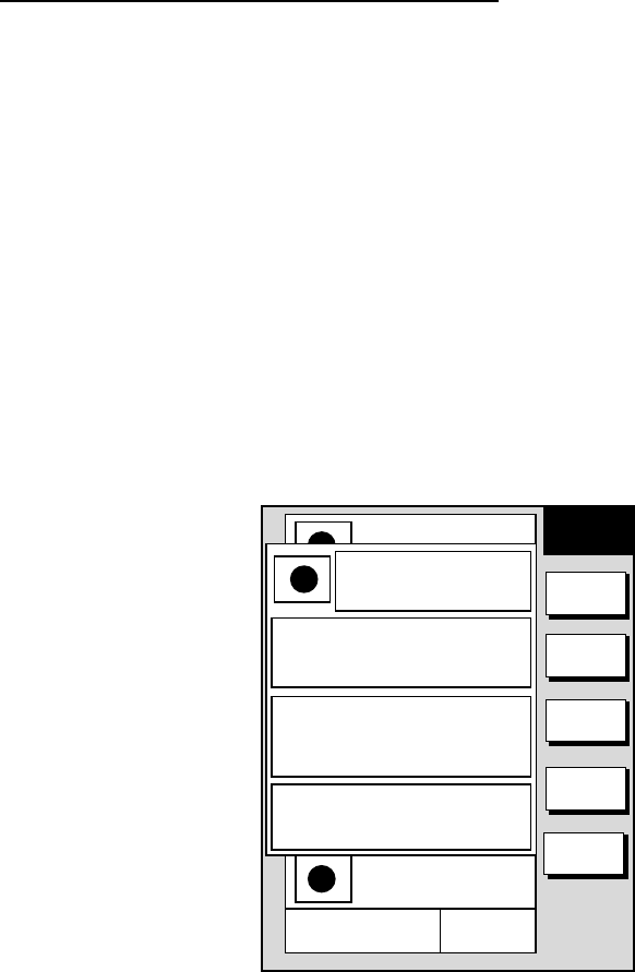
4. Press the NEW WPT soft key. The waypoint window appears and it shows
mark shape, waypoint name, comment (default: date), position of waypoint
and proximity alarm radius.
NEW
WPT
▲
001WPT
00:00 01JAN00
34°44.000'N
135°21.000'W 359.9°
0.00nm
002WPT
00:00 01JAN00
34°44.000'N
135°21.000'W 359.9°
0.00nm
003WPT
00:00 01JAN00
34°44.000'N
135°21.000'W 359.9°
0.00nm
004WPT
00:00 01JAN00
34°44.000'N
135°21.000'W 359.9°
0.00nm
NAME
001WP
COMMENT
02:36 09SEP00
POSITION
34°
12. 345N
134°
12. 345N
PROXIMITY ALARM RADIUS
1. 23n
SELECT
MARK
COORD
TYPE
N
⇔
S
E
⇔
W
SAVE
RETURN
Waypoint window
5. If necessary, change waypoint data following the instructions from step 7 in
“Entering waypoints with the cursor.”
6. Press the SAVE soft key to register the waypoint.
3. PLOTTER OPERATION
3-31
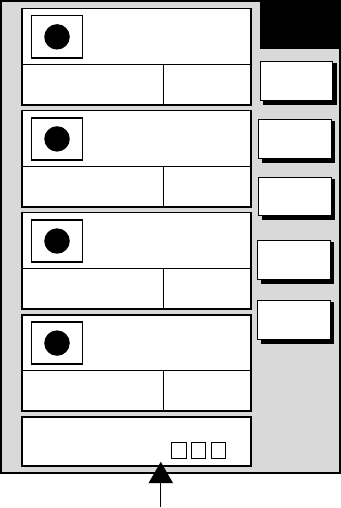
Entering a waypoint from the waypoint list
1. Press the [MENU] key to open the menu.
2. Press the WAYPOINT/ROUTE and WAYPOINTS soft keys.
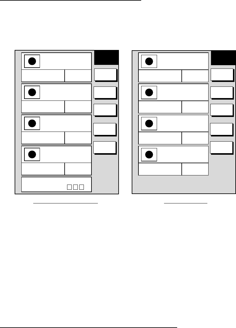
3. Press the LOCAL LIST (lists waypoints in order from nearest to furthest) or
ALPHA/NUMERIC LIST (lists waypoints in alphanumeric order) soft key.
Alphanumeric waypoint list
▲
001WPT
00:00 01JAN00
34°44.000'N
135°21.000'W 359.9°
0.00nm
002WPT
00:00 01JAN00
34°44.000'N
135°21.000'W 359.9°
0.00nm
003WPT
00:00 01JAN00
34°44.000'N
135°21.000'W 359.9°
0.00nm
004WPT
00:00 01JAN00
34°44.000'N
135°21.000'W 359.9°
0.00nm
PUSH ENTER KEY
TO SEARCH FOR
▲
001WPT
00:00 01JAN00
34°44.000'N
135°21.000'W 359.9°
0.00nm
002WPT
00:00 01JAN00
34°44.000'N
135°21.000'W 359.9°
0.00nm
003WPT
00:00 01JAN00
34°44.000'N
135°21.000'W 359.9°
0.00nm
004WPT
00:00 01JAN00
34°44.000'N
135°21.000'W 359.9°
0.00nm
WPT
LOCAL
Local waypoint list
GO TO
NEW
WPT
EDIT
WPT
ERASE
WPT
RETURN
WPT
ALPHA
GO TO
NEW
WPT
EDIT
WPT
ERASE
WPT
RETURN
Alphanumeric and local waypoint lists
4. Press the NEW WPT soft key to show the waypoint window. Own ship
position is shown in the position box. If necessary, change the data following
from step 7 in “Entering waypoints with the cursor.”
5. Press the SAVE soft key to register the waypoint.
6. Press the RETURN soft key followed by the [MENU] key to close the menu.
3.10.2 Editing waypoint data
Waypoint data may be from the waypoint list. You can select the waypoint to edit
directly from the waypoint list or with the cursor.
Selecting waypoint data to edit from the waypoint list
1. Press the [MENU] key to open the menu.
2. Press the WAYPOINT/ROUTE and WAYPOINTS soft key.
3. Press the LOCAL LIST or ALPHA/NUMERIC LIST soft key.
4. Select the waypoint you want to edit.
5. Press the EDIT WPT soft key.
6. Edit waypoint as appropriate.
7. Press the SAVE soft key.
8. Press the RETURN soft key followed by the [MENU] key to close the menu.
3. PLOTTER OPERATION
3-32
Selecting waypoint data to edit with the cursor
1. Use the cursor pad to place the cursor on the waypoint to edit. A flashing
diamond appears over the waypoint when it is correctly selected.
2. Press the EDIT MOVE soft key followed by the EDIT WPT soft key.
3. Edit waypoint as appropriate.
4. Press the SAVE SOFT key.
5. Press the RETURN soft key followed by the [MENU] key to close the menu.
Changing waypoint position from the plotter display
You may change the latitude and longitude position of waypoints from the plotter
display as follows:
1. Press the [MENU] key followed by the WAYPOINTS soft key to open the
waypoint menu.
2. Press the WAYPOINT BY CURSOR soft key.
3. Operate the cursor pad to place the cursor on the waypoint which you want to
change. A flashing diamond mark appears on the waypoint when it is correctly
selected.
4. Press the EDIT MOVE soft key.
5. Press the MOVE WPT soft key.
6. Operate the cursor pad to place the cursor on the location desired. A line
connects previous position and new position.
7. Push the [ENTER] knob.
The waypoint moves to the cursor position and its new position is recorded on the
waypoint list. If the waypoint is set as destination or is part of a route, you are
asked if you are sure to move the waypoint. In this case, push the [ENTER] knob
to move the waypoint, or press the [CLEAR] key to cancel.
BRIDGE
FISH
WP-002 RNG
BRG
CANCEL
Use omnipad to place
cursor at new location
for waypoint. Press to alternately display
range from own ship, range
from waypoint.
1024 nm
34° 22. 3456'N 359.9° TRIP NU
080° 22. 3456'E
59.9nm 99.9 nm
Plotter display

3. PLOTTER OPERATION
3-33
3.10.3 Erasing waypoints
Erasing a waypoint with the cursor
1. Press the cursor pad to turn on the cursor.
2. Operate the cursor pad to place the cursor on the waypoint you want to erase.
A flashing diamond mark appears over the waypoint when the waypoint is
correctly selected.
3. Press the [CLEAR] key, or press the EDIT MOVE soft key followed by the
ERASE WPT soft key. You are asked if you are sure to erase the waypoint.
4. Push the [ENTER] knob. The waypoint is erased from both the plotter screen
and the waypoint list.
Erasing a waypoint from the waypoint list
1. Press the [MENU] key to open the menu.
2. Press the WAYPOINT/ROUTE followed by WAYPOINTS soft keys.
3. Press the LOCAL LIST or ALPHA/NUMERIC LIST soft key.
4. Select the waypoint you want to erase.
5. Press the ERASE WPT soft key. You are asked if you are sure to erase the
waypoint.
6. Push the [ENTER] knob. The waypoint is erased from both the waypoint list
and the plotter screen (if it is currently displayed).
7. Press the RETURN soft key followed by the [MENU] key to close the menu.
3. PLOTTER OPERATION
3-34
3.10.4 Changing waypoint mark size (FURUNO, NAV CHART)
You may change the size of all waypoint marks to small or large (default), or you
may turn them off.
1. Press the [MENU] key to open the menu.
2. Press the CHART SETUP and CHART DETAILS soft keys.
LAT LON GRID
ON
TEXT INFO
ON
WAYPOINT
LARGE
WAYPOINT NAME
ON
CHART BOARDER LINES
ON
LANDMASS
ON
NAV AIDS
ON
SECTOR INFO
ON
OTHER SYMBOL
ON
MARK SIZE
NORMAL
▲
MODEL-1700 series
LAT LON GRID
GREEN
TEXT INFO
ON
WAYPOINT
LARGE
WAYPOINT NAME
ON
CHART BOARDER LINES
ON
LANDMASS
BRT YELLOW
BACKGROUND
BLUE
BRT YELLOW
SECTOR INFO
ON
OTHER SYMBOL
WHITE
MARK SIZE
NORMAL
▲
MODEL-1700C series
CHART
DETAILS CHART
DETAILS
EDIT
DEPTH
INFO
RETURN
EDIT
DEPTH
INFO
RETURN
Chart details menu
3. Select WAYPOINT.
4. Press the EDIT soft key.
5. Select LARGE, SMALL or OFF.
LARGE: Shows mark in actual shape.
SMALL: Displays all waypoints with an “X” regardless of mark shape
selected.
OFF: Turns off all waypoints and their names. Waypoints which are part
of a route are always shown regardless of this setting.
6. Press the ENTER soft key or the [ENTER] knob.
7. Press the RETURN soft key followed by the [MENU] key to close the menu.
3. PLOTTER OPERATION
3-35
3.10.5 Searching waypoints
You can search for a waypoint through the alpha/numeric list as follows:
1. Press the [MENU] key.
2. Press the WAYPOINT & ROUTE, WAYPOINTS and ALPHA/NUMERIC LIST
soft keys to show the alpha/numeric list.
▲
001WPT
00:00 01JAN00
34°44.000'N
135°21.000'W 359.9°
0.00nm
002WPT
00:00 01JAN00
34°44.000'N
135°21.000'W 359.9°
0.00nm
003WPT
00:00 01JAN00
34°44.000'N
135°21.000'W 359.9°
0.00nm
004WPT
00:00 01JAN00
34°44.000'N
135°21.000'W 359.9°
0.00nm
PUSH ENTER KEY
TO SEARCH FOR
EDIT
NEW
WPT
EDIT
WPT
ERASE
WPT
RETURN
WPT
ALPHA
Search window
Alphanumeric list
3. Use the alphanumeric keys to enter the first 1 - 3 characters in the search
window. The waypoint searched appears at the top of the screen.
4. Press the RETURN soft key followed by the [MENU] key to close the menu.
3. PLOTTER OPERATION
3-36
3.11 Routes
Often a trip from one place to another involves several course changes, requiring
a series of route points (waypoints) which you navigate to, one after another. The
sequence of waypoints leading to the ultimate destination is called a route. Your
unit can automatically advance to the next waypoint on a route, so you do not
have to change the destination waypoint repeatedly.
You can store up to 200 routes, and a route may have 35 waypoints.
3.11.1 Creating routes
Entering a route from the route list
This method constructs routes using existing waypoints.
1. Press the [MENU] key.
2. Press the WAYPOINT/ROUTE soft key.
3. Press the ROUTES soft key to open the route menu. (No data will be shown if
there is no route data entered.)
ROUTE
GO TO
NEW
ROUTE
EDIT
ROUTE
ERASE
ROUTE
RETURN
PUSH ENTER KEY
TO SEARCH FOR
POTS
LENGTH
56.7 nm
LENGTH
4.7 nm
12:30 01AUG00
WAYPOINTS
6
LENGTH
25.6 nm
NETS
TRAPS
15:21 01AUG00
16:45 01AUG00
WAYPOINTS
35
WAYPOINTS
3
WAYPOINTS
1
FISH01
LENGTH
21.1 nm
10:42 01SEP00
Route menu
4. Press the NEW ROUTE soft key to open the new route entry screen.
ROUTE NAME
COMMENT
0 0 1
NEW
ROUTE
PLOT
LOCAL
LIST
ALPH
LIST
CONECT
ROUTE
CANCEL
New route entry screen

3. PLOTTER OPERATION
3-37
5. If desired you can change the route name shown and/or add a comment. To
change route name, press the [CLEAR] key to clear the route name. Use the
cursor pad to locate the cursor and then use the [ENTER] knob to enter
appropriate alphanumeric. To enter a comment, place the cursor in the
COMMENT window. Use the cursor pad and the [ENTER] knob to enter your
comment. A route name may consist of six characters; comment, 13
characters.
6. Press the LOCAL LIST or ALPH LIST soft key to open the waypoint list.
7. Select a waypoint, and press the ADD WPT soft key to add it to the route.
8. Repeat step 7 to complete the route.
Note: To clear a waypoint, press the ERASE LST WP soft key. Each pressing
of this key deletes the last waypoint entered.
9. Press the SAVE soft key to register the route.
10.Press the RETURN soft key followed by the [MENU] key to close the menu.
Entering a route with the cursor
This method allows you to construct a route directly on the plotter display, using
existing waypoints or new locations. Any new location will be saved as a waypoint,
under the youngest empty waypoint number.
1. Follow step 1-5 in “Entering routes through the route list.”
2. Press the PLOT soft key. The plotter display appears.
3. Operate the cursor pad to place the cursor on an existing waypoint (ADD
WPT soft key appears) or new location (ADD NEW WPT soft key appears).
4. Press the ADD WP soft key (or ADD NEW WPT soft key).
5. Repeat steps 3 and 4 to complete the route.
6. Push the [ENTER] knob to register the route.
3. PLOTTER OPERATION
3-38
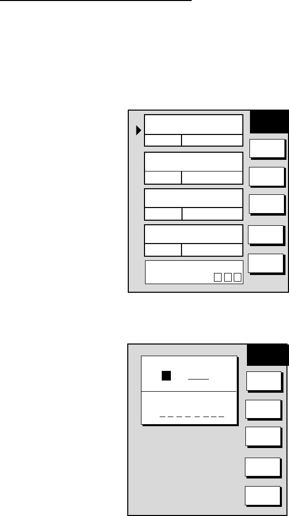
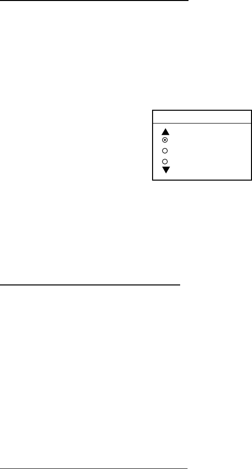
3.11.2 Connecting routes
Two routes can be connected as follows:
1. Press the [MENU] key to open the menu.
2. Press the WAYPOINT/ROUTE soft key.
3. Press the ROUTES soft key.
4. Press the NEW ROUTE soft key.
5. Enter the name for new route.
6. Press the CONECT ROUTE soft key.
7. Enter the route name for the first route beneath FIRST in the CONNECT
ROUTE window.
NEW
ROUTE
CONNECT ROUTE
FIRST SECOND
_ _ _ _ _ _ _ _ _ _ _ _
F F
F
⇔
R
SAVE
ROUTE
CANCEL
ROUTE NAME
COMMENT
0 0 1
Connect route window
8. Press the F⇔R soft key to select direction to transverse the waypoints of the
route, forward or reverse.
9. Enter the route name of the second route as you did for the first route.
10. Press the SAVE soft key.
11. Press the RETURN soft key followed by the [MENU] key to close the menu.
Note: The maximum number of waypoints in a route is 35. If this number is
exceeded an error message appears. In this case, delete waypoints in one
or both routes so the total number of waypoints does not exceed 35.
3. PLOTTER OPERATION
3-39
3.11.3 Inserting waypoints in a route
Inserting a waypoint from the route list
Waypoints can be inserted in routes as follows:
1. Press the [MENU] key to open the menu.
2. Press the WAYPOINT/ROUTE soft key.
3. Press the ROUTES soft key.
4. Select a route.
5. Press the EDIT ROUTE soft key. The route name screen appears.
6. Press the LOCAL LIST soft key. All waypoints in the route are displayed.
EDIT
ROUTE
▲
01
34°44.000'N
135°21.000'W
001WPT
359.9°
6.00nm
02
34°44.000'N
135°41.000'W
002WPT
29.9°
12.0nm
03
34°14.000'N
135°21.000'W
003WPT
159.°
6.00nm
04
34°34.000'N
135°51.000'W
004WPT
50.5°
29.8nm
05
34°44.000'N
135°21.000'W
005WPT
359.9°
3.0nm
INSERT
WPT
REMOVE
WPT
CHANGE
WPT
COORD
TYPE
RETURN
Edit route menu
7. Place the cursor at the location where you want to insert a waypoint.
8. Press the INSERT WPT soft key to show the waypoint list.
EDIT
ROUTE
01
34°44.000'N
135°21.000'W
001WPT
359.9°
6.00nm
02
34°44.000'N
135°41.000'W
002WPT
29.9°
12.0nm
03
34°14.000'N
135°21.000'W
003WPT
159.°
6.00nm
04
34°34.000'N
135°51.000'W
004WPT
50.5°
29.8nm
05
34°44.000'N
135°21.000'W
005WPT
359.9°
3.0nm
01
34°44.000'N
135°21.000'W
001WPT
02
34°44.000'N
135°21.000'W
002WPT
03
34°44.000'N
135°21.000'W
003WPT
04
34°44.000'N
135°21.000'W
004WPT
▲
SELECT
WPT
COORD
TYPE
ALPHA
LIST
CANCEL
LOCAL
LIST
Waypoint list for editing a route (local list)
3. PLOTTER OPERATION
3-40
9. Select the waypoint you want to insert. You can switch between the local list
and alphanumeric list by pressing the LOCAL LIST or ALPH LIST soft key.
10. Press the SELECT WPT soft key.
11. Press the RETURN soft key followed by the [MENU] key to close the menu.
Inserting a waypoint from the plotter display
Inserting waypoints before the first waypoint or after the last waypoint
1. Press the [MENU] key to open the menu.
2. Press the WAYPOINT/ROUTE soft key.
3. Press the ROUTES soft key.
4. Select a route.
5. Press the EDIT ROUTE soft key.
6. Press the PLOT soft key to show the plotter screen.
7. Operate the cursor to place the cursor on the waypoint which you want to
insert.
8. Press the ADD TO START soft key.
9. Operate the cursor pad to place the cursor on an existing waypoint (ADD
WPT soft key appears) or new location (ADD NEW WPT soft key appears).
10.Press the ADD WPT soft key (ADD NEW WPT soft key).
11.Press the [ENTER] knob.
To insert a waypoint after the last waypoint, press the ADD TO END soft key at
the step 8.
Inserting waypoints in an intermediate location within a route
1. Follow steps 1 through 4 in “Inserting waypoints before the first waypoint or
after the last waypoint.”
2. Operate the cursor pad to place the cursor on a line connecting waypoints.
3. Press the SPLIT LEG soft key. The selected line turns red.
4. Operate the cursor pad to place the cursor on an existing waypoint (INSERT
WPT soft key appears) or new location (INSERT NEW WPT soft key
appears).
5. Press the appropriate soft key appearing at step 4.
3. PLOTTER OPERATION
3-41
3.11.4 Removing waypoints from a route
Removing a waypoint from the route list
1. Press the [MENU] key to open the menu.
2. Press the WAYPOINT/ROUTE soft key.
3. Press the ROUTES soft key
4. Select a route.
5. Press the EDIT ROUTE and LOCAL LIST soft keys to show the waypoint list.
6. Select the waypoint you want to delete.
7. Press the REMOVE WPT soft key.
8. Press the RETURN soft key followed by the [MENU] key to close the menu.
Removing a waypoint from the plotter display
1. Press the [MENU] key to open the menu.
2. Press the WAYPOINT/ROUTE soft key.
3. Press the ROUTES soft key.
4. Select a route.
5. Press the EDIT ROUTE soft key.
6. Press the PLOT soft key to show the plot screen.
7. Operate the cursor pad to place the cursor on the waypoint you want to
remove from the route.
8. Press the REMOVE WPT soft key.
3.11.5 Creating voyage-based routes
You can create routes based on your ship’s track. This can be done automatically
by time or distance, or manually. 35 waypoints may be entered. This feature is
useful when you wish to retrace previous track.
How to create a voyage-based route
1. Press the [MENU] key to open the menu.
2. Press the WAYPOINT/ROUTE soft key.
3. Press the CREATE VOYAGE BASED ROUTE soft key.
SAVE
ROUTE
ABCDEFGHIJKL
LENGTH
25.6 nm
HPT001
12:30 29SE00
TRAP
15:21 01OCT00
NET
16:45 01OCT00
WAYPOINTS
35
LENGTH
56.7 nm WAYPOINTS
6
LENGTH
21.1 nm WAYPOINTS
3
LENGTH
4.7 nm WAYPOINTS
1
SEARCH FOR
FISH
12:30 29SE00
NEW
SELECT
ROUTE
RETURN
Save route menu
4. Press the NEW soft key to show the new route window.
3. PLOTTER OPERATION
3-42
SAVE
ROUTE
ROUTE NAME
0 0 6
COMMENT
Next consecutive route number
BCKTRK
TIME
BCKTRK
RANGE
MANUAL
CANCEL
Save route window
5. If required, you may change the route name and enter a comment. You may
also enter an existing route, for which track-based waypoints will be tacked on
from the last waypoint in the route.
6. Choose how to record points for your route, by time, by range or manual entry.
Press one of BCKTRK TIME and BCKTRK RANGE or MANUAL soft key as
appropriate. For manual go to step 7. For BCKTRK TIME, BCKTRK RANGE
one of the following displays appears.
ROUTE NAME
COMMENT
0 0 1
SAVE
ROUTE
START
CANCEL
TIME INTERVAL
01 m 00 s
ROUTE NAME
COMMENT
0 0 1
SAVE
ROUTE
START
CANCEL
RANGE INTERVAL
05.0 nm
Save route menu, displays for entry of time, range interval
7. Enter interval desired and press the START and RETURN soft keys followed
by the [MENU] key to close the menu.

3. PLOTTER OPERATION
3-43
8. For manual entry of waypoints, do the following:
a) Press the [SAVE/MOB] key with a touch-and-release action to enter a
waypoint mark at own ship position. A new waypoint is created under the next
consecutive waypoint number and that waypoint is added to the route.
b) Repeat step a) as necessary. 35 waypoints may be entered. The “SAVE” icon
appears at the top of the screen when points are saved manually.
To stop recording waypoints and save the route
When 35 waypoints have been entered the message “Total 35 WPTS have been
already registered in the route. Stop creating voyage based route.” is displayed.
In this case, follow the procedure above to stop recording waypoints and save the
route as shown below. You can also stop recording waypoints at any time
desired.
1. Press the [MENU] key followed by the WAYPOINT/ROUTE and CREATE
VOYAGE BASED ROUTE soft keys.
2. Press the FINISH LOG soft key to register the route.
3.11.6 Erasing routes
1. Press the [MENU] key to open the menu.
2. Press the WAYPOINT/ROUTE soft key.
3. Press the ROUTES soft key.
4. Select a route.
5. Press the ERASE ROUTE soft key. You are asked if you are sure to erase the
route.
6. Press the [ENTER] knob to erase the route.
7. Press the RETURN soft key followed by the [MENU] key to close the menu.
3. PLOTTER OPERATION
3-44
3.12 Navigation
This section shows you how to get to a desired destination by “quick points,”
waypoints, port services and routes.
3.12.1 Navigating to a “quick point”
The “quick point” feature allows you to navigate to point(s) without retaining the
data indefinitely in your unit‘s memory.
Selecting quick point entry method
You need to tell your unit how to set the quick point: 1 POINT, 35 POINT (up to 35
points) or WPT/PORT SERV. (For WPT/PORT SERV, see the next page.)
1. Press the [MENU] key.
2. Press the PLOTTER SETUP soft key.
3. Select SET GO TO METHOD and press the EDIT soft key.
SET GO TO METHOD
1 POINT
35 POINT
WPT/PORT
Set go to method window
4. Select 1 POINT.
5. Press the ENTER soft key.
6. Press the RETURN soft key followed by the [MENU] key to close the menu.
Navigating to a single quick point
1. Press the [MENU] key followed by the PLOTTER SETUP soft key.
2. Place the cursor on an existing waypoint (GO TO WPT soft key appears) or a
new location (GO TO CURSOR soft key appears).
3. Depending on the selection you made at step, two press GO TO CURSOR or
GO TO WPT soft key.
A line (light-blue on the MODEL-1700C series) with arrows connects between own
ship and destination, marked “QP<01>,” and it shows the shortest course to the
destination. Arrows on the line show the direction to follow to get to the quick point.
Range and bearing from own ship to the destination appear at the top of screen.
This location is saved to the waypoint list as waypoint “QP01.”
Navigating to multiple quick points
1. Press the [MENU] key followed by the PLOTTER OPTION soft key.
2. Press the GO TO soft key.
3. Place the cursor on an existing waypoint (SELECT WPT soft key appears) or
a new location ADD QP soft key appears).
3. PLOTTER OPERATION
3-45
4. Depending on the action taken at step 3 press the SELECT WPT soft key or
ADD QP. “QP<01>” appears at the cursor location. To erase last-entered
waypoint press the ERASE LST WPT soft key.
5. Repeat steps 3 and 4 to complete the route.
6. Push the [ENTER] knob to finish.
A line (light-blue on the MODEL-1700C series) with arrows connects between
own ship and all quick points, and it shows the shortest course to destination.
Arrows on the line show the direction to follow to get to your destination. Quick
points are numbered in sequential order from QP<01> and are saved to the
waypoint list. Range and bearing from own ship to the first destination appear at
the top of screen. The points are saved as a route, under the name “Q>RTE”
(Quick Route).
3.12.2 Navigating to waypoints
1. Press the [MENU] key to open the menu.
2. Press the WAYPOINT/ROUTE soft key.
3. Press the WAYPOINTS soft key to open the waypoint menu.
4. Press the LOCAL LIST or ALPHA/NUMERIC LIST soft key to show
corresponding waypoint list.
5. Select a waypoint.
6. Press the GO TO soft key.
The plotter display appears. A line (light-blue on the MODEL-1700C series) runs
between destination selected and own ship’s position. Arrows on the line show
the direction to the follow to get to the waypoint. Waypoint data appears at the top
of screen.
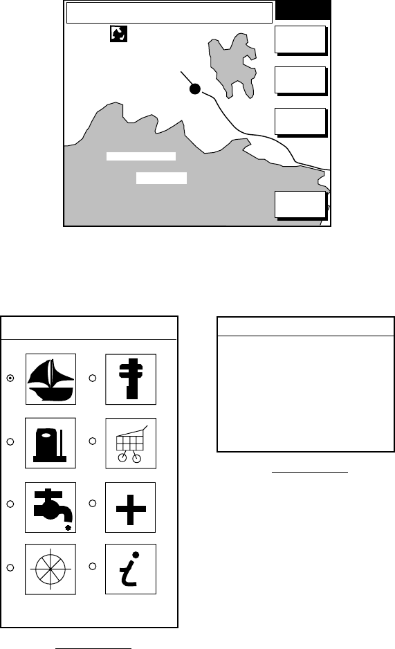
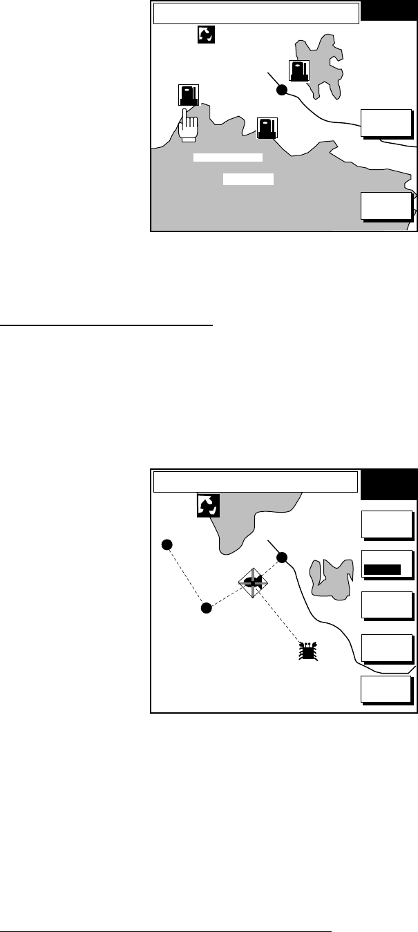
3.12.3 Navigating to ports, port services
Some Nav-Charts™ and C-MAP have a port service list, shown at the top of the
screen, which shows services available at ports or harbors. (See page 3-4.) You
can use the list to set destination as follows:
1. Press the [MENU] key followed by the PLOTTER OPTION soft key.
2. Press the DISPLAY OPTIONS soft key.
3. Select SET GO TO METHOD and press the EDIT soft key. The following
display appears.
SET GO TO METHOD
1 POINT
35 POINT
WPT/PORT
Set go to method window
4. Select WPT/PORT.
5. Press the ENTER soft key or [ENTER] knob.
3. PLOTTER OPERATION
3-46
6. Press the [MENU] key to close the menu and return to the plotter display. Soft
key titles change as in the figure below.
FROM
OS 0.26 nm
180.2°
PUNTA CORNACCHIA
ACCO AMENO
I. ISCHIA
CASAMICCIOLA
ISCHIA
PORTO
40°45.971'N
13°57.462'E
+
QUICK
ROUTE
NEAR
SRVCE
PORT
CANCEL
GO TO
GO TO
1024 nm
Plotter display
7. Press the PORT or NEAR SRVICE soft key depending on objective. PORT
shows a list of ports in your area. NEAR SRVICE displays the port service list.
▼
SELECT PORT
SERVICE
SELECT PORT
ACCIAROLI
ACQUAMORTA
AGNONE S. NICOLA
AGROPOLI
AMALFI
BAIA
CAPRI
CASA MICCIOLA-ISCHIA
▲
Port services
Port list (Italy)
Port services and sample port list
8. If you selected PORT at step 7, use the Omnipad to select a port and press
the ENTER soft key. Make a route using the soft keys and press the [ENTER]
knob. (If you want to go directly to that port, simply press the ADD QP soft key
followed by the [ENTER] knob.)
If you selected NEAR SERVICE at step 7, select service mark desired and
then press the ENTER soft key. Then, the display shows the locations of
those services nearest you. (The figure below shows location of filling
stations in an area in southern Italy.) Place the “hand cursor” on the port
service icon desired and press the ENTER soft key. Make a route using the
soft keys and push the [ENTER] knob. (If you want to go directly to location
selected, simply press the ADD QP soft key followed by the [ENTER] knob.)
3. PLOTTER OPERATION
3-47
FROM
OS 0.26 nm
180.2°
PUNTA CORNACCHIA
ACCO AMENO
I. ISCHIA
CASAMICCIOLA
ISCHIA
PORTO
40°45.971'N
13°57.462'E
+
ENTER
CANCEL
GO TO
GO TO
1024 nm
Sample filling station locations (southern Italy)
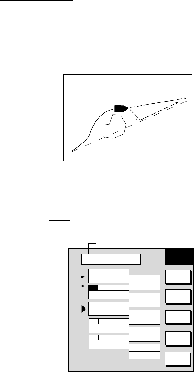
2.12.4 Following a route
Selecting the route to follow
1. Press the [MENU] key to open the menu.
2. Press the WAYPOINT/ROUTE soft key.
3. Press the ROUTE soft key to open the route list.
4. Select a route.
5. Press the GO TO soft key to show the plotter display. The cursor is on the
route waypoint nearest own ship.
WPT FROM
OS
FISH 1.3 nm
208.5°
WP-002
WP-001
FISH
CRAB
GO TO
ROUTE
MARK
ENTRY
GO TO
WPT
RVSE
ROUTE
RETURN
MODE
NTH UP
1024 nm
Plotter display, route selected as destination
6. Operate the cursor pad to place the cursor on the waypoint or leg desired in
the route.
7. Press the GO TO WPT or FOLLOW LEG soft key (depending on the action
taken at step 6).
Green lines connect all route waypoints and arrows on the lines point in the
direction to traverse the route.
Navigating route waypoints in reverse order
Press the RVSE ROUTE soft key to reverse the order to traverse waypoints. The
arrows on the route line point in direction selected.

3. PLOTTER OPERATION
3-48
Navigating directly to a route waypoint
If you want to go directly to a route waypoint, place the cursor on the waypoint to
show the flashing diamond, and then press the GO TO WPT soft key.
Navigating along specific leg of route
Place the cursor on the leg to display it in a white and red flashing line, and then
press the FOLLOW LEG soft key.
3. PLOTTER OPERATION
3-49
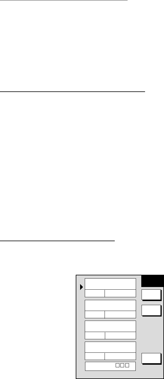
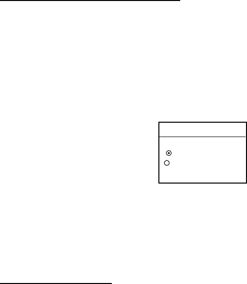
Restarting navigation
When you steer to avoid an obstacle or the vessel drifts, you may go off your
intended course (Line 1 in the figure below). Use the steering or highway display
to return to course.
Also, if you don’t need to return to the original course, you can go directly to the
waypoint (Line 2 in the figure below) using the restart function as on the next
page.
Original course
Obstacle Line 1
Line 2
Example of when to restart navigation
1. Set a destination.
2. Press the [MENU] key to open the menu.
3. Press the WAYPOINT/ROUTE soft key.
4. Press the LOG soft key.
Estimated Time of Arrival at destination
Passed waypoint (gray characters)
TO Waypoint (WPT no. in reverse video)
02
01
03
04
05
BRIDGE
HARBOR
002WPT
003WPT
004WPT
34°23.564'N
135°23.456'E
34°32.456'N
135°32.456'E
34°23.345'N
135°12.456'E
34°34.555'N
135°55.555'E
34°32.555'N
134°99.999'E
120.5°
23.4nm
23.6°
23.4nm
123.6°
23.5nm
180.5°
23.5nm
180.5°
23.5nm
ETA 23:59 31.SEP
LOG
RE-
START
STOP
RVSE
ROUTE
SPEED
RETURN
Log display
5. Press the RESTART soft key.
3. PLOTTER OPERATION
3-50
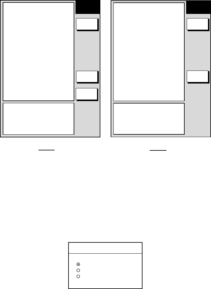
Setting speed for ETA calculation
Speed, which may be input manually or automatically, is required to calculate
ETA (Estimated Time of Arrival) to a waypoint.
1. Press the [MENU] key to open the menu.
2. Press the WAYPOINT/ROUTE soft key.
3. Press the LOG soft key.
4. Press the SPEED soft key.
SELECT SPEED
FOR ETA
▲
SPD 10.0kt
GPS AVG SPD
▼
Select speed for ETA window
5. Key in speed manually in the SPD field, or use GPS speed data by selecting
GPS AVG SPD.
6. Press the ENTER soft key to register your selection.
Switching waypoints
When you arrive to a waypoint on a route, you can switch to the next waypoint
three ways: AUTO1, AUTO2 and MANUAL.
AUTO1: Automatically switches the TO waypoint when your boat is within the
arrival alarm area. For how to set the arrival alarm area, see “9.3 Arrival Alarm”.
AUTO2: Automatically switches the TO waypoint when the boat enters the arrival
alarm range or the boat passes an imaginary perpendicular line passing through
the center of the destination waypoint.
MANUAL: When the boat enters the arrival alarm area, the TO waypoint may be
switched by using the RESTART soft key (on the LOG display). If the arrival
alarm is not set, the waypoint will not be switched. To be alerted when you arrive
at a waypoint turn on the audio alarm, on the alarm menu.
To select waypoint switching method do the following:
1. Press the [MENU] key.
2. Press the PLOTTER OPTION soft key.
3. Press the DISPLAY OPTION soft key.
4. Select WAYPOINTS SW.
5. Press the EDIT soft key to show the waypoint sw window.
6. Select appropriate waypoint switching method; AUTO1, AUTO2, or MANUAL.
7. Press the ENTER soft key to close the window.

3. PLOTTER OPERATION
3-51
Cancelling route navigation
1. Press the [MENU] key to open the menu.
2. Press the WAYPOINT/ROUTE soft key.
3. Press the LOG soft key.
4. Press the STOP soft key.
5. Push the [ENTER] knob.
6. Press the RELEASE soft key.
7. Push the [ENTER] knob.
3. PLOTTER OPERATION
3-52
3.13 Alarms
The plotter section has eight conditions which generate both audible and visual
alarms: Arrival alarm, Anchor Watch alarm, XTE (Cross Track Error) alarm,
Proximity alarm, and Speed alarm, and Trip Alarm, Water Temperature Alarm and
Bottom Alarm. (The bottom and water temperature alarms require depth and
water temperature data respectively, via the blackbox echo sounder.)
The alarm menu may be displayed by pressing the [ALARM] key.
AUDIO ALARM
OFF
ARRIVAL ALARM
ON 0.010nm
ANCHOR ALARM
ON 0.001nm
PROXIMITY ALARM
ON
XTE ALARM
ON 0.050nm
SPEED ALARM
ON 12.0-20.0kt
TRIP ALARM
9999.9nm
ALARM INFOMATION
NO ALARM
ALARM
EDIT
NEXT
PAGE
RETURN
BOTTOM ALARM
ON 2000-2400ft
TEMP ALARM
ON 68.0-99.9°F
ALARM INFOMATION
NO ALARM
ALARM
EDIT
PREV
PAGE
Page 1 Page 2
Plotter alarm menu
3.13.1 Audio alarm on/off
The audio alarm sounds whenever an alarm setting is violated. You can enable or
disable the audio alarm as follows:
1. Press the [ALARM] key to show the alarm menu.
2. Select AUDIO ALARM.
3. Press the EDIT soft key to show the audio alarm window.
AUDIO ALARM
▲INT+EXT
INT
OFF
▼
Audio alarm window
4. Select INT+EXT (Internal + External alarm), INT (Internal alarm) or OFF.
5. Press the ENTER soft key or push the [ENTER] knob to register your
selection.
3. PLOTTER OPERATION
3-53
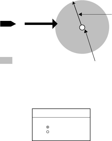
3.13.2 Arrival alarm
The arrival alarm informs you that your boat is approaching a destination
waypoint. The area that defines an arrival zone is that of a circle which you
approach from the outside of the circle. The alarm will be released if your boat
enters the circle. When the arrival alarm is active a red dashed circle marks the
arrival alarm area.
: Alarm area
Own ship
Alarm
range
Destination
waypoint
How the arrival alarm works
1. Press the [ALARM] key to open the alarm menu.
2. Select ARRIVAL ALARM.
3. Press the EDIT soft key to show the arrival alarm window.
ARRIVAL ALARM
▲
ON 0.500nm
OFF
▼
Arrival alarm window
4. Select ON.
5. Operate the cursor pad to place the cursor on the digit desired.
6. Use the [ENTER] knob to set the alarm range desired. The arrival alarm range
is 0.001 to 9.999 miles.
7. Press the ENTER soft key or the [ENTER] knob to finish.
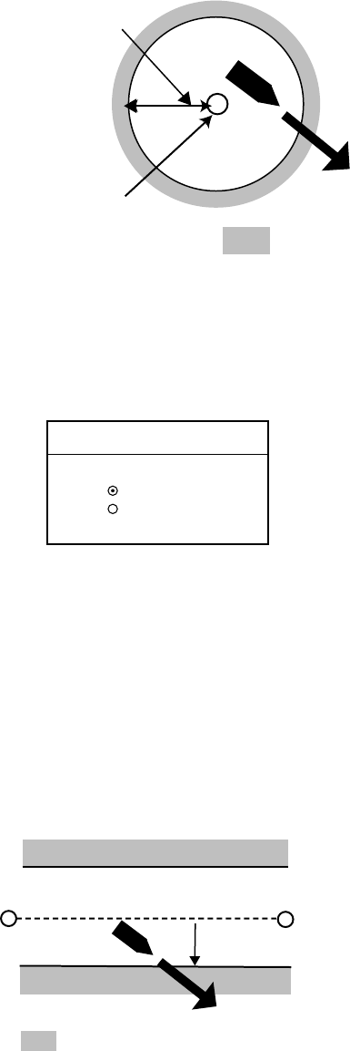
3. PLOTTER OPERATION
3-54
3.13.3 Anchor watch alarm
The anchor watch alarm informs you that your boat is moving when it should be
at rest. When the anchor watch is active, a red dashed circle marks the anchor
watch area.
Your ship's position where
you start the anchor watch
alarm.
Alarm
setting
: Alarm
area
How the anchor watch alarm works
1. Press the [ALARM] key to open the alarm menu.
2. Select ANCHOR ALARM.
3. Press the EDIT soft key to open the anchor alarm window.
ANCHOR ALARM
▲
ON 0.050nm
OFF
▼
Anchor watch alarm window
4. Select ON.
5. Use the [ENTER] knob to set the alarm range desired. The anchor watch
range is 0.001 to 9.999 miles.
6. Press the ENTER soft key or the [ENTER] knob to finish.
3.13.4 XTE (Cross Track Error) alarm
The XTE alarm warns you when your boat is off its intended course. When the
XTE alarm is active two red dashed lines mark the XTE alarm area.
: Alarm
Destination
waypoint
Own ship
position Alarm
setting
How the XTE alarm works
1. Press the [ALARM] key to open the alarm menu.
2. Select XTE ALARM.
3. Press the EDIT soft key to open the XTE alarm window.
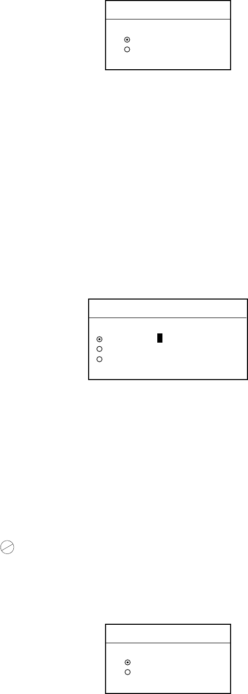
3. PLOTTER OPERATION
3-55
XTE ALARM
▲
ON 0.100nm
OFF
▼
XTE alarm window
4. Select ON.
5. Use the [ENTER] knob to set the alarm range desired. The XTE alarm range
is 0.001 to 9.999 miles.
6. Press the ENTER soft key or the [ENTER] knob to finish.
3.13.5 Speed alarm
The speed alarm warns when your boat’s speed is within, over/under or under
the speed range set.
1. Press the [ALARM] key to open the alarm menu.
2. Select SPEED ALARM.
3. Press the EDIT soft key to display the speed alarm window.
SPEED ALARM
▲
WITHIN 15.0 ~ 15.3 kt
OVER/UNDER
OFF
▼
Speed alarm window
4. Select WITHIN, OVER/UNDER, or OFF.
5. Use the [ENTER] knob to set the alarm range desired.
6. Press the ENTER soft key or the [ENTER] knob to finish.
3.13.6 Proximity alarm
The proximity alarm alerts you when your vessels nears a waypoint by the
distance set for that waypoint on the waypoint list. You can globally activate or
deactivate the proximity alarm here. Waypoints whose proximity alarm is active
have a ( ) mark near them.
1. Press the [ALARM] key to open the alarm menu.
2. Select PROXIMITY ALARM.
3. Press the EDIT soft key to show the proximity alarm window.
PROXIMITY ALARM
▲ON
OFF
▼
Proximity alarm window
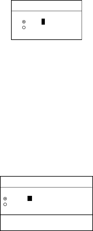
3. PLOTTER OPERATION
3-56
4. Select ON or OFF by the Omnipad.
5. Press the ENTER soft key or the [ENTER] knob to finish.
3.13.7 Trip alarm
The trip alarm informs you when you traveled a certain distance.
1. Press the [ALARM] key to open the alarm menu.
2. Select TRIP ALARM.
3. Press the EDIT soft key to show the trip alarm window.
TRIP ALARM
▲ON 00000
OFF
▼
Trip alarm window
4. Select ON by the cursor pad.
5. Use the [ENTER] knob to set the alarm range desired.
6. Press the ENTER soft key or the [ENTER] knob to finish.
3.13.8 Bottom alarm
The bottom alarm sounds when the bottom echo is within the alarm range set. To
activate the bottom alarm the depth must be displayed. This function requires
depth data, via the blackbox echo sounder
1. Press the [ALARM] key to open the alarm menu.
2. Select BOTTOM ALARM.
3. Press the EDIT soft key to display the speed alarm window.
BOTTOM ALARM
▲
ON 0000.0-0000.0ft
OFF
▼
LIMIT: -0-9999.9ft
DEFAULT: 0ft
Bottom alarm window
4. Select ON or OFF.
5. If you selected ON at step 4, use the [ENTER] knob to set the alarm range
desired.
6. Press the ENTER soft key or the [ENTER] knob to finish.
3. PLOTTER OPERATION
3-57
3.13.9 Water temperature alarm
There are two types of water temperature alarms: WITHIN and WITHOUT. The
WITHIN alarm sounds when the water temperature is within the range set; the
WITHOUT alarm sounds when the water temperature is higher or lower than the
range set. This function requires water temperature data via the black box echo
sounder.
1. Press the [ALARM] key to open the alarm menu.
2. Select TEMP. ALARM.
3. Press the EDIT soft key to display the speed alarm window.
TEMP. ALARM
▲WITHIN
0000.0-0000.0ft
WITHOUT
OFF
▼
LIMIT: -999.9 - 999.9˚F
DEFAULT: 0 - 0˚F
Temperature alarm window
4. Select ON or OFF.
5. If you selected ON at step 4, use the [ENTER] knob to set the alarm range
desired.
6. Press the ENTER soft key or the [ENTER] knob to finish.
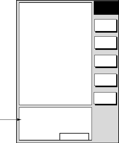
3. PLOTTER OPERATION
3-58
3.13.10 Alarm information
When an alarm setting has been violated the buzzer sounds and the speaker
icon appears. You can see which alarm has been violated, as well as silence the
buzzer, on the alarm menu display. In the example below the arrival alarm has
been violated.
1. Press the [ALARM] key.
AUDIO ALARM
OFF
ARRIVAL ALARM
ON 0.010nm
ANCHOR ALARM
ON 0.001nm
PROXIMITY ALARM
ON
XTE ALARM
ON 0.050nm
SPEED ALARM
ON 12.0-20.0kt
TRIP ALARM
9999.9nm
ALARM INFOMATION
YOU HAVE ARRIVED
AT WAYPOINT.
CONTINUE
ALARM
EDIT
NEXT
INFO
CLEAR
ALARM
NEXT
PAGE
RETURN
Alarm information
window
Alarm menu
2. Press the CLEAR ALARM soft key to silence the buzzer. For the MODEL-
1700C the color of the alarm message and the speaker icon change from red
to black.
Note: The speaker icon is displayed until all alarms have been acknowledged on
the alarm menu display. If more than one alarm has been violated the
message CONTINUE appears at the bottom of the display. In this case
press the NEXT INFO soft key to see which other alarms have been
violated.

3. PLOTTER OPERATION
3-59
Alarm messages
The table below shows the plotter alarm messages and their meanings
Alarm messages and their meanings
Message Meaning
YOU HAVE ARRIVED AT
WAYPOINT.
Arrival alarm violated.
YOU HAVE EXCEEDED ANCHOR
WATCH LIMIT.
Anchor watch alarm violated.
YOU’VE ENTERED AN
AVOIDANCE AREA.
Proximity alarm violated.
YOU HAVE EXCEEDED XTE LIMIT. XTE alarm violated.
YOU HAVE EXCEED BOTTOM
ALARM LIMIT
Bottom alarm violated
YOU HAVE EXCEED
TEMPERATURE ALARM LIMIT
Water temperature alarm
violated.
YOU HAVE EXCEEDED SPEED
ALARM LIMIT.
Speed alarm violated.
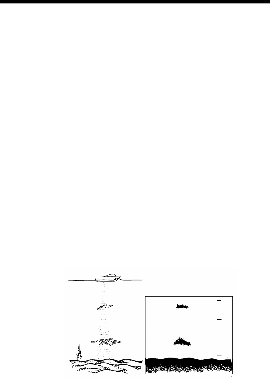
4-1
4. VIDEO SOUNDER OPERATION
With connection of the blackbox echo sounder you can display echo sounder
images on the display.
4.1 Principle of Operation
The video sounder determines the distance between its transducer and
underwater objects such as fish, lake bottom or seabed and displays the results
on screen. It does this by utilizing the fact that an ultrasonic wave transmitted
through water travels at a nearly constant speed of 4800 feet (1500 meters) per
second. When a sound wave strikes an underwater object such as fish or sea
bottom, part of the sound wave is reflected back toward the source (transducer).
Thus by calculating the time difference between the transmission of a sound
wave and the reception of the reflected sound wave, the depth to the object can
be determined.
The entire process begins in the display unit. Transmitter power is sent to the
transducer as a short pulse of electrical energy. The electrical signal produced by
the transmitter is converted into an ultrasonic signal by the transducer and
transmitted into the water. Any returning signals from intervening objects (such as
a fish school) are received by the transducer and converted into an electrical
signal. The signals are then amplified in the amplifier section, and finally,
displayed on screen.
The picture displayed is made up of a series of vertical scan lines, one for each
transmission. Each line represents a snapshot of what has occurred beneath the
boat. A series of snapshots are accumulated side by side across the screen, and
the resulting contours of the bottom and fish between the bottom and surface are
displayed.
-
-
-
-
-
-
-
-
-
-
-
-
0
50
150
100
Underwater conditions and video sounder display
4. VIDEO SOUNDER OPERATION
4-2
4.2 Sounder Displays
The figure below shows all indications and markers which may appear on the
normal sounder display.
4.2.1 Selecting a sounder display
There are six display modes from which to choose: dual frequency, single
frequency (normal), marker zoom, bottom zoom, bottom lock bottom
discrimination, and a-scope (available only with single and dual frequency
displays).
To select a display;
1. Press the DISPLY MODE soft key to show the display mode window.
DISPLAY MODE
DUAL FREQ.
SINGLE FREQ.
MARKER ZOOM
BOTTOM ZOOM
BOTTOM LOCK
BOTTOM DSCRM
Display mode window
2. Use the cursor pad to select the display.
3. Press the RETURN soft key to close the window.
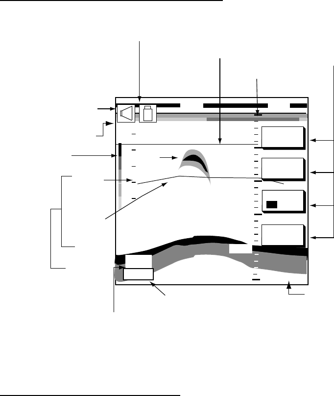
4. VIDEO SOUNDER OPERATION
4-3
4.2.2 Description of sounder displays
Single frequency display (normal display)
AUTO/
D.BOX
SHIFT
FREQ
50/200
DISPLY
MODE
Echo
strength bar
Soft keys
Variable Range
Marker
(white fon MODEL-1700C series)
Depth scale
Tx frequency
Depth
20
10
Temp.
scale
Water
temp.
graph
Water
temp.
display
212 ft
˚C
Minute marker
Icons (alarm,
battery)
Bottom echo
Zero line
Fish
echo
50k
15
0
250
49.8
50
100
150
200
Indications on the single frequency display
Note: The water temperature graph can be turned on or off.
Selecting transmission frequency
The single frequency display shows either the 50 kHz picture or 200 kHz picture.
To select transmission frequency, press the FREQ 50/200 soft key. “50” or “200”
is highlighted on its key label with each pressing of the key.
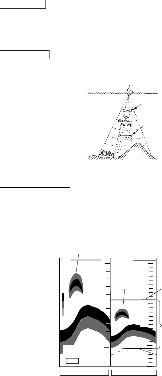
4. VIDEO SOUNDER OPERATION
4-4
50 kHz picture
The sounder uses ultrasonic pulses to detect bottom conditions. The lower the
frequency of the pulse, the wider the detection area. Therefore, the 50 kHz
frequency is useful for general detection and judging bottom condition.
200 kHz picture
The higher the frequency of the ultrasonic pulse the better the resolution.
Therefore, the 200 kHz frequency is ideal for detailed observation of fish school.
50 kHz
200 kHz
Sounding area and transmission frequency
Marker-zoom display
The marker-zoom display expands a selected area of the normal sounder picture
to full vertical size of the screen on the left-half window. You may specify the
portion to expand by operating the VRM (Variable Range Marker), which you can
shift with the cursor pad. The area between the VRM and zoom marker is
expanded. The length of the segment is equal to one division of the depth scale.
200k
162
0
50
100
150
200
90.0
180
200
MARKER-ZOOM
DISPLAY
Fish school
Fish
school
This part
is zoomed.
Zoom marker
(yellow)
VRM
(white)
ft
NORMAL
DISPLAY
250
Marker-zoom display plus normal sounder display
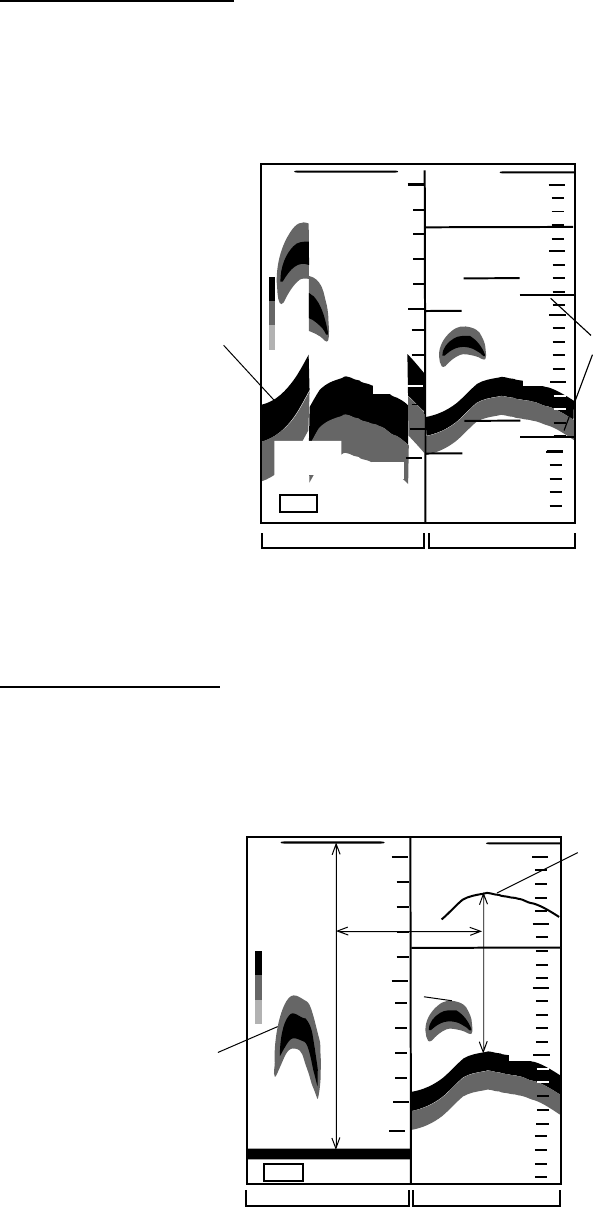
4. VIDEO SOUNDER OPERATION
4-5
Bottom-zoom display
The bottom-zoom display expands bottom and bottom fish echoes two to five
times to vertical size of the screen, and is useful for determining bottom hardness.
A bottom displayed with a short echo tail usually means it is a soft, sandy bottom.
A long echo tail means a hard bottom.
200k
162
40.0
Bottom
NORMAL DISPLAY
Zoom
marker
(yellow)
ft
BOTTOM-ZOOM
DISPLAY
0
50
100
150
200
190
200
250
Bottom-zoom display plus normal sounder display
Bottom-lock display
The bottom-lock display provides a compressed normal picture on the right half of
the screen and a 5 or 10 meter (10 or 20 feet) wide layer in contact with the
bottom is expanded onto the left half of the screen. This mode is useful for bottom
discrimination.
200k
162
68.3
This part
is zoomed.
Fish
school
Fish
school
Zoom
marker
(yellow)
ft
NORMAL DISPLAYBOTTOM-LOCK
DISPLAY
0
50
100
150
200
10
0
5
Bottom-lock display plus normal sounder display
Note: The zoom marker is not displayed in the default setting. It may be turned
on from the SOUNDER menu.
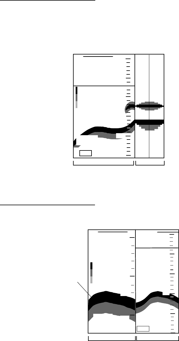
4. VIDEO SOUNDER OPERATION
4-6
A-scope display (display only)
The A-scope display shows echoes at each transmission with amplitudes and
tone proportional to their intensities, on the right 1/3 of the screen. It is useful for
estimating fish species and seabed composition. To show the A-scope display
first select SINGLE FREQ. or DUAL FREQ. with the DISPLY MODE soft key and
then press the A-SCOPE soft key to show A-SCOPE ON.
NORMAL DISPLAY A-SCOPE
DISPLAY
200k
160
68.3
ft
0
50
100
150
200
250
A-scope display
Bottom discrimination display
The bottom discrimination display expands the bottom echo to let you
discriminate bottom fish from the bottom echo.
162
40.0
Bottom
NORMAL DISPLAY
ft
BOTTOM
DISCRIMINATION
DISPLAY
200k
0
50
100
200
150
160
150
250
Bottom discrimination display
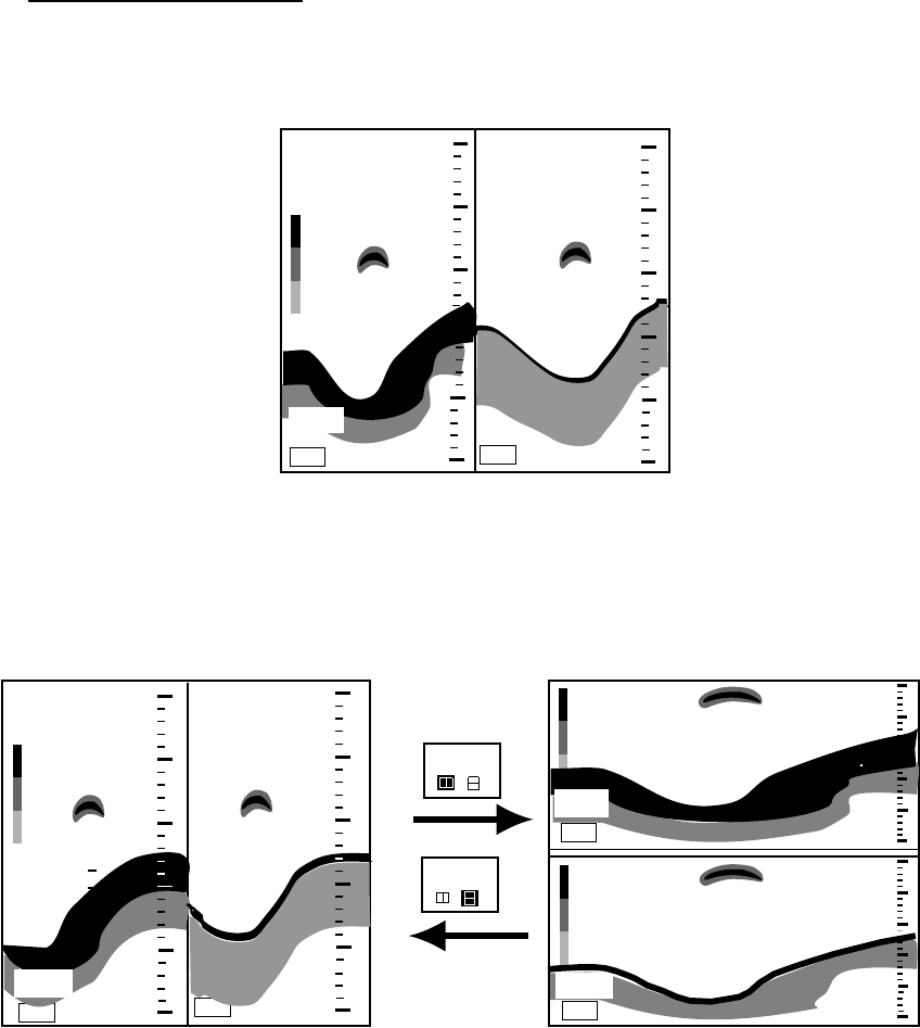
4. VIDEO SOUNDER OPERATION
4-7
Dual-frequency display
The 50 kHz picture appears on the left; the 200 kHz picture on the right. This
display is useful for comparing the same picture with two different sounding
frequencies.
200k
50k
40
ft
130
0
50
100
150
250
200
0
50
100
150
250
200
Dual-frequency display
4.2.3 Selecting screen split method in combination displays
On combination displays you can split the screen vertically or horizontally, using
the SPLIT soft key as below.
110
50k ft
110
200k ft
SPLIT
/
200k
50k ft
0
50
100
250
200
150
0
50
100
150
250
200
SPLIT
/
0
50
100
150
250
200
0
50
100
150
250
200
130
How to use the SPLIT soft key (example: dual frequency display)
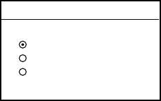
4. VIDEO SOUNDER OPERATION
4-8
4.3 Automatic Sounder Operation
Automatic sounder operation is useful when you are preoccupied with other tasks
and do not have time to adjust the display.
4.3.1 How the automatic sounder works
The automatic sounder function automatically selects the proper gain, range
scale and clutter suppression level according to depth. It works as follows:
• Range changes automatically to locate the bottom on the lower half of screen.
It jumps to one step shallower range when bottom echoes reach a half way
point of the full scale from top and to one step deeper range when they come to
the lower edge of scale.
• The gain is automatically adjusted to display the bottom echo in reddish brown
(default color arrangement).
• Clutter, which suppresses low level noise, is automatically adjusted.
4.3.2 Types of automatic sounder modes
Two types of automatic sounder modes are available: CRUISING and FISHING.
CRUISING is for tracking the bottom, and FISHING is for searching fish schools.
CRUISING uses a higher clutter rejection setting than FISHING therefore it is not
recommended for fish detection - weak fish echoes may be erased by the clutter
suppression circuit.
4.3.3 How to enable automatic sounder operation
1. Press the MODE/D. BOX soft key
AUTO MODE
▲CRUISING
FISHING
OFF (MANUAL)
▼
Mode/frequency window
2. Use the cursor pad to select CRUISING or FISHING, respectively.
3. Press the RETURN soft key to close the window automatically, or wait 10
seconds and the window closes automatically.
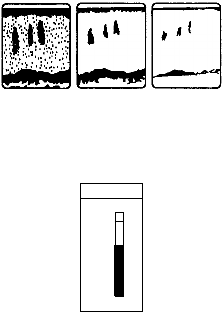
4. VIDEO SOUNDER OPERATION
4-9
4.4 Manual Sounder Operation
Manual operation is useful for observing fish schools and bottom using fixed gain
setting.
The gain, range and range shifting functions used together give you the means to
select the depth you can see on screen. The basic range can be thought of as
providing a “window” into the water column and range shifting as moving the
“window” to the desired depth.
4.4.1 Selecting the manual mode
1. Press the MODE/D. BOX soft key to show the mode/freq window.
2. Select OFF (MANUAL).
3. Press the RETURN soft key.
4.4.2 Selecting display range
Press the [RANGE +] or [RANGE -] key to select a range.
4.4.3 Adjusting the gain
Normally, set the gain to the point where excessive noise does not appear on
screen. Use a higher gain setting for greater depths and a lower setting for
shallow waters.
Gain too high Gain proper Gain too low
Examples of proper and improper gain
Press the [GAIN] key to show the gain window, and use the cursor pad to set the
gain. Current level is shown above the bar. Press the RETURN key or the [GAIN]
key to finish.
GAIN
57
▲
HIGH
LOW
▼
Gain window
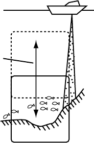
4. VIDEO SOUNDER OPERATION
4-10
Note1: On the dual-frequency display, the gain can be independently set for 50
kHz and 200 kHz. Use the FREQ soft key to select frequency for which
to adjust gain
Note2: Gain cannot be adjusted in the automatic sounder mode. The message
“SOUNDER GAIN CANNOT BE ADJUSTED IN AUTO MODE” is
displayed when you attempt to do so.
4.4.4 Range shifting
The basic range may be shifted up or down as desired with SHIFT soft key.
Shift
Shift concept
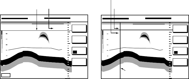
4. VIDEO SOUNDER OPERATION
4-11
4.5 Measuring Depth, Range
4.5.1 Measuring depth with the VRM
The VRM functions to measure the depth to fish schools, etc.
1. Rotate the [ENTER] knob to shift the VRM; clockwise rotation to shift It
downward, counterclockwise rotation to shift it upward. You may also use the
cursor pad to shift the VRM.
2. Depth is shown just above the VRM.
4.5.2 Measuring depth, range with the cross-hair cursor
A cross-hair cursor is provided to measure the depth and range to an object This
function is not available on the bottom zoom or A-scope display.
1. Press the cursor pad to show the cross cursor on the screen.
2. Use the cursor pad to position the cross-hair cursor
50k
DISPLY
MODE
SHIFT
VRM (white)
20
10
0
54.0
15.0
Depth to VRM
ft
DISPLY
MODE
AUTO/
D.BOX
SHIFT
20
10
0
0.04nm
40.1
Depth to cursor intersection
Range to cursor intersection
Cross-hair
cursor
FREQ.
50 /200 FREQ.
50 /200
0
50
100
150
250
200
0
50
100
150
250
200
MODE/
D.BOX
How to use the VRM, cross-hair cursor
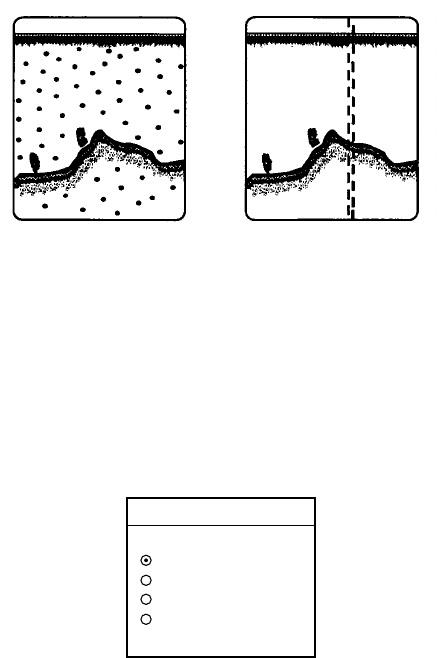
4. VIDEO SOUNDER OPERATION
4-12
4.6 Reducing Interference
Interference from other acoustic equipment operating nearby or other electronic
equipment on your boat may show itself on the display as shown below.
Interference from Electrical inteference
other sounder
Types of interference
To reduce interference, do the following:
1. Press the [MENU] key followed by the SOUNDER MENU soft key.
2. Select NOISE LIMITER and press the EDIT soft key to show the noise limiter
window.
NOISE LIMITER
▲OFF
LOW
MEDIUM
HIGH
▼
Noise limiter window
3. Use the cursor pad to select degree of suppression desired or turn the noise
limiter off.
4. Press the RETURN soft key to finish.
Turn the noise limiter circuit off when no interference exists, otherwise weak
echoes may be missed.

4. VIDEO SOUNDER OPERATION
4-13
4.7 Reducing Low Level Noise
Light-blue dots may appear over most of screen. This is mainly due to dirty water
or noise. This noise can be suppressed by adjusting CLUTTER on the
SOUNDER menu.
Appearance of clutter
When the sounder mode is Auto, the clutter suppression setting is fixed at AUTO.
To reduce low level noise in manual sounder operation do the following:
1. Press the [MENU] key followed by the SOUNDER MENU soft key.
2. Select CLUTTER and press the EDIT soft key to show the clutter window.
CLUTTER
▲
OFF
▼
LIMITS: OFF, 1-9
DEFAULT: 6
CAN NOT CHANGE WHEN
AUTO MODE IS ON.
Clutter window
3. Use the cursor pad to select clutter rejection level desired; 0 (OFF) through 9.
The higher the number the higher the degree of suppression. Note that weak
echoes may not be displayed when the clutter circuit is on. Therefore turn off
the clutter when its use is not required.
4. Press the RETURN soft key to finish.
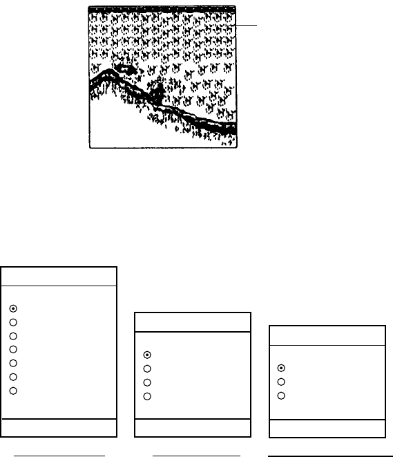
4. VIDEO SOUNDER OPERATION
4-14
4.8 Erasing Weak Echoes (MODEL-1700C series)
Dirty water or reflections from plankton may be painted on the display in green or
light blue. These weak echoes may be erased as follows:
Weak
echoes
Appearance of weak echoes
1. Press the [MENU] key followed by the SOUNDER MENU soft key.
2. Select SIGNAL LEVEL, and press the EDIT soft key to show the signal level
window.
SIG LVL
▲
OFF
SL1
SL2
SL3
SL4
SL5
SL6
▼
SIG LVL
▲
OFF
SL1
SL2
SL3
▼
16-color display 8-color display Monochrome display
DEFAULT: OFF DEFAULT: OFF
SIG LVL
▲
OFF
SL1
SL2
▼
DEFAULT: OFF
Signal level window
3. Use the cursor pad to select level of erasure or OFF as appropriate. The
higher the number the stronger the echo that will be erased.
4. Press the RETURN soft key to finish.
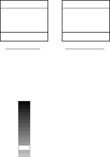
4. VIDEO SOUNDER OPERATION
4-15
4.9 White Marker (MODEL-1700C series)
The white marker functions to display a particular echo color in white. For
example, you may want to display the bottom echo (reddish-brown) in white to
discriminate fish echoes near the bottom. Note that the bottom must be displayed
in reddish-brown for the white marker to function.
1. Press the [MENU] key followed by the SOUNDER MENU soft key.
2. Select WHITE MARKER, and press the EDIT soft key to open the white
marker window.
WHITE MARKER
▲
OFF
▼
WHITE MARKER
▲
OFF
▼
LIMITS: OFF, 1-8 LIMITS: OFF, 1-16
8-color display 16-color display
White marker window
3. Use the cursor pad to select color to display in white. As you Use the cursor
pad, the number (corresponds to echo number) in the marker window
changes, the white marker on the echo strength bar shifts and selected echo
color is displayed in white.
←White marker shows
color currently
displayed in white.
Echo strength bar (16 color) when white marker function is active
4. Press the RETURN soft key to finish.
To turn the white marker function off, display “0” in the white marker window.
4. VIDEO SOUNDER OPERATION
4-16
4.10 Picture Advance Speed
The picture advance speed determines how quickly the vertical scan lines run
across the screen. When selecting a picture advance speed, keep in mind that a
fast advance speed will expand the size of the fish school horizontally on the
screen and a slow advance speed will contract it.
The speed may be set independent or dependent on ship’s speed.
4.10.1 Advancement independent of ship’s speed
1. Press the [MENU] key followed by the SOUNDER MENU soft key.
2. Select PICTURE ADVANCE, and press the EDIT soft key to open the picture
advance window.
PICTURE ADVANCE
▲2/1
1/1
1/2
1/4
1/8
STOP
▼
DEFAULT: 1/1
Picture advance window
The fractions in the window denote number of scan lines produced per
transmission. For example, 1/8 means one scan line is produced every eight
transmissions. STOP freezes the display and it is convenient for observing an
echo.
3. Use the cursor pad to select speed desired.
4. Press the RETURN soft key to finish.
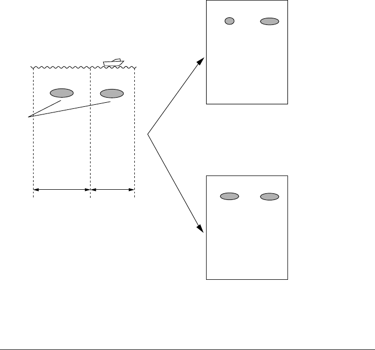
4. VIDEO SOUNDER OPERATION
4-17
4.10.2 Advancement synchronized with ship’s speed
With speed data provided by a speed measuring device, picture advance speed
may be automatically adjusted with ship’s speed. As shown in the figure below
the horizontal scale of the display is not influenced with the speed dependent
picture advance mode active, thus it permits judgement of fish school size and
abundance at any speed. With the advancement synchronized with ship’s speed
the picture advance speed setting (on the previous page) is ignored.
FULL
SPEED
HALF
SPEED
Actual Movement
Same size
fish schools
Speed
Normal Mode
Speed Dependent Picture Advance Mode
Fish school shrinks as speed
is increased; expanded
as speed is decreased.
Fish schools are shown
same size regardless
of ship’s speed.
How the speed dependent advance mode works
Activating/deactivating the speed dependent picture advance mode
1. Press the [MENU] key followed by the SOUNDER MENU soft key.
2. Select SPD SENSING PIC ADV.
3. Press the EDIT soft key to open the setting window.
4. Use the cursor pad to select ON or OFF (default setting) as appropriate.
5. Press the RETURN soft key to finish.
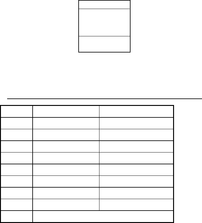
4. VIDEO SOUNDER OPERATION
4-18
4.11 Display Colors (MODEL-1700C series)
You can select the number of colors to display and background color as follows:
1. Press the [MENU] key followed the SOUNDER MENU soft key.
2. Select HUE, and then press the EDIT soft key to show the hue window.
HUE
▲
1
▼
LIMITS: 1-9
DEFAULT: 1
Hue window
3. Use the cursor pad to select hue number, referring to the table below. (You
can see the result of your selection on the display.)
Available background and echo colors for the sounder display
Hue No. Echo Color Background Color
1 16 color Blue
2 8 color Blue
3 16 color Dark blue
4 8 color Dark blue
5 16 color White
6 8 color White
7 16 color Black
8 8 color Black
9 Monochrome, eight intensities
4. Press the RETURN soft key to finish.
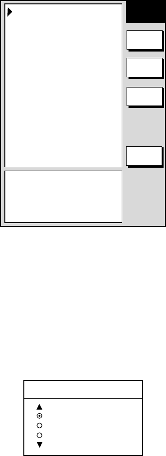
4. VIDEO SOUNDER OPERATION
4-19
4.12 Alarms
The sounder section has five conditions which generate visual and audio alarms:
Bottom Alarm, Fish Alarm (bottom lock), Fish Alarm (normal), Water Temperature
Alarm, and Speed Alarm.
The sounder alarm menu may be displayed by pressing the [ALARM] key.
ALARM AUDIO
INT
BOTTOM ALARM
200.0~ 220.0ft
FISH (B/L) ALARM
BOTTOM~ 20.0ft
FISH (NORMAL) ALARM
100.0~ 129.0ft
TEMP. ALARM
IN 68.0~ 78.0F
SPEED ALARM
In 00.0~ 99.9kt
ALARM INFOMATION
NO ALARM
SOUNDER
ALARM
EDIT
NEXT
INFO
CLEAR
ALARM
RETURN
Sounder alarm menu
4.12.1 Audio alarm on/off
The audio alarm sounds whenever an alarm setting is violated. You can enable or
disable the audio alarm as follows:
1. Press the [ALARM] key to show the ALARM menu.
2. Use the cursor pad to select ALARM AUDIO.
3. Press the EDIT soft key to show the audio alarm window.
ALARM AUDIO
INT+EXT BUZZ
INTERNAL BUZZ
OFF
Audio alarm window
4. Use the cursor pad to select INT+EXT (Internal + External alarm), INTERNAL
(Internal alarm) or OFF.
5. Press the ENTER soft key or push the [ENTER] knob to register your
selection.
6. Press the [MENU] key to close the menu
4. VIDEO SOUNDER OPERATION
4-20
4.12.2 Bottom alarm
The bottom alarm sounds when the bottom echo is within the alarm range set. To
activate the bottom alarm the depth must be displayed.
1. Press the [ALARM] key to show the ALARM menu.
2. Use the cursor pad to select BOTTOM ALARM.
3. Press the EDIT soft key to show the bottom alarm window.
BOTTOM ALARM
▲
ON 0000.0-0000.0ft
OFF
▼
LIMIT: -0-9999.9ft
DEFAULT: 0ft
Bottom alarm window
4. Use the cursor pad to select ON or OFF as appropriate. For ON, enter alarm
range with the [ENTER] knob.
5. Press the ENTER soft key or push the [ENTER] knob to register your
selection.
6. Press the [MENU] key to close the menu.
4.12.3 Fish (B/L) alarm
The bottom-lock fish alarm sounds when a fish echo is within a predetermined
distance from the bottom.
1. Press the [ALARM] key to show the ALARM menu.
2. Use the cursor pad to select FISH (B/L) ALARM.
3. Press the EDIT soft key to show the fish alarm (B/L) window.
FISH ALARM(B/L)
▲
ON BOTTOM -000.0ft
OFF
▼
LIMIT: -0-20ft
Fish alarm(B/L) window
4. Use the cursor pad to select ON or OFF as appropriate. For ON, enter alarm
range with the cursor pad.
5. Press the ENTER soft key or push the [ENTER] knob to register your
selection.
6. Press the [MENU] key to close the menu.
4. VIDEO SOUNDER OPERATION
4-21
4.12.4 Fish (normal) alarm
The normal fish alarm sounds when a fish echo is within the preset alarm range.
Note that the sensitivity of the fish alarm (which echo strength triggers the alarm)
can be set on the SOUNDER MENU.
1. Press the [ALARM] key to show the ALARM menu.
2. Use the cursor pad to select FISH ALARM(NORMAL).
3. Press the EDIT soft key to show the fish alarm (normal) window.
FISH ALARM(NORMAL)
▲
ON 0000.0-0000.0ft
OFF
▼
LIMIT: -0-9999.9ft(m, fa, pb)
Fish alarm(normal) window
4. Use the cursor pad to select ON or OFF as appropriate. For ON, enter alarm
range with the cursor pad
5. Press the ENTER soft key or push the [ENTER] knob to register your
selection.
6. Press the [MENU] key to close the menu
4.12.5 Water temperature alarm
There are two types of water temperature alarms: WITHIN and WITHOUT. The
WITHIN alarm sounds when the water temperature is within the range set, the
WITHOUT alarm sounds when the water temperature is higher or lower than the
range set. This alarm requires water temperature data.
1. Press the [ALARM] key to show the ALARM menu.
2. Use the cursor pad to select TEMP. ALARM.
3. Press the EDIT soft key to show the temp. alarm window.
TEMP. ALARM
▲WITHIN
0000.0-0000.0ft
WITHOUT
OFF
▼
LIMIT: -999.9 - 999.9˚F
DEFAULT: 0 - 0˚F
Water temperature alarm window
4. Use the cursor pad to select WITHIN, WITHOUT or OFF as appropriate. For
WITHIN, enter alarm range with the cursor pad.
5. Press the ENTER soft key or push the [ENTER] knob to register your
selection.
6. Press the [MENU] key to close the menu.
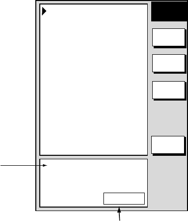
4. VIDEO SOUNDER OPERATION
4-22
4.12.6 When an alarm setting is violated...
When an alarm setting is violated the buzzer sounds, and the speaker icon
appears at the bottom of the screen. (The speaker icon is displayed until all
alarms have been acknowledged on the alarm menu display.) You can silence the
buzzer with the [CLEAR] key, however the buzzer will sound whenever the alarm
setting is violated.
To see which alarm(s) has been violated;
1. Press the [ALARM] key. The offending alarm is shown in the ALARM
INFORMATION window.
ALARM AUDIO
INT
BOTTOM ALARM
200.0~ 220.0ft
FISH (B/L) ALARM
BOTTOM~ 20.0ft
FISH (NORMAL) ALARM
100.0~ 129.0ft
TEMP. ALARM
IN 68.0~ 78.0F
SPEED ALARM
In 00.0~ 99.9kt
ALARM INFOMATION
NO ALARM
SOUNDER
ALARM
EDIT
NEXT
INFO
CLEAR
ALARM
RETURN
Alarm information
window
CONTINUE
Means multiple alarms
have been violated.
Sounder alarm menu
2. Press the CLEAR ALARM soft key to acknowledge the alarm. For the
MODEL-1700C series the color of the alarm message and the speaker icon
change from red to black to indicate acknowledgement.
Note: If more than one alarm has been violated the message CONTINUE
appears at the bottom of the alarm information window. In this case
press the NEXT INFO soft key to see which other alarms have been
violated.

4. VIDEO SOUNDER OPERATION
4-23
Alarm messages
The table below shows the sounder alarm messages and their meanings
Alarm messages and their meanings
Message Meaning
EXCEEDED THE FISH (B/L)
ALARM.
Fish (bottom lock) alarm
violated.
EXCEEDED THE FISH (NORMAL)
ALARM.
Fish (normal) alarm violated.
EXCEEDED SPEED ALARM LIMIT. Speed alarm violated.
EXCEEDED BOTTOM ALARM
LIMIT.
Bottom alarm violated.
EXCEEDED TEMPERATURE
ALARM LIMIT.
Water temperature alarm
violated.
4.13 Water Temperature Graph
The water temperature graph (appropriate sensor required) plots water
temperature on the sounder display. It can be turned on or off as below.
1. Press the [MENU] key to open the menu.
2. Press the SOUNDER MENU soft key to show the SOUNDER menu.
3. Select TEMP GRAPH and press the EDIT soft key.
4. Select OFF (default setting) or ON as appropriate.
5. Press the RETURN soft key.
6. Press the [MENU] key to close the menu.
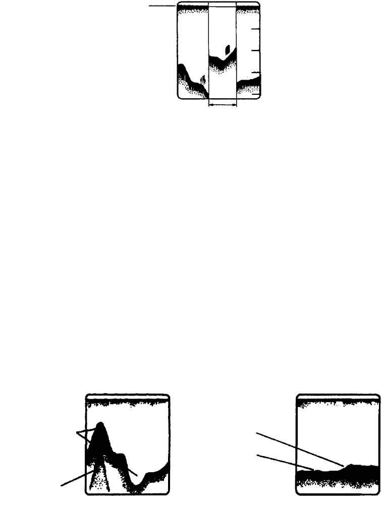
4. VIDEO SOUNDER OPERATION
4-24
4.14 Interpreting the Sounder Display
4.14.1 Zero line
The zero line (sometimes referred to as the transmission line) represents the
transducer’s position, and moves off the screen when a deep phased range is
used.
Zero line
Shift
Zero line
4.14.2 Bottom echo
Echoes from the bottom are normally the strongest and are displayed in reddish-
brown color but the color and width will vary with bottom composition, water
depth, frequency, sensitivity, etc.
In a comparatively shallow depth, a high gain setting will cause a second or
sometimes a third or a fourth echo to be displayed at the same interval between
them below the first echo trace. This is because the echo travels between the
bottom and the surface twice or more in shallow depths.
The color of the bottom echo can be used to help determine the density of the
bottom materials (soft or hard). The harder the bottom, the wider the trace. If the
gain is set to show only a single bottom echo on mud, a rocky bottom will show a
second or third bottom return. The range should be chosen so the first and
second bottom echoes are displayed when bottom hardness is being determined.
Intensity difference
in water depth
Second bottom
echo
Rock base
Mud and sand
Bottom echoes
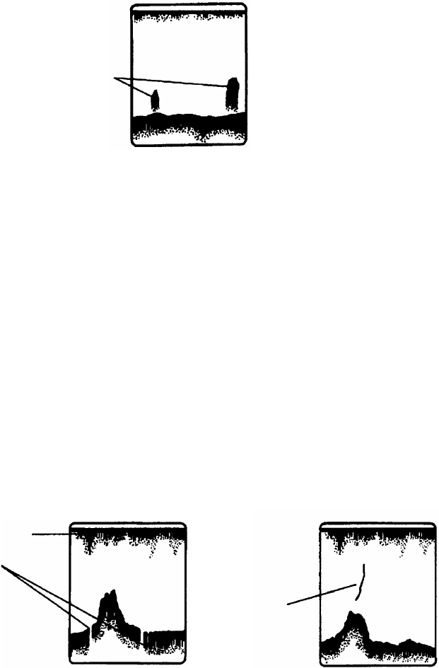
4. VIDEO SOUNDER OPERATION
4-25
4.14.3 Fish school echoes
Fish school echoes will generally be plotted between the zero line and the bottom.
Usually the fish school/fish echo is weaker than the bottom echo because its
reflection property is much smaller compared to the bottom. The size of the fish
school can be ascertained from the density of the display.
Size of
fish school
Small
school
Large
school
Fish school echoes
4.14.4 Surface noise/Aeration
When the waters are rough or the boat passes over a wake, surface noise may
appear near the zero line. As surface turbulence is acoustically equivalent to
running into a brick wall, the bottom echo will be displayed intermittently. Similar
noise sometimes appears when a water temperature difference (thermocline)
exists. Different species of fish tend to prefer different temperature zones, so the
thermocline may be useful to help identify target fish. 200 kHz tends to show
shallow thermoclines better than 50 kHz.
In rough waters the display is occasionally interrupted due to below-the-ship air
bubbles obstructing the sound path. This also occurs when the boat makes a
quick turn or reverses movement. Lowering the picture advance speed may
reduce the interruption. However, reconsideration of the transducer installation
may be necessary if the interruption occurs frequently.
Surface noise
Caused by aerated
water
Thermocline
Surface noise/aeration