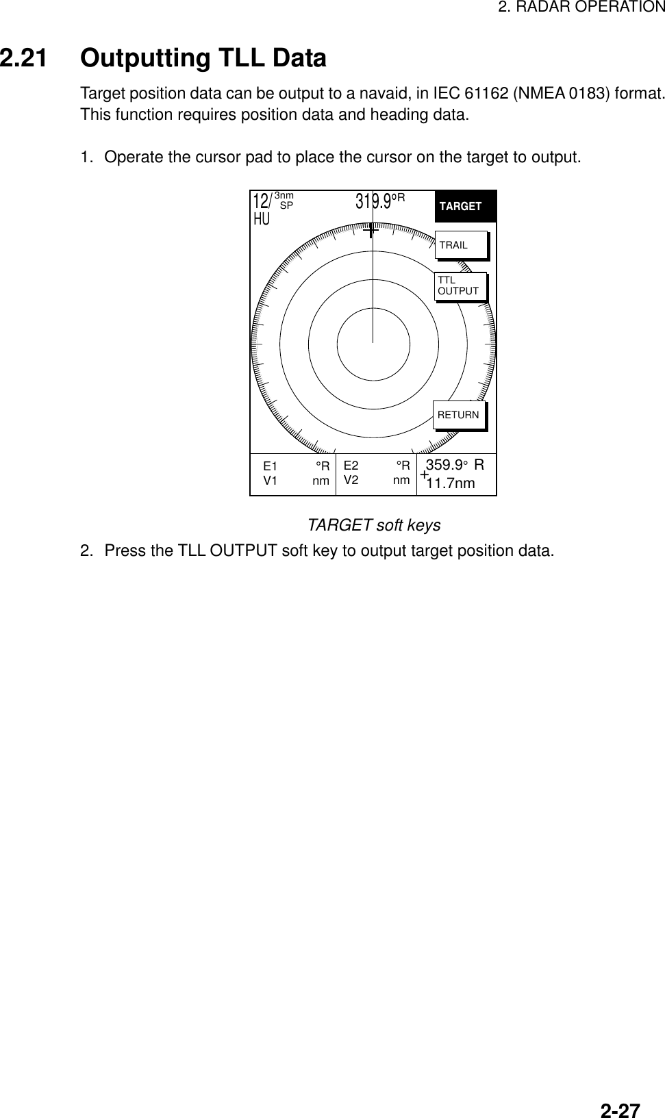
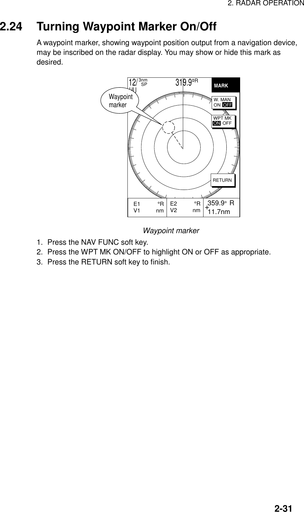
Furuno USA 9ZWRTR058 MARINE RADAR User Manual operators manual part2
Furuno USA Inc MARINE RADAR operators manual part2
Contents
- 1. operators manual part 1
- 2. operators manual part2
- 3. operators manual part 3
- 4. operators manual part 4
operators manual part2
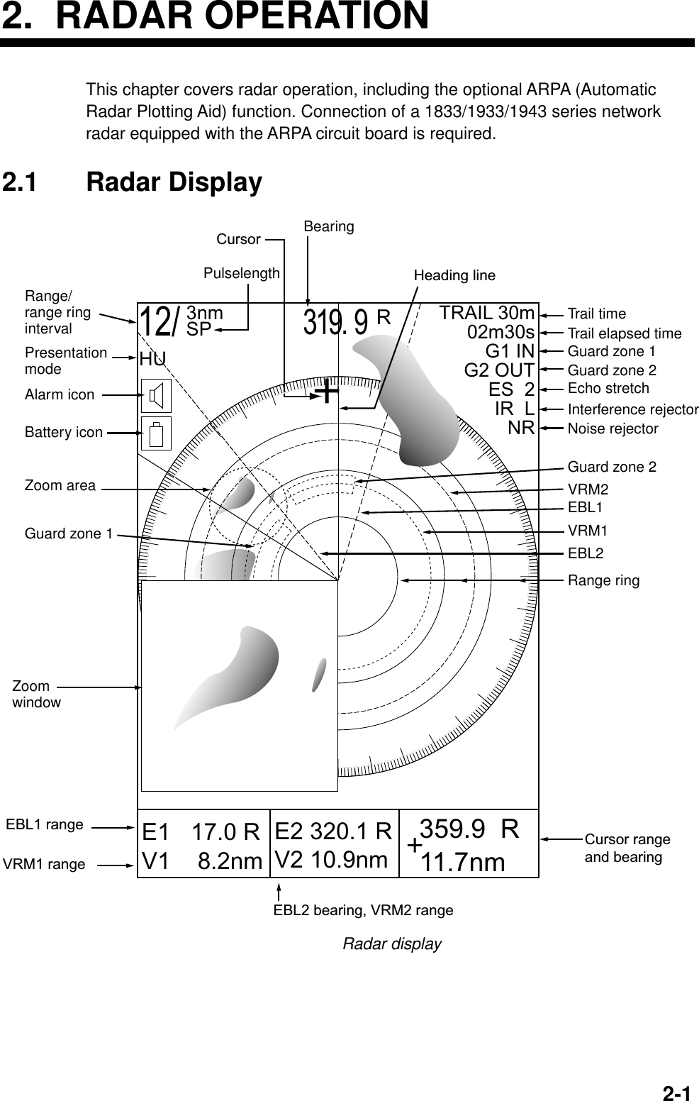
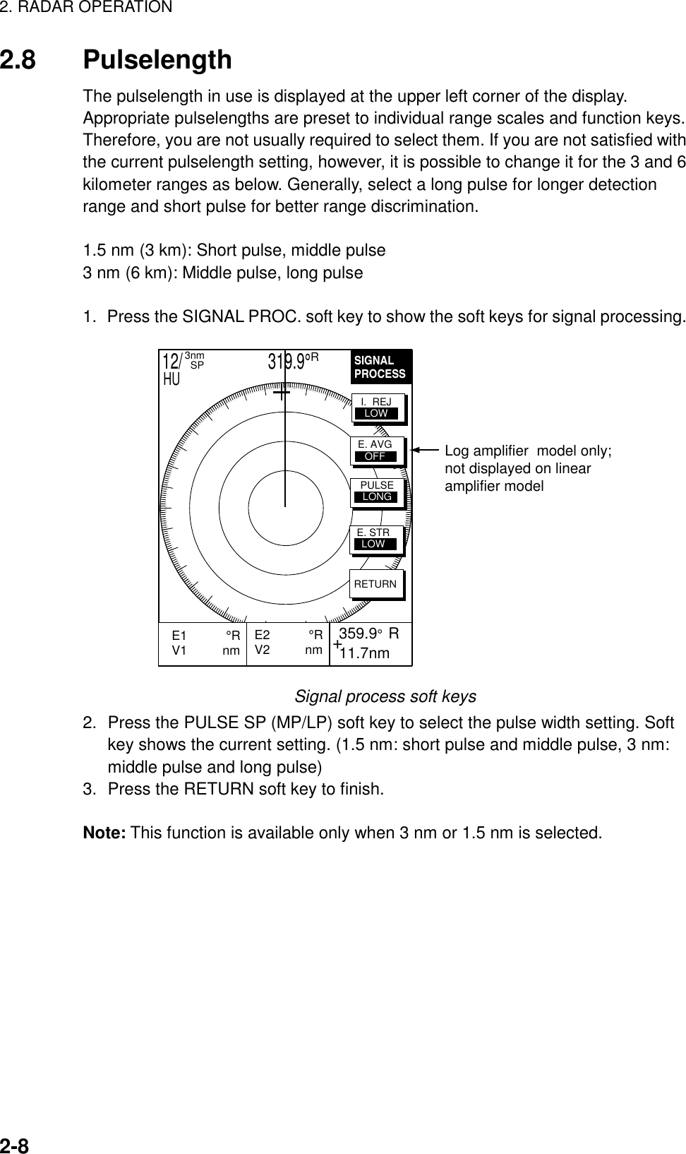
![2. RADAR OPERATION2-22.2 Transmitting, Stand-by1. Press the RADAR TX soft key to show the radar picture.2. When the radar picture is not required, but you want keep it in a state ofreadiness, press the RADAR TX soft key to go into the standby mode. ST-BYappears on the display and the RADAR soft key shows STBY as its currentoption.2.3 Adjusting the GainThe gain circuit adjusts the gain (sensitivity) of the radar receiver. It works inprecisely the same manner as the volume control of a broadcast receiver,amplifying the signals received.The proper setting is such that the background noise is just visible on the screen.If you set up for too little gain, weak echoes may be missed. On the other handexcessive gain yields too much background noise; strong targets may be missedbecause of the poor contrast between desired echoes and the background noiseon the display.To adjust receiver gain, transmit on long range, and then do the following.1. Press the [GAIN] key to display the soft key for adjustment of gain.GAINADJUST +E2 °RV2 nm 359.9° R 11.7nmE1 °RV1 nm GAINA/CSEAA/CRAINFTCRETURN12/ 319.9°R3nm SPHUGAINADJUST +E2 °RV2 nm 359.9° R 11.7nmE1 °RV1 nm GAINA/CSEAA/CRAINRETURN12/ 319.9°R3nm SPHULinear amp Log amp A/C ATON OFFGain adjust menu](https://usermanual.wiki/Furuno-USA/9ZWRTR058.operators-manual-part2/User-Guide-132263-Page-2.png)
![2. RADAR OPERATION2-32. Press the GAIN soft key to show the GAIN SENSITIVITY window.GAIN SENSITIVITY▲ AUTO ROUGH/OCEAN AUTO MODERATE AUTO CALM/HARBOR MAN▼68Gain sensitivity window3. Operate the cursor pad to select AUTO ROUGH/OCEAN, AUTO MODERATE,AUTO CALM/HARBOR or MAN (manual) as appropriate.4. For manual adjustment, rotate the [ENTER] knob to adjust the gain. Theadjustable range is 0-100(%).5. Press the RETURN soft key to finish.2.4 Reducing Sea ClutterEchoes from waves can be troublesome, covering the central part of the displaywith random signals known as “sea clutter”. The higher the waves, and the higherthe antenna above the water, the further the clutter will extend. Sea clutterappears on the display as many small echoes which might affect radarperformance. (See the left-hand figure in the figure below.) When sea cluttermasks the picture, adjust the A/C SEA circuit to reduce the clutter.A/C SEA adjusted;sea clutter suppressedSea clutter atscreen centerEffect of A/C SEA2.4.1 How the A/C SEA circuit worksThe A/C SEA circuit reduces the amplification of echoes at short ranges (whereclutter is the greatest) and progressively increases amplification as the rangeincreases, so amplification will be normal at those ranges where there is no seaclutter.](https://usermanual.wiki/Furuno-USA/9ZWRTR058.operators-manual-part2/User-Guide-132263-Page-3.png)
![2. RADAR OPERATION2-42.4.2 Adjusting A/C SEAThe proper setting of the A/C SEA should be such that the clutter is broken upinto small dots, and small targets become distinguishable.1. Press the [GAIN] key.2. Press the A/C SEA soft key to show the A/C SEA setting window.A/C SEA▲ AUTO ROUGH/OCEAN AUTO MODERATE AUTO CALM/HARBOR MAN▼68A/C SEA setting window3. Operate the cursor pad to select AUTO LOW, AUTO MEDIUM, AUTO HIGHor MAN (manual).4. When MAN is selected, rotate the [ENTER] knob to adjust the A/C SEA. Theadjustable range is 0-100(%).5. For the log amp type network radar (MODEL-1833/C, 1933/C, 1943/C), A/CSEA and A/C RAIN can be automatically adjusted. Press the soft key A/C ATto turn automatic adjustment on or off as appropriate.6. Press the GAIN or RETURN soft key to finish.2.5 Reducing Precipitation ClutterThe vertical beamwidth of the antenna is designed to see surface targets evenwhen the ship is rolling. However, by this design the unit will also detect rainclutter (rain, snow, hail, etc.) in the same manner as normal targets. Theillustration in below shows the appearance of rain clutter on the display.[A/C RAIN] controloff [A/C RAIN] controladjustedEffect of A/C RAIN](https://usermanual.wiki/Furuno-USA/9ZWRTR058.operators-manual-part2/User-Guide-132263-Page-4.png)
![2. RADAR OPERATION2-52.5.1 Adjusting the A/C RAINWhen rain clutter masks echoes, adjust the A/C RAIN circuit. This circuit splits upthese unwanted echoes into a speckled pattern, making recognition of solidtargets easier.1. Press the [GAIN] key to show the GAIN ADJUST menu.2. Press the A/C RAIN soft key to show the A/C RAIN window.A/C RAIN68A/C RAIN setting window3. Rotate the [ENTER] knob to adjust the A/C RAIN affect. The current level isshown on the A/C RAIN level bar in the A/C RAIN window, and the adjustablerange is 0 to 100(%).4. Press the A/C RAIN or RETURN soft key to finish.2.5.2 Adjusting the FTC (linear amp-type network radar only)To suppress rain clutter from heavy storms or scattered rain clutter, adjust FTC.The FTC circuit splits up these unwanted echoes into a speckled pattern, makingrecognition of solid targets easier.Note:In addition to reducing clutter, the FTC can be used in fine weather toclarify the picture when navigating in confined waters. However, with thecircuit activates the receiver is less sensitive. Therefore, turn off the circuitwhen its function is not required.1. Press the [GAIN] key to show the GAIN ADJUST menu.2. Press the FTC soft key to show the FTC window.FTC68FTC setting window3. Rotate the [ENTER] knob to adjust FTC circuit affect. The adjustable range is0-100(%).4. Press the GAIN or RETURN soft key to finish.](https://usermanual.wiki/Furuno-USA/9ZWRTR058.operators-manual-part2/User-Guide-132263-Page-5.png)
![2. RADAR OPERATION2-62.6 Tuning the ReceiverThe radar receiver can be tuned automatically or manually, and the default tuningmethod is automatic.2.6.1 Manual tuningIf you require manual tuning do the following:1. Press the [MENU] key to display the main menu.2. Press the RADAR DISPLAY SETUP soft key.3. Select TUNING and press the EDIT soft key.AUTOMANTUNE▲▼Tuning barTuning window4. Choose MAN.5. Adjust the [ENTER] knob to show the longest tuning bar.6. Press the RETURN soft key.7. Press the [MENU] key to close the menu.](https://usermanual.wiki/Furuno-USA/9ZWRTR058.operators-manual-part2/User-Guide-132263-Page-6.png)
![2. RADAR OPERATION2-72.7 Selecting the Range ScaleThe range selected automatically determines the range ring interval, the numberof range rings, pulselength and pulse repetition rate, for optimal detectioncapability in short to long ranges.The range, range ring interval and pulselength appear at the top left-hand cornerof the display.Press the [RANGE (+ or -)] key to change the range scale.Range scales (nm, sm)Range 0.125 0.25 0.5 0.75 1 1.5 2 3468121624364864RingInterval 0.0625 0.125 0.125 0.25 0.25 0.5 0.5 11223 4 6121216# ofRings 2 2 4 3 4 3 4 34344 4 4 3 4 4Range scales (km)Range 0.25 0.5 0.75 1 1.5 2 3 4 6 6 8 12 16 24 36 48 64RingInterval 0.125 0.25 0.25 0.25 0.5 0.5 0.5 1 1 2 2 3 4 6 12 12 16# ofRings 2 2 3 4 3434344444344Note: Maximum range depends on the network radar connected as below.1722, 1722C: 24 nm1732, 1732C, 1752, 1752C, 1833, 1833C; 36 nm1762, 1762C, 1933, 1933C: 48 nm1943, 1943C: 64 nm](https://usermanual.wiki/Furuno-USA/9ZWRTR058.operators-manual-part2/User-Guide-132263-Page-7.png)
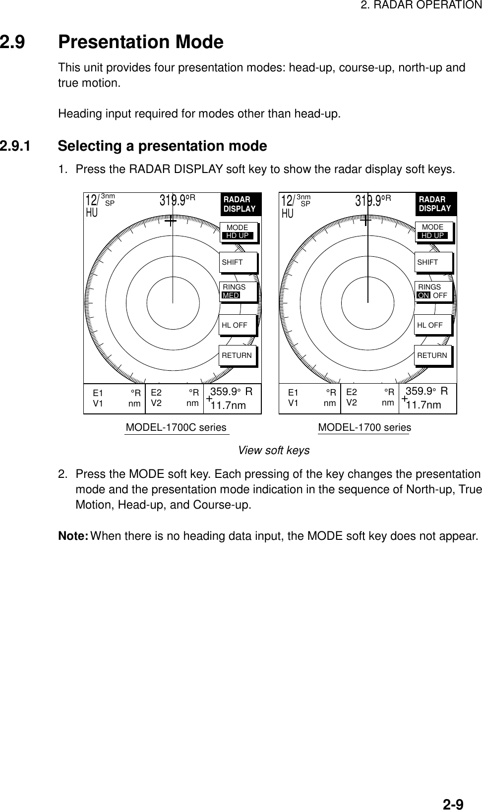
![2. RADAR OPERATION2-102.9.2 Presentation mode overviewHead-up (HU)A display without azimuth stabilization in which the line connecting the center withthe top of the display indicates own ship’s heading. The target pips are painted attheir measured distances and in their directions relative to own ship’s heading.A short line on the bearing scale is the north marker indicating compass north.Heading LineNorth markerHead-up presentation modeCourse-up (CU)An azimuth stabilized display in which a line connecting the center with the top ofthe display indicates own ship’s intended course (namely, own ship’s previousheading just before this mode has been selected).Target pips are painted at their measured distances and in their directions relativeto the intended course which is maintained at the 0-degree position while theheading line moves in accordance with ship’s yawing and course changes. Thismode is useful to avoid smearing of picture during course change. After a coursechange, press the [CLEAR] key to reset the picture orientation if you wish tocontinue using the course-up mode.Heading LineNorth markerCourse-up presentation mode](https://usermanual.wiki/Furuno-USA/9ZWRTR058.operators-manual-part2/User-Guide-132263-Page-10.png)
![2. RADAR OPERATION2-11North-up (NU)In the north-up mode, target pips are painted at their measured distances and intheir true (compass) directions from own ship, north being maintained UP of thescreen. The heading line changes its direction according to the ship’s heading.Heading LineNorthNorth-up presentation modeTrue motion (TM)Own ship and other moving objects move in accordance with their true coursesand speeds. All fixed targets, such as landmasses, appear as stationary echoes.When own ship reaches a point corresponding to 75 % of the radius of thedisplay, the own ship is automatically reset to a point of 75 % radius opposite tothe extension of the heading line passing through the display center. Resettingcan be made at any moment before the ship reaches the limit by pressing the[CLEAR] key. Automatic resetting is preceded by a beep sound.Heading LineNorthTrue motion presentation modeLOSS OF COMPASSS SIGNAL: When the compass signal is lost, thepresentation mode automatically becomes head-up and the compass readout atthe screen top shows xxx.x°. Once the compass signal is restored thepresentation mode in use when the compass signal was lost is restored.](https://usermanual.wiki/Furuno-USA/9ZWRTR058.operators-manual-part2/User-Guide-132263-Page-11.png)
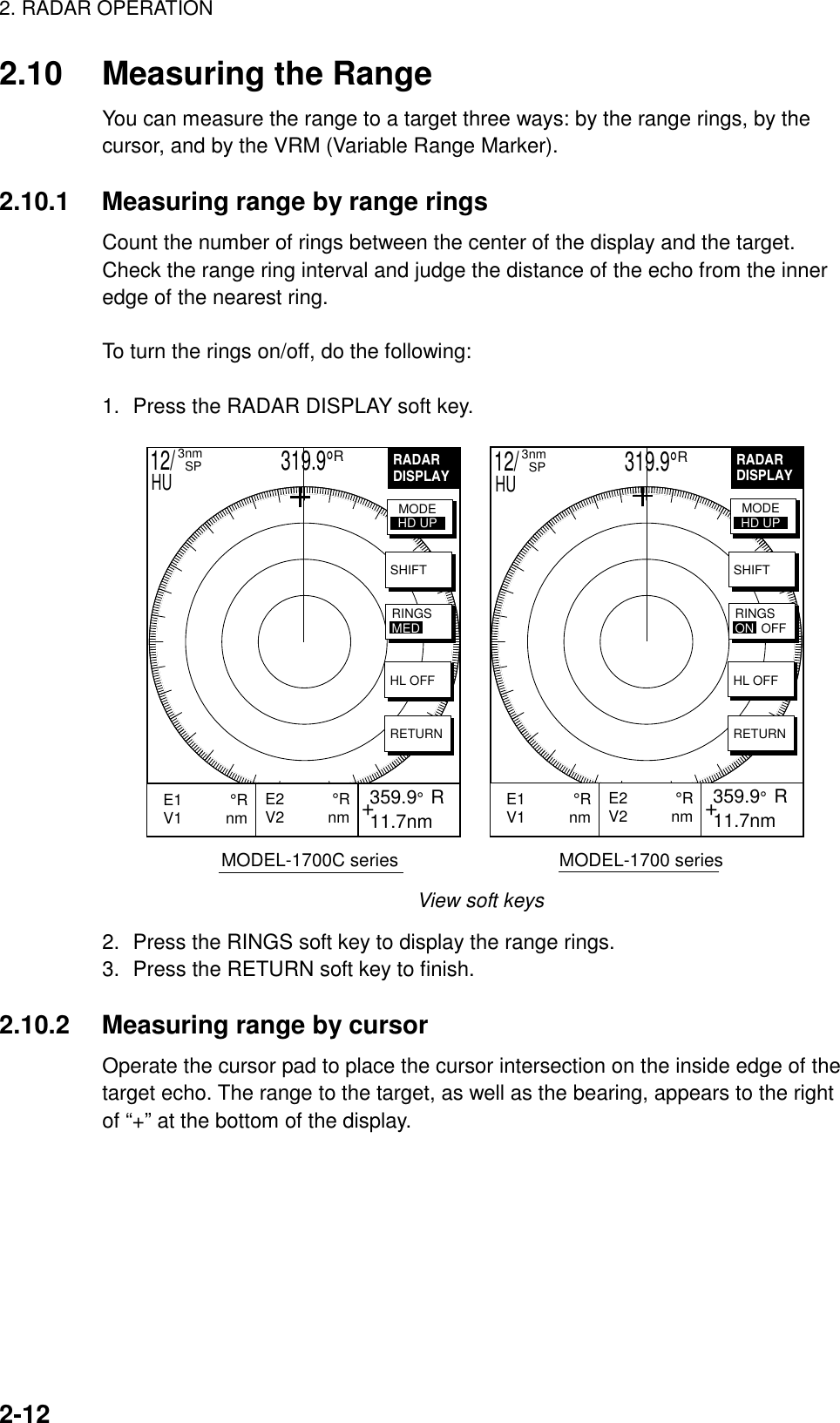
![2. RADAR OPERATION2-132.10.3 Measuring range by VRM1. Press the [EBL/VRM] key to display the EBL and VRM soft keys.EBLVRM+E2 °RV2 nm 359.9° R 11.7nmE1 °RV1 nm EBL1VRM1OFFSETEBL2VRM212/ 319.9°R3nm SPHUEBL/VRM soft keys2. Press the VRM1 (dotted ring) or VRM2 (dashed line) soft key to select VRMdesired. The selected VRM and its indication (at the bottom center) ishighlighted.3. Rotate the [ENTER] knob the place the VRM on the inside edge of a targetecho. Read the VRM indication to find range.VRM1(Dotted line)VRM2(Dashed line)VRM1 rangeVRM2 rangeActive marker is highlighted.+ 359.9° R 11.7nmE1 °RV1 3.45nm E2 °RV2 9.88nmEBLVRMEBL1VRM1OFFSETEBL2VRM212/ 319.9°R3nm SPHUHow to measure range with the VRM](https://usermanual.wiki/Furuno-USA/9ZWRTR058.operators-manual-part2/User-Guide-132263-Page-13.png)
![2. RADAR OPERATION2-142.10.4 Erasing a VRMPress appropriate VRM soft key and press the [CLEAR] key.2.10.5 Erasing EBL/VRM data boxesThe EBL/VRM data boxes are automatically erased any time an EBL or VRM isturned off. If you do not require the EBL/VRM data boxes during operation of anEBL or VRM, you can erase them by pressing the [CLEAR] key. The data boxeswill be redisplayed when an EBL or VRM is operated or an EBL/VRM data box ismoved.2.10.6 Moving EBL/VRM data boxesWhen an EBL/VRM data box is obscuring a wanted target you can move it toanother location. Place the cursor in the data box and press the [ENTER] knob.Use the cursor pad to move the box to new location and then press the [ENTER]knob.](https://usermanual.wiki/Furuno-USA/9ZWRTR058.operators-manual-part2/User-Guide-132263-Page-14.png)
![2. RADAR OPERATION2-152.11 Measuring the BearingThere are two ways to measure the bearing to a target: by the cursor, and by theEBL (Electronic bearing Line).2.11.1 Measuring bearing by cursorOperate the cursor pad to bisect the target with the cursor intersection. Thebearing to the target appears at the bottom to the right of “+” at the bottom of thedisplay.2.11.2 Measuring bearing by EBL1. Press the [EBL/VRM] key.2. Press the EBL1 (dotted line) or EBL2 (dashed line) soft key to select EBLdesired. The selected EBL and its indication (at the bottom center) ishighlighted.3. Rotate the [ENTER] knob to bisect the target echo with the EBL. Read theEBL indication to find bearing.4. To erase an EBL, press the EBL1/EBL2 soft key again.EBL1(Dotted line)EBL2(Dashed line)EBL2 bearingActive marker is highlighted.+ 359.9° R 11.7nmE1 330.1°RV1 nm E2 232.3°RV2 nmEBL1 bearingVRM2EBL2OFFSETVRM1EBL1EBLVRM12/ 319.9°R3nm SPHUHow to measure bearing with the EBL2.11.3 Erasing an EBLPress appropriate EBL soft key and press the [CLEAR] key.](https://usermanual.wiki/Furuno-USA/9ZWRTR058.operators-manual-part2/User-Guide-132263-Page-15.png)
![2. RADAR OPERATION2-162.11.4 Erasing EBL/VRM data boxesThe EBL/VRM data boxes are automatically erased any time an EBL or VRM isturned off. If you do not require the EBL/VRM data boxes during operation of anEBL or VRM, you can erase them by pressing the [CLEAR] key. The data boxeswill be redisplayed when an EBL or VRM is operated or an EBL/VRM data box ismoved.2.11.5 Moving EBL/VRM data boxesWhen an EBL/VRM data box is obscuring a wanted target you can move it toanother location. Place the cursor in the data box and press the [ENTER] knob.Use the cursor pad to move the box to new location and then press the [ENTER]knob.2.12 Erasing the Heading Line, North MarkerThe heading line indicate the ship's heading in all presentation modes. Theheading line is a line from the own ship position to the outer edge of the radardisplay area and appears at zero degrees on the bearing scale in head-up modecentered; it changes the orientation depending on the ship orientation in north-upand true motion modes.The north marker appears as a short dashed line. In the head-up mode, the northmarker moves around the bearing scale in accordance with the compass signal.To temporarily erase the heading line and north marker, press the VIEW soft keyfollowed by the HL OFF soft key. Release the key to redisplay the markers.2.13 Reducing Noise InterferenceWhite noise, appearing on the displays as random “speckles,” can be rejected asfollows:1. Press the [MENU] key to open the menu.2. Press the RADAR DISPLAY SETUP soft key.3. Select NOISE REJECTION and press the EDIT soft key.4. Select ON or OFF as appropriate.5. Press the RETURN soft key.6. Press the [MENU] key to close the menu.](https://usermanual.wiki/Furuno-USA/9ZWRTR058.operators-manual-part2/User-Guide-132263-Page-16.png)
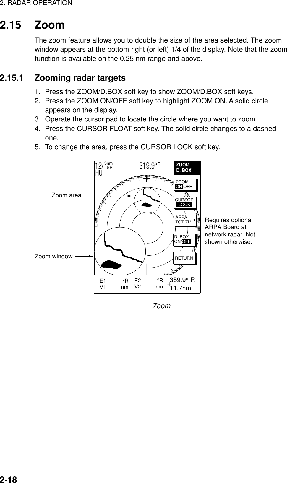
![2. RADAR OPERATION2-192.15.2 Zooming ARPA, TTM targetsIf TTM data sentence is input to the equipment, you can magnify correspondingtracked targets as follows:1. Press the ZOOM/D.BOX soft key to show ZOOM/D.BOX soft keys.2. Press the ZOOM ON/OFF soft key to highlight ZOOM ON.3. Press the ARPA TGT ZM soft key. Target no. selection window appears.SELECT TGT NO.▲▼1ARPA target no. selection window4. Use the rotary encoder to select number and press the [ENTER] knob. If thetarget could not be magnified the audio alarm sounds and the zoom functionis cancelled.To cancel, press the CURSOR FLOAT soft key.2.16 Shifting the PictureOwn ship position, or sweep origin, can be displaced manually or automatically toexpand the view field without switching to a larger scale.Manual shiftThe sweep origin can be shifted in any presentation mode to a point specified bythe cursor, up to 75% of the range in use in any direction.Automatic shiftThe sweep origin is automatically shifted sternwise, the amount of shiftdependent on the automatic shift maximum speed. The formula for determiningamount of shift is as below.When the ship’s speed is lower than the automatic ship speed setting;Temporary shift amount = effective radius dot X 0.75 X speed/auto shift speed setting • Absolute position (previous shift amount – interim shift amount) ≥ judged shfit amount Shift amount = interim shift amount • Absolute position (previous shift amount – interim shift amount) < judged shift amount Shift amount = previous shift amountWhen the ship’s speed is higher than the automatic ship speed settingShift amount = effective radius X 0.75](https://usermanual.wiki/Furuno-USA/9ZWRTR058.operators-manual-part2/User-Guide-132263-Page-19.png)
![2. RADAR OPERATION2-202.16.1 Manual shift1. Locate the cursor anywhere within the effective radius of the display.2. Press the RADAR DISPLAY soft key.3. Press the SHIFT soft key.4. Press the MANUAL soft key to shift. The heading line shifts to the cursorlocation.5. To cancel shift, press the OFF soft key.CursorPlace cursorwhere desired. Press the MANUAL soft key.OFFCENTERShifting the picture manually2.16.2 Automatic shiftThe automatic shift mode is only available in the heading up mode.Setting automatic shift maximum speed1. Press the RADAR DISPLAY soft key.2. Press the SHIFT soft key to show the shift soft keys.3. Press the AUTO S.SPD soft key to display the AUTO S. SPD setting window.AUTO S. SPD▲ 120 kt▼AUTO S.SPD setting window4. Rotate the [ENTER] knob to enter the maximum ship’s at which the display isautomatically shifted. The setting range is 1-999 kt and the default setting is15 kt.5. Press the ENTER soft key to close the window.Automatic shiftPress the AUTO key to automatically shift the display. To cancel shift, press theOFF soft key.](https://usermanual.wiki/Furuno-USA/9ZWRTR058.operators-manual-part2/User-Guide-132263-Page-20.png)
![2. RADAR OPERATION2-212.17 Using the Offset EBLThe offset EBL functions to predict collision course and measure the range andbearing between two targets.3.17.1 Predicting collision course with the Offset EBLThe procedure below checks if the target echo shown in below is on a collisioncourse.1. Use the cursor pad to place the cursor on the target which looks like it mightbe on a collision course with your vessel.2. Press the [EBL/VRM] key to show the EBL and VRM soft keys.3. Press the OFFSET soft key. The origin of EBL1 moves to the cursor positionand an “X” appears at the cursor position.4. Press the [ENTER] knob to fix the origin position.5. After waiting for a few minutes (at least three minutes), rotate the [ENTER]knob so the EBL bisects the target at the new position. If the target tracksalong the EBL towards the center of the display (your ship’s position), thetarget may be on a collision course.6. To cancel the offset EBL, press the OFFSET soft key.Initial targetpositionTarget trackedhere+E2 °RV2 nm 359.9° R 11.7nmE1 45.0°RV1 nm EBLVRMEBL1VRM1OFFSETEBL2VRM212/ 319.9°R3nm SPHUPredicting collision course with the offset EBL](https://usermanual.wiki/Furuno-USA/9ZWRTR058.operators-manual-part2/User-Guide-132263-Page-21.png)
![2. RADAR OPERATION2-222.17.2 Measuring range & bearing two targetsThe procedure which follows shows how to measure the range and bearingbetween target “A” and target “B” in the figure below.1. Operate the cursor pad to place the cursor on the target “A”.2. Press the [EBL/VRM] key to show the EBL and VRM soft keys.3. Press the OFFSET soft key. The origin of EBL1 and VRM1 moves to thecursor position and an “X” appears at the cursor position.4. Rotate the [ENTER] knob so the EBL bisects the target “B”.5. Press the VRM1 soft key and then rotate the [ENTER] knob to place theVRM1 on the inner edge of the target “B”.+E2 °RV2 nm 359.9° R 11.7nmTarget ATarget BBearing and rangebetween target Aand target BEBLVRMEBL1VRM1OFFSETEBL2VRM212/ 319.9°R3nm SPHUE1 065.3°RV1 0.34 nm Measuring bearing between two targets](https://usermanual.wiki/Furuno-USA/9ZWRTR058.operators-manual-part2/User-Guide-132263-Page-22.png)
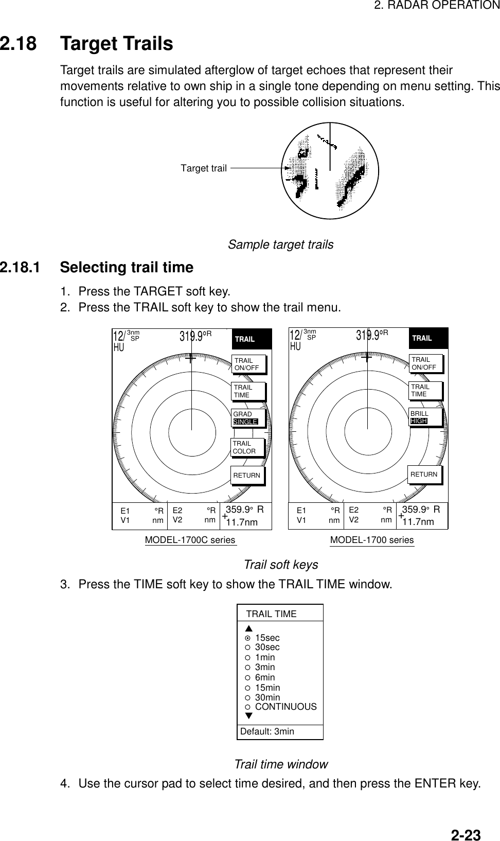
![2. RADAR OPERATION2-242.18.2 Starting target trail1. Press the [MENU] key.2. Press the TARGET and TRAIL soft keys.3. Press the TRAIL soft key to show ON.TRAIL, the echo trail time selected and elapsed time appear at the top right-handcorner of the display. Then afterglow starts extending from all targets. Trails arerestarted when the range or mode is changed or zoom or shift is turned on. Forcontinuous trails the maximum continuous trail time is 99 minutes and 59seconds. When the elapsed time clock counts up to that time the elapsed timedisplay resets to zero and trail begins again.4. To turn off echo trail, press the TRAIL soft key to select OFF.2.18.3 Trail brilliance (MODEL-1700 series only)Trail brilliance can be selected to high or low as below.1. Press the [MENU] key.2. Press the TARGET and TRAIL soft keys.3. Press the BRILL soft key to select HIGH or LOW.2.18.4 Trail gradation (MODEL-1700C series only)The echo trails can be shown in single or multiple gradations. Multiple gradationpaints the trails getting thinner with time, like the afterglow on an analog PPIradar. Press the GRAD soft key to show GRAD SINGLE or GRAD MULTIPLE asappropriate.(Multitone) (Monotone)Multitone and monotone trails](https://usermanual.wiki/Furuno-USA/9ZWRTR058.operators-manual-part2/User-Guide-132263-Page-24.png)
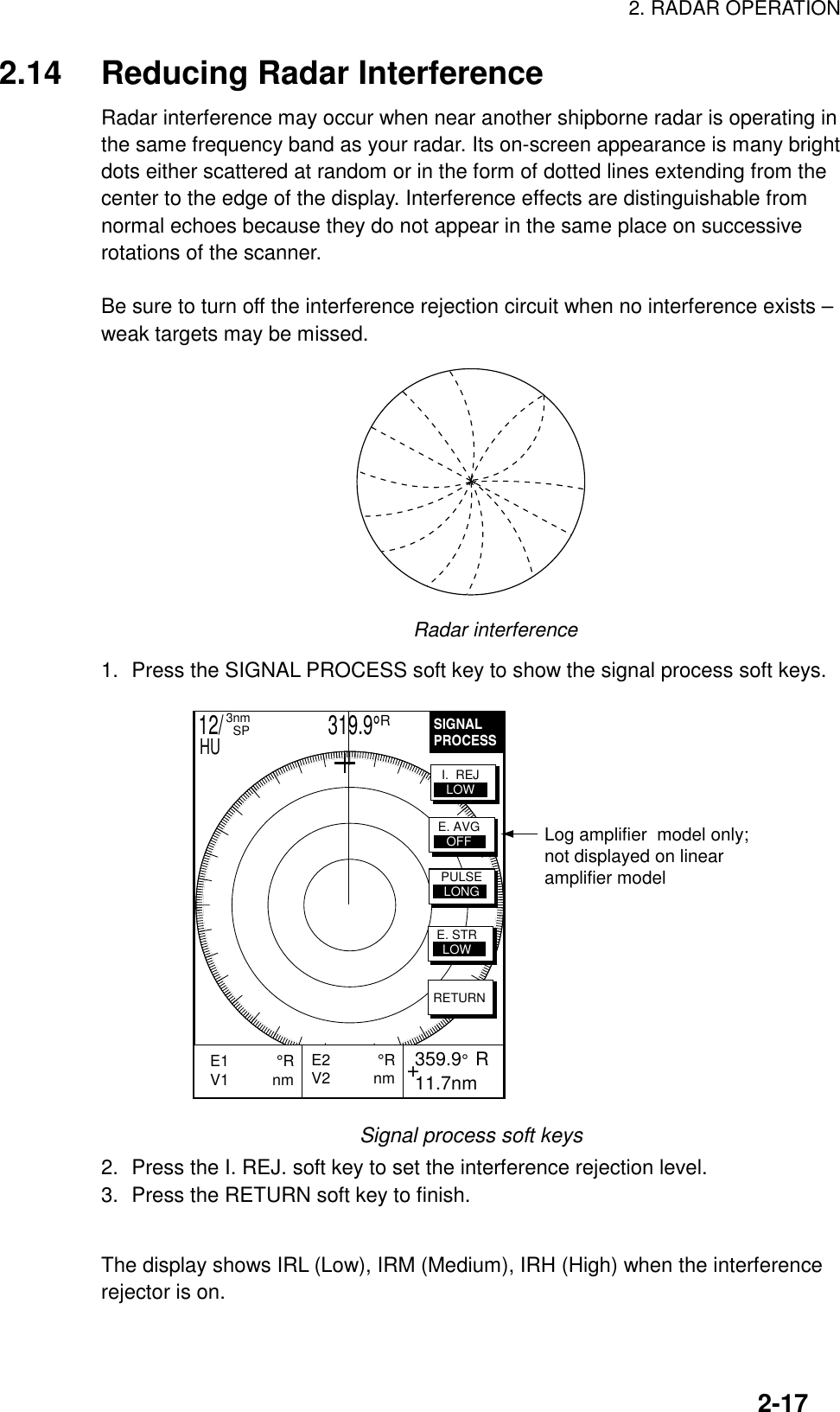
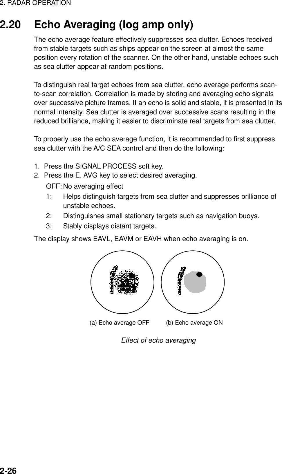
![2. RADAR OPERATION2-252.18.5 Trail color (MODEL-1700C series) onlyThe MODEL-1722C series can show trails in colors1. Press the [MENU] key.2. Press the TARGET, TRAIL and TRAIL COLOR soft keys.TRAIL COLOR▲BLUEYELLOWGREEN WHITE▼DEFAULT: YELLOWTrail color window3. Use the cursor pad to select color desired.4. Press the RETURN soft key to quit.2.19 Magnifying Long Range Echoes (echo stretch)Normally, the reflected echoes from long range targets appear on the display asweaker and smaller blips even though they are compensated by the radar’sinternal circuitry. The echo stretch function magnifies these small blips in allranges. Two types of echo stretch are available: ES LOW which stretches echoesin bearing direction and ES HIGH which stretches them in both range andbearing directions."LOW" Echo stretch "HIGH" Echo stretchBearingdirection BearingdirectionRangedirectionTypes of echo stretchThis function magnifies not only targets but also sea clutter and radarinterference. For this reason be sure sea clutter and radar interference areproperly suppressed before activating the echo stretch.1. Press the SIGNAL PROCESS soft key.2. Press the E. STR soft key to select E. STR HIGH or E. STR LOW asappropriate.3. Press the RETURN soft key to finish.The display shows ES H (High) or ES L (Low) when the echo stretch is on.](https://usermanual.wiki/Furuno-USA/9ZWRTR058.operators-manual-part2/User-Guide-132263-Page-25.png)
![2. RADAR OPERATION2-282.22 Guard AlarmThe guard alarm allows the operator to set the desired range and bearing for aguard zone. When ships, islands, landmasses, etc. violate the guard zone anaudible alarm sounds and the offending target blinks to call the operator’sattention.CAUTION• The alarm should not be relied upon as the sole means for detecting possible collision situations.• A/C SEA, A/C RAIN and GAIN controls should be properly adjusted to be sure the alarm system does not overlook target echoes.2.22.1 Setting a guard alarm zoneTo set a guard alarm zone transmit and do the following:1. Press the [ALARM] key.2. Use the cursor pad to set the cursor on the top left (or top right corner) of theguard zone to set and press the SET GUARD 1 or SET GUARD 2 soft key.3. Use the cursor pad to set the cursor on the bottom right (or top left corner) ofthe guard zone and press the [ENTER] knob. 359.9R 12.3nmGUARDALARM 359.9R 12.3nmVRM.125nm.032nmEBL 19.9TNO ALARM(1) Drag cursor to top (or bottom) cornerfor guard zone and press the SET GUARD 1 or SET GUARD 2 soft key. (2) Drag cursor diagonally to bottom (or top) corner for guard zone and press the [ENTER] knob. MOVE +CURSOR TO ANOTHERCONER OF GUARD1 ANDPRESS ENTER TO CONFIRM.GUARDALARMSETGUARD1ERASEGUARD1SETGUARD2RETURN12/ 319.9°R3nm SPHU 12/ 319.9°R3nm SPHU++How to set a guard alarm zone](https://usermanual.wiki/Furuno-USA/9ZWRTR058.operators-manual-part2/User-Guide-132263-Page-28.png)
![2. RADAR OPERATION2-292.22.2 Guard zone typeAfter the guard zone is set, the radar searches for targets inside the guard zoneto determine guard alarm type. If no targets are found the guard zone type is“inward” and the guard zone indication is G1(G2) OUT. The “inward” alarm istriggered when a target enters the guard zone. If a target is found the guard zonetype is “outward” and the guard zone indication is G1(G2) IN. The “outward”alarm is triggered when a target exits the guard zone.(a) Inward alarm (b) Outward alarm How the inward and outward alarms workNote 1: When the radar range is less than the guard zone range, the alarm iconis displayed in reverse video, the audio alarm sounds and the message“GUARD 1(2) IS OUTSIDE RADAR RANGE” appears. Press the[ALARM] key to silence the alarm and erase the message. Reselectappropriate range.Note 2: If the network radar is set to standby while the guard alarm is active, theguard alarm is cancelled and the radar goes into standby. The guardalarm is redisplayed when radar pulses are again transmitted.Note 3: If the network radar is set to standby while the radar picture is notdisplayed, the alarm icon appears in reverse video and the alarm sounds.Further, the message “STBY MODE HAS BEEN SELECTED.GUARD/WTCHMN CANCELED.” or GUARD/WATCHMAN CANCELED.STBY/TX SELECTED. 2.22.3 When the alarm is violated…Any radar target violating the guard zone will flash, the audio alarm sounds, thealarm icon appears, and the message “TARGET HAS ENTERED G1(G2)” or“TARGET HAS LEFT G1(G2)” is displayed at the bottom of the screen. Press the[CLEAR] key to silence the alarm and erase the alarm icon. When this is done,“G1(G2) ACK” replaces G1(G2) IN(OUT) at the top right corner of the display.This means the alarm is temporarily deactivated. Press the SETGUARD1 orSETGUARD2 soft key again to reactivate the alarm.2.22.4 Cancelling the guard alarm1. Press the [ALARM] key to show the ALARM menu.2. Press the SET GUARD1 or SET GUARD2 soft key as appropriate.3. Press the RETURN soft key to finish.](https://usermanual.wiki/Furuno-USA/9ZWRTR058.operators-manual-part2/User-Guide-132263-Page-29.png)
![2. RADAR OPERATION2-302.23 Watchman2.23.1 How watchman worksThe watchman function periodically transmits radar pulses for one minute tocheck for targets in a guard zone. If a target is found in the zone, watchman iscancelled, the audio alarm sounds and the radar continues transmitting. If notarget is found the radar goes into standby. This feature is useful when you do notneed the radar’s function continuously but want to be alerted to radar targets in aspecific area.ST-BY5,10or20 min Tx1 min Tx1 minWatchmanstarts5,10or20 minST-BY*** Timer counts down one minute before radar transmits.How watchman works2.23.2 Turning on/off watchman1. Press the NAV FUNC soft key to show the NAV FUNC soft keys.2. Press the W. MAN ON/W. MAN OFF soft key to highlight ON or OFF asappropriate.To cancel watchman, press any key.Note:When the watchman is activated and no guard zone is active, the message“PLEASE SET GUARD ZONE. PRESS ANY KEY TO CONTINUE.”appears. Press any key and then set a guard zone.2.23.3 Setting watchman stand-by intervalThe watchman standby interval can be set to 5, 10 or 20 minutes as follows:1. Press the [MENU] key.2. Press the RADAR DISPLAY SETUP soft key.3. Select WATCHMAN and press the EDIT soft key.WATCHMAN▲▼OFF5min10min20minWatchman window4. Select option desired and press the RETURN soft key.5. Press the [MENU] key to close the menu.](https://usermanual.wiki/Furuno-USA/9ZWRTR058.operators-manual-part2/User-Guide-132263-Page-30.png)
![2. RADAR OPERATION2-332.25.1 Activating/deactivating ARPA1. Press the [MENU] key followed by the ARPA SETUP soft keys to show theARPA SETUP menu.ARPA TARGET INFOARPACANCEL ALL TARGETONVECTOR MODERELATIVEVECTOR TIME1minINTERVALOFFCPAOFFTCPA30secAUTO PLOTOFFTGT NO. OFF▲ARPASETUPEDITRETURNARPA SETUP menu2. Select ARPA TARGET INFO, and then press the EDIT soft key to show theARPA TARGET INFO window.ARPA TARGET INFO▲▼OFFTTMARPAPlot window3. Select ARPA, TTM or OFF as appropriate. For TTM, targets cannot beacquired.4. Press the ENTER soft key.5. Press the [MENU] key to close the menu.](https://usermanual.wiki/Furuno-USA/9ZWRTR058.operators-manual-part2/User-Guide-132263-Page-33.png)
![2. RADAR OPERATION2-342.25.2 Acquiring and tracking targetsWhen selecting ARPA on the ARPA SETUP menu, targets can be acquired.Manual acquisition10 targets can be manually acquired and automatically tracked.1. Place the cursor on the target to acquire.2. Press the ACQ soft key.The plot symbol changes its shape according to the status as below. A vectorappears in about one minute after acquisition indicating the target’s motion trend.If the target is consistently detected for three minutes, the plot symbol blinks anddisappears shortly. When all 10 targets have been acquired the message ARPATGT FULL-TRACKING 10 TARGETS appears. To acquire another target,terminate tracking of an unnecessary target.At acquisition 1 min. afteracquisition 3 min. afteracquisition111VectorPlot symbolsAutomatic acquisitionThe ARPA automatically acquires up to 10 targets which come into the acquisitionarea.1. Press the [MENU] key to show the main menu.2. Press the ARPA SETUP soft key to show the ARPA SETUP menu.3. Operate the cursor pad to select AUTO PLOT.4. Press the EDIT soft key to show the AUTO PLOT window.AUTO PLOT▲▼OFFON(AUTO/MAN)Auto plot window5. Select ON. An acquisition area of 2.0 to 2.5 miles in range and ±45º on eitherside of the heading line appears.](https://usermanual.wiki/Furuno-USA/9ZWRTR058.operators-manual-part2/User-Guide-132263-Page-34.png)
![2. RADAR OPERATION2-35Automatic acquisitionareaAutomatic acquisition areaWhen the automatic acquisition capacity is reached the message ARPA TARGETFULL-TRACKING 10 TARGETS appears.2.25.3 Terminating tracking of targetsWhen 10 targets have been acquired, no more acquisition occurs unless targetsare lost. Should this happen, cancel tracking of individual targets or all targets bythe procedure described below.Terminating tracking of selected targets1. Place the cursor on the target to terminate tracking.2. Press the [CLEAR] key to erase.Terminating tracking of all targets1. Press the [MENU] followed by the ARPA SETUP soft keys.2. Select CANCEL ALL TARGET, and then press the EDIT soft key.CANCEL ALL TARGET▲▼ONOFFCancel all target window3. Select YES and press the ENTER soft key.4. Press the [MENU] key to close the menu.](https://usermanual.wiki/Furuno-USA/9ZWRTR058.operators-manual-part2/User-Guide-132263-Page-35.png)
![2. RADAR OPERATION2-362.25.4 Vector attributesTrue or relative vectorTarget vectors display speed and course of tracked targets. You may referencethe vectors to North (True) or ship’s heading (relative) as desired. Own ship doesnot have a vector in relative mode.Vector timeVector time can be set to 30 seconds, 1, 3, 6, 15 or 30 minutes and the selectedvector time is indicated on the screen. The vector tip shows an estimated positionof the target after the selected vector time elapses. It can be valuable to extendthe vector length to evaluate the risk of collision with any target.1VectorVector1. Press the [MENU] key followed by the ARPA SETUP soft keys to show theARPA SETUP menu.2. Operate the cursor pad to select VECTOR MODE.3. Press the EDIT soft key to show the VECTOR MODE window.VECTOR MODE▲▼RELATIVETRUEVector mode window4. Select TRUE or RELATIVE as appropriate.5. Press the ENTER soft key.6. Select VECTOR TIME, and then press the EDIT soft key to show theVECTOR TIME window.VECTOR TIME▲▼30s1m3m6m15m30m Vector time window7. Operate the cursor pad to select vector length among 30 sec, 1 min, 3 min, 6min, 15 min and 30 min.8. Press the ENTER soft key.9. Press the [MENU] key to close the menu.](https://usermanual.wiki/Furuno-USA/9ZWRTR058.operators-manual-part2/User-Guide-132263-Page-36.png)
![2. RADAR OPERATION2-372.25.5 Past position displayThis ARPA displays equally time-spaced dots (maximum 10 dots) marking thepast positions of any targets being tracked. If a target changes its speed, thespacing will be uneven. If it changes the course, its plotted course will not be astraight line in TM mode.To turn the past position display on/off:1. Press the [MENU] key followed the RADAR and ARPA SETUP soft keys inorder.2. Operate the cursor pad to select INTERVAL.3. Press the EDIT soft key to show the INTERVAL window.INTERVAL▲▼OFF15s30s1m2m3m6mInterval window4. Operate the cursor pad to select plotting interval among 15 sec, 30 sec, 1 min,2 min, 3 min and 6 min. (OFF turns off the past position display.)5. Press the ENTER soft key.6. Press the [MENU] key to close the menu.](https://usermanual.wiki/Furuno-USA/9ZWRTR058.operators-manual-part2/User-Guide-132263-Page-37.png)
![2. RADAR OPERATION2-382.25.6 Displaying target dataThis ARPA calculates motion trends (range, bearing, course, speed, CPA andTCPA) of all targets under tracking, and displays data of selected target at thebottom of the screen.1. Place the cursor on the target you want to see its data.2. Press the TARGET INFO soft key. The data of the selected target appears 359.9° R 11.7nmVRM.125nm.032nmEBL 19.9TNo.1 VECTOR TRUE 15minCSE 359.9°R SPD 12.5ktCPA 2nm TCPA 12:35TARGETTRAILTLLOUTPUTACQTGTINFORETURN12/ 319.9°R3nm SPHUCPA and TCPACourse and speedTarget no., vector reference, vector timeARPA target dataDisplaying the target numberYou can turn the acquired target number display on or off as follows:1. Press the [MENU] key followed by the RADAR MENU and ARPA SETUPMENU soft keys.2. Operate the cursor pad to select TARGET NO.3. Press the EDIT soft key.4. Select YES or NO as appropriate.5. Press the ENTER soft key.6. Press the [MENU] key to close the menu.](https://usermanual.wiki/Furuno-USA/9ZWRTR058.operators-manual-part2/User-Guide-132263-Page-38.png)
![2. RADAR OPERATION2-392.25.7 CPA/TCPA alarmVisual and audible alarms are generated when the predicted CPA and TCPA ofany target become less than their preset limits. Press the [CLEAR] key toacknowledge and silence the CPA/TCPA audible alarm.This ARPA continuouslymonitors the predicted range at the Closest Point of Approach (CPA) andpredicted time to CPA (TCPA) of each tracked to own ship.When the predicted CPA of any target becomes smaller than a preset CPA alarmrange and its predicted TCPA less than a preset TCPA alarm limit, the ARPAreleased an audible alarm. In addition, the target plot symbol changes to atriangle and flashes together with its vector and the massage appears.Provided that this feature is used correctly, it will help prevent the risk of collisionby alerting you to threatening targets. It is important that gain, A/C SEA, A/CRAIN and other radar controls are properly adjusted and the ARPA is set up sothat it can track targets effectively.CPA/TCPA alarm ranges must be set up properly taking into consideration thesize, tonnage, speed, turning performance and other characteristics of own ship.CAUTIONThe CPA/TCPA alarm should never berelied upon as a sole means for detect-ing the risk of collision. The navigator isnot relieved of the responsibility to keepvisual lookout for avoiding collisions,whether or not the radar or other plottingaid is in use.Follow the steps shown below to set the CPA/TCPA alarm range:1. Press the [MENU] key followed by ARPA SETUP soft keys in order.2. Operate the cursor pad to select CPA.3. Press the EDIT soft key to show the CPA window.CPA▲▼OFF0.5nm1nm2nm3nm5nm6nmCPA window4. Select a CPA limit desired among 0.5 nm, 1 nm, 2 nm, 5nm and 6 nm by thecursor pad.5. Press the ENTER soft key. The ARPA SETUP menu reappears.6. Press the cursor pad to select TCPA.7. Press the EDIT soft key to show the TCPA window.](https://usermanual.wiki/Furuno-USA/9ZWRTR058.operators-manual-part2/User-Guide-132263-Page-39.png)
![2. RADAR OPERATION2-40TCPA▲▼30s1m2m3m4m5m6nm12mTCPA window8. Select a TCPA limit among 1 min, 2 min, 3 min, 4 min, 5 min, 6 min and 12min.9. Press the ENTER soft key.10.Press the [MENU] key to close the menu.2.25.8 Lost target alarmWhen the system detects a lost target, the target symbol becomes a diamond (1)and tracking is discontinued one minute later. The normal plotting symbol isrestored to the target when the target is manually acquired.](https://usermanual.wiki/Furuno-USA/9ZWRTR058.operators-manual-part2/User-Guide-132263-Page-40.png)
![2. RADAR OPERATION2-432.26.2 False echoesOccasionally echo signals appear on the screen at positions where there is notarget or disappear even if there are targets. They are, however, recognized if youunderstand the reason why they are displayed. Typical false echoes are shownbelow.Multiple echoesMultiple echoes occur when a transmitted pulse returns from a solid object like alarge ship, bridge, or breakwater. A second, a third or more echoes may beobserved on the display at double, triple or other multiples of the actual range ofthe target as shown below. Multiple reflection echoes can be reduced and oftenremoved by decreasing the gain (sensitivity) or properly adjusting the [A/C SEA]control.Own shipTargetTrueechoMultiple echoMultiple echoesSidelobe echoesEvery time the radar pulse is transmitted, some radiation escapes on each side ofthe beam, called sidelobes. If a target exists where it can be detected by the sidelobes as well as the main lobe, the side echoes may be represented on bothsides of the true echo at the same range. Sidelobes show usually only on shortranges and from strong targets. They can be reduced through careful reduction ofthe gain or proper adjustment of the A/C SEA control.Target B(True)Target B(Spurious)Target ASidelobe echoes](https://usermanual.wiki/Furuno-USA/9ZWRTR058.operators-manual-part2/User-Guide-132263-Page-43.png)
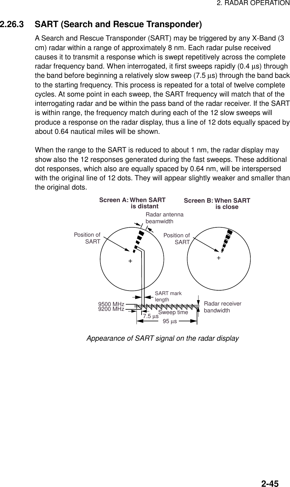
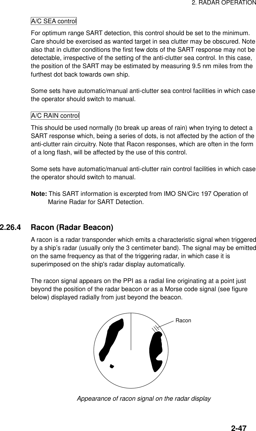
![2. RADAR OPERATION2-46General procedure for detecting SART response1. Use the range scale of 6 or 12 nm as the spacing between the SARTresponses is about 0.6 nm (1125 m) to distinguish the SART.2. Turn off the automatic clutter suppression.3. Turn off the Interference Rejector.General remarks on receiving SARTSART range errorsWhen responses from only the 12 low frequency sweeps are visible (when theSART is at a range greater than about 1 nm), the position at which the first dot isdisplayed may be as much as 0.64 nm beyond the true position of the SART.When the range closes so that the fast sweep responses are seen also, the firstof these will be no more than 150 meters beyond the true position.Radar bandwidthThis is normally matched to the radar pulselength and is usually switched with therange scale and the associated pulselength. Narrow bandwidths of 3-5 MHz areused with long pulses on long range and wide bandwidths of 10-25 MHz withshort pulses on short ranges.Any radar bandwidth of less than 5 MHz will attenuate the SART signal slightly,so it is preferable to use a medium bandwidth to ensure optimum detection of theSART.Radar side lobesAs the SART is approached, sidelobes from the radar antenna may show theSART responses as a series of arcs or concentric rings. These can be removedby the use of the [A/C SEA] control although it may be operationally useful toobserve the sidelobes as they may be easier to detect in clutter conditions andalso they will confirm that the SART is near to the ship.GainFor maximum range SART detection the normal gain setting for long rangedetection should be used, that is, with background noise speckle visible.](https://usermanual.wiki/Furuno-USA/9ZWRTR058.operators-manual-part2/User-Guide-132263-Page-46.png)