Furuno USA 9ZWRTR059A Marine Radar User Manual Cover
Furuno USA Inc Marine Radar Cover
Contents
- 1. op man part 1
- 2. op man part 2
- 3. op man part 3
- 4. inst manual
op man part 2

1. DESCRIPTION OF OPERATION
1-36
1.28 Custom Setup
1.28.1 About custom setup
When your navigating environment or task changes, you must adjust the radar. In-
stead of changing radar settings case by case, you can assign the CUSTOM key to
provide best settings for common conditions.
There are three default custom setups for the internal computer of the radar (see the
table on the next page). You can adjust these settings on the [Custom 1], [Custom 2]
and [Custom 3] menus to meet your navigation needs.
To activate a custom setup, press the CUSTOM key. The CUSTOM key switches be-
tween Custom 1, Custom 2 or Custom 3 each time you press the key. (Custom setup
numbers which are turned off are ignored.) The selected custom setup name is shown
at the upper-left corner. To escape from custom setup, operate any control.
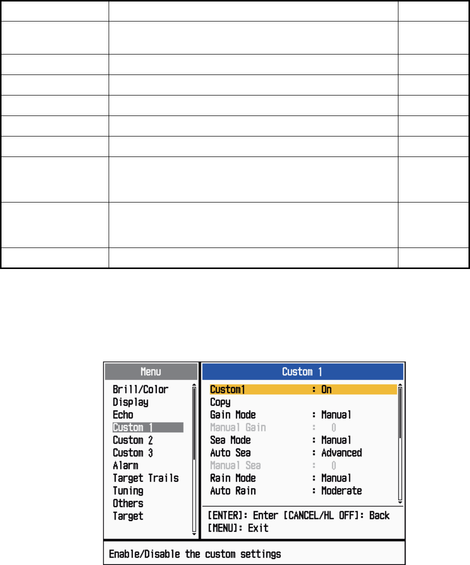
1.28.2 Description of custom setup items
Description of custom setup items
Menu item Available settings See section
[Custom1(2 or 3)] Turn on/off each custom program.
[Copy] Copy settings from the [Echo] menu. The message "Com-
plete" appears after the copying is completed.
[Gain Mode] [Auto]: Automatic gain adjustment according to noise level
[Manual]: Manual gain adjustment 1.9
[Manual Gain] Copy the current position of the GAIN knob when you do
[Copy]. This item is for read-only.
[Sea Mode] [Auto]: Automatic sea clutter adjustment according to sea
state
[Manual]: Manual sea clutter adjustment
1.10
[Auto Sea] [Coastal]: Suppress both land and sea clutter.
[Advanced]: Automatically discriminate land echoes from
sea reflections to suppress only sea reflections.
1.10
[Manual Sea] Copy the current position of the A/C SEA knob when you do
[Copy]. This item is for read-only.
[Rain Mode] [Auto]: Automatic rain clutter adjustment according to rain
cloud
[Manual]: Manual rain clutter adjustment
1.11
[Auto Rain] [Calm]: For light rain
[Moderate]: When you can not reduce the rain clutter with
[Calm] mode
[Rough]: For heavy rain
1.11
[Manual Rain] Copy the current position of the A/C RAIN knob when you do
[Copy]. This item is for read-only.
[A/C Auto] [Off], [On] 1.12
1. DESCRIPTION OF OPERATION
1-37
1.28.3 How to set custom setups
1. Press the MENU key to open the menu.
2. Use the Cursorpad (S or T) to select [Custom 1 (2 or 3)] and press the ENTER
key.
Custom menu
3. Set menu items.
Note: For easy set up, you can copy the settings of the [Echo] menu (to [Custom
1], [Custom 2], [Custom 3]). Select [Copy] and press the ENTER key. When the
copying is completed, the message "Complete" appears. To erase this message,
press any key.
4. Press the MENU key to close the menu.
[Pulse Length] [Short] or [Long], you can select on 1.5, 1.6, 3.0 and 3.2 nm
ranges. 1.18
[Echo Stretch] [Off], [1], [2], [3] 1.22
[Echo Average] [Off], [1], [2], [Auto] 1.23
[Noise Rejector] [Off], [On] 1.30
[Wiper] [Off], [1], [2] 1.31
[Int Rejector] [Off], [1], [2], [3] 1.14
[Display-Dynamic] [Narrow]: Erase weak echoes.
[Normal]: Normal use
[Wide]: Display weaker echoes compared to [Narrow].
1.36
[Display-Curve] [1]: Reduce weak echoes.
[2]: Normal use
[3]: Display weaker echoes in stronger color compared to [1].
1.37
[Color Erase] 0 - 11 1.44.3
Menu item Available settings See section

1. DESCRIPTION OF OPERATION
1-38
1.29 How to Program Function Keys (F1, F2 and F3
keys)
You can program function keys (F1, F2 and F3) to provide one-touch access to a re-
quired function.
Function key operation
To activate a function, press function key, F1, F2 or F3. Press same key to change the
setting.
The default programs are [Gain Mode] for F1, [Sea Mode] for F2, [A/C Auto] for F3.
When you press the F1 or F2 key, the window for Gain/Sea/Rain indicator shows. See
section 1.9 and 1.10 for operation. When you press the F3 key, [A/C Auto] is turned on.
How to change a function key program
1. Press the MENU key to open the menu.
2. Use the Cursorpad (S or T) to select [Others] and press the ENTER key.
3. Use the Cursorpad (S or T) to select [F1 (F2 or F3) Setup] and press the ENTER
key.
4. Use the Cursorpad (S or T) to select a function from the list and press the EN-
TER key. Below are the available functions.
Function list
5. Press the MENU key to close the menu.
Rings Brill
Mark Brill
HL Brill
Character Brill
View Position
Display Color
Echo Color
Background Color
Character Color
Menu Transparency
Echo Color Mode
Display Mode
Zoom
Zoom Mode
Echo Area
Data Box
STBY Display
Gain Mode
Sea Mode
Auto Sea
Rain Mode
Auto Rain
A/C Auto
Pulse Length
Echo Stretch
Echo Average
Noise Rejector
Wiper
Int Rejector
Display-Dynamic
Display-Curve
2nd Echo Rejector
Target Alarm 1
Target Alarm 2
Alarm Level
Watchman
Panel Buzzer
External Buzzer
Trails-Gradation
Trails-Color
Trails-Mode
Trails-Level
Trails-Restart
Trails-Narrow
Trails-Own Ship
Tuning Mode
WPT Mark
EBL Reference
VRM Unit
Cursor Position
TLL Key Mode
Vector Reference
History Dots
History Interval
CPA
TCPA
Proximity
ARPA-Display
ARPA-Color
ARPA-Auto Acquisition
ARPA-ACK Lost Targets
AIS-Display
AIS-Color
AIS-Sort By
AIS-ACK Lost Targets
GPS-Mode
GPS-Datum
GPS-WAAS
1. DESCRIPTION OF OPERATION
1-39
1.30 Noise Rejector
White noise can appear on the screen as random "marks". You can reduce this noise
as follows:
1. Press the MENU key to open the menu.
2. Use the Cursorpad (S or T) to select [Echo] and press the ENTER key.
3. Use the Cursorpad (S or T) to select [Noise Rejector] and press the ENTER key.
Noise Rejector options
4. Use the Cursorpad (S or T) to select [Off] or [On] then press the ENTER key.
5. Press the MENU key to close the menu.
1.31 Wiper
The wiper feature automatically reduces the brilliance of unwanted weak signals
(noise, sea clutter, rain clutter, etc.) and unnecessary signals, like radar interference,
to clear the picture of unnecessary echoes. The result of wiper depends on the wiper
setting used and whether echo averaging is turned on or off, as described below.
Echo averaging and wiper states and wiper effect
Processing content A: The brilliance of unnecessary weak echoes, like noise and
radar interference, is reduced to clear the picture. The difference between wiper 1 and
2 is that brilliance is lowered more slowly in 1.
Processing content B: Echo averaging is automatically turned on from off when the
wiper feature is turned on. You can see how the picture changes with the echo aver-
aging turned off and turned on.
To activate the wiper feature, do the following:
1. Press the MENU key to open the menu.
2. Use the Cursorpad (S or T) to select [Echo] and press the ENTER key.
3. Use the Cursorpad (S or T) to select [Wiper] and press the ENTER key.
Wiper options
4. Use the Cursorpad (S or T) to select [1] or [2] then press the ENTER key.
5. Press the MENU key to close the menu.
Note: When the [Display Mode] is [True View], this function is not available (see sec-
tion 1.7.2).
Wiper 1 Wiper 2
Echo Average Off Processing content A
Echo Average On (1, 2, Auto) Processing content A Processing content B
1. DESCRIPTION OF OPERATION
1-40
1.32 How to Reduce Second-trace Echoes
Echoes from very distant targets can appear as false echoes (second-trace echoes)
on the screen. The second-trace echo occurs when the return echo is received one
transmission cycle later, or after a next transmission of radar pulse.
Second-trace echoes
1. Press the MENU key to open the menu.
2. Use the Cursorpad (S or T) to select [Echo] and press the ENTER key.
3. Use the Cursorpad (S or T) to select [2nd Echo Rejector] and press the ENTER
key.
2nd Echo Rejector options
4. Use the Cursorpad (S or T) to select [Off] or [On] then press the ENTER key.
5. Press the MENU key to close the menu.
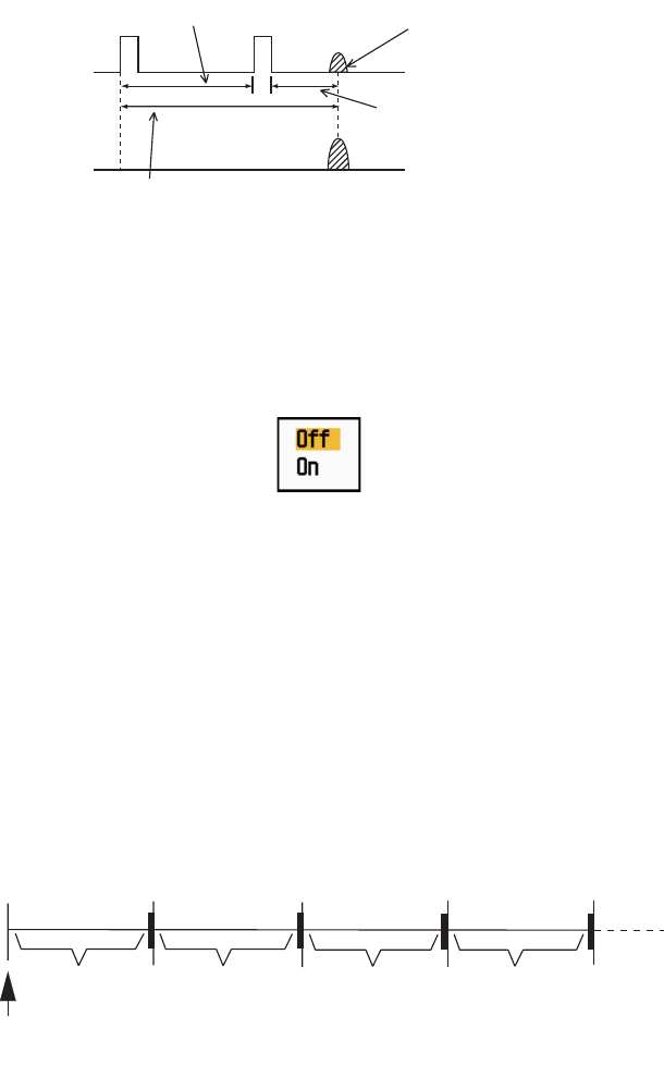
1.33 Watchman
The Watchman sounds the buzzer to tell the operator to check the radar display. The
radar transmits for one minute and then goes into standby for the selected time inter-
val. If the target alarm is active and a target is found in the alarm zone, Watchman is
cancelled, and the radar transmits continuously.
How watchman operates
In standby, the timer near the <WATCH> label at the center of the screen counts down
the remaining time until the transmission. When the set time interval has passed, the
audio alarm sounds, the timer disappears and the radar transmits for one minute. After
one minute, the audio alarm sounds and the watch alarm timer again begins the count-
down sequence.
If you press the STBY/TX key before the set time interval comes, the radar goes into
transmission.
Second-trace
echo
TX repetition
Actual range
False echo
range
ST-BY
5,10 or 20 min.
Tx
1 min.
Watchman
starts
*
* Beep sounds just before radar transmits
or goes into standby.
ST-BY
Tx *
5,10 or 20 min.
1 min.
**
1. DESCRIPTION OF OPERATION
1-41
Do the following to activate the Watchman:
1. Press the MENU key to open the menu.
2. Use the Cursorpad (S or T) to select [Alarm] and press the ENTER key.
3. Use the Cursorpad (S or T) to select [Watchman] and press the ENTER key.
Watchman options
4. Use the Cursorpad (S or T) to select [Off] or the time ([5min], [10min] or [20min])
then press the ENTER key.
5. Press the MENU key to close the menu.
1.34 Color Selections
1.34.1 Preset colors
This radar is preset with color combinations that provide best viewing in daytime,
nighttime and twilight. Below are the default color settings for each display item and
display color setting.
Display item, color design and color
1. Press the MENU key to open the menu.
2. Use the Cursorpad (S or T) to select [Brill/Color] and press the ENTER key.
3. Use the Cursorpad (S or T) to select [Display Color] and press the ENTER key.
Display Color options
4. Use the Cursorpad (S or T) to select the color design and press the ENTER key.
5. Press the MENU key to close the menu.
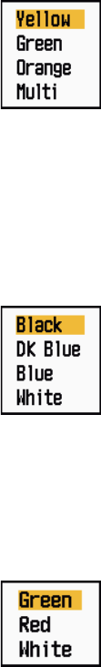
DIsplay item Day Night Twilight Custom
Characters Black Red Green Green
Range rings, marks Green Red Green Green
Echo Yellow Green Green Yellow
Background White Black Blue Black
1. DESCRIPTION OF OPERATION
1-42
1.34.2 Custom colors
The custom color design lets you select preferred echo, background, characters,
range rings and marks colors. Select [Custom] in the [Display Color] menu item (see
section 1.34.1) to use the user selected echo, background, characters, range rings
and marks colors.
1. Press the MENU key to open the menu.
2. Use the Cursorpad (S or T) to select [Brill/Color] and press the ENTER key.
3. Use the Cursorpad (S or T) to select [Echo Color] and press the ENTER key.
Echo Color options
4. Use the Cursorpad (S or T) to select an echo color and press the ENTER key.
[Multi] displays echoes in colors of red, yellow and green according to echo
strength, and [Multi] is not available in the [IEC] or [Russian-River] mode.
5. Use the Cursorpad (S or T) to select [Background Color] and press the ENTER
key.
Background Color options
6. Use the Cursorpad (S or T) to select a background color and press the ENTER
key.
7. Use the Cursorpad (S or T) to select [Character Color] and press the ENTER
key.
Character Color options
8. Use the Cursorpad (S or T) to select a character color (including range rings and
marks) and press the ENTER key.
9. Press the MENU key to close the menu.
1. DESCRIPTION OF OPERATION
1-43
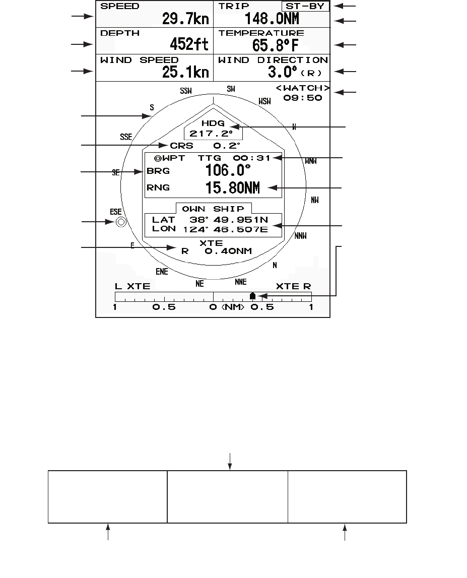
1.35 Navigation Data
1.35.1 Navigation data during standby
The navigation data is shown in standby when [STBY Display] on the [Display] menu
is set to [Nav]. Appropriate sensors are required to display the data.
Navigation data display at standby
1.35.2 Navigation data at the bottom of the screen
The navigation data is displayed at the bottom of the screen.
Navigation data
Speed Standby indication
Depth Water temperature
Trip
Wind speed Wind direction
Time until TX
in watchman
Heading indicator
Heading
Course
Time to go to
destination waypoint
Bearing to
destination
waypoint Range to go to
destination waypoint
Waypoint mark Your ship position
Cross track error
(numeric value) Cross track error
(graphic): For example,
when the indicator is off
to the right side, steer
your ship to the left to go
to the destination waypoint.
- Cursor latitude position
- Cursor longitude position
- Time to go to cursor position
Your ship position and speed - Bearing from your ship to waypoint
- Range from your ship to waypoint
- Time to go from your ship position to waypoint
LAT 34°56.123N
LON 135°34.567E
SPEED 12.3KN
LAT 34°56.123N
LON 135°34.567E
TTG 01:00
BRG
14.8°
RNG 0.876NM
TTG
00:20
OWN SHIP + CURSOR WAYPOINT
1. DESCRIPTION OF OPERATION
1-44
To show or hide the navigation data at the bottom of the screen, do the following:
1. Press the MENU key to open the menu.
2. Use the Cursorpad (S or T) to select [Display] and press the ENTER key.
3. Use the Cursorpad (S or T) to select [Data Box] and press the ENTER key.
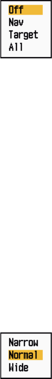
Data Box options
4. Use the Cursorpad (S or T) to select an option and press the ENTER key.
[Off]: Turn off the data display.
[Nav]: Navigation data
[Target]: ARPA and AIS target data (See section 3.8 and 4.5.)
[All]: Navigation data plus ARPA and AIS target data
5. Press the MENU key to close the menu.
1.36 Dynamic Range
You can change the dynamic range to erase unwanted weak echoes (sea reflections,
etc.). Select [Narrow], [Normal] or [Wide] depending on conditions.
1. Press the MENU key to open the menu.
2. Use the Cursorpad (S or T) to select [Echo] and press the ENTER key.
3. Use the Cursorpad (S or T) to select [Display-Dynamic] and press the ENTER
key.
Display-Dynamic options
4. Use the Cursorpad (S or T) to select [Narrow], [Normal] or [Wide] then press the
ENTER key.
[Narrow]: Erase weak echoes.
[Normal]: Normal use
[Wide]: Display weaker echoes compared to [Narrow].
5. Press the MENU key to close the menu.
1. DESCRIPTION OF OPERATION
1-45
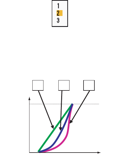
1.37 Characteristics Curve
You can change the characteristics curve to reduce unwanted weak echoes (sea re-
flections, etc.). Select [1], [2] or [3] depending on conditions when unwanted weak
echoes hide wanted targets.
1. Press the MENU key to open the menu.
2. Use the Cursorpad (S or T) to select [Echo] and press the ENTER key.
3. Use the Cursorpad (S or T) to select [Display-Curve] and press the ENTER key.
Display-Curve options
4. Use the Cursorpad (S or T) to select [1], [2] or [3] then press the ENTER key.
[1]: Reduce weak echoes.
[2]: Normal use
[3]: Display weaker echoes in stronger color compared to [1].
Display curve
5. Press the MENU key to close the menu.
321
Input level
Echo color
strength
Strong
Strong
1. DESCRIPTION OF OPERATION
1-46
1.38 Waypoint Marker
The waypoint marker shows the location of the destination waypoint set on a naviga-
tion plotter. The heading signal or course data are required. You can turn on/off the
waypoint marker as follows:
Waypoint marker
1. Press the MENU key to open the menu.
2. Use the Cursorpad (S or T) to select [Others] and press the ENTER key.
3. Use the Cursorpad (S or T) to select [WPT Mark] and press the ENTER key.
WPT Mark options
4. Use the Cursorpad (S or T) to select [Off] or [On] then press the ENTER key.
5. Press the MENU key to close the menu.
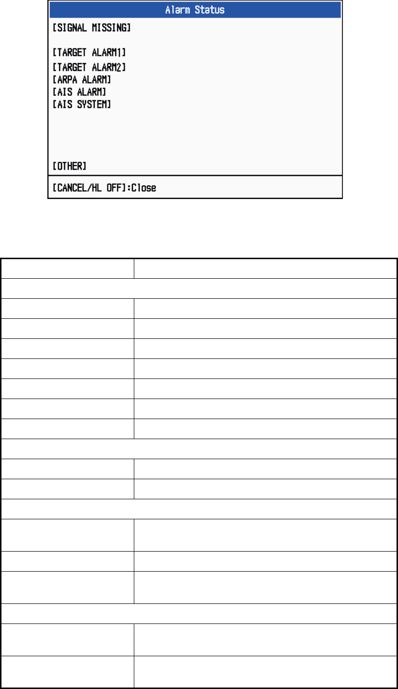
1.39 Alarm Message
The alarm status window shows all currently violated alarms.
Note: The alarm status window is not automatically displayed when an alarm occurs.
1. Press the MENU key to open the menu.
2. Use the Cursorpad (S or T) to select [Alarm] and press the ENTER key.
+
Waypoint
marker
1. DESCRIPTION OF OPERATION
1-47
3. Use the Cursorpad (S or T) to select [Alarm Status] and press the ENTER key.
Alarm Status display
4. Press the CANCEL/HL OFF key to close the alarm status display.
5. Press the MENU key to close the menu.
Alarm category Meaning
SIGNAL MISSING*
TRIGGER Trigger signal lost (only for remote display)
HEADING Heading signal lost
BEARING Bearing signal lost
GYRO AD-10 format gyro signal lost
VIDEO Video signal lost
POSITION NMEA format position data lost
NMEA_HDG NMEA format heading signal lost
TARGET ALARM1(2)
IN An echo has entered a target alarm zone.
OUT An echo has exited a target alarm zone.
ARPA ALARM
COLLISION CPA and TCPA of an ARPA target is less than CPA and
TCPA alarm settings.
LOST Acquired ARPA target becomes lost.
PROXIMITY The range to an ARPA target is less than the user-set
proximity alarm range.
AIS ALARM
COLLISION CPA and TCPA of an AIS target is less than CPA and
TCPA alarm settings.
PROXIMITY The range to an AIS target is less than the user-set prox-
imity alarm range.
TRIGGER HEADING BEARING GYRO
VIDEO POSITION NMEA_HDG
IN OUT
IN OUT
COLLISION LOST PROXIMITY
COLLISION PROXIMITY
TX ANT CH1 CH2 CH70 FAIL MKD
EPFS L/L SOG COG HDG ROT
OVER_TEMP
1. DESCRIPTION OF OPERATION
1-48
*: Have a qualified technician check the equipment.
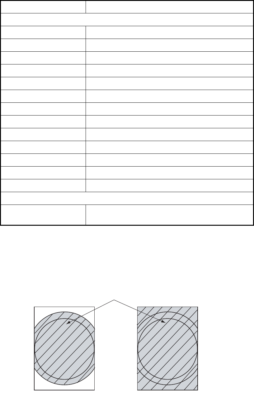
1.40 Echo Area
You can select the display area from [Normal] or [Full Screen].
Echo area
1. Press the MENU key to open the menu.
2. Use the Cursorpad (S or T) to select [Display] and press the ENTER key.
AIS SYSTEM*
TX TX stopped or TX error
ANT Antenna VSWR problem
CH1 TDM2 RX1 board problem
CH2 TDM2 RX2 board problem
CH70 RX channel 70 problem
FAIL System failure
MKD Minimum input device lost
EPFS Navigator (GPS, etc.) problem
L/L Position data lost
SOG Speed data lost
COG Course data lost
HDG Heading data lost
ROT Rate of turn data lost
OTHER*
OVER_TEMP The temperature of the equipment is more than the spec-
ified value.
Alarm category Meaning
Normal Full Screen
Area in which echoes are displayed

1. DESCRIPTION OF OPERATION
1-49
3. Use the Cursorpad (S or T) to select [Echo Area] and press the ENTER key.
Echo Area options
4. Use the Cursorpad (S or T) to select [Normal] or [Full Screen] then press the EN-
TER key.
5. Press the MENU key to close the menu.
1.41 Initial Sub Menu
The [Initial] sub menu in the [System] menu contains the items which allow you to cus-
tomize your radar to meet your needs.
1.41.1 How to open the Initial sub menu
1. Press the MENU key to open the menu.
2. Use the Cursorpad (S or T) to select [Initial] and press the ENTER key.
Initial sub menu
1.41.2 Description of Initial sub menu
[Key Beep]: When a key is pressed, a beep sounds. You can turn on or off this beep.
[Offcenter Speed]: Set the speed of your ship to calculate amount of your ship’s off-
center. The setting range is 1-99 (kn).
[Compass Type]: Select the type of bearing sensor connected to the radar; [True]
(gyrocompass, satellite compass) or [Magnetic] (magnetic compass).
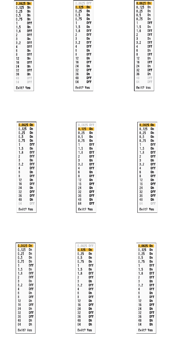
[Range Preset]: You can select the radar ranges. Select a range and press the EN-
TER key to switch on and off. At least two ranges must be turned on. The maximum
range available depends on the radar model. 0.0625 is not available in KM (kilome-
ters).
1. DESCRIPTION OF OPERATION
1-50
NM (nautical miles) KM (kilometers) SM (statute miles)
Available ranges for MODEL 1835
NM (nautical miles) KM (kilometers) SM (statute miles)
Available ranges for MODEL 1935
NM (nautical miles) KM (kilometers) SM (statute miles)
Available ranges for MODEL 1945
1. DESCRIPTION OF OPERATION
1-51
[Wind Direction]: Wind direction is shown as [Apparent] or [True].
[NMEA Port 1]: Set the baud rate of the equipment connected to Port 1 ([Auto],
[4800], or [38400] (bps)). [Auto] provides automatic detection of baud rate from 4800,
9600, 19200 or 38400 (bps).
[NMEA Port 2]: Same function as Port 1 but for Port 2.
[NMEA Mixing Out]: Data input to Port 1 may be output from Port 2 mixed with data
output to Port 2. Select [On] to use this feature.
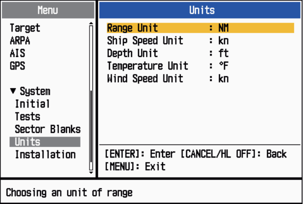
1.42 Units Sub Menu
You can select the unit of measurement for range, ship speed, depth, temperature and
wind speed on the [Units] sub menu in the [System] menu. You can not open this sub
menu in normal operation. To open this menu, select [Units], hold the CANCEL/HL
OFF key and press the MENU key five times.
Units sub menu
[Range Unit]: NM, KM, SM
[Ship Speed Unit]: kn, km/h, mph
[Depth Unit]: m, ft, fa, pb, HR
[Temperature Unit]: °C, °F
[Wind Speed Unit]: kn, km/h, mph, m/s
1. DESCRIPTION OF OPERATION
1-52
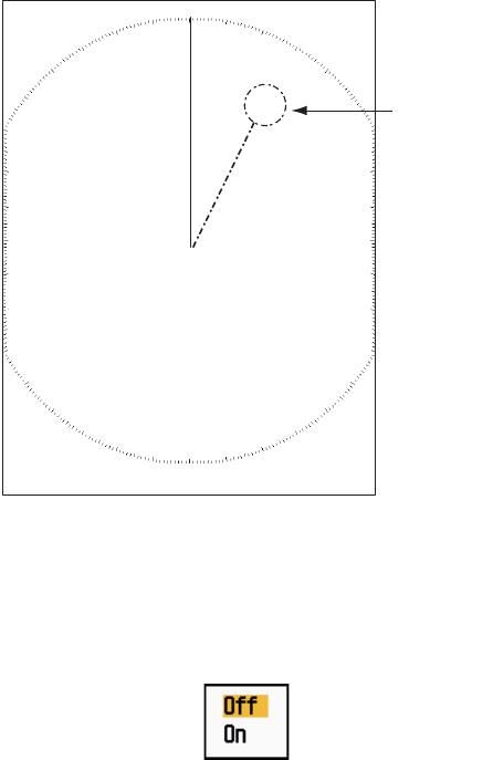
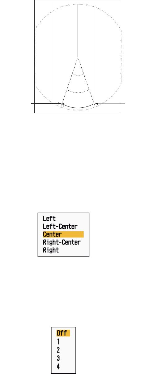
1.43 Sector Blank
You must prevent the transmission in some areas to protect passengers and crew
from microwave radiation. Also, if the reflections of echoes from the mast appear on
the screen, you must prevent the transmission in that area. You can set two sectors.
1. Press the MENU key to open the menu.
2. Use the Cursorpad (S or T) to select [Sector Blanks] and press the ENTER key.
3. Use the Cursorpad (S or T) to select [Sect-Blank 1 (or 2) Status] and press the
ENTER key.
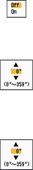
Sect-Blank Status options
4. Use the Cursorpad (S or T) to select [On] and press the ENTER key.
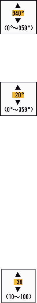
5. Use the Cursorpad (S or T) to select [Sect-Blank 1 (or 2) Start] and press the
ENTER key.
Sect-Blank Start setting window
6. Use the Cursorpad (S or T) to set the start point of the sector and press the EN-
TER key.
7. Use the Cursorpad (S or T) to select [Sect-Blank 1 (or 2) End] and press the EN-
TER key.
Sect-Blank End setting window
8. Use the Cursorpad (S or T) to set the end point of the sector and press the EN-
TER key.
Note 1: You can not set the sector more than 180 degrees.
Note 2: You can not set the total width of sector 1 and sector 2 more than 270
degrees.
9. Press the MENU key to close the menu.
As shown in the following illustration, dashed lines mark the start and end points of the
sector.
1. DESCRIPTION OF OPERATION
1-53
Sector blank
1.44 Other Menu Items
This section describes the menu items not previously described.
1.44.1 Menu items on the [Brill/Color] menu
[View Position]: You can select the angle from where you see the screen.
View Position options
[Menu Transparency]: You can select the degree of transparency of the menu win-
dow so the menu window does not hide the echo display. [4] is the greatest degree of
transparency. [Off] functions to hide the echo display behind the menu window com-
pletely.
Note: Alpha blending technology is used for transparency effects.
Menu Transparency options
[Echo Color Mode]: You can select the color palette from [System] or [Custom]. [Sys-
tem] is the pre-set color palette and [Custom] is the color palette you can set yourself.
This function is not available in the [IEC] or [Russian-River] mode.
+
Area of no
transmission
Start bearing
of sector
End bearing
of sector
1. DESCRIPTION OF OPERATION
1-54
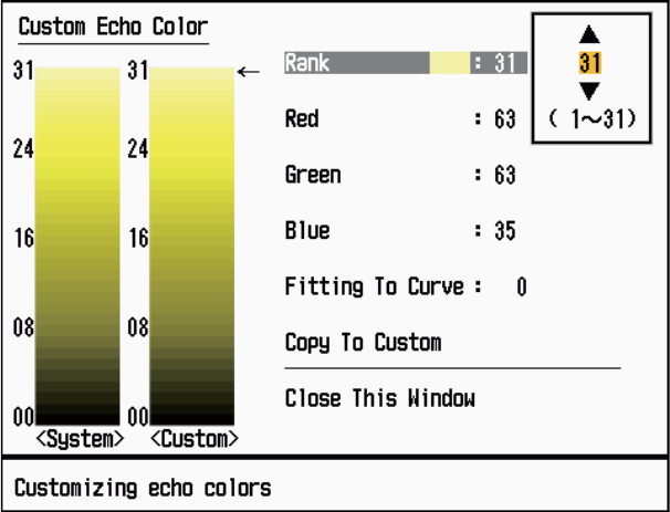
[Custom Echo Color]: You can customize the echo color with the following two meth-
ods. This function is not available in the [IEC] or [Russian-River] mode.
Custom Echo Color setting window
Method 1: 1) Select the echo rank to change on the [Rank] (setting range: 1 - 31).
2) Set the RGB values for selected echo rank on the [Red], [Green] and
[Blue] (setting range: 0 - 63).
Method 2: 1) Select 31 on the [Rank].
2) Set the RGB values for 31 echo rank on the [Red], [Green] and [Blue]
(setting range: 0 - 63).
3) Interpolate the RGB values between the maximum rank and minimum
rank on the [Fitting To Curve] with the following curves (setting range:
-20 to 20).
Setting range > 0: Logarithmic curve, useful to emphasize the weak
echoes.
Setting range = 0: Straight line
Setting range < 0: Exponential curve, useful to emphasize the strong
echoes.
[Copy To Custom]: Copy the color palette from [System] to [Custom].
1. DESCRIPTION OF OPERATION
1-55
1.44.2 Menu items on the [Display] menu
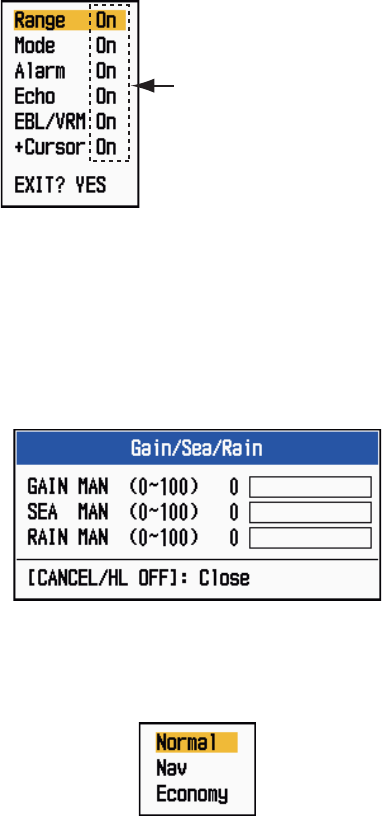
[Base Text Display]: You can select on/off for the text indications of the following
items on the display. The settings on this function are used when you set [Echo Area]
to [Full Screen] on the [Display] menu. This function is not available in the [IEC] or
[Russian-River] mode.
Base Text Display options
The text indications set to off appear when you operate any key. The indications dis-
appear when there is no key operation for 10 seconds.
[Gain/Sea/Rain Bar]: Open the Gain/Sea/Rain indicator. You can check the current
settings.
Gain/Sea/Rain Bar
[STBY Display]: Set the function of the standby display.
STBY Display options
[Normal]: Display "ST-BY" at the screen center.
[Nav]: Display navigation data.
[Economy]: Turn off the backlight of the LCD. The radar must be switched from
TX to ST-BY to activate this mode.
Press the ENTER key
to change between
on and off.
1. DESCRIPTION OF OPERATION
1-56
1.44.3 Menu items on the [Echo] menu
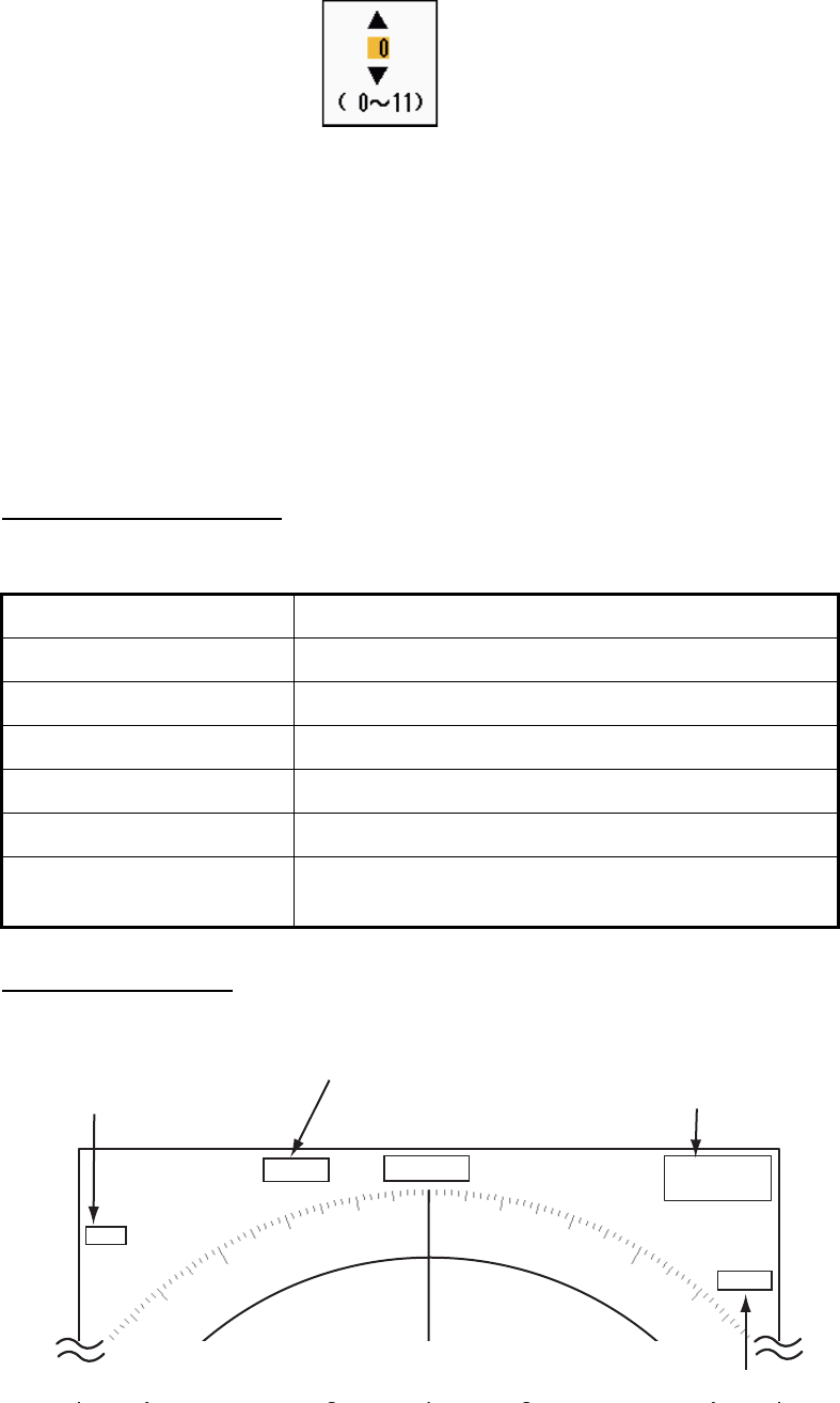
[Color Erase]: Erase the lower echo color whose level is set here. Set a large value
to display only the stronger echoes.
Color Erase setting window
1.45 Remote Display
You can use this radar as a remote display when you set [Input Source] to [Slave] on
the [Installation] sub menu. When this setting is done, the menu and display change
as described below. To display the radar image on the remote display, transmit from
the main radar.
Note: The message "Please turn to STBY-mode when you change this setting." ap-
pears when you switch the mode in transmission.
Unavailable menu items
The menu items are not available with the remote display as shown in the table.
Display appearance
The display changes as shown in the following illustration.
Transmitting or standby display indications for remote display
Menu Unavailable menu item(s)
[Echo] [Pulse Length], [2nd Echo Rejector]
[Custom 1, 2, 3] [Pulse Length]
[Alarm] [Watchman]
[Tuning] All menu items are inoperative.
[System] - [Sector Blanks] All menu items are inoperative.
[System] - [Installation] [Antenna Rotation], [MBS Adjust],
[Auto Install Setup], [Total TX Time]
HDG
OFFCENT(M)
Shown when display
unit functions as
remote display.
Tuning indicator
is not displayed.
Pulselength
is not displayed.
WTC is not displayed.
SLAVE
0.5
NM
0.125
CS1
H UP
TRAIL(T)
06MIN
ALM1_ACK
ALM2_OUT
359.9°

1. DESCRIPTION OF OPERATION
1-57
Items unavailable with Function key F1, F2 and F3
• [Pulse Length] ([Echo] menu)
• [2nd Echo Rejector] ([Echo] menu)
• [Watchman] ([Alarm] menu)
• [Tuning Mode] ([Tuning] menu)
Total TX time indication
The total TX time (TX TIME XXXXXX.XH) does not appear on the diagnostic test or
on the Normal standby display.
1. DESCRIPTION OF OPERATION
1-58
This page is intentionally left blank.

2-1
2. DESCRIPTION OF RADAR
2.1 General
2.1.1 Minimum and maximum ranges
Minimum range
The minimum range is defined by the shortest distance at which, using a scale of
0.0625 or 0.125 nm, a target having an echoing area of 10 m2 is shown separate from
the point representing the antenna position.
The minimum range depends on the pulselength, antenna height, and signal process-
ing (like main bang suppression and digital quantization). Use a shorter range scale
as far as it gives favorable definition or clarity of picture. This MODEL 1835 series
meets the requirements of IEC 62252 5.14.1 (Class A).
Maximum range
The maximum detection range, Rmax, varies depending on the height of the antenna,
the height of the target above the sea, the size, shape and material of the target, and
the atmospheric conditions.
Under normal atmospheric conditions, the maximum range is equal or a little shorter
than the optical horizon. The radar horizon is longer than the optical one by approxi-
mately 6% because of the diffraction property of the radar signal. The Rmax is shown
in the following formula.
If the height of the antenna is 9 m and the height of the target is 16 m, the maximum
radar range is;
Note: The detection range is reduced by precipitation (which absorbs the radar sig-
nal).
R
max
= 2.2 x ( h1 + h2)
where R
max
: radar horizon (nautical miles)
h1: antenna height (m)
h2: target height (m)
Radar horizon
Optical horizon
R
max
= 2.2 x ( 9 + 16) = 2.2 x (3 + 4) = 15.4 nm
2. DESCRIPTION OF RADAR
2-2
2.1.2 Radar resolution
The bearing resolution and range resolution are important in radar resolution.
Bearing resolution
The bearing resolution is the ability of the radar to display the echoes received from
two targets at the same range as the separate echoes. The bearing resolution is pro-
portional to the antenna length and the wavelength.
Range resolution
The range resolution is the ability to display the echoes received from two targets on
the same bearing as separate echoes. The range resolution is determined by only
pulselength.
The test targets used to determine the range and bearing resolution are radar reflec-
tors that have an echoing area of 10 m2.
Targets
Targets
Horizontal beam width
Horizontal beam width
Separate
target echoes
Overlapped
target echoes
Separate
target echoes
Overlapped
target echoes
Targets
Targets
Overlapping
Transmission
pulse
Transmission
pulse
2. DESCRIPTION OF RADAR
2-3
2.1.3 Bearing accuracy
One of the most important features of the radar is how accurately the bearing of a tar-
get can be measured. The accuracy of bearing measurement depends on the narrow-
ness of the radar beam. The bearing is taken relative to the heading of the ship.
Correct adjustment of the heading line at installation is important to get accurate bear-
ings. To minimize the error when you measure the bearing of a target, put the target
echo at the extreme position on the screen by selecting a suitable range.
2.1.4 Range measurement
Measurement of the range to a target is important function of the radar. There are
three methods of measuring range: the fixed range rings, the Variable Range Marker
(VRM), and the cursor (if set to measure range and bearing). The fixed range rings
appear on the screen with a given interval and provide a rough estimate of the range
to a target. The diameter of VRM is increased or decreased so that the marker touches
the inner edge of the target (see section 1.15.2). The VRM is a more accurate range
measurement than the fixed range rings. For cursor, see section 1.13.
2.2 False Echoes
The echo signals can appear on the screen at positions where there is no target or
disappear when there are targets. These false echoes are shown below.
2.2.1 Multiple echoes
Multiple echoes occur when a transmitted pulse returns from a solid object like a large
ship, bridge, or breakwater. A second, a third or more echoes can be seen on the dis-
play at double, triple or other multiples of the actual range of the target as shown be-
low. You can reduce and remove the multiple reflection echoes with the A/C SEA
control.
Multiple echoes
Y
our ship
Target
True
echo
Multiple
echo
2. DESCRIPTION OF RADAR
2-4
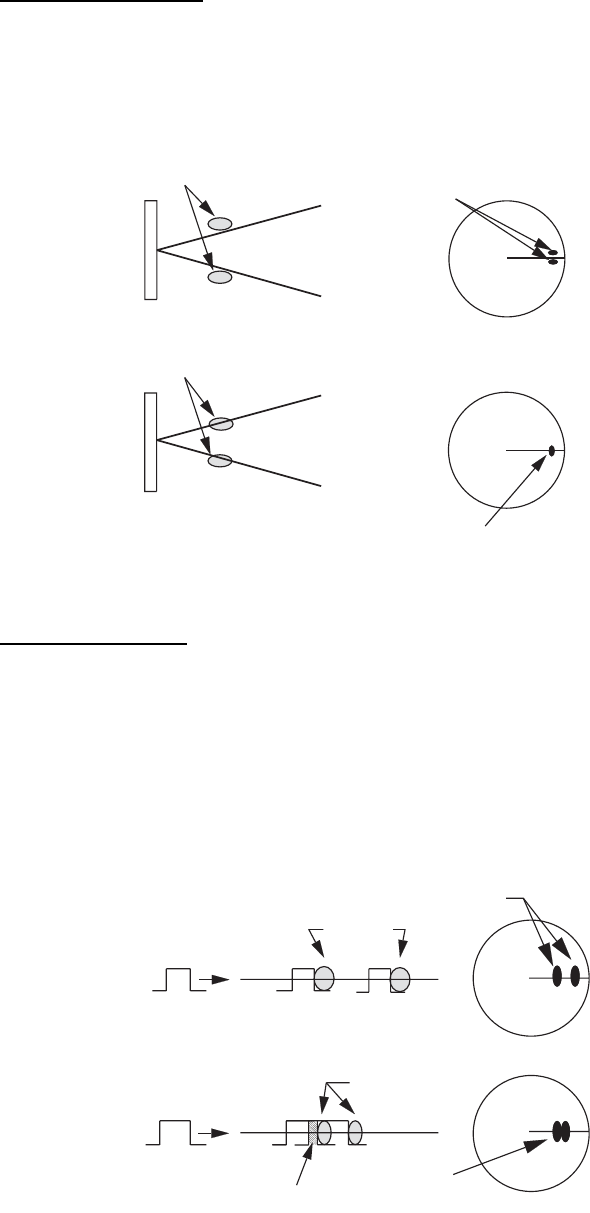
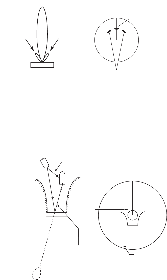
2.2.2 Sidelobe echoes
When the radar pulse is transmitted, some radiation escapes on each side of the
beam, called "sidelobes”. If a target is where a target can be detected by the sidelobes
as well as the mainlobe, the side echoes can be shown on both sides of the true echo
at the same range. Sidelobes show normally only on short ranges and from strong tar-
gets. You can reduce the sidelobes with the A/C SEA control.
Sidelobe echoes
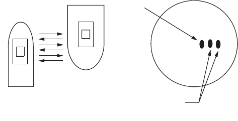
2.2.3 Virtual image
A large target close your ship can appear at two positions on the screen. One of them
is the true echo reflected by the target. The other is a false echo which is caused by
the mirror effect of a large object on or close your ship as shown in the following figure.
If your ship comes close to a large metal bridge, for example, a false echo can tempo-
rarily appear on the screen.
Virtual image
True target
Mainlobe (beam)
Antenna
Sidelobe
False echoes by sidelobes
Sidelobe
True
echo
False
echo
Your ship
Target ship
Mirror image
of target ship
Bridge
Route for direct reflection
Route for
indirect reflection
2. DESCRIPTION OF RADAR
2-5
2.2.4 Shadow sector
Funnels, stacks, masts, or derricks near the antenna interrupt the radar beam, and a
non-detecting sector can occur. Targets can not be detected within this sector.
Shadow sector
Wharf and its echo
Large ship
Shadow sector
occurs because
wharf is hidden
behind ship.
Size of blind sector depends
on size of obstruction and range.
Radar position Radar position Wharf and its echo
Shadow sector occurs
because obstruction
(like mast) is in path
of radar beam.
2. DESCRIPTION OF RADAR
2-6
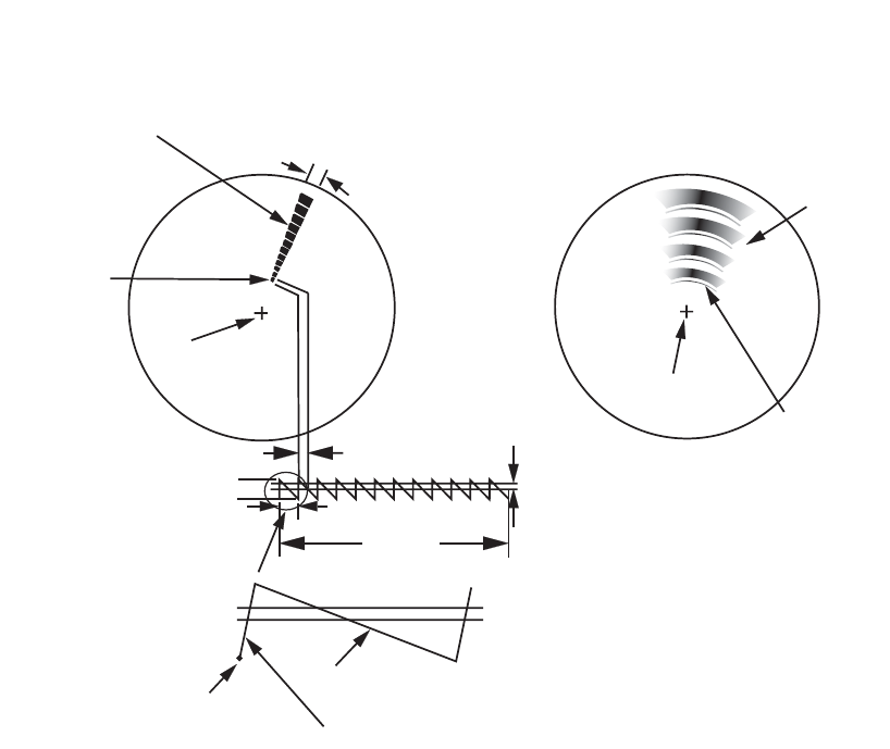
2.3 SART (Search and Rescue Transponder)
2.3.1 SART description
When any X-band radar reaches within a range of approximately 8 nm, a Search and
Rescue Transponder (SART) sends a response to the radar signal. The transmitter
signal of response is 12-sweeps signal between 9,500 MHz to 9,200 MHz. The time
of slow sweep signal is 7.5 μs and the time of fast sweep signal is 0.4 μs. When the
radar receives this SART signal, a line of 12 dots appears. When the position of SART
is distant, the radar display shows only slow sweep signals like the illustration of
screen A.
When the radar reaches the SART within approximately 1 nm, the radar display can
also show the 12 responses of fast sweep signals like the illustration of screen B. The
position of the SART is the closest position of the radar echoes.
SART echo
9500 MHz
9200 MHz
Radar antenna
beamwidth
Screen A: When SART is distant Screen B: When SART is close
Echo from SART
Position of
SART
Your ship
position Your ship
position
SART mark
length Radar receiver
bandwidth
Sweep time
7.5 µs 95 µs
Sweep start High speed sweep signal
Low speed sweep signal
24 NM 1.5 NM
Position o
f
SART
Echo from
SART
Lines of 12 dots are displayed in
concentric arcs.

2. DESCRIPTION OF RADAR
2-7
2.3.2 General remarks on receiving SART
SART range errors
When the SART is at a range greater than approximately 1 nm, the first dot is dis-
played at 0.64 nm beyond the true position of the SART. When the range closes so
that the fast sweep responses are seen also, the first range echoes are displayed at
150 m beyond the true position.
Range scale
When you find the SART position, do as follows:
1. Use the RANGE key to set the range scale to 6 nm or 12 nm.
2. Turn off [A/C Auto].
3. Turn off [Int Rejector].
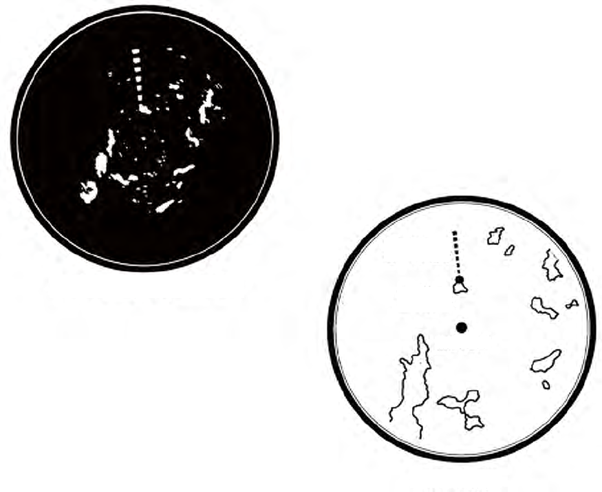
SART display
To display only the SART echo clearly on the radar screen, reduce the tuning on man-
ual mode. The normal radar echoes get weak, however, the SART echoes remain.
Your ship comes close to the SART, the arc for the SART display becomes larger.
Most of the radar screen becomes fuzzy. Adjust the A/C SEA and GAIN controls to
display the necessary screen.
2. DESCRIPTION OF RADAR
2-8
2.4 RACON
A RACON is a radar beacon which emits radar-receivable signals in the radar frequen-
cy spectrum (X- or S-band). There are several signal formats; in general, the RACON
signal appears on the radar screen as a rectangular echo originating at a point just
beyond the position of the radar beacon. It has a Morse coded pattern. Note that the
position on the radar display is not accurate.
RACON
Echoes on the radar screen
Echo description
Your ship position
RACON signal
RACON station
3-1
3. ARPA OPERATION
The Automatic Radar Plotter ARP-11 (option) manually or automatically acquires and
tracks ten targets. Once a target is acquired automatically or manually, a target is au-
tomatically tracked within 0.1 to 16 nm.
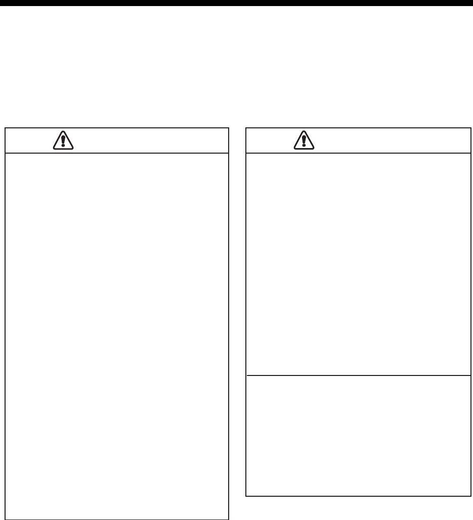
3.1 Precautions for Use
3.2 Controls for Use with ARPA
ENTER: Acquire cursor-selected target. Display data for tracked target (in the data
box at the bottom of the screen).
CANCEL/HL OFF: Remove data of cursor-selected tracked target from the data box.
Stop tracking the cursor-selected target (when its data is not displayed in the data
box).
MENU: Access the [Target] and [ARPA] menus for ARPA operations.
Cursorpad: Select a target to acquire (or cancel the tracking). Select a target to show
(or remove) target data.
Do not depend on one navigation device
for the navigation of the ship. The
navigator must check all aids available
to confirm position. Electronic aids are
not a replacement for basic navigation
principles and common sense.
· The ARPA automatically tracks an
automatically or manually acquired radar
target and calculates its course and
speed, indicating them by a vector. Since
the data from the auto plotter depend on
the selected radar targets, the radar must
be optimally tuned for use with the auto
plotter, to ensure required targets will not
be lost or unnecessary targets like sea
returns and noise will not be acquired
and tracked.
· A target is not always a landmass, reef,
ship, but can be returns from the sea
surface and clutter. As the level of clutter
changes with the environment, the
operator must correctly adjust the A/C
SEA, A/C RAIN and GAIN controls so
that the target echoes do not disappear
from the radar screen.
The plotting accuracy and response of
this ARPA meets IMO standards.
The tracking accuracy is affected by the
following:
· The tracking accuracy is affected by
course change. One to two minutes is
required to restore vectors to full
accuracy after a sudden course change.
(The actual amount depends on
gyrocompass specifications.)
· The amount of tracking delay is inversely
proportional to the relative speed of the
target. Delay is on the order of 15-30
seconds for high relative speed; 30-60
seconds for low relative speed.
The display accuracy is affected by the
following:
· Echo intensity
· Pulse width of radar transmission
· Radar bearing error
· Gyrocompass error
· Course change (your ship or target)
CAUTION
CAUTION
CAUTION
CAUTION
3. ARPA OPERATION
3-2
3.3 ARPA Display On/Off
You can turn the ARPA display on or off. The system continuously tracks ARPA tar-
gets regardless of this setting.
1. Press the MENU key to open the menu.
2. Use the Cursorpad (S or T) to select [ARPA] and press the ENTER key.
3. Use the Cursorpad (S or T) to select [Display] and press the ENTER key.
ARPA-Display options
4. Use the Cursorpad (S or T) to select [Off] or [On] then press the ENTER key.
5. Press the MENU key to close the menu.
3.4 How to Acquire and Track the Targets
Ten targets are acquired and tracked manually or automatically.
3.4.1 Manual acquisition
You can acquire up to ten ARPA targets. When the automatic acquisition ([Auto Ac-
quisition] on the [ARPA] menu) is set to on, you can manually acquire up to five tar-
gets.
1. Use the Cursorpad to put the cursor on the target to acquire.
2. Press the ENTER key.
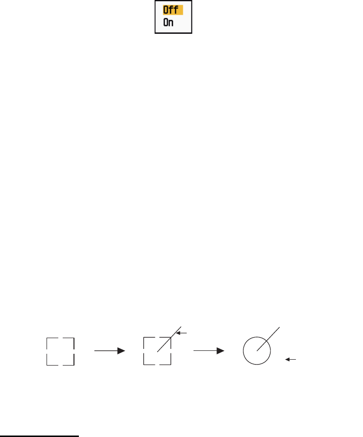
The ARPA target symbol changes over time as below. A vector which indicates the
motion direction of the target appears approximately one minute after acquisition.
ARPA target symbol
Target number
River and Sea (Non-IEC system): An acquired target gets the youngest unused
number. When a target is lost and disappears from the number list, the next acquired
target takes the number of that lost target (ie; In a 5 target list, if the target 2 is lost, the
next acquired target takes the number of target 2).
IEC and Russian-River (IEC system): An acquired target gets the youngest unused
number. When a target is lost and disappears from the number list, the next acquired
target takes the next sequential number until reaching a maximum 10. If the target
number reaches a maximum 10, the next acquired target takes the number of a pre-
viously lost target.
A
t acquisition 1 min. after
acquisition
3 min. after
acquisition
01 Target number
Vector
01
01
3. ARPA OPERATION
3-3
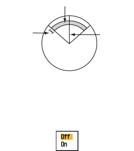
3.4.2 Automatic acquisition
When you set an automatic acquisition area, the ARPA can acquire up to five targets
automatically.
The automatic acquisition area is 2.0 to 2.5 nm in range and ±45° on either side of the
heading line in bearing. When you change the automatic acquisition to manual acqui-
sition, targets being tracked in automatic acquisition are continuously tracked.
Automatic acquisition area
1. Press the MENU key to open the menu.
2. Use the Cursorpad (S or T) to select [ARPA] and press the ENTER key.
3. Use the Cursorpad (S or T) to select [Auto Acquisition] and press the ENTER
key.
Auto Acquisition options
4. Use the Cursorpad (S or T) to select [On] and press the ENTER key.
5. Press the MENU key to close the menu.
3.5 How to Stop the Tracking of ARPA Target
When ten targets have been acquired, no more acquisition occurs unless targets are
cancelled. If you acquire additional targets, you must cancel one or more individual
targets, or all targets. Use one of the following procedures.
3.5.1 How to stop the tracking of selected targets
1. Use the Cursorpad to put the cursor on the target to cancel the tracking.
2. Press the CANCEL/HL OFF key to cancel the tracking and erase the ARPA sym-
bol. The unit beeps twice and the symbol is erased from the screen.
3.5.2 How to stop the tracking of all targets
1. Press the MENU key to open the menu.
2. Use the Cursorpad (S or T) to select [ARPA] and press the ENTER key.
Automatic acquisition area
45° port 45° starboard
2.0 - 2.5 nm Heading line
3. ARPA OPERATION
3-4
3. Use the Cursorpad (S or T) to select [All Cancel] and press the ENTER key.
All Cancel options
4. Use the Cursorpad (S) to select [Yes] and press the ENTER key. All symbols are
erased from the screen and the long beep sounds.
5. Press the MENU key to close the menu.
3.6 Vector Attributes
3.6.1 What is a vector?
A vector is a line extending from a tracked target. A vector shows speed and course
of the target. The top of a vector shows estimated position of the target after the se-
lected vector time elapses. If you extend the vector length (time), you can evaluate the
risk of collision with any target.
When vector time is 15 minutes
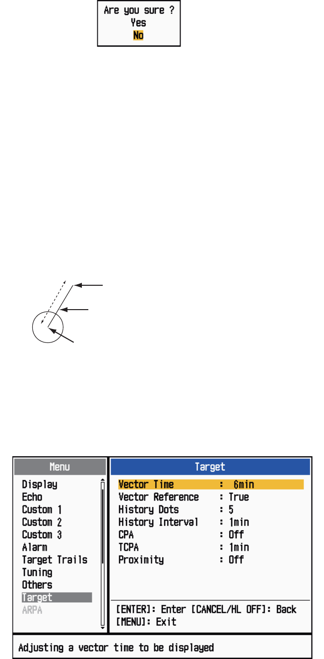
3.6.2 Vector time and vector reference
1. Press the MENU key to open the menu.
2. Use the Cursorpad (S or T) to select [Target] and press the ENTER key.
Target menu
Vector
Current position of the target
Vector time
Vector time
Vector time Predicted position of the target in 15 minutes late
r
3. ARPA OPERATION
3-5
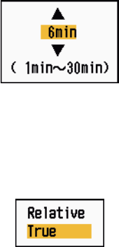
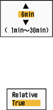
3. Use the Cursorpad (S or T) to select [Vector Time] and press the ENTER key.
Vector Time setting window
4. Use the Cursorpad (S or T) to select time and press the ENTER key.
5. Use the Cursorpad (S or T) to select [Vector Reference] and press the ENTER
key.
Vector Reference options
6. Use the Cursorpad (S or T) to select [Relative] or [True] then press the ENTER
key. This function is not activate for [IEC] or [Russian-River] purpose. The mode
is set to [True].
[Relative]: Other ships’ vectors are displayed relative to your ship. This mode
helps find targets on a collision course. If a ship is on a collision course with your
ship, the vector of a ship points toward your ship position.
[True]: Your ship’s and other ships’ vectors are displayed at their true motions.
This mode helps discriminate between moving and stationary targets.
7. Press the MENU key to close the menu.
Note: The functions of the [Target] menu are shared by ARPA and AIS.
3.6.3 Vector of your ship
The vector of your ship is shown as an arrow from your ship position. The vector of
your ship is shown on the following conditions:
• Connect ARP-11 (option)
• Select [True] on the menu item [Vector Reference] on the [Target] menu
• Independent of on/off on the menu item [Display] on the [ARPA] menu
Note: The vector of your ship is shown in the same color as the ARPA symbol color
(see section 3.12).
3. ARPA OPERATION
3-6
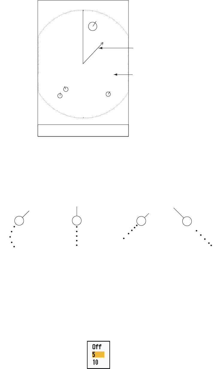
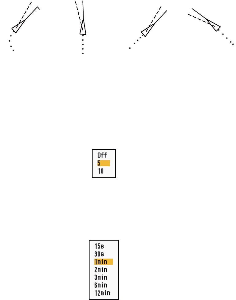
3.7 History Display (target past position)
This radar can display time-spaced dots (maximum ten dots) that mark the past posi-
tions of any tracked ARPA target. You can evaluate actions of a target by the spacing
between dots. Below are examples of dot spacing and target movement.
Target movement and history display
You can select the number of history dots to display and the time interval to display
the history dots.
1. Press the MENU key to open the menu.
2. Use the Cursorpad (S or T) to select [Target] and press the ENTER key.
3. Use the Cursorpad (S or T) to select [History Dots] and press the ENTER key.
History Dots options
4. Use the Cursorpad (S or T) to select number of history dots to display (5 or 10)
or select [Off] to turn off the history display.
5. Press the ENTER key.
+
Vector of
your ship
01
Data box
02
Cursor
03
04
(a) Ship turning (b) Ship running
straight (c) Ship reduced
speed (d) Ship increased
speed
3. ARPA OPERATION
3-7
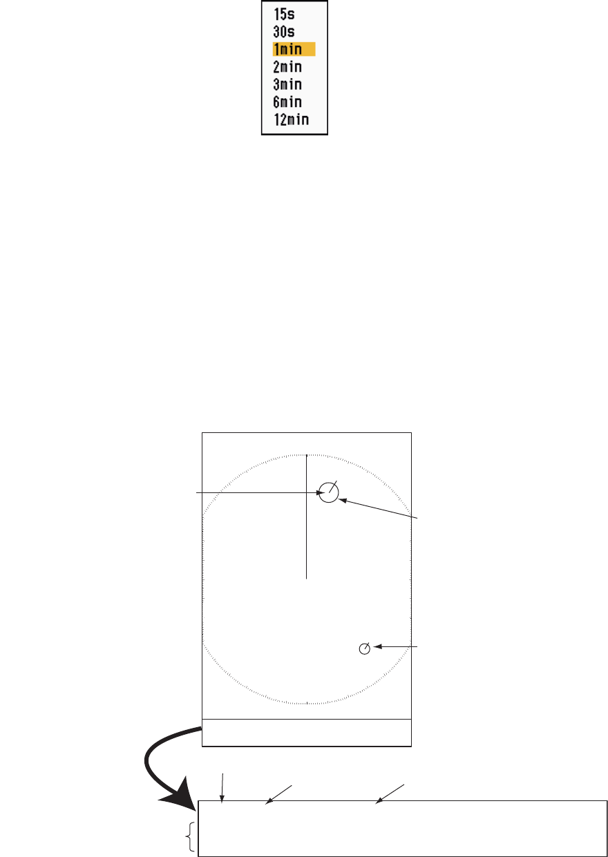
6. Use the Cursorpad (S or T) to select [History Interval] and press the ENTER key.
History Interval options
7. Use the Cursorpad (S or T) to select the time interval and press the ENTER key.
8. Press the MENU key to close the menu.
3.8 ARPA Target Data
You can show the data for a tracked ARPA target in the data box at the bottom of the
screen. To display ARPA target data, the menu item [Display] on the [ARPA] menu
must be set for [On] and the menu item [Data Box] on the [Display] menu must be set
for [Target] or [All].
1. Use the Cursorpad to put the cursor on an ARPA target.
2. Press the ENTER key to show the data of the target.
ARPA target data
The symbol for the selected ARPA target is enlarged double to distinguish from other
symbols.
To remove the data of a target from a data box, put the cursor on its target symbol and
press the CANCEL/HL OFF key.
TRUE 05:00 <ARPA> No. 01
BRG
53.7°T
RNG 2.987NM CRS 350.4° SOG 23.45KN
CPA 1.65NM TCPA
06:14
Vector reference
Vector time Target no.
Bearing, range, course, speed
CPA, TCPA
+
ARPA target
selected for
data display
01
ARPA target
Data box
02
Cursor
3. ARPA OPERATION
3-8
3.9 CPA/TCPA Alarm
Set CPA (Closest Point of Approach) alarm range and TCPA (predicted Time to CPA)
alarm time to alert you to targets that can be on a collision course. When CPA and
TCPA of any ARPA target become less than the preset CPA and TCPA alarm settings,
the audio alarm sounds. The alarm message "COLLISION" appears. The target sym-
bol changes to a dangerous target symbol (triangle) and flashes with its vector. You
can stop the audio alarm with any key. The flashing of the triangle stops when the
tracked ARPA target is not in the CPA and TCPA alarm setting. The ARPA continu-
ously monitors CPA and TCPA of all tracked ARPA targets.
Dangerous target symbol
This feature helps identify targets that can be on a collision course. Correctly adjust
GAIN, A/C SEA, A/C RAIN and other radar controls.
1. Press the MENU key to open the menu.
2. Use the Cursorpad (S or T) to select [Target] and press the ENTER key.
3. Use the Cursorpad (S or T) to select [CPA] and press the ENTER key.
CPA options
4. Use the Cursorpad (S or T) to select CPA distance and press the ENTER key.
CAUTION
CAUTION
Do not depend on the CPA/TCPA alarm
as the only method to detect the risk of
collision. The navigator is not released
of the responsibility to keep visual caution
for collision situations, whether or not the
radar or other plotting aid is in use.

3. ARPA OPERATION
3-9
5. Use the Cursorpad (S or T) to select [TCPA] and press the ENTER key.
TCPA options
6. Use the Cursorpad (S or T) to select TCPA and press the ENTER key.
7. Press the MENU key to close the menu.
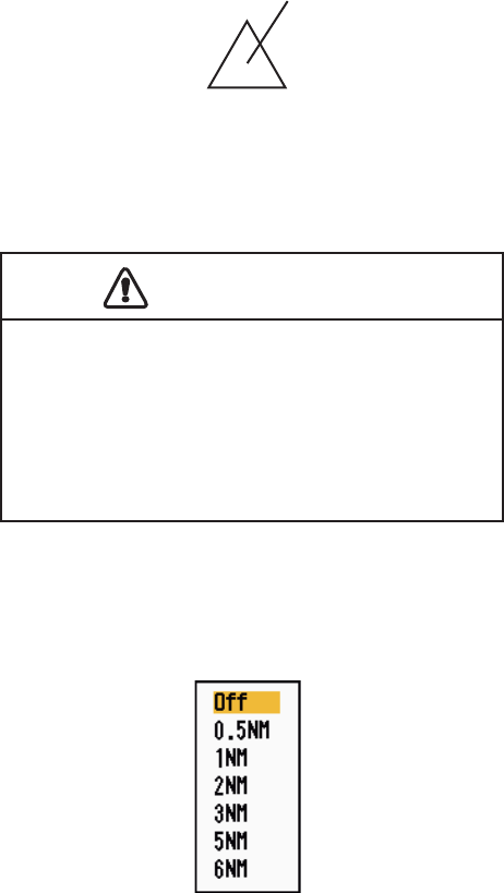
3.10 Proximity Alarm
The proximity alarm alerts you when an ARPA target is within the range you set. The
audio alarm sounds and the alarm message "PROXIMITY" appears. The target sym-
bol changes to a dangerous target symbol (triangle, see section 3.9) and flashes with
its vector. Press any key to stop the audio alarm. The flashing continues until the tar-
get is not within the range set, the alarm range is changed to exclude the target, or the
proximity alarm is deactivated.
1. Press the MENU key to open the menu.
2. Use the Cursorpad (S or T) to select [Target] and press the ENTER key.
3. Use the Cursorpad (S or T) to select [Proximity] and press the ENTER key.
Proximity options
4. Use the Cursorpad (S or T) to select the range and press the ENTER key.
5. Press the MENU key to close the menu.

3. ARPA OPERATION
3-10
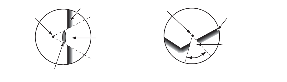
3.11 Lost Target
When the system detects a lost target, the audio alarm sounds and the alarm mes-
sage "LOST" appears. The target symbol becomes a flashing square like the following
illustration. When the system detects the target again, the target symbol becomes a
normal symbol.
Lost target symbol
To erase a lost target symbol, put the cursor on the symbol and press the CANCEL/
HL OFF key. If you leave a lost target symbol flashing, the symbol disappears after
one minute.
You can remove all lost ARPA targets from the screen as follows:
1. Press the MENU key to open the menu.
2. Use the Cursorpad (S or T) to select [ARPA] and press the ENTER key.
3. Use the Cursorpad (S or T) to select [ACK Lost Targets] and press the ENTER
key.
ACK Lost Targets options
4. Use the Cursorpad (S) to select [Yes] and press the ENTER key. All lost targets
symbols are erased from the screen and the long beep sounds.
5. Press the MENU key to close the menu.
3.12 Symbol Color
You can select the ARPA symbol color from Green, Red, Blue, White or Black.
1. Press the MENU key to open the menu.
2. Use the Cursorpad (S or T) to select [ARPA] and press the ENTER key.
3. Use the Cursorpad (S or T) to select [Color] and press the ENTER key.
Color options
4. Use the Cursorpad (S or T) to select the color and press the ENTER key.
5. Press the MENU key to close the menu.
Note: Symbols can not be shown in the same color as the background color.
4-1
4. AIS OPERATION
Connected to the FURUNO AIS Transponders FA-150, FA-100, FA-50 or the AIS Re-
ceiver FA-30, the MODEL 1835 series can show the name, position and other naviga-
tion data of the nearest 100 AIS transponder-equipped ships.
This radar accepts position data fixed by WGS-84 geodetic datum. Set the datum to
WGS-84 on the GPS navigator connected to this radar. If this radar is interfaced with
the FURUNO GPS Navigator GP-320B, see section 5.2 for the procedure.
4.1 Controls for Use with AIS
ENTER: Activate cursor-selected target. Display data for selected active target (in the
data box at the bottom of the screen).
CANCEL/HL OFF: Remove data of cursor-selected AIS target from the data box.
Sleep cursor-selected target (when its data is not displayed in the data box).
MENU: Access the [Target] and [AIS] menus for AIS operations.
Cursorpad: Select a target to activate (or sleep). Select a target to show (or remove)
target data.
4.2 AIS Display On/Off
You can turn the AIS display on or off. The system continues processing AIS targets
regardless of on/off for AIS display when the AIS transponder is turned on.
1. Press the MENU key to open the menu.
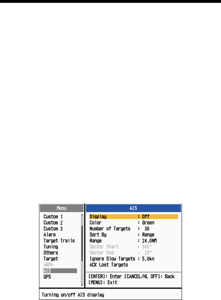
2. Use the Cursorpad (S or T) to select [AIS] and press the ENTER key.
AIS menu
4. AIS OPERATION
4-2
3. Use the Cursorpad (S or T) to select [Display] and press the ENTER key.
AIS-Display options
4. Use the Cursorpad (S or T) to select [Off] or [On] then press the ENTER key.
5. Press the MENU key to close the menu.
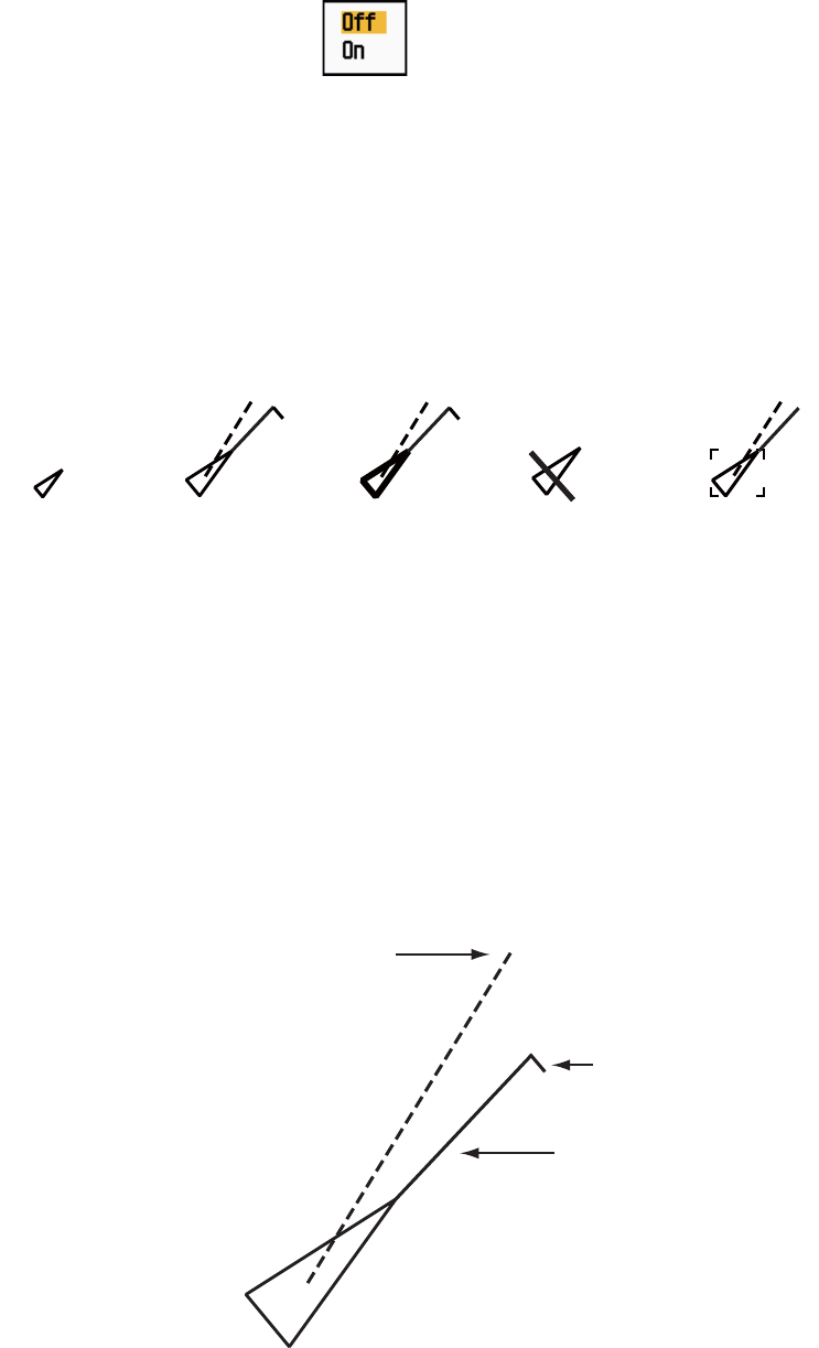
4.3 AIS Symbols
When the AIS is turned on, AIS targets are displayed with AIS symbol as below.
AIS symbols
Note: The AIS symbols are momentarily erased after the screen is redrawn when the
heading is changed on the head-up mode.
4.4 Activating, Sleeping Targets
When you change a sleeping target to an activated target, a vector shows the course
and speed of that target. You can easily judge the target movement by the vector.
Activated target
Sleeping
target Activated
target
Dangerous
target
Lost target Target selected
for data display
Heading line
SOG (Speed Over Ground) and
COG (Course over Ground) vector
(If there is no heading data,
the line points in direction of COG.)
ROT
(Rate of Turn)
4. AIS OPERATION
4-3
When there are many activated targets on the screen, you can not easily distinguish
the activated targets from the radar images or ARPA targets. You can sleep an acti-
vated target for easy view of radar images.
Sleeping target
To activate a target: Put the cursor on the target and press the ENTER key.
To sleep a target: Put the cursor on the target and press the CANCEL HL/OFF key.
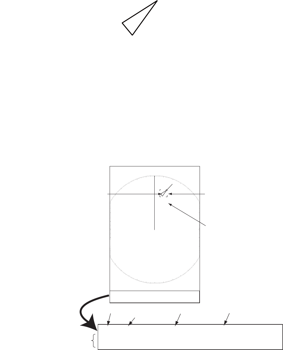
4.5 AIS Target Data
You can show the AIS target data in the data box at the bottom of the screen. To dis-
play AIS target data, the menu item [Display] on the [AIS] menu must be set for [On]
and the menu item [Data Box] on the [Display] menu must be set for [Target] or [All].
1. Use the Cursorpad to put the cursor on an activated target.
2. Press the ENTER key to show the data of the target.
AIS target data
To remove the target data from a data box, put the cursor on its target symbol and
press the CANCEL/HL OFF key.
AIS target
selected for
data display
MMSI of vessel Name of
vessel
PEGASUS
Cursor
Data box
TRUE 05:00 <AIS> MMSI: 123456789 NAME: PEGASUS
BRG
53.7°T
RNG 2.987NM COG
350.4°
SOG 23.45KN
CPA 1.65NM TCPA 06:14 LEN 100M BEAM 45M
Vector reference
Vector time
Bearing, range, course, speed
CPA, TCPA, Length, Beam of vessel
+
Name of vessel
(or MMSI)
4. AIS OPERATION
4-4
4.6 How to Sort Targets
You can sort the AIS targets received from the AIS transponder by range from your
ship, by sector, by CPA or TCPA.
1. Press the MENU key to open the menu.
2. Use the Cursorpad (S or T) to select [AIS] and press the ENTER key.
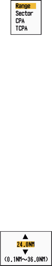
3. Use the Cursorpad (S or T) to select [Sort By] and press the ENTER key.
Sort By options
4. Use the Cursorpad (S or T) to select sorting method and press the ENTER key.
[Range]: Sort targets within the display range set (see section 4.7), from nearest
to furthest.
[Sector]: Sort targets within the display sector set (see section 4.8) and within 24
nm, from nearest to furthest.
[CPA]: Sort targets within 24 nm by CPA, from closest to furthest.
[TCPA]: Sort targets within 24 nm by TCPA, from earliest time to latest time.
5. Press the MENU key to close the menu.
4.7 Display Range
You can set the AIS system to show only those AIS targets within the range you set.
The setting range is 0.1-36 nm for MODEL 1835, 0.1-48 nm for MODEL 1935, 0.1-64
nm for MODEL 1945. Actual range depends on the AIS Transponder. If the target sort-
ing method is selected to [Range], the target data within the range set here is trans-
mitted to this radar.
1. Press the MENU key to open the menu.
2. Use the Cursorpad (S or T) to select [AIS] and press the ENTER key.
3. Use the Cursorpad (S or T) to select [Range] and press the ENTER key.
AIS-Range setting window (for MODEL 1835)
4. Use the Cursorpad (S or T) to set the display range and press the ENTER key.
5. Press the MENU key to close the menu.
Note: The unit of measurement for range is NM.
4. AIS OPERATION
4-5
4.8 How to Display the Targets within a Specific Sec-
tor
You can display AIS targets only within a specific sector. If the target sorting method
is selected to [Sector], the target data within the sector set here is transmitted to this
radar.
1. Press the MENU key to open the menu.
2. Use the Cursorpad (S or T) to select [AIS] and press the ENTER key.
3. Use the Cursorpad (S or T) to select [Sector Start] and press the ENTER key.
Sector Start setting window
4. Use the Cursorpad (S or T) to set the start point for the sector and press the EN-
TER key.
5. Use the Cursorpad (S or T) to select [Sector End] and press the ENTER key.
Sector End setting window
6. Use the Cursorpad (S or T) to set the end point for the sector and press the EN-
TER key.
7. Press the MENU key to close the menu.
4.9 Number of Targets to Display
You can select the maximum number of AIS targets to display. The setting value is 10
to 100. When the screen becomes cluttered with AIS targets, you can limit the number
of AIS targets to show. Targets are selected and displayed according to sort method.
(See section 4.6.)
1. Press the MENU key to open the menu.
2. Use the Cursorpad (S or T) to select [AIS] and press the ENTER key.
3. Use the Cursorpad (S or T) to select [Number of Targets] and press the ENTER
key.
Number of Targets setting window
4. AIS OPERATION
4-6
4. Use the Cursorpad (S or T) to select the number of targets to display and press
the ENTER key.
5. Press the MENU key to close the menu.
4.10 Vector Attributes
4.10.1 What is a vector?
A vector is a line extending from a tracked target. A vector shows speed and course
of the target. The top of a vector shows estimated position of the target after the se-
lected vector time elapses. If you extend the vector length (time), you can evaluate the
risk of collision with any target.
4.10.2 Vector time and vector reference
1. Press the MENU key to open the menu.
2. Use the Cursorpad (S or T) to select [Target] and press the ENTER key.
3. Use the Cursorpad (S or T) to select [Vector Time] and press the ENTER key.
Vector Time setting window
4. Use the Cursorpad (S or T) to select time and press the ENTER key.
5. Use the Cursorpad (S or T) to select [Vector Reference] and press the ENTER
key.
Vector Reference options
6. Use the Cursorpad (S or T) to select [Relative] or [True] then press the ENTER
key. This function is not activate for [IEC] or [Russian-River] purpose. The mode
is set to [True].
[Relative]: Other ships’ vectors are displayed relative to your ship. This mode
helps find targets on a collision course. If a ship is on a collision course with your
ship, the vector of a ship points toward your ship position.
[True]: Your ship’s and other ships’ vectors are displayed at their true motions.
This mode helps discriminate between moving and stationary targets.
7. Press the MENU key to close the menu.
4. AIS OPERATION
4-7
4.11 History Display (target past position)
This radar can display time-spaced dots (maximum ten dots) that marks the past po-
sitions of any tracked AIS target. You can evaluate actions of a target by the spacing
between dots. Below are examples of dot spacing and target movement.
Target movement and history display
You can select the number of history dots to display and the time interval to display
the history dots.
1. Press the MENU key to open the menu.
2. Use the Cursorpad (S or T) to select [Target] and press the ENTER key.
3. Use the Cursorpad (S or T) to select [History Dots] and press the ENTER key.
History Dots options
4. Use the Cursorpad (S or T) to select number of history dots to display (5 or 10)
or select [Off] to turn off the history display.
5. Press the ENTER key.
6. Use the Cursorpad (S or T) to select [History Interval] and press the ENTER key.
History Interval options
7. Use the Cursorpad (S or T) to select time interval and press the ENTER key.
8. Press the MENU key to close the menu.
(a) Ship turning (b) Ship running
straight (c) Ship reduced
speed
(d) Ship increased
speed
4. AIS OPERATION
4-8
4.12 CPA/TCPA Alarm
Set CPA (Closest Point of Approach) alarm range and TCPA (predicted Time to CPA)
alarm time to alert you to targets that can be on a collision course. When CPA and
TCPA of any AIS target (including a sleeping target) become less than the preset CPA
and TCPA alarm settings, the audio alarm sounds. The alarm message "COLLISION"
appears. The target symbol changes to a dangerous target symbol (red) and flashes
with its vector. You can stop the audio alarm and flashing with any key. The dangerous
target symbol is displayed until the AIS target is not in the CPA and TCPA alarm set-
ting. The AIS continuously monitors CPA and TCPA of all AIS targets.
This feature helps identify targets that can be on a collision course.
1. Press the MENU key to open the menu.
2. Use the Cursorpad (S or T) to select [Target] and press the ENTER key.
3. Use the Cursorpad (S or T) to select [CPA] and press the ENTER key.
CPA options
4. Use the Cursorpad (S or T) to select CPA distance and press the ENTER key.
5. Use the Cursorpad (S or T) to select [TCPA] and press the ENTER key.
TCPA options
6. Use the Cursorpad (S or T) to select TCPA and press the ENTER key.
7. Press the MENU key to close the menu.

4. AIS OPERATION
4-9
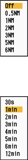
4.13 Proximity Alarm
The proximity alarm alerts you when an AIS target is within the range you set. The au-
dio alarm sounds and the alarm message "PROXIMITY" appears. The target symbol
changes to a dangerous target symbol (red) and flashes with its vector. Press any key
to stop the audio alarm and flashing. The dangerous target symbol is displayed until
the target is not within the range set, the alarm range is changed to exclude the target,
or the proximity alarm is deactivated.
1. Press the MENU key to open the menu.
2. Use the Cursorpad (S or T) to select [Target] and press the ENTER key.
3. Use the Cursorpad (S or T) to select [Proximity] and press the ENTER key.
Proximity options
4. Use the Cursorpad (S or T) to select the range and press the ENTER key.
5. Press the MENU key to close the menu.
4.14 Lost Target
When AIS data is not received from a target at fixed interval (3-5* report intervals), the
target symbol changes to the lost target symbol (flashing). No audio or visual alarm is
given for a lost target.
Lost target symbol
* The interval at which AIS data is sent depends on speed of the AIS transponder. For
detailed information, refer to the Operator's Manual for the AIS transponder.
You can remove all lost AIS targets from the display as follows:
1. Press the MENU key to open the menu.
2. Use the Cursorpad (S or T) to select [AIS] and press the ENTER key.
3. Use the Cursorpad (S or T) to select [ACK Lost Targets] and press the ENTER
key.
ACK Lost Targets options
4. AIS OPERATION
4-10
4. Use the Cursorpad (S) to select [Yes] and press the ENTER key. All lost targets
symbols are erased from the screen and the long beep sounds.
5. Press the MENU key to close the menu.
4.15 Symbol Color
You can select the AIS symbol color among Green, Red (unavailable in the [IEC] or
[Russian-River] purpose), Blue, White or Black.
1. Press the MENU key to open the menu.
2. Use the Cursorpad (S or T) to select [AIS] and press the ENTER key.
3. Use the Cursorpad (S or T) to select [Color] and press the ENTER key.
Color options
4. Use the Cursorpad (S or T) to select the color and press the ENTER key.
5. Press the MENU key to close the menu.
Note: Symbols can not be shown in the same color as the background color.
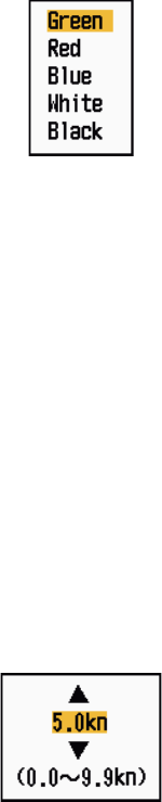
4.16 How to Ignore Slow Targets
You can prevent activation of the CPA/TCPA alarm against AIS targets that are trav-
eling at a speed lower than set here. The AIS symbols are not affected by this setting.
1. Press the MENU key to open the menu.
2. Use the Cursorpad (S or T) to select [AIS] and press the ENTER key.
3. Use the Cursorpad (S or T) to select [Ignore Slow Targets] and press the ENTER
key.
Ignore Slow Targets setting window
4. Use the Cursorpad (S or T) to select speed (0.0 - 9.9 kn) and press the ENTER
key.
5. Press the MENU key to close the menu.