Furuno USA 9ZWRTR059A Marine Radar User Manual Cover
Furuno USA Inc Marine Radar Cover
Contents
- 1. op man part 1
- 2. op man part 2
- 3. op man part 3
- 4. inst manual
op man part 3
4. AIS OPERATION
4-10
4. Use the Cursorpad (S) to select [Yes] and press the ENTER key. All lost targets
symbols are erased from the screen and the long beep sounds.
5. Press the MENU key to close the menu.
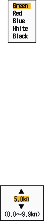
4.15 Symbol Color
You can select the AIS symbol color among Green, Red (unavailable in the [IEC] or
[Russian-River] purpose), Blue, White or Black.
1. Press the MENU key to open the menu.
2. Use the Cursorpad (S or T) to select [AIS] and press the ENTER key.
3. Use the Cursorpad (S or T) to select [Color] and press the ENTER key.
Color options
4. Use the Cursorpad (S or T) to select the color and press the ENTER key.
5. Press the MENU key to close the menu.
Note: Symbols can not be shown in the same color as the background color.
4.16 How to Ignore Slow Targets
You can prevent activation of the CPA/TCPA alarm against AIS targets that are trav-
eling at a speed lower than set here. The AIS symbols are not affected by this setting.
1. Press the MENU key to open the menu.
2. Use the Cursorpad (S or T) to select [AIS] and press the ENTER key.
3. Use the Cursorpad (S or T) to select [Ignore Slow Targets] and press the ENTER
key.
Ignore Slow Targets setting window
4. Use the Cursorpad (S or T) to select speed (0.0 - 9.9 kn) and press the ENTER
key.
5. Press the MENU key to close the menu.
5-1
5. GPS OPERATION
If the FURUNO GPS Navigator GP-320B is connected to this radar, you can set GP-
320B from this radar.
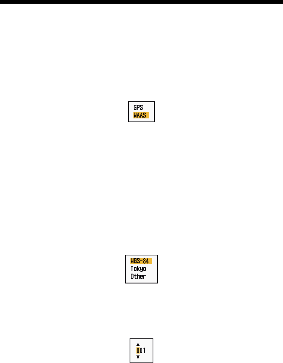
5.1 Navigator Mode
1. Press the MENU key to open the menu.
2. Use the Cursorpad (S or T) to select [GPS] and press the ENTER key.
3. Use the Cursorpad (S or T) to select [Mode] and press the ENTER key.
Mode options
4. Use the Cursorpad (S or T) to select [GPS] or [WAAS] then press the ENTER
key.
5. Press the MENU key to close the menu.
5.2 Datum
Select the type of datum which matches the paper charts you use for navigation. Se-
lect [WGS-84] if the radar is connected to an AIS Transponder.
1. Press the MENU key to open the menu.
2. Use the Cursorpad (S or T) to select [GPS] and press the ENTER key.
3. Use the Cursorpad (S or T) to select [Datum] and press the ENTER key.
Datum options
4. Use the Cursorpad (S or T) to select the type of datum and press the ENTER
key. If you select [WGS-84] or [Tokyo], go to step 7. If you select [Other], go to the
next step.
5. Use the Cursorpad (S or T) to select [Datum No] and press the ENTER key.
Datum No setting window
6. Use the Cursorpad (S or T) to select the datum number and press the ENTER
key. (The setting range is 001 - 192 and 201 - 254. Refer to the appendix 2 “GEO-
DETIC CHART LIST”.)
7. Press the MENU key to close the menu.
5. GPS OPERATION
5-2
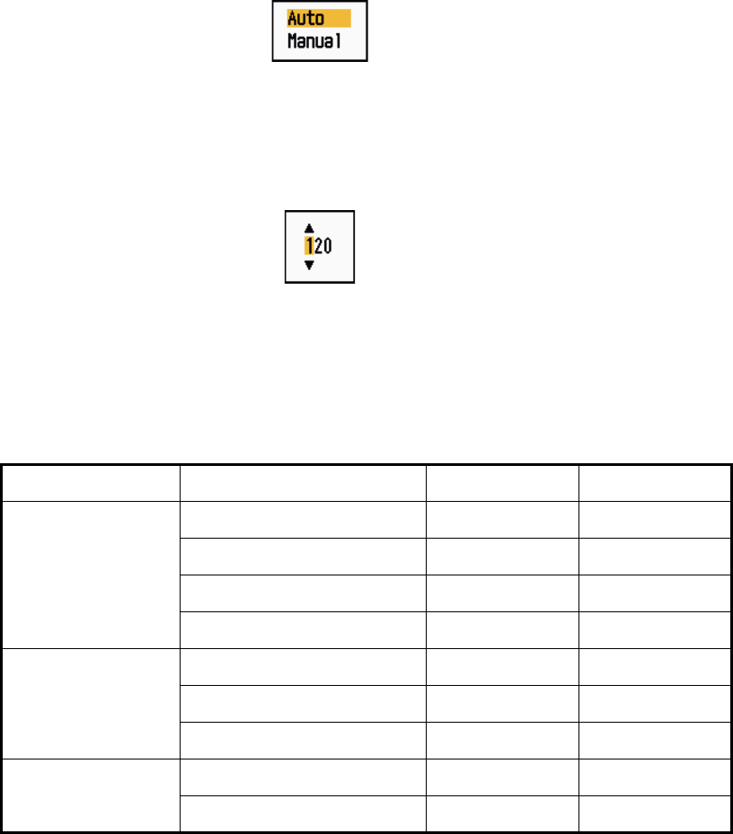
5.3 WAAS Setup
Geostationary satellites, the type used with WAAS, provide more accurate position
data when compared to GPS. These satellites can be tracked automatically or manu-
ally. Auto tracking automatically searches for the best geostationary satellite from your
current position.
1. Press the MENU key to open the menu.
2. Use the Cursorpad (S or T) to select [GPS] and press the ENTER key.
3. Use the Cursorpad (S or T) to select [WAAS] and press the ENTER key.
WAAS options
4. Use the Cursorpad (S or T) to select [Auto] or [Manual] then press the ENTER
key. If you select [Auto], go to step 7. If you select [Manual], go to the next step.
5. Use the Cursorpad (S or T) to select [WAAS No] and press the ENTER key.
WAAS No setting window
6. Use the Cursorpad (S or T) to select WAAS number and press the ENTER key.
(The setting range is 120 - 158. Refer to the following table.)
7. Press the MENU key to close the menu.
Provider Satellite type Longitude Satellite No.
WAAS Inmarsat-3-F4 (AOR-W) 142°W 122
Inmarsat-3-F3 (POR) 178°E 134
Intelsat Galaxy XV 133°W 135
TeleSat Anik F1R 107.3°W 138
EGNOS Inmarsat-3-F2 (AOR-E) 15.5°W 120
Artemis 21.5°E 124
Inmarsat-3-F5 (IOR-W) 25°E 126
MSAS MTSAT-1R 140°E 129
MTSAT-2 145°E 137
5. GPS OPERATION
5-3
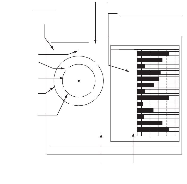
5.4 Satellite Monitor
The Satellite Monitor provides the information about GPS and WAAS satellites. See
your GPS navigator's owner's manual for detailed information.
1. Press the MENU key to open the menu.
2. Use the Cursorpad (S or T) to select [GPS] and press the ENTER key.
3. Use the Cursorpad (S or T) to select [Satellite Monitor] and press the ENTER
key.
Satellite monitor
4. Press the ENTER key to close only the satellite monitor display.
06
W3D DOP
1.5
15m
13
Altitude
01GPS
WAAS
12
24
16
SNRSatellite No.
30 40 50
122
01
31
18
19
06
07
09
08
13
North marker
DOP (Dilution of Precision, 0.0 - 99.0)
SNR of tracked GPS satellites
Satellites whose SNR is above
40 are used to fix position.
GPS mode
2D, 3D,
W2D, W3D
GPS satellite no.*
WAAS satellite
Satellites in ring
have elevation
angle of 5°
Satellites in ring
have elevation
angle of 45°
Altitude of
GPS antenna
from sea
surface
SNR of tracked
WAAS satellite
W
N
[MENU]: Close MENU [ENTER]: Close this window
* Satellites used to fix
position are shown in red.
Satellite Monitor
01
09
24
12
19
18
07
13
16
08
31

5. GPS OPERATION
5-4
5.5 Cold Start
Cold start, which clears the Almanac from the GPS receiver, can be necessary in the
following conditions:
• If you have turned off the power of the GPS receiver for a long time.
• The ship has moved far away from the previous fixing position (e.g., more than 500
km).
• Other reason that prevents the receiver from finding its position within five minutes
after you turn on the power.
To do cold start, do the following:
1. Press the MENU key to open the menu.
2. Use the Cursorpad (S or T) to select [GPS] and press the ENTER key.
3. Use the Cursorpad (S or T) to select [Cold Start] and press the ENTER key.
Cold Start options
4. Use the Cursorpad (S) to select [Yes] and press the ENTER key. After processing
cold start, the long beep sounds. (To stop cold start, press the CANCEL/HL OFF
key instead of the ENTER key.)
5. Press the MENU key to close the menu.
6-1
6. MAINTENANCE, TROUBLE-
SHOOTING
This chapter has information about maintenance and troubleshooting that the user
can follow to care for the equipment.
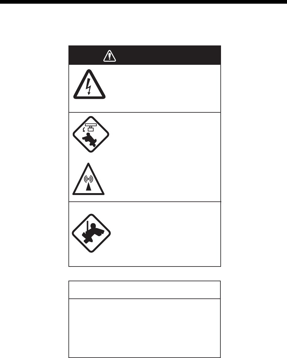
WARNING
ELECTRICAL SHOCK HAZARD
Do not open the equipment.
Only qualified personnel can work
inside the equipment.
Turn off the power before you
service the antenna unit. Post
a warning sign near the power
switch not to turn on the power
while you service the antenna
unit.
Prevent the potential risk of being
struck by the rotating antenna and
exposure to RF radiation hazard.
When you work on the antenna
unit, wear a safety belt and hard
hat.
Serious injury or death can result
if a person falls from the radar
antenna mast.
NOTICE
Do not apply paint, anti-corrosive sealant
or contact spray to plastic parts or
equipment coating.
Those items contain products that can
damage plastic parts and equipment coating.

6. MAINTENANCE, TROUBLESHOOTING
6-2
6.1 Preventive Maintenance
Regular maintenance helps keep your equipment in good condition and prevents fu-
ture problems. Check the items shown in the table below to help keep your equipment
in good condition for years to come.
Maintenance
Interval Item Check point Remedy
When
necessary LCD Dust on the LCD Remove the dust from the LCD
with the tissue paper and an LCD
cleaner. To remove dirt or salt, use
the LCD cleaner. Change the tis-
sue paper often so as not to
scratch the LCD.
3 to 6
months Ground terminal on
display unit Check for tight connec-
tion and rust. Tighten or replace as necessary.
Display unit
connectors Check for tight connec-
tion. Tighten if the connectors are loos-
ened.
Exposed nuts and
bolts on the anten-
na unit
Check for corroded or
loosened bolts. Clean and repaint as necessary.
Use sealing compound instead of
paint.
Antenna radiator Check for dirt and cracks
on the radiator surface. Clean radiator surface with fresh-
water-moistened cloth. Do not use
plastic solvents to clean.
6. MAINTENANCE, TROUBLESHOOTING
6-3
6.2 Fuse Replacement
The fuse on the power cable protects the equipment from overcurrent and equipment
fault. If the fuse blows, find the cause before you replace the fuse. Use the correct
fuse. A wrong fuse can damage the equipment.
6.3 Magnetron Life
When the life of the magnetron is reached, the targets do not appear on the display.
If long-range performance appears to have decreased, contact a FURUNO agent or
dealer about replacement of the magnetron.
6.4 LCD Backlight Life
The life of the LCD backlight, which provides illumination for the LCD, is approximately
4,800 hours at 25°C (ambient temperature). The display brilliance cannot be raised
when the backlight has worn out. When brilliance cannot be raised, have a qualified
technician replace the backlight.
Unit Type Code No. Remarks
Display unit
(fitted on
power cable)
FGB0 125V 10A PBF 000-155-826-10 12 VDC
FGB0-A 125V 5A PBF 000-155-853-10 24 VDC
Model Magnetron type Code No. Estimated life
MODEL 1835
MODEL 1935 E3571 000-087-300 Approx. 2,000 hours
MODEL 1945 MAF1422B 000-158-788-11 Approx. 3,000 hours
Name Type Code No.
Lamp holder complete set 104LHS46 000-160-949-10
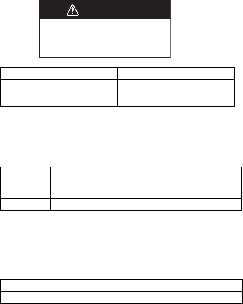
WARNING
Use the correct fuse.
A wrong fuse can damage the equipment
and cause fire.

6. MAINTENANCE, TROUBLESHOOTING
6-4
6.5 Simple Troubleshooting
This section provides simple troubleshooting procedures which the user can follow to
restore normal operation. If you cannot restore normal operation, do not check inside
the unit. Have a qualified technician check the equipment.
Simple troubleshooting
Problem Remedy
You cannot turn on the power. • Check for blown fuse.
• Check that the power connector is fastened.
• Check for corrosion on the power cable con-
nector.
• Check for damaged power cable.
• Check battery for correct voltage output.
There is no response when a key is
pressed. Turn off and on the power. If you do not get a
response, the key is damaged. Contact your
dealer for instructions.
The power is on and you operated the
STBY/TX key to transmit. The marks
and letters appear, but no echo ap-
pears.
Check that the antenna cable is fastened.
Tuning is correctly adjusted, but
sensitivity is poor.
Replace the magnetron. Contact your dealer.
The range is changed, but radar pic-
ture does not change. • Try to hit the RANGE key again.
• Turn off and on the display unit.
Poor discrimination in range because
of many echoes from the waves. Adjust A/C SEA control.
The true motion presentation is not
working correctly. • Check that the setting of [Display Mode] in
the [Display] menu is set to [True Motion].
• Check if the heading and position data are in-
put and correct.
The range rings are not displayed. Check that the setting of [Rings Brill] in the
[Brill/Color] menu is set to other than [Off].
Target is not tracked correctly be-
cause of sea clutter. Adjust A/C SEA and A/C RAIN controls.

6. MAINTENANCE, TROUBLESHOOTING
6-5
6.6 Advanced-level Troubleshooting
This section describes how to cure hardware and software troubles which the qualified
service persons must do.
Advanced-level troubleshooting
Problem Probable cause or
check points Remedy
Power cannot be
turned on. 1) Mains voltage/polarity
2) Power supply board
1) Correct the wiring and input
voltage.
2) Replace power supply
board.
Brilliance adjusted
but no picture. 1) SPU Board 1) Replace SPU board.
Antenna not rotat-
ing. 1) Antenna drive mechanism 1) Replace the antenna drive
mechanism.
Data and marks
not displayed in
transmit.
1) SPU board 1) Replace SPU board.
Set GAIN to maxi-
mum with A/C SEA
set at minimum.
Marks and indica-
tions appear but no
noise or echo.
1) Signal cable between an-
tenna and display unit
2) IF amplifier
3) Video amplifier board
1) Check continuity and isola-
tion of coaxial cable.
2) Replace IF amplifier.
3) Check coax line for fasten
connection. If connection is
good, replace SPU board.
Marks, indications
and noise appear
but no echo.
(Transmission leak
representing your
ship position is ab-
sent.)
1) Magnetron
2) Modulator board
3) SPU board
1) Check magnetron current.
2) Replace modulator board.
3) Replace SPU board.
Picture not updat-
ed or picture
freeze-up.
1) Bearing signal generator
2) SPU board
3) Video freeze-up
1) Check that signal cables
are fastened.
2) Replace SPU board.
3) Turn off and on the radar.

6. MAINTENANCE, TROUBLESHOOTING
6-6
Radar is correctly
tuned but sensitivi-
ty is poor.
1) [2nd Echo Rejector] is [On]
2) Dirt on radiator face
3) Deteriorated magnetron
4) Detuned MIC
1) Turn off the [2nd Echo Re-
jector], from the [Echo]
menu.
2) Clean radiator.
3) Check the magnetron cur-
rent with the radar transmit-
ting on 48 nm range. If the
current is below normal,
magnetron may be defec-
tive. Replace the magne-
tron.
4) Check MIC detecting cur-
rent. If MIC detecting cur-
rent is below normal value,
MIC may have become de-
tuned.
Range changed
but radar picture
does not change.
1) RANGE key has faults
2) SPU board
3) Video freeze-up
1) Try to operate the RANGE
key. If you can not operate
the RANGE key, replace
the keypad.
2) Replace SPU board.
3) Turn off and on radar.
Range rings are
not displayed. 1) Adjust their brilliance on the
[Brill/Color] menu.
2) SPU Board
1) Replace associated circuit
board if unsuccessful.
2) Replace SPU Board.
Problem Probable cause or
check points Remedy
6. MAINTENANCE, TROUBLESHOOTING
6-7
6.7 Diagnostic Test
The diagnostic test checks the system for correct operation. This test is for use by ser-
vice technicians, but the user can do this test to provide the service technician with
information.
1. Press the MENU key to open the menu.
2. Use the Cursorpad (S or T) to select [Tests] and press the ENTER key.
3. Use the Cursorpad (S or T) to select [Self Test] and press the ENTER key.
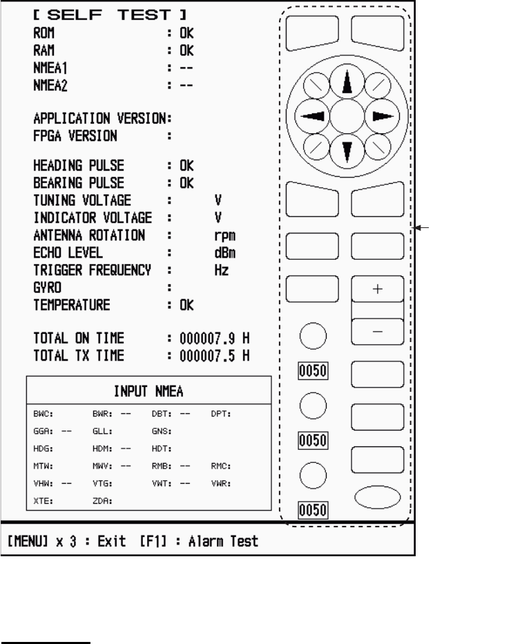
Self Test screen
Test results
• ROM, RAM: The results of the ROM and RAM test are displayed as OK or NG
(No Good).
• NMEA1, NMEA2: The results of the ports NMEA1 and NMEA2 are displayed as
OK or "- -". Ports NMEA1 and NMEA2 require a special connector to test them.
When a special connector is not connected, "- -" is shown. If "- -" is displayed
with a special connector, contact your dealer for instruction.
• APPLICATION VERSION, FPGA VERSION: The program numbers and pro-
gram version numbers (XX) are displayed.
XX: Program version no.
0359246-XX.XX
0359247-XX.XX
10.1
4.2
48.1
-40
3112
123.4°
567
OK
OK
OK
OK
OK
OK
OK
OK
OK
OK
OK
OK
Key, buzzer,
knob cotrol
and cursorpad
check

6. MAINTENANCE, TROUBLESHOOTING
6-8
• HEADING PULSE, BEARING PULSE: The results of the pulse input are dis-
played as OK or NG. When [Antenna Rotation] is set to [Stop], or [Watchman]
is set to [Off] in the STBY mode, this test is skipped and "- -" is shown for both
heading and bearing.
• TUNING VOLTAGE, INDICATOR VOLTAGE, ANTENNA ROTATION, ECHO
LEVEL, TRIGGER FREQUENCY: The results of measurement are displayed.
• GYRO: The current gyrocompass reading is displayed.
• TEMPERATURE: The result of the temperature test is displayed as OK or NG
and the temperature is measured and shown.
• TOTAL ON TIME, TOTAL TX TIME: The total number of hours, for which the
radar has been powered and transmitted, are displayed.
• INPUT NMEA window: The condition of all the NMEA sentences being input to
this radar are displayed as OK or "- -". "- -" means no data input. Sentences are
updated every second.
Key check
Press each key one by one. A key’s on-screen location becomes green if the key
is normal.
Buzzer check
The F1 key tests on/off for the panel buzzer or external buzzer. To stop the buzz-
er, press the F1 key again.
Knob control check
Rotate each control knob. The four digits below the on-screen location for the
GAIN, A/C SEA and A/C RAIN knob controls show the control position. Press
each knob. The knob corresponding on-screen circle changes in green if the knob
is normal.
Cursorpad check
Press each arrow and diagonal dot one by one. The on-screen location changes
in green if the key is normal.
4. Press the MENU key three times to escape from the test.
5. Press the MENU key to close the menu.
6. MAINTENANCE, TROUBLESHOOTING
6-9
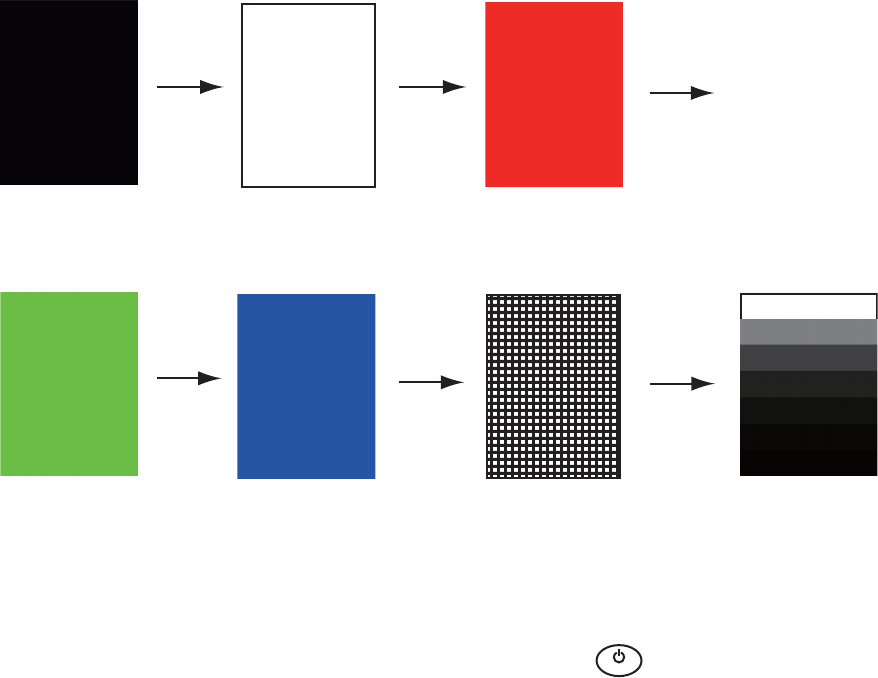
6.8 LCD Test
1. Press the MENU key to open the menu.
2. Use the Cursorpad (S or T) to select [Tests] and press the ENTER key.
3. Use the Cursorpad (S or T) to select [LCD Pattern] and press the ENTER key.
4. Press the MENU key several times to close the menu.
Note 1: You can cancel the test at any time when you press the CANCEL/HL OFF
key.
Note 2: You can adjust the screen brilliance with the key during the test.
Black
MENU
key MENU
key MENU
key
MENU
key MENU
key MENU
key
White Red
Green Blue Checker board design 7 tones of gray
B
R
I
L
L

6. MAINTENANCE, TROUBLESHOOTING
6-10
6.9 ARPA Test
If the optional ARPA board is installed, its program number and test results (OK or NG)
are shown on the screen. [ARPA Test] menu item is inoperative with no ARPA board.
The radar must be transmitting to test ARPA function.
1. Press the MENU key to open the menu.
2. Use the Cursorpad (S or T) to select [Tests] and press the ENTER key.
3. Use the Cursorpad (S or T) to select [ARPA Test] and press the ENTER key.
ARPA test
4. Press the MENU key three times to close the menu.
XXX: Program version no.
[ ARPA TEST ]
ROM : OK
RAM
: OK
ARPA VERSION
: 1859127XXX
SPEED : OK 12.3KN
COURSE
: OK 287.6
°
TRIGGER
: OK
VIDEO : OK
BEARING PULSE
: OK
HEADING PULSE : OK
MIN-HIT
: 0012
SCAN-TIME
: 0250
MANUAL-ACQ
: 03
AUTO-ACQ
: 05
FE-DATA1 : 0217
FE-DATA2 : 0023
ECHO NUMBER
[No. 1] 0123 [No. 2] 0321 [No. 3] 0084 [No. 4] 0234
[No. 5] 0110 [No. 6] 0219 [No. 7] 0073 [No. 8] 0145
[MENU] x 3 : Exit
6. MAINTENANCE, TROUBLESHOOTING
6-11
6.10 GPS Test
You can check the FURUNO GPS receiver GP-320B interfaced with this radar for cor-
rect operation as follows:
1. Press the MENU key to open the menu.
2. Use the Cursorpad (S or T) to select [GPS] and press the ENTER key.
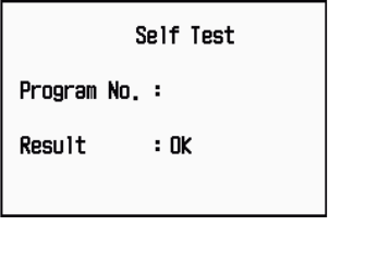
3. Use the Cursorpad (S or T) to select [Self Test] and press the ENTER key. The
program no. and result of the test are shown, as OK or NG (No Good). When NG
appears, check the GPS receiver.
GPS-Self Test screen
4. Press any key to close the test screen.
5. Press the MENU key to close the menu.
48502380XX
XX: Program version no. varies
according to equipment connected.
6. MAINTENANCE, TROUBLESHOOTING
6-12
This page is intentionally left blank.
AP-1
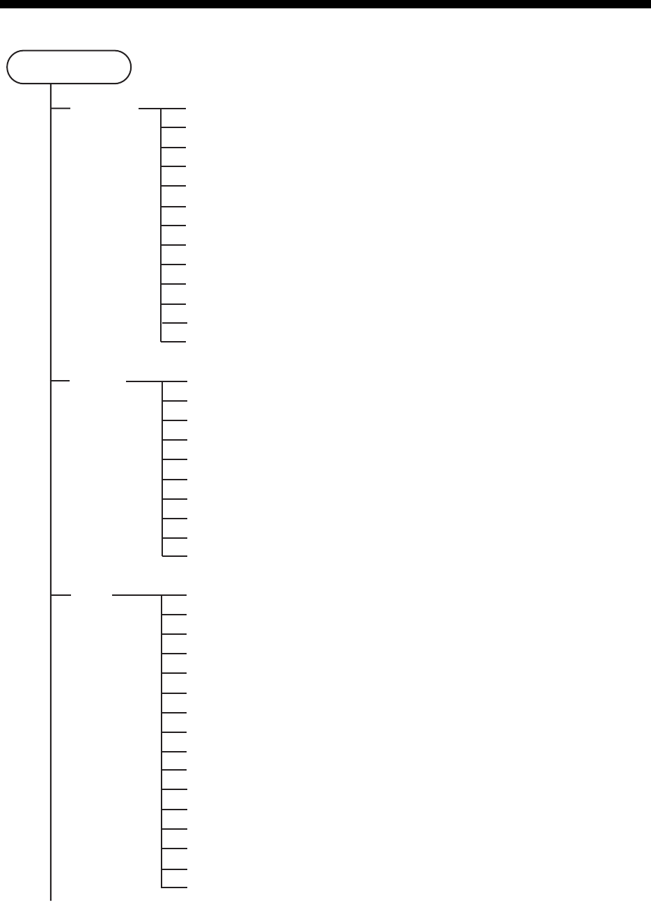
APPENDIX 1 MENU TREE
MENU key
Brill/Color
Display
Echo
Echo Brill (1 - 8)
Rings Brill (Off, 1, 2, 3, 4)
Mark Brill (1, 2, 3, 4)
HL Brill (1, 2, 3, 4)
Character Brill (1, 2, 3, 4)
View Position (Left, Left-Center, Center, Right-Center, Right)
Display Color (Day, Night, Twilight, Custom)
Echo Color (Yellow, Green, Orange, Multi)
Background Color (Black, DK Blue, Blue, White)
Character Color (Green, Red, White)
Menu Transparency (Off, 1, 2, 3, 4)
Echo Color Mode (System, Custom)
Custom Echo Color
Display Mode (Head Up, Course Up, North Up, True Motion, True View)
Zoom (Off, On)
Zoom Mode (Relative, True, Target)
Offcenter Mode (Manual, Custom, Auto)
Save Offcenter
Echo Area (Normal, Full Screen)
Base Text Display (Range, Mode, Alarm, Echo, EBL/VRM, +Cursor)
Data Box (Off, Nav, Target, All)
Gain/Sea/Rain Bar
STBY Display (Normal, Nav, Economy)
Gain Mode (Auto, Manual)
Sea Mode (Auto, Manual)
Auto Sea (Coastal, Advanced)
Rain Mode (Auto, Manual)
Auto Rain (Calm, Moderate, Rough)
A/C Auto (Off, On)
Pulse Length (Short, Long)
Echo Stretch (Off, 1, 2, 3)
Echo Average (Off, 1, 2, Auto)
Noise Rejector (Off, On)
Wiper (Off, 1, 2)
Int Rejector (Off, 1, 2, 3)
Display-Dynamic (Narrow, Normal, Wide)
Display-Curve (1, 2, 3)
Color Erase (0 - 11)
2nd Echo Rejector (Off, On)
(Continued on next Page)
APPENDIX 1 MENU TREE
AP-2
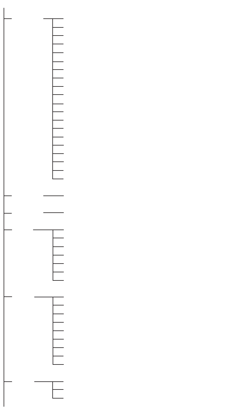
(Continued from previous page)
Custom 1
Custom 2
Custom 3
Alarm
Target
Trails
Tuning
Custom1 (Off, On)
Copy
Gain Mode (Auto, Manual)
Manual Gain (0 - 100)
Sea Mode (Auto, Manual)
Auto Sea (Coastal, Advanced)
Manual Sea (0 - 100)
Rain Mode (Auto, Manual)
Auto Rain (Calm, Moderate, Rough)
Manual Rain (0 - 100)
A/C Auto (Off, On)
Pulse Length (Short, Long)
Echo Stretch (Off, 1, 2, 3)
Echo Average (Off, 1, 2, Auto)
Noise Rejector (Off, On)
Wiper (Off, 1, 2)
Int Rejector (Off, 1, 2, 3)
Display-Dynamic (Narrow, Normal, Wide)
Display-Curve (1, 2, 3)
Color Erase (0 - 11)
Same as Custom 1
Same as Custom 1
Target Alarm 1 (In, Out)
Target Alarm 2 (In, Out)
Alarm Level (Low, Med, High)
Watchman (Off, 5min, 10min, 20min)
Panel Buzzer (Off, On)
External Buzzer (Off, On)
Alarm Status
Time (15s, 30s, 1min, 3min, 6min, 15min, 30min, Continuous)
Gradation (Single, Multi)
Color (Green, Red, Blue, White, Black)
Mode (Relative, True)
Level (1, 2, 3)
Restart (Off, On)
Narrow (Off, On)
Own Ship (Off, 1, 2)
All Cancel
Tuning Mode (Auto, Manual)
Manual Tuning (0.00V - 12.00V)
Tuning Init Adjust
(Continued on next page)

APPENDIX 1 MENU TREE
AP-3
(Continued from previous page)
Others
Target
ARPA
AIS
GPS
F1 Setup
F2 Setup
F3 Setup
WPT Mark (Off, On)
EBL Reference (Relative, True)
VRM Unit (NM, KM, SM, KYD, NM&YD)
Cursor Position (Rng/Brg, Lat/Lon)
TLL Key Mode (TLL Output, Origin Mark, Both)
Vector Time (1min - 30min)
Vector Reference (Relative, True)
History Dots (Off, 5, 10)
History Interval (15s, 30s, 1min, 2min, 3min, 6min, 12min)
CPA (Off, 0.5NM, 1NM, 2NM, 3NM, 5NM, 6NM)
TCPA (30s, 1min, 2min, 3min, 4min, 5min, 6min, 12min)
Proximity (Off, 0.5NM, 1NM, 2NM, 3NM, 5NM, 6NM, 12NM, 24NM)
Display (Off, On)
Color (Green, Red, Blue, White, Black)
Auto Acquisition (Off, On)
ACK Lost Targets
All Cancel
Display (Off, On)
Color (Green, Red, Blue, White, Black)
Number of Targets (10 - 100)
Sort By (Range, Sector, CPA, TCPA)
Range (0.1NM - 36.0NM*)
Sector Start (0° - 359°)
Sector End (0° - 359°)
Ignore Slow Targets (0.0 - 9.9kn)
ACK Lost Targets
Mode (GPS, WAAS)
Datum (WGS-84, Tokyo, Other)
Datum No (001 -192, 201 - 254)
WAAS (Auto, Manual)
WAAS No (120 - 158)
Satellite Monitor
Self Test
Cold Start
(Continued on next page)
*: 36.0NM for MODEL 1835
48.0NM for MODEL 1935
64.0NM for MODEL 1945

APPENDIX 1 MENU TREE
AP-4
(Continued from previous page)
System Initial
Tests
Sector
Blanks
Units
Installation (For use by the installer. Not accessible by user.)
Factory (For use by the installer. Not accessible by user.)
Key Beep (Off, On)
Offcenter Speed (1kn - 99kn)
Compass Type (Magnetic, True)
Range Preset
Wind Direction (Apparent, True)
NMEA Port 1 (Auto, 4800bps, 38400bps)
NMEA Port 2 (Auto, 4800bps, 38400bps)
NMEA Mixing Out (Off, On)
Self Test
LCD Pattern
ARPA Test
Sect-Blank 1 Status (Off, On)
Sect-Blank 1 Start (0° - 359°)
Sect-Blank 1 End (0° - 359°)
Sect-Blank 2 Status (Off, On)
Sect-Blank 2 Start (0° - 359°)
Sect-Blank 2 End (0° - 359°)
Range Unit (NM, KM, SM)
Ship Speed Unit (kn, km/h, mph)
Depth Unit (m, ft, fa, pb, HR)
Temperature Unit (°C, °F)
Wind Speed Unit (kn, km/h, mph, m/s)

AP-5
APPENDIX 2 GEODETIC CHART LIST
001: WGS84
002: WGS72
003: TOKYO :
004: NORTH AMERICAN 1927 : Mean Value (CONUS)
005: EUROPEAN 1950 : Mean Value
006:
AUSTRALIAN GEODETIC 1984
: Australia & Tasmania
007: ADINDAN-MN : Mean Value (Ethiopia & Sudan)
008: ADINDAN-E : Ethiopia
009: ADINDAN-MA : Mali
010: ADINDAN-SE : Senegal
011: ADINDAN-SU : Sudan
012: AFG : Somalia
013: AIN EL ABD 1970 : Bahrain Is.
014: ANNA 1 ASTRO 1965 : Cocos Is.
015: ARC 1950-MN : Mean Value
016: ARC 1950-B : Botswana
017: ARC 1950-L : Lesotho
018: ARC 1950-M : Malawi
019: ARC 1950-S : Swaziland
020: ARC 1950-ZR : Zaire
021: ARC 1950-ZM : Zambia
022: ARC 1950-ZB : Zimbabwe
023: ARC 1960-MN : Mean Value (Kenya & Tanzania)
024: ARC 1960-K : Kenya
025: ARC 1960-T : Tanzania
026: ASCENSION IS. 1958 : Ascension Is.
027: ASTRO BEACON “E” : Iwo Jima Is.
028: ASTRO B4 SOR. ATOLL : Tern Is.
029: ASTRO POS 71/4 : St. Helena Is.
030:
ASTRONOMIC STATION 1952
: Marcus Is.
031:
AUSTRALIAN GEODETIC 1966
: Australia & Tasmania
032: BELLEVUE (IGN) : Efate & Erromango Is.
033: BERMUDA 1957 : Bermuda Is.
034: BOGOTA OBSERVATORY : Columbia
035: CAMPO INCHAUSPE : Argentina
036: CANTON IS. 1966 : Phoenix Is.
037: CAPE : South Africa
038: CAPE CANAVERAL :
039: CARTHAGE : Tunisia
040: CHATHAM 1971 : Chatham Is. (New Zealand)
041: CHUA ASTRO : Paraguay
042: CORREGO ALEGRE : Brazil
043: DJAKARTA (BATAVIA) : Sumatra Is. (Indonesia)
044: DOS 1968 : Gizo Is. (New Georgia Is.)
045: EASTER IS. 1967 : Easter Is.
046: EUROPEAN 1950-WE : Western Europe
047: EUROPEAN 1950-CY : Cyprus
048: EUROPEAN 1950-EG : Egypt
049: EUROPEAN 1950-ESC :
050: EUROPEAN 1950-EIS :
051: EUROPEAN 1950-GR : Greece
052 EUROPEAN 1950-IR : Iran
053: EUROPEAN 1950-SA : Italy, Sardinia
054: EUROPEAN 1950-SI : Italy, Sicily
055: EUROPEAN 1950-NF : Norway & Finland
056: EUROPEAN 1950-PS : Portugal & Spain
057: EUROPEAN 1979 : Mean Value
058: GANDAJIKA BASE : Republic of Maldives
059: GEODETIC DATUM 1949 : New Zealand
060: GUAM 1963 : Guam Is.
061: GUX 1 ASTRO : Guadalcanal Is.
062: HJORSEY 1955 : Iceland
063: HONG KONG 1963 : Hong Kong
064: INDIAN-TV : Thailand & Vietnam
065: INDIAN-BIN : Bangladesh, India & Nepal
066: IRELAND 1965 : Ireland
067: ISTS 073 ASTRO 1969 : Diego Garcia
068: JOHNSTON IS. 1961 : Johnston Is.
069: KANDAWALA : Sri Lanka
070: KERGUELEN IS. : Kerguelen Is.
071: KERTAU 1948 : West Malaysia & Singapore
072: LA REUNION : Mascarene Is.
073: L. C. 5 ASTRO : Cayman Brac Is.
074: LIBERIA 1964 : Liberia
075: LUZON : Philippines (excl. Mindanao Is.)
076: LUZON-M : Mindanao Is.
077: MAHE 1971 : Mahe Is.
078: MARCO ASTRO : Salvage Islands
079: MASSAWA : Eritrea (Ethiopia)
080: MERCHICH : Morocco
081: MIDWAY ASTRO 1961 : Midway Is.
082: MINNA : Nigeria
083: NAHRWAN-O : Masirah Is. (Oman)
084: NAHRWAN-UAE : United Arab Emirates
085: NAHRWAN-SA : Saudi Arabia
086: NAMIBIA : Namibia
087: MAPARIMA, BWI : Trinidad & Tobago
088:
NORTH AMERICAN 1927WU
: Western United States
089:
NORTH AMERICAN 1927EU
: Eastern United States
090:
NORTH AMERICAN 192
7AK : Alaska
091:
NORTH AMERICAN 1927BH
:Bahamas (excl. San Salvador Is.)
Mean Value (Japan, Korea & Okinawa)
Mean Value (Florida & Bahama Is.)
England, Scotland, Channel & Shetland Is.
England, Ireland, Scotland & Shetland Is.
092: NORTH AMERICAN 1927SS : Bahamas, San Salvador Is.
093: NORTH AMERICAN 1927CN : Canada (incl. Newfoundland Is.)
094: NORTH AMERICAN 1927AB : Alberta & British Columbia
095: NORTH AMERICAN 1927EC : East Canada
096: NORTH AMERICAN 1927MO : Manitoba & Ontario
097: NORTH AMERICAN 1927NE :
098: NORTH AMERICAN 1927YK : Yukon
099: NORTH AMERICAN 1927CZ : Canal Zone
100: NORTH AMERICAN 1927CR : Caribbean
101: NORTH AMERICAN 1927CA : Central America
102: NORTH AMERICAN 1927CU : Cuba
103: NORTH AMERICAN 1927GR : Greenland
104: NORTH AMERICAN 1927MX : Mexico
105: NORTH AMERICAN 1983AK : Alaska
106: NORTH AMERICAN 1983CN : Canada
107: NORTH AMERICAN 1983CS : CONUS
108: NORTH AMERICAN 1983MX : Mexico, Central America
109: OBSERVATORIO 1966 : Corvo & Flores Is. (Azores)
110: OLD EGYPTIAN 1930 : Egypt
111: OLD HAWAIIAN-MN : Mean Value
112: OLD HAWAIIAN-HW : Hawaii
113: OLD HAWAIIAN-KA : Kauai
114: OLD HAWAIIAN-MA : Maui
115: OLD HAWAIIAN-OA : Oahu
116: OMAN : Oman
117:
ORDNANCE SURVEY OF GREAT BRITAIN 1936-NM
: Mean Value
118:
ORDNANCE SURVEY OF GREAT BRITAIN 1936-E
: England
119:
ORDNANCE SURVEY OF GREAT BRITAIN 1936-IM
: England, Isle
of Man & Wales
120:
ORDNANCE SURVEY OF GREAT BRITAIN 1936-SSI
: Scotland &
Shetland Is.
121:
ORDNANCE SURVEY OF GREAT BRITAIN 1936-WL
: Wales
122: PICO DE LAS NIVIES : Canary Is.
123: PITCAIRN ASTRO 1967 : Pitcairn Is.
124: PROVISIONS SOUTH CHILEAN 1963: South Chile (near 53°S)
125: PROVISIONAL SOUTH AMERICAN 1956MN: Mean Value
126: PROVISIONAL SOUTH AMERICAN 1956BO: Bolivia
127: PROVISIONAL SOUTH AMERICAN 1956NC: Chile-Northern Chile
(near 19°S)
128: PROVISIONAL SOUTH AMERICAN 1956SC: Chile-Southern Chile
(near 43°S)
129: PROVISIONAL SOUTH AMERICAN 1956CO: Columbia
130: PROVISIONAL SOUTH AMERICAN 1956EC: Ecuador
131: PROVISIONAL SOUTH AMERICAN 1956GY: Guyana
132: PROVISIONAL SOUTH AMERICAN 1956PR: Peru
133: PROVISIONAL SOUTH AMERICAN 1956VN: Venezuela
134: PUERTO RICO : Puerto Rico & Virgin Is.
135: QATAR NATIONAL : Qatar
136: QORNOQ : South Greenland
137: ROME 1940 : Sardinia Is.
138: SANTA BRAZ :
139: SANTO (DOS) : Espirito Santo Is.
140: SAPPER HILL 1943 : East Falkland Is.
141: SOUTH AMERICAN 1969MN : Mean Value
142: SOUTH AMERICAN 1969AG : Argentina
143: SOUTH AMERICAN 1969BO : Bolivia
144: SOUTH AMERICAN 1969BR : Brazil
145: SOUTH AMERICAN 1969CH : Chile
146: SOUTH AMERICAN 1969CO : Columbia
147: SOUTH AMERICAN 1969EC : Ecuador
148: SOUTH AMERICAN 1969GY : Guyana
149: SOUTH AMERICAN 1969PA : Paraguay
150: SOUTH AMERICAN 1969PR : Peru
151: SOUTH AMERICAN 1969TT : Trinidad & Tobago
152: SOUTH AMERICAN 1969VZ : Venezuela
153: SOUTH ASIA : Singapore
154: SOUTHEAST BASE : Porto Santo & Madeira Is.
155: SOUTHWEST BASE :
156: TIMBALAI 1948 :
157: TOKYO JP : Japan
158: TOKYO KP : Korea
159: TOKYO OK : Okinawa
160: TRISTAN ASTRO 1968 : Tristan da Cunha
161: VITI LEVU 1916 : Viti Levu Is. (Fiji Is.)
162: WAKE-ENIWETOK 1960 : Marshall Is.
163: ZANDERIJ : Surinam
164: BUKIT RIMPAH :
165: CAMP AREA ASTRO : Camp Mcmurdo Area, Antarctica
166: G. SEGARA : Kalimantan Is. (Indonesia)
167: HERAT NORTH : Afghanistan
168: HU-TZU-SHAN : Taiwan
169: TANANARIVE OBSERVATORY 1925 : Madagascar
170: YACARE : Uruguay
171: RT-90 : Sweden
172: TOKYO :
Mean Value (Japan, Korea & Okinawa)
173: AIN EL ABD 1970 : Bahrain Is.
Northwest Territories & Saskatchewan
Sao Miguel, Santa Maria Is. (Azores)
Faial, Graciosa, Pico, Sao Jorge & Terceria Is.
Brunei & East Malaysia (Sarawak & Sabah)
Bangka & Belitung Is. (Indonesia)
174:
175: ARC 1960
ARS-A : Mean Value (Kenya, Tanzania)
: Kenya

APPENDIX 2 GEODETIC CHART LIST
AP-6
178: CAPE CANAVERAL
179: EASTER IS. 1967
180: EUROPEAN 1950 :
181: JHONSTON IS. 1961 : Jhonston Is.
182: NAHRWAN : Saudi Arabia
183:
NAPARIMA, BWI
: Trinidad & Tobago
184: NORTH AMERICAN 1927 : Caribbeen
185: OLD HAWAIIAN : Oahu
186: SAPPER HILL 1943 : East Falkland Is.
187: TIMBALAI 1948 :
Brunei & East Malaysia (Sarawak & Sabah)
188: TOKYO : Japan
189: TOKYO : South Korea
190: TOKYO : Okinawa
191: WAKE-ENIWETOK 1960 : Marshall Is.
192: HU-TZU-SHAN : Taiwan
201: ADINDAN : Burkina Faso
202: ADINDAN : Cameroon
203: ARC 1950 : Burundi
204: AYABELLE LIGHTHOUSE : Djibouti
205: BISSAU : Guinea-Bissau
206: DABOLA : Guinea
207: EUROPEAN 1950 : Tunisia
208: LEIGON : Ghana
209: MINNA : Cameroon
210: M’ PORALOKO : Gebon
211: NORTH SAHARA 1959 : Algeria
212 POINT58 :
Mean Solution (Burkina Faso & Niger)
213: POINTE NOIRE 1948 : Congo
214: SIERRA LEONE 1960 : Sierra Leone
215:
VOIROL 1960
: Algeria
216:
AIN EL ABD 1970
: Saudi Arabia
217: INDIAN : Bangladesh
218: INDIAN : India & Nepal
219: INDIAN 1954 : Thailand
220: INDIAN 1960 : Vietnam (near 16N)
221: INDIAN 1960 : Con Son Is. (Vietnam)
222: INDIAN 1975 : Thailand
223: INDONESIAN 1974 :
224:
CO-ORDINATE SYSTEM 1937 OF ESTONIA
: Estonia
225: EUROPEAN 1950 : Malta
Portugal & Spain
Indonesia
226: EUROPEAN 1950 : Tunisia
227: S-42 (PULKOVO 1942) : Hungary
228: S-42 (PULKOVO 1942) : Poland
229: S-42 (PULKOVO 1942) : Czechoslovakia
230: S-42 (PULKOVO 1942) : Latvia
231: S-42 (PULKOVO 1942) :
232: S-42 (PULKOVO 1942) : Albania
233: S-42 (PULKOVO 1942) : Romenia
234: S-JTSK : Czechoslovakia
235: NORTH AMERICAN 1927 : East of 180W
236: NORTH AMERICAN 1927 : West of 180W
237: NORTH AMERICAN 1983 : Aleutian Is.
238: NORTH AMERICAN 1983 : Hawaii
239: SOUTH AMERICAN 1969 : Baltra, Galapagos Is.
240: ANTIGUA IS. ASTRO 1943 : Antigua, Leeward Is.
241: DECEPTION IS. : Deception Is., Antarctica
242: FORT THOMAS 1955 : Nevis, St. Kitts, Leeward Is.
243: ISTS 061 ASTRO 1968 : South Georgia Is.
244:
MONTSERRAT IS. ASTRO 1958
: Montserrat, Leeward Is.
245: FEUNION : Mascarene Is.
246: AMERICAN SAMOA 1962 : American Samoa Is.
247: INDONESIAN 1974 : Indonesia
248: KUSAIE ASTRO 1951 :
Caroline Is., Fed. States of Micronesia
249: WAKE Is. ASTRO 1952 : Wake Atoll
250: EUROPEAN 1950 :
Iraq, Israel, Jordan, Kuwait, Lebanon,
251:
HERMANNSKOGEL : Yugoslavia (Prior to 1990) Slovenia,
252:
INDIAN
: Pakistan
253: PULKOVO 1942 : Russia
254: VOIROL 1874 : Tunisia/Algeria
Kazakhstan
:Easter Is.
:Mean Value (Florida & Bahama Is.)
Saudi Arabia, and Syria
Croatia Bonsia and Herzegovina Serbia
176:
177: ARS-B
ASCENSION IS. 1958 : Tanzania
: Ascension Is.

FURUNO
MODEL 1835/1935/1945
SP - 1 E3579S01C-M
SPECIFICATIONS OF MARINE RADAR
MODEL 1835/1935/1945
1 GENERAL
1.1 Range scale, pulselength (PL) and Pulse repetition rate (PRR)
MODEL 1835 MODEL 1935
Range scale
(NM) PL (μs) PRR
(Hz approx.) Range scale
(NM) PL (μs) PRR
(Hz approx.)
0.0625 to 1.6 0.08 2100 0.0625 to 1.6 0.08 2100
1.5 to 3.2 0.3 1200 1.5 to 3.2 0.3 1200
3 to 36 0.8 600
3 to 48 0.8 600
MODEL 1945
Range scale
(NM) PL (μs) PRR
(Hz approx.)
0.0625 to 1.6 0.08 2100
1.5 to 3.2 0.3 1200
3 to 64 0.8 600
1.2 Range discrimination 25 m
1.3 Minimum range 25 m
1.4 Bearing resolution MODEL 1835: 4°, MODEL 1935: 2.4°, MODEL 1945: 1.9°
1.5 Bearing accuracy ±1°
1.6 Range ring accuracy 0.9% of range in use or 8 m, whichever is greater
2 ANTENNA UNIT
2.1 Radiator type MODEL 1835: Printed array,
MODEL 1935/1945: Slotted waveguide array
2.2 Radiator length MODEL 1835: 60 cm, MODEL 1935: 100 cm,
MODEL 1945: 120 cm
2.3 Horizontal beamwidth MODEL 1835: 4.0°, MODEL 1935: 2.4°, MODEL 1945: 1.9°
2.4 Vertical beamwidth MODEL 1835: 20°, MODEL 1935/1945: 22°
2.5 Sidelobe MODEL 1835: Within ±20° of main lobe: -18dB
Outside ±20° of main lobe: -23dB
MODEL 1935: Within ±20° of main lobe: -20dB
Outside ±20° of main lobe: -28dB
MODEL 1945: Within ±20° of main lobe: -24dB
Outside ±20° of main lobe: -30dB
2.6 Polarization Horizontal
2.7 Antenna rotation speed MODEL 1835: 24 rpm, MODEL 1935/1945: 24 rpm/48 rpm
2.8 Wind resistance MODEL 1935/1945: Relative wind speed 100 kn for 24 rpm/
70 kn for 48 rpm

FURUNO
MODEL 1835/1935/1945
SP - 2 E3579S01C-M
3 TRANSCEIVER MODULE (CONTAINED IN ANTENNA UNIT)
3.1 Radiation type P0N
3.2 Frequency 9410 MHz±30MHz
3.3 Peak output power MODEL 1835/1935: 4 kW, MODEL 1945: 6 kW
3.4 Duplexer Circulator with diode limiter
3.5 Modulator switching FET
3.6 IF amplifier Log-amplifier
3.7 IF frequency 60 MHz
3.8 Tuning Automatic or manual
3.9 Warm-up time 90 s
4 DISPLAY UNIT
4.1 Screen type 10.4-inch color LCD, 640 (V) x 480 (H) dots, VGA
4.2 Effective radar diameter 158 mm
4.3 Range scales and Ring interval
Range
scale
(NM) 0.0625 0.125 0.25 0.5 0.75 1 1.5 1.6 2 3 3.2 4 6 8 12 16 24 32 36 48* 64**
Ring
interval
(NM) 0.03125 0.0625 0.125 0.125 0.25 0.25 0.5 0.4 0.5 1 0.8 1 2 2 3 4 6 8 12 12* 16**
Number
of rings 2 2 2 4 3 4 3 4 4 3 4 4 3 4 4 4 4 4 3 4* 4**
*: For MODEL 1935/1945, **: For MODEL 1945
4.4 Marks Heading line, Bearing scale, Range ring, Tuning indicator, Cursor,
North mark, Variable range marker (VRM), Electric bearing line
(EBL), Target alarm zone, Zoom window, Waypoint mark*, Origin
mark*
4.5 Alphanumeric indication Range, Range ring interval, Pulselength (SP/MP/LP), Display
mode (H UP/C UP/N UP/TM/TRUE VIEW), Off-centre (OFFCENT
(M/A/C)), Heading data*, Target trails, Tuning indicator, Target
alarms, Echo stretch (ES), Echo average (EAV), Electric bearing
line (EBL), Vector time*, Range and bearing to cursor or cursor
position*, Interference rejecter (IR), Auto anti-clutter (A/C Auto),
Variable range marker (VRM), Navigation data*(position, speed,
course), ARPA/AIS target data*
*: external data required
5 INTERFACE
5.1 Heading signal AD-10 format or NMEA0183
5.2 NMEA 2 ports, NMEA0183 Ver-1.5/2.0/3.0
5.3 Remote display/ Ext. buzzer 1 port (option)
5.4 USB 1 port, USB2.0 for maintenance
5.5 Input data sentences BWC, BWR, DBT, DPT, GGA, GLL, GNS, HDG, HDT, HDM, MTW,
MWV, RMB, RMC, VHW, VTG, VWR, VWT, XTE, ZDA
5.6 Output data sentences RSD, TLL, TTM
FURUNO
MODEL 1835/1935/1945
SP - 3 E3579S01C-M
6 POWER SUPPLY
6.1 MODEL 1835 12-24 VDC: 4.1-2.0 A
6.2 MODEL 1935 12-24 VDC: 6.8-3.3 A for 24 rpm, 8.2-3.8 A for 48 rpm
6.3 MODEL 1945 12-24 VDC: 7.3-3.5 A for 24 rpm, 8.8-4.1 A for 48 rpm
6.4 Rectifier MODEL 1835: PR-62, option,
100/110/220/230 VAC, 1 phase, 50/60 Hz
MODEL 1935/1945: RU-3423, option,
100/110/115/220/230 VAC, 1 phase,
50/60 Hz
7 ENVIRONMENTAL CONDITION
7.1 Ambient temperature
Antenna unit -25°C to +55°C
Display unit -15°C to +55°C
7.2 Relative humidity 93% at 40°C
7.3 Degree of protection
Antenna unit IP26
Display unit IP55
7.4 Vibration IEC 60945
8 COATING COLOR
8.1 Antenna unit N9.5
8.2 Display unit N2.5
9 COMPASS SAFE DISTANCE
9.1 Antenna unit Standard: MODEL 1835: 0.90 m, MODEL 1935/1945: 1.00 m
Steering: MODEL 1835: 0.70 m, MODEL 1935/1945: 0.75 m
9.2 Display unit Standard: 0.45 m Steering: 0.30 m
This page is intentionally left blank.

IN-1
INDEX
A
A/C RAIN control..................................... 1-12
A/C SEA control ...................................... 1-11
AIS
activating targets ..................................... 4-2
controls for .............................................. 4-1
display on/off ........................................... 4-1
display range........................................... 4-4
sleeping targets....................................... 4-2
sorting targets ......................................... 4-4
symbols ................................................... 4-2
target data ............................................... 4-3
Alarm message ....................................... 1-46
Anti-clutter ............................................... 1-13
ARPA
acquiring targets...................................... 3-2
controls for .............................................. 3-1
CPA/TCPA alarm .............................3-8, 4-8
display on/off ........................................... 3-2
display sector .......................................... 4-5
history display ..................................3-6, 4-7
lost target ....................................... 3-10, 4-9
number of targets .................................... 4-5
precautions for use.................................. 3-1
proximity alarm.................................3-9, 4-9
stopping tracking of targets ..................... 3-3
symbol color .................................3-10, 4-10
target data ............................................... 3-7
test ........................................................ 6-10
vector ............................................... 3-4, 4-6
B
Background color .................................... 1-42
Brilliance.................................................. 1-35
C
CANCEL/HL OFF key ............................. 1-35
Characteristics curve............................... 1-45
Color selections....................................... 1-41
Controls..................................................... 1-1
Course-up mode ....................................... 1-8
CPA/TCPA alarm
AIS .......................................................... 4-8
ARPA ...................................................... 3-8
Cursor ..................................................... 1-14
CUSTOM key .......................................... 1-36
Custom setup
description............................................. 1-36
setting.................................................... 1-37
D
Depth unit................................................ 1-51
Display indications .................................... 1-3
Display mode
course-up ................................................ 1-8
head-up ................................................... 1-8
north-up................................................... 1-8
true motion .............................................. 1-9
true view.................................................. 1-9
Dynamic range ........................................ 1-44
E
EBL
measuring bearing by............................ 1-18
reference ............................................... 1-19
EBL key................................................... 1-18
Echo area................................................ 1-48
Echo average .......................................... 1-29
Echo stretch ............................................ 1-29
F
F1, F2, F3 key ......................................... 1-38
False echoes............................................. 2-3
Function keys .......................................... 1-38
Fuse replacement ..................................... 6-3
G
GAIN control............................................ 1-10
GPS
cold start.................................................. 5-4
datum ...................................................... 5-1
navigator mode ....................................... 5-1
satellite monitor ....................................... 5-3
test ........................................................ 6-11
WAAS...................................................... 5-2
H
Heading line ............................................ 1-35
Head-up mode .......................................... 1-8
History display
AIS .......................................................... 4-7
ARPA ...................................................... 3-6
I
Initial sub menu ....................................... 1-49
Interference rejector ................................ 1-15
L
LCD backlight life ...................................... 6-3
Lost target
AIS .......................................................... 4-9
ARPA .................................................... 3-10
M
Magnetron life ........................................... 6-3
Maintenance
fuse replacement..................................... 6-3
LCD backlight life .................................... 6-3
magnetron life ......................................... 6-3
preventive................................................ 6-2
INDEX
IN-2
Menu ..........................................................1-4
MENU key..................................................1-4
Multiple echoes ..........................................2-3
N
Navigation data
at screen bottom ....................................1-43
stand-by .................................................1-43
Noise rejector...........................................1-39
North-up mode ...........................................1-8
O
OFF CENTER key ...................................1-25
Off-centering the display ..........................1-25
P
POWER/BRILL key............................ 1-2, 1-4
Proximity alarm
AIS ...........................................................4-9
ARPA .......................................................3-9
Pulselength ..............................................1-20
Q
Quick start..................................................1-2
R
RACON ......................................................2-8
Range and bearing between two targets .1-19
RANGE key................................................1-9
Range measurement ...............................1-16
Range preset ...........................................1-49
Range ring brilliance ................................1-16
Range unit................................................1-51
Remote display ........................................1-56
S
SART .........................................................2-6
Second-trace echoes ...............................1-40
Sector blank .............................................1-52
Shadow sector ...........................................2-5
Ship speed unit ........................................1-51
Sidelobe echoes ........................................2-4
STBY/TX key .............................................1-2
System configuration .................................. xii
T
Target alarm
alarm type ..............................................1-23
deactivating.................................. 1-23, 1-24
setting.....................................................1-22
stopping..................................................1-22
strength level..........................................1-24
TARGET ALARM key ..............................1-22
Target trails
color .......................................................1-32
gradation ................................................1-32
level........................................................1-33
mode ......................................................1-31
narrow trails............................................1-34
restarting ................................................1-33
starting ...................................................1-31
stopping..................................................1-31
trail copy.................................................1-33
your ship trail..........................................1-34
Temperature unit......................................1-51
Test
ARPA .....................................................6-10
diagnostic.................................................6-7
GPS........................................................6-11
LCD..........................................................6-9
TLL key ....................................................1-34
TRAILS key..............................................1-31
Troubleshooting
advanced-level.........................................6-5
simple.......................................................6-4
True motion mode......................................1-9
True view mode..........................................1-9
Tuning ........................................................1-6
V
Virtual image ..............................................2-4
VRM
measuring range by ...............................1-17
unit of range measurement ....................1-17
VRM key ..................................................1-17
W
Watchman................................................1-40
Waypoint marker......................................1-46
Wind direction ..........................................1-51
Wind speed unit .......................................1-51
Wiper........................................................1-39
Z
Zoom........................................................1-27

9-52 Ashihara-cho, Nishinomiya, 662-8580, Japan
Tel: +81 (798) 65-2111 Fax: +81 (798) 65-4200
www.furuno.co.jp
Publication No. DOC-1077
Declaration of Conformity
We FURUNO ELECTRIC CO., LTD.
-----------------------------------------------------------------------------------------------------------------------------------------------
(Manufacturer)
9-52 Ashihara-Cho, Nishinomiya City, 662-8580, Hyogo, Japan
-----------------------------------------------------------------------------------------------------------------------------------------------
(Address)
declare under our sole responsibility that the product
10.5 inch color LCD radar equipment Model 1835 Series, types Model 1835 (36 NM, 4 kW,
24 rpm), Model 1935 (48 NM, 4 kW, 24/48 rpm), Model 1937 (48 NM, 4 kW, 48 rpm) and
Model 1945 (64 NM, 6 kW, 24/48 rpm)
-----------------------------------------------------------------------------------------------------------------------------------------------
(Model name, type number)
are in conformity with the essential requirements as described in the Directive 1999/5/EC of the
European Parliament and of the Council of 9 March 1999 on radio equipment and
telecommunications terminal equipment (R&TTE Directive) and satisfies all the technical
regulations applicable to the product within this Directive
IEC 60945 Fourth edition: 2002-08, IEC 60950-1 First edition: 2001-10
ITU-R M.1177-3: 2003-06, SM.1539-1: 2002-11, SM.1541-2: 2006-05, SM.329-10: 2003-02
-----------------------------------------------------------------------------------------------------------------------------------------------
(title and/or number and date of issue of the standard(s) or other normative document(s))
For assessment, see
• Statement of Opinion No 09214003/AA/00 of 30 January 2009 issued by Telefication bv, The Netherlands
• Test reports K03-17-164 and -165 of 19 November 2003, K03-17-173, -174, -175, -176, -177 and -188 of
05 January 2004 prepared by Furuno Electric Co., Ltd., Japan
• Test reports FLI 12-08-074 of 27 December 2008, FLI 12-08-075 Rev.1 0f 22 January 2009 and FLI
12-08-076 of 27 December 2009 prepared by Furuno Labotech International Co., Ltd., Japan
Nishinomiya City, Japan
February 4, 2009
------------------------------------------------------
(
Place and date of issue
)
On behalf of Furuno Electric Co., Ltd.
Hiroaki Komatsu
Manager,
International Rules and Regulations
----------------------------------------------------------------------------------
(
name and si
g
nature or equivalent markin
g
of authorized person
)