Furuno USA 9ZWRTR081A Marine Radar User Manual FAR2xx7 OME
Furuno USA Inc Marine Radar FAR2xx7 OME
UserManual.wiki
>
Furuno USA
>
9ZWRTR081A User Manual
>
op manual
Contents
1.
op manual
2.
inst manual part 1
op manual
Navigation menu
Upload a User Manual
Namespaces
Wiki Guide
HTML
PDF
Info
Views
User Manual
Discussion / Help
Navigation
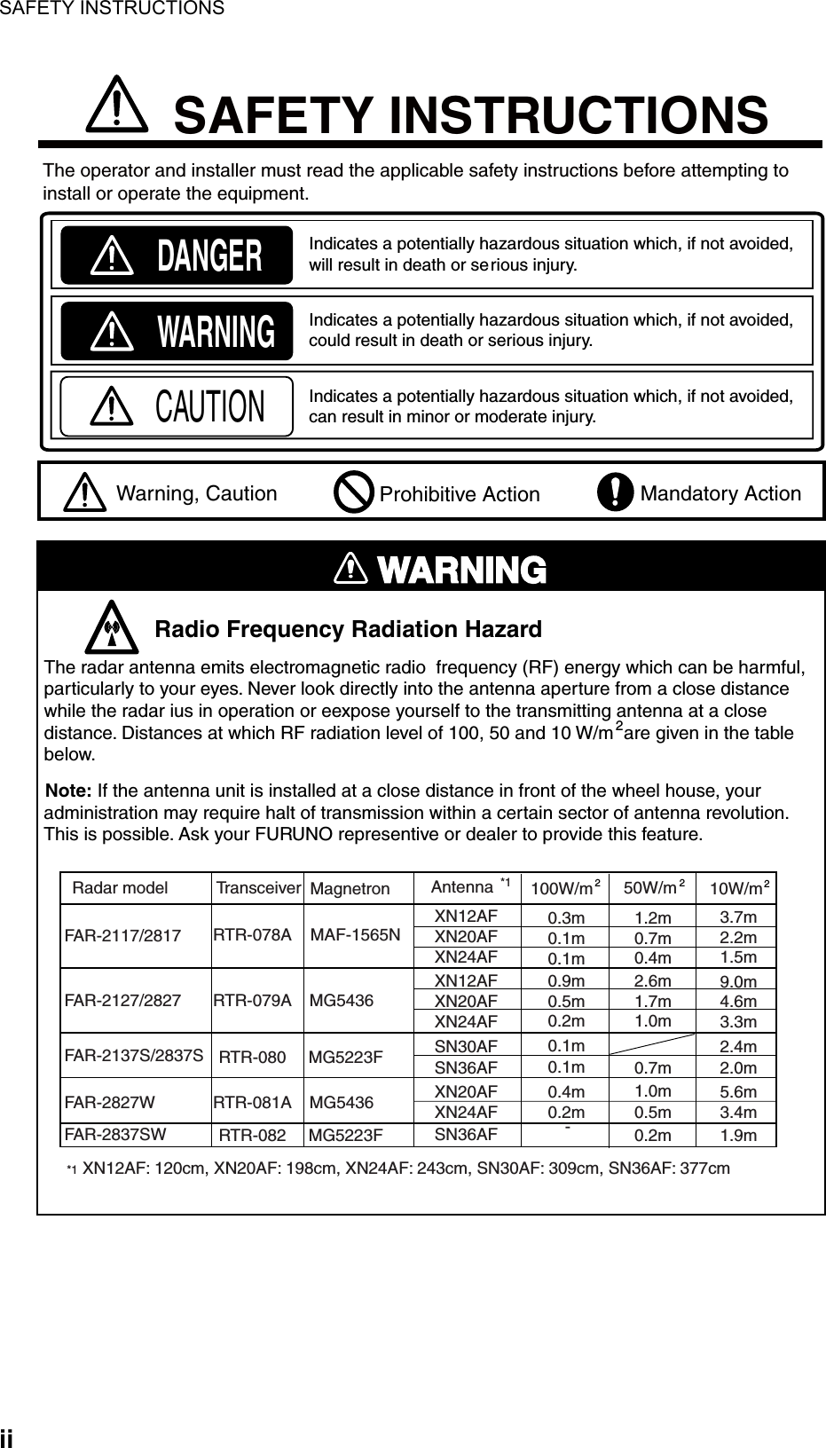

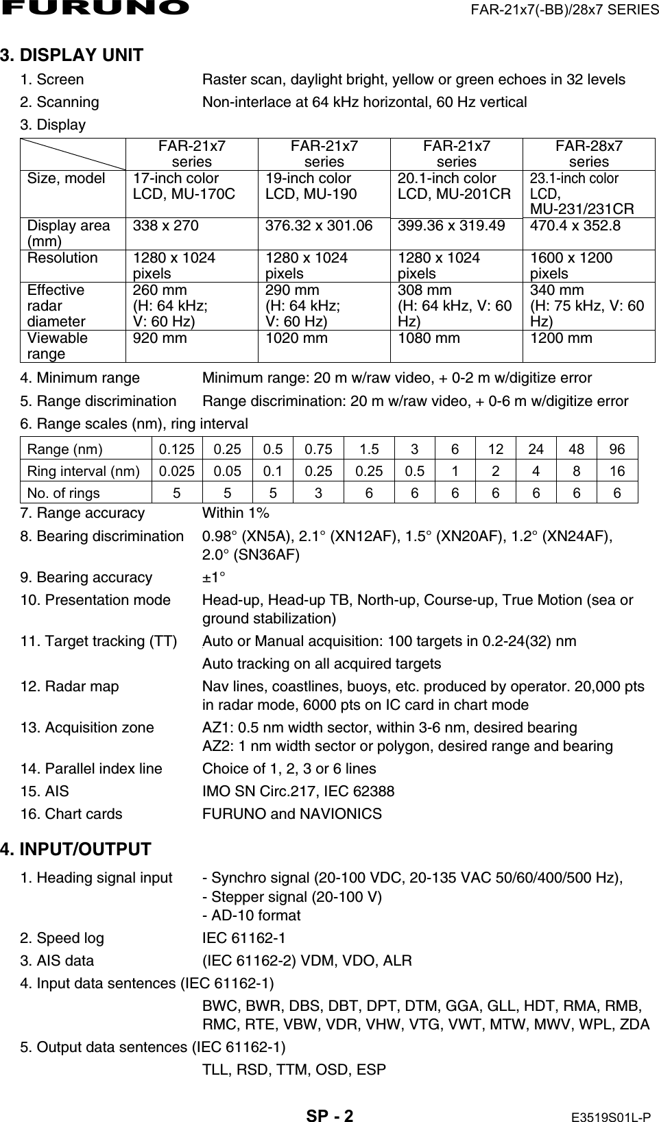
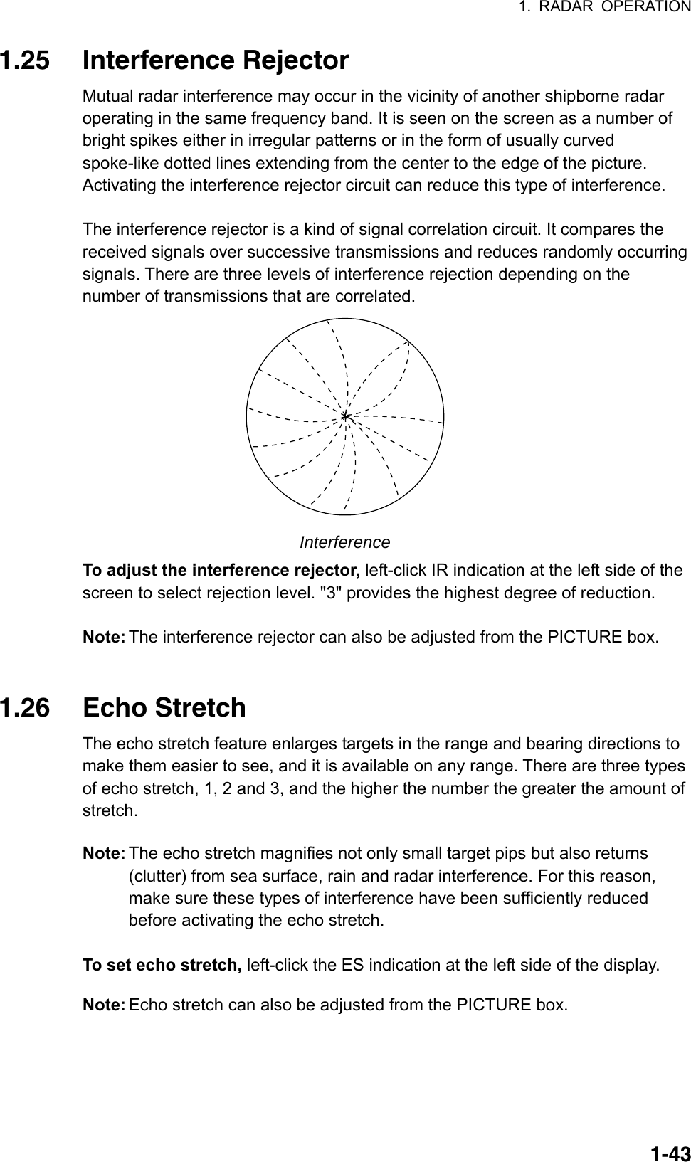
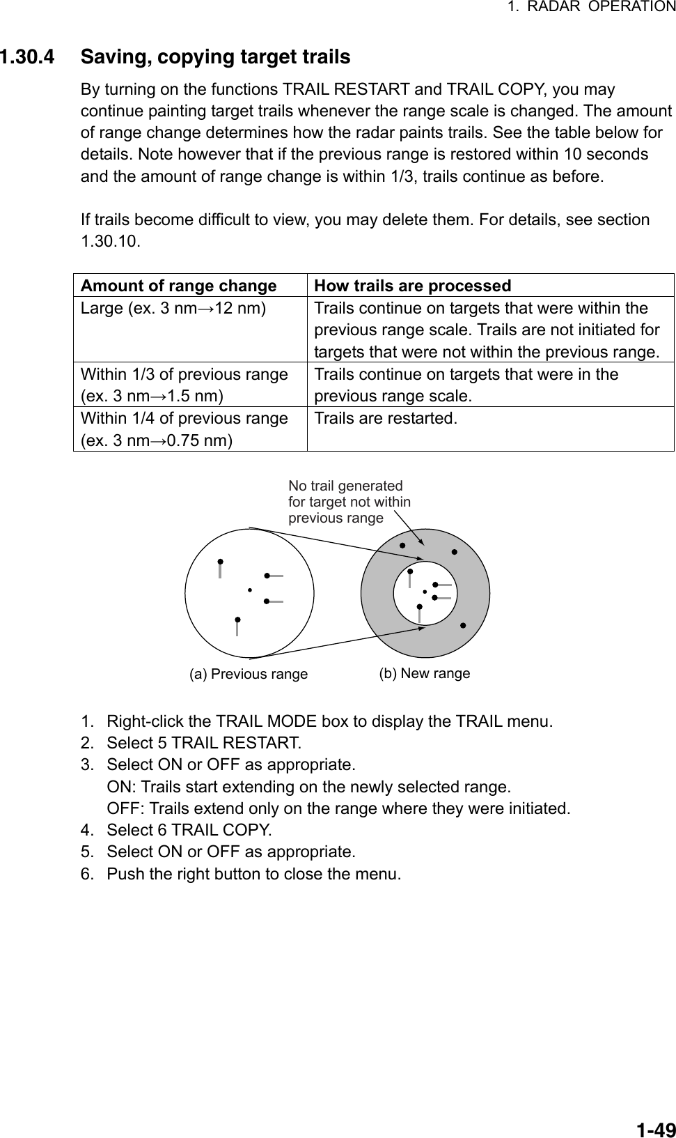
![1-11. RADAR OPERATION 1.1 Turning on the Power The [POWER] switch ( ) is located at the left corner of the control unit. Open the POWER switch cover and press the switch to turn on the radar system. To turn off the radar, press the switch again. The screen shows the bearing scale and digital timer approximately 30 seconds after power-on. The timer counts down three minutes of warm-up time. During this period the magnetron (transmitter tube) is warmed for transmission. When the timer has reached 0:00, the indication "ST-BY" appears at the screen center, meaning the radar is now ready to transmit pulses. In the stand-by condition, markers, rings, map, charts, etc. are not shown. Further, TT and AIS are not shown. In the warm-up and stand-by conditions, ON TIME and TX TIME count in hours and tenths of hour appear at the screen center. Note 1: Do not turn the power on directly after it has been turned off. Wait several seconds before you reapply the power, to be sure the radar starts up properly. Note 2: Parameters set on the menus are stored in a non-volatile memory (flash memory), and are preserved when the power is turned off. 1.2 Transmitter ON After the power is turned on and the magnetron has warmed up, ST-BY appears at the screen center, meaning the radar is ready to transmit radar pulses. You may transmit by pressing the [STBY/TX] key on the full keyboard, or use the trackball to select the TX STBY box at the bottom left corner of the display then push the left button (above the trackball). The label at the left-hand side of the guidance box at the bottom right corner of the screen changes from TX to STBY. GuidanceboxSTBY/TXSTBYTX STBY box Radar display](https://usermanual.wiki/Furuno-USA/9ZWRTR081A.op-manual/User-Guide-1456778-Page-22.png)
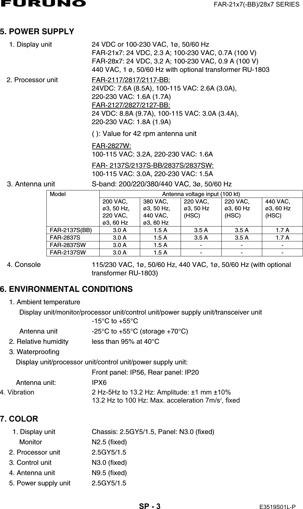
![1. RADAR OPERATION 1-2The radar is initially set to previously used range and pulse length. Other settings such as brilliance levels, VRMs, EBLs and menu option selections are also set to previous settings. The [STBY/TX] key (or TX STBY box) toggles the radar between STBY and TRANSMIT status. The antenna stops in stand-by and rotates in transmit. The magnetron ages with time resulting in a reduction of output power. Therefore, it is highly recommended that the radar be set to stand-by when not used for an extended period of time. How to stop antenna rotation Antenna rotation can be stopped. One method is to turn off the antenna switch on the radar. The other method is to stop rotation from the menu. For how to stop rotation from the menu, see the installation manual. Picture freeze When the picture freezes the picture is not updated. 30 seconds after the picture freezes, the buzzer sounds, the [ALARM ACK] key blinks and the alarm contact signal is output. Reset the power to restore normal operation. Quick start Provided that the radar was once in use with the transmitter tube (magnetron) still warm, you can turn the radar into TRANSMIT condition without three minutes of warm-up. If the [POWER] switch was turned off by mistake or the like and you wish to restart the radar promptly, turn on the [POWER] switch not later than 10 seconds after power-off. Echo area The echo display area for the B, C and W types is available in three configurations: round, wide, and full screen. You can select a configuration with 7 ECHO AREA on the ECHO menu. Round Wide Full](https://usermanual.wiki/Furuno-USA/9ZWRTR081A.op-manual/User-Guide-1456778-Page-23.png)
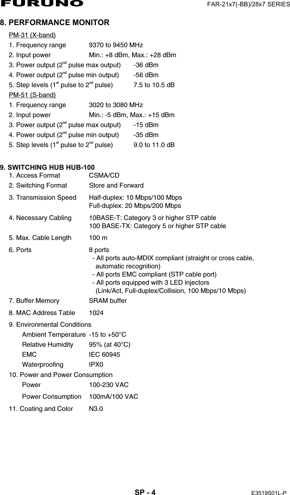
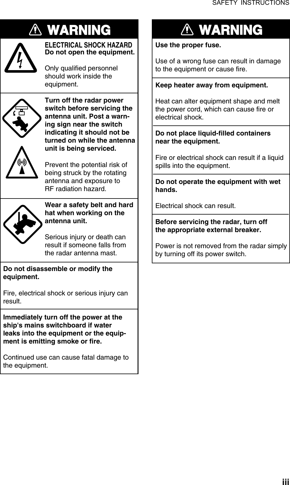
![1. RADAR OPERATION 1-51.4 Main Menu You may access the MAIN menu from the full keyboard or by using the trackball. In later sections only the procedure for menu operation by trackball is given. Main menu operation by keyboard 1. Press the [MENU] key. The MAIN menu appears in the text area at the right side of the screen. [MAIN MENU] 1 [ECHO] 2 [MARK] 3 [ALARM] 4 [TT AIS] 5 [PLOTTER] 6 [CARD] 7 [NAV DATA] 8 [NAV LINE WPT] 9 [CUSTOMIZE TEST] Echo processing functionsMainly turns markers on/off.Sets guard alarm functions; outputs alarm signal.Sets TT and AIS functions.Chart and track functionsMemory card functionsTurns nav data on/off.Processes nav lines and waypoints.Customizes operation; executes diagnostics. MAIN menu 2. Press the numeral key corresponding to the menu you wish to open. For example, press the [2] key to open the MARK menu. [MARK] 1 BACK 2 OWN SHIP MARK OFF/MIN/SCALED 3 STERN MARK OFF/ON 4 [PI LINE] 5 ANCHOR WATCH OFF/ON 0.0NM6 DROP MARK OFF/ON7 [INS MARK] *1 8 EBL OFFSET BASE STAB GND/STAB HDG/ STAB NORTH 9 [EBL, VRM, CURSOR SET]*20 RING OFF/ON *1[BARGE MARK] depending on installation preset. *2IMO and A types show 9 EBL CURSOR BEARING (REL/TRUE) MARK menu 3. Press the numeral key applicable to the item you wish to set. 4. Consecutively press the same numeral key pressed at step 3 to select appropriate option then press the [ENTER MARK] key to confirm your selection. 5. Press the [MENU] key to close the menu. To clear a line of numeric data:Use the [CANCEL TRAILS] key. Switch between plus and minus,North and South or East and West:Use the [2] key.Useful keys in menu operation](https://usermanual.wiki/Furuno-USA/9ZWRTR081A.op-manual/User-Guide-1456778-Page-26.png)
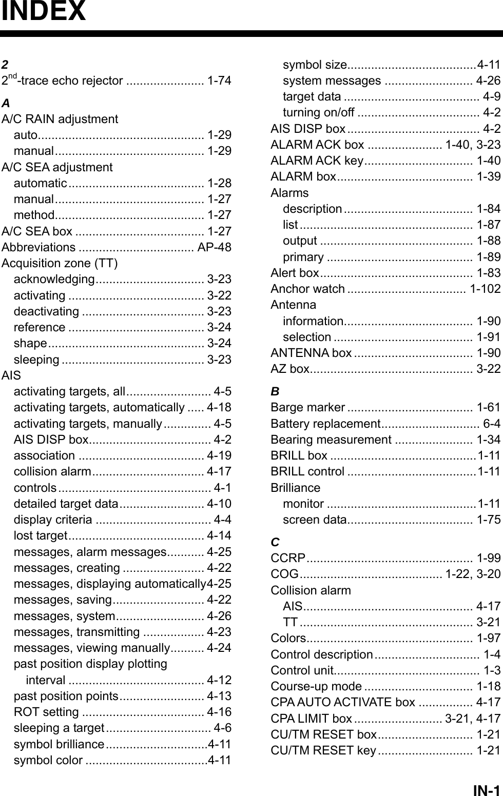
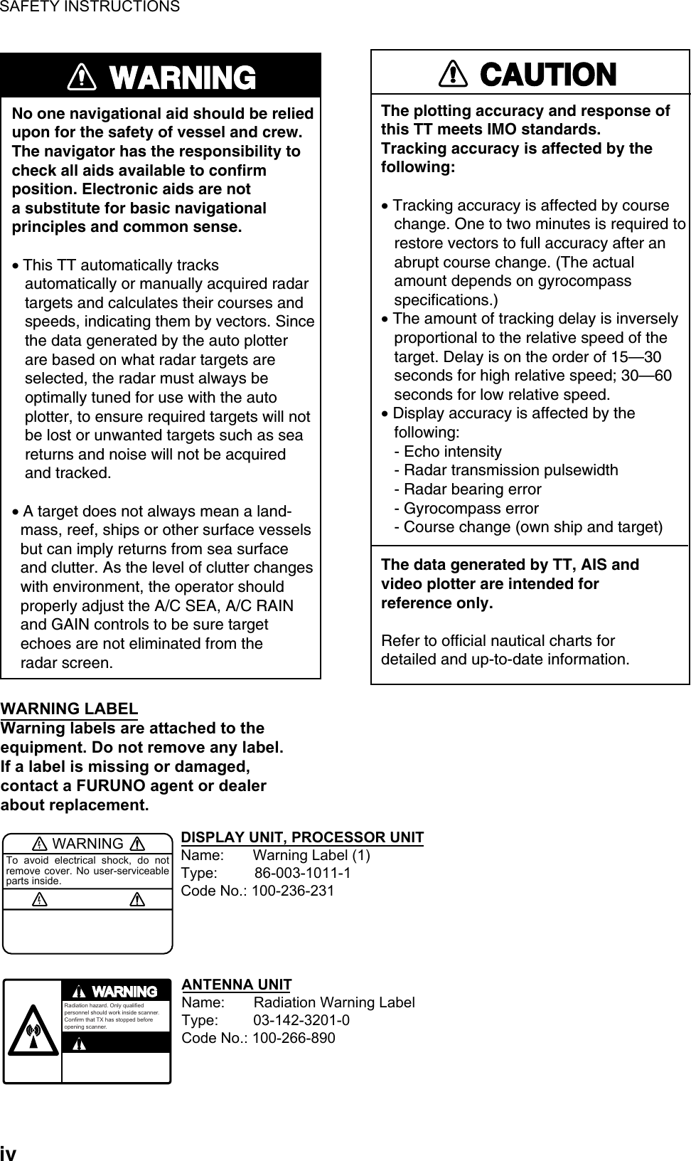
![1. RADAR OPERATION 1-6Main menu operation by trackball 1. Use the trackball to select the MENU box at the right side of the screen. The guidance box at the bottom right corner (see the illustration at the bottom of the next page for location) now reads "DISP MAIN MENU." 2. Push the left button to display the MAIN menu. [MAIN MENU] 1 [ECHO] 2 [MARK] 3 [ALARM] 4 [TTAIS] 5 [PLOTTER] 6 [CARD] 7 [NAV DATA] 8 [NAV LINEWPT] 9 [CUSTOMIZETEST] Echo processing functionsMainly turns markers on/off.Sets guard alarm functions; outputs alarm signal.Sets TT and AIS functions.Chart and track functionsMemory card functionsTurns nav data on/off.Processes nav lines and waypoints.Customizes operation; executes diagnostics. MAIN menu 3. Roll the scrollwheel or trackball to select a menu and push the left button. For example, select the 2 [MARK] menu. [MARK] 1 BACK 2 OWN SHIP MARK OFF/MIN/SCALED 3 STERN MARK OFF/ON 4 [PI LINE] 5 ANCHOR WATCH OFF/ON 0.0NM6 DROP MARK OFF/ON7 [INS MARK] *1 8 EBL OFFSET BASE STAB GND/STAB HDG/ STAB NORTH 9 [EBL, VRM, CURSOR SET]*20 RING OFF/ON *1[BARGE MARK] depending on installation preset. *2IMO and A types show 9 EBL CURSOR BEARING (REL/TRUE) MARK menu 4. Use the trackball to select a menu item and push the left button. 5. Roll the scrollwheel to select an option and push the left button to validate your selection. 6. Push the right button consecutively to close the menu. (Several pushes may be necessary depending on the menu used.) Note: Hereafter all menu procedures are described using the trackball module (trackball, scrollwheel, buttons). For sake of brevity we write, "Select [menu item] (or [menu option])" where you roll the scrollwheel and push the left button (or scrollwheel) to complete a task on the menu.](https://usermanual.wiki/Furuno-USA/9ZWRTR081A.op-manual/User-Guide-1456778-Page-27.png)
![1. RADAR OPERATION 1-93. The pop-up menu attached to the MARK box is the MARK menu. To open the menu, push the right button. The menu opens in the text area at the right side of the screen. [MARK MENU] 1 ORIGIN MARK STAB GND/SEA 2 MARK KIND ORIGIN MARK(No. )/ ORIGIN MARK(SYM)/ MAP MARK/ WP 1~50/ WP 51~ 100/ WP 101~150/ WP 151~198/ OWN SHIP SHAPE 8 MARK POSN CURSOR/OS/L/L 00°000.00 N 000°000.00 E9 MAP DISPLAY OFF/ON0 MAP MARK COLOR* RED/GRN/BLU/YEL/ CYA/MAG/WHT * Not available on IMO or A type MARK menu Note:Any menu may be operated from the full keyboard or with the trackball, or a combination of the two in case of Control Unit RCU-014. Note that in later sections only the procedure for menu operation by the trackball is given. 4. Select item desired. Selected item is initially shown in reverse video and changes to normal video and circumscribed when the scrollwheel or the left button is pushed. 5. Select option desired. Selected option is initially shown in reverse video and changes to normal video and circumscribed when the scrollwheel or the left button is pushed. 6. Push the right button to close the menu. (On some menus several presses of the right button are required to close the menu.)](https://usermanual.wiki/Furuno-USA/9ZWRTR081A.op-manual/User-Guide-1456778-Page-30.png)
![1. RADAR OPERATION 1-10[CURSOR MENU]2TARGET DATA & ACQ/TARGET CANCEL/TT TGT DATA & ACQ/TARGET TRACK ON*1/TARGET TRACK OFF*1/REF MARK/EBL OFFSET/OFFCENTER/ZOOM/MARK DELETE/OWN TRACK DELETE/TGT TRACK DELETE*1/CHART ALIGNTRAIL ERASER*1, *2/89 CURSOR*1, *2SMALL/LARGE*1 Not available on IMO type*1 Not available on A type1.6 Cursor Menu Functions that require the use of the cursor, such as EBL offset and zoom, may be activated directly from the guidance box or from the CURSOR menu, either method with the cursor inside the effective display area. Below is the procedure for choosing a cursor-related function from the CURSOR menu. In later sections only the procedure for selection from the guidance box is given. 1. Put the cursor inside the effective display area. 2. Roll the scrollwheel to show "TARGET DATA & ACQ / CURSOR MENU" in the guidance box. 3. Push the right button to show the CURSOR menu. 4. Select "2" then push the left button. 5. Select function desired then push the left button. Note: For operation from the keyboard, you may press the [2] key to select a function in top-to-bottom order or the [8] key to select in reverse order. Cursor Menu item Description TARGET DATA & ACQ TT: Acquires target; displays data for selected tracked target. AIS: Activates sleeping AIS target; display data for selected AIS target. TARGET CANCEL TT: Cancels tracking on selected tracked target. AIS: Sleeps selected AIS target. TT TARGET DATA & ACQ Acquires selected echo as tracked target. TARGET TRACK ON Turns track for TT/AIS on. TARGET TRACK OFF Turns track for TT/AIS off. REF MARK Inscribes reference mark, for target-based speed input. EBL OFFSET Offsets EBL to measure range and bearing between two targets. OFF CENTER Shifts screen center to selected location. ZOOM Zooms selected location. MARK DELETE Deletes selected mark (plotter mark, origin mark or waypoint mark). OWN TRACK DELETE Deletes own ship’s tracks. TGT TRACK DELETE Deletes other ship’s tracks. CHART ALIGN Aligns chart with radar picture. TRAIL ERASER Erases trails. (A, B and C types) CURSOR SIZE Selects cursor size. (A, B and C types) 6. The guidance box shows "XX / EXIT." (XX = function selected). Use the trackball to put the cursor where desired. 7. Push the left button to execute the function selected at step 5. 8. To quit the function selected, push the right button when the guidance box shows "XX / EXIT." (XX = function selected at step 5)](https://usermanual.wiki/Furuno-USA/9ZWRTR081A.op-manual/User-Guide-1456778-Page-31.png)
![1. RADAR OPERATION 1-111.7 Monitor Brilliance The brilliance of the entire screen should be adjusted according to lighting conditions. Monitor brilliance should be adjusted before adjusting relative brilliance levels on the BRILL menu to be explained later. Note: The brilliance of a commercial monitor cannot be adjusted from the radar. See the owner’s manual of the commercial monitor for how to adjust its brilliance. By keyboard Operate the [BRILL] control on the control unit to adjust brilliance. Turn it clockwise to increase brilliance; counterclockwise to decrease brilliance. Watch the BRILL box (see illustration below) to know current brilliance level. By trackball 1. Use the trackball to place the arrow on the brilliance level indicator in the brilliance level indication box at the bottom left corner of the screen. BRILL1 Place arrow inside boxto adjust screen brilliance.Brilliance barShows brilliance level.26Brilliance levelBrillance, color set no.(For details, see para. 1.50.) Brilliance level indicator 2. Roll the scrollwheel downward to increase brilliance or roll it upward to decrease brilliance. The length of the brilliance bar increases or decreases with operation of the scrollwheel. Note: If nothing appears on the screen in stand-by when using Control Unit RCU-015 (palm control), press and hold down one of the keys F1-F4* to raise the brilliance to level "50". *Key set for other than USER DEFAULT. See section 1.36.2.](https://usermanual.wiki/Furuno-USA/9ZWRTR081A.op-manual/User-Guide-1456778-Page-32.png)
![1. RADAR OPERATION 1-151.10 Tuning the Receiver 1.10.1 Choosing the tuning method The tuning method can be selected with the TUNE box at the top of the screen. 1. Select the TUNE box (TUNE AUTO or TUNE MAN) at the top of the screen. TUNE AUTO Place arrow inside boxto adjust tuning, whenTUNE MAN is selected.Tuning method (AUTO or MAN)Tuning barTuning level TUNE box 2. Push the left button or scrollwheel to display TUNE AUTO or TUNE MAN as appropriate. 3. If you used the scrollwheel to select tuning method, push the scrollwheel or the left button to change setting. 1.10.2 Initializing tuning Automatic tuning is initialized during the installation. However, if you feel that automatic tuning is not working properly try re-initializing it as follows: 1. Left-click the MENU box to open the menu. 2. Select 1 [ECHO]. [ECHO] 1 BACK 2 2ND ECHO REJ OFF/ON 3 TUNE INITIALIZE 4 PM*1 OFF/ON 5 SART OFF/ON 6 WIPER OFF/1/2 7 ECHO AREA*2 CIRCLE/WIDE/ALL*1 Not available on FAR-2157/2167DS*2 Not available on IMO or A type8 [PICTURE SELECT]9 STC RANGE +00 ECHO menu 3. Select 3 TUNE INITIALIZE. (For operation from the keyboard, press the [ENTER MARK] key.) "WARNING – TUNE INITIALIZE" appears in the Alert Box during the initialization. 4. Push the right button twice to close the menu.](https://usermanual.wiki/Furuno-USA/9ZWRTR081A.op-manual/User-Guide-1456778-Page-36.png)
![1. RADAR OPERATION 1-16 [HDG MENU] 1 HDG SOURCE AD-10/SERIAL 2 GC-10 SETTING 000.0° 1.10.3 Automatic tuning Select automatic tuning following section 1.10.1. The TUNE box shows TUNE AUTO. 1.10.4 Manual tuning 1. Select the 48-mile range from the RANGE box. Push the left button to lower the range; the right button to raise the range. 2. Select manual tuning following the procedure in section 1.10.1. 3. Use the trackball to place the arrow on the tuning bar area in the TUNE box. 4. Roll the scrollwheel to adjust tuning. The best tuning point is where the bar graph swings maximum. The arrow below the bar graph shows tuning control position; not the tuning condition. 1.11 Aligning Heading with Gyrocompass With connection of a gyrocompass, ship's heading is displayed at the right side of the screen. Turn on the radar and match the on-screen GYRO readout with the gyrocompass reading as shown below. Once you have set the initial heading correctly, resetting is not usually required. This alignment is not necessary for the FURUNO SC-60/120 Satellite Compass. 1. Right-click the HDG box at the top right corner of the screen. HDG menu 2. Roll the scrollwheel downward to select GC-10 SETTING. Note: If the heading source selected is not suitable change it at 1 HDG SOURCE to match your heading source. 3. Roll the scrollwheel to set the heading. (For entry through the keyboard, use the numeric keys.) 4. Push the scrollwheel to finish. 5. Push the right button to close the menu.](https://usermanual.wiki/Furuno-USA/9ZWRTR081A.op-manual/User-Guide-1456778-Page-37.png)
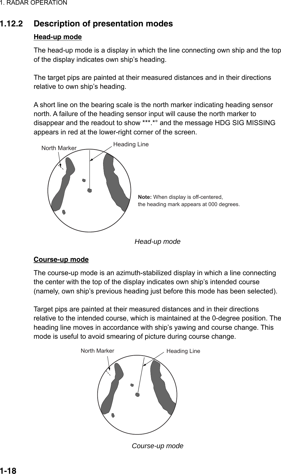
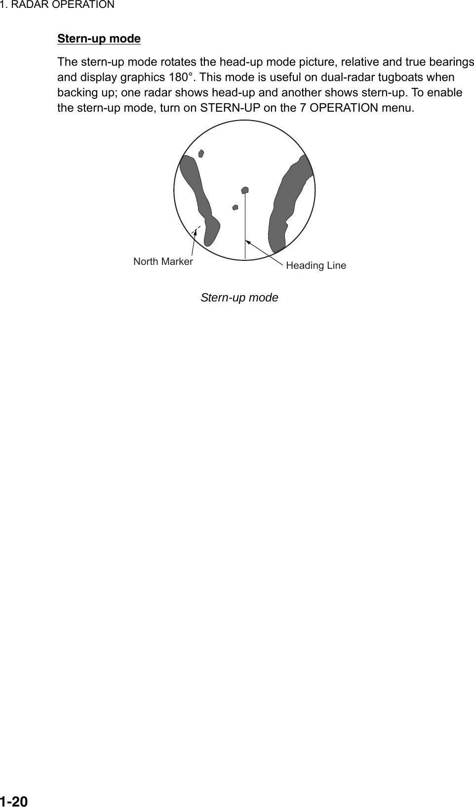
![1. RADAR OPERATION 1-171.12 Presentation Modes This radar has the following presentation modes: Relative Motion (RM) Head-up: Unstabilized Head-up TB: Head-up with compass-stabilized bearing scale (True Bearing) where the bearing scale rotates with the compass reading. Course-up: Compass-stabilized relative to ship’s orientation at the time of selecting course-up. North-up: Compass-stabilized with reference to north Stern-up: The radar image is rotated 180°. Graphics and relative and true bearings are also rotated 180°. True Motion (TM) Land objects and sea are stationary. Requires compass and speed data. 1.12.1 Choosing presentation mode By keyboard Press the [MODE] key consecutively to select presentation mode desired. The PRESENTATION MODE box shows the current presentation mode. (See the illustration below.) By trackball Left-click the PRESENTATION MODE box at the top left corner of the screen to select a presentation mode. HEAD UP RM** = Other modes:STERN-UP, HEAD UP TB RM, COURSE UP RM,NORTH UP RM, NORTH UP TM PRESENTATION MODE box Loss of gyrocompass signal When the compass signal is lost, "GYRO" appears in red in the Alert Box, the presentation mode automatically becomes head-up, and TT and AIS targets, map and chart are erased. After restoring the compass signal, "HEADING SET" appears in the Alert Box. Then, stop the alarm with the [ALARM ACK] key or the ALARM ACK box and check the GYRO data.](https://usermanual.wiki/Furuno-USA/9ZWRTR081A.op-manual/User-Guide-1456778-Page-38.png)
![1. RADAR OPERATION 1-21True motion mode Own ship and other moving objects move in accordance with their true courses and speed. In ground stabilized TM, all fixed targets, such as landmasses, appear as stationary echoes. In the sea stabilized TM without set and drift inputs, the landmass can move on the screen. Note that true motion is not available on the 72 nm (non-IMO type only) or 96 nm range scale. If COG and SOG (both over the ground) are not available on TM mode, enter the set (tide direction) and drift (tide speed) manually referring to the Tide Table. When own ship reaches a point corresponding to 50% of the radius of the display, own ship position is automatically reset to a point of 75% radius opposite to the extension of the heading line passing through the display center. You may also reset the own ship symbol manually by pressing the [CU/TM RESET] key, or left-clicking the CU/TM RESET box at the bottom right corner of the display. If the heading sensor fails, the mode is changed to the head-up and the north marker disappears. The HDG readout shows ***.*° and the message HDG SIG MISSING appears in red at the lower-right corner of the screen. Note: A part of the bearing scale is drawn differently depending on antenna reference position. ANT: Bearing scale interval is different when display is offcentered. CONN: A part of the bearing scale is not displayed if the conning position is not within the radar display area. Heading LineNorth Marker True motion mode Automatic resetting of own ship mark in true motion mode HeadinglineNorthmarker(a) True motionis selected(b) Own ship has reached apoint 75% of display radius(c) Own ship is automaticallyreset to 75% of radius](https://usermanual.wiki/Furuno-USA/9ZWRTR081A.op-manual/User-Guide-1456778-Page-42.png)
![1. RADAR OPERATION 1-22[SPEED MENU] 1 SHIP SPEED LOG(BT)/LOG(WT)/ GPS/MANUAL/REF 2 MANUAL SPEED 0.0kn 3 SET DRIFT OFF/ON 1.13 Entering Own Ship's Speed The TT and azimuth stabilized presentation modes require own ship speed input and compass signal. The speed can be entered from a log (STW) or GPS (SOG) or manually on the menu. Note that FURUNO GPS Navigator GP-90 provides COG and SOG. 1.13.1 Automatic speed input by log or GPS navigator 1. Right-click the SPD box at the top right corner of the screen. SPEED menu 2. Select 1 SHIP SPEED. 3. Select the appropriate source for automatic speed input then push the left button. LOG (BT): Log, speed over ground (SOG). Note that a log cannot produce BT (Bottom Tracking) speed in deep waters without set and drift entry. LOG (WT): Log, speed thru water (STW) GPS: Speed input by GPS navigator MANUAL: Manually input speed REF: Echo-referenced speed input 4. Push the right button to close the menu. Notes on speed input • IMO Resolution A.823(19) for TT recommends that a speed log to be interfaced with a TT should be capable of providing through-the-water speed (forward speed). • Be sure not to select a LOG option when a speed log is not connected. If the log signal is not provided, the ship speed readout at the top of the screen will be blank. In the event of a log error, enter speed manually. • The SPD is shown as "*.* kn" and the label "LOG" (in red) appears and the alarm buzzer sounds if no log signal is present for 30 s. • With the serial speed inputs and SOG selection, if the type of data is changed from SOG to STW the label "LOG" (in red) appears and the alarm buzzer sounds.](https://usermanual.wiki/Furuno-USA/9ZWRTR081A.op-manual/User-Guide-1456778-Page-43.png)
![1. RADAR OPERATION 1-23• On the IMO type with AIS in use, LOG(WT), MANUAL and REF are shown in gray to indicate they are not available for selection. • A single-axis water log cannot measure speed when the wind is coming from the leeway direction. • If speed over the ground cannot be obtained in a deep area, select LOG(WT), turn on SET DRIFT and enter set and drift values. See section 3.12 for the procedure. 1.13.2 Manual speed input If the speed log is not working, enter speed manually as below. In this case the speed data type is shown as MANUAL and is speed thru water (STW). Manual speed input is not available on the IMO radar when the AIS feature is active. 1. Right-click the SPD box at the top right corner of the screen to display the SPEED menu. 2. Select 1 SHIP SPEED. 3. Select MANUAL then push the left button. 4. Select 2 MANUAL SPEED. 5. Roll the scrollwheel to set speed. (For entry through the keyboard, use the numeric keys.) 6. Push the left button to confirm setting. 7. Push the right button to close the menu. 1.14 Choosing a Range Scale The selected range scale, range ring interval and pulselength are shown at the upper left corner on the screen. When a target of interest comes closer, reduce the range scale so that it appears in 50-90% of the display radius. By keyboard Use the [RANGE] key to select range desired. Hit the "+" part of the key to raise the range; the "-" part to lower the range. By trackball 1. Use the trackball to select the RANGE box at the top left corner of the screen. The guidance box shows "RANGE DOWN / RANGE UP." 0.125NM0.025 RANGE box 2. Push the left button to lower the range; the right button to raise the range. You may also select the range by rolling the scrollwheel then pushing it or the left button.](https://usermanual.wiki/Furuno-USA/9ZWRTR081A.op-manual/User-Guide-1456778-Page-44.png)
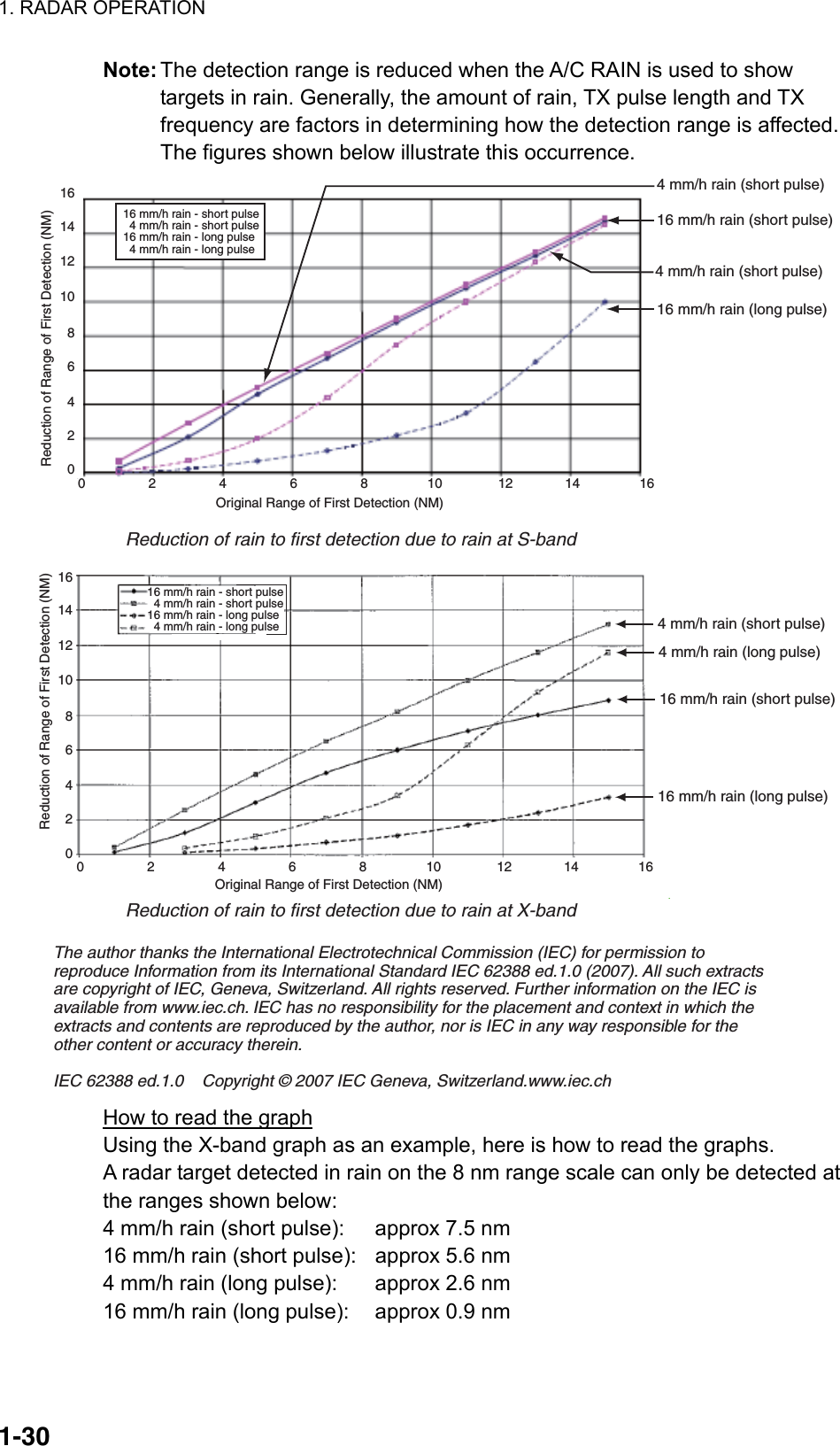
![1. RADAR OPERATION 1-24 [PICTURE MENU] 1 INT REJECT OFF/1/2/3 2 ECHO STRETCH OFF/1/2/3 3 ECHO AVERAGE OFF/1/2/3 4 NOISE REJ OFF/ON 5 AUTO STC OFF/ON 6 AUTO RAIN OFF/1/2/3/4 7 VIDEO CONTRAST 1/2/3/4/ A/B/C 8 [PULSE] 9 [CONDITION] 0 DEFAULT NO/SAVE/USER/ FACTORY 1.15 Choosing a Pulselength The pulselength in use is displayed at the upper-left position of the screen using the indications shown in the table below. Label and pulselength X-band 10, 25 kW, S-band 30 kW Indication Pulselength (μs)S1 (Short pulse 1) 0.07 S2 (Short pulse 2) 0.15 M1 (Medium pulse 1)0.3 M2 (Medium pulse 2)0.5 M3 (Medium pulse 3)0.7 L (Long pulse) 1.2 Appropriate pulselengths are preset to individual range scales and function keys. If you are not satisfied with the current pulselength settings, you may change them as shown below. 1.15.1 Choosing a pulselength You can select the pulselength for the 0.5 to 24 nm range scales as below. 1. Right-click the PICTURE box at the left side of the screen to show the PICTURE menu. Note: The PICTURE box sets up the radar picture according to expected usage, such as harbor navigation, long range, short range, etc. For further details see section 1.35. PICTURE menu](https://usermanual.wiki/Furuno-USA/9ZWRTR081A.op-manual/User-Guide-1456778-Page-45.png)
![1. RADAR OPERATION 1-25 [PULSE MENU] 1 BACK 2 0.5NM S1/S2 3 0.75NM S1/S2/M1 4 1.5NM S1/S2/M1 5 3NM S2/M1/M2/M3 6 6NM M1/M2/M3/L 7 12-24NM M2/M3/L 2. Select 8 [PULSE]. PULSE menu 3. Select a range then push the left button. 4. Select pulselength desired then push the left button. 5. Push the right button twice to close the menu. 1.15.2 Changing pulselength 1. Use the trackball to select the PULSELENGTH box at the left side of the screen. The guidance box shows "PULSE SHORTER / PULSE LONGER." PULSE XX** XX = Pulse width setting PULSELENGTH box 2. Push the left button to shorten the pulselength or the right button to lengthen the pulselength. You may also select the pulselength by rolling the scrollwheel and pushing it or the left button.](https://usermanual.wiki/Furuno-USA/9ZWRTR081A.op-manual/User-Guide-1456778-Page-46.png)
![1. RADAR OPERATION 1-261.16 Adjusting the Sensitivity The gain control adjusts the sensitivity of the receiver. The proper setting is such that the background noise is just visible on the screen. If you set up for too little sensitivity, weak echoes may be missed. On the other hand excessive sensitivity yields too much background noise; strong targets may be missed because of the poor contrast between desired echoes and the background noise on the display. To adjust receiver sensitivity, adjust the gain control so background noise is just visible on the screen. By keyboard While monitoring the gain level indicator at the top of the screen, operate the [GAIN] control to adjust the sensitivity. By trackball 1. Use the trackball to place the arrow on the gain level indicator at the top of the screen. GAIN Place arrow insidewindow to adjust gain.Level bar30 GAIN level indicator 2. Roll the scrollwheel downward to increase the gain or upward to decrease it. 100 levels (0-100) are available.](https://usermanual.wiki/Furuno-USA/9ZWRTR081A.op-manual/User-Guide-1456778-Page-47.png)
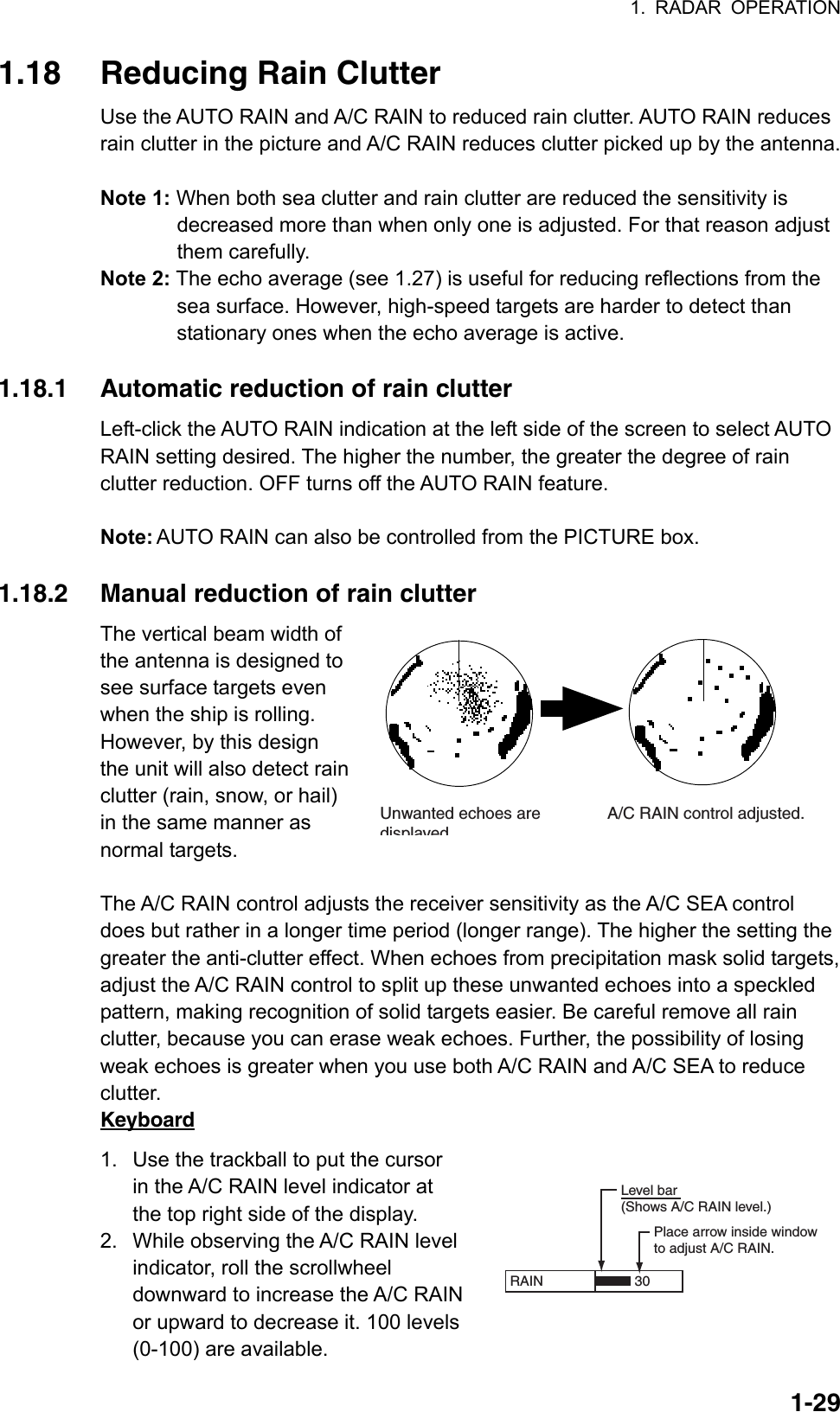
![1. RADAR OPERATION 1-271.17 Reducing Sea Clutter Echoes from waves cover the central part of the display with random signals known as sea clutter. The higher the waves, and the higher the antenna above the water, the further the clutter extends. When sea clutter masks the picture, reduce it by the A/C SEA control, either manually or automatically. Note 1: When both sea clutter and rain clutter are reduced, the sensitivity is decreased more than when only one is adjusted. For that reason adjust them carefully. Note 2: The echo average (see 1.27) is useful for reducing reflections from the sea surface. However, high-speed targets are harder to detect than stationary ones when the echo average is active. 1.17.1 Choosing method of adjustment 1. Use the trackball to select SEA AUTO or SEA MAN (whichever is shown) at the top of the display. SEA AUTO Place arrow inside windowto adjust A/C SEA.A/C SEA adjustmentmethod (SEA AUTO or SEA MAN)Level bar30 A/C SEA level indicator 2. Push the left button to display SEA AUTO or SEA MAN as appropriate. 1.17.2 Automatic reduction of sea clutter Auto A/C SEA allows for fine tuning of the A/C SEA circuit, within ±20 dB. Accordingly, with the bar reading set to 100, gain is not lowered to minimum as with manual A/C SEA on close-in ranges. Further, the auto A/C SEA level is low because the average value of the original input echo is low in areas where there are no sea surface reflections. For example, when the ship is alongside a quay and the radar picture shows echoes from both land and sea, you can observe the size of the echoes because the STC curve changes with the size of the echoes. Note: The auto A/C function can erase weak target echoes. Adjust the control carefully, watching the display. By keyboard 1. Select SEA AUTO following the procedure in section 1.17.1. 2. While observing the A/C SEA level indicator, adjust the A/C SEA with the [A/C SEA] control. 100 levels are available.](https://usermanual.wiki/Furuno-USA/9ZWRTR081A.op-manual/User-Guide-1456778-Page-48.png)
![1. RADAR OPERATION 1-28By trackball 1. Select SEA AUTO following the procedure in section 1.17.1. 2. Use the trackball to place the arrow in the A/C SEA level indicator at the top of the display. 3. While observing the A/C SEA level indicator, roll the scrollwheel downward to increase the A/C SEA or upward to decrease it. 100 levels (0-100) are available. 1.17.3 Manual reduction of sea clutter The A/C SEA control reduces the amplification of echoes at short ranges (where clutter is the greatest) and progressively increases amplification as the range increases, so amplification will be normal at those ranges where there is no sea clutter. The proper setting of the A/C SEA should be such that the clutter is broken up into small dots, and small targets become distinguishable. If the setting is set too low, targets will be hidden in the clutter, while if the setting is too high, both sea clutter and targets will disappear from the display. In most cases adjust the control until clutter has disappeared to leeward, but a little is still visible windward. Be careful not to remove all sea clutter, because you may erase weak echoes. Further, the possibility of losing weak echoes is greater when you use both A/C SEA and A/C RAIN to reduce clutter. A/C SEA adjusted;sea clutter suppressedSea clutter atscreen center By keyboard 1. Select SEA MAN following the procedure in section 1.17.1. 2. Watching the A/C SEA level indicator at the top of the display, adjust the A/C SEA with the [A/C SEA] control. 100 levels (0-100) are available. By trackball 1. Select SEA MAN following the procedure in section 1.17.1. 2. Use the trackball to place the arrow on the A/C SEA level indicator at the top of the display. 3. While observing the A/C SEA level indicator, roll the scrollwheel downward to increase the A/C SEA or upward to decrease it. 100 levels (0-100) are available.](https://usermanual.wiki/Furuno-USA/9ZWRTR081A.op-manual/User-Guide-1456778-Page-49.png)
![1. RADAR OPERATION 1-311.19 Measuring Range The range to a target may be measured three ways: with the fixed range rings, with the cursor, or with the VRM. Use the fixed range rings to get an estimate of the range to a target. The rings are the concentric solid circles on the display. The number of rings is automatically set by the current range scale. The distance between the rings is the range ring interval, and the current interval appears at the upper-left position on the screen. To measure the range to a target with the range rings, count the number of rings between the center of the display and the target. Check the range ring interval and estimate the distance of the echo from the inner edge of the nearest ring. 1.19.1 Showing, hiding the fixed range rings 1. Left-click the MENU box to open the menu. 2. Select 2 [MARK]. [MARK] 1 BACK 2 OWN SHIP MARK OFF/MIN/SCALED 3 STERN MARK OFF/ON 4 [PI LINE] 5 ANCHOR WATCH OFF/ON 0.0NM6 DROP MARK OFF/ON7 [INS MARK] *1 8 EBL OFFSET BASE STAB GND/STAB HDG/ STAB NORTH 9 [EBL, VRM, CURSOR SET]*20 RING OFF/ON *1[BARGE MARK] depending on installation preset. *2IMO and A types show 9 EBL CURSOR BEARING (REL/TRUE) MARK menu 3. Select 0 RING. 4. Select OFF or ON as appropriate then push the left button. 5. Push the right button twice to close the menu.](https://usermanual.wiki/Furuno-USA/9ZWRTR081A.op-manual/User-Guide-1456778-Page-52.png)
![1. RADAR OPERATION 1-32 VRM1 VRM2 1.19.2 Measuring range by the variable range marker (VRM) There are two VRMs, No. 1 and No. 2, which appear as dashed rings so that you can distinguish them from the fixed range rings. The two VRMs can be distinguished from each other by the different lengths of their dashes; the dashes on the No. 2 VRM are longer. 000 010 020030040050060070080090100110120130140150160170180190200210220230240250260270280290300310320330 340 350No. 1VRMTargetblipNo. 2VRM VRM1 VRM2 >0.66NM<1.18NM45:0299:59TTG to VRM Measuring range with VRMs By keyboard 1. Press the [VRM ON] key to display either of the VRMs. Successively pressing the [VRM ON] key toggles the active VRM between No. 1 and No. 2. The currently active marker is enclosed with >...<. 2. Operate the VRM rotary control to align the active variable range marker with the inner edge of the target of interest and read its distance at the lower-right corner of the screen. Each VRM remains at the same geographical distance when you operate the [RANGE] key or the RANGE box. This means that the apparent radius of the VRM ring changes in proportion to the selected range scale. 3. Press the [VRM OFF] key to erase each VRM. By trackball 1. Use the trackball to place the arrow in the VRM1 or VRM2 box, whichever VRM you want to use. 2. The guidance box reads "VRM ON/." Push the left button to turn on the VRM. The guidance box now reads "VRM SET L = DELETE /." 3. Push the left button again and the cursor jumps to inside the effective display area. The guidance box now reads "VRM FIX / EXIT." 4. Use the trackball (coarse adjustment) or scrollwheel (fine adjustment) to align the active variable range marker with the inner edge of the target of interest and read its distance at the lower-right corner of the screen. Each VRM remains at the same geographical distance when you operate the [RANGE] key. This means that the apparent radius of the VRM ring changes in proportion to the selected range scale. 5. Push the left button to anchor the VRM and fix its readout, or push the right button to return the VRM to its previous location (range). 6. To erase a VRM, select the appropriate VRM readout box then push the left button until the VRM disappears from the screen.](https://usermanual.wiki/Furuno-USA/9ZWRTR081A.op-manual/User-Guide-1456778-Page-53.png)
![1. RADAR OPERATION 1-331.19.3 VRM unit of measurement (B and C types) 1. Left-click the MENU box to open the menu. 2. Select 2 [MARK]. 3. Select 9 [EBL, VRM, CURSOR SET] then push the scrollwheel. 4. Select VRM1 or VRM2 as appropriate and push the scrollwheel. 5. Select unit of measurement desired then push the scrollwheel. 6. Push the right button twice to close the menu. 1.19.4 TTG to VRM indication You can show the TTG to VRMs as follows: 1. Left-click the MENU box to open the menu. 2. Select 9 [CUSTOMIZE·TEST] to open the CUSTOMIZE·TEST menu. 3. Select 7 [OPERATION]. 4. Select 0 NEXT. 5. Select 3 VRM TTG. 6. Select OFF, 1, 2 or 1+2 as applicable and push the left button. OFF: NO VRM TTG display 1: TTG to VRM1 2: TTG to VRM2 1+2: TTG to VRM1 and VRM2 7. Push the right button four times to close the menu. VRM1>3.682NM<00:00TTG indication VRM and TTG indications](https://usermanual.wiki/Furuno-USA/9ZWRTR081A.op-manual/User-Guide-1456778-Page-54.png)
![1. RADAR OPERATION 1-341.20 Measuring Bearing Use the Electronic Bearing Lines (EBLs) to take bearings of targets. There are two EBLs, No. 1 and No. 2. Each EBL is a straight dashed line extending out from the own ship position up to the circumference of the radar picture. The two EBLs can be distinguished from each other by the different lengths of their dashes; the dashes on the No. 2 EBL are longer. Each EBL carries a range marker, or a short line crossing the EBL at right angles. Its distance from the EBL origin is indicated at the VRM readout whether or not the corresponding VRM is displayed. The range marker changes its position along the EBL with the rotation of the VRM control. To operate this marker, rotate the VRM rotary control on the full keyboard, or put the cursor in the applicable VRM box and roll the scrollwheel. 1.20.1 Measuring bearing By keyboard 1. Press the [EBL ON] key to display either of the EBLs. Successive presses of the [EBL ON] key toggle the active EBL between No. 1 and No. 2. The currently active marker is enclosed with >...<. 2. Operate the EBL rotary control clockwise or counterclockwise until the active EBL bisects the target of interest, and read its bearing at the lower-left corner of the screen. 3. Press the [EBL OFF] key to erase each EBL. By trackball 1. Use the trackball to place the arrow in the EBL1 or EBL2 box, whichever EBL you want to use. EBL1 EBL2 EBL boxes 2. The guidance box reads "EBL ON/." Push the left button to turn on the EBL. The guidance box now reads "EBL SET L=DELETE /." 3. Push the left button again and the cursor jumps to inside the effective display area. The guidance box now reads "EBL FIX L=DELETE/." 4. Use the trackball (coarse adjustment) or scrollwheel (fine adjustment) to bisect the target with the EBL. 5. Push the left button to anchor the EBL and fix its readout, or push the right button to return the EBL to its previous location (bearing). 6. To erase an EBL, select the appropriate EBL readout box then push the left button until the EBL disappears from the screen.](https://usermanual.wiki/Furuno-USA/9ZWRTR081A.op-manual/User-Guide-1456778-Page-55.png)
![1. RADAR OPERATION 1-35 [EBL, VRM, CURSOR SET] 1 BACK 2 EBL1 REL/TRUE 3 EBL2 REL/TRUE 4 VRM1 NM/SM/km/kyd 5 VRM2 NM/SM/km/kyd 6 CURSOR BEARING REL/TRUE 7 CURSOR RANGE NM/SM/km/kyd 8 [◊CURSOR SHAPE]* 000 010 020030040050060070080090100110120130140150160170180190200210220230240250260270280290300310320330 340 350No. 2EBLTargetblipNo. 1EBLRange markerson EBLs VRM1 VRM2 12.1NM EBL1 EBL2 >128.0°T<100.8°T>10.2NM< Measuring bearing with EBLs 1.20.2 True or relative bearing The EBL readout is affixed by "R" (relative) if it is relative to own ship's heading, "T" (true) if it is referenced to the north. Available on the IMO and A type radars. True or relative indication is available regardless of presentation mode. 1. Left-click the MENU box to open the menu. 2. Select 2 [MARK] to open the MARK menu. 3. Select 9 [EBL, VRM, CURSOR SET] (B, C and W types) or 9 EBL CURSOR BEARING (IMO and A types). For the B, C and W types the menu below appears; go to step 4. For the IMO and A types go to step 5. 4. Select EBL1 or EBL2 as applicable. 5. Select REL or TRUE as applicable. 6. Push the right button twice to close the menu. Note: When the gyrocompass heading changes, the EBL and its indication change as follows: Head-up / relative EBL indication and EBL marker are unchanged. Head-up / true EBL indication does not change, however the EBL marker moves accordingly. Course-up / relative EBL indication does not change, however the EBL marker moves accordingly. Course-up / true EBL indication and EBL marker are unchanged. North-up / relative EBL indication does not change, however the EBL marker moves accordingly. North-up / true EBL indication and EBL marker are unchanged.](https://usermanual.wiki/Furuno-USA/9ZWRTR081A.op-manual/User-Guide-1456778-Page-56.png)
![1. RADAR OPERATION 1-36 1.21 Collision Assessment by Offset EBL The origin of the EBL can be placed anywhere with the trackball to enable measurement of range and bearing between any targets. This function is also useful for assessment of the potential risk of collision. It is possible to read CPA (Closest Point of Approach) by using a VRM as shown in (a) in the illustration on the next page. If the EBL passes through the sweep origin (own ship) as shown in (b) in the illustration on the next page, the target ship is on a collision course. 1.21.1 How to assess risk of collision by the offset EBL By keyboard 1. Press the [EBL ON] key to display or activate an EBL (No. 1 or No. 2). 2. Put the cursor (+) on a target appearing as threatening (A in the illustrated example on the next page) by operating the trackball. 3. Press the [EBL OFFSET] key, and the origin of the active EBL shifts to the cursor position. Press the [EBL OFFSET key] again to anchor the EBL origin. 4. After waiting for a few minutes (at least 3 minutes), operate the EBL rotary control until the EBL bisects the target at the new position (A'). The EBL readout shows the target ship's course, which may be true or relative depending on the EBL bearing reference setting. Note: If relative motion is selected, it is also possible to read CPA by using a VRM as shown in left-hand figure at the top of the next page. If the EBL passes through the sweep origin (own ship) as illustrated in the right-hand figure at the top of then next page, the target ship is on a collision course. 5. To return the EBL origin to the own ship's position, press the [EBL OFFSET] key twice. By trackball 1. Display an EBL, following steps 1-3 in "By trackball" in section 1.20.1. 2. With the cursor inside the effective display area, push the left button, roll the scrollwheel to show "EBL OFFSET / EXIT" in the guidance box then push the left button. 3. Use the trackball to place the offset EBL on a target appearing as threatening (A in the illustrated example on the next page) then push the left button to anchor the EBL origin. 4. After waiting for a few minutes (at least 3 minutes), operate the EBL used in step 1 until it bisects the target at the new position (A'). The EBL readout shows the target ship's course, which may be true or relative depending on the EBL bearing reference setting. To return the EBL origin to the screen center, show "EBL OFFSET / EXIT" in the guidance window then push the left button.](https://usermanual.wiki/Furuno-USA/9ZWRTR081A.op-manual/User-Guide-1456778-Page-57.png)
![1. RADAR OPERATION 1-37000 010 020030040050060070080090100110120130140150160170180190200210220230240250260270280290300310320330 340 350000 010 020030040050060070080090100110120130140150160170180190200210220230240250260270280290300310320330 340 350AA1AA1No. 1EBLNo. 1EBL EBL1 >150.3°T< VRM1 >3.85NM< EBL1 >138.2°T< VRM1 >3.85NM<(a) (b) Collision assessment by offset EBL 1.21.2 Point of reference for origin point of offset EBL The origin point of the offset EBL can be ground stabilized (geographically fixed), north stabilized (true) or referenced to own ship’s heading (relative). 1. Left-click the MENU box to open the menu. 2. Select 2 [MARK] to open the MARK menu. [MARK] 1 BACK 2 OWN SHIP MARK OFF/MIN/SCALED 3 STERN MARK OFF/ON 4 [PI LINE] 5 ANCHOR WATCH OFF/ON 0.0NM6 DROP MARK OFF/ON7 [INS MARK] *1 8 EBL OFFSET BASE STAB GND/STAB HDG/ STAB NORTH 9 [EBL, VRM, CURSOR SET]*20 RING OFF/ON *1[BARGE MARK] depending on installation preset. *2IMO and A types show 9 EBL CURSOR BEARING (REL/TRUE) MARK menu 3. Select 8 EBL OFFSET BASE. 4. Select STAB GND, STAB HDG or STAB NORTH as applicable. STAB GND: Reference to latitude and longitude. Origin position is always fixed regardless of your ship's movement. STAB HDG: Reference to heading. The relationship between origin position and own position is kept always. STAB NORTH: Reference to North. The origin position changes with North position. 5. Push the right button twice to close the menu.](https://usermanual.wiki/Furuno-USA/9ZWRTR081A.op-manual/User-Guide-1456778-Page-58.png)
![1. RADAR OPERATION 1-381.22 Measuring Range and Bearing Between Two Targets By keyboard 1. Press the [EBL OFFSET] key. Operate the trackball to place the origin of the No. 1 EBL, for example, on a target of interest (target 1 in the illustrated example). 2. Operate the EBL rotary control until the EBL passes through another target of interest (target 2). 3. Operate the VRM rotary control until the range marker on the EBL is on the inside edge of target 2. The active VRM readout at the lower-right corner of the screen indicates the distance between the two targets. 4. You can repeat the same procedure on third and fourth targets (targets 3 and 4) by using the No. 2 EBL and the No. 2 VRM. Bearing is shown relative to own ship with suffix "R" or as a true bearing with suffix "T" depending on EBL relative/true settings of EBL CURSOR BEARING in the MARK menu. To return the EBL origin to the screen center, press the [EBL OFFSET] key again. By trackball 1. Display an EBL, following the steps 1-3 in section 1.20.1. 2. With the cursor inside the effective display area, push the left button, roll the scrollwheel to show "EBL OFFSET / EXIT" in the guidance box then push the left button. 3. Use the trackball to put the cursor on target 1 then push the left button. 4. Operate the No. 1 VRM until the range marker on the EBL aligns with target 2. The active VRM readout at the lower-right corner of the screen indicates the distance between the two targets. 5. You can repeat the same procedure on third and fourth targets (targets 3 and 4) by using the No. 2 EBL and the No. 2 VRM. To return the EBL origin to the screen center, show "EBL OFFSET / EXIT" in the guidance window then push the left button. 000 010 020030040050060070080090100110120130140150160170180190200210220230240250260270280290300310320330 340 350EBLoriginR2Target 2No.1EBLNo. 2EBLRangeMarkerRange/bearingbetween targets1 and 2Range/bearingbetween targets 3 and 4 EBL1 EBL2 >140.0°R<335.2°R VRM1 VRM2 >0.50NM<0.98NMRangeMarkerTarget 4Target 3Target 1](https://usermanual.wiki/Furuno-USA/9ZWRTR081A.op-manual/User-Guide-1456778-Page-59.png)
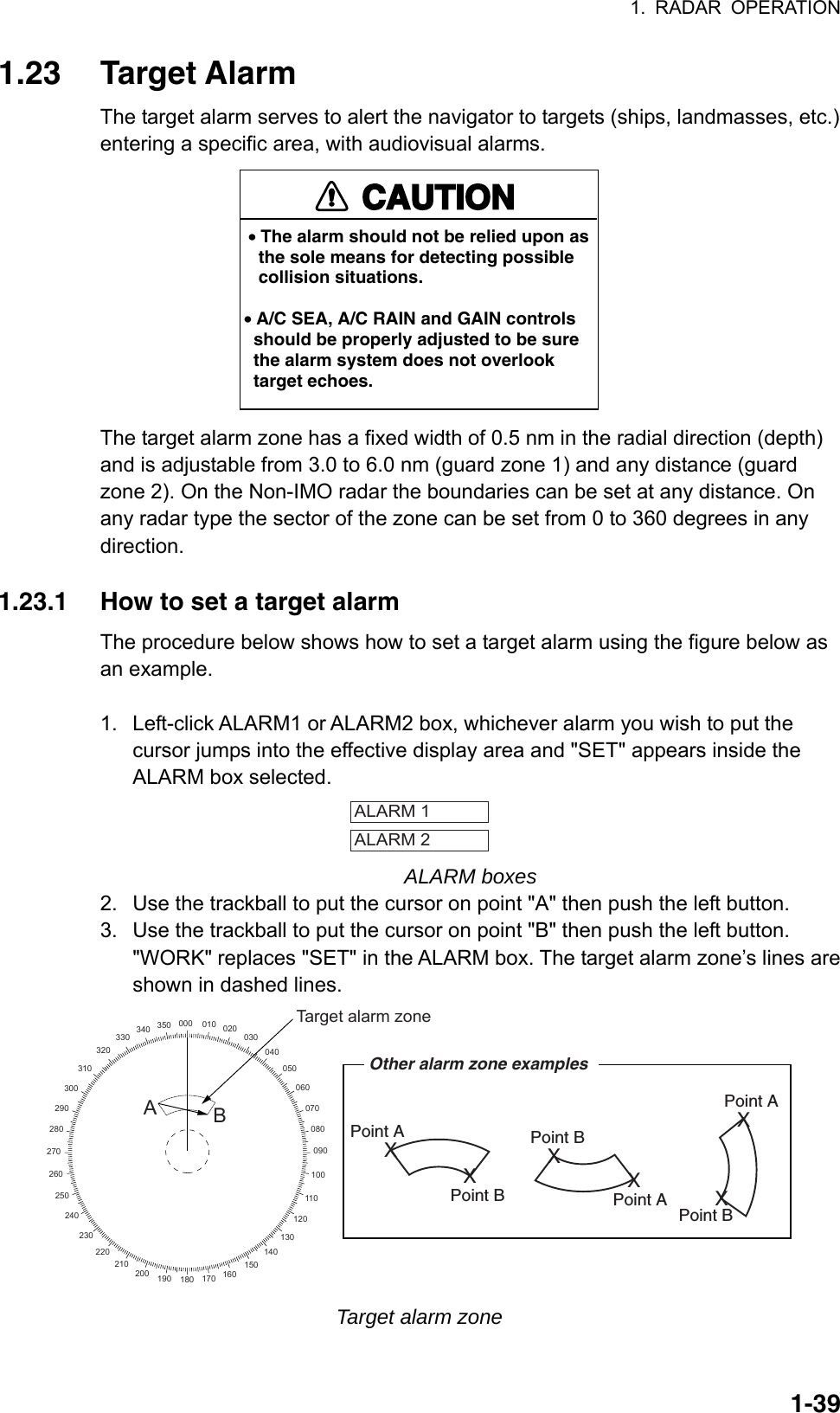
![1. RADAR OPERATION 1-40Note 1: If you wish to create a target alarm zone having a 360-degree coverage around own ship, set point "B" in almost the same direction as point "A." Note 2: Two target alarm zones may be set. Note however that the 2nd target alarm zone is available only when the 1st target alarm zone is active. Note 3: When the target alarm zone is not within the range in use the indication UP RNG appears to the right of the ALARM box. In this case select a range that will display the target alarm zone. 1.23.2 Acknowledging the target alarm A target in the target alarm zone produces both visual (flashing) and audible (beep) alarms. To silence the audio alarm, press the [ALARM ACK] key on the full keyboard or select the appropriate ALARM box then push the left button. The ALARM box shows "ALARMx ACK." This will deactivate the audio alarm but will not stop the flashing of the offending target. To reactivate the audio alarm, press the [ALARM ACK] key again or select the ALARM box then push the left button. (When an external buzzer is connected, the audio alarm does not stop until the alarm zone itself is deactivated.) The ALARM box shows "ALARMx WORK." 1.23.3 Deactivating a target alarm Left-click ALARM1 or ALARM2 box, whichever alarm you wish to deactivate, until the alarm status in the ALARM box disappears. In this radar deactivation of the target alarm zone 1 deactivates target alarm zone 2 .](https://usermanual.wiki/Furuno-USA/9ZWRTR081A.op-manual/User-Guide-1456778-Page-61.png)
![1. RADAR OPERATION 1-41 [ALARM] 1 BACK 2 TARGET ALARM MODE IN/OUT 3 TARGET ALARM LEVEL 1/2/3/4 4 WATCH ALARM OFF/6M/10M/ 12M/15M/20M 5 ALARM SOUND LEVEL OFF/LOW/MID/HIGH 6 [ALARM OUT1] 7 [ALARM OUT2] 8 [ALARM OUT3] 9 [ALARM OUT4] 0 [PRIMARY ALARM] 1.23.4 Target alarm attributes You may select the echo strength level that triggers the alarm, the condition that generates the alarm and the volume of the audio alarm as follows: 1. Left-click the MENU box to open the menu. 2. Select 3 [ALARM]. ALARM menu 3. Select 2 TARGET ALARM MODE. 4. Select IN or OUT as appropriate. IN: Targets entering the zone trigger the alarms. OUT: Targets exiting the zone trigger the alarms. Inward target alarm Outward target alarm Alarm types 5. Select 3 TARGET ALARM LEVEL. 6. Select echo strength level that will trigger the alarm. "1" is highest strength. 7. Select 5 ALARM SOUND LEVEL. 8. Select audio alarm volume, among OFF, LOW, MID and HIGH. Note: 5 ALARM SOUND LEVEL also sets the level of the audio alarm for the watch alarm. 9. Push the right button twice to close the menu.](https://usermanual.wiki/Furuno-USA/9ZWRTR081A.op-manual/User-Guide-1456778-Page-62.png)
![1. RADAR OPERATION 1-42CursorPut cursor where desiredand do appropriateOFF CENTER procedure Off-centered display1.24 Off-Centering the Display Own ship position, or sweep origin, can be displaced to expand the view field without switching to a larger range scale. The sweep origin can be off-centered to the cursor position, but not more than 75% of the range in use; if the cursor is set beyond 75% of the range scale, the sweep origin will be off-centered to the point of 75% of the limit. This feature is not available on the 96 nm range or in the true motion mode. If the conning position is outside the effective radar display, some parts of the bearing scale are not shown. For details, see section 1.50. To off-center the radar picture, do the following: By keyboard 1. Use the trackball to put the cursor at a position where you wish to move the sweep origin. 2. Press the [OFF CENTER] key. Then, the sweep origin is off-centered to the cursor position. 3. To cancel off-centering, press the [OFF CENTER] key again. By trackball 1. With the cursor inside the effective display area, roll the scrollwheel to display "OFF CENTER / EXIT" in the guidance box. 2. Use the trackball to put the cursor where you want to locate the screen center. 3. Push the left button to off center the sweep origin. 4. To cancel the off-center function, push the left button when the guidance box reads "OFF CENTER / EXIT." Note: When the conditions shown below are met, offcenter cannot be cancelled. This is because the radar antenna position is located at a position greater than 75% of the effective radar display. - Own ship marker is large - The distance between antenna position and conning position is large - Short-distance display range. To cancel the offcenter first select a larger range then cancel the offcenter.](https://usermanual.wiki/Furuno-USA/9ZWRTR081A.op-manual/User-Guide-1456778-Page-63.png)
![1. RADAR OPERATION 1-45 [PICTURE MENU] 1 INT REJECT OFF/1/2/3 2 ECHO STRETCH OFF/1/2/3 3 ECHO AVERAGE OFF/1/2/3 4 NOISE REJ OFF/ON 5 AUTO STC OFF/ON 6 AUTO RAIN OFF/1/2/3/4 7 VIDEO CONTRAST 1/2/3/4/ A/B/C 8 [PULSE] 9 [CONDITION] 0 DEFAULT NO/SAVE/USER/ FACTORY 1.28 Noise Rejector White noise may show itself on the screen as random "speckles" spread over the entire radar image. You can remove this noise as follows: 1. Right-click the PICTURE box at the left side of the screen to open the PICTURE menu. 2. Select 4 NOISE REJ. 3. Select ON or OFF as appropriate. 4. Push the right button to close the menu.](https://usermanual.wiki/Furuno-USA/9ZWRTR081A.op-manual/User-Guide-1456778-Page-66.png)
![1. RADAR OPERATION 1-461.29 Wiper The wiper feature automatically reduces the brilliance of weak signals (noise, sea clutter, rain clutter, etc.) and unwanted signals such as radar interference to clear the picture of unwanted echoes. Its effect depends on the wiper setting used and whether each averaging is turned on or off, as described below. Echo averaging and wiper states and wiper effect Wiper setting 1 Wiper setting 2 Echo averaging OFF Condition A Condition A Echo averaging ON (1/2/3) Condition A Condition B Condition A: The brilliance of unwanted weak echoes, such as noise, sea clutter and rain clutter, is reduced to clear up the picture. The difference between wiper setting "1" and "2" is that brilliance is lowered more slowly in "2". Condition B: Echo averaging is automatically activated when the wiper feature is turned on, allowing you to instantly see how the picture is affected with echo averaging turned off and turned on. To activate the wiper feature, do the following: 1. Left-click the MENU box to open the menu. 2. Select 1 [ECHO] to open the ECHO menu. [ECHO] 1 BACK 2 2ND ECHO REJ OFF/ON 3 TUNE INITIALIZE 4 PM OFF/ON 5 SART OFF/ON 6 WIPER OFF/1/2 7 ECHO AREA*1 CIRCLE/WIDE/ALL*1 Not available on IMO or A type8 [PICTURE SELECT]9 STC RANGE +00 ECHO menu 3. Select 6 WIPER. 4. Select OFF, 1 or 2 as appropriate. 5. Push the right button twice to close the menu.](https://usermanual.wiki/Furuno-USA/9ZWRTR081A.op-manual/User-Guide-1456778-Page-67.png)
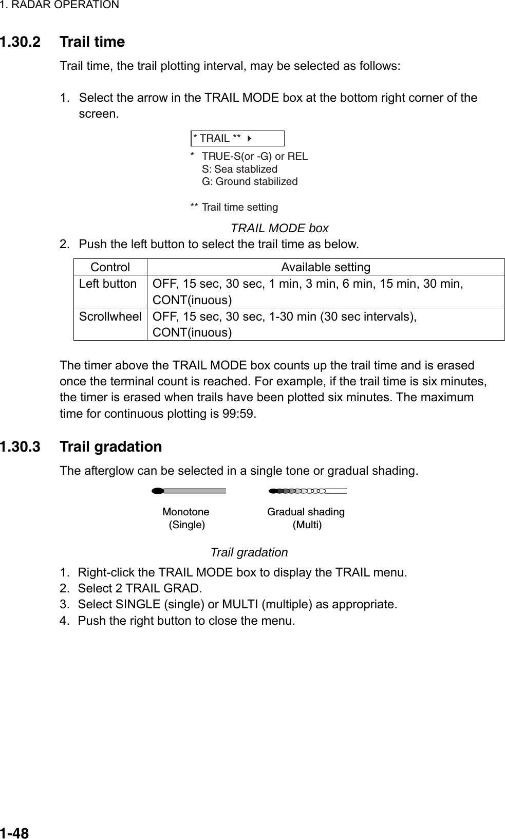
![1. RADAR OPERATION 1-471.30 Target Trails The trails of the radar echoes of targets may be displayed in the form of synthetic afterglow. Target trails are shown either relative or true and may be sea or ground stabilized. True motion trails require a compass signal, and position and speed data. 1.30.1 True or relative trails You may display echo trails in true or relative motion. Relative trails show relative movements between targets and own ship. True motion trails present true target movements in accordance with their over-the-ground speeds and courses. Note: When true trail is selected on the RM mode, the TRAIL MODE box is shown in blue. The reference for the past position displays for AIS and TT is also switched whenever trail reference is switched. 1. Right-click the TRAIL MODE box at the bottom right corner of the screen to open the TRAIL menu. *1Shown when 8 TRAIL LENGTH is selected to other than "NORMAL". Other than IMO and A types. W-type does not show 48H.*2B and C types only[TRAIL MENU]1 TRAIL MODEREL/TRUE2 TRAIL GRADSINGLE/MULTI3 NARROW TRAIL*3OFF/1/24 TRAIL LEVEL1/2/3/45 TRAIL RESTARTOFF/ON6 TRAIL COPYOFF/ON7 OS TRAILOFF/1/28 TRAIL LENGTH*1NORMAL/12H/24H/48H9 TRAIL HIDE*1START 00:00END 00:000 [TRAIL COLOR]*1,*2*3 B, C and W types 2. Select 1 TRAIL MODE. 3. Select TRUE or REL. 4. Push the right button to close the menu. (a) True target trails (No smearing of stationary targets)(b) Relative target trails (Targets moving relative to own ship)](https://usermanual.wiki/Furuno-USA/9ZWRTR081A.op-manual/User-Guide-1456778-Page-68.png)
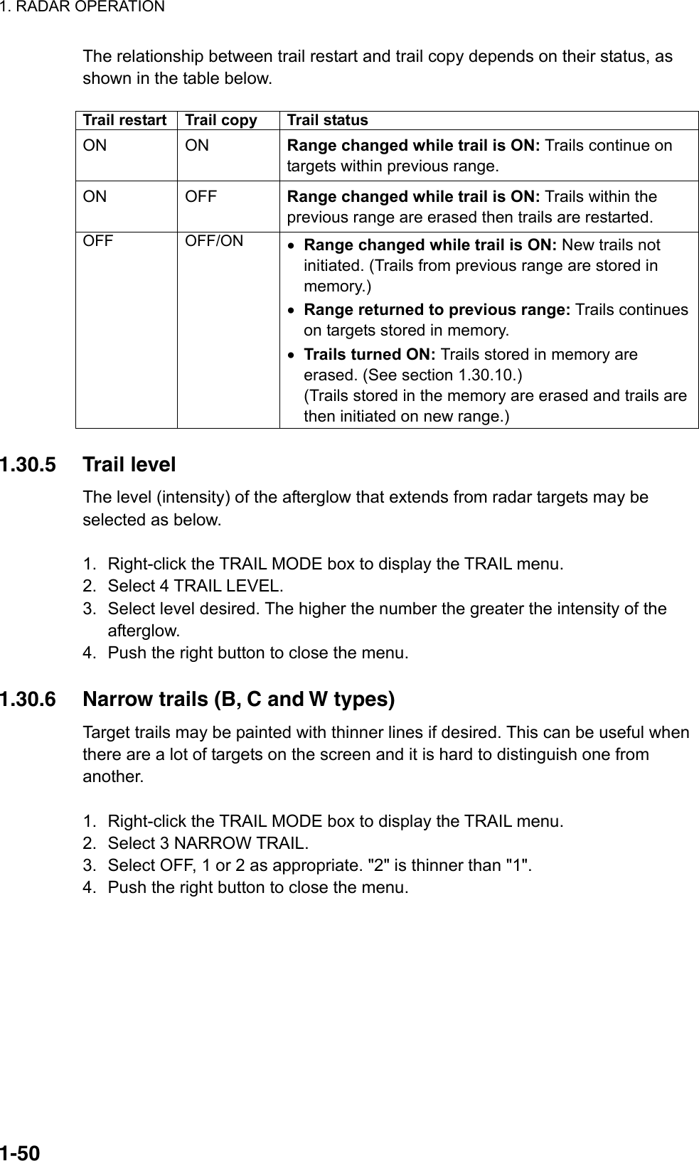
![1. RADAR OPERATION 1-511.30.7 Longer trails (B, C and W types) In addition to the trail times mentioned in section 1.30.2, you may also extend trails 12 ,24 or 48 hours. 1. Right-click the TRAIL MODE box to display the TRAIL menu. 2. Select 8 TRAIL LENGTH. 3. Select NORMAL, 12H, 24H or 48H as appropriate. Note: 48H not available with W-type. NORMAL: Trails are extended according to the setting made on the TRAIL MODE box. 12H: Extend trails for 12 hours. 24H: Extend trails for 24 hours. 48H: Extend trails for 48 hours (not available on W type). 4. If you selected 12 hour, 24 hour or 48 hour, 9 TRAIL HIDE appears together with start and end times. This item allows you to designate a time period in which no trails will be extended. Enter time frame at START and END. 5. Push the right button to close the menu. 1.30.8 Temporarily removing trails from the display You may wish to temporarily remove all trails from the display. Trails are removed but are continued internally. By keyboard: Press the [CANCEL TRAILS] key to show OFF in the TRAIL MODE box. By trackball: Left-click the TRAIL MODE box to display OFF in the box. 1.30.9 Trail stabilization in true motion True motion trails may be ground stabilized or sea stabilized. The TRAIL box shows current stabilization as TRUE-G or TRUE-S. To change stabilization mode, open the SPEED menu and set SHIP SPEED to BT (ground stabilization) or WT (sea stabilization). 1.30.10 Erasing trails All trails may be erased (including those in the memory) and restarted to start trails fresh. By keyboard: Press and hold down the [CANCEL TRAILS] key until trails disappear. By trackball: Left-click the TRAIL MODE box until all trails disappear.](https://usermanual.wiki/Furuno-USA/9ZWRTR081A.op-manual/User-Guide-1456778-Page-72.png)
![1. RADAR OPERATION 1-52PIlines1.30.11 Preventing sea clutter in true trails You can prevent the display of sea clutter in true trails about your ship to clear the radar picture. Your ship's trails can also be shown or hidden. 1. Right-click the TRAIL MODE box to show the TRAIL menu. 2. Select 7 OS TRAIL and push the left button. 3. Roll the scrollwheel to select OFF, 1 or 2 as appropriate, referring to the table below. Option Show own ship's trail Prevent sea clutter in true trails OFF No No 1 Yes Yes 2 No Yes 4. Push the right button to close the menu. 1.31 PI (Parallel Index) Lines PI lines are useful for keeping a constant distance between own ship and a coastline or a partner ship when navigating. Up to six sets of PI lines are available depending on the maximum number of PI lines selected on the menu. Max. 1 PI line: Six sets of PI lines (PI1 - PI6) Max. 2, 3 or 6 PI lines: Four sets of PI lines (PI1 – PI4) You may control the orientation and interval of the PI lines from the PI line box, which is at the lower left corner. 1.31.1 Displaying, erasing PI lines By keyboard 1. With the menu closed, press the [INDEX LINE] key. The guidance box shows "DISP PI LINE/." 2. While watching the PI line number box, press and hold the [INDEX LINE] key to select a PI line. Press the key again to display or erase the PI line selected. PI line number Status (ON or OFF)PI 1 ON032.0°T5.60NMPI line orientationPI line interval(Boxes not shown when PI line is OFF.) PI line boxes By trackball 1. Select the PI line number box and use the trackball to select a PI line number. 2. Push the left button to turn the PI line on or off as appropriate.](https://usermanual.wiki/Furuno-USA/9ZWRTR081A.op-manual/User-Guide-1456778-Page-73.png)
![1. RADAR OPERATION 1-53PI 1 ON032.0°T5.60NMPI line orientationPI line interval [PI LINE] 1 BACK 2 PI LINE BEARING REL/TRUE 3 PI LINE 1/2/3/6 4 PI LINE MODE PARALLEL/PERPENDIC.5 RESET PI LINE NO/YES 1.31.2 Adjusting PI line orientation, PI line interval 1. If not already displayed, show a PI line, referring to section 1.31.1. 2. Use the trackball to place the arrow in the PI line orientation box. 3. Roll the scrollwheel to adjust the PI line orientation, between 000.0-359.9(°T). Enter a negative value to move the PI line to the opposite side of the PI line passing through the own ship position. 4. Use the trackball to put the cursor in the PI line interval box. 5. Roll the scrollwheel to adjust the PI line interval. 1.31.3 PI line bearing reference PI line bearing reference may be relative to own ship’s heading (Relative) or referenced to North (True) as below. 1. Left-click the MENU box to open the menu. 2. Select 2 [MARK]. 3. Select 4 [PI LINE]. 4. Select 2 PI LINE BEARING. 5. Select REL or TRUE as appropriate. 6. Push the right button twice to close the menu.](https://usermanual.wiki/Furuno-USA/9ZWRTR081A.op-manual/User-Guide-1456778-Page-74.png)
![1. RADAR OPERATION 1-541.31.4 Maximum number of PI lines to display The maximum number of PI lines to display may be selected from 1, 2, 3 or 6 lines as below. The actual number of lines visible may be less depending on line interval. For the W specification radar, you may specify the number of lines for two sets of PI lines – the menu displays 4 PI LINE1 and 5 PI LINE2. 1. Left-click the MENU box to open the menu. 2. Select 2 [MARK] to open the MARK menu. 3. Select 4 [PI LINE]. 4. Select 3 PI LINE. 5. Select 1, 2, 3 or 6 as appropriate. 6. Push the right button twice to close the menu. 1.31.5 PI line orientation PI lines orientation may be selected from parallel or perpendicular. This function is available when 3 PI LINE in the PI LINE menu is set for other than "1". 1. Left-click the MENU box to open the menu. 2. Select 2 [MARK] to open the MARK menu. 3. Select 4 [PI LINE]. 4. Select 4 PI LINE MODE. 5. Select PARALLEL or PERPENDIC. as appropriate. 6. Push the right button twice to close the menu. 1.31.6 Resetting PI lines You can automatically return PI lines to default orientation, 0-degrees for parallel orientation, 90-degrees for perpendicular orientation. This is faster than doing it manually. From the menu 1. Left-click the MENU box to open the menu. 2. Select 2 [MARK] to open the MARK menu. 3. Select 4 [PI LINE]. 4. Select 5 PI LINE MODE. 5. Select YES. 6. Push the right button twice to close the menu. From the PI line number box Put the cursor on the PI line number box and long-push the left button.](https://usermanual.wiki/Furuno-USA/9ZWRTR081A.op-manual/User-Guide-1456778-Page-75.png)
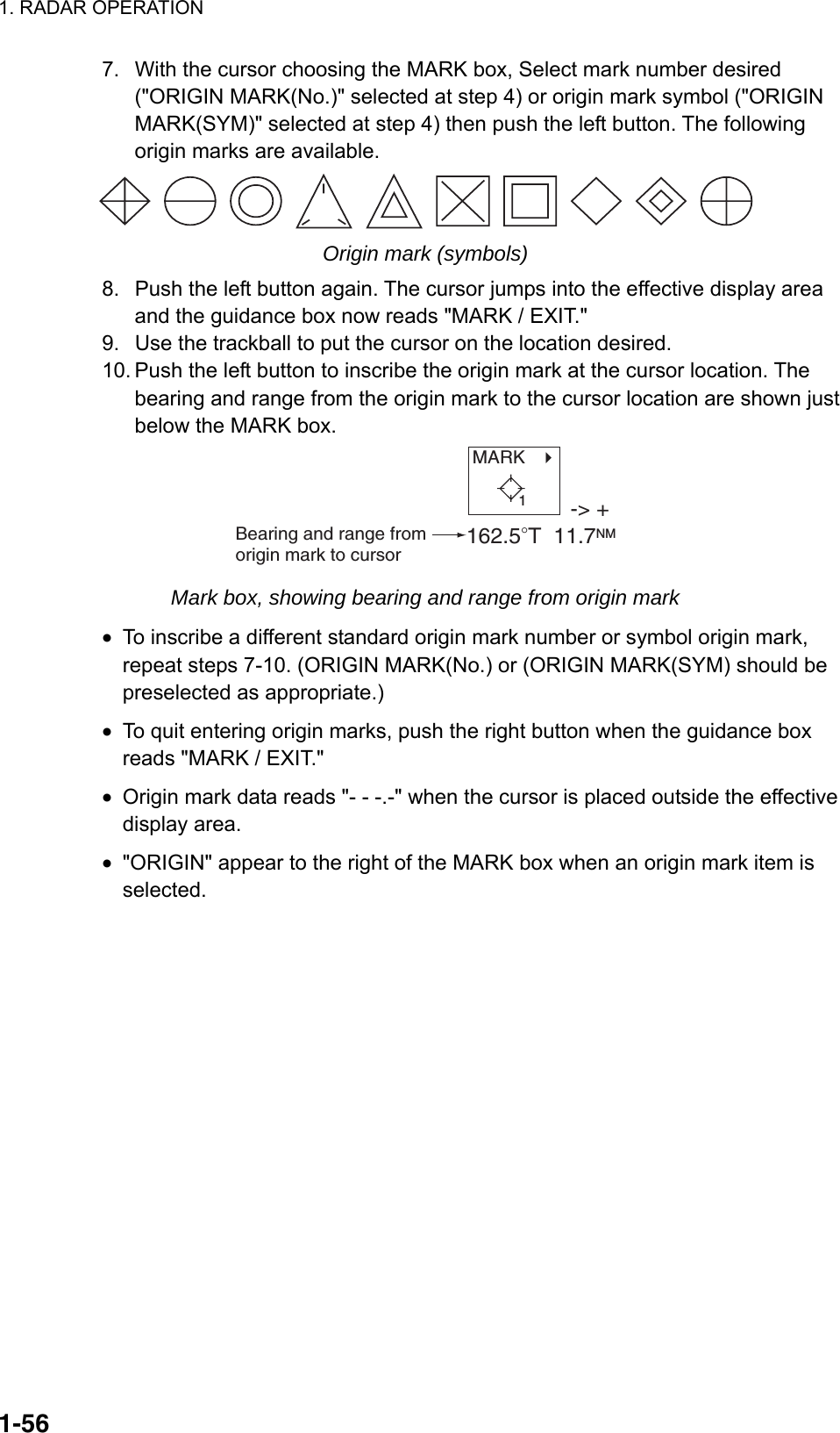
![1. RADAR OPERATION 1-551.32 Origin Mark You can mark any prominent target or a point of particular interest using the origin mark feature. Twenty origin marks may be entered: 10 standard origin marks (with number) and one each of the 10 symbol origin marks. The marks may be geographically fixed (ground stabilized) or sea stabilized. To display the origin marks, heading signal and own ship position data are required. 1.32.1 Entering origin marks 1. Use the trackball to select the MARK box at the left side of the screen. The guidance box now reads "MARK SELECT / MARK MENU." MARK Mark type last selected, mark number -> +1 MARK box 2. Push the right button to open the MARK menu. [MARK MENU] 1 ORIGIN MARK STAB GND/SEA 2 MARK KIND ORIGIN MARK(No. )/ ORIGIN MARK(SYM)/ MAP MARK/ WP 1~50/ WP 51~ 100/ WP 101~150/ WP 151~198/ OWN SHIP SHAPE 8 MARK POSN CURSOR/OS/L/L 00°000.00 N 000°000.00 E9 MAP DISPLAY OFF/ON0 MAP MARK COLOR* RED/GRN/BLU/YEL/ CYA/MAG/WHT * Not available on IMO or A type MARK menu 3. Select 2 MARK KIND. 4. Select ORIGIN MARK (No.) or ORIGIN MARK (SYM) as appropriate. Select ORIGIN MARK (No.) to inscribe standard origin mark ( ) plus mark number; ORIGIN MARK (SYM) to inscribe desired origin mark symbol (no number). 5. Push the left button. 6. Push the right button to close the menu. The guidance box now reads "MARK SELECT / MARK MENU."](https://usermanual.wiki/Furuno-USA/9ZWRTR081A.op-manual/User-Guide-1456778-Page-76.png)
![1. RADAR OPERATION 1-571.32.2 Origin mark stabilization Origin marks may be geographically fixed (ground stabilized) or moving (sea stabilized). 1. Right-click the MARK box to open the MARK menu. [MARK MENU] 1 ORIGIN MARK STAB GND/SEA 2 MARK KIND ORIGIN MARK(No. )/ ORIGIN MARK(SYM)/ MAP MARK/ WP 1~50/ WP 51~ 100/ WP 101~150/ WP 151~198/ OWN SHIP SHAPE 8 MARK POSN CURSOR/OS/L/L 00°000.00 N 000°000.00 E9 MAP DISPLAY OFF/ON0 MAP MARK COLOR* RED/GRN/BLU/YEL/ CYA/MAG/WHT * Not available on IMO or A type MARK menu 2. Select 1 ORIGIN MARK STAB then push the scrollwheel. 3. Select GND or SEA as appropriate. 4. Push the right button to close the menu. 1.32.3 Deleting individual origin marks The procedure below shows how to delete individual origin marks. Note that origin marks cannot be deleted collectively. 1. With the cursor inside the effective display area, roll the scrollwheel to display "MARK DELETE / EXIT" in the guidance box. 2. Use the trackball to put the cursor on the origin mark you wish to erase. 3. Push the left button or the scrollwheel to erase the mark. 4. To erase another mark, repeat steps 2 and 3. 5. To finish, push the right button when the guidance box reads "MARK DELETE / EXIT."](https://usermanual.wiki/Furuno-USA/9ZWRTR081A.op-manual/User-Guide-1456778-Page-78.png)
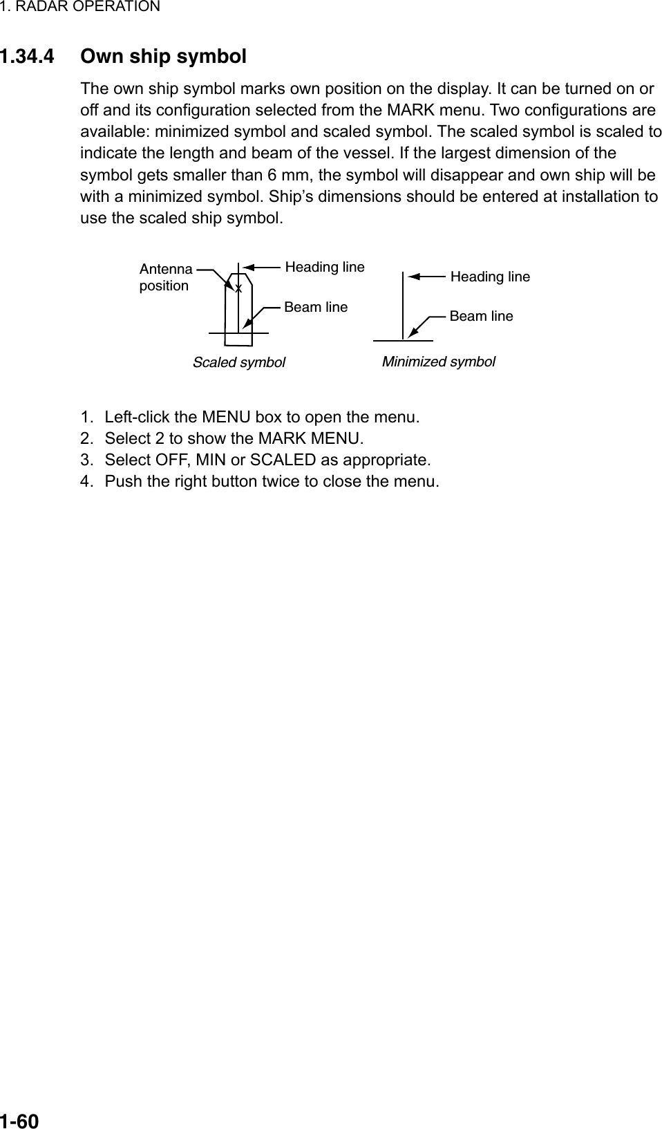
![1. RADAR OPERATION 1-591.34 Markers 1.34.1 Heading line The heading line is a line from the own ship position to the outer edge of the radar display area and appears at zero degrees on the bearing scale in head-up mode; it changes the orientation depending on the ship orientation in north-up and true motion modes. Temporarily erasing the heading line To temporarily extinguish the heading line to look at targets existing dead ahead of own ship, press the [HL OFF] key on the keyboard, or use the trackball to select the HL OFF box at the bottom left corner of the display then push the left button. In addition to the heading line, the stern marker and all graphics within the effective display are also erased. To redisplay the heading line, etc., release the key or the left button. 1.34.2 Stern marker The stern marker, which is a dot-and-dash line, appears opposite to the heading line. To display or erase this marker do the following: 1. Left-click the MENU box to open the MAIN menu. 2. Select MARK to show the MARK menu. 3. Select 3 STERN MARK. 4. Select OFF or ON as appropriate. 5. Push the right button twice to close the menu. 1.34.3 North marker The north marker appears as a short dashed line. In the head-up mode, the north marker moves around the bearing scale in accordance with the compass signal.](https://usermanual.wiki/Furuno-USA/9ZWRTR081A.op-manual/User-Guide-1456778-Page-80.png)
![1. RADAR OPERATION 1-61 [BARGE INFORMATION] 1 BACK 2 BARGE MARK OFF/ON 3 BARGE SIZE LENGTH 0ft WIDTH 0ft 4 ARRANGEMENT 4 9 9 9 4 1.34.5 Barge marker You may mark the locations of barges on the display with icons. This feature is available with an installation preset. Set up barge information as follows: 1. Left-click the MENU box to open the menu. 2. Select 2 [MARK] to show the MARK menu. 3. Select 7 [BARGE MARK]. BARGE INFORMATION menu 4. Select 2 [BARGE MARK] and push the left button. Select ON and push the left button. 5. Select 3 BARGE SIZE and push the left button. Enter length (three digits) and width (two digits) of barge. 6. Select 4 ARRANGEMENT and push the left button. This item lets you set a single barge or a barge chain. Select one of the five arrangements and push the scrollwheel. Select number of barges (max. 9) to display. As you roll the scrollwheel the squares light or extinguish and the number of barges selected appears at the right side. 7. Push the right button twice to close the menu. XBargeFar left is 1st row 1.34.6 INS marker You can get predicted position data by connecting this radar to an INS. 1. Open the menu and select 2 [MARK]. 2. Spin the scrollwheel to select 7 [INS MARK] and 7 PREDICTOR. 3. Select ON. 4. Push the right button three times to close the menu.](https://usermanual.wiki/Furuno-USA/9ZWRTR081A.op-manual/User-Guide-1456778-Page-82.png)
![1. RADAR OPERATION 1-64 [PICTURE MENU] 1 INT REJECT OFF/1/2/3 2 ECHO STRETCH OFF/1/2/3 3 ECHO AVERAGE OFF/1/2/3 4 NOISE REJ OFF/ON 5 AUTO STC OFF/ON 6 AUTO RAIN OFF/1/2/3/4 7 VIDEO CONTRAST 1/2/3/4/ A/B/C 8 [PULSE] 9 [CONDITION] 0 DEFAULT NO/SAVE/USER/ FACTORY 1.35.1 Selecting a picture setup option You may select a picture setup options as follows: Left-click PICTURE box at the left side of the screen to select picture setup option desired. NEAR BUOY* * Other possible indications:NEAR, FAR, FAR BUOY,ROUGH SEA, SHIP,HARBOR, COAST, PICTURE 1 - PICTURE 4 1.35.2 Programming and saving picture setups User-programmable picture setups and they are provided in the PICTURE box. Normally, PICTURE1-PICTURE4 are for programming but you may program any other picture item as desired. You may program and save them as below. 1. Left-click the PICTURE box at the left side of the screen to select the item to program. 2. Push the right button to show the PICTURE menu. PULSE menu](https://usermanual.wiki/Furuno-USA/9ZWRTR081A.op-manual/User-Guide-1456778-Page-85.png)
![1. RADAR OPERATION 1-65 [CONDITION MENU] 1 BACK 2 SEA CONDITION 1/2/3/4/5 3 ANT HEIGHT 5/7.5/10/15/20/ 25/30/35/40/45/ more50m 4 LOW LEVEL ECHO 0 3. Set items 1-6 and 8 referring to the following sections: 1 INT REJECT: 1.25 5 AUTO STC: 1.17 2 ECHO STRETCH: 1.26 6 AUTO RAIN: 1.18 3 ECHO AVERAGE: 1.27 8 PULSE: 1.15 4 NOISE REJ: 1.28 4. Select 7 VIDEO CONTRAST. 5. Select 1, 2, 3 or 4 (Dynamic Range) or A, B, C (Curve) as appropriate. Refer to the description below and the illustration on the next page. 1-4: Control dynamic range. 1 provides the widest dynamic range; 4 is the narrowest dynamic range. A: Mid-level in the curve is low, so this setting is suitable for reducing rain clutter. B: Curve between A and C. C: Mid-level in the curve is high, so this setting is suitable for detecting distant targets. 5 db 7 db9 db11 db4 3 2 1CBAPICTURE levelVIDEO SIGNAL level* ** Default Video contrast settings 6. Select 9 [CONDITION] then push the scrollwheel to show the CONDITION menu. CONDITION menu 7. Select 2 SEA CONDITION. 8. Select appropriate sea condition. The larger the number the rougher the sea state.](https://usermanual.wiki/Furuno-USA/9ZWRTR081A.op-manual/User-Guide-1456778-Page-86.png)
![1. RADAR OPERATION 1-67 [PICTURE SELECT] 1 BACK 2 PICTURE SELECT PICTURE1 OFF/ON PICTURE2 OFF/ON PICTURE3 OFF/ON PICTURE4 OFF/ON NEAR OFF/ON FAR OFF/ON NEAR BUOY OFF/ON FAR BUOY OFF/ON ROUGH SEA OFF/ON SHIP OFF/ON HARBOR OFF/ON COAST OFF/ON 1.35.5 Disabling unnecessary picture setups There are quite a few picture setups from which to select, some which you may not require. You can disable unnecessary ones as follows: 1. Left-click the MENU box to open the menu. 2. Select 1 [ECHO]. 3. Select 8 [PICTURE SELECT]. 4. Select 2 PICTURE SELECT. 5. Select the picture setup you wish to disable and push the left button. 6. Select OFF or ON as applicable and push the left button. 7. Push the right button twice to close the menu.](https://usermanual.wiki/Furuno-USA/9ZWRTR081A.op-manual/User-Guide-1456778-Page-88.png)
![1. RADAR OPERATION 1-68 [CUSTOMIZE•TEST] 1 BACK 2 [DATA BOX] 3 [F1] 4 [F2] 5 [F3] 6 [F4] 7 [OPERATION] 8 [TEST] [F1] 1 BACK 2 [ECHO] 3 [STD KEY] 4 [TT•AIS] 5 [OPERATION] 6 [PICTURE] 1.36 Function Keys Less-often used functions are provided in the menu. To avoid opening the menus to set up the radar for a particular situation, function keys F1-F4 may be assigned any of the functions shown in the CUSTOMIZE•TEST sub menu. 1.36.1 Activating function keys To activate the function assigned to a function key, press the key to instantly set the radar for the preset purpose. Further press the key to select option. Function key Default setting F1 Interference Rejector F2 Echo Stretch F3 Auto Rain F4 Heading Line Off 1.36.2 Programming function keys Do the following to program the function keys. 1. Left-click the MENU box to open the menu. 2. Select 9 [CUSTOMIZE•TEST] then push the scrollwheel. CUSTOMIZE•TEST menu 3. Select 3 [F1], 4 [F2], 5 [F3] or 6 [F4], whichever function key you want to set, For example, select 3 [F1] then push the left button. F1 menu](https://usermanual.wiki/Furuno-USA/9ZWRTR081A.op-manual/User-Guide-1456778-Page-89.png)
![1. RADAR OPERATION 1-69 [ECHO] 1 BACK 2 PICTURE/ IR ES/ EAV/ NOISE REJ/ ANT SELECT/ PULSE LENGTH/ A/C SEA SELECT/ AUTO RAIN SELECT/ TUNE SELECT/ ANT HEIGHT/ SEA CONDITION/ 2ND ECHO REJ/ PM/ SART WIPER [TT•AIS] 1 BACK 2 DISP TT/ DISP AIS/ TARGET DATA & ACQ/ PAST POSN INTERVAL/ REF MARK/ CPA LIMIT/ CPA/ TCPA/ AZ1/ AZ2/ TARGET LIST SORT/ TRIAL MANEUVER/ ASSOCIATION/ AIS MESSAGE/ TRIAL MODE CHANGE AIS SCALED SYMBOL [STD KEY] 1 BACK 2 ALARM ACK/ STBY TX/ HL OFF/ EBL OFFSET/ MODE/ OFF CENTER/ CU TM RESET/ PI LINE/ VECTOR TIME/ VECTOR MODE/ TARGET LIST/ TRAIL/ BRILL/ MARK/ MENU/ RANGE UP/ RANGE DOWN/ ACQ/ TARGET DATA/ TARGET CANCEL [OPERATION] 1 BACK 2 ECHO COLOR/ PALETTE/ RING/ ALARM1/ ALARM2/ WATCH ALARM RESET/ ZOOM/ MARK DELETE/ OWN TRACK DELETE/ TGT TRACK DELETE*/ CHART ALIGN/ DISPLAY SELECT/ RADAR COMBINE*/ MOB/ USER DEFAULT TLL*/ ANCHOR WATCH/ COLOR SHIFT/ ICON/ DISP*/ OWN TRK ALL ERASE TGT TRK ALL ERASE* MARK ALL ERASE DROP MARK 4. Select appropriate category, ECHO, STD KEY, TT•AIS, OPERATION or PICTURE. Refer to the menus below to select appropriate category. * Not available on IMO type [PICTURE] 1 BACK 2 PICTURE1/ PICTURE2/ PICTURE3/ PICTURE4/ NEAR/ FAR/ NEAR BUOY/ FAR BUOY/ ROUGH SEA/ SHIP/ HARBOR COAST](https://usermanual.wiki/Furuno-USA/9ZWRTR081A.op-manual/User-Guide-1456778-Page-90.png)
![1. RADAR OPERATION 1-705. Select "2". 6. Select function desired then push the scrollwheel or left button. 7. Push the right button twice to close the menu. Description of function key programs Item Description [ECHO] PICTURE Selects picture setup function. IR Selects interference rejection level. ES Selects echo stretch function. EAV Selects echo averaging function. NOISE REJ Turns noise rejector on/off. ANT SELECT Selects antenna. PULSE LENGTH Selects pulselength. A/C SEA SELECT Selects A/C SEA adjustment method. AUTO RAIN SELECT Selects AUTO RAIN level. TUNE SELECT Selects tuning adjustment method. ANT HEIGHT Sets antenna height. SEA CONDITION Sets sea condition. 2ND ECHO REJ Turns 2nd trace echo rejector on/off. PM Turns performance monitor on/off. SART Turns SART setup conditions on/off. WIPER Turns wiper (reduce weak and unwanted signals) on/off. [STD KEY] ALARM ACK Acknowledges alarm. (Silences audio alarm.) STBY TX Toggles between stand-by and transmit. HL OFF Turns heading line on/off. EBL OFFSET Offsets EBL. OFF CENTER Off centers the display. CU TM RESET Returns own ship mark to point 75% of range in use. PI LINE Turns PI line on/off. VECTOR TIME Sets vector time. VECTOR MODE Sets vector mode. TARGET LIST Displays target list. TRAIL Sets trail parameters. BRILL Sets brilliance. MARK Selects mark to inscribe. MENU Opens the MAIN menu. RANGE UP Raises the range scale. RANGE DOWN Lowers the range scale. ACQ Acquires target; activates sleeping AIS target. TARGET DATA Shows target data for selected tracked target or AIS target. TARGET CANCEL Cancels tracking of tracked target; sleeps AIS target.](https://usermanual.wiki/Furuno-USA/9ZWRTR081A.op-manual/User-Guide-1456778-Page-91.png)
![1. RADAR OPERATION 1-71Description of function key programs (con’t from previous page) Item Description [TT•AIS] DISP TT Activates/deactivates TT. DISP AIS Activates/deactivates AIS. TARGET DATA & ACQ TT: Acquires target; shows data for tracked target selected. AIS: Activates sleeping AIS target; shows data for AIS target selected. PAST POSN INTERVAL Selects past position plotting interval. REF MARK Inscribes reference mark (for target-based speed). CPA LIMIT Turns CPA limit on/off. CPA Enters CPA range. TCPA Enters TCPA time. AZ1 Sets Alarm Zone 1. AZ2 Sets Alarm Zone 2. TARGET LIST SORT Sorts target list. TRIAL MANEUVER Executes trial maneuver. ASSOCATION Changes indication in Association Usage box. See 4.13. AIS MESSAGE Displays AIS message board. TRIAL MODE CHANGE Switches between dynamic and static modes. AIS SCALED SYMBOL Scales AIS target symbols according to target (ship) size. [OPERATION] ECHO COLOR Selects echo color. BACK COLOR Selects background color. RING Turns range rings on/off. ALARM1 Sets no. 1 target alarm. ALARM2 Sets no. 2 target alarm. WATCH ALARM RESET Resets watch alarm. ZOOM Enables zoom. MARK DELETE Deletes mark (origin mark, waypoint mark, plotter mark). OWN TRACK DELETE Deletes own ship’s tracks according to setting of OWN TRACK menu (see page 5-15). TGT TRACK DELETE Deletes other ship’s tracks according to setting of TARGET TRACK menu (see page 5-15). CHART ALIGN Aligns chart with radar picture. DISPLAY SELECT Selects display mode. RADAR COMBINE* Dual-radar display. *Non-IMO only MOB Inscribes MOB mark. USER DEFAULT Restores user defaults for [F1]-[F3]. For F-KEY: 1. Set equipment as desired. 2. Long-push (more then 1 s) function key registered as USER DEFAULT. 3. To recall a setting, do step 2. The radar is then set to stand-by and "USER DEFAULT" appears at the bottom-right corner. For STORE: 1. Set equipment as desired. 2. Select STORE at 2 USER DEFAULT BACKUP from page (2/2) of the OPERATION menu. Select HOLD to register settings. 3. To recall setting, press the function key registered as USER DEFAULT. The radar is then set to stand-by and "USER DEFAULT" appears at the bottom-right corner. TLL Target latitude and longitude output (to chart plotter). ANCHOR WATCH Enables the anchor watch alarm. COLOR SHIFT Paint own ship's tracks in different colors. ICON DISP Hides and shows boxes outside the effective display area.](https://usermanual.wiki/Furuno-USA/9ZWRTR081A.op-manual/User-Guide-1456778-Page-92.png)
![1. RADAR OPERATION 1-72 [OS POSN MENU] 1 NAV AID GPS1/GPS2/ DEAD RECKONING/ LAN 2 MANUAL L/L 00°00.00 N 000°00.00 W 3 SIO DATA LAN OUTPUTOFF/ON Item Description [OPERATION] (con't from previous page) OWN TRK ALL ERASE Erases all own ship’s tracks. TGT TRK ALL ERASE Erases all other ship’s tracks. MARK ALL ERASE Erases all marks. DROP MARK Inscribe a drop mark. [PICTURE] PICTURE1 – PICTURE4 Actuates settings of user-programmed setup. NEAR Optimum setting for short range detection using a range scale of 3 nm or less on calm seas FAR Optimum setting for long range detection using a range scale of 6 nm or larger NEAR BUOY Optimum setting for detecting navigation buoys, small vessels and other small surface objects at close range FAR BUOY Optimum setting for detecting navigation buoys, small vessels and other small surface objects at long range ROUGH SEA Optimum setting for rough weather or heavy rain SHIP Optimum setting for detecting vessels HARBOR Optimum setting for harbor navigation COAST Optimum setting for coastal navigation 1.37 Ship’s Position Select the source of ship’s position data as follows: 1. Right-click the OSN POSN box at the top right corner of the screen to show the OS POSN menu. OS POSN menu 2. Select 1 NAV AID. 3. Select GPS1, GPS2 or DEAD RECKONING as appropriate. GPS1: GPS navigator connected to nav port GPS2: GPS navigator connected to SPEED LOG port or TRACK CONTROL port.](https://usermanual.wiki/Furuno-USA/9ZWRTR081A.op-manual/User-Guide-1456778-Page-93.png)
![1. RADAR OPERATION 1-734. If you have selected DEAD RECKONING do the following to enter position manually. For GPS1 or GPS2, go to step 6. a) Select 2 MANUAL L/L then push the scrollwheel. Enter latitude and longitude position as follows. b) Roll the scrollwheel to set appropriate digit in the latitude field then push the scrollwheel. (You may push the scrollwheel again to skip a place.) For keyboard operation, press appropriate numeric keys then press the [ENTER MARK] key. c) Set longitude similar to how you set latitude then push the scrollwheel. (For keyboard operation, press the [ENTER MARK] key.) Note: Co-ordinate polarity may be switched by rolling the scrollwheel, or pressing the [2] key. 5. To use a navigation device connected to radars via a LAN, set 3 SIO DATA LAN OUTPUT to ON, then select LAN at 1 NAV AID. 6. Push the right button to close the menu. Note: When the AIS function is active, DEAD RECKONING is shown in gray to indicate that it is not available for selection.](https://usermanual.wiki/Furuno-USA/9ZWRTR081A.op-manual/User-Guide-1456778-Page-94.png)
![1. RADAR OPERATION 1-741.38 Second-trace Echoes In certain situations, echoes from very distance targets may appear as false echoes (second-trace echoes) on the screen. This occurs when the return echo is received one transmission cycle later, or after a next radar pulse has been transmitted. Second-traceechoTx repetitionActual rangeFalse echorange Second-trace echoes To reject second-trace echoes: 1. Left-click the MENU box to open the menu. 2. Select 1 [ECHO] to open the ECHO menu. [ECHO] 1 BACK 2 2ND ECHO REJ OFF/ON 3 TUNE INITIALIZE 4 PM OFF/ON 5 SART OFF/ON 6 WIPER OFF/1/2 7 ECHO AREA*1 CIRCLE/WIDE/ALL*1 Not available on IMO or A type8 [PICTURE SELECT]9 STC RANGE +00 ECHO menu 3. Select 2 2ND ECHO REJ. 4. Select OFF or ON as appropriate. 5. Push the right button twice to close the menu.](https://usermanual.wiki/Furuno-USA/9ZWRTR081A.op-manual/User-Guide-1456778-Page-95.png)
![1. RADAR OPERATION 1-751.39 Brilliance of Screen Data You can adjust relative brilliance levels of various markers and alphanumeric readouts displayed on the screen. 1. Right-click the BRILL box at the bottom left corner of the screen to show the BRILL menu. [BRILL1 MENU (2/2)]1 BACK2 BRG CURSOR3 EBL4 VRM5 PI LINE6 TT SYMBOL7 AIS SYMBOL8 L/L GRID9 MARK0 CHART*Choose 0 NEXTto show page 2of the BRILL menu. [BRILL1 MENU (1/2)]1 ECHO COLOR YEL/GRN/ WHT/COLOR*2 PALETTE DAY-GRY/DAY-BLU/ DUSK-GRY/DUSK-BLU/ NIGHT-GRY/NIGHT-BLU/3 PANEL DIMMER4 CHARACTER5 CURSOR6 ECHO7 TRAIL8 HL9 RING0 NEXT* Not available on IMO or A typeNote: Four brilliance and color sets are provided. For further details see section 1.49. BRILL menu 2. Select item you wish to adjust. (To go to the second page of the BRILL menu select 0 NEXT and push the scrollwheel.) Page 1 Page 2 Item Adjusts brilliance of; Item Adjusts brilliance of; 1 ECHO COLOR See section 1.49. 2 BRG CURSOR Bearing cursor 2 PALETTE See section 1.49. 3 EBL EBLs 3 PANEL DIMMER Backlighting of control unit 4 VRM VRMs 4 CHARACTER All alphanumeric characters 5 PI LINE PI lines 5 CURSOR Cursor (+) and arrow 6 TT SYMBOL TT symbols 6 ECHO Radar echoes 7 AIS SYMBOL AIS symbols 7 TRAIL Target trails 8 L/L Chart grid 8 HL Heading line 9 MARK All marks 9 RING Range rings 0 CHART Chart 3. Roll the scrollwheel to set brilliance level. The range of adjustment for items except "HL" and "CURSOR" is 0-100%. The range of adjustment for HL and CURSOR is 50-100%. 4. Push the right button once or twice to close the menu.](https://usermanual.wiki/Furuno-USA/9ZWRTR081A.op-manual/User-Guide-1456778-Page-96.png)
![1. RADAR OPERATION 1-76 [ALARM] 1 BACK 2 TARGET ALARM MODE IN/OUT 3 TARGET ALARM MODE 1/2/3/4 4 WATCH ALARM OFF/6M/10M/ 12M/15M/20M 5 ALARM SOUND LEVEL OFF/LOW/MID/HIGH 6 [ALARM OUT1] 7 [ALARM OUT2] 8 [ALARM OUT3] 9 [ALARM OUT4] 0 [PRIMARY ALARM] 1.40 Watch Alarm The watch alarm sounds the audio alarm at the selected time interval to help you keep regular watch of the radar picture for safety or other purposes. The WATCH box appears at right side of the screen with a watch alarm timer counts down from value set (for example, "12:00"). WATCH12:00 WATCH box When a preset time interval has elapsed, the audible watch alarm is released, the screen label WATCH turns red and the watch alarm timer freezes at "0:00." To silence the alarm, press the [ALARM ACK] key on the full keyboard or left-click the ALARM ACK box. The label WATCH turns to normal color and the watch alarm timer is reset to the initial value and starts the count-down sequence again. If you press the [ALARM ACK] key or click the box with the left button before the selected time interval is reached, the watch alarm timer is reset to the initial value and starts the count-down sequence again. To set watch time interval: 1. Left-click the MENU box to open the menu. 2. Select 3 [ALARM] to open the ALARM menu. ALARM menu 3. Select 4 WATCH ALARM. 4. Select appropriate time interval then push the right button twice to close the menu.](https://usermanual.wiki/Furuno-USA/9ZWRTR081A.op-manual/User-Guide-1456778-Page-97.png)
![1. RADAR OPERATION 1-77 [NAV DATA] 1 BACK 2 DEPTH OFF/m/ft 3 DEPTH GRAPH SCALE 10/20/50/ 100/200/500 4 DEPTH MARK 000 5 CURRENT OFF/ON 6 WIND OFF/m/s/kn RELATIVE/ TRUE THEORETICAL/ TRUE NORTH 7 TEMP OFF/ON 8 DATE-TIME OFF/UTC/LOCAL 9 LOCAL TIME ADJ +00:00 0 WPT DATA OFF/REL/TRUE 1.41 Nav Data Wind, depth, ocean current, water temperature, date and time and waypoint data may be set up as follows: 1. Left-click the MENU box to open the menu. 2. Select 7 [NAV DATA]. NAV DATA menu 3. Select appropriate options referring to the table on the next page for details.](https://usermanual.wiki/Furuno-USA/9ZWRTR081A.op-manual/User-Guide-1456778-Page-98.png)
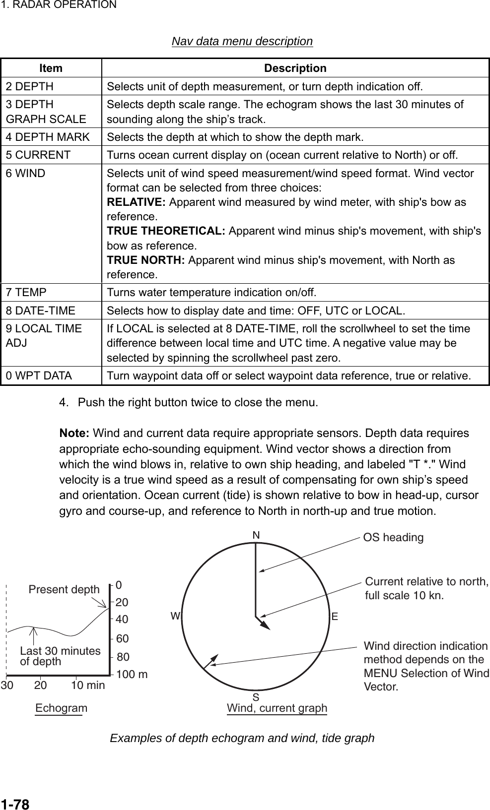
![1. RADAR OPERATION 1-79 [CUSTOMIZE•TEST] 1 BACK 2 [DATA BOX] 3 [F1] 4 [F2] 5 [F3] 6 [F4] 7 [OPERATION] 8 [TEST] [DATA BOX] 1 BACK 3 NAV DATA OFF/ON 4 ZOOM OFF/2TIMES/3TIMES 5 ZOOM DISPLAY STAB GND/STAB HGD/ STAB NORTH/ TT TRACK 6 TARGET DATA 1BOX/2BOX/3BOX/ LARGE 1.42 Text Window The text window, displayed at the right 1/4 of the screen, mainly shows nav data, zoomed target, and tracked target data. You can set up this window as follows: 1. Left-click the MENU box to open the menu. 2. Select 9 [CUSTOMIZE•TEST] CUSTOMIZE•TEST menu 3. Select 2 [DATA BOX]. DATA BOX menu 4. Select 3 NAV DATA. 5. Select OFF or ON as appropriate. 6. Select 4 ZOOM. 7. Select OFF or zoom magnification factor (2TIMES or 3 TIMES). 8. If you selected a zoom factor at step 7, go to step 9. Otherwise, go to step 11. 9. Select 5 ZOOM DISPLAY.](https://usermanual.wiki/Furuno-USA/9ZWRTR081A.op-manual/User-Guide-1456778-Page-100.png)
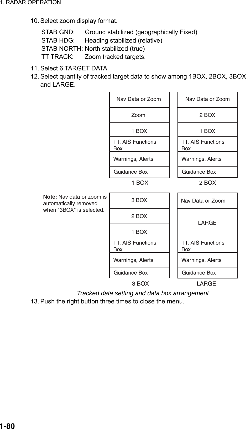
![1. RADAR OPERATION 1-81 [CUSTOMIZE•TEST] 1 BACK 2 [DATA BOX] 3 [F1] 4 [F2] 5 [F3] 6 [F4] 7 [OPERATION] 8 [TEST] [OPERATION] 1 BACK 2 WHEEL DRIVE NORMAL/REVERSE 3 KEY BEEP OFF/LO/MID/HI 4 REMOTE KEY F*-KEY/ DISPLAY SELECT 5 POP UP GUIDANCE* OFF/ON 6 OWN SHIP VECTOR OFF/HDG/COURSE 7 STERN-UP OFF/ON 8 SHUTTLE FERRY OFF/MODE1/MODE2 0 NEXT 1.43 Customizing Operation Several operation items may be customized to suit your needs. 1. Left-click the MENU box to open the menu. 2. Select 9 [CUSTOMIZE•TEST] to open the CUSTOMIZE•TEST menu. CUSTOMIZE•TEST menu 3. Select 7 [OPERATION]. * Not available on IMO or A type OPERATION menu 4. Set each item as appropriate, referring to the table on the next page for details. 5. Push the right button to close the menu.](https://usermanual.wiki/Furuno-USA/9ZWRTR081A.op-manual/User-Guide-1456778-Page-102.png)
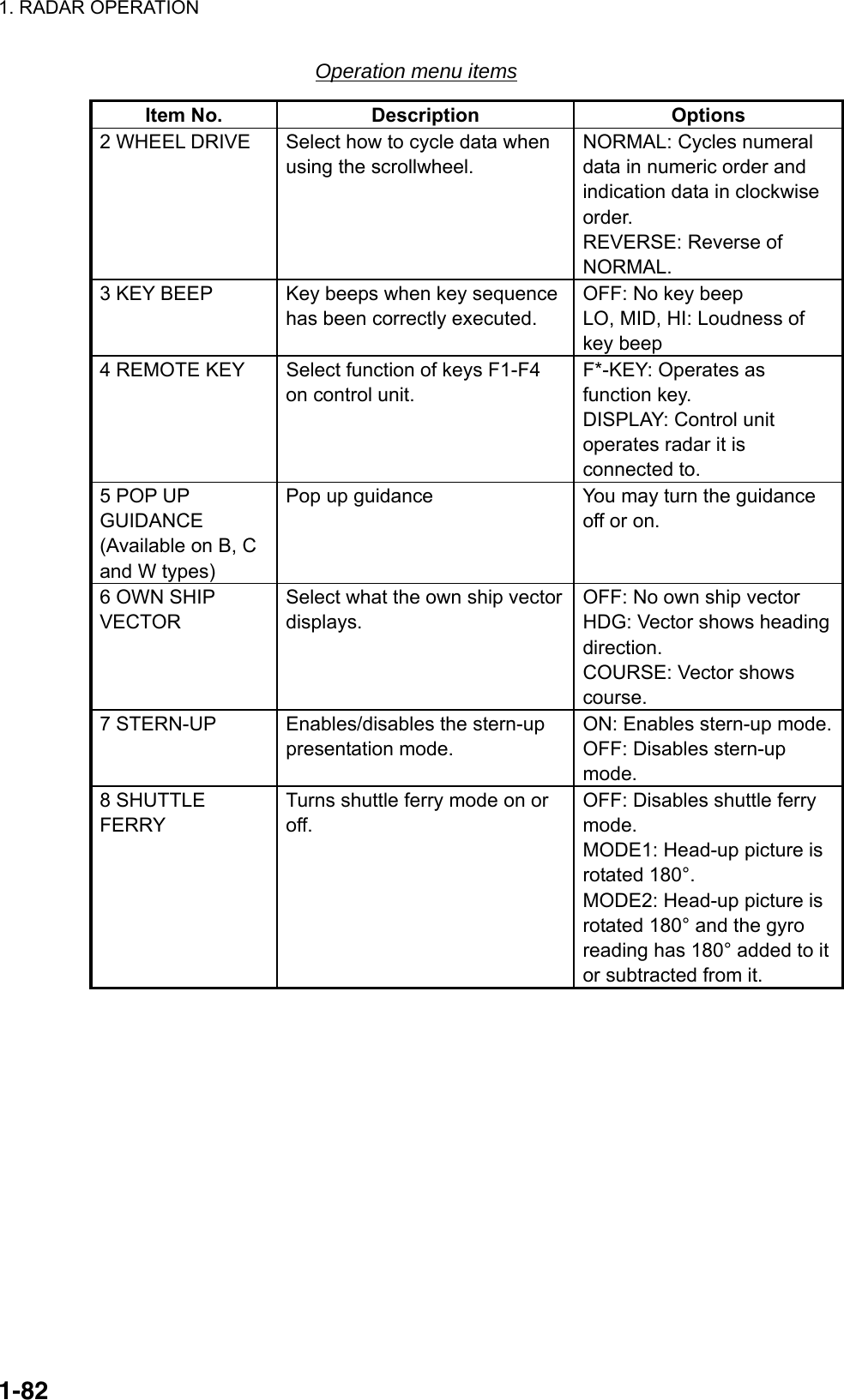
![1. RADAR OPERATION 1-831.44 Alert Box When error or alarm setting violation is found, the applicable indication appears (red, flashing) in the Alert Box and the buzzer sounds. The Alert Box is composed of four lines of information, as shown below. Silence the buzzer with the [ALARM ACK] key or select the ALARM ACK box then push the left button. The buzzer and the flashing stop but the alarm indication remains on the display until the reason for the alarm is removed. Display Example 1: ERROR and WARNINGDisplay Example 2: ERROR onlyDisplay Example 3: ERROR and WARNINGAlert Box Configuration(lines inside box not present in actual box)- - - - - SYSTEM ERROR - - - - -VIDEO - - - - - - WARNING - - - - - - FORMAT CARD DATA- - - - AIS ALARM MESSAGE - - - -AIS: no valid ROT information- - - - AIS ALARM MESSAGE - - - -AIS: no valid ROT info - - - - - - WARNING - - - - - - RD CARD DATALine 1: Name of ERROR or ALARM categoryLine 2: Name of error or alarmLine 3: Message Category WARNINGLine 4: Name of warning](https://usermanual.wiki/Furuno-USA/9ZWRTR081A.op-manual/User-Guide-1456778-Page-104.png)
![1. RADAR OPERATION 1-841.44.1 Alarm description Alarm description Alarm name (visual indication) Visual alarm, reason To quit alarm status SYSTEM ERROR AZIMUTH No antenna rotation signal HEADLINE No heading signal KEY No key signal RF No RF communications signal TRIGGER No trigger signal TT SYSTEM ERROR TT system malfunction VIDEO No video signal Acknowledge indication by pressing the [ALARM ACK] key or left-clicking the ALARM ACK box. Restore signal or remove reason for to remove indication. SENSOR ERROR GYRO The indication "GYRO" (in red) appears and the HDG indication reads "***.*°". The orientation mode is automatically set for head-up. TT, radar map, AIS, and echo averaging are disabled. Match the on-screen HDG indication with the actual compass. The indication "HEADING SET" appears. Press the [ALARM ACK] key to erase the indication. LOG The indication "LOG" (in red) appears and the and the speed indication shows "**.* kn" if the speed signal is lost more than 30 s. For BT error, CPA and TCPA for AIS are not calculated. If the SDME has failed, use another speed sensor. EPFS The indication "EPFS" (in red) appears and the position display shows all asterisks if the position input is lost more than 30 s. Radar map, AIS, and echo averaging are disabled. Acknowledge indication by pressing the [ALARM ACK] key or left-clicking the ALARM ACK box. Restore signal to remove indication. Message cannot be erased if position signal is missing; it is automatically erased when the signal is restored. DATUM For the IMO type, the indication "DATUM" (in red) appears if the datum is other than WGS-84 or WGS-84 is not input. AIS is inoperative with datum other than WGS-84. Acknowledge indication by pressing the [ALARM ACK] key or left-clicking the ALARM ACK box. Use WGS-84 datum.](https://usermanual.wiki/Furuno-USA/9ZWRTR081A.op-manual/User-Guide-1456778-Page-105.png)
![1. RADAR OPERATION 1-85 Alarm name (visual indication) Visual alarm, reason To quit alarm status AIS ALARM (See section 4.15.) DUAL RADAR ALARM (Non-IMO only) EXT RADAR STBY External radar is in standby Set external radar in transmit to erase indication. EXT RADAR ERROR External radar malfunction Restore external radar to normal condition to erase indication. EXT RADAR HDG SET Problem with heading data at external radar. Re-set external radar's heading data to erase indication. OTHER ALARM ANCHOR WATCH Ship has drifted more than a threshold value. Acknowledge indication by pressing the [ALARM ACK] key or left-clicking the ALARM ACK box. ARRIVAL Own ship has arrived to a waypoint. Acknowledge indication by pressing the [ALARM ACK] key or left-clicking the ALARM ACK box. CHECK INT-SW Interswitch malfunction Acknowledge indication by pressing the [ALARM ACK] key or left-clicking the ALARM ACK box. Check interswitch. DEPTH Depth is lower or higher than threshold value. Acknowledge indication by pressing the [ALARM ACK] key or left-clicking the ALARM ACK box. HEADING SET Heading signal has been restored. Press the [ALARM ACK] key to erase the message. Match the on-screen HDG readout with the actual compass reading, if necessary. MEMORY CARD FULL Memory card is full Acknowledge indication by pressing the [ALARM ACK] key or left-clicking the ALARM ACK box. TARGET ALARM A target has entered (or exited) the target alarm zone. Target flashes. Acknowledge indication by pressing the [ALARM ACK] key or left-clicking the ALARM ACK box. WATCH WATCH 0:00 (WATCH appears and time count freezes at 0:00). Press the [ALARM ACK] key or click the WATCH box with the left button. The WATCH box is displayed in normal video and the timer is reset. XTE Own ship is off course more than threshold value. Acknowledge indication by pressing the [ALARM ACK] key or left-clicking the ALARM ACK box.](https://usermanual.wiki/Furuno-USA/9ZWRTR081A.op-manual/User-Guide-1456778-Page-106.png)
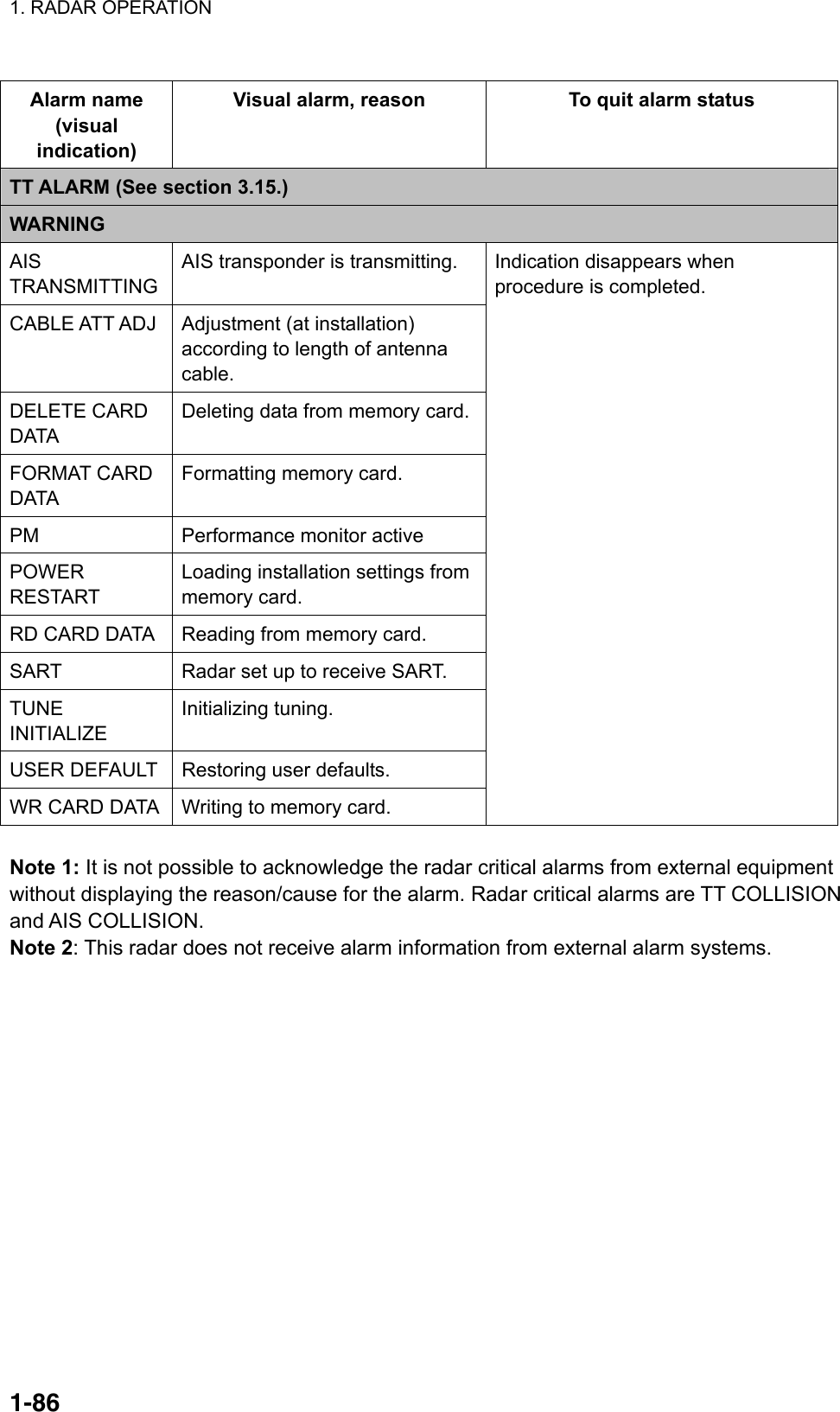
![1. RADAR OPERATION 1-871.44.2 Alarm list The alarm list displays the names of violated alarms, including the time and date violated. A maximum of 28 alarms are shown, on four pages. Unacknowledged alarms are displayed first in the list (in red text), in the order in which they appear in the Alert Box. An unacknowledged alarm can be acknowledged from the list by selecting its number and hitting the left button. To erase the data for the number selected, hit the left button again. To erase all alarm indications, select 9 REFRESH DATA and long-push the left button. To display the alarm list, put the cursor in the Alert Box and push the right button. [ALARM LIST (1/1)]1 BACK (L=TOP)2 - - - SENSOR ERROR - - -EPFS03/APR/2008 09:343 - - - AIS ALARM - - -AIS NEW TARGET03/APR/2008 08:024 - - - SENSOR ERROR - - -LOG03/APR/2008 07:185 - - - PRIMARY ALARM - - -TT COLLISION03/APR/2008 06:506 - - - - TT ALARM - - - -TT LOST03/APR/2008 06:437 - - - OTHER ALARM - - -DEPTH02/APR/2008 23:538 - - - OTHER ALARM - - -WATCH02/APR/2008 20:009 REFRESH DATA (L=CLR)0 NEXTAlarm category*Alarm nameDate and time of violation* AIS ALARMDUAL RADAR ALARMOTHER ALARMPRIMARY ALARMSENSOR ERRORSYSTEM ERRORTT ALARM • When there is more than one alarm page you can switch between them with 0 NEXT and 0 BACK (last page). • ZDA sentence required in order to display time in Alarm list.](https://usermanual.wiki/Furuno-USA/9ZWRTR081A.op-manual/User-Guide-1456778-Page-108.png)
![1. RADAR OPERATION 1-88 [ALARM] 1 BACK 2 GUARD ALARM MODE IN/OUT 3 GUARD ALARM LEVEL 1/2/3/4 4 WATCH ALARM OFF/6M/10M/ 12M/15/20M 5 ALARM SOUND LEVEL OFF/LOW/MID/HIGH 6 [ALARM OUT1] 7 [ALARM OUT2] 8 [ALARM OUT3] 9 [ALARM OUT4] 0 [PRIMARY ALARM] [ALARM OUT1] 1 BACK 2 TARGET ALARM WATCH ALARM TT NEW TARGET TT LOST TARGET TT CPA LIMIT TT AUTO ACQ TGT FULL TT MAN ACQ TGT FULL TT SYSTEM ERROR AIS NEW TARGET AIS LOST TARGET AIS CPA LIMIT AIS TGT FULL AZIMUTH HEAD LINE TRIGGER VIDEO GYRO LOG EPFS XTE ARRIVAL WPT DEPTH ALARM ACK OUT OPERATOR FITNESS ANCHOR WATCH NO CPA/TCPA FOR AIS 9 ALARM OUT POLARITY NORMAL/INVERT 1.44.3 Outputting alarm signals Four ports are provided from which to output alarm signals to external equipment. Select the port and alarm signals to output as follows: 1. Left-click the MENU box to open the menu. 2. Select 3 [ALARM]. ALARM menu 3. Select appropriate "ALARM OUT" item (6-9). ALARM OUT1, 2: Normally closed ALARM OUT3, 4: Normally open 4. Select an alarm to output. The alarm selected is underlined. 5. Repeat step 5 to select other alarms to output. 6. Push the right button three times to close the menu. ALARM OUT1 menu](https://usermanual.wiki/Furuno-USA/9ZWRTR081A.op-manual/User-Guide-1456778-Page-109.png)
![1. RADAR OPERATION 1-89 [PRIMARY ALARM] 1 BACK 2 TARGET ALARM WATCH ALARM TT NEW TARGET TT LOST TARGET TT AUTO ACQ TGT FULL TT MAN ACQ TGT FULL AIS NEW TARGET AIS LOST TARGET AIS TGT FULL XTE ARRIVAL WPT DEPTH ANCHOR WATCH NO CPA/TCPA FOR AIS 1.44.4 Primary alarm Violated alarms appear in the Alert Box in the order of priority shown in the table below. Priority Alarm group Alarms 1 Error (sensor and system) Azimuth, Datum EPFS, Gyro, Headline, Key, Log, RF, Trigger, TT System Error, Video 2 Primary See the PRIMARY ALARM menu below. TT CPA LIMIT and NO CPA/TCPA FOR AIS are ON in default. 3 Other alarms Any alarm not listed here. If desired you can assign primary alarms the same priority as Error alarms. 1. Left-click the MENU box to open the menu. 2. Select 3 [ALARM]. 3. Select 0 [PRIMARY ALARM]. PRIMARY ALARM menu 4. Select alarm(s) for which you want to give priority equal to that of Error alarms. Selected alarms are underlined. 5. Press the right button several times to close the menu.](https://usermanual.wiki/Furuno-USA/9ZWRTR081A.op-manual/User-Guide-1456778-Page-110.png)
![1. RADAR OPERATION 1-901.45 Interswitch The interswitch of this radar uses an Ethernet to transfer video and control signals. A digital signal transfers the video and control signals. You can connect four antennas and eight display units. Set radar display and antenna groups from the ANTENNA SELECT display. When you switch to a different antenna, the heading skew and timing adjustment (set at installation) for that antenna is automatically applied. The ANTENNA box at the upper left position shows current antenna selection. 6HEAD UP TB RMANT1M X-BAND PULSE S1PICTURE4 NM/1 DISPLAYRADAR ANTENNA Box- ANT1: Antenna no.- M: Master (or S for Slave)- X-band (or S-band) 1.45.1 Displaying antenna information The ANTENNA SELECT display shows: • Radar band, output power and antenna position of each antenna currently powered. (If an antenna is not powered, its data area is blank.) • Current antenna and display combinations. • Your radar number To show the ANTENNA SELECT display, right-click the ANTENNA. [ANT SELECT] ANT1: X-BAND 12 FORE ANT2: X-BAND 12 MAIN TOP ANT3: X-BAND MAIN TOP 12 ANT4: X-BAND AFT OWN RADAR No.: 2 1 DISP1 ANT1 MASTER 2 DISP2 ANT2 MASTER Antenna no.Output power(kW)Radar band (X or S)Radar antenna position (set at installation)(FORE, MAIN TOP,MAIN 2ND,MAIN 3RD,AFT, PORT, STARBOARD)* Not available on IMO or A radar.9 STORE INTER-SW NO/YES0 SUB MONITOR* OFF/ONOwn radar no.Current display andantenna combinationsUsing the information displayed in thisexample, the antenna system configurationwould look like this.ANT1 ANT2 ANT3 ANT4DISP1 DISP2 DISP3 DISP4HUB3 DISP3 ANT3MASTER4 DISP4 ANT4MASTER 12](https://usermanual.wiki/Furuno-USA/9ZWRTR081A.op-manual/User-Guide-1456778-Page-111.png)
![1. RADAR OPERATION 1-911.45.2 Presetting antenna and display combinations You can preset the antenna and display combinations for each antenna and display in the radar system. As an example, the procedure below shows how to select the no. 1 antenna unit for the no. 2 display unit. 1. Right-click the ANTENNA box to show the ANT SELECT display. [ANT SELECT] ANT1: X-BAND 12 FORE ANT2: X-BAND 12 MAIN TOP ANT3: X-BAND MAIN TOP 12 ANT4: X-BAND AFT OWN RADAR No.: 2 1 DISP1 ANT1 MASTER 2 DISP2 ANT2 MASTER * Not available on IMO or A radar.9 STORE INTER-SW NO/YES0 SUB MONITOR* OFF/ON3 DISP3 ANT3MASTER4 DISP4 ANT4MASTER 12 2. Select the display unit for which to select an antenna (at the next step). For example, select 2 DISP2 to select the no. 2 display unit. 3. The cursor is now selecting the current display and antenna combination for the no. 2 display unit. Roll the scrollwheel to display ANT1 MASTER and push the left button. 4. Repeat step 3 and 4 to set other display and antenna combinations. 5. Select 0 STORE INTER-SW. 6. Select YES to save display and antenna combinations. 7. Push the right button twice to close the menu. Selection considerations • A antenna unit cannot be controlled from multiple display units. Select one MASTER display unit for one antenna unit. If two antenna units are set as masters, the display last-set as master becomes the master and all other displays are automatically changed to slave. • An antenna unit without a MASTER display cannot be selected on the sub display units. If there is no antenna unit set as master, the lowest number display is automatically set as master.](https://usermanual.wiki/Furuno-USA/9ZWRTR081A.op-manual/User-Guide-1456778-Page-112.png)
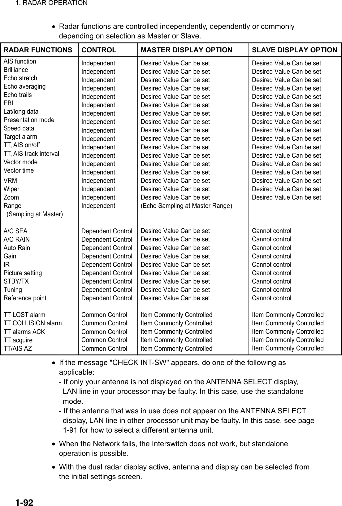
![1. RADAR OPERATION 1-93+ 34°40.849 N135°18.303 ECURSOR DATA box (L/L position)1.45.3 Selecting an antenna For the ship that carries multiple antennas, you may choose the antenna to use as follows: 1. Roll the trackball to place the arrow in the ANTENNA box at the left side of the screen. ANT1 X-BAND (M) 2. Roll the scrollwheel to choose an antenna then push the left button. 1.46 Cursor Data Cursor data can be shown in latitude and longitude position or cursor’s X-Y coordinates, with the C specification radar. Left-click the CURSOR DATA box at the right side of the display to select the cursor data to show. The cursor data changes in the sequence shown below. + 34°30.323 N135°08.263 E+ 9.649NM 9.683NMLatitude and longitudeposition of cursorCursor X-Y position Cursor data options Note 1: For the X-Y coordinates display, the Y-axis is the heading line, right/top is "plus" and left/lower is "minus." Note 2: When displaying latitude and longitude position and the cursor has been aligned (on the PLOTTER menu), the indication "CHART ALIGN" appears at the right side of the screen (in red). Note 3: Cursor data reads "- - -.-" when the cursor is placed outside the effective display area. Note 4: Cursor bearing format (true or relative) and cursor range unit (nm, sm, km or kyd) are available as below. Type Cursor bearing format Cursor range unit Menu operation IMO Yes No A Yes No 2 [MARK]→9 EBL CURSOR BEARING B Yes Yes C Yes Yes W Yes No 2 [MARK] →9 [EBL, VRM CURSOR SET] →CURSOR BEARING, CURSOR RANGE](https://usermanual.wiki/Furuno-USA/9ZWRTR081A.op-manual/User-Guide-1456778-Page-114.png)
![1. RADAR OPERATION 1-941.47 Performance Monitor A performance monitor is required for a radar installed on vessels of 300 GT and upward engaged in international voyages. Two units are available: X-band radar: PM-31 (9410 ± 45 MHz) S-band radar: PM-51 (3050 ± 30 MHz). The performance monitor is incorporated in the antenna unit. When the performance monitor is active, the indication "PM" appears (in yellow) in the alarm box. 1.47.1 Activating, deactivating the performance monitor 1. Left-click the MENU box to open the menu. 2. Select 1 [ECHO] to open the ECHO menu. [ECHO] 1 BACK 2 2ND ECHO REJ OFF/ON 3 TUNE INITIALIZE 4 PM OFF/ON 5 SART OFF/ON 6 WIPER OFF/1/2 7 ECHO AREA*1 CIRCLE/WIDE/ALL*1 Not available on IMO or A type8 [PICTURE SELECT]9 STC RANGE +00 ECHO menu 3. Select 4 PM. 4. Select OFF or ON as appropriate. 5. Push the right button twice to close the menu. "PM" appears on the display when the performance monitor is active. 1.47.2 Checking radar performance 1. The radar is automatically set up as follows: Range: 24 nm Pulselength: Long Shadow Sector: Off A/C SEA: Off A/C RAIN: Off Echo Stretch: Off Echo Average: Off Interference Rej.: Off Video Contrast: 4-B Tune: Auto Gain: Initial setting (as set with PM GAIN ADJ at installation)](https://usermanual.wiki/Furuno-USA/9ZWRTR081A.op-manual/User-Guide-1456778-Page-115.png)
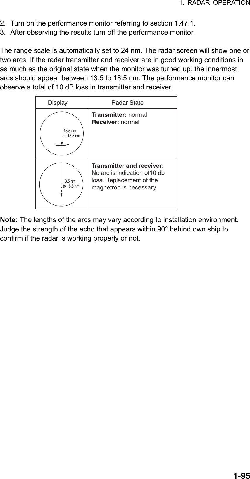
![1. RADAR OPERATION 1-96010304050607081009021.48 Own Ship Marker Own ship marker ( ) may be inscribed on the screen as below. You may enter ten such symbols. Each own ship symbols is shown with a number. 1. Use the trackball to select the MARK box at the left side of the screen. The guidance box now reads "MARK SELECT / MARK MENU." MARK Mark type lastselected, marknumber-> + - - -m, - - -m1Dimensions ofown ship Mark box 2. Push the right button to open the MARK menu. [MARK MENU] 1 ORIGIN MARK STAB GND/SEA 2 MARK KIND ORIGIN MARK(No. )/ ORIGIN MARK(SYM)/ MAP MARK/ WP 1~50/ WP 51~ 100/ WP 101~150/ WP 151~198/ OWN SHIP SHAPE 8 MARK POSN CURSOR/OS/L/L 00°000.00 N 000°000.00 E9 MAP DISPLAY OFF/ON0 MAP MARK COLOR* RED/GRN/BLU/YEL/ CYA/MAG/WHT * Not available on IMO or A type MARK menu 3. Select "2". 4. Select OWN SHIP SHAPE. (On the W-type, the indication "OS" appears to the right of the MARK box.) 5. Push the right button to close the menu. 6. Use the trackball to select the own ship symbol at the bottom left corner. 7. Roll the scrollwheel to select the point number for which you want to change its position. See figure at right. 8. Push the left button. The cursor positions at the point number selected. 9. Use the trackball to drag the point to location desired. 10. Push the left button to confirm selected location. 11. Repeat steps 6-10 continue changing symbol shape.](https://usermanual.wiki/Furuno-USA/9ZWRTR081A.op-manual/User-Guide-1456778-Page-117.png)
![1. RADAR OPERATION 1-971.49 Color and Brilliance Sets This radar provides six sets of color and brilliance sets to match any ambient lighting condition. 1.49.1 Selecting color and brilliance set Left-click the BRILL box at the left side of the screen to select color and brilliance set from among BRILL1 – BRILL4. The default specifications of each brilliance set are is in the table below. PALETTE BRILL PANEL OTHERSTEXT COLOR BKGD/CIRCLE DAY-GRY 100 15 15 GREEN GRY/BLK DAY-BLU 100 15 15 WHITE BLU/BLU DUSK-GRY 20 10 15 GREEN GRY/BLU DUSK-BLU 20 10 15 WHITE BLU/BLU NIGHT-GRY 4 5 15 RED GRY/BLK NIGHT-BLU 4 5 15 WHITE BRT-BLU/BRT-BLU 1.49.2 Presetting color and brilliance set 1. Right-click the BRILL box at the left side of the screen to open the BRILL menu. * Not available on IMO or A type [BRILL1 MENU (1/2)]1 ECHO COLOR YEL/GRN/ WHT/COLOR*2 PALETTE DAY-GRY/DAY-BLU/ DUSK-GRY/DUSK-BLU/ NIGHT-GRY/NIGHT-BLU/3 PANEL DIMMER4 CHARACTER5 CURSOR6 ECHO7 TRAIL8 HL9 RING0 NEXT BRILL menu 2. Select 1 ECHO COLOR. 3. Select echo color desired. "COLOR," available on the B, C and W types, displays echoes in colors of red, yellow and green, corresponding to signal levels of strong, medium and weak.](https://usermanual.wiki/Furuno-USA/9ZWRTR081A.op-manual/User-Guide-1456778-Page-118.png)
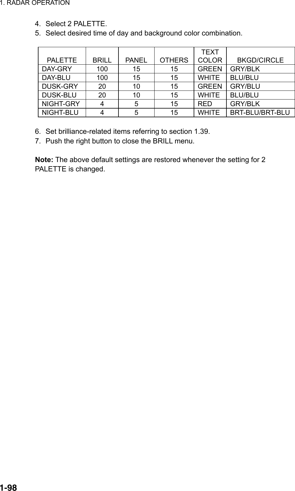
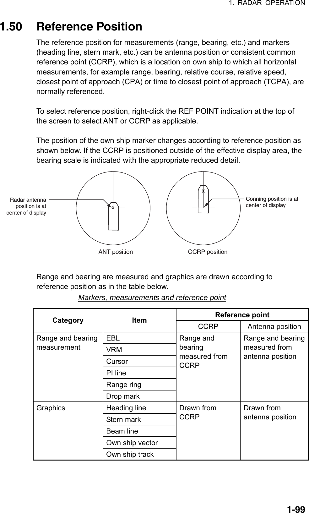
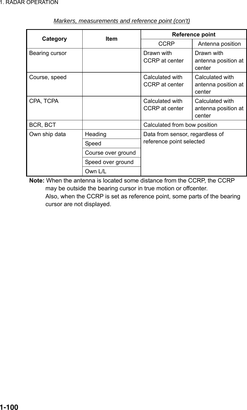
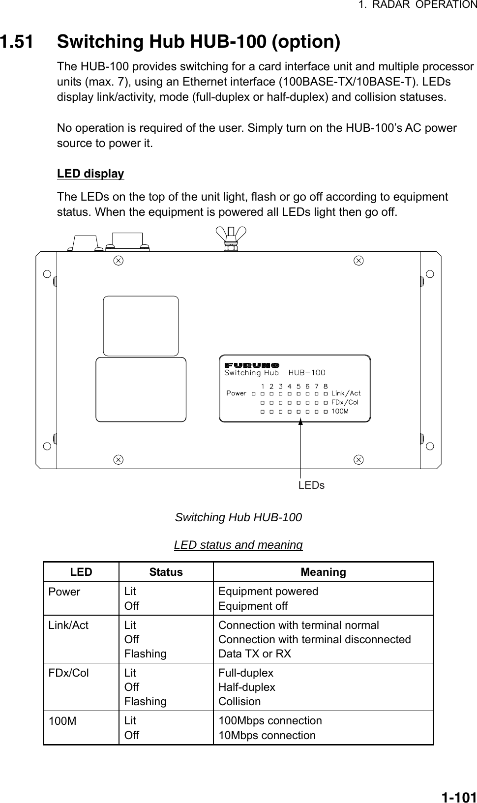
![1. RADAR OPERATION 1-1021.52 Anchor Watch The anchor watch feature alerts you when your ship has traveled a distance greater than a threshold value, when it should be at rest. When the anchor watch is active, an orange dashed circle marks the anchor watch range. If your ship goes outside the circle, "ANCHOR WATCH" appears in the Alert Box. Your ship's position, where you start the anchor watch.Alarmsetting: Alarm triggered 1. Left-click the MENU box to open the menu. 2. Select 2 [MARK]. 3. Select 5 ANCHOR WATCH. 4. Select ON. 5. Roll the scrollwheel to set the alarm range, from 0-9.99 (nm). 6. Push the right button to close the menu.](https://usermanual.wiki/Furuno-USA/9ZWRTR081A.op-manual/User-Guide-1456778-Page-123.png)
![1. RADAR OPERATION 1-1031.53 Drop Mark The operator inscribes a drop mark ( ) at a selected location to find the range and bearing from own ship to the mark. This can be useful for marking a point to avoid while navigating to a destination. 1.53.1 Activating the drop mark feature 1. Left-click the MENU box to open the menu. 2. Select 2 [MARK]. [MARK] 1 BACK 2 OWN SHIP MARK OFF/MIN/SCALED 3 STERN MARK OFF/ON 4 [PI LINE] 5 ANCHOR WATCH OFF/ON 0.0NM6 DROP MARK OFF/ON7 [INS MARK] *1 8 EBL OFFSET BASE STAB GND/STAB HDG/ STAB NORTH 9 [EBL, VRM, CURSOR SET]*20 RING OFF/ON *1[BARGE MARK] depending on installation preset. *2IMO and A types show 9 EBL CURSOR BEARING (REL/TRUE) 3. Select 6 DROP MARK. 4. Select ON. Two "DROP MARK" boxes appear at the bottom of the display. (See the figure on the next page.) 5. Push the right button several times to close the menu.](https://usermanual.wiki/Furuno-USA/9ZWRTR081A.op-manual/User-Guide-1456778-Page-124.png)
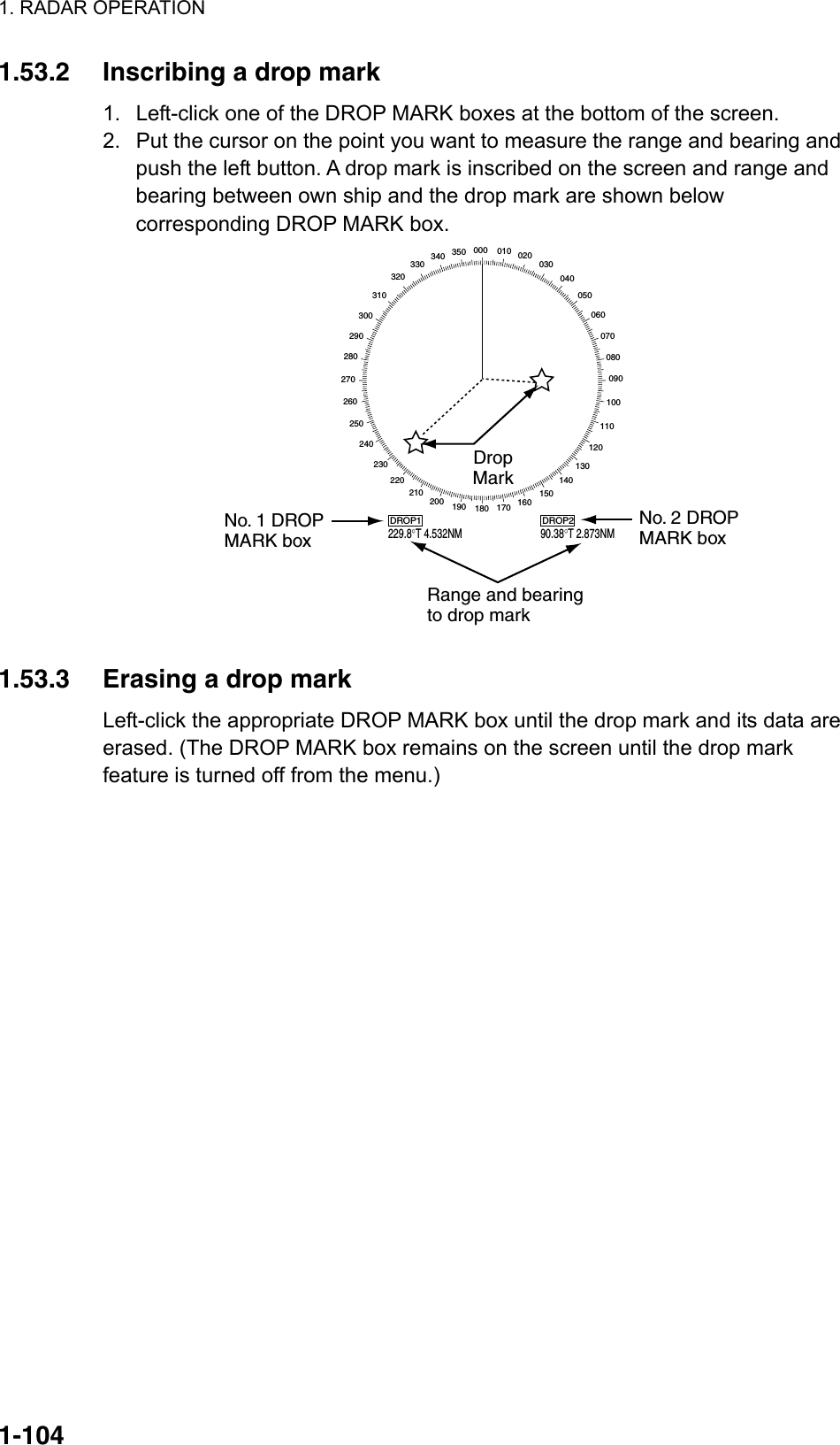
![1. RADAR OPERATION 1-1051.54 Sub Monitor (A, B, C and W types) The picture from a radar outside the LAN network can be shown on this radar (processor unit+display unit+control unit). 1. Put the cursor in the ANTENNA box at the upper left side of the screen. 2. Right-click to show the ANT SELECT menu. [ANT SELECT] ANT1: X-BAND 12 FORE ANT2: X-BAND 12 MAIN TOP ANT3: X-BAND MAIN TOP 12 ANT4: X-BAND AFT OWN RADAR No.: 2 1 DISP1 ANT1 MASTER 2 DISP2 ANT2 MASTER * Not available on IMO or A radar.9 STORE INTER-SW NO/YES0 SUB MONITOR* OFF/ON3 DISP3 ANT3MASTER4 DISP4 ANT4MASTER 12 3. Spin the scrollwheel to select 0 SUB MONITOR then push the left button. 4. Spin the scrollwheel to select ON then push the left button. The antenna box shows "SUB" and the image from the sub monitor is shown on this radar 5. Push the right button to close the menu. Antenna-related functions of the sub monitor; for example, pulselength, cannot be controlled from this radar.](https://usermanual.wiki/Furuno-USA/9ZWRTR081A.op-manual/User-Guide-1456778-Page-126.png)
![1. RADAR OPERATION 1-1061.55 Net Cursor The net cursor is used to depict your fishing net on the radar display. It is especially useful for bottom trawlers for knowing where the net is located. Enter the dimensions of your net in the menu to show the net in scale on the display. Net cursorEBL2 1.55.1 Activating the net cursor 1. Left-click the MENU box. 2. Select 2 [MARK] then push the left button. 3. Select 9 [EBL, VRM, CURSOR SET] then push the left button. [EBL, VRM, CURSOR SET] 1 BACK2 EBL1 REL/TRUE3 EBL2 REL/TRUE4 VRM1 NM/SM/km/kyd5 VRM2 NM/SM/km/kyd6 CURSOR BEARING REL/TRUE7 CURSOR RANGE NM/SM/km/kyd8 [ CURSOR SHAPE]9 CURSOR BRG SCALE 360°/32 POINTS 4. Select 8 [CURSOR SHAPE] then push the left button.](https://usermanual.wiki/Furuno-USA/9ZWRTR081A.op-manual/User-Guide-1456778-Page-127.png)
![1. RADAR OPERATION 1-107FRONT HALFLENGTH REAR HALFLENGTH NET WIDTHab [ CURSOR SHAPE] 1 BACK2 CURSOR OFF/ON3 FRONT HALF LENGTH 0.0m4 REAR HALF LENGTH 0.0m5 NET WIDTH 0.0m6 ROTATE STEP 360°/32 POINTS WARP LENGTH 0.0m 5. Select 2 [CURSOR] then push the left button. 6. Select ON then push the left button to enable the net cursor. EBL2 is then automatically turned on. 7. Push the right button four times to close the menu. 1.55.2 Setting net cursor dimensions, adjusting net cursor orientation 1. Left-click the MENU box. 2. Select 2 [MARK] then push the left button. 3. Select 9 [EBL, VRM, CURSOR SET] then push the left button. 4. Select 8 [CURSOR SHAPE] then push the left button. 5. Set net cursor dimensions as follows, referring to the illustration at right. a) Select FRONT HALF LENGTH then push the left button. b) Spin the scrollwheel to set front half length (0-3000 m) then push the left button. c) Set REAR HALF LENGTH and NET WIDTH similarly. d) Warp length (a+b in the illustration at right) is indicated at the bottom of the menu. The net cursor is placed at the screen center, with its top and bottom points bisected by EBL2. To adjust the position of the net cursor, go to step 6. Otherwise, go to step 9. 6. Select 6 ROTATE STEP then push the left button. 7. Select 360° or 32 POINTS as appropriate then push the left button. These figures determine how finely to rotate the EBL2 when adjusting the orientation of the net cursor. Select 360° for fine rotation or 32 POINTS for coarse rotation. 8. Use the rotary encoder for the EBL to adjust the orientation of the net cursor.](https://usermanual.wiki/Furuno-USA/9ZWRTR081A.op-manual/User-Guide-1456778-Page-128.png)
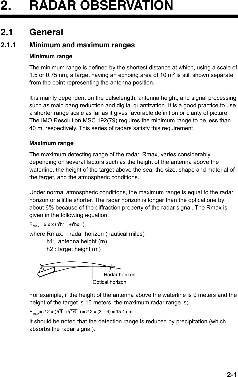
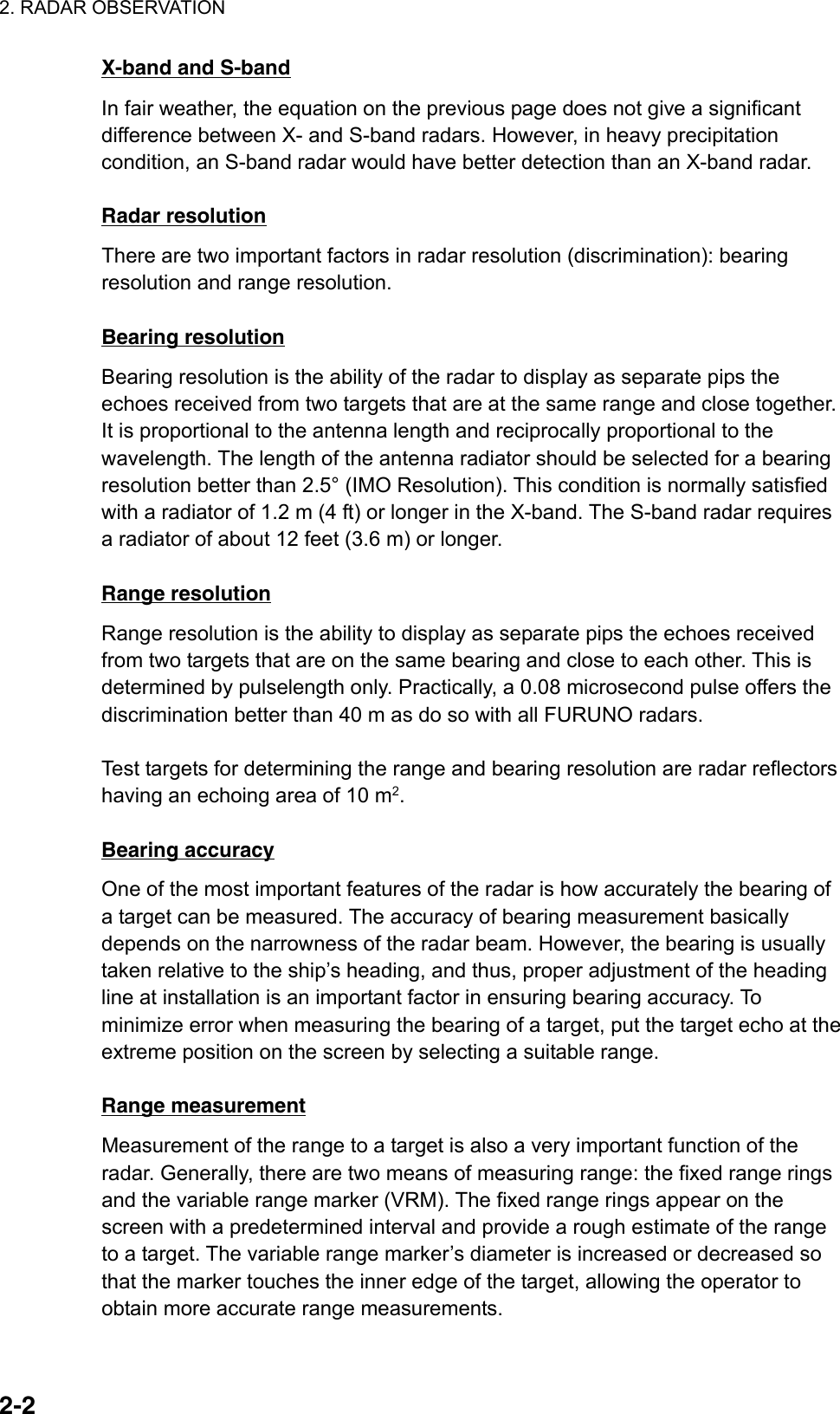
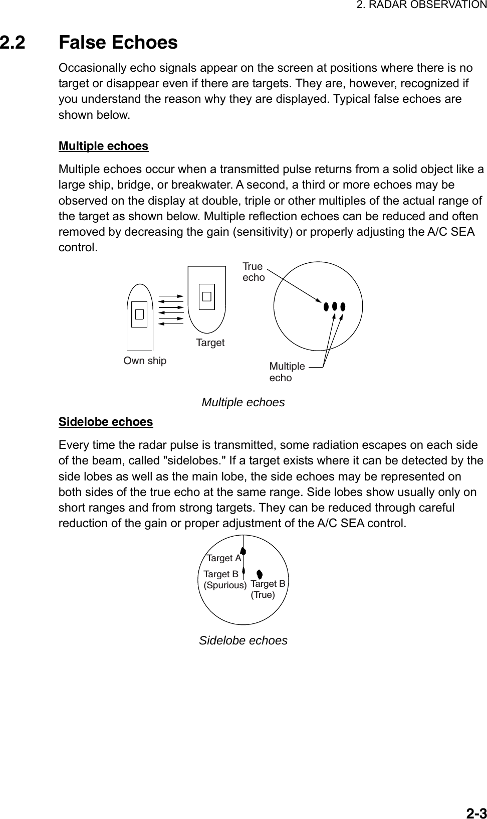
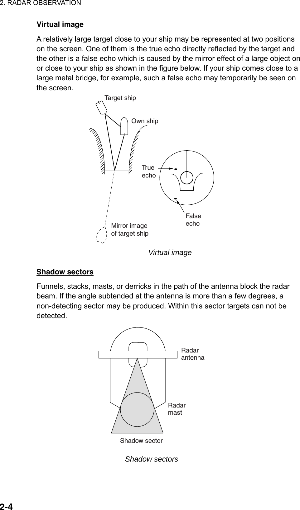
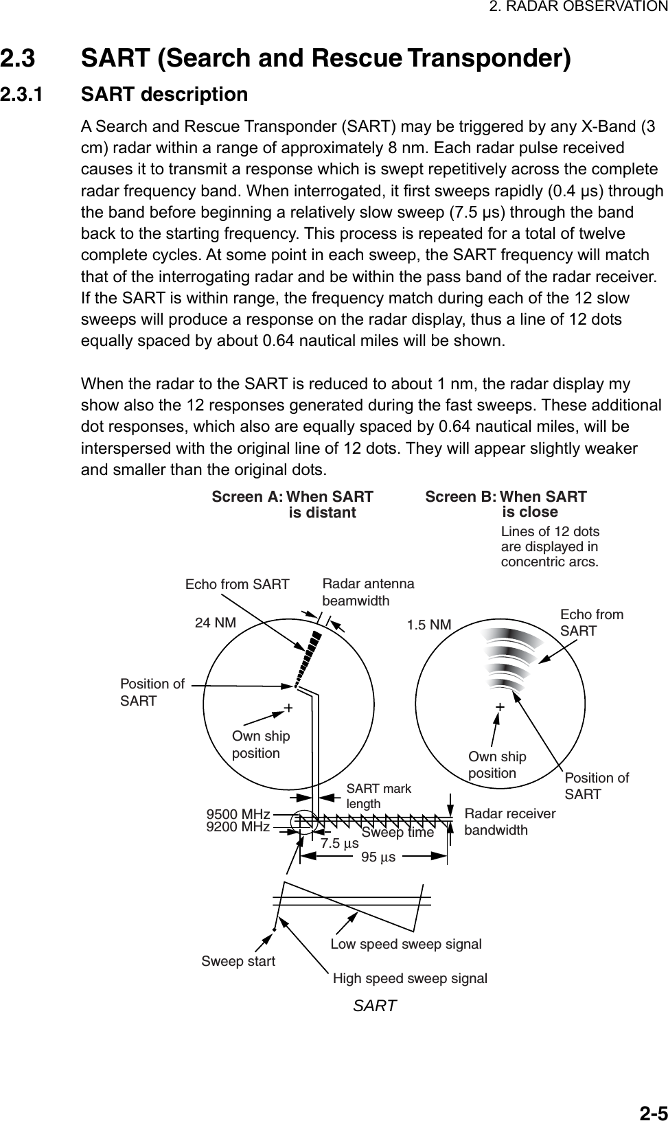
![2. RADAR OBSERVATION 2-62.3.2 Showing SART marks on the radar display This radar is equipped with a feature that optimally sets up the radar for SART detection. This feature automatically detunes the radar receiver out of its best tuning condition. This erases or weakens all normal radar echoes, but the SART marks are not erased because the SART response signal scans over all frequencies in the 9 GHz band. When the radar approaches the SART in operation, the SART marks will enlarge to large arcs, blurring a large part of the screen. To set up for SART detection do the following: 1. Left-click the MENU box to open the menu. 2. Select 1 [ECHO]. [ECHO] 1 BACK 2 2ND ECHO REJ OFF/ON 3 TUNE INITIALIZE 4 PM OFF/ON 5 SART OFF/ON 6 WIPER OFF/1/2 7 ECHO AREA*1 CIRCLE/WIDE/ALL*1 Not available on IMO or A type8 [PICTURE SELECT]9 STC RANGE +00 ECHO menu 3. Select 5 SART. 4. Select ON. With SART turned on radar functions are set as follows: Range: 12 nm Pulselength: Long Echo Stretch: Off Noise Rejector: Off Echo Averaging: Off Interference Rejector: Off Performance Monitor: Off A/C RAIN: Off 5. Push the right button twice to close the menu. "SART" appears at the bottom of the display when this feature is active. Be sure to turn off the SART feature when SART detection is no longer your objective.](https://usermanual.wiki/Furuno-USA/9ZWRTR081A.op-manual/User-Guide-1456778-Page-135.png)
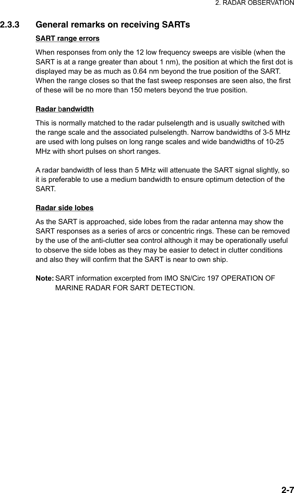
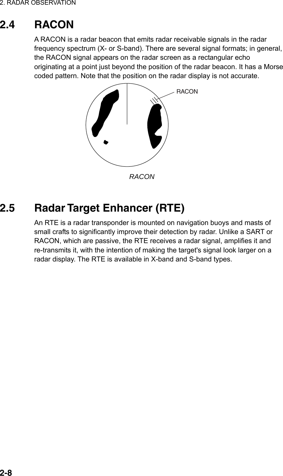
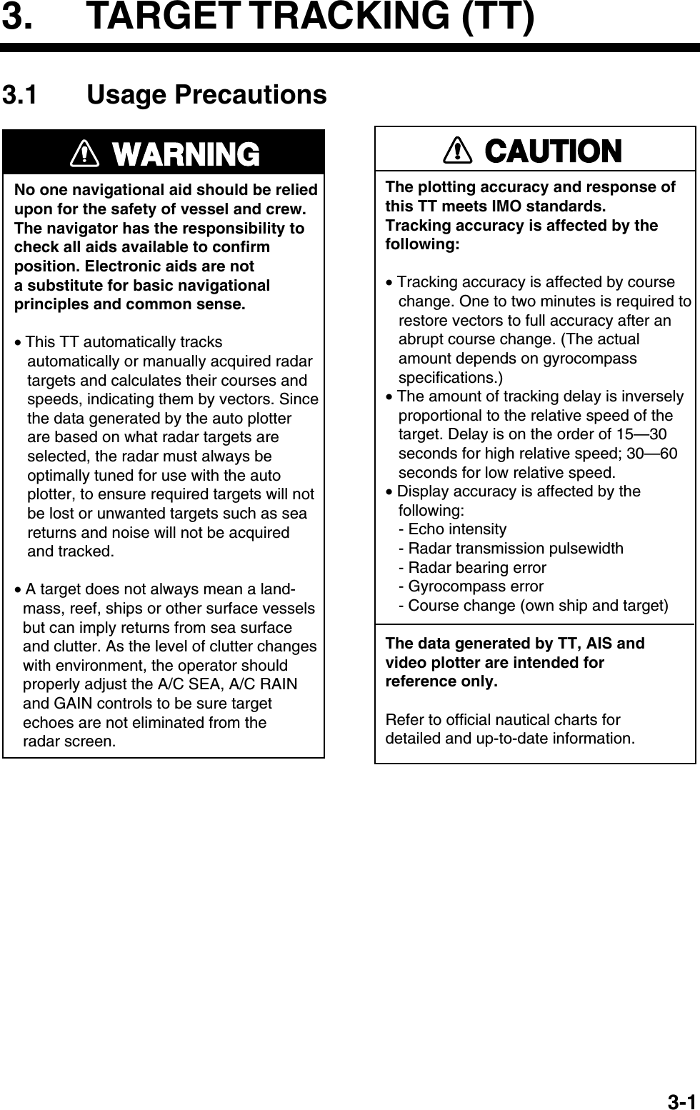
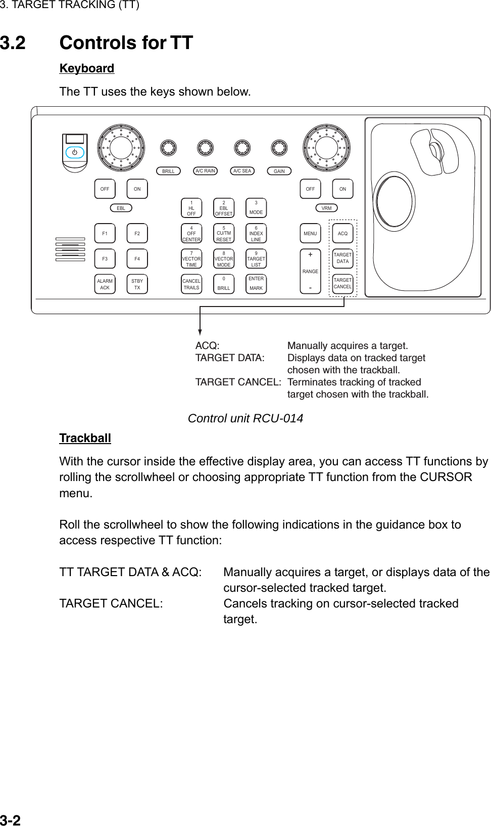
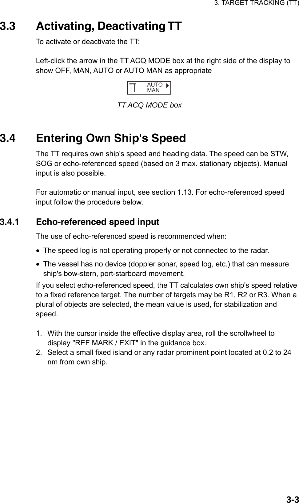
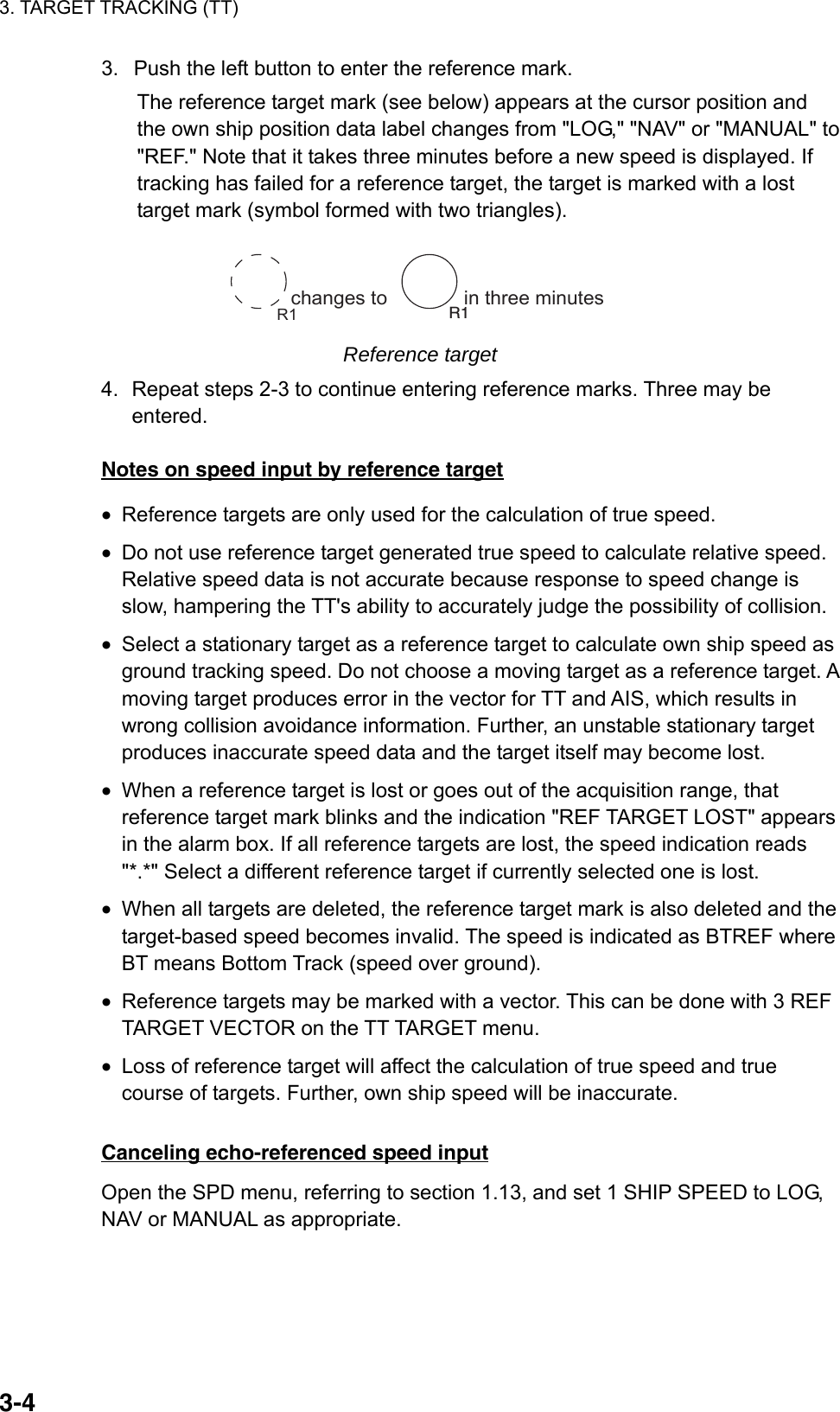
![3. TARGET TRACKING (TT) 3-5 [TT TARGET MENU] 1 TT SELECT MANUAL100/ AUTO 25/ AUTO 50/ AUTO 75/ AUTO 100 2 ALL CANCEL NO/YES 3 REF TARGET VECTOR OFF/ON 3.5 Automatic Acquisition The FAR-2xx7 radars can acquire a maximum of 100 targets, the number of automatically and manually acquired targets determined by the TT TARGET menu setting. TT TARGET setting and target acquisition condition Menu Setting Acquisition condition MANUAL100 100 targets manually AUTO25 25 targets automatically, 75 targets manually AUTO50 50 targets automatically, 50 targets manually AUTO75 75 targets automatically, 25 targets manually AUTO100 100 targets automatically A target just acquired automatically is marked with a broken square and a vector appears within one minute to indicate the target's motion trend. Within three minutes, the initial tracking stage is finished and the target becomes ready for stable tracking. At this point, the broken square mark changes to a solid circle. (Targets automatically acquired are distinguished from those acquired manually. The targets which are acquired manually are displayed with a thicker line.) 3.5.1 Enabling auto acquisition 1. Right-click the arrow in the TT ACQ MODE box to show the TT TARGET menu. TT TARGET menu 2. Select 1 TT SELECT. 3. Select automatic acquisition condition desired, referring to the table above for details. 4. Push the right button to close the menu. Note 1: The TT ACQ MODE box shows AUTO when the automatic acquisition condition is selected. Note 2: When the menu-set number of automatically acquired targets is reached, the message "TARGET-FULL (AUTO)" is displayed at the right-hand side of screen.](https://usermanual.wiki/Furuno-USA/9ZWRTR081A.op-manual/User-Guide-1456778-Page-142.png)
![3. TARGET TRACKING (TT) 3-6 [TT TARGET MENU] 1 TT SELECT MANUAL100/ AUTO 25/ AUTO 50/ AUTO 75/ AUTO 100 3 ALL CANCEL NO/YES 3 REF TARGET VECTOROFF/ON3.5.2 Terminating tracking of targets (including reference targets) When the TT has acquired the menu-set number of targets automatically, the message "TARGET-FULL(AUTO)(or MAN)" appears at the right side of the screen and no more auto acquisition occurs unless targets are lost. Should this happen, cancel tracking of less important targets or perform manual acquisition. Canceling individual targets By keyboard: 1. Use the trackball to put the cursor (+) on the tracked target, reference target or lost target you wish to cancel tracking. 2. Press the [TARGET CANCEL] key. By trackball: 1. With the cursor inside the effective display area, roll the scrollwheel to show TARGET CANCEL / EXIT in the guidance box. 2. Put the cursor (+) on the tracked target, reference target or lost target you wish to cancel tracking. 3. Push the left button to cancel tracking on the target selected. 4. To finish, push the right button. Canceling tracking on all targets 1. Right-click the TT ACQ MODE box at the right side of the screen to show the TT TARGET menu. TT TARGET menu 2. Select 2 ALL CANCEL and YES. 3. Push the left button to cancel tracking on all tracked targets.](https://usermanual.wiki/Furuno-USA/9ZWRTR081A.op-manual/User-Guide-1456778-Page-143.png)
![3. TARGET TRACKING (TT) 3-7 [TT TARGET MENU] 1 TT SELECT MANUAL100/ AUTO 25/ AUTO 50/ AUTO 75/ AUTO 100 4 ALL CANCEL NO/YES 3 REF TARGET VECTOR OFF/ON 3.6 Manual Acquisition Maximum 100 targets may be acquired manually depending on the acquisition condition set on the TT TGT menu. 3.6.1 Setting manual acquisition conditions 1. Right-click the arrow in the TT ACQ MODE box at the right side to show the TT TARGET menu. TT TARGET menu 2. Select 1 TT SELECT. 3. Select MANUAL 100, AUTO 25, AUTO 50 or AUTO 75 as appropriate. For details see the table on page 3-5. 4. Push the right button to close the menu. 3.6.2 Manually acquiring targets By keyboard 1. Put the cursor on the target you want to acquire. 2. Press the [ACQ] key. By trackball 1. With the cursor inside the effective display area, roll the scrollwheel to show "TT TARGET DATA & ACQ" in the guidance box. 2. Put the cursor on the target you want to acquire. 3. Push the left button to acquire the target.](https://usermanual.wiki/Furuno-USA/9ZWRTR081A.op-manual/User-Guide-1456778-Page-144.png)
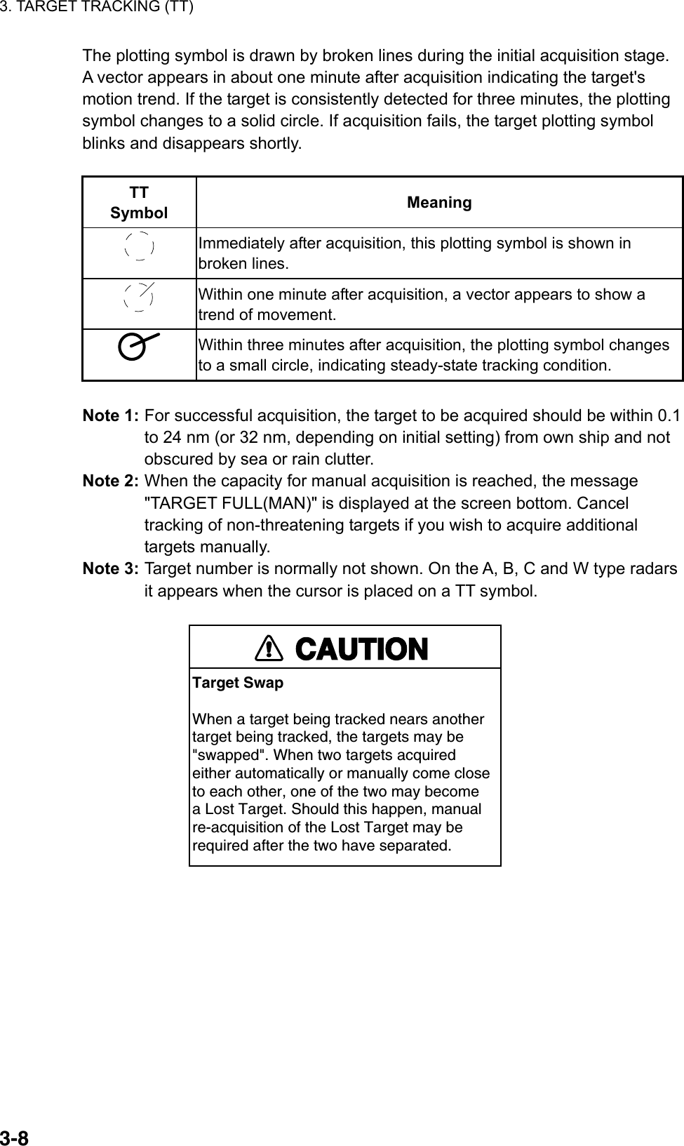
![3. TARGET TRACKING (TT) 3-9 [TT LOST ALM FILTER] 1 BACK 2 MAX RANGE OFF/ON 0NM 3 MIN SHIP SPEED OFF/ON 0.0kn 3.7 Lost Target Targets not detected in five consecutive scans become "lost targets." A lost target is shown in the display with flashing red "X". Flashing stops after lost target alarm is acknowledged. If you are in an area where tracked targets are lost frequently you may want to disable the lost target alarm against tracked targets by maximum range or minimum speed. 3.7.1 Setting the lost target filter You can set the lost target alarm to sound against lost TTs that are within a specific range or ship speed. Set the criteria as below. 1. Left-click the MENU box to open the menu. 2. Select 4 [TT.AIS] to open the TT.AIS menu. 3. Select 9 [TT LOST FILTER]. 4. Set items 2 and 3 as appropriate, referring to the description below. MAX RANGE: Any TT lost targets beyond this range will not trigger the lost target alarm. MIN SHIP SPEED: Any TT lost targets slower than this setting will not trigger the lost target alarm. 5. Push the right button several times to close the menu. Note: Reference targets are not affected by this filter. 3.7.2 Enabling, disabling the lost target alarm The LOST TARGET ALARM box at the bottom right corner enables and disables the lost target alarm. Select OFF, ALL or FILT as appropriate. OFF: Disable the alarm ALL: Get the alarm against all lost targets. FILT: Get the alarm against the targets whose criteria meet the settings on the TT LOST ALM FILTER menu. LOST TARGET ALAEM OFFLOST TARGET box](https://usermanual.wiki/Furuno-USA/9ZWRTR081A.op-manual/User-Guide-1456778-Page-146.png)
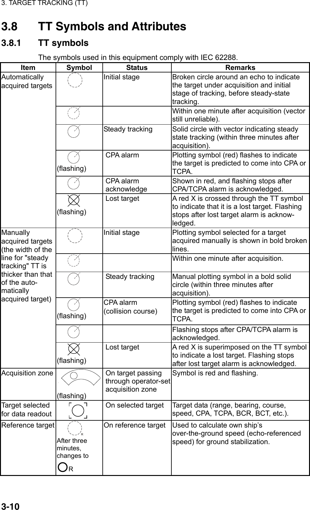
![3. TARGET TRACKING (TT) 3-11Other TT symbols Item Symbol Status Remarks Trial maneuver T (flashing) Bottom center Appears during execution of a trial maneuver. Performance test S (flashing) Bottom center Appears during performance test. 3.8.2 Choosing TT symbol (B, C and W types) In addition to the "standard" circle TT symbol, you may select from the symbols shown below, using the full keyboard. This cannot be done with trackball-type control unit (RCU-015, RCU-016). However, you can program a function key to do so, with the combination of the "STD KEY" category and the option "TARGET DATA." 1. Put the cursor on the TT symbol you want to change. 2. Press the [TARGET DATA] key. 3. Press the [TARGET DATA] key until desired symbol is displayed. 3.8.3 TT symbol brilliance 1. Right-click the BRILL box at the left side of the screen. 2. Select 0 NEXT. [BRILL1 MENU (2/2)]1 BACK2 BRG CURSOR3 EBL4 VRM5 PI LINE6 TT SYMBOL7 AIS SYMBOL8 L/L GRID9 MARK0 CHART BRILL menu, page 2 3. Select 6 TT SYMBOL. 4. Roll the scrollwheel to adjust brilliance. 5. Push the right button twice to close the menu.](https://usermanual.wiki/Furuno-USA/9ZWRTR081A.op-manual/User-Guide-1456778-Page-148.png)
![3. TARGET TRACKING (TT) 3-12 [TT•AIS] 1 BACK 2 AZ STAB STAB HDG/STAB NORTH 3 AZ POLYGON OFF/STAB GND/ STAB HDG/STAB NORTH 4 [TRIAL MANEUVER] 5 [TT•AIS SYMBOL] 6 [CPA AUTO ACTIVATE] 7 [AIS DISP FILTER] 8 [AIS LOST FILTER] 9 [TT LOST FILTER] 0 [ASSOCIATION] [TT•AIS SYMBOL] 1 BACK 2 TT•AIS SYMBOL COLOR RED*/GRN/BLU/YEL*/ CYA/MAG/WHT 3 AIS ROT TAG LIMIT 0.000°/MIN 4 TT PAST POSN POINTS 5/10 5 AIS PAST POSN POINTS 5/10 6 AIS SCALED SYMBOL OFF/ON 3.8.4 TT symbol color You may select the color for the TT symbol as follows: 1. Left-click the MENU box to open the menu. 2. Select 4 [TT•AIS] to open the TT.AIS menu. TT•AIS menu 3. Select 5 [TT•AIS SYMBOL]. * Not available onIMO type](https://usermanual.wiki/Furuno-USA/9ZWRTR081A.op-manual/User-Guide-1456778-Page-149.png)
![3. TARGET TRACKING (TT) 3-133.9 Displaying Target Data The TT mode provides the full functionality of TT as required by the IMO Resolution A.823(19) and IEC 62288, including display of range, bearing, course, speed, CPA and TCPA of all tracked targets. The target bearing is show in relative bearing in the head-up mode and true bearing in the course-up, north-up and true motion modes, with the suffix "R" (Relative) or "T" (True). The target speed and course are shown as speed over the ground or speed through the water depending on speed source. 3.9.1 Displaying target data By keyboard Use the trackball to put the cursor on a desired tracked target and press the [TARGET DATA] key. The target’s shape changes to a square. To erase a target’s data from the data box, press the key again. By trackball 1. With cursor inside the effective display area, roll the scrollwheel to show "TARGET DATA & ACQ / CURSOR MENU" in the guidance box. 2. Use the trackball to put the cursor on a desired tracked target then push the left button. 3. To erase a target’s data from the data box, select the target on the radar display then push the left button. Target data display is as below. RNG/BRG: Range and bearing from own ship to the selected target with suffix "T" (True) or "R" (Relative). COG/SOG (in case of GPS): Course and speed are displayed for the selected target with suffix "T" (True) or "R" (relative). CSE/STW are shown for manual speed and speed through the water. CPA/TCPA: CPA (Closest Point of Approach) is the closest range a target will approach to own ship. TCPA is the time to CPA. Both CPA and TCPA are automatically calculated. When the CPA has passed clear of own ship, it is indicated by a TCPA with a negative (-) sign. TCPA is counted to 99.9 min and beyond this, it is indicate as TCPA> -99.9MIN. BCR/BCT: BCR is the closest range at which the selected target is predicted to cross your ship’s bow. BCT is the time at which the selected target is predicted to cross your ship’s bow.](https://usermanual.wiki/Furuno-USA/9ZWRTR081A.op-manual/User-Guide-1456778-Page-150.png)
![3. TARGET TRACKING (TT) 3-14000 010 020030040050060070080090100110120130140150160170180190200210220230240250260270280290300310320330 340 350Target selected for data readoutTT TARGET No. 01BRG 25.5°TRNG 3.4NMT COG 205.1°T*T SOG 12.3KN*CPA 2.9NMTCPA 12.2MINBCR 1.7NMBCT 20MIN 01BRG: Bearing from own ship to targetin R (Relative) or T (True)RNG: Range from own ship to targetCOG: Course of target over ground, True or Relative*SOG: Speed of target over ground*CPA: Closest Point of Approach of target to own shipTCPA: Time to CPABCR: Bow crossing range of targetBCT: Bow crossing time of target* CSE and STW are shown in case of manual speed, speed through the water. Tracked target display You may display the target data for two targets in one data box and the data for as many as six targets can be displayed. For further details, see section 1.42. Removing a target data display Full keyboard: Put the cursor on the data you want to remove then hit the [TARGET DATA] key. Cursor menu: TARGET DATA & ACQ Canceling tracking on a target from target data display Full keyboard: Put the cursor on the data you want to remove then hit the [TARGET CANCEL] key. Cursor menu: TARGET CANCEL](https://usermanual.wiki/Furuno-USA/9ZWRTR081A.op-manual/User-Guide-1456778-Page-151.png)
![3. TARGET TRACKING (TT) 3-15 [TARGET LIST (1/1)] SORT BY CPA 1 BACK 2 TT TARGET No: 01 BRG 16.5°T RNG 2.05 NM CPA 0.17NM TCPA>99.59M3 TT TARGET No: 02 BRG 19.0°T RNG 2.49 NM CPA 0.29NM TCPA>99.59M 9 REFRESH DATA 3.9.2 Target list The target list provides a comprehensive data display of all TT (and AIS) targets being tracked. Displaying the target list To display the target list, do the following: 1. Select the TARGET LIST box at the right side of the screen. TARGETLIST TARGET LIST box 2. Push the left button to display the TARGET LIST. ">" in the TCPA means that the time is greater than 99:59. Target list 3. To scroll the list when there are more than three targets, select 0 NEXT. Note: To refresh data, select 9 REFRESH DATA then push the scrollwheel. This is not necessary when the sorting method is changed (see next page); data is automatically updated whenever the sorting method is changed. 4. Push the right button to close the list.](https://usermanual.wiki/Furuno-USA/9ZWRTR081A.op-manual/User-Guide-1456778-Page-152.png)
![3. TARGET TRACKING (TT) 3-16 [TARGET LIST MENU] 1 SORT BY CPA/TCPA/BCR/BCT/ RANGE/SPEED Sorting the target list You may sort the target list by CPA, TCPA, BCR, BCT, RANGE or SPEED as follows: 72 nm or 96 nm range scale 1. Right-click the TARGET LIST box. TARGET LIST menu 2. Select 1 SORT BY. 3. Select sorting method desired. 4. Push the right button to close the menu. 3.10 Vector Modes Target vectors can be displayed relative to own ship's heading (Relative) or north (True). 3.10.1 Description of vectors Ground stabilization and sea stabilization Target vectors can be ground stabilized or sea stabilized. You can select ground or sea stabilization from the SPEED menu. Select BT(Bottom Tracking) for ground stabilization or WT(Water Tracking) for sea stabilization. The TT VECTOR box shows the stabilization mode as TRUE-G or TRUE-S. Sea stabilization is a mode where own ship and all targets are referenced to the sea using a compass heading and single-axis log water speed inputs. Ground stabilization is a mode where own ship and all targets are referenced to the ground using the ground track or set and drift inputs. If the accuracy seems unsatisfactory, enter set and drift corrections. Note that set and drift cannot be used on the IMO radar when the radar is displaying AIS targets.](https://usermanual.wiki/Furuno-USA/9ZWRTR081A.op-manual/User-Guide-1456778-Page-153.png)
![3. TARGET TRACKING (TT) 3-17True vector Own ship and other ship's move on the display at their true speeds and courses. This mode is useful for distinguishing moving targets from stationary ones. True vectors inhead-up modeRelative vectors inhead-up modeBOwn shipABOwn shipBuoy BuoyTarget oncollisioncourseA True and relative vectors Relative vector Other ships move relative to your ship. This mode is useful for finding ships on a collision course with your ship. A ship whose vector passes through your ship's position is on a collision course. 3.10.2 Vector mode and length Vectors may be displayed in true or relative mode. Vector time (or the length of vectors) can be set between 1 and 60 minutes. By keyboard 1. Press the [VECTOR MODE] key consecutively to select relative or true vector mode. Your selection is shown on the vector motion box. (Note that this also selects the vector mode for the past position display.) 2. Press the [VECTOR TIME] key consecutively to select vector time. Your selection appears in the vector time box (see illustration below). By trackball 1. Use the trackball to select VECTOR TRUE-S(or -G) or VECTOR REL (whichever is displayed) at the right side of the screen. VECTOR TRUE-S* 15MINVector modeVectortime* TRUE or RELS: Sea stablizedG: Ground stabilized(No stabilizationindication in relative.) TT VECTOR boxes](https://usermanual.wiki/Furuno-USA/9ZWRTR081A.op-manual/User-Guide-1456778-Page-154.png)
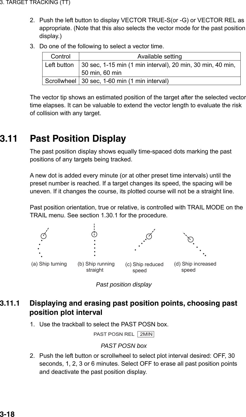
![3. TARGET TRACKING (TT) 3-19 [TT•AIS] 1 BACK 2 AZ ZONE STAB STAB HDG/STAB NORTH 3 AZ POLYGON OFF/STAB GND/ STAB HDG/STAB NORTH 4 [TRIAL MANEUVER] 5 [TT•AIS SYMBOL] 6 [CPA AUTO ACTIVATE] 7 [AIS DISP FILTER] 8 [AIS LOST FILTER 9 [TT LOST FILTER] 0 [ASSOCIATION] [TT•AIS SYMBOL] 1 BACK 2 TT•AIS SYMBOL COLOR RED*/GRN/BLU/YEL*/ CYA/MAG/WHT 3 AIS ROT TAG LIMIT 0.000°/MIN 4 TT PAST POSN POINTS 5/10 5 AIS PAST POSN POINTS 5/10 6 AIS SCALED SYMBOL OFF/ON 3.11.2 Past position display attributes You may select the number of past points to display per plotting interval as follows. 1. Left-click the MENU box to open the menu. 2. Select 4 [TT•AIS]. 3. Select 5 [TT•AIS SYMBOL]. * Not available on IMO radar TT•AIS SYMBOL menu 4. Select 4 TT PAST POSN POINTS. 5. Select 5 or 10 as appropriate. 6. Push the right button three times to close the menu. 3.11.3 Past position display mode The display mode for the past position display is the same as that set for the TT vector. In the true motion mode, the true vector is displayed.](https://usermanual.wiki/Furuno-USA/9ZWRTR081A.op-manual/User-Guide-1456778-Page-156.png)
![3. TARGET TRACKING (TT) 3-20 [SPEED MENU] 1 SHIP SPEED LOG(BT)/LOG(WT)/ GPS/MANUAL/REF 2 MANUAL SPEED 0.0kn 3 SET DRIFT OFF/ON 3.11.4 Stabilization in true mode The true mode past position display may be ground stabilized or sea stabilized. The PAST POSN box shows current stabilization as TRUE-G or TRUE-S. To change stabilization mode, open the SPEED menu and set SHIP SPEED to BT (ground stabilization) or WT (sea stabilization). 3.12 Set and Drift Set, the direction in which a water current flows, can be manually entered in 0.1-degree steps. Drift, in another word Rate, the speed of tide, can also be entered manually in 0.1 knot steps. When course through water and speed through water are available, activate set and drift to get course over ground and speed over ground. Set and drift corrections are beneficial for increasing the accuracy of vectors and target data. Refer to the tide table on board the ship for setting information. These values are applied to all targets. If stationary targets have vectors, set and drift values should be adjusted until they lose vectors. To enter set and drift do the following: 1. Right-click the SPD box to show the SPEED menu. 2. Select 3 SET DRIFT. 3. Select ON. 4. Push the right button to close the menu. Then, the SET and DRIFT boxes appear at the top of the display. 5. Select the SET box. 6. Use the scrollwheel to set value, rolling it to select numeral and pushing it to set. (Setting range: 000.0 – 359.9 (°T)) 7. Select the DRIFT box. 8. Use the scrollwheel to set value, rolling it to select numeral and pushing it to set. (Setting range: 00.0 – 19.9(kn)) Note 1: Set and drift are available when using manually input speed, speed through the water. The speed source is shown as "WTC" (Water Tracking Count). Note 2: Set and drift should be checked periodically for correctness. Note 3: Set and drift can also be adjusted with the EBL and VRM. Put the cursor in either the SET or DRIFT box and operate the EBL for set and VRM for drift. SET 66.8°T SET box DRIFT 7.2kn DRIFT box](https://usermanual.wiki/Furuno-USA/9ZWRTR081A.op-manual/User-Guide-1456778-Page-157.png)
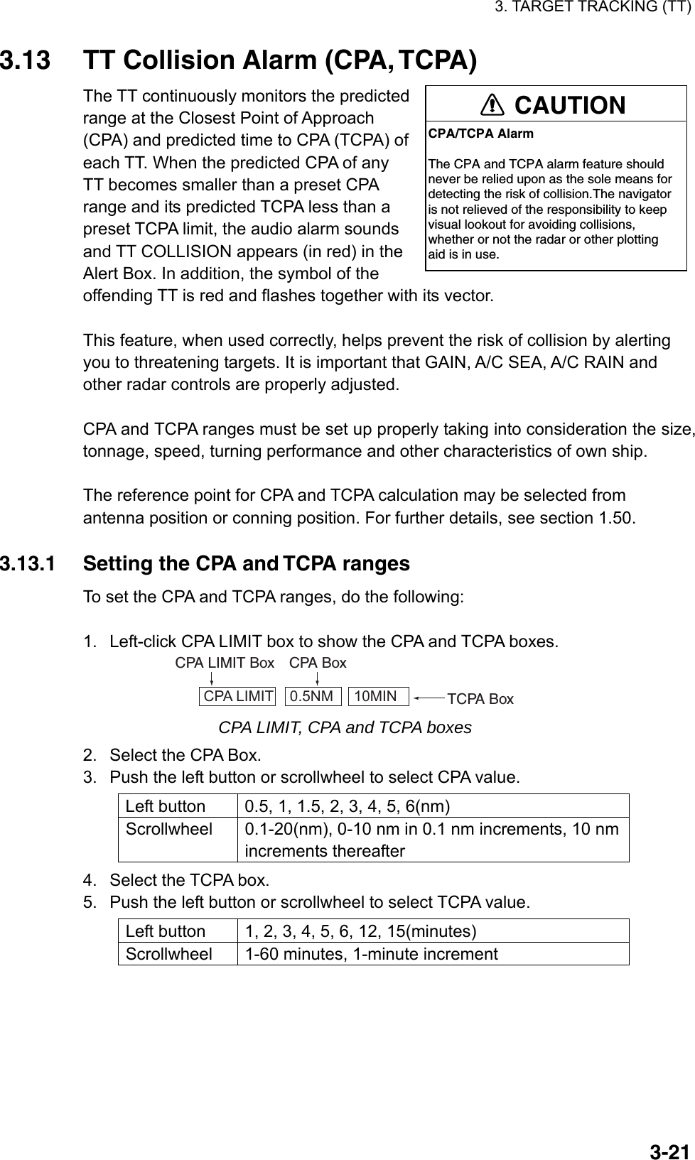
![3. TARGET TRACKING (TT) 3-223.13.2 Acknowledging the TT collision alarm Press the [ALARM ACK] key on the keyboard, or select the ALARM ACK box with the trackball then push the left button to acknowledge the alarm and silence the buzzer. The warning label TT COLLISION and the flashing of the triangle plotting symbol and vector remain in the Alert Box until the dangerous situation is gone or you intentionally terminate tracking of the target. Note that when the TT COLLISION alarm is generated the AIS display is automatically turned on. 3.14 Acquisition Zone The acquisition zone functions both to alert you targets in a specific area and acts as an automatic acquisition area when automatic target acquisition is active. Any targets entering the zone will be automatically acquired. When a target enters an acquisition zone, the buzzer sounds and the indication TT NEW TARGET (or AIS NEW TARGET) appears (in red) in the Alert Box. The symbol of the offending target is red and flashing. Further, the AIS display is automatically turned on if it is off. 3.14.1 Activating an acquisition zone One or two acquisition zones may be activated. The No. 1 acquisition zone is available between 3 and 6 nm and the No. 2 acquisition zone can be set anywhere when the No. 1 zone is already in use. The TT/AIS acquisition zone’s lines are white and dashed so as to distinguish them from the radar target alarm. The procedure below shows how to set an acquisition zone, using the example at the bottom of the page. 1. Use the trackball to select one of the AZ (Acquisition Zone) boxes at the right side of the screen. AZ 1 AZ 2 Acquisition zone statusBlank: Cancel acquisition zoneSET: Set acquisition zoneWORK: Activate acquisition zoneSLEEP: Sleep acquisition zone AZ boxes 2. Push the left button. The AZ box now reads "AZx SET." 3. Put the cursor on point A then push the left button. 4. Put the cursor on point B then push the left button. The AZ box now reads "AZx WORK."](https://usermanual.wiki/Furuno-USA/9ZWRTR081A.op-manual/User-Guide-1456778-Page-159.png)
![3. TARGET TRACKING (TT) 3-230.5-1 nm Target in acquision zone isred and flashing.AB If you are setting a polygon acquisition zone with AZ2, set at least three points. Push the right button to finish. Note that the status indication should be WORK or SLEEP to set AZ2. When a TT or AIS target enters the zone, the indication TT NEW TARGET or AIS NEW TARGET appears (in red) in the Alert Box and the offending target flashes. For the AIS, all sleeping targets are changed to activated targets. Note 1: If you wish to create an acquisition zone having a 360-degree coverage around own ship, set point B in almost the same direction (approx. ±3°) as point A then push the left button. Note 2: If the range scale is changed to less than half of the acquisition zone, "Azx (x=1 or 2) OUT" is shown in light-blue in the AZ box.If the left button is pushed in this state, the acquisition zone goes into "sleep" state and the guidance box reads "AZ WORK L = DELETE." Note 3: The default acquisition zone is fan shaped. It may also be a polygon having 3-10 points. For details, see section 3.14.5. Note 4: If both acquisition zones are displayed, maximum of four polygon points are shown. Note 5: TT and AIS are automatically set to TT=AUTO and AIS=DISP, respectively, when an AZ is activated in the following conditions: TT: TT=OFF or TT=MANUAL 100 AIS: AIS FUNC=OFF or AIS DISP=OFF 3.14.2 Sleeping, deactivating an acquisition zone 1. Select the appropriate AZ box. 2. Sleep or deactivate the alarm zone as appropriate: Sleep alarm zone: Push the left button to remove the acquisition zone from the screen. The indication in the AZ box changes from "AZx WORK" to "AZx SLEEP." To reactivate and display the acquisition zone, repeat this procedure to display "AZx WORK." Deactivate alarm zone: Push and hold down the left button until the AZ box goes blank. 3.14.3 Acknowledging the alarm Press the [ALARM ACK] key, or select the ALARM ACK box then push the left button to acknowledge the alarm and silence the buzzer.](https://usermanual.wiki/Furuno-USA/9ZWRTR081A.op-manual/User-Guide-1456778-Page-160.png)
![3. TARGET TRACKING (TT) 3-24 [TT•AIS] 1 BACK 2 AZ STAB STAB HDG/STAB NORTH 3 AZ POLYGON OFF/STAB GND/ STAB HDG/STAB NORTH 4 [TRIAL MANEUVER] 5 [TT•AIS SYMBOL] 6 [CPA AUTO ACTIVATE] 7 [AIS DISP FILTER] 8 [AIS LOST FILTER OFF/ON 9 [TT LOST FILTER] 0 [ASSOCIATION] 3.14.4 Acquisition zone reference The acquisition zone may be referenced to heading or North as follows: 1. Left-click the MENU box to open the menu. 2. Select 4 [TT•AIS] to open the TT•AIS menu. TT•AIS menu 3. Select 2 AZ STAB. 4. Select STAB HDG or STAB NORTH as appropriate. STAB HDG: Acquisition zone keeps position relation with your ship. STAB NORTH: Acquisition zone is fixed to North. 5. Push the right button twice to close menu. 3.14.5 Acquisition zone shape and stabilization The shape of the No. 2 acquisition zone may be a sector or a polygon having up to 10 points. (The shape of the No.1 acquisition zone is always a sector.) 1. Left-click the MENU box to open the menu. 2. Select 4 [TT.AIS] to open the TT.AIS menu. 3. Select 3 AZ POLYGON. 4. Select OFF, STAB GND, STAB HDG or STAB NORTH as appropriate. OFF: Acquisition zone is a sector; number of points is limited to four. Stabilized against land. STAB GND: Polygon having 3-10 points. Stabilized against ground. STAB HDG: Polygon having 3-10 points. Stabilized against heading. STAB NORTH: Polygon having 3-10 points. Stabilized against North. 5. Push the right button twice to close menu.](https://usermanual.wiki/Furuno-USA/9ZWRTR081A.op-manual/User-Guide-1456778-Page-161.png)
![3. TARGET TRACKING (TT) 3-253.15 TT System Messages There are seven main situations that cause the TT to trigger audio and visual alarms: • Reference target alarm • Collision alarm • Acquisition zone alarm • Lost target alarm • Target full alarm for manual acquisition • Target full alarm for automatic acquisition • System failure To acknowledge the audio alarm, press the [ALARM ACK] key, or select the ALARM ACK box then push the left button. TT system messages Message Meaning Action REF TARGET LOST When the system detects a loss of a reference target, the target symbol turns red and flashes. At the same time, an audio alarm is produced for one second. The reference target mark disappears from the screen after the reference target alarm is acknowledged. Press the [ALARM ACK] key or click the ALARM ACK box to acknowledge. TT COLLISION A tracked target is on collision course. Take evasive action or terminate tracking of TT.TT NEW TARGET Tracked target has entered an acquisition zone. The tracked target's symbol is red and flashing. Press the [ALARM ACK] key or click the ALARM ACK box to acknowledge. TT LOST When the system detects a loss of a tracked target, the lost tracked target symbol appears in red and flashes. At the same time, an audio alarm is produced for one second. The lost target mark disappears from the screen after the lost target alarm is acknowledged. Press the [ALARM ACK] key or click the ALARM ACK box to acknowledge. TT TARGET 95% (AUTO) or (MAN) Appears when capacity for automatically(manually) tracked targets is 95% full. TT TARGET FULL (AUTO) or (MAN) Appears when capacity for automatically(manually) acquired targets is full. TT SYSTEM ERROR When the TT malfunctions because of hardware error, the screen shows this indication. Press the [ALARM ACK] key or click the ALARM ACK box to acknowledge. Reset power to restore normal operation.](https://usermanual.wiki/Furuno-USA/9ZWRTR081A.op-manual/User-Guide-1456778-Page-162.png)
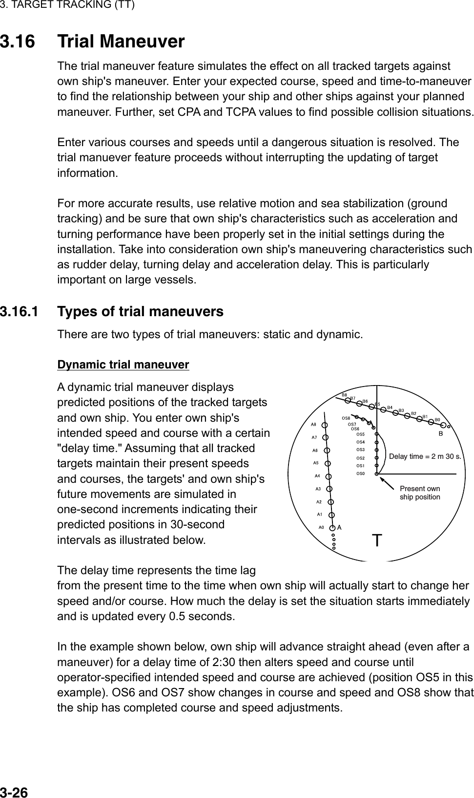
![3. TARGET TRACKING (TT) 3-27 [TT•AIS] 1 BACK 2 AZ STAB STAB HDG/STAB NORTH 4 AZ POLYGON OFF/STAB GND/ STAB HDG/STAB NORTH 4 [TRIAL MANEUVER] 5 [TT•AIS SYMBOL] 6 [CPA AUTO ACTIVATE] 7 [AIS DISP FILTER] 8 [AIS LOST FILTER OFF/ON 9 [TT LOST FILTER] 0 [ASSOCIATION] Static trial maneuver The static trial maneuver shows the relationship between your ship and tracked targets at the completetion of the trial maneuver. Enter expected course and speed and delay time until start of a maneuver and the expected position of your ship and tracked targets at the end of the trial maneuver are shown on the display. By shortening and extending the trial time you can find the safe time to make a maneuver. Thus, the static trial maneuver will be convenient when you wish to know the maneuver result immediately. ABCurrent positionof your shipDelay timeTCourse and speed changescompleted; position wherecourse and speed are changedPosition of target Aat end of trialmaneuverPosition of target B at endof trial maneuver 3.16.2 Performing a trial maneuver To perform a trial maneuver, do the following: 1. Left-click the MENU box to open the menu. 2. Select 4 [TT•AIS] to open the TT•AIS menu. TT•AIS menu](https://usermanual.wiki/Furuno-USA/9ZWRTR081A.op-manual/User-Guide-1456778-Page-164.png)
![3. TARGET TRACKING (TT) 3-28 [TRIAL MANEUVER] 1 BACK 2 TRIAL OFF/STATIC/DYNAMIC3 TRIAL SPEED RATE 0kn 0.00kn/s 0kn 0.00kn/s 4 TRIAL TURN RATE 0kn 0.0°/s 0kn 0.0°/s 3. Select 4 [TRIAL MANEUVER]. TRIAL MANEUVER menu 4. Select 2 TRIAL. 5. Select STATIC or DYNAMIC as appropriate. The TRAIL box appears at the upper right corner. TRIAL OFF 6. Select 3 TRIAL SPEED RATE. Set trial speed rate with the scrollwheel, in the upper box. 7. Select 4 TRIAL TURN RATE. Set trial turn rate with the scrollwheel, in the upper box. Note: Two sets of trial speed and trial turn rate combinations are provided. Enter the data by sets as shown in the figure below. This is done to provide accurate trial maneuver results for various ship’s speed. 3 TRIAL SPEED RATE 4 TRIAL TURN RATE Set 10kt 0.00kn/s0kt 0.00kn/sSet 2Set 10kt 0.0°/s0kt 0.0°/sSet 2Set speed and turn rate tozero (0) to simulate course and speed changesnot affected by ship’sinertia. 8. Push the right button three times to close the menu. 9. Use the trackball to select the TRIAL box and push the left button. Then, the TRIAL box reads TRIAL SET and boxes appear above the TRIAL box as below. 86.8°T06.5kn 00:30 DELAYTRIAL SET 00:00 Course for trial maneuverSpeed for trial maneuverDelay time for trial maneuverTrial time Boxes for setting trial maneuver parameters 10. Use the scrollwheel to set delay time at DELAY. This is the time after which own ship takes a new situation, not the time the simulation begins. Change the delay time according to own ship loading condition, etc. Use the scrollwheel to set the delay time. 11. Select the course setting box. Use the scrollwheel to set the course](https://usermanual.wiki/Furuno-USA/9ZWRTR081A.op-manual/User-Guide-1456778-Page-165.png)
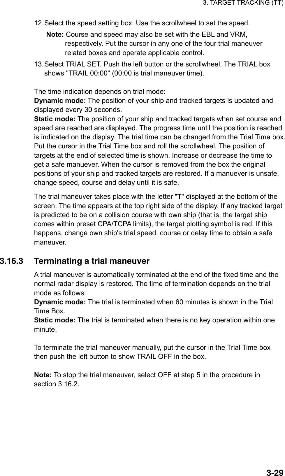
![3. TARGET TRACKING (TT) 3-30 [CUSTOMIZE•TEST] 1 BACK 2 [DATA BOX] 3 [F1] 4 [F2] 5 [F3] 6 [F4] 7 [OPERATION] 8 [TEST] [TEST] 1 BACK 2 [SELF TEST] 3 [TT TEST] [TT TEST] 1 BACK 2 TT TEST START NOTE: THE DISPLAY IS CLEARER WHEN RUNNING TT TEST. RUN TT TEST? YES: SELECT 2 START NO: SELECT 1 BACK 3.17 TT Performance Test A test program is provided for assessing overall performance of the TT. Normal operation is suspended and the indication "S" appears at the bottom of the effective display area during the test. The test may be terminated at any time. 1. Right-click the MENU box to open the menu. 2. Select 9 [CUSTOMIZE•TEST]. CUSTOMIZE•TEST menu 3. Select 8 [TEST]. TEST menu 4. Select 2 TT TEST START] TT TEST menu](https://usermanual.wiki/Furuno-USA/9ZWRTR081A.op-manual/User-Guide-1456778-Page-167.png)
![3. TARGET TRACKING (TT) 3-315. Select 2 TT TEST START then push the left button to start the test. An alert "S" flickers during the test. Approx. 10 minutes to complete the test scenario. The test does not require echo, gyro or log signals. (Gyro required if TT W/O GYRO setting is OFF. 6. Acquire all three targets. The simulated movement of three targets automatically runs ten minutes and repeats. The courses and speeds for the targets are as shown in the table below. 7. Put the cursor on target A then push the [TARGET DATA] key. Target data appears at the right side of the display. 8. Confirm that test data displayed for target A matches the data shown in the table below. Range, bearing and TCPA change over time. 9. Confirm that data for target B and C. 10. To terminate the test, press the [STBY TX] key, or select the TX STBY box at the bottom left corner then push the left button. Select any target with the cursor and check that the selected target shows the course and speed as in the table. CPA and TCPA shown in the table are with ship’s speed of 0 kn. Range, CPA and TCPA change with time; bearing and speed are fixed. Range (nm) Bearing(°) Speed (kn) Course(°) CPA (nm) TCPA (min) Target A 3.0 45.0 20.0 0 2.1 -6.4 Target B 2.0 120.0 5.0 120.0 0.0 -24.0 Target C 7.0 270.0 100 120.0 3.5 3.5 ASCB](https://usermanual.wiki/Furuno-USA/9ZWRTR081A.op-manual/User-Guide-1456778-Page-168.png)
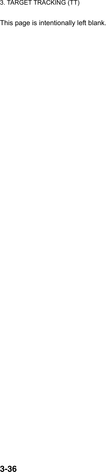
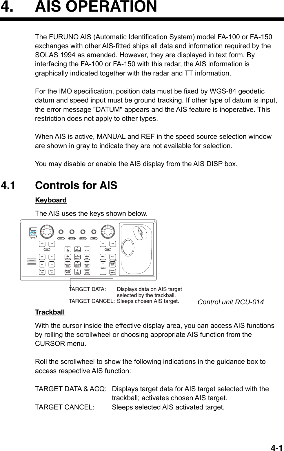
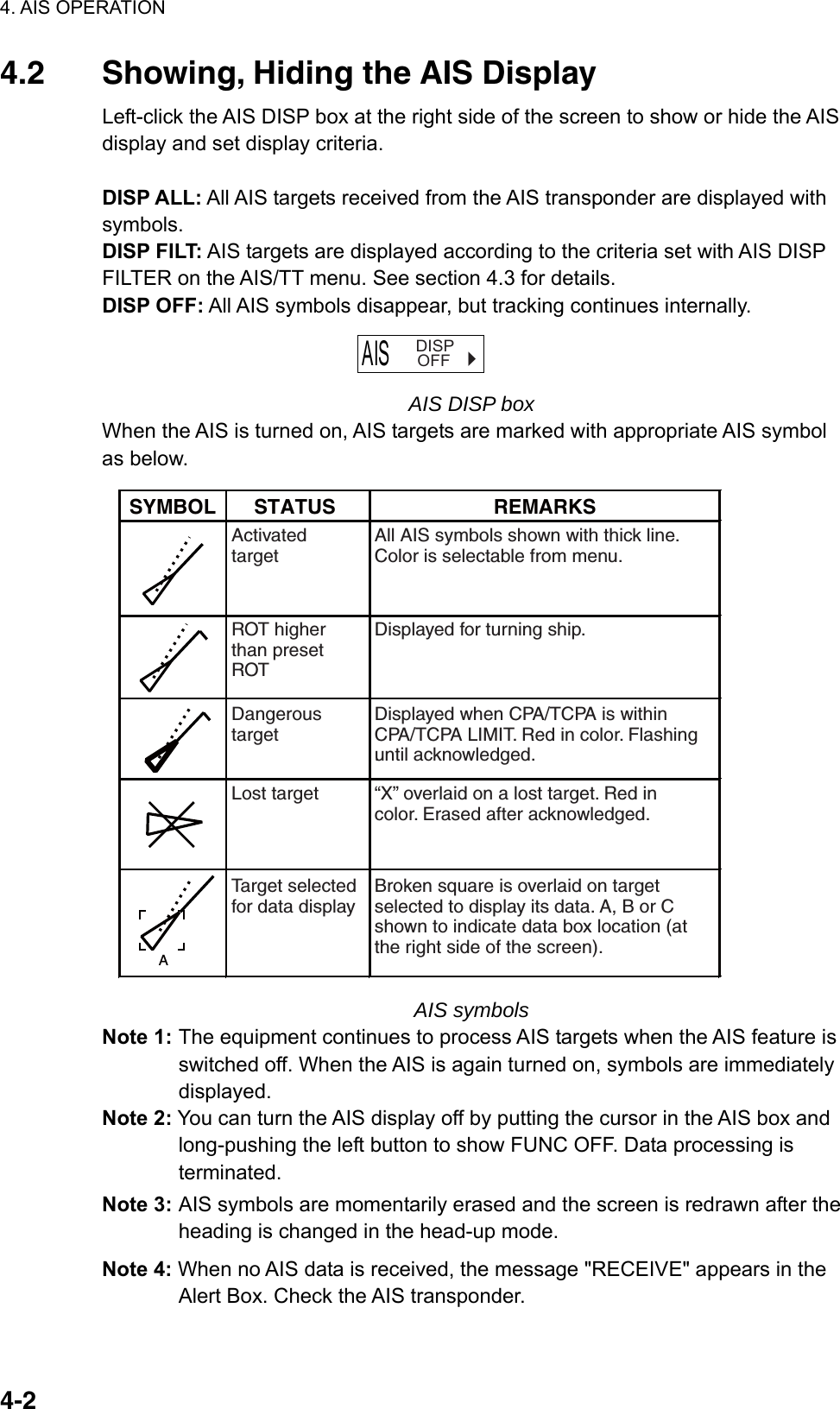
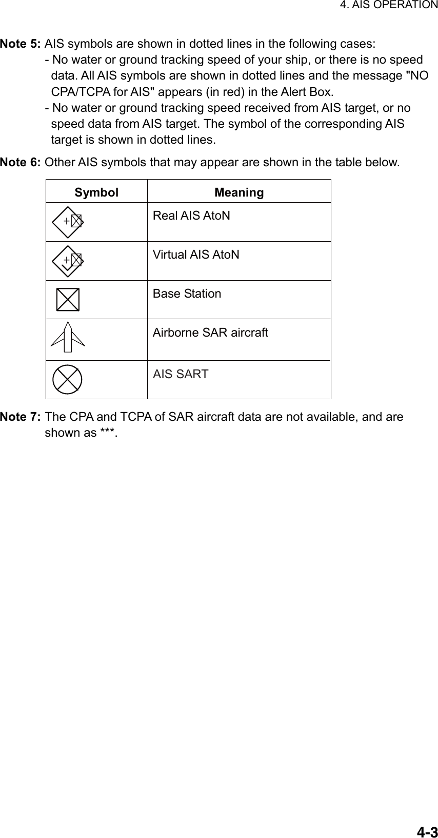
![4. AIS OPERATION 4-4 [TT•AIS MENU] 1 BACK 2 AZ STAB STAB HDG/STAB NORTH 3 AZ POLYGON OFF/STAB GND/ STAB HDG/STAB NORTH 4 [TRIAL MANEUVER] 5 [TT.AIS SYMBOL] 6 [CPA AUTO ACTIVATE] 7 [AIS DISP FILTER] 8 [AIS LOST FILTER] 9 [TT LOST FILTER] 0 [ASSOCIATION] [AIS DISP FILTER] 1 BACK 2 MAX RANGE OFF/ON 0NM 3 MIN SHIP SPEED OFF/ON 0.0kn 4 EXCEPT CLASS B OFF/ON 5 MIN SHIP LENGTH OFF/ON 0M 4.3 AIS Display Filter If there are too many AIS targets on the screen you may wish to remove unnecessary ones. You may remove targets by distance from own ship, speed, class and length. For example, you might want to remove slow moving targets, as they normally do not require close monitoring. 1. Left-click the MENU box to open the menu. 2. Select 4 [TT●AIS] to open the TT●AIS menu. TT/AIS menu 3. Select 7 [AIS DISP FILTER]. AIS DISP FILTER menu 4. Set items 2-5 referring to the description below. MAX RANGE: Any AIS target beyond the range set here will not be shown. MIN SHIP SPEED: Any AIS target slower than this setting will not be shown. EXCEPT CLASS B: Select ON to remove Class B AIS targets. MIN SHIP LENGTH: Any AIS target whose length is shorter than this setting will not be shown. 5. Push the right button twice to close the menu. 6. Select "DISP FILT" from the AIS DISP box. Note: An AIS target whose data is currently displayed is not affected by the filter setting. If the AIS DISP box is operated when all settings on this menu are set for OFF, the setting of the AIS DISP box becomes DISP ALL.](https://usermanual.wiki/Furuno-USA/9ZWRTR081A.op-manual/User-Guide-1456778-Page-177.png)
![4. AIS OPERATION 4-54.4 Activating Targets When you convert a sleeping target to an activated target, that target’s course and speed are shown with a vector. You can easily judge target movement by monitoring the vector. Sleeping targets within an acquisition zone are automatically changed to activated targets and are colored red. See section 3.14 for details. 4.4.1 Activating specific targets manually By keyboard 1. Use the trackball to put the cursor on the AIS target you wish activate. 2. Press the [TARGET DATA] key to activate the target. By trackball 1. With the cursor inside the effective display area, roll the scrollwheel to display "TARGET DATA & ACQ / CURSOR MENU" in the guidance box. 2. Use the trackball to put the cursor on the sleeping AIS target you wish to activate; that is, know more about a vessel’s motion. 3. Push the left button to activate the target. Heading line *2SOG (Speed over Ground)and COG (Course over Ground) vector*1Turning direction(ROT)*1Vector shows STW (speedthru water) and CSE(course) when watertracking mode isselected at the radar.*2If there is no heading data, the line points in direction of COG. Activated target 4.4.2 Activating all targets 1. Right-click the AIS DISP box to open the AIS TARGET menu. 2. Select 2 ACTIVATE ALL TRGTS. 3. Push the right button to close the menu. Thicker thanactivated target Dangerous targetWhen an activated target violates the CPA/TCPAalarm setting its symbol changes to the dangeroustarget symbol (red and flashing) and the indication AIS COLLISON appears. Press the [ALARM ACK] key (or click the ALARM ACK box with the left button)to acknowledge the CPA/TCPA alarm. The audiblealarm is silenced and the symbol stops flashing.Take appropriate action to avoid collision.](https://usermanual.wiki/Furuno-USA/9ZWRTR081A.op-manual/User-Guide-1456778-Page-178.png)
![4. AIS OPERATION 4-64.5 How to Sleep Targets 4.5.1 Sleeping an individual target You may "sleep" an AIS target as below when the screen becomes filled with targets, which might prevent important radar and AIS displays from being identified. Note that targets that have been activated automatically cannot be "slept." 1. With the cursor inside the effective display area, roll the scrollwheel to display "TARGET CANCEL / EXIT" in the guidance box. 2. Use the trackball to put the cursor on an activated AIS target symbol. 3. Push the left button. The activated target symbol is replaced with the sleeping target symbol. Sleeping target 4.5.2 Sleeping all targets 1. Right-click the AIS DISP box to open the AIS TARGET menu. [AIS TARGET MENU]1 SLEEP ALL TRGTSNO/YES2 ACTIVATE ALL TRGTSNO/YES3 AUTO DISP MESSAGES OFF/ON4 [RECEIVED MESSAGES]5 [TRANSMIT MESSAGE]6 [VOYAGE DATA]7 [STATIC DATA]8 [AIS ALM MESSAGES] AIS TARGET menu 2. Select 1 SLEEP ALL TRGTS. 3. Select YES to sleep all AIS targets. 4. Push the right button to close the menu.](https://usermanual.wiki/Furuno-USA/9ZWRTR081A.op-manual/User-Guide-1456778-Page-179.png)
![4. AIS OPERATION 4-7 [VOYAGE DATA] 1 BACK 2 NAVIGATION STATUS 03 RESTRICTED MANOEVRABILITY 3 ETA 00/000/0000 00:00 4 DESTINATION 12 5 DRAUGHT 00.0m 6 CREW 0002 4.6 Setting Up for a Voyage There are five items on the VOYAGE DATA menu you will need to enter at the start of a voyage: navigational status, ETA, destination, draught and crew. 1. Right-click the AIS DISP box at the right side of the screen to open the AIS TARGET menu. [AIS TARGET MENU]1 SLEEP ALL TRGTSNO/YES2 ACTIVATE ALL TRGTSNO/YES3 AUTO DISP MESSAGES OFF/ON4 [RECEIVED MESSAGES]5 [TRANSMIT MESSAGE]6 [VOYAGE DATA]7 [STATIC DATA]8 [AIS ALM MESSAGES] AIS TARGET menu 2. Select 6 VOYAGE DATA. VOYAGE DATA menu 3. Select 2 NAVIGATION STATUS.](https://usermanual.wiki/Furuno-USA/9ZWRTR081A.op-manual/User-Guide-1456778-Page-180.png)
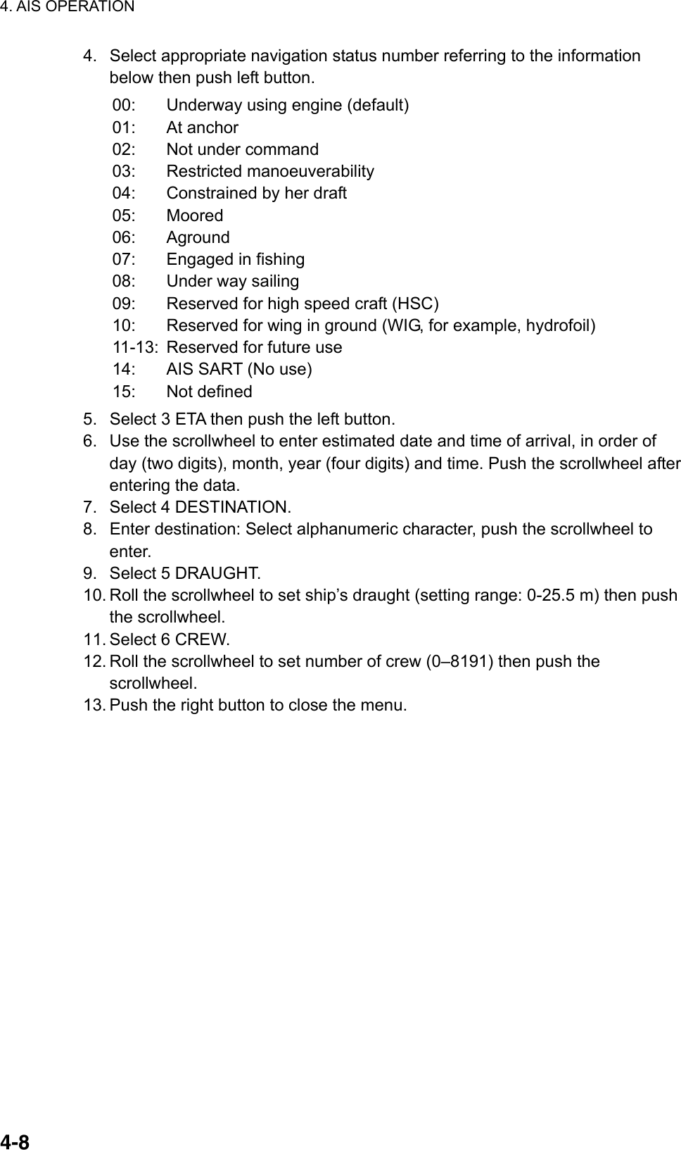
![4. AIS OPERATION 4-94.7 Target Data You may display an AIS target’s data by selecting it on the display, when the AIS function is set for "AIS DISP FILT". 4.7.1 Basic target data By keyboard 1. Use the trackball to put the cursor on the AIS target symbol you want to know its data. 2. Press the [TARGET DATA] key. By trackball 1. With the cursor inside the effective display area, roll the scrollwheel to display "TARGET DATA & ACQ / CURSOR MENU". 2. Use the trackball to put the cursor on an AIS target symbol. The selected target is marked with a broken square and AIS data is shown in the AIS data box when the target is correctly selected. ALocation of target’s data box.Not shown on W-type radar. Activated target selected for data display AIS B MMSI 665498114VOYAGERBRG 208.6°TRNG 12.3NMTCOG 9.0°T* TSOG 8.2kn#CPA 5.32NM TCPA 33:31BCR 5.65NMBCT 25:30 * = CSE (course) when water tracking mode is selected at radar.# = STW (speed thru water) when water tracking mode is selected at radar.PositionLocation of target data, MMSI No.Rate of turnHeadingBearing to targetRange to targetTarget's courseTarget's speedTarget's CPATarget's TCPATarget's bow cross rangeTarget's bow cross time 34°37.912 N135°21.569 ENAV-STATUS UNDER WAY USING ENGINEHDG 048.0°T0.0°/min Name of shipNav status AIS data display](https://usermanual.wiki/Furuno-USA/9ZWRTR081A.op-manual/User-Guide-1456778-Page-182.png)
![4. AIS OPERATION 4-104.7.2 Detailed target data 1. Use the trackball to put the cursor on the desired AIS target in the data box at the right side of the screen. 2. Push the left button to show detailed data. [EXPANDED DATA]NAME: VOYAGERCALL: WRE45T LAT: 34°44.2345'NLON: 135°32.1890'EPOS. SENSOR GPSPOS. ACC.: HIGHNAV. STATUS UNDERWAY USING ENGINE MMSI No.: 107374182IMO No.: 123544876SHIP LENGTH: 55mSHIP WIDTH: 15mSHIP DRAFT: 2.8mDESTINATION KOBEETA: 01/FEB 12:59AIS VERSION: 0ASSOCIATION: OFF SHIP & CARGO TYPE: CARGO SHIPS ALL SHIPS OF THIS TYPE Ship's nameCall signLatitudeLongitudePosition fixing devicePosition accuracy (HIGH, LOW)Navigation statusMMSI No.IMO No.LengthWidthDraftDestinationEstimated Time of ArrivalAIS program no.Assocation ON/OFFType of ship and cargo Expanded data 4.7.3 Removing a target data display Put the cursor on the data you want to remove and hit the [TARGET DATA] key. 4.7.4 Canceling tracking on a target from target data display Put the cursor on the target you want to stop tracking and hit the [TARGET CANCEL] key.](https://usermanual.wiki/Furuno-USA/9ZWRTR081A.op-manual/User-Guide-1456778-Page-183.png)
![4. AIS OPERATION 4-114.8 AIS Symbol Attributes You may adjust the brilliance and select the size and color of the AIS symbol. 4.8.1 AIS symbol brilliance 1. Right-click the BRILL box at the left side of the screen. 2. Select 0 NEXT. [BRILL1 MENU (2/2)]1 BACK2 BRG CURSOR3 EBL4 VRM5 PI LINE6 TT SYMBOL 7 AIS SYMBOL8 L/L GRID9 MARK0 CHART* * Not available on IMO type BRILL menu, page 2 3. Select 7 AIS SYMBOL. 4. Roll the scrollwheel to adjust brilliance. 5. Push the right button twice to close the menu. 4.8.2 AIS symbol size and color You may select the size and color of the AIS symbol as follows: 1. Left-click the MENU box to open the menu. 2. Select 4 [TT/AIS]. 3. Select 5 [TT/AIS SYMBOL]. [TT.AIS SYMBOL]1BACK2TT.AIS SYMBOL COLORRED*/GRN/BLU/YEL*/CYA/MAG/WHT3 AIS ROT TAG LIMIT000.0˚/min4 TT PAST POSN POINTS5/105 AIS PAST POSN POINTS5/106 AIS SCALED SYMBOLOFF/ON * Not available on IMO type AIS SYMBOL menu 4. Select 2 TT•AIS SYMBOL COLOR. 5. Select color desired.](https://usermanual.wiki/Furuno-USA/9ZWRTR081A.op-manual/User-Guide-1456778-Page-184.png)
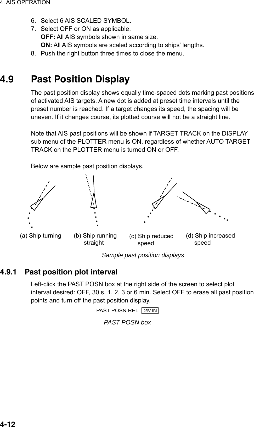
![4. AIS OPERATION 4-134.9.2 Past position points You may select the number of past position points to show per plot interval as follows: 1. Left-click the MENU box to open the menu. 2. Select 4 [TT/AIS] to open the TT.AIS menu. 3. Select 5 [TT/AIS SYMBOL]. [TT.AIS SYMBOL]1BACK2TT.AIS SYMBOL COLORRED*/GRN/BLU/YEL*/CYA/MAG/WHT3 AIS ROT TAG LIMIT000.0˚/min4 TT PAST POSN POINTS5/105 AIS PAST POSN POINTS5/106 AIS SCALED SYMBOLOFF/ON * Not available on IMO type AIS SYMBOL menu 4. Select 5 AIS PAST POSN POINTS. 5. Select 5 or 10 as appropriate. 6. Push the right button three times to close the menu. 4.9.3 Past position display motion The past position display may be shown in true or relative motion. Open the TRAIL menu and set TRAIL MODE to TRUE or RELATIVE as appropriate. 4.9.4 Stabilization in true motion The true motion past position display may be ground stabilized or sea stabilized. The PAST POSN box shows current stabilization as TRUE-G or TRUE-S. To change the stabilization mode, open the SPEED menu and set SHIP SPEED to BT (ground stabilization) or WT (sea stabilization).](https://usermanual.wiki/Furuno-USA/9ZWRTR081A.op-manual/User-Guide-1456778-Page-186.png)
![4. AIS OPERATION 4-14 [AIS LOST FILTER] 1 BACK 2 MAX RANGE OFF/ON 0NM 4 MIN SHIP SPEED OFF/ON 0.1kn 5 EXCEPT CLASS B OFF/ON 5 MIN SHIP LENGTH OFF/ON 0M 4.10 Lost Target A target is declared a lost target when it fails to produce data for six minutes or five reporting intervals, whichever is the shorter. When this occurs, the target is marked with the (flashing) lost target symbol and the indication "LOST" appears in the Alert Box. To acknowledge a lost target, press the [ALARM ACK] key, or use the trackball to select the ALARM ACK box then push the left button. Lost target Note 1: If a TT lost target mark is displayed when the [ALARM ACK] key is pressed (or the ALARM ACK box is clicked) to acknowledge an AIS lost target, the TT lost target also is erased. Note 2: The AIS data transmission interval depends on target’s speed. For example, the data is transmitted every 10 seconds on ship speed of 0 to 14 knots and every two seconds on the ship speed of more than 23 knots. For details see the owner’s manual of the AIS. 4.10.1 Lost target filter If there are a lot of AIS targets in your area, the lost target alarm may sound frequently. In this case you may wish to have the alarm ignore lost targets whose range, speed, class or length are below the threshold value you specify. 1. Left-click the MENU box to open the menu. 2. Select 4 [TT●AIS] to open the TT.AIS menu. 3. Select 8 [AIS LOST FILTER]. AIS LOST FILTER menu](https://usermanual.wiki/Furuno-USA/9ZWRTR081A.op-manual/User-Guide-1456778-Page-187.png)
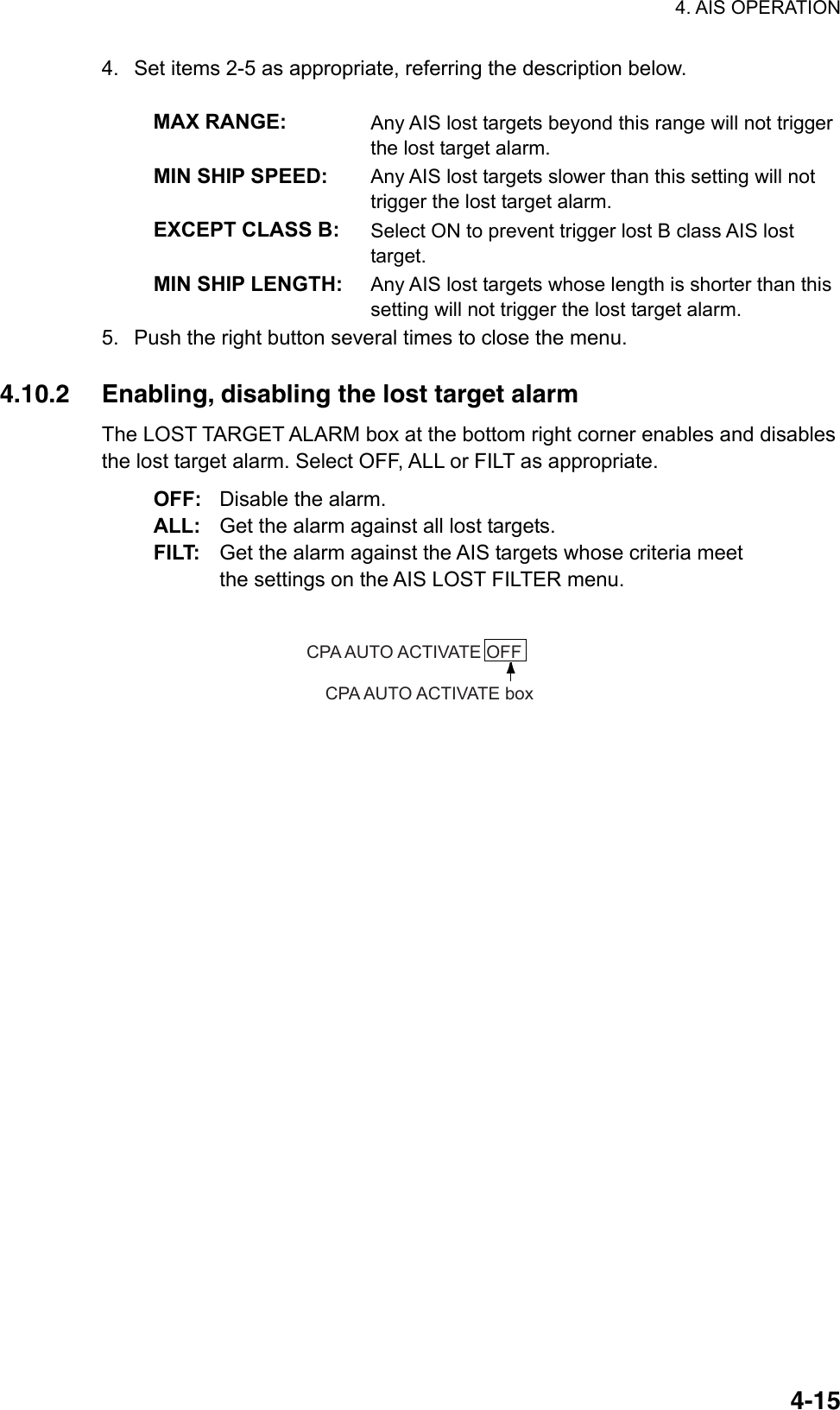
![4. AIS OPERATION 4-164.11 ROT Setting You may set the lower limit of the ROT (Rate Of Turn) at which the heading line on target symbols will point in direction of turning of the vessel. 1. Left-click the MENU box to open the menu. 2. Select 4 [TT/AIS] to open the TT/AIS menu. [TT.AIS SYMBOL]1BACK2TT.AIS SYMBOL COLORRED/GRN/BLU/YEL/CYA/MAG/WHT3 AIS ROT TAG LIMIT000.1˚/min4 TT PAST POSN POINTS5/105 AIS PAST POSN POINTS5/106 AIS SCALED SYMBOLOFF/ON AIS SYMBOL menu 3. Select 3 AIS ROT TAG LIMIT. 4. Use the numeral keys or the scrollwheel to enter ROT (setting range: 0.1 to 720.0 (°/min)). 5. Push the right button three times to close the menu. Ship turningto starboard ROT display](https://usermanual.wiki/Furuno-USA/9ZWRTR081A.op-manual/User-Guide-1456778-Page-189.png)
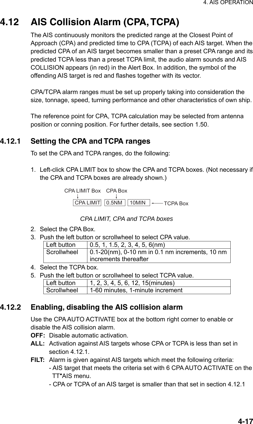
![4. AIS OPERATION 4-18 [CPA AUTO ACTIVATE] 1 BACK 2 MAX RANGE OFF/ON 0NM 3 MIN SHIP SPEED OFF/ON 0.0KN 4 EXCEPT CLASS B OFF/ON 5 MIN SHIP LENGTH OFF/ON 0M CPA AUTO ACTIVATE OFFCPA AUTO ACTIVATE box 4.12.3 Limiting the function of the collision alarm You can limit the function of the collision alarm by distance from own ship, ship's speed, ship class, and ship's length. 1. Left-click the MENU box to open the menu. 2. Choose 4 TT●AIS. 3. Choose 6 [CPA AUTO ACTIVATE]. CPA AUTO ACTIVATE menu 4. Set items 2-5 as appropriate. MAX RANGE: Any AIS target beyond this range will not be automatically activated. MIN SHIP SPEED: Any AIS targets slower than this setting will not be automatically activated. EXCEPT CLASS B: Select ON to prevent automatic activation of class B AIS targets. MIN SHIP LENGTH: Any AIS targets whose length is shorter than this setting will not be automatically activated. 5. Push the right button several times to close the menu.](https://usermanual.wiki/Furuno-USA/9ZWRTR081A.op-manual/User-Guide-1456778-Page-191.png)
![4. AIS OPERATION 4-19 [ASSOCIATION] 1 BACK 2 ASSOCIATION TARGET OFF/AIS/TT 3 GAP 0.050NM 4 RANGE 0.100NM 5 BEARING 9.9° 6 SPEED 6.0kn 7 COURSE 25.0° 4.13 Association of TT and AIS Targets If the target data from AIS and TT are both available, and if the association criteria (for example position, motion) are fulfilled such that the AIS and TT are considered as one physical target, the activated AIS (or TT) target symbol and the alphanumeric AIS (or TT) target data is automatically selected and displayed. If the AIS and radar information become sufficiently different, the AIS and radar information shall be considered as two distinct targets. One activated AIS target and one tracked radar target shall be displayed. 1. Confirm that the TT ACQ MODE box shows AUTO, AUTO MAN or MAN. 2. Left-click the MENU box to open the menu. 3. Select 4 [TT●AIS] to open the TT/AIS menu. 4. Select 0 [ASSOCIATION] to show the ASSOCATION menu, shown right. 5. Select ASSOCIATION TARGET. 6. Select OFF, AIS or TT as applicable to select which symbols and data to show when association criteria is met. OFF: Turn off association. AIS: Use AIS symbols and AIS data. TT: Use TT symbols and TT data.](https://usermanual.wiki/Furuno-USA/9ZWRTR081A.op-manual/User-Guide-1456778-Page-192.png)
![4. AIS OPERATION 4-20Note: Association can also be switched on and off from the screen by left-clicking the Association Usage icon, shown below. TT AIS FILTVECTOR REL 30M3MCPA LIMIT 0. 5NM 22MINTARGET DATA & ACQCURSOR MENUOFF DISPCPA AUTO ACTIVATEOFFLOST TARGET ALARMOFFPAST POSN REL 3M <Association Usage>: Use TT symbols and data<: Use AIS symbols and dataNo indication: Assocation OFF 7. Enter the information below, pushing the scrollwheel (or the [MARK ENTER] key) after entering each data. This information will be used to determine which tracked targets to convert. GAP: Enter the range in bearing direction between AIS target and tracked target. (setting range: 0.000-0.999(nm)) RANGE: Enter the range direction difference from own ship to AIS target and tracked target. (setting range: 0.000-0.999(nm)) BEARING: Enter the bearing difference from own ship to AIS target and tracked target. (setting range: 0.0-99.9(°)) SPEED: Enter the speed difference between AIS target and tracked target. (setting range: 0.0-9.9(kn)) COURSE: Enter the course difference between AIS target and tracked target. (setting range: 0.0-99.9(°)) 8. Push the right button three times to close the menu. When the association criteria (gap, range, bearing, speed, and course) is met, and the ASSOCIATION TARGET setting is "AIS," the TT symbol is erased and only the AIS symbol is displayed. Further, "ASSOCIATION" appears in the Alert Box. All default association settings are restored whenever the power is turned on.](https://usermanual.wiki/Furuno-USA/9ZWRTR081A.op-manual/User-Guide-1456778-Page-193.png)
![4. AIS OPERATION 4-214.14 Own Ship’s Data Own ship’s static data (type of ship, call sign, name and position of internal and external GPS antennas) can be viewed as follows 1. Right-click the AIS DISP box at the right side of the screen to open the AIS TARGET menu. 2. Select 7 STATIC DATA. 1BACK TYPE OF SHIP000ALL SHIPS OFTHIS TYPECALL SIGN(call sign here)NAME(ship name here) EXT GPS ANT POSNA: 000m B: 000mC: 00m D: 00m[STATIC DATA]ABCD STATIC DATA menu 3. Push the right button to close the menu.](https://usermanual.wiki/Furuno-USA/9ZWRTR081A.op-manual/User-Guide-1456778-Page-194.png)
![4. AIS OPERATION 4-22 [TRANSMIT MESSAGE] 1 BACK 2 ADDRESS TYPE ADDRESSED/BROADCAST3 MESSAGE TYPE SAFETY/BINARY 4 MMSI No. 000000000 5 CHANNEL A/B/A or B/A and B 6 OPEN FILE 1 7 SAVE FILE 1 8 EDIT 9 TRANSMIT MESSAGE 4.15 Messages You may transmit and receive messages via the AIS, to a specified destination (MMSI) or all ships in the area. Messages can be sent to warn of safety of navigation, for example, an iceberg sighted. Routine messages are also permitted. Short safety related messages are only an additional means to broadcast safety information. They do not remove the requirements of the GMDSS. 4.15.1 Creating, saving messages This section shows you how to create and save a message. Nine messages may be saved. Note: You can display the TRANSMIT MESSAGE menu and set ship's MMSI no. by right-clicking the appropriate AIS target in the AIS target data display. 1. Right click the AIS DISP box. 2. Select 5 TRANSMIT MESSAGE. TRANSMIT MESSAGE menu 3. Select 2 ADDRESS TYPE. 4. Select ADDRESSED (message for specific MMSI) or BROADCAST (message to all AIS-equipped vessels in area). 5. Select 3 MESSAGE TYPE. 6. Select SAFETY for safety message or BINARY for routine message. 7. For ADDRESSED message, do this step. For BROADCAST message, go to step 9. 1) Select 4 MMSI NO. 2) Use the scrollwheel to enter ship’s MMSI no.: Select alphanumeric character then push the scrollwheel. 8. Select 5 CHANNEL. 9. Select the AIS channel to transmit your message over: A, B, A or B, or A and B. Push the scrollwheel after making your selection.](https://usermanual.wiki/Furuno-USA/9ZWRTR081A.op-manual/User-Guide-1456778-Page-195.png)
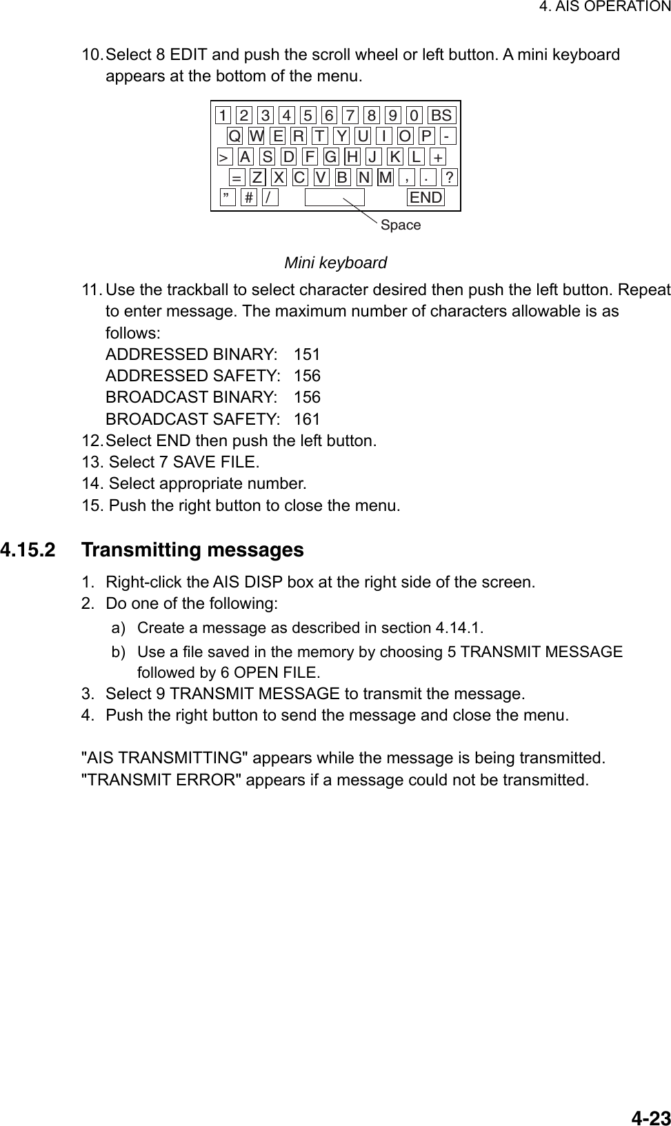
![4. AIS OPERATION 4-24 [RECEIVED MESSAGES] (1/1)1 BACK [L = TOP] 2 09DEC2003 12:34 ADDRESSED SAFETY MMSI: 107374182 4.15.3 Viewing messages When an AIS message is received, the display shows an appropriate icon to alert you. If you are set up to automatically display AIS messages they are automatically displayed upon receipt. The system stores up to 20 AIS messages. When the storage capacity is reached the oldest AIS message is automatically erased to make room for the latest. Note that received messages and alarm messages are not backed up when the power is turned off. Manually viewing received messages To view received AIS messages do the following: 1. Right-click the AIS DISP box at the right side of the display. [AIS TARGET MENU]1 SLEEP ALL TRGTSNO/YES2 ACTIVATE ALL TRGTSNO/YES3 AUTO DISP MESSAGES OFF/ON4 [RECEIVED MESSAGES]5 [TRANSMIT MESSAGE]6 [VOYAGE DATA]7 [STATIC DATA]8 [AIS ALM MESSAGES] AIS TARGET menu 2. Select 4 RECEIVED MESSAGES. (Up to five received messages are displayed.) RECEIVED MESSAGES menu](https://usermanual.wiki/Furuno-USA/9ZWRTR081A.op-manual/User-Guide-1456778-Page-197.png)
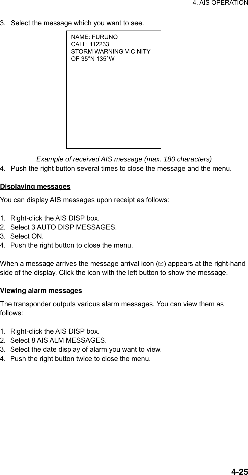
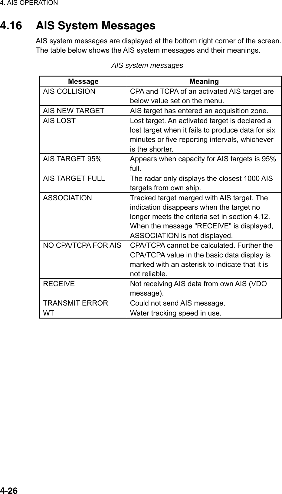
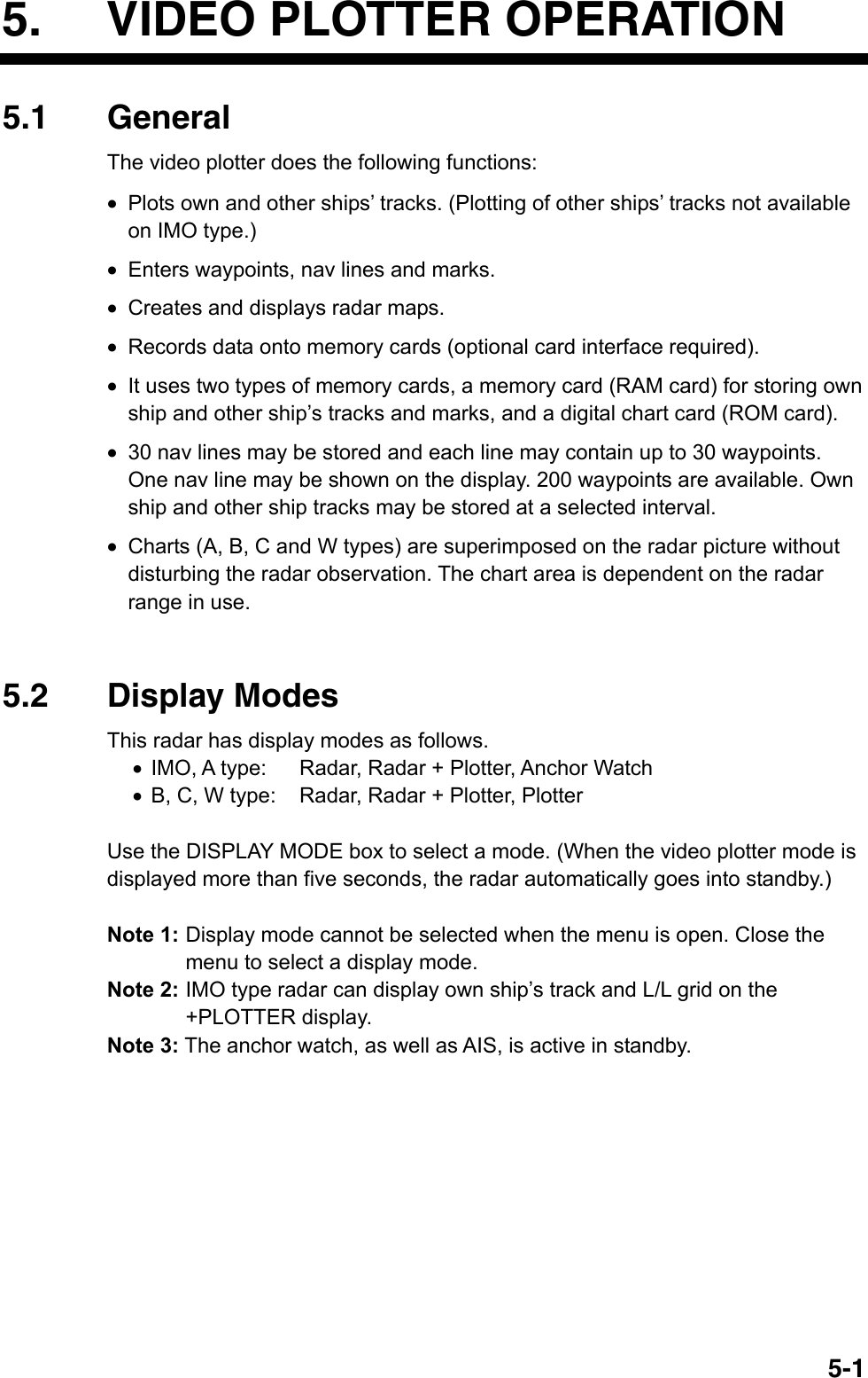
![5. VIDEO PLOTTER OPERATION 5-2Sample video plotter display W012Dangerous side ofown ship safecontour may looklike this (hatched line)Heading linePlanned routeAIS activatedtarget Own shipvector Tracked Target(TT)Past position(AIS and TT)Separation zoneNavlineOwn shipsafe contourApproximatecoastlineWaypoint Video plotter display 5.3 Presentation Modes Five presentation modes are available: North-up, Course-up, Head-up, Head-up TB (True Bearing) Stern-up and North-up TM (True Motion). To select a mode, use the [MODE] key or select the PRESENTATION MODE box then push the left button. For a description of the presentation modes, see section 1.12. Note 1: Chart data is not displayed on the HEAD UP and HEAD UP TB modes. Note 2: The screen may flash when the heading is changed more than one degree in the HEAD UP or HEAD UP TB mode. Automatic resetting of own ship mark in true motion mode In the true motion mode, the own ship mark is automatically returned sternward 75% from the screen center when it reaches a location 50% of the display radius.](https://usermanual.wiki/Furuno-USA/9ZWRTR081A.op-manual/User-Guide-1456778-Page-201.png)
![5. VIDEO PLOTTER OPERATION 5-35.4 Radar Map A radar map is a combination of map lines and symbols whereby the user can define and input the navigation data, route planning and monitoring data. The radar map may contain 20,000 points of data. The map data can be saved to facilitate repeated use on a routine navigation area. The user can create a radar map on-real time while using the radar for navigation or at leisure time at anchor or while the radar is not being used. Place of a map can be made for any waterways apart from the actual own ship location. The radar map does not affect any radar function. 5.4.1 Showing, hiding the radar map display From menu 1. Use the trackball to select the MARK box. 2. Push the right button to open the MARK menu. [MARK MENU] 1 ORIGIN MARK STAB GND/SEA 2 MARK KIND ORIGIN MARK(No. )/ ORIGIN MARK(SYM)/ MAP MARK/ WP 1~50/ WP 51~ 100/ WP 101~150/ WP 151~198/ OWN SHIP SHAPE 8 MARK POSN CURSOR/OS/L/L 00°000.00 N 000°000.00 E9 MAP DISPLAY OFF/ON0 MAP MARK COLOR* RED/GRN/BLU/YEL/ CYA/MAG/WHT * Not available on IMO or A type MARK menu 3. Select 9 MAP DISPLAY. 4. Select ON or OFF as applicable. 5. Push the right button to close the menu. From mark legend MARK > MAPONPlace cursor on text andleft-click to hide and showmap alternately.](https://usermanual.wiki/Furuno-USA/9ZWRTR081A.op-manual/User-Guide-1456778-Page-202.png)
![5. VIDEO PLOTTER OPERATION 5-45.4.2 Inscribing radar map marks and lines 1. Use the trackball to select the MARK box at the left side of the display. MARK >Mark type MARK box 2. Push the right button to open the MARK menu. [MARK MENU] 1 ORIGIN MARK STAB GND/SEA 2 MARK KIND ORIGIN MARK(No. )/ ORIGIN MARK(SYM)/ MAP MARK/ WP 1~50/ WP 51~ 100/ WP 101~150/ WP 151~198/ OWN SHIP SHAPE 8 MARK POSN CURSOR/OS/L/L 00°000.00 N 000°000.00 E9 MAP DISPLAY OFF/ON0 MAP MARK COLOR* RED/GRN/BLU/YEL/ CYA/MAG/WHT * Not available on IMO or A type MARK menu 3. Select 2 MARK KIND. 4. Select MAP MARK. Note 1: For other than IMO- and A-type radars you may specify mark color by choosing 0 MAP MARK COLOR, pushing the scrollwheel then choosing color desired. Note 2: On the W-type, the indication "MAP" appears to the right of the MARK box. 5. Push the right button to close the menu. The guidance box now reads "MARK SELECT / MARK MENU." 6. With the cursor choosing the MARK box, use the scrollwheel to select the mark or line type you wish to inscribe then push the left button. See the next page for available marks. The cursor jumps into the effective display area and the guidance box now reads "MARK / EXIT." 7. Select 8 MARK POSN. 8. Select mark entry method, CURSOR, OS or L/L. For L/L, enter position. 9. For cursor, use the trackball to put the cursor on the location desired. (You can see the range and bearing from own ship to the cursor location by monitoring the bearing and range indication just below the MARK box.) Push the left button to inscribe the mark or line point.](https://usermanual.wiki/Furuno-USA/9ZWRTR081A.op-manual/User-Guide-1456778-Page-203.png)
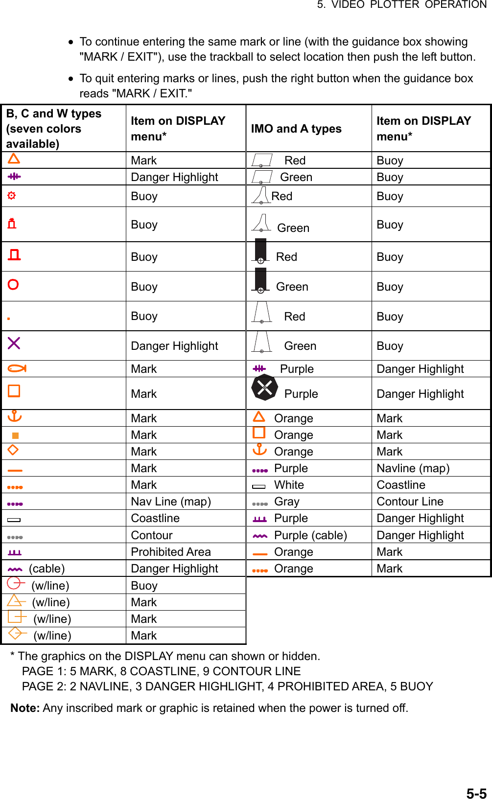
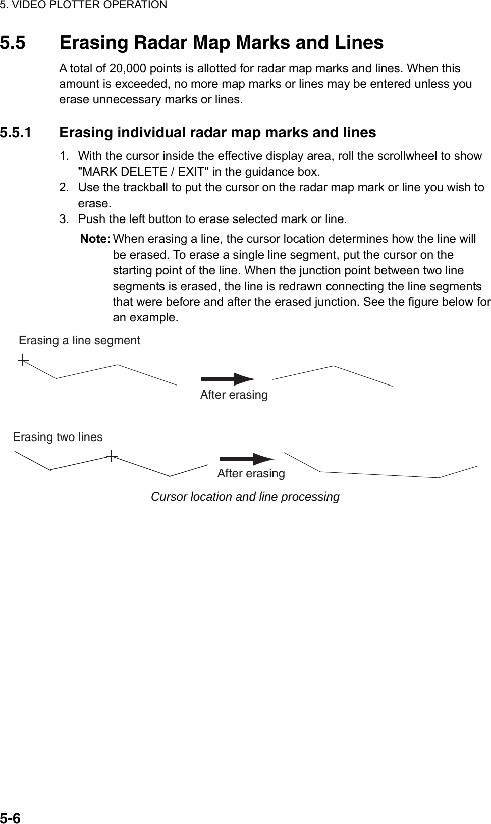
![5. VIDEO PLOTTER OPERATION 5-75.5.2 Erasing all radar map marks and lines You can erase all radar map marks and lines from the screen as below. Be absolutely sure you want to erase all map marks and lines – erased marks and lines cannot be restored. 1. Left-click the MENU box to open the menu. 2. Select 5 [PLOTTER] to open the PLOTTER menu. 3. Select 8 [DATA ERASE]. *1 Colors not shown on IMO type*2 Not available on IMO type*3 Not available on IMO or A type[DATA ERASE]1BACK2 OWN TRACK*1RED/GRN/BLU/YEL/CYA/MAG/WHT/30%/50%/80%/ALL3 TARGET TRACK*2RED/GRN/BLU/YEL/CYA/MAG/WHT/30%/50%/80%/ALL4 MARK ALL ERASENO/YES5 WPT ALL ERASENO/YES6 NAV LINE ALL ERASE NO/YES7 OWN TRACK DELETE*32POINTS/AREA8 TARGET TRACK DELETE*32POINTS/AREA DATA ERASE menu 4. Select 4 MARK ALL ERASE. 5. Select YES to erase all marks. 6. Push the right button three times to close the menu.](https://usermanual.wiki/Furuno-USA/9ZWRTR081A.op-manual/User-Guide-1456778-Page-206.png)
![5. VIDEO PLOTTER OPERATION 5-85.6 Radar Map Corrections 5.6.1 Radar map correction When there is positional error between the radar screen and radar map marks and lines, do the following to correct it. 1. With the cursor inside the effective display area, roll the scrollwheel to display "CHART ALIGN L=OFF / EXIT" in the guidance box. 2. Operate the trackball to align the radar map with the radar screen. 3. Push the left button to set. "MAN ALIGNED" appears at the right side of the screen. To release the radar map correction, display "CHART ALIGN L=OFF / EXIT" in the guidance box then push the left button until "MAN ALIGNED" disappears from the screen. 5.6.2 Cursor data correction You can correct cursor data as below. 1. Left-click the MENU box to open the menu. 2. Select 5 [PLOTTER] to open the PLOTTER menu. [PLOTTER] 1 BACK 2 CHART COLOR* GRN/YEL/CYA ORANGE/GRAY 3 OWN TRACK INTERVAL OFF/DRAW/10S/30S/ 1M/2M/3M/6M/15M 4 OWN TRACK COLOR* RED/GRN/BLU/YEL/ CYA/MAG/WHT 5 TGT TRACK INTERVAL* OFF/DRAW/10S/30S/ 1M/2M/3M/6M/15M 6 TGT TRACK COLOR* RED/GRN/BLU/YEL/ CYA/MAG/WHT 7 CURSOR L/L ALIGN OFF/ON 8 [DATA ERASE] 9 [DISPLAY] 0 AUTO TARGET TRACK* OFF/ON * Not available on IMO type PLOTTER menu 3. Select 7 CURSOR L/L ALIGN.](https://usermanual.wiki/Furuno-USA/9ZWRTR081A.op-manual/User-Guide-1456778-Page-207.png)
![5. VIDEO PLOTTER OPERATION 5-94. Select ON. "ALIGN" appears (in light blue) next to cursor position in the text area if chart alignment has been done. To remove the correction, select OFF. If you are using the AIS function, select ON. 5. Push the right button twice to close the menu. 5.7 Chart Cards (A, B, C and W types) FURUNO or NAVIONICS charts can be overlaid on the radar image when they are interfaced with the optional Card I/F Unit CU-200. CAUTIONHandle chart cards and memory cardswith care. Keep cards away from direct sunlight, heat sources, and active gases. Keep cards away from water and chemicals. Keep the connector free foreign material. Do not drop the cards.Chart cards are intended as an aid to navigation. The navigator has the responsibility to check all aids availableto confirm position. 5.7.1 Displaying a chart To display a chart: 1. Insert a chart card in either of the two card slots in the Card I/F Unit CU-200. Card Slot++12 Card slot location 2. Press the [POWER] button on the control unit to turn the power on. With the radar transmitting, select the radar display (NU, CU, TM modes only) or the radar/video plotter display to display the chart. To display a chart after the power has been turned on, change the range by pressing the [RANGE+] or [RANGE-] key or operating the RANGE box.](https://usermanual.wiki/Furuno-USA/9ZWRTR081A.op-manual/User-Guide-1456778-Page-208.png)
![5. VIDEO PLOTTER OPERATION 5-105.7.2 Chart position correction There may be a case where the chart overlay is not aligned with the radar image. This is due to an error in the position fixing system (GPS, Loran, etc.) or the different coordinates between the position fixing system and the radar. In this case, align the chart with the radar image as below. 1. With the cursor inside the effective display area, roll the scrollwheel to display "CHART ALIGN L=OFF / EXIT" in the guidance box. 2. Operate the trackball to align the chart with the radar map. Note that track is neither recorded nor displayed at this point. 3. Push the left button to set. "CHART ALIGN" appears (in red) at the right side of the screen. To release the chart position correction, display "CHART ALIGN L=OFF / EXIT" in the guidance box then push the left button until "CHART ALIGN" disappears from the screen. 5.7.3 Correcting cursor data 1. Left-click the MENU box to open the menu. 2. Select 5 [PLOTTER] to open the PLOTTER menu. [PLOTTER] 1 BACK 2 CHART COLOR* GRN/YEL/CYA ORANGE/GRAY 3 OWN TRACK INTERVAL OFF/DRAW/10S/30S/ 1M/2M/3M/6M/15M 4 OWN TRACK COLOR* RED/GRN/BLU/YEL/ CYA/MAG/WHT 5 TGT TRACK INTERVAL* OFF/DRAW/10S/30S/ 1M/2M/3M/6M/15M 6 TGT TRACK COLOR* RED/GRN/BLU/YEL/ CYA/MAG/WHT 7 CURSOR L/L ALIGN OFF/ON 8 [DATA ERASE] 9 [DISPLAY] 0 AUTO TARGET TRACK* OFF/ON * Not available on IMO type PLOTTER menu 3. Select 7 CURSOR L/L ALIGN. 4. Select ON. "ALIGN" appears (in red) next to cursor position in the cursor data box. (To remove the correction, select OFF. If you are using the AIS function, select ON.) 5. Push the right button twice to close the menu.](https://usermanual.wiki/Furuno-USA/9ZWRTR081A.op-manual/User-Guide-1456778-Page-209.png)
![5. VIDEO PLOTTER OPERATION 5-115.7.4 Chart land color (B, C and W types) You may select the color for the land on charts as follows: 1. Left-click the MENU box to open the menu. 2. Select 5 [PLOTTER] to open the PLOTTER menu. [PLOTTER] 1 BACK 2 CHART COLOR* GRN/YEL/CYA ORANGE/GRAY 3 OWN TRACK INTERVAL OFF/DRAW/10S/30S/ 1M/2M/3M/6M/15M 4 OWN TRACK COLOR* RED/GRN/BLU/YEL/ CYA/MAG/WHT 5 TGT TRACK INTERVAL* OFF/DRAW/10S/30S/ 1M/2M/3M/6M/15M 6 TGT TRACK COLOR* RED/GRN/BLU/YEL/ CYA/MAG/WHT 7 CURSOR L/L ALIGN OFF/ON 8 [DATA ERASE] 9 [DISPLAY] 0 AUTO TARGET TRACK* OFF/ON * Not available on IMO type PLOTTER menu 3. Select 2 CHART COLOR. 4. Select color desired. 5. Push the right button twice to close the menu.](https://usermanual.wiki/Furuno-USA/9ZWRTR081A.op-manual/User-Guide-1456778-Page-210.png)
![5. VIDEO PLOTTER OPERATION 5-125.8 Hiding, Showing Graphics on the Video Plotter Display 1. Left-click the MENU box to open the menu. 2. Select 5 [PLOTTER] to open the PLOTTER menu. 3. Select 9 [DISPLAY]. Select an item. To go to page 2, select 0 NEXT. You may return to page 1 by choosing 1 BACK and pressing the scrollwheel or the left button. Page 1Page 2Choose0 NEXTto showpage 2.* Not available on IMO or A type[DISPLAY (1/2)]1BACK2 GRIDOFF/ L/L3 OWN TRACKOFF/ON4 TARGET TRACK*OFF/ON5 MARKOFF/ON6 LAND DENSITY*OFF/ON7 PLACE NAME*OFF/ON8 COAST LINEOFF/ON9 CONTOUR LINEOFF/ON/DEPTH0 NEXT[DISPLAY (2/2)]1BACK2 NAV LINE(MAP)OFF/ON3 DANGER HIGHLIGHTOFF/ON4 PROHIBITED AREAOFF/ON5 BUOYOFF/ON DISPLAY menus 4. Push the scrollwheel to select OFF or ON. Note: LAND DENSITY fills (ON) or hollows (OFF) land on an electronic chart. Land will be hollow when wrong card or wrong scale is used, regardless of LAND DENSITY setting. 5. Repeat steps 3 and 4 to set other items. 6. Push the right button three or four times to close the menu depending on which page of the DISPLAY menu you are using.](https://usermanual.wiki/Furuno-USA/9ZWRTR081A.op-manual/User-Guide-1456778-Page-211.png)
![5. VIDEO PLOTTER OPERATION 5-135.9 Track 5.9.1 Plotting own ship’s track A total of 20,000 points are allotted for storage of own ship’s track, marks and lines. When this memory becomes full, the oldest track is deleted to make room for the latest. For that reason you may want to adjust the recording interval to conserve the memory. The table below shows the relation between plotting interval and maximum track recording time. Own track plotting interval and storage time Interval Max. Recording Time Interval Max. Recording Time10 s 55 hr 30 min 2 min 27 days 18 hr 40 min 30 s 166 hr 40 min 3 min 41 days 16 hr 1 min 13 days 21 hr 20 min 6 min 83 days 8 hr 1. Left-click the MENU box to open the menu. 2. Select 5 [PLOTTER] to open the PLOTTER menu. [PLOTTER] 1 BACK 2 CHART COLOR* GRN/YEL/CYA ORANGE/GRAY 3 OWN TRACK INTERVAL OFF/DRAW/10S/30S/ 1M/2M/3M/6M/15M 4 OWN TRACK COLOR RED/GRN/BLU/YEL/ CYA/MAG/WHT 5 TGT TRACK INTERVAL* OFF/DRAW/10S/30S/ 1M/2M/3M/6M/15M 6 TGT TRACK COLOR* RED/GRN/BLU/YEL/ CYA/MAG/WHT 7 CURSOR L/L ALIGN OFF/ON 8 [DATA ERASE] 9 [DISPLAY] 0 AUTO TARGET TRACK* OFF/ON * Not available on IMO type PLOTTER menu 3. Select 3 OWN TRACK INTERVAL. 4. Select appropriate option. Select OFF to stop plotting own ship’s track. DRAW displays the track but does not record it. Track is erased when the power is turned off or the range is changed. 5. Push the right button twice to close the menu.](https://usermanual.wiki/Furuno-USA/9ZWRTR081A.op-manual/User-Guide-1456778-Page-212.png)
![5. VIDEO PLOTTER OPERATION 5-145.9.2 Plotting interval for other ships' tracks (A, B, C and W types) The tracks of 15 targets (other ships) can be recorded. The memory capacity for other ships’ track is 15,000 points (1,000 points per each of 15 targets). When the other ships’ track memory becomes full the oldest track is deleted to make room for the latest. For that reason you may want to adjust the recording interval to conserve the memory. The table below shows the relation between plotting interval and maximum track recording time for other ships’ track. Other target plot interval and storage time Interval Max. Recording Time Interval Max. Recording Time 10 s 2 hrs 46 min 2 min 66 hrs 20 min 30 s 8 hrs 20 min 3 min 50 hrs 1 min 16 hrs 40 min 6 min 100 hrs 1. Left-click the MENU box to open the menu. 2. Select 5 [PLOTTER] to open the PLOTTER menu. 3. Select 5 TGT TRACK INTERVAL. 4. Select appropriate option. Select OFF to stop plotting own ship’s track. DRAW displays the track but does not record it. 5. Push the right button twice to close the menu.](https://usermanual.wiki/Furuno-USA/9ZWRTR081A.op-manual/User-Guide-1456778-Page-213.png)
![5. VIDEO PLOTTER OPERATION 5-155.9.3 Auto target track (A, B, C and W types) You may display the track for up to 15 targets, automatically or manually. 1. Left-click the MENU box to open the menu. 2. Select 5 [PLOTTER] to open the PLOTTER menu. 3. Select 0 AUTO TARGET TRACK. 4. Select OFF or ON as appropriate. ON: TT target number (1-15) automatically assigned to corresponding ship's track on the plotter display. OFF: The operator manually assigns target numbers to TT and AIS targets. 5. Push the right button twice to close the menu. If you selected OFF at step 4, go to step 6 to assign a number to a track. 6. Put the cursor inside the effective display then spin the scrollwheel to show TARGET TRACK ON/EXIT in the guidance area. 7. Select the track of the TT or AIS target for which to assign target number then push the left button. 8. Repeat step 7 to assign target numbers to other tracked targets, up to 15 targets. 9. Push the right button to finish. 5.9.4 Choosing track color (A, B, C and W types) 1. Left-click the MENU box to open the menu. 2. Select 5 [PLOTTER] to open the PLOTTER menu. 3. Select 4 OWN TRACK COLOR or 6 TGT TRACK COLOR, whichever track color you want to set. 4. Select color desired. 5. Push the right button twice to close the menu.](https://usermanual.wiki/Furuno-USA/9ZWRTR081A.op-manual/User-Guide-1456778-Page-214.png)
![5. VIDEO PLOTTER OPERATION 5-165.9.5 Erasing track from the menu, on the screen The display may become full of track when, for example, own ship traces the same route several times or there are many tracks from other ships. You may erase track two ways: through the menu (by color or percentage) or directly on the screen (track between specified points is erased). Erasing track from the menu 1. Left-click the MENU box to open the menu. 2. Select 5 [PLOTTER] to open the PLOTTER menu. 3. Select 8 [DATA ERASE]. *1 Colors not shown on IMO type*2 Not available on IMO type*3 Not available on IMO or A type[DATA ERASE]1BACK2 OWN TRACK*1RED/GRN/BLU/YEL/CYA/MAG/WHT/30%/50%/80%/ALL3 TARGET TRACK*2RED/GRN/BLU/YEL/CYA/MAG/WHT/30%/50%/80%/ALL4 MARK ALL ERASENO/YES5 WPT ALL ERASENO/YES6 NAV LINE ALL ERASE NO/YES7 OWN TRACK DELETE*32POINTS/AREA8 TARGET TRACK DELETE*32POINTS/AREA DATA ERASE menu 4. Select 2 OWN TRACK or 3 TARGET TRACK (not available on IMO-type radar), whichever track you want to erase. 5. Select color (not available on IMO type) or percentage to erase. For example, "30" erases the oldest 30% of the track selected at step 4. Select "ALL" to erase all of the corresponding track. 6. Push the right button three times close the menu.](https://usermanual.wiki/Furuno-USA/9ZWRTR081A.op-manual/User-Guide-1456778-Page-215.png)
![5. VIDEO PLOTTER OPERATION 5-175.9.6 Erasing track with the cursor You may erase own ship track or any target’s track directly on the screen, by two points or area. Select the erasure method and then erase track. Erase track between two pointsx: Specified pointErase track within a specific range Choosing erasure method 1. Left-click the MENU box. 2. Select 5 [PLOTTER] and push the left button. 3. Select 8 [DATA ERASE] and push the left button. 4. Select 7 OWN TRACK DELETE and push the left button. 5. Select 2POINTS or AREA as appropriate and push the left button. 2POINTS: Erase track between two points AREA: Erase all track within an area 6. Select appropriate option for 8 TARGET TRACK DELETE similarly. 7. Push the right button three times to close the menu. Erasing track between two points, area 1. Place the cursor inside the effective display area. 2. Spin the scrollwheel to show OWN TRACK DELETE/EXIT or TGT TRACK DELETE/EXIT in the guidance box at the bottom right-hand corner on the screen, whichever track you want to erase. 3. Use the trackball to place the cursor at the top-left corner of the area (or 1st point in case of erasure by two points) and push the left button. 4. Use the trackball to drag the cursor at the bottom-right corner of the area (or 2nd point in case of erasure by two points). If the erasure method (chosen on the previous page) is "AREA", a rectangle appears when you start dragging the cursor. 5. Push the left button to erase track. 6. Push the right button to quit. Note that this function is automatically canceled if there is no erasure occurring in 30 seconds.](https://usermanual.wiki/Furuno-USA/9ZWRTR081A.op-manual/User-Guide-1456778-Page-216.png)
![5. VIDEO PLOTTER OPERATION 5-185.10 Waypoints A particular location is known as a "waypoint," whether it be a starting point, a destination point or an intermediate point on a voyage. This unit can store 200 waypoints, numbered 001 to 200. Waypoints may be entered with the cursor, by manual input of latitude and longitude and at current position. 5.10.1 Entering waypoints Entering waypoints with the cursor 1. Use the trackball to select the MARK box at the left side of the screen. MARK >Mark type lastselected, marknumber 162.5°T 11.7NMBearing and range from own ship to waypoint1 MARK box 2. Push the right button to open the MARK menu. [MARK MENU] 1 ORIGIN MARK STAB GND/SEA 2 MARK KIND ORIGIN MARK(No. )/ ORIGIN MARK(SYM)/ MAP MARK/ WP 1~50/ WP 51~ 100/ WP 101~150/ WP 151~198/ OWN SHIP SHAPE 8 MARK POSN CURSOR/OS/L/L 00°000.00 N 000°000.00 E9 MAP DISPLAY OFF/ON0 MAP MARK COLOR* RED/GRN/BLU/YEL/ CYA/MAG/WHT * Not available on IMO or A type MARK menu 3. Select 2 MARK KIND. 4. Select the WPT item which best matches the waypoint number you wish to enter. For example, if you want to enter waypoint number 59, select "WPT 51-100." 5. Push the right button to close the menu. The guidance box now reads "MARK SELECT / MARK MENU."](https://usermanual.wiki/Furuno-USA/9ZWRTR081A.op-manual/User-Guide-1456778-Page-217.png)
![5. VIDEO PLOTTER OPERATION 5-19 [NAV LINE•WPT (1/2)] 1 BACK 2 NAV LINE DATA OFF/EXT DATA/ INTERNAL DATA/ WPT MARK* 3 NAV LINE SELECT - - FORWARD/REVERSE 4 SKIP NEXT WPT 5 NAV LINE WIDTH 9.99NM 6 [WPT SET] 7 [WPT LIST] 8 [NAV LINE SET] 9 [NAV LINE LIST] 0 NEXT [WPT SET] 1 BACK 2 WPT NO. SELECT 001 3 WPT NAME 4 WPT L/L _ _°_ _._ _ _ N _ _ _°_ _. _ _ _E 5 CLEAR DATA NO/YES 6. With the MARK box selected, roll the scrollwheel to display waypoint number desired then push the left button. The cursor jumps into the effective display area and the guidance box reads "MARK / EXIT." 7. Use the trackball to put the cursor where you want to inscribe a waypoint mark then push the left button to inscribe the mark. The waypoint mark (" " + waypoint number) appears at the location selected. (You can see the range and bearing to the cursor location by monitoring the mark range and bearing indication just below the MARK box.) • To enter another waypoint, push the right button when the guidance box reads "MARK / EXIT" then repeat steps 6-8. ("WPT" should be selected on the MARK menu.) • To quit entering waypoints, push the right button when the guidance box reads "MARK / EXIT." Entering waypoints by manual input of latitude and longitude 1. Left-click the MENU box to open the menu. 2. Select 8 [NAV LINE•WPT]. * Not available on IMO type NAV LINE•WPT menu 3. Select 6 [WPT SET]. WPT SET menu](https://usermanual.wiki/Furuno-USA/9ZWRTR081A.op-manual/User-Guide-1456778-Page-218.png)
![5. VIDEO PLOTTER OPERATION 5-204. Select 2 WPT NO. SELECT. 5. Use the scrollwheel to select waypoint number: Select location then push the scrollwheel to set. 6. To enter waypoint name, follow the procedure below. If you do not require waypoint name go to step 7. e) Select 3 WPT NAME. f) Select alphanumeric character desired then push the scrollwheel. g) Repeat step 2 to complete the waypoint name. You may use up to 15 alphanumeric characters for waypoint name. 7. Select 4 WPT L/L. 8. Enter latitude and longitude position as follows: a) Select location desired then push the scrollwheel. (The scrollwheel may be pushed again to skip a place.) For input by keyboard, press appropriate numeric keys then press the [ENTER MARK] key. b) To switch co-ordinate polarity, roll the scrollwheel or use the [2] key in case of keyboard operation. 9. To enter another waypoint, repeat steps 4-8. 10. Push the right button three times to close the menu. 5.10.2 Editing, erasing waypoints from the menu You may edit or erase waypoints from the menu as follows. You cannot erase or edit a waypoint that is part of a route that is currently in use. 1. Left-click the MENU box to open the menu. 2. Select 8 [NAV LINE•WPT]. 3. Select 6 [WPT SET]. 4. Select 2 WPT NO. SELECT. 5. Use the scrollwheel to enter waypoint number you wish to edit. Then, do one of the following: • To change the waypoint name, Select 3 WPT NAME. Use the scrollwheel to edit waypoint name. • To edit the waypoint position, Select 4 WPT L/L. Use the scrollwheel to edit waypoint position. • To erase the waypoint, Select 5 CLEAR DATA. Note that a waypoint cannot be erased if it is part of a nav line. 6. Push the right button three times to close the menu.](https://usermanual.wiki/Furuno-USA/9ZWRTR081A.op-manual/User-Guide-1456778-Page-219.png)
![5. VIDEO PLOTTER OPERATION 5-215.10.3 Erasing waypoints Waypoints may be erased individually or collectively. Note that a waypoint cannot be erased if it is part of a nav line. Erasing individual waypoints 1. With the cursor inside the effective display area, roll the scrollwheel to display "MARK DELETE / EXIT" in the guidance box. 2. Use the trackball to put the cursor on the waypoint you wish to erase. A flashing "+" appears on the mark when it is correctly selected. 3. Push the left button or the scrollwheel to erase the waypoint. 4. To erase another waypoint, repeat steps 2 and 3. 5. To finish, push the right button when the guidance reads "MARK DELETE / EXIT". Erasing all waypoints 1. Left-click the MENU box to open the menu. 2. Select 5 [PLOTTER] to open the PLOTTER menu. 3. Select 8 [DATA ERASE]. *1 Colors not shown on IMO type*2 Not available on IMO type*3 Not available on IMO or A type[DATA ERASE]1BACK2 OWN TRACK*1RED/GRN/BLU/YEL/CYA/MAG/WHT/30%/50%/80%/ALL3 TARGET TRACK*2RED/GRN/BLU/YEL/CYA/MAG/WHT/30%/50%/80%/ALL4 MARK ALL ERASENO/YES5 WPT ALL ERASENO/YES6 NAV LINE ALL ERASE NO/YES7 OWN TRACK DELETE*32POINTS/AREA8 TARGET TRACK DELETE*32POINTS/AREA DATA ERASE menu 4. Select 5 WPT ALL ERASE. 5. Select YES to erase all waypoints. 6. Push the right button three times to close the menu.](https://usermanual.wiki/Furuno-USA/9ZWRTR081A.op-manual/User-Guide-1456778-Page-220.png)
![5. VIDEO PLOTTER OPERATION 5-22 [WPT LIST (1/25)] 1 BACK (L=TOP) 001 WP1 34°42.110 N 136°31.580 E 002 WP2 33°97.690 N 134°64.350 E 003 004 005 006 007 008 0 NEXT (L=LAST) 5.10.4 Waypoint list The waypoint list stores position data of all registered waypoints. Each page of the waypoint list holds eight waypoints. To display the waypoint list: 1. Right-click the MENU box at the right side of the screen to open the menu. 2. Select 8 [NAV LINE•WPT] to open the NAV LINE•WPT menu. 3. Select 7 [WPT LIST]. Asterisks indicate no data. WPT list 4. To go to a next page, select 0 NEXT. 5. Push the right button several times to close the waypoint list and the menu.](https://usermanual.wiki/Furuno-USA/9ZWRTR081A.op-manual/User-Guide-1456778-Page-221.png)
![5. VIDEO PLOTTER OPERATION 5-23 [NAV LINE•WPT (2/2)] 1 BACK 2 ARRIVAL WPT ALARM OFF/ON 3 TURNING LINE OFF/ON/REVISED 4 DISP WPT NO. OFF/ON 5 DISP WPT NAME OFF/ON 5.10.5 Displaying waypoint name and number You may turn waypoint name and number display on or off as desired. 1. Left-click the MENU box to open the menu. 2. Select 8 [NAV LINE•WPT]. 3. Select 0 NEXT. NAV LINE•WPT menu (2/2) 4. Select 4 DISP WPT NO.. 5. Select OFF or ON as appropriate. 6. Select 5 DISP WPT NAME. 7. Select OFF or ON as appropriate. 8. Push the right button three times to close the menu.](https://usermanual.wiki/Furuno-USA/9ZWRTR081A.op-manual/User-Guide-1456778-Page-222.png)
![5. VIDEO PLOTTER OPERATION 5-24 [NAV LINE SET] 1 BACK 2 NAV LINE NO. SELECT 01 3 NAV LINE NAME 4 NAV LINE ENTRY — — — — — — — — — — — — — — — — — — — — — — — — — — — — — — 5 CLEAR DATA NO/YES 5.11 Nav Lines 30 nav lines may be entered, and each line may have up to 30 waypoints. 5.11.1 Entering a new nav line To enter a nav line, first enter appropriate waypoints. Then, do the following: 1. Left-click the MENU box to open the menu. 2. Select 8 [NAV LINE•WPT]. 3. Select 8 [NAV LINE SET]. NAV LINE SET menu 4. Select 2 NAV LINE NO. SELECT. 5. Use the scrollwheel to enter nav line no., in two digits. 6. Select 3 NAV LINE NAME. 7. Use the scrollwheel to enter a name. 8. Select 4 NAV LINE ENTRY. 9. Use the scrollwheel to enter waypoint numbers (in three digits): Select numeral and push it to set. 10. To enter another nav line, select 0 BACK to return to the NAV LINE SET menu then repeat steps 4-9. 11. To finish, push the right button several times to close the menu.](https://usermanual.wiki/Furuno-USA/9ZWRTR081A.op-manual/User-Guide-1456778-Page-223.png)
![5. VIDEO PLOTTER OPERATION 5-255.11.2 Editing a nav line Follow the procedure below to edit a nav line. Before editing a nav line it must be disabled. See section 5.11.6. 1. Left-click the MENU box to open the menu. 2. Select 8 [NAV LINE•WPT]. 3. Select 8 [NAV LINE SET]. 4. Select 2 NAV LINE NO. SELECT. 5. Use the scrollwheel to enter nav line number to edit. 6. To edit nav line name, Select 3 NAV LINE NAME. Use the scrollwheel to change name. 7. To replace waypoints in a nav line, do the following: 1) Select 4 [NAV DATA ENTRY]. 2) Push the scrollwheel to select the waypoint you wish to replace. 3) Roll the scrollwheel to set new waypoint number. To delete the waypoint from the nav line, enter "000". 4) Push the scrollwheel to finish. 8. Push the right button several times to close the menu.](https://usermanual.wiki/Furuno-USA/9ZWRTR081A.op-manual/User-Guide-1456778-Page-224.png)
![5. VIDEO PLOTTER OPERATION 5-26 [NAV LINE LIST (1/30)] 1 BACK (L=TOP) 01 LINE 1 001—002—003 004—005—006 — — — — — — — — — — — — — — — — — — — — — — — — 0 NEXT (L=LAST) 5.11.3 Nav line list The nav line list, which shows all nav lines registered, may be displayed as follows: 1. Left-click the MENU box to open the menu. 2. Select 8 [NAV LINE•WPT]. 3. Select 9 [NAV LINE LIST]. NAV LINE LIST 4. To go to a next page select 0 NEXT. To return to a previous page, select 1 BACK. 5. Push the right button as many times as necessary to close the menu.](https://usermanual.wiki/Furuno-USA/9ZWRTR081A.op-manual/User-Guide-1456778-Page-225.png)
![5. VIDEO PLOTTER OPERATION 5-27[NAV LINE SET] 1 BACK 2 NAV LINE NO. SELECT 01 3 NAV LINE NAME 4 NAV LINE ENTRY — — — — — — — — — — — — — — — — — — — — — — — — — — — — — — 5 CLEAR DATA NO/YES 5.11.4 Erasing a nav line 30 nav lines may be entered. You may erase unnecessary nav lines as shown below. A nav line that is currently in use cannot be erased. Erasing individual nav lines 1. Left-click the MENU box to open the menu. 2. Select 8 [NAV LINE•WPT]. 3. Select 8 [NAV LINE SET]. NAV LINE SET menu 4. Select 2 NAV LINE NO. SELECT. 5. Use the scrollwheel to enter nav line no., in two digits. 6. Select 5 CLEAR DATA. 7. Push the scrollwheel or the left button to delete the nav line. 8. Push the right button three times to close the menu.](https://usermanual.wiki/Furuno-USA/9ZWRTR081A.op-manual/User-Guide-1456778-Page-226.png)
![5. VIDEO PLOTTER OPERATION 5-28 [NAV LINE•WPT (1/2)] 1 BACK 2 NAV LINE DATA OFF/EXT DATA/ INTERNAL DATA/ WPT MARK* 3 NAV LINE SELECT - - FORWARD/REVERSE 4 SKIP NEXT WPT 5 NAV LINE WIDTH 0.00NM 6 [WPT SET] 7 [WPT LIST] 8 [NAV LINE SET] 9 [NAV LINE LIST] 0 NEXT Erasing all nav lines 1. Left-click the MENU box. 2. Select 5 [PLOTTER]. 3. Select 8 [DATA ERASE]. *1 Colors not shown on IMO type*2 Not available on IMO type*3 Not available on IMO or A type[DATA ERASE]1BACK2 OWN TRACK*1RED/GRN/BLU/YEL/CYA/MAG/WHT/30%/50%/80%/ALL3 TARGET TRACK*2RED/GRN/BLU/YEL/CYA/MAG/WHT/30%/50%/80%/ALL4 MARK ALL ERASENO/YES5 WPT ALL ERASENO/YES6 NAV LINE ALL ERASE NO/YES7 OWN TRACK DELETE*32POINTS/AREA8 TARGET TRACK DELETE*32POINTS/AREA DATA ERASE menu 4. Select 6 NAV LINE ALL ERASE. 5. Select YES to erase all nav lines and their data. 6. Push the right button three times to close the menu. 5.11.5 Setting up nav lines Nav lines can be set up as follows: 1. Left-click the MENU box. 2. Select 8 [NAV LINE•WPT]. 3. Select 2 NAV LINE DATA. 4. Select INTERNAL DATA. 5. Select 5 NAV LINE WIDTH. 6. Use the scrollwheel to enter the width for the nav line, from 0.0-9.99(nm). A pair of orange lines mark the width of the nav line. * Not available on IMO type NAV LINE•WPT menu (1/2)](https://usermanual.wiki/Furuno-USA/9ZWRTR081A.op-manual/User-Guide-1456778-Page-227.png)
![5. VIDEO PLOTTER OPERATION 5-29 [NAV LINE•WPT (2/2)] 1 BACK 2 ARRIVAL WPT ALARM OFF/ON 0.19NM 3 TURNING LINE OFF/ON/REVISED 4 DISP WPT NO. OFF/ON 5 DISP WPT NAME OFF/ON 7. If you want to be alerted when own ship nears a waypoint by a preset distance, select 0 NEXT then push the scrollwheel. NAV LINE•WPT menu (2/2) 8. Select ARRIVAL WPT ALARM. 9. Select ON. 10. Select 3 TURNING LINE. 11. Select appropriate option. OFF: Turns turning lines off. ON: Use this setting when the vessel is not to correct cross track error to return to course set, after arriving at turning line location. REVISED: Use this setting when vessel is to return to course set after correcting cross track error, after arriving at turning line location. Note: Before using the turning line feature, set the Trial Maneuver function as appropriate, on the TT●AIS menu. Own shipTurning lineCourseNavlineTrackTurning lineTURNING LINE: REVISEDTURNING LINE: ONNo cross track error correction at turning lineCross track error correction at turning line Turning line 12. Push the right button three times to close the menu.](https://usermanual.wiki/Furuno-USA/9ZWRTR081A.op-manual/User-Guide-1456778-Page-228.png)
![5. VIDEO PLOTTER OPERATION 5-305.11.6 Displaying nav line, waypoint mark Displaying internal nav lines 1. Left-click the MENU box to open the menu. 2. Select 8 [NAV LINE•WPT]. 3. Select 2 NAV LINE DATA. 4. Select INTERNAL DATA. 5. Select 3 NAV LINE SELECT. 6. Use the scrollwheel to enter the nav line number you want to display. Select numeral and push it to set. Note that the same nav line no. cannot be entered more than once. 7. Use FORWARD or REVERSE to select the order to display waypoints on the nav line. FORWARD to display them in original order or REVERSE to display them in reverse order. Select appropriate option then push the scrollwheel. 8. To skip the next waypoint, Select 2 SKIP NEXT WPT. 9. Push the right button twice to close the menu. Displaying external nav lines Nav lines from an external navigator can be displayed as below. RTE and WPL sentences are necessary to display a nav line from a navigator. 1. Left-click the MENU box to open the menu. 2. Select 8 [NAV LINE•WPT]. 3. Select 2 NAV LINE DATA. 4. Select EXT DATA. 5. Do the following as appropriate: 1) Set width (0.0-9.9 nm) of the nav line with 5 NAV LINE WIDTH. 2) Turn waypoint number display on or off with 4 DSP WPT NO (page 2 of NAV LINE•WPT menu). 3) Set turning line with 3 TURNING LINE (page 2 of NAV LINE•WPT menu). 6. Push the right button two or three times depending on which page of the NAV LINE•WPT menu you are using.](https://usermanual.wiki/Furuno-USA/9ZWRTR081A.op-manual/User-Guide-1456778-Page-229.png)
![5. VIDEO PLOTTER OPERATION 5-31Waypoint mark (A, B, C and W types only) The waypoint mark shows the location of a destination waypoint that is set on a navigator. You may mark this location on the radar display by following the procedure shown below. 000 010 020 030040050060070080090100110120130140150160170180190200210220230240250260270280290300310320330 340 350Waypoint Mark Waypoint mark 1. Left-click the MENU box to open the menu. 2. Select 8 [NAV LINE•WPT]. 3. Select 2 NAV LINE DATA. 4. Select WPT MARK. 5. Push the right button twice to close the menu.](https://usermanual.wiki/Furuno-USA/9ZWRTR081A.op-manual/User-Guide-1456778-Page-230.png)
![5. VIDEO PLOTTER OPERATION 5-32 [CARD (1/2)] 1 BACK 2 DRIVE SELECT A/B/C/D* 3 [READ CARD] 4 [WR MARK] 5 [WR NAV LINE•WPT] 6 [WR OWN TRACK] 7 [WR TARGET TRACK]** 8 [WR SETTING DATA] 9 [WR INSTALL DATA] 0 NEXT 5.12 Recording Data The optional Card I/F Unit CU-200 is required to record or replay data. The CU-200 has two card slots and you can connect two units, for a total of four card slots. 5.12.1 Initializing memory (RAM) cards Before you can use a memory (RAM) card it must be initialized. Formatting prepares the recording surface of the card for use with the system, and deletes all data recorded in the memory card. You can format cards you’ve used before, however, in which case all prior information on them is erased. 1. Insert a blank memory card into the appropriate card slot in the Card I/F Unit. Card Slot++12 Card I/F unit, front view 2. Left-click the MENU box to open the menu. 3. Select 6 [CARD]. (Note that "WR" in the CARD menu means "Write.") CARD menu, page 1 4. Select 2 DRIVE SELECT. 5. Select appropriate drive. Note: If one unit is connected the drives are, from the left drive on the unit, A=1 and B=2. In case of a second drive unit, its drives are, from the left drive on the unit, C=1 and D=2. ++12++12A B C DOne Unit 2nd Unit * Drives available are shown. ** Not available on IMO type](https://usermanual.wiki/Furuno-USA/9ZWRTR081A.op-manual/User-Guide-1456778-Page-231.png)
![5. VIDEO PLOTTER OPERATION 5-33[CARD (1/2)] 1 BACK 2 DRIVE SELECT A/B/C/D* 3 [READ CARD] 4 [WR MARK] 5 [WR NAV LINE•WPT] 6 [WR OWN TRACK] 7 [WR TARGET TRACK]** 8 [WR SETTING DATA] 9 [WR INSTALL DATA] 0 NEXT 6. Select 0 NEXT. CARD menu, page 2 7. Select 3 CARD INITIALIZE. CARD INITIALIZE menu 8. Select 2 INITIALIZE START to initialize the card. The LED near the card flashes, the CARD menu disappears and the message "FORMAT CARD DATA" appears. 5.12.2 Recording data When the memory becomes full, the oldest track is erased to make room for the latest. Further, when the memory is full you cannot enter another mark or line unless you erase unnecessary marks, lines or track. Thus you should save important data to a memory card so as not to lose important data. 1. Insert initialized memory card into appropriate drive in Card I/F Unit. 2. Left-click the MENU box to open the menu. 3. Select 6 [CARD]. CARD menu [CARD (2/2)] 1 BACK 2 [FILE DELETE] 3 [CARD INITIALIZE] [CARD INITIALIZE] 1 BACK 2 INITIALIZE START NO/YES * Drives available are shown. ** Not available on IMO type](https://usermanual.wiki/Furuno-USA/9ZWRTR081A.op-manual/User-Guide-1456778-Page-232.png)
![5. VIDEO PLOTTER OPERATION 5-344. Select DRIVE SELECT. 5. Select appropriate drive. 6. Select data to record (one item among 4-9). For example select 4 WR MARK. The display then looks something like the one below. CARD WRITE menu Note: The file name is composed of a single alphabet, the file type, and seven alphanumeric characters, the file number. The file type is denoted as follows: M: Radar map mark (20,000 points) W: Waypoint, nav line (Waypoint, 20 points, nav line, 30 lines) T: Own track (20,000 points) A: Target track (1,000 points x 15 targets) S: Setting data (all operating information other than initial settings) I: Installation data (initial settings) 7. Use the scrollwheel and the left button to enter file name. You may use up to seven alphanumeric characters. 8. After entering the last digit of the file name the selected item is recorded. The message "WR CARD DATA" is shown during recording. [WR MARK] 1 BACK 2 NAME (See note below.) M0000000](https://usermanual.wiki/Furuno-USA/9ZWRTR081A.op-manual/User-Guide-1456778-Page-233.png)
![5. VIDEO PLOTTER OPERATION 5-35 [CARD (1/2)] 1 BACK 2 DRIVE SELECT A/B/C/D* 3 [READ CARD] 4 [WR MARK] 5 [WR NAV LINE•WPT] 6 [WR OWN TRACK] 7 [WR TARGET TRACK]** 8 [WR SETTING DATA] 9 [WR INSTALL DATA] 0 NEXT 5.13 Replaying Data Video plotter data (track, marks, etc.) may be replayed on the screen. This is useful for analyzing past data. 1. Insert memory card into the appropriate slot in an I/F card unit. 2. Left-click the MENU box to open the menu. 3. Select 6 [CARD]. CARD menu 4. Select 2 DRIVE SELECT. 5. Select the drive where you inserted the memory card. 6. Push the left button. 7. Select 3 READ CARD and push the scrollwheel or the left button. READ CARD menu 8. Select the data to replay. 9. Push the left button to replay selected data. The message "RD CARD DATA" is shown during playback. If you selected WR INSTALL DATA, the prompt "POWER ON RESET" appears; turn the power off and on again to read in installation data. [READ CARD (1/2)] 1 BACK 2 T200304109 . . . 9 W200307318 0 NEXT * Drives available are shown.** Not available on IMO type](https://usermanual.wiki/Furuno-USA/9ZWRTR081A.op-manual/User-Guide-1456778-Page-234.png)
![5. VIDEO PLOTTER OPERATION 5-36Note: Marks, own ship’s track and other ships’ tracks replayed from a memory card are added to the data currently displayed. If, at replay, the memory is full, the message "MEMORY ERROR" appears. Press the [ALARM ACK] key to erase the message. Memory capacity is as shown below. Mark: 20,000 points Own ship's track: 20,000 points Other ships’ tracks: 1,000 points x 15 targets 5.14 Deleting Files 1. Left-click the MENU box to open the menu. 2. Select 6 [CARD]. 3. Select 2 DRIVE SELECT. 4. Select the appropriate drive. 5. Select 0 NEXT. CARD menu, page 2 6. Select 2 FILE DELETE. FILE DELETE display 7. Select the file to delete. The message "DELETE CARD DATA" appears while data is being deleted. [CARD] 1 BACK 2 FILE DELETE 3 CARD INITIALIZE [FILE DELETE (1/1)] 1 BACK 2 T2003410 3 W2003126 4 A20035311 5 S20030129 6 S20030118](https://usermanual.wiki/Furuno-USA/9ZWRTR081A.op-manual/User-Guide-1456778-Page-235.png)
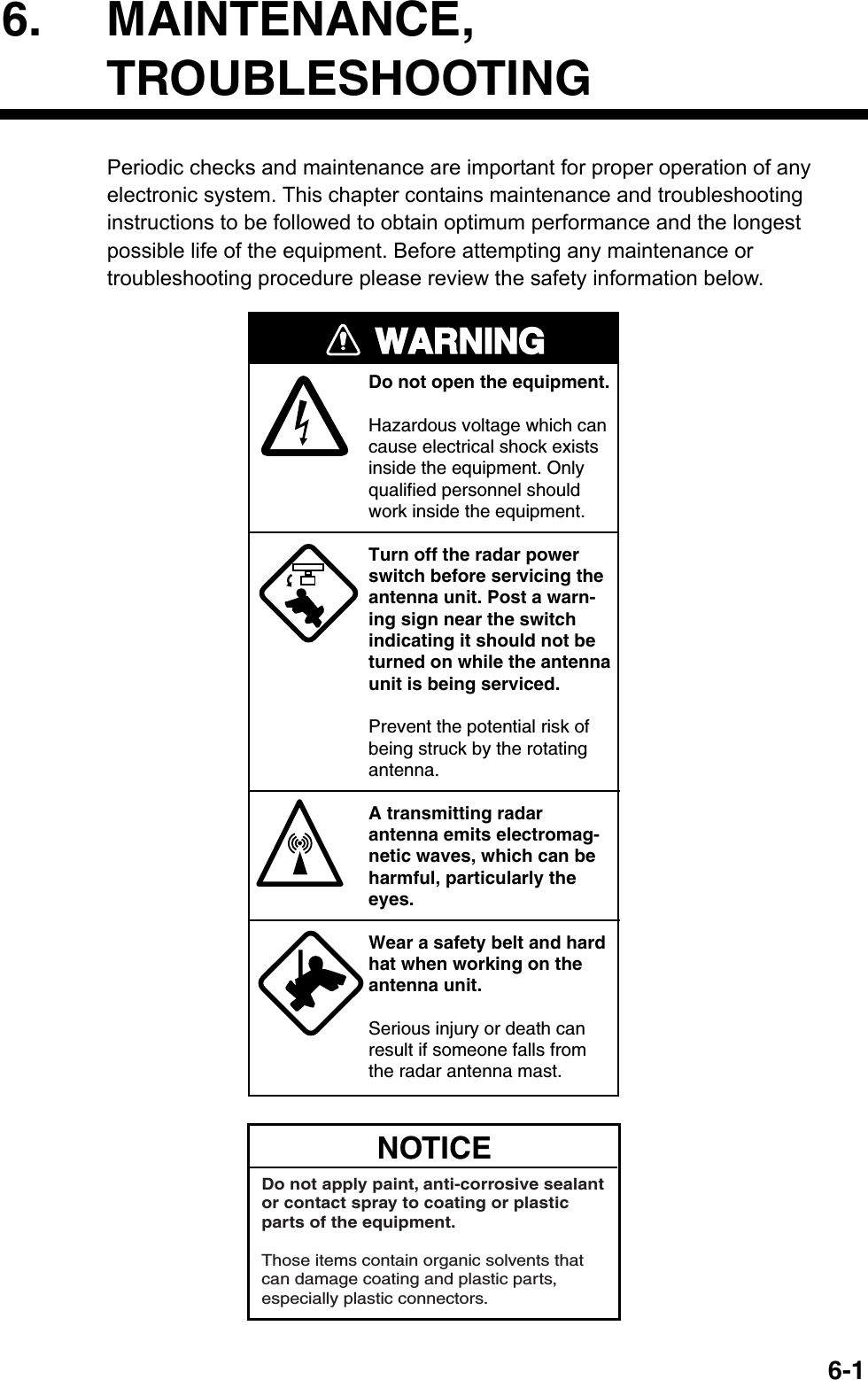
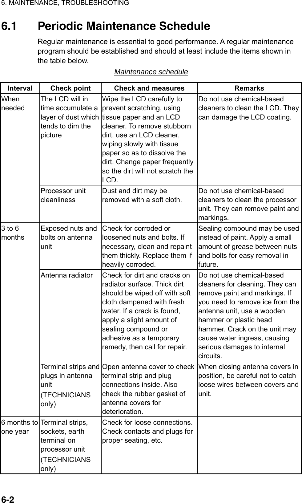
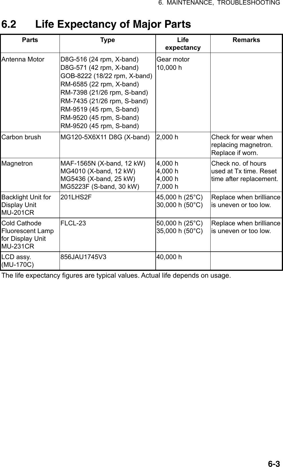
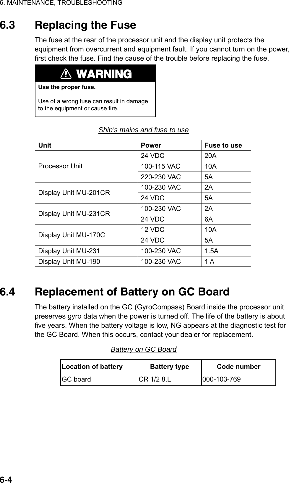
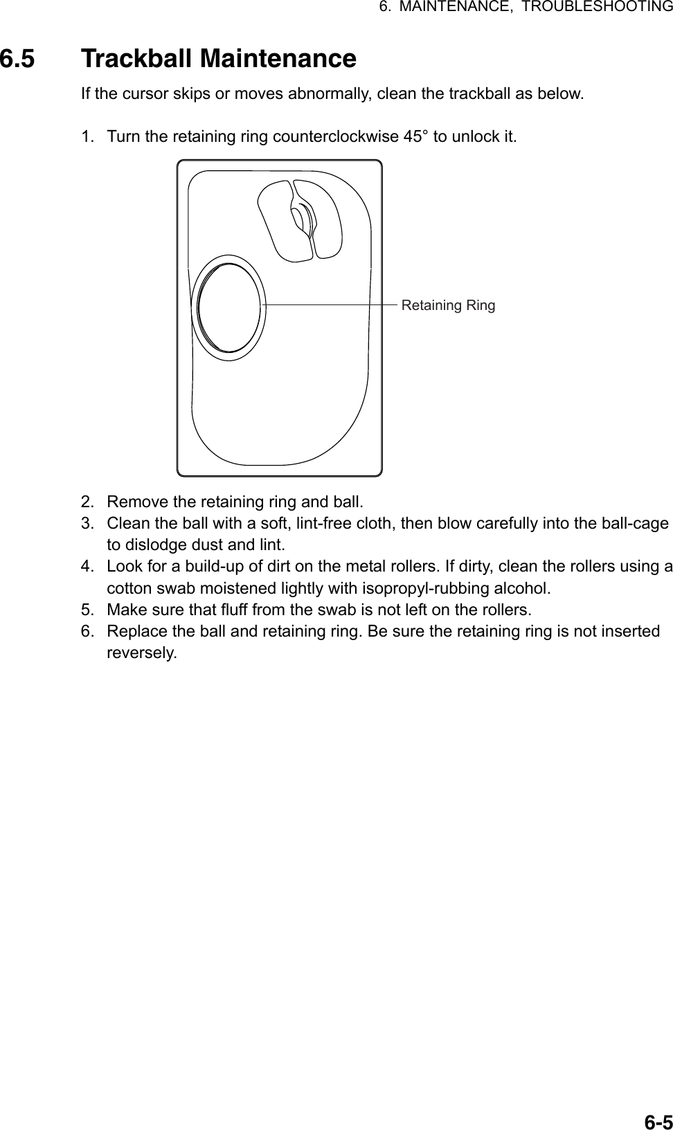
![6. MAINTENANCE, TROUBLESHOOTING 6-66.6 Easy Troubleshooting This section provides troubleshooting procedures that the user may follow to restore normal operation. If you cannot restore normal operation, do not attempt to check inside any unit. Any repair work is best left to a qualified technician. Easy troubleshooting procedures Problem Cause Remedy Key beep inaudible Key beep turned off Adjust key beep level on the OPERATION menu, referring to section 1.43. Picture not updated or picture freeze. 30 seconds after the picture freezes, the buzzer sounds, the [ALARM ACK] key blinks and alarm signal is output. Video freeze Turn the power off and on again to restore normal operation. Power is ON but nothing appears on monitor. Brilliance is too low. Keyboard-type control unit: Turn BRILL control clockwise to increase the brilliance. Trackball-type control unit: Press any one of F1-F4 for five seconds to increase the brilliance to "50". Marks, indications and noise appear but no echo Tx high voltage protection circuit has activated. Reset the power to restore normal operation. Range changed but radar picture does not change Defective range key or video freeze up Try to hit RANGE [+] and [-] keys (or RANGE box) several times. (If unsuccessful, replacement of keypad may be required in case of the keyboard-type control unit.) If that does not work try to turn the power off and on again to see if the problem might be video freeze up. Only 2 PI lines when 6 lines are wanted Incorrect setting of PI line interval Incorrect setting of PI line interval. Adjust PI line interval, referring to section 1.31.2. Also, the setting for number of PI lines to display may be inappropriate. Check the menu setting for number of PI lines, referring to section 1.31.4. Range rings are not displayed Range rings turned off Try turning on the range rings with 0 RINGS in the MARK menu. If they do not appear, their brilliance may be too low. Adjust their brilliance at page 1 of the BRILL menu. Tracked target not tracked correctly Poor definition of targets in sea clutterAdjust A/C SEA and A/C RAIN referring to section 1.17 and 1.18. Tuning adjusted but poor sensitivity 2nd trace echo rejector on or dirt on radiator face • Turn off the 2nd trace echo rejector, referring to section 1.38. • Clean the radiator face.](https://usermanual.wiki/Furuno-USA/9ZWRTR081A.op-manual/User-Guide-1456778-Page-241.png)
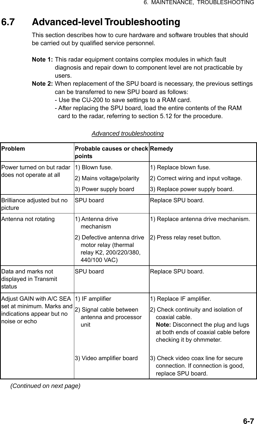
![6. MAINTENANCE, TROUBLESHOOTING 6-8Advanced troubleshooting (con’t) Problem Probable causes or check points Remedy Marks, indications and noise appear but no echo (Transmission leak representing own ship position is absent) 1) TX high voltage protection circuit has activated. 2) Magnetron 3) Modulator board 4) SPU board 1) Reset power to restore normal operation. 2) Check magnetron current. Replace magnetron. 3) Replace modulator board. 4) Replace SPU board. Picture not updated or picture freeze-up 1) Bearing signal generator board (in antenna unit) 2) SPU board 3) Video freeze-up 1) Check the connection of signal cables. 2) Replace SPU board. 3) Turn off and on the radar. Incorrect orientation of picture 1) SPU board 2) Gyro interface 1) The message HDG SIG MISSING appears when the heading pulse is not received during transmitting. 2) Replace the gyro interface. Cannot operate radar from on-screen boxes SPU Board Replace SPU Board. Radar is properly tuned but poor sensitivity 1) Deteriorated magnetron 2) Detuned MIC 3) Dirt on radiator face 4) Water ingress to the waveguide or other feeder line 5) Second trace echo rejection is ON 1) With the radar transmitting on 48 nmrange, check magnetron current. If current is below normal, magnetron may be defective. Replace it. 2) Check MIC detecting current. If it is below normal value, MIC may have become detuned. MIC must be tuned. 3) Clean the radiator surface. 4) Remove water from the feeder line. 5) Disable the second-trace echo rejector referring to section 1.38. Range changed but radar picture not changing 1) Defective range key 2) SPU board 3) Video freeze up 1) Try to hit RANGE [+] and [-] keys several times. If unsuccessful, replacement of keypad may be required. 2) Replace SPU board. 3) Turn off and on radar. (Continued on next page)](https://usermanual.wiki/Furuno-USA/9ZWRTR081A.op-manual/User-Guide-1456778-Page-243.png)
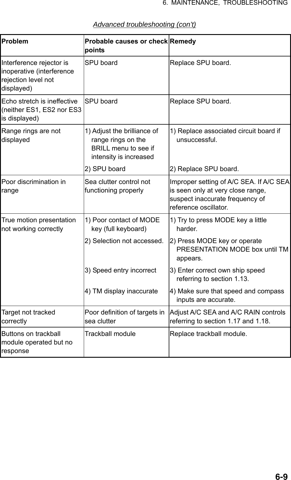
![6. MAINTENANCE, TROUBLESHOOTING 6-10 [CUSTOMIZE•TEST] 1 BACK 2 [DATA BOX] 3 [F1] 4 [F2] 5 [F3] 6 [F4] 7 [OPERATION] 8 [TEST] [TEST] 1 BACK 2 [SELF TEST] 3 [TT TEST] 6.8 Diagnostics A diagnostic test program is provided to test major circuit boards in the control unit, processor unit and card I/F unit. Note that the normal radar picture is lost during this test. Proceed as follows to execute the diagnostic test: 1. Left-click the MENU box to open the menu. 2. Select 9 [CUSTOMIZE•TEST]. CUSTOMIZE•TEST menu 3. Select 8 [TEST]. TEST menu 4. Select 2 [SELF TEST] . SELF TEST menu 5. Select 2 START to start the test. In a few moments the results of the test are displayed and the buzzer sounds continuously. The ROMs and RAMs of the SPU, RFC, KEYBOARD (Control Unit), REMOTE (Trackball-only Control Unit) and CARD I/F UNIT are checked for proper operation. OK appears for normal operation. If NG (No Good) appears, corresponding components may be defective. Consult your dealer. In the middle of the display the rpm of the antenna unit and various voltages are displayed. [SELF TEST] 1 BACK 2 START](https://usermanual.wiki/Furuno-USA/9ZWRTR081A.op-manual/User-Guide-1456778-Page-245.png)
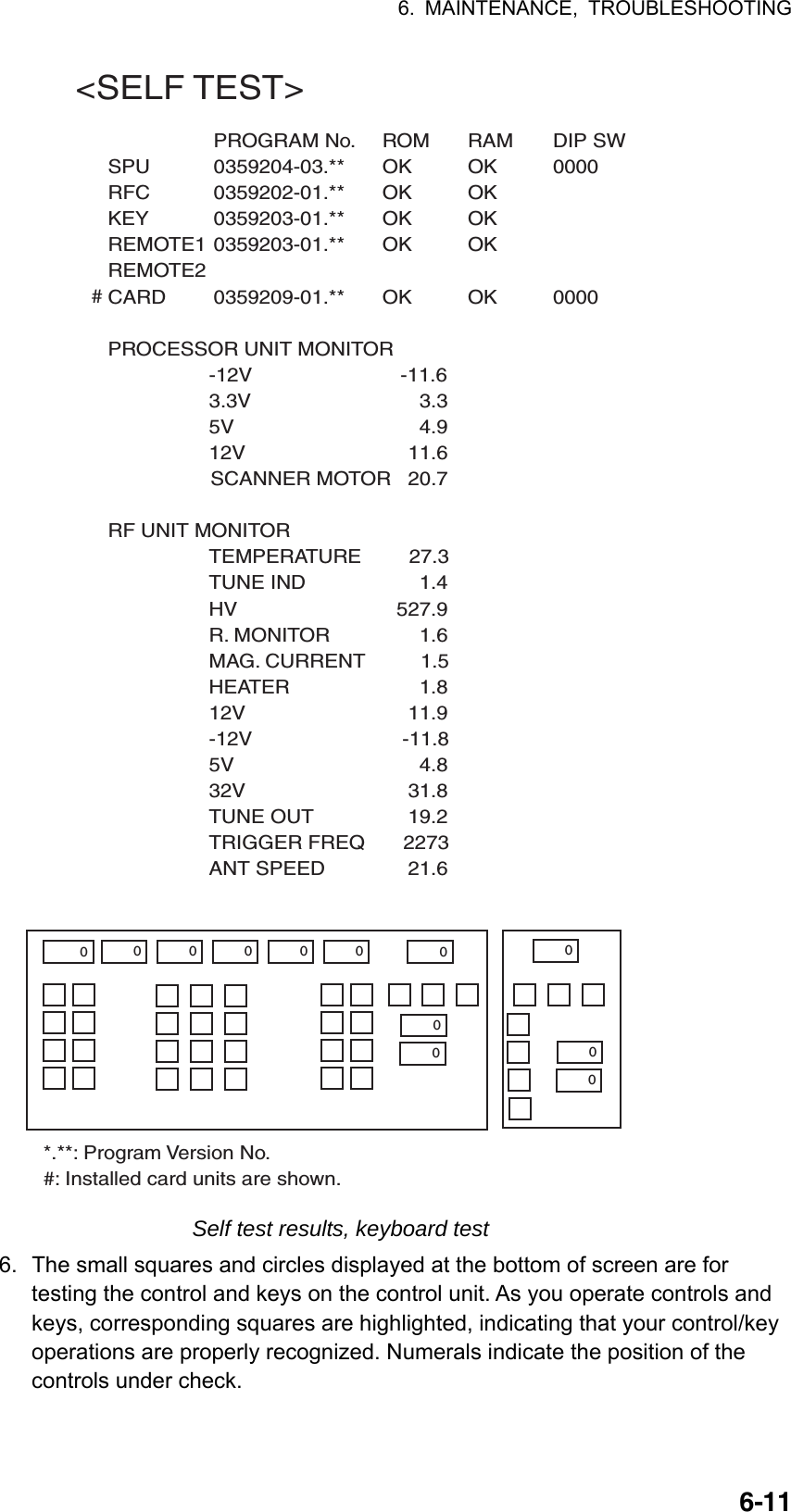
![6. MAINTENANCE, TROUBLESHOOTING 6-127. Press the [F1] key to change the display. The buzzer stops and the screen shows the sentences being input from external equipment (GPS1, GPS2SPEED, HEADING and NAV DATA). Below is an example. The sentences shown depend on your system settings. <GPS1>GGAGLLRMCRMBVTGZDADTMBWRBWC <GPS2>GGAGLLRMCRMBVTGZDADTMBWRBWC<SPEED>VBWVHWVDR <HEADING>HDT <NAV DATA>WPLRTEMWVVWTVWRDPTDBTDBSMTWVDM Sentence input display](https://usermanual.wiki/Furuno-USA/9ZWRTR081A.op-manual/User-Guide-1456778-Page-247.png)
![6. MAINTENANCE, TROUBLESHOOTING 6-138. Press the [F1] key again to show the data sentences input from AIS and INS. <AIS>VDOVDM <INS>ZDAGGAGLLOSDDPTMWVDTMFUGLLPAESPPAESCPAESFPLSPLPLSPSPAESWPAESN 8. To terminate the test, press the [F1] key.](https://usermanual.wiki/Furuno-USA/9ZWRTR081A.op-manual/User-Guide-1456778-Page-248.png)

![AP-1APPENDIX 1. Menu Tree Main menu (accessed by MENU key or MENU box) 1 ECHO2 MARK3 ALARM(Continued on next page)1 BACK2 2ND ECHO REJ (OFF, ON)3 TUNE INITIALIZE4 PM (OFF, ON) 5 SART (OFF, ON)6 WIPER (OFF, 1, 2)7 ECHO AREA (CIRCLE, WIDE, ALL)*18 [PICTURE SELECT]9 STC RANGE (-10 to +10, 00) MENU keyorMENU box1 BACK2 (TARGET ALARM, WATCH ALARM, TT NEW TARGET, TT LOST TARGET, TT CPA LIMIT, TT AUTO ACQ TGT FULL, TT MAN ACQ TGT FULL, TT SYSTEM ERROR, AIS NEW TARGET, AIS LOST TARGET, AIS CPA LIMIT, AIS TGT FULL, AZIMUTH, HEAD LINE, TRIGGER, VIDEO, GYRO, LOG, EPFS, XTE, ARRIVAL WPT, DEPTH, ALARM ACK OUT, OPERATOR FITNESS, ANCHOR WATCH, NO CPA/TCPA FOR AIS)9 ALARM OUT POLARITY (NORMAL, INVERT) 1 BACK2 EBL1 (REL, TRUE)3 EBL2 (REL, TRUE)4 VRM1 (NM, SM, km, kyd)5 VRM2 (NM, SM, km, kyd)6 CURSOR BEARING (REL, TRUE)7 CURSOR RANGE (NM, SM, km, kyd)8 [CURSOR SHAPE]*11 BACK2 OWN SHIP MARK (OFF, MIN, SCALED)3 STERN MARK (OFF, ON)4 [PI LINE]5 ANCHOR WATCH (OFF, ON, 0.00NM)6 DROP MARK (OFF, ON)7 [INS MARK]*58 EBL OFFSET BASE (STAB GND , STAB HDG, STAB NORTH) 9 [EBL, VRM, CURSOR SET]*6 0 RING (OFF, ON)1 BACK2 TARGET ALARM MODE (IN, OUT) 3 TARGET ALARM LEVEL (1, 2, 3, 4)4 WATCH ALARM (OFF, 6M, 10M, 12M, 15M, 20M)5 ALARM SOUND LEVEL (OFF, LOW, MID, HIGH)6 [ALARM OUT1]7 [ALARM OUT2]8 [ALARM OUT3]9 [ALARM OUT4]0 [PRIMARY ALARM]*1 Not available on IMO or A type.*2 W type shows PI LINE1. Same choices as "PI LINE".*3 W type shows PI LINE2. Same choices as "PI LINE".*4 Appears when 3 PI LINE is set for other than "1".Not shown on IMO or A type.*5 When INS MARK is OFF, BARGE MARK menu appears.*6 IMO and A types show 9 EBL CURSOR BEARING (REL, TRUE).1 BACK2 USER CHART (OFF, ON)3 CURVED EBL (OFF, ON)4 CHART SYMBOL (OFF, ON)5 NOTE BOOK (OFF, ON, DISPLAY)6 ROUTE (OFF, CENT, ALL)7 PREDICTOR (OFF, ON)7 [BARGE MARK] 1 BACK2 BARGE MARK (OFF, ON)3 BARGE SIZE (LENGTH and WIDTH)4 ARRANGEMENT 1BACK2 (PICTURE 1 (OFF, ON),PICTURE 2 (OFF, ON),PICTURE 3 (OFF, ON),PICTURE 4 (OFF, ON),NEAR (OFF, ON),FAR (OFF, ON),NEAR BUOY (OFF, ON),FAR BUOY (OFF, ON),ROUGH SEA (OFF, ON),SHIP (OFF, ON),HARBOR (OFF, ON),COAST (OFF, ON))1 BACK2 PI LINE BEARING (REL, TRUE)*23 PI LINE (1, 2, 3, 6*3)4 PI LINE MODE (PARALLEL , PERPENDIC.)*45 RESET PI LINE (NO, YES)1 BACK2 (TARGET ALARM, WATCH ALARM, TT NEW TARGET, TT LOST TARGET, TT AUTO ACQ TGT FULL, TT MAN ACQ TGT FULL, AIS NEW TARGET, AIS LOST TARGET, AIS TGT FULL XTE, ARRIVAL WPT, DEPTH ANCHOR WATCH,NO CPA/TCPA FOR AIS) 1 BACK2 CURSOR (OFF, ON)3 FRONT HALF LENGTH4 REAR HALF LENGTH5 NET WIDTH6 ROTATE STEP(360°, 32 POINTS)](https://usermanual.wiki/Furuno-USA/9ZWRTR081A.op-manual/User-Guide-1456778-Page-250.png)
![APPENDIX AP-2 4 TTAIS5 PLOTTER1 BACK2 AZ STAB (STAB HDG, STAB NORTH)3 AZ POLYGON (OFF, STAB GND, STAB HDG, STAB NORTH)4 [TRIAL MANEUVER]5 [TTAIS SYMBOL]6 [CPA AUTO ACTIVATE]7 [AIS DISP FILTER]8 [AIS LOST FILTER]9 [TT LOST FILTER]0 [ASSOCIATION]1 BACK2 TRIAL (OFF, STATIC, DYNAMIC)3 TRIAL SPEED RATE ( 0-99 kn, 0.00-99.99 kn/s, two sets)4 TRIAL TURN RATE ( 0-99 kn, 0.00-99.99 kn/s, two sets)5 TRIAL TGT DATA ( ACTUAL , TRIAL)1 BACK2 TTAIS SYMBOL COLOR (RED, GRN, BLU, CYA, MAG, WHT)3 AIS ROT TAG LIMIT (000.0°-720.0°/min)4 TT PAST POSN POINTS (5, 10)5 AIS PAST POSN POINTS (5,10)6 AIS SCALED SYMBOL (OFF, ON)1 BACK2 MAX RANGE (OFF, ON, 0-99 NM)3 MIN SHIP SPEED (OFF, ON, 0.0-9.9 kn)4 EXCEPT CLASS B (OFF, ON)5 MIN SHIP LENGTH (OFF, ON, 0-999 m)1 BACK2 CHART COLOR (GRN, YEL, CYA, ORANGE, GRAY)*3 OWN TRACK INTERVAL (OFF, DRAW, 10S, 30S, 1M, 2M, 3M, 6M, 15M)4 OWN TRACK COLOR (RED, GRN, BLU, YEL, CYA, MAG, WHT)5 TGT TRACK INTERVAL (OFF, DRAW, 10S, 30S, 1M, 2M, 3M, 6M, 15M)*6 TGT TRACK COLOR (RED, GRN, BLU, YEL, CYA, MAG, WHT)*7 CURSOR L/L ALIGN (OFF, ON)8 [DATA ERASE] 1 BACK2 OWN TRACK (RED, GRN, BLU, YEL, CYA, MAG, WHT, 30%, 50%, 80%, ALL)3 TARGET TRACK (RED, GRN, BLU, YEL, CYA, MAG, WHT, 30%, 50%, 80%, ALL)**4 MARK ALL ERASE (NO, YES)5 WPT ALL ERASE (NO, YES)6 NAV LINE ALL ERASE (NO, YES)7 OWN TRACK DELETE (2POINTS, AREA)**8 TARGET TRACK DELETE (2POINTS, AREA)**(Continued on next page)(Continued from previous page)* Not available on IMO type radar** Not available on IMO or A type radar1 BACK2 MAX RANGE (OFF, ON, 0-99 NM)3 MIN SHIP SPEED (OFF, ON, 0.0-9.9 kn)4 EXCEPT CLASS B (OFF, ON)5 MIN SHIP LENGTH (OFF, ON, 0-999 m)1 BACK2 MAX RANGE (OFF, ON, 0-99 NM)3 MIN SHIP SPEED (OFF, ON, 0.0-9.9 kn)4 EXCEPT CLASS B (OFF, ON)5 MIN SHIP LENGTH (OFF, ON, 0-999 m)1 BACK2 MAX RANGE (OFF, ON)3 MIN SHIP SPEED (OFF, ON)1 BACK2 ASSOCIATION TARGET (OFF, AIS, TT)3 GAP (0.000-0.999(nm)) 4 RANGE (0.000-0.999(nm)) 5 BEARING (00.0-99.9°) 6 SPEED (0.0-9.9(kn)) 7 COURSE (00.0-99.9°)](https://usermanual.wiki/Furuno-USA/9ZWRTR081A.op-manual/User-Guide-1456778-Page-251.png)
![APPENDIX AP-3 9 [DISPLAY]0 AUTO TARGET TRACK (OFF, ON)*1 BACK2 GRID (OFF, L/L )3 OWN TRACK (OFF, ON)4 TARGET TRACK (OFF, ON)*5 MARK (OFF, ON)6 LAND DENSITY (OFF, ON)*7 PLACE NAME (OFF, ON)*8 COAST LINE (OFF, ON)9 CONTOUR LINE (OFF, ON, DEPTH)0 NEXT 1 BACK2 NAV LINE(MAP) (OFF, ON)3 DANGER HIGHLIGHT (OFF, ON)4 PROHIBITED AREA (OFF, ON)5 BUOY (OFF, ON)(Continued on next page)(Continued from previous page)6 CARD7 NAV DATA8 NAV LINEWPT1 BACK2 DRIVE SELECT3 READ CARD4 WR MARK5 WR NAV LINEWPT6 WR OWN TRACK7 WR TARGET TRACK*8 WR SETTING DATA 9 WR INSTALL DATA0 NEXT 1 BACK2 FILE DELETE3 CARD INITIALIZE1 BACK2 DEPTH (OFF, m, ft)3 DEPTH GRAPH SCALE (10, 20, 50, 100, 200, 500)4 DEPTH MARK (000 - 500)5 CURRENT (OFF, ON)6 WIND (OFF, m/s, kn, RELATIVE, TRUE THEORETICAL, TRUE NORTH)7 TEMP (OFF, ON)8 DATE-TIME (OFF, UTC, LOCAL)9 LOCAL TIME ADJ (00:00 - +13:30)0 WPT DATA (OFF, REL, TRUE)1 BACK2 NAV LINE DATA SOURCE (OFF, EXT DATA, INTERNAL DATA, WPT*)3 NAV LINE SELECT (Enter nav line no., FORWARD, REVERSE)4 SKIP NEXT WPT5 NAV LINE WIDTH (0.00 - 9.99 (NM))6 [WPT SET] 1 BACK2 WPT NO. SELECT3 WPT NAME4 WPT L/L5 CLEAR DATA (NO, YES)* Not available on IMO type](https://usermanual.wiki/Furuno-USA/9ZWRTR081A.op-manual/User-Guide-1456778-Page-252.png)
![APPENDIX AP-4 7 [WPT LIST]8 [NAV LINE SET]9 [NAV LINE LIST]0 NEXT(Continued on next page)(Continued from previous page)9 CUSTOMIZE TEST1 BACK2 [DATA BOX]3 [F1]4 [F2]5 [F3]6 [F4] 1 BACK2 NAV LINE NO. SELECT3 NAV LINE NAME4 NAV LINE ENTER5 CLEAR DATA1 BACK2 ARRIVAL WPT ALARM (OFF, ON(0.00-9.99 nm))3 TURNING LINE (OFF, ON, REVISED)4 DISP WPT NO. (OFF, ON)5 DISP WPT NAME (OFF, ON)1 BACK3 NAV DATA (OFF, ON)4 ZOOM (OFF, 2TIMES, 3TIMES)5 ZOOM DISPLAY (STAB GND, STAB HDG, STAB NORTH, TT TRACK)6 TARGET DATA (1BOX, 2BOX, 3BOX, LARGE)1 BACK2 [ECHO]3 [STD KEY]4 [TTAIS]5 [OPERATION]1 BACK2 (PICTURE, IR, ES, EAV, NOISEREJ, ANT SELECT, PULSE LENGTH,A/C SEA SELECT, AUTO RAINSELECT, TUNE SELECT, ANTHEIGHT, SEA CONDITION, 2NDECHO REJ, PM, SART, WIPER)1 BACK2 (ALARM ACK, STBY TX, HLOFF, EBL OFFSET, MODE, OFFCENTER, CU TM RESET, PILINE, VECTOR TIME, VECTORMODE, TARGET LIST, TRAIL,BRILL, MARK, MENU, RANGEUP, RANGE DOWN, ACQ, TARGET DATA, TARGET CANCEL)1 BACK2 (DISP TT, DISP AIS, TARGETDATA & ACQ, PAST POSNINTERVAL, REF MARK, CPA LIMIT,CPA, TCPA, AZ1, AZ2, TARGET LISTSORT, TRIAL MANEUVER, ASSOCIATION,AIS MESSAGE, TRIAL MODE CHANGE,AIS SCALED SYMBOL)1 BACK2 (ECHO COLOR, PALETTE, RING, ALARM1, ALARM2, WATCHALARM RESET, ZOOM, MARKDELETE, OWN TRACK DELETE,TGT TRACK DELETE*, CHART ALIGN,DISPLAY SELECT, MOB, USER DEFAULT TLL, ANCHOR WATCH, COLOR SHIFT, ICON DISP, OWN TRK ALL ERASE, TGT TRK ALL ERASE, MARK ALL ERASE,DROP MARK) Default settings:F1: IRF2: ESF3: AUTO RAIN SELECTF4: HL OFF* B, C and W types](https://usermanual.wiki/Furuno-USA/9ZWRTR081A.op-manual/User-Guide-1456778-Page-253.png)
![APPENDIX AP-57 [OPERATION]8 [TEST](Continued from previous page)1 BACK2 WHEEL DRIVE (NORMAL, REVERSE)3 KEY BEEP (OFF, LO, MID, HI)4 REMOTE KEY (F*-KEY, DISPLAY SELECT)5 POPUP GUIDANCE (OFF, ON)*1 6 OWN SHIP VECTOR (OFF, HDG, COURSE)7 STERN-UP (OFF, ON)8 SHUTTLE FERRY (OFF, MODE1, MODE2)0 NEXT1 BACK2 [SELF TEST]3 [TT TEST]6 [PICTURE] 1 BACK2 (PICTURE1, PICTURE 2, PICTURE 3, PICTURE 4, NEAR, FAR, NEAR BUOY, FAR BUOY, ROUGH SEA, SHIP,HARBOR, COAST) *1 Not available on IMO or A type1 BACK2 USER DEFAULT BACKUP (F-KEY, HOLD, STORE)3 VRM TTG (OFF/ 1/ 2/ 1+2)](https://usermanual.wiki/Furuno-USA/9ZWRTR081A.op-manual/User-Guide-1456778-Page-254.png)
![APPENDIX AP-6 Pop-up menus of on-screen boxes [TT TARGET MENU] 1 TT SELECT MANUAL 100/AUTO 25/AUTO 50/AUTO 75/AUTO 100 ALL CANCELNO/YES 23 REF TARGET VECTOR OFF/ON TT TARGET menu[AIS TARGET MENU] 1 SLEEP ALL TRGTS2 ACTIVATE ALL TRGTS 3 AUTO DISP MESSAGE /ON 4 [RECEIVED MESSAGES]5 [TRANSMIT MESSAGE] 6 [VOYAGE DATA] 7 [STATIC DATA] 8 [AIS ALM MESSAGES] AIS TARGET menuOS POSN menu [VOYAGE DATA] 1 BACK 2 NAVIGATION STATUS 00 3 ETA 00/000/0000 00:00 4 DESTINATION 5 DRAUGHT 00.0m 6 CREW 0002 [TRANSMIT MESSAGE] 1 BACK 2 ADDRESS TYPE ADDRESSED/BROADCAST 3 MESSAGE TYPE SAFETY/BINARY 4 MMSI NO. 000000000 5 CHANNEL A/B/A or B/A and B 6 OPEN FILE 1 7 SAVE FILE 1 8 EDIT 9 TRANSMIT MESSAGE TRANSMIT MESSAGE menu VOYAGE DATA menu STATIC DATA menu[TRAIL MENU] 1 TRAIL MODE REL/TRUE 2 TRAIL GRAD SINGLE/MULTI 4 TRAIL LEVEL 1/2/3/4 5 TRAIL RESTART OFF/ON 6 TRAIL COPY OFF/ON 7 [TARGET LIST MENU] CPA/TCPA/BCR/BCT/RANGE/SPEEDTGT LIST menu1 SORT BYOS TRAILOFF/1/2TRAIL menu3 NARROW TRAIL*3, *4 OFF/1/2*1Shown when 12H, 24H or 48H ischosen at 8 TRAIL LENGTH.*2B and W types. 48H notavailable on W type. *3Not available on IMO type*4Not available on A type8 TRAIL LENGTH*2 NORMAL/12/24H/48HCURSOR menu[OS POSN MENU] 1 NAV AID GPS1/GPS2/ DEAD RECKONING/ 2 MANUAL L/L 00°00.000 N 000°00.000 W 3 SIO DATA LAN OUTPUTOFF/ONLANNO/YESNO/YES9 TRAIL HIDE*1,*3,*4/ START: 00:00 END: 00:001BACKTYPE OF SHIP000ALL SHIPS OF THIS TYPECALL SIGNNAMEEXT GPS ANT POSNA: 000m B: 000mC: 00m D: 00m[STATIC DATA]OFF0 [TRAIL COLOR]*3,*4, *5[CURSOR MENU]2TARGET DATA & ACQ/TARGET CANCEL/TT TGT DATA & ACQ/TARGET TRACK ON*3/TARGET TRACK OFF*3/REF MARK/EBL OFFSET/OFFCENTER/ZOOM/MARK DELETE/OWN TRACK DELETE/TGT TRACK DELETE*3/CHART ALIGNTRAIL ERASER*3,*4/89 CURSOR*3,*4/SMALL/LARGE* Not available on IMO type [HDG MENU]1 HDG SOURCEAD-10/SERIAL2 GC-10 SETTING000.0° HDG menu[SPD MENU]1 SHIP SPEEDLOG(BT)/LOG(WT)/GPS/MANUAL/REF2 MANUAL SPEED0.0kn3 SET DRIFTOFF/ON SPEED menu*5Not available on W type [TRAIL COLOR] 1 BACK2 COLOR SHIFT NO/YES3 TRAIL COLOR 1: FUCHSIA 2: MAROON 3: RED 4: PURPLE 5: YELLOW 6: LIME 7: GREEN 8: OLIVE 9: TEAL 10: CYAN 11: BLUE12: NAVY TRAIL COLOR menu](https://usermanual.wiki/Furuno-USA/9ZWRTR081A.op-manual/User-Guide-1456778-Page-255.png)
![APPENDIX AP-7[MARK MENU] 1 ORIGIN MARK STAB GND/SEA 2 MARK KIND ORIGIN MARK(No. )/ ORIGIN MARK(SYM)/ MAP MARK / WP 1~50/ WP 51~ 100/ WP 101~150/ WP 151~ 198/ OWN SHIP SHAPE BRILL menu, page 1 [BRILL1 MENU (2/2)]1 BACK2 BEARING CURSOR3 EBL4 VRM5 PI LINE6 TT SYMBOL7 AIS SYMBOL8 L/L GRID9 MARK0 CHART* [BRILL1 MENU (1/2)]1 ECHO COLOR YEL/GRN/ WHT/COLOR*2 PALETTE DAY-GRY/DAY-BLU/ DUSK-GRY/DUSK BLU/ NIGHT-GRY/NIGHT-BLU3 PANEL DIMMER4 CHARACTER5 CURSOR6 ECHO7 TRAIL8 HL9 RING0 NEXTBRILL menu, page 2MARK menu[PICTURE MENU] 1 INT REJECT OFF/1/2/3 2 ECHO STRETCH OFF/1/2/3 3 ECHO AVERAGE OFF/1/2/3 4 NOISE REJ OFF/ON 5 AUTO STC OFF/ON 6 AUTO RAIN 7 VIDEO CONTRAST 1/2/3/4 A/B/C 8 [PULSE] 9 [CONDITION] PICTURE menuOFF/1/2/3/4 PULSE menu ANTENNA SELECT menu[ANT SELECT]ANT NO 1: X-BAND12 MAIN TOPANT NO 2: X-BAND12 MAIN TOPANT NO 3:ANT NO 4:OWN RADAR NO: 21 DISP ANT1MASTER2 DISP ANT2MASTER8 STORE INTER-SWOFF/ON9 SUB MONITOR* OFF/ON0 DEFAULT NO/SAVE/FACTORY/ DEFAULT 8 MARK POSN CURSOR/OS/L/L 00°000.00 N 000°000.00 E9 MAP DISPLAY OFF/ON0 MAP MARK COLOR* RED/GRN/BLU/YEL/ CYA/MAG/WHTCONDITION menu[CONDITION MENU] 1 BACK 2 SEA CONDITION 1/2/3/4/5 3 ANT HEIGHT 5/7.5/10/15/20/ 25/30/25/30/35/40/45/ more 50 m 4 LOW LEVEL ECHO 0 * Not available on IMO or A type [PULSE MENU] 1 BACK 2 0.5NM S1/S2 3 0.75NM S1/S2/M1 4 1.5NM S1/S2/M1 5 3NM S2/M1/M2/M3 6 6NM M1/M2/M3/L 7 12-24NM M2/M3/L](https://usermanual.wiki/Furuno-USA/9ZWRTR081A.op-manual/User-Guide-1456778-Page-256.png)