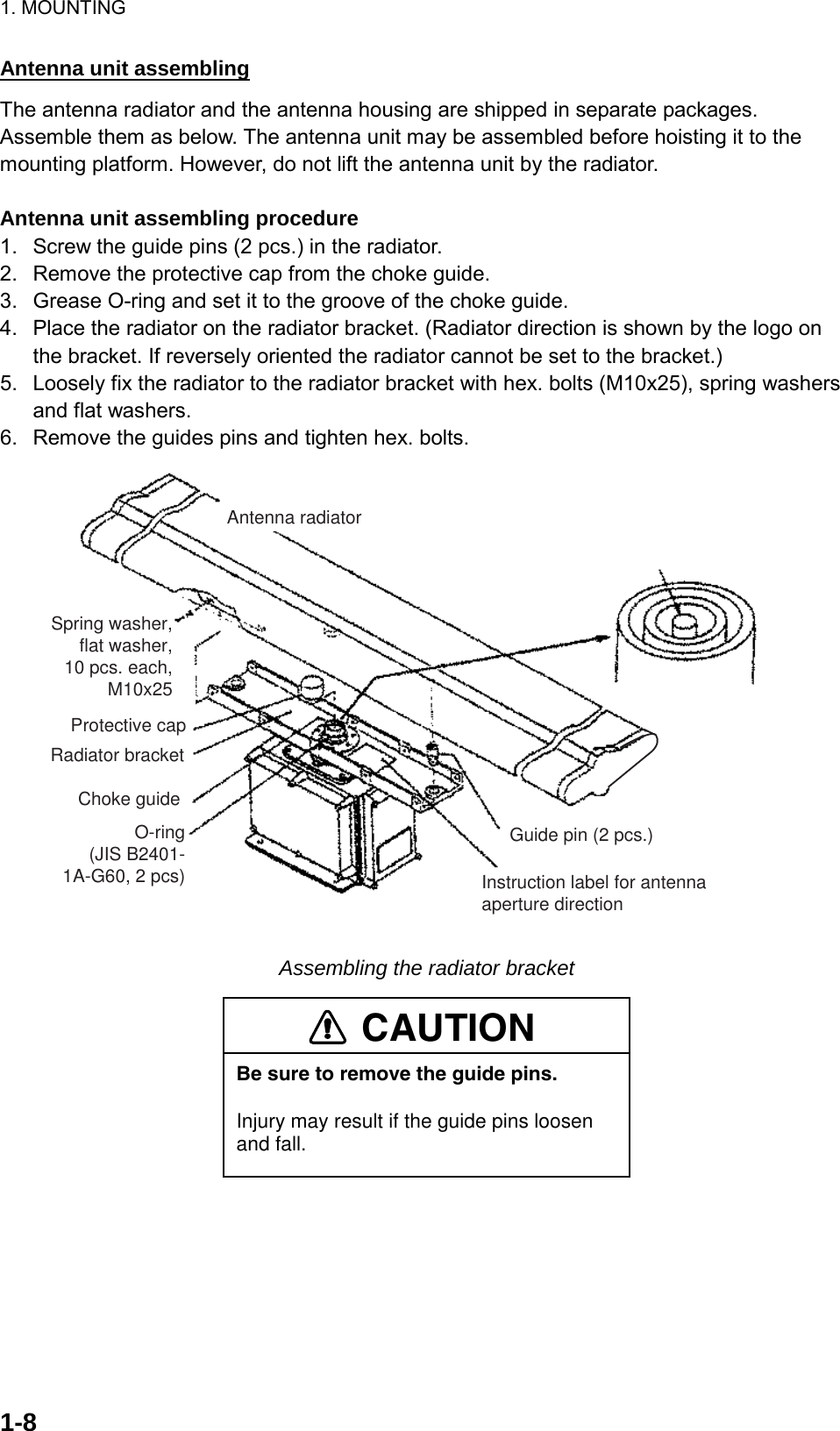
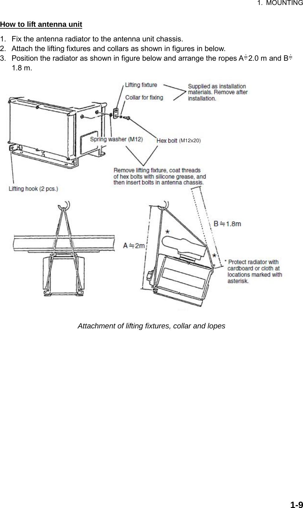
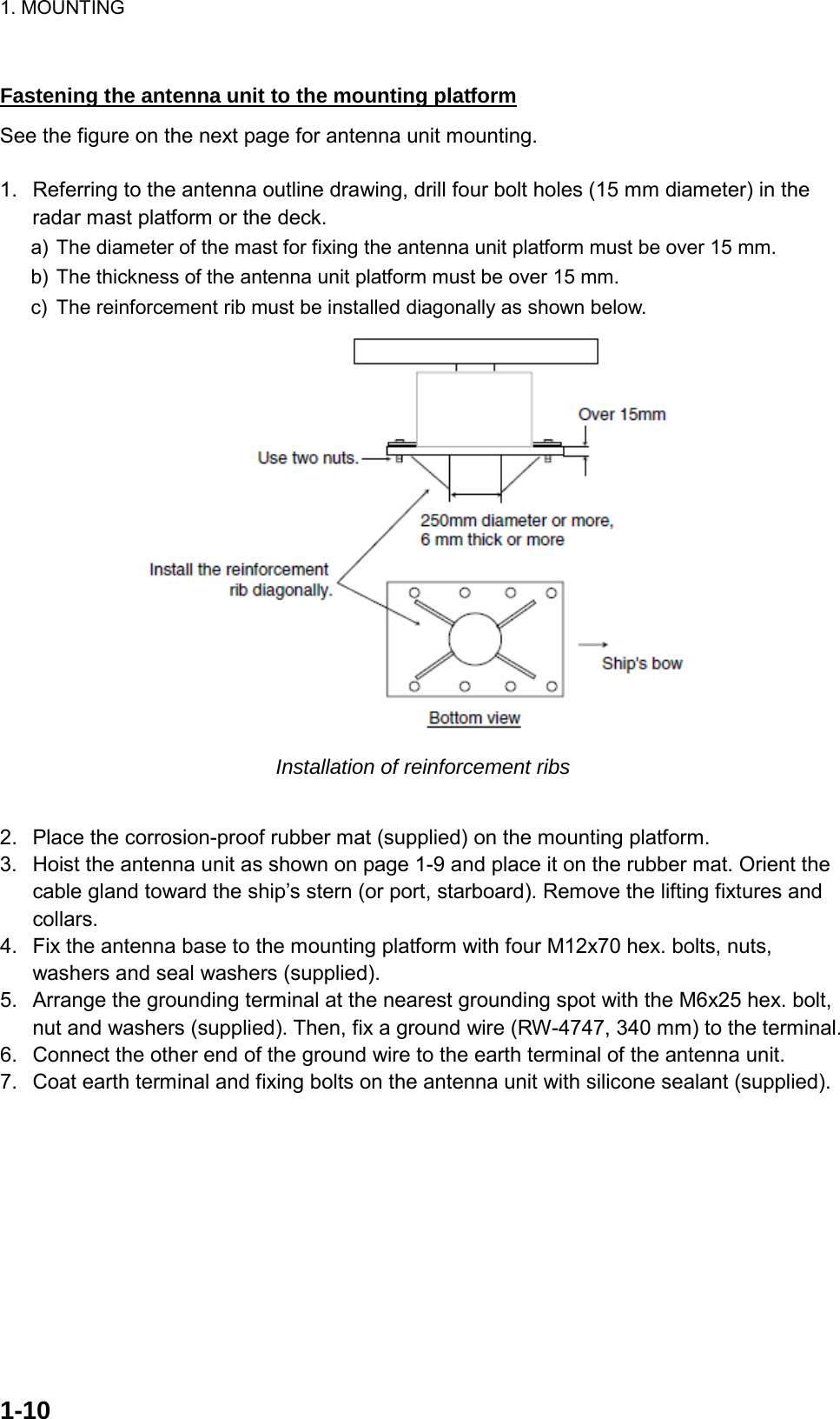
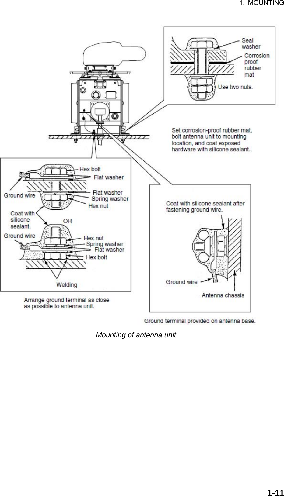
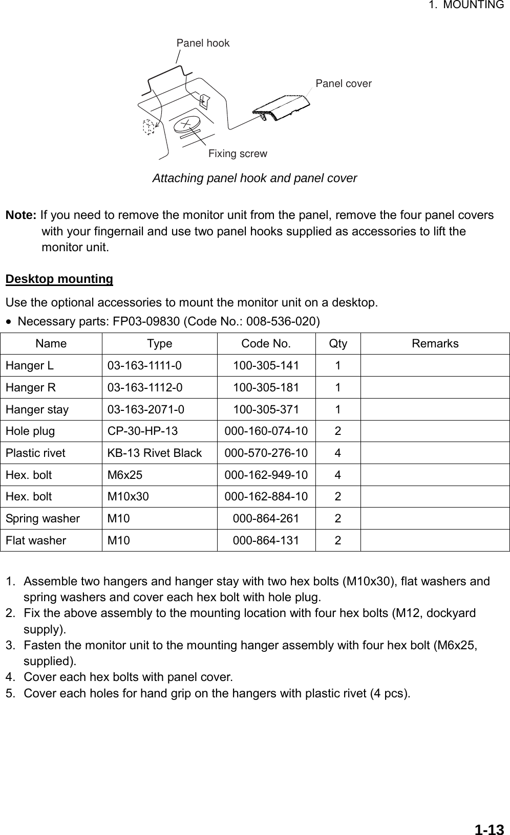
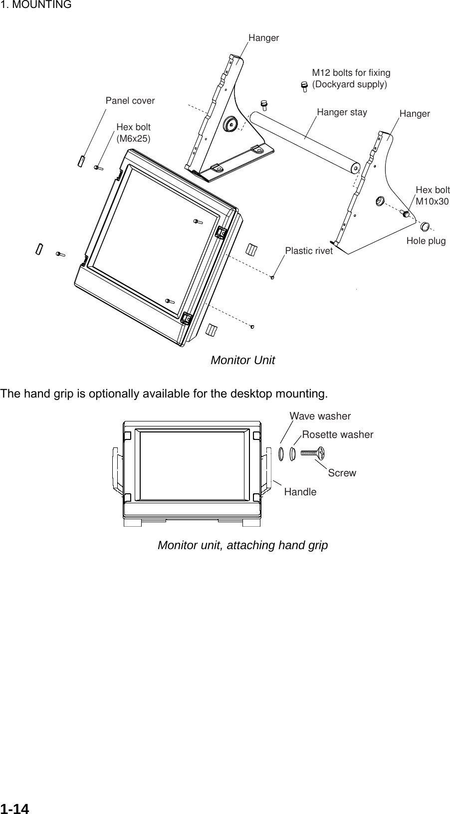
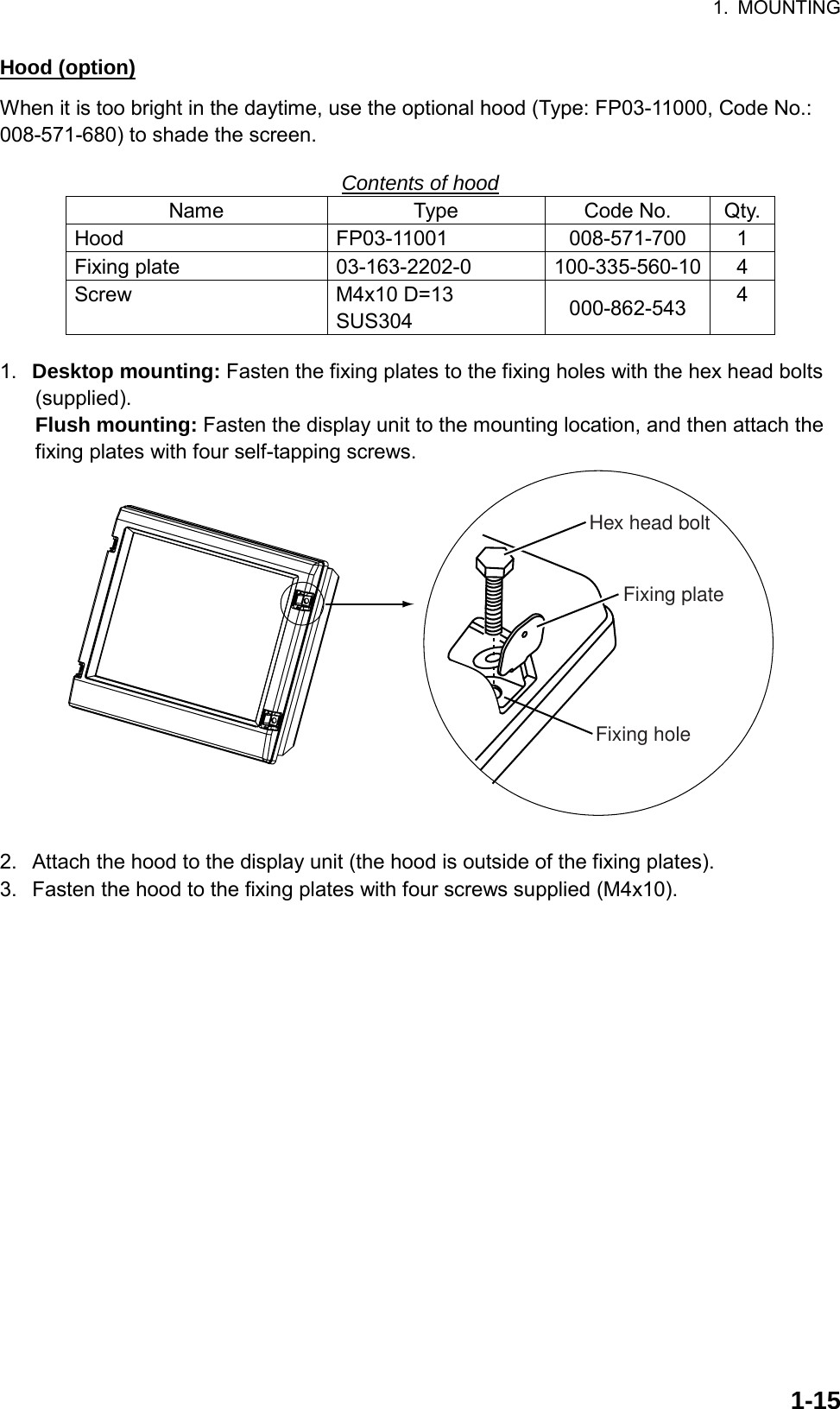
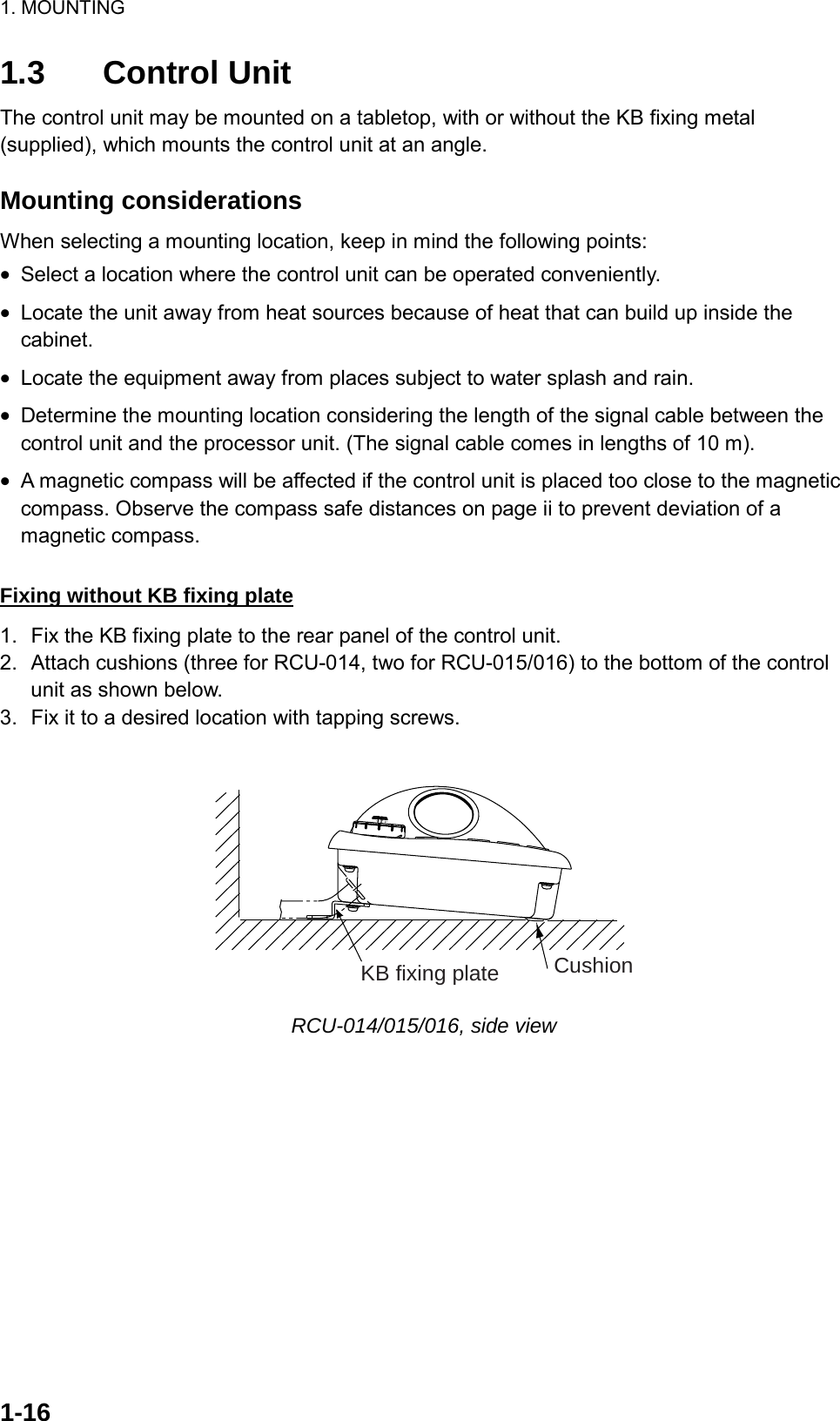
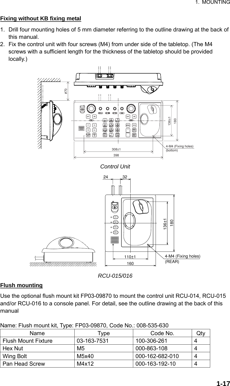
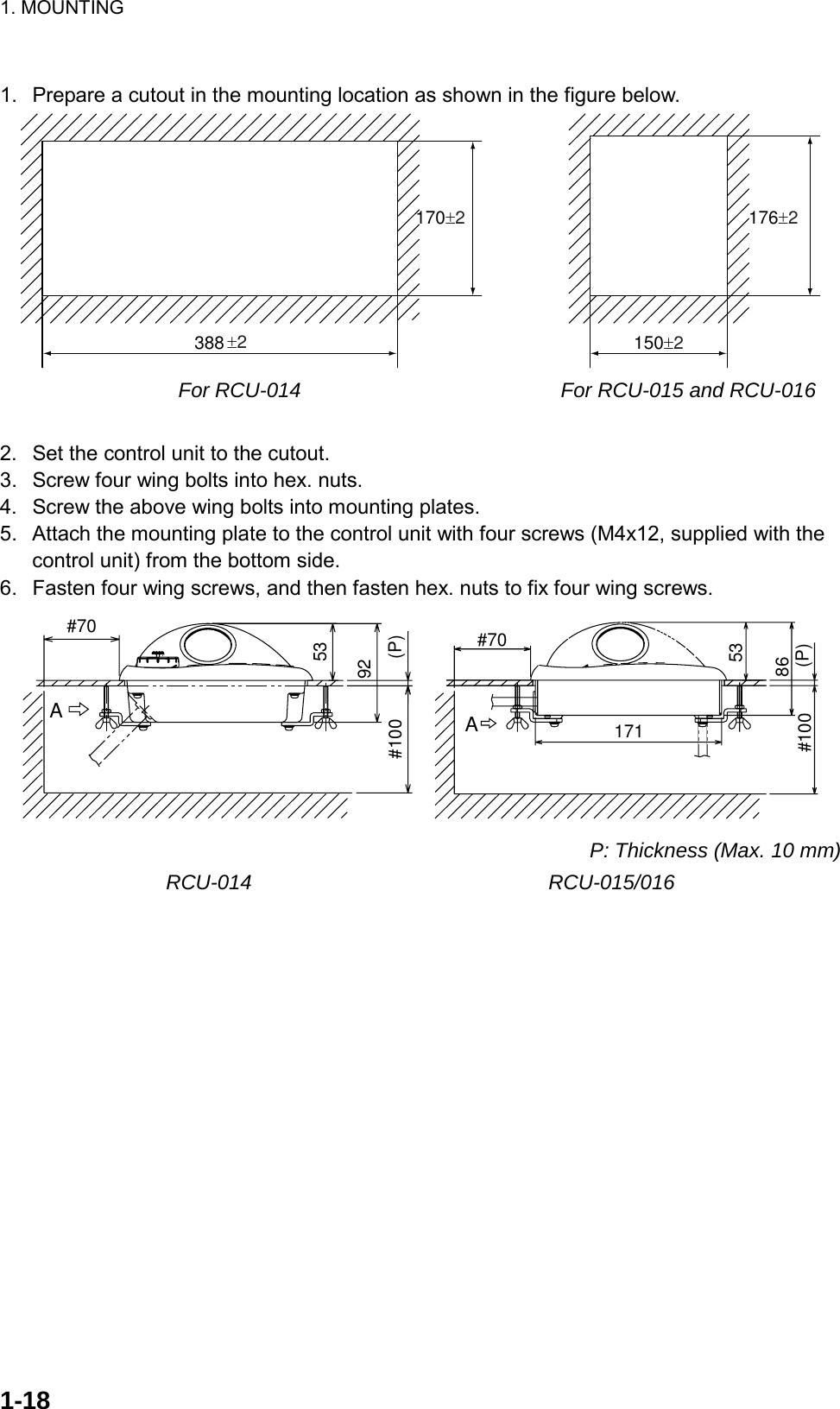
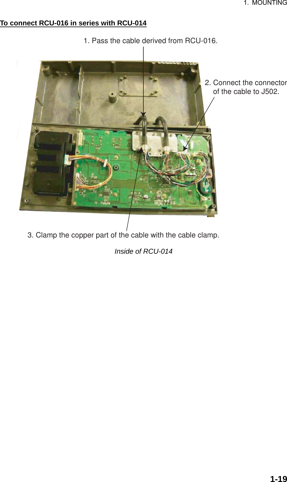
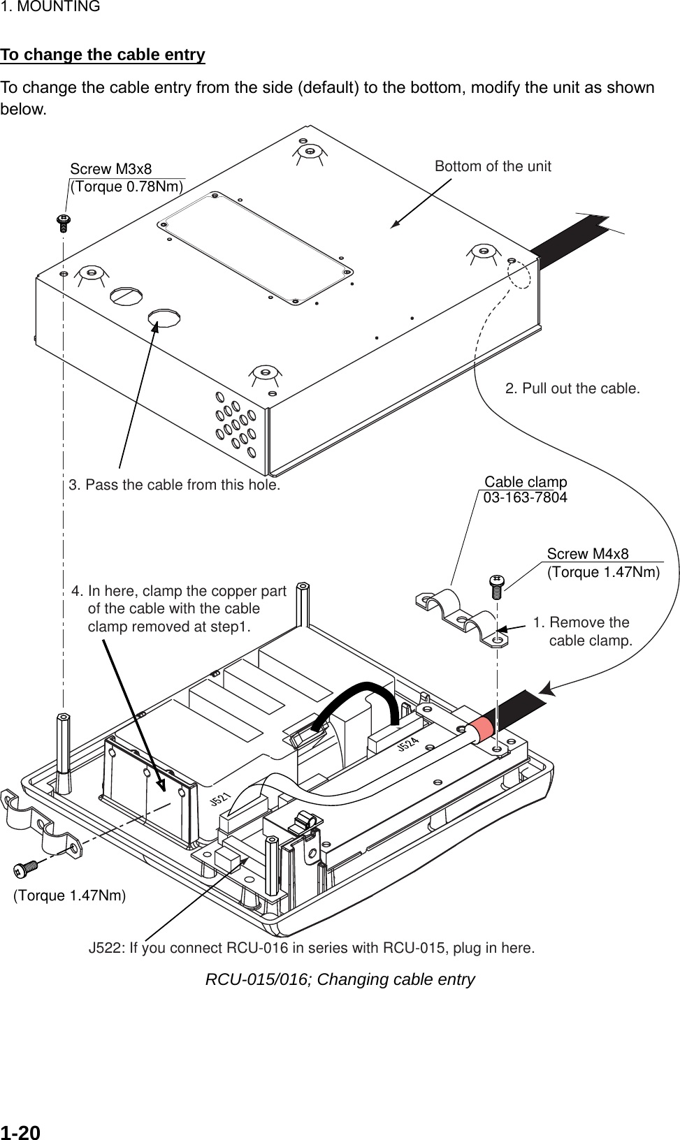
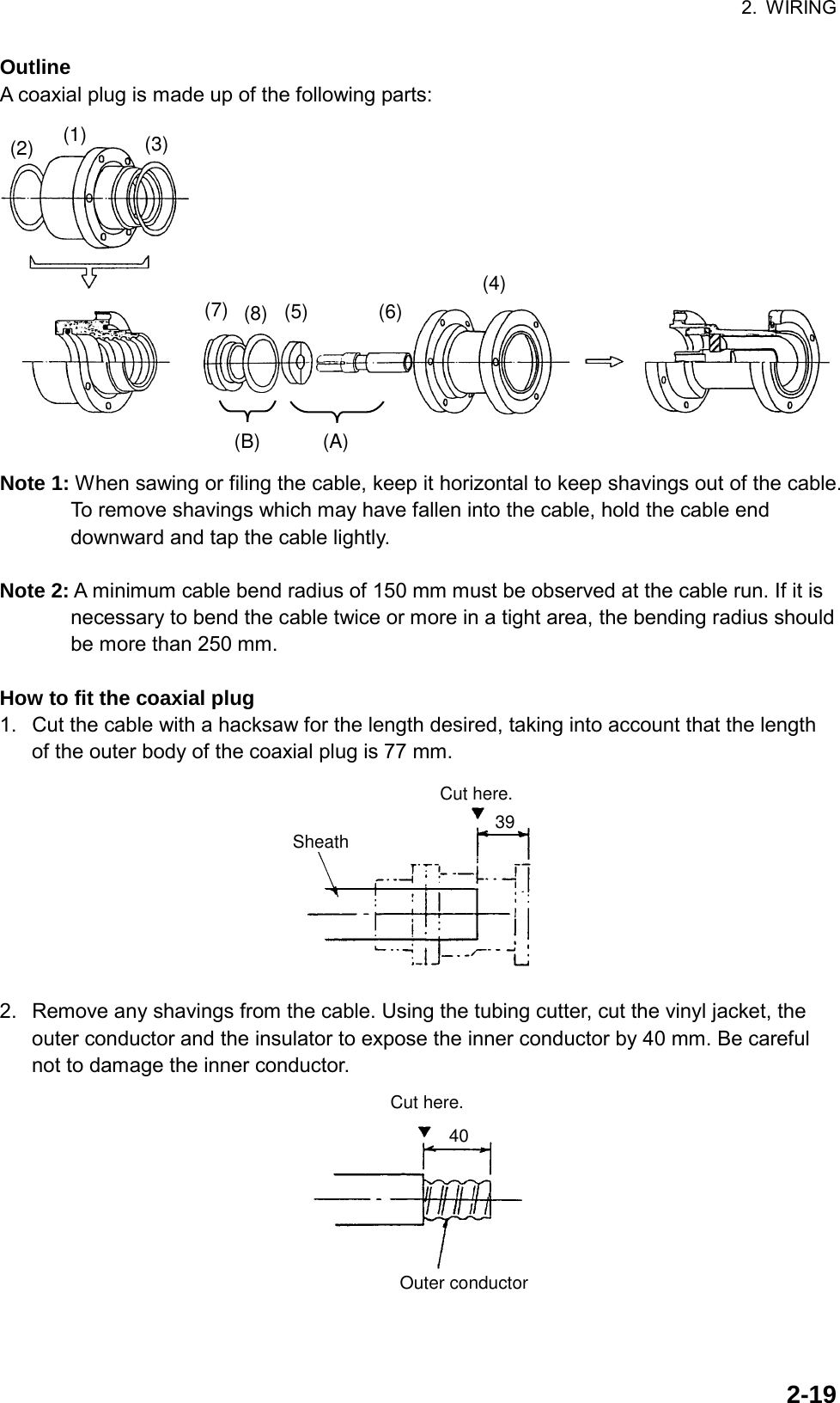
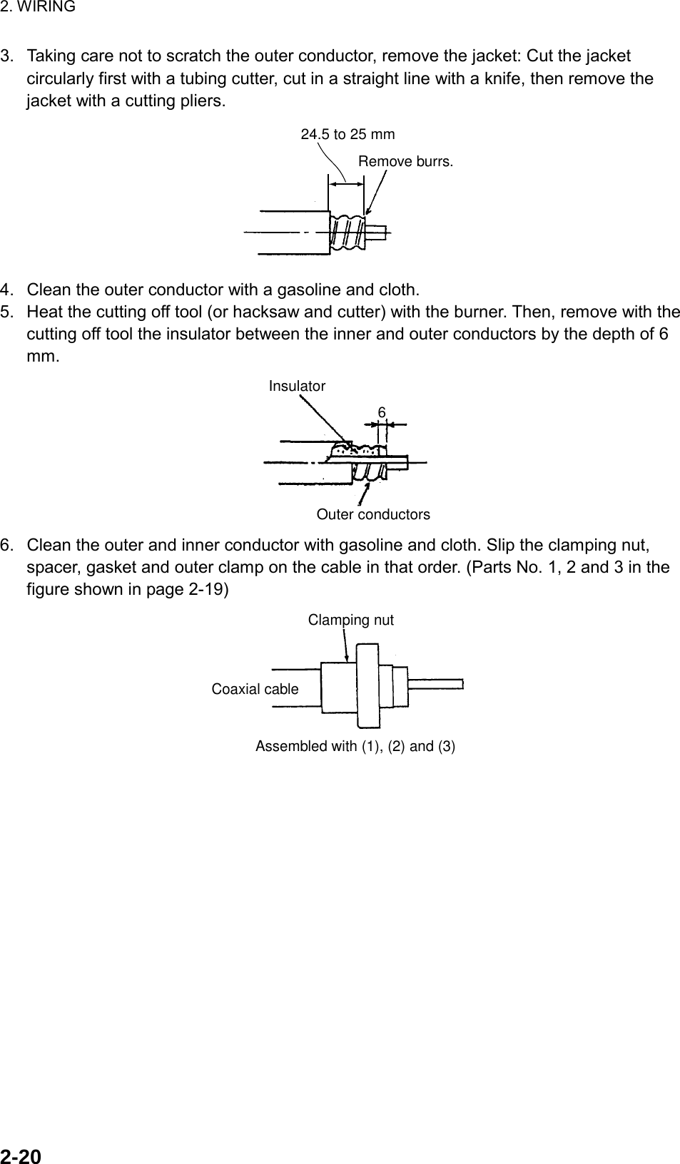
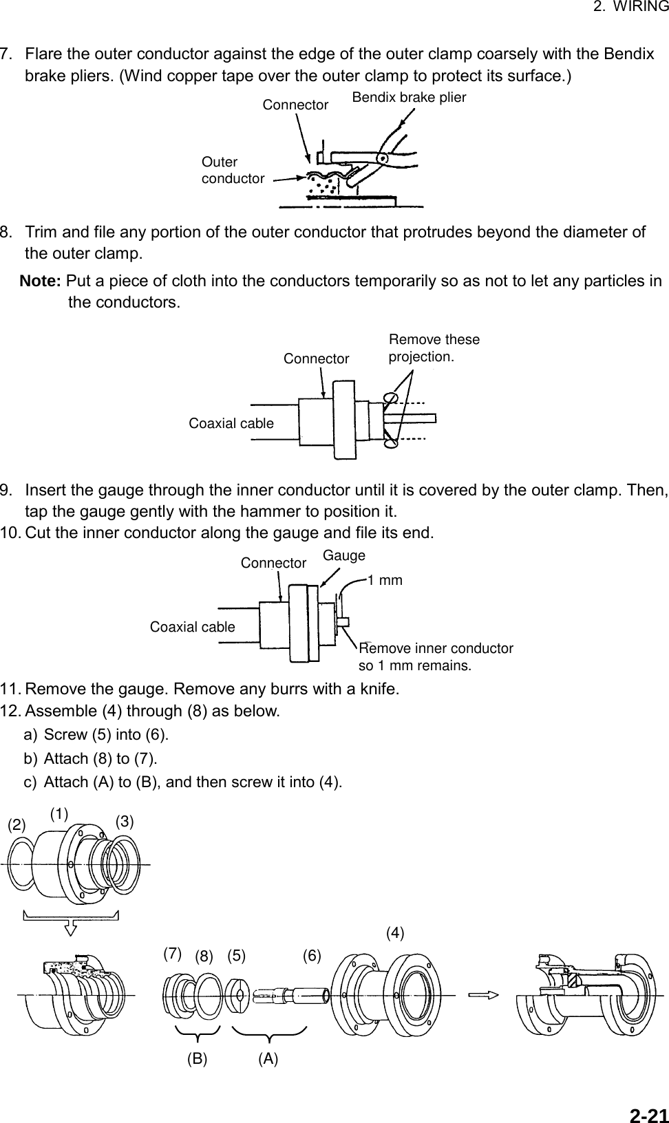
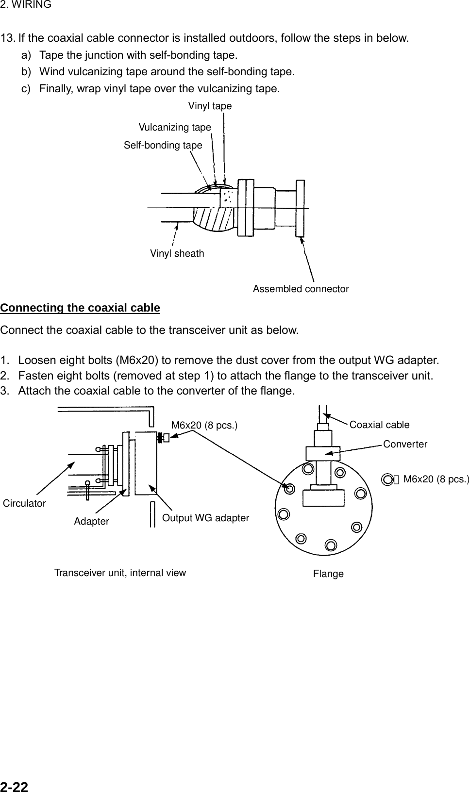
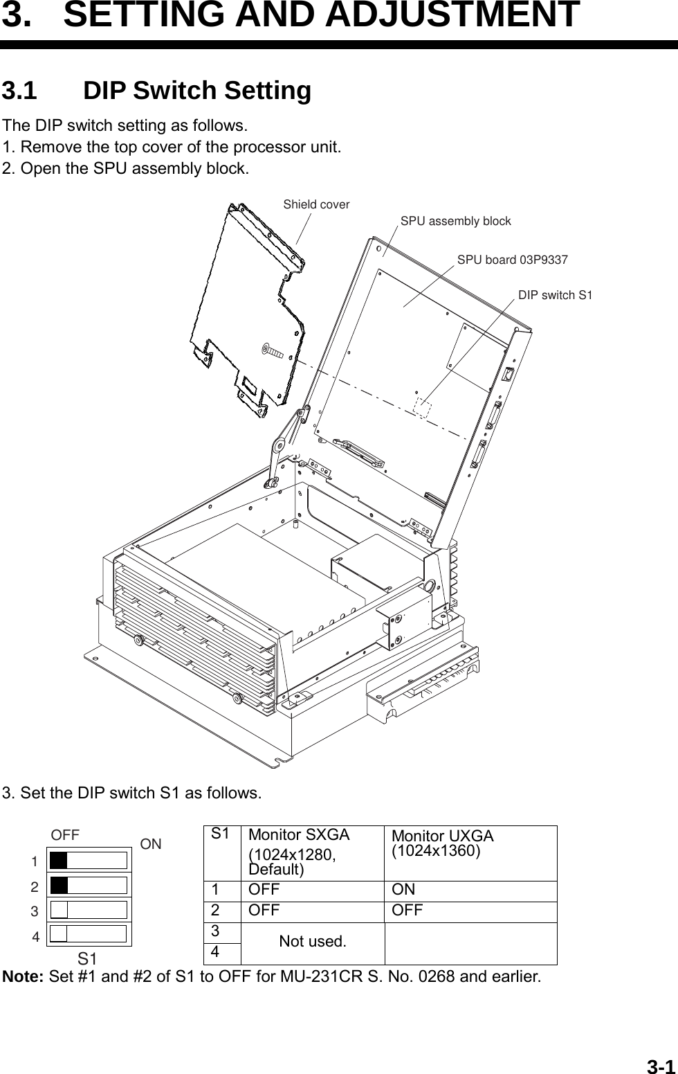
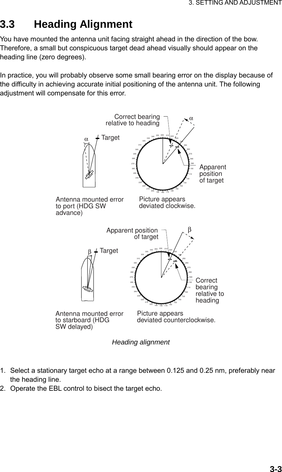
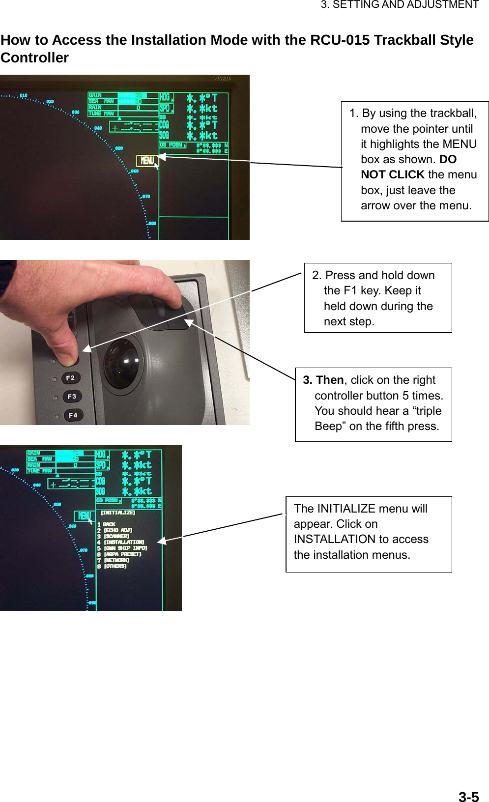
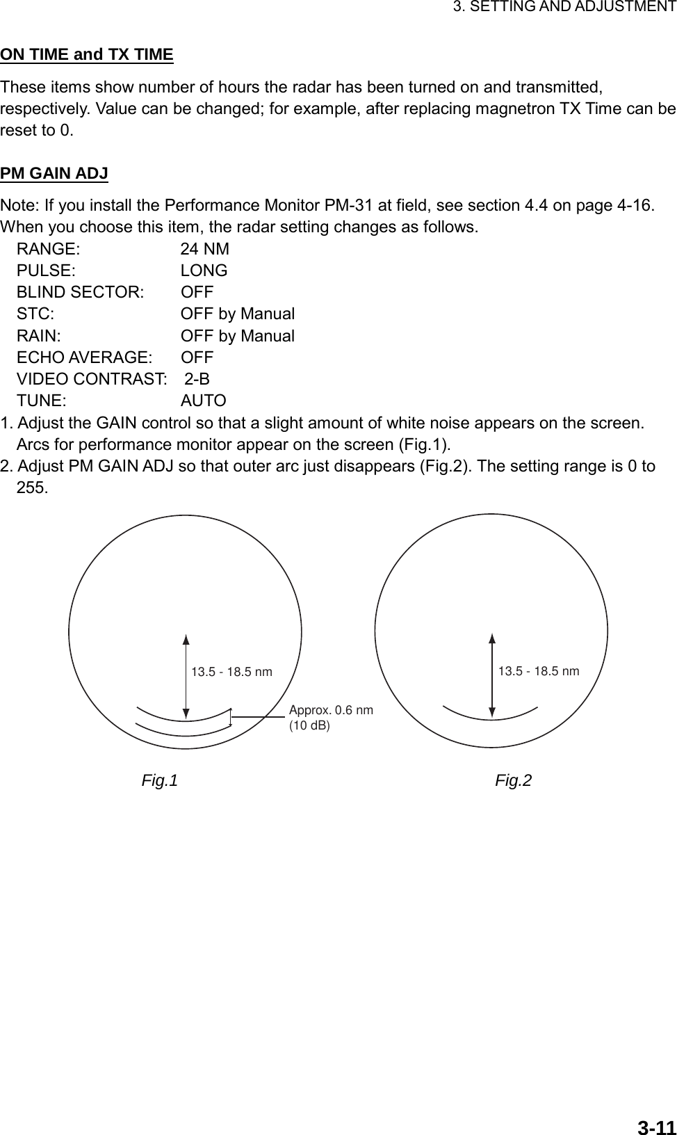
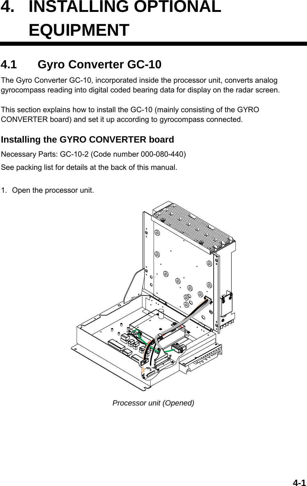
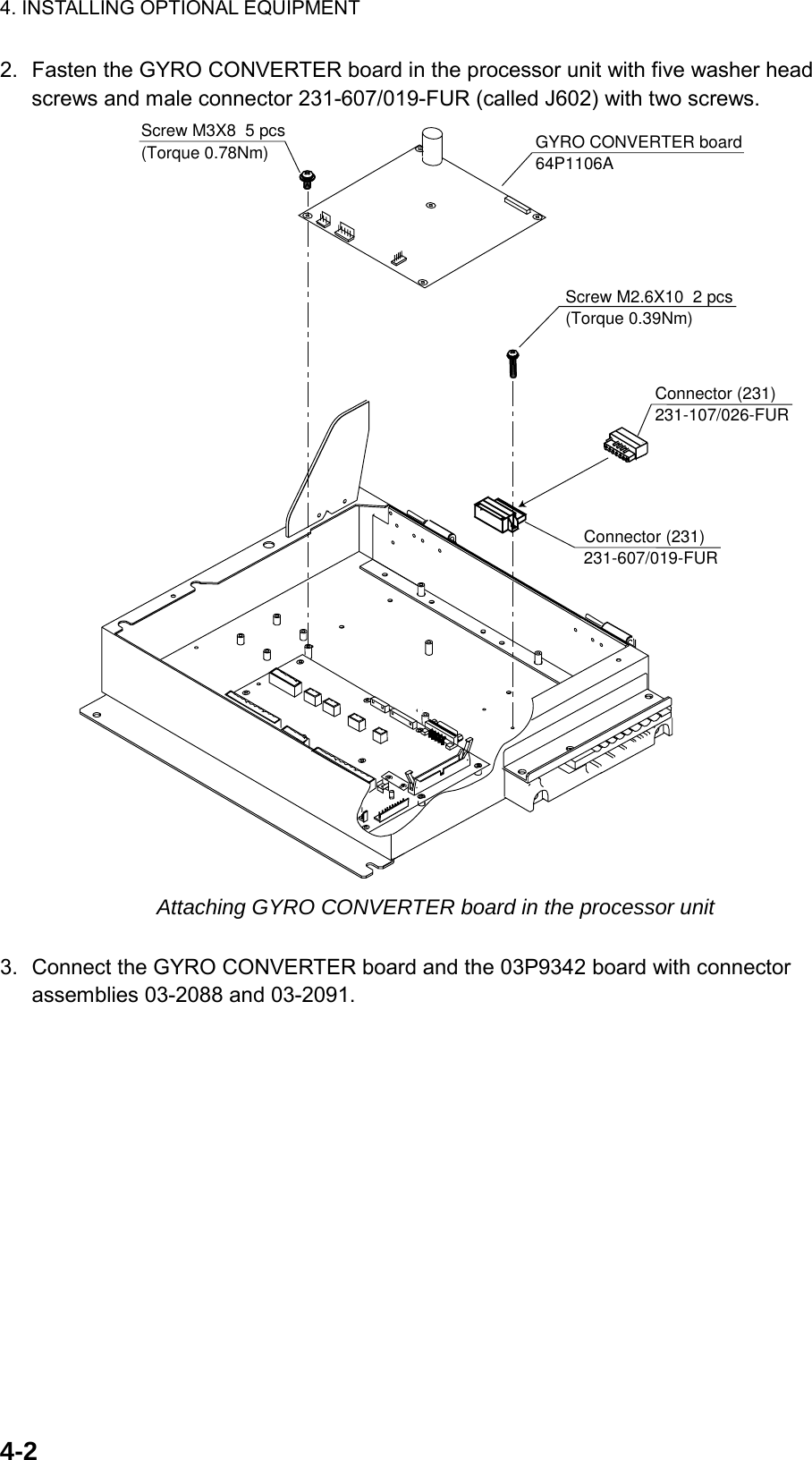
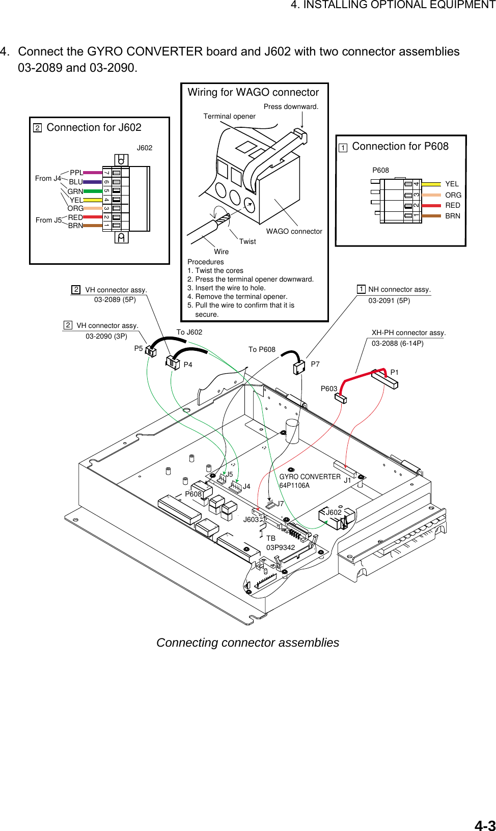
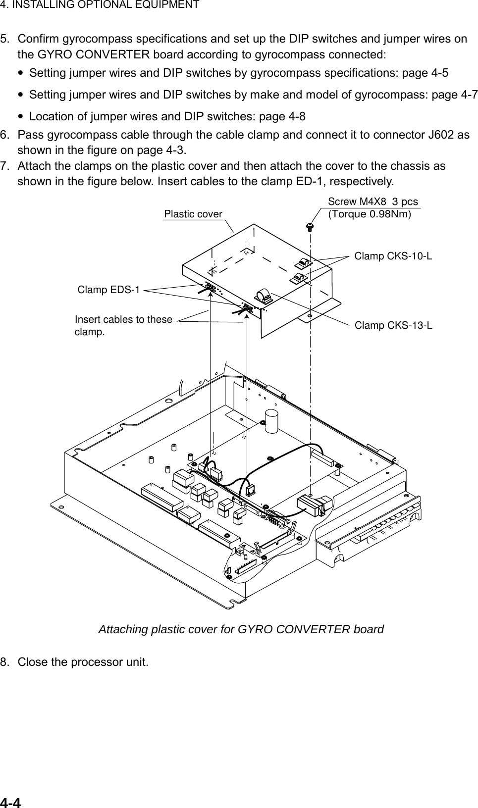
Furuno USA 9ZWRTR081A Marine Radar User Manual inst manual part 1
Furuno USA Inc Marine Radar inst manual part 1
UserManual.wiki
>
Furuno USA
>
9ZWRTR081A User Manual
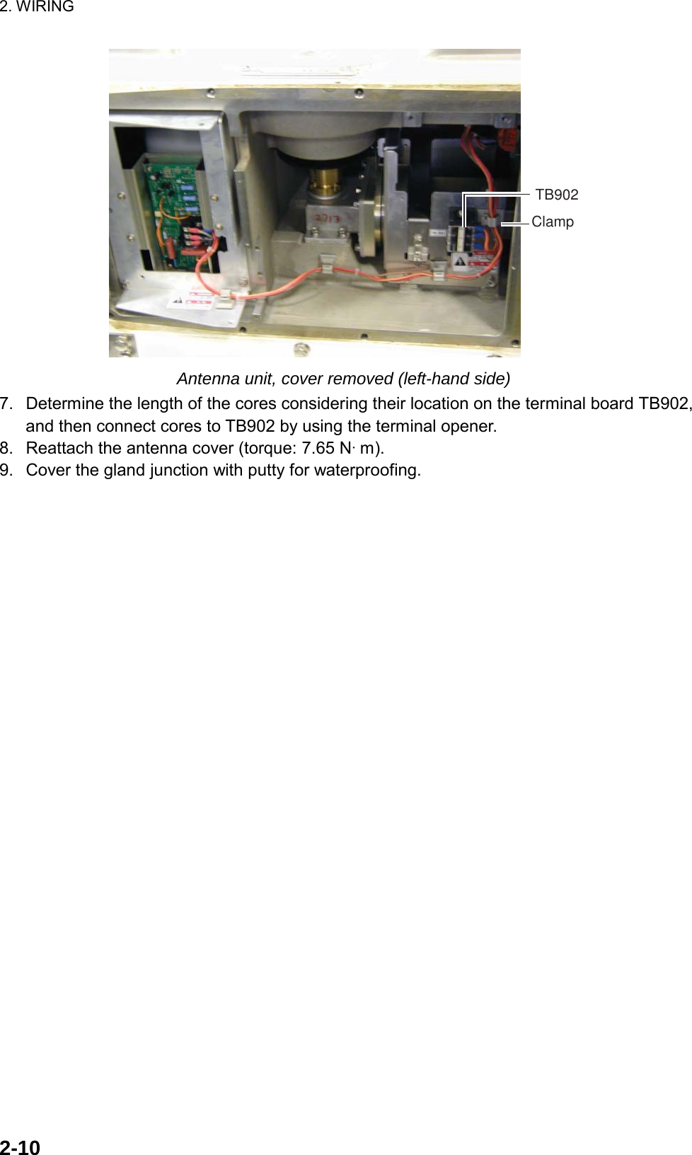
>
inst manual part 1
Contents
1.
op manual
2.
inst manual part 1
inst manual part 1
Navigation menu
Upload a User Manual
Namespaces
Wiki Guide
HTML
PDF
Info
Views
User Manual
Discussion / Help
Navigation


![3. SETTING AND ADJUSTMENT 3-2 [ECHO] 1 BACK 2 2ND ECHO REJ OFF/ON 3 TUNE INITIALIZE 4 PM OFF/ON 5 SART OFF/ON 6 WIPER OFF/1/2 7 ECHO AREA* CIRCLE/WIDE/ALL 8 [PICTURE SELECT] 9 STC RANGE +00 3.2 Initializing Tuning 1. Transmit the radar on 48 nm range and rotate the GAIN knob to show 70-80 of the gain bar. 2. Roll the trackball to choose the MENU box at the right side of the screen and then push the left button. 3. Roll the wheel to choose 1 ECHO and then push the wheel. Bold: Default settings (Same for all menu illustrations) *: non IMO-type only. ECHO menu 4. Roll the wheel to choose 3 TUNE INITIALIZE. 5. Push the wheel to initialize automatic tuning. After a while, echoes appear on the screen. The message “TUNE INITIALIZE” appears in red during automatic tuning. When this message disappears, the tuning is completed. If necessary adjust the GAIN to show echoes clearly. 6. Push the right button twice to close the menu.](https://usermanual.wiki/Furuno-USA/9ZWRTR081A.inst-manual-part-1/User-Guide-1456779-Page-66.png)
![3. SETTING AND ADJUSTMENT 3-43. Read the target bearing. 4. Measure the bearing of the stationary target on the navigation chart and calculate the difference between actual bearing and apparent bearing on the radar screen. 5. Press the [MENU] key to show the main menu. 6. While pressing and holding down the [HL OFF] key, press the [MENU] key five times. 7. Press the [0] key to show the [INITIALIZE] menu. [INITIALIZE]1 BACK2 [ECHO ADJ]3 [SCANNER]4 [INSTALLATION]5 [OWN SHIP INFO]6 [TT PRESET]7 [NETWORK]8 [OTHER]9 [FACTORY] Note: See next page to access the INITIALIZE menu with the trackball style control unit RCU-015. 8. Press the [2] key to open the [ECHO ADJ] menu. [ECHO ADJ]1 BACK2 CABLE ATT ADJ AUTO/MANUAL303 HD ALIGN000.0°4 TIMING ADJ05 MBS06 DEFAULT ANT HEIGHT5/7.5/10/15/20/25/30/35/40/45/more 50 m7 NEAR STC CURVE2/2.5/3/3.5/4.28 MID STC CURVE3/4/5/69 FAR STC CURVE6/7/80 RING SUPPRESSION0 ECHO ADJ menu 9. Press the [3] key to choose the HD ALIGN option. 10. Key in the bearing difference. The setting range is 0 to 359.9°. 11. Confirm that the target echo is displayed at correct bearing on the screen. 12. Press the [MENU] key to finish.](https://usermanual.wiki/Furuno-USA/9ZWRTR081A.inst-manual-part-1/User-Guide-1456779-Page-68.png)
![3. SETTING AND ADJUSTMENT 3-63.4 Adjustment Sweep Timing Sweep timing differs with respect to the length of the signal cable between the antenna unit and the processor unit. Adjust sweep timing at installation to prevent the following symptoms: • The echo of a “straight” target (for example, pier), on the 0.25 m range, will appear on the display as being pulled inward or pushed outward. See Figure below. • The range of target echoes will also be incorrectly shown. (1) Correct (2) Target pushed (3) Target pushed inward outward Examples of correct and incorrect sweep timings 1. Transmit on the 0.25 nm range. 2. Adjust radar picture controls to display picture properly. 3. Select a target echo which should be displayed straightly. 4. Press the [4] key to choose the [TIMING ADJ] on the [ECHO ADJ] menu. [ECHO ADJ]1 BACK2 CABLE ATT ADJ AUTO/MANUAL 303 HD ALIGN000.0°4 TIMING ADJ05 MBS06 DEFAULT ANT HEIGHT5/7.5/10/15/20/25/30/35/40/45/more 50 m7 NEAR STC CURVE2/2.5/3/3.5/4.28 MID STC CURVE3/4/5/69 FAR STC CURVE6/7/80 RING SUPPRESSION0 5. Rotate the wheel to set a suitable value which causes the target to be displayed straightly. The setting range is 0 to 4095. 6. Press the [MENU] key to finish.](https://usermanual.wiki/Furuno-USA/9ZWRTR081A.inst-manual-part-1/User-Guide-1456779-Page-70.png)
![3. SETTING AND ADJUSTMENT 3-73.5 Suppressing Main Bang If main bang appears at the screen center, suppress it as follows. 1. Transmit the radar on a long range and then wait ten minutes. 2. Adjust gain to show a slight amount of noise on the display. 3. Select the 0.25 nm range. Adjust sea clutter control to suppress sea clutter. 4. Press [5] key to choose the MBS on the [ECHO ADJ] menu. [ECHO ADJ]1 BACK2 CABLE ATT ADJ AUTO/MANUAL303 HD ALIGN000.0°4 TIMING ADJ 05 MBS 06 DEFAULT ANT HEIGHT5/7.5/10/15/20/25/30/35/40/45/more 50 m7 NEAR STC CURVE2/2.5/3/3.5/4.28 MID STC CURVE3/4/5/69 FAR STC CURVE6/7/80 RING SUPPSSION0 5. Rotate the wheel to set a suitable value so that the main bang disappears. The setting range is 0 to 255. 6. Press the [MENU] key to finish.](https://usermanual.wiki/Furuno-USA/9ZWRTR081A.inst-manual-part-1/User-Guide-1456779-Page-71.png)
![3. SETTING AND ADJUSTMENT 3-83.6 Other Settings ECHO menu setting Open the ECHO ADJ menu as described on page 3-3 and 3-4. [ECHO ADJ]1 BACK2 CABLE ATT ADJ AUTO/MANUAL303 HD ALIGN000.0°4 TIMING ADJ05 MBS06 DEFAULT ANT HEIGHT5/7.5/10/15/20/25/30/35/40/45/more 50 m7 NEAR STC CURVE2/2.5/3/3.5/4.28 MID STC CURVE3/4/5/69 FAR STC CURVE6/7/80 RING SUPPRESSION0 To close the menu, press the [MENU] key. CABLE ATT ADJ Before adjusting, set the radar as follows: IR: 2, ES: off, EAV: off, 24nm range, long pulse (Same as default setting of PICTURE1) To adjust the cable attenuation manually, choose MANUAL by pressing [2] and the [ENTER] key, and then rotate the wheel so that noise just appears on the screen when the gain is set to 80. Default setting is 30 for the antenna cable length of 15m. The setting range is 0 to 73. To adjust automatically, choose AUTO and press the [ENTER] key. The message “CABLE ATT ADJ” appears in red at the bottom of the screen. It takes about five minutes to complete the adjustment, after which the radar goes into stand-by. DEFAULT ANT HEIGHT Select height (m) of the radar antenna unit from the sea surface among 5, 7.5, 10, 15, 20, 25, 30, 35, 40, 45 and “more 50 m”. NEAR STC CURVE, MID STC CURVE AND FAR STC CURVE Use the default setting. Change the setting if desired according to sea condition. RING SUPPRESSION This is mainly used to removes “ring” noise which appears in the waveguide-type radar. Adjust so the rings disappear at the range of 0.125 nm. The setting range is 0 to 255.](https://usermanual.wiki/Furuno-USA/9ZWRTR081A.inst-manual-part-1/User-Guide-1456779-Page-72.png)
![3. SETTING AND ADJUSTMENT 3-9Scanner setting 1. Open the INITIALIZE menu described on page 3-2. 2. Press [3] key to open the SCANNER menu. [SCANNER]1 BACK2 BLIND SECTOR 1START 000°ANGLE 000°3 BLIND SECTOR 2START 000°ANGLE 000°4 ANT REVOLUTIONLO/HI/AUTO5 ANT SWOFF/ON/EXT6 ANT STOPPEDSTBY/TX7 M SPEC OFF/ON8 BB TYPE NORMAL/BB9 [DUAL RADAR]*Note 1: Set the blind sector as minimum as possible.Note 2: Do not set the blind sector in the bow direction.*non IMO-type only To close the menu, press the [MENU] key. BLIND SECTOR 1 and BLIND SECTOR 2 Set area (up to 2) where no radar pulses will be transmitted, and heading should be adjusted before setting any blind sector. For example, set the area where an interfering object at the rear of the scanner would produce a dead sector (area where no echoes appear) on the display. To enter an area, enter start bearing relative the heading and dead sector angle. To erase the area, enter 0 for both the START and ANGLE sections. The setting range of START is 0 to 359° and ANGLE is 0 to 180°. ANT REVOLUTION This menu item is used for 42 rpm antenna unit. The default is AUTO, where antenna revolution speed is high for short range setting and low speed for long range setting. When LO is selected, the antenna always rotate in 36 rpm, and HI, 42 rpm. ANT SW and ANT STOPPED This is used for antenna maintenance by serviceman. Note: Choose OFF at ANT SW to prevent the antenna rotation. As for ANT STOPPED, choose STBY to prevent transmission while the antenna is stopped. M SPEC and BB TYPE Not used. DUAL RADAR See section 3.7.](https://usermanual.wiki/Furuno-USA/9ZWRTR081A.inst-manual-part-1/User-Guide-1456779-Page-73.png)
![3. SETTING AND ADJUSTMENT 3-10INSTALLATION menu setting Open the INSTALLATION menu by pressing [4] key on the INITIALIZE menu. [INSTALLATION]1 BACK2 RADAR*MAIN/SUB3 RANGE UNIT **NM/SM/km/kyd4 RADAR NO***1/2/3/4/5/6/7/85 RADAR POSNFORE/MAIN TOP/MAIN 2ND/MAIN 3RD/AFT/PORT/STAR BOARD6 MODEL6/12/25 UP/25 DOWN/50/30 UP/30 DOWN/607 TYPEIMO/A/B/C/W8 ON TIMEXXXXXXX.X H9 TX TIMEXXXXXXX.X H0 PM GAIN ADJ0**: non IMO-type only.***: No.1-4: with antenna unitNo.5-8: without antenna unit*: Cannot be selected. RADAR Choose main radar or sub radar. RANGE UNIT Choose NM, SM, km or kyd (kilo yard) as appropriate, however-IMO type radar is “NM” only. RADAR NO and RADAR POSN For multiple radar system using the network hub, set number (name) and antenna position for each system to easily distinguish the radar configuration. MODEL Confirm the model of your radar. If the setting of this item is different from your model (combination of the antenna unit), the radar functions abnormally. 25 DOWN: for FAR-2827W 30 DOWN: for FAR-2837SW TYPE Choose type of radar: IMO, A, B, C, or W.](https://usermanual.wiki/Furuno-USA/9ZWRTR081A.inst-manual-part-1/User-Guide-1456779-Page-74.png)
![3. SETTING AND ADJUSTMENT 3-12OWN SHIP INFO menu setting Open the OWN SHIP INFO menu by pressing the [5] key on the INITIALIZE menu. [OWN SHIP INFO]1 BACK2 LENGTH/WIDTHLENGTH 100 mWIDTH 50 m3 SCANNER POSNBOW 0 mPORT 0 m4 GPS1 ANT POSNBOW 0 mPORT 0 m5 GPS2 ANT POSNBOW 0 mPORT 0 m6 CONNING POSN BOW 0 m PORT 0 m LENGTH/WIDTH and SCANNER POSN To inscribe own ship shape on the screen when you choose it on the menu, enter length and width of the ship and antenna position from the bow and left sides. The setting ranges are as follows. LENGTH: 0 to 999 m WIDTH: 0 to 999 m BOW: 0 to 999 m LEFT: 0 to 999 m GPS 1 ANT POSN and GPS 2 ANT POSN These items are needed for AIS information. Enter the GPS antenna position from the bow and left sides. The setting ranges are the same as above. CONNING POSN Enter the conning position in the wheelhouse, from the bow and left sides. The setting ranges are the same as above. When you set the display reference point to the conning position, these values are used to correct the radar antenna position. Note: If two or more radars are installed, items other than 3 SCANNER should be the same on each radar.](https://usermanual.wiki/Furuno-USA/9ZWRTR081A.inst-manual-part-1/User-Guide-1456779-Page-76.png)
![3. SETTING AND ADJUSTMENT 3-13TT PRESET menu setting Open the TT PRESET menu by pressing [6] key on the INITIALIZE menu. [TT PRESET]1 BACK2 TT DATA OUTPUTOFF/TTM/TTDREL/TRUE4800/9600/19200/384003 MAX RANGE24/324 ECHO LEVEL165 QV DISPLAYOFF/ON6 TT W/O GYRO*OFF/ON7 [TT PRESET]8 [TRACK PRESET]9 [TT SENSOR DATA]0 DEFAULT1 BACK2 LAND SIZE1600 M3 ANT SELECT XN12AF/XN20AF/ XN24AF/XN4A/XN5A SN30AF/SN36AF/SN4A/SN5A4 AUTO ACQ CORRE5 SCAN5 AUTO ACQ WEED1 SCAN6 [TT DETAIL DATA]1 BACK2 GATE SIZES/ M /L/LL3 FILTER RESPONSE1/ 2 /3/44 LOST COUNT9 SCAN5 MAX SPEED100 KTS6 TRACKING MODE1 /2/3/47 START TIME TGT VECTTIME /SCAN50 SEC20 SCAN[TT PRESET][TRACK PRESET] *: Not on IMO radar TT DATA OUTPUT Set the output format from J691 port (sentence, bearing and baud rate) of tracked targets. Sentence: (OFF: No output, TTM: Tracked target information, TTD: Tracked target data) Bearing: REL: Target bearing from own ship, degree relative, target course, degree relative. TRUE: Target bearing, degree true, target course, degree true. Baud rate: (4800, 9600, 19200 or 38400 bps) NOTE: The TT OUTPUT port changes according to the setting for INS as described on page 3-15. INS-OFF: Output from J619 port only INS-SERIAL: Output from J619 and J620 (TTM only) ports INS-LAN: Output from J619 and NETWORK (TTM only) ports MAX RANGE Choose the target tracking range, 24 or 32 nm. ECHO LEVEL Set the detection level of echoes. The setting range is 1 to 31. QV DISPLAY OFF: Normal picture ON: Quantized picture; always off at power on](https://usermanual.wiki/Furuno-USA/9ZWRTR081A.inst-manual-part-1/User-Guide-1456779-Page-77.png)
![3. SETTING AND ADJUSTMENT 3-15OTHER menu setting Open the OTHER menu by pressing [8] key on the INITIALIZE menu. [OTHERS]1BACK2 DEMO ECHOOFF/EG/TT-TEST/PC3 EAV W/O GYROOFF/ON4 TT CATEGORY SELECTCAT1/CAT2 35INSOFF/SERIAL/LAN EAV w/o GYRO If a gyrocompass is not connected, choose the echo average function, ON (working) or OFF (no working). TT CATEGORY SELECT Choose CAT1 or CAT2•3 depending on your ship’s size. CAT1: All ships over than 10,000 GT CAT2: All ships between 500 and 10,000 GT CAT3: All ships less than 500 GT INS Choose appropriate item according to the ECDIS connected. OFF: No connection SERIAL: When connecting FEA-2105 series ECDIS. LAN: When connecting FEA-2107 series ECDIS.](https://usermanual.wiki/Furuno-USA/9ZWRTR081A.inst-manual-part-1/User-Guide-1456779-Page-79.png)
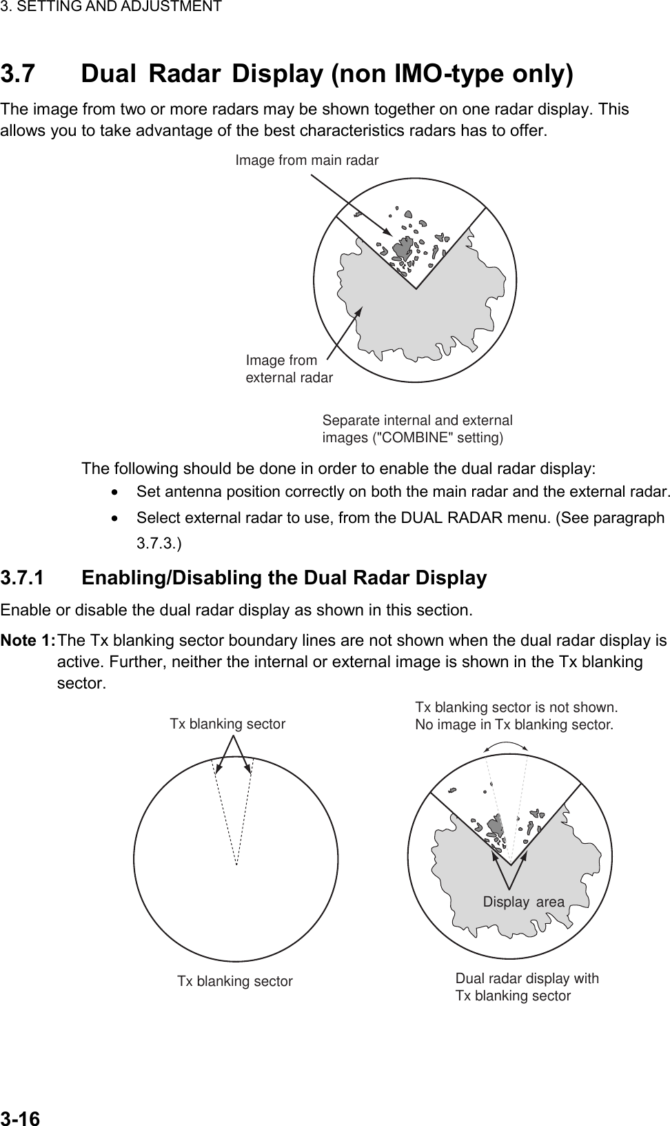
![3. SETTING AND ADJUSTMENT 3-17Note 2: In the dual radar display, a guard zone set on the main radar is also accommodated on the external radar. When the position of the antennas for the main and external radars is different and the No. 2 guard zone is set on a close-in range, the on-screen guard zone may be shifted slightly from both the main radar antenna reference and external radar antenna reference. Accordingly, on the dual radar display, the actual guard zone area may be shifted slightly. For example, the guard alarm sounds against a target which has almost entered the guard zone. The further the range the smaller the shift; however, there is little shift with the No.1 guard zone (3-6 mile range, fixed). Further, do not set a guard zone such that it straddles a boundary line of the dual radar sector. A guard zone cannot be set while the dual radar display is active. Set a zone before activating the dual radar display. 1. Open the INITIALIZE menu. See page 3-4. 2. Press the [3] key to show the SCANNER menu. 3. Select 9 [DUAL RADAR] and push the left button. 1BACK2 DUAL RADAROFF/ COMBINE3 COMBINE MODEOWN/EXT4 COMBINE SECTORSTART 000°ANGLE 000°5 COMBINE RANGESTART 00.00NMLENGTH 00.00NM6 EXT RADAR1/2/3/4[DUAL RADAR] 4. Select 2 [DUAL RADAR] and push the left button. 5. Select OFF or COMBINE as appropriate and push the left button. For COMBINE, the ANTENNA box at the top left-hand side becomes gray. OFF: Turn off the dual radar display. COMBINE: Display a part of the external radar image in the window on the main radar.](https://usermanual.wiki/Furuno-USA/9ZWRTR081A.inst-manual-part-1/User-Guide-1456779-Page-81.png)
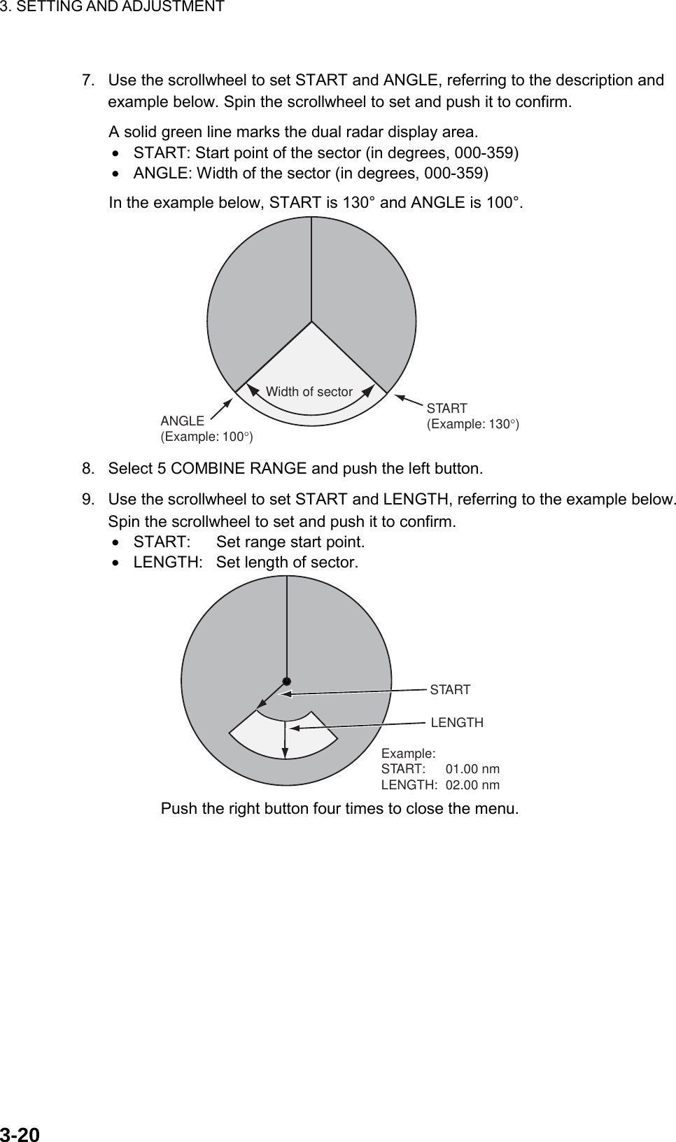
![3. SETTING AND ADJUSTMENT 3-193.7.2 Specifying Sector Width and Length When 2 DUAL RADAR in the DUAL RADAR menu is set for "COMBINE", specify the width and length of the sector from the external radar to display on own radar. 1. Open the INITIALIZE menu. 2. Press the [3] key to show the SCANNER menu. 3. Select 9 [DUAL RADAR] and push the left button. 4. Select 3 COMBINE MODE and push the left button. 5. Select OWN or EXT and push the left button. OWN: Set own radar’s antenna as reference point and set display area of own radar. The area outside that set here is where the image from the external radar will be displayed. EXT: Set external radar’s antenna as reference point and set display area of external radar. The area outside that set here is where the image from own radar will be displayed. Picture fromexternal radarPosition of antennafor external radarPosition of antennafor own radarPicture fromown radar Radar selected for COMBINE: OwnSTART: 45 degreesANGLE: 270 degreesSTART: 00.00 nmLENGTH: 99.99 nmRadar selected for COMBINE: ExternalSTART: 315 degreesANGLE: 90 degreesSTART: 00.00 nmLENGTH: 99.99 nm 6. Select 4 COMBINE SECTOR and push the left button.](https://usermanual.wiki/Furuno-USA/9ZWRTR081A.inst-manual-part-1/User-Guide-1456779-Page-83.png)
![3. SETTING AND ADJUSTMENT 3-213.7.3 Choosing External Radar (image source) Select the external radar to use in the dual radar display. 1. Open the INITIALIZE menu. 2. Press the [3] key to show the SCANNER menu. 3. Select 9 [DUAL RADAR] and push the left button. 1BACK2 DUAL RADAROFF/ COMBINE3 COMBINE MODEOWN/EXT4 COMBINE SECTORSTART 000°ANGLE 000°5 COMBINE RANGESTART 00.00NMLENGTH 00.00NM6 EXT RADAR1/2/3/4[DUAL RADAR] 4. Select 6 EXT RADAR and push the left button. 5. Select desired radar no. and push the left button. Only the numbers of connected radars are valid. Radar no. is set on the Installation Setting menu. 6. Press the [MENU] key to close the menu.](https://usermanual.wiki/Furuno-USA/9ZWRTR081A.inst-manual-part-1/User-Guide-1456779-Page-85.png)

![4. INSTALLING OPTIONAL EQUIPMENT 4-5Connection of external power supply An external power supply is necessary when the repeater signal is step-by-step type and the step voltage is below 20 V or output voltage is less than 5 W. 1. Cut jumper wire JP1 on the GYRO CONVERTER board when an external power supply is used. 2. Connect gyro cable and power cable as shown below. GYRO CONVERTER board[A] 64P11061 > R2Either connectionin case of DCpolarity.J52 > R1/COMExternal Power Supply20 - 135 VAC20 - 100 VDC1 > S12 > S23 > S34 > T5 > F.G.Gyrocompass(Step type)S1S2S3COMF.G.J4 Connection of external power supply to GYRO CONVERTER board DIP switch, jumper wire settings Default setting The gyro converter GC-10 is set at the factory for connection with the gyrocompass specifications below. AC synchronous signal: 50/60 Hz Rotor voltage: 60 V to 135 V AC Stator voltage: 60 V to 135 V AC Gear ratio: 360x Supply voltage: 30 V to 135 V AC If the specifications of the gyrocompass differ from those mentioned above, change jumper wire and DIP switch settings on the GYRO CONVERTER board. Settings may be changed according to gyrocompass specifications (see page 4-6) or make and model of gyrocompass (see page 4-7). For the location of DIP switches and jumper wires, see page 4-8. Note: If you change the setting with power supplied, set #8 of SW2 from OFF to ON, then OFF again.](https://usermanual.wiki/Furuno-USA/9ZWRTR081A.inst-manual-part-1/User-Guide-1456779-Page-91.png)
![4. INSTALLING OPTIONAL EQUIPMENT 4-8Location of DIP switches, jumper wires on the GYRO CONVERTER board 64P1106JP5, JP4(Supply voltage)JP2(Rotor voltage)JP3(Stator voltage)JP1(Gyro type)Fuse(2A)J5(Rotor signal input,external power input)J4(Stator signal input)SW1DIP switchJ6(IEC-61162-1 output port) J7(Data output port #1)J8(Data output port #2)J9(Data output port #3)JP6, JP7(AD formatdata Tx interval)SW2DIP switchJ10 (Data output port #4)J11(Data output port #5)J12(Data outputport #6)SW3DIP switch GYRO CONVERTER board Setting the heading readout on the radar display Confirm that the gyrocompass is giving a reliable readout. Then, set the heading readout on the radar display with the gyrocompass readout as follows: 1. Roll the trackball to place the arrow in the HDG box at the top right corner of the screen. 2. Push the right button on the trackball module to open the HDG menu. [HDG MENU]1 HDG SOURCEAD-10/SERIAL2 GC-10 SETTING000.0 HDG menu 3. Press the [1] key to choose the HDG SOURCE and choose AD-10. 4. Press the [2] key to choose the GC-10 SETTING option. 5. Roll the wheel to set gyrocompass reading. 6. Press the [MENU] key to close the menu.](https://usermanual.wiki/Furuno-USA/9ZWRTR081A.inst-manual-part-1/User-Guide-1456779-Page-94.png)
![4. INSTALLING OPTIONAL EQUIPMENT 4-19RED[B]GRN[B]WHTBLKGRNREDWHT[B]PPL[B]COAXGLY[B]BLU[B]YEL[B]ORG[B]BRNRG-12/UYTTYCY-4DPYCY-6N.C.N.C.N.C.03P9349TB8021221314345678910111TB801GNDSIG-GND12BoxJunctionTransceiver unitGNDIF_VIDEO_INRF_SPU_D_BRF_SPU_D_ASPU_RF_D_BSPU_RF_D_AMOTOR(-)MOTOR(-)MOTOR(+)MOTOR(+)24V_MINUS24V_PLUSN.C.TX-HVRED[B]GRN[B]WHTBLKGRNREDWHT[B]PPL[B]GLY[B]BLU[B]YEL[B]ORG[B]BRNN.C.N.C.N.C.03P9342J610GNDSIG-GND12234567891011121J613BoxJunction Processor unitGNDIF_VIDEORF_SPU_D_BRF_SPU_D_ASPU_RF_D_BSPU_RF_D_AMOTOR(-)MOTOR(-)MOTOR(+)MOTOR(+)24V_MINUS24V_PLUSN.C.TX-HV131415RW-9600123456789101112131415123456789101112131415N.C.DPYCY-6DPYCY-61212RED[B]GRN[B]WHTBLKGRNREDWHT[B]PPL[B]COAXGLY[B]BLU[B]YEL[B]ORG[B]BRNRG-12/UYTTYCY-4N.C.N.C.N.C.03P9349TB8021221314345678910111TB801GNDSIG-GND12BoxJunctionTransceiver unitGNDIF_VIDEO_INRF_SPU_D_BRF_SPU_D_ASPU_RF_D_BSPU_RF_D_AMOTOR(-)MOTOR(-)MOTOR(+)MOTOR(+)24V_MINUS24V_PLUSN.C.TX-HVRED[B]GRN[B]WHTBLKGRNREDWHT[B]PPL[B]GLY[B]BLU[B]YEL[B]ORG[B]BRNN.C.N.C.N.C.03P9342J610GNDSIG-GND12234567891011121J613BoxJunction Processor unitGNDIF_VIDEORF_SPU_D_BRF_SPU_D_ASPU_RF_D_BSPU_RF_D_AMOTOR(-)MOTOR(-)MOTOR(+)MOTOR(+)24V_MINUS24V_PLUSN.C.TX-HV131415RW-9600123456789101112131415123456789101112131415N.C.DPYCY-61212Clamp with cable gland.IV-1.25IV-1.25Clamp with cable gland.FR-2827WFR-2837SWPPPPDPYCY-6 Interconnection for FAR-2827W/2837SW](https://usermanual.wiki/Furuno-USA/9ZWRTR081A.inst-manual-part-1/User-Guide-1456779-Page-105.png)

![%1&'016;2'⇛ޓޓ࿑176.+0'ฬޓޓ⒓0#/'ᢙ㊂36;↪ㅜ㧛⠨4'/#4-5⇟ภ01ဳฬ㧛ⷙᩰ&'5%4+26+105+056#..#6+10/#6'4+#.5Ꮏ᧚ᢱ%3:50#(#(#(/5##(#(㩕㩩㩧)7+&'2+0 41*5 %1&'011㩢㩧㩂㩨14+0) ,$#) %1&'01㩚㩀㩨㩁ᐔᐳ㊄(.#69#5*'4 /575 %1&'01㩔㩨㩒ᐳ㊄524+0)9#5*'4 /575ޓ %1&'01ⷺ㩘㩨㩣㩎*':$1.6 /:575 %1&'01㩃㩚㩆㨺㩣5+.+%1047$$'4 59㨻㩣㩚㩋㨷㨺㩖㩨) %1&'01㧔⇛࿑ߩኸᴺߪޔෳ⠨୯ߢߔޕޓ&+/'05+105+0&4#9+0)(144'('4'0%'10.;㧕㧲㨁㧾㨁㧺㧻ޓ㧱㧸㧱㧯㨀㧾㧵㧯ޓ㧯㧻ޓ㧚㧘㧸㨀㧰%3:ဳᑼ㩄㨺㩎㩨⇟ภ߇㧞Ბߩ႐วޔਅᲑࠃࠅᲑߦઍࠊࠆㆊᷰᦼຠߢࠅޔߤߜࠄ߆߇ߞߡ߹ߔޕޓߥ߅ޔຠ⾰ߪᄌࠊࠅ߹ߖࠎޕ6916;2'5#0&%1&'5/#;$'.+56'&(14#0+6'/6*'.19'4241&7%6/#;$'5*+22'&+02.#%'1(6*'722'4241&7%637#.+6;+56*'5#/'008-254-590A-16PACKING LISTPACKING LISTPACKING LISTPACKING LIST03FT-X-9851 -0 SN30AF/SN36AFSN30AF/SN36AFSN30AF/SN36AFSN30AF/SN36AFN A M EO U T L I N EDESCRIPTION/CODE №Q'TY1/1ユニットユニットユニットユニット UNITUNITUNITUNITアンテナ組品ANTENNASN30AF008-505-9501**アンテナ工材アンテナ工材アンテナ工材アンテナ工材 ANTENNA INSTALLATION MATERIALSANTENNA INSTALLATION MATERIALSANTENNA INSTALLATION MATERIALSANTENNA INSTALLATION MATERIALS工事材料INSTALLATION MATERIALSSN5AF/7AF/30AF/36AF008-254-59011.䍘-䍢䍼⇟ภᧃየ䈱[**]䈲䇮ㆬᛯຠ䈱ઍဳᑼ/䍘䍎䍢䍼䉕䈚䉁䈜䇯CODE NUMBER ENDED BY "**" INDICATES THE NUMBER OF TYPICAL MATERIAL.(略図の寸法は、参考値です。 DIMENSIONS IN DRAWING FOR REFERENCE ONLY.)(略図の寸法は、参考値です。 DIMENSIONS IN DRAWING FOR REFERENCE ONLY.)(略図の寸法は、参考値です。 DIMENSIONS IN DRAWING FOR REFERENCE ONLY.)(略図の寸法は、参考値です。 DIMENSIONS IN DRAWING FOR REFERENCE ONLY.)03FT-X-9851A-15](https://usermanual.wiki/Furuno-USA/9ZWRTR081A.inst-manual-part-1/User-Guide-1456779-Page-116.png)
![12 4356ABCDMASSSCALEDWG.No.APPROVEDCHECKEDDRAWNkg名称TYPENAMEMARINE RADAR/ARPA相互結線図INTERCONNECTION DIAGRAM船舶用レーダー/ARPAFAR-2827WREF.No.C3527-C01- MT.YAMASAKI25/Sep/0803-163-6003-3注記 NOTES*4: USE 3A BREAKER IN SHIP'S MAINS SWITCH BOX.*5: USE GRN/YEL WIRE FOR PROTECTIVE EARTH.*1: SHIPYARD SUPPLY*2: OPTION*3: MAX. 100m. (JUNCTION BOX RJB-001 IS REQUIRED FOR EXTENSION.)*6: FOR RUSSIAN FLAG VESSELS ONLY.*7: ブレーキユニットの接続はいずれかを選択。*1: 造船所手配*2: オプション*3: 最長 100m (延長するときは接続箱RJB-001が必要 )。*4: 船内配電盤では3Aのブレーカを使用。*5: 保護アース用ケーブルは緑/黄の絶縁線を使用のこと。*6: ロシア型検仕様のみ。*7: SELECT 1 OR 2 FOR CONNECTION OF BREAK UNIT.25/Sep/08 T.TAKENO03P9229ARGB バッファ 基板RGB BUFFER PCBJ615J3J4SLB-FRN4-ADVI-RGB CONVERSION BOARDDVI-RGB変換基板PP*1 J9VGA CABLE J2*2DVI-RGB-1RGBビデオコンバータJ1 J3J603(XH)J5(VH)03-2090(3P)J4(VH)03-2089(5P)BOARDGYRO CONVERTER64P1106A *2J1J7(NH) 03-2091(5P) J608J609J610J613-12Vミドリ GRN 5GNDキ YEL 4+5Vダイ ORG 3GNDアカ RED 2+12Vチャ BRN 1-5/-12VGNDVCC321NCNCGNDGND+12V+12V365421151413121110987654321NCY_SYNCH_SYNCNCGNDGNDNCGNDGNDGNDNCNCB_VIDEOG_VIDEOR_VIDEO-5/-12VGNDVCCGNDV_SYNCGNDH_SYNCGNDB_VIDEOGNDG_VIDEOGNDR_VIDEO13121110987654321GNDVSGNDHSGNDBGNDGRGND21431098765212324TB BOARD03P934212111094365211413NC3GYRO_R12GYRO_R21GYRO_FG5GYRO_T4GYRO_S33GYRO_S22GYRO_S11FGSHIFT1-CSHIFT1-HDATA1-CDATA1-H 15YELキ4ORGダイ3アカ RED2BRNチャ4321IF_VIDEOGNDSGMOTOR(-)MOTOR(-)MOTOR(+)MOTOR(+)24V_MINUS24V_PLUS12111098765432121J602109876543GND+12VGNDPWR_SW21KEY_TXD-BKEY_TXD-AKEY_RXD-BKEY_RXD-ASYS_FAIL-HSYS_FAIL-CSYS_ACK-CSYS_ACK-HJ622 12AD_DATA-HAD_DATA-CAD_CLK-HAD_CLK-CRF_SPU_D-BRF_SPU_D-ASPU_RF_D-BSPU_RF_D-AGC_5VGC_0VGC_DOWNGC_UPGC_HOLDGC_LED03-2088(6-14P)NCTX_HVPJ605J601RS-232CHDG_GND 321NC 9NC 8NC 7NC 64GNDNC5TXD 3NC 1RXD 2HDG-BHDG-APJ606NC 321NAV-BNAV-APJ607NC 321LOG-BLOG-AJ620GND 54321TRK_RD-BTRK_RD-ATRK_TD-BTRK_TD-A PPJ619NC 321ARPA-BARPA-APPPJ611AIS_GND 54321AIS_RD-BAIS_RD-AAIS_TD-BAIS_TD-AJ617(NH)J616(NH)J618(NH)PPPPPPJ61287654321OP_VIDEO_1GNDOP_TRIG_1GNDOP_BP_1GNDOP_HD_1GNDOP_VIDEO_INGNDOP_TRIG_INGNDOP_BP_INGNDOP_HD_INGND8765432187654321OP_VIDEO_2GNDOP_TRIG_2GNDOP_BP_2GNDOP_HD_2GNDOPERATOR_FITNESS_1OPERATOR_FITNESS_0GNDEXT_ALM_ACK_NALARM3_1ALARM3_0ALARM2_1ALARM2_0ALARM1_1ALARM1_0121110987654321SYS_FAIL-HSYS_FAIL-C(IEC-61162-2)HDG SENSOR*1RS-232C CABLE PC(IEC-61162-1)NAVIGATOR(IEC-61162-1)SPEED LOG(IEC-61162-1)TRACK_CONTROL(IEC-61162-1)ECDIS(IEC-61162-2)AISALARM SYSTEM*1TTYCS-1Q*1TTYCS-1*1TTYCS-1*1*1TTYCS-1TTYCS-4*1TTYCS-4*1TTYCS-7RW-4864,φ9.5RW-4864,φ9.5RW-4864,φ9.5(FULL-LOG)SUB DISPLAY1MASTER RADAR(SEMI-LOG)SUB DISPLAY2IV-8sq.保護アースPE *1 *5ムラサキアオミドリキダイアカチャPPLBLUGRNYELORGREDBRN76543211413IF_VIDEOGNDSG24V_MINUS24V_PLUSNCTX_HV121110987654321RF_SPU_D-BRF_SPU_D-ASPU_RF_D-BSPU_RF_D-AWHTGRN[B]RED[B]BLKGRNREDWHT[B]PPL[B]GRY[B]BLU[B]YEL[B]ORG[B]BRNチャダイ(太)キ(太)アオ(太)ハイ(太)ムラサキ(太)シロ(太)アカミドリクロシロミドリ(太)アカ(太)1110987654321TB803+12VNCHDBP-12VPM-TRIGPM-LEVELPM-ENABLGNDGNDTB801TB802GNDGND3211110987654321+12VNCHDBP-12VPM-TRIGPM-LEVELPM-ENABLGNDGNDNCTB803MOTOR(+)MOTOR(+)MOTOR(-)MOTOR(-)TB804 TB801MOTOR-HMOTOR-HMOTOR-CMOTOR-CPERFORMANCE MONITORパフォーマンスモニターPM-315678BNCコネクタコンバータCONVERTER *2BNC CONNECTORCOAX.(75Ω)x5VDR*1DSUB-BNC-1MPYC-7*1TTYCS-4*1GYROCOMPASSRGB EXT. MONITORA-D CONVERTER2.3/10/20/30m,φ9XH10P-W-6P1.5/10/20/30m,φ9XH10P-W-5P-ANCNC 109876543GND+12VGNDPWR_SW21109876543GND+12VGNDPWR_SW21操作部CONTROL UNITRCU-014/015KEY_TXD-BKEY_TXD-AKEY_RXD-BKEY_RXD-ASYS_FAIL-HSYS_FAIL-CKEY_TXD-BKEY_TXD-AKEY_RXD-BKEY_RXD-A1234SYS_ACK-CSYS_ACK-HSYS_FAIL-CSYS_FAIL-HJ502/J522J501/J521J507/J527J501NCNC109876543GND+12VGNDPWR_SW21KEY_RXD-AKEY_RXD-BKEY_TXD-AKEY_TXD-BRCU-016CONTROL UNIT*2操作部*1TX-STCANTENNA UNIT空中線部IV-3.5sq.PE保護アース*1 *5*4氷結防止用FOR DE-ICER*1DPYC-1.5DPYCY-1.5 *1*2RU-330550-60Hz100VAC,1φ,220/230VAC,110/115/1φ,50-60HzNC321100VAC-C100VAC-HTB901RSB-103RW-4747FR-9-20/30/5020/30/50mRW-9600 MPYCY-19MAX.30m15/30/40/50m,φ22*3RGB VIDEO CONVERTERJ602送受信部RTR-081AUNITTRANSCEIVERJ614GND+12V2121345610J6521021345656412303P9339 PWR PCBJ10521MOTOR_DOMOTOR_CBRCJ66203P9485DVI-DMONITORDVI-DMONITORSAMEASAVOBE2421J205242322212019181716151413121110987654321J204DVI0TXC_NDVI0TXC_PA_GNDNCNCA_GNDDVI0TXD_PDVI0TXD_NNCGNDVCCNCNCA_GNDDVI0TX1_PDVI0TX1_NNCNCNCNCNCA_GNDDVI0TX2_PDVI0TX2_N5/10m,φ7J3242322212019181716151413121110987654321TMDS_CLOCK(-)TMDS_CLOCK(+)TMDS_CLOCK_SHIELDNCNCTMDS_DATA0/5_SHIELDTMDS_DATAB(+)TMDS_DATAB(-)HOT_PLUG_DETECTGND+5V_POWERNCNCTMDS_DATA1/3_SHIELDTMDS_DATA(+)TMDS_DATA(-)NCDDC_DATADDC_CLOCKNCNCTMDS_DATA2/4_SHIELDTMDS_DATA2(+)TMDS_DATA2(-)外部モニター *2DVI CABLEEXT. MONITORPROCESSOR UNITRPU-013制御部DVI-D/D SINGLELINK 5M/10MNETWORKLANNCNCRXNNCNCRXPTXNTXP87654321*2MEMORY CARD I/F UNITPP*1IV-1.25sq.MPS588-CCU-200シロクロWHTBLK321NCNCRXNNCNCRXPTXNTXP87654321+12VGNDFGJ1J302MJ-A3SPFP5E-4PTX-BL,10m,φ6.3防水型カードインターフェイスMJ-A3SPF0015-100C,10m,φ6HUB-100 (8 PORTS)1φ,50/60Hz100-230VAC*1PPLAN CABLE(CAT5) ORFR-FTPC-CY,10/20/30m,φ13MPS588-CSWITCHING HUB *2スイッチング ハブチャBRNシロ/チャWHT/BRNダイORGシロ/アオWHT/BLUアオBLUシロ/ダイWHT/ORGミドリGRNシロ/ミドリWHT/GRNGNDACAC321NCNCRXNNCNCRXPTXNTXP87654321NR203PF-VVS1.253.5m, φ8.6IV-1.25sq.保護アース PE*1 *5DPYC-2.5TB121CH1φ,50-60Hz100-230VAC保護アース表示部MU-231CRMONITOR UNITPE *1 *5IV-8sq.21DPYC-1.5*1BRU-001/002BREAK UNITブレーキユニット*2J1MOTOR-HMOTOR-CNC21DPYC-1.5*1BRU-001/002BREAK UNITブレーキユニット*2J1ブレーキユニット接続(2)CONNECTION FOR BREAK UNIT (2)CONNECTION FOR BREAK UNIT (1)ブレーキユニット接続(1)*7*7合計:31.5m以下 TOTAL: UP TO 31.5mIV-8sq.*1TB121HC100-120/1φ,50-60Hz200-230VAC*2RU-1803TRANSFORMERトランス56HC電源制御部PSU-011POWER SUPPLYUNIT12HC*1 *5保護アースIV-8sq.PE*6*1DPYC-1.5440VAC1φ,50-60Hz*1保護アースPE *1 *5IV-8sq.DPYC-2.5*18/Oct/08 R.EsumiS-1](https://usermanual.wiki/Furuno-USA/9ZWRTR081A.inst-manual-part-1/User-Guide-1456779-Page-154.png)
![12 4356ABCDMASSSCALEDWG.No.APPROVEDCHECKEDDRAWNkg名称TYPENAMEMARINE RADAR/ARPA相互結線図INTERCONNECTION DIAGRAM船舶用レーダー/ARPAFAR-2837SW03P9229ARGB バッファ 基板RGB BUFFER PCBJ615J3J4SLB-FRN4-ADVI-RGB CONVERSION BOARDDVI-RGB変換基板PP*1 J9VGA CABLE J2*2DVI-RGB-1RGBビデオコンバータJ1 J3J603(XH)J5(VH)03-2090(3P)J4(VH)03-2089(5P)BOARDGYRO CONVERTER64P1106A *2J1J7(NH) 03-2091(5P) J608J609J610J613-12Vミドリ GRN 5GNDキYEL 4+5Vダイ ORG 3GNDアカ RED 2+12Vチャ BRN 1-5/-12VGNDVCC321NCNCGNDGND+12V+12V365421151413121110987654321NCY_SYNCH_SYNCNCGNDGNDNCGNDGNDGNDNCNCB_VIDEOG_VIDEOR_VIDEO-5/-12VGNDVCCGNDV_SYNCGNDH_SYNCGNDB_VIDEOGNDG_VIDEOGNDR_VIDEO13121110987654321GNDVSGNDHSGNDBGNDGRGND21431098765212324TB BOARD03P934212111094365211413NC3GYRO_R12GYRO_R21GYRO_FG5GYRO_T4GYRO_S33GYRO_S22GYRO_S11FGSHIFT1-CSHIFT1-HDATA1-CDATA1-H 15YELキ4ORGダイ3アカ RED2BRNチャ4321IF_VIDEOGNDSGMOTOR(-)MOTOR(-)MOTOR(+)MOTOR(+)24V_MINUS24V_PLUS12111098765432121J602NCNC 109876543GND+12VGNDPWR_SW21109876543GND+12VGNDPWR_SW21109876543GND+12VGNDPWR_SW21操作部CONTROL UNITRCU-014/015KEY_TXD-BKEY_TXD-AKEY_RXD-BKEY_RXD-ASYS_FAIL-HSYS_FAIL-CKEY_TXD-BKEY_TXD-AKEY_RXD-BKEY_RXD-AKEY_TXD-BKEY_TXD-AKEY_RXD-BKEY_RXD-ASYS_FAIL-HSYS_FAIL-C1234SYS_ACK-CSYS_ACK-HSYS_FAIL-CSYS_FAIL-HSYS_ACK-CSYS_ACK-HJ622 12J502/J522J501/J521J507/J527AD_DATA-HAD_DATA-CAD_CLK-HAD_CLK-CRF_SPU_D-BRF_SPU_D-ASPU_RF_D-BSPU_RF_D-A合計:33m以下 TOTAL: UP TO 33m2.3/10/20/30m,φ9XH10P-W-6PGC_5VGC_0VGC_DOWNGC_UPGC_HOLDGC_LED03-2088(6-14P)NCTX_HVJ614GND+12V21PJ605J601RS-232CHDG_GND 321NC 9NC 8NC 7NC 64GNDNC5TXD 3NC 1RXD 2HDG-BHDG-APJ606NC 321NAV-BNAV-APJ607NC 321LOG-BLOG-AJ620GND 54321TRK_RD-BTRK_RD-ATRK_TD-BTRK_TD-A PPJ619NC 321ARPA-BARPA-APPPJ611AIS_GND 54321AIS_RD-BAIS_RD-AAIS_TD-BAIS_TD-AJ617(NH)J616(NH)J618(NH)PPPPPPJ61287654321OP_VIDEO_1GNDOP_TRIG_1GNDOP_BP_1GNDOP_HD_1GNDOP_VIDEO_INGNDOP_TRIG_INGNDOP_BP_INGNDOP_HD_INGND8765432187654321OP_VIDEO_2GNDOP_TRIG_2GNDOP_BP_2GNDOP_HD_2GNDOPERATOR_FITNESS_1OPERATOR_FITNESS_0GNDEXT_ALM_ACK_NALARM3_1ALARM3_0ALARM2_1ALARM2_0ALARM1_1ALARM1_0121110987654321SYS_FAIL-HSYS_FAIL-CJ501NCNC109876543GND+12VGNDPWR_SW21KEY_RXD-AKEY_RXD-BKEY_TXD-AKEY_TXD-BRCU-016CONTROL UNIT*2操作部1.5/10/20/30m,φ9XH10P-W-5P-A(IEC-61162-2)HDG SENSOR*1RS-232C CABLE PC(IEC-61162-1)NAVIGATOR(IEC-61162-1)SPEED LOG(IEC-61162-1)TRACK_CONTROL(IEC-61162-1)ECDIS(IEC-61162-2)AISALARM SYSTEM*1TTYCS-1Q*1TTYCS-1*1TTYCS-1*1*1TTYCS-1TTYCS-4*1TTYCS-4*1TTYCS-7RW-4864,φ9.5RW-4864,φ9.5RW-4864,φ9.5(FULL-LOG)SUB DISPLAY1MASTER RADAR(SEMI-LOG)SUB DISPLAY2IV-8sq.保護アースPE *1 *5MPYC-7*1GYROCOMPASSRGB EXT. MONITORTTYCS-4*1A-D CONVERTERBNCコネクタコンバータCONVERTER *2BNC CONNECTORCOAX.(75Ω)x5VDR*1DSUB-BNC-1ANT. TYPE空中線型式DVI-D MONITORDVI-D MONITORNETWORKLANSAMEASAVOBE2421J205242322212019181716151413121110987654321J204DVI0TXC_NDVI0TXC_PA_GNDNCNCA_GNDDVI0TXD_PDVI0TXD_NNCGNDVCCNCNCA_GNDDVI0TX1_PDVI0TX1_NNCNCNCNCNCA_GNDDVI0TX2_PDVI0TX2_NNCNCRXNNCNCRXPTXNTXP876543215/10m,φ7J3242322212019181716151413121110987654321TMDS_CLOCK(-)TMDS_CLOCK(+)TMDS_CLOCK_SHIELDNCNCTMDS_DATA0/5_SHIELDTMDS_DATAB(+)TMDS_DATAB(-)HOT_PLUG_DETECTGND+5V_POWERNCNCTMDS_DATA1/3_SHIELDTMDS_DATA(+)TMDS_DATA(-)NCDDC_DATADDC_CLOCKNCNCTMDS_DATA2/4_SHIELDTMDS_DATA2(+)TMDS_DATA2(-)*2MEMORY CARD I/F UNITPP*1IV-1.25sq.MPS588-CCU-200シロクロWHTBLK321NCNCRXNNCNCRXPTXNTXP87654321+12VGNDFGJ1J302MJ-A3SPFP5E-4PTX-BL,10m,φ6.3防水型カードインターフェイスHUB-100 (8 PORTS)保護アース PE1φ,50/60Hz100-230VAC*1PPLAN CABLE(CAT5) ORFR-FTPC-CY,10/20/30m,φ13MPS588-CSWITCHING HUB *2スイッチング ハブチャ BRNシロ/チャ WHT/BRNダイ ORGシロ/アオ WHT/BLUアオ BLUシロ/ダイ WHT/ORGミドリ GRNシロ/ミドリ WHT/GRNGNDACAC321NCNCRXNNCNCRXPTXNTXP87654321NR203PF-VVS1.253.5m, φ8.6IV-1.25sq. *1 *5外部モニター *2DVI CABLEEXT. MONITORIV-8sq.PE保護アース*1 *5PROCESSOR UNITRPU-013制御部ムラサキアオミドリキダイアカチャPPLBLUGRNYELORGREDBRN7654321RW-9600,15/30/40/50m,φ22321UVW1413IF_VIDEOGNDSG24V_MINUS24V_PLUSNCTX_HV121110987654321RF_SPU_D-BRF_SPU_D-ASPU_RF_D-BSPU_RF_D-ANCNCNCNCWHTGRN[B]RED[B]BLKGRNREDWHT[B]PPL[B]GRY[B]BLU[B]YEL[B]ORG[B]BRNチャダイ(太)キ(太)アオ(太)ハイ(太)ムラサキ(太)シロ(太)アカミドリクロシロミドリ(太)アカ(太)*3ANTENNA UNIT空中線部RSB-104/105321UVWTB912321TB902UVW11109876543211110987654321TPYCY-2.5 MPYCY-12,MAX.30m+12VNCHDBP-12VPM-TRIGPM-LEVELPM-ENABLGNDGNDNCPERFORMANCE MONITORパフォーマンスモニターPM-51LHPX-20D-ASSY,20/30mPOWER SUPPLY電源200/220VAC380/440VACRSB-104RSB-105TB803RTR-082TRANSCEIVER UNIT送受信部+12VNCHDBP-12VPM-TRIGPM-LEVELPM-ENABLGNDGNDNC*1 *1RW-4747IV-3.5sq.PE保護アース*1 *5*4氷結防止用FOR DE-ICER*1DPYC-1.5DPYCY-1.5 *1*2RU-330550-60Hz100VAC,1φ,220/230VAC,110/115/1φ,50-60HzNC321100VAC-C100VAC-HTB901*2440VAC,3φ,50Hz TPYC-2.5*1RU-5466-1200/380VAC,3φ,50Hz220/440VAC,3φ,60Hz TPYC-2.5*1110VAC,3φ,60Hz220VAC,3φ,50HzRU-5693 *2*2RU-6522TPYC-2.5*1TPYC-2.5*1*1 *5PEIV-8sq.保護アースTB803TB911TB801TB802GNDGNDMJ-A3SPF0015-100C,10m,φ6TAKAHASHI.TDVI-D/D SINGLELINK 5M/10MRGB VIDEO CONVERTERE.MIYOSHIJ602C3528-C01- MTB121HC440VAC1φ,50-60Hz*6保護アースIV-8sq.PE *1 *5*1DPYC-1.5*2RU-1803TRANSFORMERトランス*1100-120/1φ,50-60Hz*6 DPYC-2.5200-230VAC*1DPYC-2.5 TB121CH1φ,50-60Hz*6100-230VACMU-231CRMONITOR UNIT表示部注記*3 : 最長 100m (延長するときは接続箱RJB-001が必要 )。*4 : 船内配電盤では3Aのブレーカを使用。*5 : 保護アース用ケーブルは緑/黄の絶縁線を使用のこと。*6 : 交流は両極切りブレーカ(造船所手配)を経由すること。NOTES*4: USE 3A BREAKER IN SHIP'S MAINS SWITCH BOX.*5: USE GRN/YEL WIRE FOR PROTECTIVE EARTH.*6: PASS THE AC LINE THROUGH A DOUBLE-CONTACT BREAKER (SHIPYARD SUPPLY).*1 : 造船所手配*2 : オプション*1: SHIPYARD SUPPLY*2: OPTION*3: MAX. 100m. (JUNCTION BOX RJB-001 IS REQUIRED FOR EXTENSION.)*7 : ロシア型検仕様のみ。 *7: FOR RUSSIAN FLAG VESSELS ONLY.123456HCHC*7保護アースIV-8sq.PEPOWER SUPPLY UNIT電源制御部PSU-011Jan. 26, '07TAKAHASHI.TS-2](https://usermanual.wiki/Furuno-USA/9ZWRTR081A.inst-manual-part-1/User-Guide-1456779-Page-155.png)