Furuno USA 9ZWRTR081A Marine Radar User Manual inst manual part 1
Furuno USA Inc Marine Radar inst manual part 1
Contents
- 1. op manual
- 2. inst manual part 1
inst manual part 1

www.furuno.co.jp
MARINE RADAR/ARPA
FAR-2827W/2837SW
Installation Manual Comply with MSC.192(79)
SAFETY INSTRUCTIONS....................... i
EQUIPMENT LISTS..............................iii
SYSTEM CONFIGURATION................. vi
1. MOUNTING.....................................1-1
1.1 Antenna Unit .........................................1-1
1.2 Monitor Unit.........................................1-12
1.3 Control Unit .........................................1-16
1.4 Processor Unit ....................................1-21
1.5 Transceiver Unit ..................................1-22
1.6 Power Supply Unit ..............................1-23
2. WIRING ...........................................2-1
2.1 Interconnection .....................................2-1
2.2 Antenna Unit .........................................2-3
2.3 Transceiver Unit ..................................2-12
2.4 Monitor Unit.........................................2-23
2.5 Processor Unit ....................................2-24
2.6 Changing AC Power Specification of
Processor Unit ...................................2-29
2.7 Power Supply Unit ..............................2-30
3. SETTING AND ADJUSTMENT .......3-1
3.1 DIP Switch Setting ................................3-1
3.2 Initializing Tuning ..................................3-2
3.3 Heading Alignment ............................... 3-3
3.4 Adjusting Sweep Timing ....................... 3-6
3.5 Suppressing Main Bang ....................... 3-7
3.6 Other Settings ...................................... 3-8
3.7 Dual Radar Display (non IMO-type only) .
...................................................... 3-16
4. INSTALLING OPTIONAL
EQUIPMENT........................................4-1
4.1 Gyro Converter GC-10 ......................... 4-1
4.2 Memory Card Interface Unit ................. 4-9
4.3 DVI-RGB Conversion Kit (for VDR
connection)........................................ 4-12
4.4 BNC Connector Converter ................. 4-15
4.5 Junction Box RJB-001........................ 4-16
5. INPUT/OUTPUT DATA....................5-1
INSTALLATION MATERIALS,
ACCESSORIES, SPARE PARTS....... A-1
OUTLINE DRAWINGS ....................... D-1
INTERCONNECTION DIAGRAMS..... S-1
Back

The paper used in this manual
is elemental chlorine free.
・FURUNO Authorized Distributor/Dealer
9-52 Ashihara-cho,
Nishinomiya, 662-8580, JAPAN
Telephone : +81-(0)798-65-2111
Fax :
+81-(0)798-65-4200
A
:
JUN
2004
.
Printed in Japan
All rights reserved. H1
:
FEB
.
28, 2011
Pub. No.
IME-35270-H1
*00014869416**00014869416*
(
HIMA
)
FAR-2827W/2837SW
*
00014869416
*
*
00014869416
*
* 0 0 0 1 4 8 6 9 4 1 6 *
i
Mandatory Action
Prohibitive Action
WARNING
Indicates a potentially hazardous situation which, if not avoided,
could result in death or serious injury.
CAUTION
Indicates a potentially hazardous situation which, if not avoided,
can result in minor or moderate injury.
Warning, Caution
SAFETY INSTRUCTIONS
The operator and installer must read the applicable safety instructions before attempting to
install or operate the equipment.
WARNING
Radio Frequency Radiation Hazard
The radar antenna emits electromagnetic radio frequency (RF) energy which can be
harmful, particularly to your eyes. Never look directly into the antenna aperture from a
close distance while the radar is in operation or expose yourself to the transmitting
antenna at a close distance.
Distances at which RF radiation levels of 100, 50 and 10 W/m are given in the table
below.
Note: If the antenna unit is installed at a close distance in front of the wheel house,
your administration may require halt of transmission within a certain sector of antenna
revolution. This is possible. Ask your FURUNO representative or dealer to provide
this feature.
*XN20AF: 6.5 ft XN24AF: 8 ft SN36AF: 12 ft
Model Transceiver Magnetron Antenna
100W/m250W/m210W/m2
XN-20AF 0.4 m 1.0 m 5.6 m
XN-24AF 0.2 m 0.5 m 3.4 m
FAR-2837SW RTR-082
(S-30 kw) MG5223F SN-36AF -- 0.2 m 1.9 m
FAR-2827W RTR-081A
(X-25 kw) MG5436
2
*
Wear a safety belt and hard hat when working on the antenna unit.
Serious injury or death can result if someone falls from the radar antenna mast.
DANGER
ii
CAUTION
Observe the following compass safe
distances to prevent deviation of a
magnetic compass:
Standard
compass
Antenna Unit
(RSB-103, 25 kw,
X-band, TR-down) 1.15 m 0.70 m
Monitor Unit
(MU-231CR) 1.85 m 1.20 m
Processor
Unit (RPU-013) 1.35 m 0.85 m
Control Unit
(RCU-014) 0.30 m 0.30 m
Control Unit
(RCU-015) 0.95 m 0.60 m
Control Unit
(RCU-016) 0.65 m 0.45 m
Steering
compass
Antenna Unit
(RSB-104/105, 30 kw,
S-band, TR-down) 1.35 m 0.85 m
Transceiver Unit
(RTR-081A)2.00 m 1.30 m
Power Supply Unit
(PSU-011)
4.25 m 2.75 m
RJB-001 1.10 m 0.70 m
Switching HUB 1.00 m 0.60 m
CU-200-FAR 0.90 m 0.60 m
0.30 m 0.30 m
Transceiver Unit
(RTR-082)
Be sure that the power supply is
compatible with the voltage rating of
the equipment.
Do not install the monitor unit,
processor unit or control unit where
they may get wet from rain or
water splash.
Fire or damage to the equipment can result
if a different cable is used.
Connection of an incorrect power supply
can cause fire or damage the equipment .
Use only the specified power cable.
Water in the units can result in fire,
electrical shock, or damage the equipment.
Attach securely protective
earth to the ship's body.
The protective earth
(grounding) is required to the
AC power supply to prevent
electrical shock.
Do not open the equipment
unless totally familiar with
electrical circuits and
service manual.
Only qualified personnel
should work inside the
equipment.
WARNING
Construct a suitable service platform
from which to install the antenna unit.
Serious injury or death can result if some-
one falls from the radar antenna mast.
Turn off the power at the mains switch-
board before beginning the installation.
Fire, electrical shock or serious injury can
result if the power is left on or is applied
while the equipment is being installed.
ELECTRICAL
SHOCK
HAZARD

iii
EQUIPMENT LISTS
Standard Supply (For FAR-2827W)
Name Type Code No. Qty Remarks
XN20AF-RSB103 - 24 rpm, 2000 mm w/CP03-19101
Antenna Unit XN24AF-RSB103 -
1 24 rpm, 2400 mm w/CP03-19101
Transceiver Unit RTR-081A - 1 25 kW, X-band
Monitor Unit MU-231CR
Processor Unit RPU-013 - 1
Power Supply Unit PSU-011 1 Russian flag vessel only
RCU-014 Standard type
Control Unit RCU-015 - 1
Trackball type
CP03-25700 000-080-435 For 15 m signal cable, RW-9600
CP03-25710 000-080-436 For 30 m signal cable, RW-9600
CP03-25730 000-082-191 For 40 m signal cable, RW-9600
CP03-25720 000-080-437
1
For 50 m signal cable, RW-9600
CP03-27502 008-540-140 1 For antenna unit
CP03-25800 000-080-434 1 For monitor unit
CP03-27501 008-540-200 1 For transceiver unit
Installation Materials
CP03-25602 008-535-940 1 For processor unit (AC set)
Rectangular waveguide
installation materials CP03-16400 000-086-743 1
CP03-16410 000-086-744 20 m, w/CP03-16411
CP03-16420 000-086-745 30 m, w/CP03-16411
Rectangular guide
installation materials CP03-16430 000-086-746
1
50 m, w/CP03-16411
FP03-09810 008-536-010 1 For monitor unit
FP03-09850 008-535-610 For RCU-014
Accessories
FP03-09860 008-535-690 1 For RCU-015
SP03-12501 008-485-360 For antenna unit
SP03-14401 008-536-990 For monitor unit (AC spec)
SP03-14404 008-535-910 For processor unit 100 VAC set
Spare Parts
SP03-14405 008-535-920
1
For processor unit 220 VAC set

iv
Standard Supply (FAR-2837SW)
Name Type Code No. Qty Remarks
SN30AF-RSB104 - 21 rpm, 3000 mm
SN30AF-RSB105 - 26 rpm, 3000 mm
SN36AF-RSB104 - 21 rpm, 3600 mm
Antenna Unit
SN36AF-RSB105 -
1
26 rpm, 3600 mm
Transceiver Unit RTR-082 - 1 30 kW, S-band
Monitor Unit MU-231CR 1 AC spec only
Processor Unit RPU-013 - 1
Power Supply Unit PSU-011 1 Russian flag vessel only
RCU-014 Standard type
Control Unit RCU-015 - 1
Trackball type
CP03-25800 000-080-434 1 For monitor unit
CP03-25602 008-535-940 1 For processor unit, AC set
CP03-27601 008-540-570 1 For transceiver unit
CP03-25700 000-080-435 For 15 m signal cable, RW-9600
CP03-25710 000-080-436 For 30 m signal cable, RW-9600
CP03-25730 000-082-191 For 40 m signal cable, RW-9600
CP03-25720 000-080-437
1
For 50 m signal cable, RW-9600
Installation Materials
CP03-27602 008-540-520 1 For antenna unit
CP03-14900 000-086-325 Coax. Cable LHPX-20DASSY (L=20) (20
m), Converter PA-5600, CP03-13948
Coaxial Cable
Installation materials CP03-14910 000-086-326
1 Coax. Cable LHPX-20DASSY (L=30) (30
m), Converter PA-5600, CP03-13948
FP03-09810 008-536-010 1 For monitor unit
FP03-09850 008-535-610 For RCU-014
FP03-09860 008-535-690 1 For RCU-015
Accessories
FP03-10101 008-538-730 1 For antenna unit
SP03-14404 008-535-910 For processor unit 100 VAC set
SP03-14405 008-535-920 1 For processor unit 220 VAC set
Spare Parts
SP03-14401 008-536-990 1 For monitor unit (AC spec)
Optional Equipment
Name Type Code No. Remarks
Gyro Converter GC-10-2 000-080-440 See chapter 4.
PM-31 - Mandatory for IMO radar (2827W)
Performance Monitor PM-51 -
Mandatory for IMO radar (2837SW)
RU-1803 000-030-420 Converts 440 VAC to 100 VAC,
For processor unit
RU-3305 000-030-448 Converts 110/115/220/230 VAC to
100 VAC, de-icer
RU-5693 000-030-456 Converts 110 VAC to 220 VAC,
2837SW only
RU-6522 000-030-410 Converts 220 VAC to 200 VAC,
2837SW only
Transformer Unit
RU-5466-1 000-030-453 Converts 440 VAC to 220 VAC,
2837SW only
Memory Card Interface Unit CU-200-FAR 000-081-568 w/CP03-27430

v
External Buzzer OP03-21 000-030-097
Control Unit RCU-016 000-080-299 Remote type, w/FP03-09860
RAM Card 00RAM08MC-005 004-376-740 8 MB
OP03-180-1 008-545-590 Assembled in factory.
OP03-180-2 008-536-070 Assembled in field, see CH 4.
OP03-180-3 008-545-610 For console, assembled in factory.
DVI-RGB Converter Kit
OP03-180-4 008-545-600 For console, assembled in field.
XH10P-W-6P L=20M 000-149-748 For control unit, 20 m
XH10P-W-6P L=30M 000-149-749 For control unit, 30 m
S03-9-5 008-206-640 For external radar, 5 m, 8-8P
S03-9-10 008-206-650 For external radar, 10 m, 8-8P
S03-9-15 008-209-160 For external radar, 15 m, 8-8P
XH10P-W-5P-A L=10M 000-149-050 For remote control, 10 m
XH10P-W-5P-A L=20M 000-149-051 For remote control, 20 m
XH10P-W-5P-A L=30M 000-149-052 For remote control, 30 m
Cable Assy.
DVI-D/D S-LINK 10M 000-150-200 For monitor, 10 m
CP03-28900 000-082-658 FR-FTPC-CY 10 m, connector
CP03-28910 000-082-659 FR-FTPC-CY 20 m, connector
LAN Cable Kit
CP03-28920 000-082-660 FR-FTPC-CY 30 m, connector
Accessories FP03-09830 008-536-020 Hanger assy. for MU-231CR
Hand Grip FP03-09840 008-535-570 For monitor unit
Dust Cover 03-163-2101 100-307-270 For MU-231CR
Hood FP03-11000 008-571-680 For MU-231CR
Clamp Plate OP03-182 008-535-620 For RCU-014
FP03-09870 008-535-630
Flush Mount Kit OP03-198 001-008-050 For control unit RCU-014/015/016
BNC Connector Converter DSUB-BNC-1 000-148-528 For VDR
Junction Box RJB-001 - For more 100 m antenna cable
Switching Hub HUB-100 -
OP03-184 008-535-650 For RCU-014 and MU-231CR
Coupling Pedestal OP03-185 008-535-660 For RCU-014
Desktop Mount Kit FP03-10201 008-539-530 For CU-200
Console Mount Kit FP03-10202 008-539-540 For CU-200
H-type Waveguide Clamp CP03-00600-W 008-198-420 For FAR-2827W
Waveguide Drain 03-009-0360 300-903-600 For FAR-2827W
E-bend Waveguide RWA-1030 B-107 310-100-140 For FAR-2827W
Waveguide Twist RWA-1050 C-109 310-100-180 For FAR-2827W
Rectangular Guide Clamp OP03-148 008-477-540 For FAR-2827W
FR-9 Rectangular Guide Tool OP03-123 008-448-870 For FAR-2827W
FR-9 Electric Tool 03S9199 000-805-737 For FAR-2827W
FR-9 Termination FR-9000 000-805-741
000X5-01 000-879-234
000X6-01 000-879-235
Thru-Deck Cable Gland
000X7-01 000-879-236
Deck-Thru Cable Gland CP03-00702 008-197-350 For FAR-2837SW
Waveguide clamp 03-011-3228 100-049-620 For FAR-2837SW
Slim Hood FP03-11010 001-033-140 For MU-231CR display unit
vi
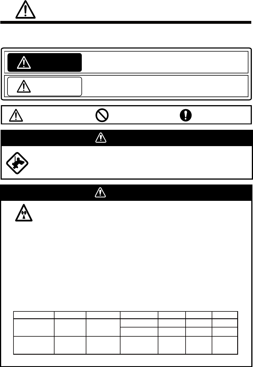
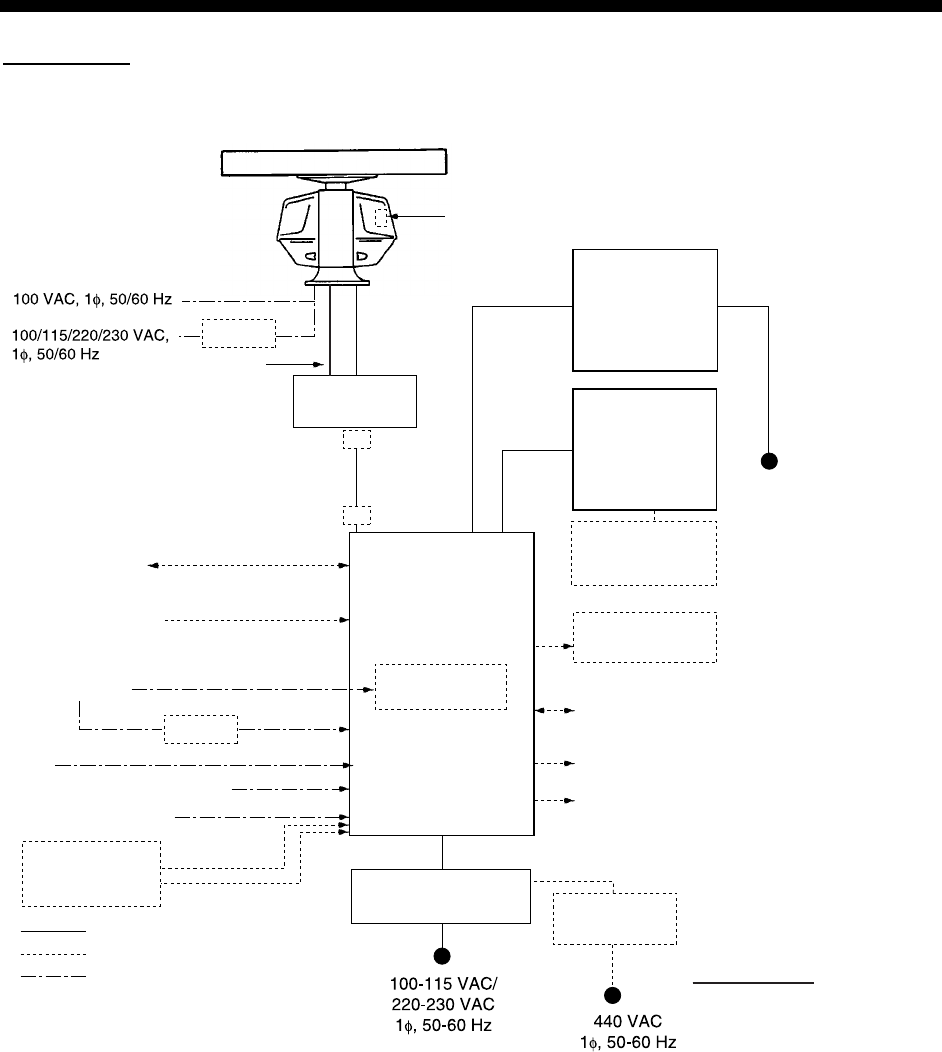
SYSTEM CONFIGURATION
FAR-2827W
Processor Unit
RPU-013
Navigator IEC-61162-1 Serial Data*
2
(Input/Output)
IEC-61162-1 Serial Data
(Input)
Speed Log
Gyro Compass
AIS
Switching HUB HUB-100
Track Control Unit
: Option
: Dockyard supply
: Standard
AD-100
Memory Card
Interface Unit
CU-200-FAR
VDR
External Monitor
Sub Display
Alarm*
4
MU-231CR
Control Unit
RCU-014
(Standard)
or
RCU-015
(Trackball)
Control Unit
RCU-016
(Remote)
XN20AF-RSB-103
XN24AF-RSB-103
Antenna Unit
Gyro Converter
GC-10
Performance Monitor
RJB-001*
1
100-230 VAC
Transceiver unit
RTR-081A
Waveguide
WRJ-9 or FR-9
RU-3305
RJB-001*
1
Category of Units
Antenna unit: Exposed to weather
All other units: Protected from weather
Step or synchro signal
IEC-61162-2
*1 When length of antenna cable is more than 100 m.
*2 For IMO spec, IEC-61162-1 Edition 2 is required.
*3 Russian flag vessels only.
*4 Contact output for Alarm
(Load current) 120 mA, (Polarity) No.1/2: Normally Close, No.3/4: Normally Open
Serial I/O for alarm is also possible, which complies with IEC 61162-1.
(For de-icer)
Transformer Unit
RU-1803
Power Supply Unit*
3
PSU-011
1)
2)
3)
*5 This monitor has been approved by the IMO (CAT1). If a different monitor is to
be used, its effective diameter must meet the applicable Category requirements
(effective diameter 320 mm or higher). Refer to its operator's manual for details.
*5
1) Connect the EPFS which is approved in accordance with the requirements of the IMO in
resolution MSC.112(73) is used.
2) Connect the SDME which is approved in accordance with the requirements of the IMO
in resolution MSC.96(72) is used.
3) Use the gyrocompass having an update rate that is adequate for the ship’s rate of turn.
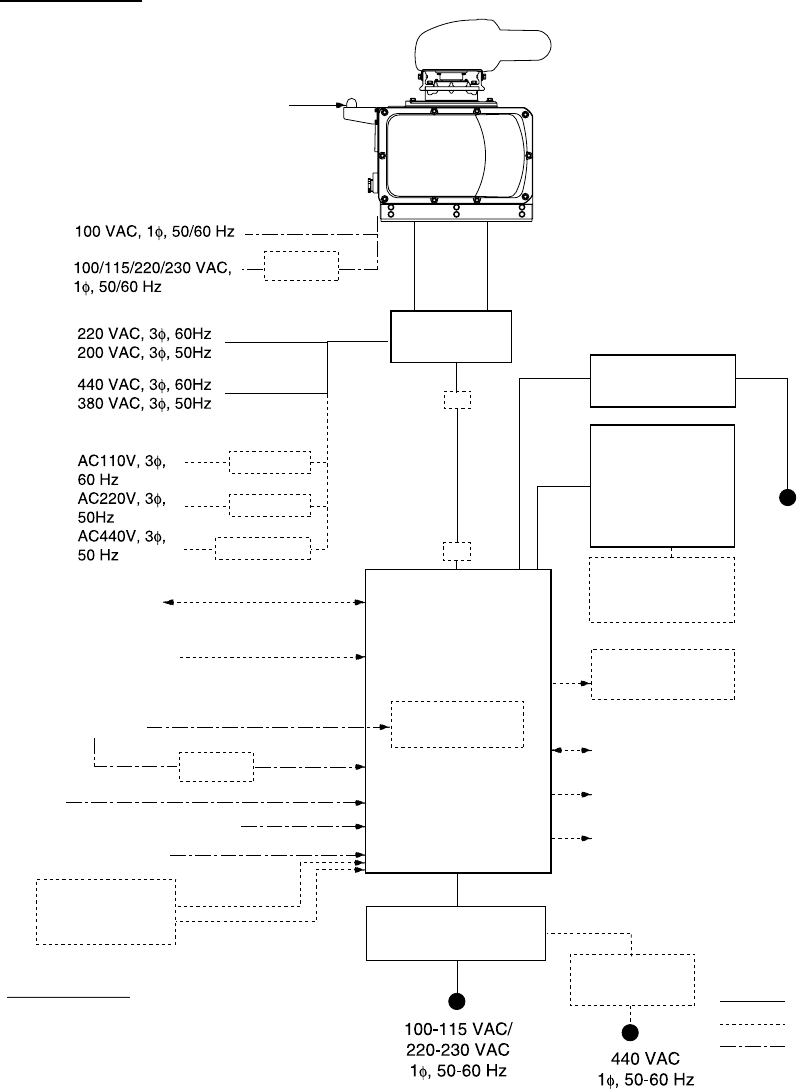
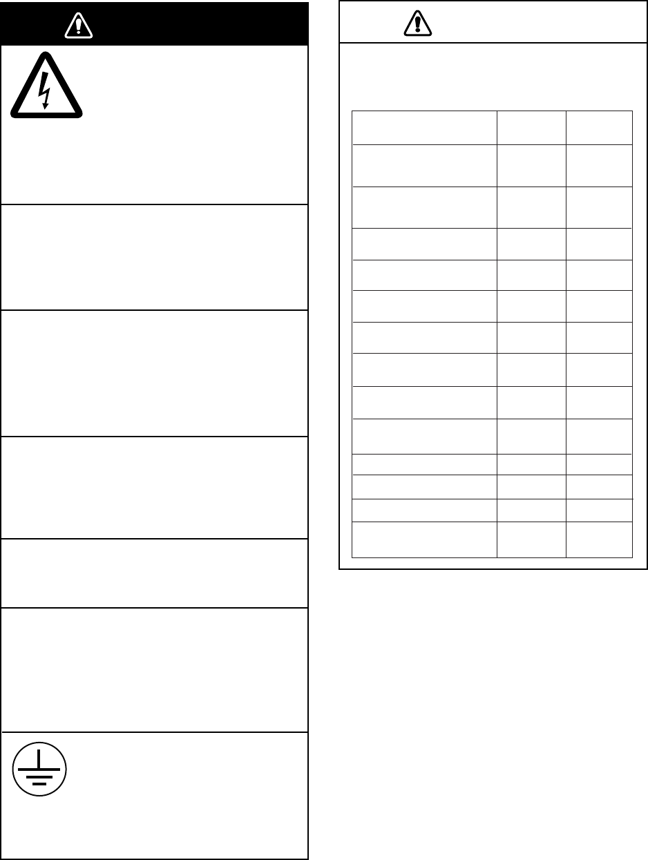
vii
FAR-2837SW
Processor Unit
RPU-013
Navigator
IEC-61162-1 Serial data
*2
(Input/output)
IEC-61162-1 Serial data
(Input)
Speed Log
Gyro Compass
AIS
Switching HUB HUB-100
Track control unit
: Option
: Shipyard Supply
: Standard Supply
AD-100
Memory Card
Interface Unit
CU-200-FAR
VDR
External Monitor
Sub Display
Alarm
*
5
MU-231CR
Control Unit
RCU-014
or
RCU-015
Remote Controller
RCU-016
Antenna Unit
Gyro Converter
GC-10
Performance
Monitor
RJB-001
*
1
100-230 VAC
SN30AF/SN36AF
Transceiver Unit
RTR-082
RU-6522
RU-5693
RU-5466-1
Coaxial cable CX-20DF
or
Waveguide WRJ-3
RSB104
RSB105
RJB-001
*
1
*
4
*
4
*
4
Category of Units
Antenna Unit: Exposed to weather
All other units: Protected from weather
*1 When length of antenna cable is more than 100 m.
*2 For IMO spec, IEC-61162-1 Edition 2 is required.
*3 Russian flag vessels only.
*4 Not available with HSC spec.
*5 Contact output for Alarm
(Load current) 120 mA, (Polarity) No.1/2: Normally Close, No.3/4: Normally Open
Serial I/O for alarm is also possible, which complies with IEC 61162-1.
Step or synchro signal
IEC-61162-2
RU-3305
(For de-icer)
AC spec
Transformer Unit
RU-1803
Power Supply Unit*3
PSU-011
1)
2)
3)
*6 This monitor has been approved by the IMO (CAT 1). If a different monitor is to be used,
its effective diameter must meet the applicable Category requirements (effective diameter
320 mm or higher). Refer to its operator's manual for details.
*
6
1) Connect the EPFS which is approved in accordance with the requirements of the IMO in
resolution MSC.112(73) is used.
2) Connect the SDME which is approved in accordance with the requirements of the IMO
in resolution MSC.96(72) is used.
3) Use the gyrocompass having an update rate that is adequate for the ship’s rate of turn.
viii
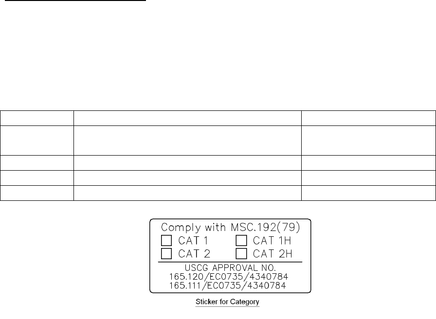
About the category sticker
This radar meets the requirements in IEC62388 (Marine navigation and radio
communication equipment and systems – Shipborne radar – Performance requirements,
method of testing and required test results).
Check the appropriate box on the sticker which is pre-attached on the processor unit.,
according to your radar’s specification. Refer to the table shown below to confirm your
category.
Category Radar type Antenna rotation speed
CAT 1 FAR-2817, FAR-2827, FAR-2837S,
FAR-2827W, FAR-2837SW Normal speed
CAT 1H FAR-2817, FAR-2827, FAR-2837S HSC
CAT 2 FR-2117/BB, FAR-2127/BB, FAR-2137S Normal speed
CAT 2H FAR-2117/BB, FAR-2127/BB, FAR-2137S/BB HSC
1-1
1. MOUNTING
NOTICE
Do not apply paint, anti-corrosive sealant
or contact spray to coating or plastic
parts of the equipment.
Those items contain organic solvents that
can damage coating and plastic parts,
especially plastic connectors.
1.1 Antenna Unit
Mounting considerations
• The antenna unit is generally installed either on top of the wheelhouse or on the radar
mast, on a suitable platform Locate the antenna unit in an elevated position to permit
maximum target visibility.
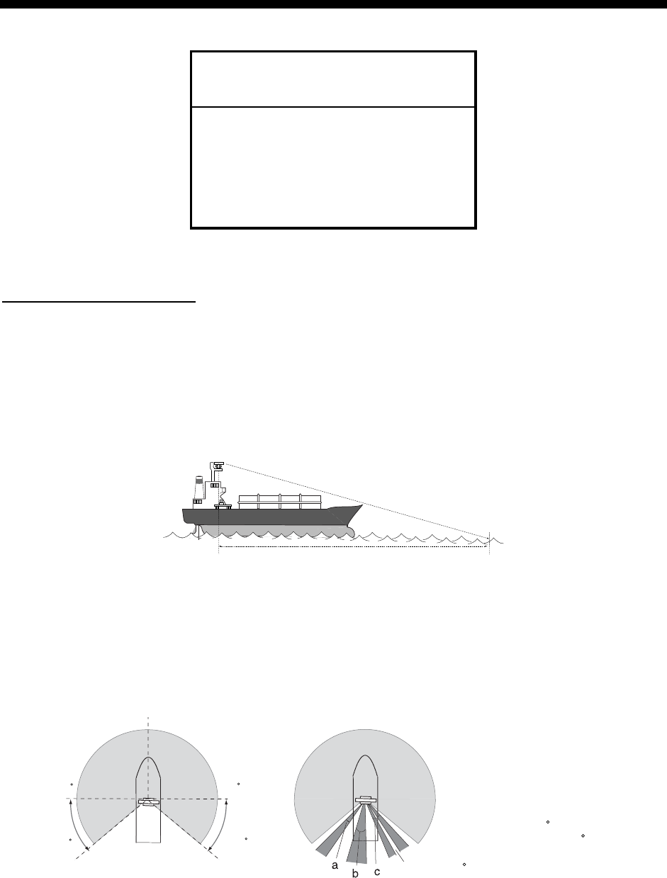
• A line of sight from the antenna unit to the bow of the ship should hit the surface of the
sea in not more than 500 m or twice the ship’s length, depending which value is smaller,
for all load and trim conditions.
less than 500 m or twice the ship’s length
• Mount the antenna unit so that any blind sectors caused by objects (mast, etc.) are kept
to a minimum. No blind sector should exist in arc of the horizon from right ahead to 22.5°
aft of the beam to either side (see Figure 1 below). Also, individual blind sectors of more
than 5°, or the total arc of both blind sectors of more than 20°, should not occur in the
remaining arc (Figure 2). Note that any two blind sectors separated by 3° or less are
regarded as one sector.
Figure 1 Figure 2
a, b, c: less than 5 respectively
a+b+c+... : less than 20
22.5
22.5
less than 3
270 90
1. MOUNTING
1-2
• Install the antenna unit safely away from interfering high-power energy sources and other
transmitting radio antenna.
• Keep the lower edge of the antenna unit (antenna radiator) above the safety rail by 500
mm or more.
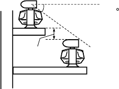
• Two antenna units should be mounted as below:
more than 20
more
than 1 m
• No funnel, mast or derrick should be within the vertical beamwidth of the antenna unit in
the bow direction, especially zero degrees ±5°, to prevent blind sectors and false echoes
on the radar picture.
• It is rarely possible to place the antenna unit where a completely clear view in all
directions is available. Thus, you should determine the angular width and relative bearing
of any shadow sectors for their influence on the radar at the first opportunity after fitting.
• Locate a direction finder antenna clear of the antenna unit to prevent interference to the
direction finder. A separation of more than two meters is recommended.
• A magnetic compass will be affected if the antenna unit is placed too close to the
magnetic compass. Observe the compass safe distances on page ii to prevent deviation
of the magnetic compass.
• Do not paint the radiator aperture, to ensure proper emission of the radar waves.
• The antenna base is made of cast aluminum. To prevent electrolytic corrosion of the
antenna base, use the seal washers and corrosion-proof rubber mat and ground the unit
with the ground wire (supplied).
• Deposits and fumes from a funnel or other exhaust vent can adversely affect the aerial
performance and hot gases may distort the radiator portion. The antenna unit must not be
mounted where the temperature is more than 70°C.
• Leave sufficient space around the unit for maintenance and servicing. See the antenna
unit outline drawing for recommended maintenance space.
1. MOUNTING
1-3
1.1.1 FAR-2827W antenna unit
Assembling the antenna unit
The antenna unit consists of the antenna radiator and the antenna unit chassis, and they
are packed separately. Fasten the antenna radiator to the antenna unit chassis as follows:
1. Attach two guide pins (supplied as installation) materials to the underside of the antenna
radiator.
2. Remove the waveguide cap from the radiator bracket. The cap may be discarded.
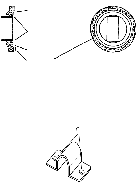
3. Coat the waveguide flange with anticorrosive sealant as shown below.
Anticorrosive sealant
10 mm O-ring Waveguide cap
5 mm
Hole for
a guide pin Hole for
a guide pin
Coating the waveguide flange with anticorrosive sealant
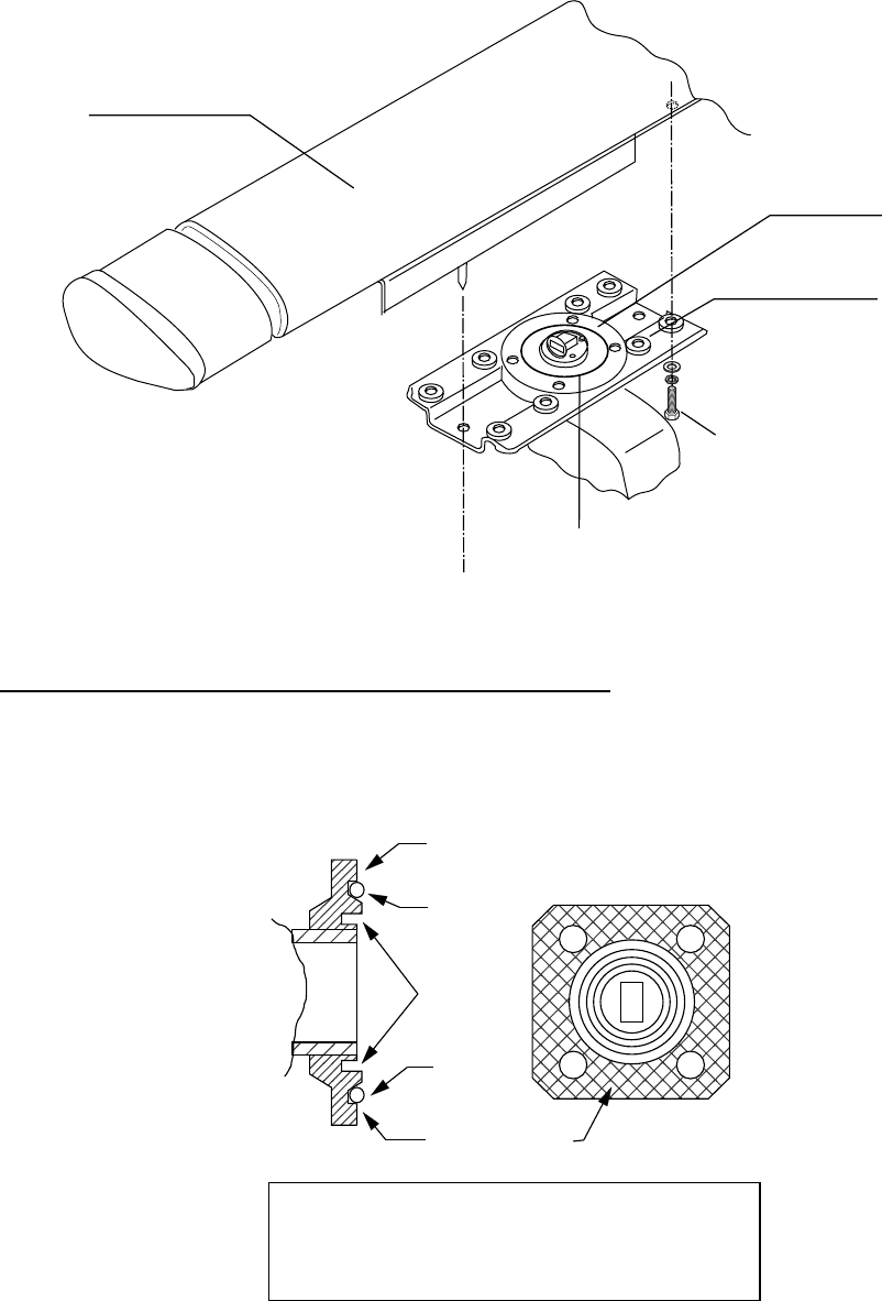
4. Coat fixing holes for the antenna radiator with anticorrosive sealant.
5. Grease the O-ring and set it to the O-ring groove of the radiator flange.
6. Set the antenna radiator to the radiator bracket.
7. Coat hex bolts M8 x 40 with anticorrosive sealant and use them to loosely fasten the
antenna radiator to the antenna unit chassis.
8. Remove two guide pins (inserted at step 1), and then tighten fixing bolts.
CAUTION
Be sure to remove the guide pins.
Injury may result if the guide pins loosen
and fall.
1. MOUNTING
1-4
O-ring
Radiator bracket
Waveguide
Antenna radiator
Hex bolt (M8x40), 8 pcs.
Fastening the radiator to the radiator bracket
Coating the waveguide flange with silicone sealant
1. Do not coat O-ring with silicone sealant; use grease.
2. Clean the surface of the waveguide flange, if necessary. Evenly coat the waveguide
flange with silicone sealant as shown in the illustration below.
O-ring
O-ring
Apply silicone
sealant here.
Apply silicone
sealant here.
Choke
groove
Evenly coat the waveguide flange with silicone
sealant. Apply sealant sparingly; it leaks out
slightly when the fixing bolts are tightened.
Be sure no sealant contacts the choke groove
and waveguide.
Coating the waveguide flange with silicone sealant
1. MOUNTING
1-5
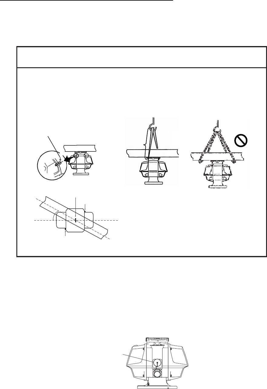
Fastening the antenna unit to the mounting platform
The antenna unit may be assembled before hoisting it to the mounting platform. However,
do not lift the antenna unit by the radiator. Always hold the unit by its housing. When using a
crane or hoist, lift the unit by the hoist rings which should be fastened to the bolt fixing
covers of the antenna housing.
NOTICE
NO!
- To hoist antenna unit aboard vessel, attach ropes to lifting fixtures and hoist unit with crane.
- To remove load from radiator when hoisting, the length of the rope between the radiator base
and the hook on the should be at least 130 cm.
- To keep the rope away from the radiator, turn the radiator and chassis approx. 30 degrees as
shown below.
- Be sure to remove the lfiting fixtures after hoisting is completed.
130cm
Approx.
30 deg.
Lifting fixture
Lifting fixture
Crane
(Top view)
NO!
Lifting
fixture
1. Construct a suitable mounting platform referring to the outline drawing at the end of this
manual.
2. Drill four mounting holes of 15 mm diameter and one cable entry hole of about 50 mm
diameter in the mounting platform.
3. Lay the rubber mat (supplied) on the mounting platform.
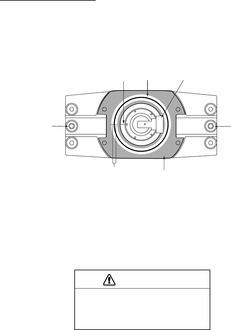
4. Place the antenna unit on the rubber mat, orienting the unit so the antenna switch on it is
facing the ship’s bow.
Antenna switch
Antenna unit, front view
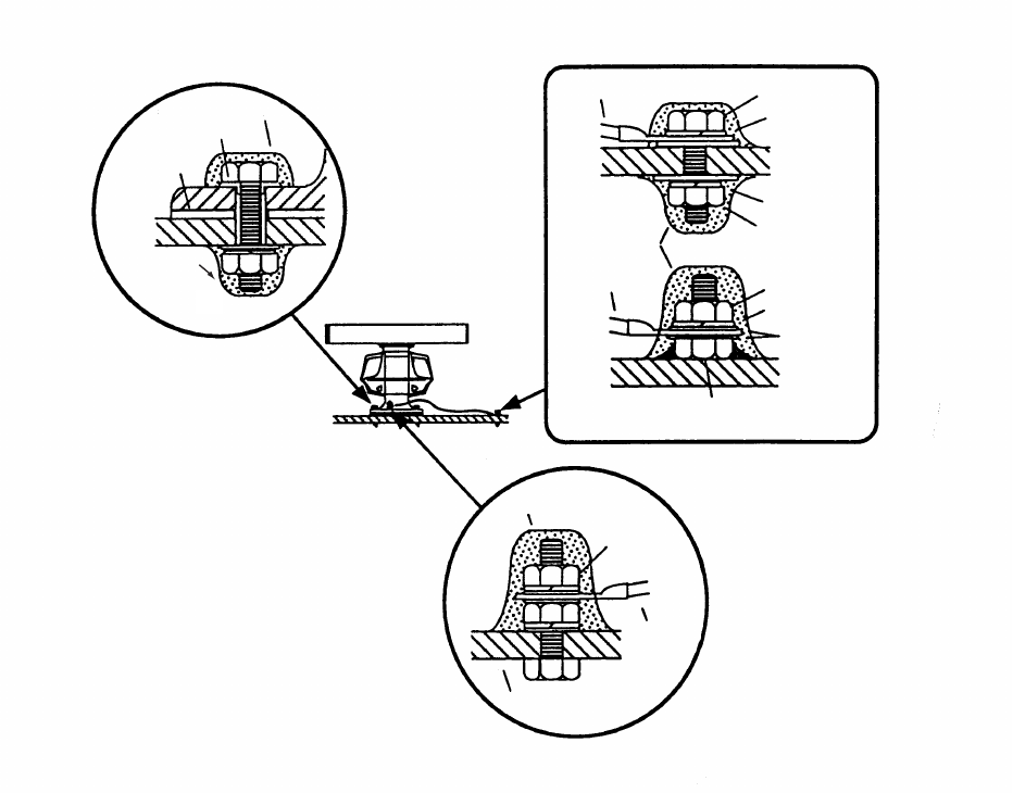
5. Fasten the antenna unit to the mounting platform with M12x60 hex bolts, nuts, flat
washers and seal washers.
1. MOUNTING
1-6
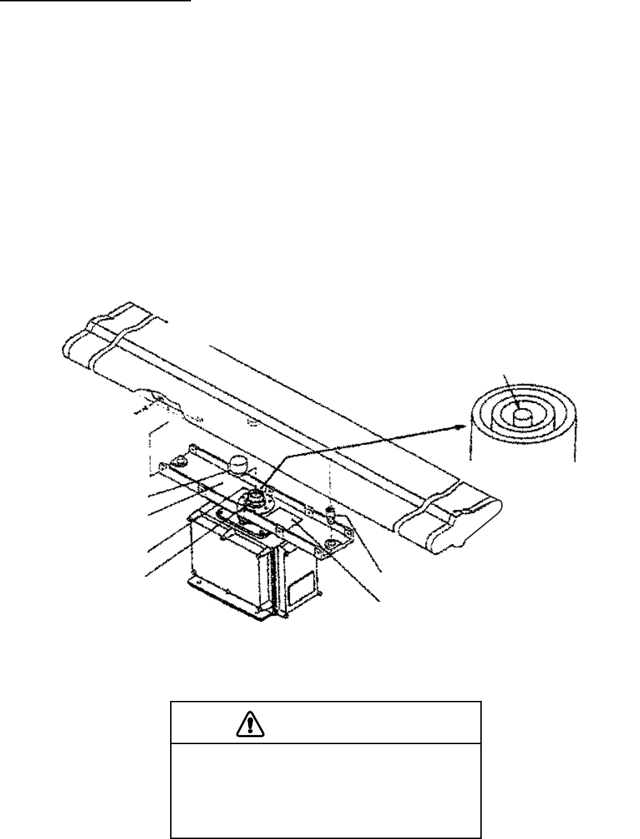
6. Using hex bolt (M6x25), nut (M6) and flat washer (M6), establish the ground system on
the mounting platform as shown below. The location should be within 340 mm of the
ground terminal on the antenna unit. Connect the ground wire (RW-4747, 340 mm,
supplied) between the grounding point and ground terminal on the antenna unit. Coat
the entire ground system with silicone sealant (supplied).
Anticorrosive sealant
Seal washer
Rubber mat
Anticorrosive
sealant
Ground wire Hex bolt
Hex bolt welded to
ship's superstructure
Hex nut
Hex nut
Spring washer
Spring washer
Spring washer
OR
Anticorrosive
sealant
Flat washer
Anticorrosive sealant
Ground
terminal
Ground
wire
Antenna base
Ground wire
How to mount the antenna unit
1. MOUNTING
1-7
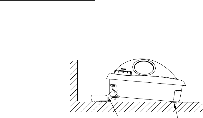
1.1.2 FAR 2837SW antenna unit
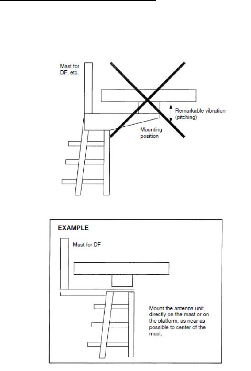
Installation precaution for S-band antenna unit
If an S-band antenna unit is mounted near the end of a platform to provide sufficient rotation
clearance for the radiator, the antenna unit, because of its weight, swings up and down by
ship’s vibration and rolling, exerting excessive levels of stress at the base of the radiator,
which can damage the radiator. To prevent this, relocate the antenna unit, or if relocation is
not possible, reinforce the platform.
Mounting of S-band antenna unit
1. MOUNTING
1-8
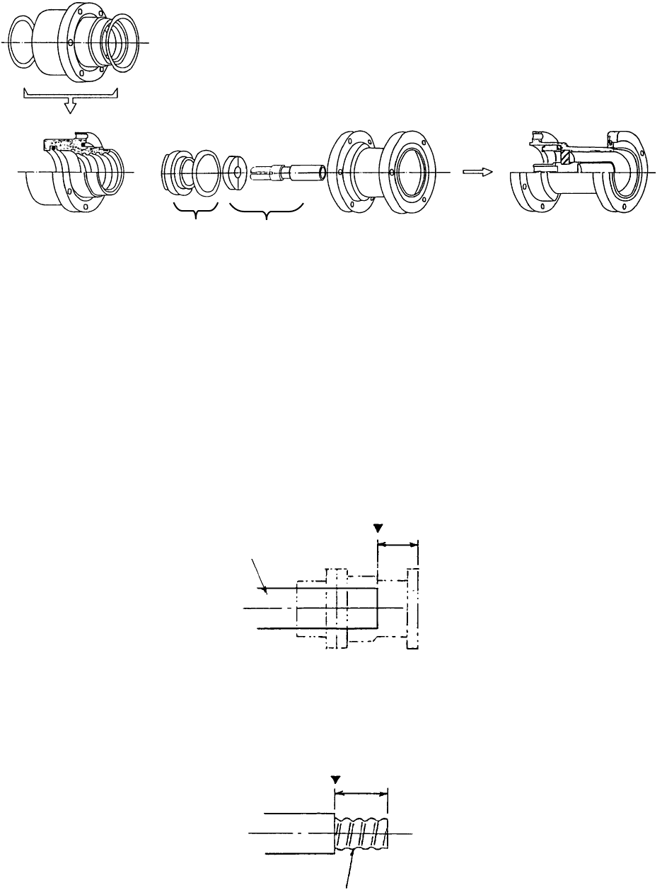
Antenna unit assembling
The antenna radiator and the antenna housing are shipped in separate packages.
Assemble them as below. The antenna unit may be assembled before hoisting it to the
mounting platform. However, do not lift the antenna unit by the radiator.
Antenna unit assembling procedure
1. Screw the guide pins (2 pcs.) in the radiator.
2. Remove the protective cap from the choke guide.
3. Grease O-ring and set it to the groove of the choke guide.
4. Place the radiator on the radiator bracket. (Radiator direction is shown by the logo on
the bracket. If reversely oriented the radiator cannot be set to the bracket.)
5. Loosely fix the radiator to the radiator bracket with hex. bolts (M10x25), spring washers
and flat washers.
6. Remove the guides pins and tighten hex. bolts.
Antenna radiator
Spring washer,
flat washer,
10 pcs. each,
M10x25
Protective cap
Radiator bracket
Choke guide
O-ring
(JIS B2401-
1A-G60, 2 pcs)
Guide pin (2 pcs.)
Instruction label for antenna
aperture direction
Assembling the radiator bracket
CAUTION
Be sure to remove the guide pins.
Injury may result if the guide pins loosen
and fall.
1. MOUNTING
1-9
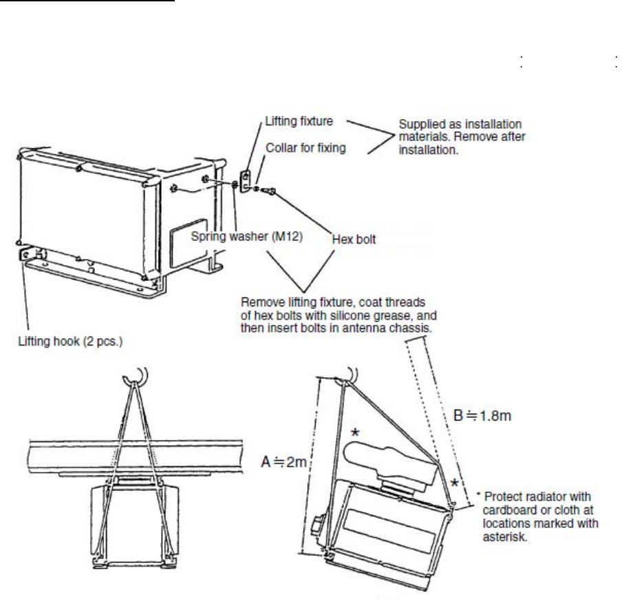
How to lift antenna unit
1. Fix the antenna radiator to the antenna unit chassis.
2. Attach the lifting fixtures and collars as shown in figures in below.
3. Position the radiator as shown in figure below and arrange the ropes A
=
2.0 m and B
=
1.8 m.
(M12x20)
Attachment of lifting fixtures, collar and lopes
1. MOUNTING
1-10
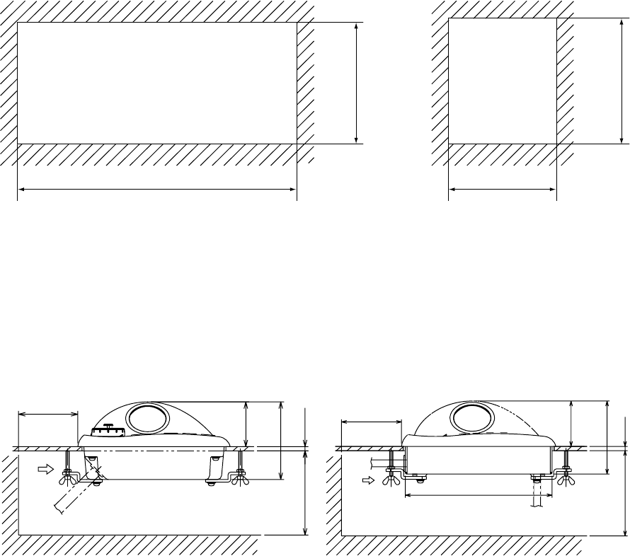
Fastening the antenna unit to the mounting platform
See the figure on the next page for antenna unit mounting.
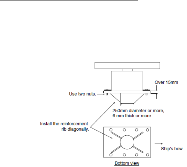
1. Referring to the antenna outline drawing, drill four bolt holes (15 mm diameter) in the
radar mast platform or the deck.
a) The diameter of the mast for fixing the antenna unit platform must be over 15 mm.
b) The thickness of the antenna unit platform must be over 15 mm.
c) The reinforcement rib must be installed diagonally as shown below.
Installation of reinforcement ribs
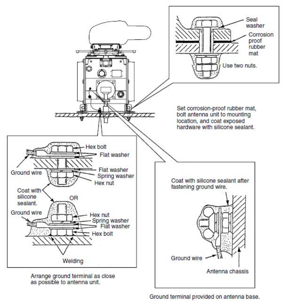
2. Place the corrosion-proof rubber mat (supplied) on the mounting platform.
3. Hoist the antenna unit as shown on page 1-9 and place it on the rubber mat. Orient the
cable gland toward the ship’s stern (or port, starboard). Remove the lifting fixtures and
collars.
4. Fix the antenna base to the mounting platform with four M12x70 hex. bolts, nuts,
washers and seal washers (supplied).
5. Arrange the grounding terminal at the nearest grounding spot with the M6x25 hex. bolt,
nut and washers (supplied). Then, fix a ground wire (RW-4747, 340 mm) to the terminal.
6. Connect the other end of the ground wire to the earth terminal of the antenna unit.
7. Coat earth terminal and fixing bolts on the antenna unit with silicone sealant (supplied).
1. MOUNTING
1-11
Mounting of antenna unit
1. MOUNTING
1-12
1.2 Monitor Unit
The monitor unit can be flush mounted in a console panel, or mounted on a desktop using
the optional accessories. The optimal viewing distances for the radar display units are:
MU-170C: 920 mm, MU-201CR: 1080 mm, MU-231CR: 1200 mm.
Mounting considerations
When selecting a mounting location, keep in mind the following points:
• Select a location where the display unit can be viewed conveniently and where the
screen can be viewed while facing towards the bow.
• Locate the unit out of direct sunlight and away from heat sources because of heat that
can build up inside the cabinet.
• Locate the equipment away from places subject to water splash and rain.
• Leave sufficient space on the sides and rear of the unit to facilitate maintenance.
• A magnetic compass will be affected if the monitor unit is placed too close to the magnetic
compass. Observe the compass safe distances on page ii to prevent deviation of a
magnetic compass.
Mounting procedure
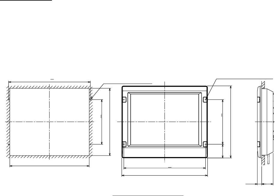
Flush mounting
Follow the procedure below to mount the monitor unit in a console panel.
1. Make cutout in mounting location referring to the outline drawing shown below.
2. Insert the monitor unit to the hole and fix it by four tapping screws (6x30).
3. Attach panel hooks near the fixing holes. These are used to pull out the monitor unit
from a console panel for servicing.
4. Attach four panel covers to the fixing holes.
570+1
4-φ9 FIXING HOLES
598
(96) 313+1
505
4-FIXING HOLES
554
471
313+1
570+1
30 80
Monitor unit MU-231CR
Flush mounting of monitor unit
1. MOUNTING
1-13
Panel hook
Panel cover
Fixing screw
Attaching panel hook and panel cover
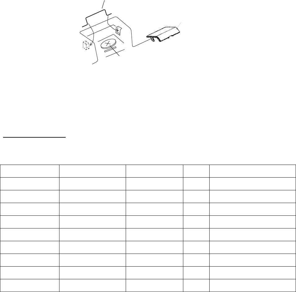
Note: If you need to remove the monitor unit from the panel, remove the four panel covers
with your fingernail and use two panel hooks supplied as accessories to lift the
monitor unit.
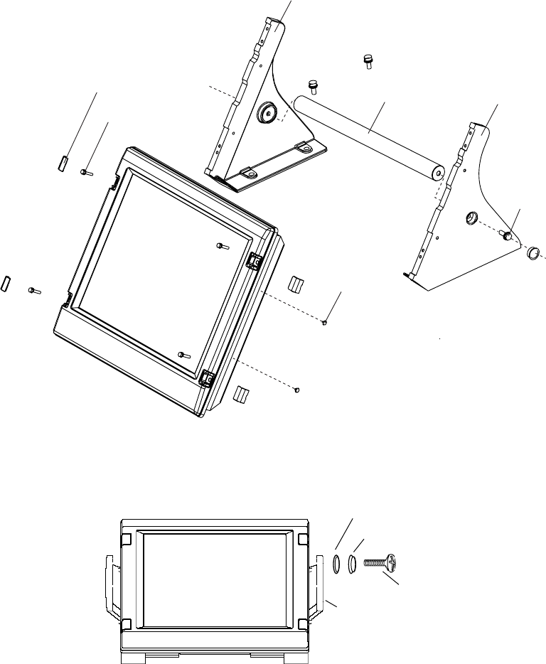
Desktop mounting
Use the optional accessories to mount the monitor unit on a desktop.
• Necessary parts: FP03-09830 (Code No.: 008-536-020)
Name Type Code No. Qty Remarks
Hanger L 03-163-1111-0 100-305-141 1
Hanger R 03-163-1112-0 100-305-181 1
Hanger stay 03-163-2071-0 100-305-371 1
Hole plug CP-30-HP-13 000-160-074-10 2
Plastic rivet KB-13 Rivet Black 000-570-276-10 4
Hex. bolt M6x25 000-162-949-10 4
Hex. bolt M10x30 000-162-884-10 2
Spring washer M10 000-864-261 2
Flat washer M10 000-864-131 2
1. Assemble two hangers and hanger stay with two hex bolts (M10x30), flat washers and
spring washers and cover each hex bolt with hole plug.
2. Fix the above assembly to the mounting location with four hex bolts (M12, dockyard
supply).
3. Fasten the monitor unit to the mounting hanger assembly with four hex bolt (M6x25,
supplied).
4. Cover each hex bolts with panel cover.
5. Cover each holes for hand grip on the hangers with plastic rivet (4 pcs).
1. MOUNTING
1-14
Panel cover
Hex bolt
(M6x25)
Hanger
Hanger stay
M12 bolts for fixing
(Dockyard supply)
Hanger
Hex bolt
M10x30
Plastic rivet Hole plug
Monitor Unit
The hand grip is optionally available for the desktop mounting.
Handle
Screw
Wave washer
Rosette washer
Monitor unit, attaching hand grip
1. MOUNTING
1-15
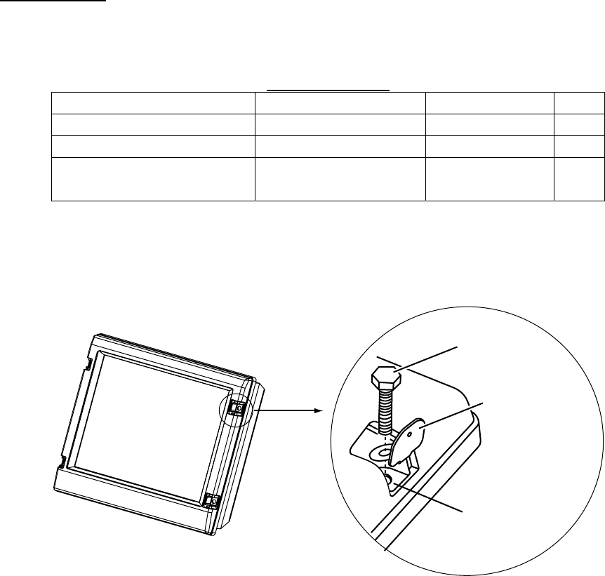
Hood (option)
When it is too bright in the daytime, use the optional hood (Type: FP03-11000, Code No.:
008-571-680) to shade the screen.
Contents of hood
Name Type Code No. Qty.
Hood FP03-11001 008-571-700 1
Fixing plate 03-163-2202-0 100-335-560-10 4
Screw M4x10 D=13
SUS304 000-862-543 4
1. Desktop mounting: Fasten the fixing plates to the fixing holes with the hex head bolts
(supplied).
Flush mounting: Fasten the display unit to the mounting location, and then attach the
fixing plates with four self-tapping screws.
Fixing plate
Fixing hole
Hex head bolt
2. Attach the hood to the display unit (the hood is outside of the fixing plates).
3. Fasten the hood to the fixing plates with four screws supplied (M4x10).
1. MOUNTING
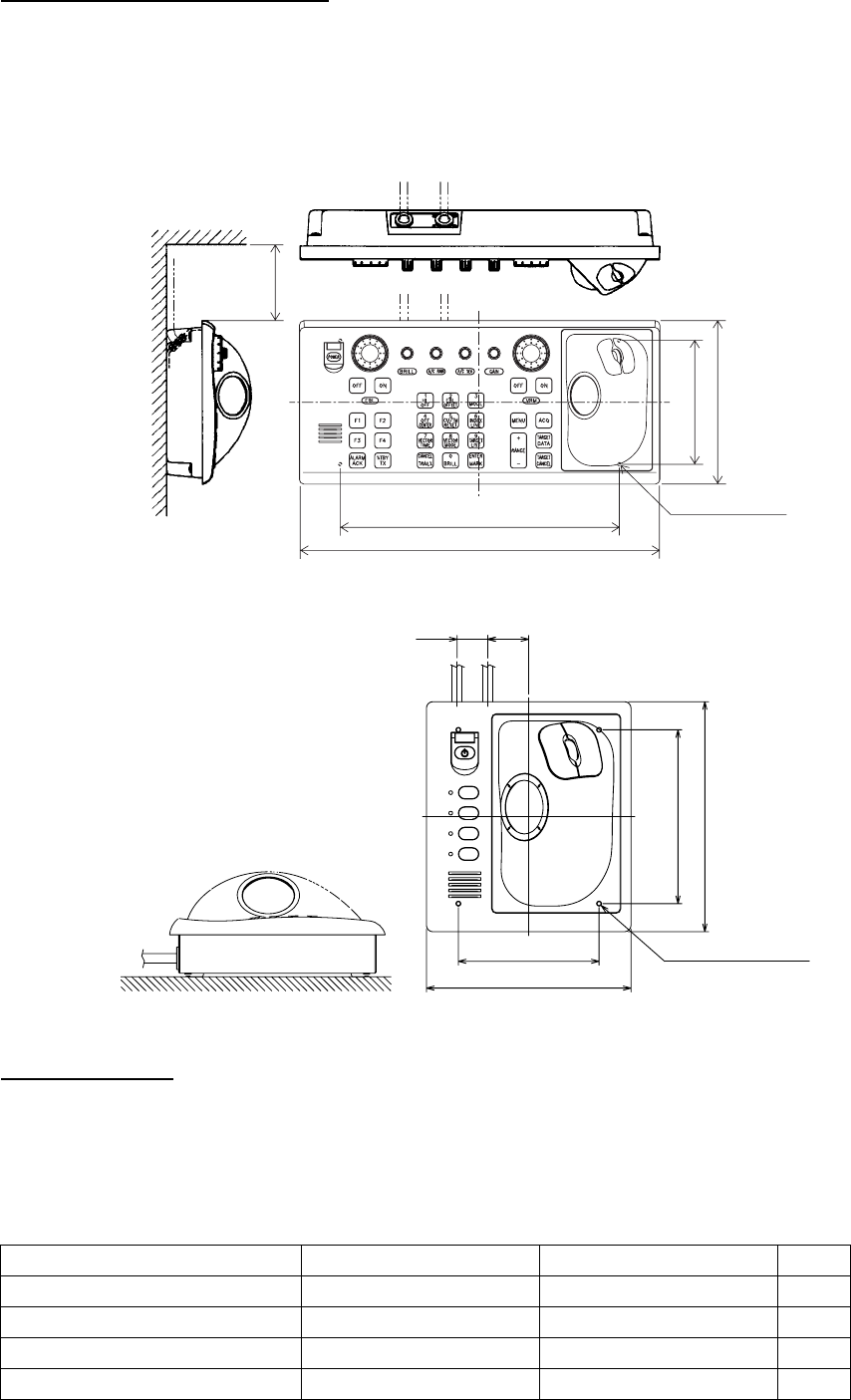
1-16
1.3 Control Unit
The control unit may be mounted on a tabletop, with or without the KB fixing metal
(supplied), which mounts the control unit at an angle.
Mounting considerations
When selecting a mounting location, keep in mind the following points:
• Select a location where the control unit can be operated conveniently.
• Locate the unit away from heat sources because of heat that can build up inside the
cabinet.
• Locate the equipment away from places subject to water splash and rain.
• Determine the mounting location considering the length of the signal cable between the
control unit and the processor unit. (The signal cable comes in lengths of 10 m).
• A magnetic compass will be affected if the control unit is placed too close to the magnetic
compass. Observe the compass safe distances on page ii to prevent deviation of a
magnetic compass.
Fixing without KB fixing plate
1. Fix the KB fixing plate to the rear panel of the control unit.
2. Attach cushions (three for RCU-014, two for RCU-015/016) to the bottom of the control
unit as shown below.
3. Fix it to a desired location with tapping screws.
Cushion
KB fixing plate
RCU-014/015/016, side view
1. MOUNTING
1-17
Fixing without KB fixing metal
1. Drill four mounting holes of 5 mm diameter referring to the outline drawing at the back of
this manual.
2. Fix the control unit with four screws (M4) from under side of the tabletop. (The M4
screws with a sufficient length for the thickness of the tabletop should be provided
locally.)
#70
308±1
398
136±1
180
4-M4 (Fixing holes)
(bottom)
Control Unit
F4
F3
F2
F1
180
24 32
110±1
160
136±1
4-M4 (Fixing holes)
(REAR)
RCU-015/016
Flush mounting
Use the optional flush mount kit FP03-09870 to mount the control unit RCU-014, RCU-015
and/or RCU-016 to a console panel. For detail, see the outline drawing at the back of this
manual
Name: Flush mount kit, Type: FP03-09870, Code No.: 008-535-630
Name Type Code No. Qty
Flush Mount Fixture 03-163-7531 100-306-261 4
Hex Nut M5 000-863-108 4
Wing Bolt M5x40 000-162-682-010 4
Pan Head Screw M4x12 000-163-192-10 4
1. MOUNTING
1-18
1. Prepare a cutout in the mounting location as shown in the figure below.
388 150±2
170±2176±2
±2
For RCU-014 For RCU-015 and RCU-016
2. Set the control unit to the cutout.
3. Screw four wing bolts into hex. nuts.
4. Screw the above wing bolts into mounting plates.
5. Attach the mounting plate to the control unit with four screws (M4x12, supplied with the
control unit) from the bottom side.
6. Fasten four wing screws, and then fasten hex. nuts to fix four wing screws.
#100 (P)
A
#70
53
92
#100 (P)
A
#70
171
53
86
P: Thickness (Max. 10 mm)
RCU-014 RCU-015/016
1. MOUNTING
1-19
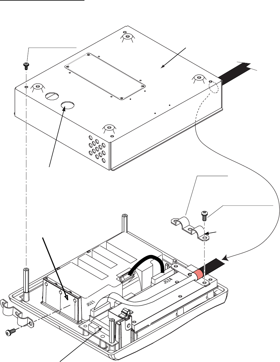
To connect RCU-016 in series with RCU-014
1. Pass the cable derived from RCU-016.
2. Connect the connector
of the cable to J502.
3. Clamp the copper part of the cable with the cable clamp.
Inside of RCU-014
1. MOUNTING
1-20
To change the cable entry
To change the cable entry from the side (default) to the bottom, modify the unit as shown
below.
Cable clamp
03-163-7804
Screw M3x8
(Torque 0.78Nm)
Screw M4x8
(Torque 1.47Nm)
2. Pull out the cable.
1. Remove the
cable clamp.
3. Pass the cable from this hole.
4. In here, clamp the copper part
of the cable with the cable
clamp removed at step1.
J522: If you connect RCU-016 in series with RCU-015, plug in here.
Bottom of the unit
(Torque 1.47Nm)
RCU-015/016; Changing cable entry
1. MOUNTING
1-21
1.4 Processor Unit
Mounting considerations
When selecting a mounting location, keep in mind the following points:
• Locate the processor unit away from heat sources because of heat that can build up
inside the cabinet.
• Locate the equipment away from places subject to water splash and rain.
• Leave sufficient space at the sides and rear of the unit to facilitate maintenance.
• A magnetic compass will be affected if the processor unit is placed too close to the
magnetic compass. Observe the compass safe distances on page ii to prevent deviation
of a magnetic compass.
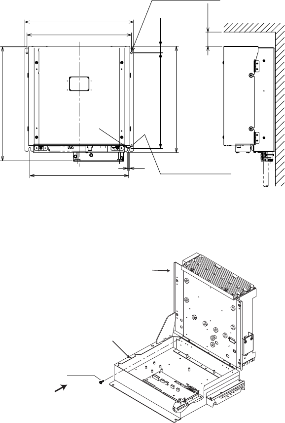
Mounting procedure
1. Fix the unit with four M6 bolts, or tapping screws.
23.5
340±1
378
385
409
350±1
#50
2-φ7
FIXING HOLES
R3.5
370±1
72-FIXING NOTCH
Floor mounting or bulkhead mounting
Note: If you fix the unit, cable entry upside, never remove the screw M3x10 that joints
the upper case assy. and lower case assy. of the processor unit.
Screw
M3x10
Upper case assy.
Lower case assy.
Never remove this screw.
Processor unit
1. MOUNTING
1-22
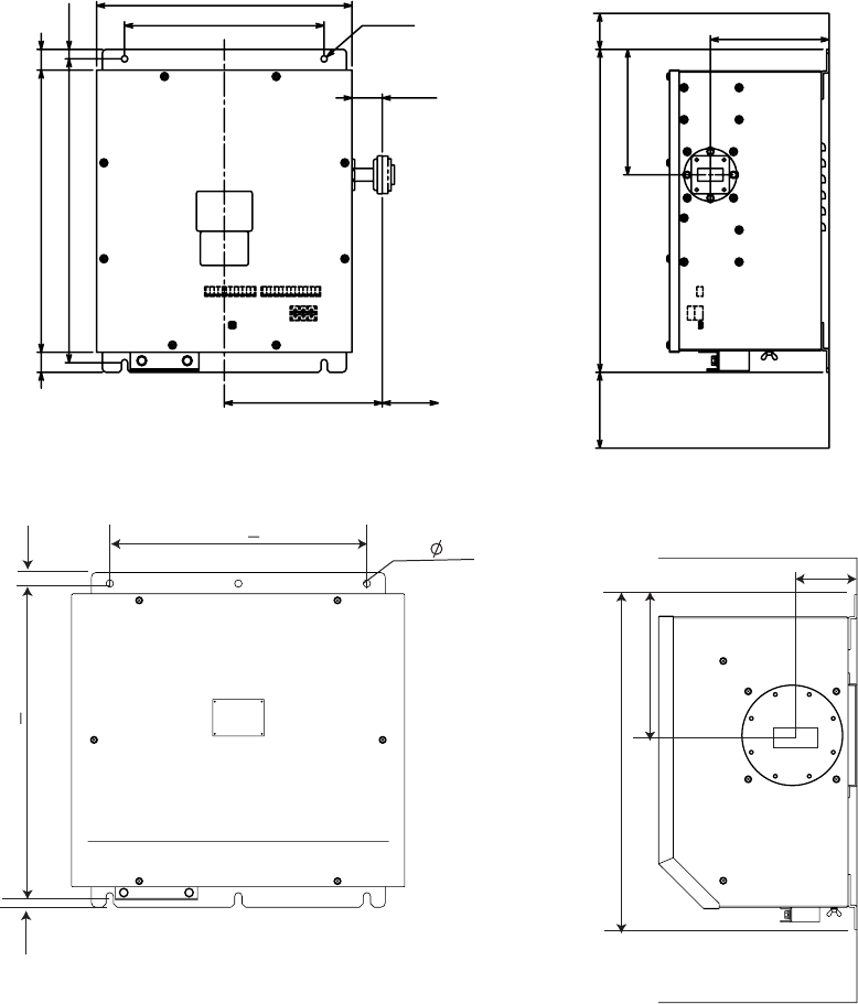
1.5 Transceiver Unit
The transceiver unit is designed for bulkhead mounting, and may be mounted in any dry,
well-ventilated place. Ensure the mounting location is strong enough to support the weight
of the unit under the continued shock and vibration normally encountered onboard. The
transceiver must not be installed in close proximity of a magnetic compass; observe the
compass safe distances.
Fix the unit to bulkhead with bolts (RTR-081A: M6, 4 pcs., RTR-082: M8, 6 pcs.). Run a
ground wire (8 mm2) between the ship’s body and the transceiver unit, using the lug
supplied to make the connection at the earth stud on the transceiver unit. Keep the length of
the ground wire as short as possible.
198 70
(38)
4-φ8
320
250±1
(25) 353
380±1
26
12
100
149
157
404
150
Transceiver unit RTR-081A (for FAR-2827W)
420+2
427+1 15
15
6- 10
457
192
88
Transceiver unit RTR-082 (for FAR-2837SW)
1. MOUNTING
1-23
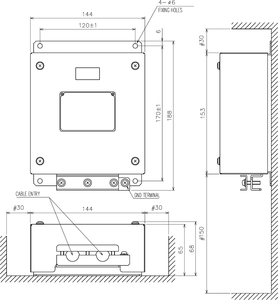
1.6 Power Supply Unit
The Power Supply Unit PSU-011 is required for Russian flag vessels. The unit can be
installed almost anywhere. The location should be dry and well-ventilated, provide sufficient
maintenance space, and satisfy the compass safe distances mentioned on page ii.
Fix the unit to the mounting location with 5×20 self-tapping screws.
1. MOUNTING
1-24
This page is intentionally left blank.
2-1
2. WIRING
Wiring consideration
• To lessen the chance of picking up electrical interference, avoid where possible routing
the signal cable near other onboard electrical equipment (radars, transmitting radio
antennas, etc.) Also avoid running the cable in parallel with power cables. When crossing
with other cable, the angle should be 90°to minimize the magnetic field coupling.
• The signal cable run between the antenna and processor units is available in lengths of
15 m (standard), 30 m, 40 m and 50 m. Whatever length is used it must be unbroken;
namely, no splicing allowed. Use the signal cable as short as possible to minimize
attenuation of the signal.
• The radar should be connected to an emergency power source, as required by SOLAS
II-1.
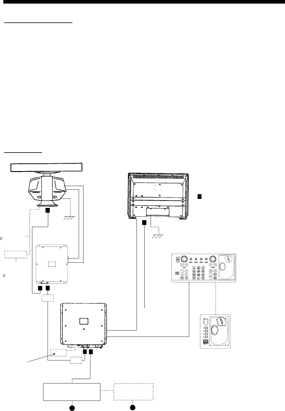
2.1 Interconnection
FAR-2827W
Processor unit
RPU-013
Antenna unit
TB803
Monitor unit
Control unit
(RCU-014 or RCU-015)
Antenna cable*
DPYC-2.5
XH10P-W-6P, 1.5/10/20/30 m
100-230 VAC
DVI-D/D SINGLE LINK 5M/10M
Waveguide
WRJ-9
or
FR-9
MPYCY-19
(Max. 30 m)
F4
F3
F2
F1
Control unit
(RCU-016)
TB803
TB801
Junction box
RJB-001*
Junction box
RJB-001*
Memory card I/F unit
CU-200-FAR
Transceiver
unit
RTR-081A
RU-3305
100 VAC,
1 , 50/60 Hz
110/115/
220/230 VAC,
1 , 50/60 Hz
For De-icer
XH10P-W-5P-A,
10/20/30 m
: Cable requires fabrication
*: If the length of the antenna cable is less than
100 m, use RW-9600. If it is more than 100 m,
see section 4.5 "Junction Box RJB-001".
AC spec
Russian flag
vessel only
DPYC-2.5
100-115 VAC/
220-230 VAC
1
φ
, 50-60 Hz
Transformer Unit
RU-1803
440 VAC
1
φ
, 50-60 Hz
Power Supply Unit
PSU-011
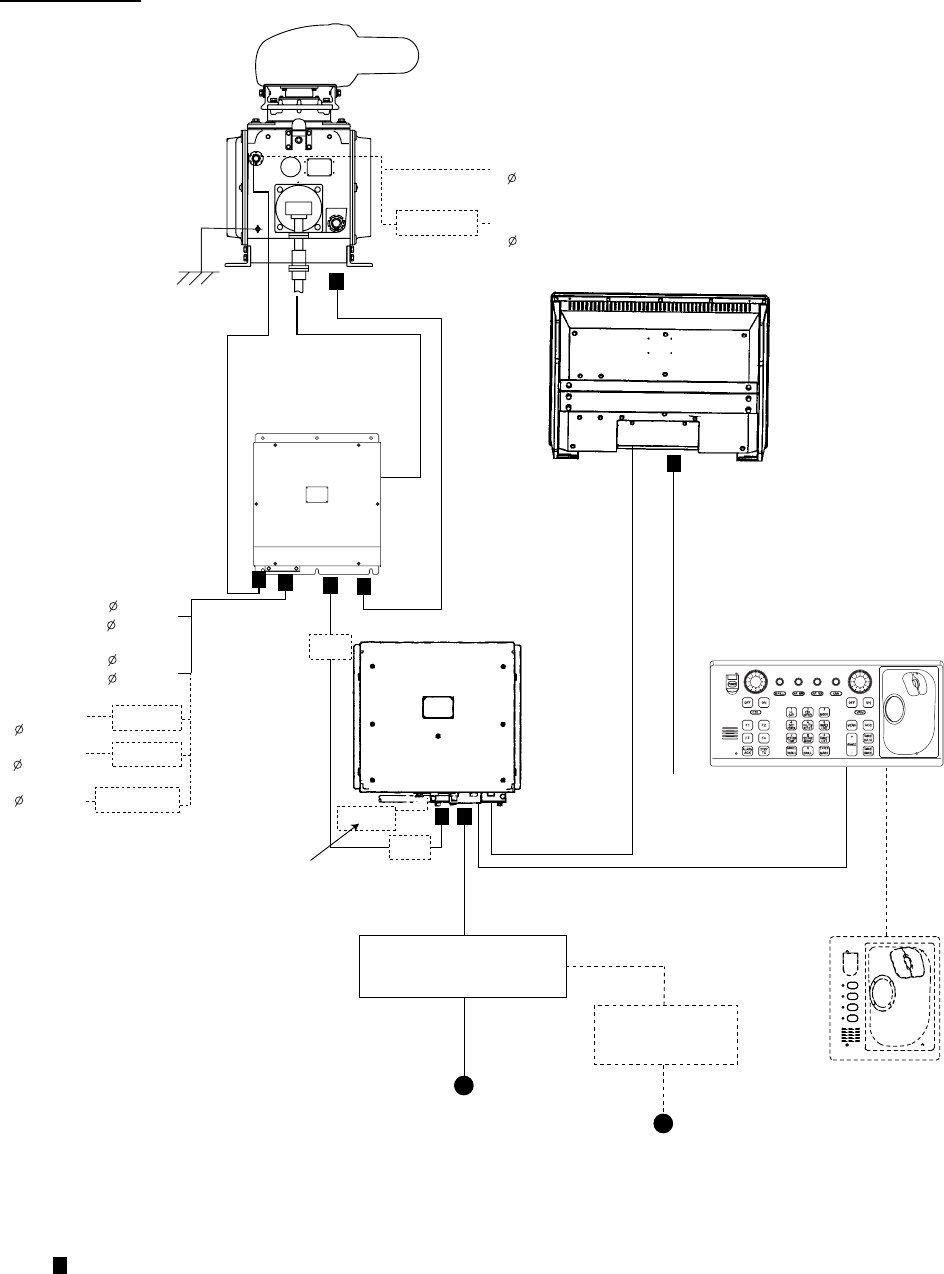
2. WIRING
2-2
FAR 2837SW
Processor unit RPU-013
: Cable requires fabrication
Antenna unit
TB803
Monitor unit
Control unit
(RCU-014 or RCU-015)
Antenna cable*
DPYC-2.5
XH10P-W-6P, 1.5/10/20/30 m
100-230 VAC
DVI-D/D SINGLE LINK 5M
Coaxial cable
(Max. 30 m)
or WRJ-3
MPYCY-12
(Max. 30 m)
Transceiver unit
RTR-082
F4
F3
F2
F1
Control unit
(RCU-016)
TB803
TB801
Memory card I/F unit
CU-200-FAR
Junction box
RJB-001*
Junction box
RJB-001*
*: If the length of the antenna cable is less than 100m, use RW-9600.
If it is more than 100 mm, see section 4.5 "Junction Box RJB-001".
RU-3305
100 VAC,
1 , 50-60 Hz
110/115/
220/230 VAC,
1 , 50-60 Hz
For De-icer
TPYCY-2.5
220 VAC, 3 , 60 Hz
200 VAC, 3 , 50 Hz
440 VAC, 3 , 60 Hz
380 VAC, 3 , 50 Hz
110 VAC,
3 , 60 Hz
220 VAC,
3 , 50 Hz
440 VAC,
3 , 50 Hz
RU-5693
RU-6522
RU-5466-1
TPYCY-2.5
XH10P-W-5P-A
10/20/30 m
Russian flag
vessel only
DPYC-2.5
100-115 VAC/
220-230 VAC
1
φ
, 50-60 Hz
Transformer Unit
RU-1803
440 VAC
1
φ
, 50-60 Hz
Power Supply Unit
PSU-011
Standard Interconnection (FAR-2837SW)
2. WIRING
2-3
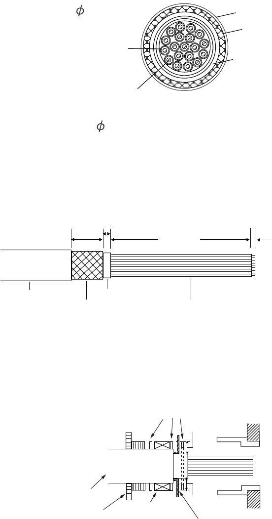
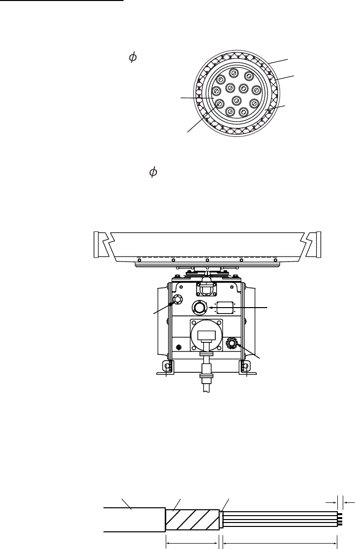
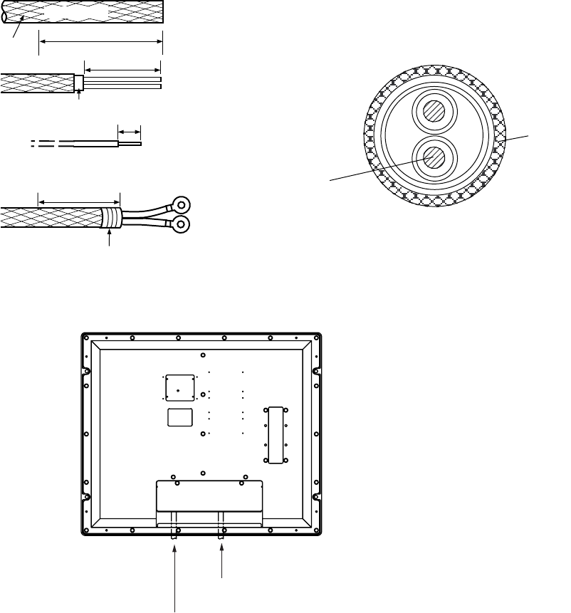
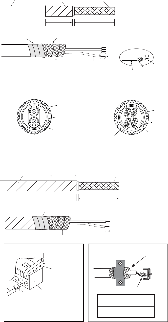
2.2 Antenna Unit
2.2.1 FAR-2827W (RSB-103)
The antenna unit requires the MPYCY-19 (Japan Industrial Standard cable) or equivalent to
connect to the transceiver unit RTR-081A.
Conductor
S = 1 mm
= 1.29 mm
2
MPYCY-19
Armor
Sheath
= 22.0
mm
Sheath
Insulator
MPYCY-19 cable, sectional view
1. Remove the antenna covers.
2. Unscrew the clamping gland and take out the washers, rubber packing and cover.
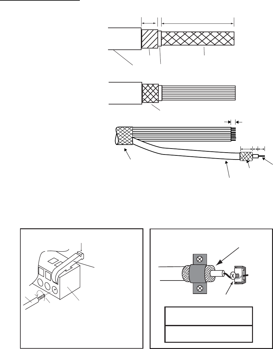
3. Fabricate the cable as below.
450 mm
Core
Vinyl sheath Vinyl sheath
Armor
5 mm
20 mm
6 mm
Wind vinyl tape around
unused cores to insulate them.
For not used cores, wind the vinyl tape around them to prevent the short circuit.
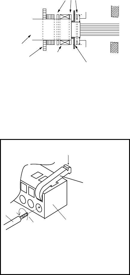
4. Slide the clamping gland, washer, gasket and washer in that order on to the cable as
shown below.
5. Fold back the armor by 5 mm, then put it between washers.
Gasket
Vinyl sheath
Clamping gland
Flat washer
Trim the armor with width of washer (5 mm).
5 mm
5 mm
6. Tighten the cable gland, and then cover the junction with putty for waterproofing.
7. Connect the cores to the connector plug TB803 by referring to the interconnection
diagram. Leave “slack” in the coaxial wire to prevent breakage.
Use the terminal opener to insert each core.
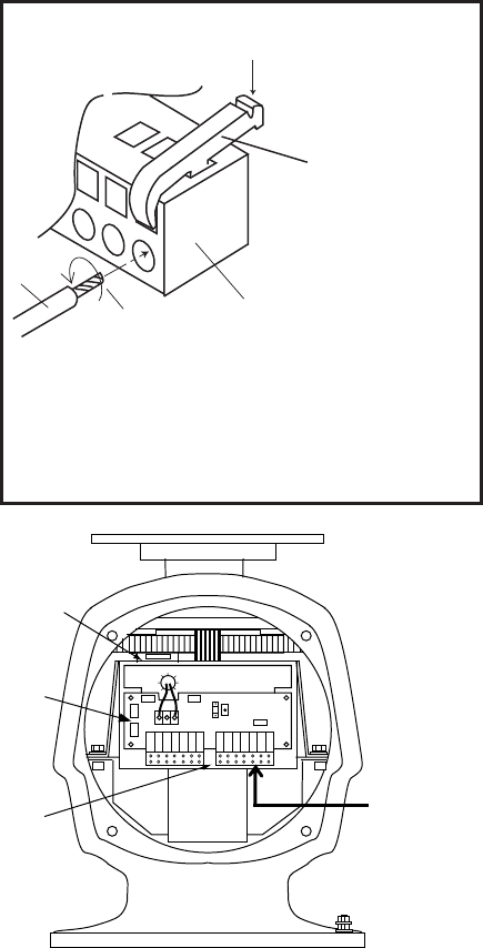
2. WIRING
2-4
Procedure
1. Twist the cores.
2. Press the terminal opener downward.
3. Insert the wire to hole.
4. Remove the terminal opener.
5. Pull the core to confirm that it is ecure.
Terminal opener
WAGO Connector
Wire
Twist
Press downward.
Wiring for WAGO connector
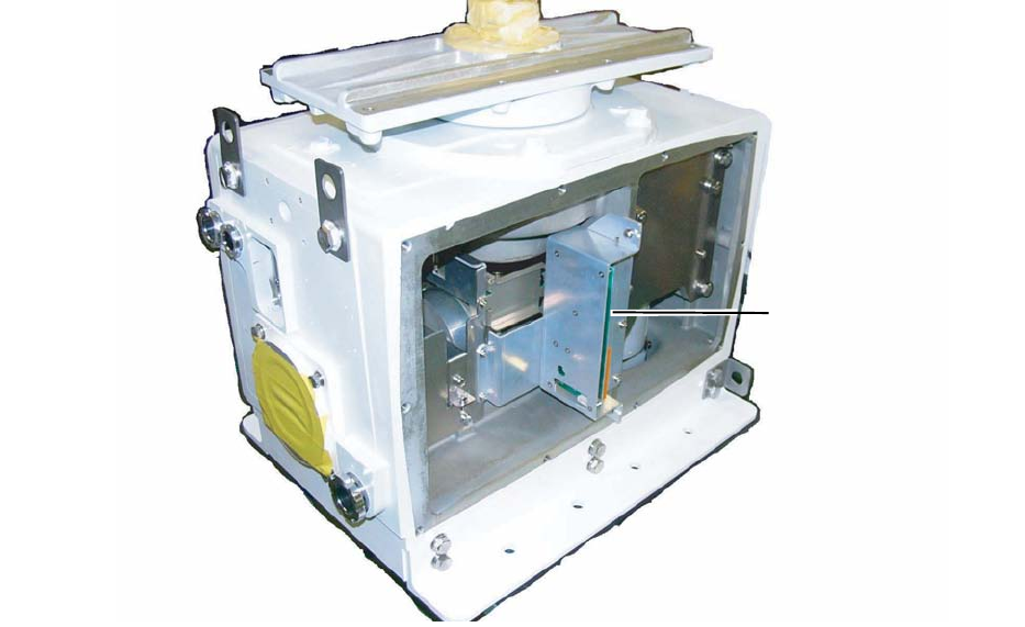
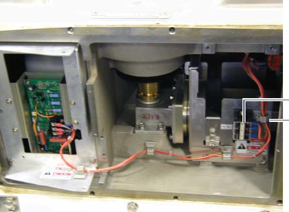
03P9349
Connector
plug
S901
MPYCY-19 cable
Antenna unit, internal view
8. Confirm that all screws are tightened and all wiring is properly made. Confirm that
waterproofing gasket, bolts and tapping holes of antenna unit are coated with silicone
grease.
9. Attach the antenna covers (torque: 2.5 N·m).

2. WIRING
2-5
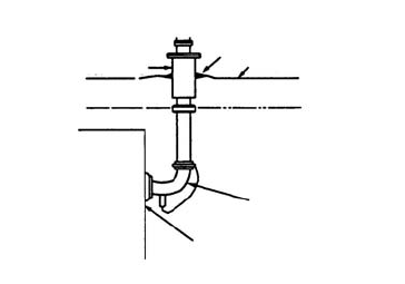
Waveguide connection at antenna unit
The signal cable entrance (cable gland) is located directly below the waveguide outlet. If the
waveguide is installed downward from the waveguide outlet position using an E-bend
waveguide, you may not be able to insert the signal cable into the cable gland. To avoid this
inconvenience, shift the waveguide run left or right using an H-bend waveguide as shown
below.
The E-band and H-band waveguides are contained in the waveguide materials set 22X-CW
or 52X-CW.
E-bend type RWA-1030 B-107, Code No. 310-100-140
H-bend type RWA-1050 C-109, Code No. 310-100-180
When the de-icer is installed
•
Before beginning any work on the antenna unit, turn off the breaker for the de-icer line at
the main switchboard to remove the power (100 VAC, 1Ф) to the de-icer. (Turning off the
power to the display unit has no effect.)
•
The neck of the antenna unit becomes VERY HOT when the de-icer is working. (The
de-icer turns on when ambient temperature is below 0 C.)
2. WIRING
2-6
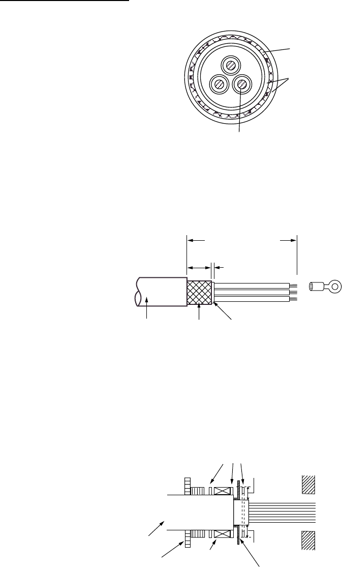
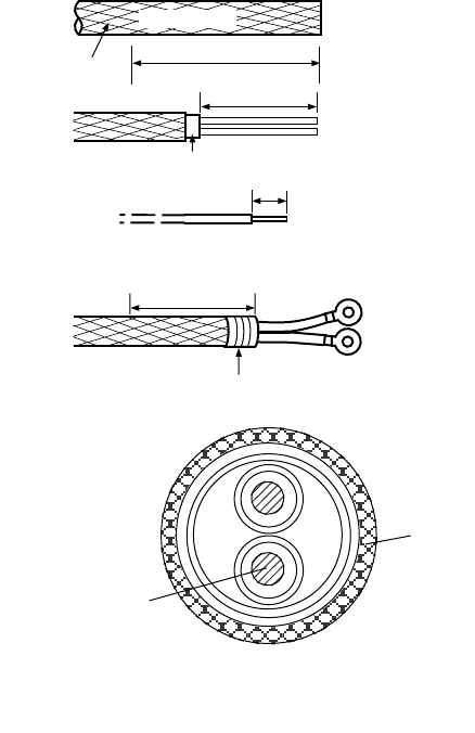
2.2.2 FAR-2837SW (RSB-104/105)
The signal cable MPYCY-12 (Japan Industrial Standard cable or equivalent), power cable
TPYCY-2.5 (Japan Industrial Standard cable or equivalent) and microwave coaxial cable
(LHPX-20-ASSY) are used between the antenna unit and transceiver unit.
MPYCY-12 single cable
Conductor
S = 1 mm
= 1.29 mm
2
MPYCY-12
Armor
Sheath
= 19.0 mm Sheath
Insulator
MPYCY-12 cable, sectional view
Antenna switch
Signal cable (MPYCY-12)
Power cable
Antenna unit, front view
1. Remove the right-hand side cover from the antenna unit by unscrew ten bolts (13 mm).
2. Unfasten the clamping gland (for signal cable), and remove the gasket, flat washers and
cover.
3. Fabricate MPYCY-12 cable as below.
20 mm
Armor
Vinyl sheath Vinyl sheath
360 mm
5 mm
6 mm
4. Slide the clamping gland, flat washer, gasket and flat washer in that order on to the
cable. (See the figure on the next page.)
5. Fold back the armor by 5 mm, then put it between washers.
2. WIRING
2-7
Gasket
Vinyl sheath
Clamping gland
Flat washers
Trim the armor with the
width of the washer (5 mm).
5 mm
5 mm
Passing clamping gland, washers and gasket on the signal cable
6. Catch the armor between two flat washers for grounding.
7. Apply sealant 1211 (supplied as installation material) to threads of the clamping gland,
and then fasten it tightly.
8. Determine the length of the cores considering their location on the terminal board TB803,
and then connect cores to TB803 by using the terminal opener.
Procedure
1. Twist the cores.
2. Press the terminal opener downward.
3. Insert the wire to hole.
4. Remove the terminal opener.
5. Pull the core to confirm that it is ecure.
Terminal opener
WAGO Connector
Wire
Twist
Press downward.
Wiring for WAGO connector
2. WIRING
2-8
TB803
Antenna unit, cover removed
9. Reattach the antenna cover (torque: 7.65 N·m), and then cover the gland junction with
putty for waterproofing.
2. WIRING
2-9
TPYCY-2.5 power cable
Conductor
S = 2.5 mm
φ = 2.01 mm
2
TPYCY-2.5
Armor
Sheath
φ = 15.5 mm
TPYCY-2.5 cable, sectional view
1. Remove the left-hand side cover from the antenna unit by unscrew ten bolts (13 mm).
2. Fabricate the cable as below.
25 mm
5 mm
FV5.5-4
Sheath
Armor
Vinyl
sheath
Approx. 170 mm
Fabricating of TPYCY-2.5
3. Unfasten the clamping gland (for power cable) to remove the gasket, flat washers and
cover.
4. Slide the clamping gland, flat washer, gasket and flat washer in that order on to the
cable. (See the figure in below.)
5. Fold back the armor by 5 mm, then put it between washers.
Gasket
Vinyl sheath
Clamping gland
Flat washer
Trim the armor with width of washer (5 mm).
5 mm
5 mm
Clamping gland (for power cable)
6. Run the power cable behind of the terminal board, and then fix it with the clamp.
2. WIRING
2-10
TB902
Clamp
Antenna unit, cover removed (left-hand side)
7. Determine the length of the cores considering their location on the terminal board TB902,
and then connect cores to TB902 by using the terminal opener.
8. Reattach the antenna cover (torque: 7.65 N·m).
9. Cover the gland junction with putty for waterproofing.
2. WIRING
2-11
When the De-icer is installed:
1. Before beginning any work on the antenna unit, turn off the breaker for the de-icer line at
the main switchboard to remove the power (100 VAC, 1ø) to the de-icer. (turning off the
power to the display unit has no effect.)
2. The neck of the antenna unit becomes VERY HOT when the de-icer is working. (The
de-icer turns on when ambient temperature is below 0ºC.)
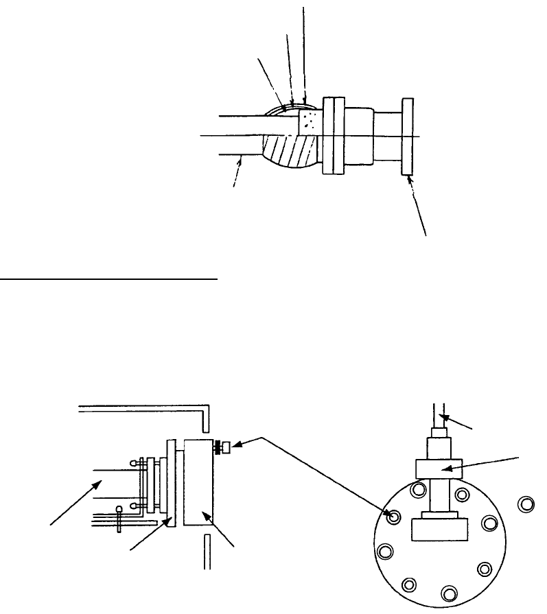
2.2.3 Coaxial cable
When connecting the coaxial cable to the antenna unit, do the followings.
1. Unfasten eight bolts (M6x20) to remove the flange cover from the antenna unit.
2. Apply grease to the O-ring located in the flange.
3. Coat between mating surfaces of the coupler at the end of the coaxial cable and
waveguide flange as below with waterproofing compound (supplied with installation
materials). Do not coat the O-ring.
O-ring
Choke
Coat with waterproofing
compound (supplied).
O-ring
4. Screw eight bolt unfastened at step 1 to fix the coupler to the flange.
Lying of microwave coaxial cable
Secure the cable with fixing bands (supplied) or clamping metal (option, type: 03-011-3228,
code no.: 100-049-620) to the mast and to the wheelhouse structure.
For the optional deck-thru cable gland, see the outline drawing at the back of this manual.
7
Clamping metal (option)
2. WIRING
2-12
2.3 Transceiver Unit
For FAR-2827W
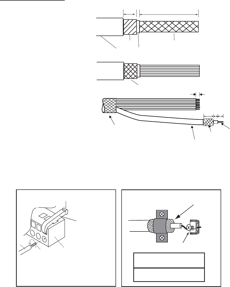
Fabricating of RW-9600
1. Fabricate the RW-9600
cable as shown right.
2. Trim each wire (except
coaxial wire) considering its
location on the terminal
board.
4. Trim the shield leaving 30
mm and then fold back it.
5. Remove insulation of each
wire by about 6 mm.
6. Using the terminal opener,
insert each core (except
coaxial cable) to appropriate
connector plug.
7. Insert the coaxial cable to
the TB802 on TB Board and
fix the shield with cable
clamp.
Wiring for Coaxial cable
CAUTION
Clamp shied with bracket.
Tighten conductor with screw.
Procedures
1. Twist the conductor.
2. Press the terminal opener downward.
3. Insert the wire to hole.
4. Remove the terminal opener.
5. Pull the wire to confirm that it is ecure.
Terminal opener
Wiring for WAGO connector
WAGO connector
Wire
Twist
Press downward.
Do not use crimp-on lug to prevent
contact resistance from increasing.
Shield
Fold back shield.
Conductor
6
14 59
Coaxial cable
Approx. 250
5
30
Unit: mm
Vinyl sheath
Armor Shield
Fold back the shield.
(30 mm)
2. WIRING
2-13
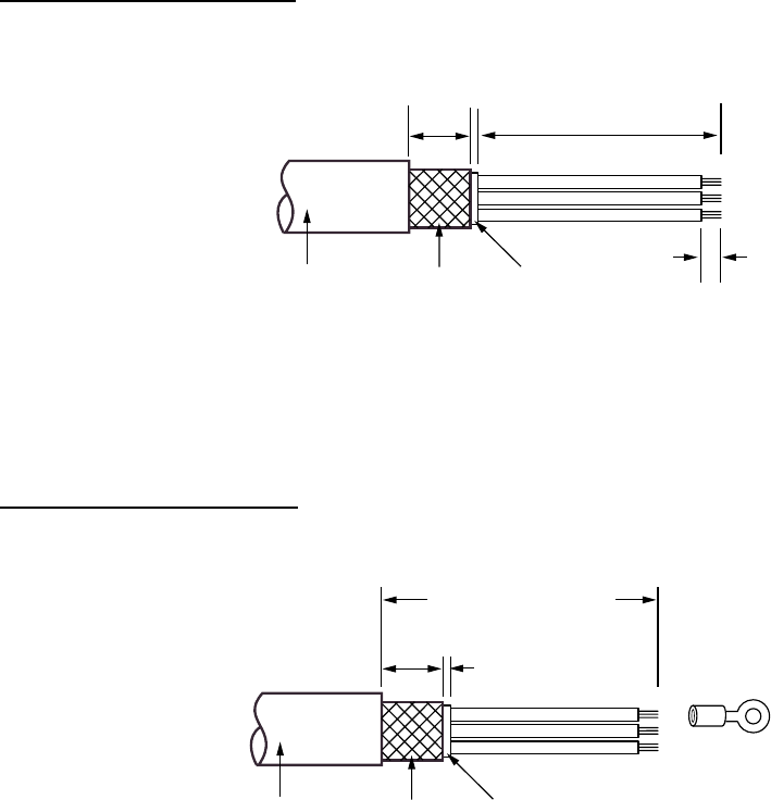
Fabricating of MPYCY-19
1. Fabricate the cable as below.
30 5
Armor
Vinyl sheath
Approx. 250
Vinyl sheath 6
Unit: mm
2. For not used cores, wind the vinyl tape around them to prevent the short circuit.
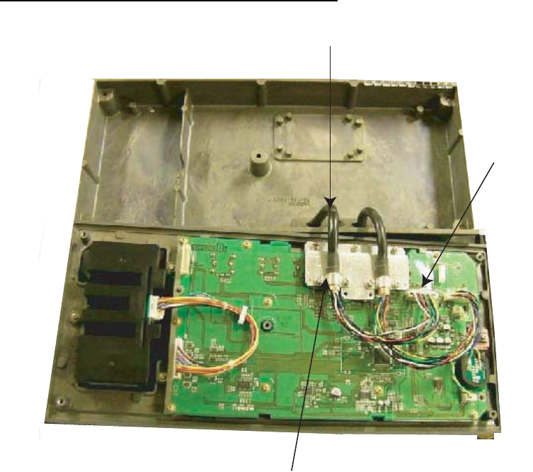
Wiring
1. Remove the cover from the RTR-081A.
2. Pass the cables through the cable entrance of the RTR-081A, and then fix the armors
with the cable clamp.
TB801
TB803
TB804
TB802
Do not remove this film.
TB Board
Cable entrance
Transceiver unit RTR-081A, internal view
3. Connect each cores to TB801, TB802, TB803 and TB804 referring to the
interconnection diagram.
4. Connect the grounding wire (shipyard supply) between the ground terminal (behind of
the cable clamp) and the grounding point.
2. WIRING
2-14
Installing the Rectangular Waveguide (WRJ-9)
The RF interconnection between the antenna unit and the transceiver can be made with a
rectangular waveguide (WRJ-9) or flexible (FR-9). If the rectangular waveguide is used,
observe the following installation guidelines.
• Correctly installed waveguide runs ensure the most efficient transmission of electrical
energy at high frequencies. Electrical losses, however, occur in the waveguide runs. To
minimize them the following factors are of great importance: minimum length, airtightness
and electrical continuity.
• Another consideration required is that of frequency disturbance. The transmitting valve, a
magnetron, is the primary oscillator in the radar.
This is different from the oscillation system at lower frequencies in which conventional
radio valves are used. In the latter case, the primary oscillator is always protected from
the effects of load impedance by a buffer stage so that frequency and waveform are left
unobstructed. With a waveguide and magnetron, however, mismatch of impedance
causes “frequency pulling.” For this reason, the number of possible mismatches in a
waveguide run, i.e., joins and bends, must be kept minimum.
• Each pair of flanges should be coupled with one O-ring, four bolts and spring washers
and the choke flange must be in the upper position. The bolts and O-ring must be
greased before insertion to facilitate removal if required at a later date.
• The transceiver unit output flange is a plain type and the antenna unit output flange is a
choke type, and it is important to maintain this relationship throughout the waveguide run.
Thru-deck hole
TRANSCEIVER
UNIT
Watertight film
Drain waveguide
Weld here.
Deck
Flange connection
• After installation of the waveguide is completed, the coupling portions must be sealed by
using the adhesive supplied.
• In a very short time the surface of the waveguide becomes green with verdigris.
Therefore, paint both the surface of the waveguide and flanges to avoid corrosion and
water penetration. Paint must not be allowed to reach the inner surface of the waveguide
or the mating surface of any flange.
2. WIRING
2-15
For FAR-2837SW
Fabricating of RW-9600
1. Fabricate the signal cable
RW-9600 as shown right.
2. Unravel the shield to expose
the wires in the inner layer.
3. Shorten each core considering
its location on the terminal
board.
4. Trim each wire (except coaxial
wire) considering its location on
the terminal board.
5. Trim the shield leaving 30 mm
and fold back it.
6. Remove insulation of each wire
by about 6 mm.
7. Insert each wire into the
connector using the terminal
opener.
8. Connect the coaxial wire to
TB802 on the TB Board, and
then fix its shield to the cable clamp.
Wiring for Coaxial cable
CAUTION
Clamp shied with bracket.
Tighten conductor with screw.
Procedures
1. Twist the conductor.
2. Press the terminal opener downward.
3. Insert the wire to hole.
4. Remove the terminal opener.
5. Pull the wire to confirm that it is ecure.
Terminal opener
Wiring for WAGO connector
WAGO connector
Wire
Twist
Press downward.
Do not use crimp-on lug to prevent
contact resistance from increasing.
Shield
Fold back shield.
Conductor
6
14 59
Coaxial cable
Approx. 250
5
30
Unit: mm
Vinyl sheath
Armor Shield
Fold back the shield.
(30 mm)
2. WIRING
2-16
Fabricating of MPYCY-12
1. Fabricate the cable as below.
30 5
Armor
Vinyl sheath
Approx. 250
Vinyl sheath 6
Unit: mm
2. For not used wires, wind vinyl tape around the core to prevent short circuit.
Fabricating of TPYCY-2.5
1. Fabricate the cable as below.
30 mm 5 mm
FV5.5-4
Sheath
Armor
Vinyl
sheath
Approx. 170 mm
2. Fix the crimp-on lug (FV5.5-4, yellow) to each conductor.
2. WIRING
2-17
Wiring
1. Remove the cover from the RTR-082.
2. Pass the cables through the cable entrance, and then fix the armor with the cable
clamp.
3. Connect each wires to TB801, TB802, TB803, TB911 and TB912 referring to the
interconnection diagram.
TB803
TB801
TB911
TB912
TB802
Transceiver unit RTR-082, internal view
4. Connect the grounding wire (shipyard supply) between the grounding terminal (behind
the cable clamp) and grounding point.

2. WIRING
2-18
How to fit microwave coaxial plug
The tool kit KZ-0244B (Code No. 000-830-258) is optionally available for fitting the coaxial
plug to the microwave coaxial cable. The contents of the kit are listed below.
Name Code No. Qty
Hacksaw 000-830-260 1
Tubing Cutter 000-830-261 1
Ruler 000-830-263 1
Diagonal cutting Pliers 000-830-264 1
Knife 000-830-265 1
Bendix Brake Pliers 000-830-266 1
Ball Peen Hammer 000-830-267 1
Metal Rod 000-830-268 1
Gauge 000-830-270 1
Flat file 000-830-270 1
Cutting Off Tool 000-830-274 1
Brush 000-830-274 1
Pliers 000-830-275 1
C-spanners 000-830-278 1
Copper Tape 000-830-279 1
Tool Box 000-830-257 2
Necessary materials
•
Gasoline
•
Clean cloths
•
Burner
2. WIRING
2-19
Outline
A coaxial plug is made up of the following parts:
(B) (A)
(2) (1) (3)
(7) (8) (5) (6)
(4)
Note 1: When sawing or filing the cable, keep it horizontal to keep shavings out of the cable.
To remove shavings which may have fallen into the cable, hold the cable end
downward and tap the cable lightly.
Note 2: A minimum cable bend radius of 150 mm must be observed at the cable run. If it is
necessary to bend the cable twice or more in a tight area, the bending radius should
be more than 250 mm.
How to fit the coaxial plug
1. Cut the cable with a hacksaw for the length desired, taking into account that the length
of the outer body of the coaxial plug is 77 mm.
39
Cut here.
Sheath
2. Remove any shavings from the cable. Using the tubing cutter, cut the vinyl jacket, the
outer conductor and the insulator to expose the inner conductor by 40 mm. Be careful
not to damage the inner conductor.
40
Cut here.
Outer conductor
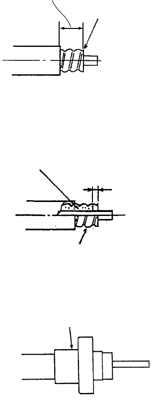
2. WIRING
2-20
3. Taking care not to scratch the outer conductor, remove the jacket: Cut the jacket
circularly first with a tubing cutter, cut in a straight line with a knife, then remove the
jacket with a cutting pliers.
Remove burrs.
24.5 to 25 mm
4. Clean the outer conductor with a gasoline and cloth.
5. Heat the cutting off tool (or hacksaw and cutter) with the burner. Then, remove with the
cutting off tool the insulator between the inner and outer conductors by the depth of 6
mm.
Outer conductors
Insulator
6
6. Clean the outer and inner conductor with gasoline and cloth. Slip the clamping nut,
spacer, gasket and outer clamp on the cable in that order. (Parts No. 1, 2 and 3 in the
figure shown in page 2-19)
Assembled with (1), (2) and (3)
Clamping nut
Coaxial cable
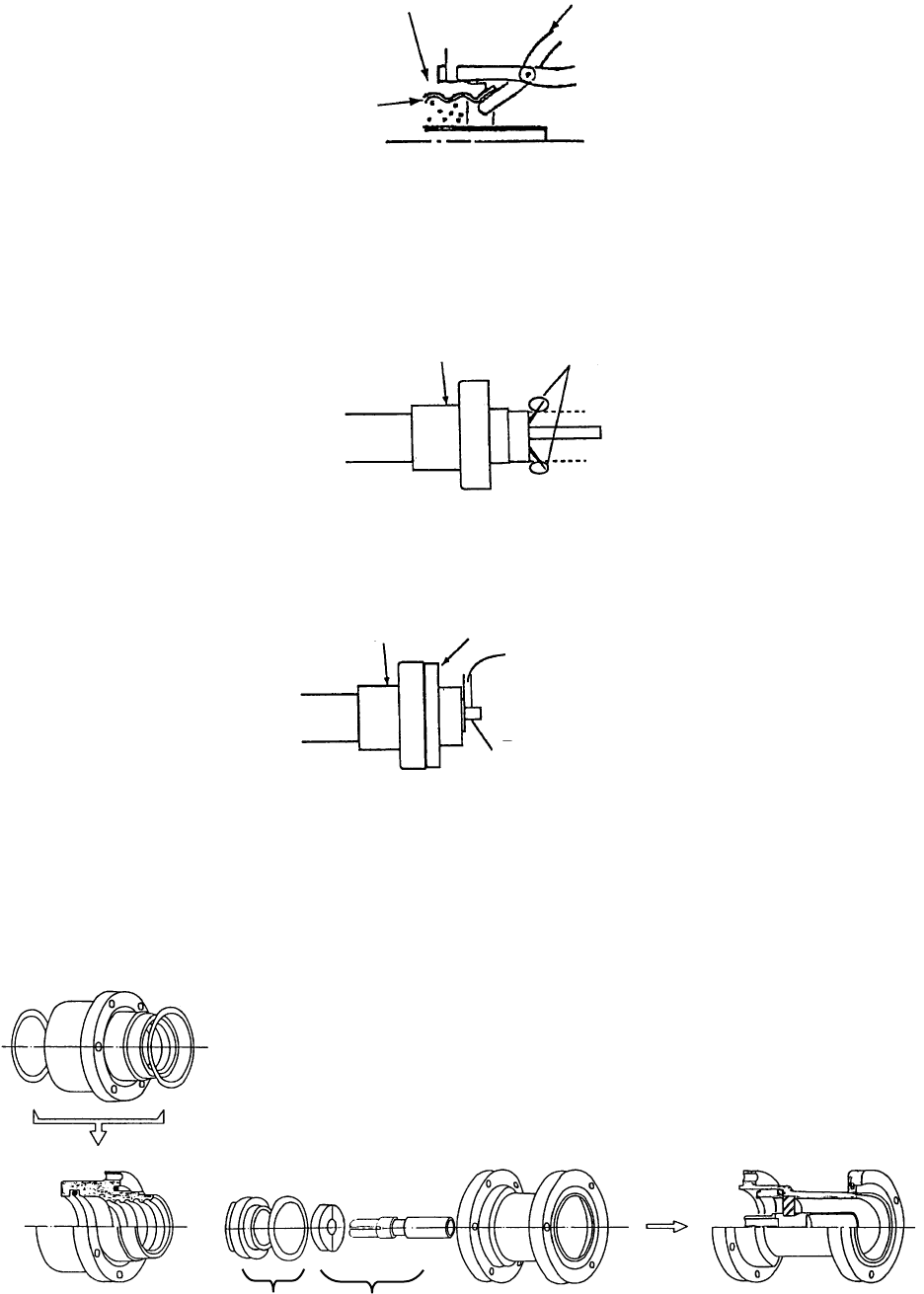
2. WIRING
2-21
7. Flare the outer conductor against the edge of the outer clamp coarsely with the Bendix
brake pliers. (Wind copper tape over the outer clamp to protect its surface.)
Connector
Outer
conductor
Bendix brake plier
8. Trim and file any portion of the outer conductor that protrudes beyond the diameter of
the outer clamp.
Note: Put a piece of cloth into the conductors temporarily so as not to let any particles in
the conductors.
Connector
Coaxial cable
Remove these
projection.
9. Insert the gauge through the inner conductor until it is covered by the outer clamp. Then,
tap the gauge gently with the hammer to position it.
10. Cut the inner conductor along the gauge and file its end.
Connector
Coaxial cable
Remove inner conductor
so 1 mm remains.
Gauge
1 mm
11. Remove the gauge. Remove any burrs with a knife.
12. Assemble (4) through (8) as below.
a) Screw (5) into (6).
b) Attach (8) to (7).
c) Attach (A) to (B), and then screw it into (4).
(B) (A)
(2) (1) (3)
(7) (8) (5) (6)
(4)
2. WIRING
2-22
13. If the coaxial cable connector is installed outdoors, follow the steps in below.
a) Tape the junction with self-bonding tape.
b) Wind vulcanizing tape around the self-bonding tape.
c) Finally, wrap vinyl tape over the vulcanizing tape.
Vinyl tape
Vulcanizing tape
Self-bonding tape
Vinyl sheath
Assembled connector
Connecting the coaxial cable
Connect the coaxial cable to the transceiver unit as below.
1. Loosen eight bolts (M6x20) to remove the dust cover from the output WG adapter.
2. Fasten eight bolts (removed at step 1) to attach the flange to the transceiver unit.
3. Attach the coaxial cable to the converter of the flange.
Circulator
Adapter Output WG adapter
M6x20 (8 pcs.) Coaxial cable
Converter
:M6x20 (8 pcs.)
Transceiver unit, internal view Flange
2. WIRING
2-23
2.4 Monitor Unit
Two cables are terminated at the monitor unit: the signal cable from the processor unit and
the power cable from the ship’s mains. The signal cable comes with a connector
preattached to it for connection to the monitor unit. Fabricate the power cable as below. Use
DPYC-2.5 (Japan Industry Standard) cable or the equivalent.
Fabricating the power cable
1. Cut armor of the cable by 40 mm.
2. Cut vinyl sheath by 35 mm.
3. Remove insulation of wires by about 10 mm. Fix crimp-on lugs to the cores.
4. Peel point of the armor by 40 mm.
5. Cover the end of armor with vinyl tape.
40 mm: Peel paint.
Taping
(a)
(b)
(d)
Armor
35 mm
10 mm
(c)
Approx. 40 mm
DPYC-xx
Vinyl sheath
Conductor
S = 2.5 mm
φ = 2.01 mm
2
Armor
(sectional view)
Fabricating power cable DPYC-2.5
Cable entrance for signal cable
(The connector side which EMI core is attached
should be connected to the processor unit.)
Cable entrance for power cable
Monitor unit (rear panel)
2. WIRING
2-24
2.5 Processor Unit
Four cables are terminated at the processor unit: the antenna unit cable, display unit cable,
control unit cable and the power cable. Cables other than the power cable come with a
connector preattached to them for connection to the processor unit. Fabricate the power
cable as below. For the power cable, use DPYC-2.5 (Japan Industry Standard) cable for DC
unit or DPYC-6 for AC unit, or the equivalent.
Fabricating the power cable
1. Cut armor of the cable by 40 mm.
2. Cut vinyl sheath by 35 mm.
3. Remove insulation of wires by about 10 mm. Fix crimp-on lugs to the cores.
4. Peel point of the armor by 40 mm.
5. Cover the end of armor with vinyl tape.
40 mm: Peel paint.
Taping
(a)
(b)
(d)
Armor
35 mm
10 mm
(c)
Approx. 40 mm
DPYC-xx
Vinyl sheath
Conductor of DPYC-2.5
S = 2.5 mm
φ = 2.01 mm
2
Armor
(sectional view)
Conductor of DPYC-6
S = 6.0 mm
φ = 3.12 mm
2
Fabricating power cable DPYC
2. WIRING
2-25
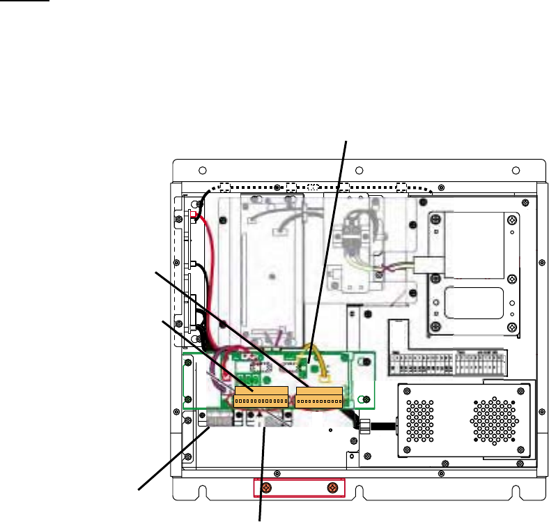
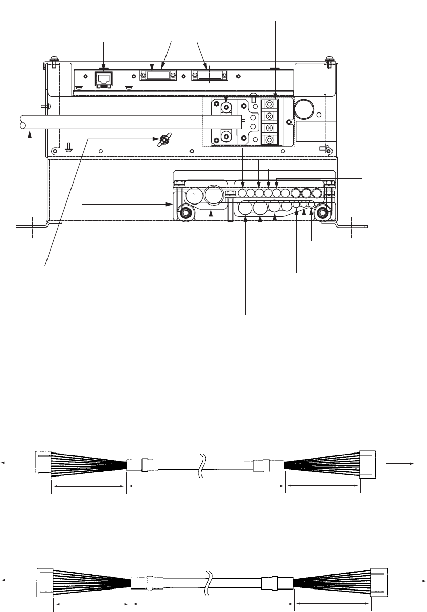
Connection of cables
The power cable is connected to the terminal board on the rear panel and the signal cable
from the display unit is connected to the DVI-D connector. Other cables are connected to
the printed circuit board 03P9342.
F1
1
2
ACK φ18.9
AIS
17
AD100
8
GYRO 28
PSU004
24
φ7.4
VDR IN
φ7
VDR OUT
24' 26
9 14 17
15
DC/AC
21
φ9HDG
32 54 6
RSD
1918 20
Monitor unit
Network DVI-D monitor
Power cable clamp
Power cable terminal board
Remove the
protection cover.
Control unit**
Heading senor
Speed log
Navigator
Memory Card IF unit
VDR OUT
VDR IN
Gyrocompass
AD-100
AIS
Antenna unit
Cable clamp
GND terminal
Power cable
*
FUSE
F70
Processor unit (rear panel)
*: The connector side which EMI core is attached should be connected to the
processor unit.
**: The configuration of optional cables between the processor unit and the
control unit is as follows. Note that the cable fabrication for each end is
different.
20/30 m
300 mm
150 mm
Control unit Processor unit
Cable XH10P-W-6P L=20/30M
When the RCU-016 is installed, optional cable (XH10P-W-5P-A, L=10/20/30M) is required.
Cable fabrication for each end is the same.
10/20/30 m 150 mm
150 mm
Control unit Control unit
XH10P-W-5P-A L=10/20/30M
2. WIRING
2-26
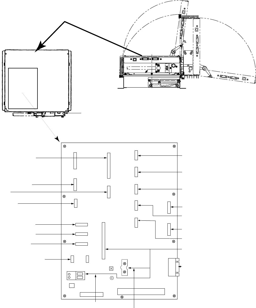
Location of connectors
Open appear part of the processor unit.
J621
J620
J619
J618
J612
J610
J608
J607
J606
J605
J604
J603
J602
J601
J617
J616
PSU
J654
J615J614
J613
Tx HV line
J609
Cable clamp
03P9342
Gyro converter board
or AD-100
Speed log
Navigator
Heading sensor
Cable from control unit
PC
Cable from antenna unit
Coaxial wire
Gyro converter board
AIS
External alarm
Track control
ECDIS
Sub display*
Master radar
+ 12 V for card I/F
Sub display*
(SEMI-LOG)
(FULL-LOG)
J611
Cable from Power
supply unit
03P9342
*: For details, see page 2-28.
2. WIRING
2-27
Cable fabrication for the cables connected to the 03P9342 board
• Signal cable RW-9600 (Between antenna unit and processor unit)
Shield
Armor
Clamp here by cable clamp.
Vinyl tape After exposing cores,
wind shield around the armor.
Vinyl sheath
Coaxial cable
6
60 450
5
Conductor
59
Coaxial cable
14
Fold back shield.
• Other cables for optional units
Use TTYCS-1 or TTYCS-4 (Japan standard cable) or equivalent.
Conductor
S = 0.75 mm
φ = 1.11 mm
2
TTYCS-1
Armor
Shield
Sheath
φ =
10.1 mm
Conductor
S = 0.75 mm
φ = 1.11 mm
2
TTYCS-4
Armor
Shield
Sheath
φ = 18.5
mm
60: Peel paint.
L
5
Shield
Armor
Clamp here by cable clamp.
Vinyl tape After exposing cores,
wind shield around the armor.
L= Depends on equipment
connected. Measure at
the processor unit.
6
Wiring for Coaxial cable
CAUTION
Clamp shied with bracket.
Tighten conductor with screw.
Procedures
1. Twist the conductor.
2. Press the terminal opener downward.
3. Insert the wire to hole.
4. Remove the terminal opener.
5. Pull the wire to confirm that it is ecure.
Terminal opener
Wiring for WAGO connector
WAGO connector
Wire
Twist
Press downward.
Do not use crimp-on lug to prevent
contact resistance from increasing.

2. WIRING
2-28
Connection of Sub-display
A conventional remote display and/or FAR-2107 series radar can be connected to J617 and
J618 in the processor unit as a sub-display. However, the control for GAIN and STC are
different depending on J617 and J618. Refer to the table to connect sub-displays.
Port Conventional remote
display
FAR-2107 series radar
Overall gain Even if input video level is
adjusted to 4 Vp-p, the
gain is 8 db lower than
that on the master radar.
The gain is 8 dB lower than
that on the master radar.
GAIN control
The GAIN control is
effective.
The GAIN control has no
effect.
J617
(FULL-LOG)
STC control The STC control is
effective.
The STC control has no
effect.
Overall gain When input video level is
adjusted to 4 Vp-p, the
gain becomes the same
as that on the master
radar.
The gain is almost same as
that on the master radar.
GAIN control The GAIN control is
effective.
The GAIN control has no
effect.
J618
(SEMI-LOG)
STC control The STC control is
effective, however this
control is added on the
signal adjusted by the
master radar. So this port
is not recommended to
use .
The STC control has no
effect.
2. WIRING
2-29
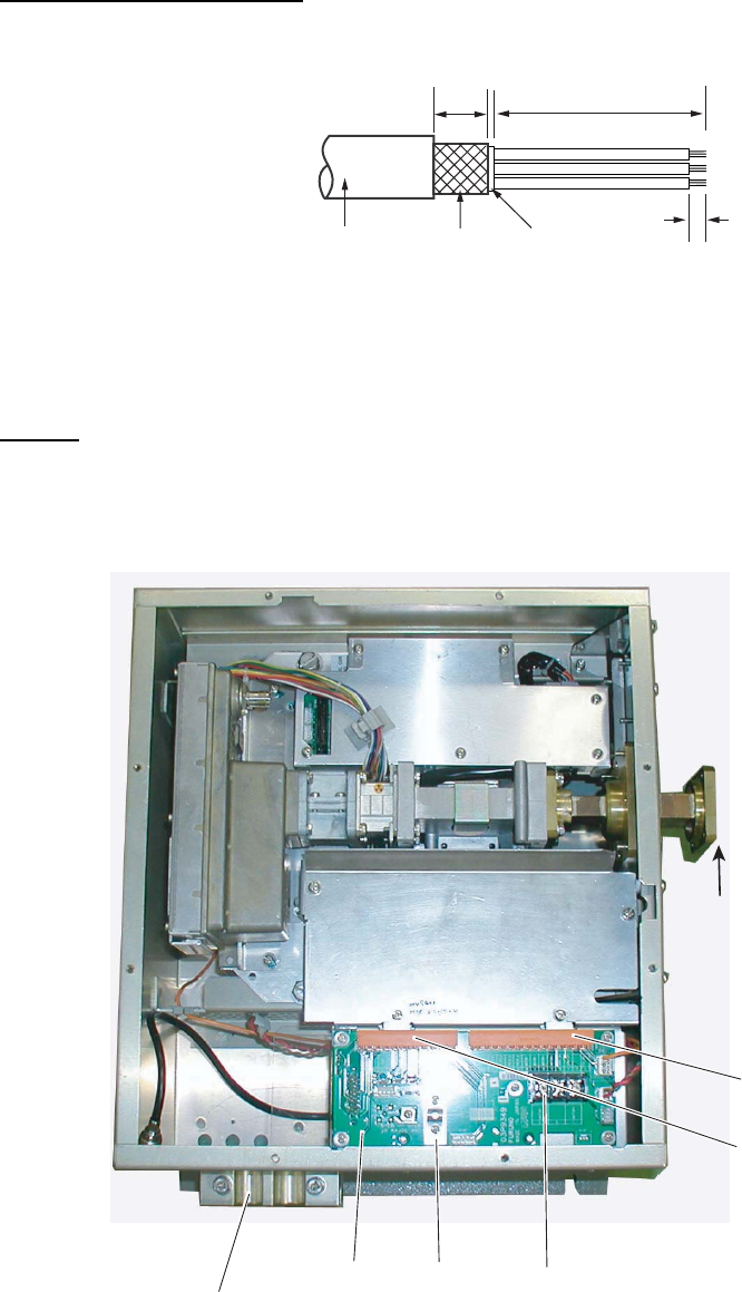
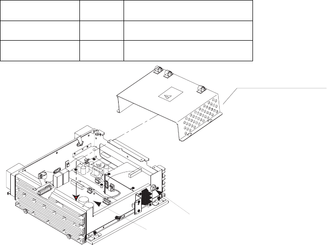
2.6 Changing AC Power Specification of Processor
Unit
To change AC power specification between 100 VAC and 220 VAC, add or remove jumper
connector P108 on the PWR board 03P9339 and change the fuse on the processor unit
according to ship’s mains as shown in the table below. The figure on the next page shows
the location of the fuse and the jumper connector on the PWR board. Also, adjustment of
the overvoltage detection circuit is required.
Note: To change from 220VAC to 100VAC, locally prepare the jumper connector, referring to
the figure on the next page (VH8P connector housing is fitted at J108).
Power supply Fuse Jumper connector P108
100 VAC 10A Added
220 VAC 5A Removed
Cover of PWR board
Fuse
Upper part of processor unit
(SPU assembly omitted)
PWR board
2. WIRING
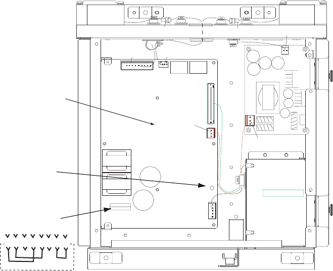
2-30
J104
J103
J106
J105
J101
PWR board
(P)HV
AC FIL
P108/J108
R21
(OVER)
8 7 6 5 4 3 2 1
Jumper connector
(VH8P)
How to adjust the overvoltage detection circuit:
1. Add or remove the jumper connector P108 and change the fuse.
2. Rotate R21 fully clockwise on the PWR board.
3. Connect a variable transformer between ship's mains and the input power terminal board
TB-1 of the processor unit.
4. Adjust the variable transformer output (i.e., input voltage to the processor unit) as follows.
For 100 VAC set: 144 VAC
For 220 VAC set: 288 VAC
5. Turn on the radar and rotate the R21 counterclockwise gradually until the overvoltage
detection circuit functions (i.e., power supply cuts off).
6. Lower the output voltage of the variable transformer and confirm that the radar
automatically turn on with a voltage lower than 142VAC or 284VAC.
7. Gradually increase the output voltage of the variable transformer and confirm that the
overvoltage detection circuit functions at 144V or 288VAC of the variable transformer
output.
8. Assemble and connect the processor unit.
2.7 Power Supply Unit
Refer to the interconnection diagrams for wiring details.
1. Unfasten the cable clamp.
2. Open the cover.
3. Connect the power cable (DPYC-2.5) between the PSU-011 and TB1 on the processor
unit. (See page 2-4 for how to fabricate the cable.)
4. Connect the power cable (DPYC-2.5) between the PSU-011 and power source.
5. Fasten the cable clamp and close the cover.
3-1
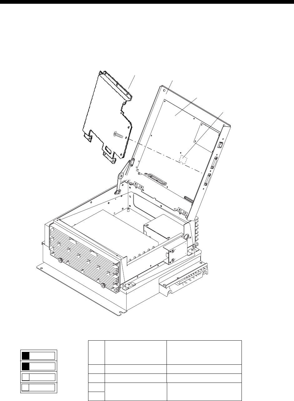
3. SETTING AND ADJUSTMENT
3.1 DIP Switch Setting
The DIP switch setting as follows.
1. Remove the top cover of the processor unit.
2. Open the SPU assembly block.
Shield cover
SPU assembly block
SPU board 03P9337
DIP switch S1
3. Set the DIP switch S1 as follows.
S1 Monitor SXGA
(1024x1280,
Default)
Monitor UXGA
(1024x1360)
1 OFF ON
2 OFF OFF
3
4 Not used.
Note: Set #1 and #2 of S1 to OFF for MU-231CR S. No. 0268 and earlier.
1
2
3
4
OFF ON
S1

3. SETTING AND ADJUSTMENT
3-2
[ECHO]
1 BACK
2 2ND ECHO REJ
OFF/ON
3 TUNE INITIALIZE
4 PM
OFF/ON
5 SART
OFF/ON
6 WIPER
OFF/1/2
7 ECHO AREA*
CIRCLE/WIDE/ALL
8 [PICTURE SELECT]
9 STC RANGE
+00
3.2 Initializing Tuning
1. Transmit the radar on 48 nm range and rotate the GAIN knob to show 70-80 of the gain
bar.
2. Roll the trackball to choose the MENU box at the right side of the screen and then push
the left button.
3. Roll the wheel to choose 1 ECHO and then push the wheel.
Bold: Default settings
(Same for all menu illustrations)
*: non IMO-type only.
ECHO menu
4. Roll the wheel to choose 3 TUNE INITIALIZE.
5. Push the wheel to initialize automatic tuning.
After a while, echoes appear on the screen. The message “TUNE INITIALIZE” appears in
red during automatic tuning. When this message disappears, the tuning is completed. If
necessary adjust the GAIN to show echoes clearly.
6. Push the right button twice to close the menu.
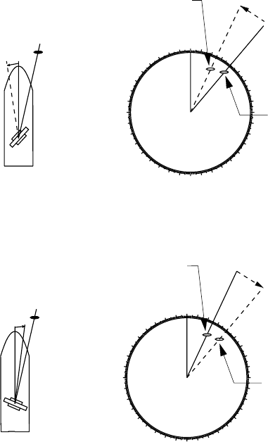
3. SETTING AND ADJUSTMENT
3-3
3.3 Heading Alignment
You have mounted the antenna unit facing straight ahead in the direction of the bow.
Therefore, a small but conspicuous target dead ahead visually should appear on the
heading line (zero degrees).
In practice, you will probably observe some small bearing error on the display because of
the difficulty in achieving accurate initial positioning of the antenna unit. The following
adjustment will compensate for this error.
000 010 020 030
040
050
060
070
080
090
100
110
120
130
140
150
160
170
180
190
200
210
220
230
240
250
260
270
280
290
300
310
320
330 340 350
αTarget
α
Correct bearing
relative to heading
Antenna mounted error
to port (HDG SW
advance)
Picture appears
deviated clockwise.
000 010 020 030
040
050
060
070
080
090
100
110
120
130
140
150
160
170
180
190
200
210
220
230
240
250
260
270
280
290
300
310
320
330 340 350
βTarget
β
Apparent position
of target
Antenna mounted error
to starboard (HDG
SW delayed)
Picture appears
deviated counterclockwise.
Correct
bearing
relative to
heading
Apparent
position
of target
Heading alignment
1. Select a stationary target echo at a range between 0.125 and 0.25 nm, preferably near
the heading line.
2. Operate the EBL control to bisect the target echo.

3. SETTING AND ADJUSTMENT
3-4
3. Read the target bearing.
4. Measure the bearing of the stationary target on the navigation chart and calculate the
difference between actual bearing and apparent bearing on the radar screen.
5. Press the [MENU] key to show the main menu.
6. While pressing and holding down the [HL OFF] key, press the [MENU] key five times.
7. Press the [0] key to show the [INITIALIZE] menu.
[INITIALIZE]
1 BACK
2 [ECHO ADJ]
3 [SCANNER]
4 [INSTALLATION]
5 [OWN SHIP INFO]
6 [TT PRESET]
7 [NETWORK]
8 [OTHER]
9 [FACTORY]
Note: See next page to access the INITIALIZE menu with the trackball style control unit
RCU-015.
8. Press the [2] key to open the [ECHO ADJ] menu.
[ECHO ADJ]
1 BACK
2 CABLE ATT ADJ
AUTO/MANUAL
30
3 HD ALIGN
000.0°
4 TIMING ADJ
0
5 MBS
0
6 DEFAULT ANT HEIGHT
5/7.5/10/15/20/
25/30/35/40/45/
more 50 m
7 NEAR STC CURVE
2/2.5/3/3.5/4.2
8 MID STC CURVE
3/4/5/6
9 FAR STC CURVE
6/7/8
0 RING SUPPRESSION
0
ECHO ADJ menu
9. Press the [3] key to choose the HD ALIGN option.
10. Key in the bearing difference. The setting range is 0 to 359.9°.
11. Confirm that the target echo is displayed at correct bearing on the screen.
12. Press the [MENU] key to finish.
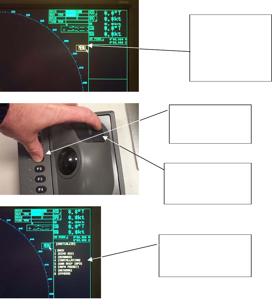
3. SETTING AND ADJUSTMENT
3-5
How to Access the Installation Mode with the RCU-015 Trackball Style
Controller
1. By using the trackball,
move the pointer until
it highlights the MENU
box as shown. DO
NOT CLICK the menu
box, just leave the
arrow over the menu.
2. Press and hold down
the F1 key. Keep it
held down during the
next step.
3. Then, click on the right
controller button 5 times.
You should hear a “triple
Beep” on the fifth press.
The INITIALIZE menu will
appear. Click on
INSTALLATION to access
the installation menus.
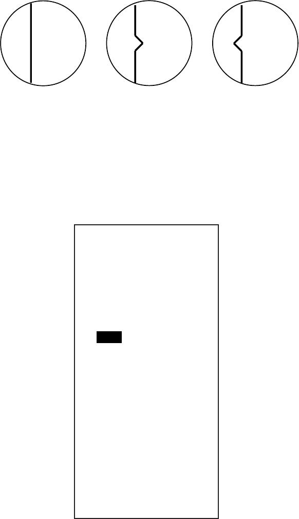
3. SETTING AND ADJUSTMENT
3-6
3.4 Adjustment Sweep Timing
Sweep timing differs with respect to the length of the signal cable between the antenna unit
and the processor unit. Adjust sweep timing at installation to prevent the following
symptoms:
• The echo of a “straight” target (for example, pier), on the 0.25 m range, will appear on the
display as being pulled inward or pushed outward. See Figure below.
• The range of target echoes will also be incorrectly shown.
(1) Correct (2) Target pushed (3) Target pushed
inward outward
Examples of correct and incorrect sweep timings
1. Transmit on the 0.25 nm range.
2. Adjust radar picture controls to display picture properly.
3. Select a target echo which should be displayed straightly.
4. Press the [4] key to choose the [TIMING ADJ] on the [ECHO ADJ] menu.
[ECHO ADJ]
1 BACK
2 CABLE ATT ADJ
AUTO/MANUAL
30
3 HD ALIGN
000.0°
4 TIMING ADJ
0
5 MBS
0
6 DEFAULT ANT HEIGHT
5/7.5/10/15/20/
25/30/35/40/45/
more 50 m
7 NEAR STC CURVE
2/2.5/3/3.5/4.2
8 MID STC CURVE
3/4/5/6
9 FAR STC CURVE
6/7/8
0 RING SUPPRESSION
0
5. Rotate the wheel to set a suitable value which causes the target to be displayed
straightly. The setting range is 0 to 4095.
6. Press the [MENU] key to finish.

3. SETTING AND ADJUSTMENT
3-7
3.5 Suppressing Main Bang
If main bang appears at the screen center, suppress it as follows.
1. Transmit the radar on a long range and then wait ten minutes.
2. Adjust gain to show a slight amount of noise on the display.
3. Select the 0.25 nm range. Adjust sea clutter control to suppress sea clutter.
4. Press [5] key to choose the MBS on the [ECHO ADJ] menu.
[ECHO ADJ]
1 BACK
2 CABLE ATT ADJ
AUTO/MANUAL
30
3 HD ALIGN
000.0°
4 TIMING ADJ
0
5 MBS
0
6 DEFAULT ANT HEIGHT
5/7.5/10/15/20/
25/30/35/40/45/
more 50 m
7 NEAR STC CURVE
2/2.5/3/3.5/4.2
8 MID STC CURVE
3/4/5/6
9 FAR STC CURVE
6/7/8
0 RING SUPPSSION
0
5. Rotate the wheel to set a suitable value so that the main bang disappears.
The setting range is 0 to 255.
6. Press the [MENU] key to finish.

3. SETTING AND ADJUSTMENT
3-8
3.6 Other Settings
ECHO menu setting
Open the ECHO ADJ menu as described on page 3-3 and 3-4.
[ECHO ADJ]
1 BACK
2 CABLE ATT ADJ
AUTO/MANUAL
30
3 HD ALIGN
000.0°
4 TIMING ADJ
0
5 MBS
0
6 DEFAULT ANT HEIGHT
5/7.5/10/15/20/
25/30/35/40/45/
more 50 m
7 NEAR STC CURVE
2/2.5/3/3.5/4.2
8 MID STC CURVE
3/4/5/6
9 FAR STC CURVE
6/7/8
0 RING SUPPRESSION
0
To close the menu, press the [MENU] key.
CABLE ATT ADJ
Before adjusting, set the radar as follows:
IR: 2, ES: off, EAV: off, 24nm range, long pulse
(Same as default setting of PICTURE1)
To adjust the cable attenuation manually, choose MANUAL by pressing [2] and the [ENTER]
key, and then rotate the wheel so that noise just appears on the screen when the gain is set
to 80. Default setting is 30 for the antenna cable length of 15m. The setting range is 0 to 73.
To adjust automatically, choose AUTO and press the [ENTER] key. The message “CABLE
ATT ADJ” appears in red at the bottom of the screen. It takes about five minutes to
complete the adjustment, after which the radar goes into stand-by.
DEFAULT ANT HEIGHT
Select height (m) of the radar antenna unit from the sea surface among 5, 7.5, 10, 15, 20,
25, 30, 35, 40, 45 and “more 50 m”.
NEAR STC CURVE, MID STC CURVE AND FAR STC CURVE
Use the default setting. Change the setting if desired according to sea condition.
RING SUPPRESSION
This is mainly used to removes “ring” noise which appears in the waveguide-type radar.
Adjust so the rings disappear at the range of 0.125 nm. The setting range is 0 to 255.

3. SETTING AND ADJUSTMENT
3-9
Scanner setting
1. Open the INITIALIZE menu described on page 3-2.
2. Press [3] key to open the SCANNER menu.
[SCANNER]
1 BACK
2 BLIND SECTOR 1
START 000°
ANGLE 000°
3 BLIND SECTOR 2
START 000°
ANGLE 000°
4 ANT REVOLUTION
LO/HI/AUTO
5 ANT SW
OFF/ON/EXT
6 ANT STOPPED
STBY/TX
7 M SPEC
OFF/ON
8 BB TYPE
NORMAL/BB
9 [DUAL RADAR]*
Note 1: Set the blind sector as minimum as possible.
Note 2: Do not set the blind sector in the bow direction.
*non IMO-type only
To close the menu, press the [MENU] key.
BLIND SECTOR 1 and BLIND SECTOR 2
Set area (up to 2) where no radar pulses will be transmitted, and heading should be
adjusted before setting any blind sector. For example, set the area where an interfering
object at the rear of the scanner would produce a dead sector (area where no echoes
appear) on the display. To enter an area, enter start bearing relative the heading and dead
sector angle. To erase the area, enter 0 for both the START and ANGLE sections. The
setting range of START is 0 to 359° and ANGLE is 0 to 180°.
ANT REVOLUTION
This menu item is used for 42 rpm antenna unit. The default is AUTO, where antenna
revolution speed is high for short range setting and low speed for long range setting. When
LO is selected, the antenna always rotate in 36 rpm, and HI, 42 rpm.
ANT SW and ANT STOPPED
This is used for antenna maintenance by serviceman.
Note: Choose OFF at ANT SW to prevent the antenna rotation. As for ANT STOPPED,
choose STBY to prevent transmission while the antenna is stopped.
M SPEC and BB TYPE
Not used.
DUAL RADAR
See section 3.7.

3. SETTING AND ADJUSTMENT
3-10
INSTALLATION menu setting
Open the INSTALLATION menu by pressing [4] key on the INITIALIZE menu.
[INSTALLATION]
1 BACK
2 RADAR*
MAIN/SUB
3 RANGE UNIT **
NM/SM/km/kyd
4 RADAR NO***
1/2/3/4/5/6/7/8
5 RADAR POSN
FORE/MAIN TOP/
MAIN 2ND/MAIN 3RD/
AFT/PORT/
STAR BOARD
6 MODEL
6/12/25 UP/25 DOWN/
50/30 UP/30 DOWN/60
7 TYPE
IMO/A/B/C/W
8 ON TIME
XXXXXXX.X H
9 TX TIME
XXXXXXX.X H
0 PM GAIN ADJ
0
**: non IMO-type only.
***: No.1-4: with antenna unit
No.5-8: without antenna unit
*: Cannot be selected.
RADAR
Choose main radar or sub radar.
RANGE UNIT
Choose NM, SM, km or kyd (kilo yard) as appropriate, however-IMO type radar is “NM”
only.
RADAR NO and RADAR POSN
For multiple radar system using the network hub, set number (name) and antenna position
for each system to easily distinguish the radar configuration.
MODEL
Confirm the model of your radar. If the setting of this item is different from your model
(combination of the antenna unit), the radar functions abnormally.
25 DOWN: for FAR-2827W
30 DOWN: for FAR-2837SW
TYPE
Choose type of radar: IMO, A, B, C, or W.
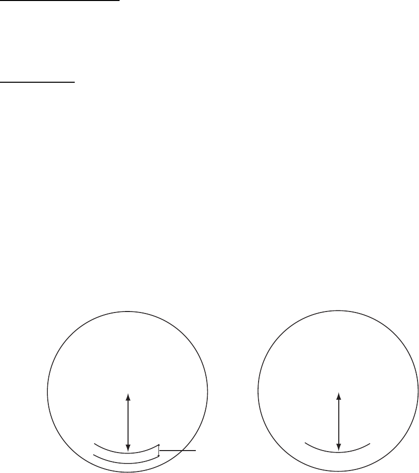
3. SETTING AND ADJUSTMENT
3-11
ON TIME and TX TIME
These items show number of hours the radar has been turned on and transmitted,
respectively. Value can be changed; for example, after replacing magnetron TX Time can be
reset to 0.
PM GAIN ADJ
Note: If you install the Performance Monitor PM-31 at field, see section 4.4 on page 4-16.
When you choose this item, the radar setting changes as follows.
RANGE: 24 NM
PULSE: LONG
BLIND SECTOR: OFF
STC: OFF by Manual
RAIN: OFF by Manual
ECHO AVERAGE: OFF
VIDEO CONTRAST: 2-B
TUNE: AUTO
1. Adjust the GAIN control so that a slight amount of white noise appears on the screen.
Arcs for performance monitor appear on the screen (Fig.1).
2. Adjust PM GAIN ADJ so that outer arc just disappears (Fig.2). The setting range is 0 to
255.
Approx. 0.6 nm
(10 dB)
13.5 - 18.5 nm 13.5 - 18.5 nm
Fig.1 Fig.2

3. SETTING AND ADJUSTMENT
3-12
OWN SHIP INFO menu setting
Open the OWN SHIP INFO menu by pressing the [5] key on the INITIALIZE menu.
[OWN SHIP INFO]
1 BACK
2 LENGTH/WIDTH
LENGTH 100 m
WIDTH 50 m
3 SCANNER POSN
BOW 0 m
PORT 0 m
4 GPS1 ANT POSN
BOW 0 m
PORT 0 m
5 GPS2 ANT POSN
BOW 0 m
PORT 0 m
6 CONNING POSN
BOW 0 m
PORT 0 m
LENGTH/WIDTH and SCANNER POSN
To inscribe own ship shape on the screen when you choose it on the menu, enter length
and width of the ship and antenna position from the bow and left sides.
The setting ranges are as follows.
LENGTH: 0 to 999 m
WIDTH: 0 to 999 m
BOW: 0 to 999 m
LEFT: 0 to 999 m
GPS 1 ANT POSN and GPS 2 ANT POSN
These items are needed for AIS information. Enter the GPS antenna position from the bow
and left sides. The setting ranges are the same as above.
CONNING POSN
Enter the conning position in the wheelhouse, from the bow and left sides. The setting
ranges are the same as above.
When you set the display reference point to the conning position, these values are used to
correct the radar antenna position.
Note: If two or more radars are installed, items other than 3 SCANNER should be the same
on each radar.
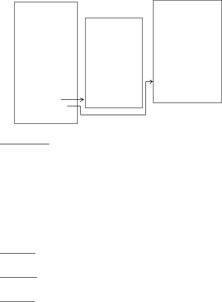
3. SETTING AND ADJUSTMENT
3-13
TT PRESET menu setting
Open the TT PRESET menu by pressing [6] key on the INITIALIZE menu.
[TT PRESET]
1 BACK
2 TT DATA OUTPUT
OFF/TTM/TTD
REL/TRUE
4800/9600/
19200/38400
3 MAX RANGE
24/32
4 ECHO LEVEL
16
5 QV DISPLAY
OFF/ON
6 TT W/O GYRO*
OFF/ON
7 [TT PRESET]
8 [TRACK PRESET]
9 [TT SENSOR DATA]
0 DEFAULT
1 BACK
2 LAND SIZE
1600 M
3 ANT SELECT
XN12AF/XN20AF/
XN24AF/XN4A/XN5A
SN30AF/SN36AF/
SN4A/SN5A
4 AUTO ACQ CORRE
5 SCAN
5 AUTO ACQ WEED
1 SCAN
6 [TT DETAIL DATA]
1 BACK
2 GATE SIZE
S/ M /L/LL
3 FILTER RESPONSE
1/ 2 /3/4
4 LOST COUNT
9 SCAN
5 MAX SPEED
100 KTS
6 TRACKING MODE
1 /2/3/4
7 START TIME TGT VECT
TIME /SCAN
50 SEC
20 SCAN
[TT PRESET]
[TRACK PRESET]
*: Not on IMO radar
TT DATA OUTPUT
Set the output format from J691 port (sentence, bearing and baud rate) of tracked targets.
Sentence: (OFF: No output, TTM: Tracked target information, TTD: Tracked target data)
Bearing: REL: Target bearing from own ship, degree relative,
target course, degree relative.
TRUE: Target bearing, degree true, target course, degree true.
Baud rate: (4800, 9600, 19200 or 38400 bps)
NOTE: The TT OUTPUT port changes according to the setting for INS as described on
page 3-15.
INS-OFF: Output from J619 port only
INS-SERIAL: Output from J619 and J620 (TTM only) ports
INS-LAN: Output from J619 and NETWORK (TTM only) ports
MAX RANGE
Choose the target tracking range, 24 or 32 nm.
ECHO LEVEL
Set the detection level of echoes. The setting range is 1 to 31.
QV DISPLAY
OFF: Normal picture
ON: Quantized picture; always off at power on

3. SETTING AND ADJUSTMENT
3-14
TT W/O GYRO (Not on IMO radar)
If a gyrocompass is not connected, choose the TT function, ON(working) or OFF (no
working).
LAND SIZE
Set the land size in units of 100 m. The setting range is 100 to 3000 m.
ANT SELECT
Set the antenna radiator type of your radar.
AUTO ACQ CORRE
Set the correlation count of automatic acquisition. The setting range is 3 to 10.
AUTO ACQ WEED
Set the cancel count of automatic acquisition. The setting range is 1 to 5.
GATE SIZE
Set the gate size among S, M, L, or LL.
FILTER RESPONSE
Set the filter response function. The setting range is 1 to 4.
LOST COUNT
Set the lost count. The setting range is 1 to 20.
MAX SPEED
Set the maximum tracking speed. The setting range is 40 to 150.
TRACKING MODE
Set the tracking mode among 1 to 4.
START TIME TGT VECT
Choose time which a vector appears after acquisition, TIME or SCAN and set seconds or
scan counts.

3. SETTING AND ADJUSTMENT
3-15
OTHER menu setting
Open the OTHER menu by pressing [8] key on the INITIALIZE menu.
[OTHERS]
1BACK
2 DEMO ECHO
OFF/EG/TT-TEST/PC
3 EAV W/O GYRO
OFF/ON
4 TT CATEGORY SELECT
CAT1/CAT2 3
5INS
OFF/SERIAL/LAN
EAV w/o GYRO
If a gyrocompass is not connected, choose the echo average function, ON (working) or OFF
(no working).
TT CATEGORY SELECT
Choose CAT1 or CAT2•3 depending on your ship’s size.
CAT1: All ships over than 10,000 GT
CAT2: All ships between 500 and 10,000 GT
CAT3: All ships less than 500 GT
INS
Choose appropriate item according to the ECDIS connected.
OFF: No connection
SERIAL: When connecting FEA-2105 series ECDIS.
LAN: When connecting FEA-2107 series ECDIS.
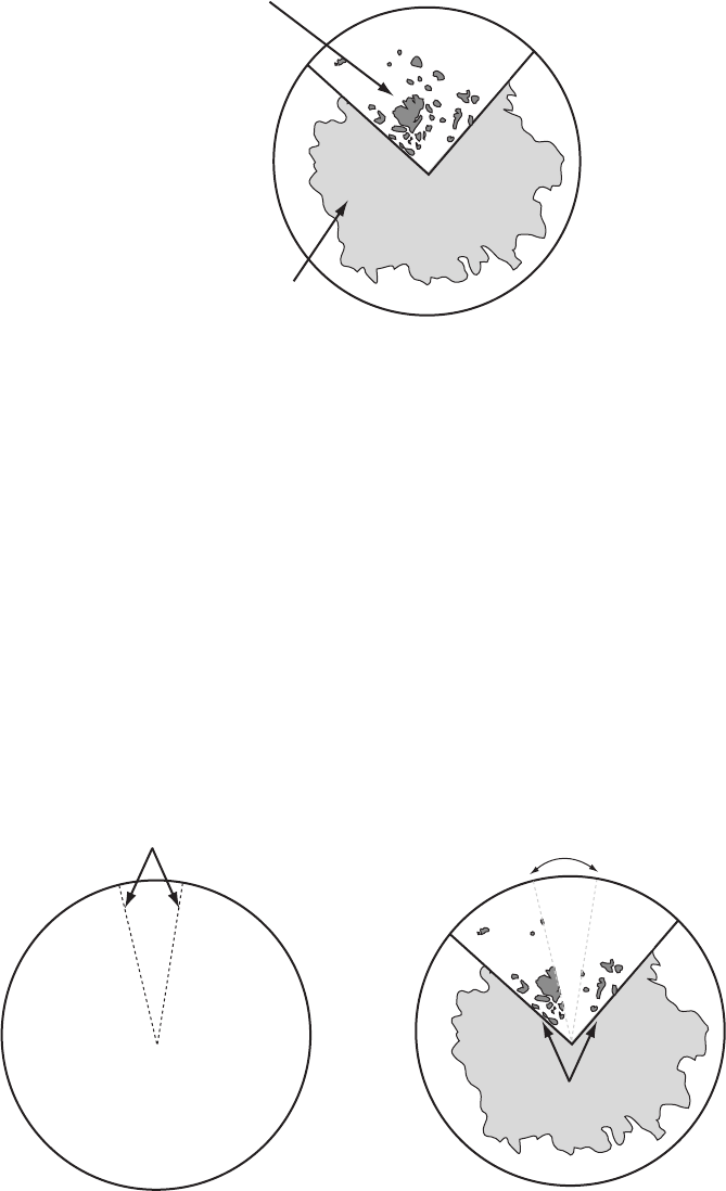
3. SETTING AND ADJUSTMENT
3-16
3.7 Dual Radar Display (non IMO-type only)
The image from two or more radars may be shown together on one radar display. This
allows you to take advantage of the best characteristics radars has to offer.
Image from main radar
Image from
external radar
Separate internal and external
images ("COMBINE" setting)
The following should be done in order to enable the dual radar display:
• Set antenna position correctly on both the main radar and the external radar.
• Select external radar to use, from the DUAL RADAR menu. (See paragraph
3.7.3.)
3.7.1 Enabling/Disabling the Dual Radar Display
Enable or disable the dual radar display as shown in this section.
Note 1: The Tx blanking sector boundary lines are not shown when the dual radar display is
active. Further, neither the internal or external image is shown in the Tx blanking
sector.
Tx blanking sector
Tx blanking sector
Display
area
Dual radar display with
Tx blanking sector
Tx blanking sector is not shown.
No image in Tx blanking sector.

3. SETTING AND ADJUSTMENT
3-17
Note 2: In the dual radar display, a guard zone set on the main radar is also accommodated on
the external radar. When the position of the antennas for the main and external radars
is different and the No. 2 guard zone is set on a close-in range, the on-screen guard
zone may be shifted slightly from both the main radar antenna reference and external
radar antenna reference. Accordingly, on the dual radar display, the actual guard zone
area may be shifted slightly. For example, the guard alarm sounds against a target
which has almost entered the guard zone. The further the range the smaller the shift;
however, there is little shift with the No.1 guard zone (3-6 mile range, fixed). Further, do
not set a guard zone such that it straddles a boundary line of the dual radar sector.
A guard zone cannot be set while the dual radar display is active. Set a zone before activating
the dual radar display.
1. Open the INITIALIZE menu. See page 3-4.
2. Press the [3] key to show the SCANNER menu.
3. Select 9 [DUAL RADAR] and push the left button.
1BACK
2 DUAL RADAR
OFF/ COMBINE
3 COMBINE MODE
OWN/EXT
4 COMBINE SECTOR
START 000°
ANGLE 000°
5 COMBINE RANGE
START 00.00NM
LENGTH 00.00NM
6 EXT RADAR
1/2/3/4
[DUAL
RADAR]
4. Select 2 [DUAL RADAR] and push the left button.
5. Select OFF or COMBINE as appropriate and push the left button. For COMBINE, the
ANTENNA box at the top left-hand side becomes gray.
OFF: Turn off the dual radar display.
COMBINE: Display a part of the external radar image in the window on the main radar.
3. SETTING AND ADJUSTMENT
3-18
Push the right button four times to close the menu.
Note 1: The dual radar function becomes inoperative when the external radar is turned off, set
to stand-by, or set as sub display. When this happens, the buzzer sounds and the
message "EXT RADAR STBY" (power off, stand-by only) appears.
Note 2: The dual radar display is inoperative on the stern-up and shuttle ferry modes.
Note 3: Some functions of the external radar image, listed below, may be adjusted from the
main radar.
1) Left-click the radar selection indication "CTRL OWN" at the top-left side of the screen to
switch control to the external radar. The indication then shows "CTRL EXT". Each click of
the indication switches control between the main and external radar alternately.
2) The external image may be adjusted from the main radar. The following functions may be
adjusted:
• Transmit/stand-by switching
• PICTURE box setting
• GAIN
• A/C SEA
• A/C RAIN
• Tuning
• ECHO menu setting (2nd trace echo rejector, performance monitor)
• Range scale
• TT functions.
• CPA/TCPA box settings
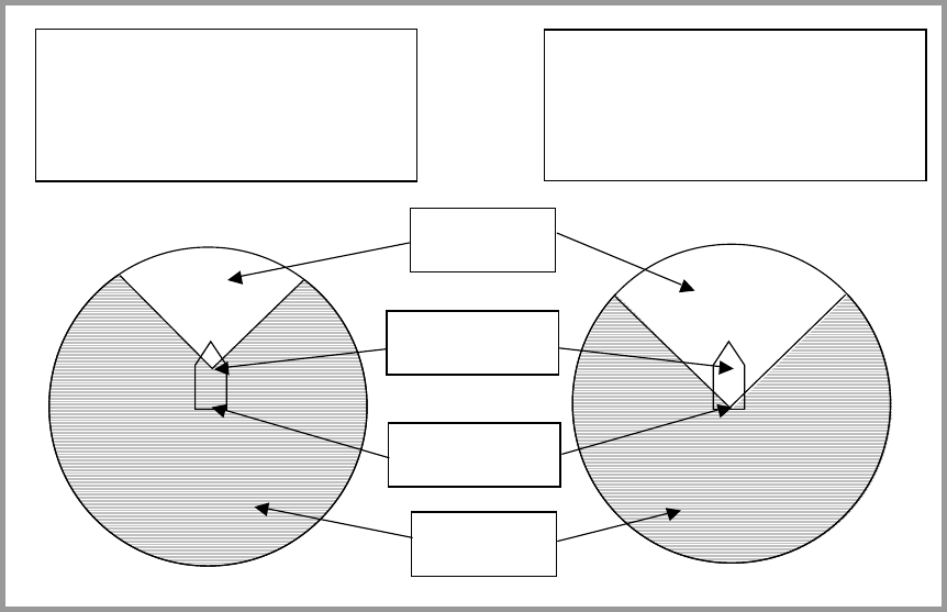
3. SETTING AND ADJUSTMENT
3-19
3.7.2 Specifying Sector Width and Length
When 2 DUAL RADAR in the DUAL RADAR menu is set for "COMBINE", specify
the width and length of the sector from the external radar to display on own radar.
1. Open the INITIALIZE menu.
2. Press the [3] key to show the SCANNER menu.
3. Select 9 [DUAL RADAR] and push the left button.
4. Select 3 COMBINE MODE and push the left button.
5. Select OWN or EXT and push the left button.
OWN: Set own radar’s antenna as reference point and set display area of own
radar. The area outside that set here is where the image from the
external radar will be displayed.
EXT: Set external radar’s antenna as reference point and set display area of
external radar. The area outside that set here is where the image from
own radar will be displayed.
Picture from
external radar
Position of antenna
for external radar
Position of antenna
for own radar
Picture from
own radar
Radar selected for COMBINE: Own
START: 45 degrees
ANGLE: 270 degrees
START: 00.00 nm
LENGTH: 99.99 nm
Radar selected for COMBINE: External
START: 315 degrees
ANGLE: 90 degrees
START: 00.00 nm
LENGTH: 99.99 nm
6. Select 4 COMBINE SECTOR and push the left button.
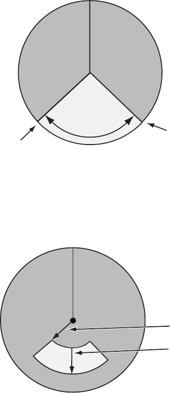
3. SETTING AND ADJUSTMENT
3-20
7. Use the scrollwheel to set START and ANGLE, referring to the description and
example below. Spin the scrollwheel to set and push it to confirm.
A solid green line marks the dual radar display area.
• START: Start point of the sector (in degrees, 000-359)
• ANGLE: Width of the sector (in degrees, 000-359)
In the example below, START is 130° and ANGLE is 100°.
START
(Example: 130°)
ANGLE
(Example: 100°)
Width of sector
8. Select 5 COMBINE RANGE and push the left button.
9. Use the scrollwheel to set START and LENGTH, referring to the example below.
Spin the scrollwheel to set and push it to confirm.
• START: Set range start point.
• LENGTH: Set length of sector.
START
LENGTH
Example:
START: 01.00 nm
LENGTH: 02.00 nm
Push the right button four times to close the menu.

3. SETTING AND ADJUSTMENT
3-21
3.7.3 Choosing External Radar (image source)
Select the external radar to use in the dual radar display.
1. Open the INITIALIZE menu.
2. Press the [3] key to show the SCANNER menu.
3. Select 9 [DUAL RADAR] and push the left button.
1BACK
2 DUAL RADAR
OFF/ COMBINE
3 COMBINE MODE
OWN/EXT
4 COMBINE SECTOR
START 000°
ANGLE 000°
5 COMBINE RANGE
START 00.00NM
LENGTH 00.00NM
6 EXT RADAR
1/2/3/4
[DUAL
RADAR]
4. Select 6 EXT RADAR and push the left button.
5. Select desired radar no. and push the left button.
Only the numbers of connected radars are valid. Radar no. is set on the Installation Setting
menu.
6. Press the [MENU] key to close the menu.
3. SETTING AND ADJUSTMENT
3-22
This page is intentionally left blank.
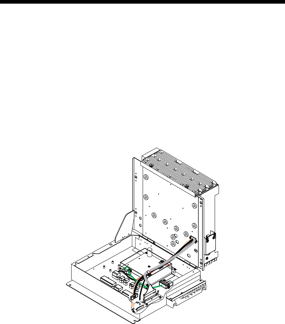
4-1
4. INSTALLING OPTIONAL
EQUIPMENT
4.1 Gyro Converter GC-10
The Gyro Converter GC-10, incorporated inside the processor unit, converts analog
gyrocompass reading into digital coded bearing data for display on the radar screen.
This section explains how to install the GC-10 (mainly consisting of the GYRO
CONVERTER board) and set it up according to gyrocompass connected.
Installing the GYRO CONVERTER board
Necessary Parts: GC-10-2 (Code number 000-080-440)
See packing list for details at the back of this manual.
1. Open the processor unit.
1
1
4
1
12
13
1
2
13
1
12
1
5
1
7
13
Processor unit (Opened)
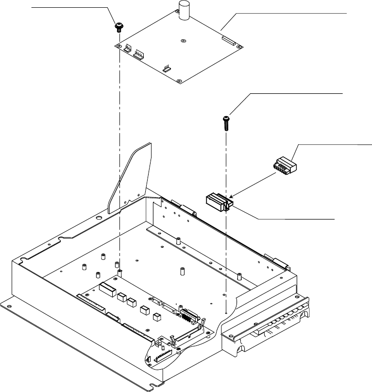
4. INSTALLING OPTIONAL EQUIPMENT
4-2
2. Fasten the GYRO CONVERTER board in the processor unit with five washer head
screws and male connector 231-607/019-FUR (called J602) with two screws.
Connector (231)
231-607/019-FUR
1
7
Connector (231)
231-107/026-FUR
1
7
GYRO CONVERTER board
64P1106A
Screw M3X8 5 pcs
(Torque 0.78Nm)
Screw M2.6X10 2 pcs
(Torque 0.39Nm)
Attaching GYRO CONVERTER board in the processor unit
3. Connect the GYRO CONVERTER board and the 03P9342 board with connector
assemblies 03-2088 and 03-2091.
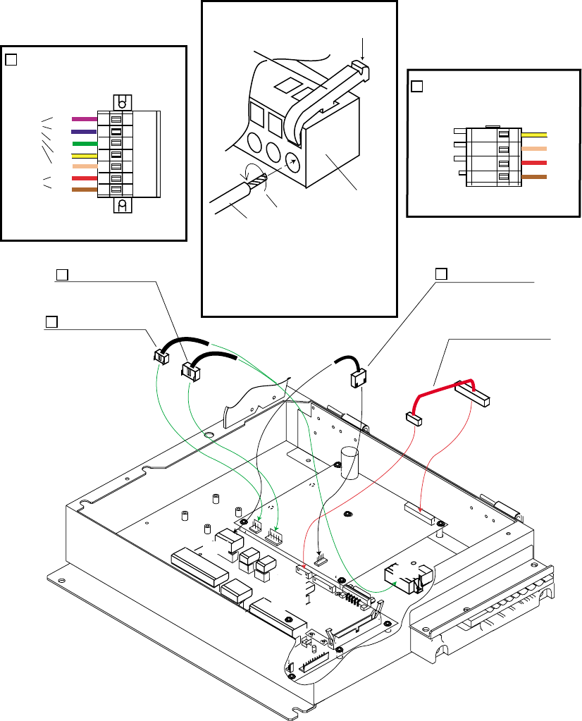
4. INSTALLING OPTIONAL EQUIPMENT
4-3
4. Connect the GYRO CONVERTER board and J602 with two connector assemblies
03-2089 and 03-2090.
1
1
4
1
12
13
1
2
13
1
12
1
5
1
7
XH-PH connector assy.
03-2088 (6-14P)
NH connector assy.
03-2091 (5P)
VH connector assy.
03-2089 (5P)
VH connector assy.
03-2090 (3P)
J1
P1
J603
P603
GYRO CONVERTER
64P1106A
TB
03P9342
P608
J7
J4
J5
P5
P4 P7
J602
To P608
To J602
1
2
2
P608
1234
BRN
RED
ORG
YEL
1
Connection for P608
2
Connection for J602
17 23456
BRN
RED
ORG
YEL
GRN
BLU
PPL
J602
Procedures
1. Twist the cores
2. Press the terminal opener downward.
3. Insert the wire to hole.
4. Remove the terminal opener.
5. Pull the wire to confirm that it is
secure.
Terminal opener
Wiring for WAGO connector
WAGO connector
Wire
Twist
Press downward.
From J5
From J4
Connecting connector assemblies
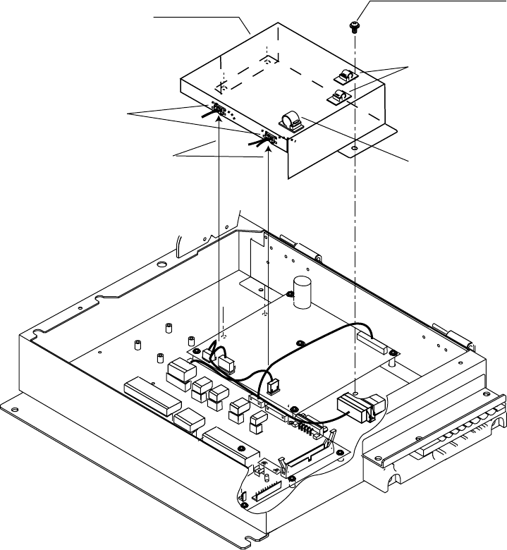
4. INSTALLING OPTIONAL EQUIPMENT
4-4
5. Confirm gyrocompass specifications and set up the DIP switches and jumper wires on
the GYRO CONVERTER board according to gyrocompass connected:
•
Setting jumper wires and DIP switches by gyrocompass specifications: page 4-5
•
Setting jumper wires and DIP switches by make and model of gyrocompass: page 4-7
•
Location of jumper wires and DIP switches: page 4-8
6. Pass gyrocompass cable through the cable clamp and connect it to connector J602 as
shown in the figure on page 4-3.
7. Attach the clamps on the plastic cover and then attach the cover to the chassis as
shown in the figure below. Insert cables to the clamp ED-1, respectively.
1
1
4
1
12
13
1
2
13
1
12
1
5
1
7
13
Screw M4X8
3 pcs
(Torque 0.98Nm)
Plastic cover
Insert cables to these
clamp.
Clamp EDS-1
Clamp CKS-10-L
Clamp CKS-13-L
Attaching plastic cover for GYRO CONVERTER board
8. Close the processor unit.
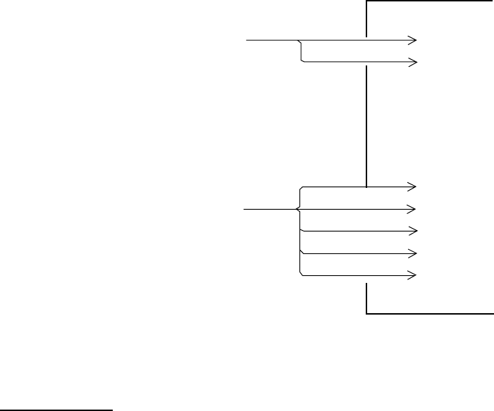
4. INSTALLING OPTIONAL EQUIPMENT
4-5
Connection of external power supply
An external power supply is necessary when the repeater signal is step-by-step type and
the step voltage is below 20 V or output voltage is less than 5 W.
1. Cut jumper wire JP1 on the GYRO CONVERTER board when an external power supply
is used.
2. Connect gyro cable and power cable as shown below.
GYRO CONVERTER board
[A] 64P1106
1 > R2
Either connection
in case of DC
polarity.
J5
2 > R1/COM
External Power Supply
20 - 135 VAC
20 - 100 VDC
1 > S1
2 > S2
3 > S3
4 > T
5 > F.G.
Gyrocompass
(Step type)
S1
S2
S3
COM
F.G.
J4
Connection of external power supply to GYRO CONVERTER board
DIP switch, jumper wire settings
Default setting
The gyro converter GC-10 is set at the factory for connection with the gyrocompass
specifications below.
AC synchronous signal: 50/60 Hz
Rotor voltage: 60 V to 135 V AC
Stator voltage: 60 V to 135 V AC
Gear ratio: 360x
Supply voltage: 30 V to 135 V AC
If the specifications of the gyrocompass differ from those mentioned above, change jumper
wire and DIP switch settings on the GYRO CONVERTER board. Settings may be changed
according to gyrocompass specifications (see page 4-6) or make and model of
gyrocompass (see page 4-7). For the location of DIP switches and jumper wires, see page
4-8.
Note: If you change the setting with power supplied, set #8 of SW2 from OFF to ON, then
OFF again.
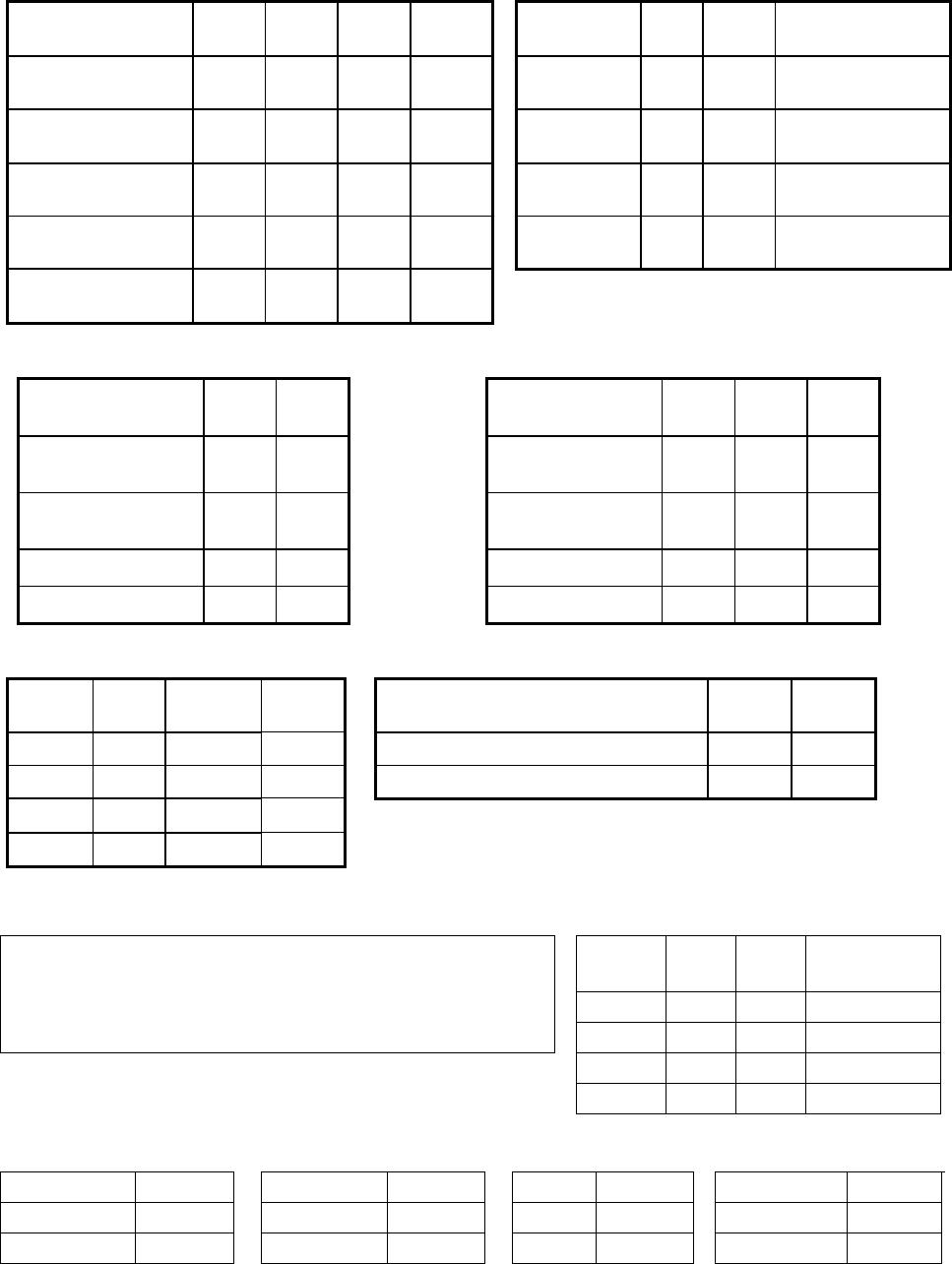
4. INSTALLING OPTIONAL EQUIPMENT
4-6
Setting method 1: DIP switch settings and gyrocompass specifications
1) Gyrocompass type 2) Frequency
Gyrocompass
type SW
1-4 SW
1-5 SW
1-6 JP1 Frequency SW
1-7 SW
1-8 Remarks
AC
synchronous OFF OFF OFF #1, #2,
#3 50/60 Hz OFF OFF AC synchronous
pulsating current
DC
synchronous OFF OFF OFF #2, #3,
#4 400 Hz ON OFF AC synchronous
pulsating current
DC step ON OFF OFF #4, #5,
#6 500 Hz OFF ON AC synchronous
pulsating current
Full-wave
pulsating current OFF ON OFF #4, #5,
#6 DC ON ON
DC synchronous
DC step
Half-wave
pulsating current ON ON OFF #4, #5,
#6
3) Rotor Voltage (between R1 & R2) 4) Stator Voltage (between S1 & S2)
Rotor Voltage SW
2-1 JP3
Stator
Voltage SW
2-2 SW
2-3 JP2
20 to 45 VAC ON #2
20 to 45 VAC, or
20 to 60 VDC ON OFF #2
30 to 70 VAC OFF #2
30 to 70 VAC, or
40 to 100 VDC OFF OFF #2
40 to 90 VAC ON #1
40 to 90 VAC ON OFF #1
60 to 135 VAC OFF #1
60 to 135 VAC OFF OFF #1
5) Ratio 6) Supply Voltage
Ratio SW
1-1 SW
1-2 SW
1-3
Stator
Voltage JP4 JP5
360X OFF OFF OFF
20 to 45 VAC, or 20 to 60 VDC #2 #2
180X ON OFF OFF
30 to 70 VAC, or 40 to 100 VDC #1 #1
90X OFF ON OFF
36X ON ON OFF
7) AD-10 format data 8) NMEA-0183
Tx interval Tx interval and Output sentence
Select data transmitting interval for ports 1 to 6 with jumper
wires JP6 and JP7.
Tx
interval
SW
2-5
SW
2-6
Output
sentence
Note: The Tx interval is available in 25 msec or 200 msec. 1 s OFF OFF HDT+VHW
Use 25 msec is for radar: 200 ms ON OFF HDT
100 ms OFF ON HDT
25 ms ON ON HDT
9) NMEA-0183
Version no. 10) NMEA-0183
Baud rate 11) NMEA-0183
Talker
12) Stator signal
breaking detection
Version no. SW3-1 Baud rate SW3-2 Talker SW3-3 Detection SW2-7
1.5 OFF 4860bps OFF AG OFF
Execute OFF
2.0 ON 38400bps ON HE ON
No execute ON
Use OFF for radar.
SW2-4: factory use only
SW3-4: not used

4. INSTALLING OPTIONAL EQUIPMENT
4-7
Setting method 2: by make and model of gyrocompass
rekaMsledoMonitacificepSSW
1-1 WS 2-1 WS 3-1 WS 4-1 WS 5-1 WS 6-1 WS 7-1 WS 8-1 WS 1-2 WS 2-2 WS 3-2 1PJ2PJ3PJ4PJ5PJ
ztuhcsnA,32dradnatSusonorhcnysCA
zH06/05
V06/05:egatlovrotoR
V22:egatlovrotatS
x063
FFOFFOFFOFFOFFOFFOFFOFFOFFONOFFO,1#
3#,2#
2#2#1#1 #
6,4dradnatSusonorhcnysCA
zH06/05
V06/05:egatlovrotoR
V09:egatlovrotatS
x063
FFOFFOFFOFFOFFOFFOFFOFFOFFOFFOFFO,1#
3#,2#
2#1#1#1 #
02dradnatSpetsCD
x081V53
)+(eriw-3,)-(MOC
NOFFOFFONOFFOFFONONO- NOFFO,4#
6#,5#
2#-2#2 #
awagokoY
cetvaN
htalP(
)epyt
3/2/A1/1-C
55-B,55-A
suonorhcnysCA
zH06/05
V06/05:egatlovrotoR
V22:egatlovrotatS
x063
FFOFFOFFOFFOFFOFFOFFOFFOFFONOFFO,1#
3#,2#
2#2#1#1 #
/X052-ZMC
005/X003
x063suonorhcnysCDFF
OF
FOFFOFFOFFOFFONONO- NOFFO-omeR
ev
2#-
**
**
petsCD
x081V53
)-(eriw-3,)+(MOC
NOFFOFFONOFFOFFONONO- NOFFO,4#
6#,5#
2#-2#2#
/002/001-ZMC
003
3/1/Z1-D,rJ1-C
3/2-SPI
suonorhcnysCA
zH06/05
V001:egatlovrotoR
V09:egatlovrotatS
x063
FFOFFOFFOFFOFFOFFOFFOFFOFFOFFOFFO,1#
3#,2#
1#1#1#1#
05-ZMCpets
x081V53
)-(eriw-3,)+(MOC
NOFFOFFONOFFOFFONONO- NOFFO-omeR
ev
2#-
**
htalPIII/ I
ITAGVA
NusonorhcnysCA
zH06/05
V06/05:egatlovrotoR
V86:egatlovrotatS
x063
FFOFFOFFOFFOFFOFFOFFOFFOFFOFFOFFO,1#
3#,2#
2#2#1#1#
cemikoT
yrrepS(
)epyt
11/2/1-SE
/201/101-TLG
701/K601/301
suonorhcnysCA
zH06/05
V011/001:egatlovrotoR
V09:egatlovrotatS
x63
NONOFFOFFOFFOFFOFFOFFOFFOFFOFFO,1#
3#,2#
1#1#1#1#
011/A11-SE
002-GT
0002/R222RP
H/L732RP
12MG
suonorhcnysCA
zH06/05
V011/001:egatlovrotoR
V22:egatlovrotatS
x09
FFONOFFOFFOFFOFFOFFOFFOFFOFFOFFO,1#
3#,2#
1#1#1#1#
41-KM
T/2/1-DOM
IE-KN,NE-KN
petsCD
x081V07
)+(eriw-3,)-(MOC
NOFFOFFONOFFOFFONONO- FFOFFO,4#
6#,5#
2#-1#1#
041/031-RSpetsCD
x081V07
rotcellocnepo,eriw-5
NOFFOFFOFFONOFFOFFOFFO- FFOFFO,4#
6#,5#
2#-1#1#
0005/001-GT
/031/753-RP
71-SE,041
202/102-TLG
302/
petsCD
x081V07
)-(eriw-3,)+(MOC
NOFFOFFONOFFOFFONONO- FFOFFO,4#
6#,5#
2#-1#1#
0006-GTpetsCD
x081V42
NOFFOFFONOFFOFFONONO- NOFFO,4#
6#,5#
2#-2#2#
11-MGusonorhcnysCA
zH06/05
V001:egatlovrotoR
V09:egatlovrotatS
x09
FFONOFFOFFOFFOFFOFFOFFOFFOFFOFFO,1#
3#,2#
1#1#1#1#
61-SE,021-RS
03/02/01-KM
petsCD
x081V53
NOFFOFFONOFFOFFONONO- NOFFO,4#
6#,5#
2#-2#2#
ikasawaK18-XGusonorhcnysCA
zH06/05
V011/001:egatlovrotoR
V09:egatlovrotatS
x09
FFONOFFOFFOFFOFFOFFOFFOFFOFFOFFO,1#
3#,2#
1#1#1#1#
nworbamrA-1LKM,01-KM
,1531SEIRES
4-DOM
petsCD
x081V05
)-(eriw-3,)+(MOC
NOFFOFFONOFFOFFONONO- FFOFFO,4#
6#,5#
2#-1#1#
nostreboR08-RKSpetsCD
x081V53
)+(eriw-3,)-(MOC
NOFFOFFONOFFOFFONONO- NOFFO,4#
6#,5#
2#-2#2#
CMZ-700 DC step
24V 180x
COM(+), 3-wire(-)
ON ON ON ONOFF OFF OFF OFF
--
ON OFF
Remo-
ve #2
See note below.
*: Set JP4 and JP5 according to the voltage of the external power supply.
Note: If CMZ-50 has 35VDC, set JP1 to #4, #5, #6.
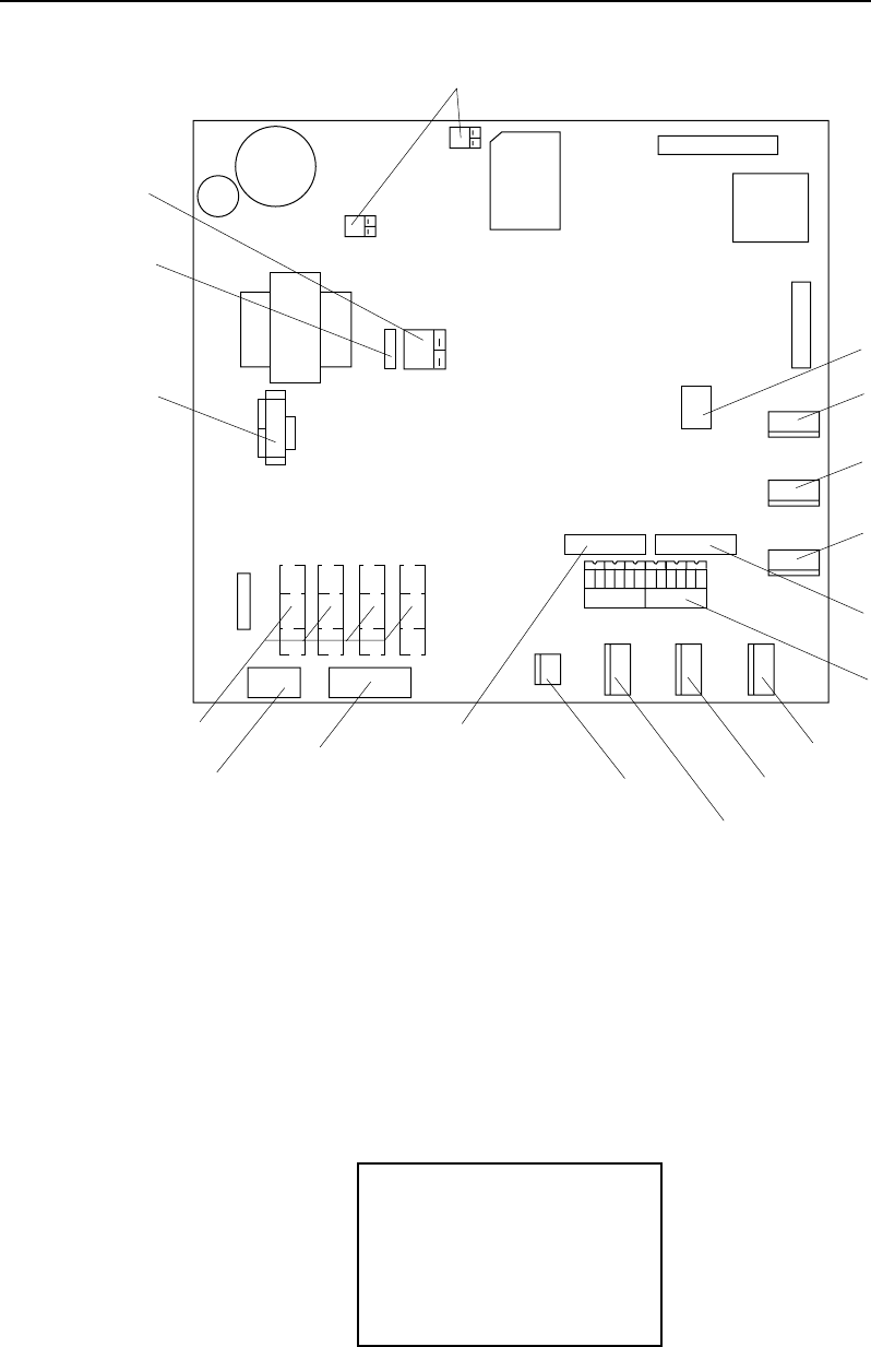
4. INSTALLING OPTIONAL EQUIPMENT
4-8
Location of DIP switches, jumper wires on the GYRO CONVERTER board
64P1106
JP5, JP4
(Supply voltage)
JP2
(Rotor voltage)
JP3
(Stator voltage)
JP1
(Gyro type)
Fuse
(2A)
J5
(Rotor signal input,
external power input)
J4
(Stator signal input)
SW1
DIP switch
J6
(IEC-61162-1 output port) J7
(Data output port #1)
J8
(Data output port #2)
J9
(Data output port #3)
JP6, JP7
(AD format
data Tx interval)
SW2
DIP switch
J10
(Data output
port #4)
J11
(Data output
port #5)
J12
(Data output
port #6)
SW3
DIP switch
GYRO CONVERTER board
Setting the heading readout on the radar display
Confirm that the gyrocompass is giving a reliable readout. Then, set the heading readout on
the radar display with the gyrocompass readout as follows:
1. Roll the trackball to place the arrow in the HDG box at the top right corner of the screen.
2. Push the right button on the trackball module to open the HDG menu.
[HDG MENU]
1 HDG SOURCE
AD-10/SERIAL
2 GC-10 SETTING
000.0
HDG menu
3. Press the [1] key to choose the HDG SOURCE and choose AD-10.
4. Press the [2] key to choose the GC-10 SETTING option.
5. Roll the wheel to set gyrocompass reading.
6. Press the [MENU] key to close the menu.
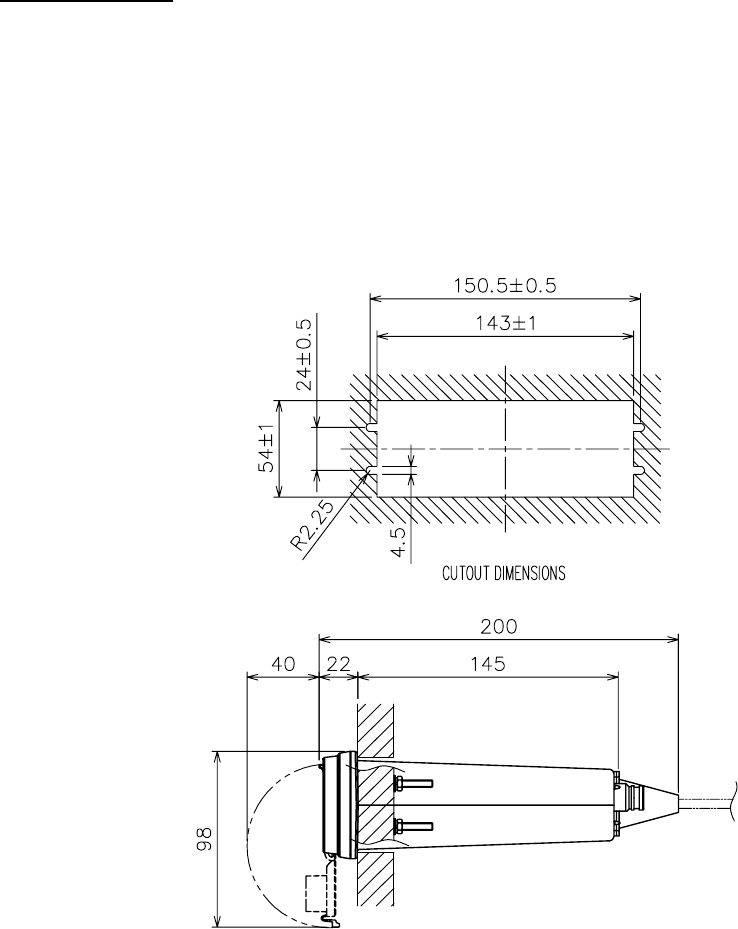
4. INSTALLING OPTIONAL EQUIPMENT
4-9
4.2 Memory Card Interface Unit
Mounting considerations
When selecting a mounting location, keep in mind the following points:
•
Locate the memory card interface unit away from heat sources because of heat that can
build up inside the cabinet.
•
Locate the unit away from places subject to water splash and rain.
•
Leave sufficient space at the sides and rear of the unit to facilitate maintenance.
•
A magnetic compass will be affected if the unit is placed too close to the magnetic
compass. Observe the compass safe distances on page ii to prevent deviation of a
magnetic compass.
Flush mounting
This unit can be flush-mounted in a panel with the standard installation materials.
1. Prepare a cutout in the mounting location, referring to the outline drawing at the end of
this manual.
2. Screw in the threaded rods to the flange of the front panel of the unit securely by hands.
3. Set the unit to the cutout.
4. Insert the flat washer, spring washer and nut in that order for each rod and fasten the
nuts.
Flush mounting
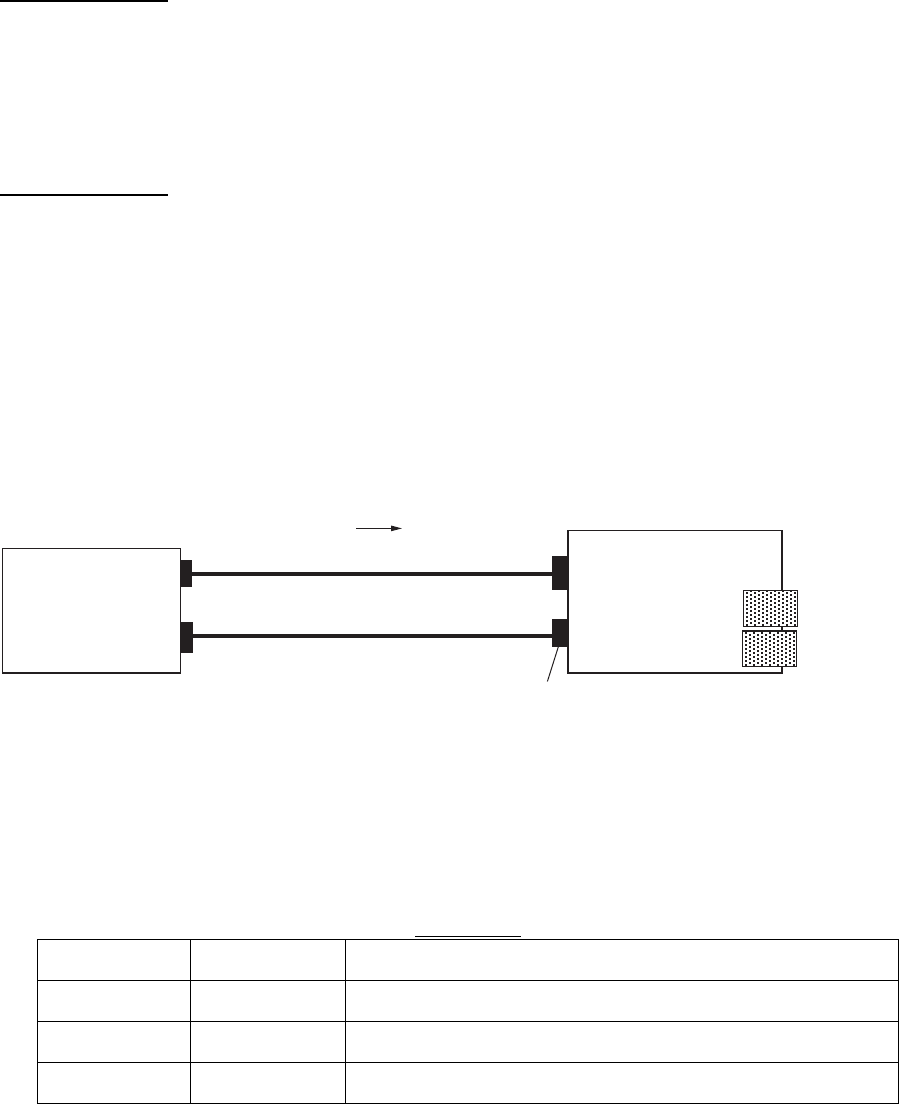
4. INSTALLING OPTIONAL EQUIPMENT
4-10
Desktop mount
For desktop mount, the optional desktop mount kit FP03-10201 is required. Refer to the end
of this manual.
1. Fix the mounting bracket 19-023-3081 on the unit with four screws.
2. Mount the above assembly on a desktop with four tapping screws.
Console mount
For console mount, the optional console mount kit FP03-10202 is required. Refer to the end
of this manual.
1. Fix the mounting bracket 19-023-3091 on the unit with four screws.
2. Mount the above assembly to the console with four sets of nut, spring washer and flat
washer.
Connection
1) Connection between one processor unit and one memory card IF unit
Connect as shown in the figure below.
Processor unit Memory card IF unit
J614
NETWORK
12 VDC
MJ-A3SPF0015-100 (10 m)
PSE-4PTX-BL (10 m) two mini-cards
12 VDC
RJ-45
NETWORK
2) Connection between one memory card IF unit and multiple processor units
Prepare optional cable FR-FTPC-CY (10, 20 or 30 m), and HUB-100 (option). Connect as
shown in the next page. Set the radar number on the INSTALLATION menu (see page 3-10),
and then turn the power off and on.
LAN cable
Type Length Code number
OP03-28900 000-082-658 Cable FR-FTPC-CY (10 m), Modular connector 2 pcs.
OP03-28910 000-082-689 Cable FR-FTPC-CY (20 m), Modular connector 2 pcs.
OP03-28920 000-082-660 Cable FR-FTPC-CY (30 m), Modular connector 2 pcs.
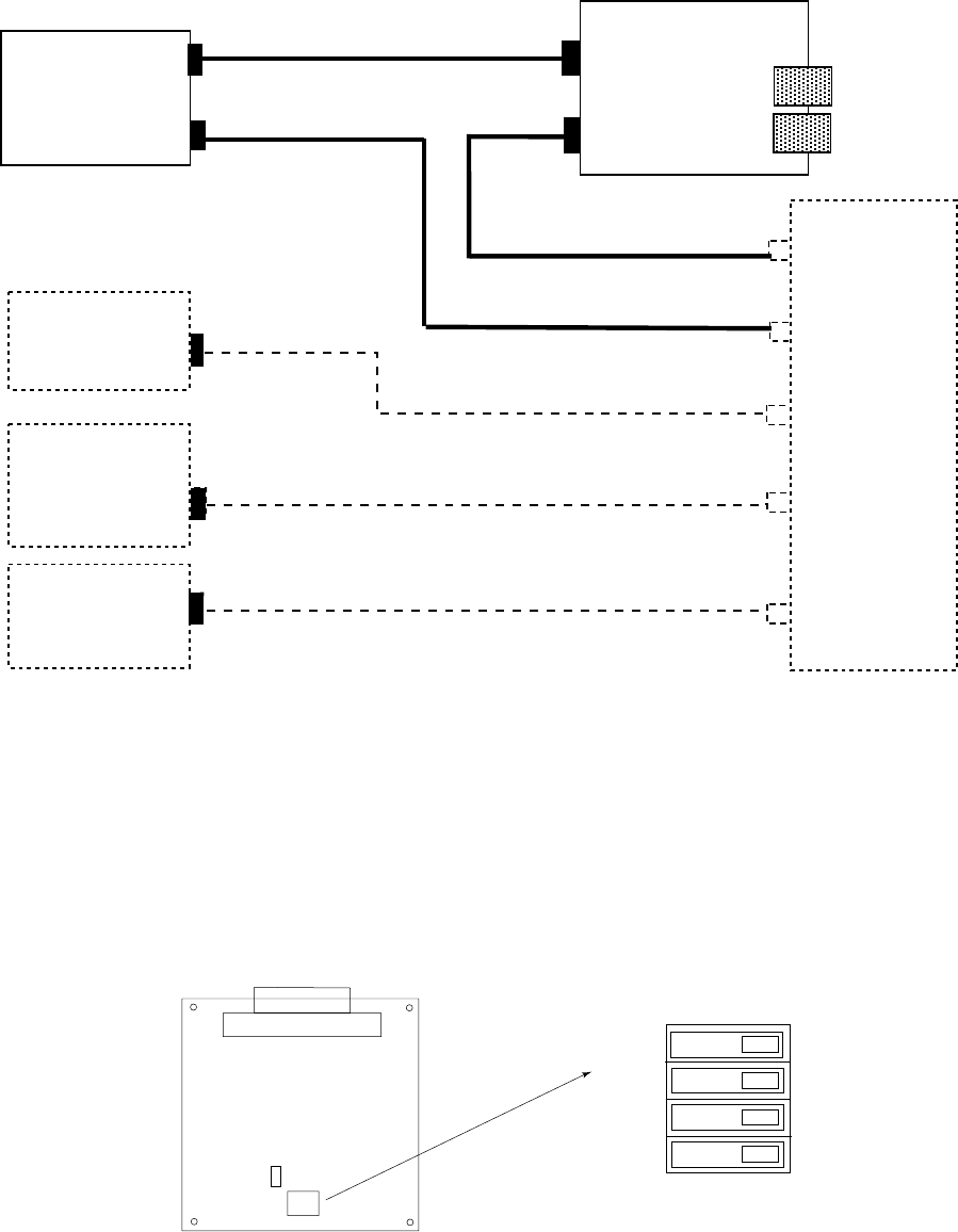
4. INSTALLING OPTIONAL EQUIPMENT
4-11
No.1
Processor
unit
J614
NETWORK
No.2
Processor
unit
No.3
Processor
unit
No.4
Processor
unit
MJ-A3SPF0015-100 (10 m) Memory card IF unit
12 VDC
FR-FTPC-CY (10/20/30 m)
(straight)
FR-FTPC-CY (10/20/30 m)
(straight)
FR-FTPC-CY
(10/20/30 m)
(straight)
FR-FTPC-CY (10/20/30 m) (straight)
FR-FTPC-CY (10/20/30 m) (straight)
Switching hub
HUB-100
(option)
two mini-cards
NETWORK
Note: When two memory card interface units are connected via network, change ID code
for the second unit.
1. Remove the cover and set IP0 bit of the DIP switch S1 to ON on the CARDCPU board
03P9333.
2. Set INIT bit of S1 to ON and turn on the power of the radar. Wait till CR2 starts blinking.
Never turn off the power until CR2 starts blinking.
3. Turn off the power and set INIT bit to OFF.
OFF
ON
(Default: all OFF)
IP0
IP1
IP2
INIT
J314
S1
CARDCPU board 03P9333
CR2
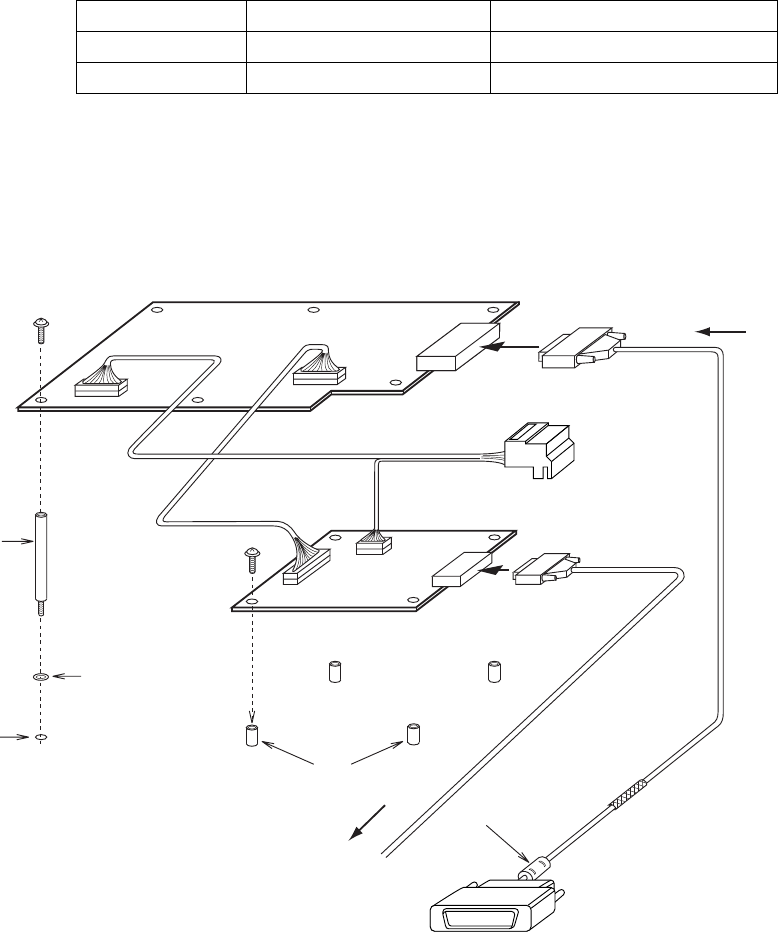
4. INSTALLING OPTIONAL EQUIPMENT
4-12
4.3 DVI-RGB Conversion Kit (for VDR connection)
This information provides the procedure necessary for the installation of the DVI-RGB
conversion kit. This kit is installed in the processor unit to enable connection of a VDR
(Voyage Data Recorder) or RGB monitor to record radar pictures into a VDR. When
changing the D-sub 15P of the RGB cable to the BNC connector, use the BNC connector
converter described on page 4-15. This RGB output complies with the image test defined in
the VDR test standard, IEC 61996.
Name: DVI-RGB conversion kit
Type: OP03-180-2
Code no.: 008-536-070
Resolution: Outputs RGB with the resolution of DVI input.
Display unit Resolution DIP switch setting (S-1#1)
MU-201CR 1024x1280 OFF
MU-231CR 1024x1365 ON
Output signal specification: Video; 0.7Vp-p, 75Ω termination, positive polarity
Horizontal sync signal; TTL level, negative polarity
Vertical sync signal; TTL level, negative polarity
See packing list for contents. Refer to the figure below for modification.
M3x8
4 pcs
SQ-35
Spacer
6 pcs
Fixing
holes
Spring washer
Boss
J2
J3
(3 pin)
J1
(13 pin)
J615
J3
J9
(10 pin)
J4
(6 pin)
M3x8
6 pcs
RGB Cable
(User supply)
Clamp copper tape
section by cable clamp.
Ferrite core side: Connect to DVI-D port on
the upper part of the processor unit.
*Indepent of the MAIN board.
DVI cable
03P9342 board
RGB-BUFF board*
(03P9229B)
(SLB-FRN4-A)
DVI-RGB Conversion board
03-2092 03-2094
03-2093
Ferrite core
To external RGB monitor or
BNC connector converter
for VDR connection (see
page 4-17).
D-sub 15P
Female
DVI video input
RGB video output
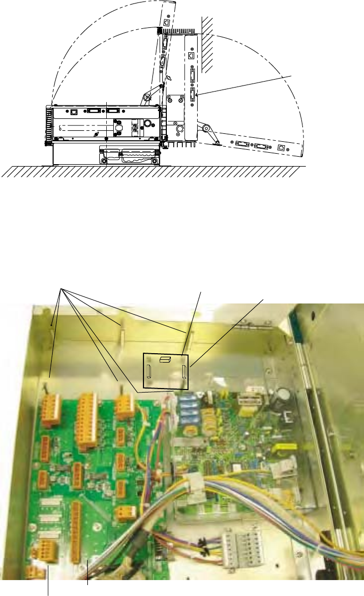
4. INSTALLING OPTIONAL EQUIPMENT
4-13
1. Remove the top cover and open the upper part of the processor unit.
DVI-D port
(Connect DVI cable at step 13)
Processor unit
2. Fix the 03P9229A board (RGB-BUFF) with four screws. (See the figure below.)
3. Attach the connector assemblies to J1 and J3 on the 03P9229A board as follows.
J1:13-pin connector of the connector assembly 03-2094
J3:3-pin connector of the connector assembly 03-2093
4. Attach six sets of spring washers and spacers to the positions shown below.
Spring washer, spacer 03P9229A board
J615 (Connect connector assembies at step 9.)
03P9342 board
J1 J3 J2
J2 (Connect RGB Cable at step 11.)
Processor unit (Lower part)
5. Attach the DVI-RGB conversion board to the location shown in the figure on the next
page.
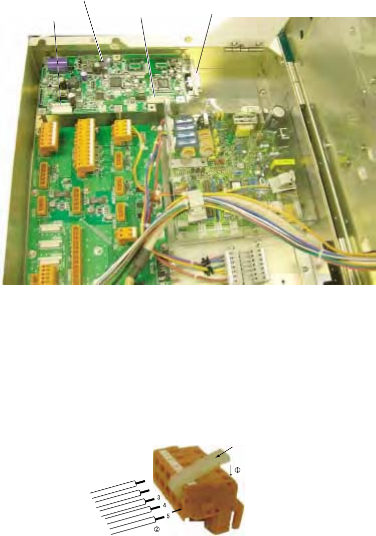
4. INSTALLING OPTIONAL EQUIPMENT
4-14
J4
DVI-RGB
Conversion board
J9 J3 (Connect DVI cable at step 10.)
Fixing the DVI-RGB conversion board
6. Attach the 10-pin connector from J1 on the 03P9229A board to J9 on the DVI-RGB
board.
7. Attach the connector assembly 03-2092 to J4 on the DVI-RGB conversion board.
8. Remove connector housing J615 from the 03P9342 board. Connect the cable from J3
on the 03P9229A board and the cable from J4 on the DVI-RGB conversion board to
J615. After connection, attach J615 to the 03P9342 board.
To connect wires to the connector housing, use the terminal opener (supplied as installation
materials) as shown below.
Press downward
Insert core
J615 Housing
Terminal opener
RED
YEL
GRN
ORG
1
2
BRN
Connecting wires to the housing
9. Connect the DVI cable to J3 on the DVI-RGB conversion board. Connect the end which
does not have the ferrite core.
10. Pass an RGB cable (local supply) through the cable clamp and connect it to J2 on the
03P9229A board.
11. Pass the DVI cable through the cable clamp, laying the section with copper tape in the
cable clamp.
12. Assemble the processor unit and connect the other end of the DVI cable to DVI-D port.
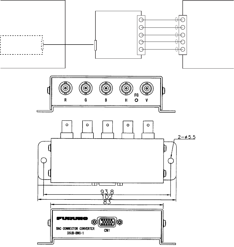
4. INSTALLING OPTIONAL EQUIPMENT
4-15
4.4 BNC Connector Converter
To connect the VR-5000 (FURUNO Voyage Data Recorder) to this radar, the DVI-RGB
conversion kit (mentioned at previous paragraph) and the BNC connector converter are
required. Also VGA cable (between the processor unit and the BNC connector converter)
and five 75 ohms coaxial cables (between the BNC connector converter and VR-5000) are
required.
BNC connector
converter
DSUB-BNC-1
VR-5000
Data collecting unit
75
Ω
coax. cable VD1
R
G
B
HS
VS
R
G
B
H
V
FAR-2107
Processor Unit
DVI-RGB
Conversion kit
D-sub 15P
Female
VGA cable
D-sub 15P
Male
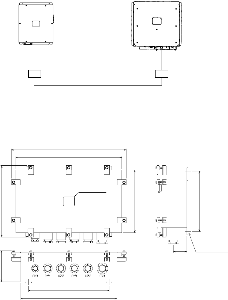
4. INSTALLING OPTIONAL EQUIPMENT
4-16
4.5 Junction Box RJB-001
If the length of the antenna cable is more than 100 m, the optional junction boxes are
required. These boxes should be mounted at the location protected because its
waterproofing is IPX3.
RW-9600
(Max 15 m)
Junction box
RJB-001
RW-9600
(Max 15 m)
DPYCY-6 (2 or 3 pcs.)
TTYCY-4 (1 pc.)
RG-12/UY (1 pc.) (Max 270 m)
Transceiver unit Processor unit
Junction box
RJB-001
Shipyard supply
Mounting
Fasten the junction box to the mounting location with four self-tapping screws (M8, local
supply).
514
474
320
280
139
360
430
270
60
NAMEPLATE
4-
φ
10
FIXING HOLES
Mass: 12kg
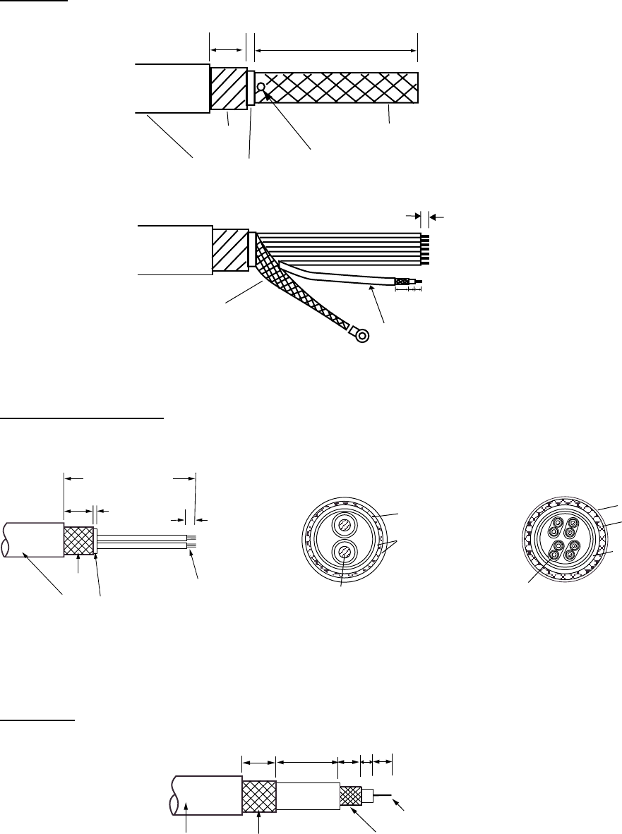
4. INSTALLING OPTIONAL EQUIPMENT
4-17
Cable Fabrication
RW-9600
6
14 59
approx. 450
5
20
Armor
Units: mm
Shield
Vinyl sheath Pull out inner cables from here.
Shield Coaxial cable
Crimp on lug for M8
DPYCY-6 and TTYC-4
20 5 6
DPYC-6: approx. 130
TTYCY-4: approx. 150
Conductor
S = 0.75 mm
= 1.11 mm
2
TTYCY-4 (Four twisted pairs)
Armor
Sheath
= 17.7 mm Sheath
Conductor
S = 6 mm
φ = 3.12 mm
2
DPYCY-6
Armor
Sheath
φ = 13.9 mm
Armor
Vinyl sheath
Taper for unused wires.
φ
φ
Sectional view of DPYCY-6 Fabrication of DPYCY-6
RG-12/UY
20 60
14 9
5
Vinyl sheath Armor
Inner conductor
Outer conductor
Sectional view of TTYCY-4
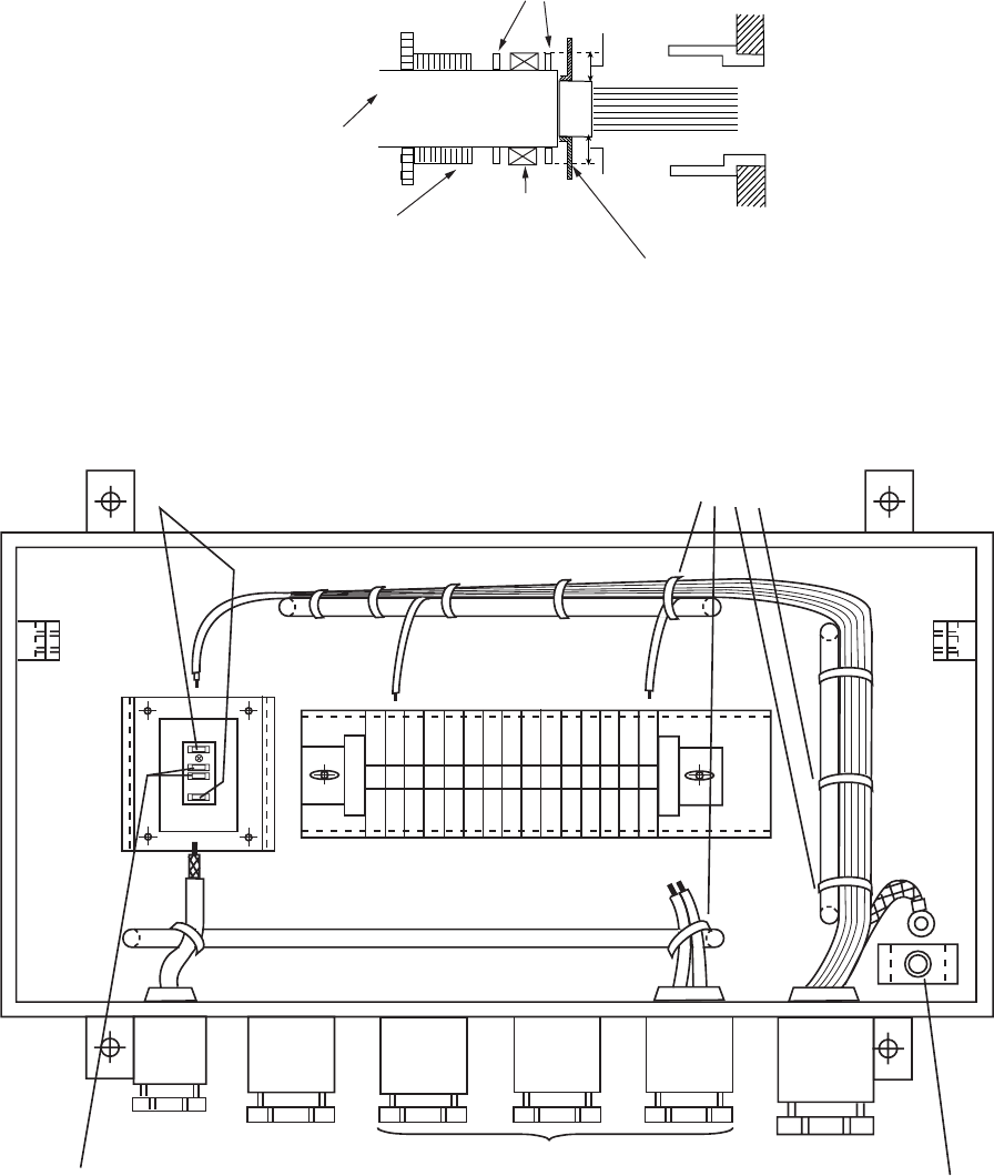
4. INSTALLING OPTIONAL EQUIPMENT
4-18
Connection
Insert each cable to the cable gland as follows.
Vinyl sheath
Clamping gland
Flat washer
Trim the armor with width of washer (5 mm).
5 mm
5 mm
Gasket
Connect each cable cores to the terminal board, referring to the interconnection diagram on
next page.
15 14 13 12 11 10 987654321
RG12/UY
RG-12/UY TTYCY-4 DPYCY-6 RW-9600
Connect inner conductors. M8 screw for grounding
Clamp outer conductor of coaxial cables. Fix wires with cable-tie.
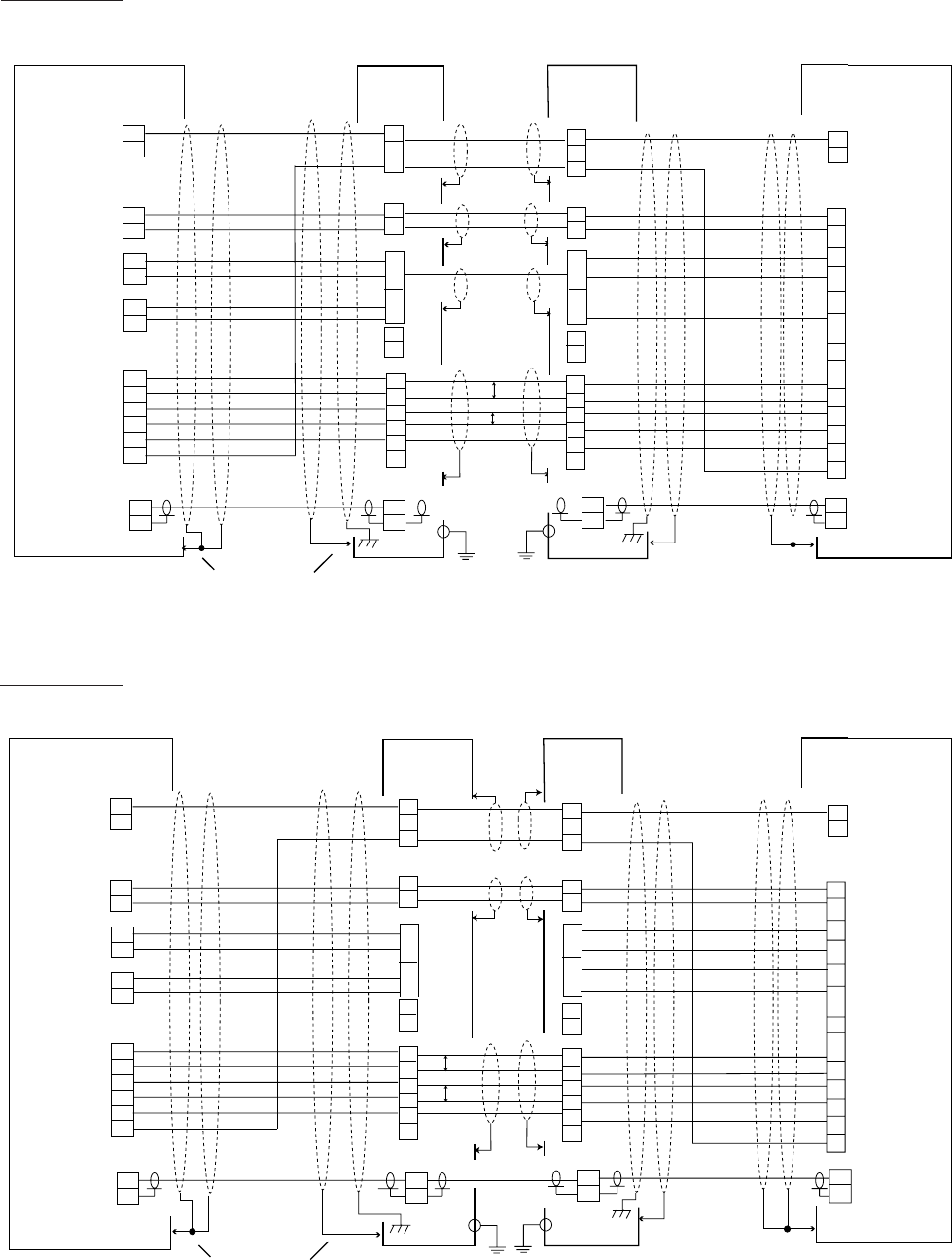
4. INSTALLING OPTIONAL EQUIPMENT
4-19
RED[B]
GRN[B]
WHT
BLK
GRN
RED
WHT[B]
PPL[B]
COAX
GLY[B]
BLU[B]
YEL[B]
ORG[B]
BRN
RG-12/UY
TTYCY-4
DPYCY-6
N.C.
N.C.
N.C.
03P9349
TB802
12
2
13
14
3
4
5
6
7
8
9
10
11
1
TB801
GND
SIG-GND
1
2
Box
Junction
Transceiver unit
GND
IF_VIDEO_IN
RF_SPU_D_B
RF_SPU_D_A
SPU_RF_D_B
SPU_RF_D_A
MOTOR(-)
MOTOR(-)
MOTOR(+)
MOTOR(+)
24V_MINUS
24V_PLUS
N.C.
TX-HV
RED[B]
GRN[B]
WHT
BLK
GRN
RED
WHT[B]
PPL[B]
GLY[B]
BLU[B]
YEL[B]
ORG[B]
BRN
N.C.
N.C.
N.C.
03P9342
J610
GND
SIG-GND
12
2
3
4
5
6
7
8
9
10
11
1
2
1
J613
Box
Junction Processor unit
GND
IF_VIDEO
RF_SPU_D_B
RF_SPU_D_A
SPU_RF_D_B
SPU_RF_D_A
MOTOR(-)
MOTOR(-)
MOTOR(+)
MOTOR(+)
24V_MINUS
24V_PLUS
N.C.
TX-HV
13
14
15
RW-9600
1
2
3
4
5
6
7
8
9
10
11
12
13
14
15
1
2
3
4
5
6
7
8
9
10
11
12
13
14
15
N.C.
DPYCY-6
DPYCY-6
1
21
2
RED[B]
GRN[B]
WHT
BLK
GRN
RED
WHT[B]
PPL[B]
COAX
GLY[B]
BLU[B]
YEL[B]
ORG[B]
BRN
RG-12/UY
TTYCY-4
N.C.
N.C.
N.C.
03P9349
TB802
12
2
13
14
3
4
5
6
7
8
9
10
11
1
TB801
GND
SIG-GND
1
2
Box
Junction
Transceiver unit
GND
IF_VIDEO_IN
RF_SPU_D_B
RF_SPU_D_A
SPU_RF_D_B
SPU_RF_D_A
MOTOR(-)
MOTOR(-)
MOTOR(+)
MOTOR(+)
24V_MINUS
24V_PLUS
N.C.
TX-HV
RED[B]
GRN[B]
WHT
BLK
GRN
RED
WHT[B]
PPL[B]
GLY[B]
BLU[B]
YEL[B]
ORG[B]
BRN
N.C.
N.C.
N.C.
03P9342
J610
GND
SIG-GND
12
2
3
4
5
6
7
8
9
10
11
1
2
1
J613
Box
Junction Processor unit
GND
IF_VIDEO
RF_SPU_D_B
RF_SPU_D_A
SPU_RF_D_B
SPU_RF_D_A
MOTOR(-)
MOTOR(-)
MOTOR(+)
MOTOR(+)
24V_MINUS
24V_PLUS
N.C.
TX-HV
13
14
15
RW-9600
1
2
3
4
5
6
7
8
9
10
11
12
13
14
15
1
2
3
4
5
6
7
8
9
10
11
12
13
14
15
N.C.
DPYCY-6
1
21
2
Clamp with cable gland.
IV-1.25
IV-1.25
Clamp with cable gland.
FR-2827W
FR-2837SW
P
P
P
P
DPYCY-6
Interconnection for FAR-2827W/2837SW
4. INSTALLING OPTIONAL EQUIPMENT
4-20
This page is intentionally left blank.

5-1
5. INPUT/OUTPUT DATA
Input and output data are shown in the table below.
Note: This radar accepts position data fixed by WGS-84 geodetic datum only. Set the
datum to WGS-84 on the EPFS (GPS, etc.) connected to this radar. If other type of datum is
input, the error message "DATUM" appears and the AIS feature is inoperative. Baud rate for
the serial input is automatically set to 4800, 9600, 19200 or 38400 as appropriate.
Input
Data Specifications Contents Remarks
synchro or step GC-10 required
AD-10 format External AD-100
Heading signal
IEC 61162-2**
AD-10 and
IEC 61162 are switched by
menu setting.
Speed signal IEC 61162-1
Navaid data IEC 61162-1 Position, course,
speed, waypoint,
route, time, wind data,
current data, depth,
temperature, roll, pitch
For IMO spec, IEC-61162-1
Edition 2 is required.
External radar
signal
Heading,
Bearing, Trigger,
Video
No STC control Operate as remote display
Contact closure Input from alarm system Alarm ACK input
IEC61162-1 ACK Input from alarm system
Track Control unit RS-422 Option
Output
Radar system data RS-232C RSD, OSD, TLL, For PC plotter
TT data* IEC 61162-1 TTD, TTM, TLB For ECDIS
ALARM data IEC 61162-1 ALR For ALARM system
Remote display
signal
HD, BP Trigger,
Video
2 ports
External LCD
monitor signal
DVI Same as main display
unit
2 systems in total
External CRT
monitor signal
R, G, B, H, V Same as main display
unit
Option
Alarm signal Contact closure Output to alarm system
by using photo-relay
4 systems, Output contents
are selected by menu.
*The output sentence, mode and baud rate can be set at the TT Preset menu.
**Data cycle should be input with more than 40 Hz (HSC) or 20 Hz (normal speed).

5. INPUT/OUTPUT DATA
5-2
IEC 61162 input sentence and priority
Contents Sentence and priority
Speed (STW)
Speed (SOG)
Speed (position)
Heading (True)
Position
Datum
Waypoint
Route
Date
Depth
Temperature
Wind
Set and Drift
ALARM ACK
VBW>VHW
VBW
VTG>RMC
THS*>HDT*
GNS>GGA >RMC>GLL
DTM
BWR>BWC>RMB
WPL, RTE
ZDA
DPT>DBT>DBS>DBK
MTW
MWV>VWT>VWR
VDR
ACK
*: THS and HDT: IEC61162-2.
OTHERS: IEC61162-1 ed2.
IEC 61162 output sentence
Contents Sentence
Target L/L
Radar system data
Own ship data
TT target data
ALARM data
TLL*
RSD
OSD
TTD, TLB, TTM
ALR
*non IMO-type only
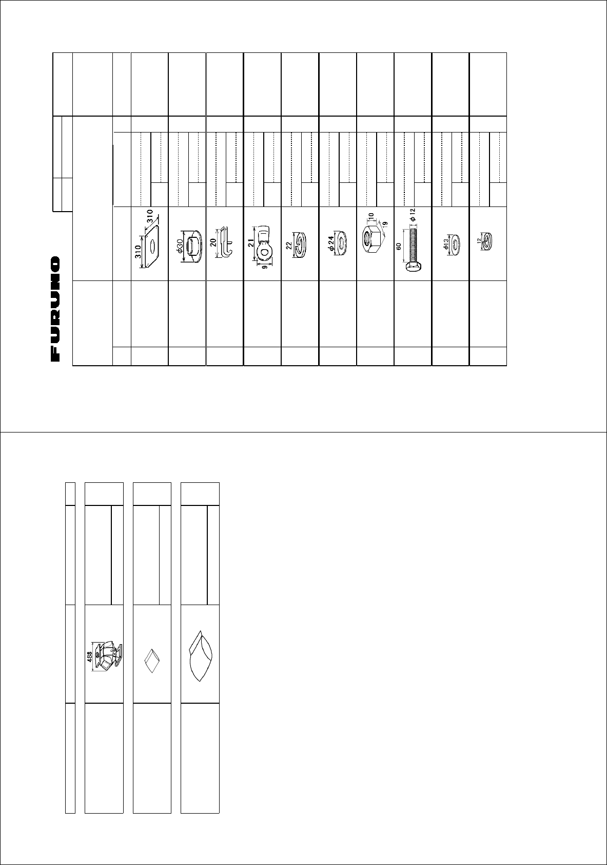
%1&'01
6;2'
%2
⇛ޓޓ࿑
176.+0'
ฬޓޓ⒓
0#/'
ᢙ㊂
36;
↪ㅜ㧛⠨
4'/#4-5
⇟ภ
01
ဳฬ㧛ⷙᩰ
&'5%4+26+105
+056#..#6+10/#6'4+#.5
Ꮏ᧚ᢱ
)/:
㒐ⲁࠧࡓ
%14415+10
2411(47$$'4
/#6
41*5
%1&'
01
㩆㨺㩣㩦㨹㩆㨶
5'#.9#5*'4
%1&'
01
41*5
ᠲ㩤㩔㩨㨺
6'4/+0#.12'0'4
%1&'
01
⌕┵ሶ
%4+/210.7) (8
%1&'
01
㩔㩨㩒ᐳ㊄
524+0)9#5*'4 /575
%1&'
01
㩚㩀㩨㩁㩙㩣ᐔᐳ㊄
(.#69#5*'4 /575
%1&'
01
ⷺ㩏㨹㩎㩆㨷
*':076 /575
%1&'
01
ⷺ㩘㩨㩣㩎㧔ో㩒㩆㩨㧕
*':$1.6 /:575
%1&'
01
㩚㩀㩨㩁ᐔᐳ㊄
(.#69#5*'4 /575
%1&'
01
㩔㩨㩒ᐳ㊄
524+0)9#5*'4 /575
%1&'
01
㧔⇛࿑ߩኸᴺߪޔෳ⠨୯ߢߔޕޓ&+/'05+105+0&4#9+0)(144'('4'0%'10.;㧕
㧲㨁㧾㨁㧺㧻ޓ㧱㧸㧱㧯㨀㧾㧵㧯ޓ㧯㧻ޓ㧚
㧘
㧸㨀㧰
)/:
ဳᑼ㩄㨺㩎㩨⇟ภ߇㧞Ბߩ႐วޔਅᲑࠃࠅᲑߦઍࠊࠆㆊᷰᦼຠߢࠅޔߤߜࠄ߆߇ߞߡ߹ߔޕޓߥ߅ޔຠ⾰ߪᄌࠊࠅ߹ߖ
ࠎޕ
6916;2'5#0&%1&'5/#;$'.+56'&(14#0+6'/6*'.19'4241&7%6/#;$'5*+22'&+02.#%'1(6*'722'4
241&7%637#.+6;+56*'5#/'
A-2
㧼㧭㧯㧷㧵㧺㧳ޓ㧸㧵㧿㨀
)/:
45$
0#/' 176.+0' &'5%4+26+10%1&'ͳ 36;
࡙࠾࠶࠻ 70+6
ⓨਛ✢ᧄㇱ
#06'00#70+6
45$05
੍ຠ 52#4'2#465
੍ຠ
52#4'2#465
52
Ꮏ᧚ᢱ +056#..#6+10/#6'4+#.5
Ꮏ᧚ᢱ
+056#..#6+10/#6'4+#.5
%2
㪈㪅䍘㪄䍢䍼⇟ภᧃየ䈱㪲㪁㪁㪴䈲䇮ㆬᛯຠ䈱ઍဳᑼ㪆䍘䍎䍢䍼䉕䈚䉁䈜䇯
㪚㪦㪛㪜㩷㪥㪬㪤㪙㪜㪩㩷㪜㪥㪛㪜㪛㩷㪙㪰㩷㩹㪁㪁㩹㩷㪠㪥㪛㪠㪚㪘㪫㪜㪪㩷㪫㪟㪜㩷㪥㪬㪤㪙㪜㪩㩷㪦㪝㩷㪫㪰㪧㪠㪚㪘㪣㩷㪤㪘㪫㪜㪩㪠㪘㪣㪅
㧔⇛࿑ߩኸᴺߪޔෳ⠨୯ߢߔޕ&+/'05+105+0&4#9+0)(144'('4'0%'10.;㧕
)/:
A
-1
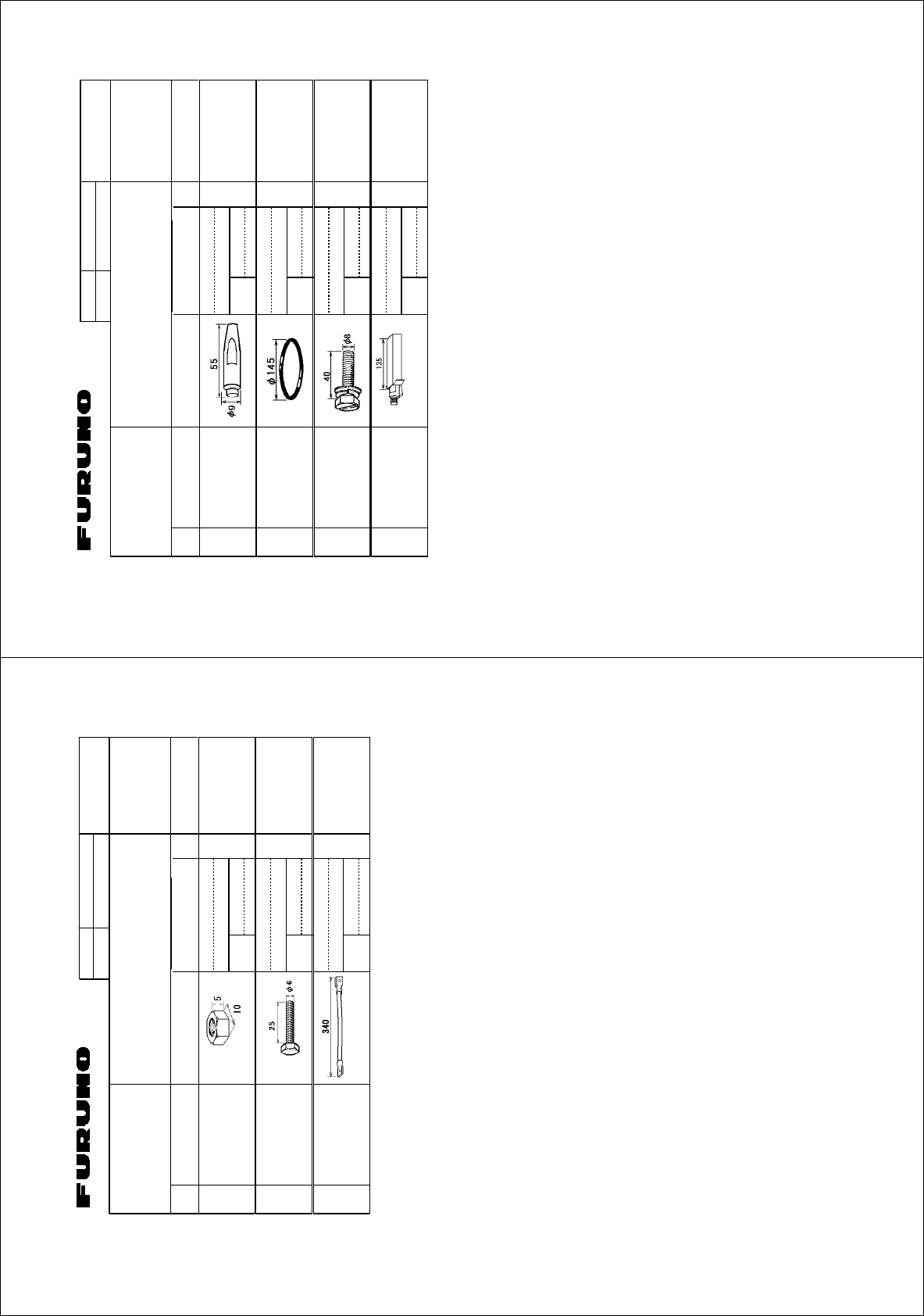
%1&'01
6;2'
%2
⇛ޓޓ࿑
176.+0'
ฬޓޓ⒓
0#/'
ᢙ㊂
36;
↪ㅜ㧛⠨
4'/#4-5
⇟ภ
01
ဳฬ㧛ⷙᩰ
&'5%4+26+105
+056#..#6+10/#6'4+#.5
Ꮏ᧚ᢱ
(5:
㩕㩩㩧
2+0
%1&'
01
1㩢㩧㩂㩨
14+0) ,$2
%1&'
01
ⷺ㩇㩢㩦㩢㩈㩛㩇$
*':$1.6
5.166'&9#5*'4
*'#&
/:575
%1&'
01
/:575
㩃㩚㩆㨺㩣
5+.+%1047$$'4 59㨻㩣㩚㩋㨷㨺㩖㩨)
%1&'
01
㧔⇛࿑ߩኸᴺߪޔෳ⠨୯ߢߔޕޓ&+/'05+105+0&4#9+0)(144'('4'0%'10.;㧕
㧲㨁㧾㨁㧺㧻ޓ㧱㧸㧱㧯㨀㧾㧵㧯ޓ㧯㧻ޓ㧚
㧘
㧸㨀㧰
(5:
ဳᑼ㩄㨺㩎㩨⇟ภ߇㧞Ბߩ႐วޔਅᲑࠃࠅᲑߦઍࠊࠆㆊᷰᦼຠߢࠅޔߤߜࠄ߆߇ߞߡ߹ߔޕޓߥ߅ޔຠ⾰ߪᄌࠊࠅ߹ߖ
ࠎޕ
6916;2'5#0&%1&'5/#;$'.+56'&(14#0+6'/6*'.19'4241&7%6/#;$'5*+22'&+02.#%'1(6*'722'4
241&7%637#.+6;+56*'5#/'
A
-4
%1&'01
6;2'
%2
⇛ޓޓ࿑
176.+0'
ฬޓޓ⒓
0#/'
ᢙ㊂
36;
↪ㅜ㧛⠨
4'/#4-5
⇟ภ
01
ဳฬ㧛ⷙᩰ
&'5%4+26+105
+056#..#6+10/#6'4+#.5
Ꮏ᧚ᢱ
)/:
ⷺ㩏㨹㩎㩆㨷
*':076 /575
%1&'
01
ⷺ㩘㩨㩣㩎
*':$1.6 /:575
%1&'
01
㨻㨺㩇✢
)4170&9+4' 49
%1&'
01
㧔⇛࿑ߩኸᴺߪޔෳ⠨୯ߢߔޕޓ&+/'05+105+0&4#9+0)(144'('4'0%'10.;㧕
㧲㨁㧾㨁㧺㧻ޓ㧱㧸㧱㧯㨀㧾㧵㧯ޓ㧯㧻ޓ㧚
㧘
㧸㨀㧰
)/:
ဳᑼ㩄㨺㩎㩨⇟ภ߇㧞Ბߩ႐วޔਅᲑࠃࠅᲑߦઍࠊࠆㆊᷰᦼຠߢࠅޔߤߜࠄ߆߇ߞߡ߹ߔޕޓߥ߅ޔຠ⾰ߪᄌࠊࠅ߹ߖ
ࠎޕ
6916;2'5#0&%1&'5/#;$'.+56'&(14#0+6'/6*'.19'4241&7%6/#;$'5*+22'&+02.#%'1(6*'722'4
241&7%637#.+6;+56*'5#/'
A
-3
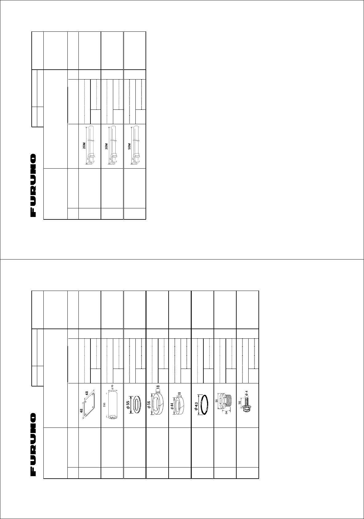
%1&'01
6;2'
⇛ޓޓ࿑
176.+0'
ฬޓޓ⒓
0#/'
ᢙ㊂
36;
↪ㅜ㧛⠨
4'/#4-5
⇟ภ
01
ဳฬ㧛ⷙᩰ
&'5%4+26+105
+056#..#6+10/#6'4+#.5
Ꮏ᧚ᢱ
㩤㨺㩊㩨㨺㩤㩂㩎㩀㩨㨼㩎㩨(4
%3:
4#,'%6)7+&'
(4㩤㩂㩎㩀㩨㨼㩎㩨
9#8')7+&' (4
ㆬᛯޓޓޓޓ
61$'5'.'%6'&
%1&'01
(4㩤㩂㩎㩀㩨㨼㩎㩨
9#8')7+&' (4
ㆬᛯޓޓޓޓ
61$'5'.'%6'&
%1&'01
(4㩤㩂㩎㩀㩨㨼㩎㩨
9#8')7+&' (4
ㆬᛯޓޓޓޓ
61$'5'.'%6'&
%1&'01
㧔⇛࿑ߩኸᴺߪޔෳ⠨୯ߢߔޕޓ&+/'05+105+0&4#9+0)(144'('4'0%'10.;㧕
㧲㨁㧾㨁㧺㧻ޓ㧱㧸㧱㧯㨀㧾㧵㧯ޓ㧯㧻ޓ㧚
㧘
㧸㨀㧰
%3:
ڏ
ဳᑼ㩄㨺㩎㩨⇟ภ߇㧞Ბߩ႐วޔਅᲑࠃࠅᲑߦઍࠊࠆㆊᷰᦼຠߢࠅޔߤߜࠄ߆߇ߞߡ߹ߔޕޓߥ߅ޔຠ⾰ߪᄌࠊࠅ߹ߖࠎޕ
6916;2'5#0&%1&'5/#;$'.+56'&(14#0+6'/6*'.19'4241&7%6/#;$'5*+22'&+02.#%'1(6*'722'4241&7%6
37#.+6;+56*'5#/'
A-6
%1&'01
6;2'
%2
⇛ޓޓ࿑
176.+0'
ฬޓޓ⒓
0#/'
ᢙ㊂
36;
↪ㅜ㧛⠨
4'/#4-5
⇟ภ
01
ဳฬ㧛ⷙᩰ
&'5%4+26+105
+056#..#6+10/#6'4+#.5
Ꮏ᧚ᢱ
(14(4ޓ4'%6)7+&'
(.':+$.'9#8')7+&'
%3:
/#4+0'4#&'4
㒐᳓㩖㨲㩣㩛
9#6'46+)*6(+./ 41*5
%1&'01
㩂㩨㩡㩧㩎㩨ᧄ
647-&'%-%#$.').#0& 41*5
%1&'01
ᐳ㊄
9#5*'4 41*5
%1&'01
㩔㩩㨹㩁㩧㧔㧕
47$$'42#%-+0) 41*5
%1&'01
㩔㩩㨹㩁㩧
47$$'42#%-+0) 41*5
%1&'01
1㩢㩧㩂㩨
14+0) #5
%1&'01
✦ઃ㩂㩨㩡㩧㩎㩨
)..#0& ,+5(#
%1&'01
ⷺ㩇㩢㩦㩢㩈㩛㩇$
*':*'#&5.16$1.6$
9#5*'4
/:575
%1&'01
㧔⇛࿑ߩኸᴺߪޔෳ⠨୯ߢߔޕޓ&+/'05+105+0&4#9+0)(144'('4'0%'10.;㧕
㧲㨁㧾㨁㧺㧻ޓ㧱㧸㧱㧯㨀㧾㧵㧯ޓ㧯㧻ޓ㧚
㧘
㧸㨀㧰
%3:
ဳᑼ㩄㨺㩎㩨⇟ภ߇㧞Ბߩ႐วޔਅᲑࠃࠅᲑߦઍࠊࠆㆊᷰᦼຠߢࠅޔߤߜࠄ߆߇ߞߡ߹ߔޕޓߥ߅ޔຠ⾰ߪᄌࠊࠅ߹ߖࠎޕ
6916;2'5#0&%1&'5/#;$'.+56'&(14#0+6'/6*'.19'4241&7%6/#;$'5*+22'&+02.#%'1(6*'722'4241&7%6
37#.+6;+56*'5#/'
A
-5
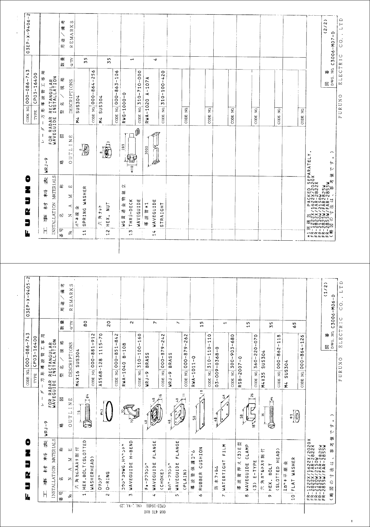
A-8
A
-7
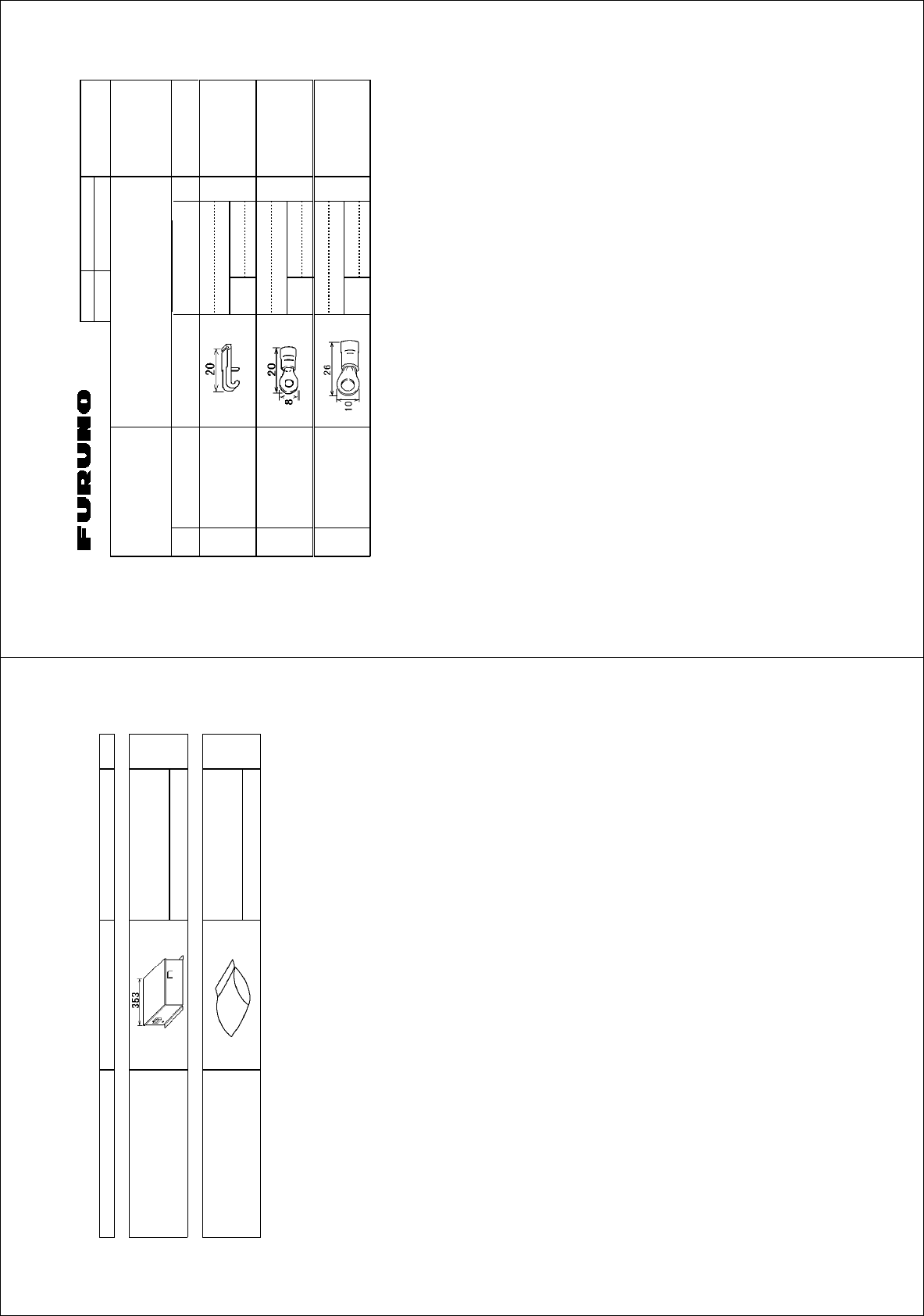
%1&'01
6;2'
%2
⇛ޓޓ࿑
176.+0'
ฬޓޓ⒓
0#/'
ᢙ㊂
36;
↪ㅜ㧛⠨
4'/#4-5
⇟ภ
01
ဳฬ㧛ⷙᩰ
&'5%4+26+105
+056#..#6+10/#6'4+#.5
Ꮏ᧚ᢱ
)/:
ᠲ㩤㩔㩨㨺
6'4/+0#.12'0'4
%1&'
01
⌕┵ሶ
%4+/210.7) (8
%1&'
01
(8.(
⌕┵ሶ
%4+/210.7) (8.(
%1&'
01
㧔⇛࿑ߩኸᴺߪޔෳ⠨୯ߢߔޕޓ&+/'05+105+0&4#9+0)(144'('4'0%'10.;㧕
㧲㨁㧾㨁㧺㧻ޓ㧱㧸㧱㧯㨀㧾㧵㧯ޓ㧯㧻ޓ㧚
㧘
㧸㨀㧰
)/:
ဳᑼ㩄㨺㩎㩨⇟ภ߇㧞Ბߩ႐วޔਅᲑࠃࠅᲑߦઍࠊࠆㆊᷰᦼຠߢࠅޔߤߜࠄ߆߇ߞߡ߹ߔޕޓߥ߅ޔຠ⾰ߪᄌࠊࠅ߹ߖ
ࠎޕ
6916;2'5#0&%1&'5/#;$'.+56'&(14#0+6'/6*'.19'4241&7%6/#;$'5*+22'&+02.#%'1(6*'722'4
241&7%637#.+6;+56*'5#/'
A
-10
㧼㧭㧯㧷㧵㧺㧳ޓ㧸㧵㧿㨀
)/:
464*-5
0#/' 176.+0' &'5%4+26+10%1&'ͳ 36;
࡙࠾࠶࠻ 70+6
ㅍฃାㇱ
64#05%'+8'470+6
464*-
Ꮏ᧚ᢱ +056#..#6+10/#6'4+#.5
Ꮏ᧚ᢱ
+056#..#6+10/#6'4+#.5
%2
㪈㪅䍘㪄䍢䍼⇟ภᧃየ䈱㪲㪁㪁㪴䈲䇮ㆬᛯຠ䈱ઍဳᑼ㪆䍘䍎䍢䍼䉕䈚䉁䈜䇯
㪚㪦㪛㪜㩷㪥㪬㪤㪙㪜㪩㩷㪜㪥㪛㪜㪛㩷㪙㪰㩷㩹㪁㪁㩹㩷㪠㪥㪛㪠㪚㪘㪫㪜㪪㩷㪫㪟㪜㩷㪥㪬㪤㪙㪜㪩㩷㪦㪝㩷㪫㪰㪧㪠㪚㪘㪣㩷㪤㪘㪫㪜㪩㪠㪘㪣㪅
㧔⇛࿑ߩኸᴺߪޔෳ⠨୯ߢߔޕ&+/'05+105+0&4#9+0)(144'('4'0%'10.;㧕
)/:
A
-9
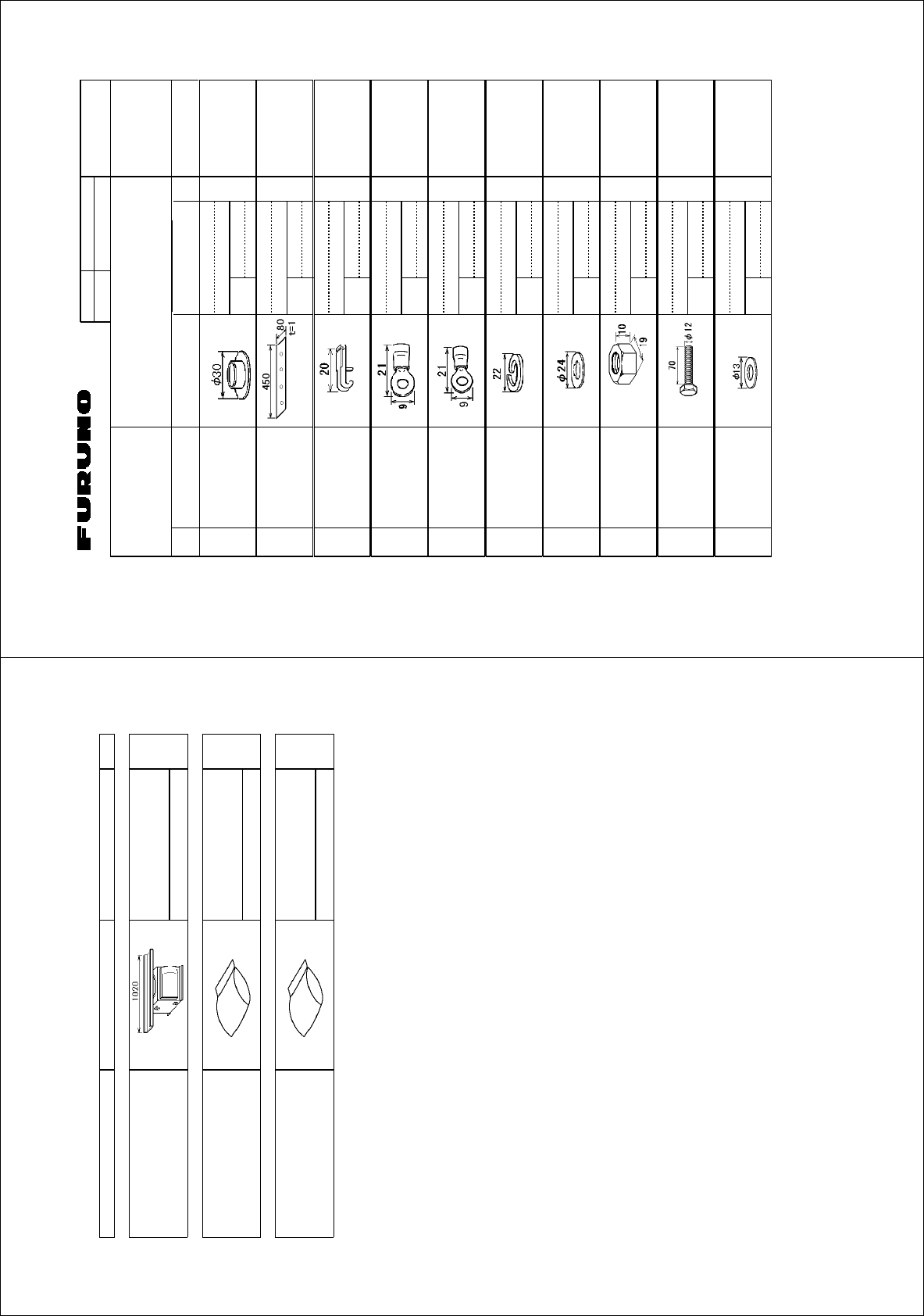
%1&'01
6;2'
%2
⇛ޓޓ࿑
176.+0'
ฬޓޓ⒓
0#/'
ᢙ㊂
36;
↪ㅜ㧛⠨
4'/#4-5
⇟ภ
01
ဳฬ㧛ⷙᩰ
&'5%4+26+105
+056#..#6+10/#6'4+#.5
Ꮏ᧚ᢱ
)2:
㩆㨺㩣㩦㨹㩆㨶
5'#.9#5*'4
%1&'
01
41*5
㒐ⲁࠧࡓ
%14415+102411(
47$$'4/#6
41*5
%1&'
01
ᠲ㩤㩔㩨㨺
6'4/+0#.12'0'4
%1&'
01
⌕┵ሶ
%4+/210.7) (8
%1&'
01
⌕┵ሶ
%4+/210.7) (8
%1&'
01
㩔㩨㩒ᐳ㊄
524+0)9#5*'4 /575
%1&'
01
㩚㩀㩨㩁㩙㩣ᐔᐳ㊄
(.#69#5*'4 /575
%1&'
01
ⷺ㩏㨹㩎㩆㨷
*':076 /575
%1&'
01
ⷺ㩘㩨㩣㩎ޓ㧔ో㩒㩆㩨㧕
*':$1.6 /:575
%1&'
01
㩚㩀㩨㩁ᐔᐳ㊄
(.#69#5*'4 /575
%1&'
01
㧔⇛࿑ߩኸᴺߪޔෳ⠨୯ߢߔޕޓ&+/'05+105+0&4#9+0)(144'('4'0%'10.;㧕
㧲㨁㧾㨁㧺㧻ޓ㧱㧸㧱㧯㨀㧾㧵㧯ޓ㧯㧻ޓ㧚
㧘
㧸㨀㧰
)2:
ဳᑼ㩄㨺㩎㩨⇟ภ߇㧞Ბߩ႐วޔਅᲑࠃࠅᲑߦઍࠊࠆㆊᷰᦼຠߢࠅޔߤߜࠄ߆߇ߞߡ߹ߔޕޓߥ߅ޔຠ⾰ߪᄌࠊࠅ߹ߖ
ࠎޕ
6916;2'5#0&%1&'5/#;$'.+56'&(14#0+6'/6*'.19'4241&7%6/#;$'5*+22'&+02.#%'1(6*'722'4
241&7%637#.+6;+56*'5#/'
A-12
㧼㧭㧯㧷㧵㧺㧳ޓ㧸㧵㧿㨀
)2:
45$45$㧙
0#/' 176.+0' &'5%4+26+10%1&'ͳ 36;
࡙࠾࠶࠻ 70+6
ⓨਛ✢ᧄㇱ
#06'00#70+6
45$05
ઃዻຠ #%%'5514+'5
ઃዻຠ
#%%'5514+'5
(2
Ꮏ᧚ᢱ +056#..#6+10/#6'4+#.5
Ꮏ᧚ᢱ
+056#..#6+10/#6'4+#.5
%2
㪈㪅䍘㪄䍢䍼⇟ภᧃየ䈱㪲㪁㪁㪴䈲䇮ㆬᛯຠ䈱ઍဳᑼ㪆䍘䍎䍢䍼䉕䈚䉁䈜䇯
㪚㪦㪛㪜㩷㪥㪬㪤㪙㪜㪩㩷㪜㪥㪛㪜㪛㩷㪙㪰㩷㩹㪁㪁㩹㩷㪠㪥㪛㪠㪚㪘㪫㪜㪪㩷㪫㪟㪜㩷㪥㪬㪤㪙㪜㪩㩷㪦㪝㩷㪫㪰㪧㪠㪚㪘㪣㩷㪤㪘㪫㪜㪩㪠㪘㪣㪅
㧔⇛࿑ߩኸᴺߪޔෳ⠨୯ߢߔޕ&+/'05+105+0&4#9+0)(144'('4'0%'10.;㧕
)2:
A
-11
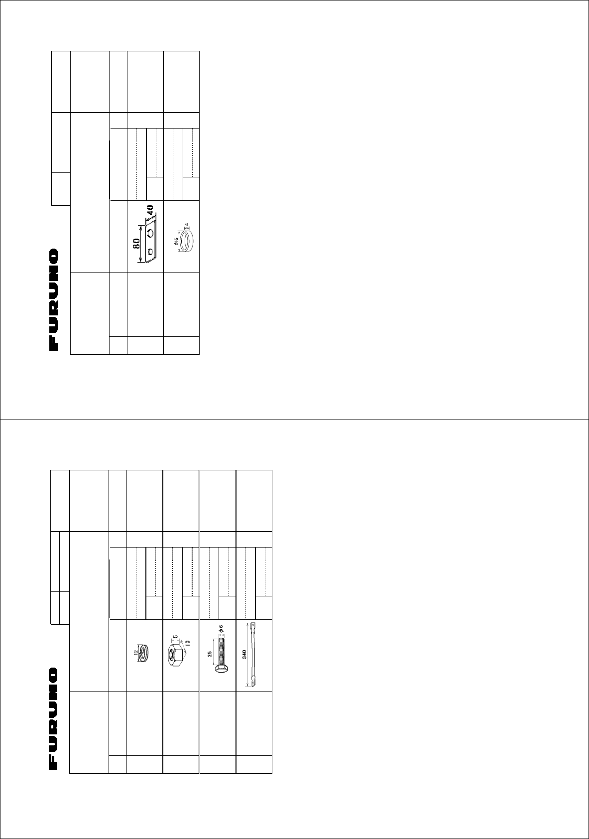
%1&'01
6;2'
(2
⇛ޓޓ࿑
176.+0'
ฬޓޓ⒓
0#/'
ᢙ㊂
36;
↪ㅜ㧛⠨
4'/#4-5
⇟ภ
01
ဳฬ㧛ⷙᩰ
&'5%4+26+105
#%%'5514+'5
ઃዻຠ
)1:
ษࠅߍ㊄ౕ
.+(6+0)(+:674' 41*5
%1&'01
ขઃ↪㩀㩡㨺
%1..#4(14.+(6+0)
(+:674'
41*5
%1&'01
㧔⇛࿑ߩኸᴺߪޔෳ⠨୯ߢߔޕޓ&+/'05+105+0&4#9+0)(144'('4'0%'10.;㧕
㧲㨁㧾㨁㧺㧻ޓ㧱㧸㧱㧯㨀㧾㧵㧯ޓ㧯㧻ޓ㧚
㧘
㧸㨀㧰
)1:
ဳᑼ㩄㨺㩎㩨⇟ภ߇㧞Ბߩ႐วޔਅᲑࠃࠅᲑߦઍࠊࠆㆊᷰᦼຠߢࠅޔߤߜࠄ߆߇ߞߡ߹ߔޕޓߥ߅ޔຠ⾰ߪᄌࠊࠅ߹ߖࠎޕ
6916;2'5#0&%1&'5/#;$'.+56'&(14#0+6'/6*'.19'4241&7%6/#;$'5*+22'&+02.#%'1(6*'722'4241&7%6
37#.+6;+56*'5#/'
A-14
%1&'01
6;2'
%2
⇛ޓޓ࿑
176.+0'
ฬޓޓ⒓
0#/'
ᢙ㊂
36;
↪ㅜ㧛⠨
4'/#4-5
⇟ภ
01
ဳฬ㧛ⷙᩰ
&'5%4+26+105
+056#..#6+10/#6'4+#.5
Ꮏ᧚ᢱ
)2:
㩔㩨㩒ᐳ㊄
524+0)9#5*'4 /575
%1&'
01
ⷺ㩏㨹㩎㩆㨷
*':076 /575
%1&'
01
ⷺ㩘㩨㩣㩎
*':$1.6 /:575
%1&'
01
㨻㨺㩇✢
)4170&9+4' 49
%1&'
01
㧔⇛࿑ߩኸᴺߪޔෳ⠨୯ߢߔޕޓ&+/'05+105+0&4#9+0)(144'('4'0%'10.;㧕
㧲㨁㧾㨁㧺㧻ޓ㧱㧸㧱㧯㨀㧾㧵㧯ޓ㧯㧻ޓ㧚
㧘
㧸㨀㧰
)2:
ဳᑼ㩄㨺㩎㩨⇟ภ߇㧞Ბߩ႐วޔਅᲑࠃࠅᲑߦઍࠊࠆㆊᷰᦼຠߢࠅޔߤߜࠄ߆߇ߞߡ߹ߔޕޓߥ߅ޔຠ⾰ߪᄌࠊࠅ߹ߖ
ࠎޕ
6916;2'5#0&%1&'5/#;$'.+56'&(14#0+6'/6*'.19'4241&7%6/#;$'5*+22'&+02.#%'1(6*'722'4
241&7%637#.+6;+56*'5#/'
A
-13
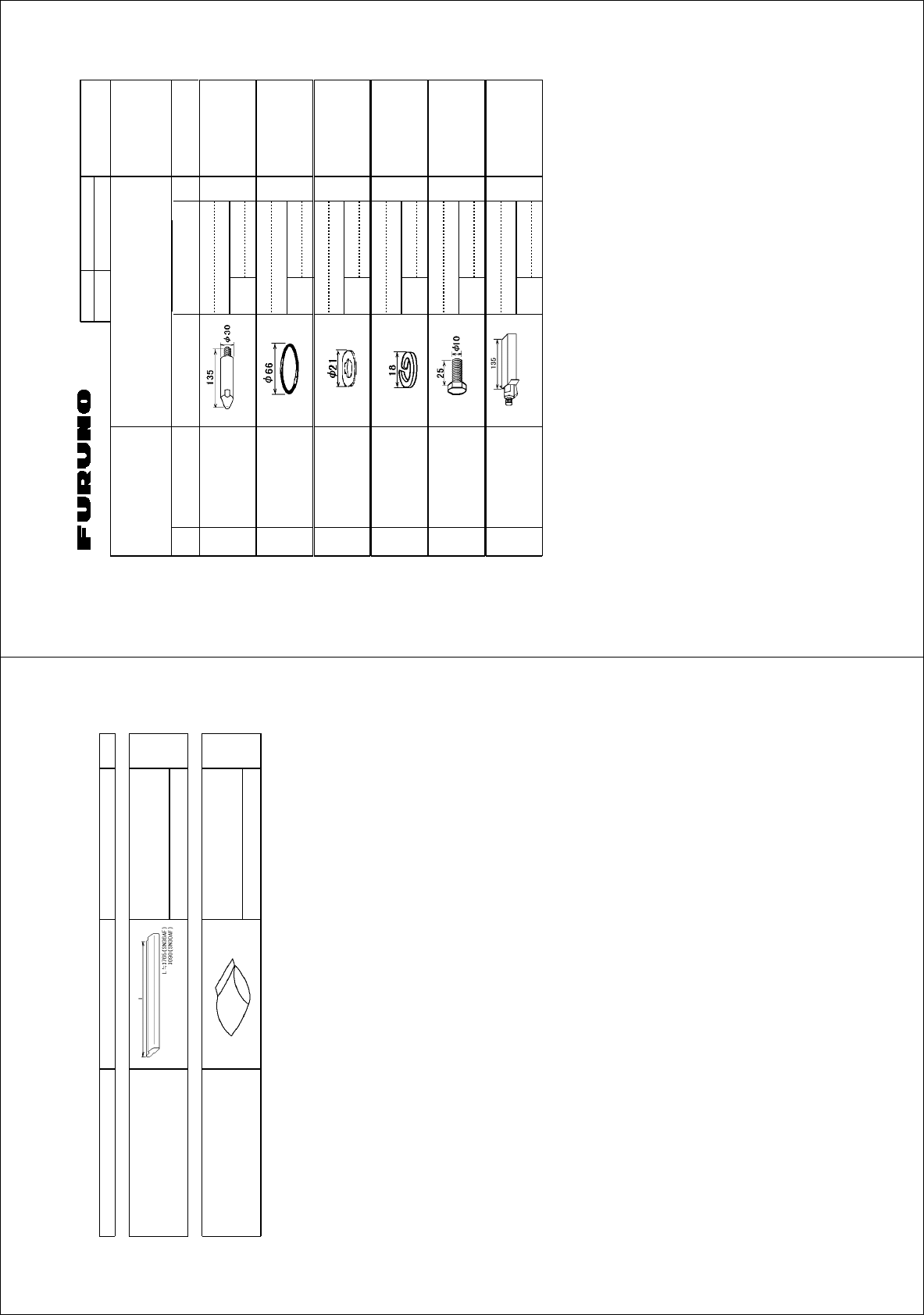
%1&'01
6;2'
⇛ޓޓ࿑
176.+0'
ฬޓޓ⒓
0#/'
ᢙ㊂
36;
↪ㅜ㧛⠨
4'/#4-5
⇟ภ
01
ဳฬ㧛ⷙᩰ
&'5%4+26+105
+056#..#6+10/#6'4+#.5
Ꮏ᧚ᢱ
%3:
50#(#(#(/5##(#(
㩕㩩㩧
)7+&'2+0 41*5
%1&'01
1㩢㩧㩂㩨
14+0) ,$#)
%1&'01
㩚㩀㩨㩁ᐔᐳ㊄
(.#69#5*'4 /575
%1&'01
㩔㩨㩒ᐳ㊄
524+0)9#5*'4 /575ޓ
%1&'01
ⷺ㩘㩨㩣㩎
*':$1.6 /:575
%1&'01
㩃㩚㩆㨺㩣
5+.+%1047$$'4 59㨻㩣㩚㩋㨷㨺㩖㩨)
%1&'01
㧔⇛࿑ߩኸᴺߪޔෳ⠨୯ߢߔޕޓ&+/'05+105+0&4#9+0)(144'('4'0%'10.;㧕
㧲㨁㧾㨁㧺㧻ޓ㧱㧸㧱㧯㨀㧾㧵㧯ޓ㧯㧻ޓ㧚
㧘
㧸㨀㧰
%3:
ဳᑼ㩄㨺㩎㩨⇟ภ߇㧞Ბߩ႐วޔਅᲑࠃࠅᲑߦઍࠊࠆㆊᷰᦼຠߢࠅޔߤߜࠄ߆߇ߞߡ߹ߔޕޓߥ߅ޔຠ⾰ߪᄌࠊࠅ߹ߖࠎޕ
6916;2'5#0&%1&'5/#;$'.+56'&(14#0+6'/6*'.19'4241&7%6/#;$'5*+22'&+02.#%'1(6*'722'4241&7%6
37#.+6;+56*'5#/'
008
-
254
-
590
A-16
PACKING LIST
PACKING LISTPACKING LIST
PACKING LIST
03FT-X-9851 -0
SN30AF/SN36AF
SN30AF/SN36AFSN30AF/SN36AF
SN30AF/SN36AF
N A M E
O U T L I N E
DESCRIPTION/CODE №
Q
'TY
1/1
ユニット
ユニットユニット
ユニット UNIT
UNITUNIT
UNIT
アンテナ組品
ANTENNA
SN30AF
008-505-950
1
**
アンテナ工材
アンテナ工材アンテナ工材
アンテナ工材 ANTENNA INSTALLATION MATERIALS
ANTENNA INSTALLATION MATERIALSANTENNA INSTALLATION MATERIALS
ANTENNA INSTALLATION MATERIALS
工事材料
INSTALLATION MATERIALS
SN5AF/7AF/30AF/36AF
008-254-590
1
1.䍘-䍢䍼⇟ภᧃየ䈱[**]䈲䇮ㆬᛯຠ䈱ઍဳᑼ/䍘䍎䍢䍼䉕䈚䉁䈜䇯
CODE NUMBER ENDED BY "**" INDICATES THE NUMBER OF TYPICAL MATERIAL.
(略図の寸法は、参考値です。 DIMENSIONS IN DRAWING FOR REFERENCE ONLY.)
(略図の寸法は、参考値です。 DIMENSIONS IN DRAWING FOR REFERENCE ONLY.)(略図の寸法は、参考値です。 DIMENSIONS IN DRAWING FOR REFERENCE ONLY.)
(略図の寸法は、参考値です。 DIMENSIONS IN DRAWING FOR REFERENCE ONLY.)
03FT-X-9851
A
-15
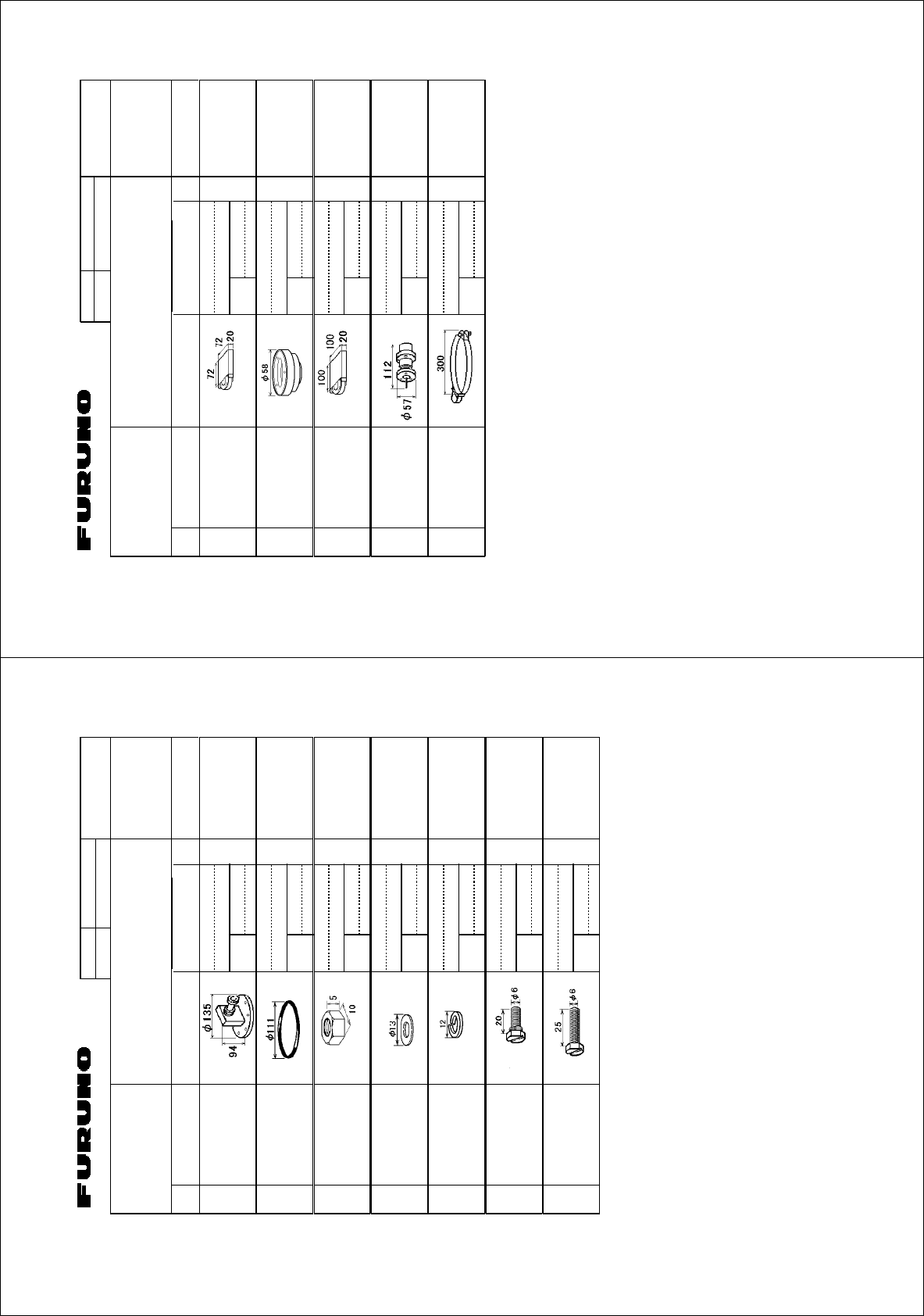
%1&'01
6;2'
%2
⇛ޓޓ࿑
176.+0'
ฬޓޓ⒓
0#/'
ᢙ㊂
36;
↪ㅜ㧛⠨
4'/#4-5
⇟ภ
01
ဳฬ㧛ⷙᩰ
&'5%4+26+105
+056#..#6+10/#6'4+#.5
Ꮏ᧚ᢱ
หゲ㩃㨺㩖㩨㩣Ꮏ↪
(14
4#ޓ%1#:%#$.'
+056#..#6+10
'2:
/#4+0'4#&'4
㩇㩚㩍㨺㩖㩩%
87.%#0+<+0)6#2' ޓ㩂㩥ޓޓޓ
%1&'01
ടᎿ㩃㩨㨺㩆㩨
)#7)'
%1&'01
㨻㩅㩕0㩍㨺㩖㩩
2.#56+%06#2' //:/
%1&'01
㩃㨺㩖㩨㩣↪㩄㩒㩂㩊
%#$.'%100'%614 &&*9(#
%1&'01
㩃㨺㩖㩨㩣↪㩔㩨㩧㩎㩨
%#$.'$#0& *#
%1&'01
㧔⇛࿑ߩኸᴺߪޔෳ⠨୯ߢߔޕޓ&+/'05+105+0&4#9+0)(144'('4'0%'10.;㧕
㧲㨁㧾㨁㧺㧻ޓ㧱㧸㧱㧯㨀㧾㧵㧯ޓ㧯㧻ޓ㧚
㧘
㧸㨀㧰
'2:
ဳᑼ㩄㨺㩎㩨⇟ภ߇㧞Ბߩ႐วޔਅᲑࠃࠅᲑߦઍࠊࠆㆊᷰᦼຠߢࠅޔߤߜࠄ߆߇ߞߡ߹ߔޕޓߥ߅ޔຠ⾰ߪᄌࠊࠅ߹ߖࠎޕ
6916;2'5#0&%1&'5/#;$'.+56'&(14#0+6'/6*'.19'4241&7%6/#;$'5*+22'&+02.#%'1(6*'722'4241&7%6
37#.+6;+56*'5#/'
A
-18
%1&'01
6;2'
2#
⇛ޓޓ࿑
176.+0'
ฬޓޓ⒓
0#/'
ᢙ㊂
36;
↪ㅜ㧛⠨
4'/#4-5
⇟ภ
01
ဳฬ㧛ⷙᩰ
&'5%4+26+105
+056#..#6+10/#6'4+#.5
Ꮏ᧚ᢱ
$(:
ᄌ឵ེ⚵ຠ
%172.'4
%1&'01
1㩢㩧㩂㩨
14+0) #42#
%1&'01
ⷺ㩏㨹㩎ޓ㧝⒳
*':076 /575
%1&'01
/575
㩚㩀㩨㩁ᐔᐳ㊄
(.#69#5*'4 /575
%1&'01
/575
㩔㩨㩒ᐳ㊄
524+0)9#5*'4 /575
%1&'01
/575
ⷺ㩇㩢㩦㩢㩈㩛㩇#
*':$1.65.166'&*'#& /:575
%1&'01
/:575
ⷺ㩘㩨㩣㩎㩇㩢ഀઃ
*':$1.65.166'&*'#& /:575
%1&'01
/:575
㧔⇛࿑ߩኸᴺߪޔෳ⠨୯ߢߔޕޓ&+/'05+105+0&4#9+0)(144'('4'0%'10.;㧕
㧲㨁㧾㨁㧺㧻ޓ㧱㧸㧱㧯㨀㧾㧵㧯ޓ㧯㧻ޓ㧚
㧘
㧸㨀㧰
$(:
ဳᑼ㩄㨺㩎㩨⇟ภ߇㧞Ბߩ႐วޔਅᲑࠃࠅᲑߦઍࠊࠆㆊᷰᦼຠߢࠅޔߤߜࠄ߆߇ߞߡ߹ߔޕޓߥ߅ޔຠ⾰ߪᄌࠊࠅ߹ߖࠎޕ
6916;2'5#0&%1&'5/#;$'.+56'&(14#0+6'/6*'.19'4241&7%6/#;$'5*+22'&+02.#%'1(6*'722'4241&7%6
37#.+6;+56*'5#/'
A
-17
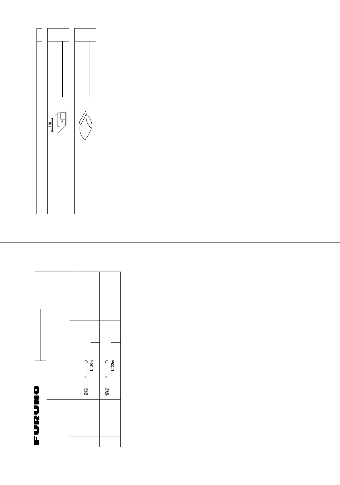
㧼㧭㧯㧷㧵㧺㧳ޓ㧸㧵㧿㨀
)2:
464
0#/' 176.+0' &'5%4+26+10%1&'ͳ 36;
࡙࠾࠶࠻ 70+6
ㅍฃାㇱ
64#05%'+8'470+6
4645
Ꮏ᧚ᢱ +056#..#6+10/#6'4+#.5
Ꮏ᧚ᢱ
+056#..#6+10/#6'4+#.5
%2
㪈㪅䍘㪄䍢䍼⇟ภᧃየ䈱㪲㪁㪁㪴䈲䇮ㆬᛯຠ䈱ઍဳᑼ㪆䍘䍎䍢䍼䉕䈚䉁䈜䇯
㪚㪦㪛㪜㩷㪥㪬㪤㪙㪜㪩㩷㪜㪥㪛㪜㪛㩷㪙㪰㩷㩹㪁㪁㩹㩷㪠㪥㪛㪠㪚㪘㪫㪜㪪㩷㪫㪟㪜㩷㪥㪬㪤㪙㪜㪩㩷㪦㪝㩷㪫㪰㪧㪠㪚㪘㪣㩷㪤㪘㪫㪜㪩㪠㪘㪣㪅
㧔⇛࿑ߩኸᴺߪޔෳ⠨୯ߢߔޕ&+/'05+105+0&4#9+0)(144'('4'0%'10.;㧕
)2:
A
-20
%1&'01
6;2'
⇛ޓޓ࿑
176.+0'
ฬޓޓ⒓
0#/'
ᢙ㊂
36;
↪ㅜ㧛⠨
4'/#4-5
⇟ภ
01
ဳฬ㧛ⷙᩰ
&'5%4+26+105
+056#..#6+10/#6'4+#.5
Ꮏ᧚ᢱ
)2:
㩃㨺㩖㩨㩣⚵ຠ
%#$.'#55;
.*2:7/
ㆬᛯޓ61$'5'.'%6'&
%1&'01
㩃㨺㩖㩨㩣⚵ຠ
%#$.'#55;
.*2:7/
ㆬᛯޓ61$'5'.'%6'&
%1&'01
㧔⇛࿑ߩኸᴺߪޔෳ⠨୯ߢߔޕޓ&+/'05+105+0&4#9+0)(144'('4'0%'10.;㧕
㧲㨁㧾㨁㧺㧻ޓ㧱㧸㧱㧯㨀㧾㧵㧯ޓ㧯㧻ޓ㧚㧘㧸㨀㧰
)2:
A
-19
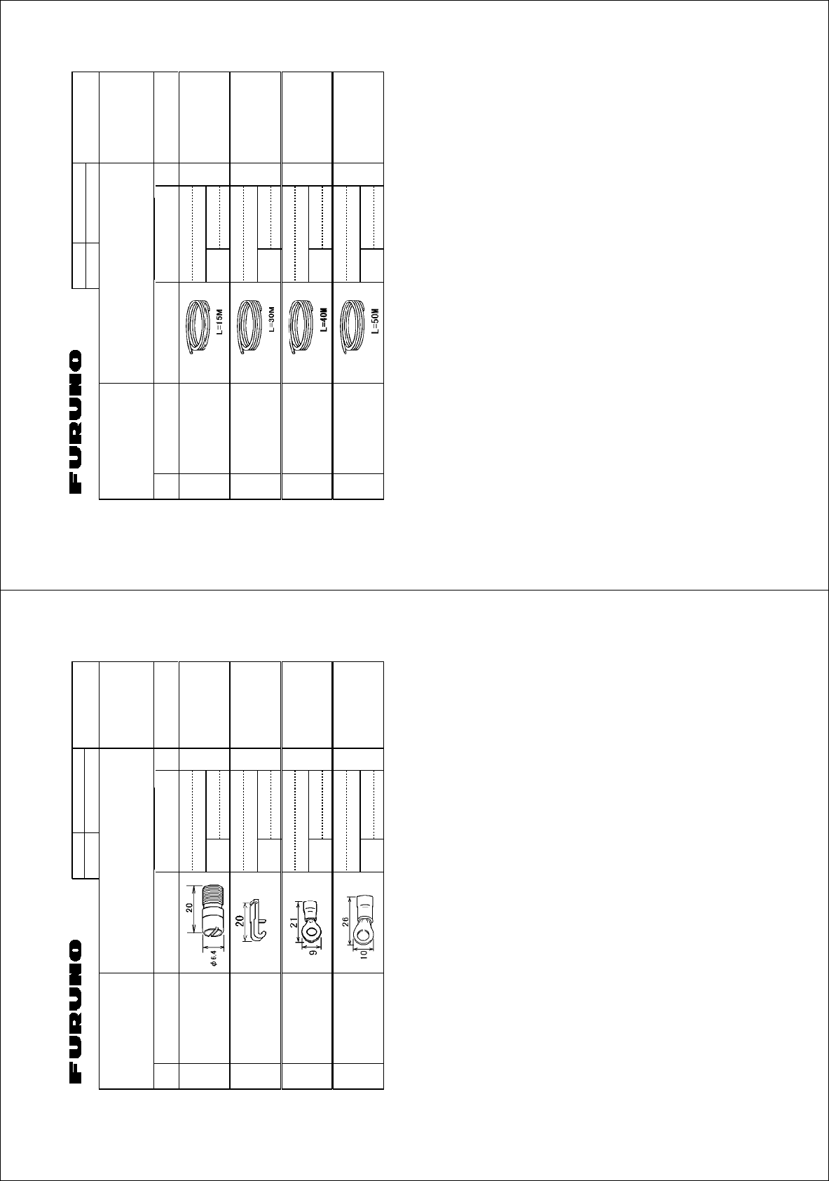
%1&'01
6;2'
⇛ޓޓ࿑
176.+0'
ฬޓޓ⒓
0#/'
ᢙ㊂
36;
↪ㅜ㧛⠨
4'/#4-5
⇟ภ
01
ဳฬ㧛ⷙᩰ
&'5%4+26+105
+056#..#6+10/#6'4+#.5
Ꮏ᧚ᢱ
).:
(#4(%4
㩃㨺㩖㩨㩣%
%#$.' 49/
ㆬᛯޓ61$'5'.'%6'&
ାภ㩃㨺㩖㩨㩣ޓޓ
5+)0#.%#$.'
%1&'
01
㩃㨺㩖㩨㩣%
%#$.' 49/
ㆬᛯޓ61$'5'.'%6'&
ାภ㩃㨺㩖㩨㩣ޓޓ
5+)0#.%#$.'
%1&'
01
㩃㨺㩖㩨㩣%
%#$.' 49/
ㆬᛯޓ61$'5'.'%6'&
ାภ㩃㨺㩖㩨㩣ޓޓ
5+)0#.%#$.'
%1&'
01
㩃㨺㩖㩨㩣%
%#$.' 49/
ㆬᛯޓ61$'5'.'%6'&
ାภ㩃㨺㩖㩨㩣ޓޓ
5+)0#.%#$.'
%1&'
01
㧔⇛࿑ߩኸᴺߪޔෳ⠨୯ߢߔޕޓ&+/'05+105+0&4#9+0)(144'('4'0%'10.;㧕
㧲㨁㧾㨁㧺㧻ޓ㧱㧸㧱㧯㨀㧾㧵㧯ޓ㧯㧻ޓ㧚
㧘
㧸㨀㧰
).:
ဳᑼ㩄㨺㩎㩨⇟ภ߇㧞Ბߩ႐วޔਅᲑࠃࠅᲑߦઍࠊࠆㆊᷰᦼຠߢࠅޔߤߜࠄ߆߇ߞߡ߹ߔޕޓߥ߅ޔຠ⾰ߪᄌࠊࠅ߹ߖ
ࠎޕ
6916;2'5#0&%1&'5/#;$'.+56'&(14#0+6'/6*'.19'4241&7%6/#;$'5*+22'&+02.#%'1(6*'722'4
241&7%637#.+6;+56*'5#/'
FAR-2117 series
A
-22
%1&'01
6;2'
%2
⇛ޓޓ࿑
176.+0'
ฬޓޓ⒓
0#/'
ᢙ㊂
36;
↪ㅜ㧛⠨
4'/#4-5
⇟ภ
01
ဳฬ㧛ⷙᩰ
&'5%4+26+105
+056#..#6+10/#6'4+#.5
Ꮏ᧚ᢱ
)2:
⟎ࡇࡦ%㧕
2+0
%1&'
01
41*5
ᠲ㩤㩔㩨㨺
6'4/+0#.12'0'4
%1&'
01
⌕┵ሶ
%4+/210.7) (8
%1&'
01
⌕┵ሶ
%4+/210.7) (8.(
%1&'
01
㧔⇛࿑ߩኸᴺߪޔෳ⠨୯ߢߔޕޓ&+/'05+105+0&4#9+0)(144'('4'0%'10.;㧕
㧲㨁㧾㨁㧺㧻ޓ㧱㧸㧱㧯㨀㧾㧵㧯ޓ㧯㧻ޓ㧚
㧘
㧸㨀㧰
)2:
ဳᑼ㩄㨺㩎㩨⇟ภ߇㧞Ბߩ႐วޔਅᲑࠃࠅᲑߦઍࠊࠆㆊᷰᦼຠߢࠅޔߤߜࠄ߆߇ߞߡ߹ߔޕޓߥ߅ޔຠ⾰ߪᄌࠊࠅ߹ߖ
ࠎޕ
6916;2'5#0&%1&'5/#;$'.+56'&(14#0+6'/6*'.19'4241&7%6/#;$'5*+22'&+02.#%'1(6*'722'4
241&7%637#.+6;+56*'5#/'
A
-21
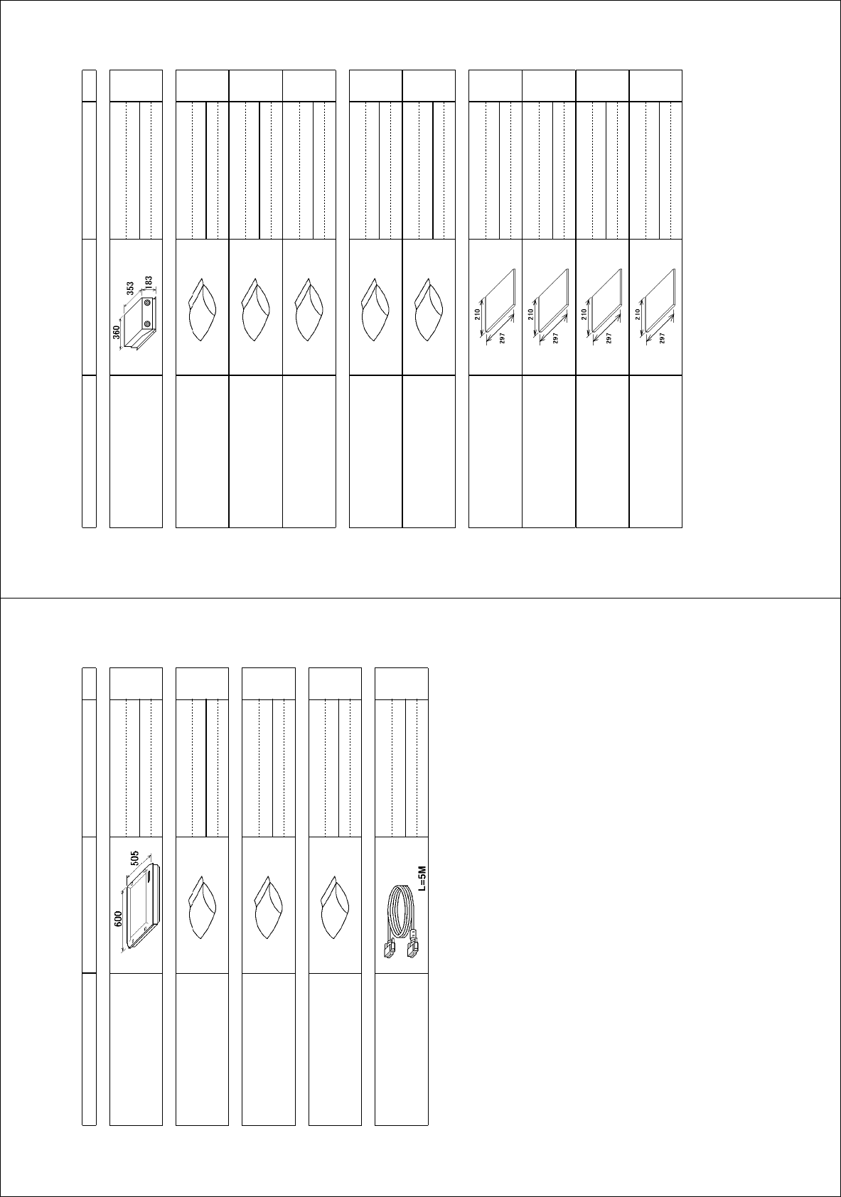
㧼㧭㧯㧷㧵㧺㧳ޓ㧸㧵㧿㨀
).:
427
0#/' 176.+0' &'5%4+26+10%1&'ͳ 36;
࡙࠾࠶࠻ 70+6
ᓮㇱ
241%'551470+6
427
੍ຠ 52#4'2#465
੍ຠ
52#4'2#465
52
੍ຠ
52#4'2#465
52
੍ຠ
52#4'2#465
52
Ꮏ᧚ᢱ +056#..#6+10/#6'4+#.5
Ꮏ᧚ᢱ
+056#..#6+10/#6'4+#.5
%2
Ꮏ᧚ᢱ
+056#..#6+10/#6'4+#.5
%2
࿑ᦠ &1%7/'06
ขᛒ⺑ᦠ
12'4#6145/#07#.
1/
ขᛒ⺑ᦠ
12'4#6145/#07#.
1/
ⵝⷐ㗔ᦠ
+056#..#6+10/#07#.
+/
ᠲⷐ㗔ᦠ
12'4#6145)7+&'
15
㪈㪅䍘㪄䍢䍼⇟ภᧃየ䈱㪲㪁㪁㪴䈲䇮ㆬᛯຠ䈱ઍ䍘䍎䍢䍼䉕䈚䉁䈜䇯
㪚㪦㪛㪜㩷㪥㪬㪤㪙㪜㪩㩷㪜㪥㪛㪠㪥㪞㩷㪮㪠㪫㪟㩷㩹㪁㪁㩹㩷㪠㪥㪛㪠㪚㪘㪫㪜㪪㩷㪫㪟㪜㩷㪚㪦㪛㪜㩷㪥㪬㪤㪙㪜㪩㩷㪦㪝㩷㪩㪜㪧㪩㪜㪪㪜㪥㪫㪘㪫㪠㪭㪜㩷㪤㪘㪫㪜㪩㪠㪘㪣㪅
㪉㪅䋨㪁㪈䋩䋨㪁㪉䋩䈲䇮䈠䉏䈡䉏᭽ㆬᛯຠ䉕䈚䉁䈜䇯
䋨㪁㪈䋩䋨㪁㪉䋩㪠㪥㪛㪠㪚㪘㪫㪜㩷㪪㪧㪜㪚㪠㪝㪠㪚㪘㪫㪠㪦㪥㩷㪪㪜㪣㪜㪚㪫㪠㪭㪜㩷㪠㪫㪜㪤㪅
㪊㪅㩿㪁㪊㪀㩷㪝㪘㪩㪄㪉㪈㪌㪎㪆㪉㪈㪍㪎㪛㪪᭽䈱ᤨ䈱䉂ᷝઃ䈘䉏䉁䈜䇯
㪪㪬㪧㪧㪣㪰㪜㪛㩷㪮㪠㪫㪟㩷㪝㪘㪩㪄㪉㪈㪌㪎㪆㪉㪈㪍㪎㪛㪪㩷㪦㪥㪣㪰㪅
䋨⇛࿑䈱ኸᴺ䈲䇮ෳ⠨୯䈪䈜䇯㩷㩷㪛㪠㪤㪜㪥㪪㪠㪦㪥㪪㩷㪠㪥㩷㪛㪩㪘㪮㪠㪥㪞㩷㪝㪦㪩㩷㪩㪜㪝㪜㪩㪜㪥㪚㪜㩷㪦㪥㪣㪰㪅䋩
).:
ဳᑼ㪆䍘䍎䍢䍼⇟ภ䈏䋲Ბ䈱႐ว䇮ਅᲑ䉋䉍Ბ䈮ઍ䉒䉎ㆊᷰᦼຠ䈪䈅䉍䇮䈬䈤䉌䈎䈏䈦䈩䈇䉁䈜䇯䇭䈭䈍䇮ຠ⾰䈲ᄌ䉒䉍䉁䈞䉖䇯
㪫㪮㪦㩷㪫㪰㪧㪜㪪㩷㪘㪥㪛㩷㪚㪦㪛㪜㪪㩷㪤㪘㪰㩷㪙㪜㩷㪣㪠㪪㪫㪜㪛㩷㪝㪦㪩㩷㪘㪥㩷㪠㪫㪜㪤㪅㩷㩷㪫㪟㪜㩷㪣㪦㪮㪜㪩㩷㪧㪩㪦㪛㪬㪚㪫㩷㪤㪘㪰㩷㪙㪜㩷㪪㪟㪠㪧㪧㪜㪛㩷㪠㪥㩷㪧㪣㪘㪚㪜㩷㪦㪝㩷㪫㪟㪜㩷㪬㪧㪧㪜㪩㩷
㪧㪩㪦㪛㪬㪚㪫㪅㩷㪨㪬㪘㪣㪠㪫㪰㩷㪠㪪㩷㪫㪟㪜㩷㪪㪘㪤㪜㪅
A
-24
㧼㧭㧯㧷㧵㧺㧳ޓ㧸㧵㧿㨀
)/:
/7%4
0#/' 176.+0' &'5%4+26+10%1&'ͳ 36;
࡙࠾࠶࠻ 70+6
␜ㇱ
&+52.#;70+6
/7%45*-#4
੍ຠ 52#4'2#465
੍ຠ
52#4'2#465
52
#%↪
੍ຠ 52#4'2#465
੍ຠ
52#4'2#465
52
&%↪
ઃዻຠ #%%'5514+'5
ઃዻຠ
#%%'5514+'5
(2
Ꮏ᧚ᢱ +056#..#6+10/#6'4+#.5
㩃㨺㩖㩨㩣⚵ຠ
%#$.'#55;
&8+&&5+0).'.+0-/
㪈㪅䍘䍎䍢䍼ᧃየ䈮㪲㪁㪁㪴䈱ઃ䈇䈢䍳䍤䍍䍢䈲ઍ䈱ဳᑼ㪆䍘䍎䍢䍼䉕␜䈚䈩䈇䉁䈜䇯
㪛㪦㪬㪙㪣㪜㩷㪘㪪㪫㪜㪩㪠㪪㪢㩷㪛㪜㪥㪦㪫㪜㪪㩷㪚㪦㪤㪤㪦㪥㪣㪰㩷㪬㪪㪜㪛㩷㪜㪨㪬㪠㪧㪤㪜㪥㪫㪅
㪉㪅੍ຠ䈲䍂㪘㪚㪃㪛㪚䈪ㆬᛯ㗿䈇䉁䈜䇯
㪚㪟㪦㪦㪪㪜㩷㪪㪧㪘㪩㪜㩷㪧㪘㪩㪫㪪㩷㪛㪜㪧㪜㪥㪛㪠㪥㪞㩷㪦㪥㩷㪘㪚㩷㪦㪩㩷㪛㪚㩷㪧㪦㪮㪜㪩㪅
䋨⇛࿑䈱ኸᴺ䈲䇮ෳ⠨୯䈪䈜䇯㩷㩷㪛㪠㪤㪜㪥㪪㪠㪦㪥㪪㩷㪠㪥㩷㪛㪩㪘㪮㪠㪥㪞㩷㪝㪦㪩㩷㪩㪜㪝㪜㪩㪜㪥㪚㪜㩷㪦㪥㪣㪰㪅䋩
)/:
ဳᑼ㪆䍘䍎䍢䍼⇟ภ䈏䋲Ბ䈱႐ว䇮ਅᲑ䉋䉍Ბ䈮ઍ䉒䉎ㆊᷰᦼຠ䈪䈅䉍䇮䈬䈤䉌䈎䈏䈦䈩䈇䉁䈜䇯䇭䈭䈍䇮ຠ⾰䈲ᄌ䉒䉍䉁䈞䉖䇯
㪫㪮㪦㩷㪫㪰㪧㪜㪪㩷㪘㪥㪛㩷㪚㪦㪛㪜㪪㩷㪤㪘㪰㩷㪙㪜㩷㪣㪠㪪㪫㪜㪛㩷㪝㪦㪩㩷㪘㪥㩷㪠㪫㪜㪤㪅㩷㩷㪫㪟㪜㩷㪣㪦㪮㪜㪩㩷㪧㪩㪦㪛㪬㪚㪫㩷㪤㪘㪰㩷㪙㪜㩷㪪㪟㪠㪧㪧㪜㪛㩷㪠㪥㩷㪧㪣㪘㪚㪜㩷㪦㪝㩷㪫㪟㪜㩷㪬㪧㪧㪜㪩㩷
㪧㪩㪦㪛㪬㪚㪫㪅㩷㪨㪬㪘㪣㪠㪫㪰㩷㪠㪪㩷㪫㪟㪜㩷㪪㪘㪤㪜㪅
A
-23
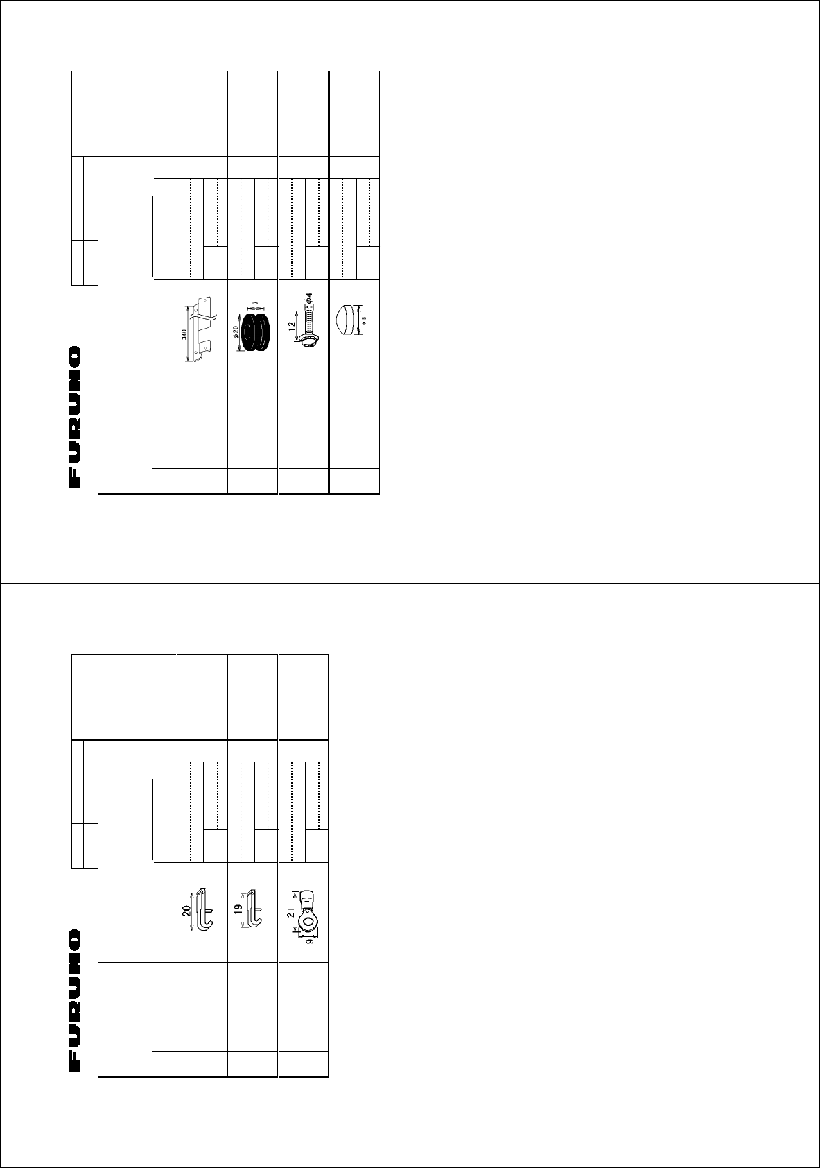
%1&'01
6;2'
(2
⇛ޓޓ࿑
176.+0'
ฬޓޓ⒓
0#/'
ᢙ㊂
36;
↪ㅜ㧛⠨
4'/#4-5
⇟ภ
01
ဳฬ㧛ⷙᩰ
&'5%4+26+105
#%%'5514+'5
ઃዻຠ
).:
-$⋥ઃ㊄ౕ
-$(+:+0)/'6#. 41*5
ᠲㇱ↪ޓޓޓ
ޓ(14%10641.70+6
%1&'
01
㩂㩨㩥㩜㨹㩎
)41//'6 )
ᠲㇱ↪ޓޓޓ
ޓ(14%10641.70+6
%1&'
01
㩏㩗㩨㩈㩛㩇$
9#5*'4*'#&5&4'9$ /:%9/$0+
ᠲㇱ↪ޓޓޓ
ޓ(14%10641.70+6
%1&'
01
㩂㩢㨻㩔㩨㩧㩘㩩㩧
%75*+10 6/
ᠲㇱ↪ޓޓޓ
ޓ(14%10641.70+6
%1&'
01
㧔⇛࿑ߩኸᴺߪޔෳ⠨୯ߢߔޕޓ&+/'05+105+0&4#9+0)(144'('4'0%'10.;㧕
㧲㨁㧾㨁㧺㧻ޓ㧱㧸㧱㧯㨀㧾㧵㧯ޓ㧯㧻ޓ㧚
㧘
㧸㨀㧰
).:
ဳᑼ㩄㨺㩎㩨⇟ภ߇㧞Ბߩ႐วޔਅᲑࠃࠅᲑߦઍࠊࠆㆊᷰᦼຠߢࠅޔߤߜࠄ߆߇ߞߡ߹ߔޕޓߥ߅ޔຠ⾰ߪᄌࠊࠅ߹ߖ
ࠎޕ
6916;2'5#0&%1&'5/#;$'.+56'&(14#0+6'/6*'.19'4241&7%6/#;$'5*+22'&+02.#%'1(6*'722'4
241&7%637#.+6;+56*'5#/'
(QT4%7&GUMVQROQWPVMKV
A
-26
%1&'01
6;2'
%2
⇛ޓޓ࿑
176.+0'
ฬޓޓ⒓
0#/'
ᢙ㊂
36;
↪ㅜ㧛⠨
4'/#4-5
⇟ภ
01
ဳฬ㧛ⷙᩰ
&'5%4+26+105
+056#..#6+10/#6'4+#.5
Ꮏ᧚ᢱ
#%↪
).:
ᠲ㩤㩔㩨㨺
6'4/+0#.12'0'4
ᓮㇱ↪ޓޓޓޓޓ
ޓ(14241%'5514
70+6
%1&'
01
ᠲ㩤㩔㩨㨺
6'4/+0#.12'0'4
ᓮㇱ↪ޓޓޓޓޓ
ޓ(14241%'5514
70+6
%1&'
01
⌕┵ሶ
%4+/210.7) (8
ᓮㇱ↪ޓޓޓޓޓ
ޓ(14241%'5514
70+6
%1&'
01
㧔⇛࿑ߩኸᴺߪޔෳ⠨୯ߢߔޕޓ&+/'05+105+0&4#9+0)(144'('4'0%'10.;㧕
㧲㨁㧾㨁㧺㧻ޓ㧱㧸㧱㧯㨀㧾㧵㧯ޓ㧯㧻ޓ㧚
㧘
㧸㨀㧰
).:
ဳᑼ㩄㨺㩎㩨⇟ภ߇㧞Ბߩ႐วޔਅᲑࠃࠅᲑߦઍࠊࠆㆊᷰᦼຠߢࠅޔߤߜࠄ߆߇ߞߡ߹ߔޕޓߥ߅ޔຠ⾰ߪᄌࠊࠅ߹ߖ
ࠎޕ
6916;2'5#0&%1&'5/#;$'.+56'&(14#0+6'/6*'.19'4241&7%6/#;$'5*+22'&+02.#%'1(6*'722'4
241&7%637#.+6;+56*'5#/'
(QT427#%UGV
A
-25
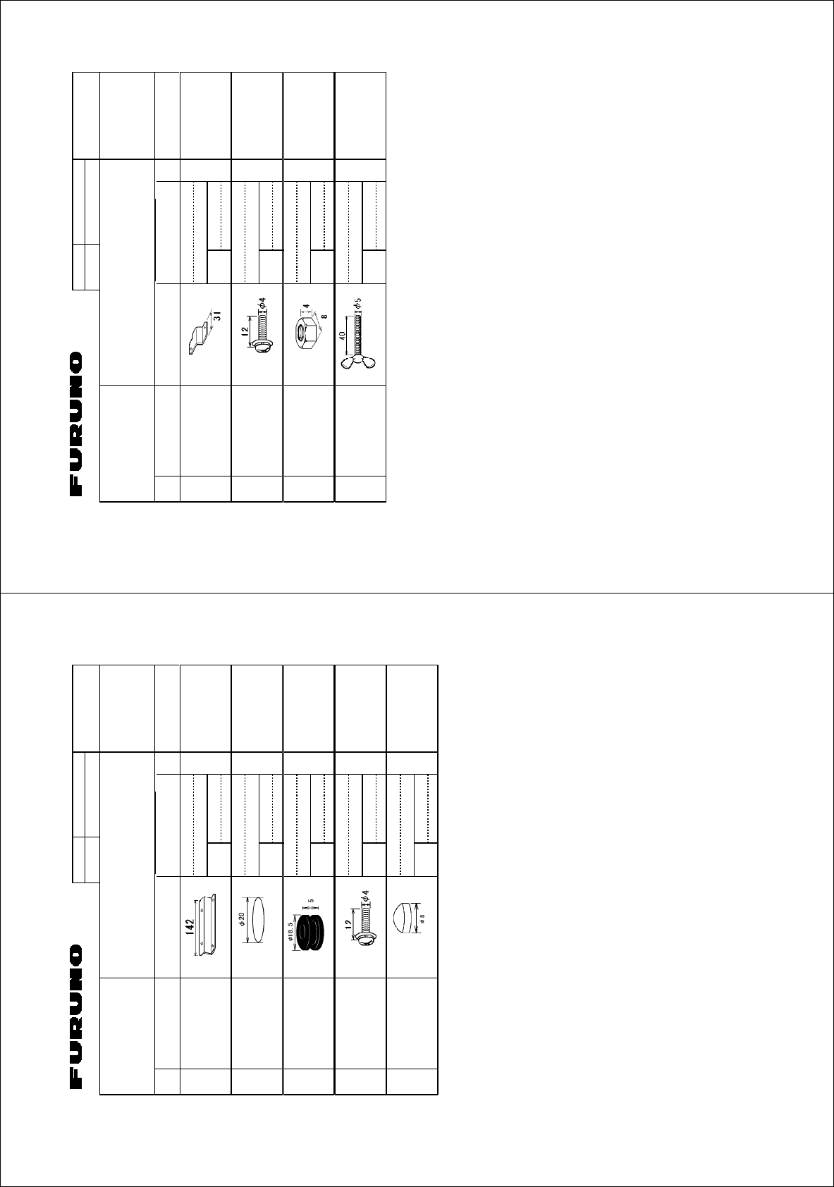
%1&'01
6;2'
(2
⇛ޓޓ࿑
176.+0'
ฬޓޓ⒓
0#/'
ᢙ㊂
36;
↪ㅜ㧛⠨
4'/#4-5
⇟ภ
01
ဳฬ㧛ⷙᩰ
&'5%4+26+105
#%%'5514+'5
ઃዻຠ
).:
㩖㩡㨹㩆㨷㩙㨽㩧㩎㊄ౕ
(.75*/1706+0)2.#6' 41*5
%1&'
01
㩏㩗㩨㩈㩛㩇$
9#5*'4*'#&5&4'9$ /:%9/$0+
%1&'
01
ⷺ㩏㨹㩎ޓ㧝⒳
*':076 /575
%1&'
01
Ⲕ㩘㩨㩣㩎
9+0)5%4'9 /:575
%1&'
01
㧔⇛࿑ߩኸᴺߪޔෳ⠨୯ߢߔޕޓ&+/'05+105+0&4#9+0)(144'('4'0%'10.;㧕
㧲㨁㧾㨁㧺㧻ޓ㧱㧸㧱㧯㨀㧾㧵㧯ޓ㧯㧻ޓ㧚
㧘
㧸㨀㧰
).:
ဳᑼ㩄㨺㩎㩨⇟ภ߇㧞Ბߩ႐วޔਅᲑࠃࠅᲑߦઍࠊࠆㆊᷰᦼຠߢࠅޔߤߜࠄ߆߇ߞߡ߹ߔޕޓߥ߅ޔຠ⾰ߪᄌࠊࠅ߹ߖ
ࠎޕ
6916;2'5#0&%1&'5/#;$'.+56'&(14#0+6'/6*'.19'4241&7%6/#;$'5*+22'&+02.#%'1(6*'722'4
241&7%637#.+6;+56*'5#/'
(QT4%7(NWUJOQWPVMKV
1RVKQP
A
-28
%1&'01
6;2'
(2
⇛ޓޓ࿑
176.+0'
ฬޓޓ⒓
0#/'
ᢙ㊂
36;
↪ㅜ㧛⠨
4'/#4-5
⇟ภ
01
ဳฬ㧛ⷙᩰ
&'5%4+26+105
#%%'5514+'5
ઃዻຠ
).:
-$⋥ઃ㊄ౕ6
-';$1#4&(+:674' 41*5
ᠲㇱ↪ޓޓޓ
ޓ(14%10641.70+6
%1&'
01
㩖㩨㩡㨼㩧㩎㩨㩆㨺㩣
$.+0&5'#. 41*5
ᠲㇱ↪ޓޓޓ
ޓ(14%10641.70+6
%1&'
01
㩂㩨㩥㩜㨹㩎
)41//'6 )
ᠲㇱ↪ޓޓޓ
ޓ(14%10641.70+6
%1&'
01
㩏㩗㩨㩈㩛㩇$
9#5*'4*'#&5&4'9$ /:%9/$0+
ᠲㇱ↪ޓޓޓ
ޓ(14%10641.70+6
%1&'
01
㩂㩢㨻㩔㩨㩧㩘㩩㩧
47$$'4(116 6/
ᠲㇱ↪ޓޓޓ
ޓ(14%10641.70+6
%1&'
01
㧔⇛࿑ߩኸᴺߪޔෳ⠨୯ߢߔޕޓ&+/'05+105+0&4#9+0)(144'('4'0%'10.;㧕
㧲㨁㧾㨁㧺㧻ޓ㧱㧸㧱㧯㨀㧾㧵㧯ޓ㧯㧻ޓ㧚
㧘
㧸㨀㧰
).:
ဳᑼ㩄㨺㩎㩨⇟ภ߇㧞Ბߩ႐วޔਅᲑࠃࠅᲑߦઍࠊࠆㆊᷰᦼຠߢࠅޔߤߜࠄ߆߇ߞߡ߹ߔޕޓߥ߅ޔຠ⾰ߪᄌࠊࠅ߹ߖ
ࠎޕ
6916;2'5#0&%1&'5/#;$'.+56'&(14#0+6'/6*'.19'4241&7%6/#;$'5*+22'&+02.#%'1(6*'722'4
241&7%637#.+6;+56*'5#/'
(QT4%7&GUMVQROQWPVMKV
A
-27
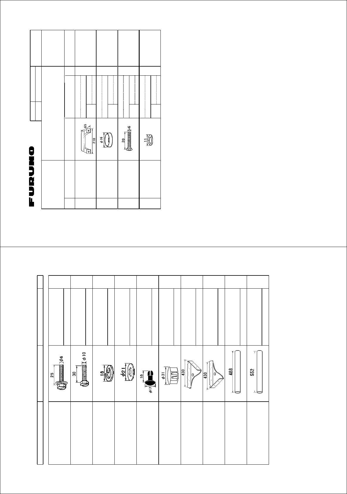
%1&'01
6;2'
(2
⇛ޓޓ࿑
176.+0'
ฬޓޓ⒓
0#/'
ᢙ㊂
36;
↪ㅜ㧛⠨
4'/#4-5
⇟ภ
01
ဳฬ㧛ⷙᩰ
&'5%4+26+105
#%%'5514+'5
ઃዻຠ
).:
ขᚻ
*#0&.' 41*5
%1&'
01
㩥㨺㩈㩨㨹㩎ᐳ㊄
415'66'9#5*'4 /%9㩘㩩㩢㩆㨺㩣
%1&'
01
/%9㩘㩩㩢㩆㨺㩣
ਣ⋁ዊ㩒㩆㩨
18#.*'#&5%4'9 /:%9㩘㩩㩢㩆㨺㩣
%1&'
01
ᵄᐳ㊄
9#8'9#5*'4 99575
%1&'
01
㧔⇛࿑ߩኸᴺߪޔෳ⠨୯ߢߔޕޓ&+/'05+105+0&4#9+0)(144'('4'0%'10.;㧕
㧲㨁㧾㨁㧺㧻ޓ㧱㧸㧱㧯㨀㧾㧵㧯ޓ㧯㧻ޓ㧚
㧘
㧸㨀㧰
).:
ဳᑼ㩄㨺㩎㩨⇟ภ߇㧞Ბߩ႐วޔਅᲑࠃࠅᲑߦઍࠊࠆㆊᷰᦼຠߢࠅޔߤߜࠄ߆߇ߞߡ߹ߔޕޓߥ߅ޔຠ⾰ߪᄌࠊࠅ߹ߖ
ࠎޕ
6916;2'5#0&%1&'5/#;$'.+56'&(14#0+6'/6*'.19'4241&7%6/#;$'5*+22'&+02.#%'1(6*'722'4
241&7%637#.+6;+56*'5#/'
1RVKQP
(QT/7%4/7%4
A
-30
PACKING LIST
PACKING LISTPACKING LIST
PACKING LIST 03GL-X-9859 -0
FP03-09820/09830
FP03-09820/09830FP03-09820/09830
FP03-09820/09830
N A M E O U T L I N E DESCRIPTION/CODE №
Q
'TY
1/1
付属品
付属品付属品
付属品 ACCESSORIES
ACCESSORIESACCESSORIES
ACCESSORIES FP03-09820/09830
FP03-09820/09830FP03-09820/09830
FP03-09820/09830
六角セムスB スリワリ
HEX.BOLT
(SLOTTED,WASHER HEAD)
M6X25 SUS304
000-802-771
4
六角ボルト スリワリ
HEX.BOLT
M10X30 SUS304
000-802-182
2
バネ座金
SPRING WASHER
M10 SUS304
000-864-261
2
ミガキ平座金
FLAT WASHER
M10 SUS304
000-864-131
2
スナップボタン
PLASTIC RIVET
KB-13ヨウ ボタンクロ
000-570-276
4
ホールプラグ
HOLE PLUG
CP-30-HP-13
000-147-143
2
ハンガーR(20)
HANGER R
03-163-1112-0
100-305-180
1
ハンガーL(20)
HANGER L
03-163-1111-0
100-305-140
1
ハンガーササエ(20)
HANGER STAY
03-163-1113-0
100-305-190
1
(*1)
ハンガーササエ(23)
HANGER STAY
03-163-2071-0
100-305-370
1
(*2)
(*1)䈲䇮FP03-09820↪䈪䈜䇯
*1:䇭FOR FP03-09820.
(*2)䈲䇮FP03-09830↪䈪䈜䇯
*2:䇭FOR FP03-09830.
(略図の寸法は、参考値です。 DIMENSIONS IN DRAWING FOR REFERENCE ONLY.)
(略図の寸法は、参考値です。 DIMENSIONS IN DRAWING FOR REFERENCE ONLY.)(略図の寸法は、参考値です。 DIMENSIONS IN DRAWING FOR REFERENCE ONLY.)
(略図の寸法は、参考値です。 DIMENSIONS IN DRAWING FOR REFERENCE ONLY.)
03GL-X-9859
(QT/7%4%4&GUMVQROQWPVMKVޓޓޓ1RVKQP
A
-29
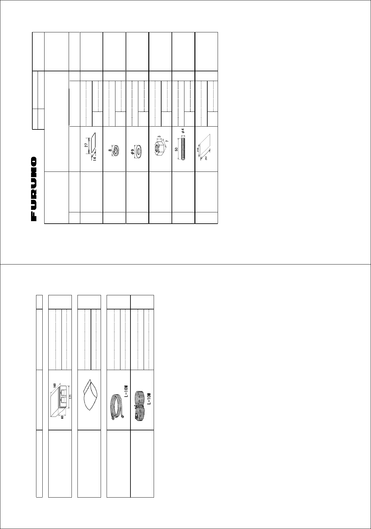
%1&'01
6;2'
%2
⇛ޓޓ࿑
176.+0'
ฬޓޓ⒓
0#/'
ᢙ㊂
36;
↪ㅜ㧛⠨
4'/#4-5
⇟ภ
01
ဳฬ㧛ⷙᩰ
&'5%4+26+105
+056#..#6+10/#6'4+#.5
Ꮏ᧚ᢱ
)1:
⥽ベ⾍ࠅ㩙㨺㩂$5*
56''4+0)9*''..#$'.
%1&'
01
㩔㩨㩒ᐳ㊄
524+0)9#5*'4 /575
%1&'
01
㩚㩀㩨㩁ਣᐔᐳ㊄
(.#69#5*'4 /575
%1&'
01
ⷺ㩏㨹㩎㩆㨷
*':076 /575
%1&'
01
ኸಾ㩘㩨㩣㩎
6*4'#&'&41& /:575
%1&'
01
⥽ベ㩙㨺㩂⾍ઃⷐ㗔
.#$'.#66#%*+0)
241%'&74'
%㩦㨾㨼
%1&'
01
㧔⇛࿑ߩኸᴺߪޔෳ⠨୯ߢߔޕޓ&+/'05+105+0&4#9+0)(144'('4'0%'10.;㧕
㧲㨁㧾㨁㧺㧻ޓ㧱㧸㧱㧯㨀㧾㧵㧯ޓ㧯㧻ޓ㧚
㧘
㧸㨀㧰
)1:
ဳᑼ㩄㨺㩎㩨⇟ภ߇㧞Ბߩ႐วޔਅᲑࠃࠅᲑߦઍࠊࠆㆊᷰᦼຠߢࠅޔߤߜࠄ߆߇ߞߡ߹ߔޕޓߥ߅ޔຠ⾰ߪᄌࠊࠅ߹ߖ
ࠎޕ
6916;2'5#0&%1&'5/#;$'.+56'&(14#0+6'/6*'.19'4241&7%6/#;$'5*+22'&+02.#%'1(6*'722'4
241&7%637#.+6;+56*'5#/'
A
-32
㧼㧭㧯㧷㧵㧺㧳ޓ㧸㧵㧿㨀
)1:
%7(#4
0#/' 176.+0' &'5%4+26+10%1&'ͳ 36;
࡙࠾࠶࠻ 70+6
㩜㩝㩢㨺㩀㨺㩎㩨㨼㩧㩊㨺㩖㨴㨼㩇
/'/14;%#4&+06'4(#%'
%7
Ꮏ᧚ᢱ +056#..#6+10/#6'4+#.5
Ꮏ᧚ᢱ
+056#..#6+10/#6'4+#.5
%2
ߘߩઁᎿ᧚ 16*'4+056#..#6+10/#6'4+#.5
㩃㨺㩖㩨㩣⚵ຠ
%#$.'#55;
2'26:$.
2'26:$.
㩃㨺㩖㩨㩣⚵ຠ/,
%#$.'#55;
/,#52(%
䋨⇛࿑䈱ኸᴺ䈲䇮ෳ⠨୯䈪䈜䇯㩷㩷㪛㪠㪤㪜㪥㪪㪠㪦㪥㪪㩷㪠㪥㩷㪛㪩㪘㪮㪠㪥㪞㩷㪝㪦㪩㩷㪩㪜㪝㪜㪩㪜㪥㪚㪜㩷㪦㪥㪣㪰㪅䋩
)1:
ဳᑼ㪆䍘䍎䍢䍼⇟ภ䈏䋲Ბ䈱႐ว䇮ਅᲑ䉋䉍Ბ䈮ઍ䉒䉎ㆊᷰᦼຠ䈪䈅䉍䇮䈬䈤䉌䈎䈏䈦䈩䈇䉁䈜䇯䇭䈭䈍䇮ຠ⾰䈲ᄌ䉒䉍䉁䈞䉖䇯
㪫㪮㪦㩷㪫㪰㪧㪜㪪㩷㪘㪥㪛㩷㪚㪦㪛㪜㪪㩷㪤㪘㪰㩷㪙㪜㩷㪣㪠㪪㪫㪜㪛㩷㪝㪦㪩㩷㪘㪥㩷㪠㪫㪜㪤㪅㩷㩷㪫㪟㪜㩷㪣㪦㪮㪜㪩㩷㪧㪩㪦㪛㪬㪚㪫㩷㪤㪘㪰㩷㪙㪜㩷㪪㪟㪠㪧㪧㪜㪛㩷㪠㪥㩷㪧㪣㪘㪚㪜㩷㪦㪝㩷㪫㪟㪜㩷㪬㪧㪧㪜㪩㩷
㪧㪩㪦㪛㪬㪚㪫㪅㩷㪨㪬㪘㪣㪠㪫㪰㩷㪠㪪㩷㪫㪟㪜㩷㪪㪘㪤㪜㪅
A
-31
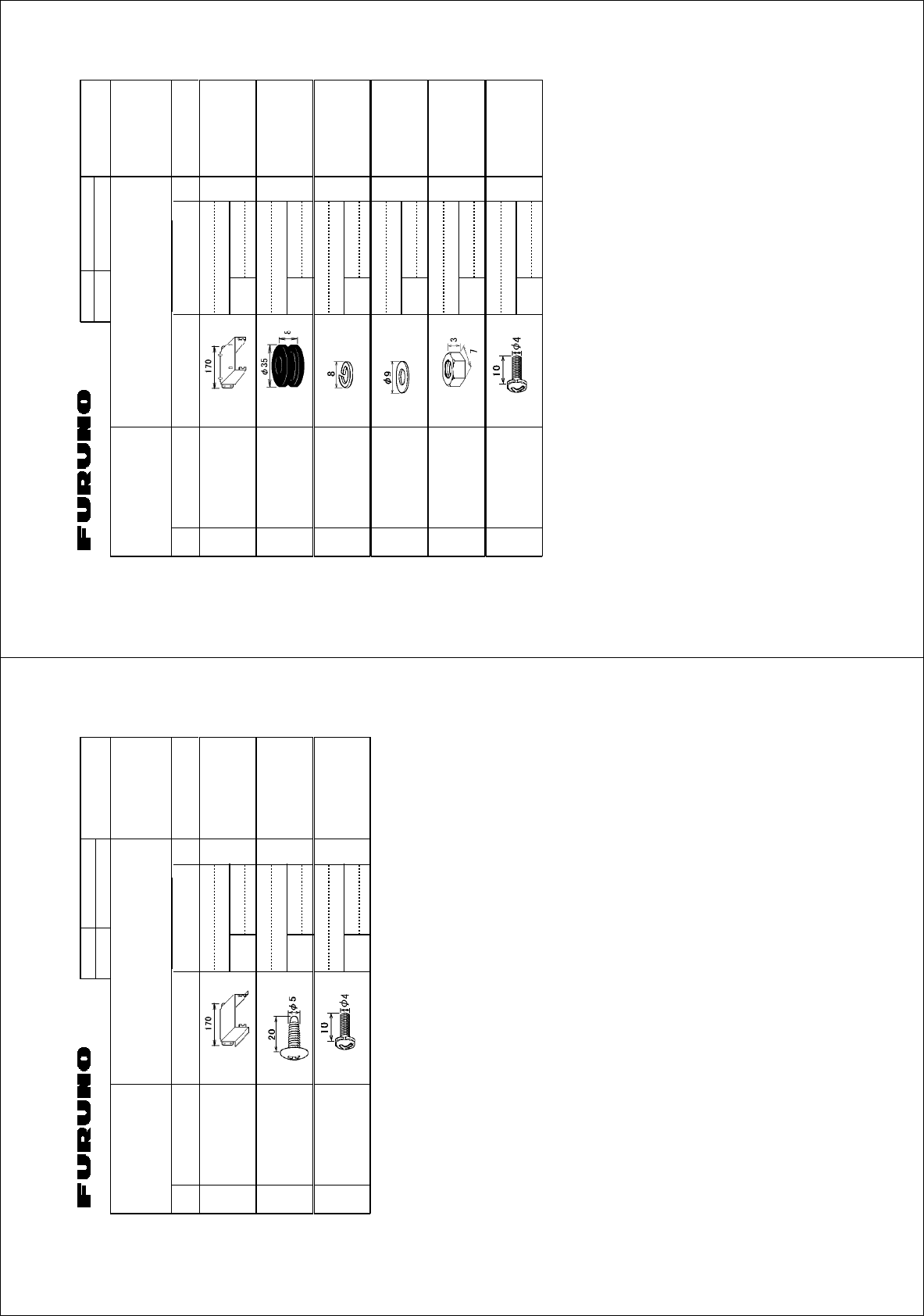
%1&'01
6;2'
(2
⇛ޓޓ࿑
176.+0'
ฬޓޓ⒓
0#/'
ᢙ㊂
36;
↪ㅜ㧛⠨
4'/#4-5
⇟ภ
01
ဳฬ㧛ⷙᩰ
&'5%4+26+105
#%%'5514+'5
ઃዻຠ
)1:
㩄㩧㩉㨺㩣㩠㨽ขઃ᧚
/1706+0)$4#%-'6 41*5
%1&'
01
㩂㩨㩥㩜㨹㩎
)41//'6 %0)37.
%1&'
01
㩔㩨㩒ᐳ㊄
524+0)9#5*'4 /575
%1&'
01
㩚㩀㩨㩁ਣᐔᐳ㊄
(.#69#5*'4 /575
%1&'
01
ⷺ㩏㨹㩎㩆㨷
*':076 /575
%1&'
01
㩏㩗㩨㩈㩛㩇#
9#5*'4*'#&5%4'9 /:%9/$0+
%1&'
01
㧔⇛࿑ߩኸᴺߪޔෳ⠨୯ߢߔޕޓ&+/'05+105+0&4#9+0)(144'('4'0%'10.;㧕
㧲㨁㧾㨁㧺㧻ޓ㧱㧸㧱㧯㨀㧾㧵㧯ޓ㧯㧻ޓ㧚
㧘
㧸㨀㧰
)1:
ဳᑼ㩄㨺㩎㩨⇟ภ߇㧞Ბߩ႐วޔਅᲑࠃࠅᲑߦઍࠊࠆㆊᷰᦼຠߢࠅޔߤߜࠄ߆߇ߞߡ߹ߔޕޓߥ߅ޔຠ⾰ߪᄌࠊࠅ߹ߖ
ࠎޕ
6916;2'5#0&%1&'5/#;$'.+56'&(14#0+6'/6*'.19'4241&7%6/#;$'5*+22'&+02.#%'1(6*'722'4
241&7%637#.+6;+56*'5#/'
A
-34
%1&'01
6;2'
(2
⇛ޓޓ࿑
176.+0'
ฬޓޓ⒓
0#/'
ᢙ㊂
36;
↪ㅜ㧛⠨
4'/#4-5
⇟ภ
01
ဳฬ㧛ⷙᩰ
&'5%4+26+105
#%%'5514+'5
ઃዻຠ
)1:
㩔㩧㩀㩨㨺
/1706+0)$4#%-'6
%1&'
01
㩎㩡㩇㩊㨹㩕㩩㩧㩒㩆㩨ޓ㩆㨷
5'.(6#22+0)5%4'9 :575
%1&'
01
㩏㩗㩨㩈㩛㩇#
9#5*'4*'#&5%4'9 /:%9/$0+
%1&'
01
㧔⇛࿑ߩኸᴺߪޔෳ⠨୯ߢߔޕޓ&+/'05+105+0&4#9+0)(144'('4'0%'10.;㧕
㧲㨁㧾㨁㧺㧻ޓ㧱㧸㧱㧯㨀㧾㧵㧯ޓ㧯㧻ޓ㧚
㧘
㧸㨀㧰
)1:
ဳᑼ㩄㨺㩎㩨⇟ภ߇㧞Ბߩ႐วޔਅᲑࠃࠅᲑߦઍࠊࠆㆊᷰᦼຠߢࠅޔߤߜࠄ߆߇ߞߡ߹ߔޕޓߥ߅ޔຠ⾰ߪᄌࠊࠅ߹ߖ
ࠎޕ
6916;2'5#0&%1&'5/#;$'.+56'&(14#0+6'/6*'.19'4241&7%6/#;$'5*+22'&+02.#%'1(6*'722'4
241&7%637#.+6;+56*'5#/'
For CU-200 Desktop mount kit
Option
A
-33
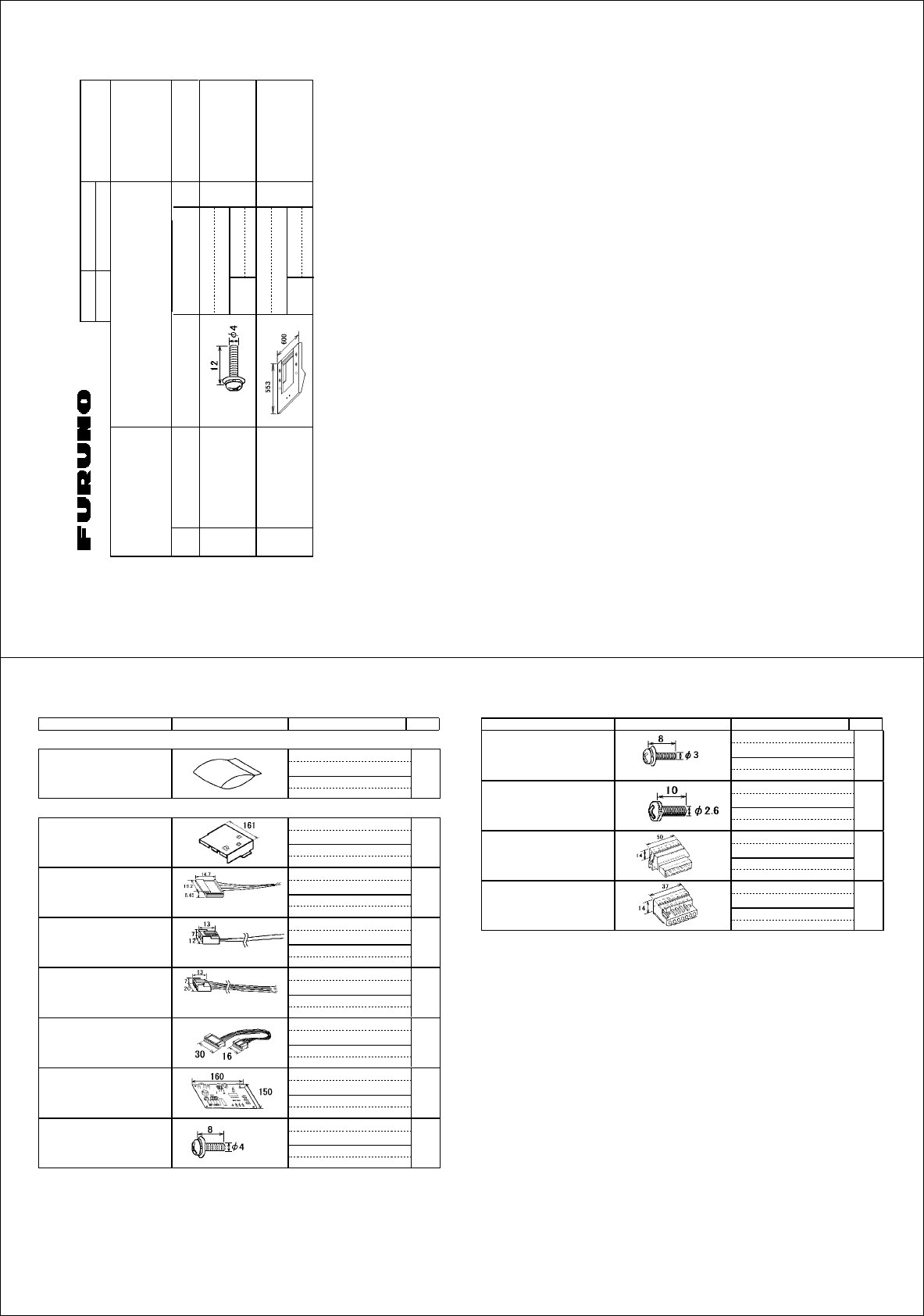
%1&'01
6;2'
12
⇛ޓޓ࿑
176.+0'
ฬޓޓ⒓
0#/'
ᢙ㊂
36;
↪ㅜ㧛⠨
4'/#4-5
⇟ภ
01
ဳฬ㧛ⷙᩰ
&'5%4+26+105
+056#..#6+10/#6'4+#.5
Ꮏ᧚ᢱ
).:
㩏㩗㩨㩈㩛㩇$
9#5*'4*'#&5&4'9$ /:%9/$0+
%1&'
01
ㅪ⚿บ⚵ຠ
%172.+0)2.#6'#55; 12
%1&'
01
㧔⇛࿑ߩኸᴺߪޔෳ⠨୯ߢߔޕޓ&+/'05+105+0&4#9+0)(144'('4'0%'10.;㧕
㧲㨁㧾㨁㧺㧻ޓ㧱㧸㧱㧯㨀㧾㧵㧯ޓ㧯㧻ޓ㧚
㧘
㧸㨀㧰
).:
ဳᑼ㩄㨺㩎㩨⇟ภ߇㧞Ბߩ႐วޔਅᲑࠃࠅᲑߦઍࠊࠆㆊᷰᦼຠߢࠅޔߤߜࠄ߆߇ߞߡ߹ߔޕޓߥ߅ޔຠ⾰ߪᄌࠊࠅ߹ߖ
ࠎޕ
6916;2'5#0&%1&'5/#;$'.+56'&(14#0+6'/6*'.19'4241&7%6/#;$'5*+22'&+02.#%'1(6*'722'4
241&7%637#.+6;+56*'5#/'
Coupling pedestal kit
RCU-014 + MU-231CR
Option
A-36
0#/' 176.+0' 36;&'5%4+26+10%1&'ͳ
㧼㧭㧯㧷㧵㧺㧳ޓ㧸㧵㧿㨀
).:
)%
0#/' 176.+0' 36;&'5%4+26+10%1&'ͳ
੍ຠ 52#4'2#465
੍ຠ
52#4'2#465
52
ߘߩઁㇱຠ 16*'42#465
)%㩀㩔㩨㨺⚵ຠ
)%%18'4#55;
0*㩄㩒㩂㩊
0*%100'%614#55;
2
8*㩄㩒㩂㩊
8*%100'%614#55;
2
8*㩄㩒㩂㩊
8*%100'%614#55;
2
:*2*㩄㩒㩂㩊
:*2*%100'%614#55;
2
Ṷ▚㩖㩩㩢㩧㩎
241%'5514$1#4&
2#.(
㩏㩗㩨㩈㩛㩇$
9#5*'4*'#&5%4'9$
/:%9/$0+
㩏㩗㩨㩈㩛㩇$
9#5*'4*'#&5%4'9
/:%9/$0+
㩏㩗㩨㩈㩛㩇#
9#5*'4*'#&5%4'9
/:%9/$0+
㩄㩒㩂㩊
%100'%614
(74
㩄㩒㩂㩊
%100'%614
(74
䯴⇛࿑䬽ኸᴺ䬾䫺ෳ⠨୯䬶䬨䫻䎃䎧䎬䎰䎨䎱䎶䎬䎲䎱䎶䎃䎬䎱䎃䎧䎵䎤䎺䎬䎱䎪䎃䎩䎲䎵䎃䎵䎨䎩䎨䎵䎨䎱䎦䎨䎃䎲䎱䎯䎼䎑䯵
).:
ဳᑼ䎒䱤䱚䱮䲈⇟ภ䬛䯾Ბ䬽႐ว䫺ਅᲑ䭗䭙Ბ䬺ઍ䭞䭚ㆊᷰᦼຠ䬶䬑䭙䫺䬸䬰䭘䬚䬛䬲䬵䬓䭍䬨䫻䫹䬹䬙䫺ຠ⾰䬾ᄌ䭞䭙䭍䬪䭢䫻
䎷䎺䎲䎃䎷䎼䎳䎨䎶䎃䎤䎱䎧䎃䎦䎲䎧䎨䎶䎃䎰䎤䎼䎃䎥䎨䎃䎯䎬䎶䎷䎨䎧䎃䎩䎲䎵䎃䎤䎱䎃䎬䎷䎨䎰䎑䎃䎃䎷䎫䎨䎃䎯䎲䎺䎨䎵䎃䎳䎵䎲䎧䎸䎦䎷䎃䎰䎤䎼䎃䎥䎨䎃䎶䎫䎬䎳䎳䎨䎧䎃䎬䎱䎃䎳䎯䎤䎦䎨䎃䎲䎩䎃䎷䎫䎨䎃
䎸䎳䎳䎨䎵䎃䎳䎵䎲䎧䎸䎦䎷䎑䎃䎴䎸䎤䎯䎬䎷䎼䎃䎬䎶䎃䎷䎫䎨䎃䎶䎤䎰䎨䎑
A
-35
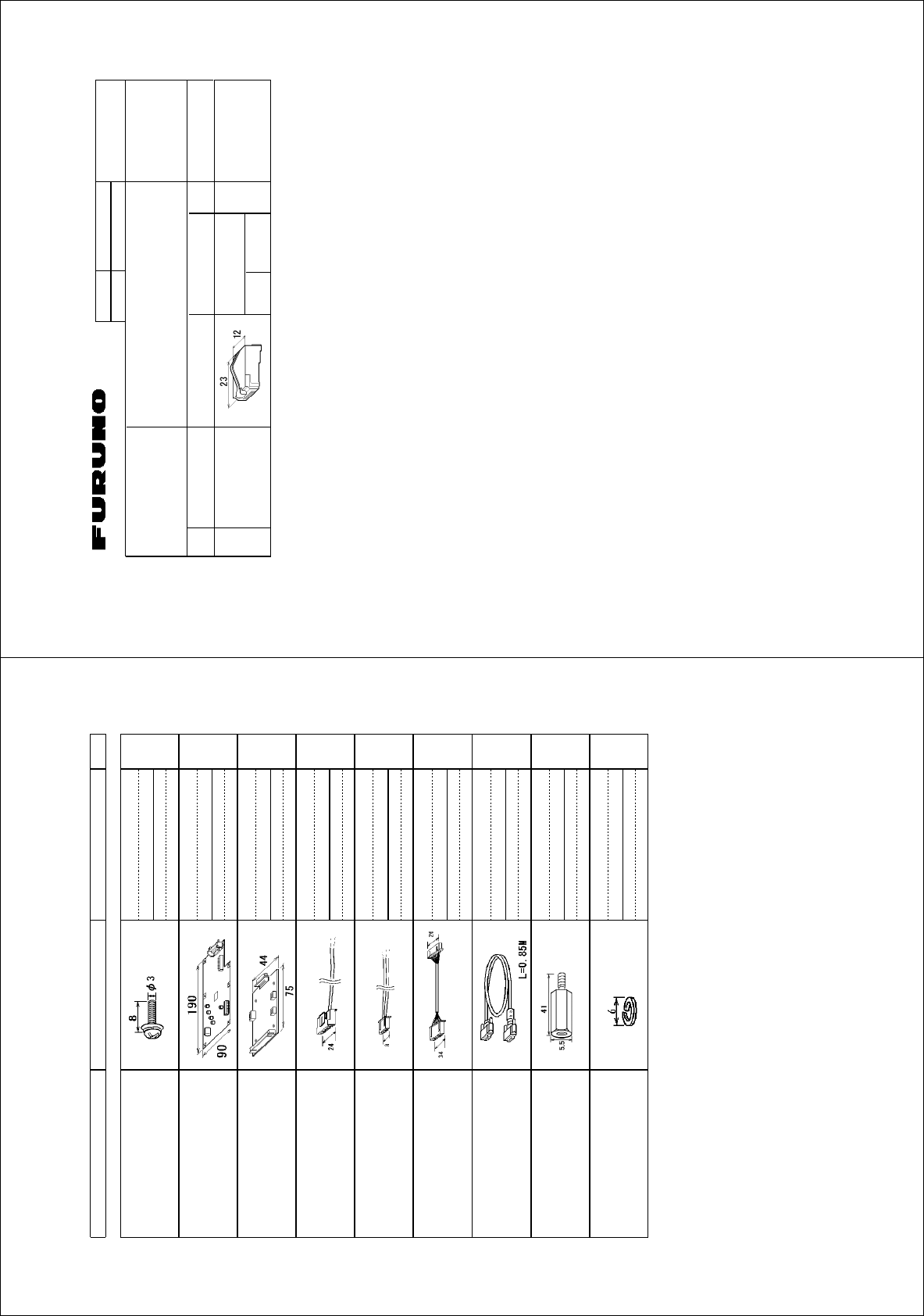
%1&'01
6;2'
%2
⇛ޓޓ࿑
176.+0'
ฬޓޓ⒓
0#/'
ᢙ㊂
36;
↪ㅜ㧛⠨
4'/#4-5
⇟ภ
01
ဳฬ㧛ⷙᩰ
&'5%4+26+105
+056#..#6+10/#6'4+#.5
Ꮏ᧚ᢱ
).:
㩄㩒㩂㩊㩝㩆㩨㨷㩡㨺
/1&7.#4%100%614
/25%
%1&'01
㧔⇛࿑ߩኸᴺߪޔෳ⠨୯ߢߔޕޓ&+/'05+105+0&4#9+0)(144'('4'0%'10.;㧕
㧲㨁㧾㨁㧺㧻ޓ㧱㧸㧱㧯㨀㧾㧵㧯ޓ㧯㧻ޓ㧚㧘㧸㨀㧰
).:
For LAN cable kit Option
A
-38
㧼㧭㧯㧷㧵㧺㧳ޓ㧸㧵㧿㨀
).:
12
0#/' 176.+0' &'5%4+26+10%1&'ͳ 36;
ߘߩઁㇱຠ 16*'42#465
㩏㩗㩨㩈㩛㩇㩒㩆㩨$
9#5*'4*'#&5%4'9
/:%9/$0+
&8+4)$⚵ຠ
&8+4)$#55;
5.$(40#
4)$$7((㩖㩩㩢㩧㩎
4)$$7(($1#4&
2$
8*㩄㩒㩂㩊⚵ຠ
8*%100'%614#55;
2
:*㩄㩒㩂㩊⚵ຠ
:*%100'%614#55;
2
:*㩄㩒㩂㩊⚵ຠ
:*%100'%614#55;
2
㩃㨺㩖㩨㩣⚵ຠ
%#$.'#55;
&8+&&5.+0-/
㩇㩗㩩㨺㩅㨺
52#%'4
53
53
㩔㩨㩒㩅㩨㩀㩨㩒
524+0)9#5*'4
/%9/$0+
䋨⇛࿑䈱ኸᴺ䈲䇮ෳ⠨୯䈪䈜䇯㩷㩷㪛㪠㪤㪜㪥㪪㪠㪦㪥㪪㩷㪠㪥㩷㪛㪩㪘㪮㪠㪥㪞㩷㪝㪦㪩㩷㪩㪜㪝㪜㪩㪜㪥㪚㪜㩷㪦㪥㪣㪰㪅䋩
).:
ဳᑼ㪆䍘䍎䍢䍼⇟ภ䈏䋲Ბ䈱႐ว䇮ਅᲑ䉋䉍Ბ䈮ઍ䉒䉎ㆊᷰᦼຠ䈪䈅䉍䇮䈬䈤䉌䈎䈏䈦䈩䈇䉁䈜䇯䇭䈭䈍䇮ຠ⾰䈲ᄌ䉒䉍䉁䈞䉖䇯
㪫㪮㪦㩷㪫㪰㪧㪜㪪㩷㪘㪥㪛㩷㪚㪦㪛㪜㪪㩷㪤㪘㪰㩷㪙㪜㩷㪣㪠㪪㪫㪜㪛㩷㪝㪦㪩㩷㪘㪥㩷㪠㪫㪜㪤㪅㩷㩷㪫㪟㪜㩷㪣㪦㪮㪜㪩㩷㪧㪩㪦㪛㪬㪚㪫㩷㪤㪘㪰㩷㪙㪜㩷㪪㪟㪠㪧㪧㪜㪛㩷㪠㪥㩷㪧㪣㪘㪚㪜㩷㪦㪝㩷㪫㪟㪜㩷㪬㪧㪧㪜㪩㩷
㪧㪩㪦㪛㪬㪚㪫㪅㩷㪨㪬㪘㪣㪠㪫㪰㩷㪠㪪㩷㪫㪟㪜㩷㪪㪘㪤㪜㪅
DVI-RGB conversion kit Option
A
-37
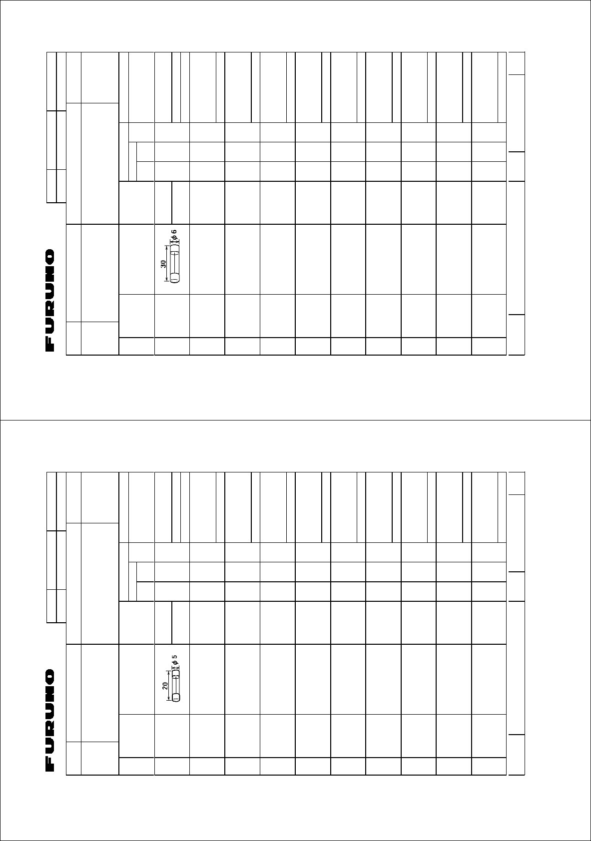
%1&'01
6;2'
52
+6'/
01
0#/'1(
2#46 176.+0'
&9)01
14
2'4
5'6
2'4
8'5
52#4'
914-+0)
37#06+6; 4'/#4-5%1&'01
$1:012
5*+201
52#4'2#465.+56(14 75'
5'652'4
8'55'.
6;2'01
).:
㩕㨷㨺㩇㩨
()$18
#2$(
#%↪ޓޓޓޓޓޓޓޓ
(14241%'551470+6
(75'
/(450#/'
(74701'.'%64+%%1.6&
&9)01
㧔⇛࿑ߩኸᴺߪޔෳ⠨୯ߢߔޕޓ&+/'05+105+0&4#9+0)ޓ(144'('4'0%'10.;㧕
).:
ဳᑼ㩄㨺㩎㩨⇟ภ߇㧞Ბߩ႐วޔਅᲑࠃࠅᲑߦઍࠊࠆㆊᷰᦼຠߢࠅޔߤߜࠄ߆߇ߞߡ߹ߔޕޓߥ߅ޔຠ⾰ߪ
ᄌࠊࠅ߹ߖࠎޕ
6916;2'5#0&%1&'5/#;$'.+56'&(14#0+6'/6*'.19'4241&7%6/#;$'5*+22'&+02.#%'1(6*'
722'4241&7%637#.+6;+56*'5#/'
RPU-013
100 VAC set
A
-40
%1&'01
6;2'
52
+6'/
01
0#/'1(
2#46 176.+0'
&9)01
14
2'4
5'6
2'4
8'5
52#4'
914-+0)
37#06+6; 4'/#4-5%1&'01
$1:012
5*+201
52#4'2#465.+56(14 75'
5'652'4
8'55'.
6;2'01
).:
㩕㨷㨺㩇㩨
()/$#8
␜ㇱ↪
(14&+52.#;70+6
(75'
()/$8#
2$(
/(450#/'
(74701'.'%64+%%1.6&
&9)01
㧔⇛࿑ߩኸᴺߪޔෳ⠨୯ߢߔޕޓ&+/'05+105+0&4#9+0)ޓ(144'('4'0%'10.;㧕
).:
ဳᑼ㩄㨺㩎㩨⇟ภ߇㧞Ბߩ႐วޔਅᲑࠃࠅᲑߦઍࠊࠆㆊᷰᦼຠߢࠅޔߤߜࠄ߆߇ߞߡ߹ߔޕޓߥ߅ޔຠ⾰ߪ
ᄌࠊࠅ߹ߖࠎޕ
6916;2'5#0&%1&'5/#;$'.+56'&(14#0+6'/6*'.19'4241&7%6/#;$'5*+22'&+02.#%'1(6*'
722'4241&7%637#.+6;+56*'5#/'
MU-231CR
A
-39
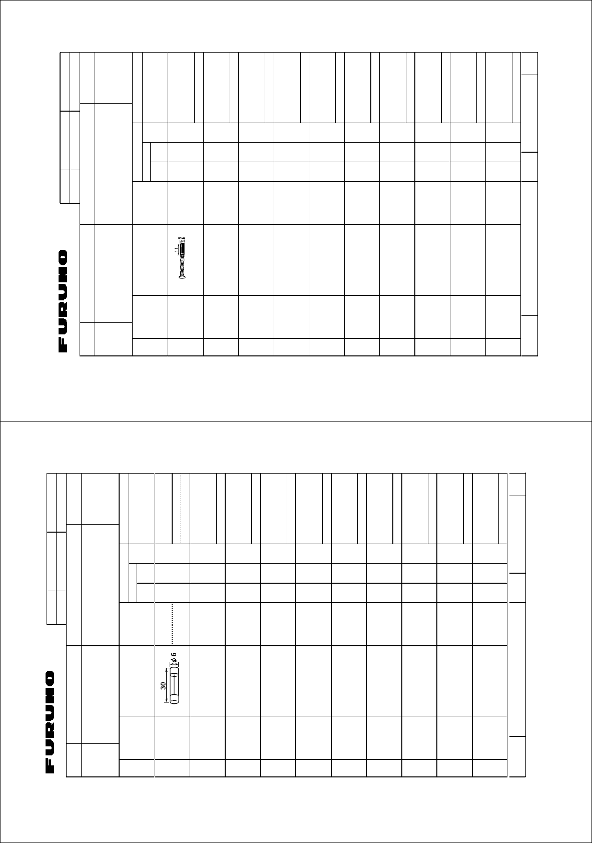
CODE NO.
CODE NO.CODE NO.
CODE NO. 008-485-360
TYPE
TYPETYPE
TYPE SP03-12501
ITEM
ITEMITEM
ITEM
NO.
NO. NO.
NO. NAME OF
NAME OF NAME OF
NAME OF
PART
PARTPART
PART OUTLINE
OUTLINEOUTLINE
OUTLINE
DWG. NO.
DWG. NO. DWG. NO.
DWG. NO.
OR
OR OR
OR
PER
PERPER
PER
SET
SETSET
SET
PER
PERPER
PER
VES
VESVES
VES
SPARE
SPARESPARE
SPARE
WORKING
WORKINGWORKING
WORKING
QUANTITY
QUANTITYQUANTITY
QUANTITY REMARKS/CODE NO.
REMARKS/CODE NO.REMARKS/CODE NO.
REMARKS/CODE NO.
BOX NO. P
BOX NO. P BOX NO. P
BOX NO. P
SHIP NO.
SHIP NO.SHIP NO.
SHIP NO. SPARE PARTS LIST FOR
SPARE PARTS LIST FOR SPARE PARTS LIST FOR
SPARE PARTS LIST FOR U S E
U S EU S E
U S E SETS PER
SETS PER SETS PER
SETS PER
VESSEL
VESSELVESSEL
VESSEL
-4
TYPE NO.
TYPE NO.TYPE NO.
TYPE NO.
03FS-X-9301 1/1
カーボンブラシ MG120-5X6X11
D8G 2
CARBON BRUSH
000-631-716
1
1/1
MFR'S NAME
MFR'S NAMEMFR'S NAME
MFR'S NAME FURUNO ELECTRIC CO.,LTD.
FURUNO ELECTRIC CO.,LTD.FURUNO ELECTRIC CO.,LTD.
FURUNO ELECTRIC CO.,LTD. DWG NO.
DWG NO.DWG NO.
DWG NO.
(略図の寸法は、参考値です。 DIMENSIONS IN DRAWING FOR REFERENCE ONLY.)
(略図の寸法は、参考値です。 DIMENSIONS IN DRAWING FOR REFERENCE ONLY.)(略図の寸法は、参考値です。 DIMENSIONS IN DRAWING FOR REFERENCE ONLY.)
(略図の寸法は、参考値です。 DIMENSIONS IN DRAWING FOR REFERENCE ONLY.)
03FS-X-9301
A
ntenna unit motor
A
-42
%1&'01
6;2'
52
+6'/
01
0#/'1(
2#46 176.+0'
&9)01
14
2'4
5'6
2'4
8'5
52#4'
914-+0)
37#06+6; 4'/#4-5%1&'01
$1:012
5*+201
52#4'2#465.+56(14 75'
5'652'4
8'55'.
6;2'01
).:
㩕㨷㨺㩇㩨
()$18#
2$(
#%↪ޓޓޓޓޓޓޓޓ
(14241%'551470+6
(75'
/(450#/'
(74701'.'%64+%%1.6&
&9)01
㧔⇛࿑ߩኸᴺߪޔෳ⠨୯ߢߔޕޓ&+/'05+105+0&4#9+0)ޓ(144'('4'0%'10.;㧕
).:
ဳᑼ㩄㨺㩎㩨⇟ภ߇㧞Ბߩ႐วޔਅᲑࠃࠅᲑߦઍࠊࠆㆊᷰᦼຠߢࠅޔߤߜࠄ߆߇ߞߡ߹ߔޕޓߥ߅ޔຠ⾰ߪ
ᄌ
ࠊࠅ߹ߖࠎޕ
6916;2'5#0&%1&'5/#;$'.+56'&(14#0+6'/6*'.19'4241&7%6/#;$'5*+22'&+02.#%'1(6*'
722'4241&7%637#.+6;+56*'5#/'
RPU-013
220 VAC set
A
-41
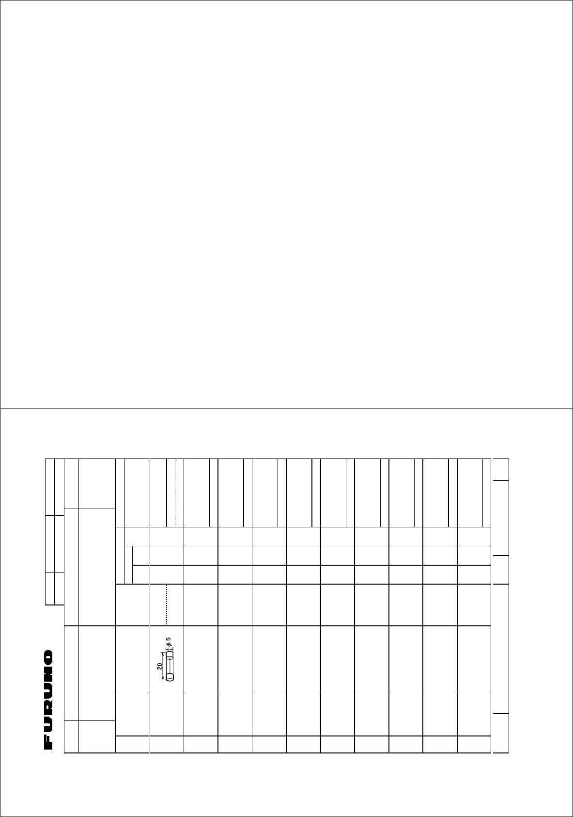
%1&'01
6;2'
52
+6'/
01
0#/'1(
2#46 176.+0'
&9)01
14
2'4
5'6
2'4
8'5
52#4'
914-+0)
37#06+6; 4'/#4-5%1&'01
$1:012
5*+201
52#4'2#465.+56(14 75'
5'652'4
8'55'.
6;2'01
).:
㩕㨷㨺㩇㩨
()/$#8
(75'
()/$8#
2$(
/(450#/'
(74701'.'%64+%%1.6&
&9)01
㧔⇛࿑ߩኸᴺߪޔෳ⠨୯ߢߔޕޓ&+/'05+105+0&4#9+0)ޓ(144'('4'0%'10.;㧕
).:
ဳᑼ㩄㨺㩎㩨⇟ภ߇㧞Ბߩ႐วޔਅᲑࠃࠅᲑߦઍࠊࠆㆊᷰᦼຠߢࠅޔߤߜࠄ߆߇ߞߡ߹ߔޕޓߥ߅ޔຠ⾰ߪ
ᄌ
ࠊࠅ߹ߖࠎޕ
6916;2'5#0&%1&'5/#;$'.+56'&(14#0+6'/6*'.19'4241&7%6/#;$'5*+22'&+02.#%'1(6*'
722'4241&7%637#.+6;+56*'5#/'
GC-10
A
-43
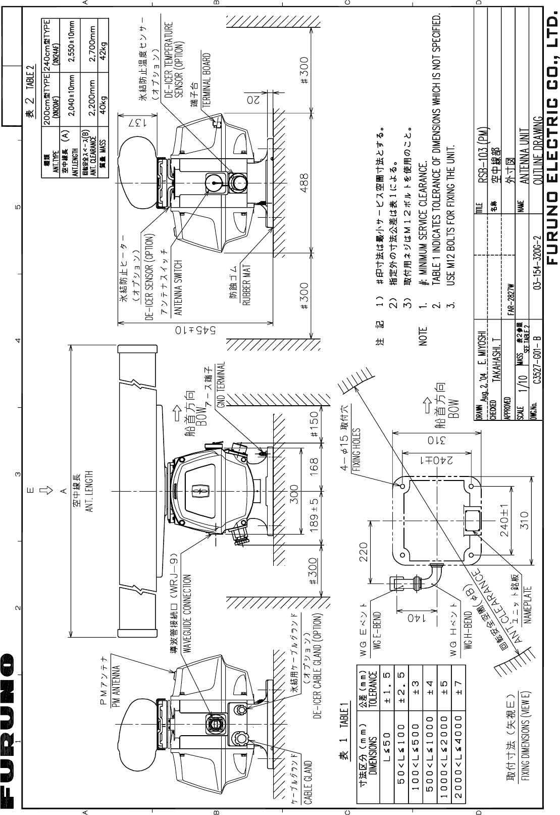
Y. Hatai
D-1
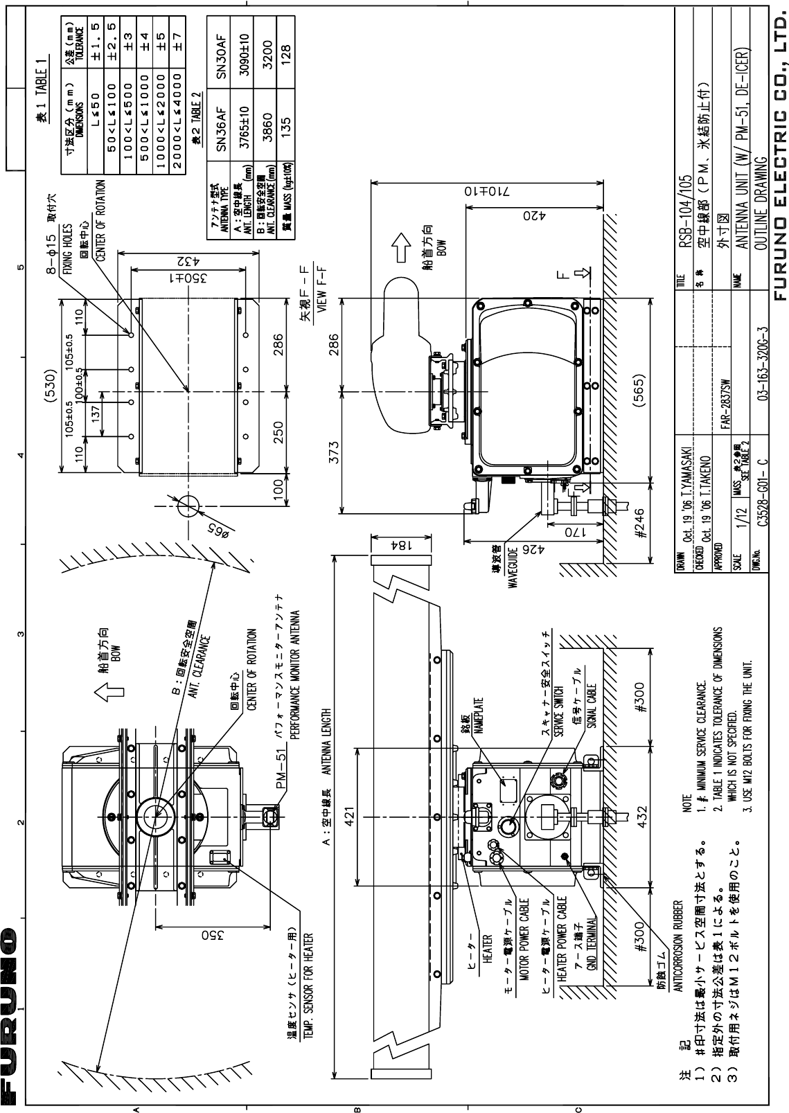
Oct.31'06T.Matsuguchi
D-2
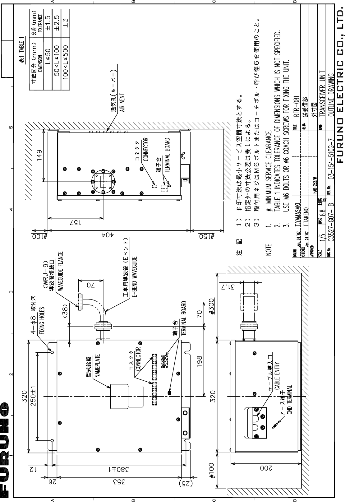
Jan.24'07 R.Esumi
D-3
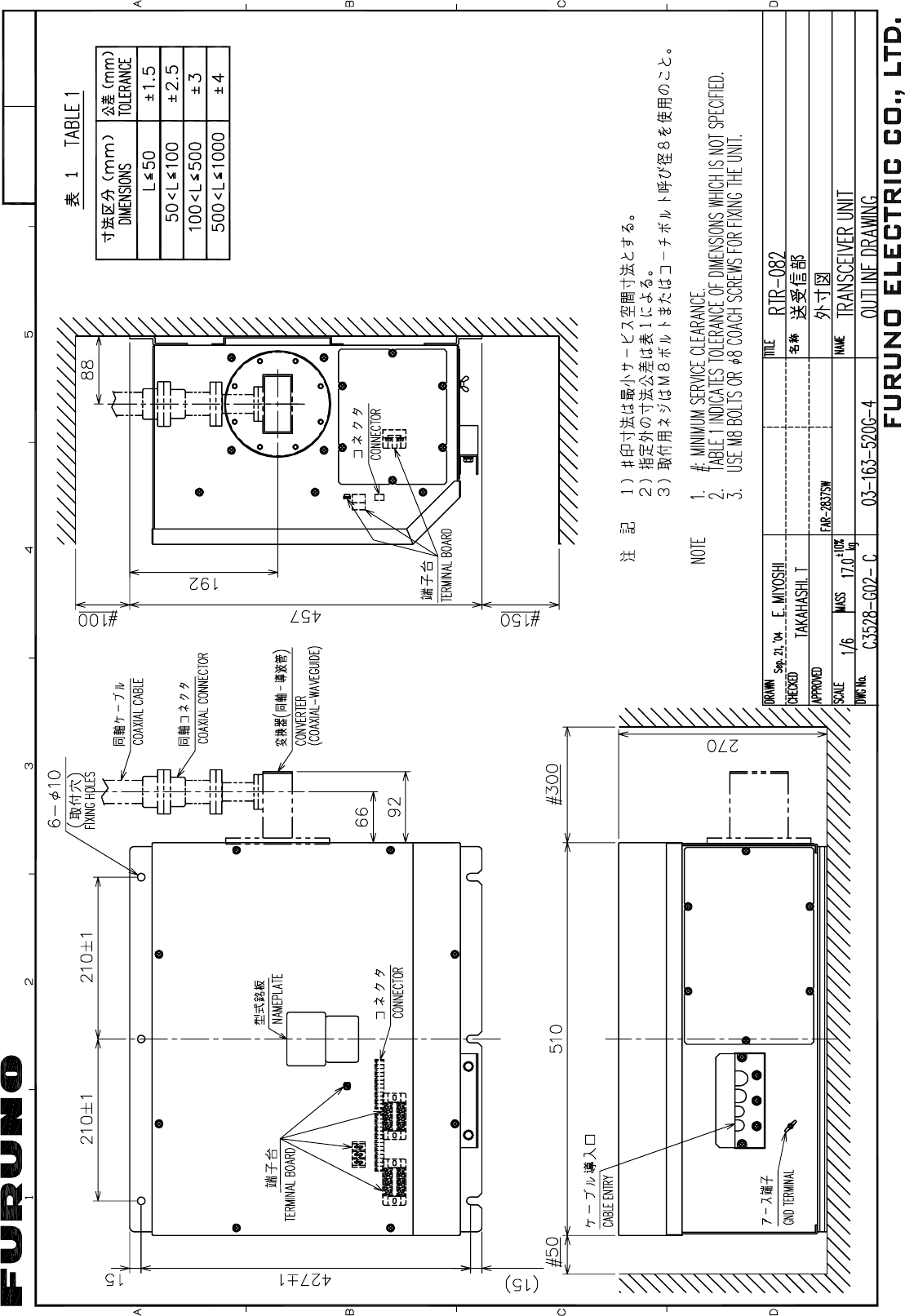
Y. Hatai
D-4
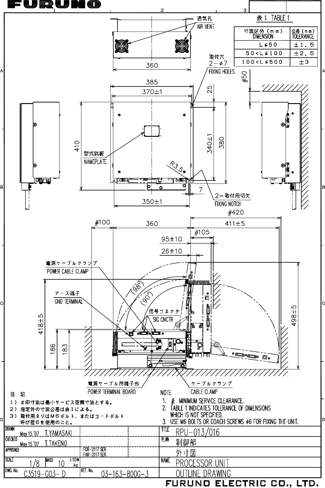
May 17'07 R.Esumi
D-5
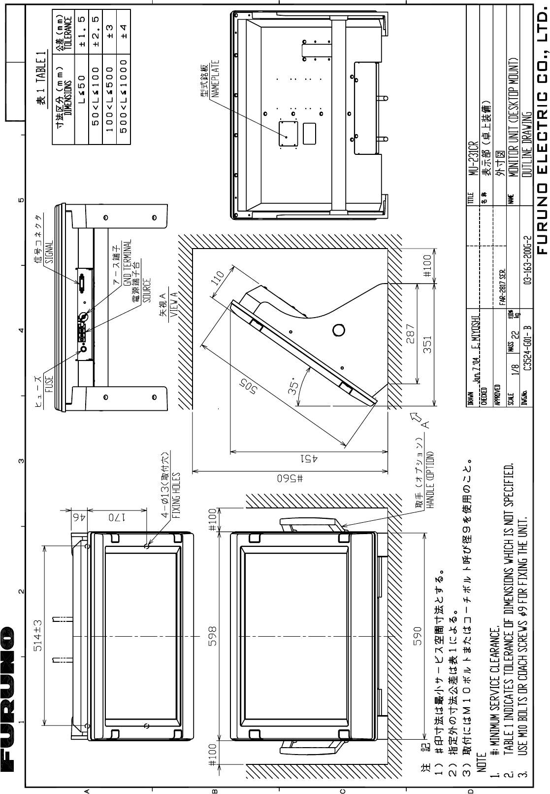
Takahashi T.
Y. Hatai
D-6
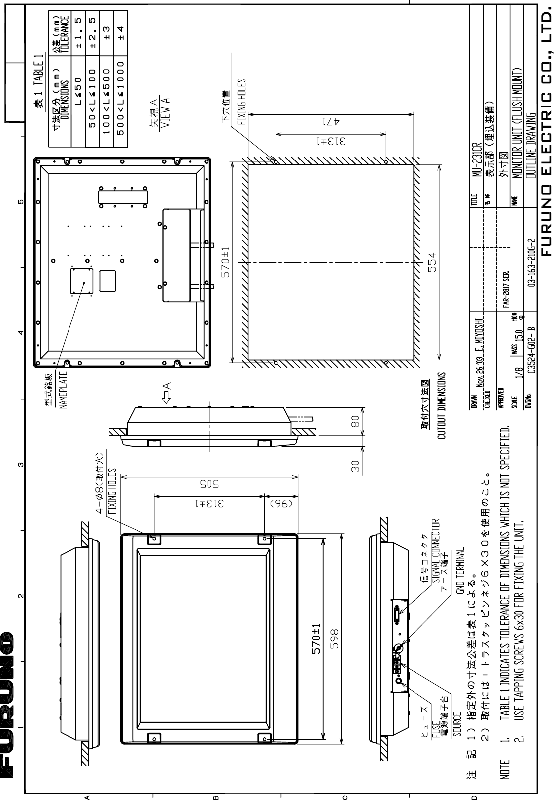
Takahashi T.
Y. Hatai
D-7
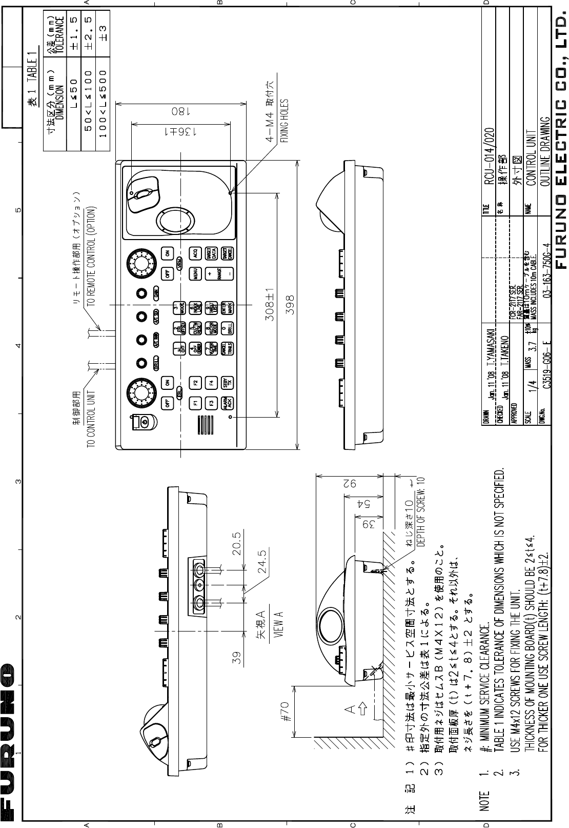
Jan.18'08 R.Esumi
D-8
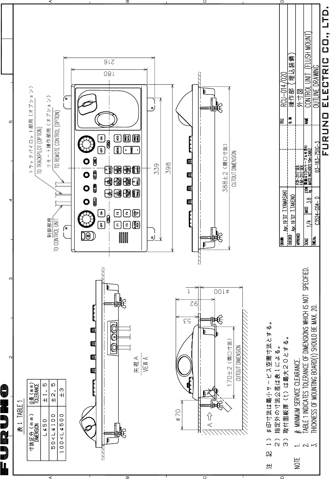
Apr.23'07 R.Esumi
D-9
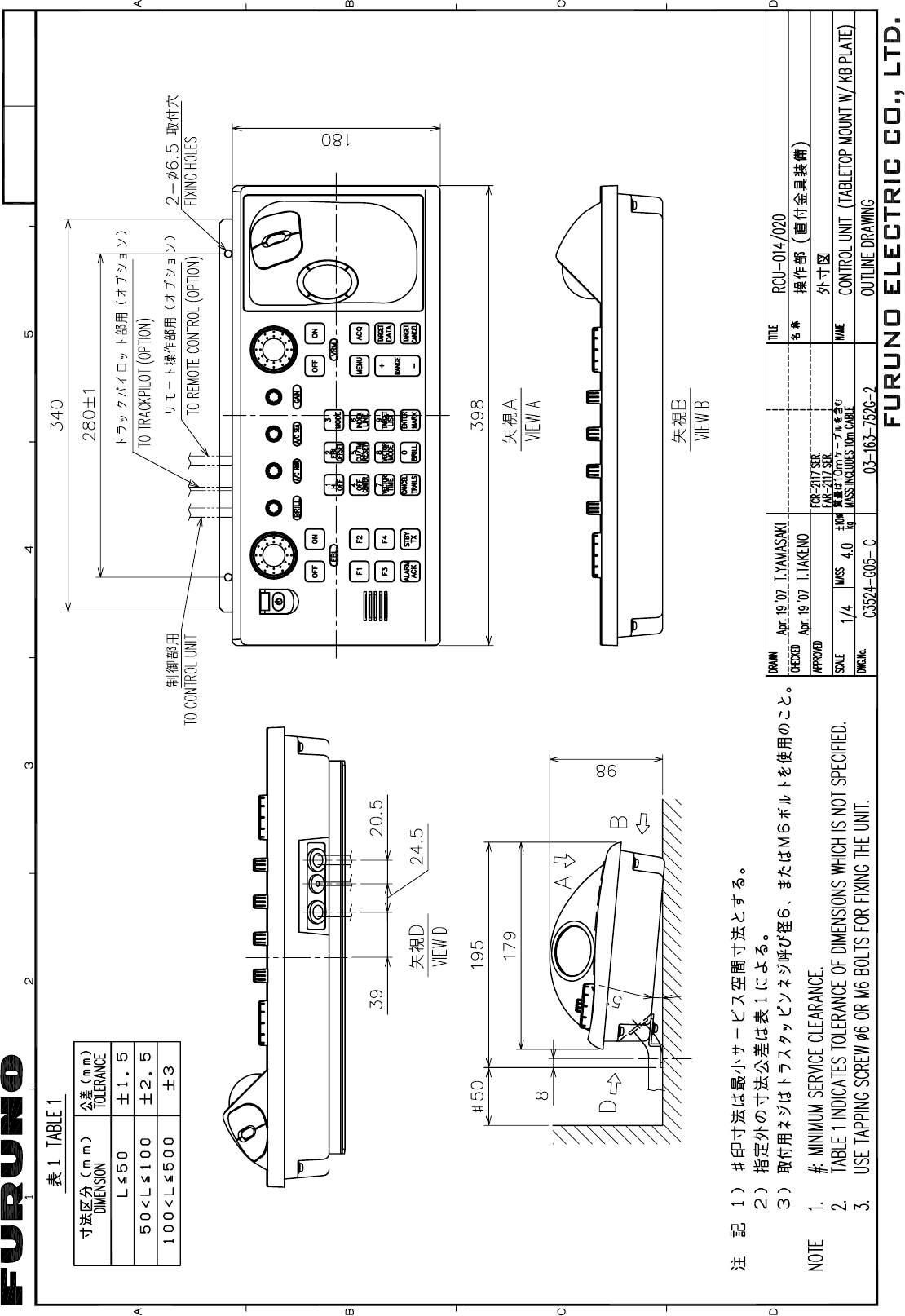
Apr.23'07 R.Esumi
D-10
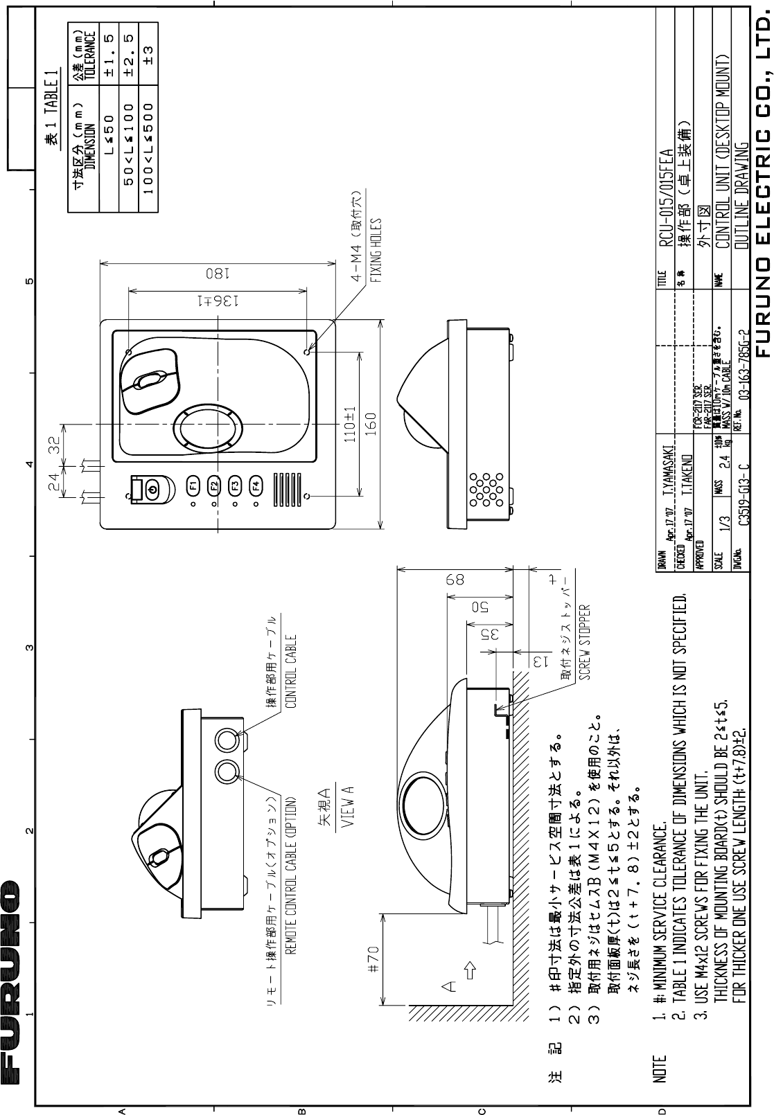
Apr.23'07 R.Esumi
D-11
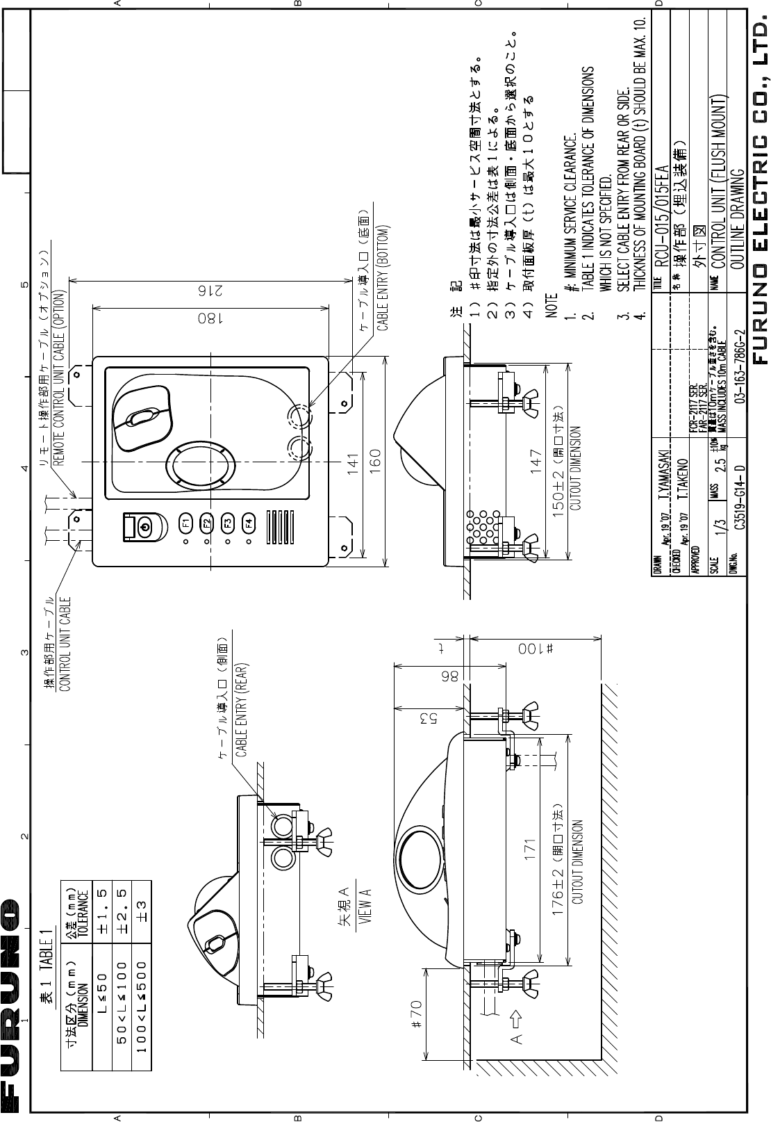
Apr.23'07 R.Esumi
D-12
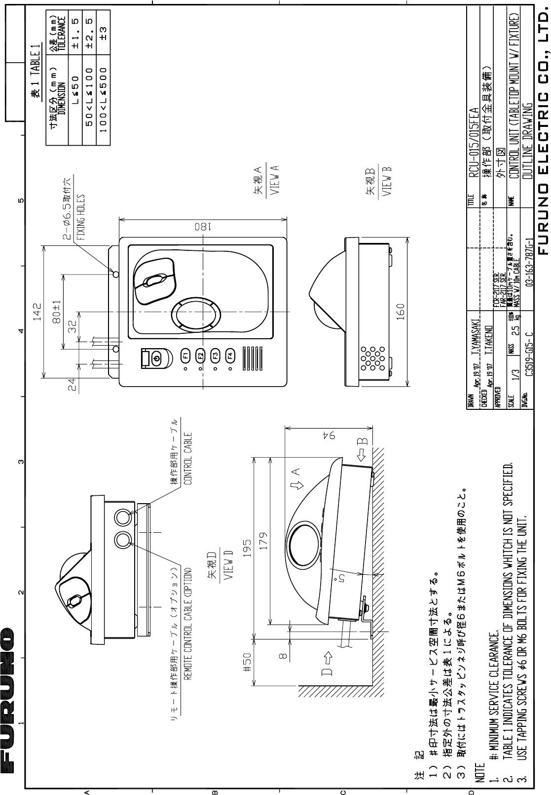
Apr.23'07 R.Esumi
D-13
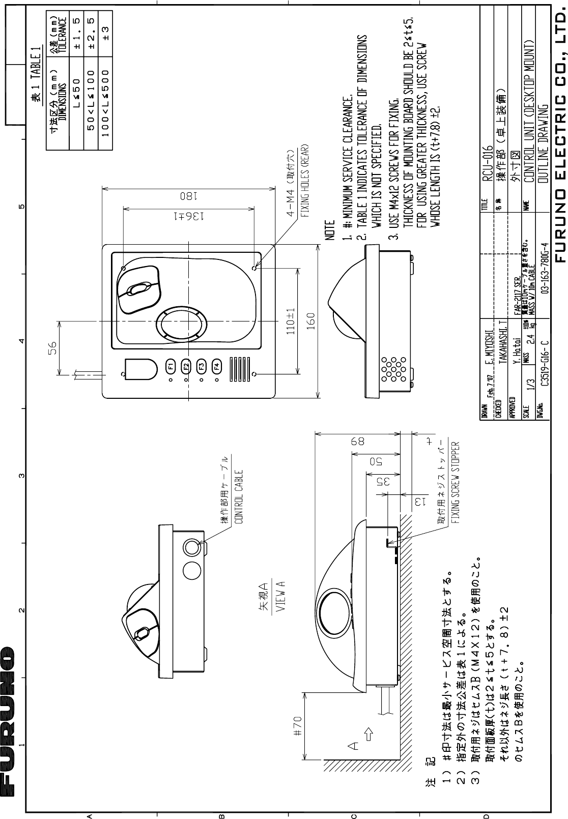
D-14
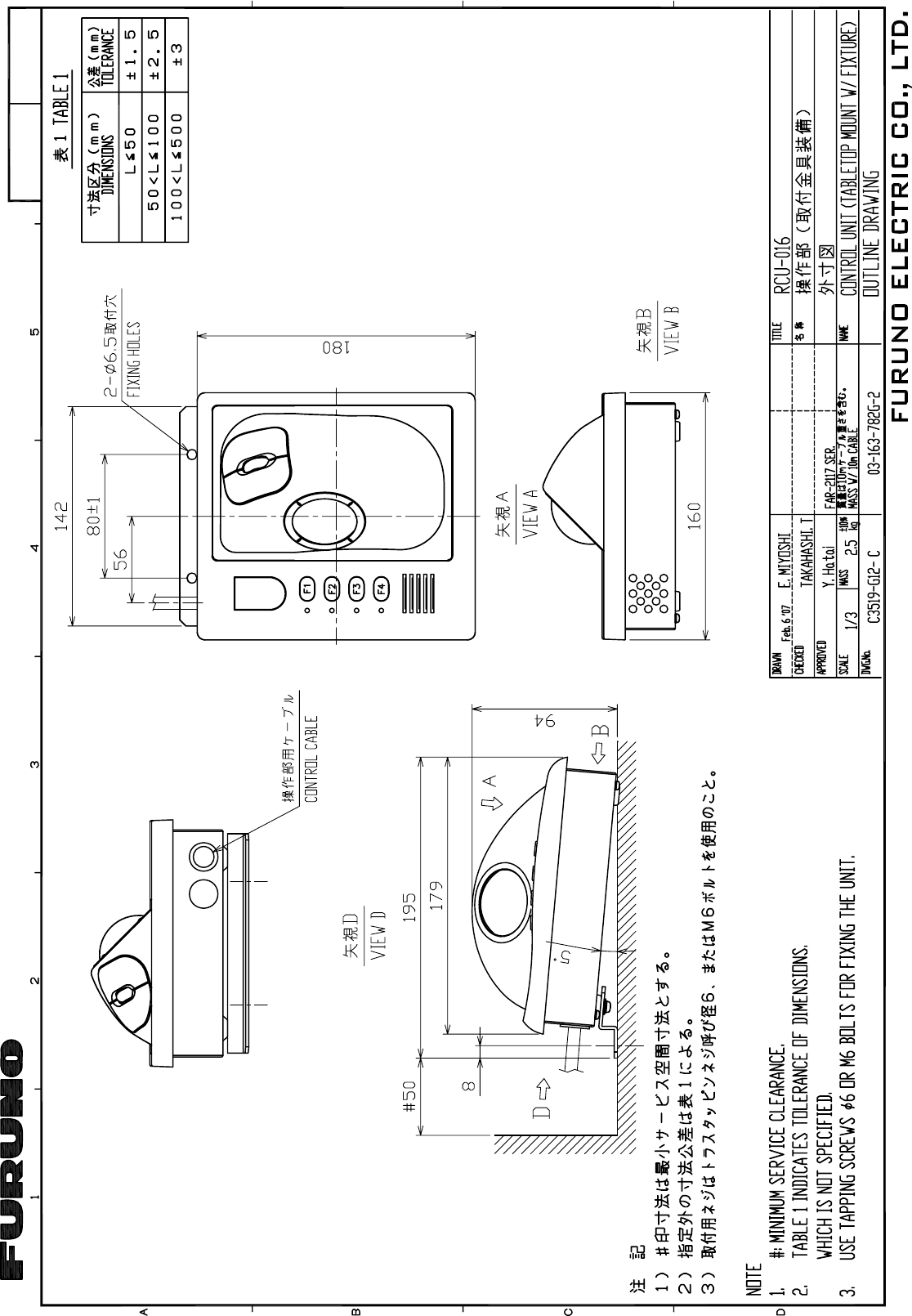
D-15
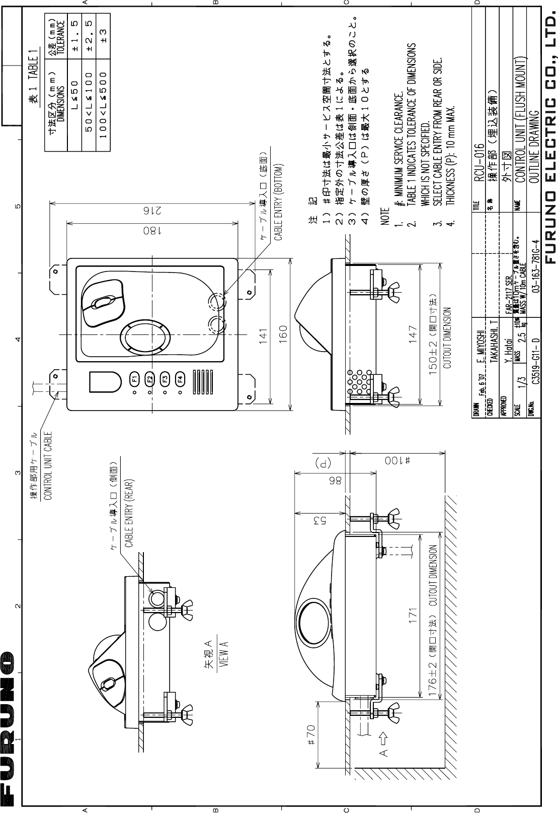
D-16
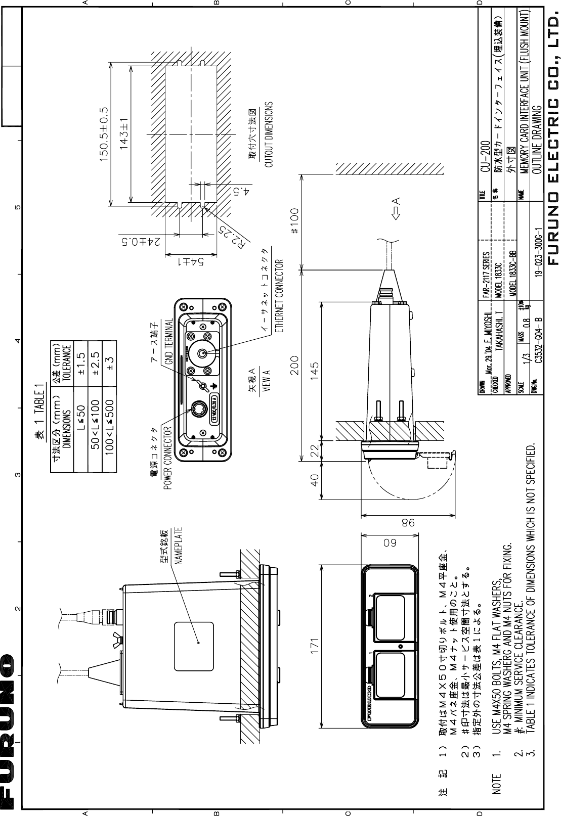
Y. Hatai
D-17
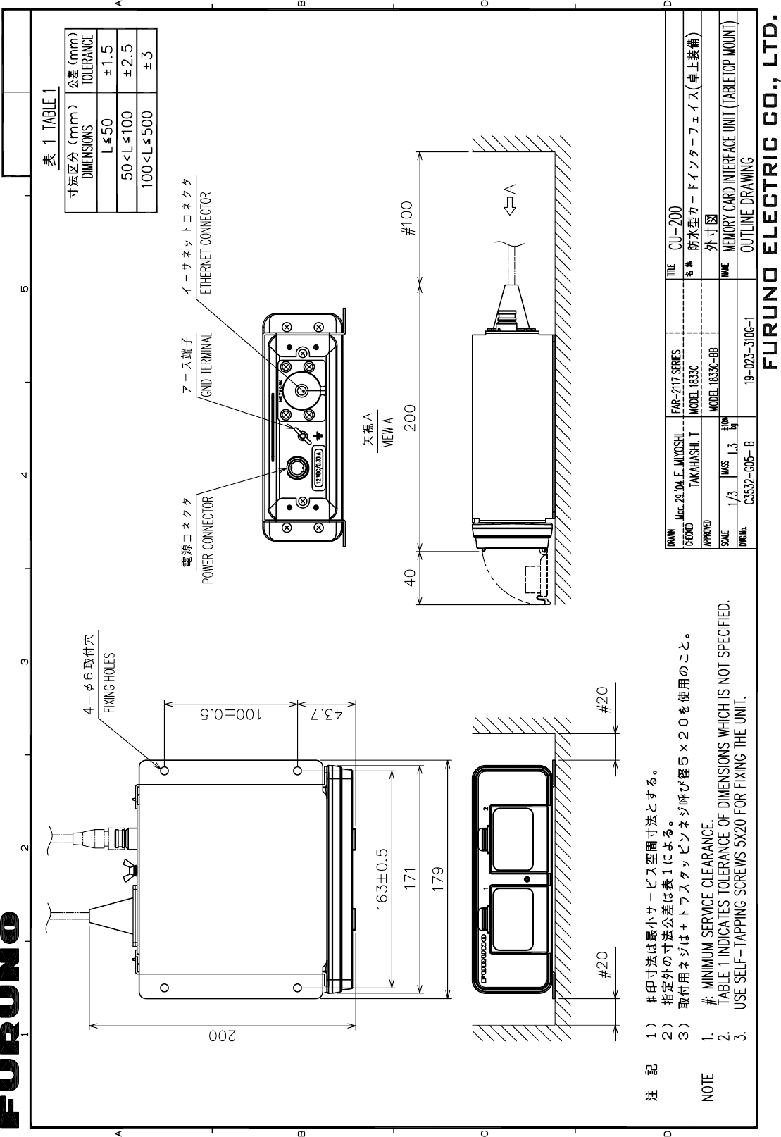
Y. Hatai
D-18
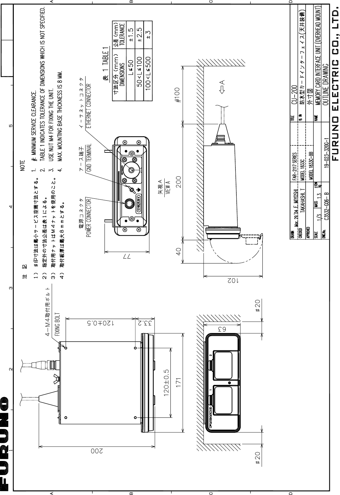
Y. Hatai
D-19
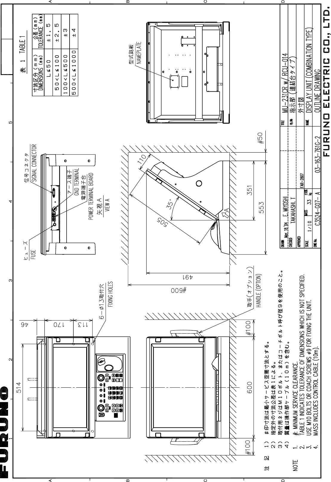
Y. Hatai
D-20
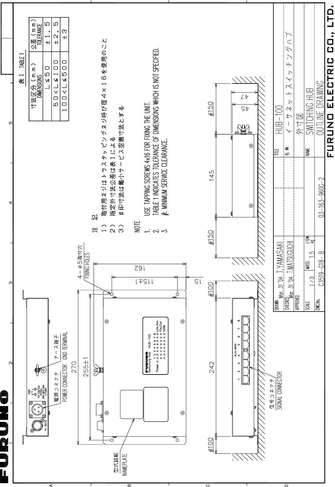
Apr.05'04
D-21
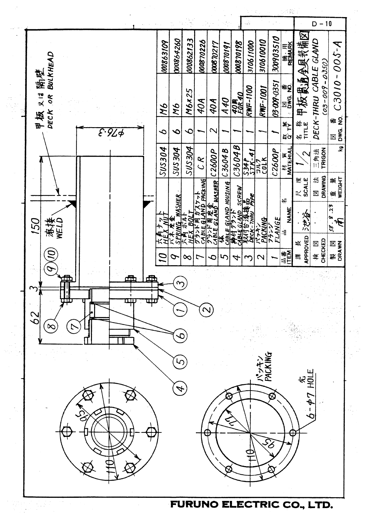
D-22
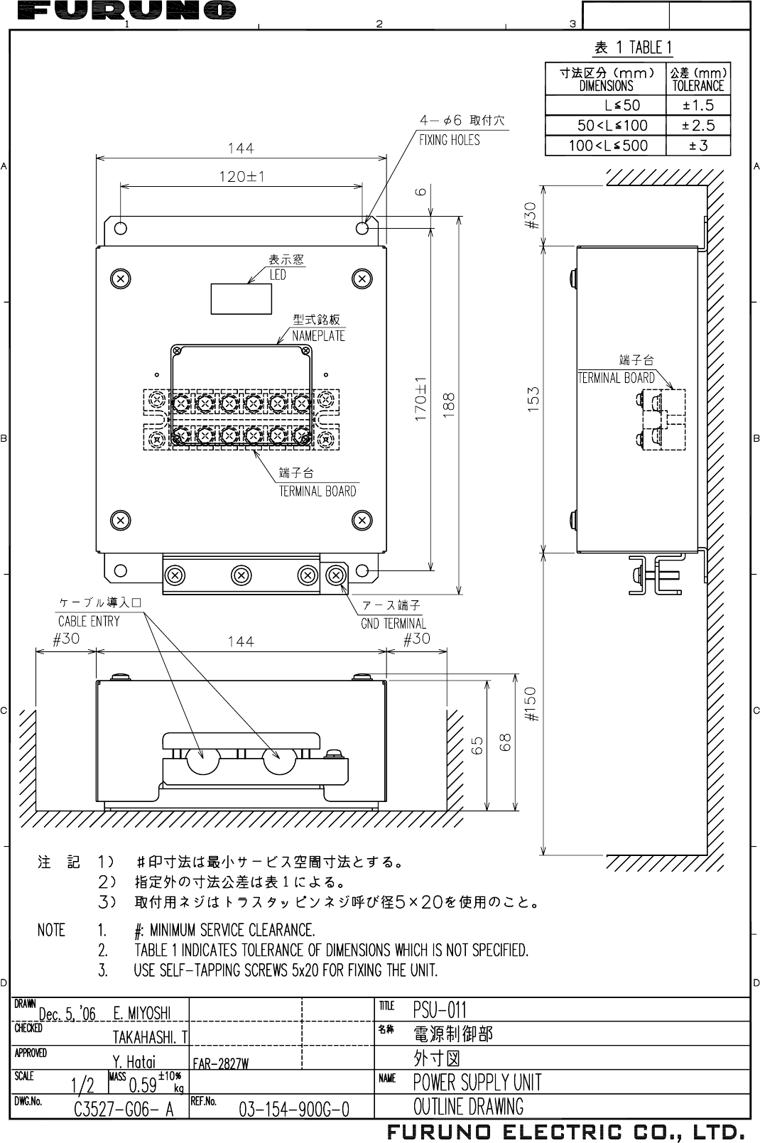
D-23
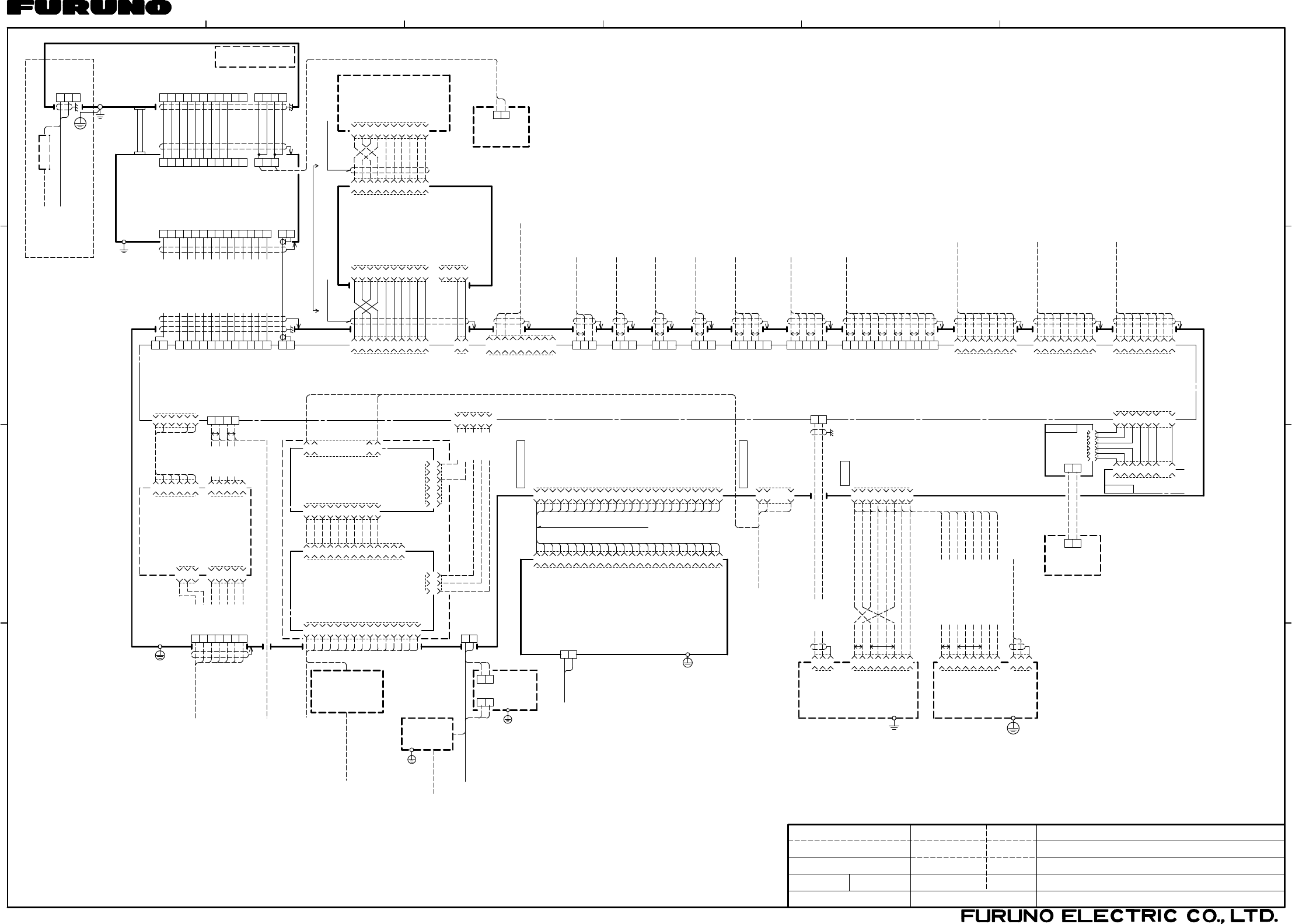
12 4356
A
B
C
D
MASSSCALE
DWG.No.
APPROVED
CHECKED
DRAWN
kg
名称
TYPE
NAME
MARINE RADAR/ARPA
相互結線図
INTERCONNECTION DIAGRAM
船舶用レーダー/ARPA
FAR-2827W
REF.No.
C3527-C01- M
T.YAMASAKI
25/Sep/08
03-163-6003-3
注記 NOTES
*4: USE 3A BREAKER IN SHIP'S MAINS SWITCH BOX.
*5: USE GRN/YEL WIRE FOR PROTECTIVE EARTH.
*1: SHIPYARD SUPPLY
*2: OPTION
*3: MAX. 100m. (JUNCTION BOX RJB-001 IS REQUIRED FOR EXTENSION.)
*6: FOR RUSSIAN FLAG VESSELS ONLY.
*7: ブレーキユニットの接続はいずれかを選択。
*1: 造船所手配
*2: オプション
*3: 最長 100m (延長するときは接続箱RJB-001が必要 )。
*4: 船内配電盤では3Aのブレーカを使用。
*5: 保護アース用ケーブルは緑/黄の絶縁線を使用のこと。
*6: ロシア型検仕様のみ。
*7: SELECT 1 OR 2 FOR CONNECTION OF BREAK UNIT.
25/Sep/08 T.TAKENO
03P9229A
RGB バッファ 基板
RGB BUFFER PCB
J615
J3
J4
SLB-FRN4-A
DVI-RGB CONVERSION BOARD
DVI-RGB変換基板
P
P
*1 J9
VGA CABLE J2
*2DVI-RGB-1
RGBビデオコンバータ
J1 J3
J603(XH)
J5(VH)
03-2090(3P)
J4(VH)
03-2089(5P)
BOARD
GYRO CONVERTER
64P1106A *2
J1
J7(NH) 03-2091(5P) J608
J609
J610
J613
-12V
ミドリ GRN 5
GND
キ YEL 4
+5V
ダイ ORG 3
GND
アカ RED 2
+12V
チャ BRN 1
-5/-12V
GND
VCC
3
2
1
NC
NC
GND
GND
+12V
+12V
3
6
5
4
2
1
15
14
13
12
11
10
9
8
7
6
5
4
3
2
1
NC
Y_SYNC
H_SYNC
NC
GND
GND
NC
GND
GND
GND
NC
NC
B_VIDEO
G_VIDEO
R_VIDEO
-5/-12V
GND
VCC
GND
V_SYNC
GND
H_SYNC
GND
B_VIDEO
GND
G_VIDEO
GND
R_VIDEO
13
12
11
10
9
8
7
6
5
4
3
2
1
GND
VS
GND
HS
GND
B
GND
G
R
GND
2
1
4
3
10
9
8
7
6
5
2
1
23
24
TB BOARD
03P9342
12
11
10
9
4
3
6
5
2
1
14
13
NC
3
GYRO_R1
2
GYRO_R2
1
GYRO_FG
5
GYRO_T
4
GYRO_S3
3
GYRO_S2
2
GYRO_S1
1
FG
SHIFT1-C
SHIFT1-H
DATA1-C
DATA1-H 1
5
YEL
キ
4
ORGダイ
3
アカ RED
2
BRNチャ
4
3
2
1
IF_VIDEO
GND
SG
MOTOR(-)
MOTOR(-)
MOTOR(+)
MOTOR(+)
24V_MINUS
24V_PLUS
12
11
10
9
8
7
6
5
4
3
2
1
2
1
J602
10
9
8
7
6
5
4
3
GND
+12V
GND
PWR_SW
2
1
KEY_TXD-B
KEY_TXD-A
KEY_RXD-B
KEY_RXD-A
SYS_FAIL-H
SYS_FAIL-C
SYS_ACK-C
SYS_ACK-H
J622 1
2
AD_DATA-H
AD_DATA-C
AD_CLK-H
AD_CLK-C
RF_SPU_D-B
RF_SPU_D-A
SPU_RF_D-B
SPU_RF_D-A
GC_5V
GC_0V
GC_DOWN
GC_UP
GC_HOLD
GC_LED
03-2088(6-14P)
NC
TX_HV
P
J605
J601
RS-232C
HDG_GND 3
2
1
NC 9
NC 8
NC 7
NC 6
4
GND
NC
5
TXD 3
NC 1
RXD 2
HDG-B
HDG-A
P
J606
NC 3
2
1
NAV-B
NAV-A
P
J607
NC 3
2
1
LOG-B
LOG-A
J620
GND 5
4
3
2
1
TRK_RD-B
TRK_RD-A
TRK_TD-B
TRK_TD-A P
P
J619
NC 3
2
1
ARPA-B
ARPA-A
P
P
P
J611
AIS_GND 5
4
3
2
1
AIS_RD-B
AIS_RD-A
AIS_TD-B
AIS_TD-A
J617(NH)
J616(NH)
J618(NH)
P
P
P
P
P
P
J612
8
7
6
5
4
3
2
1
OP_VIDEO_1
GND
OP_TRIG_1
GND
OP_BP_1
GND
OP_HD_1
GND
OP_VIDEO_IN
GND
OP_TRIG_IN
GND
OP_BP_IN
GND
OP_HD_IN
GND
8
7
6
5
4
3
2
1
8
7
6
5
4
3
2
1
OP_VIDEO_2
GND
OP_TRIG_2
GND
OP_BP_2
GND
OP_HD_2
GND
OPERATOR_FITNESS_1
OPERATOR_FITNESS_0
GND
EXT_ALM_ACK_N
ALARM3_1
ALARM3_0
ALARM2_1
ALARM2_0
ALARM1_1
ALARM1_0
12
11
10
9
8
7
6
5
4
3
2
1
SYS_FAIL-H
SYS_FAIL-C
(IEC-61162-2)
HDG SENSOR
*1
RS-232C CABLE PC
(IEC-61162-1)
NAVIGATOR
(IEC-61162-1)
SPEED LOG
(IEC-61162-1)
TRACK_CONTROL
(IEC-61162-1)
ECDIS
(IEC-61162-2)
AIS
ALARM SYSTEM
*1
TTYCS-1Q
*1
TTYCS-1
*1
TTYCS-1
*1
*1
TTYCS-1
TTYCS-4
*1
TTYCS-4
*1
TTYCS-7
RW-4864,φ9.5
RW-4864,φ9.5
RW-4864,φ9.5
(FULL-LOG)
SUB DISPLAY1
MASTER RADAR
(SEMI-LOG)
SUB DISPLAY2
IV-8sq.
保護アース
PE *1 *5
ムラサキ
アオ
ミドリ
キ
ダイ
アカ
チャ
PPL
BLU
GRN
YEL
ORG
RED
BRN
7
6
5
4
3
2
1
14
13
IF_VIDEO
GND
SG
24V_MINUS
24V_PLUS
NC
TX_HV
12
11
10
9
8
7
6
5
4
3
2
1
RF_SPU_D-B
RF_SPU_D-A
SPU_RF_D-B
SPU_RF_D-A
WHT
GRN[B]
RED[B]
BLK
GRN
RED
WHT[B]
PPL[B]
GRY[B]
BLU[B]
YEL[B]
ORG[B]
BRN
チャ
ダイ(太)
キ(太)
アオ(太)
ハイ(太)
ムラサキ(太)
シロ(太)
アカ
ミドリ
クロ
シロ
ミドリ(太)
アカ(太)
11
10
9
8
7
6
5
4
3
2
1
TB803
+12V
NC
HD
BP
-12V
PM-TRIG
PM-LEVEL
PM-ENABL
GND
GND
TB801
TB802
GNDGND
3
2
1
11
10
9
8
7
6
5
4
3
2
1+12V
NC
HD
BP
-12V
PM-TRIG
PM-LEVEL
PM-ENABL
GND
GND
NC
TB803
MOTOR(+)
MOTOR(+)
MOTOR(-)
MOTOR(-)
TB804 TB801
MOTOR-H
MOTOR-H
MOTOR-C
MOTOR-C
PERFORMANCE MONITOR
パフォーマンスモニター
PM-31
5
6
7
8
BNCコネクタコンバータ
CONVERTER *2
BNC CONNECTOR
COAX.(75Ω)x5
VDR
*1
DSUB-BNC-1
MPYC-7
*1
TTYCS-4
*1
GYROCOMPASS
RGB EXT. MONITOR
A-D CONVERTER
2.3/10/20/30m,φ9
XH10P-W-6P
1.5/10/20/30m,φ9
XH10P-W-5P-A
NC
NC 10
9
8
7
6
5
4
3
GND
+12V
GND
PWR_SW
2
1
10
9
8
7
6
5
4
3
GND
+12V
GND
PWR_SW
2
1
操作部
CONTROL UNIT
RCU-014/015
KEY_TXD-B
KEY_TXD-A
KEY_RXD-B
KEY_RXD-A
SYS_FAIL-H
SYS_FAIL-C
KEY_TXD-B
KEY_TXD-A
KEY_RXD-B
KEY_RXD-A
1
2
3
4SYS_ACK-C
SYS_ACK-H
SYS_FAIL-C
SYS_FAIL-H
J502/J522J501/J521
J507/J527
J501
NC
NC
10
9
8
7
6
5
4
3
GND
+12V
GND
PWR_SW
2
1
KEY_RXD-A
KEY_RXD-B
KEY_TXD-A
KEY_TXD-B
RCU-016
CONTROL UNIT
*2
操作部
*1
TX-STC
ANTENNA UNIT
空中線部
IV-3.5sq.
PE
保護アース
*1 *5
*4
氷結防止用
FOR DE-ICER
*1
DPYC-1.5
DPYCY-1.5 *1
*2
RU-3305
50-60Hz
100VAC,1φ,
220/230VAC,
110/115/
1φ,50-60Hz
NC
3
2
1
100VAC-C
100VAC-H
TB901
RSB-103
RW-4747
FR-9-20/30/50
20/30/50m
RW-9600 MPYCY-19
MAX.30m
15/30/40/50m,φ22
*3
RGB VIDEO CONVERTER
J602
送受信部
RTR-081A
UNIT
TRANSCEIVER
J614
GND
+12V
2
1
2
1
3
4
5
6
10
J652
10
2
1
3
4
5
6
5
6
4
1
2
3
03P9339 PWR PCB
J105
2
1MOTOR_DO
MOTOR_C
BRC
J662
03P9485
DVI-DMONITOR
DVI-DMONITOR
SAMEASAVOBE
24
2
1
J205
24
23
22
21
20
19
18
17
16
15
14
13
12
11
10
9
8
7
6
5
4
3
2
1
J204
DVI0TXC_N
DVI0TXC_P
A_GND
NC
NC
A_GND
DVI0TXD_P
DVI0TXD_N
NC
GND
VCC
NC
NC
A_GND
DVI0TX1_P
DVI0TX1_N
NC
NC
NC
NC
NC
A_GND
DVI0TX2_P
DVI0TX2_N
5/10m,φ7
J3
24
23
22
21
20
19
18
17
16
15
14
13
12
11
10
9
8
7
6
5
4
3
2
1
TMDS_CLOCK(-)
TMDS_CLOCK(+)
TMDS_CLOCK_SHIELD
NC
NC
TMDS_DATA0/5_SHIELD
TMDS_DATAB(+)
TMDS_DATAB(-)
HOT_PLUG_DETECT
GND
+5V_POWER
NC
NC
TMDS_DATA1/3_SHIELD
TMDS_DATA(+)
TMDS_DATA(-)
NC
DDC_DATA
DDC_CLOCK
NC
NC
TMDS_DATA2/4_SHIELD
TMDS_DATA2(+)
TMDS_DATA2(-)
外部モニター *2
DVI CABLE
EXT. MONITOR
PROCESSOR UNIT
RPU-013
制御部
DVI-D/D SINGLELINK 5M/10M
NETWORK
LAN
NC
NC
RXN
NC
NC
RXP
TXN
TXP
8
7
6
5
4
3
2
1
*2MEMORY CARD I/F UNIT
P
P
*1
IV-1.25sq.
MPS588-C
CU-200
シロ
クロ
WHT
BLK
3
2
1
NC
NC
RXN
NC
NC
RXP
TXN
TXP
8
7
6
5
4
3
2
1
+12V
GND
FG
J1
J302
MJ-A3SPF
P5E-4PTX-BL,10m,φ6.3
防水型カードインターフェイス
MJ-A3SPF0015-100C,10m,φ6
HUB-100 (8 PORTS)
1φ,50/60Hz
100-230VAC
*1
P
P
LAN CABLE(CAT5) OR
FR-FTPC-CY,10/20/30m,φ13MPS588-C
SWITCHING HUB *2
スイッチング ハブ
チャBRN
シロ/チャWHT/BRN
ダイORG
シロ/アオWHT/BLU
アオBLU
シロ/ダイWHT/ORG
ミドリGRN
シロ/ミドリWHT/GRN
GND
AC
AC
3
2
1
NC
NC
RXN
NC
NC
RXP
TXN
TXP
8
7
6
5
4
3
2
1
NR203PF-VVS1.25
3.5m, φ8.6
IV-1.25sq.
保護アース PE
*1 *5
DPYC-2.5
TB1
2
1
C
H
1φ,50-60Hz
100-230VAC
保護アース
表示部
MU-231CR
MONITOR UNIT
PE *1 *5
IV-8sq.
2
1DPYC-1.5
*1
BRU-001/002
BREAK UNIT
ブレーキユニット
*2
J1
MOTOR-H
MOTOR-C
NC
2
1DPYC-1.5
*1
BRU-001/002
BREAK UNIT
ブレーキユニット
*2
J1
ブレーキユニット接続(2)
CONNECTION FOR BREAK UNIT (2)
CONNECTION FOR BREAK UNIT (1)
ブレーキユニット接続(1)
*7
*7
合計:31.5m以下 TOTAL: UP TO 31.5m
IV-8sq.
*1
TB1
2
1H
C
100-120/
1φ,50-60Hz
200-230VAC
*2RU-1803
TRANSFORMER
トランス
5
6
H
C
電源制御部
PSU-011
POWER SUPPLY
UNIT
1
2
H
C
*1 *5
保護アース
IV-8sq.
PE
*6
*1
DPYC-1.5
440VAC
1φ,50-60Hz
*1
保護アース
PE *1 *5
IV-8sq.
DPYC-2.5
*1
8/Oct/08 R.Esumi
S-1
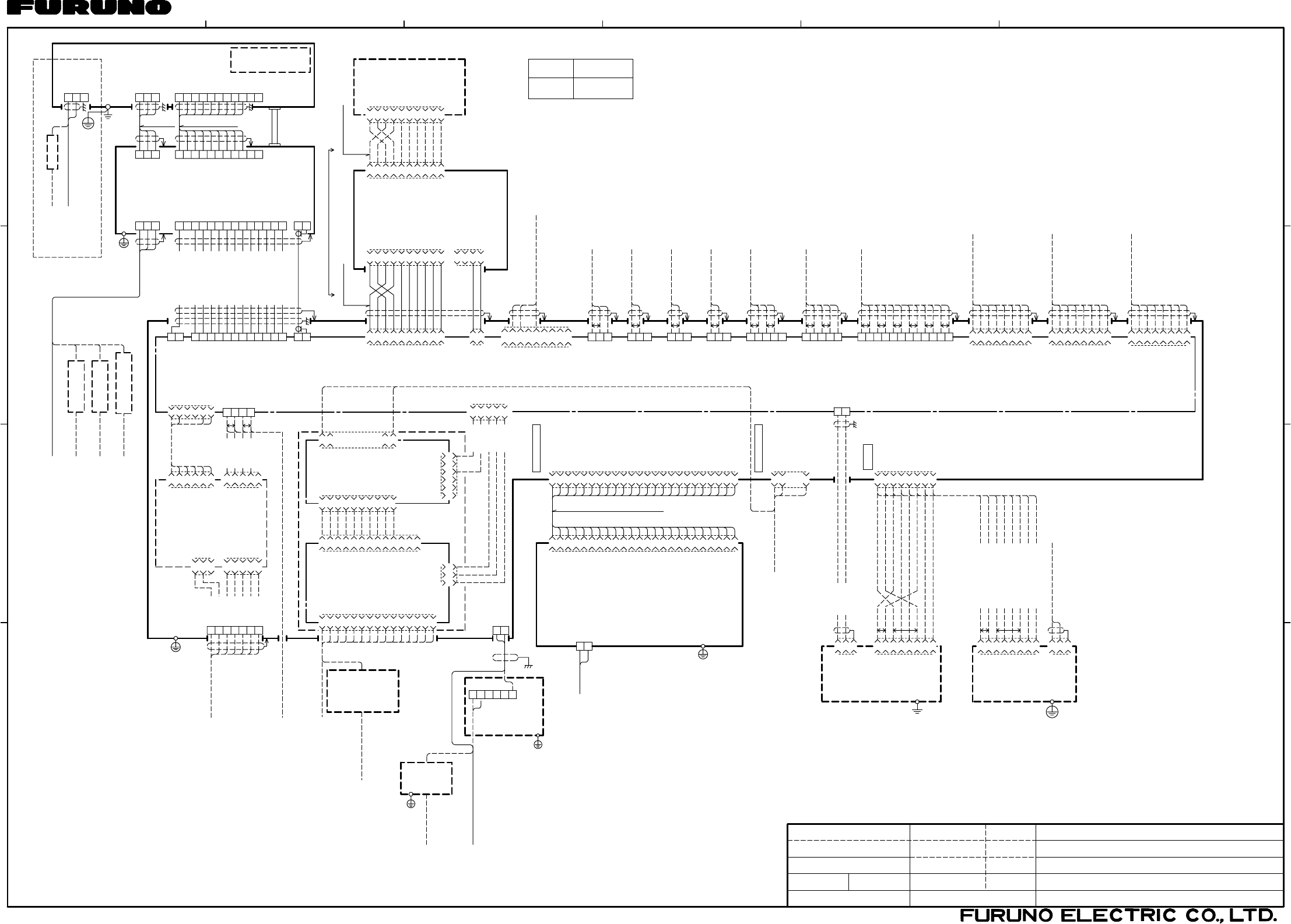
12 4356
A
B
C
D
MASSSCALE
DWG.No.
APPROVED
CHECKED
DRAWN
kg
名称
TYPE
NAME
MARINE RADAR/ARPA
相互結線図
INTERCONNECTION DIAGRAM
船舶用レーダー/ARPA
FAR-2837SW
03P9229A
RGB バッファ 基板
RGB BUFFER PCB
J615
J3
J4
SLB-FRN4-A
DVI-RGB CONVERSION BOARD
DVI-RGB変換基板
P
P
*1 J9
VGA CABLE J2
*2DVI-RGB-1
RGBビデオコンバータ
J1 J3
J603(XH)
J5(VH)
03-2090(3P)
J4(VH)
03-2089(5P)
BOARD
GYRO CONVERTER
64P1106A *2
J1
J7(NH) 03-2091(5P) J608
J609
J610
J613
-12V
ミドリ GRN 5
GND
キYEL 4
+5V
ダイ ORG 3
GND
アカ RED 2
+12V
チャ BRN 1
-5/-12V
GND
VCC
3
2
1
NC
NC
GND
GND
+12V
+12V
3
6
5
4
2
1
15
14
13
12
11
10
9
8
7
6
5
4
3
2
1
NC
Y_SYNC
H_SYNC
NC
GND
GND
NC
GND
GND
GND
NC
NC
B_VIDEO
G_VIDEO
R_VIDEO
-5/-12V
GND
VCC
GND
V_SYNC
GND
H_SYNC
GND
B_VIDEO
GND
G_VIDEO
GND
R_VIDEO
13
12
11
10
9
8
7
6
5
4
3
2
1
GND
VS
GND
HS
GND
B
GND
G
R
GND
2
1
4
3
10
9
8
7
6
5
2
1
23
24
TB BOARD
03P9342
12
11
10
9
4
3
6
5
2
1
14
13
NC
3
GYRO_R1
2
GYRO_R2
1
GYRO_FG
5
GYRO_T
4
GYRO_S3
3
GYRO_S2
2
GYRO_S1
1
FG
SHIFT1-C
SHIFT1-H
DATA1-C
DATA1-H 1
5
YEL
キ
4
ORGダイ
3
アカ RED
2
BRNチャ
4
3
2
1
IF_VIDEO
GND
SG
MOTOR(-)
MOTOR(-)
MOTOR(+)
MOTOR(+)
24V_MINUS
24V_PLUS
12
11
10
9
8
7
6
5
4
3
2
1
2
1
J602
NC
NC 10
9
8
7
6
5
4
3
GND
+12V
GND
PWR_SW
2
1
10
9
8
7
6
5
4
3
GND
+12V
GND
PWR_SW
2
1
10
9
8
7
6
5
4
3
GND
+12V
GND
PWR_SW
2
1
操作部
CONTROL UNIT
RCU-014/015
KEY_TXD-B
KEY_TXD-A
KEY_RXD-B
KEY_RXD-A
SYS_FAIL-H
SYS_FAIL-C
KEY_TXD-B
KEY_TXD-A
KEY_RXD-B
KEY_RXD-A
KEY_TXD-B
KEY_TXD-A
KEY_RXD-B
KEY_RXD-A
SYS_FAIL-H
SYS_FAIL-C
1
2
3
4SYS_ACK-C
SYS_ACK-H
SYS_FAIL-C
SYS_FAIL-H
SYS_ACK-C
SYS_ACK-H
J622 1
2
J502/J522J501/J521
J507/J527
AD_DATA-H
AD_DATA-C
AD_CLK-H
AD_CLK-C
RF_SPU_D-B
RF_SPU_D-A
SPU_RF_D-B
SPU_RF_D-A
合計:33m以下 TOTAL: UP TO 33m
2.3/10/20/30m,φ9
XH10P-W-6P
GC_5V
GC_0V
GC_DOWN
GC_UP
GC_HOLD
GC_LED
03-2088(6-14P)
NC
TX_HV
J614
GND
+12V
2
1
P
J605
J601
RS-232C
HDG_GND 3
2
1
NC 9
NC 8
NC 7
NC 6
4
GND
NC
5
TXD 3
NC 1
RXD 2
HDG-B
HDG-A
P
J606
NC 3
2
1
NAV-B
NAV-A
P
J607
NC 3
2
1
LOG-B
LOG-A
J620
GND 5
4
3
2
1
TRK_RD-B
TRK_RD-A
TRK_TD-B
TRK_TD-A P
P
J619
NC 3
2
1
ARPA-B
ARPA-A
P
P
P
J611
AIS_GND 5
4
3
2
1
AIS_RD-B
AIS_RD-A
AIS_TD-B
AIS_TD-A
J617(NH)
J616(NH)
J618(NH)
P
P
P
P
P
P
J612
8
7
6
5
4
3
2
1
OP_VIDEO_1
GND
OP_TRIG_1
GND
OP_BP_1
GND
OP_HD_1
GND
OP_VIDEO_IN
GND
OP_TRIG_IN
GND
OP_BP_IN
GND
OP_HD_IN
GND
8
7
6
5
4
3
2
1
8
7
6
5
4
3
2
1
OP_VIDEO_2
GND
OP_TRIG_2
GND
OP_BP_2
GND
OP_HD_2
GND
OPERATOR_FITNESS_1
OPERATOR_FITNESS_0
GND
EXT_ALM_ACK_N
ALARM3_1
ALARM3_0
ALARM2_1
ALARM2_0
ALARM1_1
ALARM1_0
12
11
10
9
8
7
6
5
4
3
2
1
SYS_FAIL-H
SYS_FAIL-C
J501
NC
NC
10
9
8
7
6
5
4
3
GND
+12V
GND
PWR_SW
2
1
KEY_RXD-A
KEY_RXD-B
KEY_TXD-A
KEY_TXD-B
RCU-016
CONTROL UNIT
*2
操作部
1.5/10/20/30m,φ9
XH10P-W-5P-A
(IEC-61162-2)
HDG SENSOR
*1
RS-232C CABLE PC
(IEC-61162-1)
NAVIGATOR
(IEC-61162-1)
SPEED LOG
(IEC-61162-1)
TRACK_CONTROL
(IEC-61162-1)
ECDIS
(IEC-61162-2)
AIS
ALARM SYSTEM
*1
TTYCS-1Q
*1
TTYCS-1
*1
TTYCS-1
*1
*1
TTYCS-1
TTYCS-4
*1
TTYCS-4
*1
TTYCS-7
RW-4864,φ9.5
RW-4864,φ9.5
RW-4864,φ9.5
(FULL-LOG)
SUB DISPLAY1
MASTER RADAR
(SEMI-LOG)
SUB DISPLAY2
IV-8sq.
保護アース
PE *1 *5
MPYC-7
*1
GYROCOMPASS
RGB EXT. MONITOR
TTYCS-4
*1
A-D CONVERTER
BNCコネクタコンバータ
CONVERTER *2
BNC CONNECTOR
COAX.(75Ω)x5
VDR
*1
DSUB-BNC-1
ANT. TYPE
空中線型式
DVI-D MONITOR
DVI-D MONITOR
NETWORK
LAN
SAMEASAVOBE
24
2
1
J205
24
23
22
21
20
19
18
17
16
15
14
13
12
11
10
9
8
7
6
5
4
3
2
1
J204
DVI0TXC_N
DVI0TXC_P
A_GND
NC
NC
A_GND
DVI0TXD_P
DVI0TXD_N
NC
GND
VCC
NC
NC
A_GND
DVI0TX1_P
DVI0TX1_N
NC
NC
NC
NC
NC
A_GND
DVI0TX2_P
DVI0TX2_N
NC
NC
RXN
NC
NC
RXP
TXN
TXP
8
7
6
5
4
3
2
1
5/10m,φ7
J3
24
23
22
21
20
19
18
17
16
15
14
13
12
11
10
9
8
7
6
5
4
3
2
1
TMDS_CLOCK(-)
TMDS_CLOCK(+)
TMDS_CLOCK_SHIELD
NC
NC
TMDS_DATA0/5_SHIELD
TMDS_DATAB(+)
TMDS_DATAB(-)
HOT_PLUG_DETECT
GND
+5V_POWER
NC
NC
TMDS_DATA1/3_SHIELD
TMDS_DATA(+)
TMDS_DATA(-)
NC
DDC_DATA
DDC_CLOCK
NC
NC
TMDS_DATA2/4_SHIELD
TMDS_DATA2(+)
TMDS_DATA2(-)
*2MEMORY CARD I/F UNIT
P
P
*1
IV-1.25sq.
MPS588-C
CU-200
シロ
クロ
WHT
BLK
3
2
1
NC
NC
RXN
NC
NC
RXP
TXN
TXP
8
7
6
5
4
3
2
1
+12V
GND
FG
J1
J302
MJ-A3SPF
P5E-4PTX-BL,10m,φ6.3
防水型カードインターフェイス
HUB-100 (8 PORTS)
保護アース PE
1φ,50/60Hz
100-230VAC
*1
P
P
LAN CABLE(CAT5) OR
FR-FTPC-CY,10/20/30m,φ13MPS588-C
SWITCHING HUB *2
スイッチング ハブ
チャ BRN
シロ/チャ WHT/BRN
ダイ ORG
シロ/アオ WHT/BLU
アオ BLU
シロ/ダイ WHT/ORG
ミドリ GRN
シロ/ミドリ WHT/GRN
GND
AC
AC
3
2
1
NC
NC
RXN
NC
NC
RXP
TXN
TXP
8
7
6
5
4
3
2
1
NR203PF-VVS1.25
3.5m, φ8.6
IV-1.25sq. *1 *5
外部モニター *2
DVI CABLE
EXT. MONITOR
IV-8sq.
PE
保護アース
*1 *5
PROCESSOR UNIT
RPU-013
制御部
ムラサキ
アオ
ミドリ
キ
ダイ
アカ
チャ
PPL
BLU
GRN
YEL
ORG
RED
BRN
7
6
5
4
3
2
1
RW-9600,
15/30/40/50m,φ22
3
2
1U
V
W
14
13
IF_VIDEO
GND
SG
24V_MINUS
24V_PLUS
NC
TX_HV
12
11
10
9
8
7
6
5
4
3
2
1
RF_SPU_D-B
RF_SPU_D-A
SPU_RF_D-B
SPU_RF_D-A
NC
NC
NC
NC
WHT
GRN[B]
RED[B]
BLK
GRN
RED
WHT[B]
PPL[B]
GRY[B]
BLU[B]
YEL[B]
ORG[B]
BRN
チャ
ダイ(太)
キ(太)
アオ(太)
ハイ(太)
ムラサキ(太)
シロ(太)
アカ
ミドリ
クロ
シロ
ミドリ(太)
アカ(太)
*3
ANTENNA UNIT
空中線部
RSB-104/105
3
2
1
U
V
W
TB912
3
2
1
TB902
U
V
W
11
10
9
8
7
6
5
4
3
2
1
11
10
9
8
7
6
5
4
3
2
1
TPYCY-2.5 MPYCY-12,MAX.30m
+12V
NC
HD
BP
-12V
PM-TRIG
PM-LEVEL
PM-ENABL
GND
GND
NC
PERFORMANCE MONITOR
パフォーマンスモニター
PM-51
LHPX-20D-ASSY,
20/30m
POWER SUPPLY
電源
200/220VAC
380/440VAC
RSB-104
RSB-105
TB803
RTR-082
TRANSCEIVER UNIT
送受信部
+12V
NC
HD
BP
-12V
PM-TRIG
PM-LEVEL
PM-ENABL
GND
GND
NC
*1 *1
RW-4747
IV-3.5sq.
PE
保護アース
*1 *5
*4
氷結防止用
FOR DE-ICER
*1
DPYC-1.5
DPYCY-1.5 *1
*2
RU-3305
50-60Hz
100VAC,1φ,
220/230VAC,
110/115/
1φ,50-60Hz
NC
3
2
1
100VAC-C
100VAC-H
TB901
*2
440VAC,3φ,50Hz TPYC-2.5
*1
RU-5466-1
200/380VAC,3φ,50Hz
220/440VAC,3φ,60Hz TPYC-2.5
*1
110VAC,3φ,60Hz
220VAC,3φ,50Hz
RU-5693 *2
*2
RU-6522
TPYC-2.5
*1
TPYC-2.5
*1
*1 *5PE
IV-8sq.
保護アース
TB803
TB911
TB801
TB802
GNDGND
MJ-A3SPF0015-100C,10m,φ6
TAKAHASHI.T
DVI-D/D SINGLELINK 5M/10M
RGB VIDEO CONVERTER
E.MIYOSHI
J602
C3528-C01- M
TB1
2
1H
C
440VAC
1φ,50-60Hz
*6
保護アース
IV-8sq.
PE *1 *5
*1
DPYC-1.5
*2RU-1803
TRANSFORMER
トランス
*1
100-120/
1φ,50-60Hz
*6 DPYC-2.5
200-230VAC
*1
DPYC-2.5 TB1
2
1
C
H
1φ,50-60Hz
*6
100-230VAC
MU-231CR
MONITOR UNIT表示部
注記
*3 : 最長 100m (延長するときは接続箱RJB-001が必要 )。
*4 : 船内配電盤では3Aのブレーカを使用。
*5 : 保護アース用ケーブルは緑/黄の絶縁線を使用のこと。
*6 : 交流は両極切りブレーカ(造船所手配)を経由すること。
NOTES
*4: USE 3A BREAKER IN SHIP'S MAINS SWITCH BOX.
*5: USE GRN/YEL WIRE FOR PROTECTIVE EARTH.
*6: PASS THE AC LINE THROUGH A DOUBLE-CONTACT BREAKER (SHIPYARD SUPPLY).
*1 : 造船所手配
*2 : オプション
*1: SHIPYARD SUPPLY
*2: OPTION
*3: MAX. 100m. (JUNCTION BOX RJB-001 IS REQUIRED FOR EXTENSION.)
*7 : ロシア型検仕様のみ。 *7: FOR RUSSIAN FLAG VESSELS ONLY.
1
2
3
4
5
6
H
C
H
C
*7
保護アース
IV-8sq.
PE
POWER SUPPLY UNIT
電源制御部
PSU-011
Jan. 26, '07
TAKAHASHI.T
S-2