Furuno USA 9ZWRTR093 marine radar User Manual
Furuno USA Inc marine radar
Contents
- 1. user manual part 1
- 2. user manual part 1a
- 3. user manual part 2
- 4. user manual part 3
user manual part 1a
Chapter 1: Operational Overview
1-11
Context-Sensitive (Pop-up) Menus
In addition to the menus, context-sensitive menus display commands relevant to the
selected object or active display. Context menus let you quickly access useful com-
mands according to the selected object or active display. To display a context-sensi-
tive menu, hit the right-button key ( ) while an object is selected, or hit the same
key anywhere on the active display. The illustration below shows the Radar pop-up
menu.
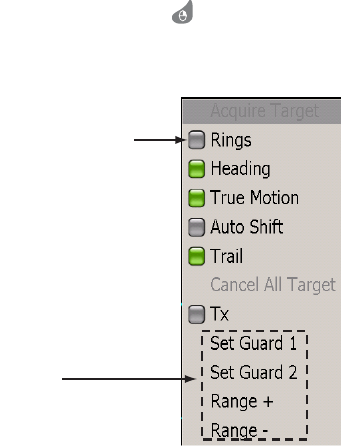
Pop-up menu for radar
To process items on a pop-up menu:
1. Rotate the Rotary Knob to select item.
2. To turn an item on or off, push the Rotary Knob to color the item’s status box in
green to turn it on, or gray to turn it off.
3. For items which have no status box, push the Rotary Knob to proceed to the next
level.
Item status box
Green: ON
Gray: OFF
No box
Push RotoKnob
to process item.
Chapter 1: Operational Overview
1-12
NavData
The four NavData boxes (default quantity) at the bottom off the display show various
navigation data. You can select what to display and add or remove boxes freely. The
data that can be displayed depends on your system configuration. To hide or show the
boxes, use the DATA/VOL key. NavData can be configured with the NavData pop-up
menu and from the NavData menu.
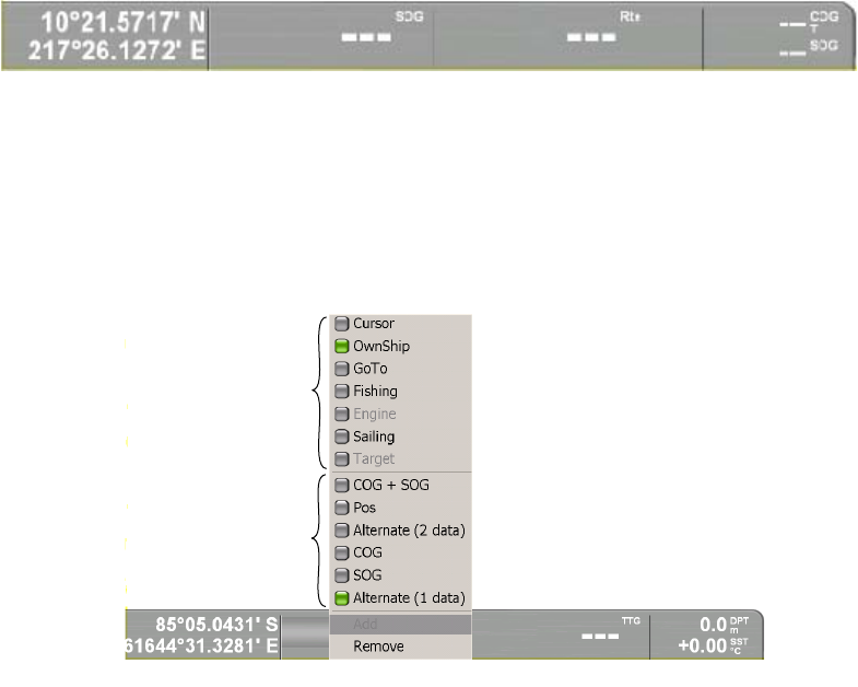
NavData boxes
To change the contents of a NavData box:
1. Put the cursor in the NavData box to process and hit the right-button key to show
the NavData pop-up menu.
The status box of the currently selected NavData category and available data are
colored green.
NavData pop-up (cursor category)
2. If the data you wish to show is displayed in the available data area, rotate the
Rotary Knob to select it and then push the Rotary Knob. If not, rotate the Rotary
Knob to select applicable data category and then push it to change the available
data.
3. Do one of the following depending on your selection.
Turn item ON or OFF: Display status box in green to turn item on, or gray to turn
it off.
Alternate (2 data): Display the two items above this item alternately.
Alternate (1 data): Display the two items above this item alternately.
Add: Add a NavData box. (Available if less than four boxes are showing.)
Remove: Remove a NavData box.
4. Push the Rotary Knob to confirm selection and close the pop-up menu.
Data category
Available data*
* Contents change according to data category.
Chapter 1: Operational Overview
1-13
1.9 Menu Overview
The menu system consists of 14 main menus and accompanying sub menus. The
main menus are Routes, Waypoints, Chart, Radar, Fish finder (under development),
NavData, Tracks, Targets, Weather, Alarms, General setup, Memory card processing,
System configuration, and Own boat data.
1. Press the MENU key to open the menu.
The menu most pertinent to the current operating mode appears. If an alarm has
been violated, the Alarm menu automatically appears.
2. Rotate the Rotary Knob to choose a menu and then push the Rotary Knob.
The background color of the menu selector changes from gray to green to indicate
active menu. To switch to a different menu, hit the CANCEL key to change the
background color back to gray. The CANCEL key can also be used for the same
purpose while working in a sub menu.
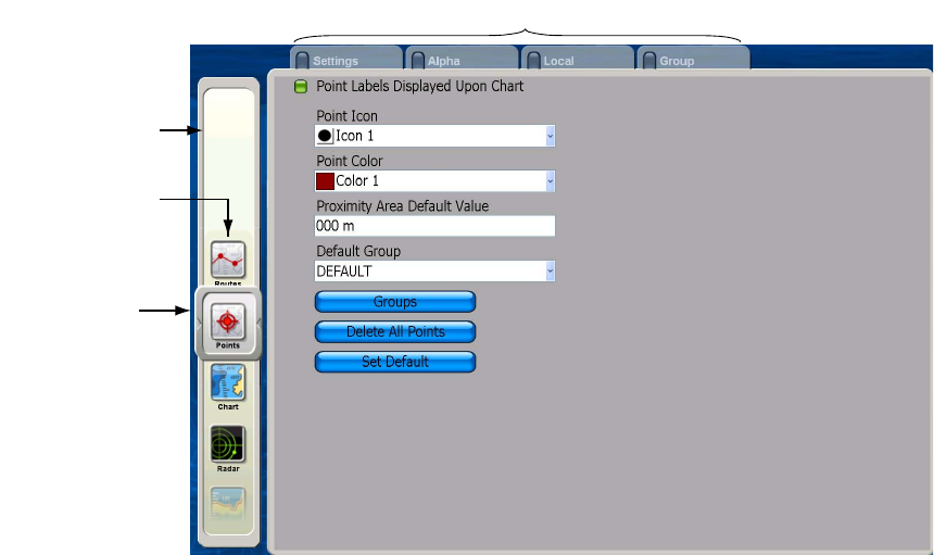
Menu selector
(Moves up and
down with
ROTOkey rotation.)
Menu bar
Tabs for sub menus (click to open)
Menus
Chapter 1: Operational Overview
1-14
3. To a select a sub menu when there are multiple sub menus, rotate the Rotary
Knob to choose desired sub menu and push the Rotary Knob. For example,
choose the Settings sub menu.
The cursor highlights the first item in the sub menu in gray and the square on the
tab of the currently selected sub menu changes from gray to green to denote
active sub menu.
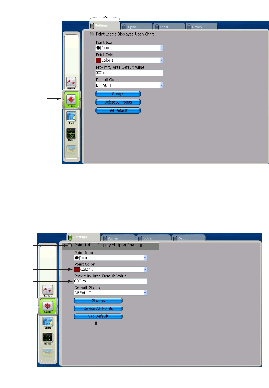
Menu selector
(Background is
green for active
menu.)
Tab is magnified and light gray
to indicate current selection.
Status box
Green: ON
Gray: OFF
Combo box
Data input
box
For quick restoration of all default
settings for current sub menu
Current selection is highlighted in gray
Chapter 1: Operational Overview
1-15
4. Rotate the Rotary Knob to select menu. Do one of the following depending on
menu item selected.
Combo box: push the Rotary Knob to open the box, rotate the Rotary Knob to
choose option, and then push the Rotary Knob to confirm selection.
ON/OFF item: Items which you turn on or off have a status box before them. To
switch an item on or off, choose it and push the Rotary Knob to color the status
box green to turn the item on, or gray to turn it off.
Alphanumeric data input: Use the Cursorpad to put the cursor to the right of the
alphanumeric data to change and push the Rotary Knob. Rotate the Rotary Knob
to choose alphanumeric (A-Z, 0-9) desired and push it to confirm selection.
Rotate the Rotary Knob clockwise to proceed in forward alphanumeric order;
counterclockwise to go in reverse order.
Show in green to turn ON;
gray to turn OFF
Value changes with
knob rotation.
Chapter 1: Operational Overview
1-16
1.10 Man Overboard (MOB) Function
Use the MOB function if you lose a person or object overboard. You need either posi-
tion data from a navigation device, or heading and speed data to calculate position by
dead reckoning. The MOB feature is available on any mode.
To mark MOB position, long-push the SAVE/MOB key. Then, the following occurs:
• The MOB symbol is placed at current position.
• The MOB data box appears and shows range and bearing from current position to
MOB position.
• Other units in the NavNet network are informed of MOB activation via an MOB
message.
Man
overboard
Range, bearing
Current
position
MOB
mark
MOB Data Box
Bearing and range
to MOB position
M
(MOB)
M
O
B162.5°M
0.49 nm
Chapter 1: Operational Overview
1-17
1.11 Selecting Language, Boat Characteristics
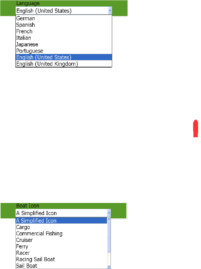
Selecting Language
The default interface language is American English. Language is also available in Brit-
ish English, German, Spanish, French, Italian, Japanese, and Portuguese.
1. Press the MENU key to open the menu.
2. Choose the System menu.
3. Choose the Settings sub menu.
4. Choose Language and push the Rotary Knob.
5. Rotate the Rotary Knob to select your language and push the Rotary Knob.
6. Press the MENU key to close the menu.
Setting Your Boat’s Characteristics
The boat icon (red) marks current position, and the default configuration looks
like the figure shown right. If you would like to show your boat realistically on
the screen, boat type and boat length can be set from the menu. Boat types
available are cargo, commercial fishing vessel, cruiser, ferry, racer, racing
sailboat sport fishing, and work boat.
1. Press the MENU key to open the menu.
2. Open the My NavNet menu and choose the Settings sub menu.
3. Choose the Boat Icon combo box and push the Rotary Knob to show the boat icon
options.
4. Rotate the Rotary Knob to choose the boat icon which best matches your own
boat and push the Rotary Knob.
5. Rotate the Rotary Knob to choose Boat Length and push the Rotary Knob.
6. Rotate the Rotary Knob to set the length of your boat and push the Rotary Knob.
7. Press the MENU key to close the menu.
Boa
t
icon
Chapter 1: Operational Overview
1-18
1.12 Entertainment
In addition to its navigation functions, the MFD BB can also provide music, radio and
video for your enjoyment. Connected to a PC you can listen to your favorite MP3 tunes
and watch video via the Windows Media Player. If you have a satellite radio receiver,
the wide variety of satellite radio music and talk shows are just a few clicks away. Lis-
ten through the built-in speaker or connect a pair of USB speakers for stereo sound.
To enable the entertainment feature, long-push the Rotary Knob on any mode to show
the ROTOkeys, select Entertain and push the Rotary Knob.

2-1
Chapter 2: Chart Plotter Operation
This chapter shows you how to use the navigation functions of this unit. Included are
• How to use chart cards
• How to place, move edit and delete points
• How to create and manage routes
• How to navigate to a point and follow a route
• How to show, save, setup and erase tracks
• How to enable chart plotter-related alarms
2.1 Chart Cards
A world map is built into your chart plotter. To use this chart plotter as a navigation aid,
you need to have electronic charts for the area in which you wish to navigate. Three
types of charts are available: C-MAP NT MAX/MAX2, Mapmedia and S52 layers.
Two card slots are provided in the display unit and control unit, and both can read chart
cards. The convenient storage slot near the card drive stores two chart cards.
The chosen chart scale is indicated at the top left-hand corner on the screen. The val-
ue shown is the distance (nm) from the top of the screen to the bottom of the screen.
To display your chart, change the range scale.
The boundary of your chart is shown with a square. You can switch off this display if
desired, from the Settings sub menu in the Chart menu.
2.2 Selecting Chart Type
If you have both Raster and Vector chart types stored on the hard disk, you can select
the type to use, with the ROTOkeys. Push the Rotary Knob, select the Chart ROTOk-
ey and then select the Raster or Vector ROTOkey and push the Rotary Knob.
2.3 Selecting Chart Scale
You can change the chart scale to
see either more or less detail, or
zoom in or out at specific location.
Use the RANGE key to select a
chart scale. Each time you oper-
ate a RANGE key the chart scale
changes to next available setting. Hit RANGE IN to decrease the chart distance, and
hit RANGE OUT to increase the chart distance. The current chart scale is shown in
the chart scale indication box at the top left corner.
To increase or decrease the chart distance at a specific location, use the Cursorpad
to position the cursor at the location desired and operate applicable RANGE key.
Chart scale
Presentation
mode icon
Chapter 2: Chart Plotter Operation
2-2
2.4 Selecting Presentation Mode
The chart can be shown in head-up, course-up or north-up orientation. To select a pre-
sentation mode, put the cursor on the presentation mode icon at the top left hand cor-
ner and push the left-button key (center of Cursorpad) to show HU (Head-up), NU
(North-up) or CU (Course-up) as applicable. Alternatively, you can use the ROTOk-
eys.
Description of presentation modes
Head-up: Displays the chart with your boat’s current compass heading upwards.
Heading data from a compass is required. As the heading changes the boat symbol
remains fixed and the chart picture rotates accordingly.
North-up: Chart orientation is fixed with true north upwards. As your heading changes
the boat symbol moves accordingly. This mode is useful for long-range navigation.
Course-up: Chart picture is stabilized and shown with your current course over
ground upwards. As your boat’s course changes, the ship symbol moves accordingly.
If you select a new course, the picture will reset to display the new course upwards.
2.5 Moving the Chart
You will need to move the chart if your vessel moves out of the area currently shown,
you want to take a look at another area, or enter points at another location.
You can move the chart several ways:
• Change the chart scale on zoom in or zoom out at cursor position.
• Use the Scrollingpad to pan the chart.
• Automatically re-center your vessel by the SHIP/3D button, or the Auto Shift
ROTOkey.
• Change 3D viewing angle by pressing and holding down the SHIP/3D button.
For further details about the 3D display, see the next section.
Chapter 2: Chart Plotter Operation
2-3
2.6 3D Display
The 3D display is convenient for observing the path between current position and an-
other location from various angles. As noted earlier, it can be activated with the SHIP/
3D button. To activate it and change its horizontal and vertical orientation, using the
ROTOkeys, do the following:
1. Long-push the Rotary Knob to display the ROTOkeys.
2. Select 3D and push the Rotary Knob.
3. Select 3D Mariner and push the Rotary Knob to display the 3D display.
4. To change vertical and horizontal orientation, do the following:
1)Show the ROTOkeys, select the 3D ROTOkey and push the Rotary Knob.
2)Select the Orientation ROTOkey and push the Rotary Knob.
3)Rotate the Rotary Knob to change vertical orientation.
4)Push the Rotary Knob when the display is oriented as desired.
5)Rotate the Rotary Knob to change horizontal orientation.
6)Push the Rotary Knob when the display is oriented as desired.
Note: The 3D Custom ROTOkey memorizes the last-used orientation settings.
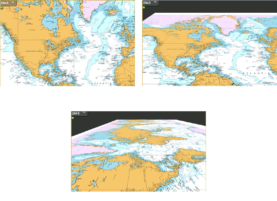
The illustration below shows a portion of a chart as viewed in 2D, 3D Mariner and 3D
Mariner-adjusted displays.
2D display 3D Mariner display
3D Mariner display plus vertical and horizontal adjustments
Chapter 2: Chart Plotter Operation
2-4
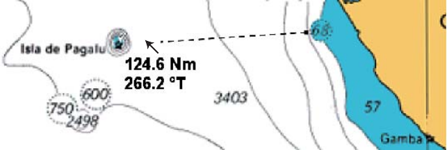
2.7 Finding Range and Bearing to a Location
The "ruler" feature measures the range and bearing between any two points on your
chart. Range and bearing between the two points are digitally indicated on the screen.
1. Long-push the Rotary Knob to show the ROTOkeys.
2. Select Ruler and push the Rotary Knob.
3. Use the Cursorpad to put the cursor on the starting point and push the left-button
key.
4. Use the Cursorpad to drag the cursor to the 2nd point. As you drag the cursor, a
dashed line extends from the 1st point to the cursor location and range and bear-
ing appear next to the cursor.
5. Push the Rotary Knob to erase the ruler and indication.
Chapter 2: Chart Plotter Operation
2-5
2.8 Displaying Object Information
Chart cards carry a large number of objects, such as buoys and lighthouses, for which
you can find information. Port, tide and current information are also available if the
chart card contains such information.
To obtain information about a chart object, port or tide:
1. Put the cursor on the object for which you want to find its information.
2. Push the right-button key. An object information pop-up appears.
Port Information
Port areas are shown on the chart with the port symbol (TBD). Choose a port and a
object information pop-up appears with name of marina or port and a list of the facili-
ties available. Where available, details for each facility, such as engine repairs, boat
yard, marine repairs, etc., can be displayed.
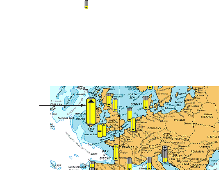
Tide Information
The tide information symbol ( ) is displayed at the locations where tide height data is
available. By selecting a symbol you can get a graph for predictions for maximum and
minimum tide heights, as well as times for sunrise and sunset.
To view tide height information, do the following:
1. Long-push the Rotary Knob to show the ROTOkeys.
2. Select the Display ROTOkey and push the Rotary Knob.
3. Select Tide and push the Rotary Knob to display the tide symbols, like the ones in
the illustration below.
The arrow on the symbol is down when the tide is going low and up when the tide
is going high. The amount of yellow fill increases and gray fill decreases with tide
height. When the tide is full the marker is completely filled in yellow.
* Tide symbol
(yellow and gray,
magnfied when
selected)
Chapter 2: Chart Plotter Operation
2-6
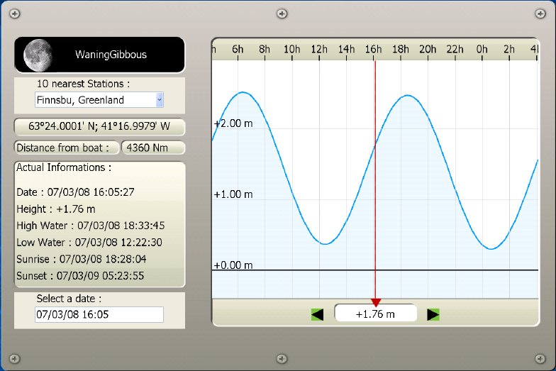
4. Use the Cursorpad to select a tide symbol and push the left-button key to show
the tide display for that location.
The predictions are mostly accurate under moderate weather conditions. However,
storms and weather fronts can influence forecasted tide times and heights.
The dotted vertical line of the graph is used to select a time for which the tide height
is displayed. To change the time, rotate the Rotary Knob.
• To find tide for 10 nearest stations, use the 10 Nearest Station combo box.
• To change the date, select "Select a date" and enter desired date.
Chapter 2: Chart Plotter Operation
2-7
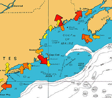
Tidal Current Information
1. Long-push the Rotary Knob to show the ROTOkeys.
2. Select the Display ROTOkey and push the Rotary Knob.
3. Select Current and push the Rotary Knob. You should see some current symbols
on the display, like the ones below.
Arrows of varying length and color depict current movement. The arrow points in
current direction. Current speed is indicated by arrow size and arrow color. The
larger the arrow the faster the speed. Color indicates the estimated speed range
of the current; red is the highest range, yellow is the lowest.
Chapter 2: Chart Plotter Operation
2-8
2.9 Overlays
Several chart overlays are available on the chart plotter display: shading, weather, sat-
ellite image, and animation.
Shading
Depth contours can be shown or hidden. Show the ROTOkeys, select the Display and
Shading ROTOkeys and then push the Rotary Knob to alternately show and hide the
depth contours.
Weather
The weather overlay superimposes weather information on the chart plotter display.
Show the ROTOkeys, select the Display and Weather keys and push the Rotary Knob
to alternately show and hide the weather display. This features requires the Sirius
weather receiver.
Satellite Image
Overlay the satellite image for the current chart. Select the Chart ROTOkey followed
by the Photo ROTOkey. Push the Rotary Knob to alternately show and hide the satel-
lite photo. Satellite image availability depends on area.
Animation
The arrows used to show tidal current information can be animated to show that data
over a period of time. Further, with connection of a Sirius receiver, weather movement
can be animated over time to give you an idea of weather conditions in the future. Dis-
play the ROTOkeys, select Animate and push the Rotary Knob to alternately enable
and disable the animation feature.
Chapter 2: Chart Plotter Operation
2-9
2.10 Markers on the Chart Plotter Display
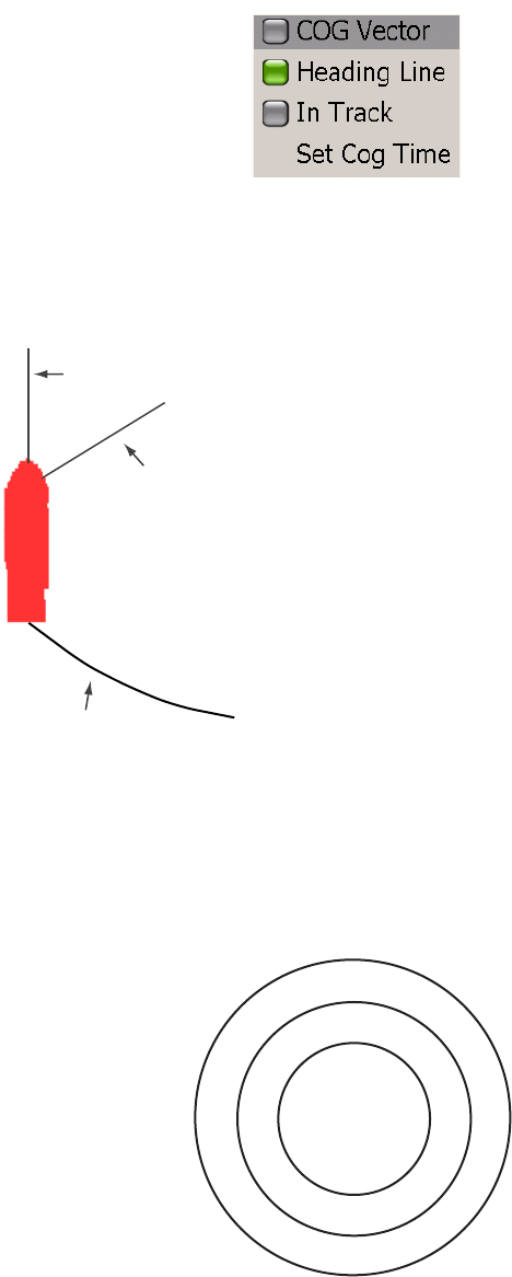
Boat Icon
The boat icon is placed at current position, and the default configuration is as shown
in the figure at the bottom of this page. An affiliated pop-up menu provides for control
of COG vector, heading line and track. To display the pop-up, put the cursor on the
icon and push the right-button key. Refer to the paragraph below for a description of
the items of this pop-up.
COG Vector is a line extending from the boat icon which points in direction of course.
Heading Line is a straight line extending from your position and it shows current
heading. In Track turns own ship’s track on or off. Set COG Time sets the length of
the COG Vector. (See the table on page 2-9 for details.)
Range Rings
A set of range rings, centered at current position, can be displayed to give you an es-
timate of range to an object. Long-push the Rotary Knob to show the ROTOkeys. Se-
lect the Rings ROTOkey and push the Rotary Knob to alternately turn the rings on and
off.
Course Over Ground (COG) vector
Track
Heading line
Chapter 2: Chart Plotter Operation
2-10
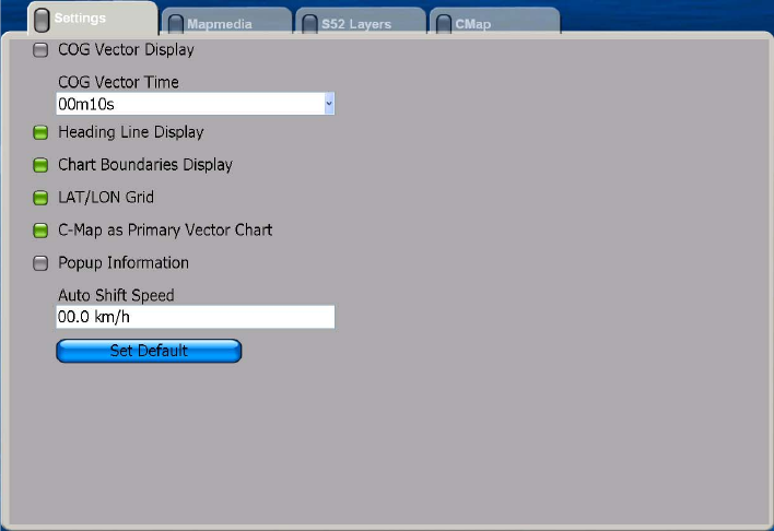
2.11 Chart Setup on the Chart Menu
The Settings sub menu in the Chart menu contains several chart-related items which
once set do not require frequent adjustment. Set them to suit your needs, following the
procedure below.
1. Press the MENU key to open the menu.
2. Open the Chart menu.
3. Select the Settings sub menu.
4. Set items as required, referring to the table on the next page.
Chapter 2: Chart Plotter Operation
2-11
5. Press the MENU key to close the menu.
Items of the Settings sub menu in Chart menu
Menu item Function
COG Vector Display The COG vector is a straight line extending from current position
in direction of course. It may be turned on or off.
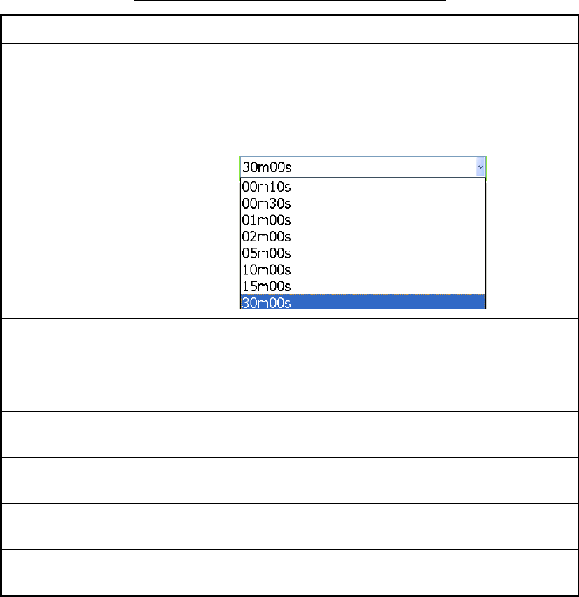
COG Vector Time If the COG vector is active, set the length of the vector, from the
choices below. It can be valuable to extend the vector length to
evaluate the risk of collision with any target.
Heading Line
Display
The heading line is a straight line extending from your position in
direction of heading. Turn the line on or off as desired.
Chart Boundaries
Display
The chart boundary line circumscribes the boundary of a chart.
This line can be turned on or off.
LAT/LON Grid The latitude and longitude grid lines help you determine your
position on the chart. You can turn them on or off as necessary.
C-MAP as Primary
Vector Chart
Turn on this function to set C-MAP charts as primary vector chart.
Popup Information Enable or disable popup information when the cursor is put on an
object (chart object, tide marker, etc.)
Auto Shift Speed Set the speed at which own ship position is shifted on the screen
70% in opposite direction of travel.
Chapter 2: Chart Plotter Operation
2-12
2.12 Points
About Points
In navigation terminology, a point is a particular location on a voyage whether it be a
starting, intermediate or destination point. A point is the simplest piece of information
your equipment requires to get you to a destination, in the shortest distance possible.
You can use points to mark good fishing spots, reference points, origin point, etc.
This unit has 2,000 points into which you can enter position information. There are
several ways you can enter a point:
• At own ship position
• At cursor position
• From the Points list
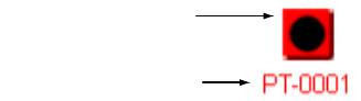
When you enter a point it is placed on the screen with the default point symbol and the
youngest empty point number. Its position, symbol, navigation information (range,
bearing, etc.) are saved to the Points list. In the default set up all points are displayed
on the screen.
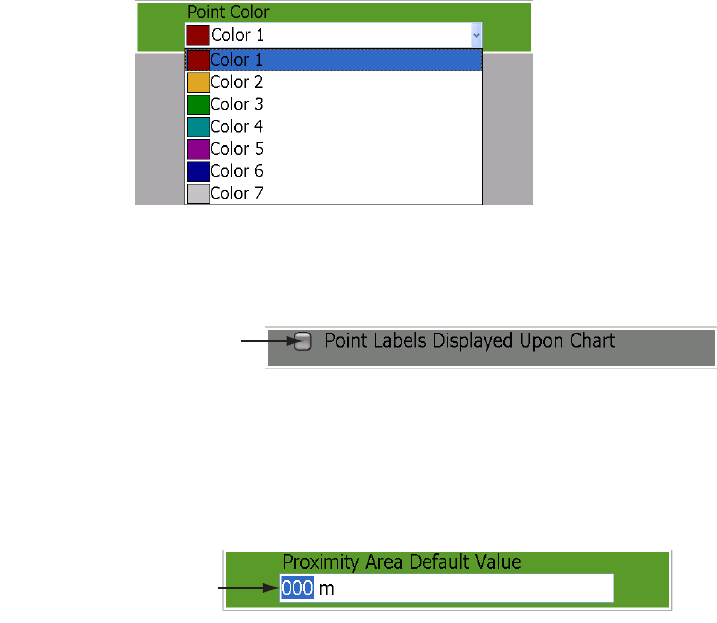
When it is necessary to edit a point you can select it directly on the screen or go to the
Points list and select it there. You can change the symbol and its color, change posi-
tion, add a comment, etc.
Entering a Point
Entering a point at own ship position
Press the SAVE/MOB key to enter a point at own ship position. The point symbol is
placed at current position, the point is saved to the Points list and tagged with the
youngest empty point number.
Entering a point at cursor position
Use the Cursorpad to put the cursor on the location where you want to enter a point.
Press the POINTS/ROUTE key. The point symbol is placed at cursor position, the
point is saved to the Points list and tagged with the youngest empty point number.
Point number
Default point symbol
(black circle in red square)
Chapter 2: Chart Plotter Operation
2-13
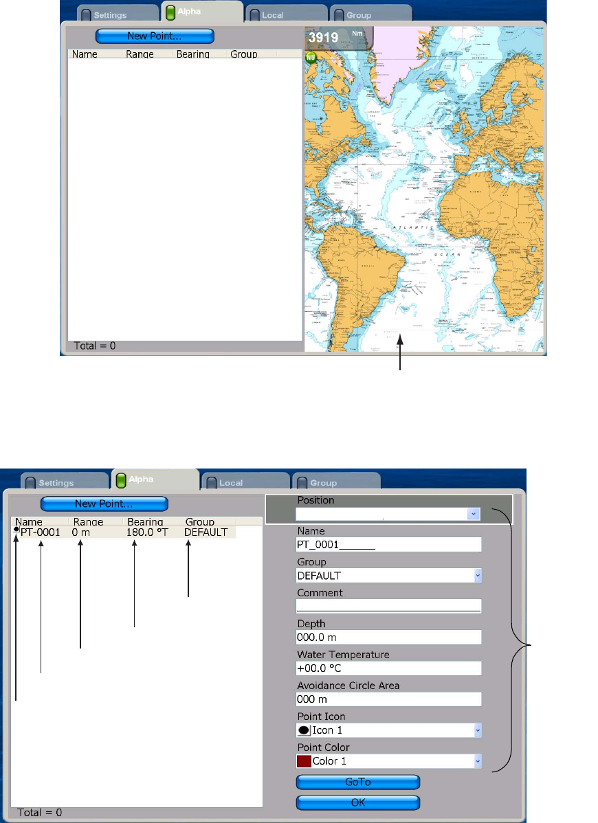
Entering a point from the Points list
Points may also be entered manually from the Points list. Use this method when you
require precise placement of point. Note that the list can also be displayed by using
the ROTOkeys or opening the Points menu.
1. Long-push the GO TO/LIST key to show the Alpha list.
2. The cursor is selecting New Point. Push the Rotary Knob, and a point is entered at
current position.The menu is now split in halves, Points list on the left and point
attributes and details for the just-entered point on the right.
Your chart appears here
Waypoint name, range and bearing
to waypoint and waypoint group name
appear here.
WPT symbol
WPT name
Range to WPT
Bearing to WPT
WPT group
01
°
12.9158'S; 000
°
30.9755'W
Waypoint
attributes
and details
Chapter 2: Chart Plotter Operation
2-14
3. The cursor is selecting the Position combo box on the right half of the display. If
you don’t need to change the position, go to step 7 to finish. To change position,
push the Rotary Knob and do the following:
1)Rotate the Rotary Knob to display latitude degree desired and push the Rotary
Knob.
2)Push the Rotary Knob and the cursor jumps to latitude minutes thousandths/
hundreds place. Rotate the Rotary Knob to display desired value and then
push it.
3)The cursor is now selecting the latitude minutes tens/ones place. Push the
Rotary Knob. Rotate the Rotary Knob to display desired value and then push it.
4)The cursor is on the position coordinate, N or S. Rotate the Rotary Knob to
switch coordinate to N or S or vice versa and then push it.
5)The cursor is now on the longitude field. Use the Rotary Knob to enter longi-
tude, similar to how you entered latitude.
4. Rotate the Rotary Knob to choose the OK button and then push it.
Don’t worry about the other items in the menu at this time. You will learn about them
in a later section.
Following a Point
You can follow (goto) a point which you have entered, or go to the cursor position. The
point can be selected on the screen or from the Points list. Once the point has been
selected you can
• Restart cross-track error (XTE) indication
• Follow route either forward or reverse
• Stop and restart Go To
Before attempting to follow a point, you should first check that the path along the way
is safe. Be sure to zoom your chart to check for hazards which might not appear on a
smaller scale.
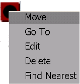
Selecting the point on-screen
1. Use the Cursorpad to select the point you which to follow.
2. Push the right-button key to show the Points pop-up menu.
3. Rotate the Rotary Knob to select Go To and push the Rotary
Knob.
Chapter 2: Chart Plotter Operation
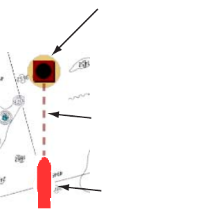
2-15
The presentation mode is automatically selected to Course-up and a red dashed line
runs between current position and the point. This line is the course to follow to get to
the point.
Go to point
Boat icon
(current position)
Course to follow
(red and dashed)
Chapter 2: Chart Plotter Operation
2-16
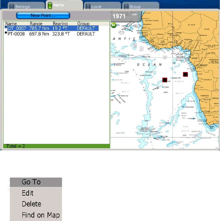
Selecting the point from the Points list
1. Long-push the GO TO/LIST key to open the Alpha list.
2. Rotate the Rotary Knob to choose a point and push the Rotary Knob. The Points
pop-up menu appears.
3. The cursor is selecting Go To; push the Rotary Knob.
After selecting the point, the menu is erased. The presentation mode is automatically
selected to Course-up. A red dashed line runs between current position and the point.
This line is the course to follow to get to the point.
Going to cursor position
Place the cursor on the location where you want to go. Press the GO TO/LIST key.
The presentation mode is automatically selected to Course-up. A red dashed line runs
between current position and the point. This line is the course to follow to get to the
point.
Chapter 2: Chart Plotter Operation
2-17
Point Follow Options
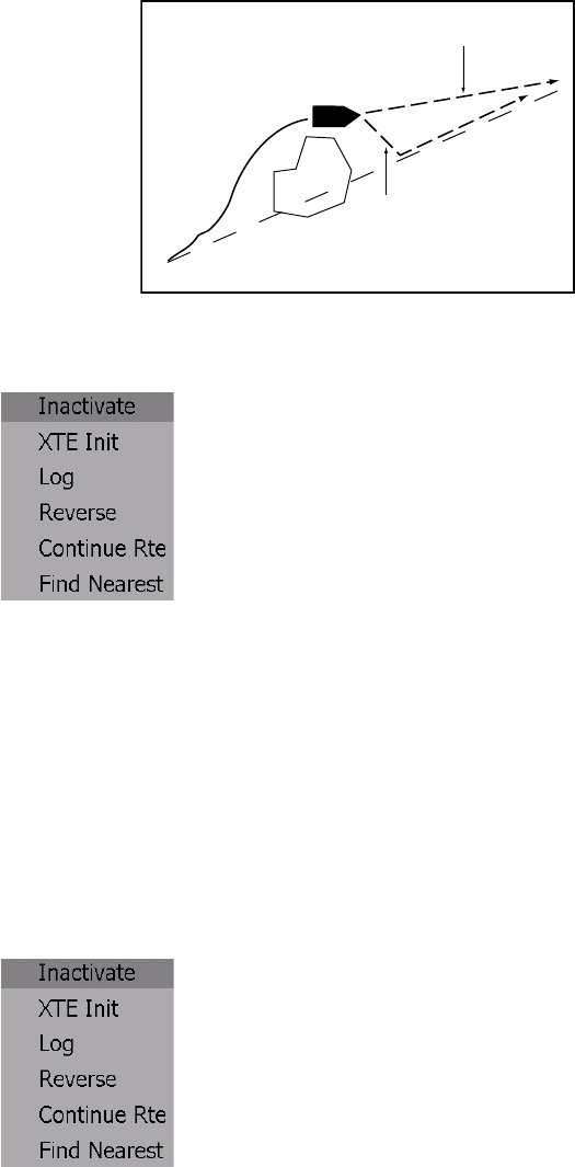
Restarting XTE
While you are following a point, you can restart the XTE. This will reset the XTE to zero
and restart XTE from actual position.
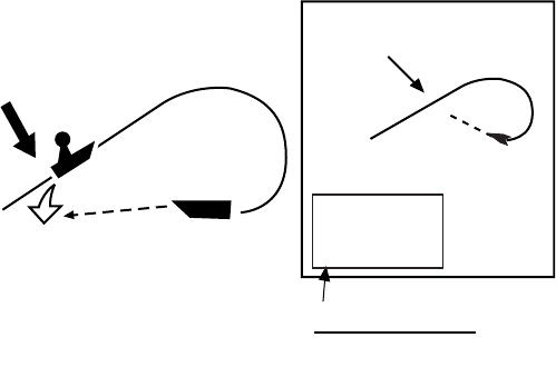
When you steer to avoid an obstacle or the vessel drifts, you may go off your intended
course, as in Line 1 in the figure below. If you don't need to return to the original
course, you can go directly to point, as in Line 2 in the figure below.
1. Put the cursor on the red dashed line and push the right-button key to show the
Points pop-up menu.
2. Rotate the Rotary Knob to choose XTE Init and push the Rotary Knob.
The route origin shifts to current position and XTE becomes zero. (You can also restart
XTE by selecting the Points and XTE ROTOkeys.)
Reversing following direction
The current point can be followed in reverse. This is useful when you have decided
not to go to a point and return to point of origin via the same path.
1. Put the cursor on the dashed red line.
2. Hit the right-button key to show the Points pop-up menu.
3. Rotate the Rotary Knob to choose Reverse and push the Rotary Knob.
You can also reverse following direction by selecting the Points and Reverse ROTOk-
eys.
Original course
Obstacle Line 1
Line 2