Furuno USA 9ZWRTR093 marine radar User Manual
Furuno USA Inc marine radar
Contents
- 1. user manual part 1
- 2. user manual part 1a
- 3. user manual part 2
- 4. user manual part 3
user manual part 3
4-1
Chapter 4: ARPA Operation
This Automatic Radar Plotting Aid (ARPA) tracks the movement of up to 30 radar tar-
gets. Targets can be acquired manually or automatically. All 30 targets can be ac-
quired manually when the ARPA acquisition area is inactive. With the acquisition area
that total is equally divided between manual and auto acquisition.
ARPA requires speed and heading data. The symbols used in this radar comply with
IEC 60872-1.
WARNING
No one navigational aid should be relied
upon for the safety of vessel and crew.
The navigator has the responsibility to
check all aids available to confirm
position. Electronic aids are not
a substitute for basic navigational
principles and common sense.
• This auto plotter automatically tracks an
automatically or manually acquired radar
target and calculates its course and
speed, indicating them by a vector. Since
the data generated by the auto plotter
are based on what radar targets are
selected, the radar must always be
optimally tuned for use with the auto
plotter, to ensure required targets will not
be lost or unwanted targets such as sea
returns and noise will not be acquired
and tracked.
• A target does not always mean a land-
mass, reef, ships or other surface vessels
but can imply returns from sea surface
and clutter. As the level of clutter changes
with environment, the operator should
properly adjust the A/C SEA, A/C RAIN
and GAIN controls to be sure target
echoes are not eliminated from the
radar screen.
CAUTION
The plotting accuracy and response of
this auto plotter meets IMO standards.
Tracking accuracy is affected by the
following:
• Tracking accuracy is affected by course
change. One to two minutes is required to
restore vectors to full accuracy after an
abrupt course change. (The actual
amount depends on gyrocompass
specifications.)
• The amount of tracking delay is inversely
proportional to the relative speed of the
target. Delay is on the order of 15–30
seconds for high relative speed; 30–60
seconds for low relative speed.
Display accuracy is affected by the
following:
• Echo intensity
• Radar transmission pulsewidth
• Radar bearing error
• Gyrocompass error
• Course change (own ship or target)

Chapter 4: ARPA Operation
4-2
4.1 Enabling, Disabling ARPA
1. On the Chart Plotter or Radar display, long-push the Rotary Knob.
2. Select the Targets ROTOkey and push the Rotary Knob.
3. Select the ARPA ROTOkey.
4. Push the Rotary Knob to alternately enable and disable the ARPA display.
4.2 Manually Acquiring a Target
1. Use the Cursorpad to put the cursor on the target you want to acquire.
2. Press the right-button key to show the Radar pop-up menu.
3. Select Acquire Target and push the Rotary Knob.
A target just acquired is marked with a broken square and a vector appears within 20
scans of the antenna to indicate the target's motion trend. Within 60 scans, the initial
tracking stage is finished and the target becomes ready for stable tracking. At this
point, the broken square mark changes to a solid circle. (Targets automatically ac-
quired are distinguished from those acquired manually. The targets which are ac-
quired manually are displayed by bold symbol.)
Note 1: For successful acquisition, the target to be acquired should be within 0.2 to
32 nm from own ship and not obscured by sea or rain clutter.
Note 2: When the capacity for manual acquisition is reached, an appropriate message
appears in the text message area. Cancel tracking of non-threatening targets if you
wish to acquire additional targets manually.
Note 3: Acquisition is also possible with the ROTOkeys. Select the target to acquire,
long-push the Rotary Knob, choose the Target ROTOkey followed by the Acquire RO-
TOkey.
4.3 Clearing a Lost Target
On the radar or chart plotter display, place the cursor on the lost target and select the
ROTOkeys Target and Clear Lost.
ARPA
Symbol Meaning
Immediately after acquisition.
Within 20 scans of the antenna after acquisition, a vector appears to show a trend
of movement.
Within 60 scans of the antenna after acquisition, the plotting symbol changes to a
small circle, indicating steady-state tracking condition.
Lost target is indicated by flashing diamond symbol. The diamond is formed from
two equal triangles.
(flashing)
Chapter 4: ARPA Operation
4-3
4.4 Cancelling Tracking of Targets
ARPA targets can be cancelled individually or collectively as shown below. All targets
can also be cancelled from the Radar pop-up menu.
1. For cancelling individual target, use the Cursorpad to put the cursor on the tar-
get you want to cancel tracking.
2. Long-push the Rotary Knob.
3. Select the Targets ROTOkey and push the Rotary Knob.
4. Select the Cancel or Cancel All ROTOkey as applicable and push the Rotary
Knob.
Tracking is cancelled and targets are erased from the screen.
4.5 CPA/TCPA Alarm
The CPA/TCPA alarm is useful for alerting to possible collision situations. With the
alarm active, the ARPA continuously monitors the predicted range at the Closest Point
of Approach (CPA) and predicted time to CPA (TCPA) of each tracked target to own
ship. When the predicted CPA of any target becomes smaller than a preset CPA alarm
range and its predicted TCPA less than a preset TCPA alarm limit, the buzzer sounds
and an appropriate text message appears. In addition, the ARPA symbol changes to
a triangle and flashes together with its vector.
Provided that this feature is used correctly, it will help prevent the risk of collision by
alerting you to threatening targets. However, it is important that gain, sea and rain con-
trols are properly adjusted.
CPA/TCPA alarm ranges must be set up properly taking into consideration the size,
tonnage, speed, turning performance and other characteristics of own ship.
Setting the CPA/TCPA Alarm
1. Press the MENU key to open the menu.
2. Select the Radar sub menu.
3. Select CPA/TCPA Alarm.
4. Push the Rotary Knob to show the status box in green to activate the CPA/TCPA
alarm.
5. Set CPA and TPCA values at CPA Alarm Value and TCPA Alarm Value.
6. Press the MENU key to close the menu.
Acknowledging the CPA/TCPA Alarm
The CPA/TCPA alarm sounds when the CPA and/or TCPA of an ARPA target is within
the CPA/TCPA alarm range. To acknowledge and silence the CPA/TCPA alarm,
press the CANCEL key. The audio alarm is silenced and the symbol stops flashing.
Disabling the CPA/TCPA Alarm
Show the status box of CPA/TCPA Alarm in gray to disable the alarm. (See "Setting
the CPA/TCPA Alarm" above for the procedure.)
Chapter 4: ARPA Operation
4-4
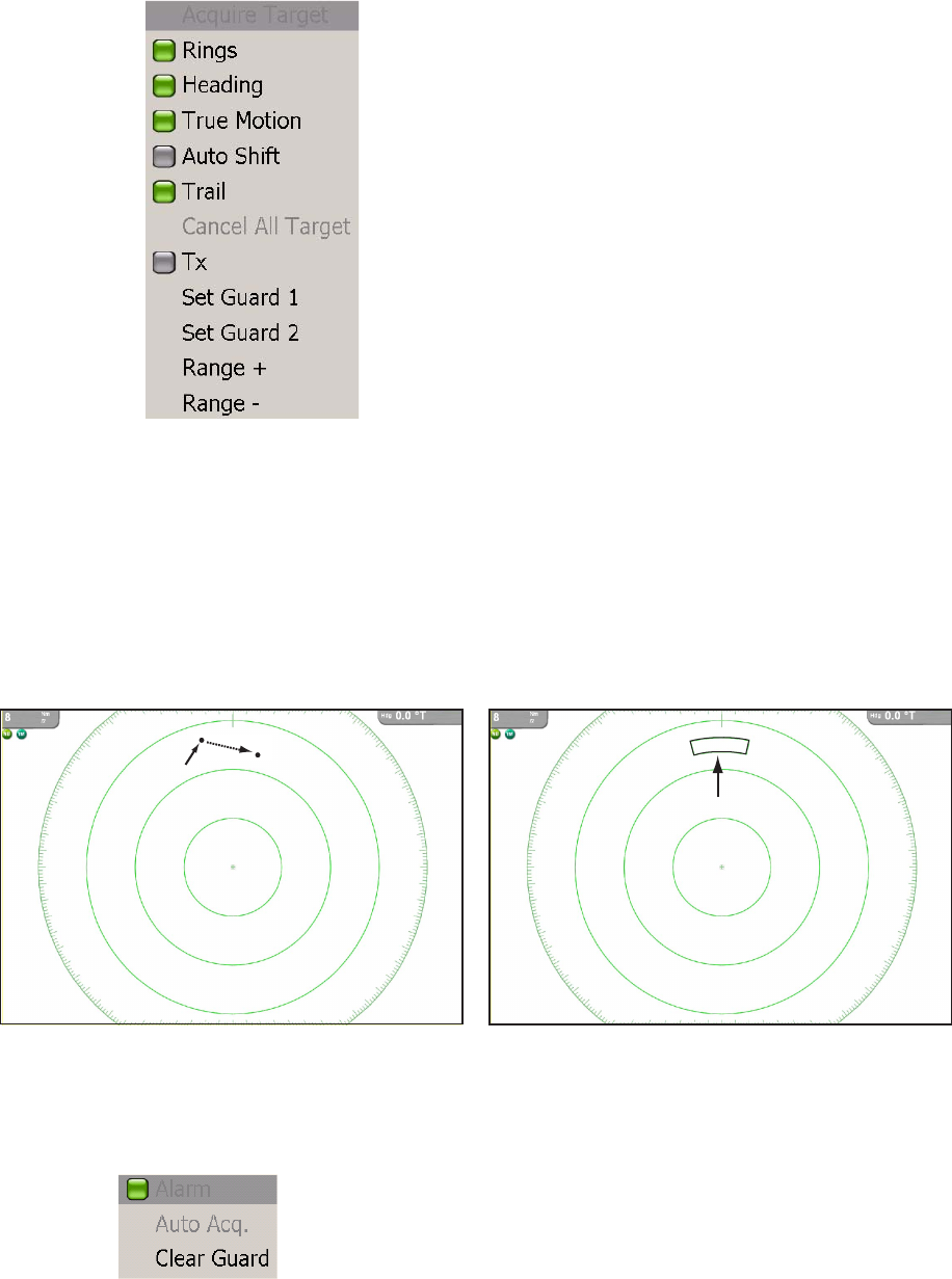
4.6 Setting ARPA Acquisition Area
Any target entering the ARPA acquisition area will be automatically acquired and
tracked. When a target transits the area, the buzzer sounds and the target causing the
warning is clearly indicated with an inverted flashing triangle. You can silence the
buzzer with the CANCEL key.
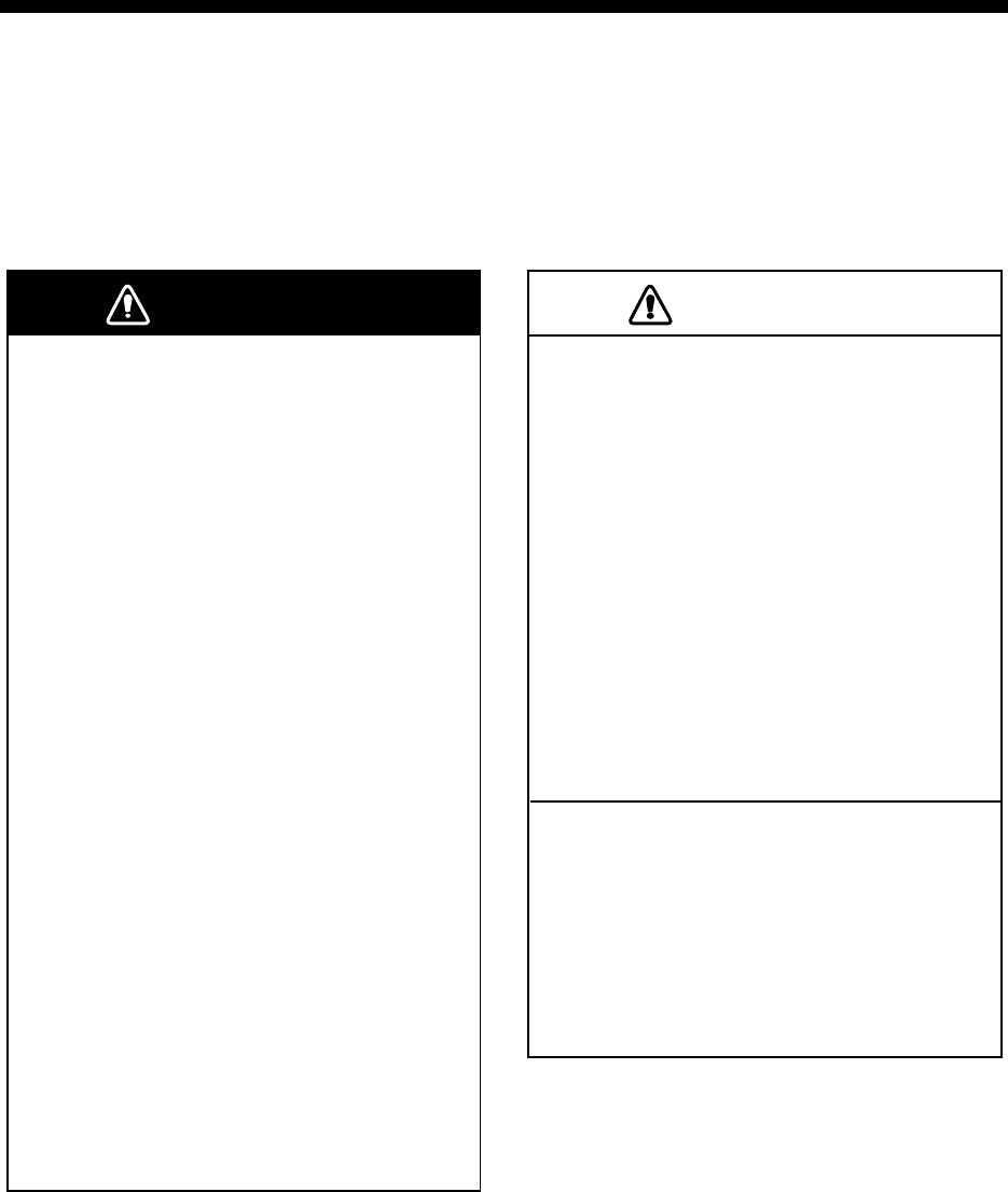
1. On the radar display, push the right-button key to show the Radar pop-up menu.
2. Rotate the Rotary Knob to choose Set Guard 1 or Set Guard 2, whichever you
want to set, and push the Rotary Knob. The point placement cursor appears at
cursor location.
3. Use the Cursorpad to put the point placement cursor at the top left corner for the
guard zone (Point A below).
4. Press the left-button key in the center of the Cursorpad.
5. Use the Cursorpad to drag the point placement cursor to the bottom right corner
(Point B below) for the guard zone and push the left-button key.
To erase the guard zone (and return to full manual acquisition), put the cursor on
a line of the guard zone and push the right-button key to show the Guard Zone pop-
up. (The line becomes thicker if correctly selected.) Rotate the Rotary Knob to choose
Clear Guard and push the Rotary Knob.
Point A
Point B
Drag cursor to Point B
Acquisition Area

Chapter 4: ARPA Operation
4-5
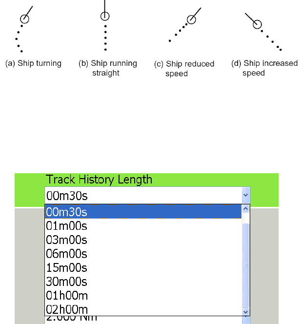
4.7 Track History Display
This ARPA can mark the past positions of any targets being tracked, with equally time-
spaced dots.
A new dot is added every minute (or at other preset time intervals) until the preset
number is reached. If a target changes its speed, the spacing between dots will be un-
even. If a target changes its course, its plotted course will not be a straight line.
Selecting Track History Plotting Interval
1. Press the MENU key to open the menu.
2. Open the Targets menu.
3. Select Track History Length and push the Rotary Knob.
4. Rotate the Rotary Knob to select plot interval desired.
5. Press the MENU key to close the menu.
Showing, Hiding the Track History Display
On the radar display or the chart plotter display, long-push the Rotary Knob to show
the ROTOkeys. Choose the Targets ROTOkey followed by the Track ROTOkey. Push
the Rotary Knob to alternately show and hide the track history display.
Chapter 4: ARPA Operation
4-6
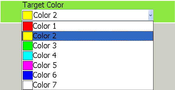
4.8 ARPA Symbol Color
The color of the ARPA symbol is available in yellow, red, green, light-blue, purple,
blue, and white.
1. Press the MENU key to open the menu.
2. Open the Targets menu.
3. Select Target Color and push the Rotary Knob.
4. Select color desired and push the Rotary Knob.
5. Press the MENU key to close the menu.
5-1
Chapter 5: AIS Operation
An AIS transponder uses VHF frequencies, and broadcasts your own vessel's posi-
tion, name, callsign, along with detailed parameters like length, beam, draft, and ton-
nage. It also broadcasts details of the current navigation system: speed, course, rate
of turn, destination, and ETA. The transponder receives this same information from
other ships, and displays it on radar and chart plotter displays. The positions and in-
tentions of nearby vessels are available to you unambiguously and in real time.
5.1 Enabling, Disabling AIS
1. Long-push the Rotary Knob to show the ROTOkeys.
2. Select the Targets ROTOkey and push the RotaryKnob.
3. Select AIS and push the Rotary Knob to alternately turn the AIS function on and
off.
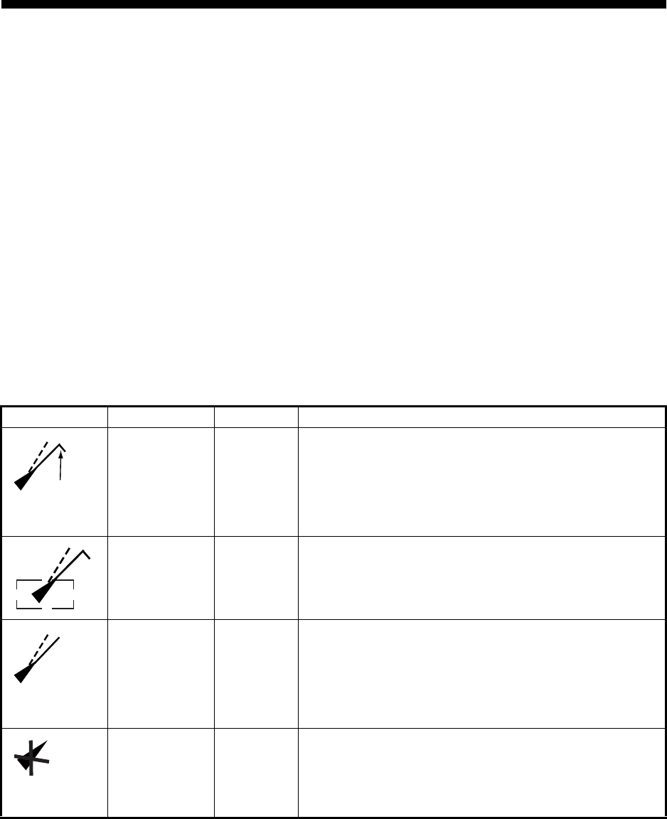
5.2 AIS Target Symbols
Symbol Target type Color Description
Activated
target w/ROT
line
Blue Heading is shown with a solid line extending from the
tip of the triangle. COG is shown with a broken line
extending from the center of the triangle. The ROT line
appears when a target's ROT is more than 10
degrees/min.
Ta rge t
selected Blue A target selected to display its data is marked with a
broken rectangle.
Dangerous
target Red An AIS target whose CPA and TCPA are less than
those values set on the CPA Settings dialog box or the
proximity alarm range is considered a dangerous tar-
get, on collision course with own ship. A dangerous
target is colored pink when selected to find its data.
Lost target Black or
white
If no signal is received from an AIS target for 10
minutes it is declared a lost target. If no signal is
received for another 10 minutes the lost target
symbol is automatically erased.
ROT line
Chapter 5: AIS Operation
5-2
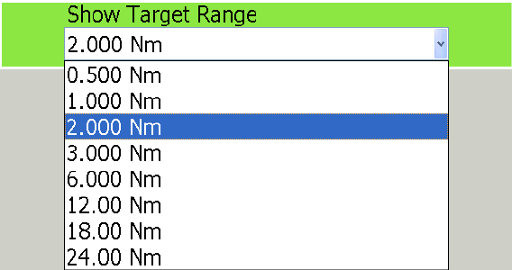
5.3 Setting Acquisition Range
In the default setting, all AIS targets within VHF range from your boat are shown on
the display. If the screen becomes too cluttered with AIS targets, you may wish to set
an acquisition range in order lessen the number of AIS targets on the screen. Only
those targets within the range selected will be monitored.
1. Press the MENU key to open the menu.
2. Open the Targets menu.
3. Select Show Target Range and push the RotaryKnob.
4. Select a range and push the Rotary Knob.
5. Press the MENU key to close the menu.
Chapter 5: AIS Operation
5-3
5.4 Track History Display
This AIS can mark the past positions of any targets being tracked, with equally time-
spaced dots.
A new dot is added every minute (or at other preset time intervals) until the preset
number is reached. If a target changes its speed, the spacing between dots will be un-
even. If a target changes its course, its plotted course will not be a straight line.
Selecting Track History Plotting Interval
1. Press the MENU key to open the menu.
2. Open the Targets menu.
3. Select Track History Length and push the RotaryKnob.
4. Rotate the Rotary Knob to select plot interval desired.
5. Press the MENU key to close the menu.
Showing, Hiding the Track History Display
On the radar display or the chart plotter display, long-push the Rotary Knob to show
the ROTOkeys. Choose the Targets ROTOkey followed by the Track ROTOkey. Push
the Rotary Knob to alternately show and hide the track history display.
Chapter 5: AIS Operation
5-4
5.5 Showing, Hiding Target ID
The MMSI no. of an AIS target can be shown or hidden on the display.
1. Press the MENU key to open the menu.
2. Open the Targets menu.
3. Select DIsplay Target IDs.
4. Push the Rotary Knob to alternately show and hide the target IDs.
5. Press the MENU key to close the menu.

6-1
Chapter 6: Card Operations
This chapter covers how to use SD cards to save and load data, and how to manage
your chart cards. Topics include
• Save tracks, routes and points
• Load tracks, routes and points
• Save user setup
• Load user setup
• Manage chart catalog
• Delete files
• Move files, and
• Request and load update files
6.1 Compatible SD Cards
The manufacturer and model of compatible SD cards are listed in the table below
xxx: Capacity of card
Compatible SD cards
Make Model Capacity
SANDISK SDSDB-xxx-J60 256 MB, 512 MB, 1 GB, 2GB
DSDH-xxx-903 512 MB, 1 GB, 2GB
Panasonic RP-SDRxxxJ1A/
RP-SDKxxxJ1A
512 MB, 1 GB, 2 GB
RP-SDxxxBL1A 256 MB
Lexar: SDxxx-231 256 MB, 512 MB, 1 GB
PQI QSDS-xxx 256 MB, 512 MB, 1 GB, 2 GB
Kingston SD/xxxFE 256 MB, 512 MB, 1 GB, 2 GB
I/O DATA SD-xxx 128 MB, 256 MB, 512 MB, 1 GB, 2 GB
SDP-xxx 256 MB, 512 MB, 1 GB, 2 GB
HAGIWARA
SYS-COM
PC-SDxxxM 256 MB
PC-SDxxxTP 256 MB, 512 MB, 1 GB
HPC-SDxxxM2 128 MB, 1 GB, 2GB
HPC-SDxxxT 128 MB, 256 MB, 512 MB, 1 GB, 2 GB
BUFFALO RSDC-Sxxx 32 MB, 64 MB, 128 MB, 256 MB, 512 MB, 1 GB, 2 GB
RSDC-Gxxx 512 MB, 1 GB, 2 GB
Chapter 6: Card Operations
6-2
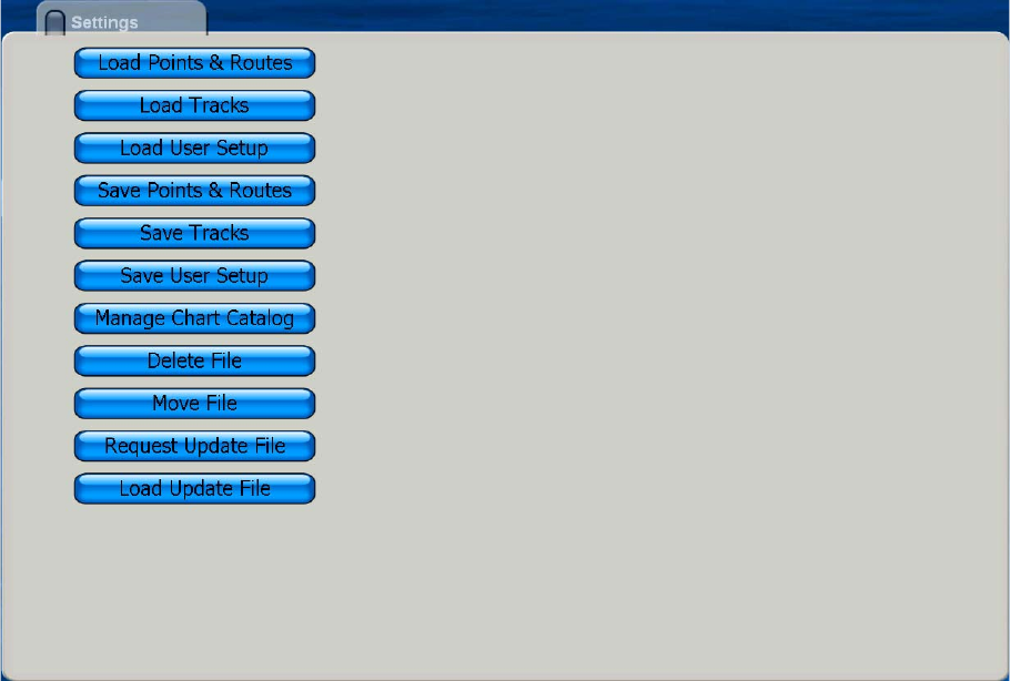
6.2 Saving and Loading Data
The Save & Load menu is where all phases of saving and loading are done. To display
the Save & Load menu, do the following:
1. Press the MENU key to open the menu.
2. Rotate the Rotary Knob to choose Save & Load and push the Rotary Knob.
Saving Data
Save Points & Routes
This unit holds 2,000 points and 200 routes in its hard disk. When the capacity for
points or routes is reached, a new point or route cannot be entered unless an unnec-
essary one is erased. For those reasons, you may wish to save points and routes to
an SD card. Select Save Points & Routes from the Save and Load menu to save points
and routes. Follow the on-screen instructions.
Save Tracks
The hard disk of this unit holds 12,000 points of tracks. When that total is reached, the
oldest track is deleted to make room for the latest. If you require the track save it to an
SD card. Select Save Tracks and follow the on-screen instructions.
Chapter 6: Card Operations
6-3
Save User Setup
The user setup feature stores all user-set menu options. It may be useful to have sev-
eral different sets of user setups to set up the system according to expected usage.
For example, you may want to have a user setup with settings suited to fishing and
one for cruising. Select Save User Setup and follow the on-screen instructions.
Loading Data
Load Points and Routes
Use the Load Points and Routes function to load points and routes saved to an SD
card. Points and routes loaded from an SD card are displayed together with current
points and routes. In case of identical names, the point or route data is written over
with the matching data on the SD card. Select Load Points & Routes and follow the
on-screen instructions.
Load Tracks
You can load past tracks on the display. This is useful when you want to created a
route using past tracks. Select Load Tracks and follow the on-screen instructions.
Load User Setup
Select Load User Setup to load user settings into the HD. The current user settings
are written over. Select Load User Setup and follow the on-screen instructions.
Deleting Files
Select Delete File and follow on-screen instructions to delete files.
Moving Files
Select Move File to copy MP3 files, etc.
Manage Chart Catalog
Use this feature to delete and transfer (to SD card) the charts stored on the hard disk.
Request Update File
This feature requests the application version nos. of all NavNet equipment in the Nav-
Net network.
Load Update File
Select this item to update all NavNet applications in the NavNet network.
Chapter 6: Card Operations
6-4
This page is intentionally left blank.

7-1
Chapter 7: Customizing Your Unit
After you have become familiar with your equipment’s basic operating procedures,
you will need to
• set it up according to equipment connected to it, and
• tailor how it operates and displays information
All tailoring is done from the menu, which is opened and closed with the MENU key.
Once you have set the values, they are retained in the processor, even when the sys-
tem is powered off. If you decide to return to default settings, a convenient, "Set De-
fault" button is provided on each sub menu to quickly restore all default settings for the
the selected sub menu.
A few of the items which you can customize are
• ROTOkeys
• NavData boxes
• units of measurement
• general settings
• system settings, and
• chart display

Chapter 7: Customizing Your Unit
7-2
7.1 ROTOkeys
The user can select how many ROTOkeys to make available with the Rotary Knob.
Three pre-set amounts are available: basic, standard and full. A custom setting is also
available, and it allows you to select the ROTOkeys to make available.
The ROTOkeys available with the basic, standard and full sets in the chart plotter and
radar modes are shown in the tables on the next several pages.
Chart plotter ROTOkey description and ROTOkey availability
Basic Standard Full Title Level 1 Function
Yes Yes Yes North-Up
North-up/Course-
up/Head-up
Presentation mode selection
Yes Yes Yes Course Up
Yes Yes Yes Head Up
No No Yes Auto Shift Autoshift on/off
No Yes Yes 3D 3D 3D/2D display selection
No Yes Yes 2D 2D view
No Yes Yes 3D Mariner Mariner 3D view
No No Yes 3D Custom last user "oriented" view
No No Yes Orientation 3D display orientation tool
Yes Yes Yes Track Show/hide track
No Yes Yes Radar Radar Overlay
on/off
No Yes Yes Rings Show/hide
range rings
No No Yes Targets ARPA/AIS
No No Yes ARPA Show/hide ARPA display.
No No Yes AIS Show/hide AIS display.
No No Yes Track Show/hide track history display.
No No Yes Acquire Acquire target for ARPA.
No No Yes Cancel
Cancel tracking on selected ARPA target.
No No Yes Cancel All
Cancel tracking on all ARPA targets.
No No Yes Clear Lost Clear lost ARPA target.
No Yes Yes Points
Point processing
No Yes Yes List Show Points list.
No Yes Yes Create Enter a point.
No No Yes Points Show/hide points.
No Yes Yes Routes
Route processing
No Yes Yes New Create new route.
No Yes Yes List Show Routes list.
No Yes Yes XTE Init Restart XTE.
No Yes Yes Stop Stop following a route.
No Yes Yes Reverse Reverse route following direction.
No No Yes Routes Show/hide routes.
Yes Yes Yes Chart Chart selection
Yes Yes Yes Raster Raster chart
Yes Yes Yes Vector Vector chart
Yes Yes Yes Photo Show/hide satellite photo.
Yes Yes Yes Display
Show/hide display
No Yes Yes Shading Show/hide depth contours.
No Yes Yes Tide Show/hide tide display.
No Yes Yes Current Show/hide tidal currents.
No No Yes Weather Show/hide weather display.
No No Yes Animate Animate Animate weather/tidal current.
Yes Yes Yes Tide Tide Show/hide tide display.
No No Yes Entertain Entertain Enable/disable entertainment.
No Yes Yes Ruler Ruler tool
Measure range/bearing to a location.

Chapter 7: Customizing Your Unit
7-3
Radar ROTOkey description and ROTOkey availability
Basic Standard Full Title Level1
No Yes Yes North-Up North-up/Course-up/Head-up
No Yes Yes North Up
No Yes Yes Course Up
No Yes Yes Hea d Up
No No Yes True motion True motion on/off
No No Yes Auto Shift Autoshift on/off
Yes Yes Yes Tx Tx on/off
No No Yes Process. Radar image processing
No No Yes Int.Rej. Interference rejector on/off
No No Yes Stretch Echo stretch on/off
No No Yes Average Echo average on/off
Yes Yes Yes Rings Range rings on/off
No Yes Yes Heading Heading line on/off
No No Yes Trail Echo trail on/off
No No Yes Clear Trail Clear echo trails.
No Yes Yes EBL EBL processing
No Yes Yes EBL1 Activate EBL1.
No No Yes EBL2 Activate EBL2.
No Yes Yes Clear1 Deactivate EBL1.
No No Yes Clear2 Deactivate EBL2.
No Yes Yes VRM VRM processing
No Yes Yes VRM1 Activate VRM1.
No No Yes VRM2 Activate VRM2.
No Yes Yes Clear1 Deactivate VRM1.
No No Yes Clear2 Deactivate VRM2.
No No Yes Guard Guard Zone processing
No No Yes Zone1 Enable guard zone 1.
No No Yes Zone2 Enable guard zone 2.
No No Yes Clear1 Disable guard zone 1.
No No Yes Clear2 Disable guard zone 2.
No No Yes Watchman Enable, disable watchman.
No No Yes Targets ARPA/AIS target processing
No No Yes ARPA Show/hide ARPA display.
No No Yes AIS Show/hide AIS display.
No No Yes Track Show/hide track history display.
No No Yes Acquire Acquire target for ARPA.
No No Yes Cancel
Cancel tracking on selected ARPA target.
No No Yes Cancel All Cancel tracking on all ARPA targets.
No No Yes Clear Lost Clear lost ARPA target.
No No Yes Routes Show/hide routes.
Yes Yes Yes Tide Show/hide tide display.
No No Yes Entertain Enable, disable entertainment.
Chapter 7: Customizing Your Unit
7-4
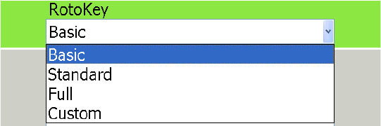
Selecting the ROTOkey Set to Use
Select the ROTOkey set to use as follows:
1. Press the MENU key to open the menu.
2. Open the Settings sub menu in the My NavNet menu.
3. Select Rotary Knob and push the Rotary Knob to display the Rotary Knob options
window.
4. Select Basic, Standard, Full or Custom as applicable and push the Rotary Knob.
(For Custom, see the next section for how to customize the ROTOkeys.)
5. Press the MENU key to close the menu.
Chapter 7: Customizing Your Unit
7-5
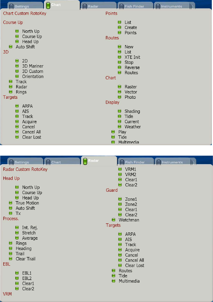
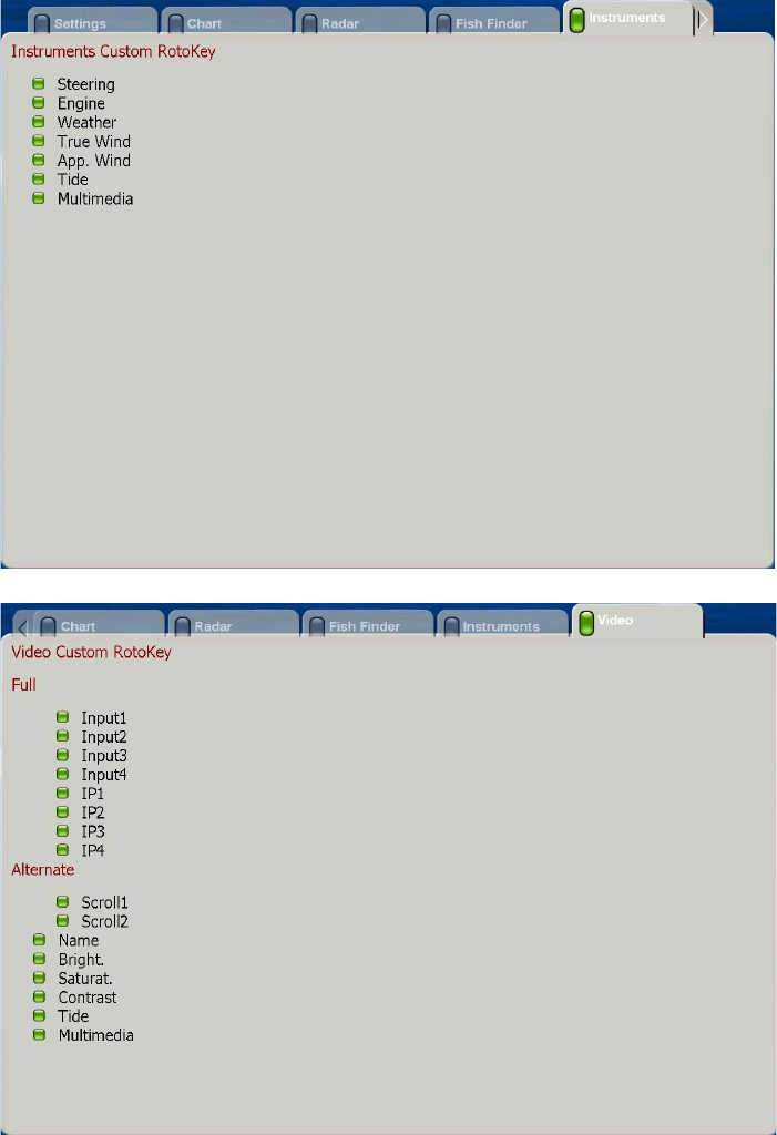
Customizing the ROTOkeys
If the basic, standard or full set of ROTOkeys is not to your liking, you can specify what
ROTOkeys to use, on the My NavNet menu.
1. Press the MENU key to open the menu.
2. Open the Settings sub menu of the My NavNet menu.
3. Open the Chart, Radar, Instruments or Video sub menu, whichever you want to
set. (Note that Fish Finder is currently under development.)
Chapter 7: Customizing Your Unit
7-6
4. Rotate the Rotary Knob to choose item.
5. Push the Rotary Knob to alternately turn item on or off. Show the item’s status box
in green to turn it on, or gray to turn it off.
6. Press the MENU key to close the menu.
To enable the custom ROTOkeys, set Rotary Knob in the Settings sub menu of the
My NavNet to Custom.
Chapter 7: Customizing Your Unit
7-7
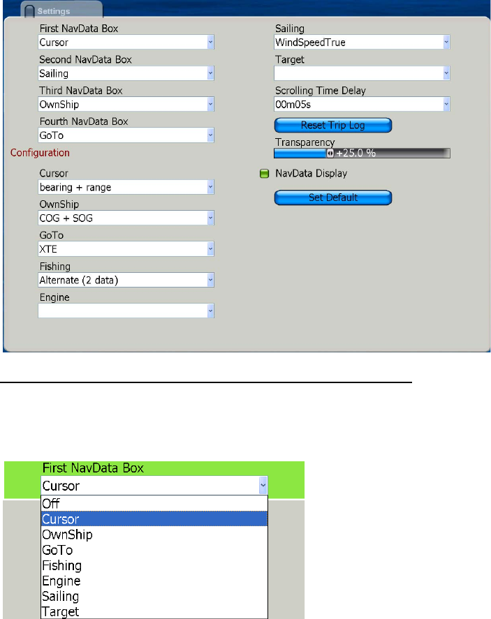
7.2 NavData Boxes
Earlier you learned how to select what data to show in the data boxes directly on-
screen. This section shows you how to further customize the boxes, from the NavData
menu.
1. Press the MENU key to open the menu.
2. Open the NavData menu.
Selecting NavData category to use for each NavData box
Select the navdata category to assign to each NavData box. The choices are cur-
sor, own ship, GoTo, Fishing, Engine, Sailing and Target
3. Use the Rotary Knob to choose FIrst NavData Box and push the Rotary Knob.
4. Select the category of NavData to use and push the Rotary Knob.
5. Set the 2nd, 3rd and 4th NavData boxes similarly.
Chapter 7: Customizing Your Unit
7-8
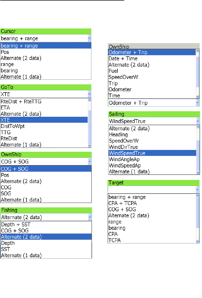
Selecting NavData for each NavData category
Select the data to go with each NavData category.
6. In the Configuration section, select Cursor, Own Ship, GoTo, Fishing, Engine, Sail-
ing and Target one by one and choose data to assign to each category.
Abbrevations key
Pos: Position
COG: Course Over Ground
CPA: Closest Point of Approach
SOG: Speed Over Ground
SST: Sea Surface Temperature
TCPA: Time to Closest Point of Approac
h
TTG: Time To Go (to a point)
Chapter 7: Customizing Your Unit
7-9
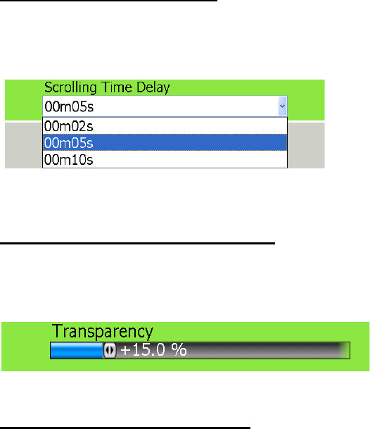
Selecting scrolling time delay
Select the amount of time to display each NavData in case of alternating data dis-
plays.
7. Select Scrolling Time Delay and push the Rotary Knob.
8. Select the amount of time to display each display in alternating displays and push
the Rotary Knob.
Selecting percentage of transparency
You can select how transparent to make the data boxes. The higher the percent-
age the greater the transparency.
9. Select Transparency and push the Rotary Knob.
10.Rotate the Rotary Knob to set the percentage desired and push the Rotary Knob.
Globally turning data boxes on/off
Data boxes can be globally turned on and off from the NavData menu, as well as
with the DATA/VOL key. Select NavData Display and push the Rotary Knob to
turn the NavData boxes on and off alternately.
Chapter 7: Customizing Your Unit
7-10
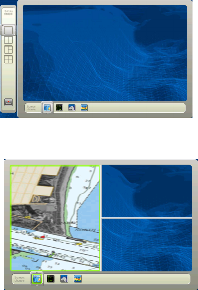
7.3 Changing Display Arrangements
The default display selection provides 10 display arrangements in various single and
combination displays. If the default arrangement is not to your liking you can change
it as follows:
1. Press the DISP key to show the display selection screen.
2. Use the Rotary Knob to select the display you want to rearrange and then long-
push the Rotary Knob.
3. Rotate the Rotary Knob to select the display split you want to use with the display
split selector at the left side of the screen and push the Rotary Knob. For example,
choose the three-split screen. Your screen should now look something like the one
below.
4. A green rectangle is circumscribing the active selection. By default the chart plot-
ter screen is selected. If you prefer a different display, rotate the Rotary Knob to
choose desired display from the choices at the bottom of the screen and push the
Rotary Knob.
Chapter 7: Customizing Your Unit
7-11
5. The green rectangle jumps to the top right 1/4 of the screen. Rotate the Rotary
Knob to select a display and then push the Rotary Knob.
Note: To switch the active screen, use the CANCEL key.
6. The green rectangle jumps to the bottom right 1/4 screen. Rotate the Rotary Knob
to choose a display and then push the Rotary Knob.
The newly arranged display appears on the screen.
Chapter 7: Customizing Your Unit
7-12
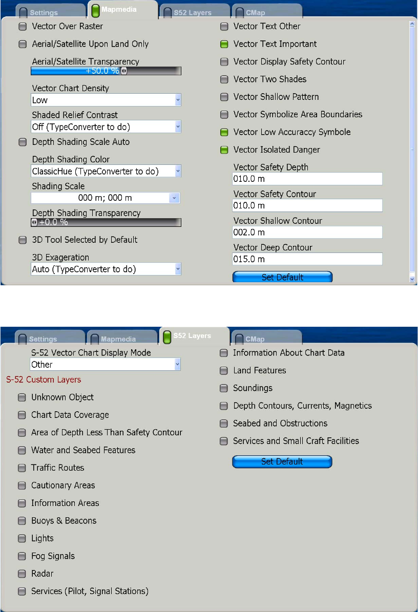
7.4 Chart Setup
Mapmedia, S52 and C-Map charts can be set up from the Chart menu. Choose appli-
cable sub menu and turn features on or off as appropriate.
Mapmedia Sub Menu
S52 Sub Menu
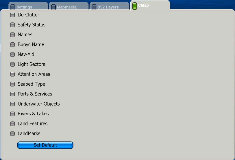
Chapter 7: Customizing Your Unit
7-13
C-Map Sub Menu
Chapter 7: Customizing Your Unit
7-14
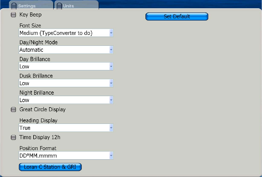
7.5 General Menu
The General menu has two sub menus for general set up of the equipment. The Set-
tings sub menu contains such items as key beep on/off, brilliance presets, time display
format, position format, etc. The Units sub menu is for selecting units of measurement
for range, depth, height, speed, etc.
Settings Sub Menu
Open the General menu and select the Settings sub menu. Set each item as desired,
referring to the description on the next page.

Chapter 7: Customizing Your Unit
7-15
Key Beep: Select to sound or not sound a beep when a key is pressed.
Font Size: Select font size for all indications, menus, etc.
Day/Night Mode: Sets the brilliance of Display Unit MCU-002 for optimum viewing in
day, night and dusk times. Automatic offers complete automatic control of brilliance.
at any time of day. Day, Dusk, Night provide control of brilliance at respective times.
Day Brilliance, Dusk Brilliance, Night Brilliance: Set the level of brilliance to use at
day, dusk and night. Effective when respective time is chosen at Day/Night Mode.
Great Circle Display: The are two methods for measuring course distances: great cir-
cle and rhumb line. Great circle is the shortest line joining two points on the earth's
surface. Rhumb line is a straight line compass course between two points. The great
circle path is short but requires you to constantly change heading.
Heading Display: The mode (magnetic or true) of all heading and bearing data.
Time Display: Turn on this item to display time in 12 hour format; turn it off to use 24
hour format.
Position Format: Choose two show position in one of two latitude and longitude for-
mats, Loran C time differences or MGRS (Military Grid Reference System).
Loran C Station and GRI: Choose the Loran C stations and GRIs from which to ob-
tain Loran C position.
General menu, settings sub menu parameters
Menu item Options Default setting
Key Beep ON, OFF Off
Font Size Small, Medium, Large Medium
Day/Night Mode Automatic, Day, Dusk,
Night, Low
Automatic
Day Brilliance Low, Medium, High Low
Dusk Brilliance Low, Medium, High Low
Night Brilliance Low, Medium, High Low
Great Circle Display ON, OFF OFF
Heading Display True, Magnetic True
Time Display 12h ON, OFF OFF
Position Format DD°MM.mmmm
DDD.dddddd
Loran-C
MGRS
DD°MM.mmmm
Loran C Station & GRI
Chapter 7: Customizing Your Unit
7-16
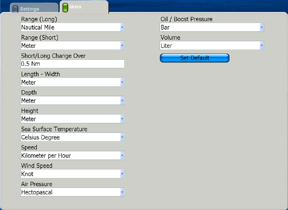
Units Sub Menu
The Units sub menu lets you choose the desired units of measurement for range,
length, depth, height, sea surface temperature, speed, wind speed, air pressure, oil /
boost pressure, and volume

Chapter 7: Customizing Your Unit
7-17
Units sub menu parameters
Menu item Options Default setting
Range (long) nautical mile, kilometer,
mile
nautical mile
Range (short) foot, meter, yard yard
Short/Long Change
OVer
feet
Length - Width foot, meter feet
Depth foot meter, fathom, passi
braza
meter
Height foot, meter feet
Sea Surface
Temperature
Celsius degree, Fahrenheit
degree
Celsius degree
Speed knot, kilometer per hour,
mile per hour, meter per
second
knot
Wind Speed knot, kilometer per hour,
mile per hour, meter per
second
knot
Air Pressure hectopascal, millibar, milli-
meter of mercury, inch of
mercury
hectopascal
Oil / Boost Pressure kilopascal, bar, pound per
square inch
kilopascal
Volume U.S. gallon, liter gallon
Chapter 7: Customizing Your Unit
7-18
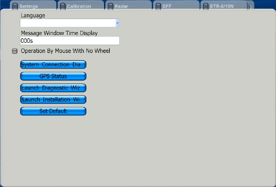
7.6 System Menu
The System menu has several sub menus for general system settings, sensor calibra-
tion, radar, fish finder (under development).
Settings Sub Menu
The Settings sub menu of the System menu provides for selection of language, mes-
sage window display time and mouse type.
Language: See section 1.2 for details.
Message Window Time Display: Set the number of seconds to leave a message
window open before it is automatically closed.
Operation By Mouse WIth No Wheel: Turns this item on if you are using a mouse
that does not have a scrollwheel.
System Connection Diagram: Display the system connection diagram.
GPS Status: Display the GPS Status screen. See chapter 8 for details.
Launch Diagnostic Wizard: Do system diagnostics. See chapter 8 for details.
Launch Installation Wizard: Launch the installation wizard to install the system.
Set Default: Restore all default settings for this sub menu.
Chapter 7: Customizing Your Unit
7-19
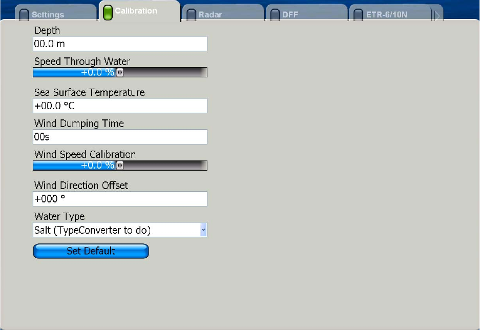
Calibration Sub Menu
The Calibration menu mainly lets you enter offsets for external sensors (speed, wind,
temperature) to show true values on the display.
Depth: Add an offset to measured depth to get actual depth. The setting range is 0-
99.9 (m).
Speed Through Water: Add an offset to measured speed to display actual speed.
The range is -50 to +50 (%).
Sea Surface Temperature: Add an offset to measured sea surface temperature to
display actual speed. The setting range is -99.9 to +99.9 (°C).
Wind Damping Time: Set wind damping time. The setting range is 0-99 (seconds).
Wind Speed Calibration: Apply an offset to measured speed to display actual wind
speed. The range of offset is -50 to +50.]
Wind Direction Offset: Add a wind direction offset to measured wind direction to cor-
rect displayed wind direction.
Water Type: Choose the type of water the vessel is used in, saltwater or freshwater.
Set Default: Restore all default settings for this sub menu.
Chapter 7: Customizing Your Unit
7-20
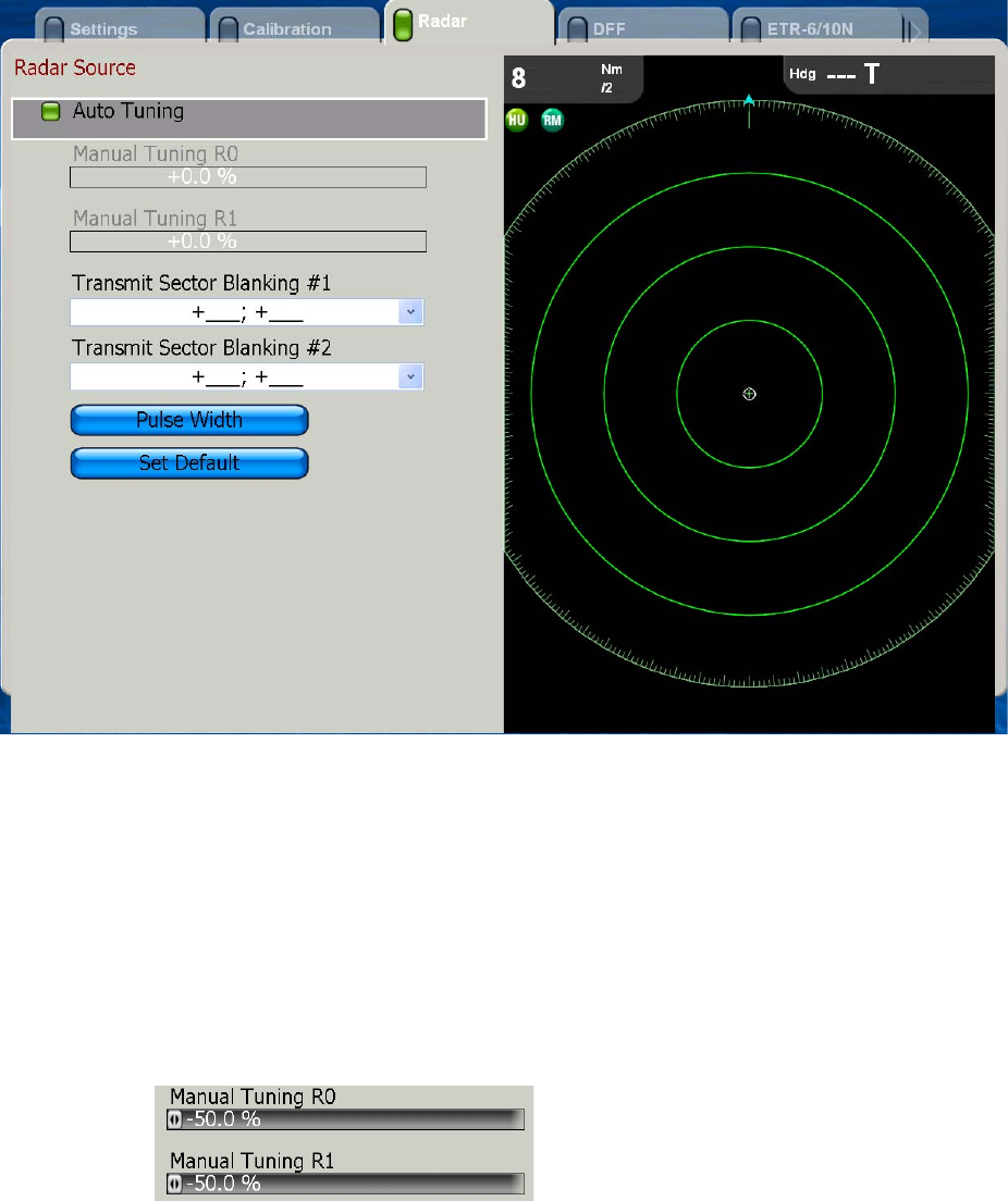
Radar Sub Menu
The radar sub menu has facilities for manual tuning, blind sector (area of no transmis-
sion) creation and pulse length selection.
Manual Tuning: If you require manual tuning, do the following:
1. Use the RANGE key to select the 48-mile range.
2. Press the MENU key to open the menu.
3. Open the System menu.
4. Open the Radar sub menu.
5. Choose Auto Tuning and push the Rotary Knob to color Auto Tuning’s status box
gray to disable automatic tuning. Then, the two manual tuning items are made
active.
6. Choose Manual Tuning R0 (range in dual range mode) or Manual Tuning R1
(range in dual range mode) as applicable and push the Rotary Knob.
7. Rotate the Rotary Knob to adjust the tuning. The range is -50 to +50(%).
8. Push the Rotary Knob to confirm the setting.
9. Press the MENU key to close the menu.
Chapter 7: Customizing Your Unit
7-21
Transmit Sector Blanking: It may be necessary to prevent the radar from transmit-
ting within a certain sector. For example, you would want to blind sector (area where
no echoes appear). To enter a blank sector, enter start bearing relative to the heading
and dead sector angle. This is usually done by the installer of the equipment. Two sec-
tors may be set. One sector should be less than 180 degrees in width and the total
width of two sectors should not exceed 270 degrees
Pulse Width: Select pulse width.
Set Default: Restore all default settings for this sub menu.
Chapter 7: Customizing Your Unit
7-22
7.7 Weather Display Setup
This section shows you how to set up the weather information display, which is avail-
able only in the United States of America. Open the Weather menu and then open ap-
propriate sub menu.
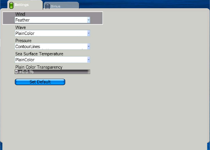
Settings Sub Menu
Wind: Display wind direction and magnitude in Plain Color or Feather. "Feather"
shows more detailed speed of winds.
Wave: Display wave height in Plain Color or Arrows. Plain Colors shows wave icons
in reds, greens and blues, in order of descending height. Arrows show height with the
arrow icon.
Pressure: Show atmospheric pressure in Plain Color or Contour Line.
Sea Surface: Show sea surface temperature in Plain Color or Contour Line.
Plain Color Transparency: Select the level of transparency for items set for Plain
Color.
Chapter 7: Customizing Your Unit
7-23
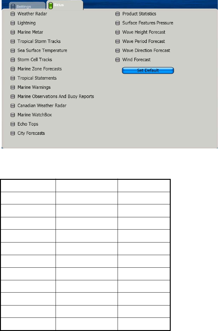
Sirius Sub Menu
The Sirius sub menu contains Sirius weather related items that can be turned on or off.
Weather Radar: Type and level of precipitation from NOWRAD (North American
Weather Radar).
Color Precipitation type Level
Light green Rain 15-19 dBZ
Medium green Rain 20-29 dBZ
Dark green Rain 30-39 dBZ
Yellow Rain 40-44 dBZ
Orange Rain 45-49 dBZ
Light red Rain 50-54 dBZ
Dark red Rain over 55 dBZ
Light blue Snow 5-19 dBZ
Dark blue Snow over 20 dBZ
Light pink Mixed 5-19 dBZ
Dark pink Mixed over 20 dBZ
Chapter 7: Customizing Your Unit
7-24
Lightning: Lighting icons show when lighting occurred, by shades of yellow. Dark yel-
low, last 0-5 min., medium yellow, last 5-10 min., weak yellow, last 10-15 min.
Marine Metar: Marine Meteorological Aviation Report.
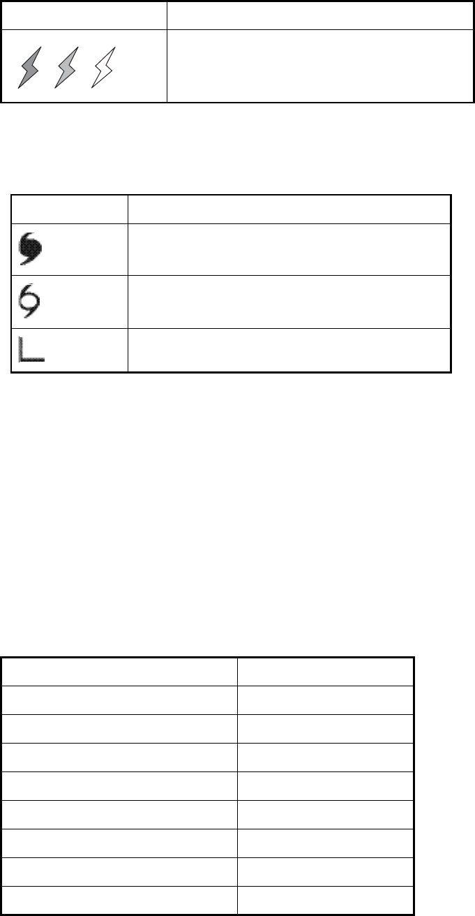
Storm Cell Tracks: Monitor remarkable storms, depressions, tropical disturbances,
hurricanes, cyclones and typhoons in your area.
Sea Surface Temperature: Sea surface temperature in shading contrasts of green,
yellow, orange and red, in order of ascending temperature.
Storm Cell Tracks: Graphical depictions of the storm attributes produced by analysis
of the radar data.
Marine Zone Forecasts: Coastal waters forecasts are subdivided by zone, each
identified by text description and a code. You can show these on the screen with lines.
Tropical Statements: Tropical storm warnings.
Marine Warnings: Marine warnings.
Marine Observations and Buoy Reports: Turn these types of reports on or off.
Canadian Weather Radar: Enable or disable Canadian weather radar service.
Marine WatchBox: Alert you when severe weather advisories are issued for you
area.
Icon Color
Dark yellow (recorded in last 0-5 min.),
Medium yellow (recorded in last 5-10 min.),
Light yellow (recorded in last 10-15 min.)
Icon Meaning
Hurricane (Category 1-5)
Tropical storm
Tropical disturbance, Tropical depression
Color Level (mm per hour)
Transparent (low precipitation) 0.00 to 0.20 mm/hr
Light green 0.21 to 1.00 mm/hr
Medium green 1.01 to 4.00 mm/hr
Dark green 4.01 to 12.00 mm/hr
Yellow 12.01 to 24.00 mm/hr
Orange 24.01 to 50.00 mm/hr
Light red 50.01 to 100 mm/hr
Dark red over 100.01 mm/hr
Chapter 7: Customizing Your Unit
7-25
Echo Tops: An echo top is the radar indicated top of an area of precipitation. Echo
tops can be used to assess the intensity of a storm. The rule of thumb is that the higher
the echo tops are in a storm then the stronger the updraft is that produced that storm.
City Forecasts: City weather forecasts.
Product Statistics: No use
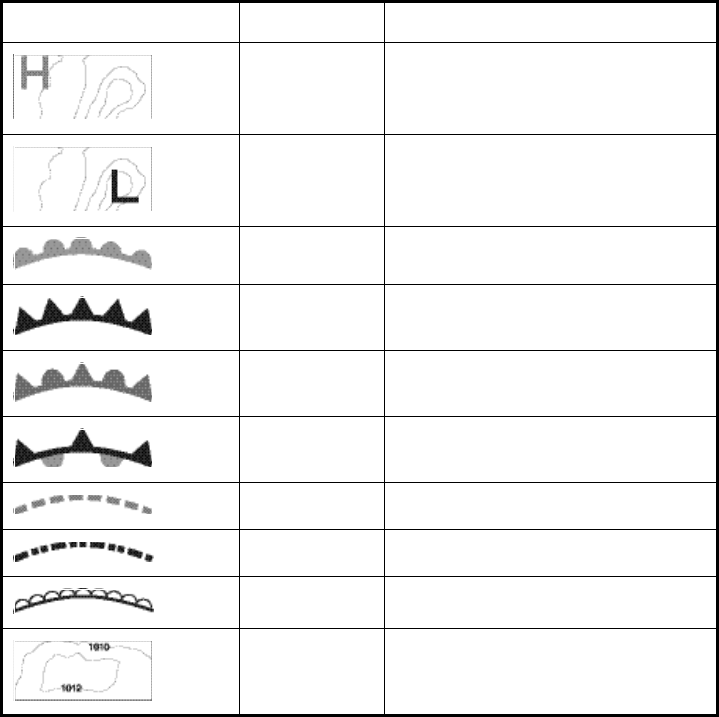
Surface Features Pressure: Show surface pressure with meteorological symbols.
Wave Height Forecast: Wave height shown in reds, greens and blues, in order of de-
scending height.
Wave Period Forecast: The time between successive waves.
Wave Direction Forecast: Wave direction over time.
WInd Forecast: Wind speed and direction over time.
Icon Color Meaning
Blue High pressure
Red Low pressure
Red Warm front
Blue Cold front
Purple Occluded front
Red-Blue Stationary front
Brown Trough
Red Squall line
Brown Dry line
Grey Isobars
Chapter 7: Customizing Your Unit
7-26
This page intentionally left blank.
8-1
Chapter 8:Maintenance,
Troubleshooting
This chapter provides information on maintenance and possible causes of problems
that you may experience.
8.1 Maintenance
Regular maintenance is necessary to maintain performance. Check the items listed in
the table below monthly to keep your unit in good working order.
Routine maintenance
Check item Check point Remedy
Cabling Check that all cabling is
securely fastened and is
free or rust and corrosion.
Reconnect if necessary. Replace if damaged.
Cabinet Dust on cabinets Remove dust with a dry clean cloth. Do not use
commercial cleaners for cleaning - they can
remove paint and markings and deform the
equipment.
LCD (For DCU12) The LCD will, in time, accu-
mulate a coating of dust
which tends to dim the pic-
ture.
Carefully wipe the LCD to prevent scratching,
using tissue paper and an LCD cleaner. To
remove dirt or salt deposits, use an LCD cleaner,
wiping slowly with tissue paper so as to dissolve
the dirt or salt. Change paper frequently so the
salt or dirt will not scratch the LCD. Do not use
commercial cleaners for cleaning - they can
remove paint and markings and deform the
equipment.
Radar antenna Foreign material on the
radar antenna can reduce
sensitivity.
Foreign material on the radar antenna can
reduce sensitivity. Clean the antenna with a
freshwater-moistened cloth. Do not use com-
mercial cleaners to clean the antenna - they can
remove paint and markings and deform the
equipment.
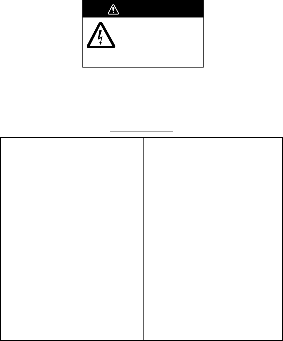
WARNING
ELECTRICAL SHOCK HAZARD
Do not open the equipment.
Only qualified personnel
should work inside the
equipment.
Chapter 8: Maintenance, Troubleshooting
8-2
8.2 Replacing Fuses
The processor unit has two fuses (10A, 24V, 20A, 12V) which protect the system from
overcurrent and equipment fault. If the power cannot be turned on a fuse may have
blown. Find out the reason for the blown fuse before replacing it. If the fuse blows
again after replacement, contact your dealer for advice.
8.3 Replacing Battery
The lithium battery on the Mother board in the processor unit backs up data when the
power is turned off. The life of the battery is about three years. When its voltage is low
the battery icon appears at the top of the display. When the icon appears, contact your
dealer to request replacement of the battery, at your earliest convenience.
8.4 Replacing the Magnetron
When the magnetron has expired, distant targets cannot be seen on the display.
When you feel that long range performance has decreased, contact a FURUNO agent
or dealer about replacement of the magnetron.
Battery ordering information
Name Type Code No.
Lithium battery CR2032 000-159-662-10
Magnetron ordering information
Radar sensor Magnetron Code No.
DRS2D E3590 000-164-574-10
DRS4D E3571 000-146-867-00
DRS4A MAF1421B 000-158-786-10
DRS6A MAF1422B 000-158-788-10
DRS12A MAF1425B 000-146-872
DRS25A MG5436(E2V) 000-140-762
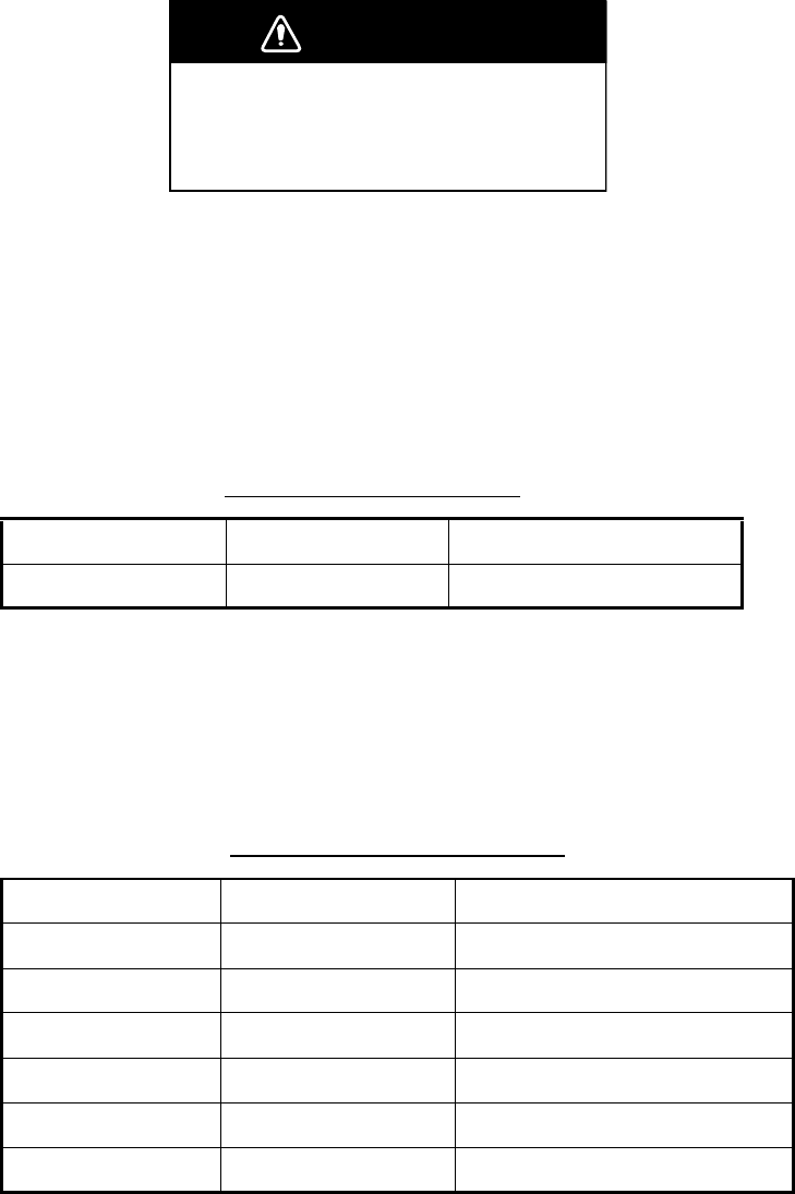
WARNING
Use the proper fuse.
Use of a wrong fuse can result in damage
to the equipment and cause fire.

Chapter 8: Maintenance, Troubleshooting
8-3
8.5 Troubleshooting
This section provides simple troubleshooting procedures that you can follow to restore
normal operation. If you cannot restore normal operation do not attempt to check in-
side the unit. Any trouble should be referred to a qualified technician.
General Troubleshooting
Radar Troubleshooting
If… Then…
you cannot turn on the power • check for blown fuse.
• check that the power connector is firmly fastened.
• check for corrosion on the power cable connector.
• check for damaged power cable.
• check battery for proper voltage output (10.8 to 31.2 V).
there is no response when a
key is pressed
turn off and on the power. If there still is no response the key may
be faulty. Request service.
If… But… Then…
you pressed the POWER
switch followed by the TX/
GAIN key to transmit
nothing appears on the dis-
play
• check that the antenna cable is
firmly fastened.
• check if radar source is correct.
marks, legends appear no echo appears • check that the antenna cable is
firmly fastened.
the picture is not updated or it
freezes
— • check antenna cable.
• for freeze up, turn the display
unit on and off again.
tuning is adjusted sensitivity is poor • magnetron may need to be
replaced. Contact your dealer.
the range is changed radar picture does not
change
• try to hit the RANGE keys again.
• turn the display unit off and on
again.
there is poor discrimination in
range
— • try to suppress sea clutter with
"Sea".
the true motion presentation
is not working properly
— • reselect true motion mode.
• check if heading and speed are
input.
the range rings are not dis-
played
— • open the Radar pop-up menu
and turn on "Rings".

Chapter 8: Maintenance, Troubleshooting
8-4
Chart Plotter Troubleshooting
8.6 Diagnostic Wizard
The diagnostic wizard facility has six diagnostic tests: Memory test, Keyboard test,
I/O test, BBGPS test, and Radar/ARPA test.
Memory Test
The memory test displays the boot and app programs and checks devices and ports
for proper operation.
If… Then…
position is not fixed within
three minutes
check that antenna connector is firmly fastened.
the track is not plotted check that track is turned on. (Put cursor on boat icon to open
pop-up and check that "In Track" is on.)
Loran C TDs do not appear check that Loran C station & GRI are properly set, on the Settings
sub menu in the General menu.
MPU-001(Mother)
Boot Program No.--
APP Program No.--
ROM : OK
RAM : OK
Port
NMEA1 : --
NMEA2 : --
NMEA3 : --
NMEA2000 : --
NETWORK : --
HDD : MHV2040AC 40GB
PCI : --
BATTRY : 4.0V
LAN MAC address :
CAN Unique Number :
MPU-001(USB-NMEA)
Boot Program No.--
APP Program No.--
ROM : OK
RAM : OK
Port
USB1 : --
USB2 : --
MCU-001(or DCU12)
Boot Program No.--
APP Program No.--
CPLD : 12345678
ROM : OK
RAM : OK
(EEPROM : OK)*
Port
NETWORK : --
SD card1 : --
SD card2 : --
LAN MAC address :
* DCU12 only

Chapter 8: Maintenance, Troubleshooting
8-5
Keyboard Test
The layout of the keyboard is replicated on-screen. Press each key one by one to
check them for proper operation. The corresponding location on the screen "lights"
when the key is pressed and goes off when the key is released. For the Rotary Knob,
rotate it to show X-Y position and push it to confirm function.
I/O Test
The I/O test checks for proper input and output of data. The result is shown as OK or
NG.
BBGPS Test
This test requires the FURUNO GPS Receiver GPS-320B. The GPS receiver program
version number is displayed, and the GPS receiver is checked for proper operation,
displaying OK or NG (No Good) as the result. For NG, request service.
Radar/ARPA Test
The ROM and RAM for the radar/ARPA are checked for proper operation. The results
are shown as OK or NG (No Good). For any NG, request service.
8.7 GPS Status Display
The GPS status display provides data about the GPS satellites. It is available with con-
nection of the GPS Receiver GP-310B/320B or a GPS navigator outputting the data
sentence GSA or GSV.
"Self test of ***"
DRS(SPU)
Boot Program No.
APP Program No.
FPGA :
ROM : OK (SPU)
RAM : OK (SPU)
Port
NMEA2000 : --
TX TIME : 000000.0h
ON TIME : 000000.0h
LAN MAC address :
CAN Unique Number :
DRS(NMEA)
Boot Program No.
APP Program No.
ROM : OK
RAM : OK
Chapter 8: Maintenance, Troubleshooting
8-6
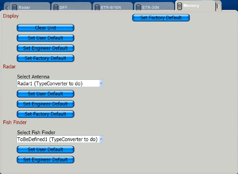
8.8 Restoring Default Settings
There are several types of default setting restorations:
•Clear unit: Clear all data - points, routes and tracks. Settings are not cleared.
•Engineer default: Restore all installer-entered settings for selected category.
•Factory default: Restore all default settings for selected category.
To restore default settings, do the following:
1. Press the MENU key to open the menu.
2. Open the System menu.
3. Open the Memory sub menu.
4. Use the Rotary Knob to select applicable item and then push the Rotary Knob.
5. Follow on-screen instructions to restore selected default type.
NavNet 3D MFDBB Series
SP-1
SPECIFICATIONS OF
MFDBB (MULTI-FUNCTION DISPLAY BLACKBOX TYPE) WITH
RADAR SENSOR (DRS2D, DRS4D, DRS4A, DRS6A, DRS12A, DRS25A)
1 PLOTTER SECTION
1.1 Projection Mercator
1.2 Usable Area 85 latitude or below
1.3 Effective Area 211.2 x 158.4 mm
1.4 Position Indication Latitude/longitude, Loran C LOP or DECCA LOP
1.5 Effective Projection Area 0.125 nm to 1,024 nm (at equatorial area)
1.6 Track Colors Red, yellow, green, purple, light-blue, blue, white
1.7 Storage Capacity Track: 12,000 points, Points: 2,000 points
Routes: 200 routes with 50 waypoints each
1.8 MOB 1 point
1.9 Electronic Chart Mapmedia, S52 layers, C-Map
1.10 Alarms Arrival, Anchor watch, XTE, Proximity, Depth,
Temperature,
Speed, Trip log, Countdown timer, Alarm clock
2 PROCESSOR UNIT MCU-001
2.1 I/O Ports NMEA 0183: 3 I/O ports, 38400 bps/4800 bps
NMEA 2000: 1 port
LAN: 4 ports (2 POE/100BASE-TX, 2 non-POE/100BASE-TX
USB: 2 ports (USB 2.0):
PIP: 2 ports (DVI)
2.2 Output Resolution 1280×1024 (SXGA)
1024×768 (XGA)
800×600 (SVGA)
3 DISPLAY CONTROL UNIT DCU012
3.1 Input 800×600 (SVGA)
3.2 Display Colors Plotter: 262,144 colors
Radar: 16 colors
3.3 Chart Card Two slots
4 CONTROL UNIT MCU-001
4.1 Chart Card Two Slots
NavNet 3D MFDBB Series
SP-2
5 RADAR SENSOR
5.1 General
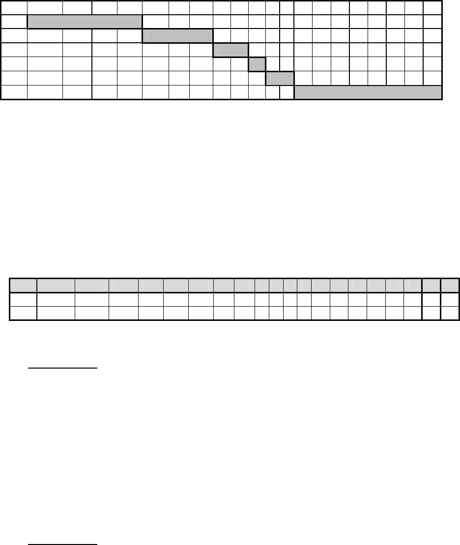
Range, Pulse length & Pulse Repetition Rate
nm 0.0625 0.125 0.25 0.5 0.75 1.0 1.5 2 3 4 6 8 12 16 24 36 48 64 72 96
S1
S2
M1
M2
M3
L
Pulse length: S1: 0.08μs, S2: 0.15μs, M1: 0.30μs, M2: 0.50μs, M3: 0.70μs, L: 0.80μs
Frequency: S1, S2: 3000 Hz, M1: 1500 Hz, M2: 1000 Hz, M3, L: 600 Hz
Max. range: See table below.
Range Resolution 20 m
Bearing Resolution DR2SD: 5.2°, DRS4D: 3.9°, DRS4A: 2.3°, DRS6A,
DRS12A, DRS25A: 1.9° (radiator XN12A),
1.4° (radiator XN13A)
Minimum Range 25 m
Bearing Accuracy ±1°
Range Ring Accuracy 1.0% of range or 8 m, whichever is the greater
Range (nm), Range Ring Interval (RI), Number of Rings (NOR)
nm 0.0625 0.125 0.25 0.5 0.75 1.0 1.5 2 346812 16 24 36 48 64 72 96
RI 0.03125 0.0625 0.125 0.25 0.25 0.25 0.5 0.5 1 1 2 2 3 4 6 12 12 16 16 24
NOR 2 2 2 2 3 4 3 4 3 4 3 4 4 4 4 3 4 4 4 4
Max. range: DRS2D: 24 nm, DRS4D: 36 nm, DRS4A: 48 nm, DRS6A, DRS12A: 64 nm, DRS25A: 96 nm
5.2 Antenna Unit
Model DRS2D
Radiator Center fed travel virtual antenna
Polarization Horizontal
Antenna Rotation Less than 2.0 nm: 48 rpm
Less than 12 nm: 36 rpm
12 nm or higher: 24 rpm
Radiator Length 46 cm
Horizontal Beamwidth 5.2°
Vertical Beamwidth 22°
Sidelobe Attenuation -25 dB or less (within ±20º of main-lobe)
-27 dB or less (±20º of main-lobe or more)
Model DRS4D
Radiator Center fed travel virtual antenna
Polarization Horizontal
Antenna Rotation Less than 2.0 nm: 48 rpm
Less than 12 nm: 36 rpm
12 nm or higher: 24 rpm
Radiator Length 60 cm

NavNet 3D MFDBB Series
SP-3
Horizontal Beamwidth 3.9°
Vertical Beamwidth 22°
Sidelobe Attenuation -25 dB or less (within ±20° of main-lobe)
-27 dB or less (±20° of main-lobe or more)
Model DRS4A
Radiator End fed travel slotted array antenna
Polarization Horizontal
Antenna Rotation Less than 1.5 nm: 48 rpm
Less than 12 nm: 36 rpm
12 nm or higher: 24 rpm
Radiator Length 100 cm (XN10A)
Horizontal Beamwidth 2.3°
Vertical Beamwidth 22°
Sidelobe Attenuation -20 dB or less (within ±10° of main-lobe)
-28 dB or less (±10° of main-lobe or more)
Model DRS6A, DRS12A, DRS25A
Radiator End fed travel slotted array antenna
Polarization Horizontal
Antenna Rotation Less than 1.5 nm: 48 rpm, Less than 12 nm: 36 rpm
12 nm or higher: 24 rpm
Radiator, Radiator Length XN12A: 120 cm, XN13A1: 130 cm
Horizontal Beamwidth XN12A: 1.9°, XN13A: 1.4°
Vertical Beamwidth 22°
Sidelobe Attenuation XN12A: -27 dB or less (within ±10° of main-lobe)
XN12A: -34 dB or less (±10° of main-lobe or more)
XN13A: -29 dB or less (within ±10° of main-lobe)
XN13A: -37 dB or less (±10° of main-lobe or more)
1 XN13A for DRS12A, DRS25A
5.3 Transceiver Module
Frequency and Modulation 9410 MHz ±30MHz (X band), P0N
Peak Output Power DRS2D: 2.2 kW nominal
DRS4D: 4 kW nominal
DRS4A: 4 kW nominal
DRS6A: 6 kW nominal
DRS12A: 12 kW nominal
DRS25A: 25 kW nominal
Modulator FET Switching Method
Intermediate Frequency 60 MHz
Tuning Automatic or manual
Receiver Front End MIC (Microwave IC)
Bandwidth M1 or shorter: 20 MHz
M2 or higher: 1.6 MHz
NavNet 3D MFDBB Series
SP-4
Duplexer Circulator with diode limiter
Warming up 90 s approx
6 INTERFACE
6.1 Input Data IEC 61162-1 (NMEA 0183 Ver1.5/2.0)
Own ship’s position: GGA>RMC>RMA>GLL
Ship’s speed: RMC>RMA>VTG>VHW
Bearing (True): HDT>HDG*1>HDM*1>VHW
Bearing (Magnetic): HDM>HDG*1>HDT*1>VHW
Course: RMC>RMA>VTG
Water depth: DPT>DBT>DBS>DBK
Wind: MWV>VWT>VWR
Water Temperature: MTW
Time: ZDA
*1: calculated by magnetic deviation
6.2 Output Data
Alarm Signal 12 VDC, 100 mA or less
NMEA 0183 Ver1.5
GGA, GLL, RMA, RMC, GTD, VTG, ZDA (GPS data required)
RMB, WPL, BWC or BWR, APB, AAM, BOD, XTE, VHW,
MTW, DPT or DBT, DBS (ETR required),
TLL (L/L, Heading data required), TTM (ARPA required)
7 POWER SUPPLY
7.1 Supply Voltage 10.8-31.2 V DC, 100-115/220-230 VAC, ø1, 50/60 Hz with
optional rectifier
7.2 Rated Voltage/Current MFDBB(MPU-001+MCU-001): 8.7A-4.4A, 12-24 VDC
DCU12: 2.5A-1.3A, 12-24 VDC
MFDBB+DRS2D: 13.6A-6.8A, 12-24 VDC
MFDBB+DRS4D: 14.3A-7.2A, 12-24 VDC
MFDBB+DRS4A: 18.3A-9.2A, 12-24 VDC
MFDBB+DRS6A: 19.7A-9.8A, 12-24 VDC
MFDBB+DRS12A: TBA
MFDBB+DRS25A(PSU-013): TBA
8 ENVIRONMENTAL CONDITIONS
8.1 Ambient Temperature Antenna Unit: -30°C to +55°C
Processor Unit: 0°C to +40°C
Display Control Unit: -15°C to +55°C
8.2 Relative Humidity 93% or less at +40°C
8.3 Waterproofing Antenna Unit: IP56
Control Unit: IP56 (Front panel), IP20 (Rear panel)
Display Control Unit: IP56 (Front panel), IP22 (Rear panel)
Processor Unit: IPX20
NavNet 3D MFDBB Series
SP-5
8.4 Vibration IEC 60945-4th - 2 Hz-5Hz and up to 13.2 Hz with an excursion of ±1 mm
±10% (7 m/s2 maximum acceleration at 13.2 Hz);
- above 13.2 Hz and up to 100 Hz with a constant
maximum acceleration of 7 m/s2.
9 COATING COLOR
9.1 Control Unit, Processor Unit N2.5
9.2 Antenna Unit DRS2D, DRS4D: N9.5 (upper), 2.5PB3.5/10 (lower)
DRS4A, DRS6A, DRS12A: N9.5

IN-1
Index
Numerics
3D display 2-3
A
AIS
acquisition range 5-2
disabling 5-1
enabling 5-1
lost target 5-1
target ID 5-3
track history display 5-3
Alarm clock 2-41
Alarms
anchor watch 2-40
audio options 2-43
clock alarm 2-41
countdown alarm 2-41
CPA/TCPA alarm 4-3
depth alarm 2-40
final arrival alarm 2-39
log 2-44
proximity alarm 2-40
proximity target 3-16
sea surface temperature alarm 2-41
setting chart plotter related 2-41
speed alarm 2-41
trip alarm 2-41
WPT arrival alarm 2-39
XTE 2-40
Alarms log 2-44
Anchor watch alarm 2-40
Animate ROTOkey 2-8
ARPA
acquisition area 4-4
CPA/TCPA alarm 4-3
disabling 4-2
enabling 4-2
lost target 4-2
symbol color 4-6
target acquisition, manual 4-2
target cancelling 4-3
track history display 4-5
Auto offcenter, radar 3-19
Auto shift, chart plotter 2-11
Avoidance circle 2-20
B
Background color, radar 3-20
Battery replacement 8-2
BBGPS test 8-5
Bearing measurement
chart plotter 2-4
radar 3-11
Boat characteristics 1-17
Boat icon 2-9
C
Calibrations 7-19
Chart boundaries on/off 2-11
Chart card
description 2-1
insertion 1-4
removal 1-4
Chart scale 2-1
Chart setup 2-10, 7-12
Chart type selection 2-1
COG vector 2-9, 2-11
Context-sensitive (pop-up) menus 1-11
Control description 1-2
Countdown timer 2-41
CTRL key 1-6
Current ROTOkey 2-7
D
Day brilliance 7-15
Day/night mode 7-15
Default settings 8-6
Depth alarm 2-40
Depth contour (shading) 2-8
DISP key 1-6
Display selection
customizing 7-10
selection 1-6
switching active in combination display 1-6
Dusk brilliance 7-15
E
EBL
bearing reference 3-12
erasing 3-12
measuring bearing with 3-11
Echo average 3-18
Echo color, radar 3-20
Echo stretch 3-18
Echo trails 3-17
Entertainment 1-18
Entertainment ROTOkey 1-18
F
Final arrival alarm 2-39
Font size 7-15
Fuse replacement 8-2
G
Gain, radar 3-2
GAIN/TX key 3-1, 3-2
GO TO/LIST key 2-13
GPS status display 8-5
Great circle display 7-15
Grid 2-11
Guard zone
acknowledging 3-15
clearing 3-16
setting 3-15
Index
IN-2
H
Heading display 7-15
Heading line
chart plotter 2-9, 2-11
radar 3-13
I
I/O test 8-5
Interference suppression 3-14
K
Key beep 7-15
Keyboard test 8-5
L
Language 1-17
Loran C station 7-15
Lost target
AIS 5-1
ARPA 4-2
M
Magnetron replacement 8-2
Maintenance 8-1
Memory test 8-4
Menu overview 1-13
MOB 1-16
Moving a chart 2-2
N
NavData
changing contents of 1-12
customizing 7-7
Night brilliance 7-15
P
Photo ROTOkey 2-8
Points
avoidance circle 2-20
color 2-20
comments for 2-20
deleting, all 2-21
deleting, at points list 2-21
deleting, on screen 2-21
depth at time of entry 2-20
entering, cursor position 2-12
entering, from points list 2-13
entering, own ship position 2-12
finding on map 2-20
following, cursor position 2-15
following, on-screen point 2-14
following, point on points list 2-15
following, restarting XTE 2-16
following, reversing following direction 2-16
following, stopping 2-17
hiding 2-21
icon 2-20
moving, at points list 2-18
moving, on-screen point 2-18
name change 2-19
nearest port 2-20
showing 2-21
water temperature at time of entry 2-20
POINTS/ROUTE key 2-12, 2-22
Pop-up (context-sensitive) menus 1-11
Port information 2-5
Position format 7-15
POWER key 1-5
POWER/BRILL key 1-5
Presentation mode
chart plotter 2-2
radar 3-6
Proximity alarm 2-40
Proximity target alarm 3-16
R
Radar/ARPA test 8-5
Rain clutter suppression 3-4
Range and bearing measurement,
chart plotter 2-4
RANGE key 2-1, 3-5
Range measurement
chart plotter 2-4
radar 3-9
Range rings
chart plotter 2-9
radar 3-9
Raster ROTOkey 2-1
Rings ROTOkey
chart plotter 2-9
radar 3-9
ROTOkeys
customizing 7-5
introduction 1-10
set selection 7-4
Route log 2-29
Routes
auto zoom in following 2-28
creating new 2-22
deleting, all 2-34
deleting, individual 2-34
editing, route leg 2-32
editing, route points 2-32
finding on map 2-33
following, restarting XTE 2-27
following, reversing following direction 2-27
following, route currently displayed 2-25
following, route selected from route list 2-26
following, stopping 2-28
hiding 2-35
log 2-29
merging 2-33
passage plan 2-30
point switching mode 2-28
renaming 2-33
route points as waypoints 2-23
showing 2-35
XTE value on route 2-29
Ruler ROTOkey 2-4
S
Satellite photo overlay 2-8
SAVE/MOB key 1-16, 2-12
Index
IN-3
SD cards
compatibility 6-1
deleting files from 6-3
loading data 6-3
moving files 6-3
saving 6-2
Sea clutter suppression 3-3
Sea Surface Temperature Alarm 2-41
Sensor icons 1-9
Shading (depth contour) 2-8
Shading ROTOkey 2-8
Speed alarm 2-41
Stand-by 3-1
Status bar 1-9
System configuration xiii
T
TIdal current information 2-7
Tide information 2-5
Tide ROTOkey 2-5
Time display 7-15
Track
clearing 2-37
color 2-37
erasing 2-38
on/off 2-9, 2-36
replaying 2-38
saving 2-38
thickness 2-36
Transmitting, radar 3-1
Trip Alarm 2-41
Troubleshooting
chart plotter 8-4
general 8-3
radar 8-3
Tuning, manual 7-20
Tx ROTOkey 3-1
U
Units of measurement 7-16
V
Vector ROTOkey 2-1
VRM
erasing 3-10
measuring range with 3-9
W
Watchman 3-17
Weather overlay 2-8
Weather ROTOkey 2-8
Wiper 3-19
WPT arrival alarm 2-39
X
XTE alarm 2-40
Pub.No. OME-44460 Z