Furuno USA 9ZWRTR095 Marine Radar User Manual
Furuno USA Inc Marine Radar
UserManual.wiki
>
Furuno USA
>
9ZWRTR095 User Manual
>
Manual 2
Contents
1.
Manual 1
2.
Manual 1a
3.
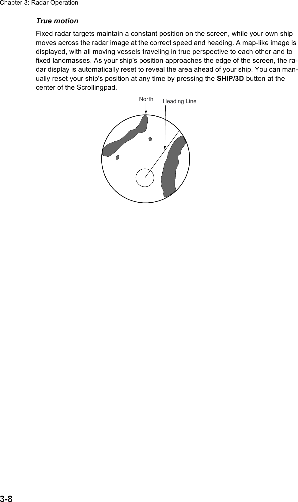
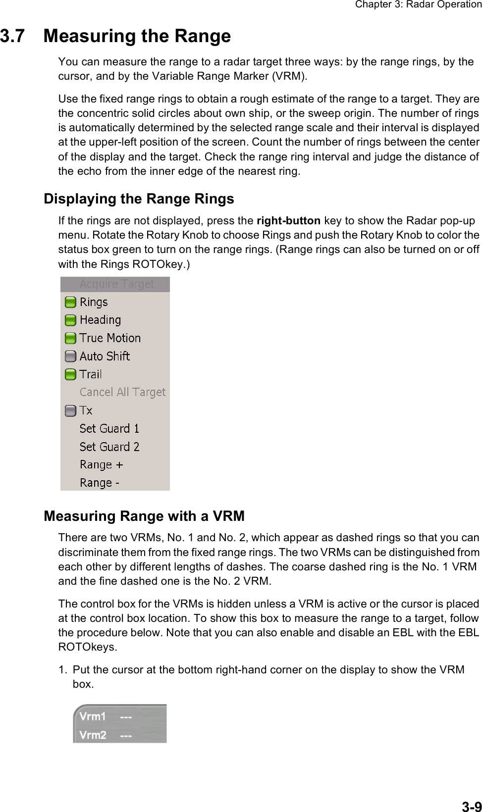
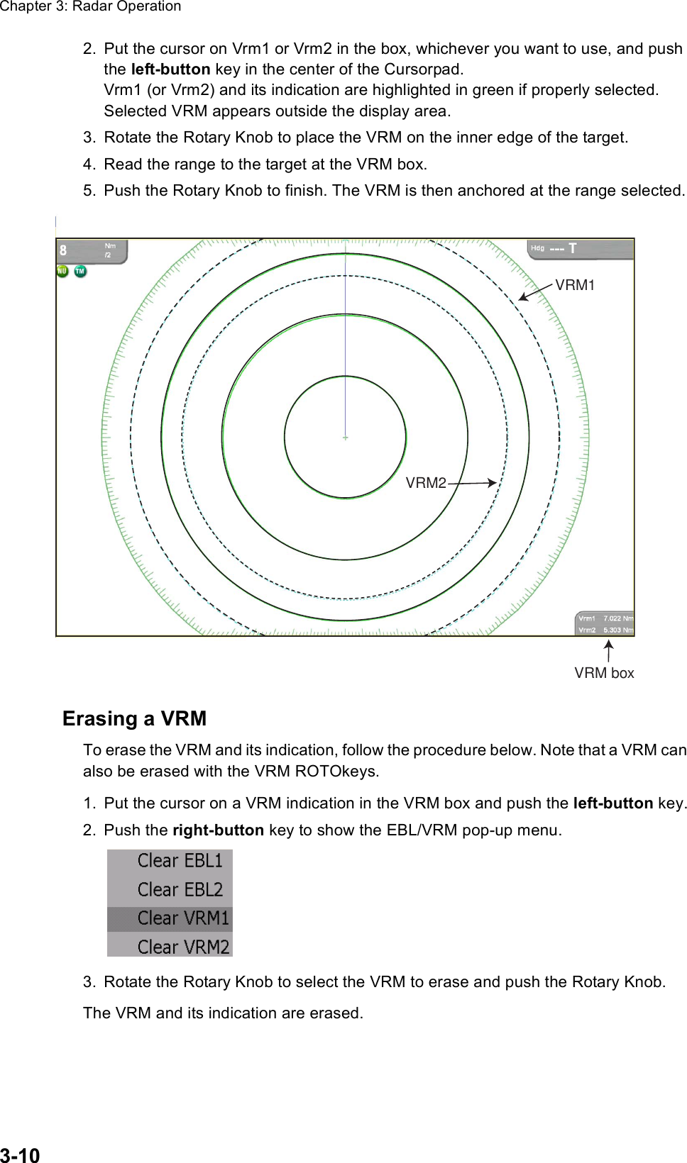
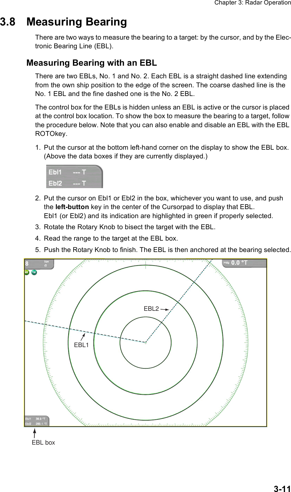
Manual 2
4.
Manual 3
5.
Installation Manual
Manual 2
Navigation menu
Upload a User Manual
Namespaces
Wiki Guide
HTML
PDF
Info
Views
User Manual
Discussion / Help
Navigation