Furuno USA 9ZWRTR095 Marine Radar User Manual
Furuno USA Inc Marine Radar
UserManual.wiki
>
Furuno USA
>
9ZWRTR095 User Manual
>
Manual 3
Contents
1.
Manual 1
2.
Manual 1a
3.
Manual 2
4.
Manual 3
5.
Installation Manual
Manual 3
Navigation menu
Upload a User Manual
Namespaces
Wiki Guide
HTML
PDF
Info
Views
User Manual
Discussion / Help
Navigation
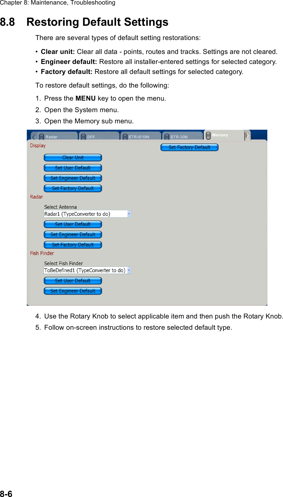
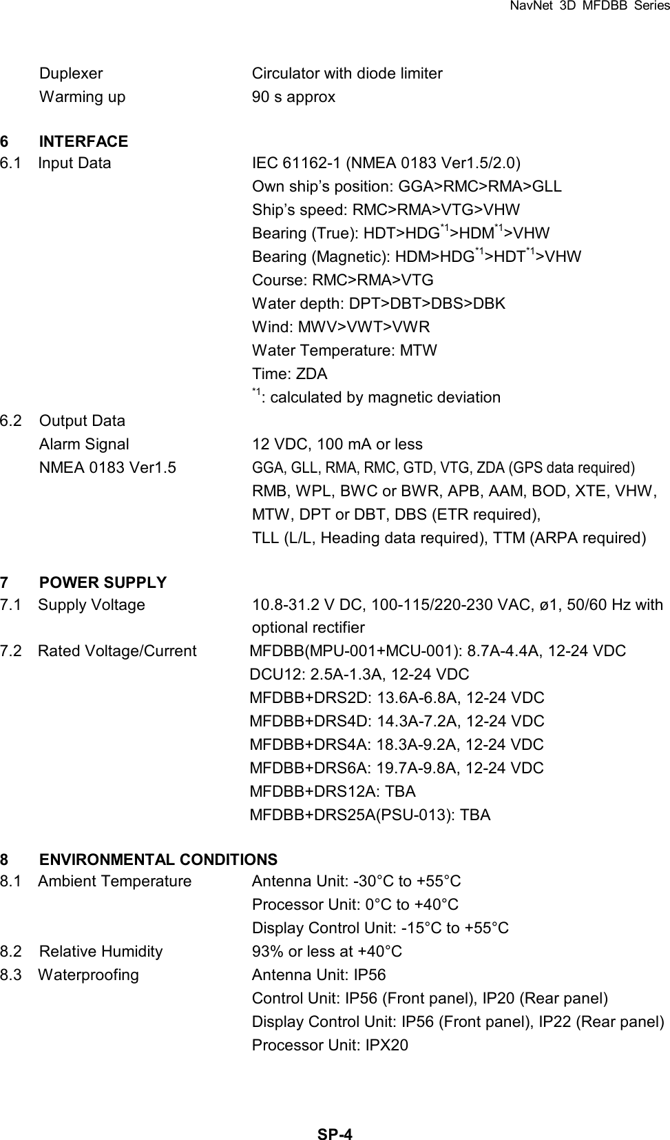
![Chapter 7: Customizing Your Unit7-19Calibration Sub MenuThe Calibration menu mainly lets you enter offsets for external sensors (speed, wind, temperature) to show true values on the display. Depth: Add an offset to measured depth to get actual depth. The setting range is 0-99.9 (m).Speed Through Water: Add an offset to measured speed to display actual speed. The range is -50 to +50 (%).Sea Surface Temperature: Add an offset to measured sea surface temperature to display actual speed. The setting range is -99.9 to +99.9 (°C).Wind Damping Time: Set wind damping time. The setting range is 0-99 (seconds).Wind Speed Calibration: Apply an offset to measured speed to display actual wind speed. The range of offset is -50 to +50.]Wind Direction Offset: Add a wind direction offset to measured wind direction to cor-rect displayed wind direction.Water Type: Choose the type of water the vessel is used in, saltwater or freshwater.Set Default: Restore all default settings for this sub menu.](https://usermanual.wiki/Furuno-USA/9ZWRTR095.Manual-3/User-Guide-928761-Page-33.png)