Furuno USA 9ZWRTR100 Transceiver for Radar model FAR-1518/1528 User Manual
Furuno USA Inc Transceiver for Radar model FAR-1518/1528
Contents
- 1. Installation Manual Part 3
- 2. Installation Manual Part 1
- 3. Installation Manual Part 2
- 4. Installation Manual Part 4
- 5. Installation Manual Part 5
- 6. Installation Manual Part 6
- 7. User Manual Part 1
- 8. User Manual Part 2
- 9. User Manual Part 3
- 10. User Manual Part 4
- 11. User Manual Part 5
- 12. User Manual Part 6
Installation Manual Part 4
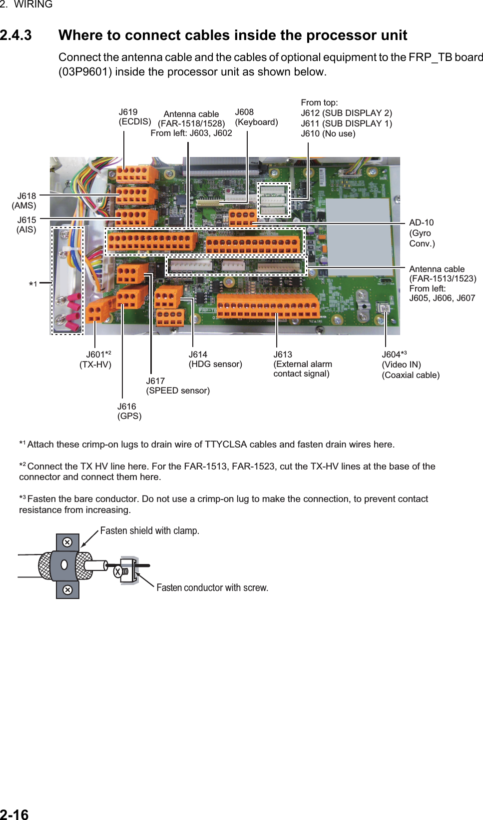
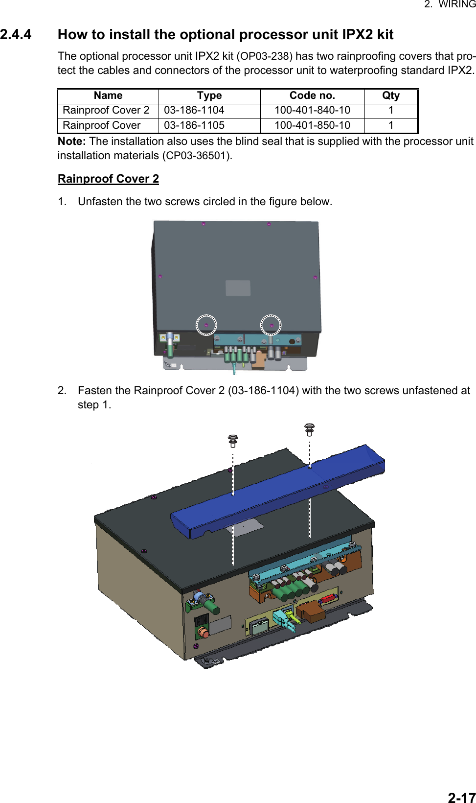
![2. WIRING2-15LAN cableIf the LAN cable is not fitted with an RJ-45 connector, attach one as shown below. Connect the cable to J202 (on the outside of the processor unit.) Using special crimping tool MPT5-8AS (PANDUIT CORP.), crimp the modular plug. Finally check the plug visually.1 WHT/GRN2 GRN3 WHT/ORG4 BLU5 WHT/BLE6 ORG7 WHT/BRN8 BRNWHT/ORG 1ORG 2WHT/GRN 3BLU 4WHT/BLE 5GRN 6WHT/BRN 7BRN 81 WHT/ORG2 ORG3 WHT/GRN4 BLU5 WHT/BLE6 GRN7 WHT/BRN8 BRNWHT/ORG 1ORG 2WHT/GRN 3BLU 4WHT/BLE 5GRN 6WHT/BRN 7BRN 8Expose inner vinyl sheath.[Crossover cable] [Straight cable]Remove the outer sheath by approx 25 mm. Be careful not to damage inner shield and cores.Fold back the shield, wrap it onto the outer sheath and cut it, leaving 9 mm.12325 mmapprox. 9 mm456approx. 9 mm approx. 11 mmDrain wireFold back drain wire and cut it, leaving 9 mm.Straighten and flatten the core in order and cut them, leaving 11 mm.Insert the cable into the modular plug so that the folded part of the shield enters the modular plug. The drain wire must be on the tab side of the jack.718Modular plug](https://usermanual.wiki/Furuno-USA/9ZWRTR100.Installation-Manual-Part-4/User-Guide-2768716-Page-1.png)
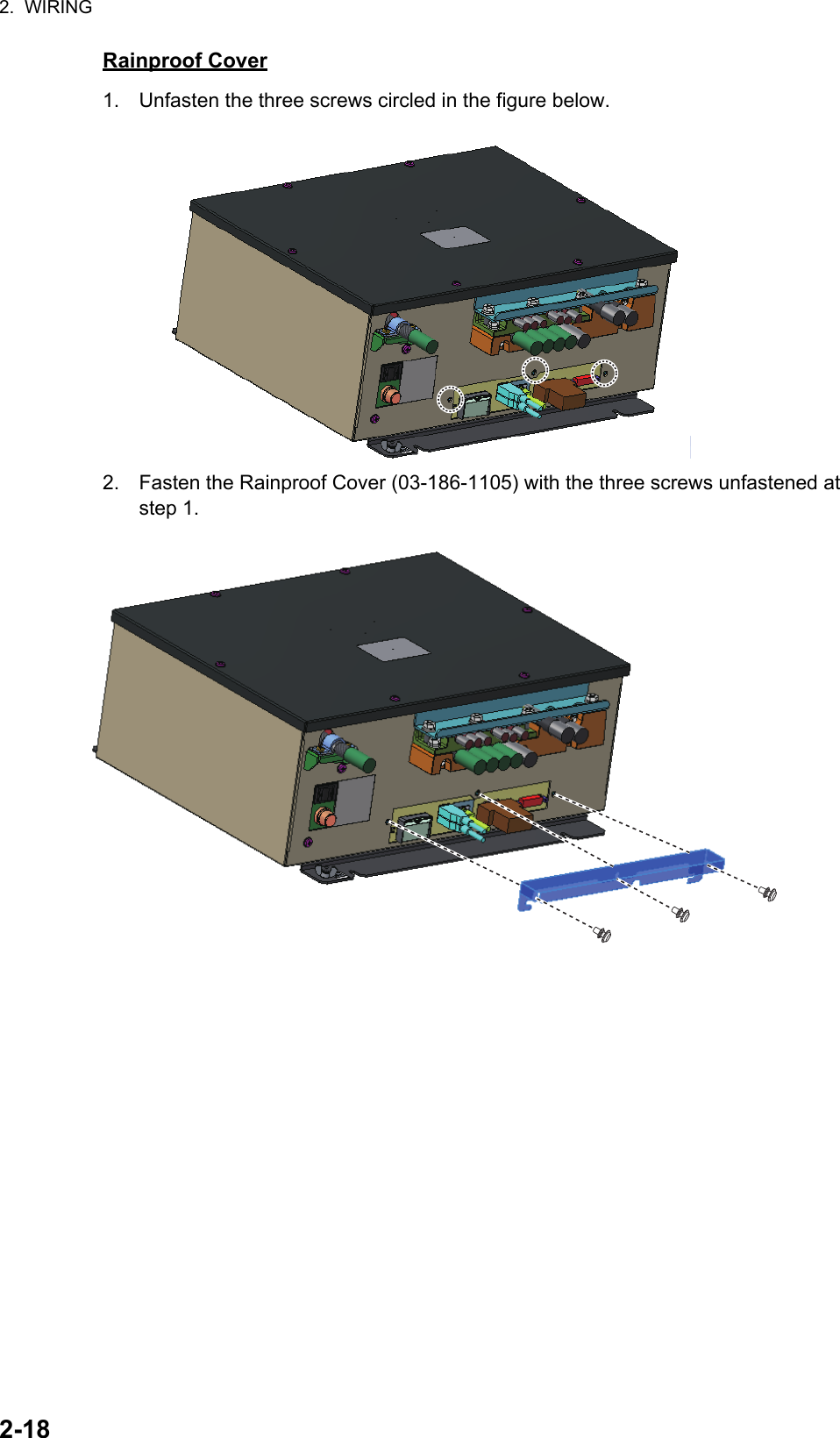
![3-13. ADJUSTMENTSNote: After completing the settings and adjustments, copy the setting data to a SD-card (SD card slot is at the back of the processor unit), referring to section 1.51 in the Operator's Manual. This will allow easy restoration of setting data after the SPU Board is replaced, etc.At the first power up after installation, open the protected menus to adjust the radar. Follow the procedures in this chapter, in the order shown, to complete the adjustment.Below are the controls on the control unit that are used to make the adjustments.3.1 How to Open the Radar Installation MenuThe [RADAR INSTALLATION] menu has the items for adjustment of the radar. Do the following to access the menu.1. Open the cover of the power switch and press the switch to turn on the radar.2. Press the MENU key five times while pressing the HL OFF key to open the [RA-DAR INSTALLATION] menu.Power key Left button Right buttonTouch pad Setting knobPower lamp[RADAR INSTALLATION] (1/2)1 BACK2 [ECHO ADJUST]3 [OWN SHIP INFO]4 [SCANNER]5 [INSTALLATION]6 [TT PRESET]7 [BAUD RATE]8 [ALERT I/F]9 [INPUT PORT]0 [NEXT][RADAR INSTALLATION] (2/2)1 BACK2 [OTHERS]3 [FACTORY]Page 2Page 1](https://usermanual.wiki/Furuno-USA/9ZWRTR100.Installation-Manual-Part-4/User-Guide-2768716-Page-7.png)
![3. ADJUSTMENTS3-23.2 How to Use the Menu1. Press the MENU key to open the main menu.2. Operate the Setting knob to select a menu then push the knob.3. Operate the Setting knob to select a menu item then push the knob.4. Operate the Setting knob to select a menu option then push the knob.5. If the menu option requires entry of numeric data, rotate the setting knob to set then push the knob.3.3 How to Initialize Tuning1. Open the main menu.2. Open the [ECHO] menu.3. Select [TUNE INITIALIZE], then press the Left button.The indication "TUNE INITIALIZE" appears on the screen during the initialization.4. After the tuning is completed, press the Right button twice to close the menu.[MAIN MENU]1 [ECHO]2 [MARK]3 [NAVTOOL]4 [ALERT]5 [TT•AIS]6 [FILES]7 [INFORMATION BOX]8 [NAV LINE•WPT]9 [INITIAL SETTING]0 [RADAR INSTALLATION][ECHO]1 BACK2 2nd ECHO REJ OFF/ON3 TUNE INITIALIZE4 PERFORMANCE MON OFF/ON5 PM ARC 2/3/5/66 SART OFF/ON7 ECHO AREA CIRCLE/WIDE/ ALL/SIMPLE8 WIPER OFF/1/29 [ACE]0 [CUSTOM SELECT]](https://usermanual.wiki/Furuno-USA/9ZWRTR100.Installation-Manual-Part-4/User-Guide-2768716-Page-8.png)
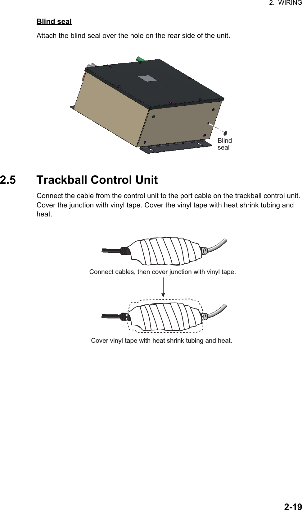
![3. ADJUSTMENTS3-33.4 How to Align the HeadingYou have mounted the antenna unit facing straight ahead in the direction of the bow. Therefore, a small but conspicuous target dead ahead visually should appear on the heading line (zero degrees). In practice, you will probably observe some small bearing error on the display because of the difficulty in achieving accurate initial positioning of the antenna unit. The following adjustment will compensate for this error.1. Select a stationary target echo at a range between 0.125 and 0.25 NM, preferably near the heading line.2. Press the EBL key to turn on the EBL. Rotate the Setting knob to pass the EBL through the center of the target echo.3. Read the target bearing.4. Measure the bearing of the stationary target on the navigation chart and calculate the difference between the actual bearing and apparent bearing on the radar screen.5. Open the [RADAR INSTALLATION] menu, then open the [ECHO ADJUST] menu.6. Select [HD ALIGN], then enter the bearing difference measured at step 4. The set-ting range is 0 to 359.9 degrees.7. Confirm that the target echo is displayed at the correct bearing on the screen.000 010 020030040050060070080090100110120130140150160170180190200210220230240250260270280290300310320330340 350aTargetaCorrect bearing(relative to heading)Antenna mounted errorto port (HDG SW advanced)Picture appearsdeviated clockwise.000 010 020030040050060070080090100110120130140150160170180190200210220230240250260270280290300310320330340 350bTargetbApparent positionof targetCorrectbearingrelativeto headingApparentposition oftargetAntenna mounted errorto port (HDG SW delayed)Picture appearsdeviated counterclockwise.[ECHO ADJUST]1 BACK2 VIDEO ADJ MAN/AUTO3 VIDEO ADJ VALUE 304 HD ALIGN 000.0°5 TIMING ADJ MAN/AUTO6 TIMING ADJ VALUE 2007 MBS LEVEL 0](https://usermanual.wiki/Furuno-USA/9ZWRTR100.Installation-Manual-Part-4/User-Guide-2768716-Page-9.png)
![3. ADJUSTMENTS3-43.5 How to Adjust Sweep TimingSweep timing differs with respect to the length of the signal cable between the antenna unit and the processor unit. Adjust sweep timing at installation to prevent the following symptoms:• The echo of a "straight" target (for example, pier), on the 0.25 NM range, will appear on the display as being pulled inward or pushed outward. See the figures below.• The range of target echoes is incorrect.1. Set the GAIN, A/C SEA and A/C RAIN controls as shown below.GAIN: 80A/C SEA: Fully counterclockwise (OFF)A/C RAIN: Fully counterclockwise (OFF)2. Open the [RADAR INSTALLATION] menu, then open the [ECHO ADJUST] menu.3. Set [TIMING ADJ] to [AUTO] to activate the automatic adjustment, which takes approx. two minutes.4. After the adjustment is completed, set the radar to the minimum range. Confirm that no echoes are "missing" at the center of the radar screen.If echoes are missing, set [TIMING ADJ] to [MAN]. Select [TIMING ADJ VALUE], then use the Setting knob to adjust the timing manually.3.6 How to Suppress Main BangIf main bang appears (a red ring at the screen center), suppress it as follows.1. Transmit the radar on a long range and then wait 10 minutes.2. Adjust the gain to show a slight amount of noise on the display.3. Select the 0.125 NM range, then adjust the A/C SEA and A/C RAIN controls.4. Go to the [RADAR INSTALLATION] menu, then open the [ECHO ADJUST] menu.5. Select [MBS LEVEL], then use the Setting knob to enter a value that causes the main bang to faintly disappear. The setting range is 0 to 255.(1) Correct (2) Target pushed inward (3) Target pushed outward](https://usermanual.wiki/Furuno-USA/9ZWRTR100.Installation-Manual-Part-4/User-Guide-2768716-Page-10.png)
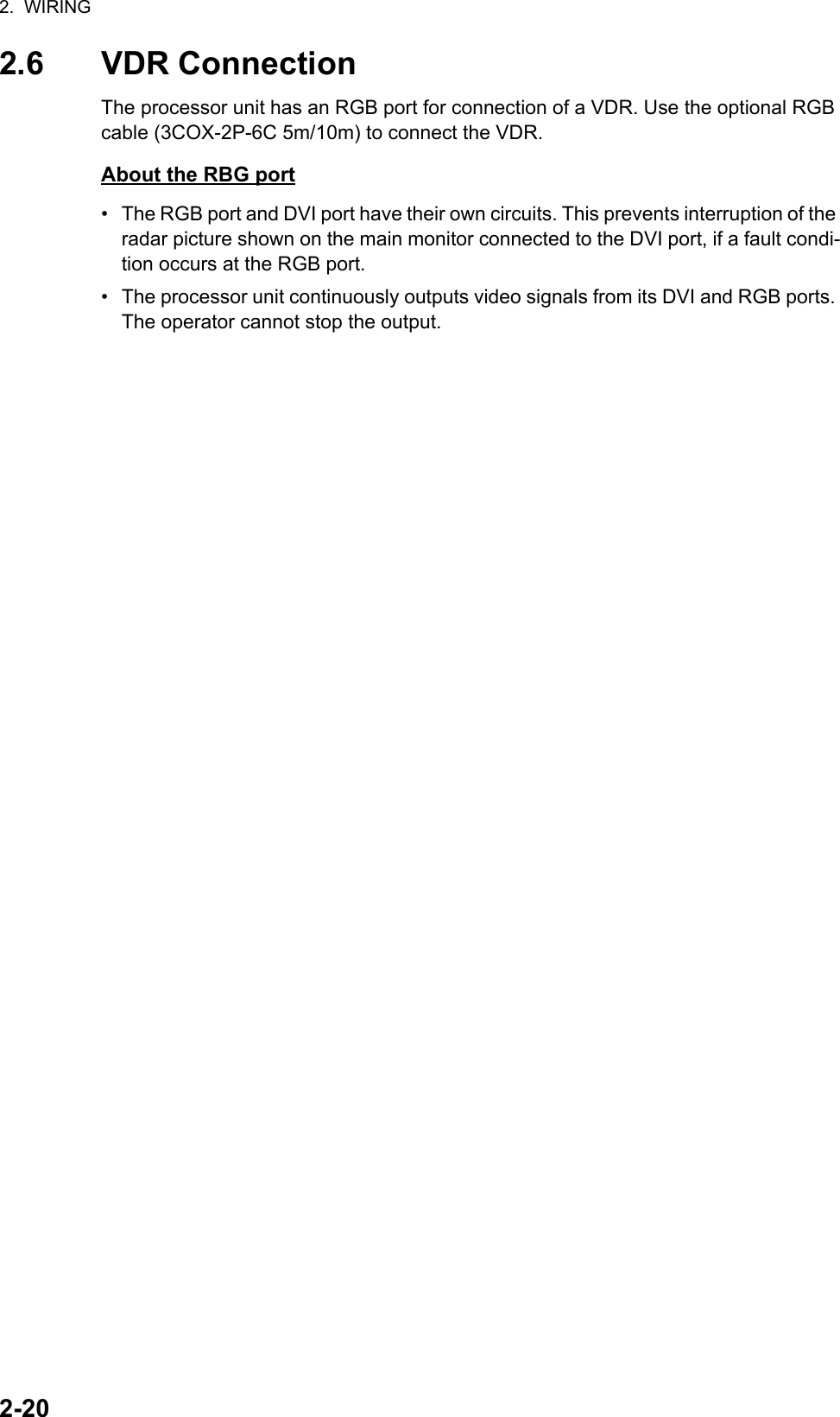
![3. ADJUSTMENTS3-53.7 RADAR INSTALLATION MenuThis section provides descriptions of the [RADAR INSTALLATION] menu items not previously mentioned.3.7.1 OWN SHIP INFO menuEnter the length and width of the ship, and scanner, GPS antenna and conning posi-tions, referring to the description and figure below.[LENGTH/WIDTH]: Enter the ship’s length and width.[SCANNER POSITION]: Enter the distance from the scanner to both bow and port.[GPS 1 ANT POSITION]: Enter the distance from the GPS antenna to both bow and port. If a 2nd GPS antenna is installed, enter its position in [GPS 2 ANT POSITION].[CONNING POSITION]: Enter the distance from the conning position to both bow and port.L1L1: Ship lengthW1: Ship widthL2: Conning position (from bow)W2: Conning position (from port)L3: Scanner position (from bow)W3: Scanner position (from port)L4: GPS antenna position (from bow)W4: GPS antenna position (from port)W1L2W2W3W4L3L4Example[OWN SHIP INFO]1 BACK2 LENGTH/WIDTH LENGTH 0m WIDTH 0m3 SCANNER POSITION BOW 0m PORT 0m4 GPS1 ANT POSITION BOW 0m PORT 0m5 GPS2 ANT POSITION BOW 0m PORT 0m6 CONNING POSITION BOW 0m PORT 0m](https://usermanual.wiki/Furuno-USA/9ZWRTR100.Installation-Manual-Part-4/User-Guide-2768716-Page-11.png)
![3. ADJUSTMENTS3-63.7.2 INSTALLATION menu[IP ADDRESS]: Enter IP address. The default address is 172.031.003.001.[RANGE UNIT]: Select the unit of range measurement, among [NM], [km], and [SM].[RADAR NO]: Select the radar number, among 1, 2, 3, and 4.[RADAR POSITION]: Select the radar position. The choices are [FORE],[MAIN-TOP], [MAIN-2ND], [MAIN-3RD], [AFT], [PORT], and [STARBOARD].[MODEL]: Select the model name, among [FAR-1513], [FAR-1523], [FAR-1518], and [FAR-1528].[TYPE]: Select the type of radar, [IMO] or [Non-IMO].[ON TIME], [TX TIME]: These items show the number of hours the radar has been turned on and transmitted, respectively. Value can be changed; for example, after re-placing the magnetron. [TX TIME] can be reset to 0.[PM GAIN ADJ]: Adjust the performance monitor gain, automatically or manually, whenever the magnetron is replaced.To adjust the performance monitor gain, do as follows:1. Select automatic or manual adjustment. For automatic adjustment, no further op-eration is required; close the menu at the completion of the adjustment. For man-ual go to the next step.2. Set the radar controls as shown below.Range: 24 NMPulse Length: LongA/C SEA: OFF (turn off manually)A/C RAIN: OFF (turn off manually)Echo Averaging (EAV): OFFVideo Contrast: 2-B [INSTALLATION 1/2]1 BACK2 IP ADDRESS 172.031.003.0013 RANGE UNIT NM/km/SM4 RADAR NO 1/2/3/45 RADAR POSITION FORE/MAIN-TOP/ MAIN-2ND/MAIN-3RD/ AFT/PORT/STARBOARD6 MODEL FAR-1513/FAR-1523/ FAR-1518/FAR-15287 TYPE IMO/Non-IMO0 NEXT [INSTALLATION 2/2]1 BACK2 ON TIME 000000.0H3 TX TIME 000000.0H4 PM GAIN ADJ MAN/AUTO 255](https://usermanual.wiki/Furuno-USA/9ZWRTR100.Installation-Manual-Part-4/User-Guide-2768716-Page-12.png)
![3. ADJUSTMENTS3-73. Adjust the GAIN control so that a slight amount of white noise appears on the screen. Arcs for the performance monitor appear on the screen.4. Select [PM GAIN ADJ]. Operate the Setting knob so that the outer arc faintly ap-pears. The setting range is 0 to 255. Wait at least eight scans then right click to set.3.7.3 ECHO ADJUST menu[VIDEO LEVEL ADJ]: Adjust the video level, automatically or manually. Set the radar as follows:Interference Rejector (IR): 2Echo Stretch (ES): OFFEcho Averaging (EAV): OFFGain: 80Range: 24 NMPulse Length: LongFor manual adjustment, select [VIDEO ADJ VALUE]. Rotate the Setting knob so that noise just disappears from the screen. The setting range is 0 to 99. After completion of the adjustment the radar goes into standby.3.7.4 SCANNER menu[SECTOR BLANK1], [SECTOR BLANK2]: Set area(s) where to prevent transmis-sion. Heading must be properly aligned (see section 3.4) before setting any blind sec-Approx. 12.1 NM (10 dB)Before setupBefore setupAfter setupAfter setup8.1 NM to 10.1 NM8.1 NM to 10.1 NMExample: [PM ARC] is set to [5]. (The location of arcs changes with the setting of [PM ARC] in [PERFORMANCE MON] in the [ECHO] menu.)HeadingStart bearingSet angleSector blank setting [SCANNER]1 BACK2 SECTOR BLANK1 START 000° ANGLE 000°3 SECTOR BLANK2 START 000° ANGLE 000°5 ANT SW OFF/ON/EXT6 ANT STOPPED STBY/TX7 DEFAULT ANT HEIGHT 5/7.5/10/15/20/ 25/30/35/40/45/ more50m](https://usermanual.wiki/Furuno-USA/9ZWRTR100.Installation-Manual-Part-4/User-Guide-2768716-Page-13.png)
![3. ADJUSTMENTS3-8tor. For example, set the area where an interfering object at the rear of the antenna would produce a dead sector (area where no echoes appear) on the display. To enter an area, enter start bearing relative to the heading and dead sector angle. To erase the area, enter 0 for both the [START] and [ANGLE] sections. The setting range of [START] is 0° to 359° and [ANGLE] is 0° to 180°.Note: Turn off a stern blind sector when adjusting the gain of the performance monitor, in order to display the echo from the performance monitor properly.[ANT STOPPED]: For serviceman.Note: Select [OFF] at [ANT SW] to prevent antenna rotation. [ANT STOPPED] pre-vents transmission while the antenna is stopped in STBY.[DEFAULT ANT HEIGHT]: Select the height of the radar antenna above the waterline.3.7.5 TT PRESET menu[MAX RANGE]: Select the maximum TT (target tracking) range, 24 or 32 NM. [TT PRESET]1 BACK2 [TT DATA OUTPUT]3 MAX RANGE 24NM/32NM4 TT ECHO LEVEL 135 QV DISPLAY OFF/ON6 TT W/O GYRO OFF/ON7 [ACQ PRESET]8 [TRACK PRESET]9 [TT SENSOR DATA]*0 DEFAULT [TRACK PRESET]1 BACK2 GATE SIZE S/M/L/LL3 FILTER RESPONSE 1/2/3/44 LOST COUNT 9SCAN5 MAX SPEED 150kn6 START TIME TGT VECT TIME/SCAN 0sec 0SCAN7 NUMBER OF TT 50/100 [TT DATA OUTPUT]1 BACK2 SELECT SENTENCE OFF/TTM/TTD3 TTM/TTD SENTENCE REL/TRUE [ACQ PRESET]1 BACK2 LAND SIZE 1600m3 ANT SELECT XN12AF/XN20AF/ XN24AF/XN12A/XN13A4 AUTO ACQ CORRE 55 AUTO ACQ WEED 1SCAN6 [TT DETAIL DATA]** For the serviceman.](https://usermanual.wiki/Furuno-USA/9ZWRTR100.Installation-Manual-Part-4/User-Guide-2768716-Page-14.png)
![3. ADJUSTMENTS3-9[TT ECHO LEVEL]: Set the detection level of TT echoes.[QV DISPLAY]: [OFF]: Normal picture, [ON]: Quantized video. The normal picture is in effect whenever the power is turned on regardless of this setting.[TT W/O GYRO]: Select [ON] to use TT without a gyro.[DEFAULT]: Restore default settings for this menu.TT DATA OUTPUT menu[SELECT SENTENCE]: Select the target data sentence (TTM or TTD) to output. Se-lect [OFF] for no output.[TTM/TTD REFERENCE]: Select the output format (bearing) for the TTM/TTD sen-tence.[REL] (Target bearing from own ship, degree relative, target course, degree relative), or [TRUE] (Target bearing, degree true, target course, degree true).ACQ PRESET menu[LAND SIZE]: Set the land size in units of 100 m. The setting range is 100 to 3000 m. A target whose length is equal to or greater than the length set here is judged as a land target.[ANT SELECT]: Select the antenna radiator type of your radar. The size of the echo changes with radiator size. Select the correct radiator type to ensure proper perfor-mance.[AUTO ACQ CORRE]: Set the correlation count of automatic acquisition. The setting range is 3 to 10.[AUTO ACQ WEED]: Set the cancel count of automatic acquisition. The setting range is 1 to 5.[TT DETAIL DATA]: For the service technician.TRACK PRESET menu[GATE SIZE]: Select the gate size, among [S], [M], [L], and [LL].[FILTER RESPONSE]: Set the filter response function. The setting range is 1 to 4.1: Filter response is improved.4: Filter stability is improved.[LOST COUNT]: Set the number of scans to allow between the time a target is lost and is declared a lost target. The setting range is 1 to 20.[MAX SPEED]: No use.[START TIME TGT VECT]: Set the number of seconds or number of scans to wait be-fore showing the vector for a newly acquired target. Select [TIME] or [SCAN] then en-ter value.[NUMBER OF TT]: Select the maximum number of TT to track, 50 or 100.TT SENSOR DATA menuFor the service technician.](https://usermanual.wiki/Furuno-USA/9ZWRTR100.Installation-Manual-Part-4/User-Guide-2768716-Page-15.png)
![3. ADJUSTMENTS3-103.7.6 BAUD RATE menuSet the baud rate, 4800 or 38400 (bps), for connected equipment - heading sensor, AIS transponder, GPS navigator, Log, AMS, and ECDIS.3.7.7 ALERT I/F menuFour alert outputs are available, [ALERT OUT1] - [ALERT OUT4]. Set each alert out referring to the description below. [BAUD RATE]1 BACK2 HDG 4800/384003 AIS 4800/384004 GPS 4800/384005 LOG 4800/384006 AMS 4800/384007 ECDIS 4800/38400 [ALERT OUT1 1/3]1 BACK2 ALERT OUT TYPE ALERT OUT/ OPERATOR FITNESS/ ALERT ACK3 ALERT OUT PRIORITY NORMAL/INVERT4 TRANSFER TT NEW TGT (A) TT NEW TGT (C) TT LOST TGT (A) TT LOST TGT (C) TT COLLISION (A) TT COLLISION (C) TT TGT FULL(AUTO) (A) TT TGT FULL(AUTO) (C) TT TGT FULL(MAN) (A) 0 NEXTPage 1/3 Page 2/3 [ALERT OUT1 2/3]1 BACK2 TT TGT FULL(MAN) (C) AIS NEW TGT (A) AIS NEW TGT (C) AIS LOST TGT (A) AIS LOST TGT (C) AIS COLLISION (A) AIS COLLISION (C) AIS TGT ACT FULL (A) AIS TGT ACT FULL (C) AIS TGT DISP FULL (A) AIS TGT DISP FULL (C) AZIMUTH HEADLINE TRIGGER VIDEO0 NEXT [ALERT OUT1 3/3]1 BACK2 KEY PM COM ERROR TUNE ERROR GYRO LOG(BT) LOG(WT) EPFS UTC XTE ARRIVAL DEPTH ANCHOR WATCHPage 3/3*Content same as[ALERT OUT1]. [ALERT]1 BACK2 [ALERT OUT1]3 [ALERT OUT2]*4 [ALERT OUT3]*5 [ALERT OUT4]*6 ALERT DATA OUT ALR/ALF7 AIS ALERT I/F OFF/LEGACY/IF1](https://usermanual.wiki/Furuno-USA/9ZWRTR100.Installation-Manual-Part-4/User-Guide-2768716-Page-16.png)
![3. ADJUSTMENTS3-11ALERT menu (main)[ALERT OUT 1] - [ALERT OUT 4]: Select the alert to output for each alert out number.[ALERT DATA OUT]: Select the alert output format, [ALR] (Set Alarm State) or [ALF] (Alert Sentence).[AIS ALERT I/F]: Set the AIS alert interface. [OFF] does not output AIS alert.[LEGACY]: For connection to FA-100, or connection to FA-150 where the AIS mode is LEGACY.[IF1]: For connection to FA-150 where the AMS mode is AlertIF1.ALERT OUT sub menus[ALERT OUT TYPE]: Select the alert out format, [ALERT OUT], [OPERATOR FIT-NESS] or [ALERT ACK].[ALERT OUT POLARITY]: Select the alert out polarity, [NORMAL] or [INVERT].Meaning of “(A)”, “(C)” suffixed items:“(A)”: Outputs the alert when the corresponding item is an unacknowledged alert.“(C)”: Outputs the alert when the corresponding alert condition is found.3.7.8 INPUT PORT menuINPUT PORT menuSelect the source for LOG, GPS, HEADING, WIND, CURRENT, WATER TEMP, and DEPTH..[GPS] menu: Select the source for GPS navigator GPS1 and GPS2. [PRIORITIZE GLL], when turned on, gives priority to the GLL sentence.[LOG]: Select the source for speed data.[HEADING]: Select the source for heading data.[WIND]: Select the source for wind data.[CURRENT]: Select the source for current (tide) for data.[WATER TEMP]: Select the source for water temperature data.[DEPTH]: Select the source for depth data. [GPS]1 BACK2 GPS1 GPS/LOG/ECDIS/HDG/AMS3 GPS2 GPS/LOG/ECDIS/HDG/AMS4 PRIORITIZE GLL OFF/ON [INPUT PORT]1 BACK2 [GPS]3 LOG GPS/LOG/ECDIS/HDG/AMS4 HEADING GPS/LOG/ECDIS/HDG/AMS5 WIND GPS/LOG/ECDIS/HDG/AMS6 CURRENT GPS/LOG/ECDIS/HDG/AMS7 WATER TEMP GPS/LOG/ECDIS/HDG/AMS8 DEPTH GPS/LOG/ECDIS/HDG/AMS](https://usermanual.wiki/Furuno-USA/9ZWRTR100.Installation-Manual-Part-4/User-Guide-2768716-Page-17.png)
![3. ADJUSTMENTS3-123.7.9 OTHERS menu[DEMO ECHO]: Select the source for the demonstration echo, [EG] (Echo Generator), [TT-TEST] or [PC]. Select [OFF] to deactivate the demonstration echo feature.[EAV W/O GYRO]: The each averaging feature can be used without a gyrocompass. Select [ON] to use the feature without a gyrocompass.[INS]: Select the INS communication method, [SERIAL] or [LAN]. Select [OFF] for no INS connection.[SUB MONITOR]: No use.[AIS FUNCTION]: Enable or disable the AIS function. (Available with non-IMO type only.)3.7.10 FACTORY menu[LANGUAGE]: Select the language to use.[FACTORY DEFAULT]: Restore factory default settings.[FACTORY TEST]: Factory use.[DISPLAY TEST]: Factory use. [OTHERS]1 BACK2 DEMO ECHO OFF/EG/TT-TEST/PC3 EAV W/O GYRO OFF/ON4 INS OFF/SERIAL/LAN5 SUB MONITOR OFF/ON6 AIS FUNCTION OFF/ON [FACTORY]1 BACK2 LANGUAGE ENGLISH/JAPANESE/ CHINESE3 FACTORY DEFAULT4 FACTORY TEST5 DISPLAY TEST](https://usermanual.wiki/Furuno-USA/9ZWRTR100.Installation-Manual-Part-4/User-Guide-2768716-Page-18.png)
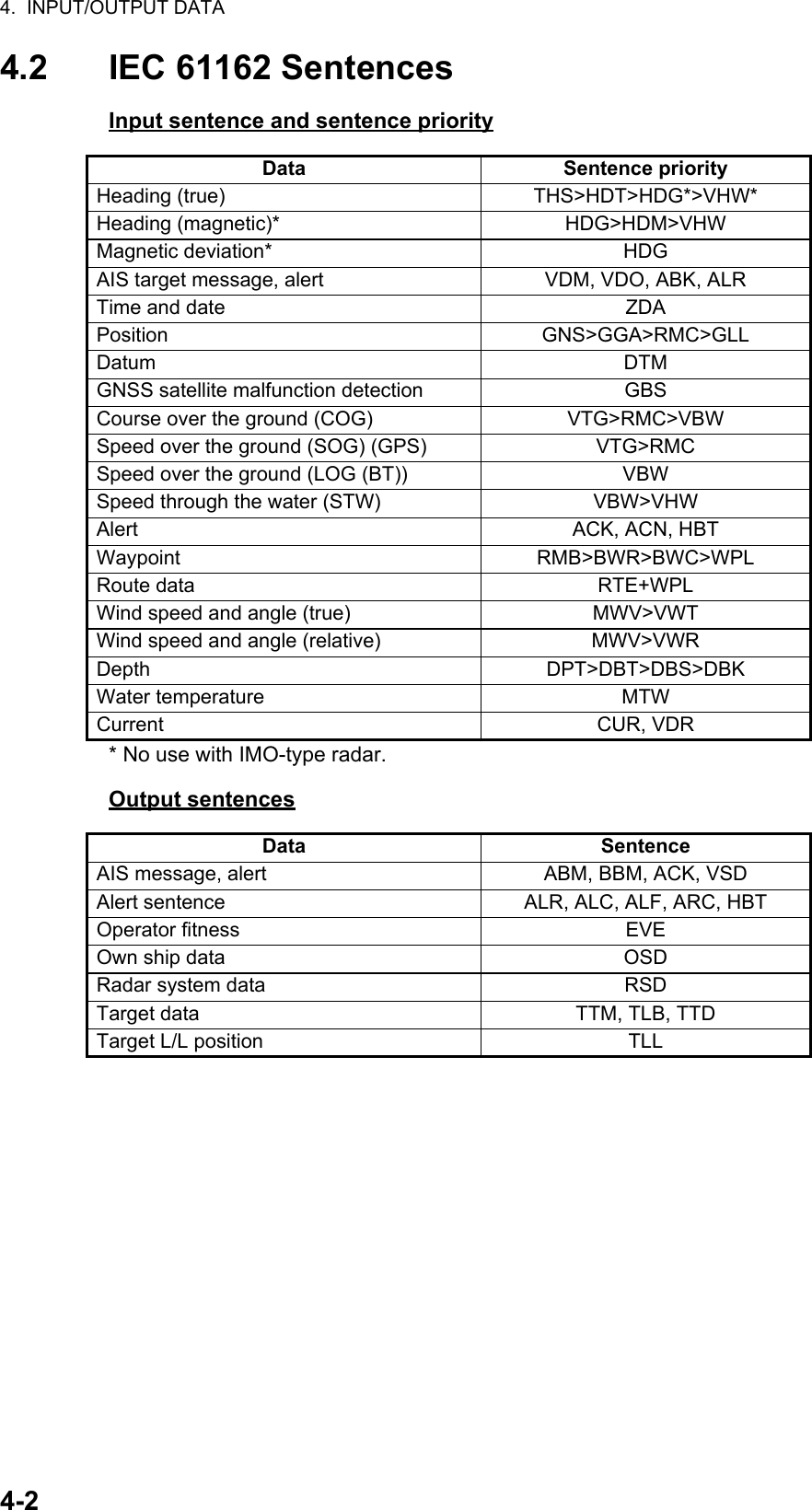
![4-14. INPUT/OUTPUT DATA4.1 Processor UnitInput and output data are shown in the table below.Input* Data input cycle must be more than 40 Hz (high speed craft) or 20 Hz (conventional ships).Output** The output sentence can be set on the [TT DATA OUTPUT] menu (see page 3-9).Data Specification Contents RemarksHeading signal IEC 61162-2*Speed signal IEC 61162-1 Ed.4Navaid data IEC 61162-1 Ed.4 Position, time and date, datum, course, speed, wind, current, depth, temperature, Navtex, etc.AIS signal IEC 61162-2Alarm handlingsignalContact closure Input from alarm systemIEC 61162-1 Ed.4 Input from alarm systemData Specification Contents RemarksRadar system data IEC 61162-1 Ed.4 RSD, OSDTT data** IEC 61162-1 Ed.4 TTD, TTM, TLBAlarm signal IEC 61162-1 Ed.4 Four systems, output con-tents are selected on the [ALARM] menu.Contact closureNotice for FAR-1518(-BB)/FAR-1528(-BB)These radars must be interconnected to the following type approved sensors: EPFS meeting the requirements of the IMO resolution MSC.112(73). Gyrocompass meeting the requirements of the IMO resolution A.424(XI). SDME meeting the requirements of IMO resolution MSC.96(72).](https://usermanual.wiki/Furuno-USA/9ZWRTR100.Installation-Manual-Part-4/User-Guide-2768716-Page-19.png)