Furuno USA 9ZWRTR100 Transceiver for Radar model FAR-1518/1528 User Manual
Furuno USA Inc Transceiver for Radar model FAR-1518/1528
Contents
- 1. Installation Manual Part 3
- 2. Installation Manual Part 1
- 3. Installation Manual Part 2
- 4. Installation Manual Part 4
- 5. Installation Manual Part 5
- 6. Installation Manual Part 6
- 7. User Manual Part 1
- 8. User Manual Part 2
- 9. User Manual Part 3
- 10. User Manual Part 4
- 11. User Manual Part 5
- 12. User Manual Part 6
Installation Manual Part 4
2. WIRING
2-15
LAN cable
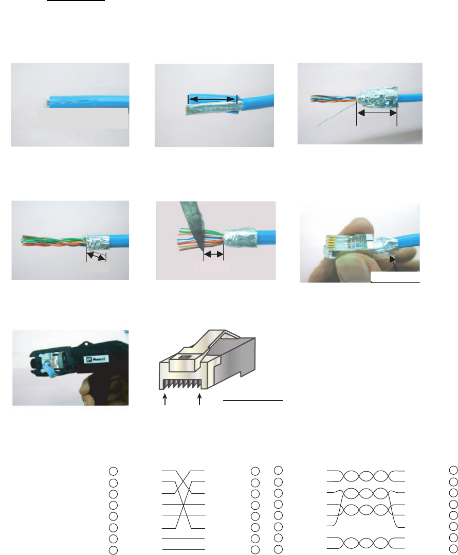
If the LAN cable is not fitted with an RJ-45 connector, attach one as shown below.
Connect the cable to J202 (on the outside of the processor unit.)
Using special crimping tool
MPT5-8AS (PANDUIT CORP.),
crimp the modular plug.
Finally check the plug visually.
1 WHT/GRN
2 GRN
3 WHT/ORG
4 BLU
5 WHT/BLE
6 ORG
7 WHT/BRN
8 BRN
WHT/ORG 1
ORG 2
WHT/GRN 3
BLU 4
WHT/BLE 5
GRN 6
WHT/BRN 7
BRN 8
1 WHT/ORG
2 ORG
3 WHT/GRN
4 BLU
5 WHT/BLE
6 GRN
7 WHT/BRN
8 BRN
WHT/ORG 1
ORG 2
WHT/GRN 3
BLU 4
WHT/BLE 5
GRN 6
WHT/BRN 7
BRN 8
Expose inner vinyl sheath.
[Crossover cable] [Straight cable]
Remove the outer sheath by
approx 25 mm. Be careful
not to damage inner shield
and cores.
Fold back the shield, wrap it
onto the outer sheath and
cut it, leaving 9 mm.
12
3
25 mm
approx. 9 mm
456
approx. 9 mm approx. 11 mm
Drain wire
Fold back drain wire and
cut it, leaving 9 mm.
Straighten and flatten the
core in order and cut them,
leaving 11 mm.
Insert the cable into the modular
plug so that the folded part of
the shield enters the modular
plug. The drain wire must be on
the tab side of the jack.
7
18
Modular plug
2. WIRING
2-16
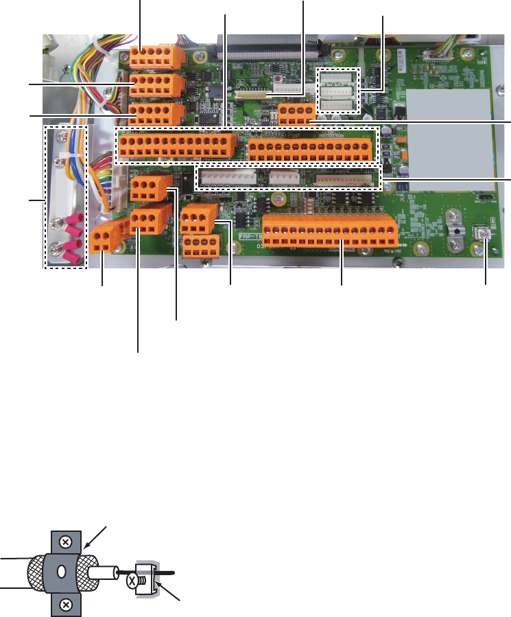
2.4.3 Where to connect cables inside the processor unit
Connect the antenna cable and the cables of optional equipment to the FRP_TB board
(03P9601) inside the processor unit as shown below.
Antenna cable
(FAR-1518/1528)
From left: J603, J602
J617
(SPEED sensor)
J614
(HDG sensor)
J601*2
(TX-HV)
J604*3
(Video IN)
(Coaxial cable)
J613
(External alarm
contact signal)
J608
(Keyboard)
J618
(AMS)
J615
(AIS) AD-10
(Gyro
Conv.)
Antenna cable
(FAR-1513/1523)
From left:
J605, J606, J607
J616
(GPS)
*1 Attach these crimp-on lugs to drain wire of TTYCLSA cables and fasten drain wires here.
*2 Connect the TX HV line here. For the FAR-1513, FAR-1523, cut the TX-HV lines at the base of the
connector and connect them here.
*3 Fasten the bare conductor. Do not use a crimp-on lug to make the connection, to prevent contact
resistance from increasing.
J619
(ECDIS)
*1
From top:
J612 (SUB DISPLAY 2)
J611 (SUB DISPLAY 1)
J610 (No use)
Fasten shield with clamp.
Fasten conductor with screw.
2. WIRING
2-17
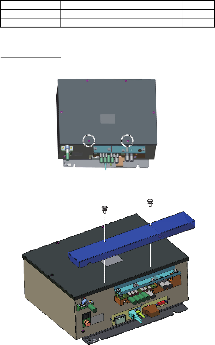
2.4.4 How to install the optional processor unit IPX2 kit
The optional processor unit IPX2 kit (OP03-238) has two rainproofing covers that pro-
tect the cables and connectors of the processor unit to waterproofing standard IPX2.
Note: The installation also uses the blind seal that is supplied with the processor unit
installation materials (CP03-36501).
Rainproof Cover 2
1. Unfasten the two screws circled in the figure below.
2. Fasten the Rainproof Cover 2 (03-186-1104) with the two screws unfastened at
step 1.
Name Type Code no. Qty
Rainproof Cover 2 03-186-1104 100-401-840-10 1
Rainproof Cover 03-186-1105 100-401-850-10 1
2. WIRING
2-18
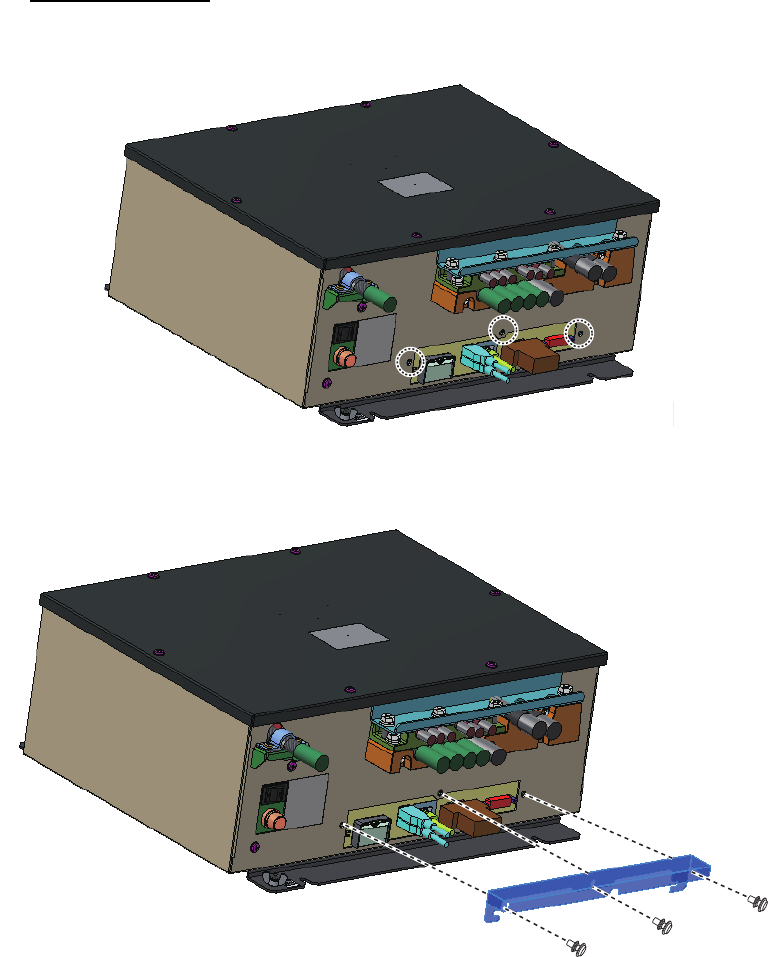
Rainproof Cover
1. Unfasten the three screws circled in the figure below.
2. Fasten the Rainproof Cover (03-186-1105) with the three screws unfastened at
step 1.
2. WIRING
2-19
Blind seal
Attach the blind seal over the hole on the rear side of the unit.
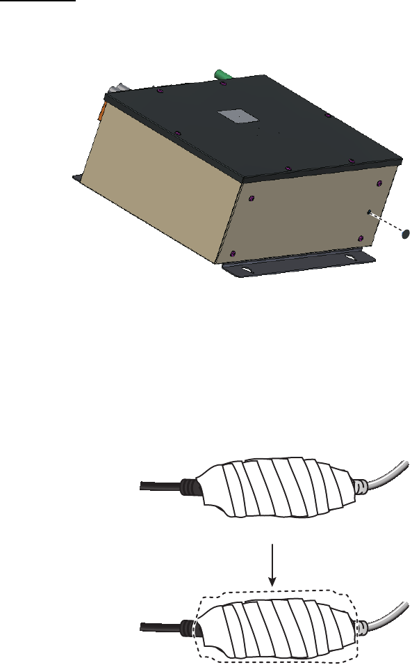
2.5 Trackball Control Unit
Connect the cable from the control unit to the port cable on the trackball control unit.
Cover the junction with vinyl tape. Cover the vinyl tape with heat shrink tubing and
heat.
Blind
seal
Connect cables, then cover junction with vinyl tape.
Cover vinyl tape with heat shrink tubing and heat.

2. WIRING
2-20
2.6 VDR Connection
The processor unit has an RGB port for connection of a VDR. Use the optional RGB
cable (3COX-2P-6C 5m/10m) to connect the VDR.
About the RBG port
• The RGB port and DVI port have their own circuits. This prevents interruption of the
radar picture shown on the main monitor connected to the DVI port, if a fault condi-
tion occurs at the RGB port.
• The processor unit continuously outputs video signals from its DVI and RGB ports.
The operator cannot stop the output.
3-1
3. ADJUSTMENTS
Note: After completing the settings and adjustments, copy the setting data to a SD-
card (SD card slot is at the back of the processor unit), referring to section 1.51 in the
Operator's Manual. This will allow easy restoration of setting data after the SPU Board
is replaced, etc.
At the first power up after installation, open the protected menus to adjust the radar.
Follow the procedures in this chapter, in the order shown, to complete the adjustment.
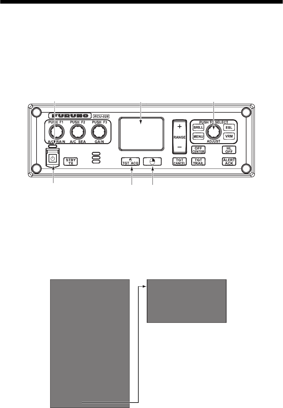
Below are the controls on the control unit that are used to make the adjustments.
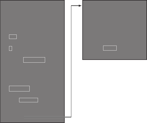
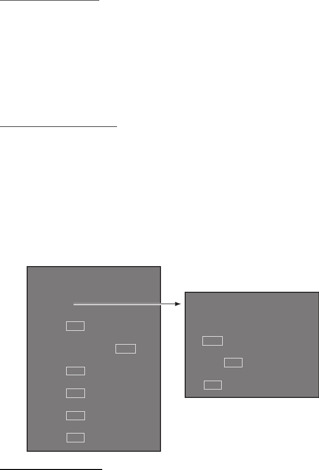
3.1 How to Open the Radar Installation Menu
The [RADAR INSTALLATION] menu has the items for adjustment of the radar. Do the
following to access the menu.
1. Open the cover of the power switch and press the switch to turn on the radar.
2. Press the MENU key five times while pressing the HL OFF key to open the [RA-
DAR INSTALLATION] menu.
Power key Left button Right button
Touch pad Setting knob
Power lamp
[RADAR INSTALLATION]
(1/2)
1 BACK
2 [ECHO ADJUST]
3 [OWN SHIP INFO]
4 [SCANNER]
5 [INSTALLATION]
6 [TT PRESET]
7 [BAUD RATE]
8 [ALERT I/F]
9 [INPUT PORT]
0 [NEXT]
[RADAR INSTALLATION]
(2/2)
1 BACK
2 [OTHERS]
3 [FACTORY]
Page 2
Page 1

3. ADJUSTMENTS
3-2
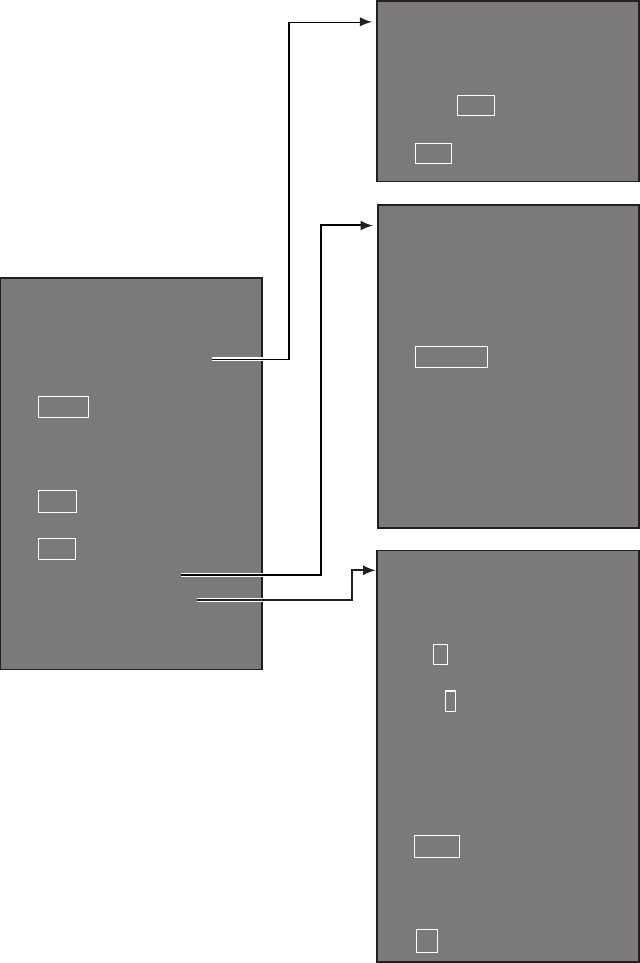
3.2 How to Use the Menu
1. Press the MENU key to open the main menu.
2. Operate the Setting knob to select a menu then push the knob.
3. Operate the Setting knob to select a menu item then push the knob.
4. Operate the Setting knob to select a menu option then push the knob.
5. If the menu option requires entry of numeric data, rotate the setting knob to set
then push the knob.
3.3 How to Initialize Tuning
1. Open the main menu.
2. Open the [ECHO] menu.
3. Select [TUNE INITIALIZE], then press the Left button.
The indication "TUNE INITIALIZE" appears on the screen during the initialization.
4. After the tuning is completed, press the Right button twice to close the menu.
[MAIN MENU]
1 [ECHO]
2 [MARK]
3 [NAVTOOL]
4 [ALERT]
5 [TT•AIS]
6 [FILES]
7 [INFORMATION BOX]
8 [NAV LINE•WPT]
9 [INITIAL SETTING]
0 [RADAR INSTALLATION]
[ECHO]
1 BACK
2 2nd ECHO REJ
OFF/ON
3 TUNE INITIALIZE
4 PERFORMANCE MON
OFF/ON
5 PM ARC
2/3/5/6
6 SART
OFF/ON
7 ECHO AREA
CIRCLE/WIDE/
ALL/SIMPLE
8 WIPER
OFF/1/2
9 [ACE]
0 [CUSTOM SELECT]
3. ADJUSTMENTS
3-3
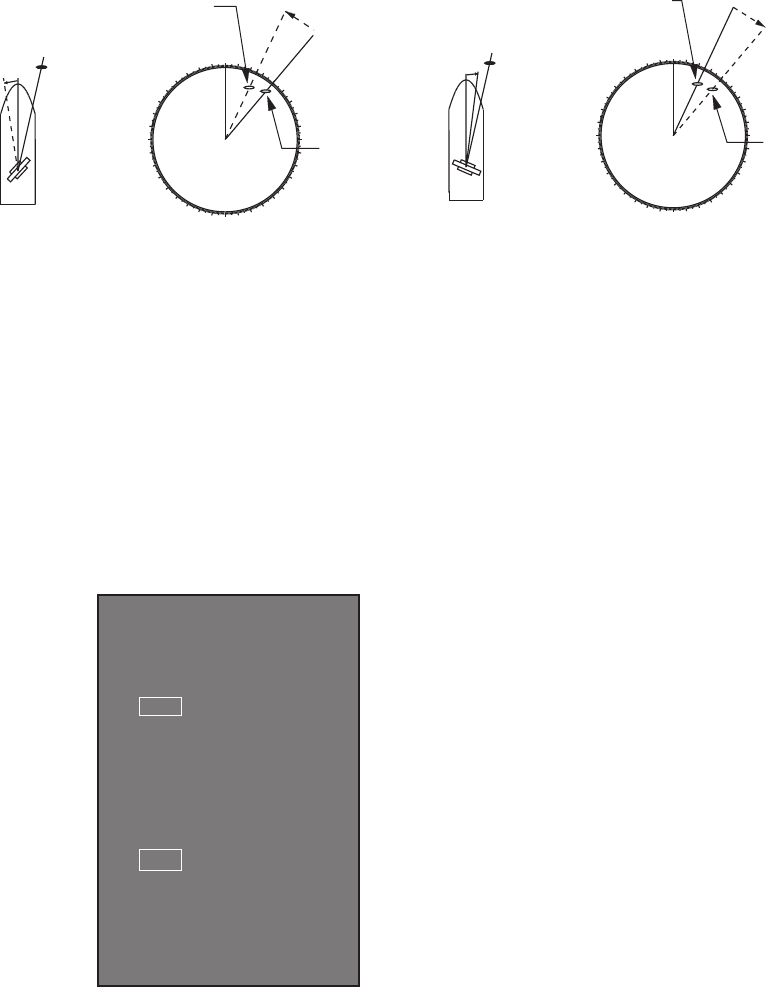
3.4 How to Align the Heading
You have mounted the antenna unit facing straight ahead in the direction of the bow.
Therefore, a small but conspicuous target dead ahead visually should appear on the
heading line (zero degrees). In practice, you will probably observe some small bearing
error on the display because of the difficulty in achieving accurate initial positioning of
the antenna unit. The following adjustment will compensate for this error.
1. Select a stationary target echo at a range between 0.125 and 0.25 NM, preferably
near the heading line.
2. Press the EBL key to turn on the EBL. Rotate the Setting knob to pass the EBL
through the center of the target echo.
3. Read the target bearing.
4. Measure the bearing of the stationary target on the navigation chart and calculate
the difference between the actual bearing and apparent bearing on the radar
screen.
5. Open the [RADAR INSTALLATION] menu, then open the [ECHO ADJUST] menu.
6. Select [HD ALIGN], then enter the bearing difference measured at step 4. The set-
ting range is 0 to 359.9 degrees.
7. Confirm that the target echo is displayed at the correct bearing on the screen.
000 010 020
030
040
050
060
070
080
090
100
110
120
130
140
150
160
170
180
190
200
210
220
230
240
250
260
270
280
290
300
310
320
330
340 350
aTarget
a
Correct bearing
(relative to heading)
A
ntenna mounted error
to port (HDG SW advanced)
Picture appears
deviated clockwise.
000 010 020
030
040
050
060
070
080
090
100
110
120
130
140
150
160
170
180
190
200
210
220
230
240
250
260
270
280
290
300
310
320
330
340 350
bTarget
b
Apparent position
of target
Correct
bearing
relative
to heading
Apparent
position of
target
Antenna mounted error
to port (HDG SW delayed)
Picture appears
deviated counterclockwise.
[ECHO ADJUST]
1 BACK
2 VIDEO ADJ
MAN/AUTO
3 VIDEO ADJ VALUE
30
4 HD ALIGN
000.0°
5 TIMING ADJ
MAN/AUTO
6 TIMING ADJ VALUE
200
7 MBS LEVEL
0

3. ADJUSTMENTS
3-4
3.5 How to Adjust Sweep Timing
Sweep timing differs with respect to the length of the signal cable between the antenna
unit and the processor unit. Adjust sweep timing at installation to prevent the following
symptoms:
• The echo of a "straight" target (for example, pier), on the 0.25 NM range, will appear
on the display as being pulled inward or pushed outward. See the figures below.
• The range of target echoes is incorrect.
1. Set the GAIN, A/C SEA and A/C RAIN controls as shown below.
GAIN: 80
A/C SEA: Fully counterclockwise (OFF)
A/C RAIN: Fully counterclockwise (OFF)
2. Open the [RADAR INSTALLATION] menu, then open the [ECHO ADJUST] menu.
3. Set [TIMING ADJ] to [AUTO] to activate the automatic adjustment, which takes
approx. two minutes.
4. After the adjustment is completed, set the radar to the minimum range. Confirm
that no echoes are "missing" at the center of the radar screen.
If echoes are missing, set [TIMING ADJ] to [MAN]. Select [TIMING ADJ VALUE],
then use the Setting knob to adjust the timing manually.
3.6 How to Suppress Main Bang
If main bang appears (a red ring at the screen center), suppress it as follows.
1. Transmit the radar on a long range and then wait 10 minutes.
2. Adjust the gain to show a slight amount of noise on the display.
3. Select the 0.125 NM range, then adjust the A/C SEA and A/C RAIN controls.
4. Go to the [RADAR INSTALLATION] menu, then open the [ECHO ADJUST] menu.
5. Select [MBS LEVEL], then use the Setting knob to enter a value that causes the
main bang to faintly disappear. The setting range is 0 to 255.
(1) Correct (2) Target pushed inward (3) Target pushed outward
3. ADJUSTMENTS
3-5
3.7 RADAR INSTALLATION Menu
This section provides descriptions of the [RADAR INSTALLATION] menu items not
previously mentioned.
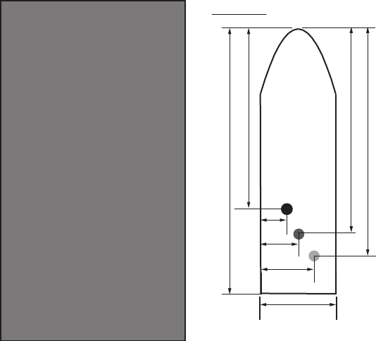
3.7.1 OWN SHIP INFO menu
Enter the length and width of the ship, and scanner, GPS antenna and conning posi-
tions, referring to the description and figure below.
[LENGTH/WIDTH]: Enter the ship’s length and width.
[SCANNER POSITION]: Enter the distance from the scanner to both bow and port.
[GPS 1 ANT POSITION]: Enter the distance from the GPS antenna to both bow and
port. If a 2nd GPS antenna is installed, enter its position in [GPS 2 ANT POSITION].
[CONNING POSITION]: Enter the distance from the conning position to both bow and
port.
L1
L1: Ship length
W1: Ship width
L2: Conning position (from bow)
W2: Conning position (from port)
L3: Scanner position (from bow)
W3: Scanner position (from port)
L4: GPS antenna position (from bow)
W4: GPS antenna position (from port)
W1
L2
W2
W3
W4
L3
L4
Example
[OWN SHIP INFO]
1 BACK
2 LENGTH/WIDTH
LENGTH 0m
WIDTH 0m
3 SCANNER POSITION
BOW 0m
PORT 0m
4 GPS1 ANT POSITION
BOW 0m
PORT 0m
5 GPS2 ANT POSITION
BOW 0m
PORT 0m
6 CONNING POSITION
BOW 0m
PORT 0m
3. ADJUSTMENTS
3-6
3.7.2 INSTALLATION menu
[IP ADDRESS]: Enter IP address. The default address is 172.031.003.001.
[RANGE UNIT]: Select the unit of range measurement, among [NM], [km], and [SM].
[RADAR NO]: Select the radar number, among 1, 2, 3, and 4.
[RADAR POSITION]: Select the radar position. The choices are [FORE],
[MAIN-TOP], [MAIN-2ND], [MAIN-3RD], [AFT], [PORT], and [STARBOARD].
[MODEL]: Select the model name, among [FAR-1513], [FAR-1523], [FAR-1518], and
[FAR-1528].
[TYPE]: Select the type of radar, [IMO] or [Non-IMO].
[ON TIME], [TX TIME]: These items show the number of hours the radar has been
turned on and transmitted, respectively. Value can be changed; for example, after re-
placing the magnetron. [TX TIME] can be reset to 0.
[PM GAIN ADJ]: Adjust the performance monitor gain, automatically or manually,
whenever the magnetron is replaced.
To adjust the performance monitor gain, do as follows:
1. Select automatic or manual adjustment. For automatic adjustment, no further op-
eration is required; close the menu at the completion of the adjustment. For man-
ual go to the next step.
2. Set the radar controls as shown below.
Range: 24 NM
Pulse Length: Long
A/C SEA: OFF (turn off manually)
A/C RAIN: OFF (turn off manually)
Echo Averaging (EAV): OFF
Video Contrast: 2-B
[INSTALLATION 1/2]
1 BACK
2 IP ADDRESS
172.031.003.001
3 RANGE UNIT
NM/km/SM
4 RADAR NO
1/2/3/4
5 RADAR POSITION
FORE/MAIN-TOP/
MAIN-2ND/MAIN-3RD/
AFT/PORT/STARBOARD
6 MODEL
FAR-1513/FAR-1523/
FAR-1518/FAR-1528
7 TYPE
IMO/Non-IMO
0 NEXT
[INSTALLATION 2/2]
1 BACK
2 ON TIME
000000.0H
3 TX TIME
000000.0H
4 PM GAIN ADJ
MAN/AUTO
255
3. ADJUSTMENTS
3-7
3. Adjust the GAIN control so that a slight amount of white noise appears on the
screen. Arcs for the performance monitor appear on the screen.
4. Select [PM GAIN ADJ]. Operate the Setting knob so that the outer arc faintly ap-
pears. The setting range is 0 to 255. Wait at least eight scans then right click to
set.
3.7.3 ECHO ADJUST menu
[VIDEO LEVEL ADJ]: Adjust the video level, automatically or manually. Set the radar
as follows:
Interference Rejector (IR): 2
Echo Stretch (ES): OFF
Echo Averaging (EAV): OFF
Gain: 80
Range: 24 NM
Pulse Length: Long
For manual adjustment, select [VIDEO ADJ VALUE]. Rotate the Setting knob so that
noise just disappears from the screen. The setting range is 0 to 99. After completion
of the adjustment the radar goes into standby.
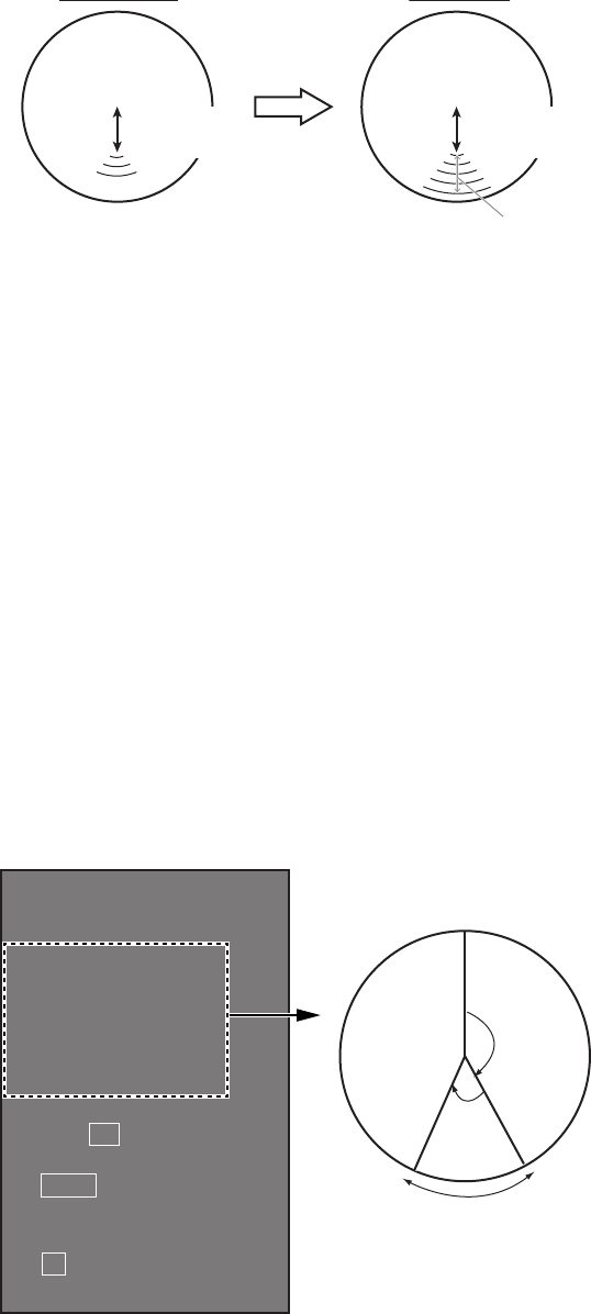
3.7.4 SCANNER menu
[SECTOR BLANK1], [SECTOR BLANK2]: Set area(s) where to prevent transmis-
sion. Heading must be properly aligned (see section 3.4) before setting any blind sec-
Approx. 12.1 NM (10 dB)
Before setup
Before setup
After setup
After setup
8.1 NM to
10.1 NM
8.1 NM to
10.1 NM
Example: [PM ARC] is set to [5]. (The location of arcs
changes with the setting of [PM ARC] in
[PERFORMANCE MON] in the [ECHO] menu.)
Heading
Start
bearing
Set
angle
Sector blank setting
[SCANNER]
1 BACK
2 SECTOR BLANK1
START 000°
ANGLE 000°
3 SECTOR BLANK2
START 000°
ANGLE 000°
5 ANT SW
OFF/ON/EXT
6 ANT STOPPED
STBY/TX
7 DEFAULT ANT HEIGHT
5/7.5/10/15/20/
25/30/35/40/45/
more50m
3. ADJUSTMENTS
3-8
tor. For example, set the area where an interfering object at the rear of the antenna
would produce a dead sector (area where no echoes appear) on the display. To enter
an area, enter start bearing relative to the heading and dead sector angle. To erase
the area, enter 0 for both the [START] and [ANGLE] sections. The setting range of
[START] is 0° to 359° and [ANGLE] is 0° to 180°.
Note: Turn off a stern blind sector when adjusting the gain of the performance monitor,
in order to display the echo from the performance monitor properly.
[ANT STOPPED]: For serviceman.
Note: Select [OFF] at [ANT SW] to prevent antenna rotation. [ANT STOPPED] pre-
vents transmission while the antenna is stopped in STBY.
[DEFAULT ANT HEIGHT]: Select the height of the radar antenna above the waterline.
3.7.5 TT PRESET menu
[MAX RANGE]: Select the maximum TT (target tracking) range, 24 or 32 NM.
[TT PRESET]
1 BACK
2 [TT DATA OUTPUT]
3 MAX RANGE
24NM/32NM
4 TT ECHO LEVEL
13
5 QV DISPLAY
OFF/ON
6 TT W/O GYRO
OFF/ON
7 [ACQ PRESET]
8 [TRACK PRESET]
9 [TT SENSOR DATA]*
0 DEFAULT
[TRACK PRESET]
1 BACK
2 GATE SIZE
S/M/L/LL
3 FILTER RESPONSE
1/2/3/4
4 LOST COUNT
9SCAN
5 MAX SPEED
150kn
6 START TIME TGT VECT
TIME/SCAN
0sec
0SCAN
7 NUMBER OF TT
50/100
[TT DATA OUTPUT]
1 BACK
2 SELECT SENTENCE
OFF/TTM/TTD
3 TTM/TTD SENTENCE
REL/TRUE
[ACQ PRESET]
1 BACK
2 LAND SIZE
1600m
3 ANT SELECT
XN12AF/XN20AF/
XN24AF/XN12A/XN13A
4 AUTO ACQ CORRE
5
5 AUTO ACQ WEED
1SCAN
6 [TT DETAIL DATA]*
* For the serviceman.

3. ADJUSTMENTS
3-9
[TT ECHO LEVEL]: Set the detection level of TT echoes.
[QV DISPLAY]: [OFF]: Normal picture, [ON]: Quantized video. The normal picture is
in effect whenever the power is turned on regardless of this setting.
[TT W/O GYRO]: Select [ON] to use TT without a gyro.
[DEFAULT]: Restore default settings for this menu.
TT DATA OUTPUT menu
[SELECT SENTENCE]: Select the target data sentence (TTM or TTD) to output. Se-
lect [OFF] for no output.
[TTM/TTD REFERENCE]: Select the output format (bearing) for the TTM/TTD sen-
tence.
[REL] (Target bearing from own ship, degree relative, target course, degree relative),
or [TRUE] (Target bearing, degree true, target course, degree true).
ACQ PRESET menu
[LAND SIZE]: Set the land size in units of 100 m. The setting range is 100 to 3000 m.
A target whose length is equal to or greater than the length set here is judged as a
land target.
[ANT SELECT]: Select the antenna radiator type of your radar. The size of the echo
changes with radiator size. Select the correct radiator type to ensure proper perfor-
mance.
[AUTO ACQ CORRE]: Set the correlation count of automatic acquisition. The setting
range is 3 to 10.
[AUTO ACQ WEED]: Set the cancel count of automatic acquisition. The setting range
is 1 to 5.
[TT DETAIL DATA]: For the service technician.
TRACK PRESET menu
[GATE SIZE]: Select the gate size, among [S], [M], [L], and [LL].
[FILTER RESPONSE]: Set the filter response function. The setting range is 1 to 4.
1: Filter response is improved.
4: Filter stability is improved.
[LOST COUNT]: Set the number of scans to allow between the time a target is lost
and is declared a lost target. The setting range is 1 to 20.
[MAX SPEED]: No use.
[START TIME TGT VECT]: Set the number of seconds or number of scans to wait be-
fore showing the vector for a newly acquired target. Select [TIME] or [SCAN] then en-
ter value.
[NUMBER OF TT]: Select the maximum number of TT to track, 50 or 100.
TT SENSOR DATA menu
For the service technician.
3. ADJUSTMENTS
3-10
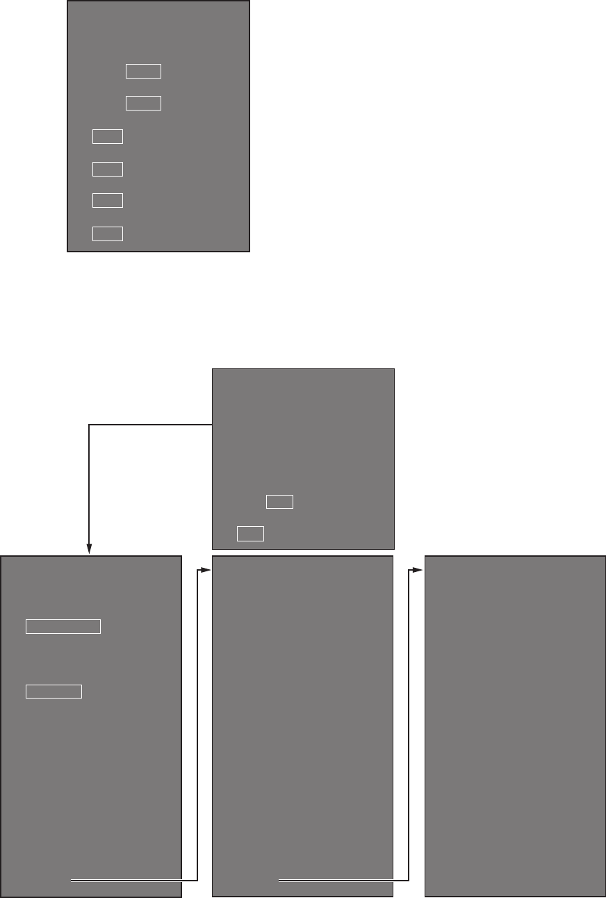
3.7.6 BAUD RATE menu
Set the baud rate, 4800 or 38400 (bps), for connected equipment - heading sensor,
AIS transponder, GPS navigator, Log, AMS, and ECDIS.
3.7.7 ALERT I/F menu
Four alert outputs are available, [ALERT OUT1] - [ALERT OUT4]. Set each alert out
referring to the description below.
[BAUD RATE]
1 BACK
2 HDG
4800/38400
3 AIS
4800/38400
4 GPS
4800/38400
5 LOG
4800/38400
6 AMS
4800/38400
7 ECDIS
4800/38400
[ALERT OUT1 1/3]
1 BACK
2 ALERT OUT TYPE
ALERT OUT/
OPERATOR FITNESS/
ALERT ACK
3 ALERT OUT PRIORITY
NORMAL/INVERT
4
TRANSFER
TT NEW TGT (A)
TT NEW TGT (C)
TT LOST TGT (A)
TT LOST TGT (C)
TT COLLISION (A)
TT COLLISION (C)
TT TGT FULL(AUTO) (A)
TT TGT FULL(AUTO) (C)
TT TGT FULL(MAN) (A)
0 NEXT
Page 1/3 Page 2/3
[ALERT OUT1 2/3]
1 BACK
2
TT TGT FULL(MAN) (C)
AIS NEW TGT (A)
AIS NEW TGT (C)
AIS LOST TGT (A)
AIS LOST TGT (C)
AIS COLLISION (A)
AIS COLLISION (C)
AIS TGT ACT FULL (A)
AIS TGT ACT FULL (C)
AIS TGT DISP FULL (A)
AIS TGT DISP FULL (C)
AZIMUTH
HEADLINE
TRIGGER
VIDEO
0 NEXT
[ALERT OUT1 3/3]
1 BACK
2
KEY
PM COM ERROR
TUNE ERROR
GYRO
LOG(BT)
LOG(WT)
EPFS
UTC
XTE
ARRIVAL
DEPTH
ANCHOR WATCH
Page 3/3
*Content same as
[ALERT OUT1].
[ALERT]
1 BACK
2 [ALERT OUT1]
3 [ALERT OUT2]*
4 [ALERT OUT3]*
5 [ALERT OUT4]*
6 ALERT DATA OUT
ALR/ALF
7 AIS ALERT I/F
OFF/LEGACY/IF1
3. ADJUSTMENTS
3-11
ALERT menu (main)
[ALERT OUT 1] - [ALERT OUT 4]: Select the alert to output for each alert out number.
[ALERT DATA OUT]: Select the alert output format, [ALR] (Set Alarm State) or [ALF]
(Alert Sentence).
[AIS ALERT I/F]: Set the AIS alert interface. [OFF] does not output AIS alert.
[LEGACY]: For connection to FA-100, or connection to FA-150 where the AIS mode
is LEGACY.
[IF1]: For connection to FA-150 where the AMS mode is AlertIF1.
ALERT OUT sub menus
[ALERT OUT TYPE]: Select the alert out format, [ALERT OUT], [OPERATOR FIT-
NESS] or [ALERT ACK].
[ALERT OUT POLARITY]: Select the alert out polarity, [NORMAL] or [INVERT].
Meaning of “(A)”, “(C)” suffixed items:
“(A)”: Outputs the alert when the corresponding item is an unacknowledged alert.
“(C)”: Outputs the alert when the corresponding alert condition is found.
3.7.8 INPUT PORT menu
INPUT PORT menu
Select the source for LOG, GPS, HEADING, WIND, CURRENT, WATER TEMP, and
DEPTH..
[GPS] menu: Select the source for GPS navigator GPS1 and GPS2. [PRIORITIZE
GLL], when turned on, gives priority to the GLL sentence.
[LOG]: Select the source for speed data.
[HEADING]: Select the source for heading data.
[WIND]: Select the source for wind data.
[CURRENT]: Select the source for current (tide) for data.
[WATER TEMP]: Select the source for water temperature data.
[DEPTH]: Select the source for depth data.
[GPS]
1 BACK
2 GPS1
GPS/LOG/ECDIS/HDG/AMS
3 GPS2
GPS/LOG/ECDIS/HDG/AMS
4 PRIORITIZE GLL
OFF/ON
[INPUT PORT]
1 BACK
2 [GPS]
3 LOG
GPS/LOG/ECDIS/HDG/AMS
4 HEADING
GPS/LOG/ECDIS/HDG/AMS
5 WIND
GPS/LOG/ECDIS/HDG/AMS
6 CURRENT
GPS/LOG/ECDIS/HDG/AMS
7 WATER TEMP
GPS/LOG/ECDIS/HDG/AMS
8 DEPTH
GPS/LOG/ECDIS/HDG/AMS

3. ADJUSTMENTS
3-12
3.7.9 OTHERS menu
[DEMO ECHO]: Select the source for the demonstration echo, [EG] (Echo Generator),
[TT-TEST] or [PC]. Select [OFF] to deactivate the demonstration echo feature.
[EAV W/O GYRO]: The each averaging feature can be used without a gyrocompass.
Select [ON] to use the feature without a gyrocompass.
[INS]: Select the INS communication method, [SERIAL] or [LAN]. Select [OFF] for no
INS connection.
[SUB MONITOR]: No use.
[AIS FUNCTION]: Enable or disable the AIS function. (Available with non-IMO type
only.)
3.7.10 FACTORY menu
[LANGUAGE]: Select the language to use.
[FACTORY DEFAULT]: Restore factory default settings.
[FACTORY TEST]: Factory use.
[DISPLAY TEST]: Factory use.
[OTHERS]
1 BACK
2 DEMO ECHO
OFF/EG/TT-TEST/PC
3 EAV W/O GYRO
OFF/ON
4 INS
OFF/SERIAL/LAN
5 SUB MONITOR
OFF/ON
6 AIS FUNCTION
OFF/ON
[FACTORY]
1 BACK
2 LANGUAGE
ENGLISH/JAPANESE/
CHINESE
3 FACTORY DEFAULT
4 FACTORY TEST
5 DISPLAY TEST

4-1
4. INPUT/OUTPUT DATA
4.1 Processor Unit
Input and output data are shown in the table below.
Input
* Data input cycle must be more than 40 Hz (high speed craft) or 20 Hz (conventional
ships).
Output
** The output sentence can be set on the [TT DATA OUTPUT] menu (see page 3-9).
Data Specification Contents Remarks
Heading signal IEC 61162-2*
Speed signal IEC 61162-1 Ed.4
Navaid data IEC 61162-1 Ed.4 Position, time and
date, datum, course,
speed, wind, current,
depth, temperature,
Navtex, etc.
AIS signal IEC 61162-2
Alarm handling
signal
Contact closure Input from alarm system
IEC 61162-1 Ed.4 Input from alarm system
Data Specification Contents Remarks
Radar system data IEC 61162-1 Ed.4 RSD, OSD
TT data** IEC 61162-1 Ed.4 TTD, TTM, TLB
Alarm signal IEC 61162-1 Ed.4 Four systems, output con-
tents are selected on the
[ALARM] menu.
Contact closure
Notice for FAR-1518(-BB)/FAR-1528(-BB)
These radars must be interconnected to the following type approved sensors:
EPFS meeting the requirements of the IMO resolution MSC.112(73).
Gyrocompass meeting the requirements of the IMO resolution A.424(XI).
SDME meeting the requirements of IMO resolution MSC.96(72).

4. INPUT/OUTPUT DATA
4-2
4.2 IEC 61162 Sentences
Input sentence and sentence priority
* No use with IMO-type radar.
Output sentences
Data Sentence priority
Heading (true) THS>HDT>HDG*>VHW*
Heading (magnetic)* HDG>HDM>VHW
Magnetic deviation* HDG
AIS target message, alert VDM, VDO, ABK, ALR
Time and date ZDA
Position GNS>GGA>RMC>GLL
Datum DTM
GNSS satellite malfunction detection GBS
Course over the ground (COG) VTG>RMC>VBW
Speed over the ground (SOG) (GPS) VTG>RMC
Speed over the ground (LOG (BT)) VBW
Speed through the water (STW) VBW>VHW
Alert ACK, ACN, HBT
Waypoint RMB>BWR>BWC>WPL
Route data RTE+WPL
Wind speed and angle (true) MWV>VWT
Wind speed and angle (relative) MWV>VWR
Depth DPT>DBT>DBS>DBK
Water temperature MTW
Current CUR, VDR
Data Sentence
AIS message, alert ABM, BBM, ACK, VSD
Alert sentence ALR, ALC, ALF, ARC, HBT
Operator fitness EVE
Own ship data OSD
Radar system data RSD
Target data TTM, TLB, TTD
Target L/L position TLL
AP-1
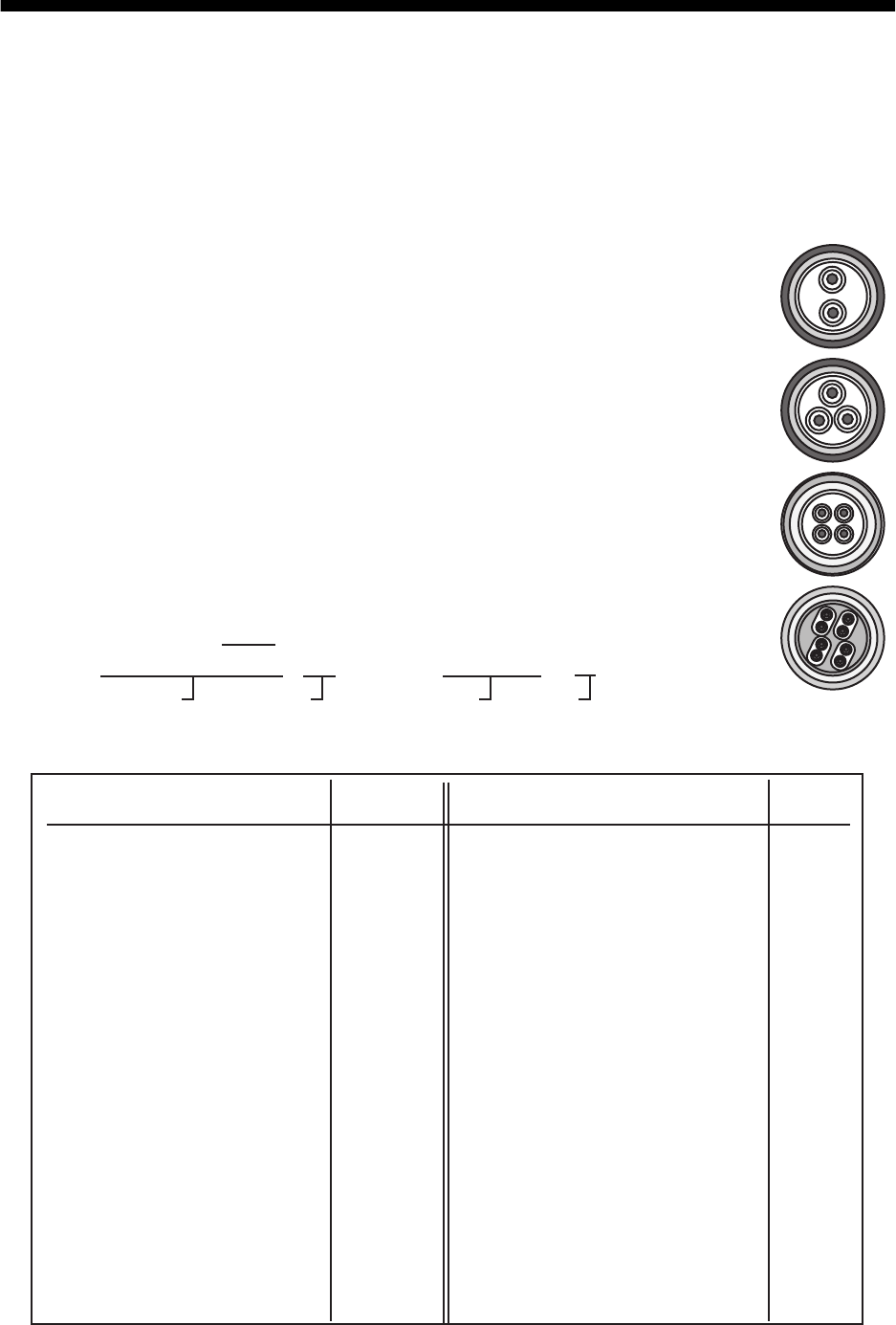
APPENDIX 1 JIS CABLE GUIDE
Core
Type Area Diameter
The following reference table lists gives the measurements of JIS cables commonly used with Furuno products:
TTYCSLA-4
MPYC-4
TPYCY
DPYCY
Cable
Diameter
DPYC-1.5 1.5mm
2
1.56mm 11.7mm
DPYC-2.5 2.5mm
2
2.01mm 12.8mm
DPYC-4 4.0mm
2
2.55mm 13.9mm
DPYC-6 6.0mm
2
3.12mm 15.2mm
DPYC-10 10.0mm
2
4.05mm 17.1mm
DPYCY-1.5 1.5mm
2
1.56mm 13.7mm
DPYCY-2.5 2.5mm
2
2.01mm 14.8mm
DPYCY-4 4.0mm
2
2.55mm 15.9mm
MPYC-2 1.0mm
2
1.29mm 10.0mm
MPYC-4 1.0mm
2
1.29mm 11.2mm
MPYC-7 1.0mm
2
1.29mm 13.2mm
MPYC-12 1.0mm
2
1.29mm 16.8mm
TPYC-1.5 1.5mm
2
1.56mm 12.5mm
TPYC-2.5 2.5mm
2
2.01mm 13.5mm
TPYC-4 4.0mm
2
2.55mm 14.7mm
TPYCY-1.5 1.5mm
2
1.56mm 14.5mm
TPYCY-2.5 2.5mm
2
2.01mm 15.5mm
TPYCY-4 4.0mm
2
2.55mm 16.9mm
TTYCS-1 0.75mm
2
1.11mm 10.1mm
TTYCS-1T 0.75mm
2
1.11mm 10.6mm
TTYCS-1Q 0.75mm
2
1.11mm 11.3mm
TTYCS-4 0.75mm
2
1.11mm 16.3mm
TTYCSLA-1 0.75mm
2
1.11mm 9.4mm
TTYCSLA-1T 0.75mm
2
1.11mm 10.1mm
TTYCSLA-1Q 0.75mm
2
1.11mm 10.8mm
TTYCSLA-4 0.75mm
2
1.11mm 15.7mm
TTYCY-1 0.75mm
2
1.11mm 11.0mm
TTYCY-1T 0.75mm
2
1.11mm 11.7mm
TTYCY-1Q 0.75mm
2
1.11mm 12.6mm
TTYCY-4 0.75mm
2
1.11mm 17.7mm
TTYCY-4S 0.75mm
2
1.11mm 21.1mm
TTYCY-4SLA 0.75mm
2
1.11mm 19.5mm
TTYCYS-1 0.75mm
2
1.11mm 12.1mm
TTYCYS-4 0.75mm
2
1.11mm 18.5mm
TTYCYSLA-1 0.75mm
2
1.11mm 11.2mm
TTYCYSLA-4 0.75mm
2
1.11mm 17.9mm
EX: TTYCYSLA - 4 MPYC - 4
Designation type # of twisted pairs Designation type # of cores
1 2 3 4 5 6 1 2 3 4
Cables listed in the manual are usually shown as Japanese Industrial Standard (JIS). Use the following guide to locate
an equivalent cable locally.
JIS cable names may have up to 6 alphabetical characters, followed by a dash and a numerical value (example:
DPYC-2.5).
For core types D and T, the numerical designation indicates the cross-sectional Area (mm2) of the core wire(s) in the
cable.
For core types M and TT, the numerical designation indicates the number of core wires in the cable.
1. Core Type
D: Double core power line
T: Triple core power line
M: Multi core
TT: Twisted pair communications
(1Q=quad cable)
2. Insulation Type
P: Ethylene Propylene
Rubber
3. Sheath Type
Y: PVC (Vinyl)
4. Armor Type
C: Steel
5. Sheath Type
Y: Anticorrosive vinyl
sheath
6. Shielding Type
S: All cores in one sheath
-S: Indivisually sheathed cores
SLA: All cores in one shield, plastic
tape w/aluminum tape
-SLA: I
ndividually shielded cores,
plastic tape w/aluminum tape
Core
Type Area Diameter
Cable
Diameter
AP-2
APPENDIX 2 DIGITAL INTERFACE
Digital Interface
Input sentence
ABK, ACK, ACN, ALR, BWC, BWR, CUR, DBK, DBS, DBT, DPT, DTM, GBS, GGA, GLL, GNS,
HBT, HDG, HDM, HDT, MTW, MWV, RMB, RMC, RTE, THS, VBW, VDM, VDO, VDR, VHW,
VSD, VTG, VWR, VWT, WPL, ZDA
Output sentences
ABM, ACK, ALC, ALF, ALR, ARC, BBM, EVE, HBT, OSD, RSD, TLB, TLL, TTD, TTM, VSD
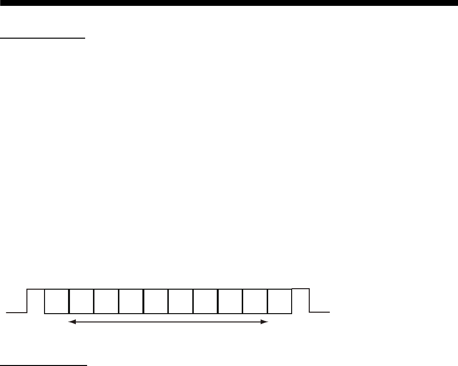
Data reception
Data is received in serial asynchronous form in accordance with the standard referenced in IEC
61162-2 or IEC 61162-1 Ed.4.
The following parameters are used:
Baud rate: 38,400 bps (HDT, THS, !AIVDM, !AIVDO, !AIABK, $AIALR. The baud rate of all other
sentences is 4800 bps
Data bits: 8 (D7=0), Parity: none, Stop bits: 1
Data Sentences
Input sentences
ABK - UAIS Addressed and binary broadcast acknowledgment
ACK - Acknowledge alarm
D0 D1 D2 D3 D4 D5 D6 D7
Data bits
Start
bit Stop
bit
$**ABK,xxxxxxxxx,x,x.x,x,x,*hh<CR><LF>
1 2 3 4 5
1. MMSI of the addressed AIS unit (9 digits) (No use)
2. AIS channel of reception (No use)
3. Message ID (6, 8, 12, 14) (No use)
4. Message sequence number (0 - 9) (No use)
5. Type of acknowledgement (See below)
0 = message (6 or 12) successfully received by the addressed AIS unit
1 = message (6 or 12) was broadcast, but not ACK by addressed AIS unit
2 = message could not be broadcast (quantity of encapsulated data exceeds five slots)
3 = requested broadcast of message (8, 14 or 15) has been successfully completed
4 = late reception of message (7 or 13) ACK that was addressed to this AIS unit (own ship)
and referenced a valid transaction
5 = message has been read and acknowledged on a display unit.
$**ACK,xxx,*hh<CR><LF>
1
1. Local alarm number (identifier) (001 - 999)
APPENDIX 2 DIGITAL INTERFACE
AP-3
ACN - Alert command
ALR - Set alarm state
BWC - Bearing and distance to waypoint - great circle
$**ACN,hhmmss.ss,aaa,x.x,x.x,ca,a*hh<CR><LF>
1 2 3 4 5 6
1. Time (hh=00 - 23, mm=00 - 59, ss.ss=00.00 - 60.99) (No use)
2. Manufacturer mnemonic code (3 digit alphanumeric code), null
3. Alert identifier (10001 - 10999)
4. Alert instance (null)
5. Alert command (A/Q/O/S)
A=ACK from ext. equipment,
Q=Request from ext. equipment
O=Responsibility transfer
S=Silence from ext. equipment
6. Sentence status flag (C)
(C should not be null field. Sentence without C is not a command.)
$**ALR,hhmmss.ss,xxx,A,A,c—c,*hh<CR><LF>
1 2 3 4 5
1. Time of alarm condition change, UTC (No use)
2. Unique alarm number (identifier) at alarm source (001 - 999)
3. Alarm condition (A/V)
A=threshold exceeded V=not exceeded
4. Alarm acknowledge state (A/V)
A=acknowledged V=not acknowledged
5. Alarm description text (alphanumeric characters, max. 32)
$ **BWC,hhmmss.ss,llll.ll, a,IIIII.II,a,yyy.y,T, yyy.y,M,yyy.y,N,c--c,A,*hh<CR><LF>
1 2 3 4 5 6 7 8 9 10 11 12 13
1. UTC of observation (No use)
2. Waypoint latitude (0000.00000 - 9000.00000)
3. N/S (N/S)
4. Waypoint longitude (00000.00000 - 18000.00000)
5. E/W (E/W)
6. Bearing, degrees true (No use)
7. Unit, True (No use)
8. Bearing, degrees (No use)
9. Unit, Magnetic (No use)
10. Distance, nautical miles (No use)
11. Unit, N (No use)
12. Waypoint ID (Max. 15 characters)
13. Mode Indicator (A/D)
A=Autonomous
D=Differential
E=Estimated (dead reckoning) mode
S=Simulator
N=Data not valid
APPENDIX 2 DIGITAL INTERFACE
AP-4
BWR - Bearing and distance to waypoint - rhumb line
CUR - Current
DBK - Depth below keel
DBS - Depth below surface
$ **BWR,hhmmss.ss,llll.ll,a,IIIII.II,a,yyy.y,T,yyy.y,M,yyy.y,N,c--c,A,*hh<CR><LF>
1 2 3 4 5 6 7 8 9 10 11 12 13
1. UTC of observation No use)
2. Waypoint latitude (0000.00000 - 9000.00000)
3. N/S (N/S)
4. Waypoint longitude (00000.00000 - 18000.00000)
5. E/W (E/W)
6. Bearing, degrees true (0.00 - 360.00) (No use)
7. Unit, True (No use)
8. Bearing, degrees magnetic (No use)
9. Unit (No use)
10. Distance, nautical miles (No use)
11. Unit (No use)
12. Waypoint ID (Max. 15 characters)
13. Mode Indicator (A/D)
A=Autonomous
D=Differential
E=Estimated (dead reckoning) mode
S=Simulator
N=Data not valid
$**CUR,A,x,x.x,x.x,x.x,a,x.x,x.x,x.x,a,a,*hh<CR><LF>
1 2 3 4 5 6 7 8 9 1011
1. Validity of data (A)
A=valid, V=not valid
2. Data set number (No use)
3. Layer number (1 - 3)
4. Current depth in meters (No use)
5. Current direction in degrees (0.00 - 360.00)
6. Direction reference in use (No use)
7. Current speed in knots (0.00 - 99.94)
8. Reference layer depth in meters (No use)
9. Heading (No use)
10. Heading reference in use (No use)
11. Speed reference (No use)
$**DBK,x.x,f,x.x,M,x.x,F<CR><LF>
1 2 3 4 5 6
1. Water depth (0.00 - 99999.994)
2. f = feet (fixed)
3. Water depth (0.00 - 99999.994)
4. M = Meters (fixed)
5. Water depth (0.00 - 99999.994)
6. F = Fathom (fixed)
$**DBS,x.x,f,x.x,M,x.x,F<CR><LF>
1 2 3 4 5 6
1. Water depth (0.00 - 99999.994)
2. f = feet (fixed)
3. Water depth (0.00 - 99999.994)
4. M = Meters (fixed)
5. Water depth (0.00 - 99999.994)
6. F = Fathom (fixed)
APPENDIX 2 DIGITAL INTERFACE
AP-5
DBT - Depth below transducer
DPT - Depth
DTM - Datum reference
GBS - GNSS satellite fault detection
$**DBT,xxxx.x,f,xxxx.x,M,xxxx.x,F<CR><LF>
1 2 3 4 5 6
1. Water depth (0.00 - 99999.994)
2. f = feet (fixed)
3. Water depth (0.00 - 99999.994)
4. M = Meters (fixed)
5. Water depth (0.00 - 99999.994)
6. F = Fathom (fixed)
$**DPT,x.x,x.x,x.x,*hh<CR><LF>
1 2 3
1. Water depth relative to the transducer, meters (0.00-99999.994)
2. Offset from transducer, meters
(IMO: -99.994 - 99.994,
Other than IMO: -99.994 - 99.994, null)
3. Minimum range scale in use (No use)
$**DTM,ccc,a,x.x,a,x.x,a,x.x,ccc,*hh<CR><LF>
1 2 3 4 5 6 7 8
1. Local datum (W84/W72/S85/P90)
W84=WGS84 W72=WGS72 S85=SGS85 P90=PE90
2. Local datum subdivision code (No use)
3. Lat offset, min (No use)
4. N/S (No use)
5. Lon offset, min (No use)
6. E/W (No use)
7. Altitude offset, meters (No use)
8. Reference datum (No use)
$**GBS, hhmmss.ss, x.x, x.x, x.x, xx, x.x, x.x, x.x,hh*hh<CR><LF>
1 2 3 4 5 6 7 8 910
1. UTC time of GGA or GNS fix associated with this sentence (No use)
2. Expected error in latitude (0.0 - 999.9)
3. Expected error in longitude (0.0 - 999.9)
4. Expected error in altitude (No use)
5. ID number of most likely failed satellite (No use)
6. Probability of missed detection for most likely failed satellite (No use)
7. Estimate of bias in meters on most likely failed satellite (No use)
8. Standard deviation of bias estimate (No use)
9. GNSS Signal ID (No use)
10. GNSS System ID (No use)
APPENDIX 2 DIGITAL INTERFACE
AP-6
GGA - Global positioning system fix data
GLL - Geographic position, latitude/longitude
GNS - GNSS fix data
$**GGA,hhmmss.ss,llll.lll,a,yyyyy.yyy,a,x,xx,x.x,x.x,M,x.x,M,x.x,xxxx,*hh<CR><LF>
1 2 3 4 5 6 7 8 9 10 11 12 13 14
1. UTC of position (no use)
2. Latitude (0000.00000 - 9000.00000)
3. N/S (N/S)
4. Longitude (0000.00000 - 18000.00000)
5. E/W (E/W)
6. GPS quality indicator (1 - 8)
0 = fix not available or invalid
1 = GPS SPS mode
2 = differential GPS, SPS mode
3 = GPS PPS mode
4 = Real Time Kinematic. Satellite system used in RTK mode with fixed integers
5 = Float RTK. Satellite system used in RTK mode with floating solution
6 = Estimated (dead reckoning) mode
7 = Manual input mode
8 = Simulator mode
7. Number of satellite in use (No use)
8. Horizontal dilution of precision (0.0 - 999.9)
9. Antenna altitude above/below mean sea level (No use)
10. Unit, m (No use)
11. Geoidal separation (No use)
12. Unit, m (No use)
13. Age of differential GPS data (0 - 999, null)
14. Differential reference station ID (No use)
$**GLL,llll.lll,a,yyyyy.yyy,a,hhmmss.ss,A,a,*hh<CR><LF>
1 2 3 4 5 6 7
1. Latitude (0000.00000 - 9000.00000)
2. N/S (N/S)
3. Longitude (0000.00000 - 18000.00000)
4. E/W (E/W)
5. UTC of position (No use)
6. Status (A)
A=data valid V=data invalid
7. Mode indicator (A/D/E/M/S)
A=Autonomous D=Differential E=Estimated M=Manual input S=Simulator N=Data not valid
$**GNS,hhmmss.ss,llll.lll,a,IIIII.III,a,c--c,xx,x.x,x.x,x.x,x.x,x.x,a*hh<CR><LF>
1 2 3 4 5 6 7 8 9 10 11 12 13
1. UTC of position (No use)
2. Latitude (0000.00000 - 9000.00000)
3. N/S (N/S)
4. Longitude (0000.00000 - 18000.00000)
5. E/W (E/W)
6. Mode indicator (A/D/P/R/F/E/M/S)
N=No fix A=Autonomous D=Differential P=Precise R=Real Time Kinematic
F=Float RTK E=Estimated Mode M=Manual Input Mode S=Simulator Mode
7. Total number of satellites in use (No use)
8. HDOP (0.00 - 999.99)
9. Antenna altitude, meters (No use)
10. Geoidal separation, meters (No use)
11. Age of differential data (0 - 999)
12. Differential reference station ID (No use)
13. Navigational status indicator(S/C/U/V, null)
S=Safe, C=Caution, U=Unsafe, V=Not valid