Furuno USA 9ZWRTR100 Transceiver for Radar model FAR-1518/1528 User Manual
Furuno USA Inc Transceiver for Radar model FAR-1518/1528
Contents
- 1. Installation Manual Part 3
- 2. Installation Manual Part 1
- 3. Installation Manual Part 2
- 4. Installation Manual Part 4
- 5. Installation Manual Part 5
- 6. Installation Manual Part 6
- 7. User Manual Part 1
- 8. User Manual Part 2
- 9. User Manual Part 3
- 10. User Manual Part 4
- 11. User Manual Part 5
- 12. User Manual Part 6
Installation Manual Part 5
APPENDIX 2 DIGITAL INTERFACE
AP-7
HBT - Heartbeat supervision sentence
HDG - Heading, deviation and variation
HDM - Heading, magnetic
HDT - Heading, true
MTW - Water temperature
MWV - Wind speed and angle
$**HBT,x.x,A,x*hh<CR><LF>
1 2 3
1. Configured repeat interval (1 - 999, null)
2. Equipment status (No use)
3. Sequential sequence identifier (0 - 9)
$**HDG,x.x,x.x,a,x.x,a*hh<CR><LF>
1 2 3 4 5
1. Magnetic sensor heading, degrees (0.00 - 360.00)
2. Magnetic deviation, degrees (0.00 - 180.00)
3. E/W
4. Magnetic variation, degrees (0.00 - 180.00)
5. E/W
*No use for
Type-IMO
$ ** HDM, x.x, M *hh <CR><LF>
1 2
1. Heading, degrees (0.00 - 360.00)
2. Magnetic (M)
*No use for
Type-IMO
$**HDT, xxx.x,T*hh<CR><LF>
1 2
1. Heading, degrees (0.00 - 360.00)
2. True (T)
$**MTW,x.x,C<CR><LF>
1 2
1. Water temperature (-9.994 - 99.994)
2. C=degrees C (fixed)
$**MWV,x.x,a,x.x,a,A*hh<CR><LF>
1 2 3 4 5
1. Wind angle, degrees (0.00 - 360.00)
2. Reference (R/T)
3. Wind speed (0.00 - 9999.94)
4. Wind speed units (K/M/N/S)
K=km/h M=m/s N=Knots S=Statute mile
5. Status (A)
APPENDIX 2 DIGITAL INTERFACE
AP-8
RMB - Recommended minimum specific navigation information
RMC - Recommended minimum specific GPS/TRANSIT data
$**RMB,A,x.x,a,CCCC,CCCC,IIII.II,a,yyyyy.yy,a,x.x,x.x,x.x,A,a*hh <CR><LF>
1 2 3 4 5 6 7 8 9 10 11 12 1314
1. Data status (A)
A=Data valid, V=Navigation receiver warning
2. Cross track error (NM) (No use)
3. Direction to steer (L/R) (No use)
4. Origin waypoint ID (No use)
5. Destination waypoint ID (Max. 15 characters)
6. Destination waypoint latitude (0000.00000 - 9000.00000)
7. N/S
8. Destination waypoint longitude (0000.00000 - 18000.00000)
9. E/W
10. Range to destination, nautical miles (No use)
11. Bearing to destination, degrees true (No use)
12. Destination closing velocity, knots (No use)
13. Arrival status (No use)
14.
Mode indicator (A/D)
A=Autonomous mode; D=Differential mode; E=Estimated (dead reckoning) mode;
M=Manual input mode; S=Simulator mode; N=Data not valid
$**RMC,hhmmss.ss,A,llll.ll,a,yyyyy.yy,a,x.x,x.x,xxxxxx,x.x,a,a,a*hh<CR><LF>
1 2 3 4 5 6 7 8 9 10
111213
1. UTC of position fix (No use)
2. Status (A)
A=data valid, V=navigation receiver warning
3. Latitude (0000.00000 - 9000.00000)
4. N/S (N/S)
5. Longitude (00000.00000 - 18000.00000)
6. E/W (E/W)
7. Speed over ground, knots (0.00 - 9999.94)
8. Course over ground, degrees true (0.00 - 360.0)
9. Date (No use)
10. Magnetic variation, degrees (No use)
11. E/W (No use)
12. Mode indicator (A/D/E/M/S/F/P/R)
A=Autonomous. Satellite system used in non-differential mode in position fix;
D=Differential. Satellite system used in differential mode in position fix;
E=Estimated (dead reckoning) mode;
F=Float RTK. Satellite system used in real time kinematic mode with floating integers;
M=Manual input mode;
N=No fix. Satellite system not used in position fix, or fix not valid;
P=Precise. Satellite system used in precision mode. Precision mode is defined as: no
deliberate degradation (such as selective availability) and higher resolution code (P-code) is
used to compute position fix. P is also used for satellite system used in multi-frequency,
SBAS or Precise Point Positioning (PPP) mode;
R=Real time kinematic. Satellite system used in RTK mode with fixed integers;
S=Simulator mode
13. Navigational status indication (S/C/U/V, null)
S=Safe, C=Caution, U=Unsafe, V=Not valid
APPENDIX 2 DIGITAL INTERFACE
AP-9
RTE - Routes
THS - True heading and status
VBW - Dual ground/water speed
VDM - UAIS VHF data-link message
VDO - UAIS VHFG data-link own vessel report
$**RTE,x.x,x.x,a,c--c,c--c,...
,
c--c*hh <CR><LF>
1 2 3 4 5 ...
6
1. Total number of sentences being transmitted (1 - 500, null)
2. Sentence number (1 - 500, null)
3. Sentence mode (C/W)
C=Complete route, all waypoints W=Working route, first listed
4. Route identifier (alphabet or null)
5. Waypoint identifier (alphabet or null)
6. Waypoint “n” identifier (alphabet or null)
$**THS,x.x,a*hh<CR><LF>
1 2
1. Heading, degrees True (0.00 to 360.00)
2. Mode indicator(A/E)
A=Autonomous; E=Estimated; M=Manual; S=Simulator; V=Data not valid
$**VBW,x.x,x.x,a,x.x,x.x,a,x.x,a,x.x,a,*hh<CR><LF>
1 2 3 4 5 6 7 8 9 10
1. Longitudinal water speed, knots (-9999.994 - 9999.994)
2. Transverse water speed, knots (-9999.994 - 9999.994, null)
3. Status: water speed, A=data valid V=data invalid (A)
4. Longitudinal ground speed, knots (-9999.994 - 9999.994)
5. Transverse ground speed, knots (-9999.994 - 9999.994, null)
6. Status: ground speed, A=data valid V=data invalid (A)
7. Stern transverse water speed, knots (No use)
8. Status: stern water speed, A=data valid V=data invalid (No use)
9. Stern transverse ground speed, knots (No use)
10. Status: stern ground speed, A=data valid V=data invalid (No use)
!VDM,x,x,x,a,s--s,x,*hh<CR><LF>
1 2 3 4 5 6
1. Total number of sentences needed to transfer the message (1 - 9)
2. Sentence number (1 - 9)
3. Sequential message identifier (0 - 9, null)
4. AIS channel number (A/B, null)
5. Encapsulated ITU-R M.1371 radio message (1 - 63 bytes)
6. Number of fill-bits (0 - 5)
!
VDO,x,x,x,a,s--s,x,*hh<CR><LF>
1 2 3 4 5 6
1
. Total number of sentences needed to transfer the message (1 - 9)
2
. Sentence number (1 - 9)
3
. Sequential message identifier (0 - 9, null)
4
. AIS channel Number (A/B, null)
5
. Encapsulated ITU-R M.1371 radio message (1 - 63 bytes)
6
. Number of fill-bits (0 - 5)
APPENDIX 2 DIGITAL INTERFACE
AP-10
VDR - Set and drift
VHW - Water speed and headings
VSD - UAIS Voyage static data
VTG - Course over ground and ground speed
$**VDR,x.x,T,x.x,M,x.x,N,*hh <CR><LF>
1 2 3 4 5 6
1. Direction, degrees (0.00 - 360.00, null)
2. T=True (fixed)
3. Direction, degrees Magnetic (No use)
4. M=Magnetic (No use)
5. Current speed (0 - 99.94)
6. N=Knots (fixed)
$**VHW,x.x,T,x.x,M,x.x,N,x.x,K,*hh <CR><LF>
1 2 3 4 5 6 7 8
1. Heading, degrees (0.00 - 360.00)
2. T=True (fixed)
3. Heading, degrees (0.00 - 360.00)
4. M=Magnetic (fixed)
5. Speed, knots (0.00 - 999.94)
6. N=Knots (fixed)
7. Speed, knots (0.00 - 999.94)
8. K=km/hr (fixed)
$--VSD,x.x,x.x,x.x,c--c,hhmmss.ss,xx,xx,x.x,x.x*hh<CR><LF>
1 2 3 4 5 6 7 8 9
1. Type of ship and cargo category (No use)
2. Maximum present static draught (No use)
3. Persons on-board (0 - 8191, null)
4. Destination (No use)
5. Estimated UTC of arrival at destination (No use)
6. Estimated day of arrival at destination (No use)
7. Estimated month of arrival at destination (No use)
8. Navigational status (No use)
9. Regional application flags (No use)
$**VTG,x.x,T,x.x,M,x.x,N,x.x,K,a,*hh <CR><LF>
1 2 3 4 5 6 7 8 9
1. Course over ground, degrees (0.00 - 360.00)
2. T=True (fixed)
3. Course over ground, degrees (No use)
4. M=Magnetic (No use)
5. Speed over ground, knots (0.00 - 9999.94)
6. N=Knots (fixed)
7. Speed over ground (0.00 - 9999.94)
8. K=km/h (fixed)
9. Mode indicator (A/D/E/M/P/S)
A=Autonomous mode;
D=Differential mode;
E=Estimated (dead reckoning) mode;
M=Manual input mode;
P=Precise. Satellite system used in precision mode. Precision mode is defined as: no
deliberate degradation (such as selective availability) and higher resolution code (P-code)
is used to compute position fix. P is also used for satellite system used in multi-frequency,
SBAS or Precise Point Positioning (PPP) mode;
S=Simulator mode;
N=Data not valid
APPENDIX 2 DIGITAL INTERFACE
AP-11
VWR - Wind relative bearing and velocity
VWT - True wind speed and angle
WPL - Waypoint location
ZDA - Time and date
Output sentences
For ACK, see input sentences.
$**VWR,x.x,a,x.x,N,x.x,M,x.x,K<CR><LF>
1 2 3 4 5 6 7 8
1. Measured wind angle relative to the vessel, degrees (0.00 to 180.00)
2. Left/Right of vessel heading (L/R)
L=Left semicircle, R=Right semicircle
3. Velocity, knots (0.00 - 999.94)
4. N=Knots (fixed)
5. Velocity (0.00 - 999.94)
6. M=m/s (fixed)
7. Velocity, km/h(0.00 - 999.94)
8. K=km/h (fixed)
$**VWT,xxx,a,xx.x,N,xx.x,M,xxx.x,K<CR><LF>
1 2 3 4 5 6 7 8
1. Measured wind angle relative to the vessel, degrees (0.00 - 180.00)
2. Left/Right of vessel heading (L/R)
L=Left semicircle, R=Right semicircle
3. Calculated wind speed kn (0.00 - 999.94)
4. N=Knots (fixed)
5. Wind speed m/s (0.00 - 999.94)
6. M=m/s (fixed)
7. Velocity, km/h (0.00 - 999.94)
8. K=km/h (fixed)
$**WPL,llll.ll,a,yyyyy.yy,a,c--c*hh<CR><LF>
1 2 3 4 5
1. Waypoint latitude (0000.00000 - 9000.00000)
2. N/S (N/S)
3. Waypoint longitude (00000.00000 - 18000.00000)
4. E/W (E/W)
5. Waypoint identifier (alphanumeric characters)
$**ZDA,hhmmss,xx,xx,xxxx,xx,xx<CR><LF>
1 2 3 4 5 6
1. UTC (000000.00 - 2400001.00)
2. Day (01 - 31)
3. Month (01 -12)
4. Year (0000-9999)
5. Local zone, hours (No use)
6. Loca zone, minutes (No use)

APPENDIX 2 DIGITAL INTERFACE
AP-12
ABM - AIS addressed binary and safety related message
ALC - Cyclic alert list
ALF - Alert sentence
!**ABM,x,x,x,xxxxxxxxx,x,xx,s--s,x,*hh<CR><LF>
1 2 3 4 5 6 7 8
1. Total number of sentences needed to transfer the message (1 - 9)
2. Sentence number (1 - 9)
3. Sequential message identifier (0 - 3)
4. The MMSI of destination AIS unit for the ITU-R M.1371 message (9 digits / null)
5. AIS channel for broadcast of the radio message (0 - 3 / null)
6. VDL message number (6 / 12 / null), see ITU-R M.1371
7. Encapsulated data (1 - 63 bytes)
8. Number of fill-bits (0 - 5)
$**ALC,xx,xx,xx,xx, aaa,x.x,x.x,x.x,’’’’’’’’’,*hh<CR><LF>
1 2 3 4 5 6 7 8 9
1. Total number of sentences this message (01 - 16)
2. Sentence number (01 - 16)
3. Sequential message identifier (00 - 99)
4. Number of alert entries (0 - 3)
5. Manufacturer mnemonic code (FEC, null)
6. Alert identifier (1 - 999 or 10001 - 10999)
7. Alert instance (null)
8. Revision counter (1 - 99)
9. Additional alert entries (see Note)
Note: Alert entry 0 - n: Each alert entry consists of
- Manufacturer Identifier (see ALF Manufactuer
- Alert Identifier (see ALF Alert identifier)
- Alert instance (see ALF instance)
- Revision counter (see ALF revision counter)
Each entry identifies a certain alert with a certain state.
It is not allowed that an alert entry is split between two ALC sentences.
Alert entry 1
See Note
$**ALF,x,x,x,hhmmss.ss,a,a,a,aaa,x.x,x.x,x.x,x,c--c,*hh<CR><LF>
1 2 3 4 5 6 7 8 9 10 11 12 13
1. Total number of ALF sentences this message (1, 2)
2. Sentence number (1, 2)
3. Sequential message identifier (0 - 9)
4. Time of last change (000000.00 - 240001.00 / null)
null when #2 is 2
5. Alert category (A/ B/null)
A=Alert category A, B=Alert category B, null when #2 is 2
6. Alert priority (A/W/C/null)
A=Alarm, W=Warning, C=Caution, null when #2 is 2
7. Alert state (A/S/O/U/V/N/null)
A=Acknowledged
S=Silence
O=Active-responsiblity transferred
U=Rectified-unacknowledged
V=Not acknowledged
N=Normal state
null when #2 is 2
8. Manufacturer mnemonic code (FEC/null)
9. Alert identifier (1 - 999 or 10001 - 10999)
10. Alert instance (null)
11. Revision counter (1 - 99)
12. Escalation counter (0 - 9)
13. Alert text (max. 16 characters)
APPENDIX 2 DIGITAL INTERFACE
AP-13
ALR - Set alarm state
ARC - Alert command refused
BBM - UAIS broadcast binary message
EVE - General event message
Note: The EVE sentence is output after input has been detected from either the trackball or the
keyboard.
HBT - Heartbeat supervision sentence
$**ALR,hhmmss.ss,xxx,A,A,c—c,*hh<CR><LF>
1 2 3 4 5
1. Time of alarm condition change, UTC (000000.00 - 240001.00)
2. Unique alarm number (identifier) at alarm source (001 - 999 / null)
3. Alarm condition (A/V)
A=threshold exceeded V=not exceeded
4. Alarm acknowledge state (A/V)
A=acknowledged V=not acknowledged
5. Alarm description text (alphanumeric characters, max. 32)
$**ARC,hhmmss.ss,aaa,x.x,x.x,c*hh<CR><LF>
1 2 3 4 5
1. Release time of the alert command refused (000000.00 - 240001.00, null)
2. Used for proprietary alerts, defined by the manufacturer (FEC)
3. The alert identifier (10001 - 10999)
4. The alert instance (null)
5. Refused alert command (A/O)
A=acknowledge, O=responsibility transfer
!**BBM,x,x,x,x,xx,s--s,x,*hh<CR><LF>
1 2 3 4 5 6 7
1. Total number of sentences needed to transfer the message (1 - 9)
2. Sentence number (1 - 9)
3. Sequential message identifier (0 - 9)
4. AIS channel for broadcast of the radio message (0 - 3/null)
5. VDL message number (8/14/null)
6. Encapsulated data (1 - 63 bytes)
7. Number of fill-bits (0 - 5)
$ **EVE,hhmmss.ss,c--c,c--c*hh <CR><LF>
1 2 3
1. Event time (000000.00 - 240001.00, null)
2. Tag code used for identification of source of event (six alphanumeric characters, two
English characters, four digits)
3. Event description (OPERATION)
$**HBT,x.x,A,x*hh<CR><LF>
1 2 3
1. Configured repeat interval (60.0)
2. Equipment status (A)
A=Normal
3. Sequential sequence identifier (0 - 9)

APPENDIX 2 DIGITAL INTERFACE
AP-14
OSD - Own ship data
RSD - Radar ship data
TLB - Target label
$**OSD,x.x,A,x.x,a,x.x,a,x.x,x,x.x,a*hh<CR><LF>
1 2 3 4 5 6 7 8 9
1. Heading, degrees true (0.0 - 359.9, null)
2. Heading status (A/V)
A
=data valid V=data invalid
3. Vessel course, degrees true (0.0 - 359.9)
4. Course reference (B/M/W/R/P, null)
B=Bottom tracking log
M=Manually entered
W=Water referenced
R=Radar tracking (of fixed target)
P=Positioning system ground reference
5. Vessel speed (0.0 - 99.9)
6. Speed reference (B/M/W/R/P, null)
7. Vessel set, degrees true, manually entered(0.0 - 359.9, null)
8. Vessel drift (speed), manually entered (0.0 – 19.9, null)
9. Speed units (K/N/S, null)
K=km/h N=Knots S=Statute mile
$**RSD,
x.x,x.x,x.x,x.x,x.x,x.x,x.x,x.x,x.x,x.x,x.x,a,aH
*hh <CR><LF>
1 2 3 4 5 6 7 8 9 10 11
12 13
1. Origin 1 range, from own ship (0.000 - 9999, null) (see note 2)
2. Origin 1 bearing, degrees from 0 (0.0 - 359.9) (see note 2)
3. Variable range marker 1(VRM1), range (0.000 – 999.9, null)
4. Bearing line 1(EBL1), degrees from 0 (0.0 - 359.9, null)
5. Origin 2 range (0.000 - 9999, null) (see note 2)
6. Origin 2 bearing (0.0 - 359.9)(see note 2)
7. VRM2,.9 range (0.000 - 999.9, null)
8. EBL2, degrees (0.0 - 359.9, null)
9. Cursor range, from own ship (0.000 - 999.9)
10. Cursor bearing, degrees clockwise from 0 (0.0 - 359.9)
11. Range scale in use (0.0625 - 120)
12. Range units (K/N/S)
K=km/h N=Knots S=Statute mile
13. Display rotation (C/H/N, null)(see note 1)
NOTES
1 Display rotation:
C=Course-up, course-over-ground up, degrees true
H=Head-up, ship's heading(center-line) 0 up
N=North-up, true north is 0 up
null=Stern-up
2 Origin 1 and origin 2 are located at the stated range and bearing from own ship and provide for two
independent sets of variable range markers (VRM) and electronic bearing lines (EBL) originating
away from own ship position.
$**TLB,x.x,c--c,x.x,c--c,…,x.x,c--c*hh<CR><LF>
1 2 3 3
1. Target number “n” reported by the device (1 - 1023)
2. Label assigned to target “n” (TT=000 - 999, AIS=000000000 - 999999999)
3. Additional label pairs
APPENDIX 2 DIGITAL INTERFACE
AP-15
TLL - Target latitude and longitude
TTD - Tracked target data
TTM - Tracked target message
$**TLL,xx,llll.ll,a,yyyyy.yy,a,c--c,hhmmss.ss,a,a*hh<CR><LF>
1 2 3 4 5 6 7 8 9
1. Target number (Fixed at null)
2. Target Latitude (0000.0000 - 9000.0000)
3. Target N/S (N/S)
4. Target Longitude (00000.0000 - 18000.0000)
5. Target E/W (E/W)
6. Target name (Fixed at null)
7. UTC of data (000000.00 - 235959.99)
8. Target status (Fixed at null)
9. Reference target (Fixed at null)
!**TTD,hh,hh,x,s--s,x*hh<CR><LF>
1 2 3 4 5
1. Total hex number of sentences need to transfer the message (1 - FF)
2. Hex sentence number (1 - FF)
3. Sequential message identifier (0 - 9)
4. Encapsulated trancked target data (6 bit binary-converted data)
5. Number of fill bits (0 - 5)
$**TTM,xx,x.x,x.x,a,x.x,x.x,a,x.x,x.x,a,c--c,a,a,hhmmss.ss,a*hh<CR><LF>
1 2 3 4 5 6 7 8 9 10 11
12 13
14 15
1. Target number (00 - 99)
2. Target distance from own ship (0.000 - 99.999)
3. Bearing from own ship,degrees (0.0 - 359.9)
4. True or Relative (T)
5. Target speed (0.00 - 999.99, null)
6. Target course, degrees (0.0 - 359.9, null)
7. True or Relative output (T/R)
8. Distance of closet point of approach (0.00 - 99.99, null)
9. Time to CPA, min., "-" increasing (-99.99 - 99.99, null)
10. Speed/distance units (N)
N=nm
11. Target name (null)
12. Target status (L/Q/T)
L=Lost Q=Acquiring T=Tracking
13. Reference target (R/null)
14. UTC of data (null)
15. Type of acquisition (A/M)
A=Automatic M=Manual
APPENDIX 2 DIGITAL INTERFACE
AP-16
VSD - UAIS Voyage static data
$--VSD,x.x,x.x,x.x,c--c,hhmmss.ss,xx,xx,x.x,x.x*hh<CR><LF>
1 2 3 4 5 6 7 8 9
1. Type of ship and cargo category (null)
2. Maximum present static draught (0 - 25.5, null)
3. Persons on-board (0 - 8191, null)
4. Destination (Alphanumeric character, null)
5. Estimated UTC of arrival at destination (000000.00 - 246000.00*, null)
6. Estimated day of arrival at destination (00 - 31) (UTC)
7. Estimated month of arrival at destination (00 - 12) (UTC)
8. Navigational status (0 - 15)
0=Under way using engine
1=At anchor
2=Not under command
3=Restricted maneuverability
4=Constrained by her draught
5=Moored
6=Aground
7=Engaged in Fishing
8=Under way sailing
9=HSC
10=WIG
11=Power-driven vessel towing astern
12=Power-driven vessel pushing ahead or towing alongside
13=Reserved for future use
14=AIS-SART (active), MOB-AIS, EPIRB-AIS
15=Undefined = default (also used by AIS-SART, MOB-AIS and
EPIRB AIS under test)
9. Regional application flags (null)
* 246000.00 when ETA is not set.
APPENDIX 2 DIGITAL INTERFACE
AP-17
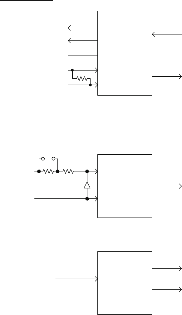
Serial Interface
IEC 61162-2 input/output
IEC 61162-1 input
IEC 61162-1 output
TD-A
TD-B
COMMON (ISOGND)
RD-A
RD-B
ADM2587E
110 ohm*
* Set with jumper.
Open/close switchable.
RD-H
RD-C
PC400
390 ohm 100 ohm
TD-A
TD-B
SN65HVD30
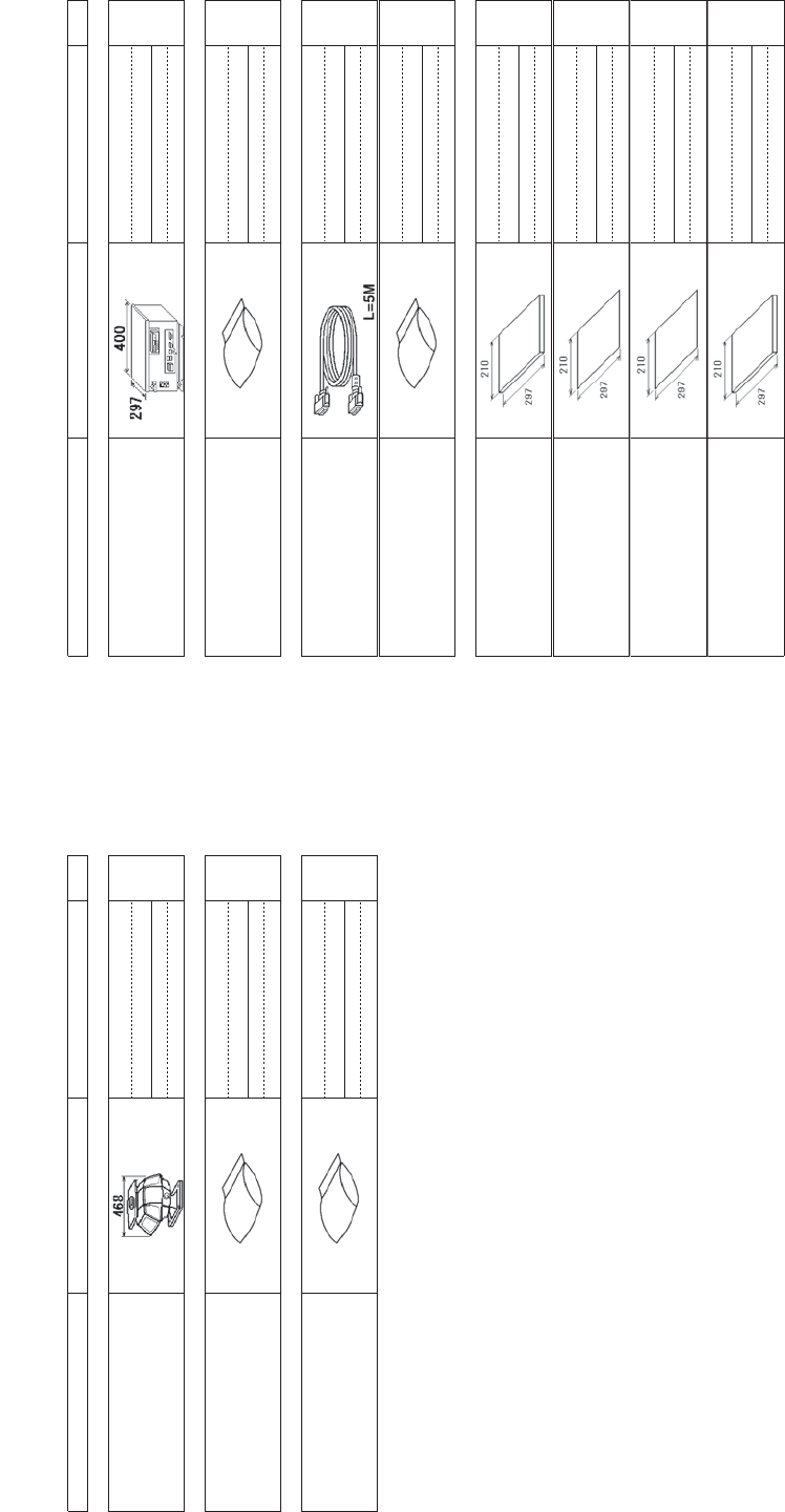
㹎㹎㸿㹁㹉㹇㹌㹅ࠉ㹊㹇㹑㹒
+4;
556%,0256%,0256%+.56%+.
1$0(
287/,1(
'(6&5,37,21&2'(θ
47<
ࣘࣘࢽࢵࢺ
881,7
✵୰⥺ᮏయ㒊
6&$11(581,7
56%
ணணഛရ
663$5(3$576
✵୰⥺ணഛရ
63$5(3$576
63
ᕤᕤᮦᩱ
,,167$//$7,210$7(5,$/6
ᕤᮦᩱ
,167$//$7,210$7(5,$/6
&3
䡶㻙䢀䢚␒ྕᮎᑿ䛾㼇㻖㻖㼉䛿䚸㑅ᢥရ䛾௦⾲䡶䡬䢀䢚䜢⾲䛧䜎䛩䚹
㻯㻻㻰㻱㻌㻺㼁㻹㻮㻱㻾㻌㻱㻺㻰㻵㻺㻳㻌㼃㻵㼀㻴㻌㻎㻖㻖㻎㻌㻵㻺㻰㻵㻯㻭㼀㻱㻿㻌㼀㻴㻱㻌㻯㻻㻰㻱㻌㻺㼁㻹㻮㻱㻾㻌㻻㻲㻌㻾㻱㻼㻾㻱㻿㻱㻺㼀㻭㼀㻵㼂㻱㻌㻹㻭㼀㻱㻾㻵㻭㻸㻚
䠄␎ᅗ䛾ᑍἲ䛿䚸ཧ⪃್䛷䛩䚹㻌㻌㻰㻵㻹㻱㻺㻿㻵㻻㻺㻿㻌㻵㻺㻌㻰㻾㻭㼃㻵㻺㻳㻌㻲㻻㻾㻌㻾㻱㻲㻱㻾㻱㻺㻯㻱㻌㻻㻺㻸㼅㻚䠅
+4;
A
-1
㹎㹎㸿㹁㹉㹇㹌㹅ࠉ㹊㹇㹑㹒
+4;
5538-+.538(+.'&
1$0(
287/,1(
'(6&5,37,21&2'(θ
47<
ࣘࣘࢽࢵࢺ
881,7
ไᚚ㒊
352&(662581,7
538
ணணഛရ
663$5(3$576
ணഛရ
63$5(3$576
63
ᕤᕤᮦᩱ
,,167$//$7,210$7(5,$/6
㺗㺎㺪㺼㺷⤌ရ
&$%/($66(0%/<
'9,''6/,1.0
ᕤᮦᩱ
,167$//$7,210$7(5,$/6
&3
ᅗᅗ᭩
''2&80(17
ྲྀᢅㄝ᫂᭩
23(5$72560$18$/
20
᧯సせ㡿᭩ከゝㄒ
23(5$7256*8,'(0/*
0/*
᧯సせ㡿᭩
23(5$7256*8,'(-3
26-
ഛせ㡿᭩
,167$//$7,210$18$/
,0
㻝㻚䡶㻙䢀䢚␒ྕᮎᑿ䛾㼇㻖㻖㼉䛿䚸㑅ᢥရ䛾௦⾲䡶䡬䢀䢚䜢⾲䛧䜎䛩䚹
㻯㻻㻰㻱㻌㻺㼁㻹㻮㻱㻾㻌㻱㻺㻰㻵㻺㻳㻌㼃㻵㼀㻴㻌㻎㻖㻖㻎㻌㻵㻺㻰㻵㻯㻭㼀㻱㻿㻌㼀㻴㻱㻌㻯㻻㻰㻱㻌㻺㼁㻹㻮㻱㻾㻌㻻㻲㻌㻾㻱㻼㻾㻱㻿㻱㻺㼀㻭㼀㻵㼂㻱㻌㻹㻭㼀㻱㻾㻵㻭㻸㻚
㻞㻚㻔㻖㻝㻕༳䛿䚸ᵝ䛻䜘䜚㑅ᢥ䚹
㻔㻖㻝㻕㻦㻌㻯㻴㻻㻻㻿㻱㻌㻻㻺㻱㻌㻰㻱㻼㻱㻺㻰㻵㻺㻳㻌㻻㻺㻌㼀㻴㻱㻌㻿㻼㻱㻯㻵㻲㻵㻯㻭㼀㻵㻻㻺㻚
䠄␎ᅗ䛾ᑍἲ䛿䚸ཧ⪃್䛷䛩䚹㻌㻌㻰㻵㻹㻱㻺㻿㻵㻻㻺㻿㻌㻵㻺㻌㻰㻾㻭㼃㻵㻺㻳㻌㻲㻻㻾㻌㻾㻱㻲㻱㻾㻱㻺㻯㻱㻌㻻㻺㻸㼅㻚䠅
+4;
A
-2