Furuno USA 9ZWRTR100 Transceiver for Radar model FAR-1518/1528 User Manual OME 36380 A
Furuno USA Inc Transceiver for Radar model FAR-1518/1528 OME 36380 A
Contents
- 1. Installation Manual Part 3
- 2. Installation Manual Part 1
- 3. Installation Manual Part 2
- 4. Installation Manual Part 4
- 5. Installation Manual Part 5
- 6. Installation Manual Part 6
- 7. User Manual Part 1
- 8. User Manual Part 2
- 9. User Manual Part 3
- 10. User Manual Part 4
- 11. User Manual Part 5
- 12. User Manual Part 6
User Manual Part 6

APPENDIX 3 ALERT CODES, MESSAGES AND MEANINGS
AP-10
601,7 SENSOR ERROR Warning
Cat: B
Message: "AIS RECEIVE"
Meaning: No AIS data received for thirty seconds.
Remedy: Press the ALERT ACK key. Check power and connection to AIS unit.
602,1 SENSOR CHANGE Caution
Cat: B
Message: "POSN SOURCE CHG"
Meaning: Positioning sensor input lost, automatically
changed sensors.
Remedy: Press the ALERT ACK key. The indication is automatically removed when the signal is
restored or a different sensor is selected.
602,2 SENSOR CHANGE Caution
Cat: B
Message: "SPD SOURCE CHG"
Meaning: Speed sensor input lost, automatically
changed sensors.
Remedy: Press the ALERT ACK key. The indication is automatically removed when the signal is
restored or a different sensor is selected.
740,1 EXT RADAR ERROR Warning
Cat: B
Message: "EXT RADAR NO SIGNAL"
Meaning: Externally connected radar has an error.
(Only displayed when Interswitch is active.)
Remedy: Press the ALERT ACK key. Restore the external radar to normal operating condition.
740,2 EXT RADAR ERROR Caution
Cat: B
Message: "EXT RADAR COM ERROR"
Meaning: Communication with external radar
interrupted or lost. (Only displayed when Interswitch
is active.)
Remedy: Press the ALERT ACK key. Check connection and power to the external radar.
790,1 ARRIVAL Warning
Cat: B
Message: "ARRIVAL"
Meaning: Ship has entered the destination arrival
alert zone.
Remedy: Press the ALERT ACK key. No other action required.
791,1 XTE Warning
Cat: B
Message: "XTE"
Meaning: Cross-track error, ship is off-course.
Remedy: Press the ALERT ACK key. Check course and adjust as necessary.
794,1 HEADING SET Warning
Cat: B
Message: "HEADING SET"
Meaning: AD-10 signal interrupted.
Remedy: Press the ALERT ACK key. Match the on-screen HDG readout with the actual
gyrocompass reading if necessary.
950,1 BAM COM ERROR Caution
Cat: B
Message: "COMMUNICATION ERROR WITH BAM"
Meaning: Communication the Bridge Alert
Management System interrupted.
Remedy: Press the ALERT ACK key. Check connection to BAM. Check power to BAM.
Alert
ID Alert title Priority &
Category Message and meaning

APPENDIX 3 ALERT CODES, MESSAGES AND MEANINGS
AP-11
ALR format alerts
Alert
code Alert title Priority &
Category Explanation
522 TT TARGET 95%(AUTO) Caution
Cat: A
Automatically acquired target capacity has
reached 95%.
Remedy: Press the ALERT ACK key. Remove TT symbols manually.
523 TT TARGET FULL(AUTO) Warning
Cat: A
Automatically acquired target capacity has
reached 100%.
Remedy: Press the ALERT ACK key. Remove TT symbols manually.
524 TT TARGET 95% (MAN) Caution
Cat: A
Manually acquired target capacity has reached
95%.
Remedy: Press the ALERT ACK key. Remove TT symbols manually.
525 TT TARGET FULL(MAN) Warning
Cat: A
Manually acquired target capacity has reached
100%.
Remedy: Press the ALERT ACK key. Remove TT symbols manually.
530 AIS DISPLAY 95% Caution
Cat: A
AIS display capacity has reached 95%
(285 targets).
Remedy: Press the ALERT ACK key. Adjust [AIS DISP FILTER] settings to decrease the number of
targets displayed.
531 AIS DISPLAY FULL Warning
Cat: A
AIS display capacity has reached 100%
(300 targets).
Remedy: Press the ALERT ACK key. Adjust [AIS DISP FILTER] settings to decrease the number of
targets displayed.
533 AIS CAPACITY FULL Caution
Cat: A
AIS capacity has reached 100% (1000 targets).
Remedy: Press the ALERT ACK key. Adjust [AIS DISP FILTER] settings to decrease the number of
targets displayed.
534 AIS ACTIVATE 95% Caution
Cat: A
Active AIS target capacity has reached 95%
(38 targets).
Remedy: Press the ALERT ACK key. Adjust [AIS DISP FILTER] settings to decrease the number of
targets displayed.
535 AIS ACTIVATE FULL Warning
Cat: A
Active AIS target capacity has reached 100%
(40 targets).
Remedy: Press the ALERT ACK key. Adjust [AIS DISP FILTER] settings to decrease the number of
targets displayed.
526 TT COLLISION Alarm
Cat: A
TT is within CPA/TCPA threshold, danger of
collision.
Remedy: Press the ALERT ACK key. Take evasive action if necessary. Adjust CPA/TCPA settings.
536 AIS COLLISION Alarm
Cat: A
AIS target is within CPA/TCPA threshold, danger
of collision.
Remedy: Press the ALERT ACK key. Take evasive action if necessary. Adjust CPA/TCPA settings.
521 TT NEW TARGET Warning
Cat: A
A new TT target has entered the Acquisition Zone.
Remedy: Press the ALERT ACK key. Confirm location of new target.
529 AIS NEW TARGET Warning
Cat: A
A new AIS target has entered the Acquisition
Zone.
Remedy: Press the ALERT ACK key. Confirm location of new target.
527 TT LOST Warning
Cat: A
TT target is lost.
Remedy: Press the ALERT ACK key. Lost target indication (blinking in red) is removed.
528 REF TARGET LOST Warning
Cat: A
REF targets is lost.

APPENDIX 3 ALERT CODES, MESSAGES AND MEANINGS
AP-12
Remedy: Press the ALERT ACK key. Lost target indication (blinking in red) is removed.
537 AIS LOST Warning
Cat: A
AIS target is lost.
Remedy: Press the ALERT ACK key. Lost target indication (blinking in red) is removed.
720 HEADLINE Warning
Cat: B
Heading signal interrupted/lost.
Remedy: Press the ALERT ACK key. Restore signal or rectify reason for signal loss.
721 AZIMUTH Warning
Cat: B
Azimuth signal is interrupted/lost.
Remedy: Press the ALERT ACK key. Restore signal or rectify reason for signal loss.
722 TRIGGER Warning
Cat: B
Output trigger interrupted/lost
Remedy: Press the ALERT ACK key. Restore signal or rectify reason for signal loss.
723 VIDEO Warning
Cat: B
Video signal interrupted/lost.
Remedy: Press the ALERT ACK key. Restore signal or rectify reason for signal loss.
70 KEY Warning
Cat: B
Control unit signal interrupted/lost.
Remedy: Press the ALERT ACK key. Restore signal or rectify reason for signal loss.
772 PM COMM ERROR Warning
Cat: B
PM communication error.
Remedy: Press the ALERT ACK key. Restore signal or rectify reason for signal loss.
48 TUNE ERROR Warning
Cat: B
TUNE error due to faulty settings or malfunction.
Remedy: Press the ALERT ACK key. Check tuning settings and adjust as necessary.
450 GYRO Warning
Cat: B
No heading information received from
gyrocompass for five seconds.
Remedy: Press the ALERT ACK key. Match the on-screen indication with the actual gyrocompass.
The indication “HEADING SET” appears. Press the ALERT ACK key to erase the indication.
278 LOG(WT) Warning/
Caution
Cat: B
No speed data received for five seconds when
[LOG(WT)] is set as speed reference.
Remedy: Press the ALERT ACK key. Check SDME sensor. Use a different sensor if necessary.
284 LOG(BT) Warning/
Caution
Cat: B
No speed data received for thirty seconds when
[LOG(BT)] is set as speed reference.
Remedy: Press the ALERT ACK key. Check SDME sensor. Use a different sensor if necessary.
170 EPFS Warning
Cat: B
EPFS Error. No speed or position data received
from EPFS device for thirty seconds.
Remedy: Press the ALERT ACK key. Restore the signal. This indication cannot be erased if the po-
sition signal is missing. The indication is automatically removed when the signal is restored.
469 DATUM Warning
Cat: B
DTM sentence no received for thirty seconds or
erroneous data received.
Remedy: Press the ALERT ACK key. Use the WGS-84 datum.
272 UTC Warning
Cat: B
UTC error. No date or time data received for thirty
seconds.
Remedy: Press the ALERT ACK key. Restore the signal to remove this indication.
380 AIS RECEIVE Warning
Cat: B
No AIS data received for thirty seconds.
Remedy: Press the ALERT ACK key. Check power and connection to AIS unit.
Alert
code Alert title Priority &
Category Explanation

APPENDIX 3 ALERT CODES, MESSAGES AND MEANINGS
AP-13
472 POSN SOURCE CHANGE Caution
Cat: B
Message: "POSN SOURCE CHG"
Meaning: Positioning sensor input lost, automati-
cally changed sensors.
Remedy: Press the ALERT ACK key. The indication is automatically removed when the signal is re-
stored or a different sensor is selected.
476 SPD SOURCE CHANGE Caution
Cat: B
Message: "SPD SOURCE CHG"
Meaning: Speed sensor input lost, automatically
changed sensors.
Remedy: Press the ALERT ACK key. The indication is automatically removed when the signal is re-
stored or a different sensor is selected.
485 DEPTH Warning
Cat: B
Depth is below set threshold.
Remedy: Press the ALERT ACK key. Confirm depth. Adjust [DEPTH] settings as required.
495 ANCHOR WATCH Warning
Cat: B
Ship position outside set anchor watch zone.
Remedy: Press the ALERT ACK key. Confirm Own Ship location and adjust as necessary.
541 TRANSMIT ERROR Caution
Cat: B
Unable to transmit AIS binary message.
Remedy: Press the ALERT ACK key. Check power to AIS unit.
542 AIS TRANSMITTING Caution
Cat: B
Transmitting AIS message.
Remedy: Press the ALERT ACK key. No other action required.
560 ASSOCIATION Caution
Cat: B
One or more sets of associated targets is
displayed.
Remedy: Press the ALERT ACK key. Set [ASSOCIATION] to [OFF].
740 EXT RADAR NO SIGNAL Warning
Cat: B
Externally connected radar has an error. (Only dis-
played when Interswitch is active.)
Remedy: Press the ALERT ACK key. Restore the external radar to normal operating condition.
750 EXT RADAR COM
ERROR
Caution
Cat: B
Communication with external radar interrupted or
lost. (Only displayed when Interswitch is
active.)
Remedy: Press the ALERT ACK key. Check connection and power to the external radar.
790 ARRIVAL Warning
Cat: B
Ship has entered the destination arrival alert zone.
Remedy: Press the ALERT ACK key. No other action required.
791 XTE Warning
Cat: B
Cross-track error, ship is off-course.
Remedy: Press the ALERT ACK key. Check course and adjust as necessary.
794 HEADING SET Warning
Cat: B
AD-10 signal interrupted.
Remedy: Press the ALERT ACK key. Match the on-screen HDG readout with the actual
gyrocompass reading if necessary.
950 BAM COM ERROR Caution
Cat: B
Communication the Bridge Alert Management
System interrupted.
Remedy: Press the ALERT ACK key. Check connection to BAM. Check power to BAM.
Alert
code Alert title Priority &
Category Explanation

AP-14
APPENDIX 4 DATA COLOR AND
MEANING
Validity and integrity of input data (mode indicator)
*1: Low or doubtful integrity can occur when the GBS sentence gives a RAIM error rate of 10 m or
higher. In this case, the ship’s latitude and longitude indications are displayed in yellow.
*2: “Age of differential GPS data” in GGA and GNS sentences is ten seconds or higher. In this
case, ship’s latitude and longitude are displayed in yellow.
Data color HDG L/L *1SPD COG/SOG
Normal color
(normal data)
THS-A,E
HDT
GNS-A, D *2, F, P, R and (NAV status: S)
GGA-1, 2 *2, 3, 4, 5
GLL-A, D and (status: A)
RMC-A, D, F, P, R and (status: A) and
(NAV status: S)
VBW-A
VHW
VTG-A, D, P
RMC-A, D,
F, P, R and
(status: A)
and (NAV
status: S).
Yellow-or-
ange color
(invalid data)
GNS-E, M, S
GGA-6, 7, 8
GLL-E, M, S and (status: A)
RMC-E, M, S and (Status: A)
VTG-E, M, S
RMC-E, M,
S, and (sta-
tus: A)
Yellow color
(low integrity) GNS-A, D*2, F, P, R, and (NAV status: C,
U, V)
RMC-A, D, F, P, R and (status: A) and
(NAV status: C, U, V)
RMC-A, D,
F, P, R and
(status: A)
and (NAV
status: C, U,
V)
***.* THS-M, N, S GNS-N, (NAV status: N)
GGA-0
RMC-N, (status: V), (NAV status: N)
GLL-N, (status: V)
VBW-V VTG-N
RMC-N (sta-
tus: V)
AP-15
APPENDIX 5 ABBREVIATIONS
A:
B:
C:
D:
Abbreviation Word Abbreviation Word
ACK Acknowledge ACQ Acquire
Act Activate ACE Automatic Clutter Elimination
ANT Antenna AIS Automatic Identification System
AP Autopilot ATON Aids to Navigation
AUTO Automatic A/C RAIN Anti Clutter RAIN
A/C SEA Anti Clutter Sea AID Aid
ALF ALF sentence ALR Alarm
AMB Amber AMS Alert Management System
APR April ARC Arc
AUG August
Abbreviation Word Abbreviation Word
BLU Blue BCR Bow Crossing Range
BCT Bow Crossing Time BRG Bearing
BRILL Brilliance BT Bottom Tracking
Abbreviation Word Abbreviation Word
CALC Calculated CALIB Calibrate
Ch Channel CHG Change
CCRP Consistent Common
Reference Point
CCRS Consistent Common
Reference System
CPA Closest Point of Approach CONT Continue
CDROM Compact Disc Read Only
Memory
CORR Corrected/Correction
CPU Central Processing Unit CRS Course
CTW Course Through the Water COG Course Over Ground
CU Course Up CURS Cursor
CYA Cyan
Abbreviation Word Abbreviation Word
DTM Datum DEC December
deg degree(s) DEST Destination
DGPS Differential GPS Diff Differential
DIST Distance DISP Display
DIST Distance DR Dead Reckoning
DISP Display
APPENDIX 5 ABBREVIATIONS
AP-16
E:
F:
G:
H:
I:
J:
L:
Abbreviation Word Abbreviation Word
E East EAV Echo Average
EBL Electronic Bearing Line ECDIS Electronic Chart Display and
Information System
ENC Electronic Navigational Chart EP Estimated Position
EQUIP Equipment ERR Error
ES Echo Stretch ES Echo Stretch
ETD Estimated Time of Departure EXT External
Abbreviation Word Abbreviation Word
FEB February FILT Filter/Filtered
FUNC Function
Abbreviation Word Abbreviation Word
GAP Gap GC Great Circle
GND Ground GMDSS Global Maritime Distress and
Safety System
GPS Global Positioning System GRAD Gradation
GRN Green GRY Gray
GT Gross Tonnage
Abbreviation Word Abbreviation Word
HD Heading HDG Heading
HL Heading Line HSC High Speed Craft
Abbreviation Word Abbreviation Word
IBS Integrated Bridge System ID Identification
IMO International Maritime
Organization
INFO Information
INS Integrated Navigation
System
IP ADDRESS Internet Protocol Address
IR Interference Rejection
Abbreviation Word Abbreviation Word
JAN January JUN June
JUL July
Abbreviation Word Abbreviation Word
L Long pulse LAT Latitude
LAN Local Area Network LCD Liquid Crystal Display
LIM Limit L/L Latitude/Longitude
LOG Log LON Longitude
LOP Line Of Position
APPENDIX 5 ABBREVIATIONS
AP-17
M:
N:
O:
P:
R:
Abbreviation Word Abbreviation Word
MAG Magnetic MAG Magenta
MAN Manual MAR March
MAX Maximum MAY May
MBS Main Bang Suppression M-CYA Multi Cyan
MFDF Medium Frequency Direction
Finder
MENU Menu
M-GRN Multi Green MIC Monolithic Integrated Circuit
MID Middle M1 Medium pulse 1
M2 Medium pulse 2 M3 Medium pulse 3
MOB Man Over Board MON Monday
Msgs Messages MSC Maritime Safety Committee
Abbreviation Word Abbreviation Word
N North NAV Navigation
NLT Not Less Than NMT Not More Than
NOV November NR Noise Rejector
Abbreviation Word Abbreviation Word
OS Own Ship OCT October
Abbreviation Word Abbreviation Word
PAST POSN Past Positions PC Personal computer
PI Parallel Index Line PM Performance Monitor
PNK Pink POSN Position
PPI Plan Position Indicator
Abbreviation Word Abbreviation Word
RACON Radar beacon RAD Radius
RAM Random Access Memory RAIN Anti Clutter Rain
RD Read RED Red
REF Reference/Echo Reference R, REL Relative
REJ Rejection RENC Regional ENC Co-ordinating Cen-
tre
RFC board RF control board RL Rhumb Line
RM Relative motion RNG Range
ROM Read Only Memory ROT Rate Of Turn
RTE Route RTGT Reference Target
RX Receive
APPENDIX 5 ABBREVIATIONS
AP-18
S:
T:
U:
V:
W:
X:
Y:
Abbreviation Word Abbreviation Word
S South S1 Short pulse1
S2 Short pulse2 S57 IHO Special Publication 57
SAR Search and Rescue SART Search and Rescue Transponder
SB Transversal Speed SD Secure Digital
SEA Anti Clutter Sea sel Select
SENC System ENC SEP September
SIO Serial input output SOLAS Safety of Life at Sea
SOG Speed Over Ground SPU Signal Processing Unit board
SPD Speed STAB Stabilized
STBD Starboard STBY Standby
STC Sensitivity time control Std Standard
STW Speed Through Water SW Switch
Symb Symbol(s) SYM Symbol
Abbreviation Word Abbreviation Word
TTrue TAGTag
TCPA Time to CPA TGT Target
TM True Motion TPL Transferred Line Of Position
True-G True ground stabilized True-S True sea stabilized
TT Target Tracking/Tracked Target TTG Time To Go
TX Transmit
Abbreviation Word Abbreviation Word
UNCAL Uncalibrated UTC Coordinated Universal Time
Abbreviation Word Abbreviation Word
VECT Vector VRM Variable Range Marker
Abbreviation Word Abbreviation Word
WWest WATWater
WGS World Geodetic System WHT White
W/O Without WOP Wheel Over Point
WP Waypoint WPT Waypoint
WR Write WT Water Tracking
WTC Water Tracking Current
Abbreviation Word
XTE Cross track error
Abbreviation Word
YEL Yellow

APPENDIX 5 ABBREVIATIONS
AP-19
Units of measurement
Abbreviation Word Abbreviation Word
deg Degree(s) ft Foot/feet
H Hour(s) km Kilometer(s)
KM Kilometer(s) kn Knot(s)
KYD Kiloyard(s) min Minute(s)
m Meter(s) MHz Megahertz
NM Nautical miles sec Second(s)
SM Statute mile(s) ° Degree(s)
AP-20
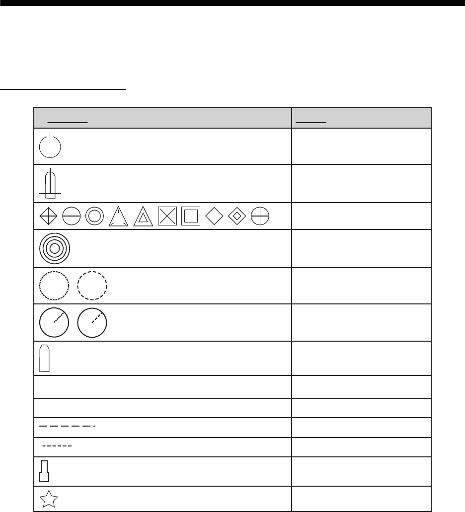
APPENDIX 6 SYMBOLS
The pages following list the symbols which can be displayed on your radar. For non-IMO type
radars, some symbol colors can be changed (see "How to select the mark color (for non-IMO
types only)" on page 1-56).
General radar symbols
(on power switch)
Power symbol
X
Own ship marker
Origin marks
Fixed range rings
Variable Range Markers
(from left, VRM1, VRM2)
Electronic Bearing Lines
(from left EBL1, EBL2)
OS mark
+ Cursor
|
Barge icon
Drop mark
Symbol Name
Heading line
North Marker
Stern Marker
APPENDIX 6 SYMBOLS
AP-21
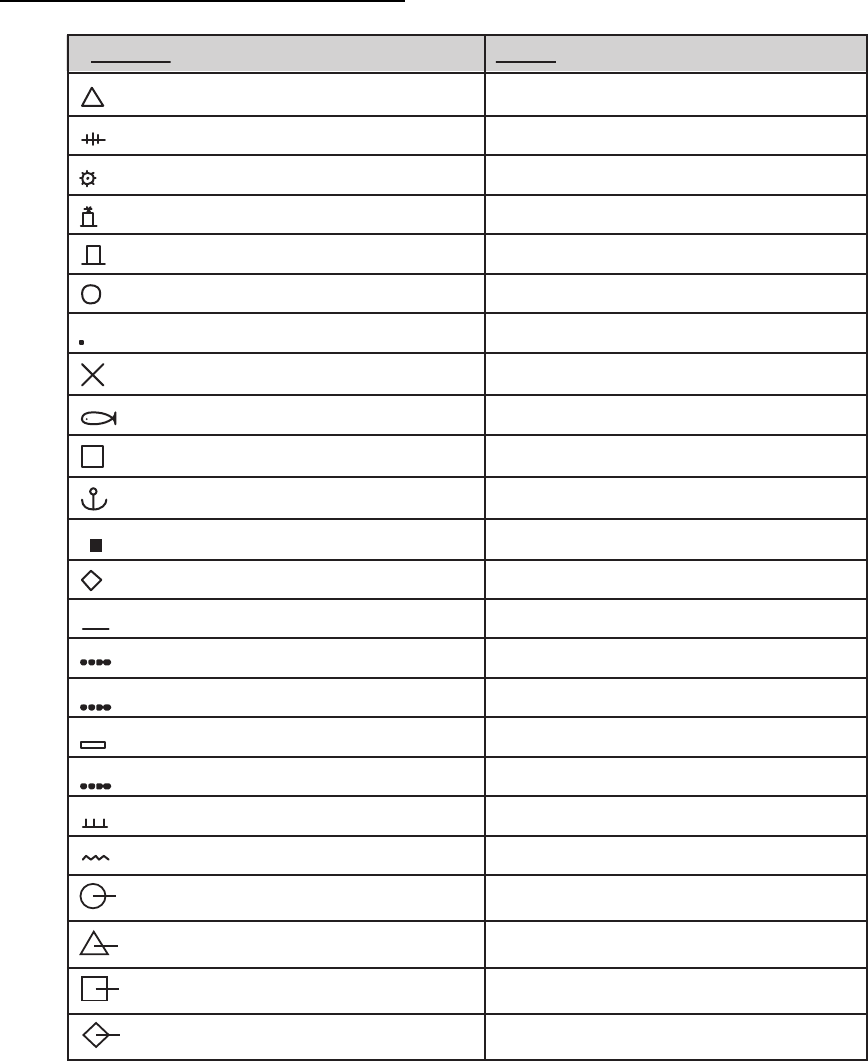
Radar map symbols (All radar types)
Symbol Name
Mark
Danger Highlight
Danger Highlight
Buoy
Buoy
Buoy
Buoy
Buoy
Danger Highlight
Mark
Mark
Mark
Mark
Mark
Mark
Mark
Nav Line (map)
Coastline
Contour
Prohibited Area
)elbac(
(w/line) Buoy
(w/line) Mark
(w/line) Mark
(w/line) Mark
APPENDIX 6 SYMBOLS
AP-22
Radar map symbols (IMO type)
TT/AIS symbols
Red Buoy
Green Buoy
Red Buoy
Green Buoy
Red Buoy
Green Buoy
Red Buoy
Green Buoy
thgilhgiH regnaD elpruP
Purple Danger Highlight
Orange Mark
Orange Mark
Orange Mark
)pam( enilvaN elpruP
eniltsaoC etihW
eniL ruotnoC yarG
thgilhgiH regnaD elpruP
thgilhgiH regnaD )elbac( elpruP
kraM egnarO
kraM egnarO
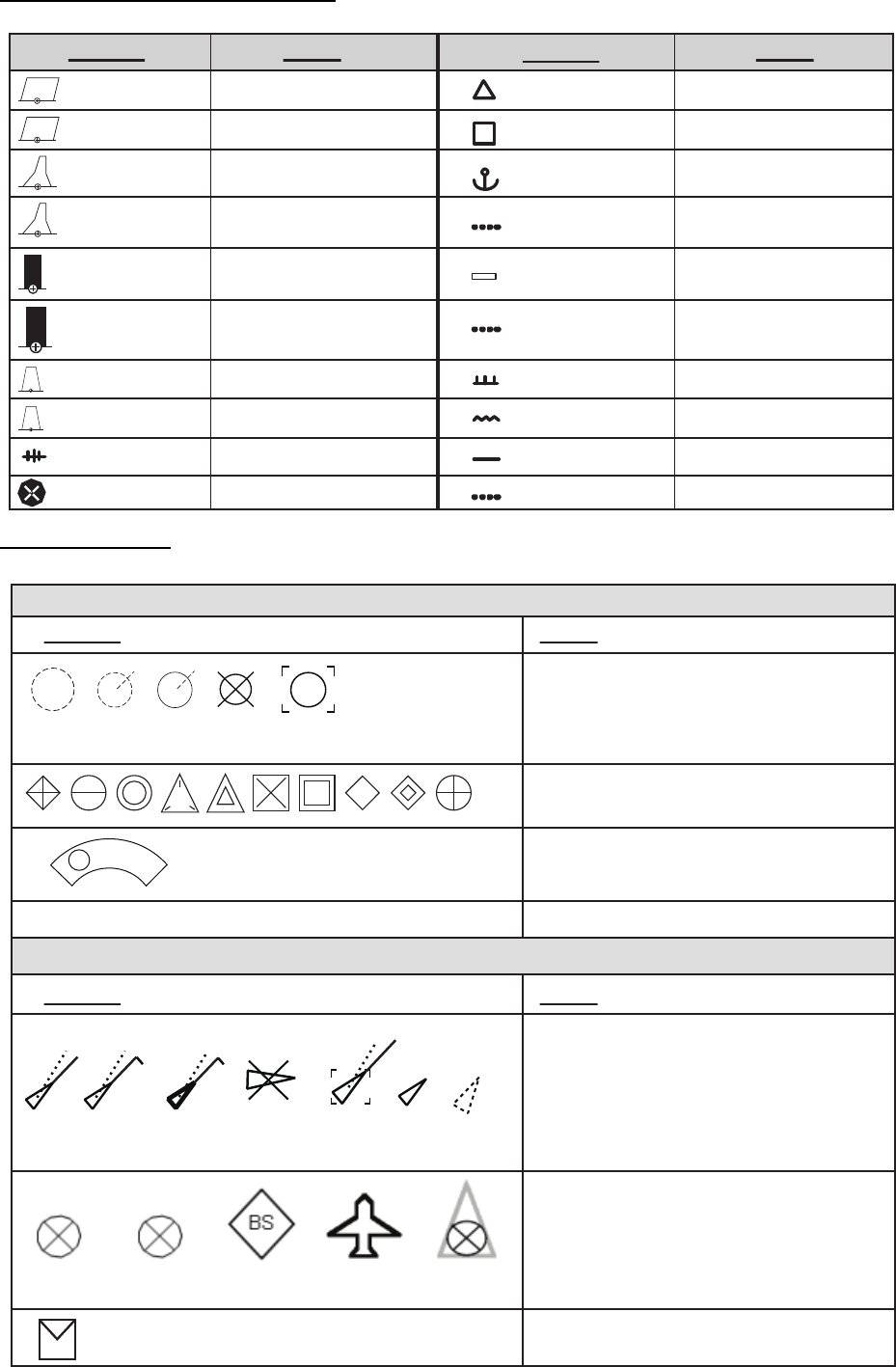
Symbol Name Name
Symbol
TT symbols
Acquisition zone
Performance test
AIS message received
S
AIS symbols
A
∟shown in red when active
Symbol Name
Symbol Name
Acquired targets (from left: initial
acquisition, one minute after acquisition,
steady tracking, lost target, target
selected for data readout)
TT symbols (User may change TT
symbols)
AIS symbols (from left: activated
target, ROT higher than preset
ROT, dangerous target, lost target,
target selected for data display,
sleeping target, CPA/TCPA lost
target)
Other AIS symbols (from left, AIS
SART (ACTIVE), AIS SART (TEST),
AIS Base station, AIS search and
rescue (SAR) Aircraft, AIS Search and
Rescue (SAR) Vessel.)
APPENDIX 6 SYMBOLS
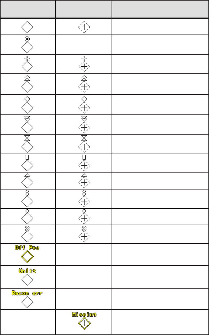
AP-23
Basic shape
RACON
Emergency wreck mark
North cardinal mark
East cardinal mark
South cardinal mark
West cardinal mark
Port hand mark
Starboard hand mark
Isolated danger
Safe water
Special mark
Off position (Displayed with yellow
line and yellow text)
Light fail or at reduced range
(Displayed with yellow text)
RACON error
(Displayed with yellow text)
Missing
(Displayed with yellow dashed
line and yellow text)
AIS Physical
AtoN Symbol
AIS Virtual
AtoN Symbol Meaning
AP-24
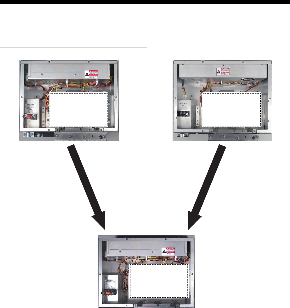
APPENDIX 7 PARTS LOCATION
This section shows the location of PC boards inside the equipment which can be replaced. For
information on parts, or to replace a part, consult your local FURUNO dealer.
Processor unit RPU-024 (AC and DC type)
AC_PWR module
AC_PWR module
AC_PWR or DC_PWR module
AC_PWR or DC_PWR module
FRP_TB Board
03P9601
FRP_TB Board
03P9601
SPU Board
03P9547
SPU Board
03P9547
AC_FIL
module
AC_FIL
module
AC_FIL
or
DC_FIL
module
AC_FIL
or
DC_FIL
module
Remove FRP_TB Board to
show SPU Board 03P9547
DC_PWR module
DC_PWR module
FRP_TB Board
03P9601
FRP_TB Board
03P9601
DC_FIL
module
DC_FIL
module
APPENDIX 7 PARTS LOCATION
AP-25
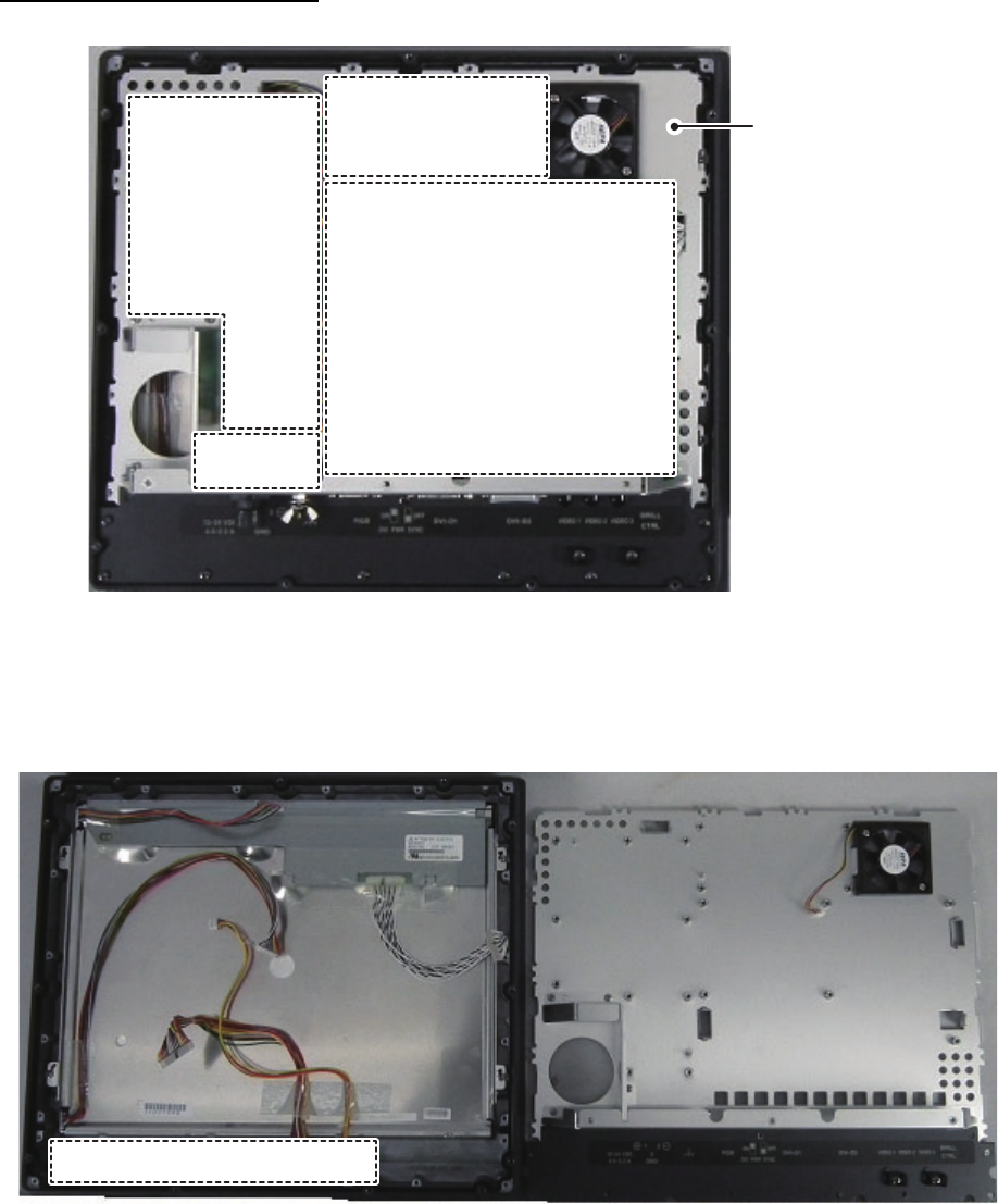
Marine display MU-150HD
Remove Power Board 26P0015, Drive Board 26P0020, AD Board 26S0029, CON Board 26S0018
and the Board fixing plate to show the LCD module and PANEL Board 26P0013.
Drive Board
26P0020
Drive Board
26P0020
Power Board
26P0015
Power Board
26P0015
AD Board
26S0029
AD Board
26S0029
CON Board
26S0018*
CON Board
26S0018*
*: CON Board 26S0018 is located under the overhang on the
board fixing plate.
Board fixing plate
Board fixing plateBoard fixing plate
LCD moduleLCD module
PANEL Board 26P0013PANEL Board 26P0013
APPENDIX 7 PARTS LOCATION
AP-26
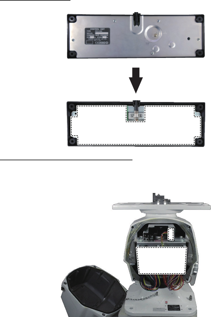
Control Unit RCU-028
Transceiver Unit RTR-100/101 Rear view
Note: The board location for both the RTR-101 and RTR-100 are the same. The image below
shows the RTR-101.
RCU-028 bottom cover
Remove to show KEY Board 03P9528
RCU-028 bottom cover
Remove to show KEY Board 03P9528
KEY Board 03P9528KEY Board 03P9528
HDBP Board
03P9347
HDBP Board
03P9347
RFTP Board
03P9488
RFTP Board
03P9488
Rear coverRear cover
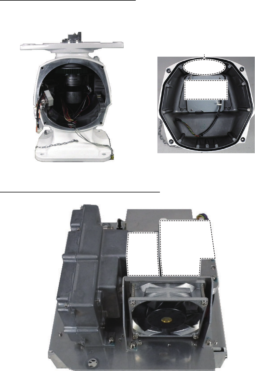
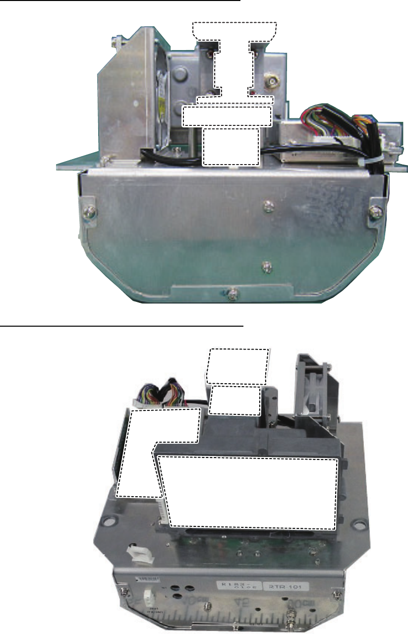
APPENDIX 7 PARTS LOCATION
AP-27
Transceiver Unit RTR-100/101 Front view
Note: The board location for both the RTR-101 and RTR-100 are the same. The image below
shows the RTR-101.
Transceiver module RTR-100/101 right-side view
Rear view with cover and transceiver
module RTR-101 removed.
Rear cover inner with PM32 module
showing.
PM32 modulePM32 module
PM ANTPM ANT
Circulator
Circulator
Limiter
Limiter
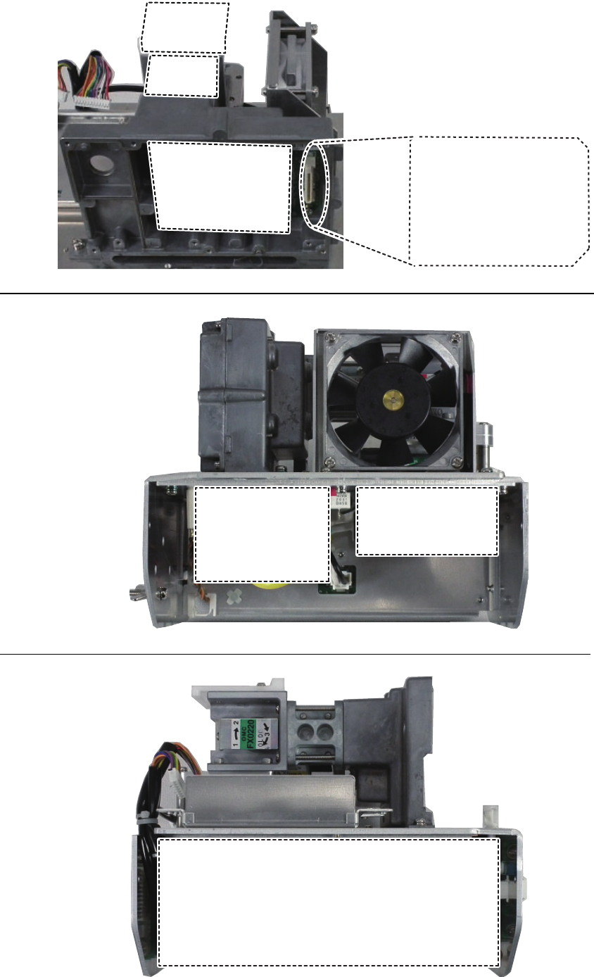
APPENDIX 7 PARTS LOCATION
AP-28
Transceiver module RTR-100/100 rear view
Transceiver module RTR-100/101 front view
CirculatorCirculator
FilterFilter
IsolatorIsolator
CirculatorCirculator
LimiterLimiter
RFC Board
03P9506
RFC Board
03P9506
IF Board
03P9487
IF Board
03P9487
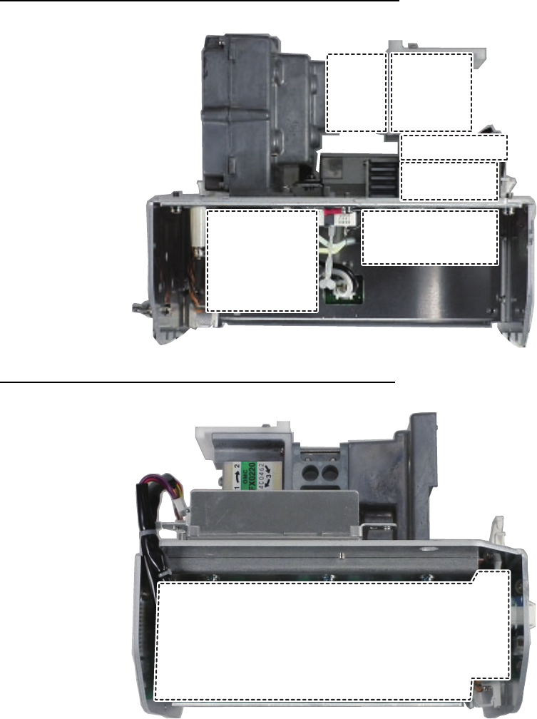
APPENDIX 7 PARTS LOCATION
AP-29
Remove IF Board 03P9487 to show MIC board 03P9505 (covered by board fixing panel).
Transceiver module RTR-101 underside-front view (For FAR-1518/1528/BB)
Transceiver module RTR-101 underside-rear view (For FAR-1518/1528/BB)
CirculatorCirculator
LimiterLimiter
Board fixing
panel
Board fixing
panel
MIC board
03P9505
(Remove Board
fixing panel).
MIC board
03P9505
(Remove Board
fixing panel).
MagnetronMagnetron
Pulse
Transmitter
Pulse
Transmitter
MD Board
03P9507
MD Board
03P9507
APPENDIX 7 PARTS LOCATION
AP-30
Transceiver module RTR-100 underside-front view
Transceiver module RTR-100 underside-rear view
MagentronMagentron
IsolatorIsolator
CirculatorCirculatorLimiterLimiter
FilterFilter
Pulse
Transmitter
Pulse
Transmitter
MD Board
03P9507
MD Board
03P9507

FURUNO
FAR-1513/1523 (-BB)
SP - 1 E3638S01A-M
SPECIFICATIONS OF MARINE RADAR
FAR-1513/1523 (-BB)
1 ANTENNA UNIT
1.1 Antenna type Slotted waveguide array
1.2 Radiator length 4 ft (XN12A), 6 ft (XN13A)
1.3 Horizontal beamwidth 1.9° (XN12A), 1.35° (XN13A)
1.4 Vertical beamwidth 20°
1.5 Sidelobe attenuation
XN12A -24 dB (within ±20° of main-lobe)
XN13A -28 dB (within ±20° of main-lobe)
1.6 Polarization Horizontal
1.7 Rotation 24 rpm (RSB-0070), 48 rpm (RSB-0073)
2 RF TRANSCEIVER
2.1 Frequency 9410 MHz ±30 MHz, P0N
2.2 Output power
FAR-1513 (-BB) 12 kW
FAR-1523 (-BB) 25 kW
2.3 Minimum range 25 m
2.4 Range discrimination 25 m
2.5 Range accuracy 1 % of range in use or 10 m whichever is the greater
2.6 Bearing accuracy ±1°
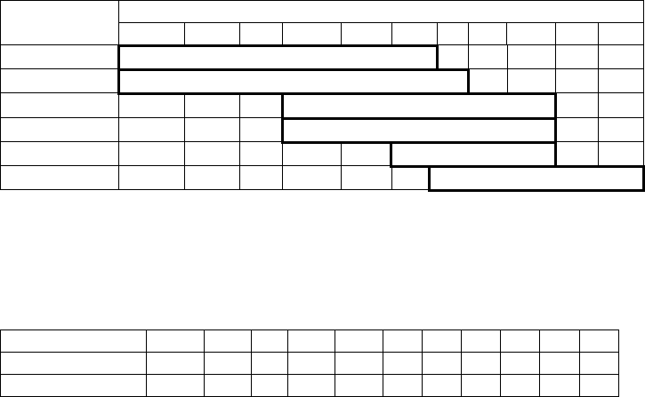
2.7 Range, Pulselength and Pulse Repetition Rate
PRR
(Hz approx.) Range scale (NM)
0.125 0.25 0.5 0.75 1 1.5 2 3 4 6 8 12 16 24 32 48 72 96 120
2100 S
1200 M
600* L
*: 500 Hz on 96/120 NM ranges
2.8 IF frequency 60 MHz
3 PROCESSOR UNIT
3.1 Range scales and ring interval
Scale (NM) 0.125 0.25 0.5 0.75 1 1.5 2 3 4 6 8 12 16 24 32 48 72 96 120
RI (NM) 0.025 0.05 0.1 0.25 0.25 0.25 0.5 0.5 1 1 2 2 4 4 8 8 12 16 20
Number of rings 5 5 5 3 4 6 4 6 4 6 4 6 4 6 4 6 6 6 6
3.2 Warm-up time 3 minutes approx.
3.3 Presentation mode Head-up, STAB Head-up, North-up (TM/RM), Course-up, Stern-up
3.4 Marks Cursor, Radar ring, Heading mark, North mark, Bearing line,
Vector, Map mark, Zoom, VRM, EBL, Acquisition zone
3.5 Target tracking (TT) Auto or manual acquisition: 50 targets in 0.2-32 NM
Tracking: 5/10 pts on all target
Time of vector: 0 to 60 minutes
3.6 AIS Display capacity: 300 targets, Tracking: 5/10 pts on all target
Time of vector: 0 to 60 minutes
3.7 Echo trail True/Relative, Trail length: 0 to 30 minutes (30 s steps) or continue
FURUNO
FAR-1513/1523 (-BB)
SP - 2 E3638S01A-M
3.8 Radar map 5,000 pts
3.9 Interswitch function Selected from menu
4 MARINE DISPLAY (MU-150HD*)
4.1 Screen size 15-inch color LCD, 304 x 228 mm, 1024 x 768 dots (XGA)
4.2 Brightness 1,000 cd/m2 typical
4.3 Contrast 600:1
4.4 View angle 160° typical
4.5 Radar effective diameter 205 mm
*: The display unit for BB-type should be prepared by user.
5 INTERFACE
5.1 Number of ports on processor unit
Heading 1 port: AD-10 format or IEC61162-2
Serial IEC61162-2: 2 ports (AIS/HDG)
IEC61162-1: 4 ports (GPS/LOG/AMS/ECDIS)
Contact closure Alert output: 4 ch, Remote ACK input, System fail, power fail
Remote display 2 ports (Signal: HD, BP, Trigger and Video)
LAN Ethernet 100Base-TX: 1 port
DVI DVI-D: 1 port for main display
RGB 1 port for VDR or RGB monitor
5.2 Data sentences
Input ABK, ACK, ACN, ALR, BWC, BWR, CUR, DBK, DBS, DBT, DPT,
DTM, GBS, GGA, GLL, GNS, HBT, HDG, HDM, HDT, MTW, MWV,
RMB, RMC, RTE, THS, VBW, VDM, VDO, VDR, VHW, VSD, VTG,
VWR, VWT, WPL, ZDA
Output ABM, ACK, ALC, ALF, ALR, ARC, BBM, EVE, HBT, OSD, RSD,
TLB, TLL, TTD, TTM, VSD
6 POWER SUPPLY
6.1 Processor unit
FAR-1513 (-BB) 24 VDC: 5.0 A max. (24 rpm), 5.6 A max. (48 rpm)
FAR-1523 (-BB) 24 VDC: 6.4 A max. (24 rpm), 7.0 A max. (48 rpm)
6.2 Marine display 12-24 VDC: 4.5-2.2 A
6.3 Rectifier (RU-1746B-2, option) 100-115/220-230 VAC, 1 phase, 50/60Hz
4 ENVIRONMENTAL CONDITIONS
4.1 Ambient temperature
Antenna unit -25°C to +55°C (storage: +70°C or less)
Processor unit -15°C to +55°C
Marine display -15°C to +55°C
4.2 Relative humidity 93% or less at +40°C
4.3 Degree of protection
Antenna unit IP26
Processor unit IP20 (IP22: option)
Control unit IP22
FURUNO
FAR-1513/1523 (-BB)
SP - 3 E3638S01A-M
Marine display IP56 (panel), IP22 (chassis)
4.4 Vibration IEC 60945 Ed.4
5 UNIT COLOR
5.1 Antenna unit N9.5 (fixed)
5.2 Processor/control unit N2.5 (fixed)
5.3 Marine display N2.5 (fixed)
FURUNO
FAR-1518/1528 (-BB)
SP - 4 E3642S01A-M
SPECIFICATIONS OF MARINE RADAR
FAR-1518/1528 (-BB)
1 ANTENNA UNIT
1.1 Antenna type Slotted waveguide array
1.2 Radiator length 4 ft (XN12AF), 6.5 ft (XN20AF), 8 ft (XN24AF)
1.3 Horizontal beamwidth 1.9° (XN12AF), 1.23° (XN20AF), 0.95° (XN24AF)
1.4 Vertical beamwidth 20°
1.5 Sidelobe attenuation
XN12AF -24 dB (within ±20° of main-lobe)
XN20/24AF -28 dB (within ±20° of main-lobe)
1.6 Polarization Horizontal
1.7 Rotation 26 rpm (RSB-120), 48 rpm (RSB-121)
2 RF TRANSCEIVER
2.1 Frequency 9410 MHz ±30 MHz, P0N
2.2 Output power
FAR-1518 (-BB) 12 kW
FAR-1528 (-BB) 25 kW
2.3 Minimum range 25 m
2.4 Range discrimination 25 m
2.5 Range accuracy 1 % of range in use or 10 m whichever is the greater
2.6 Bearing accuracy ±1°
2.7 Range, Pulselength and Pulse Repetition Rate
PRR
(Hz approx.) Range scale (NM)
0.125 0.25 0.5 0.75 1.5 3 6 12 24 48 96
3000* S1
2760* S2
1500 M1
1000 M2
1000 M3
600** L
*: 2200 Hz approx. with TT range on 32 NM. **: 500 Hz on 96 NM range.
2.8 IF frequency 60 MHz
3 PROCESSOR UNIT
3.1 Range scales and ring interval
Scale (NM) 0.125 0.25 0.5 0.75 1.5 3 6 12 24 48 96
RI (NM) 0.025 0.05 0.10.250.250.5124816
Number of rings 5 5 53 6 666666
3.2 Warm-up time 3 minutes approx.
3.3 Presentation mode Head-up, STAB Head-up, North-up (TM/RM), Course-up, Stern-up
3.4 Marks Cursor, Radar ring, Heading mark, North mark, Bearing line,
Vector, Map mark, Zoom, VRM, EBL, Acquisition zone
3.5 Target tracking (TT) Auto or manual acquisition: 50 targets in 0.2-32 NM
Tracking: 5/10 pts on all target
Time of vector: 0 to 60 minutes
FURUNO
FAR-1518/1528 (-BB)
SP - 5 E3642S01A-M
3.6 AIS Display capacity: 300 targets, Tracking: 5/10 pts on all target
Time of vector: 0 to 60 minutes
3.7 Echo trail True/Relative, Trail length: 0 to 30 minutes (30 s steps) or continue
3.8 Radar map 5,000 pts
3.9 Interswitch function Selected from menu
4 MARINE DISPLAY (MU-150HD*)
4.1 Screen size 15-inch color LCD, 304 x 228 mm, 1024 x 768 dots (XGA)
4.2 Brightness 1,000 cd/m2 typical
4.3 Contrast 600:1
4.4 View angle 160° typical
4.5 Radar effective diameter 213 mm
*: The display unit for BB-type should be prepared by user.
5 INTERFACE
5.1 Number of ports on processor unit
Heading 1 port: AD-10 format or IEC61162-2
Serial IEC61162-2: 2 ports (AIS/HDG)
IEC61162-1: 4 ports (GPS/LOG/AMS/ECDIS)
Contact closure Alert output: 4 ch, Remote ACK input, System fail, power fail
Remote display 2 ports (Signal: HD, BP, Trigger and Video)
LAN Ethernet 100Base-TX: 1 port
DVI DVI-D: 1 port for main display
RGB 1 port for VDR or RGB monitor
5.2 Data sentences
Input ABK, ACK, ACN, ALR, BWC, BWR, CUR, DBK, DBS, DBT, DPT,
DTM, GBS, GGA, GLL, GNS, HBT, HDG, HDM, HDT, MTW, MWV,
RMB, RMC, RTE, THS, VBW, VDM, VDO, VDR, VHW, VSD, VTG,
VWR, VWT, WPL, ZDA
Output ABM, ACK, ALC, ALF, ALR, ARC, BBM, EVE, HBT, OSD, RSD,
TLB, TLL, TTD, TTM, VSD
6 POWER SUPPLY
6.1 Processor unit
AC type
FAR-1518 (-BB) 100-115/220-230 VAC: 3.0/1.4 A (26 rpm), 3.6/1.6 A (48 rpm)
FAR-1528 (-BB) 100-115/220-230 VAC: 3.8/1.7 A (26 rpm), 4.3/2.0 A (48 rpm)
DC type
FAR-1518 (-BB) 24 VDC: 6.7 A max. (26 rpm), 8.3 A max. (48 rpm)
FAR-1528 (-BB) 24 VDC: 8.3 A max. (26 rpm), 10.0 A max. (48 rpm)
6.2 Marine display 12-24 VDC: 4.5-2.2 A
6.3 Rectifier (RU-1746B-2/RU-3424, option)
100-115/220-230 VAC, 1 phase, 50/60Hz
6.4 Transformer (RU-1803, option) 440 VAC, 1 phase, 50/60Hz
FURUNO
FAR-1518/1528 (-BB)
SP - 6 E3642S01A-M
7 ENVIRONMENTAL CONDITIONS
7.1 Ambient temperature
Antenna unit -25°C to +55°C (storage: +70°C or less)
Processor unit -15°C to +55°C
Marine display -15°C to +55°C
7.2 Relative humidity 93% or less at +40°C
7.3 Degree of protection
Antenna unit IP56
Processor unit IP20 (IP22: option)
Control unit IP22
Marine display IP56 (panel), IP22 (chassis)
7.4 Vibration IEC 60945 Ed.4
8 UNIT COLOR
8.1 Antenna unit N9.5 (fixed)
8.2 Processor/control unit N2.5 (fixed)
8.3 Marine display N2.5 (fixed)
9 PERFORMANCE MONITOR (PM-32A)
9.1 Frequency range 9380 to 9440 MHz
9.2 Input power +18dBm to 30dBm
9.3 Output power -21 dBm (2nd pulse max. output), -41 dBm (2nd pulse min. output)
9.4 Step level 8 to 12 dB (1st pulse to last pulse)

IN-1
INDEX
Numerics
2nd trace echoes..................................... 1-30
A
Acquisition zone ...................................... 3-15
acknowledge AZ alert............................ 3-16
activate AZ1 .......................................... 3-15
AZ shape............................................... 3-17
AZ stabilization...................................... 3-17
AZ2 polygon .......................................... 3-16
change AZ reference............................. 3-17
sleep a zone.......................................... 3-16
AIS
CPA/TCPA alarm .................................. 4-13
AIS lost target
disable alert........................................... 4-12
enable alert ........................................... 4-12
filtering................................................... 4-12
AIS operation ............................................ 4-1
activate target.......................................... 4-5
auto activate function enable/disable ...... 4-6
auto activate function limit settings ......... 4-6
controls.................................................... 4-2
CPA/TCPA ............................................ 4-13
CPA/TCPA range settings..................... 4-13
create and save messages ................... 4-17
display AIS alerts .................................. 4-19
display filter ............................................. 4-5
how to set up for a voyage ...................... 4-7
how to sleep all targets ........................... 4-7
how to sleep individual targets ................ 4-7
how to sleep targets ................................ 4-7
manually activate target .......................... 4-5
messages.............................................. 4-16
own ship data ........................................ 4-16
ROT setting ........................................... 4-13
symbols and meanings ........................... 4-3
system messages ................................. 4-19
target data ............................................... 4-9
transmit messages ................................ 4-18
TT/AIS association ................................ 4-15
view messages...................................... 4-18
AIS opertation
lost target .............................................. 4-12
number of past positions ....................... 4-11
past position display.............................. 4-11
past position orientation ........................ 4-11
past position plotting interval................. 4-11
past position stabilization ...................... 4-11
symbol attributes ................................... 4-10
symbol brilliance.................................... 4-10
symbol color .......................................... 4-10
AIS target data
how to display AIS target data ................ 4-9
how to remove AIS target data................ 4-9
Alerts
alert box ................................................ 1-71
alert icons and meanings ...................... 1-73
alert list.................................................. 1-72
ALF format ............................................AP-7
ALR format ..........................................AP-11
codes and definitions ............................AP-7
descriptions ........................................... 1-71
priority assignment ................................ 1-73
Anchor watch .......................................... 1-70
Automatic Clutter Elimination (ACE) function1-
25
AZ............................................................ 3-15
B
Background colors .................................. 1-61
Bearing measurement............................. 1-36
EBL key................................................. 1-37
methods ................................................ 1-37
on-screen box ....................................... 1-37
true/relative ........................................... 1-38
Brilliance.................................................... 1-6
on-screen data ...................................... 1-61
C
CCRP ...................................................... 1-69
Color palettes .......................................... 1-61
Controls..................................................... 1-1
trackball................................................... 1-2
CPA/TCPA .............................................. 3-14
acknowledge alarm ............................... 3-14
set ranges ............................................. 3-14
Cursor data ............................................. 1-10
Custom settings ...................................... 1-12
Customized echo
editing.................................................... 1-29
restoring to factory default settings ....... 1-30
restoring to saved settings .................... 1-29
selection ................................................ 1-28
Customizing operation ............................ 1-12
D
Display indications .................................... 1-4
Display mode .......................................... 1-74
DRIFT...................................................... 3-13
E
EA ........................................................... 1-24
EBL collision assessment ....................... 1-39
assess risk............................................. 1-39
set reference point ................................ 1-40
Echo average .......................................... 1-24
Echo colors ............................................. 1-62
Echo stretch ............................................ 1-24
ES ........................................................... 1-24
INDEX
IN-2
F
False echoes
multiple echoes ........................................2-3
shadow sectors ........................................2-4
sidelobe echoes .......................................2-3
virtual images...........................................2-4
Funtion keys.............................................1-11
G
GAIN ........................................................1-20
H
Heading alignment ...................................1-12
Heading line
how to hide the heading line ..................1-58
I
Information box ........................................1-64
Information box menu ..............................1-64
Interference rejector.................................1-23
Interswitch................................................1-65
antenna information ...............................1-65
IR .............................................................1-23
L
List of abbreviations ..............................AP-15
Longitude error tables .............................AP-5
Lost target alert
enable/disable alert..................................3-6
M
Maintenance ..............................................6-1
major parts life expectancy ......................6-3
periodic schedule .....................................6-2
trackball....................................................6-4
Marks
barge mark.............................................1-60
delete marks...........................................1-58
drop mark ...............................................1-57
hide heading line ....................................1-58
how to inscribe a mark ...........................1-57
how to use marks...................................1-55
INS mark ................................................1-59
mark inscription position.........................1-56
mark type ...............................................1-55
origin mark stabilization..........................1-57
own ship symbol settings .......................1-59
radar map marks ....................................1-59
show/hide radar map marks...................1-59
show/hide stern mark.............................1-58
Menu operations ........................................1-6
box menus................................................1-8
context menus..........................................1-8
cursor menu .............................................1-9
main menu ...............................................1-6
menu layers..............................................1-7
Menu tree................................................AP-1
N
Nav data...................................................1-63
display settings.......................................1-63
enable/disable display............................1-63
Navigational data .....................................1-63
Noise rejector...........................................1-26
NR............................................................1-26
O
Observation
bearing accuracy......................................2-2
false echoes.............................................2-3
min/max ranges........................................2-1
range measurement .................................2-2
resolution..................................................2-2
Off-center .................................................1-43
On-screen indications ................................1-4
Orientation modes....................................1-31
description..............................................1-31
selection .................................................1-31
Own ship position.....................................1-14
Own ship speed .......................................1-13
auto input ...............................................1-13
manual input...........................................1-14
P
Parallel index lines ...................................1-51
bearing and interval................................1-51
bearing reference ...................................1-52
displayed lines........................................1-51
length adjustment...................................1-53
orientation ..............................................1-52
reset .......................................................1-52
Past position
POSN plotting intervals ..........................3-12
set points to display................................3-12
show/hide past POSN............................3-12
Past position display ................................3-12
PAST POSN ............................................3-12
Performance monitor................................1-67
activate/deactivate .................................1-67
check radar performance .......................1-68
PI..............................................................1-51
PI lines .....................................................1-51
Plotter.........................................................5-1
PM............................................................1-67
Power switch..............................................1-3
Pulselength ..............................................1-19
adjustment..............................................1-19
R
RACON ......................................................2-7
Radar map .................................................5-2
disable map alignment .............................5-3
enable map alignment..............................5-3
map marks ...............................................5-2
show/hide map.........................................5-2
Radar Target Enhancer..............................2-7
Rain clutter...............................................1-22
adjustment methods...............................1-22
manual ...................................................1-22
Range and bearing measurement............1-41
EBL to VRM OFFSET link......................1-41
INDEX
IN-3
how to measure..................................... 1-41
Range measurement............................... 1-34
on-screen box ....................................... 1-35
TTG to VRM .......................................... 1-36
VRM key................................................ 1-35
VRM units.............................................. 1-35
Range rings
hide/show rings ..................................... 1-34
Range scale ............................................ 1-33
Reference position .................................. 1-69
RTE ........................................................... 2-7
S
SART......................................................... 2-5
bandwidth................................................ 2-6
description............................................... 2-5
radar sidelobes........................................ 2-7
range errors............................................. 2-6
show/hide SART marks........................... 2-6
SC card ................................................... 1-75
access data ........................................... 1-75
delete data ............................................ 1-75
load data ............................................... 1-75
read data ............................................... 1-75
save data............................................... 1-75
Sea clutter ............................................... 1-20
adjustment methods.............................. 1-20
auto ....................................................... 1-21
manual .................................................. 1-21
Search and rescure transponder............... 2-5
Second trace echoes .............................. 1-30
Sensitivity ................................................ 1-20
SET ......................................................... 3-13
SET DRIFT.............................................. 3-13
Symbols ................................... AP-20, AP-24
general radar symbols.........................AP-20
IMO map radar symbols......................AP-22
radar map............................................AP-21
radar(AIS symbols) .............................AP-22
radar(TT symbols)...............................AP-22
T
Target alarm............................................ 1-49
alarm settings........................................ 1-50
deactivate.............................................. 1-50
mute ...................................................... 1-50
on/off ..................................................... 1-49
setting.................................................... 1-49
Target tracking
activate/deactivate tracking..................... 3-3
controls.................................................... 3-2
display/remove target data...................... 3-8
echo referenced speed ........................... 3-4
hide target list.......................................... 3-9
lost target ................................................ 3-6
lost target filter......................................... 3-6
manual acquisition .................................. 3-3
mode selection ........................................ 3-2
on-screen box overview .......................... 3-2
own ship speed ....................................... 3-4
precautions.............................................. 3-1
remove target data .................................. 3-9
selection criteria .................................... 3-20
show target list ........................................ 3-9
simulation mode .................................... 3-19
sort target list........................................... 3-9
symbol brilliance...................................... 3-7
symbol color ............................................ 3-8
symbols and attributes ............................ 3-7
system messages.................................. 3-18
Target trails ............................................. 1-44
clutter prevention................................... 1-46
hide trails............................................... 1-46
narrow trails........................................... 1-46
trail erase/restart ................................... 1-46
trail gradation ........................................ 1-45
trail level ................................................ 1-45
trail stabilization..................................... 1-46
trail time................................................. 1-45
true/relative ........................................... 1-44
Terminology .............................................. 1-2
Transmission on/off................................. 1-17
Troubleshooting ........................................ 6-1
advanced troubleshooting ....................... 6-5
basic troubleshooting .............................. 6-4
diagnostics .............................................. 6-7
TT............................................................ 1-44
Tuning ..................................................... 1-18
auto ....................................................... 1-18
manual .................................................. 1-18
V
Vector modes .......................................... 3-10
description............................................. 3-10
vector length.......................................... 3-12
vector time............................................. 3-12
Video plotter .............................................. 5-1
create waypoints ..................................... 5-6
delete own ship’s track............................ 5-5
delete waypoints ..................................... 5-7
display waypoint list................................. 5-7
display waypoint name/number............... 5-7
enter waypoints ....................................... 5-6
orientation modes.................................... 5-1
own ship’s track....................................... 5-4
own ship’s track color.............................. 5-4
own ship’s track plot interval ................... 5-4
radar map................................................ 5-2
waypoints ................................................ 5-6
W
Wiper....................................................... 1-26
Z
Zoom ....................................................... 1-54
area selection........................................ 1-54
area selection with function key ............ 1-54
enable/disable ....................................... 1-54
set magnification ................................... 1-54