Furuno USA 9ZWRTR100 Transceiver for Radar model FAR-1518/1528 User Manual OME 36380 A
Furuno USA Inc Transceiver for Radar model FAR-1518/1528 OME 36380 A
Contents
- 1. Installation Manual Part 3
- 2. Installation Manual Part 1
- 3. Installation Manual Part 2
- 4. Installation Manual Part 4
- 5. Installation Manual Part 5
- 6. Installation Manual Part 6
- 7. User Manual Part 1
- 8. User Manual Part 2
- 9. User Manual Part 3
- 10. User Manual Part 4
- 11. User Manual Part 5
- 12. User Manual Part 6
User Manual Part 2

1. OPERATIONAL OVERVIEW
1-12
1.10 How to Customize Operation
Several operation items can be customized to suit your needs.
1. Open the [MAIN MENU].
2. Select [INITIAL SETTING], then press the ADJUST knob.
3. Select [OPERATION], then press the ADJUST knob.
4. Referring to the table below, select the appropriate menu item to customize.
*: Non-IMO radars only.
5. Rotate the ADJUST knob to select the appropriate setting, then press the knob.
6. Close the menu.
1.11 How to Select the Interface for Heading Input
When a gyrocompass is connected, the ship’s heading is displayed on the right side
of the screen, in the data display area.
Heading input can be selected as follows:
1. Place the cursor on the [HDG] box at the top-right of the screen, then press the
right button. The [HDG] context menu is displayed.
2. Select [HDG SOURCE], then press the ADJUST knob.
3. Select [AD-10] or [SERIAL] as appropriate, then press the ADJUST knob.
This refers to the type of connection, [AD-10] is for AD-10 format (FURUNO
original) connection, [SERIAL] is for serial connections.
4. Close the menu.
Note: The heading sensor must be able follow a minimum ROT of 20° per second.
Heading sensors with a lesser capability may degrade the performance of echo aver-
aging, trails and TT. The data refresh rate should also be as short as possible. If the
refresh rate is too long, the ability to follow courses lessens, thereby affecting the per-
formance of echo averaging, trails and TT.
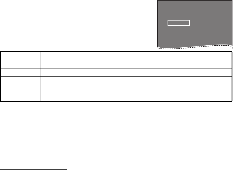
Menu items Description Available settings
WHEEL DRIVE Set the direction of the wheel drive. [NORMAL], [RE-
VERSE]
KEY BEEP Adjust the key operation sound. [OFF], [LOW], [MID],
[HIGH]
OWN SHIP VECTOR Adjust how the own ship vector is
displayed.
[OFF], [HDG],
[COURSE]
STERN UP RM HEAD UP RM display is reversed. [ON], [OFF]
GUIDANCE* Turn operational guidance on/off. [ON], [OFF]
SHUTTLE FERRY Set the shuttle ferry mode to use. [OFF], [MODE1],
[MODE2]
SENSITIVITY Adjust sensitivity for optional mouse/
trackball.
[1], [2], [3], [4], [5]
1. OPERATIONAL OVERVIEW
1-13
1.12 How to Set Own Ship’s Speed
The TT and azimuth stabilized presentation modes require own ship speed input and
compass signal. The speed can be entered from a log (STW, SOG) or GPS (SOG) or
manually on the menu.
1.12.1 Automatic speed input (log or GPS navigator)
1. Select the [SPD] box at the top right corner of the
screen, then press the right button. The [SPEED]
box menu is displayed.
2. Select [SHIP SPEED], then press the ADJUST knob.
3. Select the appropriate source for automatic speed
input, then press the ADJUST knob.
*: Set and drift may be required to display [LOG (BT)] correctly in deep waters. To
adjust set and drift do the following:
4. Close the menu.
Notes on speed input
It should be noted that in determining a target's aspect by radar; the calculation of its
true track is dependent on the choice and accuracy of the own ship's course and
speed input. A ground-stabilized target plot may accurately calculate the ground track
of the target, but the target's heading may be significantly different from its track when
experiencing set, drift or leeway. Similarly, a sea stabilized target plot may be
inaccurate when own ship and the target, are experiencing different rates of set, drift
or lee-way.
Selection Explanation Stabilization Mode
[LOG (BT)]* Log, speed over ground (SOG). Ground stabilization
[LOG (WT)] Log, Speed Thru Water (STW) Sea stabilization
[GPS] Speed input by GPS navigator Ground stabilization
[MANUAL] Manually input speed Sea stabilization
[REF] Echo-referenced speed input Ground stabilization
1) From the [SPEED MENU], select [SET DRIFT], then press the ADJUST knob.
2) Select [ON], then press the ADJUST knob.
3) Select the set angle, then press the ADJUST knob.
4) Select the drift speed, then press the ADJUST knob.
• IMO Resolution A.823(19) for TT recommends that a speed log to be interfaced with
a TT should be capable of providing through-the-water speed (forward speed).
• Be sure not to select a [LOG] option when a speed log is not connected. If the log
signal is not provided, the ship speed readout at the top of the screen will be blank.
In the event of a log error, enter speed manually.
• The [SPD] is shown as "*.* kn" and the label "LOG(BT)" or "LOG(WT)"
(in yellow-orange) appears and the alert buzzer sounds if no log signal is present for
30 s.
• With the serial speed inputs and [SOG] selection, if the type of data is changed from
[SOG] to [STW] the label "LOG(BT)" (in yellow-orange) appears and the alert
buzzer sounds.
• On the IMO type with AIS in use, [MANUAL] and [REF] are shown in gray to indicate
they are not available for selection.
• A single-axis water log cannot measure speed when the wind is coming from the lee-
way direction.
[SPEED MENU]
1 SHIP SPEED
LOG(BT) / LOG(WT) /
GPS / MANUAL REF
2 MANUAL SPEED
0.0KN
1. OPERATIONAL OVERVIEW
1-14
1.12.2 Manual speed input
If the speed log is not working, enter speed manually as below. In this case the speed
data type is shown as "MANUAL" and is speed thru water (STW). Manual speed input
is not available on the IMO radar when the AIS feature is active.
1. Select the [SPD] box at the top right corner of the screen, then press the right
button to display the [SPEED] menu.
2. Select [SHIP SPEED], then press the ADJUST knob.
3. Select [MANUAL], then press the ADJUST knob.
4. Select [MANUAL SPEED], then press the ADJUST knob.
5. Rotate the ADJUST knob to set speed.
6. Press the ADJUST knob to confirm the new setting.
7. Close the menu.
1.13 How to Set the Own Ship Position
You can select the data source for own ship’s position as follows:
1. Place the cursor on the [OS POSN] box in the data display area, then press the
right button. The [OWN SHIP POSN] menu is displayed.
2. Select [NAV AID] or [MANUAL L/L] as appropriate, then press the ADJUST knob.
3. Select the appropriate setting, referring to the list below, then press the ADJUST
knob.
• [NAV AID]: Using navigational aids. Select the navigational aid in use. Available
options are: [GPS1], [GPS2], [LAN], [INS] or [DEAD RECKONING].
• [MANUAL L/L]: Manual input of own ship coordinates.
Note: Where [NAV AID] is set to [LAN], [INS] or [DEAD RECKONING], the indi-
cation "DR" is displayed at the bottom of the [OS POSN] box.
4. To set [MANUAL L/L], do the following:
1) Rotate the ADJUST knob to set the value.
2) Press the ADJUST knob to move the cursor to the next digit.
3) Repeat steps 1 and 2 to set the latitude and longitude.
5. To share [OS POSN] data across the same network, do the following:
1) Select [SIO DATA LAN OUTPUT], then press the ADJUST knob.
2) Select [ON], then press the ADJUST knob to share data. To disable [OS
POSN] data sharing, select [OFF], then press the ADJUST knob.
Note: A navigational aid must be selected at [NAV AID] to share [OS POSN]
across the same network.
6. Close the menu.

1. OPERATIONAL OVERVIEW
1-15
1.14 User Settings
The user functions shown in the table below can be reset to their default settings by
enabling the [PILOT SETTING] option in the [USER SET] menu. Functions not shown
in the table below maintain their previous setting.
The unit an store two separate user settings, for the functions listed below, in the
internal memory. These settings can also be recalled. Functions not shown the table
below cannot be stored or recalled.
Function Setting(s) Menu/On-screen box
GAIN Maintained as per
previous setting.
[GAIN] box
SEA [AUTO] [SEA] box
RAIN [AUTO] [RAIN] box
TUNE [AUTO] [TUNE] box
Range [6 NM] [RANGE] box
Range rings [OFF] [MAIN MENU] [NAVTOOL] [RANGE
RING]
VRM1 Display [ON] [VRM1] box
Distance [0.250 NM]
VRM2 Display [OFF] [VRM2] box
Distance [0.000 NM]
EBL1 Display [ON] [EBL1] box
Bearing Maintained as per
previous setting.
Reference [TRUE] [MAIN MENU] [NAVTOOL]
[EBL•VRM•CURSOR] [EBL•CURSOR
BEARING]
EBL2 Display [OFF] [EBL2] box
Bearing [000.0°]
Reference [TRUE] [MAIN MENU] [NAVTOOL]
[EBL•VRM•CURSOR] [EBL•CURSOR
BEARING]
PI Lines Display [OFF] [PI Line] box
Interval
Orientation
Bearing (True
or Relative)
[MAIN MENU] [NAVTOOL]
[PI LINE] [PI LINE BEARING] *1
Number of PI
lines
[MAIN MENU] [NAVTOOL]
[PI LINE] [SET ALL PI LINE]
Mode
(Parallel or
Perpendicular)
[MAIN MENU] [NAVTOOL]
[PI LINE] [PI LINE MODE]
Presentation Mode [NORTH UP TM] [PRESENTATION MODE] box
Stabilization mode (Sea/
Ground)
[GPS] (Ground) [SPEED] [SHIP SPEED]
Off-centering On-centering OFF CENTER key.*2
Target
trails
Display, time [ON], [6 MIN] [TRAIL MODE] box
Mode [TRUE] [PAST POSN] box
Continued on following page
1. OPERATIONAL OVERVIEW
1-16
*1: This menu is not available for IMO type and the setting is fixed to [TRUE].
*2: Has the same effect as selecting True Motion presentation mode.
1.14.1 How to reset the user settings
1. Select the [USER SET] box, then press the right
button to display the [USER SET MENU].
2. Select [PILOT SETTING], then press the ADJUST
knob.
3. Select [YES], then press the ADJUST knob.
4. Close the menu.
Note 1: Items not shown in the above table keep their
previous settings when [PILOT SETTING] is activated.
Note 2: TT tracking is continued after [PILOT SETTING]
is activated.
Note 3: The radar map displays the same map as before [PILOT SETTING] is
activated.
1.14.2 How to store/load user settings
1. Select the [USER SET] box, then press the right button to display the [USER
SET MENU].
2. Select [USER1(2) LOAD] or [USER1(2) SAVE] to recall or save user settings,
respectively, then press the ADJUST knob.
3. Select [YES], then press the ADJUST knob.
4. Close the menu.
When loading settings, the following points apply:
• If the newly loaded settings cannot be applied to items not listed in the table above,
then these items keep their previous settings.
• TT tracking is continued after the settings are loaded.
• The radar map displays the same map as before the settings were loaded.
Continued from previous page
Vector mode [REL] [VECTOR] box
Vector time [6 MIN]
AZ1 [OFF] [AZ1] box
AZ2 [OFF] [AZ2] box
TT acquisition mode [MAN50] [TT TARGET] [TT SELECT]
AIS display [DISP ALL] [AIS] box
Association [ON] (TT > AIS) [MAIN MENU] [TT•AIS]
[ASSOCIATION] [ASSOCIATION TGT]
Lost Target Alert [OFF] (Disabled) LOST TARGET ALERT box
CPA/
TCPA
alarm
ON/OFF [ON] [CPA LIMIT] box
CPA [2 NM]
TCPA [12 MIN]
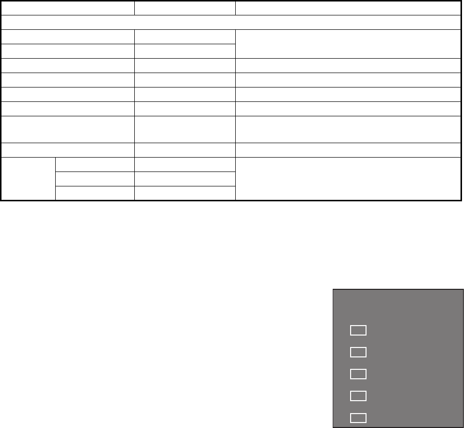
Function Setting(s) Menu/On-screen box
[USER SET MENU]
1 PILOT SETTING
NO / YES
2 USER1 LOAD
NO / YES
3 USER1 SAVE
NO / YES
4 USER2 LOAD
NO / YES
5 USER2 SAVE
NO / YES

1. OPERATIONAL OVERVIEW
1-17
1.15 How to Start/Stop Transmission
The radar is ready to transmit when the message "STBY" is displayed on screen.
Transmission can be started using one of the following procedures:
• Using the control unit: Press the key.
• Using the on-screen box: Select the [STBY/TX] box on the screen, then press the
left button.
How to stop antenna rotation
Antenna rotation can be stopped using one of the following procedures:
• Turn the antenna switch off.
• Turn antenna rotation off from the menu (See installation manual).
Screen freeze
The on-screen display is not refreshed if the screen has frozen. An audio alarm is
released 30 seconds after a screen freeze. The key flashes and a Contact
Alert Signal is also released. To return the radar to normal operation, turn the radar
off, then on again.
Quick start
Provided that the radar was in use and the magnetron (transmitter tube) is still warm,
you can switch to transmit mode without the three minute warm-up time. If the radar
was turned off by mistake or you wish to restart the radar promptly, press the POWER
switch within ten seconds after the power is turned off.
1. OPERATIONAL OVERVIEW
1-18
1.16 How to Tune the Receiver
1.16.1 How to choose the tuning method
1. Select the [TUNE] box at the top of the screen to change the tuning method. The
tuning box is displayed as "TUNE AUTO" or "TUNE MAN", depending on the
currently selected tuning method.
2. Press the left button to change the tuning method.
3. Rotate the ADJUST knob to adjust the tuning level, then press the knob to apply
the setting.
1.16.2 How to initialize tuning
Automatic tuning is initialized at installation. However, if you feel that the automatic
tuning is not functioning properly, re-initialize it by following the procedure below.
1. Open the [MAIN MENU].
2. Select [ECHO], then press the ADJUST knob.
3. Select [TUNE INITIALIZE], then press the ADJUST knob.
The indication "TUNE INITIALIZE" appears in the [ALERT] box during the
initialization.
4. Close the menu.
1.16.3 How to tune the receiver manually
1. Select the 48-mile range from the [RANGE] box. Press the left button to lower
the range; the right button to raise the range.
2. Select manual tuning following the procedure in paragraph 1.16.1.
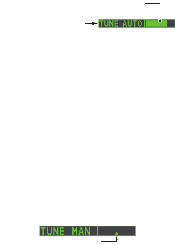
3. Place the arrow on the tuning bar area in the [TUNE] box.
4. Rotate the ADJUST knob to adjust tuning. The best tuning point is where the bar
graph swings maximum. The tuning control position is indicated with a
triangle, displayed inside the tuning bar.
Tuning method (AUTO or MAN)
Tuning level indicator. Place arrow inside box to
adjust tuning, when TUNE MAN is selected.
Tuning control position

1. OPERATIONAL OVERVIEW
1-19
1.17 How to Select a Pulselength
The pulselength in use is displayed at the upper-left position of the screen using the
indications shown in the table below.
Appropriate pulselengths are preset to individual range scales and function keys. If
you are not satisfied with the current pulselength settings, you can change them as
shown in "How to adjust the pulselength" on page 1-19.
1.17.1 How to adjust the pulselength
The pulselength can be adjusted using the procedure below.
1. Place the cursor in the [PULSE] box at the top left corner of the screen.
2. Press the left button, right button or rotate the ADJUST knob to cycle through
pulselengths. The order in which the pulselengths are cycled is shown in the table
below.
Note: Available pulselengths are restricted depending on the currently selected
range. See the table below for details.
FAR-1518/FAR-1528
(PULSE) indication
FAR-1513/FAR-1523
(PULSE) indication
S1 (short pulse 1) S (short pulse)
S2 (short pulse 2) M (medium pulse)
M1 (medium pulse 1) L (long pulse)
M2 (medium pulse 2)
M3 (medium pulse 3)
L (long pulse)
Method Cycle order
Left button Decreases the pulselength.
Right button Increases the pulselength.
ADJUST knob (clockwise) Increases the pulselength.
ADJUST knob (counter-clockwise) Decreases the pulselength.
FAR-1518/FAR-1528 FAR-1513/FAR-1523
Range (PULSE)
indication Range (PULSE)
indication
0.5 NM S1, S2 1.5 NM S, M
0.75 NM, 1.5 NM S1, S2, M1 3 NM M, L
3 NM S2, M1, M2, M3
6 NM M1, M2, M3, L
12 NM, 24 NM M2, M3, L
1. OPERATIONAL OVERVIEW
1-20
1.18 How to Adjust Sensitivity
The gain control adjusts the sensitivity of the receiver.
The proper setting is such that the background noise is just visible on the screen. If
you set up for too little sensitivity, weak echoes may be missed. On the other hand
excessive sensitivity yields too much background noise; strong targets may be missed
because of the poor contrast between desired echoes and the background noise on
the display.
To adjust receiver sensitivity, adjust the gain control so background noise is just visible
on the screen.
1. Place the cursor in the [GAIN] box at the top of the screen.
2. Rotate the ADJUST knob anticlockwise to decrease the gain, or clockwise to
increase the gain. The setting range is [0] to [100].
1.19 How to Reduce Sea Clutter
Echoes from waves cover the central part of the display with random signals known
as sea clutter. The higher the waves, and the higher the antenna above the water, the
further the clutter extends. When sea clutter masks the picture, reduce it with the A/C
SEA control, either manually or automatically.
Note 1: When both sea clutter and rain clutter are reduced, the sensitivity is
decreased more than when only one is adjusted. For that reason adjust them carefully.
Note 2: The echo average (see "Echo Averaging" on page 1-24) is useful for reducing
reflections from the sea surface. However, high-speed targets are harder to detect
than stationary ones when the echo average is active.
1.19.1 How to select the method of clutter adjustment
1. Place the cursor in the [SEA AUTO] or [SEA MAN] (whichever is shown) at the top
of the display.
2. Press the left button to display [SEA AUTO] or [SEA MAN] as appropriate.
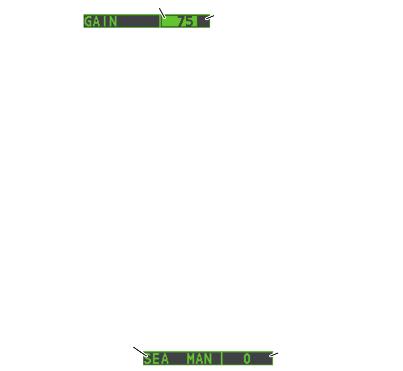
Place arrow inside
window to adjust gain.
Level bar
Place arrow inside window
to adjust A/C SEA.
A/C SEA adjustment method
(SEA AUTO or SEA MAN)
1. OPERATIONAL OVERVIEW
1-21
1.19.2 How to automatically reduce sea clutter
Auto A/C SEA allows for fine tuning of the A/C SEA circuit, within ±20 dB. Accordingly,
with the bar reading set to 50, gain is not lowered to minimum as with manual A/C SEA
on close-in ranges. Further, the auto A/C SEA level is low because the average value
of the original input echo is low in areas where there are no sea surface
reflections. For example, when the ship is alongside a quay and the radar picture
shows echoes from both land and sea, you can observe the size of the echoes
because the STC curve changes with the size of the echoes.
Note: The auto A/C function can erase weak target echoes. Adjust the control
carefully, watching the display.
1. Select [SEA AUTO], following the procedure in paragraph 1.19.1.
2. Place the arrow in the A/C SEA level indicator at the top of the display.
3. While observing the A/C SEA level indicator, rotate the ADJUST knob
clockwise to increase the A/C SEA or counter-clockwise to decrease it. The
setting range is [-50] to [50].
1.19.3 How to manually reduce sea clutter
The A/C SEA control reduces the amplification of echoes
at short ranges (where clutter is the greatest) and
progressively increases amplification as the range
increases, so amplification will be normal at those ranges
where there is no sea clutter.
The proper setting of the A/C SEA should be such that the
clutter is broken up into small dots, and small targets
become distinguishable. If the setting is set too low, tar-
gets will be hidden in the clutter, while if the setting is too
high, both sea clutter and targets will disappear from the
display. In most cases adjust the control until clutter has
disappeared to leeward, but a little is still visible windward.
Be careful not to remove all sea clutter, because you may
erase weak echoes. Further, the possibility of losing weak
echoes is greater when you use both A/C SEA and A/C
RAIN to reduce clutter.
1. Select [SEA MAN], following the procedure in paragraph 1.19.1.
2. Place the arrow in the A/C SEA level indicator at the top of the display.
3. While observing the A/C SEA level indicator, rotate the ADJUST knob
clockwise to increase the A/C SEA or counter-clockwise to decrease it. The
setting range is [0] to [100].
Sea clutter at
screen center
A/C SEA control adjusted;
sea clutter reduced

1. OPERATIONAL OVERVIEW
1-22
1.20 How to Reduce Rain Clutter
Use the AUTO RAIN and A/C RAIN to reduced rain clutter. AUTO RAIN reduces rain
clutter in the picture and A/C RAIN reduces clutter picked up by the antenna.
Note 1: When both sea clutter and rain clutter are reduced, the sensitivity is
decreased more than when only one is adjusted. For that reason adjust them carefully.
Note 2: The echo average (see "Echo Averaging" on page 1-24) is useful for reducing
reflections from the sea surface. However, high-speed targets are harder to detect
than stationary ones when the echo average is active.
1.20.1 How to automatically reduce rain clutter
Select the [RAIN] indication at the top-right of the screen, then press the left
button to select [RAIN AUTO].
1.20.2 How to manually reduce rain clutter
The vertical beam width of the antenna is designed to see
surface targets even when the ship is rolling. However, by
this design the unit will also detect rain clutter (rain, snow,
or hail) in the same manner as normal targets.
The A/C RAIN control adjusts the receiver sensitivity as
the A/C SEA control does but rather in a longer time
period (longer range). The higher the setting the greater
the anti-clutter effect. When echoes from precipitation
mask solid targets, adjust the A/C RAIN control to split up
these unwanted echoes into a speckled pattern, making
recognition of solid targets easier. Be careful remove all
rain clutter, because you can erase weak echoes. Further,
the possibility of losing weak echoes is greater when you
use both A/C RAIN and A/C SEA to reduce clutter.
1. Select the [RAIN] indication at the top-right of the screen, then press the left
button to select [RAIN MAN].
2. While observing the A/C RAIN level indicator, rotate the ADJUST knob
clockwise to increase the A/C SEA or counter-clockwise to decrease it. 100 levels
(0-100) are available.
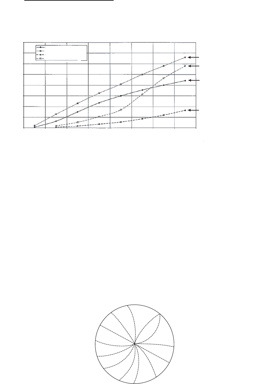
Note: The detection range is reduced when the RAIN is used to show targets in rain.
Generally, the amount of rain, TX pulse length and TX frequency are factors in
determining how the detection range is affected. The figure below illustrates this.
Left-click inside the box to change the A/C RAIN
adjustment method (RAIN AUTO or RAIN MAN)
Rain clutter at
screen center
A/C RAIN control adjusted;
rain clutter reduced
Place arrow inside window
to adjust A/C RAIN.
Level bar
1. OPERATIONAL OVERVIEW
1-23
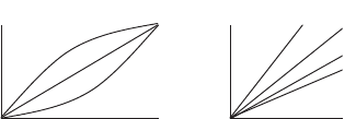
How to interpret the graph
Using the graph below as an example, a radar target originally detected on the 8 NM
range can only be detected in rain at the ranges shown below:
Accordingly, the short pulse may be preferable in rain on ranges less than 10 NM.
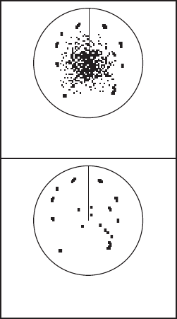
1.21 Interference Rejector
Mutual radar interference can occur in the vicinity of another shipborne radar
operating in the same frequency band. It is seen on the screen as a number of bright
spikes either in irregular patterns or in the form of usually curved spoke-like dotted
lines extending from the center to the edge of the picture. Activating the interference
rejector circuit can reduce this type of interference. The interference rejector is a kind
of signal correlation circuit. It compares the received signals over successive trans-
missions and reduces randomly occurring signals. There are three levels of
interference rejection depending on the number of transmissions that are correlated.
Example of interference
To adjust the interference rejector, select the [IR] box at the left side of the screen,
then press the left button to cycle through the rejection levels. The available settings,
in cyclic order, are: [OFF] [1] [2] [3] [OFF]...
Level [3] provides the highest level of rejection.
16
12
10
8
6
4
2
0
14
0 2 4 6 8 10 12 14 16
4 mm/h rain (short pulse)
16 mm/h rain (short pulse)
4 mm/h rain (long pulse)
16 mm/h rain (long pulse)
Original range of first detection (NM)
16 mm/h rain - short pulse
4 mm/h rain - short pulse
16 mm/h rain - long pulse
4 mm/h rain - long pulse
Reduction of rain to first detection due to rain at X-band
The author thanks the International Electrotechnical Commission (IEC) for permission to reproduce Information from its Interantional
Standard IEC 62388 ed.1.0 (2007). All such extracts are copyright of IEC, Geneva, Switzerland. All rights reserved. Further
information on the IEC is available from www.iec.ch. IEC has no responsibility for the placement and context in which the extracts
and contents are reproduced by the author, or is IC in any way responsible for the other content or accuracy therein.
Reduction of Range of First Detection (NM)
1. OPERATIONAL OVERVIEW
1-24
1.22 Echo Stretch
The echo stretch feature enlarges targets in the range and bearing directions to make
them easier to see, and it is available on any range. There are three types of echo
stretch, 1, 2 and 3, and the higher the number the greater the amount of stretch.
Note: The echo stretch magnifies not only small target pips but also returns (clutter)
from sea surface, rain and radar interference. For this reason, make sure these types
of interference have been sufficiently reduced before activating the echo stretch.
To set echo stretch, select the [ES] box at the left side of the screen, then press the
left button to cycle through the settings.
The cyclic order is [OFF] [1] [2] [3] [OFF]...
1.23 Echo Averaging
The echo averaging feature effectively reduces sea clutter. Echoes received from
stable targets such as ships appear on the screen at almost the same position every
rotation of the antenna. On the other hand, unstable echoes such as sea clutter
appear at random positions.
To distinguish real target echoes from sea clutter, echoes are averaged over
successive picture frames. If an echo is solid and stable over successive frames, it is
presented in its normal intensity. Sea clutter is averaged over successive scans and
its brilliance reduced, making it easier to discriminate real targets from sea clutter.
Echo averaging uses scan-to-scan signal correlation technique based on the true
motion over the ground of each target. Thus, small stationary targets such as buoys
will be shown while reducing random echoes such as sea clutter. True echo averaging
is not however effective for picking up small targets running at high speeds over the
ground.
Note 1: With echo average active it is harder to detect high-speed targets than
stationary ones.
Note 2: Do not use the echo averaging function under heavy pitching and rolling; loss
of targets can result.
Note 3: Echo averaging requires heading, position and speed data.
Before using the echo averaging function, reduce sea clutter with the A/C SEA control.
Leave a little sea clutter on the screen so as not to erase weak targets. Then, do as
follows:
Select the [EAV] box at the left side of the screen, then press the left button to select
the desired level of echo averaging.
• [OFF]
• [1], [2]
• [3]
: Echo averaging is not enabled
: Detects targets hidden in sea clutter. [2] is more effective than [1] in
detecting targets hidden in strong sea clutter. However, [1] is more effective
than [2] in displaying high-speed targets. Select the setting best suited to
current conditions. For effective monitoring of high-speed craft, you should
use [2] together with Wiper.
: Stably displays unstable targets; distinguishes high-speed craft from sea
clutter.
1. OPERATIONAL OVERVIEW
1-25
1.24 Automatic Clutter Elimination (ACE) Function
This radar has the Automatic Clutter Elimination (ACE) function. This function detects
sea and rain clutter from received echoes’ range and bearing trend and automatically
reduces sea and rain clutter according to the Automatic Clutter Elimination (ACE)
threshold setting.
Note: Use this function with caution. Weak target echoes may disappear from the
screen.
1.24.1 How to turn the Automatic Clutter Elimination (ACE) function
on/off
Select the [ACE] box at the top left of the operational display area, then press the left
button to switch the [ACE] function [ON] or [OFF].
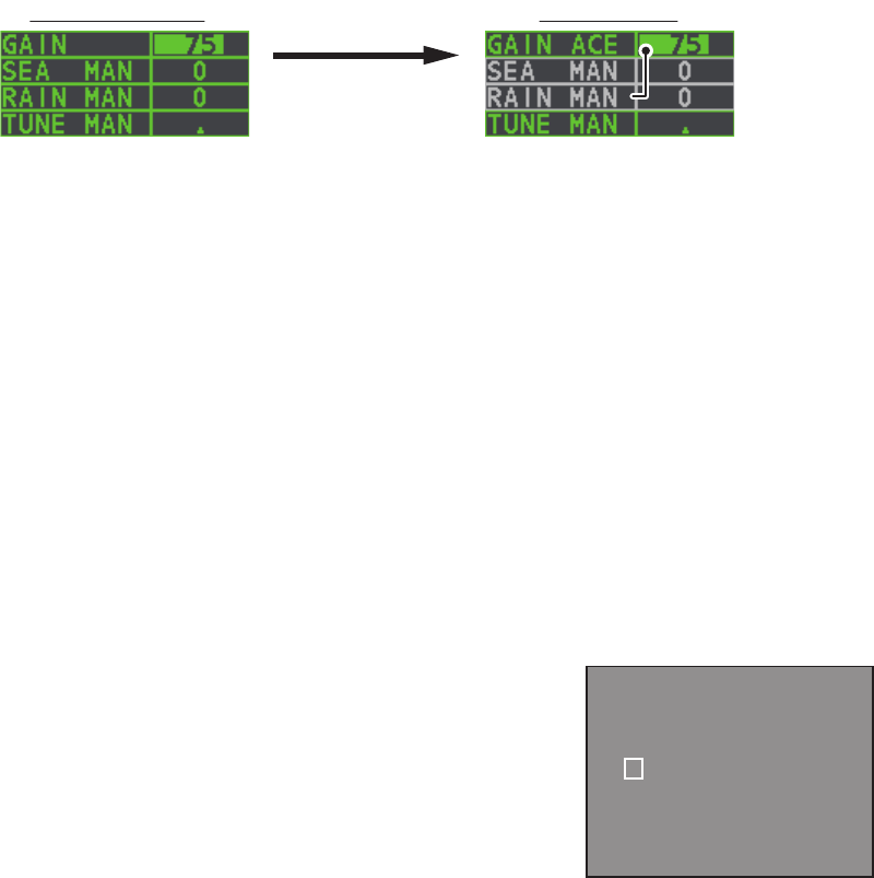
When [ACE] is activated, the [SEA] box and [RAIN] box are gray colored and cannot
be adjusted. The [GAIN] box changes to [GAIN ACE], as shown in the figure below.
Note: When [PERFORMANCE MON] (see section 1.46) or [SART] (see section 2.3)
is [ON], [ACE] is disabled and cannot be activated.
1.24.2 How to adjust the gain in Automatic Clutter Elimination (ACE)
mode
Rotate the F3 knob to adjust the sensitivity. (For default function key settings only.)
ACE can also be adjusted by placing the cursor inside the [GAIN ACE] level, then
rotating the ADJUST knob.
1.24.3 How to get high sensitivity
When Automatic Clutter Elimination (ACE) function is [ON], the high sensitivity mode
operates while pressing the GAIN control. You can select the level for the high
sensitivity mode as follows:
1. Open the [MAIN MENU].
2. Select [ECHO], then press the ADJUST knob.
3. Select [0 ACE] (For non-IMO radars) or [9 ACE]
(IMO radars), then press the ADJUST knob.
4. Select [SIGNAL ENHANCEMENT], then press the
ADJUST knob.
5. Select the level from [1], [2] or [3].
6. Close the menu.
ACE not activated ACE activated
Place arrow inside window
to adjust ACE.
Place arrow inside window
to adjust ACE.
[ACE]
1 BACK
2 SIGNAL ENHANCEMENT
1 / 2 / 3
3 SUPPRESS SECTOR
START : 000
ANGLE : 000

1. OPERATIONAL OVERVIEW
1-26
1.24.4 How to suppress false echoes
The echo signals can appear on the screen at positions where there is no target or
disappear when there are targets (see section 2.2). You can suppress the false
echoes.
1. Open the [MAIN MENU].
2. Select [ECHO], then press the ADJUST knob.
3. Select [0 ACE] (For non-IMO radars) or [9 ACE] (IMO radars), then press the
ADJUST knob.
4. Select [SUPPRESS SECTOR], then press the ADJUST knob.
5. Rotate the ADJUST knob to set the starting angle for sector to be suppressed,
then press the ADJUST knob.
6. Rotate the ADJUST knob to set the angle range of the sector to be suppressed,
then press the ADJUST knob.
7. Close the menu.
1.25 Noise Rejector
White noise can show itself on the screen as random “speckles” spread over the
entire radar image. This equipment reduces the white noise, then improves the on-
screen S/N ratio by processing the weighted moving average filter for the received
echoes in the range direction.
Note: Use this function with caution. Weak target echoes may disappear from the
screen or the range resolution may worsen.
You can remove this noise by placing the cursor inside the [NR] box at the left side of
the screen, then press the left button to select [ON] or [OFF].
1.26 Wiper
The wiper feature automatically reduces the brilliance of weak signals (noise, sea
clutter, rain clutter, etc.) and unwanted signals such as radar interference to clear the
picture of unwanted echoes. Its effect depends on the wiper setting used and whether
each averaging is turned on or off, as described below.
Condition A: The brilliance of unwanted weak echoes, such as noise, sea clutter and
rain clutter, is reduced to clear up the picture. The difference between wiper setting [1]
and [2] is that brilliance is lowered more slowly in [2].
Condition B: Echo averaging is automatically activated when the wiper feature is
turned on, allowing you to instantly see how the picture is affected with echo averaging
turned off and turned on.
To activate the wiper feature, do the following:
1. Open the [MAIN MENU].
Wiper setting 1 Wiper setting 2
Echo averaging OFF Condition A Condition A
Echo averaging ON(1/2/3) Condition A Condition B

1. OPERATIONAL OVERVIEW
1-27
2. Select [ECHO], then press the ADJUST knob.
3. Select [WIPER], then press the ADJUST knob.
4. Rotate the ADJUST knob to cycle through and select the desired setting. The
options, in order, are: OFF 1 2 OFF...
With the desired setting selected, press the ADJUST knob.
5. Close the menu.
1.27 How to Preset Controls for a Specific Navigation
Purpose
Every time your navigating environment or task changes, you must adjust the radar,
which can be a nuisance in a busy situation. Instead of changing radar settings case
by case, it is possible to assign the function keys to provide optimum settings for
often-encountered situations.
The radar's internal computer offers several picture preset options to be assigned to
each function key for your specific navigating requirements. For instance, one of the
presets is [HEAVY RAIN], and is designed to be used in heavy rain.
Two user-programmable presets are also provided (labeled as [CUSTOM1],
[CUSTOM2]), so that you can have the radar automatically adjusted to those condi-
tions that are not covered by the provided setup options.
Below are the preset options provided with this radar.
Each picture option defines a combination of several radar settings for achieving
optimum setup for a particular navigating situation. These include interference
rejector, echo stretch, echo average, noise rejector, automatic anti-sea and anti-rain
clutters, video contrast, pulse length and sea and radar conditions.
Adjusting these features from the [CUSTOMIZE ECHO] menu changes the original
function key settings. To restore the original settings for a particular customize option,
it is necessary to select the default setting. For this reason, we recommended that you
use the user-programmable presets ([CUSTOM1] or [CUSTOM2]) when frequent
adjustment of the radar image is necessary.
Label Description Label Description
[CUSTOM1] User-defined custom
settings.
[CUSTOM2] User-defined custom
settings.
[NEAR] Optimum setting for short
range detection using a range
scale of 3 NM or less on calm
seas.
[FAR] Optimum setting for long
range detection, on a range
scale of 6 NM or larger.
[HEAVY RAIN] Optimum setting for rough
weather or heavy rain.
[SHIP] Optimum setting for detecting
other vessels.
1. OPERATIONAL OVERVIEW
1-28
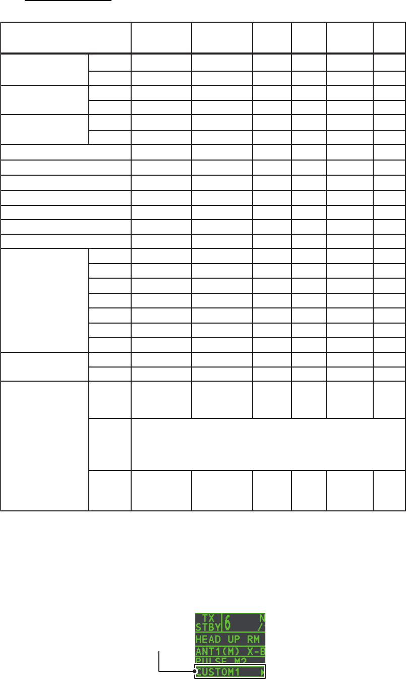
Default settings
1.27.1 How to select a customized echo
Left-click [CUSTOMIZE ECHO] box at the top left of the screen to cycle through the
options and select a customized echo option. The available options, in cyclic order,
are: [CUSTOM1] [CUSTOM2] [NEAR] [FAR] [HEAVY RAIN] [SHIP].
CUSTOM1
GAIN MODE MAN
85
MAN
85
MAN
85
MAN
85
MAN
85
MAN
85LEVEL
CUSTOM2 NEAR FAR HEAVY
RAIN
SHIP
SEA MODE MAN
30 30 30 30 40 30
AUTO MAN MAN MAN MAN
LEVEL
RAIN
INT REJECT
MODE MAN
00004025
111122
21 OFF 3 OFF 2
211221
ONOFF OFF OFF ON ON
2-B2-B 2-B 3-B 1-B 2-B
ON
OFF OFF OFF ON ON
8080 80 80 80 80
S1S1 S1 S1 S1 S1
S1S1 S1 S2 S1 S2
S2S1 S1 M1 S1 M1
M1S2 S2 M2 S2 M2
M2M2 M1 M3 M1 M3
M3M3 M2 L M2 L
LL M3 L M3 L
MAN MAN MAN MAN MAN
LEVEL
PULSE
(FAR-1518/1528)
0.5NM
0.75NM
SSSMSM
MMMMMM
PULSE
(FAR-1513/1523)
1.5NM
3NM
1.5NM
3NM
6NM
12NM
24NM
333333CONDITION NEAR
STC
CURVE
000000LOW
LEVEL
ECHO
Set at installation.
STC
ANT
HEIGHT
(m)
ECHO STRETCH
ECHO AVERAGE
NOISE REJECT
VIDEO CONTRAST TYPE
ACE
ACE GAIN
Customize
echo box
1. OPERATIONAL OVERVIEW
1-29
1.27.2 How to edit a customized echo
1. Select a customize echo option to edit (see paragraph 1.27.1).
2. Select the [CUSTOMIZE ECHO] box, then press the right button to display the
[CUSTOMIZE ECHO] menu.
3. Set the items below referring to the sections shown.
4. Select [VIDEO CONTRAST TYPE], then press the ADJUST knob.
5. Select [1], [2], [3] or [4] (Dynamic Range) or [A], [B], [C] (Curve) as appropriate
then press the left button. Refer to the description and illustration below.
1-4: Control dynamic range. 1 provides the widest dynamic range; 4 is the
narrowest dynamic range.
A: The mid-level in the curve is low, so this setting is suitable for suppressing rain
clutter.
B: Curve between A and C.
C: The mid-level in the curve is high, so this setting is suitable for detecting distant
targets.
6. Select [9 CONDITION], then press the ADJUST knob.
7. Select [2 NEAR STC CURVE], then press the ADJUST knob.
8. Select the appropriate setting for the current sea conditions, then press the
ADJUST knob. The available settings are: [2], [2.5], [3], [3.5], [4.2]. A higher
setting is recommended for rough weather.
9. Select [1 STC ANT HEIGHT], then press the ADJUST knob.
10. Select the radar antenna height (above the waterline), then press the ADJUST
knob.
11. If necessary, select [2 LOW LEVEL ECHO] to reject low level echoes. The setting
range is [0] to [8]. The higher the figure, the stronger the low level echo that is
erased.
12. To save custom settings, select [SAVE] from [0 DEFAULT], then press the
ADJUST knob.
1.27.3 How to restore a user customized echo to the saved settings
If you get lost in operation while adjusting the settings for a user customized echo, you
can easily restore the settings for that user customized echo saved at
paragraph 1.27.2.
1. Select the [CUSTOMIZE ECHO] box, then press the right button to display the
[CUSTOMIZE ECHO] menu.
2. Select [0 DEFAULT], then press the ADJUST knob.
3. Select [USER], then press the ADJUST knob.
• [INT REJECT] : section 1.21 • [HATCHING] : section 1.37
• [ECHO STRETCH] : section 1.22 • [NOISE REJECT] : section 1.25
• [ECHO AVERAGE] : section 1.23 • [PULSE] : section 1.17
• [TARGET ANALYZER] : section 1.37 • [ACE] : section 1.24
CONTRAST
CB
A
CONTRAST
321
4
1. OPERATIONAL OVERVIEW
1-30
1.27.4 How to restore a user customized echo to the factory default
settings
You can restore customized echo options to their factory default (see the table on
page 1-28).
1. Select the [CUSTOMIZE ECHO] box, then press the right button to display the
[CUSTOMIZE ECHO] menu.
2. Select [0 DEFAULT], then press the ADJUST knob.
3. Select [FACTORY], then press the ADJUST knob.
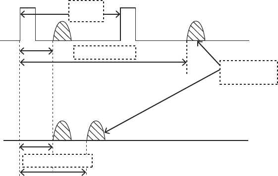
1.28 How to Reject Second-trace Echoes
In certain situations, echoes from very distance targets can appear as false echoes
(second-trace echoes) on the screen. This occurs when the return echo is received
one transmission cycle later, or after a next radar pulse has been transmitted.
This equipment lengthens the pulse repetition period to reject false echoes.
Note: This function decreases the number of echo hits. Use this function carefully so
that the possibility of detecting small targets and high-speed craft does not lessen.
To reject second trace echoes, do the following:
1. Open the [MAIN MENU].
2. Select [ECHO], then press the ADJUST knob.
3. Select [2ND ECHO REJ], then press the ADJUST knob.
4. Select [ON], then press the ADJUST knob. Select [OFF] to disable rejection.
5. Close the menu.
Pulse
interval
Actual ranges
Second-trace
echo
Measured ranges
1. OPERATIONAL OVERVIEW
1-31
1.29 Presentation Modes
This radar has the following presentation modes available:
Relative Motion (RM)
True Motion (TM)
Land objects and sea are stationary. Requires compass and speed data.
1.29.1 How to select an presentation mode
Select the [PRESENTATION MODE] box at the top left corner of the screen, then
press the left button to select a presentation mode.
Loss of gyrocompass signal
When the compass signal is lost, "GYRO" appears in yellow-orange in the [ALERT]
box, the presentation mode automatically becomes HEAD UP, and TT and AIS
targets, map and chart are erased. After restoring the compass signal, "HEADING
SET" appears in the [ALERT] box. Stop the alert with the [ALERT ACK] key or select
the [ALERT] box, then press the left button and then check the GYRO data.
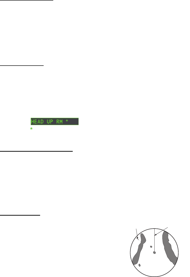
1.29.2 Description of presentation modes
HEAD UP mode
A display without azimuth stabilization in which the
line that connects the center with the top of the display
indicates your heading. Targets are shown at their
measured distances and their directions relative to
your heading. The short dotted line on the bearing
scale is the north marker.
HEAD UP : Not stabilized
STAB HEAD UP : Head-up with compass bearing scale (True Bearing) where the
bearing scale rotates with the compass reading.
COURSE UP : Compass-stabilized relative to ship’s orientation at the time of
selecting COURSEUP.
NORTH UP : Compass-stabilized with reference to North.
STERN UP : The radar image is rotated 180°. Graphics and relative and true
bearings are also rotated 180°.
= Other modes:
STERN UP RM, STAB HEAD UP RM,
COURSE UP RM, NORTH UP RM, NORTH UP TM
Heading line
North marker
1. OPERATIONAL OVERVIEW
1-32
COURSE UP mode
The radar picture is stabilized and displayed with the
currently selected course at the top of the screen.
When you change the heading, the heading line
moves with the course selected. If you select a new
course, select the course up mode again to display
the new course at the top of the display. Targets are
shown at their measured distances and their direc-
tions relative to the set course, which is at the 0-de-
gree position. The heading line moves according to
the yawing and any course change.
NORTH UP mode
Targets are shown at their measured distances and
their true (compass) directions from your ship. North is
at the top of the screen. The heading line changes its
direction according to your heading.
STAB HEAD UP mode
Radar echoes are shown in the same way as in the HEAD UP mode. The difference
from normal HEAD UP presentation lies in the orientation of the bearing scale. The
bearing scale is heading sensor stabilized. That is, it rotates in accordance with the
heading sensor signal, enabling you to know own ship's heading at a glance.
This mode is available when the radar is interfaced with a gyrocompass. If the
gyrocompass fails, the bearing scale returns to the state of HEAD UP mode.
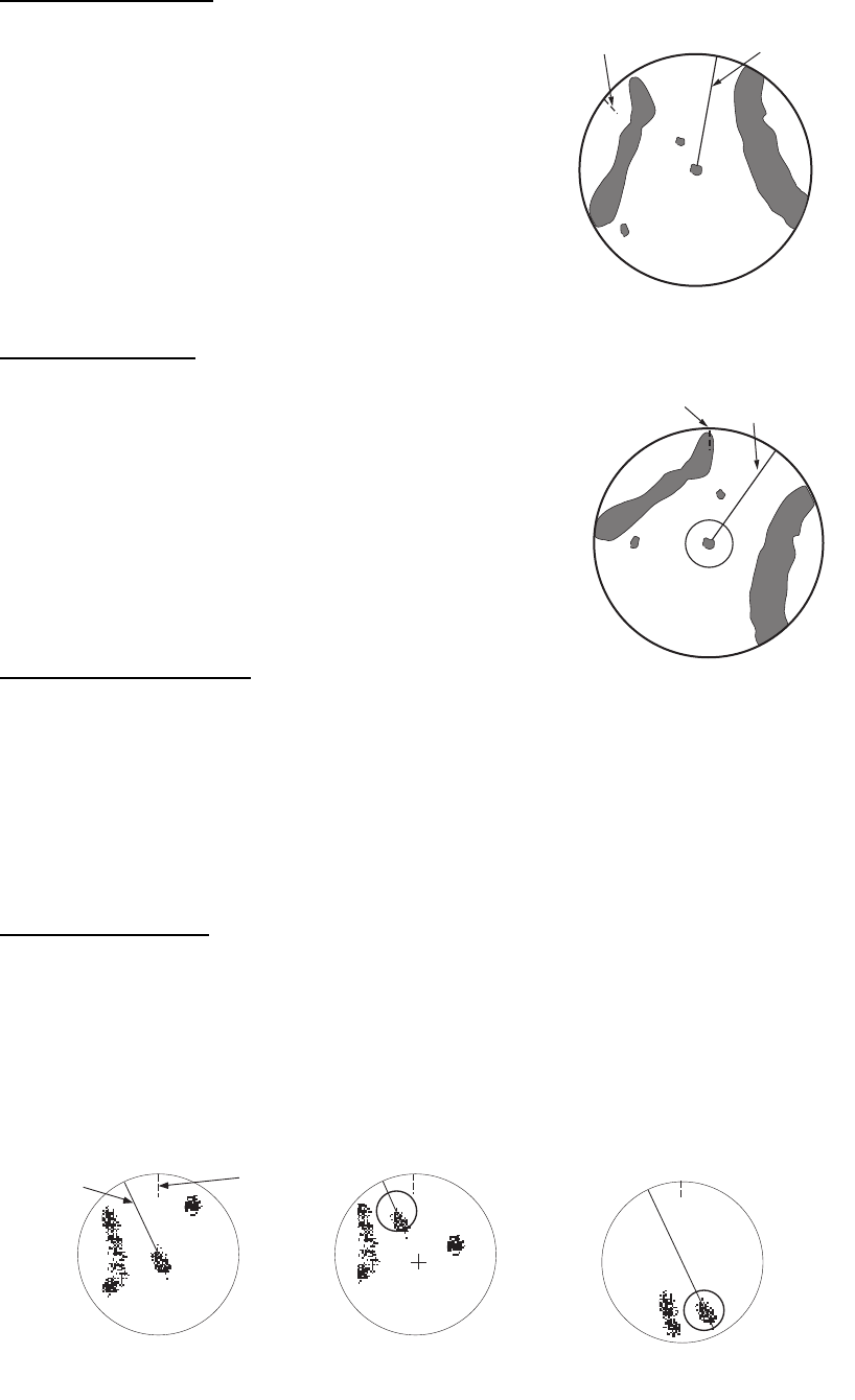
True motion mode
Your ship and other objects in motion move with their true courses and speed. All fixed
targets, like landmasses, appear as fixed echoes in ground stabilized TM. When your
ship reaches a point that is 50% of the radius of the display, the position is reset. The
ship appears at 75% radius opposite to the extension of the heading line on the display
center. You can manually reset your ship symbol if you highlight the [CU/TM RESET]
indication at the top of the screen, then press the left button.
Heading line
North marker
Heading line
North marker
Heading
line
North
marker
(a) True motion
is selected
(b) Your ship has reached a
point 50% of display radius
(c) Your ship is automatically
reset to 75% of display radius
1. OPERATIONAL OVERVIEW
1-33
STERN UP mode
The STERN UP mode rotates the HEAD UP
mode picture, relative and true bearings and
display graphics 180°. This mode is useful on
dual-radar tugboats when backing up; one
radar shows HEAD UP and another shows
STERN UP. To enable the STERN UP mode,
turn on [STERN UP] on the [OPERATION]
menu.
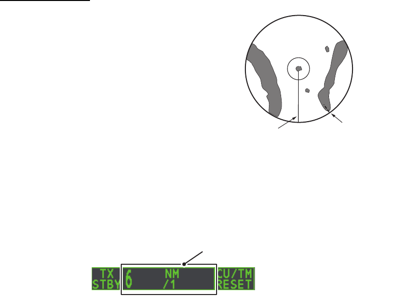
1.30 How to Select a Range Scale
The selected range scale, range ring interval and pulselength are shown at the upper
left corner on the screen. When a target of interest comes closer, reduce the range
scale so that it appears in 50-90% of the display radius.
1. Place the cursor in the [RANGE] box at the top left corner of the screen.
2. Press the left button to lower the range; the right button to raise the range.
You can also select the range by rotating the ADJUST knob then pressing the
ADJUST knob when the cursor is inside the range box.
Heading line North marker
Range Box
1. OPERATIONAL OVERVIEW
1-34
1.31 How to Measure Range
The range to a target can be measured three ways: with the fixed range rings, with the
cursor, or with the VRM.
Use the fixed range rings to get an estimate of the range to a target. The rings are the
concentric solid circles on the display. The number of rings is automatically set by the
current range scale. The distance between the rings is the range ring interval, and the
current interval appears at the upper-left position on the screen. To measure the range
to a target with the range rings, count the number of rings between the center of the
display and the target. Check the range ring interval and estimate the distance of the
echo from the inner edge of the nearest ring.
1.31.1 How to show/hide the range rings
1. Open the [MAIN MENU].
2. Select [NAVTOOL], then press the ADJUST knob.
3. Select [RANGE RING], then press the ADJUST knob.
4. Rotate the ADJUST knob to select [ON] or [OFF] as appropriate, then press the
ADJUST knob.
5. Close the menu.
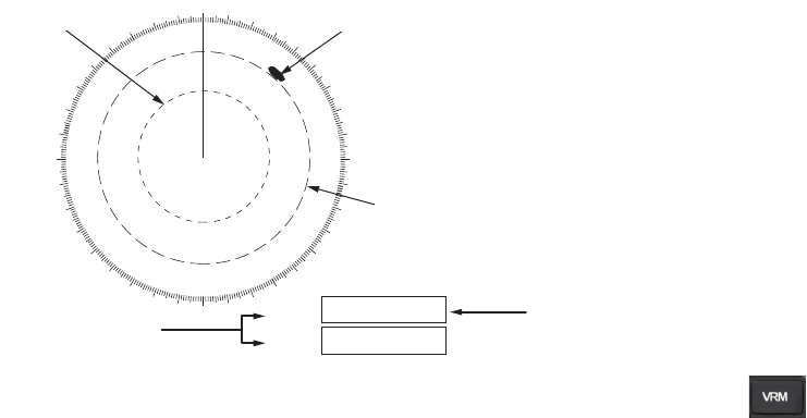
1.31.2 How to measure range with the variable range marker (VRM)
There are two VRMs, No. 1 and No. 2, which appear as dashed rings so that you can
distinguish them from the fixed range rings. The two VRMs can be distinguished from
each other by the different lengths of their dashes; the dashes on the No. 2 VRM are
longer.
There are two methods for measuring range with the VRMs, using the key and
on-screen menu box operation.
000 010 020
030
040
050
060
070
080
090
100
110
120
130
140
150
160
170
180
190
200
210
220
230
240
250
260
270
280
290
300
310
320
330
340 350
VRM1
VRM2
>0.66NM<
1.18NM
45:02
99:59
TTG to VRM
No. 1
VRM
No. 2
VRM
Target
Currently active VRM is
shown enclosed in “>....<”
1. OPERATIONAL OVERVIEW
1-35
Using the VRM key
1. Press the key to display the VRMs. Press the key again to switch
between active VRMs. The currently active VRM marker is displayed as shown in
the figure on the previous page.
2. Rotate the ADJUST knob to align the active VRM with the inner edge of the target,
then read the distance at the lower right of the screen. In the above
example, the VRM reads "0.66NM".
Each VRM remains at the same geographical distance when you operate the
RANGE key or the [RANGE] box. This means that the apparent radius of the VRM
ring changes in proportion to the selected range scale.
3. Press and hold the key to erase the selected VRM.
On-screen menu box operation
1. Select the appropriate VRM box.
2. The guidance box reads "VRM ON/". Press the left button to turn on the VRM.
The guidance box now reads "VRM SET L = DELETE /".
3. Press the left button again and the cursor jumps to inside the operational display
area. The guidance box now reads "VRM FIX / EXIT".
4. Rotate the ADJUST knob to set the distance for VRM.
Note: The maximum VRM distance is set by the current display range and can be
set as high as twice the distance of the display range.
5. Press the left button to anchor the VRM and fix its readout, or press the
right button to cancel and return the VRM to its previous location (range).
6. Press and hold the key to erase the selected VRM.
1.31.3 How to set the VRM unit of measurement
VRMs can be displayed in the following units of measurement:
To change the unit of measurement, do the following:
1. Open the [MAIN MENU].
2. Select [NAVTOOL], then press the ADJUST knob.
3. Select [EBL•VRM], then press the ADJUST knob.
4. Select [VRM1] or [VRM2] as appropriate, then press the ADJUST knob.
5. Select the unit of measurement, then press the ADJUST knob.
6. Close the menu.
• NM (Nautical Miles)
• SM (Statute Miles)
• KM (Kilometers)
• KYD (Kiloyards)
1. OPERATIONAL OVERVIEW
1-36
1.31.4 How to show TTG to VRM
TTG (Time To Go) to a selected VRM can be displayed as follows:
1. Open the [MAIN MENU].
2. Select [NAVTOOL], then press the ADJUST knob.
3. Select [EBL•VRM•CURSOR], then press the ADJUST knob.
4. Select [VRM TTG], then press the ADJUST knob.
5. Select [OFF], [1], [2] or [1&2] as appropriate, then press the ADJUST knob.
6. Close the menu.
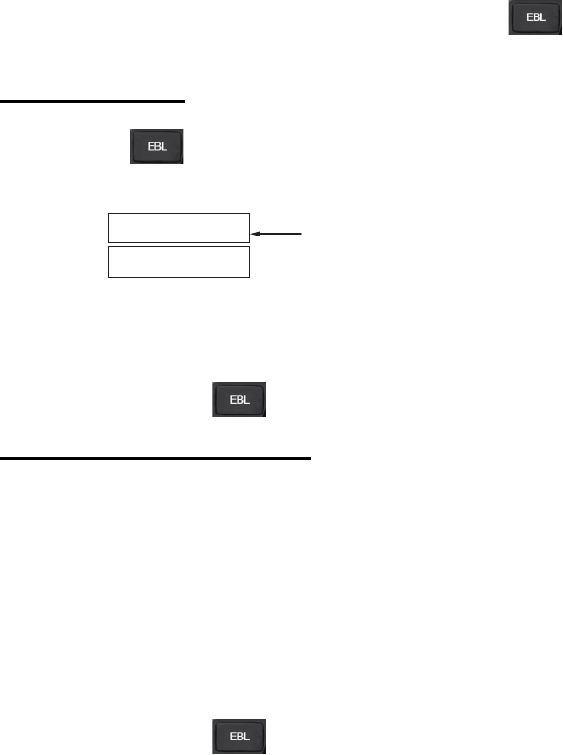
1.32 How to Measure Bearing
The Electronic Bearing Lines (EBLs) are used to take bearings of targets.There are
two EBLs, EBL1 and EBL2. Each EBL is a straight dashed line extending out from the
own ship position up to the circumference of the radar picture. The two EBLs can be
distinguished from each other by the different lengths of their dashes; the dashes on
EBL2 are longer.
Each EBL carries a range marker, or a short line crossing the EBL at right angles. Its
distance from the EBL origin is indicated at the VRM readout whether or not the
corresponding VRM is displayed.
• [OFF]
• [1]
• [2]
• [1&2]
No TTG to VRM displayed.
TTG to VRM1 displayed.
TTG to VRM2 displayed.
TTG to VRM1 and VRM2 displayed.
VRM1
>3.682NM<
01:15
TTG indication
000 010 020
030
040
050
060
070
080
090
100
110
120
130
140
150
160
170
180
190
200
210
220
230
240
250
260
270
280
290
300
310
320
330
340 350
No. 2
EBL
Target
blip
No. 1
EBL
Range markers
on EBLs
VRM1
VRM2
12.1
NM
EBL1
EBL2
>128.0
°
T<
100.8
°
T
>10.2
NM
<
1. OPERATIONAL OVERVIEW
1-37
1.32.1 Methods to measure bearing
There are two methods for measuring bearing, using the key and on-screen
menu box operation.
Using the EBL key
1. Press the key to display EBL1. Press the key again to change between
EBLs. The currently active EBL is displayed as shown in the figure below.
2. Rotate the ADJUST knob clockwise or counterclockwise until the active EBL bi-
sects the target of interest, and read its bearing at the lower-left corner of the
screen.
3. Press and hold the key to erase the active EBL.
On-screen menu box operation
1. Select the appropriate EBL box.
2. The guidance box reads "EBL ON/". Press the left button to turn on the EBL.The
guidance box now reads "EBL SET L=DELETE /".
3. Press the left button again and the cursor jumps to inside the operational display
area. The guidance box now reads "EBL FIX L=DELETE/".
4. Rotate the ADJUST knob clockwise or counterclockwise until the active EBL bi-
sects the target of interest, then press the ADJUST knob to anchor the EBL. Read
the bearing at the lower-left corner of the screen.
5. Press and hold the key to erase the active EBL.
EBL1
EBL2
>189.5°T<
159.8°T
Currently active EBL
displayed enclosed in “>...<”

1. OPERATIONAL OVERVIEW
1-38
1.32.2 True or relative bearing
The EBL readout is affixed by "R" (relative) if it is relative to own ship's heading, "T"
(true) if it is referenced to the north. True or relative indication is available regardless
of presentation mode.
1. Open the [MAIN MENU].
2. Select [NAVTOOL], then press the ADJUST knob.
3. Select [EBL•VRM], then press the ADJUST knob.
4. Select [EBL1] or [EBL2] as appropriate, then press the ADJUST knob.
5. Select the [REL] or [TRUE] as appropriate, then press the ADJUST knob.
6. Close the menu.
Note: The EBL and its indication change according to gyrocompass changes as
follows:
Gyro heading EBL changes
HEAD UP/relative EBL indication and EBL marker are unchanged.
HEAD UP / true EBL indication does not change, however the EBL
marker moves accordingly
COURSE UP / relative EBL indication does not change, however the EBL
marker moves accordingly.
COURSE UP / true EBL indication and EBL marker are unchanged.
NORTH UP / relative EBL indication does not change, however the EBL
marker moves accordingly
NORTH UP / true EBL indication and EBL marker are unchanged.
1. OPERATIONAL OVERVIEW
1-39
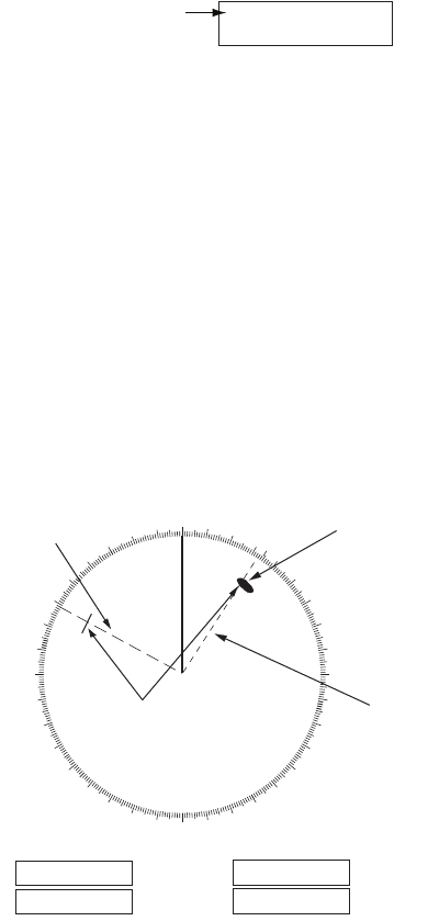
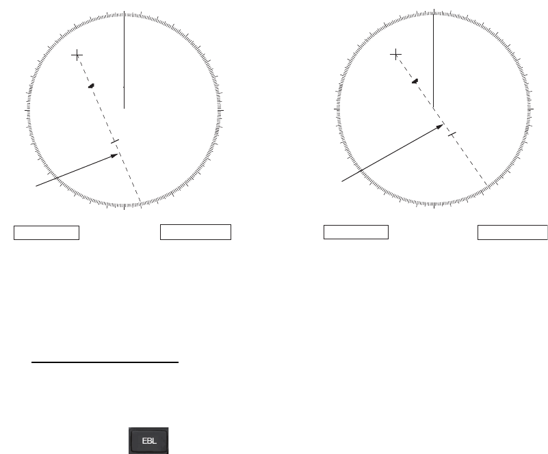
1.33 Collision Assessment by Offset EBL
The origin of the EBL can be placed anywhere with the touchpad to enable
measurement of range and bearing between any targets. This function is also useful
for assessment of the potential risk of collision. It is possible to read CPA (Closest
Point of Approach) by using a VRM as shown in (a) in the illustration below. If the EBL
passes through the sweep origin (own ship) as shown in (b) in the illustration below,
the target ship is on a collision course.
1.33.1 How to assess risk of collision using the offset EBL
There are two methods for assessing risk collision. You can use the touchpad or
the [CURSOR] menu.
Using the touchpad
Note: The [EBL OFFSET] function must be assigned to a function key (F1, F2 or F3)
for this method. See section 1.9 for how to assign the function keys.
1. Press the key to display or activate the EBL (EBL1 or EBL2).
2. Place the cursor on a target appearing as threatening (indicated as “A” in the
figure above).
3. Press the EBL OFFSET function key and the origin of the active EBL shifts to the
cursor position. Press the EBL OFFSET function key again to anchor the EBL
origin.
4. After waiting for a few minutes (at least 3 minutes), operate the ADJUST knob
until the EBL bisects the target at the new position (A1). The EBL readout shows
the target ship's course, which can be true or relative depending on the EBL
bearing reference setting.
Note: If relative motion is selected, it is also possible to read CPA by using a VRM
as shown in left-hand figure at the top of the next page. If the EBL passes through
the sweep origin (own ship) as illustrated in the right-hand figure above, the target
ship is on a collision course.
5. To return the EBL origin to the own ship's position, press the EBL OFFSET
function key.
000 010 020
030
040
050
060
070
080
090
100
110
120
130
140
150
160
170
180
190
200
210
220
230
240
250
260
270
280
290
300
310
320
330
340 350
000 010 020
030
040
050
060
070
080
090
100
110
120
130
140
150
160
170
180
190
200
210
220
230
240
250
260
270
280
290
300
310
320
330
340 350
A
A
1
A
A
1
No. 1
EBL
No. 1
EBL
EBL1
>169.7
°
T<
VRM1
>3.85NM<
EBL1
>145.1
°
T<
VRM1
>3.85NM<
(a) (b)