Furuno USA 9ZWRTR107 Transceiver for Radar model FAR-3230S/3330S User Manual
Furuno USA Inc Transceiver for Radar model FAR-3230S/3330S
Contents
- 1. User Manual
- 2. Users Manual
Users Manual
18-1
18. TT AND AIS DISPLAYS
Tracked targets and AIS targets can be overlaid on the chart. Only the differences be-
tween the radar and chart TT and AIS displays are described here.
The data of received radar-tracked targets must have reference to ground. If the data
does not meet that criteria, target vectors are not shown and the indications COG and
SOG in the TT info data box show [missing].
18.1 TT Display
18.1.1 TT symbols
Refer to paragraph 3.7.1.
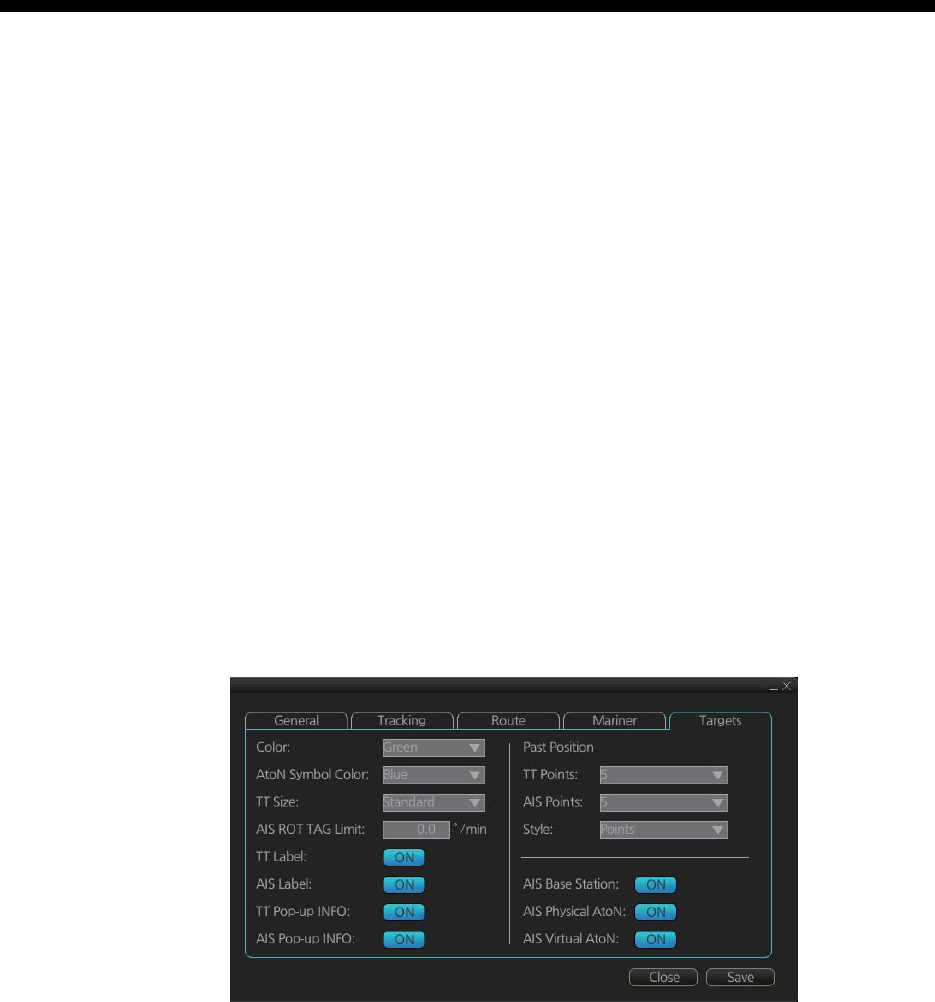
18.1.2 TT symbol color and size
Do the following to select TT symbol color and size. Note that the color of the AIS sym-
bol is also changed.
1. Click the [DISP], [SET] and [Symbol DISP] buttons on the InstantAccess bar to
show the [Symbol Display] menu.
2. Click the [Targets] tab.
3. Select the color among, green, blue, black, magenta and brown, with the [Color]
pull-down list.
4. Select the size from standard or small, with the [TT Size] pull-down list.
18. TT AND AIS DISPLAYS
18-2
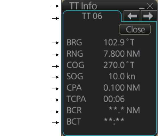
18.1.3 How to display tracked target data
Control Unit: Put the cursor on a target then push the TARGET DATA key.
Trackball module: Click the target for which you want to show its data.
To erase data from a data box, click the appropriate close data button.
The basic target data display for a TT consists of the following information:
• Target's number. Target numbering starts from "01". When a target is erased the
number will not be reused until the power is re-set or more than 200 targets are ac-
quired.
• Bearing (BRG) and distance (RNG) of the target from own ship
• True speed (SOG) and true course (COG) of the target
• CPA and TCPA. A negative TCPA value means that you have already passed the
closest point and the TT is going away from own ship.
• Bow Crossing Range (BCR) and Bow Crossing Time (BCT)
Title bar
TT No.
Bearing
Range
Course over ground
Speed over ground
CPA
TCPA
Bow crossing range
Bow crossing time
18. TT AND AIS DISPLAYS
18-3
18.1.4 Past position point attributes
You can define past position point attributes for tracked targets by points and style.
1. Click the [DISP], [SET] and [Symbol DISP] buttons on the InstantAccess bar to
show the [Symbol Display] menu.
2. Click the [Targets] tab.
3. At [TT Points], select the number of points to show.
4. At [Style], select the style for the past position points. The choices are [Points] and
[Points and Dots].
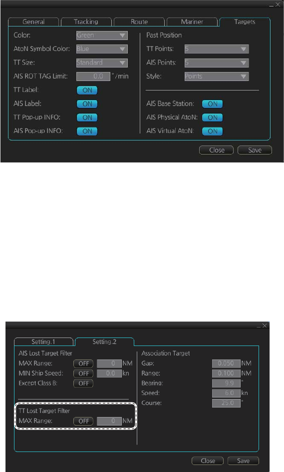
18.1.5 How to set the TT lost target filter
If you are in a congested area the lost target alert may sound against many AIS tar-
gets. In this case, you can prevent the alarm from sounding against TT that are be-
yond a certain range and/or smaller than a specific length.
1. Open the MENU and select [TT/AIS] and [Setting] then click the [Setting.2] tab.
2. In the [TT Lost Target Filter] window, set the maximum range to track a target.
[Max Range]: The maximum range at which to track a lost target. A tracked target
not within this range is not tracked.
3. Click the [ON/OFF] button to show ON or OFF as appropriate.
18.1.6 TT recording functions
Tracked target information is saved to the [Danger Targets] log. See section 19.5.
18. TT AND AIS DISPLAYS
18-4
18.2 AIS Display
18.2.1 AIS symbols
Refer to section 4.3.
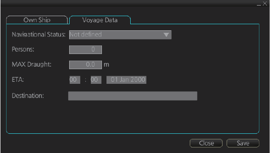
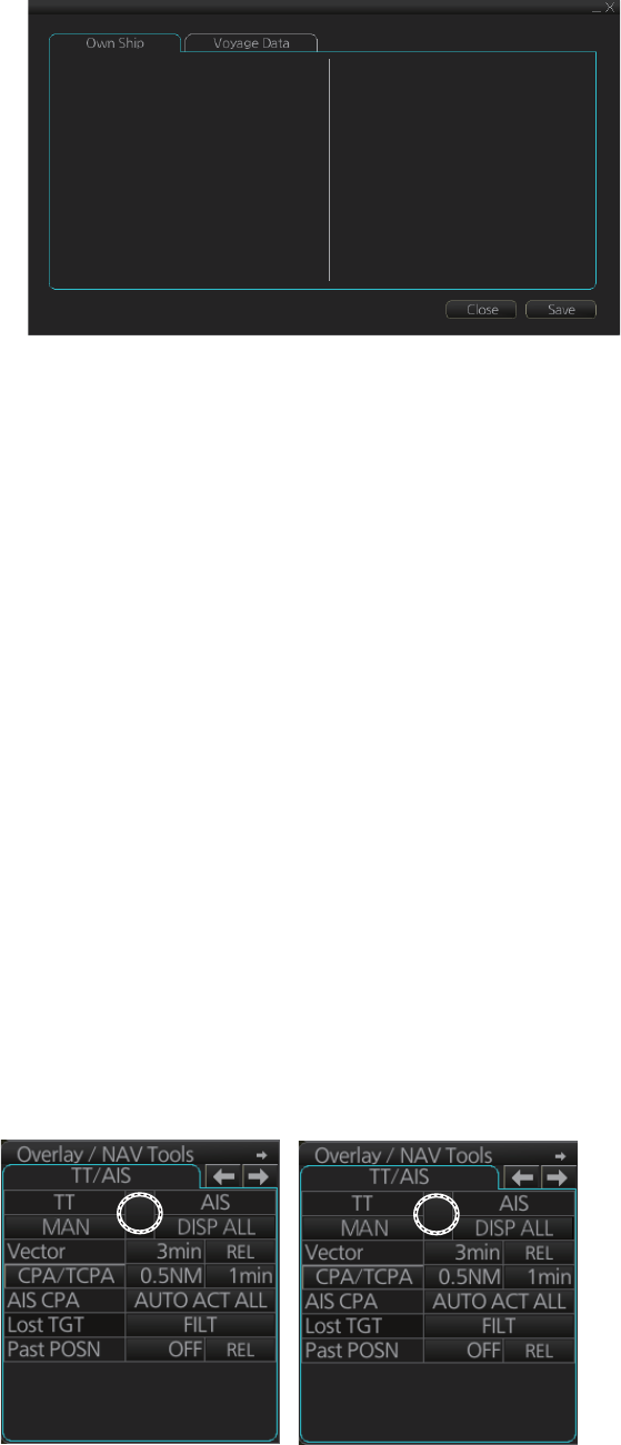
18.2.2 Voyage data
Before you embark on a voyage, set your navigation status, ETA, destination, draught
and crew, on the [Voyage Data] page in the [NAV Status] menu. The data entered
here is reflected to the AIS transponder.
Note: [Persons], the total number of persons onboard, should be set at the AIS tran-
sponder. Some AIS transponders may not accept this input from the radar.
1. Open the MENU then click both [NAV Status] in the [TT/AIS] menu and the [Voy-
age Data] tab.
2. Click the [Navigational Status] drop-down list then select your navigational status,
from the list below.
3. Enter ship's draught (0.0 - 25.5 (m)) at [MAX Draught].
4. Enter your ETA at [ETA].
Day: two digits
Month: Three-character abbreviation
Year: Four digits
5. Enter your destination at [Destination], using a maximum of 20 characters.
6. Click the [Save] button to save the settings.
• [Underway using engine]
• [At anchor]
• [Not under command]
• [Restricted maneuverability]
• [Constrained by her draught]
• [Moored]
• [Aground]
• [Engaged in fishing]
• [Under way sailing]
• [Reserved for high speed craft]
• [Reserved for wing in ground]
• [Reserved for future use] (x3)
• [AIS-SART (active)]
• [Not defined]
18. TT AND AIS DISPLAYS
18-5
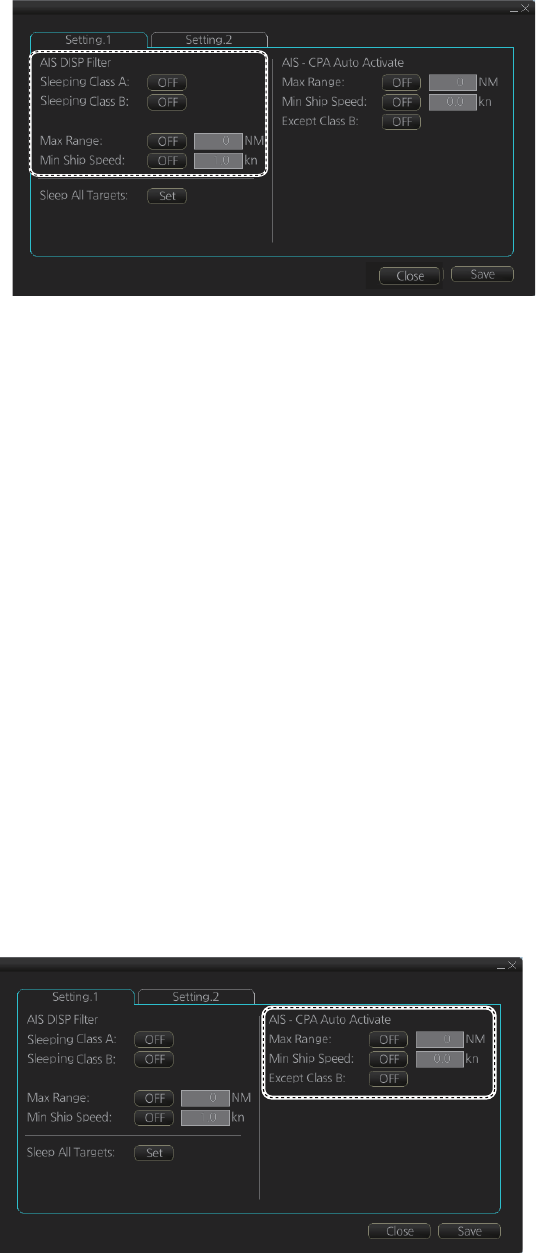
18.2.3 How to filter AIS targets
1. Right-click [AIS] on the [TT/AIS] page in the [NAV Tools/Overlay box], select [Set-
ting] and open the [Setting.1] page.
(The [Setting.1] page can also be opened from the menu (MENU → [TT/AIS] →
[Setting] → [Setting.1].)
2. In the [AIS DISP Filter] window, set each item referring to the description below.
• Click the buttons of [Sleeping Class A] and [Sleeping Class B] to show [OFF] or
[ON] to hide or show those targets.
• Set the maximum range with [Max Range]. Any target beyond the range set
here will not be displayed.
• Set the ship speed for AIS targets, with [Min Ship Speed]. Any AIS target whose
speed is lower than that set here will not be displayed.
3. Click the [Save] button to save settings. Click the [Close] button to close the dialog
box.
Note: AIS and tracked target viewing limitations are as follows:
AIS and tracked targets are displayed on top of chart 1:1,000,001 for S57 charts.
18.2.4 How to set conditions for automatic activation of sleeping tar-
gets
The AIS target automatic activation feature is turned on or off from the [TT/AIS] page
in the [Overlay/NAV Tools] box. Set the conditions for automatic activation as shown
below. The CPA/TCPA alarm must be active to get automatic activation of AIS targets.
Right-click [AIS] on the [TT/AIS] page in the [NAV Tools/Overlay box], select [Setting]
and open the [Setting.1] page.
18. TT AND AIS DISPLAYS
18-6
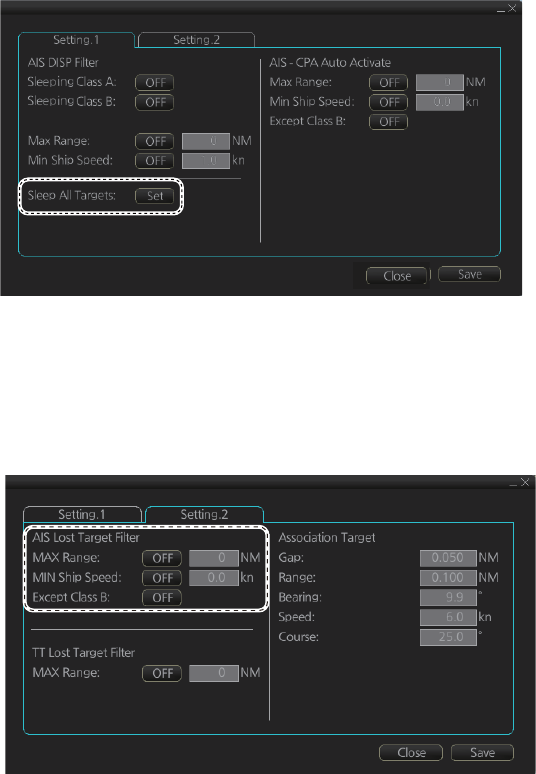
18.2.5 How to sleep all activated targets
You can sleep all activated targets. Right-click [AIS] on the [TT/AIS] page in the [NAV
Tools/Overlay box], select [Setting] and open the [Setting.1] page. Click the [Sleep All
Targets] button to sleep all activated targets.
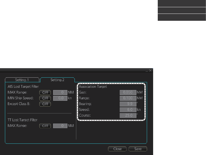
18.2.6 How to set the AIS lost target filter
You can select what AIS targets to exclude from the AIS lost target alert, on the [Set-
ting.2] page in the [TT/AIS] menu.
[Max Range]: Set the max. range at which a target must be to be declared a lost target.
[Min Ship Speed]: A tracked target whose speed is slower than set here does not trig-
ger the lost target alarm.
[Except Class B]: Exclude class B AIS targets from the AIS lost target alert.
18. TT AND AIS DISPLAYS
18-7
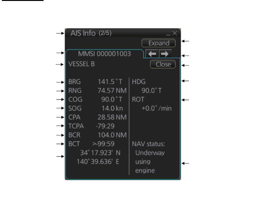
18.2.7 How to display AIS target data
Normal data
Put the cursor on an AIS target then push the left button.
Title bar
MMSI
Bearing
Range
Course over ground
Speed over ground
CPA
TCPA
Bow crossing range
Bow crossing time
Position
“Level of detail” button
Heading
Navigation status
Rate of turn
Scroll buttons*
Close button
Vessel name
*: Scroll buttons appear when there are multiple AIS targets.
18. TT AND AIS DISPLAYS
18-8
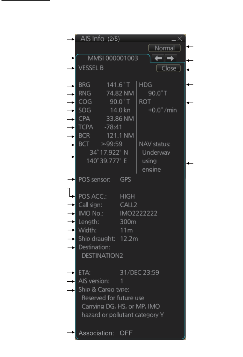
Expanded data
Put the cursor on a desired AIS target then push the left button. Click the [Expand] but-
ton (level of detail) on the [AIS Info] box to show expanded AIS data.
Title bar
MMSI
Bearing
Range
Course over ground
Speed over ground
CPA
TCPA
Bow cross range
Bow cross time
Position
“Level of detail”
button
Heading
Navigation status
Rate of turn
Scroll buttons*
Close button
Position sensor
Position sensor accuracy
(HIGH, LOW)
Call sign
IMO No.
Length
Width
Draught
Destination
ETA
AIS version no.
Ship & Cargo type
Vessel name
Association condition
*: Scroll buttons appear when there are multiple AIS targets.
18. TT AND AIS DISPLAYS
18-9
18.2.8 How to display own ship data
You can see own ship's data on the [Own Ship] page in the [NAV Status] menu. Open
the menu then click both [NAV Status] in the [TT/AIS] menu and the [Own Ship] tab.
18.3 Association
An AIS-equipped ship is usually displayed by two symbols on the chart for radar dis-
play. This is because the AIS ship position is measured by a GPS navigator (L/L)
whereas the radar detects the same ship by PPI principle (range and bearing relative
to own ship radar antenna).
To avoid the presentation of two target symbols for the same physical target, use the
“association” function. If target data from both AIS and TT are available and if the as-
sociation criteria are fulfilled, either the AIS or TT symbol is presented according to the
association method selected.
Association will not happen between AIS and TT if the AIS target is sleeping or the AIS
target is lost.
All association settings, including ON/OFF, can also be controlled from the radar
mode, with the [TT/AIS] setting box (see section 4.14). All settings are mutually
shared.
18.3.1 How to select association method
Click the location circled below to show "<" to select AIS symbol for associated target,
or ">" to select TT symbol for associated target. This setting overrides the correspond-
ing item on the [TT/AIS] menu. To turn off association, click the location to remove the
arrow.
MMSI: 457804356
Name: FURUNO Voyager
Call Sign: JZ5890312
Type: 0
Description: All ships of this type
Length(LOA): 223.2 m
Width: 31.8 m
Ref Bow: 3.3 m
Ref Port: 2.8 m
<
<>
18. TT AND AIS DISPLAYS
18-10
Note: You can also select the method by right-clicking the loca-
tion. Click desired association method.
18.3.2 How to set the conditions for association
To set the criteria for association, right-click [AIS] on the [TT/AIS] page in the [NAV
Tools/Overlay] box, select [Setting] and open the [Setting.2] page. For setting details,
see paragraph 4.14.2.
Association: OFF
Association: TT
Association: AIS
19-1
19. RECORDING FUNCTIONS
The chart radar records various voyage-related items like movement and position of
own ship and dangerous radar targets (from Radar). These items are recorded in the
following logs:
19.1 How to Record User, Position Events
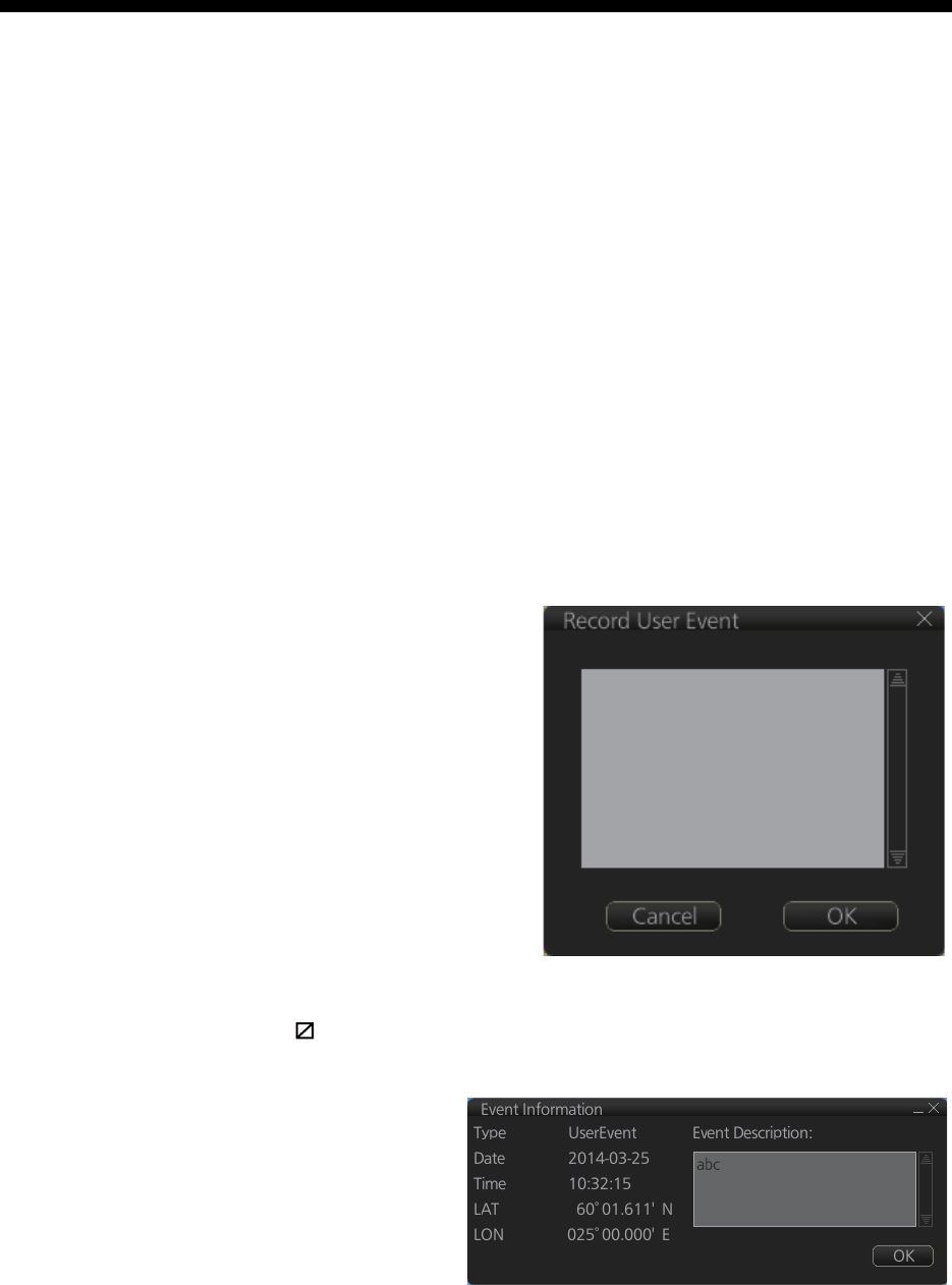
19.1.1 User events
A user event is a comment about an event
(weather, etc.). You can show user events
on the chart area. Open the [Tracking]
page of the [Symbol Display] menu show
or hide the events.
To record a user event:
1. Get into the Voyage planning mode
then click the [Record], [Event Log]
and [User Event] buttons on the In-
stantAccess bar to show the [Record
User Event] window.
2. Enter a comment. Click the [OK] but-
ton to finish and close the text box.
An event marker ( ) appears at your position and the event is recorded to the [Voy-
age] log.
To view the comment entered for
an event, put the cursor on the
event then left click to show the
[Event Information] window. The
window shows the name of the
event ([UserEvent]), time and date
of entry, latitude and longitude po-
sition of the event and comment.
Note that the comment can be edited from this window. Edit the comment then click
the [OK] button to save.
Event log: Records user events and position events.
NAV log: Records entire voyage (i.e., a sailing of a route from first point to the last,
also MOB data), details (position, speed and course every minute), chart
usage (information on charts used for display).
Target log: Records dangerous TT.
Alert log: Records alerts generated by the system.
Chart log: Records the install and update history for the ENC and C-MAP charts.
19. RECORDING FUNCTIONS
19-2
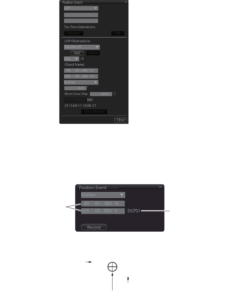
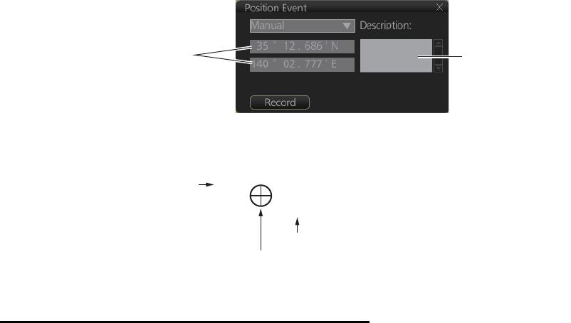
19.1.2 Position events
The operator may manually save positions to the [Event] log by position or LOP (Line
of Position):
To record a position, get into the Voyage navigation mode or Voyage planning mode
then do as follows:
1. Click the [Record], [Event Log] and [POSN Event] buttons on the InstantAccess
bar to show the [Position Event] dialog box.
2. At the list box at the top of the dialog box, select position type.
[Manual]: Manual input of ship’s position. Go to step 4.
[LOP]: Latitude and longitude position of a fixed object at ship's position. Go to
step 5.
[Position]: Ship’s position fed from navigator selected. Go to step 3.
3. For [Position], click the [Record] button.
The position event mark appears at the ship’s position. The position is recorded
to the [Voyage] log.
Ship’s position fed from
navigator selected Selected navigator
Navigator selected
Time of entry
1044
DGPS1
Position event mark
19. RECORDING FUNCTIONS
19-3
4. For [Manual], manually enter position, enter a comment if required, then click the
[Record] button.
The position event mark appears at the manual input position. The position is re-
corded to the [Voyage] log.
5. For [LOP], see the description below.
Position fixes defined by Line of Position (LOP)
A plotted line on which a vessel is located, determined by observation or measure-
ment of the range or bearing to an aid to navigation or other charted element. Two or
more simultaneous observations can be combined to produce an estimate of the
ship's current position. If the position is based on only two observations, it is an "esti-
mated position" (EP); otherwise it is called a fix. A maximum of 6 observations can be
entered to obtain a fix.
Basic operation: Coordinates of the aid to navigation can be entered into dialog box-
es or they can be selected graphically on the chart. Click on a charted object (beacon,
light, buoy etc.). Description of the object appears above coordinate boxes.
Default values for bearing and range are approximated from ship's current position in-
formation. The time of observation is stopped when the object is selected (or when the
[Add] button is clicked). Click the [Add] box to include the observation in the fix com-
putation. The counter shows "new/1", at the input of the second observation. The word
"new" indicates that the observation currently displayed is not yet included in the fix
computation, and it appears as a dashed line or ring on the chart. The added obser-
vations can be edited or deleted after selecting them at the counter. When at least two
measurements are entered, the EP or fix is computed and the coordinates are shown
in the top part of the dialog.To show a position symbol on the chart, click the [Record]
button. In the case of an EP, the letters EP are shown on the right side of the coordi-
nates. If a valid position estimate cannot be obtained, a message is displayed under
the coordinates. This may happen, for example, if the lines / circles have multiple
crossings that are far apart, or if two lines are nearly parallel or don't intersect at all.
The accuracy limit (estimated standard error) is 1.0 NM. If the estimate is valid, the
[Record] box can be clicked to record the current position estimate in the [Voyage] log.
Discrepancy between LOP result and ship position is also recorded in the log (this in-
formation may be viewed by Info query on the position event symbol on the chart -
which is displayed if position event display is on in chart display settings).
Enter position manually. Enter comment
here if required.
Navigator selected
Time of entry
1044
DGPS1
Position event mark
19. RECORDING FUNCTIONS
19-4
Time transfer: If the observations are not simultaneous, they should be transferred to
a common time. Transferring is based on dead reckoning of ship movement. If a po-
sition line (or ring) is transferred, the letters TPL are shown beside its timestamp on
the chart. The method of transfer may be selected in the bottom of the dialog. [Trans-
fer to latest] transfers the measurements as if they were all made at the time of the
newest measurement. [Continuous transfer] transfers all measurements to real time.
[Transfer off] can be used to check where the measurement origins are. The position
estimate and the record function follow the same logic, which means that Transfer off
shows a position that has no relevance and Transfer to latest sends an old position to
the [Voyage] log (timestamp in the log does not match the position).
If you are satisfied with the position shown in the latitude and longitude fields, then
click the [Record] button to save the position observation to the Voyage log. If you wish
you can also enter latitude and longitude values manually.
Timeouts: The observations cannot be used long after they were made because dead
reckoning is inaccurate.
Click the [Record] button to put a position event at the LOP-calculated position. The
position is recorded to the [Voyage] log.
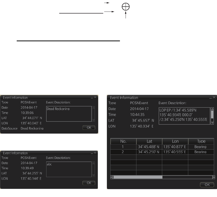
How to find position event information
You can find information about a position event by putting the cursor on the event
mark then left click. The [Event Position] window shows event type (position event),
time of entry, event position, name of sensor ([Position] only), comment (automatic for
[LOP] and [Position]; user-entered comment* for [Manual]), and position line data
([LOP] only).
*Comment cannnot be changed from this window.
Time of entry
1044
EP LOP
Position event
mark
A
ccuracy of position
EP: Low accuracy
DR: High accuracy
Position event: Position
Position event: Manual Position event: LOP
19. RECORDING FUNCTIONS
19-5
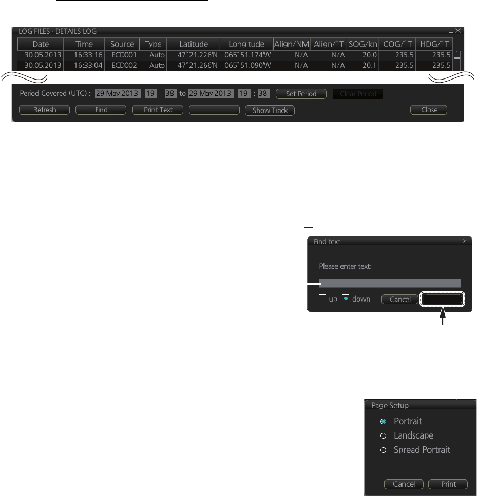
19.2 Details Log
The [Details] log contains voyage information, recorded once per minute.
How to view the Details log
Click the [Record], [NAV Log] and [Detail] buttons on the InstantAccess bar.
• To show the logs of a specific period, enter the period to show with [Period Cov-
ered (UTC)] then click the [Set Period] button. Use the [Clear Period] button to dis-
play all logs.
• To refresh the log, click the [Refresh] button.
• To search the log, do as follows:
1) Click the [Find] button to show the [Find
text] box.
2) Click the input box then enter the text to
search.
3) Select the search direction with the up or
down radio button.
4) Click the [Find] button. The first matching
text is highlighted in yellow at the top of the
screen.
5) To continue the search click the [Find] button. To cancel the search, click the
[Cancel] button.
• To print the log, click the [Print Text] button. Select print-
ing format then click the [Print] button. [Spread Portrait]
prints two pages of data on one page.
• To show track for the period selected, click the [Show
Track] button. Use the [Hide Track] button to erase the
track.
• To export the log, click the [Export File] button. The file is
named
DetailsLogYYYYMMDDhhmmss.csv.
• [Date]
• [Time]
• [Source]: No. of unit which generated log
• [Type]: Type of position data
• [Auto]: Automatic input of position
• [Latitude], [Longitude]: Position as output by selected sensor
• [Align/NM], [Align/°T]: Range, bearing offset, if used
• [SOG/kn]: Speed over the ground
• [COG/°T]: Course over the ground
• [HDG/°T]: Heading
• [CORR/°T]: Gyro correction value, if used
Export File
Find
Input box
Input text in box and
[Find] button appears.
19. RECORDING FUNCTIONS
19-6
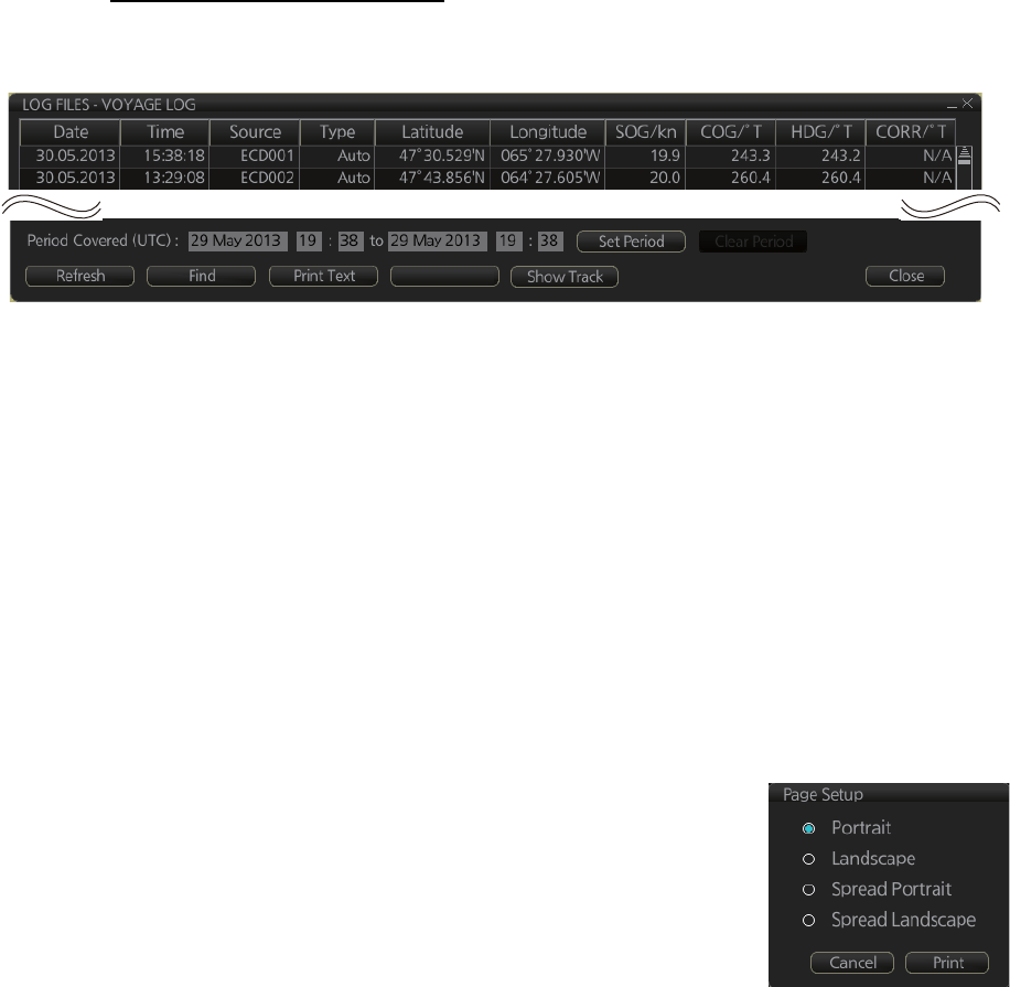
19.3 Voyage Log
The [Voyage] log records all voyage-related data of the past three months. Recorded
events are:
• [Date]: Date of entry
• [Time]: TIme of entry
• [Source]: No. of unit which generated log
• [Type]: Log entry types
• [Auto]: Automatic entry of ship position, in 1 to 4 hr intervals, set by operator.
• [Ship]: Logged if speed or course exceed operator-set values.
• [MOB]: MOB position, entered with [MOB] button.
• [User]: Operator-entered position. The information entered in the [Description] box
is logged.
• [Posdev]: Operator-entered GPS position or LOP. The information entered in the
[Description] box is logged.
• [Latitude], [Longitude]: Latitude and longitude position
• [SOG/kn], [COG/°T], [HDG/°T]: Speed over the ground, course over the ground,
heading.
• [CORR/°T]: Offset bearing, if used
• [Wind/kn], [Wind/°T]: Wind speed and angle
• [Dist/NM]: Offset distance
• [Depth/m]: Depth in meters
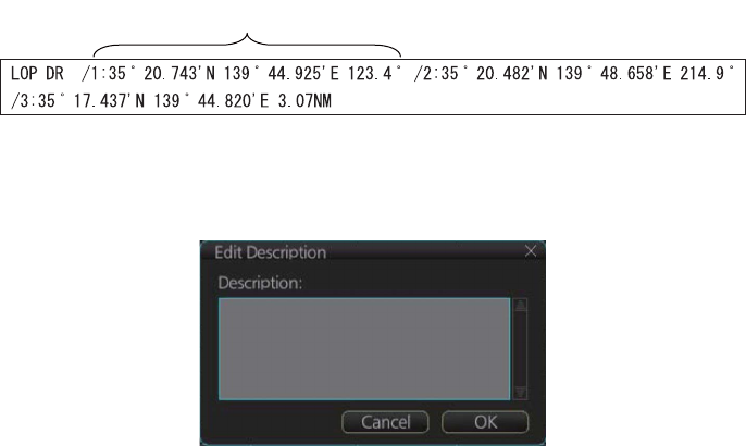
• [Description]: The latitude and longitude position and bearing (or distance) of a max-
imum of three objects are automatically recorded to each log entry. An object whose
position accuracy is low is not recorded. If an object has both a bearing and distance,
separate entries are made.
If desired the description can be edited. Click the applicable Description block to
show the [Edit Description] box. Edit the description as required then click the [OK]
button.
L/L position, bearing of object (no.1)
19. RECORDING FUNCTIONS
19-7
How to view the Voyage log
To open the Voyage log, click the [Record], [NAV Log] and [Voyage] buttons on the
InstantAccess bar.
• To show the logs of a specific period, enter the period to show with [Period Cov-
ered (UTC)] then click the [Set Period] button. Use the [Clear Period] button to dis-
play all logs.
• To refresh the log, click the [Refresh] button.
• To search the log, do as follows:
1) Click the [Find] button to show the [Find text] box.
2) Click the input box then enter the text to search.
3) Select the search direction with the up or down radio button.
4) Click the [Find] button. The first matching text is highlighted in yellow at the top
of the screen.
5) To continue the search click the [Find] button. To cancel the search, click the
[Cancel] button.
• To print the log, click the [Print Text] button. Select print-
ing format then click the [Print] button. [Spread Portrait]
and [Spread Landscape] print two pages of data on one
page.
• To show track for the period selected, click the [Show
Track] button. Use the [Hide Track] button to erase the
track.
• To export the log, click the [Export File] button. The file is named
VoyageLogYYYYMMDDhhmmss.csv.
Export File
19. RECORDING FUNCTIONS
19-8
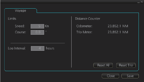
19.3.1 How to set conditions of logging
The operator can set the conditions for automatic voyage logging. When your speed
or course equals the amount set here, an entry is made in the [Voyage] log:
• Define the amount of course and speed change which creates a log entry.
• Set the interval of logging, regardless of speed and course change.
To set the conditions of logging, do as follows:
1. Open the menu and select the [Voyage] menu from the [NAVI Log] menu.
2. Set desired limits for speed, course and log interval.
[Speed]: 1 - 10 kn, 1 kn interval
[Course]: 0 - 30°, 1° interval
[Log Interval]: 1 - 4 hr, 1 hr interval
When your speed or course changes by the amount set here, an entry is made in the
[Voyage] log, at the interval selected.
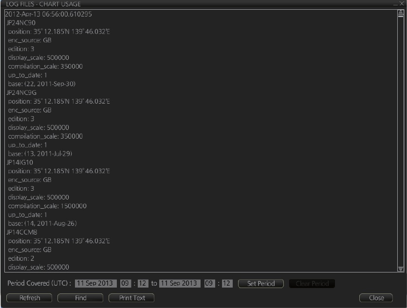
19.4 Chart Usage Log
The [Chart Usage] log stores which charts were used in chart alerts. To open the log,
click [Record], [NAV Log] and [Chart Usage] on the InstantAccess bar. The following
information is recorded in the chart usage log:
• Date and time chart was displayed
• Chart ID
• Center position of display (Lat, Lon)
• Chart source
• Chart edition
• Display scale
• Compilation scale
• The latest update included to chart
• Chart base
19. RECORDING FUNCTIONS
19-9
• To show the logs of a specific period, enter the period to show with [Period Cov-
ered (UTC)] then click the [Set Period] button. Use the [Clear Period] button to dis-
play all logs.
• To refresh the log, click the [Refresh] button.
• To search the log, do as follows:
1) Click the [Find] button to show the [Find text] box.
2) Click the input box then enter the text to search.
3) Select the search direction with the up or down radio button.
4) Click the [Find] button. The first matching text is highlighted in yellow at the top
of the screen.
5) To continue the search click the [Find] button. To cancel the search, click the
[Cancel] button.
• To print the log, click the [Print Text] button.
19. RECORDING FUNCTIONS
19-10
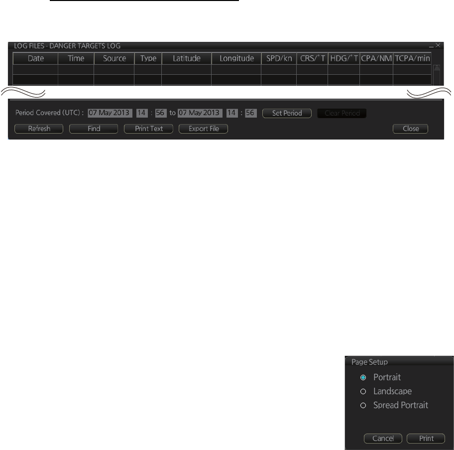
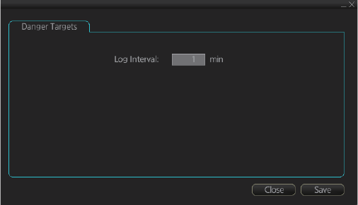
19.5 Danger Targets Log
The [Danger Targets] log stores information about dangerous targets that are re-
ceived from a radar (TTs) and/or targets that are received from an AIS transponder
(AIS targets).
If a TT or AIS target is within the set CPA (Closest Point of Approach) and TCPA (Time
to CPA), information of all TTs (including non-dangerous targets) are recorded into the
danger target log. This data is as follows:
How to view the danger targets log
To open the [Danger Targets] log, click the [Record], [Target Log] and [Danger Target]
buttons on the InstantAccess bar.
• To show the logs of a specific period, enter the period to show with [Period Cov-
ered (UTC)] then click the [Set Period] button. Use the [Clear Period] button to dis-
play all logs.
• To refresh the log, click the [Refresh] button.
• To search the log, do as follows:
1) Click the [Find] button to show the [Find text] box.
2) Click the input box then enter the text to search.
3) Select the search direction, with the up or down radio button.
4) Click the [Find] button. Matching text is highlighted in yellow at the top of the
screen.
5) To continue the search click the [Find] button. To cancel the search, click the
[Cancel] button.
• To print the log, click the [Print Text] button.
• To export the log, click the [Export File] button. The file
is namedDangerTargetLogYYYYMMDDhhmmss.csv.
• [Date]: Date of entry
• [Time]: Time of entry
• [Source]: Unit which generated log
• [Type]: Type of dangerous target
• [Latitude], [Longitude]: Latitude and longitude position of dangerous target
• [SPD/kn]: Speed of dangerous target
• [CRS/°T]: Course of dangerous target
• [HDG/°T]: Heading of dangerous target
• [CPA/NM], [TCPA/min]: CPA and TCPA of dangerous target
• [Index]: Radar target no. (TT), MMSI (AIS)
2013-05-08 13:55:59 ECD00
1 TT 35°38.164’N 139°49.842’E 15.1 193.3 N/A 1.3 0.7
2013-05-08 13:53:42 ECD00
1 TT 35°57.770’N 139°49.732’E 12.1 200.6 N/A 1.1 0.2
19. RECORDING FUNCTIONS
19-11
19.5.1 How to set the conditions for logging danger targets
The operator may set Closest Point of Arrival (CPA), Time for CPA (TCPA) and Log
interval for viewing dangerous TT and AIS targets on the chart radar display.
1. Open the menu and select the [RECORD], [Target Log], [Danger Target] menus.
2. Set how often to record dangerous TTs and AIS targets with [Log interval].
19. RECORDING FUNCTIONS
19-12
This page is intentionally left blank.

20-1
20. ALERTS
20.1 What is an Alert?
“Alert" is a generic name for a notice to any unusual or potentially dangerous situation
generated within the system.
Alerts are classified according to priority and category.
Alert priority
There are three alert priorities: alarm, warning and caution.
Alarm: Situations or conditions which require immediate attention, decision and (if
necessary) action by the bridge team to avoid any kind of hazardous situation and to
maintain the safe navigation of the ship.
Warning: Situations or conditions which require immediate attention for precautionary
reasons, to make the bridge team aware of conditions which are not immediately haz-
ardous, but may become so.
Caution: Awareness of a condition which continues to require attention out of the or-
dinary consideration of the situation or of given information.
Alert category
An alert is further classified by category, A, B or C, according to its degree of severity
or source.
Category Description
A Category A alerts include alerts indicating
• Danger of collision
• Danger of grounding
B Category B alerts are alerts where no additional information for decision
support is necessary. Category B alerts are all alerts not falling under
category A.
C IAS (Integrated Automation System) generated engine alert
20. ALERTS
20-2
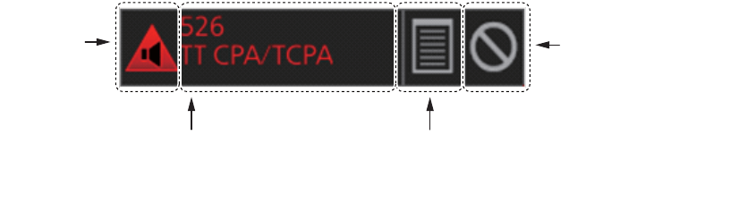
20.2 Alert Box
When an alert is generated, the related alert message and alert state icon appear in
the [Alert] box, which is at the bottom right corner on the screen. An audible alarm is
additionally generated for alarms and warnings.
In addition to the alert message and alert state icon, the [Alert] box has the buzzer stop
button and provides access to the [Alert List] and [Alert Log].
Alert state icon: The state of an alert is shown with an icon. See page 20-4.
Alert message: The number and name of all active alerts appear in the message ar-
ea, with the alert of the highest priority on top always. The color of both the message
and the background change according to alert priority and alert state. See the table on
the next page.
An alert can be acknowledged from the [Alert] box or [Alert List]. An alert remains in
the [Alert] box and [Alert List] until it is acknowledged and rectified. See section 20.5.
Alert List/Alert Log button: Right-click to select [Alert List Window] or [Alert Log Win-
dow]. The background color of the button is light blue when the list or log is open. See
sections 20.5 and 20.6 for a description of the list and log.
Buzzer stop button: Click to temporarily silence the buzzer, which sounds against
alarms and warnings. See page 20-4.
Alert message
(Number and name of alert)
Alert List/Alert Log button
(Right-click to select [Alert List Window]
or [Alert Log Window].)
Buzzer stop button
(Click to stop
buzzer temporarily.)
A
lert state
icon
20. ALERTS
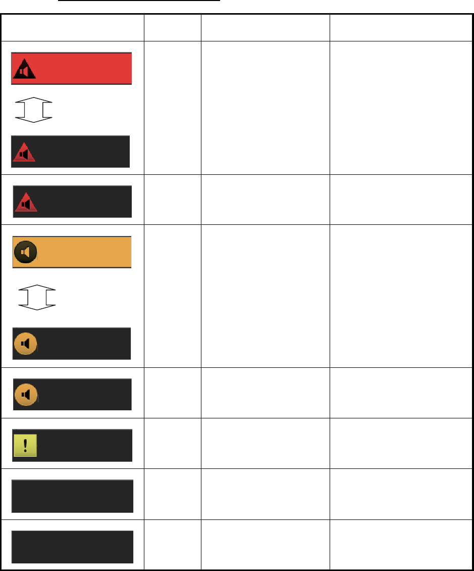
20-3
Alert message display format
Alert indication Priority
of alert Alert state Display state
Alarm - Not acknowledged/Not
rectified.
OR
- Not acknowledged/Rec-
tified.
Black characters on red
background.
Flashing interval
• 0.5 s, 0.5 s (Not rectified)
• 3 s, 1 s (Rectified)
Red characters on gray
background.
Alarm Acknowledged/Not recti-
fied.
Red characters on gray
background.
Warning - Not acknowledged/Not
rectified.
OR
Not acknowledged/Recti-
fied.
Black characters on yellow-
orange background.
Flashing interval
• 0.5 s, 0.5 s (Not rectified)
• 3 s, 1 s (Rectified)
Yellow-orange characters
on gray background.
Warning Acknowledged/Not recti-
fied.
Yellow-orange characters
on gray background.
Caution Not rectified. Yellow characters on gray
background.
Alarm/
Warning
Acknowledged/Rectified. No display.
Caution Rectified. No display.
526
526
Displayed
alternately
TT CPA/TCPA
TT CPA/TCPA
526
TT CPA/TCPA
008
008
Fan 2 No Rotati..
Displayed
alternately
Fan2 No Rotati..
008
Fan2 No Rotati..
362
Wind Sensor 3..
20. ALERTS
20-4
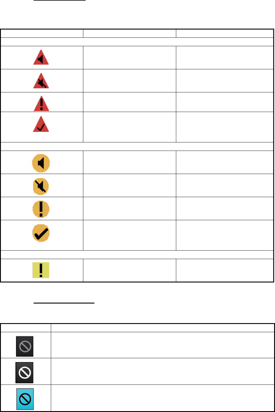
Alert state icons
The table shows the icons used to indicate the various alert states for the alarm, warn-
ing and caution alerts.
Buzzer stop button
The color of both the background and the icon change according to alert state.
Icon Alert state Icon description
Alert priority: Alarm
Not acknowledged/Not rectified Red triangle with black loudspeak-
er in center of triangle. Flashing
every 0.5 s.
Not acknowledged/Not rectified,
Buzzer temporarily silenced
Red triangle with crossed out
black loudspeaker in center of tri-
angle. Flashing every 0.5 s.
Acknowledged/Not rectified Red triangle with black exclama-
tion point in center of triangle.
Not acknowledged/Rectified Red triangle with black check
mark in center of triangle. The icon
flashes 3 s, goes off 1 s, repeats
the sequence.
Alert priority: Warning
Not acknowledged/Not rectified Yellow-orange circle with black
loudspeaker in center of circle.
Flashing every 0.5 s.
Not acknowledged/Not rectified,
Buzzer temporarily silenced
Yellow-orange circle with crossed
out black loudspeaker in center of
circle. Flashing every 0.5 s.
Acknowledged/Not rectified Yellow-orange circle with black
exclamation point in center of cir-
cle.
Not acknowledged/Rectified Yellow-orange circle with black
check mark in center of circle. The
icon flashes 3 s, goes off
1 s, repeats the sequence.
Alert priority: Caution
Caution Steadily displayed yellow square
with black exclamation point in
center of square.
Button state Description
No alert generated. The background is gray and the icon is grayed out.
An alarm or warning is being acknowledged. The background is gray and the icon
is white.
Button clicked to silence buzzer temporarily. The background is light-blue and the
icon is black.
20. ALERTS
20-5
20.3 How to Temporarily Silence the Buzzer for an
Alarm or Warning
When the buzzer for an alarm or warning sounds, you can temporarily silence it by do-
ing one of the following:
• Click the buzzer stop button in the [Alert] box.
• In the [Alert List], click the [Silence] button.
The buzzer is stopped and the alert state changes. An alert message remains in the
[Alert] box and [Alert List] until acknowledged and rectified. If an alarm or warning is
not acknowledged within 30 seconds, the buzzer sounds again.
20.4 How to Acknowledge an Alarm or Warning
When an alarm or warning is generated, the buzzer sounds and the name of the alert
appears and flashes in the [Alert] box and [Alert List].
To acknowledge the alert, do one of the following:
• Press the ALARM ACK key.
• In the [Alert] box or [Alert List], click the unacknowledged alert.
After acknowledgement, the buzzer and the flashing for the alert message are stopped
and the priority of the alert changes as shown in the table below. The alert message
remains on the display until rectified.
Unacknowledged warnings
If a warning (Alert 150 "Early Course Change Indication" and 151 "Actual Course
Change Indication") is not acknowledged within 30 seconds then the priority changes
to alarm. If a warning (except for Alert 150 and 151) is not acknowledged within 60
seconds, the warning is generated again.
Category of alert and place of alert acknowledgement
The place of alert acknowledgement depends on the category of the alert.
Priority no. Priority of alert Alert state
High
Low
1 Alarm Not acknowledged/Not rectified
2 Warning Not acknowledged/Not rectified
3 Alarm Not acknowledged/Rectified
4 Warning Not acknowledged/Rectified
5 Alarm Acknowledged/Not rectified
6 Warning Acknowledged/Not rectified
7 Caution Not rectified
Category Where the alert is generated Place of alert
acknowledgement
A Equipment that generated the
alert.
Equipment that generated the
alert.
B Equipment that generated the
alert.
Equipment that generated the alert
or AMS.
C IAS (Integrated Automation Sys-
tem) generated engine alert
–
20. ALERTS
20-6
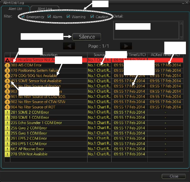
20.5 Alert List
The [Alert List] displays all active alerts, with unacknowledged alerts at the top, in pri-
ority order. To display the list, right-click the [Alert List/Alert Log] button in the [Alert]
box then select [Alert List/Log Window]. The ZDA sentence is required to display the
time in the list.
Note: The [Alert List] cannot be opened while the radar is transmitting.
The list shows
The background color of an unacknowledged alarm is red and flashing and unac-
knowledged warning is yellow-orange and flashing. An acknowledged alert is dis-
played steadily, in red for alarm and yellow-orange for warning. A caution is displayed
steadily in yellow.
The [Filter] checkboxes at the top of the window let you select what alerts to view.
Check or uncheck the boxes to show or hide the corresponding alerts.
To find details about an alert, click the applicable alert info icon at the left side of the
window to show the details in the [Detail] box at the top of the window. The box shows
the reason for the alert, how to handle the alert, etc.
An individual alarm or warning can be acknowledged by clicking it.
The [Silence] button silences the buzzer.
• Alert no.
• Alert text
• Source of alert
• Time (UTC) alert was generated
• Time (UTC) alert was acknowledged
• Details about the alert selected
Filter
Time
ACKed
Alert details
Silence buzzer
Time
generated
Alert text
Alert no.
Alert info icon
Source
20. ALERTS
20-7
How the alert list is updated after acknowledgement, rectification
When you acknowledge an alert, its display method on the [Alert] list changes accord-
ing to alert category and alert state. Acknowledged and rectified alerts are immediately
removed from the list.
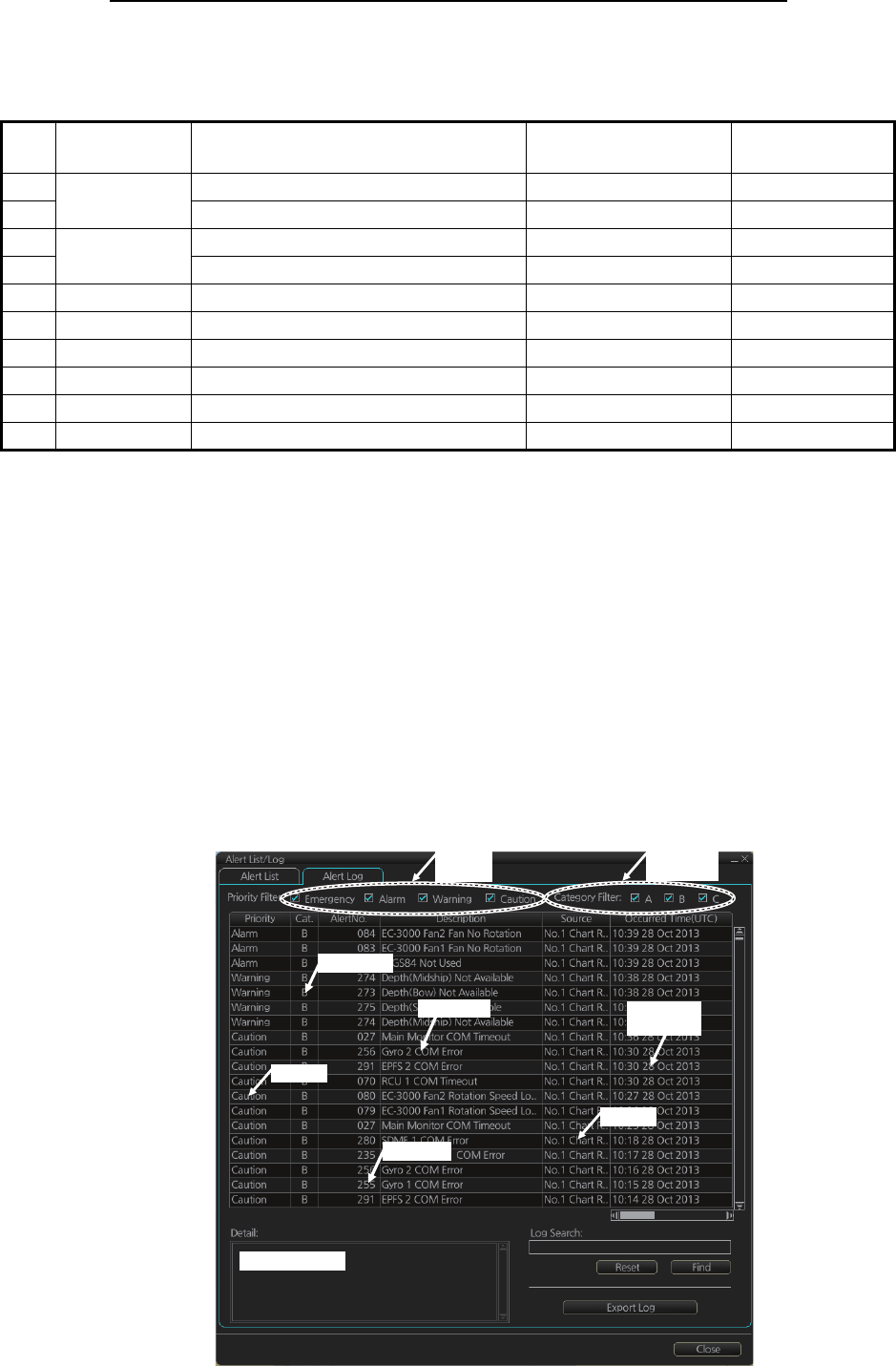
20.6 Alert Log
The [Alert] log stores and displays the latest 10,000 alerts. To display the log, right-
click the [Alert List/Alert Log] button then select [Alert List/Log Window].
Note: The [Alert Log] cannot be opened while the radar is transmitting.
The log shows the following information for each alert:
No. Alert
priority Alert state Display after
acknowledgement
Display after
rectification
1 Alarm Not acknowledged/Not rectified 5 2
2 Not acknowledged/Rectified 8 –
3 Warning Not acknowledged/Not rectified 6 4
4 Not acknowledged/Rectified 9 –
5 Alarm Acknowledged/Not rectified – 8
6 Warning Acknowledged/Not rectified – 9
7 Caution Not rectified – 10
8 Alarm Acknowledged/Rectified – –
9 Warning Acknowledged/Rectified – –
10 Caution Rectified – –
• Priority of alert (Alarm, Warning, Caution)
• Category of alert (A, B or C)
• Alert no.
• Alert description
• Source of alert
• Occurred Time (UTC)
• ACKed Time (UTC)
• Rectified Time (UTC)
• Alert details
Alarm Details
Priority
filter
Category
filter
Occured
time
Source
Alert no.
Alert text
Category
Priority

20. ALERTS
20-8
You can select what type of alerts to display with [Priority Filter] and [Category Filter]
at the top of the list. The list can be sorted by [Priority], [Cat.], [Alert No.], [Description],
[Occurred Time], [ACKed TIime] or [Rectified Time]. Click the corresponding column
title to sort. To find detailed information about an alert, select it to show detailed infor-
mation in the [Detail] box. To search the log, enter text in the [Log Search] box then
click the [Find] button. You can save the contents of the log to a USB flash memory,
in .dat format, by clicking the [Export Log] button.
20.7 Alert Reception from Connected Sensors
An "ALR receive and ACK transmit" communication is available for every serial line
input. The ALR message from the sensor includes information about alerts from the
sensor, and is presented though the normal alert system. When you acknowledge an
alert, an ACK message is sent to the sensor to do remote acknowledge.
This interface is based on IEC 61162-1 and IEC 80/520/INF.
20.8 List of Alerts
Below is a list of all available alerts and their default priorities. The priority of Alerts 620
to 638 can be switched between Caution and Warning on the [Chart Alert] page (see
paragraph 11.1.2).
No. Text Default
priority
001 Fan1 Rotation Speed Lowering Caution
002 Fan2 Rotation Speed Lowering Caution
003 Fan3 Rotation Speed Lowering Caution
004 Fan4 Rotation Speed Lowering Caution
005 LCD Unit Lifetime Over Warning
006 High Temperature Inside Monitor Warning
007 Fan1 No Rotation Warning
008 Fan2 No Rotation Warning
009 Fan3 No Rotation Warning
010 Fan4 No Rotation Warning
011 RS485 Communication Timeout Caution
012 No Signal Caution
013 Sentence Syntax Error Caution
014 Fan1 Rotation Speed Lowering Caution
015 Fan2 Rotation Speed Lowering Caution
016 Fan3 Rotation Speed Lowering Caution
017 Fan4 Rotation Speed Lowering Caution
018 LCD Unit Lifetime Over Warning
019 High Temperature Inside Monitor Warning
020 Fan1 No Rotation Warning
021 Fan2 No Rotation Warning
022 Fan3 No Rotation Warning
023 Fan4 No Rotation Warning
024 RS485 Communication Timeout Caution
025 No Signal Caution Caution

20. ALERTS
20-9
026 Sentence Syntax Error Caution
027 Main Monitor COM Timeout Caution
028 Sub Monitor COM Timeout Caution
030 Sensor Adapter 1 COM Timeout Caution
031 Sensor Adapter 2 COM Timeout Caution
032 Sensor Adapter 3 COM Timeout Caution
033 Sensor Adapter 4 COM Timeout Caution
034 Sensor Adapter 5 COM Timeout Caution
035 Sensor Adapter 6 COM Timeout Caution
036 Sensor Adapter 7 COM Timeout Caution
037 Sensor Adapter 8 COM Timeout Caution
038 Sensor Adapter 9 COM Timeout Caution
039 Sensor Adapter 10 COM Timeout Caution
070 RCU 1 COM Timeout Caution
071 RCU 2 COM Timeout Caution
072 RCU 3 COM Timeout Caution
073 EC-3000 CPU Temp High Caution
074 EC-3000 GPU Temp High Caution
075 EC-3000 CPU Board Temp High Caution
076 EC-3000 Remote 1 Temp High Caution
077 EC-3000 Remote 2 Temp High Caution
078 EC-3000 CPU Fan Rotation Speed Lowering Caution
079 EC-3000 Fan1 Rotation Speed Lowering Caution
080 EC-3000 Fan2 Rotation Speed Lowering Caution
082 EC-3000 CPU Fan No Rotation Warning
083 EC-3000 Fan1 Fan No Rotation Warning
084 EC-3000 Fan2 Fan No Rotation Warning
086 EC-3000 CPUboard 5V Power Error Warning
087 EC-3000 CPUboard 3.3V Power Error Warning
088 EC-3000 CPUboard 12V Power Error Warning
089 EC-3000 CPUboard Battery Power Error Caution
090 EC-3000 CPUboard Core Power Error Caution
094 Sensor Adapter 11 COM Timeout Caution
095 Sensor Adapter 12 COM Timeout Caution
096 Sensor Adapter 13 COM Timeout Caution
097 Sensor Adapter 14 COM Timeout Caution
098 Sensor Adapter 15 COM Timeout Caution
099 Sensor Adapter 16 COM Timeout Caution
150 Early Course Change Indication Warning
151 Actual Course Change Indication Warning
170 Positioning System Failure Warning
171 Crossing Safety Contour Alarm
172 Off Track Alarm Alarm
175 Different Geodetic Datum Warning
176 System Malfunction Warning
235 Echo Sounder 1 COM Error Caution
236 Echo Sounder 2 COM Error Caution
237 Echo Sounder 3 COM Error Caution
No. Text Default
priority

20. ALERTS
20-10
255 Gyro 1 COM Error Caution
256 Gyro 2 COM Error Caution
257 Gyro 3 COM Error Caution
258 Gyro 4 COM Error Caution
259 Gyro 5 COM Error Caution
260 Backup Navigator Alarm
272 UTC Time Not Available Warning
273 Depth(Bow) Not Available Caution
274 Depth(Midship) Not Available Caution
275 Depth(Stern) Not Available Caution
277 Wind Speed/Direction Not Available Warning
278 STW Not Available Caution
279 COG/SOG Not Available Warning
280 SDME 1 COM Error Caution
281 SDME 2 COM Error Caution
282 SDME 3 COM Error Caution
284 SOG Not Available Warning
290 EPFS 1 COM Error Caution
291 EPFS 2 COM Error Caution
292 EPFS 3 COM Error Caution
293 EPFS 4 COM Error Caution
294 EPFS 5 COM Error Caution
295 EPFS 6 COM Error Caution
296 EPFS 7 COM Error Caution
297 EPFS 8 COM Error Caution
298 EPFS 9 COM Error Caution
310 Other Sensor 1 COM Error Caution
311 Other Sensor 2 COM Error Caution
312 Other Sensor 3 COM Error Caution
313 Other Sensor 4 COM Error Caution
314 Other Sensor 5 COM Error Caution
315 Other Sensor 6 COM Error Caution
316 Other Sensor 7 COM Error Caution
317 Other Sensor 8 COM Error Caution
318 Other Sensor 9 COM Error Caution
319 Other Sensor 10 COM Error Caution
320 EC-3000 Ch.01 COM Timeout Caution
321 EC-3000 Ch.02 COM Timeout Caution
322 EC-3000 Ch.03 COM Timeout Caution
323 EC-3000 Ch.04 COM Timeout Caution
324 EC-3000 Ch.05 COM Timeout Caution
325 EC-3000 Ch.06 COM Timeout Caution
326 EC-3000 Ch.07 COM Timeout Caution
327 EC-3000 Ch.08 COM Timeout Caution
360 Wind Sensor 1 COM Error Caution
361 Wind Sensor 2 COM Error Caution
362 Wind Sensor 3 COM Error Caution
370 Water Current COM Error Caution
No. Text Default
priority

20. ALERTS
20-11
371 Water Temp COM Error Caution
380 AIS COM Error Warning
390 NAVTEX COM Error Caution
400 Network Printer Not Available Caution
401 Local Printer Not Available Caution
411 Other Sensor 11 COM Error Caution
412 Other Sensor 12 COM Error Caution
413 Other Sensor 13 COM Error Caution
414 Other Sensor 14 COM Error Caution
415 Other Sensor 15 COM Error Caution
416 Other Sensor 16 COM Error Caution
417 Other Sensor 17 COM Error Caution
418 Other Sensor 18 COM Error Caution
419 Other Sensor 19 COM Error Caution
420 Other Sensor 20 COM Error Caution
421 Other Sensor 21 COM Error Caution
422 Other Sensor 22 COM Error Caution
423 Other Sensor 23 COM Error Caution
424 Other Sensor 24 COM Error Caution
425 Other Sensor 25 COM Error Caution
426 Other Sensor 26 COM Error Caution
427 Other Sensor 27 COM Error Caution
428 Other Sensor 28 COM Error Caution
429 Other Sensor 29 COM Error Caution
430 Other Sensor 30 COM Error Caution
450 Heading Sensor Not Available Warning
451 Gyro CORR. Source Change Caution
453 SDME Sensor Not Available Warning
469 WGS84 Not Used Warning
470 Datum Change Caution
472 Position Source Change Warning
473 Heading Source Change Warning
474 COG/SOG Source Change Warning
475 CTW/STW Source Change Warning
485 Depth Limit Alarm
495 Anchor Watch Error Warning
500 Watch Alert Warning
520 TT System Error Warning
521 TT New Target Warning
522 TT Auto ACQ 95% Caution
523 TT Auto ACQ 100% Warning
524 TT MAN ACQ 95% Caution
525 TT MAN ACQ 100% Warning
526 TT CPA/TCPA Alarm
527 TT Lost Warning
528 REF Target Lost Warning
529 AIS New Target Warning
530 AIS Target Display 95% Caution
No. Text Default
priority

20. ALERTS
20-12
531 AIS Target Display 100% Warning
532 AIS Target Capacity 95% Caution
533 AIS Target Capacity 100% Warning
534 AIS Target Activate 95% Caution
535 AIS Target Activate 100% Warning
536 AIS CPA/TCPA Alarm
537 AIS Lost Warning
539 AIS Message Received Caution
541 AIS Message Transmit Error Caution
542 AIS Transmitting Caution
543 No CPA/TCPA for AIS Warning
550 Active AIS-SART/MOB/EPIRB Warning
560 Association Caution
620 User Chart Danger Area Warning
621 Traffic Separation Zone Warning
622 Inshore Traffic Zone Warning
623 Restricted Area Warning
624 Caution Area Warning
625 Offshore Production Area Warning
626 Military Practice Area Warning
627 Seaplane Landing Area Warning
628 Submarine Transit Lane Warning
629 Anchorage Area Warning
630 Marine Farm / Aquaculture Warning
631 PSSA Area Warning
632 Areas to be Avoided Warning
633 Buoy Warning
634 UKC Limit Warning
635 Non-official ENC Warning
636 No Vector Chart Warning
637 Not Up-to-date Warning
638 Permit Expired Warning
640 Chartalign: Over 30 min Caution
689 Drift Comp Error Warning
690 TC Start Timeout Alarm
691 RM Stop - Exceed Max XTE Alarm
692 RM Stop - No Valid Sensor Data Alarm
693 RM Stop - Other Causes Alarm
720 No ANT Heading Signal Warning
721 No ANT Azimuth Signal Warning
722 No ANT Trigger Signal Warning
723 No ANT Video Signal Warning
724 No RPU Gyro Signal Warning
725 No ANT Echo Signal Warning
726 RF Unit COM Error Warning
727 Radar Sensor COM Error Warning
728 Radar Sensor SW Version Error Warning
730 EXT Radar STBY Caution
No. Text Default
priority

20. ALERTS
20-13
740 EXT Radar No Signal Warning
750 EXT Radar COM Error Warning
760 Datum Mismatch Warning
770 SPU Error Warning
771 MTR-DRV Error Warning
772 PM Error Warning
773 RF-Converter Error Warning
774 PSU-Control Error Warning
820 NAVTEX Message Received Caution
851 EPFS 1 Sensor Banned Caution
852 EPFS 2 Sensor Banned Caution
853 EPFS 3 Sensor Banned Caution
854 EPFS 4 Sensor Banned Caution
855 EPFS 5 Sensor Banned Caution
856 EPFS 6 Sensor Banned Caution
857 EPFS 7 Sensor Banned Caution
858 EPFS 8 Sensor Banned Caution
859 EPFS 9 Sensor Banned Caution
860 EPFS 10 Sensor Banned Caution
861 SDME 1 Sensor Banned Caution
862 SDME 2 Sensor Banned Caution
863 SDME 3 Sensor Banned Caution
871 Gyro 1 Sensor Banned Caution
872 Gyro 2 Sensor Banned Caution
873 Gyro 3 Sensor Banned Caution
874 Gyro 4 Sensor Banned Caution
875 Gyro 5 Sensor Banned Caution
881 ROT Gyro 1 Sensor Banned Caution
882 ROT Gyro 2 Sensor Banned Caution
883 ROT Gyro 3 Sensor Banned Caution
891 Water Current Sensor Banned Caution
900 No Filter Source of Position Warning
901 No Filter Source of COG/SOG Warning
902 No Filter Source of CTW/STW Warning
903 No Filter Source of Heading Warning
904 No Filter Source of ROT Warning
950 HBT Timeout Caution
No. Text Default
priority
20. ALERTS
20-14
This page is intentionally left blank.
21-1
21. PARAMETERS
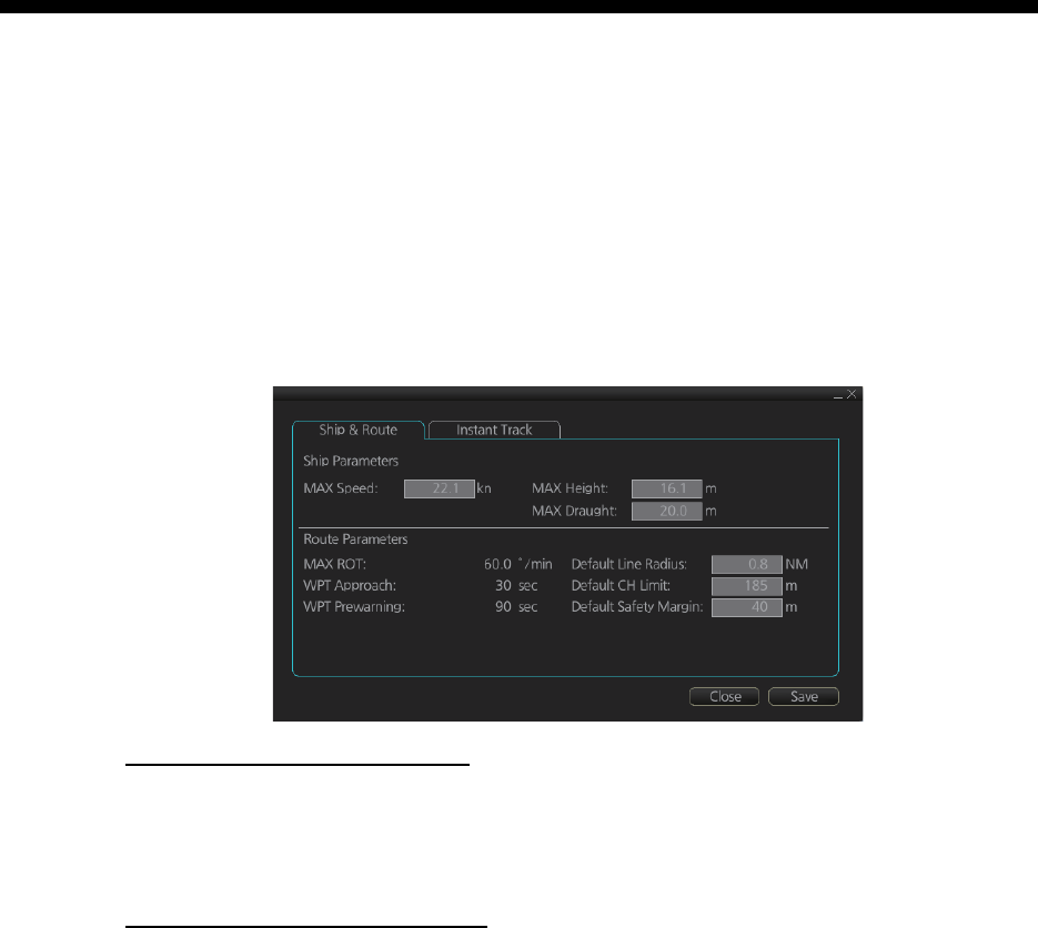
21.1 Ship and Route Parameters
The purpose of the ship and route parameters is set the basic parameters for the ship.
These parameters are relative to ship steering and they are very important to get cor-
rect function of the integrated navigation system. They must be maintained carefully.
Modification requires a good knowledge of the parameters' importance.
Open the menu and select [Ship & Route Parameters] from the [General] menu to
show the [Ship & Route] page. Set each item referring to the description below.
Ship parameters description
[MAX Speed]: Maximum speed the ship can do.
[MAX Height]: Max. height of ship above sea level.
[MAX Draught]: Max. draught of ship.
Route parameters description
[MAX R.O.T]*: The maximum rate of turn of the ship. Set at installation.
[WPT Approach]*: The alert time before reaching the wheel over point.
[WPT Prewarning]*: The alert time before reaching the wheel over point.
[Default Line Radius]: Define the default value of radius between waypoints during au-
tomatic route steering.
[Default CH Limit]: Define the default value of channel limit.
[Default Safety Margin]: Define the default value of extension for channel limits to be
checked against selected alerts.
* Set at installation and cannot be changed by the operator.
21. PARAMETERS
21-2
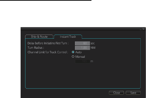
21.2 Instant Track Parameters
The instant track feature can create, in route monitoring, a simple route in the following
situations:
• Return to the monitored route when the vessel goes outside the channel limits.
• Temporarily deviate from the monitored route (avoid collision, etc.).
How to set instant track parameters
Set the parameters for the instant track ([MENU] → [General] → [Ship & Route Pa-
rameters] → [Instant Track] tab).
[Delay before Initiating First Turn]: Set the number of seconds (30 - 600 seconds) to
wait before initiating the first turn in the simple route.
[Turn Radius]: Set the turning radius (0.02 - 3.00 NM) to use between waypoints (four
waypoints) in the simple route.
[Channel Limit for Track Control]: Set the channel limit (10 - 1852 m) for the instant
track, automatically or manually. The [Auto] setting uses the channel limit set for the
monitored route.
21. PARAMETERS
21-3
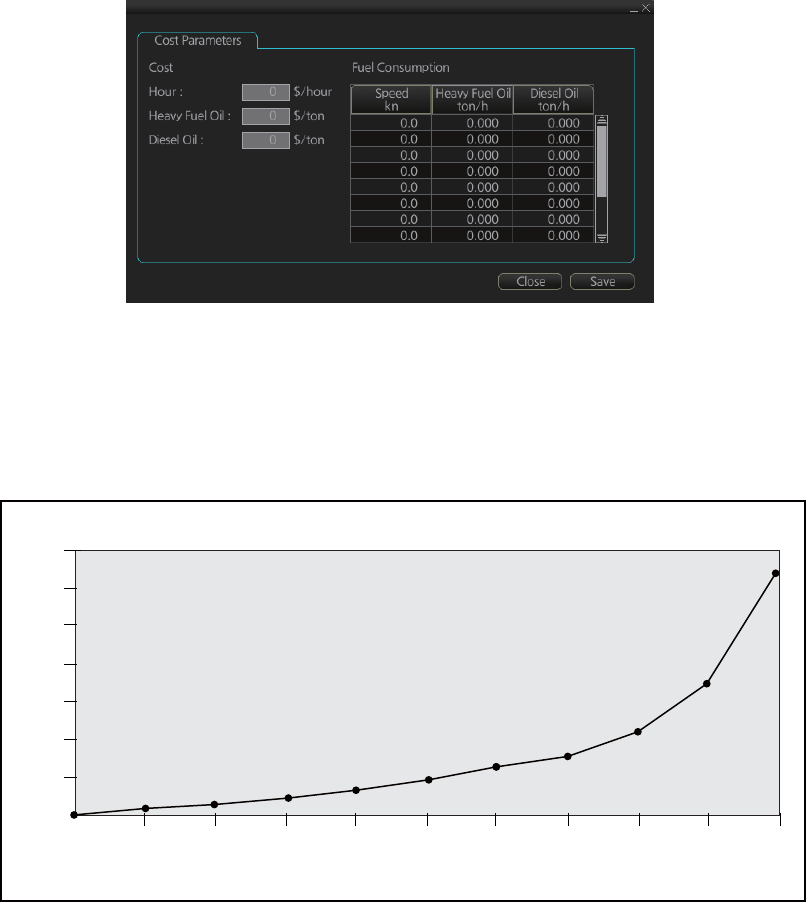
21.3 Cost Parameters
The cost parameters are used in the optimization calculation. Therefore define these
parameters before doing the calculation.
Open the menu and select [Cost Parameters] from the [General] menu to show the
[Cost Parameters] page. Set each item according to ship’s plan, etc.
At the [Cost] window, enter the cost/hour and cost/ton for heavy fuel oil and diesel oil.
At the [Fuel Consumption] window, define the fuel consumption figures for up to 12
different speeds. Before entering the data, plot the data on a graph, like the one shown
below. Use a second graph if, for example, diesel oil consumption is different from that
of heavy fuel oil. Reset the power to effect the settings.
7
6
5
4
3
2
1
0
0 1 2 4 6 8 10 12 14 16 20
FUEL CONSUMPTION
SHIP’S SPEED (kn)
TON/h
21. PARAMETERS
21-4
This page is intentionally left blank.
22-1
22. SETTINGS MENU
The [Settings] menu provides file import, export and maintenance, testing facilities
(display, keyboard, self test), customizing, screenshot processing, and CCRP selec-
tion.
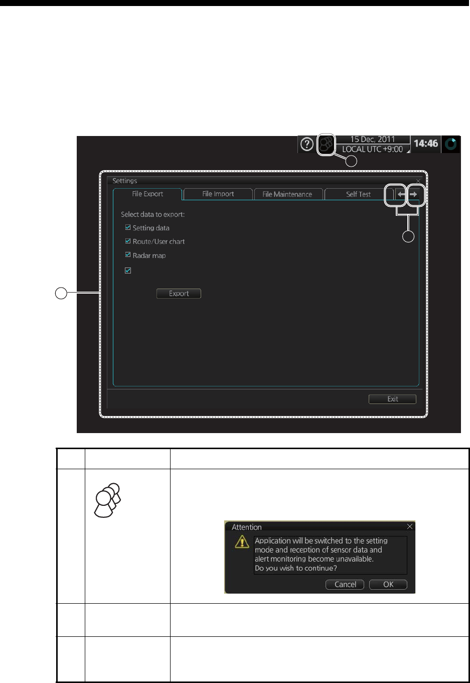
22.1 How to Access the Settings Menu
No. Name Description
1
([Settings]
menu access
button)
Click the button then select [Settings] to open the [Settings]
menu. The message shown below appears. Click the [OK] but-
ton to open the [Settings] menu.
2 [Settings] menu
display area
The [Settings] menus appear here.
3 Page selection
buttons
To open a page, use the page selection buttons to select a
page then click the tab of the page required. The color of the
border of the page selected is light blue.
2
1
3
Radar Installation
22. SETTINGS MENU
22-2
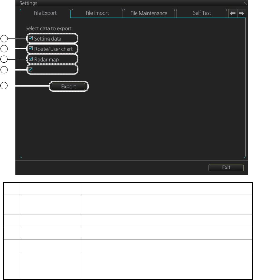
22.2 File Export
The [File Export] page lets you export setting data, routes, user charts, radar maps
and radar installation to a USB flash memory, in .zip file format.
Note 1: Item 5 does not appear until a object is selected.
Note 2: The message "Now processing" appears during the exporting. The message
"File export finished." appears upon completion of the exporting. Click the [OK] button.
No. Name Description
1 [Setting data] Check to export setting data (radar, chart, conning, com-
mon, performance monitor data) and ten user profile data.
2 [Route/User chart] Check to export all routes and user charts.
3 [Radar map] Check to export all radar maps.
4 [Radar Installation] Check to export all setting of radar installation.
5 [Export] button Click the button to open the [SAVE FILE] dialog box. Select
the destination to save then click the [Save] button to export
all selected objects.
1
2
3
Radar Installation
5
4
22. SETTINGS MENU
22-3
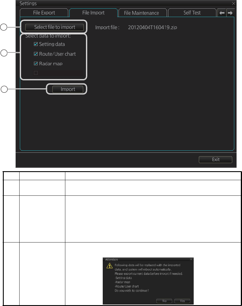
22.3 File Import
The [File Import] page lets you import setting data, routes, user charts, radar maps
and radar installation from an external media (USB flash memory, etc.).
Note 1: The system automatically restarts if setting data is imported.
Note 2: If importing could not be completed, first check if the USB flash memory is
properly inserted. If inserted properly, try importing again.
Note 3: Items 2 and 3 do not appear until a file is selected.
Note 4: The message "Now processing" appears during the importing. The message
"File import finished." appears upon completion of the importing. Click the [OK] button.
No. Name Description
1 [Select file to
import] button
Click to show the [OPEN FILE] dialog box, where you can select
the file to import.
2[Select data to
import]
Check the data to import, among [Setting data], [Route/User
chart] and [Radar map].
Note 1: Execute [User Default] (see section 22.11) before im-
porting [Setting data].
Note 2: [Radar Installation] is available only with the service
mode.
3 [Import] button Click to import the objects selected. The following message ap-
pears on the display.
1
2
3
Radar Installation
22. SETTINGS MENU
22-4
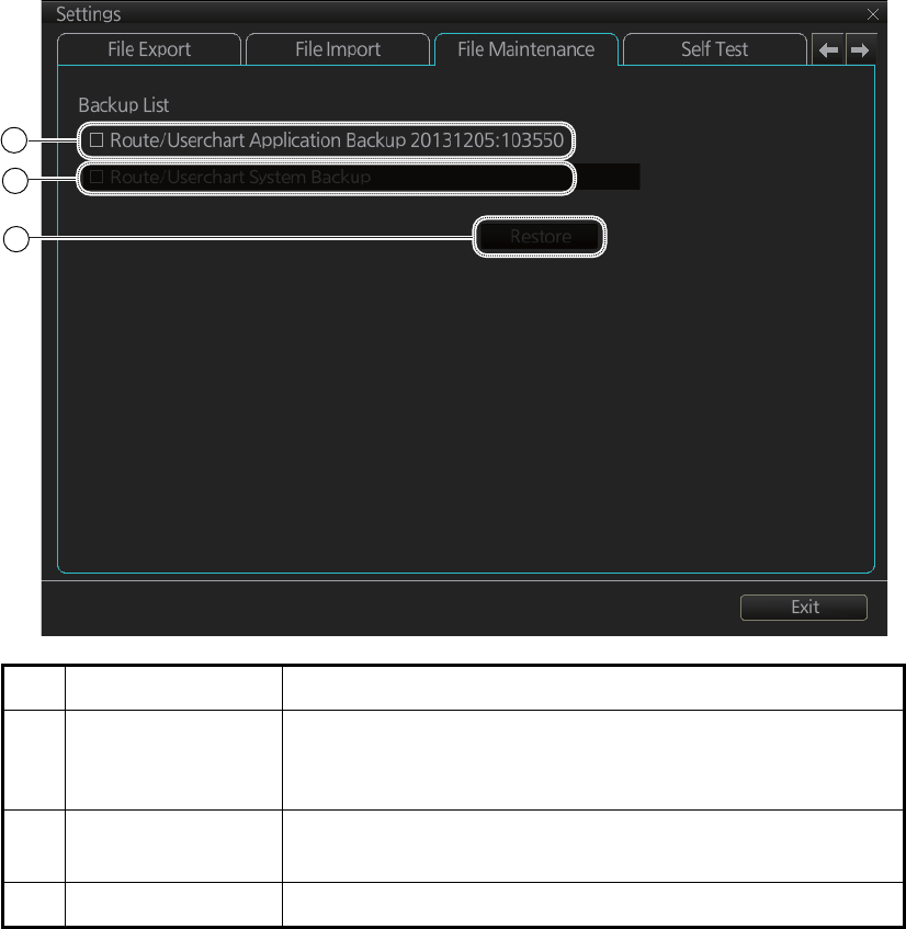
22.4 File Maintenance
The [File Maintenance] page lets you restore the last-saved route/user chart applica-
tion and route/user chart system.
Note: To back up route data, first check for the chart radar with the most recent route
list then do the restore from that chart radar.
No. Name Description
1 [Route/Userchart
Application Back-
up]
Click to restore last-saved route/userchart application.
2 [Route/Userchart
System Backup]
Click to restore last-saved route/userchart system.
3 [Restore] button Click to restore item selected.
1
2
3
22. SETTINGS MENU
22-5
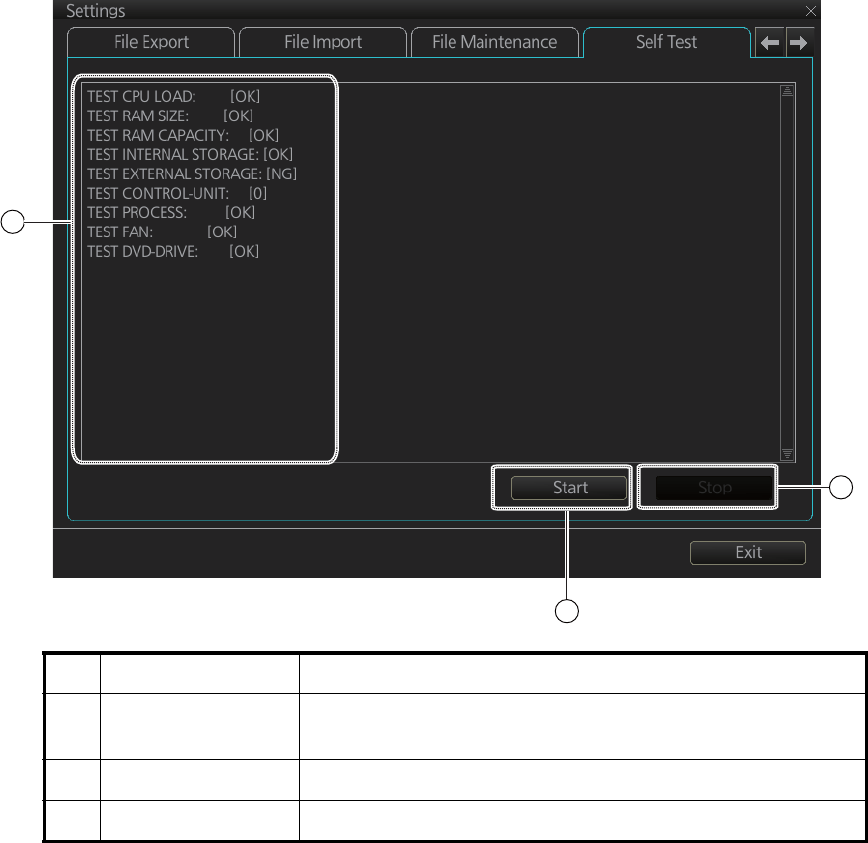
22.5 Self Test
The [Self Test] page is mainly for use by the service technician to check the equip-
ment. The chart radar is inoperative during the test.
No. Name Description
1 Test results, pro-
gram numbers
The results of the self test and the program numbers.
(xx=version number)
2 [Start] button Start the self test.
3 [Stop] button Stop the self test. (Shown during test.)
[EC-3000]
RADAR Software Version: 0359266-02.xx
[Radar Sensor]
SPU Software Version: 0359281-01.xx
[key1]
Software Version: 2450086-01.xx
[Dongle Information]
Function: ecdis,radar
ENC User Permit: ERROR
ARCS User Permit: ERROR
ARCS PIN: ERROR
1
2
3
22. SETTINGS MENU
22-6
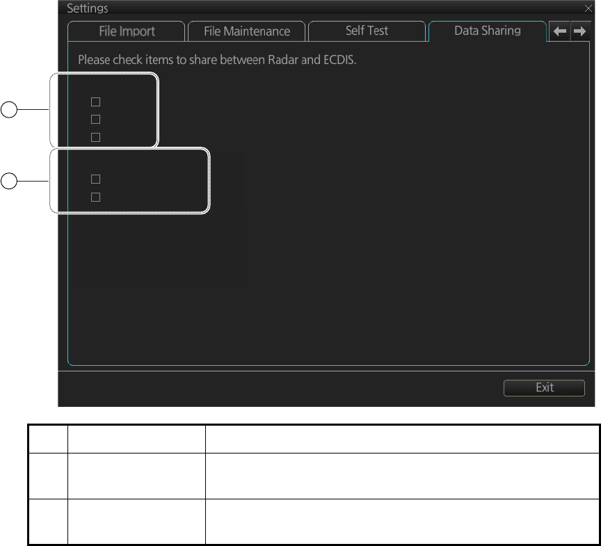
22.6 Data Sharing
The [Data Sharing] page selects the items to share between the radar and the chart
radar.
No. Name Description
1 [NAV Tools] Check the NAV tools items to share them between the chart
and the radar.
2 [Display Settings] Check the display setting items to share between the chart
and the radar.
NAV Tools
VRM
EBL
PI Line
Display Settings
Color Palette
Display Brilliance
1
2
22. SETTINGS MENU
22-7
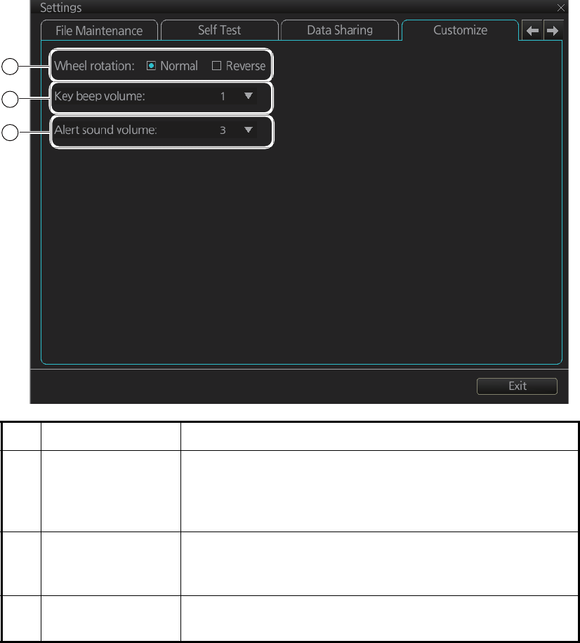
22.7 Customize
The [Customize] page lets you set buzzer volume, key beep volume, and scrollwheel
rotation direction.
No. Name Description
1 [Wheel rotation] Set the direction of scrollwheel rotation direction.
[Normal]: Downward to increase value, upward to decrease
value.
[Reverse]: Reverse of [Normal].
2 [Key beep volume] Set the loudness of the key beep that sounds for correct key
or mouse button operation.
0: No beep, 1: LOW, 2: MID, 3: HIGH
3 [Alert sound vol-
ume]
Set the loudness of the alert buzzer.
1: LOW, 2: MID, 3: HIGH
1
2
3
22. SETTINGS MENU
22-8
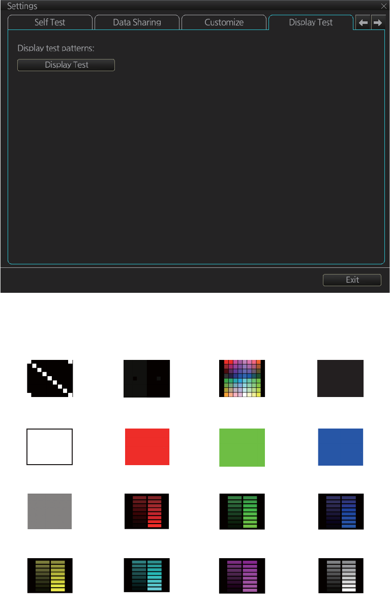
22.8 Display Test
The [DIsplay Test] page displays various test patterns to check the FURUNO-supplied
monitor for proper display of colors. Click the [Display Test] button to start the test. The
buzzer sounds when the display test starts.
Left-click to proceed in the numerical order shown below; right-click to proceed in re-
verse order.
To quit the display test at any time, press the ESC key on the applicable Control Unit.
(1) (2) (3) (4)
(5) (6) (7) (8)
(9) (10) (11) (12)
(13) (14) (15) (16)
Diagonal Gray and black All colors Black
White Red Green Blue
Gray Red bars Green bars Blue bars
Yellow bars Aqua bars Purple bars Gray bars
22. SETTINGS MENU
22-9
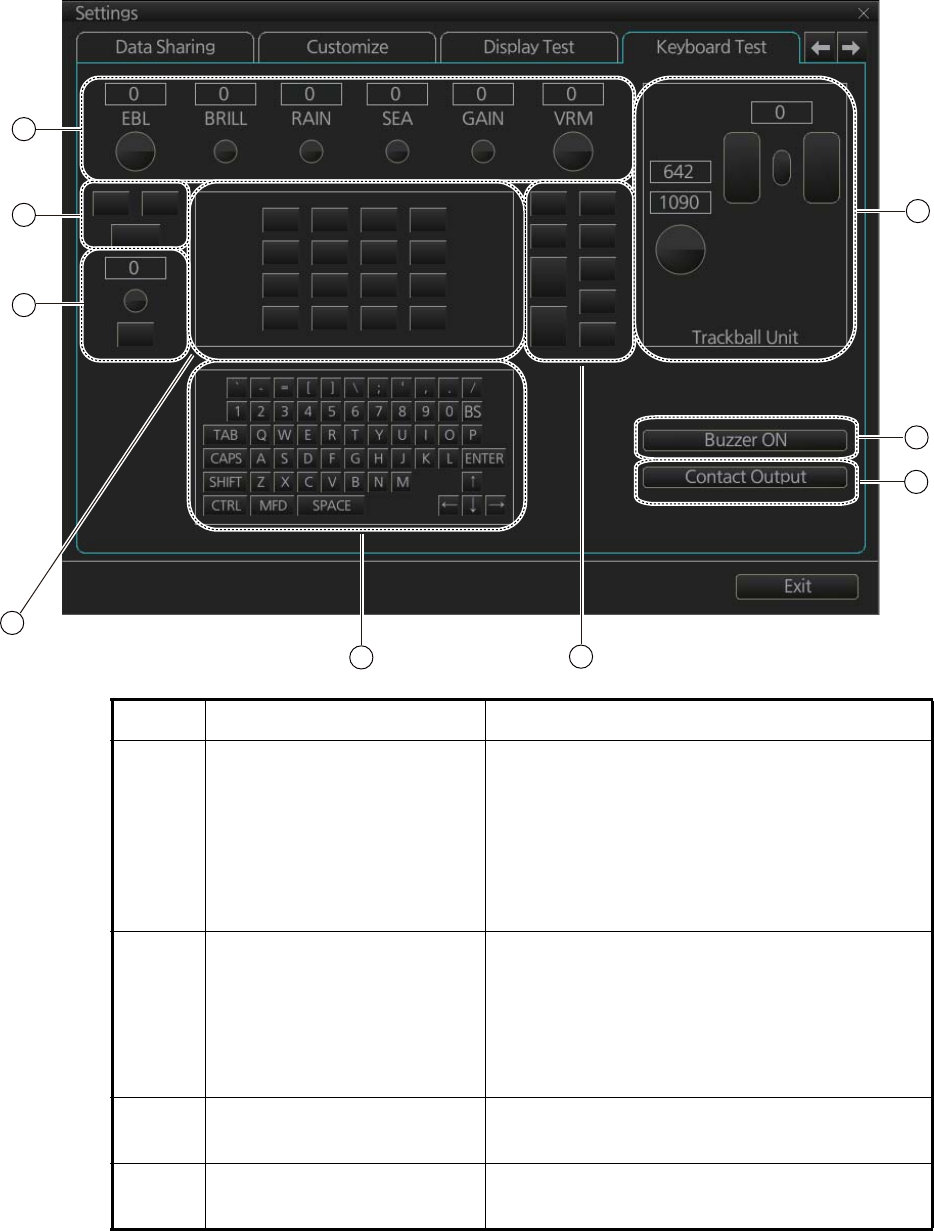
22.9 Keyboard Test
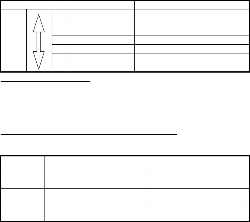
The [Keyboard Test] page checks the controls and keys on the Radar Control Unit and
the ECDIS Control Unit and the trackball module on the Radar Control Unit, ECDIS
Control Unit and Trackball Control Unit.
No. Name Description
1 Common controls Operate the corresponding controls on the Ra-
dar Control Unit and chart radar Control Unit.
Rotate a control and the window above the
control shows the setting value. Push a control
and the corresponding location on screen
lights in light blue. (The EBL and VRM controls
do not have a push function.)
2 InstantAccess knob/key Check the InstantAccess knob and key.
1) Rotate the knob and the setting value ap-
pears in the window.
2) Push the knob and the knob lights in light
blue.
3) Push the key and the key lights in blue.
3 Keys of the Radar Control
Unit
Operate each key. The key pressed lights in
light blue.
4 Keyboard of the chart radar
Control Unit
Operate each key. The key pressed lights in
light blue.
1
5
2
3
45
8
7
6

22. SETTINGS MENU
22-10
5 Keys of both the Radar Con-
trol Unit and chart radar
Control Unit
Operate each key. The pressed key lights in
light blue.
6 Trackball module Check the trackball module of a Control Unit:
1) Spin the scrollwheel and rotate the track-
ball. The indication above the operated
control shows the setting value.
2) Push each button. The window above a
pushed button lights in light blue.
3) Push the scrollwheel. The window above
the wheel lights in light blue.
7 [Buzzer ON] button Click the [Buzzer ON] button to sound the
buzzer. The buzzer sounds and the button
flashes (in red). Click the button again to can-
cel.
8 [Contact Output] button Click the [Contact Output] button to output the
System Failure contact signal from the Pro-
cessor Unit. Click the button again to cancel.
No. Name Description