Furuno USA 9ZWRTR108 Transceiver for Radar model FAR-3320W User Manual
Furuno USA Inc Transceiver for Radar model FAR-3320W
Contents
- 1. Users Manual
- 2. User Manual
User Manual

2-1
2. WIRING
2.1 Overview
Cabling considerations
To lessen the chance of picking up electrical interference, avoid where possible rout-
ing the antenna cable (power and LAN) near other onboard electrical equipment (ra-
dars, TX radio antennas, etc.). Also avoid running the cable in parallel with power
cables. When crossing with other cable, the angle must be 90° to minimize the mag-
netic field coupling.
The antenna cable between the antenna and processor units is available in lengths of
15 m, 30 m, 40 m, and 50 m. Whatever length is used, it must be unbroken; namely,
no splicing allowed. Use the antenna cable as short as possible to minimize attenua-
tion of the signal.
The radar must be connected to an emergency power source, as required by SOLAS
II-1.
About network construction
About wiring
• Use the optional Switching Hub HUB-100 to connect the sensor networks. For the gate-
way networks, use the optional Intelligent Hub HUB-3000.
• Do not connect the ship’s LAN network to the optional HUBs. Also, commercial PCs
cannot be connected to the gateway network, other than for maintenance.
• To connect the FEA-2xx7, FMD-32xx, FAR-2xx7, FCR-2xx9 via LAN network, use the
INS network.
• Use the optional USB cable (type: OP24-32) to connect to the USB port on the control
unit.
• The length of the USB cable must be within 5 m to prevent equipment trouble.
• The length of LAN cables must be within 50 m.
• Use the Cat5e or Cat6 LAN cable for the network if available locally.
• If LAN cables are not available locally, use the optional LAN cables (FR-FTPC-CY for
sensor network, DTI-C5E350 VCV for gateway network).
• If extension or division of the DVI or RGB cables is necessary, use the dividers shown
below.
• DVI cable divider: DVI-12A (maker: IMAGENICS)
• RGB divider: CIF-12H, DD-106 or WBD-14F (maker: IMAGENICS)
• Make sure that the ground wires are connected between the ground terminals on each
equipment and the ship’s earth.
• If a UPS (user supply) is connected to this equip-
ment, be sure that the grounding lamp does not
light.
• The output from the UPS must be a sine wave, as
in the right figure.
50Hz
60Hz
2. WIRING
2-2
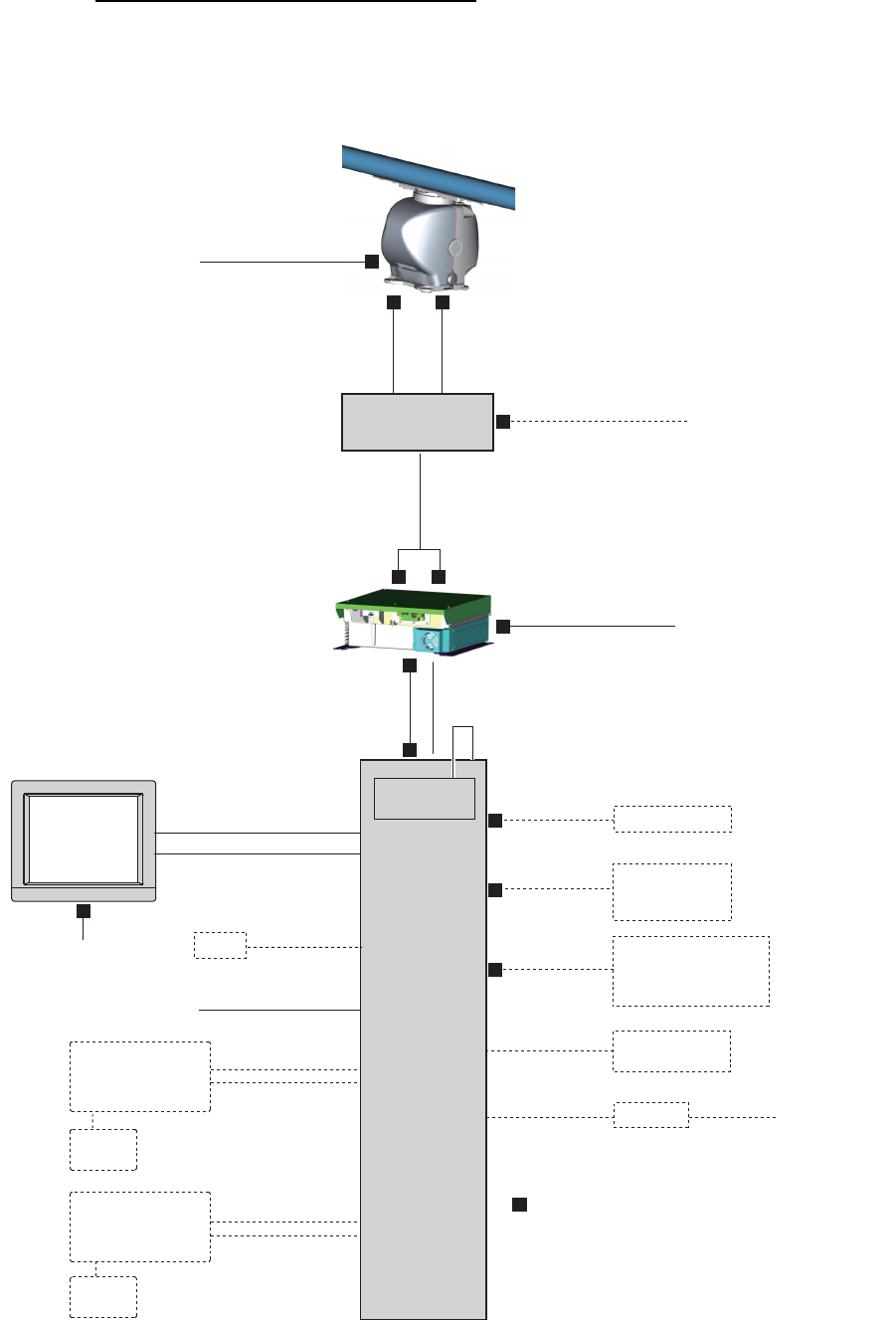
FAR-3320W, FAR-3320W-BB wiring
The maximum length of cabling is 130 m.
Cabling between the transceiver unit and the antenna unit: 80 m
Waveguide: 50 m
Antenna Unit
TTYCYSLA-10
15/30/40/50 m
FR-9 Waveguide
20/30/50 m
100-115 /
220-230 VAC
DPYCY-1.5
De-icer
100-230 VAC
DPYC-2.5
: Cable requires fabrication
DSUB9P-DSUB9P
5 m/10 m
Processor Unit
EC-3000
100-230 VAC
DVI-D/D SINGLE LINK
5 m/10 m
Power Supply Unit
PSU-014
Sensor Adapter
or HUB-100
Serial: TTYCS-1Q
FR-FTPC-CY
100-230 VAC
GYRO, AIS
TTYCS-4
x2
GPS, LOG, E/S,
WIND, ALARM,
NAVTEX etc.
TTYCS-1Q
x5
5 m
(for USB)
30 m
x2
TTYCS-10
System fail, Power fail,
Normal close 1/2,
Normal open 1/2,
ACK IN
TB1
Monitor
Unit
MU-231
DPYC-1.5
VDR
RGB cable
IEC60320-C13-L5M
HUB-3000
5 m
(for USB)
30 m
100-230 VAC
USB
memory
Radar
Control Unit
RCU-025
Trackball
Control Unit
RCU-026
USB
memory
DTI-C5E 350 VCV
(10/20/30 m)
LAN: DTI-C5E 350 VCV (10/20/30 m)
(or Cat 5e LAN cable (local supply))
I/O Board
LAN: MOD-Z072-050+
RW-00135
15/30/40/50 m
LAN Power
Sub monitor
RW-00136
15/30/40/50 m
Transceiver Unit
RTR-108
2. WIRING
2-3
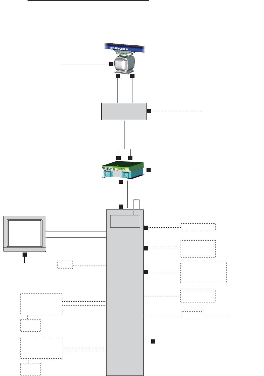
FAR-3330SW, FAR-3230SW-BB wiring
The maximum length of cabling is 110 m.
Cabling between the transceiver unit and the antenna unit: 80 m
Microwave coaxial cable: 30 m
RW-00135
15/30/40/50 m
LAN Power
Antenna Unit
TTYCYSLA-10
15/30/40/50 m
LHPX-20-ASSY
20/30 m
100-115 /
220-230 VAC
Sub monitor
RW-00136
15/30/40/50 m
Transceiver Unit
RTR-109
DPYCY-1.5
De-icer
100-230 VAC
DPYC-2.5
: Cable requires fabrication
DSUB9P-DSUB9P
5 m/10 m
Processor Unit
EC-3000
100-230 VAC
DVI-D/D SINGLE LINK
5 m/10 m
Power Supply Unit
PSU-014 or PSU-015
Sensor Adapter
or HUB-100
Serial: TTYCS-1Q
FR-FTPC-CY
100-230 VAC
GYRO, AIS
TTYCS-4
x2
GPS, LOG, E/S,
WIND, ALARM,
NAVTEX etc.
TTYCS-1Q
x5
5 m
(for USB)
30 m
x2
TTYCS-10
System fail, Power fail,
Normal close 1/2,
Normal open 1/2,
ACK IN
TB1
Monitor
Unit
MU-231
DPYC-1.5
VDR
RGB cable
IEC60320-C13-L5M
HUB-3000
5 m
(for USB)
30 m
100-230 VAC
USB
memory
Radar
Control Unit
RCU-025
Trackball
Control Unit
RCU-026
USB
memory
DTI-C5E 350 VCV
(10/20/30 m)
LAN: DTI-C5E 350 VCV (10/20/30 m)
(or Cat 5e LAN cable (local supply))
I/O Board
LAN: MOD-Z072-050+
2. WIRING
2-4
2.2 Antenna Unit
2.2.1 How to fabricate the cables
FAR-3320W, FAR-3330SW
Three cables are connected to the antenna unit: the serial cable from the transceiver
unit, waveguide (FAR-3220W) or microwave coaxial cable (FAR-3330SW), and power
cable for the de-icer (option).
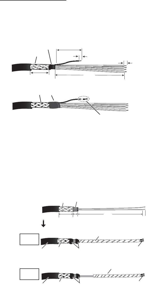
Serial cable (TTYCYSLA-10)
Power cable (DPYCY-1.5) for de-icer
? Before beginning any work on the antenna unit, turn off the breaker for the de-icer
at the mains switchboard. (Turning of the display unit has not effect.)
? The neck of the antenna unit becomes VERY HOT when the de-icer is working.
(The de-icer turns on when ambient temperature goes down to 5°C and heats to
55°C.)
Sheath
Sheath
Pass the heat shrink tubing (local
supply) onto the drain wire. Attach
crimp-on lug to the wire.
* Preattched to the X-band antenna.
See figure on page 2-7 for location.)
Vinyl tape
Crimp-on lug* (FV1.25-3(LF) RED)
Clamp armor with
cable clamp.
* L1: X-band, 450, S-band, 350 L2: X-band, 450, S-band, 200
6
5
L2*
Drain wire
L1*
Armor
Sheath
Sheath
5
36
Sheath
Sheath
*X-band, 900, S-band, 1270
For
X-band
For
S-band
Crimp-on lug
(FV2-M4)
Wrap spiral tubing.
Clamp here.
SheathSheath Vinyl tape
Armor SheathSheath
6
10 L*
36
Crimp-on lug
(FV2-M4)
Wrap spiral tubing.
Clamp here.
SheathSheath Vinyl tape
2. WIRING
2-5
Flexible waveguide for FAR-3220W
The connector at the antenna side is preattached to the flexible waveguide. The bend-
ing radius shown below must be observed to prevent damage to the waveguide.
E-bend: 200 mm, H-bend: 400 mm
Microwave coaxial cable for FAR-3330SW
See the FURUNO Installation Handbook (publication no. TIE-00160) for how to treat
this cable.
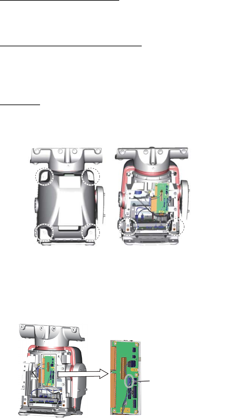
2.2.2 How to connect the serial cable, power cable for de-icer
FAR-3320W
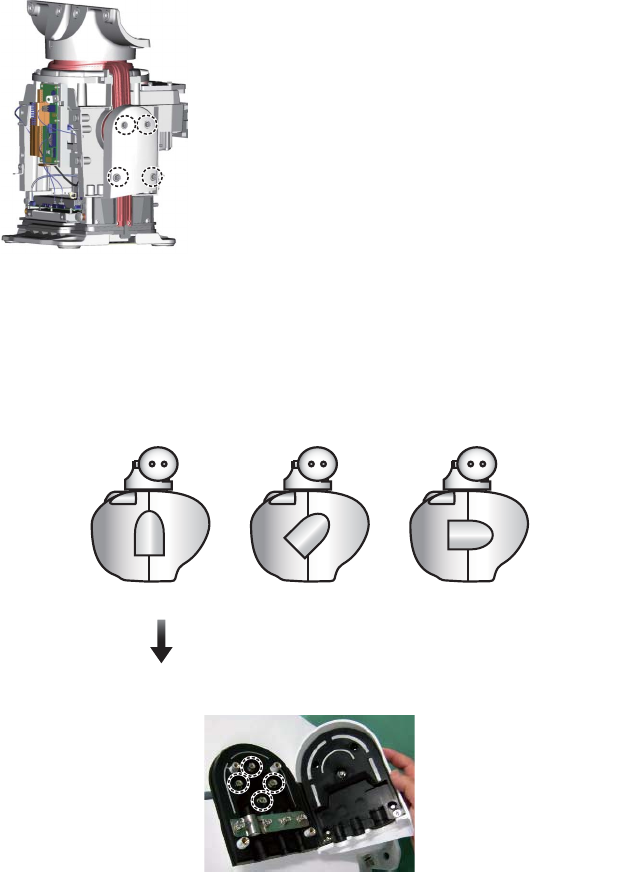
1. Unfasten four bolts from the rear cover to remove the rear cover. If the de-icer is
to be installed, remove two bolts inside the antenna to remove the front cover. See
Note 2 below.
Note 1: The cable for the performance monitor is connected between the rear
cover and the RF-TB Board in the antenna unit. Open the cover slowly to prevent
damage to the cable and connector.
Note 2: If the de-icer is to be installed, spread open the right and left heater ele-
ments on the cover, then remove the cover, being careful not to hit the elements
on the radiator or chassis.
2. Detach the performance monitor connector (J807) from the RF-TB board.
J807 (performance monitor)
2. WIRING
2-6
3. Unfasten four screws to open the cable entrance cover.
Note: The orientation of the cable entrance assy. can be changed, in one of the
three positions shown below. The default entrance is “deck”. No other orienta-
tion is allowed, to maintain watertight integrity. To change the entrance, un-
fasten the four screws circled in the figure below, then orient the cable entrance
assy. in the required direction. Refasten the screws.
Deck entrance Mid-stern entrance Stern entrance
BOW ►
TO CHANGE THE ORIENTATION:
Unfasten these screws to change the orientation of the cable entrance assy.
2. WIRING
2-7
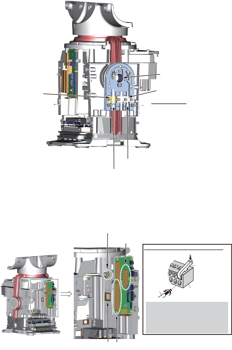
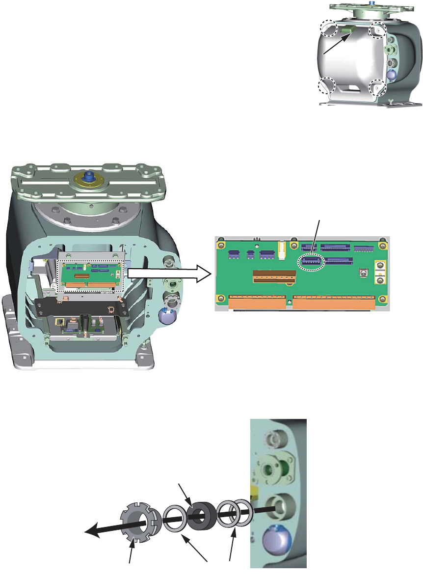
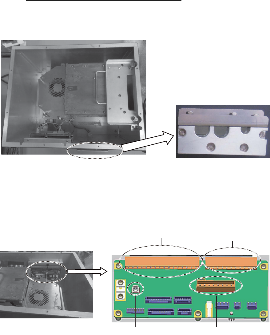
4. Unfasten the four screws fixing the cable clamp plates (2 pcs.).
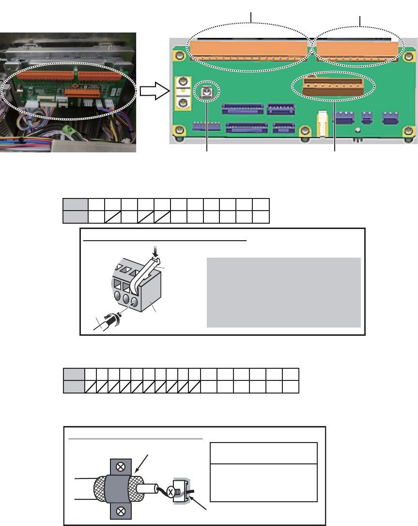
5. Pass the serial cable (TTYCYSLA-10) through the cable entrance and the locking
wire saddle circled below. Attach appropriate WAGO connectors (TB802, 8 pin;
TB803, 16 pin, 10 pins used) to the serial cable and attach the connectors to the
RF-TB board. Attach the crimp-on lug (preattached to chassis) shown below to the
drain wire and connect the wire to the chassis.
Cable slot for serial cable
Cable slot for de-icer
Cable entrance
Cable clamp plate
for serial cable
Cable clamp plate for de-icer
DUMMY PLUG
Dummy plugs are provided to
insert into the unused cable slots.
Insert the plugs for waterproofing.
Note: A terminal opener is provided on the
RF-TB Board.
Locking wire saddle TB803
TB802
Attach crimp-on lug (pre-attached to
chassis) to drain wire and connect
to chassis.
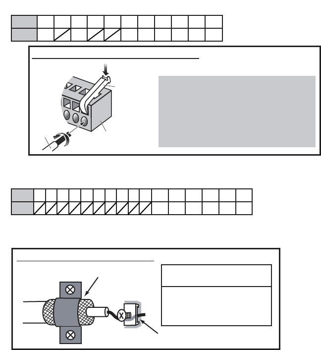
How to connect wires to WAGO connector
Press downward.
Terminal opener
WAGO connector
Wire
Twist
<Procedure>
1. Twist the cores.
2. Press the terminal opener downward.
3. Insert the wire to hole.
4. Remove the terminal opener.
5. Pull the wire to confirm that it is secure.
2. WIRING
2-8
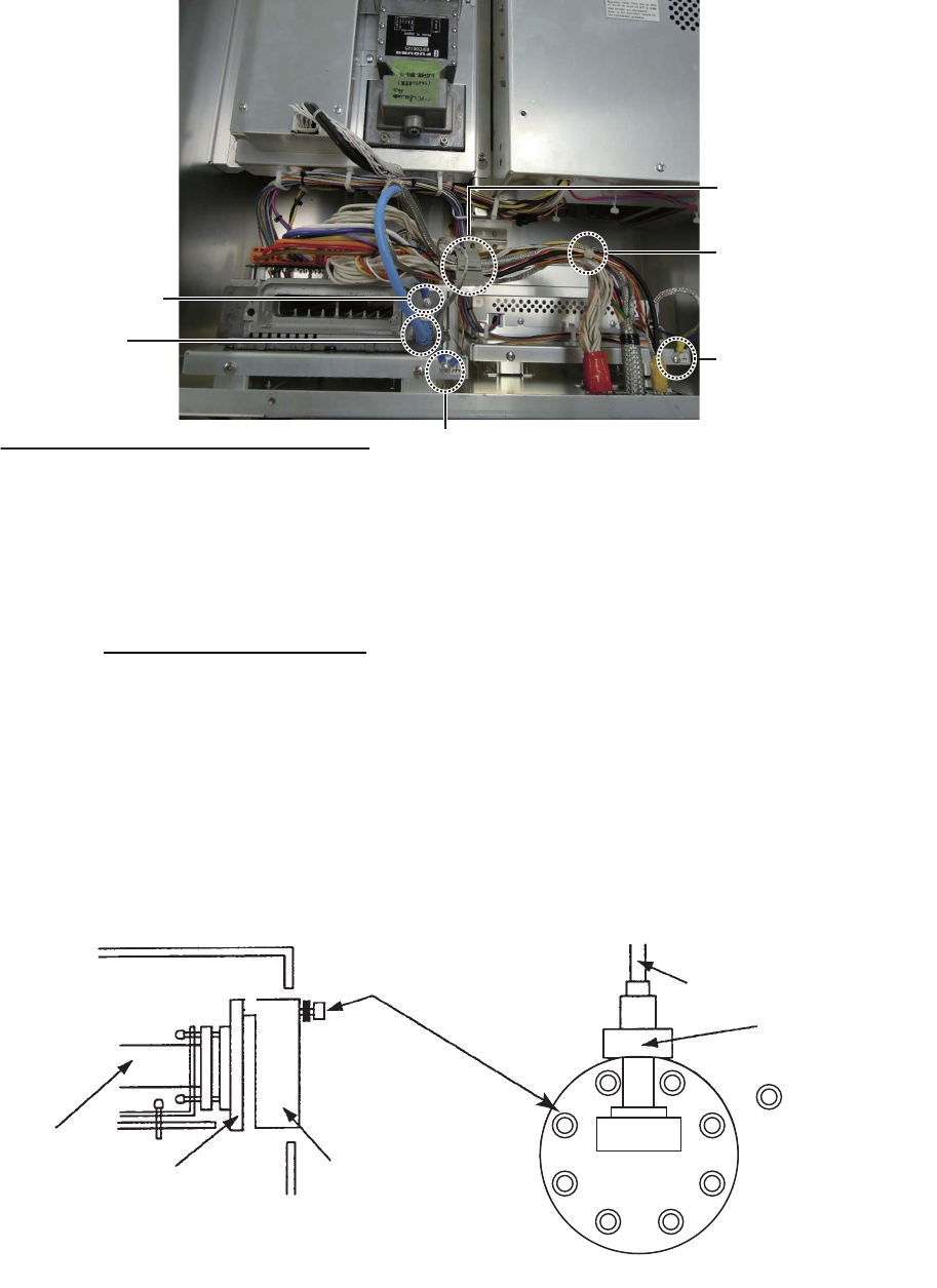
6. DE-ICER INSTALLATION. See also “X-band De-icer Kit Installation Instructions”,
issued separately, for the de-icer not fitted at the factory. If the de-icer is not pro-
vided, go to step 7.
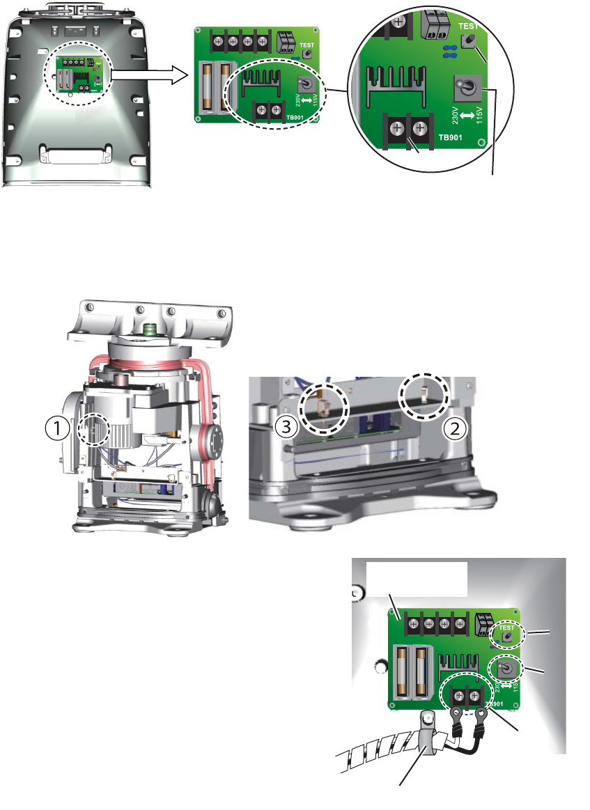
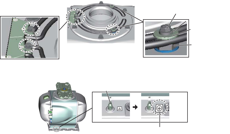
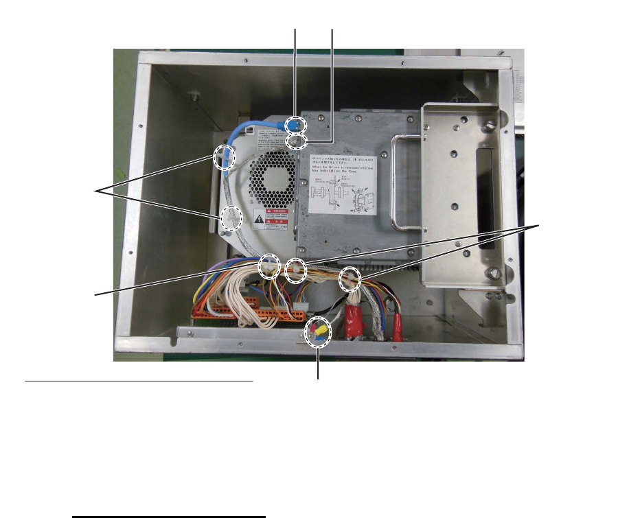
1) Set a locking wire saddle (supplied at locations (2) and (3) shown below. Pass
the power cable through the locking wire saddles (1) through (3) and pull it to
the front side.
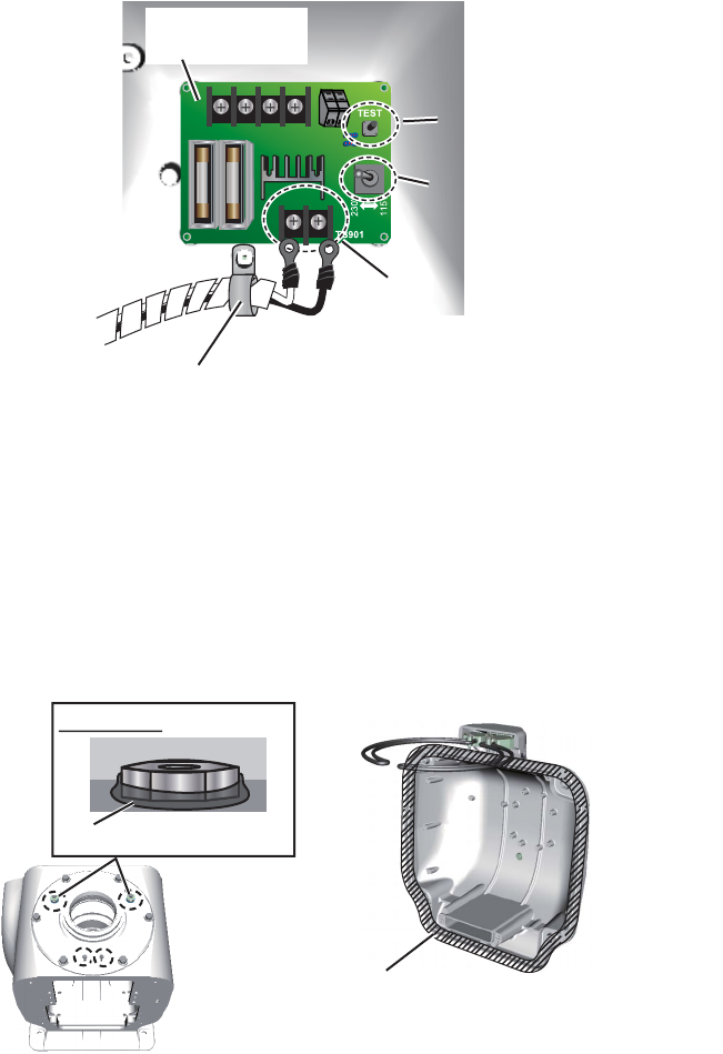
2) Unfasten the cable band*. Pass the
power cable for the de-icer through
the band then fasten the band. Con-
nect the cable to TB901 on the DE-
ICER board (03P9573), using the
crimp-on lugs supplied.
* For the DE-ICER installation kit,
unfasten the cable band on the cov-
er supplied. (The original cover can
be discarded.).
3) Set the voltage setting switch ac-
cording to the power source for the
de-icer; 115 V or 230 V. The default
setting is 230 V.
4) Apply power to the de-icer then press the [TEST] button on the DE-ICER board
approx. ten seconds. Check that the heater gets hot.
Front cover, inside view
DEICER Board
(03P9573)
DE-ICER Board (03P9573)
Voltage Selection switch
[TEST] button[TEST] button
TB901TB901
DE-ICER board
(03P9573)
TB901
Cable band
Cable band
[TEST]
button
[TEST]
button
Voltage
Selection
switch
Voltage
Selection
switch
2. WIRING
2-9
5) Set the front cover supplied with the kit. Take care not to hit the heater ele-
ments on the chassis or radiator.
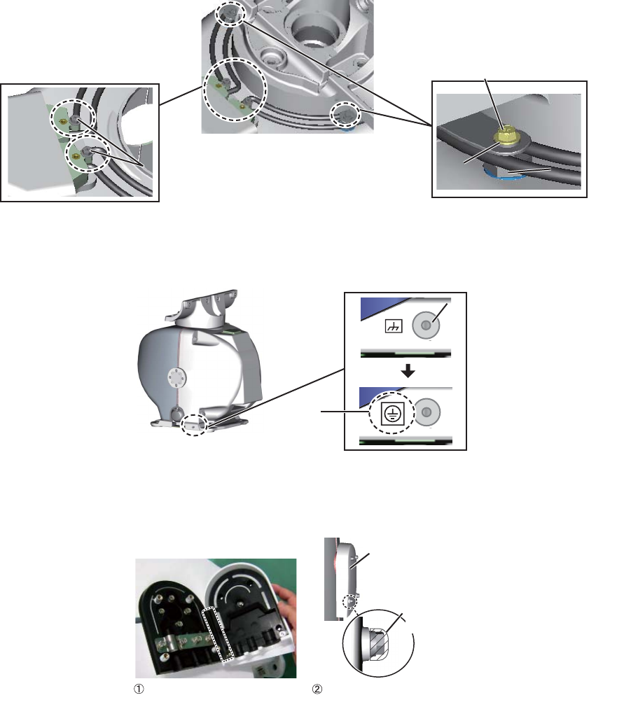
6) Coat two M5 screws (supplied) with marine sealant then use them to fasten
the base of the heater. Take care not to hit the heater elements on the chassis
or radiator. Fasten the installation materials shown below to each of the cover
bolts.
7) Attach the supplied earth label over the earth label currently attached near the
grounding terminal.
7. Position the cables so their armors lie beneath their respective cable clamp plates
in the cable entrance. Fasten the plates.
8. Close the cable entrance cover as shown in the figure below.
9. Connect the performance monitor connector (J807) to the RF-TB Board.
10. Check that the gasket on the front and rear covers is seated properly, then
close the covers. Be careful not to hit the heater elements on the chassis or radi-
ator. The torque for the fixing bolts is 10.0 N•m.
Cover boltCover bolt
Fixing
shaft
Fixing
shaft
M5 screwM5 screw
M5 screw coated with
marine sealant
M5 screw coated with
marine sealant
Grounding
terminal
Grounding
terminal
Earth
label
Cable entrance
cover
Marine
sealant
Close cover then coat screw
heads with marine sealant.
Coat this part of gasket
with marine sealant.
2. WIRING
2-10
11. Connect the waveguide to the antenna with either an E-bend or H-bend wave-
guide. See FURUNO Technical Information TIE00160 for further information.
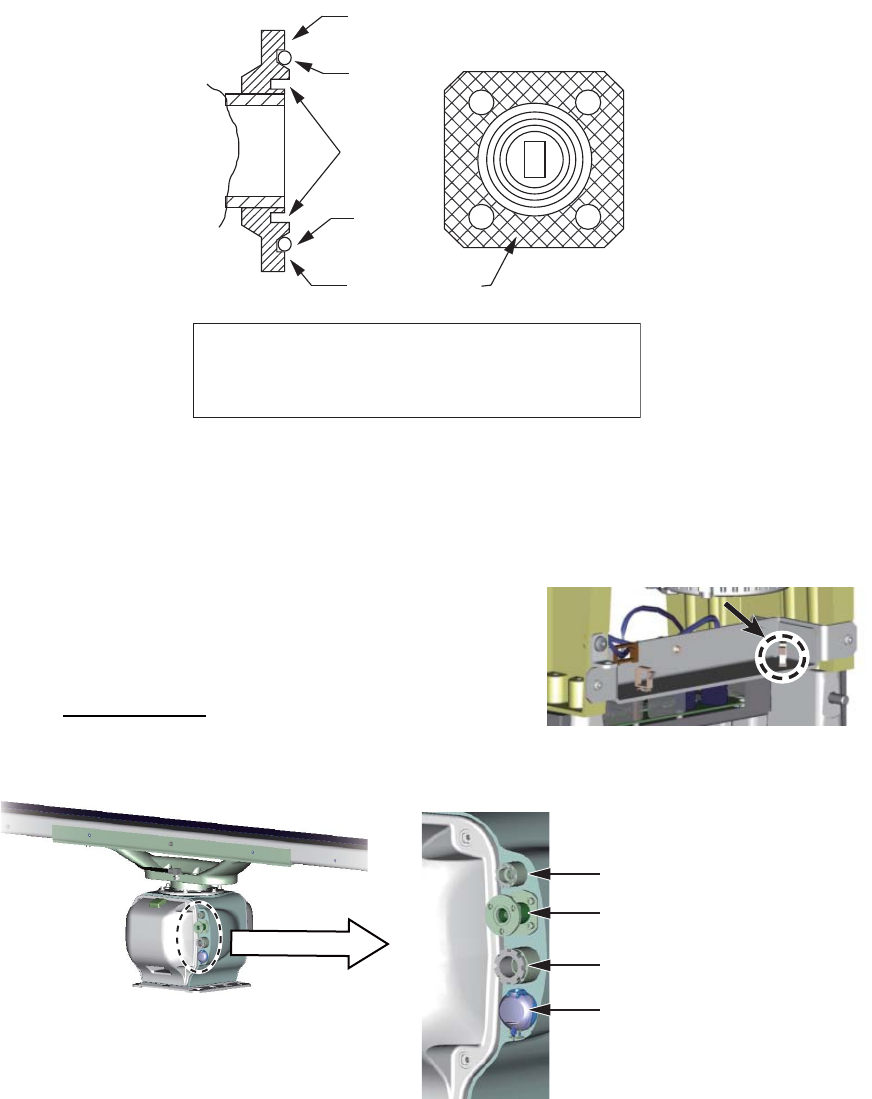
1) Grease the O-ring and set it in its groove on the antenna unit.
2) Wipe the surface of the waveguide flange with a clean, dry cloth to remove any
foreign material.
3) Evenly coat the waveguide flange with marine sealant.
Note: If it is necessary to open the front cover
after installing the de-icer kit, remove the power
cable from the locking wire saddle shown in the
right figure then detach the cover slowly to pre-
vent damage to the heater element.
FAR-3300SW
Connect the cables as follows:
O-ring
O-ring
Apply silicone
sealant here.
Apply marine
sealant here.
Choke
groove
Evenly coat the waveguide flange with marine sealant.
Apply sealant sparingly; it leaks out slightly when the
fixing bolts are tightened. Be sure no sealant contacts
the choke groove and waveguide.
Remove cable from locking wire
saddle to open front cover.
Remove cable from locking wire
saddle to open front cover.
Antenna motor switch
Microwave coaxial cable
Cable for de-icer
Serial cable
2. WIRING
2-11
1. Unfasten four bolts to detach the stern cover.
Note 1: The connector for the performance mon-
itor is connected between the stern cover and the
RF-TB Board. Detach the stern cover slowly to
prevent damage to the connector.
Note 2: If the de-icer is to be installed, remove the
bow cover also. Spread open the right and left
heater elements on the cover, then remove the
cover, being careful not to hit the elements on the
radiator or chassis.
2. Disconnect the performance monitor connector (J807) from the RF-TB board
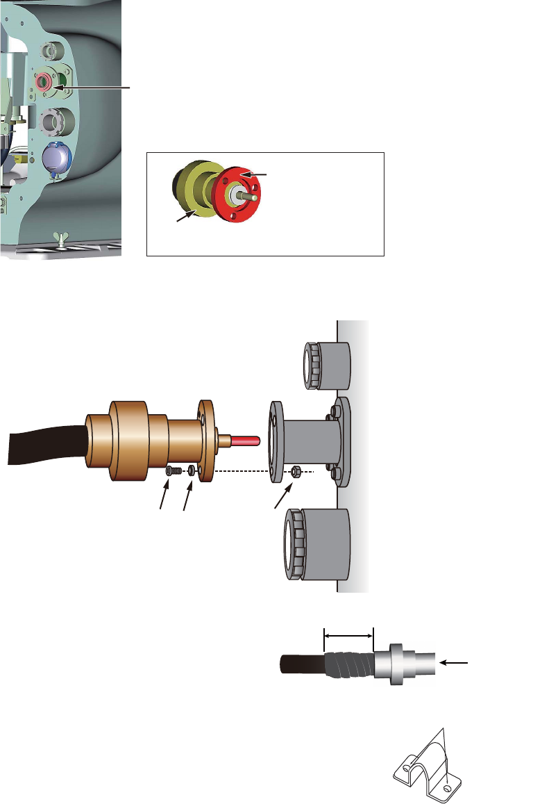
3. Unfasten the clamping gland for the serial cable and remove the gasket and flat
washers.
4. Slide the clamping gland, flat washer, gasket and flat washers in that order onto
the serial cable. Push the flat washer against the armor. Trim the armor so that it
Performance monitorPerformance monitor
J807
(performance monitor)
Flat washers
Gasket
Clamping gland

2. WIRING
2-12
does not extend past the flat washers, then pass the antenna cable through the
cable entrance.
5. Pass the serial cable through the locking wire saddle circled below. Attach the ca-
ble to appropriate WAGO connectors, referring to the interconnection diagram,
then connect them to the RF-TB Board.
- TB802 (motor): 8 pin
- TB803 (signal): 16 pin
- Ground wire: Attach crimp-on lug (FV1.25-3(LF) RED) to wire. Fasten the
crimp-on lug to the chassis with the screw shown below.
6. Apply sealant 1211 (supplied as installation material) to the threads of the clamp-
ing gland, and then fasten it tightly with the hook spanner wrench.
Note: Use the wrench of the correct size. If you do not have the hook spanner
wrench, contact your dealer.
Sheath
Sheath
Cable gland
Cable gland
Flat washer
Flat washer
Gasket
Gasket
Flat washer
Flat washer
Trim the armor.
Push the flat washer
against the armor.
Outer sheath
Outer sheath
Inner sheath
Inner sheath
TB802
TB803
Locking wire saddle
for serial cable
Locking wire saddle
for serial cable
Fasten ground
wire of serial cable
with this screw.
Fasten ground
wire of serial cable
with this screw.
2. WIRING
2-13
7. Coat the O-ring in the gland for the microwave coaxial cable with silicon grease.
Using the supplied waterproofing compound, coat the mating surface between the
coaxial connector of the cable and the waveguide flange on the antenna unit. Do
not coat the O-ring with the waterproofing compound.
8. Fasten the coaxial connector to the waveguide flange with three sets of M6×20
hex bolts, M6 spring washers and M6 nuts.
9. Tape the cable with two or more turns of
self-bonding tape then wrap with PVC
tape.
10. Secure the cable with fixing bands (sup-
plied) or the optional clamping metal (Type: 03-011-3228,
Code no.: 100-049-620) to the mast and to the wheel-
house structure. For the optional through-deck cable
gland, see the outline drawing at the back of this manual.
Coat surface of flange with
waterproofing compound.
Coat surface with
waterproofing
compound.
Coaxial
connector
Hex bolt Spring
washer
Nut
5 cm
Coaxial
connector
ø7
Fixing band
2. WIRING
2-14
11. DE-ICER INSTALLATION. Follow all steps if the de-icer is not already installed.
(See also “X-band De-icer Kit Installation Instructions”, issued separately.) If the
de-icer is already installed, do only steps 1) through 7). If the de-icer is not provid-
ed, go to step 12.
1) Unfasten the clamping gland for the de-icer’s power cable, then remove the
gasket, flat washers and cover.
2) Slide the clamping gland, flat washer, gasket and flat washers in that order
onto the cable as shown in step 4 on page 2-11.
3) Unfasten two bolts to remove the RF-TB assembly, then pass the power cable
for the de-icer through the cable entrance.
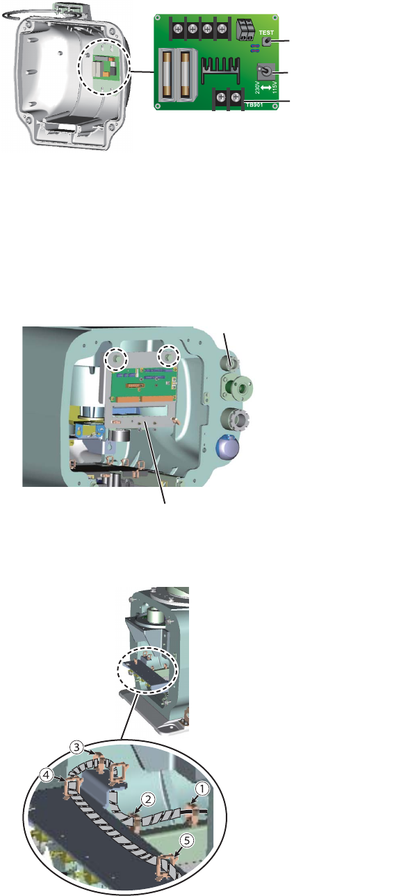
4) Set the supplied locking wire saddle at location (5) in the figure below. Pass
the cable through locking wire saddles (1) to (5).
DE-ICER Board (03P9573)
Voltage Selection switch
[TEST] button[TEST] button
TB901TB901
Cable entrance
Cable entrance
TB assembly
TB assembly
2. WIRING
2-15
5) Unfasten the cable band. Pass the power cable through the band then fasten
the band. Connect the cable to TB901 on the DE-ICER board (03P9573), us-
ing the crimp-on lugs supplied.
6) Set the Voltage Selection switch according to the power source for the de-icer;
115 V or 230 V. The default setting is 230 V.
7) Turn on the power to the de-icer. Press the [TEST] button on the DE-ICER
board about ten seconds to check if the heater gets hot.
8) Remove seals and hex bolts from four locations. Insert the two cover bolts.
Coat the cover bolts with marine sealant. Coat the cover bolts with marine
sealant. Coat the rubber gasket of the cover with the supplied oil compound.
Be sure the compound contacts no other areas.
9) Set the bow cover supplied with kit. (You can discard the original bow cover.)
Also, fasten the cable entrance for the DE-ICER. Take care not to hit the heat-
er elements on the chassis or radiator.
10)Fasten the bow cover, fasten the RF-TB assembly, and close the rear cover.
(You can discard the original bow cover.) Also, fasten the cable entrance for
the DE-ICER. Take care not to hit the heater elements on the chassis or radi-
ator.
DE-ICER board
(03P9573)
TB901
Cable band
Cable band
[TEST]
button
[TEST]
button
Voltage
Selection
switch
Voltage
Selection
switch
Marine sealant
Cover Bolt
Cover Bolt
Coat hatched area with oil compound.
2. WIRING
2-16
11) Fasten the two heater elements to the chassis as follows:
? Fasten the base of the heater with two M5 screws (supplied) coated with
marine sealant.
? Fasten the installation materials shown in the right figure below to each of
the cover bolts.
12)Attach the supplied earth label over the earth label currently attached near the
ground terminal.
12. Reconnect the performance monitor connector (J807) then close the stern cover.
The torque for the fixing bolts is 21 N•m.
Cover boltCover bolt
M5 screw coated with marine sealant M5 screw coated with marine sealant
Fixing shaft Fixing shaft
SD heater fixing plateSD heater fixing plate
M5 screw coated with
marine sealant.
M5 screw coated with
marine sealant.
Grounding terminal
Ground terminal
Earth label
2. WIRING
2-17
2.3 Transceiver Unit
2.3.1 Fabrication of cables
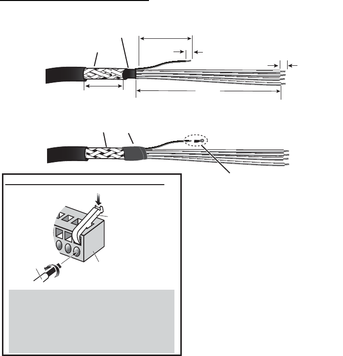
Serial cable (TTYCYSLA-10)
Sheath
Sheath
Pass the heat shrinkable tube
(local supply) onto the drain
wire, then attach the crimp-on
lug to the wire.
Vinyl tape
Crimp-on lug*
How to connect wires to WAGO connector
Press downward.
Terminal opener
WAGO connector
Wire
Twist
<Procedure>
1. Twist the cores.
2. Press the terminal opener downward.
3. Insert the wire to hole.
4. Remove the terminal opener.
5. Pull the wire to confirm that it is secure.
Clamp armor with
cable clamp.
* L1: X-band, 250, S-band, 480 L2: X-band, 100, S-band, 320
6
5
L2*
Drain wire
L1*
Armor
Sheath
Sheath
5
36
Sheath
Sheath
* X-band: FV1.25-3(LF) RED
S-band: FV1.25-4(LF) RED
2. WIRING
2-18
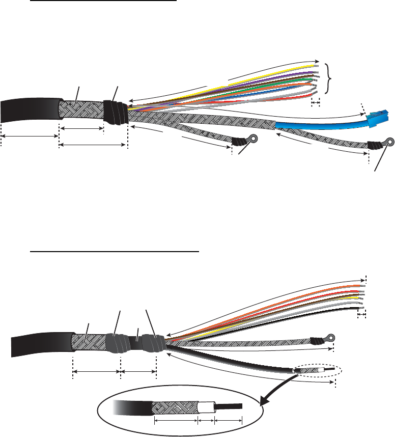
Antenna cable (RW-00135)
Fabricate the LAN cable as shown below. See "How to fabricate the LAN
cable" on page 2-27 for how to attach the LAN cable connector.
Sub monitor cable (RW-00136)
SheathSheath
Armor Vinyl tape
Crimp-on lug
(FV2-M3 BLU)
Braided
shield
LAN cable
6
L1
*2
L3
*2
36
31
150
Power line
L2
*2
Crimp-on lug (FV2-4 BLU)
ANTENNA
Side
*2
Length for X-band. (Length adjustment not necessary for
S-band.) Shorten as shown and reattach crimp-on lug.
L1: 410, L2: 469, L3: 200
50
*1
*1
S-band only. Remove
sheath to expose armor.
Armor
Crimp-on lug
(FV5.5-4(LF) YEL)
Shield
SheathSheath
Vinyl tape
Coaxial cable
Braided shield
6
14 59
36 5
L
3
L
3
L2L2
L
1
L
1
L1: X-band, 200, S-band, 480
L2: X-band, 150, S-band, 180
L3: X-band, 180, S-band, 380
2. WIRING
2-19
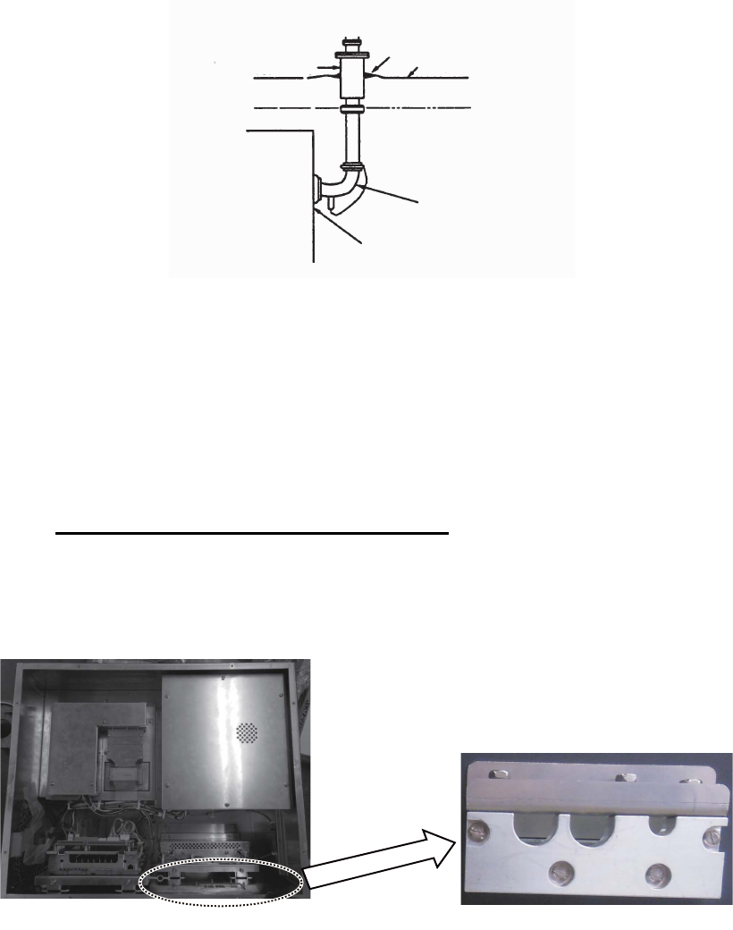
2.3.2 Transceiver unit for FAR-3320W
Antenna cable, serial cable, sub monitor cable
1. Remove the cover of the unit.
2. Unfasten the bolts from the cable clamp. Lay the cables in respective cable slots
so their armors rest in the slots.
3. Connect the power line of the antenna cable, serial cable and sub monitor cable
on the RF-TB board. See the figure on the next page for pin arrangement, etc.
? Antenna cable (power): TB801
? Serial cable: TB802, TB803
? Sub monitor cable (serial): TB803
? Sub monitor cable (coaxial): TB804
Sub monitor cableSub monitor cable
Antenna cableAntenna cable
Serial cableSerial cable
TB804 TB802
TB803 TB801
2. WIRING
2-20
POWER: TB801 on RF-TB Board (03P9570)
Wire
How to connect wires to WAGO connector
Press downward.
Terminal
opener
WAGO
connector
Twist
<Procedure>
1. Twist the cores.
2. Press the terminal opener downward.
3. Insert the wire to hole.
4. Remove the terminal opener.
5. Pull the wire to confirm that it is secure.
SIGNAL: TB803 on RF-TB board
1 3 6789
11 12 13 14 15 16
245 10
BRN RED ORG YEL BLKWHT
Pin
Color
COAXIAL CABLE: TB804 on RF-TB board
How to fasten the coaxial cable
Fasten shield with clamp.
Fasten conductor with screw.
NOTICE
Do not use crimp-on lug, to
prevent contact resistance
from increasing.
1 3 6789 11
245 10
BRN RED ORG YEL GRN BLU
Pin
Color
PPL WHT
2. WIRING
2-21
4. Pass the LAN cable through two locking wire saddles and connect it to port J821.
Attach a crimp-on lug to the shield of each cable, referring to the figure below for
the type of crimp-on lug to use. Connect shields to the locations shown below.
Bind all cables with the locking wire saddle and two cable ties (local supply).
5. Check that armor of cables are lying in their respective cable slots then fasten the
cable clamp.
Flexible waveguide (FR-9)
The RF interconnection between the antenna unit and the transceiver can be made
with a flexible waveguide (FR-9). If the rectangular waveguide is used, observe the fol-
lowing installation guidelines.
? Correctly installed waveguide runs ensure the most efficient transmission of electri-
cal energy at high frequencies. Electrical losses, however, occur in the waveguide
runs. To minimize them the following factors are of great importance: minimum
length, airtightness and electrical continuity.
? Another consideration required is that of frequency disturbance. The transmitting
valve, a magnetron, is the primary oscillator in the radar. This is different from the
oscillation system at lower frequencies in which conventional radio valves are used.
In the latter case, the primary oscillator is always protected from the effects of load
impedance by a buffer stage so that frequency and waveform are left unobstructed.
With a waveguide and magnetron, however, mismatch of impedance causes “fre-
quency pulling.” For this reason, the number of possible mismatches in a waveguide
run, i.e., joins and bends, must be kept minimum.
? Each pair of flanges should be coupled with one O-ring, four bolts and spring wash-
ers and the choke flange must be in the upper position. The bolts and O-ring must
be greased before insertion to facilitate removal if required at a later date.
Connect shield of
LAN cable here.
Bind all cables
with two
cable ties
(local supply).
Connect shield of antenna cable, serial
cable and sub monitor cable here.
Pass LAN cable
through these
locking wire
saddles.
Connect LAN cable
to port J821.
Bind all cables
with locking wire
saddle.
Cable and crimp-on lug to use for shield:
Antenna cable: FV2-3 BLU
LAN cable: FV2-M3 BLU
Serial cable: FV1.25-3(LF) RED
Sub monitor cable: FV5.5-4(LF) YEL
2. WIRING
2-22
? The transceiver unit output flange is a plain type and the antenna unit output flange
is a choke type, and it is important to maintain this relationship throughout the wave-
guide run.
? After installation of the waveguide is completed, the coupling portions must be
sealed by using the adhesive supplied.
? In a very short time the surface of the waveguide becomes green with verdigris.
Therefore, paint both the surface of the waveguide and flanges to avoid corrosion
and water penetration. Paint must not be allowed to reach the inner surface of the
waveguide or the mating surface of any flange.
2.3.3 Transceiver unit for FAR-3330SW
Antenna cable, serial cable, sub monitor
1. Remove the cover of the unit.
2. Unfasten the bolts from the cable clamp. Lay the cables in their cable slots so their
armors rest in the slots.
3. Connect the power line of the antenna cable, serial cable and sub monitor to the
RF-TB Board as shown in the figure below and on the next page.
? Antenna cable (power): TB801
? Serial cable: TB802, TB803
? Sub monitor cable (power): TB803
? Sub monitor cable (coaxial): TB804
Thru-deck hole
Weld here.
Deck
TRANSCEIVER
UNIT
Drain waveguide
Watertight film
Cable entrance
Sub monitor cableSub monitor cable
Antenna cableAntenna cable
Serial cableSerial cable
2. WIRING
2-23
TB804 TB802
TB803 TB801
POWER: TB801 on RF-TB Board (03P9570)
Wire
How to connect wires to WAGO connector
Press downward.
Terminal
opener
WAGO
connector
Twist
<Procedure>
1. Twist the cores.
2. Press the terminal opener downward.
3. Insert the wire to hole.
4. Remove the terminal opener.
5. Pull the wire to confirm that it is secure.
SIGNAL: TB803 on RF-TB board
1 3 6789
11 12 13 14 15 16
245 10
BRN RED ORG YEL BLKWHT
Pin
Color
COAXIAL CABLE: TB804 on RF-TB board
How to fasten the coaxial cable
Fasten shield with clamp.
Fasten conductor with screw.
NOTICE
Do not use crimp-on lug, to
prevent contact resistance
from increasing.
1 3 6789 11
245 10
BRN RED ORG YEL GRN BLU
Pin
Color
PPL WHT
2. WIRING
2-24
4. Connect the LAN cable to J821. Attach a crimp-on lug to the shield of each cable,
referring to the figure below for the type of crimp-on lug to use. Connect the
shields to the locations shown below. Bind all cables with a cable tie (local supply).
5. Check that armor of cables are lying in their respective cable slots then fasten the
cable clamp.
Microwave coaxial plug
Attach the microwave coaxial plug to the coaxial cable. See the applicable FURUNO
technical information for the procedure. Attach the coaxial cable assy. to the transceiv-
er unit as follows:
1. Unfasten four bolts (M6×10) to remove the dust cover from the output WG adapt-
er.
2. Fasten eight bolts (removed at step 1) to attach the flange to the transceiver unit.
3. Attach the coaxial cable to the converter of the flange.
Connect shield of sub
monitor cable here.
Connect shield of antenna
cable, serial cable here.
Bind all cables with
cable tie (local supply).
Connect LAN
cable to port J821.
Connect shield of
LAN cable here.
Cable and crimp-on lug to use for shield:
A
ntenna cable: FV2-4 BLU
LAN cable: FV2-M3 BLU
Serial cable: FV1.25-4(LF) RED
Sub monitor cable: FV5.5-4(LF) YEL
Bind all cables with
locking wire saddle.
M6×10 (4 pcs.)
Circulator
Adapter Output WG adapter
Coaxial cable
Converter
: M6×20 (8 pcs.)
Transceiver unit, inside view
Flange