Furuno USA 9ZWRTR108 Transceiver for Radar model FAR-3320W User Manual
Furuno USA Inc Transceiver for Radar model FAR-3320W
UserManual.wiki
>
Furuno USA
>
9ZWRTR108 User Manual
>
Users Manual
Contents
1.
Users Manual
2.
User Manual
Users Manual
Navigation menu
Upload a User Manual
Namespaces
Wiki Guide
HTML
PDF
Info
Views
User Manual
Discussion / Help
Navigation
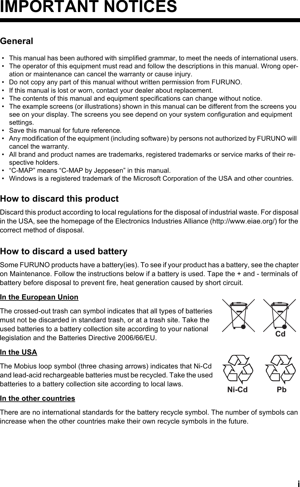

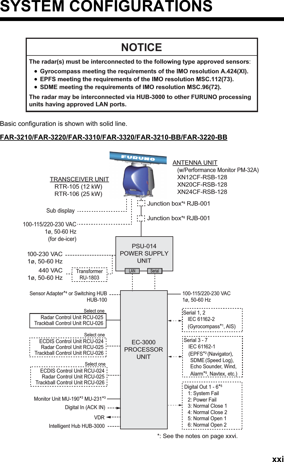
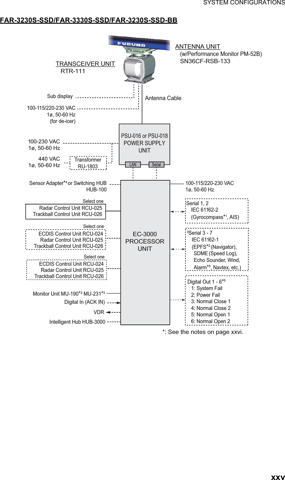
![FOREWORDxix• The buttons on the InstantAccess bar, Status bar and menu items are shown in brackets; for example, the [TUNE] button.• Context-sensitive menus are available with many buttons, and boxes and objects. Right-click an item to display the related context-sensitive menu.• This radar is available in three types of specifications: IMO, A, or B. This manual provides the descriptions for the B type, of which some functions are not available with the IMO or A type. See the menu tree in Appendix 1 for function availability.• “C-MAP” means “C-MAP by Jeppesen”.• The display colors mentioned in this manual are those with the color palette setting “Day-Gray”.Program NumberPlease access the following URL if you need software information:http://www.furuno.com/en/business_product/merchant/product/chartradar/software.htmlxx: Minor changeVirus PreventionThis equipment is not equipped with a virus checker. This equipment operates in real time; there-fore, having a virus checker that periodically checks the equipment for viruses would increase the processing load, which can affect operation. However, you can avoid viruses by following the in-structions in this section. When you update a chartThe PC and medium (USB flash memory, etc.) used to download and store an update for an ex-isting chart or a new chart may be infected with a virus. Check the PC and the medium for viruses with a commercial virus checker - BEFORE you connect them to the ECDIS. Be sure the virus checker contains the latest virus definition files. Network connectionThe ECDIS receives and displays information from various navigation equipment and radar via a LAN. A PC and other equipment connected to a network can carry viruses. To prevent the intro-duction of a virus to the LAN, DO NOT connect the ECDIS or HUB to an external network, includ-ing other shipboard LAN.Do not install 3rd party programs in the ECDISPrograms installed via an external network can carry viruses that can cause the ECDIS to mal-function. Do not install any Windows® software.System Program no. Version no. RemarksAntenna unitSPU 0359281 01.xx For magnetron radarSPU 0359286 01.xx For solid state radarMTR-DRV 0359293 01.xxPM 0359296 01.xxRF-Converter 0359302 01.xx For solid state radarPower supply unitPSU-Control 0359299 01.xxProcessor Unit: EC-3000Main 0359266 02.xx](https://usermanual.wiki/Furuno-USA/9ZWRTR108.Users-Manual/User-Guide-2496309-Page-21.png)
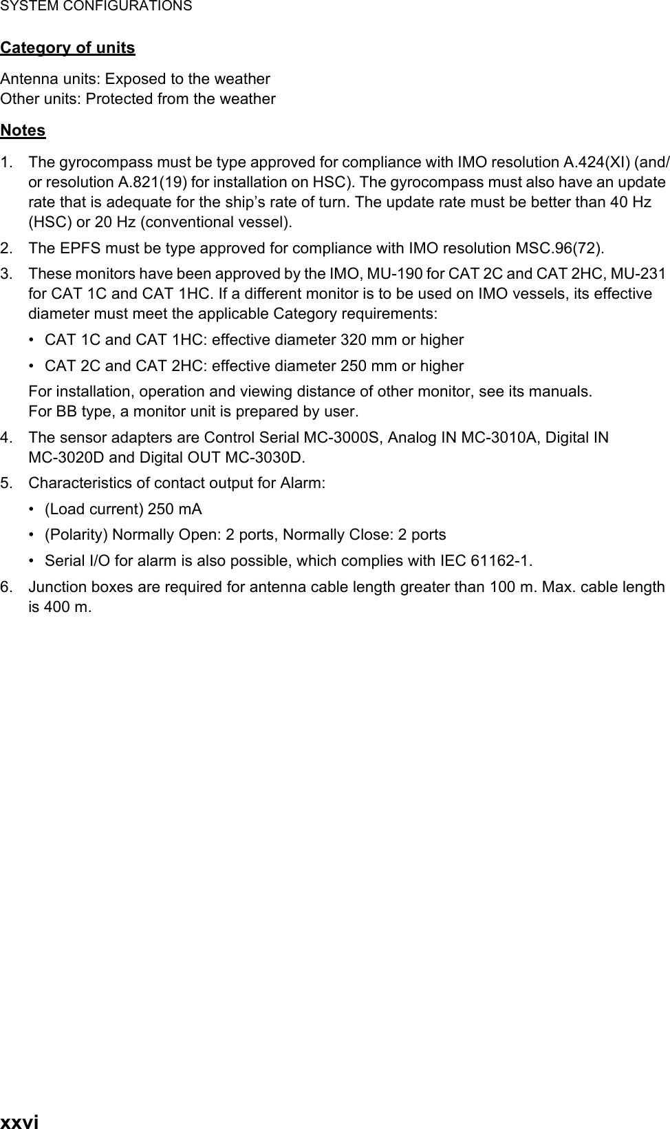
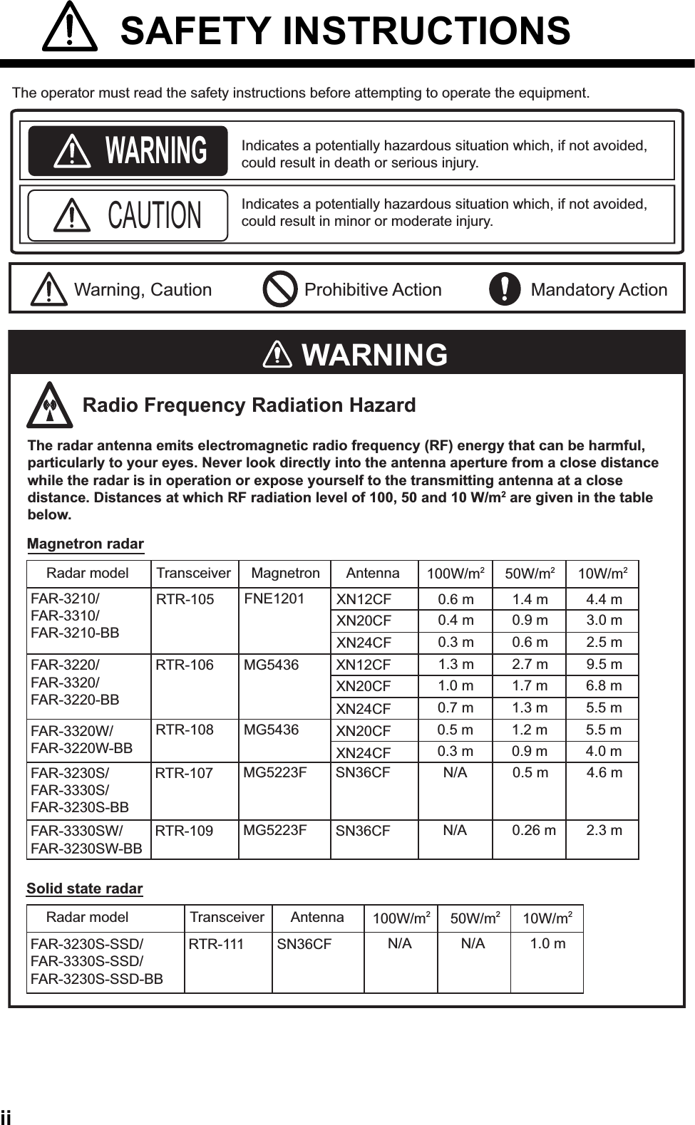
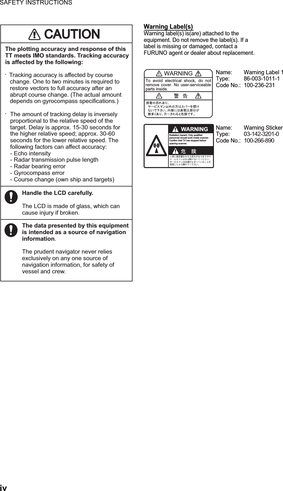
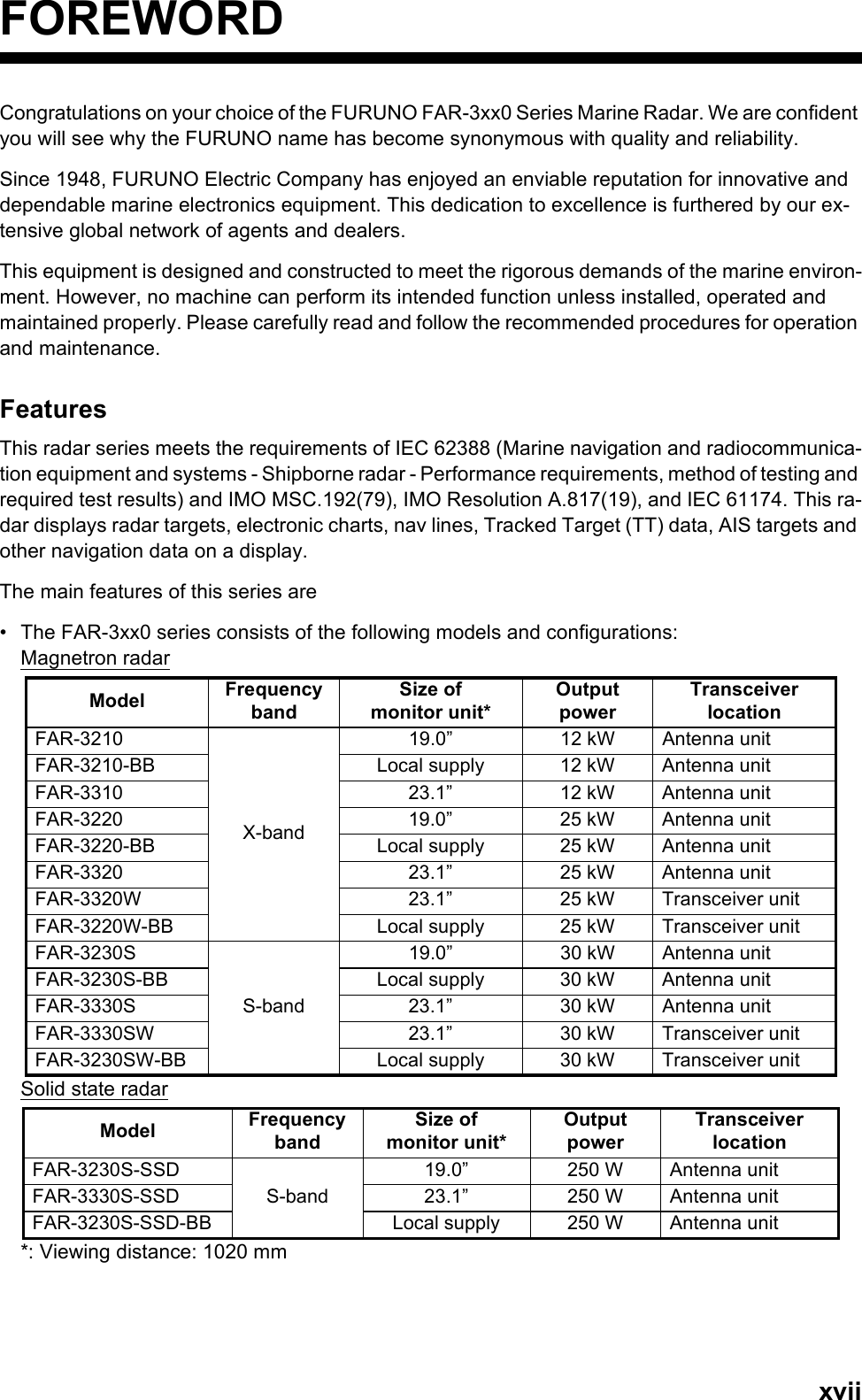
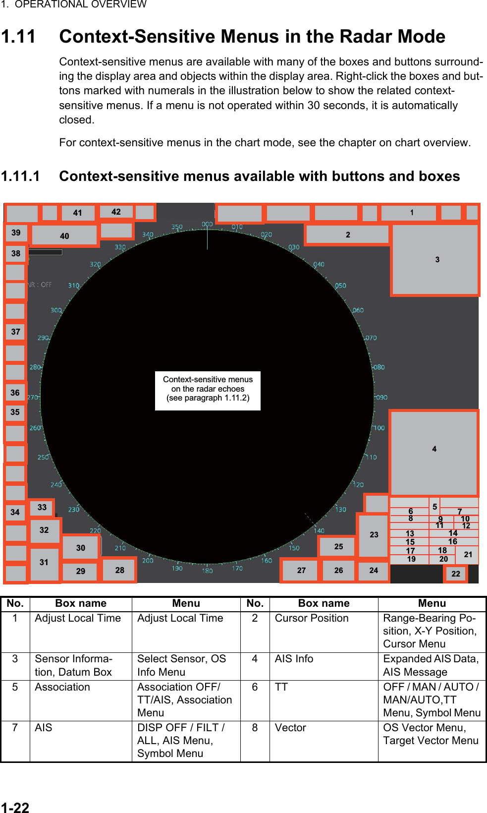
![1-11. OPERATIONAL OVERVIEW1.1 Units of the System1.1.1 Radar Control Unit RCU-025The Radar Control Unit RCU-025 consists of various controls and a trackball module (trackball, scrollwheel and left and right buttons). The trackball module functions like a PC mouse. The user rolls the trackball and operates the left and right buttons and the scrollwheel to do various functions.When you press the correct key, a single beep sounds to alert you to correct opera-tion. For wrong operation, several beeps sound. You can select the loudness of the beep or deactivate the beep on the [Customize] menu.No. Control Description1 Turns the system on or off. (With a FURUNO monitor unit, the monitor is also turned on or off with this switch.)2 Status LED The color and state of the LED change according to system or alert status.Green, lighting: Normal operation status; no alerts generated.Green, flashing: The heater on the CPU board is on, because ambient temperature is not at least 0°C. The heater takes about two minutes to warm the equipment. The LED lights green after the heater goes off.Red, lighting: Acknowledged alert or SYSTEM FAIL. SYSTEM FAIL oc-curs when there is trouble in the Processor Unit or communication failure between the Processor Unit and a Control Unit. Each Control Unit detects trouble and its lamp flashes in red and the buzzer sounds. If this condition occurs at the No. 1 Control Unit, the SYSTEM FAIL signal is output.Red, flashing: Unacknowledged alert or SYSTEM FAIL.34Rotary control,EBL1, EBL2Rotary control: Adjusts the active EBL.EBL1, EBL2: Activates or deactivates the respective EBL.4488991010111112121313141416161717181820202121222223232424252526262727292930303737112228283336363232151555333334343535191931317766Navigation toolDisplay controlRadar signal processingRadar systemNavigation toolTargetRangeAlert Menu control](https://usermanual.wiki/Furuno-USA/9ZWRTR108.Users-Manual/User-Guide-2496309-Page-29.png)
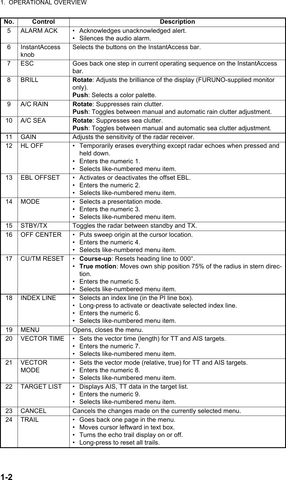
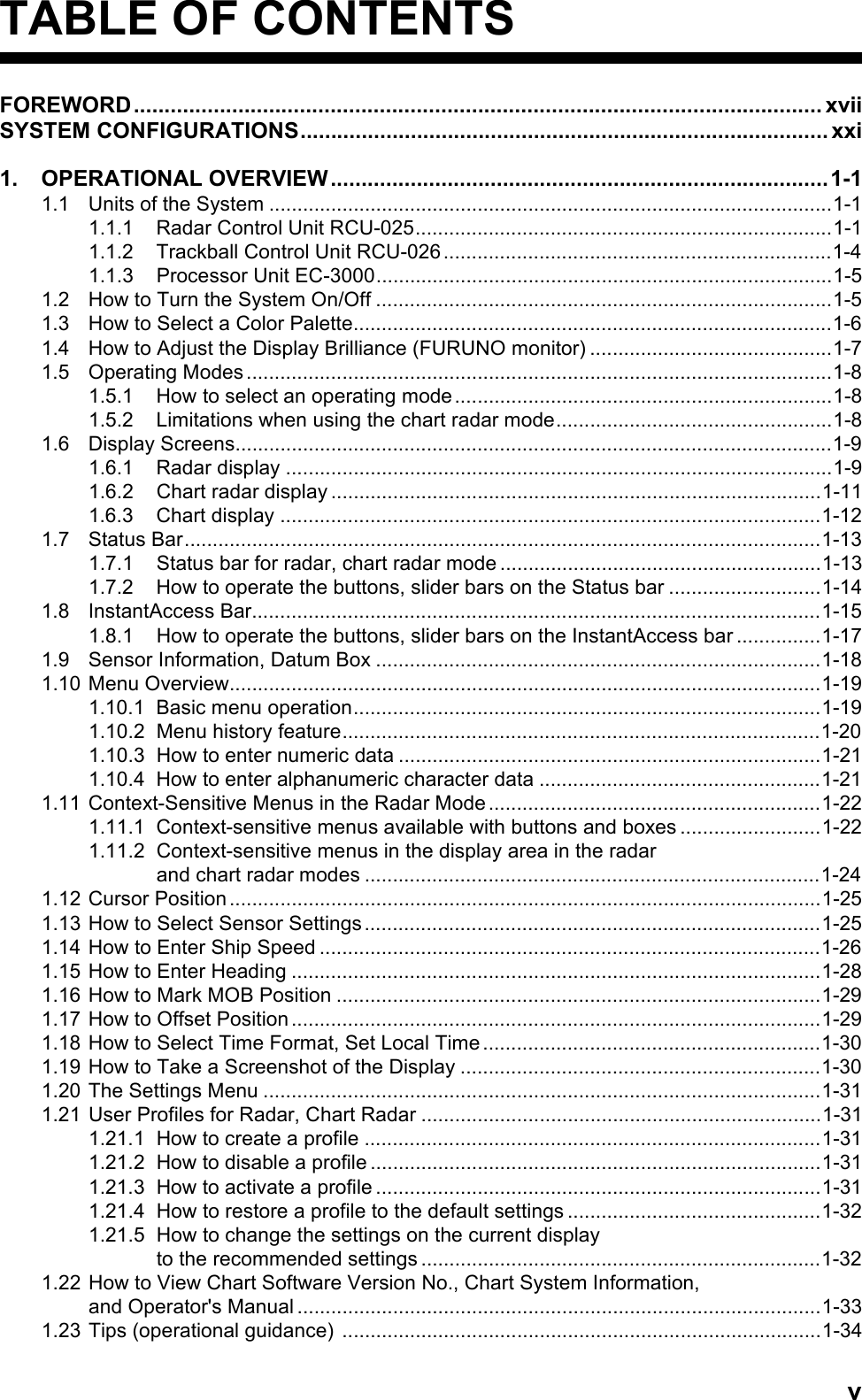
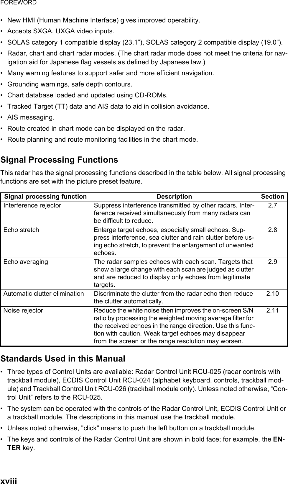
![1. OPERATIONAL OVERVIEW1-325 PANEL • Adjusts the backlighting of the keys.• Enters the numeric 0.• Selects like-numbered menu item.26 MARK • Goes forward one page in the menu.• Moves cursor rightward in text box.• Inputs selected mark on the radar screen, at the position selected.27 ENTER Confirms selection on menu.2829Rotary control,VRM1, VRM2Rotary control: Adjusts the diameter of the active VRM.VRM1, VRM2: Activates or deactivates the respective VRM.30 UNDO Undoes edit or text input when creating a radar map, route, user chart.31 VIEW/HIDE Radar mode, chart radar mode: Shows or hides the AZ box, Drop mark boxes, Mark box, PI line box, Trial box.Chart mode: Shows or hides the EBLs, InstantAccess bar, [Overlay/NAV Tools] box, [Route information] box, VRMs.32 RANGE Selects radar range (radar and chart radar modes), chart scale (chart mode).33 ACQ/ACT • TT: Acquires cursor-selected target, for target tracking.• AIS: Activates cursor-selected sleeping AIS target.34 TARGET DATA Displays the detailed data for selected TT, AIS target, in the TT/AIS infor-mation box.35 TARGETCANCEL• TT: Stops tracking cursor-selected tracked target.• AIS: Sleeps cursor-selected activated AIS target.• Long-press to erase all displayed TT target data.36 TrackballmoduleThe trackball module is the same as that used in the Trackball Control Unit RCU-026. See the description in the next section.37 USB port For connection of USB flash memory (FAT16 or FAT32 format). Do not con-nect a USB HDD or PC keyboard. The DVD drive (Maker: TEAC, Type: PU-DRV10) is for chart updates. No. Control Description](https://usermanual.wiki/Furuno-USA/9ZWRTR108.Users-Manual/User-Guide-2496309-Page-31.png)
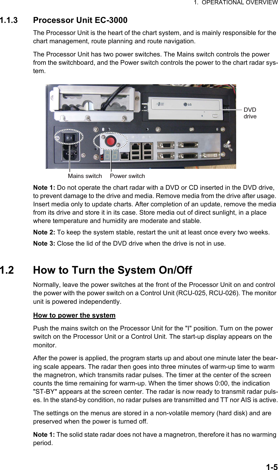
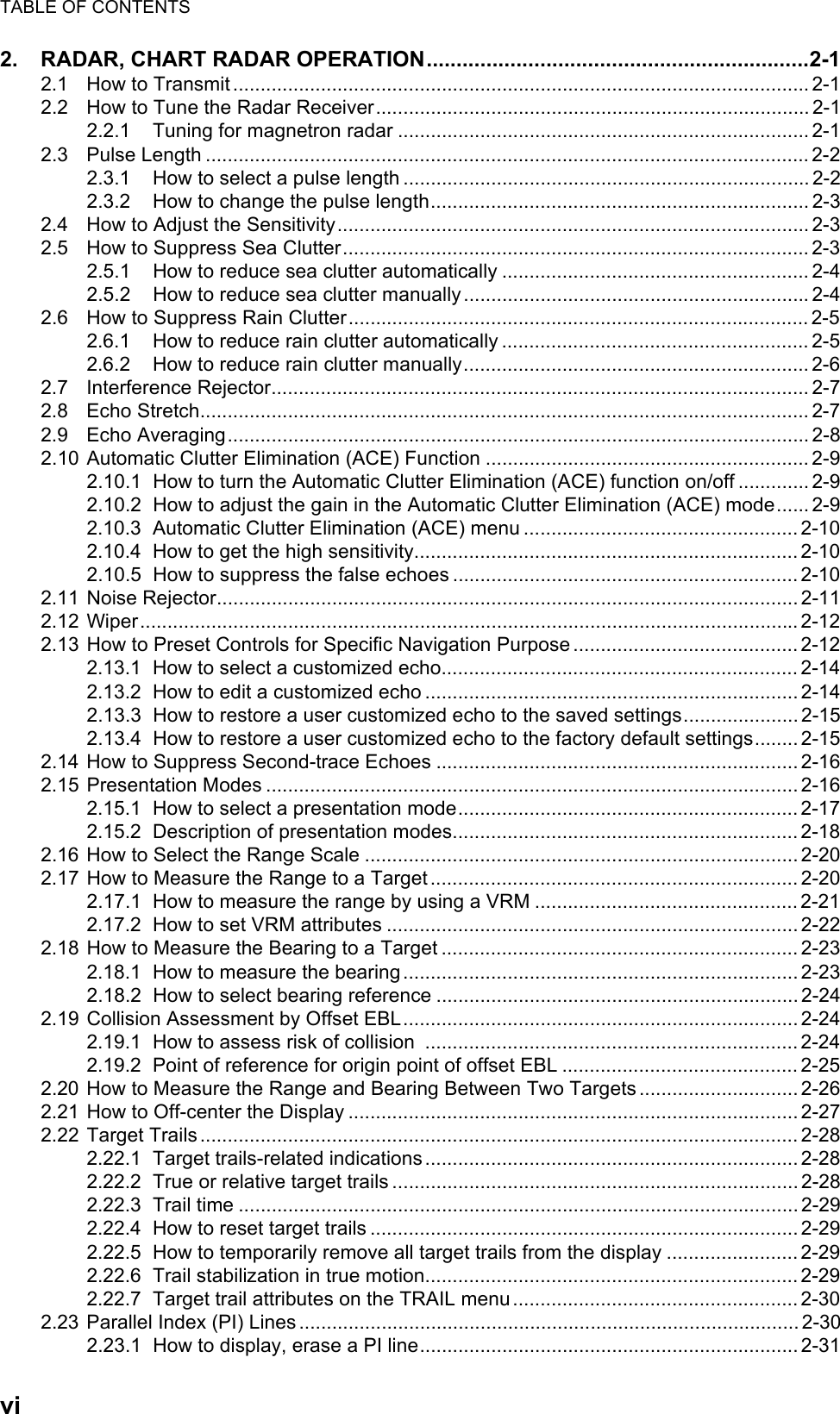
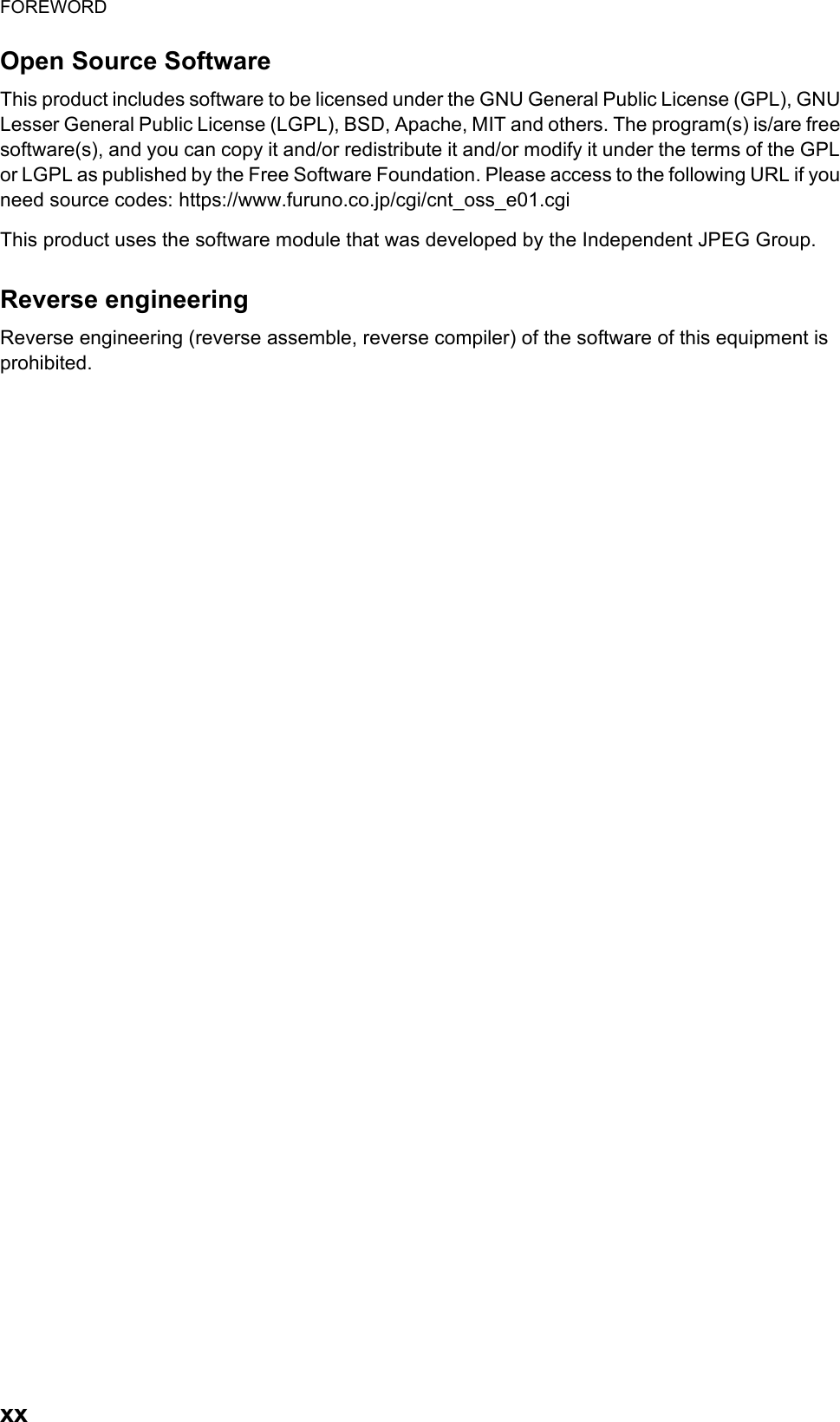
![1. OPERATIONAL OVERVIEW1-6Note 2: If the ambient temperature is less than 0°C (32°F) when the power is applied, nothing appears on the display and the Status LED on the Control Unit flashes. This is because the heater is warming the unit. The display appears in approx. two minutes. How to power off the systemPress the power switch on the Processor Unit or a Control Unit. Push the Mains switch for the "O" position. Note: Provided that the radar was once in use with the transmitter tube (magnetron) still warm, you can put the radar in transmit state without three minutes of warm-up. If the Power switch was turned off by mistake or the like and you wish to restart the radar promptly, turn on the Power switch not later than 10 seconds after power-off.1.3 How to Select a Color PaletteThis radar provides three sets of color and brilliance sets (palette), day, dusk and night, to match any ambient lighting condition. The default specifications of each pal-ette are as shown in the table below. The panel dimmer setting is automatically changed, and the number of steps depends on the color palette selected.To select a palette, do the following:1. Click the [Palette] button.Palette Brilliance Panel dimmer (step)TextcolorBackgroundcolorMU-190 MU-231Day-gray 86 88 15 White GrayDay-blue 86 88 15 White BlueDusk-gray 77 79 7 Light gray Dark grayDusk-blue 77 79 7 Light gray Dark blueNight-gray 53 53 3 Orange Dark grayNight-blue 53 53 3 Light gray Dark blue [Palette] button](https://usermanual.wiki/Furuno-USA/9ZWRTR108.Users-Manual/User-Guide-2496309-Page-34.png)
![1. OPERATIONAL OVERVIEW1-72. Click [Day], [Dusk] or [Night] as appropriate. For example, select [Day] to show its options.3. Click the palette (gray, blue) desired.Note: A palette can also be selected by pushing the BRILL control on the Control Unit.1.4 How to Adjust the Display Brilliance (FURUNO monitor)The brilliance setting is defined according to the color palette setting (see section 1.3). However, manual adjustment of the brilliance is also possible.Note 1: The brilliance of the FURUNO monitor can only be adjusted from the Control Unit. Use a serial cable for brilliance adjustment to make the connection between the Processor Unit and the Control Unit.Note 2: Improper brilliance may affect the visibility of information, especially on the night display.How to adjust the brilliance manually with the BRILL controlOperate the BRILL control to adjust brilliance. Turn it clockwise to increase the bril-liance; counterclockwise to decrease the brilliance. Watch the brilliance level indica-tion on the [BRILL] button (see the illustration below) to see the current brilliance level.How to adjust the brilliance manually with the InstantAccess knob1. Push the InstantAccess knob.2. Rotate the knob to select the [BRILL] button then push the knob to show the bril-liance adjustment window.3. Push the knob, rotate the knob to set the brilliance then push the knob to confirm the setting. The calibration state indication changes to "UNCALIB". 4. To restore the default setting, rotate the knob to select the [CALIB] button then push the knob. The calibration state indication changes to "CALIB".86Current brilliance level[CALIB] button[BRILL] buttonCalibration stateCALIB: Default settingUNCALIB: Manual setting](https://usermanual.wiki/Furuno-USA/9ZWRTR108.Users-Manual/User-Guide-2496309-Page-35.png)
![1. OPERATIONAL OVERVIEW1-8How to adjust the brilliance manually using the trackball module1. Click the [BRILL] button on the InstantAccess bar to show the brilliance adjust-ment window. 2. For coarse adjustment, put the cursor on a location within the slider bar area then push the left button. For fine adjustment, put the cursor on the end of the slider bar and roll the trackball while holding down the left button. 3. Release the left button to confirm setting. The calibration state indication changes to "UNCALIB".4. To restore the default setting, click the [CALIB] button. The calibration state indi-cation changes to "CALIB".1.5 Operating ModesThis chart radar has the following operating modes:1.5.1 How to select an operating modeClick the [Operating Mode] button to select desired mode from the pull-down list. Se-lect [RADAR] for the radar or chart radar mode or [CHART for RADAR] for the chart mode.1.5.2 Limitations when using the chart radar modeThe presentation mode for the chart radar mode can be course-up RM, north-up RM, or north-up TM. The presentation mode is automatically switched to north-up RM if the mode is head-up at the time the chart radar mode is selected.• [RADAR]: - The radar mode provides the traditional radar display.- The chart radar mode overlays the electronic chart on the radar image.• [CHART for RADAR]: The chart mode shows the electronic charts.[Operating Mode] buttonRADARRADARCHARTfor RADAR](https://usermanual.wiki/Furuno-USA/9ZWRTR108.Users-Manual/User-Guide-2496309-Page-36.png)
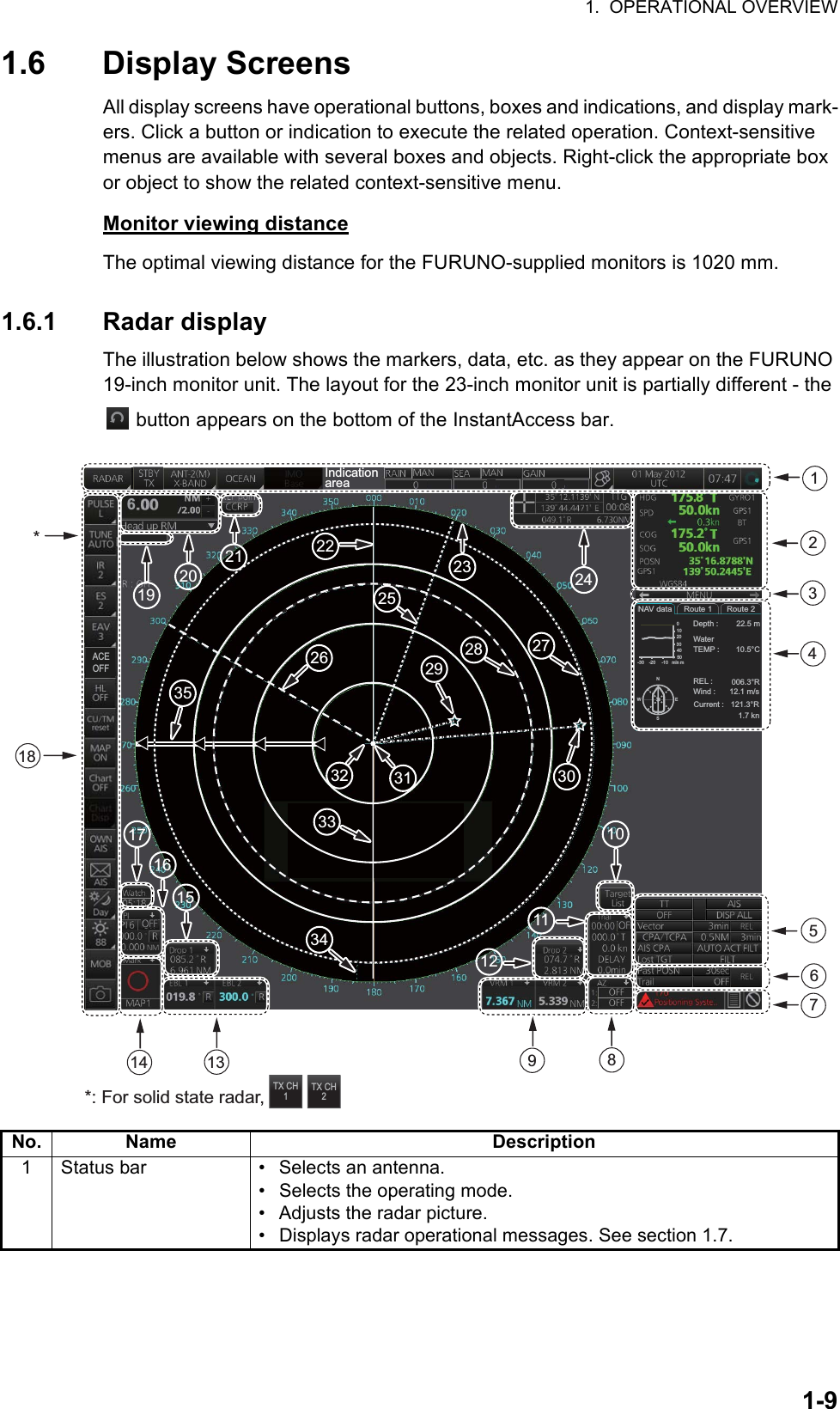
![1. OPERATIONAL OVERVIEW1-11How to minimize, maximize the boxes at the bottom of the screenThe boxes at the bottom of the screen that contain an arrow can be minimized. Click the arrow to minimize the box. To restore maximum size, click the minimized box.Example: Mark boxNote: The respective VRM or EBL is erased from the screen when the corresponding VRM or EBL box is minimized.1.6.2 Chart radar displayThe chart radar display overlays an electronic chart on the radar picture. To switch be-tween the radar and chart radar displays, click the [Chart ON/OFF] button on the In-stantAccess bar.Click arrow to minimize.Click here to maximize.Click to hide, show chart.OFFACE](https://usermanual.wiki/Furuno-USA/9ZWRTR108.Users-Manual/User-Guide-2496309-Page-39.png)
![1. OPERATIONAL OVERVIEW1-121.6.3 Chart displayThe chart display shows only the electronic chart. Click the [Operating Mode] button to select [CHART for RADAR] to activate this display. See chapter 6 for a description of the chart display.Select [CHART for RADAR]. CHARTfor RADAR0.5NM 4minAUTO ACT FILT](https://usermanual.wiki/Furuno-USA/9ZWRTR108.Users-Manual/User-Guide-2496309-Page-40.png)
![1. OPERATIONAL OVERVIEW1-131.7 Status BarThe Status bar is displayed at the top of screen in all modes. This bar provides, in the radar and chart radar modes, buttons for selection of the mode, antenna and chart da-tabase, and adjustment of the radar picture.For a description of the Status bar used in the chart mode, see paragraph 6.1.2.1.7.1 Status bar for radar, chart radar mode*: The indication is grayed out when the Automatic Clutter Elimination (ACE) function is [ON].No. Button name Description1 Operating Mode Selects a mode: RADAR or CHART for RADAR.2 STBY TX Toggles the radar between stand-by and transmit.3 Antenna Selects an antenna.4Customize EchoPresets the radar controls for specific navigation purpose; for example, congested waters.5 Chart database Selects the IMO chart database (base, primary, standard or all). Available in the chart radar mode.6 RAIN* Reduces rain clutter.7 SEA* Reduces sea clutter.8 GAIN Adjusts the gain of the radar receiver.9 Settings Manages user profiles; opens the Settings menu.10 Date • Displays the date.• Selects the time to use, local or UTC.• Sets the time difference between local and UTC (to use local time).11 Time Displays the time, local or UTC.12 Working IndicatorRotates clockwise if the system is working properly.Picture freezeIf the picture freezes, the picture is not updated. After the picture freezes, the buzzer sounds and the Status LED blinks in red. Reset the power to re-store normal operation. 112111023467895](https://usermanual.wiki/Furuno-USA/9ZWRTR108.Users-Manual/User-Guide-2496309-Page-41.png)
![1. OPERATIONAL OVERVIEW1-141.7.2 How to operate the buttons, slider bars on the Status barThe Status bar has three types of controls: toggle button, drop-down list button and slider bar. You operate the buttons and bars with the trackball module.Control type Example of controlToggle buttonA toggle button alternately selects one of two functions assigned to a button. For example, the [STBY TX] button toggles the radar between stand-by and TX. The background color of the [STBY TX] button momentarily changes to light- blue when switching from stand-by to TX.Drop-down list buttonA drop-down list button provides a list from which to select an option related to the label on the but-ton. A drop-down list button is identified by a tri-angle on the button’s bottom-right corner. The [Chart database] button, shown in the right figure, is an example of a drop-down list button.Slider barThe slider bars provide for adjustment of the ra-dar picture. [RAIN], [SEA] and [GAIN] are slider bar buttons. To adjust the bar coarsely, put the cursor at any location within the slider bar area then push the left button. For fine adjustment, put the cursor at the end of the slider bar and roll the trackball while holding down the left button. Re-lease the button to finish.STBY TXClick button to show drop-down list.](https://usermanual.wiki/Furuno-USA/9ZWRTR108.Users-Manual/User-Guide-2496309-Page-42.png)
![1. OPERATIONAL OVERVIEW1-151.8 InstantAccess BarThe InstantAccess bar runs vertically along the left edge of the screen and is displayed always. This bar provides, in the radar and chart radar modes, buttons for adjustment of the radar picture and chart, AIS operations, display brilliance con-trol (FURUNO monitor only), MOB, screenshot, etc.For a description of the InstantAccess bar used in the chart mode, see paragraph 6.1.3.*1: For solid state radar, [TX CH] icon is displayed instead of [TUNE].*2: This button is not displayed on the FURUNO 19-inch monitor unit.Radar mode, map ONRadar mode, chart ON112111023467895131415161718*2*1IROFFESOFFEAVOFFHLOFFCU/TMresetPULSEM3TUNEMANMAPOFFChartONChartDispOWNAISAISDay88MOBIROFFESOFFEAVOFFHLOFFCU/TMresetPULSEM3TUNEMANMAPONChartOFFChartDispOWNAISAISDay88MOBACEOFFACEOFF](https://usermanual.wiki/Furuno-USA/9ZWRTR108.Users-Manual/User-Guide-2496309-Page-43.png)
![1. OPERATIONAL OVERVIEW1-16No. Button name Description1 PULSE Selects the radar pulse length.2 TUNE Selects the radar receiver tuning method, automatic or manual, and manually tunes the radar receiver.TX CH Selects the transmit frequency from [TX CH 1] or [TX CH 2].3 IR Activates or deactivates the interference rejector.4 ES Activates or deactivates the echo stretch.5 EAV Activates or deactivates the echo averaging when Automatic Clut-ter Elimination (ACE) function is off.6 ACE Activates or deactivates the Automatic Clutter Elimination (ACE) function.Automatic Clutter Elimination (ACE) automatically sets the gain, rain and sea clutter controls according to the sea and rain clutter states.7 HL OFF Temporarily erases everything but radar echoes.8 CU/TM reset • Puts the ship’s heading at the top of the screen in course-up mode the moment this button is pressed.• Resets the ship's position to a point of 75% radius opposite to the extension of the heading line passing through the display center in true motion modes.9 MAP ON/OFF Shows or hides the radar map marks on the radar display, in the radar mode.10 CHART ON/OFF Shows or hides the electronic chart.11 Chart Disp Shows or hides various chart objects. Shown in the chart radar mode. See paragraph 2.41.2.12 OWN AIS Shows the [VOYAGE DATA] menu, to set your ship’s AIS data.13 AIS message Displays screen for “received AIS messages”.14 Palette Selects a color palette.15 BRILL Adjusts the brilliance of a FURUNO monitor.16 MOB Enters a MOB mark at the current position.17 Capture Takes a screenshot.18 UNDO Restores previous condition in radar map and text input.](https://usermanual.wiki/Furuno-USA/9ZWRTR108.Users-Manual/User-Guide-2496309-Page-44.png)
![1. OPERATIONAL OVERVIEW1-171.8.1 How to operate the buttons, slider bars on the InstantAccess barThe InstantAccess bar has three types of controls: toggle button, drop-down list button and slider bar. (The MOB and Capture buttons are special buttons.) You operate the buttons and bars with the trackball module or the InstantAccess knob. This section shows you how to use the InstantAccess knob.1. Push the InstantAccess knob to enable its use with the InstantAccess bar.2. Rotate the InstantAccess knob to select a button. The background color of the button selected is light-blue.3. Do one of the following depending on button type.1) Toggle button: Push the knob to select setting.2) Drop-down list button or slider bar: Push the knob then rotate the knob to select an item or adjust the slider bar. Push the knob to confirm your selection.Note: You can use the ESC key to go back one step in the current operating sequence.Toggle button Drop-down list button Slider barA drop-down list button provides a list from which to select an option related to the label on the button. A drop-down list button is identified by a tri-angle on the button’s bottom-right corner. [Palette] buttonPalette list](https://usermanual.wiki/Furuno-USA/9ZWRTR108.Users-Manual/User-Guide-2496309-Page-45.png)
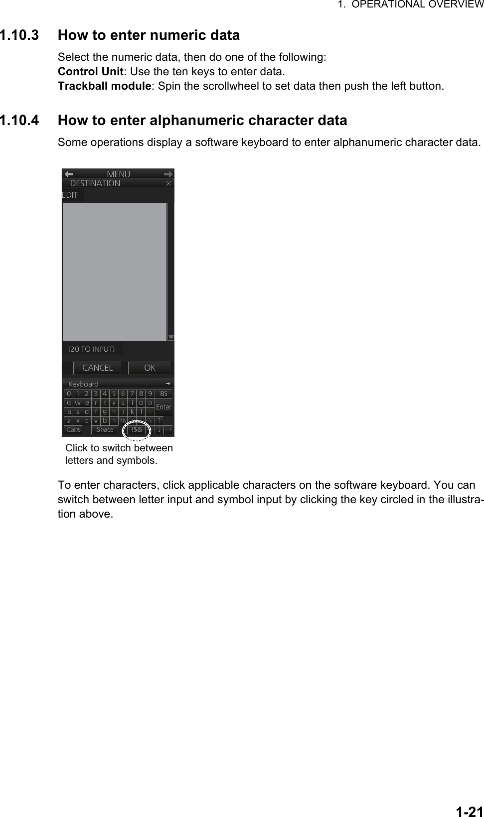
![1. OPERATIONAL OVERVIEW1-191.10 Menu OverviewThe menu consists of eight main menus and several sub menus. You can operate the menu with the Radar Control Unit or trackball module. The system closes open menus whenever there is no menu operation for 30 seconds.1.10.1 Basic menu operation1. Open the main menu.Control Unit: Press the MENU key.Trackball module: Click the menu title bar at the right side of the display.2. Select a menu.Control Unit: Press the corresponding numeric key. For example, press the 3 key to show the [NAV TOOL] menu.Trackball module: Click the menu desired. The current selection is highlighted in blue.3. Select a menu item.Control Unit: Press the corresponding numeric key.Trackball module: Click the menu item desired. The current selection is highlight-ed in blue.4. Select a menu option.Control Unit: Press the corresponding numeric key. The current selection is high-lighted in orange.Trackball module: Spin the scrollwheel. The current selection is highlighted in or-ange.5. Confirm your selection.Control Unit: Press the ENTER key. Trackball module: Push the left button.Note: Hereafter, "select" in a menu operating procedure means to press the applica-ble numeric key on the Control Unit or push the left button on the trackball module.Menu title barClick [3 NAV TOOL] or press the 3 key.](https://usermanual.wiki/Furuno-USA/9ZWRTR108.Users-Manual/User-Guide-2496309-Page-47.png)
![1. OPERATIONAL OVERVIEW1-20Keys, buttons to use in menusControl UnitMENU key: Open main menu, or close menu.CANCEL key: Go back one layer in menu, or close menu when main menu is dis-played.←key: Return to main menu, in no. 2 layer or higher.Trackball moduleRight button: Go back one layer, or close menu when main menu is displayed.Left button: (1) Click menu title bar to go back one layer, or close menu when main menu is displayed, (2) Click the left arrow on the menu title bar to return to the main menu, in no.2 layer or higher.1.10.2 Menu history featureThis chart radar remembers the 10 last-used menus to help you go to recently used menus quickly. The memorized menus are cleared when the power is turned off. In-stallation- and service-related menus and menus where no operation occurred are not memorized. Menus accessed multiple times are counted as one menu.Click the memory history buttons on the menu title bar to navigate through the last-used menus.For example, the last two used menus are [NAV TOOL] and [AIS].Menu history buttonsHistory back buttonHistory forward buttonMemorized menu no. 1Memorized menu no. 2ClickClick](https://usermanual.wiki/Furuno-USA/9ZWRTR108.Users-Manual/User-Guide-2496309-Page-48.png)
![1. OPERATIONAL OVERVIEW1-241.11.2 Context-sensitive menus in the display area in the radar and chart radar modesRight-click anywhere in the display area in the radar and chart radar modes to show the context-sensitive menu.[Target Data/ACQ/ACT]: For cursor-selected TT or AIS target, display target data, acquire target for TT, or activate sleeping AIS target.[Target Cancel]: Cancel tracking on selected tracked target (erase target), sleep activated AIS target.[Off Center]: Off center the display.[EBL Offset]: Offset EBL1, EBL2 (to measure range and bearing between two targets).[Zoom Set]: Select zoom area.[Area Select]: Specify the area where to delete, copy marks.[Mark Delete]: Delete cursor-selected mark. Grayed out when radar map is off.[Mark Copy]: Copy cursor-selected mark. Grayed out when radar map is off.[Own Ship Offset]: Apply an offset to own shipposition.[REF Mark]: Make cursor-selected target a reference target (for use in TT). Grayed out unless TT is active.[Cursor Size]: Select cursor size, large or small.[Notes Detail]: Show details about cursor-selected Notes.[MOB Delete]: Delete selected MOB mark.Area selectedThis context-sensitive menu is available when an area is created to cancel tracking on specific targets, or delete or copy marks.[Area Target Cancel]: Cancel tracking on targets within the area selected.[Area Mark Delete]: Delete all marks within the area selected.[Area Mark Copy]: Copy all marks within the area se-lected.[Area Cancel]: Cancel the area created.Radar mode, map ONRadar mode, map OFF or chart ONRadar mode, map ON, area selected](https://usermanual.wiki/Furuno-USA/9ZWRTR108.Users-Manual/User-Guide-2496309-Page-52.png)
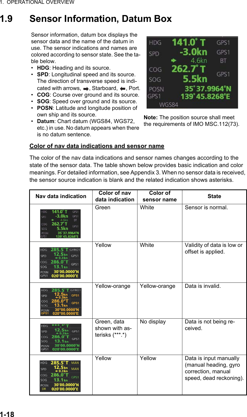
![1. OPERATIONAL OVERVIEW1-251.12 Cursor PositionCursor data appears in the cursor position box at the top-right position on the display. The appearance of the box is slightly different between the 23-inch and 19-inch dis-plays, although the content is the same.For the cursor position box that appears in the chart mode, see section 6.6.The indication below the cursor position can show the range and bearing to the cursor or x-y coordinates of the cursor position. Click that indication and select [Range-Bear-ing Position] or [X-Y Position] as appropriate. For the x-y coordinate display, the y-axis is the heading line, right/top is "plus" and left/lower is "minus".Note 1: The cursor bearing can be selected to true or relative with [1 CURSOR BEAR-ING] in the [CURSOR] menu. Right-click the indication and select [Cursor Menu] to open the [CURSOR] menu.Note 2: The cursor position is shown as "---.-" when the cursor is not within the effec-tive display area.1.13 How to Select Sensor SettingsThis radar system accepts navigation data input two ways: System or Local. System shares sensor data among multiple radars in a network. Sensor priority is also com-monly shared among the radars. Local selects a sensor outside the network.1. Right-click anywhere in the Sensor information, datum box to show the context-sensitive menu.2. Click [Select Sensor].3. Click [System] or [Local].Note: The sensor system can also be selected in the chart mode through this pro-cedure and through the menu. Open the menu then select [7 OWN SHIP INFO] followed by [1 SENSOR].Cursor position (lat/lon)Bearing and range to cursor positionTime to go to cursor positionx and y coordinates of cursor positionClick indication to switch between bearing and range and x and y coordinates.SystemLocal[Setting]SystemLocalSelect Sensor[OS Info Menu][Setting]](https://usermanual.wiki/Furuno-USA/9ZWRTR108.Users-Manual/User-Guide-2496309-Page-53.png)
![1. OPERATIONAL OVERVIEW1-261.14 How to Enter Ship SpeedThe TT and azimuth stabilized presentation modes require own ship speed input and compass signal. The speed can be entered automatically from a speed log (STW, SOG) or GPS (SOG), or manually on the menu. Note that the FURUNO GPS Naviga-tor GP-150 provides COG and SOG.1. Right-click anywhere in the Sensor information, datum box to show the context-sensitive menu.2. Click [Select Sensor] then click [Setting].3. Use the arrow buttons to select the [SPD] page.4. For automatic input, follow the procedure below. For manual input, go to step 5.1) Check [Sensors].2) Set the priority for the speed sensors in case of Local sensor. Click the triangle on any line then select the sensor to set as the primary source of speed. All other sensors are then set as secondary source. Only one sensor can be pri-mary while the others can be secondary. If a speed sensor is changed from secondary to primary state and another speed sensor was selected as prima-SystemLocal[Setting]SystemLocalSelect Sensor[OS Info Menu][Setting]Sensor type selectionSpeed sensor listCheck for manual speed inputCheck for automatic speed inputStablilization modeSelect to use radar as source for speed and courseSet speed and course of driftArrow buttons](https://usermanual.wiki/Furuno-USA/9ZWRTR108.Users-Manual/User-Guide-2496309-Page-54.png)
![1. OPERATIONAL OVERVIEW1-27ry, then that sensor previously selected to primary state is then automatically selected to secondary state.3) Select [Bottom] or [Water] at [Stabilization Mode] to set the stabilization meth-od. Select [Bottom] for GPS or [Water] for a speed log.4) Check [GPS] or [LOG] at [Sensor Type] to select the source of speed data.5) Go to step 6.5. For manual input, set the stabilization mode for [Water] and check [Manual]. Click the manual box to show the up and down arrows. Click the arrows to set speed.Note: For [Set Drift], see page 16-3.6. Click the [OK] button to save the settings then click the [MENU] bar to close the menu.Notes on speed input• IMO Resolution A.823(19) for TT requires that a speed log to be interfaced with a TT should be capable of providing through-the-water speed (forward speed).• A single-axis water log cannot measure speed when the wind is coming from the leeway direction.• When AIS is active, [Manual], [Reference SPD] and [Set Drift] are shown in gray to indicate that they are not available for selection.](https://usermanual.wiki/Furuno-USA/9ZWRTR108.Users-Manual/User-Guide-2496309-Page-55.png)
![1. OPERATIONAL OVERVIEW1-281.15 How to Enter HeadingSelect manual or automatic heading input as follows:1. Right-click anywhere in the Sensor information, datum box to show the context-sensitive menu.2. Click [Select Sensor] then click [Setting].3. Use the arrow buttons to select the [HDG] page.4. For automatic input, follow the procedure below. For manual input, go to step 5.1) Check [Sensors].2) Set the priority for the heading sensors. Click the triangle on any line then se-lect the sensor to set as the primary source of heading. All other sensors are then set as secondary source. Only one sensor can be primary while the oth-ers can be secondary. If a heading sensor is changed from secondary to pri-mary state and another heading sensor was selected as primary, then that sensor previously selected to primary state is then automatically selected to secondary state. 3) Go to step 6.5. For manual input, check the [Manual] box. Click the heading input box to show the up and down arrows. Click the arrows to set heading.6. Click the [OK] button to save the settings then click the [MENU] bar to close the menu.Heading sensor listAnalog gyro headingCheck for automatic heading inputGY001GY002Manual heading input (not shown on IMO type) Gyro Correction[Gyro Correction] is not shown● when [SYSTEM] is selected in the [OWN SHIP INFO] - [SENSOR] menu.[Gyro Correction] is grayed out● when manual heading is in use.Arrow buttons](https://usermanual.wiki/Furuno-USA/9ZWRTR108.Users-Manual/User-Guide-2496309-Page-56.png)
![1. OPERATIONAL OVERVIEW1-291.16 How to Mark MOB PositionUse the MOB (man overboard) feature to mark the position of man overboard on the display screen. Click the [MOB] button (in any mode) on the InstantAccess bar.The MOB mark instantly appears at the geographical position of your ship when the button is clicked.Up to 100 MOB marks can be saved. When the capacity for MOB marks is reached, the oldest mark is automatically erased to make room for the latest.To delete an MOB mark, right-click the mark to show the context-sensitive menu then select [MOB Delete]. Exercise caution when using this feature in strong tide or current. The person will not be at the MOB position for a very long time.1.17 How to Offset PositionThe position shown in the Sensor information, datum box (section 1.9) may be differ-ent from the actual position. This error affects the positioning accuracy of radar ech-oes, radar map and TT and AIS symbols. If there is a difference, apply an offset to position as shown below to compensate for the error.1. Right-click the display area to show the context-sensitive menu.2. Select [Own Ship Offset] and push the left button. The color of the cursor be-comes blue.3. Roll the trackball until the cursor is at the "correct position".4. Push the left button to confirm.To cancel the offset, show the context-sensitive menu then select [Reset Own Ship Offset]. The indication [Offset] and the offset values are then erased from the display.[MOB] button Offset value (range, bearing)](https://usermanual.wiki/Furuno-USA/9ZWRTR108.Users-Manual/User-Guide-2496309-Page-57.png)
![1. OPERATIONAL OVERVIEW1-301.18 How to Select Time Format, Set Local TimeThe GPS navigator feeds time and date data to the chart radar and they appear on the Status bar. Neither the time nor the date can be adjusted, however you can select be-tween UTC time (default) and local time. You can switch between the local time and the UTC time by left-clicking the Current time format indication.To use the local time, enter the time difference between the local time and the UTC time as shown below.1. Right-click the Current time format indication to show the context-sensitive menu then click [Adjust Local Time] to display the [Local Time Adjust] dialog box.2. Enter the time difference between the local time and the UTC time, in hours and minutes. Use the button on the left to select the time offset direction. Select "+" if the local time is ahead of the UTC time, or "-" if it is behind the UTC time.1.19 How to Take a Screenshot of the DisplayClick the [Capture] button on the InstantAccess bar to take a screenshot and save it to the SSD (Solid State Drive). You can save a maximum of 100 screenshots. When the capacity for screenshots is reached, the oldest screenshot is automatically deleted to make room for the latest. You cannot take a screenshot when a menu or a dialog box is opened.Screenshots can be copied to a USB flash memory. For how to process screenshots, see section 22.10.Current time formatLeft click: Switch between local and UTC timesRight click: Adjust local timeTime+00[Capture] button](https://usermanual.wiki/Furuno-USA/9ZWRTR108.Users-Manual/User-Guide-2496309-Page-58.png)