Furuno USA 9ZWRTR108 Transceiver for Radar model FAR-3320W User Manual
Furuno USA Inc Transceiver for Radar model FAR-3320W
Contents
- 1. Users Manual
- 2. User Manual
Users Manual

OPERATOR'S MANUAL
www.furuno.com
CHART RADAR
FAR-3210
FAR-3220
FAR-3230S
FAR-3230S-SSD
FAR-3310
FAR-3320
FAR-3330S
FAR-3330S-SSD
FAR-3320W
FAR-3330SW
FAR-3210-BB
FAR-3220-BB
FAR-3230S-BB
FAR-3230S-SSD-BB
FAR-3220W-BB
FAR-3230SW-BB
Model
(Product Name: MARINE RADAR)

The paper used in this manual
is elemental chlorine free.
・FURUNO Authorized Distributor/Dealer
9-52 Ashihara-cho,
Nishinomiya, 662-8580, JAPAN
A
:
APR
2014
.
Printed in Japan
All rights reserved.
B2
:
DEC
.
15, 2014
Pub. No.
OME-36160-B2
(
YOTA
)
FAR-3000SERIES
0 0 0 1 7 8 0 2 7 1 1

i
IMPORTANT NOTICES
General
How to discard this product
Discard this product according to local regulations for the disposal of industrial waste. For disposal
in the USA, see the homepage of the Electronics Industries Alliance (http://www.eiae.org/) for the
correct method of disposal.
How to discard a used battery
Some FURUNO products have a battery(ies). To see if your product has a battery, see the chapter
on Maintenance. Follow the instructions below if a battery is used. Tape the + and - terminals of
battery before disposal to prevent fire, heat generation caused by short circuit.
In the European Union
The crossed-out trash can symbol indicates that all types of batteries
must not be discarded in standard trash, or at a trash site. Take the
used batteries to a battery collection site according to your national
legislation and the Batteries Directive 2006/66/EU.
In the USA
The Mobius loop symbol (three chasing arrows) indicates that Ni-Cd
and lead-acid rechargeable batteries must be recycled. Take the used
batteries to a battery collection site according to local laws.
In the other countries
There are no international standards for the battery recycle symbol. The number of symbols can
increase when the other countries make their own recycle symbols in the future.
• This manual has been authored with simplified grammar, to meet the needs of international users.
• The operator of this equipment must read and follow the descriptions in this manual. Wrong oper-
ation or maintenance can cancel the warranty or cause injury.
• Do not copy any part of this manual without written permission from FURUNO.
• If this manual is lost or worn, contact your dealer about replacement.
• The contents of this manual and equipment specifications can change without notice.
• The example screens (or illustrations) shown in this manual can be different from the screens you
see on your display. The screens you see depend on your system configuration and equipment
settings.
• Save this manual for future reference.
• Any modification of the equipment (including software) by persons not authorized by FURUNO will
cancel the warranty.
• All brand and product names are trademarks, registered trademarks or service marks of their re-
spective holders.
• “C-MAP” means “C-MAP by Jeppesen” in this manual.
• Windows is a registered trademark of the Microsoft Corporation of the USA and other countries.
Cd
Ni-Cd Pb
ii
SAFETY INSTRUCTIONS
The operator must read the safety instructions before attempting to operate the equipment.
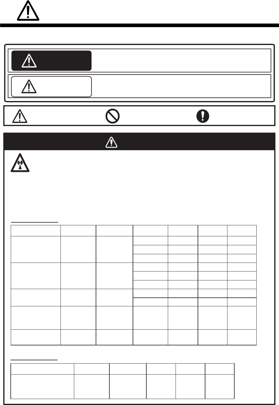
The radar antenna emits electromagnetic radio frequency (RF) energy that can be harmful,
particularly to your eyes. Never look directly into the antenna aperture from a close distance
while the radar is in operation or expose yourself to the transmitting antenna at a close
distance. Distances at which RF radiation level of 100, 50 and 10 W/m
2
are given in the table
below.
Indicates a potentially hazardous situation which, if not avoided,
could result in death or serious injury.
Indicates a potentially hazardous situation which, if not avoided,
could result in minor or moderate injury.
100W/m
2
Radar model
FAR-3220/
FAR-3320/
FAR-3220-BB
FAR-3210/
FAR-3310/
FAR-3210-BB
FAR-3230S/
FAR-3330S/
FAR-3230S-BB
FAR-3330SW/
FAR-3230SW-BB
FAR-3320W/
FAR-3220W-BB
Transceiver Magnetron Antenna 10W/m
2
50W/m
2
Warning, Caution Prohibitive Action Mandatory Action
Radio Frequency Radiation Hazard
WARNING
CAUTION
WARNING
RTR-105 FNE1201 XN12CF
XN20CF
XN24CF
RTR-106 MG5436 XN12CF
XN20CF
XN24CF
RTR-108 MG5436 XN20CF
XN24CF
RTR-107 MG5223F SN36CF
RTR-109 MG5223F SN36CF
Magnetron radar
100W/m
2
Radar model
FAR-3230S-SSD/
FAR-3330S-SSD/
FAR-3230S-SSD-BB
Transceiver Antenna 10W/m
2
50W/m
2
RTR-111 SN36CF
Solid state radar
N/A
N/A N/A 1.0 m
0.5 m 4.6 m
0.6 m 1.4 m 4.4 m
0.4 m 0.9 m 3.0 m
0.3 m 0.6 m 2.5 m
1.3 m 2.7 m 9.5 m
1.0 m 1.7 m 6.8 m
0.7 m 1.3 m 5.5 m
N/A 0.26 m 2.3 m
0.5 m 1.2 m 5.5 m
0.3 m 0.9 m 4.0 m
SAFETY INSTRUCTIONS
iii
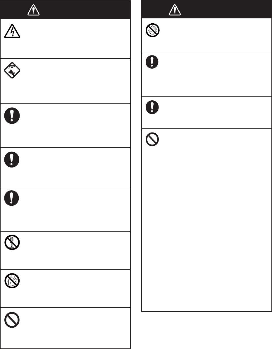
WARNING
Do not open the equipment.
The equipment uses high voltage that
can cause electrical shock. Refer any
repair work to a qualified technician.
Before turning on the radar, be sure
no one is near the antenna.
Prevent the potential risk of being
struck by the rotating antenna, which
can result in serious injury or death.
If water leaks into the equipment or
something is dropped into the
equipment, immediately turn off the
power at the switchboard.
Fire or electrical shock can result.
If the equipment is giving off smoke
or fire, immediately turn off the
power at the switchboard.
Fire or electrical shock can result.
If you feel the equipment is acting
abnormally or giving off strange
noises, immediately turn off the
power at the switchboard and
contact a FURUNO service techni-
cian.
Do not disassemble or modify the
equipment.
Fire, electrical shock or serious injury
can result.
Make sure no rain or water splash
leaks into the equipment.
Fire or electrical shock can result if
water leaks into the equipment.
Do not place liquid-filled containers
on or near the equipment.
Fire or electrical shock can result if a
liquid spills into the equipment.
Do not operate the equipment with
wet hands.
Electrical shock can result.
Keep objects away from the open-
type antenna unit, so as not to
impede rotation of the antenna.
Fire, electrical shock or serious injury
can result.
Use the proper fuse.
Use of the wrong fuse can cause fire or
damage the equipment.
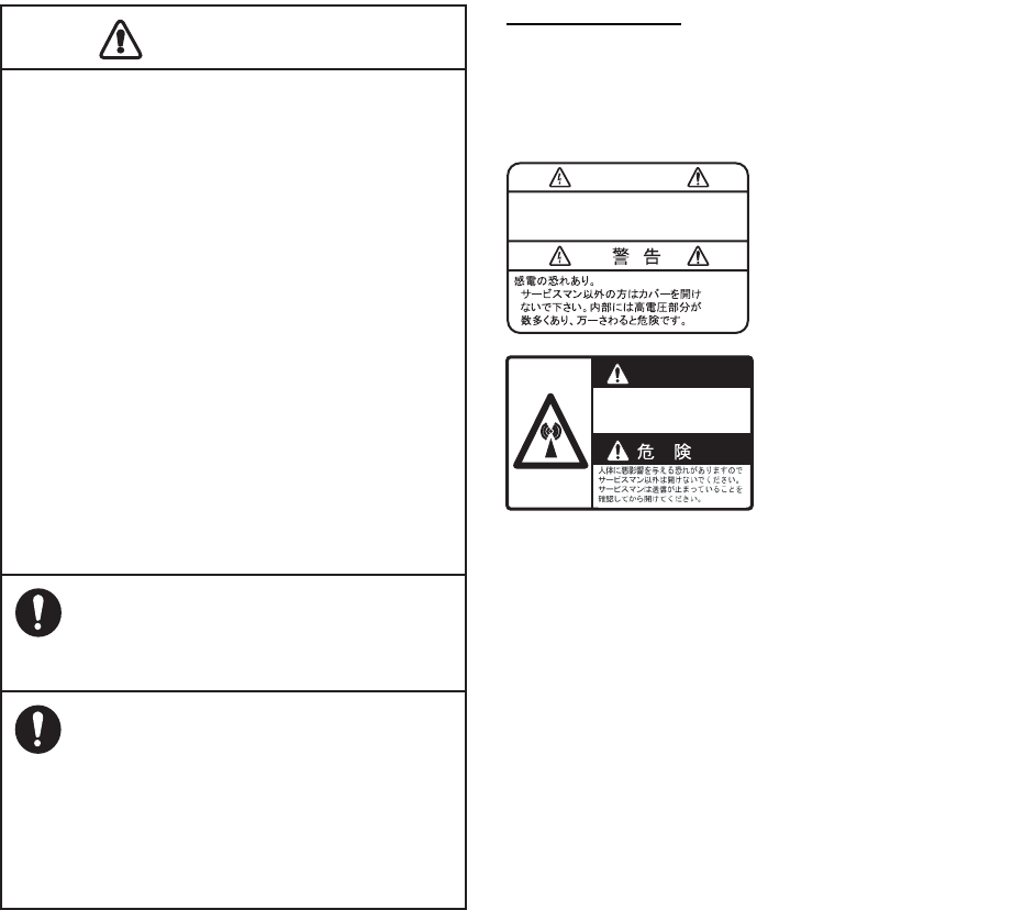
The TT function is a valuable aid to
navigation. However, the navigator
must check all aids available to
avoid collision.
- The TT automatically tracks an
automatically or manually acquired
radar target and calculates its course
and speed, indicating them with a
vector. Since the data generated by
the TT depends on the selected radar
targets, the radar must be optimally
tuned for use with the TT, to ensure
required targets will not be lost or
unnecessary targets, like sea returns
and noise, will not be acquired and
tracked.
- A target is not always a landmass,
reef, ship, but can also be returns
from the sea surface and from clutter.
As the level of clutter changes with
the environment, the operator must
correctly adjust the sea and rain
clutter controls and the gain control so
that the target echoes do not dis-
appear from the radar screen.
WARNING WARNING
SAFETY INSTRUCTIONS
iv
The plotting accuracy and response of this
TT meets IMO standards. Tracking accuracy
is affected by the following:
•
Tracking accuracy is affected by course
change. One to two minutes is required to
restore vectors to full accuracy after an
abrupt course change. (The actual amount
depends on gyrocompass specifications.)
•
The amount of tracking delay is inversely
proportional to the relative speed of the
target. Delay is approx. 15-30 seconds for
the higher relative speed; approx. 30-60
seconds for the lower relative speed. The
following factors can affect accuracy:
- Echo intensity
- Radar transmission pulse length
- Radar bearing error
- Gyrocompass error
- Course change (own ship and targets)
Handle the LCD carefully.
The LCD is made of glass, which can
cause injury if broken.
The data presented by this equipment
is intended as a source of navigation
information.
The prudent navigator never relies
exclusively on any one source of
navigation information, for safety of
vessel and crew.
WARNING
To avoid electrical shock, do not
remove cover. No user-serviceable
parts inside.
WARNING
Radiation hazard. Only qualified
personnel should work inside scanner.
Confirm that TX has stopped before
opening scanner.
Name: Warning Label 1
Type: 86-003-1011-1
Code No.: 100-236-231
Name: Warning Sticker
Type: 0
3-142-3201-0
Code No.:
100-266-890
Warning Label(s)
Warning label(s) is(are) attached to the
equipment. Do not remove the label(s). If a
label is missing or damaged, contact a
FURUNO agent or dealer about replacement.
CAUTIO
CAUTION

v
TABLE OF CONTENTS
FOREWORD................................................................................................................ xvii
SYSTEM CONFIGURATIONS...................................................................................... xxi
1. OPERATIONAL OVERVIEW.................................................................................1-1
1.1 Units of the System ....................................................................................................1-1
1.1.1 Radar Control Unit RCU-025..........................................................................1-1
1.1.2 Trackball Control Unit RCU-026.....................................................................1-4
1.1.3 Processor Unit EC-3000.................................................................................1-5
1.2 How to Turn the System On/Off .................................................................................1-5
1.3 How to Select a Color Palette.....................................................................................1-6
1.4 How to Adjust the Display Brilliance (FURUNO monitor) ...........................................1-7
1.5 Operating Modes........................................................................................................1-8
1.5.1 How to select an operating mode...................................................................1-8
1.5.2 Limitations when using the chart radar mode.................................................1-8
1.6 Display Screens..........................................................................................................1-9
1.6.1 Radar display .................................................................................................1-9
1.6.2 Chart radar display .......................................................................................1-11
1.6.3 Chart display ................................................................................................1-12
1.7 Status Bar.................................................................................................................1-13
1.7.1 Status bar for radar, chart radar mode .........................................................1-13
1.7.2 How to operate the buttons, slider bars on the Status bar ...........................1-14
1.8 InstantAccess Bar.....................................................................................................1-15
1.8.1 How to operate the buttons, slider bars on the InstantAccess bar ...............1-17
1.9 Sensor Information, Datum Box ...............................................................................1-18
1.10 Menu Overview.........................................................................................................1-19
1.10.1 Basic menu operation...................................................................................1-19
1.10.2 Menu history feature.....................................................................................1-20
1.10.3 How to enter numeric data ...........................................................................1-21
1.10.4 How to enter alphanumeric character data ..................................................1-21
1.11 Context-Sensitive Menus in the Radar Mode...........................................................1-22
1.11.1 Context-sensitive menus available with buttons and boxes .........................1-22
1.11.2 Context-sensitive menus in the display area in the radar
and chart radar modes .................................................................................1-24
1.12 Cursor Position.........................................................................................................1-25
1.13 How to Select Sensor Settings.................................................................................1-25
1.14 How to Enter Ship Speed .........................................................................................1-26
1.15 How to Enter Heading ..............................................................................................1-28
1.16 How to Mark MOB Position ......................................................................................1-29
1.17 How to Offset Position ..............................................................................................1-29
1.18 How to Select Time Format, Set Local Time ............................................................1-30
1.19 How to Take a Screenshot of the Display ................................................................1-30
1.20 The Settings Menu ...................................................................................................1-31
1.21 User Profiles for Radar, Chart Radar .......................................................................1-31
1.21.1 How to create a profile .................................................................................1-31
1.21.2 How to disable a profile ................................................................................1-31
1.21.3 How to activate a profile ...............................................................................1-31
1.21.4 How to restore a profile to the default settings .............................................1-32
1.21.5 How to change the settings on the current display
to the recommended settings .......................................................................1-32
1.22 How to View Chart Software Version No., Chart System Information,
and Operator's Manual.............................................................................................1-33
1.23 Tips (operational guidance) .....................................................................................1-34
TABLE OF CONTENTS
vi
2. RADAR, CHART RADAR OPERATION................................................................2-1
2.1 How to Transmit......................................................................................................... 2-1
2.2 How to Tune the Radar Receiver............................................................................... 2-1
2.2.1 Tuning for magnetron radar ........................................................................... 2-1
2.3 Pulse Length .............................................................................................................. 2-2
2.3.1 How to select a pulse length ..........................................................................2-2
2.3.2 How to change the pulse length..................................................................... 2-3
2.4 How to Adjust the Sensitivity...................................................................................... 2-3
2.5 How to Suppress Sea Clutter..................................................................................... 2-3
2.5.1 How to reduce sea clutter automatically ........................................................ 2-4
2.5.2 How to reduce sea clutter manually............................................................... 2-4
2.6 How to Suppress Rain Clutter.................................................................................... 2-5
2.6.1 How to reduce rain clutter automatically ........................................................ 2-5
2.6.2 How to reduce rain clutter manually............................................................... 2-6
2.7 Interference Rejector.................................................................................................. 2-7
2.8 Echo Stretch............................................................................................................... 2-7
2.9 Echo Averaging.......................................................................................................... 2-8
2.10 Automatic Clutter Elimination (ACE) Function ........................................................... 2-9
2.10.1 How to turn the Automatic Clutter Elimination (ACE) function on/off .............2-9
2.10.2 How to adjust the gain in the Automatic Clutter Elimination (ACE) mode...... 2-9
2.10.3 Automatic Clutter Elimination (ACE) menu .................................................. 2-10
2.10.4 How to get the high sensitivity...................................................................... 2-10
2.10.5 How to suppress the false echoes ............................................................... 2-10
2.11 Noise Rejector.......................................................................................................... 2-11
2.12 Wiper........................................................................................................................2-12
2.13 How to Preset Controls for Specific Navigation Purpose ......................................... 2-12
2.13.1 How to select a customized echo................................................................. 2-14
2.13.2 How to edit a customized echo .................................................................... 2-14
2.13.3 How to restore a user customized echo to the saved settings.....................2-15
2.13.4 How to restore a user customized echo to the factory default settings........ 2-15
2.14 How to Suppress Second-trace Echoes ..................................................................2-16
2.15 Presentation Modes ................................................................................................. 2-16
2.15.1 How to select a presentation mode.............................................................. 2-17
2.15.2 Description of presentation modes............................................................... 2-18
2.16 How to Select the Range Scale ............................................................................... 2-20
2.17 How to Measure the Range to a Target ................................................................... 2-20
2.17.1 How to measure the range by using a VRM ................................................2-21
2.17.2 How to set VRM attributes ........................................................................... 2-22
2.18 How to Measure the Bearing to a Target ................................................................. 2-23
2.18.1 How to measure the bearing........................................................................ 2-23
2.18.2 How to select bearing reference ..................................................................2-24
2.19 Collision Assessment by Offset EBL........................................................................ 2-24
2.19.1 How to assess risk of collision .................................................................... 2-24
2.19.2 Point of reference for origin point of offset EBL ........................................... 2-25
2.20 How to Measure the Range and Bearing Between Two Targets............................. 2-26
2.21 How to Off-center the Display .................................................................................. 2-27
2.22 Target Trails............................................................................................................. 2-28
2.22.1 Target trails-related indications.................................................................... 2-28
2.22.2 True or relative target trails .......................................................................... 2-28
2.22.3 Trail time ...................................................................................................... 2-29
2.22.4 How to reset target trails .............................................................................. 2-29
2.22.5 How to temporarily remove all target trails from the display ........................ 2-29
2.22.6 Trail stabilization in true motion.................................................................... 2-29
2.22.7 Target trail attributes on the TRAIL menu .................................................... 2-30
2.23 Parallel Index (PI) Lines ........................................................................................... 2-30
2.23.1 How to display, erase a PI line..................................................................... 2-31
TABLE OF CONTENTS
vii
2.23.2 How to adjust PI line orientation, PI line interval ..........................................2-31
2.23.3 How to select the number of PI lines to display............................................2-31
2.23.4 How to select the bearing reference for the PI line ......................................2-31
2.23.5 How to select the PI lines orientation ...........................................................2-32
2.23.6 How to reset PI lines ....................................................................................2-32
2.23.7 How to adjust PI line length..........................................................................2-32
2.24 Zoom ........................................................................................................................2-33
2.25 Markers.....................................................................................................................2-34
2.25.1 Heading line .................................................................................................2-34
2.25.2 Stern marker.................................................................................................2-34
2.25.3 North marker ................................................................................................2-34
2.25.4 Own ship marker ..........................................................................................2-34
2.25.5 Vectors .........................................................................................................2-35
2.25.6 Barge marker................................................................................................2-35
2.25.7 Antenna marker............................................................................................2-36
2.25.8 Cursor...........................................................................................................2-36
2.26 How to Adjust Brilliance of Screen Data...................................................................2-37
2.27 Watch Alert...............................................................................................................2-38
2.28 Information Box ........................................................................................................2-39
2.28.1 Information box contents ..............................................................................2-39
2.28.2 How to show the information box .................................................................2-40
2.28.3 How to turn NAV data on/off.........................................................................2-41
2.29 Interswitch ................................................................................................................2-42
2.29.1 Displaying antenna information ....................................................................2-42
2.29.2 How to preset antenna and display combinations........................................2-43
2.29.3 How to select an antenna.............................................................................2-44
2.30 Dual Radar (B-type only)..........................................................................................2-45
2.30.1 How to enable or disable the dual radar display ..........................................2-46
2.30.2 Operating considerations for the dual radar display.....................................2-46
2.31 Performance Monitor................................................................................................2-48
2.32 Magnetron Reset (For A- and B-types) ....................................................................2-50
2.33 CCRP (Common Consistent Reference Point).........................................................2-51
2.34 Drop Mark.................................................................................................................2-53
2.34.1 How to show, hide the drop mark box ..........................................................2-53
2.34.2 How to inscribe a drop mark.........................................................................2-53
2.34.3 Drop mark bearing reference .......................................................................2-53
2.34.4 How to erase a drop mark ............................................................................2-54
2.35 Anchor Watch ...........................................................................................................2-54
2.36 SART ........................................................................................................................2-55
2.36.1 What is an SART?........................................................................................2-55
2.36.2 How to receive an SART ..............................................................................2-55
2.37 Alert Box, Alert List...................................................................................................2-56
2.37.1 Alert box .......................................................................................................2-56
2.37.2 Alert list.........................................................................................................2-57
2.37.3 Changing priority of primary alerts ...............................................................2-57
2.38 Echo Area.................................................................................................................2-58
2.39 Echo Color................................................................................................................2-58
2.40 Icing Prevention........................................................................................................2-59
2.41 Chart Radar Functions .............................................................................................2-60
2.41.1 How to switch between radar and chart radar modes ..................................2-60
2.41.2 How to show or hide chart objects ...............................................................2-60
2.41.3 How to create and recall custom sets of chart display objects.....................2-62
2.41.4 Chart database information ..........................................................................2-63
2.41.5 Chart scale indications .................................................................................2-63
2.41.6 Chart status ..................................................................................................2-63
2.41.7 Chart alert function .......................................................................................2-64
TABLE OF CONTENTS
viii
2.41.8 Notes details ................................................................................................ 2-64
2.42 Radar Observation ...................................................................................................2-65
2.42.1 General ........................................................................................................ 2-65
2.42.2 False echoes................................................................................................2-66
2.42.3 RACON ........................................................................................................ 2-68
2.42.4 Radar Target Enhancer (RTE).....................................................................2-68
2.42.5 Solid state radar...........................................................................................2-69
3. TARGET TRACKING (TT) .....................................................................................3-1
3.1 About TT ....................................................................................................................3-1
3.2 How to Show, Hide the TT Display ............................................................................ 3-1
3.3 How to Input Your Ship's Speed ................................................................................ 3-2
3.3.1 Echo-referenced speed input......................................................................... 3-2
3.4 Automatic Acquisition................................................................................................. 3-3
3.4.1 How to enable auto acquisition ......................................................................3-3
3.4.2 How to set an automatic acquisition zone...................................................... 3-4
3.5 Manual Acquisition ..................................................................................................... 3-5
3.5.1 How to set manual acquisition conditions ......................................................3-5
3.5.2 How to manually acquire a target................................................................... 3-6
3.6 How to Stop Tracking Targets (including reference targets)...................................... 3-6
3.6.1 How to cancel tracking on individual tracked targets ..................................... 3-6
3.6.2 How to cancel tracking on all TTs .................................................................. 3-7
3.7 TT Symbols and TT Symbol Attributes ...................................................................... 3-7
3.7.1 TT symbols..................................................................................................... 3-7
3.7.2 TT symbol brilliance ....................................................................................... 3-8
3.7.3 Color for TT symbol........................................................................................ 3-8
3.8 How to Display TT Data ............................................................................................. 3-9
3.8.1 How to display target data for individual TT ................................................... 3-9
3.8.2 TT pop-up information..................................................................................3-10
3.8.3 Target list ..................................................................................................... 3-10
3.9 Vector Modes...........................................................................................................3-11
3.9.1 Description of vectors................................................................................... 3-11
3.9.2 Vector motion and length .............................................................................3-13
3.10 Past Position Display ............................................................................................... 3-13
3.10.1 How to enable/disable the past position display,
select past position reference ...................................................................... 3-14
3.10.2 Past position points ...................................................................................... 3-14
3.11 How to Enter Set and Drift .......................................................................................3-14
3.12 TT CPA/TCPA Alarm ............................................................................................... 3-16
3.12.1 How to set the CPA and TCPA limits...........................................................3-16
3.12.2 How to enable, disable the TT CPA/TCPA alarm ........................................3-16
3.12.3 How to acknowledge the TT CPA/TCPA alarm............................................3-16
3.13 TT Lost Target Alert ................................................................................................. 3-17
3.13.1 How to enable, disable the TT lost target alert............................................. 3-17
3.13.2 How to set the TT lost target filter ................................................................ 3-17
3.14 Trial Maneuver ......................................................................................................... 3-18
3.14.1 Types of trial maneuvers.............................................................................. 3-18
3.14.2 How to do a trial maneuver ..........................................................................3-19
3.15 TT Simulation Mode ................................................................................................. 3-20
3.16 TT Alerts...................................................................................................................3-21
3.17 Criteria for Selecting Targets for Tracking ............................................................... 3-22
3.18 Factors Affecting Target Tracking ............................................................................ 3-24
4. AIS OPERATION ...................................................................................................4-1
4.1 How to Deactivate the AIS Function .......................................................................... 4-2
4.2 How to Show, Hide the AIS Display ........................................................................... 4-3
TABLE OF CONTENTS
ix
4.3 AIS Symbols...............................................................................................................4-3
4.4 How to Filter Sleeping AIS Targets ............................................................................4-5
4.5 How to Activate Targets .............................................................................................4-5
4.5.1 How to activate specific target........................................................................4-5
4.5.2 How to automatically activate targets.............................................................4-6
4.6 How to Sleep Targets .................................................................................................4-6
4.6.1 How to sleep an activated AIS target .............................................................4-6
4.6.2 How to sleep all activated AIS targets............................................................4-7
4.7 How to Display AIS Target Data.................................................................................4-7
4.7.1 AIS pop-up information...................................................................................4-7
4.7.2 Basic AIS target data......................................................................................4-7
4.7.3 Expanded AIS data ........................................................................................4-9
4.8 AIS CPA/TCPA Alarm ..............................................................................................4-10
4.9 AIS Symbol Brilliance ...............................................................................................4-10
4.10 AIS Symbol Color .....................................................................................................4-11
4.11 AIS Lost Targets.......................................................................................................4-11
4.11.1 How to enable, disable the AIS lost target alert ...........................................4-11
4.11.2 How to set the AIS lost target filter ...............................................................4-12
4.12 How to Display AIS Target Past Positions................................................................4-12
4.12.1 How to enable/disable the past position display,
select past position reference.......................................................................4-12
4.12.2 Past position points ......................................................................................4-13
4.13 How to Display True or Relative Speed Vectors ......................................................4-13
4.14 Association of TT and AIS Targets...........................................................................4-13
4.14.1 How to select association method................................................................4-13
4.14.2 How to set the conditions for association .....................................................4-14
4.15 Voyage Data.............................................................................................................4-14
4.16 AIS Messages ..........................................................................................................4-15
4.16.1 How to create and transmit a new AIS message .........................................4-15
4.16.2 How to transmit a saved AIS message ........................................................4-16
4.16.3 How to display received AIS messages .......................................................4-16
4.17 Other AIS Features...................................................................................................4-18
5. RADAR MAP AND TRACK ...................................................................................5-1
5.1 What is a Radar Map?................................................................................................5-1
5.2 Presentation Modes....................................................................................................5-1
5.3 How to Show, Hide the Radar Map Display ...............................................................5-1
5.4 How to Enter Radar Map Marks and Lines.................................................................5-2
5.5 How to Find Number of Map Points Used ..................................................................5-3
5.6 How to Select the Radar Map to Display....................................................................5-4
5.7 How to Attach a Comment to a Radar Map, Find Comment for a Map......................5-4
5.7.1 How to attach a comment to a radar map ......................................................5-4
5.7.2 How to find the comment for a map ...............................................................5-4
5.8 How to Erase Radar Map Marks and Lines................................................................5-5
5.8.1 How to erase individual radar map marks and lines.......................................5-5
5.8.2 How to erase map marks and lines in an area ...............................................5-5
5.8.3 How to erase all radar map marks and lines in a map file..............................5-6
5.9 How to Copy Radar Map Marks and Lines.................................................................5-7
5.9.1 How to copy individual radar map mark and line to another map file.............5-7
5.9.2 How to copy radar map marks and lines within an area to another map file..5-7
5.9.3 How to copy all radar map marks and lines in a map file to another map file 5-8
5.10 How to Export Radar Map ..........................................................................................5-9
5.11 How to Import Radar Map ........................................................................................5-10
5.12 How to Show, Hide Radar Map Features.................................................................5-13
5.13 Track.........................................................................................................................5-13
5.13.1 How to set up ship's track.............................................................................5-13
TABLE OF CONTENTS
x
5.13.2 How to erase track ....................................................................................... 5-14
5.14 Route Display........................................................................................................... 5-14
5.15 User Chart Display ................................................................................................... 5-15
6. CHART OVERVIEW...............................................................................................6-1
6.1 Chart Screen Overview .............................................................................................. 6-1
6.1.1 Electronic chart area ...................................................................................... 6-2
6.1.2 Status bar....................................................................................................... 6-3
6.1.3 InstantAccess bar........................................................................................... 6-5
6.1.4 Sensor information box .................................................................................. 6-8
6.1.5 Own ship functions box.................................................................................. 6-8
6.1.6 Route information box.................................................................................... 6-9
6.1.7 Overlay/NAV Tools box................................................................................ 6-10
6.1.8 Alert box....................................................................................................... 6-10
6.1.9 Permanent warning box ............................................................................... 6-10
6.1.10 EBL, VRM boxes.......................................................................................... 6-10
6.1.11 Context-sensitive menus.............................................................................. 6-11
6.1.12 How to enter alphanumeric data ..................................................................6-12
6.2 How to Select the Operating Mode .......................................................................... 6-13
6.3 How to Select the Chart Operating Mode ................................................................ 6-13
6.4 How to Select the Chart Scale ................................................................................. 6-14
6.5 How to Select the Presentation Mode...................................................................... 6-15
6.6 Cursor Position Box ................................................................................................. 6-16
6.7 The Standby Mode...................................................................................................6-16
6.8 True Motion Reset.................................................................................................... 6-17
6.9 How to Control Route and User Charts in Voyage Navigation
and Voyage Planning Modes ...................................................................................6-18
6.10 How to Use the VRM and EBL.................................................................................6-19
6.10.1 How to hide/show an EBL, VRM.................................................................. 6-19
6.10.2 How to measure the range and bearing.......................................................6-19
6.10.3 How to select bearing reference ..................................................................6-19
6.10.4 EBL, VRM functions available with the context-sensitive menu...................6-20
6.11 Split Screen.............................................................................................................. 6-21
6.12 Datum.......................................................................................................................6-21
6.12.1 General ........................................................................................................ 6-21
6.12.2 Paper charts.................................................................................................6-21
6.12.3 Electronic sea charts.................................................................................... 6-21
6.12.4 Positioning devices and datum ....................................................................6-21
6.12.5 Chart radar and datum.................................................................................6-21
6.13 How to Select Sensor Settings................................................................................. 6-22
6.14 How to Enter Ship Speed.........................................................................................6-22
6.15 How to Enter Heading.............................................................................................. 6-24
6.16 Set up Before Departure .......................................................................................... 6-26
6.16.1 Updates before departure ............................................................................ 6-26
6.16.2 Create or update a route..............................................................................6-27
6.16.3 How to check and prepare route to monitor................................................. 6-28
6.16.4 Check configuration of navigation sensors .................................................. 6-30
6.16.5 How to reset odometer and trip meter..........................................................6-31
7. HOW TO MANAGE CHARTS ................................................................................7-1
7.1 How to Install Public Keys for ENC Charts ................................................................ 7-1
7.2 How to Install ENC Licenses, Charts ......................................................................... 7-2
7.2.1 How to install an ENC license........................................................................ 7-2
7.2.2 How to install ENC charts .............................................................................. 7-3
7.3 How to Delete ENC Licenses..................................................................................... 7-5
7.4 How to Install C-MAP Charts ..................................................................................... 7-6
TABLE OF CONTENTS
xi
7.4.1 How to register the eToken ............................................................................7-6
7.4.2 How to install the C-MAP database................................................................7-6
7.4.3 How to install C-MAP licenses .......................................................................7-8
7.4.4 How to generate and order an update file ......................................................7-9
7.4.5 How to apply the update file...........................................................................7-9
7.5 How to Delete a C-MAP Database.............................................................................7-9
7.6 How to Install C-MAP DL (Dynamic Licensing) Charts.............................................7-10
7.6.1 How to generate and order an update file ....................................................7-10
7.6.2 How to apply the update file.........................................................................7-10
7.6.3 How to enable and set up the C-MAP DL ....................................................7-11
7.7 How to Export a List of Charts..................................................................................7-11
7.8 How to Export a List of Specific Licenses.................................................................7-12
7.9 How to Show the ENC Permit ..................................................................................7-12
7.10 How to Backup, Restore Licenses............................................................................7-12
7.11 How to View Permit Expiration Date.........................................................................7-13
7.12 How to Display Install/Update History ......................................................................7-14
7.13 Catalog of Chart Cells ..............................................................................................7-15
7.13.1 How to group chart cells...............................................................................7-16
7.13.2 How to view status of chart cells ..................................................................7-18
7.14 How to Open Charts.................................................................................................7-18
7.15 How to Print Chart List, Cell Status List....................................................................7-19
7.15.1 How to print the chart list..............................................................................7-19
7.15.2 How to print the cell status list......................................................................7-20
7.16 How to Delete Charts ...............................................................................................7-20
7.17 How to Show Publishers Notes for ENC Charts.......................................................7-21
7.18 How to Find the Chart Type......................................................................................7-22
7.19 How to Update ENC, C-MAP Charts Manually.........................................................7-22
7.19.1 How to insert update symbols ......................................................................7-23
7.19.2 How to delete update symbols .....................................................................7-24
7.19.3 How to modify existing update symbols .......................................................7-24
7.20 How to Synchronize Chart Data ...............................................................................7-25
7.20.1 How to select the units to synchronize .........................................................7-25
7.20.2 How to check synchronization status ...........................................................7-26
7.20.3 Manual updates and synchronization...........................................................7-27
7.21 How to Reconvert All SENC Charts .........................................................................7-27
8. HOW TO CONTROL CHART OBJECTS ..............................................................8-1
8.1 How to Browse Your Charts .......................................................................................8-1
8.2 How to Control Visibility of Chart Objects...................................................................8-1
8.2.1 How to set value for shallow contour, safety depth, safety contour
and deep contour ...........................................................................................8-1
8.2.2 Basic Setting menu ........................................................................................8-3
8.2.3 Chart Display menu........................................................................................8-4
8.2.4 Display base...................................................................................................8-5
8.3 How to Control Visibility of Symbols, Features...........................................................8-5
8.3.1 General page..................................................................................................8-5
8.3.2 Tracking page.................................................................................................8-7
8.3.3 Route page.....................................................................................................8-8
8.3.4 Mariner page ..................................................................................................8-8
8.3.5 Targets page ..................................................................................................8-9
8.4 Control of Predefined IMO Chart Display Settings ...................................................8-10
9. VECTOR (S57) CHARTS.......................................................................................9-1
9.1 Introduction to S57 Charts..........................................................................................9-1
9.1.1 Definitions of terms.........................................................................................9-2
9.1.2 Chart legend for S57 charts ...........................................................................9-2
TABLE OF CONTENTS
xii
9.1.3 Permanent warnings for S57 charts............................................................... 9-3
9.2 Chart Viewing Dates and Seasonal Features of the S57 Chart ................................. 9-4
9.2.1 Introduction .................................................................................................... 9-4
9.2.2 How to approve and highlight S57 chart updates .......................................... 9-4
9.2.3 How to set Display date and Approved until dates......................................... 9-5
9.2.4 About chart viewing date dependency of S57 standard................................. 9-5
9.3 Symbology Used in S57 Charts ................................................................................. 9-6
9.3.1 Presentation library used for S57 chart features............................................ 9-6
9.4 How to Find Information About S57 Chart Objects .................................................... 9-7
9.5 Admiralty Information Overlay (AIO) .......................................................................... 9-8
9.5.1 Installation ...................................................................................................... 9-8
9.5.2 How to display the AIO................................................................................... 9-8
9.5.3 Catalog of AIO cells ....................................................................................... 9-9
9.5.4 How to find AIO chart object information........................................................ 9-9
9.5.5 How to select the information to display....................................................... 9-10
10. C-MAP CHARTS..................................................................................................10-1
10.1 C-MAP Cartographic Service...................................................................................10-1
10.2 How to Register the System at C-MAP Norway....................................................... 10-1
10.3 How to Order Charts ................................................................................................ 10-1
10.4 How to Apply for Licenses........................................................................................ 10-1
10.5 Troubleshooting ....................................................................................................... 10-2
10.6 Chart Subscription Services..................................................................................... 10-2
10.6.1 C-MAP services ........................................................................................... 10-2
10.6.2 What is ENC delivery? ................................................................................. 10-2
10.7 Chart Display............................................................................................................ 10-3
10.7.1 Introduction .................................................................................................. 10-3
10.8 Permanent Warnings ...............................................................................................10-4
11. CHART ALERTS..................................................................................................11-1
11.1 Chart Alerts .............................................................................................................. 11-2
11.1.1 How to set safety contour............................................................................. 11-2
11.1.2 How to select objects used in chart alerts.................................................... 11-3
11.2 How to Activate Own Ship Check ............................................................................ 11-4
11.3 Route Planning.........................................................................................................11-5
11.3.1 Chart alerts for route planning...................................................................... 11-5
11.4 Route Monitoring...................................................................................................... 11-7
12. ROUTES...............................................................................................................12-1
12.1 Route Planning Overview.........................................................................................12-1
12.2 Main Menu for Route Planning.................................................................................12-2
12.3 How to Create a New Route .................................................................................... 12-2
12.3.1 How to use the Waypoints page ..................................................................12-4
12.3.2 How to use the User Chart page..................................................................12-5
12.3.3 How to use the Optimize page..................................................................... 12-6
12.3.4 How to use the Alert Parameters page ........................................................ 12-6
12.3.5 How to use the Check Results page ............................................................ 12-8
12.4 How to Modify an Existing Route ............................................................................. 12-8
12.4.1 How to change waypoint position................................................................. 12-8
12.4.2 How to change other waypoint data.............................................................12-9
12.4.3 How to add a new waypoint at the end of a route........................................12-9
12.4.4 How to insert a waypoint.............................................................................. 12-9
12.4.5 How to delete a waypoint ............................................................................. 12-9
12.4.6 Geometry check of route............................................................................ 12-10
12.5 SAR Operations ..................................................................................................... 12-10
12.6 Route Bank ............................................................................................................ 12-13
TABLE OF CONTENTS
xiii
12.7 Route Optimization.................................................................................................12-14
12.7.1 Available route optimization strategies.......................................................12-14
12.7.2 How to optimize a route..............................................................................12-15
12.7.3 How to plan a speed profile........................................................................12-16
12.8 How to Import Routes.............................................................................................12-17
12.8.1 How to import FMD-3xx0, FCR-2xx9, FAR-3xx0 route data ......................12-17
12.8.2 How to import FEA-2x07 route data ...........................................................12-17
12.8.3 How to import csv, ASCII format route data ...............................................12-18
12.9 How to Export Route Data......................................................................................12-18
12.9.1 How to export FAR-3xx0 route data ...........................................................12-18
12.9.2 How to export route data in FEA-2x07, csv, ASCII format .........................12-19
12.10How to Delete Routes............................................................................................12-19
12.11Reports ..................................................................................................................12-20
13. USER CHARTS ...................................................................................................13-1
13.1 Introduction...............................................................................................................13-1
13.1.1 Objects of user charts ..................................................................................13-1
13.2 How to Create a User Chart .....................................................................................13-2
13.3 How to Import a User Chart Created with ECDIS FEA-2x07....................................13-6
13.4 How to Edit Objects on a User Chart........................................................................13-7
13.4.1 How to edit objects on the chart area...........................................................13-7
13.4.2 How to edit objects from the User Chart dialog box .....................................13-7
13.5 How to Delete Objects from a User Chart ................................................................13-7
13.6 How to Select the User Chart Objects to Display .....................................................13-8
13.7 How to Delete User Charts.......................................................................................13-8
13.8 User Chart Reports...................................................................................................13-9
14. HOW TO MONITOR ROUTES.............................................................................14-1
14.1 How to Start Route Monitoring .................................................................................14-1
14.2 How to Stop Route Monitoring (Manual, Auto).........................................................14-3
14.3 How to Select What Parts of a Route to Display ......................................................14-3
14.4 How to View Waypoint Information...........................................................................14-4
14.5 How to View User Chart Information ........................................................................14-5
14.6 How to Change Monitored Route to Planned Route ................................................14-5
14.7 How to Use Instant Track to Return to or Deviate from Monitored Route ................14-6
14.7.1 Safe off track mode ......................................................................................14-6
14.7.2 Back to track mode.......................................................................................14-7
14.7.3 Instant track messages ................................................................................14-8
14.7.4 Instant track details ......................................................................................14-9
14.7.5 How to monitor, stop monitoring an instant track route ..............................14-10
14.7.6 How to change a monitored route when following an instant track route
(safe off track mode only)...........................................................................14-11
14.7.7 Button label and equipment state...............................................................14-12
15. NAVIGATION TOOLS .........................................................................................15-1
15.1 How to Access the Nav Tools in the Overlay/NAV Tools Box ..................................15-1
15.2 Parallel Index (PI) Lines ...........................................................................................15-2
15.2.1 How to activate, deactivate PI lines..............................................................15-2
15.2.2 PI line bearing reference ..............................................................................15-2
15.2.3 Number of PI lines to display........................................................................15-2
15.2.4 PI line mode .................................................................................................15-2
15.2.5 How to adjust PI line orientation, PI line interval ..........................................15-3
15.2.6 How to reset the PI lines ..............................................................................15-3
15.2.7 How to adjust PI line length..........................................................................15-4
15.3 Check Area...............................................................................................................15-4
15.4 Ring ..........................................................................................................................15-5
TABLE OF CONTENTS
xiv
15.5 Predictor...................................................................................................................15-5
15.6 Anchor Watch........................................................................................................... 15-6
15.7 UKC (Under Keel Clearance)...................................................................................15-7
15.7.1 UKC overview .............................................................................................. 15-7
15.7.2 How to set UKC............................................................................................ 15-7
15.7.3 UKC window................................................................................................. 15-8
15.8 Mini Conning Display ............................................................................................... 15-9
15.9 Divider .................................................................................................................... 15-10
15.9.1 How to use the divider................................................................................ 15-10
15.9.2 Usage characteristics, limitations............................................................... 15-11
15.9.3 How to deactivate and erase the divider....................................................15-11
16. NAVIGATION SENSORS.....................................................................................16-1
16.1 CCRS.......................................................................................................................16-1
16.2 How to Select Navigation Sensors........................................................................... 16-2
16.2.1 Sensors menu description............................................................................16-2
16.3 Source of Position .................................................................................................... 16-6
16.4 Primary and Secondary Positions of Own Ship .......................................................16-7
16.5 Source of Navigation Data ....................................................................................... 16-8
16.6 Switching of Sensor and Indication ........................................................................16-10
16.7 Filter Status ............................................................................................................ 16-10
16.8 Position Alignment ................................................................................................. 16-12
16.8.1 How to align position.................................................................................. 16-12
16.8.2 How to cancel position alignment............................................................... 16-13
16.9 Wind Sensor........................................................................................................... 16-13
16.10Depth Sensor......................................................................................................... 16-14
17. AIS SAFETY, NAVTEX MESSAGES...................................................................17-1
17.1 AIS Safety Messages............................................................................................... 17-1
17.1.1 How to send an AIS safety message ...........................................................17-1
17.1.2 How to display received and sent AIS safety messages.............................. 17-2
17.1.3 How to delete received and sent AIS safety messages ............................... 17-3
17.2 Navtex Messages.....................................................................................................17-3
17.2.1 How to receive Navtex messages................................................................17-3
17.2.2 How to delete received Navtex messages ................................................... 17-4
18. TT AND AIS DISPLAYS.......................................................................................18-1
18.1 TT Display ................................................................................................................ 18-1
18.1.1 TT symbols................................................................................................... 18-1
18.1.2 TT symbol color and size ............................................................................. 18-1
18.1.3 How to display tracked target data............................................................... 18-2
18.1.4 Past position point attributes........................................................................ 18-3
18.1.5 How to set the TT lost target filter ................................................................ 18-3
18.1.6 TT recording functions ................................................................................. 18-3
18.2 AIS Display............................................................................................................... 18-4
18.2.1 AIS symbols ................................................................................................. 18-4
18.2.2 Voyage data................................................................................................. 18-4
18.2.3 How to filter AIS targets ............................................................................... 18-5
18.2.4 How to set conditions for automatic activation of sleeping targets...............18-5
18.2.5 How to sleep all activated targets ................................................................ 18-6
18.2.6 How to set the AIS lost target filter............................................................... 18-6
18.2.7 How to display AIS target data..................................................................... 18-7
18.2.8 How to display own ship data....................................................................... 18-9
18.3 Association............................................................................................................... 18-9
18.3.1 How to select association method................................................................18-9
18.3.2 How to set the conditions for association...................................................18-10
TABLE OF CONTENTS
xv
19. RECORDING FUNCTIONS .................................................................................19-1
19.1 How to Record User, Position Events ......................................................................19-1
19.1.1 User events ..................................................................................................19-1
19.1.2 Position events .............................................................................................19-2
19.2 Details Log................................................................................................................19-5
19.3 Voyage Log ..............................................................................................................19-6
19.3.1 How to set conditions of logging...................................................................19-8
19.4 Chart Usage Log ......................................................................................................19-8
19.5 Danger Targets Log................................................................................................19-10
19.5.1 How to set the conditions for logging danger targets .................................19-11
20. ALERTS ...............................................................................................................20-1
20.1 What is an Alert? ......................................................................................................20-1
20.2 Alert Box...................................................................................................................20-2
20.3 How to Temporarily Silence the Buzzer for an Alarm or Warning ............................20-5
20.4 How to Acknowledge an Alarm or Warning..............................................................20-5
20.5 Alert List....................................................................................................................20-6
20.6 Alert Log ...................................................................................................................20-7
20.7 Alert Reception from Connected Sensors ................................................................20-8
20.8 List of Alerts..............................................................................................................20-8
21. PARAMETERS ....................................................................................................21-1
21.1 Ship and Route Parameters .....................................................................................21-1
21.2 Instant Track Parameters .........................................................................................21-2
21.3 Cost Parameters.......................................................................................................21-3
22. SETTINGS MENU................................................................................................22-1
22.1 How to Access the Settings Menu............................................................................22-1
22.2 File Export ................................................................................................................22-2
22.3 File Import.................................................................................................................22-3
22.4 File Maintenance ......................................................................................................22-4
22.5 Self Test ...................................................................................................................22-5
22.6 Data Sharing.............................................................................................................22-6
22.7 Customize.................................................................................................................22-7
22.8 Display Test..............................................................................................................22-8
22.9 Keyboard Test ..........................................................................................................22-9
22.10Screenshots...........................................................................................................22-11
22.10.1How to export screenshots.........................................................................22-12
22.10.2How to delete screenshots .........................................................................22-12
22.11User Default...........................................................................................................22-13
22.12CCRP.....................................................................................................................22-14
23. COMMON REFERENCE SYSTEM......................................................................23-1
23.1 Installation of the System .........................................................................................23-1
23.2 Accuracy of the System............................................................................................23-1
24. MAINTENANCE AND TROUBLESHOOTING.....................................................24-1
24.1 Maintenance.............................................................................................................24-2
24.2 How to Replace the Fuses .......................................................................................24-3
24.3 Trackball Maintenance .............................................................................................24-4
24.4 How to Clean the Filter in the Processor Unit...........................................................24-4
24.5 Troubleshooting........................................................................................................24-5
24.6 Consumable Parts ....................................................................................................24-7
24.7 Color Differentiation Test for S57 Charts..................................................................24-8
24.8 Fallback Arrangements.............................................................................................24-9
TABLE OF CONTENTS
xvi
APPENDIX 1 MENU TREE .......................................................................................AP-1
APPENDIX 2 ABBREVIATIONS, SYMBOLS ...........................................................AP-9
APPENDIX 3 DATA COLOR AND MEANING........................................................AP-22
SPECIFICATIONS .....................................................................................................SP-1
INDEX.......................................................................................................................... IN-1
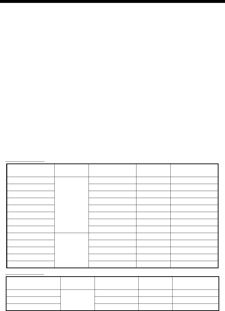
xvii
FOREWORD
Congratulations on your choice of the FURUNO FAR-3xx0 Series Marine Radar. We are confident
you will see why the FURUNO name has become synonymous with quality and reliability.
Since 1948, FURUNO Electric Company has enjoyed an enviable reputation for innovative and
dependable marine electronics equipment. This dedication to excellence is furthered by our ex-
tensive global network of agents and dealers.
This equipment is designed and constructed to meet the rigorous demands of the marine environ-
ment. However, no machine can perform its intended function unless installed, operated and
maintained properly. Please carefully read and follow the recommended procedures for operation
and maintenance.
Features
This radar series meets the requirements of IEC 62388 (Marine navigation and radiocommunica-
tion equipment and systems - Shipborne radar - Performance requirements, method of testing and
required test results) and IMO MSC.192(79), IMO Resolution A.817(19), and IEC 61174. This ra-
dar displays radar targets, electronic charts, nav lines, Tracked Target (TT) data, AIS targets and
other navigation data on a display.
The main features of this series are
• The FAR-3xx0 series consists of the following models and configurations:
Magnetron radar
Solid state radar
*: Viewing distance: 1020 mm
Model Frequency
band
Size of
monitor unit*
Output
power
Transceiver
location
FAR-3210
X-band
19.0” 12 kW Antenna unit
FAR-3210-BB Local supply 12 kW Antenna unit
FAR-3310 23.1” 12 kW Antenna unit
FAR-3220 19.0” 25 kW Antenna unit
FAR-3220-BB Local supply 25 kW Antenna unit
FAR-3320 23.1” 25 kW Antenna unit
FAR-3320W 23.1” 25 kW Transceiver unit
FAR-3220W-BB Local supply 25 kW Transceiver unit
FAR-3230S
S-band
19.0” 30 kW Antenna unit
FAR-3230S-BB Local supply 30 kW Antenna unit
FAR-3330S 23.1” 30 kW Antenna unit
FAR-3330SW 23.1” 30 kW Transceiver unit
FAR-3230SW-BB Local supply 30 kW Transceiver unit
Model Frequency
band
Size of
monitor unit*
Output
power
Transceiver
location
FAR-3230S-SSD
S-band
19.0” 250 W Antenna unit
FAR-3330S-SSD 23.1” 250 W Antenna unit
FAR-3230S-SSD-BB Local supply 250 W Antenna unit

FOREWORD
xviii
• New HMI (Human Machine Interface) gives improved operability.
• Accepts SXGA, UXGA video inputs.
• SOLAS category 1 compatible display (23.1”), SOLAS category 2 compatible display (19.0”).
• Radar, chart and chart radar modes. (The chart radar mode does not meet the criteria for nav-
igation aid for Japanese flag vessels as defined by Japanese law.)
• Many warning features to support safer and more efficient navigation.
• Grounding warnings, safe depth contours.
• Chart database loaded and updated using CD-ROMs.
• Tracked Target (TT) data and AIS data to aid in collision avoidance.
• AIS messaging.
• Route created in chart mode can be displayed on the radar.
• Route planning and route monitoring facilities in the chart mode.
Signal Processing Functions
This radar has the signal processing functions described in the table below. All signal processing
functions are set with the picture preset feature.
Standards Used in this Manual
• Three types of Control Units are available: Radar Control Unit RCU-025 (radar controls with
trackball module), ECDIS Control Unit RCU-024 (alphabet keyboard, controls, trackball mod-
ule) and Trackball Control Unit RCU-026 (trackball module only). Unless noted otherwise, “Con-
trol Unit” refers to the RCU-025.
• The system can be operated with the controls of the Radar Control Unit, ECDIS Control Unit or
a trackball module. The descriptions in this manual use the trackball module.
• Unless noted otherwise, "click" means to push the left button on a trackball module.
• The keys and controls of the Radar Control Unit are shown in bold face; for example, the EN-
TER key.
Signal processing function Description Section
Interference rejector Suppress interference transmitted by other radars. Inter-
ference received simultaneously from many radars can
be difficult to reduce.
2.7
Echo stretch Enlarge target echoes, especially small echoes. Sup-
press interference, sea clutter and rain clutter before us-
ing echo stretch, to prevent the enlargement of unwanted
echoes.
2.8
Echo averaging The radar samples echoes with each scan. Targets that
show a large change with each scan are judged as clutter
and are reduced to display only echoes from legitimate
targets.
2.9
Automatic clutter elimination Discriminate the clutter from the radar echo then reduce
the clutter automatically.
2.10
Noise rejector Reduce the white noise then improves the on-screen S/N
ratio by processing the weighted moving average filter for
the received echoes in the range direction. Use this func-
tion with caution. Weak target echoes may disappear
from the screen or the range resolution may worsen.
2.11

FOREWORD
xix
• The buttons on the InstantAccess bar, Status bar and menu items are shown in brackets; for
example, the [TUNE] button.
• Context-sensitive menus are available with many buttons, and boxes and objects. Right-click
an item to display the related context-sensitive menu.
• This radar is available in three types of specifications: IMO, A, or B. This manual provides the
descriptions for the B type, of which some functions are not available with the IMO or A type.
See the menu tree in Appendix 1 for function availability.
• “C-MAP” means “C-MAP by Jeppesen”.
• The display colors mentioned in this manual are those with the color palette setting “Day-Gray”.
Program Number
Please access the following URL if you need software information:
http://www.furuno.com/en/business_product/merchant/product/chartradar/software.html
xx: Minor change
Virus Prevention
This equipment is not equipped with a virus checker. This equipment operates in real time; there-
fore, having a virus checker that periodically checks the equipment for viruses would increase the
processing load, which can affect operation. However, you can avoid viruses by following the in-
structions in this section.
When you update a chart
The PC and medium (USB flash memory, etc.) used to download and store an update for an ex-
isting chart or a new chart may be infected with a virus. Check the PC and the medium for viruses
with a commercial virus checker - BEFORE you connect them to the ECDIS. Be sure the virus
checker contains the latest virus definition files.
Network connection
The ECDIS receives and displays information from various navigation equipment and radar via a
LAN. A PC and other equipment connected to a network can carry viruses. To prevent the intro-
duction of a virus to the LAN, DO NOT connect the ECDIS or HUB to an external network, includ-
ing other shipboard LAN.
Do not install 3rd party programs in the ECDIS
Programs installed via an external network can carry viruses that can cause the ECDIS to mal-
function. Do not install any Windows® software.
System Program no. Version no. Remarks
Antenna unit
SPU 0359281 01.xx For magnetron radar
SPU 0359286 01.xx For solid state radar
MTR-DRV 0359293 01.xx
PM 0359296 01.xx
RF-Converter 0359302 01.xx For solid state radar
Power supply unit
PSU-Control 0359299 01.xx
Processor Unit: EC-3000
Main 0359266 02.xx
FOREWORD
xx
Open Source Software
This product includes software to be licensed under the GNU General Public License (GPL), GNU
Lesser General Public License (LGPL), BSD, Apache, MIT and others. The program(s) is/are free
software(s), and you can copy it and/or redistribute it and/or modify it under the terms of the GPL
or LGPL as published by the Free Software Foundation. Please access to the following URL if you
need source codes: https://www.furuno.co.jp/cgi/cnt_oss_e01.cgi
This product uses the software module that was developed by the Independent JPEG Group.
Reverse engineering
Reverse engineering (reverse assemble, reverse compiler) of the software of this equipment is
prohibited.
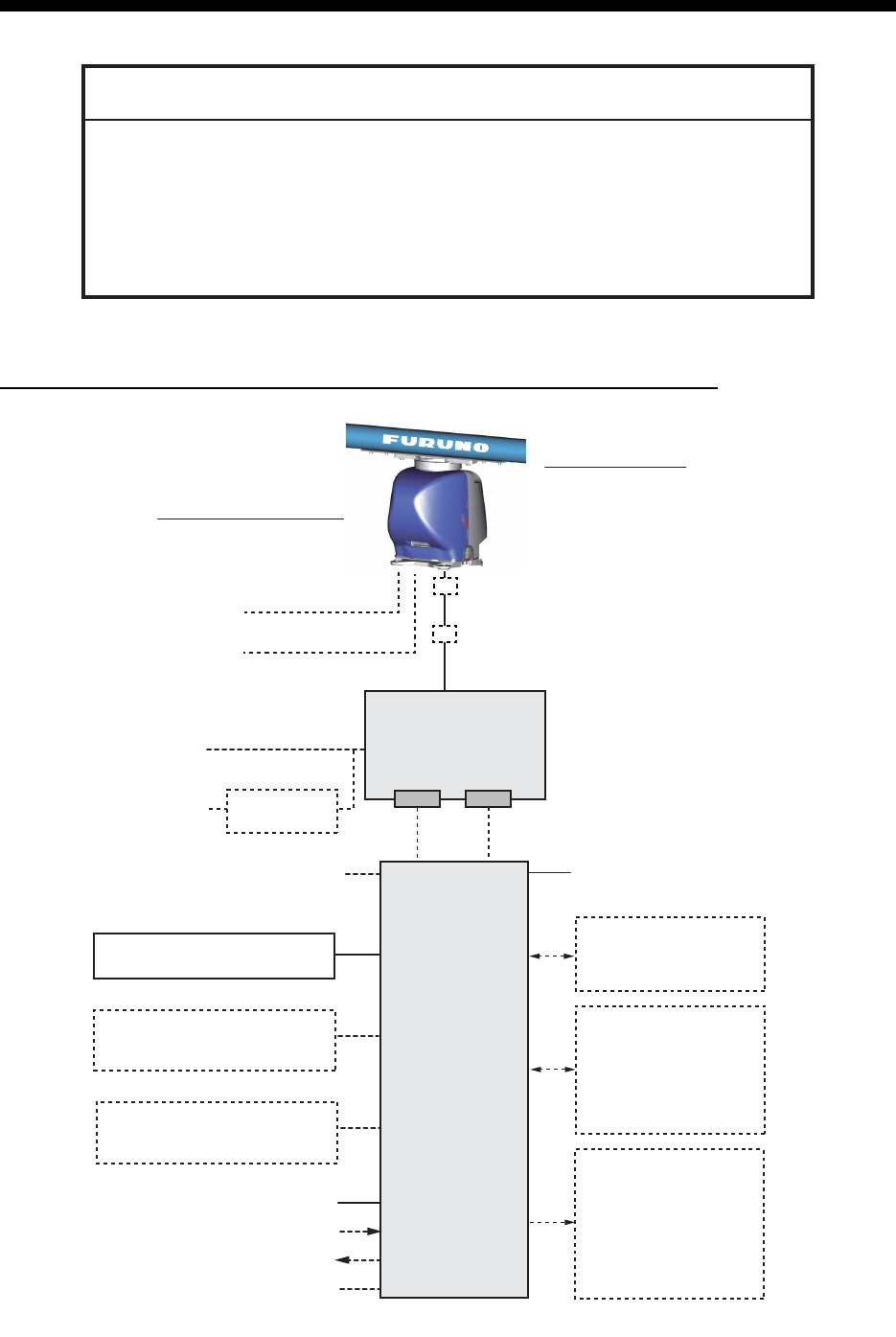
xxi
SYSTEM CONFIGURATIONS
Basic configuration is shown with solid line.
FAR-3210/FAR-3220/FAR-3310/FAR-3320/FAR-3210-BB/FAR-3220-BB
NOTICE
The radar(s) must be interconnected to the following type approved sensors:
Gyrocompass meeting the requirements of the IMO resolution A.424(XI).
EPFS meeting the requirements of the IMO resolution MSC.112(73).
SDME meeting the requirements of IMO resolution MSC.96(72).
The radar may be interconnected via HUB-3000 to other FURUNO processing
units having approved LAN ports.
100-115/220-230 VAC
1ø, 50-60 Hz
PSU-014
POWER SUPPLY
UNIT
EC-3000
PROCESSOR
UNIT
Serial 1, 2
IEC 61162-2
(Gyrocompass*
1
, AIS)
Serial 3 - 7
IEC 61162-1
(EPFS*
2
(Navigator),
SDME
(Speed Log),
Echo Sounder, Wind,
Alarm*
5
, Navtex, etc.)
Digital Out 1 - 6*
5
1: System Fail
2: Power Fail
3: Normal Close 1
4: Normal Close 2
5: Normal Open 1
6: Normal Open 2
100-230 VAC
1ø, 50-60 Hz
Transformer
RU-1803
440 VAC
1ø, 50-60 Hz
Sensor Adapter*
4
or Switching HUB
HUB-100
ANTENNA UNIT
(w/Performance Monitor PM-32A)
XN12CF-RSB-128
XN20CF-RSB-128
XN24CF-RSB-128
TRANSCEIVER UNIT
RTR-105 (12 kW)
RTR-106 (25 kW)
Sub display
LAN Serial
Select one
Select one
Select one
100-115/220-230 VAC
1ø, 50-60 Hz
(for de-icer)
Radar Control Unit RCU-025
Trackball Control Unit RCU-026
ECDIS Control Unit RCU-024
Radar Control Unit RCU-025
Trackball Control Unit RCU-026
ECDIS Control Unit RCU-024
Radar Control Unit RCU-025
Trackball Control Unit RCU-026
Monitor Unit MU-190*
3
MU-231*
3
Digital In (ACK IN)
VDR
Intelligent Hub HUB-3000
*
: See the notes on page xxvi.
Junction box
*
6
RJB-001
Junction box
*
6
RJB-001
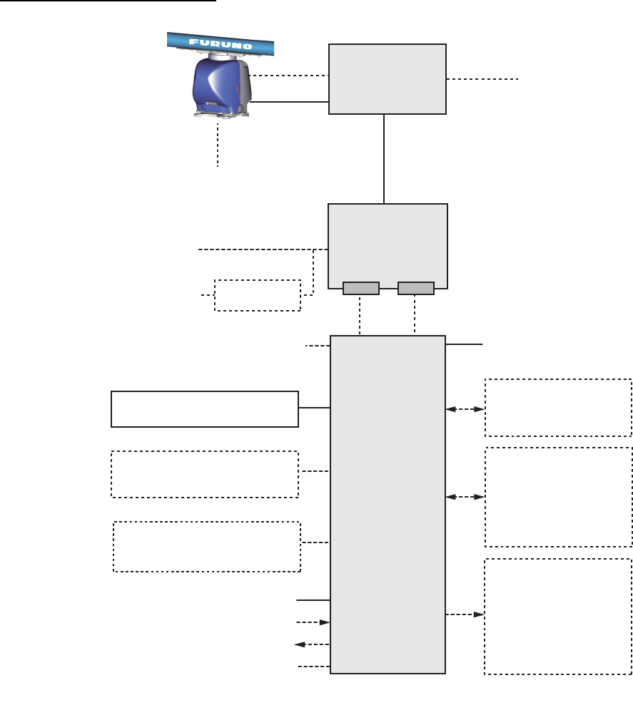
SYSTEM CONFIGURATIONS
xxii
FAR-3320W/FAR-3220W-BB
100-115/220-230 VAC
1ø, 50-60 Hz
Serial 1, 2
IEC 61162-2
(Gyrocompass
*
1
, AIS)
Serial 3 - 7
IEC 61162-1
(EPFS
*
2
(Navigator),
SDME
(Speed Log),
Echo Sounder, Wind,
Alarm
*
5
, Navtex, etc.)
Digital Out 1 - 6
*
5
1: System Fail
2: Power Fail
3: Normal Close 1
4: Normal Close 2
5: Normal Open 1
6: Normal Open 2
100-230 VAC
1ø, 50-60 Hz
Transformer
RU-1803
440 VAC
1ø, 50-60 Hz
Sensor Adapter
*
4
or Switching HUB
HUB-100
ANTENNA UNIT
(w/Performance Monitor
PM-32A)
XN20CF-RSB-130
XN24CF-RSB-130
Sub display
EC-3000
PROCESSOR
UNIT
PSU-014
POWER
SUPPLY UNIT
LAN Serial
Select one
Select one
Select one
TRANSCEIVER
UNIT
RTR-108
100-115/220-230 VAC
1ø, 50-60 Hz (for de-icer)
Waveguide
Antenna Cable
Radar Control Unit RCU-025
Trackball Control Unit RCU-026
ECDIS Control Unit RCU-024
Radar Control Unit RCU-025
Trackball Control Unit RCU-026
ECDIS Control Unit RCU-024
Radar Control Unit RCU-025
Trackball Control Unit RCU-026
Monitor Unit MU-231
*
3
Digital In (ACK IN)
VDR
Intelligent Hub HUB-3000
*
: See the notes on page xxvi.

SYSTEM CONFIGURATIONS
xxiii
FAR-3230S/FAR-3330S/FAR-3230S-BB
100-115/220-230 VAC
1ø, 50-60 Hz
EC-3000
PROCESSOR
UNIT
Serial 1, 2
IEC 61162-2
(Gyrocompass
*
1
, AIS)
Serial 3 - 7
IEC 61162-1
(EPFS
*
2
(Navigator),
SDME
(Speed Log),
Echo Sounder, Wind,
Alarm
*
5
, Navtex, etc.)
Digital Out 1 - 6
*
5
1: System Fail
2: Power Fail
3: Normal Close 1
4: Normal Close 2
5: Normal Open 1
6: Normal Open 2
100-230 VAC
1ø, 50-60 Hz
Transformer
RU-1803
440 VAC
1ø, 50-60 Hz
Sensor Adapter
*
4
or Switching HUB
HUB-100
ANTENNA UNIT
(w/Performance Monitor PM-52A)
SN36CF-RSB-129
TRANSCEIVER UNIT
RTR-107
Sub display
Antenna Cable
LAN Serial
Select one
Select one
Select one
PSU-014 or PSU-015
POWER SUPPLY
UNIT
100-115/220-230 VAC
1ø, 50-60 Hz
(for de-icer)
Radar Control Unit RCU-025
Trackball Control Unit RCU-026
ECDIS Control Unit RCU-024
Radar Control Unit RCU-025
Trackball Control Unit RCU-026
ECDIS Control Unit RCU-024
Radar Control Unit RCU-025
Trackball Control Unit RCU-026
Monitor Unit MU-190
*
3
MU-231
*
3
Digital In (ACK IN)
VDR
Intelligent Hub HUB-3000
*
: See the notes on page xxvi.
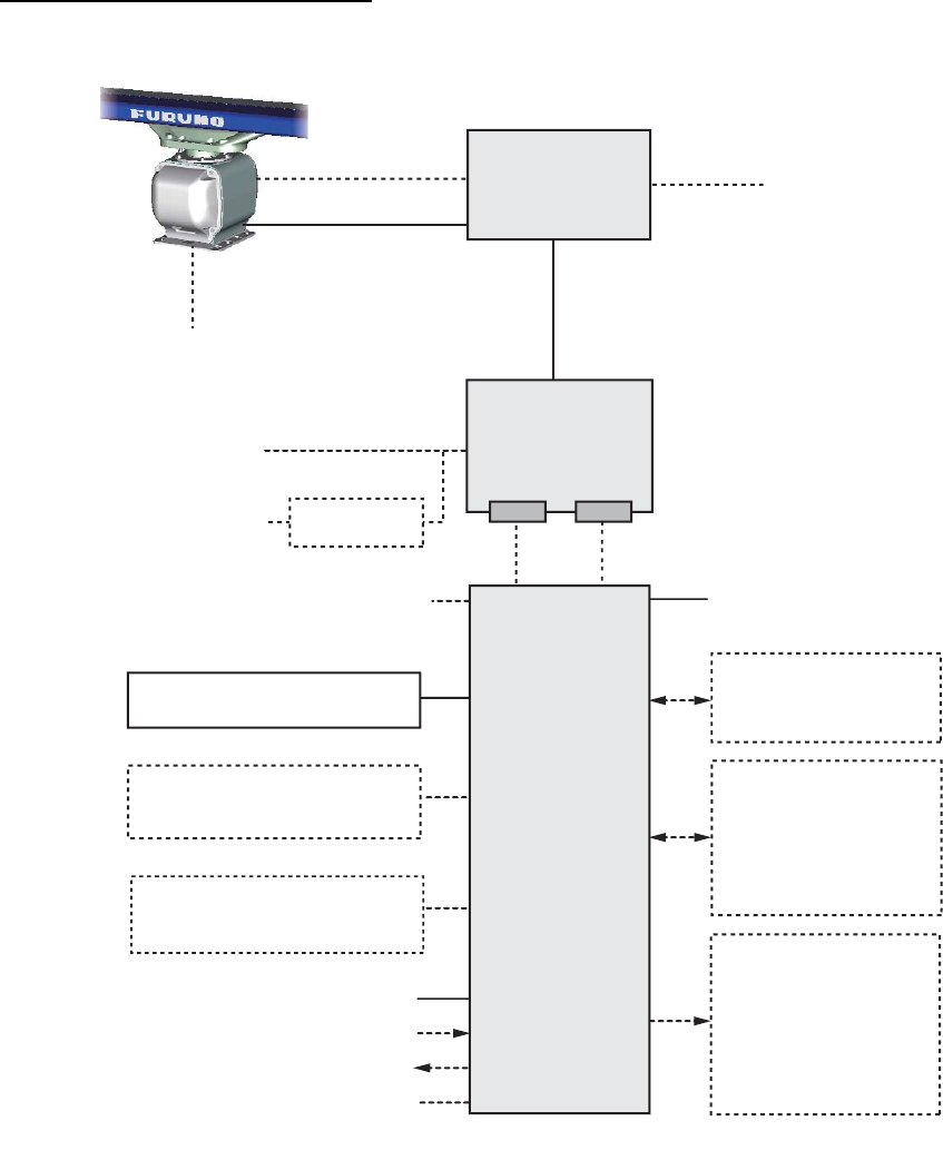
SYSTEM CONFIGURATIONS
xxiv
FAR-3330SW/FAR-3230SW-BB
100-115/220-230 VAC
1ø, 50-60 Hz
Serial 1, 2
IEC 61162-2
(Gyrocompass*
1
, AIS)
Serial 3 - 7
IEC 61162-1
(EPFS*
2
(Navigator),
SDME
(Speed Log),
Echo Sounder, Wind,
Alarm*
5
Navtex, etc.)
Digital Out 1 - 6*
5
1: System Fail
2: Power Fail
3: Normal Close 1
4: Normal Close 2
5: Normal Open 1
6: Normal Open 2
100-230 VAC
1ø, 50-60 Hz
Transformer
RU-1803
440 VAC
1ø, 50-60 Hz
Sensor Adapter*
4
or Switching HUB
HUB-100
ANTENNA UNIT (w/Performance Monitor PM-52A)
SN36CF-RSB-131
Sub display
EC-3000
PROCESSOR
UNIT
LAN Serial
PSU-014 or PSU-015
POWER SUPPLY
UNIT
Select one
Select one
Select one
TRANSCEIVER
UNIT
RTR-109
100-115/220-230 VAC
1ø, 50-60 Hz
(for de-icer)
Coaxial cable
Antenna Cable
Radar Control Unit RCU-025
Trackball Control Unit RCU-026
ECDIS Control Unit RCU-024
Radar Control Unit RCU-025
Trackball Control Unit RCU-026
ECDIS Control Unit RCU-024
Radar Control Unit RCU-025
Trackball Control Unit RCU-026
Monitor Unit MU-231*
3
Digital In (ACK IN)
VDR
Intelligent Hub HUB-3000
*
: See the notes on page xxvi.
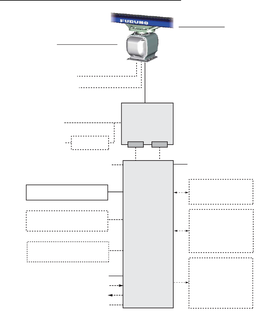
SYSTEM CONFIGURATIONS
xxv
FAR-3230S-SSD/FAR-3330S-SSD/FAR-3230S-SSD-BB
100-115/220-230 VAC
1ø, 50-60 Hz
PSU-016 or PSU-018
POWER SUPPLY
UNIT
EC-3000
PROCESSOR
UNIT
Serial 1, 2
IEC 61162-2
(Gyrocompass*1, AIS)
3Serial 3 - 7
IEC 61162-1
(EPFS*2 (Navigator),
SDME (Speed Log),
Echo Sounder, Wind,
Alarm*5, Navtex, etc.)
Digital Out 1 - 6*5
1: System Fail
2: Power Fail
3: Normal Close 1
4: Normal Close 2
5: Normal Open 1
6: Normal Open 2
100-230 VAC
1ø, 50-60 Hz
Transformer
RU-1803
440 VAC
1ø, 50-60 Hz
Sensor Adapter*4 or Switching HUB
HUB-100
ANTENNA UNIT
(w/Performance Monitor PM-52B)
SN36CF-RSB-133
TRANSCEIVER UNIT
RTR-111
Sub display Antenna Cable
LAN Serial
Select one
Select one
Select one
100-115/220-230 VAC
1ø, 50-60 Hz
(for de-icer)
Radar Control Unit RCU-025
Trackball Control Unit RCU-026
ECDIS Control Unit RCU-024
Radar Control Unit RCU-025
Trackball Control Unit RCU-026
ECDIS Control Unit RCU-024
Radar Control Unit RCU-025
Trackball Control Unit RCU-026
Monitor Unit MU-190
*3 MU-231*3
Digital In (ACK IN)
VDR
Intelligent Hub HUB-3000
*
: See the notes on page xxvi.

SYSTEM CONFIGURATIONS
xxvi
Category of units
Antenna units: Exposed to the weather
Other units: Protected from the weather
Notes
1. The gyrocompass must be type approved for compliance with IMO resolution A.424(XI) (and/
or resolution A.821(19) for installation on HSC). The gyrocompass must also have an update
rate that is adequate for the ship’s rate of turn. The update rate must be better than 40 Hz
(HSC) or 20 Hz (conventional vessel).
2. The EPFS must be type approved for compliance with IMO resolution MSC.96(72).
3. These monitors have been approved by the IMO, MU-190 for CAT 2C and CAT 2HC, MU-231
for CAT 1C and CAT 1HC. If a different monitor is to be used on IMO vessels, its effective
diameter must meet the applicable Category requirements:
• CAT 1C and CAT 1HC: effective diameter 320 mm or higher
• CAT 2C and CAT 2HC: effective diameter 250 mm or higher
For installation, operation and viewing distance of other monitor, see its manuals.
For BB type, a monitor unit is prepared by user.
4. The sensor adapters are Control Serial MC-3000S, Analog IN MC-3010A, Digital IN
MC-3020D and Digital OUT MC-3030D.
5. Characteristics of contact output for Alarm:
• (Load current) 250 mA
• (Polarity) Normally Open: 2 ports, Normally Close: 2 ports
• Serial I/O for alarm is also possible, which complies with IEC 61162-1.
6. Junction boxes are required for antenna cable length greater than 100 m. Max. cable length
is 400 m.
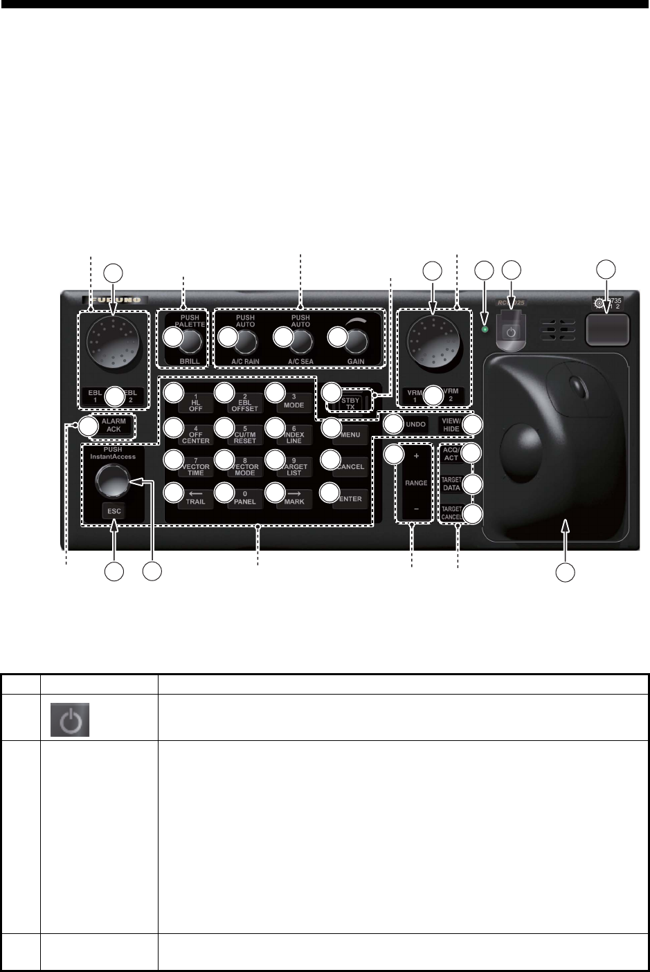
1-1
1. OPERATIONAL OVERVIEW
1.1 Units of the System
1.1.1 Radar Control Unit RCU-025
The Radar Control Unit RCU-025 consists of various controls and a trackball module
(trackball, scrollwheel and left and right buttons). The trackball module functions like
a PC mouse. The user rolls the trackball and operates the left and right buttons and
the scrollwheel to do various functions.
When you press the correct key, a single beep sounds to alert you to correct opera-
tion. For wrong operation, several beeps sound. You can select the loudness of the
beep or deactivate the beep on the [Customize] menu.
No. Control Description
1 Turns the system on or off. (With a FURUNO monitor unit, the monitor is
also turned on or off with this switch.)
2 Status LED The color and state of the LED change according to system or alert status.
Green, lighting: Normal operation status; no alerts generated.
Green, flashing: The heater on the CPU board is on, because ambient
temperature is not at least 0°C. The heater takes about two minutes to
warm the equipment. The LED lights green after the heater goes off.
Red, lighting: Acknowledged alert or SYSTEM FAIL. SYSTEM FAIL oc-
curs when there is trouble in the Processor Unit or communication failure
between the Processor Unit and a Control Unit. Each Control Unit detects
trouble and its lamp flashes in red and the buzzer sounds. If this condition
occurs at the No. 1 Control Unit, the SYSTEM FAIL signal is output.
Red, flashing: Unacknowledged alert or SYSTEM FAIL.
3
4
Rotary control,
EBL1, EBL2
Rotary control: Adjusts the active EBL.
EBL1, EBL2: Activates or deactivates the respective EBL.
4
4
8
8
9
9
10
10
11
11
12
12
13
13
14
14
16
16
17
17
18
18
20
20
21
21
22
22
23
23
24
24
25
25
26
26
27
27
29
29
30
30
37
37
1
1
2
2
28
28
3
3
36
36
32
32
15
15
5
5
33
33
34
34
35
35
19
19
31
31
7
7
6
6
Navigation tool
Display control
Radar signal processing
Radar system
Navigation tool
Target
Range
A
lert Menu control

1. OPERATIONAL OVERVIEW
1-2
5 ALARM ACK • Acknowledges unacknowledged alert.
• Silences the audio alarm.
6 InstantAccess
knob
Selects the buttons on the InstantAccess bar.
7 ESC Goes back one step in current operating sequence on the InstantAccess
bar.
8BRILL Rotate: Adjusts the brilliance of the display (FURUNO-supplied monitor
only).
Push: Selects a color palette.
9 A/C RAIN Rotate: Suppresses rain clutter.
Push: Toggles between manual and automatic rain clutter adjustment.
10 A/C SEA Rotate: Suppresses sea clutter.
Push: Toggles between manual and automatic sea clutter adjustment.
11 GAIN Adjusts the sensitivity of the radar receiver.
12 HL OFF • Temporarily erases everything except radar echoes when pressed and
held down.
• Enters the numeric 1.
• Selects like-numbered menu item.
13 EBL OFFSET • Activates or deactivates the offset EBL.
• Enters the numeric 2.
• Selects like-numbered menu item.
14 MODE • Selects a presentation mode.
• Enters the numeric 3.
• Selects like-numbered menu item.
15 STBY/TX Toggles the radar between standby and TX.
16 OFF CENTER • Puts sweep origin at the cursor location.
• Enters the numeric 4.
• Selects like-numbered menu item.
17 CU/TM RESET • Course-up: Resets heading line to 000°.
• True motion: Moves own ship position 75% of the radius in stern direc-
tion.
• Enters the numeric 5.
• Selects like-numbered menu item.
18 INDEX LINE • Selects an index line (in the PI line box).
• Long-press to activate or deactivate selected index line.
• Enters the numeric 6.
• Selects like-numbered menu item.
19 MENU Opens, closes the menu.
20 VECTOR TIME • Sets the vector time (length) for TT and AIS targets.
• Enters the numeric 7.
• Selects like-numbered menu item.
21 VECTOR
MODE
• Sets the vector mode (relative, true) for TT and AIS targets.
• Enters the numeric 8.
• Selects like-numbered menu item.
22 TARGET LIST • Displays AIS, TT data in the target list.
• Enters the numeric 9.
• Selects like-numbered menu item.
23 CANCEL Cancels the changes made on the currently selected menu.
24 TRAIL • Goes back one page in the menu.
• Moves cursor leftward in text box.
• Turns the echo trail display on or off.
• Long-press to reset all trails.
No. Control Description

1. OPERATIONAL OVERVIEW
1-3
25 PANEL • Adjusts the backlighting of the keys.
• Enters the numeric 0.
• Selects like-numbered menu item.
26 MARK • Goes forward one page in the menu.
• Moves cursor rightward in text box.
• Inputs selected mark on the radar screen, at the position selected.
27 ENTER Confirms selection on menu.
28
29
Rotary control,
VRM1, VRM2
Rotary control: Adjusts the diameter of the active VRM.
VRM1, VRM2: Activates or deactivates the respective VRM.
30 UNDO Undoes edit or text input when creating a radar map, route, user chart.
31 VIEW/HIDE Radar mode, chart radar mode: Shows or hides the AZ box, Drop mark
boxes, Mark box, PI line box, Trial box.
Chart mode: Shows or hides the EBLs, InstantAccess bar, [Overlay/NAV
Tools] box, [Route information] box, VRMs.
32 RANGE Selects radar range (radar and chart radar modes), chart scale (chart
mode).
33 ACQ/ACT • TT: Acquires cursor-selected target, for target tracking.
• AIS: Activates cursor-selected sleeping AIS target.
34 TARGET DATA Displays the detailed data for selected TT, AIS target, in the TT/AIS infor-
mation box.
35 TARGET
CANCEL
• TT: Stops tracking cursor-selected tracked target.
• AIS: Sleeps cursor-selected activated AIS target.
• Long-press to erase all displayed TT target data.
36 Trackball
module
The trackball module is the same as that used in the Trackball Control Unit
RCU-026. See the description in the next section.
37 USB port For connection of USB flash memory (FAT16 or FAT32 format). Do not con-
nect a USB HDD or PC keyboard. The DVD drive (Maker: TEAC, Type: PU-
DRV10) is for chart updates.
No. Control Description
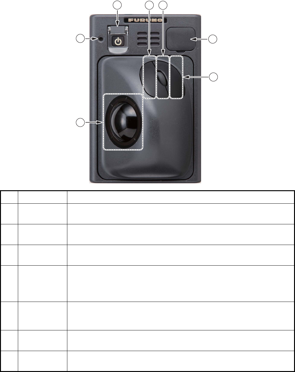
1. OPERATIONAL OVERVIEW
1-4
1.1.2 Trackball Control Unit RCU-026
The Trackball Control Unit RCU-026 has a power switch, a trackball module (trackball,
scrollwheel and left and right mouse buttons), a status LED, and a USB port. The
trackball module functions like a PC mouse; the user rolls the trackball and operates
the left and right buttons and the scrollwheel to do various functions.
No. Control Description
1 Power switch Turns the system on or off. (With a FURUNO monitor unit, the monitor is also
turned on or off with this switch.)
2 Status LED The color and state of the LED change according to system or alert status.
See the Status LED description on page 1-1.
3 Left button • Does the operation related to the object selected.
• Confirms the operation done for the object selected.
4 Scrollwheel • Selects menu options.
• Selects chart scale.
• Sets numeric data.
(The scrollwheel does not have a "push" function.)
5 Right button • Displays context-sensitive menu when the cursor is put in the display
area.
• Cancels operation done on the object selected.
6 Trackball • Moves the cursor.
• Selects an object.
7 USB port For connection of USB flash memory (FAT16 or FAT32 format). Do not con-
nect a USB HDD or PC keyboard.
1
1
3
3
6
6
7
7
4
4
5
5
2
2
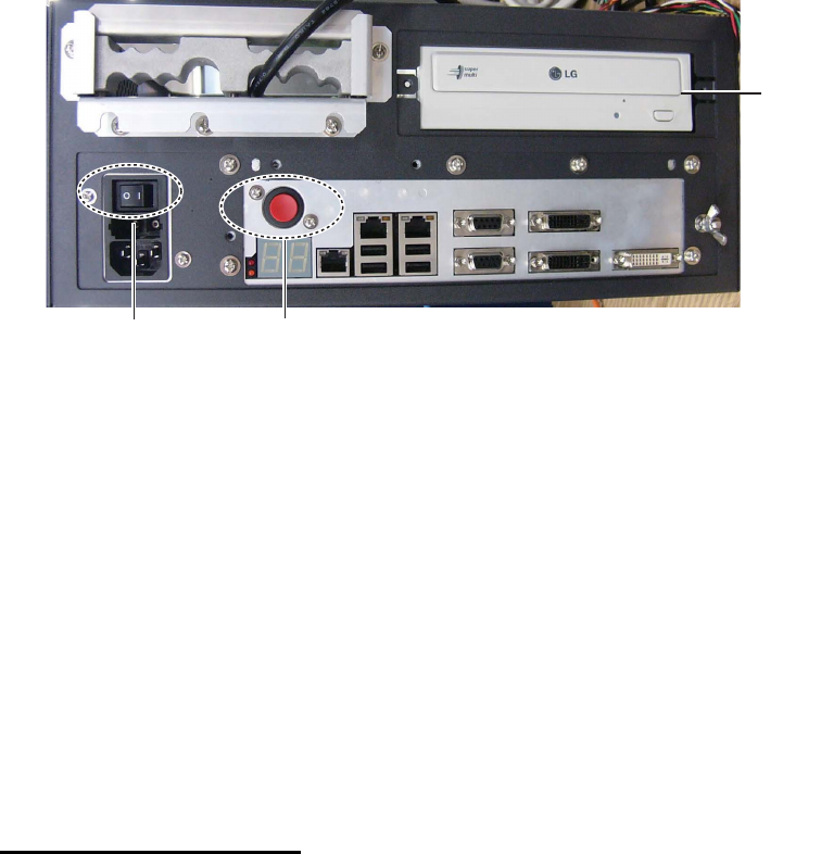
1. OPERATIONAL OVERVIEW
1-5
1.1.3 Processor Unit EC-3000
The Processor Unit is the heart of the chart system, and is mainly responsible for the
chart management, route planning and route navigation.
The Processor Unit has two power switches. The Mains switch controls the power
from the switchboard, and the Power switch controls the power to the chart radar sys-
tem.
Note 1: Do not operate the chart radar with a DVD or CD inserted in the DVD drive,
to prevent damage to the drive and media. Remove media from the drive after usage.
Insert media only to update charts. After completion of an update, remove the media
from its drive and store it in its case. Store media out of direct sunlight, in a place
where temperature and humidity are moderate and stable.
Note 2: To keep the system stable, restart the unit at least once every two weeks.
Note 3: Close the lid of the DVD drive when the drive is not in use.
1.2 How to Turn the System On/Off
Normally, leave the power switches at the front of the Processor Unit on and control
the power with the power switch on a Control Unit (RCU-025, RCU-026). The monitor
unit is powered independently.
How to power the system
Push the mains switch on the Processor Unit for the "I" position. Turn on the power
switch on the Processor Unit or a Control Unit. The start-up display appears on the
monitor.
After the power is applied, the program starts up and about one minute later the bear-
ing scale appears. The radar then goes into three minutes of warm-up time to warm
the magnetron, which transmits radar pulses. The timer at the center of the screen
counts the time remaining for warm-up. When the timer shows 0:00, the indication
"ST-BY" appears at the screen center. The radar is now ready to transmit radar puls-
es. In the stand-by condition, no radar pulses are transmitted and TT nor AIS is active.
The settings on the menus are stored in a non-volatile memory (hard disk) and are
preserved when the power is turned off.
Note 1: The solid state radar does not have a magnetron, therefore it has no warming
period.
Power switch
DVD
drive
Mains switch
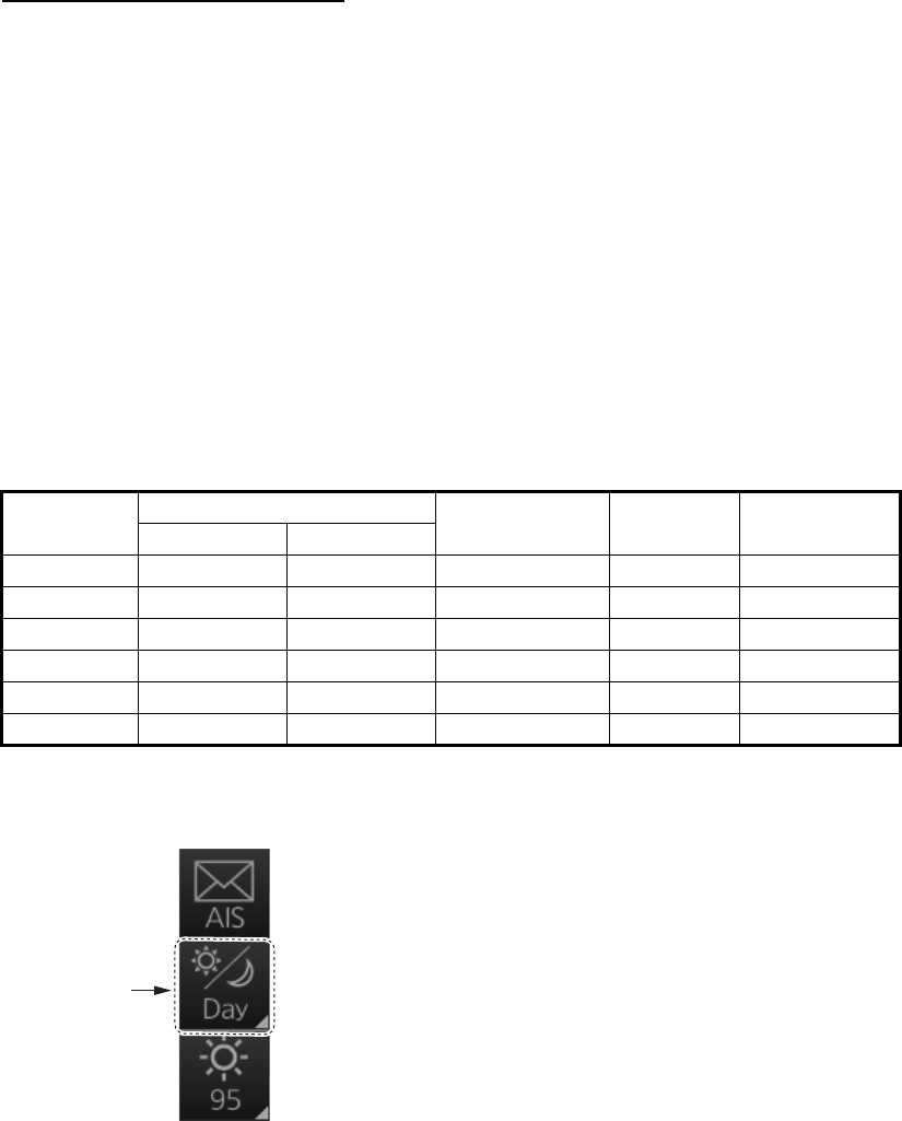
1. OPERATIONAL OVERVIEW
1-6
Note 2: If the ambient temperature is less than 0°C (32°F) when the power is applied,
nothing appears on the display and the Status LED on the Control Unit flashes. This
is because the heater is warming the unit. The display appears in approx. two minutes.
How to power off the system
Press the power switch on the Processor Unit or a Control Unit. Push the Mains switch
for the "O" position.
Note: Provided that the radar was once in use with the transmitter tube (magnetron)
still warm, you can put the radar in transmit state without three minutes of warm-up. If
the Power switch was turned off by mistake or the like and you wish to restart the radar
promptly, turn on the Power switch not later than 10 seconds after power-off.
1.3 How to Select a Color Palette
This radar provides three sets of color and brilliance sets (palette), day, dusk and
night, to match any ambient lighting condition. The default specifications of each pal-
ette are as shown in the table below. The panel dimmer setting is automatically
changed, and the number of steps depends on the color palette selected.
To select a palette, do the following:
1. Click the [Palette] button.
Palette Brilliance Panel dimmer
(step)
Text
color
Background
color
MU-190 MU-231
Day-gray 86 88 15 White Gray
Day-blue 86 88 15 White Blue
Dusk-gray 77 79 7 Light gray Dark gray
Dusk-blue 77 79 7 Light gray Dark blue
Night-gray 53 53 3 Orange Dark gray
Night-blue 53 53 3 Light gray Dark blue
[Palette]
button
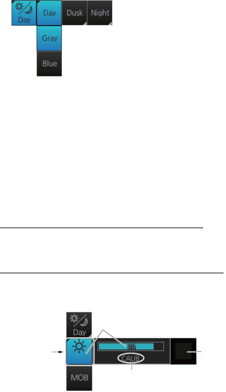
1. OPERATIONAL OVERVIEW
1-7
2. Click [Day], [Dusk] or [Night] as appropriate. For example, select [Day] to show its
options.
3. Click the palette (gray, blue) desired.
Note: A palette can also be selected by pushing the BRILL control on the Control Unit.
1.4 How to Adjust the Display Brilliance (FURUNO
monitor)
The brilliance setting is defined according to the color palette setting (see section 1.3).
However, manual adjustment of the brilliance is also possible.
Note 1: The brilliance of the FURUNO monitor can only be adjusted from the Control
Unit. Use a serial cable for brilliance adjustment to make the connection between the
Processor Unit and the Control Unit.
Note 2: Improper brilliance may affect the visibility of information, especially on the
night display.
How to adjust the brilliance manually with the BRILL control
Operate the BRILL control to adjust brilliance. Turn it clockwise to increase the bril-
liance; counterclockwise to decrease the brilliance. Watch the brilliance level indica-
tion on the [BRILL] button (see the illustration below) to see the current brilliance level.
How to adjust the brilliance manually with the InstantAccess knob
1. Push the InstantAccess knob.
2. Rotate the knob to select the [BRILL] button then push the knob to show the bril-
liance adjustment window.
3. Push the knob, rotate the knob to set the brilliance then push the knob to confirm
the setting. The calibration state indication changes to "UNCALIB".
4. To restore the default setting, rotate the knob to select the [CALIB] button then
push the knob. The calibration state indication changes to "CALIB".
86
Current brilliance level
[CALIB]
button
[BRILL]
button
Calibration state
CALIB: Default setting
UNCALIB: Manual setting

1. OPERATIONAL OVERVIEW
1-8
How to adjust the brilliance manually using the trackball module
1. Click the [BRILL] button on the InstantAccess bar to show the brilliance adjust-
ment window.
2. For coarse adjustment, put the cursor on a location within the slider bar area
then push the left button. For fine adjustment, put the cursor on the end of the
slider bar and roll the trackball while holding down the left button.
3. Release the left button to confirm setting. The calibration state indication changes
to "UNCALIB".
4. To restore the default setting, click the [CALIB] button. The calibration state indi-
cation changes to "CALIB".
1.5 Operating Modes
This chart radar has the following operating modes:
1.5.1 How to select an operating mode
Click the [Operating Mode] button to select desired mode from the pull-down list. Se-
lect [RADAR] for the radar or chart radar mode or [CHART for RADAR] for the chart
mode.
1.5.2 Limitations when using the chart radar mode
The presentation mode for the chart radar mode can be course-up RM, north-up RM,
or north-up TM. The presentation mode is automatically switched to north-up RM if the
mode is head-up at the time the chart radar mode is selected.
• [RADAR]: - The radar mode provides the traditional radar display.
- The chart radar mode overlays the electronic chart on the radar image.
• [CHART for RADAR]: The chart mode shows the electronic charts.
[Operating Mode]
button
RADAR
RADAR
CHART
for RADAR
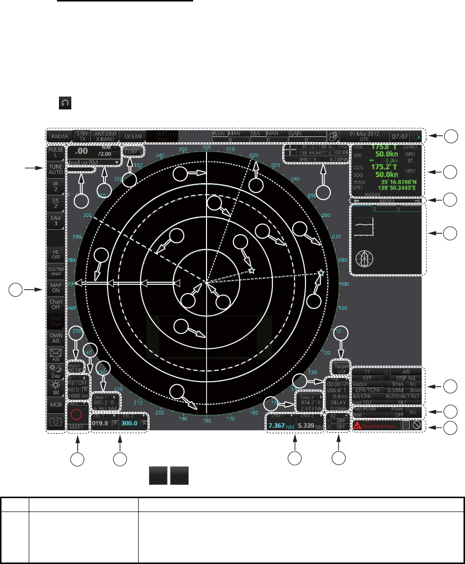
1. OPERATIONAL OVERVIEW
1-9
1.6 Display Screens
All display screens have operational buttons, boxes and indications, and display mark-
ers. Click a button or indication to execute the related operation. Context-sensitive
menus are available with several boxes and objects. Right-click the appropriate box
or object to show the related context-sensitive menu.
Monitor viewing distance
The optimal viewing distance for the FURUNO-supplied monitors is 1020 mm.
1.6.1 Radar display
The illustration below shows the markers, data, etc. as they appear on the FURUNO
19-inch monitor unit. The layout for the 23-inch monitor unit is partially different - the
button appears on the bottom of the InstantAccess bar.
No. Name Description
1 Status bar • Selects an antenna.
• Selects the operating mode.
• Adjusts the radar picture.
• Displays radar operational messages. See section 1.7.
Depth : 22.5 m
Water
TEMP : 10.5°C
REL : 006.3°R
Wind : 12.1 m/s
Current : 121.3°R
1.7 kn
NAV data Route 1 Route 2
N
E
S
W
0
10
20
30
40
50
-30 -20 -10 min m
Indication
area
*
*: For solid state radar,
TX CH
1
TX CH
2
OFF
18
18
14
14
13
13
8
8
9
9
5
5
6
6
7
7
1
1
2
2
3
3
4
4
1515
16
1717
34
33
3232 31
35
2626
1919
20
2121 22
2323
2525
24
29
28 27
3030
1010
11
1212
ACE
6

1. OPERATIONAL OVERVIEW
1-10
2 Sensor information,
datum box
Shows your ship's heading, heading source, ship's speed, water
tracking speed, speed source, course over ground, speed over
ground, course and speed source, ship's position, position source,
chart datum.
Note: Position source shall meet the requirements of IMO
MSC.112(73).
3 Menu Drop-down menu with various radar and chart functions.
4 Information box Provides various navigation data and route information.
5 TT/AIS setting box Sets the parameters for TT and AIS targets.
6 Trail box Sets the parameters for the target trails.
7 Alert box Shows alert messages by alert name and alert number.
• Unacknowledged or regenerated alerts flash in red (alarm) or yel-
low-orange (warning).
• Acknowledged alerts are shown in normal video.
8 Acquisition zone box Sets an acquisition zone for TT, AIS.
9 VRM boxes Shows the range and TTG to the VRM1, VRM2.
10 Target list button Displays the TT and AIS target list.
11 Trial maneuver box Sets the parameters for the trial maneuver.
12 Drop mark 2 box Shows the bearing and range to the drop mark 2.
13 EBL boxes Shows the bearing to the EBL1, EBL2.
14 Mark box Selects the mark to inscribe on the radar display.
15 Drop mark1 box Shows the bearing and range to the drop mark 1.
16 PI line box • Adjusts the direction and width of the parallel index lines.
• Activates or deactivates the parallel index lines.
17 Watch box Counts down the time remaining until the buzzer sounds to alert the
operator to view the radar picture.
18 InstantAccess bar Quick access to often-used radar, chart radar and chart functions. For
radar and chart radar functions, see section 1.8. For chart functions,
see paragraph 6.1.3.
19 Tuning bar Shows tuning status. (No function with solid state radar.)
20 Range/Presentation
mode box
• Selects the radar range.
• Selects the presentation mode.
21 REF point box Selects the reference point (antenna or CCRP) for measurements
(range, bearing, etc.) and markers (position, etc.)
22 Heading line Indicates ship's heading.
23 Bearing scale The bearing scale provides an estimate of the bearing to a target.
24 Cursor position box This box shows
• Latitude and longitude of the cursor position.
• Range and bearing to the cursor position.
• TTG to the cursor position.
25 EBL1 Measures the bearing to a target.
26 EBL2
27 VRM1 Measures the range to a target.
28 VRM2
29 Drop mark 1 Finds the range and bearing to drop mark position.
30 Drop mark 2
31 Antenna marker A cross marks antenna position.
32 Own ship marker An inverted “T” marks your ship’s position.
33 Stern marker Marks location of stern.
34 North marker Marks North.
35 Range rings Provide an estimate of the range to a target.
No. Name Description
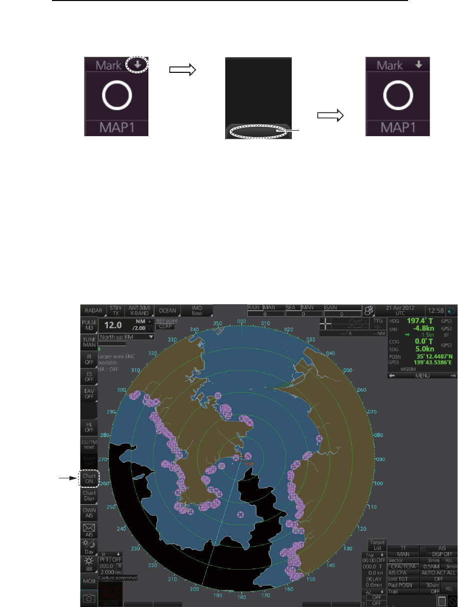
1. OPERATIONAL OVERVIEW
1-11
How to minimize, maximize the boxes at the bottom of the screen
The boxes at the bottom of the screen that contain an arrow can be minimized. Click
the arrow to minimize the box. To restore maximum size, click the minimized box.
Example: Mark box
Note: The respective VRM or EBL is erased from the screen when the corresponding
VRM or EBL box is minimized.
1.6.2 Chart radar display
The chart radar display overlays an electronic chart on the radar picture. To switch be-
tween the radar and chart radar displays, click the [Chart ON/OFF] button on the In-
stantAccess bar.
Click arrow
to minimize.
Click here to
maximize.
Click to hide,
show chart.
OFF
ACE
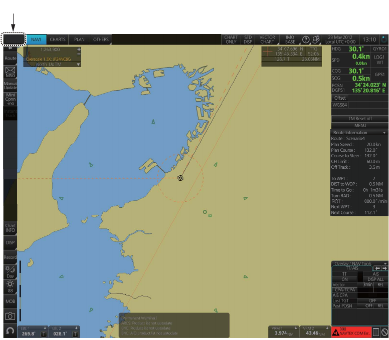
1. OPERATIONAL OVERVIEW
1-12
1.6.3 Chart display
The chart display shows only the electronic chart. Click the [Operating Mode] button
to select [CHART for RADAR] to activate this display. See chapter 6 for a description
of the chart display.
Select [CHART for RADAR].
CHART
for RADAR
0.5NM 4min
AUTO ACT FILT
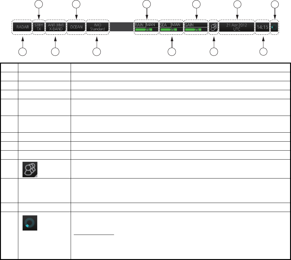
1. OPERATIONAL OVERVIEW
1-13
1.7 Status Bar
The Status bar is displayed at the top of screen in all modes. This bar provides, in the
radar and chart radar modes, buttons for selection of the mode, antenna and chart da-
tabase, and adjustment of the radar picture.
For a description of the Status bar used in the chart mode, see paragraph 6.1.2.
1.7.1 Status bar for radar, chart radar mode
*: The indication is grayed out when the Automatic Clutter Elimination (ACE) function
is [ON].
No. Button name Description
1 Operating Mode Selects a mode: RADAR or CHART for RADAR.
2 STBY TX Toggles the radar between stand-by and transmit.
3 Antenna Selects an antenna.
4Customize
Echo
Presets the radar controls for specific navigation purpose; for example,
congested waters.
5 Chart database Selects the IMO chart database (base, primary, standard or all). Available
in the chart radar mode.
6 RAIN* Reduces rain clutter.
7 SEA* Reduces sea clutter.
8 GAIN Adjusts the gain of the radar receiver.
9 Settings Manages user profiles; opens the Settings menu.
10 Date • Displays the date.
• Selects the time to use, local or UTC.
• Sets the time difference between local and UTC (to use local time).
11 Time Displays the time, local or UTC.
12 Working
Indicator
Rotates clockwise if the system is working properly.
Picture freeze
If the picture freezes, the picture is not updated. After the picture freezes,
the buzzer sounds and the Status LED blinks in red. Reset the power to re-
store normal operation.
1
12
11
10
2
3
46
7
8
9
5
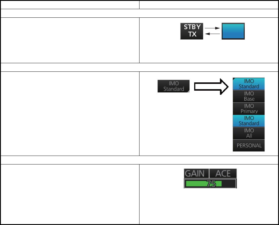
1. OPERATIONAL OVERVIEW
1-14
1.7.2 How to operate the buttons, slider bars on the Status bar
The Status bar has three types of controls: toggle button, drop-down list button and
slider bar. You operate the buttons and bars with the trackball module.
Control type Example of control
Toggle button
A toggle button alternately selects one of two
functions assigned to a button. For example, the
[STBY TX] button toggles the radar between
stand-by and TX. The background color of the
[STBY TX] button momentarily changes to light-
blue when switching from stand-by to TX.
Drop-down list button
A drop-down list button provides a list from which
to select an option related to the label on the but-
ton. A drop-down list button is identified by a tri-
angle on the button’s bottom-right corner. The
[Chart database] button, shown in the right figure,
is an example of a drop-down list button.
Slider bar
The slider bars provide for adjustment of the ra-
dar picture. [RAIN], [SEA] and [GAIN] are slider
bar buttons. To adjust the bar coarsely, put the
cursor at any location within the slider bar area
then push the left button. For fine adjustment, put
the cursor at the end of the slider bar and roll the
trackball while holding down the left button. Re-
lease the button to finish.
STBY
TX
Click button to show
drop-down list.
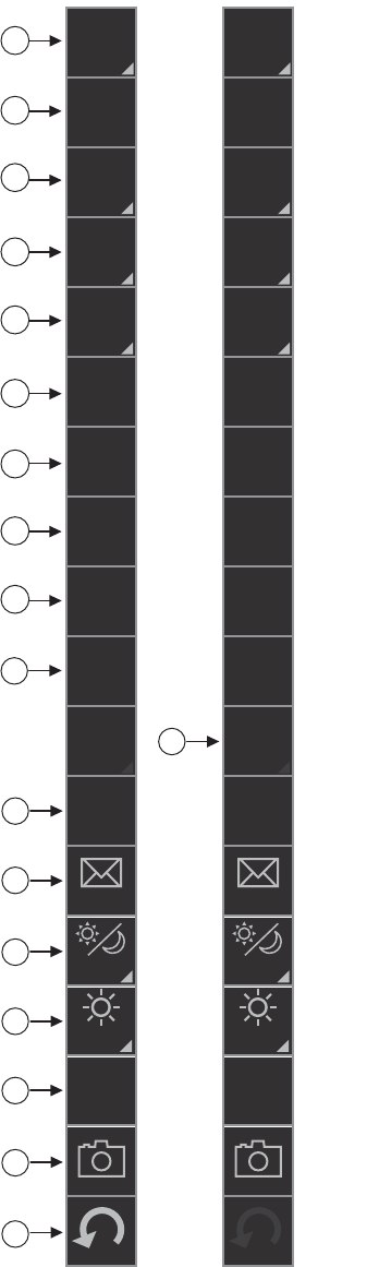
1. OPERATIONAL OVERVIEW
1-15
1.8 InstantAccess Bar
The InstantAccess bar runs vertically along the
left edge of the screen and is displayed always.
This bar provides, in the radar and chart radar
modes, buttons for adjustment of the radar picture
and chart, AIS operations, display brilliance con-
trol (FURUNO monitor only), MOB, screenshot,
etc.
For a description of the InstantAccess bar used in
the chart mode, see paragraph 6.1.3.
*1: For solid state radar, [TX CH] icon is displayed
instead of [TUNE].
*2: This button is not displayed on the FURUNO
19-inch monitor unit.
Radar
mode,
map
ON
Radar
mode,
chart
ON
1
12
11
10
2
3
4
6
7
8
9
5
13
14
15
16
17
18
*2
*1
IR
OFF
ES
OFF
EAV
OFF
HL
OFF
CU/TM
reset
PULSE
M3
TUNE
MAN
MAP
OFF
Chart
ON
Chart
Disp
OWN
AIS
AIS
Day
88
MOB
IR
OFF
ES
OFF
EAV
OFF
HL
OFF
CU/TM
reset
PULSE
M3
TUNE
MAN
MAP
ON
Chart
OFF
Chart
Disp
OWN
AIS
AIS
Day
88
MOB
ACE
OFF
ACE
OFF
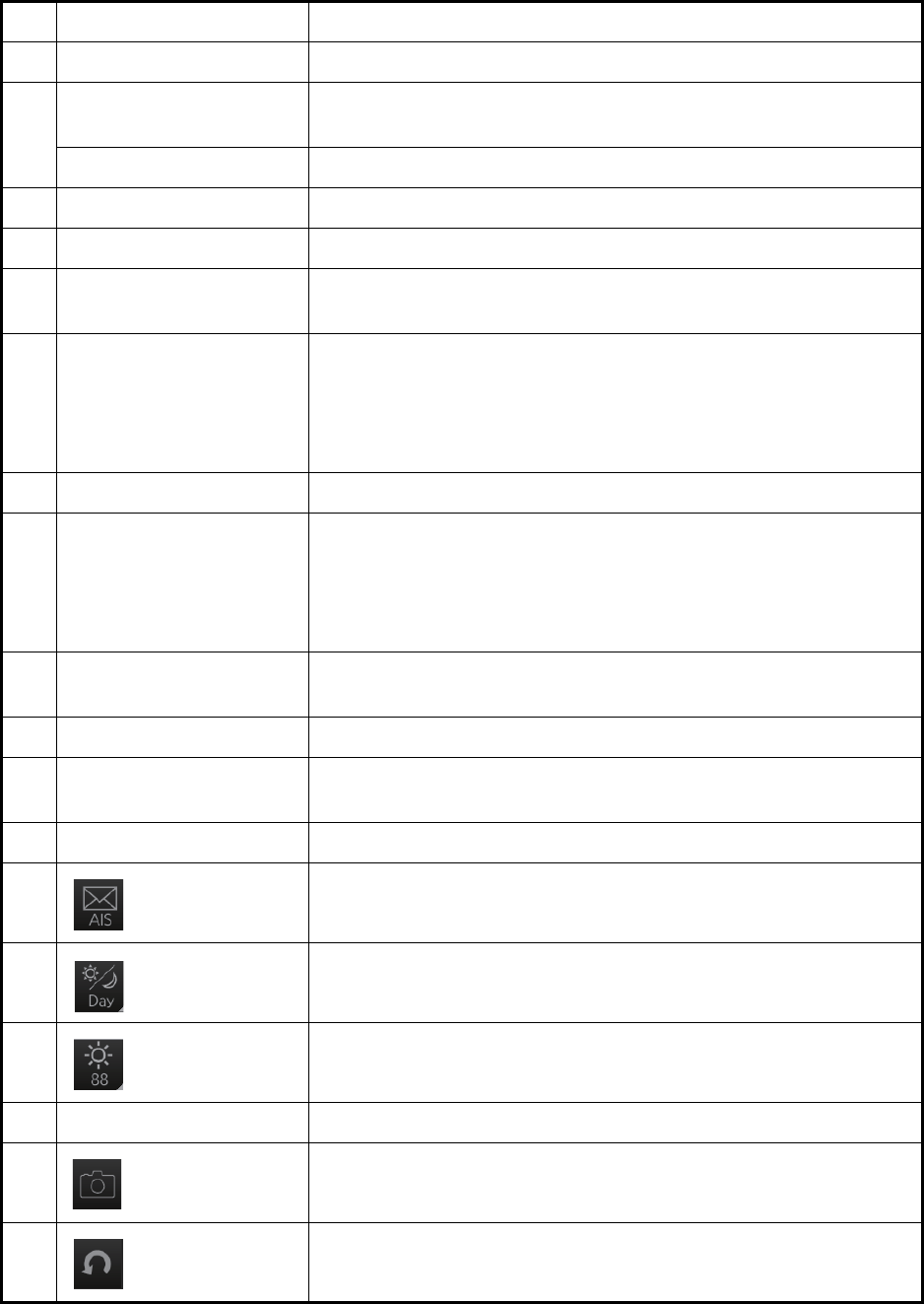
1. OPERATIONAL OVERVIEW
1-16
No. Button name Description
1 PULSE Selects the radar pulse length.
2 TUNE Selects the radar receiver tuning method, automatic or manual,
and manually tunes the radar receiver.
TX CH Selects the transmit frequency from [TX CH 1] or [TX CH 2].
3 IR Activates or deactivates the interference rejector.
4 ES Activates or deactivates the echo stretch.
5 EAV Activates or deactivates the echo averaging when Automatic Clut-
ter Elimination (ACE) function is off.
6 ACE Activates or deactivates the Automatic Clutter Elimination (ACE)
function.
Automatic Clutter Elimination (ACE) automatically sets the gain,
rain and sea clutter controls according to the sea and rain clutter
states.
7 HL OFF Temporarily erases everything but radar echoes.
8 CU/TM reset • Puts the ship’s heading at the top of the screen in course-up
mode the moment this button is pressed.
• Resets the ship's position to a point of 75% radius opposite to
the extension of the heading line passing through the display
center in true motion modes.
9 MAP ON/OFF Shows or hides the radar map marks on the radar display, in the
radar mode.
10 CHART ON/OFF Shows or hides the electronic chart.
11 Chart Disp Shows or hides various chart objects. Shown in the chart radar
mode. See paragraph 2.41.2.
12 OWN AIS Shows the [VOYAGE DATA] menu, to set your ship’s AIS data.
13 AIS message Displays screen for “received AIS messages”.
14 Palette Selects a color palette.
15 BRILL Adjusts the brilliance of a FURUNO monitor.
16 MOB Enters a MOB mark at the current position.
17 Capture Takes a screenshot.
18 UNDO Restores previous condition in radar map and text input.
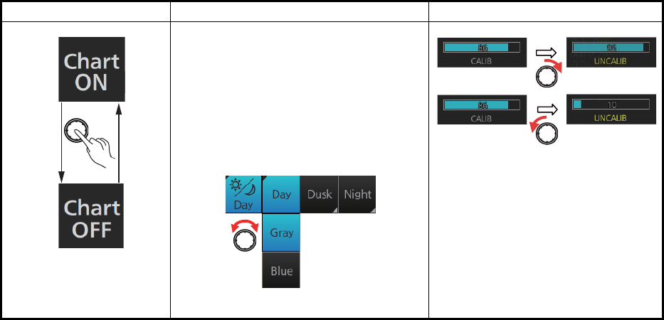
1. OPERATIONAL OVERVIEW
1-17
1.8.1 How to operate the buttons, slider bars on the InstantAccess
bar
The InstantAccess bar has three types of controls: toggle button, drop-down list button
and slider bar. (The MOB and Capture buttons are special buttons.) You operate the
buttons and bars with the trackball module or the InstantAccess knob. This section
shows you how to use the InstantAccess knob.
1. Push the InstantAccess knob to enable its use with the InstantAccess bar.
2. Rotate the InstantAccess knob to select a button. The background color of the
button selected is light-blue.
3. Do one of the following depending on button type.
1) Toggle button: Push the knob to select setting.
2) Drop-down list button or slider bar: Push the knob then rotate the knob to
select an item or adjust the slider bar. Push the knob to confirm your selection.
Note: You can use the ESC key to go back one step in the current operating
sequence.
Toggle button Drop-down list button Slider bar
A drop-down list button provides a list
from which to select an option related
to the label on the button. A drop-
down list button is identified by a tri-
angle on the button’s bottom-right
corner.
[Palette]
button
Palette list
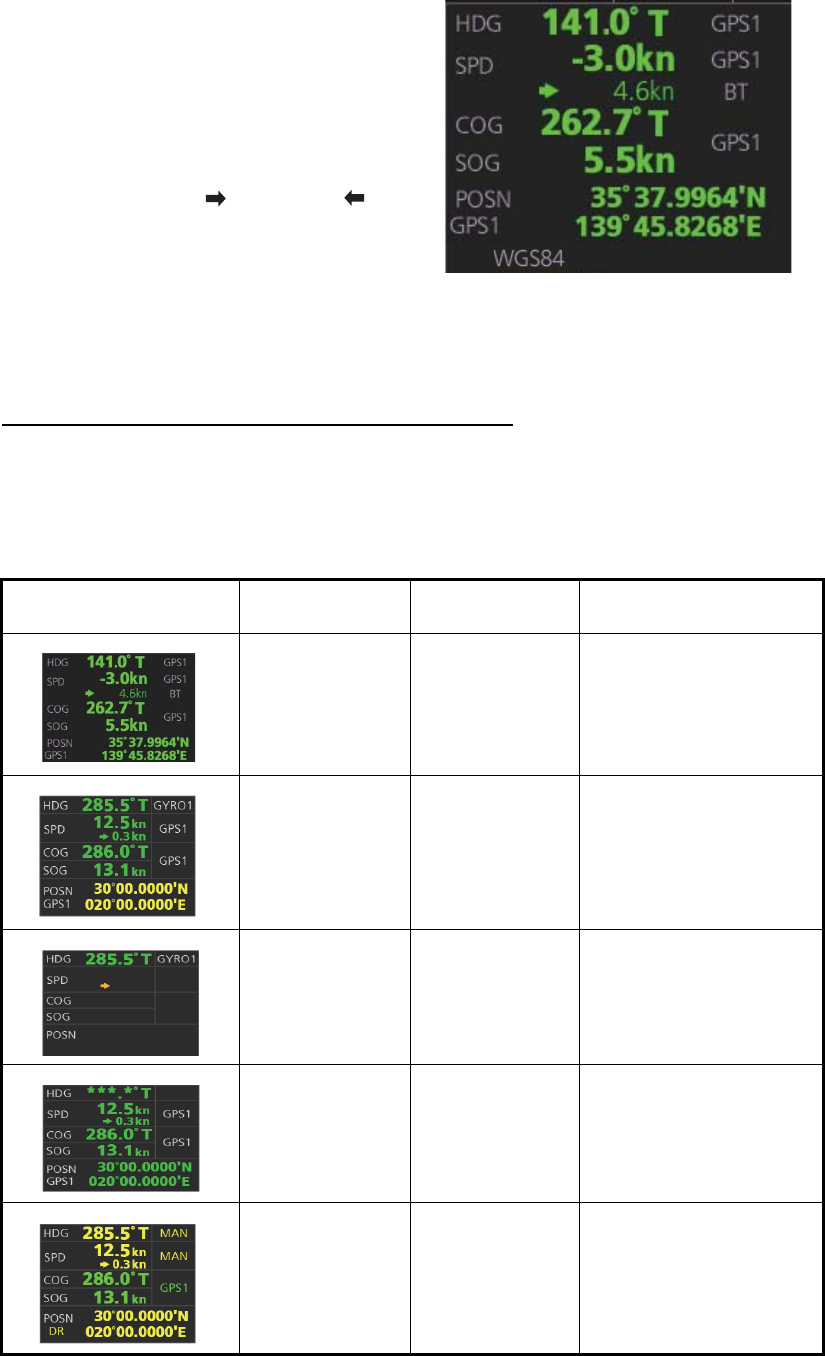
1. OPERATIONAL OVERVIEW
1-18
1.9 Sensor Information, Datum Box
Color of nav data indications and sensor name
The color of the nav data indications and sensor names changes according to the
state of the sensor data. The table shown below provides basic indication and color
meanings. For detailed information, see Appendix 3. When no sensor data is received,
the sensor source indication is blank and the related indication shows asterisks.
Sensor information, datum box displays the
sensor data and the name of the datum in
use. The sensor indications and names are
colored according to sensor state. See the ta-
ble below.
• HDG: Heading and its source.
• SPD: Longitudinal speed and its source.
The direction of transverse speed is indi-
cated with arrows, , Starboard, , Port.
• COG: Course over ground and its source.
• SOG: Speed over ground and its source.
• POSN: Latitude and longitude position of
own ship and its source.
• Datum: Chart datum (WGS84, WGS72,
etc.) in use. No datum appears when there
is no datum sentence.
Note: The position source shall meet
the requirements of IMO MSC.112(73).
Nav data indication Color of nav
data indication
Color of
sensor name State
Green White Sensor is normal.
Yellow White Validity of data is low or
offset is applied.
Yellow-orange Yellow-orange Data is invalid.
Green, data
shown with as-
terisks (***.*)
No display Data is not being re-
ceived.
Yellow Yellow Data is input manually
(manual heading, gyro
correction, manual
speed, dead reckoning).
12.5
kn
0.3kn
GPS1
GPS1
286.0°T
13.1
kn
GPS1
30°00.0000'N
020°00.0000'E
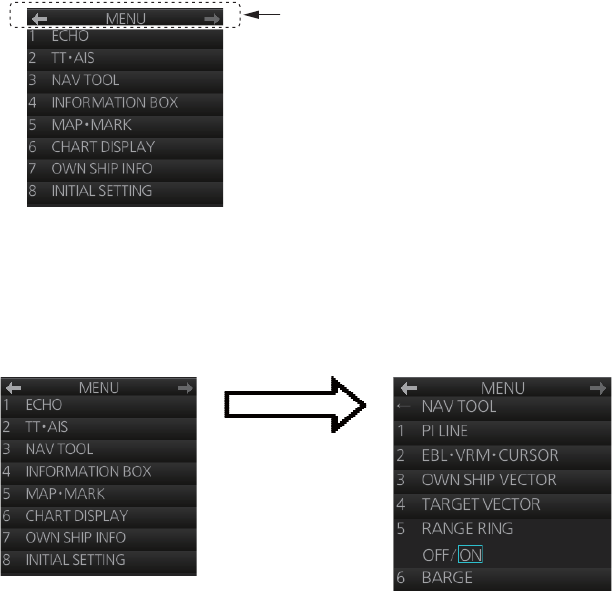
1. OPERATIONAL OVERVIEW
1-19
1.10 Menu Overview
The menu consists of eight main menus and several sub menus. You can operate the
menu with the Radar Control Unit or trackball module. The system closes open menus
whenever there is no menu operation for 30 seconds.
1.10.1 Basic menu operation
1. Open the main menu.
Control Unit: Press the MENU key.
Trackball module: Click the menu title bar at the right side of the display.
2. Select a menu.
Control Unit: Press the corresponding numeric key. For example, press the 3 key
to show the [NAV TOOL] menu.
Trackball module: Click the menu desired. The current selection is highlighted in
blue.
3. Select a menu item.
Control Unit: Press the corresponding numeric key.
Trackball module: Click the menu item desired. The current selection is highlight-
ed in blue.
4. Select a menu option.
Control Unit: Press the corresponding numeric key. The current selection is high-
lighted in orange.
Trackball module: Spin the scrollwheel. The current selection is highlighted in or-
ange.
5. Confirm your selection.
Control Unit: Press the ENTER key.
Trackball module: Push the left button.
Note: Hereafter, "select" in a menu operating procedure means to press the applica-
ble numeric key on the Control Unit or push the left button on the trackball module.
Menu title bar
Click [3 NAV TOOL]
or press the 3 key.
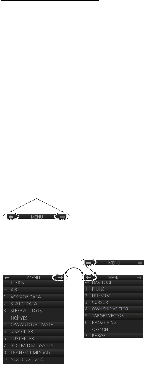
1. OPERATIONAL OVERVIEW
1-20
Keys, buttons to use in menus
Control Unit
MENU key: Open main menu, or close menu.
CANCEL key: Go back one layer in menu, or close menu when main menu is dis-
played.
←key: Return to main menu, in no. 2 layer or higher.
Trackball module
Right button: Go back one layer, or close menu when main menu is displayed.
Left button: (1) Click menu title bar to go back one layer, or close menu when main
menu is displayed, (2) Click the left arrow on the menu title bar to return to the main
menu, in no.2 layer or higher.
1.10.2 Menu history feature
This chart radar remembers the 10 last-used menus to help you go to recently used
menus quickly. The memorized menus are cleared when the power is turned off. In-
stallation- and service-related menus and menus where no operation occurred are not
memorized. Menus accessed multiple times are counted as one menu.
Click the memory history buttons on the menu title bar to navigate through the last-
used menus.
For example, the last two used menus are [NAV TOOL] and [AIS].
Menu history buttons
History back
button
History forward
button
Memorized menu no. 1
Memorized menu no. 2
Click
Click
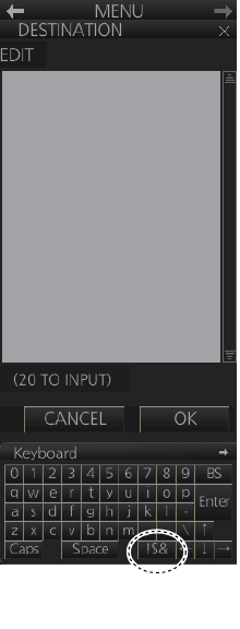
1. OPERATIONAL OVERVIEW
1-21
1.10.3 How to enter numeric data
Select the numeric data, then do one of the following:
Control Unit: Use the ten keys to enter data.
Trackball module: Spin the scrollwheel to set data then push the left button.
1.10.4 How to enter alphanumeric character data
Some operations display a software keyboard to enter alphanumeric character data.
To enter characters, click applicable characters on the software keyboard. You can
switch between letter input and symbol input by clicking the key circled in the illustra-
tion above.
Click to switch between
letters and symbols.
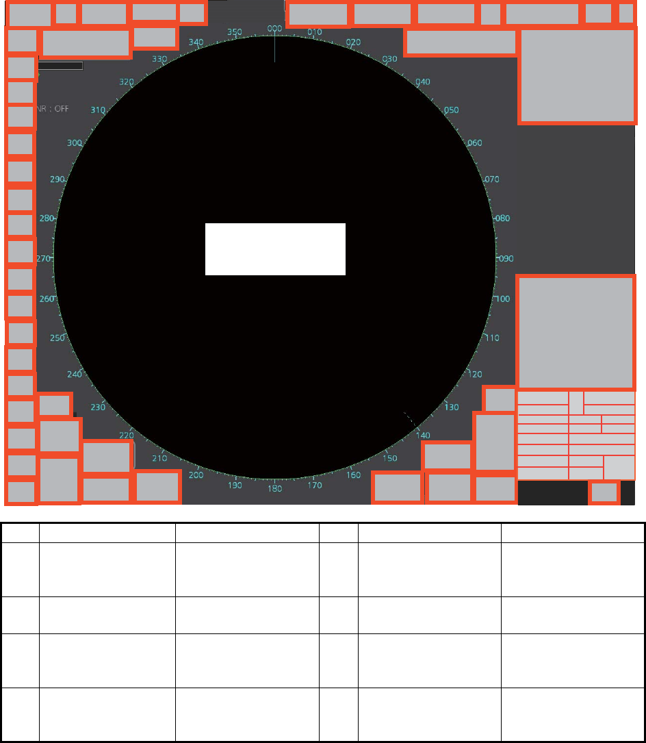
1. OPERATIONAL OVERVIEW
1-22
1.11 Context-Sensitive Menus in the Radar Mode
Context-sensitive menus are available with many of the boxes and buttons surround-
ing the display area and objects within the display area. Right-click the boxes and but-
tons marked with numerals in the illustration below to show the related context-
sensitive menus. If a menu is not operated within 30 seconds, it is automatically
closed.
For context-sensitive menus in the chart mode, see the chapter on chart overview.
1.11.1 Context-sensitive menus available with buttons and boxes
No. Box name Menu No. Box name Menu
1 Adjust Local Time Adjust Local Time 2 Cursor Position Range-Bearing Po-
sition, X-Y Position,
Cursor Menu
3 Sensor Informa-
tion, Datum Box
Select Sensor, OS
Info Menu
4 AIS Info Expanded AIS Data,
AIS Message
5 Association Association OFF/
TT/AIS, Association
Menu
6 TT OFF / MAN / AUTO /
MAN/AUTO,TT
Menu, Symbol Menu
7 AIS DISP OFF / FILT /
ALL, AIS Menu,
Symbol Menu
8 Vector OS Vector Menu,
Target Vector Menu
240.8
°
3229
°
0.088
42
3
20
23
28
29
31
32
39
38
36
35
34 57
8
14
16
15
2
1
30
21
40
610
13
17 18
11
33
9
4
2019
22
24
25
2627
12
41
Context-sensitive menus
on the radar echoes
(see paragraph 1.11.2)
37

1. OPERATIONAL OVERVIEW
1-23
*: For solid state radar, this menu is not displayed.
9 Vector Time Vector Time (30 s -
60 min), OS Vector
Menu, Target Vector
Menu
10 Vector Reference True-G(S), REL, OS
Vector Menu, Target
Vector Menu
11 CPA Range CPA Range
(0.5 - 20 NM)
12 CPA time CPA Time
(1 - 60 min)
13 AIS CPA Auto Activate Menu 14 Auto Activate OFF, AUTO ACT
FILT, AUTO ACT
ALL, Auto Activate
Menu
15 Lost TGT TT Lost Filter Menu,
AIS Lost Filter Menu
16 Lost TGT Filter OFF, FILT, ALL, TT
Lost Filter Menu,
AIS Lost Filter Menu
17 Past POSN Past POSN Menu 18 Past POSN time Past POSN Time
(OFF, 30 s - 6 min),
Past POSN Menu
19 Trail Trail All Clear, Trail
Menu
20 Trail Time Trail Time (OFF, 15
s - 30 min, CONT),
Trail Menu
21 Trail/Past POSN
Reference
True-G(S), REL,
Past POSN Menu,
Trail Menu
22 Alert List Alert List/Log Win-
dow
23 Trial Trial Mode, Trial
Maneuver Menu
24 AZ Acquisition Zone
Menu
25 Drop Mark 2 Drop2 Off 26 VRM 2 VRM2 Off,
EBL•VRM Menu
27 VRM 1 VRM1 Off,
EBL•VRM Menu
28 EBL 2 EBL2 Off,
EBL•VRM Menu
29 EBL 1 EBL1 Off,
EBL•VRM Menu
30 Drop Mark 1 Drop1 Off
31 Mark Mark Color (B-type
only), Mark Position,
MAP File, Edit Map
Comment,
Map•Mark Menu
32 PI Line Number of PI Line,
Reset PI Line,
PI Menu
33 Watch Watch Time
(OFF, 6 - 20 min)
34 Brill Menu Brill Menu
35 Chart ON/OFF Chart Display Menu 36 MAP ON/OFF Radar Map Menu,
Route Menu, Event
Menu, User Chart
Menu
37 ACE Automatic Clutter
Elimination (ACE)
Menu
38* TUNE Tune Initialize
39 PULSE Pulse Menu 40 RANGE Range Scales
(0.125 - 96.0 NM)
41 Antenna Selection Dual Radar,
ANT Select Menu
42 Customize Echo Customize Echo
Menu
No. Box name Menu No. Box name Menu
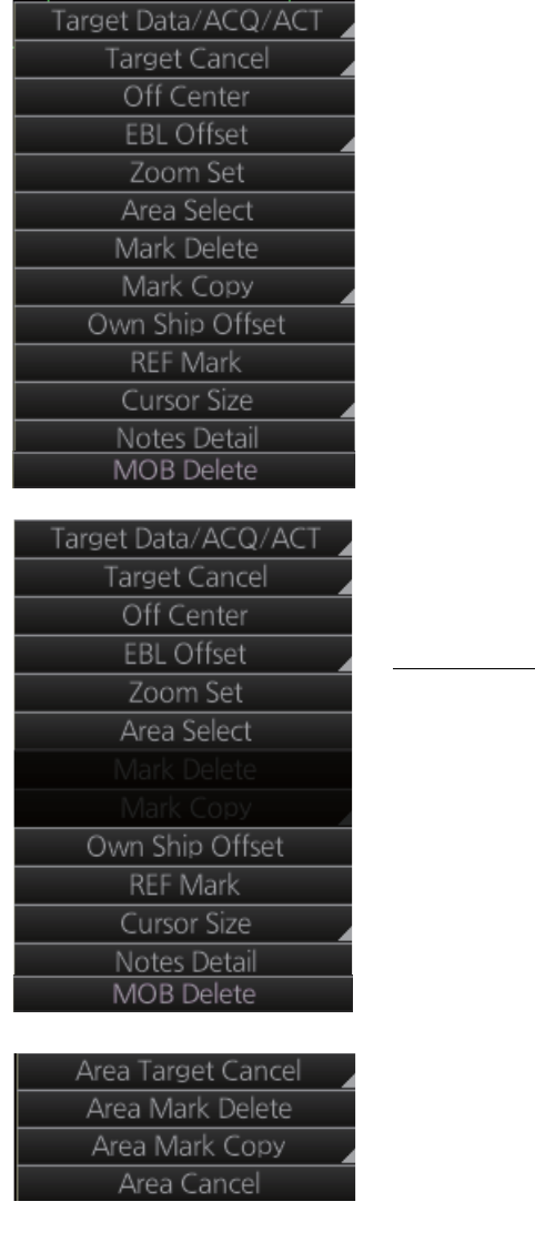
1. OPERATIONAL OVERVIEW
1-24
1.11.2 Context-sensitive menus in the display area in the radar and
chart radar modes
Right-click anywhere in the display area in the radar and chart radar modes to show
the context-sensitive menu.
[Target Data/ACQ/ACT]: For cursor-selected TT or
AIS target, display target data, acquire target for TT,
or activate sleeping AIS target.
[Target Cancel]: Cancel tracking on selected tracked
target (erase target), sleep activated AIS target.
[Off Center]: Off center the display.
[EBL Offset]: Offset EBL1, EBL2 (to measure range
and bearing between two targets).
[Zoom Set]: Select zoom area.
[Area Select]: Specify the area where to delete, copy
marks.
[Mark Delete]: Delete cursor-selected mark. Grayed
out when radar map is off.
[Mark Copy]: Copy cursor-selected mark. Grayed out
when radar map is off.
[Own Ship Offset]: Apply an offset to own ship
position.
[REF Mark]: Make cursor-selected target a reference
target (for use in TT). Grayed out unless TT is active.
[Cursor Size]: Select cursor size, large or small.
[Notes Detail]: Show details about cursor-selected
Notes.
[MOB Delete]: Delete selected MOB mark.
Area selected
This context-sensitive menu is available when an
area is created to cancel tracking on specific targets,
or delete or copy marks.
[Area Target Cancel]: Cancel tracking on targets
within the area selected.
[Area Mark Delete]: Delete all marks within the area
selected.
[Area Mark Copy]: Copy all marks within the area se-
lected.
[Area Cancel]: Cancel the area created.
Radar mode, map ON
Radar mode, map OFF or chart ON
Radar mode, map ON, area selected
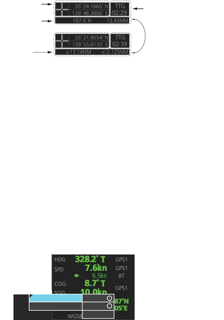
1. OPERATIONAL OVERVIEW
1-25
1.12 Cursor Position
Cursor data appears in the cursor position box at the top-right position on the display.
The appearance of the box is slightly different between the 23-inch and 19-inch dis-
plays, although the content is the same.
For the cursor position box that appears in the chart mode, see section 6.6.
The indication below the cursor position can show the range and bearing to the cursor
or x-y coordinates of the cursor position. Click that indication and select [Range-Bear-
ing Position] or [X-Y Position] as appropriate. For the x-y coordinate display, the y-axis
is the heading line, right/top is "plus" and left/lower is "minus".
Note 1: The cursor bearing can be selected to true or relative with [1 CURSOR BEAR-
ING] in the [CURSOR] menu. Right-click the indication and select [Cursor Menu] to
open the [CURSOR] menu.
Note 2: The cursor position is shown as "---.-" when the cursor is not within the effec-
tive display area.
1.13 How to Select Sensor Settings
This radar system accepts navigation data input two ways: System or Local. System
shares sensor data among multiple radars in a network. Sensor priority is also com-
monly shared among the radars. Local selects a sensor outside the network.
1. Right-click anywhere in the Sensor information, datum box to show the context-
sensitive menu.
2. Click [Select Sensor].
3. Click [System] or [Local].
Note: The sensor system can also be selected in the chart mode through this pro-
cedure and through the menu. Open the menu then select [7 OWN SHIP INFO]
followed by [1 SENSOR].
Cursor position
(lat/lon)
Bearing and
range to cursor
position
Time to go to
cursor position
x and y
coordinates of
cursor position
Click indication to switch
between bearing and range
and x and y coordinates.
System
Local
[Setting]
System
Local
Select Sensor
[OS Info Menu]
[Setting]
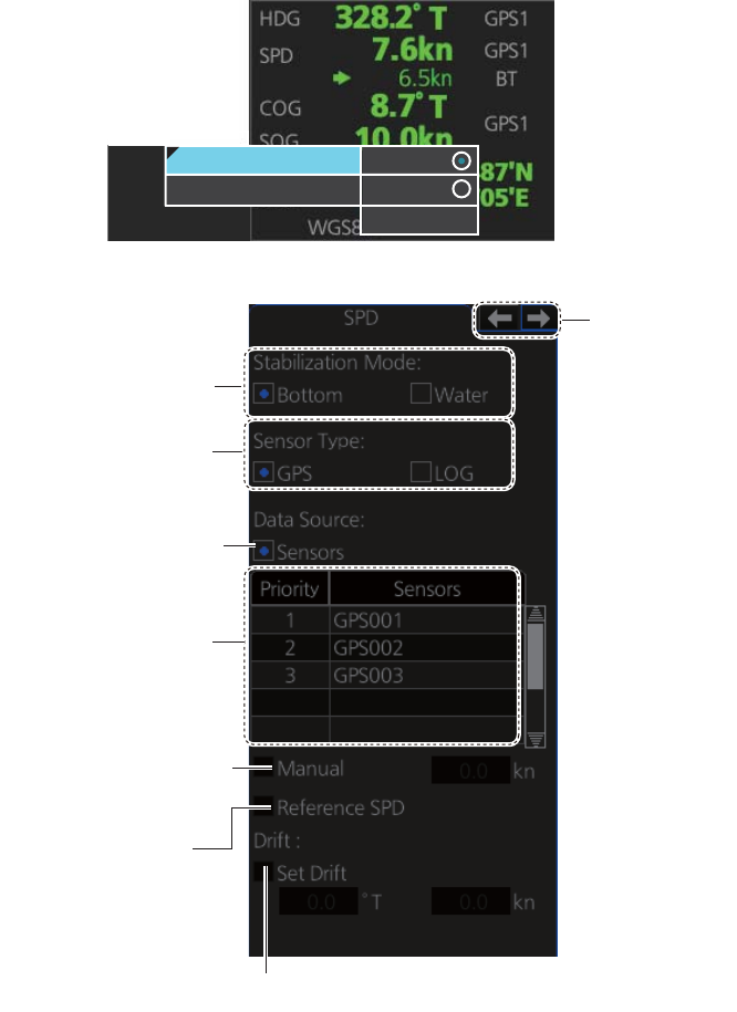
1. OPERATIONAL OVERVIEW
1-26
1.14 How to Enter Ship Speed
The TT and azimuth stabilized presentation modes require own ship speed input and
compass signal. The speed can be entered automatically from a speed log (STW,
SOG) or GPS (SOG), or manually on the menu. Note that the FURUNO GPS Naviga-
tor GP-150 provides COG and SOG.
1. Right-click anywhere in the Sensor information, datum box to show the context-
sensitive menu.
2. Click [Select Sensor] then click [Setting].
3. Use the arrow buttons to select the [SPD] page.
4. For automatic input, follow the procedure below. For manual input, go to
step 5.
1) Check [Sensors].
2) Set the priority for the speed sensors in case of Local sensor. Click the triangle
on any line then select the sensor to set as the primary source of speed. All
other sensors are then set as secondary source. Only one sensor can be pri-
mary while the others can be secondary. If a speed sensor is changed from
secondary to primary state and another speed sensor was selected as prima-
System
Local
[Setting]
System
Local
Select Sensor
[OS Info Menu]
[Setting]
Sensor type
selection
Speed
sensor
list
Check for manual
speed input
Check for automatic
speed input
Stablilization
mode
Select to use radar
as source for speed
and course
Set speed and course of drift
Arrow buttons

1. OPERATIONAL OVERVIEW
1-27
ry, then that sensor previously selected to primary state is then automatically
selected to secondary state.
3) Select [Bottom] or [Water] at [Stabilization Mode] to set the stabilization meth-
od. Select [Bottom] for GPS or [Water] for a speed log.
4) Check [GPS] or [LOG] at [Sensor Type] to select the source of speed data.
5) Go to step 6.
5. For manual input, set the stabilization mode for [Water] and check [Manual].
Click the manual box to show the up and down arrows. Click the arrows to set
speed.
Note: For [Set Drift], see page 16-3.
6. Click the [OK] button to save the settings then click the [MENU] bar to close the
menu.
Notes on speed input
• IMO Resolution A.823(19) for TT requires that a speed log to be interfaced with a
TT should be capable of providing through-the-water speed (forward speed).
• A single-axis water log cannot measure speed when the wind is coming from the
leeway direction.
• When AIS is active, [Manual], [Reference SPD] and [Set Drift] are shown in gray to
indicate that they are not available for selection.
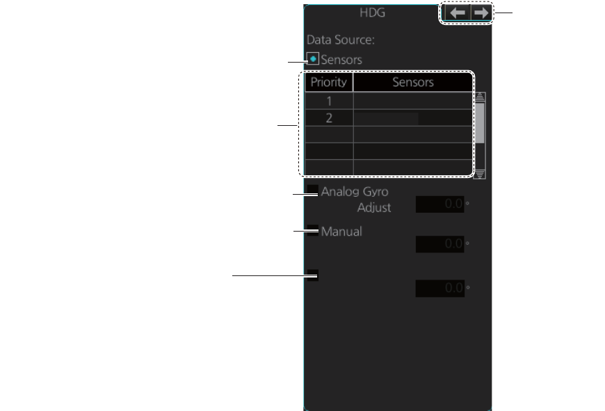
1. OPERATIONAL OVERVIEW
1-28
1.15 How to Enter Heading
Select manual or automatic heading input as follows:
1. Right-click anywhere in the Sensor information, datum box to show the context-
sensitive menu.
2. Click [Select Sensor] then click [Setting].
3. Use the arrow buttons to select the [HDG] page.
4. For automatic input, follow the procedure below. For manual input, go to
step 5.
1) Check [Sensors].
2) Set the priority for the heading sensors. Click the triangle on any line then se-
lect the sensor to set as the primary source of heading. All other sensors are
then set as secondary source. Only one sensor can be primary while the oth-
ers can be secondary. If a heading sensor is changed from secondary to pri-
mary state and another heading sensor was selected as primary, then that
sensor previously selected to primary state is then automatically selected to
secondary state.
3) Go to step 6.
5. For manual input, check the [Manual] box. Click the heading input box to show
the up and down arrows. Click the arrows to set heading.
6. Click the [OK] button to save the settings then click the [MENU] bar to close the
menu.
Heading sensor list
Analog gyro heading
Check for automatic heading input
GY001
GY002
Manual heading input (not shown on IMO type)
Gyro Correction
[Gyro Correction] is not shown
●
when [SYSTEM] is selected in the
[OWN SHIP INFO] - [SENSOR] menu.
[Gyro Correction] is grayed out
●
when manual heading is in use.
Arrow buttons
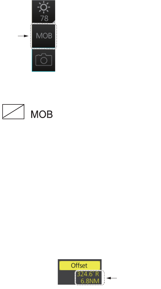
1. OPERATIONAL OVERVIEW
1-29
1.16 How to Mark MOB Position
Use the MOB (man overboard) feature to mark the position of man overboard on the
display screen. Click the [MOB] button (in any mode) on the InstantAccess bar.
The MOB mark instantly appears at the geographical position of your ship when the
button is clicked.
Up to 100 MOB marks can be saved. When the capacity for MOB marks is reached,
the oldest mark is automatically erased to make room for the latest.
To delete an MOB mark, right-click the mark to show the context-sensitive menu then
select [MOB Delete].
Exercise caution when using this feature in strong tide or current. The person will not
be at the MOB position for a very long time.
1.17 How to Offset Position
The position shown in the Sensor information, datum box (section 1.9) may be differ-
ent from the actual position. This error affects the positioning accuracy of radar ech-
oes, radar map and TT and AIS symbols. If there is a difference, apply an offset to
position as shown below to compensate for the error.
1. Right-click the display area to show the
context-sensitive menu.
2. Select [Own Ship Offset] and push the
left button. The color of the cursor be-
comes blue.
3. Roll the trackball until the cursor is at the "correct position".
4. Push the left button to confirm.
To cancel the offset, show the context-sensitive menu then select [Reset Own Ship
Offset]. The indication [Offset] and the offset values are then erased from the display.
[MOB]
button
Offset value
(range, bearing)
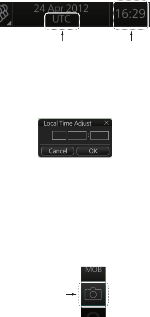
1. OPERATIONAL OVERVIEW
1-30
1.18 How to Select Time Format, Set Local Time
The GPS navigator feeds time and date data to the chart radar and they appear on the
Status bar. Neither the time nor the date can be adjusted, however you can select be-
tween UTC time (default) and local time. You can switch between the local time and
the UTC time by left-clicking the Current time format indication.
To use the local time, enter the time difference between the local time and the UTC
time as shown below.
1. Right-click the Current time format indication to show the context-sensitive menu
then click [Adjust Local Time] to display the [Local Time Adjust] dialog box.
2. Enter the time difference between the local time and the UTC time, in hours and
minutes. Use the button on the left to select the time offset direction. Select "+" if
the local time is ahead of the UTC time, or "-" if it is behind the UTC time.
1.19 How to Take a Screenshot of the Display
Click the [Capture] button on the InstantAccess bar to take a screenshot and save it
to the SSD (Solid State Drive). You can save a maximum of 100 screenshots. When
the capacity for screenshots is reached, the oldest screenshot is automatically deleted
to make room for the latest. You cannot take a screenshot when a menu or a dialog
box is opened.
Screenshots can be copied to a USB flash memory. For how to process screenshots,
see section 22.10.
Current time format
Left click: Switch between local
and UTC times
Right click: Adjust local time
Time
+00
[Capture]
button