Furuno USA 9ZWRTR110 Marine Radar User Manual Cover
Furuno USA Inc Marine Radar Cover
UserManual.wiki
>
Furuno USA
>
9ZWRTR110 User Manual
>
operators manual
Contents
1.
operators manual
2.
install manual
operators manual
Navigation menu
Upload a User Manual
Namespaces
Wiki Guide
HTML
PDF
Info
Views
User Manual
Discussion / Help
Navigation

![11. BASIC OPERATION This Chapter explains basic operations using keys, knobs and boxes displayed on the screen in the control unit. Some functions have several ways to operate but this manual explains the simplest operations. 1.1 Using keys and knobs PUSH TOHUEPUSH TOAUTOPUSH TOAUTOPUSH TOAUTOBRILL A/C RAIN A/C SEA GAINSTDYTXVECTORMODEMODE ECHOTRAILHLOFF MARK TARGETCANCELEBLOFFSETALARMACKEBLOFFEBLONOFFCENTERF1F2 VRMOFFVRMONRANGE+TARGETLISTEBL control VRM control TrackballTrackball moduleScrollwheelLeft buttonRight buttonUSB port coverPower lampACQ Key, knob Function Turn ON /OFF power. Power lamp lights up when the power is turned on. (Depends on the setting of [PANEL BRILLIANCE] on the [BRILLIANCE DETAIL] menu. Image brilliance Turn: Adjust brilliance. Press: Select color. Precipitation clutter rejection Turn: Reject precipitation clutter. Press: Switch between the precipitation clutter rejection function and the noise rejection function. Sea clutter rejection Turn: Reject sea clutter. Press: Select Auto or Manual of the sea clutter function. Gain Turn: Adjust gain. Press: Select Auto or Manual of gain. Getting ready/Transmit Switch between Getting ready and Transmit Mode selection Select display mode such as Head-up, Cursor gyro, North-up or True motion, etc. Vector True/Relative - Switch vector mode. - Call registered function (Function key).](https://usermanual.wiki/Furuno-USA/9ZWRTR110.operators-manual/User-Guide-1672487-Page-11.png)
![31.2 Turning ON/OFF the Power, Transmission 1.2.1 Turning the power ON/OFF Please note the following when using the radar. Note: Make sure to use the [ ] key in the control unit when turning off the power of this radar. A personal computer is used inside of the equipment. Turning off the power by using the breaker, etc. instead of using the [ ] key may cause loss of data stored inside. In the worst situation, it may prevent the machine from functioning properly. If you experience abnormal function, seek for immediate service. Lost data are unrecoverable. Please backup your data periodically. 1. Open the cover at the left upper section of the control unit, press the [ ] key to turn the radar switch on. When the slide switch of the monitor unit (MU-150HD or MU-190HD) is ON (factory default), the power of the monitor unit is turned on automatically. When the switch is turned OFF, press the [/ BRILL] key in the monitor unit to turn the power on. After the power is turned on, the display on the screen changes in the order of FURUNO screen → Machine type name screen → Getting ready screen. It takes approximately 1 and 1 ½ minutes until the Getting ready screen appears. For FAR-1417, preheating of magnetron is completed during this time. For FAR 1427, it starts counting down the remaining time (1 ½ minutes) necessary for preheating magnetron. When getting ready appears on the screen, you can start transmission. On the Getting ready screen, mark, fixed range ring, chart, TT target and AIS target are not displayed. Left-click inside of the warning message box to erase the warning message. Warning message01:19Stant count down at [01:19], it changes to GETTING READY. Note 1: Do not turn the power on while USB memory is inserted in the control unit. The GETTING READY screen does not show when USB memory is inserted. Note 2: When ambient temperature is low, display on the screen moves slower. 2. Press the [ ] key in the control unit when turning the power off. The message “Shutting down” appears at the center of the screen. Release the [ ] key immediately. The power turns off in about 15 seconds.](https://usermanual.wiki/Furuno-USA/9ZWRTR110.operators-manual/User-Guide-1672487-Page-13.png)
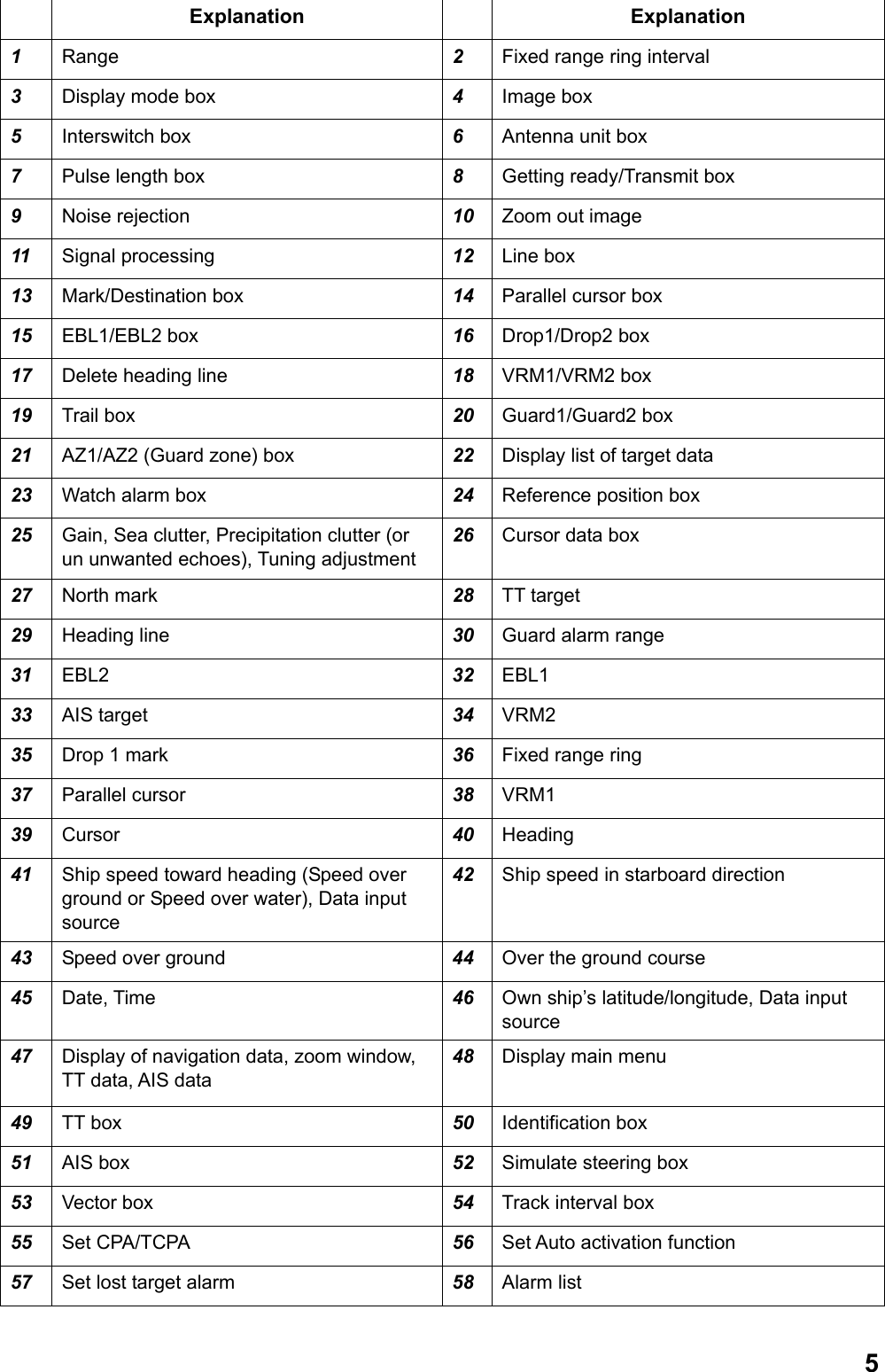
![4Quick Start When magnetron is sufficiently warmed up, you can start the transmission without waiting full preheating time. Press the [ ] key again within 10 seconds after the power is turned off in error. 1.2.2 Switching between TRANSMISSION and GETTING READY To start transmission, press the [Getting ready/Transmit] key while getting ready is displayed on the screen. Radar echoes are displayed on the screen with the previously used settings of range, brilliance, VRM, EBL and menu settings. Each press of the [Getting ready/Transmit] key switches between getting ready and transmit. Antenna is stopped at the time of Getting ready and starts rotating when transmission starts. Life of magnetron shortens in proportion of transmission time. Keep the equipment in the Getting ready state when there is no need for transmission. 1.3 Examples of Screen Display 1234567891011121314151617 18192021222324 252628 293031323334383736404142434445464749 50 4851525354565758392735IRESEAV55](https://usermanual.wiki/Furuno-USA/9ZWRTR110.operators-manual/User-Guide-1672487-Page-14.png)
![61.4 Operating from boxes on the screen Users can perform all the operations from the trackball area alone. Select a box on the screen with the trackball and select an item with the left/right button or the wheel. (See chapter 1.3 for box positions.) Follow the steps below to use boxes on the screen. 1. Roll the trackball and place the cursor on the box required. Shape of the cursor changes as shown in the figure below depending on positions of the cursor. Cursor is within the valid area for displaying images.Cursor is not within the valid area for displaying images.: Valid area for displaying radar images. For example, select the display mode box on the left upper side on the screen. Display mode box When a box is selected correctly, color of texts inside of the box (or the box) changes. A function when you press the button next is displayed in the guide column in the information display area. The screen shows the left button functions on the left side of the vertical line and the right button functions on the right side of the vertical line. In this example, the display mode box is selected and [Select mode/Mode menu] is displayed on the screen. Select the display mode with the left button and display the [Display mode] menu with the right button. Function of the left button Function of the rigth buttonGuide columnThe bottom section of the information display area on right side of the screen. 2. Press the left button or the right button to select a necessary item. In this manual, “left-click” means to press the left button and “right-click” means to press the right button. Note: You can also select an item inside of the box by rolling the wheel instead of using the left button. The color of the item changes when you select the item by rolling the wheel, which means that the setting has changed from the current setting. To change the setting to another setting, press the wheel or the left button to set the selection. If the selection is not set after selecting the item by rolling the wheel, the setting returns to the previous setting.](https://usermanual.wiki/Furuno-USA/9ZWRTR110.operators-manual/User-Guide-1672487-Page-16.png)
![71.5 Brilliance and Color Scheme 1.5.1 Adjusting brilliance Brilliance of the entire screen can be adjusted from the monitor or the control unit. To adjust brilliance from the control unit, the monitor settings need to be changed. Adjusting brilliance Monitor settings Short press the [ / BRILL]キー Set [EXT BRILL CTRL] at [OFF] in the [SYSTEM] menu (Factory default) Rotate the [Image brilliance] knob in the control unit. Set [EXT BRILL CTRL] at [USB] in the [SYSTEM] menu. 1.5.2 Selecting color scheme This equipment provides eight sets of color and brilliance depending on any ambient lighting conditions. The following table shows the factory default of color and brilliance sets. Sets Screen brilliance Color Text Echo Fix range ring BackgroundDay 100% White White Orange Green Light gray Dusk-Green 50% Green Green Orange Green Black Dusk-White 50% White text on blue White Orange Green Blue Night-Red 20% Red Red Orange Red Dark gray Night-Blue 20% White text on blue White Orange Green Blue Black 100% Black Red Orange Red Black Custom 1 100% White White Orange Green Light gray Custom 2 100% White White Orange Green Light gray Press the [Image brilliance] knob to select color scheme. Each press of the knob switches between the color sets of Day, Dusk-Green, Dusk-White, Night-Red, Night-Blue, Black, Custom 1 and Custom 2. User can register desired color sets from Custom 1 and Custom 2. (See chapter 2.9) Note: Brilliance of marks and texts displayed on the screen can be adjusted by color scheme. (See chapter 2.9)](https://usermanual.wiki/Furuno-USA/9ZWRTR110.operators-manual/User-Guide-1672487-Page-17.png)
![81.6 Tuning 1.6.1 Choosing the tuning method. User can choose either automatic or manual tuning. 1. Roll the trackball to place the cursor on [Tuning] at the upper right section on the screen. -50500 2. Left-click to select [Manual] or [Auto]. Each click switches the displays. [Auto] triggers the function to tune the image clearly. Refer to Chapter 1.6.2 for [Manual] setting. Note: If automatic tuning does not show clear images, try initializing tuning. (See chapter 2.10.11.) 1.6.2 Manual tuning Follow the following steps for manual tuning. 1. Press the [Range limit] key several times to set it at 48NM. 2. Roll the trackball and place the cursor on the tuning bar. 3. Roll the wheel to adjust the tuning bar at maximum. Tuning bar 1.7 Display Modes This radar has the display modes of Head-up, Cursor gyro, Stern-up, Course-up, North-up and True Motion. Each display mode is explained in Chapter 1.7.2. Display modes except Head-up and Stern-up need heading signal. For True Motion, connection to GPS navigation equipment is necessary. The true-view display function enables smooth rotation of radar echo in accordance with own ship’s turns in Head-up, Cursor gyro and Stern-up modes only. When Gyrocompass is connected Gyrocompass readings and heading values in the information display area of this equipment need to be matched accurately when receiving analog signal (Synchronization or Step signal) from gyrocompass. (Setting method: Main menu → Echo → GC-10, See chapter 2.11.1.)](https://usermanual.wiki/Furuno-USA/9ZWRTR110.operators-manual/User-Guide-1672487-Page-18.png)
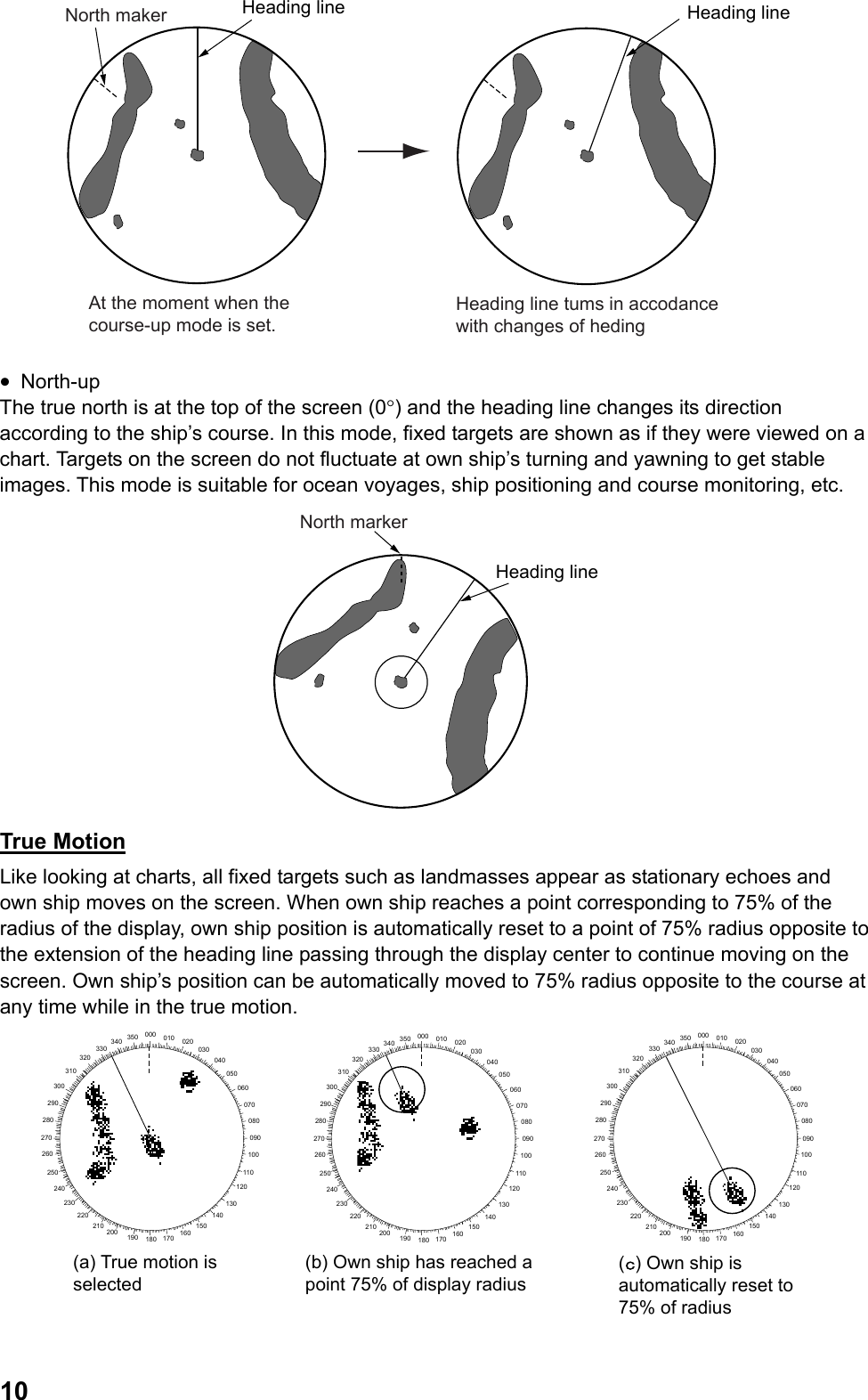
![91.7.1 Selecting display mode Press the [Select mode] key several times to select display mode necessary. Name of the display mode currently being selected is displayed in the display mode box at the upper left section on the screen. Presentation mode box Note 1: When heading signal is interrupted, the blinking message “Sensor Error Gyro” appears in the alarm section in the information display area. Heading reading in the information display area becomes “xxx°” and the North mark disappears and the monitor mode automatically becomes the head-up mode. When heading signals are restored, select the monitor mode with the [Select mode] key again. Note 2: User can pre-set appropriate monitor mode to use. (See chapter 2.10.2.) 1.7.2 Description of display modes Relative motion In relative motion, own ship position is stationary on the screen to observe relative motion of surrounding targets. • Head-up The head-up mode is a display in which the line connecting the own ship and the top of the display indicates own ship’s heading. Targets are displayed as if they were viewed from the bridge. Therefore, this mode is suitable for navigating through narrow channels and crowded waters. On the other hand, target images may fluctuate due to own ship’s turning and yawing. A short line on the bearing scale is the north marker indicating heading sensor north. • Cursor Gyro It is the same screen as Head-up but bearing scale links to heading signal. The cursor gyro can be used only when bearing sensor is connected to the radar. A failure of the bearing sensor will cause the bearing scale to become the same as that in the head-up mode. • Stern-up The stern-up mode rotates the head-up mode picture 180° showing ship’s stern on top of the display at all times. • Course-up The course-up mode is an azimuth-stabilized display in which a line connecting the center with the top of the display indicating own ship’s intended course (harbor, destination, etc.) Own ship’s heading moves in accordance with changes of its course indicating the initial bearing on the top at all times to see errors between the set course and the current course. Target images do not fluctuate at own ship’s turning and yawning to get stable images. Heading lineNoth maker](https://usermanual.wiki/Furuno-USA/9ZWRTR110.operators-manual/User-Guide-1672487-Page-19.png)
![111.8 Selecting range The selected range scale, range ring interval and pulse length are shown at the upper left corner of the screen. When a target of interest comes closer, reduce the range scale so that it appears in 50~90% of the display radius. Press the [Range] key several times to select range desired. Hit the “+” part of the key to raise the range and “-”part to lower the range. When range is switched, range ring interval and pulse length also change automatically. Range Fixed range ring intervalPulse length 3NM 12 NMSmall range Large rangeSame object appears in different sizes. 1.9 Adjusting Gain To properly display targets at all times, it is necessary to adjust gain in accordance with signal strength. Gain can be adjusted automatically or manually. 1. Press the [Gain] knob to select the method of gain adjustment. Each press of the [Gain] knob switches between [Auto] and [Manual]. -50500 2. For automatic adjustment, roll the [Gain] knob according to sea condition to fine tune the sensitivity. (Range: -50 ~ +50) For manual adjustment, roll the [Gain] knob to tune the sensitivity. (Range: 0 ~ 100) Note: For manual adjustment, adjust the gain control so that the background noise is just visible on the screen. If the gain level is too low, weak echoes may be missed. On the other hand, if the gain level is too high, the strong background noise may hide weak targets.](https://usermanual.wiki/Furuno-USA/9ZWRTR110.operators-manual/User-Guide-1672487-Page-21.png)
![121.10 Rejecting Sea Clutter Strong sea clutter occurs around own ship in bad weather due to strong reflection from sea surface to prevent identification of targets on the screen. In such a case, use the sea clutter rejection function to control sea clutter. Sea clutter can be rejected automatically or manually. Sea clutter appears at the center of the screen.Sea clutter is rejected. Sea clutter rejection function 1. Press the [Sea clutter rejection] knob to select the method of sea clutter rejection. Each press of the [Sea clutter rejection] knob switches between [Auto] and [Manual]. The control sea clutter is automatically set at optimum level when the setting is [Auto]. -50500 2. For automatic rejection, roll the [Sea clutter rejection] button according to sea conditions to fine tune the setting. (Setting range: -50 ~ +50) To reduce sea clutter, increase the setting value toward [+] and to increase sea clutter toward [-]. 3. For manual rejection, roll the [Sea clutter rejection] knob while observing echoes on the screen to reject sea clutter. (Setting range: 0 ~ 100) Note: For manual adjustment, do not set the sea clutter rejection level too high. When the sea clutter rejection level is too high, it may miss approaching targets. Normally set the level just so weak sea clutter appears on the screen. Set the sea clutter rejection level at 0 (the minimum) when there is no sea clutter appearing on calm sea surface. 1.11 Rejecting Precipitation Clutter Radio waves transmitted from antenna are reflected on rain and snow to appear on the screen as precipitation clutter. The function of precipitation clutter rejection is used when unwanted echo covers up and hides targets. The precipitation clutter rejection is controlled in the similar way as the sea clutter rejection but it becomes effective not only in near range but in longer range as well. The higher the setting, the greater the anti-clutter effect becomes. Unwaned echoes are displayed. (Toward the starboard)Precipitation rejection control adjusted. Function of precipitation rejection 1. Press the [Precipitation clutter rejection] knob to select the function of precipitation clutter rejection. Each press of the [Precipitation clutter rejection] switches between [Precipitation clutter manual] and [Unwanted echo]](https://usermanual.wiki/Furuno-USA/9ZWRTR110.operators-manual/User-Guide-1672487-Page-22.png)
![132. Roll the [Precipitation clutter rejection] knob while observing the screen to reject the precipitation clutter. (Setting range: 0 ~ 100) -50500 1.12 Automatic rejection of sea clutter and precipitation clutter When sea clutter and precipitation clutter cannot be removed fully, press the [Precipitation clutter rejection] knob to select the unwanted echo rejection function. “Unwanted echo” is displayed at the upper right section on the screen while the unwanted echo rejection function is working. Notes on usage • Echoes covering wide areas such as lands and islands may become smaller. • Clutter or strong precipitation clutter more than necessary. In such a case, use the functions of sea clutter rejection or precipitation clutter rejection to manually adjust the echo level at optimum. 1.13 Deleting heading line temporarily Heading line is displayed in all display modes and shows the own ship’s heading. Heading line appears directly above own ship (0°) in the head-up mode and the cursor gyro mode. Heading line appears directly under own ship (180°) in the stern-up mode. In the north-up, true motion and course-up modes, heading line moves in accordance with own ship’s direction. Thickness and color of heading lines can be changed in the [Mark] menu. (See page 2-31.) To confirm small targets in heading direction press the [Delete heading line] to temporarily delete the heading line. All the marks on the heading line and radar screen disappear and only targets are displayed while this key is being pressed](https://usermanual.wiki/Furuno-USA/9ZWRTR110.operators-manual/User-Guide-1672487-Page-23.png)
![141.14 Cursor position User can measure range and bearing from own ship to target and see latitude and longitude of target position. Roll the trackball and put the cursor on target to display information at the cursor position in the cursor data 1 and cursor data 2 boxes. [---] is displayed when the cursor is outside of the effective radar range. Cursor Data 1 BoxCursor Data 2 BoxTime required before arrival Cursor Data 1 Box: Displays latitude/longitude of cursor position. Cursor Data 2 Box: Displays range/bearing from own ship to cursor position or X-Y coordinates. Cursor Data 2 Box Do the following to switch displays of Cursor Data 2 Box. 1. Roll the trackball to put the cursor on Cursor Data 2 Box at the upper right side on the screen. 2. Left-click to select the display method. Each click switches the displays. Range/Bearing from own ship cursorRX-Y coordinatesClick here to switch bearing reference.True: True bearing Rel.: Relative bearingLeft click Note 1: When the reference position at the upper screen is [Steering position], range/bearing from the steering position is displayed and when the reference position is [Antenna], range/bearing from the antenna position is displayed. Note 2: The table below shows the relationship between X-Y coordinates and bearing reference. Bearing reference REL Bearing reference TRUE Y-axis indicates heading line. Heading direction is plus (+) and stern direction is minus (-). For X-axis, the starboard direction is plus (+) and the port direction is minus (-) Y-axis indicates South/North. North direction is plus (+) and South direction is minus (-). X-axis indicates East/West. East direction is plus (+) and West direction is minus (-).](https://usermanual.wiki/Furuno-USA/9ZWRTR110.operators-manual/User-Guide-1672487-Page-24.png)
![151.15 Measuring range to target There are three methods to measure range to target; fixed range ring, Cursor (See chapter 1.14.) and VRM (Variable Range Ring). 1.15.1 Using Fixed Range Ring Fixed range ring (Concentric circle with own ship at its center) is used to make a rough measurement. Fixed range ring interval is displayed at the upper left side on the screen. Range between own ship and a target is estimated from the nearing fixed range ring closest from the target by counting number of fixed range rings. Note 1: Number of fixed range ring is determined in accordance with range selected. However, the number can be selected manually. (See chapter 2.10.1.) Note 2: Each left-click switches between ON/OFF of fixed range ring while cursor is put on the fixed range ring interval (numerical value). 1.15.2 Using VRM (Variable Range Ring) There are two types of VRM; VRM1 and VRM2, which are shown by broken lines to distinguish from fixed range ring. The two types of VRM can be distinguished from each other by the length of the broken line also. VRM1 has shorter broken lines and VRM2 has longer broken lines. 1. Press the [VRM ON] key to display VRM. 2. Roll the [VRM] knob to put VRM on the inner side of target to which range you want to measure. Read range displayed at the lower right side on the screen. VRM value remains even when range is changed. 3. Press the [VRM OFF] key to delete VRM. The way it is deleted varies according to display condition of VRM. • When both VRM1 and VRM2 are displayed and either VRM1 or VRM2 is in operable condition, either VRM2 or VRM1 whichever is not in operable condition disappears. • When either VRM1 or VRM2 is displayed, the VRM of the displayed one disappears.](https://usermanual.wiki/Furuno-USA/9ZWRTR110.operators-manual/User-Guide-1672487-Page-25.png)
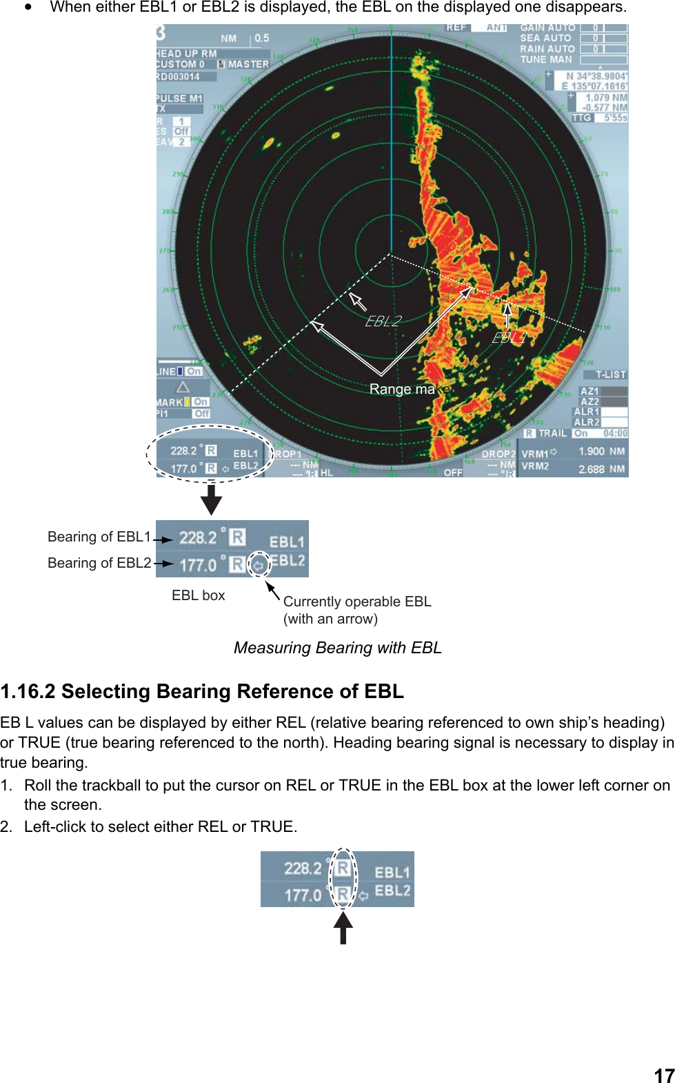
![16Range to VRM1Range to VRM2Currently operable VRM(with arrow mark)VRM box Range by VRM Note: Unit of VRM can be changed in the [Edit image] menu. (See chapter 2.1.4.) 1.16 Measuring bearing of target Use the Electronic Bearing Lines (EBL) to take bearing of targets. There are two EBLs, No.1 and No.2. Each EBL is a straight broken line extending out from the own ship position to distinguish from heading line. The two EBLs can be distinguished from each other by the different length of their dashes; dashes of EBL1 are shorter than EBL2. 1.16.1 Measuring bearing using EBL (Electronic cursor) 1. Press the [EBL ON] key to display either of the EBLs. Each press switches the arrow in the box between EBL1 and EBL2. The EBL with the arrow mark can be operated with the [EBL] knob. 2. Roll the [EBL] knob to put the EBL on the center of the target of interest Read its bearing at the lower left corner on the screen. 3. condition of EBL. • When both EBL1 and EBL2 are displayed and either EBL1 or EBL2 is in operable condition, the one that is not in operable condition disappears.](https://usermanual.wiki/Furuno-USA/9ZWRTR110.operators-manual/User-Guide-1672487-Page-26.png)
![181.17 Measuring Range and Bearing between Two Targets Range and bearing between two targets can be measured by moving EBL origin. 1. Press the [EBL ON] key to display EBL1. 2. [Press the EBL offset] key. The EBL origin moves to the cursor position. 3. Roll the trackball to move the cursor on target A. 4. Roll the [EBL] knob to put EBL1 at the center of target B. 5. Press the [VRM ON] key to display VRM1. 6. Roll the [VRM] knob so that VRM1 touches target B. Range and bearing between the two targets are displayed at the lower section on the screen. Press the [EBL offset] key to return the EBL origin to the center of the screen. Bearing/Range between target A and B Bearing/Range between target C and D Similarly, range and bearing between target C and target D can be measured using EBL2 and VRM2. Note: User can select the method of fixing origin of EBL offset. (See page 2-31.) 1.18 Selecting Transmission Pulse Length Transmission pulse length is displayed at the upper left side on the screen. Pulse length can be changed according to situations except for far range. To emphasize far range detection, extend the pulse length and to emphasize resolution, shorten the pulse length. Shortening pulse length can also reject precipitation clutter. 1. Roll the trackball to put the cursor on the pulse length box at the upper left side on the screen. Pulse length box 2. Left-click to shorten the pulse length and right-click to lengthen the pulse length. Each click switches between available pulse lengths in the current range scale.](https://usermanual.wiki/Furuno-USA/9ZWRTR110.operators-manual/User-Guide-1672487-Page-28.png)
![191.19 Off-Centering the Display Own ship position, or sweep origin, can be displaced to expand the view field without switching to a larger range scale. The sweep origin can be off-centered to the cursor position, but not more than 75% of the range in use. In the true dynamic mode, the sweep origin can be off-centered to the cursor position within 50% of the range in use. Note: This function can be used for ranges other than 96NM and 120NM ranges. 1. Roll the trackball to move the cursor to a position where you wish to center the image. 2. Press the [OFF CENTER] key. Own ship position moves to the cursor position. 3. Press the [OFF CENTER] key again to return the own ship position to the previous position. 1.20 Rejecting Interference Mutual radar interference may occur in the vicinity of another ship borne radar operating in the same frequency band. (X band: 9GHz) It is seen on the screen as a number of bright spikes either in irregular pattern or in the form of dotted lines extending from the center of the edge of the picture. This type of interference can be rejected by the interference rejecting function. 1. Roll the trackball to put the cursor on the box next to the [Interference] at the upper left side on the screen. 2. Left-click to select the strength of interference rejection. Each click switches between OFF →1→2→3. The larger the value, the stronger the interference rejection, however, it may weaken ship’s echo. Note: Set the level of interference rejection function at OFF when there is no interference from other ships to avoid missing small targets near own ship. 1.21 Echo Stretch The echo stretch feature enlarges targets in the range and bearing directions to make them easier to see. There are three levels of echo stretch, 1, 2 and 3. We recommend the level 3 for normal use. Note: The echo stretch magnifies not only small target pips but also clutter from sea surface, precipitation and radar interference. For this reason, make sure these types of interference have been sufficiently reduced before activating the echo stretch function. 1. Roll the trackball to put the cursor on the box next to [Stretch] at the upper left side on the screen. Interference by other ships radar](https://usermanual.wiki/Furuno-USA/9ZWRTR110.operators-manual/User-Guide-1672487-Page-29.png)
![20 2. Left-click to select the desired setting. Each click switches between OFF→1→2→3. Set the echo stretch level while observing the screen. • OFF: no stretch • 1: Smooth eco • 2: Stretches 1.2 ~ 1.5 times in the bearing direction • 3: Stretches in range and bearing directions. 1.22 Signal Processing Function Rejecting sea clutter may also reject necessary targets. In such a case, the signal processing function can suppress sea clutter while maintaining targets. Note 1: Heading bearing signal and own ship positioning data are necessary for the signal processing function Note 2: Do not use the signal processing function in rough conditions of pitching and rolling of own ship to avoid loss of target. Note 3: Targets moving at high speed become difficult to detect compared of static targets when using the signal processing function. Prior to using the signal processing function, use the sea clutter rejection function just so some weak sea clutter appears on the screen. 1. Roll the trackball to put the cursor next to [Processing] at the upper left side on the screen. 2. Left-click to select the desired setting. Each click switches the setting between OFF→1→2→3→4→5. Set a value while observing the echoes. • Off: Set the signal processing function OFF. • 1,2: Effective for target detection in sea clutter. The signal processing 2 is more effective compared with the signal processing 1 for target detection in strong sea clutter. However, detecting targets moving at high speed on the screen is more difficult for the signal processing 2 compared with the signal processing 1. Use either the signal processing 1 or 2 in accordance with user’s purpose. When detecting targets in sea clutter and targets moving at high speed simultaneously, it becomes effective to use the signal processing function together with the wiper processing (See page 2-20.) 3. Detect weak targets, such as floats, in stormy weather. 4. Detect weak targets, such as floats, in stormy weather. To use this setting, set the equipment as follows: • Set the interference rejector to 3. This raises the sensitivity against weak targets. • Manually set the gain to 80. • Manually set the A/C SEA to 50. • Manually set the A/C RAIN to 40. This is effective for reducing unwanted clutter and suppressing false echoes. 5. Effective for detecting high speed targets and unstable echoes.](https://usermanual.wiki/Furuno-USA/9ZWRTR110.operators-manual/User-Guide-1672487-Page-30.png)
![211.23 Echo Trail Function Echo trail function is useful to observe other ships’ movement, which displays a track in lower brilliance than the actual image 1.23.1 Starting Echo Trail Set trail time to start the echo trail. Trail time can be selected from 15 seconds, 30 seconds, 45 seconds 1-20 minutes (1 min. interval), 30 minutes, 40 minutes, 50 minutes, 60 minutes, 20 hours, 24 hours, 48 hours and continuous. Trail is displayed for the set trail time. 1. Press the [Echo Trail] key several times to select the desired trail time. The trail time currently selected is displayed in the trail box at the lower right side on the screen. The longer the trail time, the longer the trail becomes. Trail box Trail timeElapsed time Elapsed time from the start of the trail to the set trail time is shown on the trail box. For example, if the trail time setting is 6 min., the elapsed time is displayed until 6 minutes is elapsed but no elapsed time is displayed beyond 6 minutes. 2. Put the cursor on [On] in the trail box and left-click to temporarily erase the trail from the screen. The display in the box changes to [Off]. The trail display disappears from the screen but it continues trail inside the machine. Note 1: Color, gradation and level can be changed in the [Trail] menu. (See chapter 2.10.5) Note 2: Long press the [Echo trail] key to delete all the trails in the machine to start over the trail. You can also put the cursor on the [Trail] (or [On], Trail time) in the trail box and long press the left button. 1.23.2 Selecting Trail Mode There are relative trail and true trail modes for echo trails. Relative trail: Relative trails show other ships’ movement with reference to own ship. Relative trail is useful to see relative movements such as avoiding a collision because own ship’s movements and other ships’ movements are combined. On the other hand, it also shows trails of fixed targets to make it difficult to see depending on locations. True trail: True trails show other ships’ true movements in accordance with their over-the-speed over grounds and courses regardless with own ship’s movement. Therefore, trails of stationary targets are not drawn. Heading bearing signal and GPS navigation equipment need to be connected.](https://usermanual.wiki/Furuno-USA/9ZWRTR110.operators-manual/User-Guide-1672487-Page-31.png)
![22True target trailsRelative targets trails Relative trail and True trail 1. Roll the trackball to put the cursor on REL, TRUE or TRUEs in the trail box at the lower right section on the screen. 2. Left-click to select trail mode. Speed over ground: Each click switches between REL (relative trail) and TRUE (Speed over ground true trail) Speed over water: Each click switches between REL (relative trail) and TRUEs (Speed over water true trail) Note: When setting of trail mode is changed, TRUE, TRUEs or REL also change in the trail interval box in the information display area. 1.24 Watch Alarm The watch alarm sounds the audio alarm and displays the alarm message when targets (other ships, island, reef, etc.) enter the set zone (Enter mode) or exit the set zone (Exit mode). (The [Watch Alarm] is ON in the ALARM menu.) User can set two alarm zones. The default setting of [Watch Alarm] is the Enter mode. Chapter 2.11.2 explains switching between the modes. WarningWatch alarm function helps prevention of collisions and use of the function does not exempt users from operational safety obiigagtions stipulated in the prevention of sea cliiision notices.When adjustments are inadequate for gain, sea clutter rejection and percipitation clutter rejection, alarm function may be lost against actual target and talse alarm may sound due to sea clutter and rain etc.](https://usermanual.wiki/Furuno-USA/9ZWRTR110.operators-manual/User-Guide-1672487-Page-32.png)
![231.24.1 Set ting Watch Alarm Zone Follow the steps below to set alarm zone. 1. Roll the truck ball to put the cursor in the box next to [Watch1] or [Watch2] at the lower right side on the screen. 2. Left-click. Cursor moves into the zone where radar image is effective. [SET] is shown inside of the box. The cursor is bordered with red color. 3. Roll the trackball to put the cursor on position A inside of the desired alarm zone then left-click. The picture below shows an example alarm zone settings. Position APosition APosition APosition BPosition APosition A 4. Roll the trackball to put the cursor on position B in the desired alarm zone. The indication in the box changes to [Operating]. Dotting line changes to solid line when the setting is completed. A single beep and alarm sound in accordance with the [Watch alarm setting] in the [Alarm] menu. In addition, alarm message appears. (See page 2-30.) Condition of watch alarm Blank (off) Set alarm zoneOperaing StopABAlarm range Note 1: When setting alarm zone 360 ゚around own ship, set position B in the same direction as position A. Note 2: When range is small and the alarm zone extends outside of the screen display area, [Out of range] is shown in the box and the color inside of the box also changes. Note 3: Shape of alarm zone can be changed from sector to polygon. (See chapter 2.10.6.) When setting the alarm zone in polygon (3~10 points), move the cursor to a desired position and](https://usermanual.wiki/Furuno-USA/9ZWRTR110.operators-manual/User-Guide-1672487-Page-33.png)
![24then left-click. Repeat this operation to insert all the points. Example of constructing a polygon • In case of a polygon with less ten points, left-click again on the point last entered. The indication in the box changes to [Operating]. • In case of a polygon with ten points, the indication in the box changes to [Operating]. Polygons cannot be made with crossing lines as shown below. 1.24.2 Stopping Alarm Sound When [Watch alarm setting] in the [Alarm] menu is ON, the alarm sounds when a target enters or exits the alarm zone and the target flashes on the screen. [Watch alarm] also flashes in the alarm section of the information display area. Press the [Cancel alarm] key to stop the alarm sound but flashing of the target continues. 1.24.3 Inactivating Watch alarm Follow the steps below to inactivate the watch alarm. 1. Roll the trackball to put the cursor on the box next to [Watch1] or [Watch 2] to inactivate. 2. Left-click. The indication in the box changes to [Stop] and the alarm zone is displayed with a dotted line. Note: To restart the watch alarm, put the cursor on the box at rest then left-click. 1.24.4 Deleting watch alarm Follow the steps below to delete the watch alarm. 1. Roll the trackball to put the cursor on the box next to [Watch1] or [Watch 2] to delete. 2. Long press the left button until the indication in the box disappears. The alarm zone disappears from the screen.](https://usermanual.wiki/Furuno-USA/9ZWRTR110.operators-manual/User-Guide-1672487-Page-34.png)
![251.25 Parallel Cursor Parallel cursor is useful for keeping a constant distant between own ship and other ship or a coastline. There are four types of parallel cursors, PI1, PI2, PI3 and PI4. You can select number of parallel cursors. Parallel index lines 1.25.1 Displaying, erasing parallel lines 1. Roll the trackball to put the cursor on [PI1], [PI2], [PI3] or [PI4] in the parallel cursor box at the lower left side on the screen. Parallel cursor no.*: Display only when inside of the box is ON.Bearing of parallel cursor *Interval of parallel corsor * 2. Roll the wheel to select parallel cursor number from PI1~PI14. 3. Press the wheel or the left button. 4. Roll the trackball to put the cursor on [Off] or [On] in the parallel cursor box. 5. Left-click to select [On] or [Off]. Parallel cursor appears on the screen when [On] is selected and disappears when [Off] is selected. Note 1: Parallel cursor reference can be moved. (See chapter 2.10.7.) Note 2: Parallel cursor can be displayed in conjunction with EBL2 and VRM2. (See page 2-31.) 1.25.2 Adjusting orientation and interval of parallel cursor Follow the following steps to adjust orientation and interval of parallel cursor while the parallel cursor is displayed. 1. Roll the trackball to put the cursor in the parallel cursor box. 2. Roll the [EBL] knob to adjust the orientation of parallel cursor. 3. Roll the [VRM] knob to adjust the interval of parallel cursor. Note: Number and mode of parallel cursor can be changed in the [Parallel cursor] menu. (See chapter 2.10.3.)](https://usermanual.wiki/Furuno-USA/9ZWRTR110.operators-manual/User-Guide-1672487-Page-35.png)
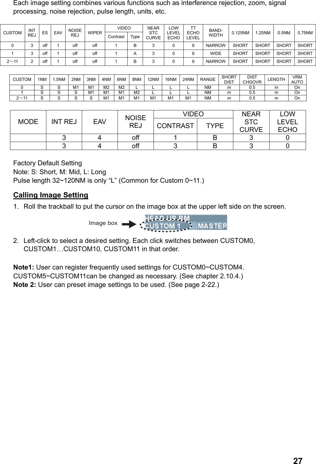
![261.25.3 Selecting bearing mode of parallel cursor Parallel cursor bearing reference may be RELATIVE (referenced to own ship’s bearing) or TRUE (reference to North). 1. Roll the trackball to put the cursor on REL or TRUE in the parallel cursor box. 2. Left-click to select REL or TRUE. 1.25.4 Reset ting parallel cursor You can reset orientation of parallel cursor currently being displayed on the screen. The table below shows the bearing of the parallel cursor after the resetting. Parallel Cursor Mode * Orientation of parallel cursor Parallel O° Perpendicular 90° *See chapter 2.10.3. 1. Roll the trackball to put the cursor on [PI1], [PI2], [PI3] or [PI4] in the parallel cursor box at the lower left section on the screen. 2. Long press the left button. 1.26 Setting Images There are twelve settings in the image box as shown below to display optimum images according to sea conditions. Image box Contents CUSTOM0 Register desired setting CUSTOM1 Register desired setting CUSTOM2 Register desired setting CUSTOM3 Register desired setting CUSTOM 4 Register desired setting CUSTOM5 Optimum setting to use over 6NM distance CUSTOM 6 Optimum setting in rough weather conditions such as storm CUSTOM7 Optimum setting for navigation in near range (within 1.5NM) CUSTOM8 Optimum setting for rainy condition CUSTOM9 Standard setting (for general navigation) CUSTOM10 Optimum setting for detecting birds CUSTOM11 Optimum setting for detecting floats attached to fishing nets](https://usermanual.wiki/Furuno-USA/9ZWRTR110.operators-manual/User-Guide-1672487-Page-36.png)
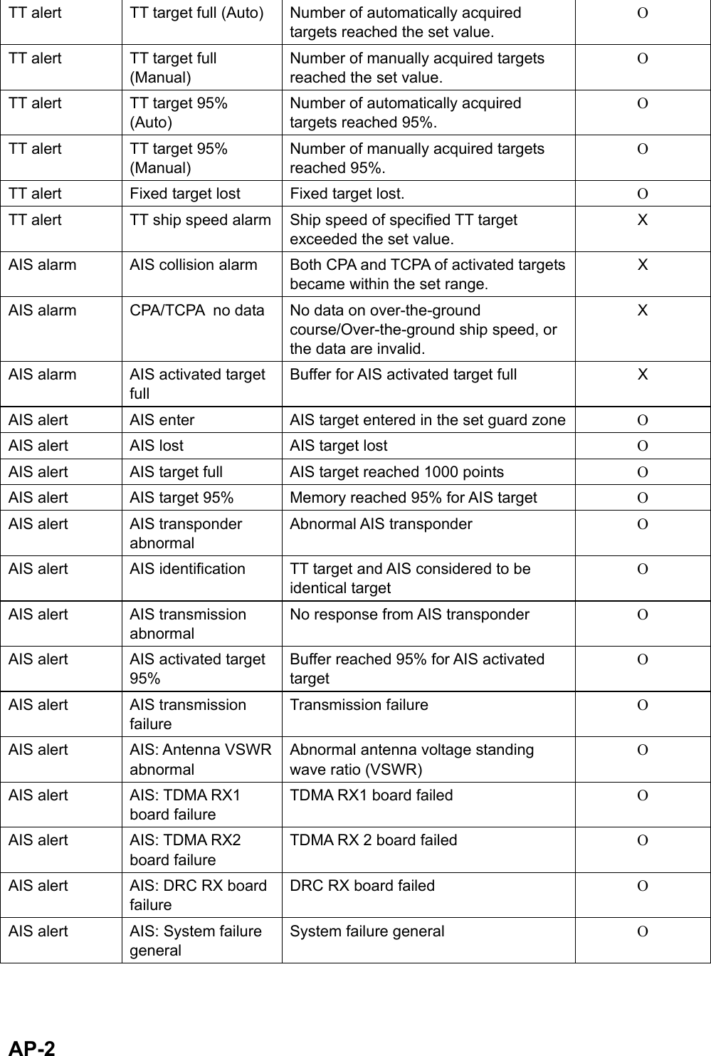
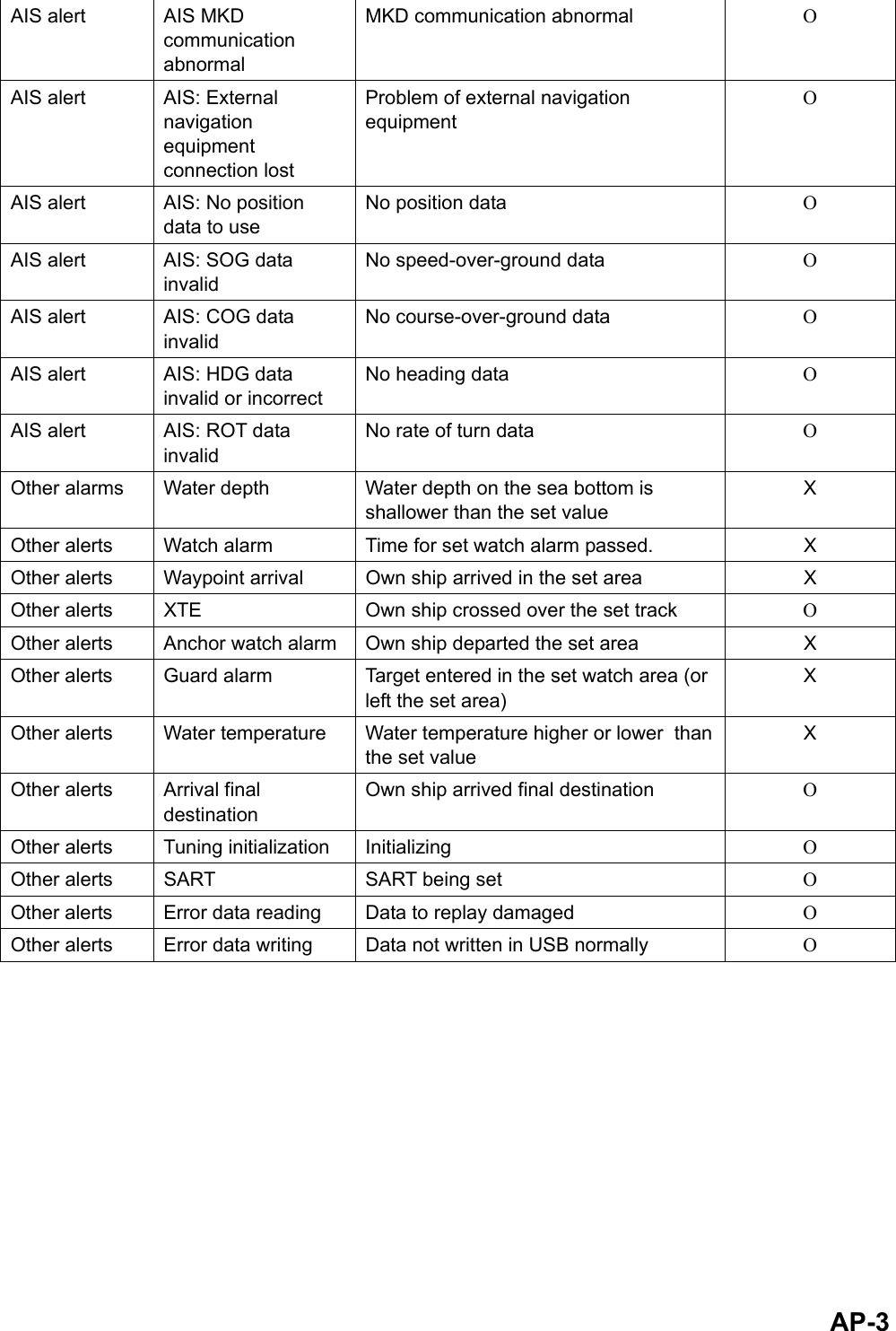
![281.27 Function Keys Frequently used image settings and operations can be registered in the function keys (F1, F2, Vector True/Relative, Target data list). Use of the function keys reduces menu operations to improve operability by simply pressing the functions keys. Operation of function keys Press the function keys [F1], [F2], [Vector True/Relative], or [Target Data List] to activate registered functions. When a function has multiple selections, press the same function key to switch its contents. Factory Default Setting Function key Function name Function key Function name [F1] key Entire screen [Vector True/Relative] key Vector True Relative[F2] key TLL [Target data list] key Target Data List To register other functions, See chapter 2.3. 1.28 Alarm When error or alarm setting violation is found, the applicable indication appears in flashing red or yellow in the alarm in the information display area and the buzzer sounds. Press the [Cancel alarm] key to stop the flashing and the buzzer. The alarm indication remains on the display until the reason for the alarm is removed. When multiple alarms are generated, later alarms are displayed. Confirm alarms in the alarm list as alerts with lower priority may not be displayed. Priority order of alarm Priority Alarm Text Buzzer 1 Highest Not acknowledged: system error, sensor error, TT Alarm, AIS Alarm Other alarm* Red flashing Long buzzer Continuous 2 Not acknowledged: alarm set at high priority in the [Priority alarm] menu. Yellow flashing Short buzzer (one time) 3 Not acknowledged: alarm set at low priority in the [Priority alarm] menu. Yellow flashing Short buzzer (one time) 4 Acknowledged: system error, sensor error, TT Alarm, AIS Alarm Other alarm* Red flashing - 5 Acknowledged: alarm set at high priority in the [Priority alarm] menu. Yellow flashing - 6 Lowest Acknowledged: alarm set at low priority in the [Priority alarm] menu. Yellow flashing - *: Alarm of which priority order cannot be changed in the [Alarm priority] menu. Note 1: Refer to the [Alarm list] on page AP-6 for alarm names displayed in the alarm box. Note 2: Priority order of alarms in the [Alarm priority] can be changed. (See chapter 2.8.)](https://usermanual.wiki/Furuno-USA/9ZWRTR110.operators-manual/User-Guide-1672487-Page-38.png)
![29Display alarm list/history A list of current alerts can be displayed. Order of alerts is shown in the above table. History of alerts can also be displayed up to the newest 100 alerts. 1. Roll the trackball to put the cursor on the alarm box in the information display area. Alarm boxType of alarmAlarm name 2. Right-click to display the alert list. Roll the wheel to scroll the alert list. Switch buttonDate/Time occurredLeft click the switch button 3. Put the cursor on the unacknowledged alarm to acknowledge it then left-click. The alarm is acknowledged and the display changes from flashing to lighting. 4. Left-click the switch button on the upper section of the alarm list to display the alarm history. Each click switches between the alarm history and the alarm list. 5. Right-click to close the alarm list or the alarm history. Note: To view the latest alarms exceeding 100 alerts, data of the alert history need to be stored in USB memory. (See chapter 5.9.1.) Open PC supplied by user to open the stored data. (File name: alarmHistory.txt) 1.29 Reference Position The reference positions for measurements of range/bearing and markers such as heading line and stern mark can be selected from the following two reference positions. • Antenna position • Steering position Roll the truck ball and put the cursor on the reference position box at the upper section on the screen to select a reference position. Each left-click toggles between [Antenna] and [Steering position]. Reference position box Own ship’s position is different depending the set reference position.](https://usermanual.wiki/Furuno-USA/9ZWRTR110.operators-manual/User-Guide-1672487-Page-39.png)
![30Radar antenna position is at the center of the screen.Steering position is at the center of the screen.[Antenna] is referenced. [Steering position] is referenced. Bearing/Range are measured according to the reference positions as shown in the table below to draw own ship’s graphic. Reference position Type Item Antenna Steering position EBL VRM Cursor Parallel cursor Fixed range ring Bearing/Range Drop mark Display bearing/range from antenna position. Display bearing/range from steering position. Heading line Stern line Beam line Own ship vector Graphics Own ship track Draw from antenna position. Draw from steering position. Bearing scale Draw with antenna position at center. Draw with steering position at center. Course, ship speed Calculate with antenna position at center. Calculate with steering position at center. CPA, TCPA Calculate with antenna position at center. Calculate with steering position at center. BCR, BCT Calculate from heading at all times. Heading Ship speed Ground speed Course Own ship’s data Latitude/Longitude of own ship Display based on input data from sensor regardless of reference position setting.](https://usermanual.wiki/Furuno-USA/9ZWRTR110.operators-manual/User-Guide-1672487-Page-40.png)
![311.30 Interswitch The interswitch of this radar uses an Ethernet to transfer digital data such as images and settings when two of this equipment are connected. For example, when an error occurs in antenna unit of radar 1, you can display images of antenna unit of radar 2 on the display unit 1. When you switch to another antenna unit with the interswitch, it automatically applies heading skew set at installation and timing adjustment. Antenna unit of radar 1 Antenna unit of radar 2Switching HubHUB-100Processor unitProcessor unitDisplay unit 1 Display unit 1 Example of Interswitch connection Follow the following steps to use the interswitch function. 1. Roll the trackball to put the cursor in the interswitch box at the upper left section on the screen. Name of the antenna unit in use is shown in the antenna unit box. Interswitch boxAntenna unit box 2. Left-click to select [Secondary]. Each click toggles between [Secondary] (Secondary radar) and [Main] (Main radar) functions.](https://usermanual.wiki/Furuno-USA/9ZWRTR110.operators-manual/User-Guide-1672487-Page-41.png)
![32Limitations of each function during the interswitch operation Radar functions include independent operations, dependent operations and common operations in [Main] and [Secondary] radars. Function Name Operation Main Secondary Getting ready/Transmission No independent operation Arbitrary setting Inoperable Range Independent operation Arbitrary setting Arbitrary setting (between ¼ to 4 times of [Main] range) Pulse length No independent operation Arbitrary setting Inoperable Second-trace echo rejection No independent operation Arbitrary setting Inoperable Reference position No independent operation Arbitrary setting Inoperable Display mode Independent operation Arbitrary setting Arbitrary setting Interference rejection No independent operation Arbitrary setting Inoperable Noise rejection No independent operation Arbitrary setting Inoperable Video slope No independent operation Arbitrary setting Inoperable Zoom No independent operation Arbitrary setting Inoperable Signal processing No independent operation Arbitrary setting Inoperable Wiper No independent operation Arbitrary setting Inoperable Echo trail Independent operation Arbitrary setting Arbitrary setting Echo trail True/Relative Independent operation Arbitrary setting Arbitrary setting Gain No independent operation Arbitrary setting Inoperable Sea clutter rejection No independent operation Arbitrary setting Inoperable Precipitation clutter rejection No independent operation Arbitrary setting Inoperable Tuning No independent operation Arbitrary setting Inoperable Guard zone No independent operation Arbitrary setting Arbitrary setting Watch Alarm zone Independent operation Arbitrary setting Arbitrary setting Chart Independent operation Arbitrary setting Arbitrary setting EBL, VRM, Other marks Independent operation Arbitrary setting Arbitrary setting TT Acquisition/TT Track No independent operation Arbitrary setting Arbitrary setting TT Display ON/OFF Independent operation Arbitrary setting Arbitrary setting TT Vector TRUE/REL Independent operation Arbitrary setting Arbitrary setting AIS Independent operation Arbitrary setting Arbitrary setting Note1: The interswitch function does not function when there is an error in the network. It may function in independent condition. Note 2: Echo trail and signal processing are transferred when images are switched with the interswitch. Erase unnecessary echo trails as necessary.](https://usermanual.wiki/Furuno-USA/9ZWRTR110.operators-manual/User-Guide-1672487-Page-42.png)
![332. RADAR OPERATION USING MENU This Chapter explains the main menu and menu operations of each function displayed when right-clicking the box on the screen except for TT, AIS and plotter. 2.1 Menu Operation This chapter explains the basic menu operation. Right-click to go one step backward when you want to know what the current operation is doing. 1. Put the cursor on [Menu] in the information display area. 2. Left-click to open the main menu. You can also open the main menu by rolling the wheel. Selection cursorIndicates tat there is a sun manu 3. Roll the trackball to put the cursor on a necessary item. The selection cursor indicates an item currently being selected. You can also select the item by rolling the wheel. 4. Press the left button or wheel. When item with mark is selected, a sub menu is displayed. Proceed to step 5. Indicates an item currently being set. 5. When the sub menu is open, select an item to change the setting then left-click. 6. Select contents of the setting and left-click. To change numerical value, roll the wheel to set a value then press the left button or press the wheel. 7. Right-click several times to close the menu. Select [Return] on the very top of the menu and left-click to immediately close the main menu.](https://usermanual.wiki/Furuno-USA/9ZWRTR110.operators-manual/User-Guide-1672487-Page-43.png)
![34Entering texts You may need to input texts when using this equipment. You can enter English characters (A~Z), numbers (0~9), Symbols (-), Hiragana (for names of image boxes only) and space. A small keyboard is displayed at the lower section on the screen where you enter texts. EnteSpac Follow the steps below to use the small keyboard. 1. Put the cursor on [BK] or [Correct] to erase texts displayed and then left-click several times. 2. Put the cursor on the first character. • Select [Japanese] on the alphabet keyboard then left-click to switch to hiragana input. • Select [ENG/JPN] on the hiragana keyboard to switch to alphabet input then left-click. 3. Left-click. Texts are entered in the input box. 4. Repeat step 2 and 3 to complete text input. 5. Lastly, put the cursor on [Enter] and left-click. The small keyboard disappears. 2.2 Echo Display Area The echo display area can be selected from [Standard] or [Full screen]. User can effectively use the full screen to confirm targets in further distance with [Full screen] without changing the range. Follow the following steps to switch to [Full screen]. Standard Full screen 1. Put the cursor on [Menu] in the information display area then left-click. 2. Select [Screen] then left-click. 3. Select [Full screen] then left-click. The information display area disappears to show the full screen. 4. Follow the steps below to return to the standard condition. 1) Press the wheel. The main menu is displayed. 2) Select [Screen] then left-click. 3) Select [Standard] then left-click.](https://usermanual.wiki/Furuno-USA/9ZWRTR110.operators-manual/User-Guide-1672487-Page-44.png)
![352.3 Registering Function Keys Follow the steps below to register other functions to the function keys, F1, F2, Vector True/Relative, Target data list. 1. Put the cursor on [Menu] in the information display area and then left-click. 2. Select [Set environment] then left-click. 3. Select [Function key] then left-click. 4. Select [F1], [F2], [Vector True/Relative] or [Target data list] then left-click. [F1] is selected 5. Select a desired item from [Echo], [Standard key], [TT/AIS], [Operation] and [Image] then left-click. Setting window appears according to your selection. [Echo] is selected[Image] is selected[Standard key] is selected [TT/AIS] is selected [Operation] is selected](https://usermanual.wiki/Furuno-USA/9ZWRTR110.operators-manual/User-Guide-1672487-Page-45.png)
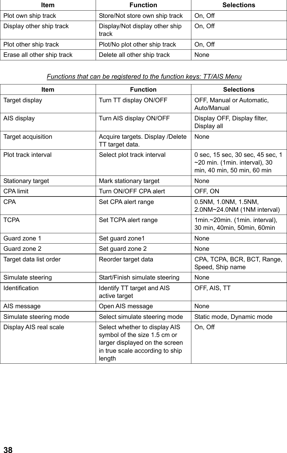
![366. Select the function to register then left-click. 7. Right-click several times to close the menu. The following table shows the functions that can be registered. Nothing is registered when [None] is selected. Functions that can be registered to the function keys: Echo Menu Item Function Selections Image Switch image preset of images. (See chapter 1.26.) CUSTOM0 or 1,2,3,4,5,6,7,8,9,10,11 Interference rejection Select setting value of interference rejection function Off, 1,2,3 Zoom Select setting value of Zoom image function Off, 1,2,3 Signal processing Select setting of the signal processing function Off, 1,2,3,4,5 Noise rejection Turn ON/OFF the noise rejection function On, Off Antenna selection Select reference position (See chapter 1.29.) Antenna, Steering position Pulse length Select pulse length - 0.125,0.25,0.5NM: S - 0.75,1,1.5,2NM: S1, M1 - 3NM: S,M1,M2 - 4, 6, 8, 12, 16, 24NM: M1, M2, L - 32,48,72,96,120NM: only L Sea clutter rejection Select method of sea clutter rejection Manual, Automatic Precipitation clutter rejection Switch between precipitation clutter rejection function and unwanted echo rejection function. Precipitation clutter rejection (manual), unwanted echo rejection Tuning selection Select tuning method Manual, Automatic Second-trace echo rejection Turn ON/OFF the second-trace echo rejection function On, Off Performance monitor Do not use. None SART Select whether to change radar setting or not to make SART images better. On, Off Trail T/R Select operation mode (Relative, True) of echo trail. Relative, True, True-s Wiper Turn ON/OFF the wiper processing function On, Off Trail color Select trail color Blue, Green, Turquoise](https://usermanual.wiki/Furuno-USA/9ZWRTR110.operators-manual/User-Guide-1672487-Page-46.png)
![37Functions that can be registered to the function keys: Standard Key Menu Item Function Selections Stop alarm sound Stop flashing of alarm box and alarm sound None Transmission getting ready Switch between [Getting ready] and [Transmission] Getting ready, Transmission EBL offset Offset EBL/Cancel Offset EBL None Mode Select display preset display mode Head-up, Cursor gyro, Stern-up, Course-up, North-up, True motion Off center Turn ON/OFF Off center function None CU/TM reset Course-up: Heading line is on the top True motion: Return own ship position to 75% radius in opposite direction against its course None Parallel cursor Turn ON/OFF parallel cursor On, Off Vector time Select vector time 0 sec, 15 sec, 30 sec, 45 sec, 1 ~20 min. (1min. interval), 30 min, 40 min, 50 min, 60 min Vector True/Relative Select vector mode, Relative, Relative, True, True-s Target data list Open/Close target data list None Trail Select trail time Off, 15 sec, 30 sec, 45 sec, 1 ~20 min. (1min. interval), 30 min, 40 min, 50 min, 60 min, 12 hours, 24 hours, 48 hours, Continuous Color scheme Select color of full screen Day, Dust-green, Dust-white, Night-red, Night-blue, Black, Custom1, Custom 2 Full screen Select display area of echo Standard, Full screen Chart overlay Display/Not display chart overlay OFF, ON Mark Insert marks and waypoints None Menu Open/Close main menu None Range (+) Increase range None Range (-) Decrease range None Acquisition Acquire target. Display/Delete target data None AIS data Display/Delete AIS target data None Erase target Cancel track of TT target selected. Inactivate AIS active target None Display own ship track Display/Not display own ship track On, Off](https://usermanual.wiki/Furuno-USA/9ZWRTR110.operators-manual/User-Guide-1672487-Page-47.png)
![39Functions that can be registered: Control menu Item Function Selection Echo color Select color of target echo Yellow, Green, White, Multiple green, Multiple Gray, Multiple Blue Color scheme Change [Color scheme] in the [Set environment] menu White, White text on blue background, Gray, Blue, Red, Green, Black Fixed range ring Select Display/Not display fixed range ring None Guard 1 Set Guard alarm1 None Guard 2 Set Guard alarm 2 None Watch alarm reset Reset time in the Watch alarm box None Delete mark Delete mark, waypoint and line selected None MOB Mark at man overboard. Range, bearing, estimated time to MOB position is displayed in the information display area when [Destination data] setting in the [Navigation data] menu is other than [OFF]. None Anchor watch alarm Turn ON/OFF anchor watch alarm On, Off Drop mark Turn ON/OFF drop mark function On, Off Erase all marks Delete all marks None Erase all own ship tracks Delete all own ship marks None Zoom Activate zoon cursor None TLL Plot data at target position (cursor position) on radar screen. None Functions that can be registered: Image Menu Item Function Selection Custom 0, Custom1 Custom 2, Custom 3 Custom 4, Custom 5 Custom 6, Custom 7 Custom 8, Custom 9 Custom 10, Custom 11 Call image setting of selected items None](https://usermanual.wiki/Furuno-USA/9ZWRTR110.operators-manual/User-Guide-1672487-Page-49.png)
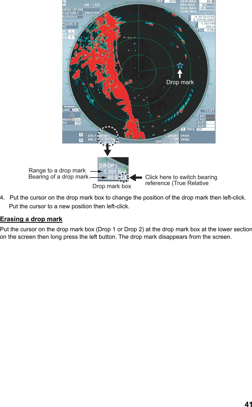
![402.4 Drop Mark User can insert a drop mark at a selected location on a geographical map as a stationary point. Range and bearing to that location such as a lighthouse or a passage buoy can be displayed at all times. Numeric values of the drop mark are updated with own ship’s movement. 2.4.1 Activating the drop mark function Follow the steps below to activate the drop mark function. 1. Put the cursor on the MENU in the information display area then left-click. 2. Select the [Set environment] menu then left-click. 3. Select [Mark] then left-click. 4. Select [Drop mark] then left-click. 5. Select [On] then left-click. (Two-drop mark boxes are shown at the lower section on the screen. (See chapter 2.4.2.) 6. Right-click several times to close the menu. 2.4.2 Inscribe/Erase drop mark Inscribing a drop mark Own ship position data is required to inscribe a drop mark. 1. Put the cursor on the drop mark box (Drop 1 or Drop 2) at the lower section on the screen then left-click. The cursor moves within the valid radar image area. A star mark of turquoise color is attached at the cursor. 3. Move the cursor to a position to where you want to measure range and bearing then left-click. A drop mark is inscribed on the screen. A turquoise broken line connects the own ship and the drop mark and range and bearing are displayed in the drop mark box.](https://usermanual.wiki/Furuno-USA/9ZWRTR110.operators-manual/User-Guide-1672487-Page-50.png)
![422.5 Watch Alarm The watch alarm sounds the audio alarm at the selected time interval to help you keep periodic watch of the radar picture for safety or other purposes. The watch box appears at lower right section on the screen showing count down time until audio alarm sounds. Setting Watch Alarm Follow the steps below to set the watch alarm. 1. Put the cursor on [Menu] in the information display area then left-click. 2. Select [Alarm] then left-click. 3. Select [Watch alarm] then left-click. 5. Select appropriate time interval then left-click. The watch alarm box is displayed at the lower right section on the screen except when [Off] is selected. 6. Right-click several times to close the menu. The set time is counted down and sounds the alarm when it is counted down to [00:00]. [Watch alarm] flashes in the alarm box in the information display area. Press the [Cancel alarm] key to stop the audio alarm. Start over the countdown. Resetting time interval Left-click the time indication in the watch alarm box before the set time is counted down to reset the time interval set in step 4 about to start over the countdown.](https://usermanual.wiki/Furuno-USA/9ZWRTR110.operators-manual/User-Guide-1672487-Page-52.png)
![432.6 Zoom The zoom function enlarges an area of interest. There are four types of zoom function. • Offset zoom: Enlarges area selected with the zoom cursor. • Double zoom: Enlarges a picture inside of the zoom cursor twice as large. • Triple zoom: Enlarges a picture inside of the zoom cursor three times as large. • Target zoom: Enlarges a picture fixed as TT target inside of the zoom cursor twice as large. (See chapter 3.9 for details.) Note: TT target or AIS target symbols are not enlarged. 2.6.1 Using Offset zoom The offset zoom function can be used in the display modes other than true dynamic mode. 1. Put the cursor in the valid radar display area then right lick. 2. Select [Offset zoom] then left-click. The zoom cursor appears on the screen. 3. Move the zoom cursor to a desired location to zoom then left-click. The area selected with the zoom cursor is enlarged. Zoom cursor Note: Left-click again while zooming to cancel the zoom function.](https://usermanual.wiki/Furuno-USA/9ZWRTR110.operators-manual/User-Guide-1672487-Page-53.png)
![442.6.2 Double zoom and Triple zoom Zoom window and cursor information cannot be displayed simultaneously in the information display area. Selecting zoom ratio 1. Put the cursor on [Menu] in the information display area then left-click. 2. Select [Set environment] then left-click. 3. Select [Navigation data] then left-click. 4. Select [Zoom mode] then left-click. 5. Select [2 x] or [3 x] then left-click. The zoom cursor appears at the screen center. [Cursor data] setting in the [Navigation data] menu becomes [Off]. The zoom function does not work when [OFF] is selected. 6. Right-click several times to close the menu. Zoom window appears in the information display area. Select a location to zoom 1. Put the cursor in the effective radar display area then right-click. 2. Select [Zoom] from the [Cursor] menu then left-click. The zoom cursor at the screen center becomes operable. 3. Move the zoom cursor to a desired location to zoom then left-click. The zoom cursor is fixed and an image inside of the zoom cursor enlarges to double or triple size in the zoom window.](https://usermanual.wiki/Furuno-USA/9ZWRTR110.operators-manual/User-Guide-1672487-Page-54.png)
![45Zoom cursor Note 1: Select [Cancel zoom] from the [Cursor] menu then left-click to cancel the zoom function. Note 2: Select [Zoom with fixed land] in the [Navigation data] menu to zoom display with land fixed. See chapter 2.10.6 for fixing land. 2.7 Anchor Watch Alarm The anchor watch function alerts you when your ship has traveled a distance greater than a threshold value with the reference position (antenna or steering position) at its center. Set rangeOwn ship position: Alarm triggeredReference position 1. Put the cursor on [Menu] in the information display area and left-click 2. Select [Set environment] then left-click. 3. Select [Mark] then left-click. 4. Select [Anchor watch alarm] then left-click. 5. Select [On] then left-click. 6. Select a line in the anchor watch range and left-click. 7. Input setting value. 7. Right-click several times to close the menu. A dashed circle with a set radius appears. When own ship goes out the circle, [Anchor watch alarm] flashes in the alarm box in the information display area. Select [Off] at step 5 to cancel the anchor watch alarm.](https://usermanual.wiki/Furuno-USA/9ZWRTR110.operators-manual/User-Guide-1672487-Page-55.png)
![462.8 Priority Order of Various Alarms Priority order of various alarms is explained in Chapter 1.28. This Chapter explains the priority order of 2 and 3 settings. 1. Put the cursor on [Menu] in the information display area and left-click. 2. Select [Alarm] then left-click. 3. Select [Priority alarm] then left-click. 4. Roll the wheel to select an alarm for which to change the priority order then left-click. See the menu list at the end of this manual to see all the items in the [Priority alarm] menu. 5. Select [Priority High] (Priority order 2) to raise the priority and [Priority Low] (Priority order 3) to lower the priority then left-click. 6. Right-click several times to close the menu.](https://usermanual.wiki/Furuno-USA/9ZWRTR110.operators-manual/User-Guide-1672487-Page-56.png)
![472.9 Color Scheme Brilliance of marks and texts and color of targets can be set by color scheme. Color and brilliance sets can also be customized and registered in [Custom 1] and [Custom 2]. 3. Put the cursor on [Menu] in the information display are then left-click. 4. Select [Set environment] then left-click. 5. Select [Color scheme] then left-click. 4. Select the color scheme to change then left-click. Cannot change Daytime is selected](https://usermanual.wiki/Furuno-USA/9ZWRTR110.operators-manual/User-Guide-1672487-Page-57.png)
![485. Select the item to change then left-click. Menu Item Contents Echo color Select color of target echo. (Yellow, Green, White, Multiple green, Multiple gray, Multiple Blue) - Multiple green: Displays four colors Red→Orange→Yellow→Green according to strength of receiving echoes. - Multiple gray: Displays 3 colors Dark red→Yellow→Gray according to strength of receiving echoes. (The color set is easy to see when the setting of [Chart color] in the [Vector chart] menu is [Daytime color].) - Multiple blue: Displays 4 colors Red→Orange→Yellow→Turquoise according to strength of receiving echoes. Brilliance Change brilliance of screen. Reset to factory default Reset items in the [Color scheme] menu at factory default. Brilliance detail Open [Brilliance detail]. Radar base color Select effective radar range (Black, Dark blue). Panel brilliance Adjust brilliance of panel including power lamp. Back ground brilliance Adjust brilliance of background. Test Adjust brilliance of texts displayed on the screen. Icon box background Adjust brilliance of boxes on the screen. Cursor (small) Adjust brilliance of cursor (small). Echo Adjust brilliance of target echoes. Trail Adjust brilliance of echo trail. Heading line Adjust brilliance of heading line and no transmission zone. Fixed range ring Adjust brilliance of fixed range ring. Cursor (large) Adjust brilliance of cursor (large). EBL Adjust brilliance of EBL1 and EBL2. VRM Adjust brilliance of VRM1 and VRM2. Parallel cursor Adjust brilliance of parallel cursor. Own ship mark Adjust brilliance of own ship mark. Track Adjust brilliance of track. TT mark Adjust brilliance of TT mark. AIS symbol Adjust brilliance of AIS symbol. Latitude/Longitude Adjust brilliance of latitude and longitude. Mark/Destination Adjust brilliance of marks and destinations. Line Adjust brilliance of lines. Chart Adjust brilliance of charts. Depth Adjust brilliance of depth value on chart. Individual contour line Adjust brilliance of individual contour line on chart. 6. Right-click several times to close the menu.](https://usermanual.wiki/Furuno-USA/9ZWRTR110.operators-manual/User-Guide-1672487-Page-58.png)
![492.10 Menus of Each Function 2.10.1 Setting fixed range ring Put the cursor on the fixed range ring interval at the upper left position on the screen then right-click to display the [Fixed range ring interval] menu. Fixed range ring interval mode: Select a display mode of the fixed range ring. Standard: Automatically display optimum number of fixed range ring according to the range selected. Manual: Display number of fixed range ring set regardless of the range selected. Fixed range ring interval: It becomes effective when [Manual] is selected in the above [Fixed range ring interval mode]. User can specify the number of fixed range ring between one and nine. 2.10.2 Preset ting display modes Put the cursor on the display mode box at the upper left position on the screen then right-click to display the [Display mode] menu. Select whether to use each display mode [On] or not [Off]. Only the display mode that is turned on can be switched with the [Select mode] key. Head-up mode cannot be turned off. 2.10.3 Setting parallel cursor Put the cursor on [PI1], [PI2], [P13] or [P14] in the parallel cursor box at the lower left section on the screen then right-click to display the [Parallel cursor] menu. Parallel cursor bearing: See chapter 1.25.3. Number of parallel cursor: Select number of parallel cursor from one to ten. When ten is selected, ten intervals and eleven parallel cursors are shown.](https://usermanual.wiki/Furuno-USA/9ZWRTR110.operators-manual/User-Guide-1672487-Page-59.png)
![50Parallel cursor mode: Select parallel cursor mode. When the number of parallel cursor is one, only lines are shown that are parallel to the reference line. Vertical: Display parallel lines that are perpendicular to the reference line. Horizontal: Display parallel lines are parallel to the reference line. Parallel cursor reset: See chapter 1.25.4. Reference linePerpendicular Horizontal0°0° 2.10.4 Custom settings Register image setting User can register custom settings at [CUSTOM0 ~ CUSTOM4] in the image box according to their situation. Settings can be edited as necessary except for [CUSTOM0 ~ CUSTOM4]. 1. Put the cursor on the image box at the upper left section on the screen. 2. Left-click to select [CUSTOM0], [CUSTOM1], [CUSTOM2], [CUSTOM3] or [CUSTOM4]. 3. Right-click. CUSTOM 1 selected](https://usermanual.wiki/Furuno-USA/9ZWRTR110.operators-manual/User-Guide-1672487-Page-60.png)
![514. Select [Edit] then left-click. 5. Select an item to change then left-click. Menu Item Contents Interference rejection Select interference rejection setting. (See chapter 1.20.) Zoom image Select image zoom setting. (See chapter 1.21.) Signal processing Select signal image setting. (See chapter 1.22.) Noise rejection Turn the noise rejection function* ON/OFF. *: Function to remove white noise appearing on radar echoes. Wiper Turn the wiper rejection function* ON/OFF. *: Function to make images more visible by automatically changing brilliance of signals. Video slope Set dynamic range (1 ~ 4). 1 is the widest dynamic range. 4 is the narrowest dynamic range. Video slope type Set curve indicating strength of video signal. A: Low at mid curve. Suitable for suppressing precipitation clutter B: Curve between A and C C: High at mid curve. Suitable for detecting far range target](https://usermanual.wiki/Furuno-USA/9ZWRTR110.operators-manual/User-Guide-1672487-Page-61.png)
![52Menu Item Contents Near range STC curve Change setting in accordance with sea condition. (2.5, 3.0, 3.5, 4.2) The larger the value, the stronger the effect of STC Color erase Erase color in the order of weaker echo first (1~8). The larger the value, the weaker the color TT echo level Set echo detection level (1~31). Echoes at the lower level than the set value do not track for TT. Band width Set according to sea state. Narrow: Gain is high compared to wide. Wide: Effective for detecting targets masked by the returns from the sea and rain. Range (0.75~24 NM) Select transmission pulse length of preset for each range. Range Select unit of far range. (NM, km, etc.) Range unit of VRM and cursor position also change. Unit for near range Select unit of near range. (m, etc.) Range unit of VRM and cursor position also change. Switch unit of range Set value (0.0~9.9) to switch the above [Range] and [Unit for near range]. E.g. When [5.0] (NM or km) is set, the unit becomes the units of far range when the range value is over 5.0 and the units of near range when the range values is under 4.9. Unit of ship length Select unit of ship length. (m, etc.) VRM automatic unit Select whether to switch unit of VRM range ON or OFF at the above [Switch unit of range] setting. When OFF is selected, put the cursor on the unit inside of the VRM box then left-click to switch the unit. Image name Change image name. Return to factory default Reset image setting of the CUSTOM No. selected at step 2. 6. Select [Save and finish] at the lowest section of the [Edit image] menu to save the registered contents then left-click. 7. Right-click several times to close the menu. The above settings can be reflected also to the function keys when image settings are registered in the function keys of F1, F2, Vector True/Relative, Target data list. Note: When the menu is closed without step 6, the icon shown below is displayed between the image box and the interswitch box. Left-click the icon to register the above settings and the icon disappears.](https://usermanual.wiki/Furuno-USA/9ZWRTR110.operators-manual/User-Guide-1672487-Page-62.png)
![54Turning off unused image settings There are twelve settings in the image box. You can turn the unused settings off. You can switch the settings of image that are turned [On] in the image box by left-clicking. Note: [CUSTOM0] and items currently open cannot be turned off. 1. Put the cursor on the image box at the upper left section on the screen then right-click. 2. Select [Preset] then left-click. 3. Select an item to change then left-click. 4. Select [Off] then left-click. 5. Right-click several times to close the menu. Items in gray background cannot be changed](https://usermanual.wiki/Furuno-USA/9ZWRTR110.operators-manual/User-Guide-1672487-Page-64.png)
![552.10.5 Setting Trails Put the cursor on [Trail] in the trail box at the lower right section on the screen then right-click to display the [Trail] menu. Trail mode: Set Relative, True, Water True. (See chapter 1.23.2 for details.) Trail gradation: Select a trail gradation. Single gradation: Display in the same shade. Gradual gradation: Gradually shades as time passes. Single gradation Gradual gradation Trail level: Select strength of target echo to trail from 1~4. No echo trail under the set value. Own ship trail: Select thickness of own ship track (1, 2). [2] is a thicker track than [1]. No own ship track is displayed when [OFF] is selected. Thin line trail: Select thickness of track. (OFF, 1, 2). It is useful when there are many targets as a track can be drawn with a thin line. [OFF] draws the thickest track and [2] draws the thinnest track. Trail color: Select trail color from blue, green and turquoise. The trail color changes in the order shown below as the time passes when the trail time settings are 12 hours, 24 hours or 48 hours, and above [Trail gradation] setting is [Monotone]. (12 hours: every one hour, 24 hours: every two hours, 48 hours: every four hours) Pink→ Reddish brown→ Red→ Purple→Yellow→Yellowish green→Green→Brownish green→Bluish green→Turquoise→Blue→Dark blue Echo trail copy: Select the trail copy function ON (Auto) or OFF. Settings Function ON, Auto When range is changed during trail, it becomes the following condition. - Range is set larger: Only the center section of the new range, or only the trail in the previous range continues on the display. Nothing is displayed outside the new range. - Range is set smaller: Trail continues with the previous trail on the display.](https://usermanual.wiki/Furuno-USA/9ZWRTR110.operators-manual/User-Guide-1672487-Page-65.png)
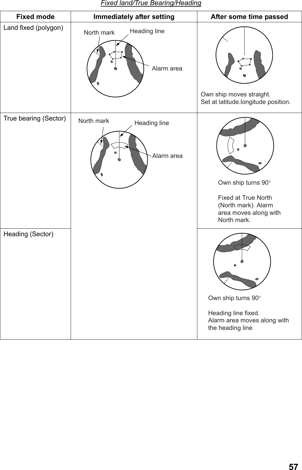
![56Trail is not copiedRange before the change Range after the change Note: When [Auto] is selected and range is changed to under ¼ of the current range, the previous trail disappears and a new trail is redrawn. For example, for 3NM, trail continues up to 0.75NM and disappears under 0.5NM. When the range is returned to ¼ of the original range within about 12 seconds after the range is changed, the previous trail continues. OFF Trails disappear in the previous range when range is changed during trailing. 2.10.6 Guard Alarm Put the cursor on the box by [Guard1] or [Guard2] at the lower right section on the screen then right-click to display the [Guard alarm1] or [Guard alarm2] menu. Status: Display operating condition of guard alarm. Delete: Delete guard alarm. Reset: Reset alarm area Area shape: Select a shape of guard area. (Sector, Polygon). When [Polygon] is selected, the setting of [Sector fixed mode] becomes [Land fixed*] *: Alarm area is fixed on land. Sector fixed mode: Select a method to fix alert area of a sector when [Sector] is selected in the above [Watch shape]. • Land fixed: Cannot use. • True bearing: Alarm area is fixed from true North. • Heading: Alarm area has the same positional relationship with own ship’s heading.](https://usermanual.wiki/Furuno-USA/9ZWRTR110.operators-manual/User-Guide-1672487-Page-66.png)
![582.10.7 Cursor Put the cursor in the valid radar then right-click to display the [cursor] menu. Target acquisition: Acquire target. (Same as the [Acquisition] function. See chapter 3.4.3.) Fixed target: Assign a fixed point mart to target. (See chapter 3.3.) EBL offset: Offset EBL origin. Zoom/Cancel Zoom/Offset Zoom: See chapter 2.6. PI Offset: Move origin of parallel cursor. 1) Display parallel cursor. (See chapter 1.25.1.) 2) Select [PI offset] from the [Cursor] menu then left-click. 3) Move the origin of parallel cursor to an arbitrary position then left-click. The parallel cursor is set. 4) Put the cursor on [PI1], [PI2], [PI3] or [PI4] in the parallel cursor box then long press the left button to return the origin of parallel cursor to the center of the screen. 2.10.8 Setting Ship Speed Put the cursor on the areas of ship speed or ship speed in starboard direction in the information display area then right-click to display the [Ship speed] menu. Ship speed in useInput source of ship speed data Ship speed: Select ship speed to use. (Speed over ground, Speed over water) [Ground] is shown when speed over ground is in use and [Water] when Speed over water is in use. Speed over ground: It becomes effective when [Speed over ground] is selected at the above [Ship speed]. Select input source of speed over ground data. • GPS: Received from GPS navigation equipment. • Log (Ground): Received from speed log. • Comparative ship speed: Speed over ground is used that is computed with the reference of fixed target selected in the TT function.](https://usermanual.wiki/Furuno-USA/9ZWRTR110.operators-manual/User-Guide-1672487-Page-68.png)
![59Speed over water: It becomes effective when [Speed over water] is selected in the above [Ship speed]. Select input source of speed over water data. • Log (Water): Read from speed log. • Manual: Use ship speed inputted manually. Manual ship speed: Input ship speed manually when speed log or GPS navigation equipment are not connected, or ship speed data are no longer available. Current correction: Select [Speed over water] at the above [Ship speed] and turn on the current correction when speed over ground is unavailable such as in deep water area to compute speed over ground. [Speed over water correction] is displayed during the current correction. Correct current direction/speed: Refer to the current table issued by the waterways authority when [Current correction] is turned on to set bearing and speed of current. 2.10.9 Setting Date Put the cursor on the date section in the information display area then right-click to display the [Date] menu. Standard time: Select display method of date and time (Standard time, Local time) Time zone: Time zone is effective when [Local] is selected in the above [Standard time]. Local time is displayed by setting the time difference between the Greenwich Mean Time. 2.10.10 Setting own ship position Put the cursor on the position area in the information display area then right-click to display the [Own ship position] menu. Select navigation: Select input source of datum positioning data. (Dead Reckoning, GPS) Manual input latitude/longitude: It becomes effective when [Dead reckoning] is selected in the above [Select navigation method]. Input latitude and longitude manually. Roll the wheel to witch between North/South latitude and East/West longitude.](https://usermanual.wiki/Furuno-USA/9ZWRTR110.operators-manual/User-Guide-1672487-Page-69.png)
![602.10.11 Setting Tuning Initialize tuning when automatic tuning is not working properly to show clear images. Put the cursor on [Tuning] at the upper right section on the screen then right-click to display the [Set tuning] menu. Left-click [Initialize tuning] to start initializing tuning. The indication [Initialize tuning] flashes. Press the [Cancel alarm] key to change the flashing to lighting. Initialization is completed when the display disappears. 2.10.12 Getting ready to transmit Put the cursor on the Getting ready/Transmission box on the upper left section on the screen then right-click to open the [Getting ready to transmit] menu. Left-click [Running time] to check the current running time and the transmission time. The menu disappears automatically after about five seconds. 2.11 Menu Items Items not explained previously are explained here. 2.11.1 Echo menu Second-trace echo rejection: Second-trace echoes of very distance targets may appear as false echoes on the screen. This occurs when the return echo is received one transmission cycle later. Mountains in far distance, for example, have strong reflections making second-trace echoes more likely to occur. Turn the rejection of second-trace echo ON to reject second-trace echo. Performance monitor: Not used. SART: When SART (Search and Rescue Transponder) power is turned ON from a ship in distress within 8NM range from own ship, response signal is transmitted from SART in response to the radar signal of own ship. When the signals are received by this equipment, the image appears as shown below (a line of 12 dots equally spaced by about 0.64 NM) Screen 1 shows when the ship in distress is at relatively far distance and only low speed sweep signals are](https://usermanual.wiki/Furuno-USA/9ZWRTR110.operators-manual/User-Guide-1672487-Page-70.png)
![61displayed. It shows the ship in distress is located at the closest position from the center of the radar. When own ship is about 1NM to SART, high speed sweep signals are also displayed as shown in Screen 2 (12 dots in arc shape) When the radar is turned [On], the setting changes as below to make SART image easier to see. Range: 12NM, Pulse length: Long, Precipitation rejection: Manual (0) Settings of second-trance echo rejection, wiper, zoom image, noise rejection, and signal processing cannot be changed. 9500 MHz9200 MHz7.5μs 95μs 24 NM 1.5 NMScreen1: When SART is distant Screen2: When SART is closeEcho from SART Radar antenna bandwidthEcho from SARTPosition of SARTOwn ship positionRadar receiver bandwidthSART mark lengthSweep timeSweep start Low speed sweep signalHigh speed sweep signalPosition of SARTOwn ship position GC-10: Set a correct value to match the indication of Gyrocompass when heading value is incorrect. 2.11.2 Alarm Menu Guard alarm level](https://usermanual.wiki/Furuno-USA/9ZWRTR110.operators-manual/User-Guide-1672487-Page-71.png)
![62 Guard alarm mode: Select guard alarm mode. - Enter: Alarm is generated when other ship, island and reef enter into the set area. - Exit: Alarm is generated when targets inside of the set area exit the set area. Guard alarm level: Echo strength of target from level 1 ~4 to generate alarm. Level 4 is a strong echo against which alarm is generated. Water temperature alarm: Data on water temperature is required. Select water temperature alarm mode. - High: Alarm sounds and displays an alarm message when own ship enters water with higher temperature than set temperature. - Low: Alarm sounds and displays an alarm message alert when own ship enters water with lower temperature than set temperature. Guard alarm setting: Set whether to output alert sounds and message when targets enter or exit alarm area. - On: A single beep is emitted when echoes exist in the alarm area and alarm sounds and an alarm message is displayed. - Off: Only a single beep sounds when echoes exist in the alarm area. When external buzzer is connected, the following condition occurs. See the installation manual when [Guard alarm] has a checkmark in [Common 2] – [Alarm external output] in the initialization wizard. - When the above setting is [On]: Alarm sounds from an external buzzer. - When the above setting is [Off]: Only single beep sounds from an external buzzer. Alarm volume: Select alarm volume from low, mid and high. No alarm sounds when alarm volume is [Off]. 2.11.3 Set Environment Menu Mark menu Enter mode Exit mode](https://usermanual.wiki/Furuno-USA/9ZWRTR110.operators-manual/User-Guide-1672487-Page-72.png)
![63Own ship mark: Select a shape of own ship mark from smallest, real scale and circle. Real scale symbol is displayed in the ship mark in accordance with ship length and beam of own ship. The ship mark disappears when own ship mark becomes less than about 2.5cm on the screen to become the smallest symbol. Size of own ship is entered at installation. Own ship mark disappears when the setting is [OFF]. Heading lineHeading line Heading lineBean line Bean lineTrue scale symbol The smalles symbol Circle symbol*When [Own ship track memory] is ON in the [Own track] menu*When [Own ship tack memory] is OFF in the [Own track] menu a white circlile is show . Stern line: Stern line is displayed opposite of the heading line when it is turned ON. EBL offset reference point: Select a reference point of EBL offset. - True bearing: The reference point is fixed at a position from true north. - Relative bearing: The reference point maintains the same position relationship with own ship’s heading line. - Land fixed: The reference point is fixed at a position on land. VRM offset link: Select whether to link VRM reference point to the reference point of EBL. - On: VRM reference point is linked to EBL reference point. - Off: VRM reference point is at the center of own ship at all times. Cursor bearing scale: Bearing scale on the screen is displayed with 360 ゚or 16 bearing. 000 010 020030040050060070080090100110120130140150160170180190200210220230240250260270280290300310320330340 350 NNNENEENEEESESESSESSSWSWWSWWWNWNWNNW16 bearing360° PI line operation: Select whether to display PI line linking EBL2 and VRM2. Width of heading line: Select width of heading line from standard, double and quadruple. Color of heading line: Select color of heading line from red, green, blue, yellow, turquoise, purple and white.](https://usermanual.wiki/Furuno-USA/9ZWRTR110.operators-manual/User-Guide-1672487-Page-73.png)
![64Navigation data menu [Wind direction/Speed] ON(True of Relatic\ve)[Cursor info] ONInside of information display area[Destination data] ON[Water deoth] ON[Current] ON Cursor data: Select whether to display cursor data in the information display area. When [On] is selected the setting of [Zoom mode] in the [Navigation data] menu is [OFF]. Water depth: Select whether to display water depth in the information display area. Fish finder needs to be connected to display water depth. Water depth alarm: Alarm sounds when water depth from the [Water depth reference] is shallower than the set value. [Water depth] flashes in the alarm box in the information display area. Water depth reference: Select a reference of water depth. - Sea surface: Display water depth from transceiver. - Keel: Display water depth from keel. Current: Select whether to display current speed/direction in the information display area. Current meter needs to be connected to display current. Bearing of current is referenced to own ship’s heading (R: relative) in Head-up, Cursor gyro and Stern-up modes. North (Blank: True) is referenced in Course-up, North-up and True motion modes. Wind speed/direction: Select whether to display wind speed/direction in the information display area. Connection of wind speed/direction sensor is required. Select [Relative] or [True] to display data received from the wind speed/direction sensor. Water temperature: Select whether to display water temperature in the information display area. Water temperature data are required to display water temperature. Destination data: Select whether to display range and bearing and estimated time from own ship to destination. Select [Relative] or [True] to display destination data. Target data: Select number of boxes (1BOX, 2BOX) to display TT target or AIS target data in the information display area.](https://usermanual.wiki/Furuno-USA/9ZWRTR110.operators-manual/User-Guide-1672487-Page-74.png)
![65Control menu Wheel: Select direction of rotation of wheel. - Forward: The selection cursor moves from top to down when wheel is rolled toward you on the menu. - Backward: The selection cursor moves from down to top when wheel is rolled away from you on the menu. Key operation sound: Select volume of sound from Low, Mid and High when key is pressed. No sound is emitted when [Off] is selected. Own ship vector: Select a method to display own ship vector. No own ship vector is displayed at [OFF]. - Heading: Display own ship vector toward heading. - Course: Display own ship vector toward course. Courser size: Select cursor size from Small or Large. Set the cursor size Large when small cursor became invisible buried in echoes when using the small cursor. Small cursor Large cursor(Up to the edge of the screen) Unit menu Water depth: Select unit of water depth from m, ftm, etc. Water temp: Select unit of water temperature from °C or °F. Speed: Select unit of speed from kn, m/s, km/h, mph. Wind speed: Select unit of wind speed from j/s, kn.](https://usermanual.wiki/Furuno-USA/9ZWRTR110.operators-manual/User-Guide-1672487-Page-75.png)
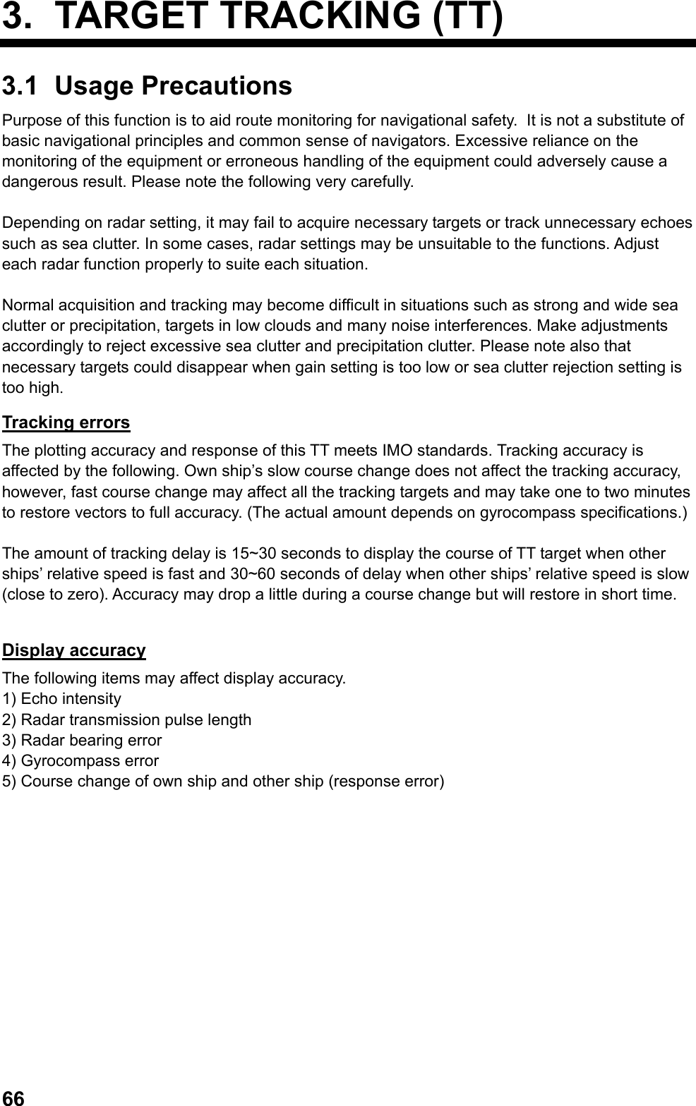
![673.2 Turning TT ON/OFF Follow the steps below to turn TT display ON/OFF. 1. Put the cursor on TT box in the information display area. DISP OFFTT box 2. Left-click to select [Auto/Manual]* or [OFF]. *: Either [Manual] or [Auto] is displayed depending on [TT target] menu setting. Auto, Manual, Auto/Manual: Display TT target on the screen. OFF: Delete TT target from the screen. 3.3 Ship Speed Input The TT requires own ship’s speed and heading data. The speed can be speed over ground, speed over water, or echo-referenced speed (based on 3 max. stationary objects). Echo-referenced ship speed is explained here. The use of echo-referenced speed is recommended when: • The speed log is not operating properly or not connected to the radar. • The vessel has no device (Doppler sonar, speed log, etc.) • No position sensor input If you select echo-referenced speed, the TT calculates own ship’s speed relative to a fixed reference target. This method is effective when error is large due to ship’s port-starboard movement. The number of targets may be numbered R1, R2 or R3. 1. Select [Speed over ground] for [Ship speed] in the [Ship speed] menu. (See chapter 2.10.8.) 2. Select [Echo-referenced speed] for [Speed over ground] in the [Ship speed] menu. [Echo-referenced speed] is displayed in the ship speed section in the information display area. 3. Move the cursor to a stationary object such as a small island or a light house within 0.1~24 (or 32) NM range from own ship. 4. Right-click to display the [Cursor] menu. 5. Select [Stationary target] then left-click. A fixed point mark is entered at the cursor position. Ship speed is displayed after about one minute. Immediately after after 3 min Fixed point mark 6. Repeat steps 3~5 to mark the maximum of three stationary objects. Note1: The fixed point mark disappears when echo disappears during acquisition and tracking stationary target. The flashing indication [Stationary target lost] is displayed in the alarm box in the information display area. Note 2: Put the cursor on the fixed point mark then press the [Delete target] key to delete the fixed point mark. Note 3: You can display a vector on a stationary object by selecting [On] at [Fixed target vector] in the [TT target] menu.](https://usermanual.wiki/Furuno-USA/9ZWRTR110.operators-manual/User-Guide-1672487-Page-77.png)
![68Notes on input of speed with a fixed target • Select a stationary target as a reference target to calculate own ship speed as ground tracking speed. Do not choose a moving target as a reference target. A moving target produces in error in the vector for TT and AIS, which results in wrong collision avoidance information. Further, an unstable stationary target produces inaccurate speed data and the target itself may become lost. • When all stationary targets are lost, the ship speed values becomes [---] in the information display area. Reselect other stationary targets. • When acquisition of all targets is interrupted, acquisition of stationary targets is also interrupted and calculation of echo-reference speed becomes impossible. Stop echo-referenced display Select [GPS] or [Log (over ground)] for [Speed over ground] in the [Ship speed] menu. 3.4 Target Acquisition and Tracking This equipment can acquire and track targets using the TT function either automatically or manually. 3.4.1 Number of automatic acquisition and manual acquisition This equipment can acquire the maximum number of 100 targets. The factory default setting is AUTO75. (See the table below.) Set distribution of automatic acquisition and manual acquisition. 1. Put the cursor on TT box in the information display area then right-click. 2. Select [Number of TT automatic acquisition] then left-click. 3. Select acquisition points necessary then left-click. Refer to the following table to decide distribution. Selection Maximum Number of Auto/Manual Acquisition Manual 100 Acquire all 100 targets manually. Auto 25 Acquire 25 targets automatically and 75 targets manually. Auto 50 Acquire 50 targets automatically and 50 targets manually. Auto 75 Acquire 75 targets automatically and 25 targets manually. Auto 100 Acquire all 100 targets automatically. 4. Right-click to close the menu. [Manual] is displayed in the TT box when [Manual 100] is selected at step 3, [Auto] when [Auto 100] is selected and [Auto/Manual] when other than [Manual 100] and [Auto 100] are selected.](https://usermanual.wiki/Furuno-USA/9ZWRTR110.operators-manual/User-Guide-1672487-Page-78.png)
![693.4.2 Automatic Acquisition When automatic acquisition area (guard zone) is set, the TT function automatically acquires and track targets entering into the guard zone. The maximum of two guard zones can be set. Sector shaped guard zone has a width of 0.5NM~1.0NM in the radial direction and is adjustable from 3.0 to 6.0NM. Polygon shaped guard zone is adjustable from 0.125~120NM. Area of automatic acquisition is from 0.1~24 (or 32) NM. The maximum tracking area varies depending on the setting of initialization wizard. (See the installation manual.) Setting a guard zone Follow the steps below to set a guard zone. Heading signal is required to activate the guard zone. 1. Put the cursor on the box by [AZ1] or [AZ2] at the lower right section on the screen. 2. Left-click. The cursor moves inside of the valid radar echo are and [Set] is displayed in the box. 3. Put the cursor on Point A in the desired area. The figure below shows an example of setting a guard zone. Point APoint APoint APoint BPoint BPoint B 4. Put the cursor on Point B in the desired area then left-click. The indication in the box changes to [Operating]. Guard zone is shown with broken line during the setting and the broken line changes to solid line when the setting is completed. When radar target enters the guard zone, it is regarded as dangerous target and TT mark flashes in red. [TT guard] in the alarm box in the information display area also flashes. Press the [Cancel alert] key to change the TT mark to lighting. The TT mark changes as the time passes as shown below. Vector (broken line or solid line) showing the moving direction of the target appears within one minute of acquisition.](https://usermanual.wiki/Furuno-USA/9ZWRTR110.operators-manual/User-Guide-1672487-Page-79.png)
![70VectorCircle with a thick dotted lineImmediately after acquisition1 minute passed after acquisition3 minute passedCircle with a solid line Setting of [TT vector] is [Dashed line] Note 1: When number of automatic acquisition target reaches 95% of the number set at Chapter 3.4.1, the flashing indication [TT target 95% (Auto)] appears in the alarm box in the information display area. Press the [Cancel alert] key. Note 2: When the guard zone extends over the display area when the range setting is small, [Over the range] indication appears in the box and the color of inside of the box changes. Note 3: When TT mark goes out of the guard zone, it is regarded as a normal target and the TT mark changes to the same one at the time of manual acquisition to continue tracking. (See chapter 3.12.2.) Note 4: To make a polygon shaped guard zone (3 ~ 10 point), move the cursor to a desired location then left-click. Repeat this operation to enter all the points. Polygon shaped guard zone • Polygon with less than ten points: Left-click again on the last point. The indication in the box changes to [Operating]. • Polygon with ten points: When the 10th point is placed, the indication in the box changes to [Operating]. No crossed lines can be drawn as shown below. Inactivating guard zone Follow the steps below to inactivate the guard zone. When the guard zone is inactive there is no automatic acquisition. 1. Put the cursor on the box by [AZ1] or [AZ2] to inactivate. 2. Left-click. The indication in the box changes to [Inactive] and the guard zone is shown in broken line. Dangerous target changes to a normal target (The same TT mark as that of manual acquisition). Note: To reactivate the guard zone, put the cursor on the inactive box then left-click.](https://usermanual.wiki/Furuno-USA/9ZWRTR110.operators-manual/User-Guide-1672487-Page-80.png)
![71Deleting a guard zone Follow the steps below to delete a guard zone. 1. Put the cursor on the box by [AZ1] or [AZ2] to delete. 2. Long press the left button until the indication disappears in the box. The guard zone disappears from the screen. Resetting a guard zone Do the following steps to reset the guard zone. 1. Put the cursor on the box by [AZ1] or [AZ2] to reset or on the guard zone on the screen. 2. Right-click to display the [Guard zone1] or [Guard zone 2] menu. Condition of guard zone 3. Select [Reset] then left-click. The guard zone on the screen disappears and the indication in the box changes to [Set]. 4. Reset the guard zone. 3.4.3 Manual acquisition Target acquisition should be done within 0.1 ~ 24 or 32 NM range and no sea clutter and precipitation clutter should exist. 1. Put the cursor over a target to acquire. 2. Press the [Acquire] key. TT mark changes as shown below as the time passes. Vector (broken line or solid line) indicating the moving direction of the target appears within one minute from the acquisition. VectorCircle with a thick dotted lineImmediately after acquisition1 minute passed after acquisition3 minute passedCircle with a solid line Note 1: When number of manual acquisition target reaches 95% of the number set at Chapter 3.4.1, the flashing indication [TT target 95% (Manual)] appears in the alarm box in the information display area. Press the [Cancel alert] key.](https://usermanual.wiki/Furuno-USA/9ZWRTR110.operators-manual/User-Guide-1672487-Page-81.png)
![723.5 Terminating Tracking When the TT has acquired the number of automatic acquisition (or manual acquisition), the message [TT target Full (Auto or Manual)] appears in the alarm box in the information display area and no more acquisition occurs unless targets are lost. Should this happen, cancel tracking of less dangerous targets. There are two methods to cancel tracking of acquisition target as shown below. • Cancel tracking target individually. • Cancel tracking all targets. Cancel tracking target individually 1. Put the cursor over TT mark for which to cancel tracking. When TT mark is selected correctly, the size of the mark gets larger. 2. Press the [Delete target] key. The TT mark disappears. Cancel tracking all targets Long press the [Delete target] to delete all TT marks and fixed point marks. 3.6 Lost Target Targets not detected in nine consecutive scans become “lost targets.” A lost target is shown in the display with flashing red “X”. [TT lost] is also flashes in the alarm box in the information display area. Before flashing(Flashing) After flasing Changes of mark before/after a lost target Acknowledge Lost target Press the [Cancel alarm] key to acknowledge a lost target. The lost target disappears from the screen. 3.6.1 Setting the lost target filter You can limit the lost target alarm to sound against lost targets by changing the maximum range or the minimum ship speed. 1. Put the cursor on [Lost target alarm] in the information display area. 2. Right-click o display the [Filer] menu.](https://usermanual.wiki/Furuno-USA/9ZWRTR110.operators-manual/User-Guide-1672487-Page-82.png)
![733. Select [Lost filter] then left-click. 4. Select [Maximum range] or [Minimum speed] then left-click. • Maximum Range: Any TT lost targets beyond this range will not trigger the lost target alarm. For example, when the setting is [5NM], TT over 5NM apart from own ship will not trigger the lost target alarm. TT within 5NM range will trigger the lost target alarm. • Minimum Ship speed: Any TT lost targets slower than this setting will not trigger the lost target alarm. 5. Select [On] then left-click. 6. Select a line within the setting limit then left-click. 7. Input value. 8. Right-click several times to close the menu. 3.6.2 Setting Lost Target Alarm Enable or disable the lost target alarm. Setting is the same with that of AIS target. (See chapter 4.9.2.) 1. Put the cursor on [Lost target alarm] in the information display area. 2. Left-click to select the setting. Each click switches between [OFF], [Filter] and [All]. • OFF: Disable the alarm. Lost targets automatically disappear. • Filter: Get the alarm against the targets whose criteria meet the settings in Chapter 3.6.1. • All: Get the alarm against all lost targets. 3.6.3 Re-acquiring a target with the same target number You can acquire a new target with the same target number of the lost target. Normally when a target is acquired, a target number is automatically assigned to it. This feature is useful when manually acquiring a target using the number of the lost target. 1. Put the cursor over the lost target. 2. Left-click. The lost target is surrounded with a broken line and a target number is assigned to it. (See chapter 3.7.1 for details.) 3. Press the left button and move the cursor to the position of a new target to acquire. A solid line connects the lost target to the cursor position. 4. Release the left button. The lost target selected in step 1 disappears and TT mark appears at the position specified in step 3.](https://usermanual.wiki/Furuno-USA/9ZWRTR110.operators-manual/User-Guide-1672487-Page-83.png)
![743.7 Displaying Target Data You can display bearing, range, course, over the ground speed of a tracked target. 3.7.1 Displaying data of individual target You can display two target data in one data box in the information display area. 1. Put the cursor on TT mark of which data to display. 2. Left-click. A target number is assigned to the TT mark. TT mark is surrounded with a dashed square when the setting of [Selection frame] is [On] (factory default) in the [TT/AIS symbol] menu. The selected target data is displayed in the data box in the information display area. 1Square of dashed lineTarget numberFactory Default ConditionTarget number TT 1Bearing Range Course SOGCPA TCPA BCR BCT61.5° 1.496 NM 246.7° 5.0 kn 1.085 NM 0’30s 1.745 NM 20’16s Display Item Contents Bearing Bering of a target seen from own ship Add [R] (Relative bearing) for Head-up and Stern-up mode. True bearing for other modes. Range Range from own ship to a target Course Course Over Ground of a target. Display [Water bearing] for water ship speed. Speed Over Ground Speed Over Ground of a target. Display [Speed over water] for Speed over water. CPA Range of target approaching own ship. TCPA Time to CPA. BCR Range from own ship when target crosses the heading. BCT Time until a target crosses the heading. Note 1: Select [2BOX] at [Target data] in the [Navigation data] menu to display the maximum of four target data. Note 2: Put the cursor over the target of which data are being displayed to delete target data then left-click.](https://usermanual.wiki/Furuno-USA/9ZWRTR110.operators-manual/User-Guide-1672487-Page-84.png)
![753.7.2 Display the target data list You can display a list of target data of all targets acquired with TT or AIS functions. Displaying the target data list Follow the steps below to display the list of target data. 1. Press the [Target data list] key (factory default) to display the target data list. Roll the wheel to scroll the target data. [>] is displayed when [TCPA] is over 99:59 min. Target that meet the identification criteria is assgined the mark in front of AIS and TT.Updatge buttonAIS(1) Target numberTCPABCTShip name (or MMSI no.)(): Indicates that target data is disolayed in the data box. Note: When other functions are registered to the [Target data list] key, put the cursor on [Target] at the lower right section on the screen then left-click. 2. Left-click the [Update] button on the upper section of the target data list to update data then left-click. Target data are automatically updated when the method of ordering is changed. 3. Right-click to close the target data list.](https://usermanual.wiki/Furuno-USA/9ZWRTR110.operators-manual/User-Guide-1672487-Page-85.png)
![76Reordering the target data list Data in the target data list can be reordered in the orders of CPA, TCPA, BCR, BCT, range, ship speed or ship name (for AIS). 1. Put the cursor on [Target] at the lower right section on the screen. 2. Right-click to display the [Target data list] menu. 3. Select [Order] then left-click. 4. Select a reference item to reorder then left-click. 5. Right-click to close the menu.](https://usermanual.wiki/Furuno-USA/9ZWRTR110.operators-manual/User-Guide-1672487-Page-86.png)
![773.8 Changing Shape and Color of TT Mark 3.8.1 Selecting a shape of TT mark You can select a shape of TT mark from twelve shapes. 1. Put the cursor on TT mark to change. 2. Right-click to display the [TT] menu. 3. Select [TT shape] then left-click. 4. Select a necessary shape then left-click. 5. Right-click to close the menu. Note 1: You can also change the shape by rolling the wheel while the cursor is on the TT mark. Note 2: Brilliance of TT mark can be adjusted by color scheme. (See chapter 2.9.) 3.8.2 Selecting color of TT mark You can select color of TT mark acquired manually from seven colors of red, green, blue, turquoise, purple, white and yellow. Color of TT marks inside of a guard zone cannot be changed. Changing colors of all TT marks 1. Put the cursor on the [menu] in the information display area then left-click. 2. Select [Set environment] then left-click. 3. Select [TT/AIS] then left-click. 4. Select [TT/AIS symbol] then left-click.](https://usermanual.wiki/Furuno-USA/9ZWRTR110.operators-manual/User-Guide-1672487-Page-87.png)
![78 5. Select [Color of TT mark] then left-click. 6. Select necessary color then left-click. Color of all TT marks change. Colors that are individually changed remain the same. 7. Right-click several times to close the menu. Changing color of TT marks on the screen 1. Put the cursor on the TT mark to change. 2. Right-click to display the [TT] menu. 3. Select [Color of TT mark] then left-click. 4. Select color desired then left-click. Select [Select color in the menu] to select the color set at [Color of TT mark] in the [TT/AIS symbol] menu. 5. Right-click to close the menu.](https://usermanual.wiki/Furuno-USA/9ZWRTR110.operators-manual/User-Guide-1672487-Page-88.png)
![793.9 Zoom Target You can enlarge a target with a specific TT mark at its center. Note 1: TT marks cannot be zoomed. Note 2: When more than three targets are displayed, no zoom window appears in the information display area. 1. Put the cursor on a TT mark to zoom on the display. 2. Right-click to display the [TT] menu. 3. Select [Target zoom] then left-click. The zoom cursor (fixed at TT mark) on the screen. The image in the zoom cursor is zoomed to twice the normal viewing size in the zoom window. The zoom cursor moves with the movement of the TT mark. Zoom cursor (a frame of dashed line with TT mark at its centerZoom window in the information display areaTT mark Note 1: The zoom function is automatically cancelled when TT mark to zoom changes to a lost target and disappears from the screen. Note 2: Move the cursor in the valid radar area then right-click to cancel the zoom function. Select [Cancel zoom] then left-click.](https://usermanual.wiki/Furuno-USA/9ZWRTR110.operators-manual/User-Guide-1672487-Page-89.png)
![803.10 Displaying Vector Vector is displayed by a line representing ship speed and course of a tracked target. The tip of vector is a predicted target position after the set vector time has passed. You can predict a possible collision with other target by extending the vector length (time). Vector time Predicted target position after 15 min.VectorCurrent vector positionVector time is set at [15 min]. 3.10.1 Types of vector True vector True vector indicates the true movement of own ship and other ship relative to a landmass. This mode is useful to distinguish between a moving target and a stationary target. Relative vector Relative vector shows movement of other ship relative to own ship. This mode is useful to find a ship on a collision course with own ship. A ship whose vector passes through own ship’s position is on a collision course. AABBBuoyBuoyOwn ship Own shipTarget on a collision courseTrue vector (Head-up)Relative vector (Head-up) True vector/Relative vector Ground stabilization/Water stabilization The true vector mode display may be ground stabilized or sea stabilized. You can switch between ground stabilization and sea stabilization at [Ship speed] in the [Ship speed] menu. Select [Speed over ground] for ground stabilization and [Speed over water] for sea stabilization. In true vector mode, [True] (Speed over ground) or [True-s] (Speed over water) is displayed in the vector mode box. Sea stabilization is a display method using heading and speed over water. Ground stabilization is a display method using speed over ground or current correction. When accuracy is low, current is corrected.](https://usermanual.wiki/Furuno-USA/9ZWRTR110.operators-manual/User-Guide-1672487-Page-90.png)
![813.10.2 Selecting vector mode and time There are true vector (ground/water) and relative vector. Vector time can be selected from 15 sec. 30 sec. 45 sec. 1~60 min. (one min. interval up to 20 min., ten min. interval after 20 min.) Settings are common with AIS target. 1. Press the [Vector True/Relative] key (factory default condition) to select [True] or [True-s] or [Relative]. The mode currently being selected is displayed in the vector box in the information display area. Vector timeVector modeRelative, True (Speed over ground) True-s (Speed over water Note: When other functions are registered to the [Vector True/Relative] key, Put the cursor on [Relative], [True] or [True-s] in the vector box then left-click. 2. Put the cursor on Vector time then left-click. Each click switches display of vector time. Right-click to reverse order. No vector is displayed when [00:00] is selected. Follow the steps below to set the interval at 1 sec. or 1 min. after 20 min. 1) Put the cursor on Vector time then press the wheel. [Minute] is activated. If setting of [Minute] is not needed, press the wheel and proceed to step 3). Minute Second 2) Roll the wheel to set [Minute] then press the wheel. [Minute] is activated. 3) Roll the wheel to set [Second] then press the wheel. 3.10.3 Selecting a vector line type Vector can be displayed either by a broken line or a solid line. 1. Put the cursor on [Menu] in the information display area. 2. Select [Set environment] then left-click. 3. Select [TT/AIS] then left-click. 4. Select [TT/AIS symbol] then left-click. 5. Select [TT vector] then left-click. 6. Select [Solid line] or [Broken line] then left-click. 7. Right-click several times to close the menu.](https://usermanual.wiki/Furuno-USA/9ZWRTR110.operators-manual/User-Guide-1672487-Page-91.png)
![823.11 Displaying Track You can see movements of all tracked targets by displaying their tracks. Number of points is allotted to display on the screen. Interval of the points changes when a target changes its speed. When a target changes its course, the track becomes a curve. The illustration below shows an example of a track. A track disappears when the power is turned off. (a) Turning (b) Moving straight (d) Accelerating(c) Reducing speed 3.11.1 Setting Track Interval You can select a track interval to display from 15 sec., 30 sec., 45 sec., 1~60 min. (One min. interval until 20 min., 10 min. interval after 20 min.) Settings are common with AIS target. (See chapter 4.8.1.) 1. Put the cursor on the track interval box in the information display area. Track interval boxChanges in accordance with the setting of trail mode. 2. Left-click to select a track interval to display. Each click switches the indication in the track interval box. Right-click to reverse order. No track is displayed when [00:00] is selected. You can also set the time interval at 1 sec. and 1 min. after 20 min. by rolling the wheel on the track interval box. 3.11.2 Selecting number of tracks to display Select number of tracks to display from five or ten. 1. Put the cursor on [Menu] in the information display area then left-click. 2. Select [Set environment] then left-click. 3. Select [TT/AIS] then left-click. 4. Select [TT/AIS symbol] then left-click. 5. Select [TT track points] then left-click. 6. Select [5] or [10] then left-click. 7. Right-click several times to close the menu.](https://usermanual.wiki/Furuno-USA/9ZWRTR110.operators-manual/User-Guide-1672487-Page-92.png)
![833.12 Guard Zone Alarm When TT or AIS target enters a set guard zone, the flashing indication [TT enter (AIS enter)] appears in the alarm section in the information display area. The applicable symbol changes to flashing red. An inactive target symbol entering the guard zone is automatically changed to an activated target symbol. (See chapter 4.2) The guard zone functions as [Automatic acquisition area] when the setting is automatic acquisition and all targets entering the guard zone are automatically acquired. Refer to Chapter 3.4.2 for how to set, stop and delete the guard zone. 3.12.1 Selecting guard zone reference Select a reference to display the guard zone AZ1 and AZ2. Note: This operation is available only when the setting is [Sector] at [Shape of zone] in the [Guard zone 1] or [Guard zone 2] menu. 1. Put the cursor on the box next to [AZ1] or [AZ2] or on the guard zone on the screen. 2. Right-click to display [Guard zone 1] or [Guard zone 2]. 3. Select [Sector Fixed mode] then left-click. 4. Select [True bearing] or [Heading] then left-click. • True bearing: Guard zone is fixed at the true north position. • Heading: Guard zone maintains the same position relationship with own ship’s heading line. [Land fixed] cannot be used. 5. Right-click to close the menu. 3.12.2 Selecting a shape of guard zone You can select a shape of AZ1 and AZ2 guard zone from sector or polygon (3~10 points). 1. Put the cursor on the box next to [AZ1] or [AZ2] of which shape to change. 2. Right-click to display the [Guard zone 1] or [Guard zone 2] menu. 3. Select [Zone shape] then left-click. 5. Select [Sector] or [Polygon] then left-click. When [Polygon] is selected, the setting of [Sector fixed mode] becomes [Land fixed*]. *: Guard zone is fixed at a geographical position. 5. Right-click to close the menu.](https://usermanual.wiki/Furuno-USA/9ZWRTR110.operators-manual/User-Guide-1672487-Page-93.png)
![843.13 Setting Collision Alarm (CPA/TCPA alarm) Thresholds of CPA (the Closest Point of Approach of other ship to own ship) and TCPA (predicted time to CPA) can be preset to avoid a collision with other ship. (Settings are common with AIS targets. See chapter 4.10.) When both CPA and TCPA of a tracking target become smaller than the preset CPA and TCPA thresholds, the target becomes a dangerous target (red flashing) and audio alarm sounds. This function is useful to avoid the risk of collision with the target. It is very important, however, to set gain, sea clutter rejection and precipitation clutter rejection correctly. Note 1: The collision alarm is a support function for detecting the risk of collision. The navigator is responsible to keep visual lookout for avoiding collisions at all times. Note 2: Consider size of own ship, tonnage, ship speed and turning capacity when setting the collision alarm. Note 3: Select the position reference to calculate CPA/TCPA from antenna or steering position. (See chapter 1.29.) Setting collision alarm 4. Put the cursor on [CPA limit OFF] in the information display area then left-click. Each click switches between the indications as shown below. CPA setting box.TCPA setting box. 2. Put the cursor on the CPA setting box. 3. Left-click to set CPA range. Each click switches the indication in the CPA setting box in the order of 0.5, 1, 1.5, 2~24 (1NM interval). You can also set the range at 0.1NM or 1 NM interval by pressing the wheel on the CPA setting box. 4. Put the cursor on the TCPA setting box. 5. Left-click to set TCPA time. Each click switches between the indications inside of the TCPA box in the order of 1min. ~60 min. (1 min. interval up to 20 min., 10 min. interval after 20 min.). You can also set the time at 1 sec. interval or 1 min. interval after 20 min. by pressing the wheel on the TCPA setting box. Acknowledging TT collision alarm When collision alarm sounds, press the [Cancel alarm] key to stop the alarm sound. The flashing indications [TT collision alarm] and the dangerous target also stop. Immediately take necessary actions to avoid a collision.](https://usermanual.wiki/Furuno-USA/9ZWRTR110.operators-manual/User-Guide-1672487-Page-94.png)
![853.14 TT Ship Speed Alarm TT Ship speed alarm is a function to sound audio alarm when ship speed of a tracking target exceeds the set value. 1. Put the cursor on [Menu] in the information display area then left-click. 2. Select [Alarm] then left-click. 3. Select [TT ship speed alarm] then left-click. 4. Enter setting value. 5. Right-click several times to close the menu. 6. Put the cursor over either of the TT mark. 7. Right-click to display [TT] menu. 8. Select [TT ship speed alarm] then left-click. 9. Select [On] then left-click. 10. Right-click to close the menu. Audio alarm sounds when the alarm condition occurs and [TT ship speed alarm] flashes in the alarm section in the information display area. A tracking target of more than the set ship speed is shown in red flashing. Select [Off] in step 9 to cancel TT ship speed alarm. 3.15 Test Steering (Steering simulation) Test steering is a simulation to avoid collision. Enter a test course, ship speed and delay time before starting the test steering to display the simulation result to predict the position relationship with other ship. This function is useful to avoid the risk of collision by setting CPA and TCPA in the steering simulation. Repeat entering various test courses, ship speeds and delay time until no dangers exist. Acquisition and tracking of targets continue during the steering simulation. Use relative motion and speed over water vector to display more accurate results. It is necessary to set up characteristics of own ship correctly such as acceleration, turning capacity in order to perform more accurate simulation. 3.15.1 Types of steering simulation There are the two types of mode, dynamic mode and static mode in steering simulation. Dynamic mode Dynamic mode continuously displays motions of tracking target and own ship. Predicted positions of own ship and each target are displayed every 30 second in the steering simulation. Preset own ship speed, course and delay time. Display is updated every one second. Delay time means the time between the current time to the time when own ship changes its course and speed. The illustration shows the own ship that is set to change its course and speed after 2 min. 30 sec. (OS5 position). OS6 and OS7 indicate positions where course and speed are being changed. OS8 indicates a position after the change of course and speed took place.](https://usermanual.wiki/Furuno-USA/9ZWRTR110.operators-manual/User-Guide-1672487-Page-95.png)
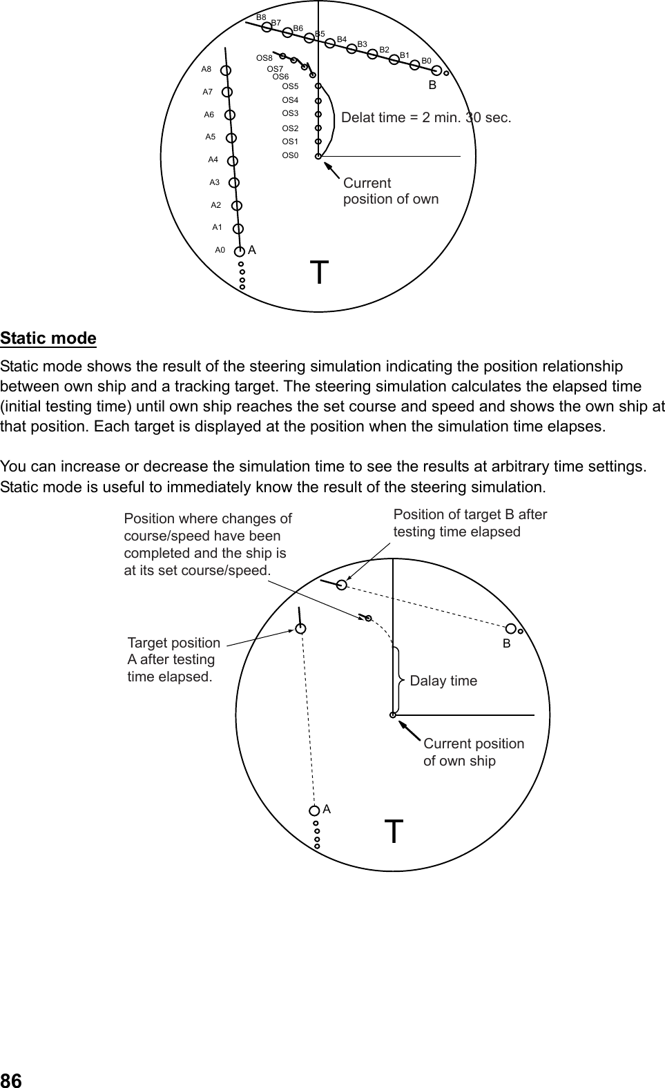
![873.15.2 Performing steering simulation Follow the steps below to perform the steering simulation. 1. Put the cursor on [Steering simulation OFF] in the information display area. 2. Right click to display the [Steering simulation] menu. 3. Select [Steering simulation] then left click. 4. Select [Static mode] or [Dynamic mode] then left-click. 5. Select [Ship speed rate] then left-click. 6. Select [Low speed] then left click. 7. Set low speed. Refer to the ship’s data sheet for ship speed and speed rate in low and high speeds. 8. Select [Low speed rate] then left-click 9. Set low speed rate then left-click. 10. Similarly, set [High speed] and [High speed rate]. 11. Right-click to return to the [Steering simulation] menu. 12. Select [Turn rate] then left-click. 13. Select [Low speed turn rate] then left-click.](https://usermanual.wiki/Furuno-USA/9ZWRTR110.operators-manual/User-Guide-1672487-Page-97.png)
![8814. Set low speed. Refer to the ship’s data sheet for ship speed and turn rate in low and high speed. 15. Select [Low speed turn rate] then left-click. 16. Set turn ate at slow speed. Note: When the setting of ship speed rate is 0.00KN/s and turn rate is 0.0°/m, there is no delay in own ship’s motion in the simulation. 17. Similarly, set [High speed] and [High speed turn rate]. 18. Right-click several times to close the menu. 19. Put the cursor on [Steering simulation OFF] in the information display area then left-click. A box appears as shown below according to the mode selected in step 4. Testing time box.Dynamic modeStatic mode1 Delay time box 2 Course setting box 3 Ship speed setting box123 20. Put the cursor on the delay time box. 21. Set delay time. Set delay time when own ship speed/course are to be changed. 22. Put the cursor on the course setting box. 23. Set course. 24. Put the cursor on the ship speed setting box. 25. Set ship speed. Note: You can also set course using the [EBL] knob, and ship speed using the [VRM] knob. Put the cursor on either one of the boxes and turn the [EBL] knob or the [VRM] knob. 26. Put the cursor on [Steering simulation] for dynamic mode then left-click. The simulation time box appears similar to the box in the static mode. Steering simulation is different depending on the mode shown as below. Dynamic mode Estimated positions of own ship and each target are updated and displayed every 30 seconds. Simulation time increases every 30 seconds. Static mode Positions of your ship and tracked targets are displayed when own ship reaches the set course and speed. The elapsed time to reach that position is indicated as the initial simulation time. After that, put the cursor on the simulation time box and roll the wheel to change the simulation time. Shorten the simulation time to display the result at the earlier position and lengthen the simulation time to display the result at the later position. Remove the cursor from the simulation time box to return the positions of own ship and each target to the positions of the initial simulation time. When the result of the steering simulation is unsatisfactory, repeat the simulation by changing the simulation ship speed, course and delay time until you can obtain a satisfactory result.](https://usermanual.wiki/Furuno-USA/9ZWRTR110.operators-manual/User-Guide-1672487-Page-98.png)
![89The letter “T” appears at the lower section on the screen during the trial maneuver. If any tracked target is predicted to be on a collision course with own ship (that is, the target ship comes within preset CPA/TCPA limits), the target plotting symbol flashes in red. If this happens, change own ship’s trial speed, course or delay time to obtain a safe maneuver. 3.15.3 Terminating steering simulation Steering simulation is automatically terminated at the end of the fixed time and the normal radar display is restored. The time of termination depends on the trial mode. • Dynamic mode: Simulation is terminated automatically when 60 minutes is shown in the immolation time box. • Static mode: Simulation is terminated automatically when there is no key operation for one min. Follow the steps below to terminate the operation manually. 1. Put the cursor on [Steering simulation] in the information display area. 2. Long press the left button until [Simulate steering OFF] is displayed.](https://usermanual.wiki/Furuno-USA/9ZWRTR110.operators-manual/User-Guide-1672487-Page-99.png)
![904. AIS OPERATION This equipment can display names and positions and other navigational data (max. 1000) of AIS-fitted ships when it is connected with the FURUNO Automatic Identification System (AIS transponder) model FA-150, FA-100, FA-50 or AIS receiver FA-30. Position data of WGS-84 geodetic datum are required for AIS operation. Set the datum of GPS navigational equipment connected at WGS-84. When other datum is used, the indication [Datum] flashes in the alarm section in the information display area and the AIS function becomes unavailable. 4.1 Turning ON/OFF AIS Display Note: When no AIS transponder is connected, the indication [AIS transponder abnormal] flashes in the alarm box in the information display area. In this case, press the [Cancel alarm] key then long press the left button on the AIS box to turn off the indication [Function OFF] in the box. Follow the steps below to turn ON/OFF the AIS display. 1. Put the cursor on the AIS box in the information display area. AIS box 2. Left-click to select [Display FILTER], [Display ALL] or [Display OFF]. Display filter: Only AIS targets set in Chapter 4.5 are displayed on the screen. Display ALL: All targets received by AIS transponder are displayed on the screen. Display OFF: All AIS symbols are erased from the screen. Note: When AIS collision alarm is generated while the setting is [Display OFF], AIS target is automatically displayed and the setting in the AIS box becomes [Display ALL]. When AIS display is turned on, AIS target is displayed by the following symbols depending on its status. Symbol Status Remarks Sleeping target Smaller triangle than an active target Activated target Heading line, ship speed/course vectors are displayed. Turning target A turning symbol is displayed. Dangerous target Collision alarm symbol is displayed in red. The symbol flashes until acknowledged.](https://usermanual.wiki/Furuno-USA/9ZWRTR110.operators-manual/User-Guide-1672487-Page-100.png)
![91Symbol Status Remarks Lost target When a target is lot, a red flashing X mark is attached to the symbol. The symbol disappears after acknowledgement. A. FURUNO Target whose data are being displayed Symbol of which data are on display is surrounded with a square broken line. Ship name or MMSI no. is shown under the symbol. Same target (TT display is prioritized.) Identification criteria are met and it is displayed with AIS data. Same target (AIS display is prioritized.) Identification criteria are met and it is displayed with AIS data. Real AIS track sign Virtual AIS track sign AIS base station Airborne SAR aircraft AIS AIS-SART Note 1: The equipment continues to process AIS target even when the AIS feature is turned off. When AIS display is turned on again, the symbols are immediately displayed. Note 2: Log press the left button on the AIS box to show [Function OFF] and data processing stops. Note 3: The screen is redrawn after the heading is changed in the head-up mode. AIS symbols may be momentarily erased during this time. Note 4: When no AIS data are received at all, the indication [AIS transponder abnormal] flashes in the alarm box in the information display area. In such a case, check the AIS transponder. Note 5: The indication [Unable to measure CPA/TCPA] flashes in the alarm box in the information display area when data are unavailable or invalid for course over ground/speed over ground of own ship. Note 6: The applicable AIS symbols are shown in dotted lines when no data are received or invalid for heading/course over ground of other ship.](https://usermanual.wiki/Furuno-USA/9ZWRTR110.operators-manual/User-Guide-1672487-Page-101.png)
![924.2 Activated Target When you convert a sleeping target to an activated target, a vector of that target is displayed indicating its course and speed. You can see the target’s movement at a glance by monitoring the vector. Note: A sleeping target getting into a guard zone is automatically changed to an activated target (red flashing). See chapter 3.12 for guard zone. 4.2.1 Activating selected targets 1. Put the cursor on the symbol that you want to activate. 2. Left-click. The selected symbol is changed to an activated target. Tuming line (indicates direction of turning)Speed over grond/Course over ground vector **: Indicates speed over water/Course over water in speed over water mode. **: Indicates course over ground when heading data is unavailable.Heading line ** 4.2.2 Activating all targets 1. Put the cursor on the AIS box in the information display area then right-click. 6. Select [Activate all targets] then left-click. All symbols become activated targets. 5. Right-click to close the menu.](https://usermanual.wiki/Furuno-USA/9ZWRTR110.operators-manual/User-Guide-1672487-Page-102.png)
![934.3 Inactivating targets You may inactivate or “sleep” activated targets when the screen gets crowded with targets which may make it difficult to identify important radar echoes and TT targets. In such a situation, inactivating the activated targets helps make the radar echoes more visible on the screen. Dangerous targets cannot be inactivated. 4.3.1 Inactivating selected targets 1. Put the cursor on the symbol to inactivate. 2. Right-click to display the [AIS] menu. 3. Select [Activate/Inactivate] then left-click. The selected symbols become inactivated targets. 4. Right-click to close the menu. 4.3.2 Inactivating all targets 1. Put the cursor on the AIS box in the information display area then right-click. 2. Select [Inactivate all targets] then left-click. All the symbols become inactivated targets. 3. Right-click to close the menu.](https://usermanual.wiki/Furuno-USA/9ZWRTR110.operators-manual/User-Guide-1672487-Page-103.png)
![944.4 Displaying AIS Target Data You can display AIS target data such as MMSI No., Ship name, bearing, range, course over ground, speed over ground, CPA, TCPA, etc. When there are no data, [---] is shown. 4.4.1 Displaying basic data One AIS data can be displayed in one data box in the information display area. 1. Put the cursor on the symbol of which data to display. 2. Left-click for activated target. Right-click for inactivated time. Next, select [AIS data display] then left-click. When the setting of [Selections] is [On] (factory default) in the [TT/AIS symbol], the symbol is surrounded with a square of broken line. The basic data of the selected AIS target appears in the data box in the information display area. When inactivated target is selected, the target automatically changes to an activated target. A. FURUNOSqare of a broken lineShip neme(NNSI No. when ship name is unavailable)Location of data box of a target (A or B) Factory default MMSI No.Ship nameCPA/TCPA of targetNavigation status*: Indicates bearing over water in the speed over water mode.Target (A,B) seleced on the screenBearing of targetRange of targetCouse over ground/Speed over ground of targetHeading/Turn speed (degrees/min.) Basic data in data box 3. Put the cursor on the basic data to display detailed data then left-click. Each click switches between the basic data and detailed data. (See the next section.) Note 1: The maximum of two AIS data can be displayed when [2BOX] is selected at [Target data] in the [Navigation data] menu. Note 2: Put the cursor on the symbol being displayed then left click to erase the basic data.](https://usermanual.wiki/Furuno-USA/9ZWRTR110.operators-manual/User-Guide-1672487-Page-104.png)
![954.4.2 Displaying detailed data Follow the steps below to display detailed data. 1. Put the cursor on the symbol of which data to display. 2. Right-click to display the [AIS] menu. 3. Select [AIS detailed data] then left-click. Detailed data are displayed. Latitude LongitudeMeasuring equip.Ship lengthCall signEstimated time of arrivalHeading crossing time/Heading passing timeFURUNO Detailed data in data box Note: Put the cursor on the symbol of which data are being displayed then left-click to erase the detailed data.](https://usermanual.wiki/Furuno-USA/9ZWRTR110.operators-manual/User-Guide-1672487-Page-105.png)
![964.5 Filtering AIS display If there are too many AIS targets on the screen you may wish to remove unnecessary ones. You may remove targets by distance from own ship, speed, class and length. For example, you might want to remove slow moving targets. 1. Put the cursor on the AIS box in the information display area then right-click. 2. Select [AIS display filter] then left-click. 3. Select [Range], [Ship speed], [Class B exclude] or [Ship length] then left-click. • Range: AIS targets over the set range are not displayed on the screen. • Ship speed: AIS targets less than the set speed are not displayed on the screen. • Class B exclude: AIS targets of Class B* are not displayed on the screen. *: Ships loaded with AIS transponder of Class B (for Non-business use) • Ship length: AIS targets shorter than the set ship length are not displayed. 4. Click [On] then left-click. When [Class B exclude] is selected in step 3, proceed to step 7. Otherwise proceed to step 5. 5. Select [Maximum Range], [Minimum Speed] or [Minimum ship length] then left-click. Select appropriate item from the selections in step 3. 6. Input values. 7. Right-click several times to close the menu. When the setting in the AIS box is [Display filter], only the AIS targets set here are displayed. When settings are [Off] for all items, all the targets are displayed. (It is the same as [Display all] in the AIS box.)](https://usermanual.wiki/Furuno-USA/9ZWRTR110.operators-manual/User-Guide-1672487-Page-106.png)
![974.6 AIS Symbol Attributes 4.6.1 Selecting a AIS symbol shape You can select a shape of AIS symbols from twelve different shapes. 1. Put the cursor on a symbol to change. 2. Right-click to display the [AIS] menu. 3. Select [AIS symbol shape] then left-click. 4. Select a necessary shape then left-click. 5. Right-click to close the menu. Note: Brilliance of AIS symbols can be adjusted by color scheme. (See chapter 2.9.) 4.6.2 Selecting color of AIS symbol You can select color of AIS symbols from the seven colors of red, green, blue, turquoise, purple, white and yellow. (Except for dangerous targets)](https://usermanual.wiki/Furuno-USA/9ZWRTR110.operators-manual/User-Guide-1672487-Page-107.png)
![98Changing colors of all AIS symbols 1. Put the cursor on [Menu] in the information display area then left-click. 2. Select [Set environment] then left-click. 3. Select [TT/AIS] then left-click. 4. Select [TT/AIS symbol] then left-click. 5. Select [AIS symbol color] then left-click. 6. Select a necessary color then left-click. Color of all AIS symbols change. Colors of AIS symbols that are individually changed do not change. 7. Right-click several times to close the menu. Changing AIS symbol colors on the screen 1. Put the cursor on the symbol to change. 2. Right-click to display the [AIS] menu. 3. Select [AIS symbol color] then left-click.](https://usermanual.wiki/Furuno-USA/9ZWRTR110.operators-manual/User-Guide-1672487-Page-108.png)
![994. Select desired color then left-click. When [Color set in the menu] is selected, the color changes to the color set at [AIS symbol color] in the [TT/AIS symbol] menu. 5. Right-click to close the menu. 4.6.3 Selecting a size of AIS symbol Select whether to display AIS symbol in real scale. 1. Put the cursor on [Menu] in the information display area then left-click. 2. Select [Set environment] then left-click. 3. Select [TT/AIS] then left-click. 4. Select [TT/AIS symbol] then left-click. 5. Select [AIS real scale] then left-click. 6. Select [On] or [Off] then left-click. • On: AIS symbols of over 1.5cm in size on the screen are displayed in real scale in accordance of hull length. AIS symbols less than 1.5cm in size are displayed in the normal symbol size. • Off: All AIS symbols are displayed in the same size. 7. Right-click several times to close the menu. 4.7 Displaying Vector Vector is a line representing ship speed and course of AIS activated target. The vector tip shows an estimated position of the target after the selected vector time elapses. You can predict a risk of collision with other AIS target by extending the vector length (means vector time). Selecting vector mode and time Vectors may be displayed in true (over ground/over water) or relative mode. Vector time can be selected from 15 sec., 30 sec., 45 sec., 1min. ~ 60min. (1 min. interval up to 20 min. and 10 min. interval after 20 min.). The settings are common with TT target. 1. Press the [Vector True/Relative] key (factory default) to select [True (or True-s)] or [Relative]. The mode currently being selected appears in the vector box in the information display area. Vector timeVector modeRelative, True (over ground speed) True-s (over water speed) Note: When other functions are registered to the [Vector True/Relative] key, put the cursor on [Relative], [True] or [True-s] in the vector box then left-click. 2. Put the cursor on Vector time then left-click. Each click switches between indications of vector time. Right-click to reverse the order. When [00:00] is selected, no vector is displayed. You can also set the vector time at 1 sec. interval or 1 min. interval after 20 min. by pressing the wheel on the vector time.](https://usermanual.wiki/Furuno-USA/9ZWRTR110.operators-manual/User-Guide-1672487-Page-109.png)
![1004.8 Displaying Past Position The past position display shows movements of all AIS targets. The past position display shows selected number of dots at the selected time interval. If a target changes its speed, the spacing will be uneven. If it changes the course, its plotted course will be a curve. The following are examples of past positions. (a) Ship turning (a) Ship running straigth(a) Ship reduced speed(a) Ship increased speed 4.8.1 Setting past position plot interval You can select past position plot interval from 15 sec., 30 sec., 45 sec., 1min. ~ 60min. (1 min. interval up to 20 min. and 10 min. interval after 20 min.). Settings are common with TT target. 1. Put the cursor on the [Past position interval] box in the information display area. Past position interval boxChange in accordance with trail mode setting. 2. Left-click to select a past position interval. Each click switches between indications in the past position interval box. Right-click to reverse the order. No past position is displayed when [00:00] is selected. You can also set the time interval at 1 sec. or 1 min. after 20 min. by pressing the wheel on the past position time interval box. 4.8.2 Selecting past position points You may select five or ten past points to display. 1. Put the cursor on [Menu] in the information display area then left-click. 2. Select [Set environment] then left-click. 3. Select [TT/AIS] then left-click. 4. Select [TT/AIS symbol] then left-click. 5. Select [AIS past position points] then left clock. 6. Select [5] or [10] then left-click. 7. Right-click several times to close the menu.](https://usermanual.wiki/Furuno-USA/9ZWRTR110.operators-manual/User-Guide-1672487-Page-110.png)
![1014.9 Lost Target Activated targets become “Lost targets” when no AIS data are received for a certain period of time. A lost target is sown in the display with flashing red “X”. The flashing indication [AIS lost] is also displayed in the alert section in the information display area. Press the [Cancel alert] key to delete the lost target from the screen. Inactivated target does not become a lost target and disappears from the screen. Note: Press the [Cancel alarm] key to erase both the lost AIS target and the lost TT target when they are overlapping. 4.9.1 Setting lost target criteria You can set criteria for lost target alarm by setting range from own ship, ship speed, ship class or hull length. 1. Put the cursor on [Lost target alarm] in the information display area. 2. Right-click to display the [Filter] menu. 3. Select [AIS lost filter] then left-click. 4. Select [Maximum range], [Class B exclude] or [Minimum ship length] then left-click. • Maximum Range: Any activated targets beyond this range will not trigger the lost target alarm. • Minimum ship speed: Any activated targets slower than this speed will not trigger the lost target alarm.](https://usermanual.wiki/Furuno-USA/9ZWRTR110.operators-manual/User-Guide-1672487-Page-111.png)
![102• Class B exclude: Any activated targets of Class B* will not trigger the lost target alarm. *: Ships loaded with Class B (for Non-business use) AIS transponder. • Minimum ship length: Any activated targets shorter than this length will not trigger the lost target alarm. 5. Select [On] then left-click. When [Remove Class B] is selected in step 4, proceed to step 8. Otherwise, proceed to step 6. 6. Select a line within the setting limit then left-click. 7. Enter value. 8. Right-click several times to close the menu. 4.9.2 Setting lost target alarm Select whether to enable the lost target alarm. Settings are common with TT target. 1. Put the cursor on [Lost target alarm] in the information display area. 2. Left-click to select a setting. Each click switches between [OFF], [Filter], and [All] inside of the box. • OFF: Disable the alarm • Filter: Get the alarm against the activated lost target set in Chapter 4.9.1. • All: Get the alarm against all activated lost targets.](https://usermanual.wiki/Furuno-USA/9ZWRTR110.operators-manual/User-Guide-1672487-Page-112.png)
![1034.10 Collision Alarm (CPA/TCPA) CPA (Closest Point of Approach) and TCPA (predicted time to CPA) limits are preset to avoid collision with other ship. (Settings are common with TT target.) When the predicted CPA and TCPA of AIS target become smaller than the present CPA and TCPA limits, the AIS target becomes a dangerous target (red, flashing) and the audio alarm sounds. [AIS collision alarm] flashes in the alarm box in the information display area. Press the [Cancel alarm] key to stop the alarm sounds and the flashing indication of the symbol. Take appropriate actions to avoid a collision. Note 1: Set size, tonnage, ship speed and turning capacity of own ship to set collision alarm. Note 2: The reference point for CPA/TCPA calculation may be selected from antenna position or steering position. (See chapter 1.29.) Collision alarm setting 1. Put the cursor on [CPA limit OFF] in the information display area then left-click. Each click switches the indication as follows. CPA setting box.TCPA setting box. 2. Put the cursor on the CPA setting box. 3. Left-click to set CPA range. Each click switches between the indications in the CPA setting box between 0.5, 1, 1.5 and 2~24 (1NM interval) in that order. You can also set the interval at 0.1NM or 1NM by pressing the wheel on the CPA setting box. 4. Put the cursor on the TCPA setting box. 5. Left-click to set TCPA time. Each click switches between the indications in the TCPA box between 1 min. ~ 60 min. (1 min. interval up to 20 min., 10 min. interval after 20 min.) Right-click to reverse the order. You can also set the interval at 1 sec. or 1 min. after 20 min. by pressing the wheel on the TCPA setting box. 4.11 Activating Targets You can activate a sleeping target when both CPA and TCPA of the target become smaller than the settings in Chapter 4.10. 4.11.1 Limiting targets for automatic activation You can limit targets by setting range from own ship, ship speed, ship class or hull length for automatic activation.](https://usermanual.wiki/Furuno-USA/9ZWRTR110.operators-manual/User-Guide-1672487-Page-113.png)
![1041. Put the cursor on [CPA auto activation] in the information display area. 2. Right-click to display the [CPA auto activation] menu. 3. Select [Maximum range], [Minimum speed], [Class B exclude] or [Minimum ship length] then left-click. • Maximum range: Inactivated targets over the set range are not displayed on the screen. • Minimum speed: Inactivated targets less than the set speed are not displayed on the screen. • Class B exclude: Inactivated targets of Class B* are not displayed on the screen. *: Ships loaded with AIS transponder of Class B (for Non-business use) • Minimum ship length: Inactivated targets shorter than the set hull length are not displayed. 4. Select [On] then left-click. When [Remove Class B] is selected in step 3, proceed to step 7. Otherwise, proceed to step 5. 5. Select a line within the setting limit then left-click. 6. Enter value. 7. Right-click several times to close the menu. 4.11.2 Activating Targets Automatically Select whether to enable automatic activation function. 1. Put the cursor on [CPA automatic activation] in the information display area. 2. Left-click to select a setting. Each click switches between [OFF], [Filter] and [All] in the box. • OFF: Disable the auto activation function. • Filter: Enable the auto activation function. Inactivated targets that meet the following two conditions will be activated. 1) Inactivated target of smaller CPA/TCPA than the settings in Chapter 4.10. 2) Inactivated target set in Chapter 4.11.1. • ALL: Enable the automatic activation function. All inactivated targets of smaller CPA/TCPA than the settings in Chapter 4.10 will be activated.](https://usermanual.wiki/Furuno-USA/9ZWRTR110.operators-manual/User-Guide-1672487-Page-114.png)
![1054.12 Turning Direction When turning speed of an activated target is faster than the set value, turning direction can be shown on the heading line of AIS symbol. 1. Put the cursor on [Menu] in the information display area then left-click. 2. Select [Set environment] then left-click. 3. Select [TT/AIS] then left-click. 4. Select [TT/AIS symbol] then left-click. 5. Select [AIS ROT mark display] then left-click. 6. Set turning direction. 7. Right-click several times to close the menu. Shows a target is turning to the right 4.13 Identification of TT and AIS When data of TT and AIS activated targets meet the identification criteria, both targets are considered to be the same targets and TT or AIS is prioritized to display on the screen. 1. Place the cursor on [Menu] in the information display area then left-click. 2. Select [Set environment] then left-click. 3. Select [TT/AS] then left-click. 4. Select [Identification] then left-click. 5. Select [Identification] then left-click. 6. Select [OFF], [AIS] or [TT] then left-click. When the identification criteria are met, choose which data to prioritize. • OFF: No identification processing • AIS: Prioritize AIS display (symbol, data) • TT: Prioritize TT display (symbol, data)](https://usermanual.wiki/Furuno-USA/9ZWRTR110.operators-manual/User-Guide-1672487-Page-115.png)
![106Symbols when AIS is prioritized Symbols when TT is prioritized AIS dangerous target (Red) TT dangerous target (Red) AIS normal target (Normal color) TT normal target (Normal color) Note: You can also select [OFF], [AIS] and [TT] from the identification box in the information display area. Put the cursor on the identification box then left-click. Each click switches between [Blank], [>] and [<] in the box. Identification boxBlank: No identification processing<: Prioritize AIS display >: Prioritize TT display 7. Set conditions. These conditions are used to determine identification criteria. • Mutual range: Input range between AIS target and TT target (0 ~ 99.99NM). • Range: Input difference in range between AIS target and TT target from own ship. (0 ~ 9.9 NM). • Bearing: Input difference in bearing between AIS target and TT target from own ship. • Ship speed: Input difference of ship speed between AIS target and TT target. • Course: Input difference of course between AIS target and TT target. (0 ~ 99°) 8. Right-click several times to close the menu. AIS target and TT target are considered to be identical when data of AIS target and TT target are smaller than the values of all the five conditions in step 7. When identification criteria are met and [AIS] is selected in step 6, TT symbols disappear and only AIS symbols are prioritized on the display. The flashing indication [AIS identification] appears in the alarm box in the information display area. Note: When the power is turned on again, the setting of [Identification] in the [Identification] menu returns to [OFF].](https://usermanual.wiki/Furuno-USA/9ZWRTR110.operators-manual/User-Guide-1672487-Page-116.png)
![1074.14 Navigation Data Own ship’s navigation data (Navigation condition, estimated date/time to arrive at a destination, name of destination, crews, and draft) can be outputted to AIS transponder connected to own ship. 1. Put the cursor on the AIS box in the information display area then right-click. 2. Select [Navigation data] then left-click. 3. Select [Navigation status] then left-click. 4. Select an appropriate navigation condition then left-click. 5. Select [ETA] then left-click. 6. Set estimated arrival at a destination (Year/Month/Day/time) 7. Select [Destination] then left-click. 8. Enter name of waypoint (Max. 20 characters) with the small keyboard appearing at the lower section on the screen.](https://usermanual.wiki/Furuno-USA/9ZWRTR110.operators-manual/User-Guide-1672487-Page-117.png)
![1089. Select [Crews] then left-click. 10. Set number of crews. 11. Select [Draft] then left-click. 12. Set draft of own ship. 13. Lastly, select [Update] then left-click. 14. Right-click several times to close the window. 4.15 Static Data Own ship’s static data set at AIS transponder can be viewed on this equipment. 1. Place the cursor on the AIS box in the information display area then right-click 2. Select [Static data] then right-click. CSXXXXNMEA00000000650702020 3. Right-click several times to close the menu.](https://usermanual.wiki/Furuno-USA/9ZWRTR110.operators-manual/User-Guide-1672487-Page-118.png)
![1094.16 Messages You may transmit and receive messages via the AIS transponder, to a specific destination (MMSI) or all ships in the area. Messages can be sent to warn of safety of navigation, for example, an iceberg sighted. Routine messages are also permitted. Short safety messages are only the additional means to broadcast safety information. They do not remove the requirements of the GMDSS. 4.16.1 Creating and saving messages This section explains how to create and save messages. Maximum of ten messages may be saved. 1. Put the cursor on the AIS box in the information display area then right-click. 2. Select [Transmit message] then left-click. 3. Select [Address type] then left-click. 4. Select [Broadcast] or [Specify destination] then left-click. • Broadcast: Send a message to all ships in the area. • Specify destination: Send a message to a specified destination. 5. Select [Message type] then left-click. 6. Select [Safety related] (safety related messages) or [Binary] (Routine business messages) then left-click. When [Broadcast] is selected in step 4, proceed to step 9. When [Specify destination] is selected, proceed to step 7. 7. Select [MMSI No.] then left-click. 8. Set MMSI No.](https://usermanual.wiki/Furuno-USA/9ZWRTR110.operators-manual/User-Guide-1672487-Page-119.png)
![1109. Select [Channel] then left-click. 10. Select a channel (A, B, A or B, A and B)to send a message then left-click. Refer to the operation manual of AIS transponder for channels A and B. 11. Select [Edit message] then left-click. 12. Compose a message (alphanumeric only) using a small keyboard appearing at the lower section on the screen. The maximum alphanumeric changes as follows in the combination of [Address type] and [Message type]. Broadcast/Safety related: 161 characters Broadcast/Binary: 156 characters Specify destination/Safety related: 156 characters Specify destination/Binary: 151 characters 13. After completing a message, select [Save file] in the lower section of the menu then left-click. 14. Select a file number (1 ~10) then left-click. The file is saved inside of this equipment. 15. Right-click several times to close the menu. 4.16.2 Transmitting a message There are two methods to send messages. One method is to compose and send a message on the spot and the other method is to send a message which is saved inside of the equipment. 1. Put the cursor on the AIS box in the information display area then right-click. 2. Select [Transmit message] then left-click. 3. Do one of the following operations. • Select [Open file] then left-click. Next, select a file number saved in Chapter 4.16.1 then left-click. Right-click to return to the [Transmit message] menu. 4. Select [Transmit message] at the lower section of the menu then left-click. 5. Right-click several times to close the menu.](https://usermanual.wiki/Furuno-USA/9ZWRTR110.operators-manual/User-Guide-1672487-Page-120.png)
![1114.16.3 Viewing a message The maximum of twenty messages can be stored. When the storage is full, the oldest message is erased to make room for the latest. Note: Received messages disappear when power is turned off. Viewing received messages When a message is received, an icon indicating a new arrival appears in the information display area. (Factory default) Icon for new arrival View the message in the following steps. 1. Put the cursor on the new arrival icon in the information display area then left-click. The message is displayed. Roll the wheel to scroll the list of AIS messages. 2. Right-click several times to close the message. Viewing messages automatically Follow the steps below to automatically display a message when the message is being received. 1. Put the cursor on the AIS box in the information display area then right-click. 2. Select [Message automatic display] then left-click. 3. Select [On] then left-click. 4. Right-click to close the menu. When a message is received, the list of AIS messages is automatically opened. The new arrival icon is not displayed at this time.](https://usermanual.wiki/Furuno-USA/9ZWRTR110.operators-manual/User-Guide-1672487-Page-121.png)
![1125. VIDEO PLOTTER OPERATION 5.1 Outline The video plotter does the following functions: • Enter marks and destinations. • Enter lines. • Enter origin marks. • Display chart overlay. • Plot own and other ships’ tracks. • Register routes. 5.2 Mark/Destination/Line You can enter marks and destinations at important points such as shallow waters, fishing zones, and passage buoys to let the system memorize those positions. You can also draw lines at signs such as small islands, landfill sites and prohibited areas for operations. These lines can be used as routes. This equipment can memorize the maximum of 20,000 mark points, 5,000 lines including routes and 100 destination points. Note: You can confirm the current number of points of marks, lines and destinations in the [Mark] menu. (See chapter 5-3.) 5.2.1 Entering marks and destinations There are the following three ways to enter marks and destinations. • Enter marks/destinations at cursor positions. • Enter marks/destinations at own ship’s positions. • Specify latitude and longitude. Entering marks and destinations at cursor position 1. Put the cursor on [Off] then left-click when [Off] is indicated in the mark/destination box at the lower left section on the screen. Marks/destinations appear on the screens when the setting is [On] and disappear when the setting is [Off]. : Types of markMark box Destination box(Mark) (Origin mark) 2. Check the type of mark set in the marks/destinations box. Put the cursor on [Mark], [Origin] or [Destination] then left-click to switch between [Mark], [Origin] or [Destination] in that order. Select [Mark] to enter a mark and [Destination] to enter a Destination. See chapter 5.3.1 for [Origin]. 3. Put the cursor on the pattern in the mark/destination box.](https://usermanual.wiki/Furuno-USA/9ZWRTR110.operators-manual/User-Guide-1672487-Page-122.png)
![113Pattern 4. Roll the wheel to select a necessary pattern then left-click. You can select a pattern of marks/destinations from 16 patterns as shown below. Patterns of marks:Patterns of waypoints: 5. Put the cursor on [Color] in the mark/destination box. Color 6. Roll the wheel to select desired color then left-click. The colors for marks and destinations can be selected from Red, Green, Blue, Yellow, Turquoise, Purple and White. 7. Move the cursor to a desired position to enter marks/destinations. 8. Press the [mark] key. A mark/destination mark is entered at the cursor position. An unused number is assigned by [Mark] for the name of the mark. An unused number is assigned by [WPT] for the name of the mark. Mark name Waypoint name Note: No mark name or destination name will be displayed when the setting of [Mark name] is [Off] in the [Display] menu. 8. Repeat steps 7 ~ 8 to enter marks/destinations of the same shape and color. The destinations you enter are saved in the destination list. Entering marks and destinations at own ship’s position 1. Follow the steps 1 ~ 6 of [Enter marks/destinations at cursor positions]. 2. Put the cursor on a pattern in the mark/destination box then right-click. Current number of pounts menorized 3. Select [Enter at own ship’s position] then left-click.](https://usermanual.wiki/Furuno-USA/9ZWRTR110.operators-manual/User-Guide-1672487-Page-123.png)
![114The mark is entered at own ship’s position. An unused number is assigned by [MARK] for the name of the mark and an unused number is assigned by [WPT] for the name of the destination. 4. Repeat step 3 to continuously enter marks/destinations of the same pattern and color. 5. Right-click to finish entering marks/destinations. The Destinations you enter are saved in the destination list. Entering marks/destinations by specifying latitude and longitude 1. Put the cursor on a patter in the mark/destinations box then right-click. 2. Select [Make marks] then left-click. 3. Select [Types of mark] then left-click. 4. Select [Destination] or [Mark] then left-click. 5. Select [Shape of mark] then left-click. 6. Roll the wheel to select a necessary pattern then left-click. 7. Select [Color of mark] then left-click.](https://usermanual.wiki/Furuno-USA/9ZWRTR110.operators-manual/User-Guide-1672487-Page-124.png)
![1158. Roll the wheel to select a necessary color then left-click. 9. Select [Input latitude/longitude] then left-click. 10. Input latitude and longitude of the mark/destination using the small keyboard appearing at the lower section on the screen. 11. Select [Enter mark] then left-click. A mark/destination is entered at a specified position. An unused number is assigned by [MARK] as the name of the mark and an unused number is assigned by [WPT] as the name of the destination. 12. Right-click to close the menu. The destination you enter is saved in the destination list. 5.2.2 Entering lines Entering lines on the screen 1. Put the cursor on [Off] then left-click when [Off] is shown in the line box at the lower section on the screen. A line appears on the screen when the setting is [On] and disappears when the setting is [Off]. 2. Put the cursor on [Line] in the line box. Line 3. Roll the wheel to select a desired line type then left-click. You can select a line type from the six line types of solid line (thick, thin), broken line (thick, thin) and dotted line (thick, thin). 4. Put the cursor on [Color] in the line box. 7. Roll the wheel too select desired color then left-click. You can select color from the seven colors from Red, Green, Blue, Yellow, Turquoise, Purple and White. Color 6. Put the cursor on the line in the line box then left-click. It becomes the line entering mode and the cursor moves inside the valid radar echo area. 7. Move the cursor at the starting point of the line. 8. Left-click to enter the starting point of the line. 9. Move the cursor at the intermittent point (end point) of the line. A broken line connects the start point and the cursor position. Range and bearing appear above the cursor position. Start pointRange and bearing from the start point2.156NM 77.6°Cursor](https://usermanual.wiki/Furuno-USA/9ZWRTR110.operators-manual/User-Guide-1672487-Page-125.png)
![11610. Left-click. The line selected in step 3 connects the start point and the intermittent point (end point). A square mark appears at the clicked point. 11. Repeat steps 9 ~ 10 to complete the line. Start pointItermittent pointEnd pointItermittent point: Left-clicked point 12. Right-click to finish entering the line. The entered line is saved in the route selection list. Unused number is assigned to [Rte] as the route name. Entering a line by specifying latitude and longitude 1. Put the cursor on a line in the line box then right-click. 2. Select [Shape] then left-click 3. Roll the wheel to select a desired line then left-click. Thick solid lineThick broken lineThich dotted lineThin solid lineThin broken lineThin dotted line 4. Select [Line color] then left-click. 5. Roll the wheel to select a necessary color then left-click. 6. Select [Input latitude/longitude] then left-click. 7. Input latitude and longitude of a start point of the line. 8. Select [Add line] then left-click. 9. Select [Input latitude/longitude] then left-click to specify an intermittent point of the line. 10. Enter latitude and longitude of an intermittent point of the line using the small keyboard appearing at the lower section on the screen. 11. Select [Add line] then left-click. [End entering line] is enabled at the lowest line of the menu. 12. Repeat step 9 ~ 11 to complete the line.](https://usermanual.wiki/Furuno-USA/9ZWRTR110.operators-manual/User-Guide-1672487-Page-126.png)
![11713. Right-click to finish entering the line. The entered line is saved in the route selection list. An unused number is assigned to [Rte] as the route name. Note: Left-click [Finish entering line] instead of right-clicking it when entering other lines continuously. 5.2.3 Editing marks/destinations You may edit marks/destinations already entered. 1. Put the cursor over a mark/destination to be edited. The mark becomes larger when the mark/destination is selected correctly. 2. Right-click to display the [Mark icon] menu. 3. Select [Correct latitude/longitude] then left-click to fine tune the entering position of marks/destinations. Next, set a correct latitude and longitude. 4. Select [Type of mark] then left-click to change the type of a mark to change the type of a mark. Select [Destination] or [mark] then left-click next. 5. Select [Mark color] then left-click to change color of marks/destinations. Select color after change then left-click next. 6. Select [Comment] then left-click to change the name of marks/destinations. Enter a name of marks/destination using the small keyboard appearing at the lower section on the screen. (Maximum 12 characters) 7. Select [Mark shape] then left-click to change the shape of a mark. Next, select a shape after the change then left-click. 8. Select [Move] then left-click to move the position of a mark/destination on the screen. Next, move the mark/destination to a new location then left-click. 9. Right-click to close the menu.](https://usermanual.wiki/Furuno-USA/9ZWRTR110.operators-manual/User-Guide-1672487-Page-127.png)
![1185.2.4 Editing lines You may edit lines already entered. 1. Put the cursor on the line to be edited. The line becomes a thick line and an arrow appears when the line is selected correctly. 2. Right-click to display the [Line] menu. 3. Select [Line color] then left-click to change the line color. Next select color after the change then left-click. 4. Select [Line type] then left-click to change the line type. Next, select a line type after the change then left-click. 5. Right-click to close the menu. 5.2.5 Erasing marks/destinations and lines There are the following five methods to erase marks/destinations and lines. • Erase marks/destinations and lines one by one. • Use the destination list to erase destinations. • Erase all marks/destinations and lines. • Erase marks and lines of specified shapes. • Erase marks and lines of specified colors. Care must be taken that erased marks/destinations and lines are unrecoverable. Note: Marks/destinations used for waypoints (or routes) cannot be erased. Erasing marks/destinations and lines one by one 1. Put the cursor on a mark, Destination or line to erase. The way a line is erased is different depending on the cursor position. • Start point or end point of a line : See the diagram below. • Intermittent point of a line : See the diagram below. • On a line: All the line is erased. Cursor is plaved on a start point of a lineCursor is placed in a start point of a line Line segment erased](https://usermanual.wiki/Furuno-USA/9ZWRTR110.operators-manual/User-Guide-1672487-Page-128.png)
![1192. Right-click to display [Mark icon] (or line, simple mark icon). • [Mark icon] menu: Cursor is put on a mark or a Destination • [Line] menu: Cursor is put on a line. • [Simple mark icon] menu]: Cursor is put on a point of a line. 3. Select [Delete] then left-click. The specified marks, destinations or lines disappear. Erasing destination using the destination list 1. Put the cursor on [Menu] in the information display area then left-click. 2. Select [Set environment] then left-click. 3. Select [Plotter] then left-click. 4. Select [Delete data] then left-click.](https://usermanual.wiki/Furuno-USA/9ZWRTR110.operators-manual/User-Guide-1672487-Page-129.png)
![1205. Select [Destination list] then left-click. All the destination data saved in this equipment are displayed. Each left-click on the switch button switches between the indications as shown below. Switch clik the swich buttonSwitch buttonRange/Bearing Latitide/Longitude 6. Roll the wheel to select a Destination to delete then left-click. 7. Right-click several times to close the menu. Erasing all marks, destinations and lines 1. Put the cursor on [Menu] in the information display area then left-click. 2. Select [Set environment] then left-click. 3. Select [Plotter] then left-click. 4. Select [Delete data] then left-click. 5. Select [Erase all marks] (or [Erase all destinations] or [Erase all lines] ) then left-click. 6. Select [Yes] then left-click. All marks/destinations, lines including routes are erased. Note: Select [No] to cancel the erasing. 7. Right-click several times to close the menu.](https://usermanual.wiki/Furuno-USA/9ZWRTR110.operators-manual/User-Guide-1672487-Page-130.png)
![121Erasing marks and lines of specified shapes and colors 1. Put the cursor on [Menu] in the information display area then left-click. 2. Select [Set environment] then left-click. 3. Select [Plotter] then left-click. 4. Select [Delete data] then left-click. 5. Select [Delete mark] (or [Delete line] )then left-click. [Delete mark] is selected. [Delete line] is selected. 6. Select [Erase by shape] or [Erase by color] then left-click. 7. Select a shape, line type, or color to erase then left-click. 8. Select [Erase] then left-click. 9. Select [Yes] then left-click. 10. Right-click several times to close the menu. 5.2.6 Displaying external destinations When a waypoint is set with the GPS navigation equipment connected to this equipment, that position can be displayed in this equipment as an external destination. Note: RMB sentence is required. 1. Put the cursor on [Menu] in the information display area then left-click. 2. Select [Display] then left-click. 3. Select [External destination] then left-click. 4. Select [ON] then left-click. An external destination of the specified shape and color is displayed in the destination box at the lower left section on the screen. No external destination is displayed when [OFF] is selected. Note: Select [Waypoint] to set an external destination as a waypoint. 5. Right-click several times to close the menu.](https://usermanual.wiki/Furuno-USA/9ZWRTR110.operators-manual/User-Guide-1672487-Page-131.png)
![1225.3 Origin Mark Range and bearing data can be displayed from the cursor position to the position where you enter an origin mark in dangerous area such as reefs. The maximum of twenty origin marks can be stored. Origin marks disappear when the power is turned off. 5.3.1 Entering origin marks Heading signal and own ship position data are required to display the origin marks. 1. Check the mark type set in the marks/Destination box at the lower left side on the screen. Put the cursor on [Mark], [Origin] or [Destination] then left-click to switch the order to [Mark], [Destination] and [Origin]. Select [Origin] to enter an origin mark. The bearing/range box appears at lower side of the mark box when [Origin] is selected. 2. Put the cursor on [Off] then left-click when [Off] is displayed in the mark box. An origin mark appears at [On] and disappears at [Off]. 3. Put the cursor on a patter inside of the mark box. Pattern 4. Roll the wheel to select a necessary number (1 ~ 20) then left-click. 5. Put the cursor on [Color] in the mark box. 6. Roll the wheel to select a necessary color then left-click. You can select color from the seven colors of Red, Green, Blue, Yellow, Turquoise, Purple and White. 7. Move the cursor to the position to enter the origin mark. 8. Press the [Mark] key. The origin mark is entered at the cursor position. Bearing and range between the origin mark to the cursor position is displayed in the bearing/range box. RClick here to switch between True and Relative bearingBearing/Range BoxBearing from origin mark to cursor position Range from origin mark to cursor position 9. To enter other origin marks continuously, change the number in step 4 then repeat steps 7 ~ 8.](https://usermanual.wiki/Furuno-USA/9ZWRTR110.operators-manual/User-Guide-1672487-Page-132.png)
![123List of origin marks You can display the list of origin marks entered. 1. Check if the setting of mark type in the mark/destination box at the lower left side on the screen is [Origin] at the lower left side on the screen. 2. Right-click to display the origin list. A list of origin marks stored in this equipment is displayed. Note: You can also enter origin marks from the origin mark list. 3. Right-click to close the origin list. 5.3.2 Editing origin marks You can edit origin marks already entered. 1. Put the cursor on the origin mark to edit. 2. Right-click to display the [Origin icon] menu. 3. Select [Correct Latitude/Longitude] then left-click to fine tune the position of the origin mark. Next, set correct latitude and longitude. 4. Select [Mark color] then left-click to change the color of the origin mark. Next select color after the change then left-click.](https://usermanual.wiki/Furuno-USA/9ZWRTR110.operators-manual/User-Guide-1672487-Page-133.png)
![1245. Select [move] then left-click to move the origin mark on the screen. Next, move the origin mark to a new location then left-click. The menu disappears in this operation. 6. Right-click to close the menu. 5.3.3 Erasing origin marks There are the following two ways to erase origin marks. • Erase origin marks one by one. • Erase all origin marks. Note that erased origin marks cannot be restored. Erasing origin marks one by one 1. Put the cursor on the origin mark to erase. 2. Right-click to display the [Origin icon] menu. 3. Select [Delete] then left-click. The specified origin mark disappears. Erasing all origin marks 1. Put the cursor on [Menu] in the information display area then left-click. 2. Select [Set environment] then left-click. 3. Select [Plotter] then left-click. 4. Select [Delete data] then left-click. 5. Select [Erase all origins] then left-click. 6. Select [Yes] then left-click. All the origin marks disappear. Note: Select [No] instead of [Yes] to cancel erasing the origin marks. 7. Right-click several times to close the menu.](https://usermanual.wiki/Furuno-USA/9ZWRTR110.operators-manual/User-Guide-1672487-Page-134.png)
![1255.4 Chart (Coastline data) This system is equipped with vector charts and satellite pictures of the Japan Sea. Vector charts are electronic data to display important data necessary for navigation. They are not the same as paper charts. CAUTIONInformation displayed on this system is intended as aid to navigation.See charts fo detalied and the latest information. 5.4.1 Displaying chart overlay You can overlay charts on radar images. Follow the steps below to display chart overlay. 1. Put the cursor on [Menu] in the information display area then left-click. 2. Select [Display] then left-click. 3. Select [Overlay] then left-click. **: Separate chart is required. 4. Select [ON] then left-click. A chart of the Japan Sea is displayed. No chart is displayed when [OFF] is selected.](https://usermanual.wiki/Furuno-USA/9ZWRTR110.operators-manual/User-Guide-1672487-Page-135.png)
![126Latitude/LongitudeExample of Chart Overlay Note: Latitude/Longitude is displayed when [Latitude/Longitude] is turned ON. 5. Right-click several times to close the menu. Note 1: Brilliance of a chart can be adjusted by color. (See chapter 2.9.) Note 2: When displaying a chart overlay and the setting of [Satellite] is [On], only satellite pictures in relatively near range can be displayed. 5.4.2 Selecting data level to display on charts Data levels can be displayed on charts from the following selections. • Basic: Display the minimum required chart data. • International: Display data required for general navigation. • Other: Display additional data other than the above data. • Fishing: Display charts useful for fishing. • Individual: Display chart data that is preset in the [Individual setting] menu. (See chapter 5.4.4.) Users can set chart data that are most appropriate for their needs. Note: This operation can be done only when the setting of [Overlay] is [ON] in the [Display] menu. 1. Put the cursor on [Menu] in the information display area then left-click. 2. Select [Display] then left-click. 3. Select [Coastline data] then left-click. 4. Select a necessary data level then left-click. 5. Right-click several times to close the menu.](https://usermanual.wiki/Furuno-USA/9ZWRTR110.operators-manual/User-Guide-1672487-Page-136.png)
![127 5.4.3 Texts and symbols on charts Various texts and symbols may be set for display on charts. Note: Depending on charts or waters on display, you may not be able to set texts or symbols. 1. Put the cursor on [Menu] in the information display area then left-click. 2. Select [Set environment] then left-click. 3. Select [Chart] then left-click. 4. Select [Vector] then left-click. 5. Select an item to change then left-click. Change each setting accordingly. Note: The illustrations of the chart symbols in this manual are examples from [Chart Symbols] below when [International] is selected in the menu.](https://usermanual.wiki/Furuno-USA/9ZWRTR110.operators-manual/User-Guide-1672487-Page-137.png)
![128Menu Item Contents Chart color Select chart color. - Standard: Specific for FAR-1417/1427 - Night color: Color scheme visible at night - International: Color scheme in accordance with the IALA (International Association of Marine Aids to Navigation and Lighthouse Authorities) guideline - S52: Color scheme in accordance with the IHO (International Hydrographic Organization) guideline - Day color: Color scheme visible in daylight Chart symbol Select symbols on charts. - International: Symbols in accordance with the IALA (International Association of Marine Aids to Navigation and Lighthouse Authorities) guideline - S52: Symbols in accordance with the IHO (International Hydrographic Organization) guideline Shallow waters Set depth of shallow waters (0m ~ 10m). [0m]~ [Shallow waters] is indicated by *1. Safe waters Set depth of safe waters (0m ~ 50m). [Shallow waters] ~ [Safe waters] is indicated by *2. Deep waters Set depth of deep waters (0m ~ 500m). [Safe waters] ~ [Deep waters] is indicated by *4. Colors of shallow waters, safe waters and deep waters are different depending on the setting of [Chart color]. Factory default Chart color Standard Night color International Daytime color S52 *1 Black Dark turquoiseDark blue Blue *2 Black Dark gray Blue Turquoise*3 Black Darker gray than *2 Pale blue Pale turquoise*4 Black Black Pale blue gray Pale green gray Caution Select whether to display CAUTION. Others Select whether to display name of location. Buoy name Select whether to display buoy name. (Example: Grand Bahama Island light!) Lighthouse Select whether to display lighthouse information. Visible arc Select whether to display visible ark of a lighthouse. Route Select whether to display routes.](https://usermanual.wiki/Furuno-USA/9ZWRTR110.operators-manual/User-Guide-1672487-Page-138.png)
![129Waypoint bearing Select whether to display bearing of a waypoint. (Example: 90 deg.) Depth Select whether to display water depth. Display specified depth in red Select whether to display water depth less than the setting of [Depth shown in red color] below. Depth to show in red color Select whether to display dangerous objects in safe waters (or under the territory) which normally do not appear. Ocean floor Select whether to display properties of ocean floor. (Example: sand, shells, etc.) Alert area Select whether to display alert area. 6. Right-click several times to close the menu. 5.4.4 Set ting chart data individually Set whether to display the following data when [individual] is selected in [Coastline information] in the [Display] menu. 1. Put the cursor in [Menu] in the information display area then left-click. 2. Select [Set environment] then left-click. 3. Select [Chart] then left-click. 4. Select [Individual setting] then left-click.](https://usermanual.wiki/Furuno-USA/9ZWRTR110.operators-manual/User-Guide-1672487-Page-139.png)
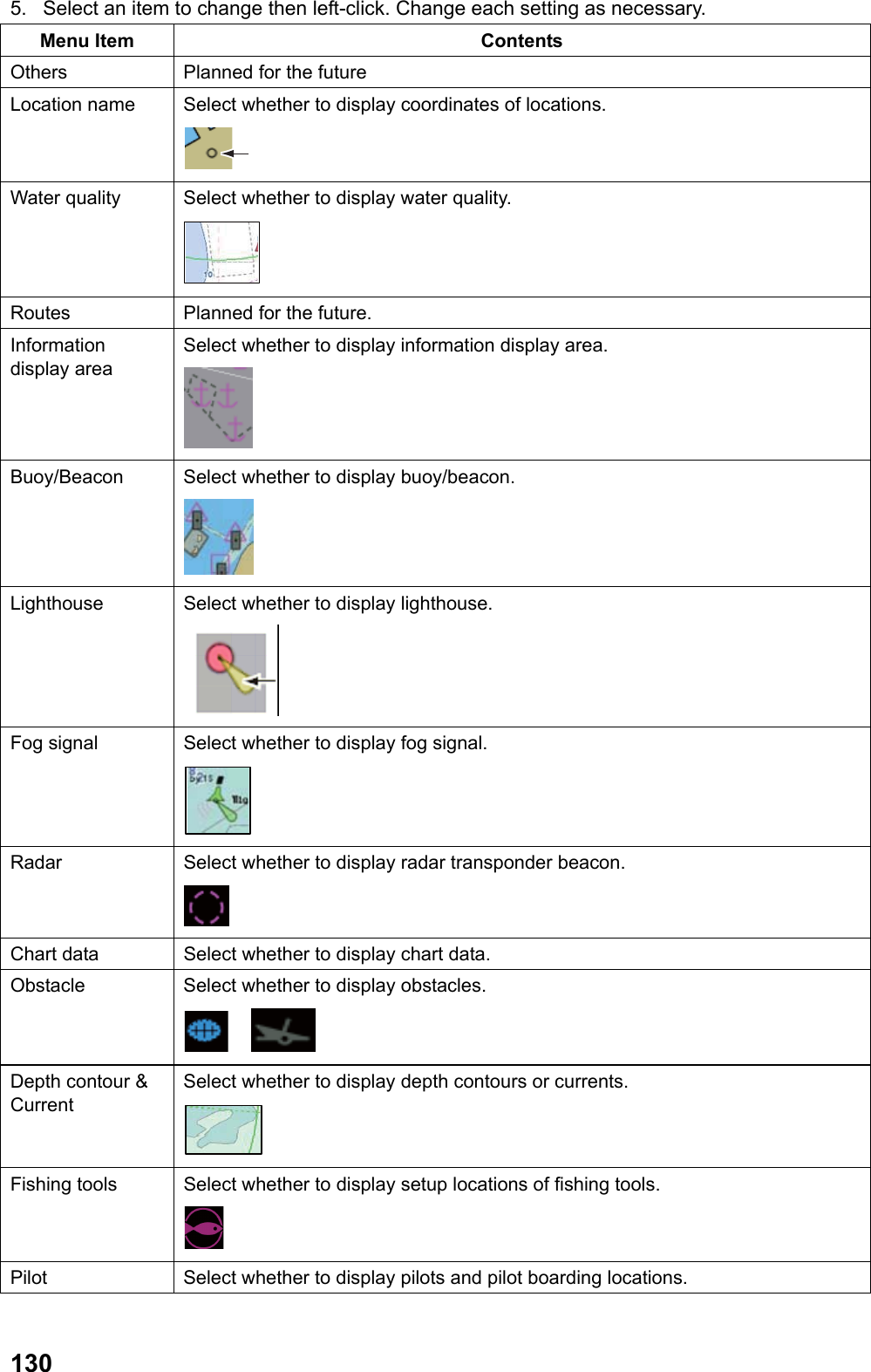
![131Menu Item Contents Harbor facility Select whether to display yacht harbors and marinas. Small boat services Select whether to display small boat services. Topography Select whether to display towers. 6. Right-click several times to close the menu. 5.4.5 Setting individual depth contour You can set individual depth contour line as necessary. Displaying individual contour line Factory default of individual contour line is [No display]. Follow the steps below to change the setting. 1. Put the cursor on [menu] in the information display area then left-click. 2. Select [Display] then left-click. 3. Select [Individual contour line] then left-click. 4. Select [On] then left-click. Individual depth contour is displayed. No individual contour is displayed when [Off] is selected. 5. Right-click several times to close the menu. Editing individual depth contour You can change color of individual depth contour to the color of your choice. 1. Put the cursor on [Menu] in the information display area then left-click. 2. Select [Set environment] then left-click. 3. Select [Chart] then left-click. 4. Select [Individual depth contour] then left-click. 5. Select [Select depth] then left-click. 6. Select [Shallow waters] or [Deep waters] then left-click. • Shallow waters: Edit individual contours of 1 ~ 250m. • Deep waters: Edit individual contours of 10 ~ 2500m.](https://usermanual.wiki/Furuno-USA/9ZWRTR110.operators-manual/User-Guide-1672487-Page-141.png)
![1327. Select [Edit depth] then left-click. [Shallow waters] [Deep waters] 8. Select a depth (m) to change then left-click to chancel displaying a specific individual depth contour. 9. Select [Off] then left-click. No individual depth contour is displayed at [Off]. Select [On] to re-display the contour. Display/No display is shown on the screen when the menu is closed. Note: In the above menu, Display/No display and color settings are the same in the order displayed between shallow waters and deep waters. For example, shallow waters 1.0m and deep waters 10.0 and shallow waters 2.0m and deep waters 20.0 and the rest have the common Display/No display and color settings. 10. Select color of which setting to change then left-click. 11. Select a necessary color then left-click. 12. Repeat steps 8 ~ 11 to complete individual depth contour. 13. Right-click several times to close the menu. 5.4.6 Changing Datum This system can convert WGS-84 (World Geodetic System) to Tokyo datum. Follow the steps below to convert to Tokyo datum. Note: The datum of GPS connected must be WGS-84. When the datum is Tokyo datum, chart may appear out of alignment. The system cannot convert Tokyo datum to WGS-84. 1. Put the cursor on [Menu] in the information display area then left-click. 2. Select [Set environment] then left-click. 3. Select [Chart] then left-click. 4. Select [Datum] then left-click.](https://usermanual.wiki/Furuno-USA/9ZWRTR110.operators-manual/User-Guide-1672487-Page-142.png)
![133 5. Select [Tokyo] then left-click. 6. Right-click several times to close the menu. 5.4.7 Installing charts The system is equipped with the Japan Sea charts only. Please contact FURUNO or its agencies for charts other than the Japan Sea. 1. Put the cursor on [Menu] in the information display area then left-click. 2. Select [Set environment] then left-click. 3. Select [Chart] then left-click. 4. Select [Install] then left-click. System ID: FAR-1417/1427 ID. (No changes allowed.) Security Setting: Display either primary or secondary. (Set at installation. No changes allowed.) Remaining capacity: displays remaining capacity of hard disk. (No changes allowed.) Unlock code: Input unlock code obtained from a chart supplier. Install: Store charts obtained in USB memory to install in the system. List of data: Display chart data installed in the system.](https://usermanual.wiki/Furuno-USA/9ZWRTR110.operators-manual/User-Guide-1672487-Page-143.png)
![1345.5 Track A total of 20,000 points are allotted for storage of own ship’s track and 200,000 points for storage of other ships. Number of points per ship is determined by number of TT acquisition. For example for 10 ships acquisition, 20,000 points are allotted per ship and for one ship acquisition 200,000 points are allotted per ship. When this memory becomes full, the oldest track is deleted to make room for the latest. Tracks do not disappear even when the power is turned off. Note: You can confirm current number of points of own ship and other ships in the [Mark] menu. (See chapter 5.2.1) 5.5.1 Displaying tracks Factory default of own ship track and other ships [No display]. Follow the steps below to change the setting. Note: Tracks are displayed only when [Own ship’s track memory] and [Other ships’ track memory] are [On] in the [Own ship’s track] ([Other ships’ track]) menu. 1. Put the cursor on [Menu] in the information display area then left-click. 2. Select [Display] then left-click. 3. Select [Own ship’s track] or [Other ships’ track] then left-click. 4. Select [On] then left-click. Track is displayed. No track is displayed when [Off] is selected. 5. Right-click several times to close the menu. 5.5.2 Plotting track intervals Tracks are drawn at certain time interval. A smooth track is drawn at short plotting interval but total plotting time is shorter. 1. Put the cursor on [Menu] in the information display area then left-click. 2. Select [Set environment] then left-click. 3. Select [Plotter] then left-click. 4. Select [Own ship’s track] or [Other ships’ track] then left-click. [Own ship’s track] is selected [Other ship’s track] is selected 5. Select [Plotting interval of own ship] or [Plotting interval of other ships] then left-click.](https://usermanual.wiki/Furuno-USA/9ZWRTR110.operators-manual/User-Guide-1672487-Page-144.png)
![1356. Set time interval. When the setting of own ship’s plotting interval is [00’00s], track is plotted each time position data is received. (only when the position is over 1m apart from the previous plot) 7. Right-click each time to close the menu. Note: Factory default is [Plot] for own ship’s track and other ships’ track. To interrupt plotting own ship’s track and other ships’ track, set [Plot own ship’s track] ([Plot other ships’ track]) in the above [Own ship’s track] ([Other ships’ track]) is set [Off]. No new tracks are drawn during the interruption. 5.5.3 Selecting color of tracks You can select color of tracks from the seven colors of Red, Green, Blue, Yellow, Turquoise, Purple and White. For example, you can identify tracks by colors set by date of voyage. 1. Put the cursor on [Menu] in the information display area then left-click. 2. Select [Set environment] then left-click. 3. Select [Plotter] then left-click. 4. Select [Own ship’s track] or [Other ships’ track] then left-click. 5. Select [Color of own ship’s track] or [Color of other ships’ track] then left-click. 6. Select necessary color then left-click. Track is displayed in the color changed at this time. Right-click several times to close the menu. Note: You can also change colors of other ships using the [TT] menu. Put the cursor on TT mark to change color then right-click. Select the [Change colors of other ships’ track] then left-click. Next, select desired color then left-click. 5.5.4 Selecting color of tracks to display You can select color of own ship’s tracks to display on the screen. 1. Put the cursor on [Menu] in the information display area then left-click. 2. Select [Set environment] then left-click. 3. Select [Plotter] then left-click. 4. Select [Own ship’s track] then left-click. 5. Select [Display own ship’s track by color] then left-click. 6. Select necessary color then left-click. Only tracks of selected colors are displayed. When [All] is selected, tracks of all colors are displayed. 7. Right-click several times to close the menu.](https://usermanual.wiki/Furuno-USA/9ZWRTR110.operators-manual/User-Guide-1672487-Page-145.png)
![1365.5.5 Erasing tracks The system has large capacity memory therefore, it is not necessary to erase tracks normally. Erase tracks when the screen is crowded with many tracks. There are the following three ways to erase tracks. • Erase all tracks. (Own ship’s tracks, Other ships’ tracks) • Erase tracks of specified colors (Other ships’ tracks only) • Erase interrupted tracks only. (Own ship’s tracks, Other ships’ tracks) Erasing all tracks 1. Put the cursor on [menu] in the information display area then left-click. 2. Select [Set environment] then left-click. 3. Select [Plotter] then left-click. 4. Select [Delete data] then left-click. 5. Select [Erase all tracks of own ship] or [Erase all tracks of other ships] then left-click. 6. Select [yes] then left-click. All tracks disappear. Note: to cancel erasing tracks, select [No] instead of [Yes]. 7. Right-click several times to close the menu. Deleting tracks of specified colors (other ships’ tracks only) 1. Put the cursor on [Menu] in the information display area then left-click. 2. Select [Set environment] then left-click. 3. Select [Plotter] then left-click. 4. Select [Delete data] then left-click. 5. Elect [Erase other ships’ tracks] then left-click. 6. Select [Erase by color] then left-click. 7. Select color to erase then left-click. 8. Select [Erase] then left-click. 9. Select [Yes] then left-click. Tracks of specified colors disappear. 10 Right-click to close the menu.](https://usermanual.wiki/Furuno-USA/9ZWRTR110.operators-manual/User-Guide-1672487-Page-146.png)
![137Erasing interrupted tracks Tracks are interrupted when power is turned on or plotting of other ships’ tracks is interrupted. Follow the steps below to erase interrupted tracks. 1. Put the cursor on interrupted track then right-click. 2. Select [Erase track section] then left-click. Interrupted track disappears. 5.6 Route It is necessary to veer your ship several times to navigate from one point to another. A line connecting veering points (destinations) is called a route. Your waypoints are updated automatically as you steer along the route and you can obtain necessary information (range and bearing to waypoints) to steer your ship. 5.6.1 Creating routes There the following two was to make routes. • Make routes using the menu. • Make routes using marks/waypoints on the screen. Making routes with the menu 1. Put the cursor on [Menu] inside the information display area then left-click. 2. Select [Route] then left-click.](https://usermanual.wiki/Furuno-USA/9ZWRTR110.operators-manual/User-Guide-1672487-Page-147.png)
![1383. Select [Make routes from marks/waypoints] then left-click. All data of marks and waypoints stored in the system are displayed. Each left-click of the switch button switches between rage/bearing, and latitude/longitude. Switch button 4. Roll the wheel to select marks or waypoints to register for routes then left-click. Repeat this step to complete routes. 5. Completed routes are stored in the route selection list. Numbers are assigned to [Rte] as a route name. Route line 6. Right-click several times to close the menu. Making routes with marks/waypoints on the screen 1. Put the cursor on the line in the line box at the lower left side on the screen then left-click. The cursor moves in the valid radar echo area. 2. Put the cursor on the mark or waypoint to register in the routes. 3. Left-click. 4. Repeat steps 2~3 to complete the route. 5. Completed routes are stored in the route selection list. Numbers are assigned by [Rte] as route name.](https://usermanual.wiki/Furuno-USA/9ZWRTR110.operators-manual/User-Guide-1672487-Page-148.png)
![1395.6.2 Changing routes You can change routes already registered. Changing colors and line types of leg lines 1. Put the cursor on a leg line to change 2. Right-click to display the [Line] menu. 3. Select [Line color] to change color then left-click. Next , select color after the change then left-click. 4. Select [Line type] to change line type then left-click. Next Select line type after the change then left-click. 5. Right-click to close the menu. Moving veering points inside routes 1. Put the cursor on a veering point (mark/waypoint). 2. Right-click to display the [Mark icon] menu. 3. Select [Move] then left-click. 4. Move the cursor to a new location. 5. Left-click. The veering point moves to a new location. 5.6.3 Erasing routes There are the following two ways to erase routes. • Erase specific routes. • Erase all routes Notes: Routes used for waypoints cannot be erased. Erasing specific routes 1. Put the cursor on a leg line to erase. 2. Right-click to display the [Line] menu. 3. Select [Delete] then left-click. Specified routes disappear. Erasing all routes 1. Put the cursor on [Menu] in the information display area then left-click. 2. Select [Set environment] then left-click. 3. Select [Plotter] then left-click. 4. Select [Delete data] then left-click. 5. Select [Erase all lines] then left-click. 6. Select [Yes] then left-click. All routes (including lines) disappear. Note: Select [No] to cancel erasing routes instead of [Yes]. 7. Right-click several times to close the menu.](https://usermanual.wiki/Furuno-USA/9ZWRTR110.operators-manual/User-Guide-1672487-Page-149.png)
![1405.7 Waypoint A particular destination (veering point) to navigate is known as a waypoint. Marks already entered, destinations, lines and registered routes can be set as waypoints. When the setting in [Waypoint data] is other than [OFF] in the [Navigation data] menu, range and bearing from own ship to the waypoint and estimated time to the waypoint are displayed when setting the waypoint. When a new waypoint is set, the previous waypoint is cancelled. Waypoint nameEstimated time to waypointRange from own ship to waypoint Bearing from own ship to waypointDisplay in the information display area 5.7.1 Setting Waypoints You can set marks and destinations as waypoints. 1. Put the cursor on a mark or a destination to set as a waypoint. 2. Right-click to display the [Mark icon] menu. 3. Select [Waypoint] then left-click. Own ship position Destination No.Set course to waypoint Waypoint 4. Right-click to close the menu. A line connects own ship and the waypoint as a set course. The line indicates the shortest course from the current position of own ship to the waypoint. The set course disappears when own ship arrives at the waypoint. Note: No destination number appears on the screen when the setting of [Destination No.] is [Off] in the [Display] menu. 5.7.2 Setting destination as waypoint with the destination list You can set a destination in the destination list as a waypoint. 1. Put the cursor on [Menu] in the information display area then left-click. 2. Select [Destination list] then left-click. All the destinations stored in the system are displayed. Each left-click of the switch button switches between range/bearing and latitude/longitude.](https://usermanual.wiki/Furuno-USA/9ZWRTR110.operators-manual/User-Guide-1672487-Page-150.png)
![141Switch buttonDisplaying Range/Bearing 3. Roll the wheel to select a destination to set as a waypoint then left-click. 4. Right-click several times to close the menu. A line connects own ship and the waypoint as a set course. The line indicates the shortest course from own ship’s current position to the waypoint. The set course disappears when own ship arrives at the waypoint. 5.7.3 Setting an entered line to a waypoint A line on the screen can be set to a waypoint. 1. Put the cursor on a leg line to the waypoint. 2. Right-click to display the [Line] menu. 3. Select [Set course] then left-click. Own ship positionSet course to the first veering pointDestination No.Arrow indicating traveling directionLeg line A line connects between own ship and the first veering point to become a set course. An arrow appears on the leg line indicating the travelling direction. A set course appears automatically at the next veering point when own ship arrives at the waypoint.](https://usermanual.wiki/Furuno-USA/9ZWRTR110.operators-manual/User-Guide-1672487-Page-151.png)
![1425.7.4 Setting a registered route to a waypoint You can set a registered route to a waypoint. 1. Put the cursor on [menu] in the information display area then left-click. 2. Select [Route] then left-click. 3. Select [Select a route from lines] then left-click. Entered lines and routes made in chapter 6.5.1 are stored in the route selection list. Route nameTotal range of a routeNumber of points in a route 4. Roll the wheel to select a route to set to a waypoint then left-click. 5. Right-click several times to close the menu. A line connects between own ship and the first veering point as a set course. An arrow appears on the leg line indicating the traveling direction. A set course appears automatically at the next veering point when own ship arrives at the waypoint. 5.7.5 Canceling a waypoint Follow the steps below to cancel a waypoint on the screen. 1. Put the cursor on a set course. 2. Right-click to display [Line] menu. 3. Select [Cancel course] then left-click. The waypoint is cancelled and the set course disappears. 5.7.6 Skipping a veering point Follow the steps below to skip a veering point during navigation. 1. Put the cursor on [Menu] in the information display area then left-click. 2. Select [Route] then left-click. 3. Select [Skip destination] then left-click. For example, when the veering point 1 is skipped, a new course is drawn to the next veering point 2.](https://usermanual.wiki/Furuno-USA/9ZWRTR110.operators-manual/User-Guide-1672487-Page-152.png)
![143Veering point 1Veering point 2Veering point 3A new courseAfter the skip 4. Right-click several times to close the menu. 5.7.7 Displaying veering start line You can display a line at the optimum position to start veering while using the route. Note: To use the veering start line, it is necessary to preset a turning rate for steering simulation with the TT function. (See chapter 3.15.) 1. Put the cursor on [menu] in the information display area then left-click. 2. Select [Display] then left-click. 3. Select [Veering start line] then left-click. 4. Select [ON] or [No off track correction] then left-click. • ON: display the veering line perpendicular (90°) to a set route. • No off track correction: display the veering start line while keeping the gap between the set route and the current position. No veering start line is displayed when [OFF] is selected. Veering start lineON No off track correction 5. Right-click several times to close the menu.](https://usermanual.wiki/Furuno-USA/9ZWRTR110.operators-manual/User-Guide-1672487-Page-153.png)
![1445.8 Plotter related alarms Destination arrival alarm The destination arrival alarm serves to alert the navigator when own ship enters a specific area with the waypoint at its center, with audio alarms. When the destination arrival alarm is set, an alarm area is shown surrounded by a red broken line. Own ship positionRange setWaypoint: Area set XTE (Cross Track Error) alarm Cross track error serves to alert the navigator when own ship navigates across the set range from the course connecting the start point to the waypoint. When XTE alarm is set, alarm area is displayed on both sides of the set course with a broken line. (Port side: Red, Starboard side: Green) Start point Own ship Range setWaypoint: Set area Setting alarm 1. Put the cursor on [Menu] in the information display area then left-click. 2. Select [Alarm] then left-click.](https://usermanual.wiki/Furuno-USA/9ZWRTR110.operators-manual/User-Guide-1672487-Page-154.png)
![1453. Select [Destination arrival alarm] or [XTE alarm] then left-click. 4. Select [On] (Destination arrival alarm) or [XTE] (XTE alarm) then left-click. 5. Select a line in the setting area then left-click. 6. Enter a setting value. 7. Right-click several times to close the menu. In the alarm condition, alarm sounds and [Waypoint arrival] or [XTE] flashes in the alarm section in the information display area. Select [Off] in step 4 to cancel the alarm. 5.9 Recording/Replaying Data Connect USB memory (User supplied) to the USB port on the control unit to record and replay data. Note 1: Do not use USB memory with security features. Note 2: Remove USB memory when the menu is closed. Data inside of the USB memory may get damaged when USB memory is removed while the menu is still open. 5.9.1 Recording Data Record important data (marks/lines/destinations, initialization settings, installation settings, own ship tracks, alarm records) periodically in USB memory. Note 1: Data recorded in USB memory are overwritten when the same file name is used and the previously recorded data are deleted. Note to save data under a different file name when the previous data need to be saved also. Data recorded in USB memory may be stored in PC for backup. Note 2: The contents of alarm history in this system will be deleted when data of alarm history data are recorded in USB memory. 1. Open the USB cover on the control unit to insert USB memory. 2. Put the cursor on [Menu] in the information display area then left-click. 3. Select [Set environment] then left-click. 4. Select [File] then left-click. Displayed only when USB memory is recognized 5. Select [Select drive] then left-click. Inside of hard driveUSB memory 6. Select [USB] then left-click.](https://usermanual.wiki/Furuno-USA/9ZWRTR110.operators-manual/User-Guide-1672487-Page-155.png)
![1467. Select [Read data (Radar - >>> Recording device)] then left-click. 8. Select an item to record then left-click. The file name input box appears as shown below when Selection other than [Alarm history] is selected. Proceed to step 9. When [Alarm history] is selected, recording starts. Proceed to step 12. 9. Left-click. 10. Input file name (Maximum ten characters) using the small keyboard appearing at the lower section on the screen. The [Confirmation] menu appears after inputting the file name. 11. Select [Yes] then left-click. Note: No menu operation can be done during the recording. 12. Right-click several times to close the menu. Note: When data are not recorded normally in the USB memory, the indication [Data writing error] flashes in the alarm box in the information display area.](https://usermanual.wiki/Furuno-USA/9ZWRTR110.operators-manual/User-Guide-1672487-Page-156.png)
![1475.9.2 Replaying data The data recorded in the USB memory are displayed on the screen. Note: When you replay marks/lines/destinations or own ship track stored in the USB memory, they are added to the data (marks/lines/destinations, or own ship track) displayed on the screen. 1. Open the USB cover on the control unit to insert USB memory. 2. Put the cursor on [Menu] in the information display area then left-click. 3. Select [Set environment] then left-click. 4. Select [File] then left-click. 5. Select [Select drive] then left-click. 6. Select [USB] then left-click. 7. Select [Read data (Recording device - >>> Radar)] then left-click. 8. Select an item to replay then left-click. File recorded 9. Select the file to replay then left-click. 10. Select [Yes] then left-click. When initialization setting is replayed, power needs to be turned on again. Note: No menu operation can be done during the replay. 11. After the replay, right-click several times to close the menu.](https://usermanual.wiki/Furuno-USA/9ZWRTR110.operators-manual/User-Guide-1672487-Page-157.png)
![1485.9.3 Deleting Files Files recorded in USB memory can be deleted. 1. Open the USB cover on the control unit to insert USB memory. 2. Put the cursor on [Menu] in the information display area then left-click. 3. Select [Set environment] then left-click. 4. Select [File] then left-click. 5. Select [Select drive] then left-click. 6. Select [USB] then left-click. 7. Select [Delete file] then left-click. 8. Select an item to delete then left-click. The file names recorded in the USB memory are displayed when the selections other than [Alarm history] is selected. Proceed to step 9. When [Alarm history] is selected, the history is deleted. Proceed to step 11. 9. Select the file to delete then left-click. 10. Select [Yes] then left-click. 11. After deleting the file, right-click several times to close the menu.](https://usermanual.wiki/Furuno-USA/9ZWRTR110.operators-manual/User-Guide-1672487-Page-158.png)
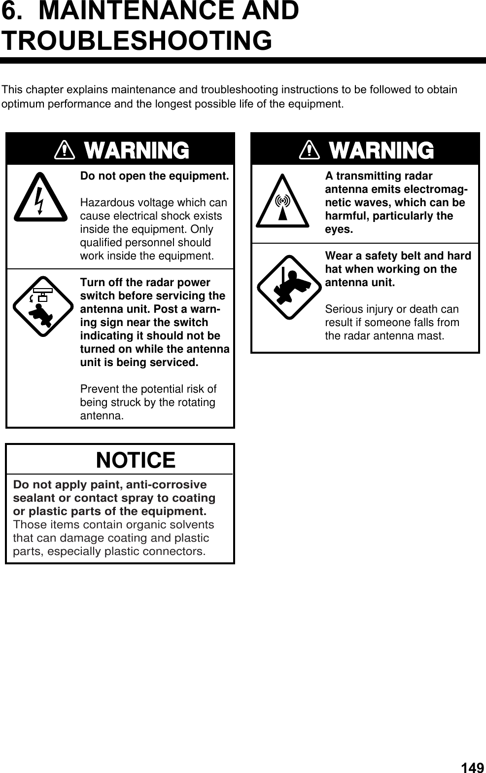
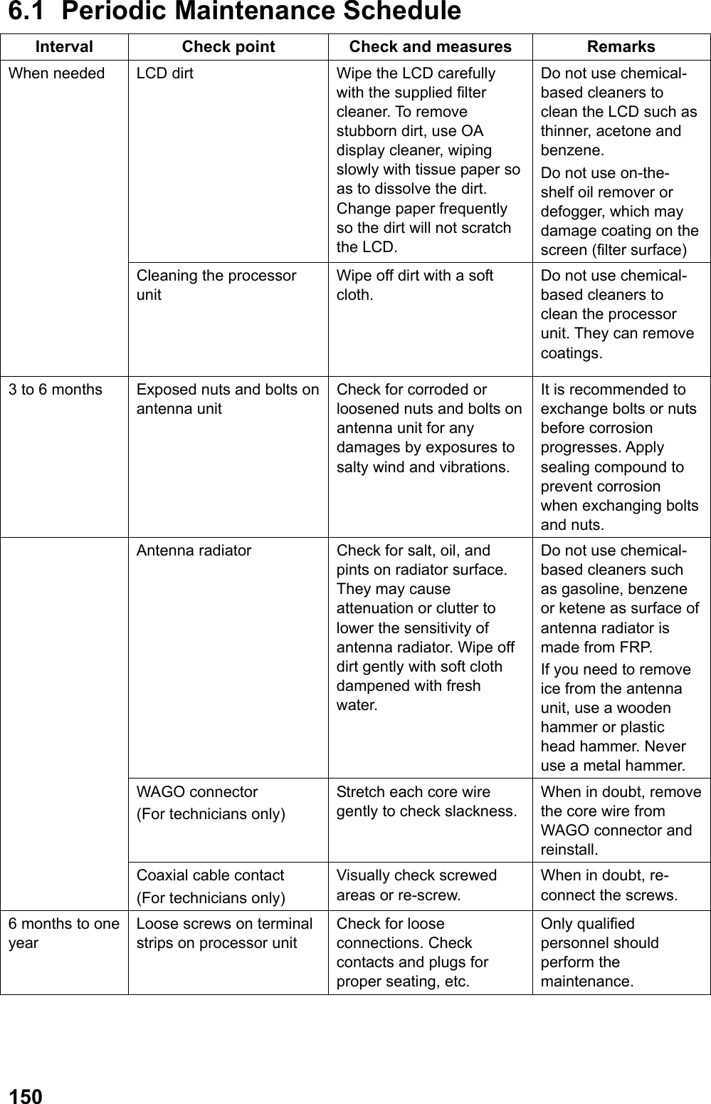
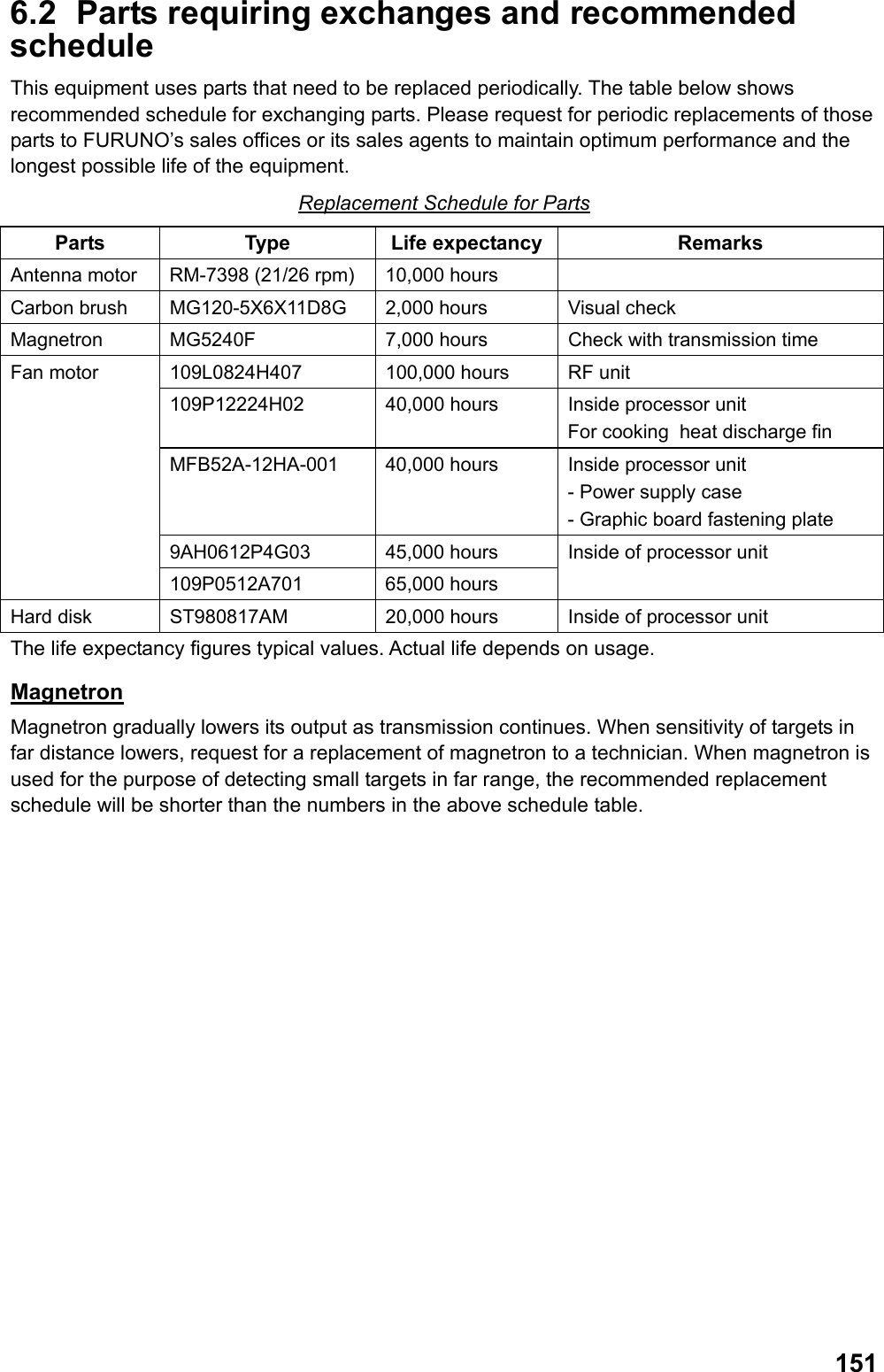
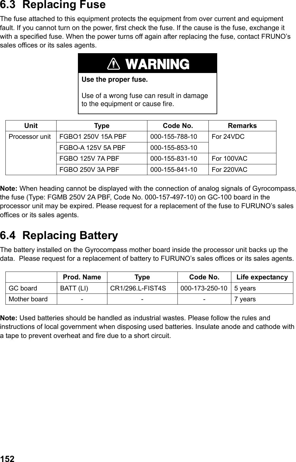
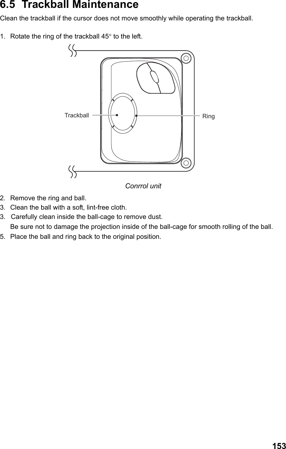
![1546.6 Simple Troubleshooting If you suspect any problems, follow the procedures below to restore normal operation. If you cannot restore normal operation, do not attempt to check inside any unit. Any repair work is best left to a qualified technician. Problem Remedy No power - Check if fuse is expired. - Connect the power cable securely. - Check any damage to the power cable. - Check voltage of battery with a tester. - For AC power, check if the power switch is ON at the rear panel of the processor unit. No Getting ready state after power is turned ON. Check if USB memory is inserted in the control unit. No reaction when a key is pressed. Reset the power. If the problem persists, contact FURUNO’s sales offices or its sales agents. Cannot adjust brilliance with the [Echo brilliance] knob in the control unit. Check the setting on the display unit. (See chapter 1.5.1.) No key sound Set [Key operation sound] in the [Control] menu at the settings other than [Off]. Screen freezes and images cannot be updated. Reset the power. No radar echoes appear when the [Prepare/Transmit] key is pressed. Check if antenna cable is securely connected. Adjust brilliance. No echoes are displayed. Check if antenna cable is securely connected. Check if LAN cable is disconnected on the rear panel of the processor unit. Low sensitivity Clean of the radiator surface in the antenna unit. Range changed but radar picture does not change. Press [+] or [-] sections of the [Range] key. Reset the power. Too much echoes on sea surface near own ship. Roll the [Sea clutter rejection] knob to adjust sea clutter rejection. Set numbers of PI lines do not appear. Set PI line interval correctly. Tracked target not tracked correctly. Adjust sea clutter rejection, precipitation clutter rejection, or TT echo level. Gyrocompass and heading do not match. Set Gyrocompass correctly at [GC-10] in the [Echo] menu.](https://usermanual.wiki/Furuno-USA/9ZWRTR110.operators-manual/User-Guide-1672487-Page-164.png)
![1556.7 Troubleshooting by Qualified Technician This chapter describes troubleshooting that should be carried out by qualified service personnel (personnel with shipboard maintenance qualifications) only. Note: Follow the steps below to transfer the previous settings to new SPU board. 1. Record current settings into USB memory by referring chapter 5.9.1. 2. After replacing the SPU board, load the recorded data. Problem Check point Remedy Power turns on but radar does not operate. - Fuse - Mains voltage - Power supply board - Replace blown fuse - Correct wiring and input voltage. - Replace power supply board. Brilliance can be adjusted but no picture. Graphic board Replace graphic board Antenna not rotating - Gear mechanism - TB board - Antenna switch of the antenna unit chassis. - Replace antenna gear. - Replace TB board - Check if switch is ON. No data or marks are displayed in transmit status - Mother board - SPU board - Replace mother board. - Replace SPU board. No echo displayed even when adjusting GAIN with sea clutter rejection, precipitation clutter rejection set at minimum. - IF amplifier - Signal cable between antenna and processor unit - Video amplifier board - Replace IF amplifier. - Check coaxial cable. - Replace video amplifier. No strong echo even if GAIN is adjusted in near range. - TX high voltage protection circuit has activated. - Magnetron - Modulator board - SPU board - Reset power to restore normal operation. - Check magnetron current. Replace magnetron. - Replace modulator board. - Replace SPU board. Picture not updated or picture freeze-up - Bearing signal board (in antenna unit) - SPU board - Check the connection of signal cables. - Replace SPU board. - Reset power. - Check LAN cable disconnection on rear panel of processor unit. No North-up - SPU board - Gyro I/F - No signal received when “Sensor error gyro” is displayed on the screen. - Replace Gyro I/F GC-100. Radar properly tuned but poor sensitivity - Deteriorated magnetron. - MIC tuning - Dirt on radiator face - Second trace echo rejection is ON - With the radar transmitting on 48NM, check magnetron current. - Clean the radiator surface. - Set Second trace echo rejection. Range can change but radar - Defective [Range] key - Press [+] or [-] keys several times.](https://usermanual.wiki/Furuno-USA/9ZWRTR110.operators-manual/User-Guide-1672487-Page-165.png)
![156Problem Check point Remedy picture does not change. - SPU board If unsuccessful, replace keyboard. - Replace SPU board. - Reset power. Interference rejecter is inoperative (interference rejection level not displayed.) SPU board Replace SPU board Zoom is not working. SPU board Replace SPU board Range rings are not displayed. Setting of fixed range ring brilliance range Adjust the brilliance of range rings on the [Brilliance detail] menu. If unsuccessful, replace SPU board. True motion presentation not working correctly - Poor contact of the [Mode selection] key - Mode is not selected correctly. - Speed entry incorrect - TM display inaccurate - Press the [Mode selection] key a little stronger again. - Press the [Mode selection] key until TM appears. - Enter correct own ship speed. - Set compass inputs correctly.](https://usermanual.wiki/Furuno-USA/9ZWRTR110.operators-manual/User-Guide-1672487-Page-166.png)
![1576.8 Diagnostic When you suspect abnormal operation, execute the diagnostic test. Should a repair be necessary by a technician, diagnostic test result helps remedy the problem faster. 1. Put the cursor on [Menu] in the information display area then left-click. 2. Select [Set environment] then left-click. 3. Select [Test] then left-click. 4. Select [Self test] then left-click. Test result of mother board, control unit and radar processor is displayed. Items 5 ~ 10 are displayed [OK] if normal and [NG] if abnormal. When [NG] is displayed, request a repair at FURUNO sales offices or its sales agents. Close WindowMother boardControl unitRadar Processorxx: Program version no. Test Result 5. Put the cursor on the button at the upper right section in the window to finish the diagnostic test then left-click. 6. Right-click several times to close the menu.](https://usermanual.wiki/Furuno-USA/9ZWRTR110.operators-manual/User-Guide-1672487-Page-167.png)
![1586.9 TT Performance Test You can perform TT function test by entering virtual echoes. Marks below are displayed on the screen and moves as the time elapses. Heading signal is required to perform the test. When the test is implemented tracking operation is cancelled with the actual echoes. Note: Turn the signal processing function off. 1. Put the cursor on [Menu] in the information display area then left-click. 2. Select [Set environment] then left-click. 3. Select [Test] then left-click. 4. Select [TT test] then left-click. The indication “S” flashes during the test. 5.Acquire three targets appearing on the screen using the [Acquire] key. Movements of the three targets are automatically simulated. (approx. ten minutes) If the test result shows the speed course as shown in the table below, TT function is operating correctly. 000 010 020030040050060070080090100110120130140150160170180190200210220230240250260270280290300310320330340 350ABCS 6. Put the cursor on target A then left-click. Data of the selected target is displayed in the data box in the information display area. 7. Check if the data in the data box approximately agree with the values of the table below. The table below shows the values at heading 0° and ship speed 0 KN. The values change in accordance with the time passage, bearing and ship speed. Range when test starts (NM) Bearing when test starts (°) Speed (kn) Course (°) CPA after 3 min (NM) TCPA after 3 min (Min)Target A 3 45 20 0 2.2 -9.2 Target B 2 120 5 120 0.0 -27.0 Target C 7 270 100 120 3.6 0.4 8. Similarly with target A, check target B and C as well. 9. Press the [Prepare/Transmit] key to finish the test and get in the Getting ready state. 10. Right-click several times to close the menu.](https://usermanual.wiki/Furuno-USA/9ZWRTR110.operators-manual/User-Guide-1672487-Page-168.png)
![1596.10 Displaying Sentences You can confirm sentences read into the equipment. Put the cursor in [Menu] in the information display area then left-click. Select [Set environment] then left-click. Select [Test] then left-click. Select [Sentence monitor] then left-click. 5. Select the item to display then left-click. Each item refers to the external equipment connection port in the processor unit. Close the window 6. Put the cursor on the button at the upper right section of the window then left-click to erase the sentences. 7. Right-click several times to close the window.](https://usermanual.wiki/Furuno-USA/9ZWRTR110.operators-manual/User-Guide-1672487-Page-169.png)
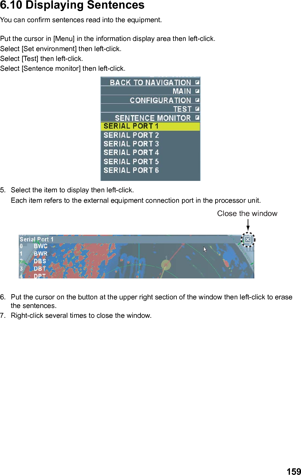
![AP-1APPENDIX ALARM LIST Types of alarm Name of alarm Cause Priority Setting Yes/No System error No trigger Trigger signal interrupted (Antenna unit) X System error No video Video signal interrupted X System error No turning signal Antenna turning signal interrupted X System error No heading line signal Heading line signal interrupted X System error Control unit Connection from control unit interrupted O System error Radar connection error FRP (Radar Processor) does not respond to UIP (User Interface Processor) O System error External radar getting ready External radar getting ready O System error Abnormal external radar Abnormal external radar O System error Abnormal interswitch Abnormal interswitch O System error Tuning control No tuning O System error Disk capacity Exceeded 80% of disk capacity O System error CPU temperature Temperature of CPU exceeded 80 ̊C O Sensor error Gyro Heading signal interrupted X Sensor error Log Ship speed log signal interrupted when the setting of [Over-the-ground speed] (or [Speed-over-water] speed) is [Log] in the [Ship speed] menu. X Sensor error Positioning Own ship position data interrupted X Sensor error Datum Position data read other than WGS-84 O Sensor error UTC No UTC data O Sensor error Sounding Sounding data interrupted O Sensor error Wind speed/direction sensor Wind direction/speed data interrupted O Sensor error Speed VTG signal interrupted when the setting of [Speed-over-ground] is [GPS] in the [Ship speed] menu. X Sensor error EPFS mode change Measuring mode is changed O Sensor error Fan motor Fan on UIP stopped O TT alarm TT collision alarm Range of both CPA and TCPA within the set range X TT alert TT entering TT target entered in the set guard zone O TT alert TT lost TT target lost O](https://usermanual.wiki/Furuno-USA/9ZWRTR110.operators-manual/User-Guide-1672487-Page-171.png)