Furuno USA 9ZWRTR110 Marine Radar User Manual
Furuno USA Inc Marine Radar
UserManual.wiki
>
Furuno USA
>
9ZWRTR110 User Manual
>
install manual
Contents
1.
operators manual
2.
install manual
install manual
Navigation menu
Upload a User Manual
Namespaces
Wiki Guide
HTML
PDF
Info
Views
User Manual
Discussion / Help
Navigation
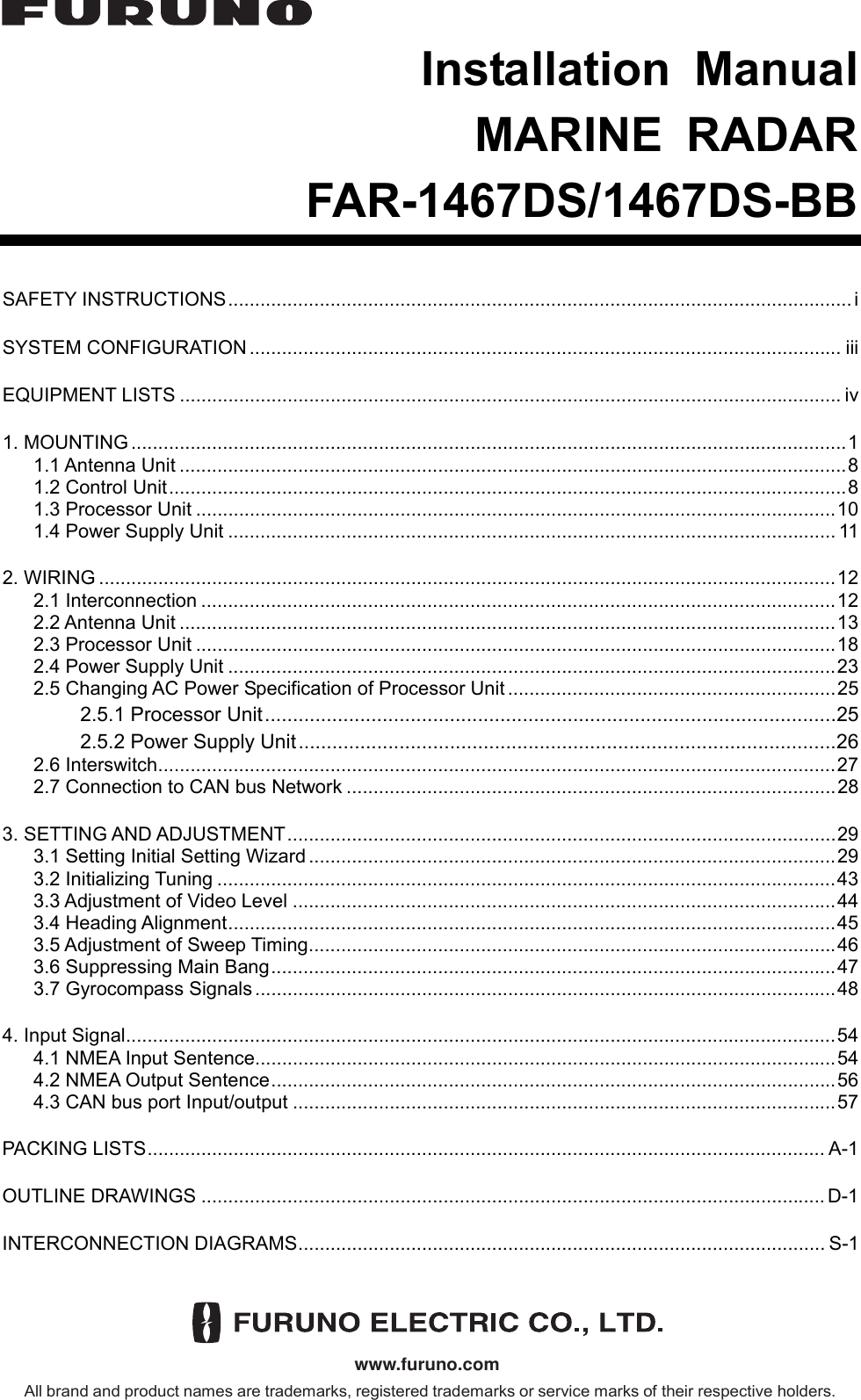
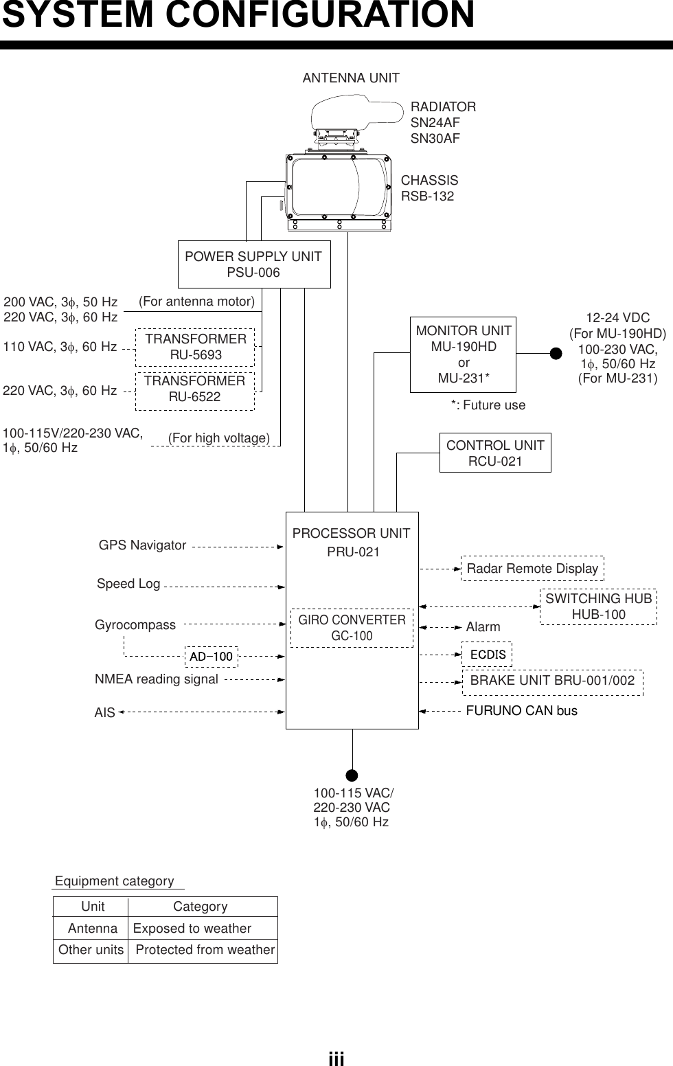
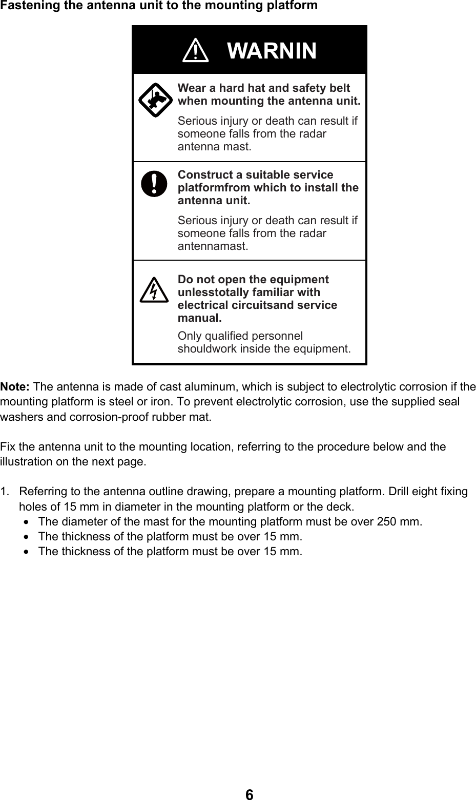
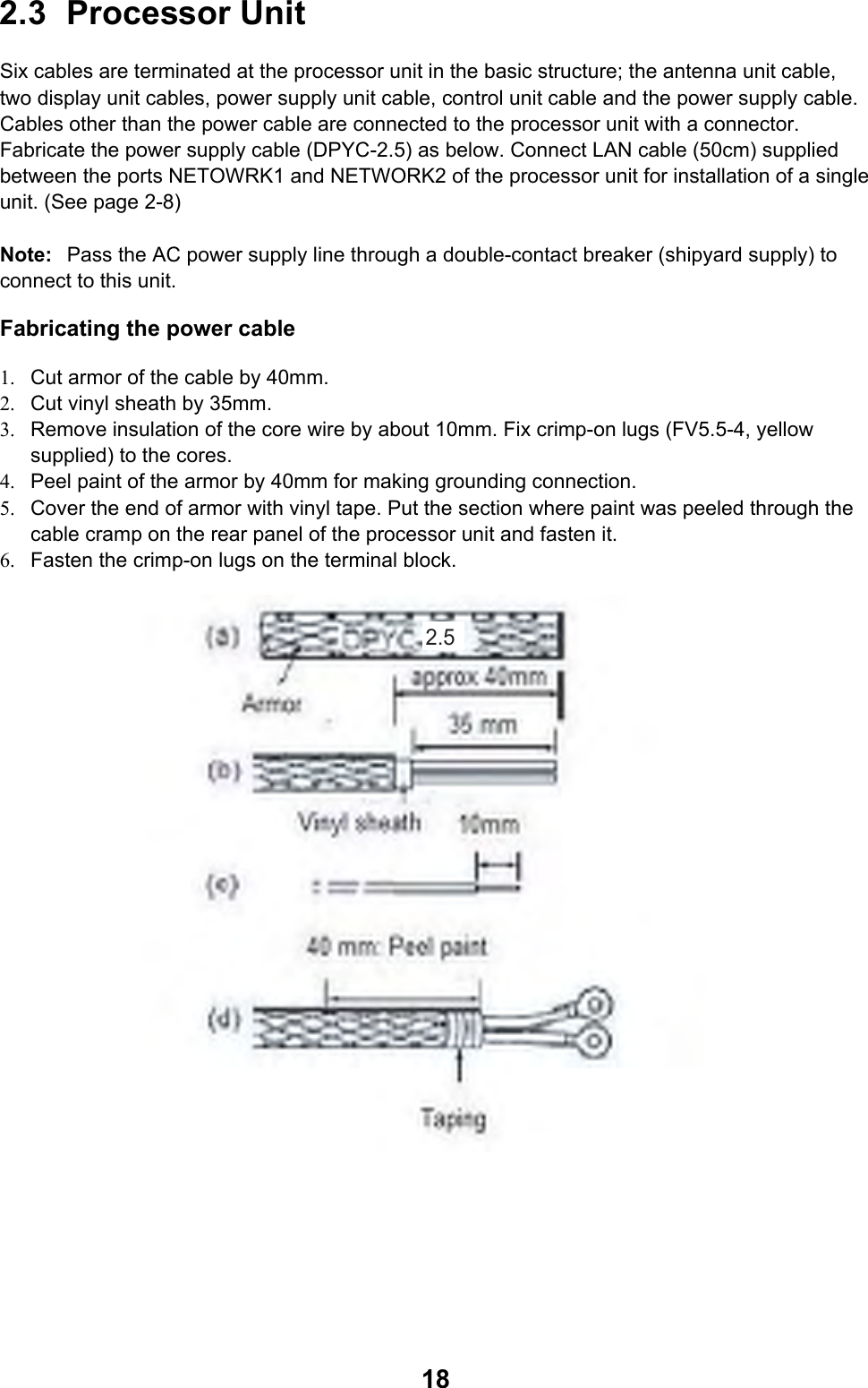
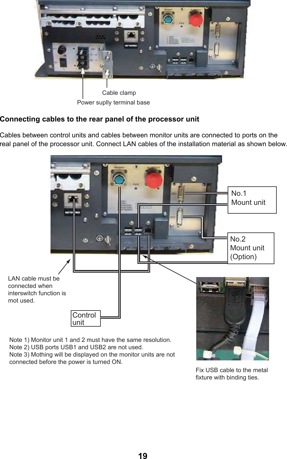
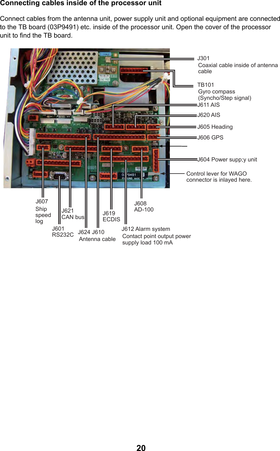
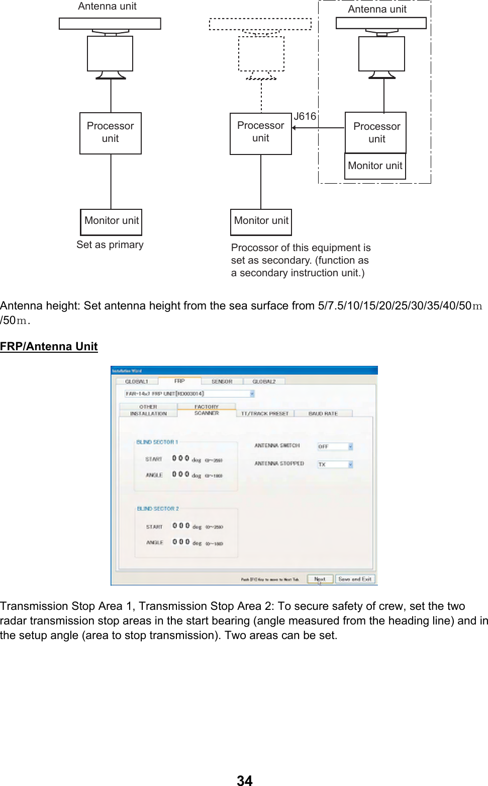
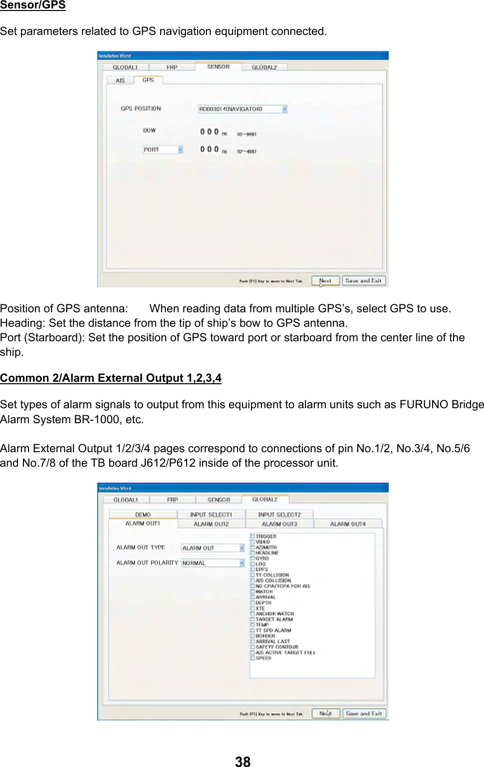
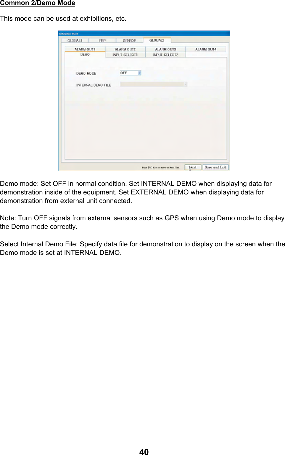
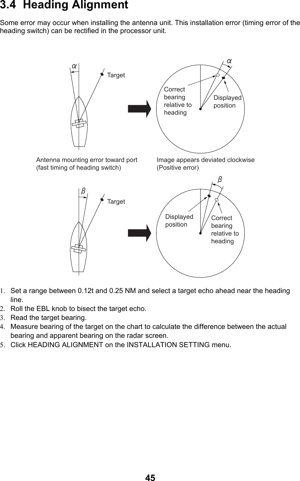
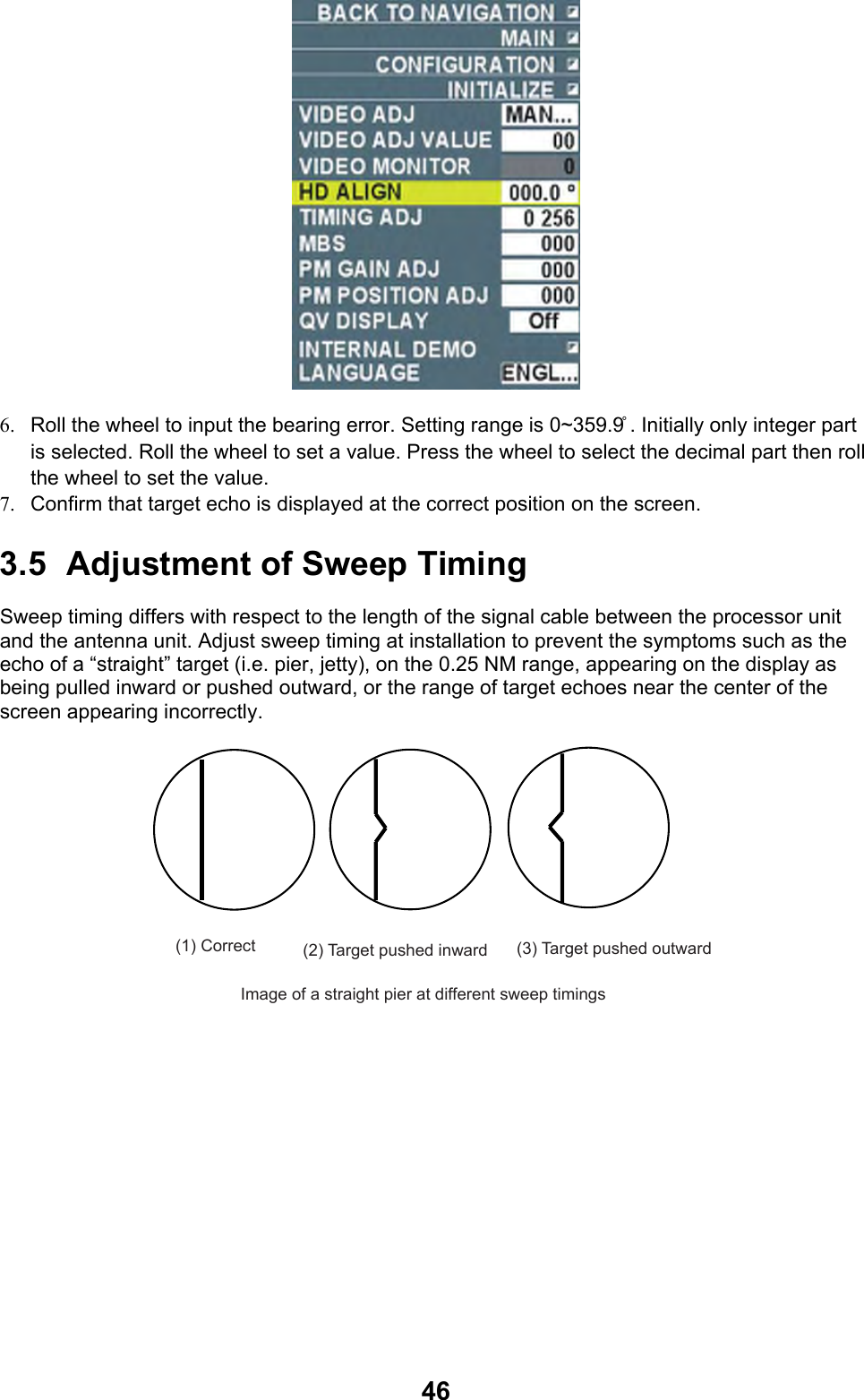
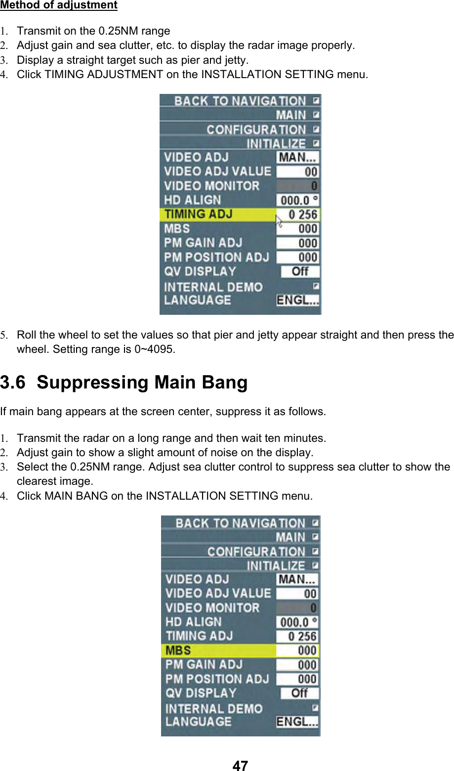
![293. SETTING AND ADJUSTMENT This chapter contains sections 3.1 through 3.7. Please set the equipment in the order of the sections. Note 1: The processor unit with AC specification has a power supply switch at the rear panel. Keep the switch ON at all times. Note 2: Every unit has the same IP address set as the factory default. Therefore when connecting the unit by inter-switching, turn on the power for each unit to set IP address. (See pages 3-2 and 3-3). After setting IP address for all units, set “Common 1/Own ship’s information” on page 3-3 while power is turned on for each unit. 3.1 Setting Initial Setting Wizard After installing equipment and wiring, turn on the power and initialize the system according to the initialization wizard. 1. Press the power switch on in the operation unit. 2. Press the [Delete heading line] key and immediately press [Delete target] key five times. SYSTEM SETUP MENU appears. 3. Select “Initialization Wizard” and click the left button. Initialization wizard appears after a few seconds. 4. Do the setting on the first page and then press the [Next page] button. 5. After setting necessary items, go to the next page using the [Next page]. 6. After all the settings are done, press the [Save settings/Finish] button. The system restarts automatically and “Preparing” is displayed. Settings in each wizard page are explained in the following pages.](https://usermanual.wiki/Furuno-USA/9ZWRTR110.install-manual/User-Guide-1672488-Page-36.png)
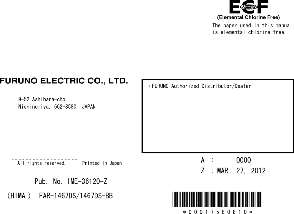
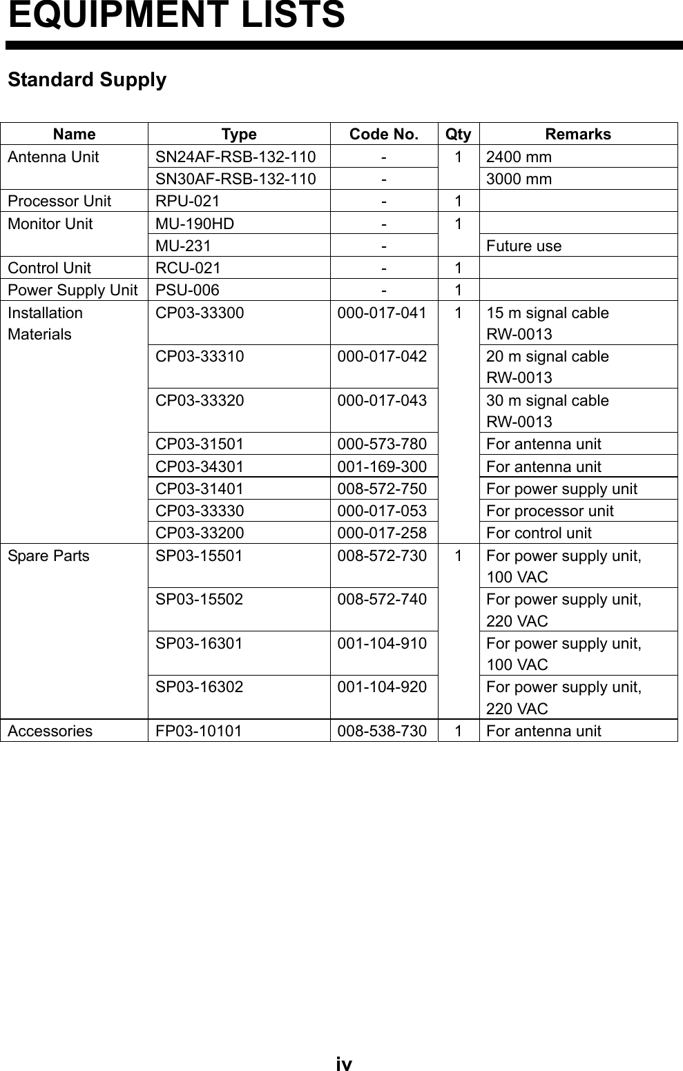
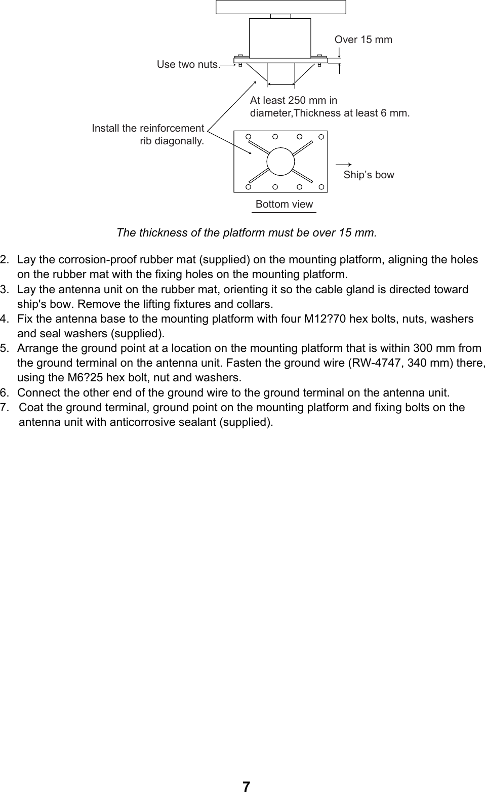
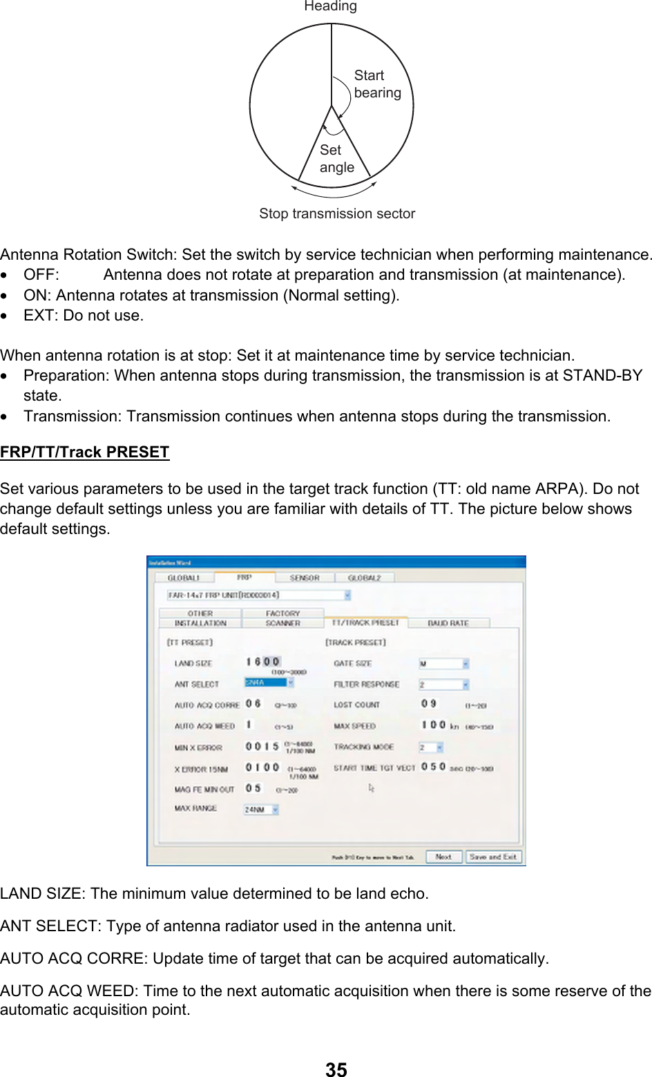
![30UIP (User Interface Processor) page Server: It means the chart server and normally YES remains as it is. IP address: Set IP address of the processor unit UIP. For single installation, no change is necessary. IP address needs to be changed for inter-switch connection (2-13 page). Change only “xxx” parts of 172.031.003.xxx. xxx is an arbitrary number from 020 to 253. Set IP address that is different from other IP addresses. Note: Do not set the same IP address on UIP and FRP pages. How to input numbers: Put the cursor on numbers and the background of the number changes to green. Rotate the wheel or right click/left click to change the number. Press the [Set] button. Pop-up menu appears to restart the system. Press [Yes] to restart the system after about 30 second to 1 min. After the restart, repeat the process. Screen size: When the display unit is MU-231, select [XGA] and the monitor unit is MU-190HD, select [SXGA] then press the [Set] button. Cursor speed: Adjust the speed of cursor on the screen when moving the cursor with the trackball. Adjust the cursor speed in accordance with user’s convenience.](https://usermanual.wiki/Furuno-USA/9ZWRTR110.install-manual/User-Guide-1672488-Page-37.png)
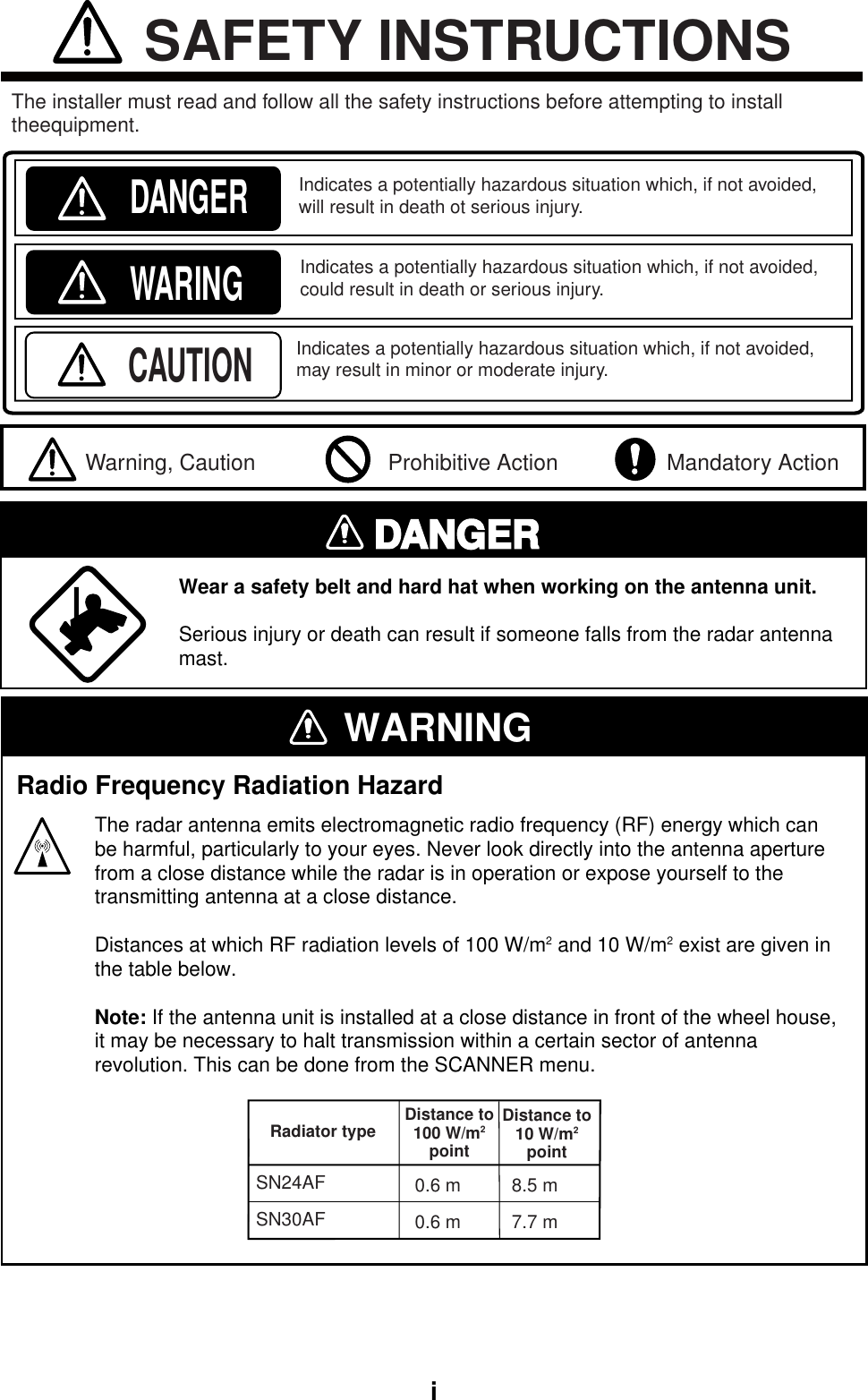
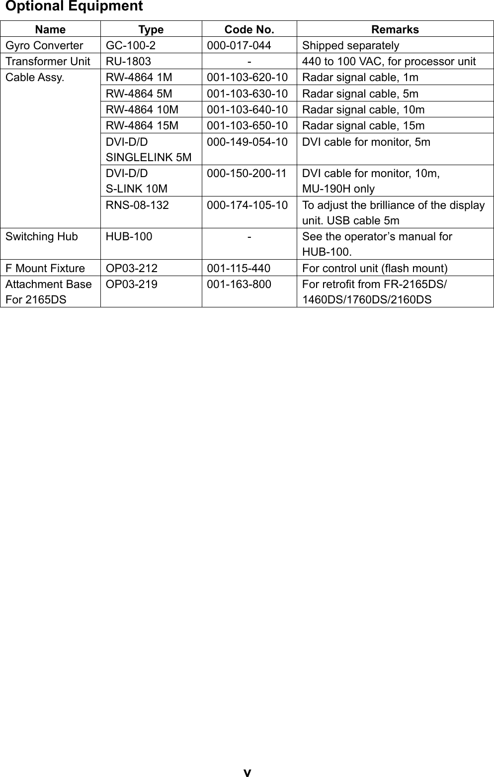
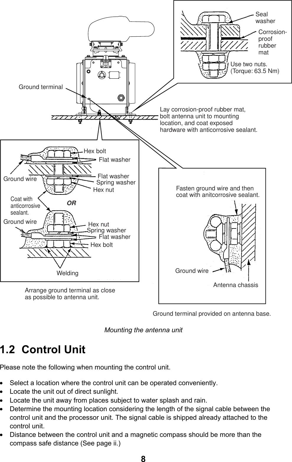
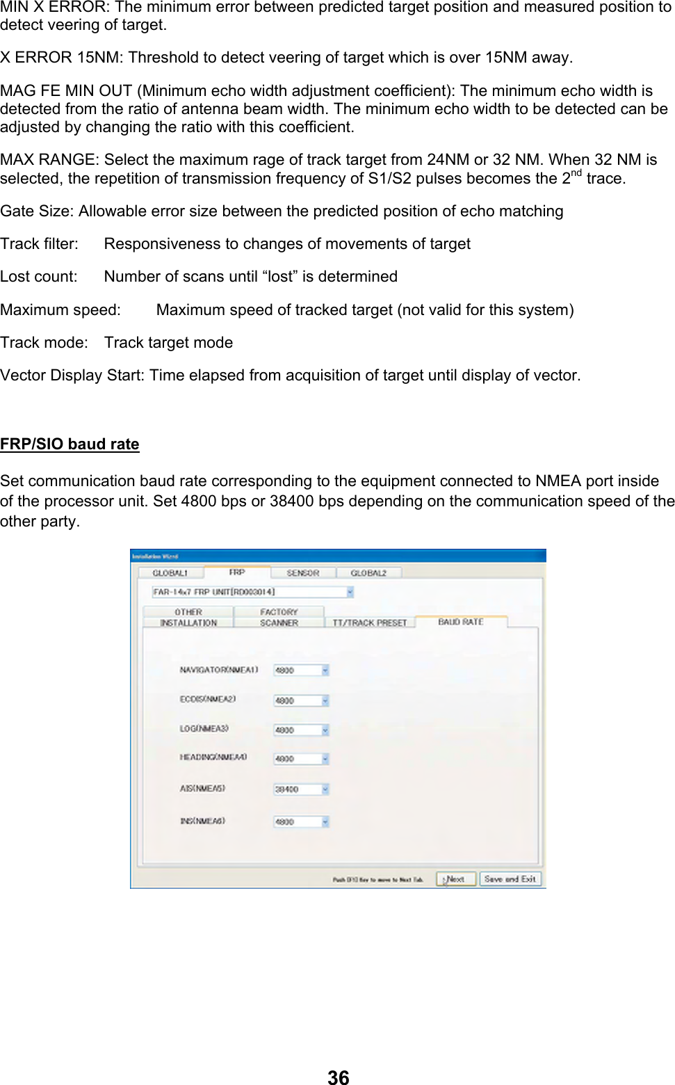
![31FRP (Radar Processor) page Partner: Set FRP which is paired with UIP. (See the next diagram.) It is set when two sets of FAR-14x7 series radars are connected through the switching hub. Normally, the factory default (FRP inside of the same processor unit) remains unchanged. IP address: Factory default is shown. In case of inter-switch connection, set a value different from other values and press the [Set] button. Restart begins and the above screen remains for about 30 seconds. Output power: Select 60kW. UIPFRPUIPFRPFRPUIPFRPUIPLANLANLANLANAntenna unit (Primary)Antenna unit (Secondary)Processor unit Processor unitHubMonitor unit Monitor unit](https://usermanual.wiki/Furuno-USA/9ZWRTR110.install-manual/User-Guide-1672488-Page-38.png)
![32Common 1/Own Ship Data Ship length: Input total length of ship. (tip of heading to end of stern) Width of hull: Input width of hull Steering position/Heading: Input distance from tip of ship to steering position. Steering position/ Port (Starboard): Input distance from the center line of the ship to the steering position toward port or starboard. Center lineSteering position L1: Ship length W1: Width of hullL2: Steering position/HeadingW2: Steering position/Port (Starboard) Unit Composition Box: When changing unit name displayed on the screen, select the name to be changed and press the [Change nickname] button. Input name from the keyboard displayed on the screen.](https://usermanual.wiki/Furuno-USA/9ZWRTR110.install-manual/User-Guide-1672488-Page-39.png)
![39Contact point output: Select among Alarm Output, Operation Report and Alarm Acknowledge as shown below. The wiring diagram at the end of this manual shows the default condition. i.e. Alarm External Output 1, 2 and 3 are for Alarm Output and Alarm External Output 4 is for Operation Report. Alarm Output: Output contact point signal to the alarm unit connected when problems occur in this equipment. Types of problems are set in the check box on the right side on the screen. Click the check box twice to enter check mark. No trigger: No trigger signals No video: No image signal No turn signal: No bearing signals Gyro: No gyrocompass bearing Log: No speed signals from ship speed meter EPFS: No positioning signals TT collision alarm: Alarm for collision by the track target function AIS collision alarm: Alarm for collision by AIS CPA/TCPA unable to measure: Alarm for CPA/TCPA not set for AIS Watch alarm: Alarm for watch Depth alarm: Alarm for depth XTE alarm: Alarm for course error Anchor watch alarm: Alarm for anchor watch Watch alarm: Alarm for target Water temperature alarm: Alarm for water temperature TT ship speed alarm: Alarm for ship speed by the track target function. Border Alarm: Not used in this equipment Arrival to Final Waypoint: Alarm for arrival at final waypoint Grounding Warning: Not used in this equipment AIS Active Full: Alarm for AIS active target full Ship speed alarm: No ship speed signals from GPS • Control Report: Output contact signals. For example, it can be used as reset signals for Watch Alarm by connecting to the alarm unit. • Alarm Acknowledge: Press the [Cancel Alarm] key in the control unit when alarm is generated to stop the alarm and the contact signals are outputted to the alarm unit. Alarm Output Polarity: Set polarity of output signals according to the equipment connected. Set STANDARD when the other party is Normal Close and set REVERSE when the other party is Normal Open.](https://usermanual.wiki/Furuno-USA/9ZWRTR110.install-manual/User-Guide-1672488-Page-46.png)
![41Common 2/Source Selection ½ Set sources of various data to be displayed on the radar screen. LAN is displayed when no equipment of corresponding signals is connected. Depending on with/without [Priority order] button, settings are deferent. • Items with [Priority order]: Click the [Priority] button to set data source. (Setting from the list box is unavailable.) • Items without [Priority order]: Set data source from the list box. Using the [Priority order] button Click the [Priority order] button to display the list of input signals. Reverse the display of the desired selections then using the UP/DOWN arrow button, set the priority order. Click the [OK] button. Note: When there are no input signals, data sources up to the upper three data sources are switched. In the below case, NAVIGATOR, HEADING and ARPA are switched in that order.](https://usermanual.wiki/Furuno-USA/9ZWRTR110.install-manual/User-Guide-1672488-Page-48.png)
![42 Own ship position: Set data source for own ship position. Set DEAD RECKON when GPS navigation equipment is unavailable to predict own ship position from heading data and ship speed data. When GPS is selected, set data source from OWN SHIP POSITION and DATUM immediately below GPS. When DEAD RECKON is selected, set data source from DEADREC. Similarly, set data source for ground speed, water speed, date and time and heading. In data source selection page 2, set data source for wind direction/speed, tide, water temperature, water depth, AIS and external waypoint. Click the [Save setting/Finish] button when all the settings are done. Wizard disappears and radar restarts. Refer to the corresponding section to adjust radar image.](https://usermanual.wiki/Furuno-USA/9ZWRTR110.install-manual/User-Guide-1672488-Page-49.png)
![433.2 Initializing Tuning Note: “Click” in the following explanations means to click the left button on the trackball. 1. Set the range at 48 NM. 2. Roll the trackball and put the cursor on TUNING on upper right side of the screen then click the right button on the trackball INITIALIZE TUNING appears at the center of the screen. 3. Click INITIALIZE TUNING Automatic tuning starts and echo appears on the screen. Blinking message “Other alarm Initializing tuning” appears in yellow during the automatic adjustment. Press the [Cancel Alarm] key. Blinking changes to lighting. Initialization is completed when this message disappears. Rotate the GAIN knob to adjust visibility of the screen. 4. Select RETURN and press the wheel to close the menu.](https://usermanual.wiki/Furuno-USA/9ZWRTR110.install-manual/User-Guide-1672488-Page-50.png)
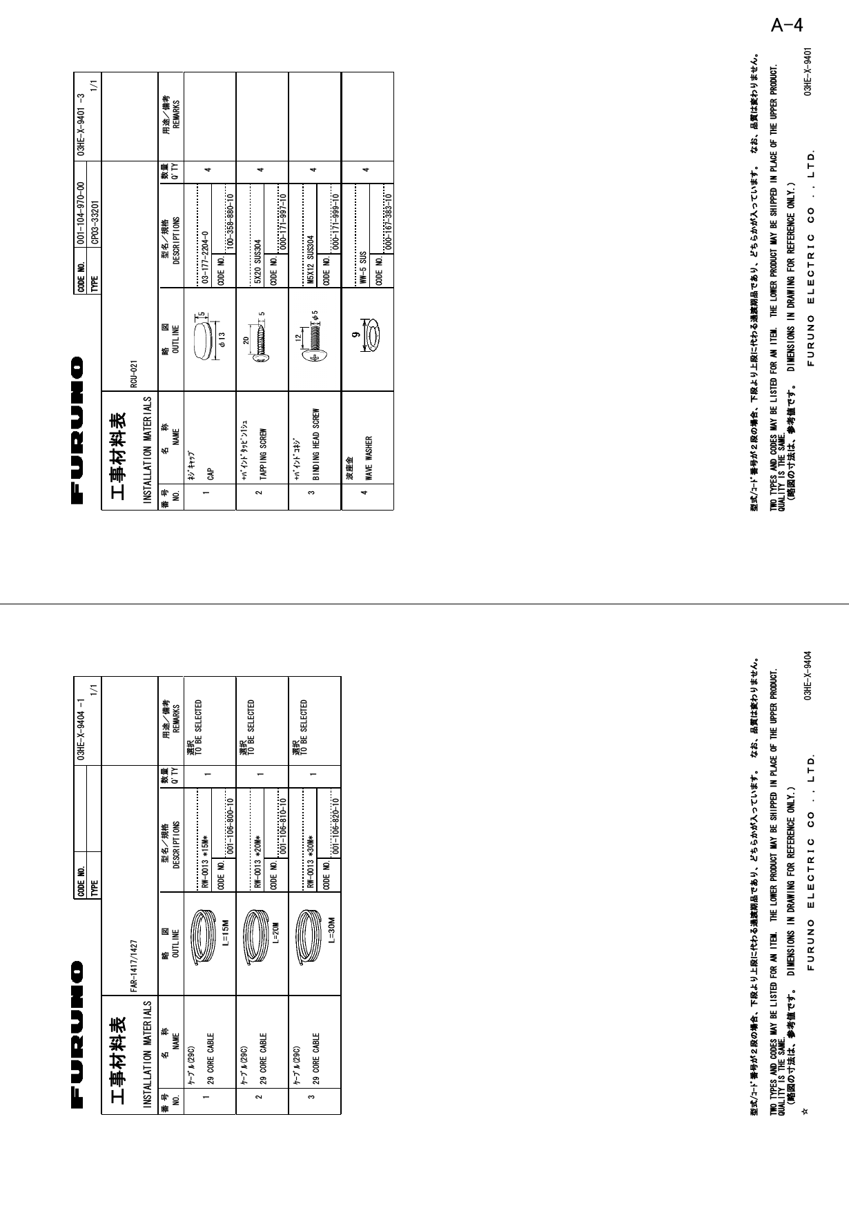
![443.3 Adjustment of Video Level After initializing tuning, adjust video level. Set the pulse width at LONG and do the following after tuning bar is stable. 1. Press the [Delete target] key five times immediately after pressing the [Delete heading line]. The environment setting menu appears. 2. Click INSTALLATION SETTING. The INSTALLATION SETTING menu appears. 3. Select VIDEO LEVEL ADJUSTMENT and click the button. 4. Select MANUAL in VIDEO LEVEL ADJUSTMENT and then click the button. 5. Input adjustment value according to the length of Antenna Cable (RW-0013). • Less than 20 m: 23 • 20 to 30 m: 25 • 30 to 50 m: 26 (Currently not used)](https://usermanual.wiki/Furuno-USA/9ZWRTR110.install-manual/User-Guide-1672488-Page-51.png)
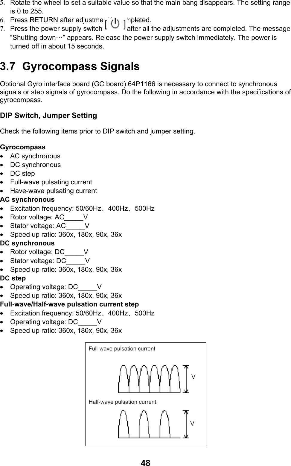
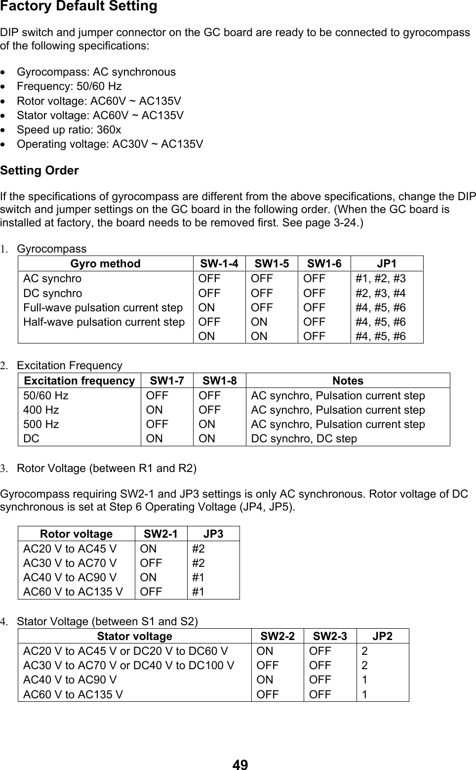
![505. Speed up ratio Speed increase ratio SW1-1 SW1-2 SW1-3360x 180x 90x 36x OFF ON OFF ON OFF OFF ON ON OFF OFF OFF OFF 6. Operating Voltage Operating voltage JP4 JP5 AC20 V to AC45 V or DC20 V to DC60 V AC20 V to AC135 V or DC4 V to DC100 V #2 #1 #2 #1 7. Transmission frequency of IEC61162 data, Version, Baud rate. (Not used for FAR-1417/1427) Set according to addressee’s of data.] Transmission frequency SW2-5 SW2-6 Output sentence 1 second 200mil. Sec. 100mil. Sec. 25mil. Sec. OFF ON OFF ON OFF OFF ON ON HDT+VHW HDT HDT HDT Version SW3-1 1.5 2.0 OFF ON Baud rate SW3-2 4.800 bps 38.400 bps OFF ON Turn OFF the DIP switch SW2-8 from ON and reset CPU. SW1J1 J6 JP3JP2 J4JP4 JP5 JP1SW2J7J8SW3J3](https://usermanual.wiki/Furuno-USA/9ZWRTR110.install-manual/User-Guide-1672488-Page-57.png)
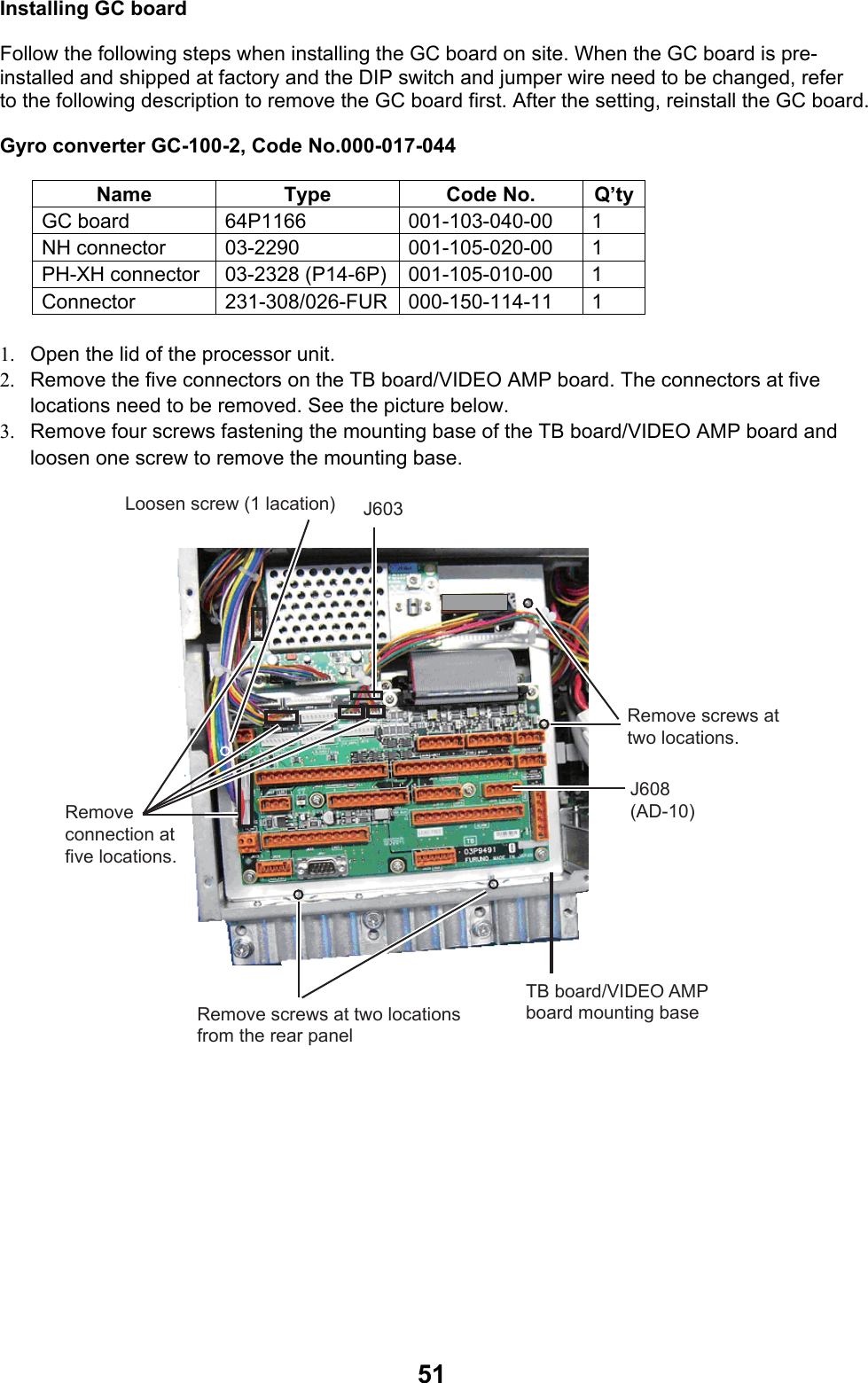
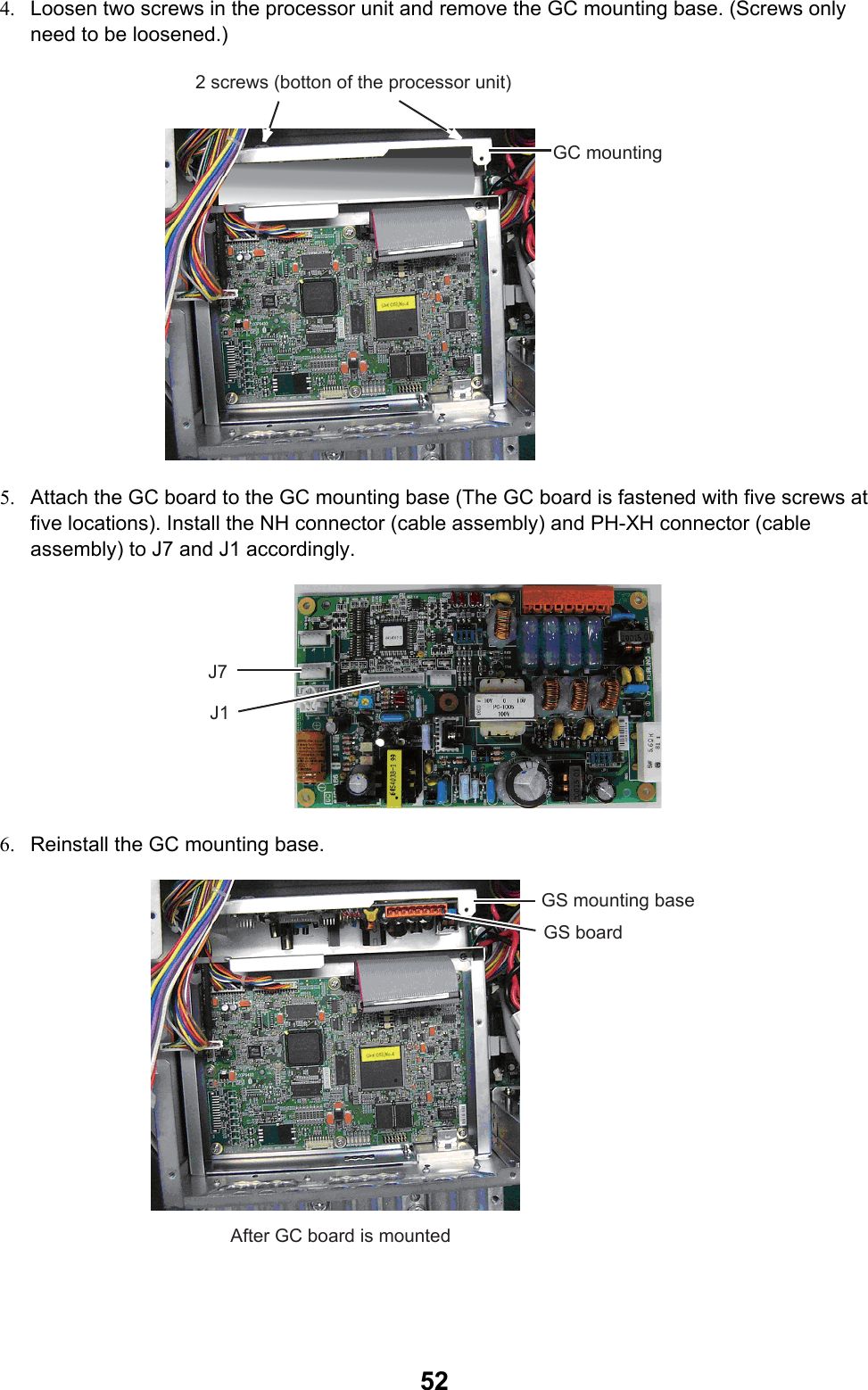
![537. Reinstall the mounting base of the TB board/VIDEO AMP board and fasten the connectors removed at step 2. 8. Connect the six pin connectors of the cable assembly on the GC board to J603 on the TB board. (See the illustration at step 3 above.) 9. Connect the other cable assembly on the GC board to 231-308/026-FUR to connect to J608 on the TB board. See page 2-11 for installation of the 231-308/026 –FUR connector. Setting Bearing Read heading of gyrocompass. Check the heading displayed on the radar screen with the gyrocompass reading. 1. Click the MENU at about middle on the right side of the screen to display the main menu. 2. Click ECHO to display the echo menu. 3. Click [GC-10] to read the gyrocompass reading. 4. Right click several times to close the menu. 5. Confirm that the heading tracks with the movement of the gyrocompass.](https://usermanual.wiki/Furuno-USA/9ZWRTR110.install-manual/User-Guide-1672488-Page-60.png)
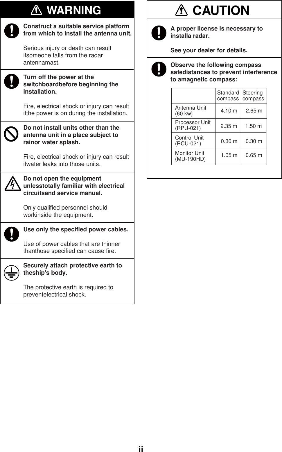
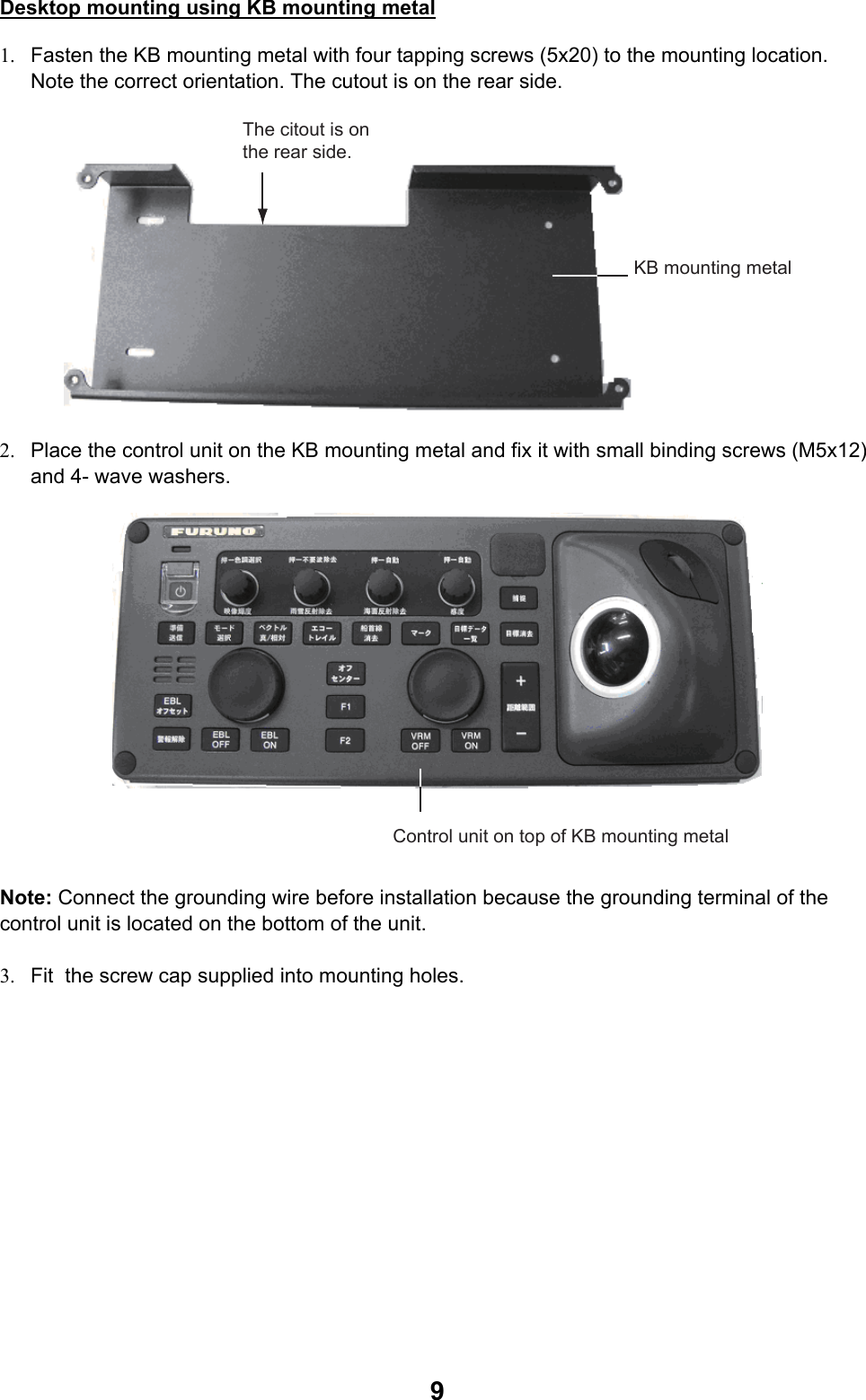
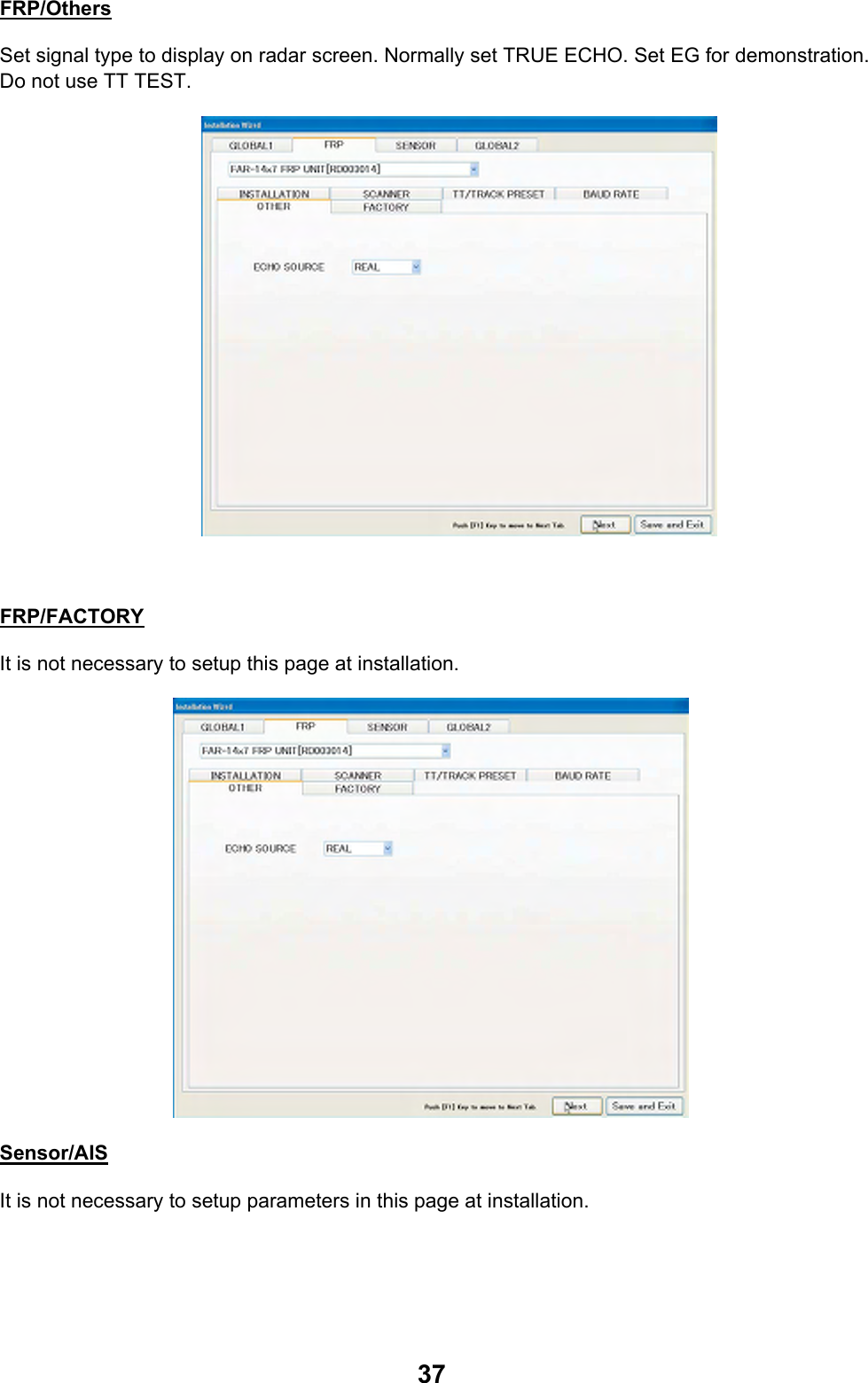
![12 4563BADCNAME名称TITLEkgMASSDWG No.SCALEAPPROVEDCHECKEDDRAWNREF.No.INTERCONNECTION DIAGRAM相互結線図T.YAMASAKI*1: SHIPYARD SUPPLY.NOTE*2: OPTION.*1)造船所手配。注記*2)オプション。*3)保護アース用ケーブルは黄/緑の絶縁線を使用のこと。*3: USE YEL/GRN WIRE FOR PROTECTIVE EARTH.船舶用レーダーMARINE RADARH.MAKIFAR-1467DS12TB11234567812345678RJ45RJ451234AD-DATA-HAD-DATA-CAD-CLK-HAD-CLK-CP6081234GYRO-R2GYRO-R1-COM567TB1015GC-100GYRO CONVERTER*28GYRO-S1GYRO-S2GYRO-S3GYRO-TGYRO-FGGYRO-FGNCE_TD-PE_TD-NE_RD-PE_RD-NSW-NSW-PNCNCE_TD-PE_TD-NE_RD-PE_RD-NNCNCNC12345678910J901GNDPWR_SW_PPWR_SW_NP12VGNDNCRADARNETWORK2NETWORK1制御部PROCESSOR UNITRPU-021P62412345678910111213141234567891011121314J30115GNDGND+12V-12VHDBPMOTOR-HMOTOR-HMOTOR-CMOTOR-CPM-EMBPM-LVLPM-ARKP610GNDGNDTX-TRIGPL-APL-BPL-CMBS-LLNA-MONHEATER-HHEATER-CTUNE-GATETUNING-INDMAG-CUR-LVLTUNING-CONTPM-TRIGGNDGND+12V-12VHDBP12345678910111213GNDGND14TB805TX-TRIGPL-APL-BPL-CMBS-LLNA-MONHEATER-HHEATER-CTUNE-GATETUNING-INDMAG-CUR-LVLTUNING-CONTTX_SIGGNDNCTX_HV1234567891011TX_HV_MONI_SELRW-4747123456789NCRXDTXDGNDNCNCNCNCNCP601123HDG-RD-AHDG-RD-BHDG-COMMONP605 *1123TTYCS-1*1P606NAV-RD-ANAV-RD-BNC123TTYCS-1*1NCLOG-RD-ALOG-RD-BP60712345*1AIS-RD-AAIS-RD-BAIS-COMMONAIS-TD-AAIS-TD-BP611 TTYCS-412345*1TTYCS-4NCP61912345*1TTYCS-412345*1TTYCS-4P620P621INS-TD-AINS-TD-BINS-RD-AINS-RD-BINS-COMMONNET-SNET-CNET-HNET-L678SHIELDEXT_NET-SEXT_NET-CFG12345*1678910111213NCSYS_FAIL-LGNDSYS_FAIL-HEXT-ALARM-ACK-NOPERATOR-FITNESS-1OPERATOR-FITNESS-0ALARM3-1ALARM3-0ALARM2-1ALARM2-0ALARM1-1ALARM1-0HEADING SENSORGPS NAVIGATORSPEED LOGAISALARM SYSTEM(IEC61162-2)(IEC61162-2)(IEC61162-2)INSNAVNET EQUIPMENT(FURUNO CAN bus)ECDISFEA-2107ser.TTYCS-1TTTYCS-7NC 9P612ECDIS-RD-BECDIS-RD-AECDIS-TD-BECDIS-TD-ARS-232C CABLE パソコン(保守用)PC FOR MAINTENANCE100-115/220-230VAC1φ,50/60Hz*1DPYC-2.54MONITOR 224DVI 24MONITOR 124DVI 1TPYCY-1.5*1IV-8sq.PE *1 *312345678GNDGNDGNDGNDJ617OP_HD_OUTOP_BP_OUTOP_TRIG_OUTOP_VIDEO_OUT8RW-4864RW-4864 同上DITTO12345678GNDGNDEXT_BP_INEXT_HD_INGNDEXT_TRIG_INGNDEXT_VIDEO_INJ616RW-4864*2*2*2MASTER RADARSUB RADARSUB RADARJ6188RW-4864 同上DITTO12345TTYC-4EXT. EQUIPMENT J626+12VGND+5VGND-12V*2(FOR MAINTENANCE)外部機器(保守用)J615EXT. TT(ARPA)EXTERNAL EQUIPMENT4USB AUSB CABLE4USB AUSB CABLEMOUSEKEYBOARD12345678910J1(PH10P)GNDPWR_SW_PPWR_SW_NP12VGNDNCNC 03S0017,5m4BRILL CTRLDVI244BRILL CTRL1POWER23MARINE DISPLAYカラーLCD表示器クロシロ WHTBLK(+)(-)SHIELDIV-8sq.*1DVI245m12-24VDC MJ-A3SPF0018-050ZC 15A:12V7A:24VMU-190HDMU-190HD *2スイッチングハブSWITCHING HUBHUB-100AD-100GYROCOMPASSTTYC-4MPYC-7*1*1*2RNS-08-132,5mDVI-D/D SINGLELINK5M,5m*2RNS-08-132,5mDVI-D/D SINGLELINK5M,5m*23.5m100-230VAC8818S1181,0.5mまたは ORSTP(CAT5)MJ-A10SPFUSB1_NUSB1_PNCUSB1_PUSB1_NGNDGNDIV-1.25sq.*1CONTROL UNITRCU-021操作部1φ,50/60HzBLK27BLK28BLK29BRN21YEL4BRN1GRY8GRN[B]15GRN[B]25チャ21キ4チャ1アカ22ハイ8ミドリ(太)15ミドリ(太)25クロ27クロ28クロ29RED22RED2アカ2ミドリ5 GRN5ムラサキ7シロ9 WHT9PPL7ダイ3ハイ18 GRY18ORG3ドウジク COAX.CABLEBLK[B]20WHT[B]19BLU[B]26ORG[B]23BLU[B]16YEL[B]24クロ(太)20シロ(太)19アオ(太)26ダイ(太)23アオ(太)16キ(太)24YEL[B]14RED[B]12ORG13ダイ13キ(太)14アカ(太)12アオ6PPL17ムラサキ17RW-0013,15/20/30m,MAX.50m,φ18.4BLU6DVI4BRILL CTRL12ACACTB1表示部MONITOR UNITMU-231IV-8sq.*1ORまたはDPYC-1.5*1100-230VAC1φ,50/60HzMU-231表示器DISPLAY/MONITORDPYC-2.5100-115/220-230VAC1φ,50/60HzDPYC-1.5440VAC,1φ,50/60HzDPYC-2.5TRANSFORMERトランス*1IV-8sq.*1*1*1DPYC-1.5 *1DPYC-1.5 *1220VAC,3φ,50HzRU-1803 *2RU-5693RU-6522 *2*2IV-8sq.PE*1 *3200VAC,3φ,50Hz220VAC,3φ,60Hz110VAC,3φ,60Hz123456NCTX_SIGGND+12VGNDPUS_ANT_ON123456789TX-HVNCTX-SIGGNDNCNCUTB3電源制御部POWER SUPPLY UNITPSU-006WV1011121314NC+12VANT_ONGNDNCTB3MPYC-7 *1*1TPYCY-2.5ANTENNA UNIT空中線部RSB-132123TB901UWV123UVW12UVTB1TB2C3612-C01- BREDアカWHTシロBLKクロP802/TB802P801/TB80103-180-6001-419/Dec/201119/Dec/201120/Dec/2011 Y.NISHIYAMAS-1](https://usermanual.wiki/Furuno-USA/9ZWRTR110.install-manual/User-Guide-1672488-Page-76.png)