Furuno USA 9ZWRTR110 Marine Radar User Manual
Furuno USA Inc Marine Radar
Contents
- 1. operators manual
- 2. install manual
install manual

Installation Manual
MARINE RADAR
FAR-1467DS/1467DS-BB
SAFETY INSTRUCTIONS....................................................................................................................i
SYSTEM CONFIGURATION .............................................................................................................. iii
EQUIPMENT LISTS ........................................................................................................................... iv
1. MOUNTING .....................................................................................................................................1
1.1 Antenna Unit ............................................................................................................................8
1.2 Control Unit..............................................................................................................................8
1.3 Processor Unit .......................................................................................................................10
1.4 Power Supply Unit ................................................................................................................. 11
2. WIRING .........................................................................................................................................12
2.1 Interconnection ......................................................................................................................12
2.2 Antenna Unit ..........................................................................................................................13
2.3 Processor Unit .......................................................................................................................18
2.4 Power Supply Unit .................................................................................................................23
2.5 Changing AC Power Specification of Processor Unit .............................................................25
2.5.1 Processor Unit......................................................................................................25
2.5.2 Power Supply Unit................................................................................................26
2.6 Interswitch..............................................................................................................................27
2.7 Connection to CAN bus Network ...........................................................................................28
3. SETTING AND ADJUSTMENT......................................................................................................29
3.1 Setting Initial Setting Wizard ..................................................................................................29
3.2 Initializing Tuning ...................................................................................................................43
3.3 Adjustment of Video Level .....................................................................................................44
3.4 Heading Alignment.................................................................................................................45
3.5 Adjustment of Sweep Timing..................................................................................................46
3.6 Suppressing Main Bang.........................................................................................................47
3.7 Gyrocompass Signals ............................................................................................................48
4. Input Signal....................................................................................................................................54
4.1 NMEA Input Sentence............................................................................................................54
4.2 NMEA Output Sentence.........................................................................................................56
4.3 CAN bus port Input/output .....................................................................................................57
PACKING LISTS.............................................................................................................................. A-1
OUTLINE DRAWINGS .................................................................................................................... D-1
INTERCONNECTION DIAGRAMS.................................................................................................. S-1
All brand and product names are trademarks, registered trademarks or service marks of their respective holders.
www.furuno.com

The paper used in this manual
is elemental chlorine free.
・FURUNO Authorized Distributor/Dealer
9-52 Ashihara-cho,
Nishinomiya, 662-8580, JAPAN
A : 0000
Printed in Japan
All rights reserved.
Z : MAR . 27, 2012
Pub. No. IME-36120-Z
*
00017580810
*
*
00017580810
*
(HIMA ) FAR-1467DS/1467DS-BB
*
00017580810
*
*
00017580810
*
* 0 0 0 1 7 5 8 0 8 1 0 *
i
Wear a safety belt and hard hat when working on the antenna unit.
Serious injury or death can result if someone falls from the radar antenna
mast.
DANGER
WARNING
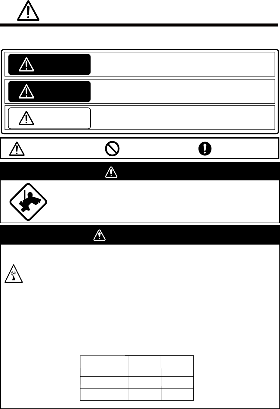
The radar antenna emits electromagnetic radio frequency (RF) energy which can
be harmful, particularly to your eyes. Never look directly into the antenna aperture
from a close distance while the radar is in operation or expose yourself to the
transmitting antenna at a close distance.
Distances at which RF radiation levels of 100 W/m2 and 10 W/m2 exist are given in
the table below.
Note: If the antenna unit is installed at a close distance in front of the wheel house,
it may be necessary to halt transmission within a certain sector of antenna
revolution. This can be done from the SCANNER menu.
Radio Frequency Radiation Hazard
Distance to
100 W/m2
point
Distance to
10 W/m2
point
Radiator type
SN24AF
SN30AF
0.6 m
0.6 m
8.5 m
7.7 m
SAFETY INSTRUCTIONS
The installer must read and follow all the safety instructions before attempting to install
theequipment.
Indicates a potentially hazardous situation which, if not avoided,
will result in death ot serious injury.
Indicates a potentially hazardous situation which, if not avoided,
could result in death or serious injury.
Indicates a potentially hazardous situation which, if not avoided,
may result in minor or moderate injury.
DANGER
WARING
CAUTION
Warning, Caution Prohibitive Action Mandatory Action
ii
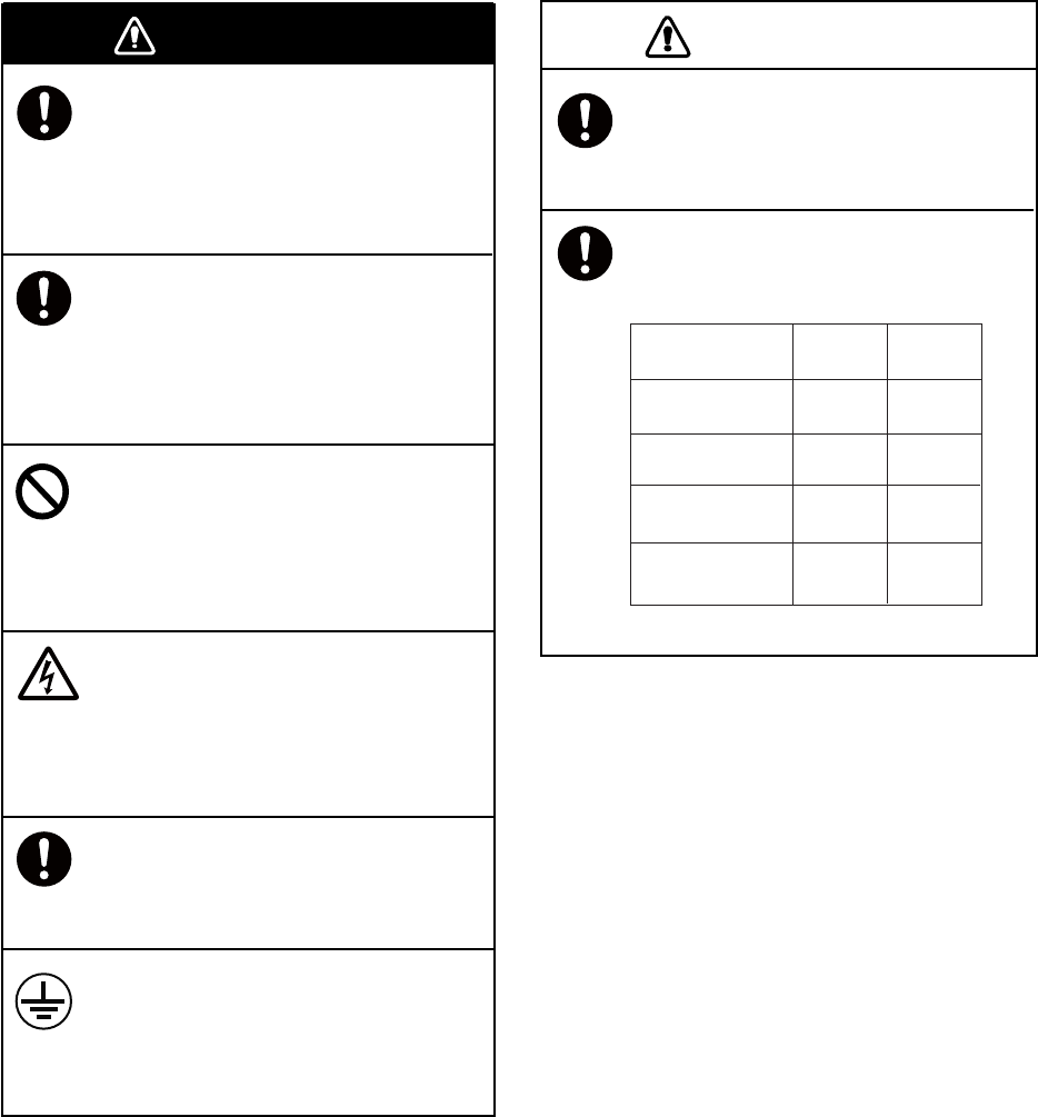
WARNING CAUTION
Antenna Unit
(60 kw)
Standard
compass
2.35 m 1.50 m
Processor Unit
(RPU-021)
0.30 m 0.30 m
Control Unit
(RCU-021)
1.05 m 0.65 m
Steering
compass
4.10 m 2.65 m
Monitor Unit
(MU-190HD)
Construct a suitable service platform
from which to install the antenna unit.
Serious injury or death can result
ifsomeone falls from the radar
antennamast.
Turn off the power at the
switchboardbefore beginning the
installation.
Fire, electrical shock or injury can result
ifthe power is on during the installation.
Do not install units other than the
antenna unit in a place subject to
rainor water splash.
Fire, electrical shock or injury can result
ifwater leaks into those units.
Do not open the equipment
unlesstotally familiar with electrical
circuitsand service manual.
Only qualified personnel should
workinside the equipment.
Use only the specified power cables.
Use of power cables that are thinner
thanthose specified can cause fire.
Securely attach protective earth to
theship's body.
The protective earth is required to
preventelectrical shock.
A proper license is necessary to
installa radar.
See your dealer for details.
Observe the following compass
safedistances to prevent interference
to amagnetic compass:
iii
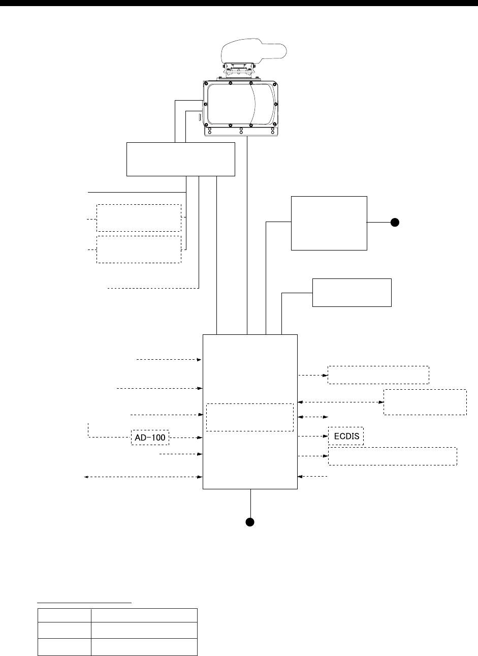
SYSTEM CONFIGURATION
ANTENNA UNIT
RADIATOR
SN24AF
SN30AF
CHASSIS
RSB-132
POWER SUPPLY UNIT
PSU-006
(For antenna motor)
TRANSFORMER
RU-5693
TRANSFORMER
RU-6522
(For high voltage)
200 VAC, 3φ, 50 Hz
220 VAC, 3φ, 60 Hz
100-115V/220-230 VAC,
1φ, 50/60 Hz
110 VAC, 3φ, 60 Hz
220 VAC, 3φ, 60 Hz
100-115 VAC/
220-230 VAC
1φ, 50/60 Hz
Gyrocompass
AIS
Speed Log
GPS Navigator PROCESSOR UNIT
PRU-021
GIRO CONVERTER
GC-100
MONITOR UNIT
MU-190HD
or
MU-231*
CONTROL UNIT
RCU-021
FURUNO CAN bus
Radar Remote Display
Alarm
SWITCHING HUB
HUB-100
12-24 VDC
(For MU-190HD)
100-230 VAC,
1φ, 50/60 Hz
(For MU-231)
BRAKE UNIT BRU-001/002
Equipment category
Unit Category
Antenna Exposed to weather
Other units Protected from weather
NMEA reading signal
*: Future use

iv
EQUIPMENT LISTS
Standard Supply
Name Type Code No. Qty Remarks
SN24AF-RSB-132-110 - 2400 mm Antenna Unit
SN30AF-RSB-132-110 -
1
3000 mm
Processor Unit RPU-021 - 1
MU-190HD - Monitor Unit
MU-231 -
1
Future use
Control Unit RCU-021 - 1
Power Supply Unit PSU-006 - 1
CP03-33300 000-017-041 15 m signal cable
RW-0013
CP03-33310 000-017-042 20 m signal cable
RW-0013
CP03-33320 000-017-043 30 m signal cable
RW-0013
CP03-31501 000-573-780 For antenna unit
CP03-34301 001-169-300 For antenna unit
CP03-31401 008-572-750 For power supply unit
CP03-33330 000-017-053 For processor unit
Installation
Materials
CP03-33200 000-017-258
1
For control unit
SP03-15501 008-572-730 For power supply unit,
100 VAC
SP03-15502 008-572-740 For power supply unit,
220 VAC
SP03-16301 001-104-910 For power supply unit,
100 VAC
Spare Parts
SP03-16302 001-104-920
1
For power supply unit,
220 VAC
Accessories FP03-10101 008-538-730 1 For antenna unit

v
Optional Equipment
Name Type Code No. Remarks
Gyro Converter GC-100-2 000-017-044 Shipped separately
Transformer Unit RU-1803 - 440 to 100 VAC, for processor unit
RW-4864 1M 001-103-620-10 Radar signal cable, 1m
RW-4864 5M 001-103-630-10 Radar signal cable, 5m
RW-4864 10M 001-103-640-10 Radar signal cable, 10m
RW-4864 15M 001-103-650-10 Radar signal cable, 15m
DVI-D/D
SINGLELINK 5M
000-149-054-10 DVI cable for monitor, 5m
DVI-D/D
S-LINK 10M
000-150-200-11 DVI cable for monitor, 10m,
MU-190H only
Cable Assy.
RNS-08-132 000-174-105-10 To adjust the brilliance of the display
unit. USB cable 5m
Switching Hub HUB-100 - See the operator’s manual for
HUB-100.
F Mount Fixture OP03-212 001-115-440 For control unit (flash mount)
Attachment Base
For 2165DS
OP03-219 001-163-800 For retrofit from FR-2165DS/
1460DS/1760DS/2160DS
1
1. MOUNTING
This chapter explains installation of the antenna unit, the control unit and the processor unit and
the power supply unit. For installation of the monitor unit, please refer to the installation manual
attached to the monitor unit.
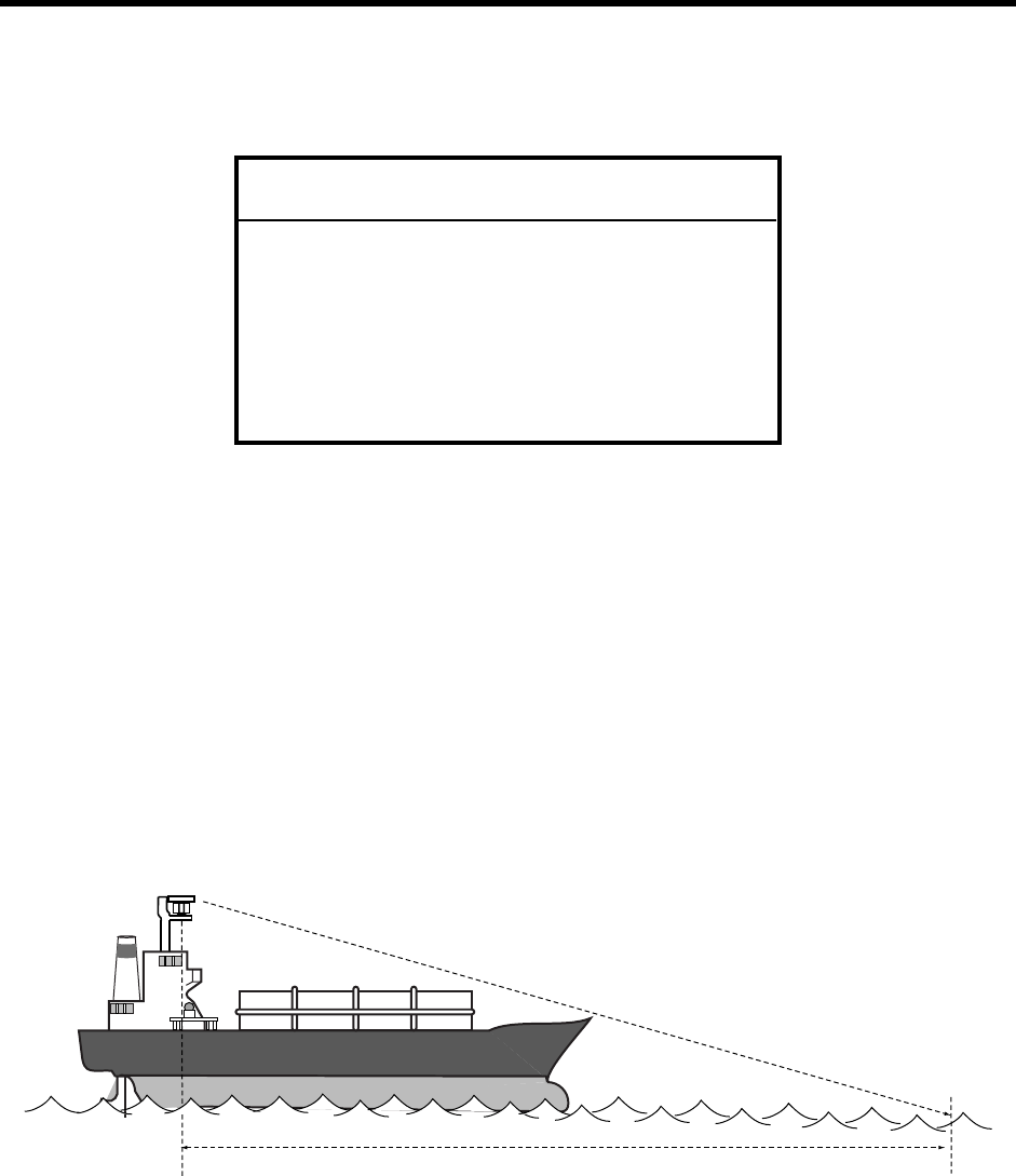
NOTICE
Do not apply paint, anti-corrosive sealant
or contact spray to coating or plastic
parts of the equipment.
Those items contain organic solvents that
can damage coating and plastic parts,
especially plastic connectors.
1.1 Antenna Unit
Mounting considerations
Please note the following when mounting the antenna unit.
• Install the antenna unit either on top of the wheelhouse or on the radar mast, on a suitable
platform clear of any structures to avoid beam interferences. Install the platform horizontally.
Install safety measures such as handrail to safely perform maintenance.
• A line of sight from the antenna unit to the bow of the ship should be the shorter of the
following two distances.
- Under 500m
- Not more than twice the ship’s length
Less than 500m or twice the ship’s length
Mount the antenna unit as high position as possible to detect targets as far as possible.
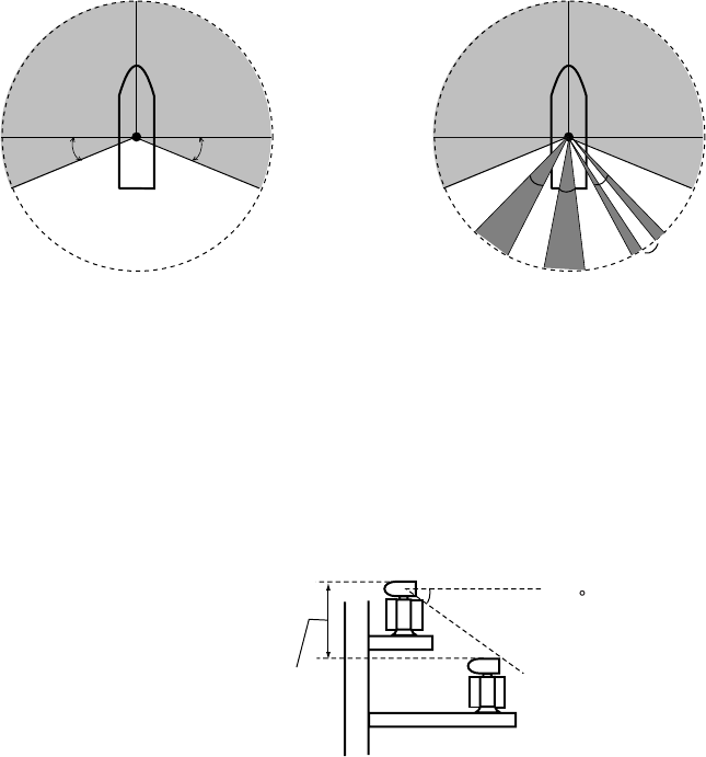
• Mount the antenna unit so that any blind sectors caused by objects (funnel, mast, etc.) are
kept to a minimum. Note the following considerations;
- No blind sectors should exist in the gray areas shown below.
- Any individual blind sector should be no more than 5 ̊. Should multiple blind sectors occur,
the total of such blind sectors should not exceed 20 ̊. Any two blind sectors separated
by 3 ̊or less are regarded as one sector. (Fig. 2)
2
22.5°22.5°
a
c
b
Heading Heading
Less than 3°
a, b, c: Less than 5° respectivety.
a+b+c+...: Less than 20°
Fig. 2Fig. 1
• Install the antenna unit away from interfering high-power energy sources and other
transmitting radio antennas.
• Keep the lower edge of the antenna unit above the safety rail by 500mm or more.
• Two antenna units should be mounted as below:
more than 20
more than 1 m
• No funnel, mast or derrick should be within the vertical beam width of the antenna unit in the
bow direction, especially zero degrees ±5 ̊m to prevent blind sectors and false echoes on the
radar picture.
• Do not install the antenna unit near a magnetic compass. Secure the safety distance shown
on page ii to prevent errors in the magnetic compass.
• Do not paint the radiator aperture.
• The antenna base is made of cast aluminum. To prevent electrolytic corrosion of the
antenna base, use the seal washers and corrosion-proof rubber mat and ground the unit
with the ground wire (supplied).
• No funnel or other exhaust vent shall exist near the antenna unit. The antenna unit must not
be mounted where the temperature is more than 55 ̊C. Deposits and fumes from a funnel or
other exhaust vent can adversely affect the aerial performance and hot gases may distort
the radiator portion.
• Leave sufficient space around the unit for maintenance and servicing. See the antenna unit
outline drawing for recommended maintenance space.
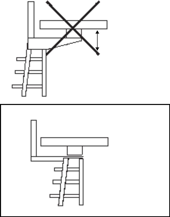
Installation precaution for S-band antenna unit
If an S-band antenna unit is mounted near the end of a platform to provide sufficient rotation
clearance for the radiator, the antenna unit, because of its weight, will swing up and down by
ship's vibration and rolling. This exerts excessive levels of stress at the base of the radiator,
which can damage the radiator. To prevent this, relocate the antenna unit, or if relocation is not
possible reinforce the platform.
3
Mast fro
DF, etc.
Remarkable vibration
(pitching)
Mounting
position
EXAMPLE
Mast for DF
Mount antenna unit directly
on mast or ona platform, as
near aspossible to center of
mast.
Mounting precaution for S-band antenna unit
4
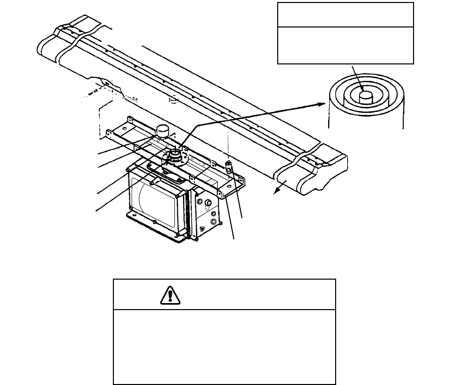
Assembling the antenna unit
The antenna unit should be assembled before mounting it. Follow the procedure below to
assemble the antenna unit.
1. Screw the guide pins (2 pcs.) in the radiator.
2. Remove the protective cap from the choke guide and radiator.
3. Grease the O-ring and set it to the groove on the choke guide.
4. Place the radiator on the radiator bracket. (Radiator direction is shown by the logo on the
bracket. If reversely oriented the radiator cannot be set to the bracket.)
5. Loosely fix the radiator to the radiator bracket with hex bolts (M10x25), spring washers and
flat washers.
6. Remove the guide pins and tighten the hex bolts.
Radiator front
Guide pin (2 pcs.)
Arrow mark for the radiator front.
Antenna radiator Do not remove teflon tube
from the center conductor.
O-ring
Choke guide
Radiator bracket
Protective cap
Spring washer,
flat washer,
10 pcs. each,
M10x25
CAUTION
Be sure to remove the guide pins
after fixing the radiator.
Injury may result if the guide pins loosen
and fall from antenna radar platform.
NOTICE
Assembling the antenna unit
5
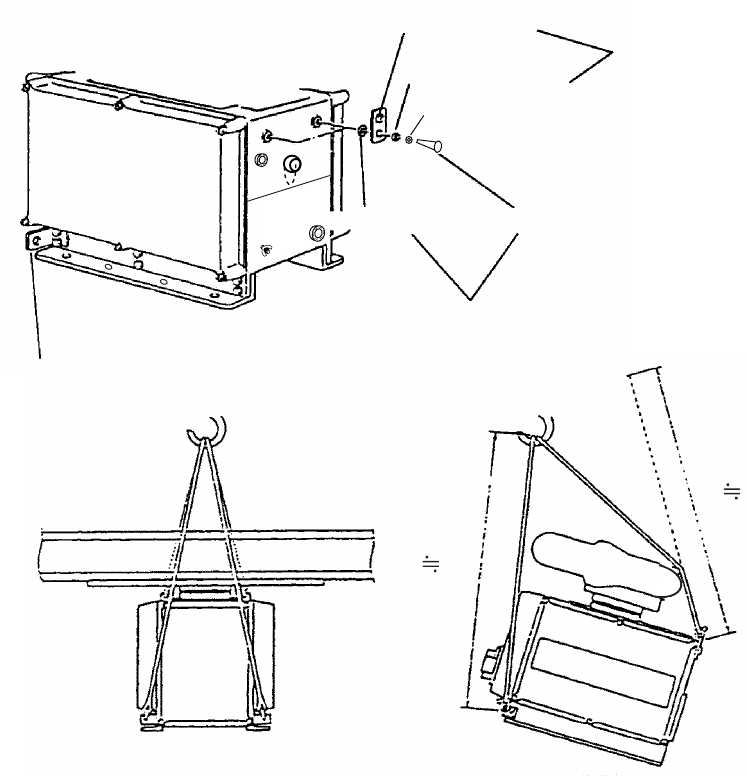
How to hoist the antenna unit
1) Fix the antenna radiator to the antenna unit chassis as shown on page 1-3.
2) Attach the lifting fixtures and collars as shown below.
3) Position the radiator as shown below and arrange the ropes A and B.
*
*
B 1.8m
A 2m
Lifting hook (2 pcs.)
Lifting fixture
Collar
Spring washer
Supplied as accessories.
Remove after installation.
Flat washer (M12) Hex bolt (M12x20)
(Torque: 63.5 Nm)
Remove lifting fixture, coat threads of
hex bolts with silicone grease, andthen
insert bolts in antenna chassis.
* 2. Place protective
material (cardboard,
foam, etc.) betweenrope
and radiator at the
asterisk-marked
locations, to prevent
Attachment of lifting fixtures, collar and ropes
6
Fastening the antenna unit to the mounting platform
WARNIN
Do not open the equipment
unlesstotally familiar with
electrical circuitsand service
manual.
Only qualified personnel
shouldwork inside the equipment.
Wear a hard hat and safety belt
when mounting the antenna unit.
Serious injury or death can result if
someone falls from the radar
antenna mast.
Construct a suitable service
platformfrom which to install the
antenna unit.
Serious injury or death can result if
someone falls from the radar
antennamast.
Note: The antenna is made of cast aluminum, which is subject to electrolytic corrosion if the
mounting platform is steel or iron. To prevent electrolytic corrosion, use the supplied seal
washers and corrosion-proof rubber mat.
Fix the antenna unit to the mounting location, referring to the procedure below and the
illustration on the next page.
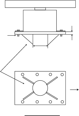
1. Referring to the antenna outline drawing, prepare a mounting platform. Drill eight fixing
holes of 15 mm in diameter in the mounting platform or the deck.
• The diameter of the mast for the mounting platform must be over 250 mm.
• The thickness of the platform must be over 15 mm.
• The thickness of the platform must be over 15 mm.
7
Over 15 mm
Use two nuts.
At least 250 mm in
diameter,Thickness at least 6 mm.
Ship’s bow
Install the reinforcement
rib diagonally.
Bottom view
The thickness of the platform must be over 15 mm.
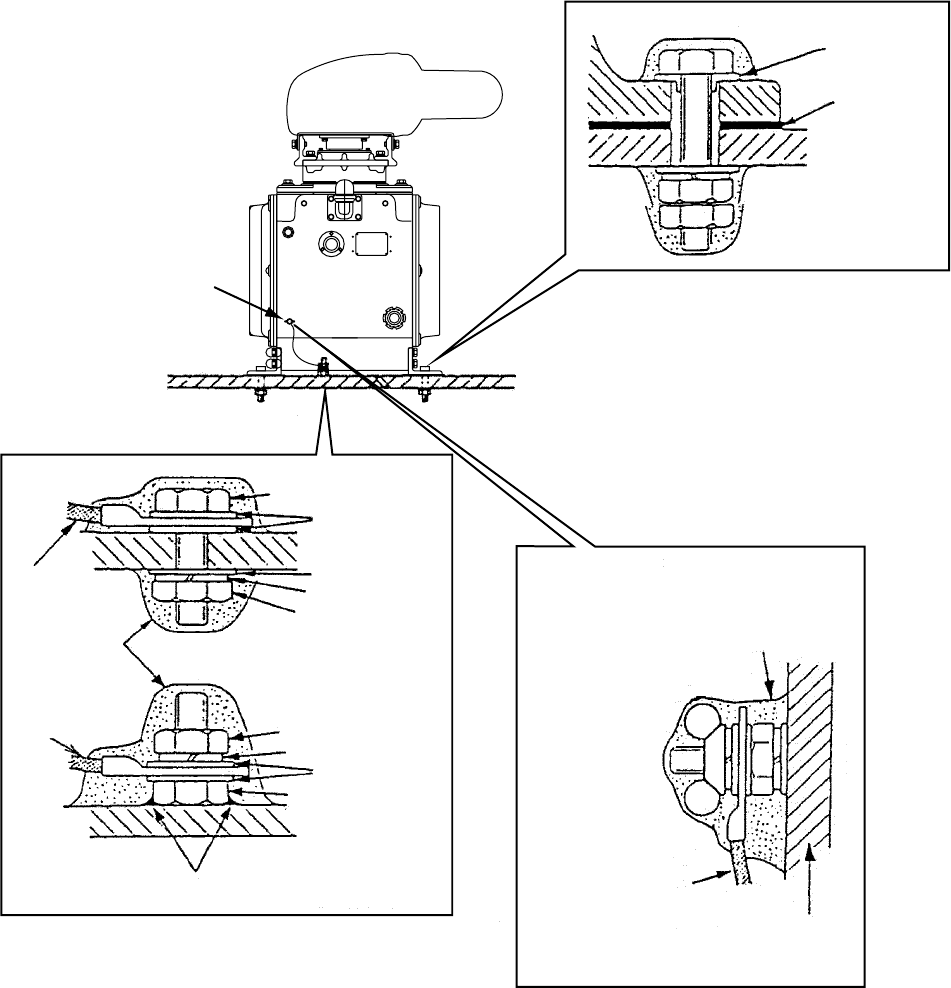
2. Lay the corrosion-proof rubber mat (supplied) on the mounting platform, aligning the holes
on the rubber mat with the fixing holes on the mounting platform.
3. Lay the antenna unit on the rubber mat, orienting it so the cable gland is directed toward
ship's bow. Remove the lifting fixtures and collars.
4. Fix the antenna base to the mounting platform with four M12?70 hex bolts, nuts, washers
and seal washers (supplied).
5. Arrange the ground point at a location on the mounting platform that is within 300 mm from
the ground terminal on the antenna unit. Fasten the ground wire (RW-4747, 340 mm) there,
using the M6?25 hex bolt, nut and washers.
6. Connect the other end of the ground wire to the ground terminal on the antenna unit.
7. Coat the ground terminal, ground point on the mounting platform and fixing bolts on the
antenna unit with anticorrosive sealant (supplied).
8
Seal
washer
Corrosion-
proof
rubber
mat
Use two nuts.
(Torque: 63.5 Nm)
Fasten ground wire and then
coat with anitcorrosive sealant.
Ground wire
Antenna chassis
Hex bolt
OR
Ground wire
Coat with
anticorrosive
sealant.
Ground wire
Welding
Hex nut
Ground terminal provided on antenna base.
Lay corrosion-proof rubber mat,
bolt antenna unit to mounting
location, and coat exposed
hardware with anticorrosive sealant.
Arrange ground terminal as close
as possible to antenna unit.
Hex bolt
Flat washer
Hex nut
Spring washer
Flat washer
Flat washer
G1_1/4-A
Ground terminal
Spring washer
Mounting the antenna unit
1.2 Control Unit
Please note the following when mounting the control unit.
• Select a location where the control unit can be operated conveniently.
• Locate the unit out of direct sunlight.
• Locate the unit away from places subject to water splash and rain.
• Determine the mounting location considering the length of the signal cable between the
control unit and the processor unit. The signal cable is shipped already attached to the
control unit.
• Distance between the control unit and a magnetic compass should be more than the
compass safe distance (See page ii.)
9
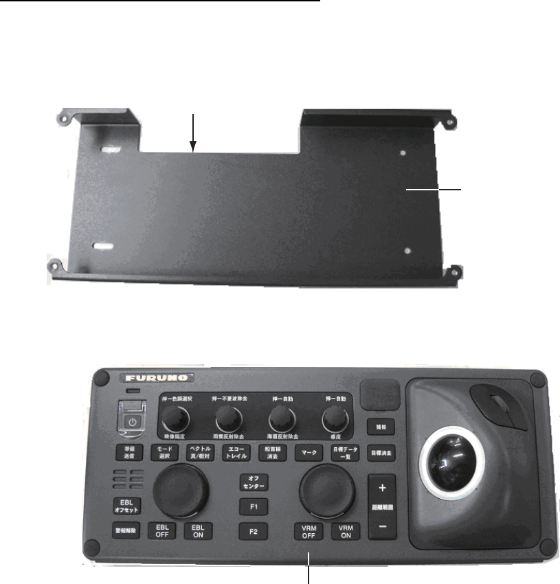
Desktop mounting using KB mounting metal
1. Fasten the KB mounting metal with four tapping screws (5x20) to the mounting location.
Note the correct orientation. The cutout is on the rear side.
The citout is on
the rear side.
KB mounting metal
2. Place the control unit on the KB mounting metal and fix it with small binding screws (M5x12)
and 4- wave washers.
Control unit on top of KB mounting metal
Note: Connect the grounding wire before installation because the grounding terminal of the
control unit is located on the bottom of the unit.
3. Fit the screw cap supplied into mounting holes.
10
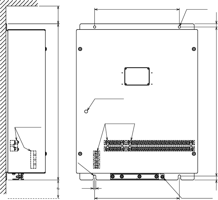
1.3 Processor Unit
Mounting location
Note the following when selecting a mounting location.
• Locate the unit away from heat sources.
• Locate the unit away from places subject to water splash and rain.
• Leave sufficient space around the unit for maintenance and servicing. See the outline
drawing for recommended maintenance space.
• Distance between the unit and a magnetic compass should be more than the safety distance
shown on page ii.
Mounting procedure
Fasten the processor unit with N6 bolts or tapping screws. Refer to the outline drawing at the
end of this manual.
1. When mounting the unit on a wall with tapping screws, prepare holes matching the screw
size.
2. Insert the tapping screws (6x30) into the two prepared holes on the upper side and loosely
screw in the tapping screws.
3. Tighten the tapping screws completely after hooking the unit on the upper tapping screws.
4. Tighten the tapping screws completely in the prepared holes on the lower side.
Mounting hole
2-R3.5
Mounting hole
2-
φ
8
11
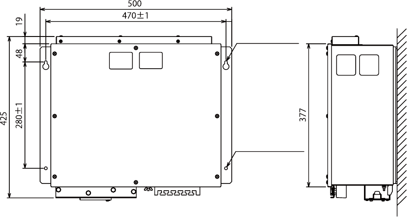
1.4 Power Supply Unit
Mounting considerations
The power supply unit may be mounted on a bulkhead or a deck. Because it has no operation
requirements it can be located almost anywhere, provided the location is well ventilated.
Mounting procedure
Fix the unit to the mounting location with four 6?20 self-tapping screws (local supply). For
mounting on a bulkhead, do the following:
1. Mark location for mounting holes.
2. Screw in the self-tapping screws at the location for the bottom fixing holes, leaving a gap of
about 5 mm between the bottom of the screw head and bulkhead.
3. Set the unit to the screws inserted at step 1.
4. Fasten the self-tapping screws at the top of the unit.
5. Tighten all self-tapping screws.
240±1
6
420±1
(11)
240±1
7
R3.5
440 #50
#250
WINDOW
LED
TERMINAL
TERMINAL
FIXING
HOLE
GND
TERMINAL
#: MAINTENANCE SPACE
2-
φ
7
Mounting dimensions for power supply unit
12
2. WIRING
Please note the following when wiring.
• To lessen the chance of picking up electrical interference, avoid where possible routing the
signal cable near other onboard electrical equipment, especially other radars, transmitting
radio antennas, etc.
• Also avoid running the cable in parallel with power cables. When crossing with other cable,
the angle should be 90 ̊to minimize the magnetic field coupling.
• The signal cable run between the antenna and processor units should be unbroken; namely
no splicing allowed.
• When connecting to analog signals (synchronous or step signals) of Gyrocompass, read
Chapter 3.7 “Setting Gyrocompass signals) prior to wiring.
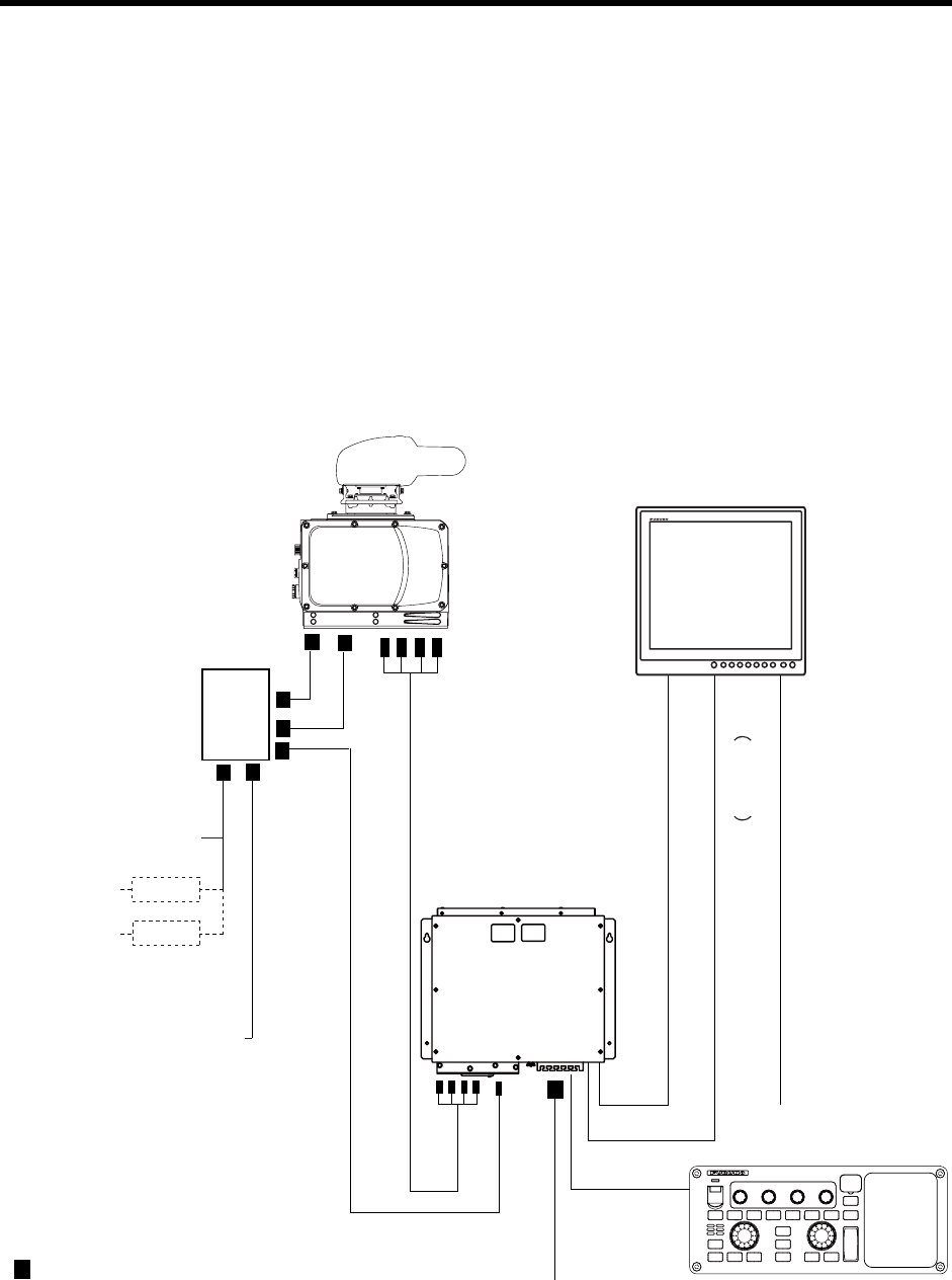
2.1 Interconnection
ANTENNA
UNIT
TB801
TB802
TB805
TB901
RW-0013
15/20/30m
(Max. 50m)
PROCESSOR
UNIT
DPYC-2.5
AC100-115V/AC220-230V
:
Fabrication required
MONITOR UNIT
(MU-190HD/MU-231*)
CONTROL UNIT
(RCU-021)
DVI-D/D
SINGLELINK5M, 5m
RNS-08-132, 5m
AC100-230V, 50/60Hz MU-231
MJ-A3SPF0018-050ZC, 5m (MU-190HD)
DC12-24V
03S0017, 5m
POWER
SUPLLY
UNIT
AC200V, 3ł , 60Hz
AC220V, 3ł , 50Hz
AC110V, 3ł,
60Hz
AC220V, 3ł,
50Hz RU-6522
RU-5693
TPYC-2.5
DPYC-2.5
MPYC-7
TPYCY-2.5
TPYCY-1.5
AC100-115V/220-230V,
1ł, 50/60Hz
Future use
13
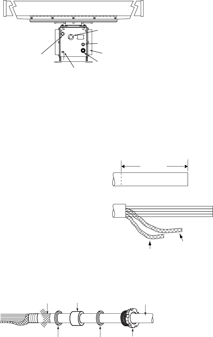
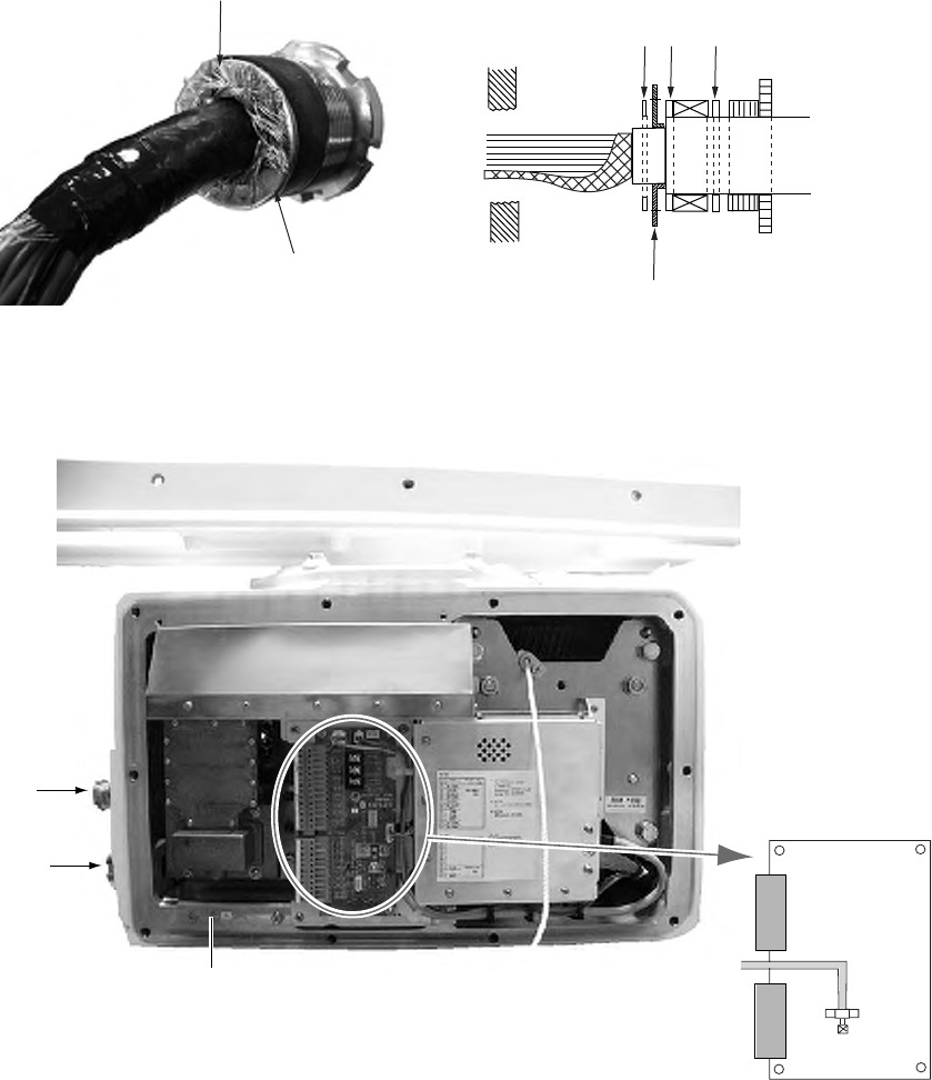
2.2 Antenna Unit
Gland for power cable
(TPYCY-2.5)
Ground terminal
Gland for signal cable (RW-9600)
Cover (right side)
Gland for HV cable (TYPCY-1.5)
Antenna safety switch
Antenna unit, front view
Fabricating signal cable RW-9600 and HV cable TYPCY-1.5
1. Use a ratchet or box wrench (diagonal 13 mm) to open port- and starboard-side covers on
the antenna unit.
2. Unfasten the gland nut for the signal cable and remove the gasket, flat washers (3 pcs.) and
gland cap. (The gland cap may be discarded.)
3. Fabricate the signal cable RW0-013 as shown below.
a) Remove the outer vinyl sheath by about 320mm.
b) Unravel the exterior shield to expose the core
wires.
c) Similarly, unravel the interior shield to expose the
core wires.
d) Combine the exterior and interior shields and
attach crimp-on lug (FV5.5-4 yellow, 4) at the
end of the shields.
e) Trim each wire matching to the position of the
terminal block. See the wiring diagram at the
back of this manual.
f) Remove insulation of each wire by about 6mm.
Fabricate the coaxial cable as shown in the
diagram below.
4. In the order shown in the figure below, pass the gland nut, flat washers (3 pcs.) and gasket
onto the signal cable.
Armor Gasket Signal cable
Flat washer
(2)
Flat washer
(1)
Gland nut
Vinyl sheath
320 mm
Interior shield
Exterior shield
14
5. As shown in the figure below, fold back the armor onto flat washer (2) and insert remaining
armor through flat washer (3). Cut off the part of the armor that protrudes past the flat
washers (2) and (3).
Fold back armor
Flat washer
(3) (2) (1)
Flat washer (2)
Cut off armor that protrudespast
flat washer.
6. Lead the signal cable through its cable gland and then into the chassis. Coat the threaded
part of gland nut with sealant (supplied) and then tighten the nut.
Gland for HV
cable
(TPYCY-1.5)
Gland for
signal cable
(RW-9600)
Connect shield of signal cable here.
TB Board
Fastening coaxial cable
TB801
TB803
TB802
Coaxial
cable
Antenna unit, front view
7. Using the terminal opener provided, connect cores (except coaxial cable) to their appropriate
locations on TB801 on the TB Board. Refer to the interconnection diagram for wiring details.
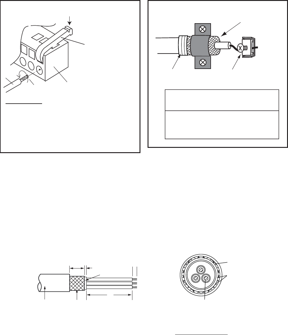
15
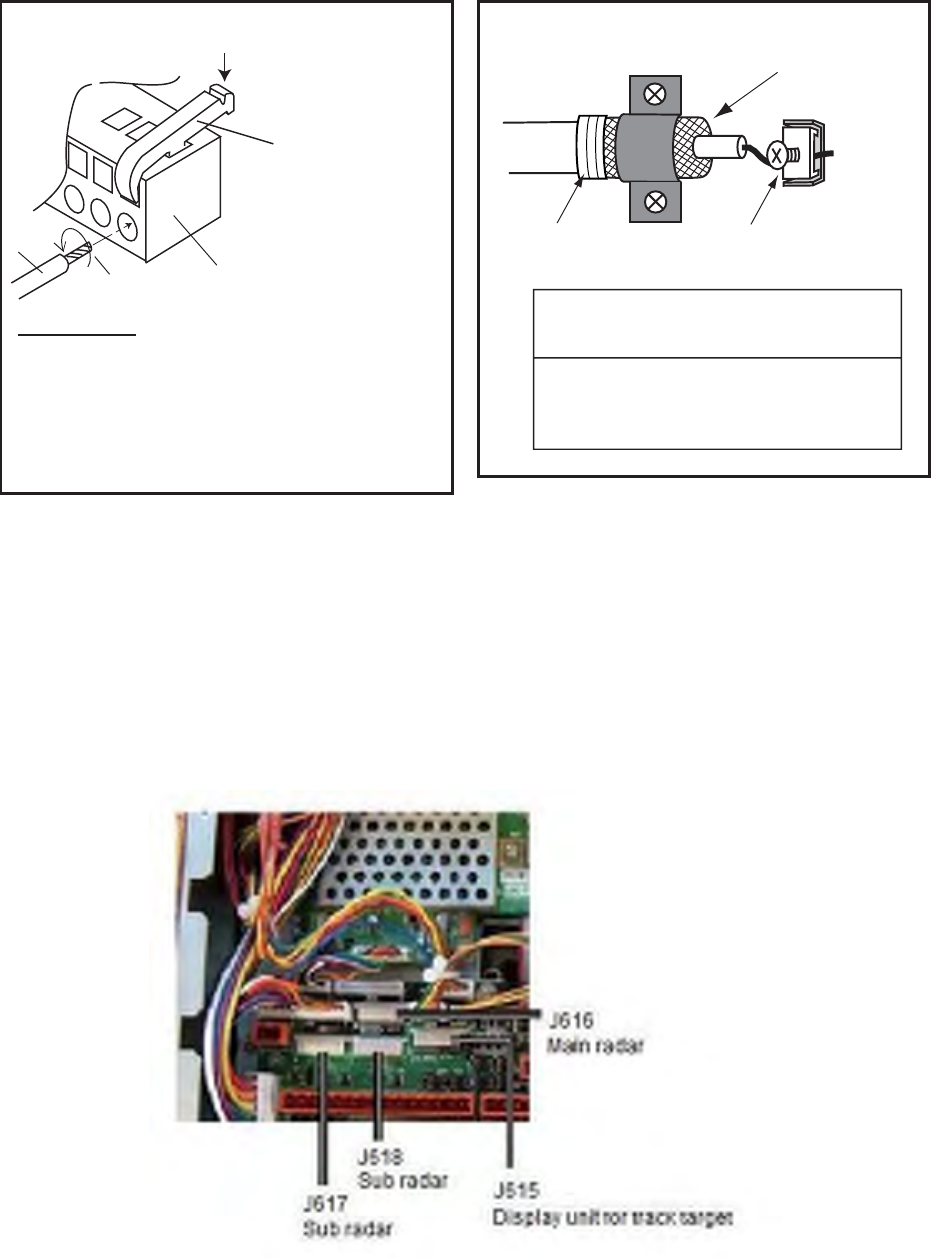
8. Connect the coaxial cable to TB802, referring to the right-hand illustration below..
Wiring WAGO connector Fastening coaxial cable
Push down.
Terminal opener
WAGO connector
Twist
Wire
Procedure
1. Twist core.
2. Insert terminal opener as shown and push
down.
3. Insert core into hole.
4. Release terminal opener.
5. Pull wire to confirm that it is firmly in place.
Fasten shield
by clamp.
Taping Fasten conductor with screw.
NOTICE
Fasten BARE conductor. Do not use
crimp-on lug, to prevent increased
contact resistance.
How to wire WAGO connector
9. Attach crimp-on lug (FV5.5-4) to the shield of the signal cable and fasten it with the screw at
the location specified in the illustration on the preceding page.
10. Process unused cores as follows:
a) Slip shrink tubing onto cores and heat.
b) Bind unused cores with cable tie.
11. Unfasten the gland nut for the HV cable and remove gasket, flat washers (3 pcs.) and gland
cap. (The gland cap may be discarded.)
12. Fabricate the HV cable as shown below.
20 mm
5 mm
Vinyl
sheath
Armor
Sheath
L
6
L: 300 mm (red)
L: 370 mm (black, white)
Armor
Sheath
Conductor
S = 1.50 mm2
φ
= 1.56 mm
SECTIONAL VIEW
How to fabricate HV cable TYPCY-1.5
13. In the order shown in the figure below, pass the gland nut, flat washers (3 pcs.) and gasket
onto the HV cable.
16
14. As shown in the figure below, fold back the armor onto the flat washer and insert it thru the
other flat washer. Cut off the part of the armor that protrudes past the washer.
(1)
Flat washer
(2) (3)
Cut off armor that
protrudes past washer.
Gasket
HV cable
Gland nut
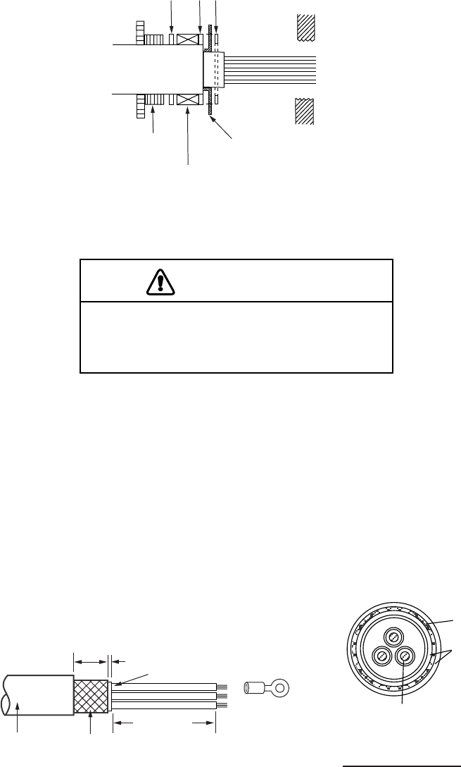
15. Pass the HV cable through its cable gland and tighten gland nut.
16. Using the terminal opener, connect wiring to TB901, referring to the interconnection diagram.
High voltage is present at the No. 1 pin
of TB801. Miswiring at this pin can
damage the antenna unit.
CAUTION
17. Close the cover.
18. Seal the cable gland for the HV cable with putty.
Fabricating the power cable TYPCY-2.5
1. Use a ratchet or box wrench to open the port-side cover on the antenna unit.
2. Unfasten the gland nut for the signal cable and remove the gasket, flat washers (3 pcs.) and
gland cap. (The gland cap may be discarded.)
3. Fabricate the power cable as shown below. Unravel the armor. Wrap sheath with vinyl tape
to fix base of vinyl wire.
25 mm
5 mm
FV2-4
Sheath
Armor
Vinyl sheath
Conductor
S = 2.50 mm
2
φ = 2.01 mm
Armor
Sheath
SECTIONAL VIEW
230 mm
How to fabricate power cable TYPCY-2.5
4. In the order shown in the figure below, pass the gland nut, flat washers (3 pcs.) and gasket
onto the power cable.
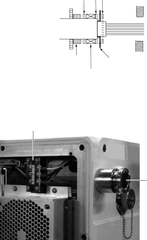
17
5. As shown in the figure below, fold back armor onto flat washer and insert it thru the other flat
washer. Cut off part of armor that protrudes past flat washer.
(1)
Flat washer
(2) (3)
Cut off armor that
protrudes past washer.
Gasket
Power cable
Gland nut
Passing flat washer, etc. onto HV cable
6. Pass the power cable though its cable gland and then tighten the gland nut.
7. Pass the power cable to the rear of the antenna unit.
Cable gland for power cable
(TPYCY-2.5)
Terminal for power cable
Antenna unit, left-side view
8. Connect the power cable to its terminal, referring to the interconnection diagram.
9. Close the cover.
10. Seal the cable gland for the power cable with putty.
18
2.3 Processor Unit
Six cables are terminated at the processor unit in the basic structure; the antenna unit cable,
two display unit cables, power supply unit cable, control unit cable and the power supply cable.
Cables other than the power cable are connected to the processor unit with a connector.
Fabricate the power supply cable (DPYC-2.5) as below. Connect LAN cable (50cm) supplied
between the ports NETOWRK1 and NETWORK2 of the processor unit for installation of a single
unit. (See page 2-8)
Note: Pass the AC power supply line through a double-contact breaker (shipyard supply) to
connect to this unit.
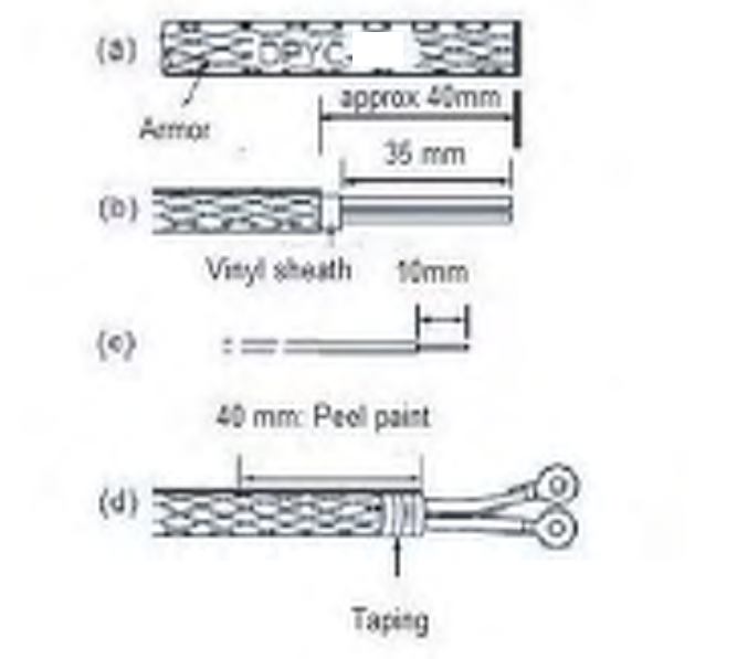
Fabricating the power cable
1. Cut armor of the cable by 40mm.
2. Cut vinyl sheath by 35mm.
3. Remove insulation of the core wire by about 10mm. Fix crimp-on lugs (FV5.5-4, yellow
supplied) to the cores.
4. Peel paint of the armor by 40mm for making grounding connection.
5. Cover the end of armor with vinyl tape. Put the section where paint was peeled through the
cable cramp on the rear panel of the processor unit and fasten it.
6. Fasten the crimp-on lugs on the terminal block.
2.5
19
Power suplly terminal base
Cable clamp
Connecting cables to the rear panel of the processor unit
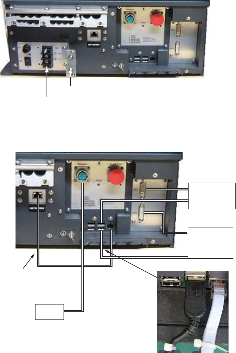
Cables between control units and cables between monitor units are connected to ports on the
real panel of the processor unit. Connect LAN cables of the installation material as shown below.
No.1
Mount unit
No.2
Mount unit
(Option)
Control
unit
LAN cable must be
connected when
interswitch function is
mot used.
Fix USB cable to the metal
fixture with binding ties.
Note 1) Monitor unit 1 and 2 must have the same resolution.
Note 2) USB ports USB1 and USB2 are not used.
Note 3) Mothing will be displayed on the monitor units are not
connected before the power is turned ON.
20
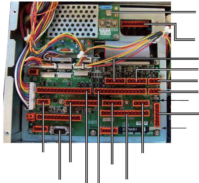
Connecting cables inside of the processor unit
Connect cables from the antenna unit, power supply unit and optional equipment are connected
to the TB board (03P9491) etc. inside of the processor unit. Open the cover of the processor
unit to find the TB board.
Ship
speed
log
Antenna cable
J612 Alarm system
Contact point output power
supply load 100 mA
J607
J601
RS232C
J621
CAN bus
J624 J610
J619
ECDIS
J608
AD-100
J301
Coaxial cable inside of antenna
cable
TB101
J611 AIS
J620 AIS
J605 Heading
J606 GPS
J604 Power supp;y unit
Gyro compass
(Syncho/Step signal)
Control lever for WAGO
connector is inlayed here.
21
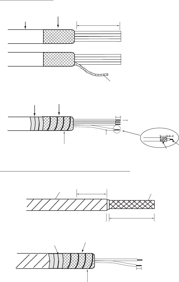
Cable fabrication for cables connected to the TB board (03P9491)
See the wiring diagram below for connecting the core cable.
Signal cable RW-0013
250
6
14 5 9
Vinyl sheath
Fold back exterior shield over the vinyl sheath.
Pull out a signal wire from the interior shield.
Interior shield
Vinyl sheath Wind the interior shiled around the exterior shiled.
Connect to WAGO connector (next page)
Clamp here by cable clamp
Coaxial cable
Conductor
Fold back shield.
Optional cable: TTYCS-1/TTYCS-4/TTYCS-7/TTYCS-1T
6
L
5
Armor
60: Peed paint
Shield
L: Depends on a
equipment connected.
Vinyl tape After exposing cores, wind shield around the armor.
Connect to WAGO connector,
Clamp here by cable clamp.
22
Wiring WAGO connector Fastening coaxial cable
Push down.
Terminal opener
WAGO connector
Twist
Wire
Procedure
1. Twist core.
2. Insert terminal opener as shown and push
down.
3. Insert core into hole.
4. Release terminal opener.
5. Pull wire to confirm that it is firmly in place.
Fasten shield
by clamp.
Taping Fasten conductor with screw.
NOTICE
Fasten BARE conductor. Do not use
crimp-on lug, to prevent increased
contact resistance.
Connection for main radar, sub-radar and track target displays
To use the equipment as main radar and connect to a sub-radar, connect to J617 (SLAVE1) or
J618 (SLAVE2) using the optional cable RW-4864. Up to two sub-radars can be connected.
To use the equipment as sub-radar and connect to a main radar, connect to J616 (MASTER)
using RW-4864.
To connect the equipment to a track target display unit, connect to J615 using RW-4864.
23
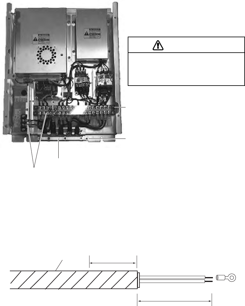
2.4 Power Supply Unit
Wire the power supply unit referring to the interconnection diagram. Be sure to ground the unit,
with IV-8sq wire (local supply).
Note 1: Motor specification cannot be changed in the field.
Note 2: Pass the AC line through a double-contact breaker (shipyard supply). Further, for
vessels where the power line is grounded, connect one end of the line to the C (common)
terminal and the other end to the H terminal.
TB3: Power output line, control line
Cable clamp: Locate armor of cables in clamp.
TB1, TB2: Power input line
Ground
High voltage is present at the
No. 6 pin of TB3. Miswiring at
this pin can damage the unit.
CAUTION
Power supply unit, inside view
Fabricating cable connected to terminal TB1, TB2, TB3
Terminal TB1: cable DPYC-2.5
See page 2-8 for sectional view of cable if using equivalent cable.
30: Remove paint.
Armor
120
FV2-4
Terminal TB2: cable TPYC-2.5 (for antenna motor)
Terminal TB3: #11-#13, cable TYPC-1.5 (between power control section and processor)
See page 2-5 for sectional views of these cables if using equivalent cables.
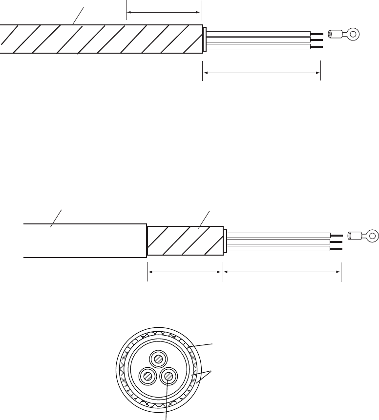
24
Armor
L: 100 (For TPYC-2.5)
150 (For TPYC-1.5)
L
FV2-4
30: Peel paint
Terminal TB3: #1-#3 TPYCY-2.5 (between power control section and antenna)
Terminal TB3: #6, #8, #9 TPYCY-1.5 (between power control section and antenna)
Conductor
30 L
FV2-4
Vinyl sheath Armor
TYPC Y-1.5: 14.5 mm
TYPC Y-2.5: 15.5 mm
φ=
Armor
Sheath
L: 80 (For TPYC Y-2.5)
120 (For TPYC Y-1.5)
S= TPYC Y-1.5 : 1.5
2
mm, TPYC Y-2.5 : 2.5
2
mm
φ= TPYC Y-1.5 : 1.56mm, TPYC Y-2.5 : 2.01mm
25
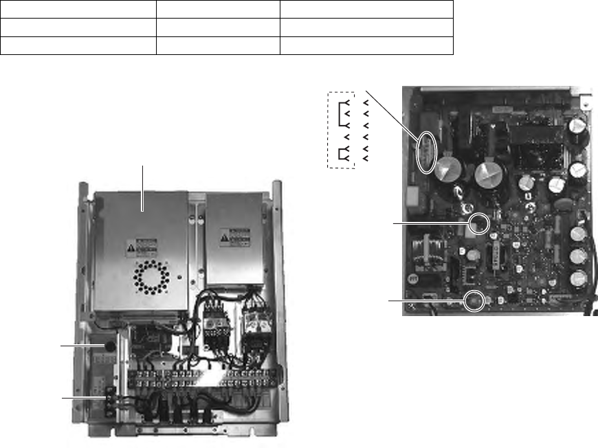
2.5 Changing AC Power Specification of Processor
Unit
To change AC power specification from AC100V to AC220V or vice versa, change the fuse and
add or remove jumper connector on the processor unit and power supply unit.
2.5.1 Processor Unit
Refer to the table and figures below to make changes. Adjust the overvoltage detection circuit
after the change. (a variable auto transformer is required.)
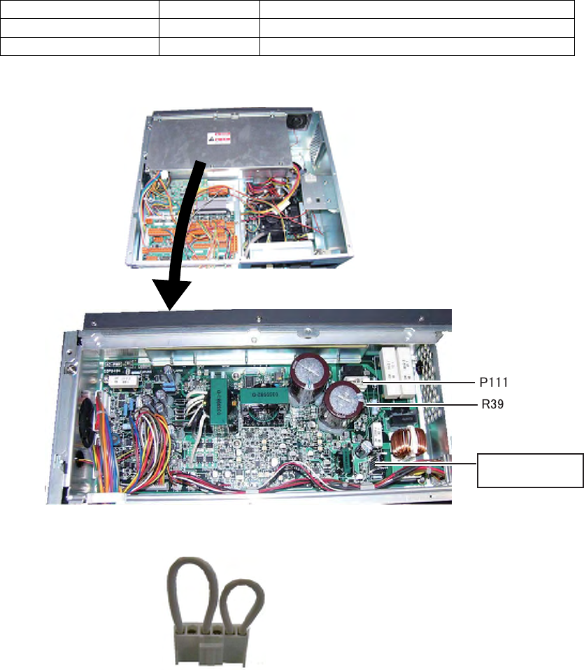
Note: To change from AC220V to AC100V, locally prepare the jumper connector, referring to
the figure shown below. (VH6P connector housing is fitted in J111.)
Power Supply Fuse Jumper connector P111
AC100V 7A Necessary (between 1-2, 4-6)
AC220V 3A Not necessary (no jumper wire needed.)
Processor unit
AC-PWR board
03P9494
Processor unit (Cover is removed)
Jumper wire for AC100 V
between 1-2, 1-6 short-circuit
26
How to adjust the overvoltage detection circuit:
1. Add or remove the jumper connector P111 and change the fuse.
2. Rotate R39 fully counterclockwise on the AC-PWR board.
3. Connect a variable transformer between ship’s mains and the input power terminal board
TB-1 of the processor unit.
4. Adjust the variable transformer output (i.e. input voltage to the processor unit) as follows.
- For AC100V specification: AC156V
- For AC220V specification: AC301V
5. Turn on the processor unit and rotate the R39 clockwise gradually until the overvoltage
detection circuit functions and the power supply cuts off.
6. Lower the output voltage of the variable transformer and confirm that the radar automatically
turns on with a voltage lower than AC155V or AC297V.
7. Gradually increase the output voltage of the variable transformer and confirm that the
overvoltage detection circuit functions at AC 156V or AC301V and the power supply is cut
off.
8. Assemble and connect the processor unit correctly.
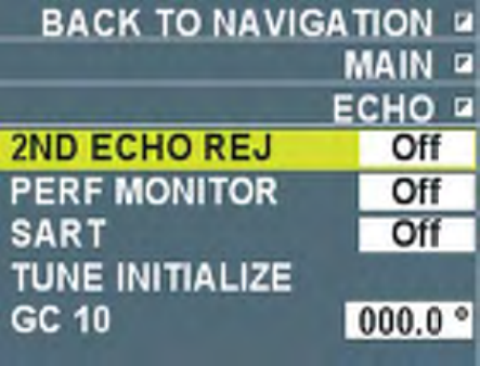
2.5.2 Power Supply Unit
Refer to the illustration and table below to add (or remove) jumper connector P8 from the TX-HV
Board (03P9350) and change fuse.
After completing jumper and fuse arrangements, adjust the overvoltage detection circuit, using a
variable transformer.
Note: When switching from 220 VAC to 100 VAC, construct a jumper connector locally,
referring to the illustration below. (VH6 connector housing is to be plugged into J8.)
Power Supply Fuse Jumper connector P8
AC100V 5A Required
AC220V 3A Unnecessary
Fuse
TX-HV Board
Unfasten four screws and remove
cover for TX-HV Board.
R21
CR23
P8/J8
6 5 4 3 2 1
Jumper connector
(VH6P)
TB1
27
How to adjust the overvoltage detection circuit:
1. Add or remove the jumper connector P8 as appropriate and change the fuse, referring to the
table above for details.
2. On the PWR board, set R21 fully clockwise.
3. Connect a variable transformer between ship's mains and the input power terminal board
TB-1 in the processor unit.
4. Adjust the variable transformer output (i.e., input voltage to the processor unit) as follows:
For 100 VAC set: 144 VAC
For 220 VAC set: 288 VAC
5. Turn on the radar and rotate R21 counterclockwise gradually until the overvoltage detection
circuit activates (i.e., power supply cuts off).
6. Lower the output voltage of the variable transformer and confirm that the radar automatically
turns on with a voltage lower than 142 VAC or 284 VAC.
7. Gradually increase the output voltage of the variable transformer and confirm that the
overvoltage detection circuit activates at 144 V or 288 VAC of the variable transformer
output.
8. Assemble and connect the power supply unit.
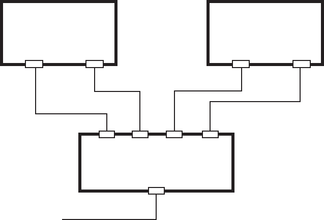
2.6 Interswitch
Switching hub HUB-100 (optional) is necessary to switch between two processor units. Four
LAN cables are necessary. The following diagram shows the connection between the processor
units.
AC100-230V
NR203PF-VSS1.25
NETWORK1 NETWORK2
Swtiching
HUB-100
4 LAN cables
LAN port on
the reat panel
PROCESSOR UNIT
NETWORK1 NETWORK2
PROCESSOR UNIT
Note: See the installation manual for HUB-100.
Either straight or cross LAN cables cab
be used.
28
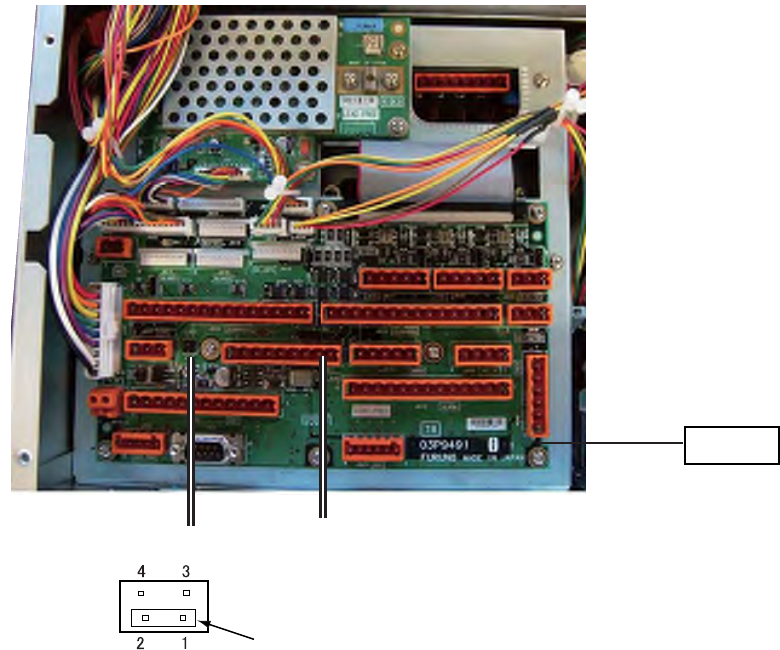
2.7 Connection to CAN bus Network
When connecting to CAN bus network through J621 (CAN bus port) of the processor unit, a
terminator may need to be connected. See the diagram below. For details of CAN bus network,
refer to “FURUNO can bus Network Design Guide” published by FURUNO for service
technicians.
TB board
J621
CAN bus
JP103
Jumper connector
between 1-2: With terminal resistance
between 3-4: No terminal resistance
29
3. SETTING AND ADJUSTMENT
This chapter contains sections 3.1 through 3.7. Please set the equipment in the order of the
sections.
Note 1: The processor unit with AC specification has a power supply switch at the rear panel.
Keep the switch ON at all times.
Note 2: Every unit has the same IP address set as the factory default. Therefore when
connecting the unit by inter-switching, turn on the power for each unit to set IP address.
(See pages 3-2 and 3-3). After setting IP address for all units, set “Common 1/Own
ship’s information” on page 3-3 while power is turned on for each unit.
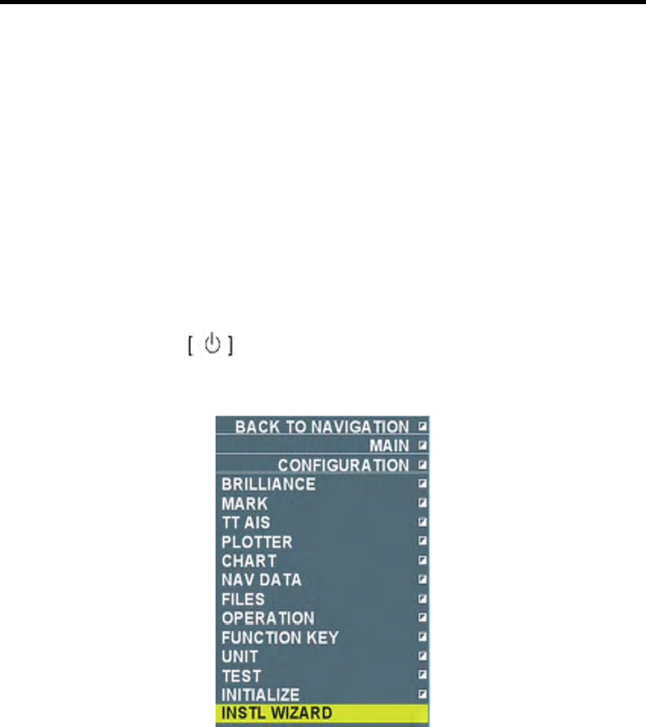
3.1 Setting Initial Setting Wizard
After installing equipment and wiring, turn on the power and initialize the system according to
the initialization wizard.
1. Press the power switch on in the operation unit.
2. Press the [Delete heading line] key and immediately press [Delete target] key five times.
SYSTEM SETUP MENU appears.
3. Select “Initialization Wizard” and click the left button. Initialization wizard appears after a few
seconds.
4. Do the setting on the first page and then press the [Next page] button.
5. After setting necessary items, go to the next page using the [Next page].
6. After all the settings are done, press the [Save settings/Finish] button. The system restarts
automatically and “Preparing” is displayed. Settings in each wizard page are explained in the
following pages.
30
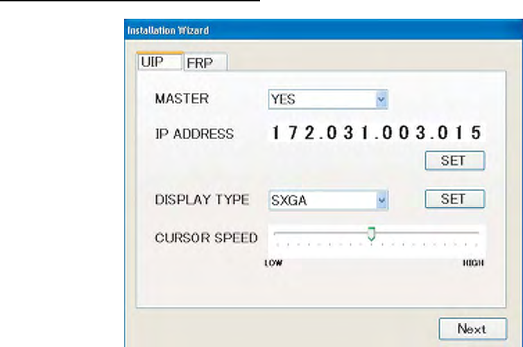
UIP (User Interface Processor) page
Server: It means the chart server and normally YES remains as it is.
IP address: Set IP address of the processor unit UIP. For single installation, no change is
necessary. IP address needs to be changed for inter-switch connection (2-13 page). Change
only “xxx” parts of 172.031.003.xxx. xxx is an arbitrary number from 020 to 253. Set IP address
that is different from other IP addresses.
Note: Do not set the same IP address on UIP and FRP pages.
How to input numbers: Put the cursor on numbers and the background of the number changes
to green. Rotate the wheel or right click/left click to change the number. Press the [Set] button.
Pop-up menu appears to restart the system. Press [Yes] to restart the system after about 30
second to 1 min. After the restart, repeat the process.
Screen size: When the display unit is MU-231, select [XGA] and the monitor unit is MU-190HD,
select [SXGA] then press the [Set] button.
Cursor speed: Adjust the speed of cursor on the screen when moving the cursor with the
trackball. Adjust the cursor speed in accordance with user’s convenience.
31
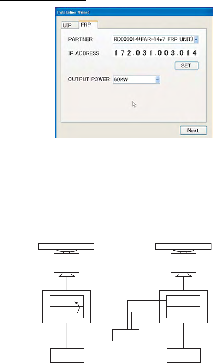
FRP (Radar Processor) page
Partner: Set FRP which is paired with UIP. (See the next diagram.) It is set when two sets of
FAR-14x7 series radars are connected through the switching hub. Normally, the factory default
(FRP inside of the same processor unit) remains unchanged.
IP address: Factory default is shown. In case of inter-switch connection, set a value different
from other values and press the [Set] button. Restart begins and the above screen remains for
about 30 seconds.
Output power: Select 60kW.
UIP
FRP
UIP
FRP
FRP
UIP
FRP
UIP
LAN
LAN
LAN
LAN
Antenna unit
(Primary)
Antenna unit
(Secondary)
Processor unit Processor unit
Hub
Monitor unit Monitor unit
32
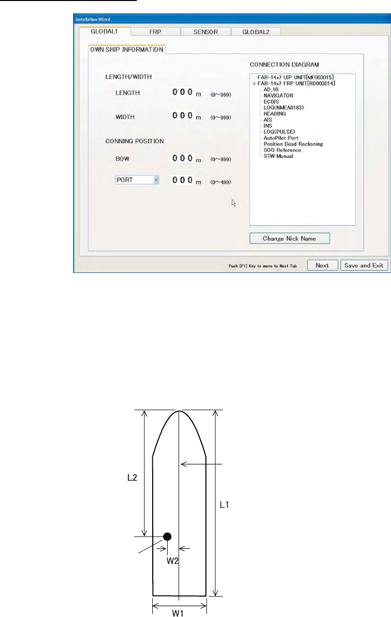
Common 1/Own Ship Data
Ship length: Input total length of ship. (tip of heading to end of stern)
Width of hull: Input width of hull
Steering position/Heading: Input distance from tip of ship to steering position.
Steering position/ Port (Starboard): Input distance from the center line of the ship to the steering
position toward port or starboard.
Center line
Steering position L1: Ship length
W1: Width of hull
L2: Steering position/Heading
W2: Steering position/Port (Starboard)
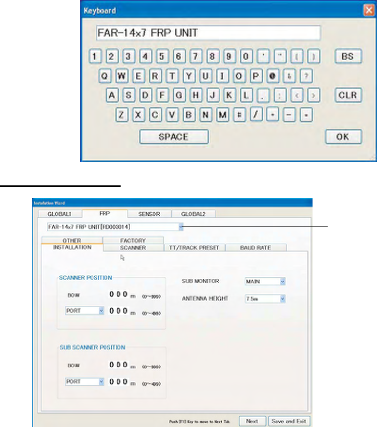
Unit Composition Box: When changing unit name displayed on the screen, select the name to
be changed and press the [Change nickname] button. Input name from the keyboard displayed
on the screen.
33
FRP/Installation Setting
When interswitch is
connected, set all
FRP in the processor
unit.
Position of antenna unit (primary), antenna unit (secondary)
• Heading: Input distance from the tip of the ship to the antenna unit.
• Port (Starboard): Set the position of antenna unit from the center line of the ship toward port
or starboard direction.
Primary/Secondary: Set processor unit to function as primary radar or secondary radar.
34
J616
Antenna unit Antenna unit
Processor
unit
Processor
unit
Processor
unit
Monitor unit
Monitor unitMonitor unit
Set as primary Procossor of this equipment is
set as secondary. (function as
a secondary instruction unit.)
Antenna height: Set antenna height from the sea surface from 5/7.5/10/15/20/25/30/35/40/50m
/50m.
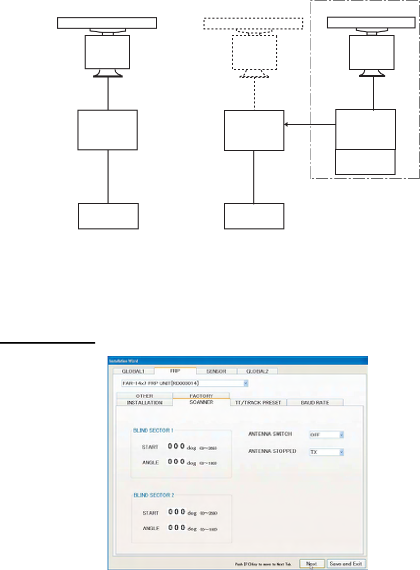
FRP/Antenna Unit
Transmission Stop Area 1, Transmission Stop Area 2: To secure safety of crew, set the two
radar transmission stop areas in the start bearing (angle measured from the heading line) and in
the setup angle (area to stop transmission). Two areas can be set.
35
Heading
Start
bearing
Set
angle
Stop transmission sector
Antenna Rotation Switch: Set the switch by service technician when performing maintenance.
• OFF: Antenna does not rotate at preparation and transmission (at maintenance).
• ON: Antenna rotates at transmission (Normal setting).
• EXT: Do not use.
When antenna rotation is at stop: Set it at maintenance time by service technician.
• Preparation: When antenna stops during transmission, the transmission is at STAND-BY
state.
• Transmission: Transmission continues when antenna stops during the transmission.
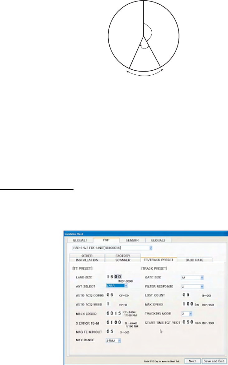
FRP/TT/Track PRESET
Set various parameters to be used in the target track function (TT: old name ARPA). Do not
change default settings unless you are familiar with details of TT. The picture below shows
default settings.
LAND SIZE: The minimum value determined to be land echo.
ANT SELECT: Type of antenna radiator used in the antenna unit.
AUTO ACQ CORRE: Update time of target that can be acquired automatically.
AUTO ACQ WEED: Time to the next automatic acquisition when there is some reserve of the
automatic acquisition point.
36
MIN X ERROR: The minimum error between predicted target position and measured position to
detect veering of target.
X ERROR 15NM: Threshold to detect veering of target which is over 15NM away.
MAG FE MIN OUT (Minimum echo width adjustment coefficient): The minimum echo width is
detected from the ratio of antenna beam width. The minimum echo width to be detected can be
adjusted by changing the ratio with this coefficient.
MAX RANGE: Select the maximum rage of track target from 24NM or 32 NM. When 32 NM is
selected, the repetition of transmission frequency of S1/S2 pulses becomes the 2nd trace.
Gate Size: Allowable error size between the predicted position of echo matching
Track filter: Responsiveness to changes of movements of target
Lost count: Number of scans until “lost” is determined
Maximum speed: Maximum speed of tracked target (not valid for this system)
Track mode: Track target mode
Vector Display Start: Time elapsed from acquisition of target until display of vector.
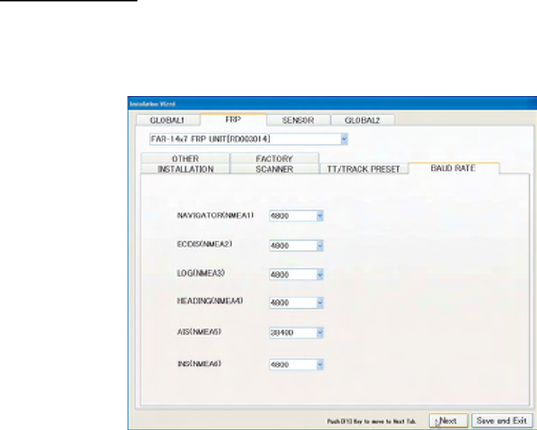
FRP/SIO baud rate
Set communication baud rate corresponding to the equipment connected to NMEA port inside
of the processor unit. Set 4800 bps or 38400 bps depending on the communication speed of the
other party.
37
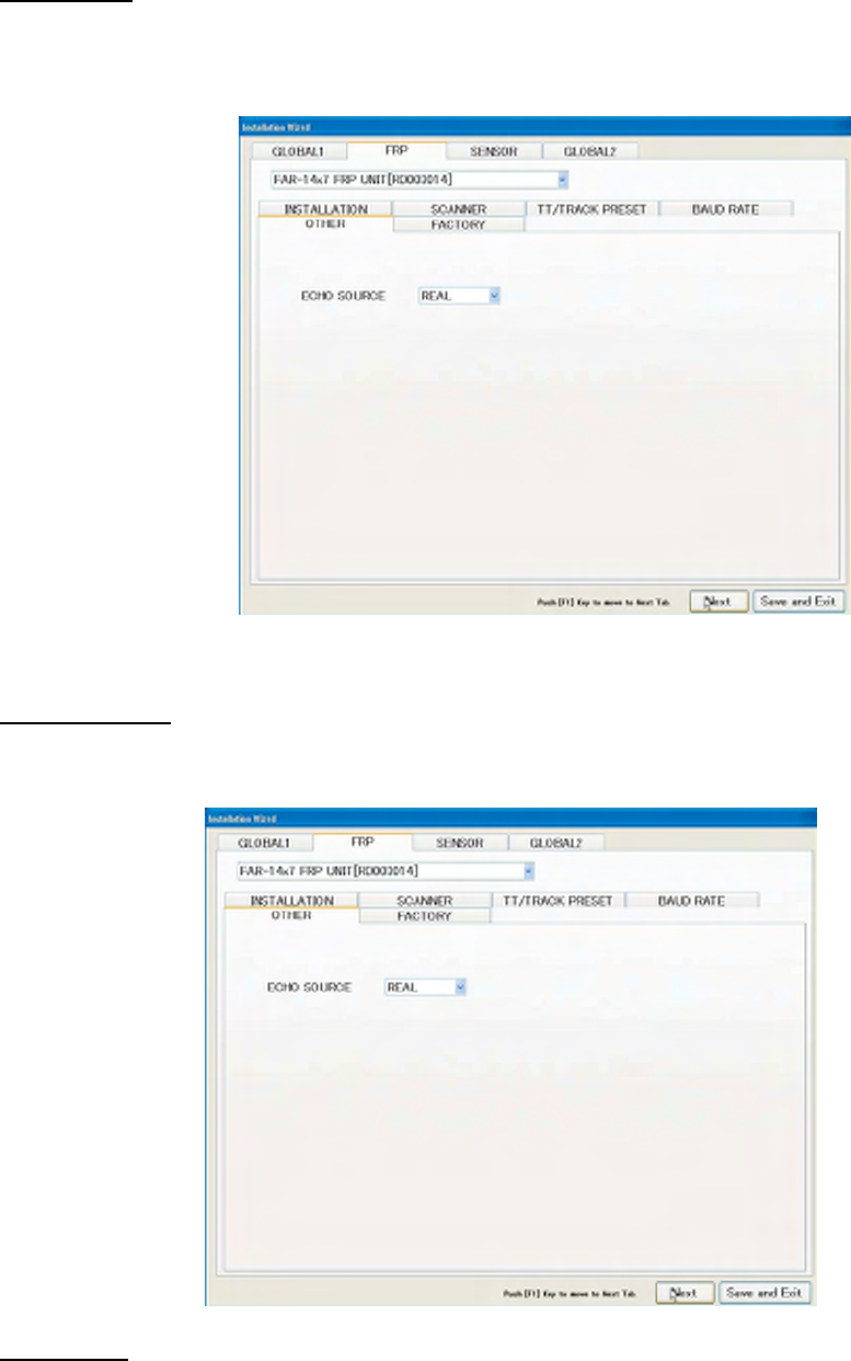
FRP/Others
Set signal type to display on radar screen. Normally set TRUE ECHO. Set EG for demonstration.
Do not use TT TEST.
FRP/FACTORY
It is not necessary to setup this page at installation.
Sensor/AIS
It is not necessary to setup parameters in this page at installation.
38
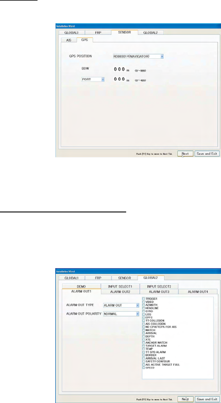
Sensor/GPS
Set parameters related to GPS navigation equipment connected.
Position of GPS antenna: When reading data from multiple GPS’s, select GPS to use.
Heading: Set the distance from the tip of ship’s bow to GPS antenna.
Port (Starboard): Set the position of GPS toward port or starboard from the center line of the
ship.
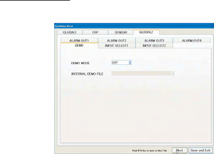
Common 2/Alarm External Output 1,2,3,4
Set types of alarm signals to output from this equipment to alarm units such as FURUNO Bridge
Alarm System BR-1000, etc.
Alarm External Output 1/2/3/4 pages correspond to connections of pin No.1/2, No.3/4, No.5/6
and No.7/8 of the TB board J612/P612 inside of the processor unit.
39
Contact point output: Select among Alarm Output, Operation Report and Alarm Acknowledge as
shown below. The wiring diagram at the end of this manual shows the default condition. i.e.
Alarm External Output 1, 2 and 3 are for Alarm Output and Alarm External Output 4 is for
Operation Report.
Alarm Output: Output contact point signal to the alarm unit connected when problems occur in
this equipment. Types of problems are set in the check box on the right side on the screen.
Click the check box twice to enter check mark.
No trigger: No trigger signals
No video: No image signal
No turn signal: No bearing signals
Gyro: No gyrocompass bearing
Log: No speed signals from ship speed meter
EPFS: No positioning signals
TT collision alarm: Alarm for collision by the track target function
AIS collision alarm: Alarm for collision by AIS
CPA/TCPA unable to measure: Alarm for CPA/TCPA not set for AIS
Watch alarm: Alarm for watch
Depth alarm: Alarm for depth
XTE alarm: Alarm for course error
Anchor watch alarm: Alarm for anchor watch
Watch alarm: Alarm for target
Water temperature alarm: Alarm for water temperature
TT ship speed alarm: Alarm for ship speed by the track target function.
Border Alarm: Not used in this equipment
Arrival to Final Waypoint: Alarm for arrival at final waypoint
Grounding Warning: Not used in this equipment
AIS Active Full: Alarm for AIS active target full
Ship speed alarm: No ship speed signals from GPS
• Control Report: Output contact signals. For example, it can be used as reset signals for
Watch Alarm by connecting to the alarm unit.
• Alarm Acknowledge: Press the [Cancel Alarm] key in the control unit when alarm is
generated to stop the alarm and the contact signals are outputted to the alarm unit.
Alarm Output Polarity: Set polarity of output signals according to the equipment connected. Set
STANDARD when the other party is Normal Close and set REVERSE when the other party is
Normal Open.
40
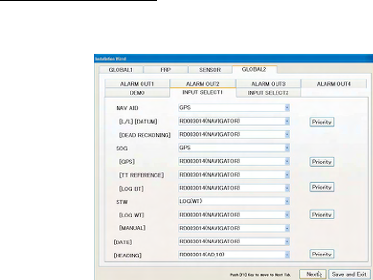
Common 2/Demo Mode
This mode can be used at exhibitions, etc.
Demo mode: Set OFF in normal condition. Set INTERNAL DEMO when displaying data for
demonstration inside of the equipment. Set EXTERNAL DEMO when displaying data for
demonstration from external unit connected.
Note: Turn OFF signals from external sensors such as GPS when using Demo mode to display
the Demo mode correctly.
Select Internal Demo File: Specify data file for demonstration to display on the screen when the
Demo mode is set at INTERNAL DEMO.
41
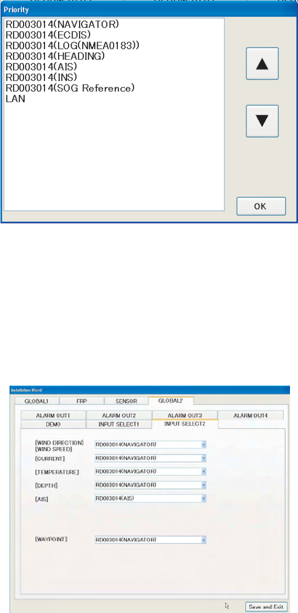
Common 2/Source Selection ½
Set sources of various data to be displayed on the radar screen. LAN is displayed when no
equipment of corresponding signals is connected.
Depending on with/without [Priority order] button, settings are deferent.
• Items with [Priority order]: Click the [Priority] button to set data source. (Setting from the list
box is unavailable.)
• Items without [Priority order]: Set data source from the list box.
Using the [Priority order] button
Click the [Priority order] button to display the list of input signals. Reverse the display of the
desired selections then using the UP/DOWN arrow button, set the priority order. Click the [OK]
button.
Note: When there are no input signals, data sources up to the upper three data sources are
switched. In the below case, NAVIGATOR, HEADING and ARPA are switched in that order.
42
Own ship position: Set data source for own ship position. Set DEAD RECKON when GPS
navigation equipment is unavailable to predict own ship position from heading data and ship
speed data.
When GPS is selected, set data source from OWN SHIP POSITION and DATUM immediately
below GPS. When DEAD RECKON is selected, set data source from DEADREC.
Similarly, set data source for ground speed, water speed, date and time and heading.
In data source selection page 2, set data source for wind direction/speed, tide, water
temperature, water depth, AIS and external waypoint.
Click the [Save setting/Finish] button when all the settings are done. Wizard disappears and
radar restarts. Refer to the corresponding section to adjust radar image.
43
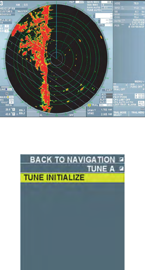
3.2 Initializing Tuning
Note: “Click” in the following explanations means to click the left button on the trackball.
1. Set the range at 48 NM.
2. Roll the trackball and put the cursor on TUNING on upper right side of the screen then click
the right button on the trackball
INITIALIZE TUNING appears at the center of the screen.
3. Click INITIALIZE TUNING
Automatic tuning starts and echo appears on the screen. Blinking message “Other alarm
Initializing tuning” appears in yellow during the automatic adjustment. Press the [Cancel Alarm]
key. Blinking changes to lighting. Initialization is completed when this message disappears.
Rotate the GAIN knob to adjust visibility of the screen.
4. Select RETURN and press the wheel to close the menu.
44
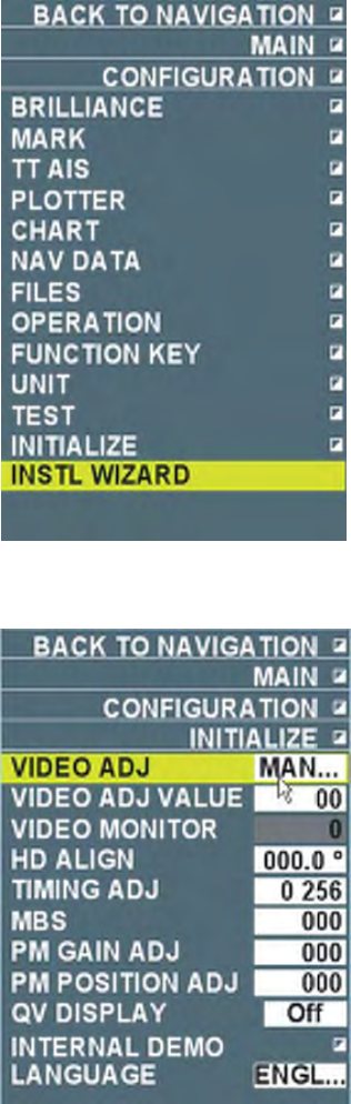
3.3 Adjustment of Video Level
After initializing tuning, adjust video level. Set the pulse width at LONG and do the following
after tuning bar is stable.
1. Press the [Delete target] key five times immediately after pressing the [Delete heading line].
The environment setting menu appears.
2. Click INSTALLATION SETTING. The INSTALLATION SETTING menu appears.
3. Select VIDEO LEVEL ADJUSTMENT and click the button.
4. Select MANUAL in VIDEO LEVEL ADJUSTMENT and then click the button.
5. Input adjustment value according to the length of Antenna Cable (RW-0013).
• Less than 20 m: 23
• 20 to 30 m: 25
• 30 to 50 m: 26 (Currently not used)
45
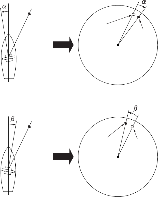
3.4 Heading Alignment
Some error may occur when installing the antenna unit. This installation error (timing error of the
heading switch) can be rectified in the processor unit.
Target
Correct
bearing
relative to
heading
Displayed
position
Target
Displayed
position
Correct
bearing
relative to
heading
Antenna mounting error toward port
(fast timing of heading switch)
Image appears deviated clockwise
(Positive error)
1. Set a range between 0.12t and 0.25 NM and select a target echo ahead near the heading
line.
2. Roll the EBL knob to bisect the target echo.
3. Read the target bearing.
4. Measure bearing of the target on the chart to calculate the difference between the actual
bearing and apparent bearing on the radar screen.
5. Click HEADING ALIGNMENT on the INSTALLATION SETTING menu.
46
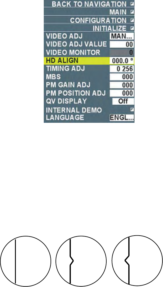
6. Roll the wheel to input the bearing error. Setting range is 0~359.9 ̊. Initially only integer part
is selected. Roll the wheel to set a value. Press the wheel to select the decimal part then roll
the wheel to set the value.
7. Confirm that target echo is displayed at the correct position on the screen.
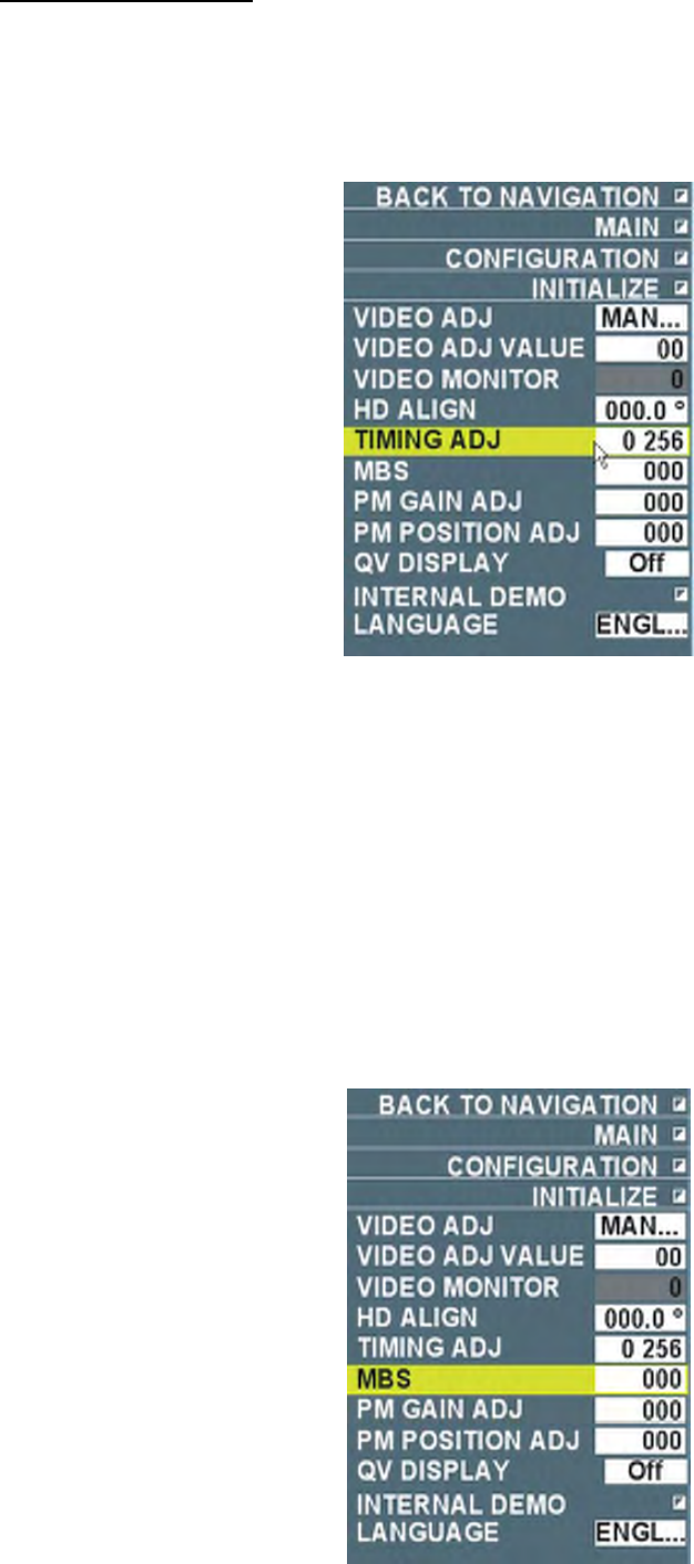
3.5 Adjustment of Sweep Timing
Sweep timing differs with respect to the length of the signal cable between the processor unit
and the antenna unit. Adjust sweep timing at installation to prevent the symptoms such as the
echo of a “straight” target (i.e. pier, jetty), on the 0.25 NM range, appearing on the display as
being pulled inward or pushed outward, or the range of target echoes near the center of the
screen appearing incorrectly.
(1) Correct (2) Target pushed inward (3) Target pushed outward
Image of a straight pier at different sweep timings
47
Method of adjustment
1. Transmit on the 0.25NM range
2. Adjust gain and sea clutter, etc. to display the radar image properly.
3. Display a straight target such as pier and jetty.
4. Click TIMING ADJUSTMENT on the INSTALLATION SETTING menu.
5. Roll the wheel to set the values so that pier and jetty appear straight and then press the
wheel. Setting range is 0~4095.
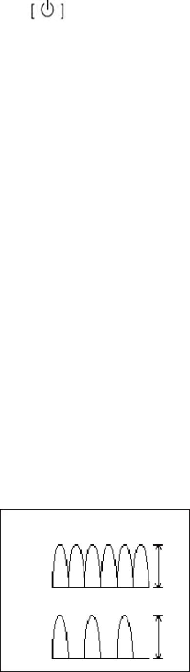
3.6 Suppressing Main Bang
If main bang appears at the screen center, suppress it as follows.
1. Transmit the radar on a long range and then wait ten minutes.
2. Adjust gain to show a slight amount of noise on the display.
3. Select the 0.25NM range. Adjust sea clutter control to suppress sea clutter to show the
clearest image.
4. Click MAIN BANG on the INSTALLATION SETTING menu.
48
5. Rotate the wheel to set a suitable value so that the main bang disappears. The setting range
is 0 to 255.
6. Press RETURN after adjustment is completed.
7. Press the power supply switch after all the adjustments are completed. The message
“Shutting down…” appears. Release the power supply switch immediately. The power is
turned off in about 15 seconds.
3.7 Gyrocompass Signals
Optional Gyro interface board (GC board) 64P1166 is necessary to connect to synchronous
signals or step signals of gyrocompass. Do the following in accordance with the specifications of
gyrocompass.
DIP Switch, Jumper Setting
Check the following items prior to DIP switch and jumper setting.
Gyrocompass
• AC synchronous
• DC synchronous
• DC step
• Full-wave pulsating current
• Have-wave pulsating current
AC synchronous
• Excitation frequency: 50/60Hz、400Hz、500Hz
• Rotor voltage: AC_____V
• Stator voltage: AC_____V
• Speed up ratio: 360x, 180x, 90x, 36x
DC synchronous
• Rotor voltage: DC_____V
• Stator voltage: DC_____V
• Speed up ratio: 360x, 180x, 90x, 36x
DC step
• Operating voltage: DC_____V
• Speed up ratio: 360x, 180x, 90x, 36x
Full-wave/Half-wave pulsation current step
• Excitation frequency: 50/60Hz、400Hz、500Hz
• Operating voltage: DC_____V
• Speed up ratio: 360x, 180x, 90x, 36x
V
V
Full-wave pulsation current
Half-wave pulsation current

49
Factory Default Setting
DIP switch and jumper connector on the GC board are ready to be connected to gyrocompass
of the following specifications:
• Gyrocompass: AC synchronous
• Frequency: 50/60 Hz
• Rotor voltage: AC60V ~ AC135V
• Stator voltage: AC60V ~ AC135V
• Speed up ratio: 360x
• Operating voltage: AC30V ~ AC135V
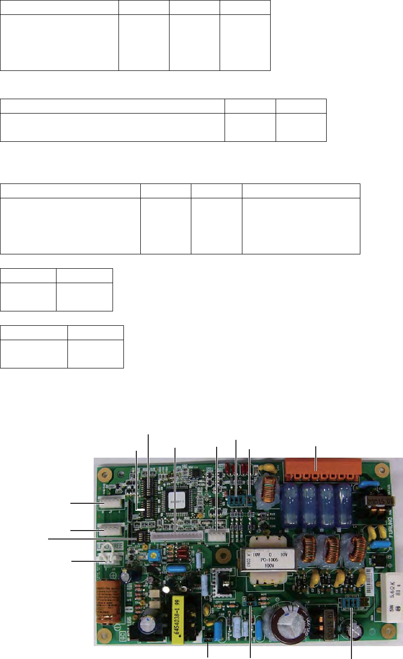
Setting Order
If the specifications of gyrocompass are different from the above specifications, change the DIP
switch and jumper settings on the GC board in the following order. (When the GC board is
installed at factory, the board needs to be removed first. See page 3-24.)
1. Gyrocompass
Gyro method SW-1-4 SW1-5 SW1-6 JP1
AC synchro
DC synchro
Full-wave pulsation current step
Half-wave pulsation current step
OFF
OFF
ON
OFF
ON
OFF
OFF
OFF
ON
ON
OFF
OFF
OFF
OFF
OFF
#1, #2, #3
#2, #3, #4
#4, #5, #6
#4, #5, #6
#4, #5, #6
2. Excitation Frequency
Excitation frequency SW1-7 SW1-8 Notes
50/60 Hz
400 Hz
500 Hz
DC
OFF
ON
OFF
ON
OFF
OFF
ON
ON
AC synchro, Pulsation current step
AC synchro, Pulsation current step
AC synchro, Pulsation current step
DC synchro, DC step
3. Rotor Voltage (between R1 and R2)
Gyrocompass requiring SW2-1 and JP3 settings is only AC synchronous. Rotor voltage of DC
synchronous is set at Step 6 Operating Voltage (JP4, JP5).
Rotor voltage SW2-1 JP3
AC20 V to AC45 V
AC30 V to AC70 V
AC40 V to AC90 V
AC60 V to AC135 V
ON
OFF
ON
OFF
#2
#2
#1
#1
4. Stator Voltage (between S1 and S2)
Stator voltage SW2-2 SW2-3 JP2
AC20 V to AC45 V or DC20 V to DC60 V
AC30 V to AC70 V or DC40 V to DC100 V
AC40 V to AC90 V
AC60 V to AC135 V
ON
OFF
ON
OFF
OFF
OFF
OFF
OFF
2
2
1
1
50
5. Speed up ratio
Speed increase ratio SW1-1 SW1-2 SW1-3
360x
180x
90x
36x
OFF
ON
OFF
ON
OFF
OFF
ON
ON
OFF
OFF
OFF
OFF
6. Operating Voltage
Operating voltage JP4 JP5
AC20 V to AC45 V or DC20 V to DC60 V
AC20 V to AC135 V or DC4 V to DC100 V
#2
#1
#2
#1
7. Transmission frequency of IEC61162 data, Version, Baud rate. (Not used for FAR-
1417/1427) Set according to addressee’s of data.]
Transmission frequency SW2-5 SW2-6 Output sentence
1 second
200mil. Sec.
100mil. Sec.
25mil. Sec.
OFF
ON
OFF
ON
OFF
OFF
ON
ON
HDT+VHW
HDT
HDT
HDT
Version SW3-1
1.5
2.0
OFF
ON
Baud rate SW3-2
4.800 bps
38.400 bps
OFF
ON
Turn OFF the DIP switch SW2-8 from ON and reset CPU.
SW1
J1 J6 JP3
JP2 J4
JP4 JP5 JP1
SW2
J7
J8
SW3
J3
51
Installing GC board
Follow the following steps when installing the GC board on site. When the GC board is pre-
installed and shipped at factory and the DIP switch and jumper wire need to be changed, refer
to the following description to remove the GC board first. After the setting, reinstall the GC board.
Gyro converter GC-100-2, Code No.000-017-044
Name Type Code No. Q’ty
GC board 64P1166 001-103-040-00 1
NH connector 03-2290 001-105-020-00 1
PH-XH connector 03-2328 (P14-6P) 001-105-010-00 1
Connector 231-308/026-FUR 000-150-114-11 1
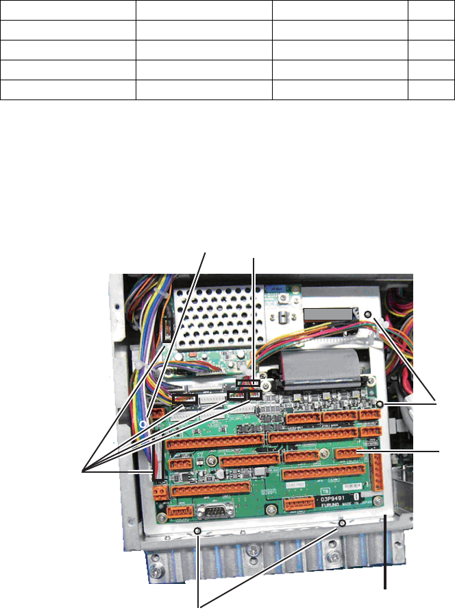
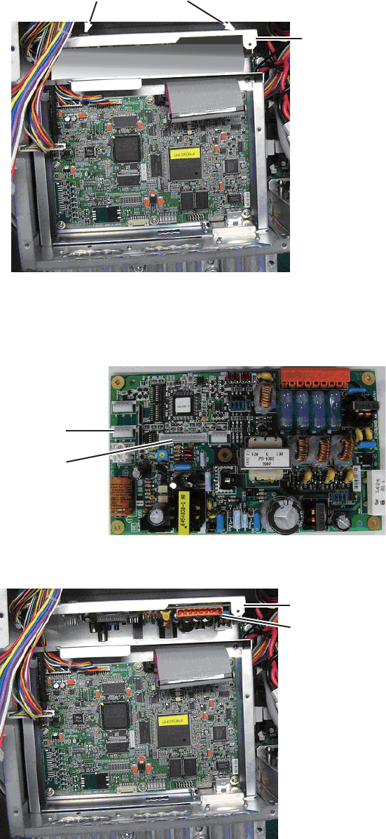
1. Open the lid of the processor unit.
2. Remove the five connectors on the TB board/VIDEO AMP board. The connectors at five
locations need to be removed. See the picture below.
3. Remove four screws fastening the mounting base of the TB board/VIDEO AMP board and
loosen one screw to remove the mounting base.
Loosen screw (1 lacation) J603
Remove
connection at
five locations.
Remove screws at two locations
from the rear panel
TB board/VIDEO AMP
board mounting base
Remove screws at
two locations.
J608
(AD-10)
52
4. Loosen two screws in the processor unit and remove the GC mounting base. (Screws only
need to be loosened.)
2 screws (botton of the processor unit)
GC mounting
5. Attach the GC board to the GC mounting base (The GC board is fastened with five screws at
five locations). Install the NH connector (cable assembly) and PH-XH connector (cable
assembly) to J7 and J1 accordingly.
J7
J1
6. Reinstall the GC mounting base.
GS mounting base
GS board
After GC board is mounted
53
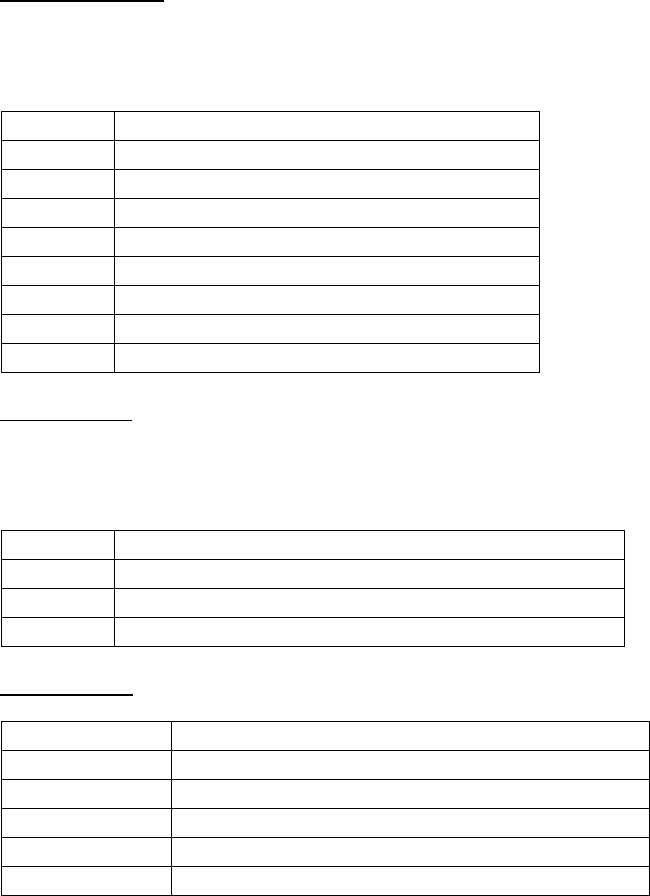
7. Reinstall the mounting base of the TB board/VIDEO AMP board and fasten the connectors
removed at step 2.
8. Connect the six pin connectors of the cable assembly on the GC board to J603 on the TB
board. (See the illustration at step 3 above.)
9. Connect the other cable assembly on the GC board to 231-308/026-FUR to connect to J608
on the TB board. See page 2-11 for installation of the 231-308/026 –FUR connector.
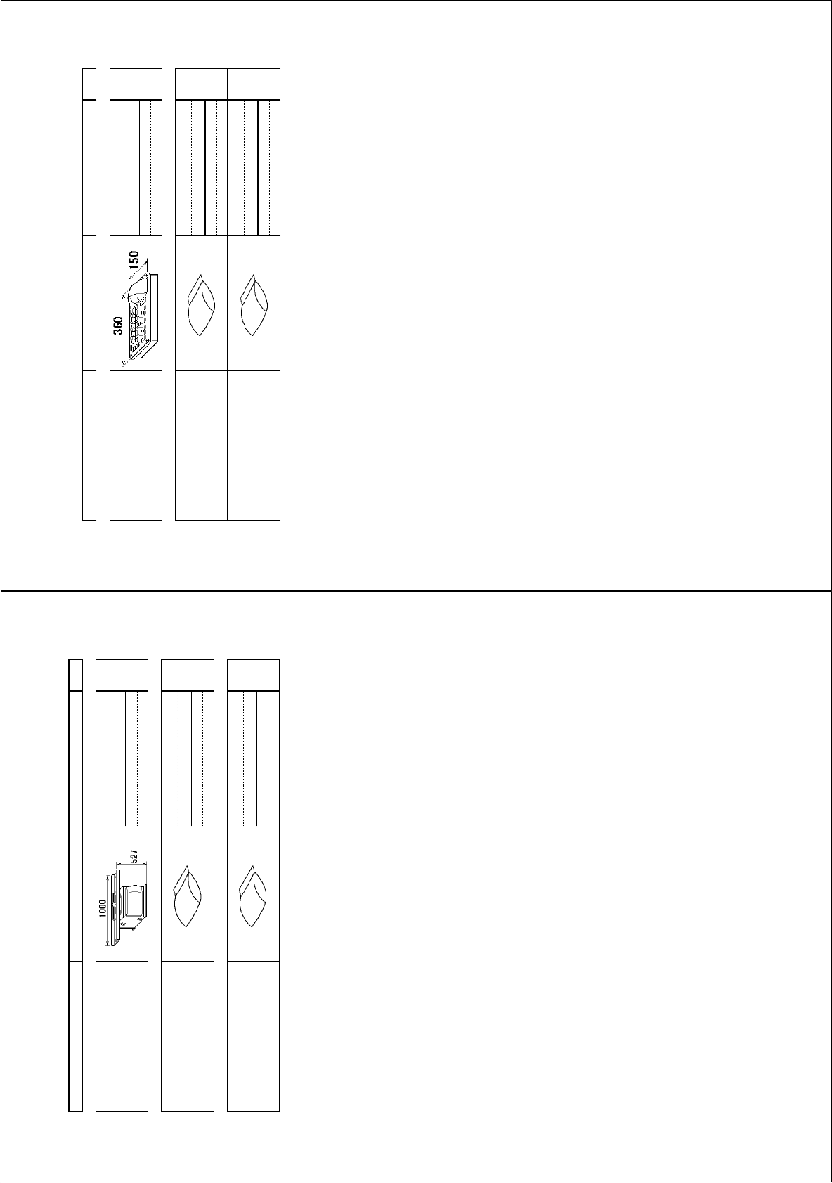
Setting Bearing
Read heading of gyrocompass. Check the heading displayed on the radar screen with the
gyrocompass reading.
1. Click the MENU at about middle on the right side of the screen to display the main menu.
2. Click ECHO to display the echo menu.
3. Click [GC-10] to read the gyrocompass reading.
4. Right click several times to close the menu.
5. Confirm that the heading tracks with the movement of the gyrocompass.

54
4. Input Signal
This equipment inputs and outputs signals in NMEA0183 format and CAN bus format. The table
below shows the details. There are six NMEA signal ports and each has different input/output
sentences. Equipment and signals to be connected are as follows.
Signal Port Name Connecting equipment Port No.
NMEA1 GPS navigation equipment J606
NMEA2 ECDIS J619
NMEA3 Ship speed meter J607
NMEA4 Heading bearing signal J605
NMEA5 AIS J611
NMEA6 INS J620
Absolute maximum
Input: Current 50 mA, Voltage 6 V
Output: Voltage supply 16 V
Out voltage (Higt): 16V
Output corrent (Low): 50 mA
4.1 NMEA Input Sentence
• Talker is arbitrary.
• Baud rate 4800 ~ 38400 bps
• NMEA0183, Ver.1.5, 2.0, 3.0
BWC Range and bearing to waypoint (Great circle route)
BWR Range and bearing to waypoint (Rhumb line)
CUR Current data
DBK Water depth from keel
DBS Water depth from sea surface
DBT Water depth from transceiver
DPT Water depth
DTM Datum
GBS Detection of GPS error
GGA GPS positioning data
GLL Latitude/longitude, UTC positioning
GNS GNSS positioning data
HDG Heading (Magnetic bearing), variation data
HDT Heading (True bearing)
MTW Water temperature
MWV Wind direction/Wind speed
RMA Navigation data
RMB Navigation data
RMC Navigation data
THS True bearing
VBW Dual-axis ground/water ship speed
VDR Drift speed (Set, Drift)
VHW Water speed, Heading bearing

55
VTG True course, Ground speed
VWR Relative wind direction/wind speed
VWT True wind direction/wind speed
ZDA Current UTC time
NMEA5 (AIS)
• Talker is AI
• Baud rate 4800~38400 bps
• NMEA0183, Ver.1.5, 2.0, 3.0
ABK Specify addressee/Broadcast acknowledge data
ALR Alarm setting status
VDM VHF data link message
VDO VHF data link Own ship report
NMEA6 (INS)
ACK Acknowledge (Talker is arbitrary.)
PFEC. pireq Type name, Transmissible NMEA data
PFEC. pidat Type name, Transmissible NMEA data
56
4.2 NMEA Output Sentence
NMEA2 (ECDIS)
• Talker is RA
• Baud rate 4800/38400 bps
• NMEA0183, Ver.3.0
AAM Arrival alarm
ALR Alarm setting status
APB Data for auto pilot
BOD Bearing from start point to waypoint
OSD Own ship data
RMB Navigation information
RSD Radar system data
TLL Target latitude/longitude
TTM Track target information
NMEA5 (AIS)
• Talker is RA
• Baud rate 4800/38400 bps
• NMEA0183, Ver.3.0
ABM Address specified binary safety related message
ACK Acknowdge
BBM Broadcast binary message
VSD Voyage static data
NMEA6 (INS)
ALR Alarm setting status
OSD Own ship data
RSD Radar system data
TTL Target latitude/longitude
PFEC. pidat Data of specified property
PEEC. prireq Output request for specified property

57
4.3 CAN bus port Input/output
Input PGN
059392 ISO Acknowledgement
059904 ISO Request
060928 ISO Address Claim
061184 Self Test Group Function
126208 NMEA - Request group function
126208 NMEA - Command group function
126208 NMEA - Acknowledge group
126720 Memory Clear Group Function
126720 Reset Group Function
126992 System Time
126996 Product Information
126250 Vessel Heading
127259 Speed, Water referenced
128267 Water, Depth
129025 Position, Rapid Update
129026 COG & SOG Rapid Up date
129029 GNSS Position Data
129033 Time & Date
129044 Datum
129545 GNSS RAIM Output
130306 Wind Data
130310 Environmental Parameters
130511 Environmental Parameters
130577 Direction Data
130816 Self Test Report
130822 Unit Division Code
130823 Browser Control Status.
Output PGN
059392 ISO Acknowledgement
059904 ISO Request
060928 ISO Address Claim
061184 Self Test Group Function
126208 NMEA - Request group function
126208 NMEA - Command group function
126208 NMEA – Acknowledge group function
126464 PGN List – Received PGN7s group function
126464 PGN List – Received PGN7s group function
126996 Product Information
130821 NAV Source Select
130822 Unit Division Code
130823 Browser Control Status
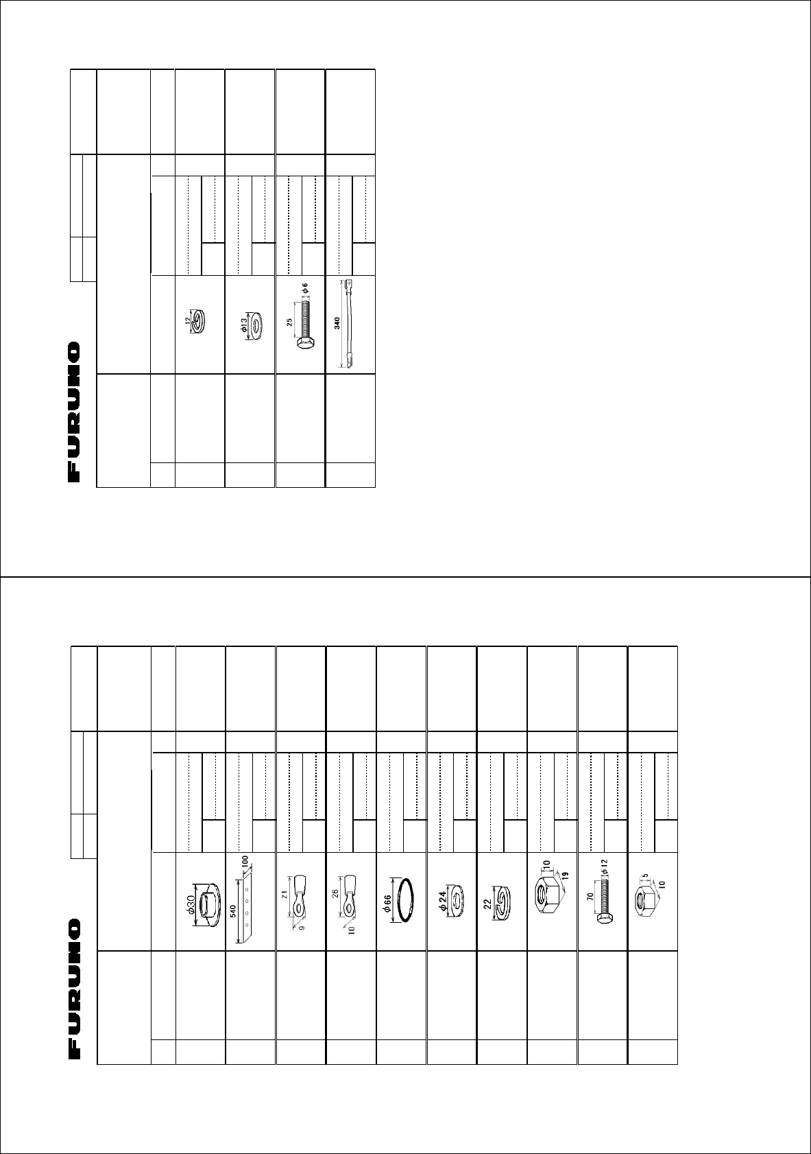
㧼㧭㧯㧷㧵㧺㧳ޓ㧸㧵㧿㨀
**:
45$
0#/' 176.+0' &'5%4+26+10%1&'ͳ 36;
࡙࠾࠶࠻ 70+6
ⓨਛ✢ᧄㇱ
#06'00#&4+8'70+6
45$
ઃዻຠ #%%'5514+'5
ઃዻຠ
#%%'5514+'5
(2
Ꮏ᧚ᢱ +056#..#6+10/#6'4+#.5
Ꮏ᧚ᢱ
+056#..#6+10/#6'4+#.5
%2
䋨⇛࿑䈱ኸᴺ䈲䇮ෳ⠨୯䈪䈜䇯㩷㩷㪛㪠㪤㪜㪥㪪㪠㪦㪥㪪㩷㪠㪥㩷㪛㪩㪘㪮㪠㪥㪞㩷㪝㪦㪩㩷㪩㪜㪝㪜㪩㪜㪥㪚㪜㩷㪦㪥㪣㪰㪅䋩
**:
ဳᑼ㪆䍘䍎䍢䍼⇟ภ䈏䋲Ბ䈱႐ว䇮ਅᲑ䉋䉍Ბ䈮ઍ䉒䉎ㆊᷰᦼຠ䈪䈅䉍䇮䈬䈤䉌䈎䈏䈦䈩䈇䉁䈜䇯䇭䈭䈍䇮ຠ⾰䈲ᄌ䉒䉍䉁䈞䉖䇯
㪫㪮㪦㩷㪫㪰㪧㪜㪪㩷㪘㪥㪛㩷㪚㪦㪛㪜㪪㩷㪤㪘㪰㩷㪙㪜㩷㪣㪠㪪㪫㪜㪛㩷㪝㪦㪩㩷㪘㪥㩷㪠㪫㪜㪤㪅㩷㩷㪫㪟㪜㩷㪣㪦㪮㪜㪩㩷㪧㪩㪦㪛㪬㪚㪫㩷㪤㪘㪰㩷㪙㪜㩷㪪㪟㪠㪧㪧㪜㪛㩷㪠㪥㩷㪧㪣㪘㪚㪜㩷㪦㪝㩷㪫㪟㪜㩷㪬㪧㪧㪜㪩㩷
㪧㪩㪦㪛㪬㪚㪫㪅㩷㪨㪬㪘㪣㪠㪫㪰㩷㪠㪪㩷㪫㪟㪜㩷㪪㪘㪤㪜㪅
㧼㧭㧯㧷㧵㧺㧳ޓ㧸㧵㧿㨀
*':
4%7,'
0#/' 176.+0' &'5%4+26+10%1&'ͳ 36;
࡙࠾࠶࠻ 70+6
ᠲㇱ
%10641.70+6
4%7'
Ꮏ᧚ᢱ +056#..#6+10/#6'4+#.5 %2
-$ขઃ㊄ౕ
-$(+:674'#55'/$.;
%2
Ꮏ᧚ᢱ
+056#..#6+10/#6'4+#.5
%2
䍘㪄䍢䍼⇟ภᧃየ䈱㪲㪁㪁㪴䈲䇮ㆬᛯຠ䈱ઍ䍘䍎䍢䍼䉕䈚䉁䈜䇯
㪚㪦㪛㪜㩷㪥㪬㪤㪙㪜㪩㩷㪜㪥㪛㪠㪥㪞㩷㪮㪠㪫㪟㩷㩹㪁㪁㩹㩷㪠㪥㪛㪠㪚㪘㪫㪜㪪㩷㪫㪟㪜㩷㪚㪦㪛㪜㩷㪥㪬㪤㪙㪜㪩㩷㪦㪝㩷㪩㪜㪧㪩㪜㪪㪜㪥㪫㪘㪫㪠㪭㪜㩷㪤㪘㪫㪜㪩㪠㪘㪣㪅
䋨⇛࿑䈱ኸᴺ䈲䇮ෳ⠨୯䈪䈜䇯㩷㩷㪛㪠㪤㪜㪥㪪㪠㪦㪥㪪㩷㪠㪥㩷㪛㪩㪘㪮㪠㪥㪞㩷㪝㪦㪩㩷㪩㪜㪝㪜㪩㪜㪥㪚㪜㩷㪦㪥㪣㪰㪅䋩
*':
ဳᑼ㪆䍘䍎䍢䍼⇟ภ䈏䋲Ბ䈱႐ว䇮ਅᲑ䉋䉍Ბ䈮ઍ䉒䉎ㆊᷰᦼຠ䈪䈅䉍䇮䈬䈤䉌䈎䈏䈦䈩䈇䉁䈜䇯䇭䈭䈍䇮ຠ⾰䈲ᄌ䉒䉍䉁䈞䉖䇯
㪫㪮㪦㩷㪫㪰㪧㪜㪪㩷㪘㪥㪛㩷㪚㪦㪛㪜㪪㩷㪤㪘㪰㩷㪙㪜㩷㪣㪠㪪㪫㪜㪛㩷㪝㪦㪩㩷㪘㪥㩷㪠㪫㪜㪤㪅㩷㩷㪫㪟㪜㩷㪣㪦㪮㪜㪩㩷㪧㪩㪦㪛㪬㪚㪫㩷㪤㪘㪰㩷㪙㪜㩷㪪㪟㪠㪧㪧㪜㪛㩷㪠㪥㩷㪧㪣㪘㪚㪜㩷㪦㪝㩷㪫㪟㪜㩷㪬㪧㪧㪜㪩㩷
㪧㪩㪦㪛㪬㪚㪫㪅㩷㪨㪬㪘㪣㪠㪫㪰㩷㪠㪪㩷㪫㪟㪜㩷㪪㪘㪤㪜㪅
A-1
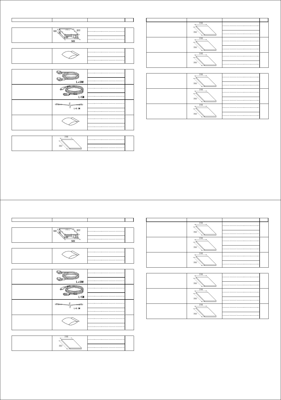
0#/' 176.+0' 36;&'5%4+26+10%1&'ͳ
㧼㧭㧯㧷㧵㧺㧳ޓ㧸㧵㧿㨀
**:
427,-'ޓ#%㧕
0#/' 176.+0' 36;&'5%4+26+10%1&'ͳ
࡙࠾࠶࠻ 70+6
ᓮㇱ
241%'551470+6
427,4/50
੍ຠ 52#4'2#465
੍ຠ
52#4'2#465
52
Ꮏ᧚ᢱ +056#..#6+10/#6'4+#.5
%2
㩃㨺㩖㩨㩣⚵ຠ
%#$.'#55'/$.;
&8+&&5.+0-/
㩃㨺㩖㩨㩣⚵ຠ
%#$.'#55'/$.;
405
㩃㨺㩖㩨㩣⚵ຠ.#0
.#0%#$.'#55'/$.;
/1&<
Ꮏ᧚ᢱ
+056#..#6+10/#6'4+#.5
%2
࿑ᦠ, &1%7/'06㧔,
ᛛㆡ⸽ⷐ㗔
#22.+%#6+10)7+&'
,
ขᛒ⺑ᦠ
12'4#6145/#07#.
1/,
ᠲⷐ㗔ᦠ
12'4#6145)7+&'
15,
ⵝⷐ㗔ᦠ
+056#..#6+10/#07#.
+/,
࿑ᦠ' &1%7/'06㧔'
ขᛒ⺑ᦠ⧷
12'4#6145/#07#.
1/'
ᠲⷐ㗔ᦠ⧷
12'4#6145)7+&'
15'
ⵝⷐ㗔ᦠ⧷
+056#..#6+10/#07#.
+/'
㪈㪅䍘㪄䍢䍼⇟ภᧃየ䈱㪲㪁㪁㪴䈲䇮ㆬᛯຠ䈱ઍ䍘䍎䍢䍼䉕䈚䉁䈜䇯
㪚㪦㪛㪜㩷㪥㪬㪤㪙㪜㪩㩷㪜㪥㪛㪠㪥㪞㩷㪮㪠㪫㪟㩷㩹㪁㪁㩹㩷㪠㪥㪛㪠㪚㪘㪫㪜㪪㩷㪫㪟㪜㩷㪚㪦㪛㪜㩷㪥㪬㪤㪙㪜㪩㩷㪦㪝㩷㪩㪜㪧㪩㪜㪪㪜㪥㪫㪘㪫㪠㪭㪜㩷㪤㪘㪫㪜㪩㪠㪘㪣㪅
㪉㪅࿑ᦠ䈲䇮⧷ᢥ䍃ᢥ᭽䈪ㆬᛯ㗿䈇䉁䈜䇯
㪚㪟㪦㪦㪪㪜㩷㪡㪘㪧㪘㪥㪜㪪㪜㩷㪦㪩㩷㪜㪥㪞㪣㪠㪪㪟㩷㪘㪚㪚㪜㪪㪪㪦㪩㪠㪜㪪㪅
䯴⇛࿑䬽ኸᴺ䬾䫺ෳ⠨୯䬶䬨䫻䎃䎧䎬䎰䎨䎱䎶䎬䎲䎱䎶䎃䎬䎱䎃䎧䎵䎤䎺䎬䎱䎪䎃䎩䎲䎵䎃䎵䎨䎩䎨䎵䎨䎱䎦䎨䎃䎲䎱䎯䎼䎑䯵
**:
ဳᑼ䎒䱤䱚䱮䲈⇟ภ䬛䯾Ბ䬽႐ว䫺ਅᲑ䭗䭙Ბ䬺ઍ䭞䭚ㆊᷰᦼຠ䬶䬑䭙䫺䬸䬰䭘䬚䬛䬲䬵䬓䭍䬨䫻䫹䬹䬙䫺ຠ⾰䬾ᄌ䭞䭙䭍䬪䭢䫻
䎷䎺䎲䎃䎷䎼䎳䎨䎶䎃䎤䎱䎧䎃䎦䎲䎧䎨䎶䎃䎰䎤䎼䎃䎥䎨䎃䎯䎬䎶䎷䎨䎧䎃䎩䎲䎵䎃䎤䎱䎃䎬䎷䎨䎰䎑䎃䎃䎷䎫䎨䎃䎯䎲䎺䎨䎵䎃䎳䎵䎲䎧䎸䎦䎷䎃䎰䎤䎼䎃䎥䎨䎃䎶䎫䎬䎳䎳䎨䎧䎃䎬䎱䎃䎳䎯䎤䎦䎨䎃䎲䎩䎃䎷䎫䎨䎃
䎸䎳䎳䎨䎵䎃䎳䎵䎲䎧䎸䎦䎷䎑䎃䎴䎸䎤䎯䎬䎷䎼䎃䎬䎶䎃䎷䎫䎨䎃䎶䎤䎰䎨䎑
0#/' 176.+0' 36;&'5%4+26+10%1&'ͳ
㧼㧭㧯㧷㧵㧺㧳ޓ㧸㧵㧿㨀
**:
427,-'ޓ#%㧕
0#/' 176.+0' 36;&'5%4+26+10%1&'ͳ
࡙࠾࠶࠻ 70+6
ᓮㇱ
241%'551470+6
427,4/50
੍ຠ 52#4'2#465
੍ຠ
52#4'2#465
52
Ꮏ᧚ᢱ +056#..#6+10/#6'4+#.5
%2
㩃㨺㩖㩨㩣⚵ຠ
%#$.'#55'/$.;
&8+&&5.+0-/
㩃㨺㩖㩨㩣⚵ຠ
%#$.'#55'/$.;
405
㩃㨺㩖㩨㩣⚵ຠ.#0
.#0%#$.'#55'/$.;
/1&<
Ꮏ᧚ᢱ
+056#..#6+10/#6'4+#.5
%2
࿑ᦠ, &1%7/'06㧔,
ᛛㆡ⸽ⷐ㗔
#22.+%#6+10)7+&'
,
ขᛒ⺑ᦠ
12'4#6145/#07#.
1/,
ᠲⷐ㗔ᦠ
12'4#6145)7+&'
15,
ⵝⷐ㗔ᦠ
+056#..#6+10/#07#.
+/,
࿑ᦠ' &1%7/'06㧔'
ขᛒ⺑ᦠ⧷
12'4#6145/#07#.
1/'
ᠲⷐ㗔ᦠ⧷
12'4#6145)7+&'
15'
ⵝⷐ㗔ᦠ⧷
+056#..#6+10/#07#.
+/'
㪈㪅䍘㪄䍢䍼⇟ภᧃየ䈱㪲㪁㪁㪴䈲䇮ㆬᛯຠ䈱ઍ䍘䍎䍢䍼䉕䈚䉁䈜䇯
㪚㪦㪛㪜㩷㪥㪬㪤㪙㪜㪩㩷㪜㪥㪛㪠㪥㪞㩷㪮㪠㪫㪟㩷㩹㪁㪁㩹㩷㪠㪥㪛㪠㪚㪘㪫㪜㪪㩷㪫㪟㪜㩷㪚㪦㪛㪜㩷㪥㪬㪤㪙㪜㪩㩷㪦㪝㩷㪩㪜㪧㪩㪜㪪㪜㪥㪫㪘㪫㪠㪭㪜㩷㪤㪘㪫㪜㪩㪠㪘㪣㪅
㪉㪅࿑ᦠ䈲䇮⧷ᢥ䍃ᢥ᭽䈪ㆬᛯ㗿䈇䉁䈜䇯
㪚㪟㪦㪦㪪㪜㩷㪡㪘㪧㪘㪥㪜㪪㪜㩷㪦㪩㩷㪜㪥㪞㪣㪠㪪㪟㩷㪘㪚㪚㪜㪪㪪㪦㪩㪠㪜㪪㪅
䯴⇛࿑䬽ኸᴺ䬾䫺ෳ⠨୯䬶䬨䫻䎃䎧䎬䎰䎨䎱䎶䎬䎲䎱䎶䎃䎬䎱䎃䎧䎵䎤䎺䎬䎱䎪䎃䎩䎲䎵䎃䎵䎨䎩䎨䎵䎨䎱䎦䎨䎃䎲䎱䎯䎼䎑䯵
**:
ဳᑼ䎒䱤䱚䱮䲈⇟ภ䬛䯾Ბ䬽႐ว䫺ਅᲑ䭗䭙Ბ䬺ઍ䭞䭚ㆊᷰᦼຠ䬶䬑䭙䫺䬸䬰䭘䬚䬛䬲䬵䬓䭍䬨䫻䫹䬹䬙䫺ຠ⾰䬾ᄌ䭞䭙䭍䬪䭢䫻
䎷䎺䎲䎃䎷䎼䎳䎨䎶䎃䎤䎱䎧䎃䎦䎲䎧䎨䎶䎃䎰䎤䎼䎃䎥䎨䎃䎯䎬䎶䎷䎨䎧䎃䎩䎲䎵䎃䎤䎱䎃䎬䎷䎨䎰䎑䎃䎃䎷䎫䎨䎃䎯䎲䎺䎨䎵䎃䎳䎵䎲䎧䎸䎦䎷䎃䎰䎤䎼䎃䎥䎨䎃䎶䎫䎬䎳䎳䎨䎧䎃䎬䎱䎃䎳䎯䎤䎦䎨䎃䎲䎩䎃䎷䎫䎨䎃
䎸䎳䎳䎨䎵䎃䎳䎵䎲䎧䎸䎦䎷䎑䎃䎴䎸䎤䎯䎬䎷䎼䎃䎬䎶䎃䎷䎫䎨䎃䎶䎤䎰䎨䎑
A-2
%1&'01
6;2'
%2
⇛ޓޓ࿑
176.+0'
ฬޓޓ⒓
0#/'
ᢙ㊂
36;
↪ㅜ㧛⠨
4'/#4-5
⇟ภ
01
ဳฬ㧛ⷙᩰ
&'5%4+26+105
+056#..#6+10/#6'4+#.5
Ꮏ᧚ᢱ
**:
㩆㨺㩣㩦㨹㩆㨶㨺
5'#.9#5*'4 41*5
%1&'01
㒐ⲁ㩄㩨㩛
%14415+102411(47$$'4
%1&'01
⌕┵ሶ
%4+/210.7) (8$.7
%1&'01
⌕┵ሶ
%4+/210.7) (8.(;'.
%1&'01
1㩢㩧㩂㩨
14+0) ,$#)
%1&'01
㩚㩀㩨㩁㩙㩣ᐔᐳ㊄
(.#69#5*'4 /575
%1&'01
㩔㩨㩒ᐳ㊄
524+0)9#5*'4 /575
%1&'01
ⷺ㩏㨹㩎㩆㨷
*':#)10#.076 /575
%1&'01
ⷺ㩘㩨㩣㩎ో㩒㩆㩨
*':#)10*'#&5%4'9 /:575
%1&'01
ⷺ㩏㨹㩎㩆㨷
*':#)10#.076 /575
%1&'01
㧔⇛࿑ߩኸᴺߪޔෳ⠨୯ߢߔޕޓ&+/'05+105+0&4#9+0)(144'('4'0%'10.;㧕
㧲㨁㧾㨁㧺㧻ޓ㧱㧸㧱㧯㨀㧾㧵㧯ޓ㧯㧻ޓ㧚
㧘
㧸㨀㧰
**:
ဳᑼ㩄㨺㩎㩨⇟ภ߇㧞Ბߩ႐วޔਅᲑࠃࠅᲑߦઍࠊࠆㆊᷰᦼຠߢࠅޔߤߜࠄ߆߇ߞߡ߹ߔޕޓߥ߅ޔຠ⾰ߪᄌࠊࠅ߹ߖࠎޕ
6916;2'5#0&%1&'5/#;$'.+56'&(14#0+6'/6*'.19'4241&7%6/#;$'5*+22'&+02.#%'1(6*'722'4241&7%6
37#.+6;+56*'5#/'
%1&'01
6;2'
%2
⇛ޓޓ࿑
176.+0'
ฬޓޓ⒓
0#/'
ᢙ㊂
36;
↪ㅜ㧛⠨
4'/#4-5
⇟ภ
01
ဳฬ㧛ⷙᩰ
&'5%4+26+105
+056#..#6+10/#6'4+#.5
Ꮏ᧚ᢱ
**:
㩔㩨㩒ᐳ㊄
524+0)9#5*'4 /575
%1&'01
㩚㩀㩨㩁ᐔᐳ㊄
(.#69#5*'4 /575
%1&'01
ⷺ㩘㩨㩣㩎
*':#)10#.*'#&$1.6 /:575
%1&'01
㩃㨺㩖㩨㩣⚵ຠ
%#$.'#55; 49
%1&'01
㧔⇛࿑ߩኸᴺߪޔෳ⠨୯ߢߔޕޓ&+/'05+105+0&4#9+0)(144'('4'0%'10.;㧕
㧲㨁㧾㨁㧺㧻ޓ㧱㧸㧱㧯㨀㧾㧵㧯ޓ㧯㧻ޓ㧚
㧘
㧸㨀㧰
**:
ဳᑼ㩄㨺㩎㩨⇟ภ߇㧞Ბߩ႐วޔਅᲑࠃࠅᲑߦઍࠊࠆㆊᷰᦼຠߢࠅޔߤߜࠄ߆߇ߞߡ߹ߔޕޓߥ߅ޔຠ⾰ߪᄌࠊࠅ߹ߖࠎޕ
6916;2'5#0&%1&'5/#;$'.+56'&(14#0+6'/6*'.19'4241&7%6/#;$'5*+22'&+02.#%'1(6*'722'4241&7%6
37#.+6;+56*'5#/'
A-3
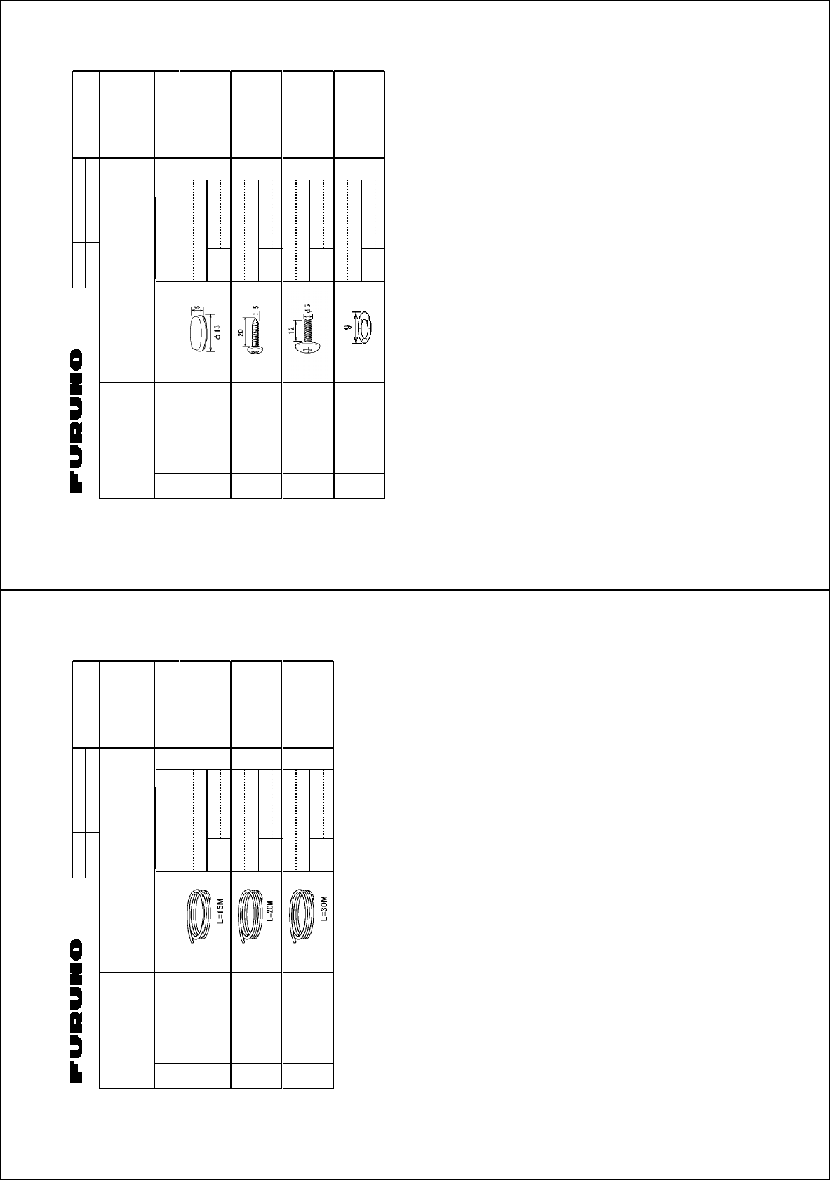
%1&'01
6;2'
⇛ޓޓ࿑
176.+0'
ฬޓޓ⒓
0#/'
ᢙ㊂
36;
↪ㅜ㧛⠨
4'/#4-5
⇟ภ
01
ဳฬ㧛ⷙᩰ
&'5%4+26+105
+056#..#6+10/#6'4+#.5
Ꮏ᧚ᢱ
*':
(#4
㩃㨺㩖㩨㩣%
%14'%#$.' 49/
ㆬᛯޓޓޓޓޓޓޓ
61$'5'.'%6'&
%1&'01
㩃㨺㩖㩨㩣%
%14'%#$.' 49/
ㆬᛯޓޓޓޓޓޓޓ
61$'5'.'%6'&
%1&'01
㩃㨺㩖㩨㩣%
%14'%#$.' 49/
ㆬᛯޓޓޓޓޓޓޓ
61$'5'.'%6'&
%1&'01
㧔⇛࿑ߩኸᴺߪޔෳ⠨୯ߢߔޕޓ&+/'05+105+0&4#9+0)(144'('4'0%'10.;㧕
㧲㨁㧾㨁㧺㧻ޓ㧱㧸㧱㧯㨀㧾㧵㧯ޓ㧯㧻ޓ㧚
㧘
㧸㨀㧰
*':
ڏ
ဳᑼ㩄㨺㩎㩨⇟ภ߇㧞Ბߩ႐วޔਅᲑࠃࠅᲑߦઍࠊࠆㆊᷰᦼຠߢࠅޔߤߜࠄ߆߇ߞߡ߹ߔޕޓߥ߅ޔຠ⾰ߪᄌࠊࠅ߹ߖࠎޕ
6916;2'5#0&%1&'5/#;$'.+56'&(14#0+6'/6*'.19'4241&7%6/#;$'5*+22'&+02.#%'1(6*'722'4241&7%6
37#.+6;+56*'5#/'
%1&'01
6;2'
%2
⇛ޓޓ࿑
176.+0'
ฬޓޓ⒓
0#/'
ᢙ㊂
36;
↪ㅜ㧛⠨
4'/#4-5
⇟ภ
01
ဳฬ㧛ⷙᩰ
&'5%4+26+105
+056#..#6+10/#6'4+#.5
Ꮏ᧚ᢱ
*':
4%7
㩒㩆㩨㩁㨶㨹㩖㩩
%#2
%1&'01
㩔㩨㨼㩧㩎㩨㩊㨹㩕㩩㩧㩆㨷
6#22+0)5%4'9 :575
%1&'01
㩔㩨㨼㩧㩎㩨㩄㩒㩆㩨
$+0&+0)*'#&5%4'9 /:575
%1&'01
ᵄᐳ㊄
9#8'9#5*'4 99575
%1&'01
㧔⇛࿑ߩኸᴺߪޔෳ⠨୯ߢߔޕޓ&+/'05+105+0&4#9+0)(144'('4'0%'10.;㧕
㧲㨁㧾㨁㧺㧻ޓ㧱㧸㧱㧯㨀㧾㧵㧯ޓ㧯㧻ޓ㧚
㧘
㧸㨀㧰
*':
ဳᑼ㩄㨺㩎㩨⇟ภ߇㧞Ბߩ႐วޔਅᲑࠃࠅᲑߦઍࠊࠆㆊᷰᦼຠߢࠅޔߤߜࠄ߆߇ߞߡ߹ߔޕޓߥ߅ޔຠ⾰ߪᄌࠊࠅ߹ߖࠎޕ
6916;2'5#0&%1&'5/#;$'.+56'&(14#0+6'/6*'.19'4241&7%6/#;$'5*+22'&+02.#%'1(6*'722'4241&7%6
37#.+6;+56*'5#/'
A-4
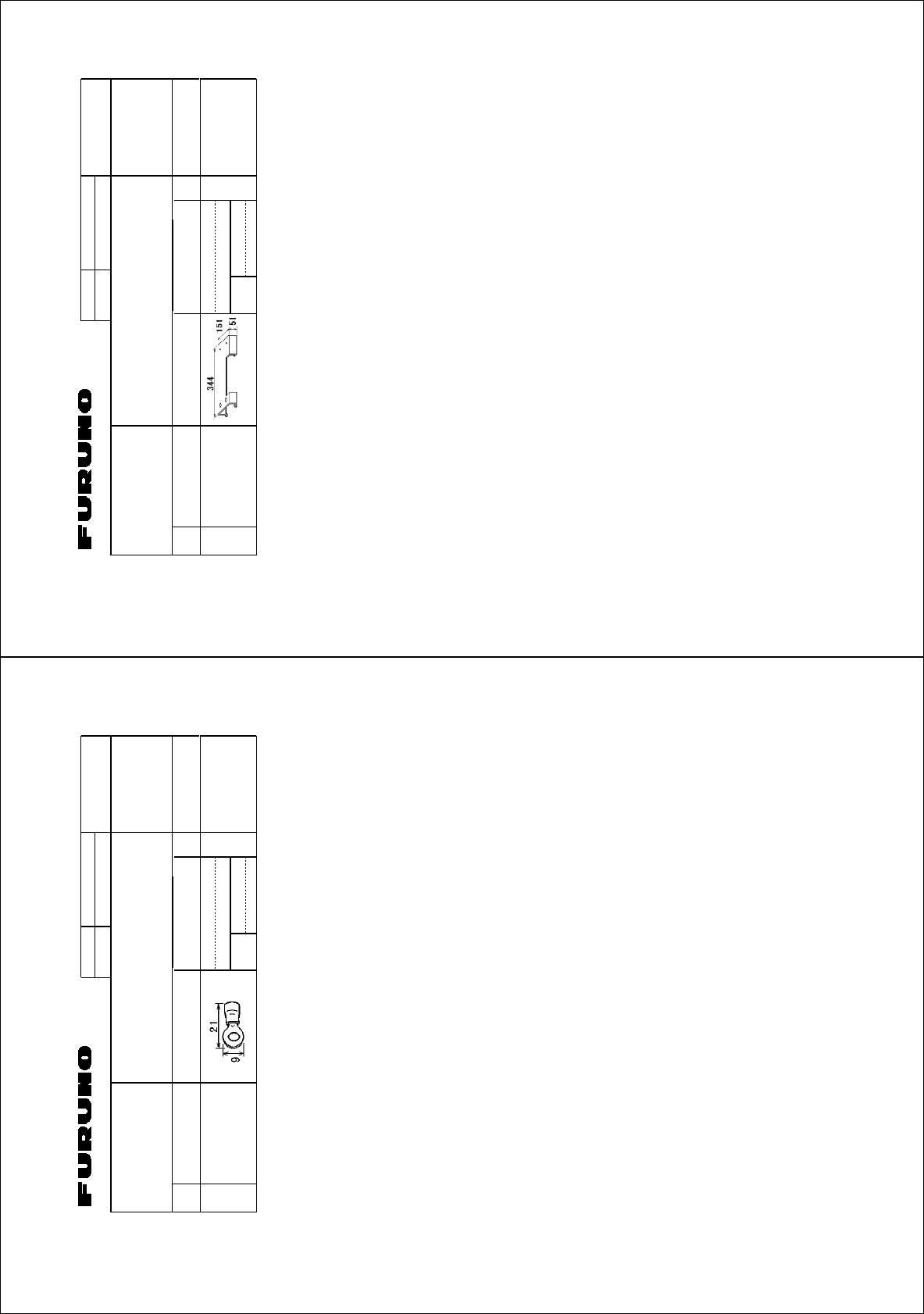
%1&'01
6;2'
%2
⇛ޓޓ࿑
176.+0'
ฬޓޓ⒓
0#/'
ᢙ㊂
36;
↪ㅜ㧛⠨
4'/#4-5
⇟ภ
01
ဳฬ㧛ⷙᩰ
&'5%4+26+105
+056#..#6+10/#6'4+#.5
Ꮏ᧚ᢱ
)::
⌕┵ሶ
%4+/210.7) (8
%1&'
01
㧔⇛࿑ߩኸᴺߪޔෳ⠨୯ߢߔޕޓ&+/'05+105+0&4#9+0)(144'('4'0%'10.;㧕
㧲㨁㧾㨁㧺㧻ޓ㧱㧸㧱㧯㨀㧾㧵㧯ޓ㧯㧻ޓ㧚
㧘
㧸㨀㧰
)::
ဳᑼ㩄㨺㩎㩨⇟ภ߇㧞Ბߩ႐วޔਅᲑࠃࠅᲑߦઍࠊࠆㆊᷰᦼຠߢࠅޔߤߜࠄ߆߇ߞߡ߹ߔޕޓߥ߅ޔຠ⾰ߪᄌࠊࠅ߹ߖ
ࠎޕ
6916;2'5#0&%1&'5/#;$'.+56'&(14#0+6'/6*'.19'4241&7%6/#;$'5*+22'&+02.#%'1(6*'722'4
241&7%637#.+6;+56*'5#/'
%1&'01
6;2'
%2
⇛ޓޓ࿑
176.+0'
ฬޓޓ⒓
0#/'
ᢙ㊂
36;
↪ㅜ㧛⠨
4'/#4-5
⇟ภ
01
ဳฬ㧛ⷙᩰ
&'5%4+26+105
+056#..#6+10/#6'4+#.5
Ꮏ᧚ᢱ
*':
4%7(58
-$ขઃ㊄ౕ
-$(+:674'
%1&'01
㧔⇛࿑ߩኸᴺߪޔෳ⠨୯ߢߔޕޓ&+/'05+105+0&4#9+0)(144'('4'0%'10.;㧕
㧲㨁㧾㨁㧺㧻ޓ㧱㧸㧱㧯㨀㧾㧵㧯ޓ㧯㧻ޓ㧚
㧘
㧸㨀㧰
*':
ဳᑼ㩄㨺㩎㩨⇟ภ߇㧞Ბߩ႐วޔਅᲑࠃࠅᲑߦઍࠊࠆㆊᷰᦼຠߢࠅޔߤߜࠄ߆߇ߞߡ߹ߔޕޓߥ߅ޔຠ⾰ߪᄌࠊࠅ߹ߖࠎޕ
6916;2'5#0&%1&'5/#;$'.+56'&(14#0+6'/6*'.19'4241&7%6/#;$'5*+22'&+02.#%'1(6*'722'4241&7%6
37#.+6;+56*'5#/'
A-5
%1&'01
6;2'
%2
⇛ޓޓ࿑
176.+0'
ฬޓޓ⒓
0#/'
ᢙ㊂
36;
↪ㅜ㧛⠨
4'/#4-5
⇟ภ
01
ဳฬ㧛ⷙᩰ
&'5%4+26+105
+056#..#6+10/#6'4+#.5
Ꮏ᧚ᢱ
*':
427#
㩎㩡㩇㩊㨹㩕㩩㩧㩒㩆㩨ޓ㩆㨷
5'.(6#22+0)5%4'9 :575
%1&'01
㩄㩧㩗㩨㨹㩂㩇
%#$.'ޓ6+' %80
%1&'01
㧔⇛࿑ߩኸᴺߪޔෳ⠨୯ߢߔޕޓ&+/'05+105+0&4#9+0)(144'('4'0%'10.;㧕
㧲㨁㧾㨁㧺㧻ޓ㧱㧸㧱㧯㨀㧾㧵㧯ޓ㧯㧻ޓ㧚
㧘
㧸㨀㧰
*':
ဳᑼ㩄㨺㩎㩨⇟ภ߇㧞Ბߩ႐วޔਅᲑࠃࠅᲑߦઍࠊࠆㆊᷰᦼຠߢࠅޔߤߜࠄ߆߇ߞߡ߹ߔޕޓߥ߅ޔຠ⾰ߪᄌࠊࠅ߹ߖࠎޕ
6916;2'5#0&%1&'5/#;$'.+56'&(14#0+6'/6*'.19'4241&7%6/#;$'5*+22'&+02.#%'1(6*'722'4241&7%6
37#.+6;+56*'5#/'
%1&'01
6;2'
(2
⇛ޓޓ࿑
176.+0'
ฬޓޓ⒓
0#/'
ᢙ㊂
36;
↪ㅜ㧛⠨
4'/#4-5
⇟ภ
01
ဳฬ㧛ⷙᩰ
&'5%4+26+105
#%%'5514+'5
ઃዻຠ
)1:
ษࠅߍ㊄ౕ
.+(6+0)(+:674' 41*5
%1&'01
ขઃ↪㩀㩡㨺
%1..#4(14.+(6+0)
(+:674'
41*5
%1&'01
㧔⇛࿑ߩኸᴺߪޔෳ⠨୯ߢߔޕޓ&+/'05+105+0&4#9+0)(144'('4'0%'10.;㧕
㧲㨁㧾㨁㧺㧻ޓ㧱㧸㧱㧯㨀㧾㧵㧯ޓ㧯㧻ޓ㧚
㧘
㧸㨀㧰
)1:
ဳᑼ㩄㨺㩎㩨⇟ภ߇㧞Ბߩ႐วޔਅᲑࠃࠅᲑߦઍࠊࠆㆊᷰᦼຠߢࠅޔߤߜࠄ߆߇ߞߡ߹ߔޕޓߥ߅ޔຠ⾰ߪᄌࠊࠅ߹ߖࠎޕ
6916;2'5#0&%1&'5/#;$'.+56'&(14#0+6'/6*'.19'4241&7%6/#;$'5*+22'&+02.#%'1(6*'722'4241&7%6
37#.+6;+56*'5#/'
A-6
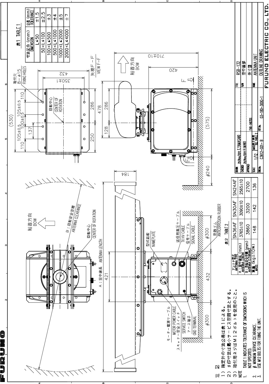
D-1
17/Nov/2011 Y.NISHIYAMA
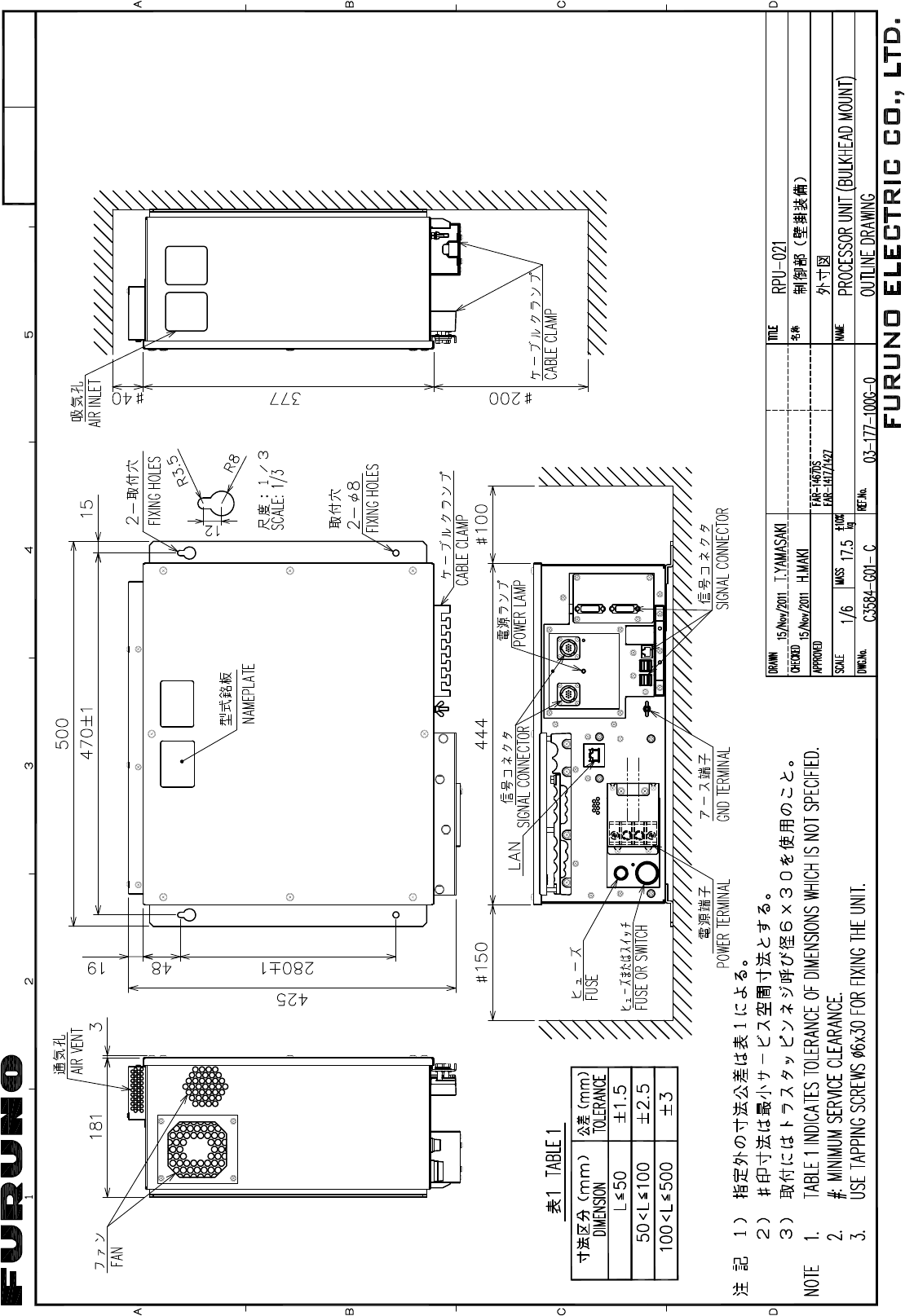
D-2
17/Nov/2011 Y.NISHIYAMA
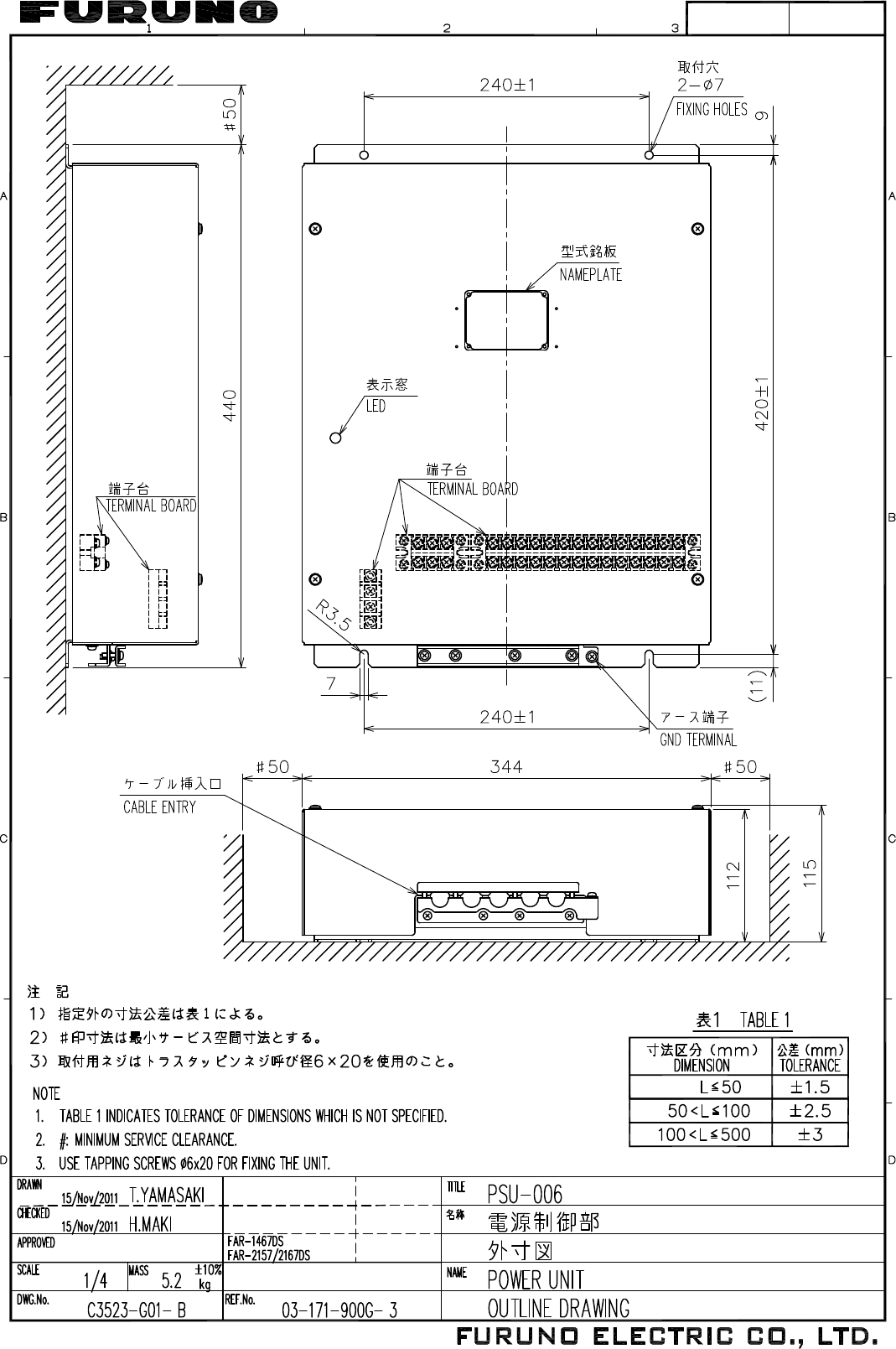
D-3
17/Nov/2011 Y.NISHIYAMA
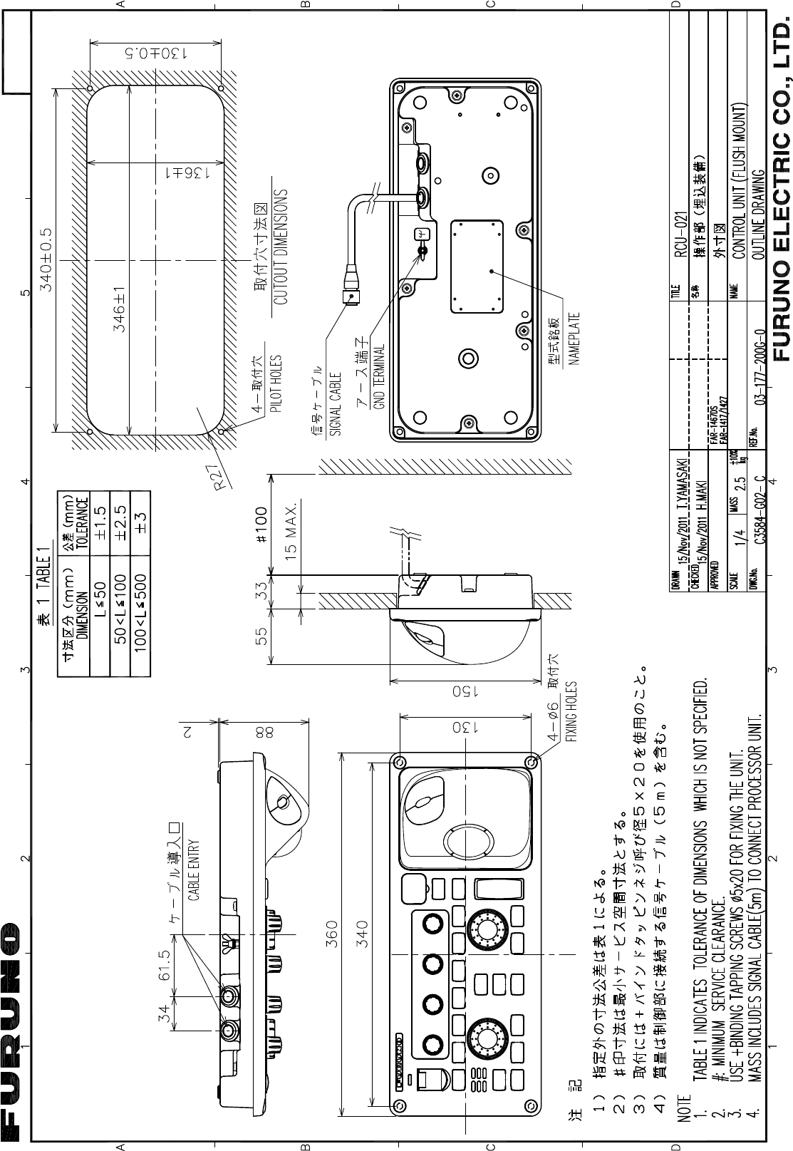
D-4
17/Nov/2011 Y.NISHIYAMA
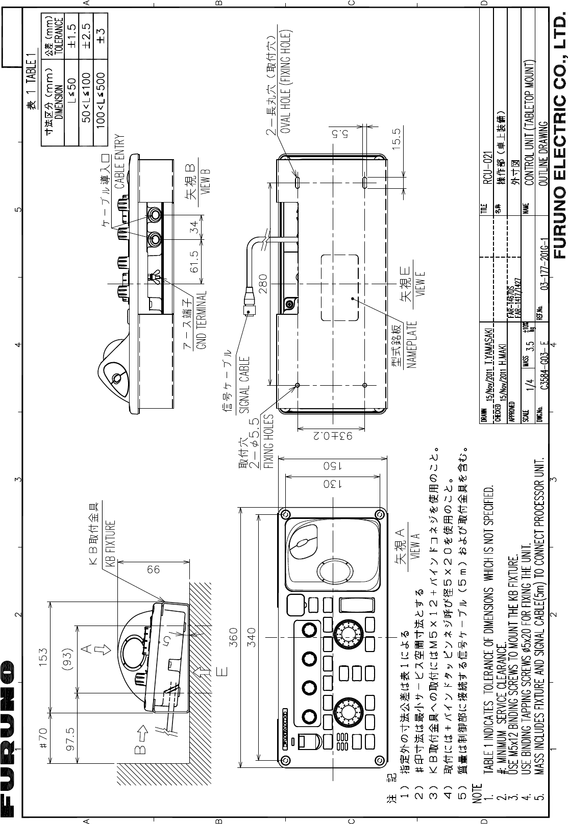
D-5
17/Nov/2011 Y.NISHIYAMA
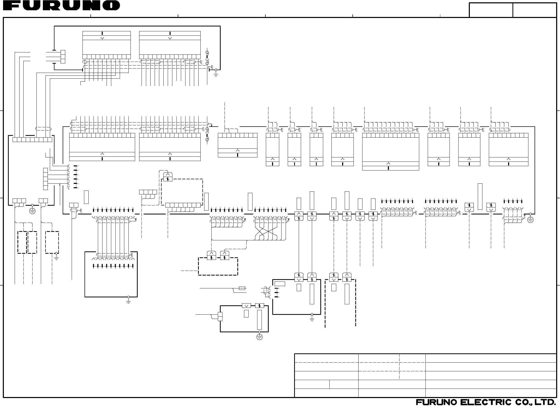
12 456
3
B
A
D
C
NAME
名称
TITLE
kg
MASS
DWG No.
SCALE
APPROVED
CHECKED
DRAWN
REF.No.
INTERCONNECTION DIAGRAM
相互結線図
T.YAMASAKI
*1: SHIPYARD SUPPLY.
NOTE
*2: OPTION.
*1)造船所手配。
注記
*2)オプション。
*3)保護アース用ケーブルは黄/緑の絶縁線を使用のこと。
*3: USE YEL/GRN WIRE FOR PROTECTIVE EARTH.
船舶用レーダー
MARINE RADAR
H.MAKI
FAR-1467DS
1
2
TB1
1
2
3
4
5
6
7
8
1
2
3
4
5
6
7
8
RJ45
RJ45
1
2
3
4
AD-DATA-H
AD-DATA-C
AD-CLK-H
AD-CLK-C
P608
1
2
3
4
GYRO-R2
GYRO-R1-COM
5
6
7
TB101
5
GC-100
GYRO CONVERTER
*2
8
GYRO-S1
GYRO-S2
GYRO-S3
GYRO-T
GYRO-FG
GYRO-FG
NC
E_TD-P
E_TD-N
E_RD-P
E_RD-N
SW-N
SW-P
NC
NC
E_TD-P
E_TD-N
E_RD-P
E_RD-N
NC
NC
NC
1
2
3
4
5
6
7
8
9
10
J901
GND
PWR_SW_P
PWR_SW_N
P12V
GND
NC
RADAR
NETWORK2
NETWORK1
制御部
PROCESSOR UNIT
RPU-021
P624
1
2
3
4
5
6
7
8
9
10
11
12
13
14
1
2
3
4
5
6
7
8
9
10
11
12
13
14
J301
15
GND
GND
+12V
-12V
HD
BP
MOTOR-H
MOTOR-H
MOTOR-C
MOTOR-C
PM-EMB
PM-LVL
PM-ARK
P610
GND
GND
TX-TRIG
PL-A
PL-B
PL-C
MBS-L
LNA-MON
HEATER-H
HEATER-C
TUNE-GATE
TUNING-IND
MAG-CUR-LVL
TUNING-CONT
PM-TRIG
GND
GND
+12V
-12V
HD
BP
1
2
3
4
5
6
7
8
9
10
11
12
13
GND
GND
14
TB805
TX-TRIG
PL-A
PL-B
PL-C
MBS-L
LNA-MON
HEATER-H
HEATER-C
TUNE-GATE
TUNING-IND
MAG-CUR-LVL
TUNING-CONT
TX_SIG
GND
NC
TX_HV
1
2
3
4
5
6
7
8
9
10
11
TX_HV_MONI_SEL
RW-4747
1
2
3
4
5
6
7
8
9
NC
RXD
TXD
GND
NC
NC
NC
NC
NC
P601
1
2
3
HDG-RD-A
HDG-RD-B
HDG-COMMON
P605 *1
1
2
3
TTYCS-1
*1
P606
NAV-RD-A
NAV-RD-B
NC
1
2
3
TTYCS-1
*1
NC
LOG-RD-A
LOG-RD-B
P607
1
2
3
4
5
*1
AIS-RD-A
AIS-RD-B
AIS-COMMON
AIS-TD-A
AIS-TD-B
P611 TTYCS-4
1
2
3
4
5
*1
TTYCS-4
NC
P619
1
2
3
4
5
*1
TTYCS-4
1
2
3
4
5
*1
TTYCS-4
P620
P621
INS-TD-A
INS-TD-B
INS-RD-A
INS-RD-B
INS-COMMON
NET-S
NET-C
NET-H
NET-L
6
7
8
SHIELD
EXT_NET-S
EXT_NET-C
FG
1
2
3
4
5
*1
6
7
8
9
10
11
12
13NC
SYS_FAIL-L
GND
SYS_FAIL-H
EXT-ALARM-ACK-N
OPERATOR-FITNESS-1
OPERATOR-FITNESS-0
ALARM3-1
ALARM3-0
ALARM2-1
ALARM2-0
ALARM1-1
ALARM1-0
HEADING SENSOR
GPS NAVIGATOR
SPEED LOG
AIS
ALARM SYSTEM
(IEC61162-2)
(IEC61162-2)
(IEC61162-2)
INS
NAVNET EQUIPMENT
(FURUNO CAN bus)
ECDIS
FEA-2107ser.
TTYCS-1T
TTYCS-7
NC 9
P612
ECDIS-RD-B
ECDIS-RD-A
ECDIS-TD-B
ECDIS-TD-A
RS-232C CABLE パソコン
(保守用)
PC FOR MAINTENANCE
100-115/220-230VAC
1φ,50/60Hz
*1
DPYC-2.5
4
MONITOR 2
24
DVI 2
4
MONITOR 1
24
DVI 1
TPYCY-1.5
*1
IV-8sq.
PE *1 *3
1
2
3
4
5
6
7
8
GND
GND
GND
GND
J617
OP_HD_OUT
OP_BP_OUT
OP_TRIG_OUT
OP_VIDEO_OUT
8
RW-4864
RW-4864 同上
DITTO
1
2
3
4
5
6
7
8
GND
GND
EXT_BP_IN
EXT_HD_IN
GND
EXT_TRIG_IN
GND
EXT_VIDEO_IN
J616
RW-4864
*2
*2
*2
MASTER RADAR
SUB RADAR
SUB RADAR
J618
8
RW-4864 同上
DITTO
1
2
3
4
5
TTYC-4
EXT. EQUIPMENT J626
+12V
GND
+5V
GND
-12V
*2
(FOR MAINTENANCE)
外部機器(保守用)
J615
EXT. TT(ARPA)
EXTERNAL EQUIPMENT
4
USB A
USB CABLE
4
USB A
USB CABLE
MOUSE
KEYBOARD
1
2
3
4
5
6
7
8
9
10
J1(PH10P)
GND
PWR_SW_P
PWR_SW_N
P12V
GND
NC
NC 03S0017,5m
4
BRILL CTRL
DVI
24
4
BRILL CTRL
1
POWER
2
3
MARINE DISPLAY
カラーLCD表示器
クロ
シロ WHT
BLK
(+)
(-)
SHIELD
IV-8sq.
*1
DVI
24
5m
12-24VDC MJ-A3SPF0018-050ZC 15A:12V
7A:24V
MU-190HD
MU-190HD *2
スイッチングハブ
SWITCHING HUB
HUB-100
AD-100
GYROCOMPASS
TTYC-4
MPYC-7
*1
*1
*2
RNS-08-132,5m
DVI-D/D SINGLELINK5M,5m
*2
RNS-08-132,5m
DVI-D/D SINGLELINK5M,5m
*2
3.5m
100-230VAC
8
8
18S1181,0.5m
または OR
STP(CAT5)
MJ-A10SPF
USB1_N
USB1_P
NC
USB1_P
USB1_N
GNDGND
IV-1.25sq.
*1
CONTROL UNIT
RCU-021
操作部
1φ,50/60Hz
BLK27
BLK28
BLK29
BRN21
YEL4
BRN1
GRY8
GRN[B]15
GRN[B]25
チャ21
キ4
チャ1
アカ22
ハイ8
ミドリ(太)15
ミドリ(太)25
クロ27
クロ28
クロ29
RED22
RED2アカ2
ミドリ5 GRN5
ムラサキ7
シロ9 WHT9
PPL7
ダイ3
ハイ18 GRY18
ORG3
ドウジク COAX.CABLE
BLK[B]20
WHT[B]19
BLU[B]26
ORG[B]23
BLU[B]16
YEL[B]24
クロ(太)20
シロ(太)19
アオ(太)26
ダイ(太)23
アオ(太)16
キ(太)24
YEL[B]14
RED[B]12
ORG13ダイ13
キ(太)14
アカ(太)12
アオ6
PPL17ムラサキ17
RW-0013,15/20/30m,
MAX.50m,φ18.4
BLU6
DVI
4
BRILL CTRL
1
2AC
AC
TB1
表示部
MONITOR UNIT
MU-231
IV-8sq.
*1
ORまたは
DPYC-1.5
*1
100-230VAC
1φ,50/60Hz
MU-231
表示器
DISPLAY/MONITOR
DPYC-2.5
100-115/220-230VAC
1φ,50/60Hz
DPYC-1.5
440VAC,1φ,50/60Hz
DPYC-2.5
TRANSFORMER
トランス
*1
IV-8sq.
*1
*1
*1
DPYC-1.5 *1
DPYC-1.5 *1
220VAC,3φ,50Hz
RU-1803 *2
RU-5693
RU-6522 *2
*2
IV-8sq.
PE
*1 *3
200VAC,3φ,50Hz
220VAC,3φ,60Hz
110VAC,3φ,60Hz
1
2
3
4
5
6NC
TX_SIG
GND
+12V
GND
PUS_ANT_ON
1
2
3
4
5
6
7
8
9
TX-HV
NC
TX-SIG
GND
NC
NC
U
TB3
電源制御部
POWER SUPPLY UNIT
PSU-006
W
V
10
11
12
13
14
NC
+12V
ANT_ON
GND
NC
TB3
MPYC-7 *1
*1
TPYCY-2.5
ANTENNA UNIT
空中線部
RSB-132
1
2
3
TB901
U
W
V
1
2
3
U
V
W
1
2
U
V
TB1
TB2
C3612-C01- B
REDアカ
WHTシロ
BLKクロ
P802/TB802
P801/TB801
03-180-6001-4
19/Dec/2011
19/Dec/2011
20/Dec/2011 Y.NISHIYAMA
S-1