Furuno USA 9ZWRTR110 Marine Radar User Manual Cover
Furuno USA Inc Marine Radar Cover
Contents
- 1. operators manual
- 2. install manual
operators manual

MARINE RADAR
FAR-1467DS
FAR-1467DS-BB
OPERATOR'S MANUAL
www.furuno.com
MODEL

The paper used in this manual
is elemental chlorine free.
・FURUNO Authorized Distributor/Dealer
9-52 Ashihara-cho,
Nishinomiya, 662-8580, JAPAN
A : 0000
Printed in Japan
All rights reserved.
Z : MAR . 30, 2012
Pub. No. OME-36120-Z
*
00017580410
*
*
00017580410
*
(DAMI ) FAR-1467DS/1467DS-BB
*
00017580410
*
*
00017580410
*
* 0 0 0 1 7 5 8 0 4 1 0 *

i
Ni-Cd Pb
IMPORTANT NOTICES
General
• This manual has been authored with simplified grammar, to meet the needs of
international users.
• The operator of this equipment must read and follow the descriptions in this manual.
Wrong operation or maintenance can cancel the warranty or cause injury.
• Do not copy any part of this manual without written permission from FURUNO.
• If this manual is lost or worn, contact your dealer about replacement.
• The contents of this manual and equipment specifications can change without notice.
• The example screens (or illustrations) shown in this manual can be different from the
screens you see on your display. The screens you see depend on your system
configuration and equipment settings.
• Save this manual for future reference.
• Any modification of the equipment (including software) by persons not authorized by
FURUNO will cancel the warranty.
• All brand and product names are trademarks, registered trademarks or service marks of
their respective holders.
How to discard this product
Discard this product according to local regulations for the disposal of industrial waste. For
disposal in the USA, see the homepage of the Electronics Industries Alliance
(http://www.eiae.org/) for the correct method of disposal.
How to discard a used battery
Some FURUNO products have a battery(ies). To see if your product has a battery, see the
chapter on Maintenance. Follow the instructions below if a battery is used. Tape the + and -
terminals of battery before disposal to prevent fire, heat generation caused by short circuit.
In the European Union
The crossed-out trash can symbol indicates that all types of
batteries must not be discarded in standard trash, or at a trash
site. Take the used batteries to a battery collection site according
to your national legislation and the Batteries Directive
2006/66/EU.
In the USA
The Mobius loop symbol (three chasing arrows) indicates that
Ni-Cd and lead-acid rechargeable batteries must be recycled. Take
the used batteries to a battery collection site according to local
laws.
In the other countries
There are no international standards for the battery recycle symbol. The number of symbols
can increase when the other countries make their own recycling symbols in the future.
Cd
ii
Mandatory Action
Prohibitive Action
WARNING
CAUTION
Warning, Caution
WARNING
Radio Frequency Radiation Hazard
The operator must read the safety instructions before attempting to operate the equipment.
The radar antenna emits electromagnetic radio frequency (RF) energy that can be harmful,
particularly to your eyes. Never look directly into the antenna aperture from a close distance
while the radar is in operation or expose yourself to the transmitting antenna at a close
distance. Distances at which RF radiation level of 100, 50 and 10 W/m
2
are given in the table
below.
Indicates a potentially hazardous situation which, if not avoided,
could result in death or serious injury.
Indicates a potentially hazardous situation which, if not avoided,
could result in minor or moderate injury.
100W/m
2
Model Antenna 10W/m
2
FAR-1467DS
SN24AF
SN30AF
0.6 m
0.5 m
8.5 m
7.7 m
SAFETY INSTRUCTIONS
iii
WARNING
WARNING WARNING
Do not open the equipment.
The equipment uses high voltage that
can cause electrical shock. Refer any
repair work to a qualified technician.
Before turning on the radar, be sure
no one is near the antenna.
Prevent the potential risk of being
struck by the rotating antenna, which
can result in serious injury or death.
If water leaks into the equipment or
something is dropped into the
equipment, immediately turn off the
power at the switchboard.
Fire or electrical shock can result.
If the equipment is giving off smoke
or fire, immediately turn off the
power at the switchboard.
Fire or electrical shock can result.
If you feel the equipment is acting
abnormally or giving off strange
noises, immediately turn off the
power at the switchboard and
contact a FURUNO service techni-
cian.
Do not disassemble or modify the
equipment.
Fire, electrical shock or serious injury
can result.
Make sure no rain or water splash
leaks into the equipment.
Fire or electrical shock can result if
water leaks into the equipment.
Do not place liquid-filled containers
on or near the equipment.
Fire or electrical shock can result if a
liquid spills into the equipment.
Do not operate the equipment with
wet hands.
Electrical shock can result.
Keep objects away from the open-n-
type antenna unit, so as not to
impede rotation of the antenna.
Fire, electrical shock or serious injury
can result.
Use the proper fuse.
Use of the wrong fuse can cause fire or
electrical shock.
Do not depend on one navigation
device for the navigation of the ship.
The navigator must check all aids
available to confirm position.
- The TT automatically tracks an
automatically or manually acquired
radar target and calculates its course
and speed, indicating them with a
vector. Since the data generated by
the TT depends on the selected radar
targets, the radar must be optimally
tuned for use with the TT, to ensure
required targets will not be lost or
unnecessary targets like sea returns
and noise will not be acquired and
tracked.
- A target is not always a landmass,
reef, ship, but can also be returns
from the sea surface and from clutter
As the level of clutter changes with
the environment, the operator must
correctly adjust the sea and rain
clutter controls and the gain control so
that the target echoes do not dis-
appear from the radar screen.

iv
TABLE OF CONTECTS
FOREWORD ..................................................................................................................vii
SYSTEM CONFIGURATION.........................................................................................viii
1. BASIC OPERATION ...................................................................................................1
1.1 Using keys and knobs .............................................................................................................1
1.2 Turning ON/OFF the Power, Transmission..............................................................................3
1.3 Examples of Screen Display ...................................................................................................4
1.4 Operating from boxes on the screen.......................................................................................6
1.5 Brilliance and Color Scheme...................................................................................................7
1.6 Tuning .....................................................................................................................................8
1.7 Display Modes ........................................................................................................................8
1.8 Selecting range .....................................................................................................................11
1.9 Adjusting Gain....................................................................................................................... 11
1.10 Rejecting Sea Clutter ...........................................................................................................12
1.11 Rejecting Precipitation Clutter...............................................................................................12
1.12 Automatic rejection of sea clutter and precipitation clutter ....................................................13
1.13 Deleting heading line temporarily ..........................................................................................13
1.14 Cursor position......................................................................................................................14
1.15 Measuring range to target .....................................................................................................15
1.16 Measuring bearing of target ..................................................................................................16
1.17Measuring Range and Bearing between Two Targets............................................................18
1.18 Selecting Transmission Pulse Length ...................................................................................18
1.19Off-Centering the Display.......................................................................................................19
1.20 Rejecting Interference ...........................................................................................................19
1.21 Echo Stretch..........................................................................................................................19
1.22 Signal Processing Function...................................................................................................20
1.23 Echo Trail Function ...............................................................................................................21
1.24 Watch Alarm..........................................................................................................................22
1.25 Parallel Cursor ......................................................................................................................25
1.26 Setting Images ......................................................................................................................26
1.27 Function Keys .......................................................................................................................28
1.28 Alarm.....................................................................................................................................28
1.29 Reference Position................................................................................................................29
1.30 Interswitch.............................................................................................................................31
2. RADAR OPERATION USING MENU........................................................................33
2.1 Menu Operation ....................................................................................................................33
2.2 Echo Display Area.................................................................................................................34
2.3 Registering Function Keys ....................................................................................................35
2.4 Drop Mark .............................................................................................................................40
2.5 Watch Alarm..........................................................................................................................42
2.6 Zoom.....................................................................................................................................43
2.7 Anchor Watch Alarm .............................................................................................................45
2.8 Priority Order of Various Alarms ............................................................................................46
2.9 Color Scheme .......................................................................................................................47
2.10 Menus of Each Function .......................................................................................................49
2.11 Menu Items ...........................................................................................................................60
3. TARGET TRACKING (TT) ........................................................................................66
v
3.1 Usage Precautions................................................................................................................66
3.2 Turning TT ON/OFF ..............................................................................................................67
3.3 Ship Speed Input...................................................................................................................67
3.4 Target Acquisition and Tracking ............................................................................................67
3.5 Terminating Tracking.............................................................................................................72
3.6 Lost Target ............................................................................................................................72
3.7 Displaying Target Data ..........................................................................................................74
3.8 Changing Shape and Color of TT Mark.................................................................................77
3.9 Zoom Target..........................................................................................................................79
3.10 Displaying Vector ..................................................................................................................80
3.11 Displaying Track....................................................................................................................82
3.12 Guard Zone Alarm.................................................................................................................83
3.13 Setting Collision Alarm (CPA/TCPA alarm)............................................................................84
3.14 TT Ship Speed Alarm ............................................................................................................85
3.15 Test Steering (Steering simulation)........................................................................................85
4. AIS OPERATION ......................................................................................................90
4.1 Turning ON/OFF AIS Display ................................................................................................90
4.2 Activated Target ....................................................................................................................92
4.3 Inactivating targets ................................................................................................................93
4.4 Displaying AIS Target Data....................................................................................................94
4.5 Filtering AIS display...............................................................................................................96
4.6 AIS Symbol Attributes ...........................................................................................................97
4.7 Displaying Vector ..................................................................................................................99
4.8 Displaying Past Position......................................................................................................100
4.9 Lost Target ..........................................................................................................................101
4.10 Collision Alarm (CPA/TCPA)................................................................................................103
4.11 Activating Targets................................................................................................................103
4.12 Turning Direction.................................................................................................................105
4.13 Identification of TT and AIS .................................................................................................105
4.14 Navigation Data...................................................................................................................107
4.15 Static Data...........................................................................................................................108
4.16 Messages............................................................................................................................109
5. VIDEO PLOTTER OPERATION.............................................................................. 112
5.1 Outline................................................................................................................................. 112
5.2 Mark/Destination/Line ......................................................................................................... 112
5.3 Origin Mark .........................................................................................................................122
5.4 Chart (Coastline data) .........................................................................................................125
5.5 Track ...................................................................................................................................134
5.6 Route ..................................................................................................................................137
5.7 Waypoint .............................................................................................................................140
5.8 Plotter related alarms ..........................................................................................................144
5.9 Recording/Replaying Data ..................................................................................................145
6. MAINTENANCE AND TROUBLESHOOTING ........................................................149
6.1 Periodic Maintenance Schedule..........................................................................................150
6.2 Parts requiring exchanges and recommended schedule ....................................................151
6.3 Replacing Fuse ...................................................................................................................152
6.4 Replacing Battery................................................................................................................152
6.5 Trackball Maintenance ........................................................................................................153
6.6 Simple Troubleshooting.......................................................................................................154
6.7 Troubleshooting by Qualified Technician.............................................................................155
6.8 Diagnostic ...........................................................................................................................157
6.9 TT Performance Test...........................................................................................................158
vi
6.10 Displaying Sentences..........................................................................................................159
APPENDIX ALART LIST ...........................................................................................AP-1

vii
FOREWORD
Congratulations on your purchase of our products. Since 1948, FURUNO Electric Company has
enjoyed an enviable reputation for performance, quality and reliability of our marine electronics
equipment from users around the world. Your radar is designed and constructed to meet the
rigorous demands of the marine environment. Please carefully read and follow the recommended
procedures for operation and maintenance of the machine to fully perform its intended functions.
Features
The FAR-1467DS consists of an antenna unit, processor unit, monitor unit and control unit.
Following are the main features.
• Type 15/19 High brilliance color LCD.
• One USB port in the control unit for data backup.
• Ability to memorize optimum image settings and switch instantaneously to detect far distance,
birds and float receptions, etc.
• Equipped with the true view function to smoothly turn radar echoes according to own ship’s
turns. (Head-up, Cursor Gyro, Stern Up modes only)
• Various alarm functions (Guard, Watch, Anchor watch, Guard zone, Arrival to destination, XTE,
etc.)
• TT* (Track target) function to watch other ships’ movement (*: equivalent to the conventional
ARPA function)
• Ability to display AIS data by connecting to the vessel automatic identification system (AIS
transponder).
• Ability to display chart layers (includes vector charts throughout Japan)
• Large capacity memory - Mark: max.20,000 points, Line (include routes): max.5,000 points,
Destination: max.100 points, Own ship’s track: max.20,000 points, Other ships’ track: max.
200,000 points
viii
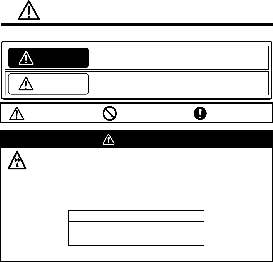
SYSTEM CONFIGURATION
ANTENNA UNIT
RADIATOR
SN24AF
SN30AF
SN36AF
CHASSIS
RSB-132
POWER SUPPLY UNIT
PSU-006
(For antenna motor)
TRANSFORMER
RU-5693
TRANSFORMER
RU-6522
(For high voltage)
200 VAC, 3φ, 50 Hz
220 VAC, 3φ, 60 Hz
100-115V/220-230 VAC,
1φ, 50/60 Hz
110 VAC, 3φ, 60 Hz
220 VAC, 3φ, 60 Hz
100-115 VAC/
220-230 VAC
1φ, 50/60 Hz
Gyrocompass
AIS
Speed Log
GPS Navigator PROCESSOR UNIT
PRU-021
GIRO CONVERTER
GC-100
MONITOR UNIT
MU-190HD
or
MU-231*
CONTROL UNIT
RCU-021
FURUNO CAN bus
Radar Remote Display
Alarm
SWITCHING HUB
HUB-100
12-24 VDC
(For MU-190HD)
100-230 VAC,
1φ, 50/60 Hz
(For MU-231)
BRAKE UNIT BRU-001/002
Equipment category
Unit Category
Antenna Exposed to weather
Other units Protected from weather
NMEA reading signal
*: Future use
1
1. BASIC OPERATION
This Chapter explains basic operations using keys, knobs and boxes displayed on the screen in
the control unit. Some functions have several ways to operate but this manual explains the
simplest operations.
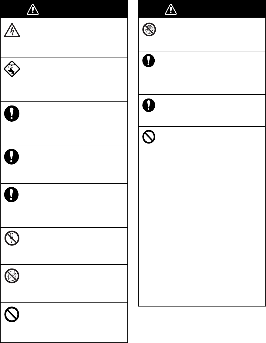
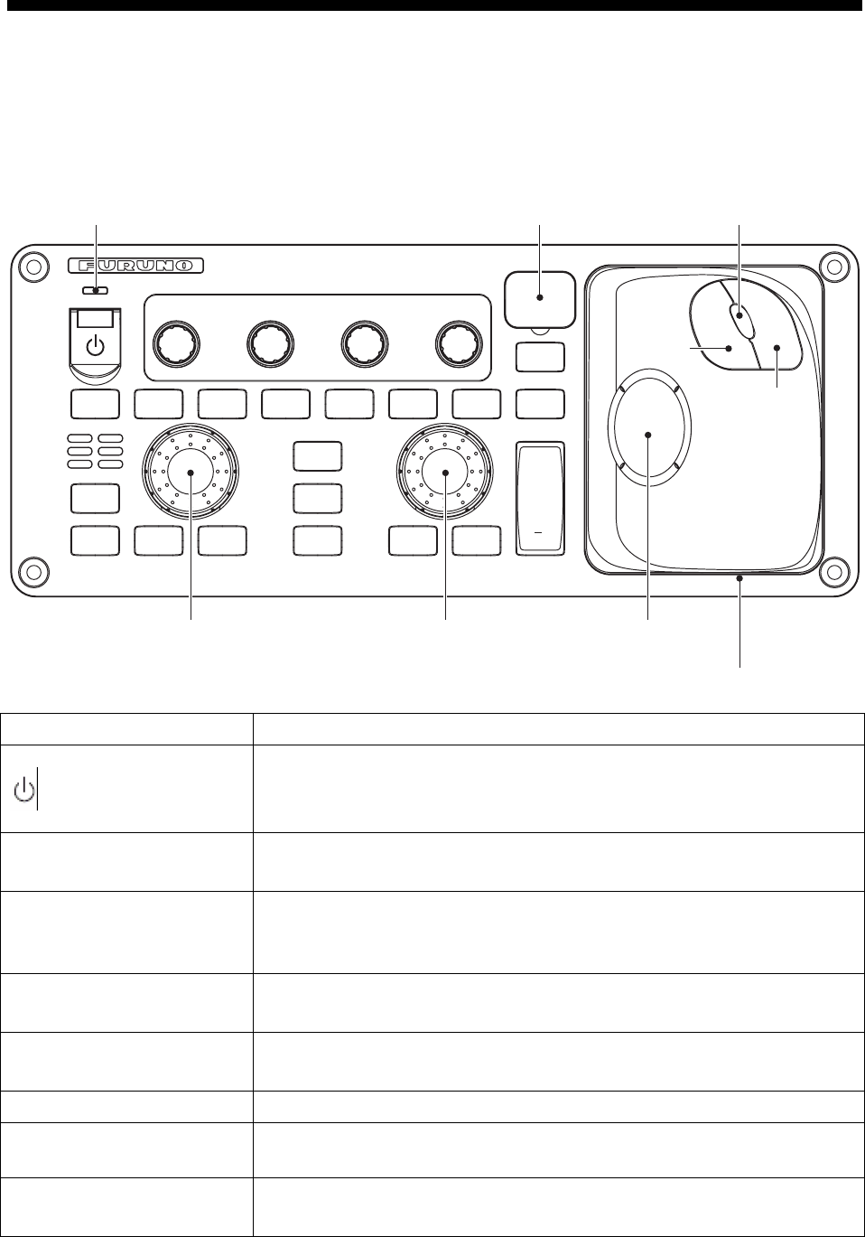
1.1 Using keys and knobs
PUSH TO
HUE
PUSH TO
AUTO
PUSH TO
AUTO
PUSH TO
AUTO
BRILL A/C RAIN A/C SEA GAIN
STDY
TX
VECTOR
MODE
MODE ECHO
TRAIL
HL
OFF MARK TARGET
CANCEL
EBL
OFFSET
ALARM
ACK
EBL
OFF
EBL
ON
OFF
CENTER
F1
F2 VRM
OFF
VRM
ON
RANGE
+
TARGET
LIST
EBL control VRM control Trackball
Trackball module
Scrollwheel
Left
button
Right
button
USB port coverPower lamp
ACQ
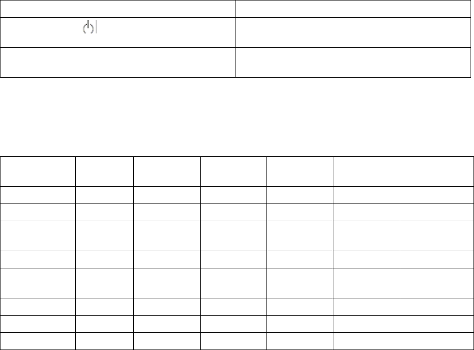
Key, knob Function
Turn ON /OFF power. Power lamp lights up when the power is turned
on. (Depends on the setting of [PANEL BRILLIANCE] on the
[BRILLIANCE DETAIL] menu.
Image brilliance Turn: Adjust brilliance.
Press: Select color.
Precipitation clutter
rejection
Turn: Reject precipitation clutter.
Press: Switch between the precipitation clutter rejection function and
the noise rejection function.
Sea clutter rejection Turn: Reject sea clutter.
Press: Select Auto or Manual of the sea clutter function.
Gain Turn: Adjust gain.
Press: Select Auto or Manual of gain.
Getting ready/Transmit Switch between Getting ready and Transmit
Mode selection Select display mode such as Head-up, Cursor gyro, North-up or True
motion, etc.
Vector True/Relative - Switch vector mode.
- Call registered function (Function key).

2
Key, knob Function
Echo trail Short press: Select trail time.
Long press: Delete trail.
Delete heading line Delete heading line while the key is being pressed.
Mark Input marks and destinations.
Target data list - Display data of all tracked target (TT/AIS)
- Call registered functions. (Function key)
Delete target Short press: Cancel selected TT track target. Stop AIS active target.
Long press: Cancel all TT track target.
Acquisition - Acquire target.
- Display/Hide data of TT target data.
EBL offset Offset/Cancel EBL offset
Cancel alarm Stop alarm sound.
EBL Knob: Operate EBL (Electronic cursor).
OFF: Delete EBL.
ON: Display EBL.
Off center Move own ship position
F1, F2 Call registered functions (Function key) .
VRM Knob: Operate VRM (variable range ring)
Range Select range for display.
Trackball section Trackball
- Move cursor.
- Select menu item.
Left button
- Fix selected item.
- Change setting inside of the box.
Wheel
- Turn: Change numerical value.
- Turn: Select menu item.
- Turn: Change setting in box.
- Press: Fix selected item.
Right button
- Display menu of each function.
- Return to one step above.
USB cover Open the cover to show an opening to insert USB memory. (for data
backup)
3
1.2 Turning ON/OFF the Power, Transmission
1.2.1 Turning the power ON/OFF
Please note the following when using the radar.
Note: Make sure to use the [ ] key in the control unit when turning off the power of this radar. A
personal computer is used inside of the equipment. Turning off the power by using the breaker,
etc. instead of using the [ ] key may cause loss of data stored inside. In the worst situation, it
may prevent the machine from functioning properly. If you experience abnormal function, seek
for immediate service. Lost data are unrecoverable. Please backup your data periodically.
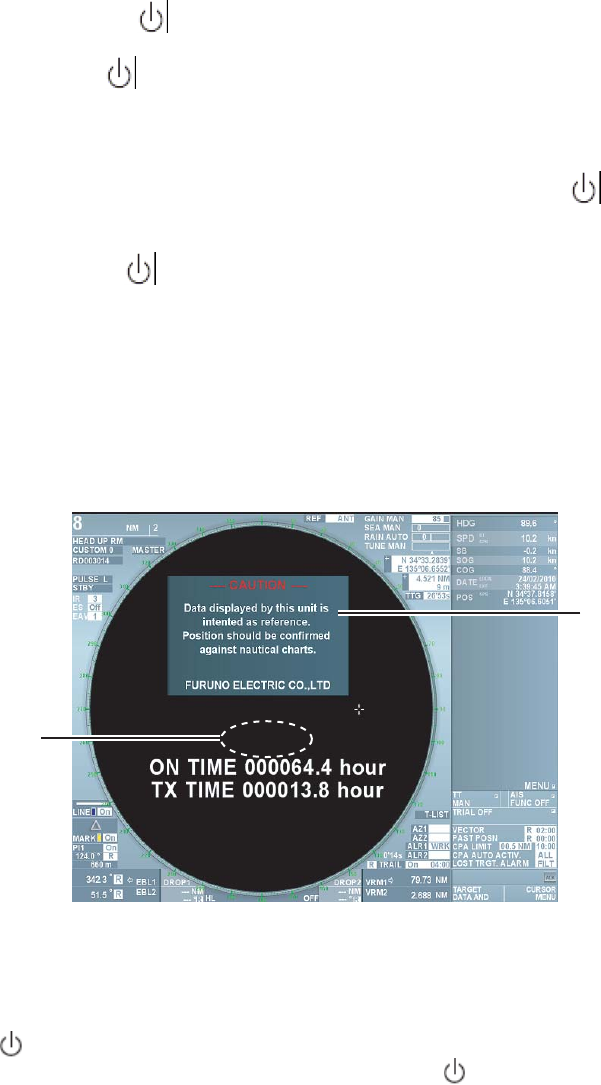
1. Open the cover at the left upper section of the control unit, press the [ ] key to turn the
radar switch on. When the slide switch of the monitor unit (MU-150HD or MU-190HD) is ON
(factory default), the power of the monitor unit is turned on automatically. When the switch is
turned OFF, press the [/ BRILL] key in the monitor unit to turn the power on. After the
power is turned on, the display on the screen changes in the order of FURUNO screen →
Machine type name screen → Getting ready screen. It takes approximately 1 and 1 ½ minutes
until the Getting ready screen appears. For FAR-1417, preheating of magnetron is completed
during this time. For FAR 1427, it starts counting down the remaining time (1 ½ minutes)
necessary for preheating magnetron. When getting ready appears on the screen, you can
start transmission. On the Getting ready screen, mark, fixed range ring, chart, TT target and
AIS target are not displayed. Left-click inside of the warning message box to erase the
warning message.
Warning message
01:19
Stant count down at
[01:19], it changes
to GETTING
READY.
Note 1: Do not turn the power on while USB memory is inserted in the control unit.
The GETTING READY screen does not show when USB memory is inserted.
Note 2: When ambient temperature is low, display on the screen moves slower.
2. Press the [ ] key in the control unit when turning the power off. The message “Shutting
down” appears at the center of the screen. Release the [ ] key immediately. The power
turns off in about 15 seconds.
4
Quick Start
When magnetron is sufficiently warmed up, you can start the transmission without waiting full
preheating time. Press the [ ] key again within 10 seconds after the power is turned off in error.
1.2.2 Switching between TRANSMISSION and GETTING READY
To start transmission, press the [Getting ready/Transmit] key while getting ready is displayed on
the screen. Radar echoes are displayed on the screen with the previously used settings of range,
brilliance, VRM, EBL and menu settings.
Each press of the [Getting ready/Transmit] key switches between getting ready and transmit.
Antenna is stopped at the time of Getting ready and starts rotating when transmission starts. Life
of magnetron shortens in proportion of transmission time. Keep the equipment in the Getting
ready state when there is no need for transmission.
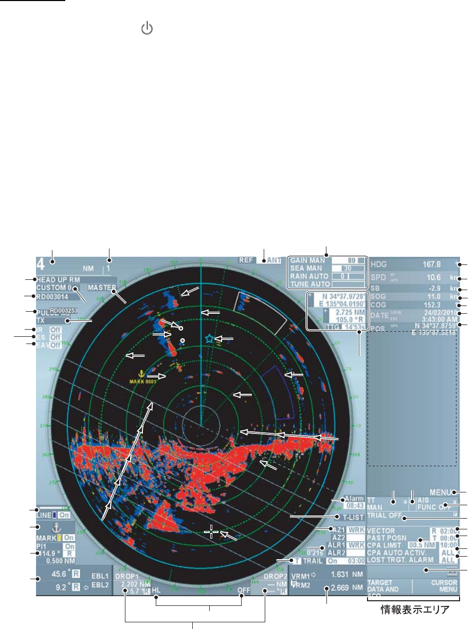
1.3 Examples of Screen Display
12
3
45
6
7
8
9
10
11
12
13
14
15
16
17 18
19
20
21
22
23
24 25
26
28 29
30
31
32
33
34
38
37
36
40
41
42
43
44
45
46
47
49 50 48
51
52
53
54
56
57
58
39
27
35
IR
ES
EAV
55

5
Explanation Explanation
1 Range 2 Fixed range ring interval
3 Display mode box 4 Image box
5 Interswitch box 6 Antenna unit box
7 Pulse length box 8 Getting ready/Transmit box
9 Noise rejection 10 Zoom out image
11 Signal processing 12 Line box
13 Mark/Destination box 14 Parallel cursor box
15 EBL1/EBL2 box 16 Drop1/Drop2 box
17 Delete heading line 18 VRM1/VRM2 box
19 Trail box 20 Guard1/Guard2 box
21 AZ1/AZ2 (Guard zone) box 22 Display list of target data
23 Watch alarm box 24 Reference position box
25 Gain, Sea clutter, Precipitation clutter (or
un unwanted echoes), Tuning adjustment
26 Cursor data box
27 North mark 28 TT target
29 Heading line 30 Guard alarm range
31 EBL2 32 EBL1
33 AIS target 34 VRM2
35 Drop 1 mark 36 Fixed range ring
37 Parallel cursor 38 VRM1
39 Cursor 40 Heading
41 Ship speed toward heading (Speed over
ground or Speed over water), Data input
source
42 Ship speed in starboard direction
43 Speed over ground 44 Over the ground course
45 Date, Time 46 Own ship’s latitude/longitude, Data input
source
47 Display of navigation data, zoom window,
TT data, AIS data
48 Display main menu
49 TT box 50 Identification box
51 AIS box 52 Simulate steering box
53 Vector box 54 Track interval box
55 Set CPA/TCPA 56 Set Auto activation function
57 Set lost target alarm 58 Alarm list
6
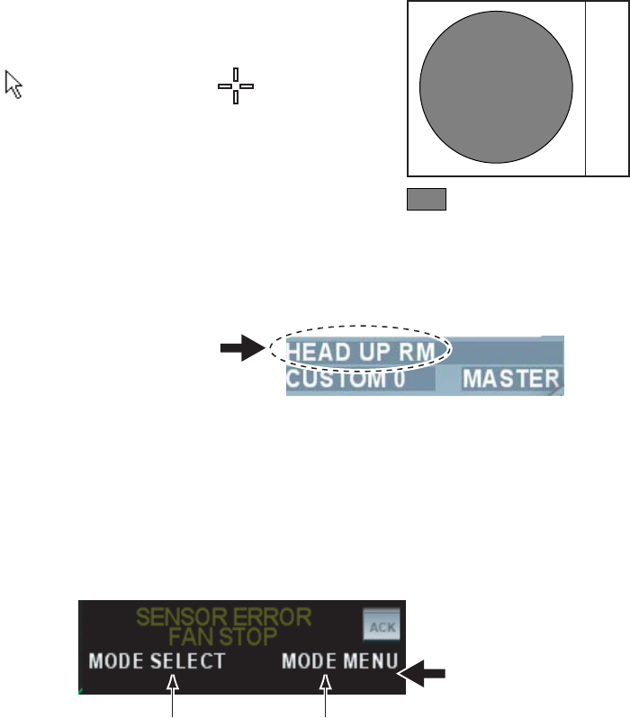
1.4 Operating from boxes on the screen
Users can perform all the operations from the trackball area alone. Select a box on the screen
with the trackball and select an item with the left/right button or the wheel. (See chapter 1.3 for
box positions.)
Follow the steps below to use boxes on the screen.
1. Roll the trackball and place the cursor on the box required. Shape of the cursor changes as
shown in the figure below depending on positions of the cursor.
Cursor is within the
valid area for
displaying images.
Cursor is not within the
valid area for
displaying images.
: Valid area for displaying
radar images.
For example, select the display mode box on the left upper side on the screen.
Display mode box
When a box is selected correctly, color of texts inside of the box (or the box) changes. A function
when you press the button next is displayed in the guide column in the information display area.
The screen shows the left button functions on the left side of the vertical line and the right button
functions on the right side of the vertical line. In this example, the display mode box is selected
and [Select mode/Mode menu] is displayed on the screen. Select the display mode with the left
button and display the [Display mode] menu with the right button.
Function of the left button Function of the rigth button
Guide column
The bottom section of the information display area
on right side of the screen.
2. Press the left button or the right button to select a necessary item.
In this manual, “left-click” means to press the left button and “right-click” means to press the
right button.
Note: You can also select an item inside of the box by rolling the wheel instead of using the left
button. The color of the item changes when you select the item by rolling the wheel, which
means that the setting has changed from the current setting. To change the setting to another
setting, press the wheel or the left button to set the selection. If the selection is not set after
selecting the item by rolling the wheel, the setting returns to the previous setting.
7
1.5 Brilliance and Color Scheme
1.5.1 Adjusting brilliance
Brilliance of the entire screen can be adjusted from the monitor or the control unit. To adjust
brilliance from the control unit, the monitor settings need to be changed.
Adjusting brilliance Monitor settings
Short press the [ / BRILL]キー Set [EXT BRILL CTRL] at [OFF] in the
[SYSTEM] menu (Factory default)
Rotate the [Image brilliance] knob in the control
unit.
Set [EXT BRILL CTRL] at [USB] in the
[SYSTEM] menu.
1.5.2 Selecting color scheme
This equipment provides eight sets of color and brilliance depending on any ambient lighting
conditions. The following table shows the factory default of color and brilliance sets.
Sets Screen
brilliance
Color Text Echo Fix range
ring
Background
Day 100% White White Orange Green Light gray
Dusk-Green 50% Green Green Orange Green Black
Dusk-White 50% White text
on blue
White Orange Green Blue
Night-Red 20% Red Red Orange Red Dark gray
Night-Blue 20% White text
on blue
White Orange Green Blue
Black 100% Black Red Orange Red Black
Custom 1 100% White White Orange Green Light gray
Custom 2 100% White White Orange Green Light gray
Press the [Image brilliance] knob to select color scheme. Each press of the knob switches
between the color sets of Day, Dusk-Green, Dusk-White, Night-Red, Night-Blue, Black, Custom
1 and Custom 2. User can register desired color sets from Custom 1 and Custom 2. (See
chapter 2.9)
Note: Brilliance of marks and texts displayed on the screen can be adjusted by color scheme.
(See chapter 2.9)
8
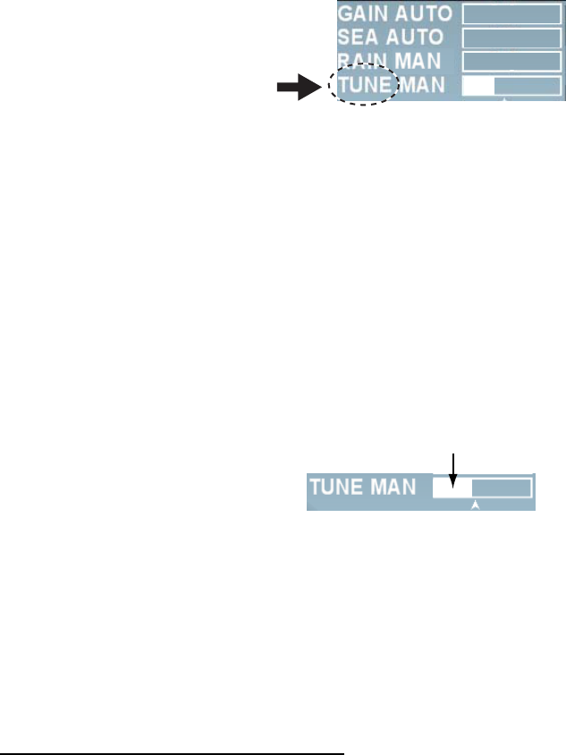
1.6 Tuning
1.6.1 Choosing the tuning method.
User can choose either automatic or manual tuning.
1. Roll the trackball to place the cursor on [Tuning] at the upper right section on the screen.
-50
50
0
2. Left-click to select [Manual] or [Auto]. Each click switches the displays. [Auto] triggers the
function to tune the image clearly. Refer to Chapter 1.6.2 for [Manual] setting.
Note: If automatic tuning does not show clear images, try initializing tuning. (See chapter
2.10.11.)
1.6.2 Manual tuning
Follow the following steps for manual tuning.
1. Press the [Range limit] key several times to set it at 48NM.
2. Roll the trackball and place the cursor on the tuning bar.
3. Roll the wheel to adjust the tuning bar at maximum.
Tuning bar
1.7 Display Modes
This radar has the display modes of Head-up, Cursor gyro, Stern-up, Course-up, North-up and
True Motion. Each display mode is explained in Chapter 1.7.2. Display modes except Head-up
and Stern-up need heading signal. For True Motion, connection to GPS navigation equipment is
necessary. The true-view display function enables smooth rotation of radar echo in accordance
with own ship’s turns in Head-up, Cursor gyro and Stern-up modes only.
When Gyrocompass is connected
Gyrocompass readings and heading values in the information display area of this equipment
need to be matched accurately when receiving analog signal (Synchronization or Step signal)
from gyrocompass. (Setting method: Main menu → Echo → GC-10, See chapter 2.11.1.)
9
1.7.1 Selecting display mode
Press the [Select mode] key several times to select display mode necessary. Name of the
display mode currently being selected is displayed in the display mode box at the upper left
section on the screen.
Presentation mode box
Note 1: When heading signal is interrupted, the blinking message “Sensor Error Gyro” appears
in the alarm section in the information display area. Heading reading in the information display
area becomes “xxx°” and the North mark disappears and the monitor mode automatically
becomes the head-up mode. When heading signals are restored, select the monitor mode with
the [Select mode] key again.
Note 2: User can pre-set appropriate monitor mode to use. (See chapter 2.10.2.)
1.7.2 Description of display modes
Relative motion
In relative motion, own ship position is stationary on the screen to observe relative motion of
surrounding targets.
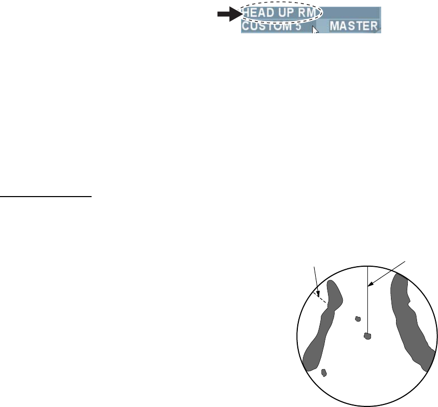
• Head-up
The head-up mode is a display in which the line
connecting the own ship and the top of the display
indicates own ship’s heading. Targets are displayed as if
they were viewed from the bridge. Therefore, this mode
is suitable for navigating through narrow channels and
crowded waters. On the other hand, target images may
fluctuate due to own ship’s turning and yawing.
A short line on the bearing scale is the north marker
indicating heading sensor north.
• Cursor Gyro
It is the same screen as Head-up but bearing scale links to heading signal. The cursor gyro can
be used only when bearing sensor is connected to the radar. A failure of the bearing sensor will
cause the bearing scale to become the same as that in the head-up mode.
• Stern-up
The stern-up mode rotates the head-up mode picture 180° showing ship’s stern on top of the
display at all times.
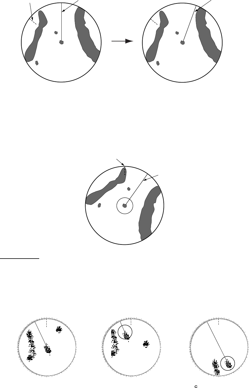
• Course-up
The course-up mode is an azimuth-stabilized display in which a line connecting the center with
the top of the display indicating own ship’s intended course (harbor, destination, etc.) Own ship’s
heading moves in accordance with changes of its course indicating the initial bearing on the top
at all times to see errors between the set course and the current course. Target images do not
fluctuate at own ship’s turning and yawning to get stable images.
Heading line
Noth maker
10
Heading line
North maker
At the moment when the
course-up mode is set.
Heading line tums in accodance
with changes of heding
Heading line
• North-up
The true north is at the top of the screen (0°) and the heading line changes its direction
according to the ship’s course. In this mode, fixed targets are shown as if they were viewed on a
chart. Targets on the screen do not fluctuate at own ship’s turning and yawning to get stable
images. This mode is suitable for ocean voyages, ship positioning and course monitoring, etc.
Heading line
North marker
True Motion
Like looking at charts, all fixed targets such as landmasses appear as stationary echoes and
own ship moves on the screen. When own ship reaches a point corresponding to 75% of the
radius of the display, own ship position is automatically reset to a point of 75% radius opposite to
the extension of the heading line passing through the display center to continue moving on the
screen. Own ship’s position can be automatically moved to 75% radius opposite to the course at
any time while in the true motion.
000 010 020
030
040
050
060
070
080
090
100
110
120
130
140
150
160
170
180
190
200
210
220
230
240
250
260
270
280
290
300
310
320
330
340 350 000 010 020
030
040
050
060
070
080
090
100
110
120
130
140
150
160
170
180
190
200
210
220
230
240
250
260
270
280
290
300
310
320
330
340 350 000 010 020
030
040
050
060
070
080
090
100
110
120
130
140
150
160
170
180
190
200
210
220
230
240
250
260
270
280
290
300
310
320
330
340 350
(a) True motion is
selected
(b) Own ship has reached a
point 75% of display radius
() Own ship is
automatically reset to
75% of radius
11
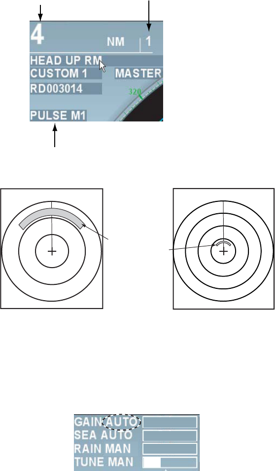
1.8 Selecting range
The selected range scale, range ring interval and pulse length are shown at the upper left corner
of the screen. When a target of interest comes closer, reduce the range scale so that it appears
in 50~90% of the display radius.
Press the [Range] key several times to select range desired. Hit the “+” part of the key to raise
the range and “-”part to lower the range. When range is switched, range ring interval and pulse
length also change automatically.
Range Fixed range ring interval
Pulse length
3NM 12 NM
Small range Large range
Same object
appears in
different
sizes.
1.9 Adjusting Gain
To properly display targets at all times, it is necessary to adjust gain in accordance with signal
strength. Gain can be adjusted automatically or manually.
1. Press the [Gain] knob to select the method of gain adjustment. Each press of the [Gain] knob
switches between [Auto] and [Manual].
-50
50
0
2. For automatic adjustment, roll the [Gain] knob according to sea condition to fine tune the
sensitivity. (Range: -50 ~ +50) For manual adjustment, roll the [Gain] knob to tune the
sensitivity. (Range: 0 ~ 100)
Note: For manual adjustment, adjust the gain control so that the background noise is just visible
on the screen. If the gain level is too low, weak echoes may be missed. On the other hand, if the
gain level is too high, the strong background noise may hide weak targets.
12
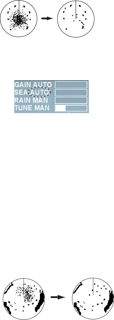
1.10 Rejecting Sea Clutter
Strong sea clutter occurs around own ship in bad weather due to strong reflection from sea
surface to prevent identification of targets on the screen. In such a case, use the sea clutter
rejection function to control sea clutter. Sea clutter can be rejected automatically or manually.
Sea clutter appears
at the center of the
screen.
Sea clutter is rejected.
Sea clutter rejection function
1. Press the [Sea clutter rejection] knob to select the method of sea clutter rejection. Each
press of the [Sea clutter rejection] knob switches between [Auto] and [Manual]. The control
sea clutter is automatically set at optimum level when the setting is [Auto].
-50
50
0
2. For automatic rejection, roll the [Sea clutter rejection] button according to sea conditions to
fine tune the setting. (Setting range: -50 ~ +50) To reduce sea clutter, increase the setting
value toward [+] and to increase sea clutter toward [-].
3. For manual rejection, roll the [Sea clutter rejection] knob while observing echoes on the
screen to reject sea clutter. (Setting range: 0 ~ 100)
Note: For manual adjustment, do not set the sea clutter rejection level too high. When the sea
clutter rejection level is too high, it may miss approaching targets. Normally set the level just so
weak sea clutter appears on the screen. Set the sea clutter rejection level at 0 (the minimum)
when there is no sea clutter appearing on calm sea surface.
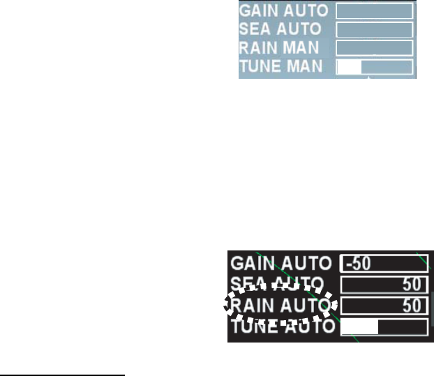
1.11 Rejecting Precipitation Clutter
Radio waves transmitted from antenna are reflected on rain and snow to appear on the screen
as precipitation clutter. The function of precipitation clutter rejection is used when unwanted echo
covers up and hides targets. The precipitation clutter rejection is controlled in the similar way as
the sea clutter rejection but it becomes effective not only in near range but in longer range as
well. The higher the setting, the greater the anti-clutter effect becomes.
Unwaned echoes are displayed.
(Toward the starboard)
Precipitation rejection
control adjusted.
Function of precipitation rejection
1. Press the [Precipitation clutter rejection] knob to select the function of precipitation clutter
rejection. Each press of the [Precipitation clutter rejection] switches between [Precipitation
clutter manual] and [Unwanted echo]
13
2. Roll the [Precipitation clutter rejection] knob while observing the screen to reject the
precipitation clutter. (Setting range: 0 ~ 100)
-50
50
0
1.12 Automatic rejection of sea clutter and
precipitation clutter
When sea clutter and precipitation clutter cannot be removed fully, press the [Precipitation clutter
rejection] knob to select the unwanted echo rejection function. “Unwanted echo” is displayed at
the upper right section on the screen while the unwanted echo rejection function is working.
Notes on usage
• Echoes covering wide areas such as lands and islands may become smaller.
• Clutter or strong precipitation clutter more than necessary. In such a case, use the functions of
sea clutter rejection or precipitation clutter rejection to manually adjust the echo level at
optimum.
1.13 Deleting heading line temporarily
Heading line is displayed in all display modes and shows the own ship’s heading. Heading line
appears directly above own ship (0°) in the head-up mode and the cursor gyro mode. Heading
line appears directly under own ship (180°) in the stern-up mode. In the north-up, true motion
and course-up modes, heading line moves in accordance with own ship’s direction. Thickness
and color of heading lines can be changed in the [Mark] menu. (See page 2-31.)
To confirm small targets in heading direction press the [Delete heading line] to temporarily delete
the heading line. All the marks on the heading line and radar screen disappear and only targets
are displayed while this key is being pressed
14
1.14 Cursor position
User can measure range and bearing from own ship to target and see latitude and longitude of
target position.
Roll the trackball and put the cursor on target to display information at the cursor position in the
cursor data 1 and cursor data 2 boxes. [---] is displayed when the cursor is outside of the
effective radar range.
Cursor Data 1 Box
Cursor Data 2 Box
Time required before arrival
Cursor Data 1 Box: Displays latitude/longitude of cursor position.
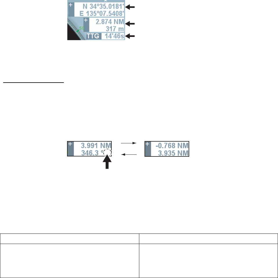
Cursor Data 2 Box: Displays range/bearing from own ship to cursor position or X-Y
coordinates.
Cursor Data 2 Box
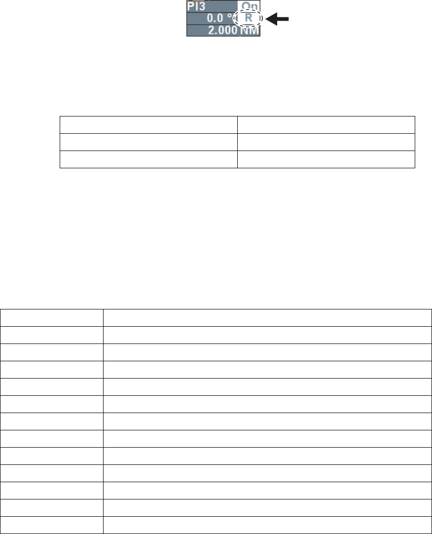
Do the following to switch displays of Cursor Data 2 Box.
1. Roll the trackball to put the cursor on Cursor Data 2 Box at the upper right side on the screen.
2. Left-click to select the display method.
Each click switches the displays.
Range/Bearing from
own ship cursor
R
X-Y coordinates
Click here to switch
bearing reference.
True: True bearing
Rel.: Relative bearing
Left click
Note 1: When the reference position at the upper screen is [Steering position], range/bearing
from the steering position is displayed and when the reference position is [Antenna],
range/bearing from the antenna position is displayed.
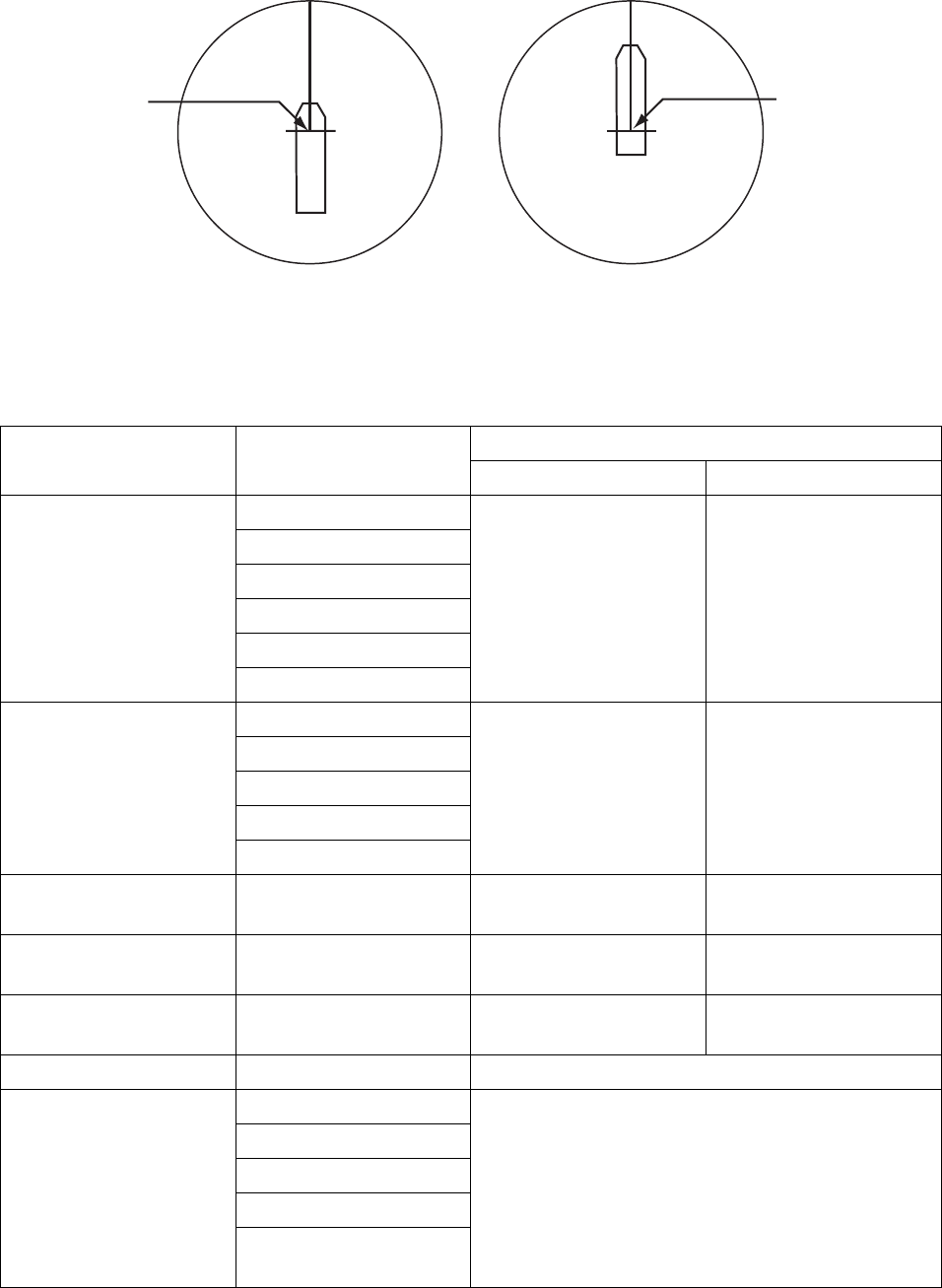
Note 2: The table below shows the relationship between X-Y coordinates and bearing reference.
Bearing reference REL Bearing reference TRUE
Y-axis indicates heading line. Heading direction
is plus (+) and stern direction is minus (-).
For X-axis, the starboard direction is plus (+) and
the port direction is minus (-)
Y-axis indicates South/North. North direction is
plus (+) and South direction is minus (-).
X-axis indicates East/West. East direction is plus
(+) and West direction is minus (-).
15
1.15 Measuring range to target
There are three methods to measure range to target; fixed range ring, Cursor (See chapter
1.14.) and VRM (Variable Range Ring).
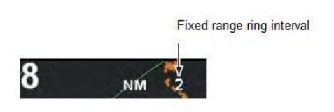
1.15.1 Using Fixed Range Ring
Fixed range ring (Concentric circle with own ship at its center) is used to make a rough
measurement. Fixed range ring interval is displayed at the upper left side on the screen.
Range between own ship and a target is estimated from the nearing fixed range ring
closest from the target by counting number of fixed range rings.
Note 1: Number of fixed range ring is determined in accordance with range selected. However,
the number can be selected manually. (See chapter 2.10.1.)
Note 2: Each left-click switches between ON/OFF of fixed range ring while cursor is put on the
fixed range ring interval (numerical value).
1.15.2 Using VRM (Variable Range Ring)
There are two types of VRM; VRM1 and VRM2, which are shown by broken lines to distinguish
from fixed range ring. The two types of VRM can be distinguished from each other by the length
of the broken line also. VRM1 has shorter broken lines and VRM2 has longer broken lines.
1. Press the [VRM ON] key to display VRM.
2. Roll the [VRM] knob to put VRM on the inner side of target to which range you want to
measure. Read range displayed at the lower right side on the screen. VRM value remains
even when range is changed.
3. Press the [VRM OFF] key to delete VRM. The way it is deleted varies according to display
condition of VRM.
• When both VRM1 and VRM2 are displayed and either VRM1 or VRM2 is in operable
condition, either VRM2 or VRM1 whichever is not in operable condition disappears.
• When either VRM1 or VRM2 is displayed, the VRM of the displayed one disappears.
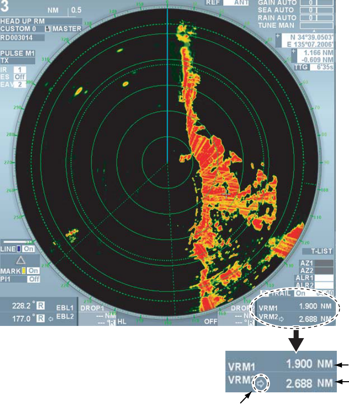
16
Range to VRM1
Range to VRM2
Currently operable VRM
(with arrow mark)
VRM box
Range by VRM
Note: Unit of VRM can be changed in the [Edit image] menu. (See chapter 2.1.4.)
1.16 Measuring bearing of target
Use the Electronic Bearing Lines (EBL) to take bearing of targets. There are two EBLs, No.1 and
No.2. Each EBL is a straight broken line extending out from the own ship position to distinguish
from heading line. The two EBLs can be distinguished from each other by the different length of
their dashes; dashes of EBL1 are shorter than EBL2.
1.16.1 Measuring bearing using EBL (Electronic cursor)
1. Press the [EBL ON] key to display either of the EBLs. Each press switches the arrow in the
box between EBL1 and EBL2. The EBL with the arrow mark can be operated with the [EBL]
knob.
2. Roll the [EBL] knob to put the EBL on the center of the target of interest Read its bearing at
the lower left corner on the screen.
3. condition of EBL.
• When both EBL1 and EBL2 are displayed and either EBL1 or EBL2 is in operable
condition, the one that is not in operable condition disappears.
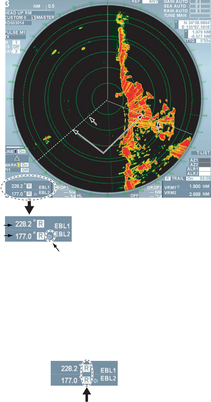
17
• When either EBL1 or EBL2 is displayed, the EBL on the displayed one disappears.
Bearing of EBL1
Bearing of EBL2
Currently operable EBL
(with an arrow)
EBL box
EBL1
EBL2
Range maker
Measuring Bearing with EBL
1.16.2 Selecting Bearing Reference of EBL
EB L values can be displayed by either REL (relative bearing referenced to own ship’s heading)
or TRUE (true bearing referenced to the north). Heading bearing signal is necessary to display in
true bearing.
1. Roll the trackball to put the cursor on REL or TRUE in the EBL box at the lower left corner on
the screen.
2. Left-click to select either REL or TRUE.
18
1.17 Measuring Range and Bearing between Two
Targets
Range and bearing between two targets can be measured by moving EBL origin.
1. Press the [EBL ON] key to display EBL1.
2. [Press the EBL offset] key. The EBL origin moves to the cursor position.
3. Roll the trackball to move the cursor on target A.
4. Roll the [EBL] knob to put EBL1 at the center of target B.
5. Press the [VRM ON] key to display VRM1.
6. Roll the [VRM] knob so that VRM1 touches target B. Range and bearing between the two
targets are displayed at the lower section on the screen. Press the [EBL offset] key to return
the EBL origin to the center of the screen.
Bearing/Range between target A and B Bearing/Range between target C and D
Similarly, range and bearing between target C and target D can be measured using EBL2 and
VRM2.
Note: User can select the method of fixing origin of EBL offset. (See page 2-31.)
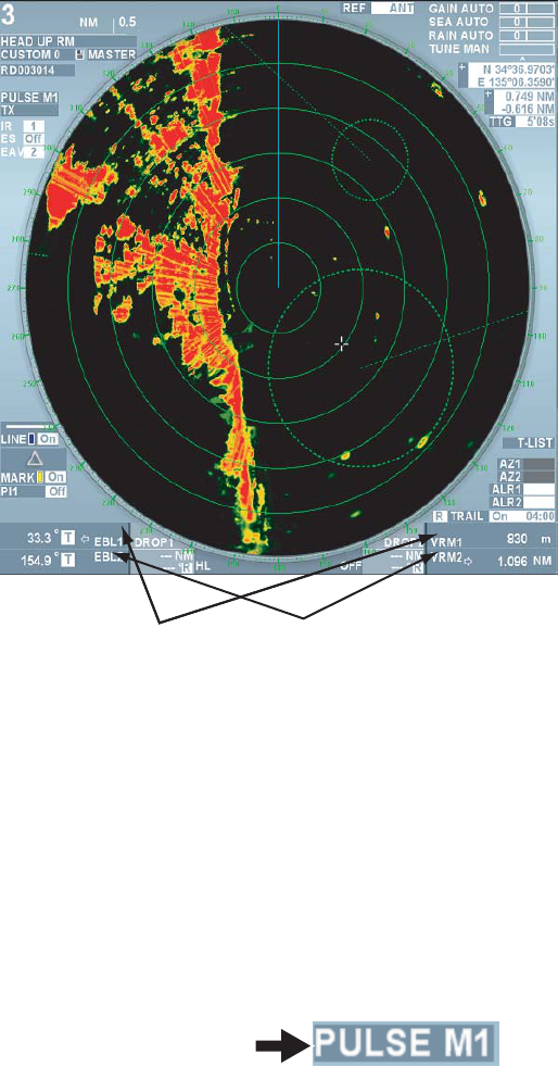
1.18 Selecting Transmission Pulse Length
Transmission pulse length is displayed at the upper left side on the screen. Pulse length can be
changed according to situations except for far range. To emphasize far range detection, extend
the pulse length and to emphasize resolution, shorten the pulse length. Shortening pulse length
can also reject precipitation clutter.
1. Roll the trackball to put the cursor on the pulse length box at the upper left side on the screen.
Pulse length box
2. Left-click to shorten the pulse length and right-click to lengthen the pulse length.
Each click switches between available pulse lengths in the current range scale.

19
1.19 Off-Centering the Display
Own ship position, or sweep origin, can be displaced to expand the view field without switching
to a larger range scale. The sweep origin can be off-centered to the cursor position, but not more
than 75% of the range in use. In the true dynamic mode, the sweep origin can be off-centered to
the cursor position within 50% of the range in use.
Note: This function can be used for ranges other than 96NM and 120NM ranges.
1. Roll the trackball to move the cursor to a position where you wish to center the image.
2. Press the [OFF CENTER] key. Own ship position moves to the cursor position.
3. Press the [OFF CENTER] key again to return the own ship position to the previous position.
1.20 Rejecting Interference
Mutual radar interference may occur in the vicinity of another
ship borne radar operating in the same frequency band. (X
band: 9GHz) It is seen on the screen as a number of bright
spikes either in irregular pattern or in the form of dotted lines
extending from the center of the edge of the picture. This
type of interference can be rejected by the interference
rejecting function.
1. Roll the trackball to put the cursor on the box next to the [Interference] at the upper left side
on the screen.
2. Left-click to select the strength of interference rejection. Each click switches between OFF
→1→2→3. The larger the value, the stronger the interference rejection, however, it may
weaken ship’s echo.
Note: Set the level of interference rejection function at OFF when there is no interference
from other ships to avoid missing small targets near own ship.
1.21 Echo Stretch
The echo stretch feature enlarges targets in the range and bearing directions to make them
easier to see. There are three levels of echo stretch, 1, 2 and 3. We recommend the level 3 for
normal use.
Note: The echo stretch magnifies not only small target pips but also clutter from sea surface,
precipitation and radar interference. For this reason, make sure these types of interference have
been sufficiently reduced before activating the echo stretch function.
1. Roll the trackball to put the cursor on the box next to [Stretch] at the upper left side on the
screen.
Interference by other ships radar
20
2. Left-click to select the desired setting. Each click switches between OFF→1→2→3. Set the
echo stretch level while observing the screen.
• OFF: no stretch
• 1: Smooth eco
• 2: Stretches 1.2 ~ 1.5 times in the bearing direction
• 3: Stretches in range and bearing directions.
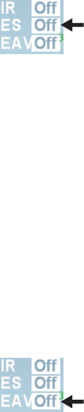
1.22 Signal Processing Function
Rejecting sea clutter may also reject necessary targets. In such a case, the signal processing
function can suppress sea clutter while maintaining targets.
Note 1: Heading bearing signal and own ship positioning data are necessary for the signal
processing function
Note 2: Do not use the signal processing function in rough conditions of pitching and rolling of
own ship to avoid loss of target.
Note 3: Targets moving at high speed become difficult to detect compared of static targets when
using the signal processing function. Prior to using the signal processing function, use the sea
clutter rejection function just so some weak sea clutter appears on the screen.
1. Roll the trackball to put the cursor next to [Processing] at the upper left side on the screen.
2. Left-click to select the desired setting. Each click switches the setting between
OFF→1→2→3→4→5. Set a value while observing the echoes.
• Off: Set the signal processing function OFF.
• 1,2: Effective for target detection in sea clutter. The signal processing 2 is more effective
compared with the signal processing 1 for target detection in strong sea clutter. However,
detecting targets moving at high speed on the screen is more difficult for the signal
processing 2 compared with the signal processing 1. Use either the signal processing 1
or 2 in accordance with user’s purpose. When detecting targets in sea clutter and targets
moving at high speed simultaneously, it becomes effective to use the signal
processing function together with the wiper processing (See page 2-20.)
3. Detect weak targets, such as floats, in stormy weather.
4. Detect weak targets, such as floats, in stormy weather. To use this setting, set the
equipment as follows:
• Set the interference rejector to 3. This raises the sensitivity against weak targets.
• Manually set the gain to 80.
• Manually set the A/C SEA to 50.
• Manually set the A/C RAIN to 40. This is effective for reducing unwanted clutter and
suppressing false echoes.
5. Effective for detecting high speed targets and unstable echoes.
21
1.23 Echo Trail Function
Echo trail function is useful to observe other ships’ movement, which displays a track in lower
brilliance than the actual image
1.23.1 Starting Echo Trail
Set trail time to start the echo trail. Trail time can be selected from 15 seconds, 30 seconds, 45
seconds 1-20 minutes (1 min. interval), 30 minutes, 40 minutes, 50 minutes, 60 minutes, 20
hours, 24 hours, 48 hours and continuous. Trail is displayed for the set trail time.
1. Press the [Echo Trail] key several times to select the desired trail time.
The trail time currently selected is displayed in the trail box at the lower right side on the
screen. The longer the trail time, the longer the trail becomes.
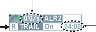
Trail box Trail time
Elapsed time
Elapsed time from the start of the trail to the set trail time is shown on the trail box. For
example, if the trail time setting is 6 min., the elapsed time is displayed until 6 minutes is
elapsed but no elapsed time is displayed beyond 6 minutes.
2. Put the cursor on [On] in the trail box and left-click to temporarily erase the trail from the
screen. The display in the box changes to [Off]. The trail display disappears from the screen
but it continues trail inside the machine.
Note 1: Color, gradation and level can be changed in the [Trail] menu. (See chapter 2.10.5)
Note 2: Long press the [Echo trail] key to delete all the trails in the machine to start over the trail.
You can also put the cursor on the [Trail] (or [On], Trail time) in the trail box and long press the
left button.
1.23.2 Selecting Trail Mode
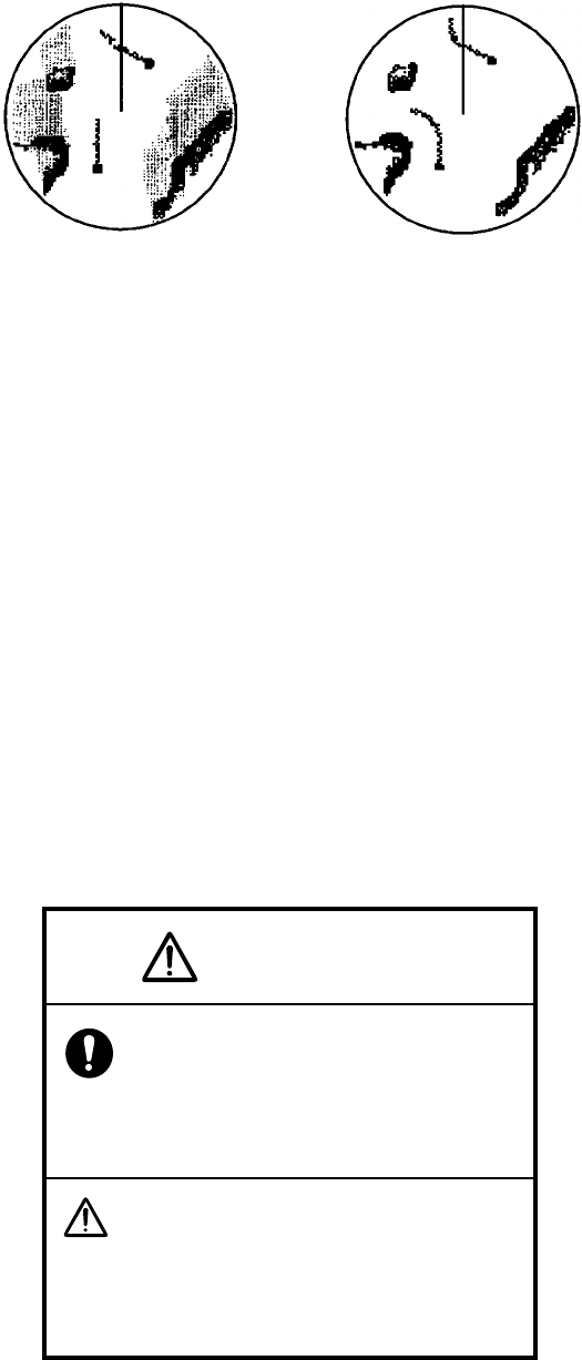
There are relative trail and true trail modes for echo trails.
Relative trail: Relative trails show other ships’ movement with reference to own ship. Relative
trail is useful to see relative movements such as avoiding a collision because own ship’s
movements and other ships’ movements are combined. On the other hand, it also shows trails of
fixed targets to make it difficult to see depending on locations.
True trail: True trails show other ships’ true movements in accordance with their over-the-speed
over grounds and courses regardless with own ship’s movement. Therefore, trails of stationary
targets are not drawn. Heading bearing signal and GPS navigation equipment need to be
connected.
22
True target trailsRelative targets trails
Relative trail and True trail
1. Roll the trackball to put the cursor on REL, TRUE or TRUEs in the trail box at the lower right
section on the screen.
2. Left-click to select trail mode.
Speed over ground: Each click switches between REL (relative trail) and TRUE (Speed over
ground true trail)
Speed over water: Each click switches between REL (relative trail) and TRUEs (Speed over
water true trail)
Note: When setting of trail mode is changed, TRUE, TRUEs or REL also change in the trail
interval box in the information display area.
1.24 Watch Alarm
The watch alarm sounds the audio alarm and displays the alarm message when targets (other
ships, island, reef, etc.) enter the set zone (Enter mode) or exit the set zone (Exit mode). (The
[Watch Alarm] is ON in the ALARM menu.) User can set two alarm zones. The default setting of
[Watch Alarm] is the Enter mode. Chapter 2.11.2 explains switching between the modes.
Warning
Watch alarm function helps prevention
of collisions and use of the function
does not exempt users from operational
safety obiigagtions stipulated in the
prevention of sea cliiision notices.
When adjustments are inadequate for
gain, sea clutter rejection and
percipitation clutter rejection, alarm
function may be lost against actual
target and talse alarm may sound due to
sea clutter and rain etc.
23
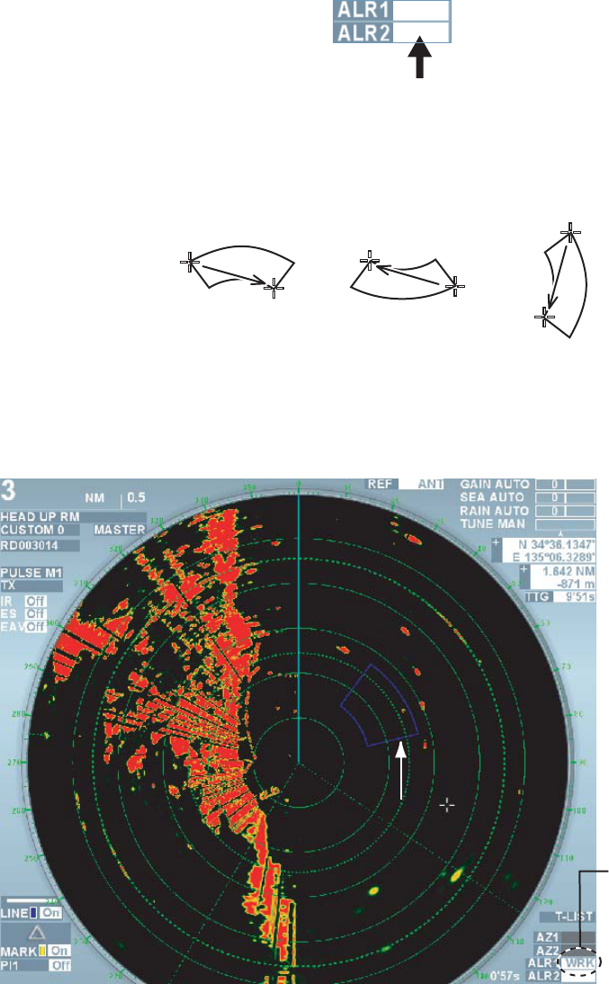
1.24.1 Set ting Watch Alarm Zone
Follow the steps below to set alarm zone.
1. Roll the truck ball to put the cursor in the box next to [Watch1] or [Watch2] at the lower right
side on the screen.
2. Left-click. Cursor moves into the zone where radar image is effective. [SET] is shown inside
of the box. The cursor is bordered with red color.
3. Roll the trackball to put the cursor on position A inside of the desired alarm zone then left-
click. The picture below shows an example alarm zone settings.
Position A
Position A
Position A
Position B
Position A
Position A
4. Roll the trackball to put the cursor on position B in the desired alarm zone. The indication in
the box changes to [Operating]. Dotting line changes to solid line when the setting is
completed. A single beep and alarm sound in accordance with the [Watch alarm setting] in
the [Alarm] menu. In addition, alarm message appears. (See page 2-30.)
Condition of watch
alarm Blank (off)
Set alarm zone
Operaing Stop
A
B
Alarm range
Note 1: When setting alarm zone 360 ゚around own ship, set position B in the same direction as
position A.
Note 2: When range is small and the alarm zone extends outside of the screen display area,
[Out of range] is shown in the box and the color inside of the box also changes.
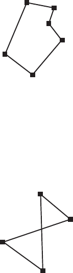
Note 3: Shape of alarm zone can be changed from sector to polygon. (See chapter 2.10.6.)
When setting the alarm zone in polygon (3~10 points), move the cursor to a desired position and
24
then left-click. Repeat this operation to insert all the points.
Example of constructing
a polygon
• In case of a polygon with less ten points, left-click again on the point last entered. The
indication in the box changes to [Operating].
• In case of a polygon with ten points, the indication in the box changes to [Operating].
Polygons cannot be made with crossing lines as shown below.
1.24.2 Stopping Alarm Sound
When [Watch alarm setting] in the [Alarm] menu is ON, the alarm sounds when a target enters or
exits the alarm zone and the target flashes on the screen. [Watch alarm] also flashes in the
alarm section of the information display area. Press the [Cancel alarm] key to stop the alarm
sound but flashing of the target continues.
1.24.3 Inactivating Watch alarm
Follow the steps below to inactivate the watch alarm.
1. Roll the trackball to put the cursor on the box next to [Watch1] or [Watch 2] to inactivate.
2. Left-click. The indication in the box changes to [Stop] and the alarm zone is displayed with a
dotted line.
Note: To restart the watch alarm, put the cursor on the box at rest then left-click.
1.24.4 Deleting watch alarm
Follow the steps below to delete the watch alarm.
1. Roll the trackball to put the cursor on the box next to [Watch1] or [Watch 2] to delete.
2. Long press the left button until the indication in the box disappears. The alarm zone
disappears from the screen.
25
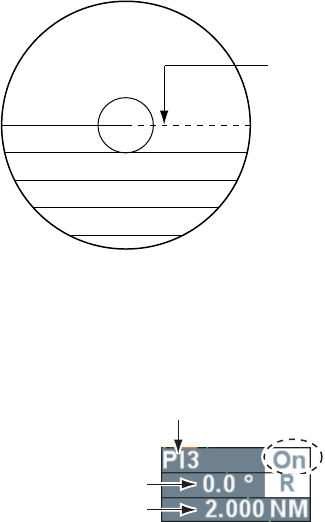
1.25 Parallel Cursor
Parallel cursor is useful for keeping a constant distant between own ship and other ship or a
coastline. There are four types of parallel cursors, PI1, PI2, PI3 and PI4. You can select number
of parallel cursors.
Parallel index lines
1.25.1 Displaying, erasing parallel lines
1. Roll the trackball to put the cursor on [PI1], [PI2], [PI3] or [PI4] in the parallel cursor box at
the lower left side on the screen.
Parallel cursor no.
*: Display only when
inside of the box is ON.
Bearing of parallel cursor *
Interval of parallel corsor *
2. Roll the wheel to select parallel cursor number from PI1~PI14.
3. Press the wheel or the left button.
4. Roll the trackball to put the cursor on [Off] or [On] in the parallel cursor box.
5. Left-click to select [On] or [Off].
Parallel cursor appears on the screen when [On] is selected and disappears when [Off] is
selected.
Note 1: Parallel cursor reference can be moved. (See chapter 2.10.7.)
Note 2: Parallel cursor can be displayed in conjunction with EBL2 and VRM2. (See page 2-31.)
1.25.2 Adjusting orientation and interval of parallel cursor
Follow the following steps to adjust orientation and interval of parallel cursor while the parallel
cursor is displayed.
1. Roll the trackball to put the cursor in the parallel cursor box.
2. Roll the [EBL] knob to adjust the orientation of parallel cursor.
3. Roll the [VRM] knob to adjust the interval of parallel cursor.
Note: Number and mode of parallel cursor can be changed in the [Parallel cursor] menu. (See
chapter 2.10.3.)
26
1.25.3 Selecting bearing mode of parallel cursor
Parallel cursor bearing reference may be RELATIVE (referenced to own ship’s bearing) or TRUE
(reference to North).
1. Roll the trackball to put the cursor on REL or TRUE in the parallel cursor box.
2. Left-click to select REL or TRUE.
1.25.4 Reset ting parallel cursor
You can reset orientation of parallel cursor currently being displayed on the screen. The table
below shows the bearing of the parallel cursor after the resetting.
Parallel Cursor Mode * Orientation of parallel cursor
Parallel O°
Perpendicular 90°
*See chapter 2.10.3.
1. Roll the trackball to put the cursor on [PI1], [PI2], [PI3] or [PI4] in the parallel cursor box at
the lower left section on the screen.
2. Long press the left button.
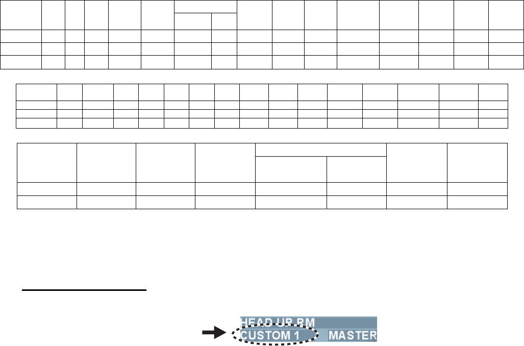
1.26 Setting Images
There are twelve settings in the image box as shown below to display optimum images
according to sea conditions.
Image box Contents
CUSTOM0 Register desired setting
CUSTOM1 Register desired setting
CUSTOM2 Register desired setting
CUSTOM3 Register desired setting
CUSTOM 4 Register desired setting
CUSTOM5 Optimum setting to use over 6NM distance
CUSTOM 6 Optimum setting in rough weather conditions such as storm
CUSTOM7 Optimum setting for navigation in near range (within 1.5NM)
CUSTOM8 Optimum setting for rainy condition
CUSTOM9 Standard setting (for general navigation)
CUSTOM10 Optimum setting for detecting birds
CUSTOM11 Optimum setting for detecting floats attached to fishing nets
27
Each image setting combines various functions such as interference rejection, zoom, signal
processing, noise rejection, pulse length, units, etc.
VIDEO
CUSTOM INT
REJ ES EAV NOISE
REJ WIPER Contrast Type
NEAR
STC
CURVE
LOW
LEVEL
ECHO
TT
ECHO
LEVEL
BAND-
WIDTH 0.125NM 1.25NM 0.5NM 0.75NM
0 3 off 1 off off 1 B 3 0 9 NARROW SHORT SHORT SHORT SHORT
1 3 off 1 off off 1 A 3 0 9 WIDE SHORT SHORT SHORT SHORT
2~11 2 off 1 off off 1 B 3 0 9 NARROW SHORT SHORT SHORT SHORT
CUSTOM 1NM 1.5NM 2NM 3NM 4NM 6NM 8NM 12NM 16NM 24NM RANGE SHORT
DIST
DIST
CHGOVR LENGTH VRM
AUTO
0 S S M1 M1 M2 M2 L L L L NM m 0.5 m On
1 S S S M1 M1 M1 M2 L L L NM m 0.5 m On
2~11 S S S S M1 M1 M1 M1 M1 M1 NM m 0.5 m On
VIDEO
MODE INT REJ EAV NOISE
REJ CONTRAST TYPE
NEAR
STC
CURVE
LOW
LEVEL
ECHO
3 4 off 1 B 3 0
3 4 off 3 B 3 0
Factory Default Setting
Note: S: Short, M: Mid, L: Long
Pulse length 32~120NM is only “L” (Common for Custom 0~11.)
Calling Image Setting
1. Roll the trackball to put the cursor on the image box at the upper left side on the screen.
Image box
2. Left-click to select a desired setting. Each click switches between CUSTOM0,
CUSTOM1…CUSTOM10, CUSTOM11 in that order.
Note1: User can register frequently used settings for CUSTOM0~CUSTOM4.
CUSTOM5~CUSTOM11can be changed as necessary. (See chapter 2.10.4.)
Note 2: User can preset image settings to be used. (See page 2-22.)
28
1.27 Function Keys
Frequently used image settings and operations can be registered in the function keys (F1, F2,
Vector True/Relative, Target data list). Use of the function keys reduces menu operations to
improve operability by simply pressing the functions keys.
Operation of function keys
Press the function keys [F1], [F2], [Vector True/Relative], or [Target Data List] to activate
registered functions. When a function has multiple selections, press the same function key to
switch its contents.
Factory Default Setting
Function key Function name Function key Function name
[F1] key Entire screen [Vector True/Relative] key Vector True Relative
[F2] key TLL [Target data list] key Target Data List
To register other functions, See chapter 2.3.
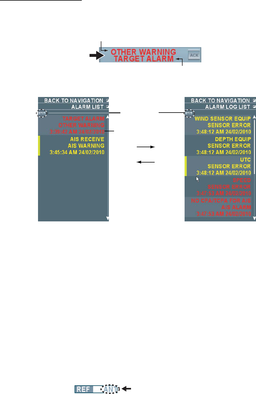
1.28 Alarm
When error or alarm setting violation is found, the applicable indication appears in flashing red or
yellow in the alarm in the information display area and the buzzer sounds. Press the [Cancel
alarm] key to stop the flashing and the buzzer. The alarm indication remains on the display until
the reason for the alarm is removed. When multiple alarms are generated, later alarms are
displayed. Confirm alarms in the alarm list as alerts with lower priority may not be displayed.
Priority order of alarm
Priority Alarm Text Buzzer
1
Highest
Not acknowledged: system error, sensor
error, TT Alarm, AIS Alarm Other alarm*
Red
flashing
Long buzzer
Continuous
2 Not acknowledged: alarm set at high
priority in the [Priority alarm] menu.
Yellow
flashing
Short buzzer
(one time)
3 Not acknowledged: alarm set at low
priority in the [Priority alarm] menu.
Yellow
flashing
Short buzzer
(one time)
4 Acknowledged: system error, sensor
error, TT Alarm, AIS Alarm Other alarm*
Red
flashing
-
5 Acknowledged: alarm set at high priority
in the [Priority alarm] menu.
Yellow
flashing
-
6
Lowest
Acknowledged: alarm set at low priority
in the [Priority alarm] menu.
Yellow
flashing
-
*: Alarm of which priority order cannot be changed in the [Alarm priority] menu.
Note 1: Refer to the [Alarm list] on page AP-6 for alarm names displayed in the alarm box.
Note 2: Priority order of alarms in the [Alarm priority] can be changed. (See chapter 2.8.)
29
Display alarm list/history
A list of current alerts can be displayed. Order of alerts is shown in the above table.
History of alerts can also be displayed up to the newest 100 alerts.
1. Roll the trackball to put the cursor on the alarm box in the information display area.
Alarm box
Type of alarm
Alarm name
2. Right-click to display the alert list.
Roll the wheel to scroll the alert list.
Switch button
Date/Time occurred
Left click the switch button
3. Put the cursor on the unacknowledged alarm to acknowledge it then left-click.
The alarm is acknowledged and the display changes from flashing to lighting.
4. Left-click the switch button on the upper section of the alarm list to display the alarm history.
Each click switches between the alarm history and the alarm list.
5. Right-click to close the alarm list or the alarm history.
Note: To view the latest alarms exceeding 100 alerts, data of the alert history need to be stored
in USB memory. (See chapter 5.9.1.) Open PC supplied by user to open the stored data. (File
name: alarmHistory.txt)
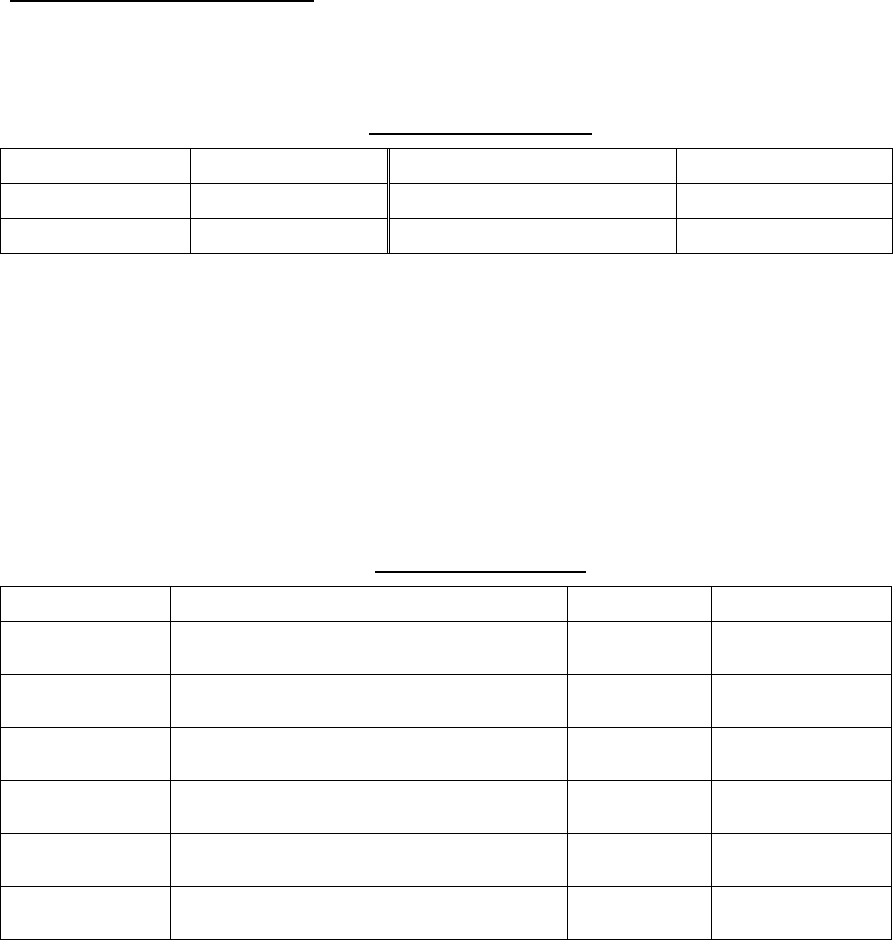
1.29 Reference Position
The reference positions for measurements of range/bearing and markers such as heading line
and stern mark can be selected from the following two reference positions.
• Antenna position
• Steering position
Roll the truck ball and put the cursor on the reference position box at the upper section on the
screen to select a reference position. Each left-click toggles between [Antenna] and [Steering
position].
Reference position box
Own ship’s position is different depending the set reference position.
30
Radar antenna
position is at
the center of
the screen.
Steering position
is at the center
of the screen.
[Antenna] is referenced. [Steering position] is referenced.
Bearing/Range are measured according to the reference positions as shown in the table below
to draw own ship’s graphic.
Reference position
Type Item
Antenna Steering position
EBL
VRM
Cursor
Parallel cursor
Fixed range ring
Bearing/Range
Drop mark
Display bearing/range
from antenna position.
Display bearing/range
from steering position.
Heading line
Stern line
Beam line
Own ship vector
Graphics
Own ship track
Draw from antenna
position.
Draw from steering
position.
Bearing scale Draw with antenna
position at center.
Draw with steering
position at center.
Course, ship speed Calculate with antenna
position at center.
Calculate with steering
position at center.
CPA, TCPA Calculate with antenna
position at center.
Calculate with steering
position at center.
BCR, BCT Calculate from heading at all times.
Heading
Ship speed
Ground speed
Course
Own ship’s data
Latitude/Longitude of
own ship
Display based on input data from sensor
regardless of reference position setting.
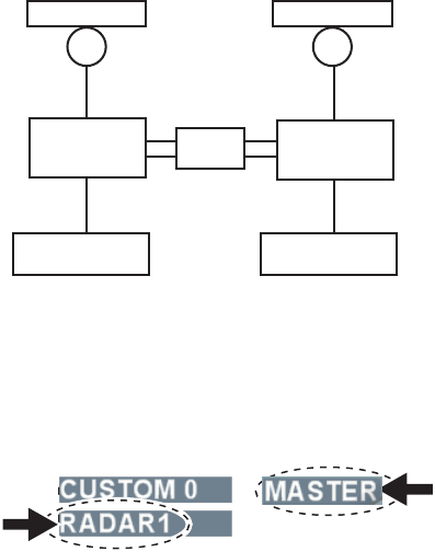
31
1.30 Interswitch
The interswitch of this radar uses an Ethernet to transfer digital data such as images and
settings when two of this equipment are connected. For example, when an error occurs in
antenna unit of radar 1, you can display images of antenna unit of radar 2 on the display unit 1.
When you switch to another antenna unit with the interswitch, it automatically applies heading
skew set at installation and timing adjustment.
Antenna unit of radar 1 Antenna unit of radar 2
Switching Hub
HUB-100
Processor
unit
Processor
unit
Display unit 1 Display unit 1
Example of Interswitch connection
Follow the following steps to use the interswitch function.
1. Roll the trackball to put the cursor in the interswitch box at the upper left section on the
screen. Name of the antenna unit in use is shown in the antenna unit box.
Interswitch box
Antenna unit box
2. Left-click to select [Secondary].
Each click toggles between [Secondary] (Secondary radar) and [Main] (Main radar) functions.

32
Limitations of each function during the interswitch operation
Radar functions include independent operations, dependent operations and common operations
in [Main] and [Secondary] radars.
Function Name Operation Main Secondary
Getting
ready/Transmission
No independent operation Arbitrary setting Inoperable
Range Independent operation Arbitrary setting Arbitrary setting
(between ¼ to 4 times
of [Main] range)
Pulse length No independent operation Arbitrary setting Inoperable
Second-trace echo
rejection
No independent operation Arbitrary setting Inoperable
Reference position No independent operation Arbitrary setting Inoperable
Display mode Independent operation Arbitrary setting Arbitrary setting
Interference rejection No independent operation Arbitrary setting Inoperable
Noise rejection No independent operation Arbitrary setting Inoperable
Video slope No independent operation Arbitrary setting Inoperable
Zoom No independent operation Arbitrary setting Inoperable
Signal processing No independent operation Arbitrary setting Inoperable
Wiper No independent operation Arbitrary setting Inoperable
Echo trail Independent operation Arbitrary setting Arbitrary setting
Echo trail True/Relative Independent operation Arbitrary setting Arbitrary setting
Gain No independent operation Arbitrary setting Inoperable
Sea clutter rejection No independent operation Arbitrary setting Inoperable
Precipitation clutter
rejection
No independent operation Arbitrary setting Inoperable
Tuning No independent operation Arbitrary setting Inoperable
Guard zone No independent operation Arbitrary setting Arbitrary setting
Watch Alarm zone Independent operation Arbitrary setting Arbitrary setting
Chart Independent operation Arbitrary setting Arbitrary setting
EBL, VRM, Other marks Independent operation Arbitrary setting Arbitrary setting
TT Acquisition/TT Track No independent operation Arbitrary setting Arbitrary setting
TT Display ON/OFF Independent operation Arbitrary setting Arbitrary setting
TT Vector TRUE/REL Independent operation Arbitrary setting Arbitrary setting
AIS Independent operation Arbitrary setting Arbitrary setting
Note1: The interswitch function does not function when there is an error in the network. It may
function in independent condition.
Note 2: Echo trail and signal processing are transferred when images are switched with the
interswitch. Erase unnecessary echo trails as necessary.
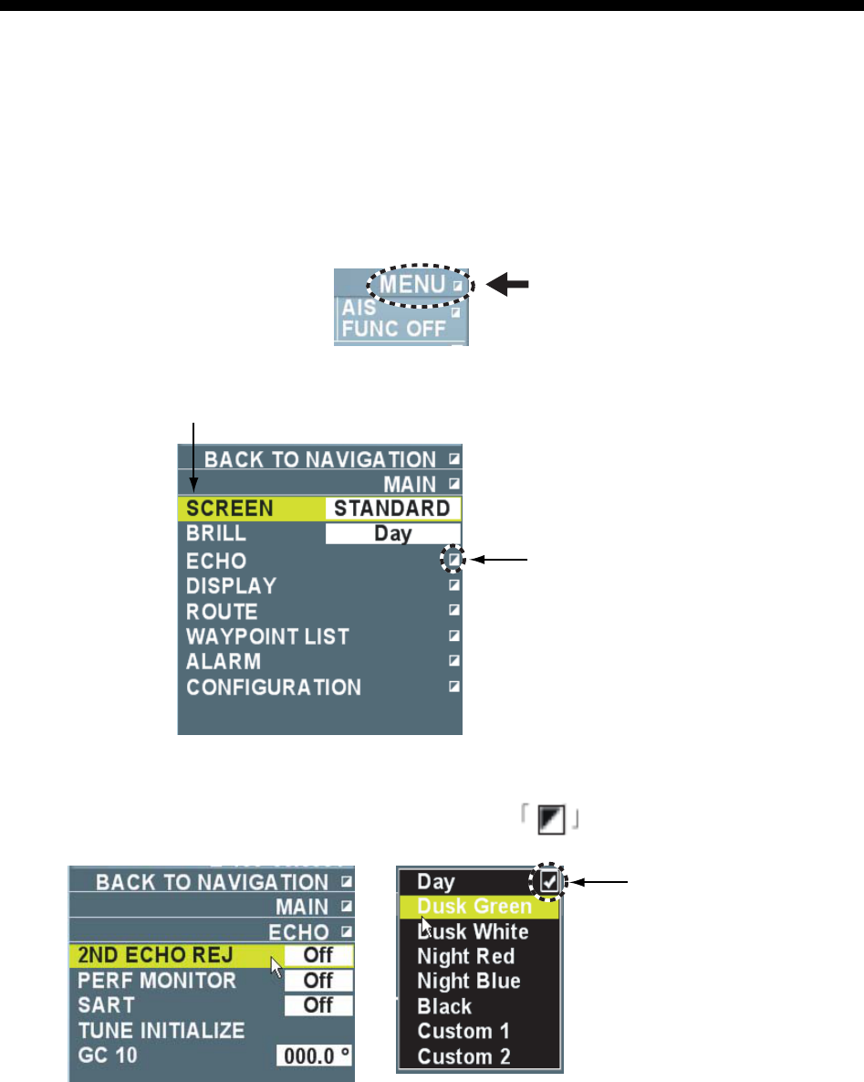
33
2. RADAR OPERATION USING MENU
This Chapter explains the main menu and menu operations of each function displayed when
right-clicking the box on the screen except for TT, AIS and plotter.
2.1 Menu Operation
This chapter explains the basic menu operation. Right-click to go one step backward when you
want to know what the current operation is doing.
1. Put the cursor on [Menu] in the information display area.
2. Left-click to open the main menu. You can also open the main menu by rolling the wheel.
Selection cursor
Indicates tat there
is a sun manu
3. Roll the trackball to put the cursor on a necessary item. The selection cursor indicates an
item currently being selected. You can also select the item by rolling the wheel.
4. Press the left button or wheel. When item with mark is selected, a sub menu is
displayed. Proceed to step 5.
Indicates an item
currently being set.
5. When the sub menu is open, select an item to change the setting then left-click.
6. Select contents of the setting and left-click. To change numerical value, roll the wheel to set a
value then press the left button or press the wheel.
7. Right-click several times to close the menu. Select [Return] on the very top of the menu and
left-click to immediately close the main menu.
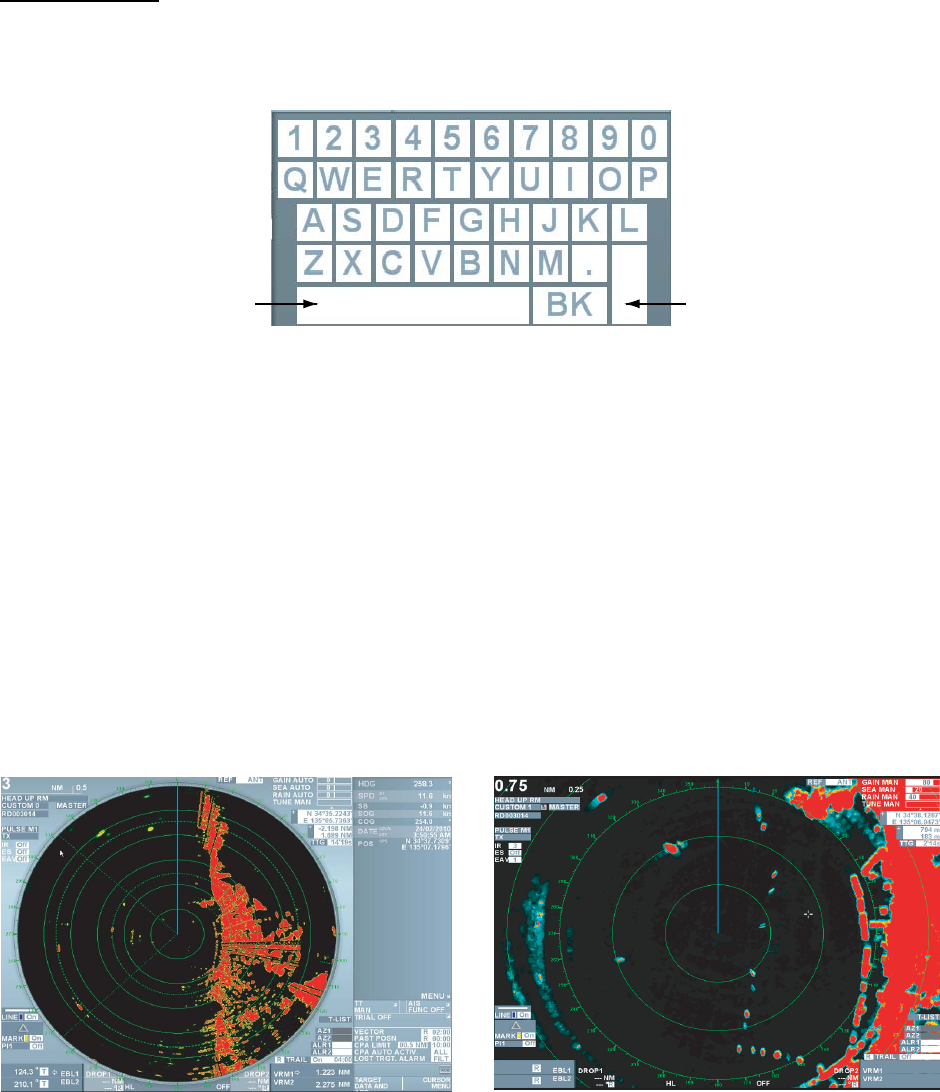
34
Entering texts
You may need to input texts when using this equipment. You can enter English characters (A~Z),
numbers (0~9), Symbols (-), Hiragana (for names of image boxes only) and space. A small
keyboard is displayed at the lower section on the screen where you enter texts.
Ente
Spac
Follow the steps below to use the small keyboard.
1. Put the cursor on [BK] or [Correct] to erase texts displayed and then left-click several times.
2. Put the cursor on the first character.
• Select [Japanese] on the alphabet keyboard then left-click to switch to hiragana input.
• Select [ENG/JPN] on the hiragana keyboard to switch to alphabet input then left-click.
3. Left-click. Texts are entered in the input box.
4. Repeat step 2 and 3 to complete text input.
5. Lastly, put the cursor on [Enter] and left-click. The small keyboard disappears.
2.2 Echo Display Area
The echo display area can be selected from [Standard] or [Full screen]. User can effectively use
the full screen to confirm targets in further distance with [Full screen] without changing the range.
Follow the following steps to switch to [Full screen].
Standard Full screen
1. Put the cursor on [Menu] in the information display area then left-click.
2. Select [Screen] then left-click.
3. Select [Full screen] then left-click. The information display area disappears to show the full
screen.
4. Follow the steps below to return to the standard condition.
1) Press the wheel. The main menu is displayed.
2) Select [Screen] then left-click.
3) Select [Standard] then left-click.
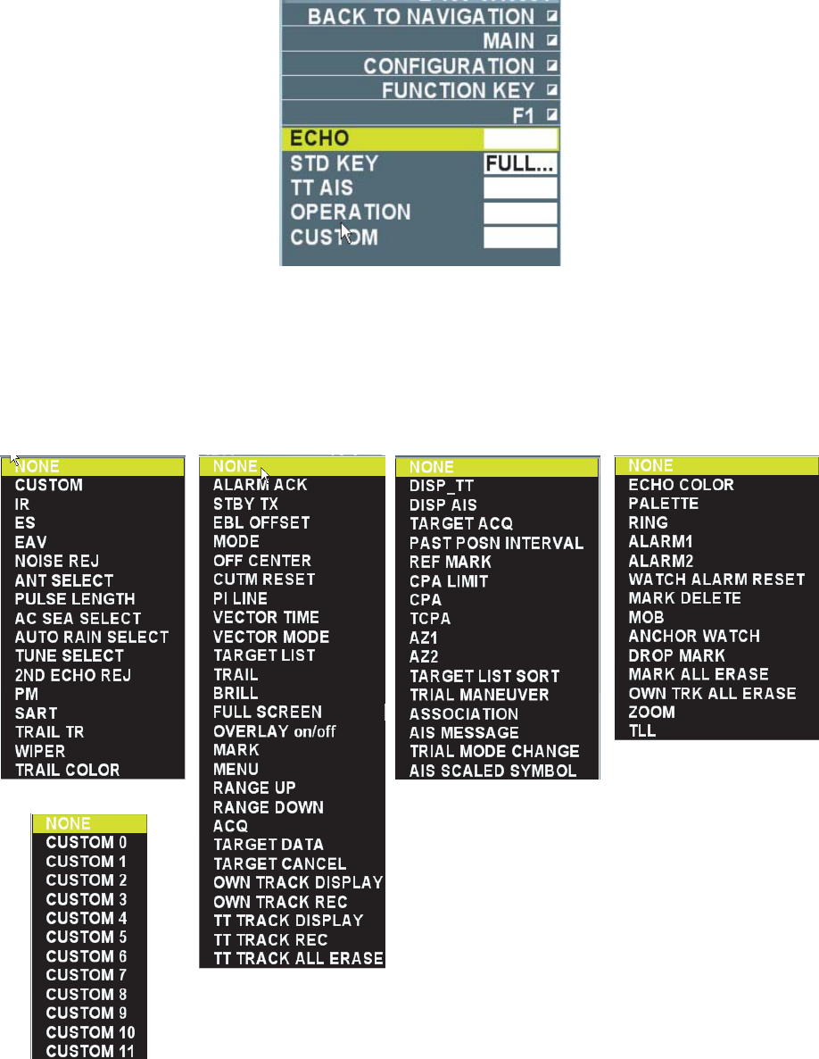
35
2.3 Registering Function Keys
Follow the steps below to register other functions to the function keys, F1, F2, Vector
True/Relative, Target data list.
1. Put the cursor on [Menu] in the information display area and then left-click.
2. Select [Set environment] then left-click.
3. Select [Function key] then left-click.
4. Select [F1], [F2], [Vector True/Relative] or [Target data list] then left-click.
[F1] is selected
5. Select a desired item from [Echo], [Standard key], [TT/AIS], [Operation] and [Image] then left-
click. Setting window appears according to your selection.
[Echo] is selected
[Image] is selected
[Standard key] is selected [TT/AIS] is selected [Operation] is selected

36
6. Select the function to register then left-click.
7. Right-click several times to close the menu.
The following table shows the functions that can be registered. Nothing is registered when
[None] is selected.
Functions that can be registered to the function keys: Echo Menu
Item Function Selections
Image Switch image preset of images.
(See chapter 1.26.)
CUSTOM0 or
1,2,3,4,5,6,7,8,9,10,11
Interference rejection Select setting value of
interference rejection function
Off, 1,2,3
Zoom Select setting value of Zoom
image function
Off, 1,2,3
Signal processing Select setting of the signal
processing function
Off, 1,2,3,4,5
Noise rejection Turn ON/OFF the noise
rejection function
On, Off
Antenna selection Select reference position (See
chapter 1.29.)
Antenna, Steering position
Pulse length Select pulse length - 0.125,0.25,0.5NM: S
- 0.75,1,1.5,2NM: S1, M1
- 3NM: S,M1,M2
- 4, 6, 8, 12, 16, 24NM:
M1, M2, L
- 32,48,72,96,120NM: only L
Sea clutter rejection Select method of sea clutter
rejection
Manual, Automatic
Precipitation clutter rejection Switch between precipitation
clutter rejection function and
unwanted echo rejection
function.
Precipitation clutter rejection
(manual), unwanted echo
rejection
Tuning selection Select tuning method Manual, Automatic
Second-trace echo rejection Turn ON/OFF the second-trace
echo rejection function
On, Off
Performance monitor Do not use. None
SART Select whether to change radar
setting or not to make SART
images better.
On, Off
Trail T/R Select operation mode
(Relative, True) of echo trail.
Relative, True, True-s
Wiper Turn ON/OFF the wiper
processing function
On, Off
Trail color Select trail color Blue, Green, Turquoise

37
Functions that can be registered to the function keys: Standard Key Menu
Item Function Selections
Stop alarm sound Stop flashing of alarm box and
alarm sound
None
Transmission getting ready Switch between [Getting ready]
and [Transmission]
Getting ready, Transmission
EBL offset Offset EBL/Cancel Offset EBL None
Mode Select display preset display
mode
Head-up, Cursor gyro, Stern-
up, Course-up, North-up, True
motion
Off center Turn ON/OFF Off center
function
None
CU/TM reset Course-up: Heading line is on
the top
True motion: Return own ship
position to 75% radius in
opposite direction against its
course
None
Parallel cursor Turn ON/OFF parallel cursor On, Off
Vector time Select vector time 0 sec, 15 sec, 30 sec, 45 sec, 1
~20 min. (1min. interval), 30
min, 40 min, 50 min, 60 min
Vector True/Relative Select vector mode, Relative, Relative, True, True-s
Target data list Open/Close target data list None
Trail Select trail time Off, 15 sec, 30 sec, 45 sec, 1
~20 min. (1min. interval), 30
min, 40 min, 50 min, 60 min, 12
hours, 24 hours, 48 hours,
Continuous
Color scheme Select color of full screen Day, Dust-green, Dust-white,
Night-red, Night-blue, Black,
Custom1, Custom 2
Full screen Select display area of echo Standard, Full screen
Chart overlay Display/Not display chart
overlay
OFF, ON
Mark Insert marks and waypoints None
Menu Open/Close main menu None
Range (+) Increase range None
Range (-) Decrease range None
Acquisition Acquire target. Display/Delete
target data
None
AIS data Display/Delete AIS target data None
Erase target Cancel track of TT target
selected. Inactivate AIS active
target
None
Display own ship track Display/Not display own ship
track
On, Off

38
Item Function Selections
Plot own ship track Store/Not store own ship track On, Off
Display other ship track Display/Not display other ship
track
On, Off
Plot other ship track Plot/No plot other ship track On, Off
Erase all other ship track Delete all other ship track None
Functions that can be registered to the function keys: TT/AIS Menu
Item Function Selections
Target display Turn TT display ON/OFF OFF, Manual or Automatic,
Auto/Manual
AIS display Turn AIS display ON/OFF Display OFF, Display filter,
Display all
Target acquisition Acquire targets. Display /Delete
TT target data.
None
Plot track interval Select plot track interval 0 sec, 15 sec, 30 sec, 45 sec, 1
~20 min. (1min. interval), 30
min, 40 min, 50 min, 60 min
Stationary target Mark stationary target None
CPA limit Turn ON/OFF CPA alert OFF, ON
CPA Set CPA alert range 0.5NM, 1.0NM, 1.5NM,
2.0NM~24.0NM (1NM interval)
TCPA Set TCPA alert range 1min.~20min. (1min. interval),
30 min, 40min, 50min, 60min
Guard zone 1 Set guard zone1 None
Guard zone 2 Set guard zone 2 None
Target data list order Reorder target data CPA, TCPA, BCR, BCT, Range,
Speed, Ship name
Simulate steering Start/Finish simulate steering None
Identification Identify TT target and AIS
active target
OFF, AIS, TT
AIS message Open AIS message None
Simulate steering mode Select simulate steering mode Static mode, Dynamic mode
Display AIS real scale Select whether to display AIS
symbol of the size 1.5 cm or
larger displayed on the screen
in true scale according to ship
length
On, Off
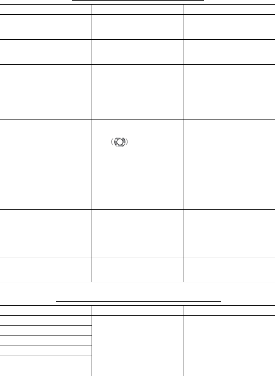
39
Functions that can be registered: Control menu
Item Function Selection
Echo color Select color of target echo Yellow, Green, White, Multiple
green, Multiple Gray, Multiple
Blue
Color scheme Change [Color scheme] in the
[Set environment] menu
White, White text on blue
background, Gray, Blue, Red,
Green, Black
Fixed range ring Select Display/Not display fixed
range ring
None
Guard 1 Set Guard alarm1 None
Guard 2 Set Guard alarm 2 None
Watch alarm reset Reset time in the Watch alarm
box
None
Delete mark Delete mark, waypoint and line
selected
None
MOB Mark at man overboard.
Range, bearing, estimated time
to MOB position is displayed in
the information display area
when [Destination data] setting
in the [Navigation data] menu is
other than [OFF].
None
Anchor watch alarm Turn ON/OFF anchor watch
alarm
On, Off
Drop mark Turn ON/OFF drop mark
function
On, Off
Erase all marks Delete all marks None
Erase all own ship tracks Delete all own ship marks None
Zoom Activate zoon cursor None
TLL Plot data at target position
(cursor position) on radar
screen.
None
Functions that can be registered: Image Menu
Item Function Selection
Custom 0, Custom1
Custom 2, Custom 3
Custom 4, Custom 5
Custom 6, Custom 7
Custom 8, Custom 9
Custom 10, Custom 11
Call image setting of selected
items
None
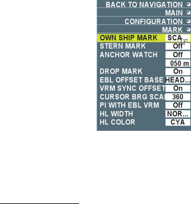
40
2.4 Drop Mark
User can insert a drop mark at a selected location on a geographical map as a stationary point.
Range and bearing to that location such as a lighthouse or a passage buoy can be displayed at
all times. Numeric values of the drop mark are updated with own ship’s movement.
2.4.1 Activating the drop mark function
Follow the steps below to activate the drop mark function.
1. Put the cursor on the MENU in the information display area then left-click.
2. Select the [Set environment] menu then left-click.
3. Select [Mark] then left-click.
4. Select [Drop mark] then left-click.
5. Select [On] then left-click. (Two-drop mark boxes are shown at the lower section on the
screen. (See chapter 2.4.2.)
6. Right-click several times to close the menu.
2.4.2 Inscribe/Erase drop mark
Inscribing a drop mark
Own ship position data is required to inscribe a drop mark.
1. Put the cursor on the drop mark box (Drop 1 or Drop 2) at the lower section on the screen
then left-click.
The cursor moves within the valid radar image area. A star mark of turquoise color is
attached at the cursor.
3. Move the cursor to a position to where you want to measure range and bearing then left-click.
A drop mark is inscribed on the screen. A turquoise broken line connects the own ship and
the drop mark and range and bearing are displayed in the drop mark box.
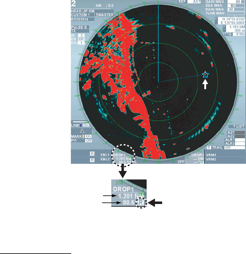
41
Click here to switch bearing
reference (True Relative
Range to a drop mark
Bearing of a drop mark
Drop mark box
Drop mark
4. Put the cursor on the drop mark box to change the position of the drop mark then left-click.
Put the cursor to a new position then left-click.
Erasing a drop mark
Put the cursor on the drop mark box (Drop 1 or Drop 2) at the drop mark box at the lower section
on the screen then long press the left button. The drop mark disappears from the screen.
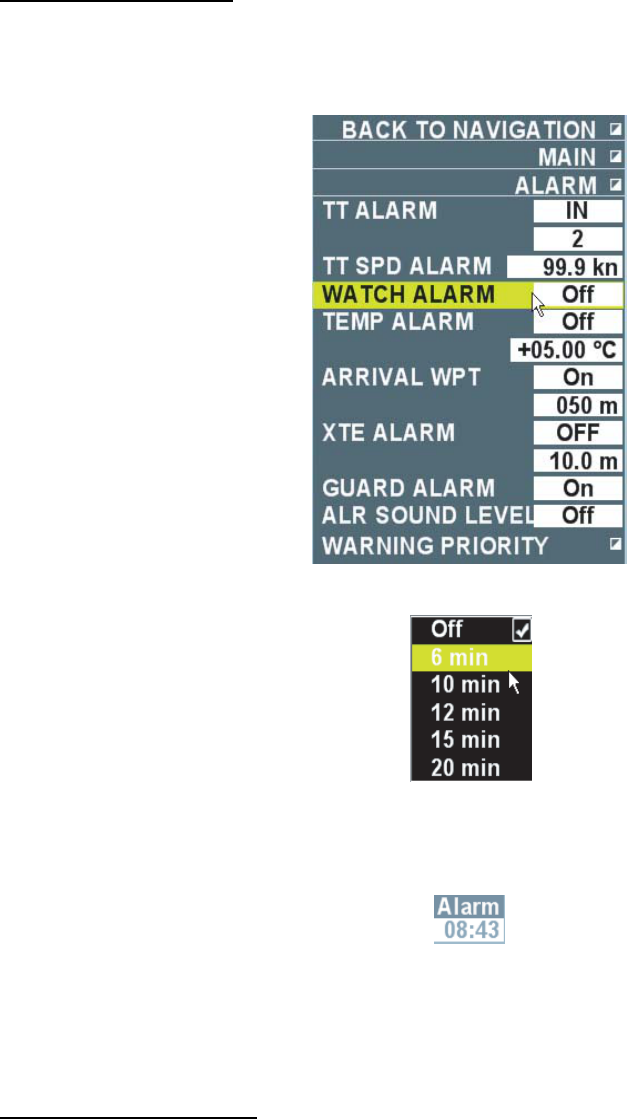
42
2.5 Watch Alarm
The watch alarm sounds the audio alarm at the selected time interval to help you keep periodic
watch of the radar picture for safety or other purposes.
The watch box appears at lower right section on the screen showing count down time until audio
alarm sounds.
Setting Watch Alarm
Follow the steps below to set the watch alarm.
1. Put the cursor on [Menu] in the information display area then left-click.
2. Select [Alarm] then left-click.
3. Select [Watch alarm] then left-click.
5. Select appropriate time interval then left-click.
The watch alarm box is displayed at the lower right section on the screen except when [Off]
is selected.
6. Right-click several times to close the menu.
The set time is counted down and sounds the alarm when it is counted down to [00:00].
[Watch alarm] flashes in the alarm box in the information display area. Press the [Cancel
alarm] key to stop the audio alarm. Start over the countdown.
Resetting time interval
Left-click the time indication in the watch alarm box before the set time is counted down to reset
the time interval set in step 4 about to start over the countdown.
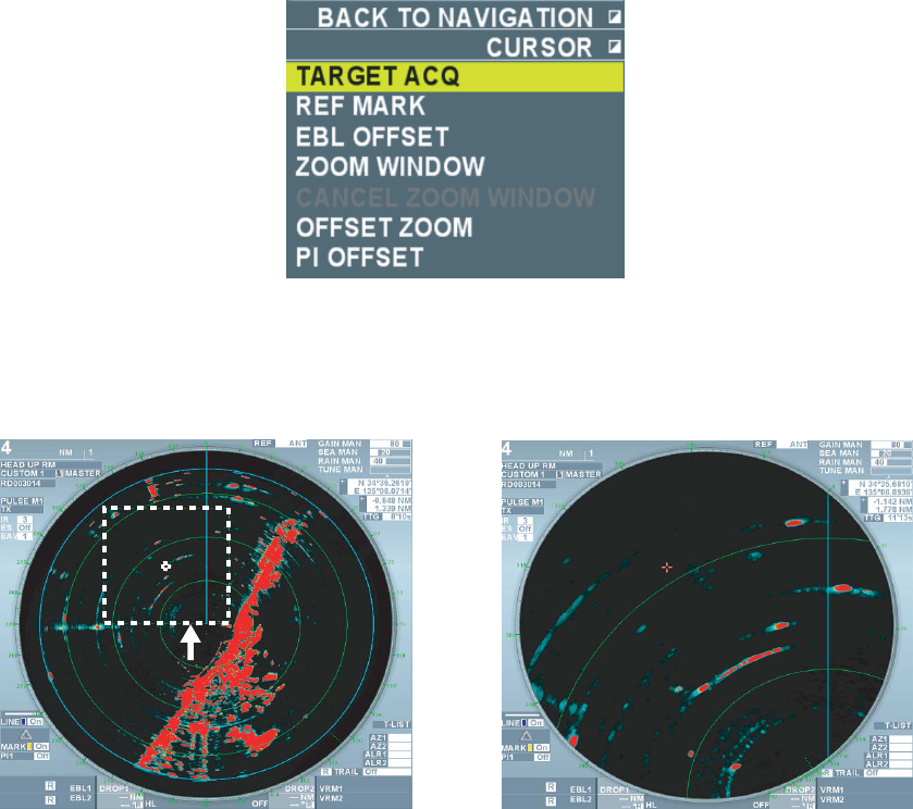
43
2.6 Zoom
The zoom function enlarges an area of interest. There are four types of zoom function.
• Offset zoom: Enlarges area selected with the zoom cursor.
• Double zoom: Enlarges a picture inside of the zoom cursor twice as large.
• Triple zoom: Enlarges a picture inside of the zoom cursor three times as large.
• Target zoom: Enlarges a picture fixed as TT target inside of the zoom cursor twice as large.
(See chapter 3.9 for details.)
Note: TT target or AIS target symbols are not enlarged.
2.6.1 Using Offset zoom
The offset zoom function can be used in the display modes other than true dynamic mode.
1. Put the cursor in the valid radar display area then right lick.
2. Select [Offset zoom] then left-click.
The zoom cursor appears on the screen.
3. Move the zoom cursor to a desired location to zoom then left-click.
The area selected with the zoom cursor is enlarged.
Zoom cursor
Note: Left-click again while zooming to cancel the zoom function.
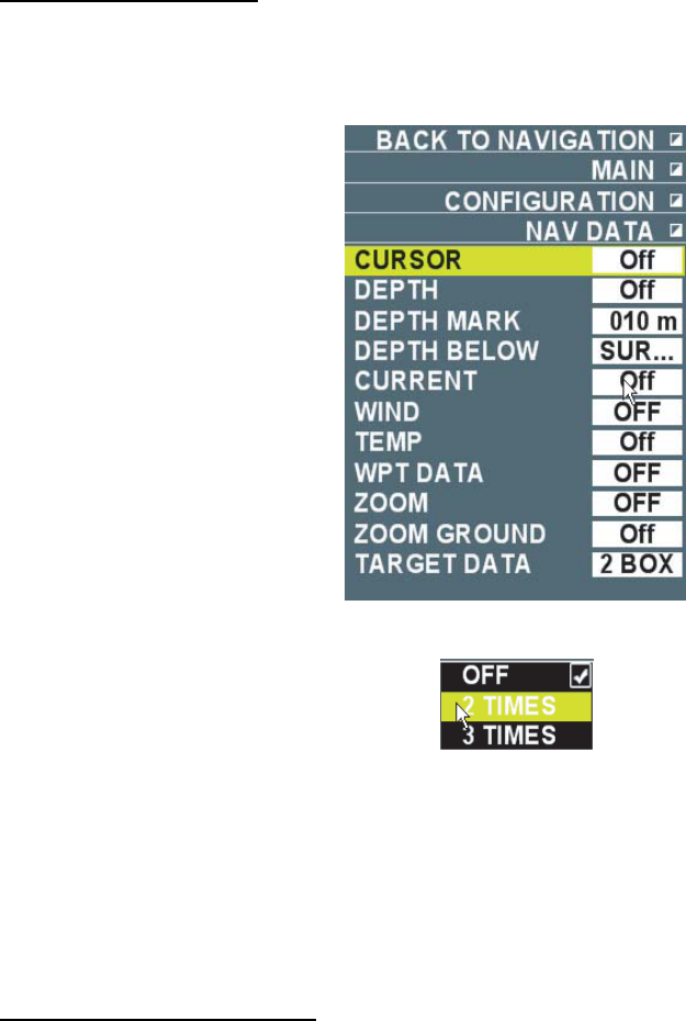
44
2.6.2 Double zoom and Triple zoom
Zoom window and cursor information cannot be displayed simultaneously in the information
display area.
Selecting zoom ratio
1. Put the cursor on [Menu] in the information display area then left-click.
2. Select [Set environment] then left-click.
3. Select [Navigation data] then left-click.
4. Select [Zoom mode] then left-click.
5. Select [2 x] or [3 x] then left-click.
The zoom cursor appears at the screen center. [Cursor data] setting in the [Navigation data]
menu becomes [Off].
The zoom function does not work when [OFF] is selected.
6. Right-click several times to close the menu.
Zoom window appears in the information display area.
Select a location to zoom
1. Put the cursor in the effective radar display area then right-click.
2. Select [Zoom] from the [Cursor] menu then left-click.
The zoom cursor at the screen center becomes operable.
3. Move the zoom cursor to a desired location to zoom then left-click.
The zoom cursor is fixed and an image inside of the zoom cursor enlarges to double or triple
size in the zoom window.
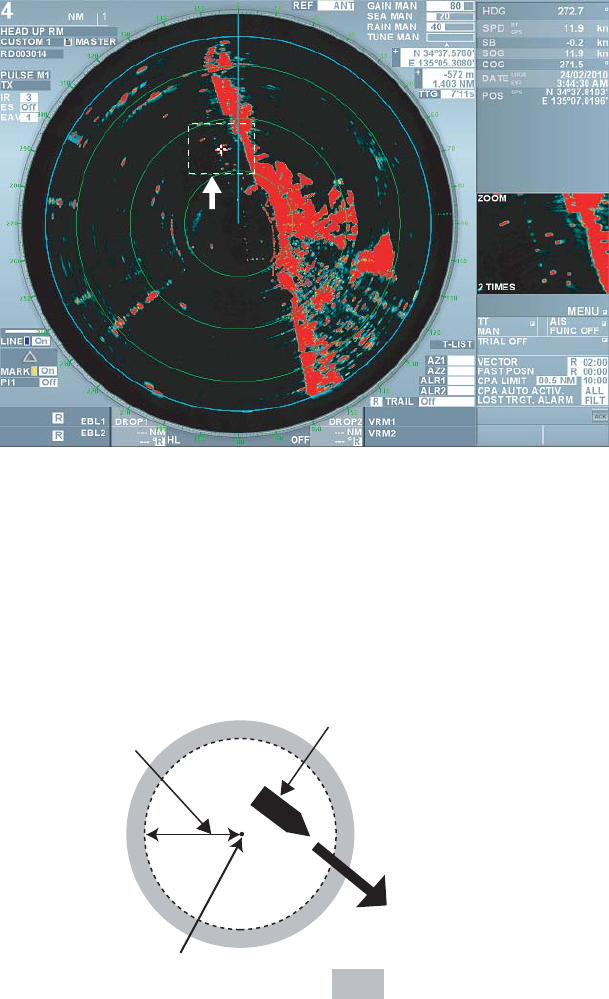
45
Zoom cursor
Note 1: Select [Cancel zoom] from the [Cursor] menu then left-click to cancel the zoom function.
Note 2: Select [Zoom with fixed land] in the [Navigation data] menu to zoom display with land
fixed. See chapter 2.10.6 for fixing land.
2.7 Anchor Watch Alarm
The anchor watch function alerts you when your ship has traveled a distance greater than a
threshold value with the reference position (antenna or steering position) at its center.
Set range
Own ship position
: Alarm triggered
Reference position
1. Put the cursor on [Menu] in the information display area and left-click
2. Select [Set environment] then left-click.
3. Select [Mark] then left-click.
4. Select [Anchor watch alarm] then left-click.
5. Select [On] then left-click.
6. Select a line in the anchor watch range and left-click.
7. Input setting value.
7. Right-click several times to close the menu.
A dashed circle with a set radius appears. When own ship goes out the circle, [Anchor watch
alarm] flashes in the alarm box in the information display area. Select [Off] at step 5 to cancel
the anchor watch alarm.
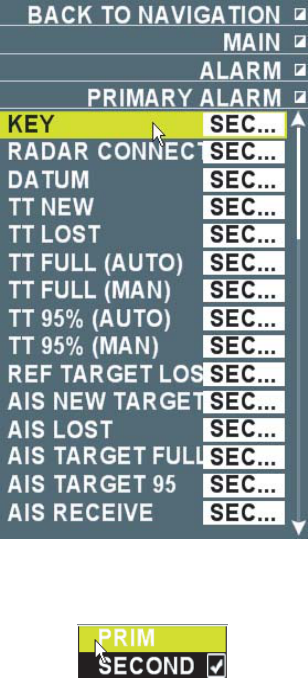
46
2.8 Priority Order of Various Alarms
Priority order of various alarms is explained in Chapter 1.28. This Chapter explains the priority
order of 2 and 3 settings.
1. Put the cursor on [Menu] in the information display area and left-click.
2. Select [Alarm] then left-click.
3. Select [Priority alarm] then left-click.
4. Roll the wheel to select an alarm for which to change the priority order then left-click.
See the menu list at the end of this manual to see all the items in the [Priority alarm] menu.
5. Select [Priority High] (Priority order 2) to raise the priority and [Priority Low] (Priority order 3)
to lower the priority then left-click.
6. Right-click several times to close the menu.
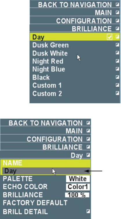
47
2.9 Color Scheme
Brilliance of marks and texts and color of targets can be set by color scheme. Color and
brilliance sets can also be customized and registered in [Custom 1] and [Custom 2].
3. Put the cursor on [Menu] in the information display are then left-click.
4. Select [Set environment] then left-click.
5. Select [Color scheme] then left-click.
4. Select the color scheme to change then left-click.
Cannot change
Daytime is selected

48
5. Select the item to change then left-click.
Menu Item Contents
Echo color Select color of target echo. (Yellow, Green, White, Multiple
green, Multiple gray, Multiple Blue)
- Multiple green: Displays four colors
Red→Orange→Yellow→Green according to strength of
receiving echoes.
- Multiple gray: Displays 3 colors Dark red→Yellow→Gray
according to strength of receiving echoes. (The color set is easy
to see when the setting of [Chart color] in the [Vector chart]
menu is [Daytime color].)
- Multiple blue: Displays 4 colors
Red→Orange→Yellow→Turquoise according to strength of
receiving echoes.
Brilliance Change brilliance of screen.
Reset to factory default Reset items in the [Color scheme] menu at factory default.
Brilliance detail Open [Brilliance detail].
Radar base color Select effective radar range (Black, Dark blue).
Panel brilliance Adjust brilliance of panel including power lamp.
Back ground brilliance Adjust brilliance of background.
Test Adjust brilliance of texts displayed on the screen.
Icon box background Adjust brilliance of boxes on the screen.
Cursor (small) Adjust brilliance of cursor (small).
Echo Adjust brilliance of target echoes.
Trail Adjust brilliance of echo trail.
Heading line Adjust brilliance of heading line and no transmission zone.
Fixed range ring Adjust brilliance of fixed range ring.
Cursor (large) Adjust brilliance of cursor (large).
EBL Adjust brilliance of EBL1 and EBL2.
VRM Adjust brilliance of VRM1 and VRM2.
Parallel cursor Adjust brilliance of parallel cursor.
Own ship mark Adjust brilliance of own ship mark.
Track Adjust brilliance of track.
TT mark Adjust brilliance of TT mark.
AIS symbol Adjust brilliance of AIS symbol.
Latitude/Longitude Adjust brilliance of latitude and longitude.
Mark/Destination Adjust brilliance of marks and destinations.
Line Adjust brilliance of lines.
Chart Adjust brilliance of charts.
Depth Adjust brilliance of depth value on chart.
Individual contour line Adjust brilliance of individual contour line on chart.
6. Right-click several times to close the menu.
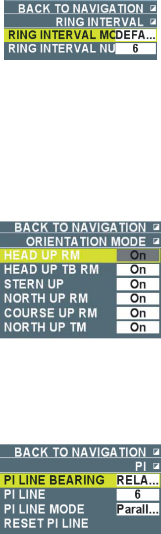
49
2.10 Menus of Each Function
2.10.1 Setting fixed range ring
Put the cursor on the fixed range ring interval at the upper left position on the screen then right-
click to display the [Fixed range ring interval] menu.
Fixed range ring interval mode: Select a display mode of the fixed range ring.
Standard: Automatically display optimum number of fixed range ring according to the range
selected.
Manual: Display number of fixed range ring set regardless of the range selected.
Fixed range ring interval: It becomes effective when [Manual] is selected in the above [Fixed
range ring interval mode]. User can specify the number of fixed range ring between one and nine.
2.10.2 Preset ting display modes
Put the cursor on the display mode box at the upper left position on the screen then right-click to
display the [Display mode] menu.
Select whether to use each display mode [On] or not [Off]. Only the display mode that is turned
on can be switched with the [Select mode] key. Head-up mode cannot be turned off.
2.10.3 Setting parallel cursor
Put the cursor on [PI1], [PI2], [P13] or [P14] in the parallel cursor box at the lower left section on
the screen then right-click to display the [Parallel cursor] menu.
Parallel cursor bearing: See chapter 1.25.3.
Number of parallel cursor: Select number of parallel cursor from one to ten. When ten is
selected, ten intervals and eleven parallel cursors are shown.
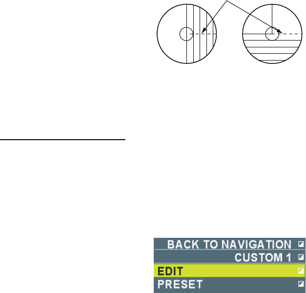
50
Parallel cursor mode: Select parallel cursor mode. When the number of parallel cursor is one,
only lines are shown that are parallel to the reference line.
Vertical: Display parallel lines that are perpendicular to the reference line.
Horizontal: Display parallel lines are parallel to the reference line.
Parallel cursor reset: See chapter 1.25.4.
Reference line
Perpendicular Horizontal
0°0°
2.10.4 Custom settings
Register image setting
User can register custom settings at [CUSTOM0 ~ CUSTOM4] in the image box according to
their situation. Settings can be edited as necessary except for [CUSTOM0 ~ CUSTOM4].
1. Put the cursor on the image box at the upper left section on the screen.
2. Left-click to select [CUSTOM0], [CUSTOM1], [CUSTOM2], [CUSTOM3] or [CUSTOM4].
3. Right-click.
CUSTOM 1 selected
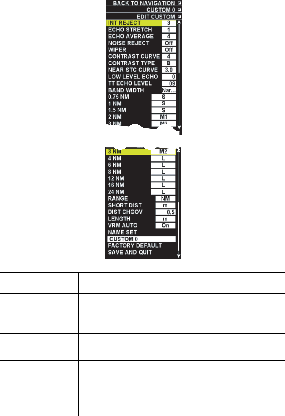
51
4. Select [Edit] then left-click.
5. Select an item to change then left-click.
Menu Item Contents
Interference rejection Select interference rejection setting. (See chapter 1.20.)
Zoom image Select image zoom setting. (See chapter 1.21.)
Signal processing Select signal image setting. (See chapter 1.22.)
Noise rejection Turn the noise rejection function* ON/OFF.
*: Function to remove white noise appearing on radar echoes.
Wiper Turn the wiper rejection function* ON/OFF.
*: Function to make images more visible by automatically changing
brilliance of signals.
Video slope Set dynamic range (1 ~ 4). 1 is the widest dynamic range. 4 is the
narrowest dynamic range.
Video slope type Set curve indicating strength of video signal.
A: Low at mid curve. Suitable for suppressing precipitation clutter
B: Curve between A and C
C: High at mid curve. Suitable for detecting far range target
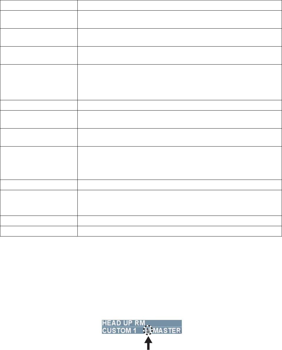
52
Menu Item Contents
Near range STC curve Change setting in accordance with sea condition. (2.5, 3.0, 3.5, 4.2) The
larger the value, the stronger the effect of STC
Color erase Erase color in the order of weaker echo first (1~8). The larger the value,
the weaker the color
TT echo level Set echo detection level (1~31). Echoes at the lower level than the set
value do not track for TT.
Band width Set according to sea state.
Narrow: Gain is high compared to wide.
Wide: Effective for detecting targets masked by the returns from the sea
and rain.
Range (0.75~24 NM) Select transmission pulse length of preset for each range.
Range Select unit of far range. (NM, km, etc.) Range unit of VRM and cursor
position also change.
Unit for near range Select unit of near range. (m, etc.) Range unit of VRM and cursor
position also change.
Switch unit of range Set value (0.0~9.9) to switch the above [Range] and [Unit for near
range]. E.g. When [5.0] (NM or km) is set, the unit becomes the units of
far range when the range value is over 5.0 and the units of near range
when the range values is under 4.9.
Unit of ship length Select unit of ship length. (m, etc.)
VRM automatic unit Select whether to switch unit of VRM range ON or OFF at the above
[Switch unit of range] setting. When OFF is selected, put the cursor on
the unit inside of the VRM box then left-click to switch the unit.
Image name Change image name.
Return to factory default Reset image setting of the CUSTOM No. selected at step 2.
6. Select [Save and finish] at the lowest section of the [Edit image] menu to save the registered
contents then left-click.
7. Right-click several times to close the menu.
The above settings can be reflected also to the function keys when image settings are
registered in the function keys of F1, F2, Vector True/Relative, Target data list.
Note: When the menu is closed without step 6, the icon shown below is displayed between the
image box and the interswitch box. Left-click the icon to register the above settings and the icon
disappears.
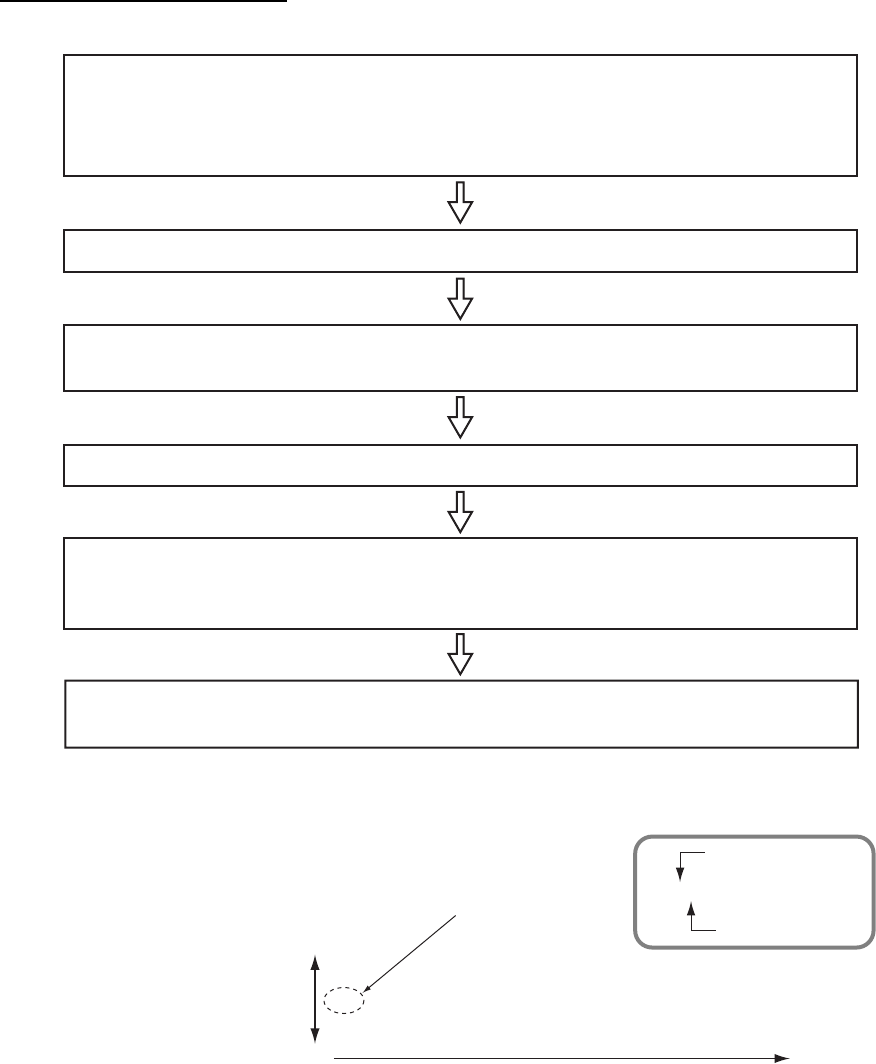
53
How to adjust the picture
Follow the flow chart below to adjust saved picture settings.
Set the controls as follows:
Interference rejector: Off Echo Stretch: Off Echo Averaging: Off
Gain: 80 (manual) A/C SEA: 0 (manual) A/C RAIN: 0 (manual)
Contrast curve: 1 Contrast type: B Low level echo: 0 Near STC curve: 3.0
Adjust the interference rejector (Off → 1→ 2→ 3) until the interference just disappears.
Set the A/C SEA to 0; A/C RAIN to 40. Then, adjust each control to sea surface and
rain returns are weak. The A/C RAIN control can also suppress sea returns.
Set the echo averaging function according to conditions.
As required, adjust the echo stretch and contrast curve.
- Echo stretch: Off ¨1 ¨2 ¨3. The larger the number the greater the stretch.
- Contrast curve: 1B is the general purpose setting. Avoid overadjustment.
Adjust the GAIN control. With the gain set at 80, adjust the control while watching sea
conditions and targets.
About the contrast curve and contrast curve type settings
1A 2A 3A 4A
1B 2B 3B 4B
1C 2C 3C 4C
General purpose
setting
Contrast curve
Ex.: 1B
Contrast curve
The gain of signal
strength at the center is
low to distinguish the
returns from the sea and
rain from targets.
The gain of signal
strength at the center is
high to get long range
detection. It is difficult to
distinguish targets from
the returns from the sea
and rain.
The gain is overall high to get
long range detection. It is difficult
to distinguish targets from the
returns from the sea and rain.
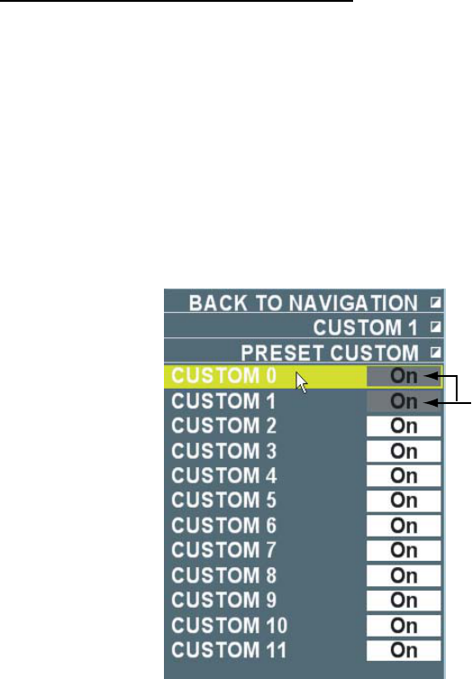
54
Turning off unused image settings
There are twelve settings in the image box. You can turn the unused settings off. You can switch
the settings of image that are turned [On] in the image box by left-clicking.
Note: [CUSTOM0] and items currently open cannot be turned off.
1. Put the cursor on the image box at the upper left section on the screen then right-click.
2. Select [Preset] then left-click.
3. Select an item to change then left-click.
4. Select [Off] then left-click.
5. Right-click several times to close the menu.
Items in gray background
cannot be changed
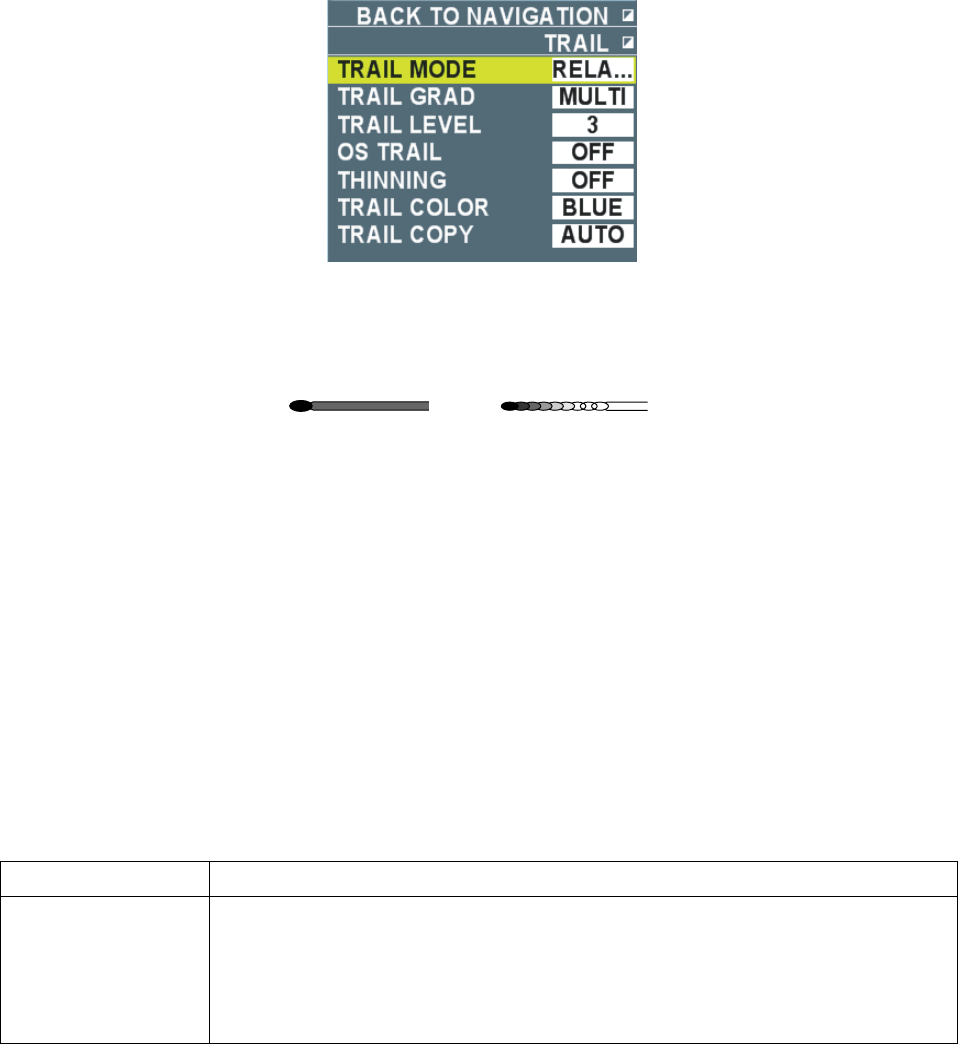
55
2.10.5 Setting Trails
Put the cursor on [Trail] in the trail box at the lower right section on the screen then right-click to
display the [Trail] menu.
Trail mode: Set Relative, True, Water True. (See chapter 1.23.2 for details.)
Trail gradation: Select a trail gradation.
Single gradation: Display in the same shade.
Gradual gradation: Gradually shades as time passes.
Single gradation Gradual gradation
Trail level: Select strength of target echo to trail from 1~4. No echo trail under the set value.
Own ship trail: Select thickness of own ship track (1, 2). [2] is a thicker track than [1]. No own
ship track is displayed when [OFF] is selected.
Thin line trail: Select thickness of track. (OFF, 1, 2). It is useful when there are many targets as
a track can be drawn with a thin line. [OFF] draws the thickest track and [2] draws the thinnest
track.
Trail color: Select trail color from blue, green and turquoise. The trail color changes in the order
shown below as the time passes when the trail time settings are 12 hours, 24 hours or 48 hours,
and above [Trail gradation] setting is [Monotone]. (12 hours: every one hour, 24 hours: every
two hours, 48 hours: every four hours)
Pink→ Reddish brown→ Red→ Purple→Yellow→Yellowish green→Green→Brownish
green→Bluish green→Turquoise→Blue→Dark blue
Echo trail copy: Select the trail copy function ON (Auto) or OFF.
Settings Function
ON, Auto When range is changed during trail, it becomes the following condition.
- Range is set larger: Only the center section of the new range, or only the trail
in the previous range continues on the display. Nothing is displayed outside
the new range.
- Range is set smaller: Trail continues with the previous trail on the display.
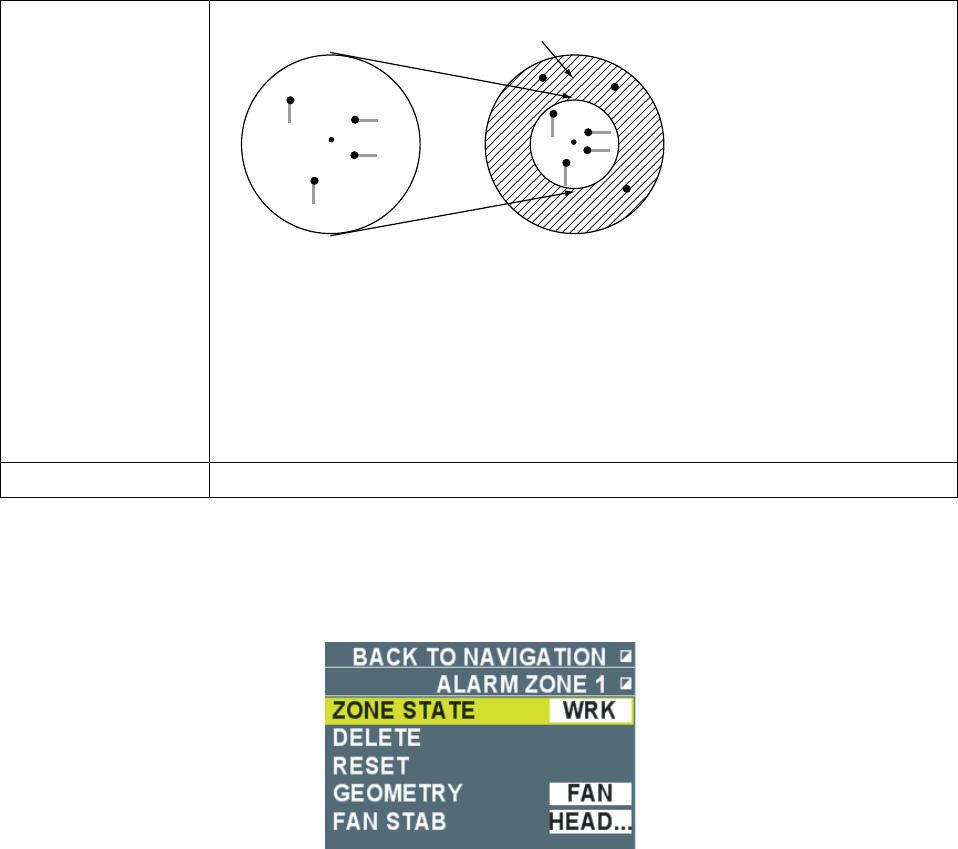
56
Trail is not copied
Range before the change Range after the change
Note: When [Auto] is selected and range is changed to under ¼ of the current
range, the previous trail disappears and a new trail is redrawn. For example,
for 3NM, trail continues up to 0.75NM and disappears under 0.5NM.
When the range is returned to ¼ of the original range within about 12 seconds
after the range is changed, the previous trail continues.
OFF Trails disappear in the previous range when range is changed during trailing.
2.10.6 Guard Alarm
Put the cursor on the box by [Guard1] or [Guard2] at the lower right section on the screen then
right-click to display the [Guard alarm1] or [Guard alarm2] menu.
Status: Display operating condition of guard alarm.
Delete: Delete guard alarm.
Reset: Reset alarm area
Area shape: Select a shape of guard area. (Sector, Polygon). When [Polygon] is selected, the
setting of [Sector fixed mode] becomes [Land fixed*] *: Alarm area is fixed on land.
Sector fixed mode: Select a method to fix alert area of a sector when [Sector] is selected in the
above [Watch shape].
• Land fixed: Cannot use.
• True bearing: Alarm area is fixed from true North.
• Heading: Alarm area has the same positional relationship with own ship’s heading.
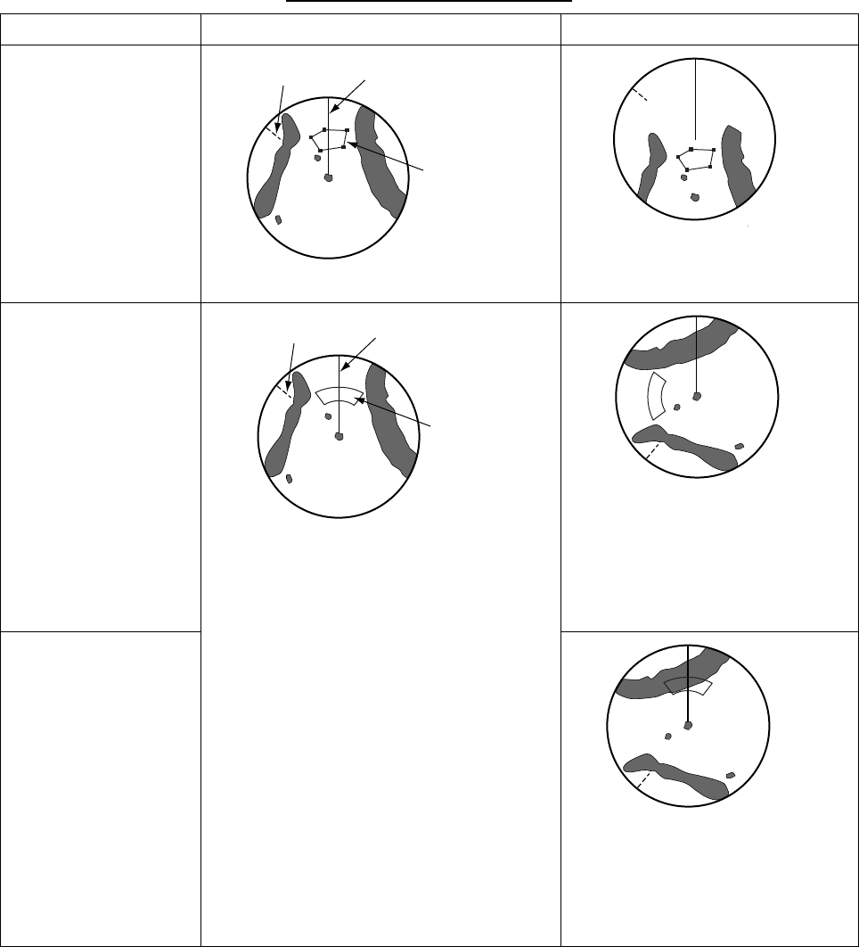
57
Fixed land/True Bearing/Heading
Fixed mode Immediately after setting After some time passed
Land fixed (polygon)
North mark Heading line
Alarm area
Own ship moves straight.
Set at latitude.longitude position.
True bearing (Sector)
Own ship turns 90°
Fixed at True North
(North mark). Alarm
area moves along with
North mark.
Heading (Sector)
North mark Heading line
Alarm area
Own ship turns 90°
Heading line fixed.
Alarm area moves along with
the heading line
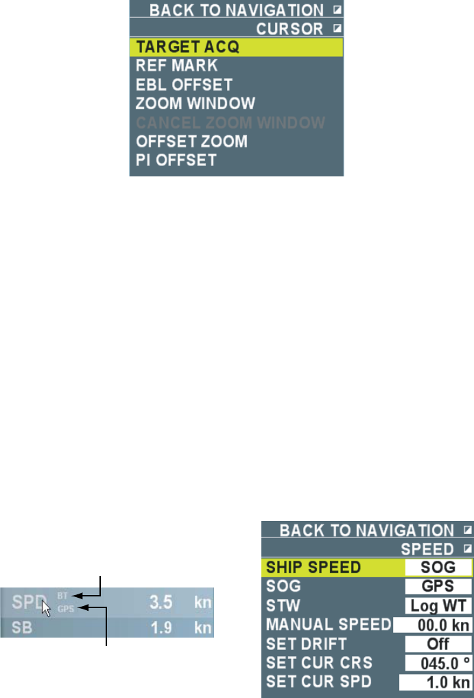
58
2.10.7 Cursor
Put the cursor in the valid radar then right-click to display the [cursor] menu.
Target acquisition: Acquire target. (Same as the [Acquisition] function. See chapter 3.4.3.)
Fixed target: Assign a fixed point mart to target. (See chapter 3.3.)
EBL offset: Offset EBL origin.
Zoom/Cancel Zoom/Offset Zoom: See chapter 2.6.
PI Offset: Move origin of parallel cursor.
1) Display parallel cursor. (See chapter 1.25.1.)
2) Select [PI offset] from the [Cursor] menu then left-click.
3) Move the origin of parallel cursor to an arbitrary position then left-click.
The parallel cursor is set.
4) Put the cursor on [PI1], [PI2], [PI3] or [PI4] in the parallel cursor box then long press the left
button to return the origin of parallel cursor to the center of the screen.
2.10.8 Setting Ship Speed
Put the cursor on the areas of ship speed or ship speed in starboard direction in the information
display area then right-click to display the [Ship speed] menu.
Ship speed in use
Input source of ship
speed data
Ship speed: Select ship speed to use. (Speed over ground, Speed over water) [Ground] is
shown when speed over ground is in use and [Water] when Speed over water is in use.
Speed over ground: It becomes effective when [Speed over ground] is selected at the above
[Ship speed]. Select input source of speed over ground data.
• GPS: Received from GPS navigation equipment.
• Log (Ground): Received from speed log.
• Comparative ship speed: Speed over ground is used that is computed with the reference of
fixed target selected in the TT function.
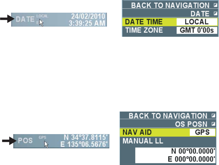
59
Speed over water: It becomes effective when [Speed over water] is selected in the above [Ship
speed]. Select input source of speed over water data.
• Log (Water): Read from speed log.
• Manual: Use ship speed inputted manually.
Manual ship speed: Input ship speed manually when speed log or GPS navigation equipment
are not connected, or ship speed data are no longer available.
Current correction: Select [Speed over water] at the above [Ship speed] and turn on the
current correction when speed over ground is unavailable such as in deep water area to
compute speed over ground. [Speed over water correction] is displayed during the current
correction.
Correct current direction/speed: Refer to the current table issued by the waterways authority
when [Current correction] is turned on to set bearing and speed of current.
2.10.9 Setting Date
Put the cursor on the date section in the information display area then right-click to display the
[Date] menu.
Standard time: Select display method of date and time (Standard time, Local time)
Time zone: Time zone is effective when [Local] is selected in the above [Standard time]. Local
time is displayed by setting the time difference between the Greenwich Mean Time.
2.10.10 Setting own ship position
Put the cursor on the position area in the information display area then right-click to display the
[Own ship position] menu.
Select navigation: Select input source of datum positioning data. (Dead Reckoning, GPS)
Manual input latitude/longitude: It becomes effective when [Dead reckoning] is selected in the
above [Select navigation method]. Input latitude and longitude manually. Roll the wheel to witch
between North/South latitude and East/West longitude.
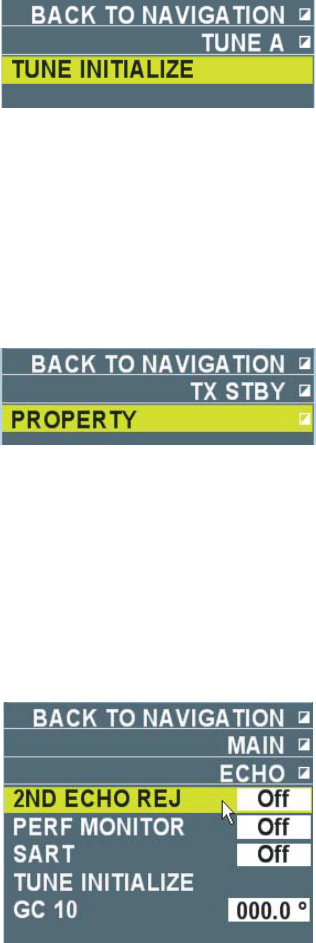
60
2.10.11 Setting Tuning
Initialize tuning when automatic tuning is not working properly to show clear images. Put the
cursor on [Tuning] at the upper right section on the screen then right-click to display the [Set
tuning] menu.
Left-click [Initialize tuning] to start initializing tuning. The indication [Initialize tuning] flashes.
Press the [Cancel alarm] key to change the flashing to lighting. Initialization is completed when
the display disappears.
2.10.12 Getting ready to transmit
Put the cursor on the Getting ready/Transmission box on the upper left section on the screen
then right-click to open the [Getting ready to transmit] menu.
Left-click [Running time] to check the current running time and the transmission time. The menu
disappears automatically after about five seconds.
2.11 Menu Items
Items not explained previously are explained here.
2.11.1 Echo menu
Second-trace echo rejection: Second-trace echoes of very distance targets may appear as
false echoes on the screen. This occurs when the return echo is received one transmission cycle
later. Mountains in far distance, for example, have strong reflections making second-trace
echoes more likely to occur. Turn the rejection of second-trace echo ON to reject second-trace
echo.
Performance monitor: Not used.
SART: When SART (Search and Rescue Transponder) power is turned ON from a ship in
distress within 8NM range from own ship, response signal is transmitted from SART in response
to the radar signal of own ship. When the signals are received by this equipment, the image
appears as shown below (a line of 12 dots equally spaced by about 0.64 NM) Screen 1 shows
when the ship in distress is at relatively far distance and only low speed sweep signals are
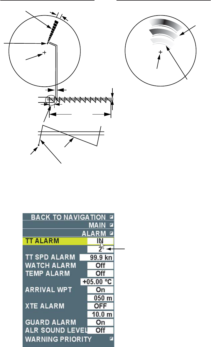
61
displayed. It shows the ship in distress is located at the closest position from the center of the
radar. When own ship is about 1NM to SART, high speed sweep signals are also displayed as
shown in Screen 2 (12 dots in arc shape) When the radar is turned [On], the setting changes as
below to make SART image easier to see.
Range: 12NM, Pulse length: Long, Precipitation rejection: Manual (0)
Settings of second-trance echo rejection, wiper, zoom image, noise rejection, and signal
processing cannot be changed.
9500 MHz
9200 MHz
7.5μs
95μs
24 NM 1.5 NM
Screen1: When SART is distant Screen2: When SART is close
Echo from SART Radar antenna
bandwidth
Echo from
SART
Position of
SART
Own ship
position
Radar receiver
bandwidth
SART mark
length
Sweep time
Sweep start Low speed sweep signal
High speed sweep signal
Position of
SART
Own ship
position
GC-10: Set a correct value to match the indication of Gyrocompass when heading value is
incorrect.
2.11.2 Alarm Menu
Guard alarm level
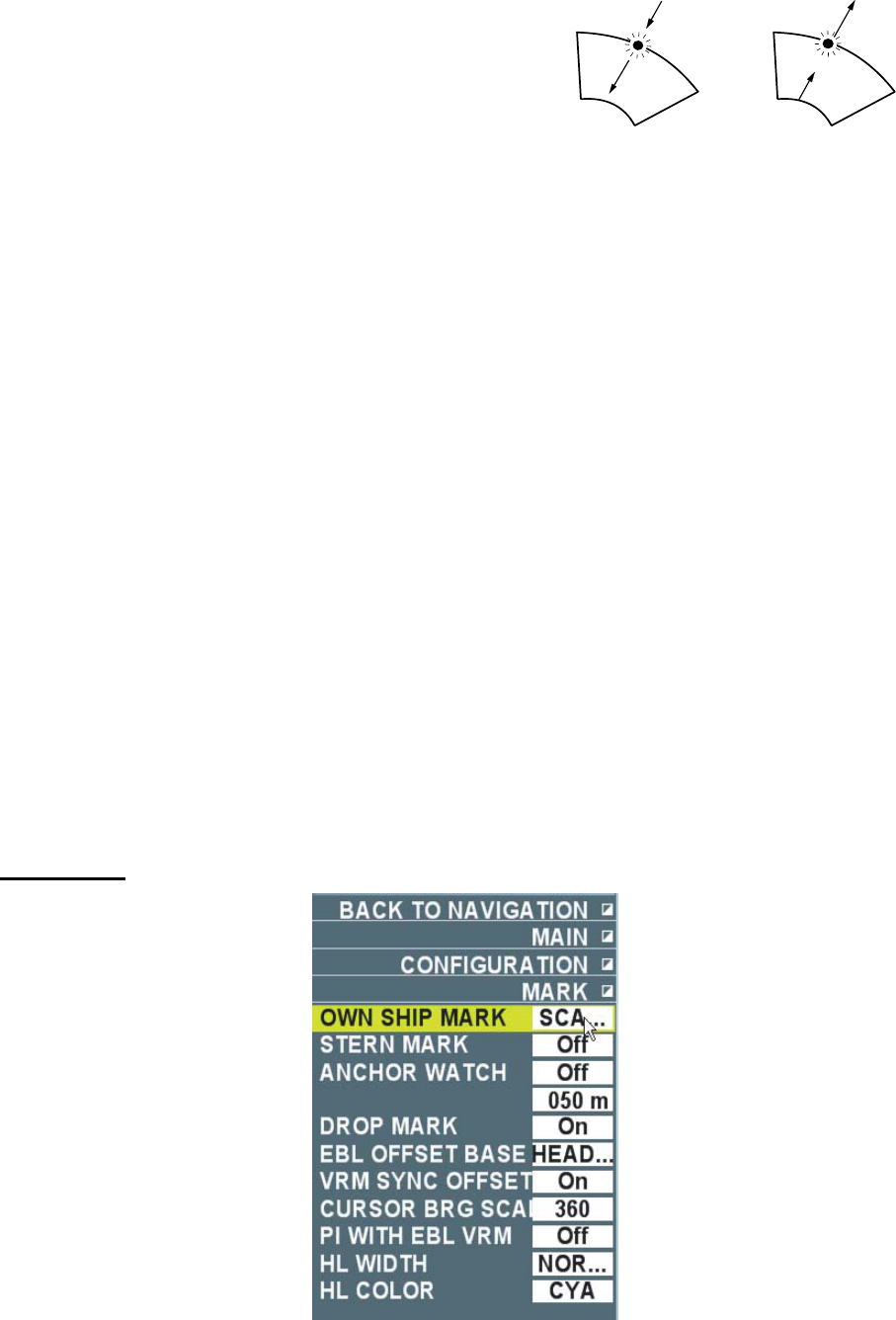
62
Guard alarm mode: Select guard alarm mode.
- Enter: Alarm is generated when other ship, island and
reef enter into the set area.
- Exit: Alarm is generated when targets inside of the set
area exit the set area.
Guard alarm level: Echo strength of target from level 1 ~4 to generate alarm. Level 4 is a strong
echo against which alarm is generated.
Water temperature alarm: Data on water temperature is required. Select water temperature
alarm mode.
- High: Alarm sounds and displays an alarm message when own ship enters water with higher
temperature than set temperature.
- Low: Alarm sounds and displays an alarm message alert when own ship enters water with
lower temperature than set temperature.
Guard alarm setting: Set whether to output alert sounds and message when targets enter or
exit alarm area.
- On: A single beep is emitted when echoes exist in the alarm area and alarm sounds and an
alarm message is displayed.
- Off: Only a single beep sounds when echoes exist in the alarm area.
When external buzzer is connected, the following condition occurs. See the installation manual
when [Guard alarm] has a checkmark in [Common 2] – [Alarm external output] in the initialization
wizard.
- When the above setting is [On]: Alarm sounds from an external buzzer.
- When the above setting is [Off]: Only single beep sounds from an external buzzer.
Alarm volume: Select alarm volume from low, mid and high. No alarm sounds when alarm
volume is [Off].
2.11.3 Set Environment Menu
Mark menu
Enter mode Exit mode
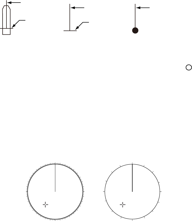
63
Own ship mark: Select a shape of own ship mark from smallest, real scale and circle. Real
scale symbol is displayed in the ship mark in accordance with ship length and beam of own ship.
The ship mark disappears when own ship mark becomes less than about 2.5cm on the screen to
become the smallest symbol. Size of own ship is entered at installation. Own ship mark
disappears when the setting is [OFF].
Heading line
Heading line Heading line
Bean line Bean line
True scale symbol The smalles symbol Circle symbol*
When [Own ship track memory] is ON
in the [Own track] menu
*When [Own ship tack memory] is OFF in
the [Own track] menu a white circlile is
show .
Stern line: Stern line is displayed opposite of the heading line when it is turned ON.
EBL offset reference point: Select a reference point of EBL offset.
- True bearing: The reference point is fixed at a position from true north.
- Relative bearing: The reference point maintains the same position relationship with own ship’s
heading line.
- Land fixed: The reference point is fixed at a position on land.
VRM offset link: Select whether to link VRM reference point to the reference point of EBL.
- On: VRM reference point is linked to EBL reference point.
- Off: VRM reference point is at the center of own ship at all times.
Cursor bearing scale: Bearing scale on the screen is displayed with 360 ゚or 16 bearing.
000 010 020
030
040
050
060
070
080
090
100
110
120
130
140
150
160
170
180
190
200
210
220
230
240
250
260
270
280
290
300
310
320
330
340 350 N
NNE
NE
ENE
E
ESE
SE
SSE
S
SSW
SW
WSW
W
WNW
NW
NNW
16 bearing
360°
PI line operation: Select whether to display PI line linking EBL2 and VRM2.
Width of heading line: Select width of heading line from standard, double and quadruple.
Color of heading line: Select color of heading line from red, green, blue, yellow, turquoise,
purple and white.
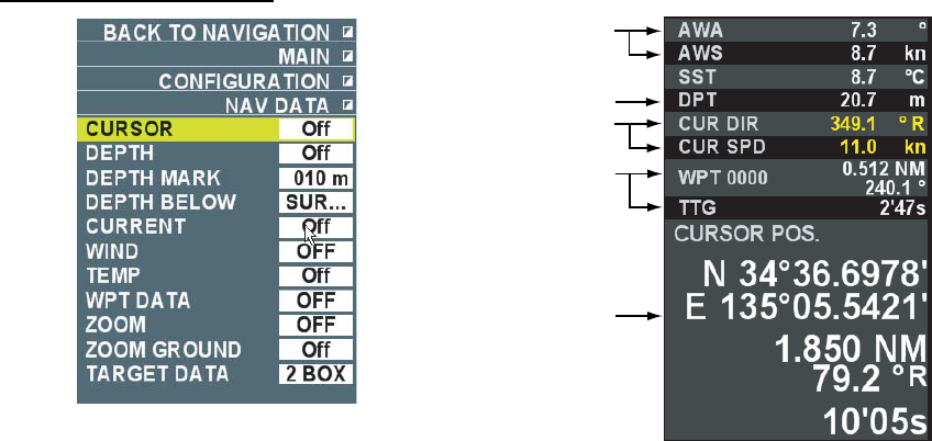
64
Navigation data menu
[Wind direction/Speed] ON
(True of Relatic\ve)
[Cursor info] ON
Inside of information display area
[Destination data] ON
[Water deoth] ON
[Current] ON
Cursor data: Select whether to display cursor data in the information display area. When [On] is
selected the setting of [Zoom mode] in the [Navigation data] menu is [OFF].
Water depth: Select whether to display water depth in the information display area. Fish finder
needs to be connected to display water depth.
Water depth alarm: Alarm sounds when water depth from the [Water depth reference] is
shallower than the set value. [Water depth] flashes in the alarm box in the information display
area.
Water depth reference: Select a reference of water depth.
- Sea surface: Display water depth from transceiver.
- Keel: Display water depth from keel.
Current: Select whether to display current speed/direction in the information display area.
Current meter needs to be connected to display current. Bearing of current is referenced to own
ship’s heading (R: relative) in Head-up, Cursor gyro and Stern-up modes. North (Blank: True) is
referenced in Course-up, North-up and True motion modes.
Wind speed/direction: Select whether to display wind speed/direction in the information display
area. Connection of wind speed/direction sensor is required. Select [Relative] or [True] to display
data received from the wind speed/direction sensor.
Water temperature: Select whether to display water temperature in the information display area.
Water temperature data are required to display water temperature.
Destination data: Select whether to display range and bearing and estimated time from own
ship to destination. Select [Relative] or [True] to display destination data.
Target data: Select number of boxes (1BOX, 2BOX) to display TT target or AIS target data in
the information display area.
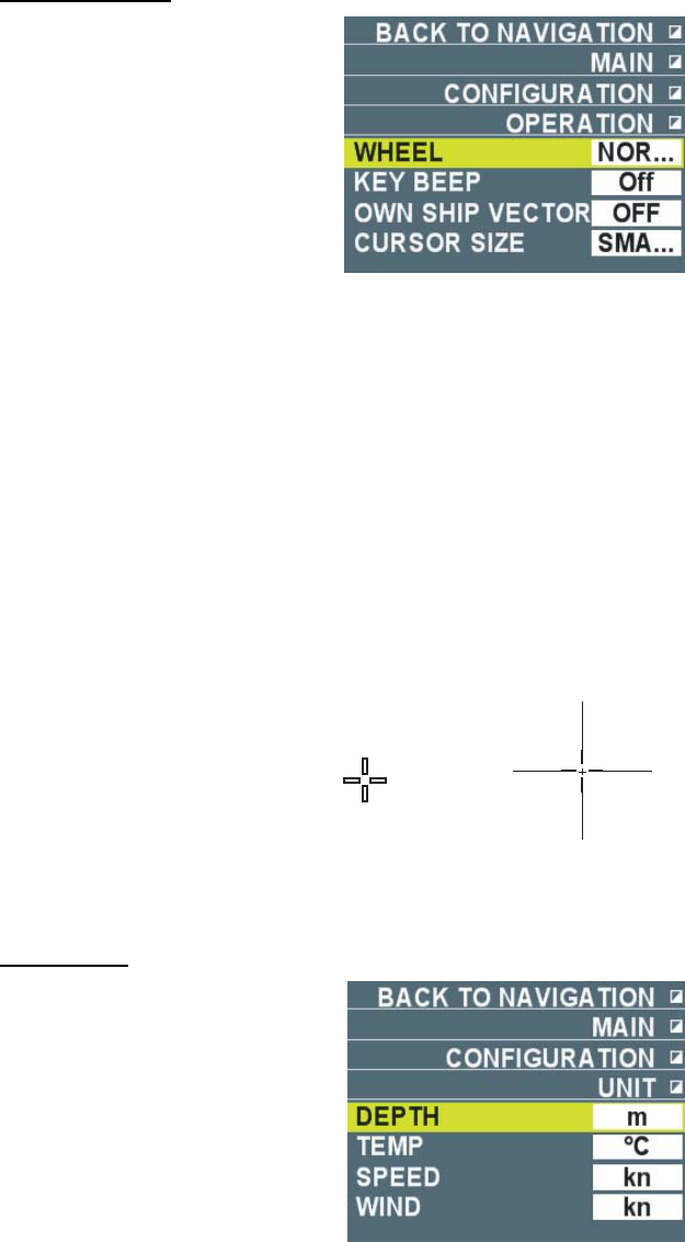
65
Control menu
Wheel: Select direction of rotation of wheel.
- Forward: The selection cursor moves from top to down when wheel is rolled toward you on the
menu.
- Backward: The selection cursor moves from down to top when wheel is rolled away from you
on the menu.
Key operation sound: Select volume of sound from Low, Mid and High when key is pressed.
No sound is emitted when [Off] is selected.
Own ship vector: Select a method to display own ship vector. No own ship vector is displayed
at [OFF].
- Heading: Display own ship vector toward heading.
- Course: Display own ship vector toward course.
Courser size: Select cursor size from Small or Large. Set the cursor size Large when small
cursor became invisible buried in echoes when using the small cursor.
Small cursor Large cursor
(Up to the edge of the screen)
Unit menu
Water depth: Select unit of water depth from m, ftm, etc.
Water temp: Select unit of water temperature from °C or °F.
Speed: Select unit of speed from kn, m/s, km/h, mph.
Wind speed: Select unit of wind speed from j/s, kn.

66
3. TARGET TRACKING (TT)
3.1 Usage Precautions
Purpose of this function is to aid route monitoring for navigational safety. It is not a substitute of
basic navigational principles and common sense of navigators. Excessive reliance on the
monitoring of the equipment or erroneous handling of the equipment could adversely cause a
dangerous result. Please note the following very carefully.
Depending on radar setting, it may fail to acquire necessary targets or track unnecessary echoes
such as sea clutter. In some cases, radar settings may be unsuitable to the functions. Adjust
each radar function properly to suite each situation.
Normal acquisition and tracking may become difficult in situations such as strong and wide sea
clutter or precipitation, targets in low clouds and many noise interferences. Make adjustments
accordingly to reject excessive sea clutter and precipitation clutter. Please note also that
necessary targets could disappear when gain setting is too low or sea clutter rejection setting is
too high.
Tracking errors
The plotting accuracy and response of this TT meets IMO standards. Tracking accuracy is
affected by the following. Own ship’s slow course change does not affect the tracking accuracy,
however, fast course change may affect all the tracking targets and may take one to two minutes
to restore vectors to full accuracy. (The actual amount depends on gyrocompass specifications.)
The amount of tracking delay is 15~30 seconds to display the course of TT target when other
ships’ relative speed is fast and 30~60 seconds of delay when other ships’ relative speed is slow
(close to zero). Accuracy may drop a little during a course change but will restore in short time.
Display accuracy
The following items may affect display accuracy.
1) Echo intensity
2) Radar transmission pulse length
3) Radar bearing error
4) Gyrocompass error
5) Course change of own ship and other ship (response error)
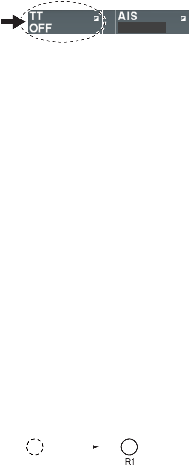
67
3.2 Turning TT ON/OFF
Follow the steps below to turn TT display ON/OFF.
1. Put the cursor on TT box in the information display area.
DISP OFF
TT box
2. Left-click to select [Auto/Manual]* or [OFF].
*: Either [Manual] or [Auto] is displayed depending on [TT target] menu setting.
Auto, Manual, Auto/Manual: Display TT target on the screen.
OFF: Delete TT target from the screen.
3.3 Ship Speed Input
The TT requires own ship’s speed and heading data. The speed can be speed over ground,
speed over water, or echo-referenced speed (based on 3 max. stationary objects). Echo-
referenced ship speed is explained here.
The use of echo-referenced speed is recommended when:
• The speed log is not operating properly or not connected to the radar.
• The vessel has no device (Doppler sonar, speed log, etc.)
• No position sensor input
If you select echo-referenced speed, the TT calculates own ship’s speed relative to a fixed
reference target. This method is effective when error is large due to ship’s port-starboard
movement. The number of targets may be numbered R1, R2 or R3.
1. Select [Speed over ground] for [Ship speed] in the [Ship speed] menu. (See chapter 2.10.8.)
2. Select [Echo-referenced speed] for [Speed over ground] in the [Ship speed] menu. [Echo-
referenced speed] is displayed in the ship speed section in the information display area.
3. Move the cursor to a stationary object such as a small island or a light house within 0.1~24
(or 32) NM range from own ship.
4. Right-click to display the [Cursor] menu.
5. Select [Stationary target] then left-click. A fixed point mark is entered at the cursor position.
Ship speed is displayed after about one minute.
Immediately after after 3 min
Fixed point mark
6. Repeat steps 3~5 to mark the maximum of three stationary objects.
Note1: The fixed point mark disappears when echo disappears during acquisition and tracking
stationary target. The flashing indication [Stationary target lost] is displayed in the alarm box in
the information display area.
Note 2: Put the cursor on the fixed point mark then press the [Delete target] key to delete the
fixed point mark.
Note 3: You can display a vector on a stationary object by selecting [On] at [Fixed target vector]
in the [TT target] menu.
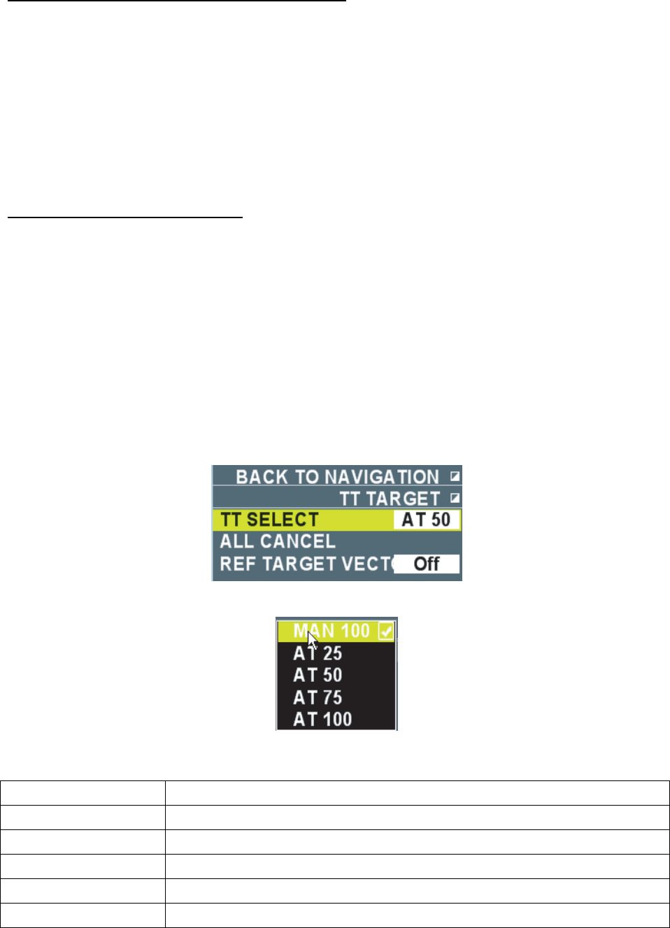
68
Notes on input of speed with a fixed target
• Select a stationary target as a reference target to calculate own ship speed as ground tracking
speed. Do not choose a moving target as a reference target. A moving target produces in error
in the vector for TT and AIS, which results in wrong collision avoidance information. Further,
an unstable stationary target produces inaccurate speed data and the target itself may
become lost.
• When all stationary targets are lost, the ship speed values becomes [---] in the information
display area. Reselect other stationary targets.
• When acquisition of all targets is interrupted, acquisition of stationary targets is also
interrupted and calculation of echo-reference speed becomes impossible.
Stop echo-referenced display
Select [GPS] or [Log (over ground)] for [Speed over ground] in the [Ship speed] menu.
3.4 Target Acquisition and Tracking
This equipment can acquire and track targets using the TT function either automatically or
manually.
3.4.1 Number of automatic acquisition and manual acquisition
This equipment can acquire the maximum number of 100 targets. The factory default setting is
AUTO75. (See the table below.) Set distribution of automatic acquisition and manual acquisition.
1. Put the cursor on TT box in the information display area then right-click.
2. Select [Number of TT automatic acquisition] then left-click.
3. Select acquisition points necessary then left-click. Refer to the following table to decide
distribution.
Selection Maximum Number of Auto/Manual Acquisition
Manual 100 Acquire all 100 targets manually.
Auto 25 Acquire 25 targets automatically and 75 targets manually.
Auto 50 Acquire 50 targets automatically and 50 targets manually.
Auto 75 Acquire 75 targets automatically and 25 targets manually.
Auto 100 Acquire all 100 targets automatically.
4. Right-click to close the menu. [Manual] is displayed in the TT box when [Manual 100] is
selected at step 3, [Auto] when [Auto 100] is selected and [Auto/Manual] when other than
[Manual 100] and [Auto 100] are selected.
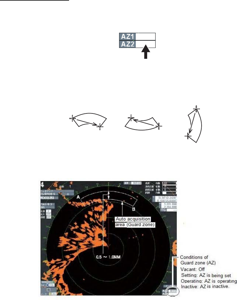
69
3.4.2 Automatic Acquisition
When automatic acquisition area (guard zone) is set, the TT function automatically acquires and
track targets entering into the guard zone. The maximum of two guard zones can be set. Sector
shaped guard zone has a width of 0.5NM~1.0NM in the radial direction and is adjustable from
3.0 to 6.0NM. Polygon shaped guard zone is adjustable from 0.125~120NM. Area of automatic
acquisition is from 0.1~24 (or 32) NM. The maximum tracking area varies depending on the
setting of initialization wizard. (See the installation manual.)
Setting a guard zone
Follow the steps below to set a guard zone. Heading signal is required to activate the guard
zone.
1. Put the cursor on the box by [AZ1] or [AZ2] at the lower right section on the screen.
2. Left-click. The cursor moves inside of the valid radar echo are and [Set] is displayed in the
box.
3. Put the cursor on Point A in the desired area. The figure below shows an example of setting a
guard zone.
Point A
Point A
Point A
Point B
Point B
Point B
4. Put the cursor on Point B in the desired area then left-click. The indication in the box changes
to [Operating]. Guard zone is shown with broken line during the setting and the broken line
changes to solid line when the setting is completed.
When radar target enters the guard zone, it is regarded as dangerous target and TT mark
flashes in red. [TT guard] in the alarm box in the information display area also flashes. Press the
[Cancel alert] key to change the TT mark to lighting. The TT mark changes as the time passes
as shown below. Vector (broken line or solid line) showing the moving direction of the target
appears within one minute of acquisition.
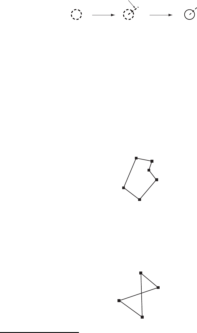
70
Vector
Circle with a thick
dotted line
Immediately after
acquisition
1 minute passed
after acquisition
3 minute passed
Circle with a solid line
Setting of [TT vector] is [Dashed line]
Note 1: When number of automatic acquisition target reaches 95% of the number set at Chapter
3.4.1, the flashing indication [TT target 95% (Auto)] appears in the alarm box in the information
display area. Press the [Cancel alert] key.
Note 2: When the guard zone extends over the display area when the range setting is small,
[Over the range] indication appears in the box and the color of inside of the box changes.
Note 3: When TT mark goes out of the guard zone, it is regarded as a normal target and the TT
mark changes to the same one at the time of manual acquisition to continue tracking. (See
chapter 3.12.2.)
Note 4: To make a polygon shaped guard zone (3 ~ 10 point), move the cursor to a desired
location then left-click. Repeat this operation to enter all the points.
Polygon shaped guard zone
• Polygon with less than ten points: Left-click again on the last point. The indication in the
box changes to [Operating].
• Polygon with ten points: When the 10th point is placed, the indication in the box changes
to [Operating].
No crossed lines can be drawn as shown below.
Inactivating guard zone
Follow the steps below to inactivate the guard zone. When the guard zone is inactive there is no
automatic acquisition.
1. Put the cursor on the box by [AZ1] or [AZ2] to inactivate.
2. Left-click. The indication in the box changes to [Inactive] and the guard zone is shown in
broken line. Dangerous target changes to a normal target (The same TT mark as that of
manual acquisition).
Note: To reactivate the guard zone, put the cursor on the inactive box then left-click.
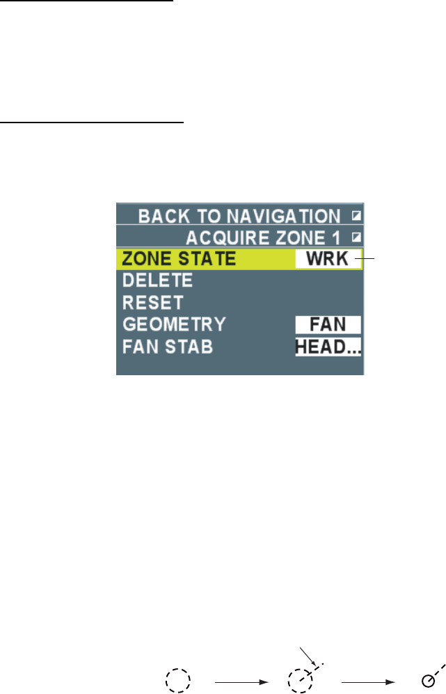
71
Deleting a guard zone
Follow the steps below to delete a guard zone.
1. Put the cursor on the box by [AZ1] or [AZ2] to delete.
2. Long press the left button until the indication disappears in the box. The guard zone
disappears from the screen.
Resetting a guard zone
Do the following steps to reset the guard zone.
1. Put the cursor on the box by [AZ1] or [AZ2] to reset or on the guard zone on the screen.
2. Right-click to display the [Guard zone1] or [Guard zone 2] menu.
Condition of guard zone
3. Select [Reset] then left-click. The guard zone on the screen disappears and the indication in
the box changes to [Set].
4. Reset the guard zone.
3.4.3 Manual acquisition
Target acquisition should be done within 0.1 ~ 24 or 32 NM range and no sea clutter and
precipitation clutter should exist.
1. Put the cursor over a target to acquire.
2. Press the [Acquire] key. TT mark changes as shown below as the time passes. Vector
(broken line or solid line) indicating the moving direction of the target appears within one
minute from the acquisition.
Vector
Circle with a thick
dotted line
Immediately after
acquisition
1 minute passed
after acquisition
3 minute passed
Circle with a solid line
Note 1: When number of manual acquisition target reaches 95% of the number set at Chapter
3.4.1, the flashing indication [TT target 95% (Manual)] appears in the alarm box in the
information display area. Press the [Cancel alert] key.
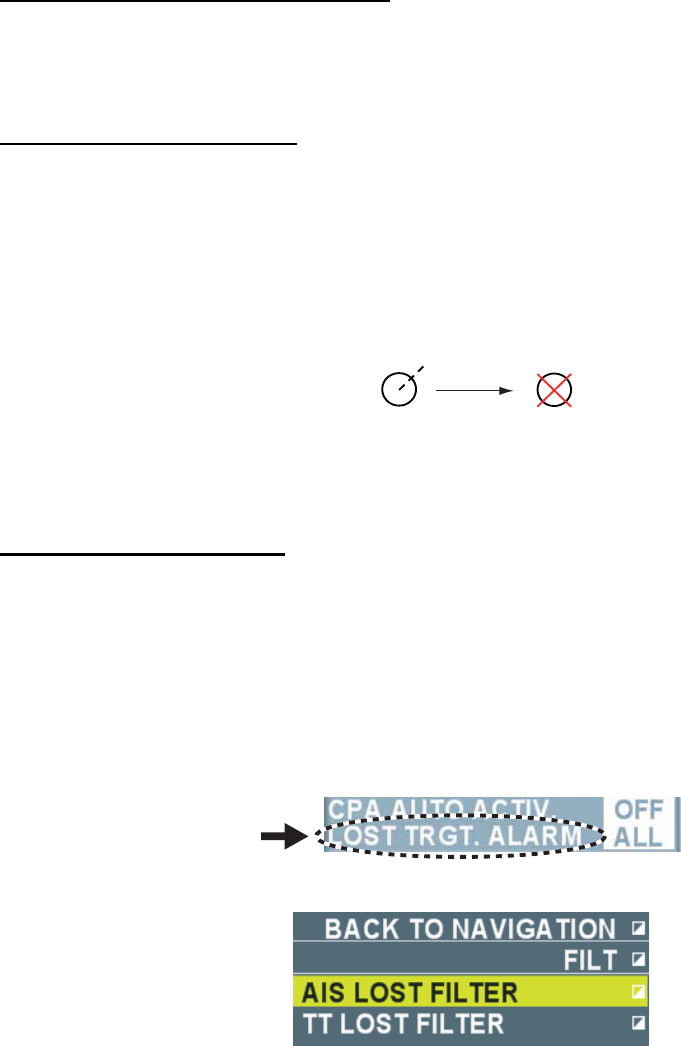
72
3.5 Terminating Tracking
When the TT has acquired the number of automatic acquisition (or manual acquisition), the
message [TT target Full (Auto or Manual)] appears in the alarm box in the information display
area and no more acquisition occurs unless targets are lost. Should this happen, cancel tracking
of less dangerous targets. There are two methods to cancel tracking of acquisition target as
shown below.
• Cancel tracking target individually.
• Cancel tracking all targets.
Cancel tracking target individually
1. Put the cursor over TT mark for which to cancel tracking. When TT mark is selected correctly,
the size of the mark gets larger.
2. Press the [Delete target] key. The TT mark disappears.
Cancel tracking all targets
Long press the [Delete target] to delete all TT marks and fixed point marks.
3.6 Lost Target
Targets not detected in nine consecutive scans become “lost targets.” A lost target is shown in
the display with flashing red “X”. [TT lost] is also flashes in the alarm box in the information
display area.
Before flashing
(Flashing)
After flasing
Changes of mark before/after a lost target
Acknowledge Lost target
Press the [Cancel alarm] key to acknowledge a lost target. The lost target disappears from the
screen.
3.6.1 Setting the lost target filter
You can limit the lost target alarm to sound against lost targets by changing the maximum range
or the minimum ship speed.
1. Put the cursor on [Lost target alarm] in the information display area.
2. Right-click o display the [Filer] menu.
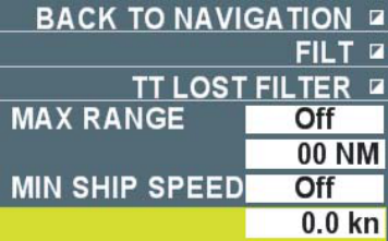
73
3. Select [Lost filter] then left-click.
4. Select [Maximum range] or [Minimum speed] then left-click.
• Maximum Range: Any TT lost targets beyond this range will not trigger the lost target
alarm. For example, when the setting is [5NM], TT over 5NM apart from own ship will not
trigger the lost target alarm. TT within 5NM range will trigger the lost target alarm.
• Minimum Ship speed: Any TT lost targets slower than this setting will not trigger the lost
target alarm.
5. Select [On] then left-click.
6. Select a line within the setting limit then left-click.
7. Input value.
8. Right-click several times to close the menu.
3.6.2 Setting Lost Target Alarm
Enable or disable the lost target alarm. Setting is the same with that of AIS target. (See chapter
4.9.2.)
1. Put the cursor on [Lost target alarm] in the information display area.
2. Left-click to select the setting. Each click switches between [OFF], [Filter] and [All].
• OFF: Disable the alarm. Lost targets automatically disappear.
• Filter: Get the alarm against the targets whose criteria meet the settings in
Chapter 3.6.1.
• All: Get the alarm against all lost targets.
3.6.3 Re-acquiring a target with the same target number
You can acquire a new target with the same target number of the lost target. Normally when a
target is acquired, a target number is automatically assigned to it. This feature is useful when
manually acquiring a target using the number of the lost target.
1. Put the cursor over the lost target.
2. Left-click. The lost target is surrounded with a broken line and a target number is assigned to
it. (See chapter 3.7.1 for details.)
3. Press the left button and move the cursor to the position of a new target to acquire. A solid
line connects the lost target to the cursor position.
4. Release the left button. The lost target selected in step 1 disappears and TT mark appears at
the position specified in step 3.
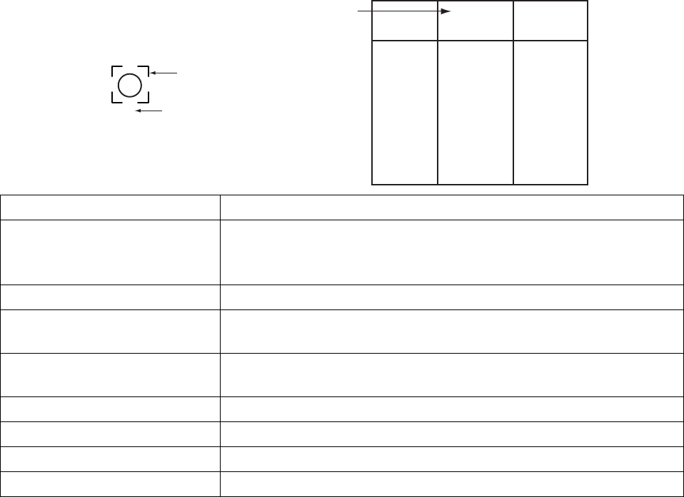
74
3.7 Displaying Target Data
You can display bearing, range, course, over the ground speed of a tracked target.
3.7.1 Displaying data of individual target
You can display two target data in one data box in the information display area.
1. Put the cursor on TT mark of which data to display.
2. Left-click. A target number is assigned to the TT mark.
TT mark is surrounded with a dashed square when the setting of [Selection frame] is [On]
(factory default) in the [TT/AIS symbol] menu. The selected target data is displayed in the
data box in the information display area.
1
Square of
dashed line
Target number
Factory Default Condition
Target number TT 1
Bearing
Range
Course
SOG
CPA
TCPA
BCR
BCT
61.5°
1.496 NM
246.7°
5.0 kn
1.085 NM
0’30s
1.745 NM
20’16s
Display Item Contents
Bearing Bering of a target seen from own ship
Add [R] (Relative bearing) for Head-up and Stern-up mode. True
bearing for other modes.
Range Range from own ship to a target
Course Course Over Ground of a target. Display [Water bearing] for water
ship speed.
Speed Over Ground Speed Over Ground of a target. Display [Speed over water] for
Speed over water.
CPA Range of target approaching own ship.
TCPA Time to CPA.
BCR Range from own ship when target crosses the heading.
BCT Time until a target crosses the heading.
Note 1: Select [2BOX] at [Target data] in the [Navigation data] menu to display the maximum of
four target data.
Note 2: Put the cursor over the target of which data are being displayed to delete target data
then left-click.
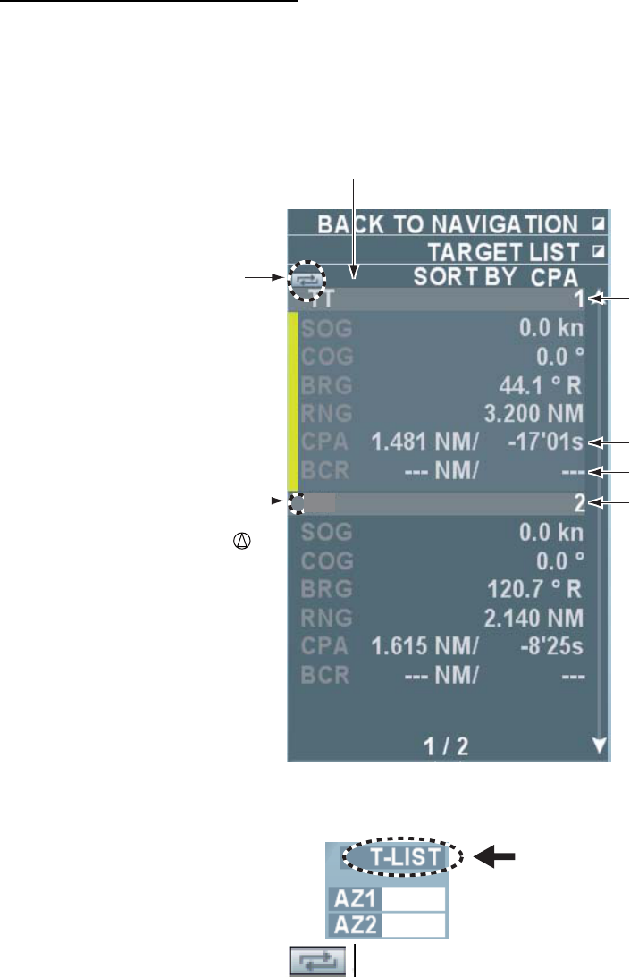
75
3.7.2 Display the target data list
You can display a list of target data of all targets acquired with TT or AIS functions.
Displaying the target data list
Follow the steps below to display the list of target data.
1. Press the [Target data list] key (factory default) to display the target data list. Roll the wheel
to scroll the target data. [>] is displayed when [TCPA] is over 99:59 min.
Target that meet the
identification criteria is
assgined the mark
in front of AIS and TT.
Updatge button
AIS
(1) Target number
TCPA
BCT
Ship name
(or MMSI no.)
(): Indicates that target data
is disolayed in the data box.
Note: When other functions are registered to the [Target data list] key, put the cursor on [Target]
at the lower right section on the screen then left-click.
2. Left-click the [Update] button on the upper section of the target data list to update
data then left-click. Target data are automatically updated when the method of ordering is
changed.
3. Right-click to close the target data list.
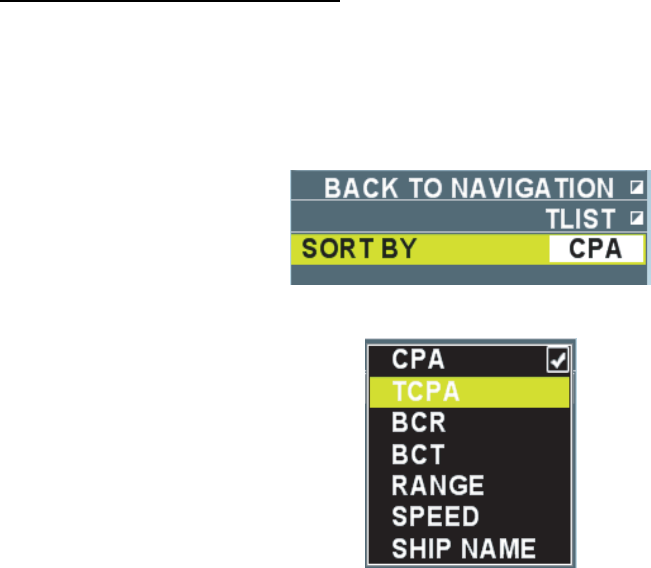
76
Reordering the target data list
Data in the target data list can be reordered in the orders of CPA, TCPA, BCR, BCT, range, ship
speed or ship name (for AIS).
1. Put the cursor on [Target] at the lower right section on the screen.
2. Right-click to display the [Target data list] menu.
3. Select [Order] then left-click.
4. Select a reference item to reorder then left-click.
5. Right-click to close the menu.
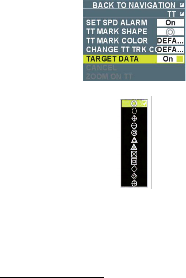
77
3.8 Changing Shape and Color of TT Mark
3.8.1 Selecting a shape of TT mark
You can select a shape of TT mark from twelve shapes.
1. Put the cursor on TT mark to change.
2. Right-click to display the [TT] menu.
3. Select [TT shape] then left-click.
4. Select a necessary shape then left-click.
5. Right-click to close the menu.
Note 1: You can also change the shape by rolling the wheel while the cursor is on the TT mark.
Note 2: Brilliance of TT mark can be adjusted by color scheme. (See chapter 2.9.)
3.8.2 Selecting color of TT mark
You can select color of TT mark acquired manually from seven colors of red, green, blue,
turquoise, purple, white and yellow. Color of TT marks inside of a guard zone cannot be changed.
Changing colors of all TT marks
1. Put the cursor on the [menu] in the information display area then left-click.
2. Select [Set environment] then left-click.
3. Select [TT/AIS] then left-click.
4. Select [TT/AIS symbol] then left-click.
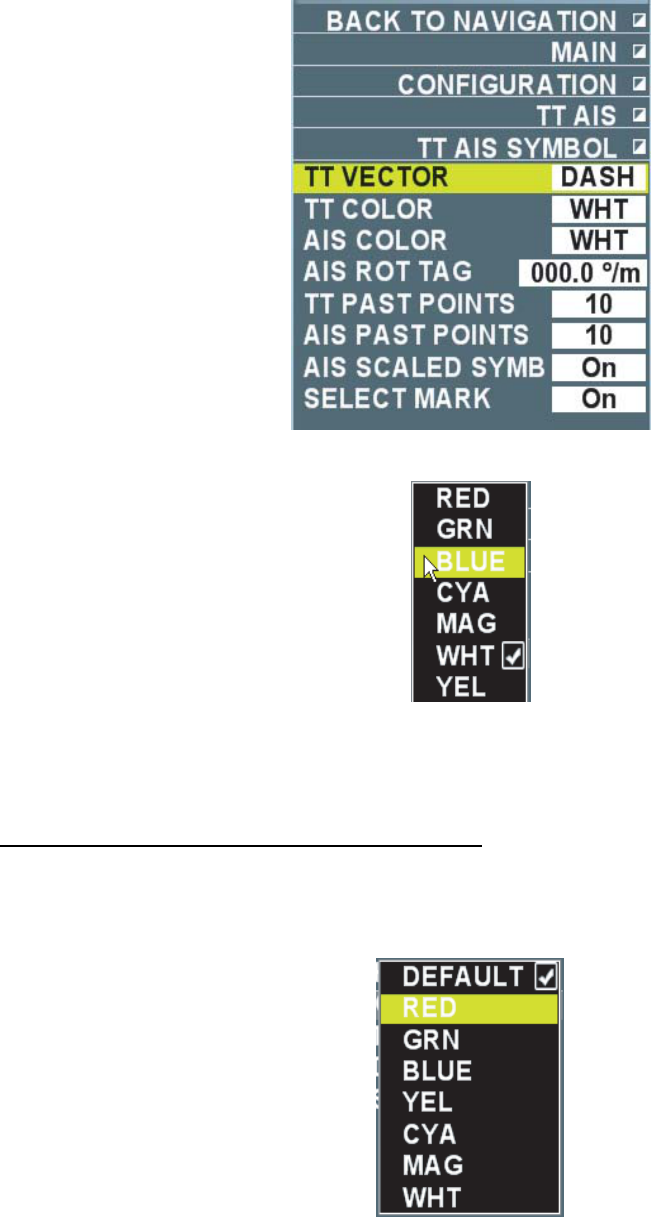
78
5. Select [Color of TT mark] then left-click.
6. Select necessary color then left-click. Color of all TT marks change. Colors that are
individually changed remain the same.
7. Right-click several times to close the menu.
Changing color of TT marks on the screen
1. Put the cursor on the TT mark to change.
2. Right-click to display the [TT] menu.
3. Select [Color of TT mark] then left-click.
4. Select color desired then left-click. Select [Select color in the menu] to select the color set at
[Color of TT mark] in the [TT/AIS symbol] menu.
5. Right-click to close the menu.
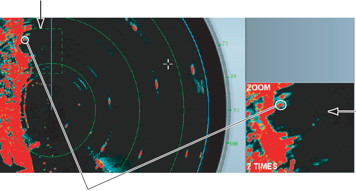
79
3.9 Zoom Target
You can enlarge a target with a specific TT mark at its center.
Note 1: TT marks cannot be zoomed.
Note 2: When more than three targets are displayed, no zoom window appears in the
information display area.
1. Put the cursor on a TT mark to zoom on the display.
2. Right-click to display the [TT] menu.
3. Select [Target zoom] then left-click. The zoom cursor (fixed at TT mark) on the screen. The
image in the zoom cursor is zoomed to twice the normal viewing size in the zoom window.
The zoom cursor moves with the movement of the TT mark.
Zoom cursor (a frame of dashed line with TT mark at its center
Zoom window in
the information
display area
TT mark
Note 1: The zoom function is automatically cancelled when TT mark to zoom changes to a lost
target and disappears from the screen.
Note 2: Move the cursor in the valid radar area then right-click to cancel the zoom function.
Select [Cancel zoom] then left-click.
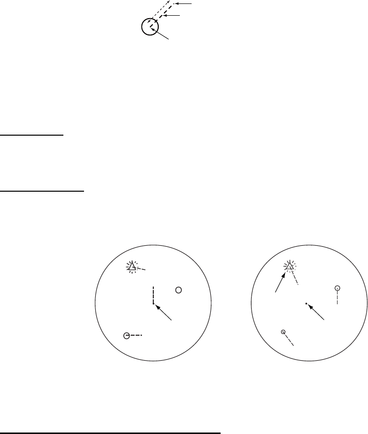
80
3.10 Displaying Vector
Vector is displayed by a line representing ship speed and course of a tracked target. The tip of
vector is a predicted target position after the set vector time has passed. You can predict a
possible collision with other target by extending the vector length (time).
Vector time Predicted target position after 15 min.
Vector
Current vector position
Vector time is set at [15 min].
3.10.1 Types of vector
True vector
True vector indicates the true movement of own ship and other ship relative to a landmass. This
mode is useful to distinguish between a moving target and a stationary target.
Relative vector
Relative vector shows movement of other ship relative to own ship. This mode is useful to find a
ship on a collision course with own ship. A ship whose vector passes through own ship’s position
is on a collision course.
AA
BB
Buoy
Buoy
Own ship Own ship
Target on
a collision
course
True vector
(Head-up)
Relative vector
(Head-up)
True vector/Relative vector
Ground stabilization/Water stabilization
The true vector mode display may be ground stabilized or sea stabilized. You can switch
between ground stabilization and sea stabilization at [Ship speed] in the [Ship speed] menu.
Select [Speed over ground] for ground stabilization and [Speed over water] for sea stabilization.
In true vector mode, [True] (Speed over ground) or [True-s] (Speed over water) is displayed in
the vector mode box.
Sea stabilization is a display method using heading and speed over water. Ground stabilization
is a display method using speed over ground or current correction. When accuracy is low,
current is corrected.
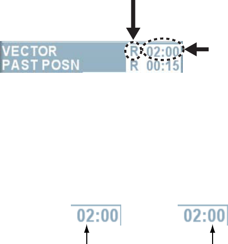
81
3.10.2 Selecting vector mode and time
There are true vector (ground/water) and relative vector. Vector time can be selected from 15
sec. 30 sec. 45 sec. 1~60 min. (one min. interval up to 20 min., ten min. interval after 20 min.)
Settings are common with AIS target.
1. Press the [Vector True/Relative] key (factory default condition) to select [True] or [True-s] or
[Relative]. The mode currently being selected is displayed in the vector box in the information
display area.
Vector time
Vector mode
Relative, True (Speed over ground)
True-s (Speed over water
Note: When other functions are registered to the [Vector True/Relative] key, Put the cursor
on [Relative], [True] or [True-s] in the vector box then left-click.
2. Put the cursor on Vector time then left-click. Each click switches display of vector time. Right-
click to reverse order. No vector is displayed when [00:00] is selected. Follow the steps below
to set the interval at 1 sec. or 1 min. after 20 min.
1) Put the cursor on Vector time then press the wheel.
[Minute] is activated. If setting of [Minute] is not needed, press the wheel and proceed to
step 3).
Minute Second
2) Roll the wheel to set [Minute] then press the wheel. [Minute] is activated.
3) Roll the wheel to set [Second] then press the wheel.
3.10.3 Selecting a vector line type
Vector can be displayed either by a broken line or a solid line.
1. Put the cursor on [Menu] in the information display area.
2. Select [Set environment] then left-click.
3. Select [TT/AIS] then left-click.
4. Select [TT/AIS symbol] then left-click.
5. Select [TT vector] then left-click.
6. Select [Solid line] or [Broken line] then left-click.
7. Right-click several times to close the menu.
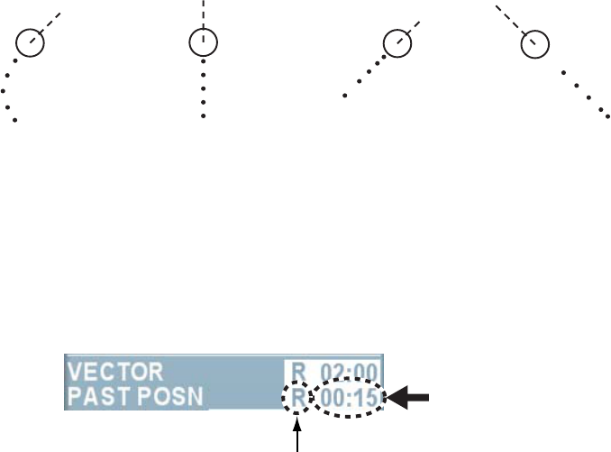
82
3.11 Displaying Track
You can see movements of all tracked targets by displaying their tracks. Number of points is
allotted to display on the screen. Interval of the points changes when a target changes its speed.
When a target changes its course, the track becomes a curve. The illustration below shows an
example of a track. A track disappears when the power is turned off.
(a) Turning (b) Moving straight (d) Accelerating(c) Reducing speed
3.11.1 Setting Track Interval
You can select a track interval to display from 15 sec., 30 sec., 45 sec., 1~60 min. (One min.
interval until 20 min., 10 min. interval after 20 min.) Settings are common with AIS target. (See
chapter 4.8.1.)
1. Put the cursor on the track interval box in the information display area.
Track interval box
Changes in accordance with the
setting of trail mode.
2. Left-click to select a track interval to display.
Each click switches the indication in the track interval box. Right-click to reverse order. No
track is displayed when [00:00] is selected. You can also set the time interval at 1 sec. and 1
min. after 20 min. by rolling the wheel on the track interval box.
3.11.2 Selecting number of tracks to display
Select number of tracks to display from five or ten.
1. Put the cursor on [Menu] in the information display area then left-click.
2. Select [Set environment] then left-click.
3. Select [TT/AIS] then left-click.
4. Select [TT/AIS symbol] then left-click.
5. Select [TT track points] then left-click.
6. Select [5] or [10] then left-click.
7. Right-click several times to close the menu.
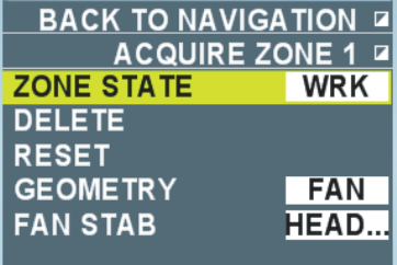
83
3.12 Guard Zone Alarm
When TT or AIS target enters a set guard zone, the flashing indication [TT enter (AIS enter)]
appears in the alarm section in the information display area. The applicable symbol changes to
flashing red. An inactive target symbol entering the guard zone is automatically changed to an
activated target symbol. (See chapter 4.2)
The guard zone functions as [Automatic acquisition area] when the setting is automatic
acquisition and all targets entering the guard zone are automatically acquired.
Refer to Chapter 3.4.2 for how to set, stop and delete the guard zone.
3.12.1 Selecting guard zone reference
Select a reference to display the guard zone AZ1 and AZ2.
Note: This operation is available only when the setting is [Sector] at [Shape of zone] in the
[Guard zone 1] or [Guard zone 2] menu.
1. Put the cursor on the box next to [AZ1] or [AZ2] or on the guard zone on the screen.
2. Right-click to display [Guard zone 1] or [Guard zone 2].
3. Select [Sector Fixed mode] then left-click.
4. Select [True bearing] or [Heading] then left-click.
• True bearing: Guard zone is fixed at the true north position.
• Heading: Guard zone maintains the same position relationship with own ship’s heading
line. [Land fixed] cannot be used.
5. Right-click to close the menu.
3.12.2 Selecting a shape of guard zone
You can select a shape of AZ1 and AZ2 guard zone from sector or polygon (3~10 points).
1. Put the cursor on the box next to [AZ1] or [AZ2] of which shape to change.
2. Right-click to display the [Guard zone 1] or [Guard zone 2] menu.
3. Select [Zone shape] then left-click.
5. Select [Sector] or [Polygon] then left-click.
When [Polygon] is selected, the setting of [Sector fixed mode] becomes [Land fixed*].
*: Guard zone is fixed at a geographical position.
5. Right-click to close the menu.
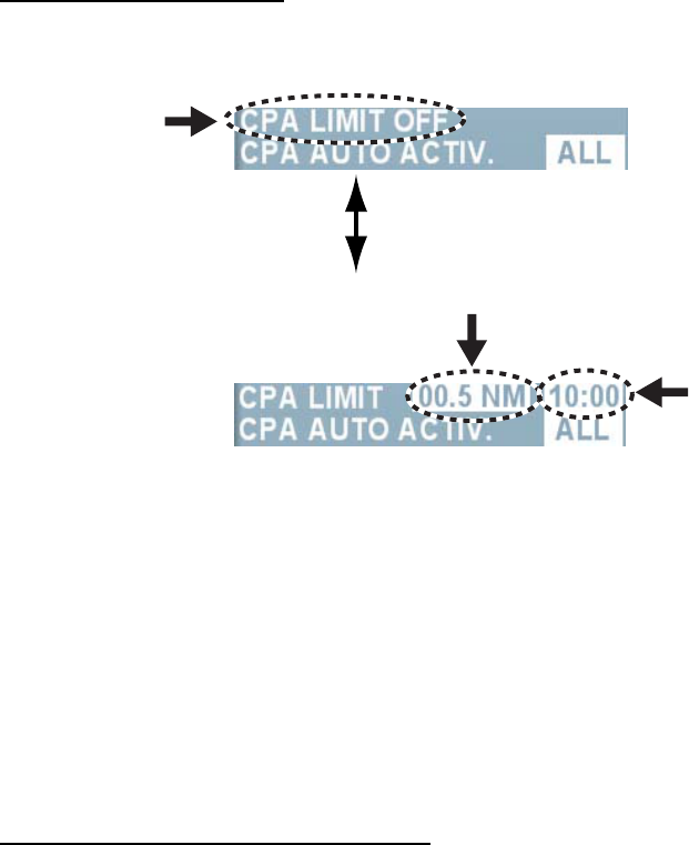
84
3.13 Setting Collision Alarm (CPA/TCPA alarm)
Thresholds of CPA (the Closest Point of Approach of other ship to own ship) and TCPA
(predicted time to CPA) can be preset to avoid a collision with other ship. (Settings are common
with AIS targets. See chapter 4.10.) When both CPA and TCPA of a tracking target become
smaller than the preset CPA and TCPA thresholds, the target becomes a dangerous target (red
flashing) and audio alarm sounds.
This function is useful to avoid the risk of collision with the target. It is very important, however, to
set gain, sea clutter rejection and precipitation clutter rejection correctly.
Note 1: The collision alarm is a support function for detecting the risk of collision. The navigator
is responsible to keep visual lookout for avoiding collisions at all times.
Note 2: Consider size of own ship, tonnage, ship speed and turning capacity when setting the
collision alarm.
Note 3: Select the position reference to calculate CPA/TCPA from antenna or steering position.
(See chapter 1.29.)
Setting collision alarm
4. Put the cursor on [CPA limit OFF] in the information display area then left-click.
Each click switches between the indications as shown below.
CPA setting box.
TCPA setting box.
2. Put the cursor on the CPA setting box.
3. Left-click to set CPA range.
Each click switches the indication in the CPA setting box in the order of 0.5, 1, 1.5, 2~24
(1NM interval). You can also set the range at 0.1NM or 1 NM interval by pressing the wheel
on the CPA setting box.
4. Put the cursor on the TCPA setting box.
5. Left-click to set TCPA time.
Each click switches between the indications inside of the TCPA box in the order of 1min. ~60
min. (1 min. interval up to 20 min., 10 min. interval after 20 min.). You can also set the time at
1 sec. interval or 1 min. interval after 20 min. by pressing the wheel on the TCPA setting box.
Acknowledging TT collision alarm
When collision alarm sounds, press the [Cancel alarm] key to stop the alarm sound. The flashing
indications [TT collision alarm] and the dangerous target also stop. Immediately take necessary
actions to avoid a collision.

85
3.14 TT Ship Speed Alarm
TT Ship speed alarm is a function to sound audio alarm when ship speed of a tracking target
exceeds the set value.
1. Put the cursor on [Menu] in the information display area then left-click.
2. Select [Alarm] then left-click.
3. Select [TT ship speed alarm] then left-click.
4. Enter setting value.
5. Right-click several times to close the menu.
6. Put the cursor over either of the TT mark.
7. Right-click to display [TT] menu.
8. Select [TT ship speed alarm] then left-click.
9. Select [On] then left-click.
10. Right-click to close the menu.
Audio alarm sounds when the alarm condition occurs and [TT ship speed alarm] flashes in the
alarm section in the information display area. A tracking target of more than the set ship speed is
shown in red flashing.
Select [Off] in step 9 to cancel TT ship speed alarm.
3.15 Test Steering (Steering simulation)
Test steering is a simulation to avoid collision. Enter a test course, ship speed and delay time
before starting the test steering to display the simulation result to predict the position relationship
with other ship. This function is useful to avoid the risk of collision by setting CPA and TCPA in
the steering simulation. Repeat entering various test courses, ship speeds and delay time until
no dangers exist. Acquisition and tracking of targets continue during the steering simulation. Use
relative motion and speed over water vector to display more accurate results. It is necessary to
set up characteristics of own ship correctly such as acceleration, turning capacity in order to
perform more accurate simulation.
3.15.1 Types of steering simulation
There are the two types of mode, dynamic mode and static mode in steering simulation.
Dynamic mode
Dynamic mode continuously displays motions of tracking target and own ship. Predicted
positions of own ship and each target are displayed every 30 second in the steering simulation.
Preset own ship speed, course and delay time. Display is updated every one second. Delay time
means the time between the current time to the time when own ship changes its course and
speed.
The illustration shows the own ship that is set to change its course and speed after 2 min. 30 sec.
(OS5 position). OS6 and OS7 indicate positions where course and speed are being changed.
OS8 indicates a position after the change of course and speed took place.
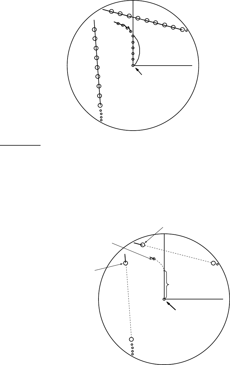
86
A
A0
B
B0
OS0
A1
A2
A3
A4
A5
A6
A7
A8
OS1
OS2
OS3
OS4
OS5
OS6
OS7
OS8 B1
B2
B3
B4
B5
B6
B7
B8
T
Delat time = 2 min. 30 sec.
Current
position of own
Static mode
Static mode shows the result of the steering simulation indicating the position relationship
between own ship and a tracking target. The steering simulation calculates the elapsed time
(initial testing time) until own ship reaches the set course and speed and shows the own ship at
that position. Each target is displayed at the position when the simulation time elapses.
You can increase or decrease the simulation time to see the results at arbitrary time settings.
Static mode is useful to immediately know the result of the steering simulation.
A
B
T
Position of target B after
testing time elapsed
Position where changes of
course/speed have been
completed and the ship is
at its set course/speed.
Target position
A after testing
time elapsed. Dalay time
Current position
of own ship
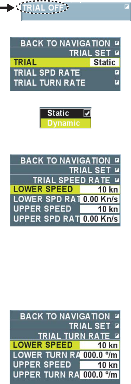
87
3.15.2 Performing steering simulation
Follow the steps below to perform the steering simulation.
1. Put the cursor on [Steering simulation OFF] in the information display area.
2. Right click to display the [Steering simulation] menu.
3. Select [Steering simulation] then left click.
4. Select [Static mode] or [Dynamic mode] then left-click.
5. Select [Ship speed rate] then left-click.
6. Select [Low speed] then left click.
7. Set low speed.
Refer to the ship’s data sheet for ship speed and speed rate in low and high speeds.
8. Select [Low speed rate] then left-click
9. Set low speed rate then left-click.
10. Similarly, set [High speed] and [High speed rate].
11. Right-click to return to the [Steering simulation] menu.
12. Select [Turn rate] then left-click.
13. Select [Low speed turn rate] then left-click.
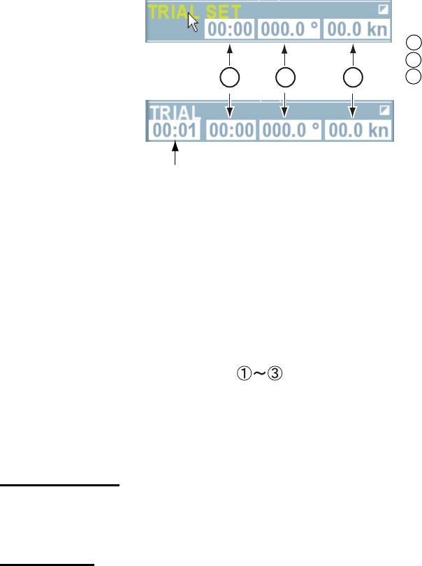
88
14. Set low speed. Refer to the ship’s data sheet for ship speed and turn rate in low and high
speed.
15. Select [Low speed turn rate] then left-click.
16. Set turn ate at slow speed.
Note: When the setting of ship speed rate is 0.00KN/s and turn rate is 0.0°/m, there is no
delay in own ship’s motion in the simulation.
17. Similarly, set [High speed] and [High speed turn rate].
18. Right-click several times to close the menu.
19. Put the cursor on [Steering simulation OFF] in the information display area then left-click. A
box appears as shown below according to the mode selected in step 4.
Testing time box.
Dynamic mode
Static mode
1 Delay time box
2 Course setting box
3 Ship speed setting box
123
20. Put the cursor on the delay time box.
21. Set delay time.
Set delay time when own ship speed/course are to be changed.
22. Put the cursor on the course setting box.
23. Set course.
24. Put the cursor on the ship speed setting box.
25. Set ship speed.
Note: You can also set course using the [EBL] knob, and ship speed using the [VRM] knob.
Put the cursor on either one of the boxes and turn the [EBL] knob or the [VRM] knob.
26. Put the cursor on [Steering simulation] for dynamic mode then left-click.
The simulation time box appears similar to the box in the static mode.
Steering simulation is different depending on the mode shown as below.
Dynamic mode
Estimated positions of own ship and each target are updated and displayed every 30
seconds. Simulation time increases every 30 seconds.
Static mode
Positions of your ship and tracked targets are displayed when own ship reaches the set
course and speed. The elapsed time to reach that position is indicated as the initial
simulation time. After that, put the cursor on the simulation time box and roll the wheel to
change the simulation time. Shorten the simulation time to display the result at the earlier
position and lengthen the simulation time to display the result at the later position. Remove
the cursor from the simulation time box to return the positions of own ship and each target to
the positions of the initial simulation time. When the result of the steering simulation is
unsatisfactory, repeat the simulation by changing the simulation ship speed, course and
delay time until you can obtain a satisfactory result.
89
The letter “T” appears at the lower section on the screen during the trial maneuver. If any tracked
target is predicted to be on a collision course with own ship (that is, the target ship comes within
preset CPA/TCPA limits), the target plotting symbol flashes in red. If this happens, change own
ship’s trial speed, course or delay time to obtain a safe maneuver.
3.15.3 Terminating steering simulation
Steering simulation is automatically terminated at the end of the fixed time and the normal radar
display is restored. The time of termination depends on the trial mode.
• Dynamic mode: Simulation is terminated automatically when 60 minutes is shown in the
immolation time box.
• Static mode: Simulation is terminated automatically when there is no key operation for one
min. Follow the steps below to terminate the operation manually.
1. Put the cursor on [Steering simulation] in the information display area.
2. Long press the left button until [Simulate steering OFF] is displayed.
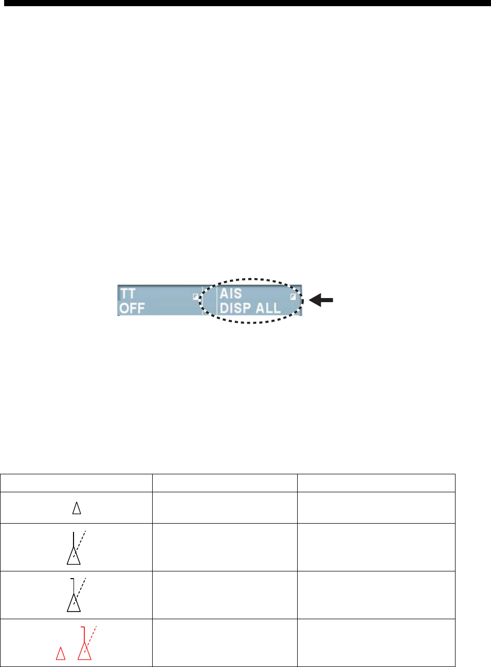
90
4. AIS OPERATION
This equipment can display names and positions and other navigational data (max. 1000) of
AIS-fitted ships when it is connected with the FURUNO Automatic Identification System (AIS
transponder) model FA-150, FA-100, FA-50 or AIS receiver FA-30.
Position data of WGS-84 geodetic datum are required for AIS operation. Set the datum of GPS
navigational equipment connected at WGS-84. When other datum is used, the indication
[Datum] flashes in the alarm section in the information display area and the AIS function
becomes unavailable.
4.1 Turning ON/OFF AIS Display
Note: When no AIS transponder is connected, the indication [AIS transponder abnormal] flashes
in the alarm box in the information display area. In this case, press the [Cancel alarm] key then
long press the left button on the AIS box to turn off the indication [Function OFF] in the box.
Follow the steps below to turn ON/OFF the AIS display.
1. Put the cursor on the AIS box in the information display area.
AIS box
2. Left-click to select [Display FILTER], [Display ALL] or [Display OFF].
Display filter: Only AIS targets set in Chapter 4.5 are displayed on the screen.
Display ALL: All targets received by AIS transponder are displayed on the screen.
Display OFF: All AIS symbols are erased from the screen.
Note: When AIS collision alarm is generated while the setting is [Display OFF], AIS target is
automatically displayed and the setting in the AIS box becomes [Display ALL].
When AIS display is turned on, AIS target is displayed by the following symbols depending on its
status.
Symbol Status Remarks
Sleeping target Smaller triangle than an active
target
Activated target Heading line, ship
speed/course vectors are
displayed.
Turning target A turning symbol is displayed.
Dangerous target Collision alarm symbol is
displayed in red. The symbol
flashes until acknowledged.
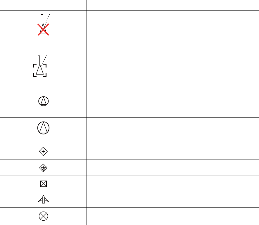
91
Symbol Status Remarks
Lost target When a target is lot, a red
flashing X mark is attached to
the symbol. The symbol
disappears after
acknowledgement.
A. FURUNO
Target whose data are
being displayed
Symbol of which data are on
display is surrounded with a
square broken line. Ship name
or MMSI no. is shown under
the symbol.
Same target (TT display is
prioritized.)
Identification criteria are met
and it is displayed with AIS
data.
Same target (AIS display is
prioritized.)
Identification criteria are met
and it is displayed with AIS
data.
Real AIS track sign
Virtual AIS track sign
AIS base station
Airborne SAR aircraft AIS
AIS-SART
Note 1: The equipment continues to process AIS target even when the AIS feature is turned off.
When AIS display is turned on again, the symbols are immediately displayed.
Note 2: Log press the left button on the AIS box to show [Function OFF] and data processing
stops.
Note 3: The screen is redrawn after the heading is changed in the head-up mode. AIS symbols
may be momentarily erased during this time.
Note 4: When no AIS data are received at all, the indication [AIS transponder abnormal] flashes
in the alarm box in the information display area. In such a case, check the AIS transponder.
Note 5: The indication [Unable to measure CPA/TCPA] flashes in the alarm box in the
information display area when data are unavailable or invalid for course over ground/speed over
ground of own ship.
Note 6: The applicable AIS symbols are shown in dotted lines when no data are received or
invalid for heading/course over ground of other ship.
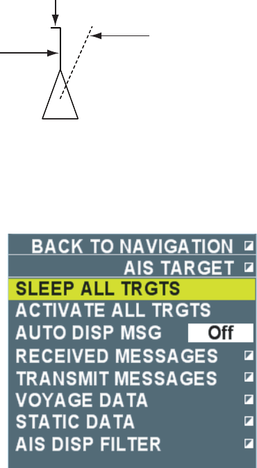
92
4.2 Activated Target
When you convert a sleeping target to an activated target, a vector of that target is displayed
indicating its course and speed. You can see the target’s movement at a glance by monitoring
the vector.
Note: A sleeping target getting into a guard zone is automatically changed to an activated target
(red flashing). See chapter 3.12 for guard zone.
4.2.1 Activating selected targets
1. Put the cursor on the symbol that you want to activate.
2. Left-click. The selected symbol is changed to an activated target.
Tuming
line (indicates direction of turning)
Speed over grond/Course
over ground vector *
*: Indicates speed over water/Course
over water in speed over water mode.
**: Indicates course over ground when
heading data is unavailable.
Heading line **
4.2.2 Activating all targets
1. Put the cursor on the AIS box in the information display area then right-click.
6. Select [Activate all targets] then left-click.
All symbols become activated targets.
5. Right-click to close the menu.
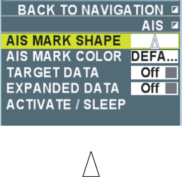
93
4.3 Inactivating targets
You may inactivate or “sleep” activated targets when the screen gets crowded with targets which
may make it difficult to identify important radar echoes and TT targets.
In such a situation, inactivating the activated targets helps make the radar echoes more visible
on the screen. Dangerous targets cannot be inactivated.
4.3.1 Inactivating selected targets
1. Put the cursor on the symbol to inactivate.
2. Right-click to display the [AIS] menu.
3. Select [Activate/Inactivate] then left-click. The selected symbols become inactivated targets.
4. Right-click to close the menu.
4.3.2 Inactivating all targets
1. Put the cursor on the AIS box in the information display area then right-click.
2. Select [Inactivate all targets] then left-click.
All the symbols become inactivated targets.
3. Right-click to close the menu.
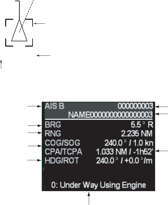
94
4.4 Displaying AIS Target Data
You can display AIS target data such as MMSI No., Ship name, bearing, range, course over
ground, speed over ground, CPA, TCPA, etc. When there are no data, [---] is shown.
4.4.1 Displaying basic data
One AIS data can be displayed in one data box in the information display area.
1. Put the cursor on the symbol of which data to display.
2. Left-click for activated target.
Right-click for inactivated time. Next, select [AIS data display] then left-click. When the
setting of [Selections] is [On] (factory default) in the [TT/AIS symbol], the symbol is
surrounded with a square of broken line. The basic data of the selected AIS target appears in
the data box in the information display area. When inactivated target is selected, the target
automatically changes to an activated target.
A. FURUNO
Sqare of a broken line
Ship neme
(NNSI No. when ship name is unavailable)
Location of data box of a target
(A or B)
Factory default
MMSI No.
Ship name
CPA/TCPA
of target
Navigation status
*: Indicates bearing over
water in the speed over
water mode.
Target (A,B) seleced
on the screen
Bearing of target
Range of target
Couse over ground/Speed
over ground of target
Heading/Turn speed
(degrees/min.)
Basic data in data box
3. Put the cursor on the basic data to display detailed data then left-click.
Each click switches between the basic data and detailed data. (See the next section.)
Note 1: The maximum of two AIS data can be displayed when [2BOX] is selected at [Target
data] in the [Navigation data] menu.
Note 2: Put the cursor on the symbol being displayed then left click to erase the basic data.
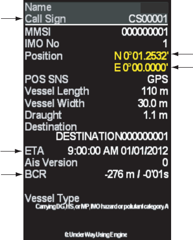
95
4.4.2 Displaying detailed data
Follow the steps below to display detailed data.
1. Put the cursor on the symbol of which data to display.
2. Right-click to display the [AIS] menu.
3. Select [AIS detailed data] then left-click.
Detailed data are displayed.
Latitude
Longitude
Measuring
equip.Ship length
Call sign
Estimated time
of arrival
Heading crossing
time/Heading
passing time
FURUNO
Detailed data in data box
Note: Put the cursor on the symbol of which data are being displayed then left-click to erase the
detailed data.
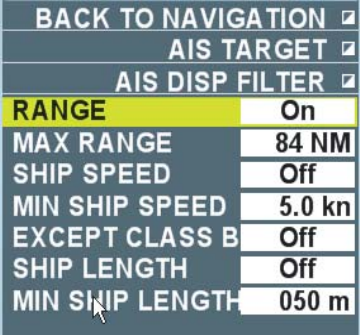
96
4.5 Filtering AIS display
If there are too many AIS targets on the screen you may wish to remove unnecessary ones. You
may remove targets by distance from own ship, speed, class and length. For example, you might
want to remove slow moving targets.
1. Put the cursor on the AIS box in the information display area then right-click.
2. Select [AIS display filter] then left-click.
3. Select [Range], [Ship speed], [Class B exclude] or [Ship length] then left-click.
• Range: AIS targets over the set range are not displayed on the screen.
• Ship speed: AIS targets less than the set speed are not displayed on the screen.
• Class B exclude: AIS targets of Class B* are not displayed on the screen.
*: Ships loaded with AIS transponder of Class B (for Non-business use)
• Ship length: AIS targets shorter than the set ship length are not displayed.
4. Click [On] then left-click.
When [Class B exclude] is selected in step 3, proceed to step 7. Otherwise proceed to step 5.
5. Select [Maximum Range], [Minimum Speed] or [Minimum ship length] then left-click.
Select appropriate item from the selections in step 3.
6. Input values.
7. Right-click several times to close the menu.
When the setting in the AIS box is [Display filter], only the AIS targets set here are displayed.
When settings are [Off] for all items, all the targets are displayed. (It is the same as [Display
all] in the AIS box.)
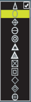
97
4.6 AIS Symbol Attributes
4.6.1 Selecting a AIS symbol shape
You can select a shape of AIS symbols from twelve different shapes.
1. Put the cursor on a symbol to change.
2. Right-click to display the [AIS] menu.
3. Select [AIS symbol shape] then left-click.
4. Select a necessary shape then left-click.
5. Right-click to close the menu.
Note: Brilliance of AIS symbols can be adjusted by color scheme. (See chapter 2.9.)
4.6.2 Selecting color of AIS symbol
You can select color of AIS symbols from the seven colors of red, green, blue, turquoise, purple,
white and yellow. (Except for dangerous targets)
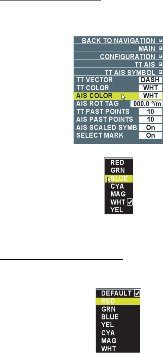
98
Changing colors of all AIS symbols
1. Put the cursor on [Menu] in the information display area then left-click.
2. Select [Set environment] then left-click.
3. Select [TT/AIS] then left-click.
4. Select [TT/AIS symbol] then left-click.
5. Select [AIS symbol color] then left-click.
6. Select a necessary color then left-click.
Color of all AIS symbols change. Colors of AIS symbols that are individually changed do not
change.
7. Right-click several times to close the menu.
Changing AIS symbol colors on the screen
1. Put the cursor on the symbol to change.
2. Right-click to display the [AIS] menu.
3. Select [AIS symbol color] then left-click.
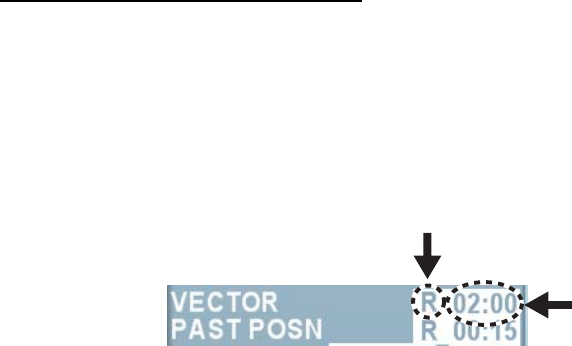
99
4. Select desired color then left-click.
When [Color set in the menu] is selected, the color changes to the color set at [AIS symbol
color] in the [TT/AIS symbol] menu.
5. Right-click to close the menu.
4.6.3 Selecting a size of AIS symbol
Select whether to display AIS symbol in real scale.
1. Put the cursor on [Menu] in the information display area then left-click.
2. Select [Set environment] then left-click.
3. Select [TT/AIS] then left-click.
4. Select [TT/AIS symbol] then left-click.
5. Select [AIS real scale] then left-click.
6. Select [On] or [Off] then left-click.
• On: AIS symbols of over 1.5cm in size on the screen are displayed in real scale in
accordance of hull length. AIS symbols less than 1.5cm in size are displayed in the
normal symbol size.
• Off: All AIS symbols are displayed in the same size.
7. Right-click several times to close the menu.
4.7 Displaying Vector
Vector is a line representing ship speed and course of AIS activated target. The vector tip shows
an estimated position of the target after the selected vector time elapses. You can predict a risk
of collision with other AIS target by extending the vector length (means vector time).
Selecting vector mode and time
Vectors may be displayed in true (over ground/over water) or relative mode. Vector time can be
selected from 15 sec., 30 sec., 45 sec., 1min. ~ 60min. (1 min. interval up to 20 min. and 10 min.
interval after 20 min.). The settings are common with TT target.
1. Press the [Vector True/Relative] key (factory default) to select [True (or True-s)] or [Relative].
The mode currently being selected appears in the vector box in the information display area.
Vector time
Vector mode
Relative, True (over ground speed)
True-s (over water speed)
Note: When other functions are registered to the [Vector True/Relative] key, put the cursor on
[Relative], [True] or [True-s] in the vector box then left-click.
2. Put the cursor on Vector time then left-click.
Each click switches between indications of vector time. Right-click to reverse the order.
When [00:00] is selected, no vector is displayed. You can also set the vector time at 1 sec.
interval or 1 min. interval after 20 min. by pressing the wheel on the vector time.
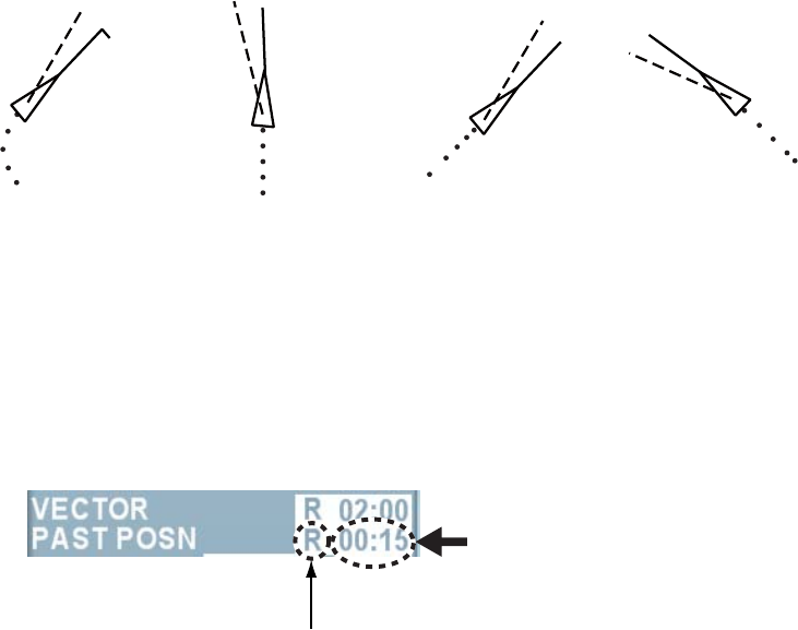
100
4.8 Displaying Past Position
The past position display shows movements of all AIS targets. The past position display shows
selected number of dots at the selected time interval. If a target changes its speed, the spacing
will be uneven. If it changes the course, its plotted course will be a curve. The following are
examples of past positions.
(a) Ship turning (a) Ship running
straigth
(a) Ship reduced
speed
(a) Ship increased
speed
4.8.1 Setting past position plot interval
You can select past position plot interval from 15 sec., 30 sec., 45 sec., 1min. ~ 60min. (1 min.
interval up to 20 min. and 10 min. interval after 20 min.). Settings are common with TT target.
1. Put the cursor on the [Past position interval] box in the information display area.
Past position interval box
Change in accordance with
trail mode setting.
2. Left-click to select a past position interval.
Each click switches between indications in the past position interval box. Right-click to
reverse the order. No past position is displayed when [00:00] is selected. You can also set
the time interval at 1 sec. or 1 min. after 20 min. by pressing the wheel on the past position
time interval box.
4.8.2 Selecting past position points
You may select five or ten past points to display.
1. Put the cursor on [Menu] in the information display area then left-click.
2. Select [Set environment] then left-click.
3. Select [TT/AIS] then left-click.
4. Select [TT/AIS symbol] then left-click.
5. Select [AIS past position points] then left clock.
6. Select [5] or [10] then left-click.
7. Right-click several times to close the menu.
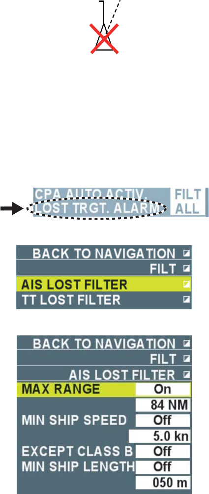
101
4.9 Lost Target
Activated targets become “Lost targets” when no AIS data are received for a certain period of
time. A lost target is sown in the display with flashing red “X”. The flashing indication [AIS lost] is
also displayed in the alert section in the information display area. Press the [Cancel alert] key to
delete the lost target from the screen. Inactivated target does not become a lost target and
disappears from the screen.
Note: Press the [Cancel alarm] key to erase both the lost AIS target and the lost TT target when
they are overlapping.
4.9.1 Setting lost target criteria
You can set criteria for lost target alarm by setting range from own ship, ship speed, ship class or
hull length.
1. Put the cursor on [Lost target alarm] in the information display area.
2. Right-click to display the [Filter] menu.
3. Select [AIS lost filter] then left-click.
4. Select [Maximum range], [Class B exclude] or [Minimum ship length] then left-click.
• Maximum Range: Any activated targets beyond this range will not trigger the lost target
alarm.
• Minimum ship speed: Any activated targets slower than this speed will not trigger the
lost target alarm.
102
• Class B exclude: Any activated targets of Class B* will not trigger the lost target alarm.
*: Ships loaded with Class B (for Non-business use) AIS transponder.
• Minimum ship length: Any activated targets shorter than this length will not trigger the
lost target alarm.
5. Select [On] then left-click.
When [Remove Class B] is selected in step 4, proceed to step 8. Otherwise, proceed to step
6.
6. Select a line within the setting limit then left-click.
7. Enter value.
8. Right-click several times to close the menu.
4.9.2 Setting lost target alarm
Select whether to enable the lost target alarm. Settings are common with TT target.
1. Put the cursor on [Lost target alarm] in the information display area.
2. Left-click to select a setting.
Each click switches between [OFF], [Filter], and [All] inside of the box.
• OFF: Disable the alarm
• Filter: Get the alarm against the activated lost target set in Chapter 4.9.1.
• All: Get the alarm against all activated lost targets.
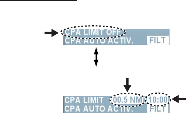
103
4.10 Collision Alarm (CPA/TCPA)
CPA (Closest Point of Approach) and TCPA (predicted time to CPA) limits are preset to avoid
collision with other ship. (Settings are common with TT target.) When the predicted CPA and
TCPA of AIS target become smaller than the present CPA and TCPA limits, the AIS target
becomes a dangerous target (red, flashing) and the audio alarm sounds. [AIS collision alarm]
flashes in the alarm box in the information display area. Press the [Cancel alarm] key to stop the
alarm sounds and the flashing indication of the symbol. Take appropriate actions to avoid a
collision.
Note 1: Set size, tonnage, ship speed and turning capacity of own ship to set collision alarm.
Note 2: The reference point for CPA/TCPA calculation may be selected from antenna position or
steering position. (See chapter 1.29.)
Collision alarm setting
1. Put the cursor on [CPA limit OFF] in the information display area then left-click.
Each click switches the indication as follows.
CPA setting box.
TCPA setting box.
2. Put the cursor on the CPA setting box.
3. Left-click to set CPA range.
Each click switches between the indications in the CPA setting box between 0.5, 1, 1.5 and
2~24 (1NM interval) in that order. You can also set the interval at 0.1NM or 1NM by pressing
the wheel on the CPA setting box.
4. Put the cursor on the TCPA setting box.
5. Left-click to set TCPA time.
Each click switches between the indications in the TCPA box between 1 min. ~ 60 min. (1
min. interval up to 20 min., 10 min. interval after 20 min.) Right-click to reverse the order.
You can also set the interval at 1 sec. or 1 min. after 20 min. by pressing the wheel on the
TCPA setting box.
4.11 Activating Targets
You can activate a sleeping target when both CPA and TCPA of the target become smaller than
the settings in Chapter 4.10.
4.11.1 Limiting targets for automatic activation
You can limit targets by setting range from own ship, ship speed, ship class or hull length for
automatic activation.
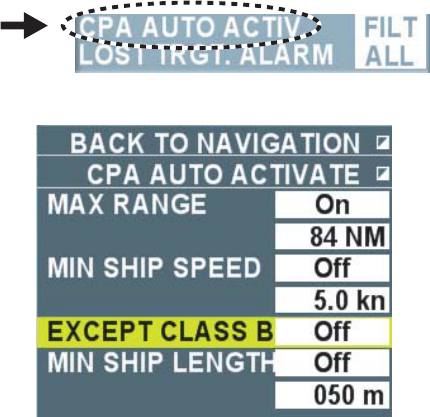
104
1. Put the cursor on [CPA auto activation] in the information display area.
2. Right-click to display the [CPA auto activation] menu.
3. Select [Maximum range], [Minimum speed], [Class B exclude] or [Minimum ship length] then
left-click.
• Maximum range: Inactivated targets over the set range are not displayed on the screen.
• Minimum speed: Inactivated targets less than the set speed are not displayed on the
screen.
• Class B exclude: Inactivated targets of Class B* are not displayed on the screen.
*: Ships loaded with AIS transponder of Class B (for Non-business use)
• Minimum ship length: Inactivated targets shorter than the set hull length are not
displayed.
4. Select [On] then left-click.
When [Remove Class B] is selected in step 3, proceed to step 7. Otherwise, proceed to step
5.
5. Select a line within the setting limit then left-click.
6. Enter value.
7. Right-click several times to close the menu.
4.11.2 Activating Targets Automatically
Select whether to enable automatic activation function.
1. Put the cursor on [CPA automatic activation] in the information display area.
2. Left-click to select a setting.
Each click switches between [OFF], [Filter] and [All] in the box.
• OFF: Disable the auto activation function.
• Filter: Enable the auto activation function. Inactivated targets that meet the following two
conditions will be activated.
1) Inactivated target of smaller CPA/TCPA than the settings in Chapter 4.10.
2) Inactivated target set in Chapter 4.11.1.
• ALL: Enable the automatic activation function. All inactivated targets of smaller
CPA/TCPA than the settings in Chapter 4.10 will be activated.
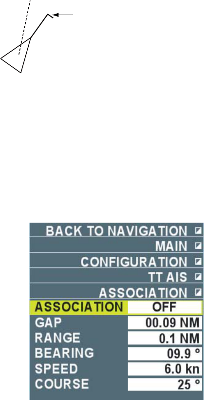
105
4.12 Turning Direction
When turning speed of an activated target is faster than the set value, turning direction can be
shown on the heading line of AIS symbol.
1. Put the cursor on [Menu] in the information display area then left-click.
2. Select [Set environment] then left-click.
3. Select [TT/AIS] then left-click.
4. Select [TT/AIS symbol] then left-click.
5. Select [AIS ROT mark display] then left-click.
6. Set turning direction.
7. Right-click several times to close the menu.
Shows a target is turning to the right
4.13 Identification of TT and AIS
When data of TT and AIS activated targets meet the identification criteria, both targets are
considered to be the same targets and TT or AIS is prioritized to display on the screen.
1. Place the cursor on [Menu] in the information display area then left-click.
2. Select [Set environment] then left-click.
3. Select [TT/AS] then left-click.
4. Select [Identification] then left-click.
5. Select [Identification] then left-click.
6. Select [OFF], [AIS] or [TT] then left-click.
When the identification criteria are met, choose which data to prioritize.
• OFF: No identification processing
• AIS: Prioritize AIS display (symbol, data)
• TT: Prioritize TT display (symbol, data)
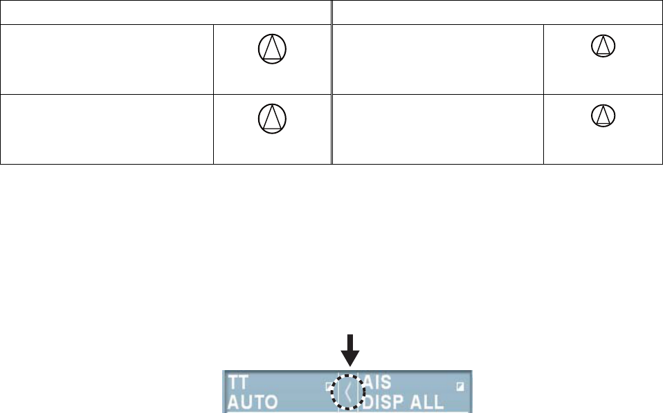
106
Symbols when AIS is prioritized Symbols when TT is prioritized
AIS dangerous target
(Red)
TT dangerous target
(Red)
AIS normal target
(Normal color)
TT normal target
(Normal color)
Note: You can also select [OFF], [AIS] and [TT] from the identification box in the information
display area. Put the cursor on the identification box then left-click. Each click switches
between [Blank], [>] and [<] in the box.
Identification box
Blank: No identification
processing
<: Prioritize AIS display
>: Prioritize TT display
7. Set conditions.
These conditions are used to determine identification criteria.
• Mutual range: Input range between AIS target and TT target (0 ~ 99.99NM).
• Range: Input difference in range between AIS target and TT target from own ship. (0 ~
9.9 NM).
• Bearing: Input difference in bearing between AIS target and TT target from own ship.
• Ship speed: Input difference of ship speed between AIS target and TT target.
• Course: Input difference of course between AIS target and TT target.
(0 ~ 99°)
8. Right-click several times to close the menu.
AIS target and TT target are considered to be identical when data of AIS target and TT target are
smaller than the values of all the five conditions in step 7. When identification criteria are met
and [AIS] is selected in step 6, TT symbols disappear and only AIS symbols are prioritized on the
display. The flashing indication [AIS identification] appears in the alarm box in the information
display area.
Note: When the power is turned on again, the setting of [Identification] in the [Identification]
menu returns to [OFF].
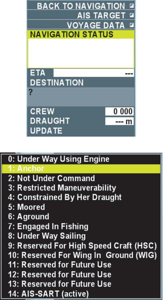
107
4.14 Navigation Data
Own ship’s navigation data (Navigation condition, estimated date/time to arrive at a destination,
name of destination, crews, and draft) can be outputted to AIS transponder connected to own
ship.
1. Put the cursor on the AIS box in the information display area then right-click.
2. Select [Navigation data] then left-click.
3. Select [Navigation status] then left-click.
4. Select an appropriate navigation condition then left-click.
5. Select [ETA] then left-click.
6. Set estimated arrival at a destination (Year/Month/Day/time)
7. Select [Destination] then left-click.
8. Enter name of waypoint (Max. 20 characters) with the small keyboard appearing at the lower
section on the screen.
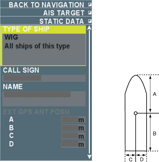
108
9. Select [Crews] then left-click.
10. Set number of crews.
11. Select [Draft] then left-click.
12. Set draft of own ship.
13. Lastly, select [Update] then left-click.
14. Right-click several times to close the window.
4.15 Static Data
Own ship’s static data set at AIS transponder can be viewed on this equipment.
1. Place the cursor on the AIS box in the information display area then right-click
2. Select [Static data] then right-click.
CSXXXX
NMEA0000000
065
070
20
20
3. Right-click several times to close the menu.
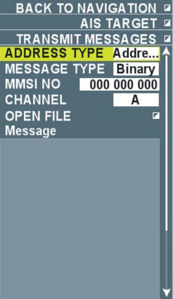
109
4.16 Messages
You may transmit and receive messages via the AIS transponder, to a specific destination
(MMSI) or all ships in the area. Messages can be sent to warn of safety of navigation, for
example, an iceberg sighted. Routine messages are also permitted.
Short safety messages are only the additional means to broadcast safety information. They do
not remove the requirements of the GMDSS.
4.16.1 Creating and saving messages
This section explains how to create and save messages. Maximum of ten messages may be
saved.
1. Put the cursor on the AIS box in the information display area then right-click.
2. Select [Transmit message] then left-click.
3. Select [Address type] then left-click.
4. Select [Broadcast] or [Specify destination] then left-click.
• Broadcast: Send a message to all ships in the area.
• Specify destination: Send a message to a specified destination.
5. Select [Message type] then left-click.
6. Select [Safety related] (safety related messages) or [Binary] (Routine business messages)
then left-click.
When [Broadcast] is selected in step 4, proceed to step 9. When [Specify destination] is
selected, proceed to step 7.
7. Select [MMSI No.] then left-click.
8. Set MMSI No.
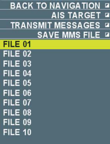
110
9. Select [Channel] then left-click.
10. Select a channel (A, B, A or B, A and B)to send a message then left-click.
Refer to the operation manual of AIS transponder for channels A and B.
11. Select [Edit message] then left-click.
12. Compose a message (alphanumeric only) using a small keyboard appearing at the lower
section on the screen.
The maximum alphanumeric changes as follows in the combination of [Address type] and
[Message type].
Broadcast/Safety related: 161 characters
Broadcast/Binary: 156 characters
Specify destination/Safety related: 156 characters
Specify destination/Binary: 151 characters
13. After completing a message, select [Save file] in the lower section of the menu then left-click.
14. Select a file number (1 ~10) then left-click.
The file is saved inside of this equipment.
15. Right-click several times to close the menu.
4.16.2 Transmitting a message
There are two methods to send messages. One method is to compose and send a message on
the spot and the other method is to send a message which is saved inside of the equipment.
1. Put the cursor on the AIS box in the information display area then right-click.
2. Select [Transmit message] then left-click.
3. Do one of the following operations.
• Select [Open file] then left-click. Next, select a file number saved in Chapter 4.16.1 then
left-click. Right-click to return to the [Transmit message] menu.
4. Select [Transmit message] at the lower section of the menu then left-click.
5. Right-click several times to close the menu.
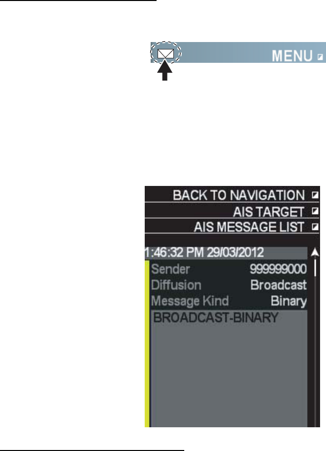
111
4.16.3 Viewing a message
The maximum of twenty messages can be stored. When the storage is full, the oldest message
is erased to make room for the latest.
Note: Received messages disappear when power is turned off.
Viewing received messages
When a message is received, an icon indicating a new arrival appears in the information display
area. (Factory default)
Icon for new arrival
View the message in the following steps.
1. Put the cursor on the new arrival icon in the information display area then left-click.
The message is displayed. Roll the wheel to scroll the list of AIS messages.
2. Right-click several times to close the message.
Viewing messages automatically
Follow the steps below to automatically display a message when the message is being received.
1. Put the cursor on the AIS box in the information display area then right-click.
2. Select [Message automatic display] then left-click.
3. Select [On] then left-click.
4. Right-click to close the menu.
When a message is received, the list of AIS messages is automatically opened. The new arrival
icon is not displayed at this time.

112
5. VIDEO PLOTTER OPERATION
5.1 Outline
The video plotter does the following functions:
• Enter marks and destinations.
• Enter lines.
• Enter origin marks.
• Display chart overlay.
• Plot own and other ships’ tracks.
• Register routes.
5.2 Mark/Destination/Line
You can enter marks and destinations at important points such as shallow waters, fishing zones,
and passage buoys to let the system memorize those positions. You can also draw lines at signs
such as small islands, landfill sites and prohibited areas for operations. These lines can be used
as routes. This equipment can memorize the maximum of 20,000 mark points, 5,000 lines
including routes and 100 destination points.
Note: You can confirm the current number of points of marks, lines and destinations in the [Mark]
menu. (See chapter 5-3.)
5.2.1 Entering marks and destinations
There are the following three ways to enter marks and destinations.
• Enter marks/destinations at cursor positions.
• Enter marks/destinations at own ship’s positions.
• Specify latitude and longitude.
Entering marks and destinations at cursor position
1. Put the cursor on [Off] then left-click when [Off] is indicated in the mark/destination box at the
lower left section on the screen.
Marks/destinations appear on the screens when the setting is [On] and disappear when the
setting is [Off].
: Types of mark
Mark box Destination box
(Mark) (Origin mark)
2. Check the type of mark set in the marks/destinations box.
Put the cursor on [Mark], [Origin] or [Destination] then left-click to switch between [Mark],
[Origin] or [Destination] in that order. Select [Mark] to enter a mark and [Destination] to enter
a Destination. See chapter 5.3.1 for [Origin].
3. Put the cursor on the pattern in the mark/destination box.
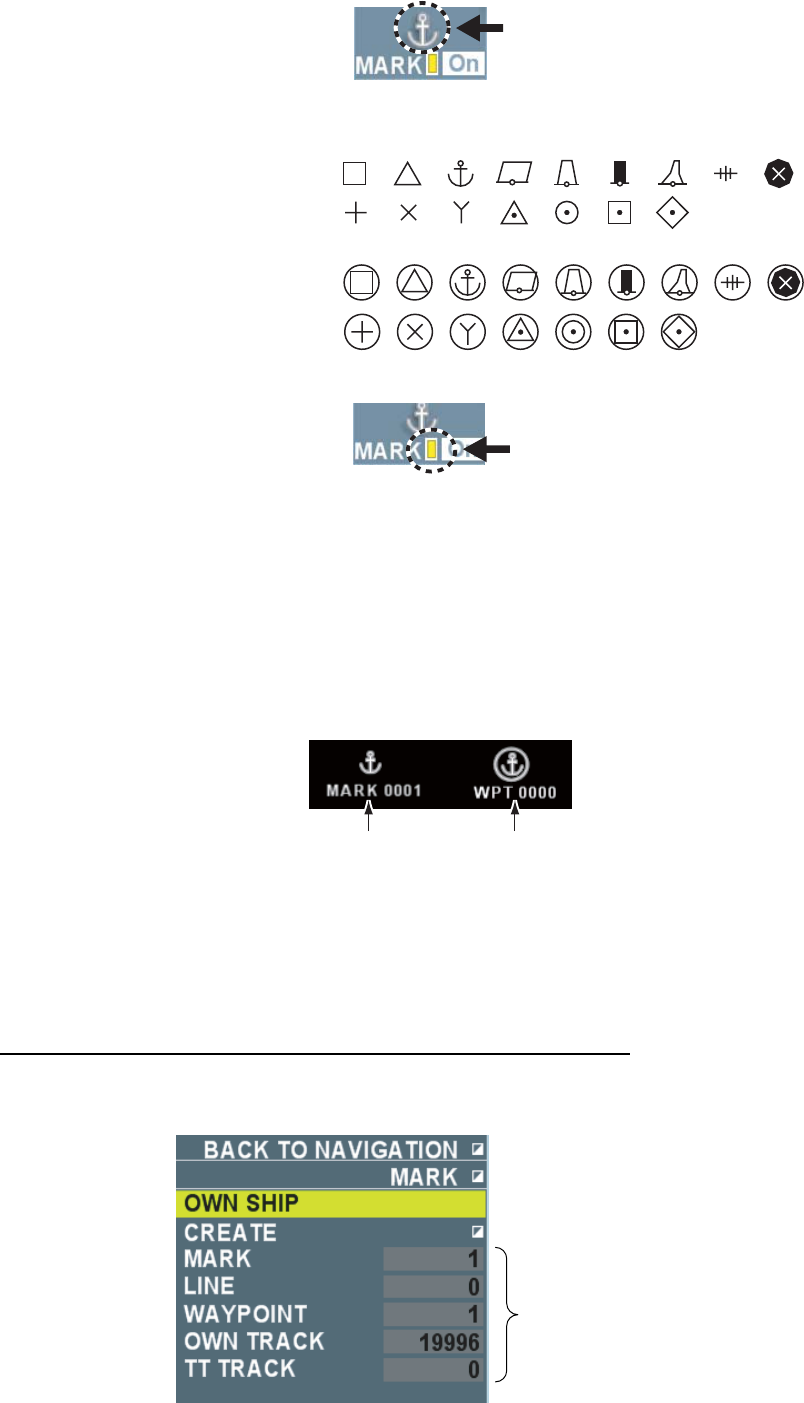
113
Pattern
4. Roll the wheel to select a necessary pattern then left-click. You can select a pattern of
marks/destinations from 16 patterns as shown below.
Patterns of marks:
Patterns of waypoints:
5. Put the cursor on [Color] in the mark/destination box.
Color
6. Roll the wheel to select desired color then left-click.
The colors for marks and destinations can be selected from Red, Green, Blue, Yellow,
Turquoise, Purple and White.
7. Move the cursor to a desired position to enter marks/destinations.
8. Press the [mark] key.
A mark/destination mark is entered at the cursor position. An unused number is assigned by
[Mark] for the name of the mark. An unused number is assigned by [WPT] for the name of
the mark.
Mark name Waypoint name
Note: No mark name or destination name will be displayed when the setting of [Mark
name] is [Off] in the [Display] menu.
8. Repeat steps 7 ~ 8 to enter marks/destinations of the same shape and color.
The destinations you enter are saved in the destination list.
Entering marks and destinations at own ship’s position
1. Follow the steps 1 ~ 6 of [Enter marks/destinations at cursor positions].
2. Put the cursor on a pattern in the mark/destination box then right-click.
Current number of pounts
menorized
3. Select [Enter at own ship’s position] then left-click.
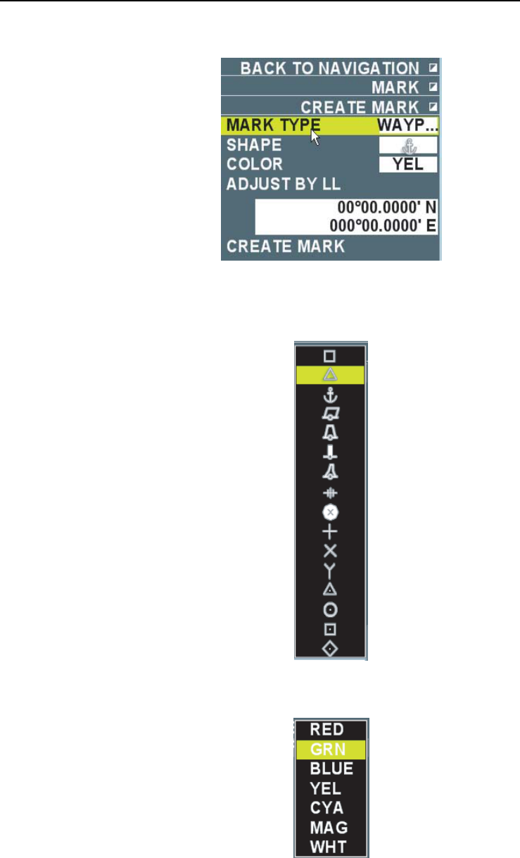
114
The mark is entered at own ship’s position. An unused number is assigned by [MARK] for the
name of the mark and an unused number is assigned by [WPT] for the name of the
destination.
4. Repeat step 3 to continuously enter marks/destinations of the same pattern and color.
5. Right-click to finish entering marks/destinations.
The Destinations you enter are saved in the destination list.
Entering marks/destinations by specifying latitude and longitude
1. Put the cursor on a patter in the mark/destinations box then right-click.
2. Select [Make marks] then left-click.
3. Select [Types of mark] then left-click.
4. Select [Destination] or [Mark] then left-click.
5. Select [Shape of mark] then left-click.
6. Roll the wheel to select a necessary pattern then left-click.
7. Select [Color of mark] then left-click.
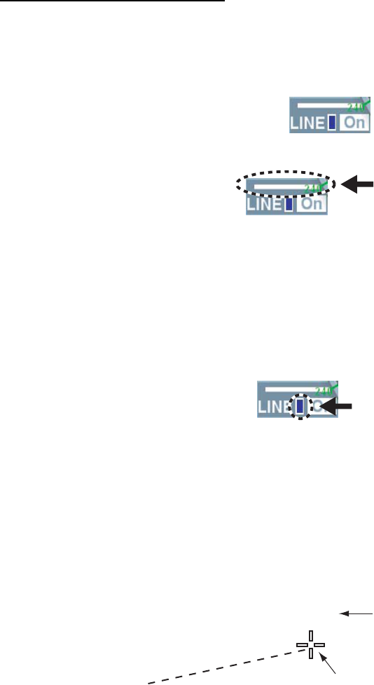
115
8. Roll the wheel to select a necessary color then left-click.
9. Select [Input latitude/longitude] then left-click.
10. Input latitude and longitude of the mark/destination using the small keyboard appearing at
the lower section on the screen.
11. Select [Enter mark] then left-click.
A mark/destination is entered at a specified position. An unused number is assigned by
[MARK] as the name of the mark and an unused number is assigned by [WPT] as the name
of the destination.
12. Right-click to close the menu.
The destination you enter is saved in the destination list.
5.2.2 Entering lines
Entering lines on the screen
1. Put the cursor on [Off] then left-click when [Off] is shown in the line box at the lower section
on the screen.
A line appears on the screen when the setting is [On] and disappears when the setting is
[Off].
2. Put the cursor on [Line] in the line box.
Line
3. Roll the wheel to select a desired line type then left-click.
You can select a line type from the six line types of solid line (thick, thin), broken line (thick,
thin) and dotted line (thick, thin).
4. Put the cursor on [Color] in the line box.
7. Roll the wheel too select desired color then left-click.
You can select color from the seven colors from Red, Green, Blue, Yellow, Turquoise, Purple
and White.
Color
6. Put the cursor on the line in the line box then left-click.
It becomes the line entering mode and the cursor moves inside the valid radar echo area.
7. Move the cursor at the starting point of the line.
8. Left-click to enter the starting point of the line.
9. Move the cursor at the intermittent point (end point) of the line.
A broken line connects the start point and the cursor position. Range and bearing appear
above the cursor position.
Start point
Range and bearing
from the start point
2.156NM
77.6°
Cursor
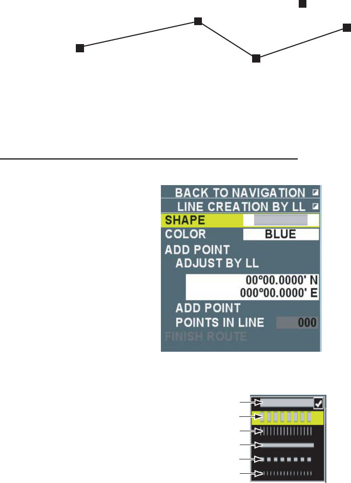
116
10. Left-click.
The line selected in step 3 connects the start point and the intermittent point (end point). A
square mark appears at the clicked point.
11. Repeat steps 9 ~ 10 to complete the line.
Start point
Itermittent point
End point
Itermittent point
: Left-clicked point
12. Right-click to finish entering the line.
The entered line is saved in the route selection list. Unused number is assigned to [Rte] as
the route name.
Entering a line by specifying latitude and longitude
1. Put the cursor on a line in the line box then right-click.
2. Select [Shape] then left-click
3. Roll the wheel to select a desired line then left-click.
Thick solid line
Thick broken line
Thich dotted line
Thin solid line
Thin broken line
Thin dotted line
4. Select [Line color] then left-click.
5. Roll the wheel to select a necessary color then left-click.
6. Select [Input latitude/longitude] then left-click.
7. Input latitude and longitude of a start point of the line.
8. Select [Add line] then left-click.
9. Select [Input latitude/longitude] then left-click to specify an intermittent point of the line.
10. Enter latitude and longitude of an intermittent point of the line using the small keyboard
appearing at the lower section on the screen.
11. Select [Add line] then left-click.
[End entering line] is enabled at the lowest line of the menu.
12. Repeat step 9 ~ 11 to complete the line.
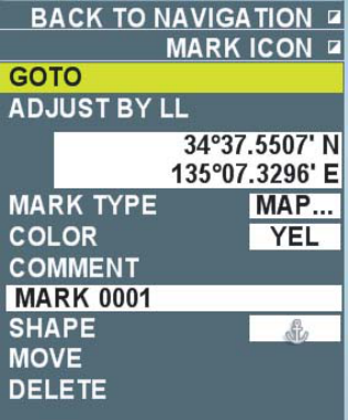
117
13. Right-click to finish entering the line.
The entered line is saved in the route selection list. An unused number is assigned to [Rte] as
the route name.
Note: Left-click [Finish entering line] instead of right-clicking it when entering other lines
continuously.
5.2.3 Editing marks/destinations
You may edit marks/destinations already entered.
1. Put the cursor over a mark/destination to be edited.
The mark becomes larger when the mark/destination is selected correctly.
2. Right-click to display the [Mark icon] menu.
3. Select [Correct latitude/longitude] then left-click to fine tune the entering position of
marks/destinations. Next, set a correct latitude and longitude.
4. Select [Type of mark] then left-click to change the type of a mark to change the type of a
mark.
Select [Destination] or [mark] then left-click next.
5. Select [Mark color] then left-click to change color of marks/destinations. Select color after
change then left-click next.
6. Select [Comment] then left-click to change the name of marks/destinations. Enter a name of
marks/destination using the small keyboard appearing at the lower section on the screen.
(Maximum 12 characters)
7. Select [Mark shape] then left-click to change the shape of a mark. Next, select a shape after
the change then left-click.
8. Select [Move] then left-click to move the position of a mark/destination on the screen. Next,
move the mark/destination to a new location then left-click.
9. Right-click to close the menu.
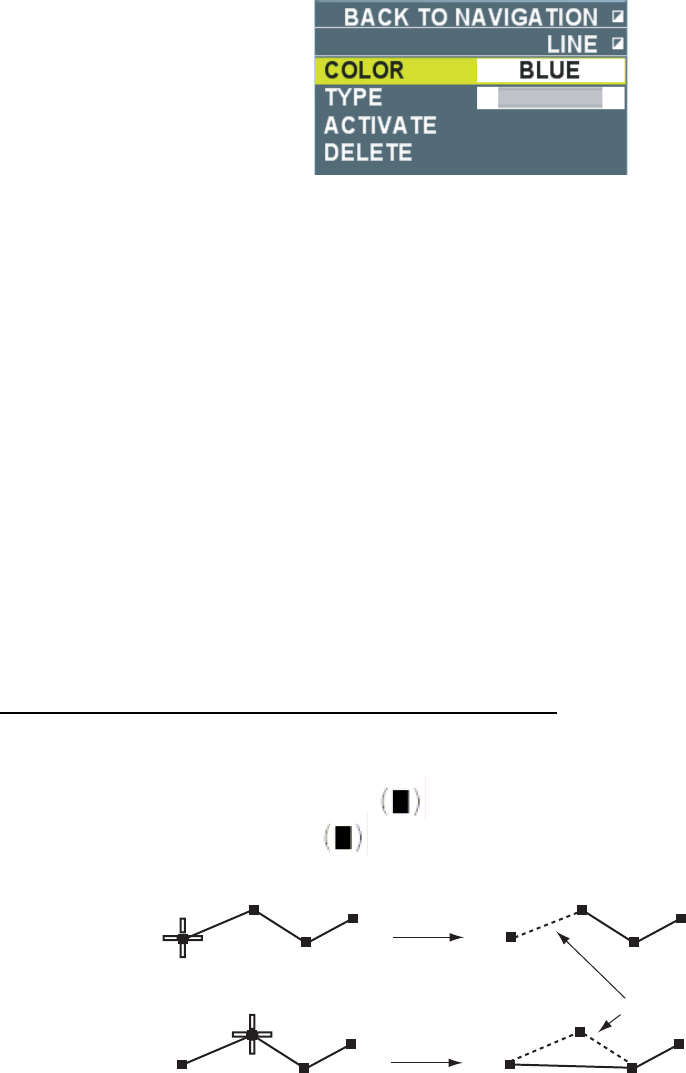
118
5.2.4 Editing lines
You may edit lines already entered.
1. Put the cursor on the line to be edited.
The line becomes a thick line and an arrow appears when the line is selected correctly.
2. Right-click to display the [Line] menu.
3. Select [Line color] then left-click to change the line color. Next select color after the change
then left-click.
4. Select [Line type] then left-click to change the line type.
Next, select a line type after the change then left-click.
5. Right-click to close the menu.
5.2.5 Erasing marks/destinations and lines
There are the following five methods to erase marks/destinations and lines.
• Erase marks/destinations and lines one by one.
• Use the destination list to erase destinations.
• Erase all marks/destinations and lines.
• Erase marks and lines of specified shapes.
• Erase marks and lines of specified colors.
Care must be taken that erased marks/destinations and lines are unrecoverable.
Note: Marks/destinations used for waypoints (or routes) cannot be erased.
Erasing marks/destinations and lines one by one
1. Put the cursor on a mark, Destination or line to erase.
The way a line is erased is different depending on the cursor position.
• Start point or end point of a line : See the diagram below.
• Intermittent point of a line : See the diagram below.
• On a line: All the line is erased.
Cursor is plaved on
a start point of a line
Cursor is placed in a
start point of a line Line segment erased
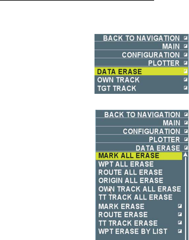
119
2. Right-click to display [Mark icon] (or line, simple mark icon).
• [Mark icon] menu: Cursor is put on a mark or a Destination
• [Line] menu: Cursor is put on a line.
• [Simple mark icon] menu]: Cursor is put on a point of a line.
3. Select [Delete] then left-click.
The specified marks, destinations or lines disappear.
Erasing destination using the destination list
1. Put the cursor on [Menu] in the information display area then left-click.
2. Select [Set environment] then left-click.
3. Select [Plotter] then left-click.
4. Select [Delete data] then left-click.
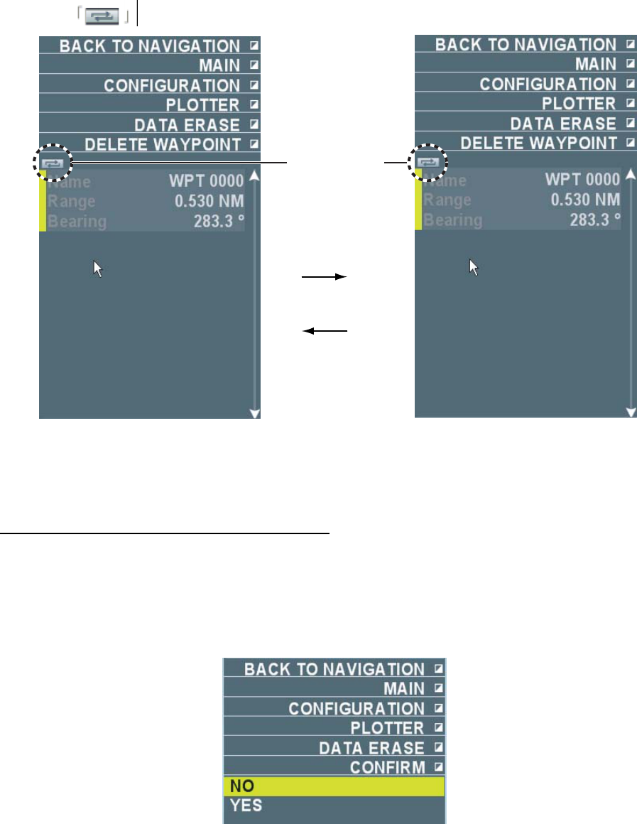
120
5. Select [Destination list] then left-click.
All the destination data saved in this equipment are displayed. Each left-click on the switch
button switches between the indications as shown below.
Switch clik the
swich button
Switch button
Range/Bearing Latitide/Longitude
6. Roll the wheel to select a Destination to delete then left-click.
7. Right-click several times to close the menu.
Erasing all marks, destinations and lines
1. Put the cursor on [Menu] in the information display area then left-click.
2. Select [Set environment] then left-click.
3. Select [Plotter] then left-click.
4. Select [Delete data] then left-click.
5. Select [Erase all marks] (or [Erase all destinations] or [Erase all lines] ) then left-click.
6. Select [Yes] then left-click.
All marks/destinations, lines including routes are erased.
Note: Select [No] to cancel the erasing.
7. Right-click several times to close the menu.
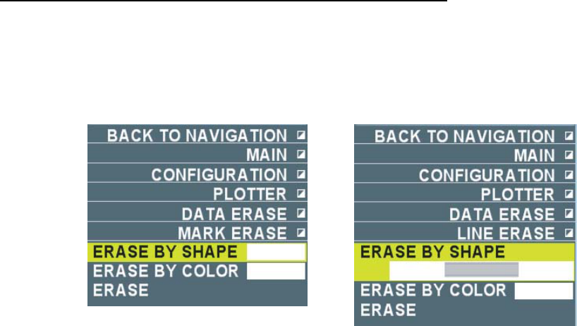
121
Erasing marks and lines of specified shapes and colors
1. Put the cursor on [Menu] in the information display area then left-click.
2. Select [Set environment] then left-click.
3. Select [Plotter] then left-click.
4. Select [Delete data] then left-click.
5. Select [Delete mark] (or [Delete line] )then left-click.
[Delete mark] is selected. [Delete line] is selected.
6. Select [Erase by shape] or [Erase by color] then left-click.
7. Select a shape, line type, or color to erase then left-click.
8. Select [Erase] then left-click.
9. Select [Yes] then left-click.
10. Right-click several times to close the menu.
5.2.6 Displaying external destinations
When a waypoint is set with the GPS navigation equipment connected to this equipment, that
position can be displayed in this equipment as an external destination.
Note: RMB sentence is required.
1. Put the cursor on [Menu] in the information display area then left-click.
2. Select [Display] then left-click.
3. Select [External destination] then left-click.
4. Select [ON] then left-click.
An external destination of the specified shape and color is displayed in the destination box at
the lower left section on the screen. No external destination is displayed when [OFF] is
selected.
Note: Select [Waypoint] to set an external destination as a waypoint.
5. Right-click several times to close the menu.
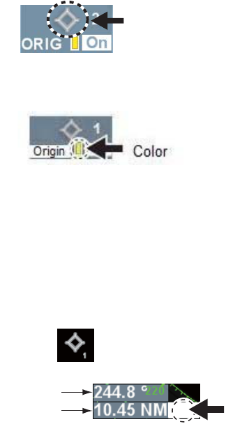
122
5.3 Origin Mark
Range and bearing data can be displayed from the cursor position to the position where you
enter an origin mark in dangerous area such as reefs. The maximum of twenty origin marks can
be stored. Origin marks disappear when the power is turned off.
5.3.1 Entering origin marks
Heading signal and own ship position data are required to display the origin marks.
1. Check the mark type set in the marks/Destination box at the lower left side on the screen.
Put the cursor on [Mark], [Origin] or [Destination] then left-click to switch the order to [Mark],
[Destination] and [Origin]. Select [Origin] to enter an origin mark. The bearing/range box
appears at lower side of the mark box when [Origin] is selected.
2. Put the cursor on [Off] then left-click when [Off] is displayed in the mark box.
An origin mark appears at [On] and disappears at [Off].
3. Put the cursor on a patter inside of the mark box.
Pattern
4. Roll the wheel to select a necessary number (1 ~ 20) then left-click.
5. Put the cursor on [Color] in the mark box.
6. Roll the wheel to select a necessary color then left-click.
You can select color from the seven colors of Red, Green, Blue, Yellow, Turquoise, Purple
and White.
7. Move the cursor to the position to enter the origin mark.
8. Press the [Mark] key.
The origin mark is entered at the cursor position. Bearing and range between the origin mark
to the cursor position is displayed in the bearing/range box.
R
Click here to switch between
True and Relative bearing
Bearing/Range Box
Bearing from origin mark to cursor position
Range from origin mark to cursor position
9. To enter other origin marks continuously, change the number in step 4 then repeat steps 7 ~
8.
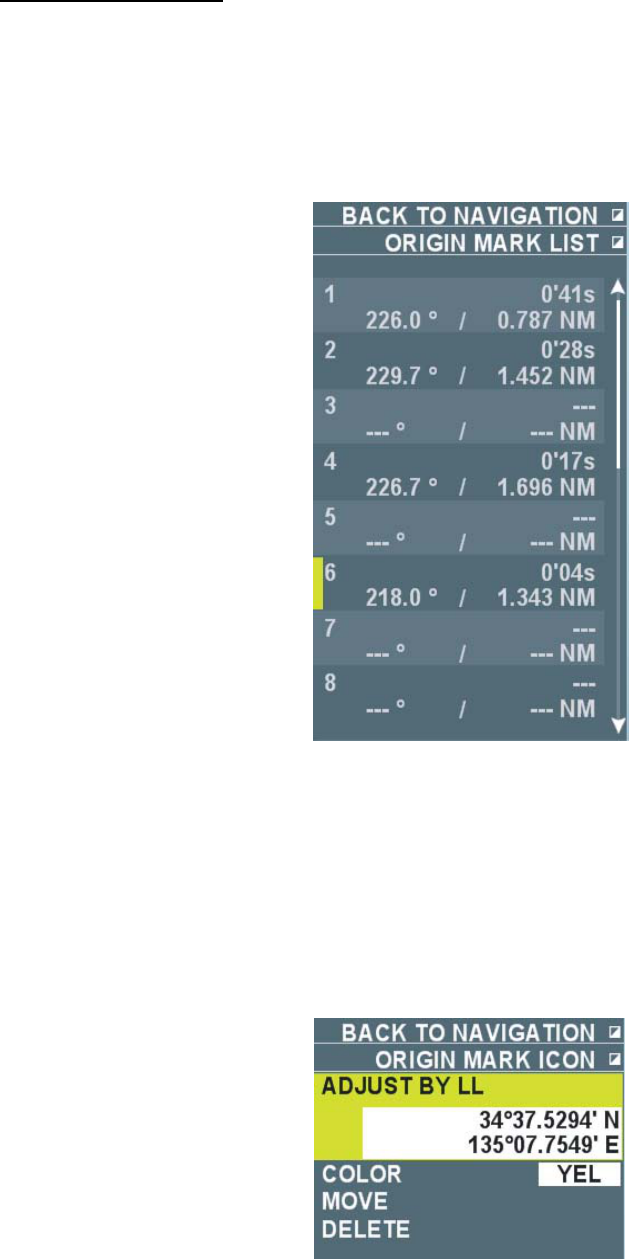
123
List of origin marks
You can display the list of origin marks entered.
1. Check if the setting of mark type in the mark/destination box at the lower left side on the
screen is [Origin] at the lower left side on the screen.
2. Right-click to display the origin list.
A list of origin marks stored in this equipment is displayed.
Note: You can also enter origin marks from the origin mark list.
3. Right-click to close the origin list.
5.3.2 Editing origin marks
You can edit origin marks already entered.
1. Put the cursor on the origin mark to edit.
2. Right-click to display the [Origin icon] menu.
3. Select [Correct Latitude/Longitude] then left-click to fine tune the position of the origin mark.
Next, set correct latitude and longitude.
4. Select [Mark color] then left-click to change the color of the origin mark. Next select color
after the change then left-click.
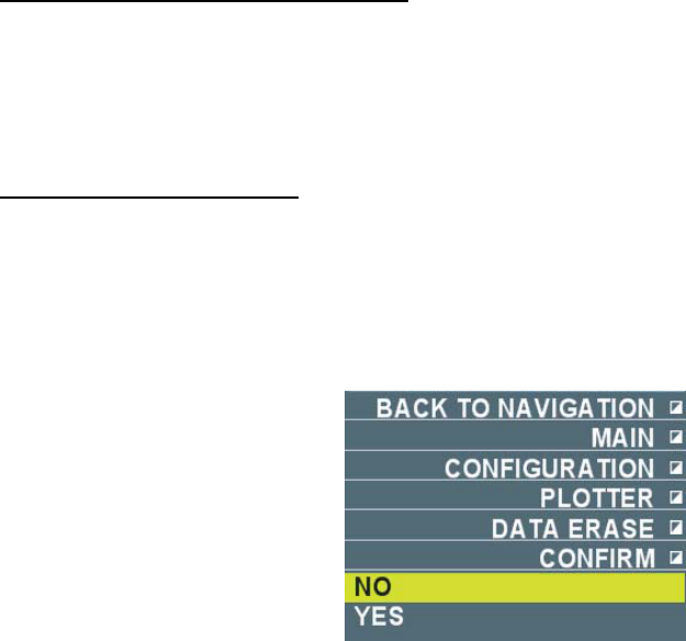
124
5. Select [move] then left-click to move the origin mark on the screen. Next, move the origin
mark to a new location then left-click.
The menu disappears in this operation.
6. Right-click to close the menu.
5.3.3 Erasing origin marks
There are the following two ways to erase origin marks.
• Erase origin marks one by one.
• Erase all origin marks.
Note that erased origin marks cannot be restored.
Erasing origin marks one by one
1. Put the cursor on the origin mark to erase.
2. Right-click to display the [Origin icon] menu.
3. Select [Delete] then left-click.
The specified origin mark disappears.
Erasing all origin marks
1. Put the cursor on [Menu] in the information display area then left-click.
2. Select [Set environment] then left-click.
3. Select [Plotter] then left-click.
4. Select [Delete data] then left-click.
5. Select [Erase all origins] then left-click.
6. Select [Yes] then left-click.
All the origin marks disappear.
Note: Select [No] instead of [Yes] to cancel erasing the origin marks.
7. Right-click several times to close the menu.
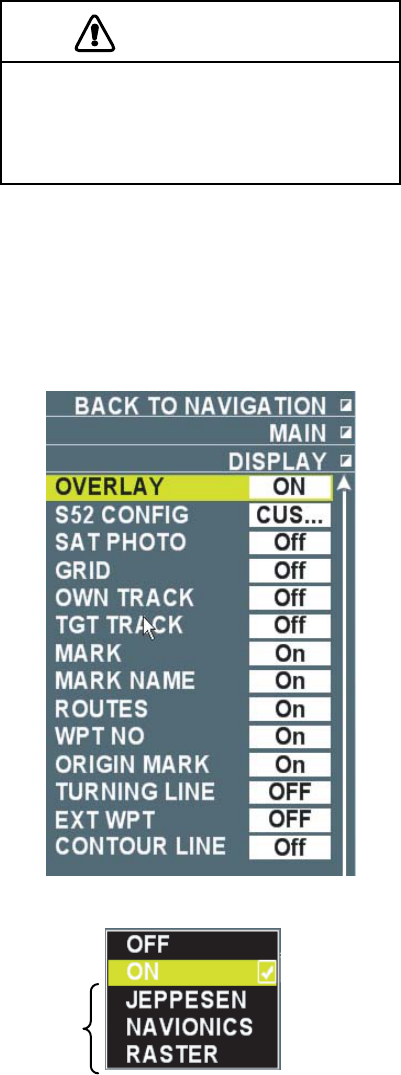
125
5.4 Chart (Coastline data)
This system is equipped with vector charts and satellite pictures of the Japan Sea. Vector charts
are electronic data to display important data necessary for navigation. They are not the same as
paper charts.
CAUTION
Information displayed on this system is
intended as aid to navigation.
See charts fo detalied and the latest
information.
5.4.1 Displaying chart overlay
You can overlay charts on radar images. Follow the steps below to display chart overlay.
1. Put the cursor on [Menu] in the information display area then left-click.
2. Select [Display] then left-click.
3. Select [Overlay] then left-click.
*
*: Separate chart is required.
4. Select [ON] then left-click.
A chart of the Japan Sea is displayed. No chart is displayed when [OFF] is selected.
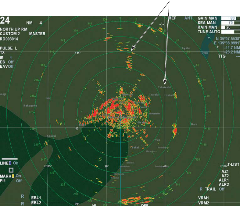
126
Latitude/Longitude
Example of Chart Overlay
Note: Latitude/Longitude is displayed when [Latitude/Longitude] is turned ON.
5. Right-click several times to close the menu.
Note 1: Brilliance of a chart can be adjusted by color. (See chapter 2.9.)
Note 2: When displaying a chart overlay and the setting of [Satellite] is [On], only satellite
pictures in relatively near range can be displayed.
5.4.2 Selecting data level to display on charts
Data levels can be displayed on charts from the following selections.
• Basic: Display the minimum required chart data.
• International: Display data required for general navigation.
• Other: Display additional data other than the above data.
• Fishing: Display charts useful for fishing.
• Individual: Display chart data that is preset in the [Individual setting] menu. (See chapter
5.4.4.) Users can set chart data that are most appropriate for their needs.
Note: This operation can be done only when the setting of [Overlay] is [ON] in the [Display]
menu.
1. Put the cursor on [Menu] in the information display area then left-click.
2. Select [Display] then left-click.
3. Select [Coastline data] then left-click.
4. Select a necessary data level then left-click.
5. Right-click several times to close the menu.
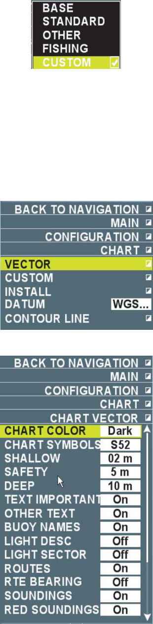
127
5.4.3 Texts and symbols on charts
Various texts and symbols may be set for display on charts.
Note: Depending on charts or waters on display, you may not be able to set texts or symbols.
1. Put the cursor on [Menu] in the information display area then left-click.
2. Select [Set environment] then left-click.
3. Select [Chart] then left-click.
4. Select [Vector] then left-click.
5. Select an item to change then left-click.
Change each setting accordingly.
Note: The illustrations of the chart symbols in this manual are examples from [Chart Symbols]
below when [International] is selected in the menu.
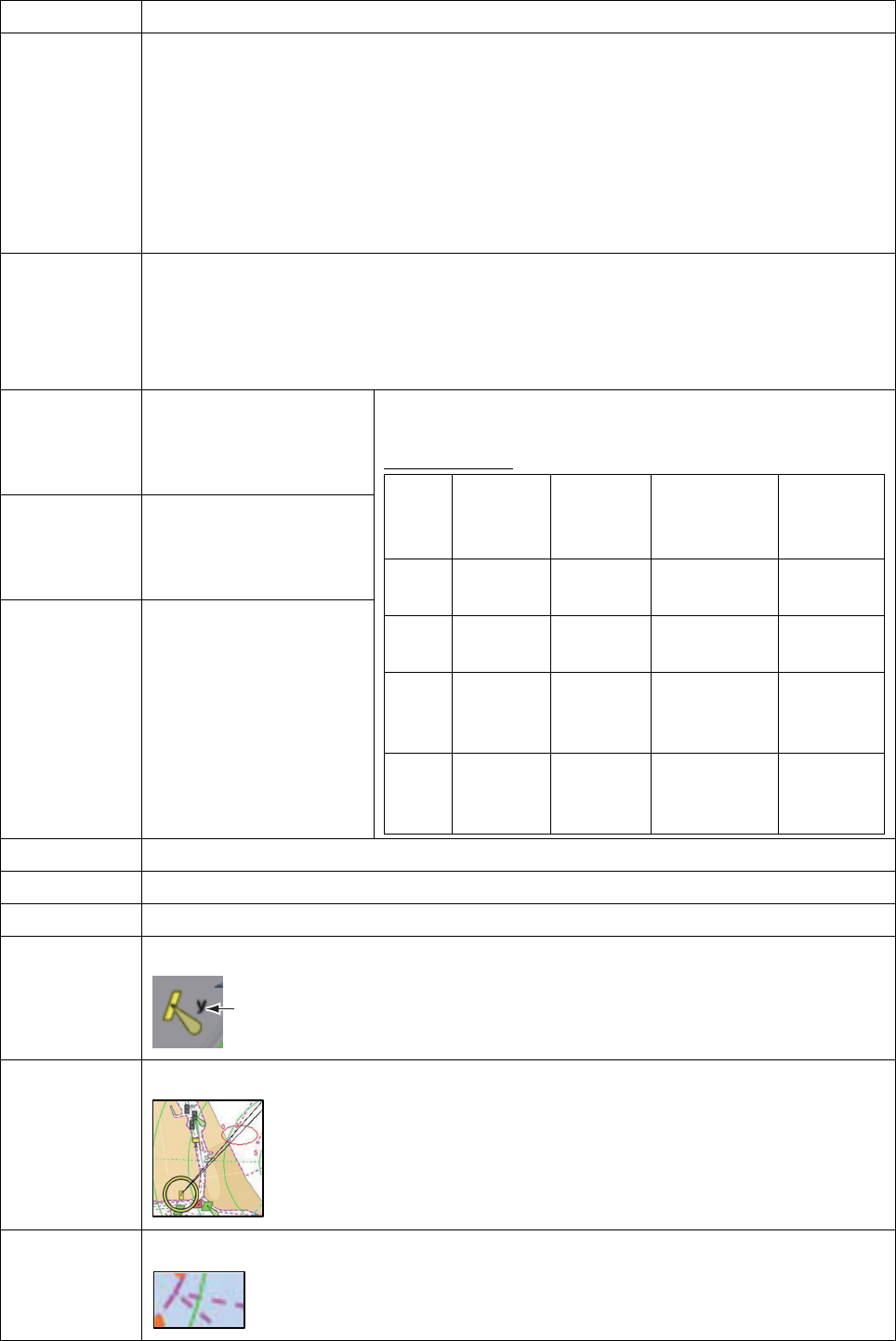
128
Menu Item Contents
Chart color Select chart color.
- Standard: Specific for FAR-1417/1427
- Night color: Color scheme visible at night
- International: Color scheme in accordance with the IALA (International Association
of Marine Aids to Navigation and Lighthouse Authorities) guideline
- S52: Color scheme in accordance with the IHO (International Hydrographic
Organization) guideline
- Day color: Color scheme visible in daylight
Chart symbol Select symbols on charts.
- International: Symbols in accordance with the IALA (International Association of
Marine Aids to Navigation and Lighthouse Authorities) guideline
- S52: Symbols in accordance with the IHO (International Hydrographic
Organization) guideline
Shallow
waters
Set depth of shallow
waters (0m ~ 10m).
[0m]~ [Shallow waters]
is indicated by *1.
Safe waters Set depth of safe waters
(0m ~ 50m). [Shallow
waters] ~ [Safe waters]
is indicated by *2.
Deep waters Set depth of deep
waters (0m ~ 500m).
[Safe waters] ~ [Deep
waters] is indicated by
*4.
Colors of shallow waters, safe waters and deep waters
are different depending on the setting of [Chart color].
Factory default
Chart
color
Standard Night
color
International
Daytime
color
S52
*1 Black Dark
turquoise
Dark blue Blue
*2 Black Dark
gray
Blue Turquoise
*3 Black Darker
gray
than *2
Pale blue Pale
turquoise
*4 Black Black Pale blue
gray
Pale
green
gray
Caution Select whether to display CAUTION.
Others Select whether to display name of location.
Buoy name Select whether to display buoy name. (Example: Grand Bahama Island light!)
Lighthouse Select whether to display lighthouse information.
Visible arc Select whether to display visible ark of a lighthouse.
Route Select whether to display routes.
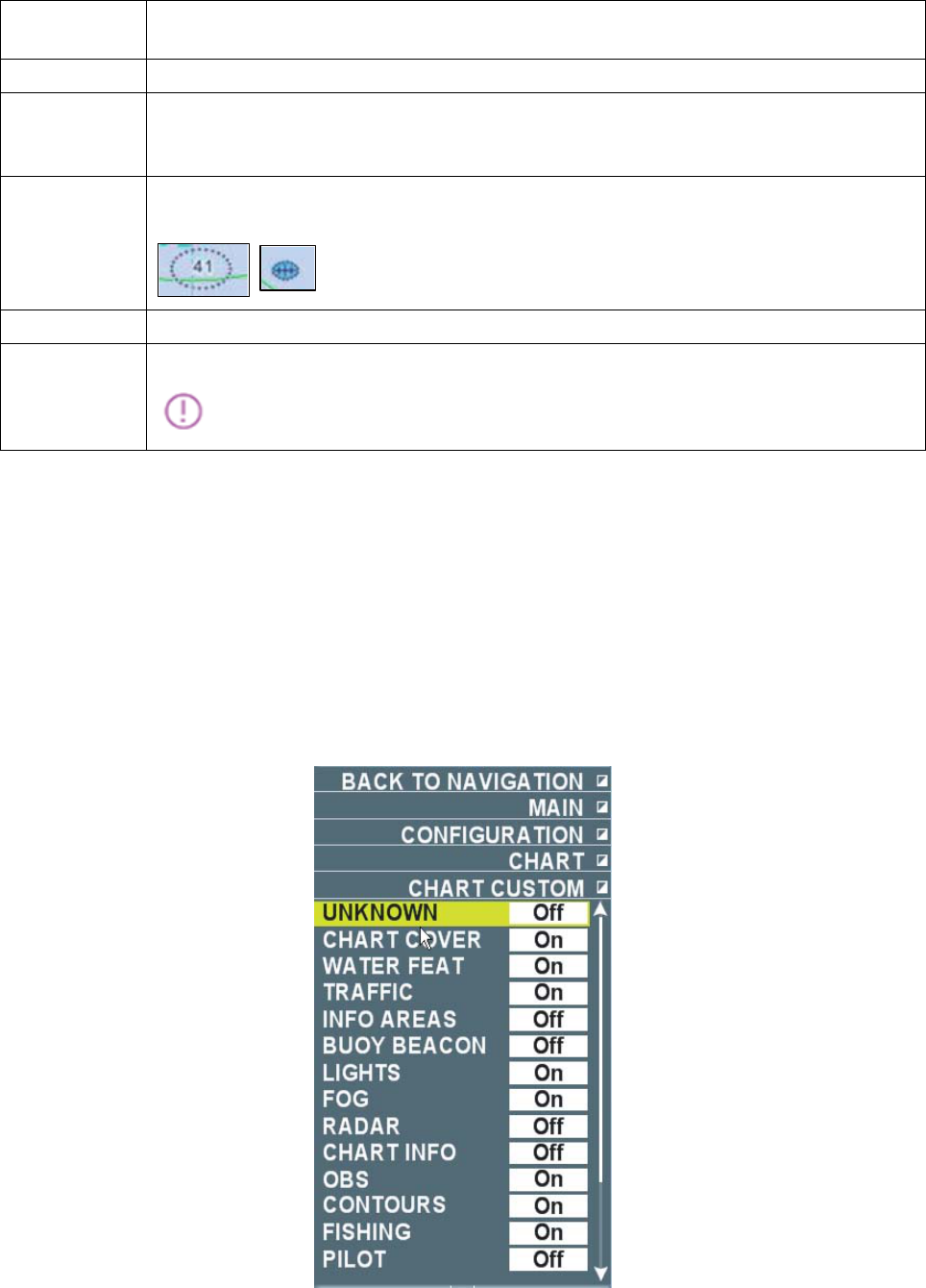
129
Waypoint
bearing
Select whether to display bearing of a waypoint. (Example: 90 deg.)
Depth Select whether to display water depth.
Display
specified
depth in red
Select whether to display water depth less than the setting of [Depth shown in red
color] below.
Depth to
show in red
color
Select whether to display dangerous objects in safe waters (or under the territory)
which normally do not appear.
Ocean floor Select whether to display properties of ocean floor. (Example: sand, shells, etc.)
Alert area Select whether to display alert area.
6. Right-click several times to close the menu.
5.4.4 Set ting chart data individually
Set whether to display the following data when [individual] is selected in [Coastline information]
in the [Display] menu.
1. Put the cursor in [Menu] in the information display area then left-click.
2. Select [Set environment] then left-click.
3. Select [Chart] then left-click.
4. Select [Individual setting] then left-click.
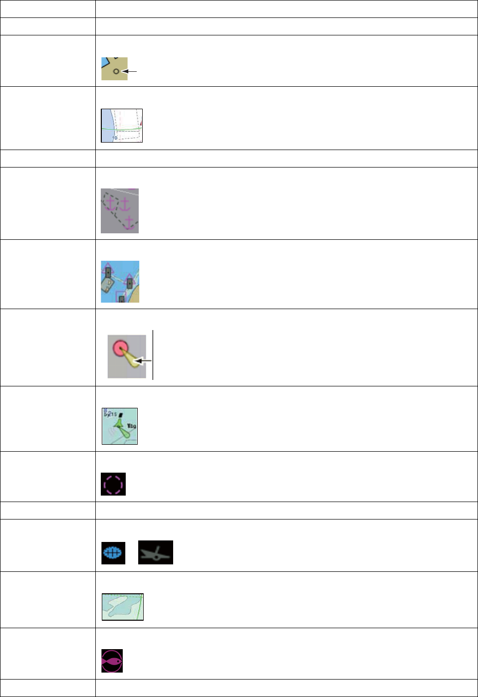
130
5. Select an item to change then left-click. Change each setting as necessary.
Menu Item Contents
Others Planned for the future
Location name Select whether to display coordinates of locations.
Water quality Select whether to display water quality.
Routes Planned for the future.
Information
display area
Select whether to display information display area.
Buoy/Beacon Select whether to display buoy/beacon.
Lighthouse Select whether to display lighthouse.
Fog signal Select whether to display fog signal.
Radar Select whether to display radar transponder beacon.
Chart data Select whether to display chart data.
Obstacle Select whether to display obstacles.
Depth contour &
Current
Select whether to display depth contours or currents.
Fishing tools Select whether to display setup locations of fishing tools.
Pilot Select whether to display pilots and pilot boarding locations.
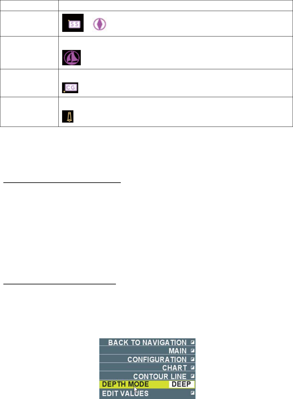
131
Menu Item Contents
Harbor facility Select whether to display yacht harbors and marinas.
Small boat
services
Select whether to display small boat services.
Topography Select whether to display towers.
6. Right-click several times to close the menu.
5.4.5 Setting individual depth contour
You can set individual depth contour line as necessary.
Displaying individual contour line
Factory default of individual contour line is [No display]. Follow the steps below to change the
setting.
1. Put the cursor on [menu] in the information display area then left-click.
2. Select [Display] then left-click.
3. Select [Individual contour line] then left-click.
4. Select [On] then left-click. Individual depth contour is displayed.
No individual contour is displayed when [Off] is selected.
5. Right-click several times to close the menu.
Editing individual depth contour
You can change color of individual depth contour to the color of your choice.
1. Put the cursor on [Menu] in the information display area then left-click.
2. Select [Set environment] then left-click.
3. Select [Chart] then left-click.
4. Select [Individual depth contour] then left-click.
5. Select [Select depth] then left-click.
6. Select [Shallow waters] or [Deep waters] then left-click.
• Shallow waters: Edit individual contours of 1 ~ 250m.
• Deep waters: Edit individual contours of 10 ~ 2500m.
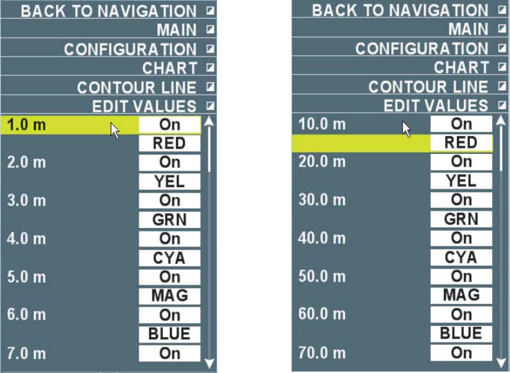
132
7. Select [Edit depth] then left-click.
[Shallow waters] [Deep waters]
8. Select a depth (m) to change then left-click to chancel displaying a specific individual depth
contour.
9. Select [Off] then left-click.
No individual depth contour is displayed at [Off]. Select [On] to re-display the contour.
Display/No display is shown on the screen when the menu is closed.
Note: In the above menu, Display/No display and color settings are the same in the order
displayed between shallow waters and deep waters. For example, shallow waters 1.0m and
deep waters 10.0 and shallow waters 2.0m and deep waters 20.0 and the rest have the
common Display/No display and color settings.
10. Select color of which setting to change then left-click.
11. Select a necessary color then left-click.
12. Repeat steps 8 ~ 11 to complete individual depth contour.
13. Right-click several times to close the menu.
5.4.6 Changing Datum
This system can convert WGS-84 (World Geodetic System) to Tokyo datum. Follow the steps
below to convert to Tokyo datum.
Note: The datum of GPS connected must be WGS-84. When the datum is Tokyo datum, chart may
appear out of alignment. The system cannot convert Tokyo datum to WGS-84.
1. Put the cursor on [Menu] in the information display area then left-click.
2. Select [Set environment] then left-click.
3. Select [Chart] then left-click.
4. Select [Datum] then left-click.
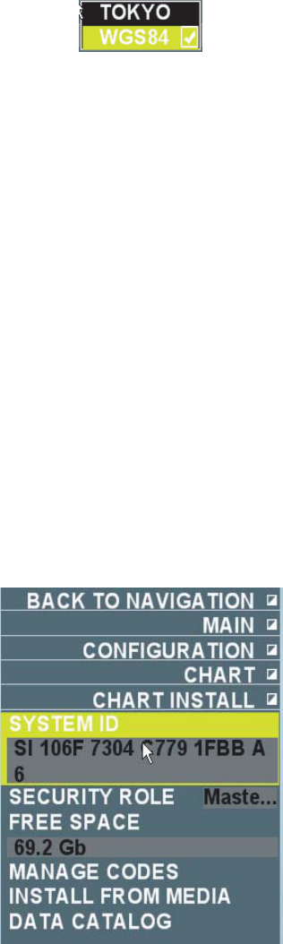
133
5. Select [Tokyo] then left-click.
6. Right-click several times to close the menu.
5.4.7 Installing charts
The system is equipped with the Japan Sea charts only. Please contact FURUNO or its agencies
for charts other than the Japan Sea.
1. Put the cursor on [Menu] in the information display area then left-click.
2. Select [Set environment] then left-click.
3. Select [Chart] then left-click.
4. Select [Install] then left-click.
System ID: FAR-1417/1427 ID. (No changes allowed.)
Security Setting: Display either primary or secondary. (Set at installation. No changes
allowed.)
Remaining capacity: displays remaining capacity of hard disk. (No changes allowed.)
Unlock code: Input unlock code obtained from a chart supplier.
Install: Store charts obtained in USB memory to install in the system.
List of data: Display chart data installed in the system.
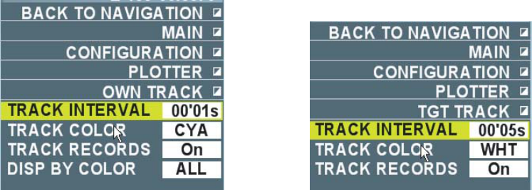
134
5.5 Track
A total of 20,000 points are allotted for storage of own ship’s track and 200,000 points for storage
of other ships. Number of points per ship is determined by number of TT acquisition. For
example for 10 ships acquisition, 20,000 points are allotted per ship and for one ship acquisition
200,000 points are allotted per ship. When this memory becomes full, the oldest track is deleted
to make room for the latest. Tracks do not disappear even when the power is turned off.
Note: You can confirm current number of points of own ship and other ships in the [Mark] menu.
(See chapter 5.2.1)
5.5.1 Displaying tracks
Factory default of own ship track and other ships [No display]. Follow the steps below to change
the setting.
Note: Tracks are displayed only when [Own ship’s track memory] and [Other ships’ track
memory] are [On] in the [Own ship’s track] ([Other ships’ track]) menu.
1. Put the cursor on [Menu] in the information display area then left-click.
2. Select [Display] then left-click.
3. Select [Own ship’s track] or [Other ships’ track] then left-click.
4. Select [On] then left-click.
Track is displayed. No track is displayed when [Off] is selected.
5. Right-click several times to close the menu.
5.5.2 Plotting track intervals
Tracks are drawn at certain time interval. A smooth track is drawn at short plotting interval but
total plotting time is shorter.
1. Put the cursor on [Menu] in the information display area then left-click.
2. Select [Set environment] then left-click.
3. Select [Plotter] then left-click.
4. Select [Own ship’s track] or [Other ships’ track] then left-click.
[Own ship’s track] is selected [Other ship’s track] is selected
5. Select [Plotting interval of own ship] or [Plotting interval of other ships] then left-click.
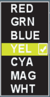
135
6. Set time interval.
When the setting of own ship’s plotting interval is [00’00s], track is plotted each time position
data is received. (only when the position is over 1m apart from the previous plot)
7. Right-click each time to close the menu.
Note: Factory default is [Plot] for own ship’s track and other ships’ track. To interrupt plotting own
ship’s track and other ships’ track, set [Plot own ship’s track] ([Plot other ships’ track]) in the
above [Own ship’s track] ([Other ships’ track]) is set [Off]. No new tracks are drawn during the
interruption.
5.5.3 Selecting color of tracks
You can select color of tracks from the seven colors of Red, Green, Blue, Yellow, Turquoise,
Purple and White. For example, you can identify tracks by colors set by date of voyage.
1. Put the cursor on [Menu] in the information display area then left-click.
2. Select [Set environment] then left-click.
3. Select [Plotter] then left-click.
4. Select [Own ship’s track] or [Other ships’ track] then left-click.
5. Select [Color of own ship’s track] or [Color of other ships’ track] then left-click.
6. Select necessary color then left-click. Track is displayed in the color changed at this time.
Right-click several times to close the menu.
Note: You can also change colors of other ships using the [TT] menu. Put the cursor on TT mark
to change color then right-click. Select the [Change colors of other ships’ track] then left-click.
Next, select desired color then left-click.
5.5.4 Selecting color of tracks to display
You can select color of own ship’s tracks to display on the screen.
1. Put the cursor on [Menu] in the information display area then left-click.
2. Select [Set environment] then left-click.
3. Select [Plotter] then left-click.
4. Select [Own ship’s track] then left-click.
5. Select [Display own ship’s track by color] then left-click.
6. Select necessary color then left-click.
Only tracks of selected colors are displayed. When [All] is selected, tracks of all colors are
displayed.
7. Right-click several times to close the menu.
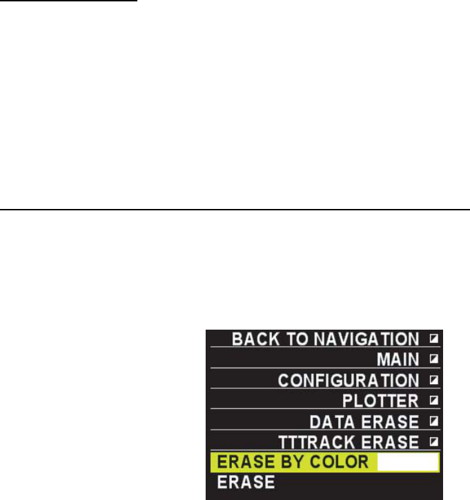
136
5.5.5 Erasing tracks
The system has large capacity memory therefore, it is not necessary to erase tracks normally.
Erase tracks when the screen is crowded with many tracks. There are the following three ways
to erase tracks.
• Erase all tracks. (Own ship’s tracks, Other ships’ tracks)
• Erase tracks of specified colors (Other ships’ tracks only)
• Erase interrupted tracks only. (Own ship’s tracks, Other ships’ tracks)
Erasing all tracks
1. Put the cursor on [menu] in the information display area then left-click.
2. Select [Set environment] then left-click.
3. Select [Plotter] then left-click.
4. Select [Delete data] then left-click.
5. Select [Erase all tracks of own ship] or [Erase all tracks of other ships] then left-click.
6. Select [yes] then left-click. All tracks disappear.
Note: to cancel erasing tracks, select [No] instead of [Yes].
7. Right-click several times to close the menu.
Deleting tracks of specified colors (other ships’ tracks only)
1. Put the cursor on [Menu] in the information display area then left-click.
2. Select [Set environment] then left-click.
3. Select [Plotter] then left-click.
4. Select [Delete data] then left-click.
5. Elect [Erase other ships’ tracks] then left-click.
6. Select [Erase by color] then left-click.
7. Select color to erase then left-click.
8. Select [Erase] then left-click.
9. Select [Yes] then left-click.
Tracks of specified colors disappear.
10 Right-click to close the menu.
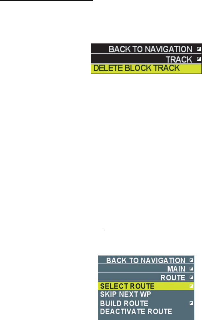
137
Erasing interrupted tracks
Tracks are interrupted when power is turned on or plotting of other ships’ tracks is interrupted.
Follow the steps below to erase interrupted tracks.
1. Put the cursor on interrupted track then right-click.
2. Select [Erase track section] then left-click.
Interrupted track disappears.
5.6 Route
It is necessary to veer your ship several times to navigate from one point to another. A line
connecting veering points (destinations) is called a route. Your waypoints are updated
automatically as you steer along the route and you can obtain necessary information (range and
bearing to waypoints) to steer your ship.
5.6.1 Creating routes
There the following two was to make routes.
• Make routes using the menu.
• Make routes using marks/waypoints on the screen.
Making routes with the menu
1. Put the cursor on [Menu] inside the information display area then left-click.
2. Select [Route] then left-click.
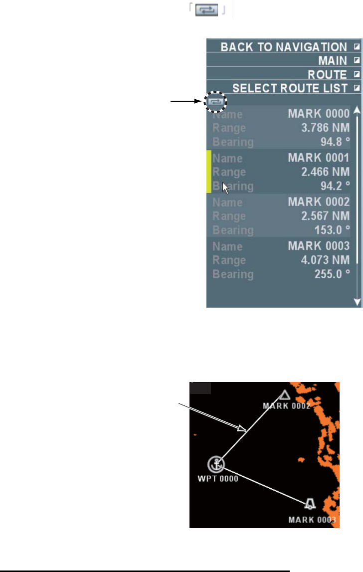
138
3. Select [Make routes from marks/waypoints] then left-click.
All data of marks and waypoints stored in the system are displayed.
Each left-click of the switch button switches between rage/bearing, and
latitude/longitude.
Switch button
4. Roll the wheel to select marks or waypoints to register for routes then left-click.
Repeat this step to complete routes.
5. Completed routes are stored in the route selection list.
Numbers are assigned to [Rte] as a route name.
Route line
6. Right-click several times to close the menu.
Making routes with marks/waypoints on the screen
1. Put the cursor on the line in the line box at the lower left side on the screen then left-click.
The cursor moves in the valid radar echo area.
2. Put the cursor on the mark or waypoint to register in the routes.
3. Left-click.
4. Repeat steps 2~3 to complete the route.
5. Completed routes are stored in the route selection list.
Numbers are assigned by [Rte] as route name.

139
5.6.2 Changing routes
You can change routes already registered.
Changing colors and line types of leg lines
1. Put the cursor on a leg line to change
2. Right-click to display the [Line] menu.
3. Select [Line color] to change color then left-click. Next , select color after the change then
left-click.
4. Select [Line type] to change line type then left-click. Next Select line type after the change
then left-click.
5. Right-click to close the menu.
Moving veering points inside routes
1. Put the cursor on a veering point (mark/waypoint).
2. Right-click to display the [Mark icon] menu.
3. Select [Move] then left-click.
4. Move the cursor to a new location.
5. Left-click.
The veering point moves to a new location.
5.6.3 Erasing routes
There are the following two ways to erase routes.
• Erase specific routes.
• Erase all routes
Notes: Routes used for waypoints cannot be erased.
Erasing specific routes
1. Put the cursor on a leg line to erase.
2. Right-click to display the [Line] menu.
3. Select [Delete] then left-click.
Specified routes disappear.
Erasing all routes
1. Put the cursor on [Menu] in the information display area then left-click.
2. Select [Set environment] then left-click.
3. Select [Plotter] then left-click.
4. Select [Delete data] then left-click.
5. Select [Erase all lines] then left-click.
6. Select [Yes] then left-click.
All routes (including lines) disappear.
Note: Select [No] to cancel erasing routes instead of [Yes].
7. Right-click several times to close the menu.
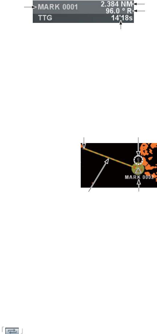
140
5.7 Waypoint
A particular destination (veering point) to navigate is known as a waypoint. Marks already
entered, destinations, lines and registered routes can be set as waypoints. When the setting in
[Waypoint data] is other than [OFF] in the [Navigation data] menu, range and bearing from own
ship to the waypoint and estimated time to the waypoint are displayed when setting the waypoint.
When a new waypoint is set, the previous waypoint is cancelled.
Waypoint name
Estimated time to waypoint
Range from own ship to waypoint
Bearing from own ship to waypoint
Display in the information display area
5.7.1 Setting Waypoints
You can set marks and destinations as waypoints.
1. Put the cursor on a mark or a destination to set as a waypoint.
2. Right-click to display the [Mark icon] menu.
3. Select [Waypoint] then left-click.
Own ship position Destination No.
Set course to waypoint Waypoint
4. Right-click to close the menu.
A line connects own ship and the waypoint as a set course. The line indicates the shortest
course from the current position of own ship to the waypoint. The set course disappears when
own ship arrives at the waypoint.
Note: No destination number appears on the screen when the setting of [Destination No.] is [Off]
in the [Display] menu.
5.7.2 Setting destination as waypoint with the destination list
You can set a destination in the destination list as a waypoint.
1. Put the cursor on [Menu] in the information display area then left-click.
2. Select [Destination list] then left-click.
All the destinations stored in the system are displayed. Each left-click of the switch
button switches between range/bearing and latitude/longitude.
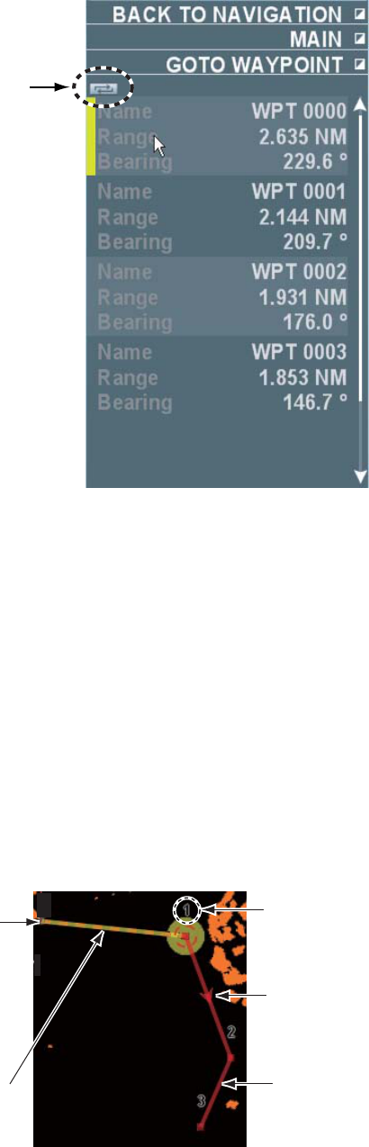
141
Switch button
Displaying Range/Bearing
3. Roll the wheel to select a destination to set as a waypoint then left-click.
4. Right-click several times to close the menu.
A line connects own ship and the waypoint as a set course. The line indicates the shortest
course from own ship’s current position to the waypoint. The set course disappears when
own ship arrives at the waypoint.
5.7.3 Setting an entered line to a waypoint
A line on the screen can be set to a waypoint.
1. Put the cursor on a leg line to the waypoint.
2. Right-click to display the [Line] menu.
3. Select [Set course] then left-click.
Own ship position
Set course to the first
veering point
Destination No.
Arrow indicating
traveling direction
Leg line
A line connects between own ship and the first veering point to become a set course. An arrow
appears on the leg line indicating the travelling direction. A set course appears automatically at
the next veering point when own ship arrives at the waypoint.
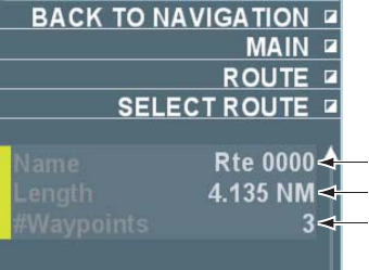
142
5.7.4 Setting a registered route to a waypoint
You can set a registered route to a waypoint.
1. Put the cursor on [menu] in the information display area then left-click.
2. Select [Route] then left-click.
3. Select [Select a route from lines] then left-click.
Entered lines and routes made in chapter 6.5.1 are stored in the route selection list.
Route name
Total range of a route
Number of points in a route
4. Roll the wheel to select a route to set to a waypoint then left-click.
5. Right-click several times to close the menu.
A line connects between own ship and the first veering point as a set course. An arrow appears
on the leg line indicating the traveling direction. A set course appears automatically at the next
veering point when own ship arrives at the waypoint.
5.7.5 Canceling a waypoint
Follow the steps below to cancel a waypoint on the screen.
1. Put the cursor on a set course.
2. Right-click to display [Line] menu.
3. Select [Cancel course] then left-click.
The waypoint is cancelled and the set course disappears.
5.7.6 Skipping a veering point
Follow the steps below to skip a veering point during navigation.
1. Put the cursor on [Menu] in the information display area then left-click.
2. Select [Route] then left-click.
3. Select [Skip destination] then left-click.
For example, when the veering point 1 is skipped, a new course is drawn to the next veering
point 2.
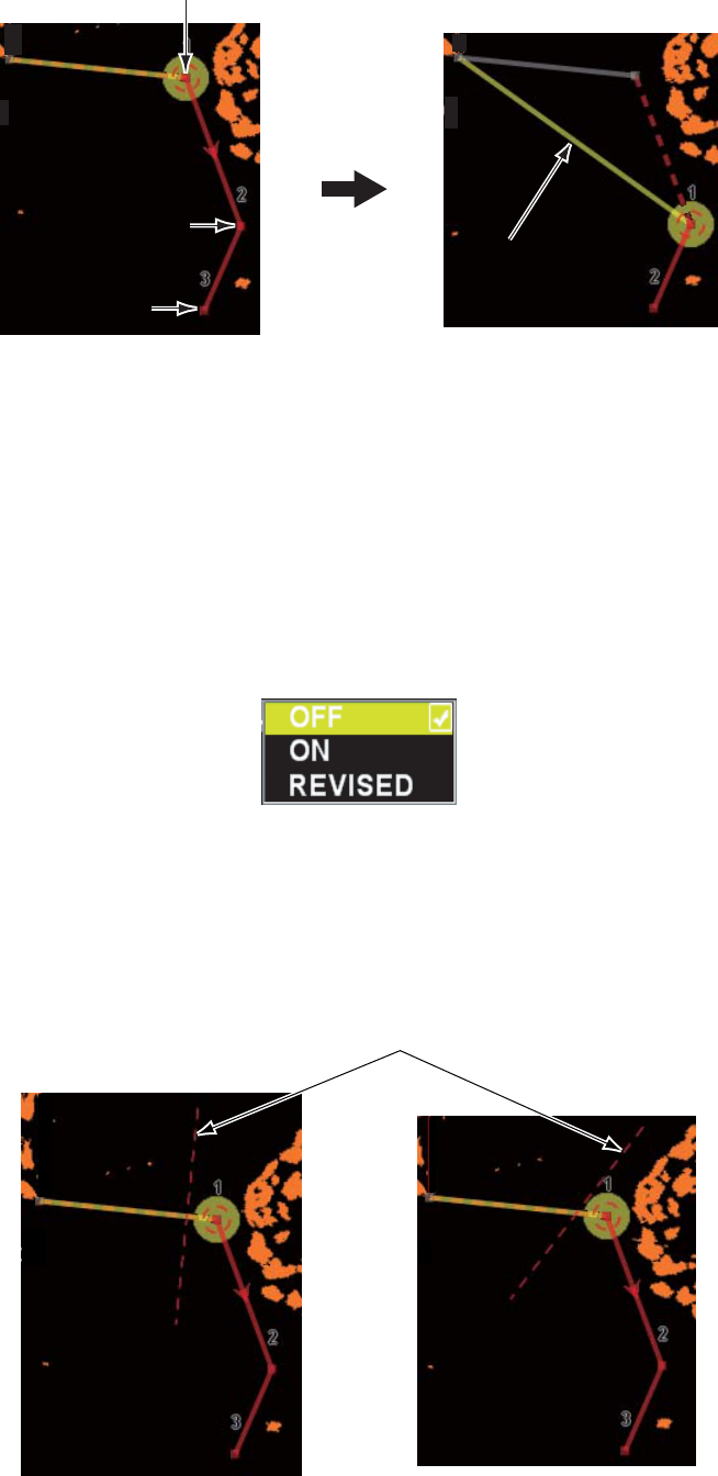
143
Veering point 1
Veering point 2
Veering point 3
A new course
After the skip
4. Right-click several times to close the menu.
5.7.7 Displaying veering start line
You can display a line at the optimum position to start veering while using the route.
Note: To use the veering start line, it is necessary to preset a turning rate for steering simulation
with the TT function. (See chapter 3.15.)
1. Put the cursor on [menu] in the information display area then left-click.
2. Select [Display] then left-click.
3. Select [Veering start line] then left-click.
4. Select [ON] or [No off track correction] then left-click.
• ON: display the veering line perpendicular (90°) to a set route.
• No off track correction: display the veering start line while keeping the gap between the
set route and the current position.
No veering start line is displayed when [OFF] is selected.
Veering start line
ON No off track correction
5. Right-click several times to close the menu.
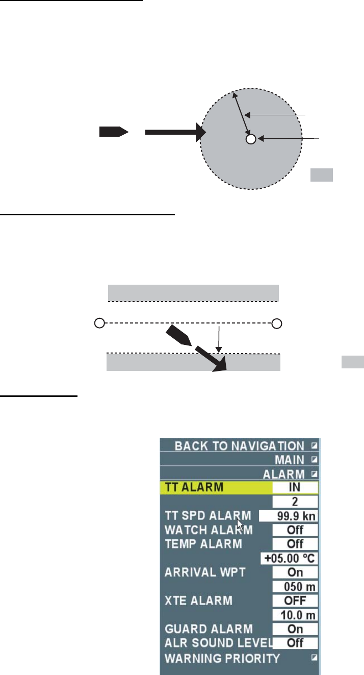
144
5.8 Plotter related alarms
Destination arrival alarm
The destination arrival alarm serves to alert the navigator when own ship enters a specific area
with the waypoint at its center, with audio alarms. When the destination arrival alarm is set, an
alarm area is shown surrounded by a red broken line.
Own ship position
Range set
Waypoint
: Area set
XTE (Cross Track Error) alarm
Cross track error serves to alert the navigator when own ship navigates across the set range
from the course connecting the start point to the waypoint. When XTE alarm is set, alarm area is
displayed on both sides of the set course with a broken line. (Port side: Red, Starboard side:
Green)
Start point Own ship Range set
Waypoint
: Set area
Setting alarm
1. Put the cursor on [Menu] in the information display area then left-click.
2. Select [Alarm] then left-click.
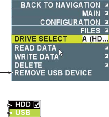
145
3. Select [Destination arrival alarm] or [XTE alarm] then left-click.
4. Select [On] (Destination arrival alarm) or [XTE] (XTE alarm) then left-click.
5. Select a line in the setting area then left-click.
6. Enter a setting value.
7. Right-click several times to close the menu.
In the alarm condition, alarm sounds and [Waypoint arrival] or [XTE] flashes in the alarm section
in the information display area.
Select [Off] in step 4 to cancel the alarm.
5.9 Recording/Replaying Data
Connect USB memory (User supplied) to the USB port on the control unit to record and replay
data.
Note 1: Do not use USB memory with security features.
Note 2: Remove USB memory when the menu is closed. Data inside of the USB memory may
get damaged when USB memory is removed while the menu is still open.
5.9.1 Recording Data
Record important data (marks/lines/destinations, initialization settings, installation settings, own
ship tracks, alarm records) periodically in USB memory.
Note 1: Data recorded in USB memory are overwritten when the same file name is used and the
previously recorded data are deleted. Note to save data under a different file name when the
previous data need to be saved also. Data recorded in USB memory may be stored in PC for
backup.
Note 2: The contents of alarm history in this system will be deleted when data of alarm history
data are recorded in USB memory.
1. Open the USB cover on the control unit to insert USB memory.
2. Put the cursor on [Menu] in the information display area then left-click.
3. Select [Set environment] then left-click.
4. Select [File] then left-click.
Displayed only when USB memory is
recognized
5. Select [Select drive] then left-click.
Inside of hard drive
USB memory
6. Select [USB] then left-click.
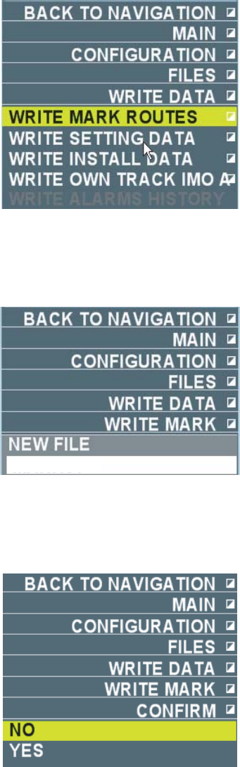
146
7. Select [Read data (Radar - >>> Recording device)] then left-click.
8. Select an item to record then left-click.
The file name input box appears as shown below when Selection other than [Alarm history] is
selected. Proceed to step 9. When [Alarm history] is selected, recording starts. Proceed to
step 12.
9. Left-click.
10. Input file name (Maximum ten characters) using the small keyboard appearing at the lower
section on the screen.
The [Confirmation] menu appears after inputting the file name.
11. Select [Yes] then left-click.
Note: No menu operation can be done during the recording.
12. Right-click several times to close the menu.
Note: When data are not recorded normally in the USB memory, the indication [Data writing
error] flashes in the alarm box in the information display area.
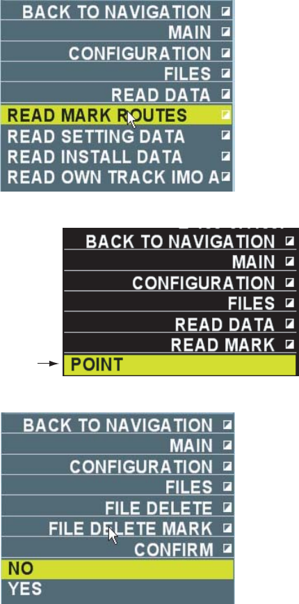
147
5.9.2 Replaying data
The data recorded in the USB memory are displayed on the screen.
Note: When you replay marks/lines/destinations or own ship track stored in the USB memory,
they are added to the data (marks/lines/destinations, or own ship track) displayed on the screen.
1. Open the USB cover on the control unit to insert USB memory.
2. Put the cursor on [Menu] in the information display area then left-click.
3. Select [Set environment] then left-click.
4. Select [File] then left-click.
5. Select [Select drive] then left-click.
6. Select [USB] then left-click.
7. Select [Read data (Recording device - >>> Radar)] then left-click.
8. Select an item to replay then left-click.
File recorded
9. Select the file to replay then left-click.
10. Select [Yes] then left-click.
When initialization setting is replayed, power needs to be turned on again.
Note: No menu operation can be done during the replay.
11. After the replay, right-click several times to close the menu.
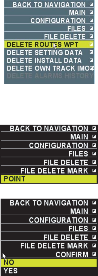
148
5.9.3 Deleting Files
Files recorded in USB memory can be deleted.
1. Open the USB cover on the control unit to insert USB memory.
2. Put the cursor on [Menu] in the information display area then left-click.
3. Select [Set environment] then left-click.
4. Select [File] then left-click.
5. Select [Select drive] then left-click.
6. Select [USB] then left-click.
7. Select [Delete file] then left-click.
8. Select an item to delete then left-click.
The file names recorded in the USB memory are displayed when the selections other than
[Alarm history] is selected. Proceed to step 9. When [Alarm history] is selected, the history is
deleted. Proceed to step 11.
9. Select the file to delete then left-click.
10. Select [Yes] then left-click.
11. After deleting the file, right-click several times to close the menu.
149
6. MAINTENANCE AND
TROUBLESHOOTING
This chapter explains maintenance and troubleshooting instructions to be followed to obtain
optimum performance and the longest possible life of the equipment.
WARNING
Do not open the equipment.
Hazardous voltage which can
cause electrical shock exists
inside the equipment. Only
qualified personnel should
work inside the equipment.
Turn off the radar power
switch before servicing the
antenna unit. Post a warn-
ing sign near the switch
indicating it should not be
turned on while the antenna
unit is being serviced.
Prevent the potential risk of
being struck by the rotating
antenna.
WARNING
A transmitting radar
antenna emits electromag-
netic waves, which can be
harmful, particularly the
eyes.
Wear a safety belt and hard
hat when working on the
antenna unit.
Serious injury or death can
result if someone falls from
the radar antenna mast.
NOTICE
Do not apply paint, anti-corrosive
sealant or contact spray to coating
or plastic parts of the equipment.
Those items contain organic solvents
that can damage coating and plastic
parts, especially plastic connectors.

150
6.1 Periodic Maintenance Schedule
Interval Check point Check and measures Remarks
LCD dirt Wipe the LCD carefully
with the supplied filter
cleaner. To remove
stubborn dirt, use OA
display cleaner, wiping
slowly with tissue paper so
as to dissolve the dirt.
Change paper frequently
so the dirt will not scratch
the LCD.
Do not use chemical-
based cleaners to
clean the LCD such as
thinner, acetone and
benzene.
Do not use on-the-
shelf oil remover or
defogger, which may
damage coating on the
screen (filter surface)
When needed
Cleaning the processor
unit
Wipe off dirt with a soft
cloth.
Do not use chemical-
based cleaners to
clean the processor
unit. They can remove
coatings.
3 to 6 months Exposed nuts and bolts on
antenna unit
Check for corroded or
loosened nuts and bolts on
antenna unit for any
damages by exposures to
salty wind and vibrations.
It is recommended to
exchange bolts or nuts
before corrosion
progresses. Apply
sealing compound to
prevent corrosion
when exchanging bolts
and nuts.
Antenna radiator Check for salt, oil, and
pints on radiator surface.
They may cause
attenuation or clutter to
lower the sensitivity of
antenna radiator. Wipe off
dirt gently with soft cloth
dampened with fresh
water.
Do not use chemical-
based cleaners such
as gasoline, benzene
or ketene as surface of
antenna radiator is
made from FRP.
If you need to remove
ice from the antenna
unit, use a wooden
hammer or plastic
head hammer. Never
use a metal hammer.
WAGO connector
(For technicians only)
Stretch each core wire
gently to check slackness.
When in doubt, remove
the core wire from
WAGO connector and
reinstall.
Coaxial cable contact
(For technicians only)
Visually check screwed
areas or re-screw.
When in doubt, re-
connect the screws.
6 months to one
year
Loose screws on terminal
strips on processor unit
Check for loose
connections. Check
contacts and plugs for
proper seating, etc.
Only qualified
personnel should
perform the
maintenance.

151
6.2 Parts requiring exchanges and recommended
schedule
This equipment uses parts that need to be replaced periodically. The table below shows
recommended schedule for exchanging parts. Please request for periodic replacements of those
parts to FURUNO’s sales offices or its sales agents to maintain optimum performance and the
longest possible life of the equipment.
Replacement Schedule for Parts
Parts Type Life expectancy Remarks
Antenna motor RM-7398 (21/26 rpm) 10,000 hours
Carbon brush MG120-5X6X11D8G 2,000 hours Visual check
Magnetron MG5240F 7,000 hours Check with transmission time
109L0824H407 100,000 hours RF unit
109P12224H02 40,000 hours Inside processor unit
For cooking heat discharge fin
MFB52A-12HA-001 40,000 hours Inside processor unit
- Power supply case
- Graphic board fastening plate
9AH0612P4G03 45,000 hours
Fan motor
109P0512A701 65,000 hours
Inside of processor unit
Hard disk ST980817AM 20,000 hours Inside of processor unit
The life expectancy figures typical values. Actual life depends on usage.
Magnetron
Magnetron gradually lowers its output as transmission continues. When sensitivity of targets in
far distance lowers, request for a replacement of magnetron to a technician. When magnetron is
used for the purpose of detecting small targets in far range, the recommended replacement
schedule will be shorter than the numbers in the above schedule table.
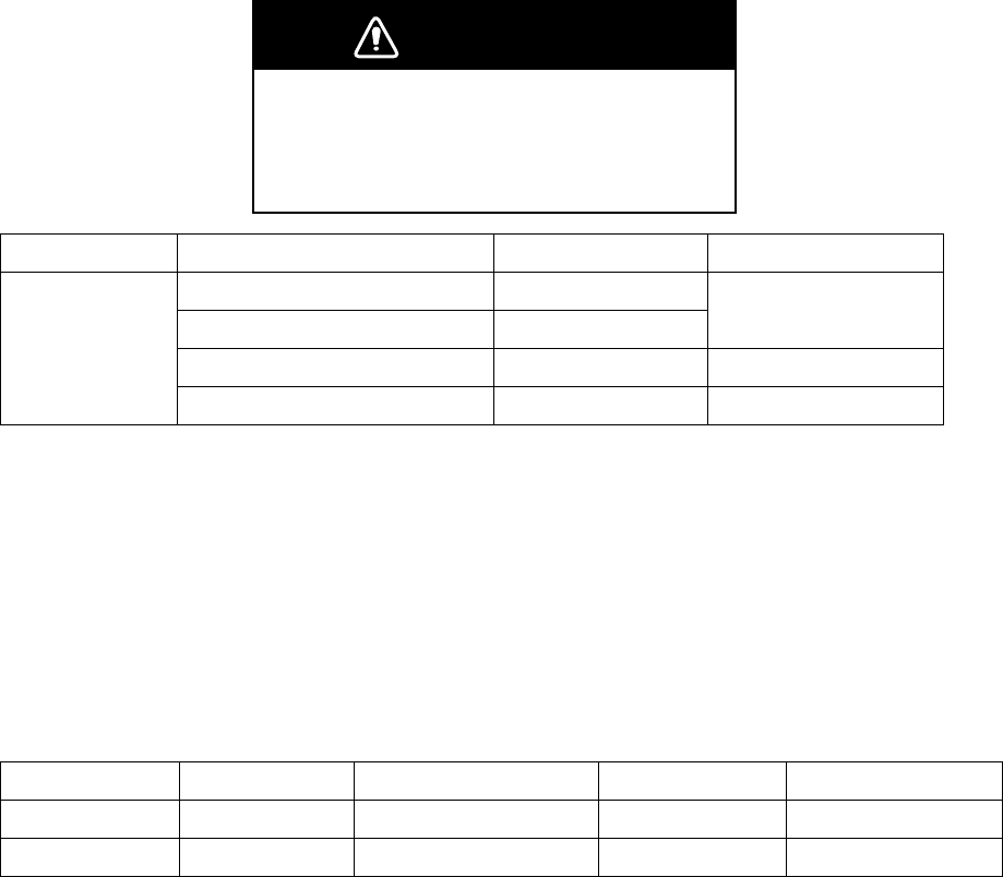
152
6.3 Replacing Fuse
The fuse attached to this equipment protects the equipment from over current and equipment
fault. If you cannot turn on the power, first check the fuse. If the cause is the fuse, exchange it
with a specified fuse. When the power turns off again after replacing the fuse, contact FRUNO’s
sales offices or its sales agents.
WARNING
Use the proper fuse.
Use of a wrong fuse can result in damage
to the equipment or cause fire.
Unit Type Code No. Remarks
FGBO1 250V 15A PBF 000-155-788-10
FGBO-A 125V 5A PBF 000-155-853-10
For 24VDC
FGBO 125V 7A PBF 000-155-831-10 For 100VAC
Processor unit
FGBO 250V 3A PBF 000-155-841-10 For 220VAC
Note: When heading cannot be displayed with the connection of analog signals of Gyrocompass,
the fuse (Type: FGMB 250V 2A PBF, Code No. 000-157-497-10) on GC-100 board in the
processor unit may be expired. Please request for a replacement of the fuse to FURUNO’s sales
offices or its sales agents.
6.4 Replacing Battery
The battery installed on the Gyrocompass mother board inside the processor unit backs up the
data. Please request for a replacement of battery to FURUNO’s sales offices or its sales agents.
Prod. Name Type Code No. Life expectancy
GC board BATT (LI) CR1/296.L-FIST4S 000-173-250-10 5 years
Mother board - - - 7 years
Note: Used batteries should be handled as industrial wastes. Please follow the rules and
instructions of local government when disposing used batteries. Insulate anode and cathode with
a tape to prevent overheat and fire due to a short circuit.
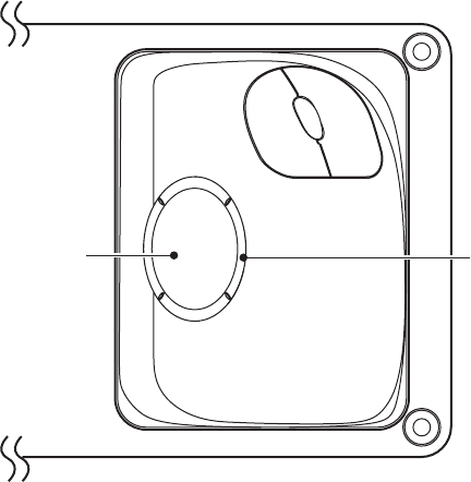
153
6.5 Trackball Maintenance
Clean the trackball if the cursor does not move smoothly while operating the trackball.
1. Rotate the ring of the trackball 45° to the left.
Trackball Ring
Conrrol unit
2. Remove the ring and ball.
3. Clean the ball with a soft, lint-free cloth.
3. Carefully clean inside the ball-cage to remove dust.
Be sure not to damage the projection inside of the ball-cage for smooth rolling of the ball.
5. Place the ball and ring back to the original position.

154
6.6 Simple Troubleshooting
If you suspect any problems, follow the procedures below to restore normal operation. If you
cannot restore normal operation, do not attempt to check inside any unit. Any repair work is best
left to a qualified technician.
Problem Remedy
No power - Check if fuse is expired.
- Connect the power cable securely.
- Check any damage to the power cable.
- Check voltage of battery with a tester.
- For AC power, check if the power switch is ON at the rear
panel of the processor unit.
No Getting ready state after power
is turned ON.
Check if USB memory is inserted in the control unit.
No reaction when a key is pressed. Reset the power. If the problem persists, contact FURUNO’s
sales offices or its sales agents.
Cannot adjust brilliance with the
[Echo brilliance] knob in the control
unit.
Check the setting on the display unit. (See chapter 1.5.1.)
No key sound Set [Key operation sound] in the [Control] menu at the settings
other than [Off].
Screen freezes and images cannot
be updated.
Reset the power.
No radar echoes appear when the
[Prepare/Transmit] key is pressed.
Check if antenna cable is securely connected.
Adjust brilliance.
No echoes are displayed. Check if antenna cable is securely connected.
Check if LAN cable is disconnected on the rear panel of the
processor unit.
Low sensitivity Clean of the radiator surface in the antenna unit.
Range changed but radar picture
does not change.
Press [+] or [-] sections of the [Range] key.
Reset the power.
Too much echoes on sea surface
near own ship.
Roll the [Sea clutter rejection] knob to adjust sea clutter
rejection.
Set numbers of PI lines do not
appear.
Set PI line interval correctly.
Tracked target not tracked
correctly.
Adjust sea clutter rejection, precipitation clutter rejection, or TT
echo level.
Gyrocompass and heading do not
match.
Set Gyrocompass correctly at [GC-10] in the [Echo] menu.

155
6.7 Troubleshooting by Qualified Technician
This chapter describes troubleshooting that should be carried out by qualified service personnel
(personnel with shipboard maintenance qualifications) only.
Note: Follow the steps below to transfer the previous settings to new SPU board.
1. Record current settings into USB memory by referring chapter 5.9.1.
2. After replacing the SPU board, load the recorded data.
Problem Check point Remedy
Power turns on but radar does
not operate.
- Fuse
- Mains voltage
- Power supply board
- Replace blown fuse
- Correct wiring and input voltage.
- Replace power supply board.
Brilliance can be adjusted but
no picture.
Graphic board Replace graphic board
Antenna not rotating - Gear mechanism
- TB board
- Antenna switch of the
antenna unit chassis.
- Replace antenna gear.
- Replace TB board
- Check if switch is ON.
No data or marks are displayed
in transmit status
- Mother board
- SPU board
- Replace mother board.
- Replace SPU board.
No echo displayed even when
adjusting GAIN with sea clutter
rejection, precipitation clutter
rejection set at minimum.
- IF amplifier
- Signal cable between
antenna and processor unit
- Video amplifier board
- Replace IF amplifier.
- Check coaxial cable.
- Replace video amplifier.
No strong echo even if GAIN is
adjusted in near range.
- TX high voltage protection
circuit has activated.
- Magnetron
- Modulator board
- SPU board
- Reset power to restore normal
operation.
- Check magnetron current.
Replace magnetron.
- Replace modulator board.
- Replace SPU board.
Picture not updated or picture
freeze-up
- Bearing signal board (in
antenna unit)
- SPU board
- Check the connection of signal
cables.
- Replace SPU board.
- Reset power.
- Check LAN cable disconnection
on rear panel of processor unit.
No North-up - SPU board
- Gyro I/F
- No signal received when “Sensor
error gyro” is displayed on the
screen.
- Replace Gyro I/F GC-100.
Radar properly tuned but poor
sensitivity
- Deteriorated magnetron.
- MIC tuning
- Dirt on radiator face
- Second trace echo
rejection is ON
- With the radar transmitting on
48NM, check magnetron current.
- Clean the radiator surface.
- Set Second trace echo rejection.
Range can change but radar - Defective [Range] key - Press [+] or [-] keys several times.

156
Problem Check point Remedy
picture does not change.
- SPU board
If unsuccessful, replace keyboard.
- Replace SPU board.
- Reset power.
Interference rejecter is
inoperative (interference
rejection level not displayed.)
SPU board Replace SPU board
Zoom is not working. SPU board Replace SPU board
Range rings are not displayed. Setting of fixed range ring
brilliance range
Adjust the brilliance of range rings
on the [Brilliance detail] menu. If
unsuccessful, replace SPU board.
True motion presentation not
working correctly
- Poor contact of the [Mode
selection] key
- Mode is not selected
correctly.
- Speed entry incorrect
- TM display inaccurate
- Press the [Mode selection] key a
little stronger again.
- Press the [Mode selection] key
until TM appears.
- Enter correct own ship speed.
- Set compass inputs correctly.
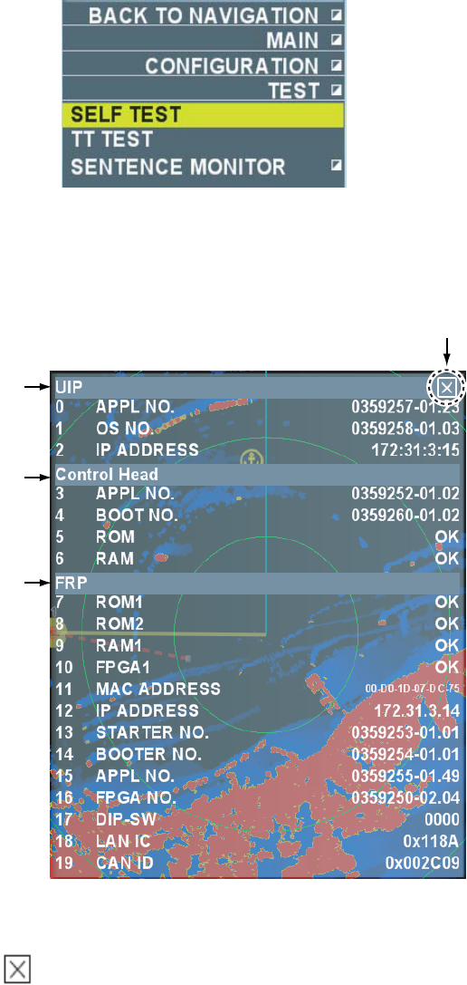
157
6.8 Diagnostic
When you suspect abnormal operation, execute the diagnostic test. Should a repair be
necessary by a technician, diagnostic test result helps remedy the problem faster.
1. Put the cursor on [Menu] in the information display area then left-click.
2. Select [Set environment] then left-click.
3. Select [Test] then left-click.
4. Select [Self test] then left-click.
Test result of mother board, control unit and radar processor is displayed. Items 5 ~ 10 are
displayed [OK] if normal and [NG] if abnormal. When [NG] is displayed, request a repair at
FURUNO sales offices or its sales agents.
Close Window
Mother board
Control unit
Radar Processor
xx: Program version no.
Test Result
5. Put the cursor on the button at the upper right section in the window to finish the
diagnostic test then left-click.
6. Right-click several times to close the menu.
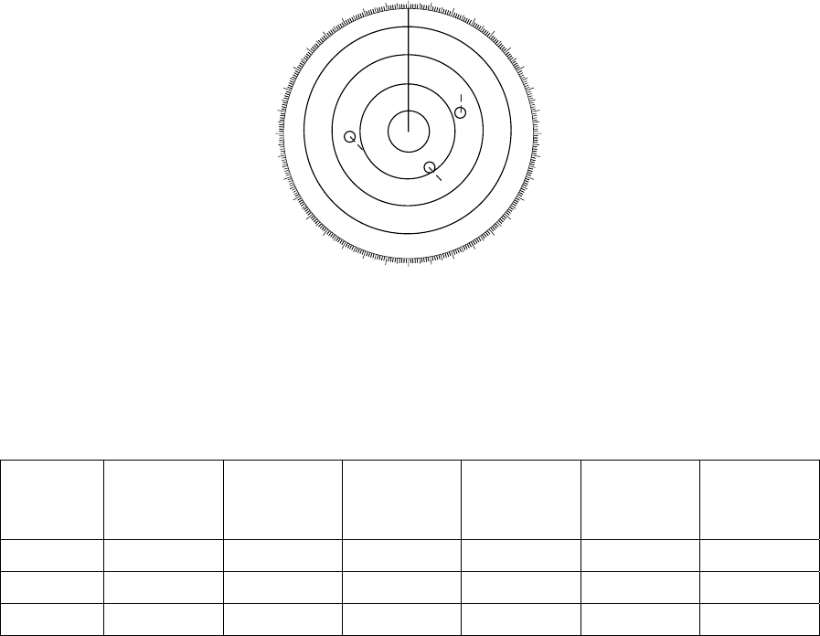
158
6.9 TT Performance Test
You can perform TT function test by entering virtual echoes. Marks below are displayed on the
screen and moves as the time elapses. Heading signal is required to perform the test. When the
test is implemented tracking operation is cancelled with the actual echoes.
Note: Turn the signal processing function off.
1. Put the cursor on [Menu] in the information display area then left-click.
2. Select [Set environment] then left-click.
3. Select [Test] then left-click.
4. Select [TT test] then left-click.
The indication “S” flashes during the test.
5.Acquire three targets appearing on the screen using the [Acquire] key.
Movements of the three targets are automatically simulated. (approx. ten minutes) If the test
result shows the speed course as shown in the table below, TT function is operating correctly.
000 010 020
030
040
050
060
070
080
090
100
110
120
130
140
150
160
170
180
190
200
210
220
230
240
250
260
270
280
290
300
310
320
330
340 350
A
B
C
S
6. Put the cursor on target A then left-click.
Data of the selected target is displayed in the data box in the information display area.
7. Check if the data in the data box approximately agree with the values of the table below.
The table below shows the values at heading 0° and ship speed 0 KN. The values change in
accordance with the time passage, bearing and ship speed.
Range
when test
starts (NM)
Bearing
when test
starts (°)
Speed (kn) Course (°) CPA after
3 min (NM)
TCPA after
3 min (Min)
Target A 3 45 20 0 2.2 -9.2
Target B 2 120 5 120 0.0 -27.0
Target C 7 270 100 120 3.6 0.4
8. Similarly with target A, check target B and C as well.
9. Press the [Prepare/Transmit] key to finish the test and get in the Getting ready state.
10. Right-click several times to close the menu.
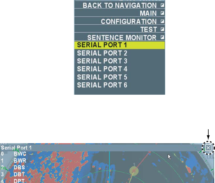
159
6.10 Displaying Sentences
You can confirm sentences read into the equipment.
Put the cursor in [Menu] in the information display area then left-click.
Select [Set environment] then left-click.
Select [Test] then left-click.
Select [Sentence monitor] then left-click.
5. Select the item to display then left-click.
Each item refers to the external equipment connection port in the processor unit.
Close the window
6. Put the cursor on the button at the upper right section of the window then left-click to erase
the sentences.
7. Right-click several times to close the window.
This page intentionally left blank.

AP-1
APPENDIX ALARM LIST
Types of
alarm
Name of alarm Cause Priority Setting
Yes/No
System error No trigger Trigger signal interrupted (Antenna unit) X
System error No video Video signal interrupted X
System error No turning signal Antenna turning signal interrupted X
System error No heading line
signal
Heading line signal interrupted X
System error Control unit Connection from control unit interrupted O
System error Radar connection
error
FRP (Radar Processor) does not
respond to UIP (User Interface
Processor)
O
System error External radar
getting ready
External radar getting ready O
System error Abnormal external
radar
Abnormal external radar O
System error Abnormal
interswitch
Abnormal interswitch O
System error Tuning control No tuning O
System error Disk capacity Exceeded 80% of disk capacity O
System error CPU temperature Temperature of CPU exceeded 80 ̊C O
Sensor error Gyro Heading signal interrupted X
Sensor error Log Ship speed log signal interrupted when
the setting of [Over-the-ground speed]
(or [Speed-over-water] speed) is [Log]
in the [Ship speed] menu.
X
Sensor error Positioning Own ship position data interrupted X
Sensor error Datum Position data read other than WGS-84 O
Sensor error UTC No UTC data O
Sensor error Sounding Sounding data interrupted O
Sensor error Wind
speed/direction
sensor
Wind direction/speed data interrupted O
Sensor error Speed VTG signal interrupted when the setting
of [Speed-over-ground] is [GPS] in the
[Ship speed] menu.
X
Sensor error EPFS mode change Measuring mode is changed O
Sensor error Fan motor Fan on UIP stopped O
TT alarm TT collision alarm Range of both CPA and TCPA within the
set range
X
TT alert TT entering TT target entered in the set guard zone O
TT alert TT lost TT target lost O

AP-2
TT alert TT target full (Auto) Number of automatically acquired
targets reached the set value.
O
TT alert TT target full
(Manual)
Number of manually acquired targets
reached the set value.
O
TT alert TT target 95%
(Auto)
Number of automatically acquired
targets reached 95%.
O
TT alert TT target 95%
(Manual)
Number of manually acquired targets
reached 95%.
O
TT alert Fixed target lost Fixed target lost. O
TT alert TT ship speed alarm Ship speed of specified TT target
exceeded the set value.
X
AIS alarm AIS collision alarm Both CPA and TCPA of activated targets
became within the set range.
X
AIS alarm CPA/TCPA no data No data on over-the-ground
course/Over-the-ground ship speed, or
the data are invalid.
X
AIS alarm AIS activated target
full
Buffer for AIS activated target full X
AIS alert AIS enter AIS target entered in the set guard zone O
AIS alert AIS lost AIS target lost O
AIS alert AIS target full AIS target reached 1000 points O
AIS alert AIS target 95% Memory reached 95% for AIS target O
AIS alert AIS transponder
abnormal
Abnormal AIS transponder O
AIS alert AIS identification TT target and AIS considered to be
identical target
O
AIS alert AIS transmission
abnormal
No response from AIS transponder O
AIS alert AIS activated target
95%
Buffer reached 95% for AIS activated
target
O
AIS alert AIS transmission
failure
Transmission failure O
AIS alert AIS: Antenna VSWR
abnormal
Abnormal antenna voltage standing
wave ratio (VSWR)
O
AIS alert AIS: TDMA RX1
board failure
TDMA RX1 board failed O
AIS alert AIS: TDMA RX2
board failure
TDMA RX 2 board failed O
AIS alert AIS: DRC RX board
failure
DRC RX board failed O
AIS alert AIS: System failure
general
System failure general O

AP-3
AIS alert AIS MKD
communication
abnormal
MKD communication abnormal O
AIS alert AIS: External
navigation
equipment
connection lost
Problem of external navigation
equipment
O
AIS alert AIS: No position
data to use
No position data O
AIS alert AIS: SOG data
invalid
No speed-over-ground data O
AIS alert AIS: COG data
invalid
No course-over-ground data O
AIS alert AIS: HDG data
invalid or incorrect
No heading data O
AIS alert AIS: ROT data
invalid
No rate of turn data O
Other alarms Water depth Water depth on the sea bottom is
shallower than the set value
X
Other alerts Watch alarm Time for set watch alarm passed. X
Other alerts Waypoint arrival Own ship arrived in the set area X
Other alerts XTE Own ship crossed over the set track O
Other alerts Anchor watch alarm Own ship departed the set area X
Other alerts Guard alarm Target entered in the set watch area (or
left the set area)
X
Other alerts Water temperature Water temperature higher or lower than
the set value
X
Other alerts Arrival final
destination
Own ship arrived final destination O
Other alerts Tuning initialization Initializing O
Other alerts SART SART being set O
Other alerts Error data reading Data to replay damaged O
Other alerts Error data writing Data not written in USB normally O