Furuno USA 9ZWRTR114 Transceiver for Radar User Manual IME 36460 B
Furuno USA Inc Transceiver for Radar IME 36460 B
UserManual.wiki
>
Furuno USA
>
9ZWRTR114 User Manual
User Manual
Navigation menu
Upload a User Manual
Namespaces
Wiki Guide
HTML
PDF
Info
Views
User Manual
Discussion / Help
Navigation
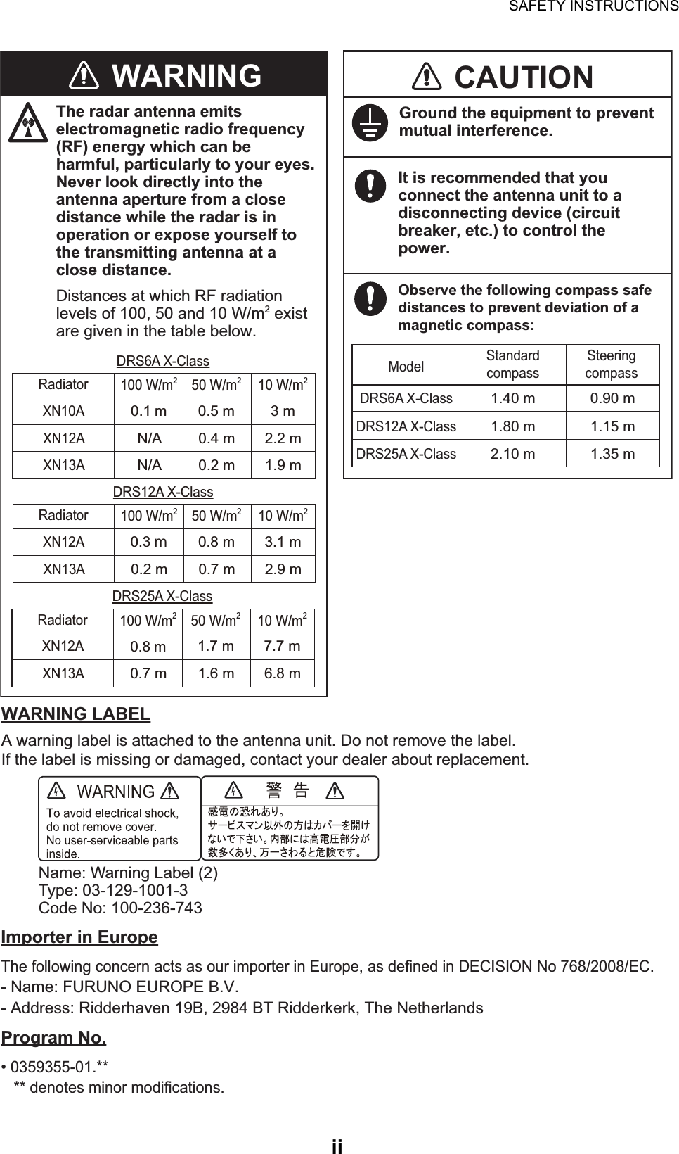
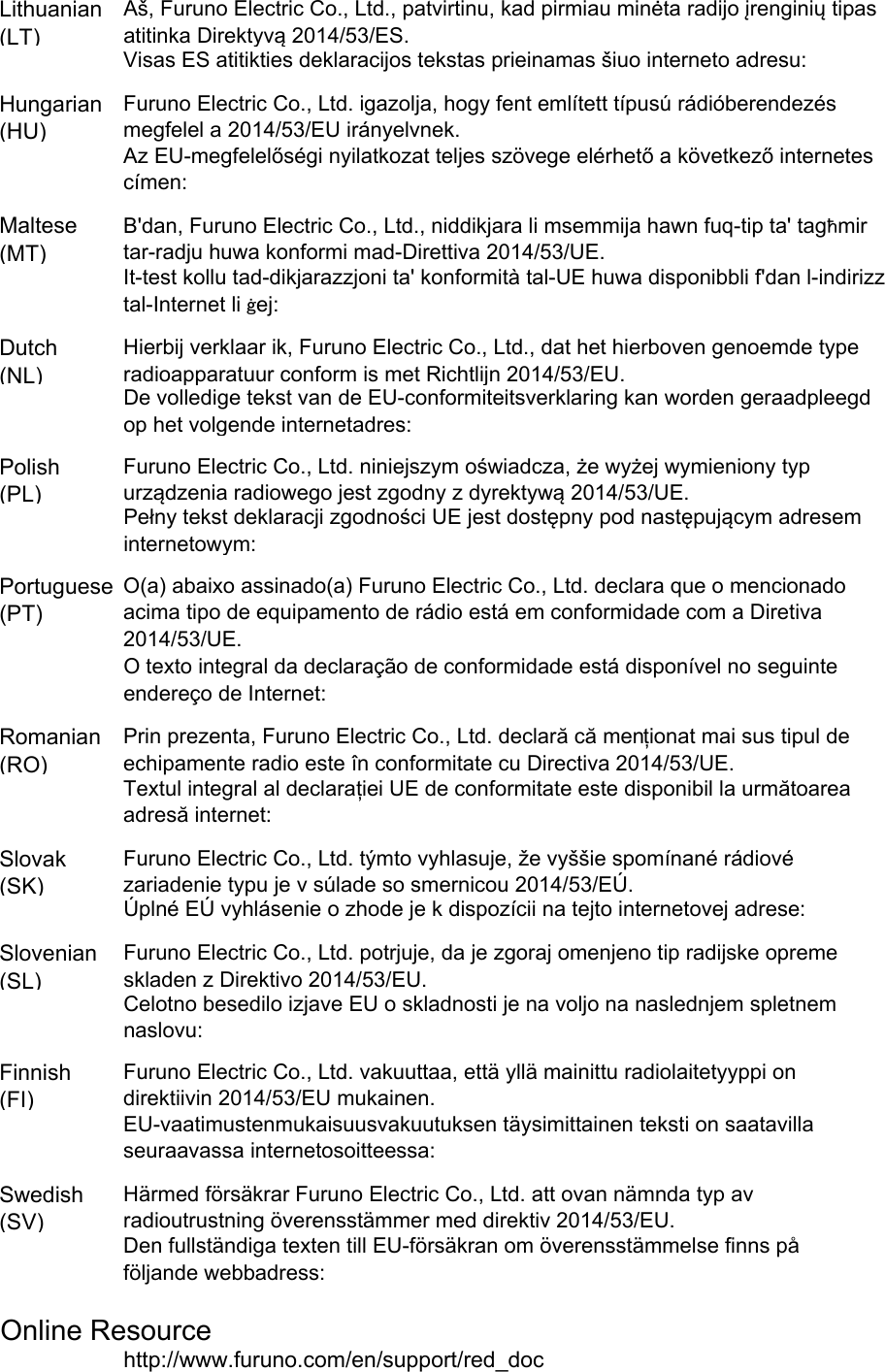
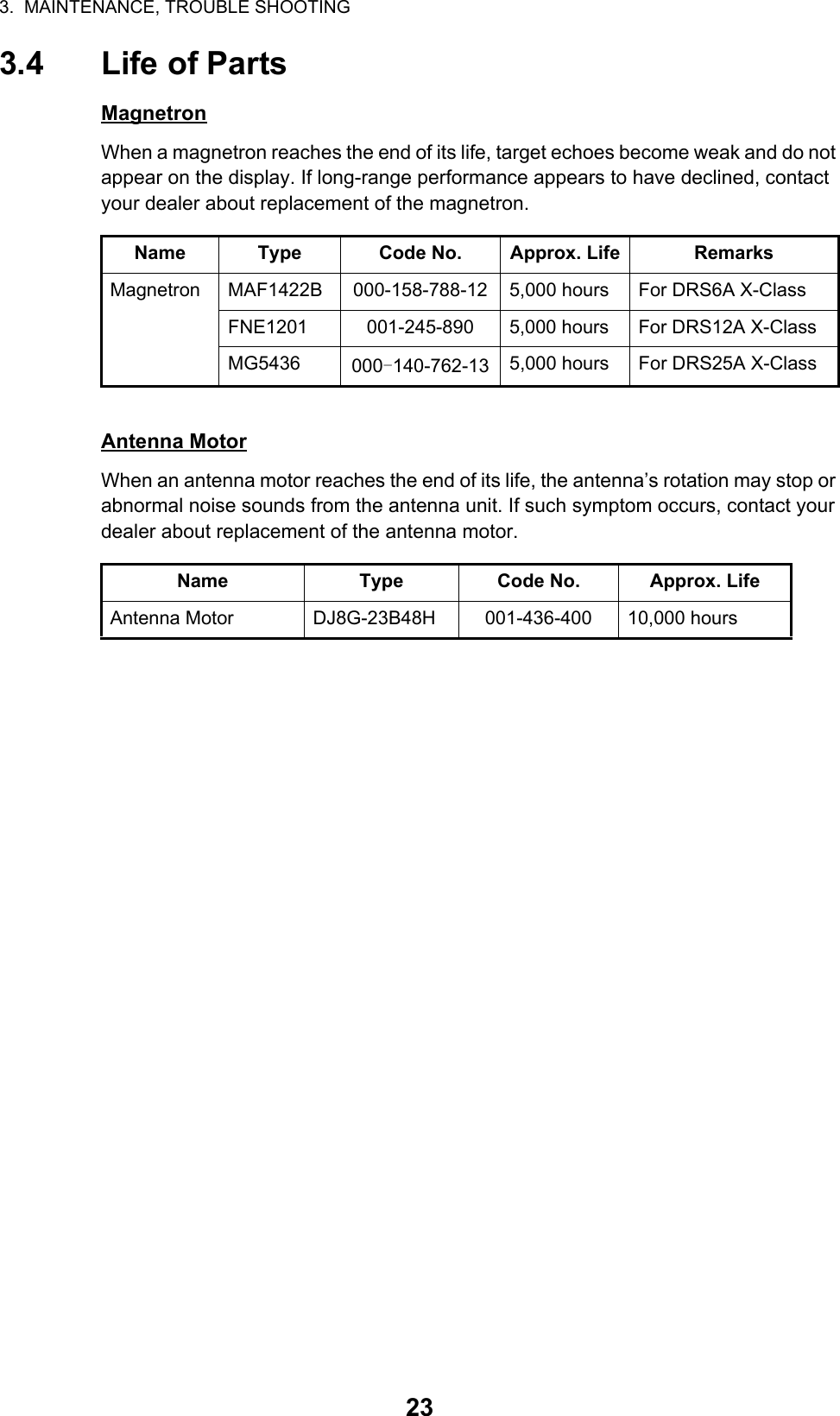
![2. INITIAL SETUP152.1 Initial Setup for TZT9/TZT14/TZTBB1. Press the Home key (or tap the Home icon).2. Select [Menu] on the menu icon bar to open the main menu.3. Select [Radar].4. Select [Radar Source] on the [Menu Radar] sub menus, then select the radar type connected.Note: If the antenna unit is con-nected but does not appear in the [Radar Source] list, close the list and open it again. The name of the antenna unit should appear with a check mark, as in the example to the right.5. Drag the [Menu Radar] sub menus to find the menu item [Radar Initial Setup]. 6. Set the items referring to the table shown belowMenu Radar (Radar Initial Setup)Menu item Description[Antenna Rotation] Select the antenna rotation speed.[Antenna Heading Align] See "How to align the antenna heading" on page 16.[Main Bang Suppression] If main bang appears at the screen center, slide the circle icon, while watching the radar echo on the left-side of the display, until the main bang disappears.[Enable Sector Blanking]/[Enable Sector Blanking2]Up to two sectors may be selected for blanking (no trans-mission). Select [ON] to enable this feature. Set the start and end angles (0° to 359°).[Antenna Height] Select the height of the antenna above the waterline.RDxxxxxx - DRS6A X-ClassRDxxxxxx - DRS6A X-ClassDisplay example for DRS6A X-ClassTitle](https://usermanual.wiki/Furuno-USA/9ZWRTR114/User-Guide-3175620-Page-20.png)
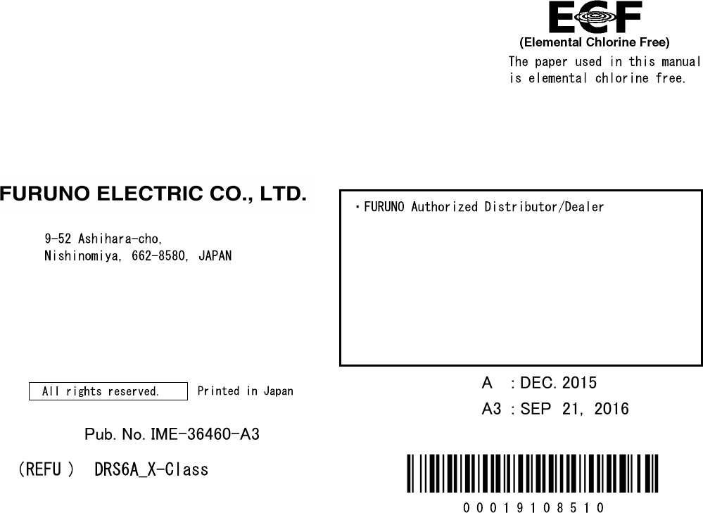
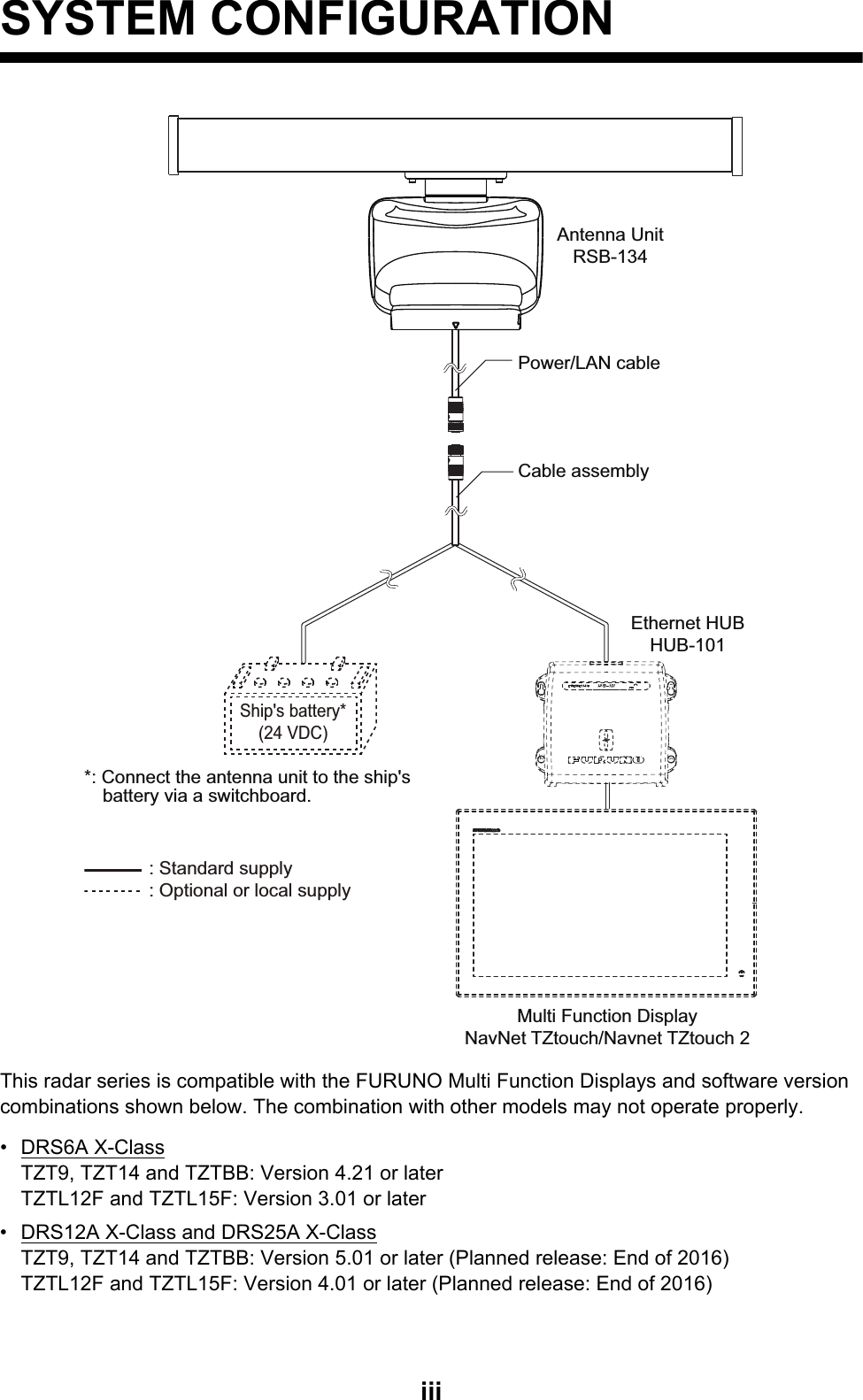
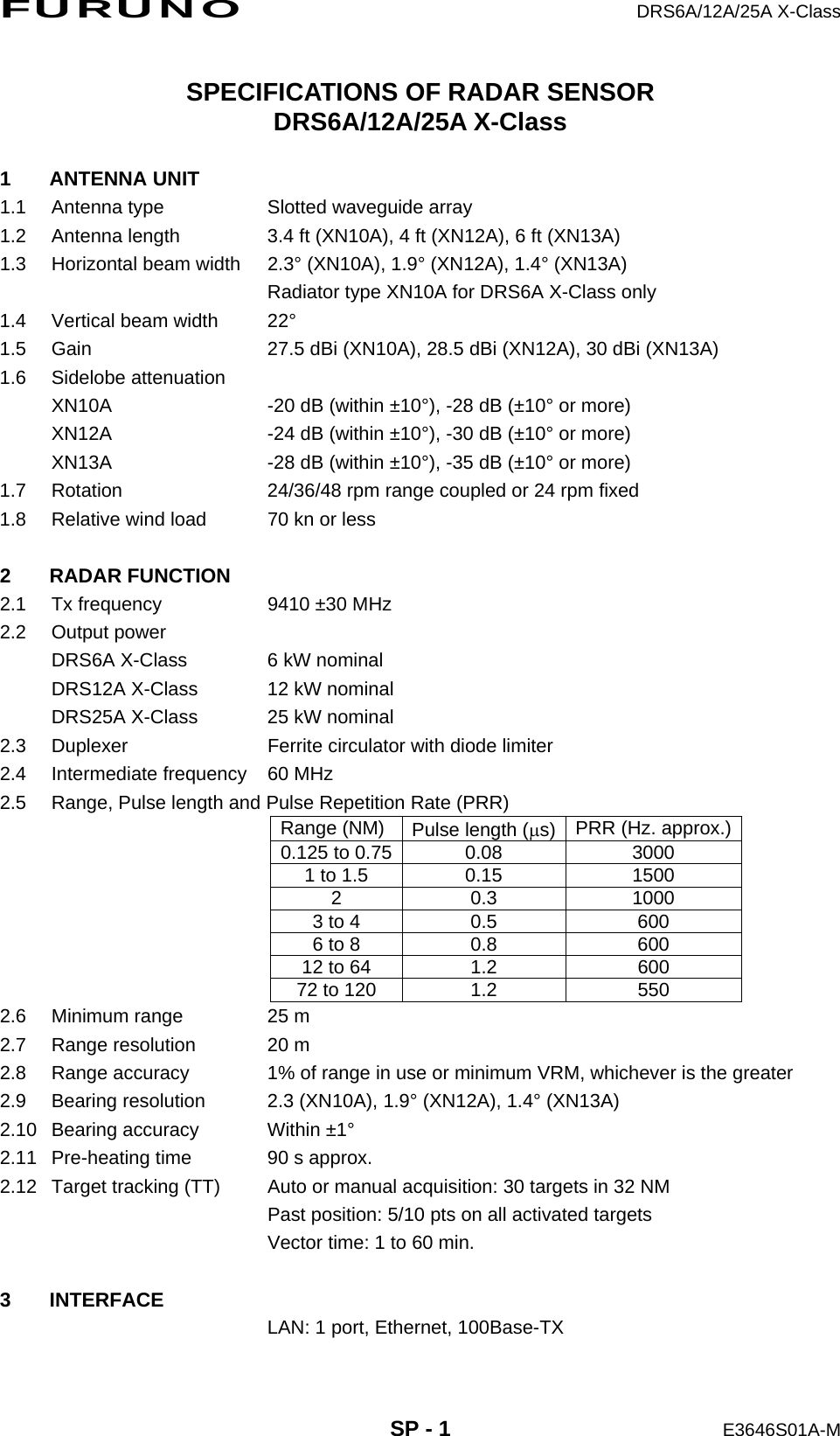
![2. INITIAL SETUP16How to align the antenna headingYou have mounted the antenna unit facing straight ahead in the direction of the bow. Therefore, a small but conspicuous target dead ahead visually should appear on the heading line (zero degrees). You may observe a minor bearing error on the display. This is due to the difficulty in orienting the radar accurately. The following adjustment will compensate for the error.1. Select a range between 0.125 and 0.25 NM and set the mode to “head up“.You can select a range by a pinch action. The range and range ring interval ap-pear at the bottom left of the screen.[Antenna Longitudinal Po-sition]Referring to the figure on the right, enter the radar antenna positioning bow-stern (Longi-tudinal) and port-starboard (Lateral) position from the origin.[Antenna Lateral Position (-Port)][Auto Tuning] Enable/disable auto tuning for the connected radar.[Tuning Source] Select the radar range to tune manually, which is used for the dual-range display.[Manual Tuning] Manually tune the radar. Not available when [Auto Tuning] is enabled.[Radar Monitoring] Display various information regarding the connected ra-dar.[Radar Optimization] Automatically adjust magnetron output and tuning for the connected radar. Note: Be sure to perform [Radar Optimization] after re-placing the magnetron.[ARPA Advanced Settings] Do not change these settings.Menu item DescriptionOrigin1Range Range ring intervalRange indicationsZoom outZoom inPinch action](https://usermanual.wiki/Furuno-USA/9ZWRTR114/User-Guide-3175620-Page-21.png)
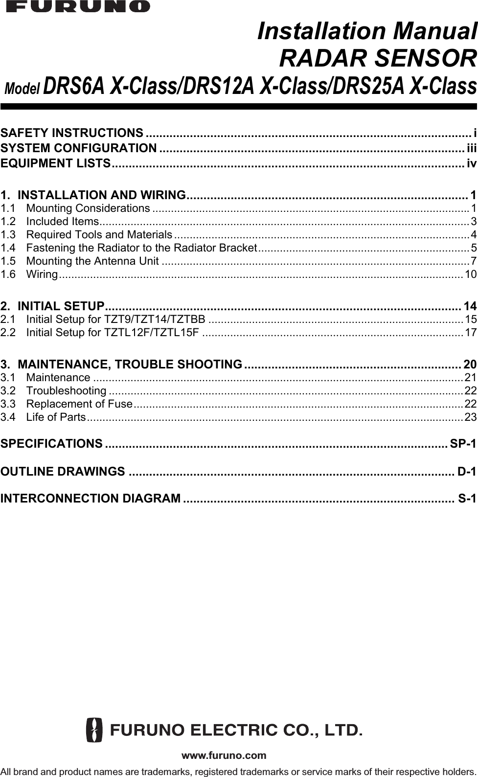
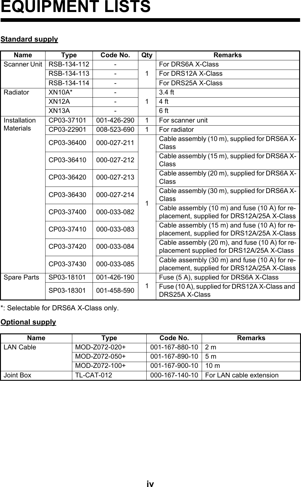
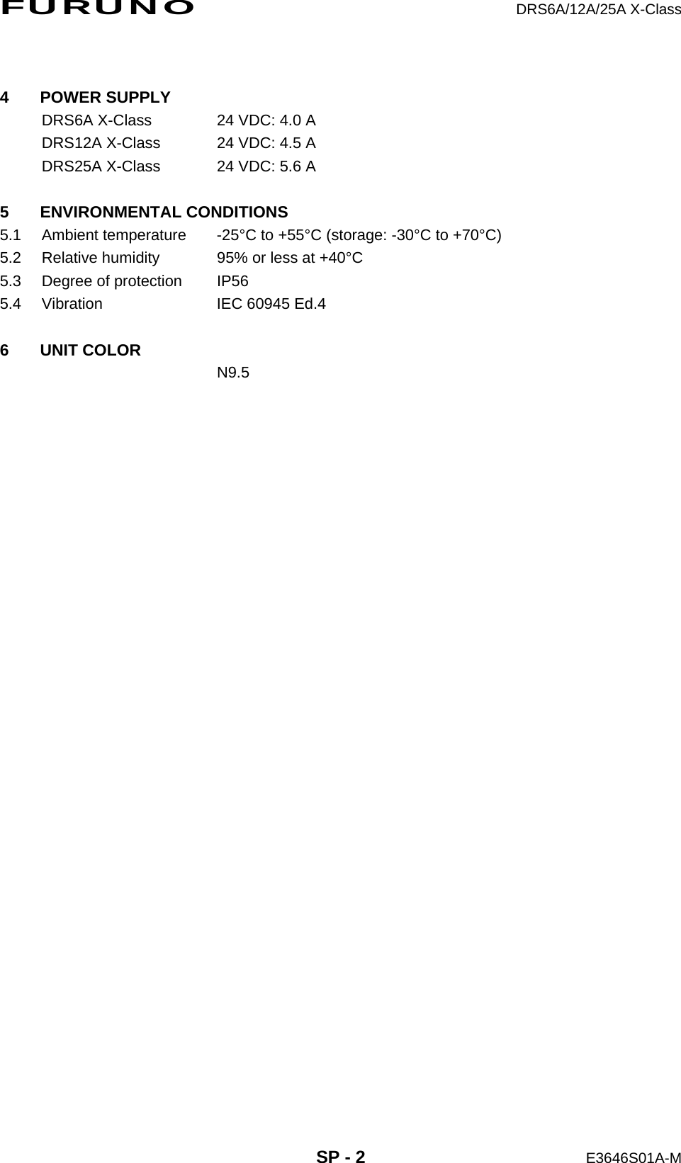
![2. INITIAL SETUP17For TZTBB, you can also control the range in the operation as follows. Tap the radar scale box at the bottom left-hand corner of the screen to display the slider bar. Drag the circle icon to set the range scale.2. Turn the vessel’s bow toward a target.3. Press the Home key (or tap the Home icon), then select [Menu] icon, [Radar], and [Antenna Heading Align] in that order to show the numeric software keyboard.4. Key in the offset value so that the target is at the very top of the screen (setting range: +/- 0° to 180°, +: clockwise direction, -: counterclockwise direction), then tap [Save].5. Confirm that the target echo is displayed at correct bearing on the screen.2.2 Initial Setup for TZTL12F/TZTL15F1. Tap the [Home] icon to show the home screen and display mode settings.2. Tap [Radar] from the [Settings] menu.3. Tap [Radar Source], then select the appropriate antenna unit.Note: If the antenna unit is connected but does not appear in the [Radar Source] list, close the list and open it again. The name of the antenna unit should appear with a check mark, as in the example below.4. Drag the [Radar] menu display the menu item [Radar Initial Setup], then tap [Radar Initial Setup]. 5. Referring to the tables below, set up the radar.[Radar] menu - [Radar Initial Setup]Menu item Description[Antenna Rotation] Select the antenna rotation speed.[Antenna Heading Align] See "How to align the antenna heading" on page 19.[Main Bang Suppression] If main bang appears at the screen center, slide the circle icon so that the main bang disappears, while watching the radar echo at the left-hand side of the display.Tap the area circled in the dashed line to display the slider bar.Note: You can switch between transmit and stand-by by tapping the right side of the radar scale box.Drag the circle icon to set the range scale.Slider barZoom inZoom out4NMCurrent rangeRDxxxxxx - DRS6A X-ClassDisplay example for DRS6A X-Class](https://usermanual.wiki/Furuno-USA/9ZWRTR114/User-Guide-3175620-Page-22.png)
![2. INITIAL SETUP18[Radar] menu - [Antenna Position][Enable Sector Blanking] Up to two sectors may be selected for blanking (no trans-mission). Select [ON] to enable this feature. Set the start and end angles (0° to 359°).[Enable Sector 2 Blanking]Menu item Description[Longitudinal (from bow)] Referring to the figure on the right, enter the radar antenna positioning bow-stern (Longi-tudinal) and port-starboard (Lateral) position from the origin.[Lateral (-Port)][Antenna Height] Select the height of the antenna above the waterline.[Auto Tuning] Enable/disable auto tuning for the connected radar.[Tuning Source] Select the radar range to tune manually, which is used for the dual-range display.[Manual Tuning] Manually tune the radar. Not available when [Auto Tuning] is enabled.[Radar Monitoring] Display various information regarding the connected ra-dar.[Radar Optimization] Automatically adjust magnetron output and tuning for the connected radar. Note: Be sure to perform [Radar Optimization] after re-placing the magnetron.[ARPA Advanced Settings] Do not change these settings.[Set Hardware To Factory Default]Resets the radar selected at [Radar Source] to factory de-fault.[Reset Default Settings] Resets [Radar] menu settings to default.Menu item DescriptionOrigin](https://usermanual.wiki/Furuno-USA/9ZWRTR114/User-Guide-3175620-Page-23.png)
![2. INITIAL SETUP19How to align the antenna headingYou have mounted the antenna unit facing straight ahead in the direction of the bow. Therefore, a small but conspicuous target dead ahead visually should appear on the heading line (zero degrees). You may observe a minor bearing error on the display. This is due to the difficulty in orienting the radar accurately. The following adjustment will compensate for the error.1. Set your radar with 0.125 and 0.25 NM range and the head up mode.The range scale can be selected two ways, as shown below. The slider bar can be shown or hidden with [Show Scale Slider] in the [Settings] - [Radar] menu.2. Turn the vessel’s bow toward a target.3. Tap the [Home] icon to show the home screen and display mode settings.4. Tap [Radar] to show the [Radar] menu. 5. Drag the [Radar] menu to show the [RADAR INITIAL SETUP] menu.6. Tap [Antenna Heading Align].7. Key in the offset value so that the target is displayed at the very top of the screen (setting range: +179.9° to -180°, +: clockwise direction, -: counterclockwise direc-tion), then tap the icon.8. Confirm that the target echo is displayed at correct bearing on the screen.Zoom in Zoom outMethod 1: Pinch screenMethod 2: Drag slider(or tap bar or +, - icons)3 NMZoom inZoom inZoom outZoom out](https://usermanual.wiki/Furuno-USA/9ZWRTR114/User-Guide-3175620-Page-24.png)
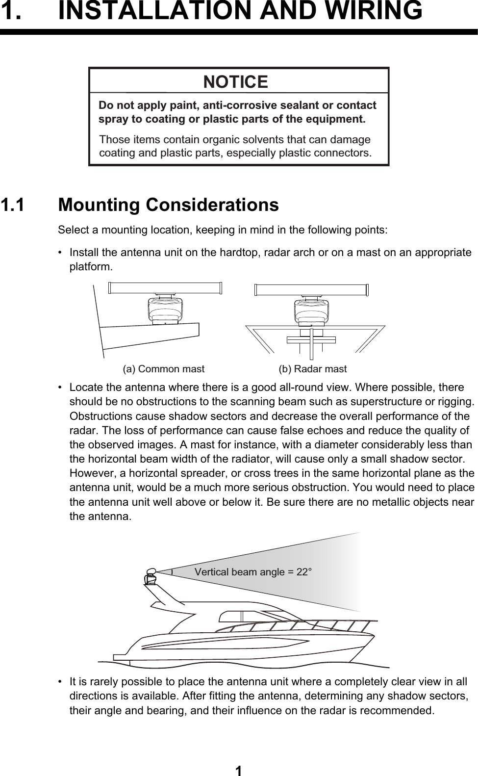
![Declaration of Conformity[DRS6A X-Class/DRS12A X-Class/DRS25A X-Class]Bulgarian(BG)Spanish(ES)Czech(CS)Danish(DA)German(DE)Estonian(ET)Greek(EL)English(EN)French(FR)Croatian(HR)Italian(IT)Latvian(LV)ELi vastavusdeklaratsiooni täielik tekst on kättesaadav järgmiselinternetiaadressil:С настоящото Furuno Electric Co., Ltd. декларира, че гореспоменат типрадиосъоръжение е в съответствие с Директива 2014/53/ЕС.Цялостният текст на ЕС декларацията за съответствие може да се намерина следния интернет адрес:Por la presente, Furuno Electric Co., Ltd. declara que el tipo de equiporadioeléctrico arriba mencionado es conforme con la Directiva 2014/53/UE.El texto completo de la declaración UE de conformidad está disponible en ladirección Internet siguiente:Tímto Furuno Electric Co., Ltd. prohlašuje, že výše zmíněné typ rádiovéhozařízení je v souladu se směrnicí 2014/53/EU.Úplné znění EU prohlášení o shodě je k dispozici na této internetové adrese:Hermed erklærer Furuno Electric Co., Ltd., at ovennævnte radioudstyr er ioverensstemmelse med direktiv 2014/53/EU.EU-overensstemmelseserklæringens fulde tekst kan findes på følgendeinternetadresse:Hiermit erklärt die Furuno Electric Co., Ltd., dass der oben genannteFunkanlagentyp der Richtlinie 2014/53/EU entspricht.Der vollständige Text der EU-Konformitätserklärung ist unter der folgendenInternetadresse verfügbar:Käesolevaga deklareerib Furuno Electric Co., Ltd., et ülalmainitud raadioseadmetüüp vastab direktiivi 2014/53/EL nõuetele.Pilns ES atbilstības deklarācijas teksts ir pieejams šādā interneta vietnē:Με την παρούσα η Furuno Electric Co., Ltd., δηλώνει ότι ο προαναφερθένταςραδιοεξοπλισμός πληροί την οδηγία 2014/53/ΕΕ.Το πλήρες κείμενο της δήλωσης συμμόρφωσης ΕΕ διατίθεται στην ακόλουθηιστοσελίδα στο διαδίκτυο:Hereby, Furuno Electric Co., Ltd. declares that the above-mentioned radioequipment type is in compliance with Directive 2014/53/EU.The full text of the EU declaration of conformity is available at the followinginternet address:Le soussigné, Furuno Electric Co., Ltd., déclare que l'équipement radioélectriquedu type mentionné ci-dessusest conforme à la directive 2014/53/UE.Le texte complet de la déclaration UE de conformité est disponible à l'adresseinternet suivante:Furuno Electric Co., Ltd. ovime izjavljuje da je gore rečeno radijska oprema tipau skladu s Direktivom 2014/53/EU.Cjeloviti tekst EU izjave o sukladnosti dostupan je na sljedećoj internetskojadresi:Il fabbricante, Furuno Electric Co., Ltd., dichiara che il tipo di apparecchiaturaradio menzionato sopra è conforme alla direttiva 2014/53/UE.Il testo completo della dichiarazione di conformità UE è disponibile al seguenteindirizzo Internet:Ar šo Furuno Electric Co., Ltd. deklarē, ka augstāk minēts radioiekārta atbilstDirektīvai 2014/53/ES.](https://usermanual.wiki/Furuno-USA/9ZWRTR114/User-Guide-3175620-Page-36.png)